ulsd061677_td_Jose_Carracho.pdf - Repositório da ...
343
UNIVERSIDADE DE LISBOA FACULDADE DE MEDICINA DENTÁRIA THE INFLUENCE OF DIFFERENT SURFACE AND HEAT TREATMENTS ON THE BIAXIAL FLEXURAL STRENGTH OF VENEERING CERAMICS FOR ZIRCONIA AND STRENGTH RELIABILITY AND MODE OF FRACTURE OF VENEERING CERAMICS/ ZIRCONIA CORE CERAMICS José Fausto Pimentel Coelho Lino Carracho DOUTORAMENTO EM MEDICINA DENTÁRIA ESPECIALIDADE DE REABILITAÇÃO ORAL 2011
-
Upload
khangminh22 -
Category
Documents
-
view
1 -
download
0
Transcript of ulsd061677_td_Jose_Carracho.pdf - Repositório da ...
UNIVERSIDADE DE LISBOA
FACULDADE DE MEDICINA DENTÁRIA
THE INFLUENCE OF DIFFERENT SURFACE AND HEAT TREATMENTS ON THE BIAXIAL FLEXURAL STRENGTH OF VENEERING CERAMICS FOR ZIRCONIA AND STRENGTH RELIABILITY AND MODE OF FRACTURE OF VENEERING
CERAMICS/ ZIRCONIA CORE CERAMICS
José Fausto Pimentel Coelho Lino Carracho
DOUTORAMENTO EM MEDICINA DENTÁRIA
ESPECIALIDADE DE REABILITAÇÃO ORAL
2011
UNIVERSIDADE DE LISBOA
FACULDADE DE MEDICINA DENTÁRIA
THE INFLUENCE OF DIFFERENT SURFACE AND HEAT TREATMENTS ON THE BIAXIAL FLEXURAL STRENGTH OF VENEERING CERAMICS FOR ZIRCONIA AND STRENGTH RELIABILITY AND MODE OF FRACTURE OF VENEERING
CERAMICS/ ZIRCONIA CORE CERAMICS
Thesis supervised by
Prof. Doutor António Vasconcelos Tavares
Dr. Michael Razzoog
José Fausto Pimentel Coelho Lino Carracho
2011


Table of Contents
III
TABLE OF CONTENTS
TABLE OF CONTENTS ........................................................................................ III
LIST OF TABLES AND FIGURES ...................................................................... VII 1 - Tables ........................................................................................... VII 2 - Figures ......................................................................................... VII
PREAMBLE ......................................................................................................... XI
CHAPTER 1 INTRODUCTION ............................................................................. 1 History of porcelain .............................................................................................. 5 Composition of dental ceramics ........................................................................... 9 Classification of dental ceramics ........................................................................ 13 Mechanical properties of dental ceramics .......................................................... 14 Optical properties of dental ceramics ................................................................. 21 Fusion of dental ceramics .................................................................................. 26 Methods of fabrication of dental ceramics ......................................................... 27 Strenghtening mechanims of dental ceramics ................................................... 30 Enameling of metals ....................................................................................... 32 Cristallization of glasses ................................................................................. 35 Lithium zinc silicate glass ceramic (LZS) - Li2O-ZnO-SiO2 system ............. 36 Lithium disilicate glass ceramic (LDS) - Li2O-2SiO2 system ....................... 37 Lithium disilicate glass ceramic (LACS) - Li2O-Al2O3-CaO-SiO2 system .... 38 Calcium phosphate glass ceramic (CP) - CaO-P2O5 system ...................... 39 Tetrasilicic fluormica glass ceramic (TSFM) - K-Mg25-Si4O10-F2 system .... 40 Apatite glass ceramic (HMPO) - CaO-MgO-P2O5-SiO2 system .................. 43 Chemical strengthening .................................................................................. 44 Thermal tempering .......................................................................................... 45 Bonding to foils ............................................................................................... 47 Bulk strengthening .......................................................................................... 48 Dispersion strengthening ................................................................................ 50 Leucite-strengthened ceramics .................................................................... 50 IPS-Empress 1 ........................................................................................ 51 Optimal Pressable Ceramic .................................................................... 53 Optec HSP .............................................................................................. 53 Alumina-strengthened ceramics .................................................................. 55 Traditional platinum foil technique ........................................................... 57 The platinum twins foil technique ............................................................. 58 The refractory die technique .................................................................... 60 Injection molded core porcelain ............................................................... 61 Slip-cast alumina ceramics ...................................................................... 62 In-Ceram Alumina ................................................................................ 62 In-Ceram Spinell .................................................................................. 64 In-Ceram Zirconia ................................................................................ 65 CAD-CAM alumina ceramics ................................................................... 66 Procera AllCeram Alumina ................................................................... 67 Lithium-disilicate-strengthened ceramics ..................................................... 70

Table of Contents
IV
IPS-Empress 2 ................................................................................... 71 3G-OPC .............................................................................................. 73 Zirconia-strengthened ceramics ............................................................. 74 Zirconia containing ceramics systems ............................................... 79 Yttrium tetragonal Zirconia polycrystals (3Y-TZP) ......................... 79 Glass-infiltrated Zirconia-toughened alumina (ZTA) ...................... 82 Magnesia partially stabilized Zirconia (Mg-PSZ) ............................ 83 Zirconia surface treatments ............................................................... 84 Soft machining of pre-sintered blanks ............................................ 84 Hard machining of 3Y-TZP and Mg-PSZ ....................................... 87 Clinical studies of ZrO2 fixed prostheses ........................................... 89 Zirconia all-ceramic systems .............................................................. 92 Procera AllZircon system ............................................................... 95 LAVA system .................................................................................. 97 Cercon smart ceramic system ....................................................... 98 In-Ceram 2000 Vita YZ CUBES ..................................................... 99 DCS- Smart-Fit system ................................................................ 100 Veneering Ceramics ........................................................................................ 101 Fracture mechanism/Mode of fracture of dental ceramics .............................. 113 Dental ceramics testing methods .................................................................... 119
CHAPTER 2 OBJECTIVES OF THE STUDY .................................................. 123
CHAPTER 3 MATERIALS AND METHODS .................................................... 127 1- Surface finish and heat treatment study ....................................................... 127
Type of research ........................................................................ 127 Dependent variable ................................................................... 127 Independent variable ................................................................. 127 Constant independent ............................................................... 128 Sample size calculations ........................................................... 128 Design of the study .................................................................... 128 Preparation of the specimens .................................................... 130 Distribution and treatment of the specimens ............................. 135 Biaxial flexural strength test ....................................................... 139 Calculations to determine biaxial flexural strength .................... 143 Statistical analysis ..................................................................... 143
2- Strength and reliability study ......................................................................... 146 Type of research ........................................................................ 146 Dependent variable ................................................................... 146 Independent variable ................................................................. 146 Constant independent ............................................................... 146 Sample size calculations ........................................................... 146 Design of the study .................................................................... 147 Preparation of the specimens .................................................... 148 Distribution and treatment of the specimens ............................. 151 Biaxial flexural strength test ....................................................... 153 Calculations to determine biaxial flexural strength .................... 155 Statistical analysis ..................................................................... 155
3- Mode of fracture study .................................................................................. 157
Type of research ........................................................................ 157 Dependent variable ................................................................... 157 Independent variable ................................................................. 157 Constant independent ............................................................... 157 Design of the study .................................................................... 157 Preparation of the specimens .................................................... 158 Distribution and treatment of the specimens ............................. 160 Mode of fracture evaluation ....................................................... 161
Table of Contents
V
CHAPTER 4 RESULTS .................................................................................... 163 1- Surface finish and heat treatment study ....................................... 163 2- Mode of fracture and biaxial flexural strength of bilayered feldspathic dental veneering ceramics/Zirconia core ceramic. ......... 173
CHAPTER 5 DISCUSSION .............................................................................. 195
CHAPTER 6 CONCLUSIONS .......................................................................... 231
SUMMARY ......................................................................................................... 235
RESUMO ......................................................................................................... 239
APPENDICES .................................................................................................... 249
APPENDIX 1- MATERIALS, MANUFACTURERS, COMPONENTS AND BATCH NUMBERS ........................................................................... 249
APPENDIX 2 - FIRING SCHEDULES OF THE FELDSPHATIC VENEERING CERAMICS ................................................................ 250
APPENDIX 3 - GLOSSARY OF CHEMICAL COMPOUNDS ............................ 251
APPENDIX 4 - GLOSSARY FOR GENERAL ACRONYMS .............................. 252
APPENDIX 5 - RAW DATA ................................................................................ 253
BIBLIOGRAPHY ................................................................................................ 291

VI
List of tables and figures
VII
LIST OF TABLES AND FIGURES
1- Tables
Table 1 Composition of each group and respective material and surface treatment .................................................................................................... 135
Table 2 Composition of each group and respective material and surface treatment .................................................................................................... 151
Table 3 Descriptive statistics by group for load fracture MPa ............................ 165
Table 4 Weibull modulus values for the feldspathic veneering ceramics versus surface treatments ......................................................................... 172
Table 5 Descriptive statistics by group for load fracture MPa ............................ 175
Table 6 Weibull modulus values for the feldspathic veneering ceramics/Zirconia core ceramic versus Zirconia location .......................... 180
2- Figures
Figure 1. Feldsphatic veneering ceramics ......................................................... 129
Figure 2. Ceramic furnace Programat P500 ...................................................... 130
Figure 3. Steriomicroscope Nikon SMZ-U ......................................................... 131
Figure 4. Ecomet 3, mechanical grinder ............................................................ 132
Figure 5. Test specimen before testing procedure ............................................ 134
Figure 6. Disc-shaped test specimen positioned over testing apparatus before fracture strength measurement. The specimen is supported by 3 ball bearings distributed in a circular pattern. The load is applied from above by use of a piston in a position concentric with the supporting ball bearings .............................................................................................. 140
Figure 7. Schematic diagram of the apparatus used for the biaxial flexural strength measurements ............................................................................. 141
Figure 8. Schematic diagram of biaxial flexural strength test arrangement ....... 142
List of tables and figures
VIII
Figure 9. Feldspathic veneering ceramics dentin and opaque .......................... 148
Figure 10. Test specimen before testing procedure. Top and cross-section view ........................................................................................................... 150
Figure 11. Test specimens of group 1 consisting of NobelRondo Zirconia veneer ceramic and Zirconia ceramic framework ..................................... 153
Figure 12. Disc-shaped test specimen positioned over testing apparatus before fracture strength measurement. The load was applied at the center of the top surface through the flat tip of a cylindrical piston (diameter 0.7mm) at a cross-head speed of 0.5mm/min until fractured ... 154
Figure 13. Amray 1820, scanning electron microscope .................................... 162
Figure 14. Biaxial flexural strength (MPa), mean values and standard errors of feldspathic veneering ceramics specimens versus surface treatments ................................................................................................. 166
Figure 15. Biaxial flexural strength mean values (MPa) of NobelRondo feldspathic veneering ceramic specimens versus surface treatments with Fisher’s grouping indicated. ............................................................... 169
Figure 16. Biaxial flexural strength mean values (MPa) of Lava Ceram feldspathic veneering ceramic specimens versus surface treatments with Fisher’s grouping indicated. ............................................................... 170
Figure 17. Biaxial flexural strength mean values (MPa) of Vita VM9 feldspathic veneering ceramic specimens versus surface treatments with Fisher’s grouping indicated. ............................................................... 171
Figure 18. Biaxial flexural strength mean values (MPa) of feldspathic veneering ceramics/Zirconia core ceramic specimens versus side placed under tension ................................................................................. 176
Figure 19. Box-and-whisker plots of biaxial flexural strength for the NobelRondo feldspathic veneering ceramic/Zirconia core ceramic specimens versus side placed under tension. The white color corresponds to the Zirconia core when placed on the top. The blue color when the Zirconia core is placed on the bottom. .............................. 177
Figure 20. Box-and-whisker plots of biaxial flexural strength for the Lava Ceram feldspathic veneering ceramic/Zirconia core ceramic specimens versus side placed under tension. The white color corresponds to the Zirconia core when placed on the top. The blue color when the Zirconia core is placed on the bottom. ...................................................... 178
Figure 21. Box-and-whisker plots of biaxial flexural strength for the Vita VM9 feldspathic veneering ceramic/Zirconia core ceramic specimens versus side placed under tension. The white color corresponds to the Zirconia core when placed on the top. The blue color when the Zirconia core is placed on the bottom. ............................................................................... 179
Figure 22. Most common representative fracture mode of bilayered feldspathic veneering ceramic/Zirconia core ceramic specimens of groups 1, 3 and 5. Hertzian cone crack and feldspathic veneering ceramic delamination with exposure of the Zirconia core are present in the loaded area. ........................................................................................ 183
List of tables and figures
IX
Figure 23. SEM micrograph of representative Hertzian cone crack observed on the surface of the bilayered feldspathic veneering ceramic/core Zirconia ceramic specimen of group 1. ...................................................... 184
Figure 24. Catastrophic failure of specimen of group 3 following initial tensile crack progression with lateral crack deflection involving veneering ceramic/Zirconia core interface as well as fracture of the Zirconia core and partial delamination of the feldspathic veneering ceramic. ..................................................................................................... 185
Figure 25. SEM micrograph of representative Hertzian cone crack and feldspathic veneering ceramic delamination following initial tensile crack progression with lateral and radial crack deflection involving veneering ceramic/Zirconia core interface observed on the surface of specimen of group 3. ................................................................................. 186
Figure 26. Catastrophic failure of specimen of group 5 following initial tensile crack progression involving veneering ceramic/Zirconia core interface as well as fracture of the Zirconia core with complete delamination of the feldspathic veneering ceramic and opaque material in some areas. ........................................................................................... 187
Figure 27. SEM micrograph of representative Hertzian cone crack and feldspathic veneering ceramic delamination with Zirconia core exposure observed on the surface of specimen of group 5. ...................... 188
Figure 28. Representative fracture mode of specimens of group 2 with partial delamination of the feldspathic veneering ceramic and opaque ceramic material and catastrophic failure of the Zirconia ceramic core as a result of crack propagation. ................................................................ 189
Figure 29. SEM micrograph of representative tensile crack progression with feldspathic veneering ceramic delamination and Zirconia core exposure observed on the surface of specimen of group 2. ...................... 190
Figure 30. Catastrophic adhesive-cohesive failure after fracture of specimen of group 4 as a result of crack progression within the Zirconia ceramic core. The initial tensile crack progressed with lateral crack deflections involving the veneering ceramic/Zirconia core interface with partial delamination of the feldspathic veneering ceramic and opaque ceramic material. ..................................................................................................... 191
Figure 31. SEM micrograph of representative tensile crack progression with feldspathic veneering ceramic delamination and Zirconia core exposure with adhesive-cohesive failure of specimen of group 4. ............ 192
Figure 32. Catastrophic failure of specimen of group 6 as a result of crack progression within the Zirconia ceramic core. The initial tensile crack progressed with lateral crack deflections involving the veneering ceramic/Zirconia core interface with partial delamination of the feldspathic veneering ceramic and opaque ceramic material. ................... 193
Figure 33. SEM micrograph of representative adhesive-cohesive failure after fracturing a specimen of group 6. In this specimen the type of fracture was mainly cohesive. .................................................................... 194

X
Preamble
XI
PREAMBLE
Pursuing a PhD project is a both painful and enjoyable experience. It is
just like climbing a high peak, step by step, accompanied with bitterness,
adversity, encouragement and frustration. The submission of this dissertation to
the Scientific Board of the University Of Lisbon School Of Dentistry is an
important key-step in my academic, professional and personal life.
My introduction to the research world started with the elaboration of a
Master’s Thesis at The University of Michigan during the years 2002-2005. It was
from the close contact with experienced researchers and highly demanding
clinicians that I discovered the importance of scientific rigor, critical thinking, and
permanent methodic doubt. This training had remarkable repercussions in the
way I see and act in the profession.
Research is a creative process that is not only accomplished by the author
but also involves the support, cooperation and effort of many persons: my
mentors and advisors, my professors, my teaching and private practice
colleagues, my family and friends. I respectfully share the result with them.
Special thanks to my two mentors and advisors; Dr. Michael Razzoog,
Professor at the Biologic & Materials Sciences Department of the University of
Michigan School of Dentistry and Chair of the Operations Committee of the
University of Michigan/Nobel Biocare Center for Excellence and Professor Doutor
António Vasconcelos Tavares, Chairman of the Fixed Prosthodontics Department
of the University of Lisbon School of Dentistry.
To Dr. Michael Razzoog for his constant intellectual stimulus, for planting
Preamble
XII
ideas, commenting on research content, for helping me complete the writing of
this dissertation as well as the challenging research that lies behind it. I hope that
I could be as lively, enthusiastic, and energetic as he is and to someday be able
to serve as an example for students as well as he is. Michael has been a friend
and mentor. He taught me how to write academic papers, made me a better
dentist, had confidence in me when I doubted myself, and brought out the good
ideas in me. He was and remains my best role model for a scientist, mentor, and
teacher. Without his encouragement and constant guidance, I could not have
finished this dissertation. He was always there to meet and talk about my ideas,
to proofread and mark up my papers and chapters, and to ask me good
questions to help me think through my problems (whether philosophical,
analytical or computational). His professional role and commitment to excellence
will stay with me forever. It was a great honor to me that he accepted being my
mentor, giving me all the intellectual and logistic support for the development of
this PhD thesis. For these reasons, all research and technical work were
performed at the Biologic & Materials Sciences Department of the University Of
Michigan School Of Dentistry and was why this dissertation was written in English.
To Professor Doutor António Vasconcelos Tavares that was, without any
doubt, the teacher that mostly marked my student and academic career. My
interest for Fixed Prosthodontics was inspired by the enthusiastic passion that
Professor Vasconcelos Tavares has for this area of dentistry. After my graduation
in 1999, I was given by him the opportunity to become a faculty member of the
department of Fixed Prosthodontics.
Professor Vasconcelos Tavares has been helpful in providing advice many
times during my academic career. His encouragement and motivation made me
feel confident to fulfill my desire and to overcome every difficulty I encountered.
His serenity, respect and support made me look for dentistry life in a different
perspective. I am very grateful, for all of that, and for the help he gave me in the
execution of this work and for his exhaustive revision and pertinent suggestions.
Preamble
XIII
It is not sufficient to express my gratitude with only a few words
To Dr Marianella Sierraalta, Clinical Associate Professor at the Biologic &
Materials Sciences Department of the University Of Michigan School Of Dentistry,
for the help she gave in accomplishing the mechanical testing tasks. Her
invaluable support, expertise, and experience were essential in the achievement
of this project. Her enthusiasm and love for teaching is contagious and will stay
with me forever as an example of dedication.
To Mr. Rui Wang, for challenging inquiring, invaluable commenting, and
indispensable help with the statistical analysis of my project. I would like to
commend the interest, encouragement, challenging inquiring and great job done
by throughout the overall process for his scientific advice and knowledge and
many insightful discussions and suggestions.
To my private practice partners, for their understanding attitude.
To my family, especially Rita, Guilherme, and Clara for their care,
company and constant support, and for accepting the several periods of absence
with a string of trips abroad, lost weekends, and odd working hours that this work
demanded.
Thank you very much.

XIV
Introduction
1
CHAPTER 1
INTRODUCTION
For decades, an objective of dental restorations has been to replace
tooth structure lost by dental disease. However, as dental techniques and
materials are improved, both clinicians and patients look for the dental
treatments restoring the tooth both functionally and esthetically, not just
restoring the function of tooth.
All-ceramic dental materials are becoming the first choice of restorative
materials because of their superior biocompatibility and distinct esthetic
appeal. However, the major drawback of dental ceramics is the low tensile
strength, which results from the presence of surface and internal flaws, a
brittleness characteristic of most ceramic materials (O’Brien, 2002; Ritter,
1995).
The brittle behavior of ceramics combined with extreme sensitivity to
microcrack-like defects has hampered wider use and limited their application
to relatively low stress-bearing areas. Flaws and defects that may grow at the
microscopic level have been shown to significantly control their strength
characteristics (Tinschert et al., 2000; Kelly, 1995).
A main focus of dental researchers and manufactures has been to
improve the strength properties of ceramic materials (Seghi et al., 1990).
Various methods and techniques have been recommended to strength dental
ceramics (Anderson et al., 1993; Anderson et al., 1998; Luthardt et al., 1999;
McLaren et al., 1999; Fischer et al., 2001; Fischer et al., 2000; Giordano et al.,
Introduction
2
1994; Anusavice et al., 1992; Campbell et al., 1989; Seghi et al., 1995;
Rosentiel et al., 1993; Burke, 1999; Mclean, 1987).
A strengthened ceramic can be used as the sole material for making an
all-ceramic crown, inlay, onlay or veneer restoration or as a core subtract for a
ceramic crown (Anusavice, 1996). In an attempt to improve the strength
characteristics of all-ceramic systems 2 avenues have been explored. The
first is directed toward enhancing the strength of core materials and the
second focused on improving processing techniques with the intent of
producing a more homogeneous ceramic material. Often both directions are
used in the development of new all-ceramic restorative systems with improved
strength. Ceramic materials with varied chemical compositions have been
developed for use with processing methods combining pressure, high
temperature and CAD/CAM (computer-aided design/computer-aided
manufacturing) technology (Anderson et al., 1993; Anderson et al., 1998;
O’Brien, 2002).
Until recently, the primary focuses of dental ceramic developers and
researchers have concentrated on improving the flexural strength and fracture
toughness of the core materials (Anderson et al., 1993; Anderson et al.;
Luthardt et al., 1999). Zirconia based restorations are a major example of this
progress (Christel et al., 1989; Piconi et al., 1999). While emphasis has been
placed on the development of core ceramics finding stronger veneering
porcelains has not been an area of significant research. Thus veneering
porcelain strength has remained largely unchanged since the original
porcelain jacket crown. Without a major improvement in the strength of the
veneering porcelain it is doubtful whether future advances in ceramic core
strength will improve the durability of all-ceramic systems.
On the other hand, the development of stronger veneering porcelains,
which is now a crucial center of attention of researchers may be the key step
to improve the strength of all-ceramic restorations. This idea is supported by
Introduction
3
different studies that have shown that a thin layer of veneering porcelain fired
onto ceramic core material diminish the strength of the 2-layer test specimens
(Hopkins, 1989; Zeng et al., 1998). The veneering porcelain is still likely to be
the weakest link in the ceramic restoration.
All-ceramic veneering materials, are subjected to different fabrication
procedures in the laboratory, and sometimes must be adjusted clinically to
allow either proper fitting or occlusion. The processing procedures and/or
clinical adjustments are more likely to initiate subcritical flaws or large defects
which, upon clinical loading and/or presence of moisture, may grow to a
critical situation leading to catastrophic failure. In addition, different surface
roughness formed through finishing procedures may cause various stress
concentrations and consequently may be accompanied by a reduction in
strength (Jager et al., 2000).
The high physical properties of many ceramic materials makes surface
polishing a difficult task. The development of microcracks during the polishing
procedure is not easily avoidable. Moreover, the skill of individual dental
technician as well as the adherence to the recommendations of a specific
dental material’s manufacturer can, to a greater extent, influence the
mechanical performance of all-ceramic materials (Chen et al., 1999).
The effect of processing procedures, polishing, grinding and glazing on
the mechanical properties of some dental materials has been studied by many
investigators (Bhrama et al., 2002; Giordano et al., 1994; Campbell et al.,
1989; Rosentiel et al., 1999; Anusavice, 1991; Giordano et al., 1995; Fairhurst
et al., 1992; Chu et al., 2000; Williamson et al., 1996; Mecholsky et al., 1977;
Kosmac et al., 1999; Brackett et al., 1989; Griggs et al., 1996; Kitazaki et al.,
2001; Haharav et al., 1999; Denry et al., 1999; Anusavice et al., 1989; Albakry
et al., 2003; Isgro et al., 2003; Guazzato et al., 2003; Guazzato et al., 2004).
However, there is still controversy concerning the most suitable method that
could produce a smooth and strong surface (Williamson et al., 1996). The
Introduction
4
purpose of this study is to contribute to the explanation and resolution of this
common clinical problem.
While much research has been conducted to assess the strength of
traditional dental porcelain materials, very little information has been reported
concerning the relative strength of many of the ceramic materials already in
clinical applications. The precision of fit and biocompatibility of specific
Zirconia crowns has been studied and found to be excellent for multiple dental
applications (Luthardt et al., 1999; Piconi et al., 1999). However, little data
exists regarding the strength and mode of fracture, of dental veneering
porcelains used in conjunction with Zirconia based structures (White et al.,
2005; Aboushelib et al., 2006). Therefore, the purpose of this investigation will
be to evaluate the influence of different surface and heat treatments on the
mechanical properties of Zirconia dental veneering porcelains and the
strength, reliability and mode of fracture of Zirconia/veneering porcelain. While
it is clear that the long-term clinical performance of Zirconia restorations will
depend on many factors, the ability of ceramic materials to withstand fracture
is of significant interest.
Ceramic development continues to be a challenge. If a reliable and
durable all-ceramic system, which remains yet somewhat elusive, is to be
achieved, it is essential to continue the research in order to increase the
knowledge about dental ceramics, thereby allowing substantial improvement
in the all-ceramic material performance.
Introduction
5
History of porcelain
Porcelains have been known for a very long period of time and can be
traced back to the early history of human civilization. The Greek word
keramos means pottery and porcelain traces its ancestry to the primitive
potter, whose first attempts were crude, baked in the sun, susceptible to
fracture, porous, ugly, and far from perfect. As man experimented to improve
them, other elements were added and techniques were enhanced, resulting in
the development of three basic types of ceramic materials. Earthenware, that
was fired at low temperatures and was relatively porous. Stoneware, which
appeared in China about 100 B.C., that was fired at higher temperature,
resulted in higher strength and also rendered the material impervious to water.
The third material was porcelain or ceramic, obtained by fluxing white china
with “China stone” to produce a white translucent stoneware. Porcelain was
developed in China about 1000 A.D. and was much stronger and more
translucent than earthenware or stoneware (Yamada, 1977; Jones, 1985).
Marco Polo’s experience in China and his return to Florence in 1295
made Europe aware of the beauty of true porcelain. Attempts to uncover the
secret of Chinese porcelain manufacture during the seventeenth and
eighteenth centuries laid the foundation for the development of a scientific
approach to the synthesis of materials. However, it is sad reflection on
ceramic science that the secret of Chinese porcelain had to be obtained by an
early example of industrial espionage. A Jesuit Father named d'Entrecolles
was able to gain confidence of Chinese potters and learn the secret in 1717. It
took less than 60 years following this breakthrough for porcelain to be used
for the first time as a dental restorative material (Yamada, 1977; Jones, 1985).
The father of modern dentistry “Pierre Fauchard” was a French dentist
Introduction
6
who is given credit by some for first suggesting the use of porcelain in
dentistry as early as 1728 (Yamada, 1977). However, it was Alexis Duchateau
who had the idea and Nicholas Dubois de Chemant who fabricated the first
pair of all-porcelain dentures in 1790 (Jones, 1985).
The introduction into dentistry of the art of fusing porcelain must stand
as one of the most important and significant historic developments in dental
materials science. The dental porcelains developed following Duchateau's
inspired idea were relatively white and opaque, until 1938 when Elias
Wildman was able to formulate a much more translucent porcelain with
shades much closer to natural teeth (Felcher, 1932; Clark, 1976). In 1880,
porcelain was first applied to restorative dentistry with the development of
Richmond and Long & Davis crowns, which attained continuity with the
remainder of the tooth by an interfaced layer of metal which was swaged and
soldered (McLean et al., 1965). Land introduced the porcelain jacket crown,
fused on a platinum matrix, in 1887 (Anusavice, 1991). Brewster developed
porcelain inlays in 1900 (Anusavice, 1991). Yet porcelain as a restorative
material went into a decline soon after this and it was probably due to over
enthusiastic use concomitant with ignorance of its physical properties (Clark,
1976; Yamada, 1977; Jones, 1985).
The next step was the introduction of a reinforcing procedure by Swann
(Craig, 2006) in which a platinum-iridium-alloy was used as a substructure to
which the porcelain was fused. However, technical difficulties in the
fabrication of the substructure limited its use. Little more development took
place for some years as methylmethacrylate resins began their rise to
popularity and it was only after the limitations of resins were realized that the
stage was set for the most recent development of ceramics (Clark, 1976).
In 1954 Weinstein (McLean, 1976) patented the use of a castable
palladium alloy and a fused-porcelain all-ceramic crown that were the basis of
the first ceramic-metal restoration. In no time after that practical investments

Introduction
7
for high fusing metals emerged, low gold and non-precious alloys were
introduced, and the ceramic-metal restoration reached a high degree of
sophistication with the development of electronically controlled vacuum-fired
ceramic furnaces (Clark, 1976).
In 1965, McLean and Hughes (McLean et al., 1965) introduced the
aluminous porcelain jacket crown technique by which a core aluminous
porcelain was applied and fired on a substrate of platinum foil. Layers of more
translucent but weaker porcelain were next applied and fired until the crown
form was completed. The foil was subsequently removed from the crown after
completion of the firing process (McLean et al., 1965). These crowns were
more resistant to fracture than the original porcelain jacket crowns but
presented high failure rates in the posterior regions of the mouth. To reduce
the failure rates of these crowns, McLean and Sced (McLean et al., 1976)
attempted to strengthen them by bonding the core porcelain to platinum foil
which was tin-planted and oxidized. It was believed that the remaining foil
would reduce the severity of flaws within the ceramic surface and that
improved bonding to the tin oxide layer would reduce the potential for crown
debonding and improve the stress distribution in the ceramic. However,
clinical data indicates that these crowns should be restricted to restoration of
anterior teeth (Grossman et al., 1987).
In the past two decades, advances have been made in methods of
strengthening of all-ceramic crowns (Andersson et al., 1993; Dong et al.,
1992; Luthardt et al., 1999). Today, heat-press injection molded glass
ceramics and high strength alumina or Zirconia core ceramics constitute the
strongest dental porcelains available (Probster et al., 1990; Claus, 1990;
Andersson et al., 1993; Dong et al., 1992; Luthardt et al., 1999).
The restoration of a patient's natural tooth requires an esthetic quality
that is life-like in appearance and beyond recognition as being artificial. To
achieve this goal, the most frequently used restoration has been the porcelain
Introduction
8
fused to metal crown. This treatment approach offers strength and excellent
marginal adaptation and when the metal substructure is combined with
porcelain, provides an acceptable esthetic result. However, for some patients,
the porcelain fused to metal restoration has not fulfilled their demands for
naturalness. As a result, the profession as the potential answer to esthetically
demanding situations has suggested the concept of the all-ceramic restoration.
The development of all-ceramic systems offered many improvements
such as increased translucency, adaptability and biocompatibility over the
porcelain fused to metal restoration (St John, 2007; Bayne, 2005; O’Brien,
2000). All-ceramic materials are inert, resistant to corrosion, and have low
temperature and electrical conductivity (Kelly, 2004; Anusavice, 1992). The
biggest advantage of all-ceramic crown may be its’ natural tooth-like
appearance. High strength ceramic copings mimic the light transmission
properties of natural tooth by improving the translucency of light through the
restoration and the underlying tooth structure. This characteristic of ceramic
copings solves the esthetic problem resulting from the opacity of metal
substructures of conventional porcelain fused to metal crowns. The absence
of metal substructures and translucency of all-ceramic coping materials
enhances the final esthetics of restorations by allowing light transmission
through the restoration and the underlying tooth or implant abutment structure.
The coping is veneered with shaded and translucent porcelains to scatter the
light, penetrating the porcelain in a manner similar to natural enamel and
dentin.
Composition of dental ceramics
Ceramics, materials largely formed from metallic oxides, have long
been used as dental materials because of their biocompatibility, stability,
durability, low thermal conductivity, and excellent optical qualities (Kelly, 2004;
Introduction
9
Denry, 1996; Anusavice, 1991). Ceramics from the finest porcelain are
composed essentially of the same constituents: feldspar (K2O Al2O3 6SiO2),
silica (quartz (SiO2), or flint), kaolin (clay) (Al2O3 2SiO2 2H2O), and metallic
pigments as opacifiers and color modifiers (Craig, 2006; O’Brien, 2002).
The quality of any ceramic depends on the correct choice and
proportioning of these elements and on the control of firing procedures. Only
the purest ingredients are used in the manufacture of dental ceramics
because of the stringent requirements of fracture and abrasion resistance, low
thermal expansion, insolubility, biocompatibility, color stability and
translucency.
The various components of the porcelain blended together by the
manufacturer result in two principal phases. One is the vitreous (or glass)
phase, and the other is the crystalline (or mineral) phase. The vitreous phase
formed during the firing process has properties typical of glass, such as
brittleness, non-directional fracture pattern, flow under stress and high surface
tension in the fluid state. The crystalline phase includes the silica or quartz
and certain metallic oxides. The vitreous phase is prominent in dental
porcelain powders and contributes to many characteristics properties as well
as bonding together the crystalline particles (Craig, 2006).
Feldspar is chemically designated as potassium aluminum silicate with
a composition of (K2O Al2O3 6SiO2). When heated to its fusing temperature,
approximately 1290°C, it becomes glassy. Unless overheated, feldspar
retains its form without rounding, therefore maintaining the contours of
porcelain restorations. Feldspar powder its difficult to obtain. Each piece of
feldspar needs to be broken with a steel hammer, and only the uniformly light-
colored pieces are selected for use in porcelain. These pieces are ground in
ball mills until they become a fine powder. Screening to remove the coarser
particles carefully controls the final particle size, and flotation processes are
used to remove the excessively fine particles. The dry powder is then slowly
Introduction
10
vibrated down inclined planes equipped with a series of narrow ledges formed
by induction magnets that separate remaining iron contaminants and make
feldspar ready for use.
Pure quartz crystals (silica, SiO2) are used in dental porcelain. Traces
of iron also may be present in quartz and must be removed to prevent
discoloration. The preparation of silica is similar to that of feldspar except that
silica is ground to the finest grain size possible. Silica remains unchanged at
the temperature normally used in firing porcelain, and this contributes stability
to the mass during heating by providing a framework for the other ingredients.
Kaolin is produced in nature by weathering of feldspar, during which
acid waters wash out the soluble potassium silicate. The residue (kaolin) is
deposited along the banks and the bottom of streams in the form of clay. The
kaolin, represented by the formula (Al2O3 2SiO2 2H2O), is prepared by
repeated washings with water until all foreign materials are separated. The
clay is then allowed to settle, and after it has been dried and screened, the
nearly white powder is ready for use. Kaolin gives porcelain its opaque quality.
When mixed with water, it becomes sticky and aids in forming a workable
mass of the porcelain during molding. When subjected to high heat, it adheres
to the framework of quartz particles and shrinks considerably.
The coloring pigments added to the porcelain are called “color frits”.
These powders are added in small amounts to obtain the delicate shades
necessary to imitate natural teeth. Pigments are prepared by grinding together
metallic oxides with fine glass or feldspar, fusing the mixture in a furnace, and
regrinding it to a powder. The metallic pigments include: titanium oxides
(yellow-brown), iron or nickel oxides (brown), manganese oxide (lavender),
cobalt oxide (blue), copper or chromium oxides (green), uranium oxide or
lanthanide earths (fluorescence) and tin oxide which provides opacity.
The manufacturers do not publicize the exact formulas for their
porcelains. Of the formulas published in the literature, feldspar constitutes

Introduction
11
between 75% to 85% of the total; quartz 12% to 22%; and kaolin 3% to 5%.
Pigments constitute a small percentage of the mixture (O’Brien, 2002; Della
Bona et al., 2002).
Dental ceramics have a composite structure. Materials for metal-
ceramic restorations contain a vitreous phase, also called glassy matrix, that
represents 75 to 85% by volume and are reinforced by various crystalline
phases (Denry et al., 1995). The choice of the crystalline phase in
compositions for metal-ceramic restorations was initially dictated by the need
for matching the thermal contraction coefficient of the porcelain close to that
of the metallic infrastructure in order to avoid the development of tensile
stresses within the porcelain when cooled. Most ceramics for metal-ceramic
restorations contain from 15 to 25 vol% leucite as their major crystalline phase,
but changes in the leucite volume fraction can occur during thermal treatment
of dental porcelains (Mackert et al., 1991). Leucite (KAlSi2O6) is a potassium
alumino-silicate with a high thermal expansion coefficient (Mackert et al.,
1996). Its name comes from the Greek word for "white" in allusion to its typical
color. At high temperatures, leucite is isometric and will form the isometric
trapezohedron crystal form. Interestingly, as leucite cools, an isometric
structure becomes unstable and transforms into a tetragonal structure without
altering the outward shape. Although the mineral is actually tetragonal, the
outward shape is pseudo-isometric and thus the crystal form is actually
pseudo-trapezohedral. For this reason leucite is considered a member of the
feldspathoid group of minerals. Leucite, like other feldspathoids, is found in
silica poor rocks containing other silica poor minerals and no quartz. If quartz
were present when the melt was crystallizing, it would react with any
feldspathoids and form feldspar. At one time leucite was used as a source of
potassium and aluminum. Probably due to the high aluminum to silicon ratio,
acids easily destroy its structure and this frees the aluminum ions.
Materials for all-ceramic restorations use a wider variety of crystalline

Introduction
12
phases as reinforcing agents and contain up to 90% by volume of crystalline
phase. The nature, amount, and particle size distribution of the crystalline
phase directly influence the mechanical and optical properties of the material
(Morena et al., 1986; Kon et al., 1994). The match between the refractive
indices of the crystalline phase and glassy matrix is a key factor for controlling
the translucency of the porcelain. Similarly, the match between the thermal
expansion coefficients of the crystalline phase and glassy matrix is critical in
controlling residual thermal stresses within the porcelain.
Brittle materials such as ceramics contain at least two populations of
flaws: fabrication defects and surface cracks. Fabrication defects are created
during processing and consist of voids or inclusions generated during
sintering. Microcracks develop upon cooling in feldspathic porcelains and are
due to thermal contraction mismatch between both the crystals and the glassy
matrix (Mackert et al., 1996) or between the porcelain and the metal or
ceramic substrate. Condensation of a ceramic slurry by hand prior to sintering
may introduce porosity. Sintering under vacuum has been shown to reduce
the amount of porosity in dental porcelains from 5.6 to 0.56% (Anusavice et
al., 1991). Surface cracks are induced by machining or grinding. The average
natural flaw size varies from 20 to 50 µm (Anusavice et al., 1991). Usually,
failure of the ceramic originates from the most severe flaw. The size and
spatial distribution of the flaws justify the necessity of a statistical approach to
failure analysis.
Surface crystallization of leucite can be induced by seeding the surface
of a feldspathic glass with leucite particles (Holand et al., 2000). Ceramic
materials for all-ceramic restorations are in contact with refractory die
materials during firing or pressing at high temperatures. Surface reactions
have also been reported between glass-ceramics and the refractory
embedment used during the crystallization process, thereby modifying the
mechanical properties of the final product (Campbell et al., 1989; Denry et al.,

Introduction
13
1993). Diffusion processes are temperature-dependent, and surface reactions
are likely to occur between the porcelain and the refractory die material.
Classification of dental ceramics
Dental ceramics are divided into different groups according to their
chemical composition (feldspar, leucite, alumina, magnesia, Zirconia, glass
alumina, and glass-ceramics), application (tooth reconstruction, ceramic
covering metals, veneers, inlay, onlays, crowns and fixed partial dentures),
the manufacturing procedure, or the structure of the material (cast metal,
burnished metal foil, glass ceramics, CAD/CAM ceramic, and sintered
ceramic core).
Sintering, pressing, casting, slip-casting followed by glass infiltration
and machining (manually or computer operated) are different manufacturing
methods that can be used for making ceramic restorations.
However, dental porcelains are generally classified, according to firing
temperatures: high melting point (1201°-1450°C), medium melting point
(1051°-1200°C), low melting point (850°-1050°C) and very low melting point
(< 850°) (O’Brien, 2002; Craig, 2006;).
High fusing porcelains have high feldspar, low kaolin and low quartz.
The resultant mix of minerals is mixed with small quantities of starch or flour,
Vaseline and water. The mix is compressed in a mold and heated to gelatinize
the organic components. The pieces are extracted from the mold, dried and
fired. Formerly, porcelain of this type was used in the fabrication of high fusing
porcelain jacket crowns and denture teeth (Southan et al., 1972; Schmitt,
1984). Now its’ use is almost entirely confined to manufacturing denture teeth
(Engelmeier, 1996). The principal advantage of high fusing porcelains is the
ability to be repaired, added to, stained or glazed without distortion (Steppo,
1968).
Medium and low fusing porcelains are modified by the manufacturers
Introduction
14
with chemical or fluxes of low melting temperature and are refused and
reground (Risito et al., 1995). This results in narrower fusing ranges and
increased tendency for the porcelain to slump during repair or when making
additions, staining or glazing (Scherer et al., 1991). Refusing and regrinding,
however, increase the homogeneity of the powder facilitating handling and
fusing operations. Concomitantly, more homogeneity of the powder means
that fewer flaws are introduced in the restoration decreasing the potential for
early failure (Seghi et al., 1990; White et al., 1992).
The high and medium fusing porcelains are unstable upon repeated
episodes of heating and cooling and for this reason they are only used for
denture teeth and occasionally for pontics (Engelmeier, 1996). To the contrary,
the low fusing porcelains, by nature of a high proportion of potassium and
sodium oxides, may be fired repeatedly without chemical change, and are,
therefore, used for single crowns, veneers, inlays and onlays and fixed partial
dentures (Drummond et al., 2000; Kon et al., 2001).
Ceramics with especially low melting points are used to cover titanium
frameworks (or titanium-based alloys), since their coefficient of thermal
expansion is close to that of the metal. These ceramics can also be used to
cover certain low melting type IV gold alloys. However, some of the ceramics
with low melting point can also be used for conventional metal-ceramic alloys
(highly noble, noble, or no noble metals), since they have sufficiently high
coefficients of thermal expansion.
Mechanical properties of dental ceramics
Dental ceramics offer considerable resistance to abrasion, are resistant
to degradation in the oral cavity and are biologically compatible (Hanks et al.,
1996; O’Brien, 2000; Denry, 1996). Their vitreous structure, consisting of an
irregular network of silica, produces physical properties typical of glass,

Introduction
15
including brittleness and lack of a definite melting temperature (Meyer et al.,
1976; O’Brien, 2002; Tinschert et al., 2000).
Dental porcelain has an inherent fragility in tension. The largely
covalent and/or ionic bonded structure of ceramics results in their resistance
to chemical degradation in the oral environment, but also imparts brittleness.
While the theoretical tensile strength of porcelain is dependent upon the
silicon-oxygen bond, the practical strength is 100-1000 times less than the
nominal strength extrapolated from the elastic modulus (Ban et al., 1990;
Evans, 1982).
Flaws are generally present on the surface of glasses that have been
melted and fabricated at high temperature. The chief cause of such flaws is
abrasion, corrosion (especially by water vapor), and surface devitrification
(Anusavice et al., 1991; Campbell et al., 1989). Dental porcelains are
basically borosilicate and/or feldspathic glass. Unlike glass, dental porcelain is
fabricated by powder sintering that can give rise to a distribution of surface
flaws and internal voids. These imperfections present in fused dental
ceramics limit its strength (Anusavice, 1992; Ritter, 1995; Kelly, 1995; Kelly,
1989).
The strength of porcelain is governed by the presence of small flaws or
cracks. When stressed in tension, according to crack propagation theory
(Griffith, 1920), small flaws tend to open and propagate, resulting in a low
tensile strength. The tendency for crack propagation is resisted by the
porcelain when a crack progresses to the metal substructure (metal-ceramic
systems), or to a high tensile strength crystal (alumina or Zirconia) within the
matrix, as in some all-ceramic systems. Compressive stresses tend to close
flaws; hence porcelains are much stronger in compression (Mumford, 1976).
One of the goals when attempting to improve all-ceramic restorations is
to maximize the mechanical characteristics of the material. Although the
relation between the mechanical properties of a ceramic and its clinical
Introduction
16
performance is influenced by many variables, some of these properties,
namely strength and fracture toughness, have often been the first parameters
investigated to understand the clinical potentiality and limits of a dental
ceramic (Seghi et al., 1990; Seghi et al., 1995; Mecholsky, 1995).
Strength is defined as the ultimate stress that is necessary to cause
fracture or plastic deformation and is strongly affected by the size of flaws and
defects present on the surface of the tested material. The inability of ceramics
to reduce the tensile stresses at the tip of the cracks by deforming explains
why they are much weaker in tension than in compression, and also why
dental restorations normally fail in areas of tensile stresses. Therefore, tensile
strength is considered more meaningful compared to compressive strength
when testing this property in brittle dental ceramics (Kelly, 1995).
The fracture toughness is defined as the mechanical resistance of the
material to crack propagation and the resulting catastrophic failure. Unlike
strength, which depends on the size of the initiating cracks present on the
surface of that particular specimen, the fracture toughness of a material is
generally independent of the size of the initiating crack, the specimen shape,
and the stress concentrations acting on the force. Fracture toughness is thus
considered a more meaningful property than strength when validating a
material’s suitability for structural components (Mecholsky, 1995).
Stress is the internal reaction to externally applied forces and is equal
in intensity, but opposite in direction, to the external force. Stresses can
happen with compression, tension or shearing forces and are distributed over
a given area (Flinn et al., 1981; Jones, 1983). Brittle materials, such as dental
ceramics, have a limited capacity for distributing localized stress at nominal
temperatures. The critical strain (change in length per unit length of the body
when it is subjected to a stress) of a dental ceramics is low; the material
deformation of approximately 0.1% before fracture (Hondrum, 1992; Baran et
al., 2001).
Introduction
17
Failure of a porcelain crown intraorally occurs by a combination of
bending and tensional forces on the crown. These forces involve tensile
stresses, upon comparatively light occlusal loading, on the inner surfaces of
the crown particularly at the cervical third (McLean et al., 1976).
Ceramics are much weaker in tension or transverse loading than in
compression (Ritter, 1995). According to Griffith's fracture theory (Griffith,
1920) stress concentrations are formed around small flaws. In ductile
materials, sufficiently mobile slip systems are present to absorb energy and to
allow plastic deformation through which concentration can be relieved. In
ceramics, on the other hand, few if any dislocations move under stress.
Consequently, stress concentration around cracks in ceramics are high since
they lack the ductility to deform and reduce sharp angles and there are no
energy absorbing processes resulting from dislocation motion. Tensile or
bending stresses tend to extend cracks while compressive stresses tend to
inhibit crack propagation (O’Brien, 1985; McLean et al., 1991).
In practice it should be noted that for a wide range of ceramics and
glass-like materials, the critical strain at fracture would range between 0.05
and 0.2% (McLean et al., 1991). It has been shown that when crystalline
grains of high strength and elasticity were introduced into a glass of similar
thermal expansion, the strength and modulus of elasticity of the mixtures
increased progressively with the proportion of the crystalline phase (Seghi et
al., 1990, Anusavice, 1991). It has also been shown, that in this type of
system, crack propagation was indiscriminate through both glass and crystal
phase. Thus, the energy required for crack propagation had to be higher than
required to fracture the glass alone. This method of strengthening glass was
the incentive behind aluminous porcelain developed by McLean and Hughes
in 1965 (McLean et al., 1965).
Dental ceramic's strength may also be affected by the presence of
residual stresses which develop as a result of uneven cooling of fused
Introduction
18
porcelain or difference in coefficients of thermal expansion among different
layers of porcelain fused together (Jones, 1983; Fairhurst et al., 1989; Dehoff
et al., 1989; Twiggs et al., 1989; Mackert et al., 1991; White, 1993). Residual
compressive stresses which exist on the outer layer of porcelain or in the
porcelain along the porcelain-metal interface will inhibit crack propagation and
increase strength (O’Brien, 1984; Morena et al., 1986).
Static fatigue of dental ceramics, or delayed failure of glass and
ceramics, is generally believed to be one of the causes of failure of ceramic
restorations in the oral environment (Jones, 1985; White et al., 1997). Static
fatigue of ceramics is caused by stress-enhancing chemical reactions aided
by water vapor acting within the small cracks or flaws in the surface of the
porcelain, which causes the flaws to grow to critical dimensions (Jung et al.,
2000; Zang et al., 2005; Okutan et al., 2006). This allows spontaneous crack
propagation (Mitov et al., 2008). Absorbed moisture in static fatigue lowers the
energy required at the crack surface to create vacancies at the crack tip,
thereby decreasing the apparent activation energy for crack growth.
Mechanical fatigue must also be considered when dental ceramics are
being evaluated for their strength. Mechanical fatigue has been defined by the
America Society of Testing Materials (1979) as: “The process of progressive
localized permanent structural change occurring in a material subjected to
conditions which produce fluctuating stresses and strains at some point or
points and which may culminate in cracks or complete fracture after a
sufficient number of fluctuation” (White, 1993).
Prostheses made from materials which undergo fast rates of
mechanical fatigue would be expected to undergo mechanical failure much
more quickly than those with lower rates of fatigue. Differing rates of
mechanical fatigue could profoundly influence the lifetimes of ceramic
prostheses and the selection of ceramics for clinical purposes (Morena et al.,
1986; Anusavice et al., 1989).

Introduction
19
Until recently, it has been assumed that ceramic materials do not
undergo mechanical fatigue. White has demonstrated, by using an indentation
technique, the existence of mechanically induced cyclic fatigue in a
feldspathic dental porcelain under ambient conditions (White, 1993). The
susceptibilities of a range of dental ceramics to mechanical fatigue, and the
possible interaction between mechanical and chemical static fatigue must be
investigated so that materials and techniques giving ceramic restorations the
longest possible lifetimes can be identified (White et al., 1997).
The coefficient of thermal expansion is a very important property of
dental materials as it represents the change in length per unit length of a
material for a 1°C change in temperature (O’Brien, 2002). The ceramics used
for metal-ceramic or all-ceramic restorations must have thermal expansion
coefficients compatible with dental alloys or ceramic substructures (Fairhurst
et al., 1980; Steiner et al., 1997; Isgro et al., 2004; Ficher et al., 2007). The
higher expansion is possible by addition of potassium oxide and the formation
of a high-expansion phase called leucite (KAlSi2O6) (Piché et al., 1994;
Mackert et al., 1996; Mackert et al., 1996; Tinschert et al., 2000).
Porcelain has a coefficient of thermal expansion (12x10-6/°C) slightly
lower than of tooth structure (Craig, 2006). This is very important to the
clinical strength characteristics of all-ceramic materials, especially those that
use core made of alumina or Zirconia (de Kler et al., 2007; Fischer et al.,
2007). When porcelains of different expansions are fused together large
interfacial stresses develop, which may be sufficient to cause immediate
fracture when the restoration is cooling after removal from the furnace. On the
other hand, the stresses may not cause an immediate fracture, but additional
forces may be generated while trial fitting, during cementation and during
mastication. Any or all of these increased stresses may cause fracture
(Mumford, 1976; Kon et al., 1994; Fischer et al., 2008).
Moisture contamination is also a significant clinical factor in weakening

Introduction
20
of the glass surface, as water plays an important role in the static fatigue of
glass and produces a time-dependent reduction in strength (Wang et al., 1958
Anusavice et al, 1989; Scherrer et al., 2001; Lohbauer et al., 2008). This
process includes the replacement of the alkali ions in glass by hydrogen ions,
which interact with water molecules into the spaces originally occupied by the
alkali. Static fatigue results from a stress-dependent chemical reaction
between water vapor and the surface faults, causing the flaw to grow to
critical dimensions and resulting in crack propagation (Tinschert et al., 2000;
Ritrer, 1995; Kelly, 1995).
The properties of fused porcelain that have been most reported include
the linear and volumetric shrinkage (Tinschert et al., 2000; Suansuwan et al.,
2001; Rizkalla et al., 2004). The linear shrinkage of glazed porcelain has been
reported to be approximately 14% for low-fusing porcelain and 11.5% for high-
fusing porcelain. Compensating for the comparatively large shrinkage that
occurs during firing is accomplished by the appropriate condensation
technique (Suansuwan et al., 2001). When porcelain powder is mixed with
water or a ceramic mixing fluid and the fluid is removed, the bulk of the mass
will shrink until the solid particles touch one another. If during this process the
particles are induced to move, they will find a position in closer proximity and
will interdigitate with one another. This only occurs while sufficient moisture is
present to allow movement, as condensation is a two-part process: agitation
of the particles and removal of excess moisture. Correct removal of moisture
is a key step not only to limit the shrinkage of dental ceramics but also to
eliminate flaws between different layers increasing the final resistance of the
restoration (Baker et al., 1993; Palin et al., 2001).
Ceramics are the hardest restorative materials used in dentistry, being
significantly harder than tooth enamel (Mahalick et al., 1971; Monasky et al.,
1971). Therefore whenever porcelain restorations oppose natural dentition
there is a possibility for the natural teeth to wear (Clelland et al., 2001; Hacker
Introduction
21
et al., 1996). In a study by Jagger and co-workers (Jagger et al., 1994) a wear
machine was used for abrasive wear tests on unglazed, glazed and polished
porcelain opposing to human enamel. Their results showed that the amount of
enamel wear produced by both glazed and unglazed porcelain was similar,
however, that produced by polished porcelain was substantially less.
Adjusted porcelain surfaces should be reglazed to restore the surface
finish, however reglazing is not always convenient or possible. Many
techniques for polishing porcelain have been evaluated and the literature is
controversial in regards to what produces less enamel wear, reglazed or
polished porcelain (Palmer et al., 1991; Delong et al., 1992; Hudson et al.,
1995; Sulong et al., 1990). Nasr and co-workers (Nasr et al., 1989) evaluated
and compared the quality of autoglazed, overglazed and polished porcelain
surfaces using interference microscopy. They showed that a smoother
surface was achieved with the overglaze, followed by autoglaze. They
concluded that polishing of porcelain should only be restricted to minute areas
of spot grinding. In a study by Haywood and co-workers (Haywood et al.,
1988) SEM specular reflectance was used to analyze the surface texture of
autoglazed and polished porcelain. They found that polished porcelain
surfaces could equal or even surpass the smoothness of glazed porcelain.
Recent investigations have also shown that polishing porcelain surfaces after
adjustment produces a surface which is smoother than that of a glazed
porcelain standard and may contribute to less enamel wear (Haywood et al.,
1988; Brewer et al., 1990).
Optical properties of dental ceramics
The appearance of esthetic dental restorations is of crucial importance.
Porcelain restorations are required to interact with light in such a way as to
mimic normal tooth structure. Knowledge of the optical properties of these
Introduction
22
materials is thus needed for the purpose of fabricating an esthetically pleasing
restoration.
Porcelain is a two-phase system, a matrix of silicate glass and a
crystalline second phase dispersed in the primary phase. The secondary
phase consists mainly of crystalline quartz, mullite and metal oxides. The
approximate composition of dental porcelain is as following: feldspar 81%,
quartz 15%, kaolin 4%, and pigments less than 1% (O’Brien, 2002).
During the manufacturing process of porcelain powders finely ground
particles of feldspar, quartz and kaolin are fused together at high
temperatures to form a frit. During this process kaolin gives rise to some
crystalline particles called mullite. These particles are relatively small in size
thus scattering light and reducing translucency. Adjusting the ratio of kaolin
and feldspar controls the concentration of these particles. Voids in the
structure of porcelain also decrease translucency (Ban et al., 1998).
The frit is subsequently reground to form glass powder. Mixing high
concentrations of finely ground metal oxides with the glass powders forms
highly colored frits. Mixture of these highly colored frits and the glass powders
are refined to form porcelain frit of the desired color. This frit is then reground
to the powder which is finally used to fabricate restorations (Mabie et al.,
1983).
Porcelain is the most stable tooth colored material available (Heydecke
et al., 2001; Sailer et al., 2007; Samra et al., 2008; Yalmaz et al., 2008). The
oxides used as colorants result in a range of tooth-like colors and do not
undergo any change in shade after firing is complete. The smooth glossy
surface resists the adherence of exogenous stains and allows regular and
diffuse transmission as well as diffuse and specular reflection light (Yalmaz et
al., 2008). Therefore, porcelain has the potential to reproduce texture, depth
of color, and the translucency of the natural teeth. The translucencies of
opaque, body, and incisal porcelains differ considerably. Opaque porcelains
Introduction
23
have very low translucency values to mask metal and ceramic cores substrate
surfaces. Body porcelain translucency values range between 20 and 35%.
Incisal porcelains have the highest values of translucency ranging between 45
and 50% (Craig, 2006).
The color of the dental porcelain at this point is completely dependent
upon the colors of the materials used to make the porcelain powder. If the
dental porcelain is manufactured as a single phase glass in which all the
oxide constituents are completely taken into solution, the resultant porcelain
should be transparent. However, most dental porcelains exhibit a slightly
greenish hue. To reduce this effect, the base porcelain frit must be shaded
before it is used to fabricate the restoration.
The dental porcelain frit may be shaded by the addition of a
concentrated color frit. These shaded glasses are prepared by fritting high
temperature-resistant pigments, generally metallic oxides, into the basic glass.
The glass will then be highly color-saturated and when ground to a fine
powder can be used to modify the uncolored porcelain powder. This may be
accomplished with small amounts of shaded frit.
The color pigments used in dental porcelain generally consists of the
following:
Pink – Chromium-tin or chromium-alumina. These pigments are stable
up to a firing temperature of 1350°C and are particularly useful in eliminating
the greenish hue in the glass and giving a warm tone to the porcelain
Yellow – Indium or praseodymium (lemon) are probably the most
stable pigments for producing an ivory shade. Vanadium-zirconium or tin
oxide plus chromium may be used but they are not as stable.
Blue – Cobalt salts are used to produce this color and are particularly
useful for producing some of the enamel shades.
Green – Chromium oxide is the main pigment for producing a greenish
Introduction
24
color: However, it should be avoided in dental porcelain whenever possible,
since green is the characteristic color of glass. In addition, the main complaint
from technicians is that some porcelain assumes a greenish hue after baking
and the inherent greenness of the basic dental porcelain can be accentuated
by over-firing (over-vitrification).
Gray – Iron oxide (black) or platinum gray are useful pigments for
producing enamels or for addition to a grayer section of the dentine colors.
Incorporation of gray colors can also give an effect of translucency.
The addition of concentrated color frits to dental porcelain is insufficient
to produce a life-like tooth effect since the translucency of the porcelain is still
too high. In order to address such a common problem opacifying agents are
used in the porcelain.
Opacifying agents usually consist of finely ground metal oxides
(smaller than 5µ). Metal oxides commonly used for this purpose are: 1) cerium
oxide, 2) titanium oxide, and 3) zirconium oxide. Zirconium oxide is the most
popular opacifying agent and is usually added along with the concentrated
color frit to the uncolored porcelain during the final preparation of the
porcelain powder. The actual amounts of opacifying agents used are often
determined initially by trial and error until a thin fired porcelain blank assumes
just the right degree of translucency and the color saturation is correctly
balanced.
Porcelain powders can generally be classified by the amount and type
of pigments they contain. Opaque porcelain has a high concentration of
opaque pigments. Gingival porcelain may have a slightly different color and a
higher concentration of pigments than that used for body porcelain. Incisal
porcelain has the least amount of pigments and the greatest translucency.
The manipulation of porcelain during the fabrication of a restoration
also affects the optical properties. The two major factors to consider are: 1)
the manner and degree of condensation of the powder before firing
Introduction
25
(Rasmussen et al., 1997), and 2) the firing procedure used (Barghi, 1982;
Uludag et al., 2007; Ozturk et al., 2008; Celik et al., 2008).
The degree of condensation before firing is related to the ability of the
powder particles to flow together during the firing process and thus affects the
amount of air incorporated into the material. The trapped air acts as a second
phase and provides a number of finely dispersed areas of different refractive
index than the glass. This is a characteristic optical property of porcelain and
is desirable to an extent. However, if large amounts of air are incorporated
into the material the optical properties can change substantially. Porcelain
powders contain particles of different sizes to allow a greater degree of
condensation of the powder than is possible with a powder of uniform sized
particles (Meyer et al., 1976; Piddock et al., 1984; Rasmussen et al., 1997).
During firing the porcelain powder forms glass bridges between the
particles. This is called sintering and the degree of sintering also affects the
appearance of the porcelain. Bisque bake porcelain has little sintering and a
high degree of dispersed air pockets. It thus appears quite opaque and light in
color (Cheung et al., 2002).
As the degree of firing is increased to a glaze, the sintering process
continues. The number of air pockets decreases and the material becomes
less opaque. The characteristic surface glaze of porcelain is due to the fact
that porcelain is a poor conductor of heat (Cheung et al., 2002). The surface
layer of porcelain reaches a higher temperature faster and longer than the
rest of the material and therefore undergoes more sintering. This layer has
fewer air bubbles and thus appears more translucent. If the firing process
goes too far, the sintering continues to the point where virtually all of the
particles are sintered together and the porcelain loses its desired translucency
and becomes transparent.
The particle size also plays a role in the sintering process (Rasmussen
et al., 1997). The more compact the condensation the less distance there is
Introduction
26
for the glass bridges to form and the faster the materials sinters. Using
particles of different size increases the degree of condensation. However,
using a high number of small particles also increases the surface area which
tends to increase the amount of air incorporated into the material, therefore
delaying the sintering process.
Fusion of dental ceramics
Dental ceramics restorations can be fused by two different techniques.
The first method is by temperature control where the furnace temperature is
raised at a constant rate until a specified temperature is reached. The second
method of fusing porcelain is by a controlled temperature and specified time.
The temperature is raised at a given rate until certain levels are reached, after
which the temperature is maintained for a pre-determined period until the
desired reactions are completed. The time/temperature method is generally
preferred as it is less critical and more likely to produce a uniform product
(Anusavice, 1993). Porcelain is a poor thermal conductor (Rosenblum et al.,
1997), and for this reason too rapid heating may overfuse the outer layers
before the inner portion is properly fused. Also, vacuum firing produces
slightly less porosity and less surface roughness than air firing (Anusavice,
1993; Kelly et al., 1996).
During firing the porcelain undergoes several changes (Craig, 2006).
The first change involves the loss of water which was added to the powder to
form the workable mix. The excess water is partially removed by warming the
restoration during the pre-heating cycle. This prevents the sudden formation
of steam and subsequent physical damage to the porcelain mass. After the
restoration is placed in the furnace, both free and combined water are
removed in various stages of heating until a temperature of 480°C is reached.
The second change occurs as the temperature is raised and the
Introduction
27
particles of porcelain fuse together by sintering. During this densification there
is a change in volume, which is inversely proportional to both the viscosity of
the mix and the particle size.
The glazing stage represents the last change. Glazing is reached in the
last firing and is held only long enough for a glossy surface to form.
Overglazing produces to thick a glaze resulting in an increase in porosity, loss
of strength, form and color of the restoration. Slow cooling of the fired mass is
necessary to prevent surface crazing or cracking.
Methods of fabrication of dental ceramics
Dental ceramics are usually processed by sintering, but in the last few
years, processing techniques used for high-technology ceramic materials
have been applied to dental ceramics, leading to the development of glass-
ceramics, slip-cast ceramics, heat-pressed ceramics, and CAD/CAM ceramics.
When applied to ceramic materials, the sintering process is defined as the
"transformation of an originally porous compact to a strong, dense ceramic". It
can be described as a complex sequence of high-temperature reactions
occurring above the softening point of the porcelain and leading to partial
melting of the glassy matrix, with coalescence of the powder particles. During
sintering, the density of the porcelain greatly increases and is associated with
volume shrinkage of between 30 and 40%. Clinically, the amount of shrinkage
still constitutes a problem in metal-ceramic restorations with all-porcelain
margins, decreasing the marginal fit.
Dental porcelains are typically comprised of a fine powder of glass-like
particles. To fabricate a dental restoration, water or some suitable liquid is
added to the powder. A wet, sandy mix is created which can be formed into
desired shapes and then fused by heat to produce a solid substance similar to
glass. In this manner, porcelain may be enameled to a metal or simply baked
Introduction
28
into a solid mass of pure porcelain. Restorations are usually fabricated on a
replica or die of the prepared tooth. Materials may be added to the porcelain
powders which improve color and strength (O’Brien 2000). Several methods
for the fabrication of dental all-ceramic porcelain restorations are described in
the literature; however four main techniques are usually employed.
The first glass-ceramics were developed in the late 1950s (Stookey,
1958). Glass-ceramics are polycrystalline solids prepared by the controlled
crystallization of glasses. The crystallization is achieved when the glass is
submitted to a heat treatment during which crystal nucleation and growth are
thermodynamically possible. Proper control of the crystallization heat
treatment is necessary to ensure the nucleation of a sufficient number of
crystals and their growth to an effective size. The dual nature of glass-ceramic
materials confers upon them the esthetic, mechanical, and chemical qualities
of ceramics as well as the ability to be cast and processed as glasses. These
characteristics are of great interest for dental applications. Machinability is
another property desirable for the maximum utility of glass-ceramics as dental
materials. The ability of glass-ceramics to be machined is closely related to
the nature and particle size of the crystalline phase that develops during the
crystallization heat treatment. Machinable glass-ceramics for industrial as well
as dental applications often contain mica as a major crystalline phase.
Hot-pressed ceramics constitute another application of high technology
to dentistry. This process relies on the application of external pressure at
elevated temperatures to obtain sintering of the ceramic body. Hot-pressed
ceramics are also called "heat-pressed" ceramics. Hot-pressing classically
helps avoid large pores caused by non-uniform mixing. It also prevents
extensive grain growth or secondary crystallization, considering the
temperature at which sintering is obtained. This technique is initiated by
creating the restoration in wax. The wax pattern is lifted from the die and
invested or surrounded by a mix of "plaster-like" material which is allowed to

Introduction
29
harden. A channel or opening leads from the outer surface of the investment
into the wax pattern. Wax is eliminated from the investment during a burnout
procedure. The dental porcelain, provided in powder or ingot form, is placed in
a special hot press and is melted and forced under pressure into the opening
of the investment. The melted material fills the void created by the wax pattern.
After cooling, the hardened ceramic is broken out of the investment. Where
desired, color or feldspathic porcelain can be baked onto the surface of the
restoration to simulate tooth color.
The mechanical properties of many ceramic systems are maximized
with high density and small grain size. Therefore, optimum properties can be
obtained by hot-pressing techniques. In spite of their excellent esthetic
qualities and their good biological compatibility, dental ceramics, like all
ceramic materials, are brittle. They are susceptible to fracture at the time of
placement or during function.
Another method is the slip-cast technique. Slip-casting has long been
used in the ceramic industry to make sanitary ware. The fabrication of dental
all-ceramic restorations by this method requires that they be made on a
special gypsum die of the tooth preparation. Slip-casting involves the
condensation of an aqueous porcelain slip on a refractory die. The porosity of
the refractory die helps condensation by absorbing the water from the slip by
capillary action. The piece is then fired at high temperature on the refractory
die. This firing process allows the grains of the material to partially fuse at
their grain boundaries while the gypsum die shrinks. Usually, the refractory
shrinks more than the condensed slip, and the piece can be separated easily
after being fired. The core may then be lifted off the die. Final shaping must
be done at this stage since the subsequent infusion of the glass matrix makes
finishing operations very difficult because of the hardness of the final ceramic.
After shaping, the porous material is ready for the infusion of the glass matrix.
A specially prepared low-fusing glass of matching thermal expansion is
Introduction
30
painted over the external surface of the core, and then placed on a thick piece
of platinum foil. The fired porous core is later glass-infiltrated, a unique
process in which molten glass is drawn into the pores by capillary action at
high temperature resulting in a very dense interpenetrating phase composite
structure that has a minimal shrinkage of about 0.21% (Campbell et al., 1995).
Materials processed by slip-casting tend to exhibit reduced porosity, fewer
defects from processing, and higher toughness than conventional feldspathic
porcelains. The core is then all-ceramic crowned with the appropriated low
fusing porcelain.
A revolutionary method of fabricating dental restorations involves the
computer-aided-design/computer-aided-manufacturing (CAD/CAM) technique.
In such method, a 3-dimensional photo or image is captured of the prepared
tooth over which a dental restoration is to be placed. The digitized image is
supplied to the CAD/CAM system software, displaying the 3-dimensional
picture on a viewing screen. The dental practitioner selects the most suitable
tooth form from a plurality of tooth forms stored in the CAD/CAM system and
projects the image of the selected tooth form over the prepared tooth until an
optimum positioning and fit of the dental restoration is obtained. The digital
data concerning the dental restoration thus formed are supplied to a
numerically controlled milling machine operating in three dimensions, which
precisely cuts a blank of a solid piece of metal or fully fused dental porcelain,
on the basis of the digital data. The obtained core is then all-ceramic crowned
with the appropriated low fusing porcelain.
Strengthening mechanisms of dental ceramics
Progress in dental ceramics is limited by the inherent problems of
clinical dentistry: space, esthetics and occlusal forces. The human tooth is a
very translucent object covered with a thin layer of enamel approximately 1-

Introduction
31
2mm thick (Nanci, 2003). The inner core of dentin nourished by the pulp is
more flexible and supports the brittle enamel. Dentin consists of
approximately 70% hydroxyapatite crystals bonded in a collagen matrix
(Goldberg et al., 2003). Human enamel may transmit up to 70% light on a
1mm-thick specimen, whereas dentin is more opaque and varies between 20
to 40% light transmission, depending upon the age of the tooth (McLean,
1979).
In order to duplicate this translucency, dental porcelains must contain a
high proportion of glassy material. Ceramics are harder than human enamel
and may cause extensive wear during chewing (Metzler et al., 1999; Derand
et al., 1999). However, they are comparatively weak materials when
compared with gold alloys used in dentistry (Al-Hiyasat et al., 1998; Ramp et
al., 1997).
Metals possess high fracture toughness and are not as dependent on
surface condition as ceramics. Indeed, many dental researchers are now
realizing that the integrity of the surface of ceramic restorations plays a major
role in the longevity of the restoration, and that a high-strength ceramic with a
badly flawed surface may perform worse in a clinical situation than a weaker
ceramic with comparatively flaw-free surface (de Jager et al., 2000; Albakry et
al., 2004; Guazzato et al., 2004; Guazzato et al., 2005). For this reason, the
margin of safety required in ceramics is always greater than that in metals,
particularly when variables in dental technology are taken into account.
Dental porcelains are brittle, vitreous ceramics with high glass content
that fail under tensile or bending stresses because of the presence of flaws
(cracks or pores) in the material, which are created during fabrication (O’Brien,
2002). Tensile or bending stresses open and widen the flaws in the material
and cause failure; compressive stresses close cracks. A pane of glass placed
on a very flat floor can be walked on without damage, but if the glass is picked
up and bent, any existing flaws will enlarge and cause the glass to break.

Introduction
32
Brittle materials have a related weakness to mechanical shock – the stresses
from dropping or applying pressure to porcelain will cause any existing flaws
to widen and fracture. These flaws can be reduced in the fabrication process,
and the modern high-strength glass fibres are made with fewer surface flaws
and very high tensile strengths.
A number of methods for strengthening ceramic restorations have been
applied in the dental field. What follows is a description of the different
methods used until 2010.
Enameling of metals
The most predominant method of strengthening dental porcelain
restorations involves enameling of metals. Weinstein and co-workers were the
first to describe commercially the production of metal-ceramic restorations
using porcelain powders containing 11-15% K2O frits (Weinstein M, Katz S,
Weinstein AB. Fused porcelain-to-metal. US Patent 3,052,982.1962).
Glasses in the Na2OK2OAl2O3SiO2 system containing not less than
11% K2O when subjected to heat treatments at room temperatures from 700-
1200°C produced expansion glasses suitable for bonding to metal at 13-15
x10-6/°C. The required thermal expansion resulted from the crystallization of
leucite. The proportion of leucite is governed by chemical composition, firing
temperature and time of heat treatment. The basic change required to
produce porcelain of thermal expansion necessary for metal bonding is to
increase the K2O content to the required level (McLean, 1991).
To achieve a strong bond to gold or palladium alloys, certain conditions
must be fulfilled. The glass must wet the metal and the stresses resulting from
thermal expansion and contraction must not exceed the tensile strength of the
glass (Craig, 2006). Alloys used for attachment to porcelain must have high
temperature strength and produce thin films of oxide for porcelain bonding
Introduction
33
(Jochen et al., 1986). Dental porcelain will wet and adhere to any clean, gas
free metal, provided that the metal is covered with an adherent layer of oxide,
and the temperature is raised to the point where this oxide partially dissolves
into glass (McLean, 1991). Excessive oxide production can produce weak
bonding, as sometimes occurs with nickel-chromium alloys (Lubovich et al.,
1977; Mackert et al., 1984).
High gold alloys containing around 80% pure gold have been used for
many years, but lately less expensive alloys have been produced that are
proving clinically successful (McLean, 1988). A quiet revolution has occurred
in the production of high palladium alloys that have been in use for over 30
years. The reduction in cost of these alloys and resistance to creep at high
temperature has lent an even more competitive edge to the metal-ceramic
restoration, which is still regarded as the strongest and most durable ceramic
restoration available today.
Bonding porcelain to a metal substructure prevents the propagation of
cracks and flaws in two ways. In the first, the metal strengthens the under
layer where tensile stresses from mastication forces can be the highest; a
high tensile metal coping resists the stresses without failing. The second
mechanism involves protective residual compressive stresses produced in the
porcelain from a slight mismatch in the thermal expansion coefficients of the
alloy and porcelain. An alloy will produce protective compressive stress if it
has a slightly higher thermal expansion coefficient than the porcelain; this
effect is formed after firing the porcelain when the alloy substructure tries to
contract more than the porcelain layer, as the restoration cools. A porcelain
with a higher thermal expansion coefficient than the alloy would produce
tensile stresses at the interface that weaken the porcelain. For the
strengthening mechanism to be successful, the porcelain needs to chemically
bond to the alloy substructure and form a hybrid layer of porcelain and oxides
on its surface (Mackert et al., 1988). Coating the alloy with pure gold for
Introduction
34
esthetics before adding the porcelain will prevent the bond from forming and
will result in a weaker crown and possible failure.
Metal-ceramic crowns have been widely accepted as the treatment of
choice for single or fixed partial denture restorations because of the
advantages of high strength, reasonable esthetics, and long-term
predictability (Reitemeier et al., 2006; Näpänkangas et al., 2008). Its only
disadvantage lies in the use of metal copings to reinforce the ceramic. The
metal requires masking with highly opaque porcelains and as a result the
natural translucency of human teeth is lost.
The translucency of metal ceramic crowns is often affected by the
metal coping, which restricts the transmission of light through the restoration
and may increase light reflectivity of the crown (Chiche et al., 1994). Two
problems that are commonly encountered in metal ceramic crowns are (1) the
high value (brightness) and excessive opacity at the cervical one-third and (2)
dark overlying gingival tissues.
The metal copings of these crowns completely mask the color of
underlying structures, and the opacity of metal coping does not allow light
transmission through the restoration and the underlying tooth structure
(Mclnnes-Lesoux et al., 1987). Moreover, even when placed subgingivally, a
dull grayish background may give the soft tissue an unnatural bluish
appearance. This darker coloring effect may entail substantial esthetic
impairment and contribute to an unsatisfactory treatment outcome.
Effective masking of the color of underlying metal structure can be
achieved by increasing the amount of opaque pigments in the porcelain and
the thickness of the coping veneering material (Yaman et al., 1997).
Increasing the thickness of the restoration may create clinical problems. If the
restoration is overcontoured food remnants may easily be entrapped around
the cervical area of the restoration and become difficult to be cleaned out.
This may cause periodontal disease resulting in gingival inflammation and

Introduction
35
destruction of soft and hard tissues (Parkinson, 1976). Also, overcontoured
restorations cannot create the natural look of teeth regarding to such factors
affecting final appearance such as emergence profiles, line angles, or
embrasures (Chiche et al., 1994). Addition of more opaque porcelain
pigments has been reported to have a positive effect on final color of the
restorations (Yaman et al., 1997; Davis et al., 1992). Typically 5% to 15%
opaque porcelain is required to achieve optimal masking. Exceeding 15%
opaque porcelain dramatically reduces light penetration and results in a
significant loss of natural appearance of restoration (Sturdevant et al., 1995).
The driving force for the developments in the dental ceramic field has
been the immense difference in reliability between metal-ceramic systems
and all-ceramic systems and a public perception that metal-free restorations
are more esthetic. The disadvantages of the metal-ceramic systems include
radiopacity, some questions centering on metal biocompatibility and lack of
natural esthetics; important features in today's consumer conscious dental
market. It is hardly surprising that research has therefore concentrated on
producing high-strength ceramic restorations that allow similar light
transmission as that of the human tooth.
Crystallization of glasses
Glass is an inorganic material comparable to enamel in hardness
(Seghi et al., 1991). Because molten glass flows easily, it can be cast to any
desire shape and the casting accuracy is usually very good. However, glass is
weak and brittle due to the surface and internal imperfections. If fine-grained
crystals with comparable thermal expansion coefficients could be incorporated
into the glass matrix by powder sintering or internal crystallization, the
strength of the material could be greatly enhanced (Olcott, 1963).
In order to develop this idea, Stookey in 1952 at the Corning Glass
Introduction
36
Works (Stookey, 1958) introduce the crystallization of glass. Controlled
crystallization of glass depended upon the fact that glass, at ordinary
temperature, is a super cooled liquid, which does not crystallize on cooling. It
can be made to crystallize by reaching to suitable temperature with crystal
seeds or nuclei present. The glass is then converted to a dense mass of very
tiny interlocking crystals. This original ideal was the first step towards the
introduction of glass ceramics. Glass ceramics have an intermediate position
between glasses and ceramics: glass ceramics are melted and formed as a
glass but after forming they are subjected to an additional heat treatment
resulting in a material composed of uniformly distributed crystals embedded in
a glassy matrix. Many properties of glass ceramics are mainly determined by
those of the crystals because these usually occupy a predominant volume
fraction. Thus, glass ceramics frequently resemble ceramics of similar
composition more closely than they resemble chemically identical base
glasses. Strengthening by crystalline reinforcement involves the introduction
of a high proportion of the crystalline phase into the ceramic to improve its
resistance to crack propagation. However, the crystalline phase must be
carefully selected. Important selection criteria include the coefficient of
thermal contraction, toughness, and the modulus of elasticity. Different crystal
seeds or nuclei are used to fabricate glass ceramics. What follows is a
description of different systems used on the fabrication of dental glass
ceramics.
Lithium zinc silicate glass ceramic (LZS) - Li2O-ZnO-SiO2 system
(Lithia-based)
MacCulloch was the first researcher to recognize the potential use of
glass-ceramics in dentistry (Grossman, 1985). He found that Li2O-ZnO-SiO2
glass based ceramics showed a translucency similar to the natural tooth and
Introduction
37
was stronger than feldspathic porcelain. The use of compact white glass
ceramics of the Li2O-ZnO-SiO2 system, in the field of dentistry, was first
applied for the manufacture of artificial ceramic denture teeth. In his paper,
MacCulloch also suggested that it should be possible to manufacture crowns
and inlays using centrifugal casting method (MacCulloch, 1968). However, he
was not able to develop such a technique to a practical stage.
On the basis of such discovery was the fact that normal glasses do not
show volume crystallization on heat treatment. Volume crystallization is
induced in glass ceramics by small additions of nucleating agents has
previously mentioned; components that readily dissolve in the glass melt but
tend to segregate at lower temperatures thus forming nuclei for the
crystallization of the major crystal phases. The number of nuclei per unit
volume may be so high that the average size of the crystals growing on them
remains well below the wavelength of visible light and thus, transparent glass
ceramics may be formed. MacCulloch used continuous glass molding
procedures to form ceramic denture teeth.
Lithium disilicate glass ceramic (LDS) - Li2O-SiO2 system
(Lithia-based)
Glass ceramics are polycrystalline materials prepared by controlled
crystallization of the crystal phase in glasses. By regulating the temperature in
a controlled manner well-shaped crystal growth occurs which is basically
random in nature. A simple composition of 20% (wt) Li2O and 80% (wt) SiO2
was investigated as a glass-ceramic for use in dental application by Hench in
1971 (Hench, 1971). The main crystal phase produced in the ceramic matrix
was lithium disilicate (Li2O-2SiO2). The diametrical tensile strength of this
glass ceramic was reported to be between 15.000-18.000 psi, compared to
fused conventional feldspathic dental porcelain of 9.000 psi. However, the
Introduction
38
presence of small cracks surrounding the crystals, arising from a local volume
change during thermal crystallization lowered the strength of the material, and
the glass ceramic produced by this system was abandoned (Grossman, 1988).
Only 30 years later was that system re-utilized, and it is now one of the most
prominent types of ceramic material.
Lithium disilicate glass ceramic (LACS) - Li2O-Al2O3-CaO-SiO2 system
(Lithia-based)
Further improvements to lithium disilicate based glass ceramics were
performed through the addition of CaO and Al2O3 (Hench, 1973). Glass-
ceramics can be obtained from a wide variety of compositions, leading to a
wide range of mechanical and optical properties, depending on the nature of
the crystalline phase nucleating and growing within the glass. Experimental
glass-ceramics in the system Li2O-Al2O3-CaO-SiO2 were the object of
extensive research work. The choice of adequate additives was critical in the
development of tougher and higher-strength glass-ceramics (Anusavice et al.,
1994). Differential thermal analysis could be efficiently used to determine the
heat treatment leading to the maximum lithium disilicate crystal population in
the shortest amount of time, thereby optimizing the nucleation and
crystallization heat treatment of this type of glass-ceramic. These additions
substantially improved both the castability and the chemical durability of the
glass ceramics. A further improvement in the mechanical properties was
found by incorporating the combined nucleating agents resulting in a fine-
grained crystalline phase uniformly dispersed within the glass matrix (Ritter et
al., 1979).
Introduction
39
Calcium phosphate glass ceramic (CP) - CaO-P2O5 system
(Phosphate-based)
Different materials were tested as glass ceramics in the following years
for dental applications. One of these was the calcium phosphate material in
light of its’ characteristics. As with natural teeth, these materials are
composed primarily of phosphorus and calcium, and are high in affinity with
gingival tissue. Accordingly, they could be cast by the lost wax process. The
preparation of calcium phosphate based glass-ceramic crowns by lost-wax
technique was first described by Abe and co-workers (Abe et al., 1975).
The disadvantages of such calcium phosphate glass-ceramics was that
they had been regarded to have drawbacks such a low degree of strength and
a tendency of easily breaking (brittleness). With the intent of improving the
strength and toughness of the calcium phosphate glass ceramics, compounds
of rare earth elements were added into the glasses prior to crystallization. For
dental materials the elements added were one type, or two or more types of
compounds selected from oxides of iron, manganese, cerium, titanium, nickel,
zinc, cobalt, tungsten, chromium, and vanadium as color component. Also, if
necessary, Al2O3 and/or SiO2 were contained as shading assistant agent in
that composite. The rare earth oxide, shading component, and shading
assistant agent added were incorporated in crystals of calcium phosphate.
Kihara and co-workers reported this new system of crystallization of
glasses to form the CaO-P2O5 glass ceramic (Kihara et al., 1984). The flexural
strength of this glass ceramic was reported as 17.000 psi (116Mpa) and the
glass was cast at 1050°C in a gypsum-bonded investment mold. The
fabrication of the ceramic by this procedure was by heat-treating the clear
glass at 645°C for 12 hours. This glass ceramic material had a very close
match in hardness to the natural tooth enamel as measured by Vickers
Microhardness Test (Fukui et al., 1977).
Introduction
40
The added rare earth compounds were dispersed by becoming oxides
during the vitrification of calcium phosphate composites, and when the
calcium phosphate glasses were crystallized, those rare earth oxides acted to
accelerate the formation of a large number of crystal nuclei in the interface
with the glasses, while inhibiting the growth of crystal grains. As a result, the
calcium phosphate glass was crystallized into aggregates of fine crystal grains.
In this manner, the strength and the toughness were improved markedly.
They were added in the form of oxides, and also of carbonates, hydroxides,
and nitrates. The rare earths were used by mixing one type or two or more
types of them, and it was desirable that yttrium (Y), lanthanum (La), or cerium
(Ce) was contained in the rare earths to be mixed.
Tetrasilicic fluormica glass ceramic (TSFM) - K-Mg25-Si4O10-F2 system
(Mica-based)
As described earlier, glass-ceramics are obtained by controlled
devitrification of glasses with a suitable composition including nucleating
agents. Depending on the composition of the glass, various crystalline phases
can nucleate and grow within the glass. The advantage of this process is that
the dental restorations may be cast by means of the lost-wax technique, thus
increasing the homogeneity of the final product compared with conventional
sintered feldspathic porcelains. The development of glass ceramics by the
Corning Glass Works (Corning, NY, USA) in the late 1950's has led to the
creation of a dental ceramic system based on the strengthening of glass with
various forms of mica. However, it was only in 1983 that this development
finally resulted and a crown was marked under the trade name Dicor®
(Dentsply International, Inc., York, PA, USA), based on the work of Grossman
and Adair (Adair, 1984; Grossman, 1987). The ceramic material contains
tetrasilicic fluromica crystals (KMg25Si4O10F2) and small amounts of Al2O3 and
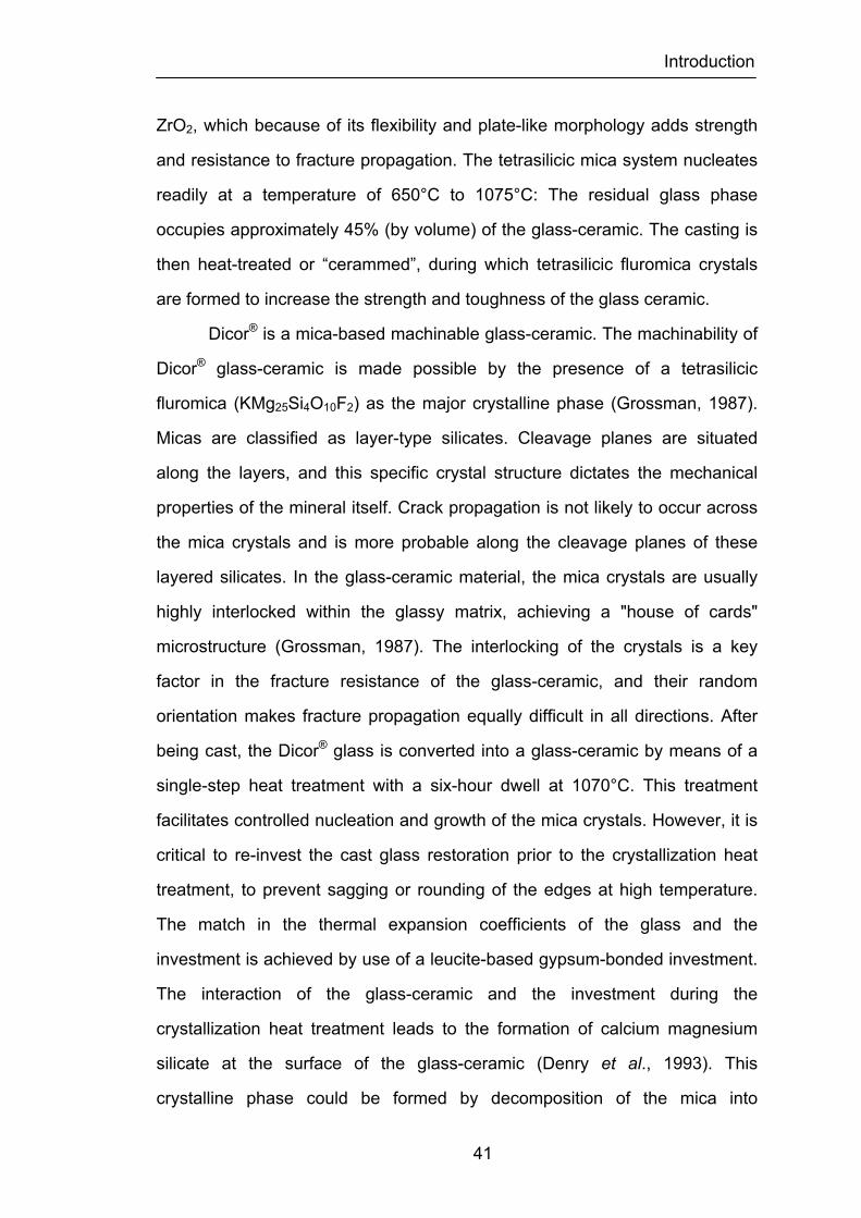
Introduction
41
ZrO2, which because of its flexibility and plate-like morphology adds strength
and resistance to fracture propagation. The tetrasilicic mica system nucleates
readily at a temperature of 650°C to 1075°C: The residual glass phase
occupies approximately 45% (by volume) of the glass-ceramic. The casting is
then heat-treated or “cerammed”, during which tetrasilicic fluromica crystals
are formed to increase the strength and toughness of the glass ceramic.
Dicor® is a mica-based machinable glass-ceramic. The machinability of
Dicor® glass-ceramic is made possible by the presence of a tetrasilicic
fluromica (KMg25Si4O10F2) as the major crystalline phase (Grossman, 1987).
Micas are classified as layer-type silicates. Cleavage planes are situated
along the layers, and this specific crystal structure dictates the mechanical
properties of the mineral itself. Crack propagation is not likely to occur across
the mica crystals and is more probable along the cleavage planes of these
layered silicates. In the glass-ceramic material, the mica crystals are usually
highly interlocked within the glassy matrix, achieving a "house of cards"
microstructure (Grossman, 1987). The interlocking of the crystals is a key
factor in the fracture resistance of the glass-ceramic, and their random
orientation makes fracture propagation equally difficult in all directions. After
being cast, the Dicor® glass is converted into a glass-ceramic by means of a
single-step heat treatment with a six-hour dwell at 1070°C. This treatment
facilitates controlled nucleation and growth of the mica crystals. However, it is
critical to re-invest the cast glass restoration prior to the crystallization heat
treatment, to prevent sagging or rounding of the edges at high temperature.
The match in the thermal expansion coefficients of the glass and the
investment is achieved by use of a leucite-based gypsum-bonded investment.
The interaction of the glass-ceramic and the investment during the
crystallization heat treatment leads to the formation of calcium magnesium
silicate at the surface of the glass-ceramic (Denry et al., 1993). This
crystalline phase could be formed by decomposition of the mica into
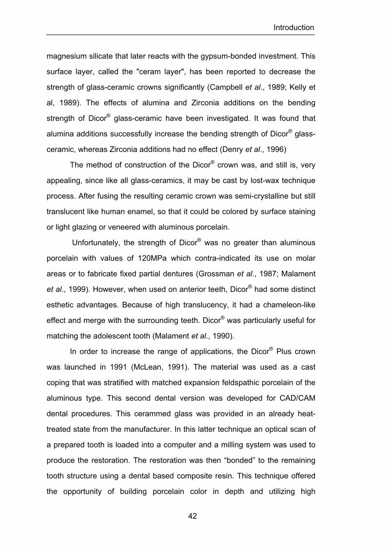
Introduction
42
magnesium silicate that later reacts with the gypsum-bonded investment. This
surface layer, called the "ceram layer", has been reported to decrease the
strength of glass-ceramic crowns significantly (Campbell et al., 1989; Kelly et
al, 1989). The effects of alumina and Zirconia additions on the bending
strength of Dicor® glass-ceramic have been investigated. It was found that
alumina additions successfully increase the bending strength of Dicor® glass-
ceramic, whereas Zirconia additions had no effect (Denry et al., 1996)
The method of construction of the Dicor® crown was, and still is, very
appealing, since like all glass-ceramics, it may be cast by lost-wax technique
process. After fusing the resulting ceramic crown was semi-crystalline but still
translucent like human enamel, so that it could be colored by surface staining
or light glazing or veneered with aluminous porcelain.
Unfortunately, the strength of Dicor® was no greater than aluminous
porcelain with values of 120MPa which contra-indicated its use on molar
areas or to fabricate fixed partial dentures (Grossman et al., 1987; Malament
et al., 1999). However, when used on anterior teeth, Dicor® had some distinct
esthetic advantages. Because of high translucency, it had a chameleon-like
effect and merge with the surrounding teeth. Dicor® was particularly useful for
matching the adolescent tooth (Malament et al., 1990).
In order to increase the range of applications, the Dicor® Plus crown
was launched in 1991 (McLean, 1991). The material was used as a cast
coping that was stratified with matched expansion feldspathic porcelain of the
aluminous type. This second dental version was developed for CAD/CAM
dental procedures. This cerammed glass was provided in an already heat-
treated state from the manufacturer. In this latter technique an optical scan of
a prepared tooth is loaded into a computer and a milling system was used to
produce the restoration. The restoration was then “bonded” to the remaining
tooth structure using a dental based composite resin. This technique offered
the opportunity of building porcelain color in depth and utilizing high

Introduction
43
translucency of the coping to reduce shadowing at the critical cervical margin
(McLean, 1991). However, the design of the coping influenced the fit. When
wall thickness of the coping was reduced to bellow 0.5mm, there was a
danger of pyroplastic flow causing distortion during the fitting of the all-
ceramic crown porcelain. Also, on cooling, cracking of the glass all-ceramic
crown could occur.
The flexural strength of the Dicor® Plus crown was about 22.000psi
(152MPa) which would not appear to be high enough for use in posterior teeth
(Duffin et al., 1989; Grossman, 1985). Although the Dicor® crown showed low
resistance to fracture, the use of an acid-etch procedure along the inner
surface, and the use of resin cements increased the resistance which was
reported to be low with the zinc phosphate cement (Malament et al., 1992).
Apatite glass ceramic (HMPO) - CaO-MgO-P2O5-SiO2 system
(Hydroxyapatite-based)
The formulation of a hydroxyapatite ceramic through reaction of glass
ceramics with moisture was described by Hobo and co-workers (Hobo et al.,
1985). This material, designated commercially as CeraPearl® (Kyocera Corp,
San Diego, CA, USA), is an apatite ceramic classified as a CaO-MgO-P2O5-
SiO2, that when reheated becomes crystalline oxyapatite (Ca10(PO4)6O). This
structure when exposed to moisture becomes the crystalline hydroxyapatite
(Hobo et al., 1985).
CeraPearl® crown was fabricated in a manner similar to the Dicor®
ceramic crown. Crystallization resulted in a crown that was highly dense,
strong and chemically stable. The hardness and thermal conductivity were
similar to that of human enamel and the material was reported as having
excellent biocompatibility (Savil, 1987). As with similar ceramics, the final
shading was accomplished by external surface staining. There are no long-

Introduction
44
term published studies concerning the performance of this system clinically,
and also, no reliable testing of the strength of the material.
Chemical strengthening (ion exchanging)
An effective method of strengthening glass-like materials, such as
dental porcelain, is to produce compressive stresses in their surfaces (Olcott,
1963; Stookey, 1965). This may be achieved chemically by modifying the
atomic structure of the surface regions of glass by ion exchange (Southan,
1970). Ion exchange yields a “crowding” or stress in the surface, produced by
larger ions taking the place of smaller ions, that is not relieved, and
permanent compression in the surface remains. The principle of chemical
strengthening relies on the exchange of small alkali ions for larger ions below
the strain point of the ceramic. Since stress relaxation is not possible in this
temperature range, the exchange leads to the creation of a compressive layer
at the surface of the ceramic (Denry et al., 1996). Finally, any applied load
must first overcome this built-in compression layer before the surface can be
placed into tension, resulting in an increase in fracture resistance. This
technique involves the use of alkali salts with a melting point lower than the
glass transition temperature of the ceramic material. Ion exchange
strengthening has been reported to increase the flexural strength of
feldspathic dental porcelain up to 80%, depending on the ionic species
involved and the composition of the porcelain (Anusavice et al., 1992;
Anusavice et al., 1992; Seghi et al., 1992; Fischer et al., 2001; Fischer et al.,
2005). The depth of the ion-exchanged layer has been shown to be greater
than 50 micrometers (Anusavice et al., 1994). However, this technique is
diffusion-driven, and its kinetics is limited by factors such as time, temperature,
and ionic radius of the exchanged ions.
Ohno and co-workers in 1985 (Ohno et al., 1985) introduced a simple
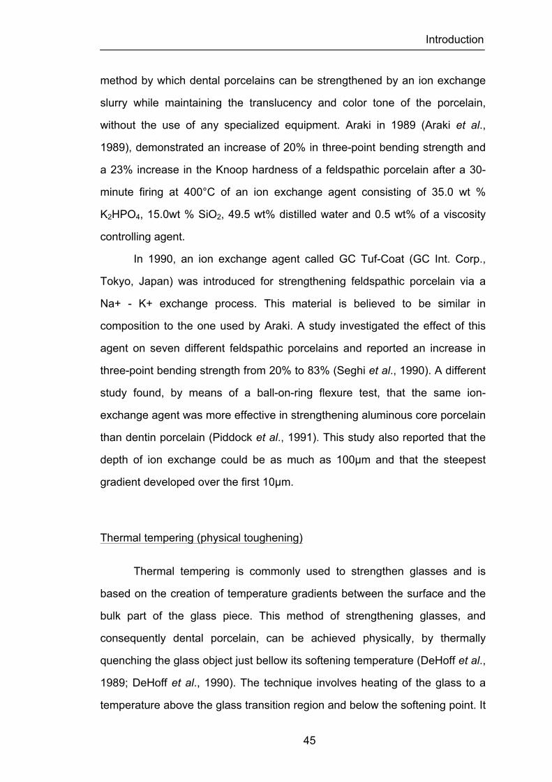
Introduction
45
method by which dental porcelains can be strengthened by an ion exchange
slurry while maintaining the translucency and color tone of the porcelain,
without the use of any specialized equipment. Araki in 1989 (Araki et al.,
1989), demonstrated an increase of 20% in three-point bending strength and
a 23% increase in the Knoop hardness of a feldspathic porcelain after a 30-
minute firing at 400°C of an ion exchange agent consisting of 35.0 wt %
K2HPO4, 15.0wt % SiO2, 49.5 wt% distilled water and 0.5 wt% of a viscosity
controlling agent.
In 1990, an ion exchange agent called GC Tuf-Coat (GC Int. Corp.,
Tokyo, Japan) was introduced for strengthening feldspathic porcelain via a
Na+ - K+ exchange process. This material is believed to be similar in
composition to the one used by Araki. A study investigated the effect of this
agent on seven different feldspathic porcelains and reported an increase in
three-point bending strength from 20% to 83% (Seghi et al., 1990). A different
study found, by means of a ball-on-ring flexure test, that the same ion-
exchange agent was more effective in strengthening aluminous core porcelain
than dentin porcelain (Piddock et al., 1991). This study also reported that the
depth of ion exchange could be as much as 100µm and that the steepest
gradient developed over the first 10µm.
Thermal tempering (physical toughening)
Thermal tempering is commonly used to strengthen glasses and is
based on the creation of temperature gradients between the surface and the
bulk part of the glass piece. This method of strengthening glasses, and
consequently dental porcelain, can be achieved physically, by thermally
quenching the glass object just bellow its softening temperature (DeHoff et al.,
1989; DeHoff et al., 1990). The technique involves heating of the glass to a
temperature above the glass transition region and below the softening point. It
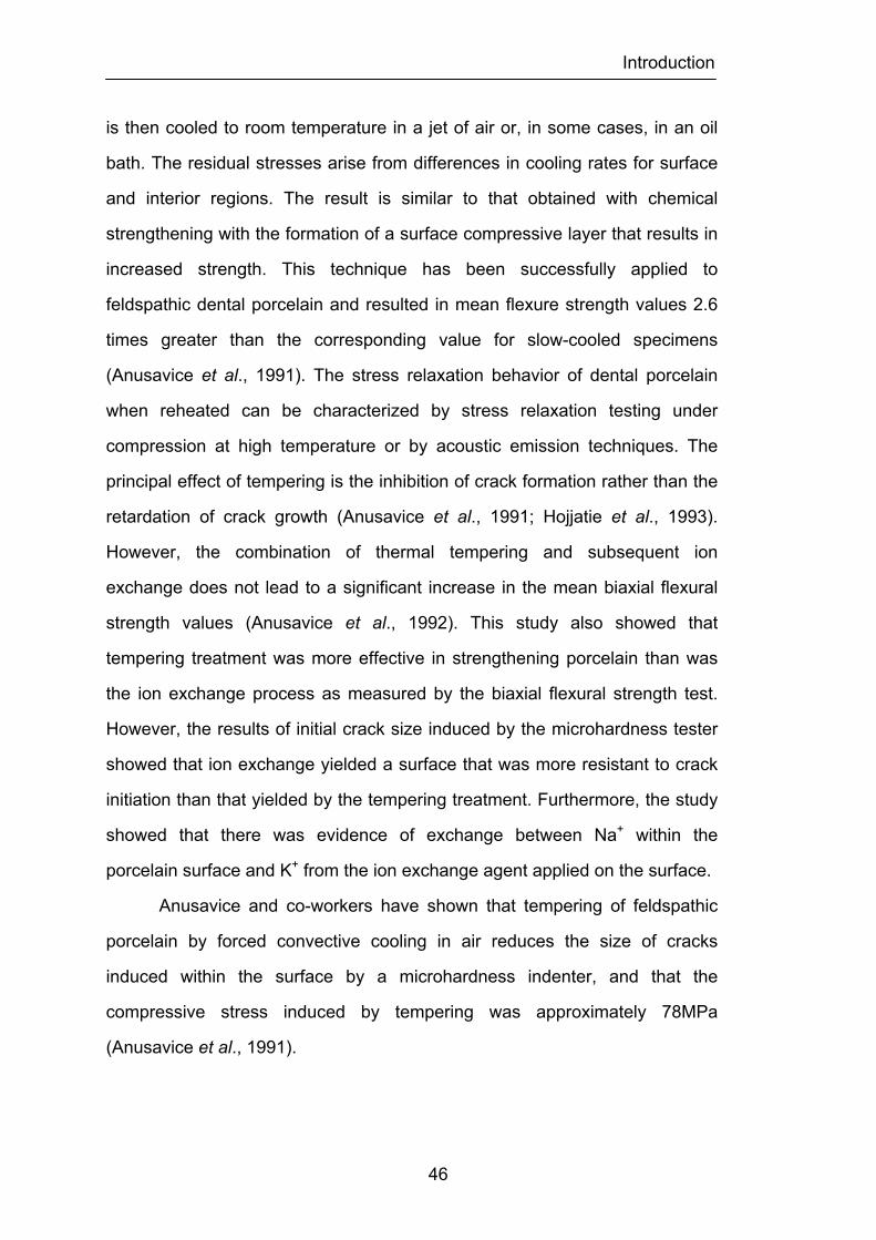
Introduction
46
is then cooled to room temperature in a jet of air or, in some cases, in an oil
bath. The residual stresses arise from differences in cooling rates for surface
and interior regions. The result is similar to that obtained with chemical
strengthening with the formation of a surface compressive layer that results in
increased strength. This technique has been successfully applied to
feldspathic dental porcelain and resulted in mean flexure strength values 2.6
times greater than the corresponding value for slow-cooled specimens
(Anusavice et al., 1991). The stress relaxation behavior of dental porcelain
when reheated can be characterized by stress relaxation testing under
compression at high temperature or by acoustic emission techniques. The
principal effect of tempering is the inhibition of crack formation rather than the
retardation of crack growth (Anusavice et al., 1991; Hojjatie et al., 1993).
However, the combination of thermal tempering and subsequent ion
exchange does not lead to a significant increase in the mean biaxial flexural
strength values (Anusavice et al., 1992). This study also showed that
tempering treatment was more effective in strengthening porcelain than was
the ion exchange process as measured by the biaxial flexural strength test.
However, the results of initial crack size induced by the microhardness tester
showed that ion exchange yielded a surface that was more resistant to crack
initiation than that yielded by the tempering treatment. Furthermore, the study
showed that there was evidence of exchange between Na+ within the
porcelain surface and K+ from the ion exchange agent applied on the surface.
Anusavice and co-workers have shown that tempering of feldspathic
porcelain by forced convective cooling in air reduces the size of cracks
induced within the surface by a microhardness indenter, and that the
compressive stress induced by tempering was approximately 78MPa
(Anusavice et al., 1991).
Introduction
47
Bonding to foils
Bonding of the porcelain to metal foils can strengthen feldspathic
dental porcelain. This procedure appears to eliminate open surface defects
from which tensile failure may originate (Sced et al., 1977). A platinum twin
foil technique was advocated by McLean and Sced in 1976 for this purpose
(McLean et al., 1976). This method could increase the shell strength of the
core porcelain to over 300 MPa, providing the platinum foil was left intact with
the porcelain (McLean, 1991). When the platinum foil was removed, strength
fell to approximately 180Mpa (Piddock et al., 1984).
In 1979, Rogers reported a rather ingenious method of making metal
copings by electroforming (Rogers, 1979). He used a tin oxide coating to
attach the porcelain to the gold coping, and conventional feldspathic metal-
bonding porcelain was used as the all-ceramic crown.
In 1981, Hopkins introduced a new method called the gold-coated
platinum foil porcelain crown (Hopkins, 1981). In this technique, porcelain
formulated for the metal-ceramic technique could be built over platinum matrix
coated with a thin layer of gold. A 75% increase in tensile strength had been
claimed (Hopkins, 1981).
Schoessow, in 1983 presented a method of bonding feldspathic
porcelain to a special noble metal foil in fabrication of metal-ceramic crown
(Schoessow, 1983). This system was marketed in the U.S. under the name
Renaissance crown system® (Williams Gold Refining CO, NY, USA) and in
Europe as Ceplatec crown system® (Ceplatec, Krefeld, Germany). The metal
foil was supplied in umbrella-shaped sheets with eight pleats and consists of
seven layers, the two outermost layers were 100% gold. Next two layers were
ceramic gold alloy composed of 85% gold, 5% platinum and 7% palladium.
The next two layers were composed of pure palladium and the inner layer was
a ceramic gold alloy composed of 85% gold, 5% platinum and 6% palladium
Introduction
48
giving a total thickness of 51-70µm (Scharer et al., 1987).
The pleated metal foil was adapted to the die by means of crimping,
burnishing and swaging. After the foil was adapted to the die, it was heat
treated, thereby forming a gold ceramic alloy and making the form rigid. An
interfacial alloy was applied to the surface of all-ceramic crowns. The matted
surface of interfacial alloy after fusion at 1000°C provided mechanical
retention to the all-ceramic crown porcelain. The compressive strength of the
cemented Renaissance crowns was evaluated by different studies (Burkl et al.,
1987; Vrijhoef et al., 1988). They found that the Renaissance crowns were
weaker than the metal-ceramic crowns, Cerestore crowns and aluminous
porcelain jacket crowns. However, the fracture strength of the Renaissance
crowns was higher than the expected average chewing forces (Haraldson et
al., 1989).
A different bonding foil technique was the Sunrise system (Tanaka
Enterprises, CA, USA) that was a gold-foil-supported ceramic system that
used Ceramco II porcelain (Dentsply International, Inc., York, PA, USA)
(Gregory et al., 1992). Its foil compressing system could be used to adapt
platinum foils as well as the system’s gold foil. This technique offered a yellow
background from which to work, but no core porcelain was recommended.
The strength of the crowns made with this system is unproven and
questionable.
Bulk strengthening (compositional strengthening)
Another method to improve mechanical properties of dental porcelain is
bulk strengthening. This means producing a porcelain with a uniform, increase
in strength. Dental porcelains are basically aluminosilicate with residual quartz
crystals and a small percentage of pigment agents. In a composite system
with a continuous glass matrix, crystalline dispersions limit the size of Griffith
Introduction
49
flaws and strengthen the system. For crystals to act as effective strengthening
agents, however, they should possess a thermal expansion similar to the
matrix phase to prevent the introducing of stress at the matrix-crystal interface
(Backer et al., 1993). McLean and Hughes reported on replacing the quartz
crystalline phase with alumina and observed a significant improvement in
strength (McLean et al., 1965). This resulted in part from the lower expansion
of alumina particles that enable them to remain in intimate contact with the
glass matrix. Southan has classified modern dental porcelains containing
quartz filler particles into two groups: one group having an intact vitreous
matrix and the other having a disrupted vitreous matrix (Southan, 1970). The
first group includes aluminous porcelains and any feldspathic porcelain having
matrices that are sufficiently plastic at 573°C to accommodate the volumetric
shrinkage of the quartz inversion. The second group includes feldspathic
porcelains having matrices that are rigid at 573°C. When porcelains in this
group are cooled, the glass matrix is stressed to the point where microcracks
are formed. Southan´s data indicated that aluminous porcelains were not
significantly stronger than matrix intact feldspathic porcelains. The implication
of this concept is that strengthening may be achieved with quartz filler
particles if the viscosity or rigidity of the glass matrix is such that the
volumetric contraction of the quartz particles does not produce stresses at the
quartz-glass interface.
Although the presence of crystals, whether quartz, alumina or leucite
can strengthen a dental porcelain under proper conditions, fracture may also
propagate through the glass in the regions between crystalline particles.
Therefore, an inquiry into methods of strengthening the glass matrix is
warranted (Backer, 1993).
Introduction
50
Dispersion strengthening
Glassy materials such as dental porcelain may be strengthened by
dispersing ceramic crystals of high strength and elasticity in the glass matrix.
If the glass has a similar thermal expansion to the crystals, the strength and
elasticity of crystal-glass composite materials may increase progressively with
the proportion of the crystalline phase. A dispersed material with a higher
thermal expansion coefficient will produce greater strengthening because a
compressive stress is formed at the dispersed phase interface. For example,
compare leucite, a potassium-alumina-silicate in a glass matrix that has a high
thermal expansion coefficient of 17ppm/°C, to a glass with a coefficient of
10ppm/°C. This was previously discussed in the section on the strengthening
mechanisms of ceramic crystallization of glasses. Several all-ceramic dental
porcelain systems use nowadays dispersion strengthening without relying on
a metal substructure. The most common crystals used are leucite, alumina,
magnesia, lithium disilicate, and Zirconia. There are several techniques and
methods in fabricating crystals-reinforced porcelain crowns that utilize the
principle of dispersion strengthening. What follows is the description of this
methods and/or respective all-ceramic systems.
Leucite-strengthened ceramics
Leucite has been widely used as a constituent of dental ceramics to
modify the coefficient of thermal expansion since 1950's. The addition of
leucite (crystals of a potassium-alumina-silica complex) increased the strength
of porcelain by limiting crack propagation. Unfortunately, the use of ceramics
restorations with high-leucite content increased the potential for wear of
opposing teeth and also reduced opalescence.
In order to solve this problem, a new wave of ceramics appeared since
Introduction
51
the 1980´s aiming to improve the esthetics and address one of the most
important drawbacks of porcelains - the potential for catastrophic failure. The
introduction of pressed leucite reinforced ceramic systems, had leucite in a
different role. In these systems the ceramic material relies on an increased
volume of fine leucite particles to increase flexural strength of the dental
porcelain (Dong et al., 1992).
Historically, a patented heat-press technique was first described in
1936 for the construction of ceramic complete dentures (Dong et al., 1992). In
1969, Dröge described a ceramic press technique based on the hot-press
resin technique (Dröge, 1969). In improving Dröge´s technique, McPhee was
able to produce complete-coverage metal-ceramic restorations that accurately
duplicated occlusal surfaces (McPhee et al., 1977). A heat-press technique
was introduced in 1983 at the University of Zurich. The development
proceeded in conjunction with the Ivoclar Company, which in 1991, introduced
the IPS Empress® system (Ivoclar, Schaan, Liechtenstein) an injection
molded glass ceramic.
The IPS Empress® system caused a major revival of the all-ceramic
crown concept. All-ceramic crowns had been somewhat dormant in the
profession for a period of years after significant failure of some previously
used crown types. The IPS Empress® system is a highly esthetic hot pressed
glass ceramic material for fabrication of ceramic restorations. Similar versions
using finely dispersed leucite grains to increase toughness, strength and
modify wear patterns and rates were then developed and are now available.
IPS-Empress® 1
IPS-Empress® 1 is a fine-grained high strength pressed ceramic
material which is leucite reinforced. The heat-pressed technique has been
described to construct single unit crowns, inlay/onlays and veneers using
Introduction
52
precerammed and precoloured glass-ceramic ingots. The crowns produced by
this system contain around 40 to 50% leucite dispersed in a lower expansion
glass. The leucite improves the strength and fracture resistance of the
feldspathic glass matrix. Leucite crystals are formed through various
temperature cycles. The technique requires that restorations be waxed to full
contour and invested in a special flask with a correspondent developed
investment. The invested pattern is placed into the Empress furnace for
burnout at 800°C. The selected shade ingot and an aluminum oxide plunger
are placed in a cylindrical opening at the investment ring and heated to
1100°C so that the leucite-reinforced ceramic becomes plasticized. The ingot
is pressed into the investment mold where it is held under pressure to allow
for complete and accurate adaptation. The casting procedure is fully
automated. After divesting the restoration, there are two ways to reproduce
the appropriate shade: (1) surface characterization: a heavily pigmented
characterization color in the form of superficial stains is applied and then
covered with translucent, extremely fine glazing material to a thickness of 50-
60µm; (2) all-ceramic crowning technique: the restoration is reduced by
grinding to allow space for placement of a selected shade all-ceramic
specially formulated fired ceramic that will create excellent anatomy and a
realistic, translucent esthetic result. This technique is indicated to achieve
superior esthetics in anterior crowns. Lüthy and co-workers demonstrated that
there is no difference in tensional strength between these two methods (Lüthy
et al., 1993). Internal crown surfaces need to be roughened by etching with
hydrofluoric, silaned and bonded to tooth structure using standard dentin and
enamel bonding techniques and resin cement in order to obtain consistent
bond strength (Ayad et al., 2008). IPS Empress® restorations are very
translucent and flexural strengths of 140 MPa to 180 MPa have been reported
(Dong et al., 1992). These materials are being used successfully as veneers
and anterior full crowns (Fradeani et al., 2002; Fradeani et al., 2005).
Introduction
53
Posterior full crowns are serving with acceptability, but more research is
necessary (Fradeani et al., 2002).
Optimal Pressable Ceramic®
The popularity of Empress has stimulated other companies to produce
similar products. The OPC® (Optimal Pressable Ceramic®) (Jeneric/Pentron
Inc., CT, USA) restorations were virtually fabricated in the same manner as
the IPS Empress® 1 crown. The only differences between the two technology
systems were the price and the ceramic ingots supplied to fabricate the
ceramic restorations. The strength reported for the OPC® crown was similar to
that of IPS Empress®1 around 140Mpa to 180Mpa (Sobrinho et al., 1998;
Cattel et al., 1999). The ceramic was used for anterior crowns, veneers, inlays,
onlays, and posterior regions with low pressure. No long-term data is
available for this crown system and the product is no longer available.
Optec HSP
Optec HSP material (Jeneric/Pentron Inc., CT, USA) was a leucite reinforced
feldspar ceramic that condensed like alumina ceramic and was sintered like
traditional feldspar ceramic. The manufacturing process was done on
refractive dies, differently from the OPC system. Because of the moderately
opaque core, this ceramic was more transparent than crowns made on
aluminum oxide cores or with glass/aluminum oxide cores. Optec HSP
material was a feldspathic porcelain containing up to 45 vol% tetragonal
leucite (Denry et al., 1995). The greater leucite content of Optec HSP
porcelain compared with conventional feldspathic porcelain for metal-
ceramics lead to a higher modulus of rupture and compressive strength. The
large amount of leucite in the material contributed to a high thermal
contraction coefficient (Katz, 1989). In addition, the large thermal contraction
Introduction
54
mismatch between leucite (22 to 25 x 10-6/°C) and the glassy matrix (8 x 10-
6/°C) resulted in the development of tangential compressive stresses in the
glass around the leucite crystals when cooled. These stresses acted as crack
deflectors and contributed to increase the resistance of the weaker glassy
phase to crack propagation. After heat treatment of Optec HSP for one hour
at temperatures ranging from 705 to 980°C, a second metastable phase
identified as sanidine (KAlSi3O8) formed at the expense of the glassy matrix.
The crystallization of sanidine was associated with a modification of the
optical properties of the material from translucent to opaque. However,
sanidine did not appear when the porcelain was heated to 980°C, since
sanidine is metastable in the temperature range 500-925°C. The precipitation
of sanidine has been reported as well upon isothermal heat treatment of
conventional feldspathic porcelain for metal-ceramics (Mackert, 1988).
Optec HSP contained a higher concentration of leucite crystals than feldspar
ceramics. Due to the opacity caused by leucite crystals, it was not necessary
to apply core ceramics. The outer layer consisted of conventional ceramics,
so that this layer showed a more inferior fracture resistance than the leucite
reinforced ceramic core. The flexural strength reported by manufacturer was
approximately 172 MPa. The flexural strength reported by Seghi and co-
workers was only 105 MPa (Seghi et al., 1995). This system was used in the
fabrication of inlays, onlays, and all-ceramic crowns for anterior teeth. No
independent long-term clinical data are available for these restorations. The
only study available for crown evaluation at 5 years revealed satisfactory
results (Hankinson et al., 1994). However, because of commercial problems
the product is no longer available.
Introduction
55
Alumina-strengthened ceramics
Alumina is the oxide of aluminum commonly extracted from the mineral
bauxite that is mainly a hydrated aluminum oxide. To produce the alumina
bauxite is finely ground and digested in hot caustic soda solution to dissolve
the Gibbsite (aluminum tri-hydroxide or "hydrate"). Digestion of Gibbsite is
achieved at a comparatively lower temperature and pressure compared to
other aluminum materials. After digestion, insoluble bauxite residue is
removed from the hydrate rich solution by settling. The clarified hydrate-rich
solution is cooled, seeded and cooled again in stages to precipitate the
alumina trihydrate crystals that are separated by filtration and then washed to
remove the final traces of caustic soda and other impurities. The alumina
trihydrate is converted to aluminum oxide by calcinations usually in a rotary
kiln at a temperature of 600°C that drives off the chemically combined water in
the hydrate to form gamma-aluminum oxide.
For ceramic applications the calcined aluminum oxide is generally ball
milled and commercially supplied as a fine powder, usually below 10 or 20 µm
in size. A binder such as methyl cellulose and a release agent may also be
added to facilitate molding into simple and intricate shapes. The molded
articles are then slowly oven dried and fired at fusion temperatures of up to
1650°C, the resulting product being a hard impermeable ceramic of high
strength and chemical resistance.
The firing of high-aluminum oxide ceramic at high temperatures is a
solid-state sintering process in which the aluminum oxide grains fuse at their
grain boundaries and atomic diffusion across interfaces occurs. Volume
diffusion, whether along grain boundaries or through lattice dislocation, is
followed by shrinkage. The initial stage of sintering is by the neck growth
between the original powder particles and involves slight increase in density
of about 10%. The beginning of the intermediate stage coincides with the
Introduction
56
beginning of grain growth. During this stage, particles grow to a grain-like
structure with pores as channels lying on three-grain edges. The final stage
starts when the cylindrical pores are transformed into spherical voids at about
5% porosity resulting in a dense crystalline structure with an average grain
size of 4 µm (Andersson et al., 1993). The shrinkage of aluminum oxide
during sintering to full density is about 15-20%, which has made it impossible
to manufacture individual tooth copings of acceptable accuracy in pure
aluminum oxide with the powder technology available in the 1970’s.
High purity alumina is biocompatible and has been used as implant
material since 1968 when Sandhaus used this material for tooth replacements
(Sandhaus, 1968). McLean and Hughes were the first to describe a method to
reinforce dental porcelain crowns using alumina, in their development of the
aluminous jacket porcelain crown (McLean et al., 1965). Aluminous core
porcelain is a typical example of strengthening by dispersion of a crystalline
phase. Alumina has a high modulus of elasticity (350 GPa) and high fracture
toughness (3.5 to 4 MPa.m0.5). Its dispersion in a glassy matrix of similar
thermal expansion coefficient leads to significant strengthening of the core.
The first aluminous core porcelains contained 40 to 50% alumina by weight
(McLean et al., 1965). The core was baked on a platinum foil and later
veneered with matched-expansion porcelain. Flexural strengths of over
120MPa were obtained for these materials. It may be generally stated that the
strength and opacity of alumina-reinforced porcelain is a function of its
crystals or particle size. The finer the crystal size the greater the strength and
opacity.
There are several techniques and methods in fabricating alumina
reinforced porcelain crowns that utilize the principle of dispersion
strengthening.
Introduction
57
Traditional platinum foil technique
McLean popularized the modern Aluminous Jacket Crown, probably
more commonly known as the Porcelain Jacket Crown in the mid 1960’s. The
fabrication of this crown utilized a technique using a platinum foil (0.0005-
0.002” inch) that was meticulously and intimately adapted to the die. The
adapted platinum foil served as a scaffold for build-up and firing of the
porcelain and also acted as a die spacer to provide the required space of the
luting agent. Platinum was used because its coefficient of thermal expansion
(9x10⁻⁶/°C) is slightly greater than that of the core porcelain so that upon
cooling, the porcelain was subjected to compressive forces. To achieve
maximum strength in such restorations, it was essential that the load-bearing
area be reinforced with at least 1.0mm thick section of core porcelain. The
ideal aluminous porcelain coping for incisors needed to be extended similarly
to a metal coping in which the lingual surface collar was at least 2.0mm in
height, and the incisal labial surface was thinned to 0.3mm for esthetic needs
since this area was considered a low stress-bearing (McLean et al., 1976).
After the build-up of the core, a specially formulated all-ceramic crown
porcelain with similar coefficient of thermal expansion and less alumina crystal
content was stratified and fired to complete the crown fabrication. The
platinum foil was then peeled off the internal surface of the crown before
cementation. The disadvantages of this technique were the unreliable
accuracy of the crown fit and the exposed defects in the internal surface
caused by incomplete wetting of platinum foil by the molten porcelain that
created porosity along the interface of the foil and the porcelain crown
affecting the compressive strength of the restoration (Munoz et al., 1982).
Introduction
58
The platinum twins foil technique
With the objective of improving the strength and consequently the
fracture resistance of the porcelain jacket crown fabricated with the traditional
foil technique, Sced and McLean reported a procedure for a reinforcement of
the jacket crown, as a result of inhibiting the propagation of cracks into brittle
materials, so called the twins foil technique (Sced et al., 1977). In this
technique, a platinum foil was adapted to the die to act as a spacer and a
matrix as in the conventional alumina crown technique. A second platinum foil
was then adapted over the first and plated with 0.2-2.0µm of tin and oxidized.
Alumina core porcelain, which was modified to mask the grayness of the foil,
was fired onto the plated foil. Enameling porcelain was then built to complete
the crown fabrication. The inner foil was removed, but the plated foil remained
as a permanent part of the completed crown.
The purpose of the plated foil was to increase the wettability of the
platinum by the core porcelain. Ordinarily, platinum tenaciously retained
absorbed carbons. The tin oxide coping prevented the platinum surface from
acting as a contact catalyst for carbon compounds. As a consequence a
chemical bond between the plated oxidized foil and the core porcelain
resulted. The oxide could bond to both the metal and the porcelain or the
oxide could dissolve into the glass and bring the porcelain into atomic contact
with the metal (Sarkar et al., 1981). As microcrack propagation was inhibited
by the bond, this resulted in an increase in fracture strength up to 83% over
the conventional aluminous porcelain crown (Sced et al., 1977). The other
advantage of this technique was that the bonded foil could inhibit the
weakening effect of moisture on the strength of porcelain crowns.
As with the conventional platinum foil technique, the fit of the platinum
foil porcelain crown was criticized as the weakest point of the technique. The
platinum twins foil technique exhibited even poorer overall fit than the

Introduction
59
conventional technique along the axial walls and the margin of the crown,
which weakened the strength of the crown after cementation (Munoz et al.,
1982; Philip et al., 1984). Using the same technique, different core materials
were tried posteriorly trying to solve the most important problems associated
with the aluminous jacket crown - strength, porosity, and misfit. One of these
materials was the magnesia jacket crown developed by O’Brien in 1985
(O'Brien, 1985). This material could be used in the construction of all-ceramic
jacket crowns with the same body and enamel porcelains used for porcelain
fused to metal crowns. Jacket crowns could be constructed using a modified
platinum foil technique with greater accuracy and higher strength. The
magnesia core ceramic developed as an experimental material had a high
thermal expansion coefficient (14.5 x 10⁻⁶/°C) that closely matched that of
body and incisal porcelains designed for bonding to metal (13.5 x 10⁻⁶/°C).
The flexural strength of unglazed magnesia core ceramic was twice as high
(131 MPa) as that of conventional feldspathic porcelain (65 MPa). The core
material was made by reacting magnesia with a silica glass within the 1100-
1150°C temperature range. These treatments lead to the formation of
forsterite (Mg2SiO4) in various amounts, depending on the holding time. The
proposed strengthening mechanism was the precipitation of fine forsterite
crystals. The magnesia core material could be significantly strengthened by
glazing, thereby placing the surface under residual compressive stresses that
have to be overcome before fracture could occur (Wagner et al., 1992). The
main advantage was a stronger jacket crown with exceptional esthetics
without the need for special equipment or long processes (Hondrum, 1988;
Hondrum et al., 1988).
Introduction
60
The refractory die technique
In order to improve the strength of the porcelain jacket crown an
alternative method was developed to fabricate this crown using a refractory
die material. The refractory die was a phosphate-bonded type investment and
had a thermal expansion comparable with aluminous porcelain. The core
porcelain used for this technique had not been opacified and contained little or
no quartz (McLean, 1988). When correctly fired, the light transmission of the
core and all-ceramic crown materials approached that of dentin and enamel
respectively.
The refractory die technique was reported to improve the internal
surface of the crown. In light of this claim, Southan did a study to compare the
fracture load of aluminous porcelain discs made on refractory dies formed in
polyvinylsiloxane impressions to fracture load of the discs of the control group
(Southan, 1987). He found that there was no difference in fracture strength.
However, the fracture loads of disc prepared on refractory dies formed in the
alginate impressions and those with deliberately flawed surfaces were
significantly weaker than the samples formed on refractory dies produced
from polyvinylsiloxane impressions.
The marginal discrepancy of these crowns was still poor and
consequently the fracture resistance. However, Southan and co-workers
found that a refractory die could be wetted better than the platinum foil and
thus felt that they could get better marginal adaptation (Southan et al., 1973).
Subsequently, the Hi-Ceram® system (VidentTM, CA, USA) was
developed to make an aluminous porcelain jacket crown (Schmidseder, 1986).
The alumina core was built on a refractory die with subsequent buildups
applied using standard feldspathic porcelain powders. The flexural strength of
this porcelain crown was approximately 150 MPa (Oilo, 1988). This system
was used in the fabrication of inlays, onlays, veneers, and all-ceramic crowns
Introduction
61
for anterior teeth (McLean et al., 1994). Although the inherent problems of
fracture resistance persisted the development of the Hi-Ceram® system was
an important step toward the development of other systems.
Injection molded core porcelain
In 1983, Sozio and Riley introduced a unique injection molding process
alumina core porcelain system and called it Cerestore® (Coors Biomedical,
CO, USA – Johnson & Johnson, USA) (Sozio et al., 1983). The Cerestore®
crown system relied on the enameling of a 60% alumina body that was
transfer-molded in the plastic state onto an epoxy die. This material
possessed some interesting features, since it was the first non-shrink ceramic
produced in dentistry. Essentially aluminum magnesium oxides were mixed
with a barium glass frit that, on firing, produced a magnesium aluminate
spinell. The spinell occupied a higher volume than the original mixed oxides,
and compensated for firing shrinkage. A reinforcing core similar to the
aluminous porcelain crown was constructed in this material onto which
matched-expansion feldspathic all-ceramic crown porcelain was baked in the
conventional manner to create the crown form (Sozio et al., 1985). The
Cerestore® crown failed for two main reasons: high cost of the system and
crowns with inadequate strength (89Mpa -150Mpa) when compared with
metal ceramic restorations (Oilo, 1988; Anusavice, 1991). The manufacturer
states that several thousand crowns are currently in use. However, to date,
the failure rates for anterior and posterior crowns have not been documented
in controlled clinical studies. The only documentation available reported a
four-year failure rate of 18.5% for molar crowns.
Introduction
62
Slip-cast alumina ceramics
Slip-casting is the art or science of preparing stable suspensions and
forming ware by building up a solid layer on the surface of a porous mold that
sucks up the liquid phase by means of capillary forces. The most common
material used in slip-casting is plaster of Paris. The process has been used in
forming clay bodies for at least 200 years, but it is only recently that the
principle has been applied to nonplastic materials.
Slip casting is generally carried out with most particles between 1-5µm
ranges. The bulk of the particles should be in a size range where their
interactions are beginning to be governed by surface forces rather than by
gravity. If however, the bulk of particles are too fine, it is difficult to exercise
proper rheological control over the slip. Minor changes in the ionic
atmosphere surrounding such particles can exert considerable influence on
the forces of interaction and thereby cause sudden undesirable viscosity
changes.
In-Ceram® Alumina
The slip-casting technique was posteriorly adapted to crown and bridge
fabrication to produce a high strength alumina coping that was marketed
under the trade name In-Ceram® (Vita® Zahnfabrick, Germany) (Probster et
al., 1992). This system was first described by Sadoun and was introduced to
the dental community at the 1989 International Dental show in Stuttgart. In-
Ceram® is a high strength aluminous core ceramic with extremely high flexural
strength of the core which is derived from slip-casting of alumina (content in
excess of 85%), and lanthanum-silicate glass infiltration into voids and pores
in a second firing process.
The pure alumina slip-cast is made on a special gypsum die of the
Introduction
63
tooth preparations. The greenware is dried and slowly brought to a
temperature of 1100°C for 2 hours. This firing process allows the alumina
grains to partially fuse at their grain boundaries while the gypsum die shrinks.
The core may then be lifted off the die. The fit of the partially sintered alumina
cores can be very accurate. Final shaping must be done at this stage since
the subsequent infusion of the glass matrix makes finishing operations very
difficult because of the hardness of the final ceramic. After shaping, the
porous alumina is ready for the infusion of the glass matrix and has a minimal
shrinkage of about 0.21% (Campbell et al., 1995). A specially prepared low-
fusing glass of matching thermal expansion is painted over the external
surface of the core, and then placed on a thick piece of platinum foil. The
glass melts at 800°C and when the temperature is raised to 1100°C it diffuses
through the porous alumina by capillary action resulting in a very dense
alumina/glass interpenetrating phase composite structure. The core is then
all-ceramic crowned with the appropriated low fusing porcelain. The different
thermal expansion coefficients of glass and alumina contribute to the strength,
and effectively limit crack propagation (Probster, 1993). Flexural strength of
the In-Ceram® Alumina core determined by three-point, four-point, and biaxial
flexural strength was found to vary from 236.15 to 530 MPa (Seghi et al.,
1995; Giordano et al., 1995; Wagner et al., 1996; Zeng et al., 1998; Tinschert
et al., 2000; Chen et al., 2008). When tested with its porcelain laminate, the
flexural strength of In-Ceram® Alumina was found to range from 174.2 to 240
MPa using biaxial bending test (Zeng et al., 1998). The strength value
depends on the different equations used to derive the formula for bilayer
model and the thickness of the laminate (Zeng et al., 1998). The strength of
the In-Ceram® Alumina core was lower when tested with its porcelain laminate
(White et al., 1994).
This material was intended for single anterior and posterior crowns,
and anterior three-unit bridges. The high alumina content of the In-Ceram®

Introduction
64
core makes it resistant to acid etching; therefore conventional cements are
used for cementation. However, the crowns can be adhesively luted with resin
cement after sandblasting (Probster et al., 1992). Margins accuracy is
acceptable independently of the method used for cementation (Pera et al.,
1994)
In-Ceram® Alumina has proven to be an acceptable treatment
alternative for single crown as well as anterior fixed partial dentures. The 5-
year survival rate of In-Ceram® Alumina crowns range from 91.7% to 100%
and is similar to the survival rate of conventional metal-ceramic crowns. The
5-year survival rate of single-retainer In-Ceram® Alumina resin-bonded fixed
partial dentures (RBFPDs) was 92.3%, which is higher than that of 2-retainer
RBFPDs (Wassermann et al., 2006). Although the material presented
excellent results, and is still today one of the most preeminent ceramic
systems used, from the esthetic and strength perspective, two problems
where usually found. The material could not be used in highly esthetic
situations and in the fabrication of posterior fixed partial dentures. The first
problem is related with the opacity derived from the high alumina content,
which is around 70%; and the second problem is related with insufficient
strength to resist high masticatory forces. In order to solve these problems the
Vita® Company developed the In-Ceram® Spinell system and the In-Ceram®
Zirconia system.
In-Ceram® Spinell
The In-Ceram® Spinell manufacturing resembles that of In-Ceram®
Alumina, with the exception that the core is made of a glass infiltrated
magnesium alumina (Spinell MgAL3O4). The indication for the In-Ceram®
Spinell crowns exists only for anterior single crowns when more translucency
is desired and where problems evident in transiluminating light caused by the
Introduction
65
semi opaque oxide core material of the In-Ceram® Alumina. The new core
material was able to offer glass-like light transmission and, accordingly, a
more natural appearance to the final restoration (Paul et al., 1995; Magne et
al. 1997) In-Ceram® Spinell crowns are cemented and adjusted in the same
way as in the In-Ceram® Alumina crowns. However, the crowns are more
susceptible to fracture than the In-Ceram® Alumina crown, mainly because
the flexural strength of the material is lower, around 350 MPa (Seghi et al.,
1995; Fradeani et al., 2002). The Spinell material has shown that it possesses
encouraging characteristics if used correctly under normal-colored abutment
teeth to maximize its translucency properties. The material is contraindicated
in situations where teeth are dark do to endodontic treatment or over metal
cores. The survival rates of the material are similar to those of In-Ceram®
Alumina (Wassermann et al., 2006).
In-Ceram® Zirconia
The In-Ceram® Zirconia will be discussed in this section instead of in
the Zirconia strengthened ceramics section, because contrary to the other
Zirconia based ceramics systems, the manufacturing procedure is different
and the Zirconia content within the material is also different. The In-Ceram
Zirconia manufacturing resembles that of In-Ceram® Alumina, with the
exception that the core is made of a glass infiltrated Zirconia/alumina
(ZrO2AL3O4). The difference is the addition of 35% partially stabilized Zirconia
to the slip composition (McLaren et al., 1999). The partially stabilized Zirconia
oxide undergoes phase transformation in the presence of propagating crack,
resulting in a 3% to 5 % volumetric expansion (Garvie et al., 1975; Seghi et al.,
1995). The volumetric change subjects the vicinity of the transformed Zirconia
to a state of compression, which contributes to strengthening of the ceramic
(Piconi et al., 1999). The indication for the In-Ceram® Zirconia exists only for
Introduction
66
anterior or posterior single crowns and fixed partial dentures (McLaren et al.,
1999). However, because of the opacity of the Zirconia core, the use of the
material for anterior crowns should be correctly evaluated (Heffernan et al.,
2002; Hefernan et al., 2002). The flexural strength of the material was
reported to be between 500 and 620 MPa (Guazzato et al., 2002; Chong et al.,
2002; Chai et al., 2007; Chen et al., 2008). The high alumina and Zirconia
content of the In-Ceram® Zirconia core makes it resistant to acid etching;
therefore conventional cements are used for cementation. However, the
crowns can be adhesively luted with resin cement that increases the bond
strength between tooth preparation and the material (Della Bona et al., 2007).
The marginal and internal fit of all-ceramic three-unit fixed partial denture
fabricated by slip-cast technique showed satisfactory results (Bindle et al.,
2007).
Long term clinical results and survival rates for In-Ceram® Zirconia crowns or
FPDs are insufficient. Then no statement can be made presently regarding
the reliability of the material (Wassermann et al., 2006). The only study
available for fixed partial dentures reveals success rates of 95% at 3 years
(Suárez et al., 2008).
CAD-CAM alumina ceramics
CAD/CAM technology has been developed since the first interactive
graphics was developed in 1960s. CAD uses computer graphics and software
to enable professionals to do most of design activities needed to complete
professional design that include creating parts in 3D, assembling them, and
producing software drawings. CAM generates tool path (i.e., NC [numerical
control] part program) with reference to CAD database for geometric
references. The CAD/CAM technology is a result of advancement of computer
hardware and software technologies and it is used in almost all areas of
Introduction
67
industries in many different forms helping people to do efficient jobs in design
and manufacturing activities.
In 1993 Matts Andersson and colleagues developed a new technique
for manufacturing an individual all-ceramic crown built on a coping of dense
sintered high purity alumina which when combined with dental porcelain could
be used as the core for an all-ceramic restoration (Andersson et al., 1993).
The all-ceramic restoration was named the Procera® AllCeram Alumina
(Procera®, Nobel BiocareTM AB, Sweden) and it was developed by Nobel
Biocare (Andersson et al., 1996). This crown was produce using the
technology CAD-CAM, and it was the first application of this technology to
restorative dentistry.
Procera® AllCeram Alumina
The Procera® system appears to fulfill the long-range research plan for the
National Institute of Dental Research in the decade of the 90s that called for
the development of cost-effective computer assisted systems for fabricating
dental restorations. The Procera® system is one all-ceramic system that
embraces the concept of CAD/CAM to fabricate dental restorations. Initially,
the Procera® system was used to fabricate crowns and fixed partial dentures
by combining a titanium substructure with a low-fusing veneering porcelain
with promising results (Andersson et al., 1989). This CAD/CAM technology
has been used to produce the Procera® AllCeram crown. This crown is
composed of a densely sintered, high purity aluminum oxide coping
(Al2O3>99.9%) with 500ppm MgO that is combined with a low-fusing AllCeram
veneering porcelain. The system relies on the production of an aluminum
oxide core as a substitute for the metal framework. One problem of dispersion
strengthening is that if too much crystalline material is added to a glass, it
becomes too viscous to fire to a glaze in an ordinary porcelain furnace, and

Introduction
68
other forming methods are needed. The Procera® porcelain core avoids this
problem using unique forming processes. Because the core has so much
alumina as explained previously, it cannot be fired in an ordinary furnace and
instead is machined using high precision CAD/CAM technology.
The Procera® system consists of a computer-controlled design station
in the dental laboratory that is joined through a modem link to the production
facility in Sweden, where the coping is fabricated. At the design station, a
scanning device controlled by a personal computer maps the surface of the
die of the prepared tooth. A die of the tooth preparation is ditched below the
finish line to clearly define the extent of the preparation. A sapphire ball forms
the tip of the scanner probe that contacts the surface of the die as it rotates
around a vertical axis. Light pressure of 20g maintains the probe in contact
with the die. As the platform rotates, one data point is collected at every
degree around the 360-degree circumference of the die. During each rotation
of the die, the probe is automatically and continuously elevated 200µm by the
computer and another scan line is read until the entire surface contour of the
die has been mapped, thus describing the tooth through the use of
approximately 50,000 measured values. When the scanning is completed, the
data is evaluated for completeness. Marking of the finish line on the three-
dimensional plots is the next step. At every 10 degrees of rotation, the
operator marks the finish line, and the software interpolates the segment
between the marks. The finish line is further refined by the operator, who
repeats this process by marking the margin at 5-degree increments. The next
step is to establish the thickness of the coping to be fabricated. A default of
600µm is customary for the coping thickness; however, for special situations
the operator may choose to change this dimension. The emergence angle of
the coping from the tooth is selected, and the relief space for the luting agent
is automatically established by a computer algorithm. When the design of the
coping has been completed, the file is saved in the computer and is ready for
Introduction
69
transmission via modem to the production station (Nobel Biocare) (Andersson
et al., 1998).
The data of the preparation and the design of the coping are
transferred via modem to the facility production in Sweden, where the coping
is manufactured with advanced powder technology and the CAD/CAM
technique. This process takes into account the sintering shrinkage of
approximately 20% by enlarging a model of the preparation that is used in the
manufacturing process. A high-purity aluminum oxide powder is compacted
against the enlarged preparation model, with an industrial dry pressing
technique, against the enlarged replica. The compacted alumina is pre-
sintered to a green stage. The core is then removed from the die and sintered
unsupported at 1550°C. After cooling, the outer surface of the core is formed
by grinding and milling the alumina and adjusting the coping along the
preparation to a predetermined dimension. Sintering of the high alumina core
occurs at 1550°C, and the wall thickness of the sintered coping is from 0.5 to
1mm with standard core thickness of 0.6mm (Andersson et al., 1998). The
color of the dense sintered alumina is close to A3 in the Vita shade system.
The coping is examined for quality control and is sent by mail to the dental
laboratory, where the ceramist finalizes the restoration by the addition of the
AllCeram veneering porcelain. The Procera® coping is veneered with
AllCeram ceramic, which is specially adapted to the coefficient of thermal
expansion 7x10⁻⁶ µm/mol of the aluminum oxide framework. Further layers of
the veneering porcelain include specific dentins, enamels, and transparent
masses. The Procera® AllCeram crown is recommended for single crown
restorations anterior and posterior, and 3 unit bridges restoration from 2nd to
2nd premolar.
The flexural strength of the aluminum oxide Procera® coping has been
reported in several studies ranging from 510 to 670MPa (Anderson et al.,
1993, Wagner et al., 1996). Mean gap dimensions for marginal openings,

Introduction
70
internal adaptation, and precision of fit for this crown are reported to be below
70 microns for premolar and molars (May et al., 1998) independently of the
luting agent or finishing lines used (Quintas et al., 2004). Although the fracture
resistance may be different depending on the cement used, the values
obtained are well above the maximum masticatory forces (Al-Makramani et al.,
2008). The clinical success of these crowns is well documented with survival
rates between 97 and 99% at 5 and 7 years respectively, and 93.5% at 10
years (Odman et al., 2001, Zitzmann et al., 2007).
Lithium-disilicate-strengthened ceramics
Increasing interest in ceramic fixed prostheses has followed
improvements in strength, esthetics, and ease of processing. Such advances
included introduction of lithium disilicate (Li2O·2SiO2) reinforced glass
ceramics for dental use. The increased strength and improved esthetics of
these systems are well-documented in the dental literature (Holand et al.,
2000). The development of these systems, with lithium disilicate as the main
crystalline phase, presume that the material could be used for the fabrication
of single crows in the anterior or molar regions and three-unit fixed partial
dentures extending to the premolar region. The ceramic restorations produced
by these systems follow the common fabrication of injection pressed ceramics.
The waxed pattern of the restoration is invested in a refractory material, which
is preheated at 850 °C for one hour to eliminate wax and create a mold, which
is subsequently transferred to a special pressing furnace. The pre-cerammed
ingots, supplied by the manufacturer in a variety of shades, are then placed in
the open end of the mold and pressed by a thermal resistant plunger attached
to the furnace. After yielding through the sprues (connectors), the cavity of the
mold is filled by the viscous flow of the glass-ceramic. In this first step, only
the framework of a crown or fixed partial denture is hot-pressed. The esthetic
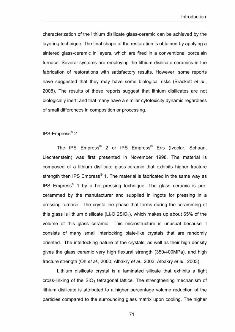
Introduction
71
characterization of the lithium disilicate glass-ceramic can be achieved by the
layering technique. The final shape of the restoration is obtained by applying a
sintered glass-ceramic in layers, which are fired in a conventional porcelain
furnace. Several systems are employing the lithium disilicate ceramics in the
fabrication of restorations with satisfactory results. However, some reports
have suggested that they may have some biological risks (Brackett et al.,
2008). The results of these reports suggest that lithium disilicates are not
biologically inert, and that many have a similar cytotoxicity dynamic regardless
of small differences in composition or processing.
IPS-Empress® 2
The IPS Empress® 2 or IPS Empress® Eris (Ivoclar, Schaan,
Liechtenstein) was first presented in November 1998. The material is
composed of a lithium disilicate glass-ceramic that exhibits higher fracture
strength then IPS Empress® 1. The material is fabricated in the same way as
IPS Empress® 1 by a hot-pressing technique. The glass ceramic is pre-
cerammed by the manufacturer and supplied in ingots for pressing in a
pressing furnace. The crystalline phase that forms during the ceramming of
this glass is lithium disilicate (Li2O·2SiO2), which makes up about 65% of the
volume of this glass ceramic. This microstructure is unusual because it
consists of many small interlocking plate-like crystals that are randomly
oriented. The interlocking nature of the crystals, as well as their high density
gives the glass ceramic very high flexural strength (350/400MPa), and high
fracture strength (Oh et al., 2000; Albakry et al., 2003; Albakry et al., 2003).
Lithium disilicate crystal is a laminated silicate that exhibits a tight
cross-linking of the SiO3 tetragonal lattice. The strengthening mechanism of
lithium disilicate is attributed to a higher percentage volume reduction of the
particles compared to the surrounding glass matrix upon cooling. The higher
Introduction
72
percentage volume reduction of the crystal is accounted for by its higher
coefficient of thermal expansion in comparison with the glass matrix and a
high-to-low temperature phase transformation. The result of pressing the
material at a temperature of 920°C is a primary crystalline phase of needle-
shape lithium disilicate crystal (0.5 to 5mm), which comprises approximately
65% volume (Albakry et al., 2004; Guazzato et al., 2004). The volume
differential between the lithium disilicate particles and the glass matrix causes
residual stresses that place the surrounding glass matrix in compression,
which must be counteracted by tensile stresses before cracks propagate.
Irrespective of the large percentage of lithium disilicate crystals, IPS
Empress® 2 exhibits a high level of translucency due to the optical properties
of the crystal structures. In addition to lithium disilicate crystals, the material
contains minor quantities of lithium orthophosphate (Li3PO4) with particle sizes
between 0.1 and 0.3mm.
The IPS Empress® 2 ceramic is etchable with hydrofluoric acid and
needs to be cemented with a resin base luting agent. A special apatite fluoride
glass-ceramic was developed for veneering of the IPS Empress® 2
frameworks. This veneering ceramic can be sintered at 800°C. During this
process, a part of the apatite crystals of the glass matrix is precipitated out of
the glass-ceramic. These crystals help to achieve a higher level of
biocompatibility and optical characteristics such as translucency, brightness,
and light-scattering of the veneering material.
The framework of the material may be luted to the dental preparation
using conventional or adhesive cementation techniques opposing the IPS
Empress® 1 system that can only be resin cemented. However, when
retentive areas are small, retention may be inadequate, and an adhesive
luting agent is desirable because bond strength can be enhanced (Spohr et
al., 2003). The results of 5-year clinical evaluation suggest that IPS Empress®
2 ceramic is an appropriate material for the fabrication of single crowns with

Introduction
73
success rates around 95% (Toksavul et al., 2007; Marquardt et al., 2006).
Survival rates of fixed partial dentures however, reveal a very low success
rate between 50 and 70 % at 2 and 5 years respectively (Marquardt et al.,
2006; Taskonak et al., 2006). Strict conditions should be considered before
the use of IPS Empress® 2 material for the fabrication of three-unit fixed
partial dentures.
3G-OPC®
The 3G-OPC® (Optimal Pressable Ceramic) (Jeneric/Pentron Inc., CT,
USA) is a pressable ceramic with a needle-like crystalline structure made of
lithium disilicate. The glass ceramic material restorations are virtually
fabricated in the same manner as the IPS-Empress® 2 crown. The only
differences between the two technology systems are the price and the
ceramic ingots supplied to construct the ceramic restorations. The strength
reported for the 3G-OPC® crown was similar to that of Empress® 2 around
350 MPa (Jin et al., 2004), but less then Procera® and In-Ceram® Alumina.
The 3G OPC® is based on lithium disilicate glass-ceramic and crystal-free
overlay porcelain. Due to the fact that the interlocking lithium disilicate crystals
prevent crack propagation, 3G-OPC® has higher fracture toughness and
flexural strength when compared to former OPC products. For instance, its
fracture strength is two times as that of OPC and it is sufficient for use in
three-unit anterior fixed partial dentures. The ceramic can be used for anterior
and posterior single unit crowns and three-unit anterior fixed partial dentures.
Because of its fluorescing core and overlay porcelain, it can achieve good
esthetic results. The fact that the overly porcelain is crystal free, it causes less
abrasive wear of the opposing natural dentition. No long term data is available
for this crown system.
Introduction
74
Zirconia-strengthened ceramics
The increased demand for optimal esthetics has made metal-ceramic
restorations no longer adequate to meet the expectations of both clinicians
and patients. In this respect, the all-ceramic crown set a standard in esthetics
that is difficult to match by the metal-ceramic crown because of the absence
of underlying metal and increased light transmission through the restoration.
These all-ceramic crowns with high strength still remain susceptible to a high
mechanical loading of chewing force. The absence of reinforcement by a
metal substructure results in relatively weak flexural strength and fracture
resistance. Therefore, currently available all-ceramic restorations have limited
clinical application in areas of high stress, such as fixed partial dentures. In
order to overcome such a mechanical weakness of all-ceramic crown systems,
several all-ceramic companies have recently investigated a high strength new
ceramic material composed of Zirconia for the coping of all-ceramic crown. Its
superior mechanical behaviors over alumina ceramic have been reported
(Christel et al., 1989).
Currently available all-ceramic crowns are practically limited to single
tooth restorations. The indication that Zirconia containing ceramics exhibit
durability in a highly loaded environment makes them attractive for use in
dentistry and increase the broad of clinical indications to posterior molar areas
and posterior fixed partial dentures.
Zircon has been known as a gem from ancient times. The name of the
metal, zirconium comes from the Arabic Zargon (golden in color) that in turn
comes from the two Persian words Zar (Gold) and Gun (Color). Zirconia, the
metal dioxide (ZrO2), was identified as such in 1789 by the German chemist
Martin Heinrich Klaproth in the reaction product obtained after heating some
gems, and was used for a long time blended with rare earth oxides as
Introduction
75
pigment for ceramics (Piconi et al., 1999).
Good chemical and dimensional stability, mechanical strength and
toughness, coupled with a Young’s modulus in the same order of magnitude
of stainless steel alloys was the origin of the interest in using Zirconia as a
ceramic biomaterial (Piconi et al., 1999). The first paper concerning
biomedical application of Zirconia was published in 1969 by Helmer and
Driskell (Helmer et al., 1969), while the first paper concerning the use of
Zirconia to manufacture ball heads for Total Hip Replacements (THR), which
is the current main application of this ceramic biomaterial, was introduced by
Christel (Christel et al., 1989).
Zirconia is a polycrystalline ceramic without any glass component. It is
a polymorph that occurs in three forms: monoclinic (M), cubic (C), and
tetragonal (T). The cubic phase is stable but brittle, while the tetragonal phase
is tough but unstable. Pure Zirconia is monoclinic at room temperature. This
phase is stable up to 1170°C. Above this temperature it transforms into
tetragonal and then into cubic phase at 2370°C. Pure Zirconia has a high
melting point (2700°C) and a low thermal conductivity. Its polymorphism,
however, restricts its widespread use in ceramic industry.
This results from the fact that noticeable changes in volume are
associated with these transformations. During the monoclinic-to-tetragonal
transformation, which occurs when Zirconia is heated, there is a 5% volume
decrease; conversely, a 3% increase in volume is observed during the cooling
process. Stresses generated by the expansion originate cracks in pure
Zirconia ceramics that break into pieces at room temperature. These
phenomena have been shown detrimental to the mechanical behavior of
Zirconia because the stresses induced during the phase transformations
resulted in crack formation inhibiting the use of pure Zirconia in many
applications. This phase transformation of zirconium oxide can be inhibited by
the addition of stabilizing oxides, like CaO, MgO, CeO2 and Y2O3 to pure

Introduction
76
Zirconia. Thus the undesirable phase transformation is prevented and allows
the material to generate multiphase materials known as Partially Stabilized
Zirconia (PSZ) whose microstructure at room temperature generally consists
of cubic Zirconia as the major phase, with monoclinic and tetragonal Zirconia
precipitates as the minor phase (Subbarao, 1981; Piconi et al., 1999). These
precipitates may exist at grain boundaries or within the cubic matrix grains.
Usually PSZ consists of larger than 8 mol% of MgO, 8 mol% of CaO, or 3-
4mol% of Y2O3. PSZ is a transformation toughened material and distinguished
by a crack initiation mechanism.
Two kinds of microstructures can be generated. In the ZrO2-MgO or
ZrO2-CaO systems, materials are sintered in the cubic state and small
tetragonal precipitates are formed during cooling has a result of partial
transformation of the cubic phase. In the ZrO2-Y2O3 system, the extent of the
stability range of the tetragonal phase in terms of temperature and amount of
yttrium oxide allows sintering of fully tetragonal fine-grained materials. Thus,
using Y2O3 as a stabilizing agent, it is possible to produce zirconium oxide
ceramic made of 100% small metastable tetragonal grains. The volume
change related to the tetragonal to monoclinic phase transformation results in
a prestressed material. In this respect, a propagating crack can release the
stresses on the neighboring grains that then transform from the metastable
state into the monoclinic phase. The associated volume expansion results in
compressive stress at the edge of the crack front and extra energy is required
for the crack to propagate further. Thus, it is believed that the main energy
absorbing mechanism is due to the martensitic-like transformation occurring
at the crack tip.
Zirconia is usually produced from the zircon, ZrSiO4. To produce
Zirconia from zircon, zircon is first converted to zirconyl chloride
(ZrOCl2.8H2O). There are two methods used to make Zirconia from the
zirconyl chloride: thermal decomposition and precipitation. Once the zirconyl

Introduction
77
chloride is heated to 200°C, it starts dehydration and becomes dehydrated
ZrOCl2. On next step, ZrOCl2 decomposes into chlorine gas and becomes
Zirconia at a much higher temperature. Zirconia lumps obtained from the
calcinations then undergo a size reduction process, such as ball milling, into
the particle size range needed, usually up to 325 meshes. However, it is not
easy to produce Zirconia powders with high purity and fine particle size by this
method. Precipitation method, on other hand, uses chemical reactions to
obtain the Zirconia hydroxides as an intermediate. Obtained Zirconia
hydroxides go through wash, filtration, freezing dry, and calcination to turn into
Zirconia powder. By this method, the grain size, particle shape, agglomerate
size, and specific surface area can be modified within certain degree by
controlling the precipitation and calcination conditions. Furthermore, using this
process its purity is also easier to be controlled.
In order to prepare stabilized Zirconia powders, stabilizers (magnesia,
calcia, or yttria) must be introduced into pure Zirconia powders prior to
sintering. Stabilized Zirconia can be formed during a process called in-situ
stabilizing. Before the forming processes, such as molding, pressing or
casting, fine particles of stabilizer and monoclinic Zirconia are well mixed.
Then the mixture is used for forming of green body. The phase conversion is
accomplished by sintering the doped Zirconia at 1700°C. During the sintering,
the phase conversion takes place. High quality stabilized Zirconia powder is
made by co-precipitation process. Stabilizers are introduced during chemical
processing, before the precipitation zirconium hydroxide. A cubic (or
tetragonal) phase Zirconia is formed during calcination of chemically
precipitated intermediates.
In the early stages of the development all these solid solutions (ZrO2-
MgO, ZrO2-CaO, and ZrO2-Y2O3) were tested for biomedical applications. But
in the following years the research efforts appeared to be more focused on
Zirconia-yttria ceramics (ZrO2-Y2O3), characterized by fine grained
Introduction
78
microstructures known as Tetragonal Zirconia Polycrystals (TZP). The
sintering behavior of Zirconia-TZP does not allow the manufacturing of
abutments and crowns/bridges by direct sintering. Therefore abutments and
crowns/bridges of industrial manufactured Zirconia-TZP ceramics can only be
fabricated by grinding. In addition, copy grinding machining techniques
requires CAD/CAM procedures. Luthardt and coworkers reported that
prosthetic restorations manufactured using CAD/CAM technologies reached a
level of quality (fracture strength, fitting accuracy) that warrants broad clinical
application (Luthardt et al., 1999). Zirconia-TZP is being used as application in
space shuttle, automobiles, cutting tools, and combustion engines because of
its good mechanical and dimensional stability, such as mechanical strength
and toughness. In vitro evaluation of the mutagenic and carcinogenic capacity
of the high purity Zirconia ceramic confirmed that it did not elicit such effects
on the cells (Covacci et al., 1999).
As mentioned previously yttrium-tetragonal Zirconia polycrystals (Y-
TZP) is now posed to replace alumina ceramic because of its superior
mechanical behavior. This material Y-TZP, exhibits an improved fracture
toughness (KIC = 9-10 MN/m3/2) related to the transformation of tetragonal
ZrO2 grains into monoclinic phase and the associated compressive stresses
occurring at the crack front. Y-TZP has a higher bending strength as
compared to alumina (900-1200 vs. 400 MPa) associated with a much lower
modulus of elasticity (200 GPa vs. 350 GPa), and a smaller grain size (0.5 µm
vs. 7 µm). In addition, the ZrO2 based material exhibits a lower Young’s
modulus pointing to an interesting elastic deformation capability.
The enhanced strength of this material can be explained by their
characteristic microstructural differences: Y2O3-partially-stabilized ZrO2
ceramic has a higher density and a smaller particle size than Al2O3 ceramic.
Moreover, the hardness of both ceramics is essentially different. The main
reason for the superior fracture strength of ZrO2 ceramic, however, lies in the
Introduction
79
metastable tetragonal crystalline structure at room temperature. This structure
represents an efficient mechanism against flaw propagation and has a strong
impact against flaw sub-critical crack growth. However, ZrO2 ceramic exhibits
1 to 10 lower thermal conductivity than Al2O3 ceramic (Munz et al., 1995).
Temperature peaks can alter the metastable tetragonal crystalline phase of
partially stabilized ZrO2 ceramic. Therefore ZrO2 ceramic materials should be
more endangered than Al2O3 ceramic materials by heat producing surface
treatments, which produce high temperature spots because of the very slow
heat dissipation.
Although many types of Zirconia-containing ceramic systems are
currently available, only three are used to date in dentistry. These are yttrium
cation-doped tetragonal Zirconia polycrystals (3Y-TZP), magnesium cation-
doped partially stabilized Zirconia (Mg-PSZ) and Zirconia-toughened alumina
(ZTA).
Zirconia containing ceramics systems
Yttrium cation-doped tetragonal Zirconia polycrystals (3Y-TZP)
Biomedical grade Zirconia usually contains 3mol% yttria (Y2O3) as a
stabilizer (3Y-TZP) (Piconi et al., 1999). While the stabilizing Y3+ cations and
Zr4+ are randomly distributed over the cationic sites, electrical neutrality is
achieved by the creation oxygen vacancies (Eichler, 2001; Fabris et al. 2002).
3Y-TZP has been used to manufacture femoral heads in total hip replacement
prostheses since late eighties but its used in orthopedic surgery has since
been reduced by more than 90% mostly due to a series of failures that
occurred in 2001 (Chevalier, 2006). 3Y-TZP is available in dentistry for the
fabrication of dental crowns and fixed partial dentures. The restorations are
processed either by soft machining of presintered blanks followed by sintering
Introduction
80
at high temperature, or by hard machining of fully sintered blocks (Filser et al.,
2003).
The mechanical properties of 3Y-TZP strongly depend on its grain size
(Burger et al., 1997; Ruiz et al., 1996). Above critical grain size, the material is
less stable and more susceptible to spontaneous tetragonal to monoclinic
transformation whereas smaller grain sizes (1µm) are associated with a lower
transformation rate (Heuer et al., 1982). Moreover, bellow certain grain size
(~0.2µm), the transformation is not possible, leading to reduce fracture
toughness (Cottom et al., 1996). Consequently, the sintering conditions have
a strong impact on both stability and mechanical properties of the final product
as they dictate the grain size. Higher sintering temperatures and longer
sintering times lead to larger grain sizes (Chevalier et al., 2004).
Currently available 3Y-TZP for soft machining of dental restorations
utilizes final sintering temperatures varying between 1350 and 1550°C
depending on the manufacturer. The fairly wide range of sintering
temperatures is therefore likely to have an influence on the grain size and
later the phase stability of the material for dental applications. From the phase
diagram established by Scott, 3Y-TZP contains some amount cubic Zirconia
(Scott, 1975). Chevalier and co-workers demonstrated that the presence of
cubic Zirconia is not desirable in 3Y-TZP for biomedical applications and is
caused by uneven distribution of yttrium stabilizer ions. The cubic grains are
enriched in yttrium while the surrounding tetragonal grains are depleted and
therefore less stable (Chevalier et al., 2004). As mentioned earlier,
restorations produced by soft machining are sintered at later stage (i.e.
following the forming steps), this process prevents the stress-induced
transformation from tetragonal to monoclinic and leads to a final surface
virtually free of monoclinic phase unless grinding adjustments are needed or
sandblasting is performed. Most manufacturers of 3Y-TZP blanks for dental
applications do not recommend grinding or sandblasting to avoid the
Introduction
81
tetragonal to monoclinic transformation and the formation of surface flaws that
could be detrimental to the long-term performance, despite the apparent
increase in strength due to the transformation-induced compressive stresses.
In contrast, restorations produced by hard machining of fully sintered 3Y-TZP
blocks have been shown to contain a significant amount of monoclinic
Zirconia (Guazzato et al., 2004). This is usually associated with surface
microcracking, higher susceptibility to low temperature degradation and lower
reliability (Huang, 2003). Liu and co-workers studied the fatigue behavior o
3Y-TZP (Liu et al., 1991). The pre-existing processing flaws were identified as
the fracture origin in all cases and microcracking was shown to be the
dominant mechanism of fatigue damage. More recently, Zhang and co-
workers studied the effect of sharp indentation damage on the long-term
performance of this material. It was shown that both sandblasting and sharp
indentations even at very low loads are detrimental to the long-term
performance of 3Y-TZP when tested in cyclic loading (Zhang et al, 2005;
Zhang et al., 2004). These studies pointed out the importance of controlling
the final surface state of 3Y-TZP for biomedical applications. In summary,
even if high strength might appear as beneficial property for dental
applications, long-term performance and reliability should also be considered.
Several authors have reported that annealing at 900°C for 1h or
relatively short heat treatments in the temperature range 900-1000°C for 1
min induce the reverse transformation from monoclinic to tetragonal (Kosmac
et al., 2000; Sundh et al., 2005). This phenomenon was accompanied by the
relaxation of the compressive stresses at the surface and a decrease in
strength. The firing of veneering porcelain during the fabrication of dental
restorations is therefore likely to promote the reverse transformation with the
consequences listed above. In addition, the reversibility of the transformation
should not be confused as providing a mechanism for healing of the flaws
previously introduced.
Introduction
82
The microstructure of 3Y-TZP ceramics for dental applications consists
of small equiaxed grains (0.2-0.5µm in diameter, depending on the sintering
temperature) (Guazzato et al., 2004). The mechanical properties are well
above those of all other available dental ceramics, with a flexural strength in
the 800-1000 MPa range and fracture toughness in the 6-8Mpa m0.5 range.
The Weibull modulus strongly depends on the type of surface finish and the
processing conditions (Kosmac et al., 1999).
Glass-infiltrated Zirconia-toughened alumina (ZTA)
Another approach to advantageously utilize the stress-induced
transformation capability of Zirconia is to combine it with an alumina matrix,
leading to a Zirconia-toughened alumina (ZTA) (Lange, 1982; Lange, 1982).
These materials have recently received interest as potential bioceramics
(Deville et al., 2003; Deville et al., 2004). One commercially available dental
product, previously discussed, In-Ceram® Zirconia was developed by adding
33 vol% of 12 mol% ceria-stabilized Zirconia (12Ce-TZP) to In-Ceram®
Alumina (Guazzato et al., 2004). In-Ceram® Zirconia can be processed by
either split-casting or soft machining. Initial sintering takes place at 1100°C for
2h, prior to this porous ceramic composite being glass infiltrated. The glass
phase represents approximately 23% of the final product. One of the
advantages of the split-cast technique is that there is very limited shrinkage.
However, the amount of porosity is greater that of sintered 3Y-TZP and
comprises between 8 and 11% (Guazzato et al., 2003). This partially explains
the generally lower mechanical properties of In-Ceram® Zirconia when
compared to 3Y-TZP dental ceramics. It should be pointed out, however, that
Ce-TZP ceramics usually exhibit better thermal conductivity and resistance to
low temperature degradation than Y-TZP under similar thermo-cycling or
aging conditions (Tsukuma et al., 1985).
Introduction
83
In-Ceram® Zirconia for machining is thought to exhibit better
mechanical properties due to more consistent processing compared to the
split-cast ceramic. Conversely, Guazzato and coworkers reported a
significantly higher flexural strength for In-Ceram® Zirconia processed by split
casting (630 ± 58 MPa) compared to the machined material (476± 50 MPa)
(Guazzato et al., 2005). There was no significant difference in fracture
toughness. The two materials exhibited a very similar microstructure with
large alumina grains (6 µm long, 2µm wide) together with clusters of small
Zirconia grains (less than 1 µm in diameter). Some faceted Zirconia grains
(2µm) were also observed. The crack patterns were consistently transgranular
for ZrO2 and intragranular for Al2O3. In some of the newly developed ZTA for
biomedical applications, excellent mechanical properties are obtained by
promoting a fine and uniform dispersion of Zirconia grains in an alumina
matrix; such dispersion is readily obtained by sol-gel processing (Tanaka et
al., 2002). An advancing crack triggers the tetragonal to monoclinic
transformation. The associated increase in volume creates microcracks in the
alumina matrix surrounding the transformed particle. The toughness is
therefore enhanced by microcracking. (Porter et al., 1977)
Magnesia cation-doped partially stabilized Zirconia (Mg-PSZ)
Although a considerable amount of research has been dedicated to
magnesia partially stabilized Zirconia (Mg-PSZ) for possible biomedical
applications, this material has not been successful due mainly to the presence
of porosity, associated with a large grain size (30-60µm) that can induce wear
(Piconi, 1999). The microstructure consists of tetragonal precipitates within a
cubic stabilized Zirconia matrix. The amount of MgO in composition of
commercial materials usually ranges between 8 and 10 mol% (Green et al.,
1988). In addition, to a high sintering temperature (between 1680 and
Introduction
84
1800°C), the cooling cycle has to be strictly controlled, particularly in aging
stage with a preferred temperature of 1100°C (Green et al., 1988).
Precipitation of the transformable tetragonal phase occurs during this stage,
which volume fraction is a critical factor in controlling the fracture toughness of
the material (Hannink et al., 1994). Due to difficulty of obtaining Mg-PSZ
precursors free of SiO2, magnesium silicates can form that lower the Mg
content in the grains and promote the tetragonal to monoclinic transformation
(Leach, 1987). This can result in lower mechanical properties and a less
stable material. Denzir-M® (Denzir®, Cadesthetics AB, Skellefteå, Sweden) is
an example of Mg-PSZ ceramic currently available for hard machining of
dental restorations.
Zirconia surface treatments
Soft machining of pre-sintered blanks
Since its development in 2001 (Filser et al., 2003); direct ceramic
machining of pre-sintered 3Y-TZP has become increasingly popular in
dentistry and is now offered by a growing number of manufacturers. Briefly,
the die or a wax pattern is scanned, an enlarged restoration is designed by
computer software (CAD) and computer aided machining mills a pre-sintered
ceramic blank. The restoration is then sintered at high temperature. Several
variations of this process exist depending on how the scanning is performed
and how the large sintering shrinkage of 3Y-TZP (~25%) is compensated for.
For example, both contact scanners and non-contact scanners are available.
Overall, non-contact scanners are characterized by higher density of data
points and a greater digitizing speed compared to contact scanners.
Typically the 3Y-TZP powder used in the fabrication of the blanks
contains a binder that makes it suitable for pressing. The binder is later
Introduction
85
eliminated during the pre-sintering step. It also contains about 2 wt. % HfO2,
classically difficult to separate from ZrO2. These powders have only minor
variations in chemical composition. The powders consist of spray-died
agglomerates (about 60 µm in diameter) of much smaller crystals that are
about 40 nm in diameter. These blanks are manufactured by cold isostatic
pressing. The mean pore size of the compacted powder is very small in the
order of 20-30 nm with a very narrow pore size distribution (Filser et al., 2001).
The binder is eliminated during pre-sintering heat treatment. This step
has to be controlled carefully by manufacturers, particularly the heating rate
and the pre-sintering temperature. If the heat rate is too fast, the elimination of
the binder and associated burn out products can lead to cracking of the
blanks. Slow heating rates are therefore preferred. The pre-sintering
temperature of the blanks affects the hardness and machinability. These two
characteristics act in opposite direction: an adequate hardness is needed for
the handling of the blanks but if the hardness is too high, it might be
detrimental to the machinability. The temperature of the pre-sintering heat
temperature also affects the roughness of the machined blank. Overall higher
pre-sintering temperatures lead to rougher surfaces. The choice of a proper
pre-sintering temperature is thus critical (Filser et al., 2001). The density of
each blank is carefully measured so that the appropriated compensating
shrinkage is applied during final sintering. The final density of the pre-sintered
blanks is about 40% of the theoretical density (6.08g/cm3). The density
gradient within the blanks is lower than 0.3% of the theoretical density in all
directions (Filser et al., 2001).
Machining is better accomplished in two steps. A first rough machining
is done at a low feed rate while the final fine machining is performed at a
higher feed rate (Filser et al., 2001; Filser et al., 2003).
Restorations can be colored after machining by immersion in solutions
of various metal salts such as cerium, bismuth, iron or a combination thereof.
Introduction
86
The color develops during the final sintering stage. The concentration of the
solution strongly influences the final shade. Concentrations as low as 0.001
mol% are sufficient to produce a satisfactory coloration. The final sintering
temperature influences the color obtained. Careful respect of the
manufacture’s instructions is therefore important. Coloration with various
solutions does not appear to affect the crystalline phases or mechanical
properties of the final product. Alternatively, colored Zirconia can be obtained
by small additions of various metal oxides to the starting powder (Cales,
1998).
Sintering of the machined restoration has to be carefully controlled,
typically by using specifically programmed furnaces. Shrinkage starts at
1000°C and reaches ~25%. Sintering conditions are product-specific. Final
sintering temperatures between 1350 and 1550°C with dwell times between 2
and 5 h lead to densities greater than 99% of the theoretical density. These
variations in sintering conditions are likely to be due the initial chemical
composition of the 3Y-TZP powder. For example, small additions of alumina
have been shown to act as a sintering aid, allowing the use of lower sintering
temperatures and times. Prior to sintering, the frameworks are placed on
Zirconia sintering beads to avoid deformation. The minimum thickness for the
copings is 0.5mm, bellow which warpage could occur. The restorations are
furnace-cooled to a temperature bellow 200°C to minimize residual stresses.
As mentioned earlier, the sintering temperatures and times strongly influence
the grain size (Matsui et al., 2003). Chevalier and coworkers also
demonstrated that the amount of cubic phase in 3Y-TZP increases when the
sintering temperature reaches 1500°C with a sintering time of 5h (Chevalier et
al., 2004). The presence of larger cubic grains is detrimental to the resistance
of the ceramic to low temperature aging. This point out the importance of
carefully controlling the sintering step.
The restorations are finally veneered with porcelains of matching
Introduction
87
coefficient of thermal expansion. The nature of the interface between 3Y-TZP
and the veneering porcelain has not been thoroughly studied. The veneering
porcelain is baked at ~900°C, with a hold time of 1min. Although diffusion
processes are time-dependent, chemical reactions could occur between the
two ceramic materials. This point will be examined in greater detail later.
Representative systems utilizing soft machining of 3Y-TZP for dental
restorations are LavaTM (3M ESPE, Germany), Procera® Zirconia (Procera,
Nobel Biocare AB, Sweden), YZ cubes for Cerec InLab (Vident, Baldwin Park,
CA, USA) and Cercon® (Dentsply International, Inc., York, PA, USA).
Hard machining of 3Y-TZP and Mg-PSZ
At least two systems, Denzir® (Denzir, Cadesthetics AB, Skellefteå,
Sweden) and DC-Zirkon® (DCS Dental AG, Germany) are available for hard
machining of Zirconia dental restorations. Y-TZP blocks are prepared by pre-
sintering at temperatures bellow 1500°C to reach a density of at least 95% of
the theoretical density. The blocks are then processed by hot isostatic
pressing at temperatures between 1400 and 1500°C under high pressure in
an inert gas atmosphere (Piconi et al., 2006). This latter treatment leads to a
very high density in excess of 99% of the theoretical density.
The blocks can then be machined using a specially designed milling
system. Due to the high hardness and low machinability of fully sintered Y-
TZP, the milling system has to be particularly robust. A study by Blue and co-
workers demonstrated that Y-TZP was significantly harder to machine than
fully sintered alumina with lower material removable rates (Blue et al., 2003).
This was confirmed by Yin and co-workers who also reported that coarse
diamond burs were more efficient for material removal with Y-TPZ, while
machining with fine burs led to a more ductile type of damage (Yin et al.,
2004). Huang studied the effect of grinding speed on the type of machining
Introduction
88
damage in Y-TZP and reported both brittle and ductile removal modes at high
speed with less subsurface damage (Huang et al., 2003). On the other hand,
the fine grain size of Y-TZP leads to very smooth surfaces after machining. As
mentioned earlier, all surface treatments cause some degree of tetragonal to
monoclinic transformation at the surface of Y-TZP. Kosmac and co-workers
showed that sandblasting was more efficient than grinding in inducing the
transformation, thereby promoting a greater increase in strength (Kosmac et
al., 1999). Conversely, coarse grinding caused the formation of deep defects
as well as reverse transformation with elimination of the compressive stresses
and decrease in strength. Guazzato and Curtis on Y-TZP confirmed these
results for dental applications (Guazzato et al., 2005; Curtis et al., 2006)
The influence of residual stresses on the susceptibility of Y-TZP to low
temperature degradation has been thoroughly examined by Deville and co-
workers (Deville et al., 2003). It was concluded that the presence of residual
stresses was more influential than the final roughness in promoting low
temperature degradation. Smooth polishing led preferential transformation
after aging around the residual scratches. A thermal treatment at 1200°C for
2h induced the relaxation of the stresses and a lower susceptibility to aging
than the polished state. Grant and co-workers reported that hot isostatically
pressed (HIPped) 3Y-TZP had a lower susceptibility to low temperature
degradation than the unHIPed material (Grant et al., 2001). The aging
susceptibility of HIPped 3Y-TZP for dental applications is likely to follow a
different scheme as the material is later machined. However, the difficulty of
comparing the results of the numerous studies dedicated to surface
treatments of Y-TZP should be pointed out, as there is no standardization of
the treatments applied. In summary, questions remain about surface state
remaining after hard machining of Y-TZP, while soft machining seems to lead
to a more consistent final state, provided that the machined restoration is left
intact after sintering.
Introduction
89
Clinical studies of ZrO2 fixed prostheses
There are approximately fifteen major long-term studies of Zirconia
prostheses underway at this time (Denry et al., 2008). It seems noticeable that
these studies mostly involve multi-unit and posterior prostheses. It is apparent
that sponsoring manufacturers have some confidence in the structural
potential of Zirconia frameworks. This also signals some comfort regarding
the performance of this core ceramic for the restoration of single anterior
teeth; reflecting the clinical finding that many less/strong tough all-ceramic
systems are found to have 90% or higher survival at 5-6 years. It is also
interesting that, other than for a few papers and IADR/AADR abstracts, there
has been little reporting of early results (von Steyern et al., 2005; Larsson et
al., 2006; Raigrodski et al., 2006). This stands in contrast to other ceramic
product launches for which 2-year and even 1-year study results were quickly
published.
Bulk fracture appears to be quite uncommon in all studies to date, even
with the majority of study prostheses being multi-unit replacing first molars or
second premolar (Denry et al., 2008). The fractures that have occurred mostly
involve connectors of multi-unit prostheses or second molar abutments.
Results for single-unit molar prostheses may turn out to be at least as good as
for alumina-based core systems; such supposition being tempered of course
by the relatively limited observation times. It is also obviously too early to
judge whether microstructural or processing differences among Zirconia
systems will be reflected in clinical performance. That said, it is rather
remarkable to have such an emphasis on clinical examination of a new
technology in dentistry.
Problems with the porcelain veneer seem to trouble all studies. In three
published reports of four separate systems, 8, 15, 25 and 50% of prostheses
Introduction
90
developed crazy or cracking with minor loss of material after only 1-2 years of
observation (von Steyern et al., 2005; Larsson et al., 2006; Raigrodski et al.,
2006). Investigators involved with studies not yet published admit to porcelain
problems as well. However, this picture is somewhat confused by non-
research clinical experience. This may signal that the difficulties are material-
specific, as was the conclusion in one published study of two systems
exhibiting, respectively, 8 and 50% incidence of porcelain cracking (Larsson
et al., 2006). It may also indicate that non-materials factors such as thickness
ratios or framework design play a role in porcelain cracking. For comparison,
porcelain problems on metal-ceramic prosthesis over a 10 years observation
period was reported to be on the order of 4% for a gold-palladium alloy, no
higher than 6% for most alternative alloys, and only as high as 15% for one
nickel-based alloy without beryllium (Anderson et al., 1993). Consistent
findings have been reported for another gold-based alloy, with 98%
completely intact porcelain at 5 years (Walter et al., 1999). Lower survival
percentages are reported for porcelain on titanium (84-87% survival at 5
years) (Lovgren et al., 2000); a metal known to have an issue involving
development of a weak “alpha case” layer during porcelain firing. Thus,
porcelain-Zirconia compatibility appears problematic in light of past
experience with metal-ceramic systems.
Ceramic-ceramic compatibility is not easily characterized. All
manufacturers appear to be using standard slow-heating dilatometry
measurers of expansion coefficients (α) and thermal shock testing during
product development. Most manufacturers provide veneering porcelains
having a slight mismatch (Δα) between their porcelain and Zirconia, with the
porcelain having approximately 1α unit (ΔL/L x 10-6 K-1) lower than the
Zirconia, which generally have an α in the range of (10.5-11.0) x 10-6 K-1. This
approach is used for most metal-ceramic systems and non-Zirconia all-
ceramic systems. Therefore, if a compatibility issue is occurring with Y-TZP it
Introduction
91
is likely not due to a simple thermal expansion coefficient mismatch between
the bulk materials.
Crazing or chipping during function signals the presence or
development of tensile stresses, likely associated with the Zirconia-porcelain
interface. Since the origin of such stresses does not appear to be related to
bilk thermal expansion/contraction mismatches, perhaps surface property
changes are involved. Silicate glasses are known to be aggressive solvents
towards refractory materials at high temperatures (Sandhage et al., 1990).
Aluminum oxide has been shown to be a soluble in dental porcelains under
firing conditions (Kelly, 1989). More recently both cerium and zirconium were
shown to diffuse into a glass used to infiltrate a partially sintered Ce-TZP
powder (Denry et al., 2008).
Depletion of stabilizing dopants (e.g., Y and Ce) might conceivably lead
to local changes in unit cell tetragonality resulting in destabilizing of the
tetragonal-phase or development of local thermal expansion anisotropy. If
significant cubic- phase is present near grain-boundaries or triple-points,
destabilization might result in cubic to metastable transformation with quite
high local associated strains. Liquid silicate penetration of grain boundaries
may be another consequence to consider, perhaps analogous to water
penetration of Y-TZP at moderately elevated temperatures (Kobayashi et al.,
1981). All manufacturers of porcelains for dental Y-TZP ceramic now provide
“liner” materials, presumably to increase porcelain bonding as well as to
provide some chroma and fluorescence. Although “bonding” does not appear
to be at issue, perhaps these liners help assure wetting or have chemistries
adjusted to reduce possible interactions with the Y-TZP. It does not appear
that prostheses have needed to be replaced in any studies due to porcelain
crazing or minor chipping.
Introduction
92
Zirconia all-ceramic systems
Ceramic restorations, suitable for the anterior as well as the posterior
region, simultaneously satisfying the demand for high strength, longevity, and
esthetics, are an increasingly important field for the dental professional.
Because of its outstanding mechanical properties and esthetics with a proven
track record in other industrial areas, Zirconia is emerging in the dental
industry. As the manufacturing method of choice, CAD/CAM is important for
the dental laboratory; however, in the final analysis, the primary focus will be
on the material properties and the clinical performance of the result of the
CAD/CAM process - in this case, Zirconia crowns and bridges. This is
especially true since some concepts do not require the acquisition of a
CAD/CAM system at all.
Several companies are offering Zirconia materials in dentistry (LavaTM,
3MTM ESPETM; Cercon® Smart Ceramics, Dentsply Ceramco®; Procera®
Zirconia, Nobel BiocareTM; Vita® InCeram® YZ, VidentTM). Even though
Zirconia can be chemically similar it is not necessarily the same, as previously
explained. Bread is often chemically similar; however the color, consistency
and taste can be very different. Many other factors outside of chemistry
influence the final result including the order in which ingredients are mixed,
the grain size or consistency of the mixture, and time and temperature used
for preparing the material. Although the Zirconia ceramic is chemically similar,
once processed, it can exhibit different mechanical and optical characteristics.
Working with Zirconia, one can experience the differences in machinability
(e.g. wet milling and dry milling) and in sintering (e.g. different sintering
temperature). Several factors should be evaluated when selecting the proper
material: (1) processing parameters for pre-sintered Zirconia since they may
affect performance attributes; (2) differences in the Zirconia powder because
they affect the strength/long-term stability and translucency of the restoration;
Introduction
93
(3) the pressing condition and pressing method since they can affect the
marginal fit, strength and translucency of the restoration (4) the pre-sintering
conditions may affect the strength of the pre-sintered material and its mill
ability (5) the material and method used for coloring the Zirconia because it
can affect the marginal fit, strength and translucency of the material.
Although this parameters may be important at long-term, different
studies show that, independently of the Zirconia material used the restorations
produced can have the potential to withstand occlusal forces applied in the
posterior region of the mouth and can therefore represent interesting
alternatives for replacing porcelain-fused-to-metal restorations (Att et al.,
2007; Pittayachawan et al., 2009)
A technique using either the traditional wax-up technique or by
advanced Computer assisted design (CAD) using computer and special
software provided by the manufacturers can be used to design the Y-TZP-
based framework for crowns or FPDs. This designing software is unique and
different from individual Y-TZP based manufacturers.
Y-TZP based frameworks are white in color. This can present clinical
limitations for its use in the esthetic zone. To overcome this problem several
all-ceramic systems have now the Zirconia framework for crown and bridges
available in different shades. This is achieved by staining or coloring the
framework before final sintering. Coloring is made by immersing or dipping,
depending on the system, the framework into a salt solution before sintering,
so that the zirconium oxide infiltrates with the liquid. This staining allows the
achievement of the final shade from intaglio surface to external surface of
veneering ceramic. Different studies evaluated the effect of such staining on
the flexural strength of the Zirconia framework and concluded that there was
no difference in flexural strength of uncolored and colored Y-TZP ceramic
(Pittayachawan et al., 2006; Shah et al., 2008). However, a decrease in
flexural strength at the higher salt concentrations can occur and is attributed
Introduction
94
to an increase in open porosity. The addition of shading pigments to Zirconia
frameworks result in structural changes that require different surface
treatment prior to veneering. To prevent delamination and chipping failures of
Zirconia veneered restorations, careful selection of both framework and
veneer ceramic materials, in addition to proper surface treatment, are
essential for maintaining good bond strength (Aboushelib et al., 2008)
Tooth preparation guidelines are as comparable to metal-fused to
ceramic crowns and bridges preparations. It is advisable to use
manufacturer’s recommendation and to use advised preparation kit. The axial
reduction of approximately 1.2 to 1.5 mm, occlusal reduction should be 1.5 to
2.0 mm. The axial taper of crown preparation should be of 5 to 6 degrees. All
the sharp edges of the crown need to be smoothened. The gingival finish line
should be uniform and can be at the gingival margin or 0.5 mm sub gingival.
Recommended cervical finish line is 0.8 or 1.2 mm deep chamfer or shoulder
with rounded internal angle. Recent publications recommend that, for crown
the chamfer or shoulder finishing line and for bridges the shoulders with
rounded internal angle type design to be used for a favorable distribution of
occlusal stresses to abutment teeth during function (Komine et al., 2007;
Reich et al., 2008; Beuer et al., 2008). However, it was found that the finish
line design seemingly wielded no influence on marginal adaptation of ZrO2
ceramic copings and crowns. It was also observed that the marginal and
internal adaptation values were all within the clinically acceptable range. The
accuracy of fit achieved by different Zirconia systems was shown by another
study within the range of clinical acceptability (Gonzalo et al., 2008).
Full coverage Y-TZP based restorations can be cemented using either
conventional cements or be bonded using adhesive cementation. Studies
show that the use of composite resin cements with a bonding agent do not
yield higher coping retention compared to other cements (Ernst et al., 2005;
Palacios et al., 2006). Before cementation the inner surface of the Zirconia
Introduction
95
frameworks should be sandblasted since it was demonstrated that
sandblasting may provide a powerful technique for strengthening Y-TZP in
clinical practice. (Guazzato et al., 2005; Kosmac et al., 1999; Kosmac et al.,
2000)
Procera® AllZircon system
The CAD/CAM technology employed to produce the Procera®
AllCeram alumina crown, is now used for the fabrication of a densely sintered
high-purity Zirconia framework. The Y-TZP Procera® (Procera®, Nobel
BiocareTM AB, Sweden) material can be used to fabricate copings for crowns,
one-piece or multi-unit all-ceramic fixed partial dentures, and ceramic implant
structures and abutments. These ceramic units are then combined with low
fusing veneering porcelain that creates the anatomic form of the restoration
and the occlusal morphology. The technique used for fabricating these
ceramic restorations is the same described previously for the Procera®
system. The individual Zirconia oxide substructures are manufactured by
Nobel BiocareTM at their facilities and then returned to the laboratory of origin
for veneering porcelain application and final finishing.
The Procera® system consists of a computer-controlled design station
in the dental laboratory that is joined through a modem link to the production
facility in Sweden, where the substructure is fabricated. At the design station,
a scanning device controlled by a personal computer maps the surface of the
die/s of the prepared tooth/teeth and ridge in case of a fixed partial denture.
When the scanning is completed, the data is evaluated for completeness and
displayed on the monitor computer as a three-dimensional image. Marking of
the finish line on the three-dimensional plots is the next step. The design of
the framework on the screen, e.g. the insertion of a pontic (from a library) or
the design/modeling of the connections is done with the keyboard, mouse and
Introduction
96
software support. The next step is to establish the thickness of the
substructure to be fabricated. The emergence angle of the tooth is selected,
and the relief space for the luting agent is automatically established by a
computer algorithm. When the design of the substructure has been completed,
the file is saved in the computer and is ready for transmission via modem to
the production station.
The data of the preparation and the design of the substructures are
transferred via modem to the facility production in Sweden. At this point the
fabrication of single copings and fixed partial dentures frameworks differs. In
the former, the sintering shrinkage is compensated through the computerized
milling of an enlarged die. After that, zirconium oxide powder is compacted
under pressure onto the die and fired. In the latter, the frameworks are
virtually enlarged to balance the sintering shrinkage and milled out of a solid
piece of high-purity zirconium oxide, which is then sintered (Polack, 2006).
The color of the dense sintered Zirconia is traditionally white; however the
manufacturer has now available Zirconia substructures in different shades for
copings. The Zirconia structure is examined for quality control and sent by
mail to the dental laboratory, where the ceramist finalizes the restoration by
the addition of the veneering porcelain. Available data demonstrates superior
mechanical fracture strength of the Zirconia material when compared to
alumina (Snyder et al., 2005). Margins accuracy is acceptable independently
of the method used and is acceptable for clinical use (Gonzalo et al., 2008;
Beuer et al., 2009). No long-term clinical trials are available for this material
until this date. The only study available made in private practice environment
revealed that most crowns studied (78%) were placed on premolars and
molars areas. The clinical outcome of the crowns was favorable. No Zirconia
core fractured and no caries were observed on the abutment teeth. Some
types of complication were recorded for 32 (16%) crowns or abutment teeth.
The most severe complications, in total 12 restorations (6%), were recorded

Introduction
97
as failures: abutment tooth was extracted (5), remake of crown due to lost
retention (4), veneer fracture (2) and persistent pain (1). The criteria for 25
crowns were rated favorably, and patient satisfaction with the Zirconia crowns
was in general high. The authors concluded that porcelain-veneered Zirconia
crowns showed good clinical results, were well accepted by the patients, and
only few complications were reported over the 3-year follow-up period. (Ortorp
et al., 2009)
LAVATM system
The LavaTM All-Ceramic System from 3MTM ESPETM comprises also a
CAD/CAM procedure for the fabrication of all-ceramic crowns and fixed partial
dentures for anterior and posterior applications. The framework ceramic
consists of Zirconia supplemented by a specially designed veneer ceramic.
The frameworks are fabricated using CAD/CAM procedures (scanning,
computer-aided framework design and milling) from presintered Zirconia
blanks; the size of which are increased to compensate for shrinkage during
sintering in a special high-temperature furnace.
The unit consists of the non-contact, optical scanning system LavaTM
Scan a PC with monitor and the LavaTM CAD software. When the sectioned
model has been positioned in the scanner, individual preparations and the
ridge are recorded automatically and displayed on the monitor as a three-
dimensional image (recording of the model situation including preparations,
gingiva and occlusal record). The preparation margins are scanned and
displayed automatically. The design of the framework on the screen, e.g. the
insertion of a pontic (from a library) or the design/modeling of the connections
is done with the keyboard, mouse and software support. The data is then
transferred to the LavaTM Form milling unit for calculation of the milling path.
The 3D shape is milled from a pre-sintered ZrO2 blank using hard metal tools.
Introduction
98
Manual finishing can be carried out before sintering takes place. The coloring
of the frameworks also takes place before the sintering process according to
the prescribed shade (7 possible shades, keyed to Vita® Classic). The fully-
automated, monitored sintering process then takes place with no manual
intervention in a special furnace, the LavaTM Therm and compensates the
volume shrinkage of the sintering process. The coefficient of thermal
expansion (CTE) of the specially developed, integrated overlay or porcelain
ceramic system has been matched closed (-0.2 ppm) to that of Zirconia. The
16-shade system is based on the Vita-Lumin range. The biaxial flexural
strength of the material was reported to be 1100MPa (Pittayachawan et al.,
2007. The marginal and internal fit of all-ceramic three-unit fixed partial
denture fabricated by CAD/CAM technique showed satisfactory results (Beuer
et al., 2009). Long term clinical results and survival rates for LavaTM Zirconia
crowns are insufficient.
Cercon® smart ceramic system
The Cercon® smart ceramic system (Dentsply International, Inc., York,
PA, USA) utilizes the conventional wax pattern method for designing
infrastructure for anterior and posterior crowns and fixed partial dentures up to
2 pontics with specific thickness. An optical laser scans the wax pattern into a
computer, where it is virtually enlarged and sintered. The collected data is
then transferred to the Computer Aided Manufacturing (CAM) unit where the
framework is automated milled from partially sintered Y-TZP blanks. The
partially sintered blanks used compensated by increasing the framework size
the sintering shrinkage of 20 to 25 %. The Cercon® system uses different
types of CAD software with different designing options and features. The
Zirconia structure is examined for quality control and finalized the restoration
by the addition of the veneering porcelain.
Introduction
99
Mean gap dimensions for marginal openings, internal adaptation, and
precision of fit for this crown are reported to be within the clinically acceptable
range (Komine et al., 2007). Although the fracture resistance may be different
depending on the cement used, the values obtained are well above the
maximum masticatory forces and around 1140MPa (Yilmaz et al., 2007). The
clinical success of these crowns is not yet well documented.
In-Ceram® 2000 Vita® YZ CUBES
In-Ceram® 2000 Vita® YZ CUBES (YZ Zirconia) (Vita®, Zahnfabrick,
Germany) is a newly developed yttria-stabilized Zirconia ceramic containing
approximately 95% zirconium oxide (ZrO2) and 5% yttrium oxide (Y2O3). The
material is marketed as presintered Y-TZP blocks used together with a
computer-aided design/computer-assisted manufacture (CAD/CAM) system
(Cerec® 3/InLab, Sirona Dental Systems Inc., NY, USA). The blocks are
available in different sizes depending on the number of elements to be
prepared. The prepared model and dies are scanned with a special designed
scan and the information is displayed on a computer where the framework is
planned. The ceramic blank is positioned in the milling machine and the
information transferred from the computer. The same similar enlarging and
sintering process is needed in this system to fabricate single copings and
fixed partial denture frameworks of up to 2 pontics. The milled presintered
ceramic blank is then fired in a high-temperature furnace to complete sintering.
The restoration is finalized by the ceramist adding veneer porcelain and
pigments. Flexural strength of the material has been reported to be around
1100 MPa (Chai et al., 2007). The marginal gap values and internal
adaptation of this material were reported to be within satisfactory acceptable
clinical range (Att et al., 2009) .The clinical application appears sufficiently
promising although no long-term clinical studies were reported.
Introduction
100
DCS- Smart-Fit system
The DCS Smart-Fit (DCS Dental, Bien Air, Switzerland) is a CAD/CAM
system that instead of employing partially sintered Y-TZP milling blocks
utilizes fully sintered Y-TZP under hot isostatic pressure called DC-Zirkon®.
This results in an extremely hard and dense ceramic that requires a mill time
of around 2 to 4 hours for a coping (McLaren et al., 2005).
The working model tooth/teeth preparations and die/s are measured
and digitized using a laser scan and the information is transferred to a
computer. The restoration is then designed and calculated using CAD
software. The resulting control and milling data are forwarded to the milling
machine were the framework is prepared from different shaped bocks,
depending on the framework that is necessary. The manual finishing
operations are performed and the framework is veneered by the ceramist
using conventional procedures. The system can be used to fabricate anterior
and posterior crowns and fixed partial dentures. Systems that use fully
sintered blanks (HIP) take longer time for milling due to increased hardness of
blank. Studies show superior marginal fit by virtue of not having sintering
shrinkage (Denry et al., 2008). However, the results of margin accuracy in all
system studied are within clinical acceptance. The mean strength of the
material was reported to be around 1120 MPa (Chai et al., 2009). The same
study reveled contradictory and unexpected results, when compared to other
studies with concern to the strength of different Zirconia based materials. In
this study the strength of LavaTM was significantly lower than that of DC-
Zirkon® but significantly higher than that of Cercon®. The authors concluded
that the probability of failure of DC-Zirkon® was significantly lower than that of
Lava and Cercon. The clinical behavior of Zirconia-based fixed partial
dentures made of DC-Zirkon® at 3-year demonstrate satisfactory results with
a sufficient success rate under clinical conditions (Tinschert et al., 2008).
Introduction
101
Veneering Ceramics
A strengthened ceramic can be used as the sole material or as the
core substrate for making an all-ceramic crown, inlay, onlay, veneer, or fixed
partial denture restoration (Anusavice, 1996). Two development directions are
recognized in efforts to improve the strength characteristics of all-ceramic
systems. The first is directed toward enhancing the strength of the core
materials, while the second focuses on improving processing techniques
designed to produce more homogeneous ceramic materials and veneering
porcelains. Often both directions are used in the development of a new all-
ceramic restorative system with improve strength. Ceramic core materials with
new chemical compositions have been developed for use with processing
methods combining different technologies (Dong et al., 1992; Anderson et al.,
1993; Probster et al., 1992; Luthardt et al., 1999).
Yttria stabilized Zirconia provides a sufficient mechanical strength to be
used in frameworks for all-ceramic crowns and fixed partial dentures (Lüthy et
al., 2005). However, for esthetical reasons, these frameworks have to be
veneered with an appropriate veneering ceramic. In clinical applications, the
veneering ceramic revealed to be the weakest link in such reconstructions
(Sailer et al., 2006; Sailer et al., 2007; Vult von Steyern et al., 2005).
Chipping of the veneer is described to be the most frequent reason for failure
with a failure rate of 15.2% after service time of 35.1± 13.8 months (Seiler et
al., 2007).
Among other reasons failure of a veneer may be caused by insufficient
bond-strength, excessive tensile stress due to a thermal mismatch between
veneer and framework or excessive load due to premature contacts (al-Sheri
et al., 1996; Isgro et al., 2003; De Jager et al., 2005; Aboushelib et al., 2005;
Drummond et al., 2000). The bond strength was intensively investigated
(Luthard et al., 1999; Aboushelib et al., 2006; Al-Dohan et al., 2004). It
Introduction
102
revealed to be in the range of that measured with metal-ceramic systems.
Furthermore, it was demonstrated that independently of the surface treatment
the bond strength of veneering ceramics to Zirconia was similar to metal
ceramic systems (Fischer et al., 2008). The tensile stress in the veneering
ceramic is established during cooling after firing, when an unequal thermal
contraction of both layers happens. The coefficients of thermal expansion
should be adjusted in a way that during cooling a slight compression of the
veneering ceramic occurs to enhance its strength (Bagby et al., 1990). In the
metal-ceramic systems, excessive thermal creep of the alloy, i.e. plastic flow,
may compensate stress to some extent especially if a high gold alloy is used
(Anusavice et al., 1987). In all-ceramic systems, the ceramic framework is
rigid and does not yield to the stress induced by a thermal mismatch to that
extent. Therefore, the risk of destructive stress formed in the veneer layer
might be higher in all-ceramic systems and thus would require a high
mechanical strength for veneering materials for all-ceramic systems. Hence,
the strength of the veneering ceramic is a crucial parameter for the clinical
long-term success. For metal-ceramic restorations failure rates after 5 years,
caused by chipping of the veneer are reported to be 0.4% for single crowns
and 2.9% for fixed partial dentures. For this reason, veneering ceramics for
Zirconia should at least show a flexural strength, which is similar to that of
veneering ceramics for alloys. In fact, this similarity was demonstrated by
Fisher and co-workers using a three-point flexural strength test (Fischer et al.,
2008).
Ceramic veneering materials do not show the strength one would
expect from their molecular structure. Small defects, for example, scratches,
can be found on the surface of almost any material and these scratches are
the reason for the lower strength (Guazzato et al., 2003). Such surface
defects are comparable to sharp cuts with crack tips that can be as narrow as
the distance between two atoms. The stress concentration that results from
Introduction
103
the defect results in a local increase in tensile stress. However, the theoretical
strength of the material is based on the assumption that there is an even
distribution of stress in the entire structure. If the tensile stress exceeds the
strength limit at the tip of a defect, the chemical bond breaks at this tip, and a
crack stars propagating. The tensile stress at the tip of the crack remains until
the crack has propagated through the entire material or has reached another
crack, a pore, or a crystalline particle, so that compression occurs and the
stresses are distributed. This phenomenon explains why some materials fail
at pressures far bellow their theoretical strength values (Isgro et al., 2003;
Albakry et al., 2004; White et al., 2005; Denry et al., 2008).
The failure of ceramics and their low tensile values can be explained
on the basis of how stress concentrations are generated at surface inclusions.
Under certain conditions inclusions can also initiate crack within the material.
Since ceramics have no other stress distribution mechanism available to deal
with tensile loads besides crack growth, crack can continue to grow under
low-pressure conditions through the entire material. Therefore the flexural
strength of ceramics and glass is essential lower than their compressive
strength (Anusavice et al., 1992; Marchack et al., 2008).
Complex stresses develop in the mouth. The maximum pressure
appears at the surface of the restoration. Therefore, surface inclusion is
especially important in judging the strength of a ceramic. Removing or
reducing the number of surface inclusions can result in a considerable
improvement of the fracture resistance. This is one of the reasons why it is
necessary to polish and or glaze dental ceramics. The fracture strength of the
material can be improved in two ways: (1) through introducing a compressive
stress within the material surface, and (2) through interrupting crack
propagation in the material. The fracture strength of the ceramic veneering
material can be improved by intrinsic strengthening mechanisms as explained
previously or by minimizing failures.
Introduction
104
Several methods can be employed in order to minimize failures. They
include: (1) use of harder and more stable ceramics to resist higher pressure
without crack formation; (2) limitation of sharp edges induced during
preparation which cause areas of high tensile stress within the restoration,
particularly when these regions have to resist bending forces; (3) reduction of
inclusions located at the outer ceramic margins and surface of a crown which
lead to high local tensile stress. For rough ceramic surfaces a self-glazing
procedure is recommended since strength increases in contrast to unglazed
ceramics. The glaze also decreases the risk of crack propagation. If the glaze
is removed by grinding, the strength is reduced by half in comparison to a
surface with intact glaze layer. As studies have shown, certain ceramics with
highly polished surfaces have comparable strength to similar ceramics that
are both polished and glazed Polishing has been advocated to strength
ceramics (Giordano et al., 1995; Chen et al., 1999). This observation is of
clinical importance, because it is common practice to adjust the occlusion by
grinding the ceramic surface after the ceramic crown has been cemented. By
doing so, the glaze is removed and a relatively rough surface exposed that
weakens the ceramic significantly. In order to cope with this problem, the
surface should be polished with disks, cups, tips and diamond polishing paste.
A smooth surface also reduces the abrasion on the opposing teeth; (4)
minimizing the number of firing cycles. The goal of ceramic firings is to
achieve denser sintering of the power particles and to manufacture a relatively,
smooth, glassy layer on the surface. In some cases, a layer of color is fired to
adapt to the color of the natural teeth or to simulate color lines or craze lines.
During firing, different chemical reactions occur of which the most important
one is the increase in concentration of crystalline leucite crystals in the
ceramics. Leucite is a crystal that has a high thermal expansion. The leucite
crystal permanently influences the thermal expansion of the ceramic. Several
firing steps clearly increase the leucite content, which could cause a disparity
Introduction
105
in the coefficients of thermal expansion between the ceramic and the metal or
ceramic substructure. During the cooling phase, this can lead to tension that
finally causes crack in the ceramic; (5) laboratory control of cooling. Proper
cooling of the ceramic restoration from the firing temperature to room
temperature is very important, particularly if the coefficient of thermal
expansion of the ceramic is higher that of the metal or ceramic substructure.
In this case, faster cooling is desirable in order to minimize tensile stresses
that arise during cooling.
If a more stable material is used as a core in an all-ceramic crown and
if there is a stable bond with the outer ceramic, cracks can occur only if the
stronger inner material is deformed or broken. The fracture risk of the entire
ceramic can be reduced to a minimum if the process is carried out properly
and if the physical properties of the ceramic and the substructure are well
balanced. Current processing technologies cannot make Zirconia frameworks
as translucent as natural teeth, nor can they provide internal shade
characterization or facilitate customized shading. Therefore, Zirconia core or
frameworks must be veneered with porcelain to achieve acceptable esthetics.
A series of studies on layered all-ceramic structures showed that a veneer of
a relative weak porcelain may result in failure at low loads should the
porcelain veneer be placed in tension. (White et al., 1994; White et al., 1996;
Kelly et al., 1995; Lang et al., 2001).
Although clinical failure of all-ceramic restorations is a very complex
process involving patient variables, dynamic loads, restoration geometry,
material properties, fatigue phenomena, and multiple failure modes, in vitro
models may help to elucidate mechanical parameters known to influence
fracture by tensile failure (Kelly, 1995; Kelly et al., 1999; White, 1993; White et
al., 1997. Tensile failure is believed to be the dominant clinical failure
mechanism of all-ceramic restorations (Kelly et al., 1989; Kelly et al., 1990;
Thompson et al., 1994).
Introduction
106
In a recent review of the use of contact testing in the characterization
and design of all-ceramic crown-like layer structure, Lawn and co-workers
have pointed out that the lifetime of a restoration can be improved by
increasing the strength of the core material and avoiding the creation of
spurious flaws in the surface (Lawn et al., 2001). All-ceramic materials are
subjected to different fabrication procedures in the laboratory, and sometimes
must be adjusted clinically to allow either proper fitting or occlusion. The
processing procedures and/or clinical adjustments are more likely to initiate
subcritical flaws or large defects, which upon clinical loading and/or presence
of moisture may grow to a critical situation leading to catastrophic failure. In
addition, different finishing procedures can cause various stress
concentrations and consequently may be accompanied by a reduction in
strength (Jager et al., 2000). These flaws may be introduced at different stage
of the fabrication of the restoration. The most common steps of the fabrication
of all-ceramic restorations are grinding, sandblasting, polishing and heat
treatment. Previous studies indicate that the influence of these steps on the
ultimate strength of a restoration is contradictory and related to the nature of
the material investigated and the operation conditions (Denry, 2008).
Grinding is commonly involved during machining of an all-ceramic
framework and adjustments by ceramist and dentist to improve occlusion and
proper fitting. The effect of grinding on the surface of ceramic and its
mechanical properties is contradictory. Giordano and co-workers have shown
that grinding induce flaws of a depth of 30-40µm in feldspathic porcelain and
are responsible for up to 80% strength degradation (Giordano et al., 1995).
However, Guazzato and co-workers showed that if grinding is followed by
heat treatment the ultimate flexural strength degradation could be avoided
(Guazzato et al., 2003). On the other hand, grinding increases the strength of
phase transforming ceramics, such as Zirconia and may increase the strength
of glass-ceramics when dimensions of the initial cracks are greater than those
Introduction
107
induced by grinding (Samuel et al., 1989; Green et al., 1983).
This apparent contradiction may be clarified by considering the effect of
grinding on the surface of a ceramic. The effect of the diamond grains of the
grinding disk has been compared to a number of closely spaced indentations
(Lange et al., 1983; Sines et al., 1983). Each single indentation dislocates a
corresponding volume of material, creating radial compressive stresses. The
overlapping of plastically deformed regions generated by neighbouring
indentations creates a layer of uniform compressive stresses (Lange et al.,
1983). These stresses become tensile within a depth of several microns
below the surface and then gradually decline to zero at greater depth (Samuel
et al., 1989). The near-surface compressive residual stresses contribute to
increase the flexural strength of the material by reducing the stress intensity
factor of a surface crack to an applied stress, whereas opposite action is
expected by underlying layer of tensile stress (Lange et al., 1983). Mecholsky
and co-workers have investigated the influence of grinding orientation on
flexural strength of alumina specimens and have shown that grinding always
generates two steps of flaws with different geometries (one parallel to the
grinding orientation and the other perpendicular) (Mecholsky et al., 1977). In
addition, grinding perpendicular to the tensile axis generates flaws that are
60% deeper with slightly greater stress intensity factor than flaws resulting
from parallel grinding. A greater strength reduction is therefore expected from
testing with the tensile axis perpendicular to the grinding direction (Mecholsky
et al., 1977). However, different studies have shown that orientation of
grinding in respect of the direction of the tensile stress do not influence the
ultimate tensile strength (Guazzato et al., 2003; Albakry et al., 2003). The
influence of grinding on the ultimate strength of a ceramic can therefore be
explained by tacking into account factors that may alter the combined effect of
the surface flaws and the residual stress layers. Some of these factors are:
the magnitude of the residual stress (which is also related to the composition
Introduction
108
and microstructure of the ceramic); the ratio of the crack length to surface
compressive layer depth (Lange et al., 1983); the effective size of grinding
particles (Johnson-Walls et al., 1986); the dimensions of the pre-existing flaws
(Tuan et al., 1998); and the orientation of grinding (Mecholsky et al., 1977).
The influence of grinding on the flexural strength of Zirconia ceramics
is also contradictory and related to the volume percentage of transformed
Zirconia, which in turn depends on the metastability of the tetragonal to
monoclinic phase transformation, the grinding severity and the locally
developed temperatures as previously explained (Kosmac et al., 1999;
Kosmac et al., 2000; Gupta, 1980; Green, 1983; Guazzato et al., 2005). In
Zirconia grinding has been recommended to create a surface region of
compressive stresses that increases the mean flexural strength of Zirconia
ceramics (Gupta, 1980; Guazzato et al., 2005). Swain and co-workers
showed that hand grinding is more effective than lapper-machine grinding in
inducing the tetragonal to monoclinic transformation (Swain et al., 1989). They
demonstrated that in the case of machine grinding the local development of
temperatures exceeded the monoclinic to tetragonal transformation
temperature, causing the reverse monoclinic to tetragonal transformation. In
this instance, the deep defects introduced by grinding are no longer
counteracted by the transformation-induced compressive stresses and act as
stress concentrators, lowering the mean flexural strength of the ceramic. More
recently, Xu and co-workers reported an improvement in strength of Y-TZP
upon fine grinding with 25 µm grit size diamond wheels, whereas coarser
grinding resulted in strength reduction (Xu et al., 1997). However, this study
did not correlate strength to the relative amount of transformed monoclinic
phase obtained upon surface treatment. The effect of such alterations in bi-
layered specimens, Zirconia/veneering porcelain has not yet been established,
and would wonder if such alterations would have any significance.
Sandblasting is used to remove excess glass from glass-infiltrated core
Introduction
109
materials and also recommended to create micro-retentive surface to increase
the adhesion of the cement of any metal or ceramic inner surface restoration
(Kern et al., 1994; Blixt et al., 2000). Due to the brittleness and elasticity of
glass and ceramics, the impact of the sand particles on the surface of the
materials creates stresses that are sufficient to generate cracks, even if the
impact energy is low (Guazzato et al., 2003). The coalescence of two or more
cracks and the impact by another particle or the elastic response of the
ceramic causes the removal of small portions of the material (Guazzato et al.,
2003). Kosmac and co-workers investigated the influence of sandblasting, wet
and dry grinding (carried out by hand with a 150 µm grit size diamond burr
mounted on a high-speed hand piece) in dry pressed and sintered 3 mol%
Y2O3 TZP (Kosmac et al., 1999). They showed that sandblasting was more
effective than grinding in inducing the tetragonal to monoclinic transformation
and therefore, increasing the flexural strength of the ceramic. On the basis of
the study conducted by Swain and Kosmac and co-workers inferred that
locally developed temperature must have exceeded the monoclinic to
tetragonal transformation temperature. In this instance, the deep defects
introduced by grinding were no longer counteracted by the transformation-
induced compressive stresses and acted as stress concentrators, lowering
the mean flexural strength of the ceramic. On the other hand, sandblasting
was described as a process able to induce transformation without developing
high temperatures or creating severe surface damage, and therefore,
strengthening the material. Guazzato and co-workers in a similar study
concluded that sandblasting and grinding may be recommended to increase
the strength of dental Y-TZP, provides they are not followed by heat treatment
(Guazzato et al., 2005). They also suggested that fine polishing might remove
the layer of compressive stresses and therefore, lower the mean flexural
strength of the material. Once more, the effect of sandblasting on the strength
of bi-layered specimens it’s yet to be determined. However the influence that
Introduction
110
it may have on the bond strength between the core material and the
veneering porcelain was already demonstrated to be unnecessary (Fischer et
al., 2008). The results from these studies suggest that sandblasting the inner
surface of a Zirconia framework before cementing may have the potential of
increasing the flexural strength of the restoration since it increases the flexural
strength of the Zirconia core. In addition, air abrasion combined with
pretreatment with a metal primer seems to be an appropriate method for
improving bond strength between Zirconia based restorations and abutments
(Lindgren et al., 2008).
Polishing has been advocated to strength ceramics. (Giordano et al.,
1995; Chen et al., 1999). The strengthening mechanisms are due to the
generation of compressive stresses (as seen for grinding) and removal of part
of the pre-existing flaws and radial cracks (Johnson-Walls et al., 1986).
However, if the dimensions of the radial cracks pass the limits of the
compressive layer or the flaws are not entirely removed in their depth, the
polishing procedure may be inconsequent to eliminate the damaged zone and
thus increase the strength of the ceramic material. Studies results from the
influence of polishing on the surface of ceramic materials are contradictory. In
one study, polishing alone did not strengthen the ceramic when compared to
untreated, sandblasted and ground ceramic groups (Guazzato et al., 2003).
However, in another study by the same authors, polishing produced
significantly highest mean flexural strength values when compared to
untreated, sandblasted and ground groups (Albakry et al., 2003). It has been
speculated that more than 50% strength increase can be achieved after fine
polishing (O’Brien, 2002). The ability of polishing to eliminate various defects
and flaws from treated surface is considered responsible for such strength
increment (Albakry et al., 2003). The high physical hardness of many ceramic
materials makes surface polishing a difficult task and the development of
microcracks is not easily avoidable. The increment in strength can be
Introduction
111
accomplished by polishing with a diamond paste material since it produces
the smoothest surface and the highest strength tensile values when compared
to diamond polishing wheels (Guazzato et al., 2004). Moreover, skills of
individual dental ceramists as well as the adherence to the recommendations
of a specific dental material’s manufacturer can, to a great extent, influence
the mechanical performance of all-ceramic materials (Chen et al., 1999). The
influence of polishing in the flexural strength of Zirconia based restorations
has not yet been determined. Available results for polishing have only been
presented for Zirconia ceramic studied alone (Guazzato et al., 2005; Kosmac
et al., 2000). These results revealed that polishing had little effect upon
mechanical strengthening of the Y-TZP ceramics. In some instances,
polishing may remove the layer of compressive stress and therefore, lower
the mean flexural strength of Zirconia. It was demonstrated by the authors
that polishing had neither been able to induce transformation, nor to remove
all of the strength- determining grinding-induced flaws. They speculated that
further polishing might minimise the size of flaws and result in greater flexural
strength.
After the fabrication of the Zirconia framework, the core material is
veneered with feldspathic veneering porcelain by firing and glazing at a
temperature of approximately 900°C. Glazing can be either the application of
a low fusing glass overcoat or auto glazing which is based on firing for a
certain time, held at the maximum ceramic temperature. Auto glazing and/or
the application of glazing material after grinding is believed to increase the
strength of ceramic materials by reducing the depth and/or sharpness of
critical flaws (Baharav et al., 1999). The overglazing surface treatment is a
routine procedure in a dental laboratory. It produces crowns with smooth and
shiny surfaces and has a positive effect on the biaxial flexural strength of
ceramic materials (McLean, 1979). However, this effect is still uncertain
(Fairhurst et al., 1992). Several reports in the literature show that auto glazing
Introduction
112
has no effect on strength (Anusavice et al., 1989; Fairhurst et al., 1992;
Griggs et al., 1996; Denry et al., 1999; Albakry et al., 2003). This is attributed
to the fact that heat treatment after polishing or grinding may degrade strength,
which is though to be a result of realising compressive stresses that normally
develop during polishing or grinding. Conversely, other studies revealed that
heat treatment procedure should always follow grinding and polishing
procedures in order to avoid strength degradation of the ceramic material, and
that the overglazed surface treatment increases the strength of ceramic core
and veneering porcelain materials (Isgro et al., 2003; Guazzato et al., 2003).
The term “overglazing” describes the firing of a low-fusing colourless glass on
the ceramic core or veneering porcelain. This thin layer of about 4 µm of glass,
produced after 60 seconds of hold time at the final temperature reduces the
size of flaws present on the surface (probably introduced during the
fabrication or clinical adjustment of the restoration), thus increasing the
strength of the materials. Furthermore it is used to provide large surface
compression, which strengthens the ceramic body.
While much research has been conducted to assess the strength of
traditional dental porcelain materials and Zirconia based frameworks very little
information has been reported concerning the relative strength of many of the
ceramic materials already in clinical applications. The precision of fit and
biocompatibility of Zirconia crowns have been studied and found to be
excellent for multiple dental applications (Luthardt et al., 1999; Piconi et al.,
1999). However, little data exists regarding the strength and mode of fracture,
of dental veneering porcelains used in conjunction with Zirconia based
structures (White et al., 2005; Aboushelib et al., 2006; Fischer et al., 2008).
The effect of processing procedures, polishing, grinding and glazing on
the mechanical properties of some dental materials has been studied by many
investigators (Bhrama et al., 2002, Giordano et al., 1994; Campbell et al.,
1989; Rosentiel et al., 1999; Anusavice, 1991, Giordano et al., 1995; Fairhurst
Introduction
113
et al., 1992; Chu et al., 2000; Williamson et al., 1996; Mecholsky et al., 1977;
Kosmac et al., 1999; Brackett et al., 1989; Griggs et al., 1996; Kitazaki et al.,
2001; Haharav et al., 1999; Denry et al., 1999; Anusavice et al., 1989; Albakry
et al., 2003; Isgro et al., 2003; Guazzato et al., 2003; Guazzato et al., 2004).
However, there is still controversy concerning the most suitable method that
can produce a smooth and strong surface (Williamson et al., 1996). The
purpose of this study is to contribute for the explanation and resolution of such
a common clinical problem.
Fracture mechanism/Mode of fracture of dental ceramics
The fracture mechanism of ceramics and metals are different due to
their different structure and bonding. Covalent and ionic bonds in ceramics
are associated with large inter-atomic forces and hence a strong resistance to
plastic deformation as compared with metals. Ceramics fail because of crack
propagation at a critical strain of 0.1%. Therefore increases in strength can be
achieved by an increase in the elastic modulus.
External loads will cause stress concentrations at a crack tip instead of
relaxation by plastic flow (Kvam et al., 1991). Even within the all-ceramic
systems fracture behavior of the restorations is different. It depends on the
bonding and interaction between different ceramic layers and the occlusal
loading rate and direction. Conservatively, restorations in the mouth should
withstand masticatory force of 200 N and more than 107 cycles at contacts
between opposing cusps of characteristic radii of 2 to 4 mm (Anusavice, 1989;
Craig, 2008).
To predict the fracture modes and fracture resistance of bilayered
ceramic restorations with different designs, one should perform analyses
using a generalized model. There are several factors that are associated with
Introduction
114
the stress state created in dental ceramic restorations. These include: (1)
thickness of ceramic layers; (2) mechanical properties of ceramics; (3) elastic
modulus of supporting substrate materials; (4) direction, magnitude, and
frequency of applied loads; (5) size and location of occlusal contact areas; (6)
residual stresses induced by processing; (7) restoration-cement interfacial
defects; and (8) environmental effects (Wakabayashi et al., 2000).
Dental structures are essentially layered composites. This is true of
both natural teeth (enamel/dentin) and restorations such as crowns, inlays,
onlays, veneers and fixed partial dentures (Claus, 1990; Probster et al., 1992;
Probster, 1993; Rinke et al., 1995; Hornberger et al., 1996; Wolf et al., 1996;
Kelly, 1997). The most esthetic restorations usually consist of at least one
ceramic component, with net outer thickness ranging from 1.5 mm down to
0.5 mm or less near the margins, on a soft dentin interior from 1 to 4 mm thick.
Sometimes there is a relatively stiff intervening core, such as alumina or
Zirconia, ideally 1 mm thick but again sometimes less. Often there is a thin
underlying "bond" layer, e.g., dento-enamel junction (DEJ) in natural teeth or
luting cement in crowns. As with many other biomechanical systems, the
properties of layered structures can be superior to those of their constituent
material components.
High masticatory forces may induce fracture or deformation in the
dental restorations, either of which can lead to premature failure. Tooth
contacts can be closely simulated by indentation with spheres-the so-called
Hertzian contact tests (Peterson et al., 1998a). Hertzian indentation testing is
a method used for evaluating the role of microstructure in the mechanical
response of dental ceramics. This test uses a hard sphere that is mounted on
the underside of the crosshead on the mechanical loading machine. During
the testing crosshead is lowered until the sphere is brought into contact with
the specimen and the load is then increased to a peak value. A major
advantage of Hertzian indentation over more traditional fracture
Introduction
115
methodologies is that it emulates the loading condition experienced by dental
restorations. In ideally brittle materials contact failure occurs by the growth of
a single macroscopic tensile cone crack (“brittle” mode), in tougher ceramics,
failure occurs by evolution of a diffuse subsurface zone of microscopic shear
cracks or faults (quasi-plastic” mode) The quasi-plasticity is macroscopically
analogous to the yield zones that occur beneath contacts in metals.
Microscopically the shear fault mechanism differs fundamentally from the
dislocation motion that characterizes flow in metallic structures (Lawn et al.,
1994). The Hertzian test has been especially valuable in demonstrating the
critical role of microstructure in these two entirely different damage modes.
Experimentally the test is very simple and requires only a hard ball bearing as
an indenter. Yet it is uniquely powerful in the insights it provides into the
damage modes. Moreover, because it samples damage in the short-crack
region, it bears closely on microstructure-sensitive properties like strength and
wear resistance. Most importantly the test simulates oral-loading conditions
more compellingly than conventional mechanical tests and is characterized by
variables that have direct clinical relevance, notably contact (occlusal) load
and indenter (cuspal) radius.
Peterson and co-workers (Peterson et al., 1998a,b) study, where they
presented data on the role of microstructure on Hertzian contact damage,
responses of selected generic ceramic systems for dental applications. The
ceramic systems studied included mica glass-ceramics, glass-infiltrated
aluminum oxide, feldspathic porcelain, and transformable Zirconia. Even
though their goal was to make a point on the importance of the test and not on
the materials differences they found that aluminum oxide and Zirconia are
much more damage tolerant. They concluded that in order to develop superior
materials a more thorough understanding of both the deformation and fracture
modes, especially in the context of microstructure is required. Ultimately a
proper understanding of microstructure properties relationships will require
Introduction
116
appropriate modeling of the damage processes. Modeling has begun on
contact quasi-plasticity at the macroscopic level by finite element modeling
and at the microscopic level in terms of shear fault micro-mechanics.
Together with such modeling, and along with relevant clinical data, the
Hertzian contact test presents itself as a powerful methodology for the
development of the next generation of dental ceramics.
In monolithic ceramics, tensile stresses generate macroscopic cone-
like cracks around the contact; shear stresses generate diffuse "quasi-plastic"
damage zones, consisting of distributed grain-localized failures, beneath the
contact (Lawn et al., 1994). The dominant damage mode in any given material
is dictated by the microstructure. Fine microstructures with minimal internal
weakness tend to exhibit macroscopic cracks; coarse microstructures with
enhanced internal weakness tend to exhibit quasi-plastic zones. Both cracks
and quasi-plasticity can lead to degradation of properties, and ultimately
compromise the useful lifetimes of restorative structures, in different ways
(Lawn et al., 1998; Peterson et al., 1998b). The two modes may be
interactive-plasticity can enhance or inhibit fractures by redistributing tensile
stresses. Similar studies were conducted to analyze contact damage in
Zirconia (Y-TZP) (Zhou et al., 2007). The results suggested that the cyclic
contact loading induce both plastic damage and tetragonal to-monoclinic
phase transformation in the Zirconia (Y-TZP) that can lead to significant
degradation in long-term strength.
Several studies have been reported on Hertzian contact stress fields in
bilayered structures with a brittle outer layer on either a hard or soft substrate
material. Systems studied include glass/glass-ceramics (Wuttiphan et al.,
1996), alumina-based bilayer (An et al., 1996), silicon nitride bilayer (Lee et al.,
1998), ceramic/metal systems (Wuttiphan et al., 1997), alumina/Zirconia
based bilayer (Guazzato et al., 2004), Zirconia Y-TZP (Zhang et al., 2004).
Generally, coating fracture is the dominant source of failure. Such fracture is
Introduction
117
driven by tensile stresses which concentrate at the surface outside the contact
and at the internal interface immediately below the contact, with relative
intensities dependent on the interlayer elastic-plastic mismatch (as measured
by differences in elastic modulus and hardness) and coating thickness.
Debate continues as to which of these two locations of tensile concentration
dominates clinical failures of ceramic-based restorations. In systems where
the mismatch is small (glass-glass-ceramic bilayer) (Wuttiphan et al., 1996),
first crack initiation tends to occur at the top surface; in systems where the
mismatch is large and the underlayer is soft (ceramic-metal/Zirconia systems)
(Pajares et al., 1996a, b), first initiation tends to occur at the internal interface.
Plasticity in the substrate can exacerbate this latter kind of interior fracture. As
the load is increased above the cracking threshold, the fracture patterns can
become complex, with a multiplicity of co-existent cracks extending both
downward from the top surface and upward from the internal interface (and
even some initiated within the coating interior) (Lee et al., 1998). Such
multiple cracks tend to be highly stable, consistent with the clinical experience
of sustainable hairline cracks in tooth enamel, especially in older patients.
Such cracks may not always be clearly visible by surface inspection prior to
failure.
Fractography is the analysis of fracture surfaces. It refers to the
quantitative fracture surface analysis (FSA) in the context of applying the
principles of fracture mechanisms to the topography observed on the fracture
surface of brittle materials. The application of FSA is based on the principle
that encoded on the fracture surface of brittle materials is the entire history of
the fracture process (Mecholsky, 1995).
In glasses, glass ceramics, polycrystalline ceramics and polymers,
many time-dependent phenomena have been observed. Slow crack growth
due to stress corrosion processes have been observed both at room
temperature and at elevated temperatures in brittle and ductile materials. On
Introduction
118
the other hand, creep and viscoelastic processes can be observed in all other
materials under the FSA. Cyclic fatigue processes can lead to an apparent
time dependence failure. These slow crack growth phenomena can be
detected using the principles of FSA.
Polycrystalline materials often have a change in the fracture surface
topography as the crack transitions from slow growth to rapid growth. In many
brittle materials this change is characterized by transition from inter-granular
propagation in the slow crack regime to trans-granular in the fast crack regime.
However, other paths have been observed, most notably a transition from
trans-granular in slow crack growth to inter-granular for fast crack growth in
ferrites. Situations arise where the transition from slow crack growth to fast
crack growth is not marked by a change in morphology, e.g. in aluminum
oxide and aluminum oxide-based materials at room temperature. At these
times the crack propagation proceeds primarily inter-granularly throughout the
specimen.
Complex loading on pre-existing cracks can be resolved into three
modes. If the loading is tensile, it is referred to as Mode I; if it is in-plane shear,
Mode II; and out-of-plane shear (or torsion), is referred to as Mode III.
Although most of the fractures that occur in brittle materials are primarily
Mode I fractures, there are cases in which shear loading, i.e., Mode II and/or
Mode III, are important contributors to failure (Jayatilaka, 1979). These cases
include bi-material applications, torsional loading, and machining damage,
which results in cracks that are at an angle to the applied stressing direction
and composites. Usually when shear contributes to failure, the initial
propagation is affected, i.e., the load which leads to failure are higher than
expected for that size crack and the angle of propagation is affected. However,
in most cases, soon after the crack starts propagation, Mode I loading will
dominate.
Introduction
119
Dental ceramics testing methods
The determination of the true tensile strength of ceramic materials has
always presented experimental difficulties in part because most ceramics are
brittle and have significantly lower tensile vs. compressive strengths. Large
differences between tensile and compressive strengths results from ceramics
inability to dissipate stress concentrations. The localize stress build-ups in
brittle ceramic material may result in crack initiation at the defect and crack
propagation through the material (Griffith, 1920). Such stress concentrations
usually occur at the point of load application in the test fixture and result in
premature fracture. Stress concentrations that may occur under tensile
loading produce problems in accurately measuring the true tensile properties
of ceramics.
The testing of dental porcelain has local stress concentration problem.
Ideally the tensile strength of ceramics would be determined from a direct
tension test but stress concentrations in the grips that holding the specimen
have produced premature fractures and ceramics lack any appreciable plastic
deformation. It is virtually impossible to apply a tensile load uniformly over the
end of a rod, making this approach unrealistic in practice. In addition,
alignment problems of the specimen usually cause bending that went
undetected unless strain gauges were place on the specimens. So the tensile
testing of ceramics is difficult and expensive. However, since the tensile
strength is the most desired design property for assessing mechanical failure,
considerable research has focused on improving the tensile test methods for
ceramics, with the result being that tensile testing is becoming more common.
For these reasons, in dentistry most tensile strengths were obtained indirectly
using the bending test or diametral compression test. The bending test is
including the three-point and four-point tests. The diametral compression test
is including the piston-on-three ball, ring-on-ring test, etc.
Introduction
120
The bend test is a simple, reliable, and sensitive method for testing the
relative strength of dental ceramic material. No special grip is required and
simple sample shapes may be used. The bending test is independent of test
geometry for a range of specimen shapes and test configurations.
Furthermore, the International Standards Organization (ISO) supports the use
of the simple three-point-bend test as a means of evaluating the strength of
dental porcelain. However, one criticism of three-point bending test is that the
bending creates a stress gradient in the specimen, and only a relatively small
volume is exposed to high tensile stress. Also, the specimens are very
sensitive to flaws along the sample edge or surface machining damage. It is
impossible to eliminate all flaws and, because fracture often initiates at the
edges, large variations strength data have been recorded. Due to those
factors the test is deceptive in that it appears easy to set up and conduct, but
too often the strength-controlling flaws in the bend test are not the same as for
a component in service.
On the other hand biaxial bend test is recommended since the edges
of the sample are not stressed and biaxial loading is commonly encountered
in service. The biaxial flexure test method involves supporting a specimen on
three or more points near its periphery and equidistance from its center and
loading a more central portion. The area of maximum tensile stress falls at the
center of the lower face of the plate and the strength should be independent
of the condition of the edges of the plate. Ring on ring involves supporting a
circular plate on a ring and loading with a small concentric ring. Wachtman
and co-workers (Wachtman et al., 1972) evaluated the biaxial flexure tests of
eight types of aluminum oxide substrate by eleven testing laboratories using
five testing methods (ring on ring, piston on ring, ball on ring, piston on 3 ball,
ball on 3 ball). The results showed that the piston on 3-ball biaxial test method
is useful for quality control purposes with the 7% variation being sufficiently
small. However, as with any bend test, the maximum stress is on the surface,
Introduction
121
and volume flaws are not generally strength controlling (Ritter, 1995).
There are two elastic solutions that exist for the biaxial flexure test,
each using unique corrections for stiffening by the annulus of material outside
the support radius, and each behaving differently with changes in disc and
loading piston dimensions. One of the biaxial stress equations is based on an
analysis by Kirstein and Woolley of the elastic solution of Bassali (Kirstein et
al., 1965; Bassali, 1957). Kirstein and Woolley observed that Bassali solution
accounted for the stiffening effect of the annular portion of the circular disc
overhanging the support circle and that the stiffening effect decreased with
increasing numbers of support points but never vanished completely. The
second approach to the axial stress equation comes from general formulae
given by either Roark or Timoshenko and Woinowsky-Krieger for a center-
loaded disc uniformly supported along its periphery (Roark, 1965;
Timoshenko et al., 1959). These equations are used to correct the effects of
the testing methods in order to find the relative flexural strength of the material.
In biaxial stress equations based on these general solutions, three-
point support is assumed to be equivalent to uniform support, and material
extending beyond the periphery support, receives no special consideration
(Kelly, 1995). The piston-on three-ball test has the disadvantage that the load
distribution under the piston is uncertain and difficult to model; ultimately the
load is not uniformly distributed (Zeng et al., 1996)
A valid test method should permit the determination of the strength of
specimens having the same surface condition which they have in use and so,
should not require any machining of a type not actually occurring in the
normal use of the material. Most substrates are used with as fired of surfaces,
so a test method capable of measuring strength on specimens in this
condition is needed. Although many investigations have been carried out to
assess the strength of the dental porcelain, a comparison of these results is
sometimes confusing. Zeng and co-workers evaluated the failure stress in

Introduction
122
flexural tests of the aluminum oxide coping material by using the three-point
bending, ring-on-ring, and piston-on-three-ball tests. These authors reported
substantial differences in the failure stresses (up to 50%) with the different
testing methods. Conclusions of this study emphasized the importance of
knowing the test method being used and the method of calculation when data
are reported or compared (Zeng et al., 1996)
The specimen size and method of fabrication should be as close as
possible to normal practice. For the strength test to accurately reflect the
variability and time-dependency of a ceramic component in service, the test
environment must be the same as the service environment, and the strength-
controlling flaw population must be the same as that responsible for failure in
service. For this reason, it is generally recommended that the test sample and
mode of loading be chosen to closely simulate the actual component in
service (Ritter, 1995).
Before testing two factors must be considered; first the glass always
fails in tension and second, the surface characteristics of glass is the most
important factor influencing its strength. All ordinary cracks in glass start from
tensions produced by pressures, scratches, or abrasions; sources of these
tensions are surface and internal imperfections such as gas bubbles. The
place and distribution and the time when these tensions develop are factors
that vary with testing conditions.
Objectives of the study
123
CHAPTER 2
OBJECTIVES OF THE STUDY
The purpose of this study was to evaluate the influence of different
surface finish and heat treatments namely grinding, polishing and glazing on
the fracture resistance, measured in terms of biaxial flexural strength, of
different feldspathic veneering ceramics used to stratified Zirconia ceramic
frameworks and assess the reliability, strength and mode of fracture of
feldspathic veneering ceramics/Zirconia ceramic frameworks used in the
fabrication of prosthodontic fixed restorations.
To reach this purpose, quantitative measurements were made of the
fracture resistance of the feldspathic veneering ceramics and the feldspathic
veneering ceramics/Zirconia ceramic frameworks and, qualitative evaluations
of the ultramorphology and mode of fracture of the veneering ceramic/Zirconia
ceramic interfaces.
From the referred objectives it resulted the formulation of the following
experimental hypotheses:
H1.0: There are no significant differences in the load to fracture,
measured in terms of biaxial flexural strength, among different ceramic
surface treatments in the feldspathic veneering ceramics.
H1.1: There are significant differences in the load to fracture, measured
in terms of biaxial flexural strength, among different ceramic surface
treatments in the feldspathic veneering ceramics.
Objectives of the study
124
H2.0: There are no significant differences in the load to fracture,
measured in terms of biaxial flexural strength, among different ceramic
surface treatments in each feldspathic veneering ceramic.
H2.1: There are significant differences in the load to fracture, measured
in terms of biaxial flexural strength, among different ceramic surface
treatments in each feldspathic veneering ceramic.
H3.0: There are no significant differences in the load to fracture,
measured in terms of biaxial flexural strength, among the feldspathic
veneering ceramics/Zirconia ceramic frameworks independently of the side
tested under tensile stress.
H3.1: There are significant differences in the load to fracture, measured
in terms of biaxial flexural strength, among the feldspathic veneering
ceramics/Zirconia ceramic frameworks independently of the side tested under
tensile stress.
H4.0: There are no significant differences in the load to fracture,
measured in terms of biaxial flexural strength, among each feldspathic
veneering ceramic/Zirconia ceramic frameworks independently of the side
tested under tensile stress.
H4.1: There are significant differences in the load to fracture, measured
in terms of biaxial flexural strength, among each feldspathic veneering
ceramic/Zirconia ceramic frameworks independently of the side tested under
tensile stress.
H5.0: There are no significant differences in the mode of fracture
among the feldspathic veneering ceramics/Zirconia ceramic frameworks
independently of the side tested under tensile stress.
H5.1: There are significant differences in the mode of fracture among
Objectives of the study
125
the feldspathic veneering ceramics/Zirconia ceramic frameworks
independently of the side tested under tensile stress.

126
Materials and methods
127
CHAPTER 2
MATERIALS AND METHODS
1- Surface finish and heat treatment study
Type of research
This was an experimental in vitro study using feldspathic dental
veneering ceramic discs used to layer Zirconia frameworks in the fabrication
of prosthodontic fixed restorations.
Dependent variable
Load to fracture was measured in terms of biaxial flexural strength of
the material.
Independent variable
Surface finish and heat treatment of 3 feldspathic dental veneering
ceramics using the following different surface treatments: 1) manufacturer's
instructions, and mimicking some possible deviations of the clinical
application; 2) grinding of the ceramic with diamond instrument, 3) grinding of
the ceramic with diamond instrument followed by glazing procedure, 4)
grinding of the ceramic with diamond instrument followed by polishing
procedure, 5) grinding of the ceramic with diamond instrument followed by
polishing and glazing procedures, and 6) polishing of the ceramic surface
followed by glazing procedure.
Materials and methods
128
Constant independent
Apparatus used to measure the biaxial flexural strength – Universal
Instron testing machine determined by the piston-on three-ball test method
(See section – biaxial flexural strength test).
Sample size calculations
Sample sizes were chosen based on data from a similar experiment
(White et al., 2005; White et al., 1996). However, a pilot study was undertaken
to evaluate the sample size necessary that would yield an estimated pooled
standard deviation of 12.05. Power was set at 80%, and an overall level of
Type I error equal to 0.05 was desired. Since all pairwise comparisons among
the eighteen (18) experimental groups were be examined, the level of Type I
error for a given pairwise comparison was set at alpha=0.05/15 =0.0034,
based on Bonferroni adjustment for multiple comparisons. This maintains a
minimum level of 0.05 for the experiment-wise Type I error. Based upon a
desire to be able to detect a 15% difference between mean percentage
surface treatment reductions between a pair of groups, 10 specimens per
treatment group were required. Given that multiple comparisons adjustment
was actually carried out using the t-test method, power would be expected to
be slightly greater.
Design of the study
A convenient sample of hundred and eighty (180) disc-shaped
specimens 2.2(± 0.1) mm thick and 12.7(± 0.1) mm in diameter were
fabricated and used in this study. The disc specimens were fabricated using
feldspathic veneering dental ceramic used to stratified Zirconia 3Y-TZP
frameworks of three (3) commercially brands: 1) NobelRondoTM Zirconia
veneer ceramic (Nobel BiocareTM AB, Sweden), 2) LavaTM Ceram veneer
Materials and methods
129
ceramic (3MTM, ESPETM, Germany), and 3) Vita® VM®9 veneer ceramic (Vita®,
Zahnfabrick, Germany). The feldspathic veneering porcelains used for the
study were the NobelRondoTM Zirconia veneer ceramic Dentine A2 (Lot No.
0709); the LavaTM Ceram veneer ceramic Dentine A2 (Lot No. 189943); and
the Vita® VM®9 veneer ceramic Dentine A2 (Lot No. 7565) (Figure 1). All disc
specimens were fabricated according to the specific manufacturer’s
recommendations for each ceramic.
Figure 1. Feldspathic veneering ceramics
Materials and methods
130
Preparation of the specimens
Specimens were prepared according to ISO/DIS 6872: 1995 (three-
point and biaxial flexural strength) (ISO/DIS 6872: 1995). Sixty (60) monolithic
specimens of each ceramic were fabricated using a separable steel mold. The
mixing liquid and the ceramic powders were combined in proportions
recommend by the manufacturers to form a sticky slurry, which was vibrated
and packed into the mold. Excess liquid was sucked off with absorbent tissue
paper. The firing of the specimens was performed in a programmable and
calibrated vacuum ceramic furnace (Programat P500, Ivoclar Vivadent AG,
Liechtenstein) according to the recommendations of the manufacturers
(Figure 2).
Figure 2. Ceramic furnace Programat P500
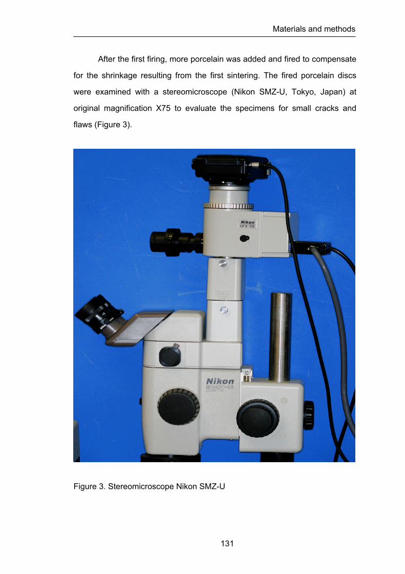
Materials and methods
131
After the first firing, more porcelain was added and fired to compensate
for the shrinkage resulting from the first sintering. The fired porcelain discs
were examined with a stereomicroscope (Nikon SMZ-U, Tokyo, Japan) at
original magnification X75 to evaluate the specimens for small cracks and
flaws (Figure 3).
Figure 3. Stereomicroscope Nikon SMZ-U

Materials and methods
132
Specimens displaying visible defects were replaced. All specimen
surfaces were then polished with SiC discs (grit-silicon-carbide P220, P500,
P1200 - Ultra-Prep, Buehler Ltd., Lake Bluff, IL, USA) in a mechanical grinder
(Ecomet® 3, Buehler Ltd., Lake Buff, IL, USA) according to ISO 6344-1: 1998
(ISO/DIS 6344-1: 1998) (Figure 4).
Figure 4. Ecomet 3, mechanical grinder
Materials and methods
133
This procedure was carried until specimens with a thickness and
diameter of approximately 2.2 (± 0.1) mm by 12.7(± 0.1) mm respectively
were obtained. A special stainless steel holder was used to ensure accuracy
of thickness and parallelism of the surfaces during grinding and polishing. As
required by the ISO Standards the two faces of the specimens did not differ
more than 0.05 mm in parallelism. The specimens’ dimensions were
measured with a digital micrometer (Digimatic Caliper Series 500, Mitutoyo
America Corporation, Dawn, IL, USA) to ensure the exact thickness and
diameter.
Finally, all specimens were cleaned in an ultrasonic bath (Eurosonic®
4D, Euronda, Vicenza, Italy) with distilled water for 15 minutes before the auto
glaze firing was performed in the ceramic furnace according to the
recommendations of the manufacturers (Figure 5). After the glazing procedure,
all specimens were again measured with the same digital caliper. The
diameter and thickness of the ceramic discs were measured by the
micrometer to the nearest 1/100 mm at five randomly selected locations prior
to the test procedures.
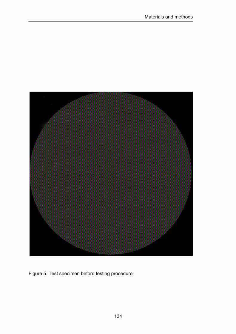
Materials and methods
134
Figure 5. Test specimen before testing procedure
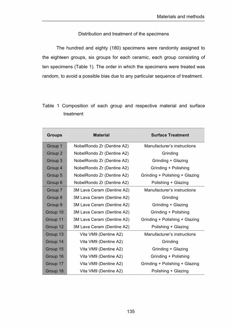
Materials and methods
135
Distribution and treatment of the specimens
The hundred and eighty (180) specimens were randomly assigned to
the eighteen groups, six groups for each ceramic, each group consisting of
ten specimens (Table 1). The order in which the specimens were treated was
random, to avoid a possible bias due to any particular sequence of treatment.
Table 1 Composition of each group and respective material and surface
treatment
Groups Material Surface Treatment
Group 1 NobelRondo Zr (Dentine A2) Manufacturer’s instructions Group 2 NobelRondo Zr (Dentine A2) Grinding Group 3 NobelRondo Zr (Dentine A2) Grinding + Glazing Group 4 NobelRondo Zr (Dentine A2) Grinding + Polishing Group 5 NobelRondo Zr (Dentine A2) Grinding + Polishing + Glazing Group 6 NobelRondo Zr (Dentine A2) Polishing + Glazing Group 7 3M Lava Ceram (Dentine A2) Manufacturer’s instructions Group 8 3M Lava Ceram (Dentine A2) Grinding Group 9 3M Lava Ceram (Dentine A2) Grinding + Glazing
Group 10 3M Lava Ceram (Dentine A2) Grinding + Polishing Group 11 3M Lava Ceram (Dentine A2) Grinding + Polishing + Glazing Group 12 3M Lava Ceram (Dentine A2) Polishing + Glazing Group 13 Vita VM9 (Dentine A2) Manufacturer’s instructions Group 14 Vita VM9 (Dentine A2) Grinding Group 15 Vita VM9 (Dentine A2) Grinding + Glazing Group 16 Vita VM9 (Dentine A2) Grinding + Polishing Group 17 Vita VM9 (Dentine A2) Grinding + Polishing + Glazing Group 18 Vita VM9 (Dentine A2) Polishing + Glazing
Materials and methods
136
The six experimental groups, for each ceramic, were prepared as
described previously and submitted to the treatment surfaces in the following
manner:
Groups 1/7/13: Control group (CN)
The preparation of the specimens was performed according to
manufacturer’s instructions for each ceramic through the method previously
described. No surface treatment was made to any group CN specimens.
These groups were used as control group.
Groups 2/8/14: Grinding procedure (G)
After preparation of the specimens according to manufacturer’s
instructions for each group of ceramic, the samples were ground under water
coolant with a 91 µm grit size diamond cup wheel (100 mm diameter, 291 6ª
Struers diamond cup wheel, Copenhagen, Denmark) mounted on a
cutting/grinding machine (Struers Accutom 50, Copenhagen, Denmark).
Grinding conditions were: 3300 rpm, 2 cm/s horizontal speed, 5 µm depth of
cut. A special stainless steel holder was used to ensure accuracy of thickness
and parallelism of the surfaces during grinding and oriented perpendicular the
length of the specimen (perpendicular to the tensile stresses applied during
fracture strength test).
Groups 3/9/15: Grinding followed by glazing (GG)
After preparation of the specimens according to manufacturer’s
instructions for each group of ceramic, the samples were ground under water
coolant with a 91 µm grit size diamond cup wheel (100 mm diameter, 291 6ª
Struers diamond cup wheel, Copenhagen, Denmark) mounted on a
cutting/grinding machine (Struers Accutom 50, Copenhagen, Denmark).
Grinding conditions were: 3300 rpm, 2 cm/s horizontal speed, 5 µm depth of

Materials and methods
137
cut. A special stainless steel holder was used to ensure accuracy of thickness
and parallelism of the surfaces during grinding and oriented perpendicular the
length of the specimen (perpendicular to the tensile stresses applied during
fracture strength test). All specimens were then auto-glazed in a
programmable and calibrated vacuum ceramic furnace (Programat P500,
Ivoclar Vivadent AG, Lichenstein) according to the recommendations of the
manufacturers for each ceramic group.
Groups 4/10/16: Grinding followed by polishing (GP)
After preparation of the specimens according to manufacturer’s
instructions for each group of ceramic, the samples were ground under water
coolant with a 91 µm grit size diamond cup wheel (100 mm diameter, 291 6ª
Struers diamond cup wheel, Copenhagen, Denmark) mounted on a
cutting/grinding machine (Struers Accutom 50, Copenhagen, Denmark).
Grinding conditions were: 3300 rpm, 2 cm/s horizontal speed, 5 µm depth of
cut. A special stainless steel holder was used to ensure accuracy of thickness
and parallelism of the surfaces during grinding and oriented perpendicular the
length of the specimen (perpendicular to the tensile stresses applied during
fracture strength test). All specimen surfaces were then polished with SiC
discs (grit-silicon-carbide P220, P320, P500, P800, P1200 - Ultra-Prep,
Buehler Ltd., Lake Bluff, IL, USA) in a mechanical grinder (Ecomet 3, Buehler
Ltd., Lake Buff, IL, USA) according to ISO 6344-1: 1998 followed by 4, 2, and
1 µm diamond paste (diamond polishing paste, Henry Schein Inc., NY, USA)
mounted on a laboratory handpiece machine (KaVo EWL K4, KaVo Dental
Gmbh, Germany).
Groups 5/11/17: Grinding followed by polishing and glazing (GPG)
After preparation of the specimens according to manufacturer’s
instructions for each group of ceramic, the samples were ground under water
Materials and methods
138
coolant with a 91 µm grit size diamond cup wheel (100 mm diameter, 291 6ª
Struers diamond cup wheel, Copenhagen, Denmark) mounted on a
cutting/grinding machine (Struers Accutom 50, Copenhagen, Denmark).
Grinding conditions were: 3300 rpm, 2 cm/s horizontal speed, 5 µm depth of
cut. A special stainless steel holder was used to ensure accuracy of thickness
and parallelism of the surfaces during grinding and oriented perpendicular the
length of the specimen (perpendicular to the tensile stresses applied during
fracture strength test). All specimen surfaces were then polished with SiC
discs (grit-silicon-carbide P220, P320, P500, P800, P1200 - Ultra-Prep,
Buehler Ltd., Lake Bluff, IL, USA) in a mechanical grinder (Ecomet 3, Buehler
Ltd., Lake Buff, IL, USA) according to ISO 6344-1: 1998 followed by 4, 2, and
1 µm diamond paste (diamond polishing paste, Henry Schein Inc., NY, USA)
mounted on a laboratory handpiece machine (KaVo EWL K4, KaVo Dental
Gmbh, Germany). All specimens were then auto-glazed in a programmable
and calibrated vacuum ceramic furnace (Programat P500, Ivoclar Vivadent
AG, Lichenstein) according to the recommendations of the manufacturers for
each ceramic group.
Groups 6/12/18: Polishing followed by glazing (PG)
After preparation of the specimens according to manufacturer’s
instructions for each group of ceramic, all specimen surfaces were then
polished with SiC discs (grit-silicon-carbide P220, P320, P500, P800, P1200 -
Ultra-Prep, Buehler Ltd., Lake Bluff, IL, USA) in a mechanical grinder (Ecomet
3, Buehler Ltd., Lake Buff, IL, USA) according to ISO 6344-1: 1998 followed
by 4, 2, and 1 µm diamond paste (diamond polishing paste, Henry Schein Inc.,
NY, USA) mounted on a laboratory handpiece machine (KaVo EWL K4, KaVo
Dental Gmbh, Germany). All specimens were then auto-glazed in a
programmable and calibrated vacuum ceramic furnace (Programat P500,
Ivoclar Vivadent AG, Lichenstein) according to the recommendations of the
Materials and methods
139
manufacturers for each ceramic group.
Before testing all specimens were examined with a stereomicroscope
(Nikon SMZ-U, Tokyo, Japan) at original magnification X75 to evaluate the
specimens for small cracks and flaws. Specimens displaying visible defects
were replaced.
Biaxial flexural strength test
The standard for testing the strength of dental ceramics has been the
three-point flexural test, but one problem has been the sensitivity of the test to
flaws along the sample edges. It is impossible to eliminate all flaws and,
because fracture often initiates at the edges, large variations strength data
have been recorded (Ban et al., 1990). The biaxial flexural test eliminates the
effect of edges because they are not directly loaded. Therefore the biaxial test
should produce less variation in data for strength determination and this was
the reason way it was used in this study. With the biaxial flexure test, a disc-
shaped specimen is supported from below by either a ring or several ball
bearings distributed in a circular pattern. The load is applied from above by
use of a piston in a position concentric with the supporting ring or ball
bearings (Figure 6).
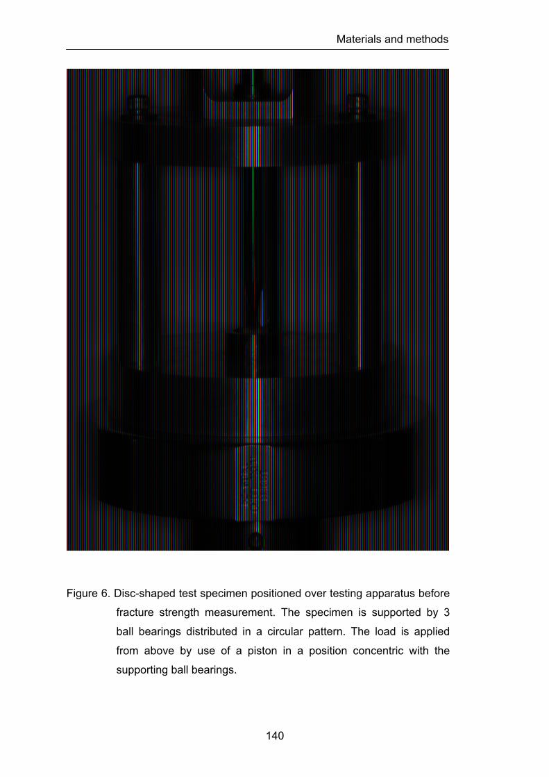
Materials and methods
140
Figure 6. Disc-shaped test specimen positioned over testing apparatus before
fracture strength measurement. The specimen is supported by 3
ball bearings distributed in a circular pattern. The load is applied
from above by use of a piston in a position concentric with the
supporting ball bearings.

Materials and methods
141
The load to fracture was measured with the piston-on-three-ball test
method by using a Universal Instron testing machine (Model TT-BM Instron
Corp., Canton, MA) according with the Standard ISO/DIS 6872 for dental
ceramics (ISO/DIS 6872: 1995) (Figure 7).
Figure 7. Schematic diagram of the apparatus used for the biaxial flexure
strength measurements.
STEEL BALL
PRECISION BALL BUSHINGS
UPPER BUSHING HOLDER
HARDENED STEEL ROD
HARDENED PRECISION PIN
STEEL BALLS SUPPORT CIRCLE
BOTTOM PLATE
SAMPLE HOLDER
3 SEPARATOR POSTS
TOP PLATE
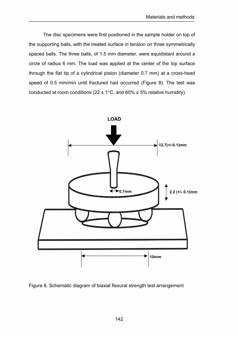
Materials and methods
142
The disc specimens were first positioned in the sample holder on top of
the supporting balls, with the treated surface in tension on three symmetrically
spaced balls. The three balls, of 1.5 mm diameter, were equidistant around a
circle of radius 6 mm. The load was applied at the center of the top surface
through the flat tip of a cylindrical piston (diameter 0.7 mm) at a cross-head
speed of 0.5 mm/min until fractured had occurred (Figure 8). The test was
conducted at room conditions (22 ± 1°C, and 60% ± 5% relative humidity).
Figure 8. Schematic diagram of biaxial flexural strength test arrangement
LOAD
10mm
12.7(+/-0.1)mm
0.7mm 2.2 (+/- 0.1)mm
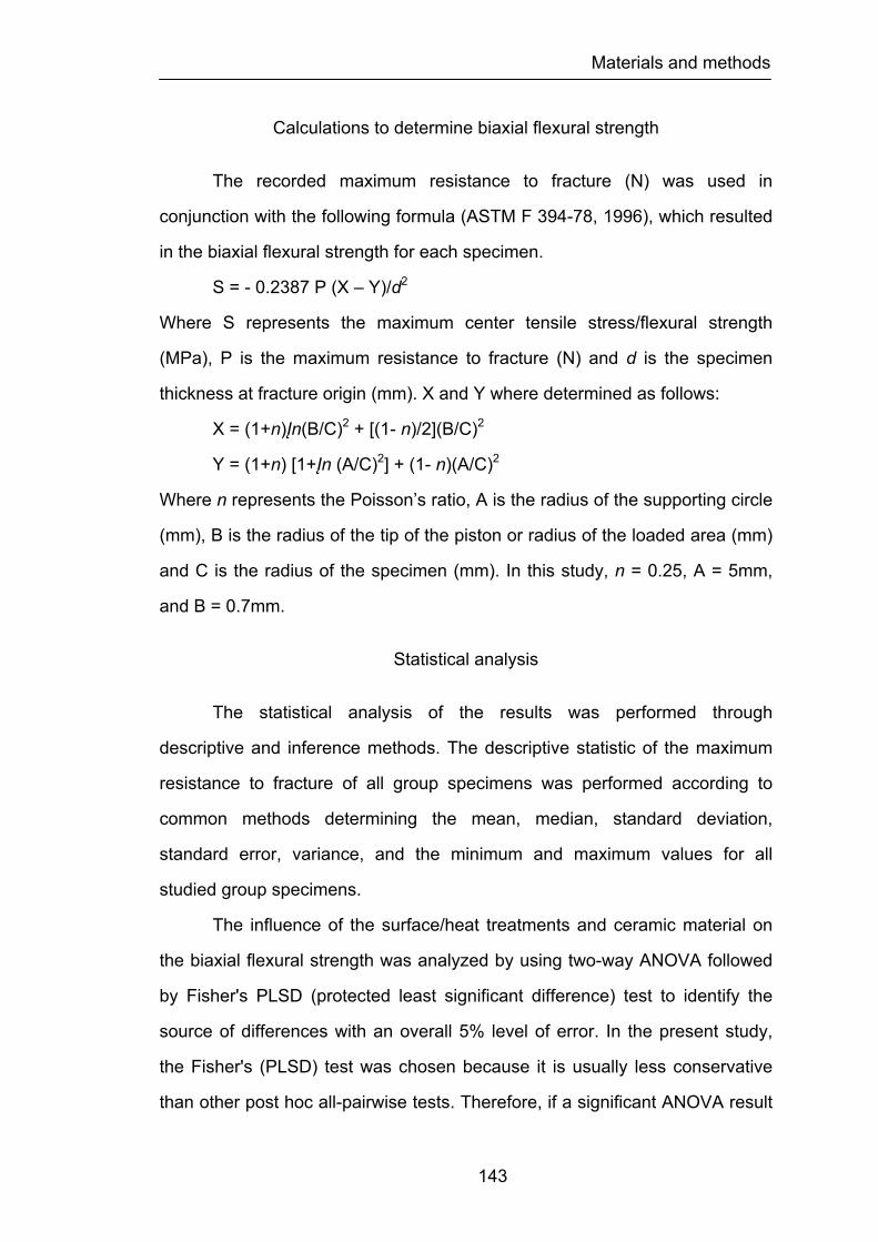
Materials and methods
143
Calculations to determine biaxial flexural strength
The recorded maximum resistance to fracture (N) was used in
conjunction with the following formula (ASTM F 394-78, 1996), which resulted
in the biaxial flexural strength for each specimen.
S = - 0.2387 P (X – Y)/d2
Where S represents the maximum center tensile stress/flexural strength
(MPa), P is the maximum resistance to fracture (N) and d is the specimen
thickness at fracture origin (mm). X and Y where determined as follows:
X = (1+n)Įn(B/C)2 + [(1- n)/2](B/C)2
Y = (1+n) [1+Įn (A/C)2] + (1- n)(A/C)2
Where n represents the Poisson’s ratio, A is the radius of the supporting circle
(mm), B is the radius of the tip of the piston or radius of the loaded area (mm)
and C is the radius of the specimen (mm). In this study, n = 0.25, A = 5mm,
and B = 0.7mm.
Statistical analysis
The statistical analysis of the results was performed through
descriptive and inference methods. The descriptive statistic of the maximum
resistance to fracture of all group specimens was performed according to
common methods determining the mean, median, standard deviation,
standard error, variance, and the minimum and maximum values for all
studied group specimens.
The influence of the surface/heat treatments and ceramic material on
the biaxial flexural strength was analyzed by using two-way ANOVA followed
by Fisher's PLSD (protected least significant difference) test to identify the
source of differences with an overall 5% level of error. In the present study,
the Fisher's (PLSD) test was chosen because it is usually less conservative
than other post hoc all-pairwise tests. Therefore, if a significant ANOVA result
Materials and methods
144
is found, then Fisher's (PLSD) is more likely than some other tests to identify
a significant pairwise comparison.
For each feldspathic veneering ceramic one-way ANOVA ceramic was
used to analyze if there was significant difference between the six groups
tested. Pairwise comparisons among the six groups for each ceramic were
made using Fisher's PLSD (protected least significant difference) test to
identify the source of differences with an overall 5% level of error. An ANOVA
test is used to find out if there is a significant difference between three or
more group means. However, the ANOVA analysis simply indicates there is a
difference between two or more group means, but it does not tell what means
there is a significant difference between. In order to find out what means there
is a significant difference between, a post hoc test needs to be done. Fisher's
PLSD (probable least significant difference) test is a post hoc test designed to
perform a pairwise comparison of the means to see where the significant
difference is; this was the reason why it was used.
In addition, the Weibull moduli were calculated for biaxial flexural
strength data. Weibull moduli are a statistical property, based on the Weibull
distribution to characterize variability of the strength of ceramic materials.
High Weibull moduli imply low variability in strength. Weibull moduli were
calculated by plotting Įn Įn (1/1 – F) versus Įn(s).
Where F = (i – 0.5)/n, i = rank of a sample in terms of strength (i = 1 for the
lowest-strength sample); n = total number of samples; and s = strength of
sample i. The slope of the line was then determined by use of linear
regression. The slope of the line was calculated as the Weibull modulus.
The Weibull equation describes the probability of failure as a function
of a characteristic stress and a shape parameter, the Weibull modulus. The
modulus can be found as the slope of a standard Weibull plot, i.e., Įn (1/1- F)
versus Įn (failure load), where F = probability of failure. The Weibull coefficient
m is a measure of variability in the strength of the material. Large values of
Materials and methods
145
the Weibull parameter m indicate a small variability in strength.
The failure stresses of the ceramic materials from each test were
analyzed using the Weibull formulation, which is given by:
F1- exp [ -∫v ( σ - σu / σ 0 )m dv ]
This is the three-parameter Weibull function where σu, σ0, and m are
three parameters. σu is the threshold stress (i.e., the stress below which the
probability of failure is zero). σ0 is a normalizing parameter (often selected as
the characteristic stress, at which the probability of failure is 0.632), m is the
Weibull modulus, which describes the flaw size distribution (and thus the data
scatter), and F is the failure probability that can be estimated as described
above. Higher m values indicate a narrower flaw size distribution, and
therefore lower scatter in the data; low m values indicate a larger flaw size
distribution and therefore a larger spread in the data.
Materials and methods
146
2- Strength and reliability study
Type of research
This was an experimental in vitro study using Zirconia ceramic discs
stratified with feldspathic dental veneering ceramic used to layer Zirconia
frameworks in the fabrication of prosthodontic fixed restorations.
Dependent variable
Load to fracture was measured in terms of biaxial flexural strength of
the material.
Independent variable
Feldspathic dental veneering ceramic employed to stratified Zirconia
3Y-TZP subtracts of three (3) commercially brands: 1) NobelRondoTM Zirconia
veneer ceramic (Nobel BiocareTM AB, Sweden), 2) LavaTM Ceram veneer
ceramic (3MTM ESPETM, Germany), and 3) Vita® VM®9 veneer ceramic (Vita®
Zahnfabrick, Germany).
Constant independent
Apparatus used to measured the biaxial flexural strength – Universal
Instron testing machine determined by the piston-on three-ball test method
(See section – biaxial flexural strength test)
Sample size calculations
Sample sizes were chosen based on data from a similar experiments
(Guazzato et al., 2004; White et al., 2005). However, a pilot study was
undertaken to evaluate the sample size necessary which would yield an
estimated pooled standard deviation of 13.45. Power was set at 80% and an
overall level of Type I error equal to 0.05 was desired. Since all pairwise

Materials and methods
147
comparisons among the six (6) experimental groups were to be examined, the
level of Type I error for a given pairwise comparison was set at
alpha=0.05/15=0.0029 based on Bonferroni adjustment for multiple
comparisons. This maintains a minimum level of 0.05 for the experiment-wise
Type I error. Based upon a desire to be able to detect a 15% difference
between mean percentages between a pair of groups, 10 specimens per
treatment group were required. Given that multiple comparisons adjustment
was actually carried out using the t-test method, power would be expected to
be slightly greater.
Design of the study
A group of sixty (60) disc-shaped specimens 2.2(± 0.1) mm thick and
12.7(± 0.1) mm in diameter were fabricated and used in this study. The disc-
shaped specimens were composed of a framework of 3Y-TZP produced by a
CAD-CAM technique and a feldspathic veneering dental ceramic. The
porcelains used to stratify the Zirconia 3Y-TZP frameworks were from 3
commercially available brands: 1) NobelRondoTM Zirconia veneer ceramic
(Nobel BiocareTM AB, Sweden), 2) LavaTM Ceram veneer ceramic (3MTM
ESPETM, Germany), and 3) Vita® VM®9 veneer ceramic (Vita® Zahnfabrick,
Germany). The feldspathic veneering dental ceramics used for the study were
the NobelRondoTM Zirconia veneer ceramic Base Liner (Lot No. 0508) and
NobelRondoTM Zirconia veneer ceramic Dentine A2 (Lot No. 0709); the
LavaTM Ceram veneer ceramic Frame-Work Modifier (Lot No. 167786) and
LavaTM Ceram veneer ceramic Dentine A2 (Lot No 189943); and the Vita
VM®9 veneer ceramic Base Dentine (Lot No. 7933) and Vita VM®9 veneer
ceramic Dentine A2 (Lot No. 7565) (Figure 9). All disc specimens were
fabricated accordingly to the specific manufacturer’s recommendations for
each ceramic.
Materials and methods
148
Figure 9. Feldspathic veneering ceramics dentin and opaque
Preparation of the specimens
Specimens were prepared according to ISO/DIS 6872: 1995 (three-
point and biaxial flexural strength) (ISO/DIS 6872: 1995). Sixty (60) 3Y-TZP
discs with 1.1 (± 0.1) mm thick and 12.7 (± 0.1) mm in diameter were
produced by CAD/CAM technology (Nobel BiocareTM AB, Sweden) and used
to veneer the 3 brands of feldspathic veneering dental ceramics. The discs
were obtained from the manufacturer without any surface treatment and in the
same condition that 3Y-TZP substructures are delivered to the commercial
laboratory. Twenty bilayered specimens of each ceramic were fabricated
using a separable steel mold. The mixing liquid and the opaque ceramic were
combined in proportions recommend by the manufacturers to form a sticky
slurry, which was applied over the 3Y-TZP discs and then vibrated. The firing
of the specimens was performed in a programmable and calibrated vacuum
ceramic furnace (Programat P500, Ivoclar Vivadent AG, Lichenstein)
according to the recommendations of the manufacturers. After the first firing
the bilayered specimens were prepared by veneering the core materials with
the feldspathic ceramics. The discs were put in a steel mold and the ceramic

Materials and methods
149
powders were combined in proportions recommend by the manufacturers to
form a sticky slurry, which was vibrated and packed. Excess liquid was wicked
off of the surface with absorbent tissue paper. The firing of the specimens was
performed in the same programmable and calibrated vacuum ceramic furnace
according to the recommendations of the manufacturers. After the first firing,
additional porcelain was added and fired to compensate for the shrinkage
resulting from the first sintering. The fired porcelain discs were examined with
a stereomicroscope (Nikon SMZ-U, Tokyo, Japan) at a magnification X75 to
evaluate the specimens for small cracks or flaws. Specimens displaying
defects were replaced. All specimen surfaces were then polished with SiC
discs (grit-silicon-carbide P220, P500, P1200 - Ultra-Prep, Buehler Ltd., Lake
Bluff, IL, USA) in a mechanical grinder (Ecomet® 3, Buehler Ltd., Lake Buff, IL,
USA) according to ISO 6344-1: 1998 (ISO/DIS 6344-1: 1998). This procedure
was repeated until samples with a thickness and diameter of approximately
2.2(± 0.1) mm x 12.7(± 0.1) mm respectively were obtained. A special
stainless steel holder was used to ensure accuracy of thickness and
parallelism of the surfaces during grinding and polishing. As required by the
ISO Standard the two faces of the specimens did not differ more than 0,05
mm in parallelism. The specimens’ dimensions were measured with a digital
micrometer (Digimatic Caliper Seriates 500, Mitutoyo America Corporation,
Dawn, IL, USA) to ensure the exact thickness and diameter. Finally, all
specimens were cleaned in an ultrasonic bath (Eurosonic® 4D, Euronda,
Vicenza, Italy) with distilled water for 15 minutes before auto glazing
according to the recommendations of the manufacturers (Figure 10). After the
glazing procedure, all specimens were again measured with the same digital
caliper. The diameter and thickness of the ceramic discs were measured by
the micrometer to the nearest 1/100 mm at five randomly selected locations
prior to the test locations.
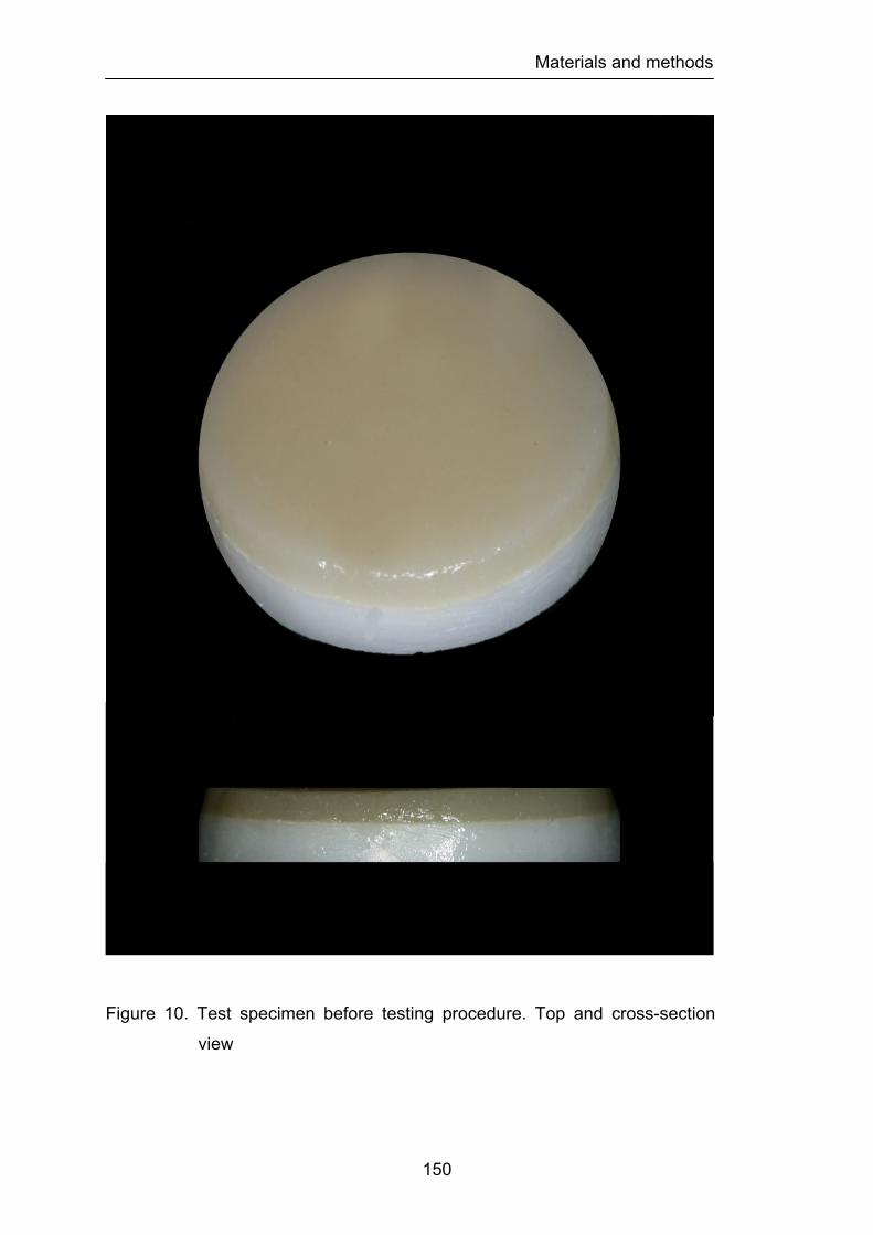
Materials and methods
150
Figure 10. Test specimen before testing procedure. Top and cross-section
view
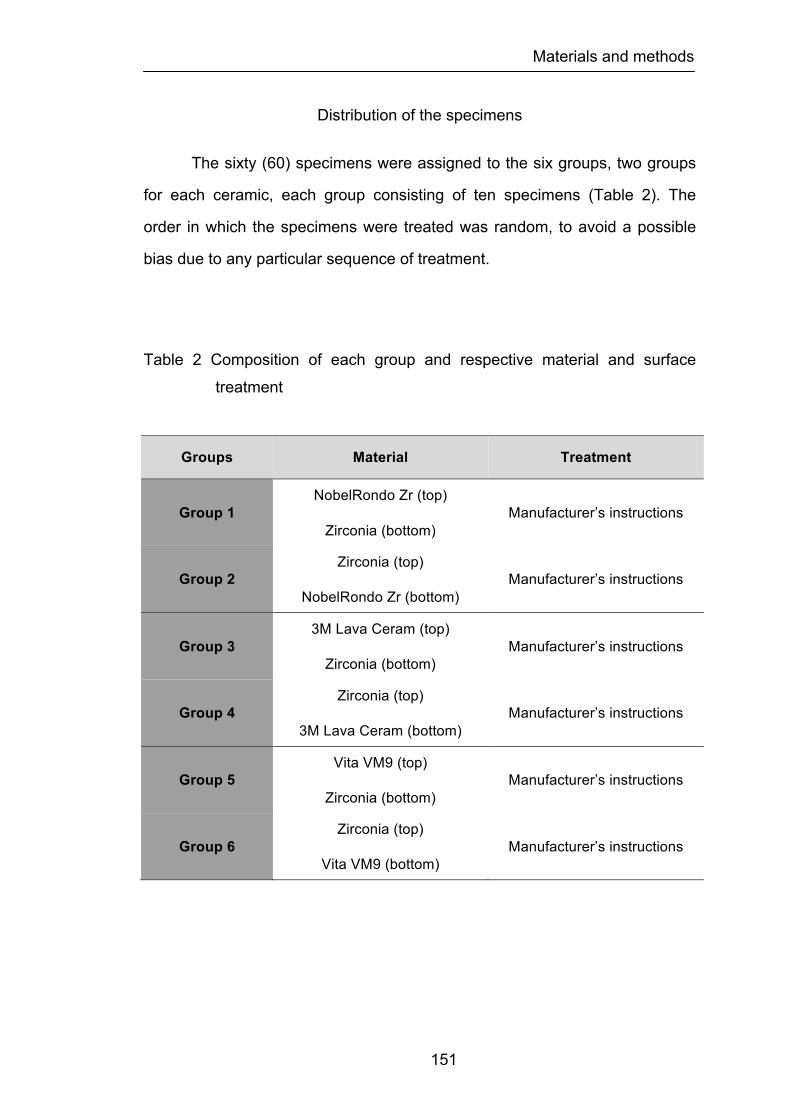
Materials and methods
151
Distribution of the specimens
The sixty (60) specimens were assigned to the six groups, two groups
for each ceramic, each group consisting of ten specimens (Table 2). The
order in which the specimens were treated was random, to avoid a possible
bias due to any particular sequence of treatment.
Table 2 Composition of each group and respective material and surface
treatment
Groups Material Treatment
Group 1 NobelRondo Zr (top)
Zirconia (bottom) Manufacturer’s instructions
Group 2 Zirconia (top)
NobelRondo Zr (bottom) Manufacturer’s instructions
Group 3 3M Lava Ceram (top)
Zirconia (bottom) Manufacturer’s instructions
Group 4 Zirconia (top)
3M Lava Ceram (bottom) Manufacturer’s instructions
Group 5 Vita VM9 (top)
Zirconia (bottom) Manufacturer’s instructions
Group 6 Zirconia (top)
Vita VM9 (bottom) Manufacturer’s instructions
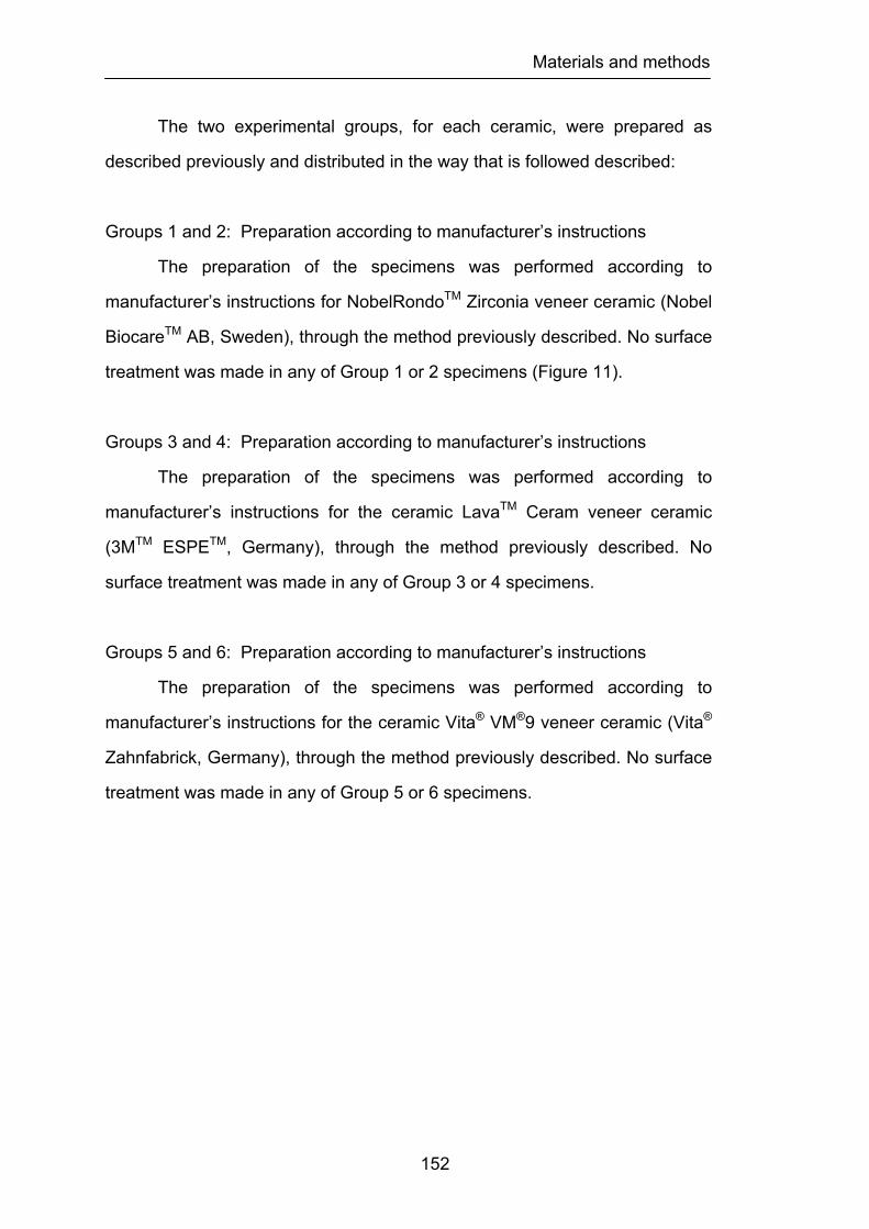
Materials and methods
152
The two experimental groups, for each ceramic, were prepared as
described previously and distributed in the way that is followed described:
Groups 1 and 2: Preparation according to manufacturer’s instructions
The preparation of the specimens was performed according to
manufacturer’s instructions for NobelRondoTM Zirconia veneer ceramic (Nobel
BiocareTM AB, Sweden), through the method previously described. No surface
treatment was made in any of Group 1 or 2 specimens (Figure 11).
Groups 3 and 4: Preparation according to manufacturer’s instructions
The preparation of the specimens was performed according to
manufacturer’s instructions for the ceramic LavaTM Ceram veneer ceramic
(3MTM ESPETM, Germany), through the method previously described. No
surface treatment was made in any of Group 3 or 4 specimens.
Groups 5 and 6: Preparation according to manufacturer’s instructions
The preparation of the specimens was performed according to
manufacturer’s instructions for the ceramic Vita® VM®9 veneer ceramic (Vita®
Zahnfabrick, Germany), through the method previously described. No surface
treatment was made in any of Group 5 or 6 specimens.
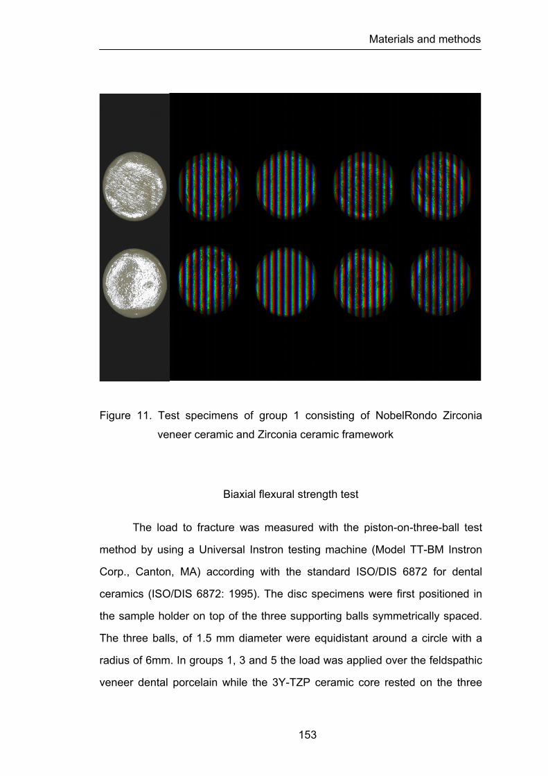
Materials and methods
153
Figure 11. Test specimens of group 1 consisting of NobelRondo Zirconia
veneer ceramic and Zirconia ceramic framework
Biaxial flexural strength test
The load to fracture was measured with the piston-on-three-ball test
method by using a Universal Instron testing machine (Model TT-BM Instron
Corp., Canton, MA) according with the standard ISO/DIS 6872 for dental
ceramics (ISO/DIS 6872: 1995). The disc specimens were first positioned in
the sample holder on top of the three supporting balls symmetrically spaced.
The three balls, of 1.5 mm diameter were equidistant around a circle with a
radius of 6mm. In groups 1, 3 and 5 the load was applied over the feldspathic
veneer dental porcelain while the 3Y-TZP ceramic core rested on the three

Materials and methods
154
supporting balls. In groups 2, 4 and 6 the position of the feldspathic veneer
dental porcelain and the 3Y-TZP ceramic core was reversed. The purpose
was to determine the influence of the feldspathic veneer ceramic on the
internal or external origin of the fracture.
The load was applied at the center of the top surface through the flat tip
of a cylindrical piston (diameter 0.7mm) at a cross-head speed of 0.5 mm/min
until fractured had occurred. The test was conducted at room conditions (22 ±
1°C, and 60% ± 5% relative humidity).
Figure 12. Disc-shaped test specimen positioned over testing apparatus
before fracture strength measurement. The load was applied at
the center of the top surface through the flat tip of a cylindrical
piston (diameter 0.7 mm) at a cross-head speed of 0.5 mm/min
until fracture.
Materials and methods
155
Calculations to determine biaxial flexural strength
The recorded maximum resistance to fracture (N) was used in
conjunction with the following formula (ASTM F 394-78, 1996), which resulted
in the biaxial flexural strength for each specimen.
S = - 0.2387 P(X – Y)/d2
Where S represents the maximum center tensile stress/flexural strength
(MPa), P is the maximum resistance to fracture (N) and d is the specimen
thickness at fracture origin (mm). X and Y where determined as follows:
X = (1+n)Įn(B/C)2 + [(1- n)/2](B/C)2
Y = (1+n) [1+Įn (A/C)2] + (1- n)(A/C)2
where n represents the Poisson´s ratio, A is the radius of the supporting circle
(mm), B is the radius of the tip of the piston or radius of the loaded area (mm)
and C is the radius of the specimen (mm). In this study, n = 0.25-0.31, A = 5
mm, and B = 0.7 mm. It needs to be stated that the Poisson´s ratio used in
these calculations was based on an adjustment between the Poisson´s ratio
of the feldspathic veneer dental ceramics (0.25) and the Poisson´s ratio of the
3Y-TZP ceramic (0.31) having in attention their thickness; which already been
established by different authors (White et al., 2005).
Statistical analysis
The statistical analysis of the results was performed through
descriptive and inference methods. The descriptive statistic of the maximum
resistance to fracture of all group specimens was performed according to
common methods determining the mean, median, standard deviation,
standard error, variance, and the minimum and maximum values for all
studied group specimens.
The influence of the feldspathic veneering ceramic material on the
biaxial flexural strength was analyzed by using two-way ANOVA followed by
Materials and methods
156
Fisher's PLSD (protected least significant difference) test to identify the
source of differences with an overall 5% level of error. In the present study the
Fisher's (PLSD) test was chosen because it is usually less conservative than
other post hoc all-pairwise tests. Therefore, if a significant ANOVA result is
found, then Fisher's (PLSD) is more likely than some other tests to identify a
significant pairwise comparison.
Pairwise comparisons among each group of ceramic and between
ceramic groups were made using the Student’s t-test for multiple comparisons
in conjunction with an overall 5% level of Type I error.
In addition, the Weibull moduli were calculated for biaxial flexural
strength data in the same method previously described. Weibull moduli are
calculated by plotting ln (1/1 – F) versus ln (s), where:
Pf=(i – 0.5)/N
Where i = rank of a samples in terms of strength (i = 1 for the lowest strength
sample), N = total number of samples, and s = strength of sample i.
The slope of the line is then determined by use of linear regression. The
resulting slope is the Weibull modulus.
Materials and methods
157
3- Mode of fracture study
Type of research
This was an experimental in vitro study using Zirconia ceramic discs
stratified with feldspathic dental veneering ceramic used to layer Zirconia
frameworks in the fabrication of prosthodontic fixed restorations.
Dependent variable
Mode of fracture of the bilayered feldspathic dental veneering
ceramic/Zirconia ceramic framework discs.
Independent variable
Feldspathic dental veneering ceramic employed to stratify Zirconia 3Y-
TZP subtracts of three (3) commercially brands: 1) NobelRondoTM Zirconia
veneer ceramic (Nobel BiocareTM AB, Sweden), 2) LavaTM Ceram veneer
ceramic (3MTM ESPETM, Germany), and 3) Vita® VM®9 veneer ceramic (Vita®
Zahnfabrick, Germany).
Design of the study
A group of sixty (60) disc-shaped specimens 2.2 (± 0.1) mm thick and
12.7(± 0.1) mm in diameter were fabricated and used in this study. The disc
specimens were composed of a framework of 3Y-TZP produced by a CAD-
CAM technique. Feldspathic veneering dental ceramic used to stratify Zirconia
3Y-TZP frameworks were from 3 commercially available brands: 1)
NobelRondoTM Zirconia veneer ceramic (Nobel BiocareTM AB, Sweden), 2)
LavaTM Ceram veneer ceramic (3MTM ESPETM, Germany), and 3) Vita® VM®9
veneer ceramic (Vita® Zahnfabrick, Germany). The feldspathic veneering
Materials and methods
158
dental ceramics used in the study were the NobelRondoTM Zirconia veneer
ceramic Base Liner (Lot No. 0508) and NobelRondoTM Zirconia veneer
ceramic Dentine A2 (Lot No. 0709); the LavaTM Ceram veneer ceramic
Frame-Work Modifier (Lot No. 167786) and LavaTM Ceram veneer ceramic
Dentine A2 (Lot No 189943); and the Vita VM®9 veneer ceramic Base Dentine
(Lot No. 7933) and Vita VM®9 veneer ceramic Dentine A2 (Lot No. 7565). All
disc specimens were fabricated accordingly to the specific manufacturer’s
recommendations for each ceramic.
Preparation of the specimens
Specimens were prepared according to ISO/DIS 6872: 1995 (three-
point and biaxial flexural strength) (ISO/DIS 6872: 1995). Sixty (60) 3Y-TZP
discs with 1.1 (± 0.1) mm thick and 12.7 (± 0.1) mm in diameter were
produced by CAD/CAM technology (Nobel BiocareTM AB, Sweden) and used
to veneer the 3 brands of feldspathic veneering dental ceramics. The discs
were obtained from the manufacturer without any surface treatment and in the
same condition that 3Y-TZP substructures are delivered to the commercial
laboratory. Twenty bilayered specimens of each ceramic were fabricated
using a separable steel mold. The mixing liquid and the opaque ceramic were
combined in proportions recommend by the manufacturers to form a sticky
slurry, which was applied over the 3Y-TZP discs then vibrated. The firing of
the specimens was performed in a programmable and calibrated vacuum
ceramic furnace (Programat P500, Ivoclar Vivadent AG, Lichenstein)
according to the recommendations of the manufacturers. After the first firing
the bilayered specimens were prepared by veneering the core materials with
the feldspathic ceramics. The discs were put in a steel mold and the ceramic
powders were combined in proportions recommend by the manufacturers to
form a sticky slurry, which was vibrated and packed. Excess liquid was wicked
off of the surface with absorbent tissue paper. The firing of the specimens was
Materials and methods
159
performed in the same programmable and calibrated vacuum ceramic furnace
according to the recommendations of the manufacturers. After the first firing,
additional porcelain was added and fired to compensate for the shrinkage
resulting from the first sintering. The fired porcelain discs were examined with
a stereomicroscope (Nikon SMZ-U, Tokyo, Japan) at a magnification X75 to
evaluate the specimens for small cracks or flaws. Specimens displaying
visible defects were replaced. All specimen surfaces were then polished with
SiC disks (grit-silicon-carbide P220, P500, P1200 - Ultra-Prep, Buehler Ltd.,
Lake Bluff, IL, USA) in a mechanical grinder (Ecomet® 3, Buehler Ltd., Lake
Buff, IL, USA) according to ISO 6344-1: 1998 (ISO/DIS 6344-1: 1998). This
procedure was repeated until samples with a thickness and diameter of
approximately 2.2 (± 0.1) mm e 12.7 (± 0.1) mm respectively were obtained. A
special stainless steel holder was used to ensure accuracy of thickness and
parallelism of the surfaces during grinding and polishing. As required by the
ISO Standard the two faces of the specimens did not differ more than 0,05mm
in parallelism. The specimens’ dimensions were measured with a digital
micrometer (Digimatic Caliper Seriates 500, Mitutoyo America Corporation,
Dawn, IL, USA) to ensure the exact thickness and diameter.
Finally, all specimens were cleaned in an ultrasonic bath (Eurosonic®
4D, Euronda, Vicenza, Italy) with distilled water for 15 minutes before auto
glazing according to the recommendations of the manufacturers in the
ceramic furnace. After the glazing procedure, all specimens were again
measured with the same digital caliper. The diameter and thickness of the
ceramic discs were measured by the micrometer to the nearest 1/100 mm at
five randomly selected locations prior to the test locations.
Materials and methods
160
Distribution of the specimens
The sixty (60) specimens were randomly assigned to the six groups,
two groups for each ceramic, each group consisting of ten specimens. The
order in which the specimens were treated was random, to avoid a possible
bias due to any particular sequence of treatment.
The two experimental groups, for each ceramic, were prepared as
described previously and distributed in the way that is followed described:
Groups 1 and 2: Preparation according to manufacturer’s instructions
The preparation of the specimens was performed according to
manufacturer’s instructions for the ceramic NobelRondoTM Zirconia veneer
ceramic (Nobel BiocareTM AB, Sweden), through the method previously
described. No surface treatment was made in any of Group 1 or 2 specimens.
Groups 3 and 4: Preparation according to manufacturer’s instructions
The preparation of the specimens was performed according to
manufacturer’s instructions for the ceramic LavaTM Ceram veneer ceramic
(3MTM ESPETM, Germany), through the method previously described. No
surface treatment was made in any of Group 3 or 4 specimens.
Groups 5 and 6: Preparation according to manufacturer’s instructions
The preparation of the specimens was performed according to
manufacturer’s instructions for the ceramic Vita® VM®9 veneer ceramic (Vita®
Zahnfabrick, Germany), through the method previously described. No surface
treatment was made in any of Group 5 or 6 specimens.
Materials and methods
161
Mode of fracture evaluation
The maximum load at failure was measured with the piston-on-three-
ball test method by using a Universal Instron testing machine (Model TT-BM
Instron Corp., Canton, MA) according with the Standard ISO/DIS 6872 for
dental ceramics (ISO/DIS 6872: 1995). The disc specimens were first
positioned in the sample holder on top of the three supporting balls
symmetrically spaced. The three balls, of 1.5 mm diameter, were equidistant
around a circle with a radius of 6 mm. In groups 1, 3 and 5 the load was
applied over the feldspathic veneer dental porcelain while the 3Y-TZP ceramic
core rested on the three supporting balls. In groups 2, 4 and 6 the position of
the feldspathic veneer dental porcelain and the 3Y-TZP ceramic core was
reversed. The purpose was to understand the influence of the feldspathic
veneer ceramic on the internal or external origin of the fracture and respective
mode of fracture.
The load was applied at the center of the top surface through the flat tip
of a cylindrical piston (diameter 0.7 mm) at a cross-head speed of 0.5mm/min
until fractured had occurred. The test was conducted at room conditions (22 ±
1°C, and 60% ± 5% relative humidity).
After fracture testing procedure, all specimens were analysed with a
stereomicroscope (Nikon SMZ-U, Tokyo, Japan) under X75 magnification
using a halogen lamp (Nikon 26120, Tokyo, Japan) as external illumination
source without any special surface coatings. This observation was performed
for all specimens of the six experimental groups with the purpose of
characterizing the origin and mode of fracture. Subsequently two
representative specimens and several fractured surfaces from each group
were selected and micrographs were taken at the same X75 magnification,
using a copulated camera (Nikon FX-35DX, Tokyo, Japan) to the
stereomicroscope.

Materials and methods
162
Morphologic characterization of the different types of fractures
registered at the Zirconia core/feldspathic veneering ceramic was performed
using scanning electron microscopy. Six representative specimens, two from
each group, were randomly selected and mounted on aluminium stubs and
coated with gold. The specimens were examined with a scanning electron
microscope (SEM) (Amray 1820, Bedford, MA, USA) (Figure 13).
Photographs at different magnifications were made of representative areas for
each specimen.
Figure 13. Amray 1820, scanning electron microscope
Results
163
CHAPTER 4
RESULTS
1- Surface finish and heat treatment study
In this investigation the influence of the surface finish and heat
treatment on the biaxial flexural strength of three different feldspathic
veneering ceramics were studied. The mean biaxial flexural strength values
and standard deviations for each group of specimens are shown in Table 3
and Figure 14.
Examination of the standard deviations revealed considerable
heterogeneity in variability of the outcome among the eighteen groups, with
the largest group variance being over thirty-fold that of the group with the least
variation.
A two-way ANOVA was carried out to determine if there was any
statistical significant difference between the two major effects; the “ceramic”
factor” and the “surface treatment” factor on the load to fracture of the test
specimens. The power values for analyzing the major factor “ceramic” and
“surface treatment” were high enough, (1 and 0.998) respectively, so that the
project design was considered valid. The two-way ANOVA results
demonstrated that both factors had statistically significant effect on load to
fracture of the test specimens (p<0.0001).
When analyzing the source of differences between the surface
treatments Fisher’s protected least significant difference (PLSD) test showed

Results
164
statistically significant differences between the grinding groups and all other
groups. Strong evidence was found that the variance of the groups
corresponding to G groups was significantly smaller than that of the variance
of the CN groups (p<0.0001). There was also evidence of differences in
variance between the G groups and the GG groups (p=0.0007), the G groups
and the GP groups (p<0.0001), the G groups and the GPG groups (p=0.0007)
and finally the G groups and the PG groups (p=0.0027). The results obtained
in the CN group differ significantly from the G group (p<0.0001), has
previously mentioned and from the PG group (p=0.0261). However the results
obtained in the CN group could not be said to differ significantly from those
obtained in the GG group (p=0.0712) nor did the results differ for the two
groups corresponding to the GP (p=0.3443) and GPG (p=0.0702). No other
comparisons among the four remaining groups were significant; i.e., variability
appeared to be similar in the GP, GG, GPG and GP groups.
When analyzing the source of differences between the ceramics,
Fisher’s protected least significant difference (PLSD) between the LavaTM
Ceram ceramic and the other two ceramics; NobelRondoTM ceramic
(p<0.0001) and Vita® VM®9 (p<0.0001). Fisher’s test indicated also that there
was no strong evidence of significant heterogeneity of variances (p=0.6665)
among the NobelRondoTM and Vita® VM®9 groups.

Results
165
Table 3 Descriptive statistic by group for load fracture MPa
Load Fracture MPa Mean STD N Min Max Range Median
Total 91,61 15,71 180 59,46 148,25 88,79
90,54
Nobel Rondo
CN 105,60 22,24 10 75,21 148,25 73,04 103,90
G 73,49 15,17 10 59,46 103,24 43,78 67,12
GG 80,44 14,81 10 60,42 104,50 44,08 80,19
GP 98,75 13,81 10 80,76 122,77 42,01 98,18
GPG 88,19 15,96 10 63,44 109,91 46,47 87,98
PG 82,65 14,50 10 62,74 108,61 45,87 78,80
Lava Ceram
CN 98,79 14,22 10 75,50 128,08 52,58 100,23
G 88,95 13,29 10 62,69 105,09 42,40 89,87
GG 106,76 19,18 10 73,83 140,76 66,93 106,74
GP 100,20 16,41 10 76,32 123,63 47,31 102,21
GPG 104,08 9,62 10 87,39 118,22 30,83 105,75
PG 98,20 13,88 10 78,76 118,94 40,18 100,51
Vita VM9
CN 91,12 5,45 10 81,10 96,09 14,99 93,74
G 78,90 8,08 10 68,10 94,01 25,91 77,74
GG 89,72 6,55 10 78,66 98,69 20,03 90,84
GP 86,85 5,83 10 78,40 96,34 17,94 86,48
GPG 84,59 5,74 10 76,73 93,47 16,74 85,17
PG 91,69 6,01 10 83,89 101,09 17,20 93,07
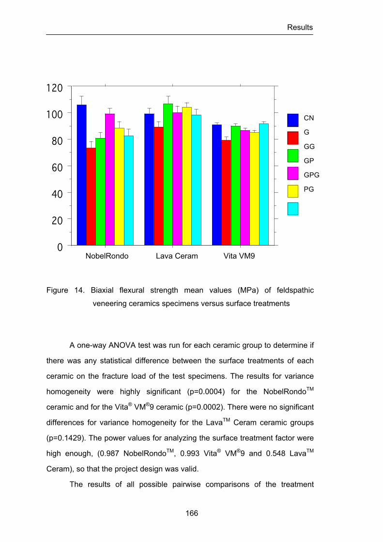
Results
166
Figure 14. Biaxial flexural strength mean values (MPa) of feldspathic
veneering ceramics specimens versus surface treatments
A one-way ANOVA test was run for each ceramic group to determine if
there was any statistical difference between the surface treatments of each
ceramic on the fracture load of the test specimens. The results for variance
homogeneity were highly significant (p=0.0004) for the NobelRondoTM
ceramic and for the Vita® VM®9 ceramic (p=0.0002). There were no significant
differences for variance homogeneity for the LavaTM Ceram ceramic groups
(p=0.1429). The power values for analyzing the surface treatment factor were
high enough, (0.987 NobelRondoTM, 0.993 Vita® VM®9 and 0.548 LavaTM
Ceram), so that the project design was valid.
The results of all possible pairwise comparisons of the treatment
NobelRondo Lava Ceram Vita VM9 0
20
40
60
80
100
120
Cel
l Mea
n
Nobel Rondo Leva Ceram Vita VM9Cell
PolishHeatGrindPolishHeatPolishGrindHeatGrindCN
Interaction Bar Plot for LoadFracture MPaEffect: Ceramic * SurfaceError Bars: ± 1 Standard Error(s)
CN
G
GG
GP
GPG
PG
Results
167
groups for the NobelRondoTM ceramic after Fisher’s protected least significant
difference (PLSD) adjustment for multiple comparisons are summarized in
Figure 15. As seen in Figure 15, the distribution of fracture loads could not be
said to differ among the three surface treatment groups with the highest
outcomes: CN, GP and GPG. The CN and GP groups clearly differed in
distribution of percentage load fracture from the three groups with the lowest
distribution of outcome the PG, the GG and the G groups. In addition, the data
provided evidence that the fracture load in the highest group (that associated
with the control group) was significantly greater than that obtained by the
GPG, and that the results obtained by this group were significantly better than
those obtained under grinding conditions. No other pairwise comparisons
were statistically significant after adjustment for multiple comparisons; the
results obtained in G group could not be said to differ significantly from those
obtained in the GG and PG groups, nor did the results differ between this two
groups. The two groups with the highest fracture loads the CN and the GP
group were not statistically different.
The results of all possible pairwise comparisons of the treatment
groups for the Vita LavaTM Ceram ceramic after Fisher’s protected least
significant difference (PLSD) adjustment for multiple comparisons are
summarized in Figure 16. As seen in Figure 16 the distribution of fracture
loads could not be said to differ among the five surface treatment groups with
the lowest outcomes: G, PG, CN, GP and GPG. In addition the data provided
evidence that the fracture load in the two highest groups (that associated with
the GG group and the GPG group) was significantly greater than that obtained
by the grind group. No other pairwise comparisons were statistically
significant after adjustment for multiple comparisons; the results obtained in
the two groups with the highest fracture loads the GG and the GPG groups
were not statistically different, nor did the results differ between these two
groups and the GP, the CN and the PG groups.
Results
168
The results of all possible pairwise comparisons of the treatment
groups for the Vita® VM®9 ceramic after Fisher’s protected least significant
difference (PLSD) adjustment for multiple comparisons are summarized in
Figure 17. As seen in Figure 17 the G group clearly differed in distribution of
percentage load fracture from all other groups. In addition the data provided
evidence that the fracture load in the two highest groups (that associated with
the PG group and the CN group) was significantly greater than that obtained
by the GPG group. No other pairwise comparisons were statistically
significant after adjustment for multiple comparisons; the results obtained in
the PG group could not be said to differ significantly from those obtained in
the CN, GG and GP groups, nor did the results differ between the GG and the
GP and GPG groups. The two groups with the highest fracture loads the CN
group and the PG group were not statistically different.
The analysis of the Weibull modulus results (Table 4) indicated that, for
the three types of ceramics tested, leaving the surface in a grinding condition
influence the flaw distribution, since the values for the three grinding groups
are smaller than for all other groups of specimens in each ceramic. This is
especially evident for the Vita® VM®9 ceramic. For the NobelRondoTM ceramic
the Weibull modulus values varied with different surface treatments, showing
higher values for GP group and similar values for the GG, GPG and PG
groups and the CN group. The Weibull modulus values for the LavaTM Ceram
ceramic showed that the surface treatment groups with simultaneous
polishing and glazing had the highest results (GPG and PG groups) and the
groups that had been grinded had lower values (G, GG and GP). The CN
group revealed intermediate Weibull modulus values. The Vita® VM®9
ceramic groups recorded similar values when compared to the other ceramic
groups. The CN group showed the highest value. All other surface treatments
showed similar results except, like previously stated, the G group.
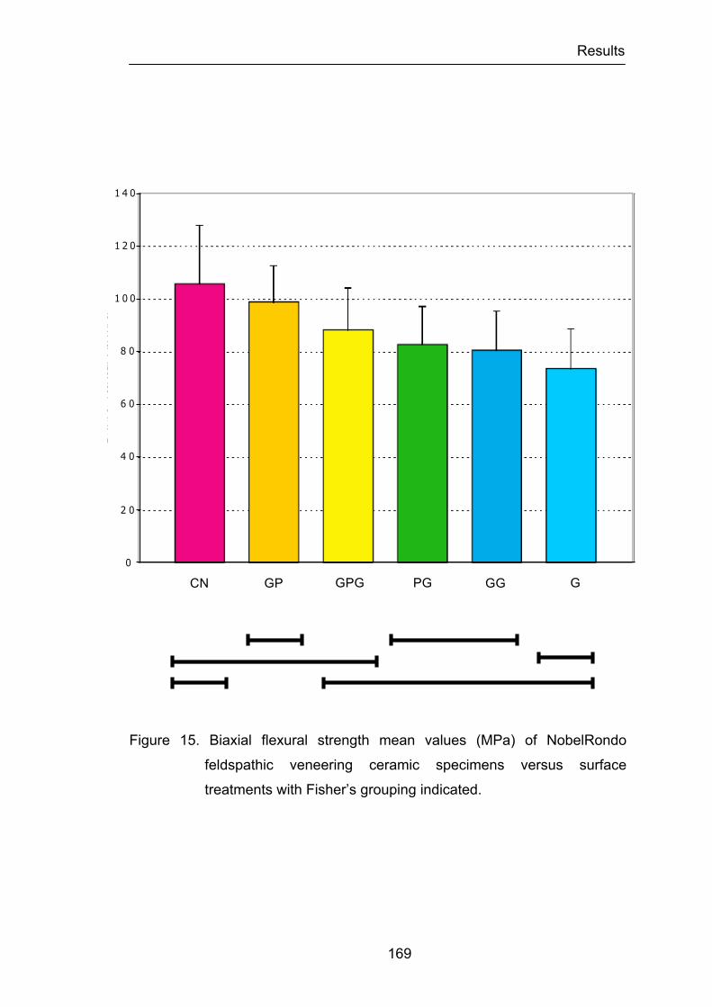
Results
169
Figure 15. Biaxial flexural strength mean values (MPa) of NobelRondo
feldspathic veneering ceramic specimens versus surface
treatments with Fisher’s grouping indicated.
CN
GP GPG PG G GG CN Polish GrindPolish
PolishHeat
GrindHeat Grind
Nobel Rondo
Fisher’s PSLD
0
2 0
4 0
6 0
8 0
1 0 0
1 2 0
1 4 0
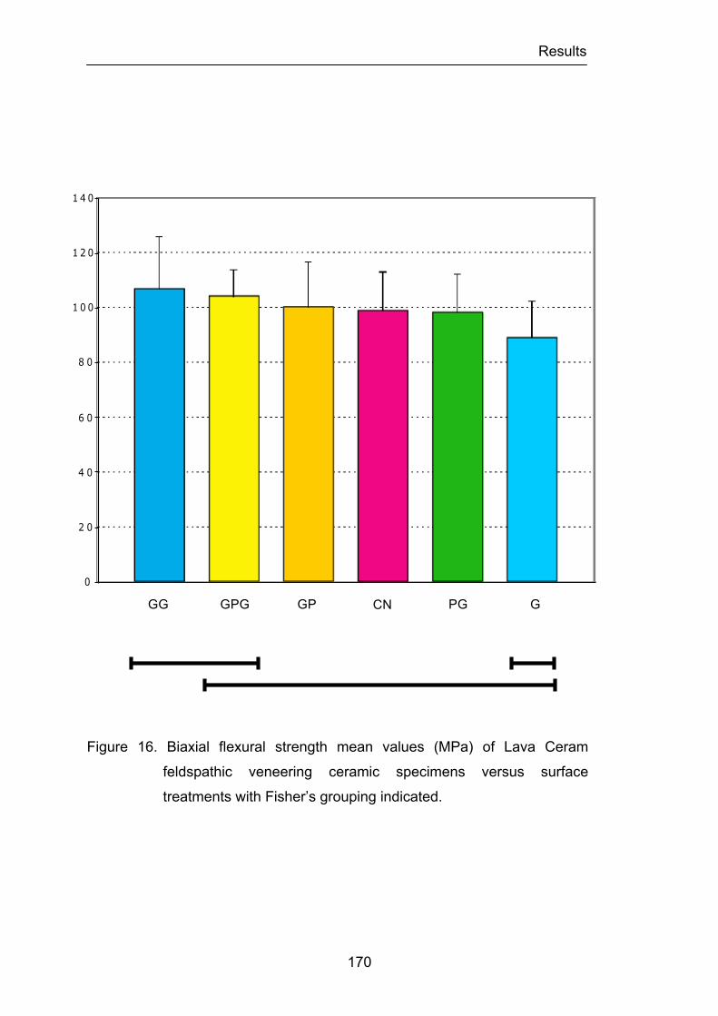
Results
170
Figure 16. Biaxial flexural strength mean values (MPa) of Lava Ceram
feldspathic veneering ceramic specimens versus surface
treatments with Fisher’s grouping indicated.
CNPolishGrindPolish
PolishHeat
GrindHeat Grind
Lava Ceram
Fisher’s PSLD
0
2 0
4 0
6 0
8 0
1 0 0
1 2 0
1 4 0
G CN
GP GPG PG GG
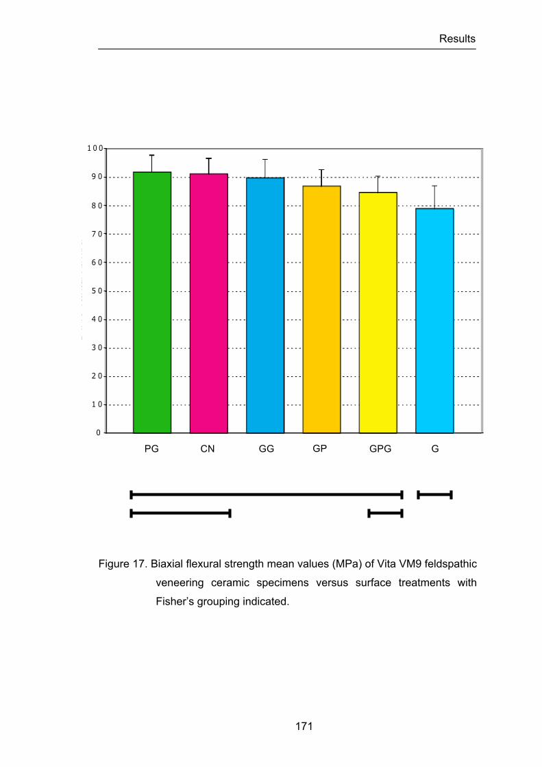
Results
171
Figure 17. Biaxial flexural strength mean values (MPa) of Vita VM9 feldspathic
veneering ceramic specimens versus surface treatments with
Fisher’s grouping indicated.
G
CN Polish GrindPolish
PolishHeat
GrindHeat Grind
Vita VM9
Fisher’s PSLD
0
1 0
2 0
3 0
4 0
5 0
6 0
7 0
8 0
9 0
1 0 0
CN GP GPG PG GG
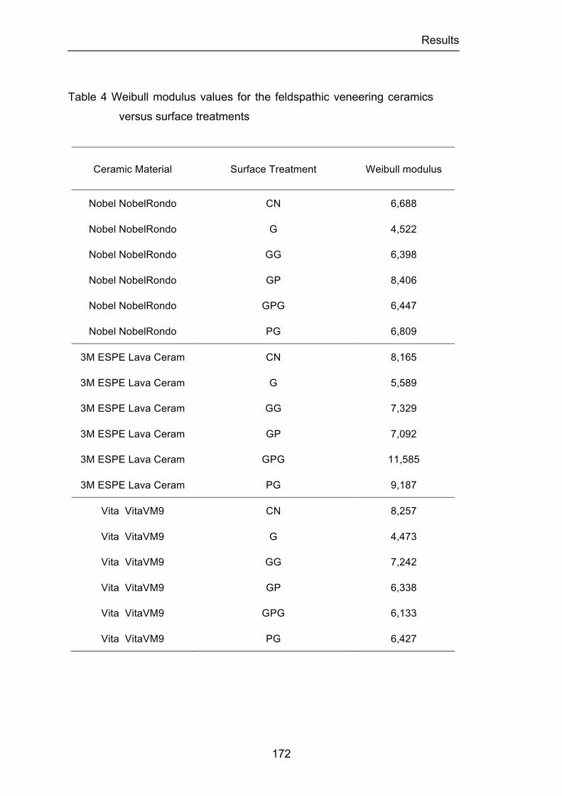
Results
172
Table 4 Weibull modulus values for the feldspathic veneering ceramics
versus surface treatments
Ceramic Material Surface Treatment Weibull modulus
Nobel NobelRondo CN 6,688
Nobel NobelRondo G 4,522
Nobel NobelRondo GG 6,398
Nobel NobelRondo GP 8,406
Nobel NobelRondo GPG 6,447
Nobel NobelRondo PG 6,809
3M ESPE Lava Ceram CN 8,165
3M ESPE Lava Ceram G 5,589
3M ESPE Lava Ceram GG 7,329
3M ESPE Lava Ceram GP 7,092
3M ESPE Lava Ceram GPG 11,585
3M ESPE Lava Ceram PG 9,187
Vita VitaVM9 CN 8,257
Vita VitaVM9 G 4,473
Vita VitaVM9 GG 7,242
Vita VitaVM9 GP 6,338
Vita VitaVM9 GPG 6,133
Vita VitaVM9 PG 6,427
Results
173
2- Mode of fracture and biaxial flexural strength of bilayered feldspathic dental
veneering ceramics/Zirconia core ceramic.
In this investigation the influence of the side tested under tensile stress
(the Zirconia core or the feldspathic veneering ceramics) on the biaxial
flexural strength of different feldspathic veneering ceramics/Zirconia core
ceramic was studied. In addition the reliability and mode of fracture of different
feldspathic veneering ceramics/Zirconia core ceramic was investigated. The
mean biaxial flexural strength values and standard deviations for each group
of specimens are shown in Table 5 and Figure 18. Examination of the
standard deviations reveals considerable heterogeneity in variability of the
outcome among the six groups, with the largest group variance being over
hundred-fold that of the group with the least variation.
A two-way ANOVA was carried out to determine if there was any
statistical significant difference between the two major effects; the “ceramic”
factor and the “Zirconia location” factor on the load to fracture of the test
specimens. The power values for analyzing the major factor “ceramic” and
“Zirconia location” were high enough (1), so that the project design was valid.
The two-way ANOVA results demonstrated that both factors had statistically
significant effect on load to fracture of the test specimens (p<0.0001).
When analyzing the source of differences between the ceramics tested,
Fisher’s protected least significant difference (PLSD) test showed statistically
significant differences between the NobelRondoTM ceramic and the other two
ceramics; LavaTM Ceram ceramic (p<0.0001) and Vita® VM®9 (p<0.0001).
Fisher’s test indicated also that there was no strong evidence of significant
heterogeneity of variances (p=0.3148) among the LavaTM Ceram and Vita®
VM®9 groups. When analyzing the difference between which surface was
placed under tensile stress the results of Fisher’s test showed that there was

Results
174
a statistical significant difference between both positions (p<0.0001).
An unpaired t-test was used to identify in each ceramic group if there
was a significant difference between the locations of the surface that was
placed under tensile stress (Zirconia core or veneering feldspathic ceramic)
(Figures 19, 20 and 21). Strong evidence was found that the variance
between groups corresponding to the LavaTM Ceram and Vita® VM®9 was
significant (p<0.0001). However, the results obtained in the NobelRondoTM
groups could not be said to differ significantly (p=0.4073).
The analysis of the Weibull modulus results (Table 6) indicated that, for
the three types of ceramics tested, when the Zirconia core ceramic was
placed under tension, with the feldspathic veneering ceramics facing the
loading piston, higher values were obtained demonstrating narrower flaw size
distribution on the Zirconia core ceramic. The results of the Weibull modulus
values for the NobelRondoTM groups showed smaller values than those for the
the LavaTM Ceram and Vita® VM®9 groups indicating a different distribution of
flaws and homogeneity of the material, which result in different strength
reliability.
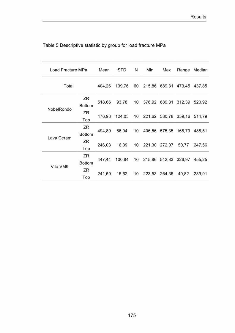
Results
175
Table 5 Descriptive statistic by group for load fracture MPa
Load Fracture MPa Mean STD N Min Max Range Median
Total 404,26 139,76 60 215,86 689,31 473,45 437,85
NobelRondo
ZR Bottom
518,66 93,78 10 376,92 689,31 312,39 520,92
ZR Top
476,93 124,03 10 221,62 580,78 359,16 514,79
Lava Ceram
ZR Bottom
494,89 66,04 10 406,56 575,35 168,79 488,51
ZR Top
246,03 16,39 10 221,30 272,07 50,77 247,56
Vita VM9
ZR Bottom
447,44 100,84 10 215,86 542,83 326,97 455,25
ZR Top
241,59 15,62 10 223,53 264,35 40,82 239,91
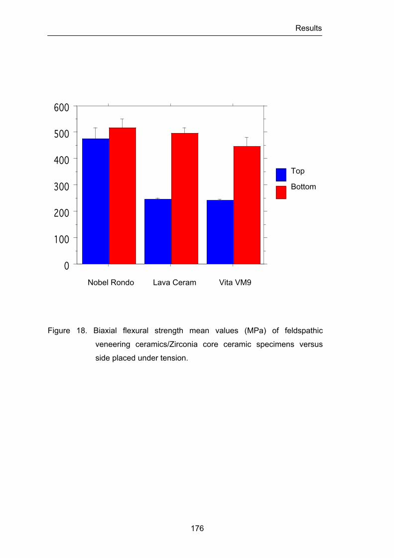
Results
176
Figure 18. Biaxial flexural strength mean values (MPa) of feldspathic
veneering ceramics/Zirconia core ceramic specimens versus
side placed under tension.
Nobel Rondo Lava Ceram Vita VM9
0
100
200
300
400
500
600
Cel
l Mea
n
Nobel Rondo Leva Ceram Vita VM9Cell
BottomTop
Interaction Bar Plot for LoadFracture MPa nAdjEffect: Ceramic * Zirconia locatedError Bars: ± 1 Standard Error(s)
Top
Bottom

Results
177
Figure 19. Box-and-whisker plots of biaxial flexural strength for the
NobelRondo feldspathic veneering ceramic/Zirconia core
ceramic specimens versus side placed under tension. The white
color corresponds to the Zirconia core when placed on the top.
The blue color when the Zirconia core is placed on the bottom.
Top
Bottom
200250300350400450500550600650700
Uni
ts
LoadFracture MPa nAdj
Bottom
Top
Box PlotSplit By: Zirconia locatedRow exclusion: Set2Data
NobelRondo
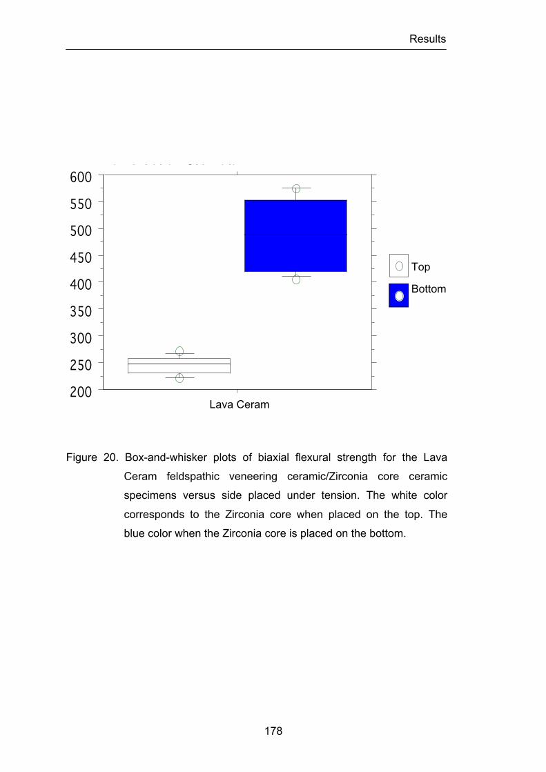
Results
178
Figure 20. Box-and-whisker plots of biaxial flexural strength for the Lava
Ceram feldspathic veneering ceramic/Zirconia core ceramic
specimens versus side placed under tension. The white color
corresponds to the Zirconia core when placed on the top. The
blue color when the Zirconia core is placed on the bottom.
200
250
300
350
400
450
500
550
600
Uni
ts
LoadFracture MPa nAdj
Bottom
Top
Box PlotSplit By: Zirconia locatedRow exclusion: Set2Data
Top
Bottom
Lava Ceram
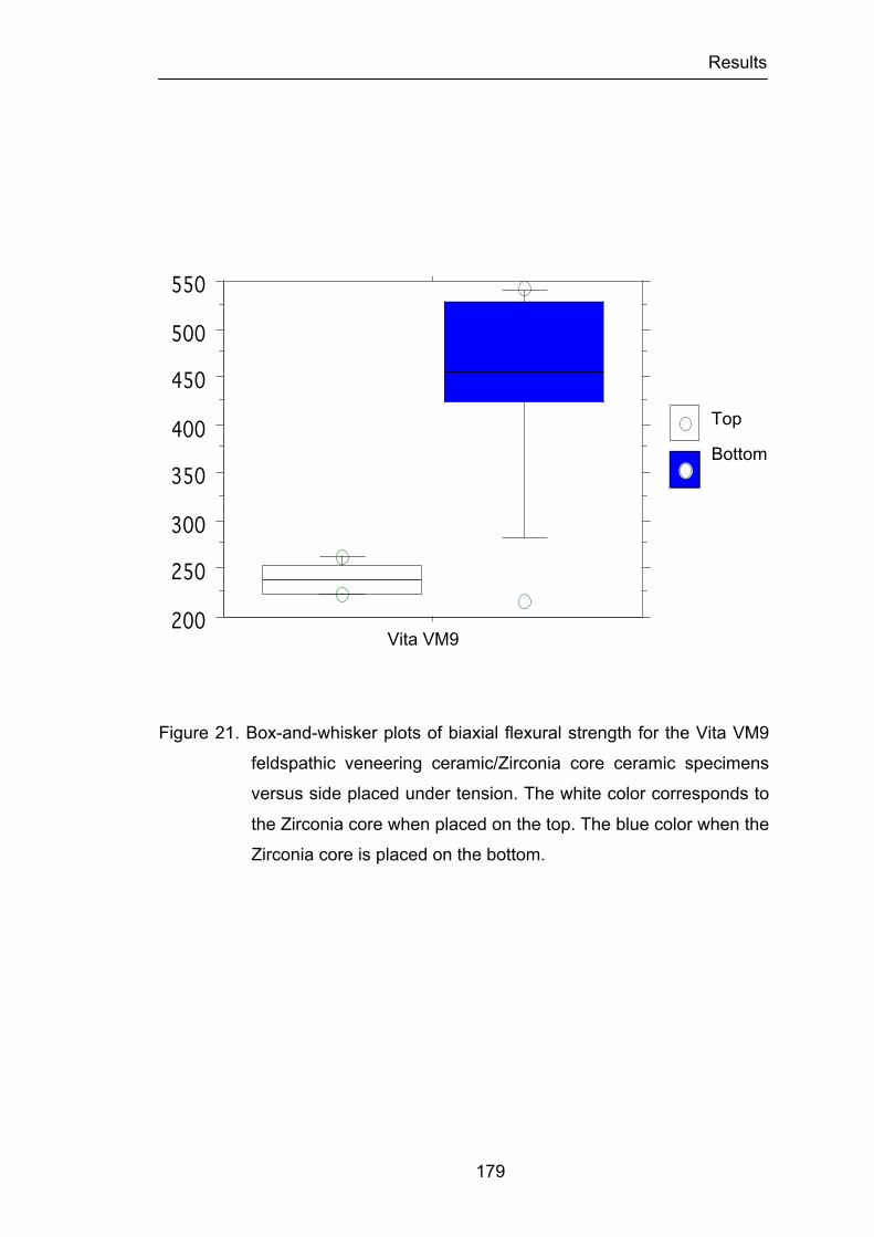
Results
179
Figure 21. Box-and-whisker plots of biaxial flexural strength for the Vita VM9
feldspathic veneering ceramic/Zirconia core ceramic specimens
versus side placed under tension. The white color corresponds to
the Zirconia core when placed on the top. The blue color when the
Zirconia core is placed on the bottom.
200
250
300
350
400
450
500
550
Uni
ts
LoadFracture MPa nAdj
Bottom
Top
Box PlotSplit By: Zirconia locatedRow exclusion: Set2Data
Top
Bottom
Vita VM9
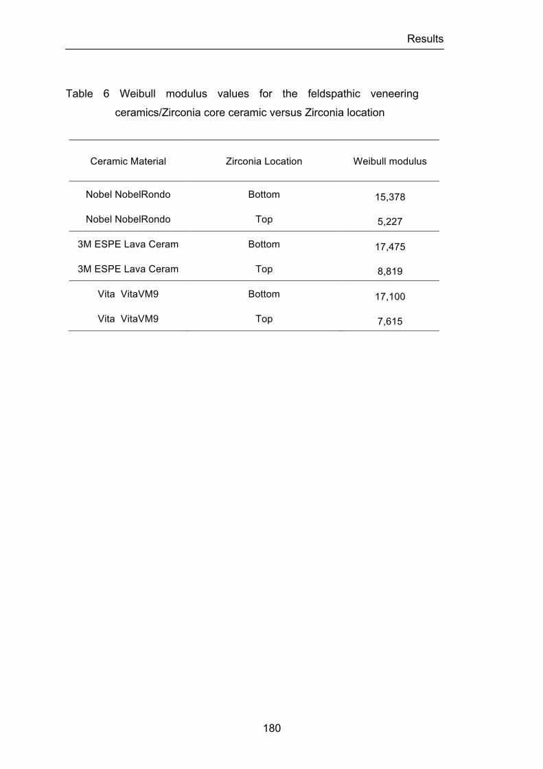
Results
180
Table 6 Weibull modulus values for the feldspathic veneering
ceramics/Zirconia core ceramic versus Zirconia location
Ceramic Material Zirconia Location Weibull modulus
Nobel NobelRondo Bottom 15,378
Nobel NobelRondo Top 5,227
3M ESPE Lava Ceram Bottom 17,475
3M ESPE Lava Ceram Top 8,819
Vita VitaVM9 Bottom 17,100
Vita VitaVM9 Top 7,615
Results
181
Different modes of fracture were observed in the six groups of
bilayered disc specimens according to which material was on the surface
contacting the loading force. The fracture patterns and failure modes of the
materials were classified in adhesive, cohesive and combined
adhesive/cohesive failure.
In groups 1, 3 and 5 when the Zirconia core material was on the
surface away from the load and the NobelRondoTM, LavaTM Ceram and Vita®
VM®9 feldspathic veneering ceramics were on the surface facing the loading
piston, fracture tended to initiate at the top surface although the maximum
peak of tensile stress was located on the bottom surface. Despite of the fact
that the maximum peak of tensile stress was located on the surface of the
core material, a Hertzian cone crack was consistently observed on the surface
of the veneering ceramic facing the loading piston. This mode of fracture was
observed in eight of the ten specimens of each group (Figures 22 and 23). In
these specimens partial delamination of the veneering ceramic was present
surrounding the Hertzian cone crack but there was no fracture of the Zirconia
ceramic core that was maintained intact. In these specimens, two distinct
failure loads were noted on the chart recorder. The first failure load occurred
upon initial tensile failure; the second occurred on crack deflection and the
initiation of delamination when the loading piston reached the Zirconia core.
Cohesive failure was the prevalent type of failure in these specimens.
In the other six remaining specimens the extension of the cone crack
to the interface caused deflection of the cracks laterally when the stronger
Zirconia core was reached. In these specimens, two distinct failure loads were
noted on the chart recorder. The first failure load occurred upon initial tensile
failure; the second occurred on lateral crack deflection and the initiation of
delamination. Catastrophic failure following initial tensile crack progression
also involved veneering ceramic/Zirconia core interface as well as fracture of

Results
182
the core material as a result of crack progression within the Zirconia ceramic.
Partial or complete delamination of the feldspathic veneering ceramic and
opaque material was also present (Figures 24, 25, 26 and 27). A combination
of adhesive/cohesive failure was the prevalent type of failure in these
specimens.
Conversely, when the core material was on top (facing the loading
piston) and the feldspathic veneering ceramic was on bottom, fracture tended
to initiate at the bottom surface, accompanied by apparent delamination at the
interface, followed by catastrophic failure with fracture of the Zirconia core
material. In a few specimens, the fracture origin was localized at the
veneering ceramic/Zirconia core material interface. In all specimens tested,
two distinct failure loads were noted on the chart recorder as previously
described. The first failure load occurred upon initial tensile failure and lateral
crack deflection and the initiation of delamination and the second occurred on
rupture of the Zirconia ceramic core. In all specimens a combination of
adhesive/cohesive failure was the prevalent type of failure.
In all specimens of group 2 corresponding to the NobelRondoTM
ceramic, the failure mode involved initial tensile crack progression with lateral
and radial crack deflection involving the veneering ceramic/Zirconia core
interface as well as partial delamination of the feldspathic veneering ceramic
and opaque ceramic material. In all specimens catastrophic failure occurred
with fracture of the Zirconia material in different areas as a result of crack
propagation through the Zirconia ceramic core (Figures 28 and 29).
In groups 4 and 6 corresponding to the LavaTM Ceram and Vita® VM®9
ceramics 90% of specimens fractured in the middle as a result of crack
progression within the Zirconia ceramic core. The initial tensile crack
progressed with one or more lateral crack deflections involving the veneering
ceramic/Zirconia core interface with partial delamination of the feldspathic
veneering ceramic and opaque ceramic material. This was followed by rupture

Results
183
of the Zirconia core material (Figures 30, 31, 32 and 33). In 2 specimens, one
in each group the fracture pattern was similar to that present in the specimens
of group 2.
Figure 22. Most common representative fracture mode of bilayered
feldspathic veneering ceramic/Zirconia core ceramic specimens
of groups 1, 3 and 5. Hertzian cone crack and feldspathic
veneering ceramic delamination with exposure of the Zirconia
core are present in the loaded area.
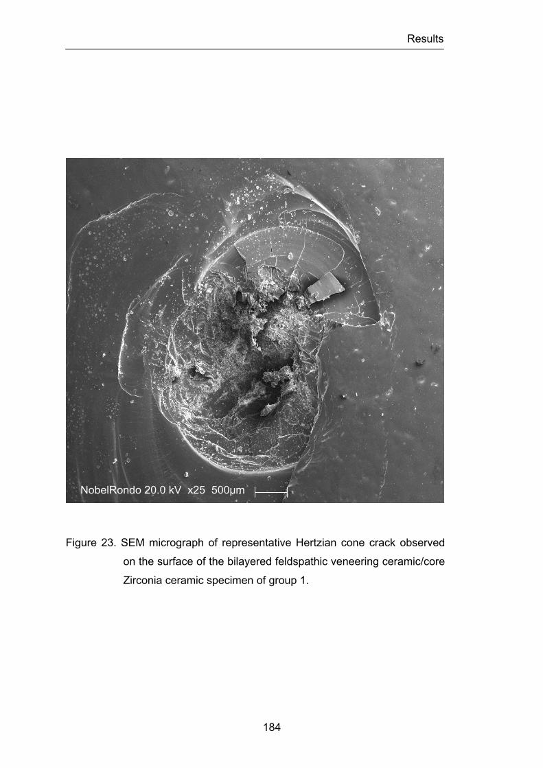
Results
184
Figure 23. SEM micrograph of representative Hertzian cone crack observed
on the surface of the bilayered feldspathic veneering ceramic/core
Zirconia ceramic specimen of group 1.
NobelRondo 20.0 kV x25 500µm

Results
185
Figure 24. Catastrophic failure of specimen of group 3 following initial tensile
crack progression with lateral crack deflection involving veneering
ceramic/Zirconia core interface as well as fracture of the Zirconia
core and partial delamination of the feldspathic veneering ceramic.
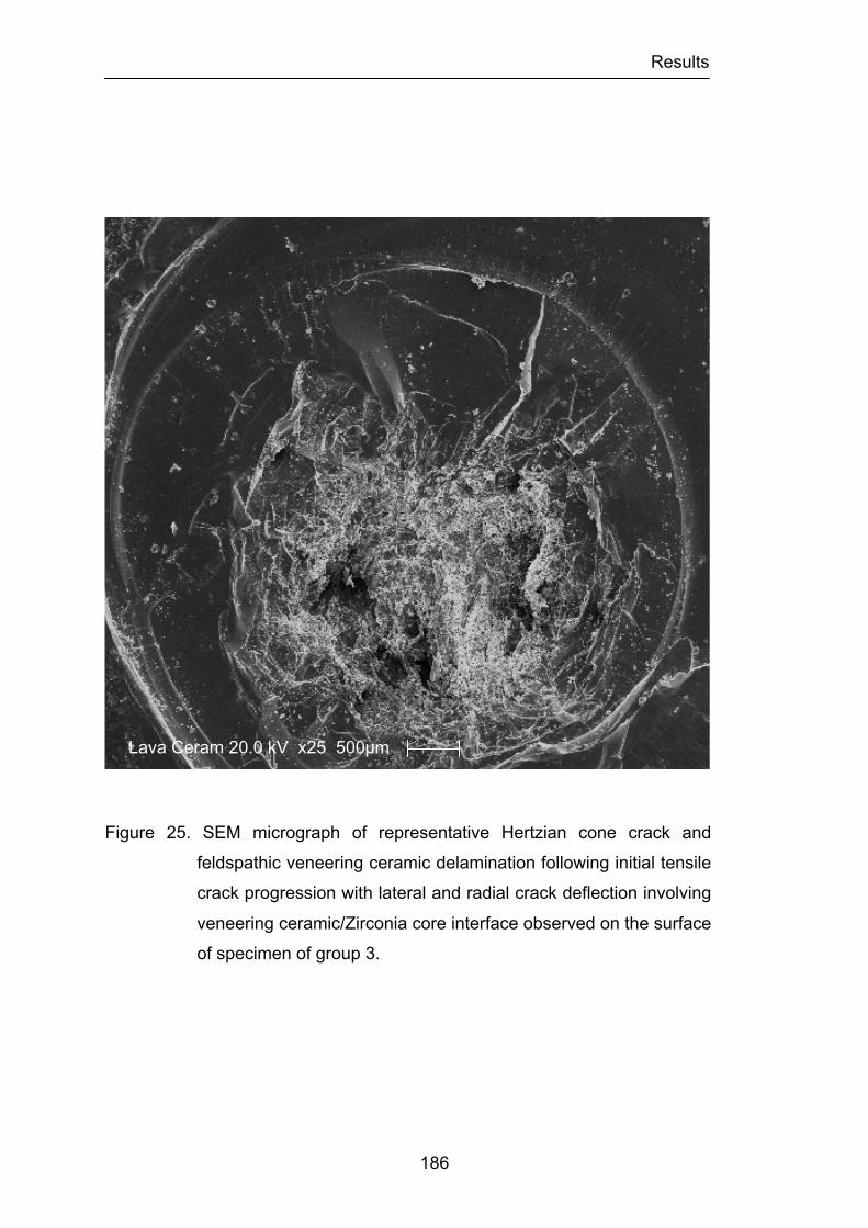
Results
186
Figure 25. SEM micrograph of representative Hertzian cone crack and
feldspathic veneering ceramic delamination following initial tensile
crack progression with lateral and radial crack deflection involving
veneering ceramic/Zirconia core interface observed on the surface
of specimen of group 3.
Lava Ceram 20.0 kV x25 500µm
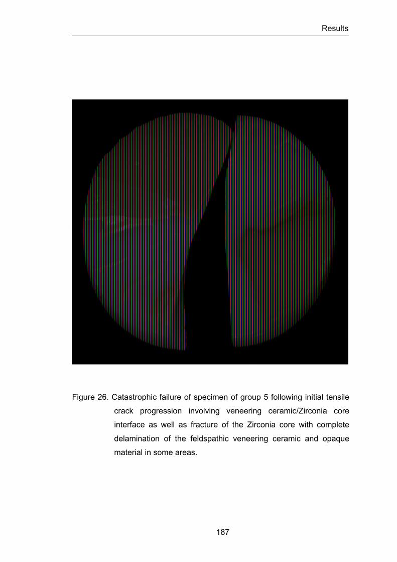
Results
187
Figure 26. Catastrophic failure of specimen of group 5 following initial tensile
crack progression involving veneering ceramic/Zirconia core
interface as well as fracture of the Zirconia core with complete
delamination of the feldspathic veneering ceramic and opaque
material in some areas.
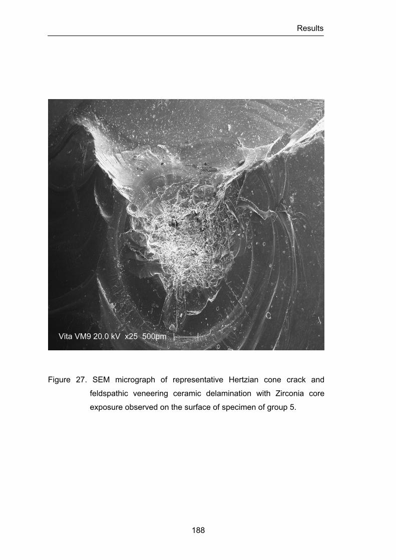
Results
188
Figure 27. SEM micrograph of representative Hertzian cone crack and
feldspathic veneering ceramic delamination with Zirconia core
exposure observed on the surface of specimen of group 5.
Vita VM9 20.0 kV x25 500µm
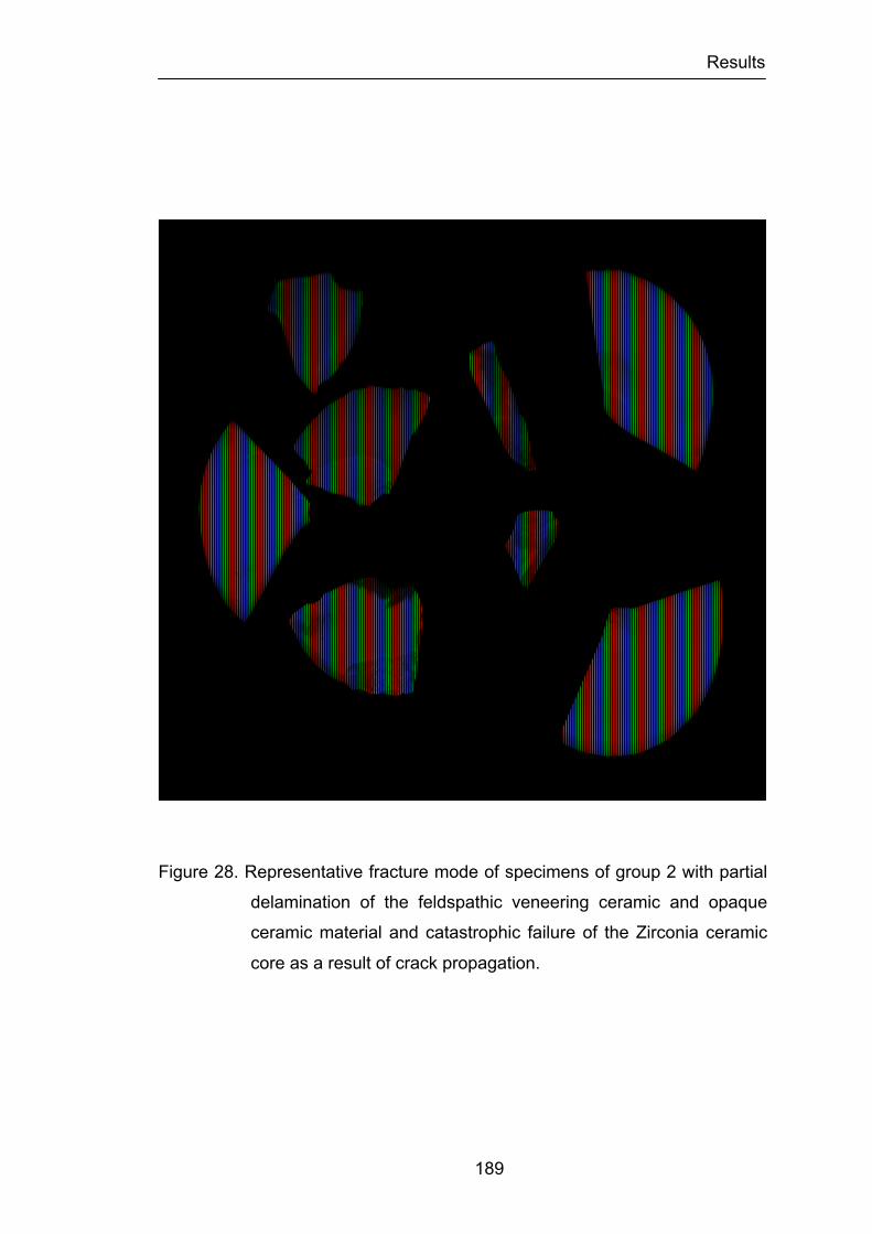
Results
189
Figure 28. Representative fracture mode of specimens of group 2 with partial
delamination of the feldspathic veneering ceramic and opaque
ceramic material and catastrophic failure of the Zirconia ceramic
core as a result of crack propagation.
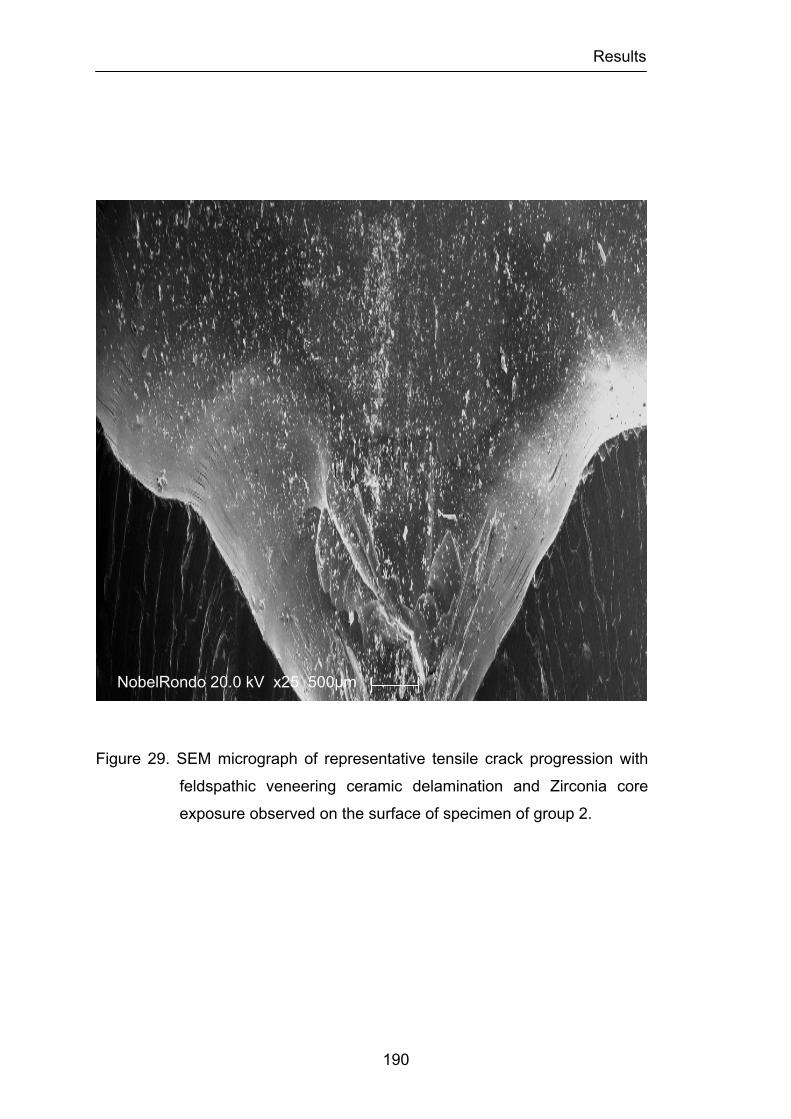
Results
190
Figure 29. SEM micrograph of representative tensile crack progression with
feldspathic veneering ceramic delamination and Zirconia core
exposure observed on the surface of specimen of group 2.
NobelRondo 20.0 kV x25 500µm
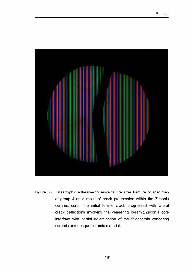
Results
191
Figure 30. Catastrophic adhesive-cohesive failure after fracture of specimen
of group 4 as a result of crack progression within the Zirconia
ceramic core. The initial tensile crack progressed with lateral
crack deflections involving the veneering ceramic/Zirconia core
interface with partial delamination of the feldspathic veneering
ceramic and opaque ceramic material.
Results
192
Figure 31. SEM micrograph of representative tensile crack progression with
feldspathic veneering ceramic delamination and Zirconia core
exposure with adhesive-cohesive failure of specimen of group 4.
Lava Ceram 20.0 kV x25 500µm
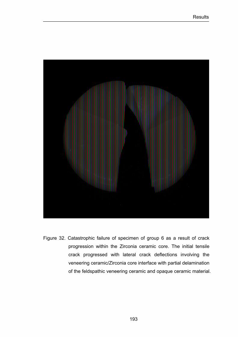
Results
193
Figure 32. Catastrophic failure of specimen of group 6 as a result of crack
progression within the Zirconia ceramic core. The initial tensile
crack progressed with lateral crack deflections involving the
veneering ceramic/Zirconia core interface with partial delamination
of the feldspathic veneering ceramic and opaque ceramic material.
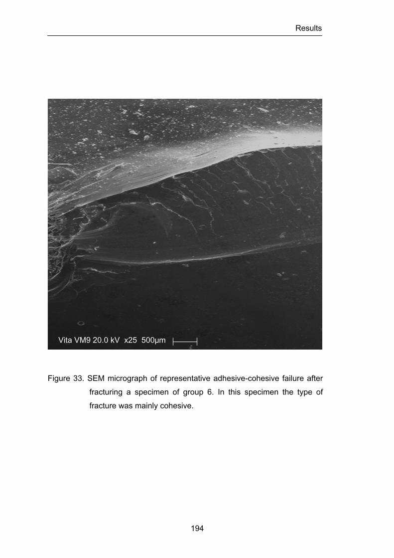
Results
194
Figure 33. SEM micrograph of representative adhesive-cohesive failure after
fracturing a specimen of group 6. In this specimen the type of
fracture was mainly cohesive.
Vita VM9 20.0 kV x25 500µm
Discussion
195
CHAPTER 5
DISCUSSION
The massive increase in demand for more esthetic restorative
materials in dentistry has led to the use of dental ceramics as an alternative
for both anterior and posterior restorations. Any material used for these
purposes must possess certain physical requirements such as high strength,
good marginal integrity, and good esthetic properties to be acceptable for
clinical usage. Metal-ceramic crowns have been widely accepted as the
treatment of choice for single or fixed partial denture restorations because of
the advantages of high strength, reasonable esthetics, and long-term
predictability (Hondrum, 1994; Denry et al., 2008).
However, the increased requirements for optimal esthetics have made
metal-ceramic restorations no longer adequate to meet the expectations of
both clinicians and patients. In this respect, the all-ceramic crown has set a
standard for esthetics that is difficult to match by the metal-ceramic crown.
This is due mainly because of the absence of underlying metal and increased
light transmission through the restoration. While recognizing the improved
esthetics clinicians and scientists have questioned the use of all-ceramic
crowns because of their lack of strength. Their counterparts, the metal-
ceramic crowns, have been used successfully with a failure rate of only 1 to
3% over 5 years (Anusavice, 1993; Fisher et al., 2008).
Metal-ceramic systems have come under scrutiny, however, because
Discussion
196
of (1) potential alloy corrosion leading to toxicity and allergy concerns; (2)
esthetic problems such as lack of translucency, discoloration of some
ceramics from silver in the alloy, and excessive value in the cervical third; (3)
the amount of tooth reduction necessary, and associated tendency to
overcontour the restoration; and (4) incompatibility between metal and
ceramic, and the difficulty in establishing standard tests for bond strength and
thermal compatibility (Denry et al., 2008).
Research has emphasized the development of stronger all-ceramic
restorations, largely because of increasing esthetic demands (Fradeani, 2003).
For this reason, since the early 1990s, researchers and clinicians have been
seeking news ways of fabricating all-ceramic restorations that possess the
needed qualities of strength, color stability, favorable wear characteristics,
and precision of fit so that they may be placed in all regions of the oral cavity.
Additionally, these techniques must produce crowns that consistently meet
these qualities in a manner that is cost-effective for the patient, dentist, and
laboratory. The development of present day all-ceramic systems has offered
many improvements over the metal-ceramic crown such as increase
translucency, adaptability and biocompatibility.
However, the biggest advantage of all-ceramic crown is its natural
tooth-like appearance. High strength ceramic copings now available, mimic
the light transmission properties of natural tooth by improving the translucency
of light through the restoration and the underlying tooth structure. Dental
ceramics allow regular and diffuse transmission, as well as diffuse and
specular reflectance of light, and therefore have the potential to reproduce the
depth of color, and texture of natural teeth (O’Brien 2002).
Several all-ceramic systems with various compositions are now
available, demonstrating technologies that are reported as satisfying the
demands of the dental profession (Luthardt et al., 1999). These ceramic
systems are widely used as restorative materials in dentistry and present
Discussion
197
similar success rates of metal-ceramic crowns (Zitzmann et al., 2007;
Fradeani et al., 2002; Odman et al., 2001). These new all-ceramic crowns
with high strength still remain susceptible to the high mechanical loading
during function. The absence of reinforcement by a metal substructure results
in relatively weak flexural strength and low fracture resistance. Therefore,
available all-ceramic restorations have limited clinical application in areas of
high stress, such as posterior single crowns and fixed partial dentures. The
major disadvantage of dental ceramics is their susceptibility to fracture during
placement, mastication, and trauma. Different reports suggest that all-ceramic
restorations demonstrate acceptable longevity compared with conventional
restorations (e.g., metal-ceramic crowns) (Odman et al., 2001; Fradeani et al.,
2002). For single-rooted anterior teeth, broad support was found for the
premise that clinicians may select from any all-ceramic systems for laminate
veneers, intracoronal restorations such as inlays and onlays, and for full-
coverage restorations. Single crowns composed of different materials (lithium
disilicate, leucite, aluminum oxide) have been successfully placed for 10 to 20
years. They have been shown to achieve good clinical survival rates and have
thus become the standard of care for single crowns, especially in the anterior
region. For restoration of molar teeth, the reviews suggest that relatively few
all-ceramic systems will provide predictable long-term success (Land et al.,
2010; Della Bona et al., 2008)
In order to overcome the inherent mechanical weakness of all-ceramic
crown systems, several manufacturers have recently investigated and
introduced a high strength ceramic material composed of Y2O3-partially-
stabilized zirconium oxide for the substructures of all-ceramic crowns and
fixed partial dentures. Its’ superior mechanical behavior over alumina ceramic
substructures has been reported in the dental literature (Piconi et al., 1999).
The indication that Zirconia containing ceramics exhibit durability in a highly
loaded environment makes them attractive for use in dentistry and increases

Discussion
198
the clinical indications to posterior molars and posterior fixed partial dentures.
Zirconia is chemically an oxide and technologically a ceramic material, not
soluble in water, that was proved not to be cytotoxic, and not to enhance
bacterial adhesion, and exhibits a favorable radio-opacity and a low corrosion
potential (Piconi et al., 1999)
While much research has been conducted to assess the strength of
traditional dental porcelain materials very little information has been reported
concerning the relative strength of many of the ceramic materials already in
clinical applications. The precision of fit, strength and biocompatibility of
Zirconia have been studied and found to be excellent for multiple dental
applications (Piconi et al., 1999, Luthard et al., 1999). However, little data
exists regarding the strength, fracture toughness, fracture mode and hardness
of veneering dental ceramics designed for Zirconia structures (Denry et al.,
2008; Fischer et al., 2008).
Some clinical studies with data up to 5 years reported a high
prevalence of chipping of the ceramic veneering material for Zirconia-
supported restorations (Sailer et al., 2006; Raigrodski et al., 2009;
Christensen et al., 2009; Schley et al., 2010). Fracture of the framework,
however has been rarely reported to date. The prevalence of veneer chipping
seems to be higher when compared to that for metal-supported restorations
(Heintze et al., 2010). The data available indicate also fewer mechanical
problems for single crowns compared to Zirconia-supported fixed partial
dentures (Ortorp et al., 2009). Whether the higher frequency of veneer
chipping could be attributed to the material or to the technique sensitivity of
the veneer porcelain processing, or whether there might be other unknown
influencing factors remains unclear. Another important conclusion drawn form
these reviews was that the frequency of chipping varied greatly across studies.
Some studies did not report any veneer chipping, and in others, more than
20% or 30% of all Zirconia restorations showed veneer chipping. An
Discussion
199
explanation as to why the results of these studies were so different could be
the clinical examination criteria. In some studies chipping was evaluated by
direct observation and in others was performed using scanning electron
microscopy. Therefore, small chippings that would otherwise not have seen
during clinical examination were recorded. Another possible reason for the
variation could be that studies were performed in different environments.
Some were carried out in private practice by general dentists and others at
universities. General practitioners might be less careful with operational
procedures (e.g., seating of restorations, occlusal adjustment, polishing) than
clinicians at universities. It may be speculated that suboptimal parameters
during the fabrication of the Zirconia restorations or during the incorporation of
the Zirconia restorations in the oral cavity could account for the variation in the
researchers findings. In this case, Zirconia restorations have a higher
technique sensitivity compared with metal-ceramic restorations, the later
showing significantly less veneer chipping, even in fabrication and evaluation
performed in the same environment and by the same technicians and
operators (Heintze et al., 2010).
The question of interest for the practitioner is how Zirconia-based
materials may be improved to reduce the risk of veneer chipping. When
Zirconia materials were introduced, it was thought that they could be handled
similar to metal-ceramic materials. Since clinical studies have shown a high
frequency of chipping at the veneer material, dental manufacturers began to
address this issue.
Several factors must be taken into account during the fabrication of a
Zirconia based restoration. The coefficient of thermal expansion of the veneer
and Zirconia material must be adjusted. Generally, the veneer material has a
higher coefficient than the core, which puts the veneer under tensile stress
and helps it to adapt well to the core. The difference in the coefficient,
however, should not be too great. If there is a strong misfit, technical failures
Discussion
200
occur with high frequency (Fischer et al., 2009). The low thermoconductivity of
Zirconia leads to unfavorable temperature distributions and the development
of internal stresses in the veneer material during firing and cooling of the
restoration (Fischer et al., 2009). Prolonged cooling until the glass ceramic
has reached the critical glass transition point results in less stress distribution
(Swain, 2009). If the thickness of the veneer exceeds that of the core twofold
or more, the risk of veneer chipping is increased considerably (Hsheh et al.,
2008). If the veneer is not supported by the core, which means that the cusps
that are built up with veneer material do not have an anatomical counterpart
on the core side, the risk of veneer chipping is increased (Rosentritt et al.,
2009). When the first computer-aided design/computer-assisted
manufacturing systems were brought to the market, the software of some
systems did not allow the core to be designed anatomically. Subsequently,
manufacturers have made it possible to anatomically alter the shape of the
Zirconia substructure. There is wide spread agreement that veneer materials
with higher strength should be developed. These materials should withstand
the occlusal and articulation forces better than the current porcelains.
Additionally, these materials should be able to be adjusted by the dental
technician and/or the dentist and maintain not only the strength but also
clinical long-term performance.
Although the last two points did not yield a significant correlation and
analyses with the frequency of veneer chipping in these studies, in can be
expected that these configuration parameters are important in reducing the
risk of chipping. For these reasons and because there is no study available to
characterize the strength alterations that can occur in the veneer ceramics,
used in conjunction with Zirconia-based restorations, after surface
adjustments or treatments the present investigation was carried out.
Strength and fracture toughness characterize the responses of
materials, like brittle dental ceramics, to loading forces and crack propagation,
Discussion
201
respectively. Strength is a very important property of all-ceramic materials.
However since many variables, such as testing design, specimen geometry,
polishing procedures and testing environments affect strength measurements,
it is not considered an intrinsic property. Conversely, fracture toughness is a
more fundamental property then strength, since it characterizes bulk structure
without involving the flaw size.
The standard for testing the strength of dental ceramics has been the
three-point flexural test, but one problem has been the sensitivity of the test to
flaws along the sample edges. It is impossible to eliminate all flaws and,
because fracture often initiates at the edges, large variations strength data
have been recorded (Ban et al., 1990). The strength measured in a uniaxial
tension test is sensitive to flaws that exist throughout the material, because
the tensile stress is uniform. In a flexure test, the stress is expected to vary
from pure compression on one surface to pure tension on the other. The
flexure strength therefore depends primarily on the size of the flaws at and
near the surface, where the tensile stresses are the highest. Four-point and
biaxial flexure tests develop lower levels of shear in the test section as
compared to three-point flexure tests. The stress state in four-point and biaxial
tests is therefore closer to pure bending. Furthermore, biaxial tests are less
sensitive to edge effects than three- or four-point flexure tests and less
sensitive to surface imperfections resulting from specimen preparation. In
addition, the biaxial test probes for the largest flaws oriented over a wider
range of angles, while the three- and four-point bend tests are most sensitive
to flaws nearly perpendicular to the beam axis of the sample. For all these
reasons the methods used for determining strength are important factors
since the methods used can profoundly affect results and test interpretations.
The difference in results of the three different test designs may be
explained as follows. Flexural strength obtained with the four-point flexure test
is generally lower because the probability to have a surface crack between
Discussion
202
the two loading pistons is higher than in the more limited area beneath the
loading piston of a three-point flexure test. In the biaxial flexure test, the force
is applied in the center of the specimen. Defects at the edges, which most
probably lead to an early failure, are less effective. Nevertheless, the
probability of a crack in the vicinity of the loading piston is higher than in the
three-point flexure test because the loaded area is larger (Anusavice et al.,
2007). It can be concluded that for screening tests, for instances, during the
development of ceramics, the biaxial flexure test is most appropriate because
preparation of the samples is easy, compared to the three- and four-point
flexure test. However, according to some studies results (Ban et al., 1990;
Fischer et al., 2007), when scientific approach is intended, the four-point
flexure test should be preferred.
Although the four-point flexure test might give a more systematic and
logical approach, the present investigation used the biaxial flexural test as the
method of choice since this test is less sensitive to surface imperfections
resulting from specimen preparation and less sensitive to flaws perpendicular
to the beam axis and on the edge of the specimens. This is especially
important in this study since the specimens tested in the first part of this
investigation were subjected to surface preparation. Moreover, the
International Standard for Dental Ceramic defines the biaxial flexural strength
test method as suitable for assessing the effect of different surface
preparations (for example air-borne-particle abrasion, as-fired, ground, and
overglazed) on the strength of ceramic materials.
The mean biaxial flexural strengths of the control groups for the three
ceramics tested in the first part of this investigation are in good agreement
with previous results found in the literature using the same ceramic materials
(Fischer et al., 2008). Although the results are slightly higher than those
reported, this may be attributed to the fact that in this study the tip piston
diameter of 0.7mm used, when compared to the 1.5mm piston tip diameter
Discussion
203
used in the Fischer’s study, gave rise to mean biaxial strength, as a smaller
area of the disc specimen was subjected to the maximum tensile stresses;
subsequently there was less chance of the specimen having a critical flaw in
that area, which led to the improved, mean biaxial strength. This clearly
shows that mean biaxial flexural strength is affected by testing design. Care is
therefore required, as mean strength comparisons under different conditions
or testing parameters may become invalid (Guazzato et al., 2002; Albakry et
al., 2004).
The present study also showed that grinding, polishing and heat
treatment have remarkable effects on the strength of the feldspathic
veneering ceramics tested. This confirm the first two hypotheses formulated
originally in this investigation that there are significant differences in the load
fracture resistance, measured in terms of biaxial flexural strength, among
different ceramic surface treatments in the feldspathic veneering ceramics
tested in conjunction or individually. The effects of surface treatments analysis
showed that grinding reduced the strength of the tested specimens, and this
was statistically significant when all the ceramics were considered together.
The tentative conclusion is that the stress concentration due to
roughness of the surface caused by the grinding procedure is responsible for
the differences between the biaxial flexural strength of the different specimen
groups. In the literature (Bazant, 1986; Jager et al., 2000), the failure of many
materials, including ceramics, has been attributed to the propagation of a
large system of densely distributed cracks, rather than to a single precisely
defined fracture. The number of cracks and microcracks is extremely large
and, according to the literature, their location and orientation are random.
Irwin (Irwin, 1957) demonstrated that stress intensity is related to a crack
shape in a particular location with respect to the loading geometry. The
finishing procedures influence the existence of microcracks and residual
stress. For example, polishing and glazing could round the crack tip of

Discussion
204
possible microcracks. The change in crack length and crack tip radius would
change the strength of the material. The finishing procedures, however, also
produce a certain surface roughness. Surface roughness will lead to a non-
uniform stress distribution and concentrate locally an applied stress due to the
shape differences in the surface layer. The distributed cracks may not develop
or propagate randomly, but occur or propagate at points with the higher stress
as a result of the surface roughness. This hypothesis is also supported by the
work of Mecholsky and co-workers, who loaded samples with grinding
grooves and gouges both perpendicular and parallel to the loading direction
(Mecholsky et al., 1977).
In the case of the specimens with the tensile axis perpendicular to the
grinding direction, like in this investigation, this resulted in a lower fracture
strength and flaws resulting in failure generally being situated parallel to the
grinding direction. Grinding grooves or gouges parallel to the tensile axis will
not cause stress concentration, while those perpendicular to the tensile axis
will do so. This stress concentration will result in lower fracture strength and in
failure-causing flaws being situated on the points with the highest stress
parallel to the grinding direction. The height difference of a rough spot over a
distance of 50 µm will dominate the stress concentration (Jager et al., 2000).
The roughness proved to be an indication for the height difference of a
characteristic rough spot.
In the dental ceramics evaluated in this study the relation between the
biaxial flexural strength and the roughness of the specimens supports the
hypothesis that surface roughness will concentrate an applied stress, and
resulting in a lower biaxial flexural strength. Stress concentration caused by
either roughness, surface defects, or internal stresses are believed to be the
main reasons for the mean biaxial strength variations among all tested groups
of the feldspathic veneering ceramics. Ground groups in the three feldspathic
veneering ceramics tested recorded the lower strength values when
Discussion
205
compared to the control, polished and glazed groups. During grinding, heat,
cracking, chipping and residual stresses may be generated, from which
strength reducing flaws are initiated. Like previously mentioned, Mecholsky
and co-workers reported that two sets of flaws grow in directions both
perpendicular and parallel to the grinding direction, but the tensile orientation
during testing determines which set initiates fracture (Mecholsky et al., 1977).
In the case of biaxial test, the direction of grinding will not be as critical, as
stresses develop uniformly within the maximum tensile area, at the centre of a
disc (Albakry et al., 2004), and the cracks developed in this area are more
likely to dictate strength. In addition, during these treatments, if a flaw size,
sharpness, orientation or distribution changed, the final strength of a ceramic
material will be changed (Kelly, 1995). This possibly explains why the
reduction in strength in this study is not as much pronounced as it is in other
studies, where the strength degradation caused by grinding can reach 80% in
relation to untreated surfaces (Giordano et al., 1995).
When each feldspathic veneering ceramic was examined separately,
only in the Vita® VM®9 veneering ceramic the grinding group was statistical
significant different from all the others surface treatment groups. The
statistical insignificant difference in strength values between the grinding
group and some other groups in the NobelRondoTM and LavaTM Ceram was
somewhat surprising. This is because lower strength values are expected
after more severe procedures such as grinding. This also indicates that
strength reduction of a ceramic material is a consequence of the finishing
tools, coarseness and feed rate, which determines the associated defects,
size and the amount of compressive stresses developed. It may also depend
upon the characteristics of different ceramics microstructure. The size of this
strength-reducing flaws originated by grinding is also dictated by the fracture
toughness of the treated material. Although grinding involve mechanical
removable and a damage of varying degrees, they may be accompanied, as
Discussion
206
previously explained, by development of residual stresses, which can be
compressive, depending upon the parameters of the treatment procedure.
The compressive layer, formed by surface plastic deformation, may act to
prevent the extension of microscopic defects. Consequently, provided no
significant median or lateral cracks formed, strength might by improved by
grinding or machining (Albraky et al., 2004).
Grinding is commonly involved during machining of an all-ceramic
framework and adjustments by ceramist and dentist to improve occlusion and
proper fitting. The effect of grinding on the surface of ceramic and its
mechanical properties can be contradictory. The influence of grinding on the
ultimate strength of a ceramic can be explained by tacking into account
factors which may alter the combined effect of the surface flaws and the
residual stress layers. Some of these factors are: the magnitude of the
residual stress (which is also related to the composition and microstructure of
the ceramic); the ratio of the crack length to surface compressive layer depth
(Lange et al., 1983); the effective size of grinding particles (Johnson-Walls et
al., 1986); the dimensions of the pre-existing flaws (Tuan et al., 1998); the
orientation of grinding (Mecholsky et al., 1977); and ceramics microstructure
(Albakry et al., 2004). When comparing to the control groups the reduction of
strength in the grinding groups was almost 30% for the NobelRondoTM
veneering ceramic 17% for the LavaTM Ceram veneering ceramic and 15% for
the Vita® VM®9 veneering ceramic. This clearly demonstrates that careful
must be taken when adjusting ceramic Zirconia based restorations since a
considerable reduction in strength can compromise the long-term success
and contribute for the failure of the rehabilitation.
It has been well established that crack propagation brought about by
tensile stress, can cause a brittle ceramic to fracture (Anusavice et al., 1991).
However, if the strength of the material, affected by internal microstructure
and surface quality is improved, then the performance of all-ceramic dental
Discussion
207
restorations should improve with respect to fracture resistance (Anusavice,
1996). The glazing surface treatment is a routine procedure in a dental
laboratory. It produces crowns with smooth and shiny surfaces and has a
positive effect on the biaxial flexural strength of ceramic materials (McLean et
al., 1979). The term “overglazing” defines the firing of a low-fusing colorless
glass on the ceramic core or veneering ceramic. This thin layer of about 4 µm
of glass, produced after 60 seconds of hold time at the final temperature
reduces the size of flaws present on the surface (probably introduced during
the fabrication of the restoration), thus increasing the strength of the materials
(Brackett et al., 1989; Isgro et al., 2003). Furthermore, it is used to provide
large surface compression, which strengthens the ceramic body.
In addition to the application of a low fusing glass overcoat, glazing
can be also be performed on firing for a certain time, held at the maximum
temperature and is termed auto-glazing or self-glazing. As far as chemical
durability is concerned, self-glazing ceramics are preferred over glazing
masses. A higher concentration of glass modifiers reduces the resistance of
the applied surface glaze compared to the normal surface glaze of the
ceramic. During glazing a thin outer layer is formed. A certain temperature
and treatment time leads to the formation of a softer glass phase and the
formation of crystalline particles within the surface region.
Auto-glazing and/or the application of glazing material after grinding is
believed to increase the strength of ceramic materials by reducing the depth
and/or sharpness of critical flaws as previously stated (Baharav et al., 1999).
However, this effect is still uncertain (Fairhurst et al., 1992). Several reports in
the literature also showed that auto-glazing had no effect on strength
(Anusavice, 1989; Fairhurst et al., 1992; Griggs et al., 1996; Denry et al.,
1999; Albakry et al., 2003). It should also be considered that heat treatment
after polishing or grinding may degrade strength, which is though to be a
result of releasing compressive stresses that normally develop during
Discussion
208
polishing or grinding. The present investigation found that submitting the
feldspathic veneering ceramic materials to heat treatment that is typically
encountered during dental laboratory processing, revealed contradictory
results in terms of improving the strength of ceramic materials and did not
clarified the contradictory results present in the literature.
When analyzing the results of all three feldspathic veneering ceramics
together glazed specimens demonstrated a statistically significant increase in
strength when compared to grinded specimens. This increase in strength was
almost 20% for the glazed groups (GG, GPG) that were previously submitted
to grinding procedure. Characteristics rough spots were found in the glazed
specimens and such spots did not appear in the untreated control specimens.
Subsurface pores in the untreated samples and/or produced by grinding
probably caused these defects. The considerable stress concentration caused
by these rough spots, especially if they were presented near the loading
piston, may help to explain the lower increase in biaxial strength verified in
glazed specimens compared to the grinding specimens. The conclusion that
the stress concentration caused by higher or lowers surface roughness after
glazing is the dominant factor may be supported by the findings of Griggs and
co-workers (Griggs et al., 1996). In their study flaws were created by means
of diamond cup wheel. The researchers found statistically significant
improvement in biaxial flexure strength after glazing, as Giordano and co-
workers did, and in contrast with different other studies (Chen et al., 1999;
Jager et al., 2000). In these studies, roughness produced on the surface was
created my means of a Vickers indenter which creates a much more severe
surface roughness that may by present even after glazing.
The glazing of grinded NobelRondoTM specimens did not resulted in a
statistical significant increase in strength, even though the percentage of
increase was almost 10%. However, in the specimens subjected to grinding
that were polished before glazing significant difference was encountered. This
Discussion
209
may be explained by the fact that the polishing may have reduced the flaws
present at the surface of the specimens produced by grinding and increased
the compressive surface layer of the ceramic. If we could extrapolate clinically
these results, they indicate that polishing should always be performed before
glazing if this ceramic needs to be adjusted. On the other hand, specimens
that were subjected to just polishing and glazing were not statistically
significant difference from those that were just grinded. The fact that the
strength of NobelRondoTM ceramic was not altered by these different surface
treatments may be due to the size of the microstructure particles and the
differences in thermal expansion between the different particles and the
surrounding glass matrix. During cooling, the particles contract more than the
surrounding glass, and above critical particle size the stress created during
cooling can induce microcracks circumferential to the particles. Also as
mentioned above grinding may introduce some surface compressive strength
especially if it is followed by polishing and glazing that reduces flaws and
pores in the surface.
On the LavaTM Ceram veneering ceramic specimens, the effects of
glazing, in contrast with the results of the NobelRondoTM ceramic specimens,
were more evident. The two groups with higher biaxial flexural strength were
the GG and GPG groups. The percentage of increase in the glazing groups
when compared to the grinding group was almost 20%. This increase was in
this particular ceramic group statistically significant. However the capability of
the heat treatment to significantly enhancing the strength is dependent of the
preceding surface treatment. This is especially apparent since there was no
statistically significant difference between the grinding group and the polishing
and glazing group. It seems that in this ceramic glazing or polishing after
grinding has a beneficial effect. This may be explained, as previously, by the
recognized capability of grinding to generate a shallow surface layer of
compressive stresses which tends to close flaws and thus strengthens the
Discussion
210
material (Lange et al., 1983). At the conditions applied in the present study,
less severe damage is expected by grinding compared to other studies (Chen
et al., 1999; Jager et al., 2000) were Vickers indenter were used. Furthermore,
the diamond grains of the grinding wheel used in this study are unevenly
distributed and relatively blunt and extensive heat (up to 700°C) can be
generated during grinding, despite the water coolant. In this case, such
temperature may favor healing of the crack and hence reduce the depth of the
damage zone. It become apparent also, that the size of the microstructure
particles and the differences in thermal expansion between the different
particles and the surrounding glass matrix may play an important role in the
alterations of the strength of this material, since just polishing and glazing
were not capable of enhancing the material strength.
On the Vita® VM®9 veneering porcelain, glazing significantly increase
the strength of the ceramic specimens. All the groups that where glazed
revealed higher strength values when compared with the grinding group. This
increase was almost 20% for the PG group. Probably in this ceramic the
damage caused by grinding was not compensated by the creation of a
compressive layer or the microstructure of the ceramic is severely affected by
the procedure and a large number of surface defects and flaws remained at
the surface after grinding. Stress concentration can be initiated not only from
surface roughness, but also, from other factors, such as internal stresses
(within the microstructure), porosity, inherently developed cracks and thin
sectional areas close to tensile stress. Thus, surface roughness can dictate
strength if no larger stress concentration greater than that of surface
roughness occurs (Jager et al., 2000). Kitazaki and co-workers reported that
surface roughness is not the only factor that determines strength (Kitazaki et
al., 2001). Furthermore, some ceramic materials exhibit different crystalline
concentrations between their surfaces and the internal portions, which may
occur as a result of different surface treatment and may act to strengthen
Discussion
211
materials significantly. This is further substantiated by the fact that in this
ceramic the PG group was the one that demonstrated the higher biaxial
flexure strength.
Polishing is a procedure often used to minimize the flaw size and
therefore improve the strength of a given ceramic (Giordano et al., 1995;
Giordano et al., 1995; Williamson et al., 1996). Polishing with SiC disks and
diamond paste material produces the smoothest surface and the highest
strength compared to all other surface treatments (Albraky et al. 2004).
In this study when considering the effect of all three veneering
ceramics tested together polished specimens demonstrated a statistically
significant increase in strength when compared to grinded specimens. This
increase was almost 20% for the GP group when compared with the G group.
The ability of polishing to eliminate various defects and flaws from the treated
surface is considered responsible for such strength increment. Moreover, the
compression layer formed during polishing is also relevant (Giordano et al.,
1995). The strengthening due to compressive surface stresses is a result of
residual stresses, which oppose the applied tensile stresses. However, if a
flaw size exceeded the depth of this layer, compressive stresses may not
contribute to the strengthening effect of polishing (Kosmac et al., 1999). It has
been speculated that more than 50% strength increase can be achieved after
fine polishing (Albakry et al., 2003).
The polishing of grinded NobelRondoTM and Vita® VM®9 specimens
resulted in a statistical significant increase in strength, with a percentage of
increase of about 25% and 10% respectively. For the LavaTM Ceram the
polishing of grinded specimens did not resulted in a statistical significant
increase in strength, even though the percentage of increase was almost 12%.
For testing mechanical strength on brittle materials like ceramics,
considerable variation among data is often reported (Seghi et al., 1990). The
traditional method for presenting the results of such tests is to report the
Discussion
212
number of specimens, the mean strength, and the standard deviation. Except
for standard deviation, little or no regard is given to the distribution of the
individual data. Alternatively, the “strength distribution” of a material can be
considered as the outcome of individual specimens deviating from the
population mean. The Weibull modulus in the equation characterizing the
scatter in strength is an excellent indicator of the variability of strength for
brittle materials. A high Weibull modulus value indicates a close grouping of
fracture stress values, while a low value suggests a wide distribution with a
long tail at low stress levels (Chandrasekhar, 1997).
The nature of flaws in most ceramics is statistical in nature. As such,
the strength of ceramics is not one specific value, but a distribution of
strengths. The Weibull modulus is a measure of the distribution of flaws,
usually for a brittle material. The modulus is a dimensionless number
corresponding to the variability in measured strength and reflects the
distribution of flaws in the material.
For brittle materials, the maximum strength (stress that a sample can
withstand) varies unpredictably from specimen to specimen -- even under
identical testing conditions. The strength of a brittle material is thus more
completely described with a statistical measure of this variability, the Weibull
modulus. For example, consider strength measurements made on many small
samples of a brittle material such as ceramic. If the measurements show little
variation from sample to sample, the Weibull modulus will be high and the
average strength of the material would be a good representation of the
potential sample-to-sample performance of the material. The material is
consistent and flaws, due to the material itself and/or the manufacturing
process, are distributed uniformly and finely throughout the material. A low
Weibull modulus reflects a high variation in measured strengths and an
increase in the likelihood that flaws will tend to congregate and produce a
weaker material. A material with a low Weibull modulus will more likely
Discussion
213
produce products where the strength is substantially below the average and
show greater inconsistency of strength. Such products will exhibit greater
variation in strength performance and will probably be less reliable.
The Weibull modulus results for the three ceramic types tested are in
good agreement with values obtained in other studies found in the literature,
and correspond to the Weibull modulus range reported for most ceramics,
which is between 5 and 15 (Albakry et al., 2004; Fischer et al., 2008). Weibull
modulus values of the control (untreated), polished, and glazed groups for the
three veneering ceramics tested showed higher values than the ground
groups. This indicates less variation in the strength and similar distribution of
flaws among samples. The damage and mechanical removal of particles
during grinding normally introduce wide distribution and different shapes of
defects and flaws. Consequently, a wider range of strength values is expected.
During testing, some specimens recorded very low load at fracture, and
consequently demonstrated lower strength value compared to other
specimens. These specimens are expected to be either defected or suffering
from detrimental pores that were located within the maximum tension area.
Weibull modulus results tend to significantly escalate if these specimens are
discarded. More reliable Weibull modulus can be achieved when large
number of specimens is tested. Typically 30 or more are recommended
(Cattel et al., 1997)
Based on the results of the first part of this study, the hypothesis that
the strength is affected by grinding and improved by polishing and glazing,
and the roughness determines the strength is partly accepted. Stress
concentration can be initiated not only from surface roughness, but also from
other factors, such as internal stress (within the microstructure), porosity,
inherently developed cracks and thin sectional areas close to tensile stress.
Thus, surface roughness can dictate strength if no larger stress concentration
greater than that of surface roughness occurs. The results of this study
Discussion
214
suggest that surface roughness determines the strength of a ceramic material,
except where the material has an inner structure which causes an even larger
stress concentration than that caused by the combination of surface
roughness and flaws. Flaws can be introduced into a ceramic during powder
compaction, forming drying, firing, and later shaping, or they can be inherent
in the microstructure. Processing flaws in dental ceramics might include
grinding damage, pullout during polishing, subsurface microporosity, or large
pores introduced by the dental technician or dentist during adjustments.
Inherent flaws might include cracking around large grains with unmatched
thermal expansion properties and pores developed during firing.
No previous studies that appraised the effect of surface treatments on
the strength of veneering ceramics for Zirconia restorations were found in the
literature. The first part of present study showed that grinding did decrease
the strength of veneering ceramics and in some cases significantly. For this
reason, grinding should always be avoided if any other procedure is to be
done, as this will either create or change the developed crack dimensions or
increase the volume loss. In addition grinding, when required, should be used
at low speed and in a wet environment to reduce the potential of microcrack
formation. Although some materials did not show a significant decrease in
strength after grinding, probably do to their microstructural nature and the
creation of a compressive layer, grinding is not advisable in areas where
layering ceramic may be added or be unsupported. By grinding in these areas
the risk is that as the bond created between the core and the layering ceramic
may deteriorate and cause fracture at lower forces. Polishing and glazing
have improved the strength of all materials and in some cases significantly,
which is thought to be related to the ability of the procedures to improve the
condition of the ceramic’s surface and free it from various defects and flaws.
Polishing and glazing are recommended to counteract the detrimental effects
of grinding. It is therefore suggested that polishing, whenever possible, should
Discussion
215
follow clinical adjustment or surface modifications in order to minimize the
effect of possible harmful defects and flaws. Further research is needed to
find a material for the outer layer of the restoration that in combination with
surface treatment produces a surface that remains smooth. Given proper
surface treatment, such a material would not require crack-stopping properties,
and in vivo, the surface of the material would remain smooth, hopefully
resulting in long-lasting restorations.
The results of this study revealed that the biaxial flexural strength
values of veneering ceramics for Zirconia are in the same range as those of
veneering ceramics for metal-ceramic systems (Fischer et al., 2008). The fact
that the strength of veneering ceramics for Zirconia is in the same order as
that of veneering materials for metal-ceramics may be interpreted in the sense
that the strength of the veneering ceramics are not the limiting factor for the
clinical long-term success of Zirconia restorations. Nevertheless, compared to
metal-ceramics excessive chipping has been observed in clinical studies with
Zirconia restorations (Vult von Steyern et al., 2005; Sailer et al., 2006; Sailer
et al., 2007). Although Zirconia based systems offer the advantage of
favorable material characteristics for substructures, the clinical problem of
chipping of the weaker esthetic veneer persists (Zarone et al., 2011).
To explain this effect, two aspects must be considered. The first is the
stress, built during cooling after firing of the veneering ceramic. In metal-
ceramic systems, this stress may be at least partially relaxed by an elastic or
plastic deformation of the substructure (Anusavice et al., 1987). Especially,
high gold alloys show a low sag-resistance (Fischer et al., 1999). A Zirconia
substructure in contrast is rigid, which leads to higher stress formation. Hence,
compared to metal-ceramics a higher flexural strength of the veneering
ceramic is favorable to provide a high reliability of the veneer. The present
investigation has shown that, depending on the test method and the brand,
the flexural strength of veneering ceramics for Zirconia is rather similar than

Discussion
216
that of veneering ceramics for the metal-ceramic technique. Therefore, the
effort to improve the veneering ceramics for Zirconia should be directed to the
optimal adjustment of the thermal expansion and the increases of mechanical
strength, which is in accordance with the appraisal of other authors (Fischer et
al., 2008). A second point is that in the oral cavity water exposure may cause
hydrolysis of the Si-O-Si bonds, thus affecting the mechanical properties of
the ceramic. Flexural strength values are obtained at ambient laboratory
conditions. The increased failure rate of veneering ceramics for Zirconia under
humid conditions in the oral cavity may be attributed to a different chemical
composition compared to ceramics for the metal-ceramic technique, resulting
in a higher susceptibility for hydrolytic attack. Further investigations are
needed to test this hypothesis.
Another focus of attention must be given to the production criteria and
design methods used in the fabrication of all-ceramic crowns. Layered all-
ceramic crowns have become widely used since the introduction of Alumina
and Zirconia cores and the availability of CAD/CAM milling techniques.
However, some questions and problems, besides those mentioned above and
related to brittle material fracture and to the esthetics of core materials remain
(McLean, 2001; McLaren et al., 2000). Design practices have been based
more upon empirical guidelines than upon clinically relevant scientific data.
(Kelly, 1999; McLaren et al., 1999). Remarkably little scientific data on optimal
design of all-ceramic crowns has been published. Ceramic copings are often
generically milled to arbitrary thickness of 0.4 or 0.7mm. This may not provide
uniform and appropriate thickness for veneering porcelain. Future studies of
failure mechanisms and clinical outcomes may guide clinical practice (Kelly,
1999; Anusavice et al., 2000; Denry et al., 2008).
Fracture appears to be the most common clinical failure mechanism of
all-ceramic crowns. (Denry et al., 2008). Overall crown thickness may be of
primary importance in resisting fracture; a minimum overall thickness of
Discussion
217
1.5mm has been recommended. (Lawn et al., 2004). However, relative layer
thickness is also important (White et al. 1994; Lawn et al., 2002; White et al.,
2005). Relative layer thickness influences strength, stress distribution, and
failure mode in Zirconia restorations (Fleming et al., 2005). It has been
suggested that a 1 to 1 ratio of core to veneering porcelain thickness may
provide reasonable strength, esthetics, and fabrication tolerance (Lawn et al.,
2004). Most authors agree that the importance of adequate core thickness
may be paramount to clinical success (Wakabayashi et al., 2000; Fleming et
al., 2005). The stiffness, or elastic modulus, of the core material is also
influential. A stiffer core may better resist flexure under load. This is important
because ceramics have low critical strains and are, in general, poorly
supported by flexible dentin (Wakabayashi et al., 2000; Lawn et al., 2002).
However, stiffer core materials may also be more vulnerable to radial cracks
originating from their internal surfaces (Wakabayashi et al., 2000). Pertinently,
Zirconia is stronger, tougher, and more flexible than alumina (White et al.,
1994). Thus, Zirconia-based crowns might be expected to differ from alumina-
based crowns in clinical failure mode and in overall clinical performance, but
such comparative data is absent in the dental literature.
The advantages of customizing coping design are that: core and
porcelain thickness can be controlled; marginal areas can be optimized for
strength with a high shoulder or for esthetics with a porcelain labial margin;
and butt joints between the porcelain and the core can be facilitated. Until
more is known about clinical failure modes and clinical performance
parameters, precise recommendations cannot be made with confidence. The
disadvantage of using a customizing technique is primarily the dental
laboratory technician time involved in full-contour waxing and cut back, as well
as in completing a second scan in some all-ceramic systems. This may be
offset by greater ease in porcelain application and in a potential, but yet
unknown, improvement clinical service. Over the past years, only one clinical
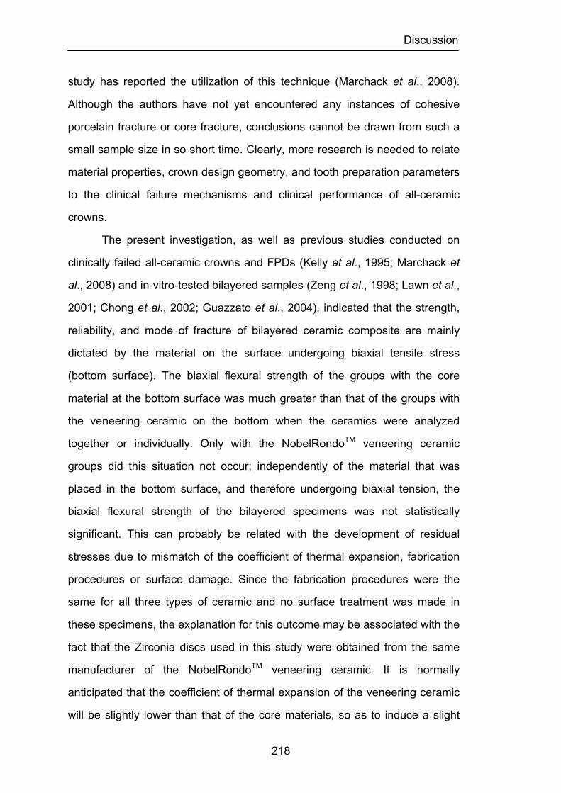
Discussion
218
study has reported the utilization of this technique (Marchack et al., 2008).
Although the authors have not yet encountered any instances of cohesive
porcelain fracture or core fracture, conclusions cannot be drawn from such a
small sample size in so short time. Clearly, more research is needed to relate
material properties, crown design geometry, and tooth preparation parameters
to the clinical failure mechanisms and clinical performance of all-ceramic
crowns.
The present investigation, as well as previous studies conducted on
clinically failed all-ceramic crowns and FPDs (Kelly et al., 1995; Marchack et
al., 2008) and in-vitro-tested bilayered samples (Zeng et al., 1998; Lawn et al.,
2001; Chong et al., 2002; Guazzato et al., 2004), indicated that the strength,
reliability, and mode of fracture of bilayered ceramic composite are mainly
dictated by the material on the surface undergoing biaxial tensile stress
(bottom surface). The biaxial flexural strength of the groups with the core
material at the bottom surface was much greater than that of the groups with
the veneering ceramic on the bottom when the ceramics were analyzed
together or individually. Only with the NobelRondoTM veneering ceramic
groups did this situation not occur; independently of the material that was
placed in the bottom surface, and therefore undergoing biaxial tension, the
biaxial flexural strength of the bilayered specimens was not statistically
significant. This can probably be related with the development of residual
stresses due to mismatch of the coefficient of thermal expansion, fabrication
procedures or surface damage. Since the fabrication procedures were the
same for all three types of ceramic and no surface treatment was made in
these specimens, the explanation for this outcome may be associated with the
fact that the Zirconia discs used in this study were obtained from the same
manufacturer of the NobelRondoTM veneering ceramic. It is normally
anticipated that the coefficient of thermal expansion of the veneering ceramic
will be slightly lower than that of the core materials, so as to induce a slight
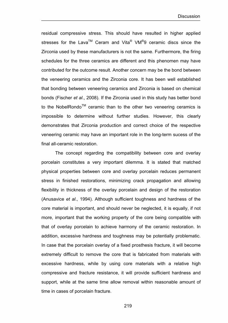
Discussion
219
residual compressive stress. This should have resulted in higher applied
stresses for the LavaTM Ceram and Vita® VM®9 ceramic discs since the
Zirconia used by these manufacturers is not the same. Furthermore, the firing
schedules for the three ceramics are different and this phenomen may have
contributed for the outcome result. Another concern may be the bond between
the veneering ceramics and the Zirconia core. It has been well established
that bonding between veneering ceramics and Zirconia is based on chemical
bonds (Fischer et al., 2008). If the Zirconia used in this study has better bond
to the NobelRondoTM ceramic than to the other two veneering ceramics is
impossible to determine without further studies. However, this clearly
demonstrates that Zirconia production and correct choice of the respective
veneering ceramic may have an important role in the long-term sucess of the
final all-ceramic restoration.
The concept regarding the compatibility between core and overlay
porcelain constitutes a very important dilemma. It is stated that matched
physical properties between core and overlay porcelain reduces permanent
stress in finished restorations, minimizing crack propagation and allowing
flexibility in thickness of the overlay porcelain and design of the restoration
(Anusavice et al., 1994). Although sufficient toughness and hardness of the
core material is important, and should never be neglected, it is equally, if not
more, important that the working property of the core being compatible with
that of overlay porcelain to achieve harmony of the ceramic restoration. In
addition, excessive hardness and toughness may be potentially problematic.
In case that the porcelain overlay of a fixed prosthesis fracture, it will become
extremely difficult to remove the core that is fabricated from materials with
excessive hardness, while by using core materials with a relative high
compressive and fracture resistance, it will provide sufficient hardness and
support, while at the same time allow removal within reasonable amount of
time in cases of porcelain fracture.
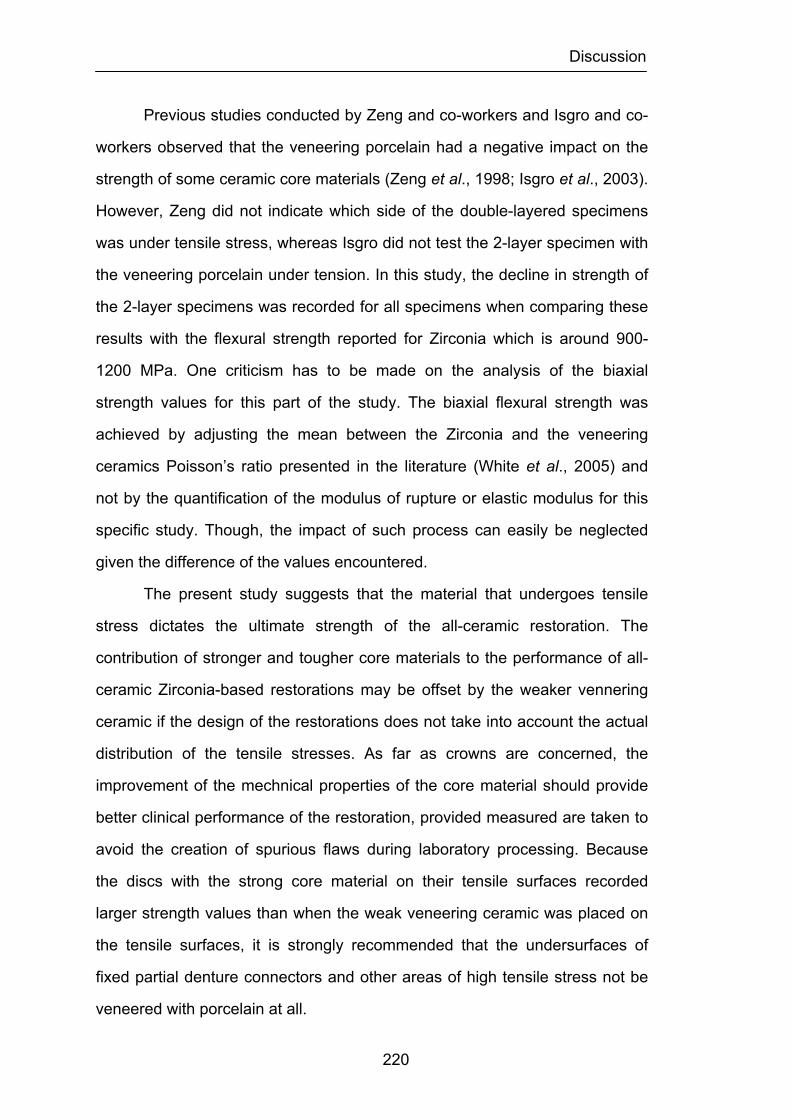
Discussion
220
Previous studies conducted by Zeng and co-workers and Isgro and co-
workers observed that the veneering porcelain had a negative impact on the
strength of some ceramic core materials (Zeng et al., 1998; Isgro et al., 2003).
However, Zeng did not indicate which side of the double-layered specimens
was under tensile stress, whereas Isgro did not test the 2-layer specimen with
the veneering porcelain under tension. In this study, the decline in strength of
the 2-layer specimens was recorded for all specimens when comparing these
results with the flexural strength reported for Zirconia which is around 900-
1200 MPa. One criticism has to be made on the analysis of the biaxial
strength values for this part of the study. The biaxial flexural strength was
achieved by adjusting the mean between the Zirconia and the veneering
ceramics Poisson’s ratio presented in the literature (White et al., 2005) and
not by the quantification of the modulus of rupture or elastic modulus for this
specific study. Though, the impact of such process can easily be neglected
given the difference of the values encountered.
The present study suggests that the material that undergoes tensile
stress dictates the ultimate strength of the all-ceramic restoration. The
contribution of stronger and tougher core materials to the performance of all-
ceramic Zirconia-based restorations may be offset by the weaker vennering
ceramic if the design of the restorations does not take into account the actual
distribution of the tensile stresses. As far as crowns are concerned, the
improvement of the mechnical properties of the core material should provide
better clinical performance of the restoration, provided measured are taken to
avoid the creation of spurious flaws during laboratory processing. Because
the discs with the strong core material on their tensile surfaces recorded
larger strength values than when the weak veneering ceramic was placed on
the tensile surfaces, it is strongly recommended that the undersurfaces of
fixed partial denture connectors and other areas of high tensile stress not be
veneered with porcelain at all.
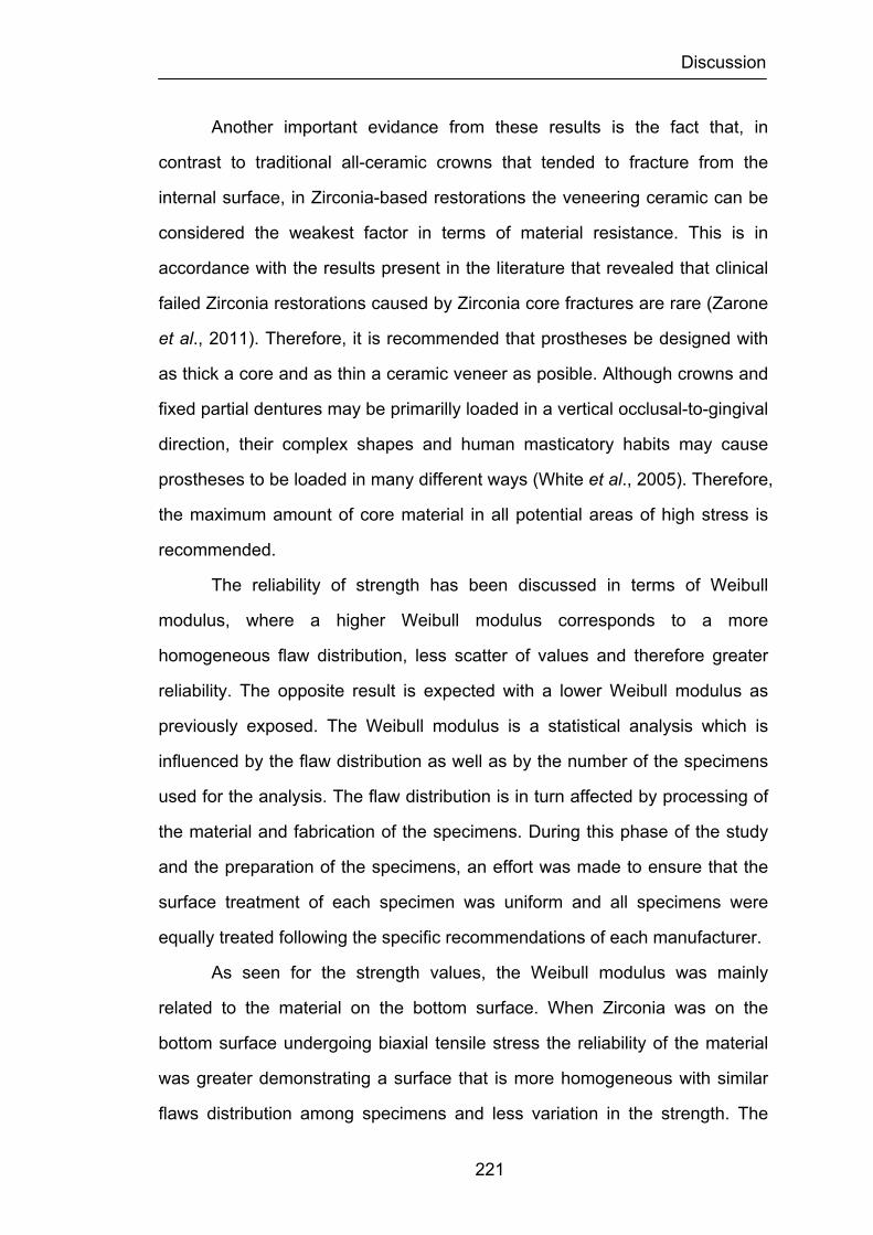
Discussion
221
Another important evidance from these results is the fact that, in
contrast to traditional all-ceramic crowns that tended to fracture from the
internal surface, in Zirconia-based restorations the veneering ceramic can be
considered the weakest factor in terms of material resistance. This is in
accordance with the results present in the literature that revealed that clinical
failed Zirconia restorations caused by Zirconia core fractures are rare (Zarone
et al., 2011). Therefore, it is recommended that prostheses be designed with
as thick a core and as thin a ceramic veneer as posible. Although crowns and
fixed partial dentures may be primarilly loaded in a vertical occlusal-to-gingival
direction, their complex shapes and human masticatory habits may cause
prostheses to be loaded in many different ways (White et al., 2005). Therefore,
the maximum amount of core material in all potential areas of high stress is
recommended.
The reliability of strength has been discussed in terms of Weibull
modulus, where a higher Weibull modulus corresponds to a more
homogeneous flaw distribution, less scatter of values and therefore greater
reliability. The opposite result is expected with a lower Weibull modulus as
previously exposed. The Weibull modulus is a statistical analysis which is
influenced by the flaw distribution as well as by the number of the specimens
used for the analysis. The flaw distribution is in turn affected by processing of
the material and fabrication of the specimens. During this phase of the study
and the preparation of the specimens, an effort was made to ensure that the
surface treatment of each specimen was uniform and all specimens were
equally treated following the specific recommendations of each manufacturer.
As seen for the strength values, the Weibull modulus was mainly
related to the material on the bottom surface. When Zirconia was on the
bottom surface undergoing biaxial tensile stress the reliability of the material
was greater demonstrating a surface that is more homogeneous with similar
flaws distribution among specimens and less variation in the strength. The

Discussion
222
production of the Zirconia discs industrially using a CAD/CAM technique
normally introduces narrow distribution and different shapes of defects and
flaws. Consequently, a smaller range of strength is expected.
The different variability in strength between all the ceramics tested
when the veneering ceramic was placed under tension may be the reason to
suspect that specimen’s preparation or type of Zirconia used in this part of the
study was a factor affecting the strength values of the NobelRondo ceramic
and the other two veneering ceramics. As far as the reliability of strength is
concerned, it should be considered that the Weibull modulus is a statistical
analysis which does not take into account some other factors which influence
the long-term clinical performance of all-ceramic Zirconia-based restorations.
For instance, a greater ratio of Zirconia/veneer ceramic or presence of
unsupported veneering ceramic areas may be capable of altering the
resistance of the restoration even when the preparation of the restorations is
the same.
The fracture mode of bilayered specimens was substantially different
according to which material underwent biaxial tensile stresses. When the core
material was on top and the veneering ceramic on the bottom, the fracture
tended to originate from a major defect at the bottom surface of the ceramic
and propagate toward the interface. The failure mode of the veneering
ceramic consisted of a star-like crack configuration radiating across the
bottom tensile surface. Inevitable failure from such cracks, opposite each
other, extended through the entire specimen. Those cracks generally met the
core near to the interface and were not deflected at the interface. Some of the
other star cracks initiated at the bottom surface did not approach the core
near to the interface and were further deflected to run along the veneering
ceramic/core interface. This behavior might be expected because of the
elastic modulus and fracture toughness mismatch between the core and
veneering ceramic. The-higher modulus core creates a greater mode II, or

Discussion
223
shear crack, loading as the crack approaches the interface, resulting in a
more inclined crack. The interlaminar crack deflection could also indicate a
relatively poor Zirconia-to-veneering ceramic bond. The clinical implication of
this finding is that this system could have a tendency to produce porcelain
“pop-off” rather than catastrophic failure. Of course, any type of damage is
unwelcome, but “pop-off” might be considered a lesser evil.
Microscopy showed that when delamination occurred, the crack
normally propagated through the lowest-toughness phase, the veneering
ceramic. In only a small number of specimens did the fracture originate at the
interface, where there was (within the stronger core material) the greatest
peak of tensile stress. In the majority of the specimens the continuing load
applied by the Instron machine resulted in catastrophic failure with fracture of
the Zirconia ceramic in different areas as a result of crack propagation
through the Zirconia core. Other investigators have shown that the fracture
origin and fracture mode are greatly influenced by the test methodology and
ct/vt ratio (White et al., 1994; Zeng et al., 1998; Thompson, 2000;
Wakabayashi et al., 2000; Guazzato et al., 2004). In this study the biaxial
flexure test was chosen because it is unaffected by edge failure and better
resembles clinical conditions compared to the uniaxial flexure test. In fact, the
biaxial flexure test more realistically replicates the in vivo situation, as it
generates the greatest number of interfacial failures. Furthermore, the disc-
shaped specimens have an area similar to dental restorations (Thompson,
2000; White et al., 2005). The site of crack initiation shifts from the veneering
porcelain to the inner core as the core/porcelain thickness ratio increases
(Wakabayashi et al., 2000). A ct/vt ratio of 1:1 was chosen in the present
study as an acceptable tradeoff between the situation of a crown and a fixed
partial denture.
When the core material was on the bottom and subjected to biaxial
tension, a Hertzian crack was seen in the veneering ceramic of the majority of

Discussion
224
the test specimens. Cone cracking was significantly extended and reached
the Zirconia core in all these samples, with partial delamination of the
veneering ceramic in the region of the cone crack but without causing fracture
of the core material. This was consistent in all the veneering ceramics tested
demonstrated like failure modes. Therefore, it is not apparent that either
residual stress remained from the ceramic firing, or finishing and polishing
procedures or that the interfacial bond was relatively poor, or that both effects
were present. Since this fracture mode was independent of the veneering
ceramic tested in this study it does not seem, as previously discussed, that
the different strength values obtained in the veneering ceramics tested are
related with the bond between the Zirconia ceramic material and the different
veneering ceramics. The results are probably related to differences in the
coefficient of thermal expansion between the veneering ceramics and the
Zirconia core.
In a few samples the cone cracking caused partial delamination as a
result of the extension of the cone crack up to and along the interface and
radial cracks progressed along the veneering ceramic causing catastrophic
failure through fracture of the Zirconia core material. This finding is consistent
with claims made in a review of the mode of fracture of flat bi- and trilayered
specimens tested with the veneering ceramic on top (Lawn et al., 2001).
Formation of a cone crack developed as a result of the contact with a blunt
indenter (corresponding to the loading piston of this study), followed by radial
cracks that initiated at the inner tensile surface and extended radially outward
within this layer. Such cracks are believed to be responsible for bulk fracture.
That study also provided an analytic analysis that relates the radial cracks in
bilayered specimens to the primary parameters and showed the linear
dependence with strength and quadratic dependence with layer thickness.
The bilayer disc mechanical model used in the present study have
been validated by finite element analysis and correlated with failure behavior

Discussion
225
(Lang et al., 2001). Although finite element analysis can identify important
trends and has relevance to more complex clinical situations, it does have
some disadvantages (Kelly et al., 1995; Kelly, 1999). It has much simpler
geometry than a fixed partial denture. It lacks thinner stress-concentrating
connectors. It does not have outer layers of ceramic on both the compressive
and tensile surfaces, as fixed partial dentures often do. It is not supported by
flexible dentine, a flexible periodontal ligament, or flexible bone. However, the
same mechanical principles do apply to crowns and fixed partial dentures.
The model is also relevant because both all-ceramic crowns and fixed partial
dentures are thought to fail most often by crack initiation during tensile loading
(Kelly et al., 1989; Thompson et al., 1994).
Predictive models, such as the finite element analysis bilayer disc
models, are widely used to study well defined systems with known parameters.
However, the current study suggests that factors such as less than optimal
interfaces and residual stresses should be included in theoretical models,
increasing their complexity and necessitating the initial exploration of such
factors. Investigation of the effects of residual stresses, various interfacial
bond strengths, and processing defects by relatively efficient theoretical
methods could be most enlightening.
It is important to note that quasi-static mechanical strength tests, used
in this study, are only a first step toward predicting clinical performance.
Dental ceramics are susceptible to the effects of chemical fatigue, or stress-
corrosion, as well as to the effects of cyclic mechanical fatigue (White, 1993;
White et al., 1997). However, comparative quasi-static mechanical testing
does provide a basis for initial comparison, and stronger dental ceramic
systems are known to give superior clinical performance compared to weaker
systems (Denry et al., 2008).
Numerous investigators have been interested in the maximal bite
forces used during mastication (Anderson, 1956; Gibbs et al., 1981; Gibbs et
Discussion
226
al., 1986) in order to understand the resistance and mode of fracture of
ceramic restorations. Apart from individual anatomic and physiologic
characteristics, it has been shown that bite force varies with the region in the
oral cavity. The greatest bite force was found in the first molar region,
whereas at the incisors it decreased to only about one third to one fourth that
in the molar region. In different studies, mean values for the maximal force
level have varied from 216 to 847 N. (Helkimo et al., 1977; Howell et al., 1959;
Linderholm et al., 1970; Ringqvist, 1973; Waltimo et al., 1993; Waltimo et al.,
1993). For the incisal region, smaller values ranging from 108 to 299 N have
been reported (Helkimo et al., 1977; Linderholm et al., 1970; Ringqvist, 1973;
Waltimo et al., 1993). Men often achieve significantly greater bite forces than
women (Waltimo et al., 1993; Waltimo et al., 1993). Additionally, cyclic fatigue
loading and stress corrosion fatigue caused by the oral environment must be
considered. According to the results of this study, such maximal loads would
be sufficient to cause ceramic failure, but not core failure, on the tensile
surfaces of fixed partial dentures and crowns of similar dimensions of the
discs tested. For this reason it is again recommended that veneering ceramic
not to be placed on tensile undersurfaces of connectors or other areas of high
tensile stress that are not supported by the core material. Similarly, the results
of this study suggest that Zirconia based restorations with a very thin core
might not withstand maximal occlusal forces, even when the core is placed in
tension and the veneering ceramic is protected in compression. For this
reason, it is recommended that thin cores not to be used, even when the
tensile undersurface is composed of core material.
Although much work has been focused on Zirconia ceramics during the
last decade, most of this work has been performed in industrial, not academic
settings. Consequently, abundant data are available in non-refereed
commercial product technical data sheets, but much less has been reported in
refereed scientific journals. Review of many commercial product data
Discussion
227
suggests that the data in this study are consistent with mid-range
performance of similar partially yttria-stabilized Zirconia. This and some other
strength values listed by the manufacturer fall within the upper ranges of
those reported in referred and no refereed literature. It is possible that such a
difference could be the result of differing specimen and test configuration,
surface preparation, and experimental conditions. However, the experimental
parameters used in this investigation fall within widely established guidelines
for the flexural testing of brittle materials.
There is considerable controversy surrounding the strengths of various
ceramic materials, and contradictory research will undoubtedly continue to
appear in the literature. Reliable laboratory data concerning the strengths of
brittle material are difficult to obtain and coefficients of variation are high.
Values are affected by a variety of factors such as geometry, temperature,
loading rates, technique variations, and fabrication and thermally-induced
imperfections. When testing crowns, mounted on laboratory materials,
inherent material strength may not be measured as much as the
characteristics of the load – the base for loading, the load-bearing applicator,
and the rate of load application. All these factors partially account for
variations in reported flexure strengths. Flexure strength is used as a measure
of crack propagation from surface microcrack, traditionally on the
undersurface of a bar or a disk. While these and similar laboratory tests may
be appropriate for comparison of inherent ultimate tensile strength of dental
ceramics, results do not necessarily extrapolate to more complex test
specimens or to the situation of the oral cavity. The laboratory cannot
accommodate intraoral variables such as the periodontal ligament, the
physical properties of the cement, the fit, and occlusion. When crowns are
cemented intraorally, factors other than and likely more important than the
inherent mechanical strength of the materials come into play. For example, a
poorly fitting crown may be weaker in a practical sense than a tightly fitting
Discussion
228
crown, regardless of the materials used; a linear relationship exists between
fit and breaking strength. Rank order strength may be affected as well as
magnitude. In addition, the strength of the core materials, because they are
used several times in thin cross-sections, may contribute only moderately to
the strength of the final restoration, and then only when maximum tensile
stresses occur at the internal surface of the restoration.
All these factors emphasize the need for a wide margin of safety when
placing brittle materials in stressful environments. The strength of dental
ceramics may be of less consequence than clinical factors such as case
selection, tooth preparation, supporting structure, and the skill of the dentist
and laboratory technician. Success remains dependent upon the skill of the
dentist and his or her knowledge of the basic behavior and indications of
restorative materials.
Furthermore, there is no single in vitro test variable that can predict
clinical performance of ceramic prostheses. Based on reviews, there is an
urgent need to develop a comprehensive classification system for identifying
clinical prosthesis failures, technical complications and biologic complications.
Guidelines on the retrieval of fractured prostheses and/or impressions that
capture the fracture surface details should also be developed. The predictive
power of in vitro data can be increased by finite element stress analysis and
computer programs that estimate the time-dependent nature of ceramic
structure survival.
The future of ceramics for dentistry is clearly open to new technologies.
However, the greatest challenge in developing all-ceramic compositions or
processing methods suitable for dental applications is satisfying strength as
well as esthetics, while ceramic materials for industrial applications generally
do not need to meet esthetic requirements. As pointed out earlier, research is
now focusing on fractographic analysis of clinically failed restorations,
measure of fatigue parameters, and lifetime prediction of ceramic restorations.
Discussion
229
It is now established that at least a five-year evaluation period must be
completed before a long-term prognosis can be proposed. The survival rates
of Zirconia-based restorations are promising. However, important
improvements of the veneering systems are required, and randomized,
controlled clinical trials are necessary for restorations in function.
The metal-ceramic technique is still the most commonly used
procedure in restorative dentistry, and the success of new all-ceramic
systems will depend as much on developmental as on analytical research.

230
Conclusions
231
CHAPTER 6
CONCLUSIONS
From the three experimental studies performed in the present work, the
following conclusions can be drawn:
1) The results require the rejection of the null hypothesis that there are
no significant differences in the load fracture resistance, measured in terms of
biaxial flexural strength, among different ceramic surface treatments in the
feldspathic veneering ceramics.
2) The results require the rejection of the null hypothesis that there are
no significant differences in the load fracture resistance, measured in terms of
biaxial flexural strength, among different ceramic surface treatments in each
feldspathic veneering ceramic.
3) The results require the rejection of the null hypothesis that there are
no significant differences in the load fracture resistance, measured in terms of
biaxial flexural strength, among the feldspathic veneering ceramics/Zirconia
ceramic frameworks independently of the side tested under tensile stress.
4) The results require the partial rejection of the null hypothesis that
there are no significant differences in the load fracture resistance, measured
in terms of biaxial flexural strength, among each feldspathic veneering
Conclusions
232
ceramic/Zirconia ceramic frameworks independently of the side tested under
tensile stress.
5) The results require the rejection of the null hypothesis that there are
no significant differences in the mode of fracture among the feldspathic
veneering ceramics/Zirconia ceramic frameworks independently of the side
tested under tensile stress.
6) Strength values of veneering ceramics for Zirconia are in the same
range to those of veneering ceramics for the metal-ceramic technique.
7) Grinding decreases the strength of veneering ceramics and in some
cases significantly.
8) Polishing and glazing have improved the strength of all materials
and in same cases significantly.
9) The results of this study suggest that surface roughness determines
the strength of a ceramic material, except where the material has an inner
structure which causes an even larger stress concentration than that caused
by the combination of surface roughness and flaws.
10) The Weibull modulus results for the three ceramic types tested are
in good agreement with values obtained in other studies found in the literature,
and correspond to the Weibull modulus range reported for most ceramics.
11) The strength, reliability, and mode of fracture of bilayered ceramic
specimens are mainly dictated by the material undergoing biaxial tensile
stress.
Conclusions
233
12) In bilayered ceramic specimens with the core material in tension,
the strength and reliability were improved by the core material that processed
better mechanical properties
12) The contribution of stronger and tougher core materials to the
performance of all-ceramic Zirconia-based restorations may be offset by the
weaker vennering ceramic if the design of the restorations does not take into
account the actual distribution of the tensile stresses.
13) In Zirconia-based restorations the veneering ceramic can be
considered the weakest factor in terms of material resistance.
14) When the Zirconia core material was placed in tension there was a
significant increase of the extension of the Hertzian cone crack that was
accompanied by partial delamination of the veneering ceramic without fracture
of the Zirconia core.
15) When the veneering ceramic was placed in tension, the fracture
tended to originate from a major defect at the bottom surface of the ceramic
and propagate toward the interface. The cracks were deflected laterally when
the stronger Zirconia core was reached demonstrating a system that could
have a tendency to produce porcelain “pop-off” rather than catastrophic failure.

234
Summary
235
SUMMARY
New processing techniques have facilitated the use of Zirconia core
materials in all-ceramic dental prostheses. Zirconia has many potential
advantages compared to existing core materials; however its performance
when layered with veneering ceramics has not been clearly evaluated.
Moreover the veneering ceramics used with Zirconia may be ground, polished
or glazed during laboratory procedures and/or clinical adjustments. These
treatments may affect their strength by introducing microscopic flaws and
defects. The purposes of this study were to investigate the effects of surface
treatments on the mean biaxial flexural strength of three feldspathic veneering
ceramics used to layer Zirconia cores: NobelRondoTM Zirconia veneer ceramic
(Nobel BiocareTM AB, Sweden), LavaTM Ceram veneer ceramic (3MTM,
ESPETM, Germany), and Vita® VM®9 veneer ceramic (Vita®, Zahnfabrick,
Germany) and compare the mean biaxial flexural strength, its reliability, and
mode of fracture of bilayered Zirconia discs veneered with the three
feldspathic veneering ceramics.
For the first part of the study one hundred and eighty monolithic disc
specimens (12.7 mm x 2.2mm), sixty for each feldspathic veneering ceramic
were prepared according to the manufacturer’s instruction and divided into
eighteen groups, 6 groups for each feldspathic veneering ceramic with 10
specimens for each group. The six groups for each feldspathic veneering
ceramic were untreated, grounded, grounded and polished, grounded and
glazed, grounded polished and glazed and polished and glazed. Mean biaxial
flexural strength and Weibull modulus were appraised. Statistical significance
Summary
236
among groups of population was analyzed using one-way and two-way
ANOVA and Fisher's PLSD comparison tests. For the second part of the study
sixty bilayered disc specimens (12.7 mm x 2.2 mm), twenty for each
feldspathic veneering ceramic were prepared using sixty Zirconia core discs
(12.7 mm x 1.1 mm) layered with the three feldspathic veneering ceramics
according to the manufacturer’s instruction and divided into 6 groups of 10
specimens for each material. Mean biaxial flexural strength and Weibull
modulus were appraised, and a scanning electron microscope was used to
describe surface features. Statistical significance among groups of population
was analyzed using two-way ANOVA, Fisher's PLSD and Student’s t-test
comparison tests.
For the first part of the study and when the veneering ceramics were
analyzed together the data provided strong evidence that there was a
significant difference in biaxial flexural strength between the grinding groups
and all other groups. When the feldspathic veneering ceramics were analyzed
individually data revealed more heterogeneity between the mean biaxial
strength of different groups. However, grinding decrease the strength of
veneering ceramics and in some cases significantly. For this reason, grinding
should always be avoided if any other procedure is to be done, as this will
either create or change the developed crack dimensions or increase the
volume loss. Conversely polishing and glazing improved the strength of all
materials and in same cases significantly. These procedures are
recommended to counteract the detrimental effects of grinding which was
related to the ability of the procedures to improve the condition of the
ceramic’s surface and free it from various defects and flaws. The Weibull
modulus values for the veneering ceramics tested varied with different
treatments. They showed higher values for polished, glazed and untreated
groups, and lower values for ground groups.
For the bilayered specimens when the veneering ceramics were
Summary
237
analyzed together, specimens with the core material on the bottom surface
were statistically stronger and more reliable than those with the veneering
ceramics on the bottom surface. When analyzed individually only in the
NobelRondoTM Zirconia veneer ceramic there was no significant difference
when the core material or the veneering ceramic was on the bottom surface.
Two different modes of fracture were observed in the bilayered specimens
according to which material was on the bottom surface.
The material that underwent tensile stress dictated the strength,
reliability, and fracture mode of the specimens. The design of the restorations
and the actual distribution of the tensile stresses must be taken into account,
otherwise the significant contribution of stronger and tougher core materials to
the performance of all-ceramic Zirconia-based restorations may be offset by
the weaker veneering ceramics.
Keywords: Zirconia, veneering ceramics, surface treatments, biaxial
flexural strength, mode of fracture.

238
Resumo
239
RESUMO
Com o objectivo de ultrapassar as limitações dos materiais em
cerâmica pura tradicionais, diversas companhias introduziram em medicina
dentária reabilitadora um material de elevada resistência composto por
cerâmica de Zircónia. A sua aplicação em prostodontia está a emergir devido
fundamentalmente às suas excelentes propriedades mecânicas, biológicas e
estéticas e ao desenvolvimento de novas tecnologias, como a tecnologia
CAD/CAM, que permitem a confecção de coroas unitárias e próteses parciais
fixas de uma forma standardizada e eficiente.
Apesar das enormes e aparentes vantagens da Zircónia,
comparativamente aos materiais cerâmicos tradicionais utilizados como infra-
estrutura de restaurações protéticas, o seu desempenho clínico quando
estratificada com cerâmicas feldspáticas de revestimento não tem sido até
agora avaliada com evidência. Do ponto de vista da selecção de material, a
substituição de materiais cerâmicos tradicionais ou mesmo alumina por
Zircónia com maior resistência deveria melhorar a performance clínica das
coroas tendo como referência a origem da fractura.
No entanto, a resistência das cerâmicas feldspáticas, e
consequentemente de uma restauração em cerâmica pura com núcleo de
Zircónia, está dependente do grau de polimento final da restauração e dos
diferentes procedimentos de fabricação no laboratório e ou ajustes clínicos
que possibilitem uma correcta adaptação e ou oclusão. Os procedimentos de
processamento e ou ajustes clínicos são passíveis de provocar pequenos
defeitos microcópicos e ou fissuras sub-críticas, que poderão ser
Resumo
240
acompanhados por uma alteração e consequente redução de resistência à
fractura. A presença destas fissuras pode como consequência de carga
clínica e ou presença de humidade crescer para uma situação crítica limite
levando a falha catastrófica. O efeito dos procedimentos de processamento
de materiais cerâmicos tem sido estudado por numerosos investigadores. No
entanto, existe ainda controvérsia no que respeita ao melhor método para
produzir a superfície mais polida e resistente.
No sentido de avaliar todas estas suposições os objectivos deste
estudo foram avaliar a resistência à fractura medida através da resistência à
flexão biaxial de cerâmicas feldspáticas de revestimento de Zircónia quando
submetidas a tratamentos de superfície nomeadamente, desgaste, polimento
e tratamento térmico; e avaliar a resistência, a fiabilidade e o modo de
fractura de restaurações em cerâmica pura com infra-estrutura de Zircónia
estratificadas com diferentes cerâmicas de revestimento.
Para alcançar estes objectivos, foram efectuadas avaliações
quantitativas da resistência à flexão biaxial, avaliações qualitativas da ultra-
morfologia e modo de fractura da interface cerâmica de revestimento – infra-
estrutura de Zircónia. A estratégia seguida levou à formulação das seguintes
hipóteses experimentais:
H1.0: Não existem diferenças significativas na resistência à fractura,
medida em termos de resistência à flexão biaxial, entre os diferentes
tratamentos de superfície no conjunto das cerâmicas feldspáticas de
revestimento.
H1.1: Existem diferenças significativas na resistência à fractura,
medida em termos de resistência à flexão biaxial, entre os diferentes
tratamentos de superfície no conjunto das cerâmicas feldspáticas de
revestimento.
Resumo
241
H2.0: Não existem diferenças significativas na resistência à fractura,
medida em termos de resistência à flexão biaxial, entre os diferentes
tratamentos de superfície em cada uma das cerâmicas feldspáticas de
revestimento.
H2.1: Existem diferenças significativas na resistência à fractura,
medida em termos de resistência à flexão biaxial, entre os diferentes
tratamentos de superfície em cada uma das cerâmicas feldspáticas de
revestimento.
H3.0: Não existem diferenças significativas na resistência à fractura,
medida em termos de resistência à flexão biaxial, no conjunto das cerâmicas
feldspáticas de revestimento/infra-estruturas de Zircónia independentemente
do material submetido a stress tensional.
H3.1: Existem diferenças significativas na resistência à fractura,
medida em termos de resistência à flexão biaxial, no conjunto das cerâmicas
feldspáticas de revestimento/infra-estruturas de Zircónia independentemente
do material submetido a stress tensional.
H4.0: Não existem diferenças significativas na resistência à fractura,
medida em termos de resistência à flexão biaxial, em cada uma das
cerâmicas feldspáticas de revestimento/infra-estruturas de Zircónia
independentemente do material submetido a stress tensional.
H4.1: Existem diferenças significativas na resistência à fractura,
medida em termos de resistência à flexão biaxial, em cada uma das
cerâmicas feldspáticas de revestimento/infra-estruturas de Zircónia
independentemente do material submetido a stress tensional.
H5.0: Não existem diferenças significativas no modo de fractura das
cerâmicas feldspáticas de revestimento/infra-estruturas de Zircónia
Resumo
242
independentemente do material submetido a stress tensional.
H5.1: Existem diferenças significativas no modo de fractura das
cerâmicas feldspáticas de revestimento/infra-estruturas de Zircónia
independentemente do material submetido a stress tensional.
Na primeira parte da investigação uma amostra de conveniência de
cento e oitenta (180) espécimes em forma de disco (12.7 mm x 2.2 mm)
foram preparados e usados neste estudo. Os discos foram fabricados com
cerâmica feldspática utilizada para estratificar infra-estruturas de Zircónia 3Y-
TZP de três (3) marcas comerciais: NobelRondoTM Zirconia veneer ceramic
(Nobel BiocareTM AB, Suécia), LavaTM Ceram veneer ceramic (3MTM,
ESPETM, Alemanha), e Vita® VM®9 veneer ceramic (Vita®, Zahnfabrick,
Alemanha).
Sessenta (60) espécimes monolíticos de cada cerâmica foram
fabricadas de acordo com as instruções ISO/DIS 6872: 1995 (three-point and
biaxial flexural strength) usando um molde de aço inoxidável (ISO/DIS 6872:
1995). O líquido de mistura e o pó cerâmico foram combinados nas
proporções recomendadas pelo fabricante. A mistura resultante de cerâmica
feldspática foi vibrada e compactada no molde e posteriormente sinterizada
em forno específico para cerâmica (Programat P500, Ivoclar Vivadent AG,
Liechtenstein). Após a primeira sinterização mais cerâmica foi adicionada por
forma a compensar a contracção resultante da primeira sinterização.
Os discos de cerâmica produzidos foram examinados com um
estereomicroscópio (Nikon SMZ-U, Tokyo, Japan) com uma ampliação X75
para avaliar a presença de pequenas fissuras ou poros. Espécimes que
demonstrassem defeitos visíveis foram substituídos. A superficie de todas os
espécimes foi posteriormente polida com discos de carbureto de silício (grão
P220, P500, P1200 - Ultra-Prep, Buehler Ltd., Lake Bluff, IL, EUA) numa
lixadora mecânica (Ecomet® 3, Buehler Ltd., Lake Buff, IL, EUA) de acordo
Resumo
243
com ISO 6344-1: 1998 (ISO/DIS 6344-1: 1998).
Este procedimento foi efectuado até serem obtidos espécimes com
2.2(± 0.1) mm por 12.7(± 0.1) mm de espessura e diâmetro respectivamente.
Um transportador especial de aço inoxidável foi utilizado para assegurar a
uniformização da espessura e paralelismo das superficies durante o corte e
polimento. As dimensões dos espécimes foram avaliadas através da
utilização de um medidor digital (Digimatic Caliper Series 500, Mitutoyo
America Corporation, Aurora, IL, EUA) por forma a garantir espessura e
diâmetros exactos. Finalmente, todas os espécimes foram limpas com água
destilada num banho de ultra-sons (Eurosonic® 4D, Euronda, Vicenza, Italia)
durante 15 minutos e posteriormente colocados no forno específico para
cerâmica onde foram auto-glazeados. Após o glaze, a espessura final e o
diâmetro foram novamente avaliados através da utilização do mesmo
medidor digital até ao centésimo de milimetro.
Os cento e oitenta (180) espécimes foram aleatoriamente distribuidos
por dezoito grupos, seis grupos para cada cerâmica, cada grupo composto
por dez espécimes. Os seis grupos experimentais de cada cerâmica foram
fabricados como anteriormente descrito e submetidos aos seguintes
tratamentos de superfície: 1) preparação segundo as instruções do fabricante
(grupo de controlo) (C), 2) com desgaste/corte da superfície com instrumento
de diamante (G), 3) com desgaste/corte da superfície com instrumento de
diamante seguido de glaze (GG), 4) com desgaste/corte da superfície com
instrumento de diamante seguido de polimento (GP), 5) com desgaste/corte
da superfície com instrumento de diamante seguido de polimento e glaze
(GPG), 6) Com polimento da superfície seguido de glaze (PG).
A resistência máxima à fractura foi medida através do método “piston-
on-three-ball” utilizando uma máquina de testes mecânicos universal Instron
(Modelo TT-BM Instron Corp., Canton, MA), e de acordo com o standard
ISO/DIS 6872 para cerâmicas dentárias (ISO/DIS 6872: 1995). A resistência
Resumo
244
máxima à fractura (N) foi registada e conjugada com a seguinte formula
(ASTM F 394-78, 1996), por forma a obter e calcular a resistência à flexão
biaxial para cada espécime: S = - 0.2387 P(X – Y)/d2 (ISO/DIS 6872: 1995).
Conjuntamente foi calculado o Weibull modulus para a resistência à flexão
biaxial obtida.
A análise estatística dos resultados foi efectuada através da utilização
do método one-way and two-way ANOVA com ajustamento de Fisher's PLSD
post-hoc para comparações múltiplas (p=0.05), para avaliar as diferenças de
resistência à fractura entre grupos.
Na segunda parte da investigação uma amostra de coveniência de
sessenta (60) espécimes em forma de disco (12.7 mm x 2.2 mm) foram
preparados e usados neste estudo. Os discos foram fabricados utilizando
sessenta discos de Zircónia 3Y-TZP produzidos por CAD/CAM (Nobel
BiocareTM AB, Suécia) (12.7 mm x 1.1 mm) que foram revestidos com
cerâmica feldspática utilizada para estratificar infra-estruturas de Zircónia 3Y-
TZP de três (3) marcas comerciais: NobelRondoTM Zirconia veneer ceramic
(Nobel BiocareTM AB, Suécia), LavaTM Ceram veneer ceramic (3MTM,
ESPETM, Alemanha), e Vita® VM®9 veneer ceramic (Vita®, Zahnfabrick,
Alemanha).
A preparação dos sessenta (60) espécimes, vinte (20) de cada
cerâmica foi efectuada de acordo com as instruções ISO/DIS 6872: 1995
(three-point and biaxial flexural strength) (ISO/DIS 6872: 1995) usando as
recomendações específicas de cada fabricante e de acordo com o
procedimento efectado para os espécimes monolíticos de cada cerâmica.
Os sessenta (60) espécimes foram aleatoriamente distribuidos por seis
grupos, dois grupos para cada cerâmica, cada grupo composto por dez
espécimes.
A resistênicia máxima à fractura foi medida através do método piston-
on-three-ball utilizando uma máquina de testes mecânicos universal Instron
Resumo
245
(Modelo TT-BM Instron Corp., Canton, MA), e de acordo com o standard
ISO/DIS 6872 para cerâmicas dentárias (ISO/DIS 6872: 1995). Em trinta (30)
espécimes, dez por cerâmica, a força foi aplicada na cerâmica felsdpática de
revestimento. Nos restante trinta (30), dez por cerâmica, a força foi aplicada
na infra-estrutura de Zircónia. O objectivo de inverter a posição dos
espécimes foi perceber a influência que a cerâmica de revestimento teria na
origem interna ou externa da fractura do material. A máxima resistência à
fractura (N) foi registada e conjugada com a seguinte formula (ASTM F 394-
78, 1996), por forma a obter e calcular a resistência à flexão biaxial para cada
especime: S = - 0.2387 P(X – Y)/d2 (ISO/DIS 6872: 1995). Conjuntamente foi
calculado o Weibull modulus para a resistência à flexão biaxial obtida.
A análise estatística dos resultados foi efectuada através da utilização
do método two-way ANOVA com ajustamento de Fisher's PLSD post-hoc e
Student’s t-test para comparações múltiplas (p=0.05), para avaliar as
diferenças de resistência à fractura entre grupos.
Após os testes de fractura todos os espécimes foram analisados com
um estereomicrocópio (Nikon SMZ-U, Tokyo, Japan) com uma ampliação de
X75 no sentido de caracterizar a origem e modo de fractura. A caracterização
morfológica dos diferentes tipos de fractura registados na interface
Zircónia/cerâmica feldspática de revestimento foi efectuada através da
utilização de microcopia electrónica de varrimento (SEM) (Amray 1820,
Bedford, MA, USA). Seis espécimes representativos, dois de cada grupo,
foram seleccionados e fotografias de diferentes amplitudes foram efectudas.
Os resultados para a primeira parte do estudo demonstraram que
quando as cerâmicas feldspáticas de revestimento são analizadas em
conjunto, os grupos de desgaste (G) apresentarm diferenças significativas em
relação a todos os outros grupos. Foram encontradas também diferenças
significativas entre os grupos de controlo (C) e os grupos de polimento/glaze
(PG). Nenhuma outra diferença significativa de resistência à flexão biaxial,
Resumo
246
entre os restantes grupos de tratamento de superfície foi encontrada.
Quando as cerâmicas feldspáticas de revestimento foram analizadas
individualmente, os resultados encontrados da resistência à flexão biaxial
entre os diferentes grupos de tratamento de superfície, foram mais
heterogéneos. No entanto, em todos as cerâmicas o tratamento de superfície
de degaste/corte (G) provocou uma diminuição de resistência à flexão biaxial,
e em alguns casos de forma estatisticamente significativa. Estes resultados
sugerem que o desgaste da superfície destas cerâmicas deve ser sempre
evitado se nenhum outro tratamento de superfície for efectuado
posteriormente, uma vez que o desgaste ou corte com instrumento de
diamante poderá criar ou alterar as dimensões de fissuras ou poros pré-
existententes diminuindo a resistência do material. Pelo contrário, os
resultados da resistência à flexão biaxial para os tratamentos de superficie de
polimento e/ou glaze (GG, GP, GPG, PG) melhoraram a resistência à flexão
biaxial dos materiais cerâmicos, e em alguns casos de forma estatisticamente
significativa. Os resultados sugerem que estes tratamentos de superfície
limitam os efeitos do desgaste/corte, devido à sua capacidade para melhorar
as condições da superfície da cerâmica, através da eliminação ou diminuição
de defeitos, fissura e/ou poros.
Os resultados sugerem que as diferenças de distribuição da
resistência à flexão biaxial entre os diferentes grupos de tratamento de
superfície estão mais dependentes da rugosidade de superfície de cada
cerâmica e consequentemente do tratamento de superfície efectuado, do que
com a sua estrutura; excepto quando a estrutura interna do material possa
provocar uma concentração de stress superior aquela originada pela
rugosidade de superfície e/ou a presença de poros ou fissuras.
Os resultados encontrados demonstraram também, que os valores
obtidos para as cerâmicas feldspáticas de revestimento para Zircónia (grupo
de controlo), se encontram dentro dos valores que as cerâmicas feldspáticas
Resumo
247
de revestimento nos sistemas metálicos apresentam.
Os resultados encontrados para o Weibull modulus das três cerâmicas
testadas são semelhantes aos valores obtidos para outras cerâmicas
feldspáticas de revestimento. Valores mais elevados foram encontrados para
os grupos de polimento, glaze e de controlo, demonstrando maior
homogeneidade de valores obtidos, do que para os grupos de desgaste.
Os resultados para a segunda parte do estudo demonstraram que,
quando os valores da resistência à flexão biaxial das cerâmicas feldspáticas
de revestimento/infra-estrutura Zircónia são analizadas em conjunto, os
espécimes que foram testados com a infra-estrutura de Zircónia na superfície
inferior, apresentaram valores estatisticamente superiores aqueles que
apresentaram as cerâmicas feldspáticas de revestimento sob tensão. Quando
analizadas individualmente apenas a NobelRondoTM Zirconia veneer ceramic
não demonstrou diferenças significativas independentemente do material que
era colocado sob tensão. Estes resultados demonstram, que o contributo de
infra-estruturas mais resistentes no desempenho clínico de restaurações em
cerâmica pura, poderá não ser significativo se o desenho da restauração não
tiver em atenção a distribuição do stress tensional sobre ela exercido.
Os resultados encontrados para o Weibull modulus das três cerâmicas
testadas são semelhantes aos valores obtidos para outras cerâmicas
feldspáticas de revestimento quando estratificadas sobre infra-estruturas
diferentes da Zircónia. Valores mais elevados foram encontrados para os
grupos que apresentavam a Zircónia sob tensão, evidenciando maior
homogeneidade de valores obtidos.
Dois modos de fractura diferentes foram predominantemente
encontrados nos espécimes, dependendo do material que era colocado em
tensão. Quando a Zircónia era colocada em tensão, um cone Hertziano
estava presente na superfície da cerâmica feldspática em practicamente
todos os espécimes. A presença deste cone, era acompanhado por traços de
Resumo
248
fractura que se propagavam lateralmente causando eventual delaminação
parcial da cerâmica feldspática de revestimento sem fractura da infra-
estrutura de Zircónia. Pelo contrário, quando as cerâmicas de revestimento
eram colocadas sob tensão, a fractura tinha origem tendencialmente num
defeito da superfície da cerâmica que se propagava até à interface cerâmica
de revestimento/ infra-estutura de Zircónia. Estes traços de fractura eram
defletidos lateralmente quando a infra-estrutura de Zircónia era atingida
provocando delaminação da cerâmica feldspática de revestimento,
demonstrando um sistema que poderá ter tendência para delaminação
parcial ou completa em vez de falha catastrófica. A continuição da aplicação
da força provocou em practicamente todos os espécimes fractura da infra-
estrutura de Zircónia.
Palavras Chave: Zircónia, cerâmicas feldspáticas de revestimento,
tratamentos de superfície, resistência à flexão biaxial, modo de fractura.
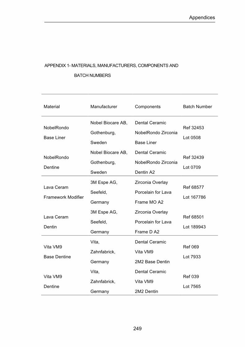
Appendices
249
APPENDIX 1- MATERIALS, MANUFACTURERS, COMPONENTS AND
BATCH NUMBERS
Material Manufacturer Components Batch Number
NobelRondo
Base Liner
Nobel Biocare AB,
Gothenburg,
Sweden
Dental Ceramic
NobelRondo Zirconia
Base Liner
Ref 32453
Lot 0508
NobelRondo
Dentine
Nobel Biocare AB,
Gothenburg,
Sweden
Dental Ceramic
NobelRondo Zirconia
Dentin A2
Ref 32439
Lot 0709
Lava Ceram
Framework Modifier
3M Espe AG,
Seefeld,
Germany
Zirconia Overlay
Porcelain for Lava
Frame MO A2
Ref 68577
Lot 167786
Lava Ceram
Dentin
3M Espe AG,
Seefeld,
Germany
Zirconia Overlay
Porcelain for Lava
Frame D A2
Ref 68501
Lot 189943
Vita VM9
Base Dentine
Vita,
Zahnfabrick,
Germany
Dental Ceramic
Vita VM9
2M2 Base Dentin
Ref 069
Lot 7933
Vita VM9
Dentine
Vita,
Zahnfabrick,
Germany
Dental Ceramic
Vita VM9
2M2 Dentin
Ref 039
Lot 7565
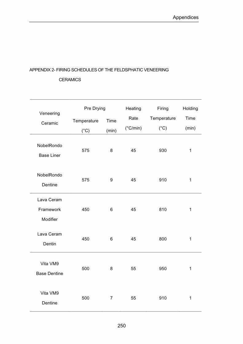
Appendices
250
APPENDIX 2- FIRING SCHEDULES OF THE FELDSPHATIC VENEERING
CERAMICS
Veneering
Ceramic
Pre Drying Heating
Rate
(°C/min)
Firing
Temperature
(°C)
Holding
Time
(min) Temperature
(°C)
Time
(min)
NobelRondo
Base Liner 575 8 45 930 1
NobelRondo
Dentine 575 9 45 910 1
Lava Ceram
Framework
Modifier
450 6 45 810 1
Lava Ceram
Dentin 450 6 45 800 1
Vita VM9
Base Dentine 500 8 55 950 1
Vita VM9
Dentine 500 7 55 910 1
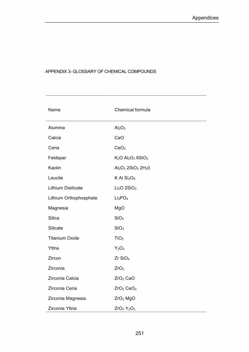
Appendices
251
APPENDIX 3- GLOSSARY OF CHEMICAL COMPOUNDS
Name Chemical formula
Alumina Al2O3
Calcia CaO
Ceria CeO2
Feldspar K2O Al2O3 6SiO2
Kaolin Al2O3 2SiO2 2H20
Leucite K Al Si2O6
Lithium Disilicate Li2O 2SiO2
Lithium Orthophosphate Li3PO4
Magnesia MgO
Silica SiO2
Silicate SiO3
Titanium Oxide TiO2
Yttria Y2O3
Zircon Zr SiO4
Zirconia ZrO2
Zirconia Calcia ZrO2 CaO
Zirconia Ceria ZrO2 CeO2
Zirconia Magnesia ZrO2 MgO
Zirconia Yttria ZrO2 Y2O3
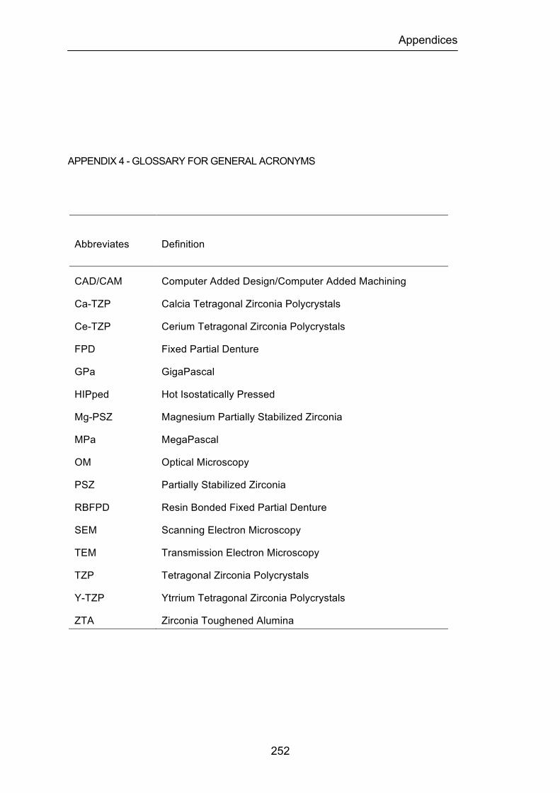
Appendices
252
APPENDIX 4 - GLOSSARY FOR GENERAL ACRONYMS
Abbreviates Definition
CAD/CAM Computer Added Design/Computer Added Machining
Ca-TZP Calcia Tetragonal Zirconia Polycrystals
Ce-TZP Cerium Tetragonal Zirconia Polycrystals
FPD Fixed Partial Denture
GPa GigaPascal
HIPped Hot Isostatically Pressed
Mg-PSZ Magnesium Partially Stabilized Zirconia
MPa MegaPascal
OM Optical Microscopy
PSZ Partially Stabilized Zirconia
RBFPD Resin Bonded Fixed Partial Denture
SEM Scanning Electron Microscopy
TEM Transmission Electron Microscopy
TZP Tetragonal Zirconia Polycrystals
Y-TZP Ytrrium Tetragonal Zirconia Polycrystals
ZTA Zirconia Toughened Alumina
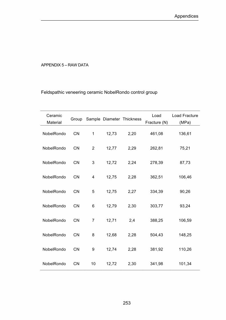
Appendices
253
APPENDIX 5 – RAW DATA
Feldspathic veneering ceramic NobelRondo control group
Ceramic Material
Group Sample Diameter Thickness Load
Fracture (N) Load Fracture (MPa)
NobelRondo CN 1 12,73 2,20 461,08 136,61
NobelRondo CN 2 12,77 2,29 262,81 75,21
NobelRondo CN 3 12,72 2,24 278,39 87,73
NobelRondo CN 4 12,75 2,28 362,51 106,46
NobelRondo CN 5 12,75 2,27 334,39 90,26
NobelRondo CN 6 12,79 2,30 303,77 93,24
NobelRondo CN 7 12,71 2,4 388,25 106,59
NobelRondo CN 8 12,68 2,28 504,43 148,25
NobelRondo CN 9 12,74 2,28 381,92 110,26
NobelRondo CN 10 12,72 2,30 341,98 101,34
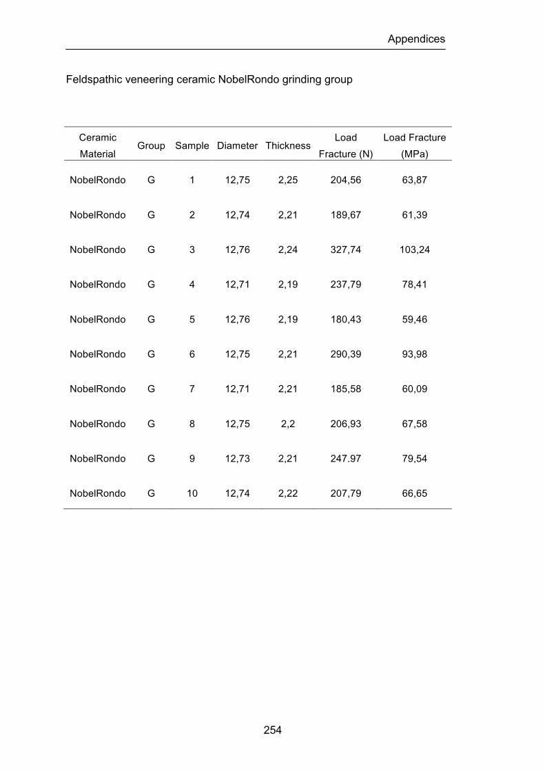
Appendices
254
Feldspathic veneering ceramic NobelRondo grinding group
Ceramic Material
Group Sample Diameter Thickness Load
Fracture (N) Load Fracture (MPa)
NobelRondo G 1 12,75 2,25 204,56 63,87
NobelRondo G 2 12,74 2,21 189,67 61,39
NobelRondo G 3 12,76 2,24 327,74 103,24
NobelRondo G 4 12,71 2,19 237,79 78,41
NobelRondo G 5 12,76 2,19 180,43 59,46
NobelRondo G 6 12,75 2,21 290,39 93,98
NobelRondo G 7 12,71 2,21 185,58 60,09
NobelRondo G 8 12,75 2,2 206,93 67,58
NobelRondo G 9 12,73 2,21 247.97 79,54
NobelRondo G 10 12,74 2,22 207,79 66,65
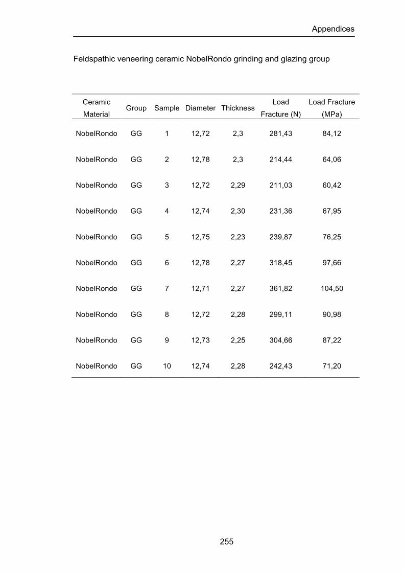
Appendices
255
Feldspathic veneering ceramic NobelRondo grinding and glazing group
Ceramic Material
Group Sample Diameter Thickness Load
Fracture (N) Load Fracture (MPa)
NobelRondo GG 1 12,72 2,3 281,43 84,12
NobelRondo GG 2 12,78 2,3 214,44 64,06
NobelRondo GG 3 12,72 2,29 211,03 60,42
NobelRondo GG 4 12,74 2,30 231,36 67,95
NobelRondo GG 5 12,75 2,23 239,87 76,25
NobelRondo GG 6 12,78 2,27 318,45 97,66
NobelRondo GG 7 12,71 2,27 361,82 104,50
NobelRondo GG 8 12,72 2,28 299,11 90,98
NobelRondo GG 9 12,73 2,25 304,66 87,22
NobelRondo GG 10 12,74 2,28 242,43 71,20
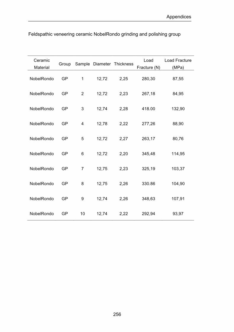
Appendices
256
Feldspathic veneering ceramic NobelRondo grinding and polishing group
Ceramic Material
Group Sample Diameter Thickness Load
Fracture (N) Load Fracture (MPa)
NobelRondo GP 1 12,72 2,25 280,30 87,55
NobelRondo GP 2 12,72 2,23 267,18 84,95
NobelRondo GP 3 12,74 2,28 418.00 132,90
NobelRondo GP 4 12,78 2,22 277,26 88,90
NobelRondo GP 5 12,72 2,27 263,17 80,76
NobelRondo GP 6 12,72 2,20 345,48 114,95
NobelRondo GP 7 12,75 2,23 325,19 103,37
NobelRondo GP 8 12,75 2,26 330.86 104,90
NobelRondo GP 9 12,74 2,26 348,63 107,91
NobelRondo GP 10 12,74 2,22 292,94 93,97
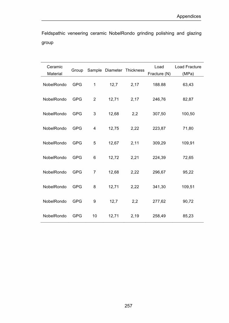
Appendices
257
Feldspathic veneering ceramic NobelRondo grinding polishing and glazing
group
Ceramic Material
Group Sample Diameter Thickness Load
Fracture (N) Load Fracture (MPa)
NobelRondo GPG 1 12,7 2,17 188.88 63,43
NobelRondo GPG 2 12,71 2,17 246,76 82,87
NobelRondo GPG 3 12,68 2,2 307,50 100,50
NobelRondo GPG 4 12,75 2,22 223,87 71,80
NobelRondo GPG 5 12,67 2,11 309,29 109,91
NobelRondo GPG 6 12,72 2,21 224,39 72,65
NobelRondo GPG 7 12,68 2,22 296,67 95,22
NobelRondo GPG 8 12,71 2,22 341,30 109,51
NobelRondo GPG 9 12,7 2,2 277,62 90,72
NobelRondo GPG 10 12,71 2,19 258,49 85,23
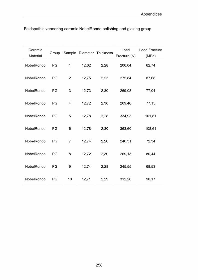
Appendices
258
Feldspathic veneering ceramic NobelRondo polishing and glazing group
Ceramic Material
Group Sample Diameter Thickness Load
Fracture (N) Load Fracture (MPa)
NobelRondo PG 1 12,62 2,28 206,04 62,74
NobelRondo PG 2 12,75 2,23 275,84 87,68
NobelRondo PG 3 12,73 2,30 269,08 77,04
NobelRondo PG 4 12,72 2,30 269,46 77,15
NobelRondo PG 5 12,78 2,28 334,93 101,81
NobelRondo PG 6 12,78 2,30 363,60 108,61
NobelRondo PG 7 12,74 2,20 246,31 72,34
NobelRondo PG 8 12,72 2,30 269,13 80,44
NobelRondo PG 9 12,74 2,28 245,55 68,53
NobelRondo PG 10 12,71 2,29 312,20 90,17
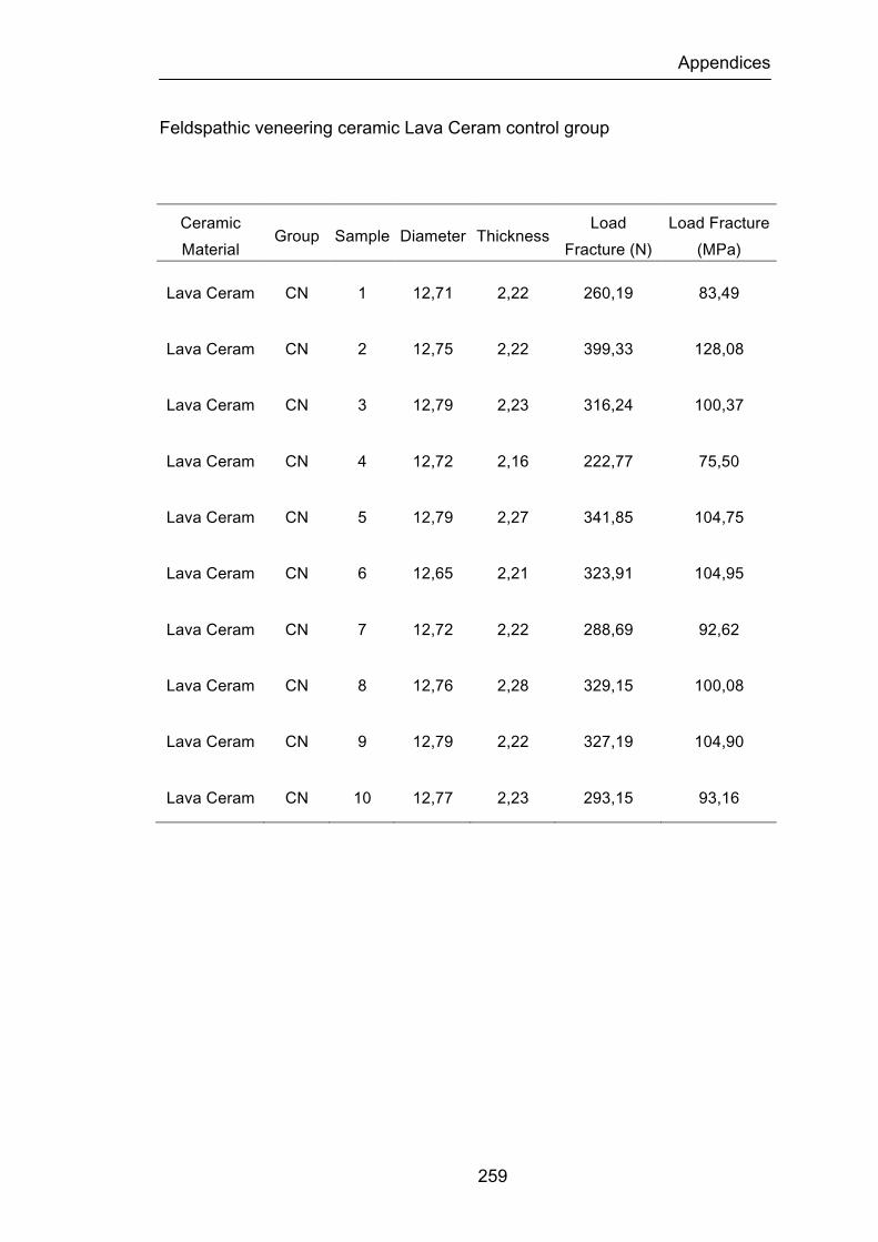
Appendices
259
Feldspathic veneering ceramic Lava Ceram control group
Ceramic Material
Group Sample Diameter Thickness Load
Fracture (N) Load Fracture (MPa)
Lava Ceram CN 1 12,71 2,22 260,19 83,49
Lava Ceram CN 2 12,75 2,22 399,33 128,08
Lava Ceram CN 3 12,79 2,23 316,24 100,37
Lava Ceram CN 4 12,72 2,16 222,77 75,50
Lava Ceram CN 5 12,79 2,27 341,85 104,75
Lava Ceram CN 6 12,65 2,21 323,91 104,95
Lava Ceram CN 7 12,72 2,22 288,69 92,62
Lava Ceram CN 8 12,76 2,28 329,15 100,08
Lava Ceram CN 9 12,79 2,22 327,19 104,90
Lava Ceram CN 10 12,77 2,23 293,15 93,16
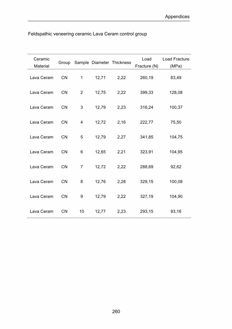
Appendices
260
Feldspathic veneering ceramic Lava Ceram control group
Ceramic Material
Group Sample Diameter Thickness Load
Fracture (N) Load Fracture (MPa)
Lava Ceram CN 1 12,71 2,22 260,19 83,49
Lava Ceram CN 2 12,75 2,22 399,33 128,08
Lava Ceram CN 3 12,79 2,23 316,24 100,37
Lava Ceram CN 4 12,72 2,16 222,77 75,50
Lava Ceram CN 5 12,79 2,27 341,85 104,75
Lava Ceram CN 6 12,65 2,21 323,91 104,95
Lava Ceram CN 7 12,72 2,22 288,69 92,62
Lava Ceram CN 8 12,76 2,28 329,15 100,08
Lava Ceram CN 9 12,79 2,22 327,19 104,90
Lava Ceram CN 10 12,77 2,23 293,15 93,16
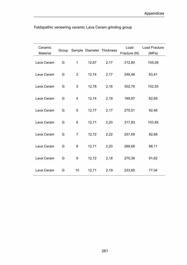
Appendices
261
Feldspathic veneering ceramic Lava Ceram grinding group
Ceramic Material
Group Sample Diameter Thickness Load
Fracture (N) Load Fracture (MPa)
Lava Ceram G 1 12,67 2,17 312,80 105,09
Lava Ceram G 2 12,74 2,17 248,46 83,41
Lava Ceram G 3 12,78 2,16 302,78 102,55
Lava Ceram G 4 12,74 2,19 189,97 62,69
Lava Ceram G 5 12,77 2,17 275,51 92,46
Lava Ceram G 6 12,71 2,20 317,83 103,85
Lava Ceram G 7 12,72 2,22 257,69 82,68
Lava Ceram G 8 12,71 2,20 268,68 88,11
Lava Ceram G 9 12,72 2,18 275,36 91,62
Lava Ceram G 10 12,71 2,19 233,65 77,04

Appendices
262
Feldspathic veneering ceramic Lava Ceram grinding and glazing group
Ceramic Material
Group Sample Diameter Thickness Load
Fracture (N) Load Fracture (MPa)
Lava Ceram GG 1 12,65 2,17 245,65 82,55
Lava Ceram GG 2 12,79 2,16 315,61 106,81
Lava Ceram GG 3 12,72 2,18 221,91 73,83
Lava Ceram GG 4 12,70 2,19 382,71 126,63
Lava Ceram GG 5 12,80 2,20 326,25 106,49
Lava Ceram GG 6 12,74 2,19 307,96 101,51
Lava Ceram GG 7 12,80 2,17 419,54 140,76
Lava Ceram GG 8 12,74 2,20 330,55 107,97
Lava Ceram GG 9 12,73 2,17 340,81 114,43
Lava Ceram GG 10 12,74 2,18 320,63 106,66

Appendices
263
Feldspathic veneering ceramic Lava Ceram grinding and polishing group
Ceramic Material
Group Sample Diameter Thickness Load
Fracture (N) Load Fracture (MPa)
Lava Ceram GP 1 12,68 2,18 296,28 98,62
Lava Ceram GP 2 12,74 2,19 375,07 123,63
Lava Ceram GP 3 12,77 2,21 357,32 115,62
Lava Ceram GP 4 12,67 2,19 329,47 108,68
Lava Ceram GP 5 12,74 2,20 276,69 90,37
Lava Ceram GP 6 12,66 2,21 245,14 79,42
Lava Ceram GP 7 12,67 2,20 266,66 87,16
Lava Ceram GP 8 12,80 2,22 238,23 76,32
Lava Ceram GP 9 12,74 2,20 356,24 116,36
Lava Ceram GP 10 12,71 2,20 323,77 105,79
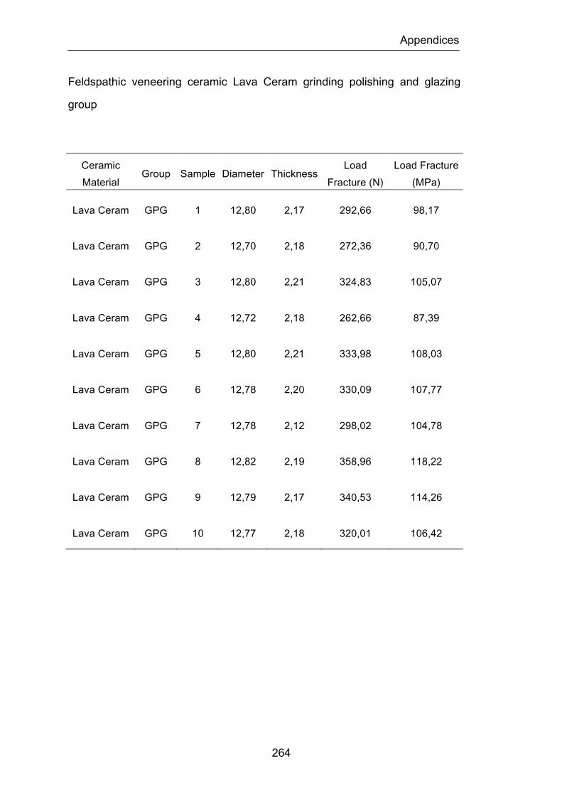
Appendices
264
Feldspathic veneering ceramic Lava Ceram grinding polishing and glazing
group
Ceramic Material
Group Sample Diameter Thickness Load
Fracture (N) Load Fracture (MPa)
Lava Ceram GPG 1 12,80 2,17 292,66 98,17
Lava Ceram GPG 2 12,70 2,18 272,36 90,70
Lava Ceram GPG 3 12,80 2,21 324,83 105,07
Lava Ceram GPG 4 12,72 2,18 262,66 87,39
Lava Ceram GPG 5 12,80 2,21 333,98 108,03
Lava Ceram GPG 6 12,78 2,20 330,09 107,77
Lava Ceram GPG 7 12,78 2,12 298,02 104,78
Lava Ceram GPG 8 12,82 2,19 358,96 118,22
Lava Ceram GPG 9 12,79 2,17 340,53 114,26
Lava Ceram GPG 10 12,77 2,18 320,01 106,42
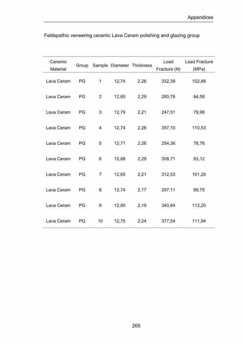
Appendices
265
Feldspathic veneering ceramic Lava Ceram polishing and glazing group
Ceramic Material
Group Sample Diameter Thickness Load
Fracture (N) Load Fracture (MPa)
Lava Ceram PG 1 12,74 2,26 332,39 102,88
Lava Ceram PG 2 12,80 2,29 280,76 84,58
Lava Ceram PG 3 12,79 2,21 247,51 79,98
Lava Ceram PG 4 12,74 2,26 357,10 110,53
Lava Ceram PG 5 12,71 2,26 254,36 78,76
Lava Ceram PG 6 12,68 2,29 308,71 93,12
Lava Ceram PG 7 12,65 2,21 312,53 101,26
Lava Ceram PG 8 12,74 2,17 297,11 99,75
Lava Ceram PG 9 12,80 2,19 340,64 112,20
Lava Ceram PG 10 12,75 2,24 377,54 111,94
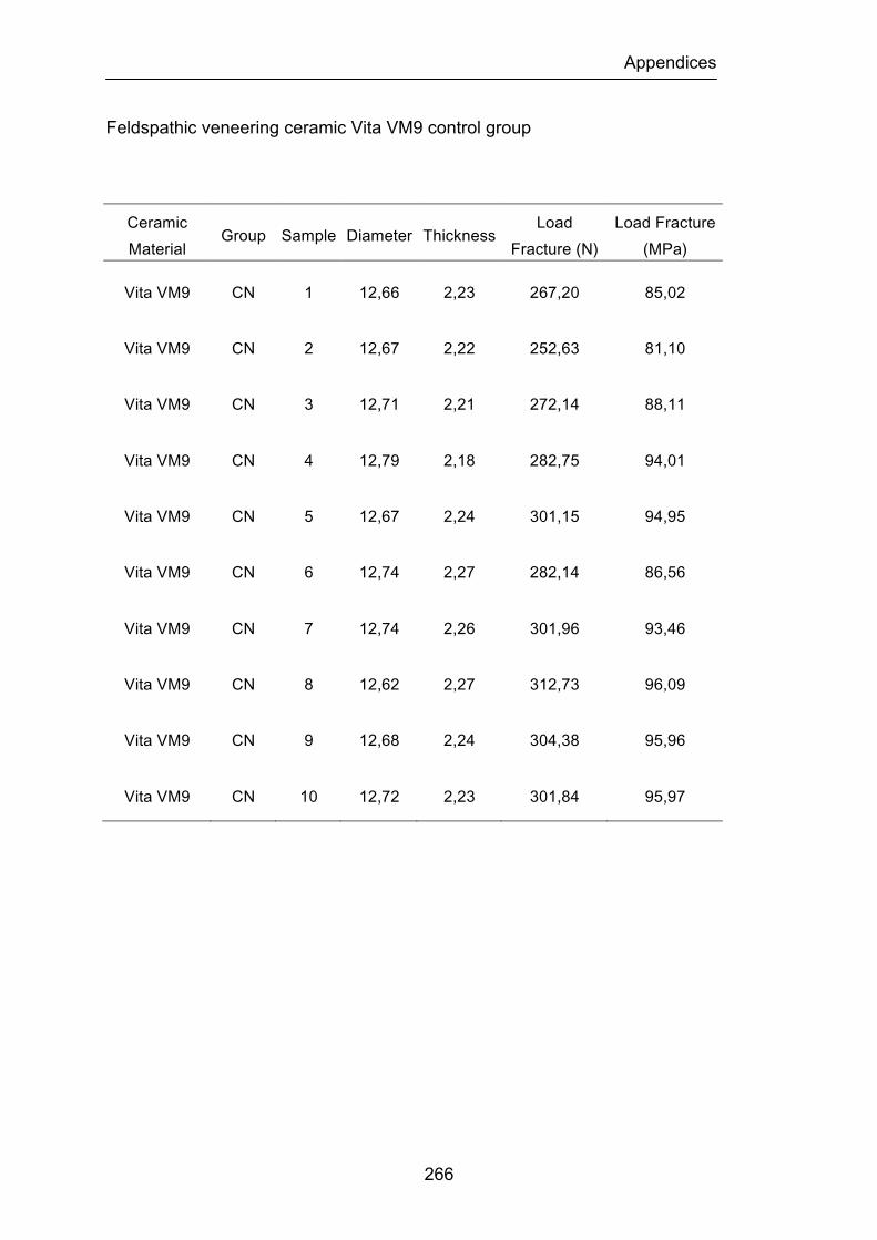
Appendices
266
Feldspathic veneering ceramic Vita VM9 control group
Ceramic Material
Group Sample Diameter Thickness Load
Fracture (N) Load Fracture (MPa)
Vita VM9 CN 1 12,66 2,23 267,20 85,02
Vita VM9 CN 2 12,67 2,22 252,63 81,10
Vita VM9 CN 3 12,71 2,21 272,14 88,11
Vita VM9 CN 4 12,79 2,18 282,75 94,01
Vita VM9 CN 5 12,67 2,24 301,15 94,95
Vita VM9 CN 6 12,74 2,27 282,14 86,56
Vita VM9 CN 7 12,74 2,26 301,96 93,46
Vita VM9 CN 8 12,62 2,27 312,73 96,09
Vita VM9 CN 9 12,68 2,24 304,38 95,96
Vita VM9 CN 10 12,72 2,23 301,84 95,97
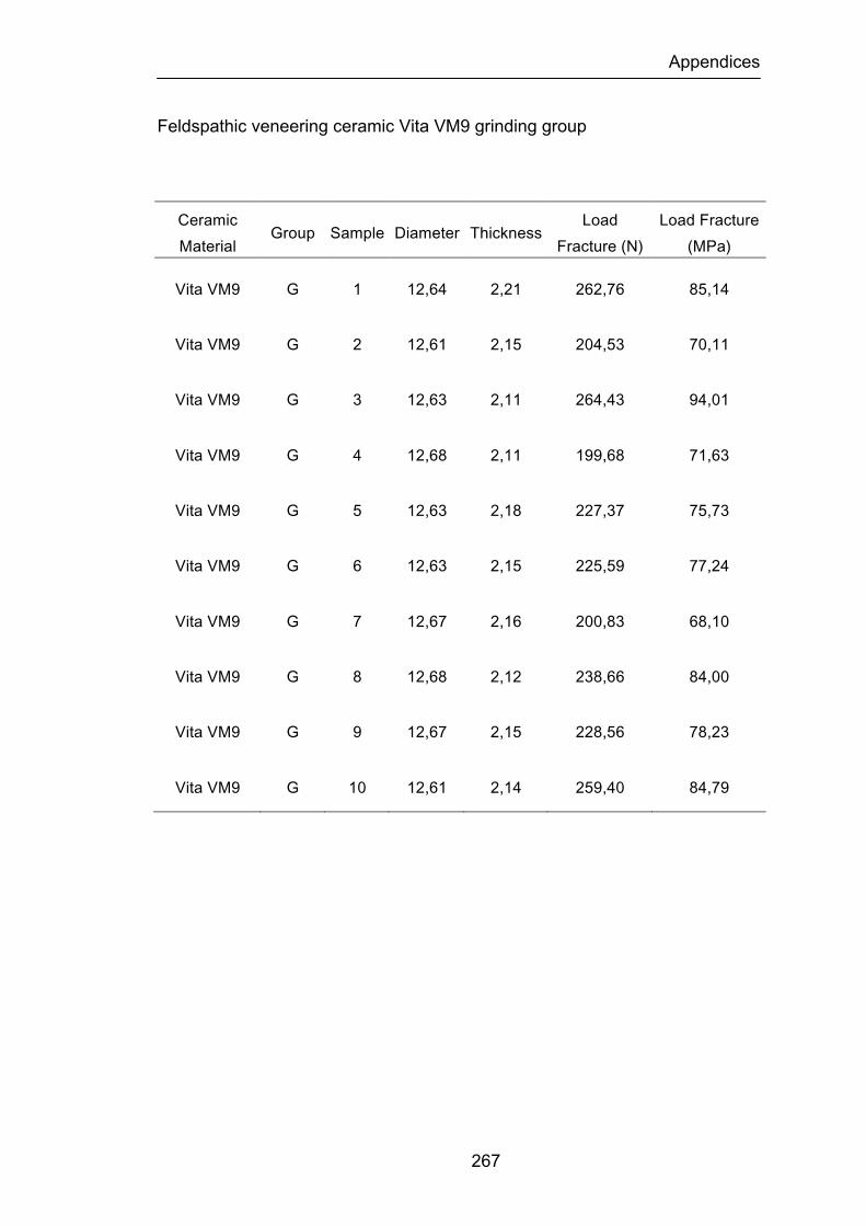
Appendices
267
Feldspathic veneering ceramic Vita VM9 grinding group
Ceramic Material
Group Sample Diameter Thickness Load
Fracture (N) Load Fracture (MPa)
Vita VM9 G 1 12,64 2,21 262,76 85,14
Vita VM9 G 2 12,61 2,15 204,53 70,11
Vita VM9 G 3 12,63 2,11 264,43 94,01
Vita VM9 G 4 12,68 2,11 199,68 71,63
Vita VM9 G 5 12,63 2,18 227,37 75,73
Vita VM9 G 6 12,63 2,15 225,59 77,24
Vita VM9 G 7 12,67 2,16 200,83 68,10
Vita VM9 G 8 12,68 2,12 238,66 84,00
Vita VM9 G 9 12,67 2,15 228,56 78,23
Vita VM9 G 10 12,61 2,14 259,40 84,79
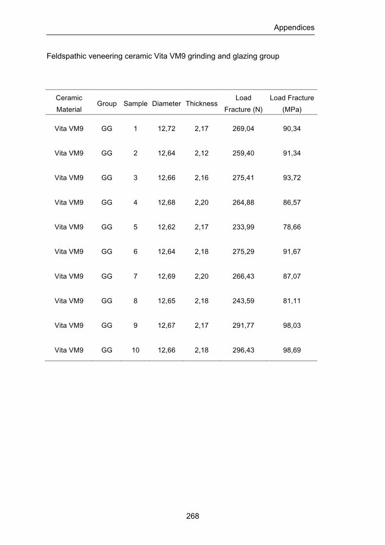
Appendices
268
Feldspathic veneering ceramic Vita VM9 grinding and glazing group
Ceramic Material
Group Sample Diameter Thickness Load
Fracture (N) Load Fracture (MPa)
Vita VM9 GG 1 12,72 2,17 269,04 90,34
Vita VM9 GG 2 12,64 2,12 259,40 91,34
Vita VM9 GG 3 12,66 2,16 275,41 93,72
Vita VM9 GG 4 12,68 2,20 264,88 86,57
Vita VM9 GG 5 12,62 2,17 233,99 78,66
Vita VM9 GG 6 12,64 2,18 275,29 91,67
Vita VM9 GG 7 12,69 2,20 266,43 87,07
Vita VM9 GG 8 12,65 2,18 243,59 81,11
Vita VM9 GG 9 12,67 2,17 291,77 98,03
Vita VM9 GG 10 12,66 2,18 296,43 98,69
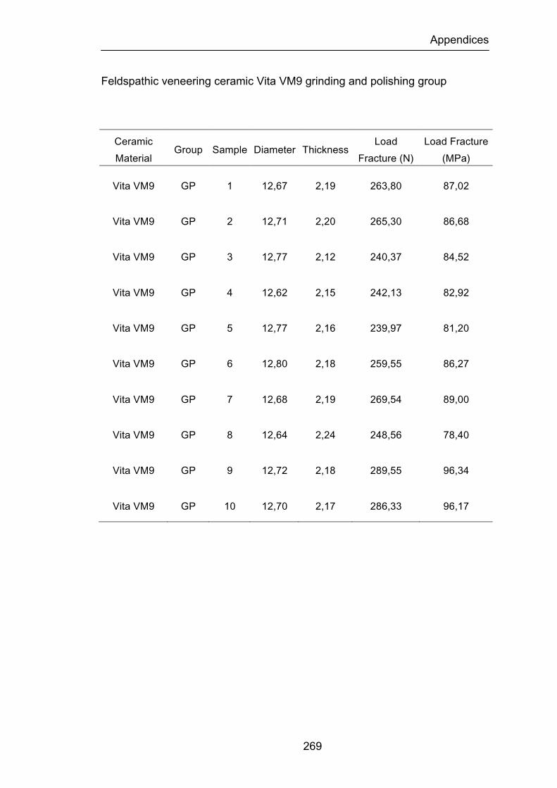
Appendices
269
Feldspathic veneering ceramic Vita VM9 grinding and polishing group
Ceramic Material
Group Sample Diameter Thickness Load
Fracture (N) Load Fracture (MPa)
Vita VM9 GP 1 12,67 2,19 263,80 87,02
Vita VM9 GP 2 12,71 2,20 265,30 86,68
Vita VM9 GP 3 12,77 2,12 240,37 84,52
Vita VM9 GP 4 12,62 2,15 242,13 82,92
Vita VM9 GP 5 12,77 2,16 239,97 81,20
Vita VM9 GP 6 12,80 2,18 259,55 86,27
Vita VM9 GP 7 12,68 2,19 269,54 89,00
Vita VM9 GP 8 12,64 2,24 248,56 78,40
Vita VM9 GP 9 12,72 2,18 289,55 96,34
Vita VM9 GP 10 12,70 2,17 286,33 96,17
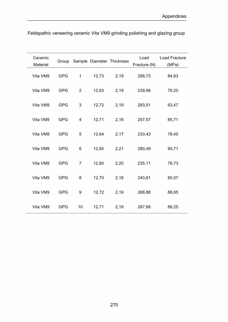
Appendices
270
Feldspathic veneering ceramic Vita VM9 grinding polishing and glazing group
Ceramic Material
Group Sample Diameter Thickness Load
Fracture (N) Load Fracture (MPa)
Vita VM9 GPG 1 12,73 2,19 256,73 84,63
Vita VM9 GPG 2 12,63 2,19 239,98 79,20
Vita VM9 GPG 3 12,72 2,19 283,51 93,47
Vita VM9 GPG 4 12,71 2,18 257,57 85,71
Vita VM9 GPG 5 12,64 2,17 233,43 78,45
Vita VM9 GPG 6 12,80 2,21 280,49 90,71
Vita VM9 GPG 7 12,80 2,20 235,11 76,73
Vita VM9 GPG 8 12,70 2,18 240,61 80,07
Vita VM9 GPG 9 12,72 2,19 268,88 88,65
Vita VM9 GPG 10 12,71 2,19 267,66 88,25
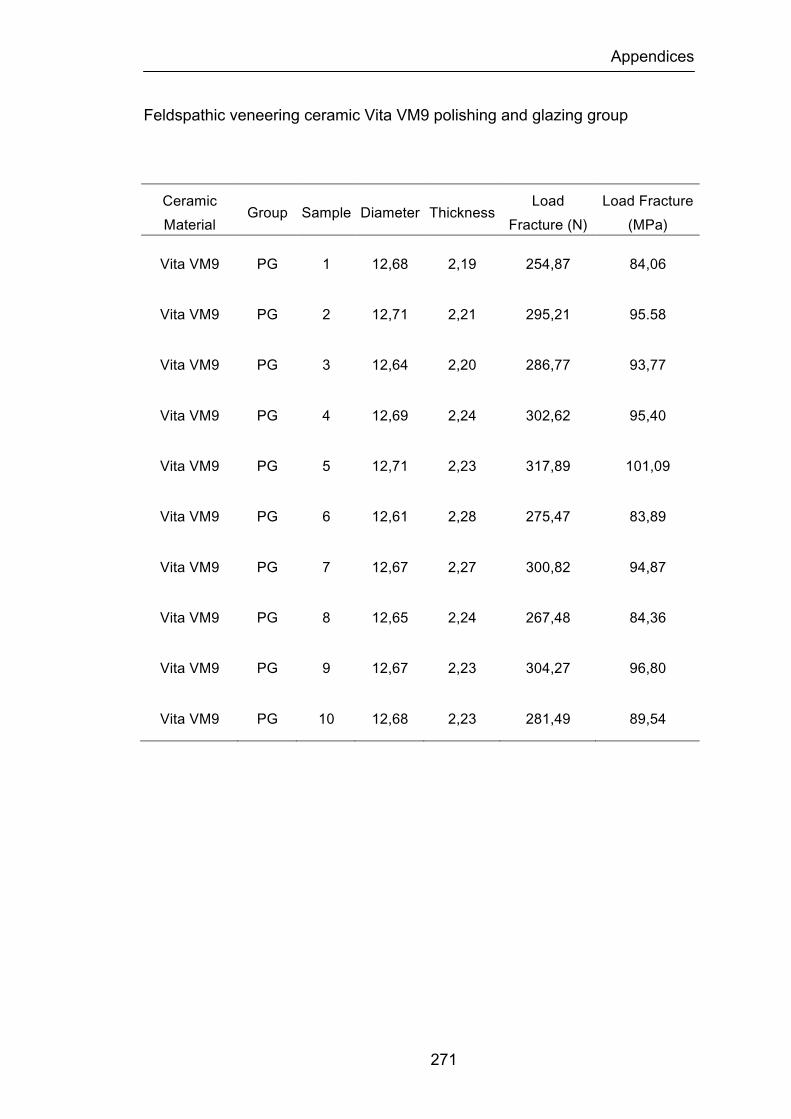
Appendices
271
Feldspathic veneering ceramic Vita VM9 polishing and glazing group
Ceramic Material
Group Sample Diameter Thickness Load
Fracture (N) Load Fracture (MPa)
Vita VM9 PG 1 12,68 2,19 254,87 84,06
Vita VM9 PG 2 12,71 2,21 295,21 95.58
Vita VM9 PG 3 12,64 2,20 286,77 93,77
Vita VM9 PG 4 12,69 2,24 302,62 95,40
Vita VM9 PG 5 12,71 2,23 317,89 101,09
Vita VM9 PG 6 12,61 2,28 275,47 83,89
Vita VM9 PG 7 12,67 2,27 300,82 94,87
Vita VM9 PG 8 12,65 2,24 267,48 84,36
Vita VM9 PG 9 12,67 2,23 304,27 96,80
Vita VM9 PG 10 12,68 2,23 281,49 89,54

Appendices
272
Feldspathic veneering ceramic NobelRondo and Zirconia group
Ceramic Material
Group Sample Diameter Thickness Load Fracture
(N) Load Fracture (MPa)
NobelRondo
Zirconia
ZR Bottom
1 12,68 2,44 1392,79 378,55
NobelRondo
Zirconia
ZR
Bottom 2 12,67 2,4 2126,96 597,80
NobelRondo
Zirconia
ZR
Bottom 3 12,69 2,43 1816,37 497,74
NobelRondo
Zirconia
ZR
Bottom 4 12,68 2,33 2113,96 689,31
NobelRondo
Zirconia
ZR
Bottom 5 12,66 2,41 1952,62 544,26
NobelRondo
Zirconia
ZR
Bottom 6 12,67 2,50 1456,48 376,92
NobelRondo
Zirconia
ZR
Bottom 7 12,66 2,42 1813,04 501,14
NobelRondo
Zirconia
ZR
Bottom 8 12,67 2,47 2115,30 560,94
NobelRondo
Zirconia
ZR
Bottom 9 12,68 2,43 1821,56 499,21
NobelRondo
Zirconia
ZR
Bottom 10 12,66 2,42 1956,11 540,69
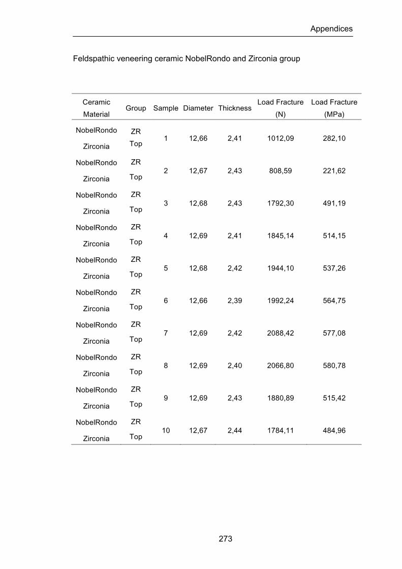
Appendices
273
Feldspathic veneering ceramic NobelRondo and Zirconia group
Ceramic Material
Group Sample Diameter Thickness Load Fracture
(N) Load Fracture (MPa)
NobelRondo
Zirconia
ZR Top
1 12,66 2,41 1012,09 282,10
NobelRondo
Zirconia
ZR
Top 2 12,67 2,43 808,59 221,62
NobelRondo
Zirconia
ZR
Top 3 12,68 2,43 1792,30 491,19
NobelRondo
Zirconia
ZR
Top 4 12,69 2,41 1845,14 514,15
NobelRondo
Zirconia
ZR
Top 5 12,68 2,42 1944,10 537,26
NobelRondo
Zirconia
ZR
Top 6 12,66 2,39 1992,24 564,75
NobelRondo
Zirconia
ZR
Top 7 12,69 2,42 2088,42 577,08
NobelRondo
Zirconia
ZR
Top 8 12,69 2,40 2066,80 580,78
NobelRondo
Zirconia
ZR
Top 9 12,69 2,43 1880,89 515,42
NobelRondo
Zirconia
ZR
Top 10 12,67 2,44 1784,11 484,96
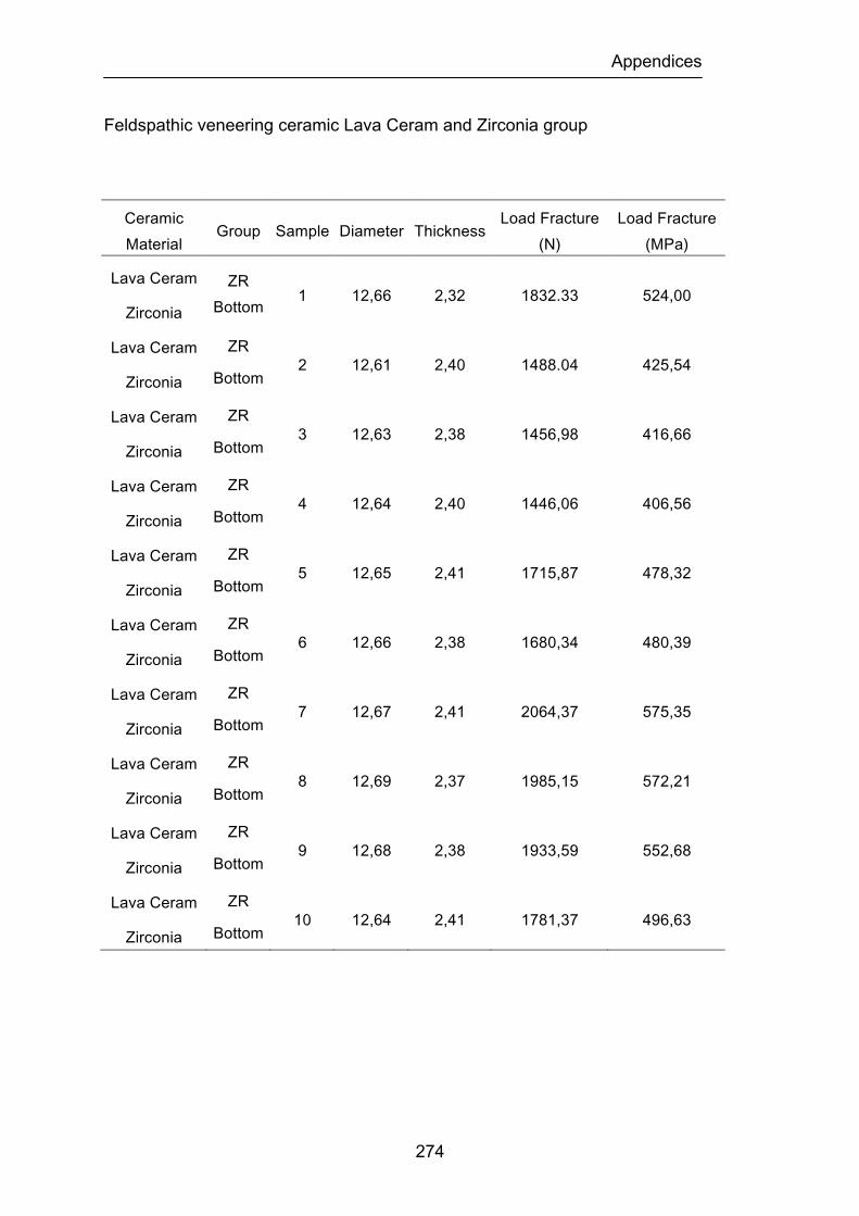
Appendices
274
Feldspathic veneering ceramic Lava Ceram and Zirconia group
Ceramic Material
Group Sample Diameter Thickness Load Fracture
(N) Load Fracture (MPa)
Lava Ceram
Zirconia
ZR Bottom
1 12,66 2,32 1832.33 524,00
Lava Ceram
Zirconia
ZR
Bottom 2 12,61 2,40 1488.04 425,54
Lava Ceram
Zirconia
ZR
Bottom 3 12,63 2,38 1456,98 416,66
Lava Ceram
Zirconia
ZR
Bottom 4 12,64 2,40 1446,06 406,56
Lava Ceram
Zirconia
ZR
Bottom 5 12,65 2,41 1715,87 478,32
Lava Ceram
Zirconia
ZR
Bottom 6 12,66 2,38 1680,34 480,39
Lava Ceram
Zirconia
ZR
Bottom 7 12,67 2,41 2064,37 575,35
Lava Ceram
Zirconia
ZR
Bottom 8 12,69 2,37 1985,15 572,21
Lava Ceram
Zirconia
ZR
Bottom 9 12,68 2,38 1933,59 552,68
Lava Ceram
Zirconia
ZR
Bottom 10 12,64 2,41 1781,37 496,63
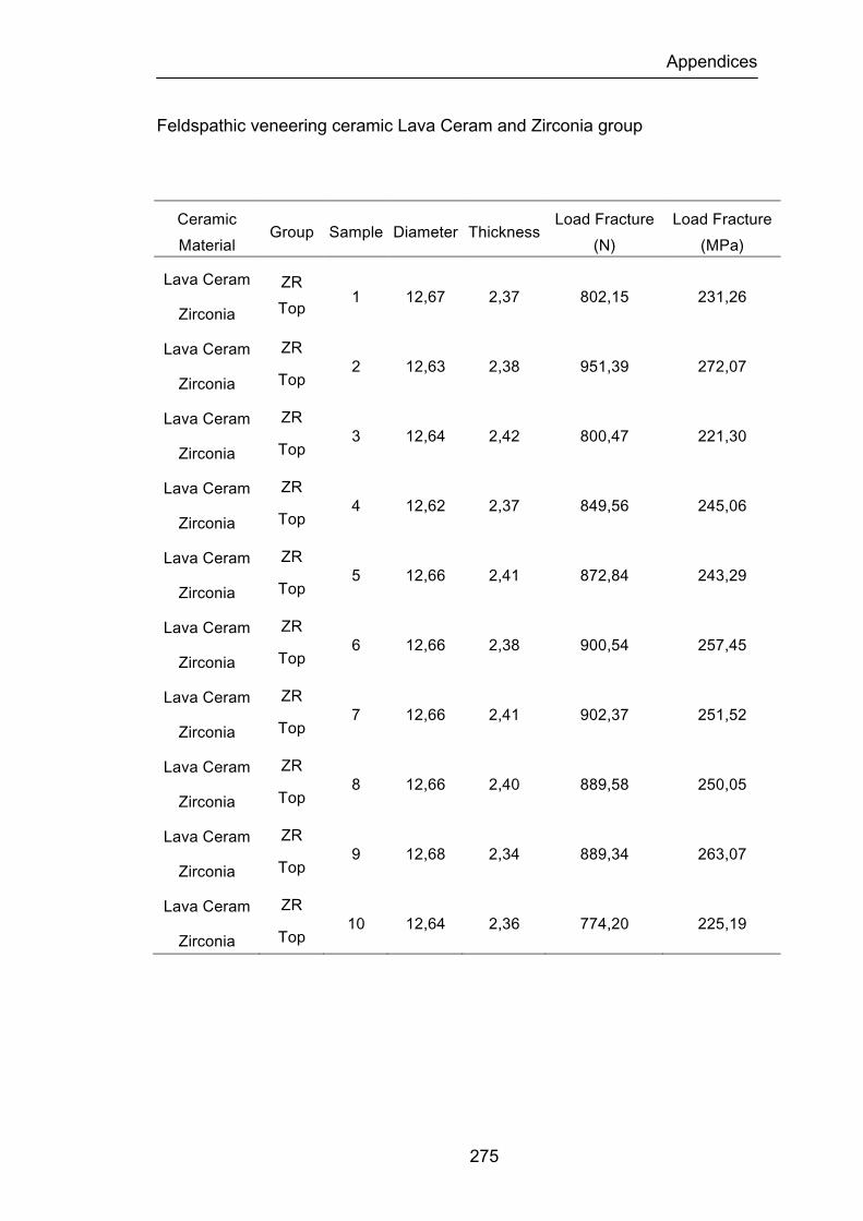
Appendices
275
Feldspathic veneering ceramic Lava Ceram and Zirconia group
Ceramic Material
Group Sample Diameter Thickness Load Fracture
(N) Load Fracture (MPa)
Lava Ceram
Zirconia
ZR Top
1 12,67 2,37 802,15 231,26
Lava Ceram
Zirconia
ZR
Top 2 12,63 2,38 951,39 272,07
Lava Ceram
Zirconia
ZR
Top 3 12,64 2,42 800,47 221,30
Lava Ceram
Zirconia
ZR
Top 4 12,62 2,37 849,56 245,06
Lava Ceram
Zirconia
ZR
Top 5 12,66 2,41 872,84 243,29
Lava Ceram
Zirconia
ZR
Top 6 12,66 2,38 900,54 257,45
Lava Ceram
Zirconia
ZR
Top 7 12,66 2,41 902,37 251,52
Lava Ceram
Zirconia
ZR
Top 8 12,66 2,40 889,58 250,05
Lava Ceram
Zirconia
ZR
Top 9 12,68 2,34 889,34 263,07
Lava Ceram
Zirconia
ZR
Top 10 12,64 2,36 774,20 225,19

Appendices
276
Feldspathic veneering ceramic Vita VM9 and Zirconia group
Ceramic Material
Group Sample Diameter Thickness Load Fracture
(N) Load Fracture (MPa)
Vita VM9
Zirconia
ZR Bottom
1 12,67 2,42 1864,33 515,27
Vita VM9
Zirconia
ZR
Bottom 2 12,65 2,38 754,98 215,86
Vita VM9
Zirconia
ZR
Bottom 3 12,65 2,42 1644,93 454,72
Vita VM9
Zirconia
ZR
Bottom 4 12,64 2,41 1259,42 351,12
Vita VM9
Zirconia
ZR
Bottom 5 12,68 2,37 1828,07 526,99
Vita VM9
Zirconia
ZR
Bottom 6 12,64 2,41 1622,07 452,22
Vita VM9
Zirconia
ZR
Bottom 7 12,65 2,42 1531,86 423,47
Vita VM9
Zirconia
ZR
Bottom 8 12,63 2,40 1620,93 455,77
Vita VM9
Zirconia
ZR
Bottom 9 12,68 2,39 1915,32 542,83
Vita VM9
Zirconia
ZR
Bottom 10 12,67 2,42 1939,90 536,15

Appendices
277
Feldspathic veneering ceramic Vita VM9 and Zirconia group
Ceramic Material
Group Sample Diameter Thickness Load Fracture
(N) Load Fracture (MPa)
Vita VM9
Zirconia
ZR Top
1 12,68 2,38 782,03 223,53
Vita VM9
Zirconia
ZR
Top 2 12,68 2,42 950,40 262,65
Vita VM9
Zirconia
ZR
Top 3 12,63 2,43 917,24 251,51
Vita VM9
Zirconia
ZR
Top 4 12,64 2,43 869,32 238,34
Vita VM9
Zirconia
ZR
Top 5 12,68 2,39 890,73 252,45
Vita VM9
Zirconia
ZR
Top 6 12,64 2,40 795,50 223,65
Vita VM9
Zirconia
ZR
Top 7 12,64 2,41 948,21 264,35
Vita VM9
Zirconia
ZR
Top 8 12,65 2,40 830,32 233,42
Vita VM9
Zirconia
ZR
Top 9 12,65 2,42 812,13 224,50
Vita VM9
Zirconia
ZR
Top 10 12,65 2,41 866,21 241,47

Appendices
278
Two-way ANOVA table for the biaxial flexural strength (load fracture) of the
ceramic and surface finish/heat treatment of test specimens.
Two-Way ANOVA
DF Sum of Squares
Mean Square F-Value P-Value Lambda Power
Ceramic 2 5632,538 2816,269 16,135 <.0001 32,27 1
Surface 5 5610,372 1122,074 6,429 <.0001 32,143 0,998
Ceramic Surface 10 4656,725 465,673 2,668 0,0048 26,679 0,962
Residual 162 28276,09 174,544
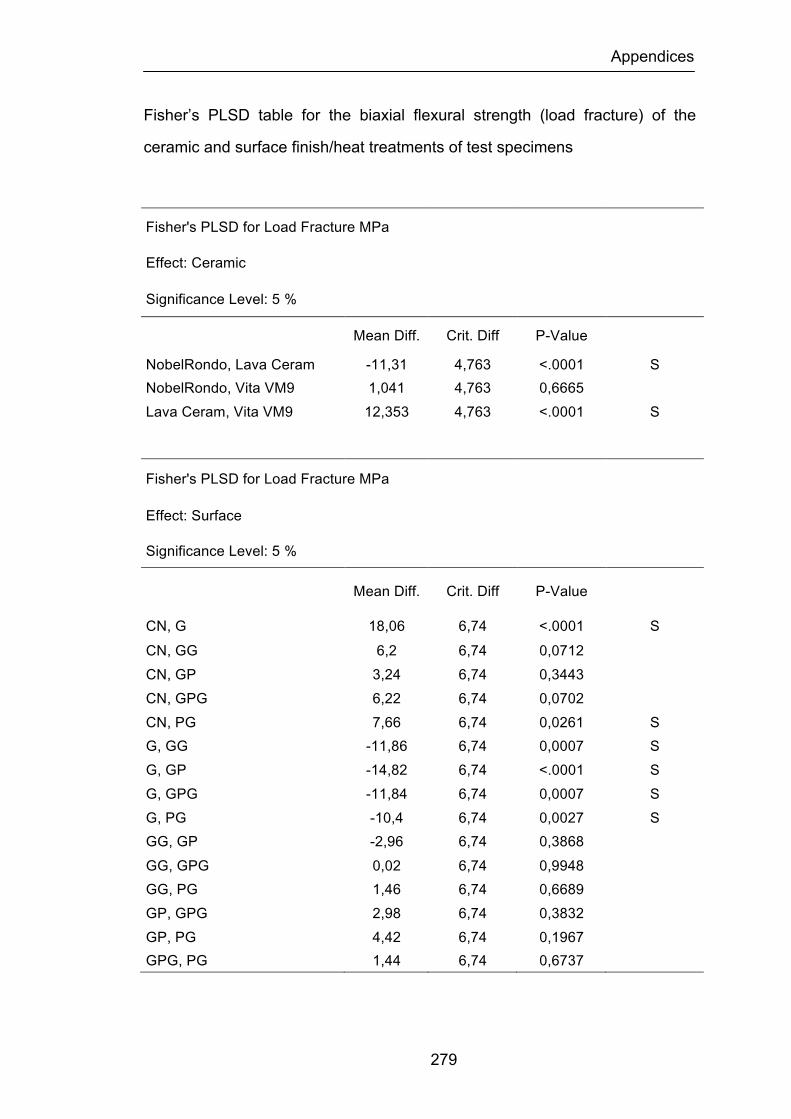
Appendices
279
Fisher’s PLSD table for the biaxial flexural strength (load fracture) of the
ceramic and surface finish/heat treatments of test specimens
Fisher's PLSD for Load Fracture MPa
Effect: Ceramic
Significance Level: 5 %
Mean Diff. Crit. Diff P-Value
NobelRondo, Lava Ceram -11,31 4,763 <.0001 S NobelRondo, Vita VM9 1,041 4,763 0,6665 Lava Ceram, Vita VM9 12,353 4,763 <.0001 S
Fisher's PLSD for Load Fracture MPa
Effect: Surface
Significance Level: 5 %
Mean Diff. Crit. Diff P-Value
CN, G 18,06 6,74 <.0001 S CN, GG 6,2 6,74 0,0712 CN, GP 3,24 6,74 0,3443 CN, GPG 6,22 6,74 0,0702 CN, PG 7,66 6,74 0,0261 S G, GG -11,86 6,74 0,0007 S G, GP -14,82 6,74 <.0001 S G, GPG -11,84 6,74 0,0007 S G, PG -10,4 6,74 0,0027 S GG, GP -2,96 6,74 0,3868 GG, GPG 0,02 6,74 0,9948 GG, PG 1,46 6,74 0,6689 GP, GPG 2,98 6,74 0,3832 GP, PG 4,42 6,74 0,1967 GPG, PG 1,44 6,74 0,6737
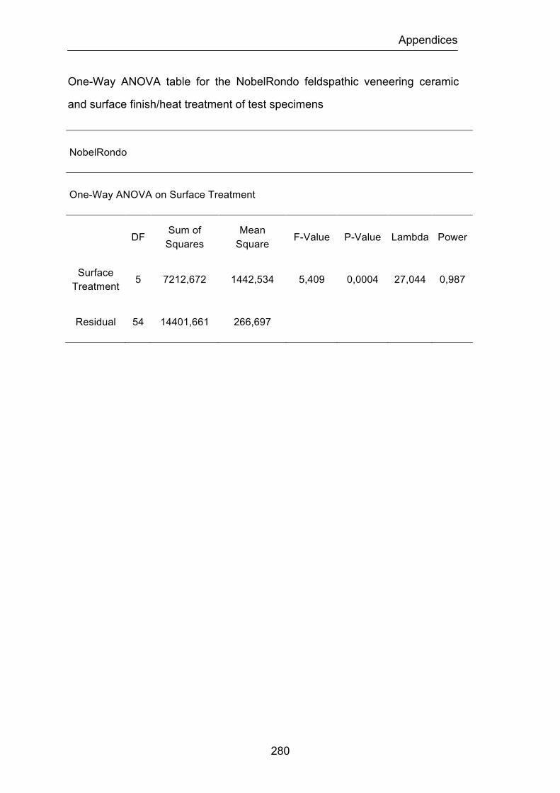
Appendices
280
One-Way ANOVA table for the NobelRondo feldspathic veneering ceramic
and surface finish/heat treatment of test specimens
NobelRondo
One-Way ANOVA on Surface Treatment
DF Sum of Squares
Mean Square F-Value P-Value Lambda Power
Surface Treatment 5 7212,672 1442,534 5,409 0,0004 27,044 0,987
Residual 54 14401,661 266,697

Appendices
281
Fisher’s PLSD table for the NobelRondo feldspathic veneering ceramic and
surface finish/heat treatments of test specimens
Fisher's PLSD for Load to Fracture in MPa
Effect: Surface Treatment
Significance Level: 5 %
Mean Diff. Crit. Diff P-Value
CN, G 32,101 14,642 <.0001 S
CN, GG 25,159 14,642 0,0011 S
CN, GP 6,843 14,642 0,3529
CN, GPG 17,410 14,642 0,0207 S
CN, PG 22,944 14,642 0,0027 S
G, GG -6,942 14,642 0,3461
G, GP -25,258 14,642 0,0011 S
G, GPG -14,691 14,642 0,0493 S
G, PG -9,157 14,642 0,2153
GG, GP -18,316 14,642 0,0152 S
GG, GPG -7,749 14,642 0,2934
GG, PG -2,215 14,642 0,7628
GP, GPG 10,567 14,642 0,1537
GP, PG 16,101 14,642 0,0318 S
GPG, PG 5,534 14,642 0,4519

Appendices
282
One-Way ANOVA table for the Lava Ceram feldspathic veneering ceramic
and surface finish/heat treatment of test specimens
Lava Ceram
One-Way ANOVA on Surface Treatment
DF Sum of Squares
Mean Square F-Value P-Value Lambda Power
Surface Treatment 5 1877,336 375,467 1,732 0,1429 8,661 0,548
Residual 54 11705,396 216,760
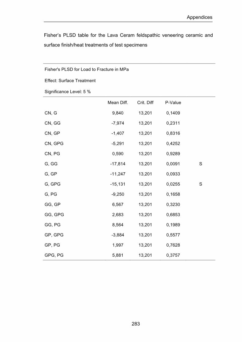
Appendices
283
Fisher’s PLSD table for the Lava Ceram feldspathic veneering ceramic and
surface finish/heat treatments of test specimens
Fisher's PLSD for Load to Fracture in MPa
Effect: Surface Treatment
Significance Level: 5 %
Mean Diff. Crit. Diff P-Value
CN, G 9,840 13,201 0,1409
CN, GG -7,974 13,201 0,2311
CN, GP -1,407 13,201 0,8316
CN, GPG -5,291 13,201 0,4252
CN, PG 0,590 13,201 0,9289
G, GG -17,814 13,201 0,0091 S
G, GP -11,247 13,201 0,0933
G, GPG -15,131 13,201 0,0255 S
G, PG -9,250 13,201 0,1658
GG, GP 6,567 13,201 0,3230
GG, GPG 2,683 13,201 0,6853
GG, PG 8,564 13,201 0,1989
GP, GPG -3,884 13,201 0,5577
GP, PG 1,997 13,201 0,7628
GPG, PG 5,881 13,201 0,3757
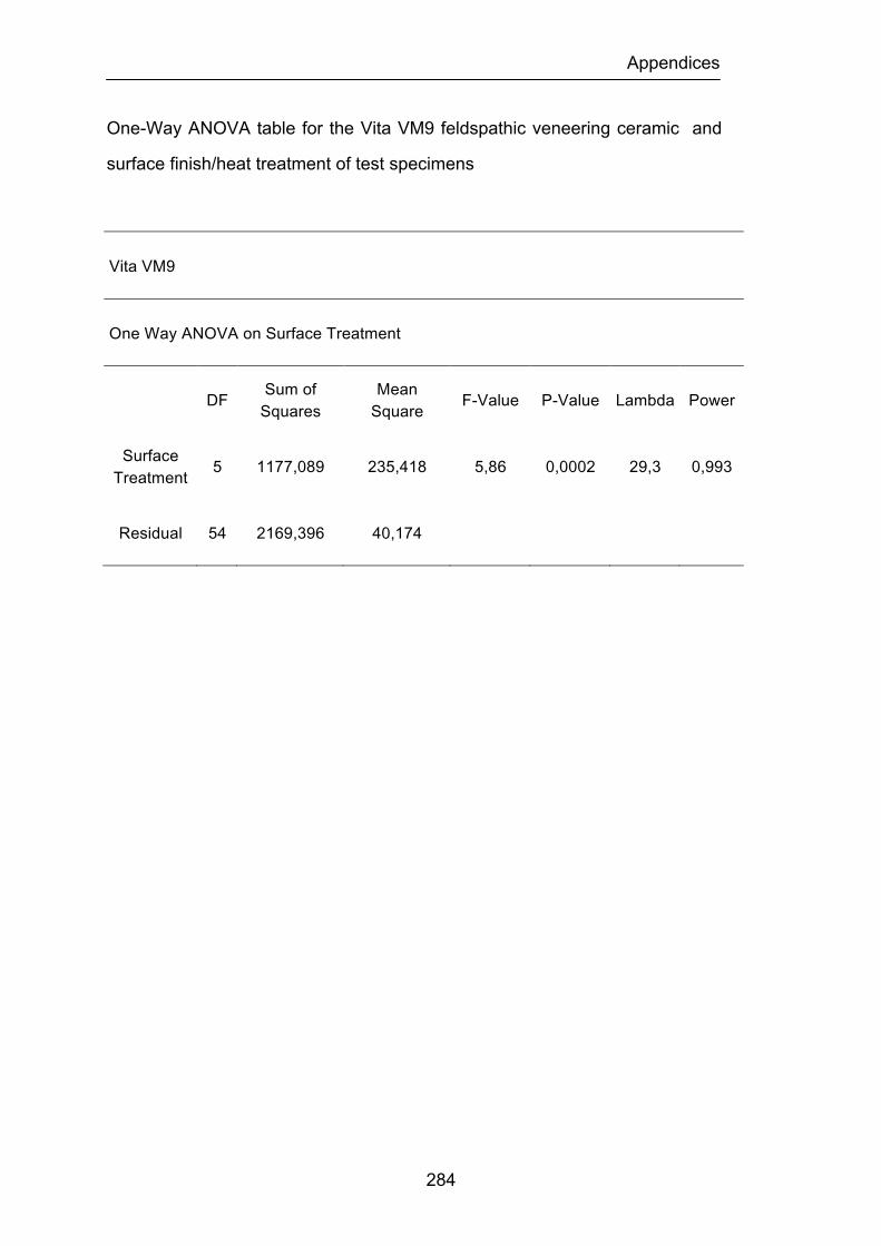
Appendices
284
One-Way ANOVA table for the Vita VM9 feldspathic veneering ceramic and
surface finish/heat treatment of test specimens
Vita VM9
One Way ANOVA on Surface Treatment
DF Sum of Squares
Mean Square F-Value P-Value Lambda Power
Surface Treatment 5 1177,089 235,418 5,86 0,0002 29,3 0,993
Residual 54 2169,396 40,174
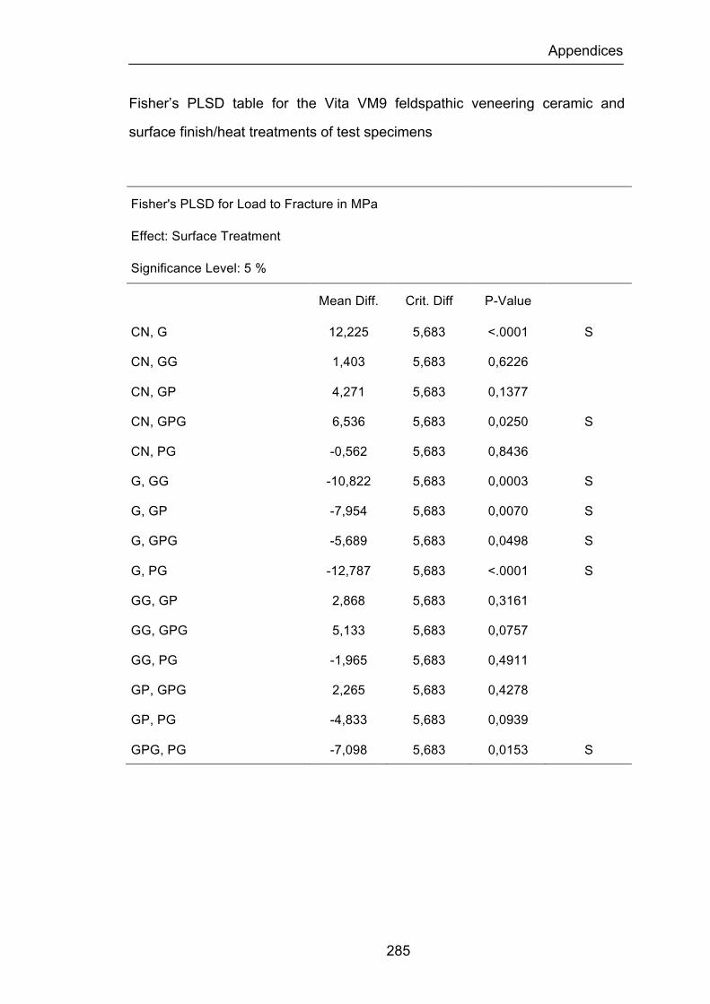
Appendices
285
Fisher’s PLSD table for the Vita VM9 feldspathic veneering ceramic and
surface finish/heat treatments of test specimens
Fisher's PLSD for Load to Fracture in MPa
Effect: Surface Treatment
Significance Level: 5 %
Mean Diff. Crit. Diff P-Value
CN, G 12,225 5,683 <.0001 S
CN, GG 1,403 5,683 0,6226
CN, GP 4,271 5,683 0,1377
CN, GPG 6,536 5,683 0,0250 S
CN, PG -0,562 5,683 0,8436
G, GG -10,822 5,683 0,0003 S
G, GP -7,954 5,683 0,0070 S
G, GPG -5,689 5,683 0,0498 S
G, PG -12,787 5,683 <.0001 S
GG, GP 2,868 5,683 0,3161
GG, GPG 5,133 5,683 0,0757
GG, PG -1,965 5,683 0,4911
GP, GPG 2,265 5,683 0,4278
GP, PG -4,833 5,683 0,0939
GPG, PG -7,098 5,683 0,0153 S
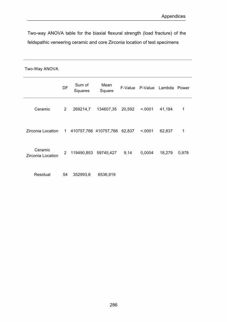
Appendices
286
Two-way ANOVA table for the biaxial flexural strength (load fracture) of the
feldspathic veneering ceramic and core Zirconia location of test specimens
Two-Way ANOVA
DF Sum of Squares
Mean Square F-Value P-Value Lambda Power
Ceramic 2 269214,7 134607,35 20,592 <.0001 41,184 1
Zirconia Location 1 410757,766 410757,766 62,837 <.0001 62,837 1
Ceramic Zirconia Location 2 119490,853 59745,427 9,14 0,0004 18,279 0,978
Residual 54 352993,6 6536,919
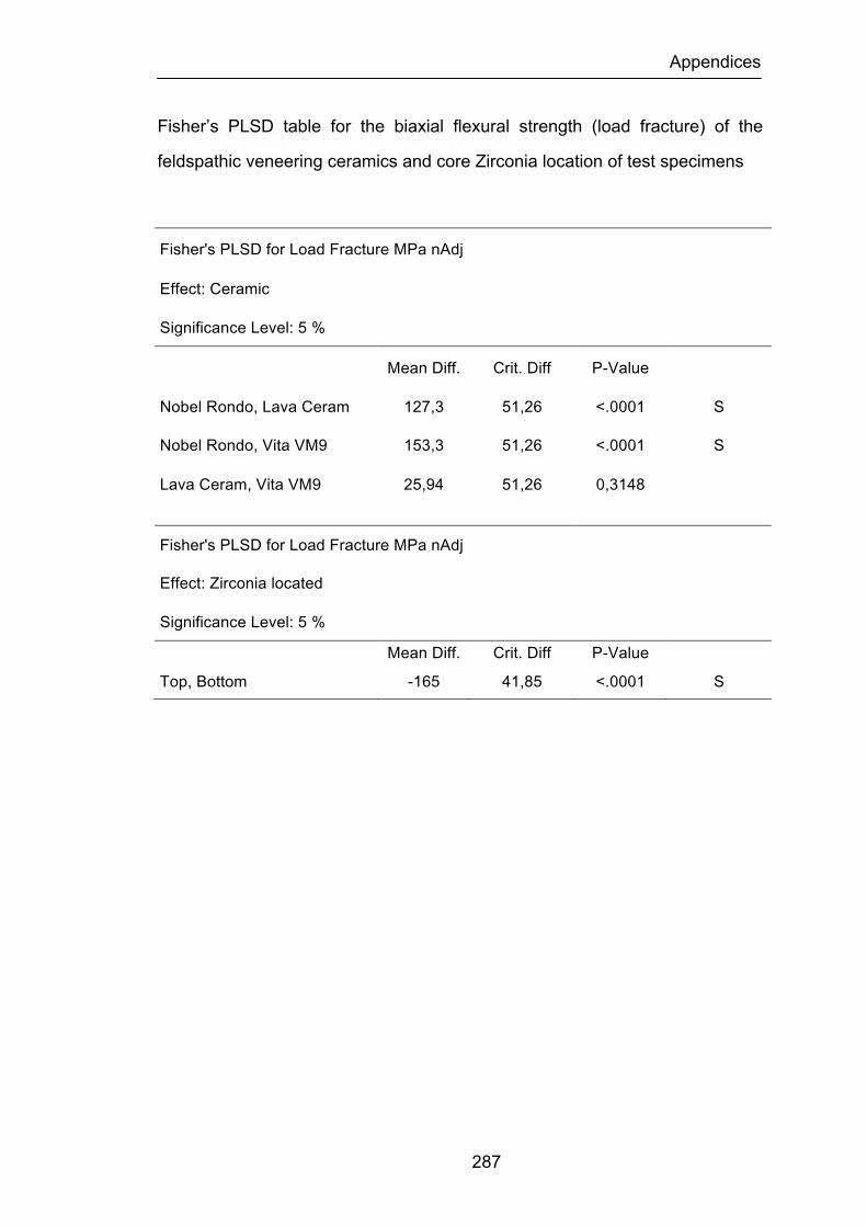
Appendices
287
Fisher’s PLSD table for the biaxial flexural strength (load fracture) of the
feldspathic veneering ceramics and core Zirconia location of test specimens
Fisher's PLSD for Load Fracture MPa nAdj
Effect: Ceramic
Significance Level: 5 %
Mean Diff. Crit. Diff P-Value
Nobel Rondo, Lava Ceram 127,3 51,26 <.0001 S
Nobel Rondo, Vita VM9 153,3 51,26 <.0001 S
Lava Ceram, Vita VM9 25,94 51,26 0,3148
Fisher's PLSD for Load Fracture MPa nAdj
Effect: Zirconia located
Significance Level: 5 %
Mean Diff. Crit. Diff P-Value
Top, Bottom -165 41,85 <.0001 S
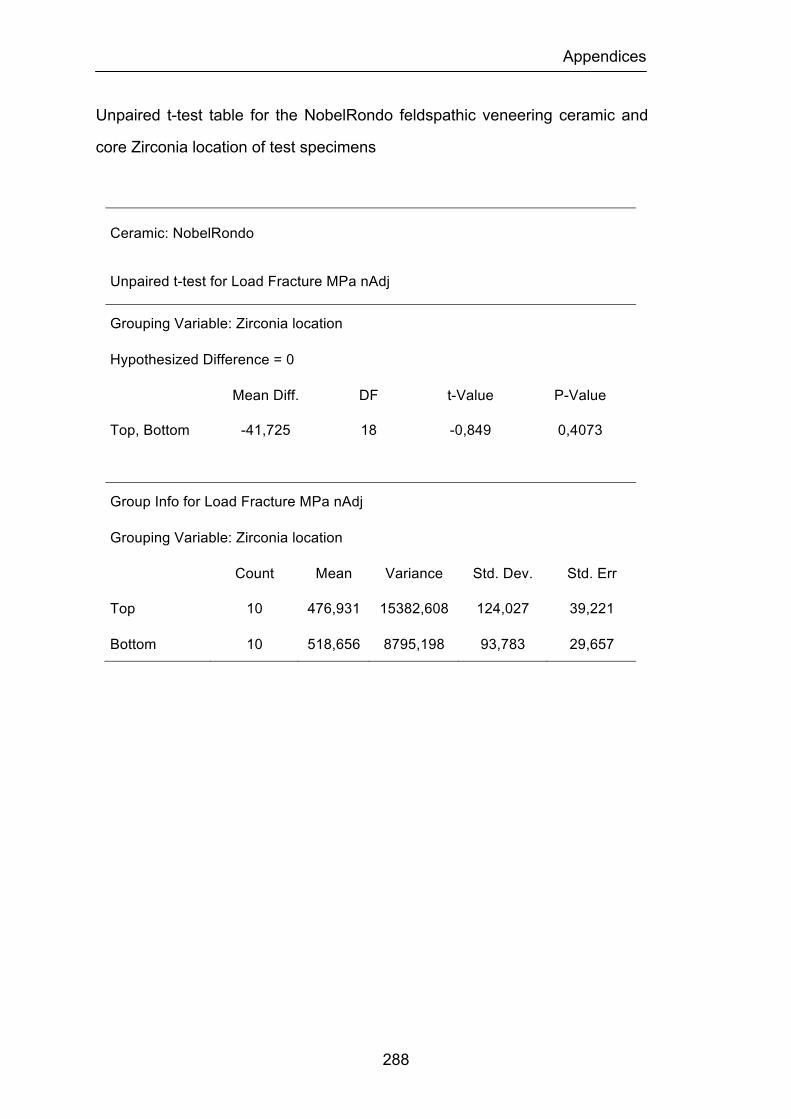
Appendices
288
Unpaired t-test table for the NobelRondo feldspathic veneering ceramic and
core Zirconia location of test specimens
Ceramic: NobelRondo
Unpaired t-test for Load Fracture MPa nAdj
Grouping Variable: Zirconia location
Hypothesized Difference = 0
Mean Diff. DF t-Value P-Value
Top, Bottom -41,725 18 -0,849 0,4073
Group Info for Load Fracture MPa nAdj
Grouping Variable: Zirconia location
Count Mean Variance Std. Dev. Std. Err
Top 10 476,931 15382,608 124,027 39,221
Bottom 10 518,656 8795,198 93,783 29,657
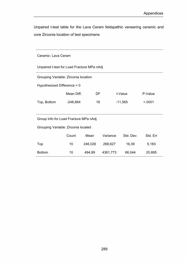
Appendices
289
Unpaired t-test table for the Lava Ceram feldspathic veneering ceramic and
core Zirconia location of test specimens
Ceramic: Lava Ceram
Unpaired t-test for Load Fracture MPa nAdj
Grouping Variable: Zirconia location
Hypothesized Difference = 0
Mean Diff. DF t-Value P-Value
Top, Bottom -248,864 18 -11,565 <.0001
Group Info for Load Fracture MPa nAdj
Grouping Variable: Zirconia located
Count Mean Variance Std. Dev. Std. Err
Top 10 246,026 268,627 16,39 5,183
Bottom 10 494,89 4361,773 66,044 20,885
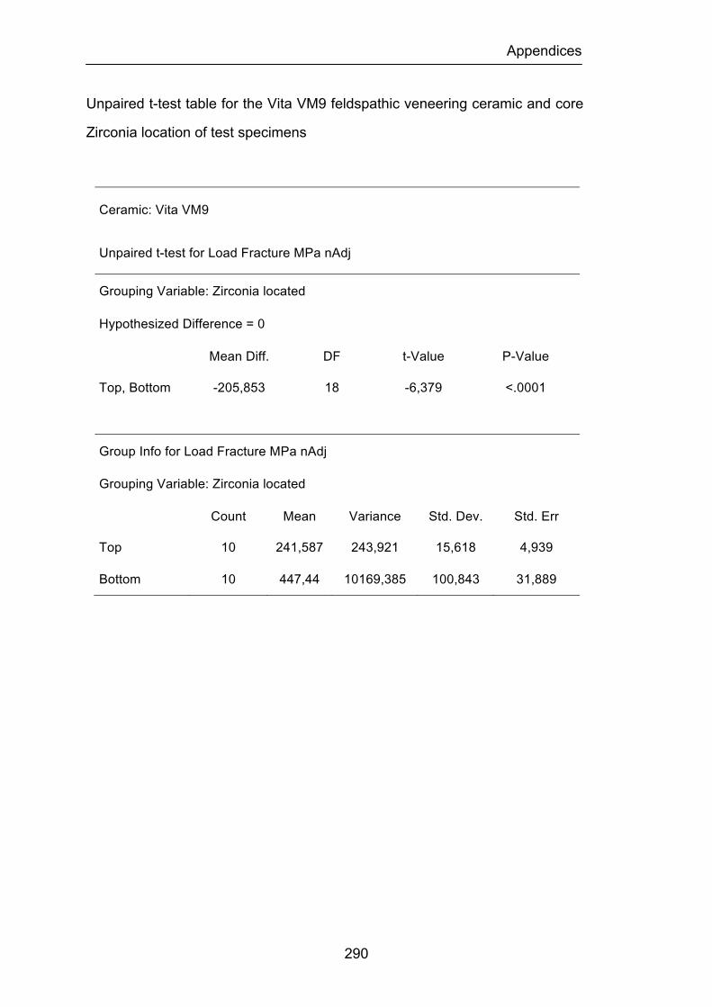
Appendices
290
Unpaired t-test table for the Vita VM9 feldspathic veneering ceramic and core
Zirconia location of test specimens
Ceramic: Vita VM9
Unpaired t-test for Load Fracture MPa nAdj
Grouping Variable: Zirconia located
Hypothesized Difference = 0
Mean Diff. DF t-Value P-Value
Top, Bottom -205,853 18 -6,379 <.0001
Group Info for Load Fracture MPa nAdj
Grouping Variable: Zirconia located
Count Mean Variance Std. Dev. Std. Err
Top 10 241,587 243,921 15,618 4,939
Bottom 10 447,44 10169,385 100,843 31,889
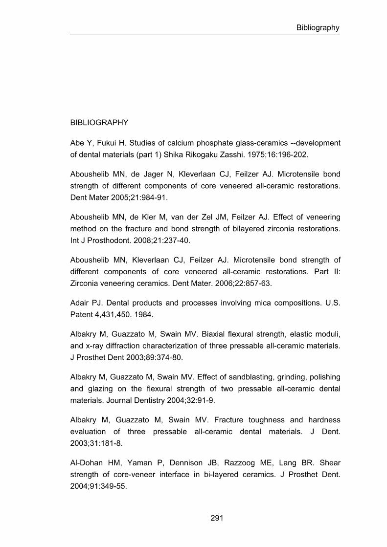
Bibliography
291
BIBLIOGRAPHY
Abe Y, Fukui H. Studies of calcium phosphate glass-ceramics --development of dental materials (part 1) Shika Rikogaku Zasshi. 1975;16:196-202.
Aboushelib MN, de Jager N, Kleverlaan CJ, Feilzer AJ. Microtensile bond strength of different components of core veneered all-ceramic restorations. Dent Mater 2005;21:984-91.
Aboushelib MN, de Kler M, van der Zel JM, Feilzer AJ. Effect of veneering method on the fracture and bond strength of bilayered zirconia restorations. Int J Prosthodont. 2008;21:237-40.
Aboushelib MN, Kleverlaan CJ, Feilzer AJ. Microtensile bond strength of different components of core veneered all-ceramic restorations. Part II: Zirconia veneering ceramics. Dent Mater. 2006;22:857-63.
Adair PJ. Dental products and processes involving mica compositions. U.S. Patent 4,431,450. 1984.
Albakry M, Guazzato M, Swain MV. Biaxial flexural strength, elastic moduli, and x-ray diffraction characterization of three pressable all-ceramic materials. J Prosthet Dent 2003;89:374-80.
Albakry M, Guazzato M, Swain MV. Effect of sandblasting, grinding, polishing and glazing on the flexural strength of two pressable all-ceramic dental materials. Journal Dentistry 2004;32:91-9.
Albakry M, Guazzato M, Swain MV. Fracture toughness and hardness evaluation of three pressable all-ceramic dental materials. J Dent. 2003;31:181-8.
Al-Dohan HM, Yaman P, Dennison JB, Razzoog ME, Lang BR. Shear strength of core-veneer interface in bi-layered ceramics. J Prosthet Dent. 2004;91:349-55.

Bibliography
292
Al-Hiyasat AS, Saunders WP, Sharkey SW, Smith GM, Gilmour WH. Investigation of human enamel wear against four dental ceramics and gold. J Dentistry 1998;26:487-95.
Al-Makramani BM, Razak AA, Abu-Hassan MI. Evaluation of load at fracture of Procera AllCeram copings using different luting cements. J Prosthodont 2008;17:120-4.
Al-Shehri SA, Mohammed H, Wilson CA. Influence of lamination on the flexural strength of a dental castable glass ceramic. J Prosthet Dent 1996;76:23-8.
Anderson DJ. Measurement of stress in mastication. Part I. J Dent Res 1956;35:664–70.
Anderson RJ, Janes GR, Sabella LR, Morris HF. Comparison of the performance on prosthodontic criteria of several alternative alloys used for fixed crown and partial denture restorations: Department of Veterans Affairs Cooperative Studies project 147. J Prosthet Dent 1993;69:1-8.
Andersson M, Bergman B, Bessing C, Ericson G, Lundquist P, Nilson H. Clinical results with titanium crowns fabricated with machine duplication and spark erosion. Acta Odontol Scand 1989;47:279-86.
Andersson M, Oden A. A new all-ceramic crown- A dense-sintered, high purity alumina coping with porcelain. Acta Odontol Scand 1993;51:59-64.
Andersson M, Razzoog M, Oden G, Hegenbarth E, Lang B. Procera: A new way to achieve an all-ceramic crown. Quintessence International 1998;29:285-96.
An L, Chan HM, Padture NP, Lawn BR. Damage-resistant alumina-based layer composites. J Mater Res 1996;11:204-10.
Anusavice KJ. Benefits and limitations of restorative dental ceramics. Symposium on esthetic restorative material. Chicago, IL. 1991.pp.73-78.
Anusavice KJ. Recent developments in restorative dental ceramics. Journal American Dental Association 1993;124(2):72-84.
Anusavice KJ. Philips Science of Dental Materials, Ed 10. Philadelphia: WB Saunders, 1996. p. 49-74.
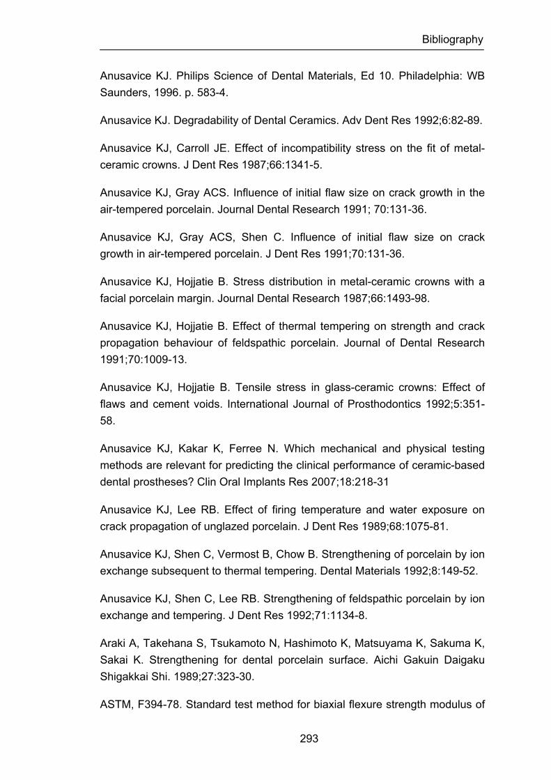
Bibliography
293
Anusavice KJ. Philips Science of Dental Materials, Ed 10. Philadelphia: WB Saunders, 1996. p. 583-4.
Anusavice KJ. Degradability of Dental Ceramics. Adv Dent Res 1992;6:82-89.
Anusavice KJ, Carroll JE. Effect of incompatibility stress on the fit of metal-ceramic crowns. J Dent Res 1987;66:1341-5.
Anusavice KJ, Gray ACS. Influence of initial flaw size on crack growth in the air-tempered porcelain. Journal Dental Research 1991; 70:131-36.
Anusavice KJ, Gray ACS, Shen C. Influence of initial flaw size on crack growth in air-tempered porcelain. J Dent Res 1991;70:131-36.
Anusavice KJ, Hojjatie B. Stress distribution in metal-ceramic crowns with a facial porcelain margin. Journal Dental Research 1987;66:1493-98.
Anusavice KJ, Hojjatie B. Effect of thermal tempering on strength and crack propagation behaviour of feldspathic porcelain. Journal of Dental Research 1991;70:1009-13.
Anusavice KJ, Hojjatie B. Tensile stress in glass-ceramic crowns: Effect of flaws and cement voids. International Journal of Prosthodontics 1992;5:351-58.
Anusavice KJ, Kakar K, Ferree N. Which mechanical and physical testing methods are relevant for predicting the clinical performance of ceramic-based dental prostheses? Clin Oral Implants Res 2007;18:218-31
Anusavice KJ, Lee RB. Effect of firing temperature and water exposure on crack propagation of unglazed porcelain. J Dent Res 1989;68:1075-81.
Anusavice KJ, Shen C, Vermost B, Chow B. Strengthening of porcelain by ion exchange subsequent to thermal tempering. Dental Materials 1992;8:149-52.
Anusavice KJ, Shen C, Lee RB. Strengthening of feldspathic porcelain by ion exchange and tempering. J Dent Res 1992;71:1134-8.
Araki A, Takehana S, Tsukamoto N, Hashimoto K, Matsuyama K, Sakuma K, Sakai K. Strengthening for dental porcelain surface. Aichi Gakuin Daigaku Shigakkai Shi. 1989;27:323-30.
ASTM, F394-78. Standard test method for biaxial flexure strength modulus of
Bibliography
294
rupture of ceramic substrates. 424 – 28, (1996).
Att W, Komine F, Gerds T, Strub JR. Marginal adaptation of three different zirconium dioxide three-unit fixed dental prostheses. J Prosthet Dent 2009;101:239-47.
Att W, Stamouli K, Gerds T, Strub JR. Fracture resistance of different zirconium dioxide three-unit all-ceramic fixed partial dentures. Acta Odontol Scand 2007;65:14-21.
Ayad MF, Fahmy NZ, Rosenstiel SF. Effect of surface treatment on roughness and bond strength of a heat-pressed ceramic. J Prosthet Dent 2008;99:123-30.
Bagby M, Marshall SJ, Marshall GW Jr. Metal ceramic compatibility: a review of the literature. J Prosthet Dent 1990;63:21-5.
Baharav M, Laufer B, Pilo R, Cardash HS. Effect of glaze thickness on the fracture toughness and hardness of alumina-reinforced porcelain. J Prosthet Dent 1999;81:515-19.
Baker PS, Clark AE. Compositional influence on the strength of dental porcelain. Int J Prosthodont 1993;6:291-97.
Ban S, Anusavice KJ. Influence of test method on failure stress of brittle dental materials. Journal of Dental Research 1990;69:1791-99.
Ban S, Matsuo K, Mizutani N, Iwase H, Kani T, Hasegawa J.Microstructure and homogeneity of dental porcelain frits. Dent Mater J 1998;17:264-74.
Baran G, Boberick K, McCool J. Fatigue of restorative materials. Crit Rev Oral Biol Med 2001;12:350-60.
Barghi N. Color and glaze: effects of repeated firings. J Prosthet Dent. 1982;47:393-5.
Bassali WA. The Transverse Flexure of Thin Elastic Plates Supportal at Several Points. Proc Cambridge Phil Soc 1957; 53: 728-743.
Bayne SC. Dental biomaterials: where are we and where are we going? J Dent Educ 2005;69:571-85.
Bazant ZP. Mechanics of distributed cracking. Appl Mech Rev 1986;39:675-
Bibliography
295
705.
Bergman B, Nilson H, Andersson M. A longitudinal clinical study of Procera ceramic-veneered titanium copings. International Journal of Prosthodontics. 1999;12:135-39.
Beuer F, Aggstaller H, Edelhoff D, Gernet W. Effect of preparation design on the fracture resistance of zirconia crown copings. Dent Mater J. 2008;27:362-7.
Beuer F, Naumann M, Gernet W, Sorensen JA. Precision of fit: zirconia three-unit fixed dental prostheses. Clin Oral Investig 2009;13:343-9.
Bhamra G, Palin WM, Fleming GJP. The effect or surface roughness on the flexural strength of an alumina reinforced all-ceramic crown material. Journal of Dentistry 2002;30:153-60
Bindl A, Mörmann WH. Fit of all-ceramic posterior fixed partial denture frameworks in vitro. Int J Periodontics Restorative Dent 2007;27:567-75.
Blixt M, Adamczak E, Lindén LA, Odén A, Arvidson K. Bonding to densely sintered alumina surfaces: effect of sandblasting and silica coating on shear bond strength of luting cements. Int J Prosthodont 2000;13:221-6.
Blue DS, Griggs JA, Woody RD, Miller BH. Effects of bur abrasive particle size and abutment composition on preparation of ceramic implant abutments. J Prosthet Dent 2003;90:247-57.
Brackett MG, Lockwood PE, Messer RL, Lewis JB, Bouillaguet S, Wataha JC. In vitro cytotoxic response to lithium disilicate dental ceramics. Dent Mater 2008;24:450-6.
Brackett SE, Leary JM, Turner KA, Jordan RD. An evaluation of porcelain strength and the effect of surface treatment. J Prosthet Dent 1989;61:446-51.
Brewer JD, Garlapo DA, Chipps BA, Tedesco LA. Clinical discrimination between autoglazed and polished porcelain surfaces. J Prosthet Dent 1990;64:631-34.
Burger W, Richter HG, Piconi C, Vatteroni R, Cittadini A, Boccalari M. New Y-TZP powders for medical grade zirconia. J Mater Sci Mater Med 1997;8:113-8.
Bibliography
296
Burke FJT. Maximizing the fracture resistance of dentine-bonded all-ceramic crowns. Journal of Dentistry 1999;27:169-73.
Campbell SD, Kelly JR. The influence of surface preparation on the strength and surface microstructure of a cast dental ceramic. International Journal of Prosthodontics 1989;2:459-66.
Campbell SD, Pelletier LB, Pober RL, Giordano RA. Dimensional and formation analysis of a restorative ceramic and how it works. J Prosthet Dent 1995;74:33–40.
Carracho JF, Razzoog M. Removable partial denture abutments restored with all-ceramic surveyed crowns. Quintessence Int 2006;37:283-88.
Cattel MJ, Clarke RL, Lynch EJ. The biaxial flexural strength and reliability of four dental ceramics-Part II: J Dent. 1997;25:409-14.
Cattell MJ, Knowles JC, Clarke RL, Lynch E. The biaxial flexural strength of two pressable ceramic systems. J Dent 1999;27:183-96.
Celik G, Uludag B, Usumez A, Sahin V, Ozturk O, Goktug G. The effect of repeated firings on the color of an all-ceramic system with two different veneering porcelain shades. J Prosthet Dent 2008;99:203-8.
Chai J, Chong KH. Probability of failure of machined zirconia dental ceramic core materials. Int J Prosthodont 2009;22:340-1.
Chai J, Chu FC, Chow TW, Liang BM. Chemical solubility and flexural strength of zirconia-based ceramics. Int J Prosthodont 2007;20:587-95.
Chandrasekhar BK. Estimation of Weibull parameter with a modified weigth function. J Mater Res 1997;12:2638-42.
Chen YA, Hickel R, Stecos JC, Kunzelma KH. Effects of surface finish and fatigue testing on the fracture strength of CAD-CAM and pressed ceramic crowns. J Prosthet Dent 1999;82:468-75.
Chen YM, Smales RJ, Yip KH, Sung WJ. Translucency and biaxial flexural strength of four ceramic core materials. Dent Mater 2008;24:1506-11.
Cheung KC, Darvell BW. Sintering of dental porcelain: effect of time and temperature on appearance and porosity. Dent Mater 2002;18:163-73.
Bibliography
297
Chevalier J. What future for zirconia as a biomaterial? Biomaterials 2006;27:535-43.
Chevalier J, Calès B, Drouin JM. Low-temperature aging of Y-TZP ceramics. J Am Ceram Soc 1999;82:2150-4.
Chevalier J, Deville S, Munch E, Julian R, Lair F. Critical effect of cubic phase on aging in 3 mol% yttria-stabilized zirconia ceramics for hip replacement prosthesis. Biomaterials 2004;25:5539-45.
Chiche GJ, Pinault A. Esthetics of anterior fixed prosthodontics. Quintessence Publishing Co., 1994, p.124.
Chong KH, Chai J, Takahashi Y, Wozniak W. Flexural strength of In-Ceram alumina and In-Ceram zirconia core materials. Int J Prosthodont 2002;15:183-8.
Christel P. Zirconia: the second hip generation of ceramics for total hip replacement. Bull Hosp Joint Dis Orthop Inst 1989;49:170-77.
Christel P, Meunier A, Dorlot JM et al. Biomechanical compatibility and design of ceramic implants for orthopaedic surgery. Bioceramics: material characteristics versus in vivo behaviour. Ann Ny Acad Sci 1998;523:234-256.
Christel P, Meunier A, Heller M, Torre JP, Pielle CN. Mechanical properties and short-term-in-vivo evaluation of yttrium-oxide-partially stabilized zirconia. Journal Biomedical Materials Research 1989; 23:45-61.
Christensen GJ. Veneering of teeth. State of the art. Dent Clin North Am. 1985;29:373-91.
Christensen RP, Ploeger BJ. 3-year clinical performance-293 PFM, zirconia, and alumina posterior prostheses. J Dent Res 2009;88 Spec Issue A.
Chu FCS, Frankel N, Smales RJ. Surface roughness and flexural strength of self-glazed, polished, and reglazed In-Ceram/vitadur Alpha porcelain laminates. International Journal of Prosthodontics 2000;13:66-71.
Clark JW. Clinical dentistry. Harper and Row, 1st ed., Hagerstone, MD, 1976.pp.1-12.
Claus H. Vita In-Ceram, a new procedure for preparation of oxide-ceramic
Bibliography
298
crown and bridge framework. Quintessenz 1990;16:35-46.
Clelland NL, Agarwala V, Knobloch LA, Seghi RR. Wear of enamel opposing low fusing and conventional ceramic restorative materials. J Prosthodont 2001;10:8-15.
Coli P, Karlsson S. Fit of new pressure-sintered zirconium dioxide copings. International Journal of Prosthodontics 2004;17:59-64.
Cottom BA, Mayo MJ. Fracture toughness of nanocrystalline ZrO2-3 mol% Y2O3 determined by Vickers indentation. Scripta Mater 1996;34:809-14.
Covacci V, Bruzzese N, Maccauro G, Andreassi C, Ricci GA, Piconi C, Marmo E, Marmo E, Burger W, Cittadini A. In vitro evaluation of mutagenic and carcinogenic power of high purity zirconia ceramic. Biomaterials 1999;20:371–376.
Curtis AR, Wright AJ, Fleming GJP. The influence of surface modification techniques on the performance of a Y-TZP dental ceramic. J Dent 2006;34:195-2006.
Davis BK, Aquilino SA, Lund PS, Diaz-Arnold AM, Denehy GE. Colorimetric evaluation of the effect of porcelain opacity on the resultant color of porcelain veneers. Int J Prosthodont 1992;5:130-6.
Davis BK, Aquilino SA, Lund PS, Diaz-Arnold AM, Denehy GE. Subjective evaluation of the effect of porcelain opacity on the resultant color of porcelain veneers. Int J Prosthodont 1990;3:567-72.
Dehoff PH, Anusavice KJ. Tempering stresses in feldspathic porcelain. J Dent Res 1989 ;68:134-8.
DeHoff PH, Anusavice KJ, Gray AE. Tempering as a means to strengthen porcelain-fused-to-metal restorations. Biomed Sci Instrum 1990;26:167-74.
Della Bona A, Anusavice KJ. Microstructure, composition, and etching topography of dental ceramics. Int J Prosthodont 2002;15:159-67.
Della Bona A, Borba M, Benetti P, Cecchetti D. Effect of surface treatments on the bond strength of a zirconia-reinforced ceramic to composite resin. Braz Oral Res 2007;21:10-5.
Bibliography
299
Della Bona A, Kelly JR. The clinical success of all-ceramic restorations. J Am Dent Assoc 2008;139 Suppl:8S-13S.
De Jager N, Feilzer AJ, Davidson CL. The influence of surface roughness on porcelain strength. Dent Mater 2000;16:381-8.
De Jager N, Pallav P, Feilzer AJ. The influence of design parameters on the FEA-determined stress distribution in CAD-CAM produced all-ceramic dental crowns. Dent Mater. 2005;21:242-51.
De Kler M, de Jager N, Meegdes M, van der Zel JM. Influence of thermal expansion mismatch and fatigue loading on phase changes in porcelain veneered Y-TZP zirconia discs. J Oral Rehabil 2007;34:841-7.
DeLong R, Pintado MR, Douglas WH. Wear of enamel opposing shaded ceramic restorative materials: An in vitro study. J Prosthet Dent1992;68:42-48.
Denry IL. Recent advances in ceramics for dentistry. Crit Rev Oral Biol Med 1996;7:134-43.
Denry IL, Holloway JA, Tarr LA. Effect of heat treatment on microcracks healing behaviour of a machinable dental ceramic. Journal of Biomedical Materials Research 1999;48:791-6.
Denry IL, Kelly JR. State of the art of zirconia for dental applications. Dent Mater. 2008;24:299-307.
Denry IL, Rosentiel SF, Holloway JA, Niemiec MS. Enhanced chemical strengthening of feldspathic dental porcelain. Journal of Dental Research 1993;72:1429-33.
Deran P, Verby P. Wear of low fusing dental porcelains. J Prosthetic Dent 1999;81:460-63.
Deville S, Chevalier J, Fantozzi G, Bartolome J, Requena J, Moya J. Development of advanced zirconia toughened alumina nanocomposites for orthopaedic applications Euro Ceram 2004;Viii(1-3):2013-6.
Deville S, Chevalier J, Fantozzi G, Bartolome J, Requena J, Moya J. Low-temperature ageing of zirconia-toughened alumina ceramics and its implication in biomedical implants. J Eur Ceram Soc. 2003;23:2975-82.

Bibliography
300
Deville S, Chevalier J, Gremillard L. Influence of surface finish and residual stresses on the ageing sensitivity of biomedical grade zirconia. Biomaterials 2006;27:2186-92.
Dong JK, Luthy H, Wolhlwend A, Scharer P. Heat-pressed ceramics: Technology and strength. International Journal of Prosthodontics 1992;5:9-16.
Dröge GG. The porcelain press technique. Dent Labor 1969;17:186-8.
Drummond JL, King TJ, Bapna MS, Koperski RD. Mechanical property evaluation of pressable restorative ceramics. Dent Mater 2000;16:226-33.
Duffin JL, Bales DJ, Johnson GH. Fracture resistance of castable ceramic crowns. J Dent Res 1989;68:235.
Eichler A. Tetragonal Y-doped zirconia: structure and ion conductivity. Phys Rev B 2001;64:174103-8.
Engelmeier RL. Complete-denture esthetics. Dent Clin North Am 1996;40:71-84.
Ernst CP, Cohnen U, Stender E, Willershausen B. In vitro retentive strength of zirconium oxide ceramic crowns using different luting agents. J Prosthet Dent 2005;93:551-8.
Evans AG. Structural reliability: a processing-dependent phenomenon. Journal of the American Ceramic Society 1982;65:127-37.
Fabris S, Paxton AT, Finnis MW. A stabilization mechanism of zirconia based on oxygen vacancies only. Acta Mater 2002;50:5171-8.
Fairhurst CW, Anusavice KJ, Hashinger DT, Ringle RD, Twiggs SW. Thermal expansion of dental alloys and porcelains. J Biomed Mater Res 1980;14:435-46.
Fairhurst CW, Hashinger DT, Twiggs SW. The effect of thermal history on porcelain expansion behaviour. J Dent Res. 1989;68:1313-5.
Fairhurst CW, Lockwood PE, Ringle RD, Thompson WO. The effect of glaze on porcelain strength. Dental Materials 1992;8:203-7.
Felcher FR. Dental Porcelains. J Am Dent Assoc 1932;19:1021
Bibliography
301
Filser FT. Direst ceramic machining of dental restorations. Ph.D. thesis. Zurich: Swiss Federal Institute of Technology Zurich;2001.
Filser F, Kocher P, Gauckler LJ. Net-shaping of ceramic components by direct ceramic machining. Assembly Autom 2003;23:382-90.
Fischer H, Brehme M, Telle R, Marx R. Effect of ion exchange of glazed dental glass ceramics on strength parameters. J Biomed Mater Res 2005;72:175-9.
Fischer J, Fleetwood PW, Baltzer N. Thermal creep analysis of precious metal alloys for the ceramic-fused-to-metal technique. J Biomed Mater Res 1999;48:258-64.
Fischer J, Grohmann P, Stawarczyk B. Effect of zirconia surface treatments on the shear strength of zirconia/veneering ceramic composites. Dent Mater J 2008;27:448-54.
Fischer H, Maier HR, Marx R. Improved reliability of leucite reinforced glass by ion exchange. Dental Materials 2000;16:120-28.
Fischer H, Marx R. Improvement of strength parameters of leucite-reinforced glass ceramic by dual-ion exchange. Journal of Dental Research 2001;80:336-39.
Fischer J, Stawarczyk B. Compatibility of machined Ce-TZP/Al2O3 nanocomposite and a veneering ceramic. Dent Mater. 2007;23:1500-5.
Fischer J, Stawarczyk B, Hämmerle CH. Flexural strength of veneering ceramics for zirconia. J Dent 2008;36:316-21.
Fischer J, Stawarczyk B, Tomic M, Strub JR, Hämmerle CH. Effect of thermal misfit between different veneering ceramics and zirconia frameworks on in vitro fracture load of single crowns. Dent Mater 2007;26:766-72.
Fischer J, Stawarzcyk B, Trottmann A, Hämmerle CH. Impact of thermal misfit on shear strength of veneering ceramic/zirconia composites. Dent Mater 2009;25:419-23.
Fleming GJ, El-Lakwah SF, Harris JJ, Marquis PM. The effect of core: dentin thickness ratio on the bi-axial flexural strength and fracture mode and origin of bilayered dental ceramic composites. Dental Mater 2005;21:164-71.
Bibliography
302
Flinn RA, Trojan PK. Engineering materials and their applications. Houghton Mifflin, 2nd ed., Boston, MA, p.313, 1981.
Fradeani M. The application of all-ceramic restorations in the anterior and posterior regions. Pract Periodont Aesthet Dent. 2003;Suppl:13-7.
Fradeani M, Aquilano A, Corrado M. Clinical experience with In-Ceram Spinell crowns: 5-year follow-up. Int J Periodontics Restorative Dent 2002;22:525-33.
Fradeani M, Redemagni M. An 11-year clinical evaluation of leucite-reinforced glass- ceramic crowns: a retrospective study. Quintessence International. 2002;33:503-10.
Fradeani M, Redemagni M, Corrado M. Porcelain laminate veneers: 6- to 12-year clinical evaluation--a retrospective study. Int J Periodontics Restorative Dent 2005;25:9-17.
Fukui H, Abe Y, Ai S. Studies of calcium phosphate glass-ceramics--development of dental materials. (Part 2) Shika Rikogaku Zasshi. 1977;18:146-51
Garvie RC, Hannink RH, Pascoe RT. Ceramic steel? Nature 1975;258:703-4.
Gibbs CH, Mahan PE, Lundeen HC, Brehnan K, Walsh EK. Occlusal forces during chewing and swallowing as measured by sound transmission. J Prosthet Dent 1981;46:443–49.
Gibbs CH, Mahan PE, Mauderli A, Lundeen HC, Walsh EK. Limits of human bite strength. J Prosthet Dent 1986;56:226–29.
Giordano RA, Campbell S. Flexural strength of feldspathic porcelain treated with ion exchange, overglazed, and polishing. J Prosthet Dent. 1994;71:468-72.
Giordano R, Cima M, Prober R. Effect of surface finish on the flexural strength of feldspathic and aluminous dental ceramics. International Journal of Prosthodontics 1995;8:311-19.
Giordano RA, Pelletier L, Campbell S, Pober R. Flexural strength of an infused ceramic, glass ceramic and feldspathic porcelain. J Prosthet Dent 1995;73:411–418.
Bibliography
303
Goldberg M, Six N, Decup F, Lasfargues JJ, Salih E, Tompkins K et al. Bioactive molecules and the future of pulp therapy. Am J Dent 2003;16:66-76.
Gonzalo E, Suárez MJ, Serrano B, Lozano JF. Marginal fit of Zirconia posterior fixed partial dentures. Int J Prosthodont 2008;21:398-9.
Grant KL, Rawlings RD, Sweeney R. Effect of HIPping, stress and surface finish on the environmental degradation of Y-TZP ceramics. J Mater Sac: Mater Med 2001;12:557-64.
Green DJ. A technique for introducing surface compression into zirconia ceramics. Journal American Ceramic Society 1983;66:C178.
Green DJ. Microcracking Mechanisms in Ceramics. In: Bradt RC, Evans AG, Lange FF, Hesselman DP(eds). Fracture Mechanics of Ceramics New York: Plenum Press 1983;5:457-478.
Griffith AA. The phenomena of rupture and flow in solids. Phil. Trans. Roy. Soc. London. Series A, 1920;221:163-198.
Griggs JA, Thompson JY, Anusavice KJ. Effects of flaw size and auto-glaze treatment on porcelain strength. Journal of Dental Research 1996;75:1414-417.
Grossman DG, Nelson JW. The bonded Dicor crown. J Dent Res 1987;66:206.
Grossman DG. Cast glass ceramics. Dent Clin North Am 1985;29:725-40.
Grossman DG. The science of castable glass ceramics. In: Preston JD. Perspectives in dental ceramics. Proceedings of the Fourth Int Symposium on Ceramics, Chicago, Quintessence,1988; p.117-133.
Guazzato M, Albakry M, Quach L, Swain MV. Influence of grinding, sandblasting, polishing and heat treatment on the flexural strength of a glass-infiltrated alumina-reinforced dental ceramic. Biomaterials 2004;25:2153-60.
Guazzato M, Albakry M, Quach L, Swain MV. Influence of surface and heat treatments on the flexural strength of a glass-infiltrated alumina/zirconia-reinforced dental ceramic. Dent Mater 2005;21:454-63.
Guazzato M, Albakry M, Ringer SP, Swain MV. Strength, fracture toughness and microstructure of a selection of all-ceramic materials. Part I. Pressable
Bibliography
304
and alumina glass-infiltrated ceramics. Dent Mater 2004;20:441-8.
Guazzato M, Albakry M, Ringer SP, Swain MV. Strength, fracture toughness and microstructure of a selection of all-ceramic materials. Part II. Zirconia-based dental ceramics. Dent Mater 2004;20:449-56.
Guazzato M, Albakry M, Swain MV, Ironside J. Mechanical properties of In-Ceram Alumina and In-Ceram Zirconia. Int J Prosthodont 2002;15:339-46.
Guazzato M, Albakry M, Swain MV, Ringer SP. Microstructure of alumina- and alumina/zirconia-glass infiltrated dental ceramics. Bioceramics 2003;15:879-82.
Guazzato M, Proos K, Sara G, Swain MV. Strength, Reliability and Mode of Fracture of Bilayered Porcelain/Core Ceramics. International Journal of Prosthodontics 2004;17:142-149.
Guazzato M, Quach L, Albakry M, Swain MV. Influence of surface and heat treatments on the flexural strength of Y-TZP dental ceramic. J Dent. 2005;33:9-18.
Gupta PK. Strengthening by surface damage in metastable tetragonal zirconia. J Am Dent Soc 1980;63:117-21.
Hacker CH, Wagner WC, Razzoog M. An in vitro investigation of the wear of enamel on porcelain and gold in saliva. J Prosthet Dent 1996;76:14-17.
Hankinson JA, Cappetta EG. Five years clinical experience with a leucite-reinforced porcelain crown system. Int J Periodontics Restorative Dent. 1994;14:138-53.
Haraldson T, Carlsson GE, Ingervall B. Functional state, bite force and postural muscle activity in patients with osseointegrated oral implant bridges. Acta Odontol Scand 1989;37:195-206.
Hanks CT, Wataha JC, Sun Z. In vitro models of biocompatibility: a review. Dental Matre 1996;12:186-93.
Hannink RHJ, Howard CJ, Kisi EH, Swain MV. Relationship between fracture toughness and phase assemblage in MG-PSZ. J Am Cram Soc 1994;77:571-9.
Bibliography
305
Haywood VB, Heymann HO, Kusy RP, Whitley JQ, Andreaus SB. Polishing porcelain veneers: an SEM specular reflectance analysis. Dent Mater 1988;4:116-21.
Heffernan MJ, Aquilino SA, Diaz-Arnold AM, Haselton DR, Stanford CM, Vargas MA. Relative translucency of six all-ceramic systems. Part II: core and veneer materials. J Prosthet Dent 2002;88:10-5.
Heffernan MJ, Aquilino SA, Diaz-Arnold AM, Haselton DR, Stanford CM, Vargas MA. Relative translucency of six all-ceramic systems. Part I: core materials. J Prosthet Dent 2002;88:4-9.
Heintze SD, Rousson V. Survival of zirconia- and metal-supported fixed dental prostheses: A systematic review. Int J Prosthodont 2010;23:493-502.
Helkimo E, Carlsson GE, Helkimo M. Bite force and state of definition. Acta Odontol Scand 1977;35:297–303.
Helmer JD, Driskell TD. Research on bioceramics Symp. On use of ceramics as surgical implants. South Carolina (USA): Clemson University, 1969.
Hench LL. Glass-ceramic dental restorations. J Dent Res 1971;50:133.
Hench LL. Ceramics, glasses, and composites in medicine. Med Instrum. 1973;7:136-44.
Heuer AH, Claussen N, Kriven WM, Ruhle M. Stability of tetragonal ZrO2 particles in ceramic matrices. J Am Ceram Soc 1982;65:642-50.
Heydecke G, Zhang F, Razzoog ME. In vitro color stability of double-layer veneers after accelerated aging. J Prosthet Dent 2001;85:551-7.
Hobo S, Iwata T. Castable apatite ceramics as a new biocompatible restorative material. Theoretical consideration. Quintessence Int 1985;16:207-16.
Hochman N, Zsalkind M. New all-ceramic indirect post and core system. J Prosthet Dent. 1999;81:625-29.
Hojjatie B, Anusavice KJ. Effects of initial temperature and tempering medium on thermal tempering of dental porcelains. Journal of Dental Research 1993;72:566-71.
Bibliography
306
Holand W, Schweiger M, Frank M, Rheinberger V. A comparison of the microstructure and properties of the IPS Empress 2 and the IPS Empress glass-ceramics. J Biomed Mater Res 2000;53:297-303.
Holloway JA, Miller RB. The effect of core translucency on the aesthetics of all-ceramic restorations. Pract Periodont Aesthet Dent 1995;9:567-74.
Hondrum SO. A review of the strength properties of dental ceramics. J Prosthet Dent 1992;67:859-63.
Hondrom SO. The strength of cemented alumina core and magnesia core crowns. Int J Prosthodont 1988;1:190-5.
Hondrum SO, O'Brien WJ. The strength of alumina and magnesia core crowns. Int J Prosthodont 1988;1:67-72.
Hopkins K. A method of strengthening aluminous porcelain jacket crown Brit Dent J 1981;15:225-27.
Hopkins K. An investigation into the role of porcelain thickness in determining the load-carrying capacity of porcelain laminates: Br Dent J 1989;66:201-204.
Hornberger H, Marquis PM, Christiansen S, Strunk HP. Microstructure of a high strength alumina glass composite. J Mater Res1996;11:855-58.
Howell AH, Brudevold F. Vertical forces used during chewing of food. J Dent Res 1959;29:133–36.
Hsueh CH, Thompson GA, Jadaan OM, Wereszczak AA, Becher PF. Analyses of layer-thickness effects in bilayered dental ceramics subjected to thermal stresses and ring-on-ring tests. Dent Mater 2008;24:9-17.
Huang H. Machining characteristics and surface integrity of yttria stabilized tetragonal zirconia in high speed deep grinding. Mater Sci Eng A: Struct 2003;345:155-63.
Huang H, Liu YC. Experimental investigations of machining characteristics and removal mechanism of advanced ceramics in high speed deep grinding. Int J Match Tool Manuf 2003;43:811-23.
Hudson JD, Goldstein GR, Georgescu M. Enamel wear caused by three restorative materials. J Prosthet Dent 1995;74:647-54.
Bibliography
307
Hulbert SF. Ceramics in clinical applications, past, present, and future. In: Vincenzinc P. High-tech ceramic. Elsevier Science, 1st ed., Amsterdam, pp.3-27, 1987.
Irwin GR. Analysis of stresses and strains near the end of a crack transversing a plate. J Appl Mech 1957;24:361-4.
Isgrò G, Kleverlaan CJ, Wang H, Feilzer AJ. Thermal dimensional behavior of dental ceramics. Biomaterials 2004;25:2447-53.
Isgrò G, Pallav P, Vander Zel JM, Feilzer AJ. The influence of the veneering porcelain and different surface treatments on the biaxial flexural strength of a heat pressed ceramic. J Prosthet Dent 2003;5:465-73.
International Organization for Standardization, ISO 6872: 1995 (E): Dental ceramics, Geneva, Switzerland (2nd ed.) (1995).
International Organization for Standardization, 6344-1: 1998 (E): Dental ceramics, Geneva, Switzerland (2nd ed.) (1995).
Jacobi R, Schillimburg HT Jr, Ducanson MG Jr. A comparison of the abrasiveness of six ceramic surfaces and gold. J Prosthet Dent 1991;66:303-09.
Jager N, Feilzer, AJ, Davidson CL. The influence of surface roughness on porcelain strength. Dental Materials 2000;16:381-88.
Jagger DC, Harrison A. An in vitro investigation into the wear effects of unglazed, glazed, and polished porcelain oh human enamel. J Prosthet Dent 1994;72:320-23.
Jayatilaka AS. Fracture of Engineering Brittle Materials. Applied Sciences Pub 1979;80-113
Jin J, Takahashi H, Iwasaki N. Effect of test method on flexural strength of recent dental ceramics. Dent Mater J 2004;23:490-6.
Jochen DG, Caputo AA, Matyas J. Effect of metal surface treatment on ceramic bond strength. J Prosthet Dent 1986;55:186-8.
Johnson-Walls D, Evans AG, Marshall BD, James MR. Residual stresses in machined ceramic surfaces. Journal American Ceramic Society 1986;69:44-7.
Bibliography
308
Jones DW. Development of dental ceramics: An historical perspective. Dent Clin North Am 1985;29:621-44.
Jung YG, Peterson IM, Kim DK, Lawn BR. Lifetime-limiting strength degradation from contact fatigue in dental ceramics. J Dent Res 2000;79:722-31.
Katz S. High strength feldspathic porcelains containing crystalline leucite. US patent 4,798,536; Jan 1989.
Keith O, Kusy RP, Whitley JQ. Zirconia brackets: An evaluation of morphology and coefficients of friction. Am J Orthod Dentofacial Orthop 1994;106:605-14.
Kelly JR. Ceramics in restorative and prosthetic dentistry. Ann Rev Mater Sci 1997;27:443-68.
Kelly JR. Clinically relevant approach to failure testing of all-ceramic restorations. J Prosthet Dent 1999;81:652-61.
Kelly JR. Dental ceramics: current thinking and trends. Dent Clin North Am. 2004;48:513-30.
Kelly JR. Perspectives on strength. Dental Materials1995;11:103-110.
Kelly JR, Campbell SD, Bowen HK. Fracture-surface Analysis of Dental Ceramics. J Prosthet Dent 1989;62 536-41.
Kelly JR, Denry IL Stabilized Zirconia as a structural ceramic: an overview. Dent Mater 2008;24:289-98.
Kelly JR, Giordano R, Pober R, Cima MJ. Fracture surface analysis of dental ceramics: clinically failed restorations. Int J Prosthodont 1990;3:430-40.
Kelly JR, Nishimura I, Campbell SD. Ceramics in dentistry: Historical roots and current perspectives. J Prosthet Dent 1996;75:18-32.
Kelly JR, Tesk JA, Sorensen JA. Failure of all-ceramic fixed partial dentures in vitro and in vivo: analysis and modelling. J Dent Res 1995;74:1253-8.
Kern M, Thompson VP. Sandblasting and silica coating of a glass-infiltrated alumina ceramic: volume loss, morphology, and changes in the surface composition. J Prosthet Dent 1994;71:453-61.

Bibliography
309
Kihara S, Watanabe A, Abe Y. Calcium phosphate glass-ceramic crown prepared by lost-wax technique. J Am Ceram Soc 1984;67:100-01.
Kirstein AF, Woolley RM. Symmetrical Bending of Thin Circular Elastic Plates on Equally Spaced Point Supports. J Res of the NBS-C. Eng and Instr 1965;71C:1-10.
Kitazaki H, Takahashi H, Hasegawa S, Nishimura F. Effect of amount of grinding on flexural strength of dental ceramics. Journal of Medical and Dental Science 2001;48:7-13.
Kobayashi K, Kuwajima H, Masaki T. Phase change and mechanical properties of ZrO2-Y2O3 solid electrolyte after aging. Solid State Ionics 1981;3:489-95.
Komine F, Iwai T, Kobayashi K, Matsumura H. Marginal and internal adaptation of zirconium dioxide ceramic copings and crowns with different finish line designs. Dent Mater J. 2007;26:659-64.
Kon M, Kawano F, Asaoka K, Matsumoto N. Effect of leucite crystals on the strength of glassy porcelain. Dent Mater J 1994;13:138-47.
Kon M, O'Brien WJ, Rasmussen ST, Asaoka K. Mechanical properties of glass-only porcelains prepared by the use of two feldspathic frits with different thermal properties. J Dent Res 2001;80:1758-63.
Kosmac T, Oblak C, Jevnikar P, Funduk N, Marion L. The effect of surface grinding and sandblasting on flexural strength and reliability of Y-TZP zirconia ceramic. Dental Materials 1999;15:426-33.
Kosmac T, Oblak C, Jevnikar P, Funduk N, Marion L. Strength and reliability of surface treated Y-TZP dental ceramics. J Biomed Mater Res 2000;53:304-13.
Kvam K, Hero H, Oilo G. Fracture Toughness Measurements of Some Dental Core Ceramics: A Methodology Study. Scnad J Dent Res 1991;99:527-32.
Lacy AM. The chemical nature of dental porcelain. Dent Clin North Am 1977;21:661-67.
Land MF, Hopp CD. Survival rates of all-ceramic systems differ by clinical indication and fabrication method. J Evid Based Dent Pract 2010;10:37-8.
Bibliography
310
Lang LA, Wang RF, Kang B, White SN. Validation of finite element analysis in dental ceramics research. J Prosthet Dent 2001;86:650-4.
Lange FF. Transformation toughening. Part 4. Fabrication, fracture-toughness and strength of AL2O3-ZrO2 composites. J Mater Sci 1982;17:247-54.
Lange FF. Transformation toughening. Part 5. Effect of temperature and alloy on fracture-toghness. J Mater Sci 1982;17:255-62.
Lange FF, Dunlop GL, Davis BI. Degradation during aging of transformation-toughened ZrO2-Y2O3 materials at 250°C. J Am Ceram Soc 1986;69:237-40.
Lange FF, James MR, Green DJ. Determination of residual stress caused by grinding in polycrystalline alumina. Journal American Ceramic Society 1983;72:16-7.
Larsson C, von Steyern PV, Sunzel B, Nilner K. All-ceramic two- and five-unit implant-supported reconstructions. A randomized, prospective clinical trial. Swed Dent J 2006;30:45-53.
Lawn BR, Deng Y, Lloyd IK, Janal MN, Rekow ED, Thompson VP. Materials design of ceramic-based layer structures for crowns. J Dent Res 2002;81:433-8.
Lawn BR, Deng Y, Thompson VP. Use of contact testing in the characterization and design of all-ceramic crown-like layer structures: a review. J Prosthet Dent 2001;86:495-510.
Lawn BR, Lee SK, Peterson IM, Wuttiphan S. A model of strength degradation from Hertzian contact damage in tough ceramics. J Am Ceram Soc 1998;81:1509-20.
Lawn BR, Padture NP, Cai H, Guiberteau F. Making ceramics "ductile". Science 1994;263:1114-6.
Lawn BR, Pajares A, Zhang Y, Deng Y, Polack MA, Lloyd IK. Materials design in the performance of all-ceramic crowns. Biomaterials 2004;25:2885-92.
Leach CA. Sintering of magnesium partially-stabilized zirconia-behavior of an impurity silicate phase. Mater Sci Technol 1987;3:321-4.
Lee KS, Wuttiphan S, Hu XZ, Lee SK, Lawn BR. Contact induced transverse
Bibliography
311
fractures in brittle layers on soft substrates: a study on silicon nitride bilayers. J Am Ceram Soc 1998;81:571-80.
Linderholm H, Wennström A. Isometric bite force and its relation to general muscle force and body build. Acta Odontol Scand 1970;28:679–89.
Lindgren J, Smeds J, Sjögren G. Effect of surface treatments and aging in water on bond strength to zirconia. Oper Dent 2008;33:675-81.
Liu SY, Chen JW. Fatigue of yttria-stabilized zirconia. I. Fatigue damage, fracture origins, and lifetime prediction. J Am Ceram Soc 1991;74:1197-205.
Lohbauer U, Krämer N, Petschelt A, Frankenberger R. Correlation of in vitro fatigue data and in vivo clinical performance of a glass ceramic material. Dent Mater 2008;24:39-44.
Lovgren R, Andersson B, Carlsson GE, Odman P. Prospective clinical 5-year study of ceramic-veneered titanium restorations with the Procera system. J Prosthet Dent 2000;84:514-21.
Lubovich RP, Goodkind RJ. Bond strength studies of precious, semiprecious, and nonprecious ceramic-metal alloys with two porcelains. J Prosthet Dent. 1977;37:288-99.
Ludwing K. Studies on the ultimate strength of all-ceramic crowns. Dent Labor 1991;39:647-51.
Luthardt RG, Sandh O, Reitz B. Zirconia-TPZ and alumina-advanced technologies for the manufacturing of single crowns. Eur J Prosthet and Rest Dent. 1999;7:113-9.
Lüthy H, Dong JK, Wohlwend A, Schärer P. Effects of veneering and glazing on the strength of heat-pressed ceramics. Schweiz Monatsschr Zahnmed. 1993;103:1257-60.
Lüthy H, Filser F, Loeffel O, Schumacher M, Gauckler LJ, Hammerle CH. Strength and reliability of four-unit all-ceramic posterior bridges. Dent Mater 2005;21:930-7.
Mabie CP, Menis DL, Whitenton EP, Trout RL, Metherate RS, Ferry CH. Gel route preparation of low fusing dental porcelain frit. J Biomed Mater Res 1983;17:691-713.
Bibliography
312
MacCulloch WT. Advances in dental ceramics. Br Dent J. 1968;124:361-5.
Magne P, Belser U. Esthetic improvements and in vitro testing of In-Ceram Alumina and Spinell ceramic. Int J Prosthodont 1997;10:459–466.
Mahalick JA, Knap FJ, Weiter EI. Occlusal wear in prosthodontics. JADA 1971;82:154-59.
Malament KA, Grossman DG. Bonded vs. non-bonded Dicor crown: Four-year report. J Dent Res 1992;71:321.
Malament KA, Socransky SS. Survival of Dicor glass-ceramic dental restorations over 14 years: Part I. Survival of Dicor complete coverage restorations and effect of internal surface acid etching, tooth position, gender, and age. J Prosthet Dent. 1999;81:23-32.
Mackert JR Jr, Evans AL. Effect of cooling rate on leucite volume fraction in dental porcelains. J Dent Res. 1991;70:137-9.
Mackert JR Jr, Khajotia SS, Russell CM, Williams AL. Potential interference of leucite crystallization during porcelain thermal expansion measurement. Dent Mater 1996;12:8-12.
Mackert JR Jr, Parry EE, Hashinger DT, Fairhurst CW. Measurement of oxide adherence to PFM alloys. J Dent Res 1984;63:1335-40.
Mackert JR Jr, Ringle RD, Parry EE, Evans AL, Fairhurst CW. The relationship between oxide adherence and porcelain-metal bonding. J Dent Res. 1988;67:474-8.
Mackert JR Jr, Twiggs SW, Evans-Williams AL. Isothermal anneal effect on leucite content in dental porcelains. J Dent Res 1995;74:1259-65.
Marchack BW, Futatsuki Y, Marchack CB, White SN. Customization of milled zirconia copings for all-ceramic crowns: a clinical report. J Prosthet Dent 2008;99:169-73.
Marquardt P, Strub JR. Survival rates of IPS empress 2 all-ceramic crowns and fixed partial dentures: results of a 5-year prospective clinical study. Quintessence Int. 2006;37:253-9.
Matsui K, Horikoshi H, Ohmichi N, Ohgai M, Yoshida H, Ikuara Y. Cubic-
Bibliography
313
formation and grain-growth mechanism in tetragonal zirconia polycrystals. J Am Ceram Soc 2003;86:1401-8.
May KB, Russell MM, Razzoog ME, Lang BR. Precision of fit: the Procera AllCeram crown. J Prosthet Dent 1998;80:394-404.
Mclnnes-Lesoux PM, Zinck JH, Weinberg R. The effectiveness of opaque and color modifier materials. A laboratory study. J Am Dent Assoc 1987;114:205-209.
McLean JW. Ceramics in clinical dentistry. Br Dent J 1988;164:187-94.
McLean JW. Evolution of dental ceramics in the twentieth century. J Prosthet Dent 2001;85:61-6.
McLean JW. High strength ceramics. Quintessence International 1987;18:97-106.
McLean JW. The science and art of dental ceramics. Oper Dent1991;16:149-56.
McLean JW, Huges TH. The reinforcement of dental porcelain with ceramic oxides. Br Dent J. 1965;21:251-267.
McLean JW, Kedge MI, Hubbard JR. The bonded alumina crown. 2. Construction using the twin foil technique. Aust Dent J 1976;21:262-8.
McLean JW, Sced IR. The bonded alumina crown. The bonding of platinum to aluminous dental porcelain using tin oxide coatings. Austral Dent J. 1976;21:119-27.
McLaren EA, Giordano RA. Zirconia-based ceramics: Material properties, esthetics, and layering techniques of a new veneering porcelain, VM9. Quintessence Dent Technol 2005;28:99-111.
McLaren EA, Terry DA. CAD/CAM systems, materials, and clinical guidelines for all-ceramic crowns and fixed partial dentures. Compend Contin Educ Dent. 2002;23:637-41, 644, 646 passim; quiz 654.
McLaren EA, White SN. Glass-infiltrated zirconia/alumina-based ceramic for crowns and fixed partial dentures. Pract Perio and Aesthet Dent. 1999;11:985-94.
Bibliography
314
McLaren EA, White SN. Survival of In-Ceram crowns in a private practice: a prospective clinical trial. J Prosthet Dent. 2000;83:216-22.
Mecholsky JJ. Fractography: Determing the Sites of Fracture. Dent Mater 1995;11:113-6.
Mecholsky JJ. Fracture mechanics principles. Dental Materials 1995;11:11-112.
Mecholsky JJ, Freiman SW, Rice RW. Effect of grinding on flaw geometry and fracture of glass. Journal American Ceramic Society 1977;60:114-17.
Mencik J. Strength and Fracture of Glass and Ceramics. Amsterdam: Elsevier Science, 1992:41-49.
Metzler KT, Woody RD, Miller AW, Miller BH. In vitro investigation of the wear of human enamel by dental porcelain. J Prosthet Dent 1999;81:356-64.
Meyer JM, O'Brien WJ, Yu CU. Sintering of dental porcelain enamels. J Dent Res 1976;55:696-9.
Mitov G, Lohbauer U, Rabbo MA, Petschelt A, Pospiech P. Investigations of subcritical crack propagation of the Empress 2 all-ceramic system. Dent Mater. 2008;24:267-73.
Monasky GE, Taylor DF. Studies of wear of porcelain, enamel, and gold. J Prosthet Dent 1971;25:299-306.
Morena R, Beaudreau GM, Lockwood PE, Evans AL, Fairhurst CW. Fatigue of dental ceramics in a simulated oral environment. J Dent Res 1986;65:993-97.
Mumford G. Dental ceramics, In: Clark, JW. Clinical dentistry. Harper and Row, 1st ed., Hagerstown, MD, pp.1-12, 1976.
Munoz CA, Goodacre CJ, Moore BK, Dykema RW. A comparative study of strength of aluminous porcelain jacket crowns constructed with conventional and twin foil technique. J Prosthet Dent 1982;48:271-81.
Munz D, Fett T. Ceramics: mechanical properties, failure behavior, materials selection. 1st ed. New York: Springer-Verlag; 1999. p. 15.
Myenberg KH, Luthy H, Scharer P. Zirconia posts: A new all-ceramic concept
Bibliography
315
for nonvital abutment teeth. Journal Esthetic Dentistry 1995;7:73-80.
Näpänkangas R, Raustia A. Twenty-year follow-up of metal-ceramic single crowns: a retrospective study. Int J Prosthodont. 2008;21:307-11.
Nanci A. In: Nanci A, ed. Ten Cate's Oral Histology: Development, Structure and Function. Mosby, 2003:145-91.
Nasr HH, El Karaksi AO. Glazing versus polishing of porcelain surfaces-an interferometric study. Egypt Dent J 1989;35:47-59.
O´Brien WJ. Dental materials and their selection. 3rd ed. Chicago: Quintessence Publishing CO 2002.pp.210-224.
O´Brien WJ. High expansion feldspathic and magnesia core material. Ceramic engineering and science proceedings 1985;6:10-18.
O'Brien WJ. Magnesia ceramic jacket crowns. Dent Clin North Am 1985;29:719-23.
O´Brien WJ. Properties of a new high expansion core material for porcelain crowns. J Dent Res 1984;36:216.
O´Brien WJ. Strengthening mechanism of current dental porcelains. Compendium 2000;8:625-30.
Odman P, Andersson M. Procera AllCeram crowns followed for 5 to 10.5 years: a prospective clinical study. International Journal of Prosthodontics 2001;14:504-9.
Oden A, Razzoog ME. Masking ability of Procera AllCeram copings of various thickness. Journal Dental Research 1997;76:310.
Oh SC, Dong JK, Luthy H, Scharer P. Strength and microstructure of IPS Empress 2 glass-ceramic after different treatments. Int J Prosthodont 2000;13:468-72.
Ohno K, Ohi N, Hayashi S. Methods for strengthening porcelain tooth. U.S. Patent 4,546,006, 1985.
Oilo G. Flexural strength and internal defects of some dental porcelains. Acta Odontol Scand 1988;46:313-22.
Bibliography
316
Okutan M, Heydecke G, Butz F, Strub JR. Fracture load and marginal fit of shrinkage-free ZrSiO4 all-ceramic crowns after chewing simulation. J Oral Rehabil 2006;33:827-32.
Olcott J. Chemical strengthening of glass. Science 1963;140:1189-93.
Ortorp A, Kihl ML, Carlsson GE. A 3-year retrospective and clinical follow-up study of zirconia single crowns performed in a private practice. J Dent 2009;37:731-6.
Ozturk O, Uludag B, Usumez A, Sahin V, Celik G. The effect of ceramic thickness and number of firings on the color of two all-ceramic systems. J Prosthet Den. 2008;100:99-106.
Pajares A, Wei LH, Lawn BR, Berndt CC. Contact damage in plasma-sprayed alumina-based coatings. J Am Ceram Soc 1996a;79:1907-14.
Pajares A, Wei LH, Lawn BR, Padture NP, Berndt CC. Mechanical characterization of plasma-sprayed ceramic coatings on metal substrates by contact testing. Mater Sci Eng 1996b;208(A):158-65.
Palacios RP, Johnson GH, Phillips KM, Raigrodski AJ. Retention of zirconium oxide ceramic crowns with three types of cement. J Prosthet Dent. 2006;96:104-14.
Palin WM, Fleming GJ, Marquis PM. An evaluation of the technique sensitivity of a hydrothermal low-fusing dental ceramic. J Dent 2001;29:443-9.
Palmer DS, Barco MT, Pelleu GBJr McKinney JE. Wear oh human enamel against a commercial castable ceramic restorative material. J Prosthet Dent 1991;65:192-95.
Parkinson CF. Excessive crown contours facilitate endemic plaque niches. J Prosthet Dent 1976;34:424.
Paul SJ, Pietrobon N, Schärer P. The new In-Ceram Spinell system - A case report. Int J Periodontics Restorative Dent 1995;15:521–527.
Pera P, Gilodi S, Bassi F, Carossa S. In vitro marginal adaptation of alumina porcelain ceramic crowns. J Prosthet Dent 1994;72:585–590.
Peterson IM, Pajares A, Lawn BR, Thompson VP, Rekow ED. Mechanical
Bibliography
317
characterization of dental ceramics using Hertzian contacts. J Dent Res 1998a;77:589-602.
Peterson IM, Wuttiphan S, Pajares A, Lawn BR. Role of microstructure on contact damage and strength degradation of micaceous glass-ceramics. Dent Mater 1998b;14:80-9.
Philip GK, Bruki CE. Compressive strength of conventional, twin foil, and all-ceramic crowns. J Prosthet Dent 1984;52:215-20.
Piché PW, O'Brien WJ, Groh CL, Boenke KM. Leucite content of selected dental porcelains. J Biomed Mater Res 1994;28:603-9.
Piconi C, Maccauro G. Zirconia as a ceramic biomaterial. Biomaterials. 1999;20:1-25.
Piconi C, Maccauro G, Pilloni L, Burger W, Muratori F, Richter HG. On the fracture of a zirconia ball head. J Mater Sci Mater Med 2006;17:289-300.
Piddock V, Marquis PM, Wilson HJ. The influence of modelling fluids on the condensation and sintering of aluminous porcelain. Quintessence Dent Technol. 1985;9:507-10.
Piddock V, Marquis PM, Wilson HJ. The role of platinum matrix in porcelain jacket crowns. Brit Dent J 1984;157:275-80.
Piddock V, Qualtrough AJE, Brough I. An investigation of an ion strengthening paste for dental porcelains. Int J Prosthodont 1991;4:132-37.
Pittayachawan P, McDonald A, Petrie A, Knowles JC. The biaxial flexural strength and fatigue property of Lava Y-TZP dental ceramic. Dent Mater. 2007;23:1018-29.
Pittayachawan P, McDonald A, Young A, Knowles JC. Flexural strength, fatigue life, and stress-induced phase transformation study of Y-TZP dental ceramic. J Biomed Mater Res B Appl Biomater. 2009;88:366-77.
Polack MA. Restoration of maxillary incisors with a zirconia all-ceramic system: a case report. Quintessence Int 2006;37:375-80.
Porter DL, Heuer AH. Mechanisms of toughening partially stabilized zirconia (PSZ). J Am Ceram Soc 1977;60:183-4.

Bibliography
318
Probster L. Compressive strength of two modern all-ceramic crowns. International Journal of Prosthodontics 1992;5:409-414.
Probster L. Survival rate of In-Ceram restorations. Int J Prosthodont 1993;6:259-63.
Probster L, Diehl J. Clinical and technical procedures of ceramic crowns and bridge system: In-Ceram Quintessenz 1990;41:613-24.
Probster L, Diehl J. Slip-casting alumina ceramics for crown and bridge restorations. Quintessence Int 1992;23:25-31
Proos KA, Swain MV, Ironside JV, Steven G. Finite element analysis studies of an all-ceramic crown on a first premolar tooth. International Journal of Prosthodontics 2002;15:404-12.
Quinn JB, Quinn GD, Kelly JR, Scherrer SS. Fractographic analysis of three ceramic whole crown restoration failures Dental Mater 2005;21:920-9.
Quintas AF, Oliveira F, Bottino MA. Vertical marginal discrepancy of ceramic copings with different ceramic materials, finish lines, and luting agents: an in vitro evaluation. J Prosthet Dent 2004;92:250-7.
Raigrodski AJ, Chiche GJ, PotiKet N, Hochstedler JL, Mohamed SE, Billiot S. The efficacy of posterior three-unit zirconium-oxide-based ceramic fixed partial dental prostheses: a prospective clinical pilot study. J Prosthet Dent 2006;96:237-44.
Ramp MH, Suzuki S, Cox C, Lacefield WR, Koth DL. Evaluation of wear; Enamel opposing three ceramic materials and a gold alloy. J Prosthet Dent 1997;77:523-530.
Rasmussen ST, Ngaji-Okumu W, Boenke K, O'Brien WJ. Optimum particle size distribution for reduced sintering shrinkage of a dental porcelain. Dent Mater 1997;13:43-50.
Reich S, Petschelt A, Lohbauer U. The effect of finish line preparation and layer thickness on the failure load and fractography of ZrO2 copings. J Prosthet Dent. 2008;99:369-76.
Reitemeier B, Hänsel K, Kastner C, Walter MH. Metal-ceramic failure in noble metal crowns: 7-year results of a prospective clinical trial in private practices.
Bibliography
319
Int J Prosthodont 2006;19:397-9.
Ringqvist M. Isometric bite forces and its relation to dimensions of facial skeleton. Acta Odontol Scand 1973;31:35–42.
Rinke S, Huls A, Jahn L. Marginal accuracy and fracture strength of conventional and copy-milled all-ceramic crowns. Int J Prosthodont 1995;8:303-10.
Risito C, Lüthy H, Loeffel O, Schärer P. The chemical solubility and stability of low-melting dental porcelains Schweiz Monatsschr Zahnmed. 1995;105:611-6.
Ritter JE. Predicting lifetimes of materials and material structures. Dental Materials 1995;11:142-6.
Ritter JE Jr, Greenspan DC, Palmer RA, Hench LL. Use of fracture mechanics theory in lifetime predictions for alumina and bioglass-coated alumina. J Biomed Mater Res 1979;13:251-63.
Rizkalla AS, Jones Dw. Mechanical properties of commercial high strength ceramic core materials. Dent Mater 2004;20:207-12
Roark RJ. Formulas for Stress and Strain, 4th Ed. New York 1965
Rogers OW. The dental application of electroformed pure gold. I. Porcelain jacket crown technique. Austral Dent J 1979;24:163-70.
Rosenblum MA, Shulman A. A review of all-ceramic restorations. Journal of the American Dental Association 1997;128:297-307.
Rosentiel SF, Gupta PK, Van Der Sluys RA, Zimmerman MH. Strength of a dental glass-ceramic after surface coating. Dental Materials 1993;9:274-79.
Rosentritt M, Steiger D, Behr M, Handel G, Kolbeck C. Influence of substructure design and spacer settings on the in vitro performance of molar zirconia crowns. J Dent 2009;37:978-83.
Ruiz L, Readey MJ. Effect of heat-treatment on grain size phase assemblage, and mechanical properties of 3 mol% Y-TZP. J Am Ceram Soc 1996;79:2331-40.
Russell MM, Andersson M, Dahlmo K, Razzoog ME, Lang BR. A new computer-assisted method for fabrication of crowns and fixed partial dentures.
Bibliography
320
Quintessence International. 1995;26:757-63.
Sailer I, Fehér A, Filser F, Gauckler LJ, Lüthy H, Hämmerle CH. Five-year clinical results of zirconia frameworks for posterior fixed partial dentures. Int J Prosthodont 2007;20:383-8.
Sailer I, Fehér A, Filser F, Lüthy H, Gauckler LJ, Schärer P, Franz Hämmerle CH. Prospective clinical study of zirconia posterior fixed partial dentures: 3-year follow-up. Quintessence Int 2006;37:685-93.
Sailer I, Holderegger C, Jung RE, Suter A, Thiévent B, Pietrobon N, Gebhard-Achilles W, Hämmerle CH. Clinical study of the color stability of veneering ceramics for zirconia frameworks. Int J Prosthodont 2007;20:263-9.
Samra AP, Pereira SK, Delgado LC, Borges CP. Color stability evaluation of aesthetic restorative materials. Braz Oral Res 2008;22:205-10.
Samuel R, Chandrasekar S. Effect of residual stresses on the fracture of ground ceramics. J Am Ceram Soc 1989;72:1960-966.
Sandhage KH, Yurek GJ. Direct and indirect dissolution of sapphire in calcia-magnesia-alumina-silica melts: dissolution kinetics. J Am Ceram Soc 1990;73:3633-42.
Sandhaus S. Technic and instrumentation of the implant C.B.S. (Cristalline Bone Screw) Inf Odontostomatol. 1968;4(3):19-24.
Sarkar NK, Jeansonne EE. Strengthening mechanism of bonded alumina crowns. J Prosthet Dent 1981;45:95-102.
Sato T, Shimada M. Transformation of yttria-doped tetragonal ZrO2 polycrystals by annealing in water. J Am Ceram Soc 1985;68:356-9.
Savil ED. Effects on colonization of oral microbiota by a cast glass-ceramic restoration. Int J Perio Rest Dent 1987;7:22-35.
Sced IR, McLean JW, Hotz P. The strengthening of aluminous porcelain with bonded platinum foils. J Dent Res 1977;56:1067-9.
Scharer P, Sato T Wohlwend A. Marginal fit in the Cera-Platin crown system. Quintessence Dent Tech 1987;11:11-25.
Scherer W, Putter H, Cooper H. Clinical technique for an in-office porcelain

Bibliography
321
modification. J Esthet Dent. 1991;3:23-6.
Scherrer SS, Denry IL, Wiskott HW, Belser UC. Effect of water exposure on the fracture toughness and flexure strength of a dental glass. Dent Mater 2001;17:367-71.
Scherrer SS, Quinn JB, Quinn GD, Kelly JR. Failure analysis of ceramic clinical cases using qualitative fractography. Int J Prosthod 2006;19:185-92.
Schley JS, Heussen N, Reich S, Fischer J, Haselhuhn K, Wolfart S. Survival probability of zirconia-based fixed dental prostheses up to 5 yr: a systematic review of the literature. Eur J Oral Sci. 2010;118:443-50.
Schmidseder J. Hi-ceram. Phillip J Restaur Zahnmed. 1986;3:226-34.
Schmitt SM. A two-die system for constructing porcelain jacket crowns. J Prosthet Dent 1984;51:195-8.
Schoessow. Die porzellan-krone nach der caera-plafnl technik. “Renaissance der jacket-krone“. Quintessenz Zahntech 1982;9:645-53.
Seghi RR, Crispin BC, Mito W. The effect of ion exchange on the flexural strength of feldspathic porcelains. Int J Prosthodont 1990;3:130-34.
Seghi RR, Daher T, Caputo A. Relative flexural strength of dental restorative ceramics. Dental Materials 1990;6:181-84.
Seghi RR, Denry IL, Brajevic F. Effects of ion exchange on hardness and fracture toughness of dental ceramics. Int J Prosthodont 1992;5:309-14.
Seghi RR, Denry IL, Rosentiel SF. Relative fracture toughness and hardness of new dental ceramics. J Prosthet Dent 1995;74:145-150.
Seghi RR, Rosenstiel SF, Bauer P. Abrasion of human enamel by different dental ceramics in vitro. Dent Res 199170:221-5.
Seghi RR, Sorensen JA. Relative flexural strength of six new ceramic materials. International Journal of Prosthodontics 1995;8:239-46.
Shah K, Holloway JA, Denry IL. Effect of coloring with various metal oxides on the microstructure, color, and flexural strength of 3Y-TZP. J Biomed Mater Res B Appl Biomater. 2008;87:329-37.
Bibliography
322
Sines G, Okada T. Flaws responsible for slow cracking in the delayed fracture of alumina. Journal of the American Ceramic Society 1977;60:114-17.
Snyder MD, Hogg KD. Load-to-fracture value of different all-ceramic crown systems. J Contemp Dent Pract 2005;6:54-63.
Sobrinho LC, Cattell MJ, Knowles JC. Fracture strength of all-ceramic crowns. J Mater Sci Mater Med 1998;9:555-9.
Southan DE. Strengthening modern dental porcelain by ion exchange. Aust Dent J 1970;15:507-10.
Southan DE. Strength of aluminous dental porcelain formed on previous refractory dies. Quintessence Int 1987;18:423-5.
Southan DE, Jorgensen KD. An explanation for the occurrence of internal faults in porcelain jacket crowns. Aust Dent J 1973;18:152-56.
Southan DE, Jorgensen KD. Precise porcelain jacket crowns. Aust Dent J 1972;17:269-73.
Sozio RB, Riley EJ. Shrink-free ceramic. Dent Clin North Am 1985;29:705-18
Sozio RB, Riley EJ. Shrink-free ceramic crown. J Prosthet Dent 1983;49:182-7.
Spohr AM, Sobrinho LC, Consani S, Sinhoreti MA, Knowles JC. Influence of surface conditions and silane agent on the bond of resin to IPS Empress 2 ceramic. Int J Prosthodont. 2003;16:277-82.
Steiner PJ, Kelly JR, Giuseppetti AA. Compatibility of ceramic-ceramic systems for fixed prosthodontics. Int J Prosthodont 1997;10:375-80.
Steptoo GS. A technique for high and low fusing porcelain crowns. Dent Tech. 1968;21:56.
St John KR. Biocompatibility of dental materials. Dent Clin North Am. 2007;51:747-60.
Stookey SD. History of the development of Pyroceram. Res Manag 1958;1:155-63.
Sturdevant CM. The art and science of operative dentistry. Third edition.
Bibliography
323
Mosby, 1995, p.663.
Suansuwan N, Swain MV. Determination of elastic properties of metal alloys and dental porcelains. J Oral Rehabilitation 2001;28:133-39.
Suárez MJ, Lozano JF, Paz Salido M, Martínez F. Three-year clinical evaluation of In-Ceram Zirconia posterior FPDs. Int J Prosthodont. 2004;17:35-8.
Subbarao EC. Zirconia- an overview. In: Jeuer AH, Hobbs LW, editors. Advances in ceramics, vol. 3. Science and Technology of Zirconia. Amsterdam: Elsevier, 1981:1-24.
Sulong MZ, Aziz RA. Wear of materials used in dentistry: A review of the literature. J Prosthet Dent 1990;63:342-349.
Sundh A, Molin M, SjogrenG. Fracture resistance of yttrium oxide partially-stabilized zirconia all-ceramic bridges after veneering and mechanical fatigue testing. Dent Mater 2005;21:476-82.
Swain MV. Unstable cracking (chipping) of veneering porcelain on all-ceramic dental crowns and fixed partial dentures. Acta Biomater 2009;5:1668-77.
Swain MV, Hannink RHJ. Metastability of the martensitic transformation in a 12 mol% ceria-zirconia alloy: grinding studies. J Am Cer Soc 1989;72:1358-64.
Tanaka K, Tamura J, Kawanabe K, Nawa M, Oka M, Uchida M. Ce-TZP/Al2O3 nanocomposite as a bearing material in total joint replacement. J Biomed Mater Res 2002;63:262-70.
Taskonak B, Sertgöz A. Two-year clinical evaluation of lithia-disilicate-based all-ceramic crowns and fixed partial dentures. Dent Mater. 2006;22:1008-13.
Terada Y, Sakai T, Hirayasu R. The masking ability of an opaque porcelain: A spectrophotometric study. International Journal of Prosthodontics 1989; 2:259-64.
Thompson JY, Anusavice KJ, Naman A, Morris HF. Fracture surface characterization of clinically failed all-ceramic crowns. J Dent Res 1994;73:1824-32.
Timoshenko S, Woinowski-Krieger S. Theory of Plates and Shells, 2nd Ed.

Bibliography
324
New York: McGrall-Hell 1959.
Tinschert J, Zwen D, Marx R, Anusavice KJ. Structural reliability of alumina-, feldspar-, leucite-, mica-, and zirconia-based ceramics. Journal of Dentistry 2000;28:525-39.
Tinschert J, Schulze KA, Natt G, Latzke P, Heussen N, Spiekermann H. Clinical behavior of zirconia-based fixed partial dentures made of DC-Zirkon: 3-year results. Int J Prosthodont 2008;21:217-22.
Toksavul S, Toman M. A short-term clinical evaluation of IPS Empress 2 crowns. Int J Prosthodont 2007;20:168-72.
Tsukuma K, Shimada M. Strength, fracture toughness and Vickers hardness of CeO2-stabilzed tetragonal ZrO2 polycrystals (Ce-TZP). J Mater Sci 1985;20:1178-84.
Tuan WH, Kuo JC. Effect of abrasing grinding on the strength and reliability of alumina. Journal of the European Ceramic Society 1998;18:117-21.
Twiggs SW, Searle JR, Ringle RD, Fairhurst CW. A rapid heating and cooling rate dilatometer for measuring thermal expansion in dental porcelain. J Dent Res 1989;68:1316-8.
Uludag B, Usumez A, Sahin V, Eser K, Ercoban E. The effect of ceramic thickness and number of firings on the color of ceramic systems: an in vitro study. J Prosthet Dent. 2007;97:25-31.
Vult von Steyern PV, Carlson P, Nilner K. All-ceramic fixed partial dentures designed according to the DC-Zircon® technique. A 2-year clinical study. J Oral Rehab 2005;32:180-7.
Wachtman JB, Capps W, Mandel J. Biaxial Flexure Tests of Ceramic Substrates. J of Materials 1972;7:188-94.
Wagner WC, Chu TM. Biaxial flexural strength and indentation fracture toughness of three new dental core ceramics. J Prosthet Dent 1996;76:140-44.
Wagner WC, O'Brien WJ, Mora GP. Fracture-surface analysis of a glaze-strengthened magnesia core material. Int J Prosthodont 1992;5:475-8.
Bibliography
325
Wakabayashi N, Anusavice KJ. Crack initiation modes in bilayered alumina/porcelain disks as a function of core/veneer thickness ratio and supporting subtract stiffness. Journal Dental Research 2000;79:1398-404.
Wall JG, Cipra DL. Alternative crown systems. Is the metal-ceramic crown always the restoration of choice? Dent Clin North Am 1992;36:765-82.
Walter M, Reppel PD, Boning K, Freesmeyer WB. Six year porcelain-fused-to-metal fixed partial dentures. J Oral Rehab 1999;26:91-6.
Waltimo A, Könönen M. A novel bite force recorder and maximal isometric bite force values for healthy young adults. Scand J Dent Res 1993;101:171–75.
Waltimo A, Kemppainen P, Könönen M. Maximal contraction force and endurance of human jaw-closing muscles in isometric clenching. Scand J Dent Res 1993;101:416–21.
Wang F, Tooley FV. Influence of reaction products on reaction between water and soda lime-silica glass. J Am Ceram Soc 1958;41:52.
Wassermann A, Kaiser M, Strub JR. Clinical long-term results of VITA In-Ceram Classic crowns and fixed partial dentures: A systematic literature review. Int J Prosthodont 2006;19:355-63.
Wen MY, Mueller HJ, Chai J, Wozniak WT. Comparative mechanical properties of 3 all-ceramic core materials. Int J Prosthodont 1999;12:534–541.
Weinstein M, Katz S, Weinstein AB. Fused porcelain-to-metal. US Patent 3,052,982.1962.
White SN. Mechanical fatigue of a feldspathic dental porcelain. Dent Mater 1993;9:260-64.
White SN, Caputo AA, Li ZC, Vidjak FM, Seghi RR. Moduli of rupture of layered dental ceramics. Dent Mater 1994;10:52-8.
White SN, Caputo AA, Li ZC, Zhao XY. Modulus of rupture of the Procera All-Ceramic System. J Esthet Dent 1996;8:120-6.
White SN, Li ZC, Yu Z, Kipnis V. Relationship between static chemical and cyclic mechanical fatigue in a feldspathic porcelain. Dent Mater 1997;13:103-
Bibliography
326
10.
White SN, Miklus VG, McLaren EA, Lang LA, Caputo AA. Flexural strength of a layered zirconia and porcelain dental all-ceramic system. J Prosthet Dent. 2005;94:125-31.
White SN, Seghi RR. The effect of ion strengthening time/temperature kinetics on the flexural strength of feldspathic porcelains. Dent Mater. 1992;8:320-3.
Williamson RT, Kovarik RE, Mitchell RJ. Effect of grinding, polishing, and overglazing on the flexural strength of high leucite feldspathic porcelain. Int J Prosthodont 1996;9:30-7.
Wolf WD, Vaidya KJ, Francis LF. Mechanical properties and failure analysis of alumina-glass dental composites. J Am Ceram Soc 1996;79:1769-76.
Wohlwend A, Studer S, Scharer P. The zirconium oxide abutment: An all-ceramic abutment for the esthetic improvement of implant superstructures. Quintessence Dent Technol 1997;1:63-74.
Wuttiphan S, Lawn BR, Padture NP. Crack suppression in strongly-bonded homogeneous/heterogeneous laminates: a study on glass/glass-ceramic bilayers. J Am Ceram Soc 1996;79:634-40.
Wuttiphan S, Pajares A, Lawn BR, Berndt CC. Effect of substrate and bond coat on contact damage in zirconia-based plasma coatings. Thin Solid Films 1997;293:251-60.
Xu HKK, Jahanmir S, Ives LK. Effect of grinding on strength of tetragonal zirconia and zirconia-toughened alumina. Mach Sci Technol 1997;1:49-66.
Yilmaz C, Korkmaz T, Demirköprülü H, Ergün G, Ozkan Y. Color stability of glazed and polished dental porcelains. J Prosthodont 2008;17:20-4.
Yilmaz H, Aydin C, Gul BE. Flexural strength and fracture toughness of dental core ceramics. J Prosthet Dent 2007;98:120-8.
Yamada HN. Dental Porcelain: the state of the art. University of Southern California School of Dentistry, 1st ed., Los Angeles, CA, 1977.
Yaman P, Qazi SR, Dennison JB, Razzoog ME. Effect of adding opaque porcelain on the final color of porcelain laminates. J Prosthet Dent
Bibliography
327
1997;77:136-140.
Yildirim M, Edelhoff D, Hanisch O, Spiekermann H. Ceramic abutments - A new era in achieving optimal esthetics in implant dentistry. International Journal Periodontics Restorative Dentistry. 2000;20:81-91.
Yin L, Huang H. Ceramic response to high speed grinding. Mach Sci Technol 2004;8:21-37.
Yoshinari M, Derand T. Fracture strength of all-ceramic crowns. Int J Prosthodont 1994;7:329-38.
Zarone F, Russo S, Sorrentino R. From porcelain-fused-to-metal to zirconia: Clinical and experimental consideration. Dent Mater 2011;27:83-96.
Zeng K, Oden A, Rowcliffe D. Evaluation of mechanical properties of dental ceramic core materials in combination with porcelain. Int J Prosthodont 1998;11:183-89.
Zeng K, Oden A, Rowcliffe D. Flexure Tests on Dental Ceramics. Int J Prosthodont 1996;9:434-39.
Zhang Y, Lawn BR. Fatigue sensitivity of Y-TZP to microscale sharp-contact flaws. J Biomed Mater Res: Appl Biomater 2005;72B:388-92.
Zhang Y, Lawn BR, Rekow ED, Thompson VP. Effect of sandblasting on the long-term performance of dental ceramics. J Biomed Mater Res B; Appl Biomater 2004;71B:381-6.
Zhang Y, Pajares A, Lawn BR. Fatigue and damage tolerance of Y-TZP ceramics in layered biomechanical systems. J Biomed Mater Res B Appl Biomater 2004;71:166-71.
Zhang Y, Song JK, Lawn BR. Deep-penetrating conical cracks in brittle layers from hydraulic cyclic contact. J Biomed Mater Res B Appl Biomater 2005;73:186-93.
Zeng K, Oden A, Rowcliffe D. Evaluation of mechanical properties of dental ceramic core materials in combination with porcelain. Int J Prosthodont 1998;11:183-89.
Zhou J, Mah J, Shrotriya P, Mercer C, Soboyejo WO. Contact damage in an
Bibliography
328
yttria stabilized zirconia: implications. J Mater Sci Mater Med 2007;18:71-8.
Zitzmann NU, Galindo ML, Hagmann E, Marinello CP. Clinical evaluation of Procera AllCeram crowns in the anterior and posterior regions. Int J Prosthodont 2007;20:239-41.