
UCAD Campus Wireless Network January 19-22, 2012 Dale ...
26
UCAD Campus Wireless Network January 19-22, 2012 Dale Smith (NSRC), Sebastian Buettrich (NSRC), Khoudia Gueye (UCAD) Version V1 seb 20120121 V2 Dale V3 Seb 20120122 V4 Seb 20120126 V5 Dale Smith V6 final Sebastian Buettrich Table of Contents UCAD Campus Wireless Network ...................................................................................................... 1 Initial observations and status.............................................................................................................. 2 Wireless Vlan(s)................................................................................................................................... 4 VLAN sizing .....................................................................................................................................................4 VLAN design details...................................................................................................................4 Unifi controller..................................................................................................................................... 5 Unifi controller install................................................................................................................. 5 Unifi AP configuration......................................................................................................................... 9 Enabling L3 management by adding controller to DNS............................................................. 9 Unifi AP deployment.......................................................................................................................... 10 Policy based routing and Captive Portal.............................................................................................11 Policy Based Routing................................................................................................................ 11 Action Points...................................................................................................................................... 17 Unifi: Further Reading....................................................................................................................... 17 Appendix 1: Discussion of provisioning via Layer 3.........................................................................18 Appendix 2: Tests regarding AP deployment problems, network and DNS issues............................ 20 Changing IP settings via Unifi controller GUI..........................................................................20 DNS tests...................................................................................................................................21 DNS tests on AP that has IP settings provided by DHCP................................................22 DNS tests on AP manually configured............................................................................ 23 Network/physical issues around the router routing 172.17.13x.0................................... 24 More DNS issues............................................................................................................. 26 ............................................................................................................................................................ 26 Appendix 3: Rapport de Mission 01/201201......................................................................................27
-
Upload
khangminh22 -
Category
Documents
-
view
1 -
download
0
Transcript of UCAD Campus Wireless Network January 19-22, 2012 Dale ...

UCAD Campus Wireless Network
January 19-22, 2012
Dale Smith (NSRC), Sebastian Buettrich (NSRC), Khoudia Gueye (UCAD)
Version V1 seb 20120121
V2 Dale V3 Seb 20120122
V4 Seb
20120126
V5
Dale Smith
V6 final
Sebastian Buettrich
Table of ContentsUCAD Campus Wireless Network ......................................................................................................1Initial observations and status..............................................................................................................2Wireless Vlan(s)...................................................................................................................................4
VLAN sizing.....................................................................................................................................................4VLAN design details...................................................................................................................4
Unifi controller.....................................................................................................................................5Unifi controller install.................................................................................................................5
Unifi AP configuration.........................................................................................................................9Enabling L3 management by adding controller to DNS.............................................................9
Unifi AP deployment..........................................................................................................................10Policy based routing and Captive Portal.............................................................................................11
Policy Based Routing................................................................................................................11Action Points......................................................................................................................................17Unifi: Further Reading.......................................................................................................................17Appendix 1: Discussion of provisioning via Layer 3.........................................................................18Appendix 2: Tests regarding AP deployment problems, network and DNS issues............................20
Changing IP settings via Unifi controller GUI..........................................................................20DNS tests...................................................................................................................................21
DNS tests on AP that has IP settings provided by DHCP................................................22DNS tests on AP manually configured............................................................................23Network/physical issues around the router routing 172.17.13x.0...................................24More DNS issues.............................................................................................................26
............................................................................................................................................................26Appendix 3: Rapport de Mission 01/201201......................................................................................27

Initial observations and status
Good fiber and ethernet backbone to large parts of campus
Fiber ending at UCAD2 complex,
no fiber above a northwest/southeast line running close to UCAD2
Many buildings and departments each have their own ADSL .
There are more than 100 independent ADLS lines on Campus. The cost
of ADSL is 1 MB - 20,000 , so we have an accumulated hidden
connectivity budget of > 2,000,000 CFA ($4000).
e.g. Library: several ADSL's - more than 100 - including the admins,
the ref desk - nobody is using the campus backbone.
The wireless network consisting of 3 superwifi ALTAI A8 masts and
connected client/APs is not working at all. #1 works, power issues on
one mast #2, no SSIDs visible on other #3.
The existing APs/clients are not worth reactivating (TP-Link devices,
home user, old)
Expected users: maybe 30% of 60.000 have laptops (?)
Captive portal – UCAD IT has some experience with both pfsense and
chilli.
pfsense seems best suited as there s an existing pfsense VPN anyway,
and the learning curve seems moderate.

Wireless Vlan(s)
VLAN sizing
/16 for all wireless networks/18 per router/23 per building (!!! 1400 seats in UCAD auditorium!!! :) )
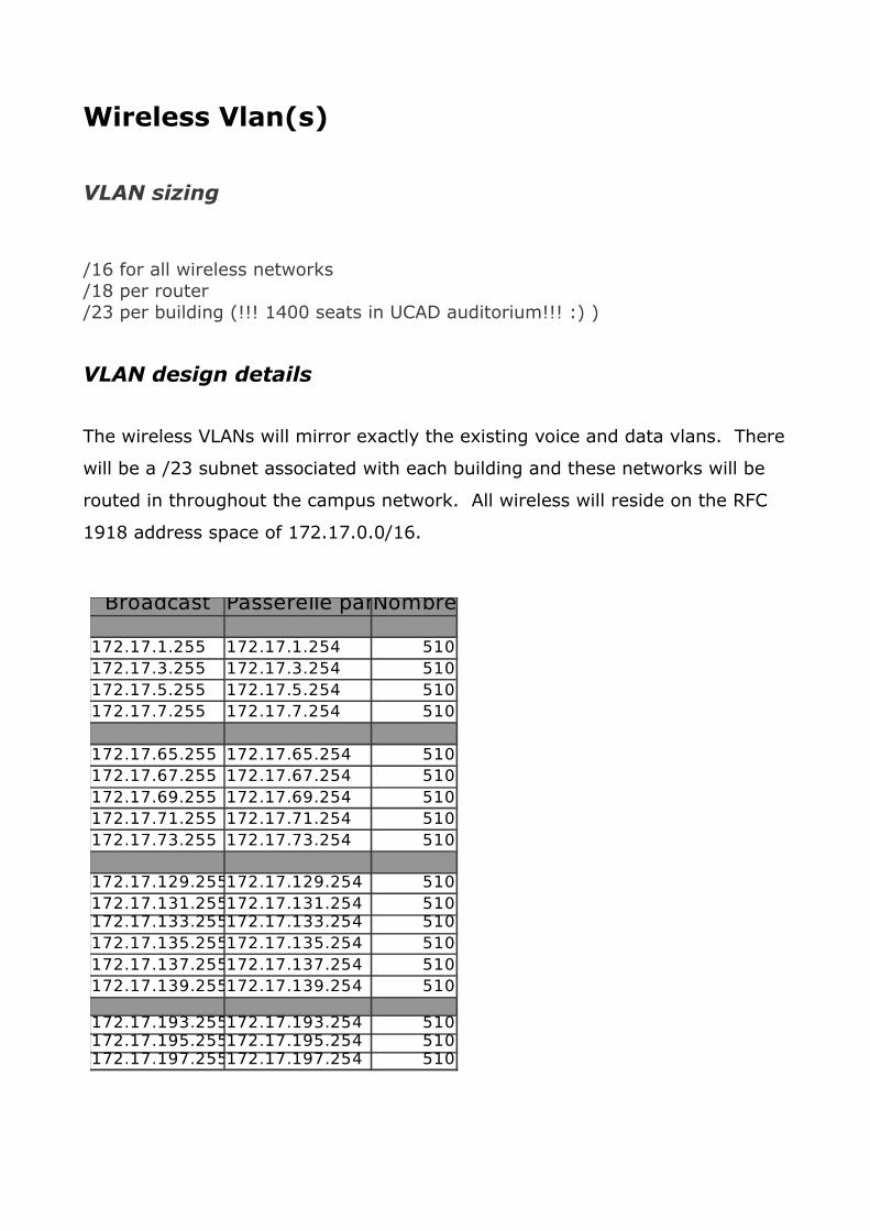
VLAN design details
The wireless VLANs will mirror exactly the existing voice and data vlans. There
will be a /23 subnet associated with each building and these networks will be
routed in throughout the campus network. All wireless will reside on the RFC
1918 address space of 172.17.0.0/16.
Broadcast Passerelle par défautNombre IP
172.17.1.255 172.17.1.254 510172.17.3.255 172.17.3.254 510172.17.5.255 172.17.5.254 510172.17.7.255 172.17.7.254 510
172.17.65.255 172.17.65.254 510172.17.67.255 172.17.67.254 510172.17.69.255 172.17.69.254 510172.17.71.255 172.17.71.254 510172.17.73.255 172.17.73.254 510
172.17.129.255172.17.129.254 510172.17.131.255172.17.131.254 510172.17.133.255172.17.133.254 510172.17.135.255172.17.135.254 510172.17.137.255172.17.137.254 510172.17.139.255172.17.139.254 510
172.17.193.255172.17.193.254 510172.17.195.255172.17.195.254 510172.17.197.255172.17.197.254 510

Unifi controller
Unifi Controller has been installed on the following server:
Ubuntu 10.04 LTS (existing 10.10 was not manageable, due to expired / non-supported repositories)
Linux dsi-desktop 2.6.32-33-generic #72-Ubuntu SMP Fri Jul 29 21:07:13 UTC 2011 x86_64 GNU/Linux
cat /etc/network/interfacesauto eth0 iface eth0 inet static address 172.16.1.250 gateway 172.16.1.254 broadcast 172.16.1.255 netmask 255.255.255.0
web GUI at https://172.16.1.250:8443
Unifi controller install
The installation followed
http://forum.ubnt.com/showthread.php?t=45945
The most important steps are:
1. aptget upgrade
2. edit /etc/apt/sources.list
to add
deb http://www.ubnt.com/downloads/unifi/distros/deb/lucid lucid ubiquiti
deb http://downloadsdistro.mongodb.org/repo/ubuntuupstart dist 10gen
3. add GPG Keys

aptkey adv keyserver hkp://keyserver.ubuntu.com recv 7F0CEB10
aptkey adv keyserver hkp://keyserver.ubuntu.com:80 recv C0A52C50
4. update, install & upgrade
aptget update
aptget install unifi
(resolves mongodb dependency by itself)
5. the UniFi webUI can be reached via https://<unifi_ip>:8443/
Securing the controller: see Action Points!

Unifi AP configuration
Enabling L3 management by adding controller to DNS
We configure our DNS server to resolve 'unifi' to your controller's IP address. Result:
sebastian@nsrcauth3:~$ nslookup unifi
Server: 172.16.1.3
Address: 172.16.1.3#53
Name: unifi.winucad.sn
Address: 172.16.1.250
In this way, all APs can find their inform URL, http://unifi:8080/inform, needed for initial handshake, adoption etc.
With this step,
full management and provisioning over layer 3 is possible, for all devices running firmware versions 2+.
Devices can be upgraded from firmware versions 1 to 2 over layer 3, and across subnets, but this requires additional command line steps, described and discussed in Appendix 1.
However, there is little motivation to do this -
it is much easier to
unpack and test each new device at your NOC/office
adopt it, upgrade and configure it
then deploy it to its final location
All configuration changes, upgrades and so forth may then be performed via the Unifi GUI, regardless of subnet/broadcast domain of the AP.

Unifi AP deployment
We deployed the first batch of Unifi APs to locations at the Rectorate and others.
Doing so, we faced a number of problems with
adopting, provisioning, configuring
remote Aps.
Detailed tests – documented in Appendix 2 – suggest that the problems are in
• physical network (cables, fiber), packet losses• DNS issues
and not related to any Unifi specific (AP or controller) issues.

Policy based routing and Captive Portal
Policy Based Routing
As we develop a scalable strategy to deploy wireless at UCAD, we have decided to implement a Wireless VLAN in each building that is present at all UCAD managed switches. This VLAN is in addition to the Data and Voice VLANs that are already present at every switch in the network. This Wireless VLAN will provide routed /23 subnets in the 172.17.0.0 rfc 1918 address block for each subnet on the UCAD campus.
Prior to the introduction of the captive portal, the campus network looked like:
We will introduce the captive portal on the core switch at DSI (the central computing center) as follows:

The key challenge is that we need to deliver all traffic from the wireless clients coming from any address in the 172.17.0.0/16 block to the captive portal so it can provide authentication services. The function of the captive portal is fully described in http://en.wikipedia.org/wiki/Captive_portal, however, in simplistic terms, the captive portal will drop all traffic from a client until the client authenticates. The authentication happens when the client starts up a web browser to access the Internet and the captive portal redirects the http or https request to a web page that provides authentication by requesting a username and password or some other type of authentication token. Once the authentication is completed successfully, the captive portal will pass all traffic from the client on to the destination.
The challenge is that standard routing looks at the destination address of a packet and forwards that packet based on the routing tables. However, we need the DSI router to look at the source address of the packets it is forwarding and for anything coming from 172.17.0.0/16, it needs to forward that packet to the captive portal. This can be accomplished with Policy Based Routing. Although it should not be a problem to apply this policy to all ports except the captive portal output/WAN port (because we should not see any traffic from 172.17.0.0/16 from the firewall, the captive portal input/LAN port, or the server net3work) . For example, we will only apply the policy based routing that says forward any packet from 172.17.0.0/16 to the captive portal on the ports marked in Green as follows:

Thus, we will not apply this policy to the ports attached to the captive portal, the firewall, or the server network. For our example, we need to know the ports assigned to each connection off of the DSI router. Let us assume that we have the following assignments:
GigEthernet0/1: RectoratGigEthernet0/2: FSJP-DORS1GigEthernet0/3: FST-DORS1GigEthernet0/4: ENSETPGigEthernet0/5: ESP-PublicGigEthernet0/6: ESPGigEthernet0/7: DSI FirewallGigEthernet0/8: Captive Portal outGigEthernet0/9: Captive Portal inGigEthernet0/10: DSI-DORS2
Policy Based Routing uses two key concepts: access lists and route maps. First, we need to define an access list that matches on a packet with a source address of anything in the 172.17.0.0/16 block. The access list that describes this is simple:
access-list 1 permit 172.17.0.0 0.0.255.255
This defines access list number will match any packet with the source address

of 172.17.*.* and will not match on any other packet. Note that access lists have a default deny at the end of the list, so we don’t specifically have to configure the deny for all other packets. Please also note that you may already have configured access list 1, in which case you need to adjust the examples here accordingly to use a different access list number.
Next we define a route map. The route map has a name that you select and an order in which the route map is applied (you can apply multiple route maps on an interface). You should always leave space between the route map number because you may want to apply a route map either before, after, or between maps you have defined. Here, we will define a route map called wireless-client. This name is arbitrary, but should be something meaningful to your organization. It is important to note that just as with an access list, each route map ends with an implicit deny all, so you do not have to have that in your configuration.
route-map wireless-client permit 10match ip address 1set ip next-hop <ip address of input interface of captive portal>
This map says that when we match the source address describe with access-list 1 (any traffic from some device on the wireless network, we will send it out interface GigEtherent0/8 that is the interface that the next-hop router, which is the port connected to the input of the Captive Portal. If we do not match the access list, then default routing will apply to the packet and it will be routed normally.
Now, in our example, we simply need to apply this route map to each interface that will have wireless client traffic coming from it (see the diagram above with the green circles on the interfaces). Note that we can apply this to all ports except the wireless portal output/WAN port (see discussion below of the captive portal for more information). Please also note that since at least the interfaces attached directly to building switches will actually have the routed interface be a VLAN interface, not the physical interface, so you will have to adjust the commands used to apply the route map to specify the appropriate interface (the wireless VLAN or in the case of router-to-router, probably the actual interface, depending on the router configuration). The configuration command required to apply the route maps to the interface is generally:
interface <interface name>ip policy route-map wireless-clientip route-cache policy
So, if we are attempting to apply this to say VLAN 22 that has a wireless VLAN to one of the directly served buildings, you would specify:
interface vlan 22ip policy route-map wireless-clientip route-cache policy

If you were placing this on a non-VLANed direct router-to-router interface, say Gigabit Ethernet 0/3, the command would be:
interface GigEthernet0/3ip policy route-map wireless-clientip route-cache policy
You will need to apply this configuration on all interfaces that will see traffic from wireless clients and can be applied to all interfaces except the output port of the captive portal. This configuration example also uses the “ip route-cache policy” to turn on fast switching of the packets rather than process switching when processing policy commands on this interface. Without fast switching, all policy processing is handled by the router's CPU. This can cause serious performance problems in a slower router, or if the traffic load is heavy.
Requirements of the Captive Portal
The above example of Policy Routing to deliver packets to the Captive Portal makes several assumptions:
1. The captive portal has an input and an output port. In descriptions of captive portals, these may be called the LAN (interface towards the wireless clients or GigEthernet0/8 in the above configuration) and WAN (interface towards the network or GigEthernet0/9 in the above configuration). You will need to configure these interfaces with IP addresses on both the router and the captive portal. The LAN and WAN networks must be different subnets.
2. The captive portal will act as a router. Since it is a router, it needs to know how to route traffic in your network. You should point a route to the wireless client network towards the LAN interface and a route to the Internet towards the WAN interface. In this case, you would point a route to 172.17.0.0/16 to the LAN and a default route to the WAN.
3. The captive portal must authenticate on IP addresses, not MAC addresses. In this design, the captive portal will not be able to see the MAC addresses of the wireless clients.
4. The captive portal must be configured to “white list” certain types of traffic. Virtually all captive portals allow you to white list various types of traffic. You will need to read the captive portal documentation to find out how to do this with the captive portal you have chosen. The following traffic should be “white listed” by the captive portal to pass the traffic without authentication:

a. All traffic to/from the IP addresses of the Access Points. This will allow the controller to manage the access points and nagios to ping the access points. If you wanted to be more restrictive, you could make the “white listing” to be all traffic to/from access points to/from the controller, nagios, and any other machines you may want to use to ping access points (the subnet for your network engineers).
b. All DHCP and DNS traffic to/from any wireless client (a laptop or tablet connected to the wireless network). This will allow the laptop/tablet to get an IP address and resolve a name using the DNS. The DNS is very important because the way authentication works is that the user must launch a browser and try to access the Internet. When the browser tries to access the Internet, it must be able to resolve a name (www.google.com for example) to an IP address or the browser will not attempt to make an http query.

Action Points• Controller: check and adjust the servers security and failover status
• Controller: key based ssh access instead of password auth
• Controller: Root password on Controller – change!
• Protect Unifi web GUI by means of firewall and/or htaccess
• Add key elements of the wireless network to Nagios
• Start work on one central user store, e.g. ex Oracle, LDAP/AD
Unifi: Further Reading
• essential: http://wiki.ubnt.com/UniFi_FAQ
is the closest thing to a technical manual (that currently does not exist).
• Quickstart: http://www.ubnt.com/downloads/guides/UniFi/UniFi_AP_QSG.pdf
• User Guide: http://www.ubnt.com/downloads/guides/UniFi/UniFi_AP_AP-
LR_User_Guide.pdf

Appendix 1: Discussion of provisioning via Layer 3
The following notes discuss the management of Unifi Aps over L2 and L3, specifically whether Unifi Aps can be fully deployed and management across L2 broadcast domains, meaning: only depending on Layer 3 connectivity.
We will not discuss the subtle differences between “subnet” and “L2 broadcast domain” here.
Both subnets and broadcast domains should be defined and limited by routers, without overlaying mulitple IP subnets over one router/switch.
Our controller network: 172.16.1.0
Our wireless (V)Lan: 172.17.2.0
We add and adopt an AP on the 172.16.1.0 network, i.e on the same subnet as the controller. This works OK and it can upgrade .
We can add and adopt an AP on 172.17.2.0 network, BUT it cannot upgrade from v1 to v2
We can ssh into two Aps with firmware version 2, whether these are on the .1.0 or .2.0 network
Both these APs can
ssh
ping
http 80 , 8080
An old firmware AP, version 1 - can it do the same? YES.
It can ping, ssh, http the controller, no matter what network it is located on.
However, it can not be upgraded from the controller side., as firmware version 1 does NOT offer L3 management capabilities.
Solution:
NOTE THAT WE ARE USING ubnt/ubnt -
as this AP is at default and not adopted yet!

BusyBox v1.11.2 (20110321 14:21:41 PDT) builtin shell (ash)
Enter 'help' for a list of builtin commands.
BZ.v1.2.3#
BZ.v1.2.3# ping 172.16.1.250
Pinging the controller
PING 172.16.1.250 (172.16.1.250): 56 data bytes
64 bytes from 172.16.1.250: seq=0 ttl=63 time=0.430 ms
now, from this v1 device, dosyswrapper.sh upgrade http://172.16.1.250:8080/dl/firmware/BZ2/<versionnr>/firmware.bin
(the exact firmware version needs to be checked, by looking into
/usr/lib/unifi/dl/firmware
on the controller.)
Here in our case it is
syswrapper.sh upgrade http://172.16.1.250:8080/dl/firmware/BZ2/2.2.0.996/firmware.bin
This works fine, so you can indeed fully upgrade them over L3,
even if not on the same broadcast domain / IP subnet .

Appendix 2: Tests regarding AP deployment problems, network and DNS issues
Looking into the various problems we encountered when provisioning remote Aps, detailed tests – documented in what follows – suggest that the problems are in
• physical network (cables, fiber), packet losses• DNS issues
and not related to any Unifi specific (AP or controller) issues.
Crucial tests:
Changing IP settings via Unifi controller GUI
Can an AP, that has received IP settings via DHCP, be moved to fixed IP via the Controller GUI?
1a) keeping the same IP address as DHCP had given? YES
Setting 172.17.130.26 manually via controller GUI - works fine.
1b) can i move an AP to a fixed address in the range 172.17.x.1...20?
Setting 172.17.130.10 manually via controller GUI - works fine.

DNS tests
Remarks on differences between nslookup and system resolver
nslookup and system resolver both use the /etc/resolv.conf file, but in diferent ways.
nslookup talks to only one name server at a time.
This is the biggest difference between nslookup's behavior and the resolver's behavior.
The resolver makes use of each nameserver directive in resolv.conf. If there are two nameserver directives in resolv.conf, the resolver tries the first name server, then the second, then the first, then the second, until it receives a response or gives up. The resolver does this for every query.
On the other hand, nslookup tries the first name server in resolv.conf and keeps retrying until it finally gives up on the first name server and tries the second.
Once it gets a response, it locks onto that server and doesn't try the next.
In other words,
When there are multiple nameservers in /etc/resolv.conf, the resolver
queries them in the order ABCABCABC..., but nslookup uses the order
AAA...BBB...CCC....
And once it gets a response from a server, it
locks onto that one for the rest of the session (or until you use the
"server" command to select a server explicitly).
Source: http://docstore.mik.ua/orelly/networking_2ndEd/dns/ch12_01.htm
Also read:
http://homepage.ntlworld.com./jonathan.deboynepollard/FGA/nslookup-flaws.html
http://veggiechinese.net./nslookup_sucks.txt

DNS tests on AP that has IP settings provided by DHCP
BZ.v2.2.0# ifconfig br0
br0 Link encap:Ethernet HWaddr 00:27:22:BC:69:9B
inet addr:172.17.130.27 Bcast:172.17.131.255 Mask:255.255.254.0
BZ.v2.2.0# cat /etc/resolv.conf
search winucad.sn
nameserver 172.16.1.3
nameserver 196.1.95.15
BZ.v2.2.0# nslookup less.dk
################### takes30 seconds !!!!!!!!!!!!!!!!!!!!!!!!!
Server: 172.16.1.3
Address 1: 172.16.1.3 serveur3.winucad.sn
Name: less.dk
Address 1: 80.71.132.234 80-71-132-234.u.parknet.dk
BZ.v2.2.0# nslookup nsrc.org
Server: 172.16.1.3
Address 1: 172.16.1.3 serveur3.winucad.sn
Name: nsrc.org
Address 1: 2001:468:d01:103::80df:9d13
Address 2: 128.223.157.19 nsrc.org
BZ.v2.2.0# nslookup nsrc.org 196.1.95.15
################### takes 1 min 30 seconds !!!!!!!!!!!!!!!!!!!!!!!!!
Server: 196.1.95.15

BZ.v2.2.0# nslookup nsrc.org 196.1.95.15
Server: 196.1.95.15
Address 1: 196.1.95.15
Name: nsrc.org
Address 1: 2001:468:d01:103::80df:9d13
Address 2: 128.223.157.19 nsrc.org
BZ.v2.2.0# nslookup nsrc.org 172.16.1.3
################### takes 30 seconds !!!!!!!!!!!!!!!!!!!!!!!!!!!!!!!
Server: 172.16.1.3
Address 1: 172.16.1.3 serveur3.winucad.sn
Name: nsrc.org
Address 1: 2001:468:d01:103::80df:9d13
Address 2: 128.223.157.19 nsrc.org
BZ.v2.2.0#
DNS tests on AP manually configured
BZ.v2.2.0# ifconfig br0
br0 Link encap:Ethernet HWaddr 00:27:22:54:DE:47
inet addr:172.17.130.26 Bcast:172.17.131.255 Mask:255.255.254.0
BZ.v2.2.0# cat /etc/resolv.conf
nameserver 172.16.1.3
#### NOTE we give no domain, search info

BZ.v2.2.0# nslookup nsrc.org
####### instant result !!!!!!!!!!!!!!!!!!!!!!!!!!!!!!!!
Server: 172.16.1.3
Address 1: 172.16.1.3 serveur3.winucad.sn
Name: nsrc.org
Address 1: 2001:468:d01:103::80df:9d13
Address 2: 128.223.157.19 nsrc.org
BZ.v2.2.0# nslookup unifi
Server: 172.16.1.3
Address 1: 172.16.1.3 serveur3.winucad.sn
nslookup: can't resolve 'unifi': Name or service not known
Network/physical issues around the router routing 172.17.13x.0
### from Controller 172.16.1.250 out to the APs 172.17.130.x
sebastian@nsrc-auth-3:~$ ssh [email protected]
[email protected]'s password:
Linux dsi-desktop 2.6.32-33-generic #72-Ubuntu SMP Fri Jul 29 21:07:13 UTC 2011 x86_64 GNU/Linux
Ubuntu 10.04.3 LTS

#################### pinging
--- 172.17.130.27 ping statistics ---
100 packets transmitted, 97 received, 3% packet loss, time 99128ms
rtt min/avg/max/mdev = 1.223/1.263/1.373/0.053 ms
--- 172.17.130.10 ping statistics ---
100 packets transmitted, 16 received, 84% packet loss, time 99128ms
rtt min/avg/max/mdev = 1.178/1.261/1.287/0.045 ms
### gateway:
#### broken cable on 172.17.130.10 ???
eth0 Link encap:Ethernet HWaddr 00:27:22:54:DE:47
UP BROADCAST RUNNING PROMISC ALLMULTI MULTICAST MTU:1500 Metric:1
RX packets:4550 errors:2993 dropped:2842 overruns:0 frame:1
TX packets:1357 errors:0 dropped:0 overruns:0 carrier:0
collisions:0 txqueuelen:1000
RX bytes:558355 (545.2 KiB) TX bytes:478810 (467.5 KiB)
Probably faulty cable!
#### 172.17.130.27 is not good either!
eth0 Link encap:Ethernet HWaddr 00:27:22:BC:69:9B
UP BROADCAST RUNNING PROMISC ALLMULTI MULTICAST MTU:1500 Metric:1
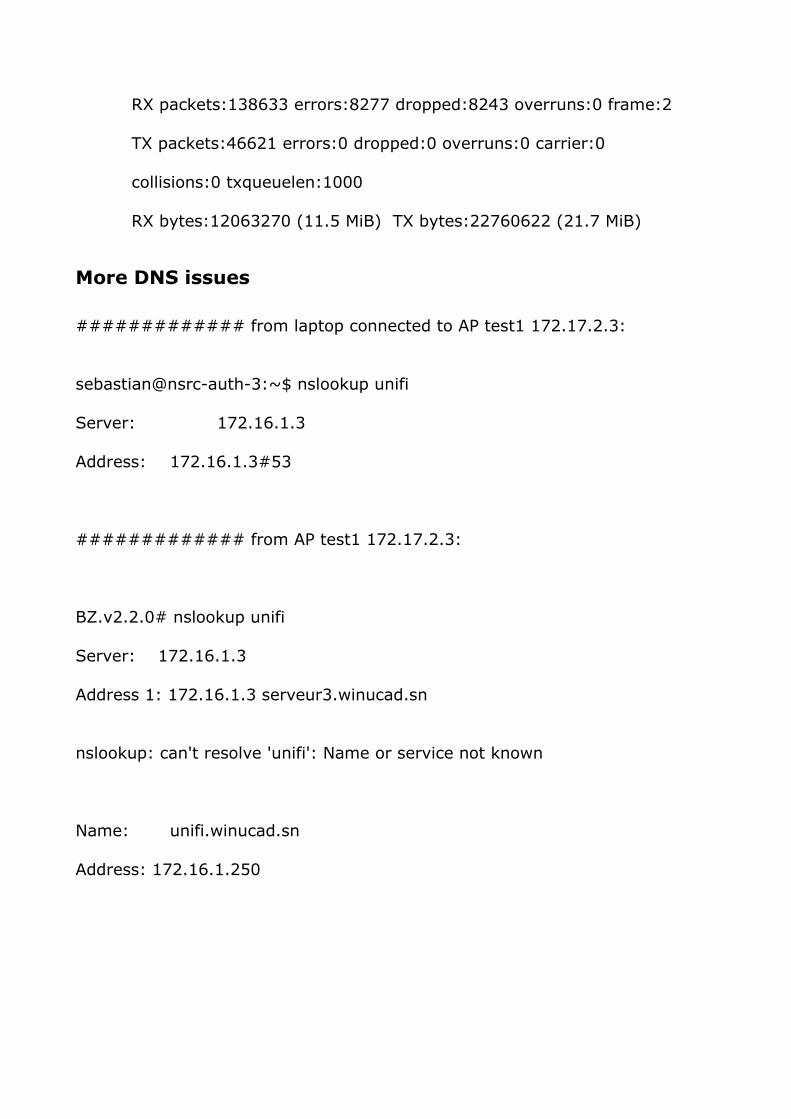
RX packets:138633 errors:8277 dropped:8243 overruns:0 frame:2
TX packets:46621 errors:0 dropped:0 overruns:0 carrier:0
collisions:0 txqueuelen:1000
RX bytes:12063270 (11.5 MiB) TX bytes:22760622 (21.7 MiB)
More DNS issues
############# from laptop connected to AP test1 172.17.2.3:
sebastian@nsrc-auth-3:~$ nslookup unifi
Server: 172.16.1.3
Address: 172.16.1.3#53
############# from AP test1 172.17.2.3:
BZ.v2.2.0# nslookup unifi
Server: 172.16.1.3
Address 1: 172.16.1.3 serveur3.winucad.sn
nslookup: can't resolve 'unifi': Name or service not known
Name: unifi.winucad.sn
Address: 172.16.1.250

Appendix 3: Rapport de Mission 01/201201
Dakar, le 25 Janvier 2012
Rapport de Mission 01/201201
Du 18 au 22 Janvier 2012, nous avons reçu une mission conjointe du Network
Startup Resource Center (NSRC) et du Centre International de Physique Théorique
Abdus Salam (ICTP). Cette mission a porté sur les 4 points suivants :
1. Audit du réseau de campus
En compagnie de Dale SMITH, Marco ZENNARO et Sebastian BUETTRICH, nous
avons visités les différents nœuds du backbone de l’UCAD (DSI, FSJP et FSJP),
en parcourant les chemins de câbles et en visitant certains regards.
A l’issue de cette visite, nos hôtes ont noté des forces, mais aussi des
faiblesses sur l’infrastructure du réseau de l’UCAD. En effet, ils ont salué la
remise à niveau du local technique de la DSI, l’existence des switchs
manageables et managés avec l’outil Nagios, la segmentation des domaines de
broadcast avec la création des VLANs voix et données par institut, l’existence
des liens en fibre sur toute l’étendue de l’UCAD, même si la plupart des liens
sont en multimode.
Toutefois, ils ont noté quelques faiblesses notamment un taux de perte de
paquets assez élevé entre la DSI et FSJP, du au fonctionnement en mode
dégradé depuis la rupture de la fibre, des câbles réseau souvent mal sertis
amenant des pertes de connexion, une instabilité du serveur DNS, l’existence
de lignes ADSL partout dans l’université en lieu et place d’un accès Internet
haut débit, symétrique et mutualisé à la DSI.
2. Wireless Survey :
Visite de sites :
En faisant le parcours des chemins de câbles du backbone pour les besoins de
l’audit réseau, nous avons visité le réseau Wi-Fi existant de l’UCAD. Ainsi, nous
sommes rendus à l’ESP, à la FST, à la BU et à l’UCAD II pour tester les zones
de couvertures du signal Wi-Fi. L’accès Internet à partir du réseau Wi-Fi ne

fonctionnait qu’au niveau de la BU. Si à l’ESP on voyait le SSID, au niveau des
autres stations de base (UCAD II et FMPOS), tous les équipements étaient
éteints.
En définitive, nous avons constaté que seul le Wi-Fi de la BU fonctionnait
correctement, mais utilise une ligne ADSL et n’est pas supervisé.
Tâches réalisées:
Pour permettre à l’UCAD de bâtir un modèle de réseau Wi-Fi géré et contrôlé
avec le maximum de zone de couverture, notre partenaire le NSRC a envoyé
des experts, assisté de l’équipe réseau de la DSI de l’UCAD pour faire ce
wireless survey.
Afin de concevoir un modèle de réseau sans fil évolutif et utilisant
l’infrastructure filaire de l’UCAD, nous avons créé de nouveaux VLANs dédiés
au trafic sans fil. L’avantage d’une telle configuration est de séparer les
domaines de broadcast par institut et de définir des règles de filtrage adaptées
à chacun de ces VLANs.
A termes, le nouveau réseau Wi-Fi de l’UCAD devra utiliser l’accès Internet
mutualisé, où tous les APs seront directement connectés au réseau filaire au
lieu d’utiliser un accès ADSL comme c’est le cas aujourd’hui
Le plan d’adressage défini pour router le trafic des VLANs Wireless est le
suivant :