Tying Construction Hoists and Mast Climbing Work Platforms ...
84
Tying Construction Hoists and Mast Climbing Work Platforms to Supporting Structures
-
Upload
khangminh22 -
Category
Documents
-
view
2 -
download
0
Transcript of Tying Construction Hoists and Mast Climbing Work Platforms ...

Insert Image here
Tying Construction Hoists
and Mast Climbing Work
Platforms to
Supporting Structures

Tying Construction Hoists to Supporting Structures 2 December 2019
Tying Construction Hoists and Mast Climbing Work Platforms to Supporting
Structures
CPA Good Practice Guide
Reference No. CHIG 1901
First Published: November 2019 Revision 1: December 2019
Published by:
Construction Hoist Interest Group (CHIG) Construction Plant-hire Association 27/28 Newbury St London EC1A 7HU
Telephone: 020 7796 3366
Email: [email protected]
CPA Copyright © November & December 2019

Tying Construction Hoists to Supporting Structures 3 December 2019
Contents
Page
Foreword …………………………………………………………………………… 4
1. Introduction to Hoist Bases and Ties ……...……………………………………. 5
2. Definitions ………………………………………………………………………….. 15
3 Responsibilities ……………………………………………………………………. 18
4. Base and Tie Loads - Calculation methods, standards and assumptions ….. 21
5. Selection of Fixings to the Supporting Structure ………………………………. 33
Annex A Example Tie Calculations ……………………………………………… 49
Annex B Bolt Tension Calculation ……………………………………………….. 64
Annex C Foundation Bearing Pressure Calculation Method ………………….. 66
Annex D Lines of Pressure at Intersection of Components of Forces ……….. 69
Annex E Template for Presenting Tie Force information ……………………… 70
Annex F Example of a Completed Template . ..………………………………... 74
Annex G TIN 302 - Construction Hoist Out-of-Service Wind Speeds ………... 82
Annex H Example of a Tie Design for an MCWP …………………………….. 85
Annex I Bibliography ……………………………………………………………… 86
Annex J Working Group Membership …………………………………………… 88
NOTE: Whilst every care has been taken to ensure the accuracy of the material contained within this booklet, no liability is accepted by the Construction Plant-hire Association in respect of the information given.
No material from this booklet may be reproduced in any shape or form without the permission of the Construction Plant-hire Association.

Tying Construction Hoists to Supporting Structures 4 December 2019
Foreword
The construction industry relies on the use of construction hoists to move materials and people between levels on site. Hoists are an essential part of the construction process and can help ensure that the vertical transportation of both materials and people can be carried out efficiently and safely.
Hoists rely on both adequate ground bearing capacity to resist the loads imposed by the hoist base and support from an adjacent structure to prevent overturning. If either of these are inadequate there is a strong likelihood of the hoist collapsing, which provides the potential for death and serious injury to occur and indeed tragically, site workers have been killed in hoist accidents in the past. In addition to the terrible cost in human suffering, accidents have a financial cost. There is a very strong business case for improving safety performance.
The law relating to hoists is clear. There are requirements to ensure that hoists are installed safely to ensure they do not present a risk to users or others in the vicinity. The purpose of this guidance is to help those involved with design and installation of hoist bases and ties to achieve a better awareness of the processes involved and the good practice required to ensure that these activities are carried out effectively.
This guidance has been prepared to provide clarity about the practical elements of hoist base and tie design, and installation. The guidance is simple but comprehensive and easy to adopt. It represents good practice for hoists used in the construction industry and is equally applicable to all construction hoist installations across all industry sectors.
I thank those who have been involved in its preparation and commend the guidance to anyone who owns, supplies or controls the operation of construction hoists. Please read the publication and turn the advice into action.
Kevin Minton
Chief Executive Construction Plant-hire Association

Tying Construction Hoists to Supporting Structures 5 December 2019
1.0 Introduction to Hoist Bases and Ties
1.1 General
All construction hoists and mast climbing work platforms (MCWPs) rely on their bases and ties for stability. This applies equally to all types and sizes of machine - passenger/goods, goods only, transport platforms and MCWPs - from the smallest to the largest.
In this document “hoist” is used as the generic term for construction hoists, transport platforms and mast climbing work platforms (MCWPs).
Recent changes to standards for both hoists and the construction fixings used to attach ties to supporting structures have resulted in confusion in the calculation of tie loads, the design of ties and the selection of fixings to attach those ties to structures. The increasing emphasis on the management of temporary works on construction projects requires that the design of hoist bases, ties and their fixings are recorded and subjected to checking.
A lack of understanding of the calculation of tie forces frequently results in excessive safety factors being applied, resulting in uneconomic tie designs requiring many fixings to attach them to the supporting structure. This has the effect of increasing costs and the difficulty of installing many fixings in one location, with the associated work at height issues.
Unfamiliarity with hoist tie and base design can provide difficulties for those carrying out temporary works checks, leading to misunderstandings and delays to programme. Hoist tie and base design should always be carried out by those with the necessary skills, knowledge, training and experience to undertake this work competently.
The aim of this document is to provide clear guidance on tie and base design, the selection and installation of fixings, and the presentation of temporary works information in a standard format.
Whilst this document is aimed specifically at tying construction hoists of all sizes to structures, the principles may be applied to Mast Climbing Work Platforms (MCWPs) and an example of an MCWP tie calculation is given in Annex H.
NOTE: The examples used in this document reflect several different types and sizes of hoist and do not necessarily apply to all hoists
1.2 Hoist types and the forces acting on them
Construction hoists, which may be for carrying both passengers and goods, transport platforms and mast climbing work platforms (MCWPs) are available in a large range of sizes as shown in Table 1.
Hoist Transport Platform Mast Climbing Work Platform
Usually with a single mast, up which the hoist carriage drives. Capacities range from 200kg for small goods only hoists to 3,200kg for large passenger-goods hoists. Payload is carried at relatively high speeds of between 24m/minute to 100m/minute
Single and twin masts with a platform fitted with a falling object protection guard. Can carry up to 7 people. The maximum speed is limited to not exceed 12m/min.
Available in both single and twin mast configurations with a long slender deck, up to 36m long on twin mast units. The deck is not enclosed and is situated close to the building so speeds are limited to not exceed 12m/minute.
Table 1 – Machine Types
As all hoists are modular and assembled from various components in various configurations it is essential that the manufacturer’s instructions for the specific make, model and configuration of hoist are followed.
Tying Construction Hoists to Supporting Structures 6 December 2019
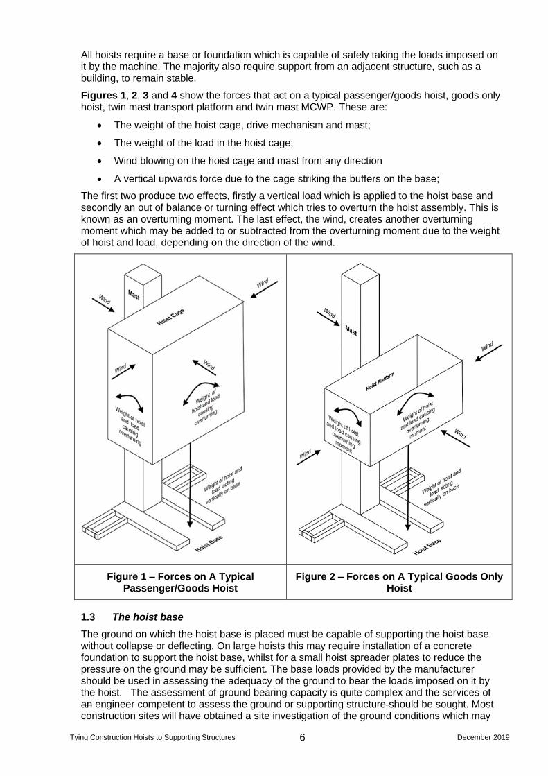
All hoists require a base or foundation which is capable of safely taking the loads imposed on it by the machine. The majority also require support from an adjacent structure, such as a building, to remain stable.
Figures 1, 2, 3 and 4 show the forces that act on a typical passenger/goods hoist, goods only hoist, twin mast transport platform and twin mast MCWP. These are:
• The weight of the hoist cage, drive mechanism and mast;
• The weight of the load in the hoist cage;
• Wind blowing on the hoist cage and mast from any direction
• A vertical upwards force due to the cage striking the buffers on the base;
The first two produce two effects, firstly a vertical load which is applied to the hoist base and secondly an out of balance or turning effect which tries to overturn the hoist assembly. This is known as an overturning moment. The last effect, the wind, creates another overturning moment which may be added to or subtracted from the overturning moment due to the weight of hoist and load, depending on the direction of the wind.
Figure 1 – Forces on A Typical Passenger/Goods Hoist
Figure 2 – Forces on A Typical Goods Only Hoist
1.3 The hoist base
The ground on which the hoist base is placed must be capable of supporting the hoist base without collapse or deflecting. On large hoists this may require installation of a concrete foundation to support the hoist base, whilst for a small hoist spreader plates to reduce the pressure on the ground may be sufficient. The base loads provided by the manufacturer should be used in assessing the adequacy of the ground to bear the loads imposed on it by the hoist. The assessment of ground bearing capacity is quite complex and the services of an engineer competent to assess the ground or supporting structure should be sought. Most construction sites will have obtained a site investigation of the ground conditions which may

Tying Construction Hoists to Supporting Structures 7 December 2019
be helpful in assessing the ground on which a hoist base is placed. The design of hoist bases is covered in Section 4.5 of this document.
Detailed guidance on ground conditions is given in the Plant Safety Group Publication Ground Conditions for Construction Plant - Good Practice Guide. Strategic Forum for Construction - Plant Safety Group (free download from www.cpa.uk.net)
Figure 3 – Forces on A Typical Twin Mast Transport Platform

Tying Construction Hoists to Supporting Structures 8 December 2019
Figure 4 – Forces on A Typical Twin Mast MCWP
1.4 Hoist ties
Most hoists can only move a small distance up the mast before they become unstable and at risk of overturning. The manufacturer will specify in their instruction manual what this maximum freestanding height is. At this point the first supporting tie to the structure must be installed before additional mast sections are installed and the hoist cage platform is raised further up the mast. The design of ties is covered in Section 4.6 of this document with example calculations given in Annex 1.
Even with ties in place there is a maximum distance the hoist cage or platform can travel above the top tie before there is a risk of overloading the mast and ties with the consequent risk of collapse. This distance, often called “oversail” will be given in the manufacturer’s instructions for the particular model and configuration of hoist. An example for a 500kg goods only hoist is shown in Table 2.
Distance from base to first mast tie Not exceeding 4 metres
Vertical distance between adjacent mast ties
Not exceeding 6 metres
Maximum mast height above the top tie when the hoist is in operation
3 metres
Maximum mast height above the top tie when the hoist is being erected.
5.5 metres
Table 2 – Maximum Tie Distances and Mast Oversail for a 500kg Goods Hoist
Hoist ties are typically steel tubes arranged in a triangular form to provide rigidity (see Figure 5). One end of a tube is attached to the hoist mast either directly or via a frame (see Figure 6). The other end of the tube is attached to the supporting structure which may include:
• A concrete slab (see Figures 7 & 8)

Tying Construction Hoists to Supporting Structures 9 December 2019
• Steelwork (see Figure 9)
• Masonry (see Figure 10)
• Scaffolding (see Figure 11).
Each of these presents particular challenges which are detailed in Section 5.0 of the guidance document
Sometimes standard ties cannot be use and special ties have to be designed. An example is shown in Figure 12.
The design of the fixing of ties to concrete slabs and masonry, including brickwork can be tricky and if a standard solution using a fixing manufacturer’s software does not work the fixing manufacturer should be contacted for application specific advice. Alternatively, another fixing method should be considered.
1.5 Factors of Safety
It would obviously be unacceptable for a structure to fail as soon as it experienced the full load it was designed to carry. In order to prevent failure, the structure needs to be designed so that it has some extra load carrying capacity – in other words a “margin of safety”. It should be noted that the presence of a safety margin does not mean that allowable (rated) loads can be exceeded - it is not spare capacity or overdesign that is available for intentional use.
Information about, for example, the size of the load, the forces involved, the strength of the material, the ground bearing capacity, etc may be provided in one of two ways:
• The characteristic load which is the load (force) applied by a hoist to a fixing,
base material or structure
NOTE: This is sometimes known as an “unfactored load”, “applied load” or “working load”.
• The design load which is the load derived from the characteristic load by
application of a partial safety factor for the load
NOTE: This is sometimes known as a “factored load”.
It is essential that the user of this information clearly understands which approach has been adopted. If they have any reservations about the accuracy of
the information or what factors (if any) have been applied they should seek clarification from the supplier or another authoritative source before proceeding with
the design.
Therefore, when obtaining the loads and forces imposed on the supporting structure by a hoist it is vital to establish if these are factored or unfactored. If this is not established, additional factors may be applied to an already factored load, resulting in double application of safety factors and unnecessarily costly base support and tie fixings. On the other hand, if safety factors are not applied to unfactored loads during base and tie designs, this may result in ground bearing failure and/or tie failure. It is essential that the designer is made aware of the status of loads and forces i.e. are they factored or unfactored.
Factored loads or capacities include a safety factor that the supplier has usually taken from a national or international code. It is also important for the designer to be sure that a factor already applied is suitable for the situation being assessed.
1.5.1 Global Safety Factors
Traditionally, loads used in the design process have been increased by a single global factor, taken from a design code or standard, which takes provides an adequate margin of safety.

Tying Construction Hoists to Supporting Structures 10 December 2019
1.5.2 Partial Safety Factors
A new approach introduced by the Eurocodes is the use of partial factors where loads are split into three categories: permanent, variable and accidental and different factors are applied to each category. The magnitude of each factor reflects the probability of an unfavourable deviation from the characteristic value, inaccuracies in the calculation method and the consequences of failure. The outcome is a more accurate prediction of the performance of a structure (including ground) than the application of a single factor of safety.
More information on partial factors is given in 4.4
1.6 Selection of Fixings
All hoist ties require fixing to the supporting structure and the various methods for doing this are detailed in 5.0.
A significant number of hoist ties are attached using construction fixings such as mechanical and chemical anchors which are selected using software provided by the fixing manufacturer. When using such software, it is important to ensure that the unfactored input loads have been multiplied by the appropriate partial factor.
1.7 Change Management
It is essential that any changes to the design of hoist bases and ties are managed and communicated effectively
Many incidents occur because site conditions have changed, or the equipment or materials provided are not quite as expected. Immediately before a job starts the specified method should be checked to see if any aspect of the job has changed and the effect that these changes could have on the safety of the operation.
If any significant modifications to the plan are required these will need to be considered by the base and tie designer. The person responsible for the activity should amend the Method Statement and sign off any significant changes. Any changes should be explained to all those involved. (See also 5.1)

Tying Construction Hoists to Supporting Structures 11 December 2019
Figure 5 – Typical Three Tube Tie with Frame
Figure 6 – Typical Three Tube Tie with Frame

Tying Construction Hoists to Supporting Structures 12 December 2019
Figure 7 – Tie to edge of Post Tensioned Concrete Slab
Figure 8 – Tie to Underside of Concrete Slab

Tying Construction Hoists to Supporting Structures 13 December 2019
Figure 9 – Tie to Steel Structure
Figure 10 – Tie to Brickwork

Tying Construction Hoists to Supporting Structures 14 December 2019
Figure 11 – Tie to Scaffolding
Figure 12 – Bespoke Tie

Tying Construction Hoists to Supporting Structures 15 December 2019
2.0 Definitions
action
load (force) applied by a hoist to a fixing, base material or structure
NOTE: action is the term used in the Eurocodes for a load.
appointed person: supplier
competent person appointed by the hoist supplier, who is responsible for supplying the hoist
appointed person: user
competent person appointed by the management of the user organization, who is responsible for liaising with the appointed person (supplier) and the safe use of the hoist
base material
material of a structure into which an anchor is installed
bolt/stud upstand
portion of stud thread between top surface of base material and the free end of the stud
competent person
person with the necessary skills and sufficient knowledge of the specific tasks to be undertaken and the risks which the work will entail, and with sufficient experience and ability to enable them to carry out their duties in relation to the project, to recognize their limitations, and to take appropriate action in order to prevent harm to those carrying out construction work, or those affected by the work
hoist
guided temporary lifting machine serving landing levels on sites of engineering and construction with a platform, cage or other load carrying device
hoist hirer
organisation hiring the hoist from the supplier
NOTE: Often referred to as hoist user
hoist supplier
organisation hiring the hoist to the hoist hirer
NOTE: This may also be the hoist owner
limit states
ultimate limit state (ULS)
the limit state at which a structure must not collapse when subjected to the peak design load for which it was designed.
serviceability limit state (SLS)
the limit state at which a structure functions effectively during normal use without exceeding limiting deflections or other limiting criteria

Tying Construction Hoists to Supporting Structures 16 December 2019
loads
characteristic load
load (force) applied by a hoist to a fixing, base material or structure
NOTE: This is sometimes known as an “unfactored load”, “applied load” or “working load”.
design load
load derived from the characteristic load by application of a partial safety factor for the load
NOTE: This is sometimes known as a “factored load”.
mast climbing work platform (MCWP)
powered access system that provides moveable access for personnel working at height on structures, consisting of the following four assemblies or groups of parts:
a) at least one mast which is climbed by and which supports the work platform;
b) a work platform capable of supporting persons, equipment, tools and materials, etc., to a
predetermined safe working load;
c) a base frame or a wheeled chassis supporting the mast structure; and
NOTE: The chassis or base frame can provide stability for MCWPs up to a predetermined free-standing height, above which the mast(s) is tied to the building or other structure.
d) mast tie assemblies
NOTE: Mast tie assemblies are not necessarily required with mobile MCWPs.
resistance
capacity of an anchorage to resist actions
allowable resistance
maximum working load derived from tests carried out on site when the proposed anchor is to be used in a base material approved by the manufacturer but for which there is no recommended resistance (load)
characteristic resistance
resistance derived as the 5% fractile of the mean ultimate resistance, determined from tests or by empirical calculation depending on mode of failure
NOTE: This is based upon a 90% probability (confidence level) that 95% of anchors will exceed the characteristic resistance.
design resistance
resistance derived from the characteristic resistance by the application of partial safety factors
mean ultimate resistance
average failure load determined in a series of tests
recommended resistance
maximum working load recommended by a manufacturer
NOTE: This is sometimes referred to as “recommended load” or “permissible load”. It is associated with the global safety factor approach, where it is derived from the characteristic action divided by a global safety factor.
temporary works co-ordinator (TWC) competent person with responsibility for the co-ordination of all activities related to the temporary works
NOTE: The appointment and responsibilities of a TWC is described in Clause 11 of BS 5975:2019
temporary works designer (TWD)
competent person with responsibility for the design of temporary works.
NOTE: The appointment and responsibilities of a TWD is described in Clause 8.4 of BS 5975:2019

Tying Construction Hoists to Supporting Structures 17 December 2019
temporary works design checker (TWDC)
competent person who evaluates the design to determine whether it conforms with the design brief and can be expected to provide a safe engineered solution
temporary works supervisor (TWS) competent person who is responsible to and assists the temporary works co-ordinator
NOTE: The appointment and responsibilities of a TWS is described in Clause 12 of BS 5975:2019
transport platform
temporarily-installed, guided powered platform with rack and pinion drive, which have an open platform and hold-to-run controls operated by authorized, trained operators on the platform, used for transporting authorised passengers and materials vertically, at limited speed, with a minimum safety offset distance and serving fixed levels on a building or structure for construction related activities including renovation and maintenance.

Tying Construction Hoists to Supporting Structures 18 December 2019
3.0 Responsibilities
Where construction hoists are installed on site a number of parties are involved, all of whom have specific responsibilities. This section identifies those parties and sets out their individual responsibilities.
3.1 CDM responsibilities
The Construction (Design and Management) Regulations 2015 (CDM 2015) cover the management of health, safety and welfare when carrying out construction projects. CDM sets out the responsibilities of all parties involved in the construction process. The roles with relevance to the provision of hoists and the design of bases and ties are as follows:
3.1.1 OEM Designer
The Original Equipment Manufacturer’s designer is responsible for the design of the construction equipment together with any OEM bracketry and equipment used to support, anchor or tie the hoist to the permanent or temporary works. This person represents the hoist manufacturer and usually provides bespoke calculations for specific design cases. The OEM rarely releases design information or calculations that are commercially sensitive, as the machinery is supplied under the Machinery Directive and is CE marked, so is safe to use within the requirements laid out in the operations manual. The designer does, however, have a duty to supply all the necessary information (base and tie loads etc.) to enable the user to install the hoist safely.
3.1.2 Principal Contractor
It is the Principal Contractor’s (PC)/Client’s responsibility to ensure that capacity of the ground is assessed for adequacy of the applied loads. The hoist manufacturer/supplier is not responsible for making this assessment as they are not in possession of the necessary information relating to the site, nor do they have the relevant expertise to make an adequate assessment. The hoist’s location is selected by the PC. The PC should also inform the hoist supplier of the location and nature of any buried services in the vicinity of the hoist and ensure that they will not be damaged due to the position of the hoist.
Although the design of the tie and any anchor bolts is generally carried out by the hoist supplier, the Client/Principal Contractor must assess whether the permanent or temporary works can accept this load without there being any deterioration to the structure. This may be a complex interface, for example anchor plates fixed onto a masonry wall. In this case the anchor plates will be assessed by the hoist/anchor plate manufacturer, the tie bolts will be designed by the hoist supplier, but the capacity of the wall will be assessed by the Principal Contractor/Client. Depending on the type of anchor used this may then be verified in practice by tests on the anchors (see 5.9).
3.1.3 Designer (Hoist supplier)
The hoist supplier’s designer is required to provide information to the hoist hirer, in particular their Temporary Works Co-ordinator (TWC), to allow the hirer to use the hoist safely. For example, the hoist supplier should:
• Select the correct assembly of parts to configure the hoist to meet the OEM designer’s
requirements;
• Provide information to the TWC to allow the hoist’s tie load’s effect on the supporting
structure to be considered;
• Provide information to the TWC to allow the hoist’s base load’s effect on the
supporting foundation to be considered;
• Outline any relevant residual risks that will affect the stability or safe use of the hoist in
the particular environment for its proposed application.

Tying Construction Hoists to Supporting Structures 19 December 2019
The hoist supplier’s designer is not usually qualified to undertake the assessment of ground conditions and building strength. Consequently, they should supply the loads at the interface with the foundation/tie bracket/wall. Under Regulation 8 of CDM 2015, designers must only work within their capability and can only be appointed to do what they are competent to do.
3.1.4 Temporary Works Co-ordinator (TWC)
The TWC employed by the hiring organisation (hirer) who is probably, but may not be, the Principal Contractor, is required to review the information received from the hoist supplier. The TWC should ensure that an adequate assessment of the building/foundation which supports the hoist (including the ties) is capable of doing so without collapsing or deteriorating over time. The TWC need not undertake the checks themselves but must ensure that a competent person undertakes a suitable assessment.
3.1.5 Temporary Works Designer (TWD) and Temporary Works Design Checker (TWDC)
TWDs should liaise with the PC’s TWC, or assistant TWC where appropriate, to agree the category of temporary works design check.
Designers and TWDCs should confirm that the design details and outline methodologies are accurately translated into the design output, and that the design conforms to appropriate engineering principles. This includes any assumed construction methods, sequences, temporary works requirements, and loads to be either imposed on or supported by the permanent works. Where the method of construction is different from that envisaged by the designer of the permanent works, there should be an assessment of the permanent works.
Designers and TWDCs should confirm that the design output adequately describes the design in a design check certificate (see 3.3).
3.1.6 Principal Designer
The Principal Designer employed by the Client may need to advise the TWC about the effect of the applied hoist loads on the permanent works, whether this is an existing building or a new structure. They will need to take into account any temporary conditions such as alterations, openings or early concrete age. They should also advise the TWC/hoist supplier of any relevant information that will assist with the siting, installation, use, maintenance and dismantling of the hoist. The Principal Designer is required to cooperate and provide sufficient information to allow the TWC to confirm the hoist can be tied and supported as proposed by the Hoist Supplier (Regulations 8, 9 and 10 apply).
NOTE: The Principal Designer may delegate the assessment to the Principal Contractor’s temporary works designer (TWD).
3.2 Hoist Supplier and User
The user organization, which is the body that procures the hoist for use on the site, has primary responsibility for the management of the erection, modification and dismantling, and for the thorough examination, operation and maintenance, of the hoist.
NOTE: This includes the provision of safe access for personnel carrying out installation, maintenance and dismantling of the hoist.
The safe erection, modification and dismantling of hoists should be planned and carried out in co-ordination with a specialist hoist supplier, using their knowledge and experience, alongside the user organization’s knowledge of the site and intended use of the hoist.
It is essential that the hoist supplier and the hoist user (hirer) liaise effectively to ensure that the correct hoist is selected and that it is installed, used, maintained and dismantled safely. Both parties should appoint an “appointed person” to take responsibility for the hoist installation and use. The responsibilities of the appointed person (supplier) and appointed person (user) are set out in Clause 6 of BS 7212:2016.

Tying Construction Hoists to Supporting Structures 20 December 2019
3.3 Design Checking
The checking of hoist tie and base designs should be carried out in accordance with Clause 13.7 of BS 5975:2019. Design checks should be undertaken in accordance with one of the categories given in Table 2 of BS 5975, which is reproduced below. The categories relate to the level of independence of the design check and are not related to the classification of risk associated with implementation stated in Clause 6.1.3 and listed in Table 1 of BS 5975.
NOTE: Implementation risk in temporary works is classified as very low, low, medium or high. This is used to establish the management level required, not the design check category.
The responsibility for ensuring that a design is checked to the appropriate category rests with the Principal Designer, taking account of any hoist user requirements. Where there are split design responsibilities, for example where the hoist supplier designs the ties and the hoist user designs the attachment to the supporting structure, the parties should agree on the category of the checks required and who will carry them out. It is essential that the design checker has the necessary competence to undertake the check, for example the hoist supplier’s designer would not have the necessary competence to undertake either the assessment of the supporting structure’s ability to absorb the loads imposed by the ties or the checking of that assessment. This equally applies to the assessment of ground below a hoist base.
On completion of the design and design check, a certificate should be issued for all categories, confirming that the design complies with the requirements of the design brief, the standards/technical literature used and the constraints or loading conditions imposed. The certificate should identify the drawings/sketches, specification and any methodology that are part of the design and it should be signed by the designer and design checker. The package of information issued to the TWC should include this certificate.
Category Scope Comment Independence of
checker Checker
0
Restricted to standard
solutions only, to ensure the
site conditions do not conflict
with the scope or limitations of
the chosen standard solution.
These may include standard
trench boxes.
This applies to the use of
standard solutions and not the
original design, which will
require both structural
calculation and checking to
category 1, 2 or 3, as
appropriate.
Because this is a site
issue, the check may
be carried out by
another member of the
site or design team.
Can be
Hoist
supplier
1
For simple designs. These
may include formwork;
falsework (where top restraint
is not assumed); needling and
propping to brickwork
openings in single storey
construction.
Such designs would be
undertaken using simple
methods of analysis and be in
accordance with the relevant
standards, supplier’s technical
literature or other reference
publications.
The check may be
carried out by another
member of the design
team.
Can be
Hoist
supplier
2
On more complex or involved
designs. Designs for
excavations, for foundations,
for structural steelwork
connections, for reinforced
concrete. Designs where
stability is obtained by restraint
at the top of the temporary
works (e.g. top restrained
falsework.)
Category 2 checks would
include designs where a
considerable degree of
interpretation of loading or soils’
information is required before
the design of the foundation or
excavation support or slope.
The check should be
carried out by an
individual not involved
in the design and not
consulted by the
designer.
Must be
Hirer or
Third Party
3
For complex or innovative
designs, which result in
complex sequences of moving
and/or construction of either
the temporary works or
permanent works. It also
includes basement
excavations and tunnels
These designs include unusual
designs or where significant
departures from standards,
novel methods of analysis or
considerable exercise of
engineering judgement are
involved.
The check should be
carried out by another
organization and
should include an
overall check to
assure co-ordination
of the whole design
Must be
Hirer or
Third Party
Table 3 – Categories of Design Check (derived from BS 5795)

Tying Construction Hoists to Supporting Structures 21 December 2019
4.0 Base and Tie Loads – Calculation methods, standards and assumptions
4.1 Introduction
Hoists, including transport platforms, and Mast Climbing Work Platforms (MCWPs) are only safe to use when they have an adequate foundation and when their stability has been considered in both the in and out of service states. It is essential that attention is given to the design of the foundation and the ties. Table 4 below highlights the various issues with, and differences between, hoists and MCWPs.
Structural Element
Hoist Transport Platform Mast Climbing Work Platform
Machine Description
Usually with a single mast, which the hoist carriage drives up and down. Payload is carried at relatively high speeds of between 24m/minute to 100m/minute
Single and twin masts with a platform fitted with a falling object protection guard. Can carry up to 7 people. The maximum speed is limited to a maximum of 12m/min.
Available in both single and twin mast configurations with a long slender deck, up to 36m long, on twin mast units. The deck is not enclosed and is situated close to the building so speeds are limited to a maximum of 12m/minute.
Base Machines with a rated capacity of 1000kg and above are, usually bolted down to a concrete slab or steel plate. May have large uplift forces and overturning moments
Machines with a rated capacity of 1000kg and above are usually bolted down to a concrete slab or steel plate. May have large uplift forces and overturning moments
The base is typically free on the ground with only local ground improvement.
See Figure 13
First tie level Usually 1.56m to 15m
NOTE: Temporary ties may be required during erection/dismantle
Usually 3m to 9m, dependent on mast type
NOTE: Temporary ties may be required during erection/dismantle
Usually at around 3m
NOTE: Temporary ties may be required during erection/dismantle
Ties Tie forces generated may be high, requiring large cross section tie members and bespoke brackets with high capacity anchors as specified by the hoist manufacturer or tie designer
NOTE: twin mast machines may have lower tie loads
Tie forces generated may be high, requiring large cross section tie members and bespoke brackets with high capacity anchors as specified by the hoist manufacturer or tie designer
NOTE: twin mast machines may have lower tie loads
Tie forces are generally less than for a hoist of similar capacity, due to the MCWP orientation and proximity to the face of the structure.
In certain circumstances it may be possible to tie using standard scaffold components, although may still use a proprietary bracket. See 4.6.1
Cantilever mast above a tie
This is the amount of free mast above the top tie which may vary from zero to 15m, depending on the hoist type, capacity and manufacturer. The hoist may travel on this mast section.
Limited ability to work above the top tie
Limited ability to work above the top tie
Table 4 – Hoist, Transport Platforms and MCWP Differences
It is very unusual to have hoists, transport platforms and MCWPs installed without a tie. If untied equipment is required, then particular attention must be given to the base, as it is the sole means of providing resistance to overturning.

Tying Construction Hoists to Supporting Structures 22 December 2019
4.2 Base and Tie Loads
The hoist manufacturer should supply the owner of the hoist with loading information as required by the relevant standard, such as Clause 7.1.2.7 of BS EN 12159:2012, Builders hoists for person and materials with vertically guided cages. These loads are given for various load cases including:
• When the hoist is freestanding, i.e. during erection / dismantle just prior to the
installation of the first tie.
• When the hoist is tied and operational (in service)
• When the hoist is tied and out-of-service with the carriage parked at an agreed
location, usually at the ground level.
The loads and forces action on various types of hoist are shown in 1.2
4.3 Wind Loads
BS EN 12159:2012, Builders hoists for person and materials with vertically guided cages specifies that out-of-service loads should be calculated using minimum design wind pressures derived from the wind regions set out in the European Storm wind Map in Annex A of EN 12159. This map places southern central England in Region C, the rest of England and Wales in Region D and Scotland and Northern Ireland in Region E, resulting in loads that are significantly higher than continental Europe. The European Storm wind Map covers terrain of all heights whilst Annex G (TIN 302) shows a UK specific out-of-service wind region map showing wind regions for land under 200m above sea level which covers the majority of areas of the UK where construction hoists are used. This shows that England and Wales fall into Region C, whilst Scotland and Northern Ireland fall into Region D, resulting in a significant reduction in loads due to out-of-service wind.
Consideration should be given to requesting zone specific wind loads for the hoist location to ensure that the calculated base and tie loads are not unnecessarily conservative.
4.4 Partial Factors Applied to Unfactored Loads
When undertaking calculations for the foundations and ties, it is important to apply partial factors to the unfactored working loads supplied by the hoist manufacturer. Table 5 shows the factors to be used, together with the source reference. Typically, all actions (loads) are considered as variable as there are assumptions made by the hoist manufacturer:
• the hoist is carrying a variable load;
• the load can be placed anywhere in the hoist cage;
• for allowances in the hoist loads e.g. how much load is actually being applied at the
landings due to landing self-weight / materials handling.
• the hoist carriage is moving and subject to wind loads,
As such the whole hoist load is considered as a variable action, even though a proportion of the load is comprised of the known self-weight of the hoist. The example calculations make this assumption and a factor of 1.5 is applied to all the actions (loads).
Forces supplied by the hoist manufacturer are generally unfactored, however this is not always the case and should be checked before starting to design the attachment of the hoist to the supporting structure. The presence (or not) of partial safety factors being applied to the loads shall be indicated on the Word hoist tie template (see Annex E ) (free download from
https://www.cpa.uk.net/construction-hoist-interest-group/) .
The forces that are applied to the mast by the hoist carriage and any wind pressures are transferred to the building via system of ties and anchor bracket (see 1.4). The values of these forces can be calculated, allowing the designer to calculate the tension/compression in connecting members such as tie tubes. Such tubes can be assessed for their structural capacity. This will include buckling loads as tubes are usually slender tension ties /

Tying Construction Hoists to Supporting Structures 23 December 2019
compression struts. It is not uncommon to have tube forces of 40 to 70kN (unfactored/Serviceability Limit State value).
Limit state Permanent actions (Gk) Variable actions (Qk) Reference
Equilibrium (EQU) 1.1G =
(0.9 when favourable )
1.1Q =
(0 when favourable) NA to BS EN 1990
Strength at ULS 1.35G =
(1.0 when favourable)
1.5Q =
(0 when favourable)
BS EN 1990 Exp (6.10) & Table A1.2(B)NA to BS EN 1990
Serviceability 1.0G = 1.0Q = BS EN 1990 Table A1.4
Accidental 1.0G = 1.0Q =
BS EN 1990 Exp (6.11a) & Table A1.3 NA to BS EN 1990 Figure 4.1 Partial factors on actions to BS EN 1990
Table 5 – Partial Load Factors NOTE: Some fixing manufacturers use a partial safety factor for actions γ = 1.4 which is taken from Clause A.2.2 of BS 8539:2012, Code of practice for the selection and installation of post-installed anchors in concrete and masonry.
The recommendation of this guidance document is to use a partial factor of γ = 1.5 as this is a commonly used factor in temporary works and most actions (loads) associated with hoists are variable. The exception to this where the actions of the hoist ties and the resistance of the supporting structure are accurately known, in which case the use of γ = 1.4 may be appropriate.
The clamp fitting at the mast/hoist framework must have a sufficient slip resistance for the applied tube load. The addition of extra ‘slip’ fittings or supplementary couplers is not often practical or desirable. Requirements for supplementary couplers can be found in BS EN 74-1 and NASC TG14 (see Annex I), consequently it can prove difficult to tie larger hoists to traditional tube and fitting scaffold or other temporary works. The typical axial load imposed by a large Passenger/Goods hoist is 70kN, whereas the slip resistance of a Class A right angled coupler is 6.1kN and a Class B right angle or swivel coupler is 9.1kN.
When tying a hoist to scaffold is being considered, the practicability of this will depend on size of hoist. It is essential that the hoist supplier is advised of the intention to tie to scaffold by the hirer at the earliest opportunity, so that they can supply the tie forces to the hirer for consideration by the scaffold designer.
4.5 Base Design.
Hoists and MCWPs require an adequate foundation. This foundation may not be on original ground, but instead could be, for example: on a new slab, a pavement, a haul road or over a brick arch, steel grillage, scaffold gantry or suspended slab. The assessment of the suitability of the bearing surface can be a complex task, especially where the hoist affects (surcharges) a party-wall or comes under the scrutiny of interested third parties such as Network Rail. The loads provided by the hoist manufacturer are used to assess the adequacy of the supporting medium.
4.5.1 Freestanding height before the first tie is installed
Hoists are particularly vulnerable to overturning just prior to the first tie being installed. One of the cases considered when calculating bearing pressure should therefore be at the maximum freestanding height, but without the tie fitted. The calculation should allow for:
• The erection/dismantle wind speed;
• An allowance for the weight and position of hoist erectors, tools, mast sections, tie
tubes;
• In-service rated load and limiting wind speed if the hoist is to be taken into service in
the freestanding condition.
NOTE: the manufacturers should be consulted to ensure that the worst case loads are considered in the
design.

Tying Construction Hoists to Supporting Structures 24 December 2019
The following operational factors over which the hoist manufacturer has no control must be considered in the design:
• The correct amount of mast to allow the tie to be installed;
• The correct weight of supporting foundation to anchor the hoist down;
• The adequacy of the supporting medium for the applied load;
• The hoist being correctly positioned on the foundation;
• The hoist being correctly anchored to the foundation.
These assumptions need to be communicated to the designer and the erection team so that they work within the design criteria. This is particularly relevant to MCWPs and hoists on narrow mast sections (for example 450mm and less) as these types of mast will usually require a low height tie which may be temporarily installed until a higher tie is installed. MCWPs, for example, are unlikely to have anchors for the ground bearing frame and consequently require the low level tie to prevent them overturning. Where low height ties are required, they must be assessed and re-installed, if required, during the dismantling operation (see 4.4). Overturning accidents have occurred where this low height tie has been omitted on erection or has not been re-installed before dismantling.
Case Study – MCWP Overturn Due to Uneven Loading
A MCWP with unequal length decks installed on a balcony, was being dismantled and the mast sections placed on the longer left-hand wing as they were removed from the mast. When the last tie was removed the base machine overturned to the left, falling from the balcony to ground level. Sadly, both erectors suffered fatal injuries.
Figure 13 – Typical MCWP Base Frame (without holding down anchors)
4.5.2 Base frame fixings
It is essential that the foundation and tie anchor bolts have adequate strength to keep the hoist attached to the supporting structure (see 4.5 and 5.0).
Some hoist suppliers will use the manufacturer’s own cast-in anchor or foundation frame see (Figure 14). Others may use a suitable anchor into concrete. Frames and/or anchors must be adequate for the loads anticipated, as must the base material into which they are fixed. For example, a mass concrete base is unlikely to cope with significant tension generated under the mast of certain large capacity hoists. In certain circumstances a hoist with a large distance to the first tie may generate tensions of 90kN in each of the holding down bolts. A competent engineer should assess the anchors as the following elements are fundamental to the stability

Tying Construction Hoists to Supporting Structures 25 December 2019
of the tie system. The following list is particularly relevant to anchoring the hoist into a hoist foundation slab, a similar list is provided later for hoist ties:
• Anchor base material strength (e.g. concrete grade and actual strength/condition) /
setting in frame capacity;
• Capacity of structural steelwork or steel foundation plate;
• Insitu reinforced concrete (RC) or precast;
• Size and proximity of reinforcement which is required to ensure that the concrete does
not crack when tension and shear forces are applied to the concrete. In some cases,
excessive cover to concrete will be unacceptable where anchors are being used.
Where this is critical, surveillance to ensure the correct positioning of reinforcement
may be required;
Case Study – Resin Anchor Failure
Some concrete slabs weighing 8 tonnes were being lifted using a 4 leg chain sling attached to lifting
eyes screwed into resin fixed inserts. During a trial lift the inserts failed when the load was about
500mm above the ground. The slab fell to the ground, shock loading the crane and causing the chain
slings to whip.
The investigation into the failure showed that there was lack of resin bonding the insert to the
concrete, which indicates that the hole may not have been cleaned correctly and that at installation
of the insert wasn’t rotated to allow the resin to mix with the thread of the insert.
• Presence of cast in items and post tensioning tendons – these will require clearance
distances and / or the ability to drill an anchor in;
NOTE: Particular care is required on refurbishment work as accurate information on the location of such
items may not be available
• Depth of reinforcement;
• Base frame thickness and hole diameter;
• Bolt/stud upstand;
• Slab thickness;
• Edge distances;
• Anchor bolt diameter;
• Anchor spacing;
• Adequacy of the structure/medium beneath the foundation – for example the allowable
bearing capacity of the soil beneath the hoist;
NOTE: It is the Principle Contractor’s (PC) / Client’s responsibility to ensure that capacity of the ground is assessed for adequacy of the applied loads. The hoist manufacturer / supplier is not required to make this assessment as they are not in possession of the information related to the site nor do they have the relevant expertise to assess this adequately. The hoist’s location is selected by the PC. Likewise, the PC must communicate information regarding any buried services in the vicinity of the hoist and ensure that they will not be damaged due to the position of the hoist.
• Is there a need for back propping beneath any supporting slabs? Care must be
exercised when positioning props. Are they located under the mast and the emergency
buffers? Do the props bear onto a foundation of adequate strength?
• Presence of underground services.

Tying Construction Hoists to Supporting Structures 26 December 2019
Figure 14 – Example of a Foundation Frame
Annex B shows an example of how to calculate bolt tensions based on a typical manufacturer’s base loading information and shows the significant difference in bolt forces at the base frame anchor of a freestanding hoist and a tied hoist. Many hoist suppliers reduce the height to the first tie in order to minimise the anchor loads and the size of the foundation slab required.
Annex B also shows a typical order of magnitude for a smaller machine with a different bolting arrangement.
It is necessary to confirm with the manufacturer that the bolt loads can be carried by any proprietary / manufacturer’s base frame. This is especially true where an old style “setting in frame” is used with a modern, large payload machine.
4.5.3 Ground assessment
If the base is located on the ground, the long-term effect of the hoist on the strata beneath it should be assessed. Soils may deteriorate over time at different rates, softening, allowing the hoist to settle and causing the base to lean. Similarly, if the soil can be washed out (scour), the base could become unstable. Any concrete or structural steel bases (e.g. base plates) providing support to the hoist must be designed and checked to the relevant design standards for the stated hoist loads.
In this example each anchor point can take a working (unfactored) load of 90kN

Tying Construction Hoists to Supporting Structures 27 December 2019
NOTE: Blinding may be required to the formation in order to provide a firm and level bearing surface and prevent degradation over time.
Detailed guidance on ground conditions is given in Ground Conditions for Construction Plant - Good Practice Guide. Strategic Forum for Construction - Plant Safety Group (free download from
www.cpa.uk.net)
The hoist supplier must ensure that base loads are provided for the specific hoist configuration that is going to be installed. Typical standard load cases will be available from the hoist manufacturer in the manual. The in-service, out-of-service and erection/dismantle load cases should be evaluated, appreciating that these loads may be applied to different parts of the hoist foundation. These specific load cases are not always provided by the hoist manufacturer or shown in their manual and may need to be requested. It is essential that the hoist hirer and user do not vary the installation and erection strategy as this could vary the base and tie loads from the manufacturer’s data (see 1.7 on change management). A standard Word template for requesting and recording loads from the hoist manufacturer is shown in Annex E (free download from https://www.cpa.uk.net/construction-hoist-interest-group/) and an example of a completed template is shown in Annex F.
The mass of the supporting foundation should be considered in the base design. This mass provides the resistance to overturning and an adequate factor safety should be applied. The magnitude of the safety factor will depend on the designer’s confidence in the loads provided by the manufacturer. A minimum factor safety of 1.67 (calculated from partial safety factors of 1.5/0.9) against overturning is recommended.
NOTE: this value is taken from CIRIA C761 (see Annex I)
In order to check the foundation, the loads must be used to calculate the peak pressure at the foundation edge. Vertical pipes are ignored in the sample calculation in Annex C as they reduce eccentricity of the hoist loads onto the foundation. In reality, vertical-pipes (which support the gates on passenger/goods machines) will need adequate support beneath them too as these can have significant load passing through them to the foundation. Some hoist installations also do not require vertical gate support tubes. In the example in Annex C, two alternative bases are being compared. The first is a base supporting a hoist just prior to its first tie being installed. The second is showing the base loads when two ties have been installed. A similar outcome is expected with only one tie installed. In this example, the hoist is located on a steel baseplate which is being used as the foundation; weighing 4.6 tonne, with a length of 4.0m and a width of 2.89m. The plate sits on the bearing structure which must be able to accept the loads with respect of bearing strength and stiffness.
Care should be taken when considering safety factors:
• Calculations of pressures applied to the ground would usually be unfactored (see
Table 6);
• Calculations where load is applied to a structure would attract standard partial safety
factors or dead/live load factors related to limit state assessments (see Table 5);
• For calculating the factor of safety for overturning systems dead loads should have a
safety factor of 0.9 as these are considered as beneficial/restoring.
The calculation in Annex C shows factored forces and moments as if applied to a structure.
The calculations refer to a chart in Annex D which indicates a factor used to assess the edge pressures based on x and y axis eccentricity. The source of this reference is given.
The base calculations in the annexes show that a hoist exerts a higher bearing pressure along both the long and short foundation sides than when the average pressure is considered. The actual increase is dependent upon applied moments, applied loads and base geometry. When considering the effect of overturning on the foundation, the edge pressures are very much higher than average pressures. Average pressure calculations underestimate the applied loads significantly.
A competent temporary works engineer must review the various calculated pressures against the strength and stiffness of the bearing surface (see 3.1). Materials that cannot tolerate the

Tying Construction Hoists to Supporting Structures 28 December 2019
high edge loads may fail structurally or may settle over time. This may be significant if the hoist foundation is located on a weak structure.
4.6 Tie Design
Construction hoists are tied for several reasons:
1. To avoid overstressing the mast;
2. To transfer the loads from the hoist to the supporting structure;
3. To restrict the amount of free cantilever of mast. Excessive mast cantilever would
allow the assembly to fail should the hoist carriage climb too high;
4. To restrict the amount of sway on a passenger hoist cage, for passenger comfort and
considerations such as the correct operation of gate interlocks;
5. To prevent overturning.
The design of the ties is therefore crucial in ensuring the integrity of the hoist installation.
Tie loading information is provided by the manufacturer in the format detailed in this document. This information should be communicated by the hoist supplier to the hirer so that they can assess the effect of the loads on the structure that is being used to support the hoist.
NOTE: Although the design of the tie and any anchor bolts is generally carried out by the hoist supplier, the Client / Principal Contractor must assess whether the permanent works can accept this load without there being any deterioration to the structure. This may be a complex interface, for example anchor plates onto a masonry wall: the anchor plates will be assessed by the hoist / anchor plate manufacturer, the tie bolts will be designed by the hoist supplier, but the capacity of the wall will be assessed by the Principal Contractor / Client. This is then verified in practice by tests on the anchors (see 5.7).
Usually just maximum values of loads are supplied, however, on occasions additional details, such as whether the loads are in and out of service, are given. Exceptionally, loads are given when the hoist is freestanding, i.e. during erection/dismantle just prior to the installation of the first tie.
4.6.1 Variations in manufacture’s tie loading information
A review of calculations provided by several hoist manufacturer’s, for a single size of hoist: a 2000kg capacity passenger/good hoist with a 1.5m x 3.2m cage, shows that some elements are fundamentally different. For example, different manufacturers have their x and y axis in different orientations. If this is not taken into account, the analysis of loads and selection of fixings will not reflect the actual loads applied, leading to potential failure. It is helpful if loads are presented in a graphical form, making the labelling and direction of the axis clear.
All the manufacturers who kindly took part in the review gave answers to the same questions, but the interpretation of their results needed care. Typically, the manufacturers give values that were of the same order of magnitude. For example, in service loads at the mast centreline were in the range 10.5 to 13.5kN for Rx values and 0.1 to 1.9kN for Ry. Out of service loads at the mast centreline varied from 9kN to 15.6kN for Rx and 7.7kN to 15.6kN for Ry. All manufacturers supplied unfactored loads i.e. characteristic loads.
EN 12158 and EN 12159 require the manufacturer to supply the tie loading information at the point at which tie tubes apply the load to the structure.
Hoist manufacturers may also supply the loads as acting at the centre line of the mast in the x and y axes, together with a torsional or twisting action which is due to the effect of the carriage on the mast due to wind and payload. Sometimes manufacturers will give the loads at the pin connection to a wall bracket or even the bolt loads where the bracket connects to the wall. This needs to be appreciated by the hoist supplier and explained to the hirer of the hoist so that the appropriate fixings can be selected, and the supporting structure checked for adequacy. Where brackets have slotted and/or oversized holes this may have an effect on the capacity of the anchor and the ability of the bracket to distribute the load between the fixings. In certain circumstances welded washers, grouting or other appropriate measures may be required.

Tying Construction Hoists to Supporting Structures 29 December 2019
It is the hoist hirer’s (user’s) responsibility to ensure that they adequately understand the effect of the applied load onto the structure that they are responsible for. Their assessment should include but may not be limited to the following:
• Anchor bracket bearing on the structure;
• Anchor tension / compression to the structure;
• Local bending, shear and bearing stresses;
• Local bursting stresses under any anchor post-tension;
• Strength and stiffness of the supporting structure;
• Local cast-in items such as post tensioning ducts, cladding support brackets/ panels;
• Actual achieved in-situ strength (not design strength). Variables in construction such
as concrete quality, compaction and amount and location of reinforcing (see 5.2.4);
• Actual achieved construction thickness, as opposed to design thickness, as variations
in construction may result in a slab or panel which is thinner or thicker that that
considered in the design. This may have implications for fixing strength and or ease of
installation;
• Coordination of the tie and anchor with other temporary and permanent works;
• Coordination of the hoist installation, modification and dismantle with the latest version
of the construction design;
• Insitu reinforced concrete or precast;
• Ties in masonry are particularly challenging as the ability of masonry to accept tension
and tolerate bending is very low compared to reinforced concrete;
• Size and proximity of reinforcement – required to ensure the concrete does not crack
when tension and shear forces are applied. In some cases, excessive cover to
concrete will be unacceptable where anchors are being used. Where this is critical,
confirmation of the correct positioning of reinforcement may be required;
• Diameter and depth of reinforcement;
• Slab thickness;
• Edge distances;
• Anchor bolt diameter;
• Anchor spacing.
There are many different types of hoist tie (See Figures 5 to 12 for examples). The principles outlined below assist when considering alternative tie designs. Specific special case tie calculations may be requested from the hoist manufacturer. They may however, charge for this service.

Tying Construction Hoists to Supporting Structures 30 December 2019
Figure 15 - Typical Tie Configuration
4.6.2 Example of manufacturer’s tie force information
The example shown in Figure 16 and Table 6 is for a hoist with 4No. tie levels. The values of Rx and Ry are values for the forces/actions on the centreline of the mast. The values of P1 etc are the actions applied at the wall anchor brackets.
NOTE: These in-service loads may not be the highest loads
Figure 16 – Example Tie Layout

Tying Construction Hoists to Supporting Structures 31 December 2019
Tie No.
Level (m)
Forces at Mast Centre (N)
Forces at Tie Brackets (N) Bolt Forces at Tie Brackets (N)
Rx’ Ry’ P1 P2 P3 P4 P1b P1s P2b P2s
1 +15.73 13912 96 28512 -28416 6984 6928 17612 3492 0 3464
2 +27.73 12108 -77 24734 -24811 6031 6077 15266 3016 0 3038
3 +39.73 11934 -77 24378 24455 5944 5990 15046 2972 0 2995
4 +51.73 14528 71 29760 -29689 7285 7243 18380 3642 0 3622
NOTE: The above forces are one load case from several design cases supplied by the manufacturer. These do not represent the worst case loads possible for this machine. They are also for a single cage machine rather than for a twin. The bolt loads P2b in the stated case is zero because of a particular load case where the wind is causing this bracket to be in compression, hence there are no bolt tension loads.
NOTE:
a) Rx’ and Ry’ can be positive or negative
b) The hoist is standing at the bottom landing when out-of-service
c) Pb are bolt tensile forces
d) Ps are bolt shear forces
e) P1b and P1s are the maximum bolt forces at the wall bracket at P1
f) P2b and P2s are the maximum bolt forces at the wall bracket at P2
Table 6 – Example Tie Force Information for Single Hoist
A series of example calculations are found in Annex A. These calculations demonstrate how to:
• Calculate the tube forces in a single sway brace;
• Calculate the tube forces in a double sway brace;
• Calculate the anchor forces in a bracket;
• Consider the slip load in a fitting attached to the tie tubes.
The assessment and selection of fixing anchors is described in general terms only.
Two examples of the calculation are given. In the example above, with the double sway brace, this means that wall bracket P1/P3 is rotating around wall bracket P2/P4 if the load is in a positive Rx direction and vice versa (see Figure 17). Given the double sway brace the two bolts in the upper bracket would have identical bolt loads and vice versa. This is because the addition of the double sway brace makes the system rigid. Designers have the option to assess bolt loads in this simplified way or to base the assessment on individual bolt loads given loads applied at the hoist tie bracket pin. This latter option will give a conservative (higher) load in the bracket as it assumes a local fulcrum on the edge of the tie bracket rather than rotation about the other tie bracket.
Furthermore, where the two brackets are equally spaced around the centre line of the hoist mast, the two brackets will have identical loads.

Tying Construction Hoists to Supporting Structures 32 December 2019
Figure 17 – Mirroring of Tie Loads
4.6.3 Variation of tie loads with increased mast height and number of ties
When building a hoist in stages, it is important to consider that the tie loads will vary with the addition of extra mast and ties. A typical example for single cage hoist is shown in Figure 18.
Tie Level
Worst in-service tie load
(kN)
4 17.8
3 13.2
2 15.9
1 17.3
Figure 18. – Example of the Variation of Tie Forces at Different Stage of Erection
Normally, all ties would be designed for the worst tie for a particular hoist location, having reviewed all the stages of erection. Figure 18 shows that:
• Generally, the highest tie force is experienced at the top tie because of the hoist on the
cantilever of mast above the tie. This can occur at any stage, so care must be taken
when assessing the worst case loading for tie design;
• If a second tie is close to the top tie, this will cause an increase in the tie forces in the
system by virtue of the lever arm principle that is present;
• Alterations to tie centres and cantilevers on site can have an adverse effect on the
magnitude of any tie forces calculated (see 4.6);
• Where tie forces are high it may be necessary to add extra ties or remove existing ties
in order to reduce the tie forces, however, care should be taken to ensure tie spacings
are approximately equal otherwise anchor forces may increase. The hoist
manufacturer should always be consulted in such cases.

Tying Construction Hoists to Supporting Structures 33 December 2019
5.0 Selection of Fixings to the Supporting Structure – including installation and testing
When choosing a fixing for a specific tying application, it is important to have accurate information on the installation location so that the correct choice of fixing can be made. Factors that should be considered include:
a) The base material to which the tie will be fixed including:
i) Steelwork;
ii) Concrete slab (core wall);
iii) Brickwork, natural hard stone;
iv) Timber framed structure;
v) Scaffolding and other temporary structures.
b) Site requirements including:
i) Accessibility, including safe access to the fixing locations;
ii) Installation process including no drilling (post fix) and pre-cast inserts
iii) Weight restrictions;
iv) Location of the tie bracket;
v) Special anchor requirement (e.g. Stainless steel, flush finish etc.);
vi) Required lifetime of fixing;
vii) Fixing removal after dismantling.
c) Environmental issues including:
i) Temperature range during installation;
ii) Temperature range during lifetime of anchor;
iii) Water exposure;
iv) Potentially corrosive elements.
d) Reusability
i) Permanent
ii) Temporary
e) The loads to be resisted by the fixings.
Fixing methods include:
• Post installed anchors (see 5.2.5)
• Cast-in sockets and channels (see 5.2.6 and 5.2.8)
• Through clamping (see 5.2.7)
• Welding or bolting to steelwork (see 5.4)
It is essential that where proprietary fixings are used the manufacturer’s instructions for selection and installation are adhered to.
Additional guidance on the selection of fixings is given in:
• BS 8539:2012, Code of practice for the selection and installation of post-installed
anchors in concrete and masonry.
• Guidance Note on Anchor Selection produced by the Construction Fixings
Association (see Annex I)

Tying Construction Hoists to Supporting Structures 34 December 2019
5.1 Change Management
Change management procedures need to be applied if the fixings need to be varied in any way. Reasons for needing to monitor change include:
• Change of hoist / type;
• Change of tie location height / spacing;
• Alteration of the tie load;
• Alteration of the tie bracket location;
• Availability of the specified anchor;
• Discovery of different anchor installation conditions e.g. condition of substrate, edge
distances, type of substrate.
It is not appropriate to require the anchor installer to verify the adequacy of the anchors in the new situation. The variation needs to be communicated back to the original anchor specifier for verification or performance checks.
Consideration of alternative anchors needs to reflect not only the ultimate resistances but also the safety margins, edge distances and spacing along with other factors.
5.2 Tying into concrete
Concrete is the material into which most structural connections are made, for which most anchors are designed, and performance is most frequently quoted.
Anchor performance is most commonly quoted for C20/25 concrete which has a mean compressive strength of 25 N/mm2. Some manufacturers also quote tensile performance in stronger grades or allow the calculation of increased allowable tensile loads within certain limits. Exceptionally strong concrete, i.e. > 60 N/mm2, may inhibit the expansion of some expanding anchors and the manufacturer’s advice should be sought to check for suitability. The same criteria apply to in-situ and pre-cast concrete; the slimmer sections and higher strengths of pre-cast units may require a different anchor choice.
5.2.1 Site details required for tying into concrete
When tying into concrete the following details are required:
• Type of slab;
• Type of concrete;
• Type of reinforcement (edge);
• Layout of existing inserts (cast in channels and sockets);
• Type of tie bracket;
• Orientation of bracket to the geometry of concrete e.g. a bracket on a slab edge or a core wall;
• Site preferred anchor (manufacturer).
5.2.2 Cracked/uncracked concrete
It is essential to determine when selecting an anchor if it is to be installed in cracked or uncracked concrete, as not all anchors have been tested and approved for use in cracked concrete.
It is acknowledged that concrete may be cracked for a variety of reasons, primarily the loading of the structure, (cracked concrete in tension zones, uncracked in compression zones) and reinforcement helps limit crack widths and restrict crack propagation. Although there is no evidence to hand in the UK of anchor failures being caused by cracked concrete, the “ETAG” (Guideline for European Technical Approval of Metal anchors for use in concrete) allows for

Tying Construction Hoists to Supporting Structures 35 December 2019
the approval of anchors for use in both cracked or uncracked concrete or for use only in uncracked concrete. Anchors are now available, using both traditional and new design concepts, which function well in cracked concrete. Such anchors have undergone specific testing to determine the difference in their performance between cracked and uncracked concrete. The results of this testing are reflected in the resistance of the chosen anchor.
As well as the new "Undercut" anchors, both expansion and resin bonded anchors are available with approval for use in cracked concrete. Expansion anchors may, with care, be considered for such applications by locating the expansion point in the compression zone. Some expansion anchors can be installed in both cracked and uncracked concrete as they are self compensating. The anchor manufacturer’s advice should always be sought before installation.
The age of concrete is important as this has a great effect on strength. For example, the strength at 1 day is 20% to 40% of the 28 day strength and at 2.5 days old, it is 40% to 60% of the 28 day strength. The strength should be verified by the crushing of sample cubes where ties are being inserted into immature concrete.
5.2.3 Reinforcement
Reinforcement in concrete can take up the tension generated in the concrete. Calculation packages for anchors do not, however, take this into account but use information on reinforcement to calculate the shell spalling effect. Consequently, reinforcement does not improve anchor performance and while theoretically it may allow setting closer to edges, this is difficult to assess and is best ignored. Performance is usually quoted for unreinforced concrete. If rebar, which may not be cut, is hit during drilling, the aborted hole should be filled with a strong, non-shrink grout and the new hole spaced at least the depth of the aborted hole away. Additional holes designed into brackets will help cater for this common eventuality. It is essential that the position of rebar should be considered at the design stage.
5.2.4 Construction variables
Construction of concrete elements to which a hoist tie is attached may be subject to several variables which may affect the “as-built” strength of the supporting structure. If this is below the design strength, the ability of the structure to resist loads from the tie may well be affected.
These variables include:
• Concrete quality;
• Compaction;
• Quantity, size and location of rebar;
• Incorrect shuttering dimensions.
5.2.5 Post installed drilled anchors
These anchors are inserted into a hole drilled in the base material and are of two types:
Mechanical anchors
Mechanical anchors work in two ways:
• Expansion of the sleeve surrounding the bolt (see Figure 19.), to transfer load to the
base material through friction. Expansion of the sleeve is either displacement or torque
controlled.
• Segments on the outer part of the anchor being forced over a cone on the inner part
and keying into an undercut in the base material to transfer the load (see Figure 20.).

Tying Construction Hoists to Supporting Structures 36 December 2019
Bonded anchors
Bonded anchors are bonded to the wall of the hole in the base material using a two part resin grout which transfers the load from the anchor stud to the wall of the hole in the base material (see Figure 21.). An example of a typical tie using a bonded anchor to a slab edge is shown in Figure 22.
Figure 19. – Example of an Expansion Anchor
Figure 20. – Example of an Undercut Anchor
Figure 21. - Example of a Bonded Anchor
Figure 22. – Typical Tie with a Bonded Anchor to Concrete Slab Edge

Tying Construction Hoists to Supporting Structures 37 December 2019
Figure 23. – Typical Tie Wall Bracket
When selecting drilled anchors, it is essential that the anchor manufacture’s information is used for selection of an appropriate anchor and its subsequent installation. Most anchor manufacturers provide software to assist with selection.
5.2.6 Cast-in sockets
Cast-in sockets are a means of attaching ties to precast panels. They consist of a threaded socket machined from solid bar with a cross hole at the inner end for either an integral cross pin or rebar. The socket is inserted to the formwork before casting and provided a permanent means of fixing (see Figure 24.). These can be used also in traditional RC slabs in order to avoid drilling by the hoist installer. It is important that the sockets are set at the correct centres to line up with the holes in the tie adaptor plates. The use of a setting in frame or jig will help ensure their correct placement.
Figure 24. – Example of a Cast-in Socket
5.2.7 Through clamping
Through clamping involves passing a threaded rod through a hole drilled in a concrete wall or slab with a tie bracket on one side and a plate or channels on the other to spread the load and transfer it into the structure. The threaded bar is then pre-tensioned to ensure that the fixing is secure (see Figure 25.). The advantage of this method is that it provides a secure fixing of

Tying Construction Hoists to Supporting Structures 38 December 2019
high capacity whilst the disadvantage is that access is required to both sides of the wall or floor slab.
Care needs to be given to the effect of the over-sized hole needed to accommodate the bar. This allows movement of the anchor in the annulus and bending stresses to be developed in the anchor, which could lead to failure. Close tolerance holes in both the wall and tie brackets through which the threaded bar passes are preferred. Where this is not possible it will be necessary to grout up the holes.
Figure 25. – Example of Through Clamping
5.2.8 Cast-in channels
Cast-in channels are a range of hot or cold rolled steel profiles designed to provide secure fixing into concrete. The channels are bonded to the concrete by adjustable bolt anchors attached to the back of the channel. The load is transferred to the channels by matching T-head bolts (see Figure 26.).
The advantages of channel fixings are:
• No drilling on site – eliminating power tools, vibration, dust and noise;
• Rapid fixing without damage to the concrete;
• Adjustable and adaptable;
• Small edge distance dimension;
• Fixtures are removable and new fixing can be made;
• Suitable for dynamic loads;
• Good resistance to corrosion;
• Suitable for prestressed structural elements – no restriction for cracked and non-cracked concrete;
• Suitable for Metal Deck type of slab.
The disadvantages are:
• Requires planning in advance, in the early stages of the project;
• Susceptible to human error for example where the channel not cast in or is in the wrong location;

Tying Construction Hoists to Supporting Structures 39 December 2019
• Not the best solution to transfer loads parallel to channel (longitudinal – shearing loads) although this can be overcome to some extent by using a toothed channel with an appropriate T bolt.
Figure 26. – Example of a Channel Fixing System
Tie brackets can be attached to either one or two channels as shown in Figures 27 and 28 Using two channels doubles the capacity of the fixing.
5.3 Tying to masonry (brickwork, blockwork and stonework)
A structural engineer should always be consulted when fixing a hoist to masonry. Applying horizontal shear forces in a perpendicular direction to walls can be dangerous.
5.3.1 Brickwork
Brickwork is probably the most awkward material to fix into. Strengths vary from 5 - 70N/mm2, mortar may be weak or non-existent in parts of the joints, bricks may be solid or have frogs or perforations which may not be filled with mortar.
When tying into brickwork the following details are required before selecting a fixing method:
• Type of brick;
• Pattern of wall (size of single brick and grout between them) total thickness of wall;
• Confirmation in writing from the PC that the wall can be drilled, this is of particular importance for listed buildings;
• Strength of brick to be confirmed (ultimate pull test required prior to installation) or site to confirm that the wall will withstand imposed load;
• The requirement for pull proof tests on the fixing.
Advice should always be sought from the fixing manufacturer and the structure designer.

Tying Construction Hoists to Supporting Structures 40 December 2019
Figure 27. – Example of a Tie Fixing to a Single Channel
Figure 28. – Example of a Tie Fixing to Two Channels
Bonded anchors (see Figures 21 and 29) are particularly suitable as they exert no expansion stresses and will fill small voids, while injection resin systems have accessories available for controlling resin in frogs, poorly filled joints and perforations. The most appropriate metal anchors are thin-walled sleeve anchors which exert low expansion stresses and are less likely to crack weak bricks than anchors with thick expanders. They can also work well in perforated bricks. Shield anchors up to medium sizes work well in reasonably strong brickwork with good mortar joints.
Fixing locations for expansion anchors should be designed on the horizontal brick centre line (to avoid frogs) away from ends of bricks, at least a brick length from the wall edge and well below the top of an unrestrained wall. Anchors should not be located in joints. Failure modes for anchors in brickwork are shown in Table 7.

Tying Construction Hoists to Supporting Structures 41 December 2019
Figure 29. – Example of Bonded Anchors in Hollow Bricks
Load Direction Failure Mode
Tensile
Failure of the anchor material
Anchor pull out
Brick break out
Pull out of one brick
Shear
Failure of the anchor material
Local brick failure
Brick edge failure
Pushing out of one brick
Table 7 – Failure Modes of Anchors in Brickwork
Ties can also be fixed to brickwork using the through clamping method (see 5.1.6). An example detail is shown in Figure 30.

Tying Construction Hoists to Supporting Structures 42 December 2019
Figure 30. – Example of Through Clamping Method in Brickwork
5.3.2 Blockwork
Block work can include the lowest strength solid substrate!
Few metal expansion anchors work satisfactorily in "thermal" blocks. Thin walled sleeve anchors may be considered for solid blocks when the compressive strength of the blocks is known to be above 10N/mm2. Metal anchors specially developed for aerated concrete work well, as do injection resin systems for which accessories are available for hollow blocks. In weak base materials the manufacturer’s recommended torque for installation in concrete may need to be reduced due to a weaker bond. Similar guidelines for positioning fixings apply as for bricks.
5.3.3 Stonework (masonry)
Tying to stonework requires a similar approach to brickwork. The strength of stones is as variable as bricks (from weak sandstone to granite). An added complication is the variation in shapes and sizes within the same wall and the possibility of rubble infill within "solid" stone walls. Anchor suitability and location guidelines are generally as for brickwork.
Additional guidance is given in Guidance Note on Tying into Brickwork and Blockwork published by the Construction Fixing Association (see Annex I)
5.4 Tying into steelwork
Tying into steelwork can be achieved using a permanently welded attachment point (see Figure 31) or with a temporary fixing. Where proprietary temporary fixings are used the system manufacturer should be consulted to ensure that the application is suitable.
Examples of temporary fixing to steelwork are:
• Bolted
o Through bolt and nut – if access to the back of steel work is available (see
Figure 32);
o Blind bolt – if access to back of steel (tie into box section) is not available;
• Lindapter type of fixing – not suitable for high shear loads (see Figure 33);
• Sandwich tie (see Figure 34);
In all cases, local stresses must be considered, for example: lateral buckling of the beam, flange or web plus any local overstressing in thin webs. The tie designer should state the maximum movement that the steelwork is permitted to move laterally to restrain the hoist.

Tying Construction Hoists to Supporting Structures 43 December 2019
When tying into steelwork the following details are required:
• Type of steelwork;
• Permitted deflection under load;
• Dimensions;
• Coating of steelwork;
• Is a permit to drill or weld (hot works permit) required?
• Location of tie bracket.
Figure 31. – Typical Welded Fixing Detail
Figure 32. – Typical Bolted Fixing Detail

Tying Construction Hoists to Supporting Structures 44 December 2019
Figure 33. – Typical Lindapter Fixing Detail
Figure 34 - Example of a “Sandwich” Tie Fixing
5.5 Anchor installation
When anchors fail in service it is generally due to poor installation. This is often due to incorrect embedment length and with resin anchors, lack of hole cleanliness.
The design performance of an anchor can only be realised if correct installation procedures are followed. In extreme cases poor installation may reduce the safety margin to the extent that the fixing fails either during installation or while in service.
Correct installation will be achieved by following the manufacturer's instructions and ensuring that installers are trained in the installation method for the specific type of fixing being used. Installers should be adequately supervised during the installation process and should use the correct installation equipment (see 5.6)
The temperature of the air and substrate will also have an effect on resin curing time. This can affect the speed of hoist installation if the hoist erectors have to wait a long time for the anchor resin to set before torqueing is possible.
5.5.1 Safe access
The installation of tie anchors on hoists inevitably involves work at height. Part of the planning process for carrying out such work should involve the provision of safe access during the installation process. This is normally the responsibility of the hoist user.

Tying Construction Hoists to Supporting Structures 45 December 2019
Where access is not possible from the hoist or other structure e.g. slipform rig, then a MEWP may be required. This may require the hiring organisation to provide a competent operator if the hoist erectors do not have the relevant competencies to operate it. An operation such as this will also require a rescue plan.
Further guidance on this is given in the CPA Best Practice Guide on Work at Height on Construction Hoists (see Annex I)
5.5.2 Pre-installation checks
Before starting installation, the following checks should be carried out:
• Fixings to be used are to the required specification;
• Equipment needed for the installation, including hole cleaning, is available and is to
the manufacturer's specification. (Special setting tools are not usually interchangeable
between makes, even if the fixing involved is of a similar type and the same size.);
• Drilling machines and cables are in a safe condition or batteries are fully charged;
• Any special conditions are complied with. For example, for bonded anchors allowable
installation temperature range and hole condition, wet, damp or dry and dust free);
• Ensure that appropriate PPE is available and worn including:
o Eye protection;
o Dust protection;
o Ear protection;
o Gloves (gloves to BS EN 374 should be worn when handling resins).
5.6 Installers
Personnel carrying out the installation of fixings should have received training in the installation of the specific type of fixing being used. They should be competent to carry out the installation and should be effectively supervised.
As the installation of drilled anchors involves the use of drilling machines, attention should be paid to the risk of Hand Arm Vibration Syndrome (HAVS). Advice on measures to prevent or mitigate HAVS can be found on the HSE website at http://www.hse.gov.uk/vibration/hav/index.htm
5.7 Supervision and certification of anchor installation
The hoist installation supervisor should monitor every stage of the fixing installation and, once
all aspects of the installation have been completed and any proof tests satisfactorily carried
out, should certify that the specified anchors have been correctly installed in accordance with
the manufacturer’s instructions and in the specified locations so that they can be put into
service. A form for this purpose, CFA Form 8539/03 Installation Certificate, is available from
the CFA website (http://www.the-cfa.co.uk/publications-and-downloads/cfa-8539-forms/).
If, at any stage, the supervisor has any concerns regarding the suitability of the fixings, the
placing of further units should not proceed and the fixings in question should be made safe
until the concerns have been addressed to the satisfaction of the fixing designer/specifier.
5.8 Basic installation procedures
The following steps are common to all drilled anchors:
• Drill hole to correct diameter and depth
• Clean hole thoroughly

Tying Construction Hoists to Supporting Structures 46 December 2019
• Use correct setting equipment and procedure
• Tighten to correct torque
Additional guidance on the installation of anchors is given in Guidance Note on Anchor Selection produced by the Construction Fixings Association (see Annex I)
5.9 On-site testing of anchors
The testing of anchors on site might be required at two stages of a hoist installation:
• Before the installation of anchors, in order to ensure that the proposed anchors are
suitable for use in the base material concerned and to determine the allowable
resistance; or
• After installation, when a sample of all anchors may be proof tested to validate the
quality of installation.
The effectiveness of anchors not only depends on the design of the selected anchor, but also on the capacity of the substrate into which the anchor is installed. Consequently, testing of the installed anchor may be required to establish the integrity of the substrate by proof loading the anchor once it is embedded and set with a torque value. This is very important as the hoist installer needs to prove that the design assessment will actually work in the installed condition. It is important that the reaction from the jack or bridge does not enhance the anchor capacity by reacting against any failure cone.
Testing may, however, prove difficult for reasons which include:
• Standard testing equipment may not fit over the anchor bracket;
• Gaining access to the ties can be challenging and may require provision of a MEWP to
gain access to the brackets once installed.
• In extreme cases access the use of a man-riding basket suspended from a crane may
be required
Additional means of access introduces additional rescue requirements which must be reflected in the planning of the operation. In order to avoid this, it may be prudent to consider undertaking a representative test elsewhere on an area of identical substrate where access is easier.
NOTE: The Construction Fixings Association states that tests are not needed if anchors are specified with a European Technical Approval and have been designed (selected) and installed fully in accordance with the requirements of the ETA
Requirements for testing are set out in:
• BS 8539:2012, Code of Practice for the selection and installation of post-installed
anchors in concrete and masonry
• Guidance Note on the Procedure for Site Testing Construction Fixings, produced by
the Construction Fixings Association (see Annex I)
5.10 Inspection
All fixings of the ties to the supporting structure should be inspected, both during installation and after testing (if required). The inspection should include:
• That the installation is in accordance with the design and/or manufacturer’s instructions
• Observation of:
o Rotation;
o Movement;

Tying Construction Hoists to Supporting Structures 47 December 2019
o Deformation;
o Cracking;
o Other damage;
The inspection findings should be recorded in writing and any notification of defects given to the fixing designer/specifier so that appropriate action can be taken.
Tie fixing inspection should form part of the thorough examination of the hoist installation both before the hoist is taken into service and periodically. Requirements for the thorough examination of hoists are given in Clause 12 of BS 7212:2016, Code of practice for the safe use of construction hoists (see Annex I).

Tying Construction Hoists to Supporting Structures 48 December 2019
Annex A – Example Tie Calculations
A.1 Resolution of tie forces at the wall plates from loads at the mast centre
A typical selection of mast centreline forces are shown in Table A1 for a twin cage passenger / goods machine. Only a small selection of the possible load cases are given and the user must consider all of the load cases in order to determine the worst one when designing the tie system. The loads at the centre of the mast will obviously be identical between the single and twin sway brace options. The forces vary in the sway braces, the tie brackets and the wall anchors between the twin and single sway brace options.
Some hoists will also have a torsion that is applied at the mast centreline. This too will affect the tie forces. Some manufacturers will apply a torsion of Mcz value at the tie location.
Mast centreline forces
Tie number and level Force Rx (kN)
Force Ry (kN)
Hoist in-service, wind x-x
Tie 1 at 15.7m above base
16.9 0.1
Tie 2 at 27.7m above base
15.5 0.1
Hoist in-service, wind diagonal
Tie 1 at 15.7m above base
14.6 6.8
Tie 2 at 27.7m above base
13.2 6.9
Hoist out-of-service, wind diagonal
Tie 1 at 15.7m 6.2 6.6
Tie 2 at 27.7m 7.5 7.4
Table A1 – Typical Mast Centreline Loads (single mast, twin carriage hoist)
Figure A1 - Wind Axis
From Table A1, two possible in-service load cases should be considered:
• In service, wind parallel to x-x giving Rx = 16.9kN and Ry = 0kN

Tying Construction Hoists to Supporting Structures 49 December 2019
• In service, wind diagonal giving Rx = 14.6kN and Ry = 6.8kN
The out of service case, Rx = 7.5kN and Ry = 7.4kN, should also be checked, as this may be a worse case.
In Table A1, the lower tie does give the highest loads, although it would be advisable to check all levels for tie forces. If there was a large cantilever of mast above the top tie, the top tie will probably have the larger value. Consider also the case where the hoist has only one tie and is in erection mode for the installation of the second tie. Furthermore, some hirers ask for a hoist to be operational with a large mast cantilever above the single tie. This can generate very large tie forces. This load case should also be checked.
The calculations in this appendix demonstrate how to calculate the loads at any given point from the mast centreline to either a tie tube pin / bracket or an intersection with the wall. The equations allow forces to be calculated in the tie tubes as well as the forces at corresponding clamp fittings
This appendix follows two calculations: single sway brace and twin sway brace. Some manufacturers may apply a torsion in order to allow for wind rotating the hoist / horizontal loading forces applied to the carriage floor. These are ignored herein but can be applied by adding the moment value into the calculations below when assessing the reactions.
Figure A2 – Tie Fixing Reaction Example – Single Sway Brace

Tying Construction Hoists to Supporting Structures 50 December 2019
A.2 Reaction equations for single or double sway brace
Taking moments about P2 gives ( . ) ( ) 1.Rx L Ry B C Mcz P B+ − + =
This makes the reaction (3.75 (2.5 1.5) )
12.5
Rx Ry MczP
+ − +=
Or 1 1.5 0.42.5
MczP Rx Ry= + +
Taking moments about P1 gives ( 2. ) ( ) ( . )P B RxL Ry C Mcz+ = +
Or 2.5 2 3.75 1.5P Rx Ry Mcz+ = +
Therefore 2 0.6 1.52.5
MczP Ry Rx= − +
Torsion at tie locations can be added simply by placing them into the equations above in the Mcz value.
It should be noted that the force calculations in the tie tubes require the creation of a force in the pipe support frame between the mast and the vertical-pipes: N1 and N2, at approx. angles
and
Using the figures from Table A1 and the reaction equations, the reactions in Table A2 and Table A3 can be calculated. The forces are taken to apply in either direction, consequently a force can be either negative or positive, tension or compression, especially where a twin hoist is considered.
From this assessment above, it is possible to see that the worst tension/compression perpendicular to the wall is 25.2 kN (unfactored). However, the horizontal load will introduce a shear into the wall fixings, so this load case should be considered.
The shear is sometimes assessed as being shared equally between the brackets, so 14.6kN (unfactored) would be applied to the anchor calculation. However, the actual value can be calculated if the angle to the wall bracket is known and the forces are ‘triangulated’. This is demonstrated in a worked example below.
In summary, the most heavily loaded bracket in this design check case is P1 in load case 1. It has a tension (and compression) on the bracket of 24.6kN and a shear force (in both directions) of a proportion of 14.4kN. The bracket and fixings should be capable of resisting this force combination.

Tying Construction Hoists to Supporting Structures 51 December 2019
Tie number and level Force Rx (kN)
Force Ry (kN)
Hoist In service, wind x-x
16.9 0.0
P1 = 1.5Rx + 0.4Ry P1 = 25.4 kN
P2 = 0.6Ry - 1.5Rx P2 = -25.4 kN
Hoist In service, wind diagonal
14.6 6.8
P1=1.5Rx + 0.4Ry P1 = 24.62kN
P2=+0.6Ry -1.5Rx P2 =-17.82kN
Hoist out of service, wind diagonal
7.5 7.4
P1=1.5Rx + 0.4Ry P1 = 14.2kN
P2=+0.6Ry -1.5Rx P2 = -6.8kN
Check sum of P1 + P2 = Ry
Table A2 – Tie Reactions Normal to the Wall
NOTE: The Mcz mast torsion value is ignored in this example.
The included angle between the single tube and the wall is 68 degrees. The gives a horizontal component of the force as:
tanθ =𝑣𝑒𝑟𝑡𝑖𝑐𝑎𝑙 𝑓𝑜𝑟𝑐𝑒 𝑐𝑜𝑚𝑝𝑜𝑛𝑒𝑛𝑡
ℎ𝑜𝑟𝑖𝑧𝑜𝑛𝑡𝑎𝑙 𝑓𝑜𝑟𝑐𝑒 𝑐𝑜𝑚𝑝𝑜𝑛𝑒𝑛𝑡
tan 68 =24.6
ℎ𝑜𝑟𝑖𝑧𝑜𝑛𝑡𝑎𝑙 𝑠ℎ𝑒𝑎𝑟 𝑐𝑜𝑚𝑝𝑜𝑛𝑒𝑛𝑡
∴ Ra (shear) = 10.0kN.
The sum of the horizontal forces should resolve to balance the external force. ∴ Rx =14.4N
Hence the horizontal force component at P4 (shear) = 14.4 – 10.0 = 4.4 kN.
Table A3 – Tie Reactions Parallel to the Wall
It is possible to see that the worst pull out and compression forces applied to the wall / bracket are 25.4kN. However, there are also horizontal forces applied also. These vary according to whether there is a single or double sway brace.
All of the load cases should be checked to assess that their individual combinations do not provide the worst case tie bracket or tie tube loadings. Only the ‘hoist in service, wind x-x’ case is considered in the examples below.
A.3 Example calculation of the reactions and tie tube loads for a single sway brace tie.
Considering the single tie brace option (from Figure A2 above where:
= = = with = = To calculate N4 tube load, then:
Sum of forces at a point add up to zero, so considering bracket P2 in figure 8,
then 22 4.sinP N =

Tying Construction Hoists to Supporting Structures 52 December 2019
Resolving for N4 2
24
sin
PN
=
254
sin 72N =
4 26.3kN axial load in the tubeN =
Resolving N4 for horizontal component gives the shear on the bracket
24 4.cosP N =
4 26.3cos72P =
4 8.1kN (bracket 2 shear)P =
To calculate N5 tube load, then:
1
1 1 1
. tan2 (mainframe force)
tan .cos sin
y xR RN
+=
+
0 16.9 tan 792
tan 79 .cos 79 sin 79N
+ =
+
86.9422 44.3
1.963N kN= =
1
1
2.cos1
cos
Rx NN
−=
16.9 44.3.cos 79 16.9 8.451 44.3kN
cos 79 0.191N
− −= = =
Vertical and horizontal components of N1 (N1V) and (N1H)
11 1.sinN V N =
1 44.3sin79 43.5kNN V = =
11 1.cosN H N =
1 44.3cos79 8.5kNN H = =
To calculate N3 tube load
1 3
3 1
2sin .cos3
sin 2cos
NN
N
=
−
44.3sin 79 .cos 603
sin 60 44.3cos 79N
=
−
3 25.1kN 8.45kN 16.6kNN = − =

Tying Construction Hoists to Supporting Structures 53 December 2019
To calculate N5 tube load
2
2
22 2
2
1 .cos3 1
sin5
sin(cos )cos
sin
N VN N H
N
+ −
=
+
43.4cos 7216.6 8.43
sin 725sin 48
(cos 48 )cos 72sin 72
N
+ −
=
+
14.1 16.6 8.435 24.8kN (tension)
0.6691 0.2414N
+ −= =
=
To calculate N6 tube load, then:
(vertical components of the forces at that node joint)6 2 N V N V=
3 16sin 2sinN N =
6sin60 2sin79N N =
44.3sin 796 50.2kN
sin 60N
= =
To calculate P3 bracket shear force, then:
0H =
2 33 5cos 6cosP N N = +
3 24.8cos48 50.2cos60P = − +
3 8.5kN (bracket shear)P =
In summary, the bracket loads have been calculated as Bracket 1 at 25.4 tension and 8.5kN in shear. Bracket 2 at 25.4kN and 8.1kN shear. The slight imbalance is in the rounding errors in the shear loads.
The ULS bracket loads and those of the axial forces in the tie tubes below use a partial safety
factor Q as 1.5
In the nomenclature of the Eurocodes, these would be expressed as below:
Bracket Serviceability Limit State Ultimate Limit State
1 Rx,k= -8.5kN Ry.k=-25.4kN Rx1,Ed=-12.75kN Ry1.Ed=-38.1kN
2 Rx,k=8.1kN Ry.k=25.4kN Rx2,Ed= 12.15kN Ry2.Ed= 38.1kN
Tie tube loads are:
Tie Tube Serviceability Limit State Ultimate Limit State
N4 Nk,4 = 26.4kN NEd,4 = 39.6kN
N5 Nk,5 = -24.8kN NEd,5 = -37.2kN
N6 Nk,6 = 50.2kN NEd,6 = 75.3kN

Tying Construction Hoists to Supporting Structures 54 December 2019
A.4 Example calculation of the reactions and tie tube loads for a twin sway brace tie.
The above calculation has been undertaken for a single sway brace, the calculation below will use the same mast centreline loads but with the addition of the second sway brace in order to assess the effect on the tie tube leg loads and the tie bracket loads.
In this case, the tie system is considered as rigid, thus the bolt group or cast-in fixings used to secure the wall bracket to the supporting structure can be assessed as rotating around the point where the line of force intersects with the concrete face of the other bracket. It should be noted that line of force is likely to not be on the centreline of the other bracket. The resulting bracket load can then be divided by two to calculate the bolt forces.
There is no need to resolve the local bolt / anchor forces by taking moments about the corner/fulcrum of the local anchor bracket. This is because the individual brackets are part of a rigid system so will not be able to locally rotate if the system is locked rigidly.
1
1 1 1
tan2
cos .tan sin
Ry RxN
+=
+
0 16.9 tan 792
cos 79 . tan 79 sin 79N
+ =
+
86.942 44.2kN
0.9816 0.9816N = =
+
1
1
2.cos1
cos
Rx NN
−=
16.9 44.28cos 79 16.9 8.451 44.3kN
cos 79 0.191N
− −= = =
Given the double tie tube / bracing from each vertical pipe, the value of N3 will tend to zero and all the load will pass into the tie legs.
1 2 1
2 2 2
1(cos .tan sin )6
cos .tan sin
NN
− −=
+
44.3(cos 79 .tan 72 sin 79 )6
cos 48 .tan 72 sin 48N
− − =
+
44.3 x 0.3946 6.2kN
2.803N
− −= =
1 2
2
1.cos 6.cos4
cos
N NN
+=
44.3cos 79 6.2cos 484
cos 72N
+ =
12.604 40.8kN
0.309N = =
1 1 3
3 3 3
2(sin cos . tan )5
sin cos . tan
NN
−=
+

Tying Construction Hoists to Supporting Structures 55 December 2019
44.28(sin 79 cos 79 .tan 605
sin 56 cos56 .tan 60N
− =
+
44.28 x 0.65115 16.0kN
1.798N = =
1 3
3
2.cos 5.cos7
cos
N NN
+=
44.28cos 79 16cos567
cos 60N
+ =
17.3967 34.8kN
0.5N = =
Considering the twin sway brace option where:
= °, = °, = ° =° with = = °
Figure A3 – Tie Fixing Reaction Example – Twin Sway Brace

Tying Construction Hoists to Supporting Structures 56 December 2019
Considering the twin sway brace option where:
= , = , = = with = = :
Figure A4 – Tie Bracket Reaction (shear) Example – Twin Sway Brace
Bracket 1 (P3) bracket shear force: 0H =
3 23 7cos 6cosP N N = −
3 34.8cos60 6.2cos48 13.3kNP = − =
Bracket 2 (P4) bracket shear force: 0H =
2 34 4cos 5cosP N N = −
4 40.8cos72 16cos56 3.66kNP = − =
Check: does P3 + P4 = Rx? Yes: 13.3+3.66 = 16.96kN comparable to 16.9kN
In summary, the bracket loads for the twin sway brace option have been calculated as Bracket 1 at 25.4 tension and 13.3kN in shear. Bracket 2 at 25.4kN and 3.7kN shear. The slight imbalance is in the rounding errors / accuracy of measuring the angles in the shear loads.
The ULS bracket loads and those of the axial forces in the tie tubes below use a partial safety
factor Q as 1.5
In the nomenclature of the Eurocodes, these would be expressed as below:
Bracket Serviceability Limit State Ultimate Limit State
1 Rx,k= -13.3kN Ry.k= - 25.4kN Rx1,Ed= - 20.0kN Ry1.Ed= - 38.1kN
2 Rx,k= - 3.7kN Ry.k= 25.4kN Rx2,Ed= - 5.6kN Ry2.Ed= 38.1kN

Tying Construction Hoists to Supporting Structures 57 December 2019
Tie tube loads are:
Tie Tube Serviceability Limit State Ultimate Limit State
N4 Nk,4 = 40.8kN NEd,4 = 61.2kN
N5 Nk,5 = -16kN NEd,5 = -24kN
N6 Nk,6 = 6.2kN NEd,6 = 9.3kN
N7 Nk,7 = -34.8kN NEd,6 = -52.2kN
Based on the above information, it is possible to design the tie tubes / fittings and also to calculate the loads in the anchor bolts.
A.5 Consideration of loads in the tubes and fittings
It can be seen from the worked examples above, that adding the second sway brace reduces the high tube load in the single sway brace option. This reduces the compression (buckling) load and will help where the slip load in the tube is compared to the slip resistance in the connection fitting.
The hoist manufacturer’s tie tube attachment / fitting should be checked against the applied loads in the bracing tubes. In the single sway brace example, the fitting must resist 50kN (characteristic / working load) compared to 40kN in the twin sway brace option. This is particularly relevant where the loads are at the slip capacity of the clips. Comparing these loads to the image in Figure A5 below, the slip capacity is 72kN, so the tie system works. It is possible to see that a traditional class B scaffold fitting which has a slip capacity of 9.1kN will not be sufficient. Care must be taking if substituting the original equipment manufacturer’s fittings for alternatives. Ensure that suitable and comparative test results are provided for the alternative before considering the substitution.
Figure A5 – Example fitting and capacity when checking tie tube connections
The loads vary in direction, so typically a +/- value is applied to the figures to cope with all eventualities of wind and load placement.
Summary bracket load for the fixing assessment would be +/-25kN and +/-14.0kN. These values should now be used to select the fixings / anchor system required to attach the hoist ties to the structure.
When using a standard anchor design package, the chosen anchor may be shown as not able to take the required load. In this case consult the anchor supplier who may be able to offer a

Tying Construction Hoists to Supporting Structures 58 December 2019
bespoke solution. Care should be taken determine whether the loads are factored or unfactored. Hoist manufacturers generally supply loads that are unfactored. In terms of anchor design, these values are described as “characteristic” or “unfactored”.
The tie forces shown in this example are for a large single mast heavy duty hoist. Figures A6 and Figure A7 show examples of typical tie forces for smaller single and twin mast hoists.
Figure A6 – Typical Tie Forces for a Lightweight Single Mast Hoist

Tying Construction Hoists to Supporting Structures 59 December 2019
Figure A7 – Typical Tie Forces for a Lightweight Twin Mast Hoist

Tying Construction Hoists to Supporting Structures 60 December 2019
A.6 Example calculation of the anchor bolt loads given loads at an eccentric tie tube pin.
Once the load is known at the pin or connection point of the tie bracket, then the forces can be resolved to provide the individual anchor loads. The anchor loads must now be calculated to allow for the type and size of bracket. The example that follows is using the values of pin load for the single sway brace example.
Figure A8 – Tie Bracket & Resin Anchor Example
The formulae to calculate the bolt loads is shown below and assumes a stiff bracket. It also shows the partial factor applied to the characteristic bracket loads that were calculated in the earlier section.
2. (0.5 ) ( 4. . )1
2
Q QP W z P eT
W z
− +=
−
25.4 x 1.5(01.15 0.05) 8.1 x 1.5 x 0.0851
0.3 0.1T
− +=
−
3.81 1.0831 24.47kN
0.2T
+= =
2 2. 1QT P T= −
2 25.4 x 1.5 24.47 13.7kNT = − =
The shear applied to the bolts will be identical = 1.5
8.1kN x 6kN2
=
The worst-case bolt loads to be used for the design of the anchors is therefore:
tension load (ULS) NSd = 25kN and shear VSd= 6kN.

Tying Construction Hoists to Supporting Structures 61 December 2019
Figure A9 - Hilti Profis Model of Tie Bracket Attachment
NOTE: The values for the applied loads are shown with partial factors applied. The stand-off / eccentricity
of the bracket/tie pin is modelled as a moment about the y-axis in the example above. The previous manual calculation also allows for this stand-off
The method above results in a M16 anchor. An expanding anchor result or resin anchor option are both shown above.
As mentioned previously, there are two possible methods of calculation of the tie in a twin sway brace solution:
1. Consider the load applied at the pin on and the anchor bracket (as already
demonstrated above;
2. Take moments about the centre of force in the other bracket (assuming a rigid tie
system).
In option two, the tension load per anchor would be the bracket reaction divided by two, however, the forces should be calculated at the line of force intersection with the tie bracket / slab edge interface
Anchor Solution(s)
RESIN OPTION: Hilti HIT- HY200-A with HIT-Z M16 anchor rod. Injection mortar with 96 mm embedment, M16, Hot dip galvanized, Hammer drilling installation per ETA 11/0493
EXPANDING ANCHOR OPTION: Hilti HST3 M16 with 85mm effective embedment but with suitable annular gap filling solution. Hammer drilling installation per ETA 11/0493

Tying Construction Hoists to Supporting Structures 62 December 2019
Figure A10 - Double Sway Brace – anchor load simplified method
Taking moments about P2 gives 1. ( . ) ( )P B Rx L Ry B C Mcz= + − +
This makes the reaction 3.824 (2.577 1.55)
12.577
Rx Ry MczP
+ − +=
Or 1.49 0.399
12.5
Rx Ry MczP
+ +=
Taking moments about P1 gives 2. . .P B Rx L Ry C Mcz+ = +
Or 2.577 2 3.842 1.55P Rx Ry Mcz+ = +
Therefore 2 0.601 1.492.577
MczP Ry Rx= − +
So 1 1.49 x 16.9 0.399 x 0 25.2kNP = + =
2 0.601 x 0 1.49 x 16.9 25.2kNP = − = −
Applying the partial safety factor 1.5 and dividing by two in order to calculate the actual bolt tension, the value = 18.9kN (ULS). This value is less than the calculated 24.9kN when considering local forces in the bracket and is due to the assumption of a rigid system.

Tying Construction Hoists to Supporting Structures 63 December 2019
The actions (loads) calculated for the above example are all characteristic (unfactored), unless stated otherwise. Figure A11 helps to explain the reasons why partial safety factors are applied to these values.
NOTE: The Hilti partial safety factor for action γ = 1.4 is taken from Clause A.2.2 of BS 8539:2012, Code of practice for the selection and installation of post-installed anchors in concrete and masonry states:
Values for γG and γQ are given in ETAG 001, Annex C [5] (and taken from BS EN 1990) as 1.35 and 1.5 respectively (see Annex E for a guide to which actions may be regarded as permanent and which variable). For the general case, and where the distinction between the permanent and variable actions is unknown or unclear, the partial safety factor for action may be taken as 1.4.
The recommendation of this guidance document is to use a partial factor of γ = 1.5 as this is a commonly used factor in temporary works and the majority of actions (loads) associated with hoists are variable.
Figure A11 – Safety Concept
The loads applied to the brackets and anchors are considered to be ‘non-static actions’. They are not shock or seismic loads, but are fatigue inducing. However due to the applied anchor torque and design methods outlined in the guidance, fatigue is not usually a problem on the typical short duration hoist projects. BS 8539:2012, Code of Practice for the selection and installation of post-installed anchors in concrete and masonry provides guidance on the process of selection and installation of the anchors.

Tying Construction Hoists to Supporting Structures 64 December 2019
Annex B – Construction Hoist Foundation Bolt Tension Calculation
The base loads supplied by the hoist manufacturer can be used to calculate the holding down bolt/anchor tension. The tension in the four bolts connecting the base frame to the support can be calculated using the following equation. Figure B.1 shows a typical mast and bolt configuration and the loads in relation to the mast.
𝐵𝑜𝑙𝑡 𝑇𝑒𝑛𝑠𝑖𝑜𝑛 [𝑘𝑁] =𝑀𝑥
2𝑤+ ((𝑑 + 𝑙) ×
𝑀𝑦
2𝑑2 + (𝑙 + 𝑑)2)
Where:
𝑀𝑥 - Overturning moment around the x axis [kNm] 𝑀𝑦 - Overturning moment around the y axis [kNm]
𝑤 - Width between bolts [m]
𝑙 - Length between bolts [m] 𝑑 - Distance from bolt to edge of mast [m]
Example values:
𝑤 = 0.96𝑚 𝑙 = 0.38𝑚
𝑑 = 0.135𝑚
Figure B.1
Hoist without ties Hoist with 2 ties
𝑀𝑥 [kNm] 5.654 0.354
𝑀𝑦 [kNm] 150.326 53.374
Bolt Tension
2 2
5.654(0.135 0.38)
2 x 0.96
150.326x
2 x 0.135 (0.38 0.135)
139.5kN (unfactored)
(
)
= + +
+ +
=
2 2
0.354(0.135 0.38)
2 x 0.96
53.374x
2 x 0.135 (0.39 0.135)
48.7kN(unfactored)
(
)
= + +
+ +
=
This example shows the significant difference that can exist between the bolt forces at the base frame anchor of a freestanding hoist and the tied hoist.
Many hoist suppliers will reduce the height to the first tie in order to reduce the bolt anchor loads.

Tying Construction Hoists to Supporting Structures 65 December 2019
The following example shows a 1000kg capacity single mast transport platform erected to 15m and tied to the adjacent structure at 3m and 12m.
F1 = 2226 kg (maximum force during erection up to first tie at 3m)
F1 = 2953 kg (maximum force with hoist stationary - loading and unloading)
F1 = 3383 kg (maximum force with hoist starting, running and stopping)
F1 = 3580 kg (maximum force during operation of safety device)
F2 = 354 kg (maximum jack loads)
F3 = 354 kg (maximum holding down bolt force)
F4 = 535 kg (maximum holding down bolt force)
F5 = 535 kg (maximum holding down bolt force)
Figure B.2

Tying Construction Hoists to Supporting Structures 66 December 2019
Annex C – Foundation Bearing Pressure Calculation Method
The following is a method of calculating the bearing pressures under a hoist foundation. Two example cases are considered. This method applies partial safety factors to the loads. No assessment is made as to the adequacy of the bearing medium beneath. This is the role of the Principal Contractor rather than the hoist supplier/installer.
NOTE: The uplift value of force generated by a buffer strike has been ignored in the following calculations as this would have a relieving effect.
The self-weight elements of the hoist and base plate are given are treated identically to the overturning forces in order to give a conservative bearing pressure
Hoist just prior to its first tie being installed.
Moments about the x-axis (factored).
Hoist that has already been tied
Moments about the y-axis (factored)
Figure C.1 – Case 1 Figure C.2 – Case 2

Tying Construction Hoists to Supporting Structures 67 December 2019
CASE 1: Hoist with no ties, low height CASE 2: Hoist with 2 ties, taller than Case 1
VERTICAL 𝐷𝑒𝑎𝑑 𝐿𝑜𝑎𝑑 = 126 × 1.6= 202𝑘𝑁
𝑃𝑙𝑎𝑡𝑒 𝐿𝑜𝑎𝑑 = 46 × 1.6= 74𝑘𝑁
VERTICAL 𝐷𝑒𝑎𝑑 𝐿𝑜𝑎𝑑 = 182 × 1.6= 291𝑘𝑁
𝑃𝑙𝑎𝑡𝑒 𝐿𝑜𝑎𝑑 = 46 × 1.6 = 74𝑘𝑁
HORIZONTAL 𝑀𝑥 = 5.7 × 1.6 = 9.1𝑘𝑁𝑚 𝑀𝑦 = 150 × 1.6 = 240𝑘𝑁𝑚
HORIZONTAL 𝑀𝑥 = 0.35 × 1.6 = 0.56𝑘𝑁𝑚 𝑀𝑦 = 53.4 × 1.6 = 85.4𝑘𝑁𝑚
OT Moment x-x around base centre line
𝑀 = 240 − 202 × 1.015 = 34.97𝑘𝑁𝑚 𝑀
𝑤=
34.97
202 + 74= 0.127𝑚 = 𝑒
𝑒
𝑏=
(0.127)
2.89= 0.044
OT Moment x-x around base centre line
𝑀 = 85 − 291 × 1.015 = −210.4𝑘𝑁𝑚 𝑀
𝑤=
−210.4
291 + 74= −0.576𝑚 = 𝑒
𝑒
𝑏=
0.576
2.89= 0.199
(note the minus sign means the eccentricity is on the opposite side of the centreline, which in this case means it is closer to the mast)
OT moment y-y around the left hand end of the steel foundation plate
𝑀 = 9.1 + 2 × (202 + 74) = 561𝑘𝑁𝑚 𝑀
𝑤=
561
202 + 74= 2.03𝑚
𝑒
𝑎=
(2 − 2.03)
4= 0.008
Using the table in Annex D and the values of e/a and e/b it is possible to derive a factor to adjust the average pressure for the effect of the overturning moment. In this example: 𝑒
𝑏⁄ = 0.044 𝑎𝑛𝑑 𝑒𝑎⁄ = 0.008
𝑐 = 1.35
𝑃𝑒𝑎𝑘 𝑝𝑟𝑒𝑠𝑠𝑢𝑟𝑒 =𝑐𝑤
𝑎𝑏=
1.35 × (202 + 74)
2.89 × 4= 32𝑘𝑁𝑚−2
This is the pressure experienced under the edge of the foundation plate. It is not a uniform pressure under the full width of the plate, which is a factor of 1.35 less.
OT moment y-y around the left hand end of the steel foundation plate
𝑀 = 0.56 + 2 × (291 + 74) = 731𝑘𝑁𝑚 𝑀
𝑤=
731
291 + 74= 2.003𝑚
𝑒
𝑏=
2 − 2.003
4= 0.001
Using the table in Annex D and the values of e/a and e/b it is possible to derive a factor to adjust the average pressure for the effect of the overturning moment. In this example: 𝑒
𝑏⁄ = 0.001 𝑎𝑛𝑑 𝑒𝑎⁄ = 0.199
c = 2.35
𝑃𝑒𝑎𝑘 𝑝𝑟𝑒𝑠𝑠𝑢𝑟𝑒 =𝑐𝑤
𝑎𝑏=
2.35 × (291 + 74)
2.89 × 4= 74𝑘𝑁𝑚−2
This is the pressure experienced under the edge of the foundation plate. It is not a uniform pressure under the full width of the plate, which is a factor of 2.35 less.
𝐴𝑣𝑒𝑟𝑎𝑔𝑒 𝑝𝑟𝑒𝑠𝑠𝑢𝑟𝑒 =𝑤
𝑎𝑏=
202 + 74
2.89 × 4= 23.9𝑘𝑁𝑚−2
𝐴𝑣𝑒𝑟𝑎𝑔𝑒 𝑝𝑟𝑒𝑠𝑠𝑢𝑟𝑒 =𝑤
𝑎𝑏=
291 + 74
2.89 × 4= 31.6𝑘𝑁𝑚−2
NOTE: refer to Annex D for the chart used to convert the eccentricity to length ratios to the enhanced edge bearing factors needed to calculate the edge bearing pressure

Tying Construction Hoists to Supporting Structures 68 December 2019
Effect of a hoist striking the buffers
If considering the effect of the hoist striking the buffers, even in an untied case, where there would be an increased likelihood of overturning, the hoist would need to be very light before such a possibility were to arise. The following example shows the principle of a check:
Declared buffer load = 238kN shared between 3 buffers. 2 at 38%, 1 at 24%. There is also an 88kN uplift created by the effect of the buffer strike. This occurs in the mast.
Pb1, Pb2 combined = 238 x 0.76 = 181kN
Pb3 = 238 x 0.24 = 57kN
Taking moments about the plate centreline gives:
(88 x 1.015) – (181 x 0.565) + (57 x 0.185) = -150 x e
-2.4 = -150e
Giving e = 0.016m
In this case there is very little eccentricity and so uniform base loads give an acceptable allowance to allow for this.
In the case where calculated bearing pressures are negative a competent temporary works engineer should be consulted.
Figure C.3 – Buffer Strike Load Case

Tying Construction Hoists to Supporting Structures 69 December 2019
Annex D – Lines of Pressure at Intersection of Components of Forces
Below is a table from the Minutes of Proceedings of the Institution of Civil Engineers, Vol CLXV (1906) Paper No. 3592 by Frederick Karl Esling entitled “A problem relating to railway-bridge piers of masonry or brickwork”. It allows a foundation with a double eccentricity to be assessed for the peak edge pressures.
The following general conclusions can be drawn from the table above:
A hoist exerts a higher bearing pressure along both the long and short foundation sides than
when the average pressure is considered. The actual increase is dependent upon applied
moments, applied loads and base geometry. When considering the effect of overturning on
the foundation, the edge pressures are very much higher than average pressures. Average
pressure calculations under-estimate the applied loads significantly. This may be significant if
the hoist foundation is a weak structure, whereas ground may be able to cope with both
values without any difficulty.
A competent temporary works engineer must review the various calculated pressures against the strength and stiffness of the bearing surface. Materials that cannot tolerate the high edge loads may fail structurally or may settle over time.

Tying Construction Hoists to Supporting Structures 70 December 2019
Annex E – Construction Hoist Temporary Works Template
NOTE: This template can be downloaded as a Word form for on-screen completion from https://www.cpa.uk.net/construction-hoist-interest-group/

Tying Construction Hoists to Supporting Structures 71 December 2019

Tying Construction Hoists to Supporting Structures 72 December 2019

Tying Construction Hoists to Supporting Structures 73 December 2019

Tying Construction Hoists to Supporting Structures 74 December 2019
Annex F – Example of a Completed Template

Tying Construction Hoists to Supporting Structures 75 December 2019

Tying Construction Hoists to Supporting Structures 76 December 2019

Tying Construction Hoists to Supporting Structures 77 December 2019

Tying Construction Hoists to Supporting Structures 78 December 2019
Annex G -TIN 302 Construction Hoist Out-of-Service Wind Speeds

Tying Construction Hoists to Supporting Structures 79 December 2019

Tying Construction Hoists to Supporting Structures 80 December 2019

Tying Construction Hoists to Supporting Structures 81 December 2019
Annex H - Example of a tie design for a MCWP
Platform – Plf3
Configuration Length Payload Extension Tie in dimension
m 2300 2.6 L (m) B (m)
CCC-A-CCCCCC-A-CC 18.9 kg m 0.75 0.55
Tie Intervals
Ground Force
Tie-in force Manufacturer’s Double (check)
coupler?
Base to 1st
(m)
1st to 2nd (m)
2nd to 3rd (m)
3rd to 4th (m)
4th to 5th (m)
Overhang (m)
Max (P1, P2) Max (P3,
P4)
kN kN kN
10.4 8.9 8.8 N/A 4.5 67.3 25.6 9.0 Yes
NOTE: Standard scaffold fittings will not be suitable for these forces
This example indicates that MCWPs may have tie forces that are similar to those of a construction hoist.

Tying Construction Hoists to Supporting Structures 82 December 2019
Annex I - Bibliography
Legislation
Health and Safety at Work etc. Act 1974. London: The Stationery Office.
The Lifting Operations and Lifting Equipment Regulations 1998 (LOLER).
Provision and Use of Work Equipment Regulations 1998 (PUWER).
L113 Safe use of lifting equipment, HSE Books.
L22 Safe use of work equipment, HSE Books.
The Management of Health and Safety at Work Regulations 1999 as amended (MHSWR).
Work at Height Regulations 2005 (WAHR).
The Supply of Machinery (Safety) Regulations 2008 (SM(S)R).
The Construction (Design and Management) Regulations 2015 (CDM).
Standards
BS 5975:2019, Code of practice for temporary works procedures and the permissible stress design of falsework
BS 7212:2016, Code of practice for the safe use of construction hoists
BS 8539:2012, Code of practice for the selection and installation of post-installed anchors in concrete and masonry
BS 5975:2019, Code of practice for temporary works procedures and the permissible stress design of falsework
BS EN 74-1:2005, Couplers, spigot pins and baseplates for use in falsework and scaffolds. Couplers for tubes. Requirements and test procedures
BS EN 1990:2002+A1:2005, Eurocode. Basis of structural design
NA to BS EN 1990:2002+A1:2005, UK National Annex for Eurocode. Basis of structural design
BS EN 1992‑4:2018, Eurocode 2 - Design of concrete structures - Part 4: Design of fastenings for use in concrete
NA to BS EN 1992-4:2018, UK National Annex to Eurocode 2: Design of concrete structures. Design of fastenings for use in concrete
BS EN 12158-1:2000 + A1:2010, Builders hoists for goods. Hoists with accessible platforms
BS EN 12159:2012, Builders hoists for goods and materials with vertically guided cages
Other Guidance
Work at Height on Construction Hoists – Best Practice Guide. Construction Plant-hire Association (free download from www.cpa.uk.net)
Ground Conditions for Construction Plant - Good Practice Guide. Strategic Forum for Construction - Plant Safety Group (free download from www.cpa.uk.net)
Guidance on Anchor Selection, Construction Fixings Association (free download from https://www.the-
cfa.co.uk/publications-and-downloads/guidance-notes/).
Guidance on Anchor Installation, Construction Fixings Association (free download from https://www.the-
cfa.co.uk/publications-and-downloads/guidance-notes/).
Guidance on Anchor Terminology and Notation, Construction Fixings Association (free download
from https://www.the-cfa.co.uk/publications-and-downloads/guidance-notes/).

Tying Construction Hoists to Supporting Structures 83 December 2019
Guidance on Deformation Controlled Expansion Anchors, Construction Fixings Association (free download from https://www.the-cfa.co.uk/publications-and-downloads/guidance-notes/).
Guidance on ETAs and Design Methods for anchors used in construction, Construction Fixings Association (free download from https://www.the-cfa.co.uk/publications-and-downloads/guidance-notes/).
Guidance on Fixings and Corrosion, Construction Fixings Association, (free download from
https://www.the-cfa.co.uk/publications-and-downloads/guidance-notes/).
Guidance on Fixings for Brickwork and Blockwork, Construction Fixings Association (free
download from https://www.the-cfa.co.uk/publications-and-downloads/guidance-notes/).
Guidance on Heavy Duty Expansion Anchors. Construction Fixings Association (free download
from https://www.the-cfa.co.uk/publications-and-downloads/guidance-notes/).
Guidance on Procedure for Site Testing Construction Fixings, Construction Fixings Association (free download from https://www.the-cfa.co.uk/publications-and-downloads/guidance-notes/).
Guidance on Resin Bonded Anchors, Construction Fixings Association (free download from
https://www.the-cfa.co.uk/publications-and-downloads/guidance-notes/).
Guidance on Shield Type Expansion Anchors, Construction Fixings Association (free download
from https://www.the-cfa.co.uk/publications-and-downloads/guidance-notes/).
Guidance on Through-bolt Expansion Anchors, Construction Fixings Association (free download
from https://www.the-cfa.co.uk/publications-and-downloads/guidance-notes/).
Guidance on Undercut Anchors, Construction Fixings Association (free download from https://www.the-
cfa.co.uk/publications-and-downloads/guidance-notes/).
C761 Tower foundation and tie design, Construction Industry Research and Information Association.
TG14:03 Supplementary Couplers and Check Couplers, National Association of Scaffolding Contractors (priced publication from https://www.nasc.org.uk/shop/)
Useful Websites
Build UK (formally UKCG) www.builduk.org
Construction Fixings Association www.the-cfa.co.uk/
Construction Plant-hire Association www.cpa.uk.net
CITB www.citb.co.uk
Health and Safety Executive www.hse.gov.uk
Home Builders Federation www.hbf.co.uk
Lifting Equipment Engineers Association www.leea.co.uk
Safety Assessment Federation www.safed.co.uk
Strategic Forum for Construction www.strategicforum.org.uk
Temporary Works Forum www.twforum.org.uk/home

Tying Construction Hoists to Supporting Structures 84 December 2019
Annex J - Working Group Membership
Name Employer Representing
K Archbold-Laming
Southern Hoists Limited CPA Construction Hoist Interest Group
K Bah Hilti (Gt. Britain) Ltd Fixing Manufacturer
G Beentjes Hoist-It Limited CPA Construction Hoist Interest Group
N Bland GB Access (A Plant) CPA Construction Hoist Interest Group
A Bolton Alimak Group CPA Construction Hoist Interest Group
M Broad Sir Robert McAlpine Temporary Works Forum
R Cox GB Access (A Plant) CPA Construction Hoist Interest Group
L Foster Southern Hoists Limited CPA Construction Hoist Interest Group
C Hook Sir Robert McAlpine CPA Construction Hoist Interest Group
J Humphrey Alimak Group CPA Construction Hoist Interest Group
J Muir Construction Fixings Association Construction Fixings Association
S Prower Steve Prower Temporary Works Limited Temporary Works Forum
T P Watson Construction Plant-hire Association CPA Construction Hoist Interest Group
K Witecki Hoist-It Limited CPA Construction Hoist Interest Group
Reference No. CHIG 1901
First Published: November 2019 Revision 1: December 2019
Published by:
Construction Hoist Interest Group (CHIG) Construction Plant-hire Association 27/28 Newbury St London EC1A 7HU
Telephone: 020 7796 3366
Email: [email protected]
CPA Copyright © November & December 2019