Turbulence Characteristics in a Tidal Channel
13
MAY 2000 855 LU ET AL. q 2000 American Meteorological Society Turbulence Characteristics in a Tidal Channel YOUYU LU,* ROLF G. LUECK, AND DAIYAN HUANG School of Earth and Ocean Sciences, University of Victoria, Victoria, British Columbia, Canada (Manuscript received 28 January 1999, in final form 3 May 1999) ABSTRACT A broadband ADCP and a moored microstructure instrument (TAMI) were deployed in a tidal channel of 30-m depth and with peak speeds of 1 m s 21 . The measurements enable us to derive profiles of stress, turbulent kinetic energy (TKE), the rate of production and dissipation of TKE, eddy viscosity, diffusivity, as well as mixing length, and to test the parameterization of dissipation rate in the model of Mellor and Yamada. At middepth in the channel where the influence of stratification was present, the Ellison length agrees with the Ozmidov length. The measured mixing length is smaller than the simple z-dependence formulation proposed for unstratified turbulence. The diffusivity of density and heat, and the viscosity for momentum, are correlated and comparable in magnitudes. The 20-min averaged production rate deduced from the ADCP agrees with the dissipation rate estimated from microstructure measurements. The dissipation rate calculated with the Mellor– Yamada model agrees with the measured values with TAMI, but the empirical constant B 1 derived from the data is larger than that conventionally used in the model. In the near-bottom layer, there is a tight correlation between the production rate and the closure-based dissipation rate. The Reynolds stress at 3.6 m above the bottom is consistently 2.5 times smaller than the shear velocity squared ( ), which is inferred from fitting the velocity 2 u * profiles to a logarithmic form. A logarithmic velocity profile almost always exists and reaches heights of 5.6 to 20 m, but the Reynolds stress is seldom constant in any part of the logarithmic layer. 1. Introduction Our ability to predict the behavior of coastal envi- ronments depends largely on our understanding of the flow and mixing processes. Deriving the flow and tur- bulence characteristics from measurements is important for understanding coastal dynamics and the develop- ment of numerical models. Turbulence measurements are few compared to the vast pool of mean flow data. The important turbulent quantities of practical interest are the frictional force on the flow, turbulence intensity, and various coefficients describing the mixing of mo- mentum and scalars. Turbulent quantities undergo com- plicated variations in space and time. A turbulent bound- ary layer is formed above the seabed by bottom friction. Within the boundary layer the flow is attenuated, the shear and frictional force are enhanced, and the turbulent kinetic energy (TKE) production is intensified. The height of the boundary layer is proportional to the scale of turbulent velocity (e.g., Bowden 1978), and can ex- * Current affiliation: Department of Oceanography, Dalhousie Uni- versity, Halifax, Nova Scotia, Canada. Corresponding author address: Rolf Lueck, School of Earth and Ocean Sciences, University of Victoria, P.O. Box 1700, 3800 Finnerty Road, Victoria, BC V8W 2Y2, Canada. E-mail: [email protected] tend over the whole water depth in shallow seas (Souls- by 1983). It is generally believed that the structure of the oceanic boundary layer bears many similarities to that in atmospheric and laboratory flows. More evi- dence, particularly from the oceanic boundary layer, is required to convincingly establish this analogy. In general, numerical models need to parameterize turbulence, partly due to the constraint of computers and partly due to the classical problem that the equations for turbulent moments are not closed. Turbulent closure schemes are commonly based upon scaling arguments and contain constants that must be determined from measurements. Mellor and Yamada (1974, 1982) pro- posed an hierarchy of turbulent closure models for geo- physical boundary layer flows, and their level-2.5 ver- sion has been implemented in practical modeling of coastal water circulation (e.g., Blumberg and Mellor 1987; Lynch et al. 1996). The feasibility of this closure scheme and the values of the empirical constants need to be tested by oceanic measurements. Whereas tur- bulent parameterization can be indirectly tested by the ability of a model to reproduce the mean flow field, a more critical test is the ability to describe the depth dependence and time evolution of turbulence (Simpson et al. 1996). In this paper, we present an analysis of the turbulent quantities from measurements in a tidal channel with flow magnitudes that are typical for coastal waters. The
-
Upload
independent -
Category
Documents
-
view
0 -
download
0
Transcript of Turbulence Characteristics in a Tidal Channel

MAY 2000 855L U E T A L .
q 2000 American Meteorological Society
Turbulence Characteristics in a Tidal Channel
YOUYU LU,* ROLF G. LUECK, AND DAIYAN HUANG
School of Earth and Ocean Sciences, University of Victoria, Victoria, British Columbia, Canada
(Manuscript received 28 January 1999, in final form 3 May 1999)
ABSTRACT
A broadband ADCP and a moored microstructure instrument (TAMI) were deployed in a tidal channel of30-m depth and with peak speeds of 1 m s21. The measurements enable us to derive profiles of stress, turbulentkinetic energy (TKE), the rate of production and dissipation of TKE, eddy viscosity, diffusivity, as well asmixing length, and to test the parameterization of dissipation rate in the model of Mellor and Yamada. Atmiddepth in the channel where the influence of stratification was present, the Ellison length agrees with theOzmidov length. The measured mixing length is smaller than the simple z-dependence formulation proposedfor unstratified turbulence. The diffusivity of density and heat, and the viscosity for momentum, are correlatedand comparable in magnitudes. The 20-min averaged production rate deduced from the ADCP agrees with thedissipation rate estimated from microstructure measurements. The dissipation rate calculated with the Mellor–Yamada model agrees with the measured values with TAMI, but the empirical constant B1 derived from the datais larger than that conventionally used in the model. In the near-bottom layer, there is a tight correlation betweenthe production rate and the closure-based dissipation rate. The Reynolds stress at 3.6 m above the bottom isconsistently 2.5 times smaller than the shear velocity squared ( ), which is inferred from fitting the velocity2u
*profiles to a logarithmic form. A logarithmic velocity profile almost always exists and reaches heights of 5.6to 20 m, but the Reynolds stress is seldom constant in any part of the logarithmic layer.
1. Introduction
Our ability to predict the behavior of coastal envi-ronments depends largely on our understanding of theflow and mixing processes. Deriving the flow and tur-bulence characteristics from measurements is importantfor understanding coastal dynamics and the develop-ment of numerical models. Turbulence measurementsare few compared to the vast pool of mean flow data.The important turbulent quantities of practical interestare the frictional force on the flow, turbulence intensity,and various coefficients describing the mixing of mo-mentum and scalars. Turbulent quantities undergo com-plicated variations in space and time. A turbulent bound-ary layer is formed above the seabed by bottom friction.Within the boundary layer the flow is attenuated, theshear and frictional force are enhanced, and the turbulentkinetic energy (TKE) production is intensified. Theheight of the boundary layer is proportional to the scaleof turbulent velocity (e.g., Bowden 1978), and can ex-
* Current affiliation: Department of Oceanography, Dalhousie Uni-versity, Halifax, Nova Scotia, Canada.
Corresponding author address: Rolf Lueck, School of Earth andOcean Sciences, University of Victoria, P.O. Box 1700, 3800 FinnertyRoad, Victoria, BC V8W 2Y2, Canada.E-mail: [email protected]
tend over the whole water depth in shallow seas (Souls-by 1983). It is generally believed that the structure ofthe oceanic boundary layer bears many similarities tothat in atmospheric and laboratory flows. More evi-dence, particularly from the oceanic boundary layer, isrequired to convincingly establish this analogy.
In general, numerical models need to parameterizeturbulence, partly due to the constraint of computersand partly due to the classical problem that the equationsfor turbulent moments are not closed. Turbulent closureschemes are commonly based upon scaling argumentsand contain constants that must be determined frommeasurements. Mellor and Yamada (1974, 1982) pro-posed an hierarchy of turbulent closure models for geo-physical boundary layer flows, and their level-2.5 ver-sion has been implemented in practical modeling ofcoastal water circulation (e.g., Blumberg and Mellor1987; Lynch et al. 1996). The feasibility of this closurescheme and the values of the empirical constants needto be tested by oceanic measurements. Whereas tur-bulent parameterization can be indirectly tested by theability of a model to reproduce the mean flow field, amore critical test is the ability to describe the depthdependence and time evolution of turbulence (Simpsonet al. 1996).
In this paper, we present an analysis of the turbulentquantities from measurements in a tidal channel withflow magnitudes that are typical for coastal waters. The

856 VOLUME 30J O U R N A L O F P H Y S I C A L O C E A N O G R A P H Y
FIG. 1. Duration of measurements made in Cordova Channel withvarious instruments.
FIG. 2. Stick diagrams of the 20-min mean velocity measured bythe ADCP and averaged over the profiling range. Open circles inpanel (c) mark the time of the 17 density profiles shown in Fig. 5.
data describe the vertical variation and temporal evo-lution of turbulence in a tidal boundary layer and areused to test a major parameterization in the Mellor–Yamada model, the closure for dissipation rate. In sec-tion 2, we describe the experiment and background mea-surements made in the study area. In section 3, we in-troduce the turbulence measurements made with abroadband acoustic Doppler current profiler (ADCP)and a moored microstructure instrument. Section 4 pro-vides a brief account of turbulence parameterization. Insection 5, we describe the variations of turbulencethroughout the water column based on measurementswith the ADCP. Sections 6 and 7 present a quantitativeanalysis of turbulent characteristics at middepth and inthe near-bottom layer, respectively. Section 8 is a sum-mary of the results of this study.
2. Study area and experiment
Cordova Channel is a side channel among a series ofnarrow passages that link Juan de Fuca Strait to theStrait of Georgia (between Vancouver Island and themainland of North America). There is a substantial es-tuarine circulation in this area due to the runoff fromseveral rivers, of which the Fraser River is the largest.The tidal flow is strong in this area and the mixing thatit generates in channels and narrow passages influencesthe estuarine circulation (e.g., Thompson 1981; Fore-man et al. 1995).
A multi-investigator experiment in Cordova Channelwas conducted in the early fall of 1994 from 19 to 30September. Most of the data analyzed in this paper arefrom instruments deployed in the narrowest part of thechannel, where it is about 1 km wide and 30 m deep(Lu and Lueck 1999a, Fig. 1). The eastern boundary(James Island) is smoothly curved. The western side issmooth and straight south of the measurement site butthe channel broadens northward due to Cordova Spitand Saanichton Bay. The influence of coastline curva-ture has been noted previously and will be discussedfurther in this paper.
The two instruments deployed by our group are a600-kHz broadband ADCP and the tethered autonomousmicrostructure instrument (TAMI) (Lueck et al. 1997;Lueck and Huang 1999). Figure 1 summarizes the du-ration of all measurements.
Throughout the experiment, the wind speed was typ-ically less than 3 m s21 and reached 5 m s21 only oc-casionally. The wind stress on the sea surface was neg-ligible compared to the frictional stress at the bottom.The water surface was calm and the wave heights didnot exceed 0.2 m during the experiment, according toour visual observation.
A multibeam survey indicates a smooth bottom alongthe axis of the channel with random undulations of lessthan 0.1 m peak to peak. The ADCP was at a ‘‘high’’point in the channel and the bottom slope was 0.015and 0.01 to the south and north, respectively, for a dis-tance of 200 m. There are small ripples of amplitude0.1 m at 200 m on either side of the ADCP. The cross-channel slope on the west side of the channel (betweenisobaths of 15 and 35 m) has many crevices that areirregularly spaced, about 1 m deep and 20 m wide.Divers reported that the bed was composed mainly offine gravel with diameters ranging from 2 to 8 (31023
m), and the bed contained neither mud nor silt.The flow in the channel was mainly tidal, directed
northward during the flood and southward during theebb (Lu and Lueck 1999a). During the experiment, thetide changed from spring to neap, and the diurnal con-stituents became increasingly dominant. Figure 2 pro-vides the time variations of the depth-mean flow for the3.8 days of ADCP measurements. During these threeintervals, the ADCP collected velocity profiles every 3seconds. An asymmetry between ebb and flood was ob-served (Lu and Lueck 1999a). The ebb tide was com-plicated due to the influence of Cordova Spit and theshallows of Saanichton Bay. During the ebb, there were

MAY 2000 857L U E T A L .
FIG. 3. Consecutive profiles of (st, in units of kg m23) collectedat the south end of Cordova Channel during the interval indicatedby open circles in Fig. 2. Successive profiles are shifted by 0.3 kgm23 to the right.
frequent reversals of streamwise shear, fluctuations offlow direction, strong secondary circulation, and trans-verse shear. During the flood, the flow above the ADCPwas nearly aligned with the channel axis and it was onlyweakly affected by the curvature of the western shoreand the shallows.
CTD profiles were taken nominally every 20 min dur-ing the period shown in Fig. 1, from the CSS Vectoranchored near the south entrance of the channel (about1.5 km to the south of the ADCP). Figure 3 shows 17consecutive density (st) profiles over one-half semidi-urnal tidal period from day 29.1 to 29.4 The stratifi-cation varied with time and it correlated with the var-iation of flow strength (cf. Fig. 2c). During strong flows,the density gradient was larger above than below mid-depth, and unstable overturns were observed during theebb. During slack current the whole water column wasstratified. The effects of stratification on turbulence willbe examined in section 6, using the density gradientmeasured by CTDs mounted on TAMI.
3. Turbulence measurements
a. ADCP
The ADCP was mounted in a quadripod on the sea-floor and the steady readings from its tilt sensors indicatethat the instrument remained motionless during the ex-periment. The ADCP measured velocities along its fourinclined beams, and the data were transferred via a cableto a computer on shore. About 3.8 days of rapidly sam-pled velocity data were collected with the standardworking mode (mode 4). The data span a range of 25m [3.6 to 27.6 mab (meters above bottom)] with a ver-tical resolution of 1 m.
The along-beam velocities, denoted by (b1, b2, b3,b4), are low-pass filtered at a cutoff period of 20 minto separate the mean (tidal) and turbulence components.The difference and sum of the turbulent components,namely ( , , , ), provide estimates of two-com-b9 b9 b9 b91 2 3 4
ponents of the Reynolds stress and a quantity Q. Theformulas used for the calculation are
12 2 2 2(u9w9, y9w9) 5 (b9 2 b9 , b9 2 b9 ), (1)1 2 3 42 sinu
12 2 2 2Q 5 (b9 1 b9 1 b9 1 b91 2 3 424 sin u
2 4D), (2)
where u 5 308 is the beam inclination angle and D isthe bias in the variances of the along-beam velocitiesdue to Doppler noise. The combination of the Reynoldsstress and mean shear provides estimates of the TKEproduction rate
]u ]yP 5 2 u9w9 1 y9w9 . (3)1 2]z ]z
The quantity Q is related to the TKE density q2/2 5(u92 1 y92 1 w92 )/2 by
Q 5 gq2/2, (4)
where the factor g 5 (1 1 2a tan22u)/(1 1 a) is de-termined by the anisotropy, a 5 w92 /(u92 1 y92 ). Thevalue of g ranges from 1 to 2.7, corresponding to a 50 (extremely anisotropic turbulence) to a 5 0.5 (iso-tropic turbulence). In this analysis we use g 5 1.8, hencea 5 0.2, which is the value estimated by Stacey (1996)from measurements in an unstratified tidal channel.
This technique of estimating turbulent quantities withthe variances of ADCP velocities has been reported byLohrmann et al. (1990), Stacey (1996), Lu (1997), andLu and Lueck (1999b). Stacey et al. (1999) pointed outthat the profiling resolution must be smaller than thesizes of the energy-containing eddies. Estimates of theturbulence length scales are required to determine if thisis true.
b. The moored instrument
The moored microstructure instrument TAMI was de-ployed twice during the experiment at a nominal depthof 15 m. The turbulent velocity and temperature fluc-tuations were measured, respectively, by shear probesand fast thermistors mounted on TAMI. The TKE dis-sipation rate, e, were estimated by fitting the velocityspectra to the theoretical spectra in the inertial subrange(Huang 1996; Lueck and Huang 1999). The temperaturespectra c(k) provide estimates of the weighted-meantemperature spectral level
5/3 1/3z 5 c(k)k e , (5)
where the overbar denotes an average over the inertial-convection subrange. The dissipation rate of tempera-ture fluctuation variance, 2x, is related to z by
x 5 z/b, (6)
where b is a constant. This constant ranges between0.35 to 1.15 (e.g., Gargett 1985). Following Edson etal. (1991), we choose b 5 0.79 in this study.

858 VOLUME 30J O U R N A L O F P H Y S I C A L O C E A N O G R A P H Y
4. Turbulence parameterization
a. Mixing coefficients and length scales
The effects of turbulence in transferring momentumand in mixing scalers are usually parameterized by in-troducing viscosity and diffusivity coefficients. In thisstudy, the measurements with the ADCP and TAMI en-able us to get three estimates of the vertical viscosityand diffusivity coefficients, namely
P Ge 2xr TA 5 , K 5 , K 5 , (7)y y y2 2 2S N (]T /]z)
where Ay is the vertical eddy viscosity and andr TK Ky y
are, respectively, the vertical diffusivity for density andheat. The profiles of Ay are derived from the productionrate and mean shear (S) measured with the ADCP. Thetime series of and are derived from the quantitiesr TK Ky y
measured with TAMI, where N is the buoyancy fre-quency, G is the mixing efficiency, and ]T/]z is the meanvertical gradient of temperature. In oceanic environ-ments, G varies between 0.04 and 0.4 (Peters et al. 1995)and is typically #0.2 (Osborn 1980). The estimates of
are based on assuming a local balance between theTK y
rates of dissipation of temperature fluctuation variance,2x, and its production (Osborn and Cox 1972).
The turbulent length scales derived from the mea-surements are the mixing length
1/2Pl 5 (8)m 31 2S
and the Ozmidov scale
1/2e
l 5 . (9)O 31 2N
According to Stacey et al. (1999), the mixing length lm
is related to the Ellison length lE (a scalar analogy tolm) by lE 5 3lm, and lE is argued to be the characteristiclength of turbulent eddies. In stratified flow, the Oz-midov length, lO, characterizes the largest possible over-turn that turbulence can accomplish (Turner 1973);hence lO sets an upper limit on lE. Determining the char-acteristic length scale of the TKE-containing eddies isalso important because the ADCP averages the velocityvertically over 1 m. The variances of the measured ve-locity fluctuations may be reduced if the size of theTKE-containing eddies is smaller than O(1 m).
In unstratified wall-bounded turbulent flows the mix-ing length is proportional to the distance from the wall.In shallow waters, the growth of the eddies is con-strained by the presence of both the seabed and surface.A simple z-dependent mixing length, lz, is sometimes(e.g., Simpson et al. 1996) proposed as
1/2zl 5 kz 1 2 , (10)z 1 2h
where k 5 0.4 is von Karman’s constant, h is the totalwater depth and z is the height above the seabed.
b. The Mellor–Yamada closure model
In an hierarchy of models proposed by Mellor andYamada (1974, 1982), the turbulent viscosity and dif-fusivity coefficients are parameterized in terms of theturbulent intensity (q) and a master length scale (l), thatis,
(Ay , Ky , ) 5 (Sm, Sh, Sq)lq,qK y (11)
where is the diffusivity for TKE, Ky the diffusivityqK y
for tracers, and (Sm, Sh, Sq) are three stability functions.The Mellor–Yamada level-2.5 model carries the gov-
erning equation for TKE density, namely
2 2 2] q q ] ] qq1 u · = 2 Ky1 2 1 2 1 2[ ]]t 2 2 ]z ]z 2
5 P 2 e 2 B. (12)
Besides the rates of production (P) and dissipation (e),the additional term on the right-hand side of (12) is therate of loss of TKE to buoyancy (B). Conventionally,P and B are parameterized by the local vertical shearand density gradient (P 5 Ay S 2, B 5 N 2). The raterK y
of dissipation is parameterized in the Mellor–Yamadamodel by
3qe 5 , (13)MY B l1
where B1 is an empirical parameter.The stability functions were formulated by Galperin
et al. (1988) as
(g 2 g G ) g2 3 h 6S 5 , S 5 ,m h(1 2 g G )(1 2 g G ) (1 2 g G )4 h 5 h 4 h
S 5 0.2,q (14)
where
2l2G 5 2 N , (15)h 2q
and g2, . . . , g6 are empirical constants. The values ofthese empirical constants were determined by appealingto data from the laboratory and the atmosphere underneutral conditions (Mellor and Yamada 1982). The val-ues cited by Galperin et al. are g2 5 0.393 27, g3 53.0858, g4 5 34.676, g5 5 6.1272, g6 5 0.493 93, andB1 5 16.6.
The Mellor–Yamada closure of the TKE dissipationrate, eMY, and also the stability functions Sm and Sh, canbe calculated using q2 measured with the ADCP, pro-vided that the master length (l) is known. Let us firstexamine how l is linked to the mixing length in a specialcase. Defining L 5 q2/|u9w9 |, we can rewrite (11) as

MAY 2000 859L U E T A L .
FIG
.4.
Dep
th–t
ime
sect
ions
ofth
e20
-min
mea
nlo
cal
fric
tion
velo
citi
es(a
)u *s,
(b)
u *n(m
s21),
(c)
log 1
0P
(m2
s23),
(d)
q(m
s21),
and
(e)
log 1
0A
y(m
2s2
1).
The
blan
kar
eas
in(c
),(d
)an
d(e
)re
pres
ent
nega
tive
valu
es.
The
blac
k(w
hite
)cu
rves
inpa
nel
(a)
indi
cate
the
heig
htof
the
log-
laye
rdu
ring
floo
d(e
bb).

860 VOLUME 30J O U R N A L O F P H Y S I C A L O C E A N O G R A P H Y
1 ql 5 (16)
S L Sm
and (13) as
Sm 2e 5 Lq S. (17)MY B1
If we choose l 5 lm, then from (16) Sm is simply
Sm 5 L21/2. (18)
In the case that the TKE budget (12) is reduced to abalance between the three terms on the right-hand sideof (12), that is,
P 5 e 1 B 5 (1 1 G)e, (19)
then combining (17) and (18) gives
B1 5 (1 1 G) .23S m (20)
In the absence of stratification Gh 5 G 5 0; hence Sm
5 g2 5 0.393 27 according to (14) and B1 5 16.4 ac-cording to (20). Hence, the values for g2 and B1 citedby Galperin et al. (1988) are consistent with assumingl 5 lm and that dissipation balances production in un-stratified flow. Stacey et al. (1999) argued that the equiv-alence of l and lm may also apply in stratified turbulentboundary layers. Following them, we shall set l 5 lm
to calculate eMY and Sm in this analysis. It is worth notingthat according to (20), B1 is not an universal constant,but rather it varies with changes in Sm and G.
5. Depth–time variations of turbulence in thechannel
Figure 4 shows the depth-time sections of the 20-minmean estimates of turbulent quantities from measure-ments taken with the ADCP. Plotted in panels (a) and(b) are the ‘‘local friction velocities’’
(2u9w9) (2y9w9)s nu* 5 , u* 5 , (21)s n1/2 1/2|(2u9w9) | |(2y9w9) |s n
where (2u9w9)s and (2y9w9)n are the along- and cross-channel components of the Reynolds stress (the along-and cross-channel directions are defined as parallel andnormal to the depth-mean flow, respectively). Duringthe flood, the alongchannel stress is positive (warmshading) and decreases with increasing height. Duringthe ebb, the alongchannel stress is negative (cold shad-ing) and its magnitude also decreases with increasingheight, but only in the lower half of the water column.Above middepth, the alongchannel stress frequently re-verses sign, corresponding to the sign reversals of thestreamwise shear. The cross-channel stress is small dur-ing the flood and large during the ebb. This ebb–floodasymmetry of the cross-channel stress reflects the asym-metry of the transverse shear, which is related to vari-ations in the strength of the transverse flow (Lu andLueck 1999a). The extremely large stress estimates, ob-tained during the turning of the tide, are unreliable be-
cause these estimates are dominated by single eventspossibly associated with the large horizontal eddies shedfrom Cordova Spit (Lu and Lueck 1999b).
The rate of TKE production [panel(c)] intensifies to-ward the seabed, which is a characteristic of wall-bound-ed turbulence. However, during the ebb, events of largeproduction occur at heights above the log-layer. Theseevents correspond to the sign reversal of stress (andshear) above middepth and are caused by the entrain-ment of slower water from the shallows of SaanichtonBay (Lu and Lueck 1999a,b). Negative estimates of P(blank areas) are either due to round-off (and are usuallysmall), or they are caused by unreliable stress estimatesobtained during the turning of the tide. The magnitudeof P spans about three decades, ranging from 1024 m2
s23 (W kg21) near the bottom to 1027 m2 s23 duringweak flows.
Panel (d) shows the turbulent intensity q, calculatedby (4) from the estimates of Q. The Doppler noise level(D) is assumed to be uniform and equal to 1.25 3 1024
m2 s22, as determined from tests in an inlet with veryweak flows (Lu and Lueck 1999b). The Doppler noiseshould to some extent depend upon the abundance ofsound scatters, which may vary with sites and flow con-ditions. In this analysis, some negative estimates of q[the blank areas in panel (d)], obtained during weakflows, indicate that the Doppler noise may not havealways been as large as 1.25 3 1024 m2 s22. The TKEdecreases with increasing height, similar to the stream-wise friction velocity. The largest estimates of q areobtained at the beginning and end of the ebb and thesmallest ones are obtained during weak flows.
The eddy viscosity coefficient Ay [panel (e)] is cal-culated by dividing P with the squares of the shear (7).The variations of Ay range from about 1023 m2 s21 dur-ing weak flows to 0.3 m2 s21 during strong flows. Theeddy viscosity increases with increasing height in thelower half of the water column and reaches a maximumnear middepth.
The white curve in panel (a) depicts the height of thelog-layer obtained by fitting the streamwise velocityprofiles to a logarithmic form with 1% accuracy (Lueckand Lu 1997). During strong flows, the top of the log-layer reaches more than half way to the surface. Theheight is predicted well by 0.04u*/v, where u* is thefriction velocity derived from log-layer fitting, and v isthe angular frequency of the dominant tidal constituent,M2.
6. Turbulence characteristics at middepth
Both the ADCP and TAMI took measurements atmiddepth in the channel. The two instruments were apartby about 50 and 100 m during the first and seconddeployments of TAMI, respectively. The vertical dis-placement of TAMI was less than 61 m (Huang 1996).For the analyses in this section, the measurements fromTAMI are averaged into 20-min ensembles, and the

MAY 2000 861L U E T A L .
FIG. 5. Estimates of the gradient Richardson number (Ri) at mid-depth using N 2 measured with TAMI and shear measured with theADCP. Each open circle represents a 20-min average.
FIG. 6. Time variations of the Ellison length (open circles) and theOzmidov length (solid lines with crosses) for the two deploymentsof TAMI. The dashed line depicts 3lz, where lz is the z-dependentmixing length calculated with (10). The quantities are estimated atmiddepth.
FIG. 7. The rates of TKE dissipation, e, measured with TAMI (solidlines with crosses) vs production, P, (open circles) measured withthe ADCP at middepth.
quantities estimated with the ADCP are averaged overthree levels near middepth over the same 20-min inter-vals.
According to CTD profiling near the south entranceof the channel (Fig. 3), sharp density gradients occurredmostly near and above middepth during strong flows.At middepth, the moored instrument TAMI carried threeCT sensors which the outer pair spaced vertically by 3m. No shear estimates were available at the site ofTAMI; however, we estimate the gradient Richardsonnumber (Ri) by dividing N 2 at TAMI by the shearsquared above the ADCP (averaged over 3 m at mid-depth). A total of 3.2 days of Ri, each value representinga 20-min ensemble mean, are shown in Fig. 5. Duringthe flood, 66% (31%) of the Ri values were greater (less)than ¼, and 3% were negative (indication of overturns).During the ebb, 56% (34%) of the Ri values were greater(less) than ¼, and 10% were negative. Note that a neg-ative Ri does not mean that the stratification was un-stable for the entire 20 minutes represented by a datum.Hence, at middepth, the water column was stable moreoften than it was unstable during the flood, whereas thechances of stability and instability were roughly equalduring the ebb. These statistics of Ri indicates that theinfluence of stratification cannot be excluded at the mid-depth.
Figure 6 shows the time series of the Ellison length(lE 5 3lm) and the Ozmidov length (lO). Both lengthscales vary significantly with time. The magnitudes oflE and lO are comparable. For the total of 3.8 days ofdata, 34% of the lE values are negative (due to negativeproduction rate P), the remaining 66% are all greaterthan 1 m, while 51% are greater than 3 m. FollowingStacey et al. (1999), if we take lE as the characteristiclength scale of TKE containing eddies, then all the datapoints shown in Fig. 8 correspond to eddies with scaleslarger than 1 m, the vertical resolution of the ADCP.
Hence, at middepth, there should not be any reductionof the beam velocity variances due to the vertical av-eraging of the ADCP. Consequently, we anticipate thatthe turbulence products are not underestimated at mid-depth.
At middepth, lE is generally smaller than 3lz. Hence,lm is smaller than the mixing length lz 5 4.3 m (10)based on geometric considerations alone. The reductionof the mixing length from the simple z-dependent for-mulation can be explained by the influence of stratifi-cation, which tends to inhibit the growth of turbulenteddies.
Figure 7 compares the estimates of e from TAMIagainst the estimates of P from the ADCP. The time

862 VOLUME 30J O U R N A L O F P H Y S I C A L O C E A N O G R A P H Y
FIG. 8. Scatter diagram of the rates of TKE dissipation vs production at middepth. Panels (a)and (b) present the data from the first and second deployments of TAMI, respectively. Solid linedenotes a ratio of 1 and dashed lines represent ratios of 5 and 1/5 between the two quantities.
FIG. 10. (a) The TKE density q2/2 (heavy solid lines) vs stressmagnitude u9w9 (thin solid lines with crosses); (b) The stability func-tion Sm calculated using (18) (solid line) and (14) (crosses) vs Sm 50.393 27 (dashed line); (c) the stick diagram of the flow. All quantitiesare estimated at middepth.
FIG. 9. Time variations of the diffusivity for (a) density ( ) andrK y
(b) temperature ( ) (both denoted by solid lines with crosses) com-TK y
pared against the vertical eddy viscosity Ay (open circles, both panels).Panel (c) shows the 20-min flow. All quantities are estimated at mid-depth.
variations of e correlate well with those of P. The peakvalues of both rates are about 2 3 1025 m2 s23 (W kg21),and the minimum values are about 2 3 1028 m2 s23.Note that during the ebb from day 24.3 to 24.6, both eand P increased by a factor of 30 when the flow directionfluctuated compared to their values between the inter-vals of fluctuation when the direction was steady (seethe stick diagram in Fig. 1). The agreement between thetwo rates is slightly better during the first deploymentof TAMI, probably because the two instruments werecloser together. Figure 8 shows a scatter plot of P versuse. During the first deployment of TAMI [panel (a)],almost all of the e values agree with P within a factorof 5, and this is also true for the majority of the e valuesfrom the second deployment [panel (b)]. The differencebetween the estimates of P and e reflects statistical var-iations more than it does the separation between the two
instruments (e.g., Moum et al. 1995). The agreement isremarkable, considering the two rates are obtained withtwo completely different instruments using very differ-ent sensors.
Figure 9 compares the vertical eddy viscosity coef-ficient Ay measured with the ADCP against the twodiffusivities obtained with TAMI: (a) for density andrK y
(b) for heat. The values of are calculated withT rK Ky y
(7) and using G 5 0.2. The agreement between Ay andis very good and both ranged between 1023 and 1rK y
m2 s21. The correlation between Ay and is generallyTK y
good except that occasionally has spikes of up to 10TK y
m2 s21, due to small mean temperature gradients.Variations of the TKE density, q2/2, and the magni-
tude of the Reynolds stress |u9w9 | at middepth are shownin Fig. 10a. There is a clear correlation between thevariations of the two quantities. The mean q2 to |u9w9 |ratio, L, is 12.1 6 0.9. Two estimates of the stability

MAY 2000 863L U E T A L .
FIG. 11. Scatter diagram of the TKE dissipation rate measured withTAMI against q3/lm measured with the ADCP. The factor of propor-tionality is B1 5 46.6.
FIG. 12. The rates of TKE dissipation, e, measured with TAMI(solid lines with crosses) vs the dissipation, eMY, calculated using (13)with l 5 lm and B1 5 46.6 (crosses).
function Sm, one calculated with Eq. (14) (assuming l5 lm) and the other with (18), are shown in Fig. 10b.Due to stratification, both estimates of Sm are less than0.393 27, the value in unstratified flow. The mean valueof Sm, calculated using (18), is 0.287. The extremelylarge and small values near day 24.6 and 24.75 areunreliable because they occur just after the start and justbefore the end of the weak flood when the turbulencewas not stationary.
Figure 11 shows a scatter diagram of e measured withTAMI against q3/lm measured with the ADCP. A straightline is fitted to the points with the least squares method.The constant of proportionality is B1 (13), the valuerequired to match the closure-based rate of dissipationeMY to the rate e derived from TAMI. The mean valueof B1 is 46.6 and it has a 95% confidence interval of64.6, which was obtained using a bootstrap method.The estimate of B1 may be biased either high or lowdepending on the degree of isotropy (4). If the anisot-ropy is even greater than a 5 0.2, then B1 is larger than46.6 and hypothetically as large as 112 for the extremecase of total anisotropy, a 5 0. Under total anisotropythe flow is no longer turbulent and there is no stressdue to the absence of vertical velocity fluctuations. Ifthe isotropy is greater than a 5 0.2, then B1 is less than46.6 and is as small as 23 in the other extreme of com-plete isotropy, a 5 0.5. Isotropic turbulence is impos-sible because there is no stress and, hence, no productionof TKE. The smallest possible value of B1 is still greaterthan the value of 16.6 cited by Galperin et al. (1988).Correction of the TKE estimates for Doppler noise doesnot produce a substantial bias because all estimates ofTKE are much larger than the noise variance. The re-
maining possible explanation for this elevated estimateof B1 is the influence of stratification, which is unmis-takably present at middepth. By assuming l 5 lm and alocal balance of the TKE budget, (20) predicts an in-crease of B1 with a decrease of Sm in a stratified envi-ronment, and this is consistent with our estimate of B1.Figure 12 compares e from TAMI and eMY calculatedwith B1 5 46.6 and l 5 lm. The values track each otherwell over a range of 2.5 decades and the agreementbetween e and eMY is slightly but not significantly betterthan that between e and P (Fig. 7).
At middepth, there are no clear tidal signals in theestimates of the turbulent quantities. Variations of theturbulent parameters appear to be only correlated withchanges in TKE density. From Fig. 4c, the region ofbottom-enhanced TKE production, which does displaya tidal signal, is generally below middepth during theflood. During the ebb, the region of enhanced productionprotrudes above middepth, but this increase of heightis due to the entrainment of water from the shallows ofSaanichton Bay into the main stream.
7. Turbulence structure in the near-bottom layer
During strong flows, stratification is weaker in thelower half of the channel than at middepth (Fig. 3). Thisdecrease of N 2 is accompanied by an increase in sheartoward the bottom. Hence, the gradient Richardsonnumber should be mostly less than its critical value inthe near-bottom layer, and we anticipate that stratifi-cation plays a less significant role in suppressing tur-bulence than at middepth.
Figure 13a shows the time variations of the mixinglength lm at 3.6 mab (the lowest bin of the ADCP). Forall 3.8 days of data, 73% of the lm values are between0.3 and 1 m, 19% are greater than 1 m, and the remaining

864 VOLUME 30J O U R N A L O F P H Y S I C A L O C E A N O G R A P H Y
FIG. 13. (a) Mixing length lm (circles) vs lz (dashed lines) (in meters)and (b) vertical eddy viscosity Ay (m2 s21). Panel (c) shows a stickdiagram of the 20-min flow (m s21). All quantities are estimates atz 5 3.6 m.
FIG. 14. (a) TKE density, q2/2, (heavy solid lines) vs stress mag-nitude u9w9 (thinner lines with crosses) (both in m2 s22). (b) Valuesof the stability function Sm calculated with (18) (solid line) vs Sm 50.393 27 (dashed line); (c) the stick diagram of the flow. All quantitiesare estimated at z 5 3.6 m.
FIG. 15. Scatter diagram of the rate of TKE production againstq3/lm. Open circles and crosses are for speeds greater than and lessthan 0.35 m s21, respectively. The constant of proportionality is B1
5 26.3. All quantities are estimates at z 5 3.6 m.
8% are either less than 0.3 m or negative (correspondingto negative production rate). Unlike at middepth, thecharacteristic length of turbulent eddies (lE 5 3lm) isnot significantly greater than the vertical averaginglength (1 m) of the ADCP.
Is the Reynolds stress in the near-bottom layer un-derestimated because of vertical averaging by theADCP? In the appendix, we analyze additional velocitydata that has a vertical resolution of 0.1 m and wascollected using the coherent mode of the ADCP. Theanalysis indicates that spatial averaging reduces the es-timated stress by no more than 5%.
Figure 13(b) shows the time variations of the verticalviscosity coefficient Ay . Except during the turning ofthe tide and during the weak flood between day 24.55and 24.75, the eddy viscosity is almost independent offlow magnitude at logarithmic scales, ranging between0.02 and 0.04 m2 s21. During the weak flood, Ay dropsto 5 3 1023 m2 s21 and lower.
Variations of the TKE density and the Reynolds stressare well correlated (Fig. 14a). Both q2/2 and |u9w9 | con-tain clear tidal signals, but they are frequently elevatedduring the beginning and the end of the ebb when theflow is turning. The mean value of L 5 q2/|u9w | is 9.84,with a 95% confidence interval of 60.61. The stabilityfunction Sm, shown in Fig. 14b, is calculated from theq2-to-stress ratio with (18). During strong flows whenthe magnitudes of the stresses are large, the values ofSm are close to g2 5 0.393 27, as predicted by (14) whenN 5 0. By comparing the near-bottom estimates of Sm
against those from middepth (Fig. 10b), it is evident thatthe effects of stratification are weaker near the bottom.
The correlation between q3/lm and P at z 5 3.6 m(Fig. 15) is tight and much closer than that betweenq3/lm and e at middepth (Fig. 11). The constant of pro-
portionality is B1 5 26.3 6 1.2 for speeds exceeding0.35 m s21. Matching the rate of production to the rateof dissipation predicted by the Mellor–Yamada closurerequires an adjustment of B1 from 16.6 to 26.3. For B1
5 16.6, the predicted rate of dissipation exceeds themeasured rate of production. Given that, on average, (i)the measured rate of production agrees with the mea-sured rate of dissipation at middepth, (ii) the Richardsonnumber is smaller near the bottom than at middepth,(iii) vertical averaging does not significantly reduce the

MAY 2000 865L U E T A L .
FIG. 16. Time series of local friction velocities (a) u*s and (b) u
*n
(open circles) at z 5 3.6 mab, and u*
(crosses) obtained by fittingthe streamwise velocity profiles to a log-layer.
estimated stress, and (iv) the rate of production of buoy-ancy is at most about 20% of the rate of dissipation,then it is unlikely that the rate of dissipation is muchless than the rate of production. Uncertainty about theactual degree of isotropy cannot explain the larger thanpredicted value of B1. The estimate of B1 is biased highif the actual isotropy is larger than a 5 0.2 because alarger isotropy would increase our estimate of TKE us-ing (4). A larger isotropy is possible, but it would haveto be a 5 0.41 to make our estimate B1 equal to 16.6and such a high degree of isotropy is not plausible. Theremaining possible explanation for this elevated esti-mate of B1 is, like at middepth, the influence of strati-fication according to (20). Some estimates of Sm aresmaller than g2 5 0.39 (Fig. 14b) even when the flowis stronger than 0.35 m s21. Thus, stratification is notalways negligible at 3.6 m.
The along- and cross-channel local friction velocitiesu*s and u*n at 3.6-m height are shown in Fig. 16. Thecross-channel local friction velocity is large during theebb, with peak values of 0.025 m s21, but small duringthe flood. The alongchannel friction velocity reaches0.04 m s21 during peak flow, corresponding to a stream-wise stress magnitude of 1.6 3 1023 m2 s22. The mag-nitude of u*s is, however, consistently smaller than theshear velocity u* obtained by fitting the streamwise ve-locity profiles to a log-layer (Lueck and Lu 1997). Themean ratio of to is 0.41; that is, the log-layer-2 2u us* *fitted bottom stress is on average larger than the mea-sured alongchannel Reynolds stress by a factor of 2.5.Vertical profiles of the Reynolds stress (not shown) areneither constant nor linear, even within the log-layer.
One possible explanation for the discrepancy |u9w9 |and is the influence of horizontal inhomogeneity2u*caused by bedforms. Theoretical analyses (e.g., Belcheret al. 1993) have shown that the turbulent boundarylayer over small-scale topographic features can be sig-nificantly distorted from the classical boundary layerover smooth walls. However, a factor 2.5 increase of
bottom stress requires sand waves of amplitude 1 m andwavelength 10 m, and there is no evidence for suchbedforms in Cordova Channel. The existence of bed-forms causes a form drag that influences the flow fieldfarther away from the bottom than does skin friction.In oceanic bottom boundary layers, measurements haverevealed the existence of multiple log-layers (Chriss andCaldwell 1982; Sanford and Lien 1999). The bottomstress inferred from fitting the velocity profile in theouter log-layer (extending more than a few meters frombottom, as in this study) likely contains a contributionfrom form drag, in additional to the local Reynoldsstress.
8. Conclusions
A bottom-mounted ADCP and the microstructure in-strument TAMI, moored at middepth, measured tur-bulence, flow, and density stratification in CordovaChannel. The flow in the channel is mainly tidal andwith peak speeds of 1 m s21. The data enable us toderive estimates of Reynolds stress, TKE density, therates of TKE production and dissipation, eddy viscosityand diffusivity, and turbulence length scales.
Depth–time variations of turbulence in the channelare revealed by measurements with the ADCP. The var-iation of the Reynolds stress with depth corresponds tothe vertical structure of the mean shear. The along-channel component of the stress contains clear tidal var-iations, but the cross-channel component is only sig-nificant during the ebb when the secondary circulationis strong. The production of turbulent kinetic energy isgenerally enhanced near the bottom, bearing the char-acter of wall-bounded turbulence, but events of largeproduction rate can occur at heights above the log-layer.The TKE density changes more strongly with time thanwith depth. The eddy viscosity has a maxima at mid-depth.
The two instruments provided simultaneous mea-surements at middepth. Statistics of the gradient Rich-ardson number indicate that stratification was importantat this depth. Estimates of the Ellison length and Oz-midov length are comparable in magnitude. The mixinglength is smaller than that predicted by the simple z-de-pendent formulation (10), which does not take stratifi-cation into account. Two estimates of eddy diffusivityand one estimate of viscosity are obtained. The threeestimates are comparable and they correlate over therange of 1023 to 1 m2 s21. The q2 to |u9w9 | ratio isestimated to be 12.1. Independent estimates of the TKEproduction and dissipation rates agree within a factorof 5 for 20-min ensembles. Both rates ranged between2 3 1028 and 2 3 1025 m2 s23.
The stability function Sm in the Mellor–Yamada mod-el, calculated using q2 and mixing length measured withthe ADCP, has a mean value of 0.287, smaller than0.393 27 for unstratified flow. The measured dissipationrate is proportional to q3/lm. By taking the mixing length
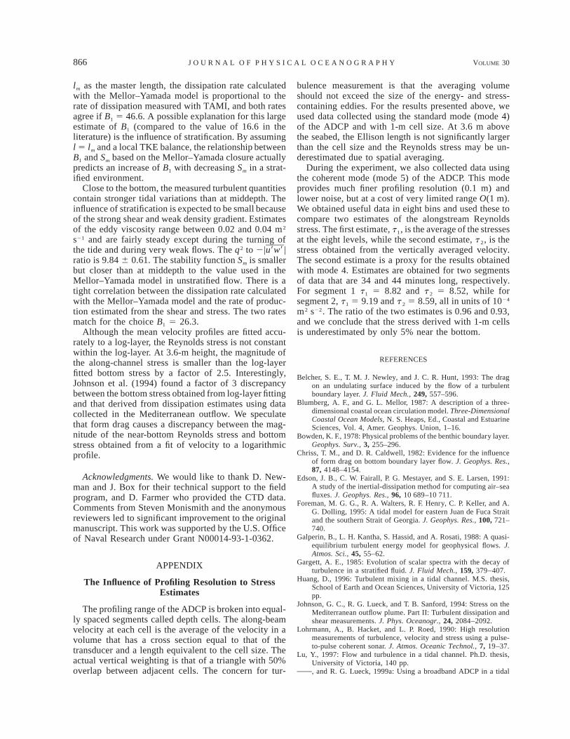
866 VOLUME 30J O U R N A L O F P H Y S I C A L O C E A N O G R A P H Y
lm as the master length, the dissipation rate calculatedwith the Mellor–Yamada model is proportional to therate of dissipation measured with TAMI, and both ratesagree if B1 5 46.6. A possible explanation for this largeestimate of B1 (compared to the value of 16.6 in theliterature) is the influence of stratification. By assumingl 5 lm and a local TKE balance, the relationship betweenB1 and Sm based on the Mellor–Yamada closure actuallypredicts an increase of B1 with decreasing Sm in a strat-ified environment.
Close to the bottom, the measured turbulent quantitiescontain stronger tidal variations than at middepth. Theinfluence of stratification is expected to be small becauseof the strong shear and weak density gradient. Estimatesof the eddy viscosity range between 0.02 and 0.04 m2
s21 and are fairly steady except during the turning ofthe tide and during very weak flows. The q2 to 2|u9w9 |ratio is 9.84 6 0.61. The stability function Sm is smallerbut closer than at middepth to the value used in theMellor–Yamada model in unstratified flow. There is atight correlation between the dissipation rate calculatedwith the Mellor–Yamada model and the rate of produc-tion estimated from the shear and stress. The two ratesmatch for the choice B1 5 26.3.
Although the mean velocity profiles are fitted accu-rately to a log-layer, the Reynolds stress is not constantwithin the log-layer. At 3.6-m height, the magnitude ofthe along-channel stress is smaller than the log-layerfitted bottom stress by a factor of 2.5. Interestingly,Johnson et al. (1994) found a factor of 3 discrepancybetween the bottom stress obtained from log-layer fittingand that derived from dissipation estimates using datacollected in the Mediterranean outflow. We speculatethat form drag causes a discrepancy between the mag-nitude of the near-bottom Reynolds stress and bottomstress obtained from a fit of velocity to a logarithmicprofile.
Acknowledgments. We would like to thank D. New-man and J. Box for their technical support to the fieldprogram, and D. Farmer who provided the CTD data.Comments from Steven Monismith and the anonymousreviewers led to significant improvement to the originalmanuscript. This work was supported by the U.S. Officeof Naval Research under Grant N00014-93-1-0362.
APPENDIX
The Influence of Profiling Resolution to StressEstimates
The profiling range of the ADCP is broken into equal-ly spaced segments called depth cells. The along-beamvelocity at each cell is the average of the velocity in avolume that has a cross section equal to that of thetransducer and a length equivalent to the cell size. Theactual vertical weighting is that of a triangle with 50%overlap between adjacent cells. The concern for tur-
bulence measurement is that the averaging volumeshould not exceed the size of the energy- and stress-containing eddies. For the results presented above, weused data collected using the standard mode (mode 4)of the ADCP and with 1-m cell size. At 3.6 m abovethe seabed, the Ellison length is not significantly largerthan the cell size and the Reynolds stress may be un-derestimated due to spatial averaging.
During the experiment, we also collected data usingthe coherent mode (mode 5) of the ADCP. This modeprovides much finer profiling resolution (0.1 m) andlower noise, but at a cost of very limited range O(1 m).We obtained useful data in eight bins and used these tocompare two estimates of the alongstream Reynoldsstress. The first estimate, t 1, is the average of the stressesat the eight levels, while the second estimate, t 2, is thestress obtained from the vertically averaged velocity.The second estimate is a proxy for the results obtainedwith mode 4. Estimates are obtained for two segmentsof data that are 34 and 44 minutes long, respectively.For segment 1 t 1 5 8.82 and t 2 5 8.52, while forsegment 2, t 1 5 9.19 and t 2 5 8.59, all in units of 1024
m2 s22. The ratio of the two estimates is 0.96 and 0.93,and we conclude that the stress derived with 1-m cellsis underestimated by only 5% near the bottom.
REFERENCES
Belcher, S. E., T. M. J. Newley, and J. C. R. Hunt, 1993: The dragon an undulating surface induced by the flow of a turbulentboundary layer. J. Fluid Mech., 249, 557–596.
Blumberg, A. F., and G. L. Mellor, 1987: A description of a three-dimensional coastal ocean circulation model. Three-DimensionalCoastal Ocean Models, N. S. Heaps, Ed., Coastal and EstuarineSciences, Vol. 4, Amer. Geophys. Union, 1–16.
Bowden, K. F., 1978: Physical problems of the benthic boundary layer.Geophys. Surv., 3, 255–296.
Chriss, T. M., and D. R. Caldwell, 1982: Evidence for the influenceof form drag on bottom boundary layer flow. J. Geophys. Res.,87, 4148–4154.
Edson, J. B., C. W. Fairall, P. G. Mestayer, and S. E. Larsen, 1991:A study of the inertial-dissipation method for computing air–seafluxes. J. Geophys. Res., 96, 10 689–10 711.
Foreman, M. G. G., R. A. Walters, R. F. Henry, C. P. Keller, and A.G. Dolling, 1995: A tidal model for eastern Juan de Fuca Straitand the southern Strait of Georgia. J. Geophys. Res., 100, 721–740.
Galperin, B., L. H. Kantha, S. Hassid, and A. Rosati, 1988: A quasi-equilibrium turbulent energy model for geophysical flows. J.Atmos. Sci., 45, 55–62.
Gargett, A. E., 1985: Evolution of scalar spectra with the decay ofturbulence in a stratified fluid. J. Fluid Mech., 159, 379–407.
Huang, D., 1996: Turbulent mixing in a tidal channel. M.S. thesis,School of Earth and Ocean Sciences, University of Victoria, 125pp.
Johnson, G. C., R. G. Lueck, and T. B. Sanford, 1994: Stress on theMediterranean outflow plume. Part II: Turbulent dissipation andshear measurements. J. Phys. Oceanogr., 24, 2084–2092.
Lohrmann, A., B. Hacket, and L. P. Roed, 1990: High resolutionmeasurements of turbulence, velocity and stress using a pulse-to-pulse coherent sonar. J. Atmos. Oceanic Technol., 7, 19–37.
Lu, Y., 1997: Flow and turbulence in a tidal channel. Ph.D. thesis,University of Victoria, 140 pp., and R. G. Lueck, 1999a: Using a broadband ADCP in a tidal

MAY 2000 867L U E T A L .
channel. Part I: Mean flow and shear. J. Atmos. Oceanic Technol.,16, 1556–1567., and , 1999b: Using a broadband ADCP in a tidal channel.Part II: Turbulence. J. Atmos. Oceanic Technol., 16, 1568–1579.
Lueck, R. G., and Y. Lu, 1997: The logarithmic layer in a tidalchannel. Contin. Shelf Res., 17, 1785–1801., and D. Huang, 1999: Dissipation measurement with a mooredinstrument in a swift tidal channel. J. Atmos. Oceanic Technol.,16, 1499–1505., , D. Newman, and J. Box, 1997: Turbulence measurementswith a moored instrument. J. Atmos. Oceanic Technol., 14, 143–161.
Lynch D. R., J. T. C. Ip, C. E. Naimie, and F. E. Werner, 1996:Comprehensive coastal circulation model with application to theGulf of Maine. Contin. Shelf Res., 16, 875–906.
Mellor, G. L., and T. Yamada, 1974: A hierarchy of turbulence closuremodels for planetary boundary layers. J. Atmos. Sci., 31, 1791–1806., and , 1982: Development of a turbulence closure modelfor geophysical fluid problems. Rev. Geophys. Space Phys., 20,851–875.
Moum, J. N., M. C. Gregg, R. C. Lien, and M. E. Carr, 1995: Acomparison of turbulent kinetic energy dissipation rate estimatesfrom two ocean microstructure profilers. J. Atmos. Oceanic Tech-nol., 12, 346–366.
Osborn, T. R., 1980: Estimates of the local rate of vertical dissipationfrom dissipation measurements. J. Phys. Oceanogr., 10, 83–89., and C. S. Cox, 1972: Oceanic fine structure. Geophys. FluidDyn., 3, 321–345.
Peters, H., M. C. Gregg, and T. B. Sanford, 1995: Detail and scalingof turbulent overturning in the Pacific Equatorial Undercurrent.J. Geophys. Res., 100, 18 333–18 348.
Sanford, T. B., and R.-C. Lien, 1999: Turbulent properties in a ho-mogeneous tidal bottom boundary layer. J. Geophys. Res., 104,1245–1257.
Simpson, J. H., W. R. Crawford, T. P. Rippeth, A. R. Campbell, andJ. V. S. Cheok, 1996: The vertical structure of turbulent dissi-pation in shelf seas. J. Phys. Oceanogr., 26, 1579–1590.
Soulsby, R. L., 1983: The bottom boundary layer of shelf seas. Phys-ical Oceanography of Coastal and Shelf Seas, B. Johns, Ed.,Elsevier Oceanogr. Ser., Vol. 35, Elsevier, 189–266.
Stacey, M. T., 1996: Turbulent mixing and residual circulation in apartially stratified estuary. Ph.D. thesis, Stanford University, 209pp., S. G. Monismith, and J. R. Burau, 1999: Observations of tur-bulence in a partially stratified estuary. J. Phys. Oceanogr., 29,1950–1970.
Thompson, R. E., 1981: Oceanography of the British Columbia Coast.Canadian Special Publication of Fisheries and Aquatic Science,Series 56, 291 pp.
Turner, J. S., 1973: Buoyancy Effects in Fluids. Cambridge UniversityPress, 367 pp.