
Tuning the Emitting Color of Organic Light-Emitting Diodes Through Photochemically Induced...
9
DOI: 10.1002/adfm.200700231 Tuning the Emitting Color of Organic Light-Emitting Diodes Through Photochemically Induced Transformations: Towards Single-Layer, Patterned, Full-Color Displays and White-Lighting Applications By Maria Vasilopoulou,* Dimitra Georgiadou, George Pistolis , and Panagiotis Argitis* 1. Introduction Organic light-emitting diodes (OLEDs), since their inven- tion, have been the subject of intense scientific and technologi- cal investigation. [1–3] A lot of progress has already been achieved but further technological developments are needed for their successful implementation in application areas such as displays and lighting. For instance, the generation of a full-col- or image in a display requires the existence of nearby discrete areas, which are capable of emitting one of the three primary colors, red, green, or blue (RGB), and several techniques have appeared in order to produce the three-color-emitting pixels. In general, the manufacture of a full-color display involves the formation of multilayer OLED structures [4] and requires deposition and patterning of usually different organic layers one over the other, where each one is capable of emitting one of the three main colors. Another common technique for the fabrication of full-color devices is ink-jet printing, [5] which has the advantages of low cost and little material loss. However, there are also issues to be solved in this case such as limitations in the achievable resolution and thickness homogeneity. Similar challenges are encountered in white-light-emitting diodes, which have potential for use in the next generation of sources for solid-state lighting. [6] White-light emission can also be obtained from a single-layer copolymer, [7] from polymer blends, [8] or from devices based on fluorescent [9a] and phos- phorescent [9b–d] dye-dispersed hosts (polymers or small mole- cules), while recently blue fluorescent along with green and red phosphorescent doped devices have been reported. [10] On the other hand, excimer- and exciplex-based emission from a single layer can appear at various wavelengths, and, thus, it is also possible to achieve white-light emission following this route. [11] Recently, alternative photopatterning approaches for light- emitting diodes based on conjugated polymers (PLEDs) have been proposed. [12,13] Full-color photopatterned light-emitting devices have been presented by Shirai and Kido, [12a] who used laser irradiation to bleach dye molecules in a poly(N-vinylcar- bazole) matrix, while other approaches employ selective photobleaching [12b,d] or tuning [12c] of the emission properties of a single layer that consists of polymer blends for RGB emis- sion. In a different approach Müller et al. [13a] and Gather et al. [13b] were able to demonstrate RGB devices by sequential patterning by means of solution processing and photocrosslink- ing of red-, green-, and blue-emitting polymer layers. Adv. Funct. Mater. 2007, 17, 3477–3485 © 2007 WILEY-VCH Verlag GmbH & Co. KGaA, Weinheim 3477 – [*] Dr. M. Vasilopoulou, Dr. P. Argitis, D. Georgiadou Institute of Microelectronics, NCSR “Demokritos” 153 10 Aghia Paraskevi, Attiki (Greece) E-mail: [email protected]; [email protected] Dr. G. Pistolis Institute of Physical Chemistry, NCSR “Demokritos” 153 10 Aghia Paraskevi, Attiki (Greece) [**] This research has been conducted within the framework of the “Archi- medes: Funding of research groups in TEI of Piraeus” project, co- funded by the European Union (75 %) and the Greek Ministry of Edu- cation (25 %). Photochemically induced emission tuning for the definition of pixels emitting the three primary colors, red, green, blue (RGB), in a single conducting polymeric layer is investigated. The approach proposed is based on an acid-induced emission shift of the (1-[4-(dimethylamino)phenyl]-6-phenylhexatriene) (DMA-DPH) green emitter and acid-induced quenching of the red fluorescent emitter (4-dimethylamino-4′-nitrostilbene) (DANS). The two emitters are dispersed in the wide bandgap conducting polymer poly(9-vinylcarbazole) (PVK), along with a photoacid generator (PAG). In the unexposed film areas, red emission is observed because of efficient energy transfer from PVK and DMA-DPH to DANS. Exposure of selected areas of the film at different doses results in quenching of the red emitter’s fluorescence and the formation of green, blue, or even other color-emitting pixels, depending on the exposure dose and the relative concentrations of the different compounds in the film. Organic light-emitting diodes having the PVK polymer containing the appropriateamounts of DMA-DPH, DANS, and PAG as the emitting layer are fabricated and electroluminescence spectra are recorded. The time stability of induced emission spectrum changes and the color stability during device operation are also examined, and the first encouraging results are obtained. FULL PAPER
Transcript of Tuning the Emitting Color of Organic Light-Emitting Diodes Through Photochemically Induced...

DOI: 10.1002/adfm.200700231
Tuning the Emitting Color of Organic Light-Emitting DiodesThrough Photochemically Induced Transformations: TowardsSingle-Layer, Patterned, Full-Color Displays and White-LightingApplications
By Maria Vasilopoulou,* Dimitra Georgiadou, George Pistolis, and Panagiotis Argitis*
1. Introduction
Organic light-emitting diodes (OLEDs), since their inven-tion, have been the subject of intense scientific and technologi-cal investigation.[1–3] A lot of progress has already beenachieved but further technological developments are neededfor their successful implementation in application areas such asdisplays and lighting. For instance, the generation of a full-col-or image in a display requires the existence of nearby discreteareas, which are capable of emitting one of the three primarycolors, red, green, or blue (RGB), and several techniques haveappeared in order to produce the three-color-emitting pixels.In general, the manufacture of a full-color display involves theformation of multilayer OLED structures[4] and requiresdeposition and patterning of usually different organic layersone over the other, where each one is capable of emitting one
of the three main colors. Another common technique for thefabrication of full-color devices is ink-jet printing,[5] which hasthe advantages of low cost and little material loss. However,there are also issues to be solved in this case such as limitationsin the achievable resolution and thickness homogeneity.
Similar challenges are encountered in white-light-emittingdiodes, which have potential for use in the next generation ofsources for solid-state lighting.[6] White-light emission can alsobe obtained from a single-layer copolymer,[7] from polymerblends,[8] or from devices based on fluorescent[9a] and phos-phorescent[9b–d] dye-dispersed hosts (polymers or small mole-cules), while recently blue fluorescent along with green and redphosphorescent doped devices have been reported.[10] On theother hand, excimer- and exciplex-based emission from a singlelayer can appear at various wavelengths, and, thus, it is alsopossible to achieve white-light emission following this route.[11]
Recently, alternative photopatterning approaches for light-emitting diodes based on conjugated polymers (PLEDs) havebeen proposed.[12,13] Full-color photopatterned light-emittingdevices have been presented by Shirai and Kido,[12a] who usedlaser irradiation to bleach dye molecules in a poly(N-vinylcar-bazole) matrix, while other approaches employ selectivephotobleaching[12b,d] or tuning[12c] of the emission properties ofa single layer that consists of polymer blends for RGB emis-sion. In a different approach Müller et al.[13a] and Gatheret al.[13b] were able to demonstrate RGB devices by sequentialpatterning by means of solution processing and photocrosslink-ing of red-, green-, and blue-emitting polymer layers.
Adv. Funct. Mater. 2007, 17, 3477–3485 © 2007 WILEY-VCH Verlag GmbH & Co. KGaA, Weinheim 3477
–[*] Dr. M. Vasilopoulou, Dr. P. Argitis, D. Georgiadou
Institute of Microelectronics, NCSR “Demokritos”153 10 Aghia Paraskevi, Attiki (Greece)E-mail: [email protected]; [email protected]. G. PistolisInstitute of Physical Chemistry, NCSR “Demokritos”153 10 Aghia Paraskevi, Attiki (Greece)
[**] This research has been conducted within the framework of the “Archi-medes: Funding of research groups in TEI of Piraeus” project, co-funded by the European Union (75 %) and the Greek Ministry of Edu-cation (25 %).
Photochemically induced emission tuning for the definition of pixels emitting the three primary colors, red, green, blue (RGB),in a single conducting polymeric layer is investigated. The approach proposed is based on an acid-induced emission shift of the(1-[4-(dimethylamino)phenyl]-6-phenylhexatriene) (DMA-DPH) green emitter and acid-induced quenching of the redfluorescent emitter (4-dimethylamino-4′-nitrostilbene) (DANS). The two emitters are dispersed in the wide bandgapconducting polymer poly(9-vinylcarbazole) (PVK), along with a photoacid generator (PAG). In the unexposed film areas, redemission is observed because of efficient energy transfer from PVK and DMA-DPH to DANS. Exposure of selected areas ofthe film at different doses results in quenching of the red emitter’s fluorescence and the formation of green, blue, or even othercolor-emitting pixels, depending on the exposure dose and the relative concentrations of the different compounds in the film.Organic light-emitting diodes having the PVK polymer containing the appropriate amounts of DMA-DPH, DANS, and PAGas the emitting layer are fabricated and electroluminescence spectra are recorded. The time stability of induced emissionspectrum changes and the color stability during device operation are also examined, and the first encouraging results areobtained.
FULL
PAPER

Technological approaches that could improve the currentmaterials and processes used in OLEDs could also be based onrecent advances reported in the related field of fluorescenceimaging in polymeric thin films. The investigation of fluores-cence-patterning possibilities in thin polymeric films hasrecently emerged as a broader topic of research for the devel-opment of plastic materials suitable for, amongst other things,lighting, image recording, sensing, and display applications.[14]
It should also be added that fluorescent organic dyes dispersedin the polymer film, or moieties pending to the polymer itself,have been used for fluorescence imaging to monitor acid diffu-sion in the area of lithographic processing,[15] where acid-in-duced changes of emission properties usually result in the pro-duction of fluorescent and nonfluorescent areas (acid-induceddye quenching).[14,15]
In this work we present a new patterning scheme for func-tional organic thin films based on energy transfer to suitableemitters, the spectrum of which is altered by photochemicaltransformations. In particular, changes initiated by photogener-ated acids determine the extent of energy transfer and induceemission tuning, enabling the definition of different color-emit-ting areas in a polymeric layer. Our first effort[16] to use a pho-toacid-generation approach for bicolor imaging in nonconduct-ing matrixes is further exploited to develop photopatterningschemes for the definition of RGB areas in a wide bandgapconductive polymer matrix. Definition of areas emitting red,green, and blue in a single layer is demonstrated, and possibili-ties for the application of the proposed imaging strategy toOLED technology are investigated and discussed.
2. Results and Discussion
2.1. Emission Tuning of the Green Emitter in a ConductingMatrix
Previously we reported an extensive spectroscopic study[16]
on acid-induced absorbance and emission shifts of the greenfluorescenct 1-[4-(dimethylamino)phenyl]-6-phenylhexa-1,3,5,-triene (DMA-DPH). Briefly, it was found that the emissionwavelength of DMA-DPH is very sensitive to themicropolarity of its immediate environment.[16b,c] The observedsizable spectral shifts of DMA-DPH arise from charge delocal-ization in the extended conjugated system of the molecule in-duced by the electron-donating effect of the p-dimethylaminogroup. It was shown that photoinduced protonation of thedimethylamino group in DMA-DPH can disrupt the conjuga-tion and, as a consequence, could hypsochromically shift theDMA-DPH absorption and emission maxima to lower bluewavelengths. These spectral changes have been demonstratedin films based on poly(methyl methacrylate) (PMMA) and onaromatic rings containing an epoxy novolac polymer.[16a]
In the present investigation, we first examined if similarchanges can also be observed in conducting matrices used inOLEDs. Poly(9-vinylcarbazole) (PVK)[17] was used as the hostmatrix, as its emission peak located is in the violet-blue region(at 413 nm), and, moreover, PVK is well-known for efficient
energy transfer to fluorescent[17b] and phosphorescent[17c] or-ganic molecules with lower-energy excited states. Efficient en-ergy transfer to the green emitter DMA-DPH was first demon-strated, as shown in Figure 1a (unexposed). A smallconcentration of the emitter in the matrix (2 % w/w) can leadto the total elimination of the emission of PVK and to the ap-pearance of the characteristic spectrum of DMA-DPH (maxi-mum at approximately 500 nm). The addition of a selectedphotoacid generator (PAG) in the matrix, which in this casewas the triphenylsulfonium trifluoromethane sulfonate, doesnot alter the energy-transfer efficiency.
It should be noted that in our first experiments the PAGused was the triphenylsulfonium hexafluoroantimonate[(Ph3S+)(SbF6
–)]. In these experiments, we observed that afterthe addition of this particular PAG, the emission of DMA-DPH inside the PVK matrix was dramatically decreased. Apossible explanation of this behavior could be that the heavyatom Sb, present in the PAG anion, causes quenching of thePVK emission. Thus, it was decided to use onium salts with allorganic anions, and triphenylsulfonium trifluoromethane sulfo-nate (SPh3
+ CF3SO3–) was selected because it has the same cat-
ion as triphenylsulfonium hexafluoroantimonate. A clear pho-tochemically induced fluorescence shift was obtained by usingthe triphenylsulfonium trifluoromethane sulfonate as PAG, as
3478 www.afm-journal.de © 2007 WILEY-VCH Verlag GmbH & Co. KGaA, Weinheim Adv. Funct. Mater. 2007, 17, 3477–3485
Figure 1. a) Photoluminescence (PL) spectra of a VK film (100 nm thick)containing the DMA-DPH emitter and the photoacid generator (PAG), tri-phenylsulfonium trifluoromethane sulfonate, at concentrations of 2 % and4 % of the polymer mass (w/w), respectively, before and after exposurethrough a 248 nm narrow band filter for 1000 s (the excitation wavelengthwas 340 nm). b) Fluorescence patterns obtained with the same PVK filmas in (a). The blue areas are the regions exposed through the photomask.Line width: 15 lm.
FULL
PAPER
M. Vasilopoulou et al./Color Tuning of OLEDs

is shown in Figure 1a (“exposed” curve). After exposure at awavelength of k = 248 nm, where only the PAG absorbsstrongly, the photogenerated acid indeed protonates the di-methylamino group of DMA-DPH, as is proven by the 60 nmhypsochromic shift observed in the absorption spectrum of theunexposed film (maximum at 500 nm) compared to that of theexposed film (maximum at 440 nm).
Color patterning is illustrated in Figure 1b. The exposure ofPVK films containing the DMA-DPH emitter and the PAGthrough a photolithographic mask results in the generation ofacid in selected film areas and in the definition of blue andgreen lines in the films. At this point it should be mentionedthat the lateral diffusion of the photogenerated acid in thepolymer matrix does not appear to be a problem, as DMA-DPH bears strongly basic amine groups and proton capture isvery efficient. On the other hand, it should be noted that theresolution requirements in our case are relaxed compared tothe demands of standard photoresist technology where imagingat the sub-micrometer level and below is required.
The stability of the DMA-DPH form obtained after photo-protonation was examined in a PMMA matrix, where the mon-itoring of any changes in the absorption spectrum is straight-forward because PMMA is transparent in the region ofinterest. On the contrary, the absorption spectrum of PVKwithin this region overlaps with that of DMA-DPH and makesit difficult to observe any absorption spectrum changes. It wasfirst observed that after several hours under ambient condi-tions the blue-emitting areas returned to green, an indicationof deprotonation of the DMA-DPH molecule. Indeed, as canbe seen in Figure 2a, the absorption spectrum of the emitterafter protonation is not stable and returns to its original posi-tion after a certain number of hours in air. This reverse changeis attributed to proton consumption by an antagonist in the ma-trix. It is very well-known[18,19] that even a very small amount—in the ppb range—of basic contaminants, which can be ab-sorbed from the atmosphere, is enough to alter the lithographicresults in acid-catalyzed resist systems. In this case, acid con-sumption can lead to deprotonation of the emitter and thereturn to its original chemical form.
To deal with this undesirable shift in the spectrum of theemitter to its initial position, the effect of thermal treatmentbefore exposure (prebake at increased temperature) was exam-ined, in order to decrease the free volume in the film and thusto reduce the diffusion of basic contaminants from the atmo-sphere inside the polymeric film. It has actually been reportedbefore that prebake at high temperature (above the glass-tran-sition temperature) greatly increases environmental stability inchemically amplified photoresists, and the development of aphotoresist class called ESCAP (environmentally stable chemi-cally amplified positive resists) is based on this finding.[18] Inour case it was indeed found that optimization of the condi-tions for film preparation (by increasing the prebake tempera-ture) and storage could help overcome the problem of undesir-able spectral changes, as shown in Figure 2b and c. Here, theabsorption spectra of PMMA films containing the DMA-DPHemitter and the PAG, which were prebaked at a higher temper-ature (130 °C instead of 70 °C) (Fig. 2b) or stored under
reduced pressure (Fig. 2c), appear stable even after one week.Alternatively, the use of an overcoat to hinder diffusion ofbasic environmental contaminants also led to stability improve-ment in accordance with results reported by others in chemical-ly amplified photoresist technology.[19]
2.2. Acid-Induced Emission Changes of Red Emitters
To achieve red emission from the PVK layer, we dispersed ared emitter in the PVK matrix. Several red emitters, includingthe red probe 4-dimethylamino-4′-nitrostilbene (DANS) andthe highly fluorescent dopant 4-(dicyanomethylene)-2-methyl-
Adv. Funct. Mater. 2007, 17, 3477–3485 © 2007 WILEY-VCH Verlag GmbH & Co. KGaA, Weinheim www.afm-journal.de 3479
Figure 2. a) Return of the absorption spectrum of DMA-DPH to its origi-nal state (corresponding to the deprotonated form) after storage in air. UVspectra of 100 nm thick films of PMMA containing 2 % w/w DMA-DPHand 4 % w/w PAG: 1) unexposed, 2) exposed through a filter for 1500 s,3) 48 h later (in air). b) Stabilization of the DMA-DPH absorption spec-trum at a higher prebake temperature (130 °C). UV spectra 1 to 3 as forfilms in (a). c) Stabilization of the DMA-DPH absorption spectrum uponstorage in a vacuum dessicator under reduced pressure (about 10 Torr;1 Torr = 133.3 Pa). UV spectra 1–3 as for films in (a); Spectrum 4 was tak-en one week after exposure.
FULL
PAPER
M. Vasilopoulou et al./Color Tuning of OLEDs
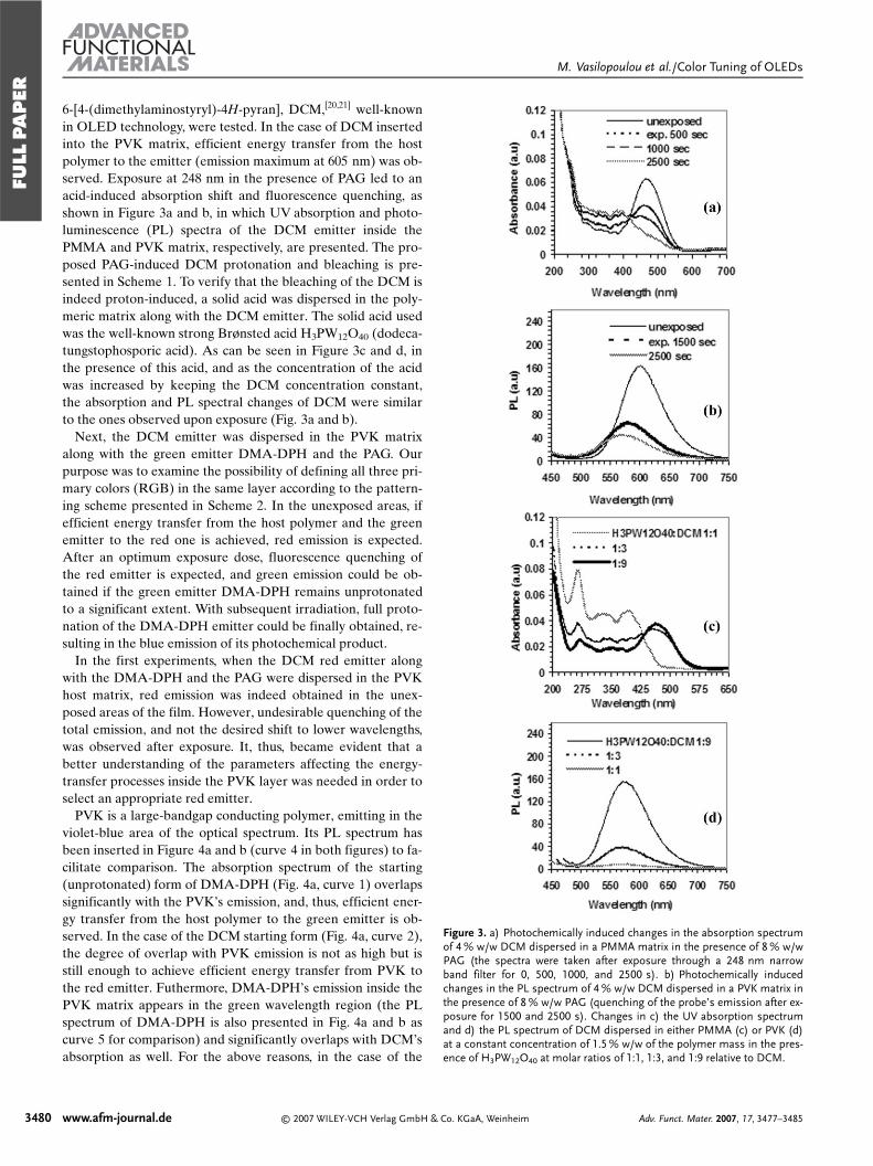
6-[4-(dimethylaminostyryl)-4H-pyran], DCM,[20,21] well-knownin OLED technology, were tested. In the case of DCM insertedinto the PVK matrix, efficient energy transfer from the hostpolymer to the emitter (emission maximum at 605 nm) was ob-served. Exposure at 248 nm in the presence of PAG led to anacid-induced absorption shift and fluorescence quenching, asshown in Figure 3a and b, in which UV absorption and photo-luminescence (PL) spectra of the DCM emitter inside thePMMA and PVK matrix, respectively, are presented. The pro-posed PAG-induced DCM protonation and bleaching is pre-sented in Scheme 1. To verify that the bleaching of the DCM isindeed proton-induced, a solid acid was dispersed in the poly-meric matrix along with the DCM emitter. The solid acid usedwas the well-known strong Brønsted acid H3PW12O40 (dodeca-tungstophosporic acid). As can be seen in Figure 3c and d, inthe presence of this acid, and as the concentration of the acidwas increased by keeping the DCM concentration constant,the absorption and PL spectral changes of DCM were similarto the ones observed upon exposure (Fig. 3a and b).
Next, the DCM emitter was dispersed in the PVK matrixalong with the green emitter DMA-DPH and the PAG. Ourpurpose was to examine the possibility of defining all three pri-mary colors (RGB) in the same layer according to the pattern-ing scheme presented in Scheme 2. In the unexposed areas, ifefficient energy transfer from the host polymer and the greenemitter to the red one is achieved, red emission is expected.After an optimum exposure dose, fluorescence quenching ofthe red emitter is expected, and green emission could be ob-tained if the green emitter DMA-DPH remains unprotonatedto a significant extent. With subsequent irradiation, full proto-nation of the DMA-DPH emitter could be finally obtained, re-sulting in the blue emission of its photochemical product.
In the first experiments, when the DCM red emitter alongwith the DMA-DPH and the PAG were dispersed in the PVKhost matrix, red emission was indeed obtained in the unex-posed areas of the film. However, undesirable quenching of thetotal emission, and not the desired shift to lower wavelengths,was observed after exposure. It, thus, became evident that abetter understanding of the parameters affecting the energy-transfer processes inside the PVK layer was needed in order toselect an appropriate red emitter.
PVK is a large-bandgap conducting polymer, emitting in theviolet-blue area of the optical spectrum. Its PL spectrum hasbeen inserted in Figure 4a and b (curve 4 in both figures) to fa-cilitate comparison. The absorption spectrum of the starting(unprotonated) form of DMA-DPH (Fig. 4a, curve 1) overlapssignificantly with the PVK’s emission, and, thus, efficient ener-gy transfer from the host polymer to the green emitter is ob-served. In the case of the DCM starting form (Fig. 4a, curve 2),the degree of overlap with PVK emission is not as high but isstill enough to achieve efficient energy transfer from PVK tothe red emitter. Futhermore, DMA-DPH’s emission inside thePVK matrix appears in the green wavelength region (the PLspectrum of DMA-DPH is also presented in Fig. 4a and b ascurve 5 for comparison) and significantly overlaps with DCM’sabsorption as well. For the above reasons, in the case of the
3480 www.afm-journal.de © 2007 WILEY-VCH Verlag GmbH & Co. KGaA, Weinheim Adv. Funct. Mater. 2007, 17, 3477–3485
Figure 3. a) Photochemically induced changes in the absorption spectrumof 4 % w/w DCM dispersed in a PMMA matrix in the presence of 8 % w/wPAG (the spectra were taken after exposure through a 248 nm narrowband filter for 0, 500, 1000, and 2500 s). b) Photochemically inducedchanges in the PL spectrum of 4 % w/w DCM dispersed in a PVK matrix inthe presence of 8 % w/w PAG (quenching of the probe’s emission after ex-posure for 1500 and 2500 s). Changes in c) the UV absorption spectrumand d) the PL spectrum of DCM dispersed in either PMMA (c) or PVK (d)at a constant concentration of 1.5 % w/w of the polymer mass in the pres-ence of H3PW12O40 at molar ratios of 1:1, 1:3, and 1:9 relative to DCM.
FULL
PAPER
M. Vasilopoulou et al./Color Tuning of OLEDs

PVK film containing both emitters, the lower bandgap com-pound, that is, the red-emitting DCM, is expected to fluoresce.After exposure, DCM is protonated but its absorption spec-trum (Fig. 4b, curve 2) overlaps significantly with the emissionspectrum of PVK. However, this protonated form of DCM isnot fluorescent. On the other hand, both forms of DMA-DPHabsorb at lower wavelengths compared to the DCM protonatedform. Thus, when DCM is protonated, energy transfer fromPVK to the DCM protonated form takes place and the fluores-cence of the whole system is quenched.
To achieve the desirable green and blue emission after expo-sure, we should use a red emitter whose absorption spectrumafter exposure shifts significantly in order to absorb at lowerwavelengths compared to DMA-DPH (both unprotonated andprotonated forms). After several experiments, a well-known—especially in the field of polymerization processes monitor-ing—red probe, DANS,[22] was chosen (Scheme 1b). DANS ini-
tially absorbs strongly at about 440 nm(Fig. 4a, curve 3) but after exposure (oralternatively, after addition of solid acid inthe film) a large absorption spectrum shiftto the blue is observed (maximum at340 nm, Fig. 4b, curve 3). The efficientenergy transfer from PVK to the originalDANS form and the quenching of itsemission after exposure in the presence ofPAG are shown in Figure 5a (see alsoScheme 1b). When DANS along withDMA-DPH (in a molar ratio of 1:1) andthe PAG were dispersed in a PVK matrix,the red fluorescence of DANS was ob-served in the unexposed film (Fig. 5b).
After exposure, a 165 nm shift to shorter wavelengths (maxi-mum at 440 nm), corresponding to the blue fluorescence of theDMA-DPH protonated molecule, was observed, as shown inFigure 5b. In this way RB emitting areas were photopatternedin a single layer of PVK. Color patterning of the PVK film,containing both emitters (at equal molar quantities) and thePAG (at double the molar ratio with respect to each emitter),
Adv. Funct. Mater. 2007, 17, 3477–3485 © 2007 WILEY-VCH Verlag GmbH & Co. KGaA, Weinheim www.afm-journal.de 3481
Scheme 1. Photogenerated acid-induced changes of the DCM and DANS emitters.
Scheme 2. Patterning scheme for the definition of RGB areas in a singlePVK layer.
Figure 4. a,b) UV absorption spectra of the original molecules and theprotonated molecules, respectively, of DMA-DPH, DCM, and DANS(curves 1, 2, and 3, respectively). All three emitters were inserted in thePMMA matrix at a concentration of 4 % w/w in the presence of PAG at aconcentration of 8 % w/w. PL spectra corresponding to PVK (curve 4) andPVK with DMA-DPH added at a concentration of 2 % w/w (curve 5) are in-serted as bold curves for comparison. The fluorescence intensity is givenin arbitrary units.
FULL
PAPER
M. Vasilopoulou et al./Color Tuning of OLEDs
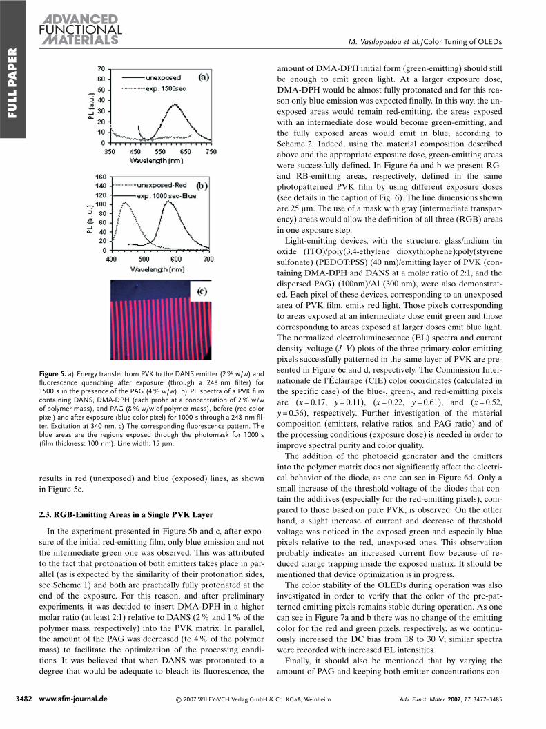
results in red (unexposed) and blue (exposed) lines, as shownin Figure 5c.
2.3. RGB-Emitting Areas in a Single PVK Layer
In the experiment presented in Figure 5b and c, after expo-sure of the initial red-emitting film, only blue emission and notthe intermediate green one was observed. This was attributedto the fact that protonation of both emitters takes place in par-allel (as is expected by the similarity of their protonation sides,see Scheme 1) and both are practically fully protonated at theend of the exposure. For this reason, and after preliminaryexperiments, it was decided to insert DMA-DPH in a highermolar ratio (at least 2:1) relative to DANS (2 % and 1 % of thepolymer mass, respectively) into the PVK matrix. In parallel,the amount of the PAG was decreased (to 4 % of the polymermass) to facilitate the optimization of the processing condi-tions. It was believed that when DANS was protonated to adegree that would be adequate to bleach its fluorescence, the
amount of DMA-DPH initial form (green-emitting) should stillbe enough to emit green light. At a larger exposure dose,DMA-DPH would be almost fully protonated and for this rea-son only blue emission was expected finally. In this way, the un-exposed areas would remain red-emitting, the areas exposedwith an intermediate dose would become green-emitting, andthe fully exposed areas would emit in blue, according toScheme 2. Indeed, using the material composition describedabove and the appropriate exposure dose, green-emitting areaswere successfully defined. In Figure 6a and b we present RG-and RB-emitting areas, respectively, defined in the samephotopatterned PVK film by using different exposure doses(see details in the caption of Fig. 6). The line dimensions shownare 25 lm. The use of a mask with gray (intermediate transpar-ency) areas would allow the definition of all three (RGB) areasin one exposure step.
Light-emitting devices, with the structure: glass/indium tinoxide (ITO)/poly(3,4-ethylene dioxythiophene):poly(styrenesulfonate) (PEDOT:PSS) (40 nm)/emitting layer of PVK (con-taining DMA-DPH and DANS at a molar ratio of 2:1, and thedispersed PAG) (100nm)/Al (300 nm), were also demonstrat-ed. Each pixel of these devices, corresponding to an unexposedarea of PVK film, emits red light. Those pixels correspondingto areas exposed at an intermediate dose emit green and thosecorresponding to areas exposed at larger doses emit blue light.The normalized electroluminescence (EL) spectra and currentdensity–voltage (J–V) plots of the three primary-color-emittingpixels successfully patterned in the same layer of PVK are pre-sented in Figure 6c and d, respectively. The Commission Inter-nationale de l’Éclairage (CIE) color coordinates (calculated inthe specific case) of the blue-, green-, and red-emitting pixelsare (x = 0.17, y = 0.11), (x = 0.22, y = 0.61), and (x = 0.52,y = 0.36), respectively. Further investigation of the materialcomposition (emitters, relative ratios, and PAG ratio) and ofthe processing conditions (exposure dose) is needed in order toimprove spectral purity and color quality.
The addition of the photoacid generator and the emittersinto the polymer matrix does not significantly affect the electri-cal behavior of the diode, as one can see in Figure 6d. Only asmall increase of the threshold voltage of the diodes that con-tain the additives (especially for the red-emitting pixels), com-pared to those based on pure PVK, is observed. On the otherhand, a slight increase of current and decrease of thresholdvoltage was noticed in the exposed green and especially bluepixels relative to the red, unexposed ones. This observationprobably indicates an increased current flow because of re-duced charge trapping inside the exposed matrix. It should bementioned that device optimization is in progress.
The color stability of the OLEDs during operation was alsoinvestigated in order to verify that the color of the pre-pat-terned emitting pixels remains stable during operation. As onecan see in Figure 7a and b there was no change of the emittingcolor for the red and green pixels, respectively, as we continu-ously increased the DC bias from 18 to 30 V; similar spectrawere recorded with increased EL intensities.
Finally, it should also be mentioned that by varying theamount of PAG and keeping both emitter concentrations con-
3482 www.afm-journal.de © 2007 WILEY-VCH Verlag GmbH & Co. KGaA, Weinheim Adv. Funct. Mater. 2007, 17, 3477–3485
Figure 5. a) Energy transfer from PVK to the DANS emitter (2 % w/w) andfluorescence quenching after exposure (through a 248 nm filter) for1500 s in the presence of the PAG (4 % w/w). b) PL spectra of a PVK filmcontaining DANS, DMA-DPH (each probe at a concentration of 2 % w/wof polymer mass), and PAG (8 % w/w of polymer mass), before (red colorpixel) and after exposure (blue color pixel) for 1000 s through a 248 nm fil-ter. Excitation at 340 nm. c) The corresponding fluorescence pattern. Theblue areas are the regions exposed through the photomask for 1000 s(film thickness: 100 nm). Line width: 15 lm.
FULL
PAPER
M. Vasilopoulou et al./Color Tuning of OLEDs

stant, it was found that for smaller PAG amounts, and withcareful control of the exposure dose, we were able to tune theemitting color in the whole range from red to blue, evenachieving white-light emission. A representative case can beseen in Figure 8, where the PL spectra of DANS (1 %), DMA-
DPH (2 %), and PAG (3 % w/w) inserted in a single PVK layerexposed through a filter for various doses are presented.
3. Conclusions
Areas emitting all three primary colors, red, green, and blue,were defined in a single layer of the wide-bandgap conductingpolymer, poly(9-vinylcarbazole), using a suitable green emitterDMA-DPH along with the red emitter DANS. The selectedemitters were dispersed in the PVK films in the presence of aphotoacid generator, and their emission was tuned through
Adv. Funct. Mater. 2007, 17, 3477–3485 © 2007 WILEY-VCH Verlag GmbH & Co. KGaA, Weinheim www.afm-journal.de 3483
Figure 6. a, b) Fluorescence patterns on a single PVK layer (containing2 % (w/w) DMA-DPH, 1 % (w/w) DANS, and 4 % (w/w) PAG): red lines(unexposed)–green lines (exposed for 1000 s)–blue lines (exposed for2000 s). Film thickness: 100 nm. Lines width: 25 lm. c) Normalized elec-troluminescence (EL) spectra and d) current density–voltage ( J–V) plotsof OLEDs having the structure glass/indium tin oxide (ITO)/poly(3,4-eth-ylene dioxythiophene):poly(styrene sulfonate) (PEDOT:PSS) (40 nm)/ac-tive layer (100nm)/Al (300 nm). The active layer was PVK containing 2 %w/w DMA-DPH, 1 % w/w DANS, and 4 % w/w PAG, either unexposed (redpixel) or exposed through a filter for 1000 s (green pixel) and 2000 s (bluepixel).
Figure 7. Color stability of the EL spectra of a) red-emitting (unexposed)and b) green-emitting (exposed through the filter for 1000 s) OLEDs, bothhaving the same structure as in Figure 6, for increased DC bias from 18 to30 V. Each value of the DC voltage was applied for 30 min.
Figure 8. PL spectra of a PVK film containing DANS (1 % w/w), DMA-DPH (2 % w/w), and the PAG (3 % w/w), before (red color) and afterexposure for 1500 s (yellow color), 2000 s (white color), and 3000 s(blue color).
FULL
PAPER
M. Vasilopoulou et al./Color Tuning of OLEDs

photochemically induced transformations. In particular, thephotogenerated acid induces bleaching of the red emitter andemission shift of the green one, allowing definition of the threeprimary color emitting areas. Electroluminescence data andstability studies (lifetime and color stability) indicate that theproposed approach is viable for potential application in OLEDtechnology, while further material and process improvementsare in progress.
4. Experimental
Materials and Instrumentation: Fluorescent dyes 1-(4′-dimethyl-ami-nophenyl)-6-phenyl-1,3,5-hexatriene (DMA-DPH), and 4-dimethyl-amino-4′-nitrostilbene (DANS) were purchased from Fluka. Thephotoacid generators (PAGs) used were triphenylsulfonium hexafluo-roantimonate and triphenylsulfonium trifluoromethane sulfonate pur-chased from Midori Kagaku. Poly(9-vinylcarbazole) (PVK) was pur-chased from Aldrich and used with no further purification, while thePMMA polymer was Elvacite 2041 purchased from DuPont. Poly(3,4-ethylene dioxythiophene):poly(styrene sulfonate) (PEDOT:PSS) waspurchased from Aldrich. For absorption spectra a Perkin–Elmer Lamb-da-40 spectrometer was employed. Fluorescence and excitation mea-surements were recorded with a Perkin–Elmer LS-50B fluorescencespectrometer. Fluorescence images were taken using the Axioscope 2plus epifluorescence microscope equipped with a Sony Cyber-Shot dig-ital camera.
Polymeric Film Preparation and Processing: Solutions containingPVK (40 mg mL–1 in 1,1,2,2-tetrachloroethane) and PMMA (4 % w/win methylisobutylketone, MIBK) were prepared. In some solutions, thePAG (4 %, 6 %, and 8 % of polymer mass) and the fluorescence emitterDMA-DPH (1 %, 2 %, and 4 % of polymer mass) were added in var-ious concentrations. Some other solutions were made by adding thePAG along with the DMA-DPH and the DANS emitter at various con-centrations (from 1:10 to 10:1 of the DMA-DPH amount). Films werespin-coated from filtered solutions at 2000 rpm and then baked on ahotplate at 80 °C for 10 min. Film thicknesses were measured with anAmbios profilometer. Photoacid generation was induced by exposingfilms to a 500 W Oriel Hg–Xe exposure lamp through a 248 nm nar-rowband filter (6.5 nm half-band width) for various times. The incidentpower was measured with an IL 1700 International Light radiometerand was found to be (0.21 ± 0.02) mJ s–1.
Electroluminescent Device Fabrication and Characterization: For theelectroluminescent devices, 100 nm thick films of PVK were spun onITO glass substrates (product of Aldrich) at 2000 rpm and baked at80 °C for 10 min. ITO-coated glass was precleaned in an ultrasonic bathwith a sequence of acetone, isopropyl alcohol, and deionized (DI)water and treated with an oxygen plasma to improve the ITO proper-ties. Prior to the PVK layer, a 40 nm thick film of PEDOT:PSS wasspin-coated (at 4000 rpm and baked at 125 °C for 15 min) in order toimprove hole injection and substrate smoothness and enhance the per-formance of the electroluminescent device. 300 nm thick aluminumcathode electrodes were deposited on top of the PVK films by vacuumevaporation. All the testing devices had an active area of2 mm × 2 mm. Current density–voltage (J–V) measurements were ob-tained using a programmable Keithley 230 voltage source and a 195 Amultimeter. EL spectra were recorded with a USB 2000-UV-vis minia-ture fiber-optic spectrometer.
Received: February 26, 2007Revised: June 4, 2007
Published online: October 31, 2007
–[1] a) J. H. Burroughes, D. D. C. Bradley, A. R. Brown, R. N. Marks,
K. Mackay, R. H. Friend, P. L. Burns, A. B. Holmes, Nature 1990, 347,539. b) R. H. Friend, R. W. Gymer, A. B. Holmes, J. H. Burroughes,
R. N. Marks, C. Taliani, D. D. C. Bradley, D. A. Dos Santos, J. L. Bré-das, M. Lögdlund, W. R. Salaneck, Nature 1999, 397, 121.
[2] a) C. W. Tang, S. A. VanSlyke, Appl. Phys. Lett. 1987, 51, 913-5.b) G. Gustafsson, Y. Cao, G. M. Treacy, F. Klavetter, N. Colaneri,A. J. Heeger, Nature 1992, 357, 477.
[3] a) D. A. Pardo, G. E. Jabbour, N. Peyghambarian, Adv. Mater. 2000,12, 1249. b) B. W. D’Andrade, J. Brooks, V. Adomovich, M. E. Thom-son, S. R. Forrest, Adv. Mater. 2002, 14, 1032. c) M. Pfeiffer, S. R. For-rest, K. Leo, M. E. Thomson, Adv. Mater. 2002, 14, 1633. d) J. S. Kim,R. H. Friend, I. Grizzi, J. H. Burroughes, Appl. Phys. Lett. 2005, 87,23 506. e) X. H. Yang, D. C. Muller, D. Neher, K. Meerholz, Adv. Ma-ter. 2006, 18, 948. f) B. Liang, C. Y. Jiang, Z. Chen, X. J. Zhang, H. H.Shi, Y. Chao, J. Mater. Chem. 2006, 16, 1281.
[4] a) G. Gu, V. Bulovic, P. E. Burrows, S. R. Forrest, M. E. Thompson,Appl. Phys. Lett. 1996, 68, 2606. b) G. Parthasarathy, G. Gu, S. R. For-rest, Adv. Mater. 1999, 11, 907. c) X. Jiang, Z. Zhang, W. Zhao,W. Zhu, B. Zhang, S. Xu, J. Phys. D: Appl. Phys. 2000, 33, 473.d) B. W. D’Andrade, M. E. Thompson, S. R. Forrest, Adv. Mater.2002, 14, 147.
[5] a) T. R. Hebner, C. C. Wu, D. Marcy, M. H. Lu, J. C. Sturm, Appl.Phys. Lett. 1998, 72, 519. b) J. H. Choi, K. H. Kim, S. J. Choi, H. H.Lee, Nanotechnology 2006, 17, 2246.
[6] a) J. Kido, K. Hongawa, K. Okuyama, K. Nagai, Appl. Phys. Lett.1994, 64, 815. b) J. Kido, M. Kimura, K. Nagai, Science 1995, 267,1332. c) C.-H. Kim, J. Shinar, Appl. Phys. Lett. 2002, 80, 2201. d) Y.-S.Huang, J.-H. Jou, W.-K. Weng, J.-M. Liu, Appl. Phys. Lett. 2002, 80,2782.
[7] a) Y. Yang, Q. Pei, J. Appl. Phys. 1997, 81, 3294. b) Y.-Z. Lee,X. Chen, M.-C. Chen, S.-A. Chen, Appl. Phys. Lett. 2001, 79, 308.c) G. Tu, Q. Zhou, Y. Cheng, L. Wang, D. Ma, X. Jing, F. Wang, Appl.Phys. Lett. 2004, 85, 2172.d) J. Y. Li, D. Liu, C. Ma, O. Lengyel, C.-S.Lee, C.-H. Tung, S. Lee, Adv. Mater. 2004, 16, 1538. e) C.-Y. Chuang,P.-I. Shih, C.-H. Chien, F.-I. Wu, C.-F. Shu, Macromolecules 2007, 40,247.
[8] a) M. Granstrom, O. Inganäs, Appl. Phys. Lett. 1996, 68, 147.b) S. Tasch, E. J. W. List, O. Ekström, W. Graupner, G. Leising,P. Schlichting, U. Rohr, Y. Geerts, U. Scherf, K. Müllen, Appl. Phys.Lett. 1997, 71, 2883.
[9] a) J. Kido, H. Shionoya, K. Nagai, Appl. Phys. Lett. 1995, 67, 2281.b) B. W. D’Andrade, R. J. Holmes, S. R. Forrest, Adv. Mater. 2004,16, 624. c) S. Tokito, T. Iijima, T. Tsuzuki, F. Sato, Appl. Phys. Lett.2003, 83, 2459. d) E. L. Williams, K. Haavisto, J. Li, G. E. Jabbour,Adv. Mater. 2007, 19, 197.
[10] a) Y. Sun, N. C. Giebink, H. Kanno, B. Ma, M. E. Thompson, S. R.Forrest, Nature 2006, 440, 908. b) G. Schwartz, K. Fehse, M. Pfeiffer,K. Walzer, L. Leo, Appl. Phys. Lett. 2006, 89, 083 509.
[11] a) M. Mazzeo, D. Pisignano, F. D. Sala, J. Thompson, R. I. R. Blyth,G. Gigli, R. Cingolani, Appl. Phys. Lett. 2003, 82, 334. b) S. P. Singh,Y. N. Mohapatra, M. Qureshi, S. S. Manoharan, Appl. Phys. Lett.2005, 86, 113 505. c) Q. J. Sun, B. H. Fun, Z. A. Tan, C. H. Yang, Y. F.Li, Appl. Phys. Lett. 2006, 88, 163 510.
[12] a) S. Shirai, J. Kido, J. Photopolym. Sci. Technol. 2001, 14, 317.b) G. Trattnig, A. Pogantsch, G. Langer, W. Kern, E. Zojer, Appl.Phys. Lett. 2002, 81, 4269. c) A. Pogantsch, S. Rentenberger, G. Lan-ger, J. Keplinger, W. Kern, E. Zojer, Adv. Funct. Mater. 2005, 15, 403.d) X. Y. Deng, K. Y. Wong, Y. Q. Mo, Appl. Phys. Lett. 2007, 90,063 505.
[13] a) C. D. Müller, A. Falcou, N. Reckefuss, M. Rojhan, V. Wiederhirn,P. Rudati, H. Frohne, O. Nuyken, H. Becker, K. Meerholz, Nature2003, 421, 829. b) M. C. Gather, A. Köhnen, A. Falcou, H. Becker,K. Meerholz, Adv. Funct. Mater. 2007, 17, 191.
[14] a) J. M. Kim, T. E. Chang, J. H. Kang, K. H. Park, D. K. Hang, K. D.Ahn, Angew. Chem. Int. Ed. 2000, 39, 1780. b) J. M. Kim, T. E.Chang, J. H. Kang, D. K. Hang, K. D. Ahn, Adv. Mater. 1999, 11,1499. c) J. M. Kim, J. H. Kang, D. K. Han, C. W. Lee, K. D. Ahn,Chem. Mater. 1998, 10, 2332. d) A. M. Vekselman, C. Zhang, Chem.Mater. 1997, 9, 1942.
3484 www.afm-journal.de © 2007 WILEY-VCH Verlag GmbH & Co. KGaA, Weinheim Adv. Funct. Mater. 2007, 17, 3477–3485
FULL
PAPER
M. Vasilopoulou et al./Color Tuning of OLEDs

[15] a) B. Lu, J. W. Taylor, F. Cerrina, C. P. Soo, A. J. Boordillion, J. Vac.Sci. Technol. B 1999, 17, 33 450. b) P. L. Zhang, S. Webber, J. Mendel-hall, J. Byers, K. Chao, Proc. SPIE 1998, 3333, 794. c) U. Okoroanyan-wu, J. D. Byers, T. Cao, S. E. Webber, C. G. Wilson, Proc. SPIE 1998,3333, 747.
[16] a) G. Pistolis, S. Boyatzis, M. Chatzichristidi, P. Argitis, Chem. Mater.2002, 14, 790. b) G. Pistolis, A. Malliaris, Langmuir 1997, 13, 1457.c) G. Pistolis, A. Malliaris, Chem. Phys. 1998, 226, 83.
[17] a) J. Kido, K. Hongawa, K. Okuyama, K. Nagai Appl. Phys. Lett.1993, 63, 2627. b) T. Dantas de Morais, F. Chaput, K. Lahlil, J.-P. Boi-lot. Adv. Mater. 1999, 11, 107. c) C.-L. Lee, R. Ragini Das, J.-J. Kim,Chem. Mater. 2004, 16, 4642. d) Y. H. Niu, B. Q. Chen, T. D. Kim,M. S. Liu, A. K. Y. Jen, Appl. Phys. Lett. 2004, 85, 5433. e) F. C.Chen, Y. Yang, M. E. Thompson, J. Kido Appl. Phys. Lett. 2002, 80,2308.
[18] H. Ito, G. Breyta, D. C. Hofer, R. Sooriyakumaran, K. Petrillio,D. Seeger, J. Photopolym. Sci. Technol. 1994, 7, 433.
[19] S. A. MacDonald, C. G. Willson, J. M. J. Frechet, Acc. Chem. Res.1994, 27, 151.
[20] C. W. Tang, S. A. Van Slyke, C. H. Chen, J. Appl. Phys. 1989, 65,3610.
[21] a) J. Kido, K. Hongawa, K. Okugama, N. Nagai, Appl. Phys. Lett.1994, 64, 815. b) H. Suzuki, S. Hoshino, J. Appl. Phys. 1996, 79, 8816.c) V. Bulovic, A. Shoustikov, M. A. Baldo, E. Bose, V. G. Gozlov,M. E. Thomson, S. R. Forrest, Chem. Phys. Lett. 1998, 287, 455.d) B.-J. Jung, C.-B. Yoon, H.-K. Shim, L.-M. Do, T. Zyung, Adv.Funct. Mater. 2001, 11, 430. e) T.-H. Liu, C.-W. Iou, C. H. Chen, Appl.Phys. Lett. 2003, 83, 5241. f) C.-L. Chiang, M.-F. Wu, D.-C. Dai, W.-S.Wen, J.-K. Wang, C.-T. Chen, Adv. Funct. Mater. 2005, 15, 231.
[22] a) E. Lippert, W. Lüder, F. Moll, W. Nägelle, H. Boos, H. Prigge, An-gew. Chem. 1961, 73, 695. b) A. P. de Silva, H. Q. Nimal Gunaratne,T. Gunnlougsson, A. J. M. Huxley, C. P. McCoy, J. T. Rademacher,T. E. Rice, Chem. Rev. 1997, 97, 1515. c) J. F. Jager, A. M. Sarker,D. C. Neckers, Macromolecules 1999, 32, 8791. d) A. M. Moran, G. P.Bartholomew, G. C. Bazan, A. M. Kelley, J. Phys. Chem. A 2002, 106,4928. e) T. Nakabayashi, Md. Wahadoszamen, N. Ohta, J. Am. Chem.Soc. 2005, 127, 7041.
______________________
Adv. Funct. Mater. 2007, 17, 3477–3485 © 2007 WILEY-VCH Verlag GmbH & Co. KGaA, Weinheim www.afm-journal.de 3485
FULL
PAPER
M. Vasilopoulou et al./Color Tuning of OLEDs