Tuning of colossal dielectric constant in gold-polypyrrole composite nanotubes using in-situ x-ray...
12
Tuning of colossal dielectric constant in gold-polypyrrole composite nanotubes using in-situ x-ray diffraction techniques Abhisakh Sarma and Milan K. Sanyal Citation: AIP Advances 4, 097121 (2014); doi: 10.1063/1.4896122 View online: http://dx.doi.org/10.1063/1.4896122 View Table of Contents: http://scitation.aip.org/content/aip/journal/adva/4/9?ver=pdfcov Published by the AIP Publishing Articles you may be interested in Biosynthesized gold nanoparticles destroy percolative behavior of KH 2 PO 4 (KDP) filled PVA composite film AIP Conf. Proc. 1536, 51 (2013); 10.1063/1.4810095 Influence of Cr2O3 nanoparticles on the physical properties of polyvinyl alcohol J. Appl. Phys. 112, 093525 (2012); 10.1063/1.4764864 Theoretical and experimental approach on dielectric properties of ZnO nanoparticles and polyurethane/ZnO nanocomposites J. Appl. Phys. 112, 054106 (2012); 10.1063/1.4749414 Hybrid nanotubes: Single step formation of homogeneous nanotubes of polypyrrole-gold composites and novel switching transition of resistance beyond liquid nitrogen temperature J. Appl. Phys. 112, 044304 (2012); 10.1063/1.4746743 Size-dependent low-frequency dielectric properties in the BaTiO3/poly(vinylidene fluoride) nanocomposite films Appl. Phys. Lett. 100, 012903 (2012); 10.1063/1.3673555 All article content, except where otherwise noted, is licensed under a Creative Commons Attribution 3.0 Unported license. See: http://creativecommons.org/licenses/by/3.0/ Downloaded to IP: 14.139.193.129 On: Thu, 18 Sep 2014 06:17:57
Transcript of Tuning of colossal dielectric constant in gold-polypyrrole composite nanotubes using in-situ x-ray...
Tuning of colossal dielectric constant in gold-polypyrrole composite nanotubes usingin-situ x-ray diffraction techniquesAbhisakh Sarma and Milan K. Sanyal
Citation: AIP Advances 4, 097121 (2014); doi: 10.1063/1.4896122 View online: http://dx.doi.org/10.1063/1.4896122 View Table of Contents: http://scitation.aip.org/content/aip/journal/adva/4/9?ver=pdfcov Published by the AIP Publishing Articles you may be interested in Biosynthesized gold nanoparticles destroy percolative behavior of KH 2 PO 4 (KDP) filled PVA composite film AIP Conf. Proc. 1536, 51 (2013); 10.1063/1.4810095 Influence of Cr2O3 nanoparticles on the physical properties of polyvinyl alcohol J. Appl. Phys. 112, 093525 (2012); 10.1063/1.4764864 Theoretical and experimental approach on dielectric properties of ZnO nanoparticles and polyurethane/ZnOnanocomposites J. Appl. Phys. 112, 054106 (2012); 10.1063/1.4749414 Hybrid nanotubes: Single step formation of homogeneous nanotubes of polypyrrole-gold composites and novelswitching transition of resistance beyond liquid nitrogen temperature J. Appl. Phys. 112, 044304 (2012); 10.1063/1.4746743 Size-dependent low-frequency dielectric properties in the BaTiO3/poly(vinylidene fluoride) nanocomposite films Appl. Phys. Lett. 100, 012903 (2012); 10.1063/1.3673555
All article content, except where otherwise noted, is licensed under a Creative Commons Attribution 3.0 Unported license. See: http://creativecommons.org/licenses/by/3.0/
Downloaded to IP: 14.139.193.129 On: Thu, 18 Sep 2014 06:17:57

AIP ADVANCES 4, 097121 (2014)
Tuning of colossal dielectric constant in gold-polypyrrolecomposite nanotubes using in-situ x-ray diffractiontechniques
Abhisakh Sarma and Milan K. SanyalaSaha Institute of Nuclear Physics, 1/AF Bidhannagar, Kolkata 700 064, India
(Received 6 March 2014; accepted 8 September 2014; published online 17 September 2014)
In-situ x-ray diffraction technique has been used to study the growth process ofgold incorporated polypyrrole nanotubes that exhibit colossal dielectric constant dueto existence of quasi-one-dimensional charge density wave state. These compositenanotubes were formed within nanopores of a polycarbonate membrane by flowingpyrrole monomer from one side and mixture of ferric chloride and chloroauric acidfrom other side in a sample cell that allows collection of x-ray data during thereaction. The size of the gold nanoparticle embedded in the walls of the nanotubeswas found to be dependent on chloroauric acid concentration for nanowires havingdiameter more than 100 nm. For lower diameter nanotubes the nanoparticle sizebecome independent of chloroauric acid concentration and depends on the diameterof nanotubes only. The result of this study also shows that for 50 nm gold-polypyrrolecomposite nanotubes obtained with 5.3 mM chloroauric acid gives colossal dielectricconstant of about 107. This value remain almost constant over a frequency rangefrom 1Hz to 106 Hz even at 80 K temperature. C© 2014 Author(s). All article content,except where otherwise noted, is licensed under a Creative Commons Attribution 3.0Unported License. [http://dx.doi.org/10.1063/1.4896122]
I. INTRODUCTION
In recent years enormous amount of academic research have been carried out in the generalareas of flexible nanodielectric materials (FNDMs), primarily composed of polymer matrix withembedded nanoparticles, to develop compact capacitors and energy storage devices.1, 2 Similar ap-plicable composite nanomaterials are also being developed for several other applications, like carbonnanotube polymer nanocomposites for getting high thermoelectric figure of merit,3 dendrimer-metalnanocomposites to obtain enhanced third-order nonlinear optical properties,4 magnetic nanoparticlesembedded in polymer matrices for potential application in electromagnetic interference shielding,5
polyaniline nanofibers decorated with gold nanoparticles6, 7 for nonvolatile memory devices8 etc.Development of FNDMs to tune effective dielectric constant (εeff) of a polymer (ε1 ≈ 3) by
introducing inorganic nano fillers having higher dielectric constant (ε2 ≈ 100) with volume fractionof φ, is of prime importance to achieve flexible and compact energy storage capacitorss9 particularlyusing metal-polymer composites,10 where εeff can be written as, (1 − φ)ε1 + φε2. It is interestingto note that the effective dielectric constant [εeff = ε1(1 − φ/φc)−s with s > 0] of a metal-polymercomposite can exhibit much higher value (εeff ≈ 1000) compared to ε1 and ε2 as the volumefraction of φ approaches the percolation threshold (φc), defined as the critical volume fraction atwhich embedded metal nanoparticles establishes a conducting channel across the sample. One veryimportant aspect in this rapidly developing field of research is to get a low value of φc so that obtainedFNDMs remains flexible.10 It is essential to develop an understanding of the microstructure of themetal-polymer composite to obtain high dielectric constant. One can also get colossal dielectric
aElectronic mail: [email protected]
2158-3226/2014/4(9)/097121/11 C© Author(s) 20144, 097121-1
All article content, except where otherwise noted, is licensed under a Creative Commons Attribution 3.0 Unported license. See: http://creativecommons.org/licenses/by/3.0/
Downloaded to IP: 14.139.193.129 On: Thu, 18 Sep 2014 06:17:57
097121-2 A. Sarma and M. K. Sanyal AIP Advances 4, 097121 (2014)
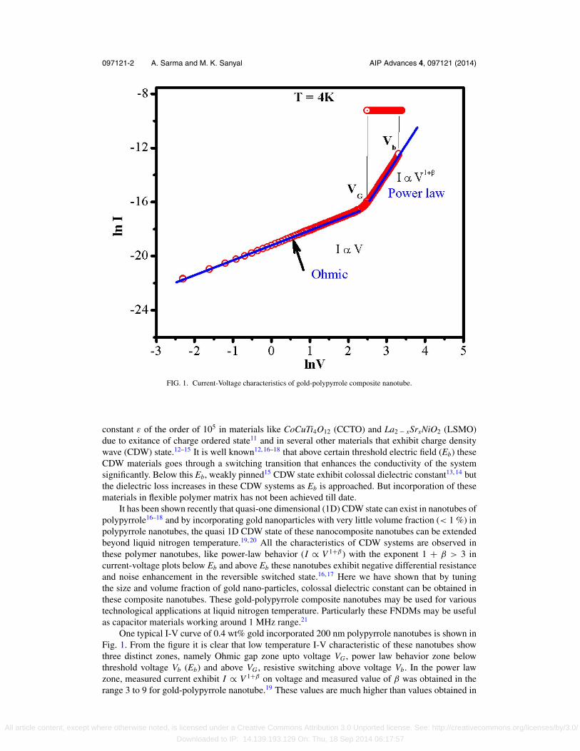
FIG. 1. Current-Voltage characteristics of gold-polypyrrole composite nanotube.
constant ε of the order of 105 in materials like CoCuTi4O12 (CCTO) and La2 − xSrxNiO2 (LSMO)due to exitance of charge ordered state11 and in several other materials that exhibit charge densitywave (CDW) state.12–15 It is well known12, 16–18 that above certain threshold electric field (Eb) theseCDW materials goes through a switching transition that enhances the conductivity of the systemsignificantly. Below this Eb, weakly pinned15 CDW state exhibit colossal dielectric constant13, 14 butthe dielectric loss increases in these CDW systems as Eb is approached. But incorporation of thesematerials in flexible polymer matrix has not been achieved till date.
It has been shown recently that quasi-one dimensional (1D) CDW state can exist in nanotubes ofpolypyrrole16–18 and by incorporating gold nanoparticles with very little volume fraction (< 1 %) inpolypyrrole nanotubes, the quasi 1D CDW state of these nanocomposite nanotubes can be extendedbeyond liquid nitrogen temperature.19, 20 All the characteristics of CDW systems are observed inthese polymer nanotubes, like power-law behavior (I ∝ V 1+β ) with the exponent 1 + β > 3 incurrent-voltage plots below Eb and above Eb these nanotubes exhibit negative differential resistanceand noise enhancement in the reversible switched state.16, 17 Here we have shown that by tuningthe size and volume fraction of gold nano-particles, colossal dielectric constant can be obtained inthese composite nanotubes. These gold-polypyrrole composite nanotubes may be used for varioustechnological applications at liquid nitrogen temperature. Particularly these FNDMs may be usefulas capacitor materials working around 1 MHz range.21
One typical I-V curve of 0.4 wt% gold incorporated 200 nm polypyrrole nanotubes is shown inFig. 1. From the figure it is clear that low temperature I-V characteristic of these nanotubes showthree distinct zones, namely Ohmic gap zone upto voltage VG , power law behavior zone belowthreshold voltage Vb (Eb) and above VG , resistive switching above voltage Vb. In the power lawzone, measured current exhibit I ∝ V 1+β on voltage and measured value of β was obtained in therange 3 to 9 for gold-polypyrrole nanotube.19 These values are much higher than values obtained in
All article content, except where otherwise noted, is licensed under a Creative Commons Attribution 3.0 Unported license. See: http://creativecommons.org/licenses/by/3.0/
Downloaded to IP: 14.139.193.129 On: Thu, 18 Sep 2014 06:17:57
097121-3 A. Sarma and M. K. Sanyal AIP Advances 4, 097121 (2014)
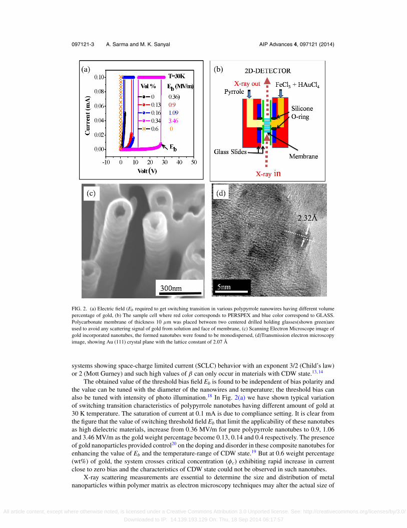
FIG. 2. (a) Electric field (Eb required to get switching transition in various polypyrrole nanowires having different volumepercentage of gold, (b) The sample cell where red color corresponds to PERSPEX and blue color correspond to GLASS.Polycarbonate membrane of thickness 10 μm was placed between two centered drilled holding glasses(shown green)areused to avoid any scattering signal of gold from solution and face of membrane, (c) Scanning Electron Microscope image ofgold incorporated nanotubes, the formed nanotubes were found to be monodispersed, (d)Transmission electron microscopyimage, showing Au (111) crystal plane with the lattice constant of 2.07 Å
systems showing space-charge limited current (SCLC) behavior with an exponent 3/2 (Child’s law)or 2 (Mott Gurney) and such high values of β can only occur in materials with CDW state.13, 14
The obtained value of the threshold bias field Eb is found to be independent of bias polarity andthe value can be tuned with the diameter of the nanowires and temperature; the threshold bias canalso be tuned with intensity of photo illumination.18 In Fig. 2(a) we have shown typical variationof switching transition characteristics of polypyrrole nanotubes having different amount of gold at30 K temperature. The saturation of current at 0.1 mA is due to compliance setting. It is clear fromthe figure that the value of switching threshold field Eb that limit the applicability of these nanotubesas high dielectric materials, increase from 0.36 MV/m for pure polypyrrole nanotubes to 0.9, 1.06and 3.46 MV/m as the gold weight percentage become 0.13, 0.14 and 0.4 respectively. The presenceof gold nanoparticles provided control20 on the doping and disorder in these composite nanotubes forenhancing the value of Eb and the temperature-range of CDW state.19 But at 0.6 weight percentage(wt%) of gold, the system crosses critical concentration (φc) exhibiting rapid increase in currentclose to zero bias and the characteristics of CDW state could not be observed in such nanotubes.
X-ray scattering measurements are essential to determine the size and distribution of metalnanoparticles within polymer matrix as electron microscopy techniques may alter the actual size of
All article content, except where otherwise noted, is licensed under a Creative Commons Attribution 3.0 Unported license. See: http://creativecommons.org/licenses/by/3.0/
Downloaded to IP: 14.139.193.129 On: Thu, 18 Sep 2014 06:17:57
097121-4 A. Sarma and M. K. Sanyal AIP Advances 4, 097121 (2014)
embedded nanoparticles due to electron beam induced coagulation process.22 The result presentedhere clearly show that the growth process of these composite nanotubes can be probed with syn-chrotron x-ray diffraction (XRD) technique and with minor modification the presented techniquescan be used to monitor growth of similar FNDMs.
II. EXPERIMENTAL METHOD
The sample cell used for the in-situ x-ray diffraction study and the schematic of the experimentalarrangement is shown in Fig. 2(b). The cell is basically composed of two compartments. Onecompartment was filled with pyrrole monomer and other one was used to keep with a mixture offerric chloride (FeCl3) and chloroauric acid (HAuCl4). The polycarbonate membrane was placed19
between these two compartments and x-ray was allowed to pass only through the membrane,perpendicular with the pore direction and the diffraction data was collected using a two dimensional(2D) detector. The thickness of the polycarbonate membrane used in this study varied from 8 μmto 12 μm and the dimension of the incident x-ray (13 keV) beam was 10 μm X 8 μm. The twocompartment sample cell used here was made with perspex (shown in Fig. 2(b) with red color).In order to obtain smooth surfaces we have used two center drilled (8 mm) glass slide (shown inblue color) over the perspex. The membrane was placed within another two glass slides (shown ingreen) having 1 mm central hole to make sure that the flatness of the sample is maintained so that theincident x-ray beam and the diffracted beam probe only the nanotubes inside the membrane. We havefound that much bigger gold nanoparticles get deposited on the surface of membrane in this reactiondue to the lack of confinement and the primary purpose of this special sample cell was to ensure thatx-ray data is obtained only from the nanotubes within the membrane and not from the surface of themembrane. The experiment was carried out in P08 and P03 beamlines of PETRA-III Synchrotronat DESY, Germany. In this study we have used polycarbonate membrane of five different porediameters (400 nm, 200 nm, 80 nm, 50 nm, 30 nm) (purchased from Whatman). Pyrrole monomer(purchased from Merck, Germany) was vacuum distilled and stored at 200C before use. Chloroauricacid (purchased from Alfa Aser) was used as gold source. Ferric chloride (purchased from Merck)was used as obtained.
In Fig. 2(c) and Fig. 2(d) we have shown typical scanning electron microscopy (SEM) andtransmission electron microscopy (TEM) images of nanotubes obtained after the x-ray experimentby dissolving the polycarbonate template using chloroform. From the low and high magnifica-tion images, shown in Fig. 2(c) and Fig. 2(d) respectively, it is clear that gold-polypyrrole nano-composites formed mono-dispersed nanotubes in the pores of the membrane and gold nano-particlesget embedded in the wall of these nanotubes. In-situ x-ray measurements and subsequent dielectricmeasurements clearly show that dielectric constant of these nanotubes can be tuned by controllingthe diameters of the nanotubes and the molar concentration of chloroauric acid and ferric chloride.We have presented here results obtained with membranes of five different pore diameters (400 nm,200 nm, 80 nm, 50 nm and 30 nm) and two different concentrations of chloroauric acid (5.3 mMand 2.6 mM).
III. RESULTS AND DISCUSSION
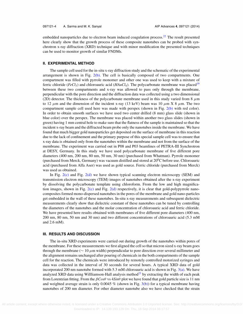
The in-situ XRD experiments were carried out during growth of the nanotubes within pores ofthe membrane. For these measurements we first aligned the cell so that micron sized x-ray beam goesthrough the membrane (∼ 10 μm width) perpendicular to pore direction over several millimeter andthe alignment remains unchanged after pouring of chemicals in the both compartments of the samplecell for the reaction. The chemicals were introduced by remotely controlled motorized syringes anddata was collected in the interval of 30 seconds for several hours. A typical XRD data of goldincorporated 200 nm nanotube formed with 5.3 mM chloroauric acid is shown in Fig. 3(a). We haveanalyzed XRD data using Willliamson-Hall analysis method23 by extracting the width of each peakfrom Lorentzian fitting. From the βCosθ vs 4Sinθ plot we have found that gold particle size is 11 nmand weighted average strain is only 0.0045 % (shown in Fig. 3(b)) for a typical membrane havingnanotubes of 200 nm diameter. For other diameter nanotube also we have checked that the strain
All article content, except where otherwise noted, is licensed under a Creative Commons Attribution 3.0 Unported license. See: http://creativecommons.org/licenses/by/3.0/
Downloaded to IP: 14.139.193.129 On: Thu, 18 Sep 2014 06:17:57
097121-5 A. Sarma and M. K. Sanyal AIP Advances 4, 097121 (2014)
FIG. 3. (a) X-ray diffraction of the gold-incorporated 200 nm polypyrrole nanotube,(b) Williamson-Hall plot constructedfrom the peak profiles of the Synchrotron X-ray powder diffraction pattern, (c) TEM image of incorporated gold nanoparticlein 200 nm (5.3 mM) nanotube, (d) FFT and spatial filtered image of rectangular zone shown in (c).
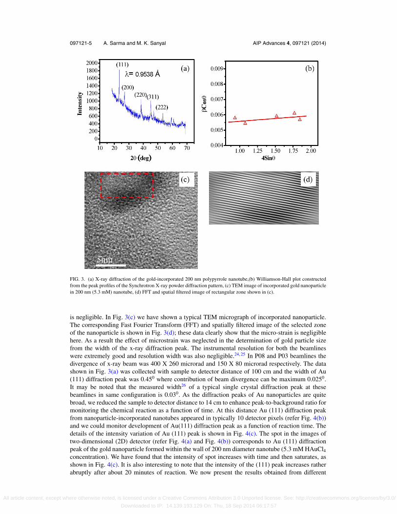
is negligible. In Fig. 3(c) we have shown a typical TEM micrograph of incorporated nanoparticle.The corresponding Fast Fourier Transform (FFT) and spatially filtered image of the selected zoneof the nanoparticle is shown in Fig. 3(d); these data clearly show that the micro-strain is negligiblehere. As a result the effect of microstrain was neglected in the determination of gold particle sizefrom the width of the x-ray diffraction peak. The instrumental resolution for both the beamlineswere extremely good and resolution width was also negligible.24, 25 In P08 and P03 beamlines thedivergence of x-ray beam was 400 X 260 microrad and 150 X 80 microrad respectively. The datashown in Fig. 3(a) was collected with sample to detector distance of 100 cm and the width of Au(111) diffraction peak was 0.450 where contribution of beam divergence can be maximum 0.0250.It may be noted that the measured width26 of a typical single crystal diffraction peak at thesebeamlines in same configuration is 0.030. As the diffraction peaks of Au nanoparticles are quitebroad, we reduced the sample to detector distance to 14 cm to enhance peak-to-background ratio formonitoring the chemical reaction as a function of time. At this distance Au (111) diffraction peakfrom nanoparticle-incorporated nanotubes appeared in typically 10 detector pixels (refer Fig. 4(b))and we could monitor development of Au(111) diffraction peak as a function of reaction time. Thedetails of the intensity variation of Au (111) peak is shown in Fig. 4(c). The spot in the images oftwo-dimensional (2D) detector (refer Fig. 4(a) and Fig. 4(b)) corresponds to Au (111) diffractionpeak of the gold nanoparticle formed within the wall of 200 nm diameter nanotube (5.3 mM HAuCl4concentration). We have found that the intensity of spot increases with time and then saturates, asshown in Fig. 4(c). It is also interesting to note that the intensity of the (111) peak increases ratherabruptly after about 20 minutes of reaction. We now present the results obtained from different
All article content, except where otherwise noted, is licensed under a Creative Commons Attribution 3.0 Unported license. See: http://creativecommons.org/licenses/by/3.0/
Downloaded to IP: 14.139.193.129 On: Thu, 18 Sep 2014 06:17:57
097121-6 A. Sarma and M. K. Sanyal AIP Advances 4, 097121 (2014)
FIG. 4. XRD spot corresponding to Au (111) in 2D Pilatus detector (a) after 1min of reaction, (b) after 30 min of reaction,(c) the time evolution of the intensity of the XRD spot.
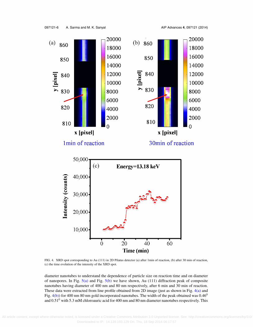
diameter nanotubes to understand the dependence of particle size on reaction time and on diameterof nanopores. In Fig. 5(a) and Fig. 5(b) we have shown, Au (111) diffraction peak of compositenanotubes having diameter of 400 nm and 80 nm respectively, after 6 min and 30 min of reaction.These data were extracted from line profile obtained from 2D image (just as shown in Fig. 4(a) andFig. 4(b)) for 400 nm 80 nm gold incorporated nanotubes. The width of the peak obtained was 0.460
and 0.510 with 5.3 mM chloroauric acid for 400 nm and 80 nm diameter nanotubes respectively. This
All article content, except where otherwise noted, is licensed under a Creative Commons Attribution 3.0 Unported license. See: http://creativecommons.org/licenses/by/3.0/
Downloaded to IP: 14.139.193.129 On: Thu, 18 Sep 2014 06:17:57
097121-7 A. Sarma and M. K. Sanyal AIP Advances 4, 097121 (2014)
FIG. 5. The time evolution of Au (111) peak after 6 min and 30 min of reaction, (a) 400 nm nanotube, (b) 80 nm nanotube,(c) The variation of the size of incorporated gold nanoparticles with the variation of nanotube diameter for two differentconcentration of HAuCl4. The data shown in (a) and (b) are extracted from the accumulated 2D detector image similar tothe one shown in Fig. 4 for 200 nm nanotubes. The extracted counts from the detector pixels were normalized to have samebackground counts, which accumulates as we collect the data as a function of reaction time.
result clearly indicate that the size of the incorporated gold nanoparticle is independent of reactiontime and only the number density of nanoparticles grow with time. At the end of the reaction wehave found that the wt% of gold in a typical 50 nm nanotube formed with 5.3 mM chlroauric acidsolution is about 4 %. The volume percentage φ of gold was obtained to be 0.34 % using bulk densityof gold and polypyrrole.
In Fig. 5(c) we have presented average sizes of gold nanoparticles obtained in different nan-otubes as a function of concentration of chloroauric acid. The data shown here were obtained afterthe reaction of 60 min in different pore diameter ranging from 30 nm to 400 nm. It is clear from theFig. 5(c) that for higher diameter nanotubes (>100 nm) the particle size is larger for higher con-centration chloroauric acid solution (5.3 mM) compare to that obtained with lower concentration(2.6 mM). For the lower diameter nanotubes (<100 nm) the particle size become independent ofconcentration of chloroauric acid. The size of the incorporated gold nanoparticles in lower diameternanotubes reduces slowly with the pore diameter that control diffusion and associated polymerizationreaction in the nano-pores of the gold-polypyrrole composite nanotubes.
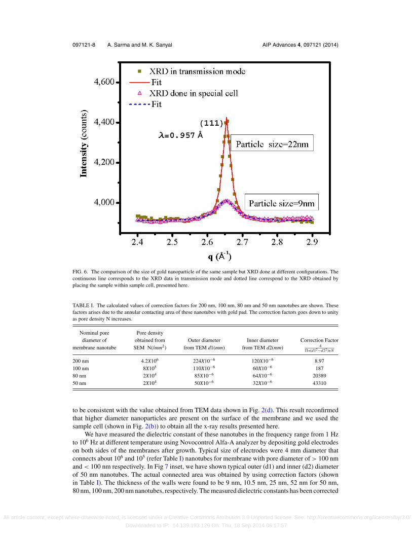
We could get systematic variation of particle size from x-ray data as the sample cell ensuredthat XRD data came only from these nanotubes embedded within the membrane. In Fig. 6 wehave compared XRD data of a polycarbonate membrane having 200 nm diameter nanotubes ofgold-polypyrrole composite (2.6 mM HAuCl4) taken using the cell (shown in Fig. 2(b)) and taken inconventional transmission geometry by keeping several layers of the membrane in the x-ray beam.The XRD data was taken in transmission mode with the beam perpendicular to the surface of themembrane and that included the diffraction from the surface deposited gold nanoparticles as well.The width of the Au (111) peak (refer Fig. 6) obtained from these two types of measurements werefound to be 0.580 and 0.240 respectively. The average size of particles obtained from analysis wasfound to be 9 nm and 22 nm respectively. The obtained value of 9 nm from the sample cell was found
All article content, except where otherwise noted, is licensed under a Creative Commons Attribution 3.0 Unported license. See: http://creativecommons.org/licenses/by/3.0/
Downloaded to IP: 14.139.193.129 On: Thu, 18 Sep 2014 06:17:57
097121-8 A. Sarma and M. K. Sanyal AIP Advances 4, 097121 (2014)
FIG. 6. The comparison of the size of gold nanoparticle of the same sample but XRD done at different configurations. Thecontinuous line corresponds to the XRD data in transmission mode and dotted line correspond to the XRD obtained byplacing the sample within sample cell, presented here.
TABLE I. The calculated values of correction factors for 200 nm, 100 nm, 80 nm and 50 nm nanotubes are shown. Thesefactors arises due to the annular contacting area of these nanotubes with gold pad. The correction factors goes down to unityas pore density N increases.
Nominal pore Pore densitydiameter of obtained from Outer diameter Inner diameter Correction Factor
membrane nanotube SEM N(/mm2) from TEM d1(mm) from TEM d2(mm) 4�∗(d12−d22)∗N
200 nm 4.2X10⁶ 224X10−6 120X10−6 8.97100 nm 8X10⁵ 110X10−6 60X10−6 18780 nm 2X10⁴ 85X10−6 64X10−6 2038950 nm 2X10⁴ 50X10−6 32X10−6 43310
to be consistent with the value obtained from TEM data shown in Fig. 2(d). This result reconfirmedthat higher diameter nanoparticles are present on the surface of the membrane and we used thesample cell (shown in Fig. 2(b)) to obtain all the x-ray results presented here.
We have measured the dielectric constant of these nanotubes in the frequency range from 1 Hzto 106 Hz at different temperature using Novocontrol Alfa-A analyzer by depositing gold electrodeson both sides of the membranes after growth. Typical size of electrodes were 4 mm diameter thatconnects about 106 and 105 (refer Table I) nanotubes for membrane with pore diameter of > 100 nmand < 100 nm respectively. In Fig 7 inset, we have shown typical outer (d1) and inner (d2) diameterof 50 nm nanotubes. The actual connected area was obtained by using correction factors (shownin Table I). The thickness of the walls were found to be 9 nm, 10.5 nm, 25 nm, 52 nm for 50 nm,80 nm, 100 nm, 200 nm nanotubes, respectively. The measured dielectric constants has been corrected
All article content, except where otherwise noted, is licensed under a Creative Commons Attribution 3.0 Unported license. See: http://creativecommons.org/licenses/by/3.0/
Downloaded to IP: 14.139.193.129 On: Thu, 18 Sep 2014 06:17:57
097121-9 A. Sarma and M. K. Sanyal AIP Advances 4, 097121 (2014)
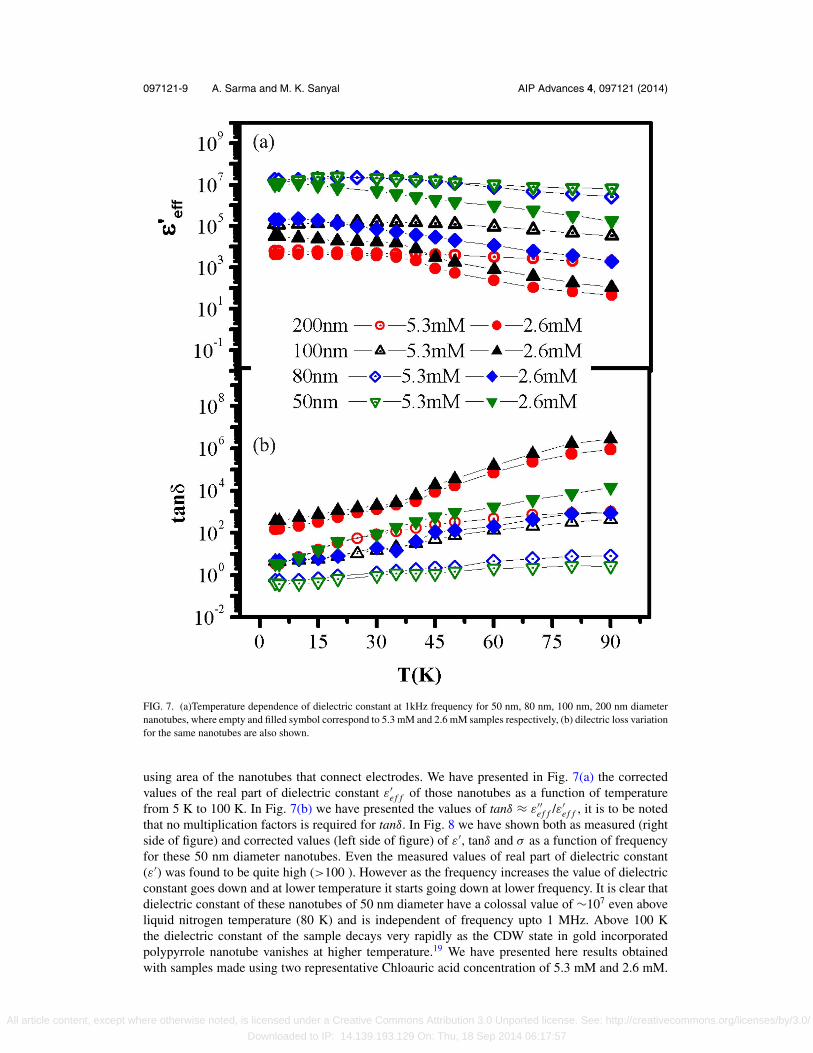
FIG. 7. (a)Temperature dependence of dielectric constant at 1kHz frequency for 50 nm, 80 nm, 100 nm, 200 nm diameternanotubes, where empty and filled symbol correspond to 5.3 mM and 2.6 mM samples respectively, (b) dilectric loss variationfor the same nanotubes are also shown.
using area of the nanotubes that connect electrodes. We have presented in Fig. 7(a) the correctedvalues of the real part of dielectric constant ε′
e f f of those nanotubes as a function of temperaturefrom 5 K to 100 K. In Fig. 7(b) we have presented the values of tanδ ≈ ε′′
e f f /ε′e f f , it is to be noted
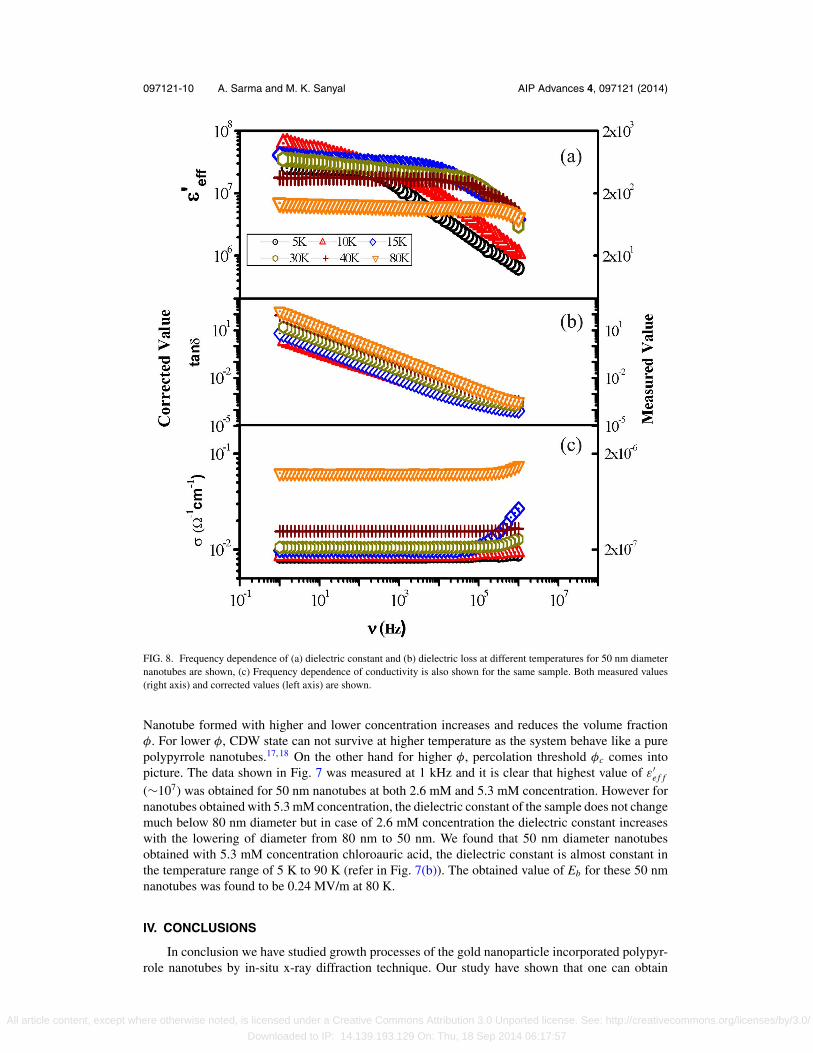
that no multiplication factors is required for tanδ. In Fig. 8 we have shown both as measured (rightside of figure) and corrected values (left side of figure) of ε′, tanδ and σ as a function of frequencyfor these 50 nm diameter nanotubes. Even the measured values of real part of dielectric constant(ε′) was found to be quite high (>100 ). However as the frequency increases the value of dielectricconstant goes down and at lower temperature it starts going down at lower frequency. It is clear thatdielectric constant of these nanotubes of 50 nm diameter have a colossal value of ∼107 even aboveliquid nitrogen temperature (80 K) and is independent of frequency upto 1 MHz. Above 100 Kthe dielectric constant of the sample decays very rapidly as the CDW state in gold incorporatedpolypyrrole nanotube vanishes at higher temperature.19 We have presented here results obtainedwith samples made using two representative Chloauric acid concentration of 5.3 mM and 2.6 mM.
All article content, except where otherwise noted, is licensed under a Creative Commons Attribution 3.0 Unported license. See: http://creativecommons.org/licenses/by/3.0/
Downloaded to IP: 14.139.193.129 On: Thu, 18 Sep 2014 06:17:57
097121-10 A. Sarma and M. K. Sanyal AIP Advances 4, 097121 (2014)
FIG. 8. Frequency dependence of (a) dielectric constant and (b) dielectric loss at different temperatures for 50 nm diameternanotubes are shown, (c) Frequency dependence of conductivity is also shown for the same sample. Both measured values(right axis) and corrected values (left axis) are shown.
Nanotube formed with higher and lower concentration increases and reduces the volume fractionφ. For lower φ, CDW state can not survive at higher temperature as the system behave like a purepolypyrrole nanotubes.17, 18 On the other hand for higher φ, percolation threshold φc comes intopicture. The data shown in Fig. 7 was measured at 1 kHz and it is clear that highest value of ε′
e f f
(∼107) was obtained for 50 nm nanotubes at both 2.6 mM and 5.3 mM concentration. However fornanotubes obtained with 5.3 mM concentration, the dielectric constant of the sample does not changemuch below 80 nm diameter but in case of 2.6 mM concentration the dielectric constant increaseswith the lowering of diameter from 80 nm to 50 nm. We found that 50 nm diameter nanotubesobtained with 5.3 mM concentration chloroauric acid, the dielectric constant is almost constant inthe temperature range of 5 K to 90 K (refer in Fig. 7(b)). The obtained value of Eb for these 50 nmnanotubes was found to be 0.24 MV/m at 80 K.
IV. CONCLUSIONS
In conclusion we have studied growth processes of the gold nanoparticle incorporated polypyr-role nanotubes by in-situ x-ray diffraction technique. Our study have shown that one can obtain
All article content, except where otherwise noted, is licensed under a Creative Commons Attribution 3.0 Unported license. See: http://creativecommons.org/licenses/by/3.0/
Downloaded to IP: 14.139.193.129 On: Thu, 18 Sep 2014 06:17:57

097121-11 A. Sarma and M. K. Sanyal AIP Advances 4, 097121 (2014)
colossal values of dielectric constant in these nanotubes by tuning the growth process. It is to benoted here that the colossal dielectric property presented here, required the presence of individualnanotubes to form 1D CDW state and one can increase the factors shown in Table I by increasing thenumber density N of pores in the membrane. Already much higher number density pores (more than100 times) are available (SPI track-etched polycarbonate). As N increases the measured values ap-proach the corrected values. Nearly flat frequency and temperature response of the dielectric constantof nanotubes of gold-polypyrrole composite with huge value reported here may find technologicalapplications at liquid nitrogen temperature. Further studies are required to improve dielectric lossand Eb of these composite nanotubes for such technological applications specified by Ragone plots.21
However with reasonable dielectric loss around 1 MHz, the composite nanotubes of 50 nm diameterprepared in polycarbonate membrane with higher pore density than reported here may already findapplications as capacitor materials at liquid nitrogen temperature or lower temperature.
ACKNOWLEDGMENTS
Authors would like to thank Department of Science and technology for supporting the access ofbeamlines at DESY to carrying out these measurements. Authors are grateful to Dr. Stephan V. Roth(beam-line P03) and Dr. Oliver Seeck (beam-line P08) of DESY, Germany for valuable suggestionsand help.
1 Z. M. Dang, J. K. Yuan, S. H. Yao, and R. J. Liao, Adv. Mater. 25, 6334 (2013).2 P. Barber, S. Balashubramanian, Y. Anguchamy, S. Gong, A. Wibowo, H. Gao, H. J. Ploehn, and H. C. Loye, Materials 2,
1697 (2009).3 C. Yu, Y. S. Kim, and J. C. Grunlan, NanoLett. 8, 4428 (2008).4 Y. Wang, X. Xie, and T. Goodson, NanoLett. 5, 2379 (2005).5 Y. Yang, M. C. Gupta, and K. L. Dudley, Micro Nano Letts. 2, 85 (2007).6 J. Huang, S. Virji, B. H. Weiller, and R. B. Kaner, Chem.-Eur. J. 10, 1314 (2004).7 J. Wang, K. G. Neoh, and E. T. Kang, J. Colloid Interface Sci. 239, 78 (2001).8 R. J. Tseng, J. Huang, J. Ouyang, R. B. Kaner, and Y. Yang, Nano Lett. 5, 1077 (2005).9 M. Dang, J. K. Yuan, J. W. Zha, T. Zhou, S. T. Li, and G. H. Hu, Prog. Mater. Sci. 57, 660 (2012).
10 L. Zhang, W. Wang, X. Wang, P. Bass, and Z. Y. Cheng, Appl. Phys. Lett. 103, 232903 (2013).11 S. Krohns, P. Lunkenheimer, Ch. Kant, A. V. Pronin, H. B. Brom, A. A. Nugroho, M. Diantoro, and A. Loidl, Appl.Phys.Lett.
94, 122903 (2009).12 P. Monceau, Advances in Physics 61, 2, 325 (2012).13 R. J. Cava, R. M. Fleming, P. Littlewood, E. A. Rietman, L. F. Schneemeyer, and R. G. Dunn, Phys. Rev. B 30, 3228
(1984).14 P. Lunkenheimer, V. Bobnar, A. V. Pronin, A. I. Ritus, A. A. Volkov, and A. Loidl, Phys. Rev. B 66, 052105 (2002).15 P. B. Littlewood, Phys. Rev. B 36, 3108 (1987).16 A. Rahman and M. K. Sanyal, Adv. Mater. 19, 3956 (2007).17 A. Rahman and M. K. Sanyal, Phys. Rev. B 76, 045110 (2007).18 A. Rahman and M. K. Sanyal, ACS Nano. 7, 7894 (2013).19 A. Sarma, M. K. Sanyal, A. Rahman, and B. Satpati, J. Appl. Phys. 112, 044304 (2012).20 I. Sarkar, A. Sarma, M. K. Sanyal, S. Thieß, and W. Drube, J. Appl.Phys. 114, 163707 (2013).21 T. Christen and M. W. Carlen, Journal of Power Sources 91, 210 (2000).22 M. K. Sanyal, V. V. Agrawal, M. K. Bera, K. P. Kalyanikutty, J. Daillant, C. Blot, S. Kubowicz, O. Konovalov, and C. N.
Rao, J. Phys. Chem. C 112, 1739 (2008).23 G. K. Williamson and W. H. Hall, Acta Metall. 1, 22–31 (1953).24 S. V. Roth, H. Walter, M. Burghammer, C. Riekel, B. Lengeler, C. Schroer, M. Kuhlmann, T. Walther, A. Sehrbrock, R.
Domnick, and P. Muller-Buschbaum, Appl. Phys. Lett. 88, 021910 (2006).25 O. H. Seeck, C. Deiter, K. Plaum, F. Bertam, A. Beerlink, H. Franz, J. Horboch, H. Schulte-Schrepping, B. M. Murphy,
M. Greve, and O. Magnussen, J. Synchrotron Radiat. 19, 30 (2012).26 M. Sharma, M. K. Sanyal, B. Satpati, O. H. Seeck, and S. K. Ray, Phys. Rev. B 89, 205304 (2014).
All article content, except where otherwise noted, is licensed under a Creative Commons Attribution 3.0 Unported license. See: http://creativecommons.org/licenses/by/3.0/
Downloaded to IP: 14.139.193.129 On: Thu, 18 Sep 2014 06:17:57