TS SCERT Class 10 Physics Textbook in English Medium
306
SCERT, TELANGANA
-
Upload
khangminh22 -
Category
Documents
-
view
2 -
download
0
Transcript of TS SCERT Class 10 Physics Textbook in English Medium

SCERT, TELA
NGANA

Step Description A. Use Android mobile phone or tablet to view content linked to QR Code: 1. Click on Play Store on your mobile/ tablet. 2. In the search bar type DIKSHA. 3.
will appear on your screen. 4. Click Install 5. After successful download and installation, Click Open 6. Choose your prefered Language - Click English 7. Click Continue 8. Select Student/ Teacher (as the case may be) and Click on Continue 9. On the top right, click on the QR code scanner icon and scan a QR code
printed in your bookOR
Click on the search icon and type the code printed below the QR code,in the search bar ( )
10. A list of linked topics is displayed 11. Click on any link to view the desired contentB. Use Computer to view content linked to QR code: 1. Go to https://diksha.gov.in/telangana 2. Click on Explore DIKSHA-TELANGANA 3. Enter the code printed below the QR code in the browser search bar ( ) 4. A list of linked topics is displayed 5. Click on any link to view the desired content
Let us know how to use QR codesIn this textbook, you will see many printed QR (Quick Response) codes, such as
Use your mobile phone or tablet or computer to see interesting lessons, videos, documents, etc. linked to the QR code.
Energized Text Books facilitate the students in understanding the concepts clearly, accurately and effectively.Content in the QR Codes can be read with the help of any smart phone or can as well be presented on the Screen withLCD projector/K-Yan projector. The content in the QR Codes is mostly in the form of videos, animations and slides,and is an additional information to what is already there in the text books.
This additional content will help the students understand the concepts clearly and will also help the teachers inmaking their interaction with the students more meaningful.
At the end of each chapter, questions are provided in a separate QR Code which can assess the level of learningoutcomes achieved by the students.
We expect the students and the teachers to use the content available in the QR Codes optimally and make theirclass room interaction more enjoyable and educative.
INSPIRE AWARDS
Inspire is a National level programme to strengthen theroots of our traditional and technological development.
The major aims of Innovations in Science Pursuit forInspired Research (INSPIRE) programme are...
• Attract intelligent students towards sciences
• Identifying intelligent students and encourage them to studyscience from early age
• Develop complex human resources to promote scientific, technologicaldevelopment and researchInspire is a competitive examination. It is an innovative programme to make
younger generation learn science interestingly. In 11th five year plan nearly TenLakhs of students were selected during 12th five year plan (2012-17) TwentyLakhs of students will be selected under this programme.
Two students from each high school (One student from 6 - 8 classes andone from 9 - 10 classes) and one student from each upper primary school areselected for this award.
Each selected student is awarded with Rs. 5000/-. One should utilize 50%of amount for making project or model remaining for display at district levelInspire programme. Selected students will be sent to State level as well asNational level.
Participate in Inspire programme - Develop our country.
SCERT, TELA
NGANA

iFree distribution by Govt. of T.S. 2021-22
Sri M. Ramabrahmam, Lecturer,Govt. IASE, Masabtank,
Hyderabad.
Prof. Kamal Mahendroo,Vidya Bhawan Education Resource Centre,
Udaipur, Rajasthan.
Dr. TVS Ramesh,Co-ordinator, C&T Dept.,
SCERT, Hyderabad.
Miss. Preeti Misra,Vidya Bhawan Education Resource Centre, Udaipur, Rajasthan.
Co-ordinators
Academic Support
Editors
Published by the Government of Telangana, Hyderabad.
Respect the LawGet the Rights
Grow by EducationBehave Humbly
PHYSICAL SCIENCESPHYSICAL SCIENCESPHYSICAL SCIENCESPHYSICAL SCIENCESPHYSICAL SCIENCES
CLASS X
Dr.B. Krishnarajulu Naidu,Retd., Professor of Physics
Osmania University, Hyderabad.
Dr.M. Adinarayana,Retd., Professor of Chemistry
Osmania University, Hyderabad.
Dr. M. SalagramRetd., Professor of Physics
Osmania University, Hyderabad.
Dr. K. Venkateswara RaoRetd., Reader in Chemistry
New Science College, Hyderabad.
Dr. Nannuru Upendar Reddy,Professor & Head C&T Dept.,
SCERT., Hyderabad.
Dr. C.V. Sarveswara SharmaRetd., Reader in Physics
Amalapuram.
QR CODE TEAM
SCERT, TELA
NGANA

ii
© Government of Telangana, Hyderabad.
First Published 2014New Impressions 2015, 2016, 2017, 2018, 2019, 2020, 2021
All rights reserved.
No part of this publication may be reproduced, storedin a retrieval system, or transmitted, in any form or byany means without the prior permission in writing of thepublisher, nor be otherwise circulated in any form ofbinding or cover other than that in which it is publishedand without a similar condition including this conditionbeing imposed on the subsequent purchaser.
The copy right holder of this book is the Directorof School Education, Hyderabad, Telangana.We have used some photographs which are undercreative common licence. They are acknowledgedat the end of the book.
This Book has been printed on 70 G.S.M. Maplitho,Title Page 200 G.S.M. White Art Card
Free Distribution by Government of Telangana 2021-22
Printed in Indiaat the Telangana Govt. Text Book Press,
Mint Compound, Hyderabad,Telangana.
SCERT, TELA
NGANA

iiiFree distribution by Govt. of T.S. 2021-22
Sri R. Ananda Kumar, SA,ZPHS Gavaravaram, Visakhapatnam.
Sri S. Naushad Ali, SA,ZPHS G.D. Nellore, Chittoor.
Sri S. Brahmananda Reddy, SA,ZPHS Immadicheruvu, Prakasam.
Sri V. Yekambareswararao, SA,ZPHS Lingaraopalem, Guntur.
Sri K.V.K. Srikanth, SA,GTWAHS S.L.Puram, Srikakulam.
Sri M. Eswara Rao, SA,GHS Sompeta, Srikakulam
Sri S.U. Siva Ram Prasad, SA,GBHS Sultan Bazar, Hyderabad.
Sri Madhusudhana Reddy Dandala, SA,ZPHS Munagala, Nalgonda.
Sri Y. Venkat Reddy, SA,ZPHS Chivemla, Nalgonda
Sri K. Gagan Kumar, SA,ZPHS Mirzapur, Nizamabad.
Dr.K. Suresh, SA,ZPHS Pasaragonda, Warangal.
Sri Tirumala Srinivasa Chary, SA,ZPHS Kapra, Medchal Dist.
Text Book Development Committee
Writers
Cover page, Graphics & Designing
Sri G. Gopal Reddy, Director,S.C.E.R.T. , Hyderabad.
Sri B. Sudhakar, Director,Govt. Textbook printing press,
Hyderabad.Dr. Nannuru Upendar Reddy,Professor & Head C&T Dept.,
S.C.E.R.T., Hyderabad.
Sri K. Sudhakara Chary, SGT,UPS Neelikurthy, Warangal.
Sri Kurra Suresh Babu, B.Tech, MA., MPhill.Mana Media Graphics, Hyderabad.
Sri Kishan Thatoju, Graphic Designer,C&T Dept.,SCERT, Hyderabad.Sri Md. Ayyub Ahmed, S.A.,
Z.P. H.S U/M, Atmakur, Mahbubnagar.
Sri M. Ramabrahmam, Lecturer,Govt. IASE, Masabtank, Hyderabad.
SCERT, TELA
NGANA

iv
Intro ...
We believe that class-10 education is a key aspect of school education and aturning point in student’s life. The present tenth class Science textbook in yourhands is developed in accordance with the National and State Curriculum Frameworkand the Right to Education Act. This book helps the student to review variousconcepts that were learned through the learning experiences provided in the schooland to get comprehensive knowledge about these conecepts. The lessons in thetextbooks are presented in such way that they help in preparing the student forcompetitive examinations and also to prepare him/her for intermediate education.
The new science textbooks are specially designed with suitable pedagogy intune with Continuous Comprehensive Evaluation (CCE) which we are right nowimplementing in school education. These textbooks help the teacher to assessstudents learning during teaching learning processes. They facilitate effective learningof various concepts of science in scientific method apart from getting knowledgeabout concepts. It is essential to complete the syllabus in the stipulated time asstudents have to write the Board Examination in class-10. But don’t forget thatcompletion of syllabus means making the students understand the concepts andtrying to achieve the learning competencies. It is mandatory on the part of teacherto implement teaching strategies like, making the student to read the content ofthe textbook, do discussion, analysis, lab activity, field trips, preparing reports, etc.Teacher must take special care to avoid the practice of rote memorisation ofscientific information from guides and question banks.
The classroom teaching of science must be in such a way that it encourageschildren to think and work scientifically. Also, it must enhance love towards nature.Even it should enable to comprehend and appreciate the laws governing the naturein constructing so much diversity all around. Scientific learning is not just disclosingnew things. It is also necessary to step forward without interrupting theinterrelationship and interdependency along with understanding of the nature’sintrinsic principles.High School children possess cognitive capacity of comprehendingthe nature and characteristics of the transforming world surrounding them. Andthey are able to analyze abstract concepts.
At this level, we cannot quench their sharp thinking capability with the dryteaching of mere equations and theoretic principles. For that, we should create alearning environment in the classroom which provides an opportunity for them toapply the scientific knowledge, explore multiple alternatives in solving problems andestablish new relations.
Scientific learning is not just confined to the four walls of classroom. It has adefinite connection to lab and field as well. Therefore, there is a lot of importanceto field experience/ experiments in science teaching.
SCERT, TELA
NGANA

vFree distribution by Govt. of T.S. 2021-22
There is a great need for compulsory implementation of instructions of theNational Curriculum Framework- 2005 which emphasizes linking of the science teachingwith local environment. The Right to Education Act- 2009 also suggested thatpriority should be given to the achievement of learning competencies among children.Likewise, science teaching should be in such a way that it would help cultivate anew generation with scientific thinking.
The key aspect of science teaching is to make the children understand thethinking process of scientists and their efforts behind each discovery. The StateCurriculum Framework- 2011 stated that children should be able to express theirown ideas and opinions on various aspects. These Science Text Books are preparedto meet the standards set by the SCF and thus assist children in becoming self-reliant researchers capable of thinking intensely in scientific terms.
The new textbooks are developed to achieve desired academic standards. Soteachers should develop various teaching learning strategies to make their studentsto achieve class specific academic standards. We should avoid rote learning methodsfor the successful implementation of Continuous Comprehensive Evaluation (CCE).It is very important to know more about different methods to assess students’progress by summative and formative evaluation. The new textbooks reflectContinuous Comprehensive Evaluation and teaching method with respect to discussedconcepts. This is very useful to teachers and students.
In the new textbooks, the design of concepts and activities help in achievingthe specified academic standards and learning outcomes. Teachers need to planappropriate teaching strategies to improve the academic standards and learningoutcomes among the students by the end of teaching the lesson. For effectiveimplementation of continuous comprehensive evaluation the teaching must moveaway from the methods of rote memorisation of concepts. There is a need forteachers to have a good understanding of the methods of evaluation which helpthem in assessing the progress of children in a constructive and comprehensiveway. The new textbooks are not confined to simply provide necessary informationsabout concepts. Instead they focus on the new teaching strategies and evaluationtechniques which are very important for both teachers and students.
We thank the VidyaBhavan Society, Rajasthan for their cooperation in designingthese new text books,the writers for preparing the lessons, the editors for checkingthe textual matters and the DTP group for cutely composing the textbook. Weinvite suggestions from educationists, teachers, parents, students and others tomake this book more meaningful.
Teachers play a pivotal role in children’s comprehensive use of the text book.We hope, teachers will make their best efforts for proper utilization of the text bookso as to inculcate scientific thinking among children and inspire them to be greatscientists.
Director,SCERT, Hyderabad
SCERT, TELA
NGANA

vi
Dear teachers...New Science Text Books are prepared in such a way that they develop children’s observation
power and research enthusiasm. The official documents of National and State Curriculum FrameWorks and the Right to Education Act are aspairing to bring gross route changes in scienceteaching. These textbooks are adopted in accordance with such an aspiration. Hence, scienceteachers need to adapt to the new approach in their teaching.
In view of this, let us observe certain Dos and Don’ts:• There is an immediate need to discard the practices adopted in the schools on a false belief
that teaching of 10th class means preparing the children for public examination. In 10th
class the teaching learning process should focus on achieving the academic standards andlearning outcomes rather winning race of scoring marks.
• Avoid practices like using guides and question banks, asking the children to read onlyimportant questions, focussing on lessons which help in scoring more marks.
• Read the lesson thoroughly before you start teaching and ask the children to read the text.Then initiate a discussion to make the children understand the concepts in the lessons.
• Encourage children to express their own views and ideas while writing the answers. Giveweightage to such type of writing in examination.
• Some instructions are given in the textbook regarding the collection of certain informationby the teacher. Collect such information and make it available to students.
• In public examination, the weightage will be given to all aspects of the syllabus. Exceptforeword of the textbook everything else must be treated as a part of the curriculum.
• Textual concepts are presented in two ways: one as the classroom teaching and the otheras the laboratory performance.
• Lab activities are part and parcel of a lesson. So, teachers must make the children conductall such activities during the lesson itself, but not separately.
• Teachers are advised to follow the following teaching steps while transacting lessons-mindmapping, reading lesson and identifyng new words by children, performing activities,demonstration and discussion, conclusion and evaluation.
• In the text, some special activities are presented as box items: ‘think and discuss, let us do,conduct interview, prepare report, display in wall magazine, participate in Theatre Day, dofield observation, organize special days’. To perform all of them is compulsory.
• The abbreviation (A.S.) given at the end of each question in the section “Improve yourlearning” indicates academic standard.
• Collect information of relevant website addresses and pass on to students so that they canutilize internet services for learning science on their own.
• Plan and execute activities like science club, elocution, drawing, writing poetry on science,making models etc.to develop positive attitude among children about environment,biodiversity, ecological balance etc.
SCERT, TELA
NGANA

viiFree distribution by Govt. of T.S. 2021-22
• As a part of continuous comprehensive evaluation, observe and record children’slearning abilities during various activities conducted in classroom, laboratory and field.We believe, you must have realized that the learning of science and scientific thinking are
not mere drilling of the lessons but, in fact, a valuable exercise in motivating the children toexplore for solutions to the problems systematically and preparing them to meet life’s challengesproperly.
Dear Students...Learning science does not mean scoring good marks in the subject. Competencies like
thinking logically and working systematically, learned through it,have to be practiced in dailylife. To achieve this, instead of memorizing the scientific theories by rote, one must be able tostudy them analytically. That means, in order to understand the concepts of science, you needto proceed by discussing, describing, conducting experiments to verify, making observations,confirming with your own ideas and drawing conclusions. This textbook helps you to learn inthat way.
What you need to do to achieve such things:• In 10th class the range of concepts is wide. So go through each lesson thoroughly
before the teacher actually deals with it.• Note down the points you came across so that you can grasp the lesson better.• Think of the principles in the lesson. Identify the concepts you need to know further,
to understand the lesson in depth.• Do not hesitate to discuss analytically about the questions given under the sub-heading
‘Think and Discuss’ with your friends or teachers.• You may get some doubts while conducting an experiment or discussing about a lesson.
Express them freely and clearly.• Plan to implement experiment/lab periods together with teachers, to understand the
concepts clearly. While learning through the experiments you may come to knowmany more things.
• Observe how each lesson is helpful to conserve nature. Put what you learnt into practice.• Analyse how each teaching point has relation with daily life and discuss the things you
learned in your science class with farmers, artisans etc.• Work as a group during interviews and field trips. Preparing reports and displaying
them is a must. Discuss on the report prepared.• List out the observations regarding each lesson to be carried through internet, school
library and laboratory.• Whether in note book or exams, write analytically, expressing your own opinions.• Read books related to your text book, as many as you can.• You organize yourself the Science Club programs in your school.• Observe problems faced by the people in your locality and find out what solutions you
can suggest through your science classroom.
SCERT, TELA
NGANA

viii
ACADEMIC STANDARDS
S.No. Academic Standard Explanation
1.
2.
3.
4.
5.
6.
7.
Conceptual understanding
Asking questions andmaking hypothesis
Experimentation and fieldinvestigation.
Information skills andProjects
Communication throughdrawing, model making
Appreciation andaesthetic sense, values
Application to daily life,concern to bio diversity.
Children are able to explain, cite examples, give reasons,and give comparison and differences, explain the processof given concepts in the textbook. Children are able todevelop their own brain mappings.
Children are able to ask questions to understandconcepts, to clarify doubts about the concepts and toparticipate in discussions. They are able to guess theresults of an issue with proper reasoning, able to predictthe results of experiments.
Children are able to do the experiments given in thetext book and developed on their own. Able to arrangethe apparatus, record the observational findings, suggestalternative apparatus, takes necessary precautions whiledoing the experiments, able to do alternate experimentsby changing variables. They are able to participate infield investigation and prepare reports.
Children are able to collect information related to theconcepts given in the text book by using various methods(eg. interviews, checklist & questionnaire) analyse theinformation and interpret it. Able to conduct project works.
Children are able to comunicate their conceptualunderstanding by the way of drawing pictures labelingthe parts of the diagram by drawing graphs, flow chartsand making models.
Children are able to appreciate the nature and efforts ofscientists and human beings in the development ofscience and have aesthetic sense towards nature. Theyare also able to follow constitutional values
Children are able to apply the knowledge of scientificconcept they learned, to solve the problem faced in dailylife situations. Recognise the importance of biodiversityand takes measures to protect the biodiversity.
SCERT, TELA
NGANA

ixFree distribution by Govt. of T.S. 2021-22
Page No.Periods Month
Chemical Equations22222
Acids, Bases and Salts33333
Reflection of light at curved surfaces11111
Refraction of Light at Curved Surfaces44444
Human Eye and Colourful world55555
Structure of Atom66666
Classification of Elements- The Periodic Table77777
88888
Electric Current99999
Electromagnetism1010101010
Principles of Metallurgy1111111111
Carbon and its Compounds1212121212
6 June 1-19
5 June 20-32
9 July 33-56
9 July 57-80
10 August 81-106
7 Aug./Sept. 107-122
10 September 123-149
12 October 150-175
10 Oct./Nov. 176-208
14 November 209-236
7 December 237-252
15 Dec./Jan. 253-292
Feb./Mar.
Chemical Bonding
INDEX
Revision
SCERT, TELA
NGANA

x
OUR NATIONAL ANTHEM
- Rabindranath Tagore
Jana-gana-mana-adhinayaka, jaya heBharata-bhagya-vidhata.
Punjab-Sindh-Gujarat-MarathaDravida-Utkala-Banga
Vindhya-Himachala-Yamuna-GangaUchchhala-jaladhi-taranga.
Tava shubha name jage,Tava shubha asisa mage,
Gahe tava jaya gatha,Jana-gana-mangala-dayaka jaya he
Bharata-bhagya-vidhata.Jaya he! jaya he! jaya he!Jaya jaya jaya, jaya he!!
PLEDGE
- Pydimarri Venkata Subba Rao
“India is my country; all Indians are my brothers and sisters.I love my country, and I am proud of its rich and varied heritage.
I shall always strive to be worthy of it.
I shall give my parents, teachers and all elders respect,and treat everyone with courtesy. I shall be kind to animals.
To my country and my people, I pledge my devotion.
In their well-being and prosperity alone lies my happiness.”
SCERT, TELA
NGANA

1Free distribution by T.S. Government 2021-22
In class 7 and 8 you have learnt about the image formation in planemirrors. You also discussed about the spherical mirrors. You know thatwhy the curved surfaces are known as spherical mirrors.
You might have got many doubts while observing your image inbulged surfaces.
• Is the image formed by a bulged surface same as the image formed bya plane mirror?
• Is the mirror used in automobiles a plane mirror? Why it is showingsmall images?
• Why does our image appear thin or bulged out in some mirrors?
• Can we see inverted image in any mirror?
• Can we focus sun light at a point using a mirror instead of magnifyingglass?
• Are the angle of reflection and angle of incidence also equal forreflection by curved surfaces?
Let us discuss about the reflection of light by spherical mirrors in thislesson to get clarity for the above questions.
Reflection of light atcurved surfaces
1Chapter
SCERT, TELA
NGANA

Reflection of light at curved surfaces2 X Class
fig-1(a) fig-1(b) fig-1(c)
Reflection of light by spherical mirrorsThe first law of reflection tells us;A light ray incident at an angle with the normal at the point of incidence
will get reflected making equal angle with the normal.This law is true for all surfaces, be it a plane surface or a curved one.
The important words here are ‘the angle made with normal at the point ofincidence’. If for any surface one can decide the normal and find the incidentangle, it is possible to deduce the angle made by the reflected ray. It is veryeasy to find a normal at any point on the plane surface but for a curved oruneven surface it is not straight forward.
Activity 1Finding the normal to a curved surface
Take a small piece of thin foam or rubber (like the sole of a slipper).Put some pins along a straight line on the foam as shown in the fig.-1(a).
All these pins are perpendicular to the plane of foam. If the foam isconsidered as a mirror, each pin would represent the normal at that point.Any ray incident at the point where the pin makes contact with the surfacewill reflect with the same angle as the incident ray made with the pin-normal.
Now bend the foam piece inwards as shown in fig.-1(b), what happensto the pins?
They still represent the normal at various points, but you will noticethat all the pins tend to converge at a point (or intersect at a point).
If we bend the foam piece outwards, we will see that the pins seem tomove away from each other or in other words they diverge as shown infig.-1(c).
This gives us an idea of what is likely to happen with a spherical mirror.A concave mirror will be like the rubber sole bent inwards (fig-1(b)) andthe convex mirror will be like the rubber sole bent out wards (fig-1(c)).
SCERT, TELA
NGANA

3Free distribution by T.S. Government 2021-22
For a concave mirror, like these pins in fig.-1(b), all normals willconverge towards a point. This point is called centre of curvature(C) ofthe mirror.
This gives us a clue about how we can find normal to any point on aspherical mirror. All that we have to do is to draw aline from the point on the mirror to centre of thesphere.
It is much easier to imagine this in a twodimensional fig. as shown in fig.-2(a). The concavemirror is actually a part of a big sphere. In order tofind this centre point (centre of curvature) we haveto think of the centre of the sphere to which theconcave mirror belongs. The line drawn from C toany point on the mirror gives the normal at thatpoint.
For the ray R, the incident angle is the angle itmakes with the normal shown as i and the reflectedangle is shown as r in fig.-2(b). We know by firstlaw of reflection i = r.
The mid point (Geometrical centre) of the mirror is called pole (P) ofthe mirror. The horizontal line shown in the fig.s which passes through thecentre of curvature and pole is called principal axis of the mirror. Thedistance between P and C is radius of curvature (R) of the mirror.
Try to construct different reflected rays for any array of rays that areparallel to the principal axis as shown in fig. 2(b). What is your conclusion?
Verifying your drawing with experiment:To verify this we must first find out some way of obtaining a beam of
parallel rays. How do we do that?First we need to create a situation in which one gets parallel rays of
light.
Recall a little bit of geometry: while learning about circlesand tangents, you have learnt that a radius is always perpendicularto the tangent to the circle drawn at the point.
P C
Normal
(pole)principal axis
fig-2(a)
CP
iR
fig-2(b)
r
SCERT, TELA
NGANA

Reflection of light at curved surfaces4 X Class
fig-4
CFP
In the fig.-3 we have stuck two pins on a thermocole block. The pinsare parallel to each other. As we see in the fig., when a source of light is
kept very near, we see the shadows diverging (fromthe base of the pins). As we move the source awayfrom the pins, the angle of divergence gets reduced.If we move the source far away we will get parallelshadows. But as we move the candle away, the lightintensity becomes low. That means to get a beam ofparallel rays the source should be at a long distance
and it must be of sufficient intensity.Where do we find one such source?Yes, we have one easily available source, you probably have guessed
it: The Sun.Let us do an experiment with sun rays and a concave mirror.
Activity 2Hold a concave mirror such that sunlight falls on it. Take a small paper
and slowly move it in front of the mirror and find out the point where youget the smallest and brightest spot, which will be the image of the sun.(See to it that your paper is small so that it does not obstruct the incoming
sun rays.)The rays coming from the sun parallel to the
principal axis of concave mirror converge to a point(see fig.-4). This point is called Focus or focal point(F) of the concave mirror. Measure the distance ofthis spot from the pole of the mirror. This distanceis the focal length (f) of the mirror. The radius of
curvature will be twice this distance (R=2f).Does this help you to verify the conclusions you arrived at, with yourdrawing?
• What happens if you hold the paper at a distance shorter than the focallength from the mirror and move it away?
• Does the image of the sun become smaller or bigger?You will notice that the image of the sun first keeps on becoming small,
beyond the focal point it keeps on becoming enlarged.Note: while drawing a ray diagram sometimes it is not clear which is
the reflecting side of the mirror. Hence we follow a convention of showinglines on the non-reflecting side(coated side).
fig-3
SCERT, TELA
NGANA

5Free distribution by T.S. Government 2021-22
Can you draw the same diagram for a convexmirror?
See fig.-5 The parallel rays appear to diverge afterreflection. If we extend the reflected rays backwardsthey meet at ‘F’ i.e. focus of the convex mirror.
When parallel rays are incident on a concave mirror, on reflection theymeet at the focus.• Do we get an image with a concave mirror at the focus every time? Let
us find out.
Aim: Observing the types of images and measuring the object distanceand image distance from the mirror.
Material required: A candle, paper, concave mirror (known focallength), V-stand, measuring tape or meter scale.
Procedure: Place the concave mirror on V-stand, arrange a candle andmeter scale as shown in fig.-6.
Keep the candle at different distances from the mirror (10cm to 80cm)along the axis and by moving the paper (screen) find the position whereyou get the sharp image on paper. (Take care that flame is above the axis ofmirror, paper is below the axis).
Think and discuss
• See fig.-5. A set of parallel rays are falling on a convex mirror. Whatconclusions can you draw from this?
• Will you get a point image if you place a paper at the focal point?
Lab Activity
fig-6
fig-5
PC F
SCERT, TELA
NGANA

Reflection of light at curved surfaces6 X Class
Note down your observations in table-1.Table-1
Group your observations based on the type of image you see (e.g. Imageis bigger and inverted). It is possible you may not get any image at somepositions, note down that too!
Since we know the focal point and centre of curvature, we can reclassifyour above observations as shown in table-2. What do you infer from thistable?.
At this point we suggest that you make one more observation. Youhave been trying to get the image on a paper when the object is at differentpositions. At the same time also look into the mirror and note yourobservations about how the image appears.• Is it inverted or erect, enlarged or diminished?
Table - 2
What do you infer from the table-2?Let us try to draw ray diagrams with concave mirrors and compare
them with your inferences.Ray diagrams for concave mirror
In activity-5 we saw the ray diagram of sunrays parallel to the concavemirror and the image of the sun was very small at the focal point
Distance of candlefrom mirror
(object distance-u)
Distance of paperfrom mirror
(image distance-v)
Enlarged/diminished
Inverted orerect
1234
Position of thecandle (object)
Enlarged/diminished
Inverted orerect
Position ofthe image
Between mirror & FAt focal pointBetween F and CAt centre of curvatureBeyond C
Real orvirtual
SCERT, TELA
NGANA

7Free distribution by T.S. Government 2021-22
(See fig.-4). Now we shall develop a technique to draw ray diagrams whenan object is placed anywhere on the axis of the mirror and validate theabove observations.
Here we will take at least two rays originating from the same point onthe object but with different direction, see how they get reflected from themirror and find out the point where they meet to form the image.
Let us take an example.As shown in the fig.-7, assume a concave mirror and
a candle placed at some distance along the axis of themirror.
The diagram shows two rays coming from the tip ofthe flame (object). The reflected rays are constructedbased on the laws of reflection.They meet at point A. Thetip of the flame of the reflected image will be at the pointof intersection, A.• Why only at point A?
If we hold the screen at any point before or beyond point A (for exampleat point B), we see that the rays will meet the screen at different points.Therefore, the image of the tip of the flame will be formed at differentpoints due to these rays. If we draw more rays emanating from the same tipwe will see that at point A they will meet but at point B they won’t. So, theimage of the tip of the flame will be sharp if we hold the screen at point Aand will become blurred (due to overlaping of multiple images) when wemove the paper slightly in any direction (forward or backward). Is this notsomething that you observed during the previous experiment with sun rays?
However, it is not going to be easy to evaluate the angle of reflectionfor any arbitrary ray, every time we will have to find the normal, measurethe incident angle and construct a ray with equal angle on the other side.This would be a tedious task, can we find any other simpler method?
Yes, there are a few. Based on our discussion so far, we can identifysome appropriate rays which we can take as representative rays to find thepoint ‘A’.
We have seen that all rays that are parallel to theaxis get reflected such that they pass through the focalpoint of the mirror. So, for drawing any diagram themost suitable ray to draw will be the one that comesfrom the object and goes parallel to the axis of themirror. The reflected ray will be the line drawn fromthe point of incidence on the mirror and passes through
AB
fig-7
F C
R1
fig-8
P
SCERT, TELA
NGANA

Reflection of light at curved surfaces8 X Class
the focal point of the mirror. To make it more convenient we will alwaystake rays that come from the tip of the object. See the ray R1 in fig.-8.
The converse situation of previous one is also true; that is, a ray thatpasses through the focal point of the mirror willtravel parallel to the axis after reflection.
This gives us our second ray. This will be theray coming from the tip of the flame and goingthrough the focal point and falling on the mirror.After reflection, this ray travels parallel to the axis.So we draw the reflected ray as a line parallel tothe axis coming from the point where the incidentray meets the mirror. See R2 in fig.-9.
Using the rays R1, R2 and finding the point where they intersect weknow the point where the image of the tip is formed.
There is one more ray which is convenient to draw.We have seen earlier that any ray that is normal to the surface, on
reflection, will travel along the same path but in the opposite direction.Which ray can such a one be for a spherical mirror?
We know that a line drawn from the centre ofcurvature to the mirror is perpendicular to the tangentat the point where the line meets the curve. So if wedraw a ray coming from the tip of the object goingthrough the centre of curvature to meet the mirror, itwill get reflected along the same line. This ray is shownas R3 in the fig.-10. In general, a ray travelling along
normal retraces its path.Along with these three rays ‘the ray which comes from the object and
reaches the pole of the mirror’ is also useful in drawing ray diagrams. Forthis ray, the principal axis is the normal.
If we have our object (candle) placed as shown in fig.-11, we can drawthe ray diagram to get the pointof intersection A, of any two rayscoming from the top of the objectand point of intersection B, of anytwo rays coming from the bottomof the object. We notice that
fig-9
F C
R2
P
fig-10
R3
F CP
R1
R2B
P
fig-11
F
A
C
R1
R2
SCERT, TELA
NGANA

9Free distribution by T.S. Government 2021-22
point B is exactly at the same distance from mirror as point A. Hence theimage is vertical and inverted.• Where is the base of the candle expected to be in the image when the
candle is placed on the axis of the mirror?Since any ray coming from any point on the axis and travelling along
the axis will get reflected on the axis itself, we can conclude that the baseof the image is going to be on the axis. Using the knowledge, that if theobject is placed vertically on the axis, the image is going to be vertical, allthat we need to do, is to draw a perpendicular from point A to the axis. Theintersection point is the point where the base of the image of the candle islikely to be formed. See fig.-12. Hence, as shown in the diagram the imagewill be inverted and diminished.
Fig.-12 is drawn for the case where the object isplaced beyond the centre of curvature.
Does this conclusion match with yourobservations? (Lab Activity)
Draw similar diagrams for other cases and verifythat they match with your observations.• During the experiment, did you get any positions
where you could not get an image on the screen?Consider the case shown in the fig.-13. The
candle object (O) is placed at a distance less than thefocal length of the mirror.
The first ray (R1) will start from tip of the objectand run parallel to axis to get reflected so as to passthrough the focal point. This one is easy to draw. Thesecond ray that we chose for earlier ray diagrams isthe ray coming from the tip of the object and going through the focal pointbut it is not possible as such a ray will not meet the mirror. So we must usethe third ray, a ray coming from the tip of the object and going through thecentre of curvature.
But that to does not seem to be possible. So we make a small change.Instead of drawing a ray from the candle tip to centre of curvature,
we consider a ray that comes from the tip and goes in such a directionthat it would go through the centre of curvature if extended backwards.This ray is normal to the surface and so will be reflected along the sameline in opposite direction and will go through centre of curvature.
fig-12
R1
R2
CFP
A
fig-13
R1
F COP
SCERT, TELA
NGANA

Reflection of light at curved surfaces10 X Class
We notice that the two reflected rays (fig.-13) diverge and will notmeet. While doing the experiments for a case such as this we were unableto find any place where we get a sharp image on the screen. This ray diagramtells us that since the reflected rays are diverging we will not get an imageanywhere. So even if we had moved the screen much away from the mirror,we would not have found an image.
In such situations, however, we do see an image when we look in themirror. Is it possible to explain this image with a ray diagram?
Remember what we did to find the image in a plane mirror. To decidethe position of image we extended the reflected rays backwards till theymeet. We will do the same here. When we look in the mirror we are lookingat these diverging reflected rays. They appear to be coming from one point.We can get this point by extending the rays backwards as shown in fig.-14.The image does not really exist the way we see in other cases, but it isvisible to us.
As seen in the fig.-14, the image will be erectand enlarged. Does this match with yourobservations?
This image that we get by extending the raysbackwards is called a virtual image. We cannotget this on a screen like a real image.
The case in which the object is at the centreof curvature is another interesting situation. Seefig.-15.
From the ray diagram (fig.-15) we concludethat the image of the object will be formed atthe same distance as the object and it will beinverted and of the same size. What is yourobservation?
From the ray diagrams and the observations you may have noticed somepeculiar properties of concave mirrors. They enlarge the image when theobject is held close to the mirror (less than the focal length). Also, theimage is erect. This property is used at many places and most commonlyin shaving mirrors and mirrors used by dentists.
R1
F COP
R3
I
fig-14
R1
R2
CFP
fig-15
Think and discussDo you get an image when object is placed at F?Draw a ray diagram. Do the experiment.SCERT, T
ELANGANA

11Free distribution by T.S. Government 2021-22
Another property is the way that it can converge the rays to its focalpoint. This is extensively used in many places. Look at the shape of TVdish antennas.
If you look around you will see many curved surfaces but all surfacesare not concave, many of these are convex.
Have you observed the rare view mirrors of a car?
What type of surface do they have?
Have you observed images formed on the rear andwindow glasses of a car? What type of surfaces arethese? See fig. -16.
Can we draw ray diagrams for convex surfaces?
Ray diagrams for convex mirrorsOne can draw ray diagrams for a convex mirror too. The ‘easy’ rays
that we identified earlier can be used in this case with small modification.Here there are three rules which describe these rays. The procedure fordrawing the diagram is similar and is not repeated here.
Rule 1: A ray parallel to the axis, on meeting theconvex mirror will get reflected so as to appear as ifit is coming from the focal point. See fig.-17.
Rule 2: This is converse of Rule 1. A ray travelling inthe direction of the focal point, after reflection, willbecome parallel to the axis. See fig.-18.
Rule 3: A ray travelling in the direction of thecentre of curvature will, on reflection, travel in theopposite direction and appears to be coming fromthe centre of curvature. See fig.-19.
fig-17
fig-16
C F PR1
C F
fig-18
C F
R3
fig-19
R2
P
P
SCERT, TELA
NGANA

Reflection of light at curved surfaces12 X Class
Now let us use these rules to show theformation of images when the object isplaced at different places infront of theconvex mirror (see fig.-20)
AB is the object placed at any point onthe principal axis infront of the convex
mirror. Using Rule (1) and Rule (3), we get an erected, diminished, andvirtual image between P and F on the back side of the mirror. This imagecan not be caught on screen and visible only in the mirror. Hence this is avirtual image. Verify this with an experiment.
Using these rules, draw ray diagrams to show formation of imageswhen an object is placed at different positions and note down yourconclusions. Verify your results experimentally.
You may get the image at a particular distance when you place the objectat a certain distance. Do you find any relation between the object distance(u)and the image distance(v)?Derivation of formula for curved mirrors
Observe fig. 21.The ray from the tip (B) of the object AB
is emanating parallel to principle axis and strikingthe mirror at X. This ray passes through F afterreflection. Another ray starting from B, passesthrough centre of curvature (C) and strikes the
mirror at Y. This ray returns back in the same direction after reflection.
There two rays XBI and YBI are meeting at BI . So BI is the image of B. Hencethe image of AB is AIBI .
From the above fig. - 21.
ΔABC and ΔAIBIC are similar triangles
AB ACA B A C
=I I I..... (1)
Draw a line XPI perpendicular to the principle axis.
Similar ΔPI XF and ΔAIBIF are similar trianglesP X P FA B A F
=I I
I I I ..... (2)
fig-20
B
A
R1
R3
PC F
BI
AI
fig-21
A
B
AI
BI
CFP PI
X
Y
SCERT, TELA
NGANA

13Free distribution by T.S. Government 2021-22
From the fig. - 21, we can say that PI X = AB
AB P FA B A F
=I
I I I ..... (3)
from the equations (1), (3) we can write
AC P FA C A F
=I
I I ..... (4)
If the paraxial rays (rays which are travelling very near to principal axis) areconsidered, we can say that PI coincides with P
Then PIF = PF
AC PFA C A F
=I I ..... (5)
We can observe from fig. 21, that
AC = PA − PC
AIC = PC − PAI
AIF = PAI − PF
by substituting these in equation (5)
PA PC PFPC PA PA PF
− =− −I I ..... (6)
we know that PA = u, PC = R = 2f, PAI = v, PF = f
u 2f f2f v v f
− =− −
(u − 2f) (v − f) = f(2f − v)
uv − uf − 2vf + 2f 2 = 2f 2 − vf
uv = 2f 2 − vf + uf + 2vf − 2f 2
uv = uf + vf ..... (7)
Divide equation (7) with uvf
uv uf vfuvf uvf uvf
= +
1 1 1f v u
= +
The relation is 1 1 1f v u
= + which is known as mirror formula. While using this
formula, we have to use sign convension in every situation.
SCERT, TELA
NGANA

Reflection of light at curved surfaces14 X Class
fig-22
I
II
O
OI
P F Cθθ
Sign convention for the parameters related to the mirror equation1. All distances should be measured from the pole.2. The distances measured in the direction of incident light, to be taken
positive and those measured in the direction opposite to incident lightto be taken negative.
3. Height of object (ho) and height of image (hi) are positive if measuredupwards from the axis and negative if measured downwards.Now let us understand magnification, i.e. the relation between the size
of the object and the size of the image.Magnification (m)
The image formed by a spherical mirror varies in size, here we discussthe variation in height only.
Observe fig. 22.A ray coming from OI is incident at pole with an angle of incidence θ,
and get reflected with same angle θ.From fig. 22 we can say that ΔPOOI and ΔPIII
are similar triangles. So|
|II
OO =
PIPO ................(1)
according to sign conventionPO = –u; PI = –v; OO| = h0; II
| = –hiSubstuting the above values in equation (3).
i
o
h vh u
− −=− i
o
h vh u
− =
∴ Magnification m = i
o
h vh u
−=
We define the magnification,
m = i
0
height of image(h )height of object (h )
In all cases it can be shown that
m = –image distance (v)object distance (u)
Calculate the magnifications with the information you have in table-2,for all the five cases.Example
An object 4cm in size, is placed at 25cm infront of a concave mirrorof focal length 15cm. At what distance from the mirror whould a screen beplaced in order to obtain a sharp image?Find the nature and the size of theimage.
SCERT, TELA
NGANA

15Free distribution by T.S. Government 2021-22
F C
OI
OP
fig-E
SolutionAccordint to sign convention:
focal length (f) = –15cmobject distance (u) = –25cmobject height (ho) = +4cmimage distance (v) = ?image height (hi) = ?
Substitute the above values in the equation1f
=1 1u v
+
1 1 115 v 25
= + − −
1 1 1v 2 5 1 5
= −
1 2v 75
−=
v = –37.5cmSo the screen should be placed at 37.5cm from the pole of the mirror.
The image is real.
magnification m = i
o
h vh u
−=
by substituting the above values ih ( 37.5)4 ( 25)
− −=−
i(37.5 4)h
(25)− ×=
hi = –6cmSo, the image is inverted and enlarged.
We have learnt the phenomenon of reflection of light by curved mirrors.Let us make use of it in our daily life.
Making of solar cookerYou might have heard the story of Archimedes burning ships using mirrors.Can we at least heat up a vessel using a mirror?Let us try:We have already learnt that a concave mirror focuses
parallel sun rays at the focal point of the mirror. So with asmall concave mirror we can heat up and burn paper as shownin the fig.-23. (Try this with convex mirror also. What doyou observe?)
fig-23
CPF
SCERT, TELA
NGANA

Reflection of light at curved surfaces16 X Class
In the same way make a big concave mirror to heat up a vessel.You might have observed the TV dish antenna. Make a wooden/ iron
frame in the shape of TV dish. Cut acrylic mirror sheets in to8 or 12 pieces in the shape of isosceles triangles with a heightequal to the radius of your dish antenna. The bases of 8 or 12triangles together make the circumference of the dish. Stickthe triangle mirrors to the dish as shown in fig.-24.
Your solar heater/cooker is ready.
Arrange it so that concave part faces sun. Find its focalpoint and place a vessel at that point. The vessel gets heatedenough to cook rice.
In practical applications (like in car-headlights), concavemirrors are of parabolic shape (see fig. 25)
fig-24
fig-25
FP
Key words
centre of curvature, radius of curvature, principal axis, pole, focus/focal point,focal length, object distance, image distance, virtual image, real image,magnification
• Normal to the curved surface at a point on it is the line joining the centre of curvature and thatpoint.
• Mirror formula: 1f
=1v
+ 1u
• Magnification m = size of the imagesize of the object
= i
o
hh
(or)
m = – image distanceobject distance
= vu
−
What we have learnt
SCERT, TELA
NGANA

17Free distribution by T.S. Government 2021-22
• The image formed by actual intersection of reflection rays is called real image. This can becaught on screen.
• The image formed by controlled rays of reflection is called virtual image. It can not be caughton screen.
I. Reflections on concepts1. Where will the image be formed when we place an
object on the principal axis of a concave mirror at apoint between focus and centre of curvature?(AS1)
2. State the differences between convex and concave mirrors? (AS1)3. Distinguish between real and virtual images. (AS1)4. How do you get a virtual image using a concave mirror? (AS1)5. What do you know about the terms given below related to spherical mirrors? (AS1)
a) Pole b) Centre of curvature c) Focusd) Radius of curvature e) Focal length f) Principal axisg) Object distance h) Image distance i) Magnification
6. What do you infer from the experiment which you did to measure the object distance andimage distance? (AS3)
II. Application of concepts
1. Find the distance of the image when an object is placed on the principal axis at a distanceof 10 cm infront of a concave mirror whose radius of curvature is 8 cm. (AS1)
2. The magnification product by a mirror is +1. What does it mean?(AS1)
Improve your learning
Position of thecandle (object)
Enlarged?/diminished?
Inverted orerect
Position ofthe image
Between mirror & F Behind the mirror Enlarged Erect VirtualOn focal point At infinity - - -Between F and C Beyond C Enlarged Inverted RealOn centre of curvature At C Same size Inverted Real
Beyond C Between F and C Diminished Inverted Real
At infinity At focus point - Real
Real orvirtual
SCERT, TELA
NGANA
Reflection of light at curved surfaces18 X Class
Multiple choice questions
3. If the spherical mirrors were not known to human beings, guess the consequences.(AS2)4. Draw suitable rays by which we can guess the position of image formed by a concave
mirror? (AS5)
5. Show the formation of image with a ray diagram when an object is placed on the principalaxis of a concave mirror away from the centre of curvature? (AS5)
6. Why do prefer a convex mirror as a rear-view mirror in the vehicles? (AS7)
III. Higher Order Thinking Questions
1. A convex mirror with a radius of curvature of 3 m is used as rear view mirror for a vehicle.If a bus is located at 5 m from this mirror, find the position, nature and size of the image?(AS7)
2. To form the image on the object itself, how should we place the object infront of a concavemirror? Explain with a ray diagram? (AS5)
IV. Multiple choices questions1. If an object is placed at C on the principal axis in front of a concave mirror, the position of the
image is [ ]a) at infinity b) between F and C c) at C d) beyond C
2. We get a diminished image with a concave mirror when the object is placed [ ]a) at F b) between the pole and F c) at C d) beyond C
3. We get a virtual image in a concave mirror when the object is placed [ ]a) at F b) between the pole and F c) at C d) beyond C
4. Which of the following represents Magnification ‘m’
i) vu ii)
vu−
iii) 0
ihh iv) 0
i
hh [ ]
a) (i) & (ii) b) (ii) & (iii) c) (iii) & (iv) d) (iv) & (i)
5. Ray which seems to be travelling through the focus of a convex mirror, path of the reflected rayof an incident [ ]a) parallel to the axis b) along the same path in opposite directionc) through F d) through C
SCERT, TELA
NGANA

19Free distribution by T.S. Government 2021-22
6. Size of image formed by a convex mirror is always [ ]a) enlarged b) diminishedc) equal to the size of object d) depends on position of object
7. An object is placed at a certain distance on the principal axis of a concave mirror. The image isformed at a distance of 30 cm from the mirror. Find the object distance if radius of curvature R =15 cm [ ]a) 15 cm b) 10 cm c) 30 cm d) 7.5 cm
8. All the distances related to spherical mirrors will be measured from [ ]a) object to image b) focus of the mirrorc) pole of the mirror d) image to object
9. The minimum distance from real object to a real image in a concave mirror is [ ]a) 2f b) f c) 0 d) f/2
Suggested Experiments
1. Conduct an experiment to find the focal length of concave mirror.
2. Find the nature and position of images, when an object is placed at different places on theprincipal axis of a concave mirror.
Suggested Project Works
1. Collect information about the history of spherical mirrors in human civilization, write a reporton it.
2. Think about the objects which acts as concave or convex mirrors in your surroundings? Makea table of these objects and display in your classroom.
3. Collect photographs from your daily life where you use convex and concave mirrors anddisplay in your class room.
SCERT, TELA
NGANA

Chemical reactions and Equations20 X Class
We had discussed in the previous classes on different changes thatoccur around us and we have classified those changes into Physical andChemical changes.
Now, just think about the changes involved in the following processesin our daily life.
• The process of digestion.• Burning of the crackers.• The process of Respiration.• Powdered lime added to water.• Ripening of the Mango.• Exposing iron nails to moisture in air for longer period.What changes do you notice? Are they physical changes or chemical
changes ? Are they temporary changes or permanent changes?
In all the above processes, the nature of original substance would bechanged. If new substances are formed with properties completely unliketo those of the original substances, we say that a chemical change hastaken place.
• How do we know that a chemical reaction has taken place?
Let us perform some activities to know this.
ChemicalEquations
2Chapter
SCERT, TELA
NGANA

21Free distribution by T.S. Government 2021-22
Activity 1Take about 1 g of quick lime (calcium oxide) in a beaker. Add 10 ml of
water to this. Touch the beaker with your finger.• What do you notice?
You notice that the beaker is hot. The reason is that the calcium oxide(quick lime) reacts with water with the liberation of heat energy. Calciumoxide dissolves in water producing colourless solution. Test the nature ofsolution with litmus papers.• What is the nature of the solution?
A red litmus paper turns blue when dipped in the above solution. Ablue litmus does not change its colour. Hence, the solution is a basicsolution.
Activity 2Take about 100 ml of water in a beaker and dissolve a
small quantity of sodium sulphate (Na2SO4).Take about 100ml of water in another beaker and
dissolve a small quantity of barium chloride (BaCl2).Observe the colours of the solutions obtained.• What are the colours of the above solutions?• Can you name the solutions obtained?
Add Na2SO4 solution to BaCl2 solution and observe.• Do you observe any change on mixing these solutions?
Activity 3
fig-1:Formation of bariumsulphate precipitate
Na2SO4
BaCl2
Take some zinc granules in a conical flask.Add about 20 ml of dilute hydrochloric acid tothe zinc granules in the conical flask.
Observe the changes in the conical flask.• What changes do you notice?
Now keep a burning match stick near themouth of the conical flask.• What happens to burning match stick?• Touch the bottom of the conical flask with
your fingers. What do you notice?• Is it hot?
From the above activities you canconclude that during a chemical change:
fig-2:Formation of hydrogen gas by the actionof dilute HCl on zinc and testing of H2 gas
Glass tube
Conical plask
Dil. HClZinc granules
H2 gasSCERT, T
ELANGANA

Chemical reactions and Equations22 X Class
1. The original substances lose their characteristic properties. Hencethese may be products with different physical states and colours.
2. Chemical changes may be exothermic or endothermic i.e, heat maybe liberated or absorbed.
3. They may form an insoluble substance known as precipitate.4. Gas may be evolvedIn our daily life we observe variety of changes taking place around us.
In this chapter we study various types of chemical reactions and theirsymbolic representation.
Chemical EquationsIn activity 1, when calcium oxide reacts with water a new substance is
formed which is unlike to either calcium oxide or water. The descriptionof chemical reactions in a sentence in activity-1 is quite long. It can bewritten in shorter form as a word equation.
The word equation of the above reaction is,calcium oxide + water calcium hydroxide ......................... (1) (Reactants) (Product)
The substances which undergo chemical change in the reaction arecalled reactants and the new substances formed are called products.
A chemical reaction written in the form of word equation shows thechange of reactants to products by an arrow placed between them. Thereactants, are written on the left side of the arrow and the final substances,or products are written on the right side of the arrow. The arrow headpoint faces the products showing the direction of the reaction.
If there is more than one reactant or product involved in the reaction,they are indicated with a plus (+) sign between them.
Writing a Chemical Equation• Can you write a chemical reaction in any other shorter way other than
the way we discussed above?Chemical equations can be made more precise and useful if we use
chemical formulae instead of words.Generally, a compound is written by giving its chemical formula,
which lists the symbols of the constituent elements and uses the subscriptto indicate the number of atoms of each element present in the compound.If no subscript is written the number 1 is understood. Thus we can write
SCERT, TELA
NGANA

23Free distribution by T.S. Government 2021-22
calcium oxide as CaO, water as H2O and the compound formed by thereaction of these two compounds is calcium hydroxide Ca (OH) 2.
Now the reaction of calcium oxide with water can be written as:
CaO + H2O Ca (OH)2 ............................ (2)In the above chemical equation, count the number of atoms of each
element on left side and right side of arrow.• Is the number of atoms of each element are equal on both sides?
Observe the following reactions and their chemical equations. Zincmetal reacts with dilute HCl to yield ZnCl2 and liberates Hydrogen gas.
Zn + HCl ZnCl2 + H2 ............................ (3)Sodium sulphate reacts with barium chloride to give white precipitate,
barium sulphate and sodium chloride.
Na2SO4 + BaCl2 BaSO4 + NaCl ............................. (4)• Do the atoms of each element on left side equal to the atoms of the
element on the right side of the equation?
THINK AND WRITEYou have brushed the wall with an aqueous suspension of Ca(OH)2. After twodays the wall turned to white colour.
• Write the balanced chemical reactions for the above changes using theappropriate symbols and formulae?.
Balancing Chemical EquationsAccording to the law of conservation of mass, the total mass of the
products formed in chemical reaction must be equal to the total mass ofreactants consumed. You know that an atom is the smallest particle of anelement that takes part in a chemical reaction. It is the atom which accountsfor the mass of any substance. As per the law of conservatioin of mass thenumber of atoms of each element before and after reaction must be thesame.
All the chemical equations must be balanced, because atoms are neithercreated nor destroyed in chemical reactions. A chemical equation in whichthe number of atoms of different elements on the reactant side (left side)are same as those on product side (right side) is called a balanced reaction.
Formula units: Balancing a chemical equation involves finding outhow many formula units of each substance take part in the reaction.as the
SCERT, TELA
NGANA

Chemical reactions and Equations24 X Class
name implies, is one unit – whether atom, ion or molecule – correspondingto a given formula. One formula unit of NaCl for example is one Na+
(Sodium ion) and one Cl– (Chlorine ion); one formula unit of MgBr2 isone Mg2+ ion and two Br– ions and one formula unit of water is one H2Omolecule.
Now let us balance the chemical equation using a systematic method.For this take the example of hydrogen reacting with oxygen to form water.
Step 1: Write the equation with the correct chemical formulae foreach reactant and product.
Eg: In the reaction of hydrogen with oxygen to yield water, you canwrite chemical equations as follow:
H2 + O2 H2O ……(5)Step 2: After writing the molecular formulae
of the substances the equation is to be balanced.For this we should not touch the ratio of atoms inthe molecules of the susbtances but we may assign
suitable numbers as the coefficients before the formulae.In the above equation write ‘2’ before the molecular formula of
hydrogen and also ‘2’ before the molecular formula of water. Observewhether atoms of both the elements hydrogen and oxyen are same (or)different on both the sides. They are in the same number on both sides.Therefore, the equation is balanced.
2H2 + O2 2H2O …………..(6)Step 3: Sometimes there is a possibility that the coefficients of all the
substances getting divided with a suitable number. Since we require thelowest ratio of coefficient for reactants and products the above operationis to be done. If no common factor is there, there is no need to divide theequation. The above equation needs no division of the coefficients of thesubstances.
Step 4: Verify the equation for the balancing of atoms on both sides ofthe equations. The above equation (6) is a balanced equation.
Let us work out some more examples to see how equations arebalanced.Eg-1: Combustion of propane (C3H8)
Propane, C 3 H8 is a colourless, odourless gas often used as a heatingand cooking fuel. Write the chemical equation for the combustion reactionof propane. The reactants are propane and oxygen and the products are
Element No of atomsLHS RHS
H 2 2O 2 1
SCERT, TELA
NGANA

25Free distribution by T.S. Government 2021-22
Element No of atomsLHS RHS
C 3(in C3H8) 1 (in CO2)H 8 (in C3H8) 2(in H2O)O 2 (in O2) 3 (in CO2, H2O)
carbon dioxide and water.Write the reaction in terms of symbols and formulae of the substances
involved and follow the four steps described in previous discussion.Step 1: Write the unbalanced equation using correct chemical formulae
for all substances.C3H8 + O2 CO2 + H2O ............(7), (Skeleton equation)Note: Unbalanced chemical equation containing molecular formulae
of the substances is known as skeleton equation.Step 2: Compare number of atoms
of each element on both sides.Find the coefficients to balance the
equation. It is better to start with themost complex substance – in this caseC3H8. Look at the skeleton equation, andnote that there are 3 carbon atoms on theleft side of the equation but only 1 onthe right side. If we add a coefficient of 3 to CO2 on the right side thecarbon atoms get balanced.
C3H8 + O2 3CO2 + H2O ................... (8)Now, look at the number of hydrogen atoms. There are 8 hydrogens
on the left but only 2 on the right side. By adding a coefficient of 4 to theH2O on the right, the hydrogen atoms get balanced.
C3H8 + O2 3CO2 + 4H2O .................(9)Finally, look at the number of oxygen atoms. There are 2 on the left
side but 10 on the right side, by adding a coefficient of 5 to the O2 on theleft, the oxygen atoms get balanced.
C3H8 + 5O2 3CO2 + 4H2O .....................(10)Step 3: Make sure the coefficients are reduced to their smallest whole-
number values. In fact, the equation (10) is already with the coefficientsin smallest whole number. There is no need to reduce its coefficients, butthis might not be achieved in each chemical reaction.
Let us assume that you have got chemical equation as shown below:2C3H8 + 10O2 6CO2 + 8H2O ................... (11)
• Is it a balanced equation as per rules?• How do you say?
Though the equation (11) is balanced, the coefficients are not thesmallest whole numbers. It would be necessary to divide all coefficientsof equation (11) by 2 to reach the final equation.
SCERT, TELA
NGANA

Chemical reactions and Equations26 X Class
C3H8 + 5O2 3CO2 + 4H2O ................... (12)Step 4: Check the answer. Count the numbers and kinds of atoms on
both sides of the equation to make sure they are the same.Eg-2:
Iron oxide reacts with Aluminum to form iron and Aluminum trioxide.Write the chemical equation to show the reaction and balance it.
Step 1: Write the equation using the correct chemical symbols andformulae for all the reactants and products.
Fe2O3 + Al Fe + Al2O3 ................. (13)Step 2: Find the suitable coefficient for the reactants and products, to
equate the number of atoms of each element on both sides.i. Examine the number of atoms of each element present in
equation (13) on both sides.
In the above equation (13), Number of oxygen atoms is equal on bothsides. We have to balance the remaining atoms.
ii. There are 2 Fe atoms on left side(on reactant side). There is one Featom on right side(on products side). To equate number of Fe atoms,multiply Fe by 2 on product side.
Now the partially balanced equation is:Fe2O3 + Al 2Fe + Al2O3 .................. (14)iii. In the above equation(14) number of Aluminum atoms still
unbalanced.There is one ‘Al’ atom on left side and 2 ‘Al’ atoms on the right side
(in Al2O3), to balance ‘Al’ atoms on both sides multiply ‘Al’ by 2 on leftside of arrow mark.
Now the partially balanced equation:Fe2O3 + 2Al 2Fe + Al2O3 ................ (15)The above equation(15), the number of atoms of each element is same
on both sides of arrow mark. This is a balanced chemical equation.Step 3: The above equation(15) is balanced and coefficients are also
smallest whole numbers.
Elements No. of atoms in reactants No. of atoms in products
Fe 2 (in Fe2O3) 1 (in Fe)O 3 (in Fe2O3) 3 (in Al2O3)Al 1 (in Al) 2 (in Al2O3)
SCERT, TELA
NGANA

27Free distribution by T.S. Government 2021-22
Elements No of Atoms of Reactants No. of Atoms in productsFe 2 (in Fe2O3) 2(in Fe)O 3 (in Fe2O3) 3(in Al2O3 )Al 2 (in 2 Al) 2(in Al2O3 )
Step4: Finally to check the correctness of balanced equation, countthe number of atoms of each element on both sides of equation.
Fe2O3 + 2Al 2Fe + Al2O3 ................. (16)
(Note: The above method of balancing is called trial and error methodonly. Sometimes you may have to take more care to balance the equation.)
Making Chemical Equations more informative:Chemical equations can be made more informative by expressing
following characteristics of the reactants and products.i. Physical stateii. Heat changes (exothermic or endothermic change)iii. Gas evolved (if any)iv. Precipitate formed (if any)i. Expressing the physical state: To make the chemical equation
more informative, the physical states of the substances may be mentionedalong with their chemical formulae. The different states ie., gaseous, liquid,and solid states are represented by the notations (g), (l) and (s) respectively.If the substance is present as a solution in water, the word ‘aqueous’ iswritten. In the short form it is written as (aq).
The balanced equation(16) is written along with the physical states as:
Fe2O3(s) + 2Al(s) 2Fe(s) + Al2O3 (s) ...... (17) ; Δ represents heating.
ii. Expressing the heat changes: Heat is liberated in exothermicreactions and heat is absorbed in endothermic reactions. See the followingexamples.
1. C(s) + O2 (g) CO2 (g) + Q (exothermic reaction)2. N2 (g) + O2 (g) 2NO (g) - Q (endothermic reaction)‘Q’ is heat energy which is shown with plus (+) sign on product side
for exothermic reactions and minus (–) sign on product side forendothermic reactions.
Δ
SCERT, TELA
NGANA

Chemical reactions and Equations28 X Class
iii. Expressing the gas evolved: If a gas is evolved in a reaction, it isdenoted by an upward arrow ‘ ’or (g)
Eg: Zn (s) + H2SO4 (aq) ZnSO4 (aq) + H2 (g)
iv. Expressing precipitate formed: If a precipitate is formed in thereactions it is denoted by a downward arrow ↓.
Eg: AgNO3 (aq) + NaCl (aq) AgCl(s) ↓ + NaNO3 (aq)
Sometimes the reaction conditions such as temperature, pressure,catalyst etc., are indicated above and/or below the arrow in the equation.
For example, sunlight
2AgCl(s) ––––– 2 Ag (s) + Cl2(g)
Sunlight6CO2 (g) + 6 H2O (l) ––––– C6H12O6 (s) + 6O2 (g) Chlorophyll (glucose)
Interpreting a balanced chemical equationi. A chemical equation gives information about the reactants and
products through their symbols and formulae.ii. It gives the ratio of molecules of reactants and products.iii. As molecular masses are expressed in ‘Unified Masses’ (U), the
relative masses of reactants and products are known from the equation.iv. If the masses are expressed in grams then the equation also gives
the molar ratios of reactants and products.v. If gases are involved, we can equate their masses to their volumes
and calculate the volumes or those gases liberated at given condition oftemperature and pressure using molar mass and molar volume relationship.
vi. Using molar mass and Avagadro’s number we can calculate thenumber of molecules and atoms of different substances from the equation.
It gives information about relative masses of reactants and products.from the equation we get,a) mass - mass relationshipb) mass - volume relationshipc) volume - volume relationshipd) mass - volume - number of molecules relationship etc.,
Eg-1: Al (s) + Fe2O3 (s) Al2O3 (s) + Fe (s)
(atomic masses of Al = 27U, Fe = 56U, and O = 16U)2Al (s) + Fe2O3 (s) Al2O3 (s) + 2Fe (s) , is a balanced equation.
SCERT, TELA
NGANA

29Free distribution by T.S. Government 2021-22
(2x27)U + (2x56+3x16)U (2x27+3x16)U + (2x56)U54 U + 160 U 102 U + 112 Uor 2 mol + 1 mol 1 mol + 2 mol54 g + 160 g 102 g + 112 g
Suppose that you are asked to calculate the amount of aluminium,required to get 1120 kg of iron by the above reaction.
Solution: As per the balanced equationAluminium Iron54 g 112 gxg (1120 x 1000)g
(1120x1000)g x 54 g∴ x g = –––––––––––––––––– 112 g = 10000 x 54 g
= 540000 g or 540 kg∴ to get 1120 kg of iron we have to use 540 kg of aluminium.
Eg-2: Calculate the volume, mass and number of molecules of hydrogenliberated when 230 g of sodium reacts with excess of water at STP.(atomicmasses of Na = 23U, O = 16U, and H = 1U)
The balanced equation for the above reaction is, 2Na (s) + 2H2O (l) 2NaOH (aq) + H2 (g)
(2x23)U + 2(2x1+1x16)U 2(23+16+1)U + (2x1)U 46 U + 36 U 80 U + 2 Uor 46 g + 36 g 80 g + 2 g
Solution: As per the balanced equation:46 g of Na gives 2g of hydrogen230g of Na gives ______? g of hydrogen. 230 g x 2g
––––––––––– = 10g of hydrogen 46 g1 gram molar mass of any gas at STP i.e, standard temperature 273K
and standard pressure 1 bar (760 mm of Hg) occupies 22.4 litres knownas gram molar volume.
∴ 2.0g of hydrogen occupies 22.4 litres at STP.10.0g of hydrogen occupies ........? litres at STP.
10.0g x 22.4 litres––––––––––––––––– = 112 litres 2.0g
SCERT, TELA
NGANA

Chemical reactions and Equations30 X Class
2 g of hydrogen i.e, 1 mole of H2 contains 6.02x10²³ (NA) molecules10 g of hydrogen contain ....................?
10.0g x 6.02x1023 molecules––––––––––––––––––––––––– 2.0g= 30.10 x 10²³ molecules= 3.01 x 1024 molecules
Eg 3- Calculate the volume and No. of molecules of CO2 liberated at STP.If 50 g. of CaCO3 is treated with dilute hydrochloric acid which contains7.3 g of dissolved HCl gas.
The Chemical equation for the above the reaction is
CaCO3(S) + 2HCl(aq) CaCl2(aq)
+ H2O (l) + CO2(g)
As per the metric staichio equation 100g of CaCO3 reacts with 73g of HClto liberate 44 g of CO2
In the above problem the amount of CaCO3 taken is 50g and HCl availbleis 7.3g.
100g of CaCO3 require 73g of HCl and 50g of CaCO3 required 36.5g ofHCl but, only 7.3g of HCl is available.
Hence the product CO2 formed depends only on the amount of HCl whichis in the least amount but not on the amount of CaCO3 which is an excess.The reactant available in less amount is called limiting reagent as it limitsthe amount of product formed.
therefore, we can write73 g of HCl 44 g of CO2
7.3 g of HCl - ?7.3g x 44g
––––––––––– = 4.4 g73g
44 g of CO2 occupies 22.4 L volume at STP4.4 g of CO2 occupies - ?
4.4g x 22.4 litres ––––––––––– = 2.24 litres
44g44 g of CO2 contain 6.022x10²³ molecules of CO2
4.4 g Contains - ?
4.4g x 6.022 x 1023
––––––––––––––– = 6.022 x 10²² molecules44 g
SCERT, TELA
NGANA

31Free distribution by T.S. Government 2021-22
Improve your learning
What we have learnt
Key words
Reactants, products, exothermic reaction, endothermic reaction Physical andchemical changes Primary or skelton Equation unit forumula, Precipitation,Co-efficient, atomic mass, standard temperature and pressure (STP) molar
mass, avagadro’s number, gram molar volume.
• A Chemical equation is the symbolic representation of a chemical change.• A balanced chemical equation explains about reactants, products and their physical states during
the reaction.• A chemical equation should always be balanced according to the Law of conservation of mass.• The chemical reaction in which heat is absorbed are called endothermic reactions and in which heat
is evolved are exothermic reactions.• A chemical equation containing simply symbols of elements and molecular formulae of the substances
without balancing is known as primary or skeleton equation.• The symbols of elements and formulae of the compounds should not be changed but only their co-
efficient should be altered while balancing the chemical equation.• Co-efficient should be least possible whole numbers.
I. Reflections on concepts1. What information do you get from a balanced chemical
equation? (AS1)
2. Why should we balance a chemical equation? (AS1)
3. Balance the following chemical equations. (AS1)
(a) NaOH+ H2SO4 Na2SO4 +H2O
(b) KClO3 KCl + O2
(c) Hg (NO3)2+ KI HgI2+KNO3
4. Mention the physical states of the reactants and products of the following chemical reactions andbalance the equatins. (AS1)
(a) C6H12O6 C2H5OH + CO2
(b) NH3 + Cl2 N2 + NH4Cl
(c) Na + H2O NaOH + H2
SCERT, TELA
NGANA

Chemical reactions and Equations32 X Class
II. Application of Concepts1. Balance the following chemical equation after writing the symbolic representation. (AS1)
(a) Calcium hydroxide (s) + Nitric acid (aq) Water (l) + Calcium Nitrate (aq)
(b) Magnesium (s) + lodine (s) Magnesium lodide (s)
2. Write the following chemical reactions including the physical states of the substances andbalance chemical equations. (AS1)
(a) Sodium Hydroxide reacts with Hydrochloric acid to form Sodium Chloride and Water.
(b) Barium Chloride reacts with liquid Sodium Sulphate to leave Barium Sulphate as aprecipitate and also form liquid Sodium Chloride.
III. Higher Order Thinking Questions1. 2 moles of Zinc reacts with a cupric choloride solution containing 6.023x10²²
formula units of CuCl2 Calculate the moles of copper obtained (AS1)
Zn(s) + CuCl2(aq) ZnCl2(aq)
+ Cu(s)
2. 1 mole of propane (C3H8) on combustion at STP gives ‘A’ kilo joules of heat energy.Caliculate the heat libarated when 2.4 ltrs of propane on combustion at STP. (AS1)
3. Caliculate the mass and volume of oxygen required at STP to convert 2.4 kg ofgraphite into carbon dioxide. (AS1)
SCERT, TELA
NGANA

33Free distribution by T.S. Government 2021-22
In class VII you learnt about acids, bases and salts.You know that acids are sour to taste and turn blue litmus to red, bases
are soapy to touch and turn red litmus to blue.You noticed that the person suffering from a problem of acidity, takes
antacid tonic or chewing tablets.• What checmical reaction takes place ?
There are many natural materials like litmus, extract of red cabbage,turmeric solution and extracts of coloured petals of some flowers containdye molecules which are weak acids or bases. These can be used as acid-base indicators to detect the nature of the solution for acidity or basicity.In adition to the above natural acid-base indicators, there are some syntheticindicators such as methyl orange and phenolphthalein that can be used totest for acids and bases.
In this chapter you study the reactions of acids and bases. How doacids neutralize bases? Many more interesting activities that we use andsee in our day-to-day life are also studied.
Do you know?
Litmus solution is a dye extracted from lichen, a plant belonging to the divisionof Thallophyta and is used as indicator. In neutral solution litmus colour is purple.Coloured petals of some flowers such as Hydrangea, Petunia and Geranium are alsoused as indicators.
Acids, Bases and Salts
3Chapter
SCERT, TELA
NGANA

Acids, Bases and Salts34 X Class
Chemical properties of Acids and BasesResponse of various laboratory substances with indicators.
Activity 1Collect the following samples from the science laboratory;
hydrochloric acid (HCl), sulphuric acid (H2SO4), nitric acid (HNO3),acetic acid (CH3COOH), sodium hydroxide (NaOH), calcium hydroxide[Ca(OH)2], magnesium hydroxide [Mg(OH)2],ammonium hydroxide(NH4OH) and potassium hydroxide (KOH), prepare dilute solutions ofthe respective substances.
Take four watch glasses and put one drop of the first solution in eachone of them and test the solution as follows.i. dip the blue litmus paper in the first watch glass.ii. dip the red litmus paper in the second watch glass.iii. add a drop of methyle organge to the third watch glass, andiv. add a drop of phenolphthalein to the fourth watch glass.
Observe the respective colour changes and note down in Table-1. Dothe same with all the above dilute solutions.
Table-1
• What do you conclude from the observations noted in table-1?• Identify the sample as acidic or basic solution.
There are some substances whose odour changes in acidic or basicmedia. These are called olfactory indicators.
Let us work with some of such indicators.
Samplesolution
Red litmuspaper
Blue litmuspaper
Phenolphthaleinsolution
Methylorange
solution1 HCl2 H2SO4
3 HNO3
4 CH3COOH5 NaOH6 KOH7 Mg(OH)2
8 NH4OH9 Ca(OH)2
S.No.
SCERT, TELA
NGANA

35Free distribution by T.S. Government 2021-22
Activity 2- Put some finely chopped onions in a plastic bag along with some clean
cloth. Tie up the bag tightly and keep it overnight in the fridge. Thecloth strips can now be used to test for acid or base.
- Check the odour of the cloth strips.- Keep two strips on a clean surface and put a few drops of dilute HCl
on one strip and a few drops of dilute NaOH on the other.- Rinse both the strips separately with distilled water and again check
their odour and note the observation.- Take some clove oil and vanilla essence.- Take some dilute HCl in one test tube and dilute NaOH in another test
tube. Add a drop of dilute vanilla essence to both test tubes and stirrwell with glass rod. Check the odour and record your observations.
- Test the change of odour with clove oil using dilute HCl and diluteNaOH and record your observations.Suggest which of these- onion, vanilla essence and clove oil, can be
used as olfactory indicators on the basis of your observations.• What do you conclude from above activity?
Why pickles and sour substances are not stored in brass and coppervessels?Reaction of Acids and Bases with Metals
Aim: To observe the reaction of Acids with Metals.
Lab Activity
Think and discuss• Can you give example for use of olfactory indicators in daily life? Discuss with
your teacher.
Zinc granules
HCl H2
Testing of hydrogen gas
Delivery tube
Soap water
Stand
Test tube
Cork
fig-1: Reaction of zincgranules with dil. HCland testing hydrogen
gas by a burningmatch stick
SCERT, TELA
NGANA

Acids, Bases and Salts36 X Class
Materials required: test tube, delivery tube, glass trough, candle,soap water, dil. HCl, and zinc granules, cork.
Procedure: Set the apparatus as shown in fig. 1.- Take about 10ml of dilute HCl in a test tube and add a few zinc
granules to it.- What do you observe on the surface of the zinc granules?- Pass the gas being evolved through the soap water.- Why are bubbles formed in the soap solution?- Bring a burning candle near the gas filled bubble.- What do you observe?You will notice the gas evolved burns with a pop sound indicating H2 .The chemical reaction of the above activity is:Acid + Metal Salt + Hydrogen2 HCl (aq) + Zn(s) Zn Cl2 (aq) + H2 (g)
Repeat the above experiment with some other acids like H2SO4 andHNO3.
• What do you observe in all these cases?From the above activities you can conclude that generally H2 gas is
evolved when acid reacts with metal.
Activity 3Place a few granules of zinc metal in one of the test tubes and add
10 ml of sodium hydroxide (NaOH) solution and warm the contents of thetest tube.
Repeat the rest of the steps as in activity-2 and record yourobservations.
In this activity also you will notice that evolved gas is hydrogen (H2)and salt formed is sodium zincate.
The reaction is written as follows.
2 NaOH + Zn Na2 ZnO2 + H2
(Sodium zincate)
From the above activity you can conclude that generally H2 gas isevolved when Acid reacts with metal.
SCERT, TELA
NGANA

37Free distribution by T.S. Government 2021-22
Reaction of acids with carbonates and metal hydrogencarbonates
Activity 4• Take two test tubes; label them as A and
B. Take about 0.5 gm of sodiumcarbonate (Na2CO3) in test tube A andabout 0.5 gm of sodium hydrogencarbonate (NaHCO3) in test tube B.
• Add about 2 ml of dilute HCl to boththe test tubes.
• What do you observe?• Pass the gas produced in each case
through lime water (calcium hydroxidesolution) as shown in Fig-2 and recordyour observations.
The reactions occurring in the above activities are as follows:
Na2 CO3 (S) + 2 HCl (aq) 2 NaCl (aq) + H2O (l) + CO2 (g)↑
NaHCO3 (S) + HCl (aq) NaCl (aq) + H2O (l) + CO2 (g)↑
Pass the gas evolved through lime water.
Ca (OH)2 (aq) + CO2 (g) CaCO3 + H2O (l)(White precipitate)
On passing excess carbon dioxide the following reaction takes place:
CaCO3 (S) + H2O (l) + CO2 (g) Ca (HCO3)2 (aq)
(Soluble in water)
Thus from above activities you can conclude that the reaction of metalcarbonates and hydrogen carbonates with acids give a corresponding salt,carbon dioxide and water. We can write generalized form of these chemicalreactions as shown below:
metal carbonate + acid salt + carbon dioxide + watermetal hydrogen carbonate + acid salt + carbon dioxide + water
fig-2: Passing CO2 gas throughCa(OH)2 solution
dil. HClacid
CO2 gas
Cork
StandThistlefunnel
Delivery tube
Test tube
Na2CO3
Ca(OH)2solution
SCERT, TELA
NGANA

Acids, Bases and Salts38 X Class
Neutralization reaction
Activity 5Acid – base (Neutralization) reaction
Take about 2 ml of dilute NaOH solution in a test tube and add onedrop of phenolphthalein indicator. Observe the colour of the solution.
- Add dilute HCl solution to the above solution drop by drop. Isthere any change of colour of the solution?
• Why did the colour of the solution change after adding the HClsolution?- Now add one or two drops of NaOH to the above mixture.
• Does the Pink colour reappear?• Do you guess the reason for reappearance of pink colour?
In the above activity you observe that the pink colour disappears onadding HCl because NaOH is completely reacted with HCl. The effect ofbase is nullified by an acid. Pink colour reappears on adding a drop ofNaOH because the solution becomes basic once again. The reactionoccuring between acid and base in the above activity can be written as:
NaOH (aq) + HCl (aq) NaCl (aq) + H2O (l)
The reaction of an acid with a base to give a salt and water is known asa neutralization reaction. In general, a neutralization reaction can be writtenas:
Base + Acid Salt + Water
Reaction of Acids with metal oxides
Acivity 6• Take a small amount of copper oxide (CuO) in a beaker and slowly add
dilute hydrochloric acid while stirring. Observe the changes in thesolution.
• Note the colour of the solution.
Think and discuss
• Is the substance present in antacid tablet acidic or basic?• What type of reaction takes place in stomach when an antacid tablet is consumed?SCERT, T
ELANGANA

39Free distribution by T.S. Government 2021-22
• What do you observe in the above reaction?You will notice that the copper oxide present in the beaker dissolves
in dilute HCl and the colour of the solution becomes blueish-green. Thereason for this change is the formation of copper (II) chloride in thereaction. The general reaction between a metal oxide and an acid can bewritten as:
Metal oxide + Acid Salt + WaterWrite the chemical equation for the reaction between copper oxide
and HCl and balance it.In above reaction metal oxide reacts with acid to give salt and water.
This reaction is similar to the reaction of a base with an acid that we haveobserved in activity - 5.• What do you conclude from the Activity-5 and 6?
In both the reactions salt and water are the products. Both metallicoxides and metallic hydrides give salt and water when they react with anacid. Thus we can conclude that metal oxides are basic in nature like themetal hydroxides.Reaction of base with non-metal oxide
You saw the reaction between carbon dioxide and calcium hydroxide(lime water) in activity-4. Calcium hydroxide, which is a base, reacts withcarbon dioxide to produce a salt and water. This reaction is similar to thereaction between a base and an acid. Thus we can conclude that carbondioxide which is a non metal oxide is acidic in nature. In general all non-metal oxides are acidic in nature.
What do acids have in common?In previous sections you have seen that acids have similar chemical
properties. In lab activity you have observed that acids generate hydrogengas on reacting with metals, so hydrogen seems to be common element to
Think and discuss
• You are provided with three test tubes containing distilled water, an acid and abase solution respectively. If you are given only blue litmus paper, how do youidentify the contents of each test tube?
• A compound of Calcium reacts with dilute hydrochloric acid to produceeffervescence. The gas evolved extinguishes a burning candle; turns lime watermilky. Write a balanced chemical equation for the reaction if one of thecompounds formed is calcium chloride.SCERT, T
ELANGANA

Acids, Bases and Salts40 X Class
all acids. Let us perform an activity to investigate whether all compoundscontaining hydrogen are acids or not.
Activity 7Prepare solutions of glucose, alcohol, hydrochloric acid and sulphuric
acid etc.,Connect two different coloured electrical wires to graphite rods
separately in a 100 ml beaker as shown in figure.Connect free ends of the wire to 230 volts AC plug and complete the
circuit as shown in the fig-3 by connecting a bulb to one of the wires.Now pour some dilute HCl in the beaker and switch on the current.
• What do you notice?Repeat activity with dilute sulphuric acid and glucose and alcohol
solutions separately.• What do you observe?• Does the bulb glow in all cases?
You will notice that the bulb glows onlyin acid solutions but not in glucose andalcohol solutions. Glowing of bulb indicatesthat there is flow of electric current throughthe solution. Acid solutions have ions and themoment of these ions in solution helps forflow of electric current through the solution.
The positive ion (cation) present in HClsolution is H+. This suggests that acidsproduce hydrogen ions H+ in solution, whichare responsible for their acidic properties. Inglucose and alcohol solution the bulb did not
glow indicating the absence of (H+) hydrogen ions in these solutions. Theacidity of acids is attributed to the (H+) hydrogen ions produced by themin solutions.
Properties of BasesRepeat the Activity-7 using alkalis such as sodium hydroxide, calcium
hydroxide solutions etc., instead of acid solutions.• Does the bulb glow?• What do you conclude from the results of this activity?
In electrolysis blub glows as bases gives hydroxide (OH–) a nagativeion (Anion)
230 volt Bulb
Beaker
Graphite rodsdil. HCl solution
fig-3: Acid solution in waterconducts electricity
AC plug
SCERT, TELA
NGANA

41Free distribution by T.S. Government 2021-22
Do acids produce ions only in aqueous solution? Let us test this. Activity 8
- Take about 1.0g of solid NaCl in a clean and dry test tube.- Add some concentrated sulphuric acid to the test tube.
• What do you observe? Is there a gas coming out of the delivery tube?Let us write chemical equation for the above reaction.2NaCl(s) + H2SO4(l) 2HCl(g) + Na2SO4(s)
Test the gas evolved successively with dry and wet blue litmus paper. Inwhich case does the litmus paper change colour?• What do you infer from the above observation?
You can conclude that dry HCl gas (Hydrogen chloride) is not an acidbecause you have noticed that there is no change in colour of dry litmuspaper but HCl aqueous solution is an acid because wet blue litmus paperturned into red.
Note to teachers: If the climate is very humid, pass the gas produced thr-ough a guard tube (drying tube) containing calcium chloride to dry the gas.
• Can you write the chemical equation for the reaction takes place at themouth of delivery tube?
Laboratory precautions : Observe the following pictures. Did you findany problems with this? When ever you work with concentrated solutionsit is very important to use test tube holder. It is very dangerous to workwith bare hands in the laboratory.
The HCl gas evolved at delivery tube dissociates in presence of water toproduce hydrogen ions. In the absence of water dissociation of HCl moleculesdo not occur.
fig-4: Preparation of HCl gas
Test tube
NaCl
Test tube
CorkDelivery tube
Moist litmus paper
Conical flaskcontainingconc H2SO4SCERT, T
ELANGANA

Acids, Bases and Salts42 X Class
The dissociation of HCl in water is shown below.
HCl + H2O H3O+ + Cl –
Hydrogen ions cannot exist as bare ions. They associate with watermolecules and exist as hydrated ions with each H+ attached by 4 to 6 watermolecules. For this we represent H+ as hydronium ion, H3O+.
H+ + H2O H3O+
You have learnt that acids give H3O+ or H+ ion in water.Let us see what happens when a base is dissolved in water.
H2ONaOH (s) ––––– Na +
(aq) + OH – (aq)
H2OKOH (s) ––––– K +
(aq) + OH – (aq)
H2OMg (OH) 2(s) ––––– Mg+2
(aq) + 2OH – (aq)
On dissolving bases in water produces hydroxide (OH-) ions. Baseswhich are soluble in water are called alkalis. All bases do not dissolve inwater. Be(OH)2 is slightly soluble in water.
What do you observe when water is mixed with acid or base?Activity 9
- Take 10 ml water in a test tube.- Add a few drops of concentrated H2SO4 to it and swirl the test tube slowly.- Touch the bottom of the test tube.• What do you feel?
• Is it an exothermic or endothermic process?Carry out the above activity with sodium hydroxide
pellets instead of H2SO4 and record your observation.The process of dissolving an acid or a base in water is
an exothermic process. Care must be taken while mixingconcentrated nitric acid or sulphuric acid with water. Theacid must always be added slowly to water with constantstirring. If water is added to a concentrated acid, the heatgenerated may cause the mixture to splash out and causeburns. The glass container may also break due to excessivelocal heating. Look out for the warning sign (shown in
fig-5: Warning signdisplayed on containerscontaining concentrated
Acids and Bases
SCERT, TELA
NGANA

43Free distribution by T.S. Government 2021-22
Fig.5) on the can of concentrated sulphuric acid and on the bottle of sodiumhydroxide pellets.
Mixing an acid or base with water result in decrease in the concentrationof ions (H3O +/OH– ) per unit volume. Such a process is called dilutionand the acid or the base is said to be diluted.
Can you decide the strength of an acid or base solutions?Let us find.
Strength of acid or base:
Activity 10A test to know whether the Acid is strong or weak.- Take two beakers A and B.- Fill the beaker A with dil. CH3 COOH (acetic acid) and beaker B
with dil. HCl (Hydrochloric Acid)- Arrange the apparatus as used in activity-7, and pass electric current
through the solutions in separate beakers.• What do you observe?• Can you guess the reason for the changes you observed?
You notice that the bulb glows brightly in HCl solution while theintensity of the bulb is low in acetic acid solution. This indicates that thereare more ions in HCl solution and fewer ions are present in acetic acidsolution. More ions in HCl solution mean more H3O+ions.Therfore it is astrong acid. Whereas acetic acid has fewer H3O
+ions and hence it is weakacid.
Carry out the above experiment by taking bases like dil. NaOH (sodiumhydroxide) and dil. NH4OH (ammonium hydroxide) instead of acids.• What do you observe? Explain your observations.
The universal indicator can also be used to know the strength of acidor base. Universal indicator is a mixture of several indicators. The universalindicator shows different colours at different concentrations of hydrogenions in a solution.
Think and discuss
• Why do HCl, HNO3 etc., show acidic characters in aqueous solutions whilesolutions of compounds like alcohol and glucose do not show acidic character?
• While diluting an acid, why is it recommended that the acid should be added towater and not water to the acid?
SCERT, TELA
NGANA

Acids, Bases and Salts44 X Class
pH scaleA scale for measuring hydrogen ion concentration in a solution is called
pH scale. (The ‘p’ in pH stands for ‘Potenz’. In German Language ‘Potenz’is power). pH value of a solution is simply a number which indicates theacidic or basic nature of a solution.
The pH of neutral solutions is 7. Values less than 7 on the pH scalerepresent an acidic solution. As the pH value increases from 7 to 14, itrepresents a decrease in H3O
+ ion concentration or an increase in OH– ionconcentration in the solution. pH value of a solution above ‘7’ representsa basic solution.
Observe the following figure.
Activity 11
- Test the pH value of solutions given in table using pH paper.- Record your observations in column three of Table – 2.- Write approximate pH values in column 4 using Universal Indicator
solution.• What is the nature of each substance on the basis of your observations?
fig. - 6
SCERT, TELA
NGANA

45Free distribution by T.S. Government 2021-22
The strength of acid or base depends on the concentraction of H3O+
ions or OH– produced in solution. If we take hydrochloric acid and aceticacid of the same concentration then they produce different concentrationof hydrogen ions. Acids that give more H3O
+ ions are said to be strongacids that give fewer H3O
+ ions are said to be weak acid. Can you nowpredict what weak and strong bases are?
NEUTRALACID ALKALIstrong weak weak strong
fig -7: pH value as shown by different colour in universal indicator
S.No. Solution Colour pHpaper
ApproximatepH value
Nature ofsubstances
1 HCl2 CH3COOH3 NH4Cl4 CH3COONa5 NaHCO3
6 Na2CO3
7 NaOH8 Distilled water9 Lemon juice10 Carrot juice11 Coffee12 Tomato juice13 Tap water14 Banana juice15 Colourless aerated drink16 Saliva (before meal)17 Saliva (after meal)
Table-2
SCERT, TELA
NGANA

Acids, Bases and Salts46 X Class
Do you know?
To avoid the negative powersof H+ concentration in dilute acidand base solutions Sorensenintroduced the concept of pH. Dueto this pH concept may berestricted for solutions of [H+]less than 1 molar.
The pH scale is from 0-14.The pH is an indication ofconcentration of H+. For example,at a pH of zero the hydronium ionconcentration is one molar.Typically the concentrations of H+
in water in most solutions fallbetween a range of 1 M (pH=0)and 10-14 M (pH=14). Figure 8depicts the pH scale with commonsolutions.
battery acid
lemon juice
pure rain (H2O inequilibrium with
atmospheric CO2
freshlydistilled water
seawater
baking soda(NaHCO3 solution)
householdammonia (NH3)
household lye(NaOH solution)
household bleach(Na2CO3 solution)
gastric fluidcarbonatedbeverages
vingerorange juicebeercoffee
egg yolks
milk
blood
milk ofmagnesia[Mg(OH)2]solution
Importance of pH in everyday life1. Are plants and animals pH sensitive?
Living organisms can survive only in a narrow range of pH change.When pH of rain water is less than 5.6, it is called acid rain. When acidrain flows in to the rivers, it lowers the pH of the river water, the survivalof aquatic life in such rivers becomes difficult.
fig -8: Solutions and theplacement of them on pH
scale
Think and discuss
• What will happen if the pH value in our body increases?• Why do living organism have narrow pH range?
SCERT, TELA
NGANA

47Free distribution by T.S. Government 2021-22
2. Is pH change cause of tooth decay?Tooth decay starts when the pH of the mouth is lower than 5.5. Tooth
enamel, made of calcium phosphate is the hardest substance in the body.It does not dissolve in water, but is corroded when the pH in the mouth isbelow 5.5. Bacteria present in the mouth produce acids by degradation ofsugar and food particles remaining in the mouth. The best way to preventthis is to clean the mouth after eating food. Using tooth pastes, which aregenerally basic neutralize the excess acid and prevent tooth decay.3. pH in our digestive system:
It is very interesting to note that our stomach produces hydrochloricacid. It helps in the digestion of food without harming the stomach. Duringindigestion the stomach produces too much acid and this causes pain andirritation. To get rid of this pain, people use bases called antacids. Theseantacids neutralize the excess acid in the stomach. Magnesium hydroxide(milk of magnesia), a mild base, is often used for this purpose.
Activity 12- Take dil. HCl in a beaker and add two to three drops methyl orange
indicator. Note the colour of the solution- Mix antacid tablet powder to the above solution in the beaker. Now
observe the change in colour of solution.• What is the reason for the change in colour of solution?• Can you write the chemical equation for this reaction?4. pH of the soil
Plants require a specific pH range for their healthy growth. To findout the pH required for the healthy growth of a plant, you can collect thesoil samples from various places and check the pH in the manner describedbelow in the following activity. Also you can note down what type ofplants are growing in the region from which you have collected the soil.
Activity 13Put about 2g soil in a test tube and add 5ml water to it. Shake the
contents of the test tube. Filter the contents and collect the filtrate in atest tube.
Check the pH of this filtrate with the help of universal indicator paper.
Think and discuss
• What can you conclude about the ideal soil pH for the growth of plants in your region?• Under what soil conditions a farmer would treat the soil of his fields with quicklime or calcium
carbonate?
SCERT, TELA
NGANA

Acids, Bases and Salts48 X Class
Self defense by animals and plants through chemical war fare?Have you ever been stung by a honey-bee? Bee sting leaves an acid
which causes pain and irritation. Use of a mild base like baking soda onthe stung area gives relief. Stinging hair of leaves of nettle plant, injectmethanoic acid (formic acid) causing burning pain.
A traditional remedy is rubbing the area with the base natured leaf ofthe dock plant, which often grows besides the nettle in the wild.
SaltsIn the previous sections you have studied the formation of salts by the
neutralization reaction of base with an acid. Let us understand more aboutthe preparation, properties and uses of salts.Family of salts
Activity 14- Write the formulae of the following salts.- Potassium sulphate, sodium sulphate, calcium sulphate, magnesium
sulphate, copper sulphate, sodium chloride, sodium nitrate, sodiumcorbonate and ammonium chloride.
- Identify the acids and bases from which the above salts are obtained.- Salts having the same positive or negative radicals belong to a
family. For example, NaCl and Na2SO4 belong to the family ofsodium salts. Similarly, NaCl, and KCl belong to the family ofchloride salts.
• How many families can you identify among the salts given above?pH of Salts
Activity 15- Collect the salt samples like, sodium chloride, aluminum chloride,
copper sulphate, sodium acetate, ammonium chloride, sodiumhydrogen carbonate and sodium carbonate.
- Dissolve them in distilled water.- Check the action of these solutions with litmus papers.- Find the pH using pH paper (universal indicator).- Classify them into acidic, basic or neutral salts?- Identify the acid and base used to form the above salts.- Record your observations in Table-3 given below.
SCERT, TELA
NGANA

49Free distribution by T.S. Government 2021-22
Salts of a strong acid and a strong base are neutral and the pH value is7. The salts of a strong acid and weak base are acidic and the pH value isless than 7. The salts of a strong base and weak acid are basic in nature andthe pH value is more than 7.• What do you say about salts of both weak acid and weak base?
In such cases the pH depends on the relative strengths of acid andbase.
Chemicals from common saltSalts are the ionic compounds which are produced by the neutralization
of acid with base. Salts are electrically neutral. There are number of saltsbut sodium chloride is the most common among them. Sodium chlorideis also known as table salt or common salt. Sodium chloride is used toenhance the taste of food.
Sea water contains many salts dissolved in it. Sodium chloride is thepredominant component and it is separated from these salts. Deposits ofsolid salt are also found in several parts of the world. These deposits oflarge crystals are often brown due to impurities. This is called rock salt.Beds of rock salt were formed when seas of bygone ages dried up. Rocksalt is mined like coal.
Common salt – A raw material for chemicalsThe common salt is an important raw material for various materials of
daily use, such as sodium hydroxide, baking soda, washing soda, bleachingpowder and many more. Let us see how one substance is used for makingall these different substances.
Sodium hydroxide from common saltWhen electricity is passed through an aqueous solution of sodium
chloride (called brine), it decomposes to form sodium hydroxide. Theprocess is called the chloro-alkali process – because of the productsformed chloro for chlorine and alkali for sodium hydroxide.
Salt pH Acidic Basic NeutralTable - 3
SCERT, TELA
NGANA

Acids, Bases and Salts50 X Class
fig-9: Important product from chloro-alkali process
at Cathode at Anode
Fuels, margarine,ammonia for fertilisers
Water treatment, swimming pools, PVC,disinfectants, CFC’s, pesticides
HYDROCHLORIC ACIDFor: cleaning steel, ammonium chloride, medicines, cosmetics
BLEACH (CaOCl2)For: household bleahes, bleaching fabric
De-greasing metals, soaps and detergents,paper making, artificial fibres
H2 Cl2 NaOH
Do you know?
Salt – a symbol of freedom struggle: Youknow common salt as a substance which enhancesthe taste of food; it also has played a remarkablerole in motivating the people towards freedomstruggle. The tax levied by the British governmenton common food substance (salt), for both thepoor and the rich, made them to become unite inthe freedom struggle.
You must have heard about Mahatma Gandhi’sDandi March and about ‘salt satyagraha’ in thestruggle for freedom of India.
2 NaCl ( aq) + 2H2O (l) 2 NaOH (aq) + Cl2 (g) + H2 (g)
Chlorine gas is given off at the anode and hydrogen gas at the cathode,sodium hydroxide solution is formed near the cathode the three productsproduced in this process are all useful Fig.-9 shows the different uses ofthese products.
Bleaching PowderYou know that chlorine is produced during the electrolysis of aqueous
sodium chloride (brine). This chlorine gas is used for the manufacture ofbleaching powder. Bleaching powder is produced by the action of chlorine
SCERT, TELA
NGANA

51Free distribution by T.S. Government 2021-22
on dry slaked lime [Ca(OH)2]. Bleaching powder is represented by formulaCaOCl2, though the actual composition is quite complex.
Ca (OH)2 + Cl2 CaOCl2 + H2O
Uses of Bleaching Powder:1. It is used for bleaching cotton and linen in the textile industry for
bleaching wood pulp in paper industry and for bleaching washedclothes in laundry.
2. Used as an oxidizing agent in many chemical industries.3. Used for disinfecting drinking water to make it free of germs.4. Used as a reagent in the preparation of chloroform.
Baking sodaBaking soda is sometimes added for faster cooking. The chemical
name of the compound is sodium hydrogen carbonate (NaHCO3). It isprepared as follows:
NaCl + H2O + CO2 + NH3 NH4 Cl + NaHCO3
Can you find the pH of sodium hydrogen carbonate as you have donein activity-14? Can you predict the reason for using NaHCO3 to neutralizean acid?
Baking soda is a mild non-corrosive base.The following reaction takes place when it is heated during cooking.
Heat2NaHCO3 ––––– Na2CO3 + H2O+CO2
Uses of sodium hydrogen carbonatei) Baking powder mainly contains NaHCO3 and its other components
are Ca(H2PO4)2 and starch. NaHCO3 produces CO2 which risesthrough bubling dough into cake or bread. This results cake andbread are smooth and spongy.
ii) Sodium hydrogen carbonate is also an ingredient in antacids. Beingalkaline, it neutralizes excess acid in the stomach and providesrelief.
iii) It is also used as soda-acid in fire extinguishersiv) It acts as mild antiseptic.
SCERT, TELA
NGANA

Acids, Bases and Salts52 X Class
Washing soda (sodium carbonate)Another chemical that can be obtained from sodium chloride is
Na2CO3. 10 H2O(washing soda). You have seen above that sodiumcarbonate can be obtained by heating baking soda. Recrystallisation ofsodium carbonate gives washing soda. It is also a basic salt.
Na2 CO3 + 10 H2O Na2 CO3·10 H2O
Sodium carbonate and sodium hydrogen carbonate are usefulchemicals for many industrial processes.Uses of Washing sodai) Sodium carbonate (washing soda) is used in glass, soap and paper
industries.ii) It is used in the manufacture of sodium compounds such as borax.iii) Sodium carbonate can be used as a cleaning agent for domestic
purposes.iv) It is used for removing permanent hardness of water.• What does 10 H2O signify from the above equation?
Does it make Na2CO3 wet?Are the crystals of salts really dry?Let us findRemoving water of crystallisation
Activity 16- Take a few crystals of copper sulphate in a dry test tube and heat
the test tube.- What change did you
notice in the colour of the coppersulphate after heating?• Did you notice water droplets
on sides of the test tube?Where did they come from?Add 2-3 drops of water on the
sample of copper sulphate obtainedafter heating.• What do you observe? Is the
blue colour of copper sulphaterestored? fig-10: Removing water of
crystallisation
Test tube holderWater droplets
Copper sulphatecrystals
Boilingtube
BunsenBurnerSCERT, T
ELANGANA

53Free distribution by T.S. Government 2021-22
In the above activity copper sulphate crystals which seem to be drycontain the water of crystallization, when these crystals are heated, waterpresent in crystals is evaporated and the salt turns white.
When the crystals are moistened with water, the blue colour reappears.Water of crystallization is the fixed number of water molecules present
in one formula unit of a salt. Five water molecules are present in oneformula unit of copper sulphate. Chemical formula for hydrated coppersulphate is CuSO4·5 H2O.
Now you would be able to answer the question whether the moleculeof Na2 CO3·10 H2O is wet or not.
Another salt which possesses water of crystallisation is gypsum. It hastwo water molecules in its crystals and the formula is CaSO4· 2H2O.
Let us see the use of this salt.
Plaster of paris (CaSO4 · ½ H2O)
On careful heating of gypsum (CaSO4 2 H2O) at 373 K it loses watermolecules partially to become calcium sulphate hemihydrate(CaSO4·½ H2O). This is called plaster of paris, the substance whichdoctors use as plaster for supporting fractured bones in the right position.Plaster of paris is a white powder and on mixing with water, it sets intohard solid mass due to the formation of gypsum.
CaSO4· ½ H2O + 1½ H2O CaSO4· 2H2O (Plaster of Paris) (Gypsum)
Note: You might have noticed that only half a water molecule is shownto be attached as water of crystallisation.• How can you get half a water molecule?
It is written in this form because two formula units of CaSO4 shareone molecule of water.
Plaster of paris is used for making toys, materials for decoration andfor making surfaces smooth.
SCERT, TELA
NGANA

Acids, Bases and Salts54 X Class
Improve your learning
Key words
Indicator, Acid, Base, Red litmus, Blue litmus, Phenolphthalein,Methyl orange, Salts, Neutralization, Guard tube, Hydronium ion,Alkali, Strong acid, Strong base, Universal indicator, pH scale,
Potenz, Antacids, tooth decay, Family of Salts, Common salt, Bleachingpowder, Baking soda, Washing soda,Hydrated salt, Water of
crystallization, Plaster of Paris.
• Acid – base indicators are dyes or mixtures of dyes which are used to detect the presence ofacids and bases.
• Acidic nature of a substance is due to the formation of H+ (aq) ions in solution. Formation ofOH- (aq) ions in solution is responsible for the basic nature of a substance.
• When a base reacts with a metal with the evolution of hydrogen gas, a salt is formed.• When an acid reacts with a metal carbonate or metal hydrogen carbonate gives the corresponding
salt, carbon dioxide gas and water.• Acidic and basic solutions in water conduct electricity because they produce hydrogen ions and
hydroxide ions respectively.• The strength of an acid or an alkali can be tested by using a scale called the pH scale (0-14)
which gives the measure of hydrogen ion concentration in a solution.• A neutral solution has a pH of 7, while an acidic solution has a pH less than 7 and a basic
solution has a pH more than 7.• Living beings carry out their metabolic activities within an optimal pH range.• Mixing concentrated acids or bases with water is a highly exothermic process.• Acids and bases neutralize each other to form corresponding salts and water.• Water of crystallization is the fixed number of water molecules chemically attached to each
formula unit of a salt in its crystalline form.• Salts have various uses in everyday life and in industries.
Reflections on concepts1. An acid or a base is mixed with water. Is this
process exothermic or endothermic one? (AS1)
2. Distilled water does not conduct electricity. Why? (AS1)
What we have learnt
SCERT, TELA
NGANA

55Free distribution by T.S. Government 2021-22
3. Draw a neat diagram for showing acid solution in water conducting electricity. (AS5)
4. Why the flow of acid rain into a river make the survival of aquatic life in a river difficult? (AS7)
5. How does baking powder make the cake soft and spongy? (AS7)
Application of concepts1. Five solutions A, B, C, D and E when tested with universal indicator showed pH as 4, 1, 11,
7 and 9, respectively, classify the solutions as given below.(AS1)
(a) neutral (b) strongly alkaline (c) strongly acidic (d) weakly acidic (e) weakly alkaline
2. Why does tooth decay start when the pH of mouth is lower than 5.5? (AS1)
3. A milkman adds a very small amount of baking soda to fresh milk. Write reasons for thefollowing. (AS2)
a) Why does he shift the pH of the fresh milk from acidic nature to slightly alkaline?
b) Why does this milk take a long time to set as curd?
4. Plaster of Paris should be stored in moisture – proof container. Explain why? (AS1)
5. Magnesium ribbons of same size are taken in test tubes A and B. Hydrochloric acid is addedto test tube A, while acetic acid is added to test tube B. The concentrations of both the acidsare the same. In which test tube will the fizzing occur more vigorously ? why? (AS3)
Higher Order Thinking Questions
1. Fresh milk has a pH of 6.6. Explain why the pH changes as it turns into curd? (AS3)
2. How do you prepare an indicator using beetroot? Explain. (AS5)
1. The colour of methyl orange indicator in acidic medium is [ ]A) Yellow B) green C) orange D) red
2. The colour of phenolphthalein indicator in basic solution is [ ]A) yellow B) green C) pink D) orange
3. Colour of methyl orange in alkali conditions? [ ]A) orange B) yellow C) red D) blue
4. A solution turns red litmus blue, its pH is likely to be [ ]A) 1 B) 4 C) 5 D) 10
5. A solution reacts with crushed egg-shells to give a gas that turns lime-water milky. Thesolution is of [ ]A) NaCl B) HCl C) LiCl D) KCl
Multiple choice questions
SCERT, TELA
NGANA

Acids, Bases and Salts56 X Class
6. If a base dissolves in water by what name is it better known? [ ]A) neutral B) base C) acid D) alkali
7. Which of the following substances when mixed together will produce table salt? [ ]A. Sodium thiosulphate and sulphur dioxideB. Hydrochloric acid and sodium hydroxideC. Chlorine and oxygenD. Nitric acid and sodium hydrogen carbonate
8. What colour would hydrochloric acid (pH=1) turn universal indicator? [ ]A) orange B) purple C) yellow D) red
9. Which one of the following types of medicines is used for treating indigestion?[ ]A) antibiotic B) analgesic C) antacid D) antiseptic
10. What gas is produced when magnesium is made to react with hydrochloric acid?[ ]A) hydrogen B) oxygen C) carbon dioxide D) chlorine
Suggested Experiments
1. Compounds such as alcohols and glucose contain hydrogen but are not categorized as acids.Describe an activity to prove it.
2. What is meant by “water of crystallization” of a substance? Describe an activity to show thewater of crystallization.
Suggested Projects
1. How do you Select a good place to plant a tree in your school / at home.Test the soil andinvestigate and write a report on it.
2. Do all vegetables are acids?To find this investigate with pH paper and tabulate the valuesand write a report on it.
3. Collect information about importance of the pH value in daily life to human beings aswell as plants.
4. Try to collect the information for calling calcium sulphate hemihydrates as Plasterof Paris.
SCERT, TELA
NGANA

57Free distribution by T.S. Government 2021-22
It is a common observation that some people use spectacles forreading. The watch repairer uses a small magnifying glass to see tiny partsof a watch.• Have you ever touched a magnifying glass with your hand?• Have you touched the glass in the spectacles used for reading with
your hand?• Is it a plane or curved surface?• Is it thicker in the middle or at the edge?
We have learnt about refraction of light at a plane surface in the previousclass. Now let us understand refraction of light at curved surfaces.
Let us do an activity to understand refraction of light at curved surfaces.
Refraction of light at a curved surface
Activity 1Draw an arrow of length 4 cm using a black sketch pen on a thick sheet
of paper. Take an empty cylindrical-shaped transparent vessel such as glasstumbler. Keep it on the table. Ask your friend to bring that sheet of paperon which arrow was drawn behind the vessel while you looking at it fromthe other side (The arrow mark should be in horizontal position).• What do you see?
You will see a diminished (small-sized) image of the arrow• Why do you see a diminished image?• Is the image real or virtual?• Can you draw a ray diagram showing how it is formed?
Refraction of Light atCurved Surfaces
4Chapter
SCERT, TELA
NGANA

Refraction of Light at Curved Surfaces58 X Class
Ask your friend to fill the vessel with water. Look at the fig.- of arrowfrom the same position as before.• What do you see now?• Do you get an inverted image?• How could this happen?
In the first case, when the vessel is empty, light from the arrow refractsat the curved interface, moves through the glass and enters into air then itagain undergoes refraction on the opposite curved surface of the vessel(at the other end from where we are looking) and comes out into the air. Inthis way light travels through two media and comes out of the vessel and
forms a diminished image.In the second case, light enters through the curved
surface, moves through water, comes out of the glassand forms an inverted image.
When the vessel is filled with water, there is acurved interface between two different media (air andwater). Assume that the refractive indices of bothwater and glass are the same (they really are not equal).This setup of air and water separated by a curved
surface is shown in fig.- 1.• What happens to a ray that is incident on a curved surface separating
the two media?• Are the laws of refraction still valid?
Let us find out. Consider a curved surface separating two
different media as shown in fig.- 2. The centre of thesphere, of which curved surface is a part, is called asthe centre of curvature. It is denoted by letter ‘C’.
Any line drawn from the centre of curvature to apoint on the curved surface becomes normal to thecurved surface at that point. The direction of thenormal changes from one point to another point on
the curved surface. The centre of the curved surface is called the pole (P)of the curved surface. The line that joins the centre of curvature and thepole is called ‘principal axis’.• How do rays bend when they are incident on a curved surface?
fig-1
fig-2
Air Water
Curvedsurface
PC
Lightrays
Normal
PrincipalaxisSCERT, T
ELANGANA

59Free distribution by T.S. Government 2021-22
As in the case of plane surfaces, a ray will bend towards the normal ifit travels from a rarer to denser medium and it bends away from the normalif it travels from a denser to a rarer medium .
Let us see how we can draw ray diagrams for certain useful cases.• What happens to a ray that travels along the principal axis? Similarly, a
ray that travels through the centre of curvature?According to Snell’s law the ray which travels
along the normal drawn to the surface does notdeviate from its path. Hence both rays mentionedabove will travel along the normal (see fig.-3), sothey do not deviate.• What happens to a ray travelling parallel to the
principal axis?Observe the following figures 4(a), 4(b), 4(c),
and 4(d). In all the cases as represented by thediagrams, the incident ray is parallel to the principalaxis.
Case1: A ray travelling parallel to the principalaxis strikes a convex surface and passes from a rarermedium to denser medium. (see fig.-4(a))
Case2: A ray travelling parallel to the principalaxis strikes a convex surface and passes from adenser medium to rarer medium. (see fig.-4(b))
Case3: A ray travelling parallel to the principalaxis strikes a concave surface and passes from adenser medium to rarer medium. (see fig-4(c))
Case4: A ray travelling parallel to the principalaxis strikes a concave surface and passes from ararer medium to denser medium. (see fig. 4(d))• What difference do you notice in the refracted
rays in figures 4(a) and 4(b)?
fig-3
fig-4(a)
fig-4(b)
CP Ray passing
alongprincipal
axis
Ray passingthorugh C
Normal
RarerDenser
C
C
Denser
Normal
Rarer
fig-4(c) fig-4(d)
C
Rarer Denser
Normal
C
Denser Rarer
NormalSCERT, TELA
NGANA

Refraction of Light at Curved Surfaces60 X Class
• What could be the reason for that difference?• What difference do you notice in refracted rays in fig.- 4c and 4d?• What could be the reasons for that difference?
You might have noticed that in figures 4(a) and 4(c) the refracted rayreaches a particular point on the principal axis.In figures 4(b) and 4(d) therefracted ray moves away from the principal axis. When you extend therefracted ray backwards along the ray as shown in 4b and 4d, the extendedray intersects the principal axis at some point. The point where refractedray intersects the axis in all the above cases is called the focal point.
You might have observed that a lemon in a glass of water appears biggerthan its actual size, when viewed from the sides of tumbler.• How can you explain this change in the size of lemon?• Is the lemon that appears bigger in size an image of lemon or is it the real lemon?• Can you draw a ray diagram to explain this phenomenon?
Let us find out.Image formationConsider a curved surface separating two media of refractive indices n1 andn2 ( fig.- 5) . A point object is placed on the principal axis at point O. The ray,which travels along the principal axis passes through the pole undeviated.The second ray, which forms an angle α with principal axis, meets theinterface (surface) at A. The angle of incidence is θ1. The ray bends andpasses through the second medium along the line AI. The angle of refractionis θ2. The two refracted rays meet at I and the image is formed there.Derivation of curved surface formula
Let the angle made by the secondrefracted ray with principal axis be γ andthe angle between the normal and principalaxis be β. (see fig.- 5)
In fig.- 5,PO is the object distance which we
denote as ‘u’PI is image distance which we denote
as ‘v’PC is radius of curvature which we denote as ‘R’n1, n2 are refractive indices of two media.Can you establish any relation between the above mentioned quantities?In the triangle ACO, θ1 = α + β
fig-5
CN
O P
n1 n2
A
Iα β γ
θ1 θ2
SCERT, TELA
NGANA

61Free distribution by T.S. Government 2021-22
and in the triangle ACI, β = θ2 + γ β – γ = θ2According to Snell’s law, we known1 sin θ1 = n2 sin θ2substituting the values of θ1 and θ2, we get,n1 sin(α+ β) = n2 sin(β- γ) ................. (1)If the rays move very close to the principal axis, the rays can be treated
as parallel and are called paraxial rays. Then the angles α, β and γ becomevery small. This approximation is called paraxial approximation.
sin (α+ β) = α+β and sin (β- γ) = β- γSubstituting in equation (1)n1 (α+ β) = n2 (β- γ) n1α + n1 β = n2 β – n2 γ ................(2)since all angles are small, we can writetan α = AN/NO = αtan β = AN/NC = βtan γ = AN/NI = γSubstitute these in equation (2), we get,n1 AN/NO + n1 AN/NC = n2 AN/NC – n2 AN/NI ............... (3)As the rays move very close to the principal axis, the point N coincides
with pole of the interface (P). Therefore NI, NO, NC can be replaced byPI, PO and PC respectively.
After substituting these values in equation (3), we get,n1/PO + n1/PC = n2/PC – n2/PIn1/PO + n2/PI = (n2- n1) /PC ................(4)Equation (4) shows the relation between refractive indices of two
media, object distance, image distance and radius of curvature.The above equation is true for the case we considered. We can generalize equation (4) if we use the following sign convention.For all purposes of applications of refraction at curved surfaces and
through lenses following conventions are used.– All distances are measured from the pole (or optic centre).– Distances measured along the direction of the incident light ray
are taken as positive– Distances measured opposite to the direction of the incident light
ray are taken as negative– The heights measured vertically above from the points on axis are
taken as positive– The heights measured vertically down from points on axis are taken
as negative.Here PO is called the object distance (u)
SCERT, TELA
NGANA

Refraction of Light at Curved Surfaces62 X Class
PI is called the image distance (v) PC is called radius of curvature (R)According to sign convention mentioned above, we havePO = -u ; PI = v ; PC = RSubstituting these values in equation (4) we get,
2 1n nv u
− = ( )2 1
Rn n−
....................... (5)
2 1 2 1n n (n -n )- =v u R
This formula can also be used for plane surfaces. In the case of a planesurface, radius of curvature (R) approaches infinity. Hence 1/R becomeszero. Substituting this in equation 5, we get formula for the plane surfaces
2 1 2 10n n n nv u v u
− = =
NOTE: The distances u and v are measured from the plane interface.Let us consider the following examples.
Example 1A bird is flying down vertically towards the surface of water in a pond
with constant speed. There is a fish inside the water. If that fish is exactlyvertically below the bird, then the bird will appear to the fish to be:
a. farther away than its actual distance.b. closer than its actual distance.c. moving faster than its actual speed.d. moving slower than its actual speed.Which of the four options are true? How can you prove it?
Solution: For refraction at a plane surface,
we use 2 1n nv u
= ..................(1)
Let x be the height of the bird above the water surface at aninstant and n be the refractive index of water.
n1= refractive index of air,Then n1 =1, n2 = n, u= -x and let v = -y, (see fig.- E1)Substituting these values in equation (1)
( ) ( )1n
y x=
− − y = nx
fig-E1
I
O
xy
SCERT, TELA
NGANA

63Free distribution by T.S. Government 2021-22
fig-E2
x xR
O I
In the above equation, we know that n is greater than 1. Hence y isgreater than x. Thus the bird appears to the fish to be farther away than itsactual distance. We have assumed that bird is flying vertically down withconstant speed. For the observer on the ground, bird appears that it hascovered ‘x’ distance for certain time. But for fish, it appears that bird hascovered a distance ‘y’ in the same time. As y is greater than x , we canconclude that the speed of the bird, observed by the fish, is greater than itsactual speed.
So, options (a) and (c) are correct.Example 2
A transparent sphere of radius R andrefractive index n is kept in air. At what distancefrom the surface of the sphere should a pointobject be placed on the principal axis so as toform a real image at the same distance from thesecond surface of the sphere?
Solution: From the symmetry of fig.- E2, the rays must pass throughthe sphere parallel to the principal axis.
From the figure,u = -x, v= ∞ (refracted ray is parallel to the optical axis after refraction
at first surface) n1 =1 and n2 = n, (where n1 is refractive index of air)
Using 2 1 2 1n n (n -n )- =v u R
n 1 ( n - 1 )- =- R∞ x
1 ( n - 1 )=Rx
R=
( n - 1 )x
Object distance from the first surface of the sphere is x= R/(n-1)
Example 3A transparent (glass) sphere has a small, opaque dot at its centre. Does
the apparent position of the dot appear to be the same as its actual positionwhen observed from outside?Solution: Let refractive index of glass n1= n
refractive index of air n2 = 1Then u = –R (radius of sphere) ; Radius of curvature R = –R
SCERT, TELA
NGANA

Refraction of Light at Curved Surfaces64 X Class
Using 2 1n nv u
− = ( )2 1
Rn n−
( )( )( )11
R Rnn
v−
− =− −
After solving this equation, we getImage distance v = –RThus we can say that the image distance and object distance are equal
and that the apparent position of dot is the same as its actual position.It is independent of the refractive index of the material of the sphere.Till now we have discussed refraction of light at a single curved surface
either convex or concave. Let us suppose that a transparent material hastwo curved surfaces.• What happens to the light ray when a transparent material with two
curved surfaces is placed in its path?• Have you heard about lenses?• How does a light ray behave when it is passed through a lens?
Let us learn about refraction of light through lenses.Lenses
A lens is formed when a transparent material is bounded by two surfacesof which one (or) both surfaces are spherical. That is a lens is bounded byatleast one curved surface. Lenses can be of various types. Some typicallenses along with their names are shown in fig.- 6.
fig.- 6 : Different types of lenses
A lens may have two spherical surfaces bulging outwards. Such a lensis called double convex lens (Biconvex lens, see fig.- 6(a)). It is thick atthe middle as compared to edges.
Similarly, a double concave lens is bounded by two spherical surfacescurved inwards. (Biconcave lens, see fig.- 6(d)). It is thin at the middleand thicker at the edges.
Observe the 6(c), 6(b), 6(e) and 6(f) to understand structure ofConcavo-Convex lens, Plano-Convex lens, Plano-Concave lens andConvexo-concave lens.
fig-6(e):Plano-concave
Converging lenses Diverging lenses
fig-6(f):Convexo-concave
fig-6(a):Biconvex
fig-6(b):Plano-convex
fig-6(c):Concavo-convex
fig-6(d):Biconcave
SCERT, TELA
NGANA

65Free distribution by T.S. Government 2021-22
Here we are concerned only with thin lenses i.e. the thickness of thelens is negligible.
Let us learn the terminology used in the case of lenses.Each curved surface of a lens is part of a sphere. The
centre of the sphere which contains the part of the curvedsurface is called centre of curvature. It is denoted by aletter ‘C’. If a lens contains two curved surfaces then theircentres of curvature are denoted as C1 and C2.The distancebetween the centre of curvature and curved surface iscalled radius of curvature (R). Radii of curvature arerepresented by R1 and R2 respectively. Let us consider adouble convex lens as shown in fig.- 7.
The line joining the points C1 and C2 is called principal axis. Themidpoint of a thin lens is called optic centre of lens (P).Focal length of the lens
A parallel beam of light incident on a lens converges to a point asshown in fig.- 8(a) or seems to emanate from a point on the principal axisas shown in fig.- 8(b). The point of convergence (or) the point from whichrays seem to emanate is called focal point or focus (F). Every lens has twofocal points. The distance between the focal point and optic centre is calledthe focal length of lens denoted by ‘f’.
For drawing ray diagrams related to lenses we represent convex lenswith a symbol and concave lens with . See figures 8(c) and 8(d).
• How does the lens form an image?
fig-8(a) fig-8(b)
>>>> >———— —<<<< <
fig-7
R2
R1
C1PC2
fig-8(c)fig-8(d)
C2 C1F1F2
C1 C2F2F1
C2 C1F1F2
C1 C2F2F1
SCERT, TELA
NGANA

Refraction of Light at Curved Surfaces66 X Class
To know the formation of image by lenses, we need to know thebehaviour of light rays when they meet a lens.
Though we know that the lens has two surfaces; while drawing raydiagrams, we can consider the lens as a single surface element because weassume that the thickness of the lens is very small and show the net refractionat only one of the surfaces, as shown in the fig.- 8(c) and 8(d).Behaviour of certain light rays when they are incident on a lens
The behaviour of a light ray when it passes through a lens can beunderstood by observing its behaviour in the following situations:Note: The points C1, C2 are not centre of curvatures. They are the points
at ‘2f’distances from optic centre.Situation I: Ray passing along the principal axisAny ray passing along the principal axis is undeviated. (see Figures 9a
and 9b)Situation II: Ray passing through the optic
centre.Any ray passing through the optic centre is
also undeviated. (see Figure 10a and 10b)
Situation III: Rays travelling parallel to the principal axis.We know that the rays passing parallel to the principal axis converge
at the focus or appear to diverge from the focus as shown in fig.- 8(c) and8(d).• If we allow a light ray to pass through the focus, which path does it
take?Situation IV: Ray passing through focus.Light rays obey the principle of least time. Hence the ray passing
through the focus will take a path parallel to principal axis after refraction.(see Figure 11(a) and 11(b) )
fig-9(b)
fig-10(a) fig-10(b)
C1 C2F2F1
C1 C2F2F1C2 C1
F1F2
C2C1F1
F2 C1C2F2
F1
fig-11(a) fig-11(b)
fig-9(a)
C2 C1F1
F2
SCERT, TELA
NGANA

67Free distribution by T.S. Government 2021-22
• What happens when parallel rays of light fall on a lens making someangle with the principal axis?Let us observe the following figures
When parallel rays, making an angle with principal axis, fall on a lens,as shown in figures 12(a) and 12(b), the rays converge at a point or appearto diverge from a point lying on the focal plane. Focal plane is the planeperpendicular to the principal axis at the focus.Rules to draw ray diagrams for image formation by lenses
Let us learn a few basic rules to draw ray diagrams to locate the positionof images.
For drawing a ray diagram to find position and size of the image formedby lens for any position of object on the principal axis you need to followthe rules mentioned below:
For locating position and to find the size of image, we need two raysout of four rays that were mentioned in the situations I to IV.
- Select a point on the object placed at a point on the principal axis.- Draw two rays that were chosen by you from rays mentioned in
situations I to IV.- Extend both rays to intersect at a point. This point gives position
of the image.- Draw a normal from point of intersection to the principal axis.- Length of this normal represents the size of the image.Observe the following diagrams (situations 1-6). They represent
image formation by a convex lens for various positions of the object.1. Object at infinity
• What do you mean by an object at infinity?• What type of rays fall on the lens?
You know that the rays falling on the lens from an object at infinity areparallel to the principal axis.
fig-12(a) fig-12(b)
C2 C1F1F2C1
C2F2F1
SCERT, TELA
NGANA

Refraction of Light at Curved Surfaces68 X Class
They converge to the focal point. So a point sized image is formed atthe focal point. This can be seen in fig.-s 8(a).
2. Object placed beyond the centre of curvature on the principal axisIn fig.- (13) you notice that when
object is placed beyond the centre ofcurvature (C2), a real, inverted anddiminished image is formed on the principalaxis between the points F1 and C1.
In fig.- (13) we have chosen two rays,one ray passing parallel to the principal axis
and another ray passing through the optic centre to locate the position ofthe image.
Try to draw ray diagram using the pair of rays, one passing parallel tothe axis another passing through the focus.
3. Object placed at the centre of curvatureWhen an object is placed at the centre
of curvature (C2) on the principal axis, youwill get an image at C1 which is real,inverted and of the same size as that ofobject. See fig.- 14.
4. Object placed between the centre of curvature and focal pointWhen an object is placed between
centre of curvature (C2) and focus (F2), youwill get an image which is real, inverted andmagnified. See fig.- 15. The image will formbeyond C1.
5. Object located at the focal pointWhen an object is placed at focus (F2),
the image will be at infinity. See fig.- 16.When the image is formed at an infinitedistance away we can not discuss the size andnature of the image.
fig-13
C2
C1F1
F2
Obj
ect
Image
fig-14C2
C1F1
F2
Object
Image
fig-15
C2
C1F1
F2
Object
Image
fig-16
C2
C1F1
F2
Object
Image atinfinity
SCERT, TELA
NGANA

69Free distribution by T.S. Government 2021-22
6. Object placed between focal point and optic centreIf we place an object between focus and optic
centre, we will get an image which is virtual,erect and magnified.
From the ray diagram shown in fig.- 17, youwill notice that the image formed is a virtual,erect and is formed on the same side of the lenswhere the object is placed. The size of the image is larger than that of theobject. It is a magnified image.
In the above situation of image formation, we understand two things:1. As the image formed is virtual, we can see it with our eyes. In all other
cases the image is real which we can’t see with our eyes but can beviewed if the image is captured on a screen.
2. A magnified virtual image is formed on the same side of the lens wherethe object is placed. Thus the image you are seeing through a lens isnot real, it is a virtual image of the object.This particular behaviour of convex lens helps to construct a
microscope, which gives a magnified image. You might remember that themagnification of the virtual image is possible only when the object is atthe distance less than the focal length of the lens.
Till now we have drawn ray diagrams for various positions of objectplaced on principal axis using convex lens. Draw ray diagram for an objectplaced between C1 and F1 for a concave lens.• What do you notice?
Verify your ray diagram with the ray diagramwe have drawn for a convex lens. See fig.- 18. Tryto draw ray diagrams for other positions of anobject. You will notice that irrespective of theposition of object, on the principal axis, you willget an erect, virtual image, diminished in size in between the focal pointand optic centre for concave lens.
Let us see a few examples of ray diagramsExample 4
Draw a ray diagram to locate the position of image when a point source(S) is placed on optical axis MN of a convex lens, in such a way that it isbeyond focal point (F2). See fig.- E(4).Solution
- Draw a perpendicular line to principal axis passing through thefocus (F1).
fig-17
C2
C1F1
F2
Obj
ect
Image
fig-18C1
C2F2
F1
Object
Image
SCERT, TELA
NGANA

Refraction of Light at Curved Surfaces70 X Class
fig-E5(c)
F2F1
fig-E5(d)
F1
F2
- Draw a ray from point source (S) inany direction to meet lens at point (PI).
- Now draw another line parallel to theray drawn from the point source (S) such that itpasses through the optic centre (P); This line
intersects thenormal at point FO.- Now draw a line passing from point PI to pass through the point FO
such that it meets principal axis at a point say (I).- ‘I’ is the image point for the point source (S).
Example 5Complete the ray diagram to show
the paths of the rays after refractionthrough the lenses shown in the fig.-sE5(a) and E5(b)?Solution: Follow the steps
mentioned in Example (4) to complete the ray diagrams.You will notice that the paths of the rays are shown in fig.-s E5(c) and 5(d).
• Can we realise in practice the results obtained in the ray diagramswhen we perform experiments with a lens?Let us see
Aim: Observing the types of images and measuring the object distanceand image distance from the lens.
Material required: A candle, paper, convex lens (known focal length),V-stand, measuring tape or meter scale.
Procedure: Take a v-stand and place it on a long (nearly 2m) table atthe middle. Place a convex lens on the v-stand. Imagine the principal axisof the lens. Light a candle and ask your friend to take the candle far awayfrom the lens along the principal axis. Adjust a screen (a sheet of whitepaper placed perpendicular to the axis) which is on other side of the lensuntil you get an image on it.• Why are we using a screen to view this image? Why don’t we see it
fig-E(4)
S
F0
F2M P F1 IN
P/
fig-E5(a)S FM
F2F1
F1F2
fig-E5(b)
Lab Activity
SCERT, TELA
NGANA

71Free distribution by T.S. Government 2021-22
directly with our eye?Measure the distance of the image from the v-stand of lens and also
measure the distance between the candle and stand of lens.Record the values in a table 1.Now place the candle at a distance
of 60 cm from the lens, such that theflame of the candle lies on the principalaxis of the lens. Try to get an image ofthe candle flame on the other side on ascreen. Adjust the screen till you get aclear image. Measure the imagedistance (v) from lens and record the values of ‘u’ and ‘v’ in table 1. Repeatthis for various object distances like 50 cm, 40 cm, 30 cm, etc. Measureimage distances in all the cases and note them in table 1.• Could you get an image on the screen for every object distance?• Why don’t you get an image for certain object distances?• Can you find the minimum limiting object distance for obtaining a
real image?• What do you call this minimum limiting object distance for real images?
When you do not get an image on the screen, try to see the image withyour eye directly from the place of the screen.• Could you see the image?• What type of image do you see?
You will see a magnified image on the same side where we kept theobject. This is a virtual image of the object which we cannot capture onthe screen.• Can you find the image distance of this virtual image?
In table-1, you got different values of ‘v’ for various position of candle(u).• Could you find focal length of the lens from the values recorded in
table-1?• Can we establish a relation between ‘u’, ‘v’ and ‘f’?
Let us find out.Consider an object OOI placed on the principal axis in front of a convex
lens as shown in fig.-(19). Let III be the real image formed by the lens onthe other side of it. Observe the fig.-(19).• How is the image formed?
Objectdistance (u)
Imagedistance (v)
Focallength (f)
Table 1
SCERT, TELA
NGANA

Refraction of Light at Curved Surfaces72 X Class
Lens formulaThe ray, starting at OI and moving parallel to the principal axis and
which falls on the lens, should pass through the focal point F1 as shown infig.- (19). To locate the point of image (II) for the object point (OI),consider another ray that passes through the optic centre P. We know thatany ray passing through the optic centre P will not deviate.
The ray starting from OI and passing through optic centre P, will meetthe refracted ray (first ray) at the point II. This point is the image of thepoint OI of the object. Similarly, the image of the point O on the principalaxis is formed at point I on the principal axis (see Figure 19). We get theinverted image III of object OOI.
PO, PI and PF1 are the object distance, image distance and focal lengthrespectively. From fig.- 19, triangle PPIF1 and triangle F1II
I are similartriangles,
PPI/III = PF1/F1I .................(1)But from the fig.- 19,F1I = PI – PF1
substituting F1I in equation (1) above, we getPPI/III = PF1/(PI – PF1) .................(2)We have another set of similar triangles OOIP and PIII.
From these triangles we get, OOI/III = PO/PI but from fig.- (19), OOI = PPI, hence wehave
PPI/III = PO/PI .................(3)From (2) and (3), we get
PO/PI = PF1/(PI-PF1) PI/PO = (PI-PF1)/PF1 PI/PO = PI/PF1 – 1On dividing the equation by PI, we get1/PO = 1/PF1 -1/PI 1/PO + 1/PI = 1/PF1The above equation is derived for a particular case of the object while
using a convex lens. To convert this into a general equation, we need touse the sign convention.
According to the sign conventionPO = -u ; PI = v ; PF1 = fSubstituting these values in equation 4, we get1/v – 1/u = 1/fThis equation is called lens formula. It can be used for any lens. But
remember to use the sign convention while using this equation.We have ‘u’ and ‘v’ values in table – 1 that were measured during activity
– 2. Find focal length of the lens from the values of the table for each setof values of ‘u’ and ‘v’.
fig-19
F1
F2O P
II
I
P IOI
SCERT, TELA
NGANA

73Free distribution by T.S. Government 2021-22
MagnificationLet us discuss the size of the image formed by a lens.Observe object OOI , image III
in fig-20.Δ OOI P, Δ III P are similar.
∴ II OO II PIPI PO OO PO
′ ′ ′= =
′Substituting the values as per signconvention in the above equation, we get
i
o
h vh u− −=
∴ Magnification i
o
h vmh u
= =
• Is the focal length same for each set of values?You might have noticed that irrespective of object distance and image
distance, you will get same focal length. If you do not get the same valueof focal length, there may be some experimental error while doing theexperiment. In such a case, find the average of all the values. This willbe equal to the focal length of the lens.
Let us see an exampleExample 6
An electric lamp and a screen are placed on the table, in a line at adistance of 1m. In what positions of convex lens of focal length of f = 21cm will the image of lamp be sharp?Solution
The distance between the lamp and screen is 100cm and ‘x’ be thedistance between lamp and lens. From fig.- E-6, we have u = -x andv = 100-x, f = 21
By substituting these in lens formula,We get1 1 121 (100 )
= +− x x
After solving this equation, we getx2 – 100x + 2100 = 0It is a quadratic equation. Hence we get
two solutions. The solutions of the above equation are
fig-20
F1
F2O P
II
I
OI
PI
ho
hi
u v
fig-E(6)
d-xd
x
Screen
Lamp
SCERT, TELA
NGANA

Refraction of Light at Curved Surfaces74 X Class
x2-70x-30x+2100=0 x (x-70)-30(x-70) = 0 (x-70)(x-30) = 0
∴ x =70cm and x = 30cm.We can place the lens at a distance of 70cm or 30cm from the bulb,
we get sharp image.• On what factors does the focal length of the lens depend?
Let us find out.Activity 2
Take the same lens that was used in lab activity. Note the averagefocal length of the lens that was calculated in the activity. Take acylindrical vessel such as glass tumbler. Its height must be muchgreater than the focal length of the lens. (We require the vesselwhich has a length (depth) nearly equal to four times of the focallength of lens). Keep a black stone inside the vessel at its bottom.Now pour water into the vessel up to a height such that the height ofthe water level from the top of the stone is greater than focal lengthof lens. Now dip the lens horizontally using a circular lens holderas shown in the fig.- (21) above the stone. Set the distance between
stone and lens that is equal to or less than focal length of lens measured inactivity 2. Now look at the stone through the lens. (Do this in open ground)• Can you see the image of the stone?• If Yes / Not, why? Give your reasons.
You can see the image of the stone if the distance between lens and stoneis less than the focal length of the lens (in air). Now increase the distancebetween lens and stone until you cannot see the image of the stone.• What do you conclude from this activity?• Does the focal length of the lens depend on surrounding medium?
You have dipped the lens to a certain height which is greater than thefocal length of lens in air. But you can see the image (when lens is raisedfurther, you could not see the image). This shows that the focal length oflens has increased in water. Thus we conclude that the focal length of lensdepends upon the surrounding medium in which it is kept.
Lens maker’s formulaImagine a point object ‘O’ placed on the principal axis of the thin lens as
shown in fig.- 22. Let this lens be placed in a medium of refractive index naand let refractive index of lens medium be nb.
Consider a ray, from ‘O’ which is incident on the convex surface ofthe lens with radius of curvature R1 at A as shown in fig.- 22.
fig-21
Lens Circularlens
holderStone
SCERT, TELA
NGANA

75Free distribution by T.S. Government 2021-22
The incident ray refracts at A.Let us assume that, it forms
image at Q, if there were no concavesurface.
From the fig.-(22), Objectdistance PO = –u;
Image distance v = PQ = xRadius of curvature R = R1
n1 = na and n2 = nb
Substitute the above values in the equation, n2 / v - n1 / u = (n2-n1) / R nb / x + na / u = (nb-na) / R1 ...................(1)
But the ray that has refracted at A suffers another refraction at B onthe concave surface with radius of curvature (R2). At B the ray is refractedand reaches I on the principal axis.
The image Q of the object due to the convex surface is taken asobject for the concave surface. So, we can say that I is the image of Q forconcave surface. See fig.- 22.
Object distance u = PQ = + xImage distance PI = vRadius of curvature R = –R2
For refraction, the concave surface of the lens is considered asmedium-1 and surrounding medium is considered as medium-2. Hencethe suffixes of refractive indices interchange. Then we get,
n1 = nb and n2 = na
Substituting the above values in equation n2 / v - n1 / u = (n2-n1) / Rna / v - nb / x = (na-nb) / (-R2) ...................(2)By adding (1) and (2) we get,
na / v + na / u = (nb-na)( 1 / R1 + 1 / R2)Dividing both sides by na, We get
1 / v + 1 / u = (nb/ na – 1)(1 / R1 + 1 / R2)We know nb / na = nba called refractive index of lens with respect to
surrounding medium.1 / v +1 / u = (nba– 1)(1 / R1 + 1 / R2)This is derived for specific case for the convex lens so we need to
generalize this relation. For this we use sign convention. Applying signconvention to this specific case we get,
1/v - 1/u = (nba– 1)(1/R1 - 1/R2)
u xv
O I
na na
nb
P
A B
R1 R2
fig-22
Q
SCERT, TELA
NGANA

Refraction of Light at Curved Surfaces76 X Class
We know that1/v -1/u = 1/fSo, we get1/f = (nba– 1)(1/R1 - 1/R2) ...................(3)If the surrounding medium is air, then the relative refractive index
could be absolute refractive index of the lens.1/f = (n– 1)(1/R1 - 1/R2)This can be used only when the lens is kept in air.Where n is absolute refractive index and this equation is called lens
maker’s formula.NOTE: Always use sign convention while using any formula derived
in this chapter and the above formula can be used for any thin lens.The convex lens behaves as a converging lens, if it is kept in a
medium with refractive index less than the refractive index of the lens. Itbehaves like a diverging lens when it is kept in a transparent medium withgreater refractive index than that of the lens.
For example an air bubble in water behaves like a diverging lens.Let us see an example for lens maker formula.
Example 7 What is the focal length of double concave lens kept in air with two
spherical surfaces of radii R1 = 30cm and R2 =60cm. Take refractive indexof lens as n = 1.5.Solution:
From the fig.- E-7 using sign convention we getR1 = -30cm, R2 = 60cm and also given
that n = 1.5using 1/f = (n-1)(1/R1 – 1/R2) 1/f = (1.5 - 1)[1/(-30)-1/60]Solving this, we get
f = -40cmHere minus indicates that the lens is divergent.
C2
fig-E(7)C1 Light rays
Key words
Lens, Focal length, Focus, Optic centre, Principal axis,Radius of curvature, Centre of curvature, Focal plane.
SCERT, TELA
NGANA

77Free distribution by T.S. Government 2021-22
• The formula used when a light ray enters a medium with refractive index n2 from amedium with refractive index n1 at curved interface with a radius of curvature R isn2/v –n1/u = (n2- n1)/R
• A lens is formed when one medium is separated from another medium by twosurfaces, one of which is curved.
• Lens formula is 1/f =1/v – 1/u where f is the focal length of lens, u is the object distance and v is the imagedistance.
• Lens maker’s formula is1/f = (n-1)(1/R1-1/R2)where R1 and R2 are radii of curvature , n is the refractive index and f is the focallength.
• Characteristics of the image formed due to convex lens
What we have learnt
Reflections on concepts
1. How do you verify experimentally that the focal length of aconvex lens is increased when it is kept in water? (AS1)
2. How do you find the focal length of a lens experimentally? (AS1)3. Draw ray diagrams for the following positions and explain the nature and position
of image.i. Object is placed at C2ii. Object is placed between F2 and optic centre P. (AS5)
Improve your learning
Position of the object Position of the Image Characteristics of the image
At infinity Focal Point (F1) Point Image
Beyond C2 Between F1 & C1 Inverted, Diminished & Real
At C2 On C1 Inverted, Same size & Real
Between F2 & C2 Beyond C1 Inverted, Magnified & Real
At F2 Infinity -
Between F2 & P Beyond F2 Erect, Magnified & Virtual
SCERT, TELA
NGANA

Refraction of Light at Curved Surfaces78 X Class
Application of concepts
1. Two converging lenses are to be placed in the path of parallel rays so that therays remain parallel after passing through both lenses. How should the lensesbe arranged? Explain with a neat ray diagram. (AS1)
2. The focal length of a converging lens is 20cm. An object of 2cm height is at adistance of 60cm from the lens. Where will the image be formed and what kindof image is it? And also find the height of the image (AS1) (Ans: A real, diminished,inverted image formed at 30cm from the lens)
3. A double convex lens has two surfaces of equal radii ‘R’ and refractive indexn = 1.5, find the focal length ‘f’. (AS1)
4. Find the refractive index of the glass which is a symmetrical convergent lens ifits focal length is equal to the radius of curvature of its surface. (AS7) (Ans:1.5)
Higher Order Thinking Questions
1) A convex lens is made up of three different materials as shown in the fig-Q(1).How many of images does it form? (AS2)
2) You have a lens. Suggest an experiment to find out the focal length of thelens.(AS3)
3) Fig.-Q(3) shows ray AB that has passed through a divergent lens. Constructthe path of the ray up to the lens if the position of its foci is known. (AS5)
fig-Q(1)
fig- Q(3)
F
F/
A BSCERT, TELA
NGANA

79Free distribution by T.S. Government 2021-22
4) Fig. -Q(4) shows a point light source and its image producedby a lens with an optical axis N1N2. Find the position of the lensand its foci using a ray diagram. (AS5)
5) Find the focus by drawing a ray diagram using the position ofsource S and the image S/ given in the fig.-Q(5). (AS5)
6) A parallel beam of rays is incident on a convergent lens with a focal length of40cm. Where a divergent lens with a focal length of 15 cm should be placed forthe beam of rays to remain parallel after passing through the two lenses? Drawa ray diagram. (AS5)
7) Suppose you are inside the water in a swimming pool near an edge. A friend isstanding on the edge. Do you find your friend taller or shorter than his usualheight? Why?(AS7)
1) Which one of the following materials cannot be used to make a lens? [ ]a) water b) glass c) acrylic d) clay
2) Which of the following is true? [ ]a) the distance of virtual image is always greater than the object distance for
convex lens
b) the distance of virtual image is not greater than the object distance for convexlens
c) convex lens always forms a real image
d) convex lens always forms a virtual image
3) Focal length of the plano-convex lens is ............. when its radius of curvature ofthe surface is R and n is the refractive index of the lens. [ ]
a) f = R b) f = R/2 c) f = R/(n–1) d) f = (n–1)/R
Multiple choice questions
N1N2
fig-Q(4)
fig- Q(5)
N1N2
S/
S
SCERT, TELA
NGANA

Refraction of Light at Curved Surfaces80 X Class
Suggested Experiments1)Conduct an experiment to find out the focal length of the lens.2)Let us assume a system that consists of two lenses with focal length f1 and f2 respectively. How
do you find the focal length of the system experimentally, wheni) two lenses are touching each otherii) they are separated by a distance ‘d’ with common principal axis.
Suggested Projects1. Collect the information about the lenses available in an optical shop. Find out how the focal
length of a lens may be determined by the given ‘power’ of the lens.2. Take two watch glasses and affix them. Pour two different liquids ( Ex. Water, Navaratan oil)
and now it will acts like a lens with two different materials .Put a light source (object) in frontof this lens and note the observations and write a report on it.
SCERT, TELA
NGANA

81Free distribution by T.S. Government 2021-22
You have studied refraction of light through lenses in the previouschapter. You have learnt about nature, position and relative size of imageformed by lenses for various distances of objects. In class IX, chapter VIon sense organs in Biological science text book, explained the structureof the human eye. The human eye functions on the principle of sensationof vision. We see objects because the light scattered from them falls onthe eye. The eye has a lens in its structure.
In the previous chapter, you learned that the focal length of lens andobject distance determine the nature, position and size of image.• What is the function of lens in human eye?• How does it help to see objects at long distances and short distances?• How is it possible to get the image at the same distance on the retina?• Are we able to see all objects in front of our eye clearly?• How do the lenses used in spectacles correct defects of vision?
To answer these questions, you need to understand the structure andfunctioning of the human eye.
Let us do the following activities to know about some interesting factsabout our vision.
Least distance of distinct visionActivity 1
Take a text book and hold it with your hands in front of you at acertain distance. Now try to read the contents on the page. Slowly movethe book towards your eye till it is very close to your eyes.• What changes do you notice?
Human Eye andColourful world
5Chapter
SCERT, TELA
NGANA

Human Eye and Colourful World82 X Class
You may see that printed letters on the page of the text book appearblurred or you feel strain in the eye.
Now slowly move the book backwards to a position where you can seeclear printed letters without straining your eye. Ask your friend to measurethe distance between your eye and text book at this position. Note downits value. Repeat the activity with other friends and note down the distancesfor distinct vision in each case.
Find the average of all these distances of clear vision.• What value do you get for average distance?
From this activity you will come to know that to see an objectcomfortably and distinctly, you must hold it at a distance about 25 cmfrom your eyes. This distance is called least distance of distinct vision.This varies from person to person and with age. At a young age (say below10 years) the muscles around the eye are strong and flexible and can bearmore strain. Therefore the least distance of distinct vision at this age is asclose as 7 to 8 cm. Generally for a healthy person the least distance ofdistinct vision is around 25 cm. In old age the muscles cannot sustainmore strain hence the least distance of distinct vision shifts to a largervalue, say, about 1 to 2 m or even more.• Are you able to see the top and bottom of an object placed at a distance
of about 25 cm from your eye irrespective of its shape?Let us find out.
Activity 2Collect a few wooden sticks used in cloth roller in
clothes store (or) collect waste PVC pipes that are usedfor electric wiring. Prepare sticks or pipes of 20 cm, 30cm, 35 cm, 40 cm, 50 cm from them. Place a retort standon a table and stand near the table such that your head isbeside the vertical stand (see fig 1). Adjust the clamp onthe horizontal rod and fix it at a distance of 25 cm fromyour eyes. Ask one of your friends to fix a wooden stickof 30 cm height to the clamp in a vertical position as shownin fig1.
Now keeping your vision parallel to horizontal rod ofthe stand, try to see the top and bottom of wooden stick kept in verticalposition.• Are you able to see both ends of the stick simultaneously without any
movement (shaking) in your eyes?
fig-1SCERT, TELA
NGANA

83Free distribution by T.S. Government 2021-22
In activity-1, you learned that least distance for distinct vision is about25 cm. It varies from person to person. If you are not able to see both endof the stick at this distance (25 cm), adjust the vertical stick on thehorizontal rod till you are able to see both ends of the stick at the smallestpossible distance from your eye. Fix the vertical stick at this position withthe help of the clamp.
Without changing the position of the clamp on the horizontal rod,replace this stick of 30 cm length with other sticks of various lengths oneby one and try to see the top and bottom of the stick simultaneously withoutany change in the position of eye either upwards downwards or side ways.• Are you able to see both ends of the sticks in all these cases? If not
why?Let us know.Observe the following fig.-2. You can see the whole object AB which
is at a distance of 25 cm (least distance of distinct vision) because therays coming from the ends A and B of the object AB will enter the eye.Similarly you can also see whole object CD with eye as explained above.Let us assume that AB moves closer to the eye to a position AI BI as shownin fig.2.• Will you be able to see the whole object now?
From the fig.-2, you notice that you will be able tosee only the part (EF) of the object AI BI because therays coming from E and F enter your eye. The rayscoming from AI and BI cannot enter your eye.
The rays coming from the extreme ends of an objectform an angle at the eye. If this angle is below 600, wecan see the whole object. If this angle is above 600, thenwe can see only the part of the object.
This maximum angle, at which we are able to see the whole object iscalled angle of vision. The angle of vision for a healthy human being isabout 600. It varies from person to person with the age.
You have learnt that the value of least distance of distinct vision isabout 25 cm and the value of angle of vision of human beings is about 600.You also learnt that these values change from person to person and withage of person.• Why do the values of least distance of distinct vision and angle of
vision change with person and age?To answer the above question, we need to understand the structure of
eye and its functioning.
A
B
AI
BI
E
F
C
Dfig-2
SCERT, TELA
NGANA

Human Eye and Colourful World84 X Class
Structure of human eyeThe human eye is one of the most important
sense organs. It enables us to see the object andcolours around us.
Fig.-3 shows schematically the basiccomponents of human eye. The eye ball is nearlyspherical in shape. The front portion is moresharply curved and is covered by a transparentprotective membrane called the ‘cornea’. It is this
portion which is visible from outside. Behind the cornea, there is placefilled with a liquid called aqueous humour and behind this a crystallinelens which is responsible for the image formation. Between the aqueoushumour and the lens, we have a muscular diaphragm called ‘iris’ which hasa small hole in it called pupil. Iris is the coloured part that we see in aneye.
The pupil appears black because any light falling on it goes into theeye and there is almost no chance of light coming back to the outside. Irishelps in controlling the amount of light entering the eye through ‘pupil’.In low light condition, the iris makes the pupil to expand so that more lightis allowed to go in and in the case of bright (or) excess light condition, itmakes the pupil contract and there by prevent the excess light not to gointo eye. Thus ‘iris’ enables pupil to act as a “variable aperture” for entryof light into the eye.
The lens is hard in the middle and gradually becomes soft towards theouter edge. The light that enters the eye forms an image on the retina. (Itcovers the rear part of eyeball). The distance between the lens and retinais about 2.5 cm i.e., for any position of object in front of the eye theimage distance is fixed and about 2.5 cm.• How can we get this same image distance for various positions of
objects?• Can you answer this question using concepts of refraction through
lenses?In the previous chapter, you have learnt that for different positions of
object, the image distance remains constant only when there is a change infocal length of lens. Further, the focal length of a lens depends on thematerial by which it has been made and radii of curvature of lens. We needto change focal length of eye lens to get same image distance for variouspositions of object in front of the eye. This is only possible when the eyelens is able to change its shape.
fig-3
retina
lens
iris
pupil
aqueoushumour
cornea
ciliarymuscles
optic nerve
SCERT, TELA
NGANA

85Free distribution by T.S. Government 2021-22
• How does eye lens change its focal length?• How does this change take place in the eye ball?
Let us knowThe ciliary muscle to which eye lens is attached (see fig-3) helps the
eye lens to change its focal length by changing the radii of curvature of theeye lens.
When the eye is focussed on a distant object, the ciliary muscles arerelaxed so that the focal length of eye lens has its maximum value which isequal to its distance from the retina. The parallel rays coming into the eyeare then focussed on to the retina and we see the object clearly.
When the eye is focussed on a closer object, the ciliary muscles arestrained and focal length of eye-lens decreases. The ciliary muscles adjustthe focal length in such a way that the image is formed on retina and wesee the object clearly. This process of adjusting focal length is called“accommodation”. However these muscles cannot strain beyond a limitand hence if the object is brought too close to eyes, the focal length cannotbe adjusted to form an image on the retina. Thus there is a minimum distancefor distinct vision of an object which is roughly equal to 25 cm as we havelearned in activity-1.• Does eye lens form a real image or virtual image?• How does the image formed on retina help us to perceive the object
without change in its shape, size and colour?Let us knowThe eye-lens forms a real and inverted image of an object on the retina.
The retina is a delicate membrane, which contains about 125 millionreceptors called ‘rods’ and ‘cones’ which receive the light signal (cones-identify the colour: rods-identify the intensity of light). These signals aretransmitted to the brain through about 1 million optic-nerve fibres. Thebrain interprets these signals and finally processes the information so thatwe perceive the object in terms of its shape, size and colour.
In our previous discussion, you have learnt that eye-lens itself changesits focal length in accordance with distance of the object with the help ofciliary muscles.• Is there any limit to the change of focal length of the eye-lens?• What are the maximum and minimum focal lengths of the eye lens?
How can we find them?Let us find
SCERT, TELA
NGANA

Human Eye and Colourful World86 X Class
When the object is at infinity, the parallel rays fromthe object falling on the eye lens are refracted andthey form a point sized image on retina (see fig-4(a)).
In this situation, eye-lens has a maximum focallength.
When the object is at infinity,u= - ∞; v = 2.5 cm (image distance which is equal
to distance between eye-lens and retina)
using the formula1f =
1 1v u
−
max
1f =
1 12.5
+∞
max
1f =
12.5 + 0
fmax = 2.5 cm
we get, fmax = 2.5 cmconsider that an object is placed at distance of 25 cm from our eye. In
this situation eye has minimum focal length.Here u = - 25 cm; v = 2.5 cm
Using the formula 1f =
1 1v u
−
min
1f =
1 12.5 25
+
min
1f =
1125
min
1f =
2511 = 2.27 cm
If the position of an object is between infinity and the point of leastdistance of distinct vision, then the eye lens adjusts it’s focal length inbetween 2.5 cm to 2.27 cm to form a clear image on the retina.
The ability of eye-lens to change its focal length is called“accommodation of lens”.• What happens if the eye lens is not able to adjust its focal length?• What happens if the focal length of eye lens is beyond the range of 2.5
cm to 2.27 cm?
fig-4(a)
fig-4(b)
L
SCERT, TELA
NGANA

87Free distribution by T.S. Government 2021-22
Let us find out.Sometimes the eye may gradually lose its ability for accommodation.
In such conditions the person cannot see an object clearly and comfortably.The vision becomes blurred due to accommodation defects of the eyelens. There are mainly three common defects of vision.
They are:i. Myopiaii. Hypermetropiaiii. Presbyopia.
MyopiaSome people cannot see objects at long distances but can see nearby
objects clearly. This type of defect in vision is called ‘Myopia’. It is alsocalled ‘near sightedness’. For these people the maximum focal length isless than 2.5 cm. In such cases the rays coming from distant objects, afterrefraction through the eye lens, form an image before the retina as shownin figures-5(a) and (b).
A healthy person can see objects at all distances more than 25 cmclearly but a person with myopia can see objects clearly up to a certaindistance. Let the extreme point from where an object appears clearly to aperson with myopia be ‘M’ (shown in fig.-5(c)).
If the object is at M or inbetween M and point of leastdistance of distinct vision(L),the eye lens can form animage on the retina (see fig.-5(c) and 5(d)). This point Mis called ‘far point’.
The point of maximumdistance at which the eye lenscan form an image on theretina is called ‘far point’.
The defect, in whichpeople cannot see objectsbeyond far point is called‘Myopia’.• What can we do to correct
myopia?
fig-5(a)
fig-5(b)
fig-5(c)
fig-5(d)
M
M
M
M
L
L
L
LO
SCERT, TELA
NGANA

Human Eye and Colourful World88 X Class
The eye lens can form clear image on the retina, when an object isplaced between far point and point of least distance of distinct vision. Ifwe are able to bring the image of the object kept beyond far point , between
the far point and the point ofleast distance of distinctvision using a lens, this imageacts as an object for the eyelens.
This can be made possible only when a concave lens is used (recollectimage formation by refraction through a concave lens).• How can you decide the focal length of the lens to be used to correct
myopia?To correct one’s Myopia, we need to select a lens which forms an
image at the far point for an object at infinity. We need to select bi-concavelens to achieve this.
This image acts like an object for the eye lens. Hence the final imageis formed on the retina.
Let us find the focal length of this bi-concave lens.Here object distance (u) is infinity and image distance (v) is equal to
distance of far point.u = - ∞ ; v = distance of far point = -Dlet ‘f’ be the focal length of bi-concave lens.
Using lens formula, 1f =
1 1v u
−
1f =
1D
− f = –D
Here ‘f’ is negative showing that it is a concave lens.• What happens when the eye has a minimum focal length greater than
2.27 cm?Let us find out.
HypermetropiaHypermetropia is also known as “far sightedness”. A person with
hypermetropia can see distant objects clearly but cannot see objects atnear distances, because the minimum focal length of eye lens for the personof hypermetropia is greater than 2.27 cm. In such cases, the rays coming
fig-5(e)
M
L
SCERT, TELA
NGANA

89Free distribution by T.S. Government 2021-22
from a nearby object, afterrefraction at eye lens, forms animage beyond the retina asshown in fig.- 6 (a).
Let the point of leastdistance at which the eye lensforms a clear image on theretina for a person withhypermetropia be ‘H’. See fig.-6(b).
If an object is at H orbeyond H, the eye can form itsimage on retina (see figures6(b) and 6(c)). If the object isbetween H and point of leastdistance of distinct vision (L) then it cannot form an image. See fig.- 6(a).
The point of minimum distance at which the eye lens can form an imageon the retina is called near point (d). The people with defect ofhypermetropia cannot see objects placed between near point (H) and pointof least distance of distinct vision (L).• How can you correct this defect?
Eye lens can form a clear image on the retina when any object is placedbeyond near point. To correct thedefect of hypermetropia, weneed to use a lens which formsan image of an object beyondnear point, when the object isbetween near point (H) and leastdistance of distinct vision (L).
This is possible only when a double convex lens is used.• How can you decide the focal length of the convex lens to be used?
To find the focal length of lens, let us consider that the object is atpoint of least distance of distinct vision (L). Then the defect of vision,hypermetropia, is corrected when the image of the object at L is formed atthe near point (H) by using a bi-convex lens as shown in fig.-6(d).
This image acts like an object for the eye lens. Hence final image dueto eye is formed at retina (see fig.- 6(d))
fig-6(a)
fig-6(b)
fig-6(c)
H
H
H
L
L
L
fig-6(d)H
L
SCERT, TELA
NGANA

Human Eye and Colourful World90 X Class
Here object distance (u) = -25 cmImage distance (v) = distance of near point = -dLet ‘f’ be the focal length of bi-convex lens.
Using lens formula, 1f =
1 1v u
−
1f =
1 125d
−− −
1f =
1 125d
− +
1f = ( )25
25d
d−
f= ( )25
25d
d − (f is measured in centimeters)
we know that if d > 25cm, then ‘f’ becomes +ve i.e., we need to usebiconvex lens to correct defect of hypermetropia.
PresbyopiaPresbyopia is vision defect when the ability of accommodation of the
eye usually decreases with ageing. For most people the near point graduallyrecedes away. They find it difficult to see nearby objects clearly anddistinctly.
This happens due to gradual weakening of ciliary muscles anddiminishing flexibility of the eye lens. This effect can be seen in agedpeople. Sometimes a person may suffer from both myopia andhypermetropia with ageing .
To correct this type of defect of vision we need bi-focal lenses whichare formed using both concave and convex lenses. Its upper portion consistsof the concave lens and lower portion consists of the convex lens.
If you go to an eye hospital to get tested for vision defects, the doctorgives you a prescription that contains some information regarding type oflens to be used to correct vision.• Have you ever observed details in the prescription?
You might have heard people saying “my sight is increased ordecreased”.• What does it mean?
SCERT, TELA
NGANA

91Free distribution by T.S. Government 2021-22
Usually doctors, after testing for defects of vision, prescribe correctivelenses indicating their power which determines the type of lens to be usedand its focal length.• What do you mean by power of lens?
Power of lens:The degree of convergence or divergence of light rays that can be
achieved by a lens is expressed in terms of its power.The reciprocal of focal length is called power of lens.Let ‘f’ be the focal length of lens.
Power of lens P = 1f (in m); P =
100f (in cm)
The unit of power is dioptre.It is denoted by the letter ‘D’.
Example1Doctor advised to use 2D lens. What is its focal length?
Solution: Given that power of lens P = 2D
Using, P = 100
f (in cm); 2 = 100
f
Therefore, f = 100
2 = 50 cm.
The lens has focal length, f = 50 cm.
Dispersion and Scattering of LightYou might have seen a rainbow form in the sky just after a rain shower.
It must have fascinated you with spectacular colours appearing as a semi-circular band of colours.• How could the white light of the sun give us various colours of the
rainbow?In previous chapters, you have studied the behaviour of light when it
refracts through plane surface and curved surfaces, such as a lens. Youalso studied the nature, position and relative size of image formed by lenses.• What happens to a light ray when it passes through a transparent
medium bounded by plane surfaces which are inclined to each other?• What is a prism?
SCERT, TELA
NGANA

Human Eye and Colourful World92 X Class
PrismA prism is a transparent medium separated from the surrounding
medium by at least two plane surfaces which areinclined at a certain angle in such a way that, lightincident on one of the plane surfaces emergesfrom the other plane surface. To understand thebehaviour of light when it is incident on a planeof prism and passes through the prism, we needto define certain terms associated with prisms.
Consider a triangular glass prism. It containstwo triangular bases and three rectangular planelateral surfaces. These lateral surfaces are inclinedto each other.
Let us consider that triangle PQR represents outline of the prism whereit rests on its triangular base. Let us assume that a light ray is incident onthe plane surface PQ of a prism at M as shown in fig.-7. Draw aperpendicular to the surface at M. It becomes a normal to that surface.The angle between the incident ray and normal is called angle of incidence(i1). The ray is refracted at M. It moves through prism and meets the otherplane surface at N and finally comes out of the prism. The ray which comesout of the surface PR at N is called emergent ray. Draw a perpendicular toPR at point N. The angle between the emergent ray and normal is calledangle of emergence (i2 ).The angle between the plane surfaces PQ and PRis called the angle of the prism or refracting angle of prism A and theangle between the incident ray and emergent ray is called angle ofdeviation(d).
Let us now take up an activity to study the refraction of light through atriangular prism.
Aim: Finding the refractive index of a prism.Material required: Prism, piece of white chart of size 20x20 cm,
pencil, pins, scale and protractor.Procedure: Take a prism and place it on the white chart in such a way
that the triangular base of the prism is on the chart. Draw a line around theprism (boundry) using a pencil. Remove the prism.• What is the shape of the outline drawn?
Lab Activity
fig-7
P
Q R
Normal
Normali1
i2MN
Incident ray Emergent ray
A
d
SCERT, TELA
NGANA

93Free distribution by T.S. Government 2021-22
It is a triangle. Name its vertices as P,Q, and R.[for many prisms thetriangle formed is equilateral]. The refracting surfaces could be rectangularin shape. Find the angle between PQ and PR . This is the angle of the prism(A).
Mark M on the side of triangle PQ and also draw a perpendicular toPQ at M. Place the centre of the protractor at M and along the normal.Mark an angle of 300 and then draw a line up to M. This line denotes theincident ray. This angle is called angle of incidence. Note it in a table (1).Draw a small arrow on it as shown in fig.- 8.
Place the prism in its position(triangle) again. Now fix two pinsvertically on the line at points A andB as shown in fig.- 8. Look for theimages of pins through the prismfrom the other side (PR) and fixanother two pins at points C and Din such a way that all the four pinsappear to lie along the same straightline. Do it carefully. Now removethe prism and take out pins. Draw aline joining the two pin-holesformed by the pins to meet surface‘PR’, this is the emergent ray which‘emerges from’ the surface PR at apoint ‘N’. The angle between thenormal at N and the emergent rayis the angle of emergence.Measure this angle and note itsvalue in the table (1).
Now join the points M and N by a straight line. The line passing throughthe points A,B, M,N,C and D represents the path of light when it suffersrefraction through the prism.• How do you find the angle of deviation?
Extend both incident and emergent rays till they meet at a point ‘O’.Measure the angle between these two rays. This is the angle of deviation.It is denoted by a letter ‘d’. Note it in table (1). Repeat this procedure forvarious angles of incidence such as 400,500 etc. Find the correspondingangles of deviation and angles of emergence and note them in table (1).
fig-8
Angle ofincidence (i1)
Angle ofemergence (i2)
Angle ofdeviation (d)
Table 1
P
Q R
Normal
Normali1
i2MN
AB C
DA
Pin
d
A
O
SCERT, TELA
NGANA

Human Eye and Colourful World94 X Class
• What do you notice from the angles of deviation?You will notice that the angle of deviation decreases first and then
increases with increase in the angle of incidence.• Can you draw a graph between angle of incidence and angle of
deviation?Take angle of incidence along X- axis and the angle of deviation along
Y- axis. Using a suitable scale, mark points on a graph paper for every pairof angles. Finally join the points to obtain a graph (smooth curve). Checkyour graph with graph shown in fig.- 9.• From the graph, can you find the minimum of the angles of deviation?
Yes we can. Draw a tangent line to the curve,parallel to X- axis, at the lowest point of the graph.The point where this line cuts the Y- axis gives theangle of minimum deviation. It is denoted by D. Drawa parallel line to y-axis through the point where thetangent touches the graph. This line meets x-axis ata point showing the angle of incidence correspondingto the minimum deviation. If you do the experimentwith this angle of incidence you will get an angle ofemergence equal to the angle of incidence. Look atyour table (1).
• Is there any relation between the angle of incidence, angle ofemergence and angle of deviation?
• Can you find refractive index of a prism? If yes, how?Let us find out.
Derivation of formula for refractive index of a prismObserve the ray diagram in the fig.- 10(a).From triangle OMN, we getd = i1- r1 + i2 – r2
d = (i1+i2) – (r1+r2) ––—— (1)From triangle PMN, we have A + (900-r1) + (900-r2) = 1800
By simplification, we get r1 + r2 = A ———(2)From (1) and (2), we haved = (i1+i2) – AA+d = i1+i2 ––——(3)
fig-9
i1=i2
D
Angle of incidence i1
Ang
le o
f dev
iatio
n d Y
X
fig-10(a) R
P
i1i2M
N
dO
Q
r1 r2
ASCERT, TELA
NGANA
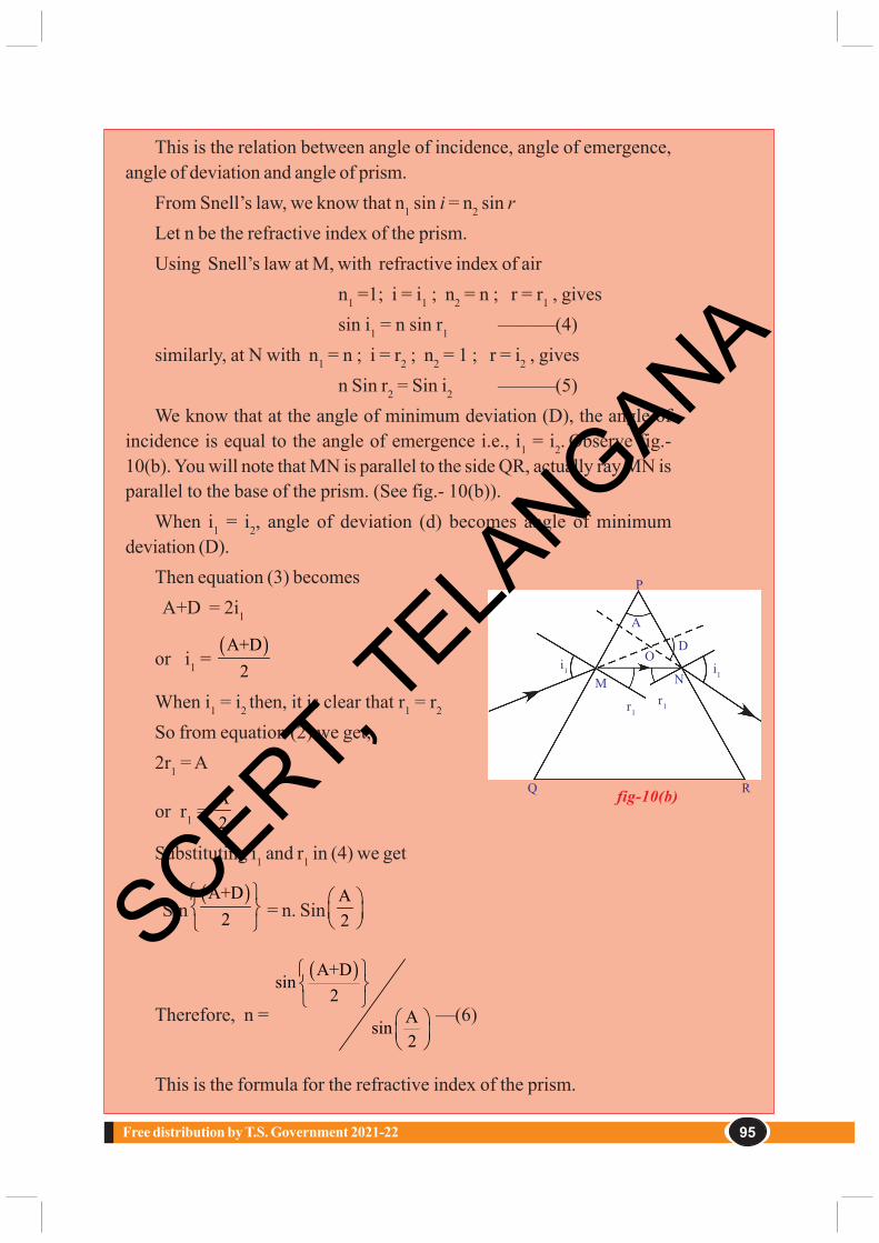
95Free distribution by T.S. Government 2021-22
This is the relation between angle of incidence, angle of emergence,angle of deviation and angle of prism.
From Snell’s law, we know that n1 sin i = n2 sin rLet n be the refractive index of the prism.Using Snell’s law at M, with refractive index of air
n1 =1; i = i1 ; n2 = n ; r = r1 , givessin i1 = n sin r1 ———(4)
similarly, at N with n1 = n ; i = r2 ; n2 = 1 ; r = i2 , givesn Sin r2 = Sin i2 ———(5)
We know that at the angle of minimum deviation (D), the angle ofincidence is equal to the angle of emergence i.e., i1 = i2. Observe fig.-10(b). You will note that MN is parallel to the side QR, actually ray MN isparallel to the base of the prism. (See fig.- 10(b)).
When i1 = i2, angle of deviation (d) becomes angle of minimumdeviation (D).
Then equation (3) becomes A+D = 2i1
or i1 = ( )A+D
2
When i1 = i2 then, it is clear that r1 = r2
So from equation (2) we get,2r1 = A
or r1 = A2
Substituting i1 and r1 in (4) we get
Sin( )A+D
2
= n. SinA2
Therefore, n =
( )A+Dsin
2Asin2
—(6)
This is the formula for the refractive index of the prism.
fig-10(b) R
P
i1 i1M N
DO
Q
r1r1
A
SCERT, TELA
NGANA

Human Eye and Colourful World96 X Class
Example 2A prism with an angle A = 600 produces an angle of minimum deviation
of 300. Find the refractive index of material of the prism.Solution: Given that A = 600 and D = 300.
Using n =
( )A+Dsin
2Asin2
= 90°sin2
sin 30
°
= sin 45sin 30
°° =
12
12
= 2
n = 2thus, the refractive index of the given prism = 2
Let us take up a simple activity with prism.
Activity 3Do this activity in the dark room. Take a prism and place it on the table
near a vertical white wall. Take a thin wooden plank. Make a small hole init and fix it vertically on the table. Place the prism between the woodenplank and wall. Place a white light source behind the hole of the woodenplank. Switch on the light. The rays coming out of the hole of plank becomea narrow beam of light. Adjust the height of the prism such that the lightfalls on one of the lateral surfaces. Observe the changes in emerged raysof the prism. Adjust the prism by slightly rotating it till you get an imageon the wall.
• What do you observe on the wall?
• Could you get a coloured image on the wall?
• Why does white light split into colours?
• What colours do you see?
• Can you notice any change in the angle of deviation of each colour?
• Which colour has the minimum deviation?
SCERT, TELA
NGANA

97Free distribution by T.S. Government 2021-22
Let us do another activity.
Activity 4Take a metal tray and fill it with water. Place a
mirror in the water such that it makes an angle to thewater surface. Now focus white light on the mirrorthrough the water as shown in fig.- 11. Try to obtaincolours on a white card board sheet kept above the watersurface. Note the names of the colours you could seein your book.
In activity (3) and (4), we observe that white light is splitting intocertain different colours.• Is this splitting of white light into colours explained by using ray
theory?It is not possible to explain the splitting of white light into different
colours using ray theory.• Why is this so?
Let us see
Dispersion of LightIn activity 3, we observe that the angle of
deviation is minimum for red as compared to theangles of deviation of other colours andmaximum for violet.
The splitting of white light into differentcolours (VIBGYOR) is called dispersion.
In our previous discussion, we learnt that for a particular refractiveindex of prism there must be only one angle of minimum deviation andaccording to Fermat’s principle, light ray always chooses the path of leasttime. But in activity-3,we noticed that light has choosen different paths.• Does this mean that the refractive index of the prism varies from colour
to colour?• Is the speed of light of each colour different?
The situation we witnessed in activities (3) and (4) rule out ray theoryof light. We can consider that white light is a collection of waves withdifferent wavelengths. Violet colour is known to have the shortestwavelength while red is of the longest wavelength.
fig-11Metaltray
Water
Whitelight
Mirror
Dispersed light
fig-12
RedOrangeYellowGreenBlueIndigoViolet
SCERT, TELA
NGANA

Human Eye and Colourful World98 X Class
According to wave theory, light can be thought of a wave propagatingin all directions. Light is an electromagnetic wave. Here no particlephysically oscillates back and forth. Instead, the magnitude of electric andmagnetic fields, associated with the electromagnetic wave, varyperiodically at every point. These oscillating electric and magnetic fieldspropagate in all directions with the speed of light.• Can you guess now, why light splits into different colours when it
passes through a prism?The reason lies in the fact that, while the speed of light is constant in
vacuum for all colours, it depends on the wavelength of light when it passesthrough a medium. We know that refractive index is the ratio of speeds invacuum and in the medium. Consequently, the refractive index of a mediumdepends on wavelength of light. When white light passes through a medium,each colour selects its least time path and we have refraction of differentcolours to different extents. This results in separation of colours, producinga spectrum on the wall and in the mirror as we saw in activities (3) and (4).It has been experimentally found that refractive index decreases with anincrease in wavelength. If we compare the wave lengths of seven coloursin VIBGYOR, red colour has longest wavelength and violet colour hasshortest wavelength. The refractive index of red is low hence it sufferslow deviation.
We noticed that when white light passes through a prism, it splits intoseven colours. Let us assume that you have sent a single colour ray throughthe prism.• Does it split into more colours? Why?
We know that the frequency of light is the property of the source andit is equal to number of waves leaving the source per second. This cannotbe changed by any medium. Hence frequency doesn’t change due torefraction. Thus coloured light passing through any transparent mediumretains its colour.
While refraction occurs at the interface, the number of waves that areincident on the interface in a second must be equal to the number of wavespassing through any point taken in another medium. This means that thefrequency of the light wave remains unaltered while its wavelength changesdepending on the medium through which it passes. We know that the relationbetween the speed of wave (v), wavelength ( λ) and frequency (υ) is.
v = υ λ (frequency denoted by υ)
SCERT, TELA
NGANA

99Free distribution by T.S. Government 2021-22
For refraction at any interface, v is proportional to λ. Speed of thewave increases with increase in wavelength of light and vice versa.• Can you give an example in nature, where you observe colours as seen
in activity 3?Your answer certainly is a rainbow. That is a good example of dispersion
of light.• When do you see a rainbow in the sky?• Can we create a rainbow artificially?
Let us see how.
Activity 5Select a white coloured wall on which the sun rays fall. Stand in front
of a wall in such a way that the sun rays fall on your back. Hold a tubethrough which water is flowing. Place your finger in the tube to obstructthe flow of water. Water comes out through the small gaps between thetube and your finger like a fountain. Observe the changes on the wall whilethe water shower is maintained; you can see colours on the wall.• How is that you are able to see colours on the
wall?• Are the sun rays coming back to your eyes from
the wall or from water drops?Let us find out.The beautiful colours of the rainbow are due
to dispersion of the sunlight by millions of tinywater droplets. Let us consider the case of anindividual water drop.
Observe fig.- 13. The rays of sunlight enter thedrop near its top surface. At this first refraction,the white light is dispersed into its spectrum of colours, violet being deviatedthe most and red the least. Reaching the opposite side of the drop, eachcolour is reflected back into the drop because of total internal reflection.Arriving at the surface of the drop, each colour is again refracted into air.At the second refraction the angle between red and violet rays furtherincreases when compared to the angle between those at first refraction.
The angle between the incoming and outgoing rays can be anythingbetween 00 and about 420. We observe bright rainbow when the anglebetween incoming and outgoing rays is near the maximum angle of 420.Diagrammatically it is shown in fig.- 13.Although each drop disperses a
fig-13
Sun light Water drop
RedViolet
42o
40o
SCERT, TELA
NGANA

Human Eye and Colourful World100 X Class
full spectrum of colours, an observer is in a position to see only a singlecolour from any one drop depending upon its position.
If violet light from a singledrop reaches the eye of anobserver, red light from thesame drop can’t reach his eye.It goes elsewhere possiblydownwards of the eye of theobserver (see in fig.- 14). To seered light, one must look at thedrop higher in the sky. Thecolour red will be seen when theangle between a beam of
sunlight and light sent back by a drop is 420. The colour violet is seenwhen the angle between a sunbeam and light sent back by a drop is 400. Ifyou look at an angle between 400 and 420, you will observe the remainingcolours of VIBGYOR• Why does the light dispersed by the raindrops appear as a bow?
To find answer this question,we need a little geometricreasoning. First of all, a rainbowis not the flat two dimensional arcas it appears to us. The rainbowyou see is actually a threedimensional cone with the tip at
your eye as shown in fig.- 15. All the drops that disperse the light towardsyou lie in the shape of the cone – a cone of different layers. The drops thatdisperse red colour to your eye are on the outer most layer of the cone,similarly the drops that disperse orange colour to your eye are on thelayer of the cone beneath the red colour cone. In this way the coneresponsible for yellow lies beneath orange and so on it till the violet colourcone becomes the innermost cone.(see in fig.- 15).
fig-15
Sun light
Sun42o
40o
fig-14
Sun light Waterdrops
Red
Violet
42o
40o
RedViolet
Think and discuss
• Can you imagine the shape of rainbow when observed during travel in an airplane?Discuss with your friends and collect information.
SCERT, TELA
NGANA

101Free distribution by T.S. Government 2021-22
It is our common experience that the sky appears blue in colour on abright dry day.• Why is the sky blue?
To answer this question, you need to understand another phenomenonof light called scattering.• What is scattering?
Let us see
Scattering of LightScattering of light is a complex phenomenon. Let us try to understand
the idea of scattering.• Do you know what happens to the free atom or molecule when it is
exposed to certain frequency of light?Atoms or molecules which are exposed to light absorb light energy
and emit some part of the light energy in different directions. This is thebasic process happens in scattering of light.
The effect of light on a molecule or an atom depends on the size ofatom or molecule. If the size of the particle (atom or molecule) is small,it will be affected by higher frequency (lower wave length) light and viceversa.
Let us consider that a certain frequency of lightis incident on an atom. Then the atom comes intovibration due to this light. This in turn releases or re-emits light in all directions with different intensity.
The intensity of light is the energy of light passingthrough unit area of plane, taken normal to thedirection of propagation of light, in one second.
Let us consider that the free atom or freemolecule is somewhere in space as shown in fig.- 16.
Light of certain frequency falls on that atom or molecule. This atomor molecule responds to the light whenever the size of the atom or moleculeis comparable to the wave length of light. If this condition is satisfied, theatom absorbs light and vibrates. Due to these vibrations, the atom re-emitsa certain fraction of absorbed energy in all directions with differentintensities. The re-emitted light is called scattered light and the processof re-emission of light in all directions with different intensity is calledscattering of light. The atoms or molecules are called scattering centre.Let us take the angle ‘θ’ between the incident light and a direction in whichthe intensity of scattered light is observed, we call this angle as angle of
fig-16
Sun lightScattered light
Atom
SCERT, TELA
NGANA

Human Eye and Colourful World102 X Class
scattering. It is experimentally observed that the intensity of scatteredlight varies with angle of scattering. The intensity is maximum at 900 angleof scattering.
This is the reason for the appearance of clear blue colour when look atthe sky in a direction perpendicular to the direction of the sun rays. If ourangle of view is changed, the intensity of blue colour also changes.
Now you might have got a doubt why scattering of light gives bluecolour only. Why can’t it give other colours?
Let us find out whether the scattering centres are responsible for theblue colour of the sky?
We know that our atmosphere contains different types of moleculesand atoms. The reason for blue sky is due to the molecules N2 and O2. Thesizes of these molecules are comparable to the wavelength of blue light.These molecules act as scattering centres for scattering of blue light.• Why is that the sky appears white sometimes when you view it in certain
direction on hot days?Our atmosphere contains atoms and molecules of different sizes.
According to their sizes, they are able to scatter different wavelengths oflight. For example, the size of the water molecule is greater than the sizeof the N2 or O2. It acts as a scattering centre for other frequencies whichare lower than the frequency of blue light.
On a hot day, due to rise in the temperature water vapour enters intoatmosphere which leads to abundant presence of water molecules in theatmosphere. These water molecules scatter the colours of otherfrequencies (other than blue). All such colours of other frequencies reachyour eye and the sky appears white.• Can we demonstrate scattering of light by an experiment?
Let us try
Activity 6Take a solution of sodium-thio-sulphate (hypo) and sulphuric acid in a
glass beaker. Place the beaker in an open place where abundant sun light isavailable. Watch the formation of grains of sulphur and observe changesin the beaker.
You will notice that sulphur precipitates as the reaction is in progress.At the beginning, the grains of sulphur are smaller in size and as the reactionprogresses, their size increases due to precipitation.
Sulphur grains appear blue in colour at the beginning and slowly theircolour becomes white as their size increases. The reason for this is
SCERT, TELA
NGANA

103Free distribution by T.S. Government 2021-22
scattering of light. At the beginning, the size of grains is small and almostcomparable to the wave length of blue light. Hence they appear blue in thebeginning. As the size of grains increases, their size becomes comparableto wave lengths of other colours. As a result of this, they act as scatteringcentres for other colours. The combination of all these colours appears aswhite.• Do you know the reasons for appearance the red colour of sun during
sunrise and at sunset?The atmosphere contains free molecules and atoms with different sizes.
These molecules and atoms scatter light of different wavelengths whichare comparable to their size. Molecules having a size that is comparable tothe wavelength of red light are less in the atmosphere. Hence scattering ofred light is less when compared to the other colours of light. The lightfrom the sun needs to travel more distance in atmosphere during sunriseand sunset to reach your eye. In morning and evening times, during sunriseand sunset, except red light all colours scatter more and vanish beforethey reach you. Since scattering of redlight is very small, it reaches you.As a result sun appears red in colour during sunrise and sunset.• Can you guess the reason why sun does not appear red during noon
hours?During noon hours, the distance to be travelled by the sun rays in the
atmosphere is less than that compared to morning and evening hours.Therefore all colours reach your eye without much scattering. Hence thesun appears white during noon hours.
So far, we have learned some ideas of the light such as refraction,dispersion and scattering. These are wonderful phenomena occuring in oursurroundings. When you observe any phenomena, try to resolve the problemand appreciate the wonderful world based on the behaviour of light.
Do you know?
Sir CV Raman
Our beloved scientist and Noble prize winner, Sir C.V.Raman explained the phenomenon of light scattering in gasesand liquids. He found experimentally that the frequency ofscattered light by the liquids is greater than the frequency ofincident light. This is called Raman Effect. By using this effectscientists determine the shapes of the molecules.SCERT, T
ELANGANA

Human Eye and Colourful World104 X Class
• The least distance of distinct vision is about 25cm and the angle of vision is about 600.• The ability of eye lens to change its focal length is called accommodation of lens.• The defect in which people cannot see objects beyond far point is called Myopia.• The defect in which people cannot see objects situated before near point is called
Hypermetropia.• Presbyopia is a vision defect indicating that the power of accommodation of the eye usually
decreases with ageing.• The reciprocal of focal length is called power of the lens.• The refractive index of prism is given by
n = Sin[(A+D)/2]/Sin(A/2)where A is angle of prism and D is angle of minimum deviation.
• The splitting of white light into colours (VIBGYOR) depending on the wave lengths is calleddispersion.
• The process of re-emission of absorbed light in all directions with different intensities by atomsor molecules, is called scattering of light.
Reflections on Concepts1. How do you correct the eye defect Myopia? (AS1)2. Explain the correction of the eye defect Hypermetropia.
(AS1)3. How do you find experimentally the refractive index of material of a prism? (AS3)4. Explain the formation of rainbow. (AS1)5. Explain two activities for the formation of artificial rainbow. (AS3)6. Light of wavelength λ1 enters a medium with refractive index n2 from a medium with refractive
index n1. What is the wave length of light in second medium? (AS 1)7. Why does the sky sometimes appear white? (AS 7)8. A person is viewing an extended object. If a converging lens is placed in front of his eye, will
he feel that the size of object has increased? Why? (AS7)
Improve your learning
What we have learnt
Key wordsLeast distance of distinct vision, Angle of vision, Accommodation of eye lens,
Myopia, Hypermetropia, Presbyopia, Power of lens, Prism, Angle of prism orrefracting angle of prism, Angle of minimum deviation, Dispersion, Scattering.
SCERT, TELA
NGANA

105Free distribution by T.S. Government 2021-22
Application of Concepts1) Incident ray on one of the face (AB) of a prism and emergent
ray from the face AC are given in figure -1. Complete the raydiagram.(AS 5)
2) Glass is known to be a transparent material. But ground glassis opaque and white in colour.Why? (AS7)
3) A light ray falls on one of the faces of a prism at an angle 40o sothat it suffers angle of minimum deviation of 30o. Find the angleof prism and angle of refraction at the given surface.
(Ans:50o, 25o) (AS7)
4) The focal length of a lens suggested to a person with Hypermetropia is 100cm. Find thedistance of near point and power of the lens. (Ans: 33.33cm, 1D ) (AS 7)
Multiple choice questions
1) The size of an object as perceived by an eye depends primarily on [ ]
A) actual size of the object B) distance of the object from the eye
C) aperture of the pupil D) size if the image formed on the retina
2) When objects at different distances are seen by the eye which of the following remain constant?
A) focal length of eye-lens B) object distance from eye-lens [ ]
C) the radii of curvature of eye-lens D) image distance from eye-lens
3) During refraction, ________ will not change. [ ]
A) Wave length B) frequency C) speed of light D) all the above
4) A ray of light falls on one of the lateral surface of an equilateral glassprism placed on the horizontal surface of a table as shown in fig.2.For minimum deviation of ray, which of the following is true?
[ ]
A) PQ is horizontal B) QR is horizontal
C) RS is horizontal D) either PQ or RS is horizontal
5) Far point of a person is 5m. In order that he has normal vision what kind of spectacles shouldhe use [ ]
A) Concave lense with focal length 5m B) concave lense with focal length 10m
C) Convex lense with focal length 5m D) convex lense with focal length 2.5m
P
Q R
S
fig-2
fig-1
A
B
C
Mirr
or
SCERT, TELA
NGANA

Human Eye and Colourful World106 X Class
6) The process of re-emission of absorbed light in all directions with different intensities by theatom or molecule is called [ ] A) Scattering of light B) dispersion of light C) reflection of light D) refraction of light
Suggested Experiments
1. Conduct an experiment to produce a rainbow in your class room and explain the procedure.(AS3)
2. Conduct an experiment to find the refractive index of a prism.3. Conduct an experiment to demonstrate the scattering of the light
Suggested Projects
1) Prisms are used in binoculars. Collect information why prisms are used in binoculars. (AS4)2) Collect the information about different types of eye defects from your nearest eye specialist or
optical shop and write a report3) Collect the different types of lenses used for correcting the eye defects and write a report.4) Collect the information about the dispersion phenomenon occurs in the daily life.
SCERT, TELA
NGANA

107Free distribution by T.S. Government 2021-22
You have studied in the previous class about sub-atomic particles likenegatively charged electrons, positively charged protons and electricallyneutral neutrons.• How do these sub-atomic particles coexist in an electrically neutral
atom?You have acquired some fundamental ideas about atomic models
suggested by J J Thomson, Ernest Rutherford and Niels Bohr which havebeen presented in Class 9.
Activity 1On the basis of your previous knowledge you prepare a model of an
atom.• Can you arrange the sub-atomic particles in any other way in an atom?
(Take the help of your friends, your teacher and the Internet). Observeyour atomic model and the models of your friends carefully and try toanswer the questions.• Do all atoms have the same sub-atomic particles?• Why is an atom of one element different from the atoms of other
elements?• How are the electrons distributed in of an atom?
To answer the above questions, we need to understand the nature oflight, coloured flames and their characteristics.
Structure of Atom
6Chapter
SCERT, TELA
NGANA

Structure of Atom108 X Class
SpectrumYou must have observed the formation of a rainbow.
There are seven colours namely violet, indigo, blue, green, yellow,orange and red (VIBGYOR) in a rainbow.
You can find the colours spreading continuously and the intensity ofeach colour varies from one point to the other.
Wave nature of light
• When you throw a stone into a still pond, you observe ripples, whichare transmitting the disturbance in the form of waves on the surfaceof water.
• You know that sound waves are produced when something vibrates;like a drum.
• In the same way electromagnetic waves are produced when anelectric charge vibrates (moves back and forth).A vibrating electric charge creates a change in the electric field. The
changing electric field creates a changing magnetic field.
This process continuous, with both the created fields beingperpendicular to each other and at right angles to the direction ofpropagation of the wave.
Visible light is an electromagnetic wave and the speed of light (c) is3 × 108 m s–1.
Characterstics of electromagnetic wave
Electromagnetic energy travelling through a vaccum behaves insome way like ocean waves travelling through water. Like ocean waves,electromagnetic energy is characterized by wavelength (λ), and frequency(υ).
Electric field
Direction of wave
Magnetic field
Wavelength
fig-1: An electromagnetic wave
SCERT, TELA
NGANA

109Free distribution by T.S. Government 2021-22
The wavelength (λ) of the wave is the distance from one wave peak tothe next. The frequency (υ) of a wave is simply the number of wave peaksthat pass by a given point per unit time, expressed in units of reciprocalseconds (1/s or s–1). The relation between these quantities is given by
λ∝ 1/υ or c = υλ
It is a universal relationship and applies to all waves. As the frequencyincreases, the wavelength becomes smaller.
Electromagnetic waves can have a wide variety of frequencies. Theentire range of electromagnetic wave frequencies is known as theelectromagnetic spectrum.
The familiar example of the visible spectrum in nature is the formationof a rainbow.
Each colour in a rainbow is characterized by a specified wavelengthfrom red (higher wavelength) to violet (shorter wavelength). These colours(wavelengths), that the human naked eye is sensitive to, are called visiblelight. The range of wavelengths covering red colour to violet colour iscalled the visible spectrum.
Electromagnetic spectrumElectromagnetic waves can have a wide variety of wavelengths. The
entire range of wavelengths is known as the electromagnetic spectrum.The electromagnetic spectrum consists of a continuous range of
wavelengths of gamma rays at the shorter wavelength to radio waves at thelonger wavelength. But our eyes are sensitive only to visible light.
fig-2: Electromagnetic Spectrum
Cosmicrays γ−rays
x-rays
UV IR
Microwaves
Radio Broadcastband
Ultraviolet (UV)rays Infrared (IR) raysVisible light
10-12 m
Short wavelength Long wavelength
400 nm 500 nm 600 nm 700 nm
10-9 m1 nm
10 -6 m1000 nm
10-3 m1 mm
100 m1 m
103 m1 km
RadarSCERT, TELA
NGANA

Structure of Atom110 X Class
• What happens when you heat an iron rod on a flame?• Do you find any change in colour on heating an iron rod?
When you heat an iron rod, some of the heat energy is emitted aslight. First it turns red (lower energy corresponding to higher wavelength)and as the temperature rises it glows orange, yellow, blue(higher energyand of lower wavelength) or even white (all visible wavelengths) if thetemperature is high enough.• Do you observe any other colour at the same time when one colour is
emitted?When the temperature is high enough, other colours will also be
emitted, but due to higher intensity of one particular emitted colour(e.g., red), others cannot be observed.
Max Planck broke with the ‘continuous energy’ tradition ofelectromagnetic energy by assuming that the energy is always emitted inmultiples of hυ;
For example: hυ, 2 hυ, 3 hυ... nhυThat is, the energy for a certain frequency E can be represented by the
equation E = hυ, where ‘h’ is Planck’s constant which has the value6.626 X 10-34Js and ‘υ’ is the frequency of the radiation absorbed oremitted.
The energy (E) for the red colour (higher wavelength or lowerfrequency) is lower compared to the energy of blue colour (lowerwavelength or higher frequency). The energy emitted from a material bodyincreases with increase in heat energy.
The significance of Planck’s proposal is that, electromagnetic energycan be gained or lost in discrete values and not in a continuous manner.
Hence, emission or absorption of light spectrum is a collection of agroup of wavelengths.• Do you enjoy Deepavali fireworks?
Variety of colours is seen from fireworks.• How do these colours come from fireworks?
Activity 2Take a pinch of cupric chloride in a watch glass and make a paste with
concentrated hydrochloric acid. Take this paste on a platinum loop andintroduce it into a non-luminous flame.• What colour do you observe?
Carry out similar activity with strontium chloride.
SCERT, TELA
NGANA

111Free distribution by T.S. Government 2021-22
Cupric chloride produces a green colourflame while strontium chloride produces acrimson red flame.• Do you observe yellow light in street lamps?
Sodium vapours produce yellow light in streetlamps.• Why do different elements emit different flame
colours when heated by the same non-luminous flame?Scientists found that each element emits its
own characteristic colour. These colourscorrespond to certain discrete wavelengths of lightand are called line spectra.
The lines in atomic spectra can be used toidentify unknown atoms, just like fingerprints areused to identify people.
Bohr’s model of hydrogen atom and itslimitations• What does a line spectrum tell us about the
structure of an atom?Niels Bohr proposed that
electrons in an atom occupy‘stationary’ orbits (states) of fixedenergy at different distances fromthe nucleus.
When an electron ‘jumps’ froma lower energy state (ground state)to higher energy states (excitedstate) it absorbs energy or emits energy when such a jump occurs from ahigher energy state to a lower energy state.
The energies of an electron in an atom can have only certain valuesE1, E2, E3 ……; that is, the energy is quantized. The states correspondingto these energies are called stationary states and the possible values ofthe energy are called energy levels.• The lowest energy state of the electron is known as ground state.• What happens when an electron gains energy?
The electron moves to a higher energy level i.e. to the excited state.
Niels Henrik DavidBohr was a Danish physicist
who made foundationalcontributions to
understanding atomicstructure and quantum theory,
for which he receivedthe Nobel Prize in Physics in
1922. Bohr was alsoa philosopher and a promoter.
fig-3: Hydrogen Spectrum
SCERT, TELA
NGANA

Structure of Atom112 X Class
• Does the electron retain the energy forever?The electron loses the energy and comes back to its ground state. The
energy emitted by the electron is seen in the form of electromagneticenergy and when the wavelength is in the visible region it is visible as anemission line.
Bohr’s model explains all the line spectra observed in the case ofhydrogen atom. It is a successful model as far as line spectra of hydrogenatom is concerned.
But the line spectrum of hydrogen atom when observed through a highresolution spectroscope appears as groups of finer lines.• Did Bohr’s model account for the splitting of line spectra of a hydrogen
atom into finer lines?Bohr’s model failed to account for splitting of line spectra.
Bohr-Sommerfeld model of an atom
In an attempt to account for the structure (splitting) of line spectraknown as fine spectra, Sommerfeld modified Bohr’s atomic model byadding elliptical orbits. While retaining the first of Bohr’s circular orbitas such, he added one elliptical orbit to Bohr’s second orbit, two ellipticalorbits to Bohr’s third orbit, etc., such that the nucleus of the atom is oneof the principal foci of these elliptical orbits. He was guided by the factthat, in general, periodic motion under the influence of a central forcewill lead to elliptical orbits with the force situated at one of the foci.
Bohr-Sommerfeld model, though successful in accounting for the fineline structure of hydrogen atomic spectra, does not provide a satisfactorypicture of the structure of atom in general.
This model failed to account for the atomic spectra of atoms of morethan one electron.• Why is the electron in an atom restricted to revolve around the nucleus
at certain fixed distances?
fig-4: The allowed electronic orbits for the main Quantum numbers by Bohr - Sommerfeld model
l=0 l=1
l=0
l=2l=1
l=0
l=3l=2
l=1
l=0
n=1 n=2 n=3 n=4
SCERT, TELA
NGANA

113Free distribution by T.S. Government 2021-22
Quantum mechanical model of an atom• Do the electrons follow defined paths around the nucleus?
If the electron revolves around the nucleus in defined paths or orbits,the exact position of the electron at various times will be known. For thatwe have to answer two questions:• What is the velocity of the electron?• Is it possible to find the exact position of the electron?
Electrons are invisible to naked eye. Then, how do you find the positionand velocity of an electron?
To find articles during dark nights we take the help of torchlight.Similarly, we can take the help of suitable light to find the position andvelocity of electron. As the electrons are very small, light of very shortwavelength is required for this task.
This short wavelength light interacts with the electron and disturbs themotion of the electron. Hence, simultaneously the position and velocityof electron cannot be measured accurately.
From the above discussion, it is clear that electrons do not followdefinite paths in an atom.
Do atoms have a definite boundary, as suggested by Bohr’s model?If the electrons are not distributed in orbits around the nucleus this
means that an atom does not have a definite boundary.As a result, it is not possible to pinpoint an electron in an atom.Under these circumstances in order to understand the properties of
electrons in an atom, a quantum mechanical model of atom was developedby Erwin Schrodinger.
According to this model of an atom, instead of orbits of Bohr’s model,the electrons are thought to exist in a particular region of space around thenucleus at a given instant of time• What do we call the region of space where the electron might be, at a
given time?The region of space around the nucleus where the probability of
finding the electron is maximum is called an orbital.
Max Karl Ernst Ludwig Planck wasa German theoretical physicist who originated quantumtheory, which won him the Nobel Prize in Physics in 1918.Planck made many contributions to theoretical physics, buthis fame rests primarily on his role as originator of thequantum theory. This theory revolutionized humanunderstanding of atomic and subatomic processes.
SCERT, TELA
NGANA

Structure of Atom114 X Class
In a given space around the nucleus, only certain orbitals can exist.Each orbital of a stable energy state for the electron is described by aparticular set of quantum numbers.
Quantum numbersEach electron in an atom is described by a set of three numbers n, l,
and ml .These numbers are called quantum numbers. These numbersindicate the probability of finding the electron in the space around thenucleus.• What information do the quantum numbers provide?
The quantum numbers describe the space around the nucleus wherethe electrons are found and also their energies. These are called atomicorbitals.• What does each quantum number signify?1. Principal Quantum Number (n)
The principal quantum number is related to the size and energy of themain shell.
‘n’ has positive integer values of 1, 2, 3,…As ‘n’ increases, the shells become larger and the electrons in those
shells are farther from the nucleus.An increase in ‘n’ also means higher energy. n = 1, 2, 3, ... are often
represented by the letters K, L, M… For each ‘n’ value there is one mainshell.
Shell K L M N n 1 2 3 4
2. The angular - momentum quantum number (l)‘l’ has integer values from 0 to n-1 for each value of ‘n’. Each ‘l’ value
represents one sub-shell.Each value of ‘l’ is related to the shape of a particular sub-shell in the
space around the nucleus.The value of ‘l’ for a particular sub-shell is generally designated by the
letters s, p, d . . . as follows:
l 0 1 2 3Name of the sub-shell s p d f
When n = 1, there is only one sub-shell with l = 0. This is designatedas ‘1s’ orbital.
When n = 2, there are two sub-shells, with l = 0, the ‘2s’ sub-shelland with l = 1, the ‘2p’ sub-shell.
SCERT, TELA
NGANA

115Free distribution by T.S. Government 2021-22
• What is the maximum value of ‘l’ for n=4?• How many values can ‘l’ have for n = 4?3. The magnetic quantum number (ml)
The magnetic quantum number (ml) has integer values between -l andl, including zero. Thus for a certain value of l, there are (2l +1) integervalues of ml as follows:
-l, (-l+1) . . ., –1, 0, 1, . . . (+l - 1), +lThese values describe the orientation of the orbital in space relative to
the other orbitals in the atom.When l = 0, (2l+ 1) = 1 and there is only one value of ml, thus we have
only one orbital i.e., 1s.When l= 1, (2l+ 1) = 3, that means ml has three values, namely, -1, 0,
and 1 or three p orbitals, with different orientations along x, y, z axes.These are labelled as px, py, and pz.• Do these three p-orbitals have the same
energy?The number of ‘ml’ values indicates the number
of orbitals in a sub-shell with a particular l value.Orbitals in the sub-shell belonging to the sameshell possess same energy. These are calleddegenerated orbitals.
Fill the table-1 with the number of degeneratedorbitals per sub-shell using (2l+1) rule. s-orbitalis spherical in shape, p-orbital is dumbell-shaped and d-orbital are doubledumbell-shaped as shown below.
fig-5: Shapes of orbitals in s, p and d subshells
Table-1l Sub- Number of
shell degeneratedorbitals
0 s1 p2 d3 f
SCERT, TELA
NGANA

Structure of Atom116 X Class
The following table-2 represents the shells, sub-shells and the numberof orbitals in the sub-shells.
Table-2
Each sub-shell holds amaximum of twice as manyelectrons as the number oforbitals in the sub-shell.
The maximum number ofelectrons that can occupyvarious sub-shells is given in thefollowing table.
4. Spin Quantum Number (ms)The three quantum numbers n, l, and ml describe the size (energy),
shape, and orientation, respectively, of an atomic orbital in space.As you have observed in the case of street lights (sodium vapour lamp),
yellow light is emitted. This yellow light is comprised of a very closelyspaced doublet when analyzed using high resolution spectroscope.
Alkali and alkaline earth metals show such type of lines.To account for such a behavior of electron an additional quantum
number is introduced. This is spin quantum number. This represents theproperty of the electron. It is denoted by ‘ms’.
Table-3Sub shells Number of Maximum
orbitals (2l+1) number ofelectrons
s (1=0) 1 2p (1=1) 3 6d (1=2) 5 10f (l=3) 7 14
n l ml sub-shell notation No of orbitalsin the subshell
1 0 0 1s 1
20 0 2s 1
1 -1,0,+1 2p 3
0 0 3s 1
3 1 -1,0,+1 3p 3
2 -2,-1,0,+1,+2 3d 5
0 0 4s 1
41 -1,0,+1 4p 3
2 -2,-1,0,+1,+2 4d 5
3 -3,-2,-1,0,+1,+2,+3 4f 7
SCERT, TELA
NGANA

117Free distribution by T.S. Government 2021-22
This quantum number refers to the two possible orientations of thespin of an electron, one clockwise and the other anticlockwise spin. Theseare represented by + ½ and -½. If both are positive values, then the spinsare parallel otherwise the spins are anti-parallel.
The importance of the spin quantum number is seen when electronsoccupy specific orbitals in multi-electron atoms.• How do electrons in an atom occupy shells, sub-shells and orbitals?
The distribution of electrons in shells, sub-shells and orbital in anatom is known as electronic configuration.
Electronic ConfigurationLet us first consider the hydrogen atom for understanding the
arrangement of electrons, as it contains only one electron.The shorthand notation consists of the principal energy level (n value),
the letter representing sub-level (l value), and the number of electrons (x)in the sub-shell is written as a superscript as shown below:
nl x
For the hydrogen (H) atom having atomic number (Z) = 1, the numberof electrons is one, then the electronic configuration is 1s1.
The electron configuration can also be represented by showing thespin of the electron.
For the electron in H, as you have seen, the set of quantum numbers is:n = 1, l = 0, ml = 0, ms = ½ or – ½.
For many-electron atoms, we must know the electron configurationof the atom. The distribution of electrons in various atomic orbitalsprovides an understanding of the electronic behavior of the atom and, inturn, its reactivity. Let us consider the helium (He) atom.• Helium (Z=2) atom has two electrons.• How are these two electrons arranged?
To describe the electronic configuration for more than one electronin the atom, we need to know three principles:Those are the Pauli Exclusion Principle, Aufbau principle and Hund’s Rule.
Let us discuss them briefly.
Denotes the principlequantum number
Denotes the number ofelectrons in orbital
Denotes the angular momentumquantum number
1s1
SCERT, TELA
NGANA

Structure of Atom118 X Class
The Pauli Exclusion PrincipleHelium atom has two electrons. The first electron occupies ‘1s’ orbital.
The second electron joins the first in the 1s-orbital, so the electronconfiguration of the ground state of ‘He’ is 1s2.• Then the question is: What are the spins of these two electrons?
According to Pauli Exclusion Principle no two electrons of the sameatom can have all four quantum numbers the same.
If n, l, and ml are same for two electrons then ms must be different. Inthe helium atom the spins must be paired.
Electrons with paired spins are denoted by ‘ ’. One electron has
ms= 1 ,2
+ the other has ms= 1
.2
− They have anti-parallel spins.
• How many electrons can occupy an orbital?The major consequence of the exclusion principle involves orbital
occupancy. Since only two values of ms are allowed, an orbital can holdonly two electrons and they must have opposite spins.
Hence, the electronic configuration of helium atom is:
1s2
Aufbau PrincipleAs we pass from one element to another one of next higher atomic
number, one electron is added every time to the atom.The maximum number of electrons in any shell is ‘2n2’, where ‘n’ is
the principal quantum number.The maximum number of electrons in a sub-shell (s, p, d or f) is equal
to 2(2l+1) where l = 0, 1, 2, 3… Thus these sub-shells can have a maximumof 2, 6, 10, and 14 electrons respectively.
In the ground state the electronic configuration can be built up byplacing electrons in the lowest available orbitals until the total number ofelectrons added is equal to the atomic number. This is called the Aufbauprinciple (The German word “Aufbau” means “building up.”).Thus orbitalsare filled in the order of increasing energy.
Two general rules help us to predict electronic configurations.1. Electrons are assigned to orbitals in order of increasing value of (n+l).2. For sub-shells with the same value of (n+l), electrons are assigned
first to the sub-shell with lower ‘n’.
SCERT, TELA
NGANA

119Free distribution by T.S. Government 2021-22
The following diagram shows the increasingvalue of (n+l). Ascending order of energies ofvarious atomic orbitals is given below.
1s < 2s < 2p < 3s < 3p < 4s < 3d < 4p < 5s <4d < 5p < 6s < 4f < 5d < 6p < 7s < 5f < 6d < 7p <8s …
The electronic configuration of some elementsin the increasing atomic number (Z) value is givenbelow.
fig-6: The filling order ofatomic orbitals(Moeller Chart)
• For carbon (C) atom (Z=6), where does the 6th electron go?• Whether the electron pairs up in the same p-orbital or will it go to the
next p-orbital?Hund’s Rule
According to this rule electron pairing in orbitals starts only when allavailable empty orbitals of the same energy (degenerate orbitals) aresingly occupied.
The configuration of Carbon (C) atom (Z=6) is 1s22s22p2. The firstfour electrons go into the 1s and 2s orbitals. The next two electrons gointo separate 2p orbitals, with both electrons having the same spin
Note that the unpaired electrons in the 2p orbitals are shown withparallel spins.
H(Z=1) 1s1
He(Z=2) 1s2
Li(Z=3) 1s22s1
Be(Z=4) 1s22s2
B(Z=5) 1s22s22p1
SCERT, TELA
NGANA

Structure of Atom120 X Class
Activity 3Complete the electronic configuration of the following elements.
Table.4
Element Atomic number (Z) Electronic configuration of elementsC 6N 7O 8F 9Ne 10Na 11Mg 12Al 13Si 14P 15S 16Cl 17Ar 18K 19Ca 20
Key words
Wave, spectrum, intensity, discrete energy, line spectrum, orbital, quantum numbers,shell, sub-shell, shapes of orbitals electron spin, electronic configuration, the Pauli’s
exclusion principle, Aufbau principle, Hund’s rule.
What we have learnt
• Light can be characterized by its wavelength (λ) and frequency (υ), and these quantities arerelated to the speed of light (c) as: c = υλ.
• Spectrum is a group of wavelengths.• Electromagnetic energy (Light) can have only certain discrete energy values which is given by
the equation E=hυ• Electrons in an atom can gain energy by absorbing a particular frequency of light and can lose
energy by emitting a particular frequency.
SCERT, TELA
NGANA

121Free distribution by T.S. Government 2021-22
Improve your learning
• Bohr’s model of atom: Electrons are present in stationary states. The electron moves to higherenergy level if it absorbs energy in the form of electromagnetic energy or moves to a lowerenergy state by emitting energy in the form of electromagnetic energy of appropriate frequency.
• Atomic line spectra arise because of absorption /emission of certain frequencies of light energy.• It is not possible to measure accurately the position and velocity of an electron simultaneously.• The space around the nucleus where the probability of finding the electron is maximum is called
orbital.• The three quantum numbers n, l, ml describe the energy, shape and orientation respectively, of
an atomic orbital.• Spin is an intrinsic property of an electron.• The arrangement of electrons in shells, sub-shells and orbitals in an atom is called the electron
configuration.• According to Pauli Exclusion Principle no two electrons of the same atom can have all the four
quantum numbers same.• Aufbau principle: The lowest-energy orbitals are filled first.• Hund’s rule: The orbitals of equal energy (degenerate) are occupied with one electron each
before pairing of electrons starts.
Reflections of concepts
1. What information does the electronic configuration of an atomprovide? (AS1)
2. Rainbow is an example for continuous spectrum – explain. (AS1)3. How orbital is different from Bohr’s orbit?(AS1)4. Explain the significance of three Quantum numbers in predicting the positions of an electron
in an atom.(AS1)5. How we are using the nl x method in writing electronic configuration? (AS1)6. Which electronic shell is a higher energy level K or L? (AS2)
Application of concepts1. Answer the following questions.
a. How many maximum number of electrons can be accommodated in a principal energy level?b. How many maximum number of electrons can be accommodated in a sub shell?c. How many maximum number of electrons can be accommodated in an orbital?d. How many sub shells are present in a principal energy level?e. How many spin orientations are possible for an electron in an orbital? (AS1)
SCERT, TELA
NGANA

Structure of Atom122 X Class
2. In an atom the number electrons in M-shell is equal to the number of electrons in the K andL Shell. Answer the following questions. (AS4)
a. Which is the outer most shell?b. How many electrons are there in its outermost shell?c. What is the atomic number of element?d. Write the electronic configuration of the element.
3. Following orbital diagram shows the electron configuration of nitrogen atom. Which ruledoes not support this? N (Z = 7) (AS1)
4. Write the four quantum numbers for the differentiating electron of sodium (Na) atom? (AS1)5. (i) An electron in an atom has the following set of four quantum numbers to which orbital
does it belong
(ii) Write the four quantum numbers for 1s1 electron.(AS4)
6. The wave length of a radio wave is 1.0m. Find its frequency.(AS7)
Multiple choice questions
1) An emission spectrum consists of bright spectral lines on a dark back ground. Which one ofthe following does not correspond to the bright spectral lines? [ ]A) Frequency of emitted radiation B) Wave length of emitted radiationC) Energy of emitted radiations D) Velocity of light
2) The maximum number of electrons that can be accommodated in the L – shell of an atom isA) 2 B) 4 C) 8 D) 16 [ ]
3) If l = 1 for an atom then the number of orbitals in its sub-shell is [ ]A) 1 B) 2 C) 3 D) 0
4) The quantum number which explains about size and energy of the orbit or shell is: [ ]A) n B) l C) ml D) ms
Suggested Projects
1. Collect the information of historical development of the atomic theory.2. Collect the information about the scientists who developed the atomic theories.3. Make the s,p and d orbital models.4. Collect the information regarding wave lengths and corresponding frequencies of three primary
colours red, blue and green.
1s2 2s2 2p3
n l ml ms
2 0 0 + ½
SCERT, TELA
NGANA

123Free distribution by T.S. Government 2021-22
A medical shop contains a vast number of medicines. The shop keeperfinds it difficult to remember all the names of medicines that he has. Whenyou go to a medical shop and ask the shopkeeper for a particular medicine,he hands over it to you without any difficulty. How is it?
Think of a super bazaar. When you step in to it you see a particulararrangement of goods inside it. When you look for needed grocery, youcan select it easily.
From the above observations you understand that for any systeminvolving several things, a particular order of arrangement of those thingsis essential.
Even in chemistry, from the earliest times, scientists have been tryingto classify the available elements in to a limited number of groups on thebasis of their properties.
Need for the arrangement of elements in an organised mannerRobert Boyle (1661) defined an element as any substance that cannot
be decomposed into a further simple substance by a physical or chemicalchange.
At his time, about thirteen elements were known.Towards the end of the eighteenth century, by the time of Lavoisier
another eleven elements were discovered. By 1865 about sixty threeelements were known and by 1940, a total of ninety one elements fromnatural sources and another seventeen elements synthetically wereobtained.
Classification of Elements-The Periodic Table
7Chapter
SCERT, TELA
NGANA

Classification of Elements - The Periodic Table124 X Class
By now, including synthetic elements, there are more than 118elements. As the number of elements increased, it became difficult tokeep in memory the chemistries of individual elements and theircompounds.
In previous classes we had learnt the classifications of elements inmetals and non-metals. For example sodium, potasium, etc. are metalsand sulphur, chlorine are non-metals. But this classification had so manylimitations Aluminium has some metallic properties and some non-metallicproperties. Elements of this type are considered as metalloides or semimetals. So, there was a need to classify them in still better ways. Hence,chemists started to frame ways to group the elements and compounds onthe basis of their physical and chemical properties.
In the beginning of the 18th century Joseph Louis Proust stated thathydrogen atom is the building material and atoms of all other elementsare simply due to the combination of number of hydrogen atoms. (It is tobe noted that at his time the atomic weights of all elements were given aswhole numbers and the atomic weight of hydrogen was taken as one.)Dobereiner’s law of Triads
A German chemist Johann Wolfgang Döbereiner (1829) noted thatthere were groups of elements with three elements known as triads ineach group with similar chemical properties. He tried to give a relationshipbetween the properties of elements and their atomic weights.
Döbereiner stated that when elements with similar properties are takenthree at a time and arranged in the ascending order of their atomic weights,the atomic weight of the middle element is the average of the atomicweights of the first and third elements. This statement is called theDobereiner’s law of triads.
Activity 1Observe the following table.Elements in each row represent a triad.
Group Elements and their Atomic weights Arithmetic mean of Atomic weight
A Lithium (Li) Sodium (Na) Potassium (K)7.0 23.0 39.0
B Calcium (Ca) Strontium(Sr) Barium (Ba)40.0 88 137.0
C Chlorine (Cl) Bromine (Br) Iodine (I)35.5 80.0 127.0
D Sulphur (S) Selenium (Se) Tellurium (Te)32.0 78.0 125.0
E Manganese(Mn) Chromium(Cr) Iron (Fe)55.0 52.0 56.0
7.0 + 39.0 ––––––––– = 23.0 2
SCERT, TELA
NGANA

125Free distribution by T.S. Government 2021-22
In the first row you will find that atomic weight of sodium(Na) is equal to the average of atomic weights of Li and K.• Can you establish the same relationship with the set of
elements given in the remaining rows?• Find average atomic weights of the first and third elements
in each row and compare it with the atomic weight of themiddle element.
• What do you observe?Döbereiner’s attempts gave a clue that atomic weights could
be correlated with properties of elements. It made chemists lookat elements in terms of groups of elements with similar chemical andphysical properties. This eventually led to rigorous classificationof elements and to develop modern periodic table of elements.
Limitations i. All the known elements at that time could not be arranged in the form of triads.ii. The law failed for very low mass or for very high mass elements.
In case of F, Cl, Br, the atomic weight of Cl is not an arithmetic meanof atomic weights of F and Br.
iii. As the techniques improved for measuring atomic masses accurately,the law was unable to remain strictly valid.
Newlands’ law of OctavesJohn Newlands was a British chemist. Newlands (1865) found
that when elements were arranged in the ascending order of theiratomic weights they appeared to fall into seven groups. Eachgroup contained elements with similar chemical properties.Based on these observations, Newlands proposed the law ofoctaves.
The law of octaves states that when elements are arranged inthe ascending order of their atomic weights they fall into a patternin which their properties repeat at regular intervals. Every eighth
Think and discuss
• What relation about elements did Döbereiner want to establish?• The densities of calcium (Ca) and barium (Ba) are 1.55 and 3.51 gcm-3
respectively. Based on Dobereiner’s law of triads can you give theapproximate density of strontium (Sr)?
Döbereiner
Newlands
SCERT, TELA
NGANA

Classification of Elements - The Periodic Table126 X Class
H 1
Li 2
G 3
Bo 4
C 5
N 6
O 7
F 8
Na 9
Mg 10
Al 11
Si 12
P 13
S 14
Cl 15
K 16
Ca 17
Cr 19
Ti 18
Mn 20
Fe 21
Co&Ni 22
Cu 23
Zn 24
Y 25
In 26
As 27
Se 28
Br 29
Rb 30
Sr 31
Ce&La 33
Zr 32
Di&Mo34
Ro&Ru 35
Pd 36
Ag 37
Cd 38
U 40
Sn 39
Sb 41
Te 43
I 42
Cs 44
Ba&V 45
Ta 46
W 47
Nb 48
Au 49
Pt&Ir 50
Os 51
Hg 52
Tl 53
Pb 54
Bi 55
Th 56
element starting from a given element resembles in its properties to thatof the given element. Elements with similar chemical properties are to bepresent along a horizontal row.
Table 1: Newlands’ table of elements (1866).
Newlands was the first to assign numbers to the elements.Unfortunately his work was neither accepted by his seniors nor by theJournal of the Chemical Society, which rejected its publication.
In Newlands’ table of elements, if we start with hydrogen and movedown to oxygen and then start at the top the eighth element from hydrogenis fluorine and next eighth element is chlorine and so on. The propertiesof hydrogen, fluorine and chlorine are similar.
Similarly, if you start at lithium, then eighth element is sodium andnext coming eighth is potassium and so on. These elements show similarphysical and chemical properties for example they are reactive metals.
Newlands’ table is not without problems.• There are instances of two elements fitted into the same slot, e.g.
cobalt and nickel.• Certain elements, totally dissimilar in their properties, were fitted into
the same group.
Element No. Element No. Element No. Element No. Element No. Element No. Element No. Element No.
Think and discuss
• Do you know why Newlands proposed the law of octaves? Explain youranswer in terms of the modern structure of the atom.
• Do you think that Newlands’ law of octaves is correct? JustifySCERT, TELA
NGANA

127Free distribution by T.S. Government 2021-22
For example he arranged Co, Ni, Pd, Pt and Ir which have differentproperties compared with halogens in the same row (F, Cl, Br, I). (seeNewlands’ first horizontal row)
Newlands periodic table was restricted to only 56 elements and didnot leave any room for new elements. Elements that were discovered latercould not be fitted into Newlands table in accordance with their properties.
Newlands attempted to link the periodicity of the chemical propertiesof elements with the periodicity found in the music. In musical scale anynote in a key is separated from its octave by an interval of seven notes.This must have made him to force to arrange all the elements into thisactive pattern sometimes without caring the similarities.
Mendeleeff’s Periodic TableMendeleeff arranged the elements known at that time
in a chart in a systematic order in the increasing order oftheir atomic weights refer to table 2 the modifiedMendeleef’s periodic table 2a . He divided the chart into 8vertical columns known as groups. Each group is dividedinto A, B sub groups. Each column contained the elementsof similar chemical properties. It is said that elements in agroup have similar properties and elements along periods(horizontal rows) have different properties.
The elements in the first column, for example, reactwith oxygen to form compounds with the general formulaR2O. For example, Li, Na and K when react with oxygen andform compounds Li2O, Na2O and K2O respectively.
Elements of the second column react with oxygen to form compoundswith the general formula RO. For example, Be, Mg and Ca when react withoxygen form BeO, MgO and CaO.
Mendeleeff tried to explain the similarities of elements in the samegroup in terms of their common valency.
Do you know?
Are you familiar with musical notes?In the Indian system of music, there are seven musical notes in a scale – sa, re
ga, ma, pa, da, ni. In the west, they use the notations - do, re, mi, fa, so, la, ti.Naturally, there must be some repetition of notes. Every eighth note is similar tothe first one and it is the first note of the next scale.
MendeleeffSCERT, TELA
NGANA

Classification of Elements - The Periodic Table128 X Class
The Periodic LawBased on Mendeleeff’s observations regarding the properties of
elements in the periodic table, a law known as the periodic law of theproperties of elements was proposed as follows.
“The law states that the physical and chemical properties of theelements are periodic functions of their atomic weights.”
Table-2(a) : Mendeleeff’s Periodic Table (1871 version)Gruppe I.
–R 2O
Gruppe II.–
R O
Gruppe III.–
R2O3
Gruppe IV.RH4
RO2
Gruppe V.RH3
R2O5
Gruppe VI.RH2
RO3
Gruppe VII.RH
R2O7
Gruppe VIII.–––RO4R
eihe
n
1 H = 1
2 Li=7 Be=9.4 B=11 C=12 N=14 O=16 F=19
3 Na=23 Mg=24 Al=27.3 Si=28 P=31 S=32 Cl=35.5
4 K=39 Ca=40 –=44 Ti=48 V=51 Cr=52 Mn=55 Fo=56, Co=59
Ni=59, Cu=63
5 (Cu=63) Zn=65 –=68 –=72 As=75 So=78 Br=80
6 Rb=85 Sr=87 ?Yt=88 Zr=90 Nb=94 Mo=96 –=100 Ru=104, Rh=104
Pd=106, Ag=108
7 (Ag=108) Cd=112 In=113 Sn=118 Sb=122 Te=125 I=127
8 Cs=133 Ba=137 ?Di=138 ?Ce=140 – – – – – – –
9 (–) – – – – – –
1 0 – – ?Ek=178 ?La=180 Ta=182 W=184 – Os=195, Ir=197,
Pt=198, Au=199
11 (Au=198) Hg=200 Tl=204 Pb=207 Bi=208 – –
12 – – – Th=231 – U=240 – – – – –
Table-2(b) :
SCERT, TELA
NGANA

129Free distribution by T.S. Government 2021-22
Salient features and achievements of the Mendeleeff’s periodictable1. Groups and sub-groups: There are eight vertical columns in
Mendeleeff’s periodic table called groups. They are represented byRoman numerals I to VIII. Elements present in a given vertical column(group) have similar properties. Each group is divided into two sub-groups ‘A’ and ‘B’. The elements within any sub-group resemble oneanother to a greater extent. For example, sub-group IA elements called‘alkali metals’ (Li, Na, K, Rb, Cs) resemble each other very much intheir properties.
2. Periods: The horizontal rows in Mendeleeff’s periodic table are calledperiods. There are seven periods in the table, which are denoted byArabic numerals 1 to 7. Elements in a period differ in their propertiesfrom one another. A period comprises the entire range of elementsafter which properties repeat themselves.
3. Predicting the properties of missing elements: Based on thearrangement of the elements in the table he predicted that someelements were missing and left blank spaces at the appropriate placesin the table.Mendeleeff believed that some new elements would be discovered
definitely. He predicted the properties of these new additional elementsin advance entierly depending on his table. His predicted properties werealmost the same as the observed properties of those elements after theirdiscovery.
He named those predicted elements tentatively by adding the prefix‘eka’ (eka is a Sanskrit word for numeral one) to the name of the elementimmediately above each empty space. The predicted properties of elementsnamely eka-boron, eka-aluminium and eka-silicon were almost same asthose of scandium, gallium and germanium respectively which werediscovered later.
S.No.
Property Predicted property byMendeleeff
Observed property
Eka-Aluminium (Ea) Eka-Silicon (Es) Gallium (1875) Germanium (1886)
1 Atomic weight 68 72 69.72 72.592 Density 5.9 5..5 5.94 5.473 Formula of oxide Ea2O3 EsO2 Ga2O3 GeO2
4 Formula of chloride EaCl3 EsCl4 GaCl3 GeCl4
Table-3SCERT, TELA
NGANA

Classification of Elements - The Periodic Table130 X Class
Do you know?Do you know what Mendeleeff said about the melting point of eka Al?‘If I hold it in my hand, it will melt’. The melting point of Ga is 30.2oC and our
body temprature 37oC.
4. Correction of atomic weights: The placement of elements inMendeleeff’s periodic table helped in correcting the atomic massesof some elements like, beryllium, indium and gold.
For example, at the time of Mendeleeff, beryllium (Be) was givenatomic weight 13.5.Atomic weight = equivalent weight × valencyThe equivalent weight of Be was found experimentally as 4.5 and itsvalency was thought as 3. Therefore, the atomic weight of berylliumwas given at that time as 4.5 × 3 = 13.5. With this atomic weight it hadto be placed in a wrong group in the table. He said that its valencyshould be only 2. Then its atomic weight would be 4.5 × 2 = 9. Ifatomic weight of ‘Be’ is 9 it would be fit in the second group and itsproperties practically are similar to Mg, Ca etc., of the second groupelements. He also helped in the calculation of the correct atomicweights of ‘Indium’ and ‘Gold’ in this manner.
5. Anomalous series: Some anomalous series of elements like ‘Te’ and‘I’ were observed in the table. The anomalous series contained elementswith more atomic weights like ‘Te’ (127.6 U) placed before theelements with less atomic weights like ‘I’ (126.9 U). Mendeleeffaccepted minor inversions in the order of increasing atomic weightsas these inversions resulted in elements being placed in the correctgroups.It was the extraordinary thinking of Mendeleeff that made the chemists
to accept the periodic table and recognise Mendeleeff more than anyoneelse as the originator of the periodic law.
Do you know?
At the time when Mendeleeff introduced his periodic table even electrons werenot discovered. Even then the periodic table was able to provide a scientific basefor the study of chemistry of elements. In his honour the 101th element was namedMendelevium.
SCERT, TELA
NGANA

131Free distribution by T.S. Government 2021-22
Limitations of Mendeleeff’s periodic table1. Anomalous pair of elements: Certain elements of highest atomic
weights precede those with lower atomic weights.For example, tellurium (atomic weight 127.6) precedes iodine (atomicweight 126.9).
2. Dissimilar elements placed together: elements with dissimilarproperties were placed in same group as sub-group A and sub-group B.For example, alkali metal like Li, Na, K etc., of IA group have littleresemblance with coinage metals like Cu, Ag, Au of IB group.Cl is ofVII A group and ‘Mn’ is of VII B, but chlorine is a non metal, where asmanganese is a metal.
Think and discuss
• All alkali metals are solids but hydrogen is a gas with diatomicmolecules. Do you justify the inclusion of hydrogen in first group withalkali metals?
Think and discuss
• Why Mendeleeff had to leave certain blank spaces in his periodic table?What is your explanation for this?
• What is your understanding about Ea2O3, EsO2?
Modern Periodic TableH.J. Moseley (1913) found that each element emits a
characteristic pattern of X-rays when subjected tobombardment with high energy electrons. By analyzing the X-ray patterns, Moseley was able to calculate the number ofpositive charges in the atoms of respective elements. Thenumber of positive charges (protons) in the atom of an elementis called the atomic number of the element. With this analysisMoseley realised that the atomic number(Z) is morefundamental characteristic of an element than its atomic weight.
After knowing the atomic numbers of elements, it wasrecognized that a better way of arranging the elements in theperiodic table is according to the increasing atomic number.This arrangement eliminated the problem of anomalous series. Forexample, though tellurium (Te) has more atomic weight than iodine (I), it
H.J. Moseley
SCERT, TELA
NGANA

Classification of Elements - The Periodic Table132 X Class
has atomic number less by one unit compared to iodine. This atomicnumber concept forced the periodic law to be changed.
The periodic law is changed from atomic weight concept to atomicnumber concept and now it is called the modern periodic law.
We know that Mendeleeff’s periodic law is stated as “The propertiesof elements are the periodic functions of their atomic weights”. Now, letus try to understand modern periodic law.
The modern periodic law may be stated as “the properties of theelements are periodic functions of their atomic numbers.”
Based on the modern periodic law, the modern periodic table which isgiven here (page 132) is proposed. It is the extension of the originalMendeleeff’s periodic table known as short form of the table and thismodern table is called the long form of the periodic table. It is given infig (2). Atomic number of an element (Z) indicates not only the positivecharges i.e., the protons in the nucleus of the atom of the element but alsothe number of electrons in the neutral atom of that element.
The physical and chemical properties of atoms of the elements dependnot on the number of protons but on the number of electrons and theirarrangements (electronic configurations) in atoms. Therefore, the modernperiodic law may be stated as “The physical and chemical properties ofelements are the periodic functions of the electronic configurations oftheir atoms.”Positions of elements in the Modern Periodic Table
The modern periodic table has eighteen vertical columns known asgroups and seven horizontal rows known as periods.
Let us see what decides the position of an element in modern periodictable.
We can explain the classification of the elements in the modernperiodic table in terms of certain electron arrangements which areperiodically repeated. The elements with similar outer shell (valence shell)electronic configurations in their atoms are in the same column calledgroup. Elements listed in a group down to it are in the order of theirincreasing principal quantum numbers.
In the chapter ‘Structure of atom’ you have learnt that ‘s’ sub-shellwith one orbital contains a maximum of two electrons. Each ‘p’ sub-shellcontains 3 orbitals and accommodates a maximum of six electrons. The‘d’sub-shell contains 5 orbitals and accommodates a maximum of 10 electronsand ‘f’ sub-shell contains 7 orbitals with 14 electrons maximum. Dependingupon to which sub-shell the differentiating electron. i.e., the last comingelectron enters in the atom of the given element, the elements are classifiedas ‘s’ ‘p’, ‘d’ and ‘f’ block elements.
For example, sodium (Na) gets its new coming electron (differentiating
SCERT, TELA
NGANA

133Free distribution by T.S. Government 2021-22
SCERT, TELA
NGANA

Classification of Elements - The Periodic Table134 X Class
electron) into 3s level. Therefore ‘Na’ is an s-block element.Aluminium (Al) gets its differentiating electron into ‘p’ subshell and it isa p-block element. Scandium (Sc) gets its differentiating electron into‘d’ subshell. Therefore it is a d-block element. Cerium (Ce) gets its newcoming electron into ‘f’ subshell, hence,it is an f-block element.
Let us observe the electronic configurations of the following elements.The last coming electron is underlined.
11Na 1s2 2s2 2p6 3s1
13Al 1s2 2s2 2p6 3s2 3p1
21Sc 1s2 2s2 2p6 3s2 3p6 4s2 3d1
58Ce 1s2 2s2 2p6 3s2 3p6 4s2 3d10 4p6 5s2 4d10 5p6 6s2 5d1 4f2
GroupsThe vertical columns in the periodic table are known as groups. There
are eighteen groups in long form of periodic table. They are representedby using Roman numeral I through VIII with letters A and B in traditionalnotation.
According to latest recommendation of the IUPAC, these groups arerepresented by Arabic numerals 1 through 18 with no A and B designations.We use the latest system with the traditional heading following inparenthesis.
Eg: Group 2 (II A); Group 16 (VI A)Group of elements is also called element family or chemical family.For example Group 1 (IA) has from Li to Fr with outer shell electronic
configuration ns1 and is called Alkali metal family.Activity 2
Some main group elements of s-block and p-block have family namesas given in the following table.
Observe the long form of the periodic table and complete the tablewith proper information.
Z Elements n 1 2 3 4 5 6
l 0 0 1 0 1 2 0 1 2 3 0 1 2 3 0Sub 1s 2s 2p 3s 3p 3d 4s 4p 4d 4f 5s 5p 5d 5f 6sShell
11 Na 2 2 6 1
13 Al 2 2 6 2 1
21 Sc 2 2 6 2 6 1 2
58 Ce 2 2 6 2 6 10 2 6 10 1 2 6 1 2
Table-4
SCERT, TELA
NGANA

135Free distribution by T.S. Government 2021-22
PeriodsThe horizontal rows in the periodic table are called periods. There are
seven periods in the modern periodic table. These periods are representedby Arabic numerals 1 to 7.1. The number of main shells present in the atom of particular element
decides to which period it belongs. For example, hydrogen (H) andhelium (He) atoms contain only one main shell (K). Therefore theybelongs to period-1. Similarly, the elements Li, Be, B, C, N, O, F andNe contain two main shells (K and L) in their atoms. Therefore theybelong to period-2.
2. The number of elements in period depend on how electrons are filledinto various shells. Each period starts with a new main shell ‘s’ subshell
GroupNo.
Name of theelement family
Elements
From To
Valenceelectrons
Valenceshell
configurationValency
1 (IA) Alkali metal family Li Fr ns1 1 12 (IIA) Alkali earth metal family13 (IIIA) Boron family14 (IVA) Carbon family15 (VA) Nitrogen family16 (VIA) Oxygen family or
(Chalcogen family)17 (VIIA) Halogen family18 (VIIIA) Noble gas family
Do you know?
• Do you know how the names of certain families of elements are derived?Alkali metal family: aliquili = plant ash, Na, K etc.... were obtained from plantash, group IA elements are called alkali metals family.Chalcogen family: chalcogenous = ore product, as the elements in group16(VIA) form ores with metals. They are called chalcogenous family.Halogen family: halos = sea salt, genus = produced. As most of the elements ingroup 17(VIIA) are obtained from nature as sea salt. They are called as halogenfamily.Noble gases: as the elements of group 18(VIIIA) are chemically least active.They are called as noble gases. There outer shell electronic configurations arebasis for octet rule.
Table-5
SCERT, TELA
NGANA

Classification of Elements - The Periodic Table136 X Class
and ends when the main shell is filled with respect to the ‘s’ and ‘p’subshells (except the first period).The first period starts with K-shell. The first main shell (K) containsonly one sub-shell, the (1s). For this subshell only two types ofelectronic configurations are possible and they are 1s1 (H) and 1s2
(He). Therefore, the first period contains only two elements.3. Second period starts with the 2nd main shell (L). L-shell has two sub-
shells, namely, 2s and 2p. Eight types of configurations are possiblein this shell (L) like 2s1 and 2s2 and 2p1 to 2p6. Hence the secondperiod contains 8 elements Li, Be, B, C, N O, F and Ne in the ordergiven. Thus, the 2nd period consists two s-block elements (Li, Be) andsix p-block elements (B to Ne).
4. Third period starts with third main shell (M). This shell (M) has 3 sub-shells, namely, 3s, 3p and 3d, but while electrons are being filled intothe shell ‘3d’ gets electrons only after ‘4s’ is filled. Therefore, the 3rd
period contains again 8 elements, which includes two s-block elements(Na, Mg) and six p-block elements (Al to Ar).
5. Fourth main shell (N). This shell (N) has four sub-shells namely 4s,4p, 4d and 4f, but while electrons are being filled into the shell,electrons enter the atoms in the order 4s, 3d and 4p. Due to this, thefourth period contains 18 elements which includes two s-block (K,Ca), 10 elements from d block (Sc to Zn) and six elements from p-block (31Ga to 36 Kr). There are altogether eighteen elements in thefourth period.On the same lines, we can explain why there are 18 elements in the
fifth period (37Rb to 54Xe).There are thirty two elements in the Sixth period from 55Cs to 86 Rn
which includes 2 elements from s-block (6s) 14 elements fromf-block (4f) 10 elements from d-block (5d) and 6 elements fromp-block (6p).
‘4f’ elements are called Lanthanoids or lanthanides. Elements from
Do you know?
‘Ide’ means ‘heir’ and it is used generally for a change like Cl to Cl-. ‘Cl’ ischlorine atom and Cl- is chloride ion. ‘Oid’ means ‘the same’.
Some scientists suggest lanthanoids as 57La to 70Yb, some suggest them as58Ce to 71Lu and some take 57La to 71Lu (15 elements). There is another argumentthat even 21Sc and 39Y should be included in lanthanoids. All these suggestions havesubstance because 21Sc, 39Y and 57La to 71Lu all have the similar outer shellsconfigurations.
Also in the case of actinoids. There are different arguments like actinoids arefrom 90Th to 103Lr or 89Ac to 102No or 89Ac to 103Lr.
SCERT, TELA
NGANA

137Free distribution by T.S. Government 2021-22
58Ce to 71Lu possess almost the same properties as 57 La. So, the namelanthanoids is the most appropriate one for these elements.
7th period is incomplete and contains 2 elements from s-block (7s) 14elements from f-block (5f), 10 elements from d-block (6d) and someelements from p-block (7p). The 5f elements are called Actinoids or asActinides. They are from 90Th to 103Lr .
The f-block elements known as lanthanoids and actinoids are shownseparately at the bottom of the periodic table.
Metals and Non metalsYou have learnt about the properties of metals in the chapter Metals
and Non Metals in class VIII. Let us study the metallic properties ofelements in periodic table.
The elements with three or less electrons in the outer shell areconsidered to be metals and those with five or more electrons in the outershell are considered to be non metals. We may find some exceptions tothis. ‘d’ block elements (3rd group to 12th group) are metals and they arealso known as transition metals and the metallic character of d-blockelements decreases gradually from left to right in periodic table.Lanthanoids and actinoids actually belong to 3rd group (III B) which is withinthe transition elements: hence they are called the inner transition elements.
Metalloids or semi-metals are elements which have properties thatare intermediate between the properties of metals and non metals. Theypossess properties like metals but are brittle like non metals. They aregenerally semi conductors. Eg: B, Si, As, Ge.
All elements in s-block are metals, whereas in p-block (except 18th
group) there are metals, non metals and metalloids. In periodic table youwill notice a staircase like demarcation. The elements to the left of thisdemarcation are metals and to the right are non-metals. The elements onstaircase (or) very near to it like B, Si, As, Ge etc., are metalloids.Periodic properties of the elements in the modern table
The modern periodic table is organized on the basis of the electronicconfiguration of the atoms of elements. Physical and chemical propertiesof elements are related to their electronic configurations particularly theouter shell configurations. The atoms of the elements in a group possess
Think and discuss
• Why lanthanoids and actinoids placed separately at the bottom of theperiodic table?
• If they are inserted within the table imagine how the table would be?
SCERT, TELA
NGANA

Classification of Elements - The Periodic Table138 X Class
similar electronic configurations. Therefore, we expect all the elementsin a group should have similar chemical properties and there should be aregular gradation in their physical properties from top to bottom.
Similarly, across the table, i.e., from left to right in any period elementsget an increase in the atomic number by one unit between any two successiveelements. Therefore, the electronic configuration of valence shell of anytwo elements in a given period is not same. Due to this reason elementsalong a period possess different chemical properties with regular gradationin their physical properties from left to right. To understand this we willtake some properties of elements and discuss how they vary in groups andin periods.Properties of elements and their trends in Groups and in Periods
1. Valence: Valence (or) valency of an element was defined as thecombining power of an element with respect to hydrogen, oxygen orindirectly any other element through hydrogen and oxygen.
Valence of an element with respect to hydrogen is the number ofhydrogen atoms with which one atom of that element chemically combines.Valence of an element with respect to oxygen is twice the number ofoxygen atoms with which one atom of that element combines. Note thatthe group number of an element gives the maximum valence of that elementas per old notation that is I to VIII groups but it is 18-group number as perIUPAC numbering.
For example one atom of ‘Na’ chemically combines with one atom of‘H’ to give NaH. Therefore, the valence of Na is 1. One atom of ‘Ca’combines with one atom of ‘O’ to give CaO. So the valency of Ca is 2.
In general, the valence of an element with respect to hydrogen is itstraditional group number. If the element is in the group V or above, itsvalence is 8– group number. For example, chlorine valence is 8-7 = 1.
In general, each period starts with valency 1 for 1st group elements,increases upto 4 with respect to the group number and then decreasesfrom 4 to 3 to 2 to 1 to zero in the following groups (this is applicableonly for main group elements i.e., ‘s’ and ‘p’ block elements with respectto hydrogen.
Now a days the valence of an elment is generally taken as the numberof valence shell (outer most shell) electrons in its atom. Oxidation numberconcept almost is the latest subsititute to the valence concept in the modernliterature.
Activity 3• Find out the valencies of first 20 elements.• How does the valency vary in a period on going from left to right?• How does the valency vary on going down a group?Atomic radius
Atomic radius of an element may be defined as the distance from thecentre of the nucleus of the atom to its outermost shell.
SCERT, TELA
NGANA

139Free distribution by T.S. Government 2021-22
Atomic radius of an element is not possible to measure in its isolatedstate. This is because it is not possible to determine the location of theelectron that surrounds the nucleus. However, we can measure the distancebetween the nuclei of adjacent atoms in a solid. From this we can estimatethe size of the atom by assigning half of this distance to the radius of eachatom. This method is best suited to elements such as the metals that existin the solid state. More than 75 percent of the elements are metals andatomic radii of metals are called metallic radii. Another way of estimatingthe size of an atom is to measure the distance between the two atoms incovalent molecules. The size of a chlorine atom is estimated by measuringthe length of the covalent bond between two chlorine atoms in a Cl2
molecule. Half of this distance is taken as atomic radius which is calledas the covalent radius of chlorine atom.
Atomic radius is measured in ‘pm’ (pico meter) units.
1 pm = 10-12m
Variation of atomic radii in groupAtomic radii increase from top to bottom in a group (column) of the
periodic table. As we go down in a group, the atomic number of the elementincreases. Therefore to accommodate more number of electrons, moreshells are required. As a result the number of shells in a group from top tobottom increases. The distance between the nucleus and the outer shell ofthe atom increases. Hence the atomic size increases with atomic numberwhen we go down the group.
Variation of atomic radii in periodAtomic radii of elements decrease across a period from left to right.
As we go to right, electrons enter into the same main shell or even innershell in case of ‘d’ block and ‘f’ block elements. Therefore, there shouldbe no change in distance between nucleus and outer shell but nuclear chargeincreases because of the increase in the atomic number of elements inperiod. Hence, the nuclear attraction on the outer shell electrons increases.As a result the size of the atom decreases.
Group Element (atomic radius in pm)
Group1: Li (152), Na (186), K (231), Rb (244) and Cs (262)Group 17: F (64), Cl (99), Br (114), I (133) and At (140)
Table-6
SCERT, TELA
NGANA

Classification of Elements - The Periodic Table140 X Class
• Do the atom of an element and its ion have same size?Let us consider the following situation.Assume that sodium (Na) atom has lost an electron and formed a cation
of sodium (Na+).Which one between Na and Na+ would have more size? Why?Atomic number of sodium (Na) is 11. Therefore sodium (Na) atom
contains 11 protons and 11 electrons with outer electron as 3s1. On theother hand Na+ ion has 11 protons but only 10 electrons. The 3s shell ofNa+ level has no electron in it. Hence its outer shell configuration is2s2 2p6. As proton number is more than electrons in it, the nucleus of Na+
ion attracts outer shell electrons with strong nuclear force. As a result theNa+ ion shrinks in size. Therefore, the size of Na+ ion is less than ‘Na’atom. In general the positive ion (cation) of an element has less size thanits neutral atom Eg. Na (157pm) Na+ (98pm); K (203pm) K+(133pm); Mg(136pm) Mg2+(65pm); Al (125pm) Al3+(50pm) for neutral atoms covalentradiai are give.
Consider another example: Assume that chlorine (Cl) atom hasgained an electron to form anion of chlorine (Cl –) i.e. chloride ion.• Which one, between Cl and Cl – would have more size? Why?
Electronic configuration of chlorine (Cl) atom is 1s2 2s2 2p6 3s2 3p5
and the electronic configuration of chloride (Cl –) ion is 1s2 2s2 2p6
3s2 3p6. Both chlorine and chloride ion have 17 protons each but there are17 electrons in chlorine atom, where as 18 electrons in chloride ion.Therefore, the nuclear attraction is less in Cl – ion when compared withchlorine atom. Therefore the size of the chlorine (Cl) atom is less sizethan Cl- ion. In general negative ion (anion) of an element has bigger sizethan its neutral atom.
Chloride ion of Cl (99pm) Cl – (181pm); F (64pm) F– (133pm); O(73pm) O2- (140pm); N (75pm) N3- (171pm);• Which one in each of the following pairs is larger in size?
(a) Na, Al (b) Na, Mg+2 (c) S2-, Cl – (d) Fe2+, Fe3+ (e) C4-, F –
Period Element (atomic radius in pm)
2nd period Li (152), Be (111), B (88), C (77), N (74), O (66), F (64)
3rd period Na (186), Mg (160), Al (143), Si (117), P(110), S(104), Cl(99)
Table-7
SCERT, TELA
NGANA

141Free distribution by T.S. Government 2021-22
Ionization EnergyThe energy required to remove an electron from the outer most orbit
or shell of a neutral gaseous atom is called ionization energy. The energyrequired to remove the first electron from the outer most orbit or shell ofa neutral gaseous atom of the element is called its first ionization energy.The energy required to remove an electron from uni- positive ion of theelement is called the 2nd ionization energy of that element and so on.
M(g) + IE1 M+(g) + e- (IE1= first ionization energy)
M+(g) + IE2 M+2
(g) + e- (IE2= second ionization energy)
Ionization energy of an element depends on its1. Nuclear charge: more the nuclear charge more is the ionization
energy.eg:Between 11Na and 17Cl, Chlorine atom has more ionization energy.2. Screening effect or sheilding effect: more the shells with
electrons between the nucleus and the valence shell, they act as screensand decrease nuclear attraction over valence electrons. This is called thescreening effect. More the screening effect, less is the ionization energy.Between 3Li and 55Cs, the element 55Cs with more inner shells has lessionization energy.
3. Penetration power of the orbitals: orbitals belonging to the samemain shell have different piercing power towards the nucleus, for examle4s>4p>4d>4f in the penetration. There fore, it is easier to remove 4felectron than 4s. Between 4Be 1s2 2s2 and 5B 1s2 2s2 2p1, the element B hasless ionization energy due to less penetration power of ‘2p’ compared to‘2s’
4. Stable configuration: it is easier to remove one electron from 8O(1s22s22p4) than 7N (1s22s22p3). This is because, 7N has stable half filledconfiguration.
5. Atomic radius: more the atomic radius, less is the ionization energy.
Think and discuss
• Second ionization energy of an element is higher than its first ionizationenergy. why?
SCERT, TELA
NGANA

Classification of Elements - The Periodic Table142 X Class
Therefore, ionization energy of ‘F’ is greater than that of ‘I’ and theionization energy of ‘Na’ is more than that of ‘Cs’.
Ionization energy decreases as we go down in a group and generallyincreases from left to right in a period.
Ionization energy is expressed in kJ mol-1
Ionization energy is also called the ionization potential but when we usethe term the ionization potential, it is better to write the unit eV atom–1.
Electron affinity - Electron gain enthalpyAtoms of some elements gain electrons while forming ionic
compounds. An atom is able to gain an electron only when the electronoutside the atom is attracted by its nucleus. Attraction involves theliberation of energy.
Ionisation Energy Values are given in the following table in KJ/mol.
H He1312.1 2372.3
Li Be B C N O F Ne520.2 899.5 800.6 1086.5 1402.3 1313.9 1681 2080.7
Na Mg Al Si P S Cl Ar495.9 737.7 577.5 786.5 1011.8 999.6 1251.5 1520.6
K Ca Ga Ge As Se Br Kr418.8 589.8 578.8 762 947 940.9 1139.9 1350.8
Rb Sr In Sn Sb Te I Xe403.0 549.5 558.2 708.4 834 869.3 1008.4 1170.4
IONIZATION POTENTIAL VALUES
Element Ist 2nd 3rd 4th 5th 6th
H 1312.1He 2372.3 5220Li 520.2 7300 11750Be 899.5 1760 14850 20900B 800.6 2420 3660 25020 32600C 1086.5 2390 4620 6220 37820 46990Al 577.5 1810 2750 11580 14820 18360Ga 578.8 1980 2970 6170 8680 71390SCERT, T
ELANGANA

143Free distribution by T.S. Government 2021-22
ElectronegativityThe ionization energy and the electron gain enthalpy are properties of
isolated atoms of elements. There has been a need to have a comparative
Think and discuss
• The calculated electron gain enthalpy values for alkaline earth metals andnoble gases are positive. How can you explain this?
• The second period element for example ‘F’ has less electron gain enthalpythan the third period element of the same group for example ‘Cl’. Why?
The electron affinity of an element is defined as the energy liberatedwhen an electron is added to its neutral gaseous atom. Electron affinity ofan element is also called electron gain enthalpy of that element.
M(g) + e- M-(g) + E1 (M = Element, E1 = First electron affinity)
M-(g) + e- M-2
(g) + E2 (E2 = Second electron affinity).The energy liberated when an electron is added to a uni-negative ion of
the element is called the 2nd electron affinity of that element. However,practically no element shows liberation of energy when the 2nd electron isadded to its uni-negative ion. It does not mean that di-negative or tri-negative ions do not form. They do form, but for adding 2nd electron, energyin another way like bond formation must be given.
Electron gain enthalpy values decrease as we go down in a group, butincrease along a period from left to right. Metals have very low electrongain enthalpy values and alkaline earth metals have even positive values.Note that the negative sign for energy value in table indicates that energyis liberated or lost, and the positive sign tells that the energy is gained orabsorbed. All the factors which influence the ionization energy would alsoinfluence the electron gain enthalpy.
Groups Electron affinity value (in kJ mol-1)
VIIA (halogens) F(-328); Cl(-349); Br (-325); I(-295) At(-270)
VIA (chalcogens) O(-141); S(-200); Ge(-195) Te(-190) PO (-174)
Table-8
SCERT, TELA
NGANA

Classification of Elements - The Periodic Table144 X Class
scale relating to the abilities of elements to attract electrons when theiratoms are combined. For this purpose, the concept of electronegativity isintroduced.
The electronegativity of an element is defined as the relative tendencyof its atom to attract electrons towards it self when it is bonded to theatom of another element.
All the factors that influence the ionization energy and the electronaffinity of elements influence the electronegativity values of thoseelements. Because of this, Mulliken proposed that the electronegativityof an element is the average value of its ionization energy and electronaffinity.
Electronegativity = ionization energy + electron affinity 2
Pauling assigned the electronegativity values for elements on the basisof their bond energies. He assumed that the electronegativity of hydrogenis 2.20 and calculated the values of other elements with respect tohydrogen. Observe the values in the following example
Electronegativity values of elements decrease as we go down in a groupand increase along a period from left to right. The most electronegativeelement is ‘F’ and the least electronegative stable element is ‘Cs’.
Metallic and Non-Metallic PropertiesMetals generally show less electronegative character. In compounds,
they generally show a tendency to remain as positive ions. This propertyis often termed as electropositive character. Metals are electropositiveelements.
Non metals are generally more electronegative due to their smalleratomic radii.
Let us examine the elements of 3rd period.
3rd period: Na Mg Al Si P S Cl
We know that Na and Mg are metals, Al and Si are semi metals(metalloids), P, S and Cl are non metals. So we find metals on left side and
Halogens: F(4.0), Cl(3.0), Br(2.8), I(2.5)2nd period: Li(1.0), Be(1.47), B(2.0), C(2.5), N(3.0), O(3.5), F(4.0), Ne(-)
Period/group Element (electronegativity with respect to hydrogen)
Table-9
SCERT, TELA
NGANA

145Free distribution by T.S. Government 2021-22
non metals on right side of the periodic table. This means metallic characterdecreases while non metallic character increases as we move along a period(from left to right).
Let us take group 14 (IVA) elements.IVA group: C Si Ge Sn PbHere also we know that carbon is nonmetal. Si and Ge are metalloids.
Sn and Pb are metals.So we find nonmetals particularly at the right hand side top and metals
at the left and right hand side bottom of the periodic table. This meansmetallic character increases while non metallic character decreases in agroup as we move from top to bottom.
Key wordsTriad, Octave, Periodic Law, Periodic table, period, group, Lanthanides,
Actinides, Element family, Metalloids, Periodicity, Atomic radius, Ionizationenergy, Electron affinity, Electronegativity, Electropositivity
What we have learnt
• Elements are classified on the basis of similarities in their properties.
• Dobereiner grouped the elements into Triads and Newlands gave the law of Octaves.
• Mendeleeff’s Periodic law: The physical and chemical Properties of the elements are the periodicfunctions of their Atomic Masses.
• Moseley’s Periodic law : The physical and chemical properties of the elements are the periodicfunctions of their Atomic numbers.
• Modern Periodic Law: The Physical and chemical Properties of the elements are the periodicfunctions of their Electronic Configurations.
• Anomalies in arrangement of elements based on increasing atomic mass could be removedwhen the elements were arranged in order of increasing atomic number, a fundamental propertyof the element discovered by Moseley.
• Elements in the Modern Periodic table are arranged in 18 groups and 7 periods.
• Elements are classified into s, p, d, f blocks, depending upon to which sub shell, the differentiatingelectron enters in the atom of the given element.
SCERT, TELA
NGANA

Classification of Elements - The Periodic Table146 X Class
Improve your learning
Periodic property Trend in
groups (From top to bottom) periods (From left to right)
increases fromValency Same for all elements 1 to 4 and decreases to 0Atomic radius Increasing DecreasingIonisation energy Decreasing Generally IncreasingElectron affinity Decreasing IncreasingElectronegativity Decreasing IncreasingElectropositivity Increasing DecreasingMetallic nature Increasing DecreasingNon-Metallic nature Decreasing Increasing
Reflections on Concepts1. What are the limitations of Mendeleeff’s periodic table?
How could the modern periodic table overcome thelimitations of Mendeleeff’s table? (AS1)
2. Define the modern periodic Law. Discuss the construction of the long form of the periodictable. (AS1)
3. Explain how the elements are classified into s, p, d and f- block elements in the periodic tableand give the advantages of this kind of classification. (AS1)
4. Write down the characteristics of the element having atomic number 17. (AS1)
Electronic configuration ____________________________________
Period number ____________________________________
Group number ____________________________________
Element family ____________________________________
No. of valence electrons ___________________________________
Valency ____________________________________Metal or non-metal ____________________________________
• All the d- block elements (except Zn group) are known as transition elements and all the f-blockelements (both Lanthanides, Actinides) are known as inner transition elements.
• Periodic properties of elements and their trends in groups and in periods
SCERT, TELA
NGANA

147Free distribution by T.S. Government 2021-22
Periodnumber
Filling up orbital’s(sub shells)
Maximum number ofelectrons, filled in all
the sub shells
Total no. ofelements in the
period
1234 4s, 3d, 4p 18 18567 7s, 5f, 6d, 7p 32 incomplete
Periodnumber
Total no. ofelements
Elements Total no. of elements in
From To s-block p-block d-block f-block1234567
5.Complete the following table using the periodic table. (AS1)
6. Complete the following table using the periodic table. (AS1)
Application of concepts1. Given below is the electronic configuration of elements A, B, C, D. (AS1)
A.1s2 2s2 1. Which are the elements coming within the same periodB.1s2 2s2 2p6 3s2 2. Which are the ones coming within the same group?C.1s2 2s2 2p6 3s2 3p3 3. Which are the noble gas elements?D.1s2 2s2 2p6 4. To which group and period does the element ‘C ‘belong
2. s - block and p - block elements (except 18th group elements) are sometimes called as‘Representative elements’ based on their abundant availability in the nature. Is it justified?Why? (AS1)
3. The electronic configuration of the elements X, Y and Z are given below?a) X = 2 b) Y = 2, 6 c) Z = 2, 8, 2
i) Which element belongs to second period?ii) Which element belongs to second group?iii) Which element belongs to 18th group?
SCERT, TELA
NGANA

Classification of Elements - The Periodic Table148 X Class
Element Valence electrons Group number Period number
SulphurOxygenMagnesiumHydrogenFluorineAluminium
4. a. State the number of valence electrons, the group number and the period number of eachelement given in the following table: (AS1)
b. State whether the following elements belong to a Group (G), Period (P) or NeitherGroup nor Period indicating the letters G or P or N. (AS1)
5. Identify the element that has the larger atomic radius in each pair of the following and markit with a symbol (✓). (AS1)(i) Mg , Ca (ii) Li , Cs (iii) N , P (iv) B , Al
6. Identify the element that has the lower Ionization energy in each pair of the following andmark it with a symbol (✓). (AS1)(i) Mg , Na (ii) Li , O (iii) Br , F (iv) K , Br
7. How does metallic property change when we move i. Down in a group ii. Across a period?8. On the basis of atomic numbers predict to which block the elements with atomic number
9,37, 46 and 64 belongs to? (AS2)9. Using the periodic table, predict the formula of compound formed between an element X of
group 13 an another element Y of group 16. (AS2)10. An element has atomic number 19. Where would you expect this element be in the periodic
table and why? (AS2)
Elements Group / Period / Neigther group nor periodLi,C,OMg, Ca, BaBr, Cl, FC,S, BrAl, Si, ClLi, Na, kC,N,OK, Ca, Br.
SCERT, TELA
NGANA

149Free distribution by T.S. Government 2021-22
Higher Order Thinking Questions1. How does the positions of elements in the periodic table help you to predict its chemical
properties? Explain with an example. (AS7)2. In period 2, element X is to the right of element Y. Then, find which of the elements have
these properties:i) Low nuclear charge (ii) Low atomic size (iii) High ionization energy(iv)High electro negativity (v) More metallic character (AS1)
1. Number of elements present in period – 2 of the long form of periodic table [ ]a) 2 b) 8 c) 18 d) 32
2. Nitrogen (Z = 7) is the element of group VA of the periodic table. Which of the following is theatomic number of the next element in the same group? [ ]a) 9 b) 14 c) 15 d) 17
3. Electron configuration of an atom is 2, 8, 7. To which of the following elements would it bechemically similar? [ ]a) nitrogen(Z=7) b) fluorine(Z=9) c) phosphorous(Z=15) d) argon(Z=18)
4. Which of the following is the most active metal? [ ]a) lithium b) sodium c) potassium d) rubidium
Suggested Experiments
1. Aluminium does not react with water at room temperature but reacts with both dil. HCland NaOH solutions. Verify these statements experimentally. Write your observationswith chemical equations. From these observations, can we conclude that Al is a metalloid?
Suggested Projects
1. Collect the information about reactivity of VIII A group elements (noble gases) from yourschool library and prepare a report on their special character when compared to otherelements of periodic table.
2. Collect information regarding metallic character of elements of IA group and prepare reportto support the idea of metallic character increases in a group as we move from top tobottom.
Multiple choice questions
SCERT, TELA
NGANA

Chemical Bonding150 X Class
You have learnt about electron configuration of elements and periodictable in previous lessons. It was learnt that there are over 118 elements.• How do they usually exist?• Do they exist as a single atom or as a group of atoms?
In Class IX, we saw that several elements like oxygen, nitrogen andhydrogen exist as diatomic molecules. What is the force that is holdingthese constituent atoms together in molecules?• Are there elements which exist as atoms?• Why do some elements exist as molecules and some as atoms?
In lower classes you have also learnt about the different laws ofchemical combinations. Since the formation of chemical compounds takesplace as a result of combination of atoms of various elements in differentways, it raises many questions.• Why do some elements and compounds react vigorously while others
are inert?• Why the chemical formula for water is H2O and for sodium chloride
NaCl, why not HO2 and NaCl2?• Why do some atoms combine while others do not?
We will try to answer such questions in this chapter.• Are elements and compounds simply made up of separate atoms
individually arranged?• Is there any attraction between atoms?
Let us take the example of common salt, NaCl. When you shake saltfrom a shaker does it separate into sodium and chlorine? No! This showsthat the sodium and chlorine atoms are being held together.• What is that holding them together?
Chemical Bonding
8Chapter
SCERT, TELA
NGANA

151Free distribution by T.S. Government 2021-22
By the late 19th century and early twentieth century, scientists knewabout three types of forces – gravitational, magnetic and electrostatic.They also knew about the existence of electrons and protons. So it wasbelieved that electrostatic forces were the cause of attraction betweenatoms in a molecule. When two atoms come sufficiently close together,the electrons of each atom experience the attractive force of the nucleusof the other atom. But the electrons which are negatively charged and repeleach other, and the positively charged nuclei also repel each other. Thestrength of attraction or repulsion will decide bond formation. If attractionis more than the repulsion then atoms combine. If repulsion is more thanattraction then the atoms do not combine. The nucleus and the electronsin the inner shell remain unaffected when atoms come close together. Butthe electrons in the outermost shell (valence shell) of atoms get affected.
It was seen that the metal part of the compoundmigrated towards the negative electrode and thenon-metal part towards the positive electrode. Soit was proposed that metals are responsible forpositively charged particles and non-metals areresponsible for negatively charged particles. Theoppositely charged particles are held together byelectrostatic forces in a compound. Do you agree with this explanation? Why?While this explanation could explain bonding in NaCl, KCl etc. it could not explainbonding in carbon compounds or diatomic molecules of elements.
A Votaic pile
Davy’s experiment –Humphry Davy (1778-1819),
a professor of chemistry at theRoyal Institution in London,constructed a battery of over 250metallic plates. In 1807, usingelectricity from this battery, hewas able to extract highly reactivemetals like potassium and sodiumby electrolysis of fused salts.
Experimental set up by Davy
Do you know?
SCERT, TELA
NGANA

Chemical Bonding152 X Class
Electrons in valence shell (valence electrons) are responsible for theformation of bonds between atoms.
In previous lessons you studied about exothermic and endothermicreactions. You also studied about reactivity of elements in periodic table.
Some elements are more reactive and some are less reactive;• Why there is absorption of energy in certain chemical reactions and
release of energy in other reactions?• Where the absorbed energy goes?• Is there any relation to energy and bond formation between atoms?• What could be the reason for the change in reactivity of elements?Lewis symbols (or) Lewis dot structures:
Periodic Classification and arrangement of elements in the periodictable according to the electron configuration gave a new thought aboutchemical bond.
The discovery of noble gases and the understanding of their electronicconfigurations helped us in explaining the formation of chemical bondsamong the atoms of the elements. Noble gases which belong to zero group(18th group or VIII A) are typical gases with almost negligible chemicalactivity when compared to other elements. They undergo few or no chemicalchanges. They are more stable and do not form molecules by allowingtheir atoms to combine among themselves or with the atoms of otherelements.• What could be the reason for this?
Let us investigate.Consult the periodic table given in the previous chapter and observe
the following table:Table-1
Look at the second column and third column. It is clear that all thenoble gases have eight electrons in the outermost shell, exceptHelium (He).
Element Z Electronic configuration Valence elctronsK L M N
Helium (He) 2 2 2Neon (Ne) 10 2 8 8Argon(Ar) 18 2 8 8 8Krypton(Kr) 36 2 8 18 8 8
SCERT, TELA
NGANA

153Free distribution by T.S. Government 2021-22
The arrangement of electrons in different shells of atoms (electronicconfiguration) of 18th group elements is shown in the table-1. The valenceelectrons in the atom of an element is depicted in a short form by Lewissymbol or electron dot structure. We represent the nucleus and inner shellelectrons of the atom by the symbol of the element and electrons in theouter shell by dots or cross marks.
Let us see how? Lewis dot structure of argon and sodium atoms arewritten.
Let us start with argon. Its atom has eight valence electrons.First write the symbol of element argon. ArPlace the valence electrons around the symbol. Put two dots at a time
on each of the four sides of the symbol of the element till all are used up.So, we get,
Similarly, for sodium, the number of valence electrons in sodium isone and the symbol is Na. We can also use cross mark for the electrons.The Lewis structure for sodium atom is therefore:
The Lewis dot structures of the atoms of noble gases are shown below:
Activity 1Write the Lewis structures of the given elements in the table. Also
consult the periodic table and fill in the group number of the element.Table – 2:
: Ar :::
Nax
He
: : Ne :::
: Rn :::
Element Hydrogen Helium Beryllium Boron Carbon Nitrogen oxygen
Group 1numberValence 1electronLewis dot H.structure
: Ar :::
: Xe :::: Kr :::
SCERT, TELA
NGANA

Chemical Bonding154 X Class
Look at the periodic table. Do you see any relation between the numberof valence electrons and group numbers? We find that for groups 1-2 and13 –18, we can use the periodic table to find the number of valenceelectrons. Group1 has one outer electron, group 2 has two, and group 13has three, group 14 has four and so on.• What did you notice in Lewis dot structure of noble gases and
electronic configurations of the atoms of these elements shown intable - 2.It was found that the elements which participate in chemical reactions
get octet or ns2 np6 configuration similar to that of noble gas elements. Itis to be noted that octet rule is still a rule not the law, because there areconsiderable exceptions for this rule.
Electronic theory of valence by Lewis and KosselThere were number of attempts to explain the chemical bond formation
between atoms in terms of electrons but a satisfactory explanation forthis concept was given by Kossel and Lewis in 1916. They gave this conceptindependently. The basis for their theory was valence in terms of electrons.They provided logical explanation of valence on the basis of the lack ofchemical activity of noble gases which led to the proposal of octet rule.
Observe the practical behaviour of atoms of main group elements(Group IA, IIA, IIIA, IVA, VA, VIA, VIIA and zero or VIIIA group elements).When they are allowed to undergo chemical changes, they try to get octetelectronic configuration in the outer shells.
Let us understand this with the following illustrations.Group IA elements (Li to Cs) try to lose one valence shell electron
from their atoms to form corresponding uni-positive ions which get octetin their outer shells.
Example: 11Na 2, 8, 1 ; 11Na+ 2, 8Group IIA elements (Mg to Ba) try to lose two valence electrons from
their atoms during chemical changes and form di– positive ions with theoctet in the outer shells.
Example: 12Mg 2, 8, 2 ; 12Mg2+ 2, 8Group IIIA elements try to lose three valence electrons from their
atoms and form corresponding tri positive ions with octates in the outershells.
SCERT, TELA
NGANA

155Free distribution by T.S. Government 2021-22
Example: 13Al 2, 8, 3 ; 13Al3+ 2, 8Group VIA elements try to gain two electrons into the valence shells
of their atoms during the chemical changes and form corresponding dinegative anions which get octet in their outer shells.
Example: 8O 2, 6 ; 8O2– 2, 8Group VIIA elements try to gain one electron into the valence shells
of their atoms during the chemical changes and form correspondinguni– anions which get octet in their outer shells.
Example: 9F 2, 7 ; 9F– 2, 8
Group VIIIA elements, the noble gases do not try to lose or gainelectrons. Generally, helium and neon do not participate in chemicalchanges. Even other elements of VIIIA do not gain or lose electrons fromtheir atoms when they participate in a very few chemical changes.
Example: 10Ne 2, 8 ; No electron gain or loss from the neonatom.
• What have you observed from the above conclusions about the maingroups?
• Why do atoms of elements try to combine and form molecules?Noble gases of VIII A possess eight electrons in the valence shells of
their atoms. Helium is an exception. Its atom has only two electrons, butits only shell is completely filled. Noble gases with eight electrons in thevalence shell in their atoms are highly stable and rarely participate inchemical changes. Therefore it is concluded that any species (atom orion) with eight electrons in the valence shell is stable.
VA VIA VIIA
N O F
P S Cl
As Se Br
Sb Te I
Bi Po At
IA IIA IIIA
Na Mg Al
K Ca Ga
Rb Sr In
Cs Ba Tl
Fr Ra
VIIIA
Ne
Ar
Kr
Xe
Rn
–3 –2 –1Magicoctet
Lose ElectronsGain Electrons
+1 +2 +3
Non metals Noble gases Metals
Net charge onthe ions }
SCERT, TELA
NGANA

Chemical Bonding156 X Class
• Is it accidental that IA to VIIA main group elements during chemicalreactions get eight electrons in the outermost shells of their ions,similar to noble gas atoms?No. It cannot be simply accidental. Eight electrons in the outermost
shell definitely gives stability to the ion or atom. Based on the aboveobservations a statement known as “ The Octet Rule” is framed.Octet rule:
It may be stated as “The atoms of elements tend to undergo chemicalchanges that help to leave their atoms with eight outer-shell electrons.”
Lewis depicted the atom in terms of a positively charged kernel (Kernelis the nucleus and all other electrons in the atom except the outer mostshell electrons) and the outershell that could accommodate a maximumof eight electrons.
Chemically active elements do not have an octet of electrons in thevalence shell of their atoms. Their reactivity arises from their tendency toachieve the octet, by forming bonds either with atoms of their own type orwith atoms of other elements.
The force of attraction between any two atoms or a group of atomsthat results a stable entity is called a ‘chemical bond’. There are manytypes of chemical bonds, but here we discuss only about ionic bond andcovalent bond.Ionic and Covalent bondsA. Ionic bond
Kossel proposed the ionic bond (electrostatic bond) based on thefollowing facts.i. Ionic bond is formed between atoms of two dissimilar elements due
to transfer of electrons from the atom of one element to the other.ii. There are highly reactive metals like alkali metals (IA) and highly
reactive non-metals like halogens (VIIA) on the left side and right sideof the periodic table respectively.
iii. Noble gases except helium have eight electrons in the valence shellsof their atoms. They are chemically inactive and stable.
iv. To attain eight electrons in the outermost shell similar to noble gasesmetal atoms that have one two or three electrons in the valence shellsgenerally lose those electrons and form stable positive ions calledcations.
SCERT, TELA
NGANA

157Free distribution by T.S. Government 2021-22
Do you know?
The number of electrons gained by a non-metal element for its atom is its valency,which is equal to (8 - its group number).
Ex. The valency of chlorine is (8 – 7) = 1.
Example: 11Na → 2, 8, 1 ; Na+ → 2, 8
12Mg → 2, 8, 2 ; Mg2+ → 2, 8
13Al → 2, 8, 3 ; Al3+ → 2, 8
v. To attain eight electrons in the outermost shell, non-metal atoms thathave 5,6 or 7 valence electrons gain 3,2 or 1 electron respectively andform negative ions known as anions.Example: 15P → 2, 8, 5 ; P3- → 2, 8, 8
16S → 2, 8, 6 ; S2- → 2, 8, 8
17Cl → 2, 8, 7 ; Cl- → 2, 8, 8
Formation of ionic bondThe positive ions (cations) and negative ions (anions) that are formeddue to the transfer of electrons from the metal atoms to the non-metalatoms experience the electrostatic forces and get attracted to formchemical bond. As this bond is between charged particles known asions, it is called ionic bond. Sometimes based on the forces beingelectrostatic, the bond is also called the electrostatic bond. As thevalence concept has been explained in terms of electrons, it is alsocalled the electrovalent bond.Thus, we can define ionic bond as follows:The electrostatic attractive force that keeps cation and anion (which
are formed from metal atoms and non-metal atoms due to transfer ofelectrons) together to form a new electrically neutral compounds is called‘ionic bond’.• Explain the formation of ionic compounds NaCl, MgCl2, Na2O and
AlCl3.
Do you know?
The number of electrons lost from a metal atom is the valence of its elementwhich is equal to its group number.
Ex. Na and Mg have valence 1 and 2 respectively.
SCERT, TELA
NGANA

Chemical Bonding158 X Class
Eg-1. Formation of sodium chloride (NaCl):Sodium chloride is formed from the elements sodium and chlorine. It
can be explained as follows:Na(s) + 1/2 Cl2(g) NaCl(s)
Cation formationWhen sodium (Na) atom loses one electron to get octet electron
configuration it forms a cation (Na+) and gets electron configuration thatof Neon (Ne) atom.
11Na (g) 11Na+ (g) + e-
Electronic Configuration 2, 8, 1 2, 8or [Ne] 3s1 [Ne]
Anion formationChlorine has shortage of one electron to get octet in its valence shell.
So it gains the electron from Na atom to form anion and gets electronconfiguration as that of argon (Ar).
17Cl (g) + e- Cl– (g)
Electronic configuration 2, 8, 7 2, 8, 8 or [Ne] 3s2 3p5 [Ne] 3s2 3p6 or [Ar]
Formation of the compound NaCl from its ions:Transfer of electrons between ‘Na’ and ‘Cl’ atoms, results in the
formation of ‘Na+’ and ‘Cl–’ ions. These oppositely charged ions getattracted towards each other due to electrostatic forces and form thecompound sodium chloride (NaCl).
Na+(g) + Cl–
(g) Na+Cl– (s) or NaClEg-2. Formation of magnesium chloride (MgCl2):
Magnesium chloride is formed from the elements magnesium andchlorine. The bond formation MgCl2 in brief using chemical equation is asfollows:
Mg(s) + Cl2(g) Mg Cl2(s)Cation formation
12Mg (g) 12Mg2+ (g) + 2e–
Electronic configuration 2, 8, 2 2, 8or [Ne] 3s2 [Ne]
Anion formation 2Cl (g) + 2e– 2Cl– (g)
Electronic configuration 2, 8, 7 2, 8, 8or [Ne] 3s2 3p5 [Ne] 3s2 3p6 or [Ar]
SCERT, TELA
NGANA

159Free distribution by T.S. Government 2021-22
The compound MgCl2 formation from its ions:Mg2+ gets ‘Ne’ configuration andEach Cl– gets ‘Ar’ configurationMg2+ (g) + 2Cl–
(g) MgCl2 (s)
One ‘Mg’ atom transfers two electrons one each to two ‘Cl’ atoms andso formed Mg2+ and 2Cl– attract to form MgCl2.Eg-3. Formation of di sodium monoxide(Na2O):
Di sodium monoxide formation can be explained as follows:Cation formation (Na+ formation):
2Na (g) 2Na+ (g) + 2e-
Electronic configuration 2, 8, 1 2, 8or [Ne] 3s1 [Ne]
Anion formation (O2–, the oxide formation): O (g) + 2e- O2- (g)
Electronic configuration 2, 6 2, 8or [He] 2s2 2p4 [He] 2s2 2p6 or [Ne]
The compound Na2O formation from its ions is as shown.2Na+ (g) + O2-
(g) Na2O(s)
Two ‘Na’ atoms transfer one electron each to one oxygen atom toform 2Na+ and O2-
Each Na+ gets ‘Ne’ configuration and O2- gets ‘Ne’ configuration.These ions (2Na+ and O2-) attract to form Na2O.
Eg-4. Formation of aluminium chloride (AlCl3):Aluminium chloride formation can be explained as follows:Formation of aluminium ion (Al3+), the cation:
13Al(g) Al3+ (g) + 3e-
Electronic configuration 2, 8, 3 2, 8or [Ne] 3s23p1 [Ne]
Formation of chloride ion (Cl-), the anion: 3Cl(g) + 3e- 3Cl–
(g)
Electronic configuration 2, 8, 7 2, 8,8or [Ne] 3s2 3p5 [Ne] 3s2 3p6 or [Ar]
Each aluminium atom loses three electrons and three chlorine atomsgain them, one electron each.
SCERT, TELA
NGANA

Chemical Bonding160 X Class
The compound AlCl3 is formed from its component ions by theelectrostatic forces of attractions.
Al3+ (g) + 3Cl–(g) AlCl3 (s)
The arrangement of ions in ionic compounds• How do cations and anions of an ionic compound exist in its solid
state?• Let us explain this with sodium chloride as our example:• Do you think that pairs of Na+ Cl- as units would be present in the solid
crystal?If you think so, it is not correct. Remember that electrostatic forces
are non directional. Therefore, it is not possible for one Na+ to be attractedby one Cl– and vice-versa. Depending upon the size and charge of a particularion, number of oppositely charged ions get attracted by it, but, in a definitenumber. In sodium chloride crystal each Na+ is surrounded by 6 Cl- andeach Cl– by six Na+ ions. Ionic compounds in the crystalline state consistof orderly arranged cations and anions held together by electrostatic forcesof attractions in three dimensions. The crystal structure of sodium chlorideis given below:
NaCl is said to possess face centered cubic lattice crystalstructure (see figure-1).
The number of ions of opposite charge that surround agiven ion of given charge is known as the coordinationnumber of that given ion.
For example, in sodium chloride crystal, thecoordination number of Na+ is 6 and that of Cl- is also 6.Factors affecting the formation of cation and anion:
In previous lesson you have learnt about variation ofmetallic and non metallic character of elements in a group
or period of the periodic table. Recall the facts about metallic and nonmetallic character of elements.
Generally elements of metals have tendency of losing electron to attainthe octet in their valence shell. This property is called as the metalliccharacter or electropositivity. Elements with more electropositivecharacter form cations. Similarly non metals like oxygen (8O), fluorine(9F) and chlorine (17Cl) acquire electron configuration of elements of inertgases by gaining electrons this property is called the non-metalliccharacter or electronegativity of the element. Elements with moreelectronegative character form anions.
fig-1Cl–Na+
SCERT, TELA
NGANA

161Free distribution by T.S. Government 2021-22
• Can you explain the reasons for all these?Ionic bond is formed between atoms of elements with electronegativity
difference equal to or greater than 1.9.In ionic bond formation, you have noticed that atoms either lose
electrons or gain electrons to attain octet in valence shell. i.e., in an ionicbond, transfer of electrons takes place between combining atoms.
The tendency of losing electrons to form cations (or) gaining electronto form anions depends on the following factors:
i. Atomic sizeii. Ionisation potentialiii. Electron affinityiv. ElectronegativityThe atoms of elements with low ionisation energy, low electron affinity
high atomic size and low electronegativity form cations.The atoms of elements with high ionisation potential, high electron
affinity, small atomic size and high electronegativity form anions.
B. Covalent bondG.N. Lewis (1916) proposed that atoms of some elements could
achieve an octet in their valence shells without transfer of electronsbetween them. They can attain octet configuration in their valence shellsby sharing the valence electrons with one or more atoms.
The electrons shared between two atoms belong to both the atoms andthe sharing of electrons between them leads to the formation of a chemicalbond known as covalent bond.
For example, take two fluorine atoms which form a stable molecule.Each fluorine atom contributes one electron for bonding and the electronpair that is formed in this way is mutually shared by both the fluorineatoms. Each atom in the F2 molecule has an octet of valence electrons.SCERT, T
ELANGANA

Chemical Bonding162 X Class
The dots around fluorine atom shows the valence electrons ofrespective atoms.
The chemical bond formed between two atoms by mutual sharing of apair of valence shell electrons so that both of them can attain octet orduplet in their valence shell is called the covalent bond.
The prefix co – is used to indicate when things are equal or joined.(for example, co exist, cooperate etc). Here each atom contributes oneelectron from the valence shell for the bonding. Therefore, the namecovalent is given (equal valence electrons contribution) for this bond.Formation of O2 molecule
The electronic configuration of 8O is 2, 6. Oxygen atom has sixelectrons in its valence shell. It requires two more electrons to get octetin its valence shell. Therefore oxygen atoms come close and each oxygenatom contributes two electrons for bonding. Thus, there exist two covalentbonds between two oxygen atoms in O2 molecule as there are two pairs ofelectrons shared between them.
We can say that a double bond is formed between two oxygen atoms inO2 molecule. Observe the following figures. Both the oxygen atoms haveoctet in the valence shell.
• Can you say what type of bond exists between atoms of nitrogenmolecule?Let us see
Nitrogen (N2) moleculeThe electronic configuration of ‘N’ atom is 2,5 and to have octet in the
valence shell it requires three more electrons. When two nitrogen atomsapproach each other, each atom contributes 3 electrons for bonding. Thereare six electrons shared between two nitrogen atoms in the form of threepairs. Therefore, there is a triple bond between two nitrogen atoms in N2molecule.
SCERT, TELA
NGANA

163Free distribution by T.S. Government 2021-22
Methane (CH4) moleculeIn the formation of methane, CH4 molecule, carbon contributes 4
electrons, (one electron to each hydrogen atom) and 4 hydrogen atomscontribute one electron each. Thus in CH4 molecule, there are four C – Hcovalent bonds as shown below:
Ammonia (NH3) moleculeIn ammonia molecule, three N – H single covalent bonds are present.Electron configuration of 7N is 2, 5 and 1H is 1.Nitrogen atom contributes three electrons for bonding. Three hydrogen
atoms at the same time contribute one electron each for bonding. Sixelectrons form three pairs and each pair is shared between nitrogen andone hydrogen atom as shown below:
SCERT, TELA
NGANA

Chemical Bonding164 X Class
Water (H2O) moleculeIn water molecule (H2O), there are two O – H single covalents bonds.Electron configuration of 8O is 2,6 and 1H is 1.Oxygen atom needs ‘2’ electrons to attain octet in its valence shell.
Therefore it shares ‘2’ electron with two hydrogen atoms to form water(H2O) molecule.
The total number of covalent bonds that an atom of an element formsis called its ‘covalency’.The Bond lengths and Bond energies of covalent bonds
Bond length or bond distance is the equilibrium distance between thenuclei of two atoms which form a covalent bond.
It is generally given in nm (nanometer) or A0 (Angstrom unit).Bond energy or Bond dissociation energy is the energy needed to break
a covalent bond between two atoms of a diatomic covalent compound inits gaseous state.
Draw backs of electronic theory of valence1) When a covalent bond is formed between any two atoms, irrespective
of the nature of the atoms, the bond lengths and bond energies are expectedto be the same. This is because any covalent bond between any two atomsis a result of mere sharing of two identical electrons. But, practically itwas observed that bond lengths and bond energies are not same when theatoms that form the bond are different. (See table - 3)• What do you understand from bond lengths and bond energies?
Do you know?
• An angstrom (A0) is a unit of length equal to 10-10 metre, or 0.1 nanometre, or100 picometre.
• 1 nanometre = 10-9 metre
SCERT, TELA
NGANA

165Free distribution by T.S. Government 2021-22
• Are the values not different for the bonds between different types of atoms?2) The theory could not explain why ClB
eCl in BeCl2 is 1800, FBF in
BF3 is 120o, HCH in CH4 is109028/, HNH in NH3 is107048/ and HOH in H2O is104o31/ etc.
i.e., it fails to explain theshapes of the molecules.Valence shell electronpair repulsion theory
To explain the bondangles in the molecules withthree or more than threeatoms with all atomsattached to a central atomthrough covalent bonds atheory called the valence –shell – electron – pairrepulsion – theory(VSEPRT) was proposed by Sidgwick and Powell (1940). It was furtherimproved by Gillespie and Nyholm (1957).
This theory suggests the following points.1. VSEPRT considers electrons in the valence shells which are in covalent
bonds and in lone pairs as charge clouds that repel one another andstay as far apart as possible. This is the reason why molecules getspecific shapes.
2. If we know the total number of electron pairs in the valence shell ascovalent bonds and lone pairs in the central atom, it will help us topredict the arrangement of those pairs around the nucleus of the centralatom and from that the shape of the molecule.
3. Lone pairs occupy more space around the central atom than bond pairs.Lone pair means unshared electron pair or non-bonding electron pair.These are attracted to only one nucleus where as the bond pair is sharedby two nuclei. Thus, the presence of lone pairs on the central atomcauses slight distortion of the bond angles from the expected regularshape. If the angle between lone pair and bond pair increases at thecentral atom due to more repulsion, the actual bond angles betweenatoms must be decreased.
Bond Bond Bond (dissociation)length (Å0) energy (KJmol-1)
H –H 0.74 436F – F 1.44 159Cl – Cl 1.95 243Br – Br 2.28 193I – I 2.68 151H – F 0.918 570H – Cl 1.27 432H – Br 1.42 366H – I 1.61 298H – O (of H2O) 0.96 460H – N (of NH3) 1.01 390H – C (of CH4) 1.10 410
Table – 3
∧ ∧
∧
∧
∧
SCERT, TELA
NGANA

Chemical Bonding166 X Class
4.1) If two bond pairs are present in two covalent bonds around thenucleus of the central atom without any lone pairs in the valence shell,they must be separated by 1800 to have minimum repulsion between them.Thus, the molecule would be linear.
Example:
4.2) If three bond pairs are there in three covalent bonds around thenucleus of the central atom, without any lone pairs they get separated by1200 along three corners of a triangle. Therefore, the shape of the moleculeis trigonal-planar.
Example:
NOTE: Did you notice that in BeCl2 and BF3 the central atoms Be andB did not possess 8 electrons around them in the valence shell. They haveonly 4 and 6 electrons respectively. These molecules are known as electrondeficient molecules.
4.3) If there are four bond pairs in the valence shell of the centralatom, the four bond pairs will orient along the four corners of a tetrahedron(three dimensional arrangement) and the bond angle expected is 109028/
.Example: Methane.☛ In methane molecule (CH4), HCH is 109028/ because of four electron
pairs (bonding) around carbon, as shown below:
∧
SCERT, TELA
NGANA

167Free distribution by T.S. Government 2021-22
4.4) If there are three bond pairs and one lone pair i.e., unshared electronpair, then the lone pair occupies more space around the nucleus of thecentral atom. The remaining three bond pairs come relatively closer as inNH3 molecule.
Example: AmmoniaIn ammonia (NH3) molecule, there are three bond pairs in
covalent bonds (3 N – H) around the nucleus of the nitrogen atomand one lone pair. Lone pair – bond pair repulsion is greater thanbond pair – bond pair repulsion. Therefore, NH3 which is expectedto be tetrahedral with four electron pairs in the valence shell andHNH = 109028/, it has HNH = 107048/ due to the more repulsion by lonepair on the bond pairs.
The shape of the NH3 molecule is triagonal pyramidal with N at theapex of the pyramid.
4.5) If there are two bond pairs and two lone pairs of electrons aroundthe nucleus of the central atom in its valence shell, lone pair – lone pairrepulsion is greater than lone pair – bond pair repulsion. Therefore, theangle between bond pairs further decreases.
Example: WaterIn water molecule, (H2O) there are four electron pairs around the
nucleus of oxygen atom, but, two of them are lone pairs and two bondpairs. Therefore, H2O molecule gets ‘V’ shape or bent shape or angularinstead of tetrahedral shape as that of CH4 due to lone pair – lone pairand lone pair – bond pair repulsions. HOH is 104031/.• What is the bond angle in a molecule?
It is the angle subtended by two imaginary lines that pass fromthe nuclei of two atoms which form the covalent bonds with thecentral atom through the nucleus of the central atom at the centralatom. (see figure ‘α’ is the bond angle).
Valence Shell Electron Pair Repulsion Theory (VSEPRT) mainly failsin explaining the strengths of the bonds. This is because; the theory stilldepends on the Lewis concept of covalent bond formation. It could notsay anything extra about the electronic nature of covalent bonds.
107048/////
ααααα
∧
∧ ∧
104031/////
SCERT, TELA
NGANA

Chemical Bonding168 X Class
To describe covalent bonding, a quantum mechanical model calledvalence bond theory has been suggested by Linus Pauling (1954).Valence bond theory
To describe covalent bonding, a quantum mechanical model calledvalence bond theory has been suggested by Linus Pauling (1954). It isexplained as follows:
1. A covalent bond between two atoms is formed when the two atomsapproach each other closely and one atom overlaps its valence orbitalcontaining unpaired electron, the valence orbital of the other atom thatcontains the unpaired electron of opposite spin. The so formed pairedelectrons in the overlapping orbitals are attracted to the nuclei of both theatoms. This bonds the two atoms together.
Eg: In the formation of H2 molecule, the 1s orbital of one ‘H’ atomcontaining an unpaired electron overlaps the ‘1s’ orbital of the other ‘H’atom containing unpaired electron of opposite spin giving H-H bond andH2 molecule.
H atom H atom H2 molecule2. The greater the overlapping of the orbitals that form the bond, the
stronger will be the bond. This gives a directional character to the bondwhen other than ‘s’ orbitals are involved.
3. Each bonded atom maintains its own atomic orbitals but the electronpair in the overlapping orbitals is shared by both the atoms involved in theoverlapping.
4. If two atoms form multiple bonds between them the first bond isdue to the overlap of orbitals along the inter-nuclear axis giving a strongersigma(σ) bond. After formation of (σ) bond the other bonds are formeddue to the overlap of orbitals side wise or laterally giving weaker π bonds.The ‘σ’ bond is stronger because the electron pair shared is concentratedmore between the two nuclei due to end-end or head on overlap andattracted to both the nuclei. The π bond overlap gives a weaker bond due tothe lateral overlap of ‘p’ orbitals which is not to greater extent.Consider Cl-Cl molecule
17Cl - 1s2 2s2 2p6 3s2 3px2 3py
2 3pz1
In the formation of Cl2 molecule, the 3pz orbital of one chlorineatom containing an unpaired electron overlaps the 3pz orbital of otherchlorine atom that contains unpaired electron of opposite spin.
SCERT, TELA
NGANA

169Free distribution by T.S. Government 2021-22
• How is HCl molecule formed?The ‘1s’ orbital of ‘H’ atom containing unpaired electron overlaps the
‘3p’ orbital of chlorine atom containing unpaired electron of opposite spin.Formation of N2 molecule
7N has electronic configuration 1s2 2s2 2px1 2py
1 2pz1. Suppose that px
orbital of one ‘N’ atom overlaps the ‘px’ orbital of the other ‘N’ atom givingσ px - px bond along the inter-nuclear axis. The py and pz orbitals of one ‘N’atom overlap the py and pz orbital of other ‘N’ atom laterally, respectivelyperpendicular to inter-nuclear axis giving π py-py and π pz-pz bonds.Therefore, N2 molecule has a triple bond between two nitrogen atoms.
Formation of O2 molecule8O has electronic configuration 1s2 2s2 2px
2 2py1 2pz
1. If the ‘py‘ orbitalof one ‘O’ atom overlaps the ‘py’ orbital of other ‘O’ atom along the inter-nuclear axis, a sigma py- py bond (σpy- py) is formed. pz orbital of one ‘O’atom overlaps the pz orbital of other ‘O’ atom laterally, perpendicular tothe inter-nuclear axis giving a π pz- pz bond. O2 molecule has a doublebond between two oxygen atoms.
Valence bond theory-Hybridisation
Formation of BeCl2 (Beryllium chloride) molecule4Be has electronic configuration 1s2 2s2. It has no unpaired electrons.
It is expected not to form covalent bonds, but it forms two covalent bondsone each with two chlorine atoms. To explain this, an excited state issuggested for Beryllium in which an electron from ‘2s’ shifts to 2px level.
Electronic configuration of 4Be 1s2 2s1 2px1 and 17Cl 1s2 2s2 2p6 3s2
3px2 3py
2 3pz1
SCERT, TELA
NGANA

Chemical Bonding170 X Class
If Be forms two covalent bonds with two chlorine atoms, one bondshould be σ2s-3p due to the overlap of ‘2s’ orbital of Be, the ‘3pz’ orbitalof one chlorine atom and the other bond should be σ2p-3p due to the overlapof ‘2px’ orbital of Be atom the 3p orbital of the other chlorine atom. As theorbitals overlapping are different, the bond strengths of two Be-Cl mustbe different. But, both bonds are of same strength and ClBeCl is 1800. Toexplain the discrepancies like this a phenomenon called ‘hybridisation ofatomic orbitals’ was proposed by Linus Pauling (1931).
Hybridisation is a phenomenon of intermixing of atomic orbitals ofalmost equal energy which are present in the outer shells of the atom andtheir reshuffling or redistribution into the same number of orbitals butwith equal properties like energy and shape.
Be atom in its excited state allows its 2s orbital and 2px orbital whichcontain unpaired electrons to intermix and redistribute to two identicalorbitals. As per Hund’s rule each orbital gets one electron. The new orbitalsbased on the types of orbitals that have undergone hybridisation are calledsp orbitals. The two sp orbitals of Be get separated by 1800. Now, eachchlorine atom comes with its 3pz
1 orbital and overlaps it the sp orbitals ofBe forming two identical Be-Cl bonds (σsp-p bonds) . ClBeCl = 1800.
Both the bonds are of same strength.
Formation of BF3 molecule5B has electronic configuration 1s2 2s2 2px
1.As it has one unpaired electron (2px
1) it should form only one covalentbond to give B-F molecule. But we get practically BF3 molecule.
To explain this, it is suggested that,i. Boron (B) first undergoes excitation to get electronic configuration
1s2 2s1 2px1 2py
1.ii. As it forms three identical B-F bonds in BF3, it is suggested that
excited ‘B’ atom undergoes hybridisation. There is an intermixing of 2s,2px, 2py orbitals and their redistribution into three identical orbitals calledsp2 hybrid orbitals. For three sp2 orbitals to get separated to have minimum
∧
∧
Beryllium Chloride
SCERT, TELA
NGANA

171Free distribution by T.S. Government 2021-22
repulsion the angle between any two orbitals is 1200
at the central atom and each sp2 orbital gets oneelectron. Now three fluorine atoms overlap their2pz orbitals containing unpaired electrons (F9 1s2
2s2 2px2 2py
2 2pz1) the three sp2 orbitals of ‘B’ that
contain unpaired electrons to form three σsp2-pbonds.Formation of NH3 molecule
One nitrogen atom and three hydrogen atoms are present in oneammonia molecule. All the three N-H bonds are of same strength andHNH = 107048/
7N has electronic configuration 1s2 2s2 2px1 2py
1 2pz1.
If three hydrogen atoms overlap their 1s orbitals on the three ‘p’orbitals of nitrogen atom, they give identical σ p-s bonds but, then theHNH should be equal to 900 where as 107048/ . To explain the discrepancyin the bond angle ‘N’ atom is said to undergo sp3 hybridisation.In this process ‘2s’ and 2px, 2py, 2pz orbitals of nitrogenintermix and redistribute into four identical sp3 orbitals. Oneof the four sp3 orbitals get a pair of electrons and the otherthree sp3 orbitals get one electron each. Now hydrogen atomsoverlap their 1s orbitals containing unpaired electrons the sp3
orbitals of ‘N’ atom containing unpaired electrons to give threeσs-sp3 bonds. HNH should be 1090 28/ for sp3 hybridisation. As there isa lone pair in one of the sp3 orbitals, there is a greater lone pair – bond pairrepulsion which decreases the bond angle HNH to 107048/.Shape of water molecule
It is found that HOH is 104031/ .The electronic configuration of 8O is 1s2 2s2 2px
2 2py1 2pz
1 and1H is 1s1.
Therefore, there should be two σ s-p bonds due to the overlap of ‘s’orbitals of two hydrogen atoms, the ‘p’ orbitals of oxygen atom whichcontain unpaired electrons. HOH should be 900.
But HOH observed is 104031/ . To explain this, sp3
hybridisation is suggested for the valence orbitals of ‘O’ atom.One s-orbital (2s) and three ‘p’ orbitals (2px, 2py, 2pz) intermixand redistribute into four identical sp3 orbitals. As there are sixelectrons and two sp3 orbitals get pairs and two sp3 orbitals getone electron each. Now, the two sp3 orbitals of ‘O’ atom overlap
107048/////
∧
∧
∧
∧
∧
∧
Boran trifluoride
∧
Ammonia
WaterSCERT, T
ELANGANA

Chemical Bonding172 X Class
the ‘s’ orbitals of two hydrogen atoms to give σsp3-s bonds. Due to thelone pair – lone pair repulsions and lone pair – bond pair repulsions HOHdecreases from 109028/ (expected for sp3 – tetrahedral hybridisation) to104031/.
CH4, C2H4 and C2H2 molecules and their structures will be explainedin carbon and its compounds chapter later in this class.
Properties of ionic and covalent compoundsTable -4
From the above table we understand that ionic compounds like NaClare solids at room temperature.
Polar compounds like HCl possess properties like melting point,boiling point, reactivity, solubility etc, between those of ionic compoundsand covalent compounds. If the covalent bond is between atoms of twodifferent elements, the shared electron pair shift more towards the atomof more electronegative element. Thus within the molecule the moreelectronegative atom bears a partial negative charge and the lesselectronegative atom bears a partial positive charge. A molecule of thistype which is neutral but possesses partial charges on the atoms within themolecule is called a polar molecule and the bond is called a polar covalentbond or partial ionic and partial covalent bond.
Eg: H+Cl +δ -δH - Cl
In ionic compounds there exist stronger electrostatic forces ofattractions between the oppositely charged ions of these compounds.Therefore, they are solids with high melting points and boiling points. Based
S.No Property NaCl (ionic) HCl (polar covalent) C2H6 (covalent)1. Formula mass 58.5 36.5 30.02. Physical appearance White crystalline solid Colourless gas Colourless gas3. Type of bond Ionic Polar covalent Covalent4. Melting point 801 0C -115 0C -183 0C5. Boiling point 1413 0C -84.9 0C -88.63 0C6. Solubility Soluble in polar Soluble in polar solvents Soluble in non-polar
solvents like water like water and to some solvents but insolubleand insoluble in non extent in non-polar in polar solvents like-polar solvents solvents water
7. Chemical activity Highly reactive in polar Moderately Slow or very slow atsolvents and reactions reactive room temperatureare instantaneous
∧
SCERT, TELA
NGANA

173Free distribution by T.S. Government 2021-22
Key wordsElectrons, noble gases, Lewis dot structures, Octet rule, chemical bond, Ionic
bond, covalent bond, cation, anion, electrostatic force, electrovalent, polar solvent,non-polar solvent, formation of molecules, ionic compounds, covalent compounds,electro positive character, electro negative character, polar bonds, bonded pairof electrons, lone pairs, bond length, bond energy, shape of the molecule, linear,tetrahedral, properties of ionic and covalent compounds.
on the principle “like dissolves in like”, they being highly polar, soluble inpolar solvents. In chemical reaction of solution of ionic compounds simplyrearrangement of ions take place in the solutions, the reactions areinstantaneous or very fast.
The forces of attractions among covalent molecules are weak.Therefore, the covalent compounds are gases or liquid at room temperature.They have low melting points and low boiling points. Based on the principlethat “like dissolve in like” these covalent compounds are soluble in non-polar solvents because of non-polar nature of solvent molecules. Inchemical reactions of covalent compounds there exist bond breaking andbond forming to get products. There fore, these reactions are moderate orvery slow.
‘Like dissolves in like’ means what type of chemical bonds are therein the solute particles that solute could be soluble in that solvent whichhas the similar type of chemical bonds in its molecules.
What we have learnt
• Location of elements in the periodic table helps in predicting the type of bonding that will take place between atoms of the elements.
• Ions are positively or negatively charged particles formed by the loss or gain of electrons respectively.
• The force between any two atoms or a group of atoms that results in the formation of a stableentity is called chemical bond.
• The outer most shell of an atom is called valence shell and electrons in this shell are calledvalence electrons.
• The gases belonging to ‘O’ group are called noble gases because they are reluctant to combinewith other atoms. Except helium all other noble gases have an octet of electron configuration intheir valence shells.
• Chemically active elements have an incomplete octet in the valence shells of their atoms.• The number of valence electrons available in the atoms of elements decides the type of bond
formed by the atom of the element.• Elements which have a tendency to gain electrons for attaining octet in their valence shell are
called with more electro negative character. They form anions.
SCERT, TELA
NGANA

Chemical Bonding174 X Class
Improve your learning
• In the formation of ionic bond the atoms of electro positive elements lose their valence electrons toatoms of electro negative elements so that both of them can attain octet in their valence shells.
• The electrostatic attractive force that keeps cation and anion together to form a new electricallyneutral entity is called an ionic bond.
• Ionic compounds are often crystalline solids with high melting points.• A chemical bond that formed by sharing of valence-shell electrons between the atoms so that both
of them can attain octet or duplet in their valence shells is called covalent bond.• A single covalent bond is formed when two atoms share a pair of electrons• Each shared pair of electrons is equivalent to one covalent bond.• Electrons are not always shared equally between the atoms in a covalent bond. This leads to bond
polarity.• To explain the strengths of covalent bonds valence band theory is discussed.
Reflections on concepts
1. Explain the difference between the valenceelectrons and the co-valency of an element. (AS1)
2. Which chemical compound has the following Lewis notation: (AS1)a) How many valence electrons does element Y have?b) What is the valency of element Y?c) What is the valency of element X?d) How many covalent bonds are there in the molecule?e) To which groups the elements X and Y belong? (AS2)
3. How bond energies and bond lengths of molecule help us in predicting their chemical properties?Explain with examples. (AS1)
4. Draw simple diagrams to show the arrangement of valence electrons in the following compounds:(AS5)a) Calcium oxide (CaO) (b) Water (H2O) (c) Chlorine (Cl2)
5. Represent each of the following atoms using Lewis notation: (AS5)(a) beryllium (b) calcium (c) lithium d) bromine (Br2)
(e) calcium chloride (CaCl2) (f) carbon dioxide (CO2)
Application of Concepts1. Explain the formation of sodium chloride and calcium oxide on the basis of the concept of electron
transfer from one atom to another atom. (AS1)2. A, B, and C are three elements with atomic numbers 6, 11 and 17 respectively.
i. Which of these cannot form ionic bond? Why? (AS1)ii. Which of these cannot form covalent bond? Why? (AS1)iii. Which of these can form ionic as well as covalent bonds? (AS1)
Fig-Q2
. .
. ...
SCERT, TELA
NGANA

175Free distribution by T.S. Government 2021-22
3. How does Lewis dot structure helps in understanding bond formation between atoms? (AS1)4. Explain the formation of the following molecules using valence bond theory
a) N2 molecule b) O2 molecule
Higher Order Thinking questions1. Two chemical reactions are described below. (AS5)
• Nitrogen and hydrogen react to form ammonia (NH3)• Carbon and hydrogen bond together to form a molecule of methane (CH4).For each reaction, give:(a) The valence of each of the atoms involved in the reaction. (AS1)(b) The Lewis structure of the product that is formed. (AS5)
1) Which one of the following four elements is more electronegative? [ ]
a) Sodium b) Oxygen c) Magnesium d) Calcium
2) An element 11X23 forms an ionic compound with another element ‘Y’. Then the charge on the ionformed by X is [ ]
a) +1 b) +2 c) -1 d) -2
3) An element ‘A’ forms a chloride ACl4. The number electrons in the valence shell of ‘A’ is
a) 1 b) 2 c) 3 d) 4 [ ]
4) The inert gas element which does not have octet electronic configuration in its
outermost orbit is [ ]
a) Helium b) Argon c) Krepton d) Radon
5) Number of covalent bonds in methane molecule [ ]
a) 1 b) 2 c) 3 d) 4
6) The concept hybridisation of orbitals of an atoms was introdused by [ ]
a) Lives pouling b) Mosley c) Lewis d) Kossel
7) The value of bond angle in Berileum chloride molecule is [ ]
a) 1800 b) 1200 c) 1100 d) 1040.31|
Suggested Projects
1. Collect the information about properties and uses of covalent compounds and prepare a report?(AS4)
Multiple choies questions
SCERT, TELA
NGANA

Electric Current176 X Class
In previous classes, you had learnt about electric current, battery,electric circuit and its components.• What do you mean by electric current?• Which type of charge (positive or negative) flows through an electric
wire when it is connected in an electric circuit?• Is there any evidence for the motion of charge in daily life situations?
In class VIII you learned about lightning. Lightning is an electricdischarge between two clouds or between cloud and Earth. This electricdischarge through air appears to us as an electric spark or lightning.
Lightning is a live example which provides evidence for the motion ofcharge in the atmosphere.• Does motion of charge always lead to electric current?
Let us see.
Activity 1Situation 1: Take a bulb, a battery, a switch and few insulated copper
wires. Connect the ends of the copper wires to the terminals of the batterythrough the bulb and switch. Now switch on the circuit and observe thebulb.• What do you notice?
Situation 2: Remove the battery from the circuit and connect theremaining components to make a complete circuit. Again switch on thecircuit and observe the bulb. Does the bulb glow?
Electric Current
9Chapter
SCERT, TELA
NGANA

177Free distribution by T.S. Government 2021-22
Situation 3: Replace the copper wires with nylon wires and connectthe nylon wires to the terminals of the battery through a bulb and switch.Now switch on the circuit and observe the bulb. Does the bulb glow?
After doing these activities you will notice that the bulb glows only insituation 1.• Can you predict the reason for the bulb not glowing in situations 2 and
3?In class VII, you have learnt that the battery stores chemical energy
and this energy converts into electric energy and makes the bulb to glowas you observed in situation 1 i.e. the battery supplies the required energyto make the bulb glow. But in situation 3, though there is a battery in thecircuit, the bulb does not glow because the connecting wires (nylon wires)are not able to carry the energy from source (battery) to bulb.
Hence, the nature of the substance plays an important role in the transferof energy from battery to bulb. The material which transfers energy frombattery (source) to the bulb is called a conductor and the material whichcannot transfer energy from battery (source) to the bulb is called a nonconductor.
• Why do all materials not act as conductors?• How does a conductor transfer energy from source to bulb?Drude and Lorentz, at the beginning of the 20th century, proposed that
conductors like metals contain a large number of free electrons while thepositive ions are fixed in their locations.
Let us understand the behaviour of these free electrons. Assume that aconductor is an open circuit. The free electrons move randomly in theconductor as shown in fig.- 1. When the electrons are in random motion,they can move in any direction. Hence, if you imagine any cross sectionas shown in fig.- 1, the number of electrons, crossing the cross section ofa conductor from left to right in one second is equal to that of electronspassing the cross section from right to left in one second. It means thatnet charge moving along a conductor through any cross section is zerowhen the conductor is in open circuit.• What happens to the motion of electrons when the ends of the
conductor are connected to the battery?When the ends of the conductor are connected
to the battery through a bulb, the bulb glows becauseenergy transfer takes place from battery to the bulb.The electrons are responsible for this transfer ofenergy. If the electrons are responsible for transfer
fig-1: Random motion ofelectrons
(in open circuit)
SCERT, TELA
NGANA

Electric Current178 X Class
of energy from battery to bulb, they must have anordered motion. When the electrons are in orderedmotion, there will be a net charge crossing throughany cross section of the conductor. See fig.- 2. This
ordered motion of electrons is called electric current.Thus we can say that electric current is ordered motion of charges.
Electric currentElectric current is defined as the amount of charge crossing any cross
section of the conductor in one second.Let Q be the charge crossing through any cross section of the conductor
in a time interval t. Then the amount of charge crossing through that cross
section in one second is Qt . Therefore,
Electric current = electric charge/time interval
I = Qt
The SI unit of electric current is ampere denoted by A.1 Ampere = 1 Coulomb/1 Second (1 Coulomb = 6.625 x 10¹⁸ electrons)1 A = 1 C/s
• How can we measure electric current?Usually an ammeter is used to measure electric current. It is always
connected in series to the circuit. We can also use a multimeter byselecting its current measurement setting.
••••• Why do electrons move in specified direction?When the conductor is not connected to the circuit through a battery,
the electrons inside the conductor are in random motion but when theconductor is connected to a battery, the electrons move in a specifieddirection.• In which direction do the electrons move?• Do the electrons experience force to accelerate continuously?• Do they move with a constant speed?
The free electrons in the conductor are accelerated towards the postiveterminal of the battery and when these electrons are in motion under the
fig-2: Ordered motionof electrons
SCERT, TELA
NGANA

179Free distribution by T.S. Government 2021-22
influence of the field, they collide with positive ions, lose energy and mayeven come to a halt at every collision. They are again accelerated by theelectric field and make collisions with other positive ions. In this waythey continue to move along the conductor. The motion of electron isshown in fig.-3.
Hence, we assume that electrons in theconductor move with a constant average speed. Wecall this speed as drift speed or drift velocity.
Let us calculate the drift speed of free chargesquantitatively.
Consider a conductor with cross sectional area A. Assume that theends of the conductor are connected to a battery to make the current flowthrough it. Let vd be the drift speed of the charges as shown in fig.- 4 and nbe the number of charges present in the conductor in a unit volume (chargedensity). The average distance covered by one charge in one second is vd.Then the volume of the conductor for this distance is equal to Avd (seefig.- 4). The number of charges contained in thatvolume is equal to nAvd. Let q be the charge of eachcarrier. Then the total charge crossing the crosssectional area at position D in one second is nqAvd.This is equal to electric current. Hence,
Electric current I = nqAvd ………………. (1)
Therefore, vd = IAnq ………………. (2)
We know that the charge carriers in a conductor are electrons. Themagnitude of electric charge ‘e’ is 1.602 x 10⁻¹⁹C.
Let us calculate the drift speed of electron in a copper wire carrying acurrent of 1A and cross sectional area A = 10-6 m2. The electron density ofcopper that was found experimentally is n = 8.5x1028m–3. Substituting thesevalues in equation (2) with q = e, we get,
vd = 28 -19 -61
(8.5×10 ×1.6×10 ×10 )
vd = 7x10⁻⁵m/s = 0.07mm/sThis shows that the electrons are moving very slowly.When we switch on any electric circuit, irrespective of length of the
connecting wire (conductor) an electric field is set up throughout theconductor instantaneously due to the potential difference of the source(battery) connected to the circuit. This electric field makes all the electrons
fig-4: Drift of positive chargesA (cross section area)
D
vd
fig-3: Motion of electron
Potential difference
Direction of electric field
A B
– +
SCERT, TELA
NGANA

Electric Current180 X Class
to move in a specified direction simultaneously.The equation I = nqAvd indicates that the values of n and A are positive.
The direction of electric current is determined by the signs of the chargeq and drift speed vd. For electrons (negative charges), q is negative and vdis positive. Then the product of q and vd is negative. This negative signshows that the direction of electric current is opposite to the flow ofnegative charge. For positive charges the product of q and vd is positive.Hence, the direction of electric current can be taken as the direction offlow of positive charges.
Potential Difference• Where do the electrons get energy for their motion from?When the ends of a conducting wire are connected to the terminals of
a battery, an electric field is setup throughout the conductor. This fieldexerts a force on the charge (electron). Let Fe be the force exerted by theelectric field on a free charge q. The free charges accelerate in the directionof the electric field (If the free charges are electrons, then the directionof electric force on them is opposite to the direction of electric field). Itmeans the electric field does some work to move free charges in a specifieddirection.• Can you find the work done by the electric force?
Let the electric force made the charges move through a distance ‘l’from A to B as shown in fig.- 5. We know that, the work is the product offorce and distance along the direction of force.
Hence, work done by the electric force on a freecharge q is given by
W = Fe lWhat is the work done by the electric force on
unit charge?
Work done by the electric force on unit charge = Wq =
F e lq
Work done by the electric force on unit positive charge to move itthrough a distance ‘l’ from A to B is called potential difference betweenthose points. Potential difference is denoted by a symbol V. The potentialdifference between two points separated by a distance l in a conductingwire is given by,
V = Wq =
F e lq
fig-5
Fe
Direction of electric field
A B
l
SCERT, TELA
NGANA

181Free distribution by T.S. Government 2021-22
This potential difference is also called voltage. The SI unit of potentialdifference is “Volt” and it is denoted by V.
1 Volt = 1 Joule/1 Coulomb1V = 1J/C
• What is the direction of electric current in terms of potentialdifference?
• Do positive charges move in a conductor? Can you give an example ofthis?Let us recall your experience of electrolysis and electroplating and
conductivity of fluids that you had learned in earlier classes. When electriccurrent is allowed to pass through fluids, the positive ions (cations) andnegative ions (anions) move in opposite directions. The direction of themotion of positive charges in an electrolyte is always in the direction ofthe electric field while negative charges move in a direction opposite tothat of positive charges. Thus for conduction in fluids there exists motionof both positive and negative charges. Whereas in case of metal conductorsthere will be only motion of electrons. (The positive charges are fixed inthe lattice)
If positive charges move from point A to B in a conductor, the electricfield does positive work so W/q is positive for free positive charges. Youcan say that the direction of the electric field is from A to B and the pointA is at high potential and point B is at low potential. As negative chargesalways move in a direction opposite to the electric field we consider thatelectrons move from low potential to high potential.
We know that in a battery or cell a constant potential difference ismaintained till the battery is completely discharged.• How does a battery maintain a constant potential difference between
its terminals?• Why does the battery discharge when its positive and negative terminals
are connected through a conductor?To answer this, we need to know about how a battery or a cell works.A battery consists of two metal plates (electrodes) and a chemical
(electrolyte). The electrolyte (chemical) between the two metal platesconsists of positive and negative ions which move in opposite directions(see fig.- 6). The electrolyte exerts a certain force on these ions and makesthem move in a specified direction. Let us call this force as a chemicalforce (Fc). Depending upon the nature of the chemical, positive ions movetowards one of the plates and accumulate on that plate. As a result of this
SCERT, TELA
NGANA

Electric Current182 X Class
accumulation of charges on this plate it becomes positively charged (calledanode). Negative ions move in a direction opposite to the motion ofpositive ions and accumulate on the other plate. As a result of this theplate becomes negatively charged (called cathode). This accumulation ofdifferent charges on respective plates continues till both plates aresufficiently charged.
But the ions in motion experience another force when sufficientnumber of charges are accumulated on the plates. Let us call this force aselectric force (Fe). The direction of this force is opposite to the directionof chemical force Fc and the magnitude of this force depends on the amountof charge accumulated on the plates.
The motion of ions continue towards theirrespective plates if the chemical force Fc isstronger than electric force Fe. See fig.- 7.The accumulation of charges on plates iscontinuous till the electric force Fe becomesequal to chemical force Fc. At this situationthere will not be any motion in ions due tobalance of forces Fe and Fc. It is shown in fig.-8. The new battery that we buy from the shopis at a stage where the ions in the electrolyteare under the influence of balanced forces.See fig.- 9. This is the reason for the constantpotential difference between the terminals ofa battery.
The amount of charge accumulated on theplates depends on nature of the chemical usedin the battery.
• What happens when the battery isconnected in a circuit?
When a conducting wire is connected tothe terminals of the battery, a potentialdifference is created between the ends of theconductor. This potential difference sets upan electric field throughout the conductor(the direction of electric field is frompositive terminal to negative terminal in theconductor).
We know that the conductor containslarge number of electrons. The electrons near
fig-6
fig-7
fig-8
fig-9
Fc Fe
Fe Fc
Fc Fe
FeFc
SCERT, TELA
NGANA
183Free distribution by T.S. Government 2021-22
the positive terminal of the battery are attracted by it and start to movetowards positive terminal. As a result, the amount of positive charge onthis plate decreases. So the electric force Fe becomes weaker than chemicalforce Fc and chemical force pulls negative ions from the positive plate(anode) and makes them move towards the negative plate (cathode). Thenegative terminal pushes one electron into the conductor because ofstronger repulsion between negative terminal and negative ion. Hence, thetotal number of electrons in the conductor remains constant during thecurrent flow. The above said process continuous till equilibrium is attainedbetween the forces Fe and Fc.Electromotive force (emf)
When the ends of the conductor are connected to the terminals of abattery, the electrons in the conductor move with a drift speed from negativeterminal to positive terminal because of the electric force acting on them.At the same time negative ions of equal amount of charge move frompositive terminal to negative terminal against the electric force (Fe) becauseof the chemical force acting on them within battery. Thus, some chemicalenergy is spent to move ions in the battery. It means that an amount ofwork is done by the chemical force (Fc).
Let us assume that work done by the chemical force to move a negativecharge q from positive terminal to negative terminal against the electricforce Fe be ‘W’ and also assume that the magnitude of chemical force Fc isequal to magnitude of electric force (Fe).
The work done on negative charge q by the chemical force, W = Fcdwhere ‘d’ is the distance between the terminals. Then work done by thechemical force to move 1 Coulomb charge from positive terminal to
negative terminal is given by, Wq =
F e dq . We know that Fc = Fe, then we get
Wq =
F e dq .
This Wq is the work done by the chemical force on unit negative charge
to move it from positive terminal to negative terminal. This is called emf(ε).
ε = Wq =
F e dq
Generally, emf is defined as the work done by the chemical force tomove unit positive charge from negative terminal to positive terminal ofthe battery.
SCERT, TELA
NGANA

Electric Current184 X Class
• How can we measure potential difference or emf?Generally a volt meter is used to measure potential difference or emf
across an electric device like battery. It must be connected in parallel tothe electric device to measure the potential difference across the ends ofthe electric device.
When a battery in a torch is used for several weeks, the light from itsbulb becomes dim. We say that the battery or cell in the torch is discharged.What does it mean?• Is there any relation between emf of battery and drift speed of electrons
in the conductor connected to a battery?
Ohm’s law
Aim: To show that the ratio V/I is a constant for a conductor.Materials required: 5 dry cells of 1.5V each, conducting wires, an
ammeter, a volt meter, thin iron/manganin spoke oflength 10cm, LED and key.
Procedure: Connect a circuit as shown in fig.-10. Solder the conducting wires to the ends of theiron spoke. Close the key. Note the readings ofcurrent from ammeter and potential difference fromvolt meter in table 1.
Table:1
Now connect two cells (in series) instead of one cell in the circuit.Note the respective readings of the ammeter and volt meter and record thevalues in table 1. Repeat the same for three cells, four cells and five cellsrespectively. Record the values of potential difference (V) and current (I)corresponding to each case in the table 1. Find V
I for each set of values.What do you notice? The ratio V
I is a constant. We can write thismathematically as
Lab Activity
SI.No. Potential difference (V) Current (I) VI
fig-10
A
V
Iron spoke
keyBattery
I
SCERT, TELA
NGANA

185Free distribution by T.S. Government 2021-22
V ∝ IFrom this experiment we can conclude that the potential
difference between the ends of the iron spoke (conductor) isdirectly proportional to the current passing through it (assumingthe temperature of the iron spoke is constant during the flowof current through it).
Draw a graph between V and I taking the current (I) alongy-axis and potential difference (V) along x-axis with appropriatescale. You will get a straight line graph passing through theorigin as shown in fig.- 11.
Repeat the process by using a LED instead of iron spoke.The long terminal of the LED is connected to the positiveterminal of the battery and short terminal of the LED isconnected to negative terminal of the battery. Note the valuesof current ‘I’ and potential difference ‘V’ in each case and recordthe values in table 1 (draw this table in your notebook). FindV/I for each set of values I and V. You will notice that the ratioV/I is not a constant. Draw a graph between V and I for LED.You will get a curved graph as shown in fig.- 12.
From the above lab activity we can conclude that the ratio between Vand I is constant for some materials at constant temperature. This fact wasestablished by German Physicist, George Simon Ohm and it is popularlyknown as Ohm’s law.
We can define Ohm’s law as follow.The potential difference between the ends of a conductor is directly
proportional to the electric current passing through it at constanttemperature.
Let V be the potential difference between the ends of the conductorand I be the current passing through it.
V ∝ I (temperature is constant)VI = Constant
This constant is called resistance of the conductor. It is denoted by‘R’. Then we get V
I = R.V = IRThe SI unit of resistance is Ohm. The symbol of ohm is Ω.1 Ohm = 1 Volt/1 Ampere1 Ω = 1V/A
fig-11V
(in volt)
I(in
Am
pere
)
fig-12V
(in volt)
I(in
ampe
re)
SCERT, TELA
NGANA

Electric Current186 X Class
• Can you guess the reason why the ratio of V and I in case of LED is notconstant?
• Do all materials obey Ohm’s law?• Can we classify the materials based on Ohm’s law?
Based on Ohm’s law materials are classified into two categories. Thosewhich obey Ohm’s law are called ohmic materials. For example, metalsare ohmic materials. Those which do not obey Ohm’s law are called nonohmic materials. For example, LEDs are non ohmic materials.Limitations of Ohm’s Law
Ohm’s law is valid for metal conductors provided the temperature andother physical conditions remain constant. The resistance of the materialchanges with temperature. Hence for changing temperature the V-I graphfor a conductor will be non-linear. Ohm’s law is not applicable to gaseousconductors. It is also not applicable to semiconductors such as germaniumand silicon.• What is resistance?• Is the value of resistance the same for all materials?
When a conductor is connected to a battery the free electrons startmoving with a drift speed in a specified direction. During the motion, theelectrons collide with positive ions (fixed) of the lattice and come to halt.This means that they lose mechanical energy in the form of heat. Due tothe electric field that was set up by the battery throughout the conductor,these electrons regain the energy from the field and proceed to move. Themotion of electrons is obstructed by the lattice ions. The obstructionoffered to the flow of electrons in a conductor by lattice ions dependsupon the nature of the material.
Therefore, the resistance of a conductor is defined as the obstructionto the motion of the electrons in a conductor. The material which offersresistance to the motion of electrons is called resistor.• Is there any application of Ohm’s law in daily life?• What causes electric shock in the human body – current or voltage?
Let us see.Electric shock
Let us assume that human body is a resistor. The resistance of thehuman body generally varies from 100 Ω (if body is wet with salt water)to 5,00,000 Ω (if the skin is very dry). Let us calculate the amount ofcurrent that flows through the human body. Let us assume you have touchedthe two electrodes of a battery of 24V with dry fingers in such a way thatthe circuit is complete. Let your body resistance be 1,00,000Ω. Then the
SCERT, TELA
NGANA

187Free distribution by T.S. Government 2021-22
current flowing through your body is given by I = 24/100000 = 0.00024A.This current is very small. When such small current passes through thehuman body, it does not affect the functioning of various organs inside thebody.• Do you know the voltage of mains that we use in our household
circuits?• What happens to our body if we touch live wire of 240V?
The current passing through our body when we touch a live wire of240V is given by I = 240/100000 = 0.0024A. When this quantities ofcurrent flows through the body the functioning of organs inside the bodygets disturbed. This disturbance inside the body is felt as electric shock. Ifthe current flow continues further, it damages the tissues of the body whichleads to decrease in resistance of the body. When this current flows for alonger time, damage to the tissues increases and thereby the resistance ofhuman body decreases further. Hence, the current through the human bodywill further increase. If this current reaches 0.07A, it effects the functioningof the heart and if this much current passes through the heart for morethan one second it could be fatal. If this current flows for a longer time,the person in electric shock is being killed. See the table 2 that describesthe effects of electric current on human body.
Table-2
From the above discussions, we can conclude that an electric shockcan be experienced when there is a potential difference exists betweenone part of the body and another part. When current flows through humanbody, it chooses the path which offers low resistance. The resistance of abody is not uniform throughout it. For example, skin offers more resistancethan the organs inside the body. As long as current flow continues insidethe body the current and resistance of human body goes on changinginversely. Hence, the electric shock is a combined effect of potentialdifference, electric current and resistance of the human body.
Current inampere Effect
0.001 Can be felt0.005 Is painful0.010 Causes involuntary muscle contractions (spasms)0.015 Causes loss of muscle control0.070 If through the heart, causes serious disruption ; probably fatal if current
lasts for more than one second
SCERT, TELA
NGANA

Electric Current188 X Class
• Why doesn’t a bird get a shock when it stands on a high voltage wire?There are two parallel transmission lines on electric poles. The potential
difference between these two lines is 240V throughout their lengths. Ifyou connect any conducting device across these two wires, it causes currentto flow between the wires. When the bird sits on a high voltage wire, thereis no potential difference between the legs of the bird because it stands ona single wire. So no current passes through the bird. Hence, it doesn’t feelany electric shock.
Factors affecting the resistance of a material
Temperature and resistance
Activity 2Measure the resistance of the bulb when it is in open circuit using a
multi meter. To measure the resistance of a bulb set the multi meter asohm meter and place the multi meter knob at 20K Ω. Now place the leadsof the multi meter on the terminals of the bulb. The meter will show oneof the following readings.- 0.00 or 1 or the actual resistance of the bulb.
Do you know?
A multi meter is an electronic measuring instrument that combines severalmeasurement functions in one unit.
Digital multi meter displays the measured value innumerals.
A multi meter has three partsDisplay: The display usually has four digits and the ability
to display a negative sign.Selection knob: The selection knob allows the user to
set the multi meter to read different functions such asmilliamps (mA) of current, voltage (V) and resistance (Ω).
Ports: Multi meters generally have two ports. One isusually labelled as ‘COM’ (common or ground port). This iswhere black test lead is connected. The other is labelled asmAVΩ port where the red lead is conventionally plugged in.
WARNING: Most multi meters can measure AC quantities also, but AC circuitscan be dangerous. So measure DC quantities only.
SCERT, TELA
NGANA

189Free distribution by T.S. Government 2021-22
− Ιf the multi meter reads 1, or displays OL, it’s overloaded. You willneed to try a higher mode such as 200K Ω or 2M Ω etc.
− If the multi meter reads 0.00 or nearly 0, then you need to lower themode to 2K Ω or 200 Ω.Note the value of resistance in your note book. Connect a circuit with
components as shown in fig.- 13. Switch on the circuit. After few minutes,measure the resistance of the bulb again as explainedabove. Note this value in your note book. Whatdifference do you notice between these tworeadings? The value of resistance of the bulb insecond instance is more than the resistance of thebulb in open circuit.• What could be the reason for increase in the
resistance of the bulb when current flowsthrough it?You will notice that the bulb gets heated. The increase in temperature
of the filament in the bulb is responsible for increase in resistance of thebulb. Hence we can conclude that there is a relation between resistance ofthe bulb and its temperature.
Thus the value of resistance of a conductor depends on temperatureand increases with rise in temperature.Nature of material and resistance
Activity 3Collect different metal rods of the same length and same cross
sectional area like copper, aluminium, iron etc. Makea circuit as shown in fig.- 14. P and Q are the freeends of the conducting wires. Connect one of themetal rods between the ends P and Q. Switch on thecircuit. Measure the electric current using theammeter connected to the circuit and note it in yournotebook. Repeat this with other metal rods andmeasure electric currents in each case. What do younotice? The values of current are different for different metal rods for aconstant potential difference.
From this activity, we conclude that the resistance of a conductordepends on the material of the conductor.• What happens to the resistance of a conductor if we increase its length?
fig-13
keyBattery
I
fig-14
keyBattery
I
P Q
different metal rods are connectedbetween P and Q
ASCERT, TELA
NGANA

Electric Current190 X Class
Let us find out.Length of the conductor and resistance
Activity 4Collect iron spokes of different lengths with the same cross sectional
areas. Make a circuit as shown in fig.- 14. Connect one of the iron spokes,say 10cm length, between P and Q. Measure the value of the current usingthe ammeter connected to the circuit and note the value in your note book.Repeat this for other lengths of the iron spokes. Note corresponding valuesof currents in your note book. What do you notice? The current decreaseswith increase in the length of the spoke. Thus the resistance of each spokeincreases with increase in the length for a constant potential difference.
From this activity, we can conclude that the resistance (R) of aconductor is directly proportional to its length (l) for a constant potentialdifference.
i.e.R ∝ l (at constant temperature and cross sectional area)
.................. (1)• Does the thickness of a conductor influence its resistance?
Let us find out.Crosssection area and resistance
Activity 5Collect iron rods of equal lengths but different cross section areas.
Make a circuit as shown in fig.- 14. Connect one of the rods betweenpoints P and Q. Note the value of the current using the ammeter connectedto the circuit and note it in your note book. Repeat this with other rods.Note the corresponding values of currents in each case and note them inyour note book. You will notice that the current flowing through the rodincreases with increase in its cross sectional area. Hence, the resistanceof a rod decreases with increase in the cross section area of the rod.
From this activity, we conclude that the resistance of a conductor isinversely proportional to its cross section area.
i.e.
R ∝ 1A (at constant temperature and length of the conductor)
.................. (2)From the equations (1) and (2), we get
SCERT, TELA
NGANA

191Free distribution by T.S. Government 2021-22
R ∝ Al (at constant temperature)
R = Alρ
Where, ρ is a proportionality constant and itis called specific resistance or resistivity. Seefig.- 15 to get clear picture of this equation.
Specific resistance depends on thetemperature and nature of the material where asthe resistance of the conductor depends on natureof material, temperature and geometrical factors like length and crosssection area of the conductor.
The SI unit of resistivity is Ω - m.The reciprocal of resistivity is called conductivity (σ).The values of resistivity of material determine their conductivity.
Metals with low resistivity behave as goodconductors. Metals such as copper aretherefore used for making electric wires. Thefilament of an electric bulb is usually made oftungsten, because of its higher resistivityvalues and melting point (34220C).
The values of resistivity of insulators arevery high of the order of 1014 to 1016 Ω-m.Alloys like Nichrome (Nickel, chromium andiron) and Manganin (86% copper, 12%manganese, 2% nickel) have 30-100 timeslarger values of resistivity than those of metals.This makes them suitable for use in the heatingelements of electric irons, toasters etc. Thesealloys also have the advantage that theirresistance varies very little with temperatureand they do not oxidise easily. The resistivityof materials such as silicon and germaniumare 105 to 1010 times more than that of metals,but 1015 to 1016 times less than that ofinsulators. Such materials are calledsemiconductors. Semiconductors are used tomake diodes, transistors and integratedCircuits (ICs). ICs are used in all sorts ofelectronic devices, including computer, TV,mobile phones etc.
Material ρρρρρ(ΩΩΩΩΩ-m) at 20 °C
Silver 1.59 × 10⁻⁸
Copper 1.68 × 10⁻⁸
Gold 2.44 × 10⁻⁸
Aluminium 2.82 × 10⁻⁸
Calcium 3.36 × 10⁻⁸
Tungsten 5.60 × 10⁻⁸
Zinc 5.90 × 10⁻⁸
Nickel 6.99 × 10⁻⁸
Iron 1.00 × 10⁻⁷
Lead 2.20 × 10⁻⁷
Nichrome 1.10 × 10⁻⁶
Carbon (Graphite) 2.50 × 10⁻⁶
Germanium 4.60 × 10⁻¹
Drinking water 2.00 × 10⁻¹
Silicon 6.40 × 10²
Wet wood 1.00 × 10³
Glass 10.0 × 10¹⁰
Rubber 1.00 × 10¹³
Air 1.30 × 10¹⁶
Table 3Resistivity of various materials
fig-15
I
I
A
l
Potentialdifference (V)
SCERT, TELA
NGANA

Electric Current192 X Class
• How are electric devices connected in circuits?
Electric CircuitsA closed path created by the connecting wires through a battery along
which electrons can flow is called a circuit. For a continuous flow ofelectrons in the circuit it must be a complete circuit with no gaps left inbetween. Usually a gap is provided in the circuit by an electric switch thatcan be opened or closed to either cut off or allow current flow through thecircuit. Circuits may have more than one device (called as component)that receives electric energy from the source. These devices are commonlyconnected in the circuit either in series or in parallel.
When the components of the circuit are connected in series, therewill be a single path for flow of electrons between the terminals of thebattery, generator or wall socket (which is simply and extension of theseterminals). When these components are connected in parallel, they formbranches and each branch provides a separate path for the flow of electrons.
Both the series and parallel connections have their own distinctivecharacteristics. We shall briefly study circuits, using these two types ofconnections.Series connection of resistors
Activity 6Take different bulbs. Measure their resistances with a multi meter.
Note their values in your book as R1, R2, R3.Connect them as shown in fig.- 16.
Measure the potential difference betweenterminals of the battery connected to the circuit.Measure the potential differences between theends of each bulb and note them as V1, V2 and V3from voltmeters in your note book. Comparethe potential difference of the battery andresistors.• What do you notice?
The sum of the potential differences of thebulbs is equal to potential difference across the combination of theresistors. Then we get,
V = V1 + V2 + V3 ......................... (1)
fig-16
keyBattery
IA
V1 V2V3
SCERT, TELA
NGANA

193Free distribution by T.S. Government 2021-22
Measure the value of the current flowing in the circuit with help of theammeter. Note its values in your book as I.• What do you notice?
Equivalent resistance of a seriesconnection:
Observe fig.- 17. In this fig.- the bulbsare shown as resistors with symbols.
In series connection of resistors there isonly one path for the flow of current in thecircuit. Hence, the current in the circuit isequal to I.
According to Ohm’s law,Potential difference across R1 is , V1 = IR1
Potential difference across R2 is , V2 = IR2
Potential difference across R3 is , V3 = IR3
Let Req is the equivalent resistance of the combination of resistors inseries.• What do you mean by equivalent resistance?
If the current drawn by a resistor is equal to the current drawn by thecombination of resistors then the resistor is called as equivalent resistor(provided the source in the circuit is constant).
So, we have V = I Req
Substituting the values of V1, V2, V3 and V in the equation (1), we getIReq = IR1 + IR2 + IR3
Req = R1 + R2 + R3
From the above equation you can conclude that the sum of individualresistances is equal to their equivalent resistance when the resistors areconnected in series.• What happens when one of the resistors in series breaks down?
When one of the resistors in series breaks down, the circuit becomesopen and flow of current cannot take place in the circuit. This is the reasonwhy household electrical appliances are not connected in series.• Can you guess in what way household wiring has been done?
Let us see
fig-17
fig-18
I I
I I
R1 R2 R3
Req
V1 V2
VV3
V
SCERT, TELA
NGANA

Electric Current194 X Class
Parallel Connection of resistors
Activity 7Use the bulbs used in activity 6 and connect
these bulbs as shown in fig.- 19.Measure the potential difference across each
bulb using a voltmeter or multi meter. Note thesevalues in your note book. What do you notice? Thepotential difference at the ends of each bulb is thesame. These bulbs are said to be in parallel connection. Measure electric currents flowing througheach bulb using ammeters. Note these values.
Let I1,I2 and I3 be the currents flowing throughR1, R2 and R3 resistors respectively.• How much current is drawn from the battery?• Is it equal to individual currents drawn by theresistors?
Measure the current (I) drawn from the battery using the ammeter 1.You will notice that the current drawn from the battery is equal to the sumof individual currents drawn by the bulbs.
Hence we can writeI = I1 + I2 + I3 .................. (1)
Equivalent resistance of a parallel connectionThe schematic circuit of fig.- 19 is shown infig.- 20.
According to the Ohm’s law,
Current through R1 is, I1 = 1
VR
Current through R2 is, I2 = 2
VR
Current through R3, is, I3 = 3
VR
Let Req be the equivalent resistance of theresistors is parallel. It is shown in fig.- 21.
Then we get; I = eq
VR
Substituting the values I, I1, I2 and I3 in equation (1), we get
eq
VR =
1
VR +
2
VR +
3
VR
eq
1R =
1
1R +
2
1R +
3
1R
fig-19keyBattery
IA
A
A
A
ammeter 1
P
I1
I2
I3
Q
fig-21
I IA
Req
fig-20
I I
A
A
AI1
I2
I3
R1
R2
R3
A
SCERT, TELA
NGANA

195Free distribution by T.S. Government 2021-22
The two resistors R1 and R2 are connected in parallel,
eq
1R =
1
1R +
2
1R
Req = 1 2
1 2
R R(R R )+
The equivalent resistance of a parallel combination is less than theresistance of each of the resistors.
You can use this result to explain why the resistance of a metal wire isinversely proportional to its area of cross section. Let us imagine a thickwire as a parallel combination of several thin wires. Then the resistance ofthe combination is less than that of each thin wire. In other words, theresistance of a thick wire is less than that of a thin wire.
Example 1: Three resisters 10 Ω, 20 Ω, 30 Ω, are connected in(a) Series (b) Parallel. Find the resultant resistance in the circuit.Solution: From the given circuit R1 = 10 Ω, R2 = 20 Ω, R3 = 30 Ω(a) Resultant resistance in Series connection: R = R1+ R2+ R3
R = 10 + 20 + 30 = 60Ω(B) Resultant resistance in parallel connection:
1 2 3
1 1 1 1R R R R
= + +
1 1 1 1 1110 20 30 60
5.5R
R
= + + =
= ΩExample 2: Three resisters R1, 4 Ω, and 8 Ω, are connected in series in acircuit. If the resultant resistance in the circuit is 20 Ω find the value ofR1.
Solution: Resultant resistance in Series connection: R = R1+ R2+ R3
20 = R1 + 4 + 820 = R1 + 12 R1 = 20 - 12
R1 = 8 ΩExample 3: Two resisters R1 and 12 Ω, are connected in parallel in a
circuit. If the resultant resistance in the circuit is 3Ω find the value of R1.
Resultaint resistance in parallel connection: 1 2
1 1 1R R R
= +
1
1
1
1 1 13 12
1 1 1 3 13 12 12 4
4
R
RR
= +
= − = =
= Ω
SCERT, TELA
NGANA

Electric Current196 X Class
Example 4: Observe the given circuit (fig. 22)and calculate theresultant resistance.
Solution: From the given circuitR1 = 4 Ω, R2 = 12 Ω, are connected in
parallel their resultant resistance is
1 2
1 2
4 12 48 34 12 16p
R RRR R
×= = = = Ω+ +
Rp is connected to R3 in series then resultaint resistance isR = 3 + 7 = 10 ΩThough the methods discussed in the previous section for replacing
series and parallel combination of resistors by their equivalent resistancesare very useful for simplifying many combinations of resistors, they arenot sufficient for the analysis of many simple circuits particularly thosecontaining more than one battery.
Let us see.
Kirchhoff’s lawsTwo simple rules called Kirchhoff’s rules are applicable to any DC
circuit containing batteries and resistors connected in any way.Junction Law
See fig.- 19.We have seen that the current divides at P. The
current drawn from the battery is equal to the sumof the currents through the resistors. P is calledjunction. The junction is a point where three ormore conducting wires meet.
At any junction point in a circuit where thecurrent can divide, the sum of the currents into the junction must equal thesum of the currents leaving the junction. This means that there is noaccumulation of electric charges at any junction in a circuit.
From fig.- 23, we haveI1 + I4 + I6 = I5 + I2 + I3
This law is based on the conservation of charge.Loop Law
The algebraic sum of the increases and decreases in potential differenceacross various components of the circuit in a closed circuit loop must be
fig-23
I1
I2
I3
I4
I5
I6
fig-22
SCERT, TELA
NGANA

197Free distribution by T.S. Government 2021-22
zero. This law is based on the conservation of energy.Let us imagine in a circuit loop the potential difference between the
two points at the beginning of the loop has a certain value. As we movearound the circuit loop and measure the potential difference across eachcomponent in the loop, the potential difference may decrease or increasedepending upon the nature of the element like a resistor or a battery. Butwhen we have completely traversed the circuit loop and arrive back at ourstarting point, the net change in the potential difference must be zero.Thus, the algebraic sum of changes in potential differences is equal tozero.• How could the sign convention be taken?
1. emf of the battery is taken as negative when we move from positiveterminal to negative terminal across the battery.
2. It is taken as positive when we move across the battery from negativeterminal to positive terminal.
3. The potential difference across the resistor is taken as negativewhen we move along the direction of electric current through theresistor.
4. It is taken as positive when we move against the direction of electriccurrent through the resistor.
Example 1: Write the loop equation for thepotentials in the given circuit.
Solution: In ABCDEA loop,The potential difference at battery is -V1
at resistance R1 the potential difference is I R1
Net change in the potential difference in thecircuit is – V1 + I R1 = 0
Example 2: Write the loop equation for thepotentials in the given circuit.
Solution: Let us apply Loop law to the given circuit.From the ABCDEA loop.
At battery v1 the potential difference is –V1
the potential difference at v2 is – V2
Potential difference at resistance R1 = IR1
fig-26
fig-25
fig-24
Direction of traversing
SCERT, TELA
NGANA

Electric Current198 X Class
Potential difference at resistance R2 = IR2
Potential difference at resistance R3 = IR3
Net change in the potential difference in the circuit isIR1 + IR2 – V1 + IR3 – V2 = 0
Example 3: Find the loop equation for thepotentials in the given circuit.
Solution: Let us apply Loop law to the givencircuit.
From Loop ABCDEAPotential difference at battery is -V1
Potential difference at resistances are IR1 + IR2
Net change in the potential difference in the circuit is-V1 + I R1 + I R2 = 0Example 4: Find the loop equation (for all
possible loops) for the potentials in the givencircuit.
Solution: Let us apply Loop law to the givencircuit.
I - From the ABCDEFA loopPotential difference at batteries = -V1 + V2
Potential difference at resistancess = +I1R1 - I2R2
Net change in the Potential difference in the loop is -V1 + V2 + I1R1 - I2R2 = 0II - From the AFEDCBA loopPotential difference at batteries = -V2 + V1
Potential difference at resistancess = +I2R2 - I1R1
Net change in the Potential difference in the loop is -V2 + V1 + I2R2 - I1R1 = 0III - From the FEDGHF loopPotential difference at batteries = -V2
Potential difference at resistancess = +I2R2 + (I1 + I2) x R3
Net change in the Potential difference in the loop is -V2 +I2R2 + (I1 + I2) x R3= 0IV - From the FHGDEF loopPotential difference at battery = + V2
Potential difference at resistancess = R3 x -(I1 + I2) - I2R2
Net change in the Potential difference in the loop is = + V2 - (I1 + I2) x R3 - I2R2 = 0V - From the HGCBAH loopPotential difference at battery = + V1
Potential difference at resistances = - R3 x (I1 + I2) - I1R1
Net change in the Potential difference in the loop is = + V1 - (I1 + I2) x R3 - I1R1 = 0
fig-27
fig-28
SCERT, TELA
NGANA

199Free distribution by T.S. Government 2021-22
VI - From the ABCGHA loopPotential difference at battery = - V1
Potential difference at resistancess = + I1R1 + (I1 + I2) x R3
Net change in the Potential difference in the loop is = - V1 + I1R1 + (I1 + I2) x R3 = 0Example 5 : Find the loop equation (all possible loops) for the
potentials in the given circuit.Solution: Shown inFor the loop ACDBA,-V2 + I2R2 – I1R1+V1 = 0For the loop EFDCE
-(I1+I2) R3 – I2R2 + V2 = 0For the loop EFBAE
-(I1+I2) R3 – I1R1+V1 = 0
Example 6: Find the electric current(fig 30) drawn from the battery of emf 12V.Solution: Do proper current distributionusing junction law.Using loop law in loop DAFED
-3I1 + 12 - 4I = 04I + 3I1 = 12 ..... (a)For loop DABCD-3I1 + 12 - 5 + 2 (I-I1) = 02I - 5I1 = -7 ..... (b)Solving the equation (a) & (b) I1 = 2ACurrent drawn from battery of 12V is I1 = 2A
• You might have heard the sentences like “this month we have consumed100 units of current”. What does ‘unit’ mean?
• A bulb is marked 60W and 220V. What do these values indicate?Let us see.
Electric powerThe electric appliances that we use in our daily life like heater, cooker,
fan, and refrigerator etc. consume electric energy. Let us consider aconductor of resistance ‘R’ through whichan electric current ‘I’ passes. We know thatwhen current passes through conductor, heatenergy is generated.
Consider that a charge Q Coulombpasses through a point A, moves to point B
fig-29
I2
I1
I1+I2
V2
V1 R1
R2
R3
A B
C D
E F
fig-31
Fe
Direction of electric field
A B
l
Qt=0 t
Potential difference V
fig-30
12V
I1
5V
I
2Ω
3Ω
4Ω
A B
CDE
F
(I-I1)
SCERT, TELA
NGANA

Electric Current200 X Class
in the time interval ‘t’ seconds as shown in fig.- 31. Let V be the potentialdifference between the points A and B. The work done by electric field intime ‘t’ is given by
W = QV .........................(1)This work is equal to the energy lost by the charge while passing through
the conductor.• What is the energy lost by the charge in 1 sec?
It is equal to Wt .
From equation (1), we getWt =
QVt .........................(2)
In above equation Qt represents the current (I) flowing through the
conductor and Wt represents the work done per second.
In lower classes you had studied that power is nothing but the rate of
doing work. Hence, Wt represents electric power (P).
Electric power P = VI .........................(3)This equation can be used to calculate power consumption by any
electric device that is connected in a circuit.According to the ohm’s law,V = IRWe can write equation (3) as
P = I2 R =
2VR
The equation P = VI can also be used to know the power that can beextracted from a battery or any source. In such case we modify the equationP = VI as P = ε I.
Where ε is the emf of the battery.Let us consider an example to understand power consumption.
A bulb is marked 60W and 120V. This means that if this bulb isconnected to 120V source, it will able to convert 60J of electrical energyinto heat or light in one second.
Thus, the bulbs marked as 60W and 120V will offer a resistance of240 Ω to the flow current through it in normal condition.
From the marking of bulb we can measure the resistance of the bulb.
SCERT, TELA
NGANA

201Free distribution by T.S. Government 2021-22
From the relation P = 2V
R R =
2VP
Substituting the values V and P in above equation, we get
R = 120 120
60×
= 240 Ω
If this bulb is connected to the 12V a battery, the consumption by thebulb is given by
P = 2V
R =
12 12240×
= 35 = 0.6 W
Since watt is a small unit of power, a bigger unit Kilowatt is generallyused to express power consumption.
1 KW = 1000 W = 1000 J/SYou might have seen the current bill that comes to your home every
month. In that bill, consumption of electricity is marked in units. Whatdoes the unit represent?
The unit of electric power consumption is equal to 1 KWH (one KiloWatt Hour).
1 KWH = (1000 J/S) (60 x 60 S)= 3600 x 1000 J= 3.6 x 10⁶ J
• What do you mean by overload?• Why does it cause damage to electric appliances?
We frequently hear news about overload of current and damages causedby this overload.
Electricity enters our homes through two wires called lines. Theseline wires have low resistance and the potential difference between thewires is usually about 240V. These two line wires run throughout thehousehold circuit, to which we connect various appliances such as fan, TV,refrigerator etc.
All the electric devices of our home are connected at different pointsbetween these two wires. This means all the electric appliances are inparallel connection. Hence, potential drop across each device is 240V. Ifwe know the value of resistance of the electric device, we can calculatethe current passing through it using the equation I = V/R. For example, thecurrent passing through a bulb with resistance 240 Ω is 1 A.
Based on the resistance of each electric device, it draws some currentfrom the supply. Total current drawn from the mains is equal to the sum ofthe currents passing through each device (Junction law).
SCERT, TELA
NGANA

Electric Current202 X Class
If we add more devices to the household circuit the current drawnfrom the mains also increases.• What happens when this current increases greatly?
To answer this, observe the values noted on digital meters fixed atyour home. You will notice the following values on the meter.
Potential difference: 240 VCurrent: 5 – 20A
This means the line wires that are entering the meter have apotential difference of 240V. The minimum and maximum limitof current that can be drawn from the mains is 5 – 20A. Thus, themaximum current that we can draw from the mains is 20A. Whenthe current drawn from the mains is more than 20A. Overheatingoccurs and may cause a fire. This is called over loading. See fig.-32. If we switch on devices, such as heater shown in fig.- 32, thecurrent drawn from the mains exceeds the max limit 20A.• How can we prevent damage due to overloading?
To prevent damages due to overloading we connect an electricfuse to the household circuit as shown in fig.- 32. In thisarrangement, the entire current from the mains must pass throughthe fuse. The fuse consists of a thin wire of low melting point.When the current in the fuse exceeds 20A, the wire will heat upand melt. The circuit then becomes open and prevents the flow ofcurrent into the household circuit. So all the electric devices aresaved from damage that could be caused by overload.
Thus we can save the house holding wiring and devices by using fuses.Note: The value of overload current varies from the household currents
to factories.
Key words
Charge, Potential difference, Electric current, Multi-meter, Ohm’s law,Resistance, Resistivity, Kirchhoff’s laws, Electric power, Electric energy.
240V
Fuse
TV
Fridge
Bulb
Fan
Heater
20A
6A
8A
2A
4A
fig-32
Think and discuss
• What do you mean by short circuit?• Why does a short circuit damage electric wiring and devices connected to it?SCERT, T
ELANGANA

203Free distribution by T.S. Government 2021-22
What we have learnt
Improve your learning
• Electric current is expressed as the amount of charge flowing through a particular cross section0area in unit time.
• A multi-meter is an electronic measuring instrument that combines several measuring functions(electric potential difference, electric current and electric resistance) in one unit.
• Ohms law: The current through a conductor element is proportional to the potential differenceapplied between its ends, provided the temperature remains constant. Mathematically V=IR.
• Ohm’s law is valid for metal conductors at constant temperature. It is not applicable for gaseousconductors and semiconductors.
• Resistance is the opposition that a substance offers to the motion of electrons.
• Resistance of a wire depends on the material of the wire, its length and its area of cross sectionRα l/A.
• The resistivity of a material is the resistance per unit length of a unit cross section of the material.
• Two or more resistors are said to be connected in series if the same current flows through them.
• The junction law: At any junction point in a circuit where the current can divide, the sum of thecurrents into the junction must equal the sum of the currents leaving the junction.
• The loop law: The algebraic sum of the increases and decreases in potential difference acrossvarious components of a closed circuit loop must be zero.
• Electric power is the product of potential difference and the current. SI unit of power is watt(W).
• Electrical energy is the product of power and time. Units of electrical energy W-s and KWH.
Reflections on concepts
1. Explain how electron flow causes electric currentwith Lorentz – Drude theory of electrons.(AS1)
2. Write the difference between potential difference and emf. (AS1)
SCERT, TELA
NGANA

Electric Current204 X Class
3. How can you verify that the resistance of a conductor is temperature dependent? (AS1)
4. Explain how electric shock takes place. (AS1)
5. Draw a circuit diagram for a circuit in which two resistors A and B are connected in serieswith a battery and a voltmeter is connected to measure the potential difference across theresistor A.(AS5)
6. In the figure Q-6 the potential at A is —————
when the potential at B is zero. (AS7)
Application of concepts
1. Explain overloading of household circuit. (AS1)
2. Why do we use fuses in household circuits? (AS1)
3. Two bulbs have ratings 100 W, 220V and 60 W, 220 V. Which one has the greaterresistance?(AS1)
4. Why do we consider tungsten as a suitable material for making the filament of a bulb? (AS2)
5. Are the head lights of a car connected in series or parallel? Why? (AS2)
6. Why should we connect electric appliances in parallel in a household circuit? What happens ifthey are connected in series? (AS2)
7. If the resistance of your body is 100000Ω. What would be the current that flows in your bodywhen you touch the terminals of a 12V battery? (AS7)
Higher Order Thinking Questions
1. Imagine that you have three resistors of 30Ω each. How many resultant resistances can beobtained by connecting these three in different ways? Draw the relevant diagrams.
2. A house has 3 tube lights, two fans and a Television. Each tube light draws 40W. The fan draws80W and the Television draws 60W. On the average, all the tube lights are kept on for fivehours, two fans for 12 hours and the television for five hours every day. Find the cost of electricenergy used in 30 days at the r ate of Rs. 3.00 per Kwh. (AS7)
5Ω
1A
2VA B
V= 0
fig. Q - 6
SCERT, TELA
NGANA

205Free distribution by T.S. Government 2021-22
1. A uniform wire of resistance 50 Ω is cut into five equal parts. These parts are now connectedin parallel. Then the equivalent resistance of the combination is [ ]
a) 2 Ω b) 10 Ω
c) 250 Ω d) 6250 Ω
2. A charge is moved from a point A to a point B. The work done to move unit charge during thisprocess is called. [ ]
a) potential at A b) potential at B
c) potential difference between A and B d) current from A to B
3. Joule/ coulomb is the same as [ ]
a) 1 watt b) 1 volt
c) 1 ampere d) 1 ohm
4. The resistors of values 2 Ω, 4 Ω, 6 Ω are connected in series. The equivalent resistance in thecircuit is [ ]
a) 2 Ω b) 4 Ω
c) 12 Ω d) 6 Ω
5. The resistors of values 3 Ω, 6 Ω, 18 Ω are connected in parallel. The equivalent resistance inthe circuit is [ ]
a) 12 Ω b) 36 Ω
c) 18 Ω d) 1.8 Ω
6. The resistors of values 6 Ω, 6 Ω are connected in series and 12 Ω are connected in parallelThe equivalent resistance of the circuit is [ ]
a) 24 Ω b) 6 Ω
c) 18 Ω d) 2.4 Ω
Multiple choice questions
SCERT, TELA
NGANA

Electric Current206 X Class
7. The current in the wire depends [ ]
a) only on the potential difference applied b) only on the resistance of the wire
c) on both of them d) none of them
Suggested Experiments
1. State Ohm’s law. Suggest an experiment to verify it and explain the procedure. (AS3)
2. How do you verify that resistance of a conductor is proportional to the length of the conductorfor constant cross section area and temperature? (AS3)
Suggested Projects
1.a. Take a battery and measure the potential difference. Make a circuit and measure the potentialdifference when the battery is connected in the circuit. Is there any difference in potential differenceof battery? (AS4)
b. Measure the resistance of a bulb (filament) in open circuit with a multi-meter. Make a circuitwith elements such as bulb, battery of 12V and key in series. Close the key. Then again measurethe resistance of the same bulb (filament) for every 30 seconds. Record the Observations in aproper table. What can you conclude from the above results? (AS4)
2. Calculate the resistance of verious bulbs that you use at your home and find which one is havinghigher / lower resistance value. Write the report on your observations.
3. Collect the information and prepare a report on power consumption in your home / school.
SCERT, TELA
NGANA

207Free distribution by T.S. Government 2021-22
Can we apply Newton law’s to the motion of electrons?Note: In this explanation, the random motion of electrons is neglected.Let us consider a conductor of length l and cross sectional area A. Let
n be the density of electrons of a conductor.The current passing through the conductor when the ends of the
conductor is maintained at a constant potential difference V is given byI = nAevd ....................... (a)Where e is the charge of electron and vd is the drift velocity of
electrons.Work done by the source to move electron between the ends (along
the conductor) is given by,W = Ve ....................... (b)We know that the work done by the electric force,W =Fl ....................... (c)Where F is the force applied by the electric field.From equations (b) and (c), We get Fl = Ve F = Ve/lFrom Newton’s second law, we know that F = ma is applicable to any
particle. Hence we have, ma = Ve/l a = Ve/lm ......................(d)Assuming that the initial velocity (u) of electron is zero. Let v velocity
acquired by the electron in a time interval τ (interval between successivecollisions). Then u = 0 and t = τ
From equation v = u+at v = aτ = Veτ/lm (from equation d)
Due to collisions with lattice ions, the motion of electrons is restricted.Hence the average velocity of electron in time τ becomes its drift velocity.
Average velocity of electron vd = (v+u)/2 = v/2Substituting the value of v in above equation, we get
Annexure
SCERT, TELA
NGANA

Electric Current208 X Class
Average velocity = Drift velocity, vd = Veτ/2lmSubstituting the value of vd in equation (a) we get,
I = nAe(Veτ/2lm)I = V(ne2τ/2m)(A/l)I (2m/ne2τ)(l/A) = V ......................(e)
In the above equation, mass of the electron (m) and charge of theelectron (e) are constants because these values are characteristics ofthe electron.
The electron density (n) of a metal conductor depends on its natureso it is also constant for a particular conductor.
For a given conductor, the length (l) and cross section area (A) arealso constants. The value of τ depends on temperature of the conductor.When the temperature increases the random motion of electronsincreases hence the value of τ decreases.
For a constant temperature of a conductor the value of τ becomesconstant.
Hence (2m/ne2τ) (l/A) becomes a constant for a particularconductor at constant temperature. Let this value be R (called resistanceof a conductor). The we get
IR = V (from equation e) ...................(f)This is what we call Ohm’s law.Where R = (2m/ne2τ) (l/A) ..................(g)In the above equation 2m/ne2τ is the characteristic value of a
conductor. The value of resistance R is different for differentgeomentrical values for a particular conductor (material). Hence 2m/ne2τ is taken as a constant independent of geomentrical values. Let itbe ρ. It is called specific resistance.
ρ = 2m/ne2τFrom equation (g) we getR = ρl/A ..................(h)Note: Drift velocity and Drift speed are synonoum
SCERT, TELA
NGANA

209Free distribution by T.S. Government 2021-22
In the previous chapter on ‘Electricity’ you have learnt about the heatingeffects of electric current. We use many electric appliances in our dailylife such as electric motor, electric generators, electric calling bells,electric cranes etc.,• How do they work?• How do electromagnets work?• Is there any relation between electricity and magnetism?• Can we produce magnetism from electricity?
In this chapter we will study electromagnetic effects. We also studyelectric motors which involve magnetic effects of electric current andelectric generator which involves electric effects of moving magnets.
Hans Christian Oersted (1777 - 1851) was one of the leadingscientists of the 19th century, played a crucial role in understandingelectromagnetism. He gave lectures which were quite popular amongthe public and also learnt a lot during the tours. During one suchlecture in April 1820, Oersted carried out an experiment that wasnever performed before. He placed a compass needle underneath awire and then turned on electric current. The needle of compass
showed deflection.Oersted recognized the significance of what he had just done. Earlier, it was
believed that electricity and magnetism were two different unconnected sciences.Oersted had demonstrated that they were interconnected. Through this observationhe showed that electricity and magnetism were related phenomena. Some scientists,influenced by this experiment, continued to work in the modern field of
Electromagnetism
10Chapter
SCERT, TELA
NGANA

Electromagnetism210 X Class
Activity 1Oersted experiment
Take a thermocole sheet and fix two thin wooden sticks of height 1cmwhich have small slit at the top of their ends. Arrange a copper wire of 24gauge so that it passes through these slits and make a circuit. The circuitconsists of a 3 (or 9) volt battery, key and copper wire which are connectedin series as shown in figure 1. Now, keep a magnetic compass below thewire. Bring a bar magnet close to the compass.• Does the needle get deflected by the bar magnet?
• Why does the needle get deflected by themagnet?
Take the bar magnet far away from the circuitand switch on the circuit. Look for changes inthe position of the needle.
• What do you notice?• Is there any change in the position of the compass needle?• Which force is responsible for the deflection of the compass needle?• Does the current-carrying wire apply a force on the needle?• What do we call this force? (Recall the idea of field forces in class 8,
chapter “Force”).In order to understand the reasons for the deflection of the compass
needle with no bar magnet near it we need to understand the idea of‘magnetic field’ and the influence of electric field on magnetic field.
Let us learn about it.
Magnetic FieldWe use the term field when a force gets applied on an object by another
object without there being any physical contact between them. You haveobserved this already in activity 1. Let us call this field which is responsiblefor deflection of the compass needle as ‘magnetic field’.• How was this field produced?• Can we observe the field of a bar magnet?
“electromagnetism”. Their research resulted in several new scientific theories andvarious vital inventions like the dynamo and the electric motor, with this a newtechnology prospered, leading to inventions such as radio, television and fiber optics.
The unit of magnetic field strength is named Oersted in his honour.Oersted was made a foreign member of the Royal Swedish Academy of Sciences
in 1822.
fig-1
SCERT, TELA
NGANA

211Free distribution by T.S. Government 2021-22
Let us try.
Activity 2Take a sheet of white paper and place it on the horizontal table. Place a
bar magnet in the middle of the sheet. Place a magnetic compass near themagnet. It settles to a certain direction. Use a pencil and put dots on thesheet on either side of the needle. Remove the compass. Draw a small linesegment connecting the two dots. Draw an arrow on it from South Pole ofthe needle to North Pole of the needle. Repeat the same by placing thecompass needle at various positions on the paper. The compass needlesettles in different directions at different positions.• Why does this happen?
Remove the bar magnet and place the magnetic compass on the paper.It comes to rest along the north-south direction. Now place the bar magnetin its previous place.• Is there any change in the direction of the needle of the magnetic
compass? Why? The needle of the magnetic compass is affected by the bar magnet
without any physical contact. A force causes the needle to deflect and makesit to come to rest in a certain direction.• What is the nature of force that acts on the needle?
The force which acts on the needle from a distance is due to themagnetic field of the bar magnet.
In activity 2, you have already seen that the orientation of needle isdifferent at different places on paper. This gives us an idea that the magneticfield has direction and it varies from one point to another.
When you changes the place of the compass near the bar magnet youcan observe that its orientation changes from point to point. Now take theneedle to places far away on the sheet and observe the orientation of thecompass needle in each case.• What do you observe?
The compass needle shows almost the same direction along north andsouth at places far from the magnet.• What does it mean?
From these observations we conclude that the strength of the fieldvaries with distance from the bar magnet. Now hold the compass a littleabove the table and at the top of the bar magnet. You can observe that fieldexists in all directions around the bar magnet. Hence we can say that the
SCERT, TELA
NGANA

Electromagnetism212 X Class
magnetic field is three dimensional i.e., magnetic field surrounds its sourcesuch as bar magnet. From the above discussion we can generalize that:
A magnetic field exists in the region surrounding a bar magnet and ischaracterized by strength and direction.
Lines of magnetic field• How can we find the strength of the field and direction of the field?
You know that the direction of the field can be determined by using acompass. Let us find out how to determine the strength of the field.
Activity 3Place a white sheet of paper on a horizontal table. Place a compass in
the middle of it. Put two dots on either side of the compass needle. Take itout. Draw a line connecting the dots which shows the North and South ofthe earth. Now place the bar magnet on the line drawn in such a way that itsnorth pole points towards geographic north. Now place the compass at thenorth pole of the bar magnet. Put a dot at the north pole of the compassneedle. Now remove the compass and place it at the dot. It will point inother direction. Again put a dot at the north pole of the compass needle.Repeat the process till you reach the south pole of the bar magnet. Connectthe dots from ‘N’ of the bar magnet to ‘S’ of the bar magnet. You will get acurved line. Now select another point from the north pole of the bar
magnet. Repeat the process for manypoints taken near the north pole. You willget different curves as shown in fig.-2.• What are these curves?
Technically these curves are called“magnetic field lines”. Field lines areimaginary lines. These lines help us tounderstand the nature of the field. Sothese curved lines represent the fieldlines. If you place a compass at any pointon the line, the needle comes to rest
along the tangent to the line. So we conclude that the tangent drawn to thefield line at a point gives the direction of the field.• Are these field lines closed or open loops?
The field lines appear to be closed loops, but you can’t conclude thatlines are closed or open loops by looking at the picture of field linesbecause we do not know about the alignment of lines that are passing
fig-2: Magnetic field linesSCERT, TELA
NGANA

213Free distribution by T.S. Government 2021-22
through the bar magnet. We will come to know about this point later in thischapter.
Observe the spacing between lines. In some places the field lines arecrowded (near the poles of a bar magnet) and in some places the fieldlines are spread apart (at long distances from the bar magnet). From thispicture we can conclude that the field is strong when lines are crowdedand field is weak when lines are spaced apart.
Thus, the field drawn is non uniform because the strength and directionboth change from point to point.
We may define the nature of the field with its characteristics such asits strength and direction. The field is said to be non uniform when any oneof the characterstics of field i.e., strength or direction changes from pointto point. Similarly the field is said to be uniform if both strength anddirection are constant throughout the field. Let us define the strength of auniform magnetic field.• Can we give certain values to magnitude of the field at every point in
the magnetic field?Magnetic flux - Magnetic flux density
Consider a uniform magnetic field in space.Imagine a plane of certain area ‘A’ placed perpendicularto the field at a certain point in the magnetic field asshown in figure 3(a). You notice that a few field linespass through this plane. This number gives anestimation of strength of the field at that point.
The number of lines passing through the plane ofarea ‘A’ perpendicular to the field is called magneticflux. It is denoted by ‘Φ’.
Magnetic flux represents the number of lines passing through theimagined plane in the field. Of course, flux depends on the orientation ofthe plane in the field. But here we are concerned only with the perpendicularcase. The S.I unit of magnetic flux is Weber. Now strength of the field iseasily defined using the idea of flux. If the imagined plane is perpendicularto the field and has unit area, then the flux through this plane of unit areagives the strength of the field. This strength of the field is technicallycalled magnetic flux density (B). So, magnetic flux density is defined asthe magnetic flux passing through unit area taken perpendicular to the field.B is also known as magnetic field induction.
Let the flux through the area ‘A’ be Φ.• What is the flux through unit area perpendicular to the field?
fig-3(a)
B
Area A
SCERT, TELA
NGANA

Electromagnetism214 X Class
It is equal to AΦ
. The ratio of magnetic flux passing through a plane
perpendicular to the field and the area of the plane is called the magneticflux density.
So magnetic flux density = magnetic flux/ area.
B = AΦ
. Φ = BA
Units of magnetic flux density is Weber/(meter)2. It is also calledTesla.
Generalize the formula of flux for any orientation of the planetaken in the field.
Let ‘θ’ be the angle between magnetic field (B)and normal to the plane with area (A) as shown infigure 3(b). The effective area of the planeperpendicular to the field is A cosθ. Then magneticflux density is given by,
B = magnetic fluxeffective area
(this formula is used when plane makes an angle with the field).
Then B = A cosθΦ
The flux through the plane, is given byΦ = BA cosθ.
• What is the flux through the plane taken parallel to the field?• What is the use of introducing the ideas of magnetic flux and magnetic
flux density?Later in this chapter, you will see how these ideas are used.
• Are there any sources of magnetic field other than magnets?• Do you know how old electric calling bells work?
Let us see
Magnetic field due to currentsIn activity 1 we observed that the compass needle is deflected when
current flows through the circuit. This observation helps us to concludethat, “Current carrying wire produces magnetic field.”
Let us discuss about the magnetic fields produced by a current carryingwire.
fig-3(b)
SCERT, TELA
NGANA

215Free distribution by T.S. Government 2021-22
(i) Magnetic field due to straight wire carrying current
Activity 4Take a wooden plank and make a hole as shown
in figure 4(a). Place this plank on the table. Nowplace a retort stand on the plank as shown in figure4(a). Pass 24 gauge copper wire through hole ofthe plank and rubber knob of the retort stand insuch a way that the wire be arranged in a verticalposition and not touch the stand. Connect the twoends of the wire to a battery via switch. Place 6 to10 compass needles in a circular path around thehole so that its centre coincides with the hole.Use 3 (or 9) volt battery in the circuit. Switch on.Current flows through the wire.
• How do the directions of the compass needleschange?
You may notice that they are directed as tangents to the circle.
• What is the shape of the magnetic field line around wire?
It must be a circular line. So we conclude that magnetic fieldlines are closed lines. The magnetic field lines due to straightwire carrying the current is shown in figures 4(b) and 4(c). Thiscan be verified by sprinkling iron filings around the wire whencurrent flows in the wire.
• What is the direction of magnetic field induction at any pointon the field line?
If the current flow is vertically upwards (out of the page),the field lines are in anticlockwise direction, as shown in figure4(b). If current flows into the page, in downward direction, thefield lines are in clockwise direction as shown in figure 4(c).How do we determine the direction of field lines? It can beeasily determined with right hand thumb rule. If you grab thecurrent carrying wire with your right hand in such way that thumbis in the direction of current, then the curled fingers show thedirection of the magnetic field as shown in figure 4(d).
fig-4(a)
Table
Battery
Switch
Compassneedle
Stand
Conductingwire
Woodenplank
Magneticfield lines
fig-4(b)Current out of the page
fig-4(c)Current into the pagex
BI
fig-4(d)
Magneticfieldlines
SCERT, TELA
NGANA

Electromagnetism216 X Class
(ii) Magnetic field due to circular coil
Activity 5Take a thin wooden plank covered with white paper
and make two holes on its surface as shown in figure5(a). Pass insulated copper wire (24 gauge) throughthe holes and wind the wire 4 to 5 times through holessuch that it looks like a coil (figure 5(a)). The ends ofthe wire are connected to terminals of the batterythrough a switch. Now switch on the circuit. Place a
compass needle on the plank at the centre of the coil. Put dots on eitherside of the compass. Again place compass at one of the dots, put other dotfurther. Do the same till you reach the edge of the plank. Now repeat thisfor the other side of the coil from the centre. Then draw a line joining thedots, you will get a field line of the circular coil. Do the same for theother points taken in between the holes. Draw corresponding lines. Youwill get field lines of the circular coil.• Can you tell the direction of the magnetic field of the coil?
This could be answered from the orientation of the compass needle.You can observe this when the compass needle is kept at the centre of thecoil. The direction in which the compass needle comes to rest indicatesthe direction of the field due to the coil. Thus the direction of the field isperpendicular to the plane of the coil.• Why does the compass needle point in the direction of field?
Place the compass in front of one of the faces of the coil and observethe orientation of the compass needle. Note the pole of the needle that
faces the coil. We know that south pole is attracted tothe north pole. The needle is oriented in such a way thatits south pole points towards the north pole of the coil.So we can say that the direction of magnetic field, dueto coil, points towards you when the current in the coilis in anticlockwise direction. Verify this in yourexperiment (do not touch the wires of the coil). Whenthe current in the coil is in clock-wise direction, the
direction of magnetic field due to the coil points away from you. Thedirection of the field due to coil is determined by using right hand rule,which states that,
“When you curl your right hand fingers in the direction of current,thumb gives the direction of magnetic field.”
Observe the direction of magnetic field in figure 5(b).
fig-5(a)
To currentsupplycircuit
fig-5(b)S
B
NI
B
I I
SCERT, TELA
NGANA

217Free distribution by T.S. Government 2021-22
(iii) Magnetic field due to solenoid
Activity 6Take a wooden plank covered with white paper.
Make equidistant holes on its surface as shown infigure 6(a). Pass copper wire through the holes asshown in figure 6(a). This forms a coil. Join the endsof the coil to a battery through a switch. Switch onthe circuit. Current passes through the coil. Nowsprinkle iron filings on the surface of the plank aroundthe coil. Give a small jerk to it. An orderly pattern ofiron filings is seen on the paper.• How do they adjust in such an orderly pattern?
This long coil is called solenoid. A solenoid is along wire wound in a close packed helix. The field ofsolenoid is shown in the figure 6(b). The magneticfield lines set up by solenoid resemble those of abar magnet indicating that a solenoid behaves like abar magnet. The direction of the field due to solenoidis also determined by using right hand rule. One end of the solenoid behaveslike a north pole and other behaves like a south pole. The field lines outsidethe solenoid are continuous with those inside. Outside the solenoid thedirection of the field lines is from north to south while inside the directionis from south to north. Thus the magnetic field lines are closed loops.This is so for the bar magnet too!
We have seen that current carrying wires produce magnetic field. So,electric charges in motion produce magnetic fields.• What happens when a current carrying wire is kept in a magnetic field?
Let us see.
Magnetic Force On Moving Charge And Current Carrying Wire
Activity 7Take a bar magnet and bring it near the TV screen (The old CRT typeTV). What do you observe?You can observe that the picture on the screen is distorted.
• Why does the picture get distorted?• Is the motion of electrons reaching the screen affected by the magnetic
field of the bar magnet?
fig-6(a)
To currentsupply circuit
fig-6(b)
N S
II
SCERT, TELA
NGANA

Electromagnetism218 X Class
Move the bar magnet away from the screen. Now you will get a clearpicture. Repeat this to confirm that the motion of electrons is affected bythe field produced by the bar magnet. This must be due to the fact that themagnetic field exerts a force on the moving charges. This force is calledmagnetic force.• Can we calculate the force experienced by a charge moving in a
magnetic field?Let a charge ‘q’ move with a velocity ‘v’ perpendicular
to the magnetic field ‘B’ as shown in figure 7. The value ofmagnetic force on the moving charge can be foundexperimentally and it is given by,
F = q v BMagnetic force on the charge is the product of three
quantities charge, speed and magnetic flux density. Theequation for magnetic force acting on a charge ‘q’ is F = q v
B and holds well only when the direction of velocity of charged particle‘v’ is perpendicular to the direction of the magnetic field ‘B’.
Generalize the equation for magnetic force on charge when there isan angle ‘θ’ between the directions of field B and velocity v.It is experimentally proved that when there is an angle between
direction of field and velocity, the magnetic force experienced by thecharge is given by,
F = q v B sinθ.When charge moves parallel to the magnetic field (along the magnetic
field or against the field) the value of θ becomes zero. In the aboveequations θ is 00 so that sinθ = 0.
Thus the charge experiences no force when it is moving parallel to themagnetic field (along field direction or against field direction).
We have an easy method to find out the direction ofmagnetic force acting on a charge moving in a magneticfield. Keep your right hand fingers along the direction ofvelocity of moving charge and next curl your fingers towardsthe direction of magnetic field then the thumb gives thedirection of magnetic force as shown in figure 8(a). Thisrule is applied for any case of angle between directions ofvelocity and field. The direction of magnetic force is alwaysperpendicular to the direction of both velocity and magneticfield.fig-8(a)
F
B
V
fig-7
q v
X indicates the direction of Band it is into the page
SCERT, TELA
NGANA

219Free distribution by T.S. Government 2021-22
Generally right hand rule is used when velocity and field areperpendicular to each other. This law states that, “If the fore-finger pointstowards the direction of velocity of charge or current, middle finger pointsto the direction of field (B) then thumb gives direction of force when thethree fingers are stretched in such a way that they are perpendicular toeach other as shown in figure 8(b).”
This rule is applicable to positive charge.• What is the direction of force acting on a negative charge
moving in a field?First find the direction of force acting on a positive charge.
Next reverse its direction. This new direction is the directionof force acting on the negative charge.
Let us see an example of force acting on a charged particle.
Example 1A charged particle ‘q’ is moving with a speed ‘v’ perpendicular to the
magnetic field of induction B.Find the radius of the path and time period of the particle.
Solution: Let us assume that the field is directed into the page as shownin figure E-1. Then the force experienced by the particle is F = q v B. Weknow that this force is always directed perpendicular to velocity. Hencethe particle moves along a circular path and the magnetic force on a chargedparticle acts like a centripetal force.
Let r be the radius of the circular path.
We know that centripetal force = 2mv
r
q v B = 2mv
r
Solving this equation, we get; r = Bmv
q
Time period of the particle; T = 2 r
vπ
Substituting r in above equation, we get T = 2B
mq
π
• What happens when a current carrying wire is placed in a magneticfield?Electric current is charges in motion. We know that each charge
experiences a magnetic force. Thus the current carrying wire (constituting
fig-8(b):Right handrule for positive
charge
v or I
F
B out ofpaper
fig-E-1
Bv
v
vv
v
v
v
v
F
F F
F
F R
F
SCERT, TELA
NGANA

Electromagnetism220 X Class
collection of charges in motion) experiences magnetic force when it iskept in a magnetic field.• Can you determine the magnetic force on a current carrying wire which
is placed along a magnetic field?We know that each charge experiences no magnetic force because
they are moving parallel to the direction of field along the field. So theforce acting on wire is zero when it is kept along a magnetic field.
Let us find the magnetic force on a straight wire carrying current whichis kept perpendicular to a uniform magnetic field ‘B’. This ‘B’ is directedinto the page. It is represented by ‘x’ as shown in the figure 9. Let the fieldbe confined to the length L. So only the part of the wire of the length ‘L’ isinside the magnetic field. Remaining wire is outside the magnetic field.We know that the electric current means charges in motion hence theymove with a certain velocity called drift velocity ‘v’.
The magnetic force on a single charge is given by,F0 = q v B
Let total charge inside the magnetic field be Q. Somagnetic force on the current carrying wire is given by
F = Q v B ..................(1)The time taken by the charge (Q) to cross the field be
t = Lv v =
Lt ..................(2)
substituting this in equation 1, we get,
F = QLB
t F = Qt LB ..................(3)
We know that Qt is equal to the electric current in
the wire,
I = Qt
Substituting ‘I’ in the equation 3, we getF = ILB .................(4)
Note: This equation holds well only when direction of electric currentis perpendicular to magnetic field.
In fig.-9, you can observe the bending in the wire due to the forceapplied on it.
Assume that the ends ofthe wire is connected to
the terminals of the battery
fig-9
BB
L
I = 0 I
xxxxxx
xxxxxx
xxxxxx
xxxxxx
xxxxxx
xxxxxx
xxxxxx
xxxxxx
xxxxxx
xxxxxx
F
SCERT, TELA
NGANA

221Free distribution by T.S. Government 2021-22
• What is the force on the wire if its length makes an angle ‘θ’ with themagnetic field?Let ‘θ’ be the angle between direction of current and magnetic field,
then the force acting on the current carrying wire is given byF = ILB sinθ (at any angle) ...................(5)
• How could you find its direction?You can use right hand rule to find out the direction of force on the
current carrying wire.Let us see the result of force applied on a current carrying wire by an
experiment.
Activity 8Take a wooden plank. Fix two long wooden sticks on it. These wooden
sticks are split at their top ends.A copper wire is passed through these splits and the ends of the wire
are connected to battery of 3 volt, through a switch. Close the switch tomake the circuit. Current passes through the wire. Now bring a horseshoemagnet near the copper wire as shown in figure 10.• What happens to the wire?• In which way does it deflect?
Use the right thumb rule to find the direction of force.• Is the direction of deflection observed
experimentally same as that of thetheoretically expected one?Change polarities of the horse shoe
magnet. Again observe the deflection.Repeat this by changing the direction ofcurrent in the circuit.• Does the right hand rule give the
explanation for the direction ofmagnetic force exerted by magnetic field on the wire?Right hand rule helps you to find the direction of magnetic force exerted
by the magnetic field on current carrying wire. It does not help you explainthe reason for deflection of wire.• Can you give a reason for it?
Imagine a situation where there is no current in the wire. Then thereexists only magnetic field due to external source (horse shoe magnet).When there is a current in the wire, it also produces a magnetic field.These fields overlap and give non- uniform field. Let us see this clearlywith diagrams.
fig-10
F
NSI
SCERT, TELA
NGANA

Electromagnetism222 X Class
The field in between north and south pole of horse shoe magnet isshown in the figure 11 (a). Let us imagine a wire passing perpendicular tothe paper. Let the current pass through it (into the page). It produces amagnetic field as shown in figure 11(b). Now let us try to sketch the resultantfield by observing the field lines. We can see that the direction of the fieldlines due to the wire in upper part (of circular lines) coincides with thedirection of the field lines of horse shoe magnet. The direction of fieldlines by wire in lower part (of circular lines) is opposite to the directionof the field lines of horse shoe magnet. So that the net field in upper partis strong and in lower part it is weak. Hence a non-uniform field is createdaround the wire. This non uniform field is shown in figure 11 (c). Thereforethe wire tries to move to the weaker field region.• Does this deflection fit with the direction of magnetic force found by
right hand rule?• What happens when a current carrying coil is placed in a uniform
magnetic field?• Can we use this knowledge to construct an electric motor?
Let us try to answer.
Electric MotorTo understand the working of an electric motor we
need to understand the behaviour of a current carryingcoil kept in a uniform magnetic field.
Consider a rectangular coil kept in a uniformmagnetic field as shown in figure 12(a). Switch on thecircuit so that the current flows through the rectangularcoil. The direction of current in the coil is shown infigure 12(a).• What is the angle made by AB and CD with magneticfield?
You will notice that they are always at right angles tothe magnetic field.
B
fig-11(a): Field lines due tohorseshoe magnet between its poles
fig-11(b): Currentinto the page
fig-11(c)
fig-12(a)Magnetic field (B)
F F
A
B C
D
SCERT, TELA
NGANA

223Free distribution by T.S. Government 2021-22
• Can you draw the direction of magnetic force on sides AB and CD?Apply right hand rule to get the direction of magnetic force. At AB, the
magnetic force acts inward perpendicular (F ) to field of the magnet andon CD, it acts outward (F ).
The force on the sides BC and DA varies because they make differentangles at different positions of the coil in the field.• What are the directions of forces on BC and DA?
In the direction of currents in BC and DA are parallel to the field.magnetic force does’t act on them. If the direction of currents in BC andDA are perpendicular to the field at BC, magnetic force pulls the coil upand at DA magnetic force pulls it down.• What is the net force on the rectangular coil?
The force on AB is equal and opposite to the force on CD due to externalmagnetic field because they carry equal currents in the opposite direction.Sum of these forces is zero; similarly the sum of the forces on sides BCand DA is also zero for the same reason. So, net force on the coil is zero.But there is rotation of the coil. How is it possible?• Why does the coil rotate?
Let us consider opening a cap of the bottle as an example wheretwo equal and opposite forces act on the cap. Two forces equal inmagnitude but opposite in direction must act on the either side ofcap of the bottle as shown in figure 12 (b). These forces bring thecap into rotation. Similarly the rectangular coil comes into rotationin clockwise direction because of equal and opposite pair of forcesacting on the two sides of the coil.• What happens to the rotation of the coil if the direction of
current in the coil remains unchanged?If the direction of current in the coil is unchanged, it rotates up
to a vertical position then due to its inertia it rotates further in clockwisedirection. But now the sides of the coil experience forces which are in theopposite direction to the previous case. Hence these forces try to rotate itin anti clockwise direction. As a result, this coil comes to halt and rotatesin anti clock wise direction, this will go on if the direction of currentremains unchanged.• How could you make the coil rotate continuously?
If the direction of current in the coil, after the first half rotation, isreversed, the coil will continue to rotate in the same direction. Thus if thedirection of current through the coil is reversed every half rotation, thecoil will rotate continuously in one and the same direction.• How can we achieve this?
To achieve this, brushes B1 and B2 are used, as shown in figure12 (c). These brushes are connected to the battery. The ends of the coil are
fig-12(b)Couple action on
bottle cap
F
F
SCERT, TELA
NGANA

Electromagnetism224 X Class
connected to slip rings C1 and C2, which rotatealong with the coil. Initially C1 is in contactwith B1 and C2 is in contact with B2. After halfrotation, the brushes come into contact withthe other slip rings in such a way that thedirection of current through the coil isreversed. This happens every half rotation. Thusthe direction of rotation of the coil remainsthe same. This is the principle used in “electricmotor.”
In electric motors, electrical energy isconverted into mechanical energy.
We have learned that a current carryingcoil rotates when it is kept in a uniformmagnetic field.
• What happens when a coil without current is made to rotate in magneticfield?
• How is current produced?
Electromagnetic induction
Ativity 9The discovery and understanding of electromagnetic induction are
based on a long series of experiments carried out by Faraday and Henry.Let us try to do one of those experiements.
Connect the terminals of a coil to a sensitiveammeter or a galvanometer as shown in the fig.-13.Normally, we would not expect any deflections of needlein the galvanometer because there is no electromotiveforce in this circuit. Now if we push a bar magnet towardsthe coil, with its north pole facing the coil, a remarkablething happens. While the magnet is moving towards thecoil, the needle in galvanometer deflects, showing that acurrent has been set up in the coil, the galvanometer does
fig-12(c)+ -
Brushes
B1 B2
C2
C1
N
SB
C
DA
Anticlockwiserotation
Slip-ringCommunicator
Current(reverses athalf turn)
Do you know?• The relation between direction of induced current, magnetic field and force can
also be explained by Flemings left hand rule. Stretch the left hand thumb, middlefinger and forefinger in such a way that they are mutually perpendicular to eachother. The forefinger indicates the direction of magnetic field, the middle fingerindicates the direction of current and thumb indicates direction of force. Byusing the Flemings left hand rule we can explain the working of electric motor.
fig-13
N
S
G
NSCERT, TELA
NGANA

225Free distribution by T.S. Government 2021-22
not deflect if the magnet is at rest. If the magnet is moved away from thecoil, the needle in the galvanometer again deflects, but in the oppositedirection, which means that a current is set up in the coil in the oppositedirection.
If we use the end of south pole of a magnet instead of north pole in theabove activity, the experiment works just as described but the deflectionsare exactly reversed.
Further experimentation enables us to understand that the relativemotion of the magnet and coil set up a current in the coil. It makes nodifference whether the magnet is moved towards the coil or the coil towardsthe magnet.
Faraday’s Law“Whenever there is a continuous change of magnetic flux linked with a
closed coil, a current is generated in the coil.”This is one form of Faraday’s law.The current generated is called induced current and is set up by an
induced electromotive force (induced EMF). This phenomenon of gettinginduced current is called electromagnetic induction.
Faraday observed that the changes in the magnetic flux through thecoil are responsible for the generation of current in the coil. He alsoobserved that the rapid changes in flux through coil generate greater inducedcurrent or induced EMF. After observing this important factor, he proposeda law of electromagnetic induction, which is as follow,
“The induced EMF generated in a closed loop is equal to the rate ofchange of magnetic flux passing through it.”
In mathematical form, we can write this as
Induced EMF = change in flux
time
ε = tΔΦΔ .....................(6)
The equation is called Faraday’s law of induction where Φ (phi) is theflux linked with coil. Let Φ0 be the flux linked with single turn. If there areN turns in the coil, the flux linked with the coil is N Φ0.
Φ = N Φ0 ......................(7)So far we have not specified the direction of the induced EMF or
induced current. In the previous example, we have observed that an inducedcurrent is set up in the loop.• What is its direction?• Can you apply conservation of energy for electromagnetic induction?
SCERT, TELA
NGANA

Electromagnetism226 X Class
Lenz LawWhen we push the bar magnet towards the coils, current is generated,
in other word electromagnetic induction takes place and mechanical energyis converted into electrical energy.
Let us discuss it in detail.We know that when a bar magnet is pushed towards a coil with its
north pole facing the coil an induced current is setup in the coil. Let the direction of current in thecoil be in clockwise direction with respect to northpole of the bar magnet. Then this current carryingloop behaves like a magnet, with its south polefacing the north pole of bar magnet. In such a case,the bar magnet attracts the coil. Then it gains kineticenergy. This is contradictory to conservation ofenergy. So our assumed clockwise direction of
induced current is wrong. Hence the correct direction of induced currenthas to be in anticlockwise direction with respect to north pole of the barmagnet. In such a case, the north pole of the coil faces the north pole ofthe bar magnet as shown in figure 14. Then north pole of bar magnet isrepelled by the north pole of the coil. Hence we need to do work toovercome this force. This work done on the magnet is converted intoelectrical energy in the coil. In this way conservation of energy takes placein electromagnetic induction.
Let us see a case where the bar magnet is pulled away from the coil,with north pole facing the coil. In such case, the coil opposes the motionof bar magnet to balance the conversion of mechanical energy into electricenergy. This happens only when the north pole of the magnet faces thesouth pole of the coil.• Can you guess what could be the direction of induced current in the
coil in such case?Invariably the direction of induced current in the coil must be in anti
clock wise direction. In simple terms, when flux increases through coil,the coil opposes the increase in the flux and when flux decreases throughcoil, it opposes the decrease in the flux. This is discovered by a RussianPhysist Heinrich Lenz.
Lenz’s law states that “the induced current will appear in such adirection that it opposes the changes in the flux in the coil.”• Could we get Faraday’s law of induction from conservation of energy?
fig-14
N
NN
NN
S
SSSS
N S
SCERT, TELA
NGANA

227Free distribution by T.S. Government 2021-22
Derivation of Faraday’s LawLet us arrange an apparatus as shown in figure 15. It consists of a pair of
parallel bare conductors which are spaced l meters apart in uniform magneticfield of ‘B’. We can hold anotherbare conductor in such a way that itis in contact with the two parallelwires(see figure-15). A galvanometer is connected to the ends ofparallel conductors to complete anelectric circuit. Now if the crosswire (cross conductor) placedacross parallel conductors is movedto the left, galvanometer needlewill deflect in one direction.
If this cross wire is moved tothe right, its needle deflects in a direction opposite to the previous deflection.Suppose that the crosswire is moved to the left to a distance of ‘s’ meters ina time of ‘Δ t’. Then the reading of galvanometer gives us the amount ofcurrent that flows in the circuit. A current will be set up in the circuit onlywhen there is an EMF in the circuit. Let this EMF be ‘ε’. The principle ofconservation of energy tells us that this electric energy (associated withflow of current) must come from the work that we have done in moving thecrosswire. If we ignore friction everywhere, in the arrangement, the workdone by this applied force = Fs. It is evident that there is a current of ‘I’amperes flowing through the length of l meters of the cross wire, and thecross wire is in a magnetic field. With this information,• Can you derive an expression for the force applied on crosswire by the
field B?We know that it is equal to BIl, from equation-4 of previous discussion
(see page 220).i.e., F = BIl .............................(8)This force must oppose the applied force. The direction of applied force
determines the direction of current through the cross wire. Here we aredoing positive work. The work done by us in moving the cross wire convertsinto electric energy. So the work done is given by,
W = Fs =BIls .............................(9) (using equation-8)When we put the cross wire across parallel conductors it makes a
complete electrical circuit which encloses a certain amount of magnetic
fig-16
N s
S
Galvanometer
Flow of inducedcurrent
Distance Fluxdensity B
Crosswire
l
Parallelconductors
fig-15
SCERT, TELA
NGANA

Electromagnetism228 X Class
flux. Now as we move the cross wire to the left, the area of the loop (formedby the parallel conductors and cross wire) decreases and the flux throughthe loop also decreases. The decrease in flux is given by,
ΔΦ = Bls .............................(10)Here B is perpendicular to the area (ls). From equations 9 and 10W = (ΔΦ) ΙLet us divide both sides of this equation by ΔtW
tΔ = I
tΔΦΔ .............................(11)
Electric power, P = I
tΔΦΔ
We know that electric power is the product of current and emf or
voltage. ε= tΔΦΔ is obviously equal to induced EMF.
Electric power, P = εΙ .............................(12)Thus the electric power generated in the circuit is equal to product of
induced EMF and the current. Thus the mechanical energy utilised to move
the cross wire in one second is converted into electric power tΔΦΔ I. This
is nothing but conservation of energy.Dividing equation (9) by Δt, we have
WtΔ =
FstΔ =
BIlstΔ ..................(13)
Here stΔ gives the speed of the cross wire, let it be taken as v. Then we
get, Electric power P = W
tΔ = Fv = BIlv ......(14)
Power is also given as force times velocity. From equations (12) and
(14), we get W
tΔ = εI εI = BIlv
We get, ε = Blv This is called motional EMF. The above equation is not Faraday’s law of induction because it is not
related to the loop. It is useful when a conductor moves in a uniformmagnetic field.
SCERT, TELA
NGANA

229Free distribution by T.S. Government 2021-22
Let us see a few examples on induced emf.Example 1
The magnetic flux inside a coil of 400 turnschanges for each single turn with time as shown infigure
Determine the maximum induced emf generatedin the coil. Is there any change in induced EMF fromt = 0.1 second to 0.3 second?
Solution: From the given graph, the increase inmagnetic flux through one turn of coil in 0.1 second is 0.001 Wb. Accordingto Faraday’s law, the maximum induced emf generated in the coil is givenby,
ε = N tΔΦΔ
Substituting the values, we get
ε = 400 0.001
0.1×
= 4V
From graph, there is no change in magnetic flux through coil fromt = 0.1s to 0.3s hence no emf is generated.
Example 2Find the length of the conductor which is moving with a speed of 10
m/s in the direction perpendicular to the direction of magnetic field ofinduction 0.8T, if it induces an emf of 8V between the ends of theconductor.
Solution: Given that B = 0.8T, v = 10 m/s and ε = 8V.Using ε = Blv 8 = 0.8(l)(10) l (length of the conductor) = 1m
Applications of Faraday’s law of electromagnetic inductionElectromagnetic induction is all around us.
• You might have seen that, during security check, people are made towalk through a large upright coil of wire which produces a weak AC(alternating) magnetic field. If we are carrying any significant quantitiesof iron, the magnetic flux linked with the large coil changes and theinduced current generated in coil triggers an alarm.
• The tape recorder which we use to listen to songs (or) record voicesworks on the principle of electromagnetic induction. It consists of apiece of plastic tape coated with iron oxide and is magnetised more in
fig-E-2
SCERT, TELA
NGANA

Electromagnetism230 X Class
some parts than in others. When the tape is moved past as a small coilof wire (head of the tape recorder), the magnetic field produced bythe tape changes, which leads to generation of current in the smallcoil of wire.
• How could we use the principle of electromagnetic induction in thecase of using ATM card when its magnetic strip is swiped through ascanner? Discuss with your friends and your teacher.
• An induction stove works on the principle of electromagneticinduction. A metal coil is kept just beneath the cooling surface. It carriesalternating current (AC) so that AC produces an alternating magneticfield. When you keep a metal pan with water on it, the varying magneticfield beneath it crosses the bottom surface of the pan and an EMF isinduced in it. Because the pan is metal the induced EMF generates aninduced current in it. Since the pan has a finite resistance, the flowinduced current in it produces heat in it and this heat is conducted tothe water. That’s why we call this stove as induction stove.Have you ever thought, from where do we get electrical energy?Let us learn about it.
Magnetic LevitationTake a wooden base as shown in figure 16(a). Fix a soft iron
cylinder on the wooden base vertically. Wind copper wire aroundthe soft iron as shown in figure 16(a). Now take a metal ring whichis slightly greater in radius than the radius of the soft iron cylinderand insert it through the soft iron cylinder on the wooden base.Connect the ends of the coil to an AC source and switch on thecurrent.• What do you notice?
You notice that the metal ring is levitated on the coil.Switch off the current, the ring will jump into the air very
dramatically. Remove the AC supply and connect a DC supply. Observewhat happens.• Why is there a difference in behaviour in these two cases?• What force supports the ring against gravity when it is being levitated?• Could the ring be levitated if DC is used?
The metal ring levitates when AC is used, therefore the net force on itshould be zero according to Newton’s second law. The free body diagramof metal ring is shown in figure 16 (b). Weight (w) acts down. To balanceit, a force (F) equal in magnitude and opposite in direction should act asshown in figure 16 (b).• What is this unknown force acting on the metal ring?
fig-16(a)
SCERT, TELA
NGANA

231Free distribution by T.S. Government 2021-22
In this activity AC is used. AC changes both its magnitude anddirection in regular time intervals. We know that the current throughthe coil, produces a magnetic field so that one end of the coil behaveslike north pole and other end behaves like south pole for a certaintime interval. For the next interval, coil changes its polarities.Hence we can say that coil undergoes changes in its poles in thesame intervals of time. The levitation of metal ring is possibleonly when the metal ring behaves like a magnet and should changeits polarities in the same time intervals but in a sense opposite to that of thesolenoid (coil) as shown in figure 16(c). Assume that the current flows in anclockwise direction in the solenoid as viewed from the top. Then the upperend becomes a south pole. An upward force is applied on the ring only whenthe upper side of the ring becomes a north pole (i.e. south pole of the ringfaces towards the south pole of solenoid). It is only possible when thereexists a anticlockwise current (viewed from the top) in the ring. After certainintervals, solenoid changes its polarities, so that the ring should also changeits polarities in the same intervals. This is the reason why the metal ring islevitated.• What is responsible for the current in the metal ring?
AC is not a constant current. So that, the magnetic induction changesin both magnitude and direction in the solenoid and in the ring.
Here the area of the metal ring is constant. But the field through themetal ring changes so that flux linked with the metal ring changes.• If DC is used, the metal ring lifts up and falls
down immediately. Why?The flux linked with metal ring is zero when
no current flows through the solenoid. When thecurrent is allowed to flow through the solenoid,it behaves like bar magnet. So the flux is linkedto the metal ring when the switch is on. At thatinstant there is a change in flux linked with ring.Hence the ring rises up. There after, there is nochange in flux linked with coil, hence it fallsdown. If the switch is off, the metal ring againlifts up and falls down. In this case also, there is a change in flux linkedwith ring when the switch is off.• What could you conclude from the above analysis?
Electric Generator and Alternating - Direct Currents• What happens when a coil is continuously rotated in a uniform magnetic
field?• Does it help us to generate electric current?
fig-16(b)
F
W
Direction ofinduced emf
Falling ring
fig-16(c)SCERT, TELA
NGANA

Electromagnetism232 X Class
Let us see:Consider a rectangular coil. Let it be held
between the poles of Curve- shapedpermanent magnet as shown in fig.-17(a). Asthe coil rotates, the magnetic flux passingthrough the coil changes. According to the lawof electro magnetic induction an inducedcurrent is generated in the coil.• Is the direction of current induced inthe coil constant? Does it change?
1. Consider initially the coil, positionedin such a way that magnetic flux passesthrough it. When the coil is at rest in verticalposition, with side A of coil at top positionand side B at bottom position, no current will
be induced in it. Thus current in the coil is zero at this position.2. When the coil is rotated in clockwise direction, current will be
induced in it and it flows from A to B. During the first quarter of rotation,the current increases from zero to a maximum and reaches peak valuewhen the coil is in horizontal position.
3. If we continue the rotation of coil, current decreases during thesecond quarter of the rotation and once again becomes zero when coilcomes to vertical position with side B at top A at bottom position. Duringthe second part of the rotation, current gener-ated follows the same patternas that in the first half except that the direction of current is reversed.
(see fig.-17(b))• Can you guess thereason for variation ofcurrent from zero tomaximum and vice-versaduring the rotation of coil?• Can we make use of thiscurrent? If so, how?
Let us find out.As shown in fig.-17(a)
the ends of the coil areconnected to two sliprings. Two carbon brushesarranged in such a way that
Slip rings
Brushes
N
SA
B
Rotation
fig-17(a):AC Generator
emf g
ener
ated
in th
e coi
l
One complete cycle
Zero emfcoil
vertical
Maximumemf, coil
horizontal
Zeroemf
Maximumreversed
emf
Zeroemf
Position of coil in one rotation.
No. ofrevolutions
0 1
fig-17(b)
B
A
AB
B
A
AB
B
A
AB
14
12
34
114
B
SCERT, TELA
NGANA

233Free distribution by T.S. Government 2021-22
they press the slip rings to obtain current fromthe coil. When these brushes are connected toexternal devices like TV, radio, we can makethem work with current supplied from ends ofcarbon brushes.
The current obtained by this processchanges its direction alternatively for each halfcycle as shown in fig.-17(b).
This current is called alternating current(AC) in which, the direction of charge flowreverses periodically. So AC possesses certainfrequency. The generator that we discussedhere is called AC generator.• How can we get DC current using a
generator?• What changes do we need to make in an AC generator to be converted
into a DC generator?Let us find out.If two half slip rings are connected to ends of the coil as shown in
fig.-17(c), the AC generator works as DC generator to produce DC current.Let us see how it works.When the coil is in the vertical position the induced current generated
during the first half rotation, rises from zero to maximum and then falls tozero again. As the coil moves further from this position, the ends of thecoil go to other slip rings. Hence during the second half rotation, thecurrent is reversed in thecoil itself, the currentgenerated in the second halfrotation of the coil isidentical with that during thefirst half of direct current(DC) as shown in fig.-17(d)for one revolution.
In generators,mechanical energy isconverted into the electricalenergy.
Commutator
Brush
N
S
Rotation
R
A
B
fig-17(c):DC Generator
114
12
34
114
emf g
ener
ated
coil
Zero emf Maximumemf
Zeroemf
Maximumemf
Zeroemf
No. ofrevolutions
0
fig-17(d)
Position of coil in one rotation.
B
A
AB
B
A
AB
A
AB
B
BSCERT, TELA
NGANA

Electromagnetism234 X Class
Key words
Magnetic flux, Magnetic flux density, Electric motor, Slip rings,Induced current, Induced EMF, Electric generator, DC andAC currents, rms values
• A measure of strength of magnetic flux by taking account of number of field lines iscalled magnetic flux.
• Magnetic flux density (B) is defined as the ratio of flux passing through a plane perpendicular tofield and the area of the plane.
• Current carrying wire produces magnetic field.• F = qvB sinθ and F = ILB sinθ• In electric motor, electrical energy is converted into mechanical energy.• The production of electric current due to relative motion between a coil and a magnetic field is
called electromagnetic induction.• Faraday’s law: The induced EMF generated in a closed loop is equal to the rate of change of
magnetic flux passing through it.• Lenz’s law: the induced current set up in the coil is in such a direction that it opposes the changes
in the flux.• When a conductor of length ‘l’ moves perpendicular to field B with a speed v then potential
difference (voltage) developed between the ends of conductor is Blv. This EMF is called motionalEMF.
• In generators, mechanical energy is converted into electrical energy.
Reflections on Concepts1. Are the magnetic field lines closed? Explain. (AS1)
2. See fig-Q2, magnetic lines are shown. What is the direction of the current flowingthrough the wire?(AS1)
3. A bar magnet with North Pole facing towards a coil moves as shown infig-Q3. What happens to the magnetic flux passing through the coil?(AS1)
What we have learnt
Improve your learning
fig- Q2
N
fig- Q3
SCERT, TELA
NGANA

235Free distribution by T.S. Government 2021-22
4. A coil is kept perpendicular to the page. At P, current flows into the page and at Q itcomes out of the page as shown in fig-Q3. What is the direction of magnetic field due tothe coil?(AS1)
Application of Concepts1. The direction of current flowing in a coil is shown in fig-Q. What
type of magnetic pole is formed at the face that has flow of currentas shown in fig-Q? (AS1)
2. Why does the picture appear distorted when a bar magnet is brought close to the screen of atelevision? Explain (AS1)
3. Symbol ‘X’ in fig.Q3 indicates the direction of a magnetic field into the page.A straight long wire carrying current along its length is kept perpendicular tothe magnetic field. What is the magnitude of force experienced by the wire? Inwhat direction does it act? (AS1)
4. An 8N force acts on a rectangular conductor 20cm long placed perpendicularto a magnetic field. Determine the magnetic field induction if the current in theconductor is 40A. (Ans: 1tesla) (AS1)
5. As shown in the fig-Q5, both coil and bar magnet moves in thesame direction. What happens? (AS2)
6. Give a few applications of Faraday’s law of induction in dailylife. (AS7)
1. Which of the following converts electrical energy into mechanical energy [ ]a) motor b) batteryc) generator d) switch
2. Which of the follwing converts mechanical energy into electrical energy [ ]a) motor b) batteryc) generator d) switch
3. The magnetic force on a current carrying wire placed in uniform magnetic field if the wire is orientedperpendicular to magnetic field is [ ]a) 0 b) ILB
c) 2ILB d) ILB
2
Multiple choice questions
fig- Q3
B
i
L
fig- Q5
N
V
C
xP
Q
fig- Q4
fig- Q
SCERT, TELA
NGANA

Electromagnetism236 X Class
4. One Tesla = [ ]a) Newton/Coloumb b) Newton / ampere - meterc) Ampere / meter d) Newton / ampere second
5. Magnetic flux [ ]a) dyne b) Oersterd c) Guass d) Weber
6. No force works on the conductor carrying electric current when kept [ ]a) parallel to magnetic field b) perpendicular to magnetic fieldc) in the magnetic field d) away from magnetic field
Suggested Experiments
1. Explain with the help of two activities that current carrying wire produces magnetic field. (AS3)2. How do you verify experimentally that the current carrying conductor experiences a force
when it is kept in magnetic field? (AS3)3. Explain Faraday’s law of induction with the help of activity. (AS3)4. What experiment do you suggest to understand Faraday’s law? What instruments are
required? What suggestions do you give to get good results of the experiment? Giveprecautions also. (AS3)
5. How can you verify that a current carrying wire produces a magnetic field with the help ofan experiment? (AS3)
Suggested Projects
1. Collect information about generation of current by using Faraday’s law. (AS4)2. Collect information about material required and procedure of making a simple electric
motor from internet and make a simple motor on your own. (AS4)3. Collect information of experiments done by Faraday. (AS4)
SCERT, TELA
NGANA

237Free distribution by T.S. Government 2020-21
Principles of Metallurgy
11Chapter
In class 8 you have studied about certain properties of metals like,malleability, ductility, sonarity etc. Metals play an important role in ourdaily life. We use various metals for various purposes like gold and silveras jewellery, copper, iron, aluminium for making conducting wires andfor making utensils etc. We use many house hold articles made up of metalsand their alloys at our home.• Can you mention some articles that are made up of metals?• Do metals exist in nature in the same form as that we use in our daily
life?• Have you ever heard the words like ore, mineral and metallurgy?• Do you know how these metals are obtained?
To understand these questions you need to know about metallurgy. Inthis chapter we discuss various concepts related to metallurgy and theprocess by which we are able to obtain the pure form of metal that we usein our daily life.
“Metallurgy is the process of extraction of metals from their ores”.Human history in terms of materials had the Bronze Age and Iron Age
pertaining to the metals they started to use the bronze (an alloy of copperand tin) and iron. Now we have more than 75% metals among the elementsavailable.
Occurrence of the metals in nature• How the metals are present in nature?
The earth’s crust is the major source of metals. Sea water also containssome soluble salts such as sodium chloride and magnesium chloride etc.
SCERT, TELA
NGANA

Principles of Metallurgy238 X Class
Think and discuss
Some metals like gold (Au), silver (Ag) and copper (Cu) are available innature in free state (native) as they are least reactive. Other metals mostlyare found in nature in the combined form due to their more reactivity. Theelements or compounds of the metals which occur in nature in the earthcrust are called minerals. At some places, minerals contain a very highpercentage of a particular metal and the metal can be profitably extractedfrom it. The minerals from which the metals are extracted withouteconomical loss are called ores.
Aluminium, for example, is the most common metal in the Earth’scrust, occurring in most of minerals. However, it isn’t economicallyfeasible to extract it from most of these minerals. Instead, the usual orefrom which it is profitable to extract it is bauxite – which contains from50 – 70 % of aluminium oxide .
Activity 1Look at the following ores.Identify the metal present in each ore.
Table - 1
• Do you agree with the statement “All ores are minerals but allminerals need not be ores?” Why?
ORE Formula metal ORE Formula metal
Bauxite Al2O3 •2H2O Al
Copper Iron Pyrites CuFeS2 Cu
Zinc Blende ZnS Zn
Magnesite MgCO3 Mg
Epsom salt MgSO4 •7H2O Mg
Horn Silver AgCl Ag
Pyrolusite MnO2 Mn
Haematite Fe2O3 Fe
Zincite ZnO Zn
Rock salt NaCl Na
Cinnabar HgS Hg
Magnetite Fe3O4 Fe
Galena PbS Pb
Gypsum CaSO4 •2H2O Ca
Lime stone CaCO3 Ca
Carnallite KCl MgCl2• 6H2O Mg
SCERT, TELA
NGANA

239Free distribution by T.S. Government 2020-21
Now try to classify them as shown in the table.Table - 2
• What metals can we get from the ores mentioned in the Table – 1?• Can you arrange these metals in the order of their reactivity?• What do you notice in Table – 2?
You will notice that the ores of many metals are oxides and sulphides.This is why oxygen - sulphur (16th group) group is called chalcogen family(chalco = ore; genus = produce)
The metals like K, Na, Ca, Mg and Al are so reactive that they arenever found in nature in free state.
The metals like Zn, Fe, Pb etc., are moderately reactive. They are foundin the earth crust mainly as oxides, sulphides and carbonates.
Metals like Au, Ag are least reactive and they are found even in freestate in nature.
Based on reactivity we can arrange metal in descending order of theirreactivity as shown below:
K, Na, Ca, Mg, Al Zn, Fe, Pb, Cu Hg, Ag, Pt, Au––––––––––––––– ––––––––––––––– ––––––––––––– High reactivity Moderate reactivity Low reactivity
• Can you think how do we get these metals from their ores?• Does the reactivity of a metal and form of its ore (oxides, sulphides,
chlorides, carbonates sulphates) has any relation with process ofextraction?
• How are metals extracted from mineral ores?• What methods are to be used?
Let us find.
Extraction of metals from the ores:The extraction of a metal from its ore involves mainly three stages.
They are:I) Concentration or DressingII) Extraction of crude metalIII)Refining or purification of the metal.
Oxides Sulphides Chlorides Carbonates Sulphates
SCERT, TELA
NGANA

Principles of Metallurgy240 X Class
I. Concentration or Dressing of the oreOres that are mined from the earth are usually contaminated with large
amount of impurities such as soil and sand etc.Concentration or Dressing means, simply getting rid of as much of
the unwanted rocky material as possible from the ore. The impurities likesand and clay are called gangue. Here, we should get as for as possiblepure or more concentrated ore.
Enrichment (concentration) of the ore: Various physical methods areused to enrich the ore. In many cases, it is possible to separate the metalcompound from unwanted rocky material by physical means. An examplefor this is froth flotation.
The physical methods adopted in dressing of the ore (or) enriching ofthe ore depends upon difference between physical properties of ore andgangue.
Concentration of ore
Ore Hand pickingWashingFroth flotationMagnetic Separation
Chemical ReductionAuto ReductionDisplacement methodElectrolytic reduction
DistillationPolingLiquationElectrolytic refining
by
Extraction of crudemetal from the ore
Metals of highreactivity
Metals of mediumreactivity
Metals of lowreactivity
Sulphide ore
Oxides
Calcination
Refining(eg:Ag)
Reduction
Metal
Carbonateore
Sulphideore
Calcination Roasting
Oxide ofmetal
Reduction of metal
Refining of metal(eg. Cu, Zn, etc.,)
Oxides
Electrolysis ofmolten ore
Metal(eg: Na, Mg, Al, etc.,)
Halides Roasting
SCERT, TELA
NGANA

241Free distribution by T.S. Government 2020-21
Name of themethod
Process
Hand picking If the ore particles and the impurities are different inone of the properties like colour, size etc., Using thatproperty the ore particles are handpicked separatingthem from other impurities.
Washing Ore particles are crushed and kept on a slopy surface.They are washed with controlled flow of water. Lessdensive impurities are carried away by water flow,leaving the more densive ore particles behind.
Froth flotation This method is mainly useful for sulphide ores whichhave no wetting property whereas the impurities getwetted. The ore with impurities is finely powdered andkept in water taken in a flotation cell. Air under pressureis blown to produce froth in water. Froth so produced,takes the ore particles to the surface whereas impuritiessettle at the bottom. Froth is separated and washed toget ore particles.(see fig.1)
Magnetic separation If the ore or impurity, one of them is magnetic substanceand the other non-magnetic substance they are separatedusing electromagnets. (see Fig.2)
Froth bubblescarrying sulphide
ore particles CompressedAir
Sulphide oreparticles
Watercontainingpine oil
Gangue
fig-1: Froth flotation process for theconcentration of sulphide ores
Powdered ore
Magneticwheel
Moving belt
Non Magnetic ore
NonMagneticwheel
fig-2: Magnetic separationMagnetic ore
Table-3
There are some other methods also for dressing which you will learn at higher classes
SCERT, TELA
NGANA

Principles of Metallurgy242 X Class
Met
als
Act
ion
ofO
xyge
nR
eact
ion
with
cold
wat
erR
eact
ion
with
stea
mR
eact
ion
with
dilu
test
rong
Aci
dsR
eact
ion
with
chlo
rine
on
heat
ing
K Na
Ca
Mg Al Zn Fe Pb Cu Hg Ag Pt Au
Form
Na 2O
, K2O
in lim
ited s
uppl
y of
O2 b
ut fo
rmpe
roxi
des i
n exc
ess
of O
2
K to
Mg d
ispla
ceH
2 fro
m co
ldw
ater w
ithde
crea
sing
reac
tivity
{K vi
olen
tly bu
tM
g ver
y slo
wly
}
K to
Fe d
ispla
ceH
2 with
stea
mw
ithou
t dec
reas
ing
reac
tivity
.{K
very
viol
ently
but F
e ver
yslo
wly
}
K to
Pb
disp
lace
H2
from
dilu
te str
ong
acid
s with
decr
easin
gre
activ
ity.
{K-e
xplo
sively
,M
g-ve
ry vi
goro
usly,
Fe-s
tead
ily,
Pb-v
ery s
low
ly}
All m
etals
reac
t with
Chlo
rine o
n hea
ting t
ofor
mth
eir r
espe
ctiv
e Chl
orid
esbu
t with
decr
easin
gre
activ
ity fr
om to
p to
botto
m. T
his i
s und
ersto
odfro
m th
e hea
t evo
lved
whe
n the
met
al re
acts
with
one m
ole o
f Chl
orin
e gas
to fo
rm C
hlor
ide.
Burn
with
decr
easin
g vig
our
to fo
rm ox
ides
CaO
, MgO
,A
l 2O3,
ZnO
,Fe
2O3
Don
’t bu
rn, b
uton
ly fo
rm a
surfa
cela
yer o
f oxi
dePb
O, C
uO, H
gO
Don
’t bu
rn or
oxid
ise ev
en on
the s
urfa
ce
From
Al t
o Au d
ono
t disp
lace
H2
from
cold
wat
er
From
Pb
to A
udo
not d
ispla
ce H
2fro
m st
eam
Cu to
Au
do n
otdi
spla
ce H
2 fro
mdi
lute
stron
g acid
s
KCl
, NaC
l, Ca
Cl2,
MgC
l 2, AlC
l 3, Zn
Cl2,
FeCl
3, Pb
Cl2,
CuCl
2,H
gCl 2, A
gCl,
PtCl
3
and A
uCl 3 a
re fo
rmed
Rea
ctiv
ity of
Met
als
Tab
le-4
SCERT, TELA
NGANA

243Free distribution by T.S. Government 2020-21
II Extraction of crude metal from the oreExtraction of the metal from its ores depends on the reactivity of the
metal. To understand the order of reactivity of metals that are very familiar,we study their chemical reactions with cold water, steam, dilute, strongacids and Cl2 and based on their vigorous activity order in these reactionswe frame out activity series. Arrangement of the metals in decreasing orderof their reactivity is known as activity series. (See table - 4)
Reduction of purified ore to the metalThe method used for a particular metal for the reduction of its ore to
the metal depends mainly on the position of the metal in the activity series.
A) Extraction of Metals at the top of the activity series(K, Na, Ca, Mg and Al). Simple chemical reduction methods like
heating with C, CO etc to reduce the ores of these metals are not feasible.The temperature required for the reduction is too high and more expensive.To make the process economical, electrolysis methods are to be adopted.Again the electrolysis of their aqueous solutions also is not feasiblebecause water in the solution would be discharged at the cathode inpreference to the metal ions.
The only method available is to extract these metals by electrolysis oftheir fused compounds. For example to extract Na from NaCl, fused NaClis electrolysed with steel cathode (-) and graphite anode (+). The metal(Na) will be deposited at cathode and chloride liberated at the anode.
At Cathode 2Na+ + 2e– 2NaAt Anode 2Cl – Cl2 + 2e–
For the above electrolysis, a large quantity of electricity is requiredto keep the ore in molten state. Suitable impurities are added to the ore todecrease its melting point.
B) Extraction of metals in the middle of the activity series(Zinc, iron, tin, lead and copper): The ores of these metals are generally
present as sulphides or carbonates in nature. Therefore prior to reductionof ores of these metals, they must be converted into metal oxides.
Sulphide ores are converted into oxides by heating them strongly inexcess of air. This process is known as roasting. Generally the sulphide
SCERT, TELA
NGANA

Principles of Metallurgy244 X Class
ores are roasted to convert them into oxides before reducing them tometal.
Eg: 2PbS + 3O2 2PbO + 2SO2
The metal oxides are then reduced to the corresponding metal by usingsuitable reducing agent such as carbon
i) Reduction of metal oxides with carbon: The oxides are reducedby coke in a closed furnace which gives the metal and carbon monoxide(CO).
at 1400 oCEg: PbO + C ––––––––––> Pb + CO
ii) Reduction of oxide ores with CO.
in blast furnaceEg: Fe2O3 + 3CO ––––––––––––> 2Fe + 3CO2
iii) Auto (self) reduction of sulphide ores: In the extraction of Cufrom its sulphide ore, the ore is subjected partial roasting in air to give itsoxide.
2Cu2S + 3O2 2Cu2O + 2SO2
When the supply of air is stopped and the temperature is raised. Therest of the sulphide reacts with oxide and forms the metal and SO2.
2Cu2O + Cu2S 6Cu + SO2
iv)Reduction of ores (compounds) by more reactive metals.Thermite process involves the reaction of metal oxides with
aluminium. When highly reactive metals such as sodium, calcium,aluminium etc., are used as reducing agents, they displace metals of lowerreactivity from the compound. These displacement reactions are highlyexothermic. The amount of heat evolved is so large that the metalsproduced are in molten state.
850 oCEg: TiCl4 + 2Mg ––––––––––––>Ti + 2MgCl2
850 oC TiCl4 + 4Na ––––––––––––> Ti + 4NaCl
SCERT, TELA
NGANA

245Free distribution by T.S. Government 2020-21
The reaction of Iron (III) oxide (Fe2O3), with aluminium producesmolten iron which is used to join railings of railway tracks or crackedmachine parts. This reaction is known as the thermite reaction.
Fe2O3 + 2Al Al2O3 + 2Fe + HeatCr2O3 + 2Al Al2O3 + 2Cr + Heat
C) Extraction of metals at the bottom of the activity series(Ag, Hg etc)
Metals at the bottom of the activity series are often found in freestate. Their reactivity with other atoms is very low. The oxides of thesemetals can be reduced to metals by heat alone and sometimes bydisplacement from their aqueous solutions.
i) When cinnabar (HgS) which is an ore of mercury, heated in air, itis first converted into (HgO) then reduced to mercury on further heating.
Heat Heat HeatEg: 2HgS+ 3O2 ––––> 2HgO + 2SO2 ––––> 2HgO –––> 2Hg + O2 (s) (g) (s) (g) (s) (s) (g)
ii) Displacement from aqueous solutions:Eg: Ag2S(s) + 4CN(aq)
- 2[Ag((CN)2](aq)- + S2
(aq)-
2[Ag(CN)2]- (aq) + Zn(s) [Zn(CN)4]2-(aq) + 2Ag(s)
Here Ag2S is dissolved in say KCN solution to get dicyanoargentate(I) ions. From these ions Ag is precipitated by treating with Zn dust powder.III. Purification of the crude metal
The metal obtained by the reduction of the ore is usually contaminatedwith impurities like unchanged ore, other metals present in the ore andnon metals from the anions in the ore.
For example, the (blister) copper obtained from its sulphide ore, acompound of copper iron pyrites (CuFeS2), contains some copper sulphide,iron and sulphur. It is purified by suitable methods including electrolysis.The process of obtaining the pure metal from the impure metal is calledrefining of the metal. Refining of the metal involves several types of
fig-3(a) fig-3(b) fig-3(c)
SCERT, TELA
NGANA

Principles of Metallurgy246 X Class
processes. Some refining methods are given below:a) Distillation (b) Poling (c) Liquation (d) Electrolysis etc.The process that has to be adopted for purification of a given metal
depends on the nature of the metal and its impurities.a) Distillation: This method is very useful for purification of low
boiling metals like zinc and mercury containing high boiling metals asimpurities. The extracted metal in the molten state is distilled to obtainthe pure metal as distillate.
b) Poling: The molten metal is stirred with logs (poles) of greenwood. The impurities are removed either as gases or they get oxidizedand form scum (slag) over the surface of the molten metal. Blister copperis purified by this method. The reducing gases, evolved from the wood,prevent the oxidation of copper.
c) Liquation: In this method a low melting metal like tin can bemade to flow on a slopy surface to separate it from high melting impurities.
d) Electrolytic refining: In this method, the impure metal is madeto act as anode. A strip of the same metal in pure form is used ascathode. They are put in a suitable electrolytic bath containing solublesalt of the same metal. The required metal gets deposited on the cathodein the pure form. The metal, constituting the impurity, goes as the anodemud. The reactions are:
Anode: M Mn+ + ne-
Cathode: Mn+ + ne- M(M = pure metal )
Where n = 1,2,3, ...We use this electrolytic method
to refine copper. For this an impure copper is taken
as anode and pure copper strips aretaken as cathode. The electrolyte is an acidified solution of copper sulphate.As a result of electrolysis copper in pure form is transferred from theanode to the cathode.
Anode: Cu Cu2+ + 2e-
Cathode: Cu2+ + 2e- CuThe soluble impurities go into the solution, where as insoluble
impurities from the blister copper get deposited at the bottom of anode asanode mud which contains metals like antimony selenium, tellurium, silver,gold and platinum; recovery of these metals may meet the cost of refining.
Zinc may also be refined this way.
fig-4: Experimental setup for the electrolyticrefining of copper
SCERT, TELA
NGANA

247Free distribution by T.S. Government 2020-21
CorrosionThe rusting of iron (iron oxide), tarnishing of silver (silver sulphide),
development of green coating on copper (copper carbonate) and bronzeare some of the examples of corrosion.• Do you know why corrosion occurs?
Let us find
Activity 2• Take three test tubes and place clean iron nails in each of them.• Label these test tubes A,B and C. pour some water in test tube A and
cork it.• Pour boiled distilled water in test tube B, add about 1 ml of oil and
cork it. The oil will float on water and prevent the air from dissolvingin the water.
• Put some anhydrous calcium chloride in test tubeC and cork it. Anhydrous calcium chloride willabsorb the moisture, if any, from the air. Leavethese test tubes for a few days and then observe(see figure).You will observe that iron nails rust in test tube
A, but they do not rust in test tubes B and C. In thetest tube A, the nails are exposed to both air andwater. In the test tube B, the nails are exposed to onlywater, and the nails in test tube C are exposed to dryair.• What does this tell us about the conditions under
which iron articles rust?In metallic corrosion, a metal is oxidised by loss of electrons generally
to oxygen and results in the formation of oxides. Corrosion of iron(commonly known as rusting) occurs in presence of water and air.
The chemistry of corrosion is quite complex but it may be consideredessentially as an electrochemical phenomenon. During corrosion at aparticular spot on the surface of an object made of iron, oxidation takesplace and that spot behaves as anode. We can write the reaction as.
Anode: 2Fe(s) 2Fe2+ + 4e–
Boileddistilled water
Anhydrouscalcium chloride
Water
Rustyironnails
Air Air Dryair
Layerof oil
fig-5: Investigating the conditionsunder which iron rusts
SCERT, TELA
NGANA

Principles of Metallurgy248 X Class
Electrons released at this anodic spot move through the metal and goto another spot on the metal and reduce oxygen at that spot in presence ofH+ (which is believed to be available from H2CO3 formed due to dissolutionof carbon dioxide from air into water in moist air condition of atmosphere.Hydrogen ion in water may also be available due to dissolution of otheracidic oxides from the atmosphere). This spot behaves as cathode with thereaction is.
Cathode: O2(g) + 4H+ (aq) + 4e- 2H2 O(l)
The overall reaction is: 2Fe(s)+O2(g)+4H+(aq) 2Fe2+
(aq)+2H2O(l)
The Ferrous ions (Fe2+) are further oxidised by atmospheric oxygen toFerric ions (Fe3+) which come out as rust in the form of hydrated ferricoxide (Fe2O3.XH2O) and with further production of hydrogen ions.Prevention of corrosion
Prevention of corrosion is of prime importance. It not only saves moneybut also helps in preventing accidents such as a bridge collapse or failureof a key component due to corrosion.
One of the simplest methods of preventing corrosion is to prevent thesurface of the metallic object to come in contact with atmosphere. Thiscan be done by covering the surface with paint or by some chemicals(eg: bisphenol).
Another simple method is to cover the surface by other metals(Sn, Zn etc) that are inert or react themselves with atmosphere to save theobject. This is generally done by electroplating.
An electrochemical method is to provide a sacrificial electrode ofanother metal (like Mg, Zn etc) which corrodes itself but saves the object.
Do you know?
Alloying is a method of improving the properties of a metal. We can get desiredproperties by this method. For example, iron is the most widely used metal. But itis never used in its pure state. This is because pure iron is very soft and stretcheseasily when hot. But, if it is mixed with a small amount of carbon, it becomes hardand strong. When iron is mixed with nickel and chromium we get stainless steelwhich will not rust. Pure gold, known as 24 carat gold, is very soft. It is, therefore,not suitable for making jewellery. It is alloyed with either silver or copper tomake it hard. Generally in India 22carat gold is used for making ornaments. Itmeans that 22 parts of pure gold is alloyed with 2 parts of either silver or copper.
SCERT, TELA
NGANA

249Free distribution by T.S. Government 2020-21
fig-6: Blast furance
Skipcar
Chargehoppers
Wastegases
Alternatinglayers of ironore and coke
Hot air
Molten iron
∼200 oC
∼700 oC
∼1200 oC
∼2000 oC
Moltenslag
Fusionz o n e
Heatabsorption
z o n e
Reduction
Combustionz o n e
A few important processes used in metallurgySmelting: Smelting is a pyrochemical (pyre = heat) process, in which
the ore is mixed with flux and fuel and strongly heated. The heat is so strongthat the ore is reduced to even metal as in the case of iron (Fe), and themetal is obtained in molten state. During smelting the impurities (gangue)in the ore react with flux to form slag which is removed. For haematite(Fe2O3)ore, coke is used as fuel and lime stone (CaCO3) is used as flux.The smelting is carried out in a specially built furnace known as blast
furnace.The reactions inside the furnace are:
2C(s) + O2 (g) ––––> 2CO(g)Fuel
Fe2O3(s) + 3CO(g) ––––> 2Fe(l) + 3CO2(g)haematite
CaCO3(s) ––––> CaO(s) + CO2 (g)Limestone(flux) lime
CaO(s) + SiO2(s) ––––> CaSiO3(l)
Lime silica(gangue) calcium silicate(slag)
Roasting: Roasting is a pyrochemical processin which the ore is heated in the presence of oxygenor air below its melting point. The products (likemetal oxide from sulphide ore) obtained in theprocess also are in solid state. Generallyreverberatory furnace is used for roasting.
2ZnS(s) + 3O2(g) ––––> 2ZnO(s) + 2SO2(g)zinc blende
Calcination: Calcination is a pyrochemical process in which the ore isheated in the absence of air. The ore gets generally decomposed in the process.
Eg: MgCO3(s) MgO(s) + CO2(g)
CaCO3(s) CaO(s) + CO2(g)
Flux: Flux is a substance added to the ore to remove the gangue from itby reacting with the gangue. If the impurity (gangue) is acidic substance likeSiO2, basic substance like CaO is used as flux and if the impurity is of basic
SCERT, TELA
NGANA

Principles of Metallurgy250 X Class
Key words
Minerals, ores, froth flotation, Thermite process, distillation,poling, liquation, electrolytic refining, smelting, roasting,calcinations, blast furnace, reverberatory furnace.
nature like FeO acidic flux like SiO2 is added to the gangue.CaO(s) + SiO2(s) ––––> CaSiO3(l)flux silica(gangue) calcium silicate(slag)
FeO(s) + SiO2(s) ––––> FeSiO3(l)gangue flux Ferrous silicate(slag)
• What is the role of furnace in metallurgy?• How they bear large amounts of heat?• Do all furnaces have same structure?
Let us see:Furnace: Furnace is the one which is used to carry out pyrochemical
processes in metallurgy. We have mainly three parts in a furnace knownas Hearth, Chimney and fire box.
Hearth is the place inside the furnace where the ore is kept forheating purpose.
Chimney is the outlet through which flue (waste) gases go out of thefurnace.
Fire box is the part of the furnace where the fuel is kept for burning.In Blast furnace both fire box and hearth are combined in big chamber
which accommodates both ore and fuel. Reverberatory furnace has bothfire box and hearth separated, but the vapours (flame) obtained due tothe burning of the fuel touch the ore in the hearth and heat it.
In furnaces like retort furnacesthere is no direct contact between thehearth or fire box and even the flamesdo not touch the ore.Ore
Hearth
fig-7: Reverberatoryfurnace
Firebox
Chim
ney
SCERT, TELA
NGANA

251Free distribution by T.S. Government 2020-21
• A metallic compound occurring in the earth crust along with impurities is called mineral.• A mineral from which a metal can be extracted economically and conveniently is called ore.• The impurity present in the ore is called gangue..• The substance added to the ore to remove gangue from it is called flux.• The extraction of metal from its ore involves mainly three stages: Concentration, Extraction of
crude metal, Refining of the metal.• Physical methods adopted in dressing the ore are : hand picking, washing, froth flotation, Magnetic
separation etc.• The methods used for Extracting of Crude metal are Calcination, Roasting, Chemical reduction,
Auto reduction, Displacement method, Electrolytic reduction .• Calcination is a process of heating the ore strongly in the absence of air or oxygen.• During calcinations, carbonate is converted to its oxide.• Roasting is a process of heating the ore strongly in a free supply of air or oxygen.• Calcination and Roasting are carried out in a reverberatory furnace
Reflections on concepts
1. List three metals that are found in nature as Oxideores.(AS1)
2. List three metals that are found in nature in uncombined form. (AS1)
3. Write a note on dressing of ore in metallurgy? (AS1)4. How do metals occur in nature? Give examples to any two types of minerals. (AS1)5. When do we use magnetic seperation method for concentration of an ore? Explain with an
example. (AS1)6. What is the difference between roasting and calcination? Give one example for each. (AS1)7. Draw the diagram showing i) Froth floatation ii) Magnetic separation. (AS5)8. Draw a neat diagram of riverboratory furnace and label it. (AS5)
Application of concepts
1. Magnesium is an active metal, if it occurs as a chloride in nature, which method of reduction issuitable for its extraction? (AS2)
2. Mention two methods which produce very pure metals from impure metals. (AS1)3. Which method do you suggest for extracting of high reactivity metals? (AS2)4. Explain Thermite process and mention its applications in our daily life. (AS7)
Improve your learning
What we have learnt
SCERT, TELA
NGANA

Principles of Metallurgy252 X Class
Multiple choice questions
5. Where do we use handpicking and washing methods in our daily life? Give examples. Howdo you correlate these examples with enrichment of ore? (AS7)
1. The impurity present in the ore is called as [ ]a) Gangue b) flux c) Slag d) Mineral
2. Which of the following is a carbonate ore? [ ]a) Magnesite b) Bauxite c) Gypsum d) Galena
3. Which of the following is the correct formula of Gypsum [ ] a) CuSO4. 2H2O b) CaSO4. ½ H2O c) CuSO4. 5H2O d) CaSO4. 2H2O4. The oil used in the froth floatation process is [ ]
a) kerosene oil b) pine oil c) coconut oil d) olive oil.5. Froth floatation is method used for the purification of ______ore. [ ]
a) sulphide b) oxide c) carbonate d) nitrate6. Galena is an ore of [ ]
a) Zn b) Pb c) Hg d) Al7. The metal that occurs in the native form is [ ]
a) Pb b) Au c) Fe d) Hg8. The most abundant metal in the earth’s crust is [ ]
a) Silver b) Aluminium c) zinc d) iron9. The reducing agent in thermite process is [ ]
a) Al b) Mg c) Fe d) Si10. The purpose of smelting an ore is [ ]
a) Oxidise b) Reduce c) Neutralise d) None of these
Suggested Experiments
1. Suggest an experiment to prove that the presence of air and water are essential for corrosion.Explain the procedure. (AS3)
Suggested Projects
1. Collect information about extraction of metals of low reactivity silver, platinum and gold andprepare a report. (AS4)
SCERT, TELA
NGANA

253Free distribution by T.S. Government 2021-22
The food you eat, the clothes you wear, the cosmetics you use, thefuels you use to run automobiles are all the compounds of carbon.
Carbon was discovered in prehistory and it was known to the ancients.They used to manufacture charcoal by burning organic material.
Carbon is a non-metal. It belongs to the fourteenth group or IV Agroup in the modern periodic table. The elements of this group have fourelectrons in the valence shell.
Let us write the electronic configuration of Carbon (6C).Atomic number of carbon is 6.Electronic configuration of carbon (ground state) 6C: 1s2 2s2 2p2. To
get the octet in its outer shell it has to gain four more electrons to formC4-. The electronegativity of carbon is only 2.5 and its nucleus has onlysix protons. Therefore it would be difficult for a nucleus with six protonsto hold ten electrons. Hence, carbon cannot form C4- ions so easily.• Can carbon get helium configuration by losing four electrons from
the outer shell? If carbon loses four electrons from the outer shell, it has to form C4+
ions. This requires huge amount of energy which is not available normally.Therefore C4+ formation also is a remote possibility. Carbon has to satisfyits tetravalency by sharing electrons with other atoms. It has to form fourcovalent bonds either with its own atoms or atoms of other elements.
Carbon and itsCompounds
12Chapter
SCERT, TELA
NGANA

Carbon and its Compounds254 X Class
The possibility of bonds formation by a carbon atom is as follows:a) i. Four single covalent bonds, with atoms of same element like
hydrogen, Chlorine
Eg: CH4, CCl4 or ,
ii. Four single covalent bonds with atoms of different elements ;
Eg:
b) Carbon atoms may form one double bond and two single bonds
Eg: ;
c) Carbon atom may form one single bond and a triple bondEg: H–C C–H or CH3 –C N or carbon atoms may also form two double bonds as in CH2 = C = CH2.
• How do carbon atoms form bonds in so many different ways asmentioned above?
• Explain the four unpaired electrons in carbon atom through excitedstate.As per valence bond theory (see chapter-8, chemical bonding), the
four unpaired electrons in a carbon atom are shown by suggesting excitedstate to carbon atom.
Electronic configuration of carbon (ground state):1s2 2s2 2p2 (or) 1s2 2s2 2px
1 2py12pz
0
Carbon (ground state)
Electronic configuration of carbon (excited state):
1s2 2s1 2px1 2py
1 2pz1
Carbon (excited state)
1s 2s 2p
1s 2s 2p
C l|
Cl – C – Cl|
Cl
H|
H – C – Cl|
Br
H|
H – C – H|
H
H H
H H
C C
H O
HH
C CH
SCERT, TELA
NGANA

255Free distribution by T.S. Government 2021-22
In excited state carbon atom gets itsone of the ‘2s’ electrons to say 2pz.
Each carbon atom has four unpairedelectrons when excited and tends to formfour covalent bonds.• Where this energy to excite electron
comes from?We have to understand that free
carbon atom would not be in excited stateunder normal conditions. When thecarbon atom is ready to form bonds withother atoms, the energy required forexcitation is taken up from bondenergies, which are the liberated energieswhen bonds are formed between carbonatom and other atoms.• In methane (CH4) molecule all four
carbon – hydrogen bonds areidentical and bond angle HC
∧ H is
109o28/. How can we explain this?In the above discussion, we have
found that in excited state, carbon atomhas three unpaired electrons in p-orbitalsand one electron in s-orbital. These fourvalence electrons are with differentenergies.
Linus Pauling - The world’sone of the greatest scientistsand a great humanist. He wasacknowledged as the mostinfluential chemist.
He is the only person everto receive two unshared NobelPrizes — for Chemistry(1954) and for Peace (1962).
• How these energetically unequal valence electrons form four equivalentcovalent bonds in methane molecule?Let us see how?
Promotion of an electronWhen bonds are formed, energy is released and the system becomes
more stable. If carbon forms four bonds rather than two, still more energyis released and so the resulting molecule becomes even more stable.
SCERT, TELA
NGANA

Carbon and its Compounds256 X Class
2s2px 2py 2pz
PromotionEn
ergy
2s2px 2py 2pzEn
ergy
From ground state toexcited state
The energy difference between the 2sand 2p orbitals is very small. When carbonatom is ready to form bonds it gets a smallamount of energy from bond energies andgets excited to promote an electron fromthe 2s to the empty 2pz to give four unpairedelectrons.
We have got four unpaired electronsready for bonding, but these electrons arein two different kinds of orbitals and theirenergies are different. We are not going toget four identical bonds unless theseunpaired electrons are in four identicalorbitals.
• How to explain the four orbitals of carbon containing unpairedelectrons as energetically equal?
We can explain it by the phenomenon called hybridisation.
HybridisationThe concept of hybridisation was introduced by Linus Pauling (1931).
The redistribution of orbitals of almost equal energy in individual atomsto give equal number of new orbitals with identical properties like energyand shape is called “hybridisation”. The newly formed orbitals are calledas ‘hybrid orbitals.’
In the excited carbon atom its one s-orbital (2s) and three p-orbitals(2px, 2py, 2pz) intermix and reshuffle into four identical orbitals known assp3 orbitals. Thus, carbon atom undergoes sp3 hybridisation.
The four electrons enter into the new four identical hybrid orbitalsknown as sp3 hybrid orbitals one each as per Hund’s rule. (because theyare made from one ‘s-orbital’ and three ‘p-orbitals’ they are called sp3
orbitals).NOTE: Read “ sp3 “ as “ s p three”. or “yes pee three”
The hybridisation enables the carbon to have four identical sp3 hybridorbitals and these have one electron each. Since carbon has four unpaired
2sEner
gy 2py2px 2pzsp3 hybrids
SCERT, TELA
NGANA

257Free distribution by T.S. Government 2021-22
electrons, it is capable of forming bonds with four other atoms may becarbon or atoms of some other monovalent element. When carbon reactswith hydrogen, four hydrogen atoms allow their ‘s’ orbitals containing oneelectron each to overlap the four sp3orbitals of carbon atom which areoriented at an angle of 109o28/ . (Four orbitals of an atom in the outershell orient along the four corners of a tetrahedron to have minimumrepulsion between their electrons). The nucleus of the atom is at the centreof the tetrahedron. See figures below:
This leads to form four sp3 – s sigma bonds between carbon atom andfour hydrogen atoms. All these bonds are of equal energy.
sp2 hybridisation
How do you explain the ability of C – atom to form two single covalentbonds and one double bond?
Consider ethene / ethylene (CH2 = CH2) molecule as the example.
In the formation of CH2=CH2 each carbon atom in its excited stateundergoes sp2 hybridisation by intermixing one s-orbital (2s) and twop-orbitals (say 2px, 2py) and reshuffling to form three sp2 orbitals. Noweach carbon atom is left with one ‘p’ orbital (say pz) unhybridised. Thethree sp2 orbitals having one electron each get separated around the nucleusof carbon atoms at an angle of 120o. When carbon is ready to form bondsone sp2 orbital of one carbon atom overlaps the sp2 orbital of the othercarbon atom to form sp2 – sp2 sigma (σ) bond. The remaining two sp2
orbitals of each carbon atom get overlapped by‘s’ orbitals of two hydrogenatoms containing unpaired electrons. The unhybridised pz orbitals on thetwo carbon atoms overlap laterally as shown in figure to form a π bond.
2s2py2px 2pz
sp2 hybrids2pz
Ener
gy
overlap
overlap
SCERT, TELA
NGANA

Carbon and its Compounds258 X Class
That means there exists a sigma (σ) bond and a pi (π) bond between twocarbon atoms in ethene molecule. Hence, the molecule ethene (C2H4) is
The common name for Ethene is Ethylene.sp hybridisation
Each carbon is only joining to two other atoms rather than four (as inmethane or ethane) or three (as in ethene). Here the carbon atoms hybridisetheir outer orbitals before forming bonds, this time they only hybridisetwo of the orbitals.
They use the ‘s’ orbital (2s) and one of the 2p orbitals, but leave theother 2p orbitals unchanged. The new hybrid orbitals formed are called sphybrid orbitals, because they are made by an s-orbital and a p-orbitalreorganizing themselves.
How do you explain the ability of carbon atom to form one singlebond and one triple bond?
To know the ability of ‘C’ to form one single bond and one triple bond,let us consider ethyne (acetylene or C2H2) molecule as our example.
H H
H H
C C
figure ofC2H4
σsp2-s σsp2-s
σsp2-sσsp2-s
σsp2-sp2
πpz-pz
σsp-sp
σs-sp σs-spπpz-pz
πpy-py
Η Η
figure of C2H2
SCERT, TELA
NGANA

259Free distribution by T.S. Government 2021-22
In acetylene molecule there exists a triple bond between two carbonatoms and the fourth valency of each carbon atom is satisfied by hydrogenatoms (H–C C–H ).
In C2H2 molecule there are two carbon atoms and two hydrogen atoms.In excited state each carbon atom undergoes sp- hybridisation by mixingits one ‘s’ orbital (2s) and one ‘p’ orbital (2px) and reshuffling to form twoidentical orbitals known as sp-orbitals. Each carbon atom has twounhybridised p-orbitals (say 2py, 2pz).
One sp-orbital of a carbon overlaps the sp-orbital of other carbon togive sp-sp sigma bond. The other sp-orbital of each carbon atom overlaps‘ s ’ orbital of a hydrogen atom to form a s-sp sigma bond. The unhybridised‘p’ orbitals of one carbon atom laterally overlap the unhybridised ‘p’ orbitalsof other carbon atom to give two π bonds between two carbon atoms(say πpy-py, πpz-pz , see figure). Thus ethyne molecule H–C C–H andthere exists three σ-bonds and two π-bonds in the molecule.
Allotropes of CarbonThe property of an element to exist in two or more physical forms
having more or less similar chemical properties but different physicalproperties is called allotropy. The different forms of the element are calledallotropes. Allotropes form due to the difference in the arrangement ofatoms in the molecules.
The allotropes of carbon are classified into two types. They are• Amorphous forms • Crystalline forms
2s2py2px 2pz sp hybrids
2pz2py
Ener
gy
Think and discuss
H H
H HC C
H
H
CC
H
H
H H
Discuss the bond distance between the nuclei of carbon atoms that
form bonds and bond energies order of H–C =_ C–H, and
Explain it.
What are bond angles HC∧ H in CH4, C2H4 and C2H2 molecules?
SCERT, TELA
NGANA

Carbon and its Compounds260 X Class
Amorphous formsDifferent amorphous allotropes of carbon are: Coal; Coke; Wood
Charcoal; Animal charcoal; Lamp black; Gas carbon; Petroleum coke; Sugarcharcoal.Crystalline forms
Carbon atoms can arrange themselves into different hybridisedchemical bonds. Therefore they exhibit different physical and chemicalstructures such as diamond and graphite. Carbon in solid phase can existin three crystalline allotropic forms: diamond, graphite andbuckminsterfullerene.
Diamond and graphite form covalent network structures whereasbuckminsterfullerene has a molecular solid structure with discrete C60molecules. As these crystalline allotropes differ in their structures, theypossess different physical properties.Diamond
In diamond each carbon atom undergoes in its excited state sp3
hybridisation. Hence, each carbon atom has a tetrahedral environment. Thethree dimensional structure of diamond is as shown:
Lattice structure of diamond Diamond structureAs C-C bonds are very strong any attempt to distort the diamond
structure requires large amount of energy. Hence diamond is one of thehardest materials known.Graphite
Graphite forms a two dimensional layer structure with C-C bonds withinthe layers. There are relatively weak interactions between the layers.
In the layer structure, the carbon atoms are in a trigonalplanarenvironment. This is consistent with each carbon atom in sp2 hybridisation.Interactions between the sp2 orbitals (overlaps) lead to the formation ofC-C bonds. Each carbon atom is with one unhybridised ‘p’ orbital. The
SCERT, TELA
NGANA

261Free distribution by T.S. Government 2021-22
unhybridised ‘p’ orbitals interact to form a π system which is delocalisedover the whole layer. The interactions known as London dispersion forcesbetween the layers which are separated by a distance of 3.35 A
o are weakened
by the presence of water molecules so that it is easy to cleave graphite.For this reason graphite is used as lubricant and as the ‘lead’ in pencils.• How do you understand the markings (writings) of a pencil on a
paper?When we write with a pencil, the interlayer attractions breakdown
and leave graphite layers on the paper. Pencil marks are easy to removefrom paper with an eraser because, the layers do not bind strongly to thepaper. Graphite is a good conductor of electricity because of thedelocalised π electron system.Buckminsterfullerene (C60)
Buckminsterfullerenes are molecules of varying sizes that arecomposed entirely of carbon. The arrangement of these molecules leadsto the form of a hollow sphere, ellipsoid, or tube depending upon theirorientations. Fullerenes are formed when vaporized carbon condenses inan atmosphere of an inert gas.
Buckyballs: Spherical fullerenes are also called buckyballs.Buckminsterfullerene (C60) contains nearly spherical C60 molecules
with the shape of a soccer ball.
Do you know?
The buckminsterfullerene, or usually just fullerene for short, was discoveredin 1985 by a team of scientists, Robert F. Curl, Harold W. Kroto and Richard E.Smalley from Rice University and the University of Sussex, three of whom wereawarded the 1996 Nobel Prize in Chemistry. They are named so for the resemblanceof their structure to the geodesic structures devised by the scientist and architectRichard Buckminster “Bucky” Fuller.
The arrangement of carbon atoms in graphite layers
SCERT, TELA
NGANA

Carbon and its Compounds262 X Class
Fullerene, C60 molecule contains 12 pentagonal and 20 hexagonalfaces on its soccer ball shape, and each carbon atom has sp2 hybridizedorbitals.
Fullerenes are under study for potential medicinal use - such as specificantibiotics to target resistant bacteria and even target certain cancer cellssuch as melanoma.
NanotubesNanotubes are another allotropic
form of carbon discovered in 1991bySumio li jima. Nano tubes consist ofhexagonal arrays of covalently bondedcarbon atoms, similar to the sheets ingraphite. Unlike the flat graphite sheets,in nanotubes the sheets are rolled intocylinders. Due to this reason they arecalled nanotubes. Nanotubes likegraphite, are electrical conductors andcan be used as molecular wires. Inintegrated circuits nanotubes are usedinstead of copper to connect thecomponents together. Scientistsinserted biomolecules into nanotubesto inject them into a single cell.
Versatile nature of carbonBy the eighteenth century scientists tried to explain the difference
between the compounds in a broader way.
Buckminsterfullerene (C60) 3D structure of Buckminsterfullerene (C60)
Single-walled carbonnanotube or Buckytube
SCERT, TELA
NGANA

263Free distribution by T.S. Government 2021-22
J. J. Berzelius (1807) named the compounds that derived from livingorganism as organic compounds and those from non-living materials asinorganic compounds. He thought that organic compounds would beprepared in the living bodies through vital force, the essence of life. As thisforce is absent outside the living bodies, it was thought that the so calledorganic compounds could not be synthesized in the laboratories.
Surprisingly F. Wohler (1828) produced an organic compound Urea inthe laboratory by heating an inorganic salt ammonium cyanate.
heat
It inspired many other chemists and they were successful to prepare theso called organic compounds, methane, acetic acid etc., in the laboratory.This gave a death blow to the idea that organic compounds are derivedfrom living organism. Chemists thought about a new definition for organic
NH4CNOAmmonium
cyanate
H
HN
C
O
NH
H
Urea
Do you know?
Graphene - The new wonder material:
As its name indicates, graphene is extracted from graphite, the material usedin pencils. Like graphite, graphene is entirely composed of carbon atoms. For athickness of 1mm graphite contains some 3 million layers of graphene. Thecarbons are perfectly distributed in a hexagonal honeycomb formation only in0.3 nanometers thickness.
Graphene conducts electricity better than copper. It is 200 times strongerthan steel but six times lighter. It is almost perfectly transparent to light.
3D illustration showing a sheet ofgraphene
A piece of graphene aerogel - weighingonly 0.16 milligrams per cubic
centimeter - is placed on a flower.
SCERT, TELA
NGANA

Carbon and its Compounds264 X Class
compounds. After observing the structures and elements of organiccompounds, they defined organic compounds as compounds of carbon.Therefore, organic chemistry is totally allotted to carbon compounds.• Allotting completely one special branch in chemistry to compounds
of only one element. Is it justified when there are so many elementsand their compounds but not with any special branches? We understand that all molecules that make life possible –
carbohydrates, proteins, nucleic acids, lipids, hormones, and vitaminscontain carbon. The chemical reactions that take place in living systemsare of carbon compounds. Food that we get from nature, various medicines,cotton, silk and fuels like natural gas and petroleum almost all of them arecarbon compounds. Synthetic fabrics, plastics, synthetic rubber are alsocompounds of carbon. Hence, carbon is a special element with the largestnumber of compounds.Catenation
Another peculiar behaviour of carbon is its ability to form longestchains with its own atoms. If any element forms bonds between its ownatoms to give big molecules we call that property as catenation property.Carbon has the ability to form longest chains containing millions of carbonatoms in molecules like some proteins. Sulphur, phosphorus and someother non metals have this property but to a very less extent.
You have understood that carbon can form:
a) Four single covalent bonds ,
Wöhler Friedrich (1800 – 1882)German chemist who was a student of Berzelius. In
attempting to prepare ammonium cyanate from silver cyanideand ammonium chloride, he accidentally synthesized urea in1828. This was the first organic synthesis, and shatteredthe vitalism theory.
Wöhler pursued the matter further and discovered that ureaand ammonium cyanate had the same chemical formula, but
very different chemical properties. This was an early discovery of isomerism, sinceurea has the formula CO(NH2)2 and ammonium cyanate has the formula NH4CNO.
H C
H
HH
SCERT, TELA
NGANA

265Free distribution by T.S. Government 2021-22
b) A double bond and two single covalent bond s ( )c) A single covalent bond and a triple bond (–C C), or two double
bonds (C = C = C) with its own atoms or atoms of other elements – tosatisfy its tetravalency.
This ability of carbon to form bonds in so many ways made it asversatile element in nature. Hence, carbon’s ability 1) to form largestnumber of compounds 2) to show catenation 3) to form various types ofbonds made it the versatile element.Hydrocarbons• What are hydrocarbons?
The compounds containing only carbon and hydrogen in their moleculesare called hydrocarbons.
Hydrocarbons are classified into two categories known as open chainhydrocarbons and closed chain hydrocarbons. Open chain hydrocarbonsare also called aliphatic hydrocarbons or acyclic hydrocarbons.Open and closed chain hydrocarbons
Let us observe the following structural formulae of differenthydrocarbons.
1) CH3–CH2–CH2–CH2–CH3 n-pentane, a straight chain compound2) CH3–CH–CH2–CH3. Iso pentane, a branched chain compound | CH3
3) CH2 – CH2 cyclo pentane, a cyclic compound or a ring compound | |CH2 CH2
CH2• Do all the above compounds have equal number of C and H atoms?
In the first example you will notice that all carbons are linked to oneanother resulting a linear structure, where as in the second example fourcarbons are linked in linear way and the fifth carbon is linked to the parentchain resulting a branch. In the third example we find that carbon chain isclosed to form a ring. So, it is a closed chain hydrocarbon or ringhydrocarbon.
All hydrocarbons (both Aliphatic and cyclic hydrocarbons) are againclassified as Alkanes, Alkenes and Alkynes:1) Hydrocarbons containing only single bonds between carbon atoms are
called Alkanes. (C–C)2) Hydrocarbons containing atleast one double bond between carbon
C C
SCERT, TELA
NGANA

Carbon and its Compounds266 X Class
atoms are called Alkenes. (C=C)3) Hydrocarbons containing atleast one triple bond between carbon atoms
are called Alkynes. (C ≡ C)Saturated and unsaturated hydrocarbons
The hydrocarbons containing only C–C single bonds are known assaturated hydrocarbons. All alkanes are saturated hydrocarbons. Thehydrocarbons that contain at least one double bond (C=C) or contain atleastone triple bond (C ≡ C) between the two carbon atoms are calledunsaturated hydrocarbons. Alkenes and Alkynes are the examples forunsaturated hydrocarbons.
Straight chain, branched chain and closed chain hydro carboncompounds may be saturated or unsaturated. See the following examples.1) Which of the following compounds are unsaturated?
a) CH3–CH2–CH3 b) CH3 – CH = CH2
c) CH – CH2 d) HC ≡ C – CH = CH2 || |
CH – CH2
e) CH3 – CH – CH= CH2 f) CH3–CH2– CH2– CH2| |CH3 CH2 – CH3
2) Identify the compounds in the following, as branched chain and closedchain compounds.a) CH3 – CH – CH – CH3 b) CH2 – CH2
| | | |CH3 CH2 – CH3 H3C – CH – CH2
CH3 |
c) CH – CH2 d) HC ≡ C – C – CH3|| | |CH CH2 CH3
CH2
Binding of carbon with other elementsWe have understood that the compounds of carbon and hydrogen are
called hydrocarbons.• Can carbon form bonds with the atoms of other elements?
Practical observations reveal that carbon forms compounds not onlywith atoms of hydrogen but also with atoms of other elements like oxygen,
SCERT, TELA
NGANA

267Free distribution by T.S. Government 2021-22
nitrogen, sulphur, phosphorus, halogens etc.Let us see the compounds of carbon with other elements.
Functional groups in carbon compoundsThe characteristic properties of an organic compound depend mainly
on an atom or group of atoms in its molecule known as the functionalgroup.
Organic compounds are classified by the type of functional group theycontain. Functional groups are responsible for the behavior of the organiccompounds. Compounds containing the same functional group undergosimilar types of reactions.
Carbon compounds with C, H, X.• Compounds containing C, H, X where ‘X’ represents halogens (Cl, Br,
I atoms).Eg: CH3Cl, CH3– CH2–Br, CH2Cl – CH2I, CH3 – CHCl2
These are known as halogen derivatives of hydrocarbons or halohydrocarbons.
Carbon compounds with C, H, O.Halo Hydrocarbons• Compounds containing C, H, O are of different types:Alcohols
If a hydrogen atom of H2O molecule is replaced by ‘R’ we get alcoholsR-OH.
The hydrocarbons that contain –OH group are called alcohols. Observethe following examples:
CH3OH, CH3CH2OH, CH3-CHOH-CH3 etc.General formula of alcohols is R – OH where ‘R’ is alkyl group, CnH2n+1. Aldehydes
The hydrocarbons with functional group –CHO are called aldehydes.Observe the following examples:
H – C = O, CH3 – C = O, CH3 – CH2 - C = O etc. | | | H H H Formaldehyde Acetaldehyde Propionaldehyde
General formula of aldehydes is R – CHO, where R = alkyl groupor hydrogen and -CHO is functional group.
SCERT, TELA
NGANA

Carbon and its Compounds268 X Class
KetonesThe hydrocarbons with functional group are called ketones.
O O || ||
CH3 – C – CH3, CH3 – CH2 – C – CH3 etc. Di methyl ketone ethyl methyl ketone
group is known as Ketone group(common system)
General formula of Ketones is
R and R1 are alkyl groups which may be same or different.Carboxylic acids
The general molecular formula of carboxylic acid is R – COOH,where R is an alkyl group or H atom.H – C = O, CH3 – C = O, CH3 – CH2– C = O | | | OH OH OH Formic acid Acetic acid Propionic acid
– C = O group is called the carboxyl group. | OH
EthersEthers are carbon compounds related to H2O in such a way that both
hydrogen atoms are replaced by two alkyl groups which may be same ordifferent.
Eg: CH3 – O – CH3 , CH3 – CH2 – O – CH3, CH2 = CH – O – CH3 etc. Di methyl ether ethyl methyl ether methyl vinyl ether
EstersThese compounds are derivatives of carboxylic acids. If the hydrogen
atom of - COOH gets replaced by ‘R’, the alkyl group esters are obtained. O O O || || ||CH3 - C - OCH3, CH3 - CH2 – C - OCH3 , CH3 - CH2 – C – OCH2CH3 etc.
Di methyl ester ethyl methyl ester Di ethyl ester
Compounds containing C, H, NAmines
If hydrogen atom is replaced from NH3 by an alkyl group are calledAmines. - NH2 group is called amine group.
C OCC
C OCC
C ORR/
SCERT, TELA
NGANA

269Free distribution by T.S. Government 2021-22
IsomerismObserve the following two structures:(a) CH3–CH2–CH2–CH3 (b) CH3–CH–CH3 | CH3
• How about their structures? Are they same?• How many carbon and hydrogen atoms are there in (a) and (b) structures?• Write the condensed molecular formulae for (a) and (b).Do they have
same molecular formulae?The first one is called butane (or) in the common system it is known
as n-butane.The second one is called 2-methyl propane or iso-butane in the
common system.We find both of these compounds in nature. They have different
properties due to the difference in their structures. Compounds of thistype which have the same molecular formula but different properties arecalled isomers.
The phenomenon of possessing same molecular formula but differentproperties by the compounds is known as isomerism. The compounds thatexhibit isomerism are called isomers.
(iso = same; meros = part, i.e., they have same molecular formula)In the above example isomerism is due to the difference in the
structures. Therefore, it is called the structural isomerism.
Do you know?We may compare amines to NH3 as we have done ROH and R – O – R/ to
H2O. If one Hydrogen Atom is replaced from NH3 by an alkyl group we get primaryamines. If two hydrogen atoms of NH3 are replaced by two alkyl groups (same ordifferent) we get secondary amines and if all the three hydrogen atoms are replacedby the same or different alkyl groups we get tertiary amines.
NH2 |
Eg: CH3–NH2, CH3–CH–NH2, CH3CH2NH2, CH3–CH2–C–CH3 etc. | | CH3 CH3
CH3 NH
H3CCH3 N
H3CCH3
Secondary amineN-methyl methane amine
(Tertiary amine)N, N-dimethyl methane amine
SCERT, TELA
NGANA

Carbon and its Compounds270 X Class
Try to draw different structures for the following carbon compoundsand name the isomers of each (Take the help of your teacher)
(a) C5H12 (b) C6H14
Homologous seriesTill now we have classified Organic compounds on the basis of
carbon chains and functional groups. There is another classificationbased on Homologous series.
The series of carbon compounds in which two successive compoundsdiffer by –CH2 unit is called homologous series.
Eg: 1) CH4, C2H6, C3H8 …2) CH3OH, C2H5OH, C3H7OH …
If you observe above series of compounds, you will notice that eachcompound in the series differs by –CH2 unit by its successive compound.
Homologous series of organic compounds have followingcharacteristic features.1) They have one general formula.
Eg: alkanes (CnH2n+2); alkynes(CnH2n-2); alcohols (CnH2n+1)OH etc.2) Successive compounds in the series possess a difference of (-CH2)
unit.3) They possess similar chemical properties due to the same functional
groupEg: alcohols, aldehydes and carboxylic acids have functional groupsC–OH, C–CHO and C-COOH respectively.
4) They show a regular gradation in their physical properties (see thetable-1).For example: we may take alkanes, alkenes, alkynes, alcohols,
aldehydes, and carboxylic acids etc. as homologous series. The individualmembers of a homologous series are called homologs.
Observe the following tables 1, 2 and 3. They represent three differenthomologous series.
Table-1: Homologous series of Alkanes
The general formula of this homologous series Alkanes is CnH2n+2, wheren = 1,2,3...
Alkane Molecularformula
Methane CH4 H-CH2-H 1 –164 –183 0.55Ethane C2H6 H-(CH2)2-H 2 –89 –183 0.51Propane C3H8 H-(CH2)3-H 3 –42 –189 0.50Butane C4H10 H-(CH2)4-H 4 0 –138 0.58Pentane C5H12 H-(CH2)5-H 5 36 –136 0.63
Structure No. ofcarbons
BoilingPoint (oC)
MeltingPoint (oC)
Density(gml -1at20oC)SCERT, T
ELANGANA

271Free distribution by T.S. Government 2021-22
Table-2:Homologous series of Alkenes
Alkenes have general molecular formula CnH2n, where ‘n’ is 2, 3, 4, …Table-3: Homologous series of Alkynes
Alkynes have general molecular formula CnH2n-2, where ‘n’ is 2, 3, 4, …
Nomenclature of organic compoundsWe have millions of organic compounds. As number of organic
compound is very big it is difficult to remember their names individually.To overcome this problem they have to be properly named. For this, theInternational Union of Pure and Applied Chemistry (IUPAC) had beenformed, and one of its responsibilities is to name the organic and inorganiccompounds in a systematic order. The basic idea behind the systematicnomenclature is that there should be only one name for the given structurethroughout the world and also there should be only one structure for thegiven name.The IUPAC name of an organic compound consists of three parts : 1) Wordroot 2) Prefix 3) Suffix.1) Word Root : The number of carbon atoms present in the molecules
or principle chain is called word root. C1 - Meth; C2 - eth; C3 - prop; C4 - but ; C5-pent; C6 - hex; C7 - hept; C8-oct; C9-non; C10 - dec and so on.2) Prefix : The substituents in the molecule are shown as the prefix.
Prefix again has several parts known as primary prefix secondaryprefix, numerical prefix and number prefix.Primary prefix : It is useful only for cyclic compounds (Cyclo). Ifthe compounds are not cyclic, this part of the name is absent.
Alkane No. of Carbons Structure Formula
Ethene 2 CH2 =CH2 C2H4
Propene 3 CH3-CH=CH2 C3H6
Butene 4 CH3-CH2-CH=CH2 C4H8
Pentene 5 CH3-CH2-CH2-CH=CH2 C5H10
Alkane No. of Carbons Structure Formula
Ethyne 2 HC =_ CH C2H2
Propyne 3 CH3- C =_ CH C3H4
Butyne 4 CH3-H2C-C =_ CH C4H6
Pentyne 5 CH3-CH2-CH2-C =_ CH C5H8
SCERT, TELA
NGANA

Carbon and its Compounds272 X Class
Secondary prefix : This tells about the second grade functional groupsknown as substituents. For example halogens, alkyl groups(R), alkoxygroups(-OR) etc. which are written as halo, alkyl, alkoxy.Numerical prefix : When the same substituent, multiple bond orfunctional group is repeated twice, thrice etc., are denoted by di, tri,tetra... respectively.Number prefix : This tells about to which carbon atoms of thecompound the substituent(s), multiple bond(s) or functional group(s)are attached.
3) Suffix : The functional groups in the molecule are shown as the suffix.It also contains several parts known as primary suffix, secondarysuffix, numerical suffix and number suffix etc.Primary suffix : This tells about the saturation of the compound.For saturated (C-C) single bonded compounds it is ‘ane’.For unsaturated (C=C) double bonded compounds it is ‘ene’.For unsaturated triple bonded (C C ) compounds it is ‘yne’.Secondary suffix : This tells about the functional groups with theparticular term. While writing the names of the derivatives ofhydrocarbons the last letter ‘e’ of ane, ene, yne is dropped if the suffixstarts with a vowel. ‘e’ should be maintained if the suffix includingnumerical preffix with a consonent.For example: For hydrocarbons it is ‘e’
for Alcohols it is ‘ –ol ’Aldehydes it is ‘ –al ‘Ketones it is ‘ –one ‘ andCarboxylic acid it is ‘ –oic acid’
You can see some more secondary suffixes and primary suffixes intable 4.
The following order is to be followed while naming carbon compound.The order is as follows:
What differences do you find among (1) (2) (3) and (6) (7) (8) and(9) (10) (11) numbers.
(1), (2) are numbers and numerical designations to be written forsecondary prefixes(3) which tell about the position and repetitions ofsecond grade functional groups known as substituents respectively.
1 2 3 4
Eg: CH3–CH–CH–CH3 2, 3 – di chloro but an e | | (1) (2) (3) (5) (8) (11)
Cl Cl
Numbers - Numerical Prefixes – Secondary Prefix – Primary Prefix - Word Root – Numbers 1 2 3 4 5 6
-Numerical Prefix, Primary Suffix, numbers, numerical Prefixes and Secondary Suffixes. 7 8 9 10 11
SCERT, TELA
NGANA

273Free distribution by T.S. Government 2021-22
(6) and (7) tell about the positions and repetitions of the multiplebonds in the structures of the molecule of the compound. These are relatedto the primary suffix (8) that tells about the unsaturation.
5 4 3 2 1
Eg: CH3-CH=CH-C ≡ CH pent – 3 – ene – 1 – yn – e (5) (6) (8) (9) (8) (11)
(9) and (10) tell about the positions and repetitions of the functionalgroup or principal functional group (11) in a poly functional compound. Itgives the information which carbon represents it or to which carbon thatfunctional group is attached and how many times it is repeated. If it comesonly once we need not write mono i.e., if no numerical prefix is present itis understood that the functional group is not repeated. Similarly, in thenames of aliphatic compounds word root (5), primary suffix (8) andsecondary suffix (11) are definitely present and all others may or maynot be present. If there are more than one similar functional groups, ‘e’letter of primary suffix may not be replaced.
Eg: CH3-CH2-CH-CH2-OH but ane – 1,2 – di ol | (5) (8) (9) (10) (11)
OH
Punctuation: Numbers are separated by comma (,) and numbers &designations by hyphen(-)
If you find more than one substituent in the structure you have to followalphabetical order while naming them. For this numerical prefixes shouldnot be considered. Substituents: X (halo), R (alkyl), -OR (alkoxy),-NO2 (nitro), NO (nitroso) etc.
If you find more than one functional group in the structure you selectthe principal functional group and write it as secondary suffix. All otherfunctional groups become substituents.
A decreasing order of priority for choosing and naming a principalcharacteristic group. This should be written as secondary suffix.
(C) indicates that “C” of functional group is included in the main carbonchain.
-COOH > -COOR > -CHO > >C=O > R-OH > -NH2
Acid ester aldehydes ketones alcohols amines
SCERT, TELA
NGANA

Carbon and its Compounds274 X Class
Class Formula Prefix SuffixSuffixes and prefixes for some important characteristic functional groups:
Acid halides -COX halocarbonyl carbonyl halide(Where X is halogen atom)
-(C)O-X oyl halideAlcohols -OH hydroxy ol
Aldehydes -CHO formyl carbaldehyde
Amides -CONH2 carbamoyl carboxamide
Amines -NH2 amino amineCarboxylic acids -COOH carboxy carboxylic acid
-(C)OOH oic acidEthers -OR (R)alcoxyEsters -COOR oxycarbonyl (R)…carboxylate
(C)OOR R - oxycarbonyl (R)… oateKetones -C = O oxo -oneNitriles -CN cyano -carbonytrile
-(C)N NitrileNumbering carbon atoms1) We can number carbon atoms from left to right or from right to left so
that sum of the numbers indicating the positions of substituents andfunctional groups should be minimum possible.
2) The functional group carbon should be given the lowest number even ifit does not obey Rule (1).
3) The carbon atoms of the chain terminating functional group say –CHO,or –COOH groups should be given always number ‘1’ even if it does notobey Rules (1) & (2).
Longest Chain rule : Select the longest continuous chain of Carbon atomwhich is known as parent chain or principle chain. All the other Carbon atomsconstitute in the chain are branched chains or side chains.
1 2 3 4 5
CH3 -- CH -- CH2 -- CH -- CH3
CH3 CH3
SCERT, TELA
NGANA

275Free distribution by T.S. Government 2021-22
Lowest Number rule : The Carbon compound which contains only onesubstituent number the Carbon atom in such a way that the carbon atomcarrying the substituent get the lowest number.
Lowest Sum rule : If there are two or more substituents in the carboncompounds the parent chain is numbered from the end which gives thelowest sum of more substituent carbon.
(2+5+5 = 12 Incorrect method) (2+2+5 = 9 Correct method)
Alphabetical Order : When two or more different groups are present,such groups are arranged in alphabetical order.
Observe the names of the following compounds. Divide the given nameas per the notations given above and identify the parts in the name throughthe numbers given above from (1) to (11) and write them in your notebook. Take the help of your teacher
❖ CH3–CH2–CH2–CH3 : Butane
4 3 2 1
❖ CH3–CH2–CH=CH2 : But-1-ene
1 2 3 4
❖ CH3–CH–CH2–CH3 : 2-Chloro butane |
Cl
1 2 3 4❖ CH3–CH–CH–CH3 : 2, 3 – dichloro butane | | Cl Cl
5 4 3 2 1
CH3 -- CH -- CH2 -- CH2 -- CH3
CH3
(Incorrect method)
1 2 3 4 5
CH3 -- CH -- CH2 -- CH2 -- CH3
CH3
(Correct method)
CH3 6 5 4 3 2 1
CH3 -- CH -- CH2 -- CH2 -- C -- CH3
CH3 CH3
CH3 1 2 3 4 5 6
CH3 -- CH -- CH2 -- CH2 -- C -- CH3
CH3 CH3
Activity 1
SCERT, TELA
NGANA

Carbon and its Compounds276 X Class
4 3 2 1
❖ CH3–CH= C =CH2 : Buta 1, 2- diene
4 3 2 1
❖ CH3–CH2–CH2–CH2–OH : Butan – 1 – ol
4 3 2 1
❖ CH3–CH2–CH2–CHO : Butanal
❖ CH3–CH2–CH2–COOH : Butanoic acid
❖ CH2–CH2 : Cyclo butane | |CH2–CH2
❖ Br Br : 1,2 – di bromo cyclo butane | |CH– CH | |CH2–CH2
❖ CH3–C–CH2–CH2–CH3 : Penta n – 2 - one ||
O
❖ CH2–CH–CHO : 2, 3 – di chloro propanal | |Cl Cl
solution :
Let us observe some more examples.
NOTE: (C) designates a carbon atom included in the name of the parenthydride and does not belong to a group designated by a suffix or a prefix.
Example: CH3–CH2–CHO propanal - (C) of CHO included in thename of the main chain.
CH3–CH–COOH 2- formyl propanoic acid - ‘C’ of CHO | not included in the name of main CHO (parent) chain.
2,3 - di chloro prop an al (1) (2) (3) (5) (8) (11)
SCERT, TELA
NGANA

277Free distribution by T.S. Government 2021-22
Example-1: CH3CH2OHPrincipal functional group : -OH (-ol)Parent hydride : CH3 – CH3
Parent hydride + one Principal functional group CH3CH2OHName of the compound Eth an ol
(5) (8) (11)
Example-2: OH OH | |
CH2 – CH2
Parent hydride + two Principal functional groups OH OH | |
Name of the compound eth ane – 1,2 – di ol CH2 – CH2 (5) (8) (9) (10) (11)
O ||
Example-3:CH3-C-CH2-CH2-CH2-CH2-CH2-OHPrincipal functional group >(C) = O -oneParent hydride CH3-CH2-CH2-CH2-CH2-CH2-CH3 HeptaneParent hydride + Principal functional group
O ||
7 6 5 4 3 2 1
CH3-CH2-CH2-CH2-CH2-C-CH3 Heptan -2-oneSubstituent -OH Hydroxy
O ||
7 6 5 4 3 2 1
OH-CH2-CH2-CH2-CH2-CH2 -C-CH3
Name of the compound 7 – hydroxy hept an – 2 – one–– –––––– ––– –––– –– ––––
(1) (3) (5) (8) (9) (11)
Note: In the solution the principal functional group >C=O (Keto) groupis given more priority than to –OH (alcohol).
Example-4:CH2 = CH – CH2 – CH –CH3 |OH
Parent hydride CH3 – CH2 – CH2 – CH2 – CH3 PentanePrincipal functional group -OH -olPrincipal hydride + Principal functions Pentan – 2 – ol
SCERT, TELA
NGANA

Carbon and its Compounds278 X Class
OH
CH3
CH3
12
34
5
6
Write the names of the organic compounds which have the following structure.
Subtractive modification (-2H) -en
Name of the compound: Pent - 4 - en - 2 - ol (5) (6) (8) (9) (11) Cl
8 7 6 5 | 4 3 2 1
Example-5: CH2 = C = C – CH –CH2 – CH2 – CH – CH2| | | Cl OH OH
5,6 – di chloro – octa – 6,7 – di en – 1,2 – di ol ––– –– ––––– –––– ––– –– –– ––– ––– ––– (1) (2) (3) (5) (6) (7) (8) (9) (10) (11)
Example-6:
2,3 – di methyl – cyclo hex an – 1 – ol ––– –– ––––– –––– ––– –– –– ––– (1) (2) (3) (4) (5) (8) (9) (11)
1. CH3 -- CH2 -- CH2 -- CH2 -- CH3
2. CH3 -- CH -- CH2 -- CH3
3. CH3 -- C -- CH3
4. CH3 -- CH2 -- CH -- CH3
5. CH2 -- CH2 -- CH2
6. CH3 -- CH2 -- CH2-- CH2-- CH2-- Cl
7. CH3 -- CH2 -- CH2-- CH -- CH3
8. CH3 -- CH2 -- CH-- CH -- CH3
9. CH3 -- CH2 -- C-- C -- CH3
CH3
CH3
CH3
CH3
CH3
CH3
Cl
Cl
Cl
BrCl
ClBr
14. CH ≡ C -- CH = C -- CH2
Cl
OCH3
15. CH2 -- CH2
CH2 CH2
CH2
16. CH -- CH2
CH CH2
CH2
Cl
Cl
CH3
Cl CH3
Cl
Cl
CH3Cl
Cl
Br
10. CH3 -- CH -- C -- C -- CH3
11. CH2 = CH -- C C -- CH3
12. CH2 = C = CH -- C -- CH2
13. CH ≡ C -- CH = C -- CH2
H
HH
H
SCERT, TELA
NGANA

279Free distribution by T.S. Government 2021-22
How to draw structure of a compound• Can we write the structure of a compound if the name of the compound
is given?Yes, we can write the structures from the name of the compound as
follows:1) From the word root in the name write the carbon atoms in the main
chain2) Select counting of carbon atoms in the appropriate manner from left
to right or right to left as for the name given.3) Attach the substituents to respective carbon atoms as per their numbers
and numerical designations.4) Find the functional group if any from the name of the compound see
that it is correctly arranged in the structure.5) Keeping in view that the tetravalency of each carbon atom has to be
satisfied use hydrogen atoms in the required number and complete thestructure..
Examples:1) 2–methyl pentan–3–ol2) 2–bromo–3–ethyl penta–1, 4–diene3) 3–bromo–2–chloro–5–oxohexanoic acid4) 3–amino–2–bromo hexan–1–ol5) 3, 4–dichloro but–1–ene
Solution : 1. CH3 - CH - CH - CH2 - CH3
CH3 OH 1 2 3 4 5
| |
17. CH -- CH -- Br
CH CH2
CH2
18. CH -- CH -- Br
CH CH-- ClCH2
19. C ---- C -- Br
C C -- ClCH2
20. CH3 -- CH2-- CH2-- CH2-- CH2
OH
OH21. CH2 = CH -- CH2-- CH -- CH2
Cl
22. CH3 -- CH2 -- CH2-- CH -- CH2
COOH
Cl
23. CH3 -- CH2 -- CH2-- C -- CH3
OH
Cl
SCERT, TELA
NGANA

Carbon and its Compounds280 X Class
Chemical properties of carbon compoundsThough we have millions of organic compounds, the reactions they
undergo are limited. Some important reactions among them are discussedhere.
They are:1) Combustion 2) Oxidation reactions3) Addition reactions 4) Substitution reactions
1. Combustion reactionsCarbon, and its compounds burn in presence of oxygen or air to give
CO2, heat and light.The process of burning of carbon or carbon compound in excess of
oxygen to give heat and light is called the combustion reaction. In thereactions carbon is in its maximum oxidation state of 4+ in the product.
Eg: 1) C + O2 CO2 + Energy
2) 2C2H6 + 7O2 4CO2 + 6H2O + Energy
3) CH3CH2OH + 3O2 CO2 + 3H2O + Energy
Generally, saturated hydrocarbons burn with a clear light blue flame,whereas unsaturated hydrocarbons burn with yellow flame with soot(carbon). If air is not sufficiently available during combustion, evensaturated hydrocarbons give sooty flame. When Coal, Petroleum etc., burnin air, they give oxides of sulphur and nitrogen in addition to CO2 and H2Owhich pollute the environment. When Coal or Charcoal is burnt sometimesthey just glow red without flame. This is because to get a flame gaseousfuels should burn.
Most of the aromatic compounds burn with sooty flame.• Why do sometimes cooking vessels get blackened on a gas or kerosene
stove?Because of the inlets of air getting closed, the fuel gases donot
completely undergo combustion. Hence, it forms a sooty carbon formwhich gets coated over the vessels.
A combustion reaction is generally defined as any reaction that sustainsa flame. It usually involves burning with oxygen, though some exceptionsare there, combustion reaction is always exothermic, that is energy isliberated during combustion reaction.
SCERT, TELA
NGANA

281Free distribution by T.S. Government 2021-22
2. Oxidation reactionsThough combustion is generally oxidation reaction, all oxidation
reactions are not combustion reactions. Oxidation reactions may be carriedout using oxidizing agents. Oxidizing agents or Oxidants are substancesthat oxidize other substances. They themselves undergo reduction.
Eg: Alkaline Potassium permanganate or Acidified Potassiumdichromate in solutions act as oxidizing agents and supplies oxygen toconvert alcohols into carboxylic acids.
Ethyl alcohol undergoes oxidation to form the product Acetaldehydeand finally Acetic acid.(see following equation)
3. Addition reactionsUnsaturated organic compounds that contain multiple bonds
(=, bonds) like alkenes and alkynes undergo addition reactions to becomesaturated. During the reactions addition of the reagent takes place at thedouble bonded or triple bonded carbon atoms.
In the above reactions ‘Ni’ acts as ‘catalyst.’• Do you know what a ’catalyst’ is?
A catalyst is a substance which increases the rate of a given reactionwithout itself finally undergoing any chemical change.
These reactions are commonly used in the hydrogenation of vegetableoils using nickel as catalyst. Vegetable oils generally have long unsaturatedcarbon chains, while animal fats have saturated carbon chains.
Fats and oils are both of fatty acids. Oils are generally liquids at roomtemperature due to unsaturated fatty acids but fats are solids due to saturatedfatty acids.
Think and discuss
• Why we are advised not to use animal fats for cooking?• Which oil is recommended for cooking? Why?
CH3CH2OH alkaline KMnO4+Heat
Ethanol(Ethyl alcohol)
CH3CHOEthanal
(Acetaldehyde)
CH3COOHEthanoic acid(Acetic Acid)
acidified K2Cr2O7+Heat
CH3C =_ C–CH3Ni catalyst
But–2-yne
CH3CH=CH–CH3 CH3–CH2–CH2–CH3But–2-ene
Ni catalyst
ButaneH2 H2
SCERT, TELA
NGANA

Carbon and its Compounds282 X Class
4. Substitution reactionsA reaction in which an atom or a group of atoms in a given compound
is replaced by other atom or group of atoms is called a substitution reaction.Alkanes, the saturated hydrocarbons are chemically least reactive.
Therefore they are also called paraffins (parum = little; affins = affinity,i.e., no affinity towards chemical changes). However they undergo somechemical changes under suitable conditions which are substitutionreactions.
For example, methane (CH4) reacts with chlorine in the presence ofsunlight. Hydrogen atoms of CH4 are replaced by chlorine atoms.
CH4 + Cl2 CH3Cl + HClMethane Methyl Chloride Hydrogen Chloride
CH3Cl + Cl2 CH2Cl2 + HClMethyl Chloride Methylene Chloride Hydrogen Chloride
CH2Cl2 + Cl2 CHCl3 + HClMethylene Chloride Chloroform Hydrogen Chloride
CHCl3 + Cl2 CCl4 + HClChloroform Carbon Hydrogen Chloride
Tetrachloride
Some important carbon compoundsMany carbon compounds are invaluable to us. But here we study, the
properties of Ethanol (Ethyl alcohol) and Ethanoic acid (Acetic acid)which are two very important carbon compounds.Ethanol (Ethyl alcohol)
Preparation: Ethanol is prepared on large scale from ethene by theaddition of water vapour to it in the presence of catalysts like P2O5 ,Tungsten oxide at high pressure and temperature.
CH2 = CH2 + H2O CH3CH2OH ethene 100-300 atm ethyl alcohol At 300 oC
Grains such as corn, wheat, barley are common sources for ethanol.Therefore, it is also called grain alcohol.Cooking grain + sprouted barley glucose ethanol + CO2
(starch) (called Malt) enzymes
The process of conversion of starches and sugars to C2H5OH is calledfermentation process.Properties
Ethanol is a colourless liquid with characteristic sweet odour. Pureethanol boils at 78.3 oC. Pure ethanol is called absolute (100 %) alcohol.
catalyst
yeast
sunlight
sunlight
sunlight
sunlight
SCERT, TELA
NGANA

283Free distribution by T.S. Government 2021-22
Denatured alcohol is ethanol that contains impurities that make itundrinkable. The impurities are methanol, methyl isobutyl ketone, aviationgasoline etc. It is toxic and 200 ml of it is a fatal dose to an adult. Solutionof about 10% ethanol in gasoline (gasohol) is a good motor fuel.
Ethanol is commonly called alcohol and is active ingredient of allalcoholic drinks. Consumption of small quantity of dilute ethanol causesdrunkenness. In addition, as it is a good solvent it is also used in medicinessuch as tincture iodine, cough syrups and many tonics• Do you know how the police detect whether suspected drivers have
consumed alcohol or not?
Chemical propertiesAs ethanol is similar to water molecule (H2O) with C2H5 group in place
of hydrogen, it reacts with metallic sodium to liberate hydrogen and formsodium ethoxide.
2C2H5OH + 2Na 2C2H5ONa + H2Ethanol sodium ethoxide
Action of conc. H2SO4: Ethanol reacts with conc. H2SO4 at about170oC (443 K) to give ethene. It is a dehydration reaction. H2SO4 is adehydrating agent and removes H2O.
CH3CH2OH CH2 = CH2 + H2OConc.H2SO4
Ethanoic acid (Acetic acid or CH3COOH)Ethanoic acid is a colourless liquid with characteristic unpleasant odour.
It is soluble in water and more acidic than H2O or ethanol, but less acidicthan mineral acids.
at 170oC
The police officer asks the suspect to blow air into a plasticbag through a mouth piece of the detecting instrument whichcontains crystals of potassium-di-chromate (K2Cr2O7). AsK2Cr2O7 is a good oxidizing agent, it oxidizes any ethanol in thedriver’s breath to ethanol and ethanoic acid.
Orange Cr2O72- changes to bluish green Cr3+ during the process
of the oxidation of alcohol. The length of the tube that turned intogreen is the measure of the quantity of alcohol that had been drunk.Now a days police are using even an electronic instrumentcontaining small fuel cell that measures the electrical signalproduced when ethanol in the breath is oxidized.
The police even use the IR Spectra to detect the bondsC – OH and C – H of CH3 – CH2OH.
SCERT, TELA
NGANA

Carbon and its Compounds284 X Class
Ethanoic acid is commonly called as acetic acid. 5-8% solution ofacetic acid in water is called vinegar and is used widely as a preservative inpickles.
Chemical ReactionsAcidity: (Reaction with metals and alkalies)1) Ethanoic acid reacts with active metals like Na to liberate hydrogen.
This reaction is similar to that of ethanol.2CH3COOH + 2Na 2CH3COONa + H2acetic acid sodium sodium acetate
2) Ethanoic acid reacts with NaOH to form sodium acetate and water.CH3COOH + NaOH CH3COONa + H2O
sodium hydroxide
3) Ethanoic acid reacts with sodium carbonate and sodium hydrogencarbonate which are weaker bases and liberates CO2.
2CH3COOH + Na2CO3 2CH3COONa + H2O + CO2 Sodium carbonate
CH3COOH + NaHCO3 CH3COONa + H2O + CO2 sodium bi carbonate
The strength of acids may be expressed in terms of their pKa values.
4) Esterification Reactions• What are esters?
Esters contain the functional group
The general formula is R – COO - R/ . R and R/ are alkyl groups orphenyl groups.
Activity -2Take 1 ml of ethanol (absolute alcohol) and 1ml of
glacial acetic acid along with a few drops of concentratedsulphuric acid in a test tube.
Warm it in a water-bath or a beaker containing waterfor at least five minutes as shown in Fig.
Pour the warm contents into a beaker containing20-50 ml of water and observe the odour of the resultingmixture.• What do you notice?
You will notice that the resulting mixture is a sweetodoured substance. This substance is nothing but ethylacetate, an ester. The reaction in activity – 2 is called
esterification reaction.
C C
O
O–C
Testtube
containingreactionmixture
WaterBeakerWiregauze
TripodstandBurner
Formation of ester
Activity 2
SCERT, TELA
NGANA

285Free distribution by T.S. Government 2021-22
EsterificationThe reaction between carboxylic acid and an alcohol in the presence
of conc. H2SO4 to form a sweet odoured substance, ester with the functional
group is called esterification.
The esterification reaction is slow and reversible.The equation for the reaction between an acid RCOOH and an alcohol
R/OH(where R and R/ can be the same or different) is:
So, for example, if you want to prepare ethyl ethanoate or ethyl acitatefrom ethanoic acid and ethanol, the equation would be:
Ethanoic acid Ethanol ethyl acetate(acetic acid) (ethyl alcohol)
Soaps – Saponification and MicellesDo you know what ‘soap’ is?Soap is a sodium or potassium salt of a higher fatty acid like palmitic
acid (C15H31COOH), stearic acid (C17H35COOH), oleic acid (C17H33COOH)etc. The formula of a soap in general is RCOONa or RCOOK, whereR = C15H31 ; C17H35 etc.
Fats are esters of higher fatty acids and the trihydroxy alcohol knownas glycerol.
When fats are treated with sodium hydroxide, sodium salts the fattyacids and glycerol is formed. The sodium salts of these higher fatty acidsbeing soaps the reaction is the soap formation reaction which is generallycalled as ‘saponification reaction’.Saponification reaction
Alkaline hydrolysis of tri esters of higher fatty acids producingsoaps is called saponification.
O–H+ R/OH R – C
O–R/+ H2O
O OR–C
CH3–CO–H
+ CH3CH2OHO
CH3–CO–CH2CH3
+ H2OOconc.H2SO4
C C
O
O–C
SCERT, TELA
NGANA

Carbon and its Compounds286 X Class
Soaps are good cleansing agents. Do you know how they do this?For understanding this you should know about a ‘true solution’ and a
colloidal solution.• What is a true solution?
A true solution is that in which the solute particles dispersed in the solventare less than 1nm in diameter. A colloidal solution contains the solute knownas ‘dispersed phase’ with its particles with diameters greater than 1nm butlesser than 1000 nm in the solvent known as ‘dispersion medium’.
Soap is an electrolyte. When soap is put in water in very small amountit gives low concentrated solutions. It gives true solution but, above aparticular concentration known as critical micelle concentration (CMC),the soap particles get aggregated and these aggregated particles are ofcolloidal size known as micelles or associated colloids.
MicelleA spherical aggregate of soap molecules in water is called micelle.
When soap is dissolved in water, it forms a colloidal suspension in whichthe soap molecules cluster together to form spherical micelles.
Activity 3
Micelle 3D structure of a micelle
Formation of micelleTake about 10 ml of water each in two test tubes.Add a drop of oil (cooking oil) to both the test tubes and label them as
A and B.Add a few drops of soap solution to test tube B.Now shake both the test tubes vigorously for the same period of time.What is that you find in them?Can you see the oil and water layers separately in both the test tubes
Activity 3
SCERT, TELA
NGANA

287Free distribution by T.S. Government 2021-22
immediately after• You stop shaking them?• Leave the test tubes undisturbed for sometime and observe. Does the
oil layer separate out?• In which test tube does this happen first? Give your observations.Cleansing action of soap
Suppose that we put dirty cloth in the soap solution. Dirt is mainlygreasy matter. The soap molecules are arranged radially with hydrocarbonends directed inwards into the greasy matter and ionic part directed outwardsinto water.
When a dirty cloth is inserted inthe solution then the hydrocarbonpart sticks to the dirt or oil. With alittle agitation the dirt particles getentrapped by the soap micelles andget dispersed in water due to whichthe soap water gets dirty and the cloth gets cleaned.• What is the action of soap particles on the greasy cloth?
We know that soaps and detergents make oil and dirt present on thecloth come out into water, thereby making the cloth clean.
Soap has one polar end (the end with carboxy) and one non-polar end (the end with hydrocarbon chain) as shownin the figure.
The polar end is hydrophilic in nature and this endis attracted towards water.
The non-polar end is hydrophobic, in nature and itis attracted towards grease or oil on the cloth, but notattracted towards water.
When soap is dissolved in water, its hydrophobicends attach themselves to dirt and remove it from thecloth, as shown sequentially in the figure that follows.• The hydrophobic end of the soap molecules move
towards the dirt or grease particle.• The hydrophobic ends attached to the dirt particle
and try to pull out.• The molecules of soap surround the dirt particle
A soap moleculeHydrophilic
endHydrophobic
end
C
O
O
Representing thecleansing action of
soap
cloth
Soapmolecules
SoapsolutionDirt
dirt with micelle
clean cloth
SCERT, TELA
NGANA

Carbon and its Compounds288 X Class
What we have learnt
Key words
Hybridisation, allotropy, diamond, graphite, buckminsterfullerene,nanotubes, catenation, tetravalency, hydrocarbons, alkanes, alkenes,alkynes, saturated hydrocarbons, unsaturated hydrocarbons, functionalgroup, isomerism, homologous series, nomenclature, combustion,oxidation, addition reaction, substitution reaction, ethanol, ethanoicacid, ester, esterification, saponification, micelle.
• Carbon forms a large variety of compounds. Its tetravalency and the property of catenation andability to form four single bonds, a double bond and two single bonds, a triple bond and a singlebond or two double bonds makes carbon versatile and brings one special branch in chemistryfor carbon compunds.
• Hydrocarbons are the compounds of carbon and hydrogen.• Hydrocarbons are of two types – saturated hydrocarbons (alkanes) and unsaturated
hydrocarbons (alkenes and alkynes).• Carbon forms covalent bonds with its own atoms and atoms of other elements such as hydrogen,
oxygen, sulphur, nitrogen and chlorine.• The functional groups such as alcohols, aldehydes, ketones and carboxylic acids bestow
characteristic properties to the carbon compounds that contain them. Even C = C,C C , givecharacteristic properties.
• A group / series of hydrocarbons having same general formula, with two successive compoundspossessing difference of - CH2 and with similar structures and similar properties (i.e., samefunctional group) are called a homologous series.
at the centre of the cluster and form a spherical structure calledmicelle.These micelles remain suspended in water like particles in a colloidal
solution.The various micelles present in water do not come together to form a
precipitate as each micelle repels the other because of the ion-ion repulsion.Thus, the dust particles remain trapped in micelles (which remain
suspended) and are easily rinsed away with water. Hence, soap micellesremove dirt by dissolving it in water.
SCERT, TELA
NGANA

289Free distribution by T.S. Government 2021-22
Improve your learning
• Carbon chains may be in the form of straight chains, branched chains or rings.• Carbon compounds with identical molecular formula but different structures are called structural
isomers.• Saturated hydrocarbons on combustion give carbon dioxide and water with the liberation of
heat.• Unsaturated hydrocarbons undergo addition reactions while saturated hydrocarbons undergo
substitution reactions.• Ethanol and Ethanoic acid (glacial acetic acid) are carbon compounds of importance in our
daily life.
Reflections on concepts1. What are the general molecular formulae of
alkanes, alkenes and alkynes. (AS1)2. Name the product other than water formed on burning of ethanol in air. (AS1)3. Name the simplest ketone and write its molecular formula. (AS1)4. Name the compound formed by heating ethanol at 443 K with excess of conc. H2SO4.
(AS1)5. Name the product obtained when ethanol is oxidized by either chromic anhydride or alkaline
potassium permanganate. (AS1)6. Write the homologous series of carbon compounds after CH3OHCH2CH3 and write the
IUPAC name. (AS1)7. Why does carbon form compounds mainly by covalent bonding? (AS1)8. Explain how sodium ethoxide is obtained from ethanol? Give chemical equations. (AS1)9. Explain the cleansing action of soap. (AS1)10. Distinguish between esterification and saponification reactions of organic compounds. (AS1)11. What happens when a small piece of sodium is dropped into ethanol? (AS2)12. Draw the electronic dot structure of ethane molecule (C2H6). (AS5)
Application of concepts
1. Explain with the help of a chemical equation, how an addition reaction is used invegetable ghee industry. (AS1)
2. a) Write the various possible structural formulae of a compound having molecularformulaC3H6O? (AS1)b) Give the IUPAC names of the above compounds write their structures. (AS1)c) What is the similarity in these compounds? (AS1)
3. Allotropy is a property shown by which class of substances : elements, compounds ormixtures? Explain allotropy with suitable examples. (AS1)
SCERT, TELA
NGANA

Carbon and its Compounds290 X Class
4. Two carbon compounds A and B have molecular formulae C3H8 and C3H6 respectively.Which one of the two is most likely to undergo addition reactions? Justify your answer.(AS2)
5. 1ml of glacial acetic acid and 1ml of ethanol are mixed together in a test tube. Few drops ofconcentrated sulphuric acid is added to the mixture and warmed in a water bath for 5 min.Answer the following:
a. Name the resultant compound formed. (AS2)b. Represent the above change by a chemical equation. (AS1)c. What name is given to such a reactions? (AS1)d. What are the special characteristics of the compound formed? (AS1)
1. Which of the following solution of acetic acid in water can be used as preservative? [ ]a) 5-10% b) 10-15%c) 15-20% d) 100%
2. The suffix used for naming an aldehyde is [ ]a) -ol b) -al c) -one d) -ene
3. Acetic acid, when dissolved in water, it dissociates into ions reversibly because it is a:[ ]a) Weak acid b) strong acidc) weak base d) strong base
4. Which one of the following hydrocarbons can show isomerism? [ ]a) C2H4 b) C2H6 c) C3H8 d. C4H10
5. Combustion of hydrocarbon is generally accompanied by the evolution ofa) Heat b) Lightc) both heat and light d) Electric current.
6. 2ml of ethanoic acid was taken in each of the three test tubes A, B and C and 2ml, 4ml and 8mlof water was added to them, respectively. A clear solution is obtained in: [ ]a) Test tube A only b) Test tubes A & B only.c) Test tubes B and C only d) All the test tubes.
7. If 2 ml of acetic acid was added slowly in drops to 5ml of water then we will notice[ ]a) The acid forms a separate layer on the top of water.b) Water forms a separate layer on the top of the acid.c) Formation of a clear and homogenous solution.d) Formation of a pink and clear solution.
Multiple choice questions
SCERT, TELA
NGANA

291Free distribution by T.S. Government 2021-22
8. A few drops of ethanoic acid were added to solid sodium carbonate. The possible results of thereactions are: [ ]a) A hissing sound was evolved b) Brown fumes evolved.c) Brisk effervescence occurred. d) A pungent smelling gas evolved.
9. When acetic acid reacts with ethyl alcohol, we add conc. H2SO4, which acts as……….andthe process is called………………….. [ ]a) Oxidizing agent, saponification b) Dehydrating agent, esterificationc) Reducing agent, Esterification d) Acid & esterificationSuggested Experiments1. Suggest a test to find the hardness of water and explain the procedure. (AS3)2. Suggest a chemical test to distinguish between ethanol and ethanoic acid and explain the
procedure.(AS3)3. An organic compound ‘X’ with a molecular formula C2H6O undergoes oxidation with alkaline
KMnO4 and forms the compound ‘Y’ that has molecular formula C2H4O2. (AS3)a. Identify ‘X’ and ‘Y’b. Write your observation regarding the product when the compound ‘X’ is made to
react with compound ‘Y’ which is used as a preservative for pickles.Suggestive Projects1. Prepare models of methane, ethane, ethene and ethyne molecules using clay balls and match
sticks. (AS4)2. Collect information about artificial ripening of fruits by ethylene. (AS4)3. How do you condemn the use of alcohol as a social practice. (AS7)
What is pKa?pKa is the negative value of logarithm of dissociation constant of an acid.pKa is a measure of how much an acid dissociates in a solution. pKa = -log10Ka
The lower the pKa value, the stronger is the acid.pKa values are related to their dissociation in aqueous solutions. Note that pKa of
1.0M HCl is zero but pKa of CH3COOH is 4.76. pKa values are useful to tell aboutacid strength. Strong acids have pKa < 1, acids with pKa between 1 and 5 are moderatelystrong and weak acids have pKa between 5 and 15. The weakest acids have pKa > 15.Note that pKa values less than zero are not generally given as they are of no use to givein terms of pKa. They may be directly given in terms of Ka.
ANNEXURE
SCERT, TELA
NGANA

Carbon and its Compounds292 X Class
Nom
encl
atur
e of c
arbo
n co
mpo
unds
Pref
ixW
ord
root
Suffi
x
Seco
ndar
ypr
efix
Prim
ary
pref
ixPr
imar
y suf
fixSe
cond
ary
suffi
x
Num
eric
alD
esig
natio
nN
umbe
rH
alid
e/A
lkyl
e /se
cond
ary
func
tiona
lgr
oup
1, 2
, 3...
.Di Tr
iTe
traFl
oro
Chlo
roBr
omo
Iodo
Hal
ide
- CH
3 - M
ethy
l- C
2H5 -
Eth
yl-
C 3H7 -
Prop
yl...
.
- R
-Alk
yl
NO
2 -N
itro
NO
- N
itras
oO
R - A
lkox
yO
H -
Hyd
roxy
NH
2 - A
min
oCH
O -
Form
ylC
= O
- O
XO
COO
H -
Carb
oxy
Seco
ndar
y fu
nctio
nal g
roup
(Onl
y fo
rcy
clic
com
poun
ds)
C
yclo
Con
tinuo
uslo
nges
t ca
rbon
chai
n
Num
ber
ofC
arbo
ns1
- Met
h2
- Eth
3 - P
rop
4 - B
ut5
- Pen
t6
- Hex
7 - H
ept
8 - O
ct9
- Non
10 -
Dec
Num
eric
alD
esig
natio
nN
umbe
r
1, 2
, 3...
.D
i
Tri
Tetra
Nat
ure o
fSa
tura
tion
C - C
- an
e
C =
C - e
ne
C≡
C -
yne
Num
eric
alD
esig
natio
nN
umbe
r
1, 2
, 3...
.D
i
Tri
Tetra
Func
tiona
lG
roup
- CH
- H
ydro
carb
on -
‘e’
- O
H -
Alc
ohol
- ‘
ol’
- CH
O -
Ald
ehyd
e -
‘al’
- C
=O -
Ket
one
- ‘o
ne’
- CO
OH
- C
arbo
xylic
aci
d
- ‘o
ic a
cid’
- N
H2
- Am
ine
- ‘a
min
e’
- CO
NH
2 - A
mid
e
- CO
OR
- Es
ter
- ‘
oate
’
(1)
(2)
(3)
(4)
(5)
(6)
(7)
(8)
(9)
(10)
(11)
AN
NEX
UR
E SCERT, TELA
NGANA

293Free distribution by T.S. Government 2021-22
Homi Jehangir BhabhaHomi J. Bhabha, (30 October 1909 – 24 January 1966) was a nuclear
Physicist, founding Director and Professor of Physics at TIFR, Mumbai. He isknown as the father of the Indian Nuclear Programme. Bhabha was the foundingdirector of two well-known research institutions, namely the Tata Institute ofFundamental Research(TIFR) and the Bhabha Atomic Research Centre bothinstitutions were the cornerstone of Indian development of nuclear reactors andnuclear energy which Bhabha also supervised as its director.
In January 1933, Bhabha received his doctorate in nuclear physics after publishing his first scientificpaper, “The Absorption of Cosmic radiation”. The paper helped him win the Isaac Newton Studentshipin 1934.
Starting his scientific career from Great Britain, Bhabha returned to India and accepted a post ofreader in physics at theIndian Institute of Science(IISC), Bangalore, headed by Nobel Laurate SirC.V.Raman. During this time, Bhabha played a key role in convincing Jawaharlal Nehru who laterbecame India’s first Prime Minister, to start the ambitious nuclear programme. In 1945, he establishedthe Tata Institute of Fundamental Research(TIFR),Bombay and set up the Atomic Energy Commissionin 1948, serving its first chairman. In the 1950s, Bhabha represented India in IAEA conferences, andserved as President of the UN Conference on the Peaceful Uses of Atomic Energy in Geneva in 1955.
Bhabha gained international prominence after deriving a correct expression for the probability ofscattering positrons by electrons, a process now known as Bhabha scattering . His major contributionincluded his work on Compton scattering, R-process and furthemore the advancement of nuclearphysics. He was awarded Padma Bhushan by Government of India in 1954. In January 1966, Bhabhadied in a plane crash near Mont Blanc, while heading to Vienna, Austria to attend a meeting of theIAEA’sScientific Advisory Committee.
C.N.R. Rao was born in Bangalore in a Kannada family to HanumanthaNagesa Rao and Nagamma Nagesa Rao. He completed secondary school leavingcertificate in first class in 1947. He studied BSc at Central College, Bangalore.He obtained his bachelor’s degree from Mysore University in 1951, in first class,and only at the age of seventeen. He obtained a master’s in chemistryfrom BHU two years later. In 1953 he was granted a scholarship for PhD in IITKharagpur. His first research paper was published in the Agra University Journalof Research in 1954. He completed PhD in 1958, only after two years and ninemonths, at age twenty-four.
Rao is an eminent scientist and a well recognised international authority on solid state and materials chemistry.
He is currently the Head of the Scientific Advisory Council to the Prime Minister of India.He has published over 1,400 research papers and 45 books.Rao was awarded Hughes Medal by the Royal Society in 2000, and he was first recipient of theIndia Science Award in 2004.Some of the major areas of his research are transition metal oxide systems, (new synthesis andnovel structures, metal-insulator transitions, CMR materials, superconductivity, multiferroics etc),hybrid materials and nanomaterials including nanotubes and graphene.Rao’s current passion is graphene, the new wonder material, and artificial photosynthesis.He was awarded ‘Bharat Ratna’ by the Government of India in the year 2013.
Chintamani Nagesa Ramachandra Rao
SCERT, TELA
NGANA

Carbon and its Compounds294 X Class
The learner...♦ Differentiates and classifies material, objects, phenomena and processes based on properties
or characteristics.Eg: (i) Differences between Virtual & Real images, (ii) Classification of acids, bases and salts.
♦ Plans and conducts simple investigations or experiments to arrive at and verify the facts,principles, phenomena to seek answers to queries on their own. Concludes and Communi-cates the findings.Eg: (i) Reaction of metals with Acids and Bases, (ii) Image formation by mirrors and lenses.
(iii) Identifies the gases eveolved in the reactions. (iv) writing reports.
♦ Relates processes and phenomena with causes and effects.Eg: (i) Refraction of light, (ii) Dispersion of light, (iii) Scattering of light.
♦ Explains processes and phenomena.Eg: (i) Scattering of right, (ii) Formation of rainbow, (iii) Extraction of metals from ore.
♦ Calculates using the data given.Eg: (i) Problems based on resultant resistance.(ii) Problems based on chemical equations.
♦ Draws labelled diagrams, flow charts, concept maps, graphs.
Eg: (i) Diagram of acid reacts with metals, (ii) Solinoid, motor, dynomo, furnace.
♦ Applies learning to hypothitical situations.Eg: (i) What happens if human eye lens can not accomidate?
♦ Analyses and interprets graphs and figures.
Eg: (i) V α I Graph, (ii) Angle of deviation and angle of incidence graph.
♦ Uses scientific conversations, symbols and equations to represent various quantities, elementsand units.Eg: (i) Chemical equations, (ii) Units for electric energy, power of lens.
♦ Measures physical quantities using appropriate apparatus, instruments and devices.
Eg: (i) lenses, mirrors, slabs (ii) Meter scale
♦ Derives formulae, equations, laws and applies Scientific concepts in daily life and solvingproblems.Eg: (i) Omh’s law, (ii) Kirchoff’s law, (iii) Laws of resistance. (iv)Lens formula.
♦ Describes Scientific discoveries and inventions.Eg: (i) Theoris and atomic struature, (ii) Omh’s law
♦ Designs models using eco-friendly resources.Eg: (i) Electric motor, (ii) Models of H2O, O2 and CH4 molecules.
♦ Exhibits values of honesty, objectivity, rational thinking, freedom from myths, superstitionsbeliefs while taking decisions, respect for life etc.
LEARNING OUTCOMES
SCERT, TELA
NGANA