
Trung 201
29
1 The Saigon CTT Chapter 1 Chapter 1 REVIEW REVIEW }Semester 2 Semester 2 Le Chi Trung Le Chi Trung The Saigon CTT }Objective Objective üReinforces the concepts you have already learned related to the OSI reference model, LANs and IP addressing. üUnderstanding these complex topics is the first step toward understanding the Cisco Internetwork Operating System (IOS), which is a major topic in this curriculum. üYou need to have a firm grasp of the internetworking principles surveyed in this chapter before attempting to understand the complexities of the Cisco IOS.
Transcript of Trung 201
1
Th
e S
aig
on
CT
T
Chapter 1Chapter 1
REVIEWREVIEW
}}Semester 2Semester 2
Le Chi TrungLe Chi Trung
Th
e S
aig
on
CT
T
}}ObjectiveObjective
üReinforces the concepts you have already learned related to the OSI reference model, LANs and IP addressing. üUnderstanding these complex topics is the
first step toward understanding the Cisco Internetwork Operating System (IOS), which is a major topic in this curriculum. üYou need to have a firm grasp of the
internetworking principles surveyed in this chapter before attempting to understand the complexities of the Cisco IOS.
2
Th
e S
aig
on
CT
T}}ContentContent
1:00:00The OSI Model à1st
0:15:00Host Layers à1:00:00TCP/IP Addressing à0:30:00LANs à
DurationTopic#Day
Th
e S
aig
on
CT
T
OSI MODELOSI MODEL
3
Th
e S
aig
on
CT
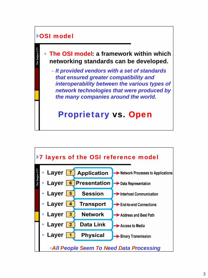
T}}OSI modelOSI model
•• The OSI modelThe OSI model: a framework within which networking standards can be developed.
–– It provided vendors with a set of standards It provided vendors with a set of standards that ensured greater compatibility and that ensured greater compatibility and interoperability between the various types of interoperability between the various types of network technologies that were produced by network technologies that were produced by the many companies around the world.the many companies around the world.
ProprietaryProprietary vs.vs. OpenOpen
Th
e S
aig
on
CT
T
}}7 layers of the OSI reference model7 layers of the OSI reference model
• Layer 7: Application
• Layer 6: Presentation
• Layer 5: Session
• Layer 4: Transport
• Layer 3: Network
• Layer 2: Data Link
• Layer 1: Physical
•All People Seem To Need Data Processing

4
Th
e S
aig
on
CT
T}}Why a layered model?Why a layered model?
• Reduces complexity.
• Standardizes interfaces.
• Facilitates modular engineering.
• Ensures interoperable technology.
• Accelerates evolution.
• Simplifies teaching and learning.
Th
e S
aig
on
CT
T
}}The physical layerThe physical layer
• Transmission of an unstructured bit stream over a physical link between end systems.
– Electrical, mechanical, procedural and functional specifications
– Physical data rate
– Distances
– Physical connector
5
Th
e S
aig
on
CT
T}}The dataThe data--link layerlink layer
• Provides for the reliable transfer of data cross a physical link.
– Frames
– Physical address
– Network topology
– Line discipline
– Synchronization
– Error control
Th
e S
aig
on
CT
T
}}The network layerThe network layer
• Provides connectivity and path selection between two host systems that may be located on geographically separated networks.
– Packets
– Logical address
– Virtual circuits
– Route, routing table, routing protocol
– Fragmentation
6
Th
e S
aig
on
CT
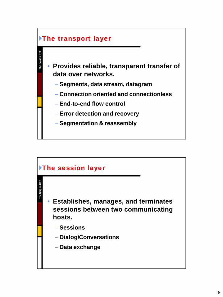
T}}The transport layerThe transport layer
• Provides reliable, transparent transfer of data over networks.
– Segments, data stream, datagram
– Connection oriented and connectionless
– End-to-end flow control
– Error detection and recovery
– Segmentation & reassembly
Th
e S
aig
on
CT
T
}}The session layerThe session layer
• Establishes, manages, and terminates sessions between two communicating hosts.
– Sessions
– Dialog/Conversations
– Data exchange
7
Th
e S
aig
on
CT
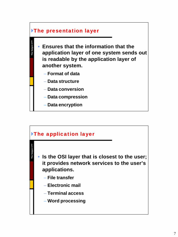
T}}The presentation layerThe presentation layer
• Ensures that the information that the application layer of one system sends out is readable by the application layer of another system.
– Format of data
– Data structure
– Data conversion
– Data compression
– Data encryption
Th
e S
aig
on
CT
T
}}The application layerThe application layer
• Is the OSI layer that is closest to the user; it provides network services to the user’s applications.
– File transfer
– Electronic mail
– Terminal access
– Word processing
8
Th
e S
aig
on
CT
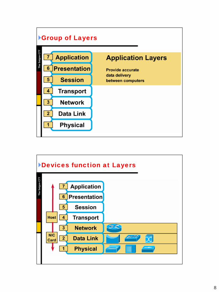
T}}Group of LayersGroup of Layers
Th
e S
aig
on
CT
T
}}Devices function at LayersDevices function at Layers
9
Th
e S
aig
on
CT
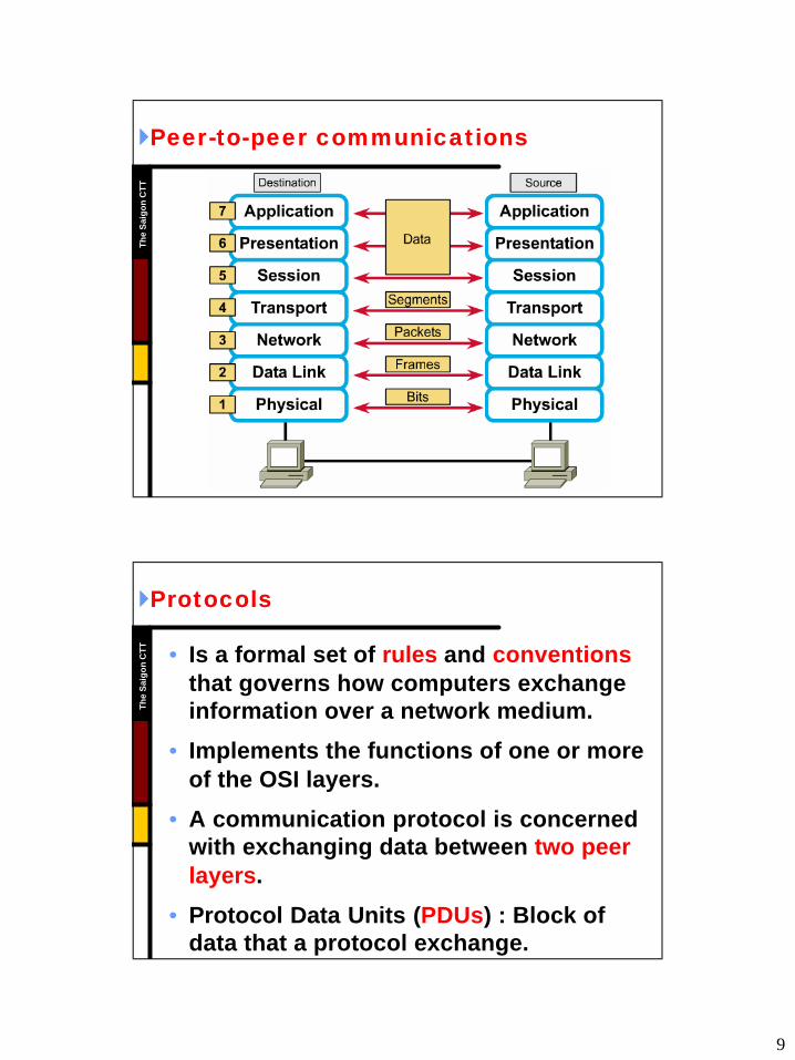
T}}PeerPeer--toto--peer communicationspeer communications
Th
e S
aig
on
CT
T
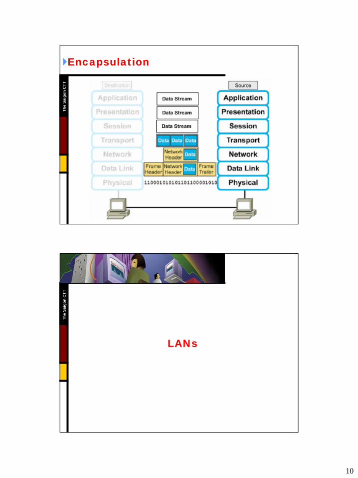
}}ProtocolsProtocols
• Is a formal set of rules and conventionsthat governs how computers exchange information over a network medium.
• Implements the functions of one or more of the OSI layers.
• A communication protocol is concerned with exchanging data between two peer layers.
• Protocol Data Units (PDUs) : Block of data that a protocol exchange.
10
Th
e S
aig
on
CT
T}}EncapsulationEncapsulation
Th
e S
aig
on
CT
T
LANsLANs
11
Th
e S
aig
on
CT
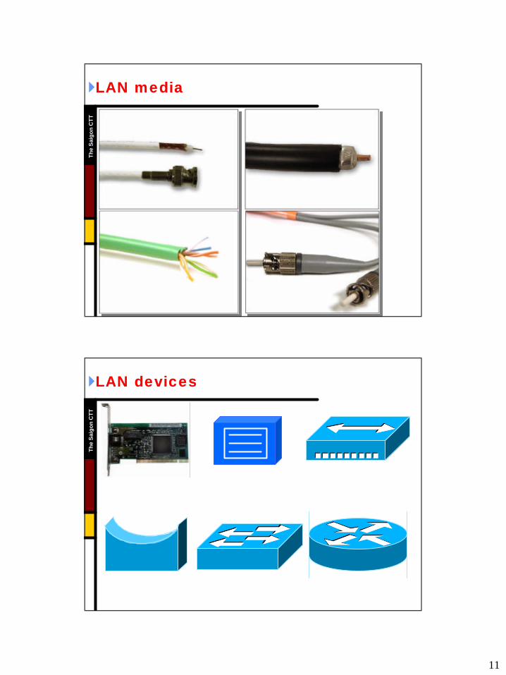
T}}LAN mediaLAN media
Th
e S
aig
on
CT
T
}}LAN devicesLAN devices
12
Th
e S
aig
on
CT
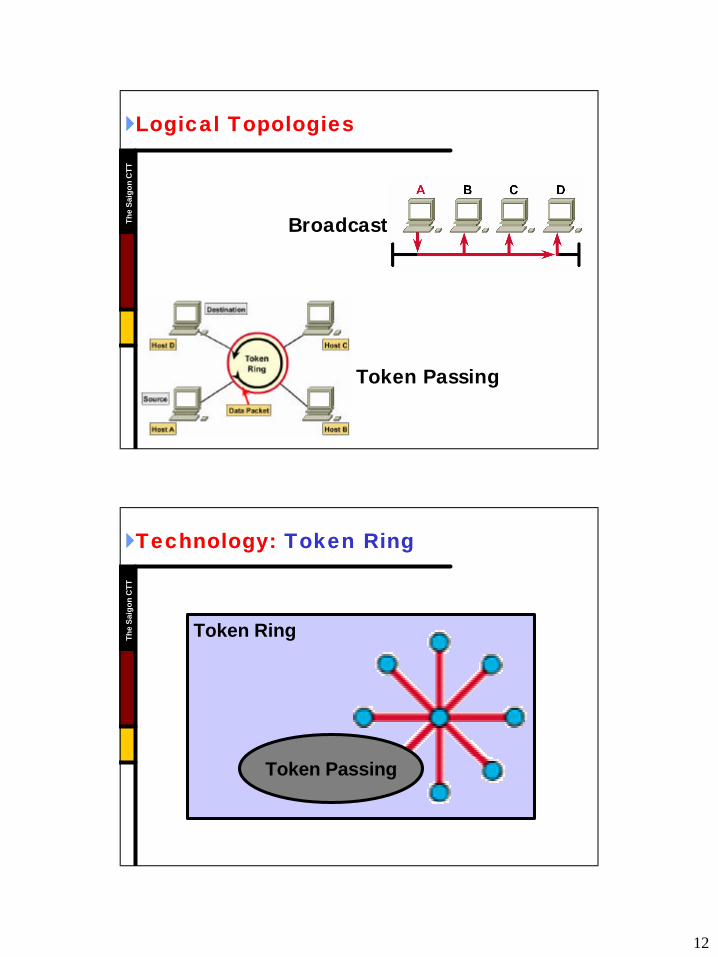
T}}Logical TopologiesLogical Topologies
Broadcast
Token Passing
Th
e S
aig
on
CT
T
}}Technology:Technology: Token RingToken Ring
Token Ring
Token Passing
13
Th
e S
aig
on
CT
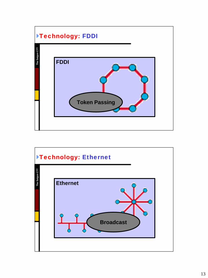
T}}Technology:Technology: FDDIFDDI
FDDI
Token Passing
Th
e S
aig
on
CT
T
}}Technology:Technology: EthernetEthernet
Ethernet
Broadcast

14
Th
e S
aig
on
CT
T}}Ethernet 802.3Ethernet 802.3
• Ethernet is broadcast topology:– Every devices on the Ethernet segment sees
every frame.
– Frames are addressed with source and destination MAC addresses.
– When a source does not know the destination or wants to communicate with every device, it encapsulates the frame with a broadcast MAC address: FFFF.FFFF.FFFF
•• What is the main network traffic problem What is the main network traffic problem caused by Ethernet topologies ?caused by Ethernet topologies ?
Th
e S
aig
on
CT
T
}}Ethernet 802.3 Ethernet 802.3 –– CSMA/CDCSMA/CD
•• Carrier Sense Multiple Access with Collision Detection.Carrier Sense Multiple Access with Collision Detection.
• A node needing to transmit listens for activity on the media. If there is none, it transmits.
• The node continue to listen. A collision is detected by a spike in voltage (a bit can only be a 0 or a 1; it cannot be a 2)
• The node generates a jam signal to tell all devices to stop transmitting for a random amount of time (back-off algorithm).
• When media is clear of any transmissions, the node can attempt to retransmit.
15
Th
e S
aig
on
CT
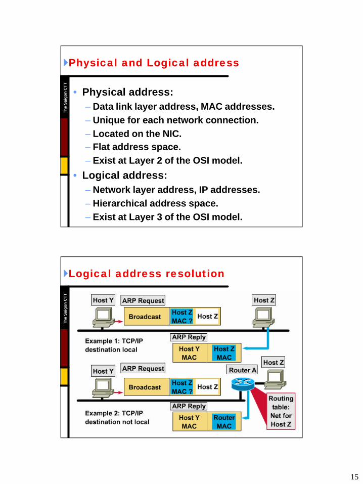
T}}Physical and Logical addressPhysical and Logical address
• Physical address:– Data link layer address, MAC addresses.– Unique for each network connection. – Located on the NIC. – Flat address space.– Exist at Layer 2 of the OSI model.
• Logical address:– Network layer address, IP addresses.– Hierarchical address space.– Exist at Layer 3 of the OSI model.
Th
e S
aig
on
CT
T
}}Logical address resolutionLogical address resolution
16
Th
e S
aig
on
CT
T
TCP/IP ADDRESSINGTCP/IP ADDRESSING
Th
e S
aig
on
CT
T
}}Network addressNetwork address
• The network address helps the router identify a path within the network cloud.
• The router uses the network address to identify the destination network of a packet within an internetwork.
• Network address is assigned by higher-level administrator. Host address is assigned manually or automatically by manager of that network.
17
Th
e S
aig
on
CT
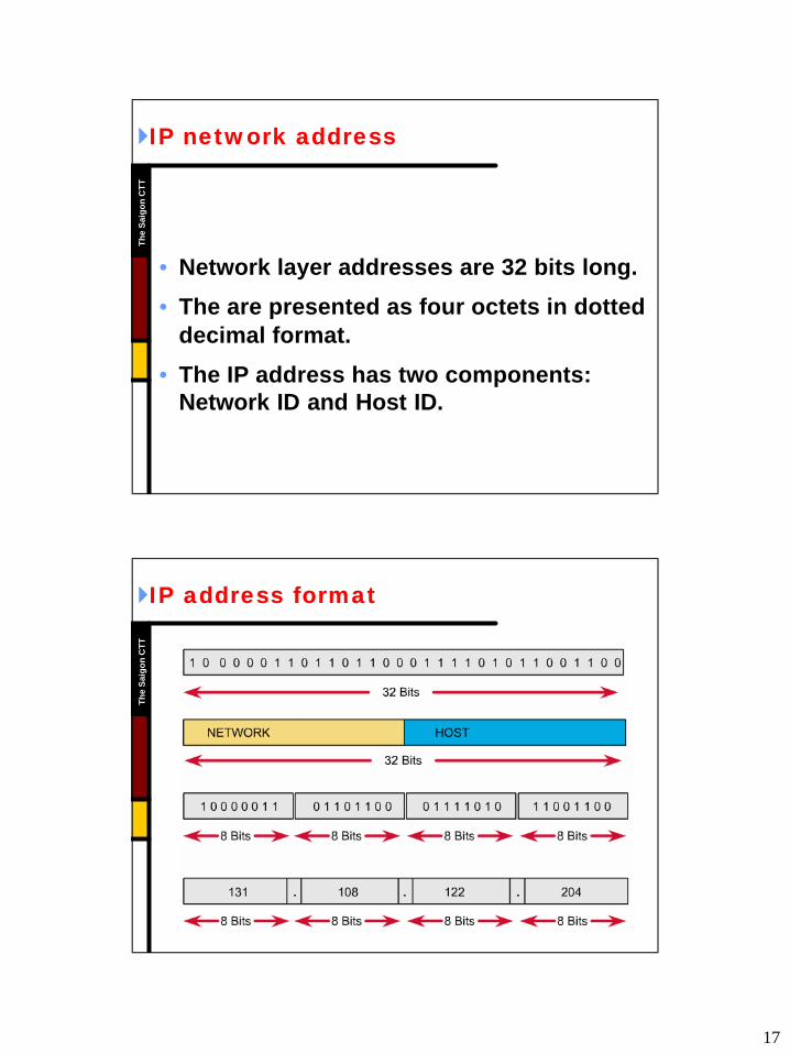
T}}IP network addressIP network address
• Network layer addresses are 32 bits long.
• The are presented as four octets in dotted decimal format.
• The IP address has two components: Network ID and Host ID.
Th
e S
aig
on
CT
T
}}IP address formatIP address format
18
Th
e S
aig
on
CT
T}}Network ID and host IDNetwork ID and host ID
• Network ID :
– Assigned by Internet Network Information Center.
– Assigned by upper organization.
– Identifies the network to which a devices is attached.
• Host ID :
– Assigned by a network administrator.
– Identifies the specific device on that network.
Th
e S
aig
on
CT
T
}}Bits on the IP addressBits on the IP address
• Network Bits :
– Identifies network ID
– Identifies class of the IP address
– All of bits = 0: not allowed
• Host Bits :
– Identifies host ID
– All of bits = 0: reserved for network address
– All of bits = 1: reserved for broadcast address
19
Th
e S
aig
on
CT
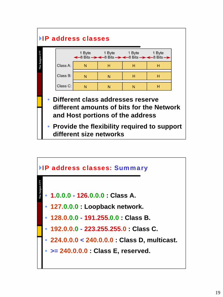
T}}IP address classesIP address classes
• Different class addresses reserve different amounts of bits for the Network and Host portions of the address
• Provide the flexibility required to support different size networks
Th
e S
aig
on
CT
T
}}IP address classes:IP address classes: SummarySummary
• 1.0.0.0 - 126.0.0.0 : Class A.
• 127.0.0.0 : Loopback network.
• 128.0.0.0 - 191.255.0.0 : Class B.
• 192.0.0.0 - 223.255.255.0 : Class C.
• 224.0.0.0 < 240.0.0.0 : Class D, multicast.
• >= 240.0.0.0 : Class E, reserved.
20
Th
e S
aig
on
CT
T}}Why we need to divide network?Why we need to divide network?
• Network administrators sometimes need to divide networks, especially large ones, into smaller networks:
– Reduce the size of a broadcast domain.
– Improve network security.
– Implement the hierarchical managements.
• So we need more network addresses for your network. But I want the outside networks see our network as a single network.
Th
e S
aig
on
CT
T
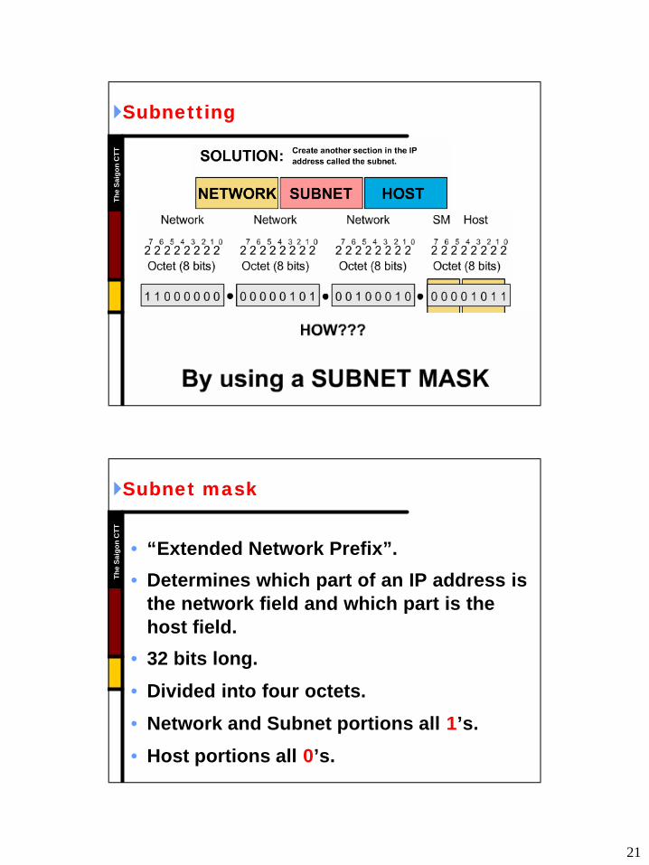
}}SubnettingSubnetting
• Subnetworks are smaller divisions of network.
• Subnet addresses include the Class A, Class B, or Class C network portion, plus a subnet field and a host field.
• To create a subnet address, a network administrator borrows bits from the original host portion and designates them as the subnet field.
• Subnet addresses are assigned locally, usually by a network administrator.
21
Th
e S
aig
on
CT
T}}SubnettingSubnetting
Th
e S
aig
on
CT
T
}}Subnet maskSubnet mask
• “Extended Network Prefix”.
• Determines which part of an IP address is the network field and which part is the host field.
• 32 bits long.
• Divided into four octets.
• Network and Subnet portions all 1’s.
• Host portions all 0’s.
22
Th
e S
aig
on
CT
T}}How many bits can I borrow?How many bits can I borrow?
• All of subnet bits are:– 0 : reserved for network address.
– 1 : reserved for broadcast address.
• The minimum bits you can borrow is:
42 bits.
• The maximum bits you can borrow is:
4A: 22 bits ~ 222 - 2 = 4.194.302 subnets.
4B: 14 bits ~ 214 - 2 = 16.382 subnets.
4C: 06 bits ~ 206 - 2 = 62 subnets.
Th
e S
aig
on
CT
T
}}Purpose of the transport layerPurpose of the transport layer
• Transport and regulate the flow of information from source to destination, reliably and accurately.
• The end-to-end control: – Sliding windows.
– Flow control
– Acknowledgments and sequencing numbers.
– Segmentation.
– Multiplexing.
23
Th
e S
aig
on
CT
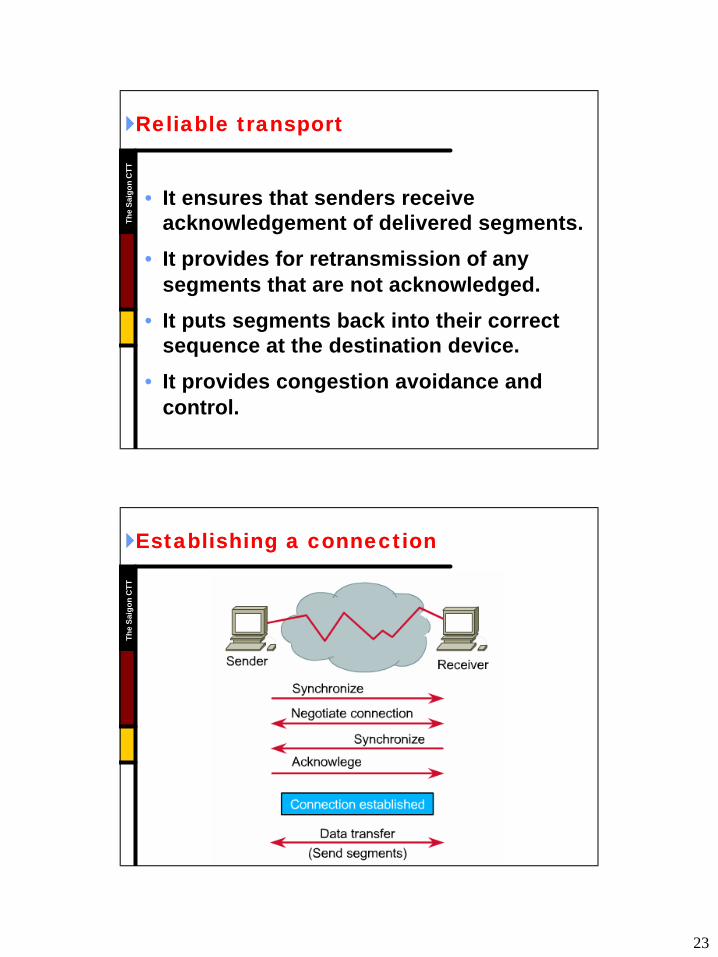
T}}Reliable transport Reliable transport
• It ensures that senders receive acknowledgement of delivered segments.
• It provides for retransmission of any segments that are not acknowledged.
• It puts segments back into their correct sequence at the destination device.
• It provides congestion avoidance and control.
Th
e S
aig
on
CT
T
}}Establishing a connection Establishing a connection
24
Th
e S
aig
on
CT
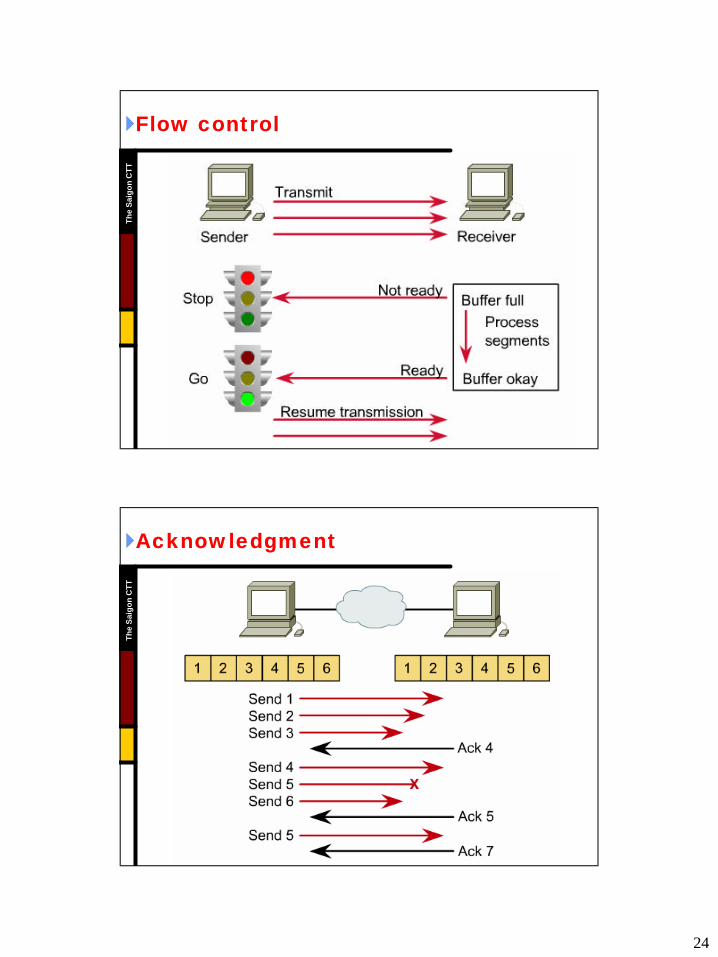
T}}Flow control Flow control
Th
e S
aig
on
CT
T
}}Acknowledgment Acknowledgment
25
Th
e S
aig
on
CT
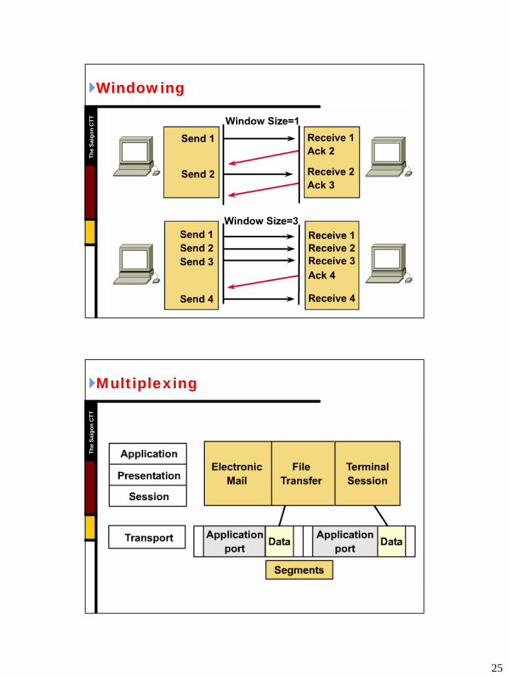
T}}Windowing Windowing
Th
e S
aig
on
CT
T
}}MultiplexingMultiplexing
26
Th
e S
aig
on
CT
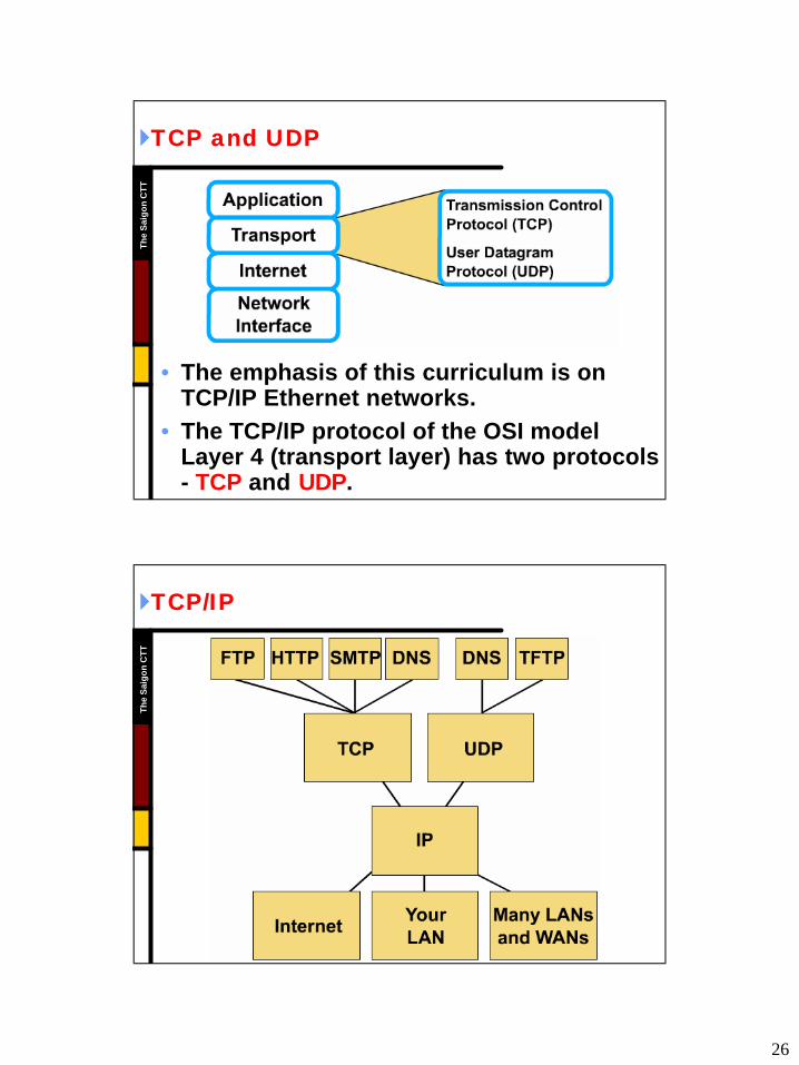
T}}TCP and UDPTCP and UDP
• The emphasis of this curriculum is on TCP/IP Ethernet networks.
• The TCP/IP protocol of the OSI model Layer 4 (transport layer) has two protocols - TCP and UDP.
Th
e S
aig
on
CT
T
}}TCP/IPTCP/IP
27
Th
e S
aig
on
CT
T
HOST LAYERSHOST LAYERS
Th
e S
aig
on
CT
T
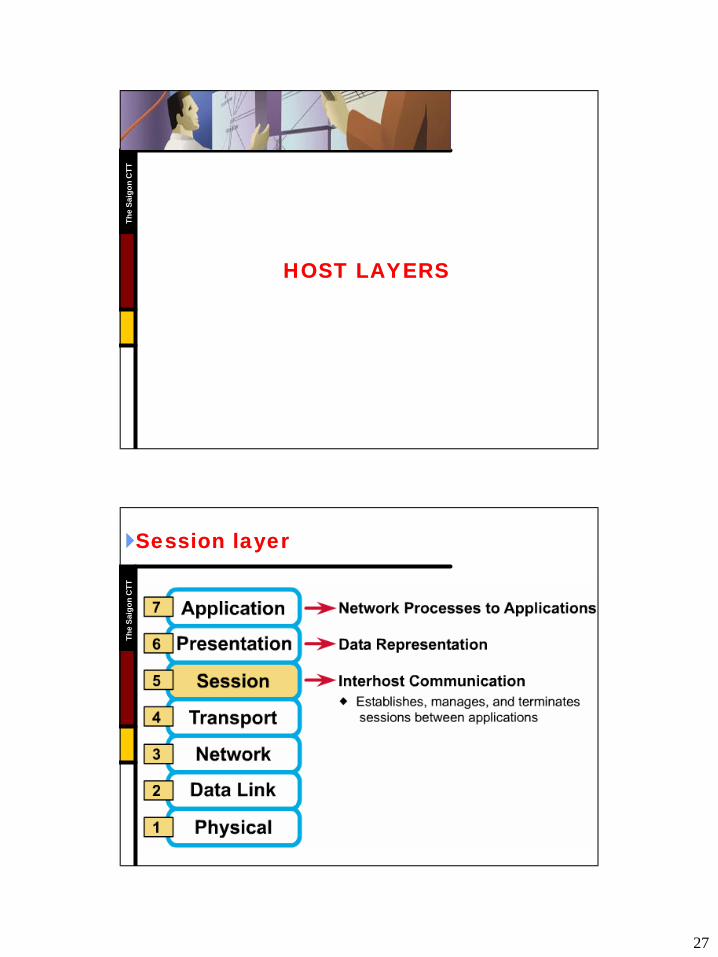
}}Session layerSession layer
28
Th
e S
aig
on
CT
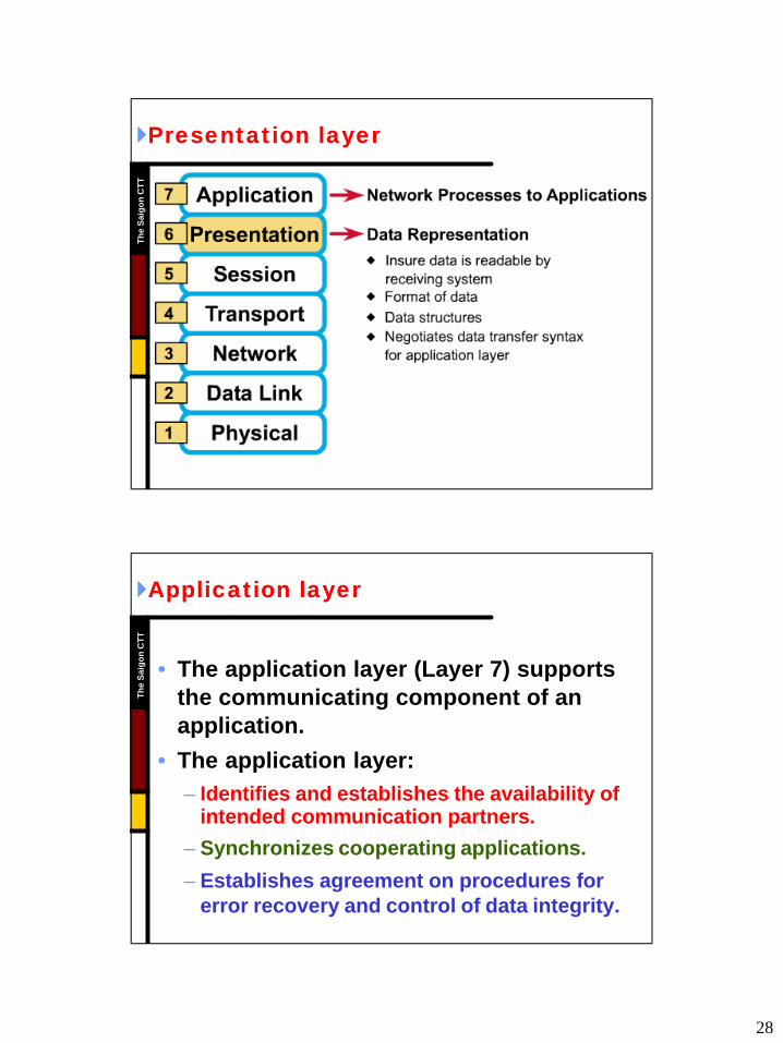
T}}Presentation layerPresentation layer
Th
e S
aig
on
CT
T
}}Application layerApplication layer
• The application layer (Layer 7) supports the communicating component of an application.
• The application layer:– Identifies and establishes the availability of
intended communication partners.
– Synchronizes cooperating applications.
– Establishes agreement on procedures for error recovery and control of data integrity.
29
Th
e S
aig
on
CT
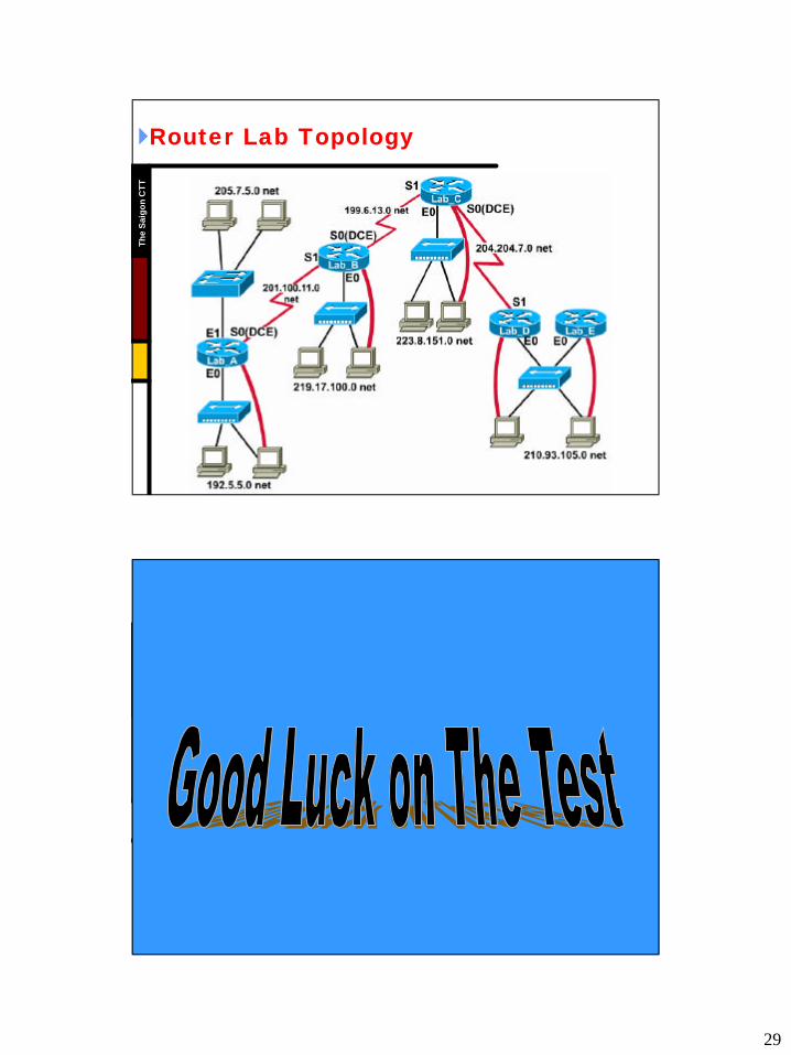
T}}Router Lab TopologyRouter Lab Topology
Th
e S
aig
on
CT
T