TROVIS 5432 - samson ag
38
Automation System TROVIS 5400 Heating and District Heating Controller TROVIS 5432 Mounting and operating instructions EB 5432-1 EN Firmware Version 1.00 Edition September 2001 ® Electronics from SAMSON Fig. 1 ⋅ Type 5432
-
Upload
khangminh22 -
Category
Documents
-
view
3 -
download
0
Transcript of TROVIS 5432 - samson ag

Automation System TROVIS 5400Heating and District Heating ControllerTROVIS 5432
Mounting andoperating instructions
EB 5432-1 EN
Firmware Version 1.00
Edition September 2001
®
Electronics from SAMSON
Fig. 1 ⋅ Type 5432

Contents Page
1. Notes for the user . . . . . . . . . . . . . . . . . . . . . . . . . . . . . . 5
2. Operation . . . . . . . . . . . . . . . . . . . . . . . . . . . . . . . . . . 6
2.1 Control levels . . . . . . . . . . . . . . . . . . . . . . . . . . . . . . . . 6
3. Start-up . . . . . . . . . . . . . . . . . . . . . . . . . . . . . . . . . . . 8
4. Setting options on the display level . . . . . . . . . . . . . . . . . . . . . 9
4.1 Short-term change in room temperature . . . . . . . . . . . . . . . . . . . . 94.2 Party mode . . . . . . . . . . . . . . . . . . . . . . . . . . . . . . . . . 94.3 Holiday mode . . . . . . . . . . . . . . . . . . . . . . . . . . . . . . . . 10
5. Setting options on the user level . . . . . . . . . . . . . . . . . . . . . . . 11
5.1 Setting the current time and date . . . . . . . . . . . . . . . . . . . . . . . 125.2 Setting the times-of-use . . . . . . . . . . . . . . . . . . . . . . . . . . . . 135.2.1 Reading the set times-of-use . . . . . . . . . . . . . . . . . . . . . . . . . 165.3 Setting the reference value for room temperature or the flow temperature
set point for rated and reduced operation . . . . . . . . . . . . . . . . . . . 175.4 Viewing the outdoor temperature . . . . . . . . . . . . . . . . . . . . . . . 18
6. Configuration and parameterization . . . . . . . . . . . . . . . . . . . . . 19
6.1 Accessing the installation level . . . . . . . . . . . . . . . . . . . . . . . . 196.2 Setting the function blocks and parameters . . . . . . . . . . . . . . . . . . 20
7. Description of the controller functions . . . . . . . . . . . . . . . . . . . . 22
7.1 Operating modes . . . . . . . . . . . . . . . . . . . . . . . . . . . . . . 227.1.1 Weather-compensated control . . . . . . . . . . . . . . . . . . . . . . . . 237.1.1.1 Heating characteristic . . . . . . . . . . . . . . . . . . . . . . . . . . . . 237.1.2 Fixed set point control . . . . . . . . . . . . . . . . . . . . . . . . . . . . 247.2 Delayed outdoor temperature adaptation . . . . . . . . . . . . . . . . . . . 257.3 Control signal . . . . . . . . . . . . . . . . . . . . . . . . . . . . . . . . 257.3.1 Three-step control . . . . . . . . . . . . . . . . . . . . . . . . . . . . . . 257.3.2 On/off control . . . . . . . . . . . . . . . . . . . . . . . . . . . . . . . . 267.4 Limitation of the flow temperature . . . . . . . . . . . . . . . . . . . . . . . 267.5 Limitation of the return flow temperature . . . . . . . . . . . . . . . . . . . 277.6 Drinking water priority . . . . . . . . . . . . . . . . . . . . . . . . . . . . 277.7 Subfloor drying . . . . . . . . . . . . . . . . . . . . . . . . . . . . . . . 287.8 Heating deactivation during the time-of-use . . . . . . . . . . . . . . . . . . 287.9 Heating deactivation during the time of non-use . . . . . . . . . . . . . . . . 287.10 Manual operation . . . . . . . . . . . . . . . . . . . . . . . . . . . . . . 29
Contents
2 EB 5432-1 EN

7.11 Pump seizure protection . . . . . . . . . . . . . . . . . . . . . . . . . . 297.12 Defective sensors . . . . . . . . . . . . . . . . . . . . . . . . . . . . . . 307.13 Actual values . . . . . . . . . . . . . . . . . . . . . . . . . . . . . . . 30
8. Installation and electrical connections . . . . . . . . . . . . . . . . . . . 31
8.1 Installing the controller . . . . . . . . . . . . . . . . . . . . . . . . . . . 318.2 Electrical connections . . . . . . . . . . . . . . . . . . . . . . . . . . . . 328.2.1 Installation recommendations . . . . . . . . . . . . . . . . . . . . . . . . 328.3 Connecting the controller . . . . . . . . . . . . . . . . . . . . . . . . . . 338.4 Connecting the sensors . . . . . . . . . . . . . . . . . . . . . . . . . . . 348.4.1 Pt 1000 sensor values . . . . . . . . . . . . . . . . . . . . . . . . . . . 348.5 Connecting the actuator . . . . . . . . . . . . . . . . . . . . . . . . . . 348.6 Connecting the pump . . . . . . . . . . . . . . . . . . . . . . . . . . . 34
9. Technical data . . . . . . . . . . . . . . . . . . . . . . . . . . . . . . . 35
Quick guide . . . . . . . . . . . . . . . . . . . . . . . . . . . . . . . . 36
Inhaltsverzeichnis
EB 5432-1 EN 3
� Assembly, start-up and operation of the device may only be performed bytrained and experienced personnel familiar with this product.According to these mounting and operating instructions, trained personnel isreferred to persons who are able to judge the work they are assigned to andrecognize possible dangers due to their specialized training, their know-ledge and experience as well as their knowledge of the relevant standards.
� The controller is designed for use in power installations. For connectionand maintenance you are required to observe the relevant safety regula-tions.
� Proper shipping and appropriate storage are assumed.
Safety instructions
4 EB 5432-1 EN
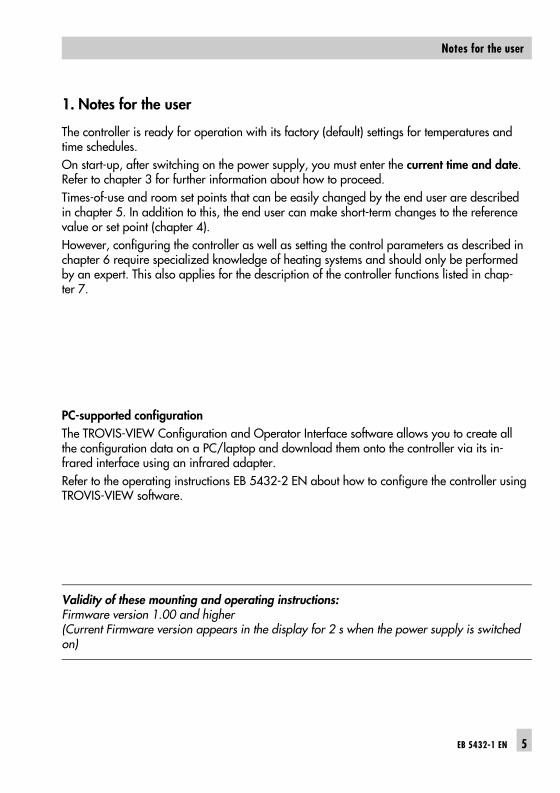
1. Notes for the user
The controller is ready for operation with its factory (default) settings for temperatures andtime schedules.
On start-up, after switching on the power supply, you must enter the current time and date.Refer to chapter 3 for further information about how to proceed.
Times-of-use and room set points that can be easily changed by the end user are describedin chapter 5. In addition to this, the end user can make short-term changes to the referencevalue or set point (chapter 4).
However, configuring the controller as well as setting the control parameters as described inchapter 6 require specialized knowledge of heating systems and should only be performedby an expert. This also applies for the description of the controller functions listed in chap-ter 7.
PC-supported configuration
The TROVIS-VIEW Configuration and Operator Interface software allows you to create allthe configuration data on a PC/laptop and download them onto the controller via its in-frared interface using an infrared adapter.
Refer to the operating instructions EB 5432-2 EN about how to configure the controller usingTROVIS-VIEW software.
Validity of these mounting and operating instructions: Firmware version 1.00 and higher(Current Firmware version appears in the display for 2 s when the power supply is switchedon)
EB 5432-1 EN 5
Notes for the user

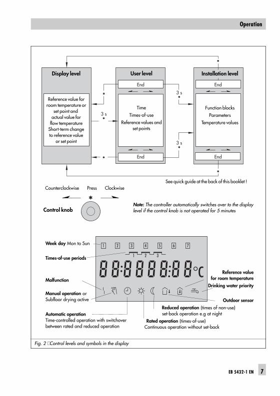
2. Operation
Just one control knob is needed to operate the controller.
� Turning the knob lets you change the current reference value or set point or lets you selectparameters and temperatures.
� Pressing the knob for three seconds lets you switch over from one control level to the next.
� Pressing the knob briefly lets you activate a parameter to change it or lets you acknow-ledge a changed parameter.
2.1 Control levels
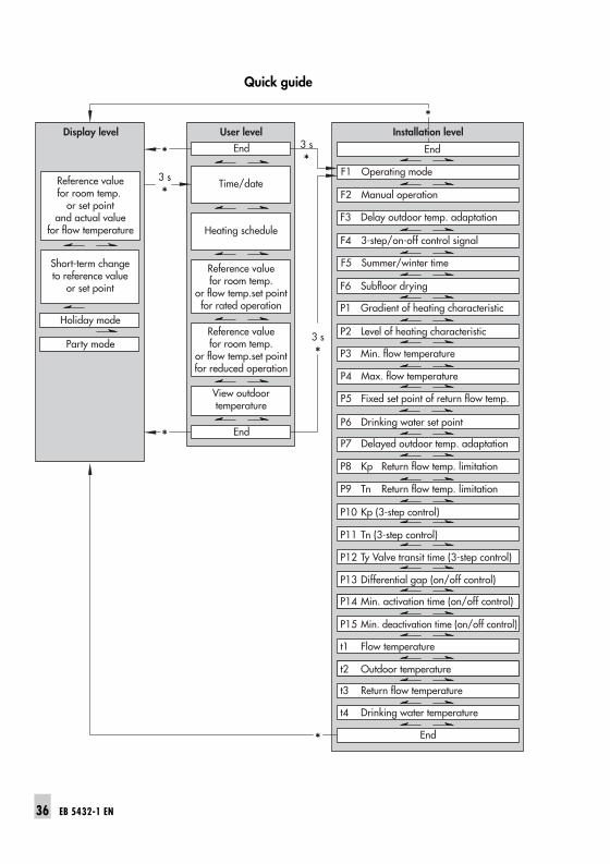
There are three levels to operate the controller. Certain parameters with their assigned symbols appear in the display depending on thelevel chosen.
The levels important for the end user are the display level and the user level. The installation level designed for the expert is described in more detail in chapter 6.
Display level
Depending on the operating mode set in the installation level:
� Lets you view the reference value for room temperature when the weather-compensatedcontrol is active.
� Lets you view the set point and the actual value of the flow temperature when the fixed setpoint control is active.
� Lets you change the currently valid reference value or set point. This change then appliesuntil the time-of-use or time of non-use ends.
User level
� Lets you view the time, time-of-use periods and the reference values or set points.
� Lets you view the outdoor temperature when a sensor is connected.
� Lets you set the time (and date).
� Lets you set the time-of-use periods for rated operation.
� Lets you set the required reference values for room temperature for rated and reducedoperation during weather-compensated control or lets you set the set points for the flowtemperature during fixed set point control for rated and reduced operation.
Installation level
� Lets you configure and parameterize the controller.
� Lets you view the actual values measured by the connected sensors.
6 EB 5432-1 EN
Operation
Counterclockwise Press Clockwise
Fig. 2 ⋅ Control levels and symbols in the display
Week day Mon to Sun
Times-of-use periods
Malfunction
Manual operation orSubfloor drying active
Automatic operationTime-controlled operation with switchoverbetween rated and reduced operation
Reference valuefor room temperature
Drinking water priority
Outdoor sensor
Reduced operation (times of non-use) set-back operation e.g at night
Rated operation (times-of-use) Continuous operation without set-back
3 s*
*
*
3 s*
3 s*
*
*
End
End
End
End
Display level
Reference value forroom temperature or
set point and actual value for
flow temperatureShort-term changeto reference value
or set point
User level
Time
Times-of-use
Reference values andset points
Installation level
Function blocks
Parameters
Temperature values
See quick guide at the back of this booklet !
*Control knob
Note: The controller automatically switches over to the displaylevel if the control knob is not operated for 5 minutes
EB 5432-1 EN 7
Operation
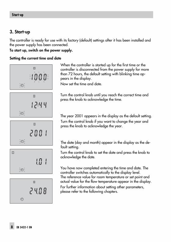
3. Start-up
The controller is ready for use with its factory (default) settings after it has been installed andthe power supply has been connected.
To start up, switch on the power supply.
Setting the current time and date
When the controller is started up for the first time or thecontroller is disconnected from the power supply for morethan 72 hours, the default setting with blinking time ap-pears in the display.
Now set the time and date.
Turn the control knob until you reach the correct time andpress the knob to acknowledge the time.
The year 2001 appears in the display as the default setting.
Turn the control knob if you want to change the year andpress the knob to acknowledge the year.
The date (day and month) appear in the display as the de-fault setting.
Turn the control knob to set the date and press the knob toacknowledge the date.
You have now completed entering the time and date. Thecontroller switches automatically to the display level. The reference value for room temperature or set point andactual value for the flow temperature appear in the display.
For further information about setting other parameters,please refer to the following chapters.
8 EB 5432-1 EN
Start-up
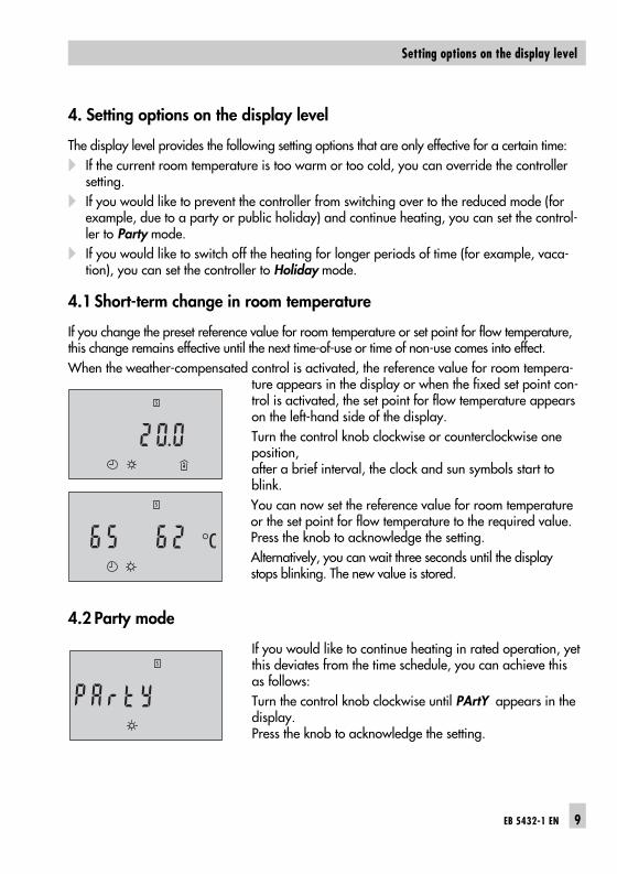
4. Setting options on the display level
The display level provides the following setting options that are only effective for a certain time:
� If the current room temperature is too warm or too cold, you can override the controllersetting.
� If you would like to prevent the controller from switching over to the reduced mode (forexample, due to a party or public holiday) and continue heating, you can set the control-ler to Party mode.
� If you would like to switch off the heating for longer periods of time (for example, vaca-tion), you can set the controller to Holiday mode.
4.1 Short-term change in room temperature
If you change the preset reference value for room temperature or set point for flow temperature,this change remains effective until the next time-of-use or time of non-use comes into effect.
When the weather-compensated control is activated, the reference value for room tempera-ture appears in the display or when the fixed set point con-trol is activated, the set point for flow temperature appearson the left-hand side of the display.
Turn the control knob clockwise or counterclockwise oneposition, after a brief interval, the clock and sun symbols start toblink.
You can now set the reference value for room temperatureor the set point for flow temperature to the required value.Press the knob to acknowledge the setting.
Alternatively, you can wait three seconds until the displaystops blinking. The new value is stored.
4.2 Party mode
If you would like to continue heating in rated operation, yetthis deviates from the time schedule, you can achieve thisas follows:
Turn the control knob clockwise until PArtY appears in thedisplay. Press the knob to acknowledge the setting.
EB 5432-1 EN 9
Setting options on the display level

Alternatively, you can wait three seconds until the display stops blinking. The party mode isactivated. The party mode remains effective until a different reference value or set point is entered.Even after a power failure, the party mode remains effective.
If you want to end the party mode, turn the control knob counterclockwise one position. Waitbriefly and then turn the knob one position further, then the set reference value or set pointreappears in the display.
4.3 Holiday mode
If you switch off the heating, but would like the frost protection to remain active, proceed asfollows:
Turn the control knob counterclockwise until HolidAY appears in the display. Press the knob to acknowledge the setting.
Alternatively, you can wait three seconds until the displaystops blinking. The holiday mode is activated.
The frost protection function comes into effect when the outdoor temperature falls below 3 °Cwhen the weather-compensated control is activated or the flow temperature falls below 5 °Cwhen the fixed set point control is activated. The circulation pump is activated and the flowtemperature is controlled to 20 °C. During fixed set point control, the circulation pump runscontinuously.
Note: The frost protection function is not active when the controller is set to manual operation.
The holiday mode setting remains effective until a different reference value or set point is en-tered. Even after a power failure, the holiday mode remains effective.
If you want to end the holiday mode, turn the control knob clockwise one position. Waitbriefly and then turn the knob one position further, then the set reference value or set pointreappears in the display.
10 EB 5432-1 EN
Setting options on the display level
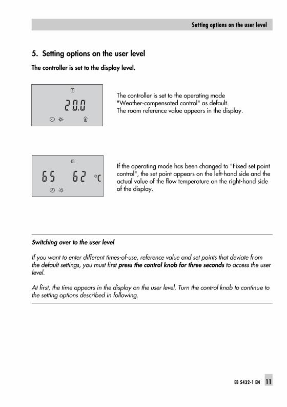
5. Setting options on the user level
The controller is set to the display level.
The controller is set to the operating mode "Weather-compensated control" as default. The room reference value appears in the display.
If the operating mode has been changed to "Fixed set pointcontrol", the set point appears on the left-hand side and theactual value of the flow temperature on the right-hand sideof the display.
Switching over to the user level
If you want to enter different times-of-use, reference value and set points that deviate fromthe default settings, you must first press the control knob for three seconds to access the userlevel.
At first, the time appears in the display on the user level. Turn the control knob to continue tothe setting options described in following.
EB 5432-1 EN 11
Setting options on the user level

5.1 Setting the current time and date
A time appears in the display or, if the controller has not been in operation for the past 72hours, the default setting 10:00 appears in the display. You only need to change the time and date, if they are different from the time and date en-tered during start-up.
Press the control knob. The clock symbol starts to blink.
Turn the control knob to until you reach the correct timeand press the knob to acknowledge the time.
The year 2001 appears in the display as the default setting.
Turn the control knob if you want to change the year andpress the knob to acknowledge the year.
The date (day and month) appear in the display as the de-fault setting.
Turn the control knob to set the date and press the knob toacknowledge the date.
You have now completed entering the time and date. Thetime, date and the clock symbol reappear in the display.
If you want to remain on the user level, you can now enterthe times-of-use (chapter 5.2) by turning the control knobone position further.
If you do not want to continue, turn the control knob untilEnd appears in the display. Then press the knob to accessthe display level.
Alternatively, if you wait five minutes, the controller auto-matically returns to the display level.
12 EB 5432-1 EN
Setting options on the user level

5.2 Setting the times-of-use
You can enter three time periods for the time-controlled operation for every day of the week,during which the heating system runs in rated operation. The default setting is a daily rated operation with just one period of time-of-use from 7:00 to22:00 hrs. During this time period, the heating system runs dependent on the predetermined operatingmode: weather-compensated according to the set heating characteristic or over a fixed flowset point. The heating system is switched over to reduced operation when the time-of-use period ends.This saves energy in the times of non-use, e.g. at night time. The heating system runs with a lower reference value during reduced operation. You can set the reference value for room temperature directly after setting the times-of-use(chapter 5.3).The heating system switches back to rated operation again when the reduced operation ends.You can enter the three time-of-use periods (1, 2 and 3) weekly (1 to 7) with the same timeschedule daily or on a day-to-day basis (1, 2, 3 etc.).
Note: If you want to enter time-of-use periods that are different on just one day or on a few days ofthe week, first select the week entry with the same time schedule daily. Then turn the controlknob until the day, which should have different times-of-use, appears in a box at the top ofthe display. Enter the new schedule. When you enter a new schedule, you write over the weekly entered times-of-use on the selected day. Caution: If you select the week entry to enter schedule, you write over all time-of-use periods that havealready been entered.
Note: An optimize function is included in the controller. This function makes sure that the con-troller automatically switches the heating circuit to the reference value or set point that ap-plies to the time-of-use at least 59 minutes before it starts dependent on the outdoor tempera-ture. The sun symbol blinks in the display when this function becomes effective.
If you are not on the user level, press the control knob forthree seconds.
First of all, the time appears in the display.
EB 5432-1 EN 13
Setting options on the user level

Entering a weekly schedule
Turn the control knob clockwise one position. The currenttime-of-use appears in the display.
Press the control knob. The time period symbol starts toblink.
Turn the control knob until the numbers for all days 1 to 7in boxes appear at the top of the display and the first timeperiod 1 appears.
Press the control knob. The time when the first time periodstarts appears in the display, the clock and sun symbolsstart to blink.Turn the control knob to set the time when you want the firsttime period to start (30 min increments) and press the knobto acknowledge the setting.
The time when the first time period stops appears in the dis-play.
Turn the control knob to set the time when you want the firsttime period to end and press the knob to acknowledge thetime.The start and stop of the time period you have just enteredappears in the display. This time period applies to all daysof the week.
Turn the control knob clockwise one position to access thesecond time period 2.
Press the control knob to the time when you want the sec-ond time period to start and end as already describedabove.
Note: The second time period has to be outside of time pe-riod 1. If you set the start and stop of a time period to havethe same time, the time period is not activated. You only need to set other times if you require time periods2 and 3.
Proceed in the same manner for the third time period 3.The third time period has to be outside of time periods 1 and 2.
14 EB 5432-1 EN
Setting options on the user level
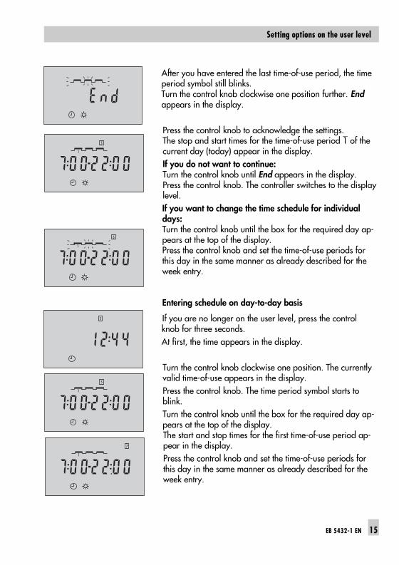
After you have entered the last time-of-use period, the timeperiod symbol still blinks.Turn the control knob clockwise one position further. End appears in the display.
Press the control knob to acknowledge the settings. The stop and start times for the time-of-use period 1 of thecurrent day (today) appear in the display.
If you do not want to continue: Turn the control knob until End appears in the display.Press the control knob. The controller switches to the displaylevel.
If you want to change the time schedule for individualdays: Turn the control knob until the box for the required day ap-pears at the top of the display.Press the control knob and set the time-of-use periods forthis day in the same manner as already described for theweek entry.
Entering schedule on day-to-day basis
If you are no longer on the user level, press the controlknob for three seconds.
At first, the time appears in the display.
Turn the control knob clockwise one position. The currentlyvalid time-of-use appears in the display.
Press the control knob. The time period symbol starts toblink.
Turn the control knob until the box for the required day ap-pears at the top of the display. The start and stop times for the first time-of-use period ap-pear in the display.
Press the control knob and set the time-of-use periods forthis day in the same manner as already described for theweek entry.
EB 5432-1 EN 15
Setting options on the user level
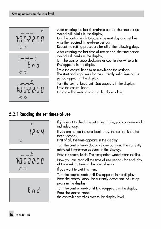
After entering the last time-of-use period, the time periodsymbol still blinks in the display,turn the control knob to access the next day and set like-wise the required time-of-use periods. Repeat the setting procedure for all of the following days.
After entering the last time-of-use period, the time periodsymbol still blinks in the display, turn the control knob clockwise or counterclockwise untilEnd appears in the display.
Press the control knob to acknowledge the settings. The start and stop times for the currently valid time-of-useperiod appear in the display.
Turn the control knob until End appears in the display.Press the control knob, the controller switches over to the display level.
5.2.1 Reading the set times-of-use
If you want to check the set times-of-use, you can view eachindividual day.
If you are not on the user level, press the control knob forthree seconds. First of all, the time appears in the display.
Turn the control knob clockwise one position. The currentlyactivated time-of-use appears in the display.
Press the control knob. The time period symbol starts to blink.
Now you can read all the time-of-use periods for each dayof the week by turning the control knob.
If you want to exit this menu:
Turn the control knob until End appears in the display.Press the control knob, the currently active time-of-use ap-pears in the display.
Turn the control knob until End reappears in the display.Press the control knob, the controller switches over to the display level.
16 EB 5432-1 EN
Setting options on the user level

5.3 Setting the reference value for room temperature or the flowtemperature set point for rated and reduced operation
If you are not on the user level, press the control knob forthree seconds.
At first, the time appears in the display.
Turn the control knob clockwise two positions.
In the operating mode "Weather-compensated control",the reference value for room temperature for rated oper-ation (time-of-use) appears in the display. The default value is 20.0.
In the operating mode "Fixed set point control", the flowtemperature set point for rated operation (time-of-use) ap-pears in the display. The default value is 65.0 °C.
If you want to change the currently displayed value:
Press the control knob. The symbols at the bottom of the dis-play start to blink.
Turn the control knob to set the required value and press theknob to acknowledge the set value.
Turn the control knob one position further to access the ref-erence value for room temperature or flow temperature setpoint for reduced operation (time of non-use).
In the operating mode "Weather-compensated control",the reference value for room temperature for reducedoperation (time of non-use) appears in the display.The default value is 17.0.
EB 5432-1 EN 17
Setting options on the user level
In the operating mode"Fixed set point control", the flowtemperature set point for reduced operation (time of non-use) appears in the display.The default value is 50.0 °C.
If you want to change the currently displayed value:
Press the control knob. The symbols at the bottom of the dis-play start to blink.
Turn the control knob to set the required value and pressthe knob to acknowledge the set value.
If you turn the control knob one position further, you canview the current outdoor temperature (see the next chapter).
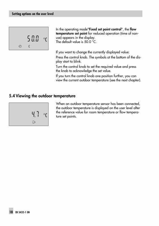
5.4 Viewing the outdoor temperature
When an outdoor temperature sensor has been connected,the outdoor temperature is displayed on the user level afterthe reference value for room temperature or flow tempera-ture set points.
18 EB 5432-1 EN
Setting options on the user level

6. Configuration and parameterization
The controller configuration und parameterization are entered on the installation level.
After accessing the installation level, the function blocks F1 to F6 appear first of all, followedby the parameters P1 to P15 and finally the measured temperatures t1 to t4.
You can select function blocks, parameters and measured temperatures you require by turn-ing the control knob.
Set the function blocks to 1 = ON or 0 = OFF depending on the function required. Set theparameters to any value within a predetermined value range.
The function blocks and parameters are listed together with their meaning and default settingin the table on page 20 and 21.
6.1 Accessing the installation level
Press the control knob for three seconds to change overfrom the display level to the user level.
At first, the time appears in the display.
Turn the control knob clockwise or counterclockwise untilEnd appears in the display.
Press the knob again for 3 seconds,
the installation level is opened when the first function blockF1 appears in the display.
Now you can continue to all other function blocks, to theparameters and the temperatures by turning the controlknob.
To make any changes, press the control knob when youreach the function block or parameter you want to change.Turn the knob to set and press it to acknowledge the newsetting.
EB 5432-1 EN 19
Configuration and parameterization

6.2 Setting the function blocks and parameters
Note: When you set certain function blocks, the associated parameter needs to be set, too.
The function blocks (F) and parameters (P) are listed in sequence. Further details about thefunctions are described in chapter 7.
F P Function S FS Comment / range
F= Function block P= Parameter S = Setting FS = Factory (default) settings
F 1 Operating mode 10
1 Weather-compensated controlFixed set point control (Chap. 7.1)
P1 Gradient Heat. characteristic 1.6 0.2...3.2
P2 Level Heating characteristic 0.0 -30.0...30.0 °C
F 2 Manual operation 10 0
ActiveNot active (Chap. 7.10)
F 3 Delayed outdoortemperature adaptation
10 0
Active with outdoor sensor AS (Chap. 7.2)
P7 5 1....6 °C/hr
F 4 Control signal 3-step 1 1 Three-step control (Chap. 7.3.1)
P10 Kp Gain 2.0 0.1...50.0
P11 Tn Reset time 120 0...999 s
P12 Ty Valve transit time 45 10...240 s
Control signal on/off 0 On/off control (Chap. 7.3.2)
P13 Differential gap 5 2...10 °C
P14 Minimum activation time 120 0...600 s
P15 Minimum deactivation time 120 0...600 s
F 5 Automatic clock resetsummer time/winter time
10
1 ActiveNot active
F 6 Subfloor drying 1 Active (Chap. 7.7)
0 0 Not active
20 EB 5432-1 EN
Configuration and parameterization

P 3 Min. flow temperature 30.0 0.0...130.0 °C (Chap. 7.4)
P 4 Max. flow temperature 80.0 20.0...130.0 °C
P 5 Fixed set point Return flow temperature
50.0 20.0...90.0 °C (Chap. 7.5)
Setting with code number
P6 Drinking water set point 55.0 20.0...90.0 °C (Chap. 7.6)
P8 Kp Return flow temp. limit. 1.0 0.1...50.0
P9 Tn Return flow temp. limit. 0 0...999 s
Measured temperatures
t1 Flow temperature Press control knob = Flow set point (Chap. 7.13)
t2 Outdoor temperature Press control knob = Delayed outdoor temperature
t3 Return flow temperature
t4 Drinking water temperature
Factory (default) settings in the user level
Time 10:00 00:00 to 23:59
Year 2001 2001 to 2050
Date 1.01 1.01 to 31.12
Heating time schedule daily or weekly
7:00 to22:00
00:00 to 24:00
Reference value for room temperature 20.0 10.0 to 30.0
Set point for flow temperature 65.0 0.0 to 130.0
Reduced reference value for room temp. 17.0 10.0 to 30.0
Reduced set point for flow temperature 50.0 0.0 to 130.0
Outdoor temperature Measuredvalue
Press control knob =
Delayed outdoor temperature
EB 5432-1 EN 21
Configuration and parameterization
7. Description of the controller functions
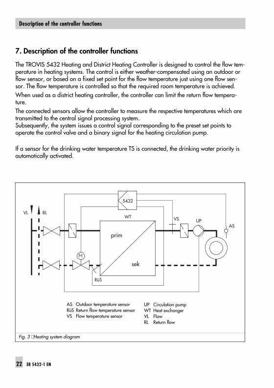
The TROVIS 5432 Heating and District Heating Controller is designed to control the flow tem-perature in heating systems. The control is either weather-compensated using an outdoor orflow sensor, or based on a fixed set point for the flow temperature just using one flow sen-sor. The flow temperature is controlled so that the required room temperature is achieved.
When used as a district heating controller, the controller can limit the return flow tempera-ture.
The connected sensors allow the controller to measure the respective temperatures which aretransmitted to the central signal processing system.Subsequently, the system issues a control signal corresponding to the preset set points tooperate the control valve and a binary signal for the heating circulation pump.
If a sensor for the drinking water temperature TS is connected, the drinking water priority isautomatically activated.
Fig. 3 ⋅ Heating system diagram
VL RL
AS Outdoor temperature sensorRüS Return flow temperature sensorVS Flow temperature sensor
UP Circulation pumpWT Heat exchangerVL FlowRL Return flow
22 EB 5432-1 EN
Description of the controller functions

7.1 Operating modes
7.1.1 Weather-compensated control
Set the function block F1 to1 = ON, and set the parameter P1= Heating characteristic gra-dient and P2 = Level. Sensors AS and VS for outdoor and flow temperatures are required.
When the weather-compensated control is active, the reference value for room temperatureappears in the display. The heating control works towards the temperature shown in the dis-play in the room/house/appartment. The reference value for room temperature allows you to influence the set point of the flowtemperature that is calculated in the controller. The set point of the flow temperature is calculated as a function of the heating characteristicgradient, the outdoor temperature and the reference value for room temperature.
Note: The current reference value for room temperature can be briefly changed in the display level,it remains activated until the next time-of-use or time of non-use comes into effect. See chapter 5.1 on setting.
7.1.1.1 Heating characteristic
The flow temperature is a function of the outdoor temperature. This correlation is describedwith the aid of the heating characteristic (Fig. 4).Using the parameters "Gradient" and "Level" the heating capacity can be adapted to thebuilding characteristic or to the type of heating (e.g. underfloor heating).
Gradient: Depending on the set gradient of the heating characteristic, a varying high flow temperatureis controlled for a outdoor temperature. The gradient of the heating characteristic can be adjusted over the parameter P1 in therange of (0.2...3.2). The parameter P1 can be accessed on the installation level and has thedefault setting of 1.6. The left graph in Fig. 4 shows a selected group of heating charac-teristics with gradients in the range of P1 = (0.4...3.2).
EB 5432-1 EN 23
Description of the controller functions
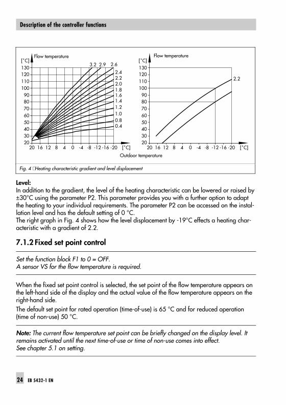
Level:In addition to the gradient, the level of the heating characteristic can be lowered or raised by±30°C using the parameter P2. This parameter provides you with a further option to adaptthe heating to your individual requirements. The parameter P2 can be accessed on the instal-lation level and has the default setting of 0 °C. The right graph in Fig. 4 shows how the level displacement by -19°C effects a heating char-acteristic with a gradient of 2.2.
7.1.2 Fixed set point control
Set the function block F1 to 0 = OFF.A sensor VS for the flow temperature is required.
When the fixed set point control is selected, the set point of the flow temperature appears onthe left-hand side of the display and the actual value of the flow temperature appears on theright-hand side.
The default set point for rated operation (time-of-use) is 65 °C and for reduced operation(time of non-use) 50 °C.
Note: The current flow temperature set point can be briefly changed on the display level. Itremains activated until the next time-of-use or time of non-use comes into effect. See chapter 5.1 on setting.
1301201101009080706050
3040
2020 16 12 8 4 0 -4 -8 -12 -16 -20
[˚C]
[˚C]
1301201101009080706050
3040
2020 16 12 8 4 0 -4 -8 -12 -16 -20
[˚C]
[˚C]
3.2 2.9 2.6
2.42.2 2.22.01.81.61.41.21.00.80.4
Outdoor temperature
Flow temperature Flow temperature
Fig. 4 ⋅ Heating characteristic gradient and level displacement
24 EB 5432-1 EN
Description of the controller functions

7.2 Delayed outdoor temperature adaptation
Set the function block F3 to 1 = ON and P7 = Delayed outdoor temperature adaptation A sensor AS for the outdoor temperature is required.
This function accounts for the fact that a building stores heat. Usually, short-term variationsin outdoor temperature do not affect the room temperature. The function makes sure that brief variations in outdoor temperature (e.g. warm winds) arenot included in the flow temperature control. If the outdoor temperature changes rapidly, this change is only taken into account to a cer-tain degree. The change in outdoor temperature that is taken into account in the control isdefined over the parameter P7 (Delayed outdoor temperature adaptation). For example, if the outdoor temperature changes by 7 °C/hr, just a 5 °C/hr change is usedfor the control. This means, the calculated outdoor temperature changes more slowly thanthe measured outdoor temperature. This function also applies when the controller switchesover to summer time operation.
The parameter P7 can be set in the range from 1 to 6 °C/hr. The setting of this parameterdepends on personal preferences and the building characteristic. The default setting is5 °C/hr.
7.3 Control signal
This setting determines whether the control signal is a three-step signal or on/off signal.
7.3.1 Three-step control
Set F4 to 1 = ON and P10 = Kp Gain, P11 = Tn Reset time and P12 = Ty Actuator transittime.
The function of the three-step control has proportional plus integral action (PI controller).Over the parameters P10 (gain factor Kp) and P11 (reset time Tn) the behavior of the controlloop can be influenced.With the aid of parameter P12, the transit time of the control valve (Ty) is taken into accountin the algorithms. The control signal issuing is limited to three times of the duration of the con-trol valve transit time (3 x Ty).Note: If Tn = 0 is set, the controller functions only as a P controller.
EB 5432-1 EN 25
Description of the controller functions
7.3.2 On/off control
Set F4 to 0 = OFF and P13 = Differential gap, P14 = Minimum activation time and P15 = Mi-nimum deactivation time.
The controller issues a control signal OPEN (+) and CLOSE (-). The switching characteristic isdetermined by selecting the differential gap. Unnecessary cycles can be avoided by specif-ying the minimum activation and deactivation time.
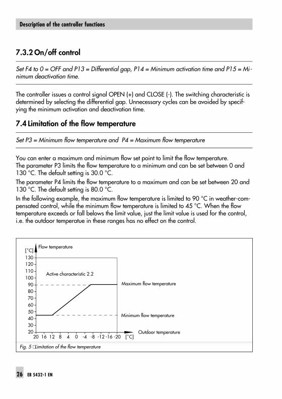
7.4 Limitation of the flow temperature
Set P3 = Minimum flow temperature and P4 = Maximum flow temperature
You can enter a maximum and minimum flow set point to limit the flow temperature.The parameter P3 limits the flow temperature to a minimum and can be set between 0 and130 °C. The default setting is 30.0 °C.
The parameter P4 limits the flow temperature to a maximum and can be set between 20 and130 °C. The default setting is 80.0 °C.
In the following example, the maximum flow temperature is limited to 90 °C in weather-com-pensated control, while the minimum flow temperature is limited to 45 °C. When the flowtemperature exceeds or fall belows the limit value, just the limit value is used for the control,i.e. the outdoor temperatue in these ranges has no effect on the control.
Active characteristic 2.2
Fig. 5 ⋅ Limitation of the flow temperature
1301201101009080706050
3040
2020 16 12 8 4 0 -4 -8 -12 -16 -20
[˚C]
[˚C]
Maximum flow temperature
Minimum flow temperature
Flow temperature
Outdoor temperature
26 EB 5432-1 EN
Description of the controller functions

7.5 Limitation of the return flow temperature
Setting with P5 = Fixed set point of return flow temperature, P8 = Kp Gain andP9 = Tn Reset time. This function is automatically activated when the sensor RüS for the return flow temperatureis connected.
The return flow temperature is limited to a fixed set point. The parameter P5 used for thisfunction is protected by a code number!
After selecting the parameter P5, you must first set the codenumber 1732 and acknowledge it, following this, you can change the parameter P5.
A PI algorithm exists for the limitation function. The integral-action component (parameter P9) is set to zero in the de-fault setting.
7.6 Drinking water priority
Set drinking water set point using the parameter P6 . The function is automatically activated when the sensor TS for the drinking water temperatu-re is connected.
If the temperature measured at the drinking water sensor TS falls below the limit value (par-ameter P6) by more than 5 K for longer than 5 minutes, the power consumption of the heat-ing circuit is reduced. For this purpose, the set point for the flow temperature is reducedgradually in increments of 5 K. The flow temperature can be reduced down to the value setin P3 "Minimum flow temperature".
� The set point is reduced by 5 K if the flow temperature of the heating circuit is below itsset point when drinking water heating starts.
� The current set point of the heating circuit is retained if the charging temperature measu-red at the drinking water sensor TS is 5 K lower than its set point.
� The heating circuit set point is raised if the charging temperature measured at the drin-king water sensor TS exceeds its set point.
You can set the limit value (parameter P6) between 20.0 and 90.0 °C. Its default setting is55 °C.
EB 5432-1 EN 27
Description of the controller functions

7.7 Subfloor drying
Set F6 to 1 = ON
Anhydrite and cement plaster floors (wet screed) must be heated prior to laying a floorcover-ing (DIN norm 4725, Part 4).
The first heating up starts with a flow temperature of 25 °C. This temperature is kept constantfor three days. After this, the maximum flow temperature is set as the set point. This maxi-mum flow temperature is used for a further four days.
After the screed drying is completed, the controller automatically deactivates the function(F6= 0)
Display: When the "Subfloor drying" function is activated, the setpoint appears on the left-hand side of the display and theactual value of the flow temperature appears on the right-hand side of the display.
Note: Any change during operation resets the function.
7.8 Heating deactivation during the time-of-use (rated operation)
Should the outdoor temperature exceed the current reference value for room temperature by1°C, the heating is deactivated. To achieve this, the control valve closes and the circulationpump is deactivated after 3 minutes.
7.9 Heating deactivation during the time of non-use (reduced operation)
During times of non-use, the heating circuit operates with a reduced reference value forroom temperature. Should the outdoor temperature exceed the current reference value for reduced operation by1°C, the heating is deactivated. To achieve this, the control valve closes and the circulationpump is deactivated after 3 minutes.
28 EB 5432-1 EN
Description of the controller functions

7.10 Manual operation
Set F2 to 1 = ON
Manual operation is carried out as stipulated in DIN EN 12098-1. The circulation pump isactivated. The controller does not issue a control signal in either on/off control or three-step control forthe heating circuit�s control valve.
Display:Depending on the operating mode, the reference value forroom temperature or flow temperature set point appears inthe display.
Note: The frost protection function is not activated when thecontroller is in manaul operation.
7.11 Pump seizure protection
If the circulation pump has not been activated within 24 hours, it is force-operated by thecontroller at 12:00 hrs for one minute.
EB 5432-1 EN 29
Description of the controller functions

7.12 Defective sensors
In the event of a defective sensor, the malfunction symbol starts to blink in the display.
Defective or missing sensor:
For three-step control: The control valve is closed completely and then opened to1/3 over the control valve transit time.
For on/off control: The controller controls the on/off output in 30 minute intervals as long as the minimal activation time lasts (P14).
Missing:Flow sensor VS: As described above
Outdoor sensor AS With fixed set point control, no effect, only display possibleWith weather-compensated control, the maximum set point set for the flow tempeature is controlled.
Return flow sensor RüS: No limitation of the return flow temperature
Drinking water sensor TS: No reverse control possible in conjuction with a self-operatedregulator
7.13 Actual values
The actual values can only be displayed when the sensors are connected and the measuredvalues are within the measuring range.No symbols that are assigned to the actual values appear in the display.
On the user level, the measured outdoor temperature appears in the display as the last point.
On the installation level, the actual values can be viewed in the following sequence:
t1 Flow temperature
t2 Outdoor temperature
t3 Return flow temperature
t4 Drinking water temperature
30 EB 5432-1 EN
Description of the controller functions

8. Installation and electrical connections
8.1 Installing the controller
The controller is made up of the casing section and the base. The casing contains the elec-tronic components, the LC display and the control knob. The base contains the terminals.
Important: The casing section must be separated from the base before the controller can beinstalled and wired. To do this, press down the tongue on top of the controller so that youcan remove the casing section from the base by tipping it forward. The controller is designed for wall or panel mounting: For wall mounting, use two or three screws to attach the base to a wall. The distances be-tween the holes are shown in the dimensional diagram. For top hat rail mounting, an adapt-er is available.For panel mounting, push the casing section through the prepared panel cut-out (138+1.0 x92+0.8 mm) and then fix it to the panel using the two threaded bolts M4 and the fasteningclips.
96
140 55.5
9113
7
8
10
5044.3
3
1529
.3
15
22
35
Base attachment
Bores for adapterfor top hat rail mounting
Fig. 6 ⋅ Dimensional diagram
EB 5432-1 EN 31
Installation and electrical connections

8.2 Electrical connections
For wiring and connection of the controller, you are required to observe the VDEregulations and the regulations of the local power supply company. For this reason,this type of work must be carried out by a specialist.
8.2.1 Installation recommendations
These recommendations are intended as a guide to help you to set up the heating system op-timally and to increase its efficiency. SAMSON assumes no responsibility or liability for anyincorrect specifications.
� Electric cablesUse a separate cable for the power supply (230 VAC, 50 Hz) to the controller. This pre-vents interference of the power supply on the signal lines.
� Signal linesUse shielded cables for the signal lines. This improves the quality of the signal trans-mission concerning interference. The shield needs only be grounded on one side at theinlet or outlet of the control cabinet (contact over a large area). The central groundingpoint must be connected to the grounding conductor PE using a copper wire (>10 mm2).To prevent any damage to the cables, we recommend you use a sufficiently thick cable(≥ 0.75 mm2).
� Avoid interferenceThe power supply cables must be laid separately from the signal lines. The distance be-tween the cables must be at least 10 cm. This can be achieved in a simple and effectivemanner by just laying the power supply and signal cables in separate cable ducts. Inside the control cabinet, the power supply cables and signal lines must run separately.We do not recommend leading or terminating the signal lines in a control cabinet wherehigh field strengths can occur. High field strengths are caused, for example, by power transformers or frequency conver-ters. In the case that high field strengths are unavoidable, we recommend such devicesshould be shielded using separating panels from the signal lines. Use separating panelsthat have good chassis ground. Inductances in the control cabinet, e.g. contactor coils, must be equipped with suitable in-terference suppressors.
32 EB 5432-1 EN
Installation and electrical connections

� Surge protectionThe following measures must be taken to protect the controller from overvoltage if signallines are installed outside of buildings or over long distances. The shield of signal lines routed outside of buildings must have current carrying capacityand must be grounded on both sides. The surge diverters must be installed at the inlet ofthe control cabinet.
8.3 Connecting the controller
Connect the controller on the basis of terminal diagram in Fig. 7. For the cable entries, knock out the grommets on the bottom of the casing base or insert theenclosed grommets. Use a cable with a cross-section of min. 1.5 mm2 for the power supply connection.
UP RK
2Pkt+N _
S4S3S2S1 Gnd
Gnd
N L
1 2 3 4 5 6 7 8 9 10
+_
11 12 13 14 15 16 17 18
S1= VS = Flow temperature sensorS2 = AS = Outdoor temperature sensorS3 = RüS = Return flow temperature sensorS4 = TS = Drinking water temperature sensorUP = Circulation pumpRK = Actuator of the control valve
Fig. 7 ⋅ Terminal wiring
EB 5432-1 EN 33
Installation and electrical connections

8.4 Connecting the sensors
Connect cables with a cross-section of min. 2x 0.5 mm2 to the terminals of the controller.
8.4.1 Pt 1000 sensor values
°C �35 �30 �25 �20 �15 �10 �5 0 5 10
Ohm 862.5 882.2 901.9 921.6 941.2 960.9 980.4 1000.0 1019.5 1039.0
°C 15 20 25 30 35 40 45 50 55 60
Ohm 1058.5 1077.9 1097.3 1116.7 1136.1 1155.4 1174.7 1194.0 1213.2 1232.4
°C 65 70 75 80 85 90 95 100 105 110
Ohm 1251.6 1270.7 1289.8 1308.9 1328.0 1347.0 1366.0 1385.0 1403.9 1422.9
°C 115 120 125 130 135 140 145 150
Ohm 1441.7 1460.6 1479.4 1498.2 1517.0 1535.8 1554.5 1573.1
8.5 Connecting the actuator
Connect the cable (suitable for damp locations) with a cross-section of min. 1.5 mm2 to theterminals of the controller output.
Following this, we recommend that you check the operating direction and the correct connec-tion (polarity) of the actuator. For this purpose, after you have connected the power supply, increase the reference valuefor room temperature considerably for a short period. This should lead the controller to openthe heating valve with its OPEN control signal (+). When the reference value is reduced, theheating valve should close with the CLOSE control signal (-).
8.6 Connecting the pump
Connect the cable with a cross-section of min. 1.5 mm2 to the terminals of the controller.
34 EB 5432-1 EN
Installation and electrical connections

9. Technical data
Inputs 4 sensor inputs Pt 1000 for
Flow temperatureOutdoor temperatureReturn flow temperatureDrinking water temperature
Outputs
Control signal y Three-step signal: load: 20 to 250 V AC; 0.3 A AC
On/off signal: load: 20 to 250 V AC; 0.3 A AC
Binary output 1 output for pump control, non-floating:230 V AC, 2 A AC (cos ϕ > 0.5)
Power supply 230 V AC (+10 %/ −15 %), 48 to 62 Hz, Power consumption approx. 1 VA
Ambient temperature Operation Transportation and storage
0 to 50 °C −10 to 60 °C
Degree of protection IP 40 according to IEC 529
Class of protection I according to VDE 0106
Degree of contamination 2 according to VDE 0110
Overvoltage category II according to VDE 0110
Humidity rating F according to VDE 40040
Noise immunity According to EN 50082 Part 1
Noise emission According to EN 50081 Part 1
Weight Approx. 0.4 kg
EB 5432-1 EN 35
Technical data
P15 Min. deactivation time (on/off control)
t1 Flow temperature
t2 Outdoor temperature
t3 Return flow temperature
End
Reference valuefor room temp.
or set pointand actual value
for flow temperature
Time/date3 s
*
3 s
*
*
3 s
*
Heating schedule
Reference valuefor room temp.
or flow temp.set pointfor reduced operation
Reference valuefor room temp.
or flow temp.set pointfor rated operation
View outdoortemperature
End
F1 Operating mode
F2 Manual operation
F3 Delay outdoor temp. adaptation
F4 3-step/on-off control signal
F5 Summer/winter time
P1 Gradient of heating characteristic
P2 Level of heating characteristic
P3 Min. flow temperature
P4 Max. flow temperature
P5 Fixed set point of return flow temp.
P6 Drinking water set point
P10 Kp (3-step control)
P11 Tn (3-step control)
P12 Ty Valve transit time (3-step control)
P13 Differential gap (on/off control)
P14 Min. activation time (on/off control)
P7 Delayed outdoor temp. adaptation
P8 Kp Return flow temp. limitation
P9 Tn Return flow temp. limitation
*
*
*
End
F6 Subfloor drying
t4 Drinking water temperature
End
Installation levelUser levelDisplay level
Short-term changeto reference value
or set point
Holiday mode
Party mode
Quick guide
36 EB 5432-1 EN

EB 5432-1 EN 37

S/C
2001-1
1
SAMSON AG ⋅ MESS- UND REGELTECHNIKWeismüllerstraße 3 ⋅ D-60314 Frankfurt am Main ⋅ GermanyPhone +49 69 4 00 9-0 ⋅ Fax +49 69 4 00 9-15 07Internet: http://www.samson.de EB 5432-1 EN