Transverse failure initiation in polymer composites - DiVA portal
166
DOCTORAL THESIS DIVISION OF POLYMER ENGINEERING 1995:178 D ISSN 0348-8373 ISRN HLU-TH-T--178-D--SE Transverse failure initiation in polymer composites LeifE. Asp JL!H TEKNISKA HÖGSKOLAN I LULEA LULEÅ UNIVERSITY OF TECHNOLOGY
-
Upload
khangminh22 -
Category
Documents
-
view
4 -
download
0
Transcript of Transverse failure initiation in polymer composites - DiVA portal

DOCTORAL THESIS D I V I S I O N O F P O L Y M E R E N G I N E E R I N G
1995:178 D ISSN 0348-8373
ISRN H L U - T H - T - - 1 7 8 - D - - S E
Transverse failure initiation in
polymer composites
LeifE. Asp
JL!H T E K N I S K A HÖGSKOLAN I LULEA
LULEÅ UNIVERSITY O F TECHNOLOGY

DOCTORAL THESIS 1995:178 D Division of Polymer Engineering ISSN 0348-8373
Transverse failure initiation in polymer composites
A K A D E M I S K A V H A N D L I N G
som med vederbörligt tillstånd av Tekniska Fakultetsnämnden vid Tekniska Högskolan i Luleå för avläggande av teknologie doktorsexamen kommer att offentligen försvaras i sal A 117 vid LuTH, den 24 november 1995 kl 1000. Avhandlingen försvaras på engelska.
Fakultetsopponent: Dr John Morton, Defence Research Agency, England
Leif B. Asp
T E K N I S K A HÖGSKOLAN I LULEA
LULEÅ UNIVERSITY OF TECHNOLOGY

To
Mom and Dad

I enjoy to get an idea, not to have
Lens P. Ås
1995

i
ABSTRACT
Transverse f a i l u r e is one o f the mos t i m p o r t a n t f a i l u r e modes i n p o l y m e r
composi tes . The p h e n o m e n o n o f t e n causes the f i r s t devia t ions f r o m n o n
l inear l amina te behavior . A l so , i n pressure vessels and pipes, f l u i d leakage
t h r o u g h a p a t h of transverse cracks is o f t en the l i m i t i n g design c r i t e r ion . I n
the present w o r k , expe r imen ta l and theore t ica l s tudies focused o n the
micromechanica l level have been carr ied out . The objective was to investigate
t ransverse f a i l u r e i n i t i a t i o n i n the ma t r ix . The other ma jo r m e c h a n i s m of
f a i l u r e i n i t i a t i o n , f i b e r / m a t r i x debond ing , was n o t considered. The t r i ax i a l
na ture o f the m a t r i x stress state i n glass f i b e r / e p o x y was c o n f i r m e d b y f i n i t e
e l emen t analysis . E x p e r i m e n t a l results f o r glassy epoxies sub jec ted to
composi te- l ike stress states demonstrated large reduct ions i n s t ra in to f a i l u r e
as c o m p a r e d w i t h un i ax i a l l oad ing . The t r i a x i a l stress state is therefore b y
i t se l f a s u f f i c i e n t exp lana t ion f o r the l o w transverse s t ra in to f a i l u r e i n
p o l y m e r composites. Plastic y i e l d i n g i n the m a t r i x was demonstra ted n o t to
be the cause o f f a i l u r e i n i t i a t i o n . Ins tead c a v i t y i n d u c e d c r a c k i n g w a s
suggested as a f a i l u r e mechanism. A c r i t e r i on was p roposed based o n a
c r i t i c a l v a l u e f o r the d i l a t a t i o n a l ene rgy d e n s i t y . C o m p a r i s o n w i t h
exper imenta l results f o r epoxies subjected to a var ie ty of m u l t i a x i a l load-cases
s u p p o r t e d the cr i te r ion . A d d i t i o n a l suppor t was obta ined f r o m compar i son
w i t h expe r imen ta l results i n the l i te ra ture f o r transverse f a i l u r e o f glass
f i b e r / e p o x y at d i f f e r e n t f ibe r contents. A l t h o u g h the epoxy m a t r i x was
d i f f e r e n t f r o m those i n the present s t udy , genera l t rends i n data w e r e
suppo r t ed b y predic t ions based o n the c r i t e r ion and f i n i t e element analysis.
The rma l res idual stresses were f o u n d to be i m p o r t a n t f o r h i g h f ibe r contents.
Based o n the cr i te r ion , a conservative estimate o f composi te s t ra in to f a i l u r e
was obta ined . This is reasonable since the c r i t e r i on predicts i n i t i a t i o n , n o t
f i n a l f a i l u r e . Based o n the m o d e l , effects f r o m changes i n c o n s t i t u e n t
p rope r t i e s were examined i n a paramet r ic f i n i t e e lement analysis . Fiber
m o d u l u s was f o u n d to s t rongly inf luence transverse fa i lure . I n t r o d u c t i o n o f a
t h i r d phase interphase be tween f i be r and m a t r i x was also inves t iga ted .
Benefic ia l results o n transverse fa i lu re s t ra in caused b y ma t r ix i n i t i a t i o n was
observed f o r t h i n rubbery interphases.

i i i
PREFACE
D u r i n g the years 1992-95 I have had the o p p o r t u n i t y to w o r k i n the d i v i s i o n
of P o l y m e r Eng inee r ing at the depar tment o f Mater ia l s and M a n u f a c t u r i n g
Engineer ing . M y w o r k has been i n the area o f f a i lu re i n i t i a t i o n i n transversely
tens i le l oaded u n i d i r e c t i o n a l glass f i b e r / e p o x y composi tes . I n i t i a t i o n o f
t ransverse cracks i n a u n i d i r e c t i o n a l composi te is, i ndeed , a complex and
in t e re s t ing phenomenon . The inves t iga t ion has been res t r ic ted to concern
m a t r i x in i t i a t ed transverse fa i lure , only.
There are a n u m b e r of people w h o deserves m y gra t i tude as they have been
i m p o r t a n t to m y thesis w o r k . I sincerely t h a n k m y adv isor Professor Lars
B e r g l u n d f o r his i n sp i r a t ion and support . Professor Berg lund creates a magic
a tmosphere i n w h i c h research becomes a pleasure, and I add ic t ed . A l l m y
colleagues at the d i v i s i o n o f Polymer Engineer ing a long w i t h m y f e l l o w post
g r adua t e s are a c k n o w l e d g e d f o r h e l p i n g and f o r o f f e r i n g m e the i r
f r i e n d s h i p s . Special thanks are due to Professor Peter G u d m u n d s o n , at the
Roya l Ins t i tu te of Technology, and Professor Ramesh Talreja, at Georgia Tech.
f o r the i r scientif ic contr ibut ions and constant interest i n m y w o r k .
F i n a l l y I w o u l d l i ke to express m y gra t i tude to m y f i a n c é e Pia f o r a lways
s u p p o r t i n g me and f o r p u t t i n g u p w i t h m y absence.
L u l e å , September 1995
Le i f A s p

i v
LIST OF PAPERS
This thesis is based o n the f o l l o w i n g papers:
I L .E. A s p , L . A . Be rg lund and P. Gudmundson , Effects of composi te
l i ke stress state o n the fracture of epoxies, Comp. Sci. Techn., 53, (1995),
p p . 27-37.
I I L .E. A s p a n d L . A . Berg lund , A biaxia l thermo-mechanical d i sk test f o r
glassy po lymers , submi t ted to Exp. Mech.
I I I L .E. A s p , L . A . Be rg lund and R. Talreja, A cr i ter ion f o r crack i n i t i a t i o n
i n glassy po lymers subjected to a composite-like stress state, s u b m i t t e d
to Comp. Sci. Techn.
I V L.E. A s p , L . A . Be rg lund and R. Talreja, Predict ion o f m a t r i x i n i t i a t ed
transverse f a i l u r e i n p o l y m e r composites, submi t ted to Comp. Sci.
Techn.
V L.E. A s p , L . A . Be rg lund and R. Talreja, Effects of f iber and interphase
o n m a t r i x in i t i a ted transverse fa i lure i n po lymer composites, submi t t ed
to Comp. Sci. Techn.

v
CONTENTS
page
A B S T R A C T i
PREFACE i i i
LIST OF PAPERS i v
C O N T E N T S v
I N T R O D U C T I O N w i t h a s u m m a r y of the papers 1
PAPER I Effects of composite-l ike stress state o n the 11
f rac ture of epoxies.
PAPER I I A b iaxia l thermo-mechanical d i sk test fo r 43
glassy polymers .
PAPER I I I A cr i te r ion f o r crack in i t i a t i on i n glassy po lymers 69
subjected to a composite-l ike stress state.
PAPER I V Predic t ion of ma t r ix in i t ia ted transverse fa i lu re i n 103
p o l y m e r composites.
PAPER V Effects of f iber and interphase o n mat r ix in i t i a ted 135
transverse fa i lu re i n po lymer composites.

ion

Asp; Introduction 3
INTRODUCTION
General Background
C o m p o s i t e mater ia l s used f o r aerospace appl ica t ions u s u a l l y consis t of
cont inuous h i g h per fo rmance f ibers, ie carbon f ibers, i n a p o l y m e r m a t r i x , eg
a thermoset such as epoxy or a thermoplas t ic such as PEEK. These types o f
composi te materials are characterized b y h i g h specific l o n g i t u d i n a l s t i f fness
and strength. H i g h per fo rmance composites are manufac tu red b y s tacking o f
t h i n p repreg plies o f un id i r ec t iona l f iber or ientat ion. These plies are stacked
at d i f f e r e n t f i be r d i rec t ions to a l amina te tha t meets r equ i red mechanica l
p rope r ty specifications.
Due to mater ia l heterogenei ty and anisotropy, cracks para l le l to the f ibers
w i l l appear i n plies or ien ted perpendicu la r to the load d i rec t ion , even at l o w
load levels. In t ra laminar transverse cracking i n off-axis plies is one of the f i r s t
f a i l u r e m o d e s 1 ' 2 . A l t h o u g h f i n a l f a i l u r e o f p o l y m e r compos i t e s w i t h
cont inuous f ibers usua l ly involves f iber fracture, transverse cracking is also of
great impor tance . Transverse cracks reduce laminate st iffness and are also
k n o w n to in i t ia te other types of damage such as local de lamina t ion and f i be r
f r a c tu r e . The i n v e s t i g a t i o n b y Spencer a n d H u l l 3 o n p ressu r i zed glass
f i b e r / p o l y e s t e r p ipes p r o v i d e s an example o f h o w transverse cracks f o r m
ear ly i n the d e f o r m a t i o n process o f a composi te structure. Onset of weepage
due to transverse cracks occurred at transverse strains o f about 0.2 % whereas
f i n a l f a i lu re occurred m u c h later.
The effect o f the m a t r i x o n transverse fa i lu re is of interest. I n the l i tera ture ,
s tudies have c o m p a r e d the s t ra in to f a i l u r e i n transverse tens ion a n d the
s t ra in to f a i l u r e of the p u r e m a t r i x loaded i n un i ax i a l t e n s i o n 1 ' 4 - 7 . U n i a x i a l
m a t r i x s train to fa i lu re v a r i e d f r o m 1.5 to 70 %. Transverse strain to fa i lures of
cor responding f iber composites were dramat ica l ly smaller and va r i ed o n l y i n
the range 0.2 to 0.9 %. There are m a n y explanations f o r the discrepancy i n
s t ra in to fa i lu re between the transversely loaded composite and the u n i a x i a l l y
loaded neat resin. Transverse composi te f a i l u r e m a y in i t ia te b y d e b o n d i n g
due to a w e a k interface, b y presence of vo ids or i n regions be tween f ibers i n
contact w i t h each other. A l s o , presence of s t i f f f ibers causes a t r i ax i a l stress
s ta te 8 " 1 0 as w e l l as stress 8 and s t r a i n 1 1 magn i f i ca t ion i n the mat r ix . A g a r w a l
and B r o u t m a n 1 2 po in t ed ou t the state of stress to be the most i m p o r t a n t factor
i n f l u e n c i n g i n i t i a t i o n of fa i lu re . H i g h l y m a g n i f i e d stresses or t r i ax ia l stresses
m a y in i t i a t e f a i l u r e i n the m a t r i x , even at l o w g loba l compos i t e loads .
Transverse f a i l u r e i n i t i a t e d b y the t r i ax i a l stress state is l i k e l y i n mater ia l s

Asp; Introduction 4
w i t h a s t r o n g a n d t o u g h f i b e r / m a t r i x in te r face . Th i s thesis concerns
transverse f a i l u r e in i t i a ted i n the ma t r ix by presence of a t r i ax ia l stress state.
Several s tudies suggest the t r i a x i a l stress state to be i m p o r t a n t f o r
i n i t i a t i o n of transverse f a i l u r e i n the ma t r ix at l o w s t r a i n s 1 0 ' 1 3 ' 1 4 . Gaggar and
B r o u t m a n calculated a s t ra in magn i f i ca t ion f r o m the t r i ax ia l stress state i n a
homogeneous m a t r i x p r o d u c e d b y the i n h i b i t i o n of Poisson c o n t r a c t i o n 1 0 . A
f a i l u r e c r i t e r ion based on d i s t o r t i o n energy theory was chosen. By use of this
c r i t e r i o n , the ca lcu la ted s t r a i n to f a i l u r e of a duc t i l e m a t r i x was 1.6 %.
H o w e v e r , the s t ra in to f a i l u r e f o r a br i t t le m a t r i x was p red ic ted to be larger
and as h i g h as 3 %. A l s o , the analysis of de K o k et a l . 1 3 is o f interest. F in i te
e lement ca lcula t ions s h o w h i g h loca l strains i n the m a t r i x at l o w g l o b a l
composi te strains, due to the t r i ax ia l stress state. The v o n Mises y i e l d c r i te r ion
is a p p l i e d a n d loca l shear strains are s h o w n to concentrate i n a t h i n b a n d .
Loca l y i e l d i n g occur at l o w g loba l strains. The m a t r i x is assumed to be idea l
elasto-plastic. Fur the rmore , exper imenta l results b y N i c h o l l s 1 4 demonstrate
l o w s t ra in to fa i lu re f o r po lymers subjected to a b iax ia l tensile load.
I n o rde r to inves t iga te t he effects f r o m the t r i a x i a l stress state, an
u n d e r s t a n d i n g o f the stress state i n the m a t r i x of a t ransverse ly l oaded
compos i te is needed. I n l i t e ra tu re , stress analyses o n t ransversely l oaded
p o l y m e r compos i t e s have been p e r f o r m e d a n a l y t i c a l l y 8 as w e l l as
n u m e r i c a l l y , u s i n g f i n i t e d i f f e r ence or f i n i t e e lement m e t h o d s 9 ' 1 5 " 1 8 . T h e
stress analyses o f m i c r o m e c h a n i c a l models p r o v i d e i n f o r m a t i o n such as;
n o r m a l and shear stresses, m a x i m u m pr inc ipa l stress, and v o n Mises effect ive
stress. Stress analysis combined w i t h fa i lure cri teria predic t f a i lu re i n i t i a t i o n .
T h e m a x i m u m p r i n c i p a l stress c r i t e r i o n has been used f o r p o l y m e r
c o m p o s i t e s 9 ' 1 9 . H o w e v e r , since the stress state i n the m a t r i x is h i g h l y t r iax ia l ,
the m a x i m u m p r i n c i p a l stress c r i t e r ion w i l l lead to erroneous and op t imis t i c
p r e d i c t i o n s . The v o n Mises c r i t e r i o n has also been a p p l i e d to p o l y m e r
c o m p o s i t e s 9 ' 1 5 . The v o n Mises effect ive stress based o n the second i nva r i an t
o f the dev ia to r ic stress tensor is used to p red ic t f a i l u r e i n i t i a t i o n i n regions
w i t h h i g h shear stresses.
A n a l y s i s of a t ransverse ly loaded composi te reveals va r i a t ions i n the
m a t r i x stress state w i t h pos i t i on . Regions w i t h h i g h shear stresses as w e l l as
regions w i t h h i g h d i l a t a t iona l stresses are active i n the p o l y m e r m a t r i x 9 . I t is
the re fo re o f interest to inves t iga te the mechanica l behav io r o f p o l y m e r s
subjec ted to e i ther h i g h d i l a t a t i o n a l or h i g h d i s t o r t i o n a l stresses. H i g h
d i s t o r t i o n a l stresses lead to plas t ic y i e l d i n g . The effect o f stress state o n
y i e l d i n g i n glassy po lymers is w e l l u n d e r s t o o d 2 0 . For glassy po lymers , shear

Asp; Introduction 5
d r i v e n y i e l d i n g b u t also c r a z i n g 2 1 has been emphasized w i t h at tent ion g iven
to the associated inf luence o f hydros ta t ic stress. A n u m b e r o f y i e l d and craze
c r i t e r ia have been p roposed f o r th is p u r p o s e 2 1 " 2 4 . The present s t udy w i l l
focus o n y i e l d and f a i l u r e c r i te r ia f o r epoxies subjected to d i f f e r en t stress
states.
I n o rder to subject glassy po lymers to h i g h d i la ta t iona l stresses, m u l t i a x i a l
tensile tests are needed. Several m u l t i a x i a l tensile tests have been proposed i n
the l i t e r a t u r e 1 4 ' 2 5 - 2 6 . M ö n c h et a l 2 5 deve loped the b i a x i a l tension c r u c i f o r m
test m e t h o d w h i c h has been successful ly app l i ed to metals and composites.
H o w e v e r , the c r u c i f o r m test is d i f f i c u l t to p e r f o r m , especial ly f o r b r i t t l e
materials . The corners o f the c r u c i f o r m specimen act as stress raisers and are
l i k e l y to in i t ia te f racture . Sul tan and M c G a r r y 2 6 p e r f o r m e d biaxia l tensile tests
o n pressurized epoxy tubes. I n their s t udy a pressurized silicone o i l inside the
cy l inder provides the hoop stress w h i l e a tensile test machine applies the axial
stress. B o t h i n the c r u c i f o r m and the pressur ized tube test, compl i ca t ed
exper imen ta l set-ups are needed. A s imple r test m e t h o d was suggested b y
N i c h o l l s 1 4 . H e app l i ed b iax ia l tensile load i n order to investigate the effect of
the b iax ia l stress state o n the s t ra in to f a i l u r e o f neat resins. Nichol l s c lamped
a shor t and w i d e specimen i n a tensile tester, creat ing a b iax ia l stress state.
H o w e v e r , the stress state is d i f f i c u l t to analyze as c l a m p i n g condi t ions are
c r i t i ca l i n th is t y p e o f test. Nevertheless, a l l test me thods described above
subject the specimens to b i a x i a l tensi le stress states. To f u r t h e r enhance
d i l a t a t iona l stresses and reduce d i s to r t iona l con t r ibu t ions to the stress f i e l d ,
t r i a x i a l tensile tests are desi red. The poke r - ch ip test m e t h o d subjects the
specimen to a t r i ax ia l tensile stress s t a t e 2 7 ' 2 8 . I n this test a poker-chip shaped
specimen is bonded be tween t w o r i g i d cy l i nd r i ca l substrates. Load is appl ied
i n the d i r ec t i on o f the cyl inders . A s a consequence, a t r i a x i a l tensile stress
state is act ivated i n the p o l y m e r specimen. The poker-chip test was appl ied to
rubbers i n the late f i f t i e s and the s i x t i e s 2 7 ' 2 8 .
I n the present s t u d y glassy epoxies w e r e sub jec ted to an a lmos t
e q u i t r i a x i a l tensile (hydros ta t ic tensile) stress state b y the poker -ch ip test
m e t h o d . Results suggest f a i l u r e to in i t i a t e b y cav i t y - induced b r i t t l e f a i l u r e
ra ther t h a n b y y i e l d i n g . For this reason a f a i l u r e c r i t e r ion based on a cr i t ica l
va lue f o r the d i l a t a t iona l energy dens i ty was developed. Predict ions made
based o n the d i l a t a t i o n a l ene rgy d e n s i t y c r i t e r i o n are s u p p o r t e d b y
exper imenta l d a t a 9 f o r transverse stresses at and strains to transverse f a i lu re
i n i t i a t i o n i n glass f iber re inforced epoxies.

Asp; Introduction 6
Objective of the thesis The objective of the thesis is to determine the effects of the t r i ax ia l stress state
i n the m a t r i x o n transverse f a i l u r e i n i t i a t i o n i n c o n t i n u o u s glass f i b e r
re inforced epoxies.
Summary of the papers To evaluate the inf luence o f t r i a x i a l stresses o n transverse crack i n i t i a t i o n i n
the m a t r i x of a p o l y m e r composi te , analysis of the stress state is needed. I n
Paper I a p r e l i m i n a r y stress analysis o f a square (quadratic) f iber d i s t r i b u t i o n
is p e r f o r m e d u s ing F E M (Fini te Element M o d e l l i n g ) . The analysis does n o t
take residual thermal stresses in to account. A reg ion of h i g h d i la ta t iona l stress
is observed at the f iber poles, see Paper I . This t r i ax ia l tensile stress state is
m i m i c k e d i n the poker-chip t e s t 2 7 ' 2 8 . The poker -ch ip strains to f a i l u r e i n the
p r i m a r y l o a d i n g d i rec t ion were 0.5 to 0.8 %, whereas strains to f a i l u r e i n the
u n i a x i a l tests were 1.8 to 7 %. The t r i ax ia l stress state i n composi te matr ices
m a y therefore b y itself be a su f f i c i en t explanat ion f o r l o w values o f transverse
composi te strains to fa i lu re . A d d i t i o n a l tests were r equ i red to evaluate the
in f luence of d i la ta t iona l stresses o n the s t rength o f po lymers . A m e t h o d f o r
t e s t ing glassy p o l y m e r s u n d e r b i a x i a l tensile l o a d i n g was deve loped , see
Paper I I . I n the test m e t h o d , a d i sk o f epoxy is b o n d e d between a steel r i n g
and a steel disk. The test m e t h o d is des igned to subject the specimen to a
b i ax ia l tensile stress state u n d e r coo l ing . A n approx imate ana ly t ica l m o d e l
was developed fo r stress analysis o f the d i sk under cool ing. The results f r o m
this test i n combina t ion w i t h those f r o m the poker -ch ip test p r o v i d e f a i l u r e
data f o r glassy polymers subjected to h i g h d i la ta t iona l stresses.
I n Paper I I I a d i l a t a t i o n a l energy dens i t y c r i t e r i o n is deve loped f o r
p r e d i c t i o n of f a i lu re i n i t i a t i o n i n glassy po lymer s subjected to a composi te
l i k e stress state. I n the analysis of the poker -ch ip data, a d d i t i o n a l t h e r m a l
r e s idua l stresses are taken i n t o account. Th i s d i l a t a t i ona l energy dens i ty
c r i t e r ion is f o u n d to give cr i t ica l energy densities f o r a t r i ax ia l composi te- l ike
stress state that correlate w e l l to those o f b i ax ia l tensile l oad cases. A l s o , as
po lymers are k n o w n to be sensitive to hydros ta t ic pressure, the poss ib i l i ty o f
y i e l d in i t i a ted fa i lu re is examined. A s a result, y i e l d in i t i a ted fa i lu re i n glassy
epoxies subjected to a composi te - l ike stress state is r u l e d out . The results
therefore i m p l y that cav i ty - induced br i t t l e f a i lu re i n glassy epoxies subjected
to a composi te- l ike stress state is indeed t ak ing place and can be pred ic ted b y
the suggested di la ta t ional energy densi ty cr i te r ion .
N u m e r i c a l analyses o f three d i f f e r e n t f i be r d i s t r i b u t i o n geometries are
p e r f o r m e d i n Paper I V . The object ive is to p red ic t transverse stress at a n d

Asp; Introduction 7
s t r a i n to f a i l u r e i n i t i a t i o n o f u n i d i r e c t i o n a l glass f i b e r / e p o x y ( G F / E P )
composi tes . A l l analyses are restr icted to glass f iber composites because o f
the i r i so t ropy . A l l analyses i n Paper I V include the rma l res idual stresses d u e
to d i f ferences i n t h e r m a l coeff ic ient o f expansion be tween f iber and ma t r i x .
Transverse f a i l u r e i n i t i a t i o n is p red ic ted b y the d i l a t a t iona l energy dens i ty
a n d the v o n Mises y i e l d criteria. I n a l l cases, independent o f f iber d i s t r i b u t i o n
or f ibe r v o l u m e f rac t ion , the numer ica l results suggest f a i l u r e to in i t ia te due
to h i g h d i l a t a t i o n a l energy dens i ty . The transverse s trengths o f a square
(quadrat ic) f iber d i s t r i b u t i o n are compared to exper imenta l data b y d e K o k 9 .
T h e c o m p a r i s o n suppor t s the a b i l i t y of the d i l a t a t i o n a l energy dens i ty
c r i t e r i o n to p r e d i c t t ransverse f a i l u r e i n i t i a t i o n i n c o n t i n u o u s G F / E P
composites.
Paper V conta ins m o d e l i n g results based o n FEM-ana lys i s and the
d i l a t a t i o n a l energy dens i ty c r i t e r ion . The object ive is to s t u d y effects o f
cons t i tuen t proper t ies o n f a i l u r e i n i t i a t i o n as p red ic t ed b y the m o d e l . I t is
a s sumed tha t the f i b e r / m a t r i x b o n d remains intact . I n the f i r s t par t , a
pa r ame t r i c s t u d y is conduc ted i n o rder to demonst ra te h o w mechanica l
p rope r t i e s o f the f ibers affect the stress at and s t ra in to f a i l u r e i n i t i a t i o n .
Speci f ic examples f o r ca rbon f i b e r and glass f i b e r r e i n f o r c e d e p o x y is
presented. I n the second part , a parametric s tudy is conducted to demonstrate
h o w mechanical proper t ies and thickness of a t h i r d phase interphase a f fec t
the stress at and strain to fa i lu re i n i t i a t i o n of a composite loaded i n transverse
t en s ion . Specif ic examples o f r ubbe r , t he rmop la s t i c , a n d i n t e r m e d i a t e
m o d u l u s interphases are presented. N u m e r i c a l stress analysis b y the f i n i t e
e lement m e t h o d is conducted o n a square f iber array. The v o n Mises y i e l d
c r i t e r ion and the d i la ta t ional energy density cr i te r ion are app l i ed to locate the
zones of y i e l d i n g and cavi ta t ion- induced br i t t le fa i lu re . A l s o , the pos i t i on o f
m a x i m u m r a d i a l stresses at the f i b e r / i n t e r p h a s e a n d i n t e r p h a s e / m a t r i x
interfaces are examined. Fiber m o d u l u s is s h o w n to have a large inf luence o n
transverse composi te stress at and strain to fa i lu re in i t i a t i on . I n t r o d u c t i o n o f a
t h i r d phase interphase between f iber and mat r ix is s h o w n to increase stress at
a n d s t ra in to f a i l u r e i n i t i a t i o n f o r t h i n , l o w m o d u l u s , h i g h Poisson's ra t io
i n t e rphase compos i tes . Hence , i n o rde r to i m p r o v e f a i l u r e i n i t i a t i o n
p rope r t i e s , a p p l i c a t i o n of t h i n rubber interphases is suggested. F i n a l l y ,
p o s i t i o n and m o d e o f f a i lu re i n i t i a t i o n is f o u n d to depend s t rong ly o n f ibe r
a n d interphase properties.

Asp; Introduction 8
REFERENCES
1. D . H u l l , An introduction to composite materials, Cambr idge U n i v e r s i t y Press,
Cambridge , 1981.
2. A .S .D. W a n g , Fracture mechanics o f sub lamina te cracks i n compos i t e
materials, / . Comp. Techn. Review, 6, (1984), p p . 45-62.
3. B. Spencer and D . H u l l , Ef fec t o f w i n d i n g angle o n the f a i l u r e of f i l a m e n t
w o u n d p ipe , Composites, 8, (1978), pp.263-271.
4. S.K. Joneja, In f luence o f m a t r i x d u c t i l i t y o n transverse fa t igue and f rac ture
toughness o f glass re inforced composites, SAMPE Quarterly, July, (1984), p p .
31-38.
5. K . W . Garre t t and J.E. Bailey, The effect of resin f a i lu re s t ra in o n the tensile
properties o f glass f ibre- re inforced polyester cross-ply laminates, / . Mater. Sci.,
12, (1977), p p . 2189-2194.
6. R . M . Chris tensen and J.A. Rinde , Transverse tensile characteristics o f f i be r
composites w i t h f l ex ib le resins: Theo ry and Test Results, Pol. Eng. Sci., 19, (1979), p p . 506-511.
7. C. Baron, K . Schulte and H . H a r i g , In f luence o f f iber and m a t r i x f a i l u r e
s t ra in o n static and f a t i gue p roper t i es o f ca rbon f ib re - r e in fo rced plast ics ,
Compos. Sci. and Technol, 29, (1987), p p . 257-272.
8. L.B. Greszczuk, In ter f iber stresses i n f i l amen ta ry composites, AIAA Journal,
A m e r i c a n Ins t i tu te of Aeronaut ics and Astronaut ics , 9, (1971),pp. 1274-1284.
9. J . M . M de K o k , Deformation,yield and fracture of unidirectional composites in
transverse loading, (D i s se r t a t i on ) , E i n d h o v e n : E i n d h o v e n U n i v e r s i t y o f
Technology, I S B N 90-386-0076-3,1995.
10. S.K. Gaggar and L.J. B r o u t m a n , Effec t o f m a t r i x d u c t i l i t y and in terface
t reatment o n mechanical proper t ies of glass-fiber ma t composites, Pol. Eng.
Sci., 16, (1976), p p . 537-543.
11 . J.A. Kies , M a x i m u m strains i n the resin o f f iberglass composites , U.S.
Naval Laboratory research report, N R L 5752 ,(1962).
12. D . A . A g a r w a l a n d L.J. B r o u t m a n , Analysis and performance of fiber
composites, 2 n d e d j o h n W i l e y & Sons Inc., N e w Y o r k , 1990, p p . 78-82.

Asp; Introduction 9
13. J . M . M . De K o k , H . E . H . M e i j e r and A . A . J . M Peijs, The inf luence o f m a t r i x
p l a s t i c i t y o n the f a i l u r e s t ra in o f t ransversely loaded composi te mater ia l s ,
Compos i t e s Behaviour , ICCM/9, ed. A . M i r a v e t e , W o o d h e a d p u b l i s h i n g
l i m i t e d , Cambr idge , 5, (1993), pp.242-249.
14. D.J. N icho l l s , Effect of stress biaxiality on the transverse tensile strain-to-failure
of composites, A S T M STP 893, ed. J .M. W h i t n e y , A m e r i c a n Society f o r Tes t ing
a n d Mater ia ls , Phi ladelphia , (1986), p p . 109-114.
15. F. Pomies and L A . Carlsson, Analys is of m o d u l u s and strength of d r y a n d
w e t thermoset and thermoplast ic composites loaded i n transverse tension, / .
Composite Materials, 28, (1994), p p . 22-35.
16. D . F . A d a m s a n d D.R. D o n e r , Transverse n o r m a l l o a d i n g o f a
un id i r ec t iona l composite, / . Composite Materials, 1, (1967), p p . 152-164.
17. D .F .Adams and S.W. Tsai, The in f luence o f r a n d o m f i l a m e n t p a c k i n g o n
the transverse st iffness o f un id i rec t iona l composites, / . Composite Materials, 3,
(1969),pp.368-381.
18. M . R . W i s n o m , Factors a f f e c t i n g the t ransverse tensi le s t r e n g t h o f
u n i d i r e c t i o n a l cont ionous s i l icon carbide f iber re in forced 6061 a l u m i n u m , / .
Composite Materials, 24, (1990),pp. 707-727.
19. D . M . Blackke t t e r , D . U p a d h y a y a a n d T.R K i n g , M i c r o m e c h a n i c s
p r e d i c t i o n o f the t ransverse tens i le s t r e n g t h o f c a r b o n f i b e r / e p o x y
composites: The inf luence of the m a t r i x and interface, Polymer Composites, 14,
(1993), pp . 437-446.
20. L M . W a r d and D . W . Hard ley , An introduction to the mechanical properties of
solid polymers, John W i l e y & Sons, Chichester, 1993, p p . 212-245.
2 1 . S.S. Sternstein a n d L . O n g c h i n , Y i e l d cr i ter ia f o r plastic d e f o r m a t i o n o f
glassy po lymers i n general stress f ie lds , A.C.S. Pol. Prep., 10, (1969), p p . 1117-
1124.
22. R.S. Raghava , R . M . C a d d e l l and G.S.Y. Yeh , The macroscopic y i e l d
behav ior of po lymers , J. Mater. Sci., 8, (1973), pp . 225-232.
23. J.C. Bauwens, Y i e l d cond i t i on and p ropaga t ion o f Luders ' lines i n tension-
to r s ion experiments on p o l y v i n y l chlor ide) , / . Polymer Sci., par t A - 2 , 8, (1970),
p p . 893-901.
24. P.B. B o w d e n and J A . Jukes, The plast ic flow of i so t ropic p o l y m e r s , / . Mater. Sci., 7, (1972), p p . 52-63.

Asp; Introduction 10
25. E. M ö n c h and D . Galster, A m e t h o d f o r p r o d u c i n g a d e f i n e d u n i f o r m
b i ax i a l tensile stress f i e l d , Brit. J. Appl. Phys., 14, (1963), p p . 810-812.
26. J .N. Sul tan and F.J. McGar ry , Effect o f rubber par t ic le size o n d e f o r m a t i o n
mechanisms i n glassy epoxy, Pol. Eng. Sci., 13, (1973), p p . 29-34.
27. A . N . Gent and P.B. L i n d l e y , In te rna l r u p t u r e o f b o n d e d rubber cyl inders
i n tension, Proc Roy Soc (London) 249A, (1959), pp . 195-205.
28. G . H . L indsey , Tr iax ia l f racture studies, J. Appl. Phys., 38, (1967), p p . 4843-
4852.


Asp; Paper I 13
Effects of composite-like stress state on the fracture of epoxies
Le i f E. A s p and Lars A . Berg lund*
Div. of Polymer Engineering
Luleå University of Technology
S-971 87 Luleå, Sweden
Peter G u d m u n d s o n
Department of Solid Mechanics
Royal Institute of Technology
S-100 44 Stockholm, Sweden
Abstract The s t ra in to f a i l u r e o f a transversely loaded composi te is m u c h l o w e r t h a n
f o r the pu re m a t r i x i n un i ax i a l tension. Several studies o f composites suggest
the t r i a x i a l m a t r i x stress state as one o f the exp lana t ions . I n o r d e r t o
inves t iga te th is expe r imen ta l ly , a t r i ax ia l tensile test p r e v i o u s l y used f o r
rubbers (poker -ch ip test) was successfully a p p l i e d to f o u r epoxies i n the
glassy state. The chosen specimen geometry m i m i c k e d the mos t severe stress
state i n the m a t r i x as de te rmined b y f in i t e element analysis of a t ransversely
l oaded glass f i b e r / e p o x y (GF/EP) composi te . The p o k e r - c h i p s t rains to
f a i l u r e i n the p r i m a r y l o a d i n g d i rec t ion were 0.5 to 0.8 %, whereas u n i a x i a l
s trains to f a i l u r e were 1.8 to 7 %. The t r i a x i a l stress state i n compos i t e
matrices m a y therefore b y itself be a suf f ic ient explanat ion f o r l o w values o f
transverse composi te strains to fa i lure .
1. INTRODUCTION
Fina l f a i l u r e o f p o l y m e r composites w i t h cont inuous f ibers u sua l ly invo lves
f iber f rac ture . H o w e v e r , transverse cracking para l le l to the f ibe r d i r ec t i on is
also o f great impor tance . Transverse cracks reduce laminate s t i ffness and are
also k n o w n to in i t ia te other types of damage such as local d e l a m i n a t i o n and
f ibe r f rac tu re . The inves t iga t ion b y Spencer and H u l l o n pressur ized glass
f i be r / p o l y e s t e r pipes p rov ides an example o f h o w transverse cracks f o r m
early i n the d e f o r m a t i o n process of a composite s t ruc ture 1 . Onset o f weepage
To whom correspondence should be addressed.

Asp; Paper I 14
due to transverse cracks occured at transverse strains o f about 0.2 % whereas
f i n a l f a i l u r e occured m u c h later.
The effect of the m a t r i x o n transverse fa i lu re is o f interest. Several studies
have c o m p a r e d the s t ra in to fa i lu re i n transverse tens ion a n d the s t ra in to
f a i l u r e o f the p u r e m a t r i x loaded i n un i ax i a l t e n s i o n 2 " 6 . U n i a x i a l m a t r i x
strains to f a i l u r e v a r i e d f r o m 1.5 to 70 %. Transverse s t ra in to fa i lures o f
cor responding f iber composites were dramatical ly smaller and v a r i e d o n l y i n
the range 0.2 to 0.9 %.
W e suggest a d i v i s i o n of explanations f o r th is p h e n o m e n o n i n t o t w o
categories. The f i r s t category of explanations is based o n the m o r e severe
stress state i n the compos i t e m a t r i x or at the f i b e r / m a t r i x in te r face as
c o m p a r e d w i t h the u n i a x i a l pu re m a t r i x case. The n o n - u n i f o r m f i b e r
d i s t r i b u t i o n i n commerc i a l l y processed materials magn i f i e s th is effect. The
second category of explanat ions is based o n the existence o f ma te r i a l f l a w s
such as v o i d s or in t e r f ac i a l debonds. This exp lana t ion can also i nc lude a
considerat ion of the stress state i n a composite.
A s a s t a r t ing p o i n t f o r an analysis of transverse f a i lu re , w e consider t w o
m a j o r mechan i sms f o r f a i l u r e i n i t i a t i o n . One is f i b e r / m a t r i x i n t e r f a c i a l
debonding . D e b o n d i n g is the f i r s t event and f i n a l f a i lu re occurs b y l i n k i n g o f
d e b o n d e d si tes. D e b o n d i n g d u r i n g t r ansverse l o a d i n g has been
d e m o n s t r a t e d f o r glass f i b e r / p o l y e s t e r 3 . The o ther m a j o r m e c h a n i s m is
f a i l u r e i n i t i a t i o n i n the ma t r ix . This mechanism is most l i k e l y i n mater ia ls
w i t h a s t rong and t o u g h f i b e r / m a t r i x interface. I t is the mechan i sm to w h i c h
the present s tudy relates. A schematic of the t w o mechanisms is presented i n
Figure 1.
L e t us cons ider theoret ica l treatments o f transverse f a i l u r e w i t h the
except ion o f s tudies related to fa i lu re i n i t i a t i o n b y in t e r f ac i a l d e b o n d i n g .
C h r i s t e n s e n a n d R i n d e a n a l y z e d the t r ansve r se s t r e n g t h u s i n g
mac romechan ica l f r ac tu r e mechanics 5 . A l t h o u g h this approach has some
theoret ical j u s t i f i c a t i o n , the inherent f l a w size of the ma t e r i a l is used as a
f i t t i n g parameter. The approach is not applicable to t o u g h matr ices 7 . A n o t h e r
p r o b l e m is l ack o f connec t ion be tween such a macroscopic m o d e l a n d
micromechan ica l models . Micromechanica l models are desirable since they
m a y i m p r o v e our unders tand ing of the physical mechanisms i n v o l v e d .
Kies cons idered n o n - u n i f o r m strain d i s t r i b u t i o n i n the m a t r i x u s i n g a
square ar ray o f f i b e r s 8 . The strain concentration factor is an average quan t i t y
f o u n d to be a f u n c t i o n o f f i b r e vo lume f r ac t ion and f iber and res in m o d u l i .
F r o m his equat ion, a number fo r the strain magn i f i ca t ion can be obta ined as a

Asp; Paper I 15
f u n c t i o n o f f ibe r v o l u m e f r ac t ion . Chamis developed a related mode l , w h e r e
the m a g n i f i c a t i o n i n m a t r i x stress due to the f ibers is expressed 9 . H i s m o d e l
relates the transverse compos i t e s t rength to the u n i a x i a l m a t r i x s t rength .
Garret t and Bailey used the theory b y Kies to expla in the relat ive insensi t iv i ty
of transverse composi te s t ra in to f a i l u r e to un iax ia l s t ra in to fa i lu re o f the
m a t r i x 4 . The ma jo r l i m i t a t i o n o f such approaches is obvious f r o m the f i n a l
result . I t is i n the f o r m of one average s t ra in or stress magn i f i ca t ion number ,
unable to express local changes i n s train w i t h posi t ion.
M o r e advanced stress analyses have also been p e r f o r m e d . T i rosh et al
de te rmined the stress d i s t r i b u t i o n a round a single f iber embedded i n a l inear
elastic m a t r i x 1 0 . W i t h the center of the f iber as a s tar t ing p o i n t , the h ighest
stress was f o u n d at a dis tance of 1.2 t imes the f ibe r r ad ius . The stress
d i s t r i b u t i o n i n a single f iber mater ia l is, however , very d i f f e r en t as compared
w i t h a rea l composi te . Greszczuck deve loped an a p p r o x i m a t e ana ly t i ca l
elasticity so lu t ion f o r the stress d i s t r i bu t i on a round an ideal ized d i s t r i bu t i on
of f i b e r s 1 1 . I n a w i d e l y q u o t e d s t udy , A d a m s and D o n e r used f i n i t e
d i f fe rence analysis i n order to solve the plane elasticity p r o b l e m fo r a square
a r r ay o f c i r cu l a r f i b e r s 1 2 . The purpose , howeve r , was to calculate the
t ransverse m o d u l u s ra ther t h a n to estimate consequences f o r transverse
fa i lure .
Gaggar and B r o u t m a n calculated a s t ra in magn i f i c a t i on f r o m the t r i ax i a l
stress state i n a homogeneous m a t r i x p roduced b y the i n h i b i t i o n of Poisson
c o n t r a c t i o n 1 3 . A f a i l u r e c r i t e r i o n based o n d i s t o r t i o n energy theory was
chosen. B y use of this c r i t e r ion , the calculated t r i ax ia l s t ra in to f a i l u r e o f a
duc t i l e m a t r i x was 1.6 %. H o w e v e r , the t r i ax ia l s t rain to f a i l u r e fo r a b r i t t l e
m a t r i x was predic ted to be larger and as h i g h as 3 %.
For transverse f a i lu re i n i t i a t i o n i n the ma t r ix , the analysis of De K o k et
a l . 1 4 is o f interest. Fini te e lement calculations show h i g h local strains i n the
m a t r i x at l o w global composi te strains. The v o n Mises y i e l d c r i te r ion is t hen
app l i ed and local shear strains are s h o w n to concentrate i n a t h i n band. Loca l
y i e l d i n g occur at l o w g loba l strains. The ma t r ix is assumed to be ideal elasto
plastic.
S t i l l , none of the exis t ing micromechanical theories a n d / o r exper imenta l
studies are able to sat isfactor i ly expla in the role of the m a t r i x i n transverse
composi te f a i lu re and f u r t h e r w o r k is needed. As par t of the m o t i v a t i o n f o r
the present s tudy , transverse f a i l u r e is assumed to in i t i a t e i n the m a t r i x .
Expe r ime n t a l studies suppo r t the poss ib i l i ty of such a mechanism. Several
f rac tographic invest igat ions repor t o n f rac ture surfaces where the f ibers are

Asp; Paper I 16
covered b y m a t r i x mater ia l , see e.g. Bascom et a l . ( C F / e p o x y ) 1 5 and P u r s l o w
( C F / P E E K ) 1 6 . I n C F / P E E K , d e b o n d i n g appears to be u n u s u a l d u r i n g
transverse c rack ing , see F igure 2 where a crack even propaga ted t h r o u g h
some carbon fibers.
Several studies suggest the t r i ax ia l m a t r i x stress state to be i m p o r t a n t f o r
i n i t i a t i o n o f transverse fa i lu re i n the m a t r i x at l o w s t r a i n s 1 3 ' 1 4 . The ef fec t o f
t r i a x i a l stress states o n p o l y m e r f a i l u r e is the re fo re o f interest . B i a x i a l
p o l y m e r tests have been repor ted to result i n l o w p o l y m e r s train to f a i l u r e 1 7 .
I n t ransverse compos i t e tests, the p o s s i b i l i t y of crack i n i t i a t i o n f r o m a
mater ia l f l a w cannot be disregarded. For this reason i t was desirable to f i n d a
test m e t h o d w h e r e a pure p o l y m e r can be subjected to a t r i ax ia l stress state.
The poke r -ch ip test is such a m e t h o d and was app l i ed to rubbers b y Gent
and L i n d l e y 1 8 and b y L i n d s e y 1 9 .
The object ive is to investigate i f the poker -ch ip test is applicable to glassy
epoxies and , i f so, compare u n i a x i a l tensile data w i t h those f r o m t r i a x i a l
p o k e r - c h i p expe r imen t s . P r o v i d e d f a i l u r e i n i t i a t i o n i n the m a t r i x is
considered, the impor tance o f the t r i ax ia l stress state i n the m a t r i x m a y t h e n
be est imated.
2. EXPERIMENTAL
2.1. Materials The chemica l s t ructures of the ma te r i a l components f o r the f o u r e p o x y
systems are presented i n Figures 3 and 4. I n three epoxy systems, presented
i n Figure 3, the epoxy component is D G E B A , (DER 332, D o w C h e m Co) . Each
system has a d i f f e r e n t cu r ing agent: (i) D E T A ( D E H 20, D o w C h e m C o ) , (ii)
M H P A , ( H Y 917, Ciba Geigy) and a m e t h y l imidazo le ( M I ) accelerator, ( D Y
070, Ciba-Geigy) , (iii) A P T A , (Jeffamine T-403, Texaco C h e m Co). I n F igure 4
the f o u r t h system is presented, T G D D M ( M Y 720, Ciba Geigy) cured b y D D S ,
( H T 976, Ciba-Geigy) . T G D D M is an aromatic epoxy and D D S is an aromat ic
amine.
2.2. Casting procedure The f o u r d i f f e r e n t systems w e r e c a r e f u l l y m i x e d b y h a n d , v a c u u m w a s
app l i ed to the mix tu res ten minu tes before casting. The mix tu res were t h e n
p o u r e d in to a f l u o r o p o l y m e r coated a l u m i n i u m m o l d . M a t e r i a l composi t ions
and cure schedules are presented i n Table I .

Asp; Paper I 17
2.3. Specimen fabrication and testing methods The cast plates were r emoved f r o m the m o l d and machined to the specimen
d imens ions r e q u i r e d f o r mechanica l test ing. The specimens des igned f o r
un iax ia l tes t ing were m i l l e d to the dimensions suggested b y A S T M D 6 3 8 M -
8 1 , type I I , i n a compute r con t ro l led m i l l i n g machine. The strains i n u n i a x i a l
tests were measured b y a 50 m m gauge length extensometer. A m i n i m u m of
seven specimens of each mater ia l was used.
For the m u l t i a x i a l poker -ch ip m e t h o d 1 8 ' 1 9 , a t h i n c i rcular spec imen was
bonded be tween t w o a l u m i n i u m rods and loaded to fa i lu re , see Figure 5. The
specimens w e r e f i r s t cu t f r o m the pla te to squares 30 m m x 30 m m a n d
b o n d e d to the a l u m i n i u m rods b y 7 3 M OST epoxy adhesive f i l m f r o m
A m e r i c a n C y a n a m i d Co. P r io r to b o n d i n g , the a l u m i n i u m was degreased
and etched i n ch romic acid. The epoxy surfaces to be b o n d e d were g r o u n d
a n d t h e n degreased b y the use o f a ce tone 2 0 . For the s t rongest e p o x y ,
D G E B A / A P T A , the epoxy itself was used as an adhesive since the adhesive
f i l m f a i l e d p r e m a t u r e l y . A f t e r b o n d i n g , the specimens w e r e g r o u n d a n d
po l i shed i n t o c i rcu la r shape. The diameter and thickness were 30 a n d 4 m m
respectively (aspect ra t io 7.5). The a l u m i n i u m rods had a l eng th o f 100 m m .
Joints i n the f ree ends of the rods were connected to g r i p p i n g extensions i n a
Dartec test machine. The strains i n the m u l t i a x i a l tests were measured over a
distance o f 50 m m b y a sensit ive extensometer ( f u l l range o f d isp lacement
±0.5 m m ) . The s t ra in to f a i lu re o f the specimen was calculated b y subt rac t ion
of strains i n a l u m i n i u m rods. St ra in rates f o r un iax ia l tests and poke r - ch ip
tests were 1 % per m i n u t e and 0.2 % per m i n u t e respectively. A l l tests w e r e
p e r f o r m e d at ambien t condi t ions .
For the u n i a x i a l tests, Young ' s m o d u l u s E was de te rmined as the secant
m o d u l u s at 0.9 % s t ra in . For the poke r -ch ip tests, the apparen t tens i le
m o d u l u s E a was calculated as the secant modu lus at 0.1 % strain. The poker -
ch ip data i n Table I I I are based o n 30 specimens out of 65. Specimens w i t h
f a i l u r e at the spec imen/subs t ra te interface were d iscarded . Data f r o m a
m i n i m u m of 7 specimens of each mater ia l are reported. For D G E B A / A P T A ,
3 ou t of 7 specimens fa i l ed at the interface. Since these specimens h a d h ighe r
strengths t h a n those w i t h t rue mater ia l fa i lure , the data was used.
2.4. Fractography Frac ture surfaces w e r e s t u d i e d v i s u a l l y and i n a s cann ing e lec t ron ic
microscope (SEM). The f r ac tu r e surfaces were coated w i t h c a r b o n / g o l d

Asp; Paper I 18
( C / A u ) i n a Blazers SCD 050 sputter coater. The SEM was a C A M S C A N S H -
80D, opera t ing at 30 k V accelerating voltage.
3. THEORETICAL ANALYSIS
3.1. FEM-analysis of transversely loaded composites The Fini te Element M e t h o d (FEM) was used to determine the stress state i n a
transversely loaded composi te . The commercia l ly available A B A Q U S system
was used f o r the F E M analys is . The generated cell c o n t a i n e d a f i b e r
s u r r o u n d e d b y res in a n d was a u n i t element i n a square a r ray o f f ibe rs .
Elements o f general p l a i n s t ra in were used to generate the mesh. Pe r iod ic i ty
was taken in to account b y c o u p l i n g of node-displacements. For nodes o n the
sides pe rpend icu la r to the l o a d i n g di rec t ion , the difference displacement o f
each oppos i te node-pa i r was equa l to an i n i t i a l displacement fac tor . The
r ema in ing t w o sides were kep t straight and free to move.
The Young ' s m o d u l u s o f the glass f i be r i n the m o d e l was Ef=76 GPa,
Poisson's r a t io was V f = 0 . 2 . For the res in E m = 3 . 0 GPa a n d V m = 0 . 3 4 . The
compos i te m a t e r i a l i n the m o d e l had a f iber v o l u m e f r a c t i o n o f 50.2 %.
Ca lcu la t ions resu l ted i n a compos i t e Poisson's rat io o f 0.31, close to the
results presented b y A d a m s a n d D o n e r 1 2 . A t r iax ia l stress state acts i n the
m a t r i x o f the composi te . The ra t io o f the stress component magn i tudes is
app rox ima te ly 1:1:2 (x:y:z) , w h e r e z, the largest stress component , is i n the
l o a d i n g d i r e c t i o n . Th i s r a t io varies w i t h pos i t i on i n the compos i t e . The
presented results refer to a mate r ia l v o l u m e i n the v ic in i ty of the f i b e r / m a t r i x
interface at the f iber center-line. W i t h i n this vo lume , the stress m a g n i f i c a t i o n
is app rox ima te ly - ^ - = 1 . 8 , w h i c h is close to the results obta ined b y A d a m s
and D o n e r 1 2 . The local stress i n the z-direct ion at the pos i t ion (x:y:z) is here
denoted a 2 and the g lobal average stress i n the z-direction is 0"°ve-
3.2. Triaxial test Idea l l y , w e w o u l d l i k e a t r i a x i a l test w h i c h mimics the m a t r i x stress state
de te rmined i n the p rev ious section. A n analysis of the poker -ch ip load-case
i n F igure 5 is therefore p e r f o r m e d . The poker-chip test specimen is a c i rcular
d i s k w i t h large d iameter . I t is b o n d e d to r i g i d substrates a n d tested i n
m o n o t o n i c t en s ion . The test m e t h o d has p r e v i o u s l y been u s e d f o r
r u b b e r s 1 8 ' 1 9 . I n the analysis of reference 18, the specimen was assumed to be
i n f i n i t e l y t h i n . Th i s i m p l i e s v a n i s h i n g in-p lane strains a n d a non-ze ro

Asp; Paper I 19
homogeneous s t ra in i n the z-direct ion. W i t h this conf igura t ion the stress f i e l d
becomes
E(l-v)
This analys is is n o t s u f f i c i e n t f o r a f i n i t e r a t io be tween thickness a n d
diameter . Th i s p r o b l e m was addressed b y Lindsey , Schapery et a l . f o r the
purpose o f p o l y u r e t h a n e t e s t s 2 1 . For p o l y u r e t h a n e 1 9 , the stress state was
almost p u r e l y hydrosta t ic , 1:1:1 (ax:o"y:o"2). This was due to the Poisson's ra t io
of close to 0.5 a n d the aspect ra t io (specimen diameter to thickness) w h i c h
was larger t h a n 10.
A more deta i led analysis o f the poker-chip m e t h o d was also presented b y
Lindsey, Schapery et a l 2 1 . F igure 5 shows a circular d i sk of normal ized rad ius
(a) w i t h its axis i n the z -d i rec t ion , and faces z = ± l . N o r m a l i z a t i o n is w i t h
respect to the ha l f thickness ( t / 2 ) of the disk. Not ice that the ha l f thickness is
taken as u n i t y , thus the aspect rat io is equal to the normal ized disk rad ius (a).
The d i s k is assumed to be loaded b y increasing the thickness b y 2e, see
Figure 5. The f o l l o w i n g equations were assumed to describe the n o r m a l i z e d
radia l and axia l displacements u and w respectively;
u = -{l-z2)-g(r)
W = £-Z (3)
whe re z is n o r m a l i z e d thickness a n d g(r ) is an unprescr ibed f u n c t i o n o f
n o r m a l i z e d r a d i a l p o s i t i o n . No t i ce tha t b o t h z and r are n o r m a l i z e d w i t h
respect to the ha l f thickness o f the disk. The strains corresponding to these
displacements are

Asp; Paper I 20
du
~~dr
£e u
r
C dw £z ~!z~
= €
Yn du
"dl + ^ = 28(r)-Z
or
(4 a-d)
Lindsey, Schapery et al. de termined the f u n c t i o n g(r) , f r o m the cond i t i on that
the z- in tegra ted e q u i l i b r i u m equat ion fo r the r ad ia l d i r ec t i o n is to vanish ,
and used the equat ions (4a-d) to calculate the average stresses t h r o u g h the
thickness o f the specimen. The analytical solutions of the stress components
are somewha t compl ica ted . A s i m p l i f i e d f o r m of the analyt ical solut ions was
also d e r i v e d 2 1 . The stress components are i n s i m p l i f i e d f o r m
Ee Ee
3v
( 1 + v ) 3(1 - 2 v ) /„
h ^ 3 ( 1 - - 2 v )
h W3(i - 2 v )
(5)
1 + - — - - ^ 1 + —
Ee Ee ( 1 + v ) 2 / 0
r V 3 ( l - 2 v )
« V 3 ( l - 2 v ) (6)
IB.. Ee
3v
( 1 + v ) 3 ( 1 - 2 v ) j / 0 [ a V 3 F 2 v ) ] J (7)
whe re a, r, and z are no rma l i zed disk radius, rad ia l pos i t ion , and pos i t ion
i n thickness d i r e c t i o n respectively. A l l parameters were n o r m a l i z e d w i t h
respect to the h a l f thickness of the disk. E is Young 's m o d u l u s , v Poisson's
ra t io , I 0 and \ are m o d i f i e d Bessel funct ions , (07, o"ø, o z ) are n o r m a l stresses
i n r-, 6-, a n d z-direct ions i n a cy l indr ica l coordinate system, xrz is the shear
stress i n the r /z-di rect ion. The stress d i s t r i bu t ion according to equations (5-6)
at z=0 is presented i n Figure 6.
Equa t ions (5-7) are s i m p l i f i e d . H o w e v e r , L i n d s e y , Schapery et a l . 2 1
conc luded these a p p r o x i m a t i o n s to be s u f f i c i e n t l y accurate i n the central
r eg ion w h e r e r / a < 0 . 6 . The analysis close to the edge is less accurate. F E M
analyses b y A d a m s et al . have s h o w n stress concentrations to be present at
the interface ( z = ± l ) co rne r s 2 2 . Since adhesive fa i lu re is of n o interest f o r our

Asp; Paper I 21
purpose , w e need to establish cohesive fa i lu re i n i t i a t i on i n the central region,
a w a y f r o m the interface.
The di f ference be tween the poker-chip and the related b u t t j o in t test is that
the aspect ra t io o f the poker -ch ip specimen is m u c h smaller. The purpose is
to test the p o l y m e r mate r ia l rather than the adhesive b o n d strength.
For each choice o f aspect ra t io of the poke r -ch ip specimen, the stress
d i s t r i b u t i o n w i l l be a f u n c t i o n of the n o r m a l i z e d rad ia l pos i t i on r. F igure 6
shows the stress d i s t r i b u t i o n i n the specimen to be f a i r l y homogeneous f r o m
the center to app rox ima te ly 60% of the r ad i a l distance ( r /a=0.6) . The z-stress
is a lmos t tw ice as large as the other t w o . N o t e that o z is no rma l i zed w i t h
respect to Young ' s m o d u l u s £ . The average of the n o r m a l i z e d oz the re fore
becomes larger t h a n one since E is smaller than the apparent m o d u l u s of the
specimen, Ea , see equat ion (8).
The shear stress is zero at z=0. I t has its m a x i m u m value at the interface,
z = ± l , b u t i t is s ign i f i can t ly lower than the n o r m a l stress.
The aspect ra t io of epoxy poker-chip specimens was chosen as 7.5 w h i c h
induces a ra t io o f the stresses x:y:z o f close to 1:1:2 i n the central r eg ion .
Hence, the stress state is s imi la r to that local ly i n the m a t r i x o f a transversely
loaded G F / E P composi te . The rma l stresses generated d u r i n g c o o l - d o w n of
the epoxy after b o n d i n g to the a l u m i n i u m substrates at elevated temperature,
are n o t i n c l u d e d i n the analysis. Their magn i tude is estimated to be s imi lar i n
the p o k e r - c h i p spec imen as i n the composi te . H o w e v e r , i f a quan t i t a t ive
f a i l u r e c r i t e r ion is seeked, t he rma l stresses have to be inc luded . They do not
c o n t r i b u t e to the apparen t stress at f a i l u r e , the i r effect is to increase the
stresses i n the p l ane a n d change the p r o p o r t i o n s b e t w e e n the stress
components .
F r o m the poker -ch ip test, the apparent m o d u l u s Ea m a y be determined as
2n\o rdr a z
A e m 2 s (8)
w h e r e 0"ZA is the average stress over the bonded surface and e z is the app l i ed
s t ra in i n the z-d i rec t ion . Not i ce that o z i n equat ion (8) is i n its u n s i m p l i f i e d
f o r m expressed b y L i n d s e y , Schapery et a l 2 1 . This can be used to w r i t e
equa t ion (8) d i f f e r e n t l y , thus:

Asp; Paper I 22
EA _ 3v
E 1 + v 3 ( 1 - 2 v) 1 -
2/,(WM)
aVM/ 0(aVF)
2 / , ( o V M |
1 + v 1 + -
WM/0(WM) (9)
a4MI0(a-M) 1 + l - 2 v
a-fMlJya^M)
where M = — 2 ( 1 - v )
The m o d u l u s E can be obta ined exper imental ly f r o m a uniaxia l test and E A
f r o m the poker-chip test. Equa t ion (9) can then be used to calculate Poisson's
ratio.
4. RESULTS AND DISCUSSION
4.1. Uniaxial test
A l t h o u g h the p r i m a r y interest is i n results f r o m t r i a x i a l tests, reference
results f r o m u n i a x i a l tests are needed. U n i a x i a l tensile test data f o r f o u r
epoxies are presented i n Table I I and Figure 7. Strains to f a i l u r e are i n the
range 1.8 to 7.0 %. The epoxies cured b y al iphatic amines show 6 to 7 % s t ra in
to f a i l u r e . Before f a i l u r e , D G E B A / A P T A s h o w e d s i g n i f i c a n t l o c a l i z e d
y i e l d i n g i n the f o r m of neck ing . For a f e w cases, our data d i f f e r f r o m results
p r ev ious ly repor ted i n the l i terature, see Table I I , p robably due to differences
i n specimen geometry, s t ra in rate a n d / o r specimen preparat ion.
T h e b e h a v i o r o f the f o u r epoxies is i n ag reemen t w i t h c u r r e n t
u n d e r s t a n d i n g o f the e f fec t o f molecu la r s t ruc tu re o n u n i a x i a l tens i le
response. A s expected f r o m its densely cross-linked n e t w o r k , T G D D M / D D S
has l o w s t r a in to f a i l u r e , 1.8 %, l o w Gic a n d h i g h T g , see Table I I . The
Young 's m o d u l u s is the highest (3.8 GPa) f o r this system. The h i g h m o d u l u s
o f dense ly c ross l inked a roma t i c thermosets is due to h i g h d e n s i t y o f
secondary b o n d s f r o m e f f i c i e n t p a c k i n g o f the a roma t i c s e g m e n t s 2 3 .
D G E B A / D E T A has l o w crossl ink density and l o w T g , see Table I I . I t also has
the l o w e s t m o d u l u s o f the inves t iga ted systems, 2.1 GPa, i n d i c a t i n g
i n e f f i c i e n t molecu la r p a c k i n g 2 3 and poss ibly some viscoelastic effects. The

Asp; Paper I 23
f r ac tu re textures are i n agreement w i t h results b y M o r g a n and O ' N e a l 2 4 .
D G E B A / D E T A fa i l s af ter s ign i f i can t d e f o r m a t i o n whereas T G D D M / D D S
shows br i t t l e f rac ture at l o w strain.
The obse rved d i f fe rences i n u n i a x i a l b e h a v i o r create in teres t i n a
compar i son be tween the investigated epoxies i n t r i ax ia l load ing .
4.2. Triaxial test The geometry o f the poker-chip specimen was chosen i n order to m i m i c the
m a t r i x stress state i n a G F / E P composi te subjected to transverse load ing , as
exp la ined p r e v i o u s l y . The poker -ch ip test was used f o r n a t u r a l rubber b y
Gent a n d L i n d l e y 1 8 and f o r po lyure thane rubbers b y L i n d s e y 1 9 . H o w e v e r ,
c o m p a r e d w i t h rubbers , p o l y m e r s i n the glassy state have s i g n i f i c a n t l y
h igher s t i f fness and strength. H i g h e r stress-levels were therefore expected,
accompanied b y r i sk f o r b o n d fa i lu re at the interface be tween the specimen
a n d the m e t a l substrate. A f t e r some exper imen ta t ion , the test p rocedure
described i n the experimental section was f o u n d to give satisfactory results.
The exper imenta l data are presented i n Table I I I ( w i t h u n i a x i a l data) and
Figure 8. A l l f o u r epoxies exh ib i ted a l inear apparent stress-strain r e l a t ion
u n t i l f a i lu re , as is c o m m o n w i t h transverse composite data. I t is i m p o r t a n t to
no t ice tha t the apparent stress is d i f f e r e n t f r o m the t rue stress, see the
p rev ious theoret ical discussion. A dramat ic r educ t ion i n s t rength and s t ra in
to fa i lu re is observed as compared w i t h typ ica l un iax ia l tensile data. L indsey
f o u n d an increase i n s t rength and a decrease i n s t ra in to f a i l u r e o f a rubber ,
as the n u m b e r o f stress-axes inc reases 1 9 . The s i g n i f i c a n t d i f f e r ence i n
Poisson's ra t io be tween rubbers and epoxies (0.5-0.3) is an i m p o r t a n t factor.
For this reason, quant i ta t ive comparisons between epoxy-rubber data are no t
v e r y m e a n i n g f u l .
As an i l l u s t r a t i o n of the stress state effect o n neat epoxies, the apparent
t r i ax ia l stress-strain curve and un iax ia l test data are presented i n Figure 9 f o r
D G E B A / M H P A .
The epoxies can be d i v i d e d i n t o t w o g r o u p s w i t h respect to t h e i r
m e c h a n i c a l b e h a v i o r . Epoxies c u r e d w i t h a l i p h a t i c c u r i n g agents ,
D G E B A / D E T A and D G E B A / A P T A , show s imi lar stress-strain behavior w i t h
s trains to f a i l u r e a r o u n d 0.8%. Epoxies cu red w i t h a romat ic and c y c l o -
a l iphat ic c u r i n g agents, D G E B A / M H P A and T G D D M / D D S , also s h o w e d
a lmost iden t ica l stress-strain behavior . These epoxies f a i l e d at strains o f 0.5
%. The l o w e r s t ra in to fa i lu re of more br i t t l e epoxies is no t unexpected f o r a
compos i te - l ike stress state. Data o n transverse s t ra in to f a i l u r e i n G F / E P

Asp; Paper I 24
g e n e r a l l y s h o w m a t r i c e s w i t h l o w f r a c t u r e t o u g h n e s s , s u c h as
D G E B A / M H P A and T G D D M / D D S (see Table I I ) , to have l o w e r s t ra in to
f a i l u r e than tougher matrices.
Typ i ca l data f o r transverse s t ra in to fa i lu re i n G F / E P f a l l i n the range 0.3-
0.8 % i f the f i b e r v o l u m e f r a c t i o n is 0.5-0.6. The s i m i l a r i t y i n stress states
be tween the poker -ch ip specimen and the most severely stressed pos i t i on i n
the m a t r i x is a p robab le explanat ion fo r the fact that poker-chip data (0.5-0.8
% ) correlate w i t h composi te data fo r this case.
Poker -ch ip data can be used i n Equa t i on (1) i n o rder to est imate the
Poisson's rat ios of the f o u r epoxies. Poisson's ratios be tween 0.28 a n d 0.36
result f r o m such calculat ions i f the apparent m o d u l u s is de te rmined as the
secant m o d u l u s at 0.1 % st ra in f r o m the poker-chip test data. A more ca re fu l
e v a l u a t i o n is n o t m e a n i n g f u l since the calculated Poisson's r a t io is v e r y
sensitive to smal l var ia t ions i n the measured m o d u l i . I t is s t i l l encouraging to
f i n d calculated values i n agreement w i t h epoxy data w h i c h were i n the range
0.32-0.35.
4.3. Fracture mechanisms in triaxial test I n order to f u r t h e r v e r i f y the accuracy of the test me thod , crack i n i t i a t i o n at
the m e t a l / p o l y m e r interface needs to be excluded. Fractographic studies m a y
be used to c o n f i r m crack i n i t i a t i o n i n the in te r io r rather than at ei ther the
edge or the subs t ra te / spec imen interface. Typ i ca l f rac ture surfaces o f the
f o u r epoxies are presented i n Figure 10.
Fracture surfaces o f the t w o epoxies w i t h the highest f rac ture toughnesses
(see Table I I ) are presen ted o n the l e f t h a n d side, D G E B A / D E T A a n d
D G E B A / A P T A (a l iphat ic c u r i n g agents). For these materials , a l l r epo r t ed
data are f o r fa i lu re i n i t i a t i o n i n the central, in ter ior region of the specimens as
conc luded f r o m f r ac tog raphy studies. Characteristic "river" ma rk ings o n the
f r a c t u r e s u r f a c e s 1 6 c o n f i r m e d crack nuc l ea t i on and g r o w t h w i t h i n the
specimen, see F igure 11 . To be absolutely sure, f o r D G E B A / D E T A a to ta l o f
23 specimens w e r e tested w h e r e centra l , i n t e r io r f a i l u r e i n i t i a t i o n w a s
conf i rmed .
T w o d i f f e r e n t types o f f rac ture surfaces were f o u n d i n D G E B A / D E T A .
One s h o w e d cracks to coalesce f r o m several i n i t i a t i o n po in ts . The other
showed the deve lopmen t o f one single crack f r o m one i n i t i a t i o n po in t , as i n
D G E B A / A P T A .
The re la ted b u t t j o i n t tests have m u c h higher specimen aspect ratios a n d
here f a i l u r e c o m m o n l y in i t i a tes at the edge of the spec imen / subs t ra t e

Asp; Paper I 25
interface. A d a m s et al . repor ted bu t t jo ints of b r i t t l e epoxy systems to s h o w
adhes ive f a i l u r e at the in te r face corners whereas b u t t j o in t s made o f
p las t i c i sed e p o x y f a i l e d a w a y f r o m the c i r c u m f e r e n c e 2 5 . They observed
f a i l u r e i n i t i a t i o n at or close to the interface f o r b o t h materials. I n a p rev ious
paper they s h o w e d that no stress concentrat ions are to be expected at the
interface i n the central parts o f the b u t t j o i n t s 2 2 . W i t h a t o u g h adhesive, the
sens i t iv i ty to stress concentrations is l o w e r e d 2 5 . I n the present inves t iga t ion ,
a t o u g h adhesive f i l m was therefore used to b o n d the poker-chip specimens
to the substrate.
I n h is ear ly poke r -ch ip s tudy , L i n d s e y presents po lyu re thane f r ac tu r e
surfaces m u c h l i ke those of D G E B A / D E T A 1 9 . I n b o t h materials, the central
pa r t of the surface has a large number of nuc lea t ion poin ts and crack g r o w t h
is p r e sumab ly s low. Outs ide the coarser central region, no nuclea t ion po in t s
are present, as expected fo r the f i n a l stages o f crack g r o w t h . Parabolic marks
indicate an i n i t i a l crack g r o w t h d i rec t ion f r o m the center rad ia l ly towards the
edge. Gent a n d L i n d l e y observed internal cavities at stresses as l o w as 15% o f
the f i n a l s t r e n g t h 1 8 . The cavities g rew u n t i l they f i l l e d the entire thickness o f
the specimen. L i n d s e y 1 9 s tud ied f a i l u r e mechanisms t h r o u g h t ransparent
substrates d u r i n g l oad ing o f po lyure thane rubbers. H i s results show cav i t y
i n i t i a t i o n i n the v i c i n i t y of the central reg ion . The cavities g r o w to f i l l the
entire thickness of the specimen. A t this stage t w o sharp cracks appear at the
ex t remi t ies o f a b u b b l e and propagate p e r p e n d i c u l a r to the d i r e c t i on o f
m a x i m u m p r i n c i p a l load.
For the t w o epoxies o n the r i g h t h a n d side i n Figure 10, D G E B A / M H P A
and T G D D M / D D S (aromatic and cycloal iphat ic c u r i n g agents), the f rac ture
surfaces are v e r y r o u g h . I n several specimens, i n i t i a t i o n p o i n t s w e r e
i d e n t i f i e d close to , b u t no t at the interface, see D G E B A / M H P A i n Figure 10.
The crack appeared to r a p i d l y have g r o w n at a smal l angle w i t h respect to
the z -d i r ec t ion and then to have f o l l o w e d the interface. H o w e v e r , f o r mos t
D G E B A / M H P A and T G D D M / D D S specimens, i n i t i a t i on points cou ld no t be
loca ted at a l l . The evidence f o r crack i n i t i a t i o n i n the i n t e r i o r of these
mater ia ls is therefore no t conclusive. The d i f f i c u l t y to locate i n i t i a t i o n po in t s
is r e l a t e d t o t he l o w f r a c t u r e t oughness o f D G E B A / M H P A a n d
T G D D M / D D S , see Table I I . Smal l sizes of m i r r o r - and s m o o t h zones i n
glassy mater ia l s have been correlated w i t h l o w f rac tu re t o u g h n e s s 2 6 . For
cases w h e r e w e c o u l d locate these zones, their size was m u c h smaller t h a n
f o r the other epoxies.

Asp; Paper I 26
F rac tog raphy demonstrates crack i n i t i a t i o n to take place i n the centra l ,
in te r ior r eg ion of the specimens f o r D G E B A / D E T A and D G E B A / A P T A . For
b r i t t l e epoxies, T G D D M / D D S and D G E B A / M H P A , several specimens show
i n i t i a t i o n p o i n t s i n the centra l , i n t e r i o r r e g i o n b u t the evidence is n o t
conclusive.
5. CONCLUSIONS
Previous studies suggest the t r i ax ia l m a t r i x stress state to be i m p o r t a n t f o r
the l o w va lues o f transverse composi te strains to f a i l u r e 1 3 ' 1 4 . H o w e v e r ,
i n s u f f i c i e n t exper imenta l data are available to v e r i f y this . A t r i ax i a l tensile
test p r e v i o u s l y used f o r rubbers (poker-chip test) was therefore a p p l i e d to
f o u r epoxies i n the glassy state and p r o v e d successful . The spec imen
geometry m i m i c s the most severe stress state i n the mat r ix . This stress state is
chosen o n the basis of f in i te element analysis of a transversely loaded G F / E P
compos i te (square array of f ibers , f ibe r v o l u m e f r a c t i o n 0.5). The t r i a x i a l
strains to f a i l u r e i n the p r i m a r y l o a d i n g d i rec t ion are 0.5 to 0.8 % whereas
un i ax i a l strains to fa i lu re are i n the range 1.8 to 7 %. The t r i ax ia l stress state
i n composi te matrices may therefore b y itself be a suf f ic ien t explanat ion f o r
the l o w transverse composite strains to fa i lure . F i b e r / m a t r i x debond ing , p r e
ex i s t i ng m a t e r i a l f l a w s and n o n - u n i f o r m f i b e r d i s t r i b u t i o n are l i k e l y to
f u r t h e r reduce i n i t i a t i o n values o f transverse s t r a in to f a i l u r e . A l t h o u g h
n u m e r o u s a t tempts are available i n the l i terature , un iax ia l m a t r i x s t ra in to
f a i l u r e cannot be expected to general ly correlate w i t h i n i t i a t i o n values o f
transverse s t ra in to fa i lure . Differences i n stress state and the geometry of the
p r o b l e m w i l l result i n vastly d i f f e ren t fa i lu re mechanisms.
Acknowledgements
M r . Johnny G r a h n is g ra te fu l ly acknowledged f o r his SEM-work . The s tudy
w a s p a r t i a l l y f i n a n c e d b y the S w e d i s h N a t i o n a l B o a r d f o r Techn ica l
Deve lopmen t ( N U T E K ) and The Swedish Inst i tute of Composites (SICOMP).

Asp; Paper I 27
REFERENCES
1. B. Spencer and D . H u l l , Effect o f w i n d i n g angle o n the f a i lu re of f i l amen t
w o u n d p ipe , Composites, 8, (1978), p p . 263-271.
2. S.K. Joneja, Inf luence o f m a t r i x d u c t i l i t y o n transverse fa t igue and f rac ture
toughness of glass re inforced composites, SAMPE Quarterly, July, (1984), pp .
31-38.
3. D . H u l l , An introduction to composite materials, Cambr idge Un ive r s i t y Press,
Cambr idge , 1981.
4. K . W . Garre t t and J.E. Bailey, The effect o f resin f a i lu re s t ra in o n the tensile
p roper t i es o f glass f ib re - re in fo rced polyester cross-ply laminates, / . Mater.
Sci., 12, (1977), p p . 2189-2194.
5. R . M . Christensen and J.A. Rinde, Transverse tensile characteristics of f iber
composi tes w i t h flexible resins: Theory a n d test results, Pol. Eng. Sci., 19, (1979), p p . 506-511.
6. C. Baron , K . Schulte and H . H a r i g , I n f luence o f f i be r and m a t r i x f a i l u r e
s t r a in o n static and fa t igue proper t ies o f ca rbon f ib re - r e in fo rced plastics,
Compos. Sci. and Technol, 29, (1987), pp . 257-272.
7. L . A . Be rg lund , J Varna and J. Yuan , Effect o f in t ra laminar toughness on the
transverse c rack ing s t ra in i n cross-ply laminates , Adv. Composite Matr., 1, (1991), p p . 225-234.
8. J.A. Kies, M a x i m u m strains i n the resin of fiberglass composites, U.S. Naval
Laboratory research report, N R L 5752 ,(1962).
9. C.C. C h a m i s , Mic romechan ics s t reng th theories, Chap . 3 o f Composite
Materials , v o l u m e 5, eds. B r o u t m a n n LJ a n d K r o c k R H , Academic Press,
1974.
10. J. T i r o s h , E. Katz , G. L i f schu tz and A.S. Te te lman, The role of f i b rous
re inforcements w e l l bonded and par t i a l ly b o n d e d o n the transverse strength
of composi te materials, Engng Fract. Mech., 12, (1979), pp.267-277.
11 . L . B . Greszczuk, I n t e r f i b e r stresses i n f i l a m e n t a r y composi tes , AIAA
Journal, A m e r i c a n Ins t i tu te o f Aeronaut ics a n d As t ronaut ics , 9, (1971),pp.
1274-1284.
12. D . F . A d a m s a n d D.R. Doner , T ransver se n o r m a l l o a d i n g o f a
un id i r ec t iona l composite, / . Comp. Mat., 1, (1967), p p . 152-164.

Asp; Paper I 28
13. S.K. Gaggar and L.J. B r o u t m a n , Ef fec t o f m a t r i x d u c t i l i t y a n d in ter face
t rea tment o n mechanical proper t ies of glass-fiber ma t composites , Polym.
Eng. Sci., 16, (1976), pp . 537-543.
14. J . M . M . De K o k , H . E . H . Mei j e r and A . A . J . M Peijs, The inf luence of m a t r i x
p l a s t i c i ty o n the f a i lu re s t ra in o f t ransversely loaded composi te mater ia ls ,
Compos i tes Behaviour , ICCM/9, ed . A . M i r a v e t e , W o o d h e a d p u b l i s h i n g
l i m i t e d , Cambridge , 5, (1993).
15. W . D . Bascom, D.J. B o l l , D . L . H u n s t o n , B. F u l l e r a n d P.J. P h i l l i s ,
Fractographic analysis of in te r laminar f racture , Toughened Composites, A S T M
STP 937, ed. N.J . Johnston, A m e r i c a n Society f o r Test ing a n d Mate r i a l s ,
Phi ladelphia , (1987), pp . 131-149.
16. D . Pur s low, M a t r i x f r ac tog raphy of f ib re - re in fo rced epoxy composi tes ,
Composites, 17, (1986), pp . 289-302.
17. D.J. Nichol l s , Effect of stress biaxiality on the transverse tensile strain-to-failure
of composites, A S T M STP 893, ed. J .M. W h i t n e y , A m e r i c a n Society f o r Tes t ing
and Mater ials , Phi ladelphia, (1986), p p . 109-114.
18. A . N . Gent and P.B. L i n d l e y , In te rna l r u p t u r e o f bonded rubber cyl inders
i n tension, Proc Roy Soc (London) 249A, (1959), p p . 195-205.
19. G . H . Lindsey, Tr iaxia l Fracture Studies, / . Appl. Phys., 38, (1967), pp . 4843-
4852.
20 .1 . Skeist, Handbook of adhesives, 3 ed, N e w Y o r k V a n Nos t rand cop., 1990.
2 1 . G . H . L indsey , R.A. Schapery, M . L . W i l l i a m s and A .R . Z a k , Aerospace
Research Laboratories Report, A R L (1963), p p . 63-152.
22. R . D . A d a m s , J. Coppenda le , a n d N . A . Pepp ia t t , Stress analys is o f ax i symmet r i c b u t t joints loaded i n to r s ion and tension, / . Strain Anal, 13, (1978), p p . 1-10.
23. E.F. O le in ik , Epoxy-aromatic amine networks in the glassy state sructure and
properties, ed. K . Dusek, E p o x y Resins and Composi tes I V , B e r l i n (Springer
Ver lag) , 1986,pp. 50-99.
24. R.J. M o r g a n and J.E. O 'Nea l , The d u r a b i l i t y of epoxies, Polym. -Plast.
Technol. Eng., 10, (1978), p p . 49-116.
25. R .D. A d a m s , and J. Coppendale , The stress-strain behav iour o f ax ia l ly -loaded b u t t joints , J. Adhesion, 10, (1979), pp . 49-62.
26. J.J. Mecho l sky and S.W. Fre iman , D e t e r m i n a t i o n of f rac ture mechanics
parameters t h r o u g h f rac tographic analysis of ceramics, Fracture Mechanics

Asp; Paper I 29
Applied to Brittle Materials, A S T M STP 678, ed . S.W. Fre iman . A m e r i c a n
Society f o r Test ing and Materials , Phi ladelphia , PA, (1980), p p . 136-150.
27. H . Z h a n g a n d L . A . B e r g l u n d , D e f o r m a t i o n a n d f r a c t u r e o f glass
b e a d / C T B N - r u b b e r / e p o x y composites, Pol Eng. Sci., 33, (1993), p p . 100-107.
28. G. L u b i n , Handbook of Composites, V a n Nos t r and Reinhold Company , N e w Y o r k , (1982).
29. G.B. M c K e n n a , J .M. Crissman and A . Lee, Relat ionships be tween f a i l u r e
a n d other t ime dependent processes i n po lymer i c materials , Polym. Prepr., 29,
(1988), p p . 128-9.
30. R.J. M o r g a n , F . M . K o n g and C M . W a l k u p , Structure-property relat ions of
po lye the r t r i amine-cured b i s p h e n o l - A - d i g l y c i d y l ether epoxies, Polymer, 25, (1984),pp. 375-386.
3 1 . D . L . H u n s t o n , Composi te In t ra laminar Fracture: Effect o f m a t r i x f rac ture
energy, Composites Technology Review, 6, (1984), p p . 176-180.
32. W . M . Jordan, W . L . Bradley and R.J. M o u l t o n , Rela t ing resin mechanica l
proper t ies to composi te f racture toughness, / . Comp. Mat., 23, (1989), p p . 923-943.
33. Ciba-Geigy, Provis ional ins t ruc t ion sheet, M a t r i x systems A r a l d i t e MY720 w i t h hardener H T 976.
34. D .C . Ph i l l i p s , J .M. Scott and M . Jones, Crack p ropaga t ion i n an amine-cured epoxy resin, / . Mater. Sci, 13, (1978), p p . 311-322.

Asp; Paper I 3 0
TABLES
Table I . Cure schedule and mater ia l composi t ion . Resin system Cure Post-cure Material Composition
(percent by weight) DGEBA/DETA 2 h / 2 0 °C 24 h / 1 0 2 °C 11.9 % DGEBA/MHPA 2 h /110 °C 6 h / 140 °C 95,4%,(0.5% MI)
DGEBA/AFTA 16 h / 6 0 °C 44.8% TGDDM/DDS 4 h / 1 5 0 °C l h / 200°C 44%
T a b l e I I . E x p e r i m e n t a l results and s tandard devia t ions f r o m u n i a x i a l tensile
tests. o"u is the n o m i n a l u l t i m a t e stress. L i t e r a tu re data: D G E B A / D E T A 2 4 - 3 4 ,
D G E B A / M H P A 2 7 , D G E B A / A P T A 2 8 " 3 0 and T G D D M / D D S 2 4 ' 3 1 " 3 3 .
MATERIAL DGEBA/DETA DGEBA/MHPA DGEBA/APTA
w
TGDDM/DDS
E(GPa) present 2.07±0.15 2.92±0.12 2.93+0.13 3.77±0.07 E(GPa)
[literature] . 3.08 3.24 4.28
O u (MPa) present 69.0+5.4 85.9+3.8 73.1±1.2* 59.9+12.7
O u (MPa) [literature] 82 84 73 42-65
e u (%) present 7.00±1.50 6.50+1.00 6.14±0.53 1.77+0.44
e u (%) [literature] 14 3.1 4.8 1.34
Gic O/m 2 ) [literature] 130±20 110 300 69-95
Tg(°C) [literature] 107 150 93 240
*Yield stress
Table I I I . Fracture data and standard deviat ions f r o m t r i ax ia l and un iax ia l tests.
Resin system Uniaxial strength
(MPa)
Poker-chip strength (MPa)
Uniaxial strain to failure
(%)
Poker-chip strain to failure
(%) (i) DGEBA/DETA 69.0+5,4 29.1+4.5 7.00+1.5 0.85±0.1
(ii) DGEBA/MHPA 85.9+3.8 26.9±5.7 6.50+1.0 0.57+0.2
(iii) DGEB A / APTA 73.1+1.2* 32.0+2.2 6.14+0.5 0.79+0.1 (iv) TGDDM/DDS 59.9±12 26.6+7.7 1.77+0.4 0.55+0.2
*Yield stress

Asp; Paper I 31
FIGURE CAPTIONS
Figure 1. Schematic o f i n i t i a t i o n mechan i sms f o r t ransverse cracks a)
Transverse crack i n i t i a t i o n i n the mat r ix , b) Transverse crack i n i t i a t i o n at the f i b e r / m a t r i x interface.
Figure 2. S E M - m i c r o g r a p h of carbon f i b e r / P E E K cross-section i n cross-ply lamina te . L o a d app l i ed i n the ho r i zon ta l d i rec t ion . M i c r o g r a p h obta ined by Prof R. Talreja, Georgia Inst of Technology, U S A and coworkers .
Figure 3. Chemica l structures of the components i n the three epoxies based on
D G E B A . T h e epox ie s are D G E B A / D E T A , D G E B A / M H P A , a n d D G E B A / A P T A . I n ( i i i ) , X+Y+Z=5.3 .
Figure 4. Chemica l structures of the components i n T G D D M / D D S .
Figure 5. Schematic o f the poker-chip test set-up a n d the coordinate system
f o r the stress analysis. The 8-direction is p e r p e n d i c u l a r to the r- and z-
direct ions
Figure 6. Calcula ted n o r m a l stress, o Z / and in-plane stresses, 0"R a n d ae f o r D G E B A / D E T A as a f u n c t i o n of radia l pos i t ion r / a , accord ing to equations (5)
and (6), aspect rat io (diameter/ thickness) of 7.5.
Figure 7. U n i a x i a l stress-strain curves f o r f o u r epoxies.
Figure 8. A p p a r e n t n o m i n a l stress versus s t ra in i n the z -d i rec t ion f o r f o u r poker -ch ip epoxies subjected to a composite-l ike t r i ax ia l stress state.
Figure 9. Stress-strain curves f o r D G E B A / M H P A i n u n i a x i a l and t r i ax ia l l oad ing .
Figure 10. Pho tographs o f t y p i c a l f r ac tu r e surfaces f o r f o u r poke r -ch ip
specimens of d i f f e ren t epoxies.
Figure 11. SEM-micrographs of f racture surfaces f o r a) D G E B A / D E T A and b) D G E B A / A P T A .

Figure 1. Schematic o f i n i t i a t i o n mechan i sms f o r t ransverse cracks a)
Transverse crack in i t i a t ion i n the matr ix , b) Transverse crack i n i t i a t i o n at the
f i b e r / m a t r i x interface.

Asp; Paper I 33
Figure 2. S E M - m i c r o g r a p h of carbon f i b e r / P E E K cross-section i n cross-ply
lamina te . L o a d app l i ed i n the hor i zon ta l d i rect ion. M i c r o g r a p h obta ined by
Prof R. Talreja, Georgia Inst of Technology, USA and coworkers .

Asp; Paper I 34
Diglycidyl ether of bisphenol A, DGEBA
C K - C H - C H - O ^ Q ) - C - Q k ) - C H - C H - C H 2
V r.w_ O
(i) Diethylene triamine, DETA
H 2 N - C H 2 - C H 2 - NH -CH2CH 2 NH 2
(ii) Methyltetra hydrophtalic anhydride, MHPA
(iii) Polyoxy propyleneamine, APTA
CH2[OCh12CH(CH3)]xNH2
Cht3CH2CCH[OCH2CH(CI-yLNH 2
CH2[OCH2CH(CK3)] zNH2
Figure 3. Chemica l structures of the components i n the three epoxies based o n
D G E B A . T h e e p o x i e s are D G E B A / D E T A , D G E B A / M H P A , a n d
D G E B A / A P T A . I n ( i i i ) , X+Y+Z=5.3 .

Asp; Paper I 35
Tetraglycidyl 4,4' diaminodiphenyl methane epoxy, TGDDM
C H 2 - C H - C H / \ = J r 2 ~ \ ^ y X C H - C H - C H 0
\ / 2 2 \ / 2
O o
4,4' Diaminodiphenyl sulfone, DDS
Figure 4. Chemica l structures of the components i n T G D D M / D D S .

Asp; Paper I 36
APPLIED LOAD
RIGID GRIPS
r , u
Figure 5. Schematic of the poker-chip test set-up and the coordina te system
f o r the stress analysis. The 9 - d i r e c t i o n is pe rpend icu l a r to the r- and z-
direct ions

Asp; Paper I 37
Figure 6. Calculated no rma l stress, 0"Z/ and in-plane stresses, 0"R and ae f o r
D G E B A / D E T A as a f u n c t i o n of radia l pos i t ion r / a , according to equations (5) and (6),
aspect ra t io (diameter / thickness) of 7.5.

Asp; Paper I 38
100
0 2 4 6 8
Strain, £ (%)
Figure 7. U n i a x i a l stress-strain curves fo r f o u r epoxies.

Asp; Paper I 39
40
O
A O D
A A O •
A O _ •
Å O •
A O o °
0 6 0.0
6 få
A o n
- TGDDM/DDS A DGEBA/MHPA O DGEBA/APTA • DGEBA/DETA
0.2 0.4 0.6 0.8
Strain, £ (%)
1.0
Figure 8. A p p a r e n t n o m i n a l stress versus s t ra in i n the z -d i rec t ion f o r f o u r
poker -ch ip epoxies subjected to a composite-l ike t r iax ia l stress state.

Asp; Paper I 40
100
0 2 4 6 8
Strain,£ (%)
Figure 9. Stress-strain curves f o r D G E B A / M H P A i n u n i a x i a l a n d t r i a x i a l
l oad ing .

Asp; Paper I 41
Figure 10. Pho tographs o f t y p i c a l f r ac tu re surfaces f o r f o u r p o k e r - c h i p
specimens of d i f fe ren t epoxies.

Asp; Paper 1 42
Figure 11. SEM-micrographs of f racture surfaces f o r a) D G E B A / D E T A and b)
D G E B A / A P T A .

P a Per /;

Asp; Paper II 45
A biaxial thermo-mechanical disk test for glassy polymers
Leif . E. A s p and Lars. A . Berglund*
Div. of Polymer Engineering
Luleå University of Technology
S-971 87 Luleå, Sweden
Abstract Fai lure cri teria f o r po lymers need to inc lude effects f r o m the stress state. For
this reason, b iax ia l test results are of interest. Howeve r , b iax ia l test me thods
usua l ly require expensive equipment . I n the presented test me thod , a d i s k o f
epoxy is bonded between a steel r i n g and a steel disk. The temperature is t hen
l o w e r e d u n t i l f r ac tu re is observed. Exper iments were p e r f o r m e d o n three
d i f f e r e n t glassy epoxy po lymers . The b i a x i a l stress state was ana lyzed b y
f i n i t e element analysis and b y an approximate analytical mode l . Exper imenta l
observations suppor t the ab i l i t y of the m e t h o d to p rov ide mater ia l p r o p e r t y
data. A n approx imate ana ly t ica l m o d e l was f o u n d su f f i c i en t ly accurate f o r
stress analysis and de te rmina t ion o f the stress state at fa i lure .
1. INTRODUCTION
T h e d e v e l o p m e n t o f i m p r o v e d p o l y m e r compos i te ma te r i a l s r equ i r e s
unde r s t and ing o f the role of mater ia l consti tuents d u r i n g fa i lu re processes.
L o a d i n g of the mater ia l i n the weak d i rec t ion transverse to the f iber d i r ec t ion
is c o m m o n l y associated w i t h f racture at v e r y l o w stresses and strains. For this
l o a d i n g case, the p o l y m e r m a t r i x is subjected to a t r i ax ia l stress state at the
mic ro l eve l 1 " 5 .
I n recent w o r k 5 , the h i g h y t r iax ia l nature o f the stress state i n t ransversely
l o a d e d glass f i b e r / e p o x y was e v a l u a t e d b y f i n i t e e l ement ana lys i s .
Exper imenta l results f r o m t r iaxia l tests o n epoxies demonstrated s ign i f i c an t l y
l o w e r e d s t ra in- to-fa i lure under these condi t ions as compared w i t h u n i a x i a l
resul ts 5 . A cr i te r ion f o r f a i l u r e i n i t i a t i on under a rb i t ra ry stress state therefore
needs to be deve loped . I n this context, the need f o r m u l t i a x i a l tests w i t h
d i f f e r e n t stress states is apparent . A n y p roposed c r i t e r ion c o u l d t h e n be
compared w i t h exper imental data f r o m a var ie ty of load ing cases.
To whom correspondence should be addressed.

Asp; Paper II 46
Several b iax ia l tensile tests have been proposed i n l i t e ra tu re 3 ' 6 " 8 . M ö n c h et
a l 6 deve loped the b i a x i a l t ens ion c r u c i f o r m test m e t h o d w h i c h has been
successfully app l i ed to metals and composites. H o w e v e r , the c r u c i f o r m test is
d i f f i c u l t to a p p l y to b r i t t l e materials . The corners of the c r u c i f o r m specimen
act as stress raisers and are l i k e l y to in i t ia te f rac ture . Sultan a n d M c G a r r y 8
p e r f o r m e d b iax ia l tensile tests o n pressurized epoxy tubes. I n the i r s t udy a
pressur ized si l icone o i l ins ide the cy l inder p rov ides the hoop stress w h i l e a
tensile test machine appl ies the axia l stress. B o t h i n the c r u c i f o r m and the
pressurized tube test compl ica ted experimental set-ups are needed. A s impler
test m e t h o d was suggested b y N i c h o l l s 3 . H e a p p l i e d b iax ia l tensile load to
invest igate the effect o f b i ax i a l stress o n the s t ra in to fa i lu re o f neat resins.
N i c h o l l s c l amped a short and w i d e specimen i n a tensile tester, c l a i m i n g a
b iax ia l stress state to be active. H o w e v e r , the stress state is d i f f i c u l t to analyze
as c l a m p i n g condi t ions are cr i t ica l i n this type o f test.
I n the present s t u d y a m e t h o d f o r test ing glassy po lymers under b i ax ia l
tensile l o a d i n g is developed. Fini te element analysis is p e r f o r m e d i n order to
de t e rmine the stress state at the m i c r o l e v e l a n d to locate sites of stress
concentrations. A l so , an approximate analytical m o d e l is invest igated i n order
to evaluate i f the stress state can be estimated b y a s i m p l i f i e d analysis.
2. EXPERIMENTAL
2.1. Materials
Three epoxy systems were tested. I n t w o of the epoxy systems, the epoxy
componen t is D G E B A , d i g l y c i d y l ether o f b i spheno l (DER 332, D o w C h e m
Co) . T h e D G E B A is c u r e d b y t w o d i f f e r e n t c u r i n g agent: (i) D E T A ,
d i e t h y l e n e t r i a m i n e ( D E H 20, D o w C h e m C o ) a n d (ii) A P T A , p o l y o x y
p r o p y l e n e a m i n e , ( Jef famine T-403, Texaco C h e m Co) . The t h i r d sys tem
consists of , (iii) t e t r ag lyc idy l 4,4' d i a m i n o d i p h e n y l methane epoxy, T G D D M
( M Y 720, Ciba Geigy) cured b y 4,4' d i a m i n o d i p h e n y l sulphone, DDS, ( H T 976,
Ciba-Geigy) . D G E B A and T G D D M are aromatic epoxies. D E T A and A P T A
are al iphat ic amines whereas D D S is an aromatic amine.

Asp; Paper II 47
2.2. Casting procedure The three d i f f e r e n t systems were c a r e f u l l y m i x e d b y h a n d , v a c u u m was
a p p l i e d to the mix tu res ten minu tes before casting. The mix tu res were then
p o u r e d in to a f l u o r o p o l y m e r coated a l u m i n i u m m o l d . M a t e r i a l composi t ions
and cure schedules are presented i n Table I .
2.3. Specimen fabrication and test methods The cast plates were r emoved f r o m the m o l d and mach ined to the specimen
d imens ions r equ i r ed f o r mechanical test ing. The specimens f o r the t he rma l
const ra in t tests were cut b y a water jet cutter. The specimen diameter was 60
m m w i t h a thickness o f 2 m m . The epoxy d isks w e r e b o n d e d to steel
adherents i n a g u i d e d f i x t u r e to ensure a l ignment of the adherents. The disks
w e r e b o n d e d to the adherents b y one o f the epoxy resins, D G E B A / D E T A .
The epoxy adhesive was cu red at 110 °C under a l o a d o f 10 k g . P r i o r to
b o n d i n g , the steel adherents and epoxy plates w e r e g r o u n d and t h e n
degreased w i t h acetone. The t w o steel adherents were o f d i f f e ren t design. The
uppe r adherent was a steel r i n g w i t h outer and inner radius of 30 m m and 15
m m , respect ively. The l o w e r adherent was a d i sk w i t h a rad ius of 30 m m .
B o t h adherents were 7 m m th ick . The use o f a steel r i n g faci l i tates crack
obse rva t ion . A schematic o f the test geomet ry and coord ina te sys tem is
presented i n Figure 1.
Specimens des igned f o r u n i a x i a l tes t ing were m i l l e d to the d imensions
suggested b y A S T M D 6 3 8 M - 8 1 , t ype I , i n a c o m p u t e r con t ro l l ed m i l l i n g
machine . The strains i n u n i a x i a l tests were measured b y s t ra in gauges, t y p e
EP-08-125AD-120, manufac tu red b y Measurement G r o u p Inc. Poisson's ra t io
a n d Young 's m o d u l u s at ambient condi t ions were measured i n an Ins t ron test
machine .
T e m p e r a t u r e dependencies o f Young 's m o d u l u s f o r the epoxies w e r e
m e a s u r e d b y D M T A tests, i n a D y n a m i c a l Mechan ica l T h e r m a l Ana lyse r
M K I I I f r o m Rheometr ic Scientific L t d . Tests were p e r f o r m e d o n 30 m m l o n g
cant i lever beam specimens w i t h cross sectional areas o f 2 X 2 m m 2 . The D M T A
specimens were cu t i n a d i a m o n d whee l cutter.
Tempera tu re dependencies of the t he rma l expans ion coeff icients f o r the
epoxies were measured f o r a free expanding plate d o w n to -160°C. The strains
at f ree expansion were measured b y s t ra in gauges, t y p e CEA-13-062UT-350
and CEA-06-240UZ-120, manufac tu red b y Measurement G r o u p Inc.
T h e t e m p e r a t u r e d u r i n g c o o l i n g was m e a s u r e d w i t h a d i g i t a l
t h e r m o m e t e r , A E A b y A u t o m a t i c Sys tems L a b o r a t o r i e s , u s i n g a
the rmocouple , Pt 100, w i t h an accuracy of ±0.1°C measur ing d o w n to -200°C.

Asp; Paper II 48
T h e d imens ions o f the t he rmocoup le w e r e 1 0 x 2 m m . D u r i n g the test the
the rmocoup le was placed on the free epoxy surface o f the specimen.
T h e spec imen was p laced o n a p e r f o r a t e d ca rdboa rd c y l i n d e r i n an
insu la ted b o x at r o o m temperature, see Figure 2. L i q u i d n i t rogen was p o u r e d
i n t o an insu la ted t e f l o n f u n n e l w h i c h ended at the b o t t o m of the box. The
c o o l i n g rate f r o m r o o m tempera ture was a p p r o x i m a t e l y 2 ° C per m i n u t e .
H o w e v e r , the c o o l i n g rate i n the b e g i n n i n g was h ighe r t h a n at the end ,
c o o l i n g rate at f a i lu re was approx imate ly 1°C per m inu t e . The specimen was
obse rved t h r o u g h a w i n d o w at the top of the test chamber, see F igure 2.
T o t a l l y 18 specimens were tested, 6 of each mater ia l .
3. STRESS ANALYSIS
The p o l y m e r disks are bonded to steel adherents and the rma l ly loaded as the
t e m p e r a t u r e is l o w e r e d . Th i s t empera tu re decrease w i l l cause b o t h the
p o l y m e r d i s k and the steel adherents to contract . D u e to the d i f fe rence i n
t h e r m a l expansion coefficients , the p o l y m e r d i sk is constrained b y the steel
adherents so that a b iaxia l tensile stress state is generated i n the po lymer .
The coord ina te system is de f ined i n F igure 1, The center of the epoxy
specimen is the o r i g i n of the coordinate system.
3.1. FEM-analysis The f i n i t e element m e t h o d (FEM) was used to determine the stress state i n a
t h e r m a l l y l oaded , cons t ra ined epoxy d i sk . The c o m m e r c i a l l y ava i l ab le
ANSYS® system was used f o r this analysis. I n the epoxy disk and its adherent
steel substrates a three-dimensional stress state is present. However , mode l s
o f ax i symmet r i c 3-D structures such as the present one can be represented i n
equ iva len t 2-D f o r m 9 . The ANSYS® p r o g r a m prov ides elements f o r this t y p e
o f ana lys is . I n the present i n v e s t i g a t i o n , the e igh t -node a x i s y m m e t r i c
h a r m o n i c element, P L A N E 8 3 , was used. The P L A N E 8 3 element assumes
l inear elastic mater ia l . The mesh is s h o w n i n F igure 3. A total number of 5000
e lements w e r e i n c l u d e d i n the mesh. The e p o x y d i s k is assumed to be
pe r fec t ly bonded to the steel adherents. Nodes o n the s y m m e t r i axis, r=0 m m ,
w e r e res t ra ined i n the rad ia l d i rec t ion . Nodes o n the lower edge of the steel
d i sk , Z--8 m m , were restrained i n the z-di rect ion. To avo id problems due to
stress averag ing f o r d iss imi lar materials , adherent and epoxy stresses w e r e
evaluated w i t h i n selected elements.

Asp; Paper II 49
Ca lcu l a t i ons w e r e p e r f o r m e d f o r one o f the epoxies, D G E B A / D E T A .
M a t e r i a l data used i n numer ica l as w e l l as i n analytical analyses are presented
i n Table I I .
3.2. Analytical approximation The approx ima te analyt ical analysis is based on the assumpt ion that the steel
adherents are r i g i d i n compar ison to the epoxy disks. The steel adherents are
therefore f ree to contract or expand according to the change i n temperature .
Th i s w i l l s i m p l i f y the analysis. O n l y the d i f fe rence i n t h e r m a l expans ion
coe f f i c i en t b e t w e e n the epoxy and the steel m u l t i p l i e d b y the change i n
tempera ture are requi red f o r calculat ion of the strain i n the epoxy disk.
The ana ly t ica l analysis does not consider any edge effects. The stresses i n
the epoxy d i s k w i l l therefore be independent o n the z-coordinate. Thus , the
b iha rmon ic equat ion
V 4 * = 0 (1)
is so lved i n po l a r coordinates f o r A i r y ' s stress f u n c t i o n 4>, w h e r e O is a
f u n c t i o n o f r ad i a l pos i t ion , 4>=3>(r), on ly . A i r y ' s stress f u n c t i o n <E> is expressed
as
® = Alogr + Br2logr+Cr2+D (2)
whe re A, B, C, and D are constants. The constants A and B equals zero as the
s o l u t i o n m u s t be f i n i t e o n the s y m m e t r i axis. The stress components can be
w r i t t e n as
- I f * ^ 1 d2<t> _ 1 d®
° r ~ r dr + r2 3d2 ~ r dr
drKrde
where the indices r, 6, and z indicate radial , tangential , and n o r m a l direct ions,
respect ively. A c c o r d i n g to Equations (2) and (3), the t w o in-plane stresses o>
and ag are iden t ica l and the in-plane shear stress zrg is zero t h r o u g h o u t the
disk. The stresses are calculated fo r the plane stress s i tuat ion, according to

Asp; Paper II 50
o", (4)
£ r and eø are ident ica l and equal to
a. 'steel epoxy (5)
w h e r e ctsteel and cCepoxy are the t h e r m a l expansion coeff ic ients f o r steel a n d
epoxy, respectively, and AT is the temperature change.
3.3. Temperature dependence of polymer properties The elastic propert ies and the the rmal expansion coeff icient o f epoxies i n the i r
glassy state d e p e n d o n t e m p e r a t u r e 1 0 " 1 2 . I n the descr ibed analyses, the
dependencies , E(T), ccepoxy(T), a n d v(T), are o f d i r e c t i m p o r t a n c e , see
Equat ions (4) and (5). The considered temperature dependence o f strains to
f a i l u r e o r ig ina tes f r o m the t h e r m a l expans ion coe f f i c i en t s o n l y . T h i s is
apparent f r o m Equa t i on (5) a n d the tempera ture dependence can be t aken
in to account b y in tegra t ion of Equa t ion (5).
The ef fec t o n u l t i m a t e stresses caused b y the t empera tu re dependence o f
elastic propert ies and thermal expansion coeff icient can be taken in to account.
The l o a d i n g s i t u a t i o n is such tha t the d i f f e r ence i n t h e r m a l e x p a n s i o n
coeff ic ient be tween steel and the glassy p o l y m e r leads to t h e r m a l l y i n d u c e d
strains i n the glassy po lymer . For an elastic mater ia l , the stress state at f a i l u r e
can therefore be obtained f r o m the strains expressed i n Equa t ion (6) t h r o u g h
k n o w l e d g e o f o n l y the m o d u l i at the f a i l u r e tempera ture . Measurement o f
Poisson's ra t io at the temperature of f a i lu re requires an a d d i t i o n a l separate
exper iment . H o w e v e r , according to Equa t ion (4) a smal l change i n Poisson's
ra t io has a m i n o r effect on the stresses i n the epoxy disk. Poisson's ra t io data
f r o m the glassy p o l y m e r at r o o m temperature cou ld therefore be used.
A s b o t h n u m e r i c a l a n d a n a l y t i c a l analyses cons ide r l inea r elast ic
mater ia ls , the tempera ture dependencies o f elastic p o l y m e r proper t ies a n d
t h e r m a l expans ion coeff ic ient have the same in f luence o n the results. Since
(6)

Asp; Paper II 51
the present paper m e r e l y invest igates the test m e t h o d itself , effects f r o m
t e m p e r a t u r e dependence o f p o l y m e r p r o p e r t i e s are e x c l u d e d unless
spec i f ica l ly stated. Th i s is i n o rder to fac i l i ta te compar i son of parameters
calculated b y d i f f e r en t theoretical methods.
4. RESULTS AND DISCUSSION
Biax ia l t e s t ing o f epoxies was ca r r i ed o u t b y c o o l i n g specimens o f the
geomet r i ca l a r r angemen t presented i n F igure 1. Fracture was observed
t h r o u g h the w i n d o w o n top of the test chamber, see Figure 2. Expe r imen ta l
results f o r three epoxies are presented i n Table I I I . The u l t imate stress o u is
the t rue stress at f a i l u r e , t a k i n g the t empera tu re dependence o f Young ' s
m o d u l u s and t h e r m a l expansion coef f ic ien t i n to account. The stress state is
b iax ia l w i t h equal magn i tude of rad ia l and tangent ia l stress. a u and e u are i n
the ranges 54 - 73 M P a and 0.6 - 1 % respectively f o r the three epoxies. These
data seem p h y s i c a l l y reasonable since they are inbe tween the values f o r
u n i a x i a l a n d t r i a x i a l l o a d i n g o f the same epoxies 5 . Measured t empera tu re
change, AT, was be tween -219 a n d -269 °C . The scatter i n o u was l o w
c o m p a r e d to the p r e v i o u s poke r ch ip test results f o r the same mate r ia l s
subjected to a t r i ax ia l stress state 5 . A l l three epoxy systems were successful ly
tested b y the thermo-mechanical d isk me thod , 16 ou t of to ta l ly 18 specimens
fa i led d u r i n g cool ing .
The f rac tu re o f a specimen was observed t h r o u g h the w i n d o w o n top o f
the test chamber, see Figure 2. I n a l l cases, the cracks were observed to g r o w
at h i g h speed t h r o u g h the entire thickness, and i n the central regions o f the
specimen. The cracks were a lways pe rpend icu la r to the d i sk plane. A t the
t ime of f a i l u r e , a l o u d p o p p i n g sound was heard . N o i n i t i a t i o n areas w e r e
detected i n s i t u , ne i the r c o u l d the p o s i t i o n o f the i n i t i a t i o n r e g i o n be
d e t e r m i n e d c o n c l u s i v e l y . T y p i c a l features o f f r a c t u r e d specimens are
presented i n Figure 4. A l l specimens showed h i g h l y branched cracks, ei ther i n
the center o r close to the inner edge of the steel r i n g , r=15 mm, see F igure 4.
The b r a n c h i n g po in t s are in t e rp re t ed as po in t s w h e r e h i g h speed cracks
t r ans fo rm i n t o t w o or more cracks w i t h l ower speed 1 3 . The stress analysis w i l l
be used to discuss the locat ion o f crack in i t i a t ion .

Asp; Paper II 52
4.1. FEM-analysis A n u m e r i c a l stress analysis b y F E M was p e r f o r m e d f o r one of the epoxies,
D G E B A / D E T A , f o r the exper imen ta l ly inves t iga ted t empera tu re change
(AT=-269 °C) . The element solutions show homogenous stresses i n the central
pa r t o f the epoxy disk , r<27 m m , fo r a l l stress components. This is c la r i f i ed i n
Figures 5, 6 and 7, w h e r e the stresses at the l o w e r interface ( z = - l m m ) , the
m i d - p l a n e (z=0 m m ) , and upper in ter face/ f ree surface ( z = l m m ) i n the epoxy,
respect ively , are p l o t t e d against rad ia l pos i t ion . The coordinate system was
d e f i n e d above, see F igure 1. The stresses are s h o w n to be a lmos t constant
t h r o u g h the thickness of the specimen. A smal l d i f ference be tween stresses at
the uppe r and l o w e r interfaces is expected as the use of a steel r i n g b r ings i n
an edge at r = 1 5 m m . I n a l l three plots the r ad ia l and tangent ia l stresses are
a lmost iden t ica l . A l s o the n o r m a l and shear stresses are close to zero or zero,
as expected f r o m theore t ica l considerat ions a l ready discussed. Howeve r ,
close to the edge the stress state is d i s tu rbed , and increases i n t angent ia l
stress, n o r m a l , and shear stresses are observed at the s t ee l / epoxy interface
edge, see Figures 5 and 7. I n the m i d d l e (z=0 m m ) of the epoxy a l l the stresses
are decreasing at the edge, see Figure 6. A c c o r d i n g to calculations, the shear
stress is zero and the average rad ia l and tangent ia l stresses are 45.4 M P a at
f a i lu re . The average n o r m a l and shear stresses are close to zero.
The results of these calculations were compared to results of a less r e f ined
mesh. The average stresses i n the epoxy d i sk were no t changed s ign i f i can t ly
(0.3 % ) . H o w e v e r , stresses at the edge show larger discrepancy as the mesh is
changed. The m o r e r e f i n e d mesh gives h ighe r stress concentrat ions at the
in te r face /edge . The stress concentrations are d i f f i c u l t to determine due to the
h i g h stress gradients.
4.2. Approximate analytical stress analysis For the pu rpose o f c o m p a r i n g d i f f e r en t theoret ical methods , calculat ions of
i n - p l a n e u l t i m a t e stresses w e r e m a d e d i s r e g a r d i n g the t e m p e r a t u r e
dependence of Young ' s m o d u l u s and t he rma l expansion coef f ic ien t f o r the
p o l y m e r . The in-plane u l t imate stresses, ou, f o r D G E B A / D E T A are then 44.5
M P a , w h i c h d i f f e r f r o m the F E M resul ts b y 2 % o n l y . The re fo re , the
app rox ima te ana ly t ica l m o d e l is suf f ic ien t f o r estimates of the stress state i n
the test spec imen p r o v i d e d stress concentra t ions at the p o l y m e r / m e t a l
interface edge do n o t cause crack in i t i a t ion .
The ana ly t ica l ly calculated true u l t imate stresses f o r the three epoxies are
presented i n Table I I I . The t rue u l t imate stresses were calculated t a k i n g the
e f f ec t o f t e m p e r a t u r e dependencies o f Young ' s m o d u l u s a n d t h e r m a l

Asp; Paper II 53
e x p a n s i o n c o e f f i c i e n t i n t o account . T h i s e f f e c t was s i g n i f i c a n t . For
D G E B A / D E T A , the u l t i m a t e stress increased b y as m u c h as 20 percent to a
t rue u l t i m a t e stress o f 54.1 MPa.
4.3. Crack initiation characterization Prematu re crack i n i t i a t i o n w o u l d lead to de t e rmina t i on o f l o w e r u l t i m a t e
stresses t h a n the t rue ma te r i a l propert ies . A s the i n s i t u and pos t m o r t e m
studies d i d n o t g ive conclusive i n f o r m a t i o n about i n i t i a t i o n sites w e need to
establish a p laus ib le reg ion o f crack in i t i a t ion .
A c c o r d i n g to the n u m e r i c a l analysis, stress concentrations are located at
the e p o x y / s t e e l in terface edge, r=30 m m . I f crack i n i t i a t i o n h a d taken place
here, d e b o n d i n g at the p o l y m e r / s t e e l in te r face w o u l d mos t l i k e l y have
occured due to the h i g h shear and n o r m a l stresses. Howeve r , this was no t the
case f o r any o f the 16 specimens. The ab i l i ty of macroscopically b r i t t l e epoxies
to u n d e r g o local ized plast ic y i e l d i n g is w e l l k n o w n 1 4 . For this reason, stress
concentra t ions calcula ted assuming l inear elastic ma te r i a l behav io r d o not
necessari ly l ead to f a i l u r e . This specimen des ign in f l i c t s stress raise at the
interfaces a l o n g the specimen circumference on ly , see Figures 5 a n d 7. The
stresses a s m a l l distance a w a y f r o m the edge, 27 m m < r < 30 m m , are lower
than the average stresses and are therefore less l i ke ly to ini t ia te c rackmg, or to
p r o v i d e the necessary crack d r i v i n g force f o r a smal l defect.
A n o t h e r possible cause of premature fa i lu re is rad ia l crack i n i t i a t i o n at the
sample edge due to the tangential stress. A w a y to reduce the tangent ia l stress
is to use a spew f i l l e t . N u m e r i c a l stress analysis of a specimen w i t h a spew
f i l l e t was therefore pe r fo rmed , see Figure 8. The stresses at the uppe r interface
( z = l m m ) are p l o t t e d i n F igure 9. The stress concentrations at the interface
edge are s i gn i f i c an t l y reduced, cf. Figure 7. This is i n agreement w i t h w h a t
was observed f o r b u t t jo in ts b y A d a m s et a l . 1 5 . They showed a r e d u c t i o n i n
the n o r m a l stress, o*z, b y almost 40 % b y i n t r o d u c t i o n of a spew f i l l e t . O u r
results s h o w a decrease i n the tangential stress, o~e, of 43%. This is i m p o r t a n t
as the t a n g e n t i a l stress c o u l d i n i t i a t e r a d i a l cracks at the edge. T w o
D G E B A / D E T A specimens were therefore p repared w i t h a spew f i l l e t and
tested. The results of these tests are encouraging. The average tempera ture
change was measured to AT=-258 °C and the crack appearance was s im i l a r to
tha t i n specimens w i t h no spew f i l l e t . This supports the hypothes is tha t the
stress concentrat ions at the interface edge do not affect the measured u l t imate
stresses, a n d that t rue in t r ins ic mater ia l propert ies are measured b y the test
m e t h o d . Crack i n i t i a t i o n most l i k e l y occured i n the centra l regions o f the

Asp; Paper II 54
specimens, r<27 mm. The stresses at f a i l u r e are then w e l l a p p r o x i m a t e d b y
the s i m p l i f i e d analyt ical mode l .
5. CONCLUSIONS
A test m e t h o d has been deve loped f o r b i ax i a l tensile t e s t ing o f glassy
po lymers . A d i sk of epoxy is bonded between a steel r i n g and a steel disk. A s
the t empera tu re is l o w e r e d a state o f b i ax ia l plane stress is i n d u c e d u n t i l
f r a c tu r e is observed. Exper imenta l observations and f i n i t e e lement analysis
suggest f r ac tu re to in i t ia te a w a y f r o m the c i rcumference o f the specimen.
Results suppor t the ab i l i ty o f the m e t h o d to p rov ide mater ia l p r o p e r t y data.
A n approx ima te analyt ical m o d e l was f o u n d su f f i c i en t ly accurate f o r stress
analysis and de terminat ion o f the stress state at fa i lure .
Acknowledgements D r . Janis Va rna and Prof. Ramesh Talreja are g r a t e f u l l y a c k n o w l e d g e d f o r
h e l p f u l suggestions d u r i n g the course of this w o r k . M s K r i s t i i n a O k s m a n
measured temperature dependence of the Young's modu lus .

Asp; Paper II 55
REFERENCES
1. L .B. Greszczuk, In te r f ibe r stresses i n f i l amenta ry composites, AIAA Journal,
A m e r i c a n Ins t i tu te of Aeronaut ics and Astronautics, 9, (1971),pp. 1274-1284.
2. S.K. Gaggar a n d L.J. B r o u t m a n , Effec t of m a t r i x d u c t i l i t y and in ter face
t rea tment o n mechanical propert ies of glass-fiber mat composites, Polym. Eng.
Sci, 16, (1976), p p . 537-543.
3. D.J. N i c h o l l s , Ef fec t o f stress b iax ia l i ty o n the transverse tensile s t rain- to-
f a i l u r e o f composites, i n J .M. W h i t n e y (ed), A S T M STP 893, American Society
for Testing and Materials, Phi ladelphia , (1986), p p . 109-114.
4. J . M . M . De K o k , H . E . H . Me i j e r and A . A . J . M Peijs, The inf luence of m a t r i x
p las t i c i ty o n the f a i l u r e s t ra in o f transversely loaded composi te mater ia ls , i n
A . M i r a v e t e (ed), Composites Behaviour, ICCM/9, W o o d h e a d , C a m b r i d g e , 5, (1993), p p . 242-249.
5. L.E. A s p , L A . B e r g l u n d a n d P. G u d m u n d s o n , Effects o f composi te - l ike
stress state o n the f rac ture of epoxies, Comp. Sci. Techn., 53, (1995),pp. 27-37.
6. E. M ö n c h a n d D . Galster, A m e t h o d f o r p r o d u c i n g a d e f i n e d u n i f o r m
b iax ia l tensile stress f i e l d , Brit. J. Appl. Phys., 14, (1963), p p . 810-812.
7. A . M a k i n d e , L . Th ibodeau and K . W . Neale, Deve lopment o f an apparatus
f o r b i a x i a l t e s t ing u s i n g c r u c i f o r m specimen, Experimental Mechanics, 22, (1992), p p . 132-137.
8. J.N. Sul tan and F.J. M c G a r r y , Effec t of rubber particle size o n d e f o r m a t i o n
mechanisms i n glassy epoxies, Polym. Eng. Sci., 13, (1973), pp . 29-34.
9. A N S Y S user's manua l , Revis ion 5.0, Swanson Analysis Systems Inc., (1994).
10. D . W . v a n K r e v e l e n , Properties of polymers, correlations with chemical
structure, Elsevier Pub l i sh ing Company , Amste rdam, (1972).
11 . E.F. O l e i n i k , Epoxy-aromatic amine networks in the glassy state structure and
properties, i n K . D u s e k (ed) , E p o x y Resins and Compos i t e s I V , B e r l i n
(Springer Ver lag) , 1986. p p . 50-99.
12. V . B . G u p t a , L . T . D r z a l , C. Y - C . Lee and M.J. Rich , The t empera tu re -
dependence of some mechanical propert ies of a cured epoxy resin sys tem,
Polym. Eng. Sci, September, 25,13, (1985), pp . 812-823.

Asp; Paper II 56
13. D . Broek , Elementary engineering fracture mechanics, 3 r d ed. , M a r t i n u s
N i j h o f f Publishers, The Hague , Netherlands, (1982), p p . 150-155.
14. A.J . K i n l o c h a n d R J . Y o u n g , Fracture behaviour of polymers, E lsevier
Publ i sh ing C o m p a n y , L o n d o n , (1988).
15. R .D . A d a m s , J. C o p p e n d a l e and N . A . Pepp ia t t , Stress ana lys i s o f
ax i symmet r i c b u t t jo in t s loaded i n tors ion and tension, J. Strain Anal, 13,
(1978), p p . 1-10.

Asp; Paper II 57
Tables
Table I . Cure schedule and mate r ia l composi t ion . Resin system Cure Post-cure Material composition
(percent by weight) DGEBA/DETA 2 h / 2 0 °C 2 4 h / 1 0 2 ° C 11.9%
DGEBA/APTA 16 h / 6 0 °C 44.8%
TGDDM/DDS 4 h / 1 5 0 ° C 1 h / 200°C 44%
Table I I . Exper imenta l data f o r the three epoxies and steel adherents.
Epoxy system Young's Poisson's ra t io Thermal
m o d u l u s V expansion
E coefficient , a (ref. Asp94)
coefficient , a
D G E B A / D E T A 2.07 GPa 0.345 6 6 * 1 0 - 6 / ° C D G E B A / A P T A 2.93 GPa 0.318 6 6 * 1 0 - 6 / ° C
T G D D M / D D S 3.77 GPa 0.328 5 2 * 1 0 - 6 / ° C
Steel 200 GPa 0.3 1 2 * 1 0 - 6 / ° C
Table I I I . Test results, temperature change and t rue u l t imate rad ia l and
tangent ia l stresses, o, j , f r o m the thermo-mechanical d isk test.
Ma te r i a l AT (°C) o u (MPa) £u (%) DGEBA/DETA -269±17 54.1 0.92 DGEBA/APTA -243±38 72.6 1.02 TGDDM/DDS -219+30 54.8 0.63
Table I V . Young's m o d u l u s of the tested epoxies at r o o m temperature and at
the corresponding fa i lure temperature i n the thermo-mechanical d isk test.
Epoxy system E (at room temerature) E (at failure temp.)
DGEBA/DETA 2.07 GPa 3.85 GPa DGEBA/APTA 2.93 GPa 4.81 GPa TGDDM/DDS 3.77 GPa 5.84 GPa

Asp; Paper II 58
Figure captions
Figure 1. Schematic of the sample design. Dimensions; d isk diameter 30 m m ,
epoxy d i s k thickness 2 m m , steel r i n g inner diameter 15 m m , and thickness o f
steel adherents 7 m m .
Figure 2. Schematic of the insulated test chamber used fo r cool ing of the r i n g
specimen.
Figure 3. The element mesh used i n the numer ica l analysis.
Figure 4. Pho tographs s h o w i n g t y p i c a l features o f cracked specimens.
Pho tog raphs a) and b) D G E B A / D E T A specimens and c) D G E B A / A P T A
specimen.
Figure 5. Stresses as a f u n c t i o n o f r ad ia l pos i t ion at the lower p o l y m e r / s t e e l
interface.
Figure 6. Stresses as a f u n c t i o n of rad ia l pos i t ion at the specimen mid-p lane .
Figure 7. Stresses as a f u n c t i o n of r ad ia l pos i t ion at the upper p o l y m e r / s t e e l
interface and free surface.
Figure 8. The element mesh fo r specimen w i t h a spew f i l l e t .
Figure 9. Stresses as a f u n c t i o n of rad ia l pos i t i on at the upper p o l y m e r / s t e e l
interface and free surface w i t h a spew f i l l e t .

Asp; Paper II 59
F igure 1. Schematic of the sample design. Dimensions; d i sk diameter 30 m m ,
epoxy d i sk thickness 2 m m , steel r i n g inner diameter 15 m m , and thickness of
steel adherents 7 m m .

Asp; Paper II 60
Liquid nitrogen Observation window Thermocouple mounted on the sample
• Insulation
B Test sample
Figure 2. Schematic of the insula ted test chamber used fo r coo l ing o f the r i n g
specimen.

Asp; Paper II 61
F igure 3. The element mesh used i n the numer ica l analysis.

Asp; Paper II 62
DGEBA/DETA
a) b)
DGEBA/APTA
C)
F i g u r e 4. P h o t o g r a p h s s h o w i n g t y p i c a l features o f c racked specimens.
Photographs a) a n d b ) D G E B A / D E T A specimens and c) D G E B A / A P T A
specimen.

Asp; Paper II 63
Radial position, (mm)
Figure 5. Stresses as a f u n c t i o n of radia l pos i t i on at the l o w e r p o l y m e r /s teel interface.

Asp; Paper II 64
Radial position, (mm)
Figure 6. Stresses as a f u n c t i o n of rad ia l pos i t ion at the specimen mid-plane .

Asp; Paper II 65
Radial position, (mm)
Figu re 7. Stresses as a f u n c t i o n o f r ad ia l pos i t ion at the u p p e r p o l y m e r / s t e e l
interface and free surface.

Asp; Paper II 66
igure 8. The element mesh fo r specimen w i t h a spew

Asp; Paper II 67
60
i 1 1 1 i 0 10 20 30 4>
Radial position, (mm)
Figure 9. Stresses as a f u n c t i o n o f radia l pos i t ion at the upper po lymer / s t ee l
interface and f ree surface w i t h a spew f i l l e t .

P a Per ///

Asp; Paper III 71
A criterion for crack initiation in glassy polymers subjected to a composite-like stress state
Le i f E. A s p and Lars A . Berglund*
Div. of Polymer Engineering
Luleå University of Technology
S-971 87 Luleå, Sweden
Ramesh Talreja
School of Aerospace Engineering
Georgia Institute of Technology
Atlanta, Georgia 30332-0150, USA
Abstract Three epoxy systems of interest as composite m a t r i x materials are examined
f o r the i r y i e l d i n g and f a i l u r e behavior under un i ax i a l , b iax ia l a n d t r i a x i a l
stress states. Y i e l d cr i ter ia applicable to glassy po lymers , i.e., account ing f o r
the hydrosta t ic stress effect o n the deviatoric stress to y i e l d i n g , are assessed. I t
is f o u n d tha t u n d e r stress states resembl ing those i n m a t r i x cons t r a ined
b e t w e e n f i b e r s , e.g., e q u i b i a x i a l and e q u i t r i a x i a l t ens ion , y i e l d i n g is
suppressed w h i l e b r i t t l e f a i lu re , p resumably caused b y crack g r o w t h f r o m
cav i t a t ion , occurs. A c r i t e r i on f o r this m o d e o f f a i l u r e is p r o p o s e d as the
c r i t i ca l d i l a t a t i ona l s t r a in energy densi ty. Exper imen ta l data are f o u n d to
suppor t this cr i te r ion .
1. INTRODUCTION
The deve lopment of po lymers f o r use as ma t r ix materials i n composites has
general ly been d r i v e n b y the desire to achieve h i g h y i e l d stress and toughness
as w e l l as good adhesion w i t h fibers. A l t h o u g h these propert ies are desirable
a n d general ly lead to i m p r o v e d composite per formance , i t is i m p o r t a n t to
real ize tha t the loca l stress state i n m a t r i x w i t h i n a composi te can i n d u c e
behavior w h i c h m a y no t be reflected i n these propert ies. A n example o f this
w a s p r o v i d e d b y Sternste in and O n g c h i n 1 w h o s h o w e d tha t i n glassy
thermoplast ics t w o modes of plastic deformat ion , shear y i e l d i n g and craz ing,
To whom correspondence should be addressed

Asp; Paper III 72
can coexist and t r ans i t i on f r o m one to the other is de t e rmined b y the stress
state. In t e re s t ing ly , the hydros ta t ic stress componen t affects b o t h y i e l d i n g
modes, a lbei t i n d i f f e r e n t ways . I n commerc ia l ly p r o d u c e d composi tes w i t h
h i g h f ibe r v o l u m e fract ions i t is inevitable that f ibers are d i s t r i bu t ed uneven ly
and that clusters o f f ibers as w e l l as resin-rich areas exist. I n such condi t ions
the loca l stress states w i l l v a r y between near ly shear d o m i n a t e d to nea r ly
hydros ta t i c . The same g i v e n m a t r i x w i l l thus be p red i sposed to d i f f e r e n t
d e f o r m a t i o n and f a i lu re modes i n d i f fe ren t regions of the composi te .
I n m o s t s tudies o f glassy po lymers , the shear d r i v e n y i e l d i n g has been
emphas i sed w i t h a t t e n t i o n b e i n g g i v e n to the associated i n f l u e n c e o f
hyd ros t a t i c stress. A n u m b e r of y i e l d c r i te r ia f o r th i s p u r p o s e has been
p r o p o s e d 2 " 5 . These c r i t e r i a u s u a l l y p r e d i c t the e f f ec t o f h y d r o s t a t i c
c o m p r e s s i o n o n the y i e l d stress sa t i s f ac to r i ly b u t d o less w e l l w h e n
hydros t a t i c t ens ion is app l i ed . A l s o , the cons ide ra t ion o f the y i e l d stress
r educ t i on alone cannot exp la in the observed fact tha t a l t h o u g h the s t ra in to
f a i l u r e i n u n i a x i a l tens ion f o r m a t r i x materials ranges f r o m 1.5% to 70%, the
s t r a in to f a i l u r e i n transverse tens ion of u n i d i r e c t i o n a l f i b e r composi tes
t yp i ca l l y varies be tween 0.2% and 0 .9% 6 - 9 . A pa r t o f the exp lana t ion c o u l d l ie
i n f i b e r / m a t r i x d e b o n d i n g w h i c h m a y occur at l o w strains. H o w e v e r , as
demons t ra ted i n a p rev ious s t u d y 1 0 , the t r i ax ia l stress state can reduce the
s t ra in to f a i l u r e o f epoxies to w i t h i n the observed f a i lu re strains i n transverse
tens ion o f composi tes . The present s tudy w i l l therefore focus o n y i e l d a n d
fa i lu re cr i ter ia f o r epoxies subjected to d i f fe ren t stress states.
I n the f o l l o w i n g a w i d e range of test data are repor ted unde r stress states
of un i ax i a l tension, un iax ia l compression, b iaxia l compression, b i ax ia l tension
w i t h v a r i o u s c o m b i n a t i o n s o f n o r m a l stresses, a n d e q u i t r i a x i a l t en s ion
(hydros ta t ic tension) . Three epoxy systems have been tested. Y i e l d c r i t e r ia
m o d i f i e d to account f o r the effect of hydrostat ic stress are examined f o r the i r
v a l i d i t y against the test data. I t is shown that the y i e l d cr i ter ia do n o t p red ic t
the behav ior i n stress states approaching the p u r e l y hydros ta t ic tension. For
these condi t ions the cr i t ica l d i la ta t ion strain energy densi ty is p roposed as the
c r i t e r ion f o r f a i l u r e . The f a i l u r e mechanism associated w i t h th i s c r i t e r i on is
proposed as cav i ta t ion f o l l o w e d by cracking.

Asp; Paper III 73
2. EXPERIMENTAL PROCEDURE
2.1. Materials Three epoxy systems were tested. I n t w o of the epoxy systems, the epoxy
componen t is D G E B A , d i g l y c i d y l ether of b i sphenol A (DER 332, D o w C h e m
Co) . T h e D G E B A is c u r e d b y t w o d i f f e r e n t c u r i n g agents: (i) D E T A ,
d i e t h y l e n e t r i a m i n e ( D E H 20, D o w C h e m Co) a n d (it) A P T A , p o l y o x y
p r o p y l e n e a m i n e , ( Jef famine T-403, Texaco C h e m Co) . T h e t h i r d sys tem
consists of , (iii) t e t r ag lyc idy l 4,4' d i a m i n o d i p h e n y l methane epoxy, T G D D M
( M Y 720, Ciba Geigy) cured by 4,4' d i a m i n o d i p h e n y l su lphone, DDS, ( H T 976,
Ciba-Geigy) . D G E B A and T G D D M are aromatic epoxies. D E T A and A P T A
are al iphat ic amines whereas D D S is an aromatic amine.
2.2. Casting procedure The three d i f f e r e n t systems were c a r e f u l l y m i x e d b y h a n d , v a c u u m w a s
a p p l i e d to the mix tu re s ten minutes before casting. The m i x t u r e s were t h e n
p o u r e d i n t o an a l u m i n i u m m o l d coated b y a f l u o r o p o l y m e r . M a t e r i a l
composi t ions a n d cure schedules are presented i n Table I .
2.3. Specimen fabrication and test methods The cast plates were r emoved f r o m the m o l d and mach ined to the specimen
d imens ions r e q u i r e d f o r mechanica l tes t ing. The specimens des igned f o r
u n i a x i a l tes t ing were m i l l e d to the dimensions suggested b y A S T M D 6 3 8 M -
8 1 , t ype I , i n a compute r cont ro l led m i l l i n g machine. The strains i n u n i a x i a l
tests were measured b y s t ra in gauges, type EP-08-125AD-120, manufac tu red
b y Measurement G r o u p Inc.
The specimens f o r compression tests were cu t b y a w a t e r jet cutter. The
u n i a x i a l compress ion specimens were cu t in to a rectangular shape, 4.9 x 30
m m f o r the t w o DGEBA-based resins and 4.9 x 10 m m f o r the T G D D M - b a s e d
resin. The reduced size o f the T G D D M / D D S specimen is due to the h i g h
y i e l d stress o f the mater ia l . A l t h o u g h square cross-sections are no t ideal , the
accuracy w a s c o n s i d e r e d s u f f i c i e n t f o r the p u r p o s e o f the p resen t
inves t iga t ion . The specimen designed f o r plane strain compress ion tests w e r e
square shaped, 30 x 30 m m . A l l compress ion specimens w e r e 1.5-1.7 m m
th ick . Strains were measured b y a C O D extensometer m o u n t e d be tween the
dies o f the test equ ipment . The compress ion specimens w e r e treated b y a
mo lybdenum-based lubr ican t i n order to reduce the i n f luence of f r i c t i o n 1 1 .

Asp; Paper III 74
The d i m e n s i o n s o f the steel dies of the test rig were , w i d t h = 5 m m a n d
length=50 m m .
Biax ia l tens ion specimens were made b y l a m i n a t i n g 1.25 m m t h i c k epoxy
plates b e t w e e n glass f i b e r / e p o x y (GF/EP) prepreg , H y - E 9082F f r o m I C I
Fiber i te , w i t h f i b e r v o l u m e f rac t ions rang ing f r o m 55 to 60%. The laminates
w e r e s tacked i n the f o l l o w i n g sequence, [902,0° ,epory] , see F i g u r e 1. The
laminates were cured f o r 2 hours at 125°C at an external pressure o f 0.7 M P a .
G F / E P tabs were b o n d e d to the cured laminate and 220 m m l o n g and 20 m m
w i d e specimens were cut f r o m the plate b y a wa te r jet cutter. The specimens
were p repared w i t h a gauge leng th of 110 m m . Strains were measured b y a 50
m m gauge l eng th extensometer. Failure of the epoxy plates is de f ined to occur
as the f i r s t c rack or g r o u p of cracks appear i n the epoxy. The t h e r m a l
e x p a n s i o n coef f i c ien t s o f the three epoxies w e r e measured i n o r d e r to
d e t e r m i n e r e s i d u a l strains i n the epoxy core o f the b i a x i a l t en s ion test
specimens.
A l l t en s ion a n d compress ion tests were p e r f o r m e d i n an I n s t r o n test
machine . S t ra in rates f o r u n i a x i a l tests were 1% per m inu t e . For the b i a x i a l
t ens ion test a n d the compression tests, the s t ra in rates are no t constant. The
stroke rates used f o r the b i ax ia l tension test and the compression tests w e r e
0.01 m m / s and 0.001 m m / s respectively. A l l tests were p e r f o r m e d at ambien t
condi t ions . For the un iax ia l tensile tests, y i e l d stress was de te rmined f r o m the
true-stress s t ra in re la t ion b y the Considere c o n s t r u c t i o n 1 2 . For b o t h types o f
compress ion tests, the y i e l d stress was taken as the m a x i m u m stress v a l u e 4
(the uppe r y i e l d stress).
The specimens f o r the thermo-mechanical d i sk tests were cut b y a wa te r jet
cut ter . The spec imen d iameter was 60 m m w i t h a thickness o f 2 m m . The
epoxy d isks w e r e b o n d e d to steel adherents i n a g u i d e d f i x t u r e to ensure
a l i gnmen t o f the adherents. The disks were bonded to the adherents b y one o f
the epoxy resins, D G E B A / D E T A . The epoxy adhesive was cured at 110 °C
under a l oad o f 10 kg . Pr ior to bond ing , the steel adherents and epoxy plates
were g r o u n d and then degreased w i t h acetone. The t w o steel adherents w e r e
of d i f f e r e n t design. The upper adherent was a steel r i n g w i t h outer and inner
rad ius of 30 m m and 15 m m , respectively. The l o w e r adherent was a d i s k
w i t h a r ad ius o f 30 m m . Bo th adherents were 7 m m th ick . The use o f a steel
r i n g fac i l i t a tes crack observa t ion . A schematic of the test g e o m e t r y a n d
coordinate system is presented i n Figure 2. The center of the epoxy specimen
is the o r i g i n o f the coordinate system.

Asp; Paper III 75
Tempera tu re dependencies o f the t he rma l expansion coeff ic ients f o r the
epoxies were measured f o r a free expanding plate d o w n to -160°C. The strains
at f ree expans ion were measured b y s t ra in gauges, type CEA-13-062UT-350
and CEA-06-240UZ-120, manufac tu red b y Measurement G r o u p Inc.
The t e m p e r a t u r e i n the c o o l i n g tests was measu red b y a d i g i t a l
t h e r m o m e t e r , A S A b y A u t o m a t i c Sys tems L a b o r a t o r i e s , u s i n g a
thermoelement , Pt 100, w i t h an accuracy of ±0.1°C measur ing d o w n to -200°C.
The d imens ions o f the the rmoe lement were 10 x 2 m m . The the rmoe lement
was placed o n the free epoxy surface of the specimen d u r i n g the test.
The specimens were p laced o n a pe r fo ra t ed ca rdboard c y l i n d e r i n an
insula ted b o x at r o o m temperature , see Figure 3. L i q u i d n i t r o g e n was p o u r e d
i n t o an insu la t ed t e f l o n f u n n e l w h i c h ended at the b o t t o m of the box . The
average c o o l i n g rate f r o m r o o m tempera ture was a p p r o x i m a t e l y 2 ° C per
m i n u t e . H o w e v e r , the coo l ing rate i n the b e g i n n i n g was h ighe r t h a n at the
end , the c o o l i n g rate at f a i l u r e was a p p r o x i m a t e l y 1°C per m i n u t e . The
specimen was observed t h r o u g h a w i n d o w at the top o f the test chamber, see
Figure 3.
T e m p e r a t u r e dependencies o f Young ' s m o d u l u s f o r the epoxies w e r e
measured b y D M T A tests, i n a dynamica l mechanical t he rma l analyser M K I I I
f r o m R h e o m e t r i c Scient i f ic L t d . Tests w e r e p e r f o r m e d o n 30 m m l o n g
canti lever beam specimens w i t h cross sectional areas o f 2 X 2 m m 2 . The D M T A
specimens were cut i n a d i a m o n d whee l cutter.
3. YIELDING AND FAILURE ANALYSIS
3.1. Yield criteria for polymers
I t is k n o w n tha t i n po lymer s the y i e l d behavior is sensitive to hydros ta t i c
pressure 5 . A s a consequence, the y i e l d stress i n tens ion becomes d i f f e r e n t
f r o m tha t i n compress ion . The classical y i e l d cr i ter ia appl icable to metals
mus t therefore be m o d i f i e d f o r po lymers . I n the f o l l o w i n g the most c o m m o n
m o d i f i c a t i o n s to the v o n Mises and Tresca cri teria are described since these
w i l l be used later to evaluate the test data.
3.1.1. Modified von Mises yield criteria
The v o n Mises y i e l d c r i t e r ion assumes the y i e l d i n g mater ia l to be isotropic . I t
states tha t the y i e l d f u n c t i o n depends o n the second i n v a r i a n t o f the stress
deviator, J2-

Asp; Paper III 76
J1=-SiiS:,=const =K2 (1) 2
where Sij is the stress d e v i a t i o n tensor and K is a constant. I t can be s h o w n
that this is equivalent to
(cr, - CJ2)2 + (<72 - 0 - 3 )
2 + (o-3 - c r , f = 6K2 (2)
This is a more f a m i l i a r f o r m of the y i e l d cr i te r ion , where o~\, Gi, and 03 are
p r i n c i p a l stresses. The v o n Mises y i e l d c r i t e r ion does no t p red ic t d i f ferences
i n y i e l d stress be tween compress ion and tension. M o d i f i c a t i o n s o f the v o n
Mises cr i ter ion have incorpora ted the effect of hydrostatic stress i n t o Equa t i on
(2). The m o d i f i e d v o n Mises c r i t e r ion can i n general f o r m be w r i t t e n as
A (cr, + CT2 + CT3) + ß[(cr, - a 2 ) 2 + (cx2 - cr 3 )2 + (CT3 - cr,) 2 j = 1 (3)
I t is possible to def ine the constants A and B i n terms of the s imple u n i a x i a l
compressive and tensile y i e l d stresses, c y and cyt respectively. Th i s w i l l g ive
the y i e l d c r i te r ion suggested b y Raghava et a l 2
2(cryc - ay! )(cr, + CT2 + CT3) + [(cr, - C72)2 + (CT2 - CT3)
2 + (a3 - a , ) 2 J = 20-^., (4)
B a u w e n s 3 de r ived a y i e l d c r i t e r ion v a l i d fo r an arbi t rary state o f stress based
o n the E y r i n g t heo ry of n o n - N e w t o n i a n f l o w . They expressed the energy
c r i t e r ion as
T 0 + A (CT, + cr2 + cr 3) = C (5)
w h e r e T o is the oc tahedra l shear ing stress, and A and C are constants .
Bauwens d e t e r m i n e d the comple t e c r i t e r i o n at constant s t ra in- ra te a n d
temperature to be
{ ^ + ^ i (6)
+[(cr, - CT2)2 +(cr 2 - CT3)
2 + (o3 - C7,)2]2 = -.

Asp; Paper III 77
N o t e tha t i f Oy C =öyf, b o t h the m o d i f i e d v o n Mises cr i ter ia b y Raghava and
Bauwens, Equations (4) and (6), reduce to the v o n Mises c r i te r ion , E q u a t i o n
(2).
The s t ra in energy i n a strained mater ia l can be expressed as the s u m of t w o
terms, d i la ta t iona l and d i s to r t iona l energies. The d is tor t iona l energy dens i ty
is expressed as
^ = ^ V , (7)
whe re G is the shear m o d u l u s . C o m p a r i s o n of the expressions i n Equat ions
(1) and (7) reveals that the d i s to r t iona l energy densi ty is the phys ica l basis of
the v o n Mises cr i ter ion.
3.1.2. Modified Tresca yield criterion
Tresca p roposed y i e l d i n g to occur w h e n a c r i t i ca l va lue o f the m a x i m u m
shear stress a s is reached. I f 0"2>Q2>ö3 the cr i te r ion is
i ( o - 1 - o - 3 ) = q t (8)
The Tresca y i e l d c r i t e r ion m a y also be m o d i f i e d to take the dependence o f
hydros ta t ic pressure i n t o account 4 . The s implest w a y is to make the c r i t i ca l
shear stress a f u n c t i o n of the hydrostat ic pressure, so that os i n Equa t ion (8) is
expressed as;
^ = ö-;-Ai(o- l + o-2 + a 3 ) (9)
w h e r e o~° is the shear y i e l d stress i n the absence of any overa l l hydros t a t i c
pressure and jl is a mater ia l constant. The hydrostat ic pressure is t aken to be
pos i t ive f o r un i ax i a l tension l o a d i n g and negative f o r un iax ia l compress ion
load ing . The y i e l d stress, as, is therefore g iven b y Equations (8) and (9). The
m a t e r i a l constants, o"° and u, are d e t e r m i n e d i n u n i a x i a l t en s ion a n d
compression.
< = 7 ^ S and ^ i f c ^ i (10)

Asp; Paper III 78
I f Oyt and CTyc are de te rmined exper imenta l ly , the envelopes o f the m o d i f i e d
v o n Mises c r i t e r i on b y Raghava a n d the m o d i f i e d Tresca c r i t e r ion m a y be
d r a w n . The Raghava c r i t e r ion is a d is tor ted ellipse inscribed b y the m o d i f i e d
Tresca hexagon.
3.2. Dilatational energy density criterion I n thermoplast ics , certain stress-field condi t ions m a y cause crazing. A craze is
a n a r r o w zone of h i g h l y d e f o r m e d and v o i d e d p o l y m e r . The successful
c r i t e r i o n f o r craze f o r m a t i o n p roposed b y Sternstein and O n g c h i n 1 can be
in t e rp re t ed as a c r i t i ca l v o l u m e increase related to a cr i t ica l p o l y m e r chain
m o b i l i t y i n d u c e d b y a d i l a t a t i ona l stress. Pressure re la ted v o l u m e change
effects have also been demons t ra ted b y Sul tan and M c G a r r y 1 3 w h o showed
tha t mic rocav i t a t i on occurred i n glassy epoxies a r o u n d particles. Associated
w i t h this p h e n o m e n o n was the f i n d i n g that a larger effect of hydrostat ic stress
o n y i e l d stress existed w h e n cav i ta t ion occurred than w i t h o u t i t . I t needs to be
p o i n t e d o u t tha t f o r densely cross- l inked glassy po lymers such as epoxies,
c raz ing does not o c c u r 1 4 .
I n stress states w h e r e the devia tor ic component is smal l and m u c h b e l o w
tha t r e q u i r e d f o r shear y i e l d i n g , i t w o u l d be expected that v o l u m e change
r e l a t ed effects w o u l d d o m i n a t e . U n d e r the ext reme c o n d i t i o n o f zero
devia tor ic stress, increasing the hydros ta t ic tension cou ld lead to the cr i t ica l
c o n d i t i o n o f mic rocav i t a t ion w i t h i n an elastic f i e l d . Such cavi ta t ion w o u l d be
i nhe ren t ly unstable since the elastic f i e l d w o u l d o f f e r l i t t l e resistance to its
g r o w t h . I f a s l ight bias exists i n the hydrosta t ic stress state, i t w o u l d also be
v e r y l i k e l y that a crack ini t iates n o r m a l to the largest p r i n c i p a l tensile stress.
I n such a case the in i t i a t ed crack w o u l d g r o w uns tab ly i n the s u r r o u n d i n g
elastic, a n d the reby b r i t t l e , m a t e r i a l . F igu re 4 i l lus t ra tes the p r o p o s e d
c a v i t a t i o n and c rack ing mechanisms. Fractographic studies o f p o k e r c h i p
specimens o f D G E B A / D E T A s u p p o r t the c a v i t y - i n d u c e d b r i t t l e f a i l u r e
mechan i sm fo r t r i ax ia l tensile load ing . A m i c r o g r a p h of an i n i t i a t i o n p o i n t i n
a D G E B A / D E T A p o k e r c h i p spec imen is p resen ted i n F igu re 5. The
m i c r o g r a p h shows a p o i n t o f i n i t i a t i o n f r o m w h i c h cracks extend i n m u l t i p l e
direct ions creat ing a star-like appearance. A c c o r d i n g to Figure 5, the diameter
of any i n i t i a t i n g cav i t y mus t have been smaller than 5 u m . The m a j o r crack
p ropaga t ed pe rpend icu la r to the d i r ec t ion i n w h i c h the test machine gr ips
were m o v i n g . Cracks extending i n other directions were arrested.
U n d e r the c o n d i t i o n that the d is tor t iona l energy densi ty at a po in t is small ,
i .e . , m u c h b e l o w tha t r e q u i r e d to cause y i e l d i n g , w e p r o p o s e tha t
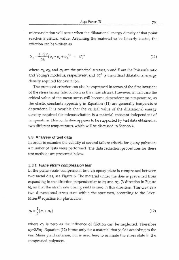
Asp; Paper III 79
microcav i t a t ion w i l l occur w h e n the d i la ta t iona l energy densi ty at that p o i n t
reaches a c r i t i ca l va lue . A s s u m i n g the ma te r i a l to be l i n e a r l y elastic, the
c r i t e r ion can be w r i t t e n as
Uv = l-^(al + <y2 + a3f = Uf (11)
whe re o\, cr?, and 0*3 are the p r inc ipa l stresses, v and E are the Poisson's ra t io
and Young's m o d u l u s , respectively, and UCJ" is the cr i t ica l d i la ta t ional energy
densi ty requi red f o r cavitat ion.
The proposed c r i t e r ion can also be expressed i n terms o f the f i r s t i nva r i an t
o f the stress tensor (also k n o w n as the mean stress). H o w e v e r , i n that case the
c r i t i ca l va lue of the mean stress w i l l become dependent o n temperature , as
the elastic constants appear ing i n Equa t i on (11) are genera l ly tempera ture
dependent . I t is possible that the c r i t i ca l va lue o f the d i l a t a t iona l energy
dens i ty r equ i r ed f o r mic rocav i t a t ion is a ma te r i a l constant independent of
temperature. This content ion appears to be suppor ted b y test data obtained at
t w o d i f f e ren t temperatures, w h i c h w i l l be discussed i n Section 4.
3.3. Analysis of test data
I n order to examine the v a l i d i t y of several f a i lu re cr i ter ia f o r glassy po lymers
a n u m b e r o f tests were pe r fo rmed . The data r educ t i on procedures f o r these
test methods are presented below.
3.3.1. Plane strain compression test
I n the plane s t ra in compression test, an epoxy plate is compressed be tween
t w o meta l dies, see Figure 6. The mater ia l under the dies is prevented f r o m
expand ing i n the d i rec t ion perpendicular to Gj and 02, (3-direct ion i n Figure
6), so that the s t ra in rate d u r i n g y i e l d is zero i n this d i rec t ion . This creates a
t w o d imens iona l stress state w i t h i n the specimen, accord ing to the L é v y -
M i s e s 1 5 equat ion f o r plastic f l o w :
^ = \ { ^ + 0-2) (12)
w h e r e 02 is zero as the in f luence o f f r i c t i o n can be neglected. Therefore
ö3=0 .5o j . Equa t ion (12) is t rue on ly fo r a mater ia l that y ie lds according to the
v o n Mises y i e l d c r i t e r ion , bu t is used here to estimate the stress state i n the
compressed polymers .

Asp; Paper III 80
3.3.2. Uniaxial compression test
I n the u n i a x i a l compression test, the res t ra in ing mater ia l of the p lane s t r a in
compress ion test is r e m o v e d . The compressed mate r ia l is therefore f r ee to
expand i n the plane, p r o v i d e d f r i c t i o n forces can be neglected. A u n i a x i a l
stress state is induced .
3.3.3. Biaxial tension test
A test was designed f o r subjec t ing the resins to b iax ia l tension. The G F / E P
[ 9 0 2 , 0 ° ] ? pa r t o f the l amina te restricts con t rac t ion o f the epoxy sheet. T h e
s t i f f e r G F / E P laminates also suppresses b r i t t l e f a i l u r e o f the epoxy due to
g r o w t h o f surface defects. The lat ter facil i tates plastic f l o w even f o r b r i t t l e
epoxies. A s imi lar test was proposed b y Rezaifard et a l . 1 6 i n w h i c h they b o n d
a neat res in inbe tween t w o 0 ° - l a y e r s of glass f ibe r re inforced plastic (GRP)
laminates . H o w e v e r , the use o f cross-ply laminates instead o f 0 ° - l a m i n a t e s
enhances the b iaxia l stress state i n the epoxy core.
Class ical l amina te t h e o r y , C L T , was used to app rox ima te the stress
s i t ua t i on i n the epoxy u n d e r l o a d i n g . Residual strains i n the epoxy due to
c u r i n g o f laminates were ca lcula ted and t aken i n t o account. The u n i a x i a l
stress-strain behavior i n tension o f the neat epoxies was used as i n p u t data f o r
the epoxy lamellae. Figure 7 shows a typ ica l n o m i n a l stress-strain curve f o r a
b i ax i a l tens ion specimen ( D G E B A / A P T A ) . There is a "knee" i n the n o m i n a l
stress-strain curve. This "knee" is due to m u l t i p l e cracking of the transverse
layers o f the G F / E P . A v a r i a t i o n a l a p p r o a c h 1 7 was used to ca lcu la te
reduct ions i n s t i ffness and Poisson's ra t io due to m u l t i p l e c racking o f the
transverse layer o f the G F / E P . The solut ions were d i v i d e d in to t w o par ts .
F i rs t ly , the s i tuat ion where no cracks existed i n the GF /EP , at strains less t h a n
about 1%. Secondly, the s i tua t ion p r i o r to f a i lu re of the epoxy layer, i.e. a f ter
transverse c rack ing of the G F / E P . The in-plane stresses i n the epoxy w e r e
calculated f o r the cor responding strains us ing CLT.
3.3.4. Thermo-mechanical test
I t was s h o w n i n a previous s t udy that the stress state i n the epoxy d i sk can be
es t imated b y an approx ima te analyt ica l m e t h o d 1 8 . The analysis is based o n
the assumpt ion that the steel adherents are r i g i d i n compar ison to the epoxy
disk. Therefore, the s train i n the epoxy equals the difference i n free expansion
be tween the steel and epoxy disks.

Asp; Paper III 81
The ana ly t ica l analysis does n o t consider any edge effects. The stresses
w i l l t he re fo re be i ndependen t o f the z-coordinate , see F igure 2. Thus , the
b i h a r m o n i c equat ion
is s o l v e d i n po l a r coordinates f o r A i r y ' s stress f u n c t i o n <I>, whe re O is a
f u n c t i o n o f r ad ia l pos i t ion , <I>=<t>(r), on ly . A s a consequence, the t w o in-plane
stresses o> and OQ are i den t i ca l and the in -p lane shear stress rre is zero
t h r o u g h o u t the disk. The stresses are calculated f o r the plane stress s i tua t ion ,
accord ing to
w h e r e the indices r, 0, and z indicate radia l , tangential , and n o r m a l directions,
respectively.
The mechanical proper t ies o f epoxies i n their glassy state are k n o w n to
d e p e n d o n t e m p e r a t u r e 1 9 " 2 1 . I n the analys is desc r ibed above these
dependencies, E(T), OeV0Xy{T), and v(T), are o f great impor tance , see Equa t ion
(14). The in f luence o f the m o d u l i change is easily t aken in to account, as the
m o d u l i at the f a i l u r e t empera tu re corresponds to the u l t i m a t e stresses.
K n o w i n g the t empera tu re dependence of aepoxy, the equ ib i ax i a l strains at
f a i lu re are de te rmined as
V43> = 0 (13)
E ( \
az=0
(14)
(15)
w h e r e Osteel a n d a^oxy (J) a r e the the rmal expansion coefficients f o r steel and
epoxy , respect ively , and T is the temperature . Poisson's ra t io is assumed
independent of temperature.

Asp; Paper III 82
4. RESULTS AND DISCUSSION
4.1. Failure predictions by yield criteria
4.1.1. Uniaxial test results
Results f r o m the un i ax i a l tests are presented i n Table I I . The un i ax i a l tensile
test results we re ob ta ined i n a p rev ious s t u d y 1 0 . F igure 8 shows t y p i c a l
curves f o r mater ia ls tested i n u n i a x i a l compression. U n i a x i a l compress ive
y i e l d stress was de te rmined f o r a l l three epoxies. T G D D M / D D S has a v e r y
h i g h y i e l d stress due to aromat ic groups i n the molecu la r s t ruc ture a n d a
densely cross-l inked n e t w o r k . The i n i t i a l i n f l e x i o n i n the stress-strain curves
are a lways present due to ex t rus ion of excess l u b r i c a n t a n d the genera l
consol idat ion of the press and the test p iece 1 1 .
For t w o of the mater ia ls , D G E B A / D E T A and T G D D M / D D S , i t was n o t
possible to de te rmine the y i e l d stress i n un iax ia l tension, due to p r e m a t u r e
b r i t t l e f a i l u r e . M o r g a n 2 2 d e t e r m i n e d a y i e l d stress o f 83 M P a f o r
D G E B A / D E T A . The rat io o f compressional to tensional y i e l d stresses (Oyjcyi)
is 1.4 and 1.2 f o r D G E B A / D E T A and D G E B A / A P T A respectively, see Table
I I . The relat ionships be tween compressive and tensile y i e l d stresses are i n the
expected range f o r e p o x i e s 1 3 - 1 4 . The resul ts f o r D G E B A / A P T A are i n
agreement w i t h those presented b y L u b i n 2 3 . This i n c o m b i n a t i o n w i t h the
reasonable Oyjoyi ratios observed f o r D G E B A / D E T A and D G E B A / A P T A ,
are i n suppor t of the assumpt ion of negligible f r i c t i o n i n the compression test.
4.1.2. Biaxial test results
Figure 9 shows the stress-strain curves fo r the plane s t ra in compress ion tests
of D G E B A / D E T A and D G E B A / A P T A , fo r w h i c h y i e l d stresses were f o u n d .
N o y i e l d c o u l d be detected f o r T G D D M / D D S before f rac tu re . The y i e l d
stresses are presented a long w i t h u n i a x i a l test data i n Table I I . The y i e l d
stresses of the p lane strain compression specimen are close to those measured
i n un iax ia l compression. The ra t io between the y i e l d stresses i n p lane s t ra in
compress ion and u n i a x i a l compress ion is 1.08 and 1.05 f o r D G E B A / D E T A
and D G E B A / A P T A , respect ively. This is i n agreement w i t h results f o r PS
(1.04) b y B o w d e n et a l 4 b u t less than their results fo r P M M A (1.28).
The results f r o m the b i ax i a l tension tests are presented i n Table I I I . These
resul ts are ca lcu la ted based o n data f o r Poisson's ra t ios a n d t h e r m a l
expans ion coeff ic ien ts presented i n Table I V . The results i n Table I I I are
stresses at f a i lu re o f the epoxy layers. The results f o r T G D D M / D D S are no t of

Asp; Paper III 83
in teres t f o r the eva lua t ion o f y i e l d cr i ter ia as i t d i d n o t y i e l d i n u n i a x i a l
tension.
4.1.3. Yield predictions
E x p e r i m e n t a l data and theoret ical predic t ions o f y i e l d i n g are presented i n
F igu re s 10 ( D G E B A / D E T A ) and 11 ( D G E B A / A P T A ) . Raghava ' s 2 a n d
Bauwens ' s 3 y i e l d criteria are almost ident ical f o r materials w i t h Oyc/Oyt =1-4 or
less. Bauwens's y i e l d cr i ter ion is therefore excluded i n Figures 10 and 11.
The b i ax ia l tension data, i n the f i r s t quadrant of F igure 11 agree w i t h the
v o n Mises a n d Raghava cr i ter ia . This indicates tha t the D G E B A / A P T A
specimen y i e lded p r i o r to br i t t le fracture. This does no t appear to be the case
f o r D G E B A / D E T A . Observat ions of the specimens a f te r f a i l u r e s h o w e d a
n u m b e r of cracks to appear s imultaneously i n a l l materials.
C o m p a r i s o n w i t h experimental data show the m o d i f i e d Tresca c r i t e r ion to
p r e d i c t y i e l d o n the compression side better t han the m o d i f i e d v o n Mises
c r i t e r i a . The m o d i f i e d v o n Mises c r i te r ia show bet ter agreement o n the
tens ion side. I t can therefore be concluded that the examined y i e l d cri teria are
f o u n d to p red ic t y i e l d i n g of glassy epoxies subjected to u n i a x i a l and b i ax ia l
stress states.
Since the examined y i e l d cri teria are three-d imensional , i t is possible to
p r e d i c t y i e l d i n g f o r the compos i t e - l i ke stress state o f the p o k e r - c h i p
s p e c i m e n 1 0 . The actual stress states ( i n c l u d i n g r e s idua l stresses) p r i o r to
f r a c t u r e o f the poker -ch ip specimen are presented i n Table V . The t h e r m a l
stresses are calculated under the assumptions that the a l u m i n i u m substrates
are i n f i n i t e l y s t i f f compared to the epoxy disks and tha t no creep is t a k i n g
place i n the adhesive nor i n the epoxy disks. The calcula ted ef fec t ive and
y i e l d stresses o f the poker chip specimens are presented i n Table V I . I t is
obv ious f r o m these results that the effect ive stress is a lways l o w e r than the
p r e d i c t e d y i e l d stress l i m i t , v i sua l i zed i n Figures 10 a n d 11 . There fore ,
a c c o r d i n g to the c r i te r ia , y i e l d i n g has n o t o c c u r r e d i n the p o k e r - c h i p
spec imens b e f o r e or d u r i n g f a i l u r e . Poker -ch ip s t r a i n to f a i l u r e w a s
p r e v i o u s l y f o u n d to agree w i t h t y p i c a l t ransverse da ta f o r G F / E P 1 0 .
A c c o r d i n g to the cri teria, i n i t i a t ion of fa i lu re i n a transversely loaded G F / E P
composi te w i l l no t take place b y ma t r ix y i e l d i n g i n regions w i t h equ i t r i ax ia l
stress states.

Asp; Paper III 84
4.2. Failure predictions by dilatational energy density criterion The d i l a t a t i ona l energy densi ty c r i t e r ion is appl icable o n l y w h e n the leve l of
d i s to r t i ona l energy densi ty is l o w . For this reason, o n l y methods that subject
the glassy epoxies to a m u l t i a x i a l tensile stress state are considered. These are
the the rmo-mechan ica l d i sk t e s t 1 8 , the b iax ia l tensile test presented above,
and the poker -ch ip t es t 1 0 .
The thermo-mechanical disk test me thod was t h o r o u g h l y invest igated i n a
p r ev ious s t u d y 1 8 . A fa i lu re behavior analysis is presented i n tha t s t udy and
therefore w i l l n o t be repeated here. The u l t ima te in-p lane stresses, crM, and
strains, e u , are ca lcula ted accord ing to Equa t ions (14) and (15). For th is
analysis the t empera tu re dependencies o f the mechan ica l p roper t i e s are
r e q u i r e d . The Young ' s m o d u l u s is k n o w n to increase w i t h a decrease i n
t e m p e r a t u r e 1 9 ' 2 0 . The m o d u l i of tested epoxies w e r e f o u n d to increase b y 55
to 85 percent f o r a temperature i n t e rva l be tween r o o m temperature and -160
° C , see Table V I I . The strains at f a i l u r e for the thermo-mechanica l tests were
ca lcu la ted f r o m the f ree expansions o f the epoxies at the c o r r e s p o n d i n g
t e m p e r a t u r e s . T h e resul ts f r o m the t h e r m o - m e c h a n i c a l d i s k tests are
presented i n Table V I I I . The in-plane stresses are f o u n d to be i n the i n t e rva l
54-73 M P a f o r the three epoxies. No t i ce that the stress state is equ ib iax ia l ,
mean ing tha t rad ia l and tangential stress components are equal.
The ca lcula ted d i la ta t iona l energy densi ty at f a i l u r e f o r the d i f f e r e n t test
methods , accord ing to Equat ion (11), are presented i n Table I X . Table I X also
includes the d i s to r t iona l energy density, fo r compar i son . A s seen i n Table I X
the c r i t i ca l va lue o f the d i l a ta t iona l energy dens i ty is r o u g h l y the same f o r
each m a t e r i a l i n poke r -ch ip and t h e r m a l l y l o a d e d d i s k tests, w h i l e i t is
s l i gh t l y h i g h e r i n the biaxia l tension test. This is p r o b a b l y because the stress
state i n the b i ax i a l tension test has unequa l p r i n c i p a l stresses l ead ing to a
s i g n i f i c a n t dev ia to r i c stress componen t and a c o r r e s p o n d i n g increase i n
d i s t o r t i o n a l energy dens i ty , see Table I X . F u r t h e r m o r e , the h i g h c r i t i c a l
d i l a t a t i ona l energy densi ty of D G E B A / A P T A is exp la ined b y that i t is l i k e l y
to have f a i l e d b y y i e l d i n g i n the b i ax ia l tension test, see Figure 11 . The l o w
d i l a t a t i o n a l energy f o r the u n i a x i a l tensile test o f T G D D M / D D S is due to
crack i n i t i a t i o n at a surface f l a w . Therefore , c o m p a r i s o n be tween c r i t i ca l
d i l a t a t iona l energy densities f o r d i f f e ren t tests is o n l y v a l i d for specimens that
f a i l b y the same mechanism, i.e. cav i ty fo rma t ion .
S terns te in a n d O n g c h i n 1 f o u n d the craze f o r m a t i o n i n P M M A to be
dependen t o n tempera ture . S i m i l a r l y , f o r the present data a t empera tu re
dependence is f o u n d f o r the d i l a t a t i ona l stress componen t (01+02+03) and
hence the average stress. This was observed as data f r o m poker -ch ip and

Asp; Paper III 85
b i ax i a l t ens ion tests at ambient temperature were compared w i t h those f r o m
t h e r m o - m e c h a n i c a l d i s k tests at temperatures be tween -110 and -160 °C .
H o w e v e r f o r d i l a t a t i o n a l energy densi ty, no tempera ture dependence was
observed f o r o u r results. Therefore , w e suggest tha t the use o f d i l a t a t iona l
ene rgy d e n s i t y is p r e f e r r e d to tha t o f d i l a t a t i o n a l o r average stress.
Never theless , f o r f a i l u r e p r e d i c t i o n o f a t ransversely loaded composi te at
amb ien t t empera tu re , a c r i t i ca l average stress o f the res in measured at the
same t e m p e r a t u r e w i l l a p p l y . N o c o r r e l a t i o n is f o u n d b e t w e e n the
d i s to r t i ona l energies at d i f f e r en t load cases f o r the three epoxies, see Table I X .
This is expected as y i e l d i n g was no t the mechanism of fa i lu re .
The resu l t s i m p l y tha t b r i t t l e f a i l u r e i n glassy epoxies subjec ted to
m u l t i a x i a l tensile loads can be predic ted b y the suggested d i la ta t iona l energy
densi ty c r i t e r ion .
5. CONCLUSIONS
E x a m i n a t i o n o f test results o n three epoxy systems u n d e r d i f f e r e n t stress
states reveals tha t the i r y i e l d stress can be described sa t i s fac tor i ly b y y i e l d
cr i ter ia o n l y w h e n the stress state results i n su f f i c i en t ly h i g h energy densi ty of
d i s t o r t i o n . W h e n the energy densi ty of d i s to r t ion is l o w such tha t y i e l d i n g is
n o t i m m i n e n t , the e n e r g y d e n s i t y o f d i l a t a t i o n causes f a i l u r e b y
m i c r o c a v i t a t i o n and subsequent crack in i t i a t i on . This behavior suggests tha t
i n e v a l u a t i n g m a t r i x behav io r i n f ibe r composi tes loaded t ransverse ly to
f ibe r s , b o t h y i e l d i n g and crack i n i t i a t i o n f r o m m i c r o c a v i t a t i o n m u s t be
considered.
Acknowledgements M s K r i s t i i n a O k s m a n and M r . Ph i l ippe Genty are g r a t e f u l l y acknowledged
f o r measurements o f temperature dependence of Young 's m o d u l u s and the b iax ia l tens ion test results.

Asp; Paper III 86
REFERENCES
1. S.S. Sternstein and L . O n g c h i n , Y i e l d cr i ter ia f o r plast ic d e f o r m a t i o n o f
glassy po lymers i n general stress f ie lds , A.C.S. Pol. Prep., 10, (1969), p p . 1117-
1124.
2. R.S. Raghava, R . M . C a d d e l l a n d G.S.Y. Yeh , The macroscopic y i e l d
behav ior o f polymers , / . Mater. Sci, 8, (1973), p p . 225-232.
3. J.C. Bauwens, Y i e l d c o n d i t i o n and p ropaga t ion of L ü d e r s ' l ines i n tension-
to r s ion experiments o n p o l y ( v i n y l chlor ide) , / . Polymer Sci, pa r t A - 2 , 8, (1970),
p p . 893-901.
4. P.B. B o w d e n and J.A. Jukes, The plastic f l o w of isotropic po lymers , / . Mater.
Sci, 7, (1972), pp . 52-63.
5. L M . W a r d , Rev iew: The y i e l d behav iour o f p o l y m e r s , J. Mater. Sci, 6, (1971), p p . 1397-1417.
6. S.K. Joneja, Inf luence of m a t r i x d u c t i l i t y o n transverse fa t igue a n d f rac ture
toughness o f glass re inforced composites, SAMPE Quarterly, July , (1984), p p .
31-38.
7. D . H u l l , An introduction to composite materials, Cambr idge U n i v e r s i t y Press,
Cambr idge , 1981.
8. K . W . Garret t and J.E. Bailey, The effect of resin f a i lu re s t ra in o n the tensile
proper t ies o f glass f ibre- re inforced polyester cross-ply laminates, / . Mater. Sci,
12, (1977), p p . 2189-2194.
9. R . M . Christensen and J A . Rinde, Transverse tensile characteristics of f ibe r
composi tes w i t h f l ex ib l e resins: Theo ry and test results, Pol. Eng. Sci, 19, (1979), p p . 506-511.
10. L .E . A s p , L . A . Be rg lund and P. G u d m u n d s o n , Effects o f compos i te - l ike
stress state o n the f racture of epoxies, Comp. Sci. Techn., 53, (1995),pp. 27-37.
1 1 . J.G. W i l l i a m s a n d H . F o r d , Stress-strain r e l a t i o n s h i p s f o r some
un re in fo rced plastics, / . M ech. Eng. Sci, 6, (1964), pp . 405-417.
12. R . N . H a w a r d , The physics of glassy polymers, A p p l i e d Science Publ ishers
L t d , L o n d o n , 1973.
13. J .N. Sultan and F.J. M c G a r r y , Effect of rubber part icle size o n d e f o r m a t i o n
mechanisms i n glassy epoxy, Pol. Eng. Sci, 13, (1973), pp . 29-34.
14. A.J . K i n l o c h and S.J. Shaw, The f rac ture resistance o f a toughened epoxy
adhesive, J. Adhesion, 12, (1981), pp.59-77.

Asp; Paper III 87
15. H i l l , R., The mathematical theory of plasticity, O x f o r d U n i v e r s i t y
Publ icat ions, O x f o r d , 1950.
16. A . M . R e z a i f a r d , M . G . Bader a n d P .A. S m i t h , I n v e s t i g a t i o n o f the
t ransverse p roper t i es of a u n i d i r e c t i o n a l c a r b o n / e p o x y lamina te : Par t 1-
M a t r i x propert ies , Comp. Sci. Techn., 52, (1994),pp. 275-285.
17. Z . H a s h i n , Ana lys i s of cracked laminates: A va r i a t iona l approach, Mech.
Mat, 4, (1985), p p . 121-136.
18. L .E . A s p and L . A . B e r g l u n d , A b i ax i a l thermo-mechanica l d i s k test f o r
glassy epoxies, submi t ted to Exp. Mech.
19. v a n K r e v e l e n , D . W . , Properties of polymers, correlations with chemical
structure, Elsevier Pub l i sh ing Company , A m s t e r d a m , 1972.
20. E.F. O l e i n i k , Epoxy-Aromatic Amine Networks in the Glassy State Structure
and Properties, i n K . Dusek (ed), Epoxy Resins and Composi tes I V , B e r l i n
(Springer Ver lag) , 1986. pp . 50-99.
2 1 . V . B . G u p t a , L . T . D r z a l , C.Y-C. Lee a n d M.J . Rich , The t empera tu re -
dependence of some mechanical properties of a cured epoxy resin system, Pol.
Eng. Sci., 25, (1985), p p . 812-823.
22. R.J. M o r g a n and J.E. O ' N e i l , The d u r a b i l i t y o f epoxies, Polym. -plast.
Technol. Eng., 10, (1978), p p . 49-116.
23. G. L u b i n , Handbook of Composites, V a n N o s t r a n d Re inho ld C o m p a n y , N e w
Y o r k , (1982).

Asp; Paper III 88
Tables
Table I . Cure schedule and mater ia l composi t ion.
Epoxy system Cure Post-cure Material Composition (curing agent by weight)
DGEBA/DETA 2 h / 2 0 °C 24 h /102 °C 11.9 % DGEBA/APTA 16 h / 6 0 °C 44.8% TGDDM/DDS 4 h / 1 5 0 °C l h / 200°C 44%
Table I I . Y i e l d stresses f o r epoxy systems under d i f f e r e n t load condi t ions .
E p o x y system Uniax ia l tension U n i a x i a l P la in s t ra in
compression compression
Cyt OyC
D G E B A / D E T A 83 MPa* 113+5 M P a 122±3 M P a D G E B A / A P T A 78±1.2 MPa 91.4+2.0 M P a 96.2+1.6 M P a T G D D M / D D S n o y ie ld 207 M P a no y i e l d
Reference 22
Table I I I . Biaxial tension data, stresses at fa i lure .
E p o x y system c x (MPa) a y (MPa)
D G E B A / D E T A 65 26
D G E B A / A P T A 94 34
T G D D M / D D S 83 34
Table I V . Exper imenta l data for the three epoxies. T h e r m a l expansion
coeff ic ient , a, measured i n the in terva l 10-70°C.
E p o x y system Poisson's rat io
v
The rma l expansion
coefficient , a
D G E B A / D E T A
D G E B A / A P T A
T G D D M / D D S
0.345
0.318
0.328
6 6 » 1 0 " 6 / o C
6 6 « 1 0 - 6 / ° C
5 2 « 1 0 - 6 / ° C
Table V . A c t i v e stresses at fa i lure i n the center of the poker -ch ip specimen
(ref. Asp94) , i n c l u d i n g the rmal stresses f r o m specimen prepara t ion .
E p o x y system no rma l stress in-plane stresses
D G E B A / D E T A
D G E B A / A P T A
T G D D M / D D S
o 2 =27.6 M P a
o z =32.9 MPa
o z =30.5 M P a
o- r=ae=27.5 M P a
a r =ae=33.8 M P a
OY=ae=31.1 M P a

Asp; Paper III 89
T a b l e V I . Table o f y i e l d cr i ter ia . L e f t side gives va lue o f y i e l d cr i ter ia at p o k e r - c h i p f a i l u r e , i n c l u d i n g the rma l stresses f r o m spec imen prepara t ion .
R i g h t side gives pred ic ted values at y i e l d i n g . A l l un i t s i n M P a .
v o n Mises
E p o x y system V ^ - O y DGEBA/DETA 0.1 < 85 DGEBA/APTA 0.9 < 78
Raghava
E p o x y system ^J2 + 2(ayc-ay,)l]<^2aycay,
DGEBA/DETA 70 < 137 DGEBA/APTA 52 < 119
Bauwens
E p o x y system A ° * - a * ) 2 V 2 f f f f ,
DGEBA/DETA 18 < 135
DGEBA/APTA 12 < 119
M o d i f i e d Tresca
E p o x y system (
l 0 max"°rniri l- 2 G
1 ( f f -<T„).
2 ( O - C + CTJ
DGEBA/DETA
DGEBA/APTA 0.1 0.9
83 76

Asp; Paper III 90
Table V I I . Young 's m o d u l u s of the tested epoxies at r o o m temperature and at
the cor responding fa i lu re temperature i n the thermo-mechanical test.
E p o x y system E (at room temerature) E (at failure temp.)
DGEBA/DETA
DGEBA/APTA
TGDDM/DDS
2.07 GPa
2.93 GPa
3.77 GPa
3.85 GPa
4.81 GPa
5.84 GPa
Table V I I I . Results f r o m thermo-mechanical d i sk test, temperature change at
f a i lu re , u l t i m a t e stress and strain.
E p o x y system AT (°C) a u (MPa) £u (%) DGEBA/DETA
DGEBA/APTA
TGDDM/DDS
-269±17
-243±38
-219±30
54.1
72.6
54.8
0.92
1.02
0.63
Table I X . Test results, d i la ta t ional ( U v ) and d i s to r t iona l (Ud) energy densities
(MPa) at f rac ture f o r d i f f e ren t test methods.
E p o x y DGEBA/DETA
system
DGEBA/APTA TGDDM/DDS
Test m e t h o d U y U d U v U d U v U d
Poker chip 0.17 (3-D)
0.00 0.20 0.00 0.13 0.00
Thermally loaded epoxy Q Iß
disk (2-D) 0.33 0.27 0.48 0.12 0.23
Biaxial tension test 0.21 (2-D)
0.70 0.34 1.0 0.21 0.61
Uniaxial tension
*
0.055 0.42
*Non-l inear elastic behavior. U v and U d are de f ined f r o m linear elasticity.

Asp; Paper III 91
FIGURE CAPTIONS
Figure 1. Schematic o f the sample design. A h y b r i d laminate consis t ing of an
epoxy core inbe tween t w o cross-ply laminates, causing a b iax ia l tensile stress
state.
Figure 2. Schematic o f specimen f o r the thermo-mechanical d i sk test.
Figure 3. Schematic of the insulated test chamber used f o r coo l ing of the r i n g
specimen.
Figure 4. a) N u c l e a t i o n and equiaxia l g r o w t h o f a cav i ty unde r equ i t r i ax ia l
tension, b) Crack f o r m a t i o n f r o m cavi ty and g r o w t h i n a p re fe r r ed d i r ec t ion
n o r m a l to the m a x i m u m pr inc ip le stress.
Figure 5. Scanning electron mic rog raph of the i n i t i a t i o n p o i n t i n a poker ch ip
specimen of D G E B A / D E T A .
Figure 6. Plane s t ra in compression test set-up.
Figure 7. Stress-strain b e h a v i o r o f the D G E B A / A P T A b i a x i a l t e n s i o n
specimen.
Figure 8 Expe r imen ta l data f r o m the un iax ia l compression test f o r the three
epoxies.
Figure 9. Stress-strain curves f r o m the p lane s t ra in compres s ion test o f
D G E B A / D E T A and D G E B A / A P T A .
Figure 10. C o m p a r i s o n be tween exper imenta l data f o r D G E B A / D E T A and
the d i f f e r e n t y i e l d cri teria predict ions.
Figure 11. C o m p a r i s o n be tween exper imenta l data f o r D G E B A / A P T A a n d
the d i f f e r en t y i e l d cri teria predict ions.

Figure 1. Schematic o f the sample design. A h y b r i d laminate consis t ing of an
epoxy core i nbe tween t w o cross-ply laminates, causing a b iax ia l tensile stress
state.

Asp; Paper III 93
Figure 2. Schematic o f specimen f o r the thermo-mechanical disk test.

Asp; Paper III 94
Liquid nitrogen Observation window Thermocouple mounted on the sample
Insulation
B Test sample
Figure 3. Schematic of the insulated test chamber used f o r coo l ing o f the r i n g
specimen.

Asp; Paper III 95
Figu re 4. a) N u c l e a t i o n and equiaxia l g r o w t h o f a cav i ty under equ i t r i ax i a l
tension, b) Crack f o r m a t i o n f r o m cavi ty and g r o w t h i n a p re fe r red d i r ec t i on
n o r m a l to the m a x i m u m pr inc ip le stress.

Asp; Paper III 96
D G E B f l - ' D E T f l 0 0 0 1 0 ZOvm > '
Figure 5. Scanning electron mic rog raph of the i n i t i a t i o n p o i n t i n a poker ch ip
specimen of D G E B A / D E T A .

Asp; Paper III 97
F igure 6. Plane strain compression test set-up

Asp; Paper III 98
400
0 1 2 3 4
Strain, £ (%)
F i g u r e 7. Stress-strain b e h a v i o r o f the D G E B A / A P T A b i a x i a l t e n s i o n
specimen.

Asp; Paper III 99
300
F i g u r e 8. Exper imenta l data f r o m the u n i a x i a l compress ion test f o r the three epoxies.

Asp; Paper III 100
150
0 10 20
Strain, 8 (%)
F i g u r e 9. Stress-strain curves f r o m the p l ane s t r a in compress ion test o f D G E B A / D E T A and D G E B A / A P T A .
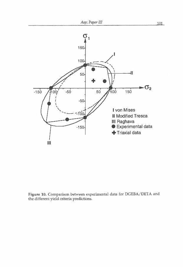
Asp; Paper III 101
F i g u r e 10. C o m p a r i s o n between exper imenta l data f o r D G E B A / D E T A a n d
the d i f f e r e n t y i e l d cri teria predictions.

Asp; Paper III 102
F i g u r e 11. C o m p a r i s o n be tween exper imen ta l data f o r D G E B A / A P T A and
the d i f f e r e n t y i e l d cri teria predict ions.


Asp; Paper PV 105
Prediction of matrix initiated transverse failure in polymer composites
Le i f E. Asp and Lars A . Berglund*
Div. of Polymer Engineering
Luleå University of Technology
S-971 87 Luleå, Sweden
Ramesh Talreja
School of Aerospace Engineering
Georgia Institute of Technology
Atlanta, Georgia 30332-0150, USA
Abstract A s t u d y is conducted of fa i lu re i n un id i rec t iona l ly re inforced f iber composites
l oaded i n tension n o r m a l to fibers. The case considered is w h e n this f a i lu re is
g o v e r n e d b y f a i l u r e o f the m a t r i x ra ther t h a n f i b e r / m a t r i x d e b o n d i n g .
Y i e l d i n g as w e l l as cavi ta t ion-induced br i t t l e f a i lu re o f m a t r i x are considered.
The lat ter m o d e of f a i l u r e was suggested b y a p rev ious s t u d y 1 as the l i k e l y
m o d e to occur i n epoxies unde r stress states tha t are p u r e l y or nea r ly
hydros ta t ic tension. Three f iber packing arrangements (square, hexagonal and
square-diagonal) w i t h d i f fe ren t f iber v o l u m e f r ac t i on are s tud ied numer ica l ly
b y a f i n i t e element me thod to determine the local stress states. I t is f o u n d that
c av i t a t i on - induced b r i t t l e f a i lu re occurs m u c h before y i e l d i n g i n a l l cases.
Exper imen ta l data taken f r o m the l i terature suppor t this f i n d i n g .
1. INTRODUCTION
W h e n a glassy p o l y m e r such as epoxy is l oaded u n i a x i a l l y i t d i sp lays
d i f f e r e n t y i e l d stress i n tension and compress ion. This is a t t r ibu ted to the
e f f ec t o f hyd ros t a t i c stress o n shear -dr iven y i e l d i n g . The classical y i e l d
c r i t e r ia , e.g. v o n Mises and Tresca, w h i c h are insensi t ive to the hydros ta t ic
stress, have thus been m o d i f i e d to account f o r this e f f ec t 2 " 4 . A l t h o u g h the
p h y s i c a l basis of the role of hydrosta t ic stress o n the y i e l d behavior is no t
f u l l y u n d e r s t o o d , there is no d o u b t tha t i n glassy p o l y m e r s this stress
* To whom correspondence should be addressed

Asp; Paper JV 106
componen t has a special s ignificance. For instance, Sternstein and O n g c h i n 5
f o u n d tha t craze f o r m a t i o n i n P M M A occurred i n a b i ax ia l stress f i e l d w h e n
the f i r s t i n v a r i a n t o f the stress tensor was pos i t i ve . They used th is stress
i n v a r i a n t i n a c r i t e r ion f o r d i l a ta t iona l y i e l d i n g . Sul tan and M c G a r r y 6 f o u n d
tha t c av i t a t i on i n glassy po lymer s was fac i l i t a ted b y part icles and that the
y i e l d stress s h o w e d more sens i t iv i ty to the hydros ta t ic tensile stress w h e n
c a v i t a t i o n occurred than w h e n i t d i d no t occur. Th i s apparent c o u p l i n g o f
d i l a t a t iona l and d is tor t iona l effects i n glassy po lymer s manifests i n behavior
no t observed i n crystall ine materials such as metals.
M o s t studies repor ted i n the l i t e ra ture have considered the d i l a t a t iona l
ef fects o n y i e l d i n p o l y m e r s . O n e m a y ask the ques t ion : w h a t i f the
d i s t o r t i o n a l effects (deviator ic stress) are sma l l a n d the d i l a ta t iona l effects
(hydrostat ic stress) are dominant? I n other words , i f y i e l d is suppressed, w h a t
w o u l d the effect o f the hydrostat ic stress be? This quest ion was considered i n
a p r e v i o u s s t u d y 7 where the so-called poke r c h i p test was p e r f o r m e d o n
epoxies to in t roduce an equi t r iax ia l tensile stress state. The apparent s t ra in to
f a i l u r e was f o u n d to reduce d ramat ica l ly . Based o n the l inear stress-strain
behav ior and appearance of fa i lu re surfaces, cav i ta t ion w i t h o u t y i e l d i n g m a y
be p roposed as the cause o f f a i lu re . I n a later s t u d y 1 i t was pos tu la ted that
cav i t a t ion w i t h i n an elastic f i e l d i n a glassy p o l y m e r w i l l g r o w unstably and
tha t th is w i l l occur w h e n the s tored d i l a t a t iona l energy densi ty reaches a
cr i t ica l value. This cr i ter ion was evaluated b y conduc t ing tests o n three epoxy
systems i n stress states r a n g i n g f r o m u n i a x i a l to b i a x i a l w i t h d i f f e r e n t
p r i n c i p a l stress ratios and f i n a l l y to equ i t r i ax ia l tension. As the stress state
approached equibiaxia l plane stress (where the d i s to r t iona l energy densi ty is
l o w ) a n d equi t r i ax ia l tension (where the d i s to r t iona l energy densi ty is zero),
the m o d i f i e d y i e l d cri teria account ing fo r hydros ta t ic stress fa i l ed to p red ic t
the c r i t i c a l states. Ins tead, the d i l a t a t i o n a l energy dens i ty approached a
constant va lue f o r these states. The cr i t i ca l va lue o f the d i la ta t iona l energy
densi ty was f o u n d also to be nearly the same at t w o d i f f e r en t temperatures.
I n compos i tes loaded i n t e n s i o n n o r m a l to f i be r s , three c o m p e t i n g
i n i t i a t i o n mechanisms can be expected to occur: f i b e r / m a t r i x d e b o n d i n g ,
y i e l d i n m a t r i x a n d c a v i t a t i o n - i n d u c e d b r i t t l e m a t r i x f a i l u r e . I n a r ea l
composi te , w h i c h m a y have an i r r egu la r d i s t r i b u t i o n o f f ibers, i t is expected
tha t the local stress states w o u l d v a r y such that the m i x o f devia tor ic and
d i l a t a t i ona l stress components c o u l d v a r y f r o m p u r e l y deviator ic to p u r e l y
d i la ta t iona l . Thus the ma t r ix c o u l d y i e l d i n some regions w h i l e other regions
c o u l d f a i l b y c a v i t a t i o n - i n d u c e d c rack ing . The f i b e r / m a t r i x d e b o n d i n g

Asp; Paper PV 107
depends o n no t o n l y the stress state at the f i b e r / m a t r i x interface b u t also o n a
range o f o ther factors such as the adhesion and toughness o f the interface.
N u m e r o u s studies o f interfaces i n composites have been conducted a n d this
f i e l d is s t i l l v e r y active. The present s t udy is focused o n stress f i e l d i n d u c e d
effects o n the y i e l d i n g a n d f a i l u r e o f m a t r i x constra ined w i t h i n s t i f f f ibe r s ,
a s suming tha t the f i b e r / m a t r i x b o n d remains intact . Three f i be r p a c k i n g
arrangements - square, hexagonal and square-diagonal - are considered i n a
f iber composi te loaded transversely i n tension. A numer ica l stress analysis b y
the f i n i t e e lement m e t h o d is conducted. The v o n Mises y i e l d c r i te r ion a n d the
d i la ta t iona l energy densi ty c r i t e r ion are app l i ed to locate the zones of y i e l d i n g
a n d cav i t a t ion - induced b r i t t l e f a i lu re , respectively. The results are ob ta ined
f o r d i f f e r e n t f i be r v o l u m e f rac t ions and against these the exper imenta l data
available i n the l i tera ture are examined.
2. METHOD OF ANALYSIS
2.1. Materials T h e a n a l y z e d compos i t e consists o f an epoxy sys tem, D G E B A / D E T A ,
r e i n f o r c e d b y glass f ibers . The mechanical proper t ies o f the epoxy sys tem
have been exper imen ta l ly invest igated i n previous s t u d i e s 1 ' 7 ' 8 . The ma te r i a l
proper t ies used i n the analysis are presented i n Table I . Recently, de K o k 1 0
r epor t ed expe r imen ta l transverse s t rength and m o d u l u s values f o r a glass
f ibe r r e in fo rced epoxy at d i f f e r e n t f iber v o l u m e fract ions. Those data w i l l be
used here f o r compar i son w i t h ou r analysis. The ma te r i a l proper t ies o f the
constituents i n the composi te used b y de K o k are s h o w n i n Table I I .
2.2. Material model and packing arrangements Analys i s of the local stresses i n a f iber composite loaded i n transverse tens ion
was conduc ted us ing a commerc ia l f i n i t e element code A N S Y S ® . Three f iber
p a c k i n g a r rangements - square, hexagona l and square -d iagona l - w e r e
analyzed, a n d f o r each case a u n i t cell was constructed. These are s h o w n i n
F i g u r e 1. D u e to the u n i f o r m i t y a n d s y m m e t r y o f the f i b e r p a c k i n g
arrangements, a l l quanti t ies averaged over a u n i t cell are also averages over a
represen ta t ive v o l u m e e lement (RVE) of the compos i te . T h e m a t r i x is
assumed to be pe r f ec t ly b o n d e d to the f ibers t h r o u g h o u t the analysis. B o t h
m a t r i x and f ibers are assumed to be l inear ly elastic. The v o l u m e f r a c t i o n of
f ibers was v a r i e d be tween 20 and 70 or 80 percent i n the RVEs depend ing o n

Asp; Paper IV 108
the f i b e r d i s t r i b u t i o n . E i g h t n o d e " P L A N E 8 2 " q u a d r i l a t e r a l - t r i a n g u l a r
elements w e r e used i n the f i n i t e element code i n a l l u n i t cells. The element has
t w o degrees o f f r e e d o m at each node. I n this analysis the "PLANE82" element
assumes a u n i t d e p t h and was c o n f i g u r e d to m o d e l p l ane s t ra in . The
" P L A N E 8 2 " e lement does n o t a d m i t the assumpt ion o f genera l ized p l ane
strain, i.e. tha t the average stress i n the z-direct ion is zero and the s train i n the
z - d i r e c t i o n at a n y p o i n t is nonzero b u t constant t h r o u g h o u t the r eg ion .
H o w e v e r , the differences i n local stresses caused b y the use of plane s t ra in
rather than generalized plane strain are expected to be s m a l l 1 1 .
The u n i t cells we re sub jec ted to l o a d i n g a n d b o u n d a r y c o n d i t i o n s
representat ive f o r a state of transverse tensile load ing , see F igure 2. For a l l
f iber d i s t r ibu t ions , u n i t cell displacements i n the x-d i rec t ion were p r o h i b i t e d
f o r a l l nodes o n the le f t edge. S imi la r ly , displacements i n the y-d i rec t ion were
p r o h i b i t e d f o r a l l nodes o n the lower edge. External stress was app l i ed to the
u n i t ce l l o n the r i g h t edge b y means o f negat ive pressure, or. To f u l f i l
c o m p a t i b i l i t y w i t h n e i g h b o r i n g u n i t cells, the uppe r and r i g h t edges w e r e
cons t ra ined to r e m a i n s t r a igh t a f te r d e f o r m a t i o n . T h e r m a l stresses w e r e
c o m p u t e d u n d e r the assumpt ion that the tempera ture is spa t ia l ly u n i f o r m
t h r o u g h o u t the u n i t ce l l . Based o n the m a x i m u m cure t e m p e r a t u r e , a
temperature change of -82 °C was used i n the analyses.
Rad ia l , t a n g e n t i a l (hoop) and z-d i rec t ional stresses (o>, ag, az), w e r e
calculated f o r the transverse tensile stress ( o r ) app l i ed o n the u n i t cells. To
a v o i d p r o b l e m s due to stress averag ing f o r d i s s imi l a r mater ia l s , m a t r i x
stresses were evaluated w i t h i n selected elements.
FE-meshes o f the three d i f f e r e n t u n i t cells are s h o w n i n Figures 3-5. T o
analyze a square a r ray o f f ibe rs , the m o d e l l e d u n i t ce l l is a quar te r o f a
pe r iod ic e lement , see Figures 1 and 3. Past experience suggests tha t th is
m o d e l y ie lds reasonable r e s u l t s 1 2 " 1 4 . The u n i t cell of the hexagonal f iber ar ray
is m o d e l l e d b y one s ix th ( 1 /6 ) of the per iodic element, see Figures 1 and 4.
A l s o this u n i t ce l l is cons t ra ined to s t ra ight edges. A s i m i l a r mesh w a s
analyzed f o r meta l ma t r ix composites b y B ö h m et a l . 1 5 . A s f o r the square f ibe r
array, the R V E of a square-diagonal array is mode l l ed b y one quarter o f the
u n i t cell , see Figures 1 and 5. Similar meshing has been used i n the analyses of
meta l m a t r i x composites b y Brockenbrough et a l . 1 2 .

Asp; Paper PV 109
2.3. Failure criteria T w o d i f f e r e n t cri teria are used to p red ic t fa i lu re in i t i a t ion i n the m a t r i x w i t h i n
the composi te . The c r i t e r ion f i r s t to reach its cr i t ica l value i n any p o i n t o f the
m a t r i x is assumed to in i t ia te fa i lu re i n the G F / E P composite.
Firs t , the d i la ta t iona l energy densi ty cr i te r ion assumes fa i lu re to in i t i a te i n
the m a t r i x mate r ia l of a composite due to the induced t r iaxia l stress state. The
d i l a t a t i o n a l energy dens i ty c r i t e r i on was p roposed f o r cav i t a t ion - induced
fa i lu re i n a p rev ious s t u d y 1 . The d i la ta t ional (volumetr ic) energy densi ty f o r a
l inear elastic mater ia l is g iven b y
Uv=——(a1 + ( j 2 + cT3) (1) 6E
where cr j , (72, and 03 are the p r i n c i p a l stresses, v and E are the Poisson's ra t io
a n d Young ' s m o d u l u s , respect ively . Cav i t a t i o n - in d u ced b r i t t l e f a i l u r e is
assumed to occur at a p o i n t w h e n this quan t i ty attains a cr i t ical value (Uc"'\.
This ma te r i a l parameter is obtained b y an equi t r iax ia l test such as the poke r
ch ip test. Uc"' f o r D G E B A / D E T A epoxy was obta ined i n a prev ious s t u d y 1 .
The c r i t i c a l d i l a t a t i o n a l ene rgy d e n s i t y appears n o t t o d e p e n d o n
tempera ture , w h i l e the cr i t ica l hydros ta t ic stress is temperature dependent
due to the temperature dependency of the elastic properties.
The second cr i t e r ion used here is the v o n Mises y i e l d cr i ter ion. Y i e l d stress
of glassy po lymer s is k n o w n to be sensitive to hydrostat ic pressure. The v o n
Mises y i e l d c r i t e r ion does no t take the dependence of hydros ta t ic pressure
in to account. Howeve r , the inf luence of the hydrostat ic pressure w i l l resul t i n
the v o n Mises effect ive stress becoming an underest imate o f the t rue y i e l d
stress i n the f i r s t quadran t and an overest imate e lsewhere 1 . A l s o , i t was
s h o w n i n the refer red s tudy that f a i l u r e i n m u l t i a x i a l l y tensile loaded ( f i r s t
quadran t ) D G E B A / D E T A epoxy was not caused b y y i e ld ing . Therefore , the
v o n Mises y i e l d c r i t e r ion w i l l give a conservative est imation of y i e l d i n i t i a t ed
fa i lu re .
3. RESULTS AND DISCUSSION
3.1. Local stresses and failure initiation sites W e examine t w o modes of fa i lure : cavi ta t ion- induced c r a :k ing and y i e l d i n g ,
and assume that each occurs w h e n the local stress state becomes c r i t i ca l f o r
that m o d e o f fa i lu re . The fa i lu re i n i t i a t i o n sites i n a u n i t cell are de te rmined

Asp; Paper PV 110
b y a p p l y i n g the d i l a t a t iona l energy dens i ty c r i t e r ion f o r cav i t a t ion - induced
c rack ing a n d the v o n Mises c r i te r ion f o r y i e l d i n g . The loca t ion o f these sites
are presented i n F igure 6. The sites o f cav i ta t ion- induced f a i l u r e i n a l l three
f iber p a c k i n g conf igura t ions l ie at the f iber poles, i.e., at intersections be tween
the f ibe r center-l ine paral lel to the load ing axis and the f ibe r surface. The sites
of y i e l d i n g , o n the other hand , depend o n the f ibe r p a c k i n g c o n f i g u r a t i o n .
Thus , f o r the square d i s t r i b u t i o n the sites are at the f i b e r equators, 9 = 9 0 ° ,
w h i l e f o r the hexagonal d i s t r i b u t i o n these are at 9 = 6 0 ° a n d f o r the square-
d iagona l the sites are at 0=45° or 9=0° . I n the last case of 9 = 0 ° , the loca t ion o f
y i e l d i n g is no t at the f iber pole bu t at the edge of the u n i t cell .
The f a i l u r e i n i t i a t i o n sites fo r the t w o modes of f a i l u r e do n o t co inc ide
since the u n d e r l y i n g f a i l u r e cr i ter ia are based o n t w o d i f f e r e n t energy
densit ies. Indeed , the three p r i n c i p a l stresses at the f i b e r poles are nea r ly
equa l w h e n the t h e r m a l stresses are i n c l u d e d . Thus , the devia tor ic energy
dens i ty is a lmost zero at these points . A t a p o i n t i n a u n i t cel l whe re y i e l d i n g
occurs the d i la ta t iona l energy density reaches its m i n i m u m .
3.2. Critical failure mode and transverse failure predictions The c r i t i c a l d i l a t a t i ona l energy densi ty and y i e l d stress of D G E B A / D E T A
were inves t iga ted i n a previous s t u d y 1 and f o u n d to be 0.2 M P a and 83 M P a ,
r espec t ive ly . The ca lcula ted d i l a t a t i o n a l energy dens i t y a n d v o n Mises
e f fec t ive stress i n the m a t r i x are compared to its c r i t ica l d i l a t a t iona l energy
dens i ty a n d y i e l d stress f o r each considered f iber v o l u m e f r a c t i o n and f i be r
d i s t r i b u t i o n . I n n o case does the v o n Mises ef fec t ive stress reach the y i e l d
stress before the d i la ta t iona l energy densi ty reaches i ts c r i t i ca l value. I n fact,
o u t of a l l the considered cases the largest va lue of the v o n Mises e f fec t ive
stress at i n i t i a t i o n of cavi ta t ion- induced b r i t t l e f a i lu re was on ly 52 MPa . This
was f o r a square-diagonal f iber d i s t r i bu t i on at a v o l u m e f r a c t i o n of 0.7. Thus ,
the cav i t a t ion - induced b r i t t l e f a i lu re is the more c r i t i ca l one ou t of the t w o
modes o f f a i l u r e considered. A l s o , qu i t e i m p o r t a n t l y , th i s f a i l u r e m o d e
becomes c r i t i ca l w h e n the stress state i n the s u r r o u n d i n g m a t r i x ma te r i a l is
s t i l l m u c h b e l o w that requi red fo r y i e l d i n g . The condi t ions f o r b r i t t l e f a i l u r e
are therefore present.
A l t h o u g h the cavi ta t ion- induced cracks w i l l in i t ia te at the f iber poles, the
g r o w t h o f these cracks i n t o the s u r r o u n d i n g m a t r i x m a y n o t occur
instantaneously. A s a crack grows i t w i l l enter zones w h e r e the stress f i e l d is
less in tens ive t h a n at the f ibe r poles. A l s o , the crack t i p w i l l i nduce h i g h
stresses loca l ly causing y ie ld ing . Thus the crack t i p can s l o w d o w n or even be
arrested. A n increased stress w o u l d then have to be imposed to cause f u r t h e r

Asp; Paper PV 111
crack g r o w t h , crack l i n k - u p and fai lure . Since the exper imenta l data available
is f o r transverse s t reng th at to ta l f a i lu re (separation) w e shal l compare our
n u m e r i c a l p red ic t ions of f a i lu re in i t i a t ion w i t h this value.
P r e d i c t e d t ransverse s t r eng th ( transverse f a i l u r e i n i t i a t i o n ) o f f i b e r
composi tes is f o u n d to be s t rong ly dependent o n the f i be r v o l u m e f r a c t i o n
a n d f i b e r d i s t r i b u t i o n , see Figure 7. The effect o f f iber v o l u m e f r a c t i o n o n
transverse s t ra in to f a i l u r e is s t rong, as seen i n Figure 8. The mos t severe of
the ana lyzed f i be r d i s t r i bu t ions f o r G F / E P composites are hexagona l and
square arrays, as s h o w n i n Figures 7 and 8. Transverse s t rength and s t ra in to
f a i l u r e o f square a n d hexagonal f iber d i s t r ibu t ions are s i g n i f i c a n t l y l o w e r
t h a n those f o r the square-diagonal array. The square-diagonal a r r ay is a
square array t i l t e d 45° to the load direct ion. The altered load d i r ec t ion results
i n an increase i n s t rength except f o r h i g h v o l u m e f ract ions of f i be r (Vf=0.7)
and a general increase i n s t ra in to fa i lu re , as seen i n Figures 7 and 8, due to
the l o w e r e d transverse m o d u l u s . These results i m p l y that the presence of
r eg ions w i t h square or hexagonal f ibe r d i s t r ibu t ions w i l l c o n t r o l f a i l u r e
i n i t i a t i o n i n a t r ansverse ly loaded G F / E P compos i te . For these f i b e r
d i s t r ibu t ions i t is i m p o r t a n t to observe the dependence of transverse s t rength
o n f i be r v o l u m e f r ac t i on , see Figure 7. A c c o r d i n g to the d i l a t a t iona l energy
densi ty c r i t e r ion , m i n i m a i n transverse strength f o r intermediate f ibe r v o l u m e
f rac t ions are predic ted . A s a consequence, the transverse s t rength o f a G F / E P
compos i t e w i t h an average f i be r v o l u m e f r a c t i o n o f 0.4-0.6 w i l l n o t be
w e a k e n e d b y f i b e r agglomerates as they are of h i g h loca l f i b e r v o l u m e
f ract ions a n d therefore can sustain higher loads than their sur roundings .
The observat ion that fa i lu re w i l l ini t iate i n regions of square and hexagonal
f i b e r d i s t r i b u t i o n s p r o v i d e s a p o s s i b i l i t y to extract i n f o r m a t i o n abou t
compos i t e m i c r o s t r u c t u r e at the f a i lu re i n i t i a t i o n p o i n t f r o m expe r imen ta l
t ransverse tensile s t r eng th data. H o w e v e r , as the f ibers are m o r e or less
r a n d o m l y d i s t r i b u t e d i n the m a t r i x , such l o w s t rength regions i n w h i c h
f a i l u r e w i l l i n i t i a t e are a lways present. M e a s u r e d s t r a in to f a i l u r e o f
t ransverse ly loaded composites w i l l no t p rov ide any i n f o r m a t i o n about the
f i b e r d i s t r i b u t i o n i n the composite . The reason f o r this is s i m p l y tha t the
measured s t ra in is an average value over the w h o l e gauge l eng th rather t h a n
tha t at the i n i t i a t i o n po in t .
The s t r o n g effect o f f i be r v o l u m e f r a c t i o n o n transverse m o d u l i f o r the
ana lyzed f i b e r d i s t r i b u t i o n s is demons t ra ted i n F igure 9. The transverse
m o d u l u s is h ighe r f o r the square f ibe r array than f o r the hexagonal . This
resu l t is c o n f i r m e d i n the l i terature , cf. the s tudy presented b y A d a m s and

Asp; Paper IV 111
T s a i 1 6 and de K o k 1 0 . The square-diagonal f iber ar ray has the lowes t s t i f fness
of the analyzed f iber d is t r ibut ions . Brockenbrough et a l . , 1 2 analyzed a square-
d iagona l f i be r d i s t r i b u t i o n f o r a M M C mater ia l and compared the results to
those o f square a n d hexagonal f i be r d i s t r ibu t ions . Thei r resul t s h o w e d o n
d i f fe rences u n d e r y i e l d i n g o f M M C mater ia ls . H o w e v e r , n o s i g n i f i c a n t
d i f fe rences i n m o d u l u s w e r e r e p o r t e d be tween hexagonal , square a n d
d iagonal f iber arrays i n the l inear elastic region.
3.3. Effect of thermal stresses on transverse failure A c c o r d i n g to the d i l a t a t iona l energy densi ty c r i te r ion , presence o f t h e r m a l
r e s i d u a l stresses causes a genera l decrease i n transverse s t r eng th o f the
G F / E P composite , as s h o w n i n Figures 10-12. However , fo r h i g h f iber v o l u m e
f rac t ions (Vf=0.6-0.8) o f square as w e l l as hexagonal f iber d i s t r i bu t i ons , n o
such decrease i n s t reng th is p r e d i c t e d . O n the cont ra ry , the presence o f
t h e r m a l stresses i n a densely packed square f iber array causes an increase i n
the composi te transverse s t rength as seen i n Figure 10. The t h e r m a l res idua l
stresses i n the square and square-d iagonal arrays are i den t i ca l . S t i l l t he
i n f luence o f t h e r m a l res idual stresses is benef ic ia ry o n composi te s t r eng th
( h i g h V f ) i n the case o f square and disadvantageous f o r the square-diagonal
f ibe r d i s t r i b u t i o n , see Figures 10 a n d 12. This is expla ined b y tha t the loca l
stresses due to mechanical l o a d i n g are d i f f e ren t as the load angle is changed.
I n the s t rength analysis, the res idua l t he rma l stresses are supe r imposed o n
the local mechanical stresses. Therefore , the inf luence of t he rma l stresses o n
transverse composi te s t rength is dependent o n the f iber d i s t r ibu t ions present
a n d the d i r ec t i on of the app l i ed load . Residual t he rma l stresses as w e l l as
mechan ica l stresses i n the m a t r i x depend s t rong ly o n p o s i t i o n a n d f i b e r
d i s t r i b u t i o n . General features o f the res idual t he rma l stresses are there fore
d i f f i c u l t to describe.
A s stated above, f a i l u r e i n i t i a t i o n i n a l l analyzed cases takes place at the
f ibe r poles. I n the cases of square and hexagonal f iber arrays, f a i l u r e a lways
ini t ia tes at the poles regardless o f t he rma l res idual stresses. For h ighe r f i b e r
v o l u m e fract ions of the square-diagonal array (Vf above 0.5), t he rma l res idua l
stresses constrain the fa i lu re i n i t i a t i o n locat ion i n the ma t r ix to the f iber poles,
as seen i n Figure 13. Figure 13 shows the effect of thermal res idual stresses o n
the f a i l u r e i n i t i a t i o n pos i t ion i n a square-diagonal f iber array. D i s r e g a r d i n g
t he rma l stresses, f o r a f iber v o l u m e f r ac t ion of 0.6 (Figure 13a) f a i l u r e ini t ia tes
at the poles as w e l l as inbe tween f ibers s imultaneously. Fur ther increase i n
f i b e r v o l u m e f r a c t i o n to 0.7 reduces the f a i l u r e i n i t i a t i o n v o l u m e as the

Asp; Paper TV 113
i n i t i a t i o n site m o v e s to a p o s i t i o n i n b e t w e e n f ibers . A s a consequence,
local izat ion o f stresses to a smaller v o l u m e i n the m a t r i x causes a d r o p i n the
transverse s t rength . I n F igure 13b, t r ans i t ion o f f a i l u r e i n i t i a t i o n p o s i t i o n is
s h o w n to be p r o h i b i t e d b y the presence of thermal res idual stresses.
3.4. Comparison with composite data Fai lure i n i t i a t i o n p red ic t ions b y the d i la ta t iona l energy densi ty c r i t e r i o n are
compared to expe r imen ta l data repor ted b y de K o k 1 0 . The procedure is the
f o l l o w i n g . Stress analysis b y the f i n i t e element m e t h o d is p e r f o r m e d o n a
square f ibe r a r ray (Vf=0.46) u s ing the mater ia l proper t ies o f the compos i te
tested b y de K o k 1 0 , see Table I I . The stress at transverse f a i lu re measured b y
de K o k is app l i ed to the square array. The d i la ta t ional energy dens i ty i n the
m a t r i x at f a i l u r e is t h e n c o m p u t e d and f o u n d to be Uf = 0.40 M P a . The
analysis inc luds t h e r m a l res idual stresses fo r a t he rma l c o o l - d o w n o f 120°C.
Predictions o f transverse s trength and strain to fa i lu re are then made f o r other
f iber contents o n the basis of Uf = 0.40 MPa. Fur thermore , f a i lu re i n i t i a t i o n
due to m a t r i x y i e l d i n g was predic ted b y the v o n Mises y i e l d c r i t e r ion . The
y i e l d stress at r o o m temperature was 94.2 M P a 1 0 .
Compar i son w i t h exper imenta l data repor ted b y de K o k 1 0 is made based
o n the described f i t t i n g procedure , see Figures 14 and 15. The p r e d i c t i o n s
based o n the d i l a t a t i o n a l energy densi ty c r i t e r ion are close to expe r imen ta l
data. Also , the p red ic ted increase i n s t rength f o r h i g h f iber v o l u m e f rac t ions is
suppor ted b y the exper imenta l data. Strength and s t ra in to f a i lu re p red ic t ions
b y the v o n Mises y i e l d c r i t e r ion are also presented i n Figures 14 a n d 15. The
results i m p l y that f a i l u r e i n i t i a t i o n due to y i e l d i n g is a lways p receded b y
cavi ta t ion- induced b r i t t l e fa i lu re .
The cr i t ica l d i l a t a t i ona l energy density, U f , is a mater ia l p r o p e r t y a n d is
expected to v a r y be tween d i f f e r e n t epoxy systems. For epoxies p r e v i o u s l y
s tudied this va r i a t i on was f a i r l y s m a l l 1 . Uf extracted f r o m the exper imen ta l
data of de K o k is s ign i f i can t ly higher (50 percent) than that o f D G E B A / D E T A .
O u r in te rpre ta t ion is therefore that the exper imental transverse s t rength w i l l
general ly be h ighe r t h a n that p red ic ted b y the d i l a t a t i ona l energy dens i t y
cr i te r ion . W e m a y discuss the difference between transverse stress at f a i l u r e
as predic ted b y Uf a n d the experimental transverse strength. Let us cal l th is
d i f f e rence " a d d i t i o n a l stress". The a d d i t i o n a l stress ref lects crack g r o w t h
processes and w i l l a m o n g other factors depend o n the m a t r i x y i e l d stress and
the f ibe r p a c k i n g c o n f i g u r a t i o n . A s s u m i n g that the a d d i t i o n a l stress is the
same at a l l f i be r v o l u m e fract ions , transverse s t rength p red ic t ed u s i n g Uf

Asp; Paper PV 114
ob ta ined f r o m one f i b e r v o l u m e f r ac t ion , w i l l h o l d f o r a l l f i b e r v o l u m e
fract ions . This is suppo r t ed b y comparisons w i t h de Kok 's data (see Figures
14 and 15). The p red ic t ed a n d somewhat su rp r i s i ng increase i n transverse
s t rength at h i g h f ibe r contents is also suppor ted b y exper imenta l data. Th i s
ver i f ies the effect o f the rmal res idual stresses o n transverse s t rength observed
i n the f i n i t e element analysis.
The t rends o f t ransverse composi te s t rength f o r RVEs of square a n d
hexagonal f iber d i s t r ibu t ions f o l l o w the t rend of the exper imenta l data b y de
K o k (see Figures 7 and 8). I n a d d i t i o n , predic t ions based o n one data p o i n t
(Vf=0.46) agree w i t h the exper imenta l data f o r other f iber v o l u m e f rac t ions .
A l t h o u g h th is m a y be i n t e rp re t ed as be ing i n suppo r t o f the d i l a t a t i o n a l
energy densi ty c r i t e r ion w e need to keep i n m i n d that in ter facia l d e b o n d i n g is
a compe t ing mechanism w h i c h cannot be excluded.
4. CONCLUSIONS
The s tudy repor ted here shows that i n unid i rec t ional f iber composites o f glass
f i b e r / e p o x y loaded i n transverse tension, f a i l u r e i n the m a t r i x in i t ia tes b y
cavi ta t ion- induced cracks. Th i s fa i lu re is f o u n d to occur earlier t h a n y i e l d i n g
at a l l f iber v o l u m e fract ions . The locat ion of the m a x i m u m d i l a t a t i on energy
dens i ty i n the m a t r i x is f o u n d to l ie i n regions close to the f i b e r / m a t r i x
interface. These regions l ie a long the tensile stress axis passing t h r o u g h the
centers o f f iber cross sections. The calculated trends i n the composi te f a i l u r e
stress and s t ra in w i t h f iber v o l u m e f rac t ion agree w i t h the exper imenta l data
f o r one glass f i b e r / e p o x y mater ia l .

Asp; Paper TV 115
REFERENCES
1. L .E . A s p , L A . Be rg lund a n d R. Talreja, A c r i t e r ion f o r crack i n i t i a t i o n i n
glassy po lymers subjected to a composi te- l ike stress state, submit ted to Comp.
Sci. Techn.
2. R.S. Raghava , R . M . C a d d e l l a n d G.S.Y. Yeh , The macroscopic y i e l d
behavior o f po lymers , / . Mater. Sci., 8, (1973), p p . 225-232.
3. J.C. Bauwens, Y i e l d c o n d i t i o n and p ropaga t ion o f L ü d e r s ' lines i n tension-
to r s ion experiments o n p o l y ( v i n y l chlor ide) , J. Polymer Sci., par t A - 2 , 8 , (1970),
p p . 893-901.
4. P.B. B o w d e n and J.A. Jukes, The plastic f l o w of isotropic polymers , / . Mater.
Sci, 7, (1972), pp . 52-63.
5. S.S. Sternstein a n d L . O n g c h i n , Y i e l d cr i ter ia f o r plast ic d e f o r m a t i o n of
glassy po lymers i n general stress f ie lds , A.C.S. Pol. Prep., 10, (1969), p p . 1117-
1124.
6. J .N. Sultan and F.J. M c G a r r y , Effec t of rubber part icle size on d e f o r m a t i o n
mechanisms i n glassy epoxy, Pol. Eng. Sci, 13, (1973), p p . 29-34.
7. L .E . A s p , L A . B e r g l u n d and P. G u d m u n d s o n , Effects o f composi te- l ike
stress state o n the f rac ture of epoxies, Comp. Sci. Techn., 53, (1995),pp. 27-37.
8. L .E . A s p and L . A . B e r g l u n d , A b i ax i a l thermo-mechanica l d i sk test f o r
glassy po lymers , submi t ted to Exp. Mech.
9. P.K. M a l l i c k , Fiber-reinforced composites: materials, manufacturing, and design,
M a r c e l Dekker , N e w York , 1988, p.18.
10. J . M . M . de K o k , Deformation,yield and fracture of unidirectional composites in
transverse loading, (D i s se r t a t i on ) , E i n d h o v e n : E i n d h o v e n U n i v e r s i t y o f
Technology, ISBN 90-386-0076-3,1995.
1 1 . D . F . A d a m s a n d D.R. D o n e r , Transverse n o r m a l l o a d i n g o f a
un id i r ec t iona l composite, / . Comp. Mater., 1, (1967), p p . 152-164.
12. J.R. Brockenbrough, S. Suresh and H . A . Wienecke, De fo rma t ion o f meta l -
m a t r i x composi tes w i t h c o n t i n u o u s f ibers : Geomet r i ca l effects o f f i b e r
d i s t r i b u t i o n and shape, Acta, metall, mater., 39, (1991), p p . 735-752.

Asp; Paper TV 116
13. B.F. S ø r e n s e n , Damage mechanics in ceramic matrix fiber composites,
Dissertation, ISSN 0903-1685, Technical Un ive r s i t y o f Denmark , 1992.
14. D . M . Blackke t te r , D . U p a d h y a y a a n d T.R K i n g , M i c r o m e c h a n i c s
p r e d i c t i o n o f the t ransverse tens i le s t r e n g t h o f c a r b o n f i b e r / e p o x y
composi tes: The i n f luence o f the m a t r i x and in terface , Polym. Comp., 14, (1993), p p . 437-446.
15. H.J. B ö h m and F.G. Rammerstorfer , Micromechan ica l inves t iga t ion o f the
processing and l oad ing o f f ib re - re inforced me ta l m a t r i x composites, Mat. Sci.
and Eng., A135, (1991), p p . 185-188.
16. D .F .Adams and S.W. Tsai, The in f luence of r a n d o m f i l a m e n t p a c k i n g o n
the transverse stiffness of un id i rec t iona l composites, / . Comp. Mater., 3, (1969),
p p . 368-381.

Asp; Paper TV 117
Table I . Ma te r i a l properties of composite constituents.
Ma te r i a l Young's
m o d u l u s
[GPa]
Poisson's The rma l
ra t io expansion
coeff ic ient
[-] [ 1 0 - V ° C ]
T g
ra
E-glass (ref. 9) 72 0.200 5 -
D G E B A / D E T A 2.07 0.345 66 107
Table I I . Ma te r i a l properties of the constituents of the composi te tested b y de
K o k (ref. 10).
Ma te r i a l Young's m o d u l u s Poisson's rat io [GPa] [-]
Thermal
expansion
coeff icient
[ 1 0 - 6 / ° C ]
E-glass 70 0.22 7
Epoxy 3.2 0.37 67.5

Asp; Paper TV 118
Figure Cap t ions
Figure 1. Schematic o f a loaded R V E f o r a square array of fibers and the
cor responding coordinate system, z-direct ion ou t of the paper.
Figure 2. Schematics of f iber conf igura t ions ; a) Square f iber array, b)
Hexagona l f iber array and c) Square-diagonal f iber array.
Figure 3. FEM-mesh of a per iodic element i n a square f iber array.
Figure 4. FEM-mesh of a per iodic element i n a hexagonal f iber array.
Figure 5. FEM-mesh of a per iodic element i n a square-diagonal f iber array.
Figure 6. Schematic of the loaded per iodic element of a square f iber array.
The zone locations o f m a x i m u m di la ta t ional and v o n Mises effect ive stresses
are indica ted . The coordinate system is the same as i n Figure 1.
Figure 7. Predicted transverse s t rength (transverse fa i lu re in i t i a t ion , o u l t ) as a
f u n c t i o n o f f iber v o l u m e f r ac t ion ( V f ) f o r three d i f fe ren t u n i t cells.
Figure 8. Predicted strain to f a i l u r e (transverse fa i lure in i t i a t ion , Sult) a s a
f u n c t i o n of f iber v o l u m e f r ac t i on ( V f ) f o r three d i f fe ren t u n i t cells.
F igure 9. Predicted transverse m o d u l u s ( E T ) as a f u n c t i o n of f iber v o l u m e
f r a c t i o n ( V f ) f o r three d i f f e ren t u n i t cells.
F igure 10. Transverse s trength (transverse fa i lu re in i t i a t ion , a u l t ) o f a square
array as a f u n c t i o n of f iber v o l u m e f rac t ion , w i t h and w i t h o u t t he rma l stresses
(AT=-82°C) .
F igure 11. Transverse s trength (transverse fa i lu re in i t i a t ion , 0"ult) o f a
hexagonal array as a f u n c t i o n of f ibe r v o l u m e f rac t ion , w i t h and w i t h o u t
t he rma l stresses (AT=-82°C).
F igure 12. Transverse s trength (transverse fa i lu re in i t i a t ion , 0"ult) ° f a square-
d iagona l array as a f u n c t i o n of f ibe r v o l u m e f rac t ion , w i t h and w i t h o u t
t he rma l stresses (AT=-82°C).
F igure 13. I n i t i a t i o n volumes (marked black) i n the ma t r ix mater ia l of a
t ransversely loaded square-diagonal array (AT=-82°C). a) N o the rma l stresses
i n c l u d e d i n the analysis and b) T h e r m a l stresses inc luded i n the analysis.
F igure 14. Exper imenta l d a t a 1 0 fo r transverse strength of G F / E P versus f ibe r
v o l u m e f rac t ion . Predictions based o n v o n Mises y i e l d cr i ter ion and the
d i la ta t iona l energy densi ty c r i te r ion .

Asp; Paper PV 119
Figure 15. Exper imenta l d a t a 1 0 f o r transverse s t ra in to fa i lu re of G F / E P
versus f iber v o l u m e f rac t ion . Predictions based o n v o n Mises y i e l d c r i t e r ion
and the d i la ta t iona l energy densi ty cr i ter ion.

Figure 1. Schematic of a loaded R V E for a square array of f ibers and the
cor responding coordinate system, z-direct ion ou t of the paper.

Asp; Paper IV 121
unit cell
a) Square array b) Hexagonal Array
F
cell
c) Square-diagonal array
Figure 2. Schematics of f iber conf igurat ions; a) Square f iber array, b) Hexagona l f ibe r array and c) Square-diagonal f ibe r array.

Asp; Paper IV 122
Figure 3. FEM-mesh of a per iodic element i n a square f iber array.

Asp; Paper IV 123
F igure 4. FEM-mesh of a per iodic element i n a hexagonal f iber array.

Asp; Paper IV 124
Figure 5. FEM-mesh of a per iod ic element i n a square-diagonal f iber array.

Asp; Paper TV 125
Max effective stress — -Matrix
—" —
\ — -Fiber \ —
\ L a — L a —
Load
Max dilatational energy density
Figure 6. Schematic of the loaded per iodic element of a square f iber array.
The zone locations of m a x i m u m di la ta t ional and v o n Mises effect ive stresses
are ind ica ted . The coordinate system is the same as i n Figure 1,

Asp; Paper PV 126
- o— Square-diagonal
-a— Square
o Hexagonal
i 1 1 r
0 0.2 0.4 0.6 0.8 1
V ,
F igu re 7. Predic ted transverse strength (transverse f a i lu re i n i t i a t i on , Oult) as a
f u n c t i o n of f iber v o l u m e f rac t ion (Vf ) fo r three d i f f e ren t u n i t cells.

Asp; Paper TV 127
F igure 8. Predicted s t ra in to fa i lure (transverse fa i lu re i n i t i a t i on , £ u l t ) as a
f u n c t i o n of fiber v o l u m e f rac t ion (Vf ) f o r three d i f fe ren t u n i t cells.

Figure 9. Predicted transverse m o d u l u s ( E j ) as a f u n c t i o n of f iber v o l u m e
f r a c t i o n ( V f ) f o r three d i f fe ren t u n i t cells.

Asp; Paper PV 129
No thermal stress
Thermal stress
V,
Figure 10. Transverse strength (transverse fa i lu re i n i t i a t i on , a u l t ) of a square
array as a f u n c t i o n o f f iber vo lume f rac t ion , w i t h and w i t h o u t t he rma l stresses
(AT=-82°C).

Asp; Paper PV 130
40
No thermal stress
Thermal stress
Figure 11. Transverse s t rength (transverse fa i lu re i n i t i a t i o n , a u l t ) of a
hexagonal ar ray as a f u n c t i o n of f iber v o l u m e f rac t ion , w i t h a n d w i t h o u t
t he rma l stresses (AT=-82°C).

Asp; Paper PV 131
60
No thermal stress
Thermal stress
2 0 J
10A
u i 1 1 1 1 0 0.2 0.4 0.6 0.8
Vf
Figure 12. Transverse s t rength (transverse fa i lu re i n i t i a t i on , a u l t ) of a square-
diagonal array as a f u n c t i o n o f f iber v o l u m e f rac t ion , w i t h and w i t h o u t
i nc luded the rma l stresses (AT=-82°C).

Asp; Paper PV 132
a) No thermal stresses
Vf<0.5 Vp0.6 VpO.7
Load direction
Figure 13. I n i t i a t i o n volumes (marked black) i n the m a t r i x mater ia l of a
transversely loaded square-diagonal array (AT=-82°C). a) N o the rmal stresses
i nc luded i n the analysis and b) Thermal stresses i nc luded i n the analysis.

Asp; Paper IV 133
80
T .... i; I
l 1
0.2 OA o!6 o!8
von Mises yield
Dilatation
o Data (de Kok)
Vf
Figure 14. Exper imenta l d a t a 1 0 f o r transverse strength of G F / E P versus f i be r
v o l u m e f r ac t ion . Predictions based o n v o n Mises y i e l d c r i t e r ion and the
d i la ta t iona l energy densi ty c r i te r ion .

Figure 15. Exper imenta l d a t a 1 0 f o r transverse strain to fa i lu re o f G F / E P
versus f iber v o l u m e f rac t ion . Predictions based o n v o n Mises y i e l d c r i t e r ion
and the d i la ta t ional energy densi ty cr i ter ion.

aper v

Asp; Paper V 137
Effects of fiber and interphase on matrix initiated transverse failure in polymer composites
Lei f E. A s p and Lars A . Berglund*
Div. of Polymer Engineering
Luleå University of Technology
S-971 87 Luleå, Sweden
Ramesh Talreja
School of Aerospace Engineering
Georgia Institute of Technology
Atlanta, Georgia 30332-0150, USA
Abstract Fai lure i n i t i a t i o n i n p o l y m e r ma t r ix composites loaded transverse to f ibers is
inves t igated b y a numer ica l parametr ic s tudy where the effects of consti tuent
p rope r t i e s as w e l l as interphase p roper t i e s a n d thickness are examined .
Fa i lu re i n i t i a t i o n i n m a t r i x o n l y is s t ud i ed ; i n t e r f a c i a l d e b o n d i n g is n o t
considered. T w o modes of f a i l u r e - y i e l d i n g and cav i ta t ion- induced b r i t t l e
f a i l u r e - are examined . A c r i t e r ion f o r the cav i ta t ion- induced b r i t t l e f a i l u r e
was p r o p o s e d i n a p rev ious s t u d y 1 and f a i l u r e p r e d i c t i o n based o n this
c r i t e r i o n w a s f o u n d to agree w i t h e x p e r i m e n t a l data f o r a glass f i b e r
r e in fo rced e p o x y 2 . The present s tudy shows that the elastic m o d u l u s of f ibers
has a large ef fect o n the stress and s t ra in to f a i l u r e i n i t i a t i o n . A r u b b e r y
interphase ma te r i a l is f o u n d i n most cases to have a beneficial effect. The site
at w h i c h f a i l u r e ini t iates and the gove rn ing m o d e o f fa i lu re i n i t i a t i on are also
affected b y the f iber m o d u l u s and the interphase properties.
1. INTRODUCTION Transverse f a i l u r e is one o f the mos t i m p o r t a n t f a i l u r e modes i n p o l y m e r
composi tes . This p h e n o m e n o n o f t e n causes the f i r s t d e v i a t i o n f r o m l inear
laminate behavior . A l s o , i n pressure vessels and pipes, f l u i d leakage t h r o u g h
a p a t h o f transverse cracks is o f t e n the l i m i t i n g design cond i t ion . Since the
f ibe rs are u s u a l l y m u c h stronger t h a n the m a t r i x , one m a y postulate t w o
To whom correspondence should be addressed

Asp; Paper V 138
p r i m a r y mechanisms o f f a i lu re in i t i a t i on . One is f i b e r / m a t r i x d e b o n d i n g and
the o ther is m a t r i x fa i lu re . I n this s tudy w e focus o n fa i lu re i n i t i a t i o n i n the
m a t r i x . The m o t i v a t i o n f o r this lies i n the observat ion that regardless of the
va lue o f the m a t r i x f a i l u r e s t ra in , the composi te f a i l u r e s t ra in i n transverse
l o a d i n g f a l l s i n the range 0.2-0.9 percent. I n the l i te ra ture , explanat ions f o r
l o w compos i t e f a i l u r e s t ra in such as presence o f vo ids , n o n - u n i f o r m f i b e r
d i s t r i b u t i o n , the m u l t i a x i a l stress-state i n the m a t r i x a n d f i b e r / m a t r i x
d e b o n d i n g have been s u g g e s t e d 3 - 6 . A n ear l ie r s t u d y b y N i c h o l l s 5
demons t ra ted a s igni f icant r educ t ion i n s t ra in to f a i lu re i n b iax ia l l o a d i n g as
c o m p a r e d w i t h u n i a x i a l tensi le l o a d i n g . I n the present a n d p r e v i o u s
s t u d i e s 1 ' 7 - 8 w e have therefore focused o n the m a t r i x fa i lu re behavior due to
the m u l t i a x i a l stress state.
A conven ien t w a y to s t u d y the effects o f t r i a x i a l stress states is b y the
poke r - ch ip test w h i c h has earlier been used f o r r u b b e r s 9 ' 1 0 . I n a p r e v i o u s
s t u d y th is test was used f o r glassy epoxies 7 whe re an equi t r iax ia l stress state
w a s generated. C o m p a r e d to the u n i a x i a l f a i l u r e strains of neat resins ,
s ign i f i can t reduct ions i n the f a i l u r e strains were f o u n d i n this composi te- l ike
stress state. The mechanism proposed f o r this f a i l u r e mode was cav i t a t ion-
i n d u c e d b r i t t l e f a i l u r e a n d the c r i t i c a l d i l a t a t i o n a l energy dens i t y w a s
p r o p o s e d as a c r i t e r i o n 1 . E x p e r i m e n t a l data f o r three epoxies p r o v i d e d
suppor t f o r the proposed cr i te r ion . A numer i ca l s tudy was then conduc ted to
invest igate f a i lu re i n i t i a t i o n i n transversely loaded composites w i t h d i f f e r e n t
f ibe r p a c k i n g arrangements and f ibe r v o l u m e f r ac t ions 2 . Y i e l d i n g as w e l l as
cav i ta t ion- induced br i t t l e f a i lu re were examined and i t was f o u n d tha t i n a l l
cases the c r i t i ca l equi t r iax ia l stress state was reached before the c r i t i ca l stress
state f o r y i e l d i n g . Exper imen ta l data f o r a glass f i b e r / e p o x y compos i te o f
d i f f e r e n t f i b e r v o l u m e f r a c t i o n s 4 s u p p o r t e d the ca lcula ted t rends i n the
app l i ed stress at i n i t i a t ion of local m a t r i x f a i lu re
M o t i v a t e d b y the studies described above w e set ou t to seek w a y s o f
i m p r o v i n g the f a i l u r e b e h a v i o r o f t ransverse ly l oaded composi tes . T o
examine the effects o f const i tuents and interphase materials w e conduc t a
p a r a m e t r i c n u m e r i c a l s t udy u s i n g the f i n i t e e lement m e t h o d ( F E M ) . The
in terphase thickness is also i n c l u d e d as a parameter . Fibers are p laced i n a
square a r r ay at a f i x e d f ibe r v o l u m e f r a c t i o n . The loca l stress states are
c o m p u t e d and the cri teria f o r y i e l d i n g and cavi ta t ion- induced b r i t t l e f a i l u r e
are app l i ed . I n order to locate the pos i t ion at w h i c h debonding is mos t l i k e l y
to occur, the poin ts of m a x i m u m rad ia l tensile stress at the interfaces are also
calculated.

Asp; Paper V 139
2. METHOD OF ANALYSIS
2.1. Materials T h e ana lyzed composi tes are u n i d i r e c t i o n a l glass f i b e r r e i n f o r c e d epoxy
G F / E P ) and carbon f ibe r re inforced epoxy (CF/EP) . The epoxy is based o n
D G E B A , w h i c h is d i g l y c i d y l ether of b isphenol A (DER 332, D o w C h e m Co) .
The D G E B A is cured b y D E T A , die thylenetr iamine ( D E H 20, D o w C h e m Co) .
The mechanica l p roper t ies o f the epoxy sys tem have been d e t e r m i n e d i n
p r e v i o u s s t u d i e s 1 ' 7 ' 8 and are presented i n Table I . Glass f iber proper t ies are
g i v e n i n the same table. Carbon f iber propert ies are presented i n Table I I . The
ana lyzed composites have a f iber v o l u m e f r a c t i o n of 0.5. The effect o f t h i n
interphases between f iber and mat r ix o n composite propert ies was s tudied b y
F E M . Interphase propert ies are g iven i n Table I I I .
2.2. Material modeling and packing arrangements Analys i s of the local stresses i n a f iber composite loaded i n transverse tension
was conduc ted u s ing a commerc ia l f i n i t e e lement code A N S Y S ® . A square
f i b e r p a c k i n g a r r angemen t was ana lyzed , f o r w h i c h a u n i t ce l l w a s
cons t ruc ted . D u e to the u n i f o r m i t y and s y m m e t r y o f the f i b e r p a c k i n g
arrangement, a l l quanti t ies averaged over a u n i t cell are also averages over a
representat ive v o l u m e element (RVE) of the composi te . T w o d i f f e r e n t u n i t
cells were mode l l ed , a f i r s t consisting o f t w o phases ( f iber and m a t r i x ) and a
second i n w h i c h a t h i r d phase interphase is i n t r o d u c e d . T h r o u g h o u t the
analysis the m a t r i x is assumed to be pe r f ec t ly b o n d e d to the f ibe r s a n d
interphase . Bo th m a t r i x , f ibers , and interphase are assumed to be l i n e a r l y
elastic. The v o l u m e f r ac t ion of fibers was constant at 50 percent i n the RVE.
Analys i s of three phase composites was conducted f o r three thicknesses of the
interphase. The analyzed interphase thicknesses were 1, 5, and 10 percent of
the f i be r rad ius . E i g h t node "PLANE82" quadr i l a t e ra l - t r i angu la r elements
w e r e used i n the f i n i t e element code i n a l l u n i t cells. The element has t w o
degrees o f f r e e d o m at each node. I n th is analysis the " P L A N E 8 2 " e lement
assumes a u n i t d e p t h and was c o n f i g u r e d to m o d e l p lane s t r a in . T h e
" P L A N E 8 2 " element does no t a d m i t the a s sumpt ion o f genera l ized p lane
s t ra in , i.e. tha t the s t ra in i n the z -d i r ec t ion at any p o i n t is non-zero b u t
constant t h r o u g h o u t the region. H o w e v e r , the d i f ferences i n local stresses
caused b y the use o f plane s t ra in rather t h a n general ized plane s t ra in are
expected to be s m a l l 1 1 .

Asp; Paper V 140
The u n i t cells w e r e sub jec ted to l o a d i n g a n d b o u n d a r y c o n d i t i o n s
representative of a state of transverse tensile load ing . U n i t cell displacements
i n the x -d i r ec t i on w e r e p r o h i b i t e d f o r a l l nodes on the l e f t edge. S i m i l a r l y ,
d isplacements i n the y - d i r e c t i o n were i n h i b i t e d f o r a l l nodes o n the l o w e r
edge. Externa l stress was app l i ed to the u n i t cell on the r i g h t edge b y means
of negat ive pressure, 07. To f u l f i l compa t ib i l i t y w i t h ne ighbo r ing u n i t cells,
the u p p e r a n d r i g h t edges w e r e cons t ra ined to r e m a i n s t r a igh t a f t e r
d e f o r m a t i o n . T h e r m a l stresses caused b y d i f f e r e n t coeff ic ients o f t h e r m a l
expansion f o r m a t r i x and f iber were computed under the assumpt ion tha t the
t empera ture is spa t ia l ly u n i f o r m t h r o u g h o u t the u n i t cel l . A t empera tu re
change of -82 ° C based on the difference between cure temperature and r o o m
temperature was used i n the analyses.
Rad i a l , t a n g e n t i a l (hoop) a n d z -d i r ec t i on stresses (o>, OQ, az), w e r e
calculated as a transverse tensile stress ( O T ) was app l i ed to the u n i t cells. To
a v o i d erroneous in terpre ta t ions of the stress state i n the m a t r i x due to stress
ave rag ing f o r d i s s imi l a r mater ia ls , m a t r i x stresses were eva lua ted w i t h i n
selected elements. FE-meshes o f t w o d i f fe ren t u n i t cells are s h o w n i n F igure 1.
To analyze a square array o f f ibers , the m o d e l l e d u n i t cel l is a quar ter o f a
per iod ic element. Past experience suggests that this m o d e l y ie lds reasonable
r e s u l t s 1 2 " 1 4 .
2.3. Failure criteria T w o d i f f e r e n t cr i ter ia are used to predict fa i lure i n i t i a t i on i n the ma t r ix w i t h i n
the composi te . The c r i t e r ion w h i c h f i r s t reaches its c r i t ica l va lue at any p o i n t
i n the m a t r i x is assumed to in i t ia te fa i lure i n the G F / E P composite.
The f i r s t c r i t e r i o n considered is the d i l a ta t iona l energy dens i ty c r i t e r ion
w h i c h assumes f a i l u r e to in i t ia te i n the ma t r ix mater ia l o f a composi te due to
the i n d u c e d t r i ax ia l stress state. I n a prev ious s tudy , the d i l a ta t iona l energy
dens i ty c r i t e r i o n was p roposed fo r cavi ta t ion- induced f a i l u r e based o n the
cr i t ical d i la ta t iona l energy densi ty of the m a t r i x 1 . A second s tudy showed that
i n u n i d i r e c t i o n a l G F / E P composi tes loaded i n transverse tens ion, m a t r i x
f a i l u r e ini t ia tes b y cav i ta t ion- induced cracks 2 . The d i l a t a t iona l (vo lume t r i c )
energy densi ty f o r a linear elastic material is g iven b y
1 — 2 V / \2 U v = - ^ - ( a l + a2 + (Ti) (1)
whe re o j , 02, and 03 are the p r inc ipa l stresses, v and E are the Poisson's ra t io
and Young ' s m o d u l u s , respect ively . C a v i t a t i o n - i n d u c e d b r i t t l e f a i l u r e is

Asp; Paper V 141
assumed to occur at a p o i n t w h e n this quan t i ty attains a cr i t ica l value ( U f ) .
This ma te r i a l parameter is obta ined b y a equ i t r i ax ia l test such as the poke r -
c h i p test. For D G E B A / D E T A epoxy this value was ob ta ined i n a p rev ious
s t u d y 1 . A s discussed there the cr i t ica l d i la ta t ional energy densi ty appears no t
to depend o n temperature , w h i l e the cr i t ical hydros ta t ic stress is temperature
dependent due to the temperature dependency of the elastic properties.
The second cr i t e r ion used is the v o n Mises y i e l d c r i t e r ion . The y i e l d stress,
Oy, o f glassy po lymers is k n o w n to be sensitive to hydros ta t ic pressure 1 5 . The
v o n Mises y i e l d c r i t e r i o n does n o t take the dependence of h y d r o s t a t i c
pressure i n t o account. A s a consequence, v o n Mises y i e l d c r i t e r i on w i l l
overest imate the y i e l d stress i n the f i r s t quadrant o f the stress plane, w h i l e i n
the other quadrants the y i e l d stress w i l l be underest imated.
The cr i t ica l values of the d i la ta t ional energy densi ty a n d the y i e l d stress o f
the D G E B A / D E T A m a t r i x ma te r i a l we re de t e rmined expe r imen ta l ly i n a
p rev ious s t u d y 1 and are presented i n Table I .
3. RESULTS AND DISCUSSION
Fai lure i n i t i a t i o n was predic ted b y the d i la ta t ional energy density c r i t e r ion as
w e l l as the v o n Mises y i e l d c r i t e r ion . The c r i t e r ion f i r s t to reach its c r i t i ca l
va lue i n any reg ion o f the m a t r i x is assumed to p red ic t the fa i lu re i n i t i a t i o n
m o d e . A l s o , ca lcula t ions of m a x i m u m r a d i a l stress at f i b e r / m a t r i x a n d
i n t e r p h a s e / m a t r i x interfaces were made. However , predic t ions of debond ing
were no t p e r f o r m e d as interfacia l fa i lu re properties f o r the analyzed materials
are no t available.
3.1. Fiber reinforced epoxy A p a r a m e t r i c s t u d y was p e r f o r m e d to de te rmine the i n f luence o f f i b e r
proper t ies o n the transverse stress at and strain to f a i l u r e i n i t i a t i o n of epoxy
based composi tes w i t h f i be r v o l u m e f rac t ions of 0.5. The f iber p roper t ies
v a r i e d are: M o d u l u s , Poisson's rat io and the rmal expans ion coeff icient . The
values o f the f i x e d propert ies i n the parametr ic s tudy are those of glass f ibe r
w i t h excep t i on o f Poisson's ra t io w h i c h is set to 0.4. This va lue is a
compromise between vf=0.2 fo r glass and vf=0.5 f o r rubber fibers. The choice
o f v f is n o t c r i t i ca l since the present s t udy shows tha t transverse f a i l u r e
predic t ions are no t so sensitive to vf .

Asp; Paper V 142
3.1.1. Transverse failure initiation predictions
The results o f transverse stress at fa i lure i n i t i a t i o n versus f ibe r m o d u l u s are
presented i n F igure 2. The g raph shows transverse f a i l u r e i n i t i a t i o n stress,
°"ul t /1° depend s t rongly o n the modu lus o f the re inforcement . A peak i n the
transverse stress at f a i lu re in i t i a t ion is s h o w n f o r a f iber m o d u l u s equal to that
o f the m a t r i x . The s t ra in to f a i l u r e i n i t i a t i o n , e u l t , as a f u n c t i o n o f f i b e r
m o d u l u s is p l o t t e d i n Figure 3. These results i m p l y a f iber m o d u l u s equal to
that o f the m a t r i x to be the most beneficial (Note , however , that the Poisson's
ra t io o f the t w o consti tuents are d i f fe ren t . ) . For s t i f f f ibers ( s t i f fe r t h a n the
m a t r i x ) a large decrease i n s train to fa i lure i n i t i a t i o n was observed. H o w e v e r ,
f o r f ibers softer t h a n the m a t r i x the d rop i n s t ra in to f a i lu re i n i t i a t i o n is smal l
due to a decrease i n transverse composite m o d u l u s .
There w a s n o dependence of transverse stress at f a i l u r e i n i t i a t i o n o n
Poisson's ra t io f o r a f iber m o d u l u s o f 72 GPa. A sof ter f iber ( E f = l GPa) was
therefore invest igated. For E f = l GPa, the effect of Poisson's ra t io o f the f iber
o n t ransverse s t reng th was smal l . Stress at f a i l u r e i n i t i a t i o n v a r i e d o n l y
be tween 26 and 27.5 MPa.
The effect o f t he rma l expansion coeff ic ient o f the f ibe r and the resu l t ing
res idual t he rma l stresses o n transverse stress at f a i lu re i n i t i a t i o n was f o u n d to
be smal l . The transverse stress at fa i lu re i n i t i a t i o n increased w i t h an increase
i n f ibe r t h e r m a l expansion coefficient. As a f increased f r o m 0 to 1 0 0 « 1 0 " 6 / ° C
the transverse stress at fa i lu re in i t i a t ion increased f r o m 23.5 M P a to 27.8 MPa .
The t ransverse composi te m o d u l u s was i n d e p e n d e n t of r e s idua l t h e r m a l
stresses.
A s a conclus ion, the effects of f iber Poisson's ra t io and t he rma l expansion
coeff ic ient o n the stress at fa i lu re in i t i a t ion are smal l compared to the effect of
f iber Young 's modu lus .
3.1.2. Failure mode and failure initiation site
For a l l values o f the f iber m o d u l u s considered here f a i lu re i n i t i a t i o n is caused
b y the d i l a ta t iona l energy density a t ta ining its cr i t ica l value. Even f o r the case
of equa l f i be r a n d m a t r i x m o d u l i , a t r i a x i a l stress state is present due to
differences i n Poisson's rat io and thermal expansion coeff ic ient . H o w e v e r , a
t r ans i t i on i n p o s i t i o n of the i n i t i a t i o n r eg ion occurs f o r equal f i b e r / m a t r i x
m o d u l u s . For s t i f f f ibers f a i lu re was p red ic ted to in i t i a te at the f iber poles,
whereas i t was pred ic ted to ini t ia te at the f i be r equators o f sof t f ibers . This
t rans i t ion , i n a d d i t i o n to lowered transverse m o d u l u s , results i n a decrease i n
c o m p o s i t e f a i l u r e i n i t i a t i o n stress f o r f i b e r s s o f t e r t h a n the m a t r i x .
Nevertheless, f a i lu re in i t i a t ion due to h i g h d i la ta t iona l energy densi ty is l i ke ly

Asp; Paper V 143
to be suppressed f o r s o f t f i be r composi tes since the d i s t o r t i o n a l energy
dens i ty has its m a x i m u m i n the same r e g i o n 1 . I f f i b e r / m a t r i x d e b o n d i n g
occurs, i t is l i k e l y to ini t ia te at the site o f m a x i m u m rad ia l stress. The pos i t ion
o f the m a x i m u m rad ia l stress at the interface was f o u n d to depend o n f iber
m o d u l u s . For f ibers o f the same s t i f fness o r s t i f f e r t h a n the m a t r i x , the
m a x i m u m r a d i a l stress is located at the f ibe r poles. This coincides w i t h the
p o s i t i o n o f m a x i m u m di la ta t ional energy densi ty. H o w e v e r , f o r sof t f ibers the
pos i t i ons o f m a x i m u m r a d i a l stress and d i l a t a t i o n a l energy dens i ty are
separated. The m a x i m u m rad ia l stress o n the interface is located at an angle
of 45° to the load direct ion, whereas the m a x i m u m di la ta t iona l energy density
is at the f i b e r equators. For the case of glass f i b e r / e p o x y , the f i b e r is
s i g n i f i c a n t l y s t i f f e r t h a n the m a t r i x . The t w o m a j o r f a i l u r e mechanisms,
d e b o n d i n g and cavi ta t ion- induced b r i t t l e f a i lu re , w i l l therefore b o t h occur at
the f i b e r poles . Since a m a t r i x - i n i t i a t e d crack m a y q u i c k l y g r o w to the
interface, i t m a y be d i f f i c u l t to exper imenta l ly d i s t i ngu i sh be tween the t w o
mechanisms.
Fa i lu re i n i t i a t i o n was una f fec t ed b y var ia t ions i n Poisson's ra t io . For a
f ibe r Young's m o d u l u s o f 72 GPa, fa i lu re in i t i a t ed at the f iber poles due to the
h i g h d i l a t a t iona l stresses. For a f iber m o d u l u s o f 1 GPa, f a i l u r e was also due
to h i g h d i l a t a t i o n a l stresses, b u t the loca t ion o f f a i l u r e was at the f i be r
equators.
For each choice of af, f a i lu re was f o u n d to in i t ia te due to h i g h d i la ta t iona l
stresses. For a thermal expansion coeff ic ient of the f iber w h i c h was l o w e r or
equal to that o f the mat r ix , f a i lu re in i t i a ted at the f ibe r poles. H o w e v e r , f o r a
h i g h t h e r m a l expans ion c o e f f i c i e n t o f the f i b e r ( a f = 1 0 0 « 1 0 " 6 / ° C ) , the
m a x i m u m v o n Mises e f fec t ive stress m o v e d to the same r e g i o n as the
m a x i m u m d i l a t a t iona l energy densi ty . Thus , the r eg ion of m a x i m u m v o n
Mises effect ive stress was observed to m o v e f r o m the f iber equators as a f was
set to a va lue s ign i f i can t ly h igher t h a n tha t o f the m a t r i x . Th i s change i n
p o s i t i o n of m a x i m u m v o n Mises ef fec t ive stress is due to a change i n the
r e s idua l t h e r m a l stress state, since tensile r e s idua l stresses i n the m a t r i x
become compressive and vice versa.
3.1.3. Special cases: CF/EP and GF/EP
A n a l y s e s o f t w o carbon f i b e r / e p o x y composi tes have been p e r f o r m e d .
M a t e r i a l data f o r the Type I and Type I I carbon f ibers are presented i n Table
I I . The transverse stresses at f a i lu re i n i t i a t i o n as a f u n c t i o n o f f ibe r v o l u m e
f r a c t i o n f o r the t w o carbon f iber composites are dep ic ted i n F igure 4. For

Asp; Paper V 144
compar i son , the results f o r a glass f iber composi te are presented i n the same
g raph . The predict ions i m p l y that fa i lu re i n carbon f iber composites ini t ia tes
r o u g h l y at the same transverse stress leve l as i n glass f iber composites. Th i s
has been exper imenta l ly ve r i f i ed . Baron et a l . 1 6 repor ted transverse strengths
f o r ca rbon f i b e r / e p o x y composites i n the range be tween 35 and 50 M P a .
These data correspond w e l l w i t h those f o r glass f i b e r / e p o x y composites b y
de K o k 4 . The curves i n F igu re 4 a l l s h o w the same t rends . M i n i m a i n
transverse stresses at fa i lure i n i t i a t i o n are f o u n d at a f iber v o l u m e f r a c t i o n of
0.5 i n a l l three cases. Transverse m o d u l u s o f carbon f iber composites is l o w e r
t h a n that of glass f iber composites. Thus, f a i l u r e i n i t i a t i o n at the same stress
levels results i n h igher strains to f a i l u r e f o r ca rbon f ibe r composites . The
results f o r transverse m o d u l i and s t ra in to f a i l u r e i n i t i a t i o n are dep ic ted i n
Figures 5 and 6.
Fa i lure predict ions suggest transverse f a i l u r e to ini t ia te at the f ibe r poles
due to h i g h d i la ta t ional stresses i n a l l three composites. The l o w e r p red ic t ed
transverse strength as compared w i t h exper imenta l data m a y be expla ined b y
either in te r fac ia l debond ing or that the d i l a t a t iona l energy densi ty c r i t e r i on
p red ic t s f a i l u r e i n i t i a t i o n rather than f i n a l composi te fa i lu re . A s the stress
state w i t h i n the ma t r ix varies, a g r o w i n g crack m a y arrest i n regions of h i g h
shear stresses 2.
3.2. Fiber reinforced epoxy with interphase A parametr ic s tudy was p e r f o r m e d i n order to demonstrate h o w mechanical
p r o p e r t y variat ions of a t h i r d phase interphase affect transverse propert ies . A
glass f iber re inforced epoxy w i t h a f ibe r v o l u m e f r ac t ion o f 0.5 was s tud ied .
Mechanica l propert ies of epoxy and glass f i be r are presented i n Table I . The
mechanical properties va r ied i n the interphase are: M o d u l u s , Poisson's ra t io ,
a n d t he rma l expansion coeff icient . I n a d d i t i o n , interphase thickness (t) was
v a r i e d be tween 1 and 10 percent of the f i be r rad ius (R). I n the presented
f igures the normal ized interphase thickness is expressed as ( t / R ) . The values
of the f i x e d properties i n the parametr ic s t udy are those of the thermoplas t ic
interphase i n Table I I I . I n the graphs presented, curves for each set of data f o r
E i / E m , v i / v m and c t i / a m are f i t t e d b y i n t e r p o l a t i o n . E i / E m , v i / v m a n d
o i / c t m are interphase m o d u l u s , Poisson's r a t i o , and t h e r m a l e x p a n s i o n
coeff icients normal ized w i t h respect to the corresponding ma t r ix p rope r ty .
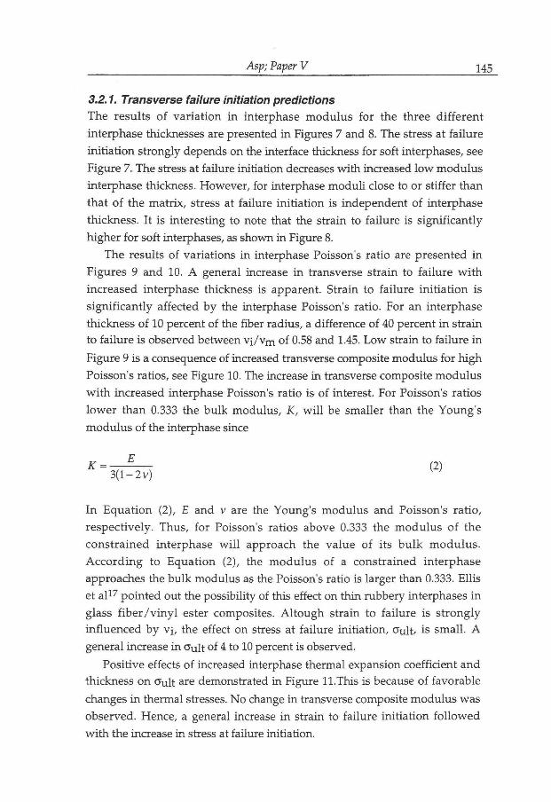
Asp; Paper V 145
3.2.1. Transverse failure initiation predictions
T h e resu l t s o f v a r i a t i o n i n in terphase m o d u l u s f o r the three d i f f e r e n t
in terphase thicknesses are presented i n Figures 7 and 8. The stress at f a i l u r e
i n i t i a t i o n s t rong ly depends on the interface thickness f o r sof t interphases, see
F igure 7. The stress at fa i lure in i t i a t ion decreases w i t h increased l o w m o d u l u s
interphase thickness. Howeve r , fo r interphase m o d u l i close to or s t i f fe r t h a n
tha t o f the m a t r i x , stress at f a i l u r e i n i t i a t i o n is i ndependen t o f in terphase
thickness . I t is in te res t ing to note that the s t ra in to f a i l u r e is s i g n i f i c a n t l y
h ighe r f o r sof t interphases, as s h o w n i n Figure 8.
The results of var ia t ions i n interphase Poisson's ra t io are presented i n
F igures 9 and 10. A general increase i n transverse s t r a in to f a i l u r e w i t h
increased in terphase thickness is apparent . S t ra in to f a i l u r e i n i t i a t i o n is
s i g n i f i c a n t l y a f fec ted b y the interphase Poisson's ra t io . For an in terphase
thickness o f 10 percent of the f iber radius , a di f ference o f 40 percent i n s t ra in
to f a i l u r e is observed between v i / v m o f 0.58 and 1.45. L o w stra in to f a i l u r e i n
F igure 9 is a consequence of increased transverse composite m o d u l u s f o r h i g h
Poisson's ratios, see Figure 10. The increase i n transverse composi te m o d u l u s
w i t h increased interphase Poisson's ra t io is o f interest. For Poisson's ra t ios
l o w e r t h a n 0.333 the b u l k m o d u l u s , K, w i l l be smal ler t h a n the Young ' s
m o d u l u s o f the interphase since
K " W ^ <2>
I n E q u a t i o n (2), E and v are the Young ' s m o d u l u s and Poisson's r a t i o ,
r e spec t ive ly . Thus , f o r Poisson's ra t ios above 0.333 the m o d u l u s o f the
c o n s t r a i n e d in te rphase w i l l app roach the va lue o f i ts b u l k m o d u l u s .
A c c o r d i n g to E q u a t i o n (2), the m o d u l u s o f a cons t r a ined in t e rphase
approaches the b u l k m o d u l u s as the Poisson's ra t io is larger than 0.333. El l i s
et a l 1 7 p o i n t e d out the possibi l i ty of this effect o n t h i n rubbery interphases i n
glass f i b e r / v i n y l ester composites . A l t o u g h s t ra in to f a i l u r e is s t r o n g l y
i n f l u e n c e d b y v i , the effect o n stress at f a i l u r e i n i t i a t i o n , 0" u l t / is s m a l l . A
general increase i n o" u l t of 4 to 10 percent is observed.
Posi t ive effects o f increased interphase the rmal expansion coef f ic ien t a n d
thickness o n o u l t are demonstrated i n Figure 11.This is because of f avorab le
changes i n the rma l stresses. N o change i n transverse composi te m o d u l u s was
observed . Hence, a general increase i n s t ra in to f a i l u r e i n i t i a t i o n f o l l o w e d
w i t h the increase i n stress at fa i lure in i t i a t ion .

Asp; Paper V 146
3.2.2. Failure mode and failure initiation site
Fa i lu re i n i t i a t i o n is a lways p red ic t ed to be due to h i g h d i l a t a t i ona l energy
dens i ty ra ther than d i s to r t iona l stresses. H o w e v e r , the p o s i t i o n of i n i t i a t i o n
site is a f fec ted b y interphase m o d u l u s . For a l l interphase thicknesses w i t h
E i /Em=0.0048 , i n i t i a t i o n occurs at the f iber equators. For the other examined
E i / E m ratios, f a i lu re in i t i a ted at the f iber poles.
Fa i lure i n i t i a t i o n is unaf fec ted b y v i and a i . Fai lure ini t ia tes due to h i g h
d i l a ta t iona l energy densities at the f iber poles f o r each invest igated interphase
Poisson's r a t io , t he rma l expansion coeff ic ient a n d thickness. The regions of
m a x i m u m v o n Mises effect ive stress are always located at the f iber equators.
M a x i m u m r a d i a l stress at f i b e r / i n t e r p h a s e a n d i n t e r p h a s e / m a t r i x
interfaces were f o u n d at the f iber poles. Hence, i n the case debond ing occurs
i t w i l l in i t i a te i n the same r e g i o n as cavi ta t ion- in i t ia ted b r i t t l e f a i lu re o f the
ma t r i x .
3.2.3. Special case interphases
Analyses o f three d i f f e r e n t interphase G F / E P composi tes were p e r f o r m e d .
The interphases consisted of: A rubber , a the rmoplas t i c p o l y m e r a n d an
i n t e r m e d i a t e l y s t i f f interphase mater ia l . The mechanica l proper t ies o f the
three interphases are presented i n Table I I I .
T h e t ransverse stress a n d s t r a in to f a i l u r e f o r d i f f e r e n t in te rphase
thicknesses are presented i n Figures 12 and 13. The results s h o w p o s i t i v e
effects f r o m t h i n r u b b e r y interphases. The s t r a in at f a i l u r e i n i t i a t i o n is
increased b y 100 to 300 percen t w h e n c o m p a r e d to compos i tes w i t h
thermoplas t ic or intermediate m o d u l u s interphases. A l so an increase i n stress
at f a i l u r e i n i t i a t i o n is observed. H o w e v e r , f o r an interphase thickness o f 10
percent of the f iber radius, the stress drops to the same leve l as those f o r the
s t i f f e r interphases, see F igure 12. The h i g h fa i lu re i n i t i a t i o n stresses of rubber
interphase ( t h i n interphases) G F / E P composites are due the l o w m o d u l u s
a n d h i g h Poisson's ra t io of the interphase. The p red ic ted increase i n s t rength
b y use of v e r y t h i n r ubbe ry interphases is suppor t ed b y exper imenta l data
f r o m T r y s o n a n d K a r d o s 1 8 . They presented data f o r t h i n l o w m o d u l u s duc t i l e
interphases i n a G F / E P composi te . The increase i n transverse s t rength was
67% as compared w i t h the same mater ia l w i t h o u t interphase.
The results of the analysis o f a rubber interphase composi te are of special
interest. N o t o n l y are the transverse fa i lure i n i t i a t i o n stresses and strains h i g h ,
a change i n f a i l u r e m o d e is also observed as the in terphase thickness is
al tered. For the thinnest interphase ( 1 % of the f iber radius) the composite fa i ls
b y c a v i t y - i n i t i a t i o n at the f ibe r poles. As the interphase thickness increases,

Asp; Paper V 147
the p o s i t i o n o f the m a x i m u m d i l a t a t iona l energy dens i ty moves a l o n g the
i n t e r p h a s e / m a t r i x interface and instead f a i l u r e in i t ia tes b y y i e l d i n g at the
f i b e r equators. A s the interphase becomes s u f f i c i e n t l y th ick , the m a x i m a of
the d i l a t a t i ona l energy densi ty and the e f fec t ive v o n Mises stress are b o t h
located at the f i be r equators. For b o t h cr i ter ia , f a i l u r e i n a composi te w i t h a
re la t ive in te rphase thickness o f 10% is p r e d i c t e d to in i t i a t e at the f i b e r
equators. H o w e v e r , cavi ta t ion- induced b r i t t l e f a i l u r e m a y be suppressed b y
the h i g h d i s t o r t i o n a l stresses and f a i l u r e m a y occur at a l o w e r transverse
stress t h a n p r e d i c t e d b y the v o n Mises c r i t e r i o n . Th i s is because o f the
i n f l u e n c e o f h y d r o s t a t i c pressure o n the y i e l d i n g o f glassy p o l y m e r s .
Fu r the rmore , h i g h d i la ta t iona l energy densities are observed i n the rubbe r
in terphase . T r i a x i a l tensile test data b y Gent and L i n d l e y 9 s how n a t u r a l
rubbe r to f a i l at d i l a t a t i ona l energy densities o f 0.3 M P a . The ca lcula ted
d i l a t a t iona l energy densities i n the rubber interphase are as h i g h as 1.1 M P a
f o r a relat ive interphase thickness of 5%. This suggests cavi ta t ion i n i t i a t i o n i n
the rubber in terphase to precede any f a i l u r e i n i t i a t i o n i n the ma t r i x . Such
in terphase i n i t i a t e d cracks m a y arrest i n the rubber . I n composites w i t h
thermoplas t ic and intermediate m o d u l u s interphases, f a i l u r e init iates at the
f i b e r poles due to h i g h d i l a t a t iona l energy densities. For each in terphase
mater ia l a n d thickness, the m a x i m u m rad ia l stress is located at the f iber poles.
4. CONCLUSIONS
A paramet r i c s t u d y of f ibe r and interphase p roper t i e s and in terphase
thickness o n f a i l u r e in i t i a t ion i n ma t r ix of transversely loaded composites has
been made. The s tudy shows that f iber m o d u l u s has a s igni f icant effect o n the
stress and s t ra in to composi te f a i l u r e caused b y cav i t a t ion - induced b r i t t l e
f a i l u r e o f the m a t r i x . A t h i n interphase of a r u b b e r y ma te r i a l p r o v i d e s
i m p r o v e m e n t i n transverse fa i lu re properties. The m o d e of ma t r ix f a i lu re and
the cor responding locat ion a round f ibers are also in f luenced b y the f iber and
interphase propert ies .

Asp; Paper V 148
REFERENCES
1. L .E . A s p , L . A . B e r g l u n d and R. Talreja, A c r i t e r ion f o r crack i n i t i a t i o n i n
glassy p o l y m e r s subjected to a composite-l ike stress state, submi t t ed to Comp.
Sci. Techn.
2. L . E . A s p , L . A . B e r g l u n d and R. Talreja , P r e d i c t i o n o f m a t r i x i n i t i a t e d
transverse f a i l u r e i n po lymer composites, submi t ted to Comp. Sci. Techn.
3. D . A . A g a r w a l and L.J. Brou tman , Analysis and performance of fiber composites,
2nd ed , John W i l e y & Sons Inc., N e w York , 1990, p p . 78-82.
4. J . M . M . de K o k , Deformation,yield and fracture of unidirectional composites in
transverse loading, (Disse r ta t ion) , E i n d h o v e n : E i n d h o v e n U n i v e r s i t y o f
Technology, ISBN90.386-0076-3,1995.
5. D.J. N i c h o l l s , Effect of stress biaxiality on the transverse tensile strain-to-failure
of composites, A S T M STP 893, ed. J .M. Whi tne y , A m e r i c a n Society f o r Test ing
and Mater ia l s , Phi ladelphia , (1986), pp . 109-114.
6. D . H u l l , An introduction to composite materials, Cambr idge U n i v e r s i t y Press,
Cambr idge , 1981.
7. L . E . A s p , L A . B e r g l u n d and P. G u d m u n d s o n , Effects o f composi te - l ike
stress-state o n the f rac ture of epoxies, Comp. Sci. Techn., 53, (1995), p p . 27-37.
8. L .E . A s p a n d L A . Be rg lund , A b iax ia l the rmo-mechanica l d i s k test f o r
glassy po lymer s , submi t ted to Exp. Mech.
9. A . N . Gent a n d P.B. L ind ley , Internal rup tu re of bonded rubber cyl inders i n
tension, Proc Roy Soc (London) 249A, (1959), pp . 195-205.
10. G . H . L indsey , Tr iax ia l f racture studies, J. Appl. Phys., 38, (1967), p p . 4843-4852.
1 1 . D . F . A d a m s a n d D.R. D o n e r , Transverse n o r m a l l o a d i n g o f a
u n i d i r e c t i o n a l composite, J. Comp. Mater., 1, (1967), p p . 152-164.
12. J.R. Brockenbrough , S. Suresh and H . A . Wienecke, D e f o r m a t i o n of meta l -
m a t r i x compos i t e s w i t h con t inuous f ibers : G e ome t r i c a l ef fects o f f i b e r
d i s t r i b u t i o n a n d shape, Acta, metall, mater., 39, (1991), p p . 735-752.

Asp; Paper V 149
13. D . M . B lackke t t e r , D . U p a d h y a y a and T.R K i n g , M i c r o m e c h a n i c s
p r e d i c t i o n o f t he t r ansverse tensi le s t r e n g t h o f c a r b o n f i b e r / e p o x y
composi tes : The i n f l u e n c e o f the m a t r i x and interface, Polymer Comp., 14,
(1993), p p . 437-446.
14 B.F. S ø r e n s e n , Damage mechanics in ceramic matrix fiber composites,
Dissertation, ISSN 0903-1685, Technical Un ive r s i ty o f Denmark , 1992.
15. L M . W a r d , Rev iew: The y i e l d behav iour o f p o l y m e r s , / . Mater. Sci, 6,
(1971), pp.1397-1417.
16. C. Baron , K . Schulte and H . H a r i g , In f luence of f ib re and m a t r i x f a i l u r e
s t r a in o n static and f a t i g u e proper t ies of ca rbon f i b r e - r e in fo rced plast ics,
Comp. Sci. Techn., 29, (1987),pp. 257-272.
17. K.R.J. E l l i s and M . G . Ph i l l ips , The effect of a compl ian t interphase o n the
transverse mechanica l proper t ies of glass f ib re re in forced plastic composi te ,
ICCM8, H o n o l u l u , (1991), p p . l l - D - 1 - 9 .
18. L . D . T r y s o n and J.L. Kardos , The use of duc t i le irvnerlayers i n glass f ibe r
r e in forced epoxies, 36th annual conference, Reinforced plastics/Composite institute,
The Society of the Plastic Industry, (1981), pp . 2-E, 1-5.

Asp; Paper V 150
T a b l e I . Mechanica l propert ies o f epoxy ( D G E B A / D E T A ) and glass f iber . U f
is the cr i t ica l d i l a ta t iona l energy density.
M a t e r i a l E
(GPa) V a
(10-6/°C)
uf (MPa)
cry
(MPa)
D G E B A / D E T A 2.07 0.345 66 0.2 83
Glass f iber
T a b l e I I . Mechanica l propert ies o f Type I and Type I I carbon f i b e r s 4 ' 6 .
Mechanical p rope r ty Type I Type I I
L o n g , m o d u l u s
( E L )
390 (GPa) 250 (GPa)
Transv. m o d u l u s
( E T )
12 (GPa) 20 (GPa)
Long , the rm, exp. coeff.
(OIL)
-1 ( 1 0 - 6 / ° C ) -0.3 ( 1 0 - 6 / ° C )
Transv. therm, exp.
coeff.
( a i )
10 (10-6/°C) 10 ( 1 0 - 6 / ° C )
M i n o r Poisson's ra t io
(VTL)
0.013 0.013
In-plane Poisson's ra t io
(VTT)
0.25 0.25

Asp; Paper V 151
T a b l e I I I . Mechanica l propert ies o f three interphases.
M a t e r i a l Young 's m o d u l u s E (GPa)
Poisson's ratio
V
Therm, exp. coeff .
a ( 1 0 " 6 / ° C )
Rubber 0.004 0.4998 66
Thermoplas t ic 1 0.4 66
In termedia te
m o d u l u s
34 0.2 5

Asp; Paper V 152
Figure captions
Figure 1. F E M - m e s h o f a per iodic element a) i n a square f ibe r ar ray, a n d b) a
square f i be r a r ray w i t h an interphase of a re la t ive thickness ( t / R ) o f 10%.
Fiber v o l u m e f rac t ion , Vf=0.5 .
Figure 2. Transverse stress at f a i lu re in i t i a t ion as a f u n c t i o n o f f i be r m o d u l u s
i n a t w o phase composi te w i t h epoxy mat r ix and Vf=0 .5 .
Figure 3. Transverse s t ra in at fa i lu re i n i t i a t i on as a f u n c t i o n of f ibe r m o d u l u s
i n a t w o phase composi te w i t h epoxy mat r ix and Vf=0.5 .
Figure 4. Transverse stress at f a i lu re i n i t i a t i o n as a f u n c t i o n of f i be r v o l u m e
f r ac t ion f o r epoxy composites w i t h d i f fe ren t f ibers.
Figure 5. Transverse s t ra in to f a i lu re i n i t i a t i on as a f u n c t i o n o f f i b e r v o l u m e
f rac t ion f o r epoxy composites w i t h d i f fe ren t f ibers.
Figure 6. Transverse m o d u l u s as a f u n c t i o n of f iber v o l u m e f r a c t i o n f o r epoxy
composites w i t h d i f f e r e n t f ibers.
Figure 7. Transverse stress at fa i lu re in i t i a t ion f o r three interphase stiffnesses
( E i / E m ) as a f u n c t i o n of relat ive interphase thickness ( t / R ) i n a three phase
composi te based o n G F / E P o f Vf=0.5 .
Figure 8. Transverse s t ra in at fa i lu re in i t i a t ion f o r three interphase stiffnesses
( E i / E m ) as a f u n c t i o n of relat ive interphase thickness ( t / R ) i n a three phase
composi te based o n G F / E P of Vf=0 .5 .
Figure 9. Transverse s t ra in to fa i lu re i n i t i a t i on f o r three interphase Poisson's
ratios ( v j / v m ) as a f u n c t i o n of relat ive interphase thickness ( t / R ) i n a three
phase composi te based o n G F / E P of Vf=0.5 .
Figure 10. Transverse composite stiffness fo r three interphase Poisson's ratios
( v i / v m ) as a f u n c t i o n of re la t ive interphase thickness ( t / R ) i n a three phase
composi te based o n G F / E P of Vf=0 .5 .
Figure 11. Transverse stress at f a i lu re i n i t i a t i on f o r three interphase t h e r m a l
expansion coeff ic ients (cci/ocm) as a f u n c t i o n o f re la t ive interphase thickness
( t / R ) i n a three phase composite based o n G F / E P of Vf=0.5 .
Figure 12. Transverse stress at f a i lu re i n i t i a t i o n f o r rubbery , thermoplas t ic ,
and in termedia te m o d u l u s interphases i n G F / E P of Vf=0 .5 .
Figure 13. Transverse s t ra in at f a i lu re i n i t i a t i o n f o r rubbery , thermoplas t ic ,
and in termedia te m o d u l u s interphases i n G F / E P of Vf=0 .5 .

Asp; Paper V 153
F igure 1. FEM-mesh of a per iodic element a) i n a square f ibe r array, and b) a
square f i be r ar ray w i t h an interphase of a re la t ive thickness ( t / R ) of 10%.
Fiber v o l u m e f rac t ion , Vf=0.5 .

Asp; Paper V 154
50
40-^
30 A cö
C L
6 s 2 0
1(H
OT at initiation
50 ~~0 50 100 150 200 250
E f (GPa)
Figu re 2. Transverse stress at f a i lu re i n i t i a t i o n as a f u n c t i o n o f f iber m o d u l u s
i n a t w o phase composite w i t h epoxy ma t r ix and Vf=0.5.

Asp; Paper V 155
Z3 00
ej at initiation
-50 0 50 100 150 200 250
Ef (GPa)
Figure 3. Transverse s t ra in at fa i lu re i n i t i a t i o n as a f u n c t i o n of f iber m o d u l u s
i n a t w o phase composi te w i t h epoxy m a t r i x and Vf=0.5 .

Asp; Paper V 156
F igure 4. Transverse stress at f a i l u r e in i t i a t ion as a f u n c t i o n o f f ibe r v o l u m e
f r ac t ion fo r epoxy composites w i t h d i f fe ren t fibers.

Figure 5. Transverse s t ra in to fa i lu re i n i t i a t i o n as a f u n c t i o n of f iber v o l u m e
f r ac t ion f o r epoxy composites w i t h d i f f e ren t fibers.

Figure 6. Transverse m o d u l u s as a f u n c t i o n o f f iber v o l u m e f rac t ion f o r epoxy
composites w i t h d i f f e ren t fibers.

Asp; Paper V 159
F igure 7. Transverse stress at fa i lu re i n i t i a t i on fo r three interphase stiffnesses
( E i / E m ) as a f u n c t i o n of relat ive interphase thickness ( t / R ) i n a three phase
composi te based on G F / E P of Vf=0 .5 .

Asp; Paper V 160
F igure 8. Transverse s t ra in at f a i lu re i n i t i a t i o n f o r three interphase stiffnesses
( E i / E m ) as a f u n c t i o n of relat ive interphase thickness ( t / R ) i n a three phase
composi te based on G F / E P of Vf=0 .5 .

Asp; Paper V 161
F igu re 9. Transverse s t ra in to f a i lu re i n i t i a t i o n f o r three interphase Poisson's
rat ios ( v i / v m ) as a f u n c t i o n of relat ive interphase thickness ( t / R ) i n a three
phase composi te based o n G F / E P of Vf=0 .5 .

Asp; Paper V 162
8
Figure 10. Transverse composi te st iffness for three interphase Poisson's ra t io
( v i / v m ) as a f u n c t i o n of re la t ive interphase thickness ( t / R ) i n a three phase
composite based o n G F / E P of Vf=0 .5 .

Asp; Paper V 163
27
23 A , , , , , 1 O 2 4 6 8 10 12
t/R (%)
Figu re 11. Transverse stress at f a i lu re i n i t i a t i o n fo r three interphase t h e r m a l
expansion coefficients ( a i / a m ) as a f u n c t i o n of relat ive interphase thickness
( t / R ) i n a three phase composite based o n G F / E P of Vf=0.5 .

Asp; Paper V 164
35
F i g u r e 12. Transverse stress at f a i l u r e i n i t i a t i o n f o r rubbery , thermoplas t ic ,
a n d in termedia te m o d u l u s interphases i n G F / E P of Vf=0 .5 .

Asp; Paper V 165
1.5
F i g u r e 13. Transverse s t ra in at f a i lu re i n i t i a t i o n f o r rubbery , thermoplas t ic ,
and in termedia te m o d u l u s interphases i n G F / E P of Vf=0.5 .