Transport Network Function Virtualization
8
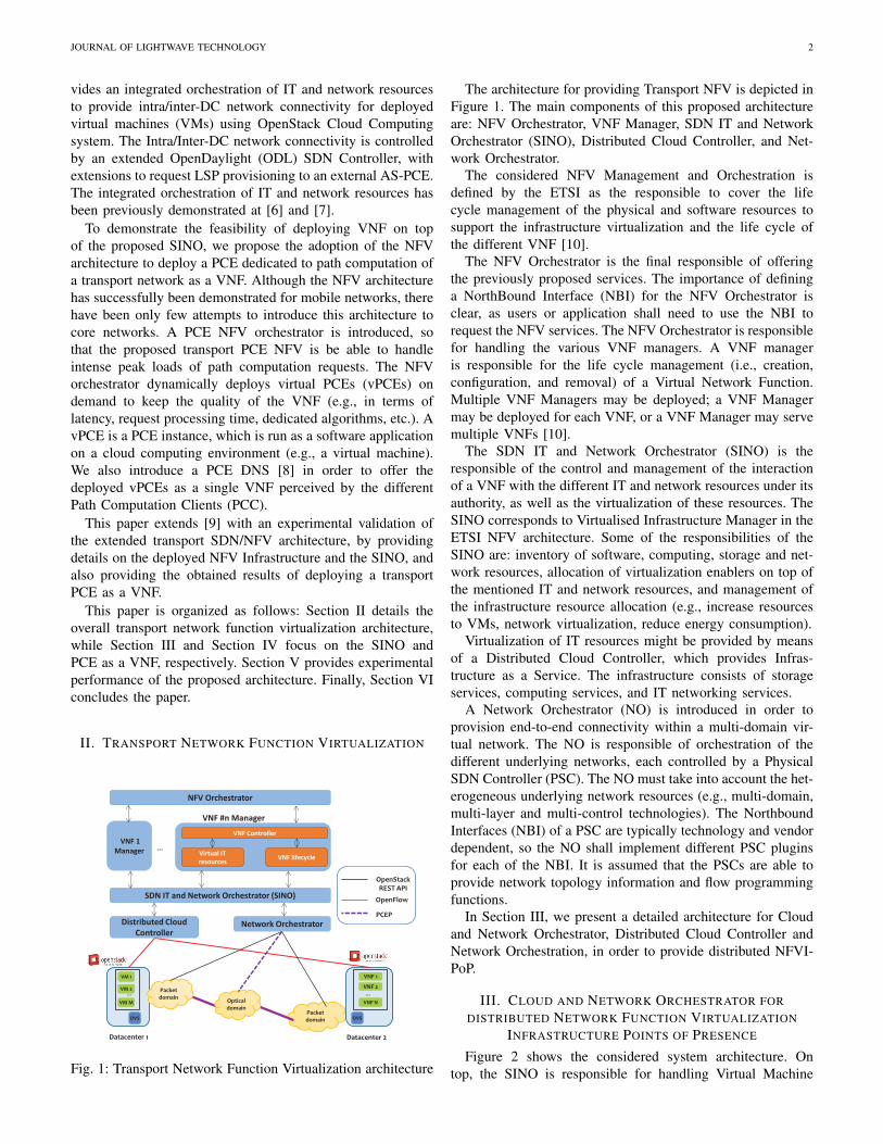
JOURNAL OF LIGHTWAVE TECHNOLOGY 1 Transport Network Function Virtualization Ricard Vilalta, Member, IEEE, Raul Mu˜ noz, Senior Member, IEEE, Arturo Mayoral, Ramon Casellas, Senior Member, IEEE, Ricardo Mart´ ınez, Senior Member, IEEE, Victor L´ opez, and Diego L´ opez (Invited Paper) Abstract— In this paper, we present a Network Function Virtualization (NFV) architecture to deploy different Virtualized Network Functions (VNF) on an optical Transport Network. NFV concepts do not only apply to data plane functions (i.e., packet processing or forwarding), but also to control plane functions, such as path computation. Firstly, we focus on the IT and Network Resources that are virtualized to provide the required VNFs. Secondly, we provide an example of VNF on top of the Virtualized Infrastructure, by proposing a Path Computation Element (PCE) architecture to deploy a PCE by means of NFV. The instances of the virtualized PCE are deployed on demand, but they are perceived as a single network element. We present the benefits of such approach by providing experimental validation. Index Terms— Network Function Virtualization, NFV Orches- tration and Management, Cloud and Network Orchestration, Path Computation Element, GMPLS, OpenDaylight, OpenStack. I. I NTRODUCTION N ETWORK Functions Virtualization (NFV) aims at using IT virtualization techniques to virtualize entire classes of network node functions. A Virtualized Network Function (VNF) consists of a network function running as software on a single or several hosts, typically inside virtual machines, instead of having custom hardware appliances for the proposed network function [1]. Possible examples of VNFs include load balancers, firewalls, security or Authentication, Authorization and Accounting (AAA) network functions. Network Functions Virtualization is applicable to any data plane packet process- ing and control plane function in fixed and mobile network infrastructures [1]. VNF are deployed on top of IT and Network resources which can be located in different geographically distributed NFV Infrastructure Points of Presence (NFVI-PoP), which might be interconnected using transport networks. There is the need of offering this IT and Network resources as a whole, by means of Virtualized Infrastructure Managesr, enabling it with the flexibility provided with the Software Defined Networking (SDN) architecture. SDN has emerged as the most promising candidate to im- prove network programmability and dynamic adjustment of the This paper was supported by the EU-Japan coordinated project STRAUSS (grant agreement n o 608528, and the Spanish Ministry of Economy and Competitiveness (MINECO) through the project FARO (TEC2012-38119). R. Vilalta, R. Mu˜ noz, A. Mayoral, R. Casellas, and R. Mart´ ınez are with the Centre Tecnol` ogic de Telecomunicacions de Catalunya (CTTC), Av. Carl Friedrich Gauss 7, 08860 Castelldefels (Barcelona), Spain, e-mail: {ricard.vilalta, raul.munoz, arturo.mayoral, ramon.casellas, ricardo.martinez}@cttc.es V. L´ opez and D. L´ opez are with Telefonica I+D, e-mail: {victor.lopezalvarez, diego.r.lopez}@telefonica.com network resources. SDN proposes a centralized architecture where the control entity (SDN controller) is responsible for providing an abstraction of network resources through pro- grammable APIs. One of the main benefits of this architecture resides on the ability to perform control and management tasks of different network forwarding technologies such as packet/flow switches, circuit switching and optical wavelength switched transport technologies, by the same network con- troller [2] altogether with upper-layer applications. OpenFlow protocol allows to program forwarding rules into OpenFlow virtualized switches inside DCs, through the defi- nition of flows which can filter traffic of different traditional networking protocols. Inter-DCs aggregated traffic can be transported by a Generalized Multiprotocol Label (GMPLS)- controlled optical transport network (e.g., WSON or Flexi-grid DWDM transport network). A centralized entity, defined as SDN controller, integrates control functions of both network domains. A transport Path Computation Element (PCE) is a transport network function, which is able to perform constrained path computation on a graph representing a network (Traffic En- gineering Database - TED) [3]. The PCE global architecture and communication protocol (PCEP) have been standardized by IETF. The PCE can be run as an application on top of Commercial Off-The-Shelf (COTS) equipment [4]. The initial driver for the deployment of PCEs was the increasing complexity of path computation. An Active Stateful Path Computation Element (AS-PCE) [5] is a PCE which maintains not only the traffic engineering information (link and node states), but also the state of the active connections in the network. The AS-PCE can receive the right of managing the active paths controlled by the nodes, allowing the PCE to modify or tear-down the connections established in the data plane. Here we propose to introduce an external AS-PCE as an SDN-enabler for a GMPLS-controlled optical transport network. The operations done in the PCE may be computationally intensive when running the path computation for transport connection provisioning or re-optimization on large production networks. To overcome this scalability limitation, several solu- tions have been proposed, being hierarchical PCE, and front- end/back-end PCE [3]. In this paper, we propose to extend the concept of NFV to transport networks by removing a dedicated PCE server and move the PCE functionality to the Cloud. The key benefit of this proposal will be the flexibility of providing dedicated IT resources to path computation. To this end, first we propose a SDN IT and Network Orches- trator (SINO), which corresponds to Virtualized Infrastructure Managers in the ETSI NFV architecture. The SINO pro-
-
Upload
independent -
Category
Documents
-
view
15 -
download
0
Transcript of Transport Network Function Virtualization

JOURNAL OF LIGHTWAVE TECHNOLOGY 1
Transport Network Function VirtualizationRicard Vilalta, Member, IEEE, Raul Munoz, Senior Member, IEEE, Arturo Mayoral, Ramon Casellas, Senior
Member, IEEE, Ricardo Martınez, Senior Member, IEEE, Victor Lopez, and Diego Lopez
(Invited Paper)
Abstract— In this paper, we present a Network FunctionVirtualization (NFV) architecture to deploy different VirtualizedNetwork Functions (VNF) on an optical Transport Network. NFVconcepts do not only apply to data plane functions (i.e., packetprocessing or forwarding), but also to control plane functions,such as path computation. Firstly, we focus on the IT andNetwork Resources that are virtualized to provide the requiredVNFs. Secondly, we provide an example of VNF on top of theVirtualized Infrastructure, by proposing a Path ComputationElement (PCE) architecture to deploy a PCE by means ofNFV. The instances of the virtualized PCE are deployed ondemand, but they are perceived as a single network element. Wepresent the benefits of such approach by providing experimentalvalidation.
Index Terms— Network Function Virtualization, NFV Orches-tration and Management, Cloud and Network Orchestration,Path Computation Element, GMPLS, OpenDaylight, OpenStack.
I. INTRODUCTION
NETWORK Functions Virtualization (NFV) aims at usingIT virtualization techniques to virtualize entire classes
of network node functions. A Virtualized Network Function(VNF) consists of a network function running as software ona single or several hosts, typically inside virtual machines,instead of having custom hardware appliances for the proposednetwork function [1]. Possible examples of VNFs include loadbalancers, firewalls, security or Authentication, Authorizationand Accounting (AAA) network functions. Network FunctionsVirtualization is applicable to any data plane packet process-ing and control plane function in fixed and mobile networkinfrastructures [1].
VNF are deployed on top of IT and Network resourceswhich can be located in different geographically distributedNFV Infrastructure Points of Presence (NFVI-PoP), whichmight be interconnected using transport networks. There is theneed of offering this IT and Network resources as a whole, bymeans of Virtualized Infrastructure Managesr, enabling it withthe flexibility provided with the Software Defined Networking(SDN) architecture.
SDN has emerged as the most promising candidate to im-prove network programmability and dynamic adjustment of the
This paper was supported by the EU-Japan coordinated project STRAUSS(grant agreement no 608528, and the Spanish Ministry of Economy andCompetitiveness (MINECO) through the project FARO (TEC2012-38119).
R. Vilalta, R. Munoz, A. Mayoral, R. Casellas, and R. Martınezare with the Centre Tecnologic de Telecomunicacions de Catalunya(CTTC), Av. Carl Friedrich Gauss 7, 08860 Castelldefels (Barcelona),Spain, e-mail: {ricard.vilalta, raul.munoz, arturo.mayoral, ramon.casellas,ricardo.martinez}@cttc.es
V. Lopez and D. Lopez are with Telefonica I+D, e-mail:{victor.lopezalvarez, diego.r.lopez}@telefonica.com
network resources. SDN proposes a centralized architecturewhere the control entity (SDN controller) is responsible forproviding an abstraction of network resources through pro-grammable APIs. One of the main benefits of this architectureresides on the ability to perform control and managementtasks of different network forwarding technologies such aspacket/flow switches, circuit switching and optical wavelengthswitched transport technologies, by the same network con-troller [2] altogether with upper-layer applications.
OpenFlow protocol allows to program forwarding rules intoOpenFlow virtualized switches inside DCs, through the defi-nition of flows which can filter traffic of different traditionalnetworking protocols. Inter-DCs aggregated traffic can betransported by a Generalized Multiprotocol Label (GMPLS)-controlled optical transport network (e.g., WSON or Flexi-gridDWDM transport network). A centralized entity, defined asSDN controller, integrates control functions of both networkdomains.
A transport Path Computation Element (PCE) is a transportnetwork function, which is able to perform constrained pathcomputation on a graph representing a network (Traffic En-gineering Database - TED) [3]. The PCE global architectureand communication protocol (PCEP) have been standardizedby IETF. The PCE can be run as an application on topof Commercial Off-The-Shelf (COTS) equipment [4]. Theinitial driver for the deployment of PCEs was the increasingcomplexity of path computation. An Active Stateful PathComputation Element (AS-PCE) [5] is a PCE which maintainsnot only the traffic engineering information (link and nodestates), but also the state of the active connections in thenetwork. The AS-PCE can receive the right of managing theactive paths controlled by the nodes, allowing the PCE tomodify or tear-down the connections established in the dataplane. Here we propose to introduce an external AS-PCEas an SDN-enabler for a GMPLS-controlled optical transportnetwork.
The operations done in the PCE may be computationallyintensive when running the path computation for transportconnection provisioning or re-optimization on large productionnetworks. To overcome this scalability limitation, several solu-tions have been proposed, being hierarchical PCE, and front-end/back-end PCE [3]. In this paper, we propose to extend theconcept of NFV to transport networks by removing a dedicatedPCE server and move the PCE functionality to the Cloud. Thekey benefit of this proposal will be the flexibility of providingdedicated IT resources to path computation.
To this end, first we propose a SDN IT and Network Orches-trator (SINO), which corresponds to Virtualized InfrastructureManagers in the ETSI NFV architecture. The SINO pro-
JOURNAL OF LIGHTWAVE TECHNOLOGY 2
vides an integrated orchestration of IT and network resourcesto provide intra/inter-DC network connectivity for deployedvirtual machines (VMs) using OpenStack Cloud Computingsystem. The Intra/Inter-DC network connectivity is controlledby an extended OpenDaylight (ODL) SDN Controller, withextensions to request LSP provisioning to an external AS-PCE.The integrated orchestration of IT and network resources hasbeen previously demonstrated at [6] and [7].
To demonstrate the feasibility of deploying VNF on topof the proposed SINO, we propose the adoption of the NFVarchitecture to deploy a PCE dedicated to path computation ofa transport network as a VNF. Although the NFV architecturehas successfully been demonstrated for mobile networks, therehave been only few attempts to introduce this architecture tocore networks. A PCE NFV orchestrator is introduced, sothat the proposed transport PCE NFV is be able to handleintense peak loads of path computation requests. The NFVorchestrator dynamically deploys virtual PCEs (vPCEs) ondemand to keep the quality of the VNF (e.g., in terms oflatency, request processing time, dedicated algorithms, etc.). AvPCE is a PCE instance, which is run as a software applicationon a cloud computing environment (e.g., a virtual machine).We also introduce a PCE DNS [8] in order to offer thedeployed vPCEs as a single VNF perceived by the differentPath Computation Clients (PCC).
This paper extends [9] with an experimental validation ofthe extended transport SDN/NFV architecture, by providingdetails on the deployed NFV Infrastructure and the SINO, andalso providing the obtained results of deploying a transportPCE as a VNF.
This paper is organized as follows: Section II details theoverall transport network function virtualization architecture,while Section III and Section IV focus on the SINO andPCE as a VNF, respectively. Section V provides experimentalperformance of the proposed architecture. Finally, Section VIconcludes the paper.
II. TRANSPORT NETWORK FUNCTION VIRTUALIZATION
Virtual IT
resources VNF lifecycle
VNF #n Manager
VNF Controller
Packet
domain
VNF 1
VNF 2
VNF N
OVS
…
Datacenter 1 Datacenter 2
Packet
domain Optical
domain
SDN IT and Network Orchestrator (SINO)
VNF 1
Manager
VM M
OVS
VM 2
VM 1
…
…
OpenStack
REST API
OpenFlow
PCEP Distributed Cloud
Controller Network Orchestrator
NFV Orchestrator
Fig. 1: Transport Network Function Virtualization architecture
The architecture for providing Transport NFV is depicted inFigure 1. The main components of this proposed architectureare: NFV Orchestrator, VNF Manager, SDN IT and NetworkOrchestrator (SINO), Distributed Cloud Controller, and Net-work Orchestrator.
The considered NFV Management and Orchestration isdefined by the ETSI as the responsible to cover the lifecycle management of the physical and software resources tosupport the infrastructure virtualization and the life cycle ofthe different VNF [10].
The NFV Orchestrator is the final responsible of offeringthe previously proposed services. The importance of defininga NorthBound Interface (NBI) for the NFV Orchestrator isclear, as users or application shall need to use the NBI torequest the NFV services. The NFV Orchestrator is responsiblefor handling the various VNF managers. A VNF manageris responsible for the life cycle management (i.e., creation,configuration, and removal) of a Virtual Network Function.Multiple VNF Managers may be deployed; a VNF Managermay be deployed for each VNF, or a VNF Manager may servemultiple VNFs [10].
The SDN IT and Network Orchestrator (SINO) is theresponsible of the control and management of the interactionof a VNF with the different IT and network resources under itsauthority, as well as the virtualization of these resources. TheSINO corresponds to Virtualised Infrastructure Manager in theETSI NFV architecture. Some of the responsibilities of theSINO are: inventory of software, computing, storage and net-work resources, allocation of virtualization enablers on top ofthe mentioned IT and network resources, and management ofthe infrastructure resource allocation (e.g., increase resourcesto VMs, network virtualization, reduce energy consumption).
Virtualization of IT resources might be provided by meansof a Distributed Cloud Controller, which provides Infras-tructure as a Service. The infrastructure consists of storageservices, computing services, and IT networking services.
A Network Orchestrator (NO) is introduced in order toprovision end-to-end connectivity within a multi-domain vir-tual network. The NO is responsible of orchestration of thedifferent underlying networks, each controlled by a PhysicalSDN Controller (PSC). The NO must take into account the het-erogeneous underlying network resources (e.g., multi-domain,multi-layer and multi-control technologies). The NorthboundInterfaces (NBI) of a PSC are typically technology and vendordependent, so the NO shall implement different PSC pluginsfor each of the NBI. It is assumed that the PSCs are able toprovide network topology information and flow programmingfunctions.
In Section III, we present a detailed architecture for Cloudand Network Orchestrator, Distributed Cloud Controller andNetwork Orchestration, in order to provide distributed NFVI-PoP.
III. CLOUD AND NETWORK ORCHESTRATOR FORDISTRIBUTED NETWORK FUNCTION VIRTUALIZATION
INFRASTRUCTURE POINTS OF PRESENCE
Figure 2 shows the considered system architecture. Ontop, the SINO is responsible for handling Virtual Machine

JOURNAL OF LIGHTWAVE TECHNOLOGY 3
ODL SDN Controller
API
OpenFlow / BGP / PCEP
Compute Neutron
OpenStack Controller
SDN IT and Network Orchestrator (SINO)
Virtual Machines VM networks
WSON/SSON
VM 1
VM 2
VM N
Host 1
OVS
…
OpenFlow-controlled
Ethernet/MPLS Switches
VM 1
VM 2
VM N
Host 2
OVS
…
Datacenter 1
OFS
OFS
OFS
VM 1
VM 2
VM N
Host 3
OVS
…
OpenFlow-controlled
Ethernet/MPLS Switches
VM 1
VM 2
VM N
Host 4
OVS
…
Datacenter 2
OFS
OFS
OFS
Active
Stateful
PCE
GMPLS
Controller
GMPLS
Controller GMPLS
Controller
GMPLS
Controller
Fig. 2: Cloud and Network Orchestrator Architecture
(VM) and network connectivity requests, which are processedthrough the Distributed Cloud Controller, which is depicted asOpenStack Controller, and the Network Orchestrator, whichis depicted as an extended OpenDayLight (ODL) SDN Con-troller. On top of the interconnected VM, the different VNFmight be deployed.
The cloud and network orchestration process consists oftwo different steps: the VM creation and network connectivityprovisioning (Fig. 3). The SINO requests the creation of aVirtual Machine (VM) instance to the OpenStack Controller,which, is responsible for the request to a specific computinghost of the creation of the instance. The OpenStack Controlleris also responsible to attach the VM to the virtual switchinside the host node, which is typically an OpenFlow softwareswitch such as OpenVSwitch (OVS). When the VM creation isfinished, the OpenStack Controller sends the VM’s networkingdetails to the orchestrator (i.e., MAC address, IP address, andhost computing node location).
The ODL SDN controller is a framework to implement end-to-end network control services in a centralized network entity(i.e., network orchestrator). The ODL SDN controller offersa complete set of programmable Application ProgrammableInterfaces (API) to northbound applications from where to re-quest networking information or switching configuration of the
network infrastructure. The interfaces exposed are completelyagnostic to the underlying network infrastructure allowingapplications to request network connectivity services withoutbeing bounded to specific networking protocols. The core ofthe ODL SDN Controller is a Service Abstraction Layer whichtranslates internal controller services and external applications’requests to the implemented networking protocols plugged inthe southbound interface of the controller.
The southbound interface of ODL SDN Controller is com-posed by a set of plugins implementing different controland management protocols, to configure physical (hardware)network devices, such as OpenFlow, Netconf, Border GatewayProtocol (BGP) or PCEP among others.
We have extended ODL SDN controller with a modulenamed PCEP-Speaker Service, which is responsible to requestto an external AS-PCE the establishment of an optical LSP.The details for this extension are provided by [11].
The SINO workflow goes as detailed in Figure 3. TheSINO requests to the ODL SDN controller to perform theflow establishment between the two VMs deployed by theVIRC. After computing the route, the ODL SDN controlleris aware either of the positive reachability of the computingresources through the packet network (intra-DC) or whetheran inter-DC connection is needed. In the first case, the ODL

JOURNAL OF LIGHTWAVE TECHNOLOGY 4
SINO ODL AS-
PCE OVS 1 Client
VMs & Net
requests Start VMs
GET Network Topology
VMs started
JSON{Ok} VMs & Net
created
… OVS N
PCInitiate{ERO}
PCRpt{LspId}
OF Flow_Mod
OF Flow_Mod
…
JSON {Nodes, Edges}
PUT Establish LSP PCReq{Src,Dst}
PCRep{ERO}
JSON {OK, LspId}
PUT Establish Flows
Fig. 3: Cloud and Network Orchestrator Workflow
SDN controller is ready to send the command to establish theforwarding rules to the OpenFlow-enabled switches and intothe intra-DC switches. In the second case, the SDN controllerneeds to establish a lightpath between the DCs.
In order to establish a lightpath, between the DCs, wepropose to use an AS-PCE, which has been demonstratedas a very robust and comprehensive solution to manage andcontrol optical domains in a centralized manner [12]. With thepresented active and stateful capabilities, the AS-PCE is a keySDN-enabler component.
AS-PCE can instantiate or tear down LSPs on the networkthrough the PCEP stateful extensions using the LSP initiaterequest message (PCInitiate [13]). The PCInitiate messageis the key-driver mechanism to request LSPs from outsidethe GMPLS control plane. The AS-PCE acts as an interfacebetween the ODL SDN controller and the GMPLS controlplane.
Once the lightpath has been established between the DCs,the SINO can proceed to send the command to establish theforwarding rules to the OpenFlow-enabled switches and intothe intra-DC switches.
IV. TRANSPORT PCE VIRTUAL NETWORK FUNCTION
In this section, the proposed transport PCE NFV architectureis described (Fig. 4). A PCE NFV Orchestrator is the entityresponsible for the deployment of the PCE as a VNF. The PCENFV Orchestrator consists of three separated modules: PCEVNF provider, Virtual IT resources and PCE computation loadmonitoring.
The PCE VNF provider implements the necessary logicfor deploying the necessary vPCE in order to guarantee thequality of the VNF. In order to guarantee the quality, thePCE VNF provider interacts with the PCE computation loadmonitoring module in order to obtain the necessary data todecide to deploy a new instance of a vPCE or to delete one,via the virtual IT resources module. Thus, the PCE VNF isthe responsible for deploying the logic of the orchestrator.
The Virtual IT resources module is responsible for request-ing to the SINO the necessary IT and Network resources. TheSINO allows the dynamic deployment and release of virtualmachines with custom images running vPCE as an application
GMPLS-controlled
WSON/SSON
Virtual IT and
network resources
PCE computation
load monitoring
PCE VNF manager
Data
Center
OVS
…
PCE VNF controller
vPCE TED
…
vPCE 1
vPCE 2
vPCE N
PCE DNS
PCC 1
PCC M
Fig. 4: PCE NFV Orchestrator Architecture
and the interconnection between them, although they mightbe geographically distributed. The cloud infrastructure mustassign to the vPCE a new IP address from a set of availableones. This IP address is parsed and the PCE DNS is notifiedwith the new IP address for a new available vPCE.
Finally, the PCE computation load monitoring module is theresponsible for monitoring the quality of the VNF. The mon-itored parameters are a set of the PCE monitoring parametersdefined in [14], which are exposed by the vPCEs, by meansof an HTTP server. One of these parameters is the mean pathprocessing time. If the mean path processing time exceeds acertain threshold, the PCE VNF could deploy a new vPCE toreduce the peak request load in the PCE VNF.
The need for path computations in a network is related to theintense dynamic usage of the network. It is also related to theneed to perform in-operation network re-planning or networkrecovery. It is in these two scenarios, where we can expect theneed for the deployment of vPCEs to perform the necessarypath computations. When the situation that has generated theneed for path computation ends, the PCE computation loadmonitoring module, shall detect its end and turn down theunnecessary vPCEs.
In the following subsections two different approaches foroffering the running vPCE to be perceived as a single PCEby the different Path Computation Clients. The first approachconsists on the usage of a PCE DNS to handle all theincomming requests and redirecting them to the allocatedvPCE. The second approach is the usage of the front-end/back-end PCE architecture in order to use a front-end PCE as aproxy for all the deployed vPCEs, which act as back-endPCEs.

JOURNAL OF LIGHTWAVE TECHNOLOGY 5
PCE VNF
Manager SINO PCE DNSvPCE
1
vPCE
N … PCC
Computation Load
High Computation Load
Start vPCE N
Start vPCE N
vPCE N started
vPCE N started
Add vPCE N
PC Request
PC Reply
Whois PCE?
vPCE N
Fig. 5: PCE NFV Workflow
A. PCE VNF using PCE DNS
As a PCE discovery mechanism, a PCE DNS is proposed.DNS is a query-response based mechanism. A Path Compu-tation Client (a PCC) can use DNS to discover a PCE onlywhen it needs to compute a path and does not require any othernode in the network to be involved. In case of an intermittentPCEP session, which are systematically opened and closed foreach PCEP request, a DNS-based query-response mechanismis suitable. Moreover, DNS supports load balancing wheremultiple vPCEs (with different IP addresses) are known inthe DNS for a single PCE server name and are seen for thePCC as a single resource. Requests are load-balanced amongvPCEs without any complexity at the PCC.
The messages exchanged between the different elements ofthe proposed architecture are displayed in Fig. 5. It can beobserved, that the PCE NFV Orchestrator is the responsiblefor checking the different quality parameters to the deployedvPCEs. Once these quality parameters are received, the PCEVNF provider module within the PCE NFV Orchestrator isthe responsible to determine whether a new vPCE is required.
If a vPCE is selected to be deployed, the Virtual ITresources module will deploy a new virtual machine with thevPCE image, will assign a new IP address to the vPCE andonce the vPCE is started, the Virtual IT resources module willnotify the new vPCE IP address to the PCE DNS.
Once a PCC requires a new path computation, first will issuea DNS query to the PCE DNS. The PCE DNS is responsibleto load balance the different vPCEs, so returns a single IPaddress corresponding to one of the vPCEs. Finally, the PCCestablishes a path computation session with the correspondingvPCE.
B. PCE VNF using front-end/back-end PCE
The so-called front-end / back-end architecture is a new loadbalancing architecture based on the concept of a front-end andone or more dedicated back-ends, where the end client of PCConly sees the front-end, and operators may deploy differentcapabilities at back-ends. The common use case is when oneor more PCEs are deployed in the same TE domain, so theback-end PCEs may use the same TED, although it is notmandatory [3]. The main motivations behind this work are
PCE VNF
Manager SINO Front-end
PCE
vPCE
1
vPCE
N … PCC
Computation Load
High Computation Load
Start vPCE N
Start vPCE N
vPCE N started
vPCE N started
Add vPCE N
PC Request
PC Reply
PC Request
PC Reply
Fig. 6: PCE NFV Workflow using front-end/back-end PCE
related to scalability and load sharing policies while enablingsome degree of specialization.
We propose to introduce a front-end PCE, which is notifiedby the PCE VNF Manager of the currently deployed vPCE.Figure 6 shows the detailed workflow for this architecture.It differs from the previously presented workflow for PCEDNS in the fact that a front-end PCE acts as a proxy forPC Requests, while in PCE DNS, the PCC issued a DNSrequest for the assigned vPCE. The front-end PCE processesthe incomming PC Request and forwards it to the suitablevPCE, who responds it to the front-end PCE. Finally, the front-end PCE forwards the PC Reply to the PCC.
This architecture allows a higher degree of scalability andload sharing policies in comparison to PCE DNS. The pro-posed front-end/back-end architecture also provides a higherlevel of robustness and redundancy: even though the front-end PCE is still a single point of failure, its implementationis significantly simpler than a back-end-PCE (b-PCE) [3].Moreover, redundancy techniques might be applied to recoverfrom a front-end PCE failure.
V. EXPERIMENTAL PERFORMANCE
In this section we provide an experimental validation ofthe proposed transport SDN/NFV architecture, by providingdetails on the deployed distributed NFVI-PoPs and its SINO,and also providing the obtained results of deploying a transportPCE as a VNF.
The proposed architecture has been validated in the CloudComputing platform of the ADRENALINE Testbed. TheOpenStack Havanna release has been deployed into five phys-ical servers with 2 x Intel Xeon E5-2420 and 32GB RAMeach, one dedicated to the cloud controller and the other fouras compute pool (hosts) for VM instantiation.
Four OpenFlow switches have been deployed using standardCustom Off The Shelf (COTS) hardware and run Open-VSwitch (OVS), which can be controlled by OpenFlow 1.0.Each Data Center border switch has been implemented usingCOTS hardware, a 10 Gb/s XFP tunable transponder and OVS.
Finally, the GMPLS-controlled optical network is composedof an all-optical WSON with 2 ROADMs and 2 OXCsproviding reconfigurable (in space and in frequency) end-to-end lightpaths, deploying a total of 610 km of G.652 and
JOURNAL OF LIGHTWAVE TECHNOLOGY 6
G.655 optical fiber, with six DWDM wavelengths per opticallink.
The SDN controller has been implemented with ODLservice provider distribution, which has been expanded withseveral components such as a PCEP-Speaker module to estab-lish the PCEP session with the AS-PCE.
A. SDN IT and Network Orchestrator
Figure 7.a shows the PCEP message exchange betweenODL SDN controller and the external AS-PCE, which acts asa SDN enabler, to establish an LSP between the border nodesin the transport network. We can observe the PC Initiate Mes-sage issued from the ODL SDN controller, and the responsemessage (PC Report) from the AS-PCE, when the LSP hasbeen established.
Figure 7.b shows the OFPT FLOW MOD messages sentfrom the ODL controller to the corresponding OpenFlowswitches. We can observe for example a Flow rule for VM withsource MAC address (fa:16:3e:1b:8e:93) to VM destinationMAC address (fa:16:3e:9f:e2:bc).
In Figure 7.c the abstracted topology from ODL is pre-sented, and also an example of the forwarding rules injectedin one of the OVS. For example, we can observe a rule forARP packets and a specific source MAC and destination MACrule to filter the traffic associated to the VMs end points.
Finally, in Figure 7.d shows the ping exchange betweenthe two previously presented VMs through the intra/inter DCnetwork.
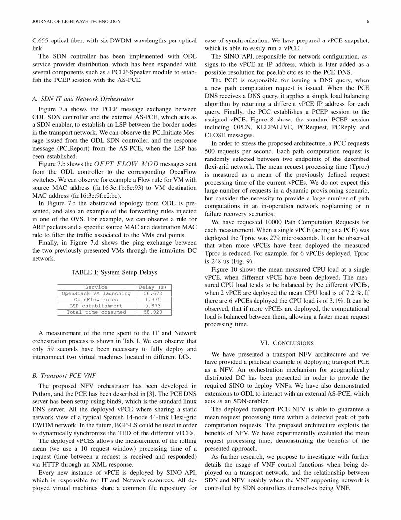
TABLE I: System Setup Delays
Service Delay (s)OpenStack VM launching 56.672
OpenFlow rules 1.375LSP establishment 0.873
Total time consumed 58.920
A measurement of the time spent to the IT and Networkorchestration process is shown in Tab. I. We can observe thatonly 59 seconds have been necessary to fully deploy andinterconnect two virtual machines located in different DCs.
B. Transport PCE VNF
The proposed NFV orchestrator has been developed inPython, and the PCE has been described in [3]. The PCE DNSserver has been setup using bind9, which is the standard linuxDNS server. All the deployed vPCE where sharing a staticnetwork view of a typical Spanish 14-node 44-link Flexi-gridDWDM network. In the future, BGP-LS could be used in orderto dynamically synchronize the TED of the different vPCEs.
The deployed vPCEs allows the measurement of the rollingmean (we use a 10 request window) processing time of arequest (time between a request is received and responded)via HTTP through an XML response.
Every new instance of vPCE is deployed by SINO API,which is responsible for IT and Network resources. All de-ployed virtual machines share a common file repository for
ease of synchronization. We have prepared a vPCE snapshot,which is able to easily run a vPCE.
The SINO API, responsible for network configuration, as-signs to the vPCE an IP address, which is later added as apossible resolution for pce.lab.cttc.es to the PCE DNS.
The PCC is responsible for issuing a DNS query, whena new path computation request is issued. When the PCEDNS receives a DNS query, it applies a simple load balancingalgorithm by returning a different vPCE IP address for eachquery. Finally, the PCC establishes a PCEP session to theassigned vPCE. Figure 8 shows the standard PCEP sessionincluding OPEN, KEEPALIVE, PCRequest, PCReply andCLOSE messages.
In order to stress the proposed architecture, a PCC requests500 requests per second. Each path computation request israndomly selected between two endpoints of the describedflexi-grid network. The mean request processing time (Tproc)is measured as a mean of the previously defined requestprocessing time of the current vPCEs. We do not expect thislarge number of requests in a dynamic provisioning scenario,but consider the necessity to provide a large number of pathcomputations in an in-operation network re-planning or infailure recovery scenarios.
We have requested 10000 Path Computation Requests foreach measurement. When a single vPCE (acting as a PCE) wasdeployed the Tproc was 279 microseconds. It can be observedthat when more vPCEs have been deployed the measuredTproc is reduced. For example, for 6 vPCEs deployed, Tprocis 248 us (Fig. 9).
Figure 10 shows the mean measured CPU load at a singlevPCE, when different vPCE have been deployed. The mea-sured CPU load tends to be balanced by the different vPCEs,when 2 vPCE are deployed the mean CPU load is of 7.2 %. Ifthere are 6 vPCEs deployed the CPU load is of 3.1%. It can beobserved, that if more vPCEs are deployed, the computationalload is balanced between them, allowing a faster mean requestprocessing time.
VI. CONCLUSIONS
We have presented a transport NFV architecture and wehave provided a practical example of deploying transport PCEas a NFV. An orchestration mechanism for geographicallydistributed DC has been presented in order to provide therequired SINO to deploy VNFs. We have also demonstratedextensions to ODL to interact with an external AS-PCE, whichacts as an SDN-enabler.
The deployed transport PCE NFV is able to guarantee amean request processing time within a detected peak of pathcomputation requests. The proposed architecture exploits thebenefits of NFV. We have experimentally evaluated the meanrequest processing time, demonstrating the benefits of thepresented approach.
As further research, we propose to investigate with furtherdetails the usage of VNF control functions when being de-ployed on a transport network, and the relationship betweenSDN and NFV notably when the VNF supporting network iscontrolled by SDN controllers themselves being VNF.

JOURNAL OF LIGHTWAVE TECHNOLOGY 7
a)
b)
c)
d)
Fig. 7: a) PCEP message exchange between PCEP-Speaker Module and AS-PCE capture for LSP establishment, b)OF FLOW MOD messages to push forwarding rules into the OVSs, c) OpenDaylight topology and Openflow forwardingrules table of a simple node, d) Ping capture proving end-to-end connectivity between launched VMs placed in DC1 and DC3
Fig. 8: PCE NFV wireshark
REFERENCES
[1] M. Chiosi, D. Clarke, P. Willis, A. Reid, J. Feger, M. Bugenhagen,W. Khan, M. Fargano, C. Cui, H. Deng, J. Benitez, U. Michel, H.Damker, K. Ogaki, T. Matsuzaki, M. Fukui, K. Shimano, D. Delisle,Q. Loudier, C. Kolias, I. Guardini, E. Demaria, R. Minerva, A. Man-zalini, D. Lopez, F. Ramon, F. Ruhl, P. Sen, “Network FunctionsVirtualisation, An Introduction, Benefits, Challenges & Call for Action”,SDN and Openflow World Congress, 2012. Available at: https ://portal.etsi.org/nfv/nfv white paper.pdf
[2] M. Channegowda, R. Nejabati, M.Rashidifard, S. Peng, N. Amaya,G. Zervas, D. Simeonidou, R. Vilalta, R. Casellas, R. Martınez, R.Munoz, L. .Liu, T. Tsuritani, I. Morita, A. Autenrieth, J.P. Elbers, P.Kostecki, and P. Kaczmarek, “First Demonstration of an OpenFlowbased Software-Defined Optical Network Employing Packet, Fixedand Flexible DWDM Grid Technologies on an International Multi-Domain Testbed”, in European Conference on Optical CommunicationsTh.3.D.2, Amsterdam, 2012.
[3] R. Casellas, R. Munoz, R. Martınez, and R. Vilalta, “Applications and
230
240
250
260
270
280
290
1 2 4 6
#vPCEs
Tproc (us)
Fig. 9: PCE measured processing time
Status of PCE”, in Journal of Optical Communications and Networkingvol. 5 n.10, 2013.
[4] Y.Yoshida, A. Maruta, K. Kitayama, M. Nishihara, T. Tanaka, T.Takahara, J. C. Rasmussen, N. Yoshikane, T. Tsuritani, I. Morita, S. Yan,Y. Shu, M. Channegowda, Y. Yan, B.R. Rofoee, E. Hugues-Salas, G.Saridis, G. Zervas, R. Nejabati, D. Simeonidou, R. Vilalta, R. Munoz, R.Casellas, R. Martınez, M. Svaluto, J. M. Fabrega, A. Aguado, V. Lopez,J. Marhuenda, O. Gonzalez de Dios, and J. P. Fernandez-Palacios, “Firstinternational SDN-based Network Orchestration of Variable capacityOPS over Programmable Flexi-grid EON”, in Optical Fiber Conference,ThA.2, 2014.
[5] E. Crabbe, I. Minei, J. Medved, R. Varga, “ PCEP Extensions for StatefulPCE”, draft-ietf-pce-stateful-pce-09, IETF, 2014.
[6] A. Mayoral, R. Vilalta, R. Munoz, R. Casellas, R. Martınez, J. Vılchez,“Integrated IT and Network Orchestration Using OpenStack, Open-Daylight and Active Stateful PCE for Intra and Inter Data CenterConnectivity”, in European Conference on Optical CommunicationsWe.2.6.6, Cannes, 2014.
[7] T. Szyrkowiec, A. Autenrieth, P. Gunning, P. Wright, A. Lord, J-P.Elbers, and A. Lumb, “First field demonstration of cloud datacenter

JOURNAL OF LIGHTWAVE TECHNOLOGY 8
0 5 10 15 20
1
2
4
6
#v
PC
Es
mean vPCE CPU load (%)
Fig. 10: PCE measured CPU usage
workflow automation employing dynamic optical transport networkresources under OpenStack and OpenFlow orchestration”, in OpticsExpress, Vol. 22, Issue 3, pp. 2595-2602 (2014).
[8] Q. Wu, D. Dhody, D. King, D. Lopez, J. Tantsura, “PCE discovery usingDNS”, draft-wu-pce-dns-pce-discovery-06, IETF, 2014.
[9] R. Vilalta, R. Munoz, R. Casellas, R. Martınez, V. Lopez, D.Lopez, “Transport PCE Network Function Virtualization”, in EuropeanConference on Optical Communications We.3.2.2, Cannes, 2014.
[10] ETSI, “Network Function Virtualization (NFV): Architectural Frame-work”, ETSI GS NFV 002 v.1.1.1, 2013.
[11] A. Mayoral, R. Vilalta, R. Munoz, R. Casellas, R. Martınez, “Ex-perimental validation of automatic lightpath establishment integratingOpenDaylight SDN controller and Active Stateful PCE within theADRENALINE Testbed”, in International Conference on TransparentOptical Networks (ICTON) 6-10 July 2014, Graz (Austria).
[12] R. Casellas, R. Martınez, R. Munoz, R. Vilalta, L. Liu, T. Tsuritani, andI. Morita, “Control and Management of Flexi-Grid Optical Networkswith an Integrated Stateful PCE and OpenFlow controller [Invited]”, inJournal of Optical Communications and Networking Vol. 5, No. 10,pp. A57-A65, 2013.
[13] E. Crabbe, I. Minei, S. Sivabalan, R. Varga, “PCEP Extensions forPCE-initiated LSP Setup in a Stateful PCE Model” draft-ietf-pce-pce-initiated-lsp-01, IETF, 2013.
[14] JP. Vasseur, JL. Le Roux, Y. Ikejiri, “A Set of Monitoring Tools forPCE-Based Architecture”, RFC 5886, IETF, 2010.
Ricard Vilalta graduated in telecommunications engineering in 2007 andreceived a Ph.D. degree in telecommunications in 2013, both from theUniversitat Politecnica de Catalunya (UPC), Spain. He also has studiedAudiovisual Communication at UOC (Open University of Catalonia) and is amaster degree on Technology-based business innovation and administrationat Barcelona University (UB). Since 2010, Ricard Vilalta is a researcherat CTTC, in the Optical Networks and Systems Department. His researchis focussed on Optical Network Virtualization and Optical Openflow. He iscurrently a Research Associate at Open Networking Foundation.
Raul Munoz (SM’12) graduated in telecommunications engineering in 2001and received a Ph.D. degree in telecommunications in 2005, both from theUniversitat Politecnica de Catalunya (UPC), Spain. Currently, he is SeniorResearcher at CTTC. Since 2000, he has participated in several R&D projectsfunded by the European Commission’s Framework Programmes (FP7, FP6and FP5) and the Spanish Ministries, as well as technology transfer projects.He leads the European Consortium of the EU-Japan project STRAUSS, andthe Spanish project FARO.
Arturo Mayoral is a graduate in Telecommunications Engineering by theUniversidad Autonoma de Madrid (2013) and currently is studying for gettingthe MSc in the Universitat Politecnica de Cataluna (UPC). During 2012 hewas an intern researcher in Telefonica I+D. In 2013, he started to work asSW developer and Research Assistant in CTTC within the ICT STRAUSSEuropean-Japan Project.
Ramon Casellas (SM’12) graduated in telecommunications engineering in1999 by both the UPC-BarcelonaTech university and ENST Telecom Paris-tech, within an Erasmus/Socrates double degree program. After working as anundergraduate researcher at both France Telecom R&D and British TelecomLabs, he completed a Ph.D. degree in 2002. He worked as an associateprofessor at the networks and computer science deptartment of the ENST(Paris) and joined the CTTC Optical Networking Area in 2006. He currentlyis a research associate and the coordinator of the ADRENALINE testbed.He has been involved in several international R&D and technology transferprojects. His research interests include the GMPLS/PCE architecture andprotocols, software defined networking and traffic engineering mechanisms.He contributes to IETF standardization within the CCAMP and PCE workinggroups. He is a member of the IEEE Communications Society and a memberof the Internet Society.
Ricardo Martınez graduated in telecommunications engineering 2002 andreceived a Ph.D. degree in telecommunications in 2007, both from theTechnical University of Catalonia, Spain. Since June 2007 he has been aresearch associate in the CTTC Optical Networking Area. He has participatedin several Spanish, EU-funded (EU FP6, FP7 and CELTIC) and Industrialprojects in the context of optical networking. His research interests includeGMPLS architecture, distributed control schemes, packet and optical transportnetworks. He has published over 80 scientific conferences and peer reviewedjournal papers.
Vıctor Lopez received the M.Sc. (Hons.) degree in telecommunications engi-neering from Universidad de Alcala de Henares, Spain, in 2005 and the Ph.D.(Hons.) degree in computer science and telecommunications engineering fromUniversidad Autonoma de Madrid (UAM), Madrid, Spain, in 2009. In 2004,he joined Telefonica I+D as a Researcher, where he was involved in nextgeneration networks for metro, core, and access. He was involved with severalEuropean Union projects (NOBEL, MUSE, MUPBED). In 2006, he joinedthe High-Performance Computing and Networking Research Group (UAM)as a Researcher in the ePhoton/One+ Network of Excellence. He worked asan Assistant Professor at UAM, where he was involved in optical metro-coreprojects (BONE, MAINS). In 2011, he joined Telefonica I+D as Technologyspecialist. He has co-authored more than 100 publications and contributed toIETF drafts. His research interests include the integration of Internet servicesover IP/MPLS and optical networks and control plane technologies (PCE,SDN, GMPLS).
Diego Lopez received his MS from the University of Granada in 1985, and hisPhD degree from the University of Seville in 2001. Diego joined TelefonicaI+D in 2011 as a Senior Technology Expert on network infrastructures andservices. He is currently in charge of the Technology Exploration activitieswithin the Transversal Projects and Innovation Unit. Diego is currently focusedon identifying and evaluating new opportunities in technologies applicable tonetwork infrastructures, and the coordination of national and internationalcollaboration activities. His current interests are related to network infrastruc-tural services, new network architectures, and network programmability andvirtualization.