Transparent Exploration of Remote Environments by Internet Telepresence
20
Transparent Exploration of Remote Environments by Internet Telepresence Sandra Hirche , Bartlomiej Stanczyk , and Martin Buss Institute of Automatic Control Engineering Technische Universit¨ at M¨ unchen D-80290 M¨ unchen, Germany, (research performed while authors were with TU Berlin) Control Systems Group Technical University of Berlin Einsteinufer 17, D-10587 Berlin, Germany - Abstract. This paper presents control methods for haptic telepresence and tele- action systems with Internet communication. Human rescuing systems are con- sidered as one of the important application areas of telepresence technology. The stability and performance of telepresence systems with kinesthetic (force) feed- back operated via a communication network with time-varying delay and under- lying packet nature as for example the Internet is discussed. A stability condition in discrete time is derived from the continuous time case for time varying delays. In experiments being the first steps towards a multimodal telepresence system with rescue and other applications the system performance in terms of trans- parency is compared for the standard velocity/force architecture and the newly proposed position/velocity/force architecture. 1 Introduction The goal of multimodal telepresence and teleaction systems is to enable a human opera- tor to be present and to actively perform complex manipulation tasks in possibly distant or differently scaled remote environments; see e.g. [1–3]. Application areas reach from telemanufacturing and teleservice to telesurgery and rescue applications. Telepresence is particularly required if a completely autonomous operation of robots is not feasible. In these cases human task and problem solving capabilities can be transported to remote environments by telepresence. One of the less developed application domains is human rescuing telepresence systems usable in catastrophic situations like earthquakes, explo- sion areas and road accidents. State-of-the-art rescue robots, as presented in [5–8], can explore the collapsed structure, extract an environment map, search for victims and re- port the location of victims in the map and plan a path such that a rescue team can reach them. Relatively much has been done in the field of robot mobility in unstructured envi- ronments. Multi-legged walking robots and tracked vehicles are commonly used as the transporting platform. The existing rescue robots make extensive use of communication
-
Upload
independent -
Category
Documents
-
view
0 -
download
0
Transcript of Transparent Exploration of Remote Environments by Internet Telepresence
Transparent Exploration of Remote Environments byInternet Telepresence
Sandra Hirche�, Bartlomiej Stanczyk�, and Martin Buss�
� Institute of Automatic Control EngineeringTechnische Universitat Munchen
D-80290 Munchen, Germany, ���� � ����������������� ������������������� �����������������
(research performed while authors were with TU Berlin)
� Control Systems GroupTechnical University of Berlin
Einsteinufer 17, D-10587 Berlin, Germany���������-��������
Abstract. This paper presents control methods for haptic telepresence and tele-action systems with Internet communication. Human rescuing systems are con-sidered as one of the important application areas of telepresence technology. Thestability and performance of telepresence systems with kinesthetic (force) feed-back operated via a communication network with time-varying delay and under-lying packet nature as for example the Internet is discussed. A stability conditionin discrete time is derived from the continuous time case for time varying delays.In experiments being the first steps towards a multimodal telepresence systemwith rescue and other applications the system performance in terms of trans-parency is compared for the standard velocity/force architecture and the newlyproposed position/velocity/force architecture.
1 Introduction
The goal of multimodal telepresence and teleaction systems is to enable a human opera-tor to be present and to actively perform complex manipulation tasks in possibly distantor differently scaled remote environments; see e.g. [1–3]. Application areas reach fromtelemanufacturing and teleservice to telesurgery and rescue applications. Telepresenceis particularly required if a completely autonomous operation of robots is not feasible.In these cases human task and problem solving capabilities can be transported to remoteenvironments by telepresence. One of the less developed application domains is humanrescuing telepresence systems usable in catastrophic situations like earthquakes, explo-sion areas and road accidents. State-of-the-art rescue robots, as presented in [5–8], canexplore the collapsed structure, extract an environment map, search for victims and re-port the location of victims in the map and plan a path such that a rescue team can reachthem. Relatively much has been done in the field of robot mobility in unstructured envi-ronments. Multi-legged walking robots and tracked vehicles are commonly used as thetransporting platform. The existing rescue robots make extensive use of communication
2 S. Hirche, B. Stanczyk, M. Buss
and multimodal environment recognition, including various levels of ”intelligence”, au-tonomy and interaction with a human operator. However, they have limited possibilityof real physical interaction with the environment.
By means of a rescue telepresence system the human rescuers could be either com-pletely replaced by teleoperated robots, or they could be used to clear and secure theway before human rescuers enter the area. Rescue applications require robotic systems,that are easily and expeditiously deployed and appropriate for working in hazardous,unstructured environments. In this paper a prototype human rescuing multimodal telep-resence system using two robot arms in the teleoperator is proposed, see also [4] forrelated work on bimanual haptic telepresence.
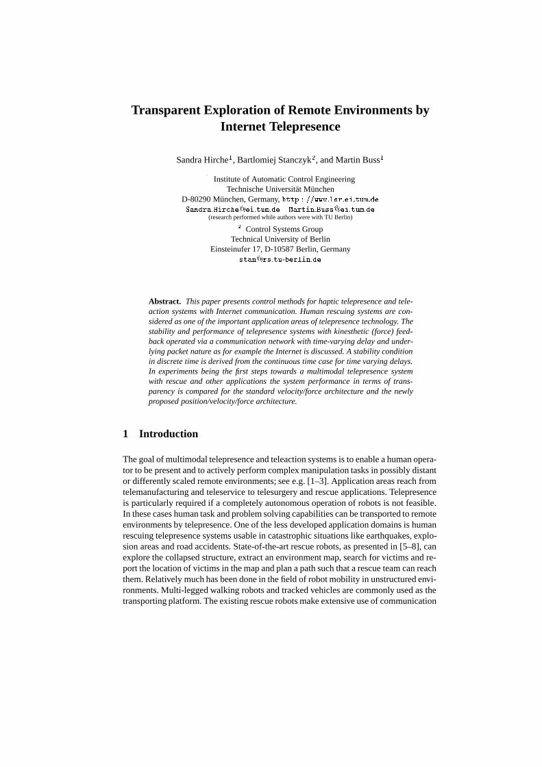
Main focus of this paper is the kinesthetic feedback system aiming at bilateral tele-operation with force feedback. The system is composed of the force feedback capableHuman System Interface (HSI) and the executing robot (teleoperator). The human op-erator manipulates the HSI in order to command the remote teleoperator that interactswith an usually unknown environment; the environment force is displayed to the oper-ator, see Fig. 1. The feedback of the other modalities (visual, auditory) as well as theproblem of moving the robot as a whole are neglected in the sequel. In [9] an overviewof related work is given.
Feedback
FeedbackVisual
FeedbackAuditory Stereo
CameraHead
e.g.Internet
Barrier
Command Signal
InformationSensor
Haptic/
7DoF Arm
Tactile
Fig. 1. Human rescuing telepresence system.
For successful task completion it is important that the operator feels directly con-nected to the remote environment, i.e. telepresence is required to be transparent. Inthe literature several transparency conditions are proposed. Transparency in the senseof [10] is achieved if the positions and forces at HSI and teleoperator are equal. An-other formulation, see [11], defines transparency as the ability to reproduce the remoteenvironment impedance to the human operator. The main problem with assuring trans-parency is the fact that the HSI and the teleoperator are connected through a com-munication medium as e.g. the Internet, see Fig. 1, which due to the communicationlatencies introduces constant or variable time delay into the system. Without furthercontrol measures, the time delay destabilizes the system. Passivity based argumentslead to the scattering transformation and the combined velocity/force (VF) control ofteleoperator/HSI, first proposed in [12]. As a result the system is stable for constant de-

Transparent Exploration of Remote Environments by Internet Telepresence 3
lay. The extension of this approach to the time varying delay case, as proposed in [13],also bases on the VF control structure. The VF architecture though may not guaranteeexact position tracking of the HSI and teleoperator as disturbances or variable time de-lay result in non-recoverable tracking errors deteriorating transparency. A transparencyoriented position/force (PF) architecture is proposed in [14] and verified by an Internetteledrilling experiment. Further discussion on other methods to achieve transparency,like e.g. the four-channel architecture can be found in [1, 9–11, 15].
The approach investigated here, increases transparency through the position feed-forward extension of the standard VF architecture, i.e. a combined position/velocitycontrol at the teleoperator site (PVF). As a result the position tracking error convergesto zero for most disturbances. The validity of the approach was shown in a simple1-degree-of-freedom (1 DOF) telepresence experiment, the stability conditions are for-mulated in continuous time, see [16].
With regard to realworld application we propose a more realistic experimental setupas a first step towards a human rescuing telepresence system. The benefit of the posi-tion/velocity/force approach compared to the standard velocity/force architecture underInternet like communication conditions is investigated. The stability condition is refor-mulated to incorporate the packet oriented discrete time nature of the problem. In ex-periments a wall environment is haptically explored. Thereto the Cartesian �-positionof the 7 DOF teleoperator arm, described in [17], is teleoperated by means of a 1 DOFforce feedback paddle via an emulated realtime communication network, see [18].
The paper is organized as follows: section 2 introduces passivity based stabilizationmethods and measures of transparency, in section 3 passivity conditions are derived tocope with the nature of packet switching networks as the Internet; section 4 presents theexperimental system architecture; the experimental results are discussed in section 5.
2 Theoretical Background
The human rescuing telepresence system basically consists of a force feedback capableHSI (variables indexed �) and the teleoperator (index �) interacting with an usuallyunknown remote environment (index �) as shown in Fig. 1. In bilateral telepresence thehuman manipulates the HSI applying the force ��. Based on stability arguments in thestandard architecture the HSI velocity ��� is communicated to the teleoperator where thelocal velocity control loop ensures the tracking of the desired teleoperator velocity �� �
�
(� denotes desired). The force �� sensed at the remote site, resulting from the interactionwith the environment, is transmitted back to the HSI serving as reference signal � �
� forthe local force control.
The HSI and the teleoperator are connected through a communication network clos-ing a global control loop via the human operator. In case of packet switched unreliableservice network, as e.g. the Internet, the data packets, thus the control signals are af-flicted with varying time delay and packet loss. Without further control measures theclosed loop system is unstable.
4 S. Hirche, B. Stanczyk, M. Buss
2.1 The Passivity Approach
A common approach to analyze and synthesize telepresence system architectures withtime delay is the passivity concept providing a sufficient condition for stability. A com-plex system of interconnected network elements (�-ports) is passive, and implicitelystable, if each of the subsystems is passive. A passive element is one for which, givenzero energy storage at � � �, the property
���
������ d� �
���
�� ������� d� � � �� � � (1)
holds, with ������ denoting the power dissipated in the system, ����, ���� being theinput and output vector. In classical telepresence architectures, as proposed in [12], theappropriately locally controlled HSI and teleoperator exchange velocity and force sig-nals, as the mapping from velocity to force is generally passive, hence the teleoperatorand the HSI are passive subsystems. The environment is considered passive and it isassumed that the (possibly so trained) human operator behaves in a cooperative, i.e.passive way.
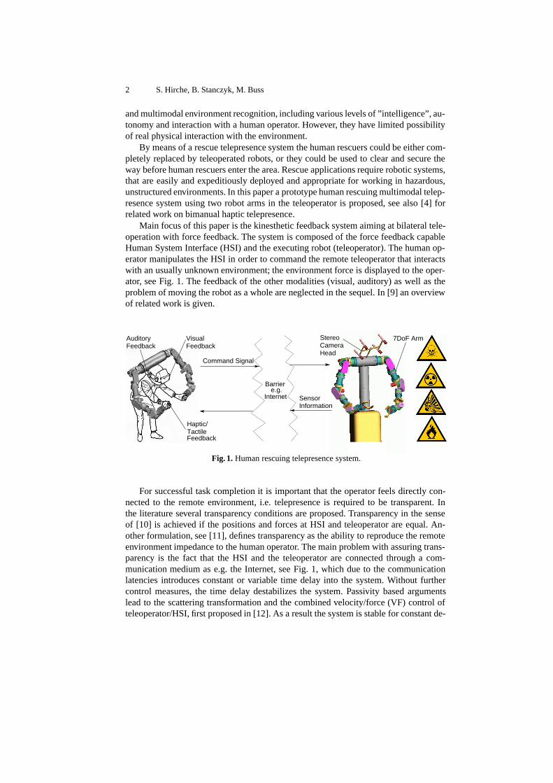
In case of time delay in the communication network the bidirectional commu-nication channel can be modeled as a time delaying two-port with time-varying de-lays ����, ���� in the forward and the backward path, respectively, as shown in thenetwork representation in Fig. 2. The blocks of the scattering transformation and � ����,����� are explained below. Applying scattering theory it is straightforward to show thatthe eigenvalues of the scattering matrix are larger than 1, i.e. the passivity condition isviolated; the communication line generates energy. The scattering transformation firstapplied to telepresence systems in [12] and extended in [19] passivates the communi-cation two-port for constant delays ���� � �, ���� � � with the wave variabletransformation equations
� �����
���� � � ���� �����
��� � � ���� �
�� �����
���� � � ���� � �����
��� � � ���� �
(2)
Using the notation of (1) the input vector is given by �� � ��� � ���� � and the outputvector by �� � ��� ���. Disregarding the blocks �����, ����� in Fig. 2, the communi-cation two-port now dissipates energy
���
����� ��� d� �
���
� ��� ��� � ���� ��� d�
�
������
�� d� �
������
�� d� � � ��
Transparent Exploration of Remote Environments by Internet Telepresence 5
fh f dh
�����
CommunicationNetwork
ScatteringTransfor-mation
f2(t)
����� f1(t)
Gain
Env
ironm
ent
Hum
an HSIScatteringTransfor-mation operator
Tele-
xh urxh
vl
ul
vr fe fe
xdt xt
Zh Ze
Fig. 2. System architecture for time-varying delay with time-varying gains ������ �����.
If the delay varies over time the passivity condition for the communication two-port/scattering transformation may be violated depending on the rate of change of thedelay
����� �d����
d�� � � �� � �
as shown in [13]. At times when the time delay increases, i.e. the rate of change of thetime delay is positive ����� � �, the communication line generates energy, thus is notpassive. At decreasing time delay ����� � � the communication line dissipates energy,hence is passive.
For causality reasons the rate of change of delay is bounded
� ������ � �� � � �� � (3)
In order to preserve passivity the time-varying gains
��� ��� � �� ������ � � �� � (4)
are inserted shaping the energy output of the communication two-port depending on therate of change of the transmission delay as shown in Fig. 2. For constant delay the gainscalculate to �� � �� � � recovering the results of [12].
2.2 Transparency
Ideal kinesthetic coupling expressed in the notion of transparency is achieved if thehuman operator feels directly connected to the remote environment. According to [10]this requires the positions and forces at the HSI and teleoperator to be equal
�� � �� � �� � �� (5)
Another formulation, see [11], demands the felt impedance � � to be equal (or as closeas possible) to the environment impedance ��
�� � �� (6)
with the mechanical impedance � describing the input/output behavior of mechanicalsystems by the ratio of effort (force � ) and flow (velocity �)
� ��
� (7)

6 S. Hirche, B. Stanczyk, M. Buss
or the generalized impedance given by the ratio of force and position.According to network theory transparency is achieved only, if the impedances of
the network elements match. The impedance matching technique, introduced in [20],adjusts the impedance of the teleoperator/environment to the characteristic impedance� in (2) of the passified transmission line by appropriately chosen controller parametersof the local velocity/force control loop.
In the time-varying delay case the passifying gains �����, ����� transform the sig-nals and thereby cause the loss of transparency. Then a position drift between HSI andteleoperator may occur that is non-recoverable as velocity control may not guaranteesteady state error free position tracking. In order to overcome this deficiency an addi-tional position feedforward is proposed in [16]. The position error
���� � ����� ������ �����
is weighted by feedforward gain �� acting as a proportional position controller with the(if necessary) saturated control output
�������� � ��sat������� with sat������� �
����� � � ������ � �
� ��������� � � ��
see Fig. 3. The gain �� and the saturation � are chosen so that the non-passivity ofthe position feedforward is compensated by the excess passivity of the teleoperator, formore details see [16].
fh f dh
ffeed
�����
CommunicationNetwork
f2(t)
ScatteringTransfor-mation
Env
ironm
ent
�����
�����
fe
xdt xt
xdt
xt
Gain
Hum
an
HSI
f1(t)
ScatteringTransfor-mation operator
Tele-
Ip
xh urxh
xh
vl
ul
vr fe
Fig. 3. Transparency orientated system architecture for time-varying delay with time-varyinggains ������ ����� and additional position feedforward.
3 Packet Switched Networks
All previous formulations consider the continuous time case from a theoretical pointof view. In realworld applications, where a packet switched communication network ase.g. the Internet is used for the transmission of the sampled control signals, the under-lying discrete nature of the problem as well as the packet order processing algorithms

Transparent Exploration of Remote Environments by Internet Telepresence 7
have to be considered. Main goal of this section is the calculation of the time varyinggains ����� under the assumption that the communication delay of every IP-packet isknown, which can be easily achieved by time stamps. Furthermore, the effect of packetprocessing algorithms on passivity is discussed.
We consider a sampled data system for HSI and teleoperator and a multi-path packetswitched network with time-varying delay for communication, see Fig. 4. The discretetime system may be described as a continuous time system in which the variables arefrozen for the sample interval �. In what follows we indicate with ���� the value ofthe discrete variable ���� corresponding to the interval � � ��� �� � ����. Discretescattering transformation is applied, see [21], using the transformation equations givenby (2) in discrete time now with the independent variable �.
The communication in the forward and in the backward path is considered to beequally structured. For clarity the subsequent discussion refers to the forward path only,but equally applies to the backward path. A fixed number � of consecutive samples ofthe wave variables ���� representing the output of the scattering transformation, arepacked into one IP-packet ����� and put on the outgoing link every ���� � ��;� � ���� � Z� represents the packet index of the � �� sample. During transmissionover the network the IP-packet � ���� experiences a link delay of ���� arriving at thereceive queue at � � ���� � �����. Processing algorithms at packet or sample levelas e.g. the introduction of virtual delay possibly causes further delay of ���, so thatthe first sample data � of the packet � is extracted at � � ���� � ����� � ������.
lul(k) l 1ScatteringTransfor-mation
f1(k) ScatteringTransfor-mation
Ul(p)
ul(k − l)
Ur(p) ur(k)...T1(p)
CommunicationNetwork
Hold last/Use freshestsample
Gain... L
Send Queue Receive Queue
per packetL samples
Fig. 4. Communication network with underlying packet nature and processing algorithms.
Hence the overall delay of a packet is the sum of the delay in the network itself, thepacketing delay and the delay introduced by processing algorithms
�� ��� � ���� � ���� � ����
where every sample belonging to a certain packet is delayed with the packet delay, aslong there is no delay introduced by processing at sample level which is assumed here.
As the delay within a packet is constant by this assumption
�� �� � �� � �� ��� � �� ���� (8)
with the sample � and ����� belonging to the same packet �, the rate of change of thedelay for samples within the packet
� �� ��� �����
��
��� � ��� ����
�with � � ��

8 S. Hirche, B. Stanczyk, M. Buss
is zero. Varying delays occur between the last and the first sample of two consecu-tively arriving packets. Therefore, without loss of generality, the effect of processingalgorithms on the rate of change of delay is demonstrated under the assumption that apacket contains only a single sample data, � � � and therefore � � �.
In dynamically routed multi-path networks as e.g. the Internet and for the TCP pro-tocol with its resend algorithm the IP-packets may arrive at the receiving queue in per-muted order. In Fig. 5 the sent (Æ) and received (�) packets are depicted with theirarriving order depending on the delay �
� ���. The ��� packet arrives one time interval� after the ��� packet, before the �� and the ��� packet. The causality condition (3)is violated, the absolute value of the rate of change of the delay is no longer bounded by1. The value of � �� ��� � ��� ��� means that the processing of packets at the receiverside jumps backward (forward) in time with respect to the order of the sent samples.
T ∗1 = 1
T ∗1 = 0
T ∗1 = 0
T ∗1 (k = 1)
T ∗1 = −4
t
TA = Tp
T ∗1
1 2 3
4
5
6
1 2 3
5
6
5
5
4
UFS
UFS
sample sent sample received
UFS
HLS
HLS
Fig. 5. Effect of processing algorithms UFS and HLS on the order of the received (�) with respectto the sent (Æ) packets and thereby on the rate of change of overall delay �� �
� .
If a younger packet and an older packet are in the receive queue then the older packetis discarded here and the youngest packet is processed next (Use-Freshest-Sample,UFS), see Fig 5, where the �� and the ��� packet are discarded in favor of the younger��� packet. With this algorithm the rate of change � �� ��� is possibly lower than -1. Sincethe rate of change of the overall delay corresponding to the UFS-algorithm is negative(decreasing overall delay), thus fulfills the passivity condition the UFS-algorithm ispassive. Assuming that a packet contains more than one sample (or sample vector inthe multidimensional case) and the UFS-algorithm applies on the packet level, i.e. be-fore the youngest packet is used all samples of the current packet have to be processed.Only the last sample of a packet may be assigned a value � �� ��� � �� due to theUFS-algorithm, all other samples within a packet are assigned � �� ��� � � as expressedin (8).
In case that there is no more data packet in the receive queue, then the last sampleof the actual packet is held until the next younger packet arrives (Hold-Last-Sample,HLS). This means, that with every time step � the overall delay increases by one timestep � corresponding to the rate of change � �� ��� � �, thus the passivity conditionis violated, the HLS-algorithm is not passive. Furthermore the rate of change of the
Transparent Exploration of Remote Environments by Internet Telepresence 9
overall delay is bounded now by
� �� ��� � � �� If a packet contains more than one sample data (or sample vector), the last sample ofthe currently processed packet is held until a younger packet arrives, � �� � � until anew sample is processed, see Fig. 5.
Assuming that the HSI and the teleoperator are synchronized, hence sampling takesplace at the same time instance � � ��, the overall delay �� is always a multiple ofthe sampling interval � resulting in an integer value � �� ��� � �� � �� ��� � Z. Now wemay determine the passifying time-varying gain � ���� according (4) in discrete time by
��� ��� � �� � �� ��� � � �� � (9)
For a packet containing more than one sample (or sample vector) � � is calculated zeroduring the processing of the packet and changes possibly for the last sample of thepacket to a value �� � �.
In summary the UFS algorithm is found to preserve passivity of the communicationline in a packet switched network, whereas the HLS algorithm is not passive. Equa-tion (9) represents the tuning rule for the time varying gains � ����, ����� in discretetime, see Fig. 3.
4 Experimental System Architecture
SensorayS626 IO
Matlab/Simulink
controlvelocityposition/
PCRTLinux
DACADC
counterforce/torque
sensor
Matlab/Simulink
PCRTLinux
ADCDAC
counter
forcecontrol
7 actuated joints
environmentmotor
SensorayS626 IO
NS 2FreeBSDPC
encoder
HSI
communications
teleoperator
Network emulator
virtual linkvirtual
rrouter
socket
wall
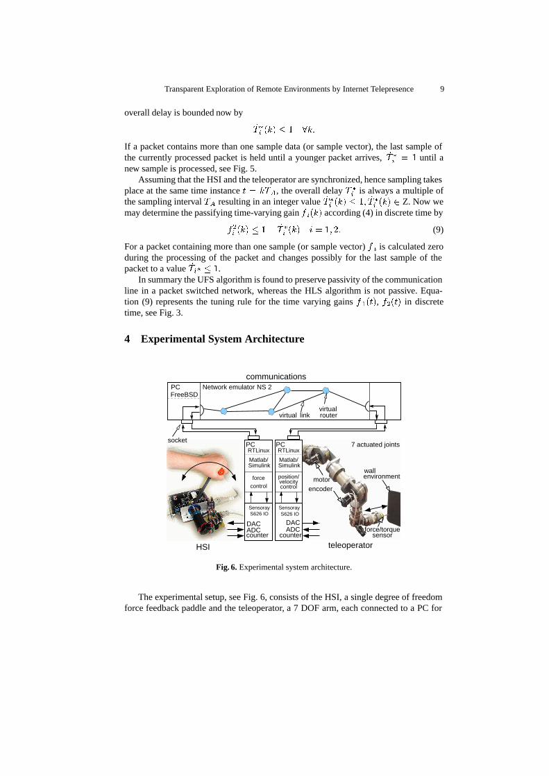
Fig. 6. Experimental system architecture.
The experimental setup, see Fig. 6, consists of the HSI, a single degree of freedomforce feedback paddle and the teleoperator, a 7 DOF arm, each connected to a PC for
10 S. Hirche, B. Stanczyk, M. Buss
control. The communication channel is represented by an emulated realtime commu-nication network that is implemented on a third PC. IP packets containing haptic andadministrative data as packet indices and time stamps are transmitted via IP socket con-nection on 100Mbps ethernet link between the HSI and the teleoperator via the networkemulator PC. The HSI acts as the server, the teleoperator as the client.
4.1 Overview of the teleoperator system
To achieve transparent telepresence, the manipulator placed on the remote site mustfulfil several conditions, which determine the requirements regarding both hardwareand control design. Roughly speaking, the remote robot has to reveal to the real worldthe same physical characteristics and abilities as the actual limb of the operator (for thenon micro-macroscaling case). This includes size, workspace, load performance anddynamic properties.
Another important requirement is that the manipulator should not have singulari-ties. Singularity poses major difficulties in Cartesian control schemes based on the Ja-cobian inverse, because of large joint velocities and instability occurring in the vicinityof singularities. Especially, in teleoperation scenarios, the trajectories are not known inadvance, but they are generated by the operator, who is liable to unintentionally drivethe teleoperator toward/through a singularity. That is why the strategies, which do notinvolve Jacobian inversion neither for trajectory generation nor for dynamic control, arepreferred.
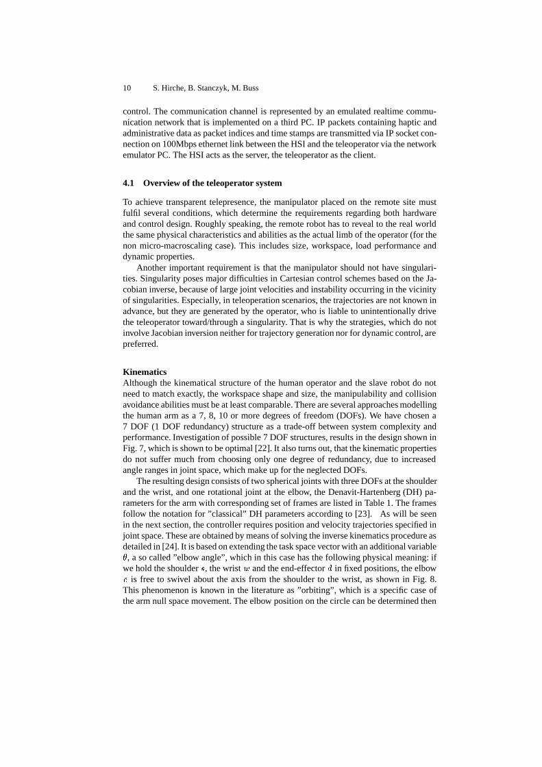
KinematicsAlthough the kinematical structure of the human operator and the slave robot do notneed to match exactly, the workspace shape and size, the manipulability and collisionavoidance abilities must be at least comparable. There are several approaches modellingthe human arm as a 7, 8, 10 or more degrees of freedom (DOFs). We have chosen a7 DOF (1 DOF redundancy) structure as a trade-off between system complexity andperformance. Investigation of possible 7 DOF structures, results in the design shown inFig. 7, which is shown to be optimal [22]. It also turns out, that the kinematic propertiesdo not suffer much from choosing only one degree of redundancy, due to increasedangle ranges in joint space, which make up for the neglected DOFs.
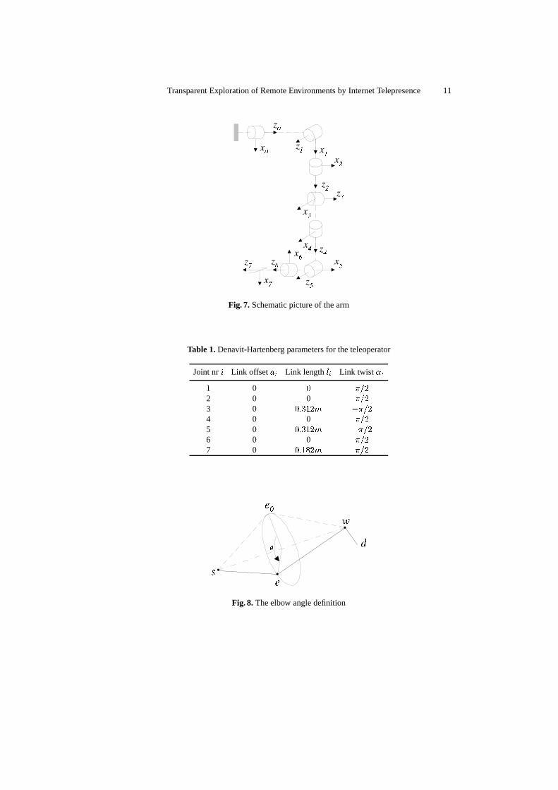
The resulting design consists of two spherical joints with three DOFs at the shoulderand the wrist, and one rotational joint at the elbow, the Denavit-Hartenberg (DH) pa-rameters for the arm with corresponding set of frames are listed in Table 1. The framesfollow the notation for ”classical” DH parameters according to [23]. As will be seenin the next section, the controller requires position and velocity trajectories specified injoint space. These are obtained by means of solving the inverse kinematics procedure asdetailed in [24]. It is based on extending the task space vector with an additional variable�, a so called ”elbow angle”, which in this case has the following physical meaning: ifwe hold the shoulder � , the wrist � and the end-effector � in fixed positions, the elbow� is free to swivel about the axis from the shoulder to the wrist, as shown in Fig. 8.This phenomenon is known in the literature as ”orbiting”, which is a specific case ofthe arm null space movement. The elbow position on the circle can be determined then
Transparent Exploration of Remote Environments by Internet Telepresence 11
Fig. 7. Schematic picture of the arm
Table 1. Denavit-Hartenberg parameters for the teleoperator
Joint nr � Link offset �� Link length � Link twist �
1 0 � ���2 0 0 ���3 0 ���� ����4 0 0 ���5 0 ���� ����6 0 0 ���7 0 ����� ���
Fig. 8. The elbow angle definition

12 S. Hirche, B. Stanczyk, M. Buss
by specifying the angle between the arm projection of an arbitrary zero position � � andthe actual position � onto the circle plane.
Manipulator controlFor real world applications, when the robot has to interact with the physical environ-ment, it is necessary to specify the suitable compliant behavior in Cartesian space. Themotivation to use a compliant control algorithms as an alternative to a stiff positioncontrol is also proposed by other researchers [25]. The main reason here is to avoidlarge forces which may often result when a stiff robot arm comes in contact with theenvironment, especially if it is unknown and unstructured. A classical example for suchsituations is a peg-in-hole experiment. In case of not exact parts aligning, a stiff robot,trying to push the peg into the hole, would generate large forces resulting in mechanicaldamage, while a compliant robotic arm would be able to complete the task [25].
A well established framework to achieve such a behavior of the manipulator isimpedance control [26]. It is a strategy that controls the dynamic relationship betweenthe manipulator and environment by establishing a mass-spring-damper system relationbetween the Cartesian position � and the Cartesian force � :
� � � ����� ������
where � , �� and �� are virtual Cartesian inertia, damping and stiffness. In otherwords, the goal of impedance control is to mask the natural properties of the robot andto replace them with the specified mechanical impedance. A good review of variousimplementation strategies is given in [27].
The control strategy chosen here is based on an extension of stiffness control [28,29]. It makes use on the idea of mapping the Cartesian matrices �� and �� into jointspace �� and �� , using the manipulator Jacobian � :
�� � �����
�� � �����
The control law is then given by
� � �������� � ������ ���
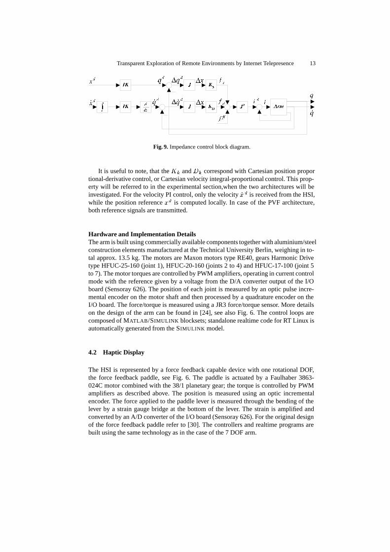
where ��� and � ��� are the position and velocity error in joint space and � is motortorque. The corresponding block diagram is shown in Fig. 9, where � �� ���� ��� ���� arethe desired position and velocity trajectories in Cartesian and in joint space, IK - inversekinematics solution, ��� �� - forces corresponding to arm stiffness and damping, � �� -feedforward force used for dynamic compensation of the arm, � �� � - desired and actualmotor current. The main reason for choosing this approach is the fact that it does notrequire inverting the manipulator Jacobian, neither the manipulator inertia matrix. Infact, the manipulator dynamic model was not used for the experiments presented here,because movement in only one Cartesian direction � was required. This was made pos-sible by setting the stiffness gains for the other directions high enough to eliminate theinfluence of gravity and friction.
Transparent Exploration of Remote Environments by Internet Telepresence 13
Fig. 9. Impedance control block diagram.
It is useful to note, that the �� and �� correspond with Cartesian position proportional-derivative control, or Cartesian velocity integral-proportional control. This prop-erty will be referred to in the experimental section,when the two architectures will beinvestigated. For the velocity PI control, only the velocity ��� is received from the HSI,while the position reference �� is computed locally. In case of the PVF architecture,both reference signals are transmitted.
Hardware and Implementation DetailsThe arm is built using commercially available components together with aluminium/steelconstruction elements manufactured at the Technical University Berlin, weighing in to-tal approx. 13.5 kg. The motors are Maxon motors type RE40, gears Harmonic Drivetype HFUC-25-160 (joint 1), HFUC-20-160 (joints 2 to 4) and HFUC-17-100 (joint 5to 7). The motor torques are controlled by PWM amplifiers, operating in current controlmode with the reference given by a voltage from the D/A converter output of the I/Oboard (Sensoray 626). The position of each joint is measured by an optic pulse incre-mental encoder on the motor shaft and then processed by a quadrature encoder on theI/O board. The force/torque is measured using a JR3 force/torque sensor. More detailson the design of the arm can be found in [24], see also Fig. 6. The control loops arecomposed of MATLAB/SIMULINK blocksets; standalone realtime code for RT Linux isautomatically generated from the SIMULINK model.
4.2 Haptic Display
The HSI is represented by a force feedback capable device with one rotational DOF,the force feedback paddle, see Fig. 6. The paddle is actuated by a Faulhaber 3863-024C motor combined with the 38/1 planetary gear; the torque is controlled by PWMamplifiers as described above. The position is measured using an optic incrementalencoder. The force applied to the paddle lever is measured through the bending of thelever by a strain gauge bridge at the bottom of the lever. The strain is amplified andconverted by an A/D converter of the I/O board (Sensoray 626). For the original designof the force feedback paddle refer to [30]. The controllers and realtime programs arebuilt using the same technology as in the case of the 7 DOF arm.

14 S. Hirche, B. Stanczyk, M. Buss
4.3 Realtime communication network emulation
Network emulation refers to the use of a network simulator, as e.g. the Berkeley Net-work Simulator (ns2) in a live network, for details see [31,32]. The live traffic generatedby the HSI and the teleoperator system is passed through the user defined virtual net-work. As mentioned in [18] it turns out to be an appropriate tool for the evaluation oftelepresence systems in communication networks.
The basic emulation system configuration is depicted in Fig. 10. A private networkis established for communication between the HSI PC (ethernet adapter eth0 - IP ad-dress 192.168.0.5), the network emulator PC (rl1 - 192.168.0.1, rl2 - 192.169.0.1) andthe teleoperator PC (eth0 - 192.169.0.3). The emulator PC acts as a gateway. For LANconnection each of the three PCs is equipped with an extra ethernet adapter (eth1, rl0).
HSI PC RTLinux Teleop. PC RTLinux
eth0eth1
eth0eth1LAN
LAN
LAN
192.168.0.* 192.169.0.*
ns (network emulator)
rl2
−> 192.169.0.3
n1 n2
filter 192.169.0.3−> 192.168.0.5
n4 n3
tap1tap2
tap3tap4
rl0
FreeBSD
192.168.0.5 192.169.0.3
192.168.0.1 192.169.0.1rl1
filter 192.168.0.5
Fig. 10. Network emulation system configuration.
The Berkeley Network Simulator (ns2) runs in emulation mode under FreeBSD,see [31, 32]. Configuration of the emulated network is defined by a tcl script as exem-plarily shown for one link frome node n1 to node n2 in the code listing below. Tapagents inside the emulator are assigned to capture (tap1, tap3) live traffic or inject(tap2, tap4) traffic from the virtual network into the live network, see listing lines 4-14. Each tap agent is attached to a virtual node (listing lines 1, 2, 9, 14). The traffic fromthe entry nodes (n1, n3) is filtered with respect to the source and destination address,see listing line 7. Each entry node is connected to an exit node by a simplex link withsufficient bandwidth of 100Mbps, see listing lines 3, 15. The forward path of communi-cation is represented by the link n1�n2 with the link delay ����, the backward pathby n3�n4 with the link delay ����. In listing line 3 the initial value for the link delay
Transparent Exploration of Remote Environments by Internet Telepresence 15
is set to 10 ms. During the experiments the delay is varied according to a deterministicpattern, see listing lines 16, 17. For this paper no additional virtual traffic is generatednor data loss incorporated.
(01) set n1 [$ns node]; # Create the node n1(02) set n2 [$ns node]; # Create the node n2(03) $ns simplex-link $n1 $n2 100Mb 10ms DropTail# Setup connections between the nodes# Configure the first entry node(04) set tap1 [new Agent/Tap]; # Create the TCPTap Agent(05) set bpf1 [new Network/Pcap/Live]; # Create the bpf(06) set dev [$bpf1 open readonly rl1](07) $bpf1 filter "src 192.168.0.5 and dst 192.169.0.3"(08) $tap1 network $bpf1; # Connect bpf to TCPTap Agent(09) $ns attach-agent $n1 $tap1; # Attach agent to the node# Configure the first exit node(10) set tap2 [new Agent/Tap]; # Create a TCPTap Agent(11) set ipnet2 [new Network/IP]; # Create a Network agent(12) $ipnet2 open writeonly(13) $tap2 network $ipnet2; # Connect network agent to tap agent(14) $ns attach-agent $n2 $tap2; # Attach agent to the node(15) $ns simplex-connect $tap1 $tap2 # Connect the agents(16) set explink1 [$ns link $n1 $n2] # link to experiment with(17) set lnk [$explink1 link] $ns at 11.0 "$lnk set delay_ 20ms"
...
5 Experimental Results
The following experiments are performed in order to investigate the transparency ofthe standard velocity/force (VF) architecture and the combined position/velocity/force(PVF) control approach. Both strategies are compared in terms of position/force track-ing, see the condition (5), and environment impedance transparency as formulatedin (6). Free space motion as well as contact with a wall is performed.
The angular position and velocity of the HSI (the paddle) are converted into linearmotion variables (scaling factor �
�m/rad ) ��� ��� and transmitted as set values for the
Cartesian position and velocity to the teleoperator (7 DOF arm), see Fig. 6. The armmovement is limited to the Cartesian �-direction only. The arm first moves in free space,0.16 m (0.19 m for VF) from the initial position it contacts a wooden wall with a 3 cmsponge attached.
The VF architecture uses velocity-PI control on the slave side, the PVF appliesvelocity-P control with position feedforward. In order to have comparable results theposition feedforward controller (PVF) is assigned the same value as the I-portion of thevelocity control (PV). It turns out that the saturation of the output of the feedforwardcontroller is not necessary for this setup. The force measured at the teleoperator end-effector is fed back as a set value for the force controlled paddle.
All controllers operate with a sample time of � � � ms, As in all experiments� � �� sample vectors are packed into one IP-packet the delay introduced by pack-eting is ���� � �� ms. The delay in the forward and the backward link is varied
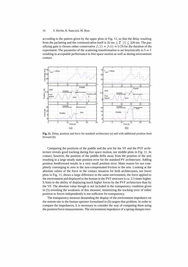
16 S. Hirche, B. Stanczyk, M. Buss
according to the pattern given by the upper plots in Fig. 11, so that the delay resultingfrom the packeting and the communication itself is �� ms � ���� � ��� ms. The pas-sifiying gain is chosen rather conservative ����� � ����� � � �� for the duration of theexperiment. The parameter of the scattering transformation is set heuristically to � � �resulting in acceptable performance in free space motion as well as during environmentcontact.
0 5 10 15 20 25
0
5
10
15
For
ce [N
]
Time [s]
Paddle Arm
0 5 10 15 20 25
0
0.2
Pos
ition
[m
]
Arm
Paddle
Free Space
Wall
0 5 10 15 20 250
25
50
75
Link
Del
ay [m
s]
Tpack
= 20ms
Position drift
Contact
Contact
0 5 10 15 20 250
25
50
75 Tpack
= 20ms
0 5 10 15 20 25
0
5
10
15
Time [s]
Paddle
Arm
0 5 10 15 20 25
0
0.2
Paddle
Free Space
Wall
Arm
Contact
Contact
(a) (b)
Fig. 11. Delay, position and force for standard architecture (a) and with additional position feed-forward (b)
Comparing the positions of the paddle and the arm for the VF and the PVF archi-tecture reveals good tracking during free space motion, see middle plots in Fig. 11. Incontact, however, the position of the paddle drifts away from the position of the armresulting in a large steady state position error for the standard PV architecture. Addingposition feedforward results in a very small position error. Main reason for not com-pletely converging to zero is the non-compensated friction in the arm. Looking at theabsolute values of the force in the contact situation for both architectures, see lowerplots in Fig. 11, shows a large difference in the same environment, the force applied tothe environment and displayed to the human in the PVF structure is ca. 2.5 times higher.It hints to the ability of displaying much higher forces by the PVF architecture than bythe VF. The absolute value though is not included in the transparency condition givenin (5) revealing the weakness of this measure; minimizing the tracking error of eitherposition or forces independently is not sufficient for transparency.
The transparency measure demanding the display of the environment impedance onthe remote site to the human operator formulated in (6) targets that problem. In order tocompare the impedances, it is necessary to consider the way of computing them usingthe position/force measurements. The environment impedance of a spring-damper envi-
Transparent Exploration of Remote Environments by Internet Telepresence 17
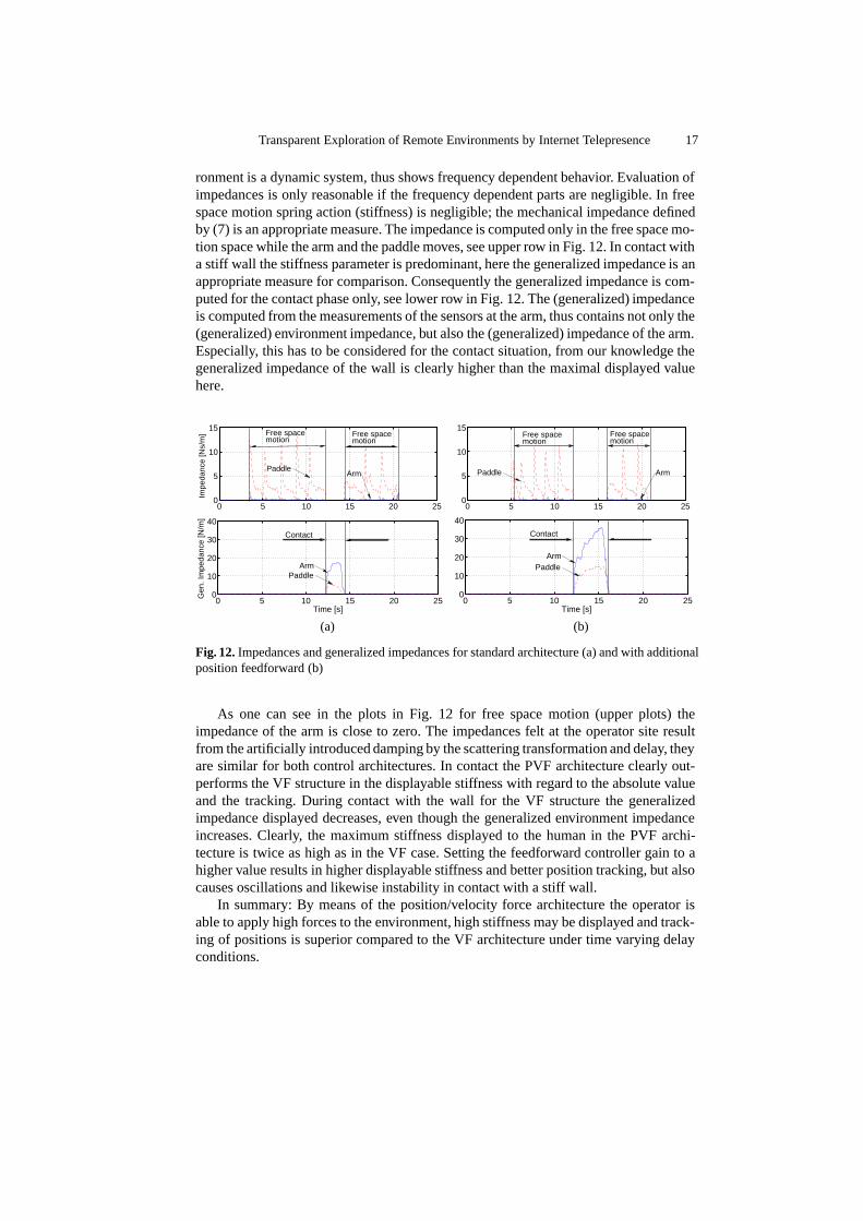
ronment is a dynamic system, thus shows frequency dependent behavior. Evaluation ofimpedances is only reasonable if the frequency dependent parts are negligible. In freespace motion spring action (stiffness) is negligible; the mechanical impedance definedby (7) is an appropriate measure. The impedance is computed only in the free space mo-tion space while the arm and the paddle moves, see upper row in Fig. 12. In contact witha stiff wall the stiffness parameter is predominant, here the generalized impedance is anappropriate measure for comparison. Consequently the generalized impedance is com-puted for the contact phase only, see lower row in Fig. 12. The (generalized) impedanceis computed from the measurements of the sensors at the arm, thus contains not only the(generalized) environment impedance, but also the (generalized) impedance of the arm.Especially, this has to be considered for the contact situation, from our knowledge thegeneralized impedance of the wall is clearly higher than the maximal displayed valuehere.
0 5 10 15 20 250
5
10
15
motionmotion
Arm
Impe
danc
e [N
s/m
] Free space Free space
Paddle
0 5 10 15 20 250
5
10
15
motionmotion
Arm
Free space Free space
Paddle
0 5 10 15 20 250
10
20
30
40
Time [s]
Arm
Gen
. Im
peda
nce
[N/m
]
Paddle
Contact
0 5 10 15 20 250
10
20
30
40
Time [s]
Arm
Contact
Paddle
(a) (b)
Fig. 12. Impedances and generalized impedances for standard architecture (a) and with additionalposition feedforward (b)
As one can see in the plots in Fig. 12 for free space motion (upper plots) theimpedance of the arm is close to zero. The impedances felt at the operator site resultfrom the artificially introduced damping by the scattering transformation and delay, theyare similar for both control architectures. In contact the PVF architecture clearly out-performs the VF structure in the displayable stiffness with regard to the absolute valueand the tracking. During contact with the wall for the VF structure the generalizedimpedance displayed decreases, even though the generalized environment impedanceincreases. Clearly, the maximum stiffness displayed to the human in the PVF archi-tecture is twice as high as in the VF case. Setting the feedforward controller gain to ahigher value results in higher displayable stiffness and better position tracking, but alsocauses oscillations and likewise instability in contact with a stiff wall.
In summary: By means of the position/velocity force architecture the operator isable to apply high forces to the environment, high stiffness may be displayed and track-ing of positions is superior compared to the VF architecture under time varying delayconditions.

18 S. Hirche, B. Stanczyk, M. Buss
6 Conclusions and Outlook
The results of this paper are the first steps towards a multimodal telepresence and tele-action system for rescue application over a packet switched network as e.g. the In-ternet. The influence of the time-varying delay characteristics together with standardpacket processing algorithms on the overall delay characteristics thus on the passivityand thereby stability has been discussed with focus on the discrete time nature of theproblem; a passivity condition has been derived. Applying these conditions in exper-iments the combined position/velocity/force architecture clearly outperforms the stan-dard velocity/force architecture with respect to transparency, hence is appropriate forthe introduced human rescuing system. Investigations for multi DOF as well as thedevelopment of intelligent communication processing algorithms from a control per-spective are subject of future research.
Acknowledgments
This work has been partially supported by the “IBB-Zukunftsfond Berlin, Projekt NeueGeneration leittechnischer Systeme (mobile und virtuelle Leittechnik)” co-financed bythe EU with EFRE funds; German Research Foundation (DFG) in the CollaborativeResearch Centre SFB 453 on “High-Fidelity Telepresence and Teleaction”. Techni-cal support by F. Bachmann and U. Weidauer as well as the helpful suggestions fromK. Kondak are appreciated.
References
1. Buss, M., and Schmidt, G.,”Control Problems in Multi-Modal Telepresence Systems,” In Ad-vances in Control: Highlights of the 5th European Control Conference ECC’99 in Karlsruhe,Germany, P. Frank, Ed. Springer, 1999, pp. 65–101.
2. Baier, H., Buss, M., Freyberger, F., and Schmidt, G., “Benefits of Combined Active StereoVisual and Haptic Telepresence,” In Proceedings of the IEEE/RSJ International Conference onIntelligent Robots and Systems IROS 2000, (Takamatsu, Japan), 2000, pp. 702-707.
3. M. Buss and G. Schmidt, “Multi-Modal Telepresence,” In Proceedings of the 17th Interna-tional Mechatronics Forum, Science and Technology Forum 2000, (Kagawa University, Ka-gawa, Japan), 2000, pp. 24-33.
4. Kron, A., and Schmidt, G.,”A Bimanual Haptic Telepresence System - Design Issues andExperimental Results,” In Proceedings of the International Workshop on High-Fidelity Telep-resence and Teleaction, jointly with the conference HUMANOIDS, (Munich, Germany), 2003,to appear.
5. ���� � ������������������
6. ���� � ����������������������������������
7. ���� � �����������������
8. ���� � ��������������������
9. Salcudean, S. “Control for Teleoperation and Haptic Interfaces.“, In Lecture Notes in Controland Information Sciences 230: Control Problems in Robotics and Automation, B. Siciliano andK. Valavanis, Eds. Springer, London, 1998, pp. 51–66.
Transparent Exploration of Remote Environments by Internet Telepresence 19
10. Y. Yokokohji and T. Yoshikawa, “Bilateral Control of Master-Slave Manipulators for IdealKinesthetic Coupling Formulation and Experiment,” IEEE Transactions on Robotics and Au-tomation, vol. 10, pp. 605–619, October 1994.
11. Lawrence, D., “Stability and Transparency in Bilateral Teleoperation,“ IEEE Transactionson Robotics and Automation 9, 5 (October 1993), 624–637.
12. R. Anderson and M. Spong, “Bilateral Control of Teleoperators with Time Delay,” IEEETransaction on Automatic Control, vol. 34, pp. 494–501, 1989.
13. R. Lozano, N. Chopra and M. Spong, “Passivation of Force Reflecting Bilateral Teleoperatorswith Time Varying Delay,” Mechatronics’02, Entschede, Netherlands, June 24-26, 2002.
14. H. Baier, M. Buss and G. Schmidt, “Stabilitat und Modusumschaltung von Regelkreisen inTeleaktionssystemen,” at—Automatisierungstechnik 48, pp. 51–59, 2 (Februar 2000).
15. Hannaford, B., “A design framework for teleoperators with kinesthetic feedback,” IEEETransactions on Robotics and Automation 5, 4 (August 1989), 426–434.
16. N. Chopra, M. W. Spong, S. Hirche, and M. Buss, “Bilateral Teleoperation over Internet: theTime Varying Delay Problem,” in Proceedings of the American Control Conference, (Denver,CO), 2003.
17. B. Stanczyk, “Teleoperated Exploration and Manipulation of Hazardous Environments withDual Arm Robot/ Avatar,” Technical Report TR-RS-2003-01-3, Control Systems Group, Tech-nical University of Berlin, 2003.
18. S. Hirche and M. Buss, “Study of Teleoperation using Realtime Communication NetworkEmulation,” in Proceedings of the International Conference on Advanced Intelligent Mecha-tronics, (Kobe, Japan), 2003.
19. Niemeyer, G., and Slotine, J.-J., “Passivation of Force Reflecting Bilateral Teleoperators withTime Varying Delay,” in Proceedings of the 8. Mechatronics Forum, Enschede, Netherlands,2002. Stable Adaptive Teleoperation. IEEE Journal of Oceanic Engineering 16, 1 (January1991), 152–162.
20. Niemeyer, G. and Slotine, J. E. “Using Wave Variables for System Analysis and RobotControl.“, In Proceedings of the IEEE International Conference on Robotics and Automation(1997), pp. 1619–1625.
21. Stramigioli, S., van der Schaft, A., Maschke, B. and Melchiorri, C., “Geometric Scatteringin Robotic Telemanipulation.“ IEEE Transactions on Robotics and Automation 20, No.Y (July2002).
22. J. M. Hollerbach, “Optimum kinematic design for a seven degree of freedom manipulator,”Robotics Research, 2nd Int. Symp. , H. Hanafusa and H. Inous, Eds., MIT Press, pp. 215-222,1985.
23. M. Spong, M. Vidyasagar, ”Robot Dynamics and Control”, Wiley&Sons,1989.24. B. Stanczyk, “Wrist-Partitioned Inverse Kinematics Solution for Anthropomorphic Robotic
Arm.”, Technical Report TR-RS-2002-01-1, Control Systems Group, Technical University ofBerlin, 2002.
25. S. Hayati, S.T. Venkataraman,”Design and implementation of a robot control system withtraded and shared control capability”, IEEE International Conference on Robotics and Au-tomation, 1989, vol 3, pp. 1310 -1315.
26. N. Hogan, ”Impedance control: An approach to ma-nipulation, part I - theory, part II - imple-mentation,part III - applications”, Journ. of Dyn. Systems, Mea-surement and Control, 1985.
27. R. Volpe. “Real and Artificial Forces in the Control of Manipulators: Theory and Experi-ments“, Ph.D. Thesis, Carnegie Mellon University, Department of Physics. September, 1990.
28. M. T. Mason, J. K. Salisbury, “Robot Hands and the Mechanics of Manipulation”, The MITPress, 1985.
29. M. Buss, “Multi-Fingered Regrasping Using a Hybrid Systems Approach,” in Proceedings ofthe 2nd IMACS/IEEE International Multiconference on Computational Engineering in SystemsApplications (CESA’98), vol. 4, (Hammamet, Tunisia), pp. 857–861, 1998.
20 S. Hirche, B. Stanczyk, M. Buss
30. Baier, H., Buss, M., Freyberger, F., Hoogen, J., Kammermeier, P. and Schmidt, G., “Dis-tributed PC-Based Haptic, Visual and Acoustic Telepresence System—Experiments in Virtualand Remote Environments.“, In Proceedings of the IEEE Virtual Reality Conference VR’99(Houston, TX, 1999), pp. 118–125.
31. UCB/LBNL/VINT Network Simulator - ns (version 2),���� � �������������������.32. K. Fall, “Network emulation in the VINT/NS simulator,”Proceedings of the fourth IEEE
Symposium on Computers and Communications, 1999.