TRANSMISSION AND TRANSFER CASE
192
TRANSMISSION AND TRANSFER CASE CONTENTS page page AUTOMATIC TRANSMISSION—30/32RH ...... 75 AX15 MANUAL TRANSMISSION ............ 38 AX5 MANUAL TRANSMISSION .............. 1 NV231 TRANSFER CASE ................. 166 AX5 MANUAL TRANSMISSION INDEX page page GENERAL INFORMATION AX5 MANUAL TRANSMISSION .............. 1 GEAR RATIOS ........................... 1 RECOMMENDED LUBRICANT ............... 1 TRANSMISSION ASSEMBLY INFORMATION .... 2 TRANSMISSION IDENTIFICATION ............ 1 DIAGNOSIS AND TESTING HARD SHIFTING ......................... 3 LOW LUBRICANT LEVEL ................... 3 TRANSMISSION NOISE .................... 4 REMOVAL AND INSTALLATION ADAPTER HOUSING SEAL ................. 7 EXTENSION HOUSING SEAL ............... 7 FRONT BEARING RETAINER SEAL ........... 6 TRANSMISSION .......................... 4 DISASSEMBLY AND ASSEMBLY ADAPTER/EXTENSION HOUSING AND FRONT BEARING RETAINER .................... 8 COUNTERSHAFT ........................ 27 INPUT SHAFT .......................... 27 OUTPUT SHAFT ........................ 28 SEMI-SYNCHRONIZED REVERSE IDLER GEAR ............................... 32 SHIFT MECHANISM AND GEARTRAIN ........ 16 CLEANING AND INSPECTION AX5 MANUAL TRANSMISSION COMPONENTS . 33 SPECIFICATIONS TORQUE .............................. 35 SPECIAL TOOLS AX5 .................................. 36 GENERAL INFORMATION AX5 MANUAL TRANSMISSION The AX5 is a five speed manual transmission with fifth gear being the overdrive range. An adapter housing is used to attach the transmission to the transfer case on 4-wheel drive applications. A stan- dard style extension housing is used for the 2-wheel drive applications. The shift mechanism is integral to the transmission assembly and mounted in the shift tower portion of the adapter/extension housing (Fig. 1). TRANSMISSION IDENTIFICATION The AX5 identification code is on the bottom sur- face of the transmission case near the fill plug (Fig. 2). The first number is year of manufacture. The sec- ond and third numbers indicate month of manufac- ture. The next series of numbers is the transmission serial number. GEAR RATIOS Gear ratios for the AX5 manual transmission are as follows: • First gear: 3.93:1 • Second gear: 2.33:1 • Third gear: 1.45:1 • Fourth gear: 1.00:1 • Fifth gear: 0.85:1 • Reverse gear: 4.74:1 RECOMMENDED LUBRICANT Recommended lubricant for AX5 transmissions is Mopart 75W–90, API Grade GL–3 gear lubricant, or equivalent. Correct lubricant level is from the bottom edge, to no more than 6 mm (1/4 in.) below the bottom edge of the fill plug hole. TJ TRANSMISSION AND TRANSFER CASE 21 - 1
-
Upload
khangminh22 -
Category
Documents
-
view
1 -
download
0
Transcript of TRANSMISSION AND TRANSFER CASE
AA
G
D
R
G
A
fhtddtt1
T
f2o
TJ TRANSMISSION AND TRANSFER CASE 21 - 1
TRANSMISSION AND TRANSFER CASE
CONTENTS
page page
UTOMATIC TRANSMISSION—30/32RH . . . . . . 75X15 MANUAL TRANSMISSION . . . . . . . . . . . . 38
page
TRANSMISSION . . . . . . . . . . . . . . . . . . . . . . . . . . 4
D
C
S
S
e
nt
AX5 MANUAL TRANSMISSION . . . . . . . . . . . . . . 1NV231 TRANSFER CASE . . . . . . . . . . . . . . . . . 166
AX5 MANUAL TRANSMISSION
INDEX
page
ENERAL INFORMATIONAX5 MANUAL TRANSMISSION . . . . . . . . . . . . . . 1GEAR RATIOS . . . . . . . . . . . . . . . . . . . . . . . . . . . 1RECOMMENDED LUBRICANT . . . . . . . . . . . . . . . 1TRANSMISSION ASSEMBLY INFORMATION . . . . 2TRANSMISSION IDENTIFICATION . . . . . . . . . . . . 1IAGNOSIS AND TESTINGHARD SHIFTING . . . . . . . . . . . . . . . . . . . . . . . . . 3LOW LUBRICANT LEVEL . . . . . . . . . . . . . . . . . . . 3TRANSMISSION NOISE . . . . . . . . . . . . . . . . . . . . 4EMOVAL AND INSTALLATIONADAPTER HOUSING SEAL . . . . . . . . . . . . . . . . . 7EXTENSION HOUSING SEAL . . . . . . . . . . . . . . . 7FRONT BEARING RETAINER SEAL . . . . . . . . . . . 6
ISASSEMBLY AND ASSEMBLYADAPTER/EXTENSION HOUSING AND FRONT
BEARING RETAINER . . . . . . . . . . . . . . . . . . . . 8COUNTERSHAFT . . . . . . . . . . . . . . . . . . . . . . . . 27INPUT SHAFT . . . . . . . . . . . . . . . . . . . . . . . . . . 27OUTPUT SHAFT . . . . . . . . . . . . . . . . . . . . . . . . 28SEMI-SYNCHRONIZED REVERSE IDLER
GEAR . . . . . . . . . . . . . . . . . . . . . . . . . . . . . . . 32SHIFT MECHANISM AND GEARTRAIN . . . . . . . . 16LEANING AND INSPECTIONAX5 MANUAL TRANSMISSION COMPONENTS . 33PECIFICATIONSTORQUE . . . . . . . . . . . . . . . . . . . . . . . . . . . . . . 35PECIAL TOOLS
AX5 . . . . . . . . . . . . . . . . . . . . . . . . . . . . . . . . . . 36ENERAL INFORMATION
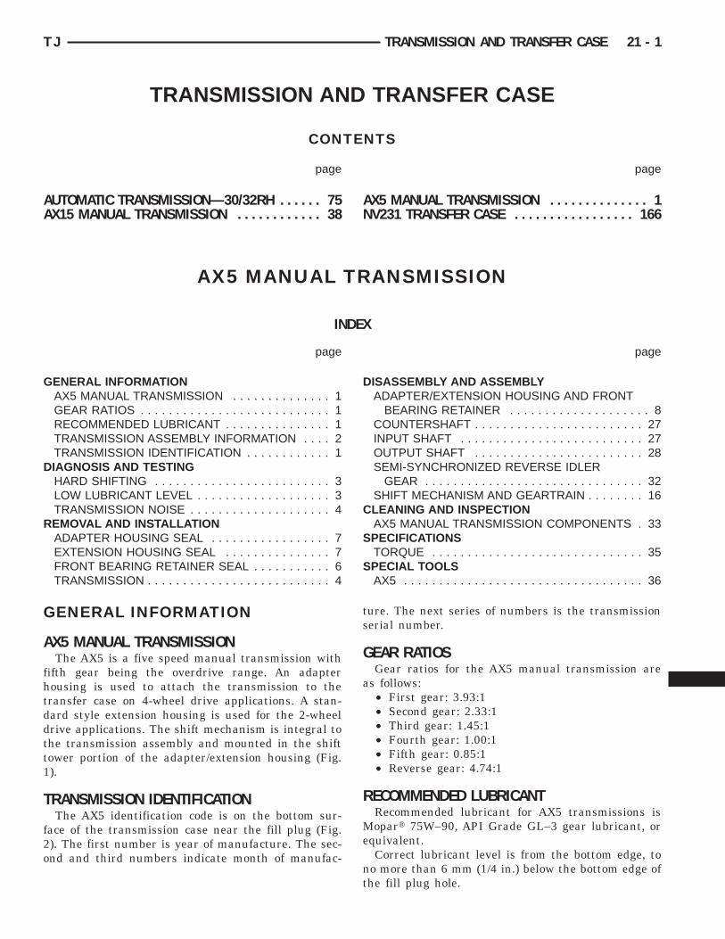
X5 MANUAL TRANSMISSIONThe AX5 is a five speed manual transmission with
ifth gear being the overdrive range. An adapterousing is used to attach the transmission to theransfer case on 4-wheel drive applications. A stan-ard style extension housing is used for the 2-wheelrive applications. The shift mechanism is integral tohe transmission assembly and mounted in the shiftower portion of the adapter/extension housing (Fig.).
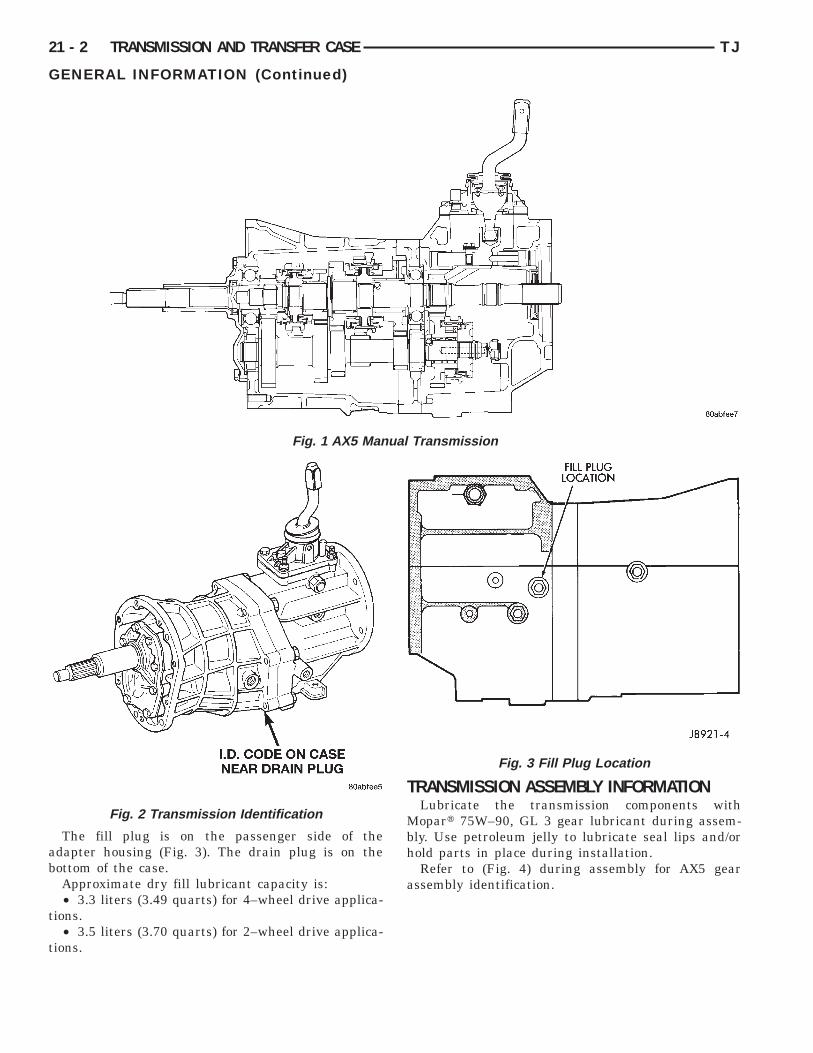
RANSMISSION IDENTIFICATIONThe AX5 identification code is on the bottom sur-
ace of the transmission case near the fill plug (Fig.). The first number is year of manufacture. The sec-nd and third numbers indicate month of manufac-
ture. The next series of numbers is the transmissionserial number.
GEAR RATIOSGear ratios for the AX5 manual transmission are
as follows:• First gear: 3.93:1• Second gear: 2.33:1• Third gear: 1.45:1• Fourth gear: 1.00:1• Fifth gear: 0.85:1• Reverse gear: 4.74:1
RECOMMENDED LUBRICANTRecommended lubricant for AX5 transmissions is
Mopart 75W–90, API Grade GL–3 gear lubricant, orquivalent.Correct lubricant level is from the bottom edge, to
o more than 6 mm (1/4 in.) below the bottom edge ofhe fill plug hole.
ab
t
t
ual
21 - 2 TRANSMISSION AND TRANSFER CASE TJ
GENERAL INFORMATION (Continued)
The fill plug is on the passenger side of thedapter housing (Fig. 3). The drain plug is on theottom of the case.Approximate dry fill lubricant capacity is:• 3.3 liters (3.49 quarts) for 4–wheel drive applica-
ions.• 3.5 liters (3.70 quarts) for 2–wheel drive applica-
ions.
Fig. 1 AX5 Man
Fig. 2 Transmission Identification
TRANSMISSION ASSEMBLY INFORMATIONLubricate the transmission components with
Mopart 75W–90, GL 3 gear lubricant during assem-bly. Use petroleum jelly to lubricate seal lips and/orhold parts in place during installation.
Refer to (Fig. 4) during assembly for AX5 gearassembly identification.
Transmission
Fig. 3 Fill Plug Location

D
L
rr
chl
ipit
eLhsi
wso
TJ TRANSMISSION AND TRANSFER CASE 21 - 3
GENERAL INFORMATION (Continued)
IAGNOSIS AND TESTING
OW LUBRICANT LEVELA low transmission lubricant level is generally the
esult of a leak, inadequate lubricant fill, or an incor-ect lubricant level check.Leaks can occur at the mating surfaces of the gear
ase, intermediate plate and adaptor or extensionousing, or from the front/rear seals. A suspected
eak could also be the result of an overfill condition.Leaks at the rear of the extension or adapter hous-
ng will be from the housing oil seals. Leaks at com-onent mating surfaces will probably be the result ofnadequate sealer, gaps in the sealer, incorrect boltightening, or use of a non–recommended sealer.
A leak at the front of the transmission will be fromither the front bearing retainer or retainer seal.ubricant may be seen dripping from the clutchousing after extended operation. If the leak isevere, it may also contaminate the clutch disc caus-ng the disc to slip, grab, and/or chatter.
A correct lubricant level check can only be madehen the vehicle is level. Also allow the lubricant to
ettle for a minute or so before checking. These rec-mmendations will ensure an accurate check and
Fig. 4 Geartra
avoid an underfill or overfill condition. Always checkthe lubricant level after any addition of fluid to avoidan incorrect lubricant level condition.
HARD SHIFTINGHard shifting is usually caused by a low lubricant
level, improper, or contaminated lubricants. The con-sequence of using non–recommended lubricants isnoise, excessive wear, internal bind, and hard shift-ing. Substantial lubricant leaks can result in gear,shift rail, synchro, and bearing damage. If a leakgoes undetected for an extended period, the first indi-cations of component damage are usually hard shift-ing and noise.
Component damage, incorrect clutch adjustment,or a damaged clutch pressure plate or disc are addi-tional probable causes of increased shift effort. Incor-rect adjustment or a worn/damaged pressure plate ordisc can cause incorrect release. If the clutch problemis advanced, gear clash during shifts can result.Worn or damaged synchro rings can cause gear clashwhen shifting into any forward gear. In some new orrebuilt transmissions, new synchro rings may tend tostick slightly causing hard or noisy shifts. In mostcases, this condition will decline as the ringswear–in.
omponents
in C
T
iws
aIpfl
R
T
R
s
n
f
c
t
e
tn
m
21 - 4 TRANSMISSION AND TRANSFER CASE TJ
DIAGNOSIS AND TESTING (Continued)
RANSMISSION NOISEMost manual transmissions make some noise dur-
ng normal operation. Rotating gears generate a mildhine that is audible, but generally only at extreme
peeds.Severe, highly audible transmission noise is gener-
lly the initial indicator of a lubricant problem.nsufficient, improper, or contaminated lubricant willromote rapid wear of gears, synchros, shift rails,orks and bearings. The overheating caused by aubricant problem, can also lead to gear breakage.
EMOVAL AND INSTALLATION
RANSMISSION
EMOVAL(1) Shift transmission into first or third gear.(2) Raise and support vehicle on suitable safety
tands.(3) Disconnect necessary exhaust system compo-
ents.(4) Remove skid plate, if equipped.(5) Remove slave cylinder from clutch housing.(6) Mark rear propeller shaft and rear axle yokes
or installation alignment (Fig. 5).
(7) Mark front propeller shaft, axle, and transferase yokes for installation alignment, if equipped.(8) Remove propeller shaft(s).(9) Unclip wire harnesses from transmission and
ransfer case, if equipped.(10) Disconnect transfer case vent hose, if
quipped.(11) Disengage any wire connectors attached to
ransmission or transfer case, if equipped, compo-ents.(12) Support transfer case, if equipped, with trans-ission jack.
Fig. 5 Marking Propeller Shaft And Axle Yokes
(13) Secure transfer case, if equipped, to jack withsafety chains.
(14) Disconnect transfer case shift linkage attransfer case, if equipped.
(15) Remove nuts attaching transfer case to trans-mission, if equipped.
(16) Remove transfer case, if equipped.(17) Remove crankshaft position sensor (Fig. 6),
(Fig. 7).
Fig. 6 Crankshaft Position Sensor—2.5L Engine
Fig. 7 Crankshaft Position Sensor —4.0L Engine
Ctri
Pa
c
t
su
a
(
g
im
btb
ii
swi
TJ TRANSMISSION AND TRANSFER CASE 21 - 5
REMOVAL AND INSTALLATION (Continued)
AUTION: It is important that the crankshaft posi-ion sensor be removed prior to transmissionemoval. The sensor can easily be damaged if leftn place during removal operations.
(18) Support engine with adjustable jack stand.osition wood block between jack and oil pan tovoid damaging pan.(19) Support transmission with transmission jack.(20) Secure transmission to jack with safety
hains.(21) Disconnect rear cushion and bracket from
ransmission.(22) Remove rear crossmember.(23) Disconnect transmission shift lever as follows:
(a) Lower transmission–transfer case assemblyapproximately 7–8 cm (3 in.) for access to shiftlever.
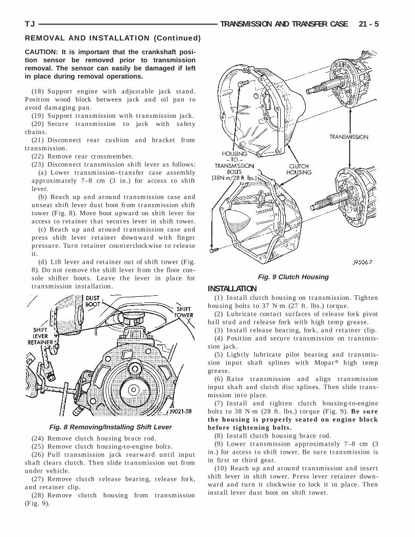
(b) Reach up and around transmission case andunseat shift lever dust boot from transmission shifttower (Fig. 8). Move boot upward on shift lever foraccess to retainer that secures lever in shift tower.
(c) Reach up and around transmission case andpress shift lever retainer downward with fingerpressure. Turn retainer counterclockwise to releaseit.
(d) Lift lever and retainer out of shift tower (Fig.8). Do not remove the shift lever from the floor con-sole shifter boots. Leave the lever in place fortransmission installation.
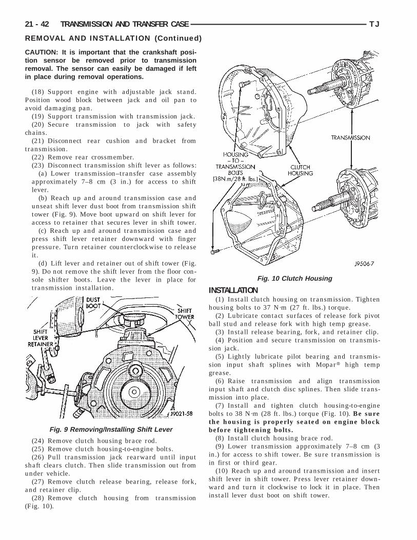
(24) Remove clutch housing brace rod.(25) Remove clutch housing-to-engine bolts.(26) Pull transmission jack rearward until input
haft clears clutch. Then slide transmission out fromnder vehicle.(27) Remove clutch release bearing, release fork,
nd retainer clip.(28) Remove clutch housing from transmission
Fig. 9).
Fig. 8 Removing/Installing Shift Lever
INSTALLATION(1) Install clutch housing on transmission. Tighten
housing bolts to 37 N·m (27 ft. lbs.) torque.(2) Lubricate contact surfaces of release fork pivot
ball stud and release fork with high temp grease.(3) Install release bearing, fork, and retainer clip.(4) Position and secure transmission on transmis-
sion jack.(5) Lightly lubricate pilot bearing and transmis-
sion input shaft splines with Mopart high temprease.(6) Raise transmission and align transmission
nput shaft and clutch disc splines. Then slide trans-ission into place.(7) Install and tighten clutch housing-to-engine
olts to 38 N·m (28 ft. lbs.) torque (Fig. 9). Be surehe housing is properly seated on engine blockefore tightening bolts.(8) Install clutch housing brace rod.(9) Lower transmission approximately 7–8 cm (3
n.) for access to shift tower. Be sure transmission isn first or third gear.
(10) Reach up and around transmission and inserthift lever in shift tower. Press lever retainer down-ard and turn it clockwise to lock it in place. Then
nstall lever dust boot on shift tower.
Fig. 9 Clutch Housing

b
btt
t
e
c
ts
s
mm
c
t
sp
m
a
c
a
21 - 6 TRANSMISSION AND TRANSFER CASE TJ
REMOVAL AND INSTALLATION (Continued)
(11) Install rear crossmember. Tighten crossmem-er-to-frame bolts to 41 N·m (31 ft. lbs.) torque.(12) Install fasteners to hold rear cushion and
racket to transmission. Then tighten transmission-o-rear support bolts/nuts to 45 N·m (33 ft. lbs.)orque.
(13) Remove support stands from engine andransmission.
(14) Install and connect crankshaft position sensor.(15) Position transfer case on transmission jack, if
quipped.(16) Secure transfer case to jack with safety
hains, if equipped.(17) Raise transfer case, if equipped, and align
ransfer case input shaft to the transmission outputhaft.(18) Slide transfer case forward until case is
eated on transmission, if necessary.(19) Install nuts to attach transfer case to trans-ission, if equipped. Tighten transfer case-to-trans-ission nuts to 35 N·m (26 ft. lbs.) torque.(20) Connect transfer case shift linkage at transfer
ase, if equipped.(21) Connect transfer case vent hose, if equipped.(22) Secure wire harnesses in clips/tie straps on
ransmission and transfer case, if equipped.(23) Engage wire connectors attached to all neces-
ary transmission or transfer case, if equipped, com-onents.(24) Install rear propeller shaft slip yoke to trans-ission or transfer case, if equipped, output shaft.(25) Align marks on rear propeller shaft and rear
xle yokes (Fig. 10).
(26) Install and tighten propeller shaft U–jointlamp bolts to 19 N·m (170 in. lbs.) torque.(27) Align marks on front propeller shaft, axle,
nd transfer case yokes, if equipped.
Fig. 10 Align Propeller Shaft And Rear Axle YokesAlignment Marks
(28) Install and tighten propeller shaft U–jointclamp bolts to 19 N·m (170 in. lbs.) torque.
(29) Install slave cylinder in clutch housing.(30) Install skid plate, if equipped. Tighten bolts to
42 N·m (31 ft. lbs.) torque. Tighten stud nuts to 17N·m (150 in. lbs.) torque.
(31) Fill transmission and transfer case, ifequipped, with recommended lubricants. Refer to theLubricant Recommendation sections of the appropri-ate component for correct fluid.
(32) Lower vehicle.
FRONT BEARING RETAINER SEAL
REMOVAL(1) Remove release bearing and lever from the
transmission.(2) Remove the bolts holding the front bearing
retainer to the transmission case.(3) Remove the front bearing retainer from the
transmission case.(4) Using a suitable pry tool, remove the front
bearing retainer seal.
INSTALLATION(1) Using Tool Handle C-4171 and Seal Installer
8211, install new seal in to the front bearing retainer(Fig. 11).
(2) Remove any residual gasket material from thesealing surfaces of the bearing retainer and thetransmission case.
Fig. 11 Install Front Bearing Retainer Seal
f
t
o
t
E
R
f
s(
I
r
8so
e
sp
TJ TRANSMISSION AND TRANSFER CASE 21 - 7
REMOVAL AND INSTALLATION (Continued)
(3) Install new front bearing retainer gasket to theront bearing retainer.
(4) Install the front bearing retainer onto theransmission case.
(5) Install the bolts to hold the bearing retainernto the transmission case.(6) Tighten the bolts to 17 N·m (12 ft. lbs.).(7) Install release bearing and lever onto the
ransmission.
XTENSION HOUSING SEAL
EMOVAL(1) Raise and support vehicle.(2) Remove propeller shaft. Refer to Group 3, Dif-
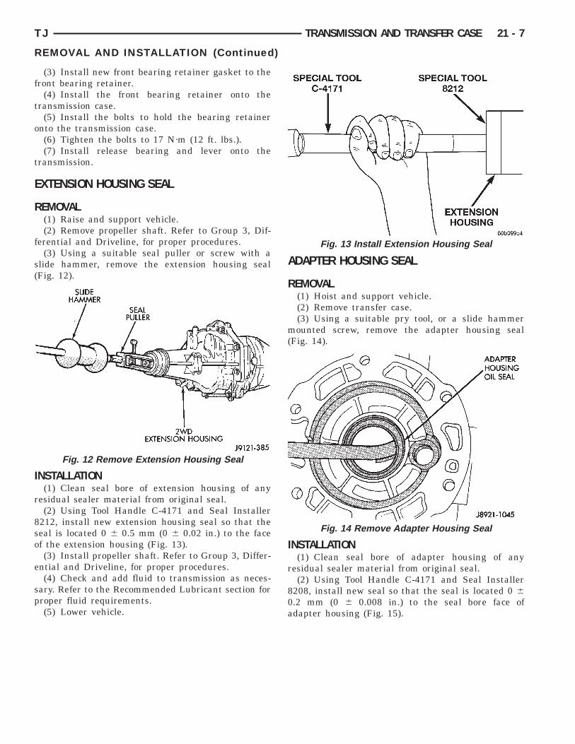
erential and Driveline, for proper procedures.(3) Using a suitable seal puller or screw with a
lide hammer, remove the extension housing sealFig. 12).
NSTALLATION(1) Clean seal bore of extension housing of any
esidual sealer material from original seal.(2) Using Tool Handle C-4171 and Seal Installer
212, install new extension housing seal so that theeal is located 0 6 0.5 mm (0 6 0.02 in.) to the facef the extension housing (Fig. 13).(3) Install propeller shaft. Refer to Group 3, Differ-
ntial and Driveline, for proper procedures.(4) Check and add fluid to transmission as neces-
ary. Refer to the Recommended Lubricant section forroper fluid requirements.(5) Lower vehicle.
Fig. 12 Remove Extension Housing Seal
ADAPTER HOUSING SEAL
REMOVAL(1) Hoist and support vehicle.(2) Remove transfer case.(3) Using a suitable pry tool, or a slide hammer
mounted screw, remove the adapter housing seal(Fig. 14).
INSTALLATION(1) Clean seal bore of adapter housing of any
residual sealer material from original seal.(2) Using Tool Handle C-4171 and Seal Installer
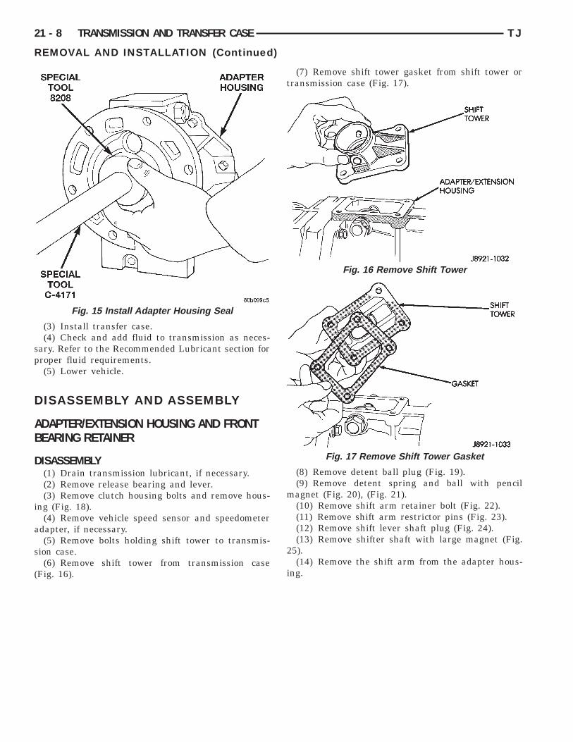
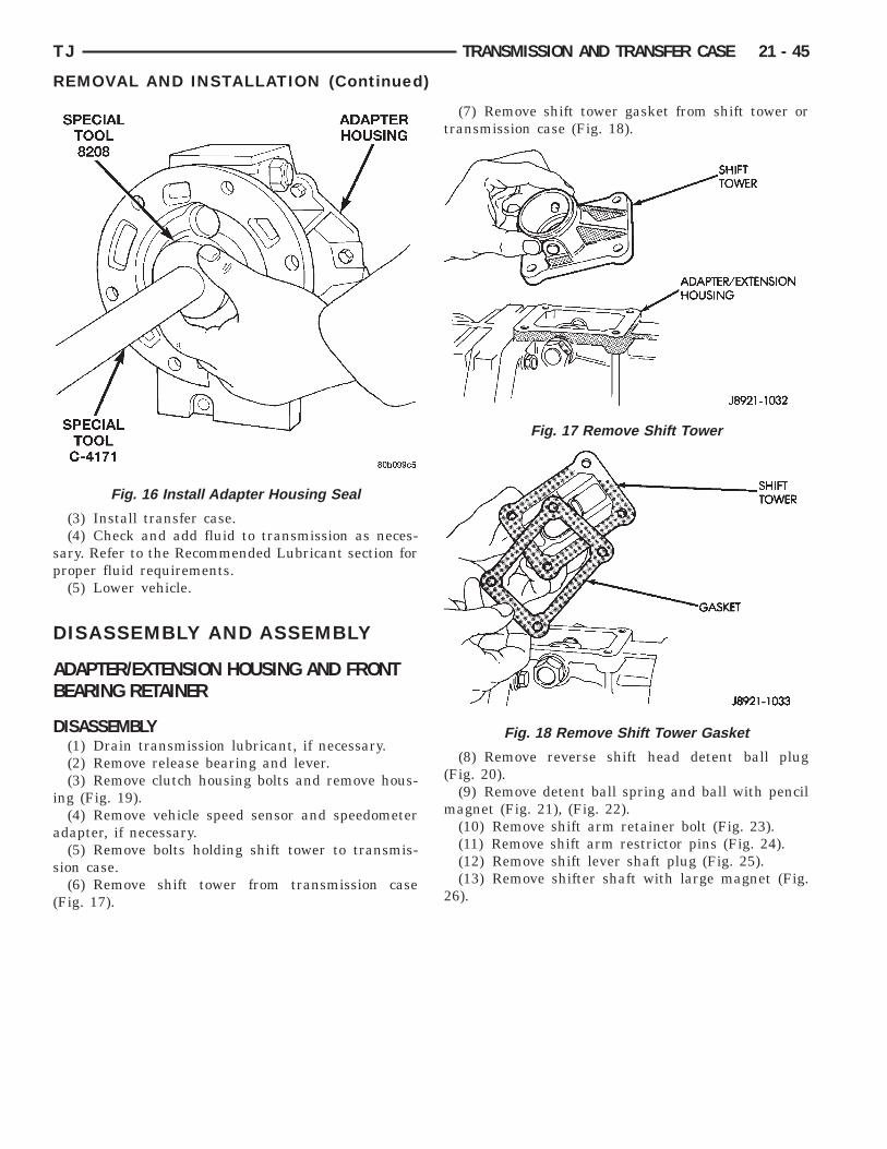
8208, install new seal so that the seal is located 0 60.2 mm (0 6 0.008 in.) to the seal bore face ofadapter housing (Fig. 15).
Fig. 13 Install Extension Housing Seal
Fig. 14 Remove Adapter Housing Seal
sp
D
AB
D
i
a
s
(
21 - 8 TRANSMISSION AND TRANSFER CASE TJ
REMOVAL AND INSTALLATION (Continued)
(3) Install transfer case.(4) Check and add fluid to transmission as neces-
ary. Refer to the Recommended Lubricant section forroper fluid requirements.(5) Lower vehicle.
ISASSEMBLY AND ASSEMBLY
DAPTER/EXTENSION HOUSING AND FRONTEARING RETAINER
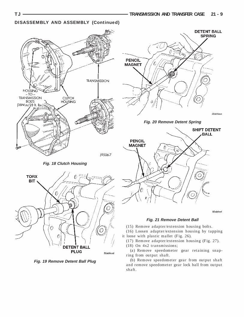
ISASSEMBLY(1) Drain transmission lubricant, if necessary.(2) Remove release bearing and lever.(3) Remove clutch housing bolts and remove hous-
ng (Fig. 18).(4) Remove vehicle speed sensor and speedometer
dapter, if necessary.(5) Remove bolts holding shift tower to transmis-
ion case.(6) Remove shift tower from transmission case
Fig. 16).
Fig. 15 Install Adapter Housing Seal
(7) Remove shift tower gasket from shift tower ortransmission case (Fig. 17).
(8) Remove detent ball plug (Fig. 19).(9) Remove detent spring and ball with pencil
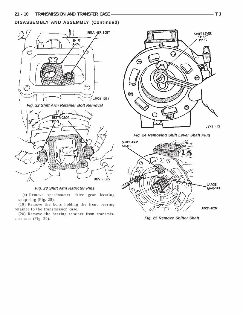
magnet (Fig. 20), (Fig. 21).(10) Remove shift arm retainer bolt (Fig. 22).(11) Remove shift arm restrictor pins (Fig. 23).(12) Remove shift lever shaft plug (Fig. 24).(13) Remove shifter shaft with large magnet (Fig.
25).(14) Remove the shift arm from the adapter hous-
ing.
Fig. 16 Remove Shift Tower
Fig. 17 Remove Shift Tower Gasket
TJ TRANSMISSION AND TRANSFER CASE 21 - 9
DISASSEMBLY AND ASSEMBLY (Continued)
Fig. 18 Clutch Housing
Fig. 19 Remove Detent Ball Plug
(15) Remove adapter/extension housing bolts.(16) Loosen adapter/extension housing by tapping
it loose with plastic mallet (Fig. 26).(17) Remove adapter/extension housing (Fig. 27).(18) On 4x2 transmissions;
(a) Remove speedometer gear retaining snap-ring from output shaft.
(b) Remove speedometer gear from output shaftand remove speedometer gear lock ball from outputshaft.
Fig. 20 Remove Detent Spring
Fig. 21 Remove Detent Ball
r
s
Fig. 24 Removing Shift Lever Shaft Plug
21 - 10 TRANSMISSION AND TRANSFER CASE TJ
DISASSEMBLY AND ASSEMBLY (Continued)
(c) Remove speedometer drive gear locatingsnap-ring (Fig. 28).(19) Remove the bolts holding the front bearing
etainer to the transmission case.(20) Remove the bearing retainer from transmis-
ion case (Fig. 29).
Fig. 22 Shift Arm Retainer Bolt Removal
Fig. 23 Shift Arm Rstrictor Pins
Fig. 25 Remove Shifter Shaft
TJ TRANSMISSION AND TRANSFER CASE 21 - 11
DISASSEMBLY AND ASSEMBLY (Continued)
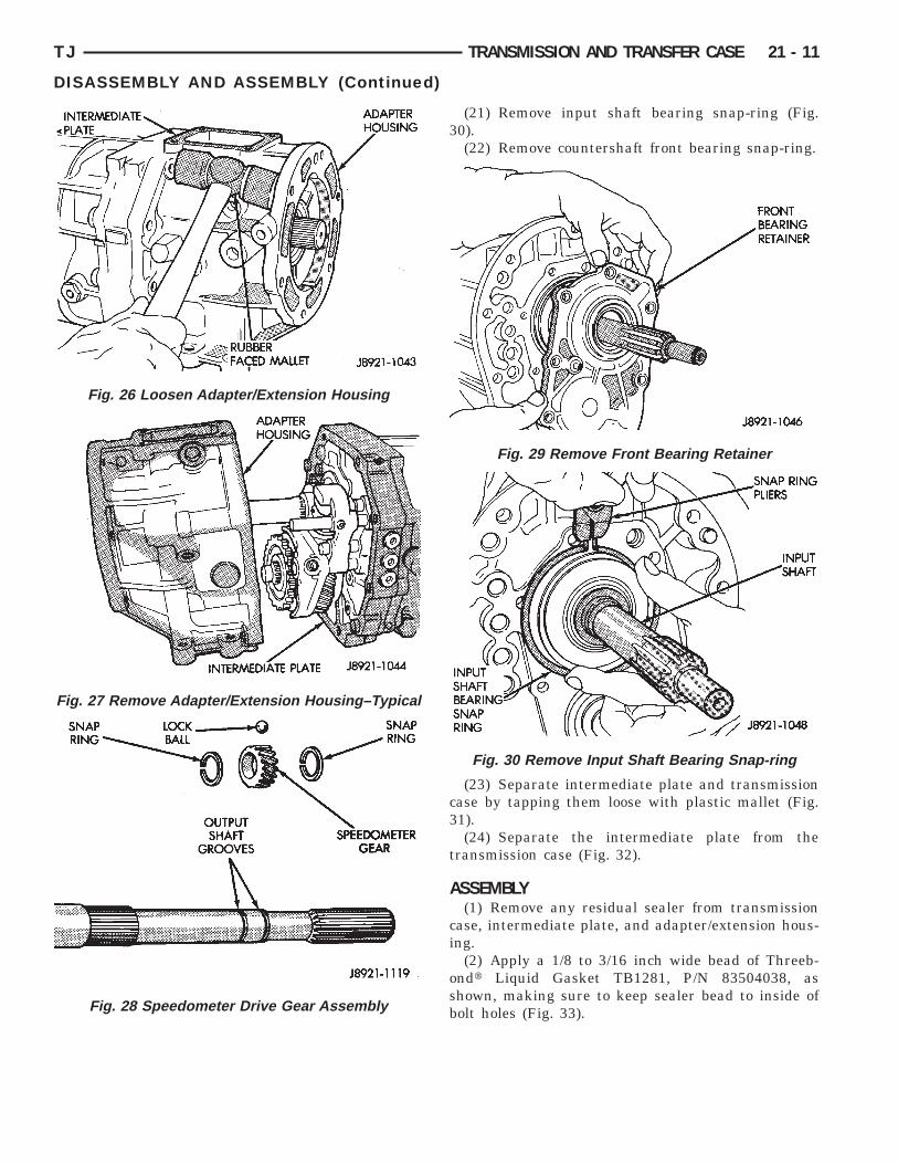
Fig. 26 Loosen Adapter/Extension Housing
Fig. 27 Remove Adapter/Extension Housing–Typical
Fig. 28 Speedometer Drive Gear Assembly
(21) Remove input shaft bearing snap-ring (Fig.30).
(22) Remove countershaft front bearing snap-ring.
(23) Separate intermediate plate and transmissioncase by tapping them loose with plastic mallet (Fig.31).
(24) Separate the intermediate plate from thetransmission case (Fig. 32).
ASSEMBLY(1) Remove any residual sealer from transmission
case, intermediate plate, and adapter/extension hous-ing.
(2) Apply a 1/8 to 3/16 inch wide bead of Threeb-ondt Liquid Gasket TB1281, P/N 83504038, asshown, making sure to keep sealer bead to inside ofbolt holes (Fig. 33).
Fig. 29 Remove Front Bearing Retainer
Fig. 30 Remove Input Shaft Bearing Snap-ring

hctp
21 - 12 TRANSMISSION AND TRANSFER CASE TJ
DISASSEMBLY AND ASSEMBLY (Continued)
(3) Align geartrain and shift rails with matingoles in transmission case and install transmissionase to the intermediate plate (Fig. 34). Verify thathe transmission case is seated on the intermediatelate locating pins.
Fig. 31 Separate Intermediate Plate andTransmission Case
Fig. 32 Remove Intermediate Plate fromTransmission Case
Fig. 33 Apply Sealer to Transmission Gear Case
(4) Install new front bearing snap rings (Fig. 35).
(5) Install front bearing retainer gasket to frontbearing retainer.
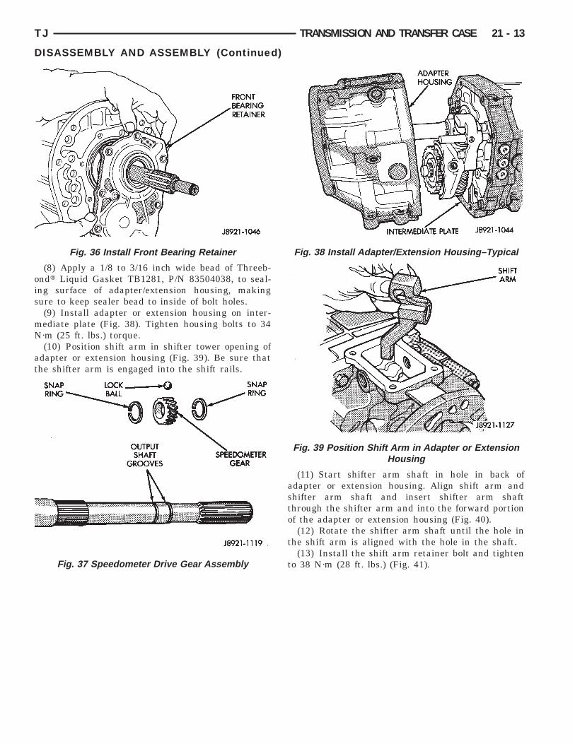
(6) Install the front bearing retainer (Fig. 36) andtighten bolts to 17 N·m (12 ft. lbs.).
(7) On 4x2 transmissions;(a) Install speedometer drive gear locating snap-
ring (Fig. 37).(b) Install speedometer gear lock ball in output
shaft and install speedometer gear onto outputshaft.
(c) Install speedometer gear retaining snap-ringonto output shaft.
Fig. 34 Install Transmission Gear Case to theIntermediate Plate
Fig. 35 Install Front Bearing Snap-rings
ois
mN
at
TJ TRANSMISSION AND TRANSFER CASE 21 - 13
DISASSEMBLY AND ASSEMBLY (Continued)
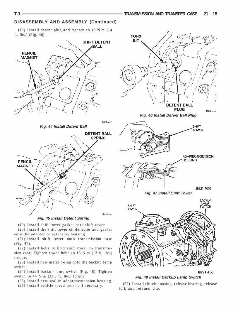
(8) Apply a 1/8 to 3/16 inch wide bead of Threeb-ndt Liquid Gasket TB1281, P/N 83504038, to seal-ng surface of adapter/extension housing, makingure to keep sealer bead to inside of bolt holes.(9) Install adapter or extension housing on inter-ediate plate (Fig. 38). Tighten housing bolts to 34·m (25 ft. lbs.) torque.(10) Position shift arm in shifter tower opening of
dapter or extension housing (Fig. 39). Be sure thathe shifter arm is engaged into the shift rails.
Fig. 36 Install Front Bearing Retainer
Fig. 37 Speedometer Drive Gear Assembly
(11) Start shifter arm shaft in hole in back ofadapter or extension housing. Align shift arm andshifter arm shaft and insert shifter arm shaftthrough the shifter arm and into the forward portionof the adapter or extension housing (Fig. 40).
(12) Rotate the shifter arm shaft until the hole inthe shift arm is aligned with the hole in the shaft.
(13) Install the shift arm retainer bolt and tightento 38 N·m (28 ft. lbs.) (Fig. 41).
Fig. 38 Install Adapter/Extension Housing–Typical
Fig. 39 Position Shift Arm in Adapter or ExtensionHousing

1
t
21 - 14 TRANSMISSION AND TRANSFER CASE TJ
DISASSEMBLY AND ASSEMBLY (Continued)
(14) Install and tighten shifter arm shaft plug to8 N·m (13 ft. lbs.) torque (Fig. 42).
(15) Install shift restrictor pins in shift tower andighten to 27 N·m (20 ft. lbs.) (Fig. 43).
Fig. 40 Install Shifter Arm Shaft
Fig. 41 Install Shift Arm Retainer Bolt
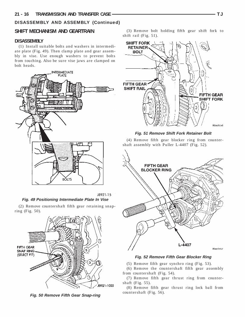
(16) Install shift detent ball in detent opening ofcase (Fig. 44).(17) Install detent spring in case (Fig. 45).
Fig. 42 Shifter Arm Shaft Plug Installation
Fig. 43 Install Shifter Restrictor Pins
f
o
(
st
s
s
TJ TRANSMISSION AND TRANSFER CASE 21 - 15
DISASSEMBLY AND ASSEMBLY (Continued)
(18) Install detent plug and tighten to 19 N·m (14t. lbs.) (Fig. 46).
(19) Install shift tower gasket onto shift tower.(20) Install the shift tower oil deflector and gasket
nto the adapter or extension housing.(21) Install shift tower onto transmission case
Fig. 47).(22) Install bolts to hold shift tower to transmis-
ion case. Tighten tower bolts to 18 N·m (13 ft. lbs.)orque.
(23) Install new metal o-ring onto the backup lampwitch.(24) Install backup lamp switch (Fig. 48). Tighten
witch to 44 N·m (32.5 ft. lbs.) torque.(25) Install new seal in adapter/extension housing.(26) Install vehicle speed sensor, if necessary.
Fig. 44 Install Detent Ball
Fig. 45 Install Detent Spring
(27) Install clutch housing, release bearing, releasefork and retainer clip.
Fig. 46 Install Detent Ball Plug
Fig. 47 Install Shift Tower
Fig. 48 Install Backup Lamp Switch
S
D
abfb
r
21 - 16 TRANSMISSION AND TRANSFER CASE TJ
DISASSEMBLY AND ASSEMBLY (Continued)
HIFT MECHANISM AND GEARTRAIN
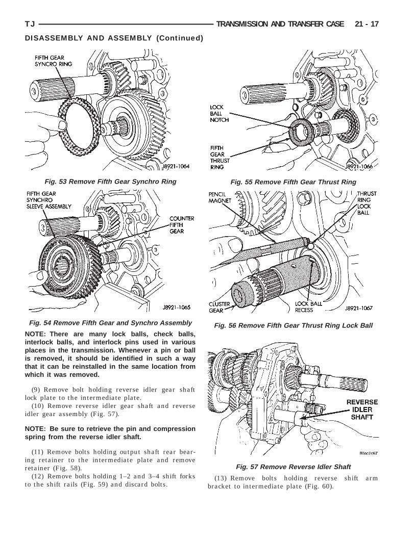
ISASSEMBLY(1) Install suitable bolts and washers in intermedi-
te plate (Fig. 49). Then clamp plate and gear assem-ly in vise. Use enough washers to prevent boltsrom touching. Also be sure vise jaws are clamped onolt heads.
(2) Remove countershaft fifth gear retaining snap-ing (Fig. 50).
Fig. 49 Positioning Intermediate Plate In Vise
Fig. 50 Remove Fifth Gear Snap-ring
(3) Remove bolt holding fifth gear shift fork toshift rail (Fig. 51).
(4) Remove fifth gear blocker ring from counter-shaft assembly with Puller L-4407 (Fig. 52).
(5) Remove fifth gear synchro ring (Fig. 53).(6) Remove the countershaft fifth gear assembly
from countershaft (Fig. 54).(7) Remove fifth gear thrust ring from counter-
shaft (Fig. 55).(8) Remove fifth gear thrust ring lock ball from
countershaft (Fig. 56).
Fig. 51 Remove Shift Fork Retainer Bolt
Fig. 52 Remove Fifth Gear Blocker Ring
Nipitw
l
i
Ns
ir
t
TJ TRANSMISSION AND TRANSFER CASE 21 - 17
DISASSEMBLY AND ASSEMBLY (Continued)
OTE: There are many lock balls, check balls,nterlock balls, and interlock pins used in variouslaces in the transmission. Whenever a pin or ball
s removed, it should be identified in such a wayhat it can be reinstalled in the same location fromhich it was removed.
(9) Remove bolt holding reverse idler gear shaftock plate to the intermediate plate.
(10) Remove reverse idler gear shaft and reversedler gear assembly (Fig. 57).
OTE: Be sure to retrieve the pin and compressionpring from the reverse idler shaft.
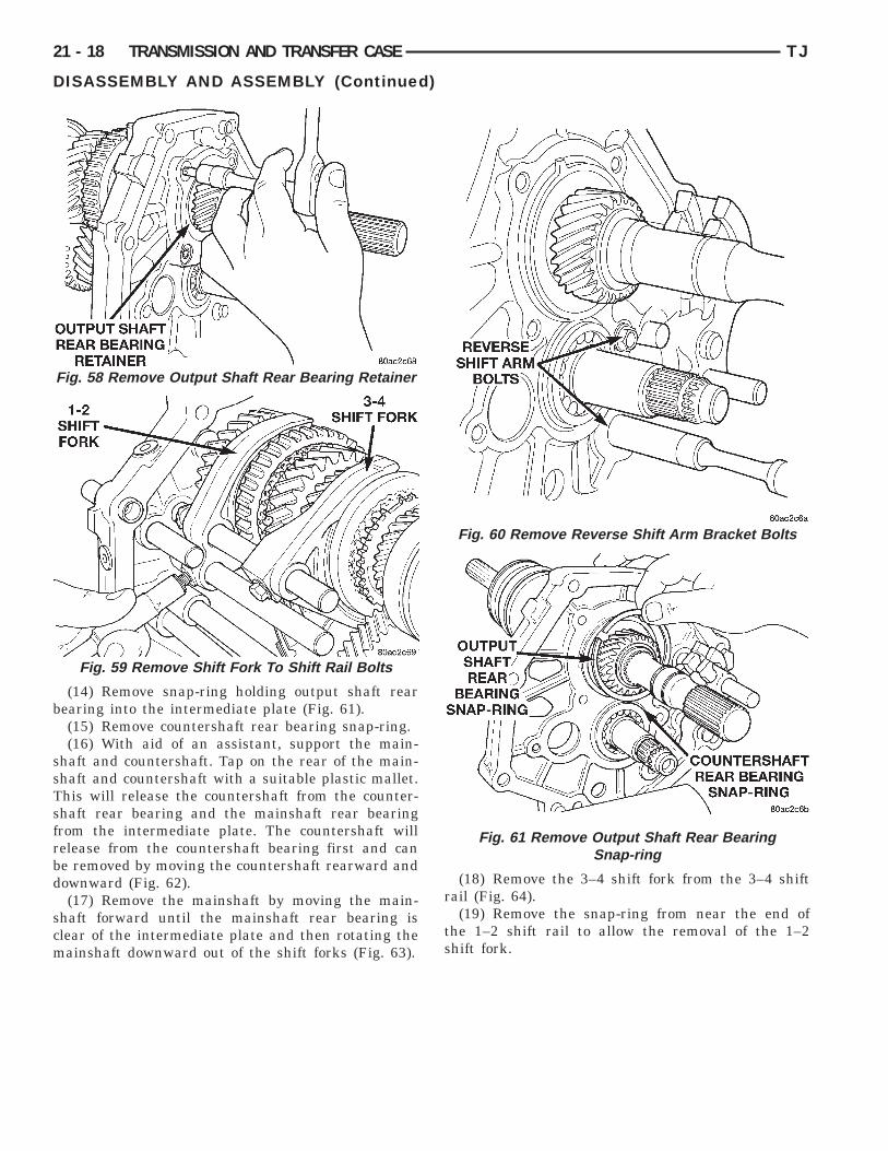
(11) Remove bolts holding output shaft rear bear-ng retainer to the intermediate plate and removeetainer (Fig. 58).(12) Remove bolts holding 1–2 and 3–4 shift forks
o the shift rails (Fig. 59) and discard bolts.
Fig. 53 Remove Fifth Gear Synchro Ring
Fig. 54 Remove Fifth Gear and Synchro Assembly
(13) Remove bolts holding reverse shift armbracket to intermediate plate (Fig. 60).
Fig. 55 Remove Fifth Gear Thrust Ring
Fig. 56 Remove Fifth Gear Thrust Ring Lock Ball
Fig. 57 Remove Reverse Idler Shaft
b
ssTsfrbd
scm
21 - 18 TRANSMISSION AND TRANSFER CASE TJ
DISASSEMBLY AND ASSEMBLY (Continued)
(14) Remove snap-ring holding output shaft rearearing into the intermediate plate (Fig. 61).(15) Remove countershaft rear bearing snap-ring.(16) With aid of an assistant, support the main-
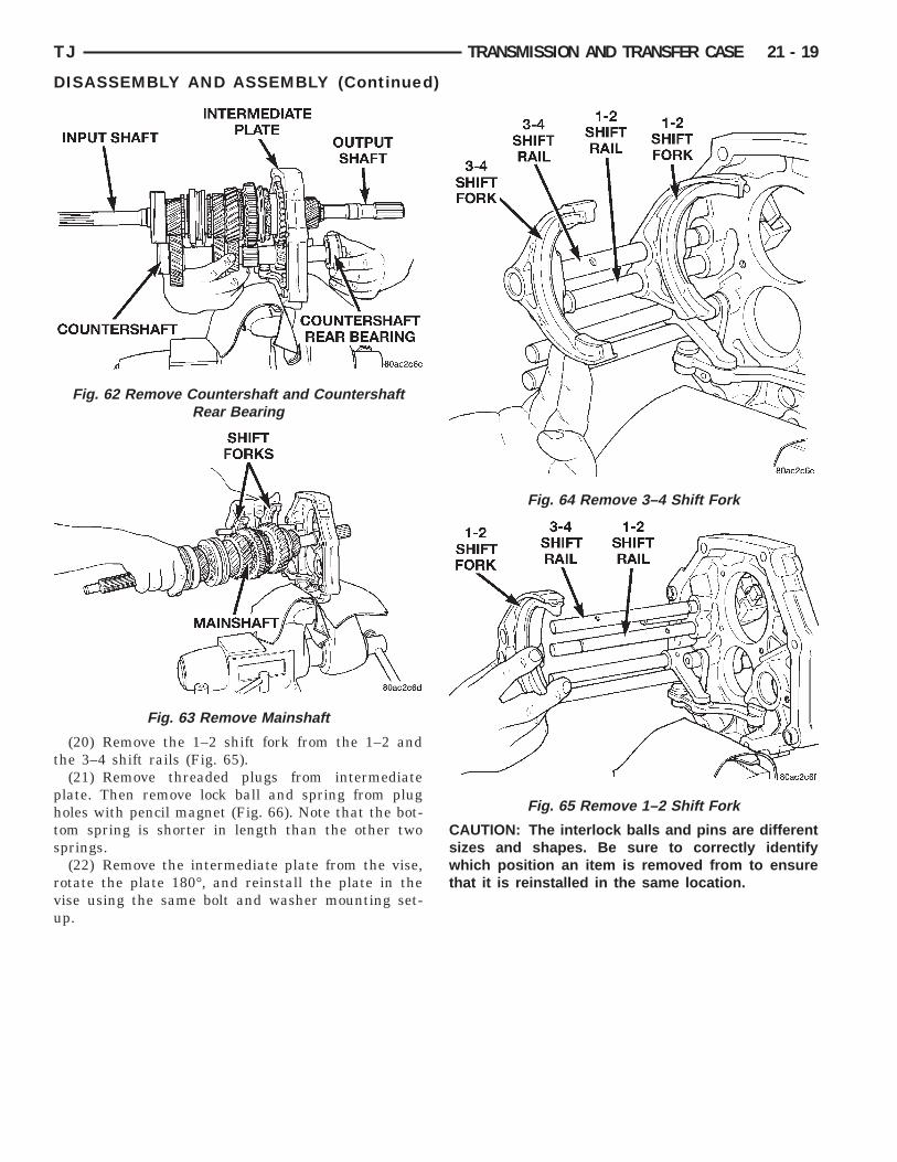
haft and countershaft. Tap on the rear of the main-haft and countershaft with a suitable plastic mallet.his will release the countershaft from the counter-haft rear bearing and the mainshaft rear bearingrom the intermediate plate. The countershaft willelease from the countershaft bearing first and cane removed by moving the countershaft rearward andownward (Fig. 62).(17) Remove the mainshaft by moving the main-
haft forward until the mainshaft rear bearing islear of the intermediate plate and then rotating theainshaft downward out of the shift forks (Fig. 63).
Fig. 58 Remove Output Shaft Rear Bearing Retainer
Fig. 59 Remove Shift Fork To Shift Rail Bolts
(18) Remove the 3–4 shift fork from the 3–4 shiftrail (Fig. 64).
(19) Remove the snap-ring from near the end ofthe 1–2 shift rail to allow the removal of the 1–2shift fork.
Fig. 60 Remove Reverse Shift Arm Bracket Bolts
Fig. 61 Remove Output Shaft Rear BearingSnap-ring
t
phts
rvu
TJ TRANSMISSION AND TRANSFER CASE 21 - 19
DISASSEMBLY AND ASSEMBLY (Continued)
(20) Remove the 1–2 shift fork from the 1–2 andhe 3–4 shift rails (Fig. 65).
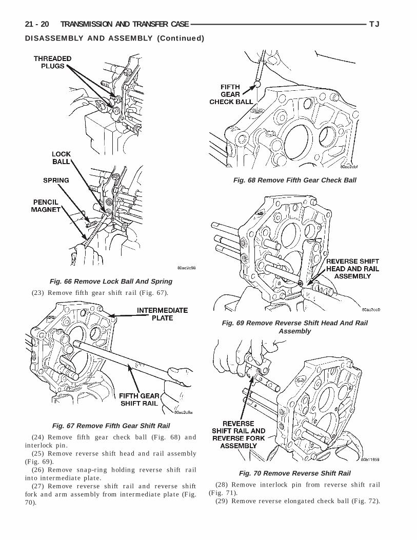
(21) Remove threaded plugs from intermediatelate. Then remove lock ball and spring from plugoles with pencil magnet (Fig. 66). Note that the bot-om spring is shorter in length than the other twoprings.(22) Remove the intermediate plate from the vise,
otate the plate 180°, and reinstall the plate in theise using the same bolt and washer mounting set-p.
Fig. 62 Remove Countershaft and CountershaftRear Bearing
Fig. 63 Remove Mainshaft
CAUTION: The interlock balls and pins are differentsizes and shapes. Be sure to correctly identifywhich position an item is removed from to ensurethat it is reinstalled in the same location.
Fig. 64 Remove 3–4 Shift Fork
Fig. 65 Remove 1–2 Shift Fork
i
(
i
f7
21 - 20 TRANSMISSION AND TRANSFER CASE TJ
DISASSEMBLY AND ASSEMBLY (Continued)
(23) Remove fifth gear shift rail (Fig. 67).
(24) Remove fifth gear check ball (Fig. 68) andnterlock pin.
(25) Remove reverse shift head and rail assemblyFig. 69).
(26) Remove snap-ring holding reverse shift railnto intermediate plate.
(27) Remove reverse shift rail and reverse shiftork and arm assembly from intermediate plate (Fig.0).
Fig. 66 Remove Lock Ball And Spring
Fig. 67 Remove Fifth Gear Shift Rail
(28) Remove interlock pin from reverse shift rail(Fig. 71).
(29) Remove reverse elongated check ball (Fig. 72).
Fig. 68 Remove Fifth Gear Check Ball
Fig. 69 Remove Reverse Shift Head And RailAssembly
Fig. 70 Remove Reverse Shift Rail

7
f
TJ TRANSMISSION AND TRANSFER CASE 21 - 21
DISASSEMBLY AND ASSEMBLY (Continued)
(30) Remove snap-ring on 3–4 shift rail.(31) Remove 1–2 shift rail from intermediate plate.(32) Remove interlock pin from 1–2 shift rail (Fig.
3).(33) Remove 1–2 shift rail elongated check ball
rom intermediate plate (Fig. 74).(34) Remove 3–4 shift rail from intermediate plate.
Fig. 71 Remove Interlock Pin From Reverse ShiftRail
Fig. 72 Remove Reverse Check Ball
ASSEMBLYRefer to (Fig. 75) while assembling and installing
the shift rail components. Also, verify that all shiftrail components are in their neutral position wheninstalling the check balls and interlock pins.
(1) Install the 3–4 shift rail into the intermediateplate.
(2) Install the 1–2 elongated check ball into theintermediate plate (Fig. 76).
(3) Install the interlock pin into the 1–2 shift rail(Fig. 77).
Fig. 73 Remove 1–2 Shift Rail Interlock Pin
Fig. 74 Remove 1–2 Check Ball

p
21 - 22 TRANSMISSION AND TRANSFER CASE TJ
DISASSEMBLY AND ASSEMBLY (Continued)
(4) Install the 1–2 shift rail into the intermediatelate.(5) Install snap-ring onto 3–4 shift rail.
Fig. 75 Shift R
Fig. 76 Install 1–2 Check Ball
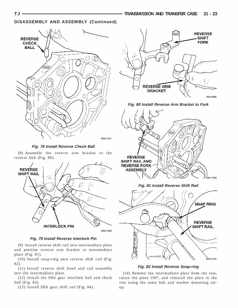
(6) Install the reverse check ball into the interme-diate plate (Fig. 78).
(7) Install the interlock pin into the reverse shiftrail (Fig. 79).
omponents
Fig. 77 Install 1–2 Shift Rail Interlock Pin
ail C
r
ap
8
i
b
TJ TRANSMISSION AND TRANSFER CASE 21 - 23
DISASSEMBLY AND ASSEMBLY (Continued)
(8) Assemble the reverse arm bracket to theeverse fork (Fig. 80).
(9) Install reverse shift rail into intermediate platend position reverse arm bracket to intermediatelate (Fig. 81).(10) Install snap-ring onto reverse shift rail (Fig.
2).(11) Install reverse shift head and rail assembly
nto the intermediate plate.(12) Install the fifth gear interlock ball and check
all (Fig. 83).(13) Install fifth gear shift rail (Fig. 84).
Fig. 78 Install Reverse Check Ball
Fig. 79 Install Reverse Interlock Pin
(14) Remove the intermediate plate from the vise,rotate the plate 180°, and reinstall the plate in thevise using the same bolt and washer mounting set-up.
Fig. 80 Install Reverse Arm Bracket to Fork
Fig. 81 Install Reverse Shift Rail
Fig. 82 Install Reverse Snap-ring

m
is
m
s
r
bmtrb
as
w
21 - 24 TRANSMISSION AND TRANSFER CASE TJ
DISASSEMBLY AND ASSEMBLY (Continued)
(15) Install the shift rail detent balls in the inter-ediate plate.(16) Install the shift rail detent springs in the
ntermediate plate. Note that the bottom detentpring is shorter than the others.(17) Install the shift rail detent plugs in the inter-ediate plate.(18) Install the 1–2 shift fork onto the 1–2 and 3–4
hift rails (Fig. 85).(19) Install the snap-ring onto the 1–2 shift rail.(20) Install the 3–4 shift fork onto the 3–4 shift
ail (Fig. 86).(21) Install mainshaft into the intermediate plate
y guiding the output shaft through opening in inter-ediate plate until the shift forks are aligned with
he appropriate synchronizer sleeves. The mainshaftear bearing will be started in the intermediate plateut not fully driven in at this point.(22) While an assistant supports the mainshaft,
lign rear of countershaft with inner race of counter-haft rear bearing.(23) Raise countershaft upward until gears meshith the mating gears on the mainshaft.
Fig. 83 Install Fifth Gear Check Ball
Fig. 84 Install Fifth Gear Shift Rail
(24) Using a suitable rubber mallet, tap on theinput shaft and the front of the countershaft equallyto install the mainshaft rear bearing into the inter-mediate plate and the rear of the countershaft intothe rear countershaft bearing. It may be necessary tooccasionally hold the countershaft into the intermedi-ate plate and tap the countershaft rear bearing ontothe countershaft and into the intermediate plate.
(25) Install snap-rings onto the rear mainshaft andcountershaft bearings.
(26) Install the bolts to hold the reverse shift armbracket to the intermediate plate.
(27) Install new bolts to hold the shift forks to theshift rails (Fig. 87).
Fig. 85 Install 1–2 Shift Fork
Fig. 86 Install 3–4 Shift Fork

op
t
ga8
p
t
i(ai
rn
TJ TRANSMISSION AND TRANSFER CASE 21 - 25
DISASSEMBLY AND ASSEMBLY (Continued)
(28) Position the mainshaft rear bearing retainerver the output shaft and onto the intermediatelate.(29) Install new bolts to hold the bearing retainer
o the intermediate plate.(30) Move the reverse shift arm into the reverse
ear position. The reverse gear position is with therm moved away from the intermediate plate (Fig.8).(31) Install the reverse idler gear assembly into
osition on the mainshaft and reverse shift arm.(32) Install the compression spring and pin into
he reverse idler gear shaft (Fig. 89).(33) Install the reverse idler shaft through the
ntermediate plate and reverse idler gear assemblyFig. 90) until the idler shaft pin contacts the gearssembly. Make sure that the notched cut-out in thedler shaft is to the rear of the transmission.
(34) Align the pin with the alignment notch in theeverse idler gear assembly (Fig. 91). The alignmentotch in the reverse idler gear race/hub is a small
Fig. 87 Install Shift Fork Bolts
Fig. 88 Reverse Shift Arm Position
relief cut above one of the main longitudinal slots. Besure that the pin is aligned with the proper slot, theopposite slot has an oil drain hole which the pin willdrop into. The assembly will then be locked onto theshaft and will need to be disassembled in order to beremoved.
(35) Depress compression spring and pin inreverse idler gear shaft (Fig. 92).
(36) Install the reverse idler gear shaft theremainder of the way through the reverse idler gearassembly.
(37) Position the reverse idler gear shaft lock plateonto the intermediate plate.
(38) Install a new bolt to hold the idler gear shaftlock plate to the intermediate plate.
(39) Install the fifth gear thrust ring lock ball tothe countershaft (Fig. 93).
(40) Install the fifth gear thrust ring onto thecountershaft and over the lock ball (Fig. 94).
(41) Install fifth gear shift fork to the countershaftfifth gear assembly.
Fig. 89 Install Compression Spring And Pin
Fig. 90 Install Reverse Idler Shaft

i
21 - 26 TRANSMISSION AND TRANSFER CASE TJ
DISASSEMBLY AND ASSEMBLY (Continued)
(42) Install the countershaft fifth gear bearingsnto the countershaft fifth gear assembly.
Fig. 91 Align Idler Shaft Pin
Fig. 92 Depress Pin In Reverse Idler Gear Shaft
Fig. 93 Install Fifth Gear Thrust Ring Lock Ball
(43) Position the countershaft fifth gear assemblyon the countershaft. Ensure that the fifth gear fork isinstalled onto the fifth gear shift rail.
(44) Install the fifth gear synchro ring.(45) Position the fifth gear blocker ring onto the
countershaft.(46) Using a suitable mallet and spacer, tap the
fifth gear blocker ring onto the countershaft.(47) Install new bolt to hold fifth gear shift fork to
the fifth gear shift rail (Fig. 95).
(48) Measure countershaft fifth gear thrust clear-ance.
(49) Select a snap-ring so that the thrust clearanceis 0.10–0.30 mm (0.004–0.010 in.).
(50) Install snap-ring to hold fifth gear blockerring onto countershaft.
(51) Remove intermediate plate from vise andremove bolts and washers from intermediate.
Fig. 94 Install Fifth Gear Thrust Ring
Fig. 95 Install Fifth Gear Retainer Bolt
C
D
t
ot
A
w
c
p
t
b
I
D
t
9u
f
t
TJ TRANSMISSION AND TRANSFER CASE 21 - 27
DISASSEMBLY AND ASSEMBLY (Continued)
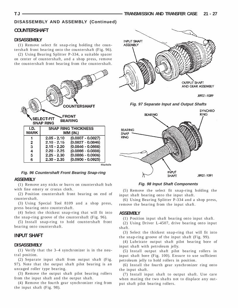
OUNTERSHAFT
ISASSEMBLY(1) Remove select fit snap-ring holding the coun-
ershaft front bearing onto the countershaft (Fig. 96).(2) Using Bearing Splitter P-334, a suitable spacer
n center of countershaft, and a shop press, removehe countershaft front bearing from the countershaft.
SSEMBLY(1) Remove any nicks or burrs on countershaft hubith fine emery or crocus cloth.(2) Position countershaft front bearing on end of
ountershaft.(3) Using Special Tool 8109 and a shop press,
ress bearing onto countershaft.(4) Select the thickest snap-ring that will fit into
he snap-ring groove of the countershaft (Fig. 96).(5) Install snap-ring to hold countershaft front
earing onto countershaft.
NPUT SHAFT
ISASSEMBLY(1) Verify that the 3–4 synchronizer is in the neu-
ral position.(2) Separate input shaft from output shaft (Fig.
7). Note that the output shaft pilot bearing is anncaged roller type bearing.(3) Remove the output shaft pilot bearing rollers
rom the input shaft and the output shaft.(4) Remove the fourth gear synchronizer ring from
he input shaft (Fig. 98).
Fig. 96 Countershaft Front Bearing Snap-ring
(5) Remove the select fit snap-ring holding theinput shaft bearing onto the input shaft.
(6) Using Bearing Splitter P-334 and a shop press,remove the bearing from the input shaft.
ASSEMBLY(1) Position input shaft bearing onto input shaft.(2) Using Driver L-4507, drive bearing onto input
shaft.(3) Select the thickest snap-ring that will fit into
the snap-ring groove of the input shaft (Fig. 99).(4) Lubricate output shaft pilot bearing bore of
input shaft with petroleum jelly.(5) Install output shaft pilot bearing rollers in
input shaft bore (Fig. 100). Ensure to use sufficientpetroleum jelly to hold rollers in position.
(6) Install the fourth gear synchronizer ring ontothe input shaft.
(7) Install input shaft to output shaft. Use carewhen mating the two shafts not to displace any out-put shaft pilot bearing rollers.
Fig. 97 Separate Input and Output Shafts
Fig. 98 Input Shaft Components

Fig. 99 Select Input Shaft Bearing Snap-ring
21 - 28 TRANSMISSION AND TRANSFER CASE TJ
DISASSEMBLY AND ASSEMBLY (Continued)
OUTPUT SHAFT
DISASSEMBLY(1) Remove input shaft and output shaft pilot
bearing rollers from output shaft.(2) Measure and note thrust clearance of output
shaft gears (Fig. 101). Clearance should be 0.10 –0.25 mm (0.004 – 0.010 in.).
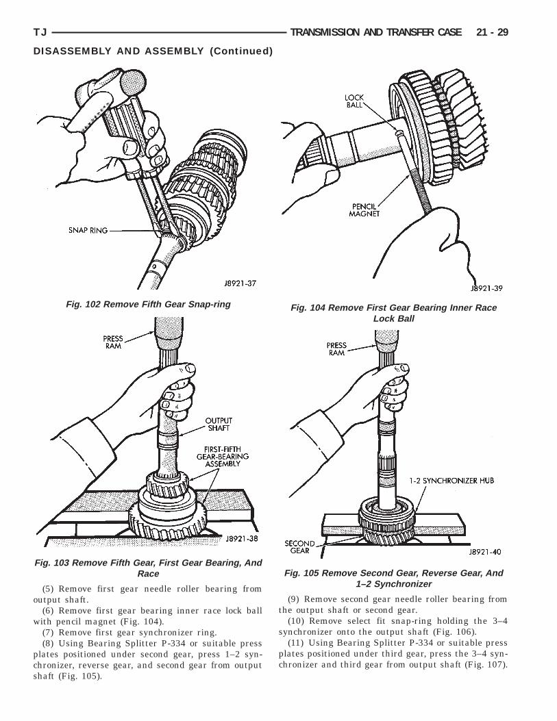
(3) Remove output shaft fifth gear snap ring withtwo screwdrivers (Fig. 102).
(4) Using Bearing Splitter P-334 or suitable pressplates positioned under first gear, press fifth gear,rear bearing, first gear, and first gear bearing innerrace off output shaft (Fig. 103).
Fig. 100 Install Output Shaft Pilot Bearing Rollers
Fig. 101 Check Output Shaft Gear Thrust Clearance
o
w
pcs
TJ TRANSMISSION AND TRANSFER CASE 21 - 29
DISASSEMBLY AND ASSEMBLY (Continued)
(5) Remove first gear needle roller bearing fromutput shaft.(6) Remove first gear bearing inner race lock ballith pencil magnet (Fig. 104).(7) Remove first gear synchronizer ring.(8) Using Bearing Splitter P-334 or suitable press
lates positioned under second gear, press 1–2 syn-hronizer, reverse gear, and second gear from outputhaft (Fig. 105).
Fig. 102 Remove Fifth Gear Snap-ring
Fig. 103 Remove Fifth Gear, First Gear Bearing, AndRace
(9) Remove second gear needle roller bearing fromthe output shaft or second gear.
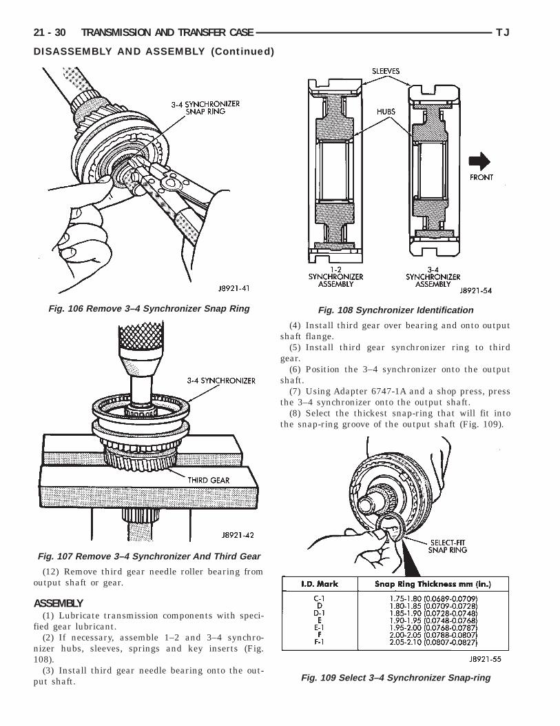
(10) Remove select fit snap-ring holding the 3–4synchronizer onto the output shaft (Fig. 106).
(11) Using Bearing Splitter P-334 or suitable pressplates positioned under third gear, press the 3–4 syn-chronizer and third gear from output shaft (Fig. 107).
Fig. 104 Remove First Gear Bearing Inner RaceLock Ball
Fig. 105 Remove Second Gear, Reverse Gear, And1–2 Synchronizer
o
A
f
n1
p
21 - 30 TRANSMISSION AND TRANSFER CASE TJ
DISASSEMBLY AND ASSEMBLY (Continued)
(12) Remove third gear needle roller bearing fromutput shaft or gear.
SSEMBLY(1) Lubricate transmission components with speci-
ied gear lubricant.(2) If necessary, assemble 1–2 and 3–4 synchro-
izer hubs, sleeves, springs and key inserts (Fig.08).(3) Install third gear needle bearing onto the out-
ut shaft.
Fig. 106 Remove 3–4 Synchronizer Snap Ring
Fig. 107 Remove 3–4 Synchronizer And Third Gear
(4) Install third gear over bearing and onto outputshaft flange.
(5) Install third gear synchronizer ring to thirdgear.
(6) Position the 3–4 synchronizer onto the outputshaft.
(7) Using Adapter 6747-1A and a shop press, pressthe 3–4 synchronizer onto the output shaft.
(8) Select the thickest snap-ring that will fit intothe snap-ring groove of the output shaft (Fig. 109).
Fig. 108 Synchronizer Identification
Fig. 109 Select 3–4 Synchronizer Snap-ring

o
g(rg
s
p
o
s
at
s
i
s
b
pi
so
TJ TRANSMISSION AND TRANSFER CASE 21 - 31
DISASSEMBLY AND ASSEMBLY (Continued)
(9) Install snap-ring to hold 3–4 synchronizer ontoutput shaft.(10) Verify third gear thrust clearance with feeler
auge (Fig. 110). Clearance should be 0.10 – 0.25 mm0.004 – 0.010 in.). If clearance is out of specification,efer to Cleaning and Inspection section within thisroup.
(11) Install second gear needle bearing onto outputhaft.(12) Install second gear over bearing and onto out-
ut shaft flange.(13) Install second gear synchronizer ring onto sec-
nd gear.(14) Position 1–2 synchronizer assembly onto
plines of output shaft.(15) Using Driver MD-998805, Adapter 6747-1A,
nd a shop press, press the 1–2 synchronizer ontohe output shaft.
(16) Install first gear synchronizer ring into 1–2ynchronizer.(17) Install first gear bearing inner race lock ball
n output shaft (Fig. 111).(18) Install first gear needle bearing onto output
haft (Fig. 112).(19) Install first gear onto output shaft and over
earing.(20) Install first gear bearing inner race onto out-
ut shaft and inside first gear bearing. Rotate bear-ng race until race installs over lock ball.
(21) Position output shaft rear bearing onto outputhaft. Ensure that the snap ring groove in bearinguter race is toward rear of output shaft.
Fig. 110 Check Third Gear Clearance
(22) Using Driver L-4507 and suitable mallet,drive bearing onto output shaft.(23) Install snap-ring onto output shaft rear bear-
ing outer race.
(24) Check first–second gear thrust clearance (Fig.113). Standard clearance is 0.10 – 0.25 mm (0.004 –0.010 in.). If clearance is out of specification, refer toCleaning and Inspection section within this group.
Fig. 111 Install First Gear Bearing Inner Race LockBall
Fig. 112 First Gear Components

gEa
s
t
s
S
D
g
g
i
r
A
o7o
itpco
g
g
21 - 32 TRANSMISSION AND TRANSFER CASE TJ
DISASSEMBLY AND ASSEMBLY (Continued)
(25) Position fifth gear onto output shaft with theear’s short shoulder toward the rear of shaft.nsure that the gear and output shaft splines areligned.(26) Using Adapter 6747-1A, Driver L-4507, and a
hop press, press fifth gear onto output shaft.(27) Select the thickest snap-ring that will fit into
he snap-ring groove of the output shaft (Fig. 114).(28) Install snap-ring to hold fifth gear onto output
haft.
EMI-SYNCHRONIZED REVERSE IDLER GEAR
ISASSEMBLY(1) Remove snap-ring holding the reverse idler
ear onto the reverse idler gear hub/race (Fig. 115).(2) Remove the plate washer from the reverse idler
ear hub/race (Fig. 116).(3) Remove the reverse idler gear from the reverse
dler gear hub/race (Fig. 117).(4) Remove the reverse idler gear synchronizer
ing from the reverse idler gear hub/race (Fig. 118).
SSEMBLY(1) Install the reverse idler gear synchronizer ring
nto the reverse idler gear hub/race. Apply a film of5W-90 GL-3 transmission oil to the contact surfacef the synchronizer ring prior to assembly.(2) Install the reverse idler gear onto the reverse
dler gear hub/race. Apply a film of 75W-90 GL-3ransmission oil to the reverse idler gear bushingrior to assembly.Verify that the teeth on the syn-hronizer ring are properly engaged into the recessesf the reverse idler gear.(3) Install the plate washer over the reverse idler
ear hub/race and onto the reverse idler gear.(4) Install the snap-ring to hold the reerse idler
ear onto the reverse idler hub/race.
Fig. 113 Check First–Second Gear Thrust Clearance
Fig. 114 Select/Install Fifth Gear Snap Ring

TJ TRANSMISSION AND TRANSFER CASE 21 - 33
DISASSEMBLY AND ASSEMBLY (Continued)
Fig. 115 Remove Reverse Idler Gear Snap-ring
Fig. 116 Remove Reverse Idler Gear Plate Washer
Fig. 117 Remove Reverse Idler Gear
CLEANING AND INSPECTION
AX5 MANUAL TRANSMISSION COMPONENTS
GENERAL INFORMATIONClean the transmission components in solvent. Dry
the cases, gears, shift mechanism and shafts withcompressed air. Dry the bearings with clean, dryshop towels only. Never use compressed air on thebearings. This could cause severe damage to thebearing roller and race surfaces.
If output shaft or inner race flange thickness iswithin specification but any gear thrust clearance isout of specification, replace the necessary gear andgear needle bearing as an assembly.
GEAR CASE, ADAPTER/EXTENSION HOUSING,INTERMEDIATE PLATE
Clean the case, housing, and intermediate platewith solvent and dry with compressed air. Replacethe case if cracked, porous, or if any of the bearingand gear bores are damaged.
Inspect the threads in the case, housing, and plate.Minor thread damage can be repaired with steelthread inserts, if necessary. Do not attempt to repairany threads which show evidence of cracks aroundthe threaded hole.
OUTPUT SHAFTCheck thickness of the output shaft and inner
bearing race flanges with a micrometer or verniercalipers (Fig. 119).
• Minimum thickness for shaft flange is 4.80 mm(0.189 in.)
Fig. 118 Remove Reverse Idler Gear SynchronizerRing

r
ft
3
m
r
(i
rcc
C
cIs
R
21 - 34 TRANSMISSION AND TRANSFER CASE TJ
CLEANING AND INSPECTION (Continued)
• Minimum thickness for first gear bearing innerace flange is 3.99 mm (0.157 in.)Measure diameter of the output shaft journal sur-
aces with a micrometer. Replace the shaft if either ofhese surfaces are worn beyond specified limits.
• Second gear surface minimum diameter is7.964 mm (1.495 in.)• Third gear surface minimum diameter is 34.984m (1.377 in.)Measure diameter of the first gear bearing inner
ace. Minimum diameter is 38.985 mm (1.535 in.).Measure output shaft runout with a dial indicator
Fig. 120). Runout should not exceed 0.05 mm (0.002n.).
Replace output shaft or first gear inner bearingace if measurement of any surface is out of specifi-ation. Do not attempt to repair out of specificationomponents.
OUNTERSHAFTInspect the countershaft gear teeth. Replace the
ountershaft if any teeth are worn or damaged.nspect the bearing surfaces and replace shaft if anyurface shows damage or wear.Check condition of the countershaft front bearing.eplace the bearing if worn, noisy, or damaged.
Fig. 119 Check Shaft And Bearing Race FlangeThickness
GEAR AND SYNCHRONIZERInstall the needle bearing and inner race in the
first gear. Then check oil clearance between the gearand inner race (Fig. 121). Clearance should be 0.009– 0.032 mm (0.0004 – 0.0013 in.).
Install the needle bearings and the second, thirdand counter fifth gears on the output shaft. Thencheck oil clearance between the gears and shaft witha dial indicator (Fig. 122). Oil clearance for all threegears is 0.009 – 0.0013 mm (0.0004 – 0.0013 in.).
Check synchronizer ring wear (Fig. 123). Inserteach ring in matching gear. Measure clearancebetween each ring and gear with feeler gauge.Replace ring if clearance exceeds 2.0 mm (0.078 in.).
Fig. 120 Check Output Shaft Runout
Fig. 121 Check Gear–To–Race Clearance

wc
g
TJ TRANSMISSION AND TRANSFER CASE 21 - 35
CLEANING AND INSPECTION (Continued)
Check shift fork–to–synchronizer hub clearanceith a feeler gauge (Fig. 124). Replace the fork if
learance exceeds 1.0 mm (0.039 in.).(1) Inspect all mainshaft gear teeth. Replace any
ear which shows any worn or damaged teeth.
Fig. 122 Check Gear–To–Shaft Oil Clearance
Fig. 123 Check Synchronizer Ring Wear
SPECIFICATIONS
TORQUE
DESCRIPTION TORQUEPlugs, Access . . . . . . . . . . . . . . . . 19 N·m (14 ft.lbs.)Bolts, Adapter Housing . . . . . . . . 34 N·m (25 ft.lbs.)Switch, Back-up Light . . . . . . . 44 N·m (32.5 ft.lbs.)Plugs, Drain and Fill . . . . . . . . 44 N·m (32.5 ft.lbs.)Bolts, Front Bearing Retainer . . . 17 N·m (12 ft.lbs.)Plugs, Interlock and Detent . . . . . 19 N·m (14 ft.lbs.)Screws, Propeller Shaft Clamp . . . . . . . . 16–23 N·m
(140–200 in.lbs.)Bolts, Rear Mount to Transmission . . . . 33–60 N·m
(24–44 ft.lbs.)Nut, Rear Mount Clevis . . 54–75 N·m (40–55 ft.lbs.)Nuts, Rear Mount to Crossmember . . . . 33–49 N·m
(24–36 ft.lbs.)Pins, Restrictor . . . . . . . . . . . . . 27.4 N·m (20 ft.lbs.)Bolts, Reverse Shift Arm Bracket . . . . . . . . . 18 N·m
(13 ft.lbs.)Screw, Shift Arm Set . . . . . . . . . . 38 N·m (28 ft.lbs.)Screws, Shift Fork Set . . . . . . . . . 20 N·m (15 ft.lbs.)Nut, Shift Knob . . . . . . . . 20–34 N·m (15–25 ft.lbs.)Screws, Shifter Floor Cover . 2–3 N·m (17–30 in.lbs.)Bolts, Shift Tower . . . . . . . . . . . . 18 N·m (13 ft.lbs.)Nuts, Transfer Case Mounting . . . . . . . . 30–41 N·m
(22–30 ft.lbs.)
Fig. 124 Check Fork–To–Hub Clearance

S
A
21 - 36 TRANSMISSION AND TRANSFER CASE TJ
PECIAL TOOLS
X5
C-3339 Dial Indicator Set
C-3995-A Installer, Extension Housing Seal
C-4171 Handle, Universal Tool
8211 Installer, Seal
8212 Installer, Seal
8208 Installer, Seal
P-334 Splitter, Bearing
8109 Cup, Installer
L-4507 Tube, Driver

TJ TRANSMISSION AND TRANSFER CASE 21 - 37
SPECIAL TOOLS (Continued)
6747–1A Adapter, Fixture
MD-998805 Installer, Seal
G
D
R
G
A
trtdo
21 - 38 TRANSMISSION AND TRANSFER CASE TJ
AX15 MANUAL TRANSMISSION
INDEX
page page
D
C
S
S
ENERAL INFORMATIONAX15 MANUAL TRANSMISSION . . . . . . . . . . . . . 38RECOMMENDED LUBRICANT . . . . . . . . . . . . . . 39TRANSMISSION ASSEMBLY INFORMATION . . . 39TRANSMISSION GEAR RATIOS . . . . . . . . . . . . . 39TRANSMISSION IDENTIFICATION . . . . . . . . . . . 38IAGNOSIS AND TESTINGHARD SHIFTING . . . . . . . . . . . . . . . . . . . . . . . . 40LOW LUBRICANT LEVEL . . . . . . . . . . . . . . . . . . 40TRANSMISSION NOISE . . . . . . . . . . . . . . . . . . . 41EMOVAL AND INSTALLATIONADAPTER HOUSING SEAL . . . . . . . . . . . . . . . . 44EXTENSION HOUSING SEAL . . . . . . . . . . . . . . . 44FRONT BEARING RETAINER SEAL . . . . . . . . . . 43
TRANSMISSION . . . . . . . . . . . . . . . . . . . . . . . . . 41ISASSEMBLY AND ASSEMBLYADAPTER/EXTENSION HOUSING AND FRONT
BEARING RETAINER . . . . . . . . . . . . . . . . . . . 45COUNTERSHAFT . . . . . . . . . . . . . . . . . . . . . . . . 64INPUT SHAFT . . . . . . . . . . . . . . . . . . . . . . . . . . 65OUTPUT SHAFT . . . . . . . . . . . . . . . . . . . . . . . . 66SHIFT MECHANISM AND GEARTRAIN . . . . . . . . 52LEANING AND INSPECTIONAX15 MANUAL TRANSMISSION
COMPONENTS . . . . . . . . . . . . . . . . . . . . . . . . 70PECIFICATIONSTORQUE . . . . . . . . . . . . . . . . . . . . . . . . . . . . . . 72PECIAL TOOLSAX15 . . . . . . . . . . . . . . . . . . . . . . . . . . . . . . . . . 73
ENERAL INFORMATION
X15 MANUAL TRANSMISSIONThe AX15 is a 5–speed, synchromesh, manual
ransmission. Fifth gear is an overdrive range with aatio of 0.79:1. An adapter housing is used to attachhe transmission to the transfer case on 4–wheelrive models. A standard extension housing is usedn 2–wheel drive models. The shift mechanism is
Fig. 1 AX15 Man
integral and mounted in the shift tower portion ofthe adapter housing (Fig. 1).
TRANSMISSION IDENTIFICATIONThe AX15 identification code numbers are on the
bottom surface of the intermediate plate (Fig. 2).The first number is year of manufacture. The sec-
ond and third numbers indicate month of manufac-ture. The next series of numbers is the transmissionserial number.
Transmission
ual
T
a
R
Me
nt
tot
TJ TRANSMISSION AND TRANSFER CASE 21 - 39
GENERAL INFORMATION (Continued)
RANSMISSION GEAR RATIOSGear ratios for the AX15 manual transmission are
s follows:• First gear: 3.83:1• Second gear: 2.33:1• Third gear: 1.44:1• Fourth gear: 1.00:1• Fifth gear: 0.79:1• Reverse: 4.22:1
ECOMMENDED LUBRICANTRecommended lubricant for AX15 transmissions isopart 75W–90, API Grade GL–3 gear lubricant, or
quivalent.Correct lubricant level is from the bottom edge, to
o more than 6 mm (1/4 in.) below the bottom edge ofhe fill plug hole.
The fill plug is located on the driver’s side of theransmission case (Fig. 3). The drain plug is locatedn the passenger side of the transmission case nearhe bottom (Fig. 4).
Fig. 2 Identification Code Number Location
Approximate dry fill lubricant capacity is:• 3.10 liters (3.27 qts.) for 4–wheel drive applica-
tions.• 3.15 liters (3.32 qts.) for 2–wheel drive applica-
tions.
TRANSMISSION ASSEMBLY INFORMATIONLubricate the transmission components with
Mopart 75W–90, GL 3 gear lubricant during assem-bly. Use petroleum jelly to lubricate seal lips and/orhold parts in place during installation.
Refer to (Fig. 5) during assembly for AX15 gearassembly identification.
Fig. 3 Fill Plug Location
Fig. 4 Drain Plug Location

D
L
rr
chl
ipit
eLhsi
wso
haf
21 - 40 TRANSMISSION AND TRANSFER CASE TJ
GENERAL INFORMATION (Continued)
IAGNOSIS AND TESTING
OW LUBRICANT LEVELA low transmission lubricant level is generally the
esult of a leak, inadequate lubricant fill, or an incor-ect lubricant level check.Leaks can occur at the mating surfaces of the gear
ase, intermediate plate and adaptor or extensionousing, or from the front/rear seals. A suspected
eak could also be the result of an overfill condition.Leaks at the rear of the extension or adapter hous-
ng will be from the housing oil seals. Leaks at com-onent mating surfaces will probably be the result ofnadequate sealer, gaps in the sealer, incorrect boltightening, or use of a non–recommended sealer.
A leak at the front of the transmission will be fromither the front bearing retainer or retainer seal.ubricant may be seen dripping from the clutchousing after extended operation. If the leak isevere, it may also contaminate the clutch disc caus-ng the disc to slip, grab, and/or chatter.
A correct lubricant level check can only be madehen the vehicle is level. Also allow the lubricant to
ettle for a minute or so before checking. These rec-mmendations will ensure an accurate check and
Fig. 5 Output S
avoid an underfill or overfill condition. Always checkthe lubricant level after any addition of fluid to avoidan incorrect lubricant level condition.
HARD SHIFTINGHard shifting is usually caused by a low lubricant
level, improper, or contaminated lubricants. The con-sequence of using non–recommended lubricants isnoise, excessive wear, internal bind, and hard shift-ing. Substantial lubricant leaks can result in gear,shift rail, synchro, and bearing damage. If a leakgoes undetected for an extended period, the first indi-cations of component damage are usually hard shift-ing and noise.
Component damage, incorrect clutch adjustment,or a damaged clutch pressure plate or disc are addi-tional probable causes of increased shift effort. Incor-rect adjustment or a worn/damaged pressure plate ordisc can cause incorrect release. If the clutch problemis advanced, gear clash during shifts can result.Worn or damaged synchro rings can cause gear clashwhen shifting into any forward gear. In some new orrebuilt transmissions, new synchro rings may tend tostick slightly causing hard or noisy shifts. In mostcases, this condition will decline as the ringswear–in.
t and Gears

T
iws
aIpfl
R
T
R
s
n
f
c
t
e
tn
m
TJ TRANSMISSION AND TRANSFER CASE 21 - 41
DIAGNOSIS AND TESTING (Continued)
RANSMISSION NOISEMost manual transmissions make some noise dur-
ng normal operation. Rotating gears generate a mildhine that is audible, but generally only at extreme
peeds.Severe, highly audible transmission noise is gener-
lly the initial indicator of a lubricant problem.nsufficient, improper, or contaminated lubricant willromote rapid wear of gears, synchros, shift rails,orks and bearings. The overheating caused by aubricant problem, can also lead to gear breakage.
EMOVAL AND INSTALLATION
RANSMISSION
EMOVAL(1) Shift transmission into first or third gear.(2) Raise and support vehicle on suitable safety
tands.(3) Disconnect necessary exhaust system compo-
ents.(4) Remove skid plate, if equipped.(5) Remove slave cylinder from clutch housing.(6) Mark rear propeller shaft and rear axle yokes
or installation alignment (Fig. 6).
(7) Mark front propeller shaft, axle, and transferase yokes for installation alignment, if equipped.(8) Remove propeller shaft(s).(9) Unclip wire harnesses from transmission and
ransfer case, if equipped.(10) Disconnect transfer case vent hose, if
quipped.(11) Disengage any wire connectors attached to
ransmission or transfer case, if equipped, compo-ents.(12) Support transfer case, if equipped, with trans-ission jack.
Fig. 6 Marking Propeller Shaft And Axle Yokes
(13) Secure transfer case, if equipped, to jack withsafety chains.
(14) Disconnect transfer case shift linkage attransfer case, if equipped.
(15) Remove nuts attaching transfer case to trans-mission, if equipped.
(16) Remove transfer case, if equipped.(17) Remove crankshaft position sensor (Fig. 7),
(Fig. 8).
Fig. 7 Crankshaft Position Sensor—2.5L Engine
Fig. 8 Crankshaft Position Sensor —4.0L Engine
Ctri
Pa
c
t
su
a
(
g
im
btb
ii
swi
21 - 42 TRANSMISSION AND TRANSFER CASE TJ
REMOVAL AND INSTALLATION (Continued)
AUTION: It is important that the crankshaft posi-ion sensor be removed prior to transmissionemoval. The sensor can easily be damaged if leftn place during removal operations.
(18) Support engine with adjustable jack stand.osition wood block between jack and oil pan tovoid damaging pan.(19) Support transmission with transmission jack.(20) Secure transmission to jack with safety
hains.(21) Disconnect rear cushion and bracket from
ransmission.(22) Remove rear crossmember.(23) Disconnect transmission shift lever as follows:
(a) Lower transmission–transfer case assemblyapproximately 7–8 cm (3 in.) for access to shiftlever.
(b) Reach up and around transmission case andunseat shift lever dust boot from transmission shifttower (Fig. 9). Move boot upward on shift lever foraccess to retainer that secures lever in shift tower.
(c) Reach up and around transmission case andpress shift lever retainer downward with fingerpressure. Turn retainer counterclockwise to releaseit.
(d) Lift lever and retainer out of shift tower (Fig.9). Do not remove the shift lever from the floor con-sole shifter boots. Leave the lever in place fortransmission installation.
(24) Remove clutch housing brace rod.(25) Remove clutch housing-to-engine bolts.(26) Pull transmission jack rearward until input
haft clears clutch. Then slide transmission out fromnder vehicle.(27) Remove clutch release bearing, release fork,
nd retainer clip.(28) Remove clutch housing from transmission
Fig. 10).
Fig. 9 Removing/Installing Shift Lever
INSTALLATION(1) Install clutch housing on transmission. Tighten
housing bolts to 37 N·m (27 ft. lbs.) torque.(2) Lubricate contact surfaces of release fork pivot
ball stud and release fork with high temp grease.(3) Install release bearing, fork, and retainer clip.(4) Position and secure transmission on transmis-
sion jack.(5) Lightly lubricate pilot bearing and transmis-
sion input shaft splines with Mopart high temprease.(6) Raise transmission and align transmission
nput shaft and clutch disc splines. Then slide trans-ission into place.(7) Install and tighten clutch housing-to-engine
olts to 38 N·m (28 ft. lbs.) torque (Fig. 10). Be surehe housing is properly seated on engine blockefore tightening bolts.(8) Install clutch housing brace rod.(9) Lower transmission approximately 7–8 cm (3
n.) for access to shift tower. Be sure transmission isn first or third gear.
(10) Reach up and around transmission and inserthift lever in shift tower. Press lever retainer down-ard and turn it clockwise to lock it in place. Then
nstall lever dust boot on shift tower.
Fig. 10 Clutch Housing

b
btt
t
e
c
ts
s
mm
c
t
sp
m
a
c
TJ TRANSMISSION AND TRANSFER CASE 21 - 43
REMOVAL AND INSTALLATION (Continued)
(11) Install rear crossmember. Tighten crossmem-er-to-frame bolts to 41 N·m (31 ft. lbs.) torque.(12) Install fasteners to hold rear cushion and
racket to transmission. Then tighten transmission-o-rear support bolts/nuts to 45 N·m (33 ft. lbs.)orque.
(13) Remove support stands from engine andransmission.
(14) Install and connect crankshaft position sensor.(15) Position transfer case on transmission jack, if
quipped.(16) Secure transfer case to jack with safety
hains, if equipped.(17) Raise transfer case, if equipped, and align
ransfer case input shaft to the transmission outputhaft.(18) Slide transfer case forward until case is
eated on transmission, if necessary.(19) Install nuts to attach transfer case to trans-ission, if equipped. Tighten transfer case-to-trans-ission nuts to 35 N·m (26 ft. lbs.) torque.(20) Connect transfer case shift linkage at transfer
ase, if equipped.(21) Connect transfer case vent hose, if equipped.(22) Secure wire harnesses in clips/tie straps on
ransmission and transfer case, if equipped.(23) Engage wire connectors attached to all neces-
ary transmission or transfer case, if equipped, com-onents.(24) Install rear propeller shaft slip yoke to trans-ission or transfer case, if equipped, output shaft.(25) Align marks on rear propeller shaft and rear
xle yokes (Fig. 11).
(26) Install and tighten propeller shaft U–jointlamp bolts to 19 N·m (170 in. lbs.) torque.
Fig. 11 Align Propeller Shaft And Rear Axle YokesAlignment Marks
(27) Align marks on front propeller shaft, axle,and transfer case yokes, if equipped.
(28) Install and tighten propeller shaft U–jointclamp bolts to 19 N·m (170 in. lbs.) torque.
(29) Install slave cylinder in clutch housing.(30) Install skid plate, if equipped. Tighten bolts to
42 N·m (31 ft. lbs.) torque. Tighten stud nuts to 17N·m (150 in. lbs.) torque.
(31) Fill transmission and transfer case, ifequipped, with recommended lubricants. Refer to theLubricant Recommendation sections of the appropri-ate component for correct fluid.
(32) Lower vehicle.
FRONT BEARING RETAINER SEAL
REMOVAL(1) Remove release bearing and lever from the
transmission.(2) Remove the bolts holding the front bearing
retainer to the transmission case.(3) Remove the front bearing retainer from the
transmission case.(4) Using a suitable pry tool, remove the front
bearing retainer seal.
INSTALLATION(1) Using Tool Handle C-4171 and Seal Installer
8209, install new seal in to the front bearing retainer(Fig. 12).
Fig. 12 Install Front Bearing Retainer Seal

st
f
t
o
t
E
R
f
s(
I
r
8so
e
sp
21 - 44 TRANSMISSION AND TRANSFER CASE TJ
REMOVAL AND INSTALLATION (Continued)
(2) Remove any residual gasket material from theealing surfaces of the bearing retainer and theransmission case.
(3) Install new front bearing retainer gasket to theront bearing retainer.
(4) Install the front bearing retainer onto theransmission case.
(5) Install the bolts to hold the bearing retainernto the transmission case.(6) Tighten the bolts to 17 N·m (12 ft. lbs.).(7) Install release bearing and lever onto the
ransmission.
XTENSION HOUSING SEAL
EMOVAL(1) Raise and support vehicle.(2) Remove propeller shaft. Refer to Group 3, Dif-
erential and Driveline, for proper procedures.(3) Using a suitable seal puller or screw with a
lide hammer, remove the extension housing sealFig. 13).
NSTALLATION(1) Clean seal bore of extension housing of any
esidual sealer material from original seal.(2) Using Tool Handle C-4171 and Seal Installer
212, install new extension housing seal so that theeal is located 0 6 0.5 mm (0 6 0.02 in.) to the facef the extension housing (Fig. 14).(3) Install propeller shaft. Refer to Group 3, Differ-
ntial and Driveline, for proper procedures.(4) Check and add fluid to transmission as neces-
ary. Refer to the Recommended Lubricant section forroper fluid requirements.(5) Lower vehicle.
Fig. 13 Remove Extension Housing Seal
ADAPTER HOUSING SEAL
REMOVAL(1) Hoist and support vehicle.(2) Remove transfer case.(3) Using a suitable pry tool, or a slide hammer
mounted screw, remove the adapter housing seal(Fig. 15).
INSTALLATION(1) Clean seal bore of adapter housing of any
residual sealer material from original seal.(2) Using Tool Handle C-4171 and Seal Installer
8208, install new seal so that the seal is located 0 60.2 mm (0 6 0.008 in.) to the seal bore face ofadapter housing (Fig. 16).
Fig. 14 Install Extension Housing Seal
Fig. 15 Remove Adapter Housing Seal
sp
D
AB
D
i
a
s
(
TJ TRANSMISSION AND TRANSFER CASE 21 - 45
REMOVAL AND INSTALLATION (Continued)
(3) Install transfer case.(4) Check and add fluid to transmission as neces-
ary. Refer to the Recommended Lubricant section forroper fluid requirements.(5) Lower vehicle.
ISASSEMBLY AND ASSEMBLY
DAPTER/EXTENSION HOUSING AND FRONTEARING RETAINER
ISASSEMBLY(1) Drain transmission lubricant, if necessary.(2) Remove release bearing and lever.(3) Remove clutch housing bolts and remove hous-
ng (Fig. 19).(4) Remove vehicle speed sensor and speedometer
dapter, if necessary.(5) Remove bolts holding shift tower to transmis-
ion case.(6) Remove shift tower from transmission case
Fig. 17).
Fig. 16 Install Adapter Housing Seal
(7) Remove shift tower gasket from shift tower ortransmission case (Fig. 18).
(8) Remove reverse shift head detent ball plug(Fig. 20).
(9) Remove detent ball spring and ball with pencilmagnet (Fig. 21), (Fig. 22).
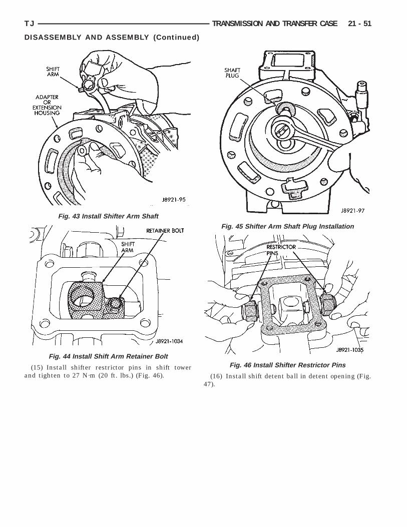
(10) Remove shift arm retainer bolt (Fig. 23).(11) Remove shift arm restrictor pins (Fig. 24).(12) Remove shift lever shaft plug (Fig. 25).(13) Remove shifter shaft with large magnet (Fig.
26).
Fig. 17 Remove Shift Tower
Fig. 18 Remove Shift Tower Gasket

i
2
i
Fig. 22 Remove Detent Ball
Fig. 23 Shift Arm Retainer Bolt Removal
21 - 46 TRANSMISSION AND TRANSFER CASE TJ
DISASSEMBLY AND ASSEMBLY (Continued)
(14) Remove the shift arm from the adapter hous-ng.
(15) Remove adapter/extension housing bolts (Fig.7).(16) Loosen adapter/extension housing by tapping
t loose with plastic mallet (Fig. 28).(17) Remove adapter/extension housing (Fig. 29).
Fig. 19 Clutch Housing
Fig. 20 Remove Detent Ball Plug
Fig. 21 Remove Detent Spring

TJ TRANSMISSION AND TRANSFER CASE 21 - 47
DISASSEMBLY AND ASSEMBLY (Continued)
Fig. 24 Shift Arm Rstrictor Pins
Fig. 25 Removing Shift Lever Shaft Plug
Fig. 26 Remove Shifter Shaft
Fig. 27 Adapter/Extension Housing Bolts
r
s
3
3
b
t
21 - 48 TRANSMISSION AND TRANSFER CASE TJ
DISASSEMBLY AND ASSEMBLY (Continued)
(18) On 4x2 transmissions;(a) Remove speedometer gear retaining snap-
ring from output shaft.(b) Remove speedometer gear from output shaft
and remove speedometer gear lock ball from outputshaft.
(c) Remove speedometer drive gear locatingsnap-ring (Fig. 30).(19) Remove the bolts holding the front bearing
etainer to the transmission case.(20) Remove the bearing retainer from transmis-
ion case (Fig. 31).(21) Remove input shaft bearing snap-ring (Fig.
2).(22) Remove cluster gear bearing snap-ring (Fig.
3).(23) Separate intermediate plate and transfer case
y tapping them loose with plastic mallet (Fig. 34).(24) Separate the intermediate plate from the
ransmission case (Fig. 35).
Fig. 28 Loosen Adapter/Extension Housing
Fig. 29 Remove Adapter/Extension Housing
ASSEMBLY(1) Remove any residual sealer from transmission
case, intermediate plate, adapter/extension housing,and front bearing retainer.
Fig. 30 Speedometer Drive Gear Assembly
Fig. 31 Remove Front Bearing Retainer
Fig. 32 Remove Input Shaft Bearing Snap-ring

o
TJ TRANSMISSION AND TRANSFER CASE 21 - 49
DISASSEMBLY AND ASSEMBLY (Continued)
(2) Apply a 1/8 to 3/16 inch wide bead of Threeb-ndt Liquid Gasket TB1281, P/N 83504038, as
Fig. 33 Remove Cluster Gear Snap-ring
Fig. 34 Separate Intermediate Plate andTransmission Case
Fig. 35 Remove Intermediate Plate fromTransmission Case
shown, making sure to keep sealer bead to inside ofbolt holes (Fig. 36).
(3) Align geartrain and shift rails with matingholes in transmission case and install transmissioncase to the intermediate plate (Fig. 37). Verify thatthe transmission case is seated on the intermediateplate.
(4) Install new front bearing snap rings (Fig. 38).(5) Apply 1/8 inch wide bead of Threebondt Liquid
Gasket TB1281, P/N 83504038, to the front bearingretainer sealing surface.
(6) Install the front bearing retainer (Fig. 39) andtighten bolts to 17 N·m (12 ft. lbs.).
(7) On 4x2 transmissions;(a) Install speedometer drive gear locating snap-
ring (Fig. 40).(b) Install speedometer gear lock ball in output
shaft and install speedometer gear onto outputshaft.
(c) Install speedometer gear retaining snap-ring
Fig. 36 Apply Sealer to Transmission Gear Case
Fig. 37 Install Transmission Gear Case to theIntermediate Plate
onto output shaft.

ois
mN
as
asto
21 - 50 TRANSMISSION AND TRANSFER CASE TJ
DISASSEMBLY AND ASSEMBLY (Continued)
(8) Apply a 1/8 to 3/16 inch wide bead of Threeb-ndt Liquid Gasket TB1281, P/N 83504038, to seal-ng surface of adapter/extension housing, makingure to keep sealer bead to inside of bolt holes.(9) Install adapter or extension housing on inter-ediate plate (Fig. 41). Tighten housing bolts to 37·m (27 ft. lbs.) torque.(10) Position shift arm in shifter tower opening of
dapter/extension housing (Fig. 42). Be sure that thehifter arm is engaged into the shift rails.(11) Start shifter arm shaft in hole in back of
dapter/extension housing. Align shift arm andhifter arm shaft and insert shifter arm shafthrough the shifter arm and into the forward portionf the adapter/extension housing (Fig. 43).
Fig. 38 Install Front Bearing Snap-rings
Fig. 39 Install Front Bearing Retainer
(12) Rotate the shifter arm shaft until the hole inthe shift arm is aligned with the hole in the shaft.
(13) Install the shift arm retainer bolt and tightento 38 N·m (28 ft. lbs.) (Fig. 44).
(14) Install and tighten shifter arm shaft plug to18 N·m (13 ft. lbs.) torque (Fig. 45).
Fig. 40 Speedometer Drive Gear Assembly
Fig. 41 Install Adapter/Extension Housing
Fig. 42 Position Shift Arm in Transmission Case
a
TJ TRANSMISSION AND TRANSFER CASE 21 - 51
DISASSEMBLY AND ASSEMBLY (Continued)
(15) Install shifter restrictor pins in shift towernd tighten to 27 N·m (20 ft. lbs.) (Fig. 46).
Fig. 43 Install Shifter Arm Shaft
Fig. 44 Install Shift Arm Retainer Bolt
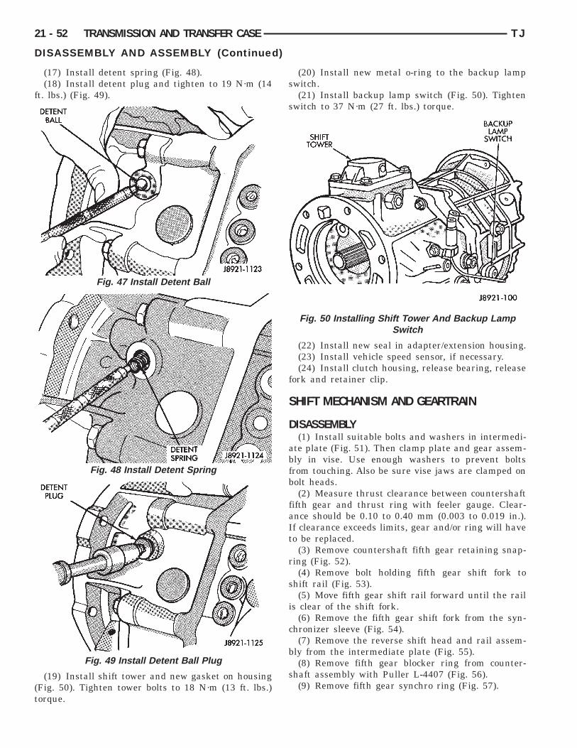
(16) Install shift detent ball in detent opening (Fig.47).
Fig. 45 Shifter Arm Shaft Plug Installation
Fig. 46 Install Shifter Restrictor Pins
f
(t
21 - 52 TRANSMISSION AND TRANSFER CASE TJ
DISASSEMBLY AND ASSEMBLY (Continued)
(17) Install detent spring (Fig. 48).(18) Install detent plug and tighten to 19 N·m (14
t. lbs.) (Fig. 49).
(19) Install shift tower and new gasket on housingFig. 50). Tighten tower bolts to 18 N·m (13 ft. lbs.)orque.
Fig. 47 Install Detent Ball
Fig. 48 Install Detent Spring
Fig. 49 Install Detent Ball Plug
(20) Install new metal o-ring to the backup lampswitch.
(21) Install backup lamp switch (Fig. 50). Tightenswitch to 37 N·m (27 ft. lbs.) torque.
(22) Install new seal in adapter/extension housing.(23) Install vehicle speed sensor, if necessary.(24) Install clutch housing, release bearing, release
fork and retainer clip.
SHIFT MECHANISM AND GEARTRAIN
DISASSEMBLY(1) Install suitable bolts and washers in intermedi-
ate plate (Fig. 51). Then clamp plate and gear assem-bly in vise. Use enough washers to prevent boltsfrom touching. Also be sure vise jaws are clamped onbolt heads.
(2) Measure thrust clearance between countershaftfifth gear and thrust ring with feeler gauge. Clear-ance should be 0.10 to 0.40 mm (0.003 to 0.019 in.).If clearance exceeds limits, gear and/or ring will haveto be replaced.
(3) Remove countershaft fifth gear retaining snap-ring (Fig. 52).
(4) Remove bolt holding fifth gear shift fork toshift rail (Fig. 53).
(5) Move fifth gear shift rail forward until the railis clear of the shift fork.
(6) Remove the fifth gear shift fork from the syn-chronizer sleeve (Fig. 54).
(7) Remove the reverse shift head and rail assem-bly from the intermediate plate (Fig. 55).
(8) Remove fifth gear blocker ring from counter-shaft assembly with Puller L-4407 (Fig. 56).
(9) Remove fifth gear synchro ring (Fig. 57).
Fig. 50 Installing Shift Tower And Backup LampSwitch
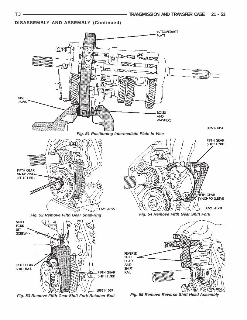
TJ TRANSMISSION AND TRANSFER CASE 21 - 53
DISASSEMBLY AND ASSEMBLY (Continued)
Fig. 51 Positioning Intermediate Plate In Vise
Fig. 52 Remove Fifth Gear Snap-ring
Fig. 55 Remove Reverse Shift Head Assembly
Fig. 53 Remove Fifth Gear Shift Fork Retainer BoltFig. 54 Remove Fifth Gear Shift Fork
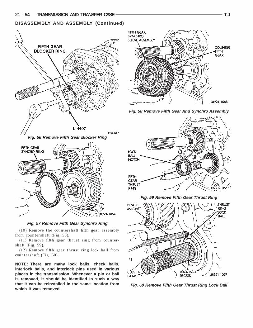
f
s
c
Nipitw
Fig. 58 Remove Fifth Gear And Synchro Assembly
Fig. 59 Remove Fifth Gear Thrust Ring
21 - 54 TRANSMISSION AND TRANSFER CASE TJ
DISASSEMBLY AND ASSEMBLY (Continued)
(10) Remove the countershaft fifth gear assemblyrom countershaft (Fig. 58).
(11) Remove fifth gear thrust ring from counter-haft (Fig. 59).(12) Remove fifth gear thrust ring lock ball from
ountershaft (Fig. 60).
OTE: There are many lock balls, check balls,nterlock balls, and interlock pins used in variouslaces in the transmission. Whenever a pin or ball
s removed, it should be identified in such a wayhat it can be reinstalled in the same location fromhich it was removed.
Fig. 56 Remove Fifth Gear Blocker Ring
Fig. 57 Remove Fifth Gear Synchro Ring
Fig. 60 Remove Fifth Gear Thrust Ring Lock Ball

i
6
b
m
h
tFig. 65 Lock Ball Plug Locations
TJ TRANSMISSION AND TRANSFER CASE 21 - 55
DISASSEMBLY AND ASSEMBLY (Continued)
(13) Remove bolts holding output shaft rear bear-ng retainer to intermediate plate (Fig. 61).
(14) Remove rear bearing retainer (Fig. 62).
(15) Remove reverse idler gear shaft and gear (Fig.3).(16) Remove bolts holding reverse shift arm
racket to intermediate plate (Fig. 64).(17) Remove threaded lock ball plugs from inter-ediate plate (Fig. 65).(18) Then remove lock ball and spring from plug
oles with pencil magnet (Fig. 66).(19) Remove the fifth gear shift rail (Fig. 67).(20) Retrieve the fifth gear shift rail lock ball from
he intermediate plate using a magnet (Fig. 68).
Fig. 61 Remove Output Shaft Rear Bearing RetainerBolts
Fig. 62 Remove Output Shaft Rear Bearing Retainer
Fig. 63 Remove Reverse Idler Shaft And Gear
Fig. 64 Reverse Shift Arm Components
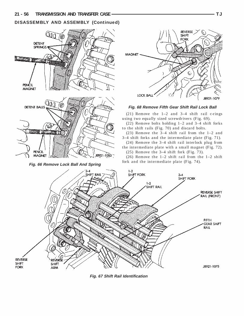
21 - 56 TRANSMISSION AND TRANSFER CASE TJ
DISASSEMBLY AND ASSEMBLY (Continued)
Fig. 66 Remove Lock Ball And Spring
Fig. 67 Shift R
(21) Remove the 1–2 and 3–4 shift rail c-ringsusing two equally sized screwdrivers (Fig. 69).
(22) Remove bolts holding 1–2 and 3–4 shift forksto the shift rails (Fig. 70) and discard bolts.
(23) Remove the 3–4 shift rail from the 1–2 and3–4 shift forks and the intermediate plate (Fig. 71).
(24) Remove the 3–4 shift rail interlock plug fromthe intermediate plate with a small magnet (Fig. 72).
(25) Remove the 3–4 shift fork (Fig. 73).(26) Remove the 1–2 shift rail from the 1–2 shift
fork and the intermediate plate (Fig. 74).
entification
Fig. 68 Remove Fifth Gear Shift Rail Lock Ball
ail Id

TJ TRANSMISSION AND TRANSFER CASE 21 - 57
DISASSEMBLY AND ASSEMBLY (Continued)
Fig. 69 Remove Shift Rail C-rings
Fig. 70 Remove Shift Fork To Shift Rail Bolts
(27) Remove the 1–2 shift rail interlock pin fromthe 1–2 shift rail (Fig. 75).
(28) Remove the 1–2 shift rail interlock plug fromthe intermediate plate (Fig. 76).
(29) Remove the 1–2 shift fork (Fig. 73).(30) Remove the c-ring holding the reverse shift
rail into the intermediate plate using two equallysized screwdrivers (Fig. 77).
(31) Remove the reverse shift rail and fork fromthe intermediate plate (Fig. 78).
Fig. 71 Remove 3–4 Shift Rail
Fig. 72 Remove 3–4 Shift Rail Interlock Plug
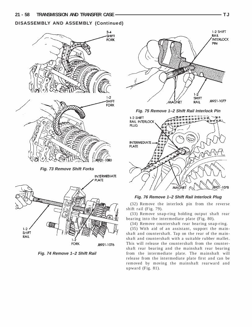
21 - 58 TRANSMISSION AND TRANSFER CASE TJ
DISASSEMBLY AND ASSEMBLY (Continued)
Fig. 73 Remove Shift Forks
Fig. 74 Remove 1–2 Shift Rail
(32) Remove the interlock pin from the reverseshift rail (Fig. 79).
(33) Remove snap-ring holding output shaft rearbearing into the intermediate plate (Fig. 80).
(34) Remove countershaft rear bearing snap-ring.(35) With aid of an assistant, support the main-
shaft and countershaft. Tap on the rear of the main-shaft and countershaft with a suitable rubber mallet.This will release the countershaft from the counter-shaft rear bearing and the mainshaft rear bearingfrom the intermediate plate. The mainshaft willrelease from the intermediate plate first and can beremoved by moving the mainshaft rearward andupward (Fig. 81).
Fig. 75 Remove 1–2 Shift Rail Interlock Pin
Fig. 76 Remove 1–2 Shift Rail Interlock Plug
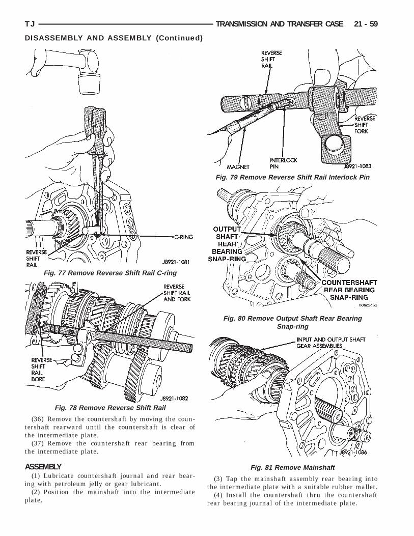
tt
t
A
i
p
TJ TRANSMISSION AND TRANSFER CASE 21 - 59
DISASSEMBLY AND ASSEMBLY (Continued)
(36) Remove the countershaft by moving the coun-ershaft rearward until the countershaft is clear ofhe intermediate plate.
(37) Remove the countershaft rear bearing fromhe intermediate plate.
SSEMBLY(1) Lubricate countershaft journal and rear bear-
ng with petroleum jelly or gear lubricant.(2) Position the mainshaft into the intermediate
late.
Fig. 77 Remove Reverse Shift Rail C-ring
Fig. 78 Remove Reverse Shift Rail
(3) Tap the mainshaft assembly rear bearing intothe intermediate plate with a suitable rubber mallet.
(4) Install the countershaft thru the countershaftrear bearing journal of the intermediate plate.
Fig. 79 Remove Reverse Shift Rail Interlock Pin
Fig. 80 Remove Output Shaft Rear BearingSnap-ring
Fig. 81 Remove Mainshaft

s
tBfob
g
b
Njp
8
a
21 - 60 TRANSMISSION AND TRANSFER CASE TJ
DISASSEMBLY AND ASSEMBLY (Continued)
(5) Align and mesh the mainshaft and counter-haft gears as much as possible.(6) Install the countershaft bearing over the coun-
ershaft bearing boss and into the intermediate plate.e sure to leave the snap-ring groove in the bearing
acing the rear of the unit. It may be necessary to tapn the bearing with a plastic mallet to fully seat theearing into intermediate plate.(7) Verify that the mainshaft and countershaft
ears are correctly meshed and rotate properly.(8) Install snap-ring to hold output shaft rear
earing into the intermediate plate (Fig. 66).(9) Install countershaft rear bearing snap-ring.
OTE: Coat all shift components with petroleumelly during assembly. Petroleum jelly will hold com-onents in position during installation.
(10) Install interlock pin in reverse shift rail (Fig.2).(11) Install the reverse shift rail in the intermedi-
te plate (Fig. 83).
Fig. 82 Install Reverse Shift Rail Interlock Pin
Fig. 83 Install Reverse Shift Rail
(12) Install c-ring to hold the reverse shift rail intothe intermediate plate.
(13) Install the 1–2 and 3–4 shift forks into thesynchronizer sleeves (Fig. 84).
(14) Install 1–2 shift rail interlock plug in theintermediate plate (Fig. 85).
(15) Install interlock pin in 1–2 shift rail (Fig. 86).
(16) Install 1–2 shift rail through intermediateplate and 1–2 shift fork (Fig. 87).
Fig. 84 Install Shift Forks
Fig. 85 Install 1–2 Shift Rail Interlock Plug

i
d
TJ TRANSMISSION AND TRANSFER CASE 21 - 61
DISASSEMBLY AND ASSEMBLY (Continued)
(17) Install 3–4 shift rail interlock plug into thentermediate plate (Fig. 88).
(18) Install the 3–4 shift rail through the interme-iate plate, 1–2 and 3–4 shift forks (Fig. 89).
Fig. 86 Install 1–2 Shift Rail Interlock Pin
Fig. 87 Install 1–2 Shift Rail
Fig. 88 Install 3–4 Shift Rail Interlock Plug
(19) Install new bolts to hold the shift forks to theshift rails (Fig. 90).
(20) Install c-rings to 1–2 and 3–4 shift rails (Fig.91).
Fig. 89 Install 3–4 Shift Rail
Fig. 90 Install Shift Fork To Shift Rail Bolts
Fig. 91 Install Shift Rail C-rings

i
m
(t
i
d
t
a
i
Fig. 94 Install Fifth Gear Shift Rail Lock Ball
21 - 62 TRANSMISSION AND TRANSFER CASE TJ
DISASSEMBLY AND ASSEMBLY (Continued)
(21) Install the fifth gear shift rail lock ball in thentermediate plate (Fig. 94).
(22) Install the fifth gear shift rail into the inter-ediate plate.(23) Install reverse idler gear and idler gear shaft
Fig. 92). Verify that the notch in the idler shaft is tohe rear of the transmission.
(24) Position output shaft rear bearing retainer onntermediate plate and into reverse idler shaft notch.
(25) Install new bolts to hold retainer to interme-iate plate (Fig. 93).
(26) Install the fifth gear thrust ring lock ball intohe countershaft (Fig. 95).
(27) Install fifth gear thrust ring onto countershaftnd over lock ball (Fig. 96).(28) Install countershaft fifth gear bearing halves
nto countershaft fifth gear assembly (Fig. 97).
Fig. 92 Install Reverse Idler Gear And Shaft
Fig. 93 Install Output Shaft Rear Bearing Retainer
Fig. 95 Install Fifth Gear Thrust Ring Lock Ball
Fig. 96 Install Fifth Gear Thrust Ring
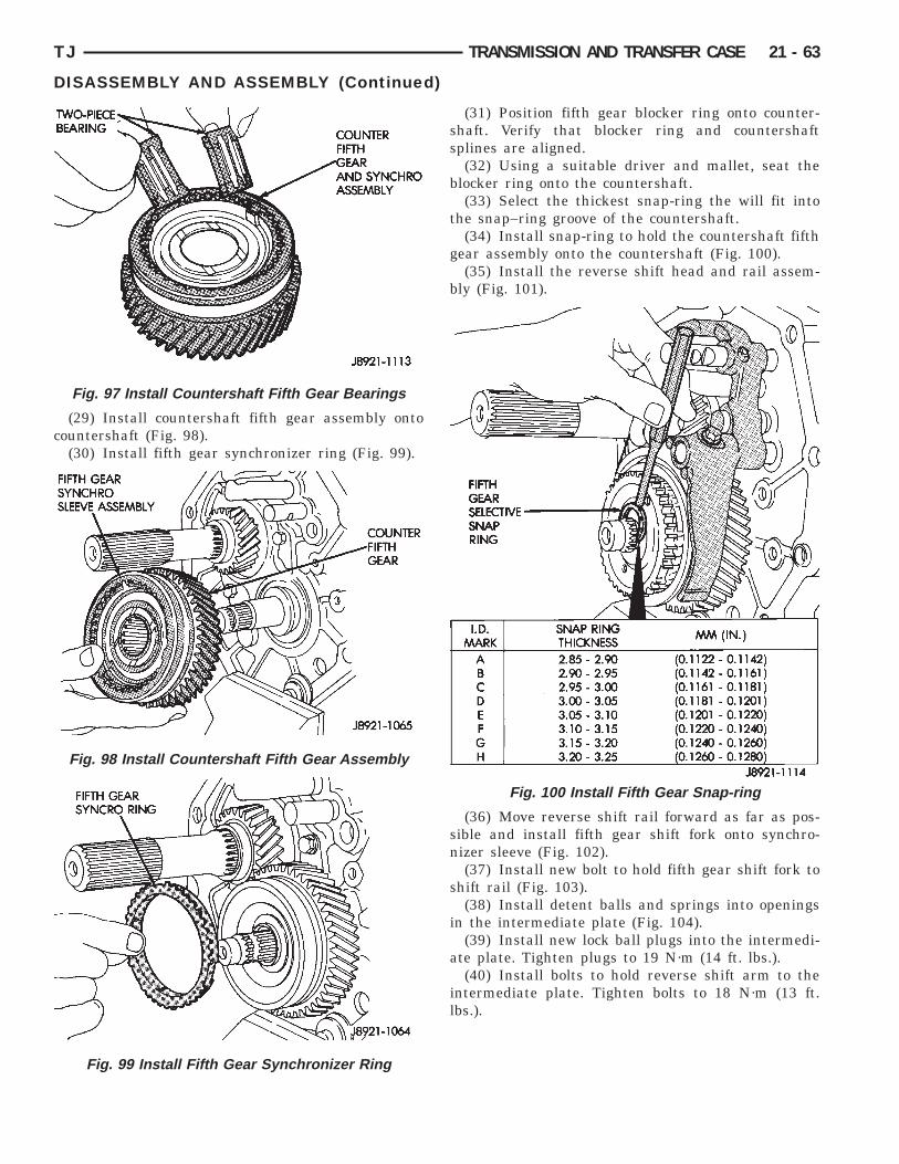
c
TJ TRANSMISSION AND TRANSFER CASE 21 - 63
DISASSEMBLY AND ASSEMBLY (Continued)
(29) Install countershaft fifth gear assembly ontoountershaft (Fig. 98).(30) Install fifth gear synchronizer ring (Fig. 99).
Fig. 97 Install Countershaft Fifth Gear Bearings
Fig. 98 Install Countershaft Fifth Gear Assembly
Fig. 99 Install Fifth Gear Synchronizer Ring
(31) Position fifth gear blocker ring onto counter-shaft. Verify that blocker ring and countershaftsplines are aligned.
(32) Using a suitable driver and mallet, seat theblocker ring onto the countershaft.
(33) Select the thickest snap-ring the will fit intothe snap–ring groove of the countershaft.
(34) Install snap-ring to hold the countershaft fifthgear assembly onto the countershaft (Fig. 100).
(35) Install the reverse shift head and rail assem-bly (Fig. 101).
(36) Move reverse shift rail forward as far as pos-sible and install fifth gear shift fork onto synchro-nizer sleeve (Fig. 102).
(37) Install new bolt to hold fifth gear shift fork toshift rail (Fig. 103).
(38) Install detent balls and springs into openingsin the intermediate plate (Fig. 104).
(39) Install new lock ball plugs into the intermedi-ate plate. Tighten plugs to 19 N·m (14 ft. lbs.).
(40) Install bolts to hold reverse shift arm to theintermediate plate. Tighten bolts to 18 N·m (13 ft.lbs.).
Fig. 100 Install Fifth Gear Snap-ring
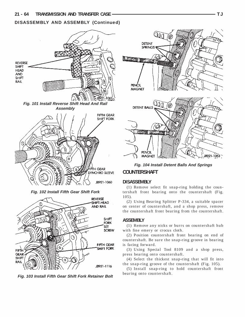
Assembly
21 - 64 TRANSMISSION AND TRANSFER CASE TJ
DISASSEMBLY AND ASSEMBLY (Continued)
COUNTERSHAFT
DISASSEMBLY(1) Remove select fit snap-ring holding the coun-
tershaft front bearing onto the countershaft (Fig.105).
(2) Using Bearing Splitter P-334, a suitable spaceron center of countershaft, and a shop press, removethe countershaft front bearing from the countershaft.
ASSEMBLY(1) Remove any nicks or burrs on countershaft hub
with fine emery or crocus cloth.(2) Position countershaft front bearing on end of
countershaft. Be sure the snap-ring groove in bearingis facing forward.
(3) Using Special Tool 8109 and a shop press,press bearing onto countershaft.
(4) Select the thickest snap-ring that will fit intothe snap-ring groove of the countershaft (Fig. 105).
(5) Install snap-ring to hold countershaft frontbearing onto countershaft.
Fig. 104 Install Detent Balls And Springs
Fig. 101 Install Reverse Shift Head And Rail
Fig. 102 Install Fifth Gear Shift Fork
Fig. 103 Install Fifth Gear Shift Fork Retainer Bolt

I
D
t
1
i
t
i
TJ TRANSMISSION AND TRANSFER CASE 21 - 65
DISASSEMBLY AND ASSEMBLY (Continued)
NPUT SHAFT
ISASSEMBLY(1) Verify that the 3–4 synchronizer is in the neu-
ral position.(2) Separate input shaft from output shaft (Fig.
06).
(3) Remove the output shaft pilot bearing from thenput shaft or output shaft (Fig. 107).
(4) Remove the fourth gear synchronizer ring fromhe input shaft (Fig. 108).
(5) Remove the select fit snap-ring holding thenput shaft bearing onto the input shaft.
Fig. 105 Countershaft Front Bearing Snap-ring
Fig. 106 Separate Input and Output Shafts
(6) Using Bearing Splitter P-334 and a shop press,remove the bearing from the input shaft.
ASSEMBLY(1) Position input shaft bearing onto input shaft.
Be sure that the snap-ring groove in the bearing isfacing forward.
(2) Using Driver 6052, drive bearing onto inputshaft.
(3) Select the thickest snap-ring that will fit intothe snap-ring groove of the input shaft (Fig. 109).
(4) Lubricate output shaft pilot bearing bore ofinput shaft with petroleum jelly.
(5) Install output shaft pilot bearing in input shaftbore (Fig. 107).
(6) Install the fourth gear synchronizer ring ontothe input shaft.
(7) Install input shaft to output shaft.
Fig. 107 Remove Output Shaft Pilot Bearing
Fig. 108 Input Shaft Components

O
d
Sha
21 - 66 TRANSMISSION AND TRANSFER CASE TJ
DISASSEMBLY AND ASSEMBLY (Continued)
UTPUT SHAFTRefer to (Fig. 110) for parts identification during
isassembly and assembly of the output shaft.
Fig. 109 Select Input Shaft Bearing Snap-ring
Fig. 110 Output
DISASSEMBLY(1) Remove input shaft and output shaft pilot
bearing from output shaft (Fig. 111), if necessary.(2) Measure and note thrust clearance of output
shaft gears (Fig. 112). First gear clearance should be0.10 – 0.40 mm (0.004 – 0.0197 in.). Second and thirdgear clearance should be 0.10 – 0.30 mm (0.003 –0.0118 in.).
ft And Gears
Fig. 111 Remove Output Shaft Pilot Bearing
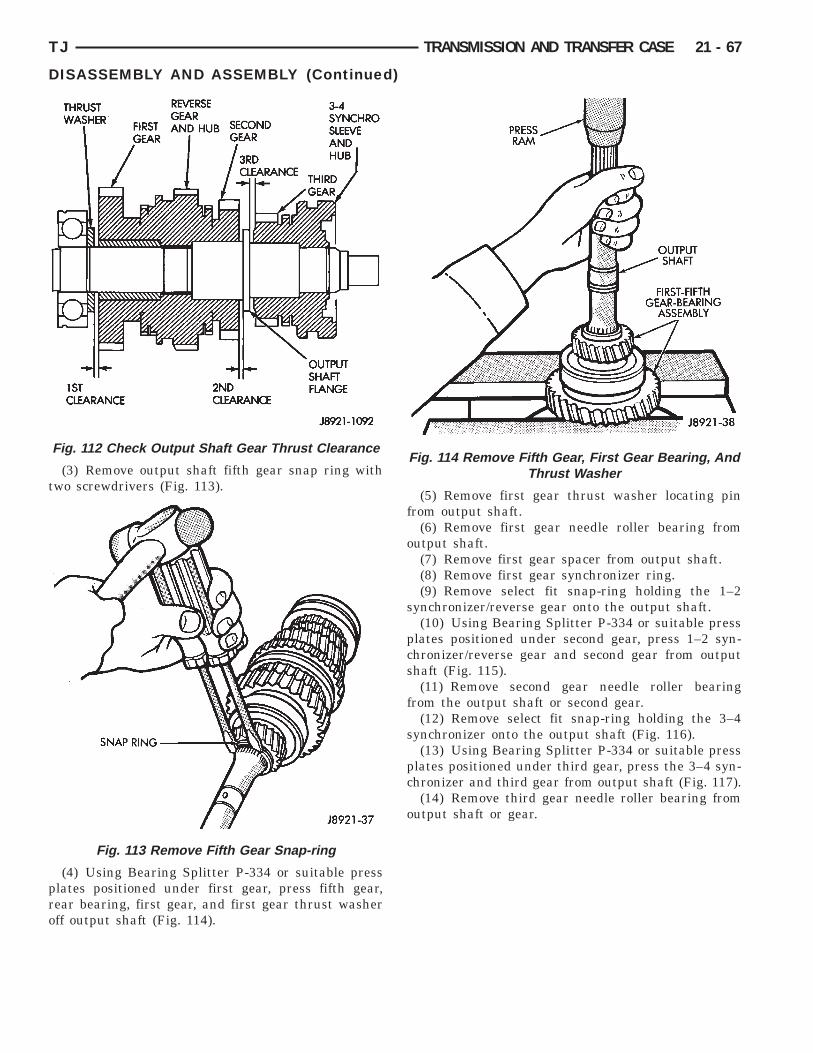
t
pro
TJ TRANSMISSION AND TRANSFER CASE 21 - 67
DISASSEMBLY AND ASSEMBLY (Continued)
(3) Remove output shaft fifth gear snap ring withwo screwdrivers (Fig. 113).
(4) Using Bearing Splitter P-334 or suitable presslates positioned under first gear, press fifth gear,ear bearing, first gear, and first gear thrust washerff output shaft (Fig. 114).
Fig. 112 Check Output Shaft Gear Thrust Clearance
Fig. 113 Remove Fifth Gear Snap-ring
(5) Remove first gear thrust washer locating pinfrom output shaft.
(6) Remove first gear needle roller bearing fromoutput shaft.
(7) Remove first gear spacer from output shaft.(8) Remove first gear synchronizer ring.(9) Remove select fit snap-ring holding the 1–2
synchronizer/reverse gear onto the output shaft.(10) Using Bearing Splitter P-334 or suitable press
plates positioned under second gear, press 1–2 syn-chronizer/reverse gear and second gear from outputshaft (Fig. 115).
(11) Remove second gear needle roller bearingfrom the output shaft or second gear.
(12) Remove select fit snap-ring holding the 3–4synchronizer onto the output shaft (Fig. 116).
(13) Using Bearing Splitter P-334 or suitable pressplates positioned under third gear, press the 3–4 syn-chronizer and third gear from output shaft (Fig. 117).
(14) Remove third gear needle roller bearing fromoutput shaft or gear.
Fig. 114 Remove Fifth Gear, First Gear Bearing, AndThrust Washer

A
f
n1
p
21 - 68 TRANSMISSION AND TRANSFER CASE TJ
DISASSEMBLY AND ASSEMBLY (Continued)
SSEMBLY(1) Lubricate transmission components with speci-
ied gear lubricant during assembly.(2) If necessary, assemble 1–2 and 3–4 synchro-
izer hubs, sleeves, springs and key inserts (Fig.18).(3) Install third gear needle bearing onto the out-
ut shaft.
Fig. 115 Remove Second Gear And 1–2Synchronizer/Reverse Gear
Fig. 116 Remove 3–4 Synchronizer Snap Ring
(4) Install third gear over bearing and onto outputshaft flange.
(5) Install third gear synchronizer ring to thirdgear.
(6) Position the 3–4 synchronizer onto the outputshaft.
(7) Using Adapter 6761 and a shop press, pressthe 3–4 synchronizer onto the output shaft.
(8) Select the thickest snap-ring that will fit intothe snap-ring groove of the output shaft (Fig. 119).
(9) Install snap-ring to hold 3–4 synchronizer ontooutput shaft.
(10) Verify third gear thrust clearance with feelergauge (Fig. 120). Clearance should be 0.10 – 0.30 mm(0.003 – 0.0118 in.). If clearance is out of specifica-tion, refer to Cleaning and Inspection section withinthis group.
Fig. 117 Remove 3–4 Synchronizer And Third Gear
Fig. 118 Synchronizer Identification
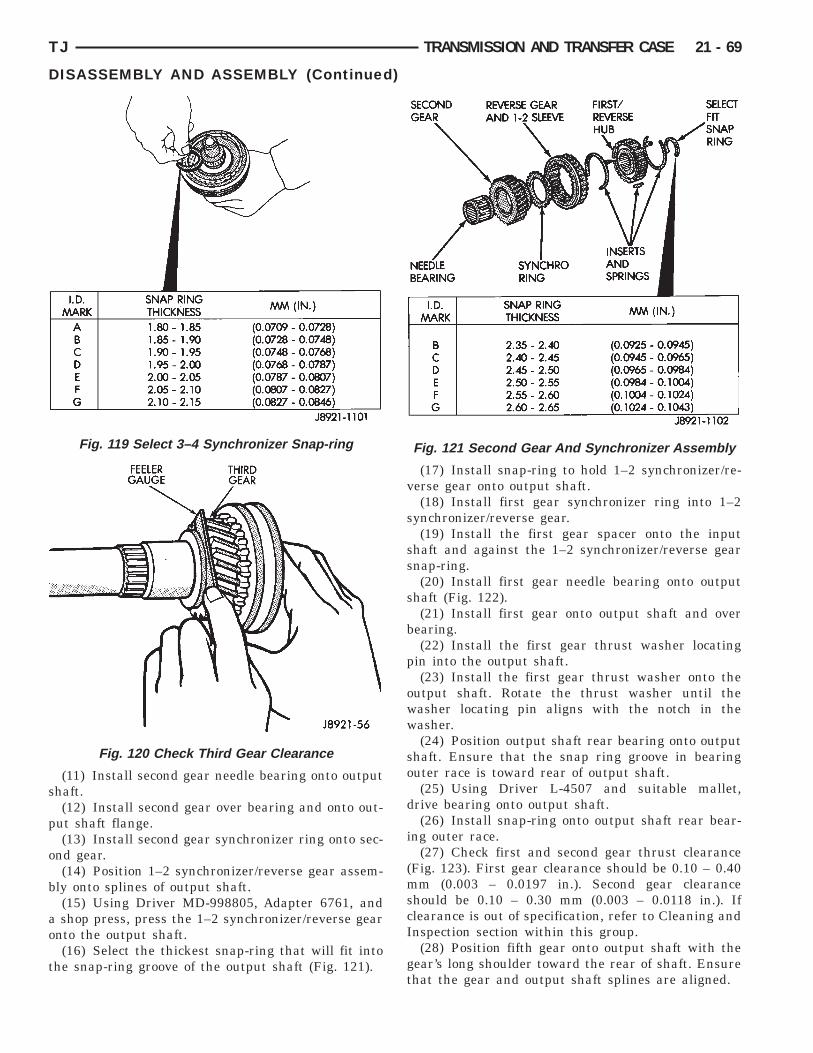
s
p
o
b
ao
t
TJ TRANSMISSION AND TRANSFER CASE 21 - 69
DISASSEMBLY AND ASSEMBLY (Continued)
(11) Install second gear needle bearing onto outputhaft.(12) Install second gear over bearing and onto out-
ut shaft flange.(13) Install second gear synchronizer ring onto sec-
nd gear.(14) Position 1–2 synchronizer/reverse gear assem-
ly onto splines of output shaft.(15) Using Driver MD-998805, Adapter 6761, andshop press, press the 1–2 synchronizer/reverse gear
nto the output shaft.(16) Select the thickest snap-ring that will fit into
he snap-ring groove of the output shaft (Fig. 121).
Fig. 119 Select 3–4 Synchronizer Snap-ring
Fig. 120 Check Third Gear Clearance
(17) Install snap-ring to hold 1–2 synchronizer/re-verse gear onto output shaft.
(18) Install first gear synchronizer ring into 1–2synchronizer/reverse gear.
(19) Install the first gear spacer onto the inputshaft and against the 1–2 synchronizer/reverse gearsnap-ring.
(20) Install first gear needle bearing onto outputshaft (Fig. 122).
(21) Install first gear onto output shaft and overbearing.
(22) Install the first gear thrust washer locatingpin into the output shaft.
(23) Install the first gear thrust washer onto theoutput shaft. Rotate the thrust washer until thewasher locating pin aligns with the notch in thewasher.
(24) Position output shaft rear bearing onto outputshaft. Ensure that the snap ring groove in bearingouter race is toward rear of output shaft.
(25) Using Driver L-4507 and suitable mallet,drive bearing onto output shaft.
(26) Install snap-ring onto output shaft rear bear-ing outer race.
(27) Check first and second gear thrust clearance(Fig. 123). First gear clearance should be 0.10 – 0.40mm (0.003 – 0.0197 in.). Second gear clearanceshould be 0.10 – 0.30 mm (0.003 – 0.0118 in.). Ifclearance is out of specification, refer to Cleaning andInspection section within this group.
(28) Position fifth gear onto output shaft with thegear’s long shoulder toward the rear of shaft. Ensurethat the gear and output shaft splines are aligned.
Fig. 121 Second Gear And Synchronizer Assembly

s
t
s
i
21 - 70 TRANSMISSION AND TRANSFER CASE TJ
DISASSEMBLY AND ASSEMBLY (Continued)
(29) Using Adapter 6761, Driver L-4507, and ahop press, press fifth gear onto output shaft.(30) Select the thickest snap-ring that will fit into
he snap-ring groove of the output shaft (Fig. 124).(31) Install snap-ring to hold fifth gear onto output
haft.(32) Install output shaft pilot bearing into the
nput shaft.(33) Install the input shaft to the output shafts.
Fig. 122 First And Fifth Gear Components
Fig. 123 Check First–Second Gear Thrust Clearance
CLEANING AND INSPECTION
AX15 MANUAL TRANSMISSION COMPONENTS
GENERAL INFORMATIONClean the transmission components in solvent. Dry
the cases, gears, shift mechanism and shafts withcompressed air. Dry the bearings with clean, dryshop towels only. Never use compressed air on thebearings. This could cause severe damage to thebearing roller and race surfaces.
If output shaft flange thickness is within specifica-tion but any gear thrust clearance is out of specifica-tion, replace the necessary gear and gear needlebearing as an assembly.
GEAR CASE, ADAPTER/EXTENSION HOUSING,INTERMEDIATE PLATE
Clean the case, housing, and intermediate platewith solvent and dry with compressed air. Replacethe case if cracked, porous, or if any of the bearingand gear bores are damaged.
Fig. 124 Select/Install Fifth Gear Snap Ring

Mtat
O
ma
bd
i
i
i
a0
fo
C
cIs
R
G
togcm
e
TJ TRANSMISSION AND TRANSFER CASE 21 - 71
CLEANING AND INSPECTION (Continued)
Inspect the threads in the case, housing, and plate.inor thread damage can be repaired with steel
hread inserts, if necessary. Do not attempt to repairny threads which show evidence of cracks aroundhe threaded hole.
UTPUT SHAFTCheck thickness of the output shaft flange with aicrometer or vernier calipers (Fig. 125). Minimum
llowable flange thickness is 4.70 mm (0.185 in.).
Check diameter of the first, second, and third gearearing surfaces on the output shaft. Minimumiameters are as follows:• First gear bearing surface is 38.86 mm (1.529
n.).• Second gear bearing surface is 46.86 mm (1.844
n.).• Third gear bearing surface is 37.86 mm (1.490
n.).Measure output shaft runout with a dial indicator
nd V-blocks (Fig. 125). Runout should not exceed.06 mm (0.0024 in.).Replace output shaft if measurement of any sur-
ace is out of specification. Do not attempt to repairut of specification components.
OUNTERSHAFTInspect the countershaft gear teeth. Replace the
ountershaft if any teeth are worn or damaged.nspect the bearing surfaces and replace shaft if anyurface shows damage or wear.Check condition of the countershaft front bearing.eplace the bearing if worn, noisy, or damaged.
EAR AND SYNCHRONIZERInstall the needle bearings in the first, second,
hird and counter fifth gears. Install the gears on theutput shaft. Then check oil clearance between theears and shaft with a dial indicator (Fig. 126). Oillearance for all three gears is 0.16 mm (0.0063 in.)aximum.Check synchronizer ring wear (Fig. 127). Insert
ach ring in matching gear. Measure clearance
Fig. 125 Check Output Shaft Tolerances
between each ring and gear with feeler gauge. Clear-ance should be 0.06 – 1.6 mm (0.024 – 0.063 in.).
Check shift fork–to–synchronizer hub clearancewith a feeler gauge (Fig. 128). Replace the fork ifclearance exceeds 1.0 mm (0.039 in.).
Check the condition of the reverse idler gear bush-ing (Fig. 129). Replace the gear if the bushing isdamaged or worn.
Fig. 126 Check Gear–To–Shaft Oil Clearance
Fig. 127 Check Synchronizer Ring Wear
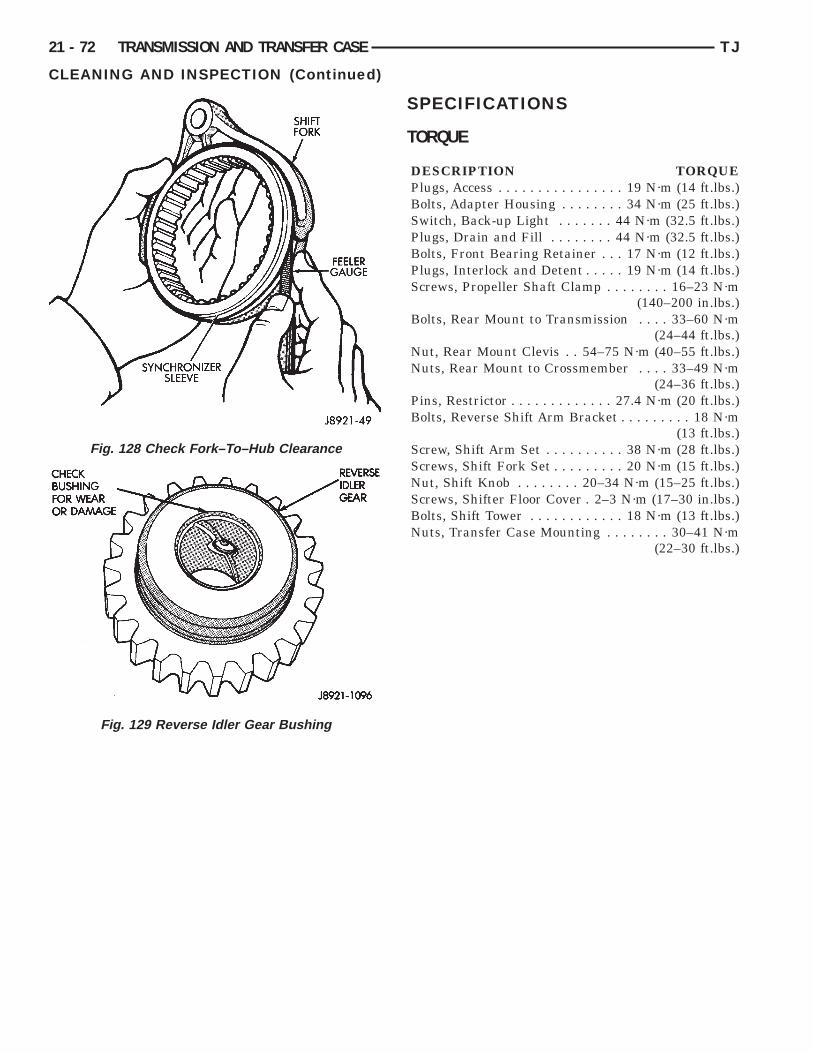
21 - 72 TRANSMISSION AND TRANSFER CASE TJ
CLEANING AND INSPECTION (Continued)
Fig. 128 Check Fork–To–Hub Clearance
Fig. 129 Reverse Idler Gear Bushing
SPECIFICATIONS
TORQUE
DESCRIPTION TORQUEPlugs, Access . . . . . . . . . . . . . . . . 19 N·m (14 ft.lbs.)Bolts, Adapter Housing . . . . . . . . 34 N·m (25 ft.lbs.)Switch, Back-up Light . . . . . . . 44 N·m (32.5 ft.lbs.)Plugs, Drain and Fill . . . . . . . . 44 N·m (32.5 ft.lbs.)Bolts, Front Bearing Retainer . . . 17 N·m (12 ft.lbs.)Plugs, Interlock and Detent . . . . . 19 N·m (14 ft.lbs.)Screws, Propeller Shaft Clamp . . . . . . . . 16–23 N·m
(140–200 in.lbs.)Bolts, Rear Mount to Transmission . . . . 33–60 N·m
(24–44 ft.lbs.)Nut, Rear Mount Clevis . . 54–75 N·m (40–55 ft.lbs.)Nuts, Rear Mount to Crossmember . . . . 33–49 N·m
(24–36 ft.lbs.)Pins, Restrictor . . . . . . . . . . . . . 27.4 N·m (20 ft.lbs.)Bolts, Reverse Shift Arm Bracket . . . . . . . . . 18 N·m
(13 ft.lbs.)Screw, Shift Arm Set . . . . . . . . . . 38 N·m (28 ft.lbs.)Screws, Shift Fork Set . . . . . . . . . 20 N·m (15 ft.lbs.)Nut, Shift Knob . . . . . . . . 20–34 N·m (15–25 ft.lbs.)Screws, Shifter Floor Cover . 2–3 N·m (17–30 in.lbs.)Bolts, Shift Tower . . . . . . . . . . . . 18 N·m (13 ft.lbs.)Nuts, Transfer Case Mounting . . . . . . . . 30–41 N·m
(22–30 ft.lbs.)

S
A
TJ TRANSMISSION AND TRANSFER CASE 21 - 73
PECIAL TOOLS
X15
C-3339 Dial Indicator Set
C-4171 Handle, Universal Tool
8209 Installer, Seal
8212 Installer, Seal
8208 Installer, Seal
L-4407A Puller, Gear
P-334 Splitter, Bearing
8109 Cup, Installer

21 - 74 TRANSMISSION AND TRANSFER CASE TJ
SPECIAL TOOLS (Continued)
6052 Tube, Driver
6761 Adapter, Installer
MD-998805 Tube, Driver
L-4507 Tube, Driver
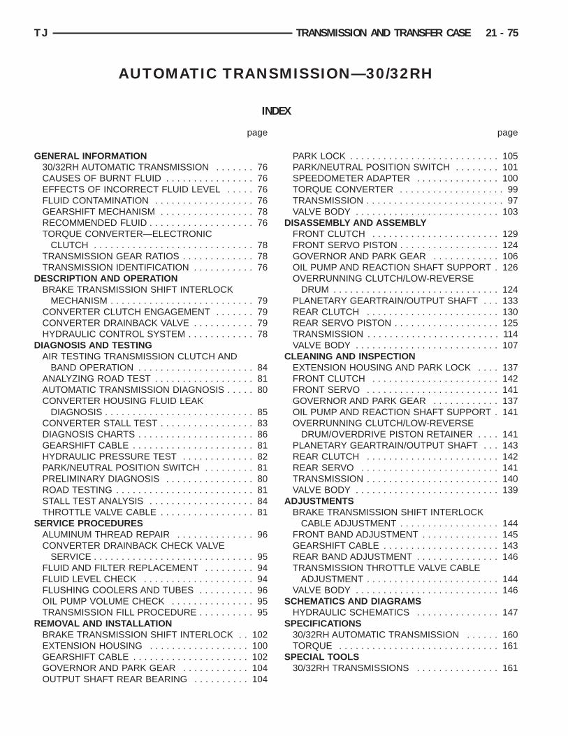
G
D
D
S
R
TJ TRANSMISSION AND TRANSFER CASE 21 - 75
AUTOMATIC TRANSMISSION—30/32RH
INDEX
page page
D
C
A
S
S
S
ENERAL INFORMATION30/32RH AUTOMATIC TRANSMISSION . . . . . . . 76CAUSES OF BURNT FLUID . . . . . . . . . . . . . . . . 76EFFECTS OF INCORRECT FLUID LEVEL . . . . . 76FLUID CONTAMINATION . . . . . . . . . . . . . . . . . . 76GEARSHIFT MECHANISM . . . . . . . . . . . . . . . . . 78RECOMMENDED FLUID . . . . . . . . . . . . . . . . . . . 76TORQUE CONVERTER—ELECTRONIC
CLUTCH . . . . . . . . . . . . . . . . . . . . . . . . . . . . . 78TRANSMISSION GEAR RATIOS . . . . . . . . . . . . . 78TRANSMISSION IDENTIFICATION . . . . . . . . . . . 76ESCRIPTION AND OPERATIONBRAKE TRANSMISSION SHIFT INTERLOCK
MECHANISM . . . . . . . . . . . . . . . . . . . . . . . . . . 79CONVERTER CLUTCH ENGAGEMENT . . . . . . . 79CONVERTER DRAINBACK VALVE . . . . . . . . . . . 79HYDRAULIC CONTROL SYSTEM . . . . . . . . . . . . 78IAGNOSIS AND TESTINGAIR TESTING TRANSMISSION CLUTCH AND
BAND OPERATION . . . . . . . . . . . . . . . . . . . . . 84ANALYZING ROAD TEST . . . . . . . . . . . . . . . . . . 81AUTOMATIC TRANSMISSION DIAGNOSIS . . . . . 80CONVERTER HOUSING FLUID LEAK
DIAGNOSIS . . . . . . . . . . . . . . . . . . . . . . . . . . . 85CONVERTER STALL TEST . . . . . . . . . . . . . . . . . 83DIAGNOSIS CHARTS . . . . . . . . . . . . . . . . . . . . . 86GEARSHIFT CABLE . . . . . . . . . . . . . . . . . . . . . . 81HYDRAULIC PRESSURE TEST . . . . . . . . . . . . . 82PARK/NEUTRAL POSITION SWITCH . . . . . . . . . 81PRELIMINARY DIAGNOSIS . . . . . . . . . . . . . . . . 80ROAD TESTING . . . . . . . . . . . . . . . . . . . . . . . . . 81STALL TEST ANALYSIS . . . . . . . . . . . . . . . . . . . 84THROTTLE VALVE CABLE . . . . . . . . . . . . . . . . . 81ERVICE PROCEDURESALUMINUM THREAD REPAIR . . . . . . . . . . . . . . 96CONVERTER DRAINBACK CHECK VALVE
SERVICE . . . . . . . . . . . . . . . . . . . . . . . . . . . . . 95FLUID AND FILTER REPLACEMENT . . . . . . . . . 94FLUID LEVEL CHECK . . . . . . . . . . . . . . . . . . . . 94FLUSHING COOLERS AND TUBES . . . . . . . . . . 96OIL PUMP VOLUME CHECK . . . . . . . . . . . . . . . 95TRANSMISSION FILL PROCEDURE . . . . . . . . . . 95EMOVAL AND INSTALLATIONBRAKE TRANSMISSION SHIFT INTERLOCK . . 102EXTENSION HOUSING . . . . . . . . . . . . . . . . . . 100GEARSHIFT CABLE . . . . . . . . . . . . . . . . . . . . . 102GOVERNOR AND PARK GEAR . . . . . . . . . . . . 104
OUTPUT SHAFT REAR BEARING . . . . . . . . . . 104PARK LOCK . . . . . . . . . . . . . . . . . . . . . . . . . . . 105PARK/NEUTRAL POSITION SWITCH . . . . . . . . 101SPEEDOMETER ADAPTER . . . . . . . . . . . . . . . 100TORQUE CONVERTER . . . . . . . . . . . . . . . . . . . 99TRANSMISSION . . . . . . . . . . . . . . . . . . . . . . . . . 97VALVE BODY . . . . . . . . . . . . . . . . . . . . . . . . . . 103ISASSEMBLY AND ASSEMBLYFRONT CLUTCH . . . . . . . . . . . . . . . . . . . . . . . 129FRONT SERVO PISTON . . . . . . . . . . . . . . . . . . 124GOVERNOR AND PARK GEAR . . . . . . . . . . . . 106OIL PUMP AND REACTION SHAFT SUPPORT . 126OVERRUNNING CLUTCH/LOW-REVERSE
DRUM . . . . . . . . . . . . . . . . . . . . . . . . . . . . . . 124PLANETARY GEARTRAIN/OUTPUT SHAFT . . . 133REAR CLUTCH . . . . . . . . . . . . . . . . . . . . . . . . 130REAR SERVO PISTON . . . . . . . . . . . . . . . . . . . 125TRANSMISSION . . . . . . . . . . . . . . . . . . . . . . . . 114VALVE BODY . . . . . . . . . . . . . . . . . . . . . . . . . . 107LEANING AND INSPECTIONEXTENSION HOUSING AND PARK LOCK . . . . 137FRONT CLUTCH . . . . . . . . . . . . . . . . . . . . . . . 142FRONT SERVO . . . . . . . . . . . . . . . . . . . . . . . . 141GOVERNOR AND PARK GEAR . . . . . . . . . . . . 137OIL PUMP AND REACTION SHAFT SUPPORT . 141OVERRUNNING CLUTCH/LOW-REVERSE
DRUM/OVERDRIVE PISTON RETAINER . . . . 141PLANETARY GEARTRAIN/OUTPUT SHAFT . . . 143REAR CLUTCH . . . . . . . . . . . . . . . . . . . . . . . . 142REAR SERVO . . . . . . . . . . . . . . . . . . . . . . . . . 141TRANSMISSION . . . . . . . . . . . . . . . . . . . . . . . . 140VALVE BODY . . . . . . . . . . . . . . . . . . . . . . . . . . 139DJUSTMENTSBRAKE TRANSMISSION SHIFT INTERLOCK
CABLE ADJUSTMENT . . . . . . . . . . . . . . . . . . 144FRONT BAND ADJUSTMENT . . . . . . . . . . . . . . 145GEARSHIFT CABLE . . . . . . . . . . . . . . . . . . . . . 143REAR BAND ADJUSTMENT . . . . . . . . . . . . . . . 146TRANSMISSION THROTTLE VALVE CABLE
ADJUSTMENT . . . . . . . . . . . . . . . . . . . . . . . . 144VALVE BODY . . . . . . . . . . . . . . . . . . . . . . . . . . 146CHEMATICS AND DIAGRAMSHYDRAULIC SCHEMATICS . . . . . . . . . . . . . . . 147PECIFICATIONS30/32RH AUTOMATIC TRANSMISSION . . . . . . 160TORQUE . . . . . . . . . . . . . . . . . . . . . . . . . . . . . 161PECIAL TOOLS30/32RH TRANSMISSIONS . . . . . . . . . . . . . . . 161

G
3
21ttcTah(viwgaftmt
T
oko
R
ma
cf
E
apIftedvcfot
C
w
21 - 76 TRANSMISSION AND TRANSFER CASE TJ
ENERAL INFORMATION
0/32RH AUTOMATIC TRANSMISSIONThe 30RH automatic transmission is used with the
.5L engine. The 32RH automatic transmission (Fig.) is used with the 4.0L engine. The 30/32RH arehree speed transmissions with a lock-up clutch inhe torque converter. The torque converter clutch isontrolled by the Powertrain Control Module (PCM).he torque converter clutch is hydraulically appliednd is released when fluid is vented from theydraulic circuit by the torque converter controlTCC) solenoid on the valve body. The torque con-erter clutch engages in third gear when the vehicles cruising on a level plane after the vehicle hasarmed up. The torque converter clutch will disen-age when the vehicle begins to go uphill or theccelerator is applied. The torque converter clutcheature increases fuel economy and reduces theransmission fluid temperature. The 30/32RH trans-ission is cooled by an integral fluid cooler inside
he radiator.
RANSMISSION IDENTIFICATIONTransmission identification numbers are stamped
n the left side of the case just above the oil pan gas-et surface (Fig. 2). Refer to this information whenrdering replacement parts.
ECOMMENDED FLUIDMopart ATF Plus 3, Type 7176 automatic trans-ission fluid is the recommended fluid for Chrysler
utomatic transmissions.Dexron II fluid IS NOT recommended. Clutch
hatter can result from the use of improperluid.
FFECTS OF INCORRECT FLUID LEVELA low fluid level allows the pump to take in air
long with the fluid. Air in the fluid will cause fluidressures to be low and develop slower than normal.f the transmission is overfilled, the gears churn theluid into foam. This aerates the fluid and causinghe same conditions occurring with a low level. Inither case, air bubbles cause fluid overheating, oxi-ation and varnish buildup which interferes withalve, clutch and servo operation. Foaming alsoauses fluid expansion which can result in fluid over-low from the transmission vent or fill tube. Fluidverflow can easily be mistaken for a leak if inspec-ion is not careful.
AUSES OF BURNT FLUIDBurnt, discolored fluid is a result of overheatinghich has two primary causes.
(1) A result of restricted fluid flow through themain and/or auxiliary cooler. This condition is usu-ally the result of a faulty or improperly installeddrainback valve, a damaged main cooler, or severerestrictions in the coolers and lines caused by debrisor kinked lines.
(2) Heavy duty operation with a vehicle not prop-erly equipped for this type of operation. Trailer tow-ing or similar high load operation will overheat thetransmission fluid if the vehicle is improperlyequipped. Such vehicles should have an auxiliarytransmission fluid cooler, a heavy duty cooling sys-tem, and the engine/axle ratio combination needed tohandle heavy loads.
FLUID CONTAMINATIONTransmission fluid contamination is generally a
result of:• adding incorrect fluid• failure to clean dipstick and fill tube when
checking level• engine coolant entering the fluid• internal failure that generates debris• overheat that generates sludge (fluid break-
down)• failure to reverse flush cooler and lines after
repair• failure to replace contaminated converter after
repairThe use of non recommended fluids can result in
transmission failure. The usual results are erraticshifts, slippage, abnormal wear and eventual failuredue to fluid breakdown and sludge formation. Avoidthis condition by using recommended fluids only.
The dipstick cap and fill tube should be wipedclean before checking fluid level. Dirt, grease andother foreign material on the cap and tube could fallinto the tube if not removed beforehand. Take thetime to wipe the cap and tube clean before withdraw-ing the dipstick.
Engine coolant in the transmission fluid is gener-ally caused by a cooler malfunction. The only remedyis to replace the radiator as the cooler in the radiatoris not a serviceable part. If coolant has circulatedthrough the transmission for some time, an overhaulmay also be necessary; especially if shift problemshad developed.
The transmission cooler and lines should bereverse flushed whenever a malfunction generatessludge and/or debris. The torque converter shouldalso be replaced at the same time.
Failure to flush the cooler and lines will result inrecontamination. Flushing applies to auxiliary cool-ers as well. The torque converter should also bereplaced whenever a failure generates sludge anddebris. This is necessary because normal converter

omatic Transmission
TJ TRANSMISSION AND TRANSFER CASE 21 - 77
GENERAL INFORMATION (Continued)
Fig. 1 30/32 RH Aut

fn
T
cTaactrspothaTaetgs
i
Cami
T
21 - 78 TRANSMISSION AND TRANSFER CASE TJ
GENERAL INFORMATION (Continued)
lushing procedures will not remove all contami-ants.
ORQUE CONVERTER—ELECTRONIC CLUTCHThe torque converter is a hydraulic device that
ouples the engine crankshaft to the transmission.he torque converter consists of an outer shell withn internal turbine, a stator, an overrunning clutch,n impeller and an electronically applied converterlutch. Torque multiplication is created when the sta-or directs the hydraulic flow from the turbine tootate the impeller in the direction the engine crank-haft is turning. The turbine transfers power to thelanetary gear sets in the transmission. The transferf power into the impeller assists torque multiplica-ion. At low vehicle speed, the overrunning clutcholds the stator (during torque multiplication) andllows the stator to free wheel at high vehicle speed.he converter clutch provides reduced engine speednd greater fuel economy when engaged. Clutchngagement also provides reduced transmission fluidemperatures. The converter clutch engages in thirdear. The torque converter hub drives the transmis-ion oil (fluid) pump.The torque converter is a sealed, welded unit that
s not repairable and is serviced as an assembly.
AUTION: The torque converter must be replaced iftransmission failure resulted in large amounts ofetal or fiber contamination in the fluid. If the fluid
s contaminated, flush the fluid cooler and lines.
RANSMISSION GEAR RATIOSForward gear ratios are:• 2.74:1 (first gear)• 1.54:1 (second gear)• 1.00:1 (third gear)
Fig. 2 Transmission Part And Serial NumberLocation
GEARSHIFT MECHANISMThe shift mechanism is cable operated and pro-
vides six shift positions. The shift indicator is locatedon the console next to the gear shift. The shift posi-tions are:
• Park (P)• Reverse (R)• Neutral (N)• Drive (D)• Manual Second (2)• Manual Low (1)Manual low (1) range provides first gear only. Over
run braking is also provided in this range. Manualsecond (2) range provides first and second gear only.Drive range provides first, second, and third gearranges.
DESCRIPTION AND OPERATION
HYDRAULIC CONTROL SYSTEMThe transmission hydraulic control system per-
forms four basic functions.• pressure supply• pressure regulation• flow control and lubrication• clutch/band application
PRESSURE SUPPLYThe oil pump develops fluid pressure for clutch/
band application and for lubrication. The pump isdriven by the torque converter. The converter isdriven by a driveplate attached to the engine crank-shaft.
Pressure RegulationThe pressure regulator valve maintains line (oper-
ating) pressure. The amount of pressure developed iscontrolled by throttle pressure which is dependent onthe degree of throttle opening. The regulator valve islocated in the valve body.
The throttle valve determines throttle pressureand shift speed. Governor pressure increases in pro-portion to vehicle speed. The throttle valve controlsupshift and downshift speeds by regulating pressureaccording to throttle position.
Flow Control And LubricationThe manual valve is operated by the gearshift link-
age and provides the operating range selected by thedriver.
The switch valve controls line pressure to the con-verter clutch. The valve also directs oil to the coolingand lubrication circuits. The switch valve regulatesoil pressure to the torque converter by limiting max-imum oil pressure to 130 psi.
t
sdd
dv
dttp
wSmp
f“cs
ccp
C
ar
bmot
TJ TRANSMISSION AND TRANSFER CASE 21 - 79
DESCRIPTION AND OPERATION (Continued)
The 1-2 shift valve provide 1-2 and 2-1 shifts andhe 2-3 shift valve provide 2-3 and 3-2 shifts.
The 1-2 shift control valve transmits 1-2 shift pres-ure to the accumulator piston. This controls kick-own band capacity on 1-2 upshifts and 3-2ownshifts.The 2-3 valve throttle pressure plug provides 3-2
ownshifts at varying throttle openings depending onehicle speed.The kickdown valve provides forced downshifts
epending on vehicle speed. Downshifts occur whenhe throttle is opened beyond downshift detent posi-ion. Detent is reached just before wide open throttleosition.The limit valve determines maximum speed athich a 3-2 part throttle kickdown can be made.ome transmissions do not have the limit valve andaximum speed for a 3-2 kickdown is at the detent
osition.The shuttle valve has two functions. First is fast
ront band release and smooth engagement duringlift foot” 2-3 upshifts. Second is to regulate frontlutch release and band application during 3-2 down-hifts.The fail safe valve restricts feed to the converter
lutch if front clutch pressure drops. It permitslutch engagement only in direct (third) gear androvides fast clutch release during kickdown.
lutch/Band ApplicationThe front/rear clutch pistons and servo pistons are
ctuated by line pressure. When line pressure isemoved, the pistons are released by spring tension.On 2-3 upshifts, the front servo piston is released
y spring tension and hydraulic pressure. The accu-ulator controls hydraulic pressure on the apply side
f the front servo during 1-2 upshifts and at allhrottle openings.
CONVERTER CLUTCH ENGAGEMENTConverter clutch engagement in third gear is con-
trolled by sensor inputs to the powertrain controlmodule. Inputs that determine clutch engagementare: coolant temperature, vehicle speed and throttleposition. The torque converter clutch is engaged bythe clutch solenoid on the valve body. The clutch willengage at approximately 56 km/h (35 mph) with lightthrottle, after the shift to third gear.
CONVERTER DRAINBACK VALVEThe drainback valve is located in the transmission
cooler outlet (pressure) line. The valve prevents fluidfrom draining from the converter into the cooler andlines when the vehicle is shut down for lengthy peri-ods. Production valves have a hose nipple at one end,while the opposite end is threaded for a flare fitting.All valves have an arrow (or similar mark) to indi-cate direction of flow through the valve.
BRAKE TRANSMISSION SHIFT INTERLOCKMECHANISM
The Brake Transmission Shifter/Ignition Interlock(BTSI), is a cable and solenoid operated system. Itinterconnects the automatic transmission floormounted shifter to the steering column ignitionswitch (Fig. 3). The system locks the shifter into thePARK position. The Interlock system is engagedwhenever the ignition switch is in the LOCK orACCESSORY position. An additional electrically acti-vated feature will prevent shifting out of the PARKposition unless the brake pedal is depressed at leastone-half an inch. A magnetic holding device in linewith the park/brake interlock cable is energizedwhen the ignition is in the RUN position. When thekey is in the RUN position and the brake pedal isdepressed, the shifter is unlocked and will move intoany position. The interlock system also prevents theignition switch from being turned to the LOCK orACCESSORY position (Fig. 4) unless the shifter isfully locked into the PARK position.

D
A
prcffalrs
lock
21 - 80 TRANSMISSION AND TRANSFER CASE TJ
DESCRIPTION AND OPERATION (Continued)
IAGNOSIS AND TESTING
UTOMATIC TRANSMISSION DIAGNOSISAutomatic transmission problems can be a result of
oor engine performance, incorrect fluid level, incor-ect linkage or cable adjustment, band or hydraulicontrol pressure adjustments, hydraulic system mal-unctions or electrical/mechanical component mal-unctions. Begin diagnosis by checking the easilyccessible items such as: fluid level and condition,inkage adjustments and electrical connections. Aoad test will determine if further diagnosis is neces-ary.
Fig. 3 Ignition Inter
Fig. 4 Ignition Key Cylinder Actuation
PRELIMINARY DIAGNOSISTwo basic procedures are required. One procedure
for vehicles that are drivable and an alternate proce-dure for disabled vehicles (will not back up or moveforward).
VEHICLE IS DRIVEABLE(1) Check for transmission fault codes using DRB
scan tool.(2) Check fluid level and condition.(3) Adjust throttle and gearshift linkage if com-
plaint was based on delayed, erratic, or harsh shifts.(4) Road test and note how transmission upshifts,
downshifts, and engages.(5) Perform stall test if complaint is based on slug-
gish acceleration. Or, if abnormal throttle opening isneeded to maintain normal speeds with a properlytuned engine.
(6) Perform hydraulic pressure test if shift prob-lems were noted during road test.
(7) Perform air-pressure test to check clutch-bandoperation.
VEHICLE IS DISABLED(1) Check fluid level and condition.(2) Check for broken or disconnected gearshift or
throttle linkage.
Cable Routing

o
sf
P
sgsTl
S
Ttw
csRo
i
G
sN
lEp
d
TJ TRANSMISSION AND TRANSFER CASE 21 - 81
DIAGNOSIS AND TESTING (Continued)
(3) Check for cracked, leaking cooler lines, or looser missing pressure-port plugs.(4) Raise and support vehicle on safety stands,
tart engine, shift transmission into gear, and noteollowing:
(a) If propeller shaft turns but wheels do not,problem is with differential or axle shafts.
(b) If propeller shaft does not turn and transmis-sion is noisy, stop engine. Remove oil pan, andcheck for debris. If pan is clear, remove transmis-sion and check for damaged drive plate, converter,oil pump, or input shaft.
(c) If propeller shaft does not turn and transmis-sion is not noisy, perform hydraulic-pressure test todetermine if problem is hydraulic or mechanical.
ARK/NEUTRAL POSITION SWITCHThe center terminal of the park/neutral position
witch is the starter-circuit terminal. It provides theround for the starter solenoid circuit through theelector lever in PARK and NEUTRAL positions only.he outer terminals on the switch are for the backup
amp circuit.
WITCH TESTTo test the switch, remove the wiring connector.
est for continuity between the center terminal andhe transmission case. Continuity should exist onlyhen the transmission is in PARK or NEUTRAL.Shift the transmission into REVERSE and test
ontinuity at the switch outer terminals. Continuityhould exist only when the transmission is inEVERSE. Continuity should not exist between theuter terminals and the case.Check gearshift linkage adjustment before replac-
ng a switch that tests faulty.
EARSHIFT CABLE(1) The floor shifter lever and gate positions
hould be in alignment with all transmission PARK,EUTRAL, and gear detent positions.(2) Engine starts must be possible with floor shift
ever in PARK or NEUTRAL gate positions only.ngine starts must not be possible in any other gearosition.(3) With floor shift lever handle push-button not
epressed and lever in:(a) PARK position—Apply forward force on cen-
ter of handle and remove pressure. Engine startsmust be possible.
(b) PARK position—Apply rearward force on cen-ter of handle and remove pressure. Engine startsmust be possible.
(c) NEUTRAL position—Normal position. Enginestarts must be possible.
(d) NEUTRAL position—Engine running andbrakes applied, apply forward force on center ofshift handle. Transmission shall not be able to shiftfrom neutral to reverse.
THROTTLE VALVE CABLETransmission throttle valve cable adjustment is
extremely important to proper operation. This adjust-ment positions the throttle valve, which controls shiftspeed, quality, and part-throttle downshift sensitivity.
If cable setting is too loose, early shifts and slip-page between shifts may occur. If the setting is tootight, shifts may be delayed and part throttle down-shifts may be very sensitive. Refer to the Adjust-ments section for the proper adjustment procedure.
ROAD TESTINGBefore road testing, be sure the fluid level and con-
trol cable adjustments have been checked andadjusted if necessary. Verify that diagnostic troublecodes have been resolved.
Observe engine performance during the road test.A poorly tuned engine will not allow accurate analy-sis of transmission operation.
Operate the transmission in all gear ranges. Checkfor shift variations and engine flare which indicatesslippage. Note if shifts are harsh, spongy, delayed,early, or if part throttle downshifts are sensitive.
Slippage indicated by engine flare, usually meansclutch, band or overrunning clutch problems. If thecondition is advanced, an overhaul will be necessaryto restore normal operation.
A slipping clutch or band can often be determinedby comparing which internal units are applied in thevarious gear ranges. The Clutch and Band Applica-tion chart provides a basis for analyzing road testresults.
ANALYZING ROAD TESTRefer to the Clutch and Band Application chart
and note which elements are in use in the variousgear ranges.
Verify that the rear clutch is applied in all forwardranges (D, 2, 1). The transmission overrunning clutchis applied in first gear (D, 2 and 1 ranges) only. Therear band is applied in 1 and R range only.
Verify that the overdrive clutch is applied only infourth gear and the overdrive direct clutch and over-running clutch are applied in all ranges except fourthgear. For example: If slippage occurs in first gear inD and 2 range but not in 1 range, the transmissionoverrunning clutch is faulty. Similarly, if slippageoccurs in any two forward gears, the rear clutch isslipping.
Applying the same method of analysis, verify thatthe front and rear clutches are applied simulta-

nsr
db(ai
at
sapts
imt
H
pk
rhgCrs
21 - 82 TRANSMISSION AND TRANSFER CASE TJ
DIAGNOSIS AND TESTING (Continued)
eously only in D range third gear. If the transmis-ion slips in third gear, either the front clutch or theear clutch is slipping.If slippage occurs during the third gear and the
irect clutch were to fail, the transmission would loseoth reverse gear and overrun braking in 2 positionmanual second gear). If the transmission slips inny other forward gears, the transmission rear clutchs probably slipping.
This process of elimination can be used to identifyslipping unit and check operation. Proper use of
he Clutch and Band Application Chart is the key.Although road test analysis will help determine the
lipping unit, the actual cause of a malfunction usu-lly cannot be determined until hydraulic and airressure tests are performed. Practically any condi-ion can be caused by leaking hydraulic circuits orticking valves.Unless a malfunction is obvious, such as no drive
n D range first gear, do not disassemble the trans-ission. Perform the hydraulic and air pressure tests
o help determine the probable cause.
YDRAULIC PRESSURE TESTHydraulic test pressures range from a low of one
si (6.895 kPa) governor pressure, to 300 psi (2068Pa) at the rear servo pressure port in reverse.An accurate tachometer and two test gauges are
equired for the pressure test. Test Gauge C-3292as a 100 psi range and is used at the accumulator,overnor, and front servo pressure ports. Test Gauge-3293-SP has a 300 psi range and is used at theear servo port and overdrive test ports where pres-ures are higher. In cases where two test gauges are
Fig. 5 Clutch And Band Application
required, the 300 psi gauge can be used at any of theother test ports.
Pressure Test Port LocationsPressure test ports locations are provided at the
accumulator, front servo, and rear servo, governorpassage, and overdrive clutch pressure passage (Fig.6), (Fig. 7) and (Fig. 8).
Line pressure is checked at the accumulator porton the right side of the case. The front servo pressureport is at the right side of the case just behind thefiller tube opening.
Connect a tachometer to the engine. Position thetachometer so it can be observed from under thevehicle. Raise the vehicle on a hoist that will allowthe wheels to rotate freely.
Fig. 6 Pressure Test Ports At Side Of Case
Fig. 7 Pressure Test Ports At Rear Of Case—2WD
Fig. 8 Pressure Test Ports At Rear Of Case—4WD
P
T
aTtC
p
p
m
w
wb
5al
p
T
t
p
sT
wb
kir
T
oC
sg
d
TJ TRANSMISSION AND TRANSFER CASE 21 - 83
DIAGNOSIS AND TESTING (Continued)
RESSURE TEST PROCEDURE
est One - Transmission In 1 RangeThis test checks pump output, pressure regulation,
nd condition of the rear clutch and servo circuit.est Gauges C-3292 and C-3293-SP are required forhis test. Gauge C-3292 has a 100 psi range. Gauge-3293-SP has a 300 psi range.(1) Connect 100 psi Gauge C-3292 to accumulator
ort.(2) Connect 300 psi Gauge C-3293-SP to rear servo
ort (Fig. 6) and (Fig. 7).(3) Disconnect throttle and gearshift rods fromanual and throttle levers.(4) Start and run engine at 1000 rpm.(5) Move shift lever (on manual lever shaft) all theay forward into 1 range.(6) Move transmission throttle lever from full for-ard to full rearward position and note pressures onoth gauges.(7) Line pressure at accumulator port should be
4-60 psi (372-414 kPa) with throttle lever forwardnd gradually increase to 90-96 psi (621-662 kPa) asever is moved rearward.
(8) Rear servo pressure should be same as lineressure within 3 psi (20.68 kPa).
est Two - Transmission In 2 RangeThis test checks pump output and pressure regula-
ion. Use 100 psi Test Gauge C-3292 for this test.(1) Connect test gauge to accumulator pressure
ort (Fig. 6) and (Fig. 7).(2) Start and run engine at 1000 rpm.(3) Move shift lever on valve body manual lever
haft, one detent rearward from full forward position.his is 2 range.(4) Move transmission throttle lever from full for-ard to full rearward position and read pressure atoth gauges.(5) Line pressure should be 54-60 psi (372-414
Pa) with throttle lever forward and graduallyncrease to 90-96 psi (621-662 kPa) as lever is movedearward.
est Three - Transmission In D RangeThis test checks pressure regulation and condition
f the clutch circuits. Use both pressure Test Gauges-3292 and C-3293-SP for this test.(1) Connect test gauges to accumulator and front
ervo ports (Fig. 6) and (Fig. 7). Use either testauge at the two ports.(2) Start and run engine at 1600 rpm for this test.(3) Move selector lever to D range. This is two
etents rearward from full forward position.
(4) Read pressures on both gauges as transmissionthrottle lever is moved from full forward to full rear-ward position.
(5) Line pressure should be 54-60 psi (372-414kPa) with throttle lever forward and graduallyincrease as lever is moved rearward.
(6) Front servo is pressurized only in D range andshould be same as line pressure within 3 psi (21 kPa)up to downshift point.
Test Four - Transmission In ReverseThis test checks pump output, pressure regulation
and the front clutch and rear servo circuits. Use 300psi Test Gauge C-3293-SP for this test.
(1) Connect 300 psi gauge to rear servo port (Fig.6) and (Fig. 7).
(2) Start and run engine at 1600 rpm for test.(3) Move valve body selector lever four detents
rearward from the full forward position. This isReverse range.
(4) Move throttle lever all way forward then allway rearward and note gauge readings.
(5) Pressure should be 145 - 175 psi (1000-1207kPa) with lever forward and increase to 230 - 280 psi(1586-1931 kPa) as lever is moved rearward.
Test Five - Governor PressureThis test checks governor operation by measuring
governor pressure response to changes in enginespeed. It is usually not necessary to check governoroperation unless shift speeds are incorrect or if thetransmission will not downshift.
(1) Connect 100 psi Test Gauge C-3292 to governorpressure port (Fig. 6) and (Fig. 7).
(2) Move shift lever to D range.(3) Start and run engine at curb idle speed and
note pressure. At idle and with vehicle stopped, pres-sure should be zero to 1.5 psi maximum. If pressureexceeds this figure, governor valve or weights aresticking open.
(4) Slowly increase engine speed and observespeedometer and pressure test gauge. Governor pres-sure should increase in proportion to vehicle speed.
(5) Pressure rise should be smooth and drop backto 0 to 1.5 psi when wheels stop rotating.
(6) Compare results of pressure tests with analysischarts (Fig. 9).
CONVERTER STALL TESTStall testing involves determining maximum
engine speed obtainable at full throttle with the rearwheels locked and the transmission in D range. Thistest checks the holding ability of the converter over-running and transmission clutches.

WDRTA
S
e
no
e
esbf
21 - 84 TRANSMISSION AND TRANSFER CASE TJ
DIAGNOSIS AND TESTING (Continued)
ARNING: NEVER ALLOW ANYONE TO STANDIRECTLY IN LINE WITH THE VEHICLE FRONT OREAR DURING A STALL TEST. ALWAYS BLOCKHE WHEELS AND FULLY APPLY THE SERVICEND PARKING BRAKES DURING THE TEST.
TALL TEST PROCEDURE(1) Connect tachometer to engine. Position tachom-
ter so it can be viewed from driver’s seat.(2) Drive vehicle to bring transmission fluid up to
ormal operating temperature. Vehicle can be drivenn road or on chassis dynamometer, if available.(3) Check transmission fluid level. Add fluid if nec-
ssary.(4) Block front wheels.(5) Fully apply service and parking brakes.(6) Open throttle completely and record maximum
ngine speed registered on tachometer. It takes 4-10econds to reach max rpm. Once max rpm haseen achieved, do not hold wide open throttleor more than 4-5 seconds.
Fig. 9 Pressure Test Analysis
CAUTION: Stalling the converter causes a rapidincrease in fluid temperature. To avoid fluid over-heating, hold the engine at maximum rpm for nomore than 5 seconds. If engine exceeds 2500 rpmduring the test, release the accelerator pedal imme-diately; transmission clutch slippage is occurring.
(7) If a second stall test is required, cool downfluid before proceeding. Shift into NEUTRAL and runengine at 1000 rpm for 20-30 seconds to cool fluid.
STALL TEST ANALYSIS
Stall Speed Too HighIf the stall speed exceeds 2500 rpm, transmission
clutch slippage is indicated.
Stall Speed LowLow stall speed with a properly tuned engine indi-
cate a torque converter overrunning clutch problem.The condition should be confirmed by road testing. Astall speed 250-350 rpm below normal indicates theconverter overrunning clutch is slipping. The vehiclealso exhibits poor acceleration but operates normallyonce highway cruise speeds are reached. Torque con-verter replacement will be necessary.
Stall Speed Normal But Acceleration PoorIf stall speeds are normal (1800-2300 rpm) but
abnormal throttle opening is required for accelera-tion, or to maintain cruise speed, the converter over-running clutch is seized. The torque converter willhave to be replaced.
Converter Noise During TestA whining noise caused by fluid flow is normal dur-
ing a stall test. However, loud metallic noises indi-cate a damaged converter. To confirm that the noiseis originating from the converter, operate the vehicleat light throttle in DRIVE and NEUTRAL on a hoistand listen for noise coming from the converter hous-ing.
AIR TESTING TRANSMISSION CLUTCH ANDBAND OPERATION
Air-pressure testing can be used to check transmis-sion front/rear clutch and band operation. The testcan be conducted with the transmission either in thevehicle or on the work bench, as a final check, afteroverhaul.
Air-pressure testing requires that the oil pan andvalve body be removed from the transmission. Theservo and clutch apply passages are shown (Fig. 10).

F
ash
R
aPa
F
sbsr
R
Ttr
CD
t
TJ TRANSMISSION AND TRANSFER CASE 21 - 85
DIAGNOSIS AND TESTING (Continued)
ront Clutch Air TestPlace one or two fingers on the clutch housing and
pply air pressure through front clutch apply pas-age. Piston movement can be felt and a soft thumpeard as the clutch applies.
ear Clutch Air TestPlace one or two fingers on the clutch housing and
pply air pressure through rear clutch apply passage.iston movement can be felt and a soft thump heards the clutch applies.
ront Servo Apply Air TestApply air pressure to the front servo apply pas-
age. The servo rod should extend and cause theand to tighten around the drum. Spring pressurehould release the servo when air pressure isemoved.
ear Servo Air TestApply air pressure to the rear servo apply passage.
he servo rod should extend and cause the band toighten around the drum. Spring pressure shouldelease the servo when air pressure is removed.
ONVERTER HOUSING FLUID LEAKIAGNOSISWhen diagnosing converter housing fluid leaks,
wo items must be established before repair.(1) Verify that a leak condition actually exists.(2) Determined the true source of the leak.
Fig. 10 Air Pressure Test Passages
Some suspected converter housing fluid leaks maynot be leaks at all. They may only be the result ofresidual fluid in the converter housing, or excessfluid spilled during factory fill or fill after repair.Converter housing leaks have several potentialsources. Through careful observation, a leak sourcecan be identified before removing the transmissionfor repair. Pump seal leaks tend to move along thedrive hub and onto the rear of the converter. PumpO-ring or pump body leaks follow the same path as aseal leak (Fig. 11). Pump vent or pump attaching boltleaks are generally deposited on the inside of theconverter housing and not on the converter itself(Fig. 11). Pump seal or gasket leaks usually traveldown the inside of the converter housing. Front bandlever pin plug leaks are generally deposited on thehousing and not on the converter.
TORQUE CONVERTER LEAK POINTSPossible sources of converter leaks are:(1) Leaks at the weld joint around the outside
diameter weld (Fig. 12).(2) Leaks at the converter hub weld (Fig. 12).
Fig. 11 Converter Housing Leak Paths
Fig. 12 Converter Leak Points—Typical

C
ifr
Io
bsc
Raimc
ttt
21 - 86 TRANSMISSION AND TRANSFER CASE TJ
DIAGNOSIS AND TESTING (Continued)
ONVERTER HOUSING AREA LEAK CORRECTION(1) Remove converter.(2) Tighten front band adjusting screw until band
s tight around front clutch retainer. This preventsront/rear clutches from coming out when oil pump isemoved.(3) Remove oil pump and remove pump seal.
nspect pump housing drainback and vent holes forbstructions. Clear holes with solvent and wire.(4) Inspect pump bushing and converter hub. If
ushing is scored, replace it. If converter hub iscored, either polish it with crocus cloth or replaceonverter.(5) Install new pump seal, O-ring, and gasket.eplace oil pump if cracked, porous or damaged inny way. Be sure to loosen the front band beforenstalling the oil pump, damage to the oil pump seal
ay occur if the band is still tightened to the frontlutch retainer.(6) Loosen kickdown lever pin access plug three
urns. Apply Loctite 592, or Permatex No. 2 to plughreads and tighten plug to 17 N·m (150 in. lbs.)orque.
(7) Adjust front band.(8) Lubricate pump seal and converter hub with
transmission fluid or petroleum jelly and install con-verter.
(9) Install transmission and converter housingdust shield.
(10) Lower vehicle.
DIAGNOSIS CHARTSThe diagnosis charts provide additional reference
when diagnosing a transmission fault. The chartsprovide general information on a variety of transmis-sion, overdrive unit and converter clutch fault condi-tions.
The hydraulic flow charts, in the Schematics andDiagrams section of this group, outline fluid flow andhydraulic circuitry. Circuit operation is provided forneutral, third, fourth and reverse gear ranges. Nor-mal working pressures are also supplied for each ofthe gear ranges.
DIAGNOSIS CHART
CONDITION POSSIBLE CAUSES CORRECTION
HARSH ENGAGEMENTFROM NEUTRAL TODRIVE OR REVERSE
1. Fluid Level Low. 1. Add Fluid.
2. Throttle Linkage Misadjusted. 2. Adjust linkage - setting may be too long.
3. Mount and Driveline Bolts Loose. 3. Check engine mount, transmissionmount, propeller shaft, rear spring to bodybolts, rear control arms, crossmember andaxle bolt torque. Tighten loose bolts andreplace missing bolts.
4. U-Joint Worn/Broken. 4. Remove propeller shaft and replaceU-Joint.
5. Axle Backlash Incorrect. 5. Check per Service Manual. Correct asneeded.
6. Hydraulic Pressure Incorrect. 6. Check pressure. Remove, overhaul oradjust valve body as needed.
7. Band Misadjusted. 7. Adjust rear band.
8. Valve Body Check Balls Missing. 8. Inspect valve body for proper check ballinstallation.
9. Axle Pinion Flange Loose. 9. Replace nut and check pinion threadsbefore installing new nut. Replace piniongear if threads are damaged.
10. Clutch, band or planetarycomponent Damaged.
10. Remove, disassemble and repairtransmission as necessary.
11. Converter Clutch (if equipped)Faulty.
11. Replace converter and flush cooler andline before installing new converter.

TJ TRANSMISSION AND TRANSFER CASE 21 - 87
DIAGNOSIS AND TESTING (Continued)
CONDITION POSSIBLE CAUSES CORRECTION
DELAYED ENGAGEMENTFROM NEUTRAL TODRIVE OR REVERSE
1. Fluid Level Low. 1. Correct level and check for leaks.
2. Filter Clogged. 2. Change filter.
3. Gearshift Linkage Misadjusted. 3. Adjust linkage and repair linkage if wornor damaged.
4. Rear Band Misadjusted. 4. Adjust band.
5. Valve Body Filter Plugged. 5. Replace fluid and filter. If oil pan and oldfluid were full of clutch disc material and/ormetal particles, overhaul will be necessary.
6. Oil Pump Gears Worn/Damaged. 6. Remove transmission and replace oilpump.
7. Hydraulic Pressure Incorrect. 7. Perform pressure test, removetransmission and repair as needed.
8. Reaction Shaft Seal RingsWorn/Broken.
8. Remove transmission, remove oil pumpand replace seal rings.
9. Rear Clutch/Input Shaft, RearClutch Seal Rings Damaged.
9. Remove and disassemble transmissionand repair as necessary.
10. Governor Valve Stuck. 10. Remove and inspect governorcomponents. Replace worn or damagedparts.
11. Regulator Valve Stuck. 11. Clean.
12. Cooler Plugged. 12. Flush transmission cooler and inspectconvertor drainback valve.
NO DRIVE RANGE(REVERSE OK)
1. Fluid Level Low. 1. Add fluid and check for leaks if drive isrestored.
2. Gearshift Linkage/CableLoose/Misadjusted.
2. Repair or replace linkage components.
3. Rear Clutch Burnt. 3. Remove and disassemble transmissionand rear clutch and seals. Repair/replaceworn or damaged parts as needed.
4. Valve Body Malfunction. 4. Remove and disassemble valve body.Replace assembly if any valves or boresare damaged.
5. Transmission Overrunning ClutchBroken.
5. Remove and disassemble transmission.Replace overrunning clutch.
6. Input Shaft Seal Rings Worn/Damaged.
6. Remove and disassemble transmission.Replace seal rings and any other worn ordamaged parts.
7. Front Planetary Failed Broken. 7. Remove and repair.
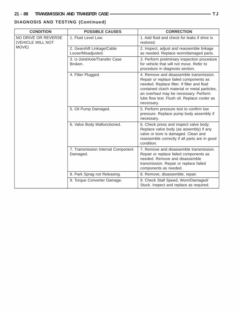
21 - 88 TRANSMISSION AND TRANSFER CASE TJ
DIAGNOSIS AND TESTING (Continued)
CONDITION POSSIBLE CAUSES CORRECTION
NO DRIVE OR REVERSE(VEHICLE WILL NOTMOVE)
1. Fluid Level Low. 1. Add fluid and check for leaks if drive isrestored.
2. Gearshift Linkage/CableLoose/Misadjusted.
2. Inspect, adjust and reassemble linkageas needed. Replace worn/damaged parts.
3. U-Joint/Axle/Transfer CaseBroken.
3. Perform preliminary inspection procedurefor vehicle that will not move. Refer toprocedure in diagnosis section.
4. Filter Plugged. 4. Remove and disassemble transmission.Repair or replace failed components asneeded. Replace filter. If filter and fluidcontained clutch material or metal particles,an overhaul may be necessary. Performlube flow test. Flush oil. Replace cooler asnecessary.
5. Oil Pump Damaged. 5. Perform pressure test to confirm lowpressure. Replace pump body assembly ifnecessary.
6. Valve Body Malfunctioned. 6. Check press and inspect valve body.Replace valve body (as assembly) if anyvalve or bore is damaged. Clean andreassemble correctly if all parts are in goodcondition.
7. Transmission Internal ComponentDamaged.
7. Remove and disassemble transmission.Repair or replace failed components asneeded. Remove and disassembletransmission. Repair or replace failedcomponents as needed.
8. Park Sprag not Releasing. 8. Remove, disassemble, repair.
9. Torque Converter Damage. 9. Check Stall Speed, Worn/Damaged/Stuck. Inspect and replace as required.
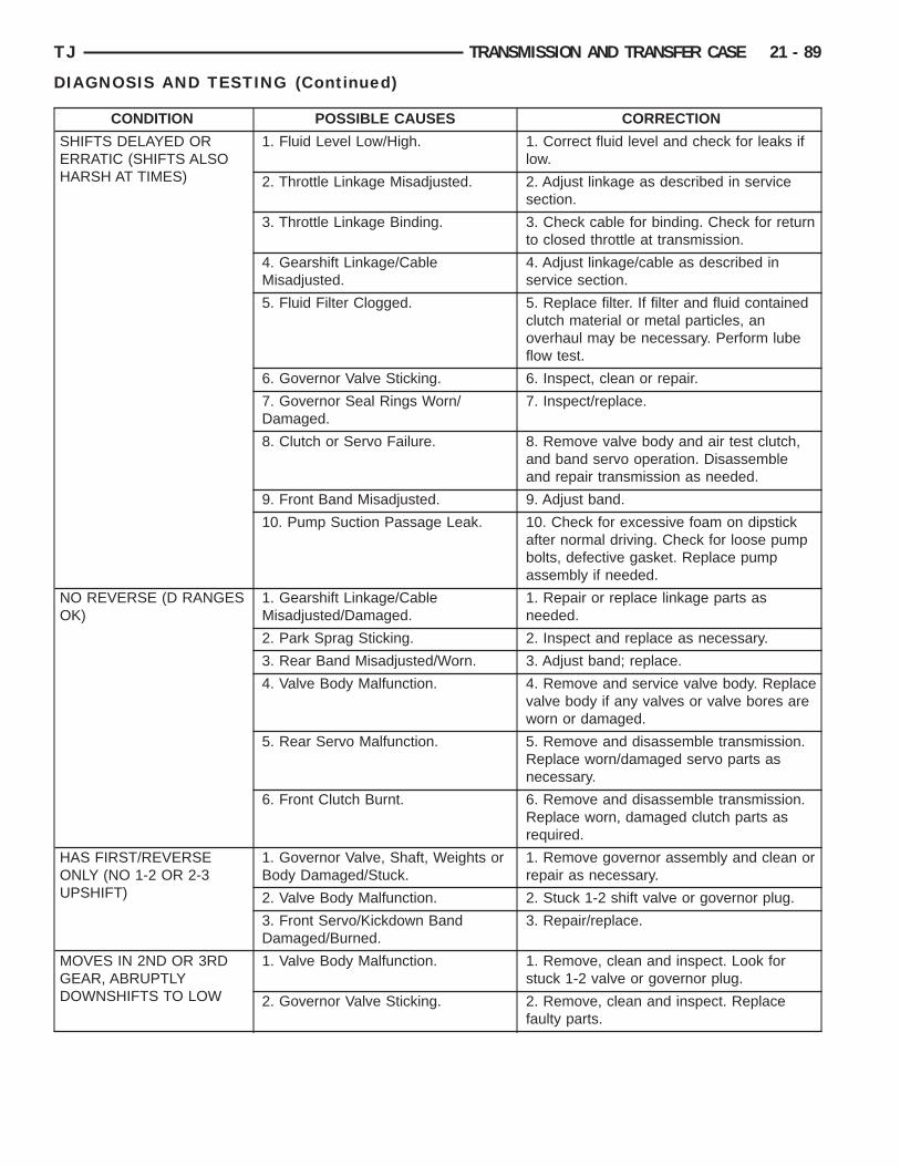
TJ TRANSMISSION AND TRANSFER CASE 21 - 89
DIAGNOSIS AND TESTING (Continued)
CONDITION POSSIBLE CAUSES CORRECTION
SHIFTS DELAYED ORERRATIC (SHIFTS ALSOHARSH AT TIMES)
1. Fluid Level Low/High. 1. Correct fluid level and check for leaks iflow.
2. Throttle Linkage Misadjusted. 2. Adjust linkage as described in servicesection.
3. Throttle Linkage Binding. 3. Check cable for binding. Check for returnto closed throttle at transmission.
4. Gearshift Linkage/CableMisadjusted.
4. Adjust linkage/cable as described inservice section.
5. Fluid Filter Clogged. 5. Replace filter. If filter and fluid containedclutch material or metal particles, anoverhaul may be necessary. Perform lubeflow test.
6. Governor Valve Sticking. 6. Inspect, clean or repair.
7. Governor Seal Rings Worn/Damaged.
7. Inspect/replace.
8. Clutch or Servo Failure. 8. Remove valve body and air test clutch,and band servo operation. Disassembleand repair transmission as needed.
9. Front Band Misadjusted. 9. Adjust band.
10. Pump Suction Passage Leak. 10. Check for excessive foam on dipstickafter normal driving. Check for loose pumpbolts, defective gasket. Replace pumpassembly if needed.
NO REVERSE (D RANGESOK)
1. Gearshift Linkage/CableMisadjusted/Damaged.
1. Repair or replace linkage parts asneeded.
2. Park Sprag Sticking. 2. Inspect and replace as necessary.
3. Rear Band Misadjusted/Worn. 3. Adjust band; replace.
4. Valve Body Malfunction. 4. Remove and service valve body. Replacevalve body if any valves or valve bores areworn or damaged.
5. Rear Servo Malfunction. 5. Remove and disassemble transmission.Replace worn/damaged servo parts asnecessary.
6. Front Clutch Burnt. 6. Remove and disassemble transmission.Replace worn, damaged clutch parts asrequired.
HAS FIRST/REVERSEONLY (NO 1-2 OR 2-3UPSHIFT)
1. Governor Valve, Shaft, Weights orBody Damaged/Stuck.
1. Remove governor assembly and clean orrepair as necessary.
2. Valve Body Malfunction. 2. Stuck 1-2 shift valve or governor plug.
3. Front Servo/Kickdown BandDamaged/Burned.
3. Repair/replace.
MOVES IN 2ND OR 3RDGEAR, ABRUPTLYDOWNSHIFTS TO LOW
1. Valve Body Malfunction. 1. Remove, clean and inspect. Look forstuck 1-2 valve or governor plug.
2. Governor Valve Sticking. 2. Remove, clean and inspect. Replacefaulty parts.

21 - 90 TRANSMISSION AND TRANSFER CASE TJ
DIAGNOSIS AND TESTING (Continued)
CONDITION POSSIBLE CAUSES CORRECTION
NO LOW GEAR (MOVESIN 2ND OR 3RD GEARONLY)
1. Governor Valve Sticking. 1. Remove governor, clean, inspect andrepair as required.
2. Valve Body Malfunction. 2. Remove, clean and inspect. Look forsticking 1-2 shift valve, 2-3 shift valve,governor plug or broken springs.
3. Front Servo Piston Cocked inBore.
3. Inspect servo and repair as required.
4. Front Band Linkage Malfunction. 4. Inspect linkage and look for bind inlinkage.
NO KICKDOWN ORNORMAL DOWNSHIFT
1. Throttle Linkage Misadjusted. 1. Adjust linkage.
2. Accelerator Pedal TravelRestricted.
2. Floor mat under pedal, accelerator cableworn or brackets bent.
3. Governor/Valve Body HydraulicPressures Too High or Too Low Dueto Sticking Governor, Valve BodyMalfunction or Incorrect HydraulicControl Pressure Adjustments.
3. Perform hydraulic pressure tests todetermine cause and repair as required.Correct valve body pressure adjustments asrequired.
4. Valve Body Malfunction. 4. Perform hydraulic pressure tests todetermine cause and repair as required.Correct valve body pressure adjustments asrequired.
5. Valve Body Malfunction. 5. Sticking 1-2, 2-3 shift valves, or governorplugs.
STUCK IN LOW GEAR(WILL NOT UPSHIFT)
1. Throttle Linkage Misadjusted/Stuck.
1. Adjust linkage and repair linkage if wornor damaged. Check for binding cable ormissing return spring.
2. Gearshift Linkage Misadjusted. 2. Adjust linkage and repair linkage if wornor damaged.
3. Governor/Valve Body, GovernorValve Stuck Closed; Loose OutputShaft Support or Governor HousingBolts, Leaking Seal Rings or ValveBody Problem (i.e., Stuck 1- 2 ShiftValve/Gov. Plug).
3. Check line and governor pressures todetermine cause. Correct as required.
4. Front Band Out of Adjustment. 4. Adjust Band.
5. Clutch or Servo Malfunction. 5. Air pressure check operation of clutchesand bands. Repair faulty component.
CREEPS IN NEUTRAL 1. Gearshift Linkage Misadjusted. 1. Adjust linkage.
2. Rear Clutch Dragging/WarpedWelded.
2. Disassemble and repair.
3. Valve Body Malfunction. 3. Perform hydraulic pressure test todetermine cause and repair as required.
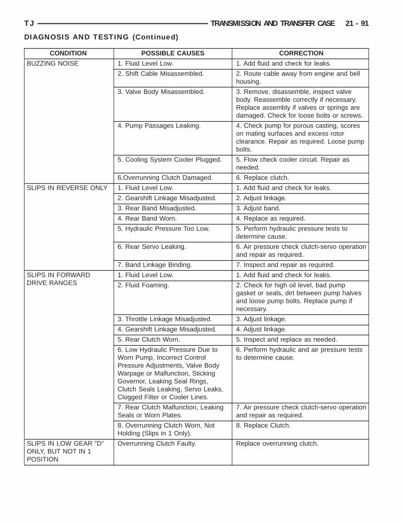
TJ TRANSMISSION AND TRANSFER CASE 21 - 91
DIAGNOSIS AND TESTING (Continued)
CONDITION POSSIBLE CAUSES CORRECTION
BUZZING NOISE 1. Fluid Level Low. 1. Add fluid and check for leaks.
2. Shift Cable Misassembled. 2. Route cable away from engine and bellhousing.
3. Valve Body Misassembled. 3. Remove, disassemble, inspect valvebody. Reassemble correctly if necessary.Replace assembly if valves or springs aredamaged. Check for loose bolts or screws.
4. Pump Passages Leaking. 4. Check pump for porous casting, scoreson mating surfaces and excess rotorclearance. Repair as required. Loose pumpbolts.
5. Cooling System Cooler Plugged. 5. Flow check cooler circuit. Repair asneeded.
6.Overrunning Clutch Damaged. 6. Replace clutch.
SLIPS IN REVERSE ONLY 1. Fluid Level Low. 1. Add fluid and check for leaks.
2. Gearshift Linkage Misadjusted. 2. Adjust linkage.
3. Rear Band Misadjusted. 3. Adjust band.
4. Rear Band Worn. 4. Replace as required.
5. Hydraulic Pressure Too Low. 5. Perform hydraulic pressure tests todetermine cause.
6. Rear Servo Leaking. 6. Air pressure check clutch-servo operationand repair as required.
7. Band Linkage Binding. 7. Inspect and repair as required.
SLIPS IN FORWARDDRIVE RANGES
1. Fluid Level Low. 1. Add fluid and check for leaks.
2. Fluid Foaming. 2. Check for high oil level, bad pumpgasket or seals, dirt between pump halvesand loose pump bolts. Replace pump ifnecessary.
3. Throttle Linkage Misadjusted. 3. Adjust linkage.
4. Gearshift Linkage Misadjusted. 4. Adjust linkage.
5. Rear Clutch Worn. 5. Inspect and replace as needed.
6. Low Hydraulic Pressure Due toWorn Pump, Incorrect ControlPressure Adjustments, Valve BodyWarpage or Malfunction, StickingGovernor, Leaking Seal Rings,Clutch Seals Leaking, Servo Leaks,Clogged Filter or Cooler Lines.
6. Perform hydraulic and air pressure teststo determine cause.
7. Rear Clutch Malfunction, LeakingSeals or Worn Plates.
7. Air pressure check clutch-servo operationand repair as required.
8. Overrunning Clutch Worn, NotHolding (Slips in 1 Only).
8. Replace Clutch.
SLIPS IN LOW GEAR 9D9ONLY, BUT NOT IN 1POSITION
Overrunning Clutch Faulty. Replace overrunning clutch.
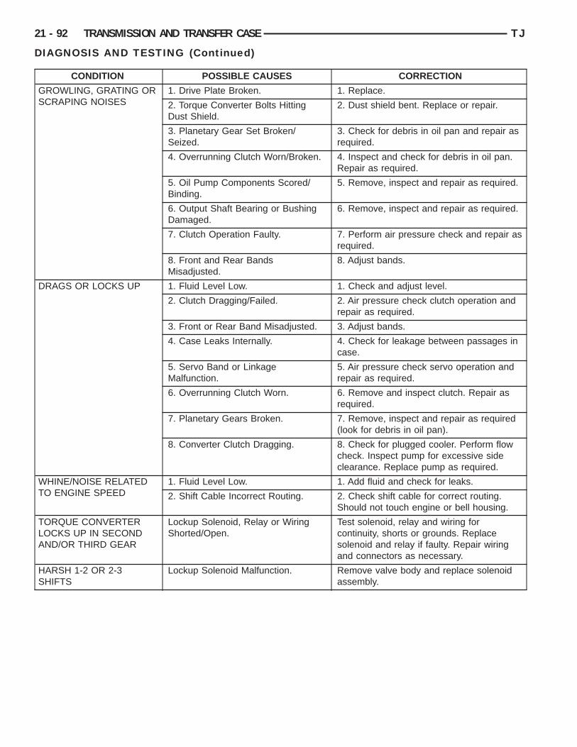
21 - 92 TRANSMISSION AND TRANSFER CASE TJ
DIAGNOSIS AND TESTING (Continued)
CONDITION POSSIBLE CAUSES CORRECTION
GROWLING, GRATING ORSCRAPING NOISES
1. Drive Plate Broken. 1. Replace.
2. Torque Converter Bolts HittingDust Shield.
2. Dust shield bent. Replace or repair.
3. Planetary Gear Set Broken/Seized.
3. Check for debris in oil pan and repair asrequired.
4. Overrunning Clutch Worn/Broken. 4. Inspect and check for debris in oil pan.Repair as required.
5. Oil Pump Components Scored/Binding.
5. Remove, inspect and repair as required.
6. Output Shaft Bearing or BushingDamaged.
6. Remove, inspect and repair as required.
7. Clutch Operation Faulty. 7. Perform air pressure check and repair asrequired.
8. Front and Rear BandsMisadjusted.
8. Adjust bands.
DRAGS OR LOCKS UP 1. Fluid Level Low. 1. Check and adjust level.
2. Clutch Dragging/Failed. 2. Air pressure check clutch operation andrepair as required.
3. Front or Rear Band Misadjusted. 3. Adjust bands.
4. Case Leaks Internally. 4. Check for leakage between passages incase.
5. Servo Band or LinkageMalfunction.
5. Air pressure check servo operation andrepair as required.
6. Overrunning Clutch Worn. 6. Remove and inspect clutch. Repair asrequired.
7. Planetary Gears Broken. 7. Remove, inspect and repair as required(look for debris in oil pan).
8. Converter Clutch Dragging. 8. Check for plugged cooler. Perform flowcheck. Inspect pump for excessive sideclearance. Replace pump as required.
WHINE/NOISE RELATEDTO ENGINE SPEED
1. Fluid Level Low. 1. Add fluid and check for leaks.
2. Shift Cable Incorrect Routing. 2. Check shift cable for correct routing.Should not touch engine or bell housing.
TORQUE CONVERTERLOCKS UP IN SECONDAND/OR THIRD GEAR
Lockup Solenoid, Relay or WiringShorted/Open.
Test solenoid, relay and wiring forcontinuity, shorts or grounds. Replacesolenoid and relay if faulty. Repair wiringand connectors as necessary.
HARSH 1-2 OR 2-3SHIFTS
Lockup Solenoid Malfunction. Remove valve body and replace solenoidassembly.

TJ TRANSMISSION AND TRANSFER CASE 21 - 93
DIAGNOSIS AND TESTING (Continued)
CONDITION POSSIBLE CAUSES CORRECTION
NO START IN PARK ORNEUTRAL
1. Gearshift Linkage/CableMisadjusted.
1. Adjust linkage/cable.
2. Neutral Switch Wire Open/Cut. 2. Check continuity with test lamp. Repairas required.
3. Neutral Switch Faulty. 3. Refer to service section for test andreplacement procedure.
4. Neutral Switch Connect Faulty. 4. Connectors spread open. Repair.
5. Valve Body Manual LeverAssembly Bent/Worn/Broken.
5. Inspect lever assembly and replace ifdamaged.
NO REVERSE (OR SLIPSIN REVERSE)
1. Direct Clutch Pack (front clutch)Worn.
1. Disassemble unit and rebuild clutchpack.
2. Rear Band Misadjusted. 2. Adjust band.
3. Front Clutch Malfunctioned/Burnt. 3. Air pressure test clutch operation.Remove and rebuild if necessary.
OIL LEAKS (ITEMSLISTED REPRESENTPOSSIBLE LEAK POINTSAND SHOULD ALL BECHECKED.
1. Speedometer Adapter Leaks. 1. Replace both adapter seals.
2. Fluid Lines and Fittings Loose/Leaks/Damaged.
2. Tighten fittings. If leaks persist, replacefittings and lines if necessary.
3. Filler Tube (where tube enterscase) Leaks/Damaged.
3. Replace O-ring seal. Inspect tube forcracks in tube.
4. Pressure Port Plug LooseLoose/Damaged.
4. Tighten to correct torque. Replace plugor reseal if leak persists.
5. Pan Gasket Leaks. 5. Tighten pan screws to 150 inch pounds.If leaks persist, replace gasket. Do no overtighten screws.
6. Valve Body Manual Lever ShaftSeal Leaks/Worn.
6. Replace shaft seal.
7. Rear Bearing Access Plate Leaks. 7. Replace gasket. Tighten screws.
8. Gasket Damaged or Bolts areLoose.
8. Replace bolts or gasket or tighten both.
9. Adapter/Extension GasketDamaged Leaks/Damaged.
9. Replace gasket.
10. Neutral Switch Leaks/Damaged. 10. Replace switch and gasket.
11. Converter Housing Area Leaks. 11. Check for leaks at seal caused by wornseal or burr on converter hub (cutting seal),worn bushing, missing oil return, oil in frontpump housing or hole plugged. Check forleaks past O-ring seal on pump or pastpump-to-case bolts; pump housing porous,oil coming out vent due to overfill or leakpast front band shaft access plug.
12. Pump Seal Leaks/Worn/Damaged.
12. Replace seal.
13. Torque Converter WeldLeak/Cracked Hub.
13. Replace converter.
14. Case Porosity Leaks. 14. Replace case.

S
F
utfctf
F
ivn
r
d
a
Cicwet
F
Lia
21 - 94 TRANSMISSION AND TRANSFER CASE TJ
ERVICE PROCEDURES
LUID LEVEL CHECKTransmission fluid level should be checked monthly
nder normal operation. If the vehicle is used forrailer towing or similar heavy load hauling, checkluid level and condition weekly. Fluid level ishecked with the engine running at curb idle speed,he transmission in NEUTRAL and the transmissionluid at normal operating temperature.
LUID LEVEL CHECK PROCEDURE(1) Transmission fluid must be at normal operat-
ng temperature for accurate fluid level check. Driveehicle if necessary to bring fluid temperature up toormal hot operating temperature of 82°C (180°F).(2) Position vehicle on level surface.(3) Start and run engine at curb idle speed.(4) Apply parking brakes.(5) Shift transmission momentarily into all gear
anges. Then shift transmission back to Neutral.(6) Clean top of filler tube and dipstick to keep
irt from entering tube.(7) Remove dipstick (Fig. 13) and check fluid level
s follows:(a) Correct acceptable level is in crosshatch area.(b) Correct maximum level is to MAX arrow
mark.(c) Incorrect level is at or below MIN line.(d) If fluid is low, add only enough Mopart ATF
Plus 3 to restore correct level. Do not overfill.
AUTION: Do not overfill the transmission. Overfill-ng may cause leakage out the pump vent whichan be mistaken for a pump seal leak. Overfillingill also cause fluid aeration and foaming as thexcess fluid is picked up and churned by the gear
rain. This will significantly reduce fluid life.
LUID AND FILTER REPLACEMENTRefer to the Maintenance Schedules in Group 0,
ubrication and Maintenance, for proper servicentervals. The service fluid fill after a filter change ispproximately 3.8 liters (4.0 quarts).
Fig. 13 Dipstick Fluid Level Marks—Typical
REMOVAL(1) Hoist and support vehicle on safety stands.(2) Place a large diameter shallow drain pan
beneath the transmission pan.(3) Remove bolts holding front and sides of pan to
transmission (Fig. 14).(4) Loosen bolts holding rear of pan to transmis-
sion.(5) Slowly separate front of pan away from trans-
mission allowing the fluid to drain into drain pan.(6) Hold up pan and remove remaining bolts hold-
ing pan to transmission.(7) While holding pan level, lower pan away from
transmission.(8) Pour remaining fluid in pan into drain pan.(9) Remove screws holding filter to valve body
(Fig. 15).(10) Separate filter from valve body and pour fluid
in filter into drain pan.(11) Dispose used trans fluid and filter properly.
Fig. 14 Transmission Pan
Fig. 15 Transmission Filter
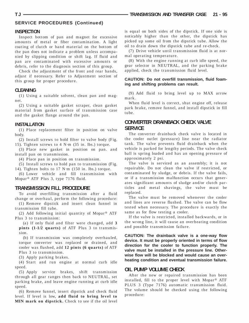
I
actnpd
at
C
n
ma
I
b
1
i
1
M
T
c
t
P
s
tps
lM
PTp
TJ TRANSMISSION AND TRANSFER CASE 21 - 95
SERVICE PROCEDURES (Continued)
NSPECTIONInspect bottom of pan and magnet for excessive
mounts of metal or fiber contamination. A lightoating of clutch or band material on the bottom ofhe pan does not indicate a problem unless accompa-ied by slipping condition or shift lag. If fluid andan are contaminated with excessive amounts orebris, refer to the diagnosis section of this group.Check the adjustment of the front and rear bands,
djust if necessary. Refer to Adjustment section ofhis group for proper procedure.
LEANING(1) Using a suitable solvent, clean pan and mag-
et.(2) Using a suitable gasket scraper, clean gasketaterial from gasket surface of transmission case
nd the gasket flange around the pan.
NSTALLATION(1) Place replacement filter in position on valve
ody.(2) Install screws to hold filter to valve body (Fig.
5). Tighten screws to 4 N·m (35 in. lbs.) torque.(3) Place new gasket in position on pan. and
nstall pan on transmission.(4) Place pan in position on transmission.(5) Install screws to hold pan to transmission (Fig.
4). Tighten bolts to 17 N·m (150 in. lbs.) torque.(6) Lower vehicle and fill transmission withopart ATF Plus 3, type 7176 fluid.
RANSMISSION FILL PROCEDURETo avoid overfilling transmission after a fluid
hange or overhaul, perform the following procedure:(1) Remove dipstick and insert clean funnel in
ransmission fill tube.(2) Add following initial quantity of Mopart ATF
lus 3 to transmission:(a) If only fluid and filter were changed, add 3
pints (1-1/2 quarts) of ATF Plus 3 to transmis-sion.
(b) If transmission was completely overhauled,torque converter was replaced or drained, andcooler was flushed, add 12 pints (6 quarts) of ATFPlus 3 to transmission.(3) Apply parking brakes.(4) Start and run engine at normal curb idle
peed.(5) Apply service brakes, shift transmission
hrough all gear ranges then back to NEUTRAL, setarking brake, and leave engine running at curb idlepeed.(6) Remove funnel, insert dipstick and check fluid
evel. If level is low, add fluid to bring level toIN mark on dipstick. Check to see if the oil level
is equal on both sides of the dipstick. If one side isnoticably higher than the other, the dipstick haspicked up some oil from the dipstick tube. Allow theoil to drain down the dipstick tube and re-check.
(7) Drive vehicle until transmission fluid is at nor-mal operating temperature.
(8) With the engine running at curb idle speed, thegear selector in NEUTRAL, and the parking brakeapplied, check the transmission fluid level.
CAUTION: Do not overfill transmission, fluid foam-ing and shifting problems can result.
(9) Add fluid to bring level up to MAX arrowmark.
When fluid level is correct, shut engine off, releasepark brake, remove funnel, and install dipstick in filltube.
CONVERTER DRAINBACK CHECK VALVESERVICE
The converter drainback check valve is located inthe cooler outlet (pressure) line near the radiatortank. The valve prevents fluid drainback when thevehicle is parked for lengthy periods. The valve checkball is spring loaded and has an opening pressure ofapproximately 2 psi.
The valve is serviced as an assembly; it is notrepairable. Do not clean the valve if restricted, orcontaminated by sludge, or debris. If the valve fails,or if a transmission malfunction occurs that gener-ates significant amounts of sludge and/or clutch par-ticles and metal shavings, the valve must bereplaced.
The valve must be removed whenever the coolerand lines are reverse flushed. The valve can be flowtested when necessary. The procedure is exactly thesame as for flow testing a cooler.
If the valve is restricted, installed backwards, or inthe wrong line, it will cause an overheating conditionand possible transmission failure.
CAUTION: The drainback valve is a one-way flowdevice. It must be properly oriented in terms of flowdirection for the cooler to function properly. Thevalve must be installed in the pressure line. Other-wise flow will be blocked and would cause an over-heating condition and eventual transmission failure.
OIL PUMP VOLUME CHECKAfter the new or repaired transmission has been
installed, fill to the proper level with Mopart ATFLUS 3 (Type 7176) automatic transmission fluid.he volume should be checked using the followingrocedure:

md
Cfn
s
td
p
rpa
cl
F
fcmfm
e
WMZB
AABEF
TI1CS
C
FFe
21 - 96 TRANSMISSION AND TRANSFER CASE TJ
SERVICE PROCEDURES (Continued)
(1) Disconnect the From cooler line at the trans-ission and place a collecting container under the
isconnected line.
AUTION: With the fluid set at the proper level,luid collection should not exceed (1) quart or inter-al damage to the transmission may occur.
(2) Run the engine at curb idle speed , with thehift selector in neutral.(3) If fluid flow is intermittent or it takes more
han 20 seconds to collect one quart of ATF PLUS 3,isconnect the To Cooler line at the transaxle.(4) Refill the transaxle to proper level and recheck
ump volume.(5) If flow is found to be within acceptable limits,
eplace the cooler. Then fill transmission to theroper level, using Mopart ATF PLUS 3 (Type 7176)utomatic transmission fluid.(6) If fluid flow is still found to be inadequate,
heck the line pressure using the Transaxle Hydrau-ic Pressure Test procedure.
LUSHING COOLERS AND TUBESWhen a transmission failure has contaminated the
luid, the oil cooler(s) must be flushed. The torqueonverter must also be replaced. This will insure thatetal particles or sludged oil are not later trans-
erred back into the reconditioned (or replaced) trans-ission.The only recommended procedure for flushing cool-
rs and lines is to use Tool 6906 Cooler Flusher.
ARNING: WEAR PROTECTIVE EYEWEAR THATEETS THE REQUIREMENTS OF OSHA AND ANSI87.1–1968. WEAR STANDARD INDUSTRIAL RUB-ER GLOVES.KEEP LIGHTED CIGARETTES, SPARKS, FLAMES,
ND OTHER IGNITION SOURCES AWAY FROM THEREA TO PREVENT THE IGNITION OF COMBUSTI-LE LIQUIDS AND GASES. KEEP A CLASS (B) FIREXTINGUISHER IN THE AREA WHERE THELUSHER WILL BE USED.KEEP THE AREA WELL VENTILATED.DO NOT LET FLUSHING SOLVENT COME IN CON-
ACT WITH YOUR EYES OR SKIN: IF EYE CONTAM-NATION OCCURS, FLUSH EYES WITH WATER FOR5 TO 20 SECONDS. REMOVE CONTAMINATEDLOTHING AND WASH AFFECTED SKIN WITHOAP AND WATER. SEEK MEDICAL ATTENTION.
OOLER FLUSH USING TOOL 6906(1) Remove cover plate filler plug on Tool 6906.
ill reservoir 1/2 to 3/4 full of fresh flushing solution.lushing solvents are petroleum based solutions gen-rally used to clean automatic transmission compo-
nents. DO NOT use solvents containing acids, water,gasoline, or any other corrosive liquids.
(2) Reinstall filler plug on Tool 6906.(3) Verify pump power switch is turned OFF. Con-
nect red alligator clip to positive (+) battery post.Connect black (-) alligator clip to a good ground.
(4) Disconnect the cooler lines at the transmission.
NOTE: When flushing transmission cooler andlines, ALWAYS reverse flush.
NOTE: The converter drainback valve must beremoved and an appropriate replacement hoseinstalled to bridge the space between the transmis-sion cooler line and the cooler fitting. Failure toremove the drainback valve will preventreverseflushing the system.
(5) Connect the BLUE pressure line to the OUT-LET (From) cooler line.
(6) Connect the CLEAR return line to the INLET(To) cooler line
(7) Turn pump ON for two to three minutes toflush cooler(s) and lines. Monitor pressure readingsand clear return lines. Pressure readings should sta-bilize below 20 psi. for vehicles equipped with a sin-gle cooler and 30 psi. for vehicles equipped with dualcoolers. If flow is intermittent or exceeds these pres-sures, replace cooler.
(8) Turn pump OFF.(9) Disconnect CLEAR suction line from reservoir
at cover plate. Disconnect CLEAR return line atcover plate, and place it in a drain pan.
(10) Turn pump ON for 30 seconds to purge flush-ing solution from cooler and lines. Turn pump OFF.
(11) Place CLEAR suction line into a one quartcontainer of Mopart ATF Plus 3, type 7176 automatictransmission fluid.
(12) Turn pump ON until all transmission fluid isremoved from the one quart container and lines. Thispurges any residual cleaning solvent from the trans-mission cooler and lines. Turn pump OFF.
(13) Disconnect alligator clips from battery. Recon-nect flusher lines to cover plate, and remove flushingadapters from cooler lines.
ALUMINUM THREAD REPAIRDamaged or worn threads in the aluminum trans-
mission case and valve body can be repaired by theuse of Heli-Coils, or equivalent. This repair consistsof drilling out the worn-out damaged threads. Thentap the hole with a special Heli-Coil tap, or equiva-lent, and installing a Heli-Coil insert, or equivalent,into the hole. This brings the hole back to its originalthread size.

re
R
T
Cmnbvr
R
e
s
CdtTi
rp
o
TJ TRANSMISSION AND TRANSFER CASE 21 - 97
SERVICE PROCEDURES (Continued)
Heli-Coil, or equivalent, tools and inserts areeadily available from most automotive parts suppli-rs.
EMOVAL AND INSTALLATION
RANSMISSION
AUTION: The transmission and torque converterust be removed as an assembly to avoid compo-ent damage. The converter drive plate, pumpushing, or oil seal can be damaged if the con-erter is left attached to the driveplate duringemoval.
EMOVAL(1) Disconnect battery negative cable.(2) Disconnect and lower or remove necessary
xhaust components.(3) Remove engine-to-transmission bending braces.(4) Disconnect fluid cooler lines at transmission.(5) Remove starter motor.(6) Disconnect and remove crankshaft position sen-
or. Retain sensor attaching bolts.
AUTION: The crankshaft position sensor can beamaged during transmission removal (or installa-
ion) if the sensor is still bolted to the engine block.o avoid damage, remove the sensor before remov-
ng the transmission.
(7) Remove torque converter access cover.(8) If transmission is being removed for overhaul,
emove transmission oil pan, drain fluid and reinstallan.(9) Remove skid plate for access, if necessary.(10) Remove fill tube bracket bolts and pull tube
ut of transmission. Retain fill tube seal. On 4 x 4
Fig. 16 Crankshaft Position Sensor—2.5L Engine
models, it will also be necessary to remove boltattaching transfer case vent tube to converter hous-ing.
(11) Mark torque converter and drive plate forassembly alignment. Note that bolt holes in crank-shaft flange, drive plate and torque converter allhave one offset hole.
(12) Rotate crankshaft in clockwise direction untilconverter bolts are accessible. Then remove bolts oneat a time. Rotate crankshaft with socket wrench ondampener bolt.
(13) Mark propeller shaft and axle yokes forassembly alignment. Then disconnect and removepropeller shaft. On 4 x 4 models, remove both propel-ler shafts.
(14) Disconnect wires from park/neutral positionswitch and vehicle speed sensor.
(15) Disconnect gearshift cable from transmissionmanual valve lever.
(16) Disconnect throttle valve cable from transmis-sion bracket and throttle valve lever.
(17) On 4 x 4 models, disconnect shift rod fromtransfer case shift lever or remove shift lever fromtransfer case.
(18) Support rear of engine with safety stand orjack.
(19) Raise transmission slightly with service jackto relieve load on crossmember and supports.
(20) Remove bolts securing rear support and cush-ion to transmission and crossmember. Raise trans-mission slightly, slide exhaust hanger arm frombracket and remove rear support.
Fig. 17 Crankshaft Position Sensor—4.0L Engine

a
c
v
m
f
t
I
nPas
s
s
rp
ssv
21 - 98 TRANSMISSION AND TRANSFER CASE TJ
REMOVAL AND INSTALLATION (Continued)
(21) Remove bolts attaching crossmember to framend remove crossmember.(22) Disconnect transfer case vent hose. Then dis-
onnect vacuum switch harness.(23) On 4 x 4 models, remove transfer case.(24) Remove all converter housing bolts.(25) Carefully work transmission and torque con-
erter assembly rearward off engine block dowels.(26) Hold torque converter in place during trans-ission removal.(27) Lower transmission and remove assembly
rom under the vehicle.(28) To remove torque converter, carefully slide
orque converter out of the transmission.
NSTALLATION(1) Check torque converter hub and hub drive
otches for sharp edges burrs, scratches, or nicks.olish the hub and notches with 320/400 grit papernd crocus cloth if necessary. The hub must bemooth to avoid damaging pump seal at installation.(2) Lubricate converter drive hub and oil pump
eal lip with transmission fluid.(3) Lubricate converter pilot hub with transmis-
ion fluid.(4) Align converter and oil pump.(5) Carefully insert converter in oil pump. Then
otate converter back and forth until fully seated inump gears.(6) Check converter seating with steel scale and
traightedge (Fig. 18). Surface of converter lugshould be 1/2 in. to rear of straightedge when con-erter is fully seated.(7) Temporarily secure converter with C-clamp.
Fig. 18 Typical Method Of Checking ConverterSeating
(8) Position transmission on jack and secure itwith safety chains.
(9) Check condition of converter driveplate.Replace the plate if cracked, distorted or damaged.Also be sure transmission dowel pins are seatedin engine block and protrude far enough tohold transmission in alignment.
(10) Raise transmission and align converter withdrive plate and converter housing with engine block.
(11) Move transmission forward. Then raise, loweror tilt transmission to align converter housing withengine block dowels.
(12) Rotate converter so alignment marks scribedon converter are aligned with mark on driveplate.
(13) Carefully work transmission forward and overengine block dowels until converter hub is seated incrankshaft.
(14) Install and tighten bolts that attach transmis-sion converter housing to engine block (Fig. 19).
CAUTION: Be sure the converter housing is fullyseated on the engine block dowels before tighten-ing any bolts.
(15) Install torque converter attaching bolts.Tighten bolts to following torque.
• 54 N·m (40 ft. lbs.) with 9.5 in. 3-lug converter• 74 N·m (55 ft. lbs.) with 9.5 in. 4-lug converter• 74 N·m (55 ft. lbs.) with 10.0 in. 4-lug converter• 31 N·m (270 in. lbs.) with 10.75 in. 4-lug con-
verter(16) Install crankshaft position sensor.(17) Install transmission fill tube and seal. Install
new fill tube seal in transmission before installation.(18) Connect transmission cooler lines to transmis-
sion.(19) Install transfer case onto transmission.(20) Install rear crossmember and attach trans-
mission rear support to crossmember.(21) Remove engine support fixture.(22) Remove transmission jack.(23) Connect vehicle speed sensor wires.(24) Connect wires to park/neutral position switch.(25) Install crankshaft position sensor.(26) Install converter housing access cover.(27) Install exhaust pipes and support brackets, if
removed.(28) Install starter motor and cooler line bracket.(29) Install new plastic retainer grommet on any
shift linkage rod or lever that was disconnected.Grommets should not be reused. Use pry tool toremove rod from grommet and cut away old grom-met. Use pliers to snap new grommet into lever andto snap rod into grommet at assembly.
(30) Connect gearshift and linkage and throttlecable.
(31) Connect transfer case shift linkage.

c
r
h
l
T
R
f
h
Clov
wt
TJ TRANSMISSION AND TRANSFER CASE 21 - 99
REMOVAL AND INSTALLATION (Continued)
(32) Adjust gearshift linkage and throttle valveable if necessary.(33) Align and connect propeller shaft(s).(34) Install skid plate, rear cushion and bracket, if
emoved.(35) Fill transfer case to bottom edge of fill plug
ole.(36) Lower vehicle and fill transmission to correct
evel with Mopart ATF Plus 3, type 7176 fluid.
ORQUE CONVERTER
EMOVAL(1) Remove transmission and torque converter
rom vehicle.(2) Place a suitable drain pan under the converter
ousing end of the transmission.
AUTION: Verify that transmission is secure on theifting device or work surface, the center of gravityf the transmission will shift when the torque con-erter is removed creating an unstable condition.The torque converter is a heavy unit. Use caution
hen separating the torque converter from theransmission.
Fig. 19 Transmi
(3) Pull the torque converter forward until the cen-ter hub clears the oil pump seal.
(4) Separate the torque converter from the trans-mission.
INSTALLATIONCheck converter hub and drive notches for sharp
edges, burrs, scratches, or nicks. Polish the hub andnotches with 320/400 grit paper or crocus cloth if nec-essary. The hub must be smooth to avoid damagingthe pump seal at installation.
(1) Lubricate converter hub and oil pump seal lipwith transmission fluid.
(2) Place torque converter in position on transmis-sion.
CAUTION: Do not damage oil pump seal or bushingwhile inserting torque converter into the front of thetransmission.
(3) Align torque converter to oil pump seal open-ing.
(4) Insert torque converter hub into oil pump.(5) While pushing torque converter inward, rotate
converter until converter is fully seated in the oilpump gears.
n Attachment
ssio
ssv
C
f
E
R
d
G
f
t
p
I
eo
Ti
r
21 - 100 TRANSMISSION AND TRANSFER CASE TJ
REMOVAL AND INSTALLATION (Continued)
(6) Check converter seating with a scale andtraightedge (Fig. 20). Surface of converter lugshould be 1/2 in. to rear of straightedge when con-erter is fully seated.(7) If necessary, temporarily secure converter with-clamp attached to the converter housing.(8) Install the transmission in the vehicle.(9) Fill the transmission with the recommended
luid.
XTENSION HOUSING
EMOVAL(1) Hoist and support vehicle on safety stands.(2) Support transmission with a suitable lifting
evice.(3) Remove transmission skid plate. Refer toroup 13, Frame and Bumpers, for proper procedure.(4) Remove propeller shafts. Refer to Group 3, Dif-
erential and Driveline, for proper procedure.(5) Remove transfer case.(6) Remove bolts holding extension housing to
ransmission case (Fig. 21).(7) Separate extension housing from transmission.(8) Slide extension housing rearward and off out-
ut shaft (Fig. 21).
NSTALLATIONClear gasket material from sealing surfaces on
xtension housing and rear of transmission. Replaceutput shaft bearing, if necessary.(1) Install new rear seal in extension housing. Use
ool Handle C-4171 and Seal Installer C-3860-A tonstall seal.
(2) Place extension housing gasket in position onear of transmission.
Fig. 20 Checking Torque Converter Seating
(3) Slide extension housing forward and over out-put shaft (Fig. 21).
(4) Guide park shaft into park sprag and pushextension housing forward until rod passes throughopening behind sprag. It may be necessary to use awire to hold sprag to the side for rod to pass through.
(5) Install bolts to hold extension housing to rearof transmission.
(6) Install transfer case.(7) Install propeller shafts.(8) Install rear transmission mount and skid plate.(9) Lower vehicle and verify transmission fluid
level. Add fluid as necessary.
SPEEDOMETER ADAPTERRear axle gear ratio and tire size determine speed-
ometer pinion requirements.
REMOVAL(1) Raise vehicle.(2) Disconnect wires from vehicle speed sensor.(3) Remove adapter clamp and screw (Fig. 22).(4) Remove speed sensor and speedometer adapter
as assembly.(5) Remove speed sensor retaining screw and
remove sensor from adapter.(6) Remove speedometer pinion from adapter.(7) Inspect sensor and adapter O-rings (Fig. 22).
Remove and discard O-rings if worn or damaged.(8) Inspect terminal pins in speed sensor. Clean
pins with Mopart electrical spray cleaner if dirty oroxidized. Replace sensor if faulty, or pins are loose,severely corroded, or damaged.
INSTALLATION(1) Thoroughly clean adapter flange and adapter
mounting surface in housing. Surfaces must be cleanfor proper adapter alignment and speedometer oper-ation.
Fig. 21 Extension Housing
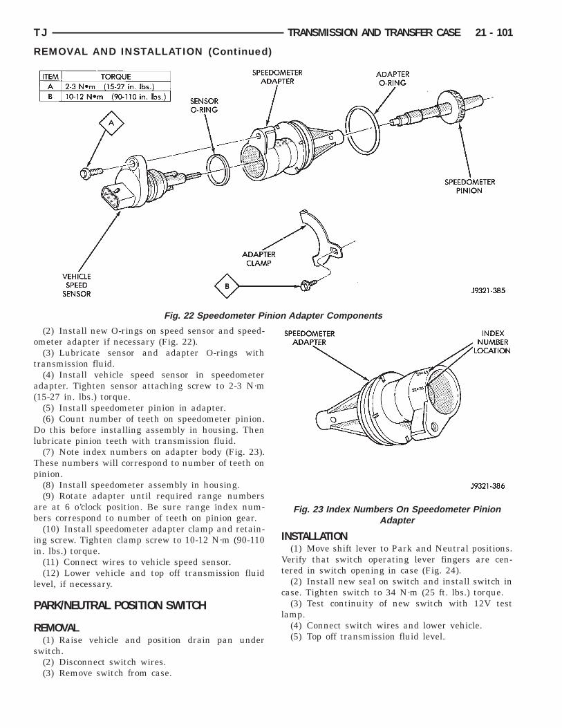
o
t
a(
Dl
Tp
ab
ii
l
P
R
s
TJ TRANSMISSION AND TRANSFER CASE 21 - 101
REMOVAL AND INSTALLATION (Continued)
(2) Install new O-rings on speed sensor and speed-meter adapter if necessary (Fig. 22).(3) Lubricate sensor and adapter O-rings with
ransmission fluid.(4) Install vehicle speed sensor in speedometer
dapter. Tighten sensor attaching screw to 2-3 N·m15-27 in. lbs.) torque.
(5) Install speedometer pinion in adapter.(6) Count number of teeth on speedometer pinion.o this before installing assembly in housing. Then
ubricate pinion teeth with transmission fluid.(7) Note index numbers on adapter body (Fig. 23).
hese numbers will correspond to number of teeth oninion.(8) Install speedometer assembly in housing.(9) Rotate adapter until required range numbers
re at 6 o’clock position. Be sure range index num-ers correspond to number of teeth on pinion gear.(10) Install speedometer adapter clamp and retain-
ng screw. Tighten clamp screw to 10-12 N·m (90-110n. lbs.) torque.
(11) Connect wires to vehicle speed sensor.(12) Lower vehicle and top off transmission fluid
evel, if necessary.
ARK/NEUTRAL POSITION SWITCH
EMOVAL(1) Raise vehicle and position drain pan under
witch.(2) Disconnect switch wires.(3) Remove switch from case.
Fig. 22 Speedometer Pin
INSTALLATION(1) Move shift lever to Park and Neutral positions.
Verify that switch operating lever fingers are cen-tered in switch opening in case (Fig. 24).
(2) Install new seal on switch and install switch incase. Tighten switch to 34 N·m (25 ft. lbs.) torque.
(3) Test continuity of new switch with 12V testlamp.
(4) Connect switch wires and lower vehicle.(5) Top off transmission fluid level.
Adapter Components
Fig. 23 Index Numbers On Speedometer PinionAdapter
ion
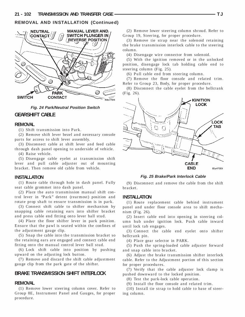
G
R
p
t
lb
I
s
tr
sa
Et
tf
u
g
B
R
Gp
21 - 102 TRANSMISSION AND TRANSFER CASE TJ
REMOVAL AND INSTALLATION (Continued)
EARSHIFT CABLE
EMOVAL(1) Shift transmission into Park.(2) Remove shift lever bezel and necessary console
arts for access to shift lever assembly.(3) Disconnect cable at shift lever and feed cable
hrough dash panel opening to underside of vehicle.(4) Raise vehicle.(5) Disengage cable eyelet at transmission shift
ever and pull cable adjuster out of mountingracket. Then remove old cable from vehicle.
NSTALLATION(1) Route cable through hole in dash panel. Fully
eat cable grommet into dash panel.(2) Place the auto transmission manual shift con-
rol lever in “Park” detent (rearmost) position andotate prop shaft to ensure transmission is in park.(3) Connect shift cable to shifter mechanism by
napping cable retaining ears into shifter bracketnd press cable end fitting onto lever ball stud.(4) Place the floor shifter lever in park position.nsure that the pawl is seated within the confines of
he adjustment gauge clip.(5) Snap the cable into the transmission bracket so
he retaining ears are engaged and connect cable enditting onto the manual control lever ball stud.
(6) Lock shift cable into position by pushingpward on the adjusting lock button.(7) Remove and discard the shift cable adjustment
auge clip from the park gate of the shifter.
RAKE TRANSMISSION SHIFT INTERLOCK
EMOVAL(1) Remove lower steering column cover. Refer toroup 8E, Instrument Panel and Gauges, for properrocedure.
Fig. 24 Park/Neutral Position Switch
(2) Remove lower steering column shroud. Refer toGroup 19, Steering, for proper procedure.
(3) Remove tie strap near the solenoid retainingthe brake transmission interlock cable to the steeringcolumn.
(4) Disengage wire connector from solenoid.(5) With the ignition removed or in the unlocked
position, disengage lock tab holding cable end tosteering column (Fig. 25).
(6) Pull cable end from steering column.(7) Remove the floor console and related trim.
Refer to Group 23, Body, for proper procedure.(8) Disconnect the cable eyelet from the bellcrank
(Fig. 26).
(9) Disconnect and remove the cable from the shiftbracket.
INSTALLATION(1) Route replacement cable behind instrument
panel and under floor console area to shift mecha-nism (Fig. 26).
(2) Insert cable end into opening in steering col-umn hub under ignition lock. Push cable inwarduntil lock tab engages.
(3) Connect the cable end eyelet onto shifterbellcrank pin.
(4) Place gear selector in PARK.(5) Push the spring-loaded cable adjuster forward
and snap cable into bracket.(6) Adjust the brake transmission shifter interlock
cable. Refer to the Adjustment portion of this sectionfor proper procedures.
(7) Verify that the cable adjuster lock clamp ispushed downward to the locked position.
(8) Test the park-lock cable operation.(9) Install the floor console and related trim.(10) Install tie strap to hold cable to base of steer-
ing column.
Fig. 25 Brake/Park Interlock Cable
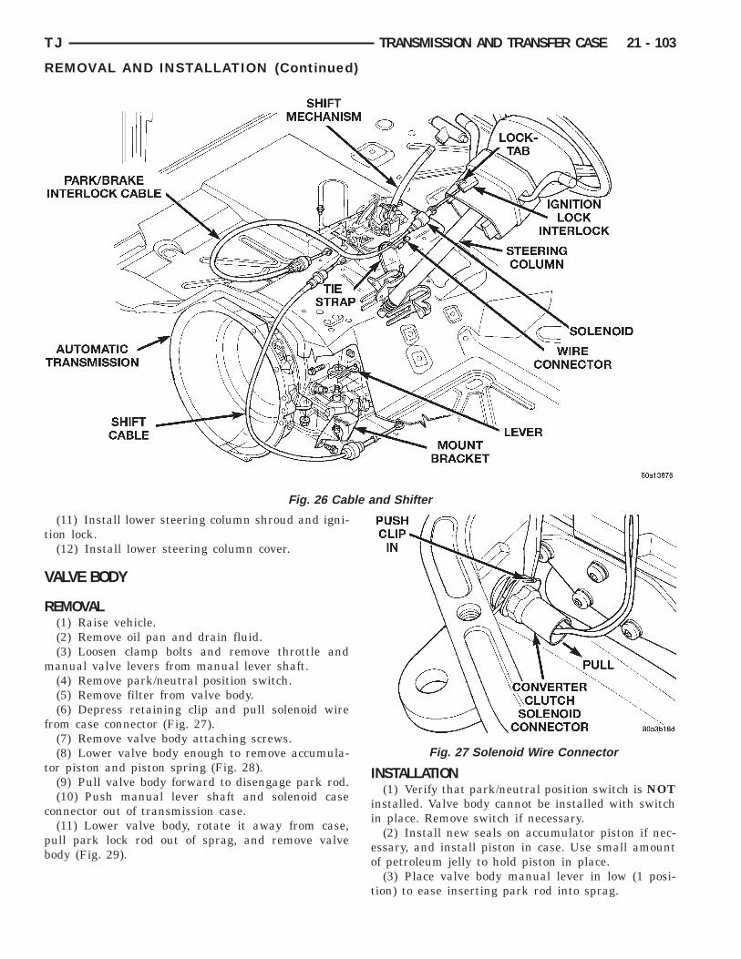
t
V
R
m
f
t
c
pb
le a
TJ TRANSMISSION AND TRANSFER CASE 21 - 103
REMOVAL AND INSTALLATION (Continued)
(11) Install lower steering column shroud and igni-ion lock.
(12) Install lower steering column cover.
ALVE BODY
EMOVAL(1) Raise vehicle.(2) Remove oil pan and drain fluid.(3) Loosen clamp bolts and remove throttle andanual valve levers from manual lever shaft.(4) Remove park/neutral position switch.(5) Remove filter from valve body.(6) Depress retaining clip and pull solenoid wire
rom case connector (Fig. 27).(7) Remove valve body attaching screws.(8) Lower valve body enough to remove accumula-
or piston and piston spring (Fig. 28).(9) Pull valve body forward to disengage park rod.(10) Push manual lever shaft and solenoid case
onnector out of transmission case.(11) Lower valve body, rotate it away from case,
ull park lock rod out of sprag, and remove valveody (Fig. 29).
Fig. 26 Cab
INSTALLATION(1) Verify that park/neutral position switch is NOT
installed. Valve body cannot be installed with switchin place. Remove switch if necessary.
(2) Install new seals on accumulator piston if nec-essary, and install piston in case. Use small amountof petroleum jelly to hold piston in place.
(3) Place valve body manual lever in low (1 posi-tion) to ease inserting park rod into sprag.
nd Shifter
Fig. 27 Solenoid Wire Connector
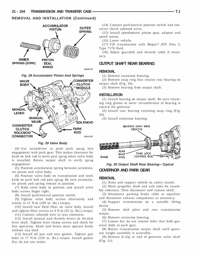
ekie
t
kt
b
e
a
lfw
bd
21 - 104 TRANSMISSION AND TRANSFER CASE TJ
REMOVAL AND INSTALLATION (Continued)
(4) Use screwdriver to push park sprag intongagement with park gear. This makes clearance fornob on lock rod to move past sprag when valve bodys installed. Rotate output shaft to verify spragngagement.(5) Position accumulator spring between accumula-
or piston and valve body.(6) Position valve body on transmission and work
nob on park lock rod past sprag. Be sure accumula-or piston and spring remain in position.
(7) Hold valve body in position and install valveody screws finger tight.(8) Install park/neutral position switch.(9) Tighten valve body screws alternately and
venly to 11 N·m (100 in. lbs.) torque.(10) Install new fluid filter on valve body. Install
nd tighten filter screws to 4 N·m (35 in. lbs.) torque.(11) Connect solenoid wire to case connector.(12) Install manual and throttle levers on throttle
ever shaft. Tighten lever clamp screws and check forree operation. Shaft and levers must operate freelyithout any bind.(13) Install oil pan and new gasket. Tighten pan
olts to 17 N·m (150 in. lbs.) torque. Install gasketry; do not use sealer.
Fig. 28 Accumulator Piston And Springs
Fig. 29 Valve Body
(14) Connect park/neutral position switch and con-verter clutch solenoid wires.
(15) Install speedometer pinion gear, adapter andspeed sensor.
(16) Lower vehicle.(17) Fill transmission with Mopart ATF Plus 3,
Type 7176 fluid.(18) Adjust gearshift and throttle cable if neces-
sary.
OUTPUT SHAFT REAR BEARING
REMOVAL(1) Remove extension housing.(2) Remove snap ring that retains rear bearing on
output shaft (Fig. 30).(3) Remove bearing from output shaft.
INSTALLATION(1) Install bearing on output shaft. Be sure retain-
ing ring groove in outer circumference of bearing istoward the governor.
(2) Install rear bearing retaining snap ring (Fig.30).
(3) Install extension housing.
GOVERNOR AND PARK GEAR
REMOVAL(1) Hoist and support vehicle on safety stands.(2) Mark propeller shaft and axle yoke for assem-
bly reference. Then disconnect and remove shaft.(3) Disconnect parking brake cable at equalizer
and disconnect exhaust components as necessary.(4) Support transmission on a suitable lifting
device.(5) Remove skid plate and rear transmission
mount.(6) Remove extension housing.(7) Loosen but do not remove bolts that hold gov-
ernor body to park gear.(8) Rotate transmission output shaft until gover-
nor weight assembly is accessible.(9) Remove E-clip at end of governor valve shaft
(Fig. 31).
Fig. 30 Output Shaft Rear Bearing—Typical
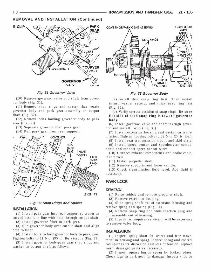
n
gs
g
I
c
p
T
w
TJ TRANSMISSION AND TRANSFER CASE 21 - 105
REMOVAL AND INSTALLATION (Continued)
(10) Remove governor valve and shaft from gover-or body (Fig. 31).(11) Remove snap rings and spacer that retain
overnor body and park gear assembly on outputhaft (Fig. 32).(12) Remove bolts holding governor body to park
ear (Fig. 33).(13) Separate governor from park gear.(14) Pull park gear from rear support.
NSTALLATION(1) Install park gear into rear support so crown on
urved boss is in line with hole through output shaft.(2) Install governor filter in park gear.(3) Slip governor body over output shaft and align
ort to filter.(4) Install bolts to hold governor body to park gear.
ighten bolts to 11 N·m (95 in. lbs.) torque (Fig. 33).(5) Install governor body-park gear snap rings andasher on output shaft as follows:
Fig. 31 Governor Valve
Fig. 32 Snap Rings And Spacer
(a) Install thin snap ring first. Then installthrust washer second, and thick snap ring last(Fig. 32).
(b) Verify correct position of snap rings. Be sureflat side of each snap ring is toward governorbody.(6) Insert governor valve and shaft through gover-
nor and install E-clip (Fig. 31).(7) Install extension housing and gasket on trans-
mission. Tighten housing bolts to 32 N·m (24 ft. lbs.).(8) Install rear transmission mount and skid plate.(9) Install speed sensor and speedometer compo-
nents and connect speed sensor wires.(10) Connect exhaust components and brake cable,
if removed.(11) Install propeller shaft.(12) Remove supports and lower vehicle.(13) Check transmission fluid level. Add fluid if
necessary.
PARK LOCK
REMOVAL(1) Raise vehicle and remove propeller shaft.(2) Remove extension housing.(3) Slide sprag shaft out of extension housing and
remove sprag and spring (Fig. 34).(4) Remove snap ring and slide reaction plug and
pin assembly out of housing.(5) If park rod requires service, it will be necessary
to remove valve body.
INSTALLATION(1) Inspect sprag shaft for scores and free move-
ment in housing and sprag. Inspect sprag and controlrod springs for distortion and loss of tension. replaceworn, damaged parts as necessary.
(2) Inspect square lug on sprag for broken edges.Check lugs on park gear for damage. Inspect knob on
Fig. 33 Governor Body

eoodt
i
spm
e
D
G
D
e
n
w
s
TP
d
21 - 106 TRANSMISSION AND TRANSFER CASE TJ
REMOVAL AND INSTALLATION (Continued)
nd of control rod for wear grooves, or being seizedn rod. Replace rod if bent, if knob is worn/grooved,r it has seized on rod. Replace park gear if lugs areamaged. Replace the park lock rod if it is suspectedhat the rod is not the correct length.
(3) Install reaction plug and pin assembly in hous-ng and secure with new snap ring (Fig. 34).
(4) Position sprag and spring in housing and insertprag shaft. Be sure square lug on sprag is towardark gear. Also be sure spring is positioned so itoves sprag away from gear.(5) Install extension housing.(6) Install propeller shaft and lower vehicle.(7) Check transmission fluid level. Add fluid if nec-
ssary.
ISASSEMBLY AND ASSEMBLY
OVERNOR AND PARK GEAR
ISASSEMBLY(1) Remove governor body from transmission.(2) Clean and inspect governor filter (Fig. 35).(3) Remove snap ring and washer that secure gov-
rnor weight assembly in body (Fig. 36).(4) Remove governor weight assembly from gover-
or body bore.(5) Slide intermediate and inner weight from outereight.(6) Position intermediate weight on suitable size
ocket (Fig. 37).(7) Push inner weight downward with nut driver.
hen remove inner weight snap ring with Millerlier Tool 6823 (Fig. 37).(8) Remove inner weight and spring from interme-
iate weight.
Fig. 34 Park Lock
ASSEMBLY
CAUTION: Exercise care when installing the rings.They are easily broken if overspread or twisted dur-ing installation.
If it was necessary to remove the park gear,inspect the seal rings and bore in rear support.Install new seal rings on park gear hub only if orig-inal rings are damaged, or worn. Install ring withinterlock ends first and ring with plain ends last.Slip each ring on hub and seat them in grooves. Ver-ify that rear ring ends are securely interlocked beforeproceeding. If the bore in rear support is damaged,replace the rear support.
(1) Lubricate governor components with MopartATF Plus 3, Type 7176 transmission fluid beforeassembly.
(2) Clean and inspect governor weights and boresfor scoring or wear. Replace the governor body and
Fig. 35 Governor Filter
Fig. 36 Snap Ring, Washer, and Outer Weight
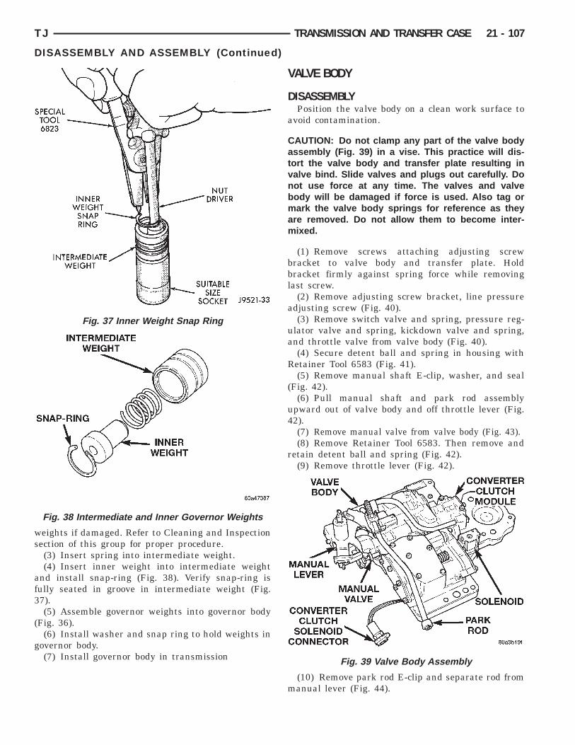
ws
af3
(
g
TJ TRANSMISSION AND TRANSFER CASE 21 - 107
DISASSEMBLY AND ASSEMBLY (Continued)
eights if damaged. Refer to Cleaning and Inspectionection of this group for proper procedure.(3) Insert spring into intermediate weight.(4) Insert inner weight into intermediate weight
nd install snap-ring (Fig. 38). Verify snap-ring isully seated in groove in intermediate weight (Fig.7).(5) Assemble governor weights into governor body
Fig. 36).(6) Install washer and snap ring to hold weights in
overnor body.(7) Install governor body in transmission
Fig. 37 Inner Weight Snap Ring
Fig. 38 Intermediate and Inner Governor Weights
VALVE BODY
DISASSEMBLYPosition the valve body on a clean work surface to
avoid contamination.
CAUTION: Do not clamp any part of the valve bodyassembly (Fig. 39) in a vise. This practice will dis-tort the valve body and transfer plate resulting invalve bind. Slide valves and plugs out carefully. Donot use force at any time. The valves and valvebody will be damaged if force is used. Also tag ormark the valve body springs for reference as theyare removed. Do not allow them to become inter-mixed.
(1) Remove screws attaching adjusting screwbracket to valve body and transfer plate. Holdbracket firmly against spring force while removinglast screw.
(2) Remove adjusting screw bracket, line pressureadjusting screw (Fig. 40).
(3) Remove switch valve and spring, pressure reg-ulator valve and spring, kickdown valve and spring,and throttle valve from valve body (Fig. 40).
(4) Secure detent ball and spring in housing withRetainer Tool 6583 (Fig. 41).
(5) Remove manual shaft E-clip, washer, and seal(Fig. 42).
(6) Pull manual shaft and park rod assemblyupward out of valve body and off throttle lever (Fig.42).
(7) Remove manual valve from valve body (Fig. 43).(8) Remove Retainer Tool 6583. Then remove and
retain detent ball and spring (Fig. 42).(9) Remove throttle lever (Fig. 42).
(10) Remove park rod E-clip and separate rod frommanual lever (Fig. 44).
Fig. 39 Valve Body Assembly
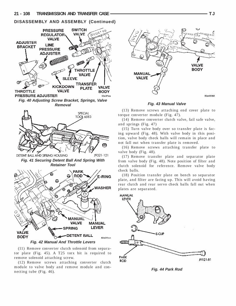
tr
mn
21 - 108 TRANSMISSION AND TRANSFER CASE TJ
DISASSEMBLY AND ASSEMBLY (Continued)
(11) Remove converter clutch solenoid from separa-or plate (Fig. 45). A T25 torx bit is required toemove solenoid attaching screw.(12) Remove screws attaching converter clutchodule to valve body and remove module and con-ecting tube (Fig. 46).
Fig. 40 Adjusting Screw Bracket, Springs, ValveRemoval
Fig. 41 Securing Detent Ball And Spring WithRetainer Tool
Fig. 42 Manual And Throttle Levers
(13) Remove screws attaching end cover plate totorque converter module (Fig. 47).
(14) Remove converter clutch valve, fail safe valve,and springs (Fig. 47)
(15) Turn valve body over so transfer plate is fac-ing upward (Fig. 48). With valve body in this posi-tion, valve body check balls will remain in place andnot fall out when transfer plate is removed.
(16) Remove screws attaching transfer plate tovalve body (Fig. 48).
(17) Remove transfer plate and separator platefrom valve body (Fig. 48). Note position of filter andclutch solenoid for reference. Remove valve bodycheck balls.
(18) Position transfer plate on bench so separatorplate, and filter are facing up. This will avoid havingrear clutch and rear servo check balls fall out whenplates are separated.
Fig. 43 Manual Valve
Fig. 44 Park Rod

t
TJ TRANSMISSION AND TRANSFER CASE 21 - 109
DISASSEMBLY AND ASSEMBLY (Continued)
(19) Remove screws attaching separator plate toransfer plate (Fig. 49).
Fig. 45 Converter Clutch Solenoid
Fig. 46 Clutch Module And Connecting Tube
Fig. 47 Converter Clutch and Fail Safe Valves
(20) Note position of filter, rear clutch servo andrear servo check balls for assembly reference (Fig.49) and (Fig. 50).
(21) Remove shuttle valve end plate (Fig. 51).(22) Remove shuttle valve E-clip and remove sec-
ondary spring and spring guides from end of valve(Fig. 52).
Fig. 48 Valve Body Transfer Plate Screws
Fig. 49 Transfer And Separator Plates

21 - 110 TRANSMISSION AND TRANSFER CASE TJ
DISASSEMBLY AND ASSEMBLY (Continued)
Fig. 50 Rear Servo and Rear Clutch Check Balls
Fig. 51 Shuttle Valve End Plate
Fig. 52 Shuttle Valve E-Clip And Secondary Spring
(23) Remove governor plug end plate (Fig. 53).(24) Remove 1-2 and 2-3 shift valve governor plugs
from valve body (Fig. 53).(25) Remove shuttle valve throttle plug, primary
spring and shuttle valve from valve body (Fig. 53).(26) Remove screws attaching kickdown limit
valve body to valve body (Fig. 53).(27) Remove 1-2 shift control valve and spring
from valve body (Fig. 53).(28) Remove 2-3 shift valve and spring from valve
body (Fig. 53).(29) Remove 1-2 shift valve and spring from valve
body (Fig. 53).(30) Remove throttle pressure plug from kickdown
limit valve body (Fig. 53).(31) Remove retainer from end of kickdown limit
valve body (Fig. 53).(32) Remove kickdown limit valve and spring from
kickdown limit valve body (Fig. 53).(33) Remove regulator valve end plate from valve
body (Fig. 53).(34) Remove regulator valve line pressure plug,
pressure plug sleeve, regulator valve throttle pres-sure plug and spring (Fig. 53).
ASSEMBLYClean and inspect all valve body components for
damage or wear. Refer to the Cleaning and Inspec-tion section of this group for proper procedure.
CAUTION: Do not force valves or plugs into placeduring reassembly. If the valve body bores, valves,and plugs are free of distortion or burrs, the valvebody components should all slide into place easily.In addition, do not overtighten the transfer plateand valve body screws during reassembly. Over-tightening can distort the valve body resulting invalve sticking, cross leakage and unsatisfactoryoperation. Tighten valve body screws to recom-mended torque only.
(1) Lubricate valve body bores, valves and plugswith Mopart ATF Plus 3, Type 7176, transmissionfluid.
(2) Install regulator valve line pressure plug, pres-sure plug sleeve, regulator valve throttle pressureplug, and spring into valve body (Fig. 53). Verifyvalve components slide freely.
(3) Install regulator valve end plate on valve body(Fig. 53).
(4) Install kickdown limit valve and spring in kick-down limit valve body (Fig. 53). Verify valve compo-nents slide freely.
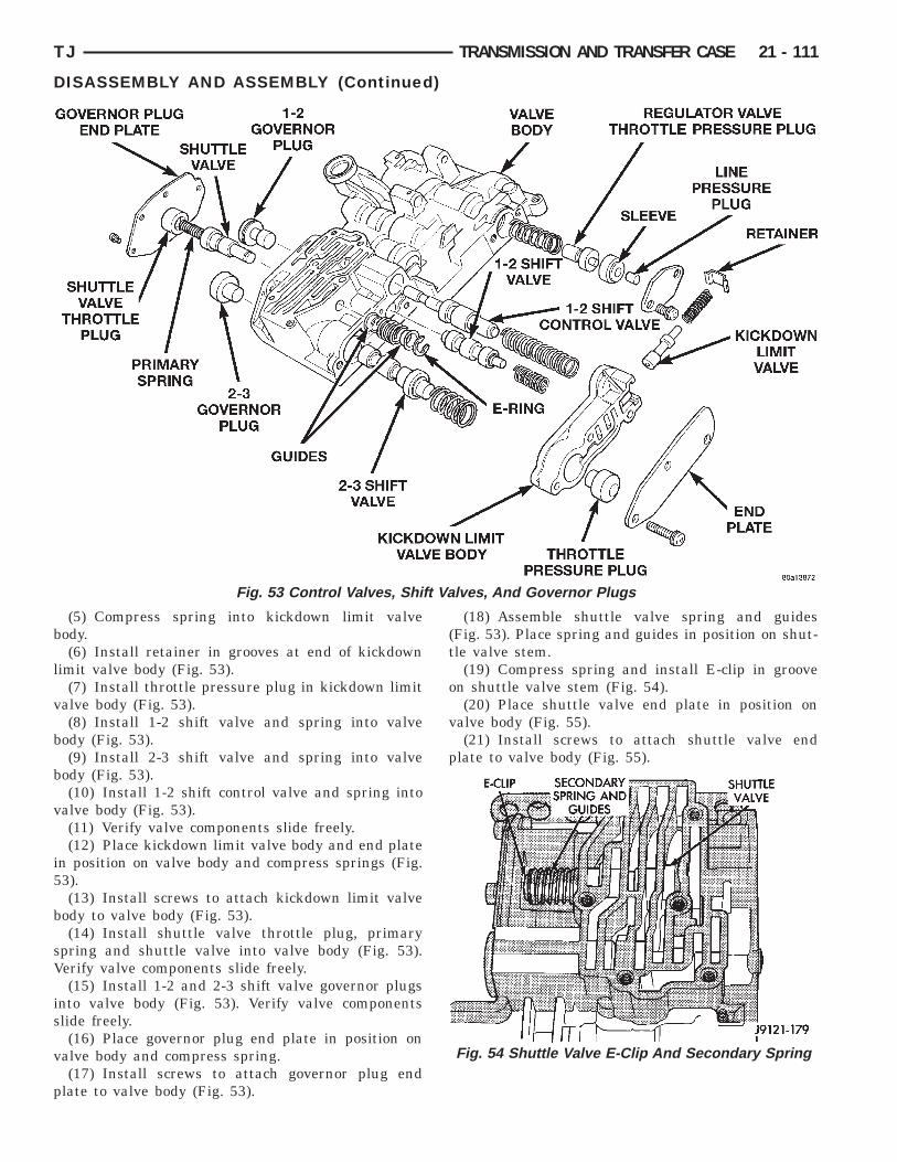
b
l
v
b
b
v
i5
b
sV
is
v
p
Valv
TJ TRANSMISSION AND TRANSFER CASE 21 - 111
DISASSEMBLY AND ASSEMBLY (Continued)
(5) Compress spring into kickdown limit valveody.(6) Install retainer in grooves at end of kickdown
imit valve body (Fig. 53).(7) Install throttle pressure plug in kickdown limit
alve body (Fig. 53).(8) Install 1-2 shift valve and spring into valve
ody (Fig. 53).(9) Install 2-3 shift valve and spring into valve
ody (Fig. 53).(10) Install 1-2 shift control valve and spring into
alve body (Fig. 53).(11) Verify valve components slide freely.(12) Place kickdown limit valve body and end plate
n position on valve body and compress springs (Fig.3).(13) Install screws to attach kickdown limit valve
ody to valve body (Fig. 53).(14) Install shuttle valve throttle plug, primary
pring and shuttle valve into valve body (Fig. 53).erify valve components slide freely.(15) Install 1-2 and 2-3 shift valve governor plugs
nto valve body (Fig. 53). Verify valve componentslide freely.(16) Place governor plug end plate in position on
alve body and compress spring.(17) Install screws to attach governor plug end
late to valve body (Fig. 53).
Fig. 53 Control Valves, Shift
(18) Assemble shuttle valve spring and guides(Fig. 53). Place spring and guides in position on shut-tle valve stem.
(19) Compress spring and install E-clip in grooveon shuttle valve stem (Fig. 54).
(20) Place shuttle valve end plate in position onvalve body (Fig. 55).
(21) Install screws to attach shuttle valve endplate to valve body (Fig. 55).
es, And Governor Plugs
Fig. 54 Shuttle Valve E-Clip And Secondary Spring
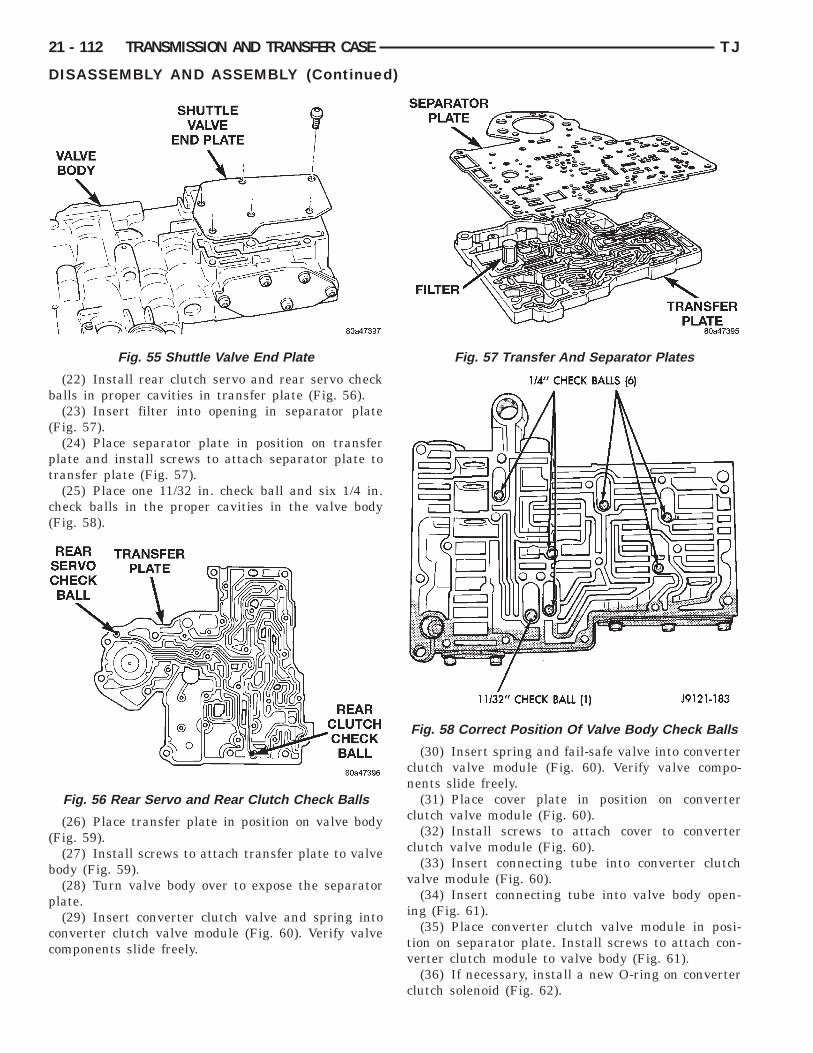
b
(
pt
c(
(
b
p
cc
21 - 112 TRANSMISSION AND TRANSFER CASE TJ
DISASSEMBLY AND ASSEMBLY (Continued)
(22) Install rear clutch servo and rear servo checkalls in proper cavities in transfer plate (Fig. 56).(23) Insert filter into opening in separator plate
Fig. 57).(24) Place separator plate in position on transfer
late and install screws to attach separator plate toransfer plate (Fig. 57).
(25) Place one 11/32 in. check ball and six 1/4 in.heck balls in the proper cavities in the valve bodyFig. 58).
(26) Place transfer plate in position on valve bodyFig. 59).
(27) Install screws to attach transfer plate to valveody (Fig. 59).(28) Turn valve body over to expose the separator
late.(29) Insert converter clutch valve and spring into
onverter clutch valve module (Fig. 60). Verify valveomponents slide freely.
Fig. 55 Shuttle Valve End Plate
Fig. 56 Rear Servo and Rear Clutch Check Balls
(30) Insert spring and fail-safe valve into converterclutch valve module (Fig. 60). Verify valve compo-nents slide freely.
(31) Place cover plate in position on converterclutch valve module (Fig. 60).
(32) Install screws to attach cover to converterclutch valve module (Fig. 60).
(33) Insert connecting tube into converter clutchvalve module (Fig. 60).
(34) Insert connecting tube into valve body open-ing (Fig. 61).
(35) Place converter clutch valve module in posi-tion on separator plate. Install screws to attach con-verter clutch module to valve body (Fig. 61).
(36) If necessary, install a new O-ring on converterclutch solenoid (Fig. 62).
Fig. 57 Transfer And Separator Plates
Fig. 58 Correct Position Of Valve Body Check Balls
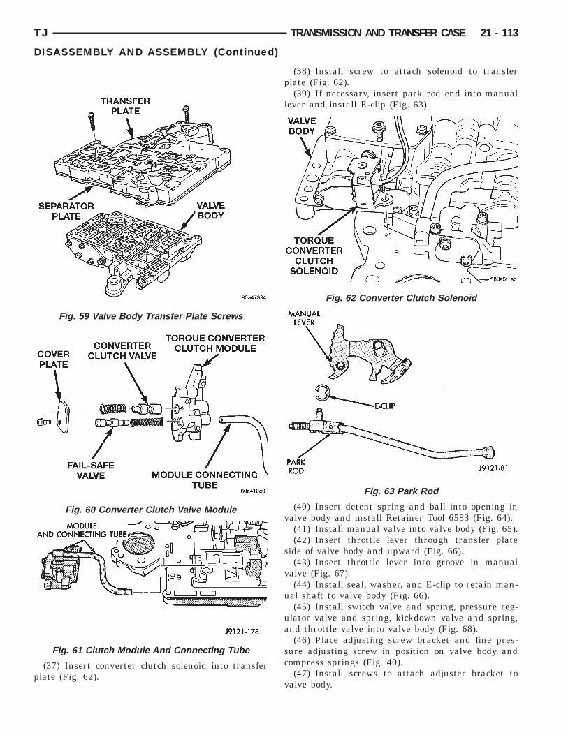
p
TJ TRANSMISSION AND TRANSFER CASE 21 - 113
DISASSEMBLY AND ASSEMBLY (Continued)
(37) Insert converter clutch solenoid into transferlate (Fig. 62).
Fig. 59 Valve Body Transfer Plate Screws
Fig. 60 Converter Clutch Valve Module
Fig. 61 Clutch Module And Connecting Tube
(38) Install screw to attach solenoid to transferplate (Fig. 62).
(39) If necessary, insert park rod end into manuallever and install E-clip (Fig. 63).
(40) Insert detent spring and ball into opening invalve body and install Retainer Tool 6583 (Fig. 64).
(41) Install manual valve into valve body (Fig. 65).(42) Insert throttle lever through transfer plate
side of valve body and upward (Fig. 66).(43) Insert throttle lever into groove in manual
valve (Fig. 67).(44) Install seal, washer, and E-clip to retain man-
ual shaft to valve body (Fig. 66).(45) Install switch valve and spring, pressure reg-
ulator valve and spring, kickdown valve and spring,and throttle valve into valve body (Fig. 68).
(46) Place adjusting screw bracket and line pres-sure adjusting screw in position on valve body andcompress springs (Fig. 40).
(47) Install screws to attach adjuster bracket tovalve body.
Fig. 62 Converter Clutch Solenoid
Fig. 63 Park Rod
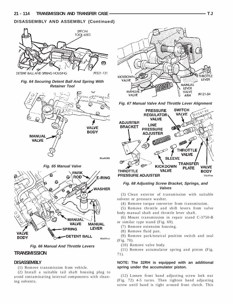
T
D
ai
21 - 114 TRANSMISSION AND TRANSFER CASE TJ
DISASSEMBLY AND ASSEMBLY (Continued)
RANSMISSION
ISASSEMBLY(1) Remove transmission from vehicle.(2) Install a suitable tail shaft housing plug to
void contaminating internal components with clean-ng solvents.
Fig. 64 Securing Detent Ball And Spring WithRetainer Tool
Fig. 65 Manual Valve
Fig. 66 Manual And Throttle Levers
(3) Clean exterior of transmission with suitablesolvent or pressure washer.
(4) Remove torque converter from transmission.(5) Remove throttle and shift levers from valve
body manual shaft and throttle lever shaft.(6) Mount transmission in repair stand C-3750-B
or similar type stand (Fig. 69).(7) Remove extension housing.(8) Remove fluid pan.(9) Remove park/neutral position switch and seal
(Fig. 70).(10) Remove valve body.(11) Remove accumulator spring and piston (Fig.
71).
NOTE: The 32RH is equipped with an additionalspring under the accumulator piston.
(12) Loosen front band adjusting screw lock nut(Fig. 72) 4-5 turns. Then tighten band adjustingscrew until band is tight around front clutch. This
Fig. 67 Manual Valve And Throttle Lever Alignment
Fig. 68 Adjusting Screw Bracket, Springs, andValves

ppn
TJ TRANSMISSION AND TRANSFER CASE 21 - 115
DISASSEMBLY AND ASSEMBLY (Continued)
revents front/rear clutches from coming out withump and possibly damaging clutch or pump compo-ents.(13) Remove oil pump bolts.
Fig. 69 Repair Stand
Fig. 70 Park/Neutral Position Switch
Fig. 71 Accumulator Piston And Spring
(14) Thread bolts of Slide Hammer Tools C-3752into threaded holes in pump body flange (Fig. 73).
(15) Bump slide hammer weights outward toremove pump and reaction shaft support assemblyfrom case (Fig. 73).
(16) Loosen front band adjusting screw until bandis completely loose (Fig. 72).
(17) Squeeze front band together and remove bandstrut (Fig. 74).
(18) Remove front and rear clutch units as anassembly. Grasp input shaft, hold clutch unitstogether and remove them from case (Fig. 75).
(19) Lift front clutch off rear clutch (Fig. 76). Setclutch units aside for overhaul.
(20) Remove output shaft thrust washer from out-put shaft (or from rear clutch hub) (Fig. 77).
Fig. 72 Front Band Adjusting Screw Lock Nut
Fig. 73 Oil Pump/Reaction Shaft Support
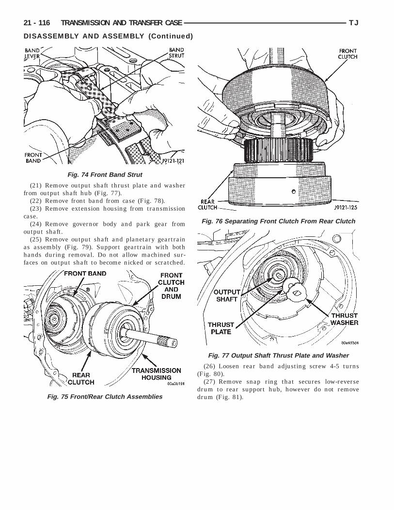
f
c
o
ahf
21 - 116 TRANSMISSION AND TRANSFER CASE TJ
DISASSEMBLY AND ASSEMBLY (Continued)
(21) Remove output shaft thrust plate and washerrom output shaft hub (Fig. 77).
(22) Remove front band from case (Fig. 78).(23) Remove extension housing from transmission
ase.(24) Remove governor body and park gear from
utput shaft.(25) Remove output shaft and planetary geartrain
s assembly (Fig. 79). Support geartrain with bothands during removal. Do not allow machined sur-aces on output shaft to become nicked or scratched.
Fig. 74 Front Band Strut
Fig. 75 Front/Rear Clutch Assemblies
(26) Loosen rear band adjusting screw 4-5 turns(Fig. 80).
(27) Remove snap ring that secures low-reversedrum to rear support hub, however do not removedrum (Fig. 81).
Fig. 76 Separating Front Clutch From Rear Clutch
Fig. 77 Output Shaft Thrust Plate and Washer

m(
c8
er
Fig. 80 Rear Band Adjuster Location
Fig. 81 Low-Reverse Drum Snap Ring
TJ TRANSMISSION AND TRANSFER CASE 21 - 117
DISASSEMBLY AND ASSEMBLY (Continued)
(28) Remove bolts attaching rear support to trans-ission case and pull support from low-reverse drum
Fig. 82).(29) Remove bolts attaching overrunning clutch
am and low-reverse drum to transmission case (Fig.3).REAR BAND—32RH.(30) Remove rear band. The 32RH transmission is
quipped with a double-wrap band that does notequire a link bar.
(a) Remove low-reverse drum and overrunningclutch as assembly. Slide drum and clutch throughrear band and out of case (Fig. 84). Set drum andclutch assembly aside for cleaning and inspection.
(b) Remove rear band from case (Fig. 84).
Fig. 78 Front Band
Fig. 79 Planetary Geartrain
Fig. 82 Rear Support

e
lw
21 - 118 TRANSMISSION AND TRANSFER CASE TJ
DISASSEMBLY AND ASSEMBLY (Continued)
REAR BAND—30RH(31) Remove rear band. The 30RH transmission is
quipped with a single-wrap band with a link bar.(a) Using snap-ring plier, pull rear band anchor
pin (located on the servo side of the rear support)from transmission case.
(b) Remove rear band and link from transmis-sion (Fig. 85).
(c) Separate rear band from link (Fig. 86).(32) If necessary remove front and rear band servo
evers. All transmission components can be servicedithout removing the levers.
(a) Using a 1/4 inch drive extension removefront band reaction pin access plug (Fig. 87).
(b) Remove front band reaction pin with pencilmagnet. Pin is accessible from converter housingside of case (Fig. 88).
(c) Remove front band lever (Fig. 89).
Fig. 83 Overrunning Clutch Cam Bolt Locations
Fig. 84 Low- Reverse Band and Drum—32RH
(d) Using snap-ring plier, pull rear band leverpivot from transmission case (Fig. 90).
(e) Separate rear band servo lever from trans-mission.
Fig. 85 Rear Band and Link—30RH
Fig. 86 Rear Band and Link—30RH
Fig. 87 Front Band Reaction Pin Access Plug
Fig. 88 Front Band Reaction Pin

wp
9Sn
s
1(b
Ts
A
r
TJ TRANSMISSION AND TRANSFER CASE 21 - 119
DISASSEMBLY AND ASSEMBLY (Continued)
(33) Compress front servo rod guide about 1/8 in.ith large C-clamp and Tool C-4470, or Spring Com-ressor Tool C-3422-B (Fig. 91).(34) Remove front servo rod guide snap ring (Fig.
1). Exercise caution when removing snap ring.ervo bore can be scratched or nicked if care isot exercised.(35) Remove compressor tools and remove front
ervo rod guide, spring and servo piston.(36) Compress rear servo spring retainer about
/16 in. with C-clamp and Tool C-4470 or SP-5560Fig. 92). Valve Spring Compressor C-3422-B can alsoe used to compress spring retainer.(37) Remove rear servo spring retainer snap ring.
hen remove compressor tools and remove rear servopring and piston.
SSEMBLY(1) Install rear servo piston, spring and spring
etainer. Compress rear servo spring and retainer
Fig. 89 Front Band Lever
Fig. 90 Rear Band Servo Lever Pin
with Compressor Tool C-3422-B (Fig. 92) or a largeC-clamp.
(2) Install front servo piston, spring, and rodguide. Compress front servo rod guide with ValveSpring Compressor C-3422-B and install servo snapring (Fig. 91).
REAR BAND—32RH(3) Install rear band
(a) Insert rear band through pan opening intransmission case. Single lug toward pan face.
(b) Place single lug under adjuster screw andtwo lugs over anchor pin in transmission case (Fig.84).REAR BAND—30RH(4) Install rear band.
Fig. 91 Compressing Front Servo
Fig. 92 Compressing Rear Servo Spring

Nhc
Ns(
am
w
n
hcb
mab
cb
tVs
b
cTl
p
t
d
N
t
21 - 120 TRANSMISSION AND TRANSFER CASE TJ
DISASSEMBLY AND ASSEMBLY (Continued)
(a) Assemble link bar to band. Notched side oflink toward band (Fig. 90).
(b) Insert rear band through pan opening intransmission case.
(c) Insert hook on band onto adjuster lever.(d) Align holes in link bar with hole in transmis-
sion case outboard of rear support opening (Fig.89).
(e) Insert anchor pin into case through link bar.(5) Examine bolt holes in overrunning clutch cam.ote that one hole is not threaded (Fig. 93). Thisole must align with blank area in clutch cam boltircle.
OTE: The bolt holes in cam are slightly counter-unk on one side. This side of cam faces rearwardtoward rear support).
(6) Lubricate overrunning clutch rollers, springsnd cam with Mopart ATF Plus 3, type 7176, trans-ission fluid.(7) Position overrunning clutch on a clean, flatork surface with countersunk holes downward.(8) Place rear of low-reverse drum over overrun-
ing clutch and align clutch rollers to hub of drum.(9) While slightly pivoting low-reverse drum, push
ub of drum into overrunning clutch. Verify thatountersunk holes are facing outward. Cam shoulde able to rotate in the drum clockwise only.(10) Insert a suitable awl through the rear supportounting hole closest to the pan sealing face. The
wl should be next to the wide space area at theack of transmission case.(11) Insert low-reverse drum and overrunning
lutch into front of transmission case and into rearand.(12) Insert awl tip into the threaded hole next to
he non-threaded hole in the overrunning clutch cam.erify that non-threaded hole is aligned with widepace area on transmission case.(13) Push low-reverse drum rearward to close gap
etween cam and case.(14) Install overrunning clutch cam bolts. Clutch
am bolts are shorter than rear support bolts.ighten cam bolts to 17 N·m (150 in. lbs. or 13 ft.
bs.) torque.(15) Hold low-reverse drum in position so rear sup-
ort will not push it out of overrunning clutch.(16) Insert rear support into opening at rear of
ransmission case (Fig. 94).(17) Align support with the embossed arrow in the
irection of the pan face.(18) Install and tighten rear support bolts to 17·m (150 in. lbs.) torque.(19) Install snap ring to retain low-reverse drum
o hub of rear support (Fig. 95).
(20) Lubricate output shaft, rear support bore andlow-reverse drum hub with transmission fluid.
(21) Install assembled output shaft and planetarygeartrain in case (Fig. 96).
Fig. 93 Clutch Cam Alignment
Fig. 94 Rear Support
Fig. 95 Low-Reverse Drum Snap Ring
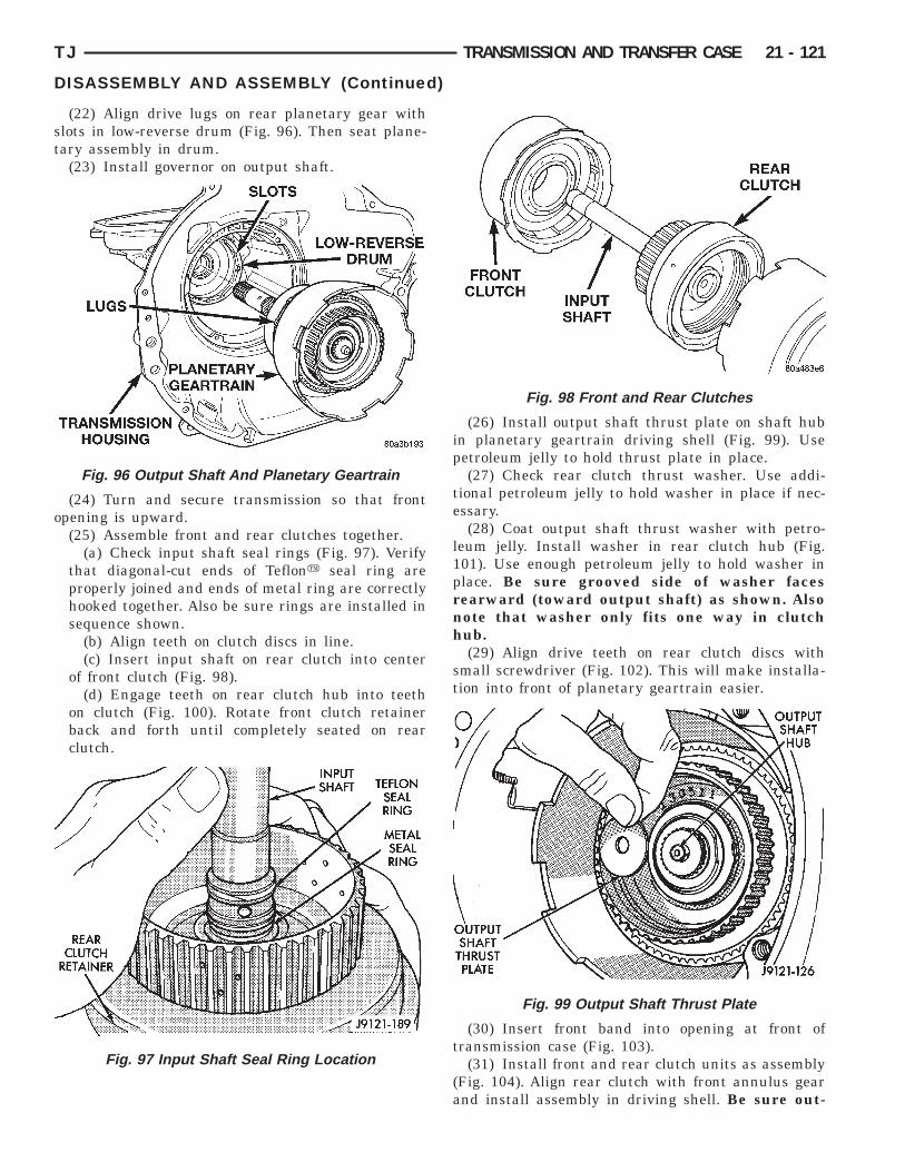
st
o
TJ TRANSMISSION AND TRANSFER CASE 21 - 121
DISASSEMBLY AND ASSEMBLY (Continued)
(22) Align drive lugs on rear planetary gear withlots in low-reverse drum (Fig. 96). Then seat plane-ary assembly in drum.
(23) Install governor on output shaft.
(24) Turn and secure transmission so that frontpening is upward.(25) Assemble front and rear clutches together.
(a) Check input shaft seal rings (Fig. 97). Verifythat diagonal-cut ends of Teflony seal ring areproperly joined and ends of metal ring are correctlyhooked together. Also be sure rings are installed insequence shown.
(b) Align teeth on clutch discs in line.(c) Insert input shaft on rear clutch into center
of front clutch (Fig. 98).(d) Engage teeth on rear clutch hub into teeth
on clutch (Fig. 100). Rotate front clutch retainerback and forth until completely seated on rearclutch.
Fig. 96 Output Shaft And Planetary Geartrain
Fig. 97 Input Shaft Seal Ring Location
(26) Install output shaft thrust plate on shaft hubin planetary geartrain driving shell (Fig. 99). Usepetroleum jelly to hold thrust plate in place.
(27) Check rear clutch thrust washer. Use addi-tional petroleum jelly to hold washer in place if nec-essary.
(28) Coat output shaft thrust washer with petro-leum jelly. Install washer in rear clutch hub (Fig.101). Use enough petroleum jelly to hold washer inplace. Be sure grooved side of washer facesrearward (toward output shaft) as shown. Alsonote that washer only fits one way in clutchhub.
(29) Align drive teeth on rear clutch discs withsmall screwdriver (Fig. 102). This will make installa-tion into front of planetary geartrain easier.
(30) Insert front band into opening at front oftransmission case (Fig. 103).
(31) Install front and rear clutch units as assembly(Fig. 104). Align rear clutch with front annulus gearand install assembly in driving shell. Be sure out-
Fig. 98 Front and Rear Clutches
Fig. 99 Output Shaft Thrust Plate

pn
f
21 - 122 TRANSMISSION AND TRANSFER CASE TJ
DISASSEMBLY AND ASSEMBLY (Continued)
ut shaft thrust washer and thrust plate areot displaced during installation.(32) Carefully work assembled clutches back and
orth to engage and seat rear clutch discs on front
Fig. 100 Assembling Front And Rear Clutch Units
Fig. 101 Output Shaft Thrust Washer
Fig. 102 Aligning Rear Clutch Disc Lugs
annulus gear. Verify that front clutch drive lugs arefully engaged in slots of driving shell after installa-tion.
(33) Engage front band on adjusting screw andhold band in place.
(34) Install strut between band lever and frontband (Fig. 105).
(35) Tighten front band adjusting screw until bandjust grips clutch retainer. Verify that front/rearclutches are still seated before continuing.
(36) Verify that reaction shaft support hub sealrings are hooked together (Fig. 106).
(37) Coat front clutch thrust washer with petro-leum jelly to hold it in place. Then install washerover reaction shaft hub and seat it on pump (Fig.107).
CAUTION: The thrust washer bore (I.D.), is cham-fered on one side. Make sure the chamfered side isinstalled so it faces the pump.
Fig. 103 Front Band
Fig. 104 Installing Front/Rear Clutch

b
TJ TRANSMISSION AND TRANSFER CASE 21 - 123
DISASSEMBLY AND ASSEMBLY (Continued)
(38) Thread two Pilot Stud Tools C-3288-B intoolt holes in oil pump flange (Fig. 108).(39) Align and install oil pump gasket (Fig. 108).
Fig. 105 Front Band Linkage Installation
Fig. 106 Reaction Shaft Support Seal Rings
Fig. 107 Front Clutch Thrust Washer Installation
(40) Lubricate oil pump seals with Mopart Door-Ease, or Ru-Glyde, Door Eze, or ATF Plus 3.
(41) Install oil pump (Fig. 109). Align and positionpump on pilot studs. Slide pump down studs andwork it into front clutch hub and case by hand. Theninstall two or three pump bolts to hold pump inplace.
(42) Remove pilot stud tools and install remainingoil pump bolts. Tighten bolts alternately in diagonalpattern to 20 N·m (15 ft. lbs.).
(43) Measure input shaft end play (Fig. 110).
Fig. 108 Installing Pilot Studs And Oil Pump Gasket
Fig. 109 Installing Oil Pump And Reaction ShaftSupport
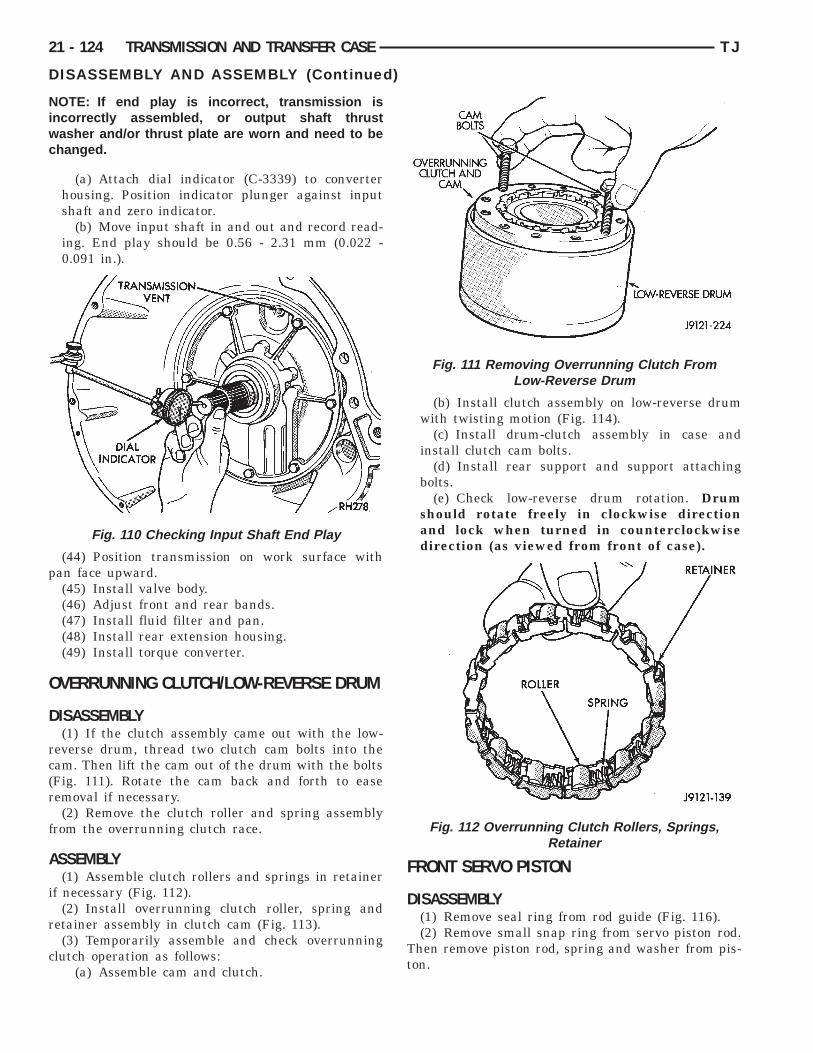
Niwc
p
O
D
rc(r
f
A
i
r
c
21 - 124 TRANSMISSION AND TRANSFER CASE TJ
DISASSEMBLY AND ASSEMBLY (Continued)
OTE: If end play is incorrect, transmission isncorrectly assembled, or output shaft thrustasher and/or thrust plate are worn and need to behanged.
(a) Attach dial indicator (C-3339) to converterhousing. Position indicator plunger against inputshaft and zero indicator.
(b) Move input shaft in and out and record read-ing. End play should be 0.56 - 2.31 mm (0.022 -0.091 in.).
(44) Position transmission on work surface withan face upward.(45) Install valve body.(46) Adjust front and rear bands.(47) Install fluid filter and pan.(48) Install rear extension housing.(49) Install torque converter.
VERRUNNING CLUTCH/LOW-REVERSE DRUM
ISASSEMBLY(1) If the clutch assembly came out with the low-
everse drum, thread two clutch cam bolts into theam. Then lift the cam out of the drum with the boltsFig. 111). Rotate the cam back and forth to easeemoval if necessary.(2) Remove the clutch roller and spring assembly
rom the overrunning clutch race.
SSEMBLY(1) Assemble clutch rollers and springs in retainer
f necessary (Fig. 112).(2) Install overrunning clutch roller, spring and
etainer assembly in clutch cam (Fig. 113).(3) Temporarily assemble and check overrunning
lutch operation as follows:(a) Assemble cam and clutch.
Fig. 110 Checking Input Shaft End Play
(b) Install clutch assembly on low-reverse drumwith twisting motion (Fig. 114).
(c) Install drum-clutch assembly in case andinstall clutch cam bolts.
(d) Install rear support and support attachingbolts.
(e) Check low-reverse drum rotation. Drumshould rotate freely in clockwise directionand lock when turned in counterclockwisedirection (as viewed from front of case).
FRONT SERVO PISTON
DISASSEMBLY(1) Remove seal ring from rod guide (Fig. 116).(2) Remove small snap ring from servo piston rod.
Then remove piston rod, spring and washer from pis-ton.
Fig. 111 Removing Overrunning Clutch FromLow-Reverse Drum
Fig. 112 Overrunning Clutch Rollers, Springs,Retainer
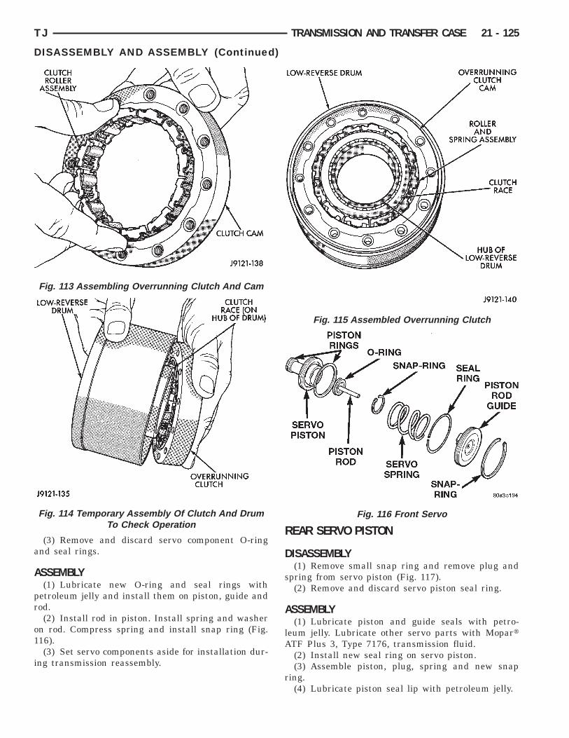
a
A
pr
o1
i
A
r
TJ TRANSMISSION AND TRANSFER CASE 21 - 125
DISASSEMBLY AND ASSEMBLY (Continued)
(3) Remove and discard servo component O-ringnd seal rings.
SSEMBLY(1) Lubricate new O-ring and seal rings with
etroleum jelly and install them on piston, guide andod.(2) Install rod in piston. Install spring and washer
n rod. Compress spring and install snap ring (Fig.16).(3) Set servo components aside for installation dur-
ng transmission reassembly.
Fig. 113 Assembling Overrunning Clutch And Cam
Fig. 114 Temporary Assembly Of Clutch And DrumTo Check Operation
REAR SERVO PISTONDISASSEMBLY(1) Remove small snap ring and remove plug and
spring from servo piston (Fig. 117).(2) Remove and discard servo piston seal ring.
ASSEMBLY(1) Lubricate piston and guide seals with petro-
leum jelly. Lubricate other servo parts with MopartTF Plus 3, Type 7176, transmission fluid.(2) Install new seal ring on servo piston.(3) Assemble piston, plug, spring and new snap
ing.(4) Lubricate piston seal lip with petroleum jelly.
Fig. 115 Assembled Overrunning Clutch
Fig. 116 Front Servo
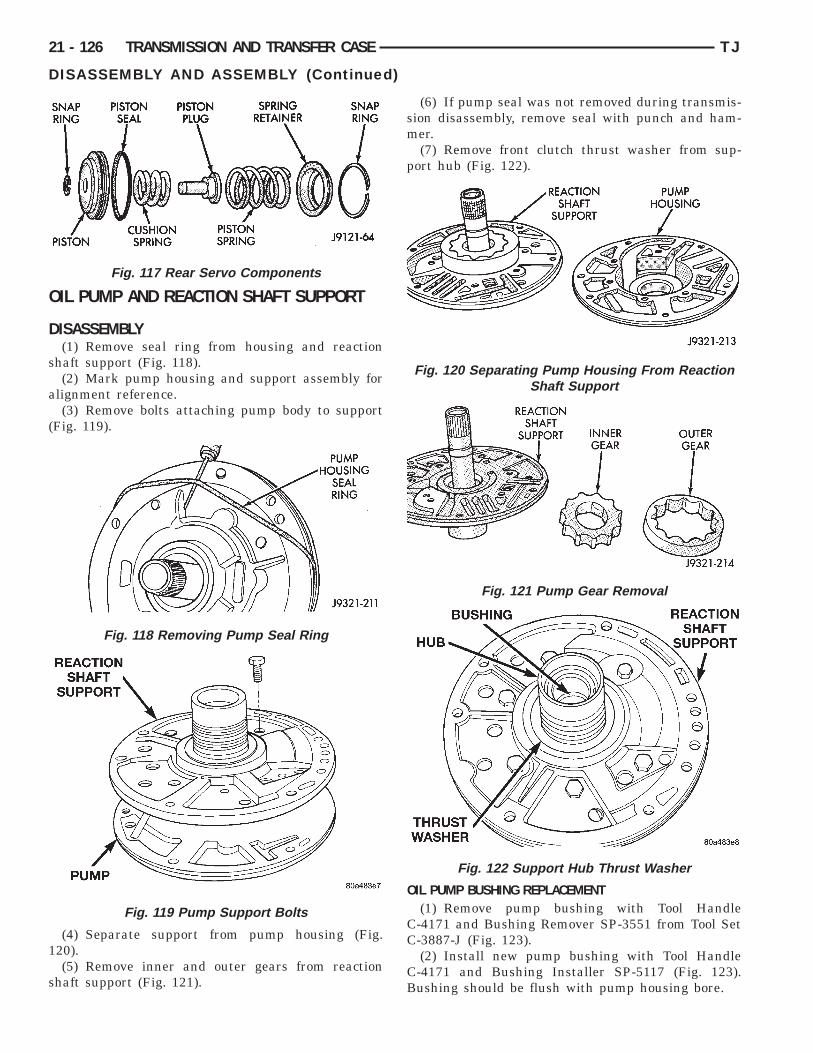
O
D
s
a
(
1
s
21 - 126 TRANSMISSION AND TRANSFER CASE TJ
DISASSEMBLY AND ASSEMBLY (Continued)
IL PUMP AND REACTION SHAFT SUPPORT
ISASSEMBLY(1) Remove seal ring from housing and reaction
haft support (Fig. 118).(2) Mark pump housing and support assembly for
lignment reference.(3) Remove bolts attaching pump body to support
Fig. 119).
(4) Separate support from pump housing (Fig.20).(5) Remove inner and outer gears from reaction
haft support (Fig. 121).
Fig. 117 Rear Servo Components
Fig. 118 Removing Pump Seal Ring
Fig. 119 Pump Support Bolts
(6) If pump seal was not removed during transmis-sion disassembly, remove seal with punch and ham-mer.
(7) Remove front clutch thrust washer from sup-port hub (Fig. 122).
OIL PUMP BUSHING REPLACEMENT(1) Remove pump bushing with Tool Handle
C-4171 and Bushing Remover SP-3551 from Tool SetC-3887-J (Fig. 123).
(2) Install new pump bushing with Tool HandleC-4171 and Bushing Installer SP-5117 (Fig. 123).Bushing should be flush with pump housing bore.
Fig. 120 Separating Pump Housing From ReactionShaft Support
Fig. 121 Pump Gear Removal
Fig. 122 Support Hub Thrust Washer

bp
R
3o
sfa
rc
TJ TRANSMISSION AND TRANSFER CASE 21 - 127
DISASSEMBLY AND ASSEMBLY (Continued)
(3) Stake new pump bushing in two places withlunt punch (Fig. 124). Remove burrs from stakeoints with knife blade afterward.
EACTION SHAFT SUPPORT BUSHING REMOVAL(1) Assemble Bushing Remover Tools SP-1191,
633 and 5324 (Fig. 125). Do not clamp any partf reaction shaft or support in vise.(2) Hold Cup Tool SP-3633 firmly against reaction
haft and thread remover SP-5324 into bushing asar as possible by hand. Then thread remover tool 3-4dditional turns into bushing with a wrench.(3) Turn remover tool hex nut down against
emover cup to pull bushing from shaft. Clean allhips from shaft after bushing removal.
Fig. 123 Removing Oil Pump Bushing
Fig. 124 Staking Oil Pump Bushing
(4) Lightly grip old bushing in vise or with pliersand back remover tool out of bushing.
(5) Assemble Bushing Installer Tools C-4171 andSP-5325 (Fig. 125).
(6) Slide new bushing onto Installer Tool SP-5325.(7) Position reaction shaft support upright on a
clean smooth surface.(8) Align bushing in bore. Then tap bushing into
place until Bushing Installer SP-5325 bottoms.(9) Clean reaction shaft support thoroughly after
installing bushing.
ASSEMBLY(1) Lubricate gear bore in pump housing with
transmission fluid.(2) Lubricate pump gears with transmission fluid.(3) Support pump housing on wood blocks (Fig.
126).(4) Install outer gear in pump housing (Fig. 126).
Gear can be installed either way (it is not a one-wayfit).
(5) Install pump inner gear (Fig. 127).
CAUTION: The pump inner gear is a one way fit.The bore on one side of the gear inside diameter(I.D.) is chamfered. Be sure the chamfered sidefaces forward (to front of pump).
(6) Install new thrust washer on hub of reactionshaft support. Lubricate washer with transmissionfluid or petroleum jelly.
(7) If reaction shaft seal rings are being replaced,install new seal rings on support hub (Fig. 128).Lubricate seal rings with transmission fluid or petro-leum jelly after installation. Squeeze each ring untilring ends are securely hooked together.
Fig. 125 Replacing Reaction Shaft Support Bushing

Cwblhrd
F
21 - 128 TRANSMISSION AND TRANSFER CASE TJ
DISASSEMBLY AND ASSEMBLY (Continued)
AUTION: The reaction shaft support seal ringsill break if overspread, or twisted. If new rings areeing installed, spread them only enough for instal-
ation. Also be very sure the ring ends are securelyooked together after installation. Otherwise, theings will either prevent pump installation, or breakuring installation.
ig. 126 Supporting Pump And Installing Outer Gear
Fig. 127 Pump Inner Gear Installation
Fig. 128 Hub Seal Ring Position
(8) Install reaction shaft support on pump housing(Fig. 129).
(9) Align reaction support on pump housing. Usealignment marks made at disassembly. Or, rotatesupport until bolt holes in support and pump housingare all aligned (holes are offset for one-way fit).
(10) Install all bolts that attach support to pumphousing. Then tighten bolts finger tight.
(11) Tighten support-to-pump bolts to requiredtorque as follows:
(a) Reverse pump assembly and install it intransmission case. Position pump so bolts are fac-ing out and are accessible.
(b) Secure pump assembly in case with 2 or 3bolts, or with pilot studs.
(c) Tighten support-to-pump bolts to 20 N·m (15ft. lbs.).
(d) Remove pump assembly from transmissioncase.(12) Install new oil seal in pump with Special Tool
C-4193 and Tool Handle C-4171 (Fig. 130). Be sureseal lip faces inward.
(13) Install new seal ring around pump housing.Be sure seal is properly seated in groove.
(14) Lubricate lip of pump oil seal and O-ring sealwith transmission fluid.
Fig. 129 Assembling Reaction Shaft Support AndPump Housing
Fig. 130 Pump Oil Seal Installation

F
D
p
Tsi
p
p
R
ra
A
a
rc
l
TJ TRANSMISSION AND TRANSFER CASE 21 - 129
DISASSEMBLY AND ASSEMBLY (Continued)
RONT CLUTCH
ISASSEMBLY(1) Remove waved snap ring and remove pressure
late, clutch plates and clutch discs (Fig. 131).(2) Compress clutch piston spring with Compressor
ool C-3575-A (Fig. 132). Be sure legs of tool areeated squarely on spring retainer before compress-ng spring.
(3) Remove retainer snap ring and remove com-ressor tool.(4) Remove spring retainer and clutch spring. Note
osition of retainer on spring for assembly reference.(5) Remove clutch piston from clutch retainer.emove piston by rotating it up and out of retainer.(6) Remove seals from clutch piston and clutch
etainer hub. Discard both seals as they are not reus-ble.
SSEMBLY(1) Soak clutch discs in transmission fluid while
ssembling other clutch parts.(2) Install new seals on piston and in hub of
etainer. Be sure lip of each seal faces interior oflutch retainer.(3) Lubricate lips of piston and retainer seals with
iberal quantity of Mopart Door Ease, or Ru-Glyde.
Fig. 131 Front C
Then lubricate retainer hub, bore and piston withlight coat of transmission fluid.
(4) Install clutch piston in retainer (Fig. 133). Usetwisting motion to seat piston in bottom of retainer. Athin strip of plastic (about 0.0209 thick), can be usedto guide seals into place if necessary.
Components
Fig. 132 Compressing Front Clutch Piston Spring
lutch

CTctt
(iur
21 - 130 TRANSMISSION AND TRANSFER CASE TJ
DISASSEMBLY AND ASSEMBLY (Continued)
AUTION: Never push the clutch piston straight in.his will fold the seals over causing leakage andlutch slip. In addition, never use any type of metalool to help ease the piston seals into place. Metalools will cut, shave, or score the seals.
(5) Position spring in clutch piston (Fig. 134).(6) Position spring retainer on top of piston spring
Fig. 135). Make sure retainer is properlynstalled. Small raised tabs should be facingpward. Semicircular lugs on underside ofetainer are for positioning retainer in spring.
Fig. 133 Front Clutch Piston Installation
Fig. 134 Clutch Piston Spring Installation
Fig. 135 Correct Spring Retainer Installed Position
(7) Compress piston spring and retainer with Com-pressor Tool C-3575-A (Fig. 132). Then install newsnap ring to secure spring retainer and spring.
(8) Install clutch plates and discs (Fig. 131).Install steel plate then disc until all plates and discsare installed. The front clutch uses 4 clutch discs.
(9) Install pressure plate and waved snap ring(Fig. 131).
(10) Using a suitable gauge bar and dial indicator,measure clutch plate clearance (Fig. 136).
(a) Position gauge bar across the clutch drumwith the dial indicator pointer on the pressureplate (Fig. 136).
(b) Using two small screw drivers, lift the pres-sure plate and compress the waved snap-ring. Thiswill assure that the snap-ring is at the top of thegroove.
(c) Release the pressure plate and zero the dialindicator.
(d) Lift the pressure plate until it contacts thewaved snap-ring and record the dial indicator read-ing.Clearance should be 1.70 to 3.40 mm (0.067 to
0.134 in.). If clearance is incorrect, clutch discs,plates pressure plates and snap ring may have to bechanged.
REAR CLUTCH
DISASSEMBLY(1) Remove thrust washer from forward side of
clutch retainer.(2) Remove input shaft front/rear seal rings.(3) Remove selective clutch pack snap ring (Fig.
137).(4) Remove top pressure plate, clutch discs, steel
plates, bottom pressure plate and wave snap ringand wave spring (Fig. 137).
(5) Remove clutch piston with rotating motion.
Fig. 136 Measuring Front Clutch Pack Clearance

mt
psi
lutch
TJ TRANSMISSION AND TRANSFER CASE 21 - 131
DISASSEMBLY AND ASSEMBLY (Continued)
(6) Remove and discard piston seals.(7) Remove input shaft snap-ring (Fig. 138). Itay be necessary to press the input shaft in slightly
o relieve tension on the snap-ring(8) Press input shaft out of retainer with shop
ress and suitable size press tool. Use a suitablyized press tool to support the retainer as close to thenput shaft as possible.
Fig. 137 Rear C
Fig. 138 Removing/Installing Input Shaft Snap-Ring
ASSEMBLY(1) Soak clutch discs in transmission fluid while
assembling other clutch parts.(2) Install new seal rings on clutch retainer hub
and input shaft if necessary (Fig. 139).(a) Be sure clutch hub seal ring is fully seated in
groove and is not twisted.(3) Lubricate splined end of input shaft and clutch
retainer with transmission fluid. Then press inputshaft into retainer. Use a suitably sized press tool tosupport retainer as close to input shaft as possible.
(4) Install input shaft snap-ring (Fig. 138).(5) Invert retainer and press input shaft in oppo-
site direction until snap-ring is seated.(6) Install new seals on clutch piston. Be sure lip
of each seal faces interior of clutch retainer.(7) Lubricate lip of piston seals with generous
quantity of Mopart Door Ease. Then lubricateretainer hub and bore with light coat of transmissionfluid.
(8) Install clutch piston in retainer. Use twistingmotion to seat piston in bottom of retainer. A thinstrip of plastic (about 0.0209 thick), can be used toguide seals into place if necessary.
Components
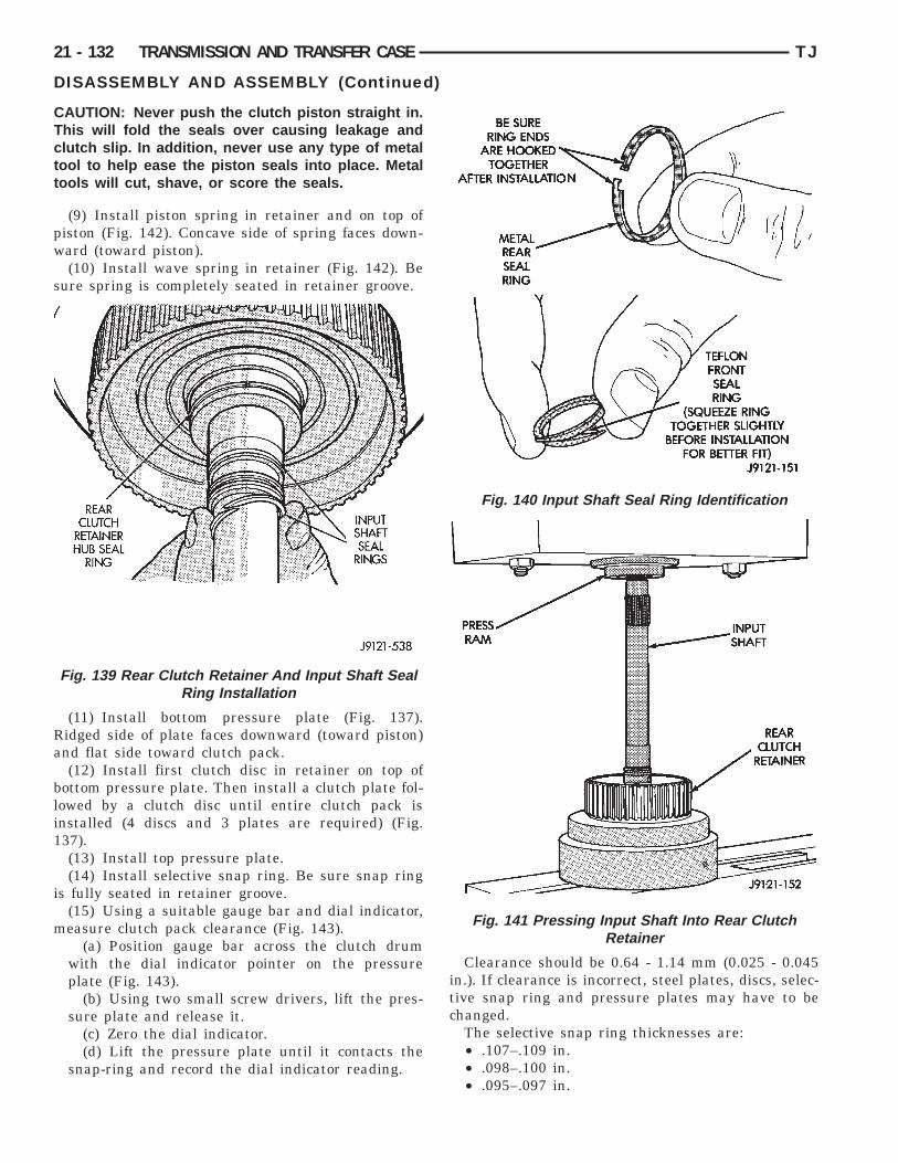
CTctt
pw
s
Ra
bli1
i
m
21 - 132 TRANSMISSION AND TRANSFER CASE TJ
DISASSEMBLY AND ASSEMBLY (Continued)
AUTION: Never push the clutch piston straight in.his will fold the seals over causing leakage andlutch slip. In addition, never use any type of metalool to help ease the piston seals into place. Metalools will cut, shave, or score the seals.
(9) Install piston spring in retainer and on top ofiston (Fig. 142). Concave side of spring faces down-ard (toward piston).(10) Install wave spring in retainer (Fig. 142). Be
ure spring is completely seated in retainer groove.
(11) Install bottom pressure plate (Fig. 137).idged side of plate faces downward (toward piston)nd flat side toward clutch pack.(12) Install first clutch disc in retainer on top of
ottom pressure plate. Then install a clutch plate fol-owed by a clutch disc until entire clutch pack isnstalled (4 discs and 3 plates are required) (Fig.37).(13) Install top pressure plate.(14) Install selective snap ring. Be sure snap ring
s fully seated in retainer groove.(15) Using a suitable gauge bar and dial indicator,easure clutch pack clearance (Fig. 143).
(a) Position gauge bar across the clutch drumwith the dial indicator pointer on the pressureplate (Fig. 143).
(b) Using two small screw drivers, lift the pres-sure plate and release it.
(c) Zero the dial indicator.(d) Lift the pressure plate until it contacts the
snap-ring and record the dial indicator reading.
Fig. 139 Rear Clutch Retainer And Input Shaft SealRing Installation
Clearance should be 0.64 - 1.14 mm (0.025 - 0.045in.). If clearance is incorrect, steel plates, discs, selec-tive snap ring and pressure plates may have to bechanged.
The selective snap ring thicknesses are:• .107–.109 in.• .098–.100 in.• .095–.097 in.
Fig. 140 Input Shaft Seal Ring Identification
Fig. 141 Pressing Input Shaft Into Rear ClutchRetainer
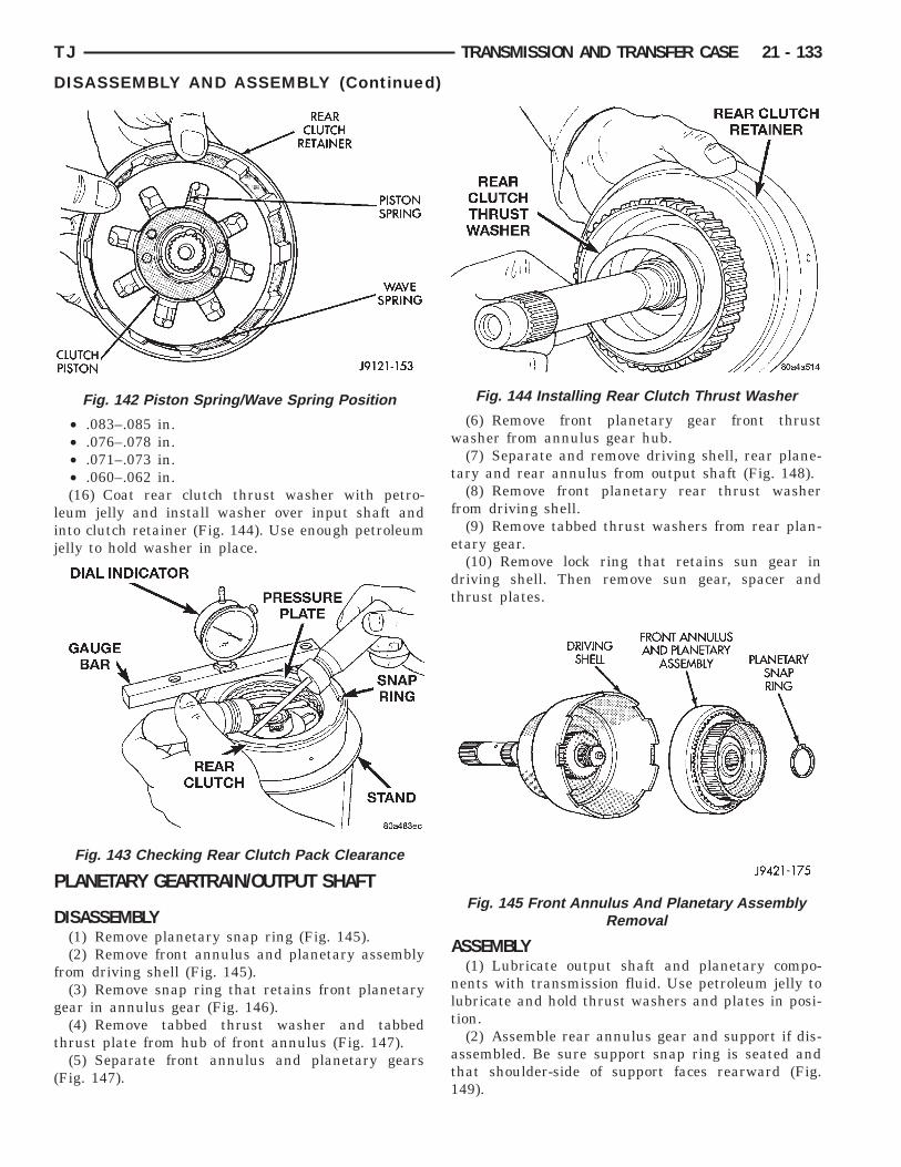
lij
P
D
f
g
t
(
TJ TRANSMISSION AND TRANSFER CASE 21 - 133
DISASSEMBLY AND ASSEMBLY (Continued)
• .083–.085 in.• .076–.078 in.• .071–.073 in.• .060–.062 in.(16) Coat rear clutch thrust washer with petro-
eum jelly and install washer over input shaft andnto clutch retainer (Fig. 144). Use enough petroleumelly to hold washer in place.
LANETARY GEARTRAIN/OUTPUT SHAFT
ISASSEMBLY(1) Remove planetary snap ring (Fig. 145).(2) Remove front annulus and planetary assembly
rom driving shell (Fig. 145).(3) Remove snap ring that retains front planetary
ear in annulus gear (Fig. 146).(4) Remove tabbed thrust washer and tabbed
hrust plate from hub of front annulus (Fig. 147).(5) Separate front annulus and planetary gears
Fig. 147).
Fig. 142 Piston Spring/Wave Spring Position
Fig. 143 Checking Rear Clutch Pack Clearance
(6) Remove front planetary gear front thrustwasher from annulus gear hub.
(7) Separate and remove driving shell, rear plane-tary and rear annulus from output shaft (Fig. 148).
(8) Remove front planetary rear thrust washerfrom driving shell.
(9) Remove tabbed thrust washers from rear plan-etary gear.
(10) Remove lock ring that retains sun gear indriving shell. Then remove sun gear, spacer andthrust plates.
ASSEMBLY(1) Lubricate output shaft and planetary compo-
nents with transmission fluid. Use petroleum jelly tolubricate and hold thrust washers and plates in posi-tion.
(2) Assemble rear annulus gear and support if dis-assembled. Be sure support snap ring is seated andthat shoulder-side of support faces rearward (Fig.149).
Fig. 144 Installing Rear Clutch Thrust Washer
Fig. 145 Front Annulus And Planetary AssemblyRemoval

gpe
t
21 - 134 TRANSMISSION AND TRANSFER CASE TJ
DISASSEMBLY AND ASSEMBLY (Continued)
(3) Install rear thrust washer on rear planetaryear. Use enough petroleum jelly to hold washer inlace. Also be sure all four washer tabs are properlyngaged in gear slots.(4) Install rear annulus over and onto rear plane-
ary gear (Fig. 149).
Fig. 146 Front Planetary Snap Ring Removal
Fig. 147 Front Planetary And Annulus GearDisassembly
Fig. 148 Removing Driving Shell, Rear PlanetaryAnd Rear Annulus
(5) Install assembled rear planetary and annulusgear on output shaft (Fig. 150). Verify that assemblyis fully seated on shaft.
(6) Install front thrust washer on rear planetarygear (Fig. 151). Use enough petroleum jelly to holdwasher on gear. Be sure all four washer tabs areseated in slots.
(7) Install spacer on sun gear (Fig. 152).(8) Install thrust plate on sun gear (Fig. 153). Note
that driving shell thrust plates are interchangeable.Use either plate on sun gear and at front/rear ofshell.
(9) Hold sun gear in place and install thrust plateover sun gear at rear of driving shell (Fig. 154).
(10) Position wood block on bench and support sungear on block (Fig. 155). This makes it easier to alignand install sun gear lock ring. Keep wood blockhandy as it will also be used for geartrain end playcheck.
Fig. 149 Assembling Rear Annulus And PlanetaryGear
Fig. 150 Installing Rear Annulus And Planetary OnOutput Shaft

Washer
On Sun Gear
TJ TRANSMISSION AND TRANSFER CASE 21 - 135
DISASSEMBLY AND ASSEMBLY (Continued)
(11) Align rear thrust plate on driving shell andinstall sun gear lock ring. Be sure ring is fully seatedin sun gear ring groove (Fig. 156).
(12) Install assembled driving shell and sun gearon output shaft (Fig. 157).
(13) Install rear thrust washer on front planetarygear (Fig. 158). Use enough petroleum jelly to holdwasher in place and be sure all four washer tabs areseated.
(14) Install front planetary gear on output shaftand in driving shell (Fig. 159).
(15) Install front thrust washer on front planetarygear. Use enough petroleum jelly to hold washer inplace and be sure all four washer tabs are seated.
(16) Assemble front annulus gear and support, ifnecessary. Be sure support snap ring is seated.
(17) Install front annulus on front planetary (Fig.159).
(18) Position thrust plate on front annulus gearsupport (Fig. 160). Note that plate has two tabson it. These tabs fit in notches of annulus hub.
Fig. 154 Installing Driving Shell Rear Thrust Plate
Fig. 155 Supporting Sun Gear On Wood Block
Fig. 151 Installing Rear Planetary Front Thrust
Fig. 152 Installing Spacer On Sun Gear
Fig. 153 Installing Driving Shell Front Thrust Plate
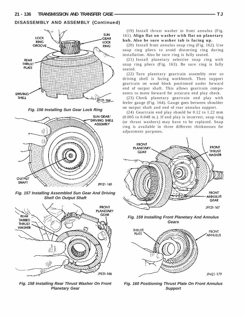
21 - 136 TRANSMISSION AND TRANSFER CASE TJ
DISASSEMBLY AND ASSEMBLY (Continued)
(19) Install thrust washer in front annulus (Fig.161). Align flat on washer with flat on planetaryhub. Also be sure washer tab is facing up.
(20) Install front annulus snap ring (Fig. 162). Usesnap ring pliers to avoid distorting ring duringinstallation. Also be sure ring is fully seated.
(21) Install planetary selective snap ring withsnap ring pliers (Fig. 163). Be sure ring is fullyseated.
(22) Turn planetary geartrain assembly over sodriving shell is facing workbench. Then supportgeartrain on wood block positioned under forwardend of output shaft. This allows geartrain compo-nents to move forward for accurate end play check.
(23) Check planetary geartrain end play withfeeler gauge (Fig. 164). Gauge goes between shoulderon output shaft and end of rear annulus support.
(24) Geartrain end play should be 0.12 to 1.22 mm(0.005 to 0.048 in.). If end play is incorrect, snap ring(or thrust washers) may have to be replaced. Snapring is available in three different thicknesses foradjustment purposes.
Fig. 159 Installing Front Planetary And AnnulusGears
Fig. 160 Positioning Thrust Plate On Front AnnulusSupport
Fig. 156 Installing Sun Gear Lock Ring
Fig. 157 Installing Assembled Sun Gear And DrivingShell On Output Shaft
Fig. 158 Installing Rear Thrust Washer On FrontPlanetary Gear

TJ TRANSMISSION AND TRANSFER CASE 21 - 137
DISASSEMBLY AND ASSEMBLY (Continued)
Fig. 161 Installing Front Annulus Thrust Washer
Fig. 162 Installing Front Annulus Snap Ring
Fig. 163 Installing Planetary Selective Snap Ring
CLEANING AND INSPECTION
GOVERNOR AND PARK GEARThoroughly clean all the governor parts in a suit-
able cleaning solution but do not use any type ofcaustic cleaning agents.
The governor weight components (Fig. 165) and thegovernor valve (Fig. 166), must slide freely in theirbores when clean and dry. Minor surface scratchesand burrs can be smoothed with crocus cloth.
The aluminum governor valve and outer weighthave a hard coating on them. Check condition of thiscoating carefully. Do not reuse either part if the coat-ing is damaged.
Inspect the governor weight spring for distortion.Replace the spring, if distorted, collapsed, or broken.Clean the filter in solvent and dry it with compressedair. Replace the filter, if damaged. Inspect the parkgear for chipped or worn gear teeth or damaged ringgrooves. Replace the gear, if damaged.
Check the teeth on the park gear for wear or dam-age. Replace the gear if necessary. Inspect the metalseal rings on the park gear hub. Replace the ringsonly if severely worn, or broken.
EXTENSION HOUSING AND PARK LOCKClean the housing and park lock components in
solvent and dry them with compressed air.Examine the park lock components in the housing.
If replacement is necessary, remove the shaft withparallel jaw snap ring pliers (Fig. 167) and removethe sprag and spring. Then remove the spring clip
Fig. 164 Checking Planetary Geartrain End Play
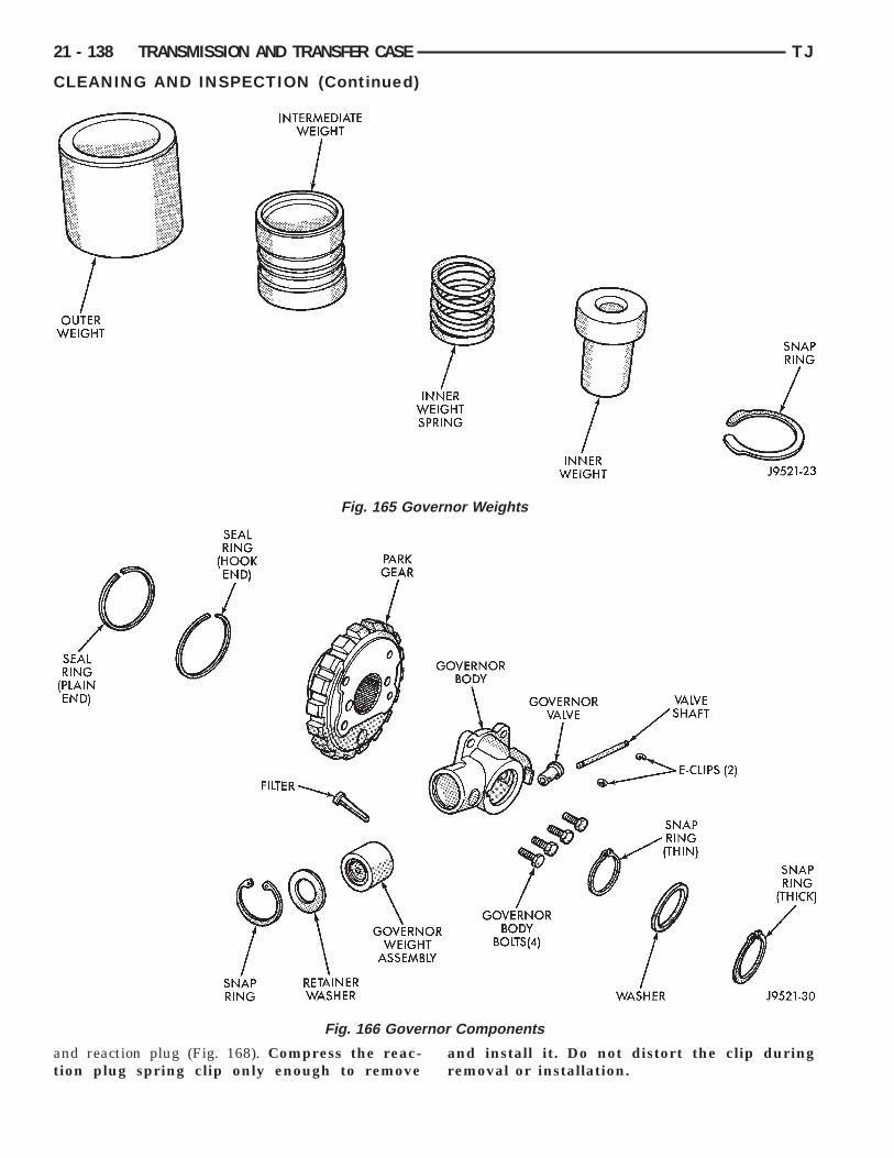
at
erno
nor
21 - 138 TRANSMISSION AND TRANSFER CASE TJ
CLEANING AND INSPECTION (Continued)
nd reaction plug (Fig. 168). Compress the reac-ion plug spring clip only enough to remove
Fig. 165 Gov
Fig. 166 Gover
and install it. Do not distort the clip duringremoval or installation.
r Weights
Components
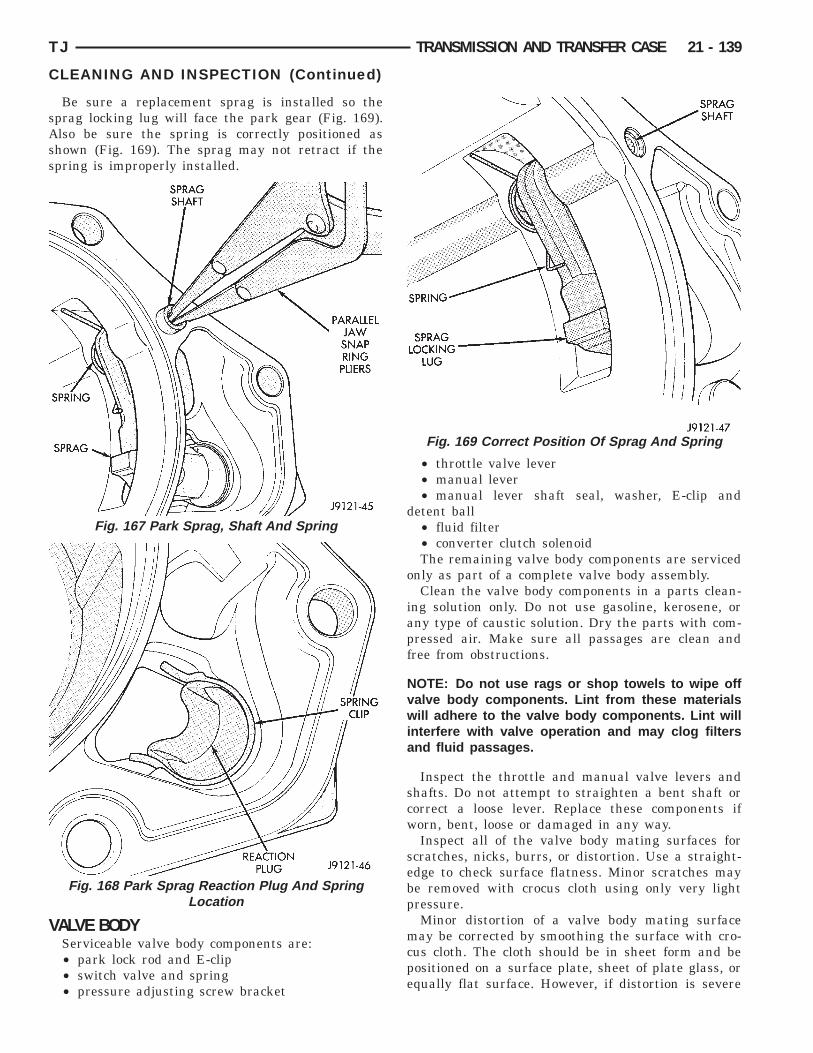
sAss
V
TJ TRANSMISSION AND TRANSFER CASE 21 - 139
CLEANING AND INSPECTION (Continued)
Be sure a replacement sprag is installed so theprag locking lug will face the park gear (Fig. 169).lso be sure the spring is correctly positioned ashown (Fig. 169). The sprag may not retract if thepring is improperly installed.
ALVE BODYServiceable valve body components are:• park lock rod and E-clip• switch valve and spring• pressure adjusting screw bracket
Fig. 167 Park Sprag, Shaft And Spring
Fig. 168 Park Sprag Reaction Plug And SpringLocation
• throttle valve lever• manual lever• manual lever shaft seal, washer, E-clip and
detent ball• fluid filter• converter clutch solenoidThe remaining valve body components are serviced
only as part of a complete valve body assembly.Clean the valve body components in a parts clean-
ing solution only. Do not use gasoline, kerosene, orany type of caustic solution. Dry the parts with com-pressed air. Make sure all passages are clean andfree from obstructions.
NOTE: Do not use rags or shop towels to wipe offvalve body components. Lint from these materialswill adhere to the valve body components. Lint willinterfere with valve operation and may clog filtersand fluid passages.
Inspect the throttle and manual valve levers andshafts. Do not attempt to straighten a bent shaft orcorrect a loose lever. Replace these components ifworn, bent, loose or damaged in any way.
Inspect all of the valve body mating surfaces forscratches, nicks, burrs, or distortion. Use a straight-edge to check surface flatness. Minor scratches maybe removed with crocus cloth using only very lightpressure.
Minor distortion of a valve body mating surfacemay be corrected by smoothing the surface with cro-cus cloth. The cloth should be in sheet form and bepositioned on a surface plate, sheet of plate glass, orequally flat surface. However, if distortion is severe
Fig. 169 Correct Position Of Sprag And Spring
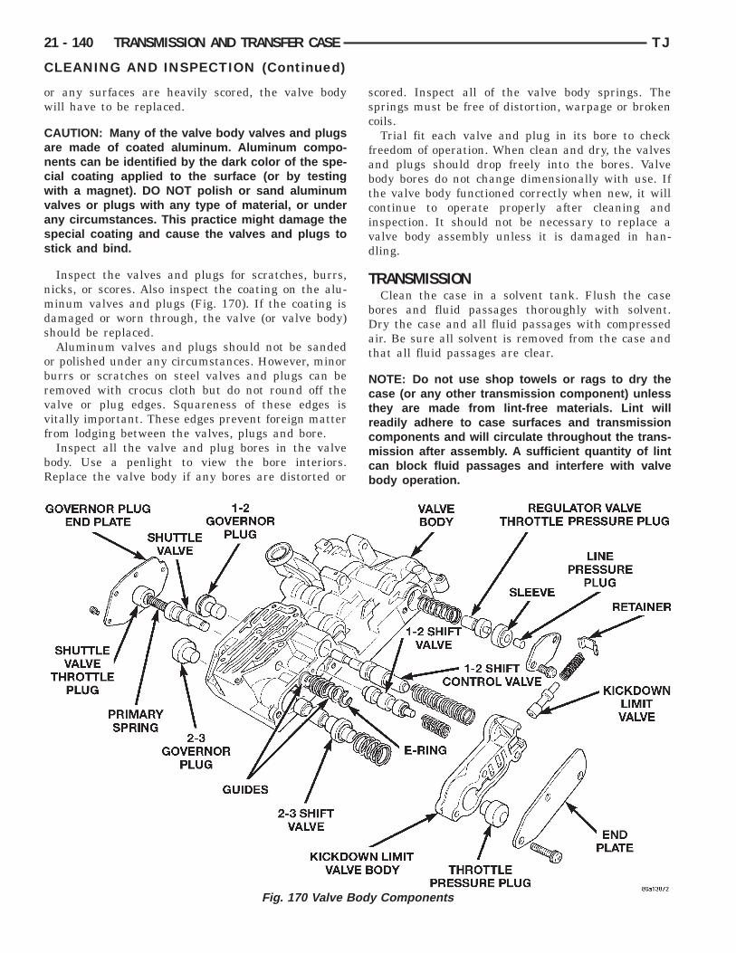
ow
Cancwvass
nmds
obrvvf
bR
21 - 140 TRANSMISSION AND TRANSFER CASE TJ
CLEANING AND INSPECTION (Continued)
r any surfaces are heavily scored, the valve bodyill have to be replaced.
AUTION: Many of the valve body valves and plugsre made of coated aluminum. Aluminum compo-ents can be identified by the dark color of the spe-ial coating applied to the surface (or by testingith a magnet). DO NOT polish or sand aluminumalves or plugs with any type of material, or underny circumstances. This practice might damage thepecial coating and cause the valves and plugs totick and bind.
Inspect the valves and plugs for scratches, burrs,icks, or scores. Also inspect the coating on the alu-inum valves and plugs (Fig. 170). If the coating is
amaged or worn through, the valve (or valve body)hould be replaced.Aluminum valves and plugs should not be sanded
r polished under any circumstances. However, minorurrs or scratches on steel valves and plugs can beemoved with crocus cloth but do not round off thealve or plug edges. Squareness of these edges isitally important. These edges prevent foreign matterrom lodging between the valves, plugs and bore.
Inspect all the valve and plug bores in the valveody. Use a penlight to view the bore interiors.eplace the valve body if any bores are distorted or
Fig. 170 Valve Body
scored. Inspect all of the valve body springs. Thesprings must be free of distortion, warpage or brokencoils.
Trial fit each valve and plug in its bore to checkfreedom of operation. When clean and dry, the valvesand plugs should drop freely into the bores. Valvebody bores do not change dimensionally with use. Ifthe valve body functioned correctly when new, it willcontinue to operate properly after cleaning andinspection. It should not be necessary to replace avalve body assembly unless it is damaged in han-dling.
TRANSMISSIONClean the case in a solvent tank. Flush the case
bores and fluid passages thoroughly with solvent.Dry the case and all fluid passages with compressedair. Be sure all solvent is removed from the case andthat all fluid passages are clear.
NOTE: Do not use shop towels or rags to dry thecase (or any other transmission component) unlessthey are made from lint-free materials. Lint willreadily adhere to case surfaces and transmissioncomponents and will circulate throughout the trans-mission after assembly. A sufficient quantity of lintcan block fluid passages and interfere with valvebody operation.
Components
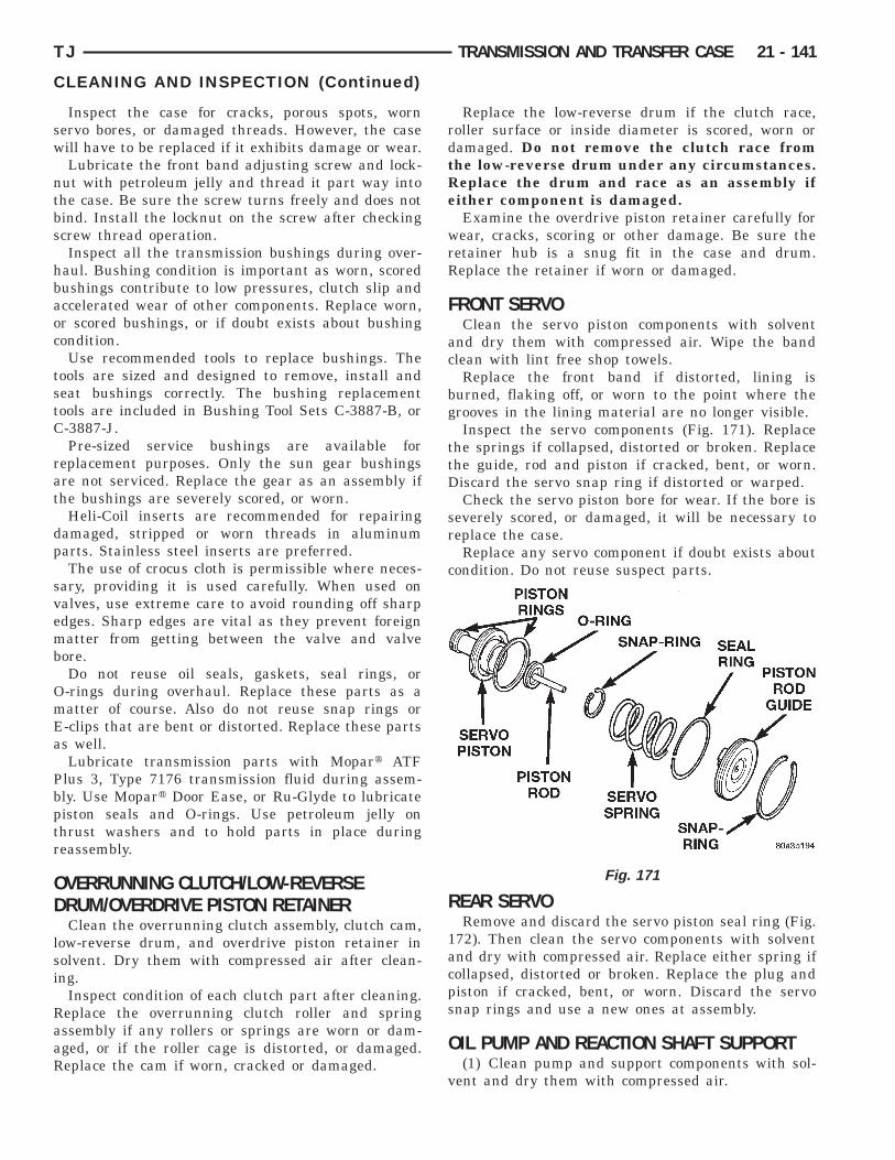
sw
ntbs
hbaoc
tstC
rat
dp
svemb
OmEa
Pbptr
OD
lsi
RaaR
TJ TRANSMISSION AND TRANSFER CASE 21 - 141
CLEANING AND INSPECTION (Continued)
Inspect the case for cracks, porous spots, wornervo bores, or damaged threads. However, the caseill have to be replaced if it exhibits damage or wear.Lubricate the front band adjusting screw and lock-
ut with petroleum jelly and thread it part way intohe case. Be sure the screw turns freely and does notind. Install the locknut on the screw after checkingcrew thread operation.Inspect all the transmission bushings during over-
aul. Bushing condition is important as worn, scoredushings contribute to low pressures, clutch slip andccelerated wear of other components. Replace worn,r scored bushings, or if doubt exists about bushingondition.Use recommended tools to replace bushings. The
ools are sized and designed to remove, install andeat bushings correctly. The bushing replacementools are included in Bushing Tool Sets C-3887-B, or-3887-J.Pre-sized service bushings are available for
eplacement purposes. Only the sun gear bushingsre not serviced. Replace the gear as an assembly ifhe bushings are severely scored, or worn.
Heli-Coil inserts are recommended for repairingamaged, stripped or worn threads in aluminumarts. Stainless steel inserts are preferred.The use of crocus cloth is permissible where neces-
ary, providing it is used carefully. When used onalves, use extreme care to avoid rounding off sharpdges. Sharp edges are vital as they prevent foreignatter from getting between the valve and valve
ore.Do not reuse oil seals, gaskets, seal rings, or-rings during overhaul. Replace these parts as aatter of course. Also do not reuse snap rings or-clips that are bent or distorted. Replace these partss well.Lubricate transmission parts with Mopart ATF
lus 3, Type 7176 transmission fluid during assem-ly. Use Mopart Door Ease, or Ru-Glyde to lubricateiston seals and O-rings. Use petroleum jelly onhrust washers and to hold parts in place duringeassembly.
VERRUNNING CLUTCH/LOW-REVERSERUM/OVERDRIVE PISTON RETAINERClean the overrunning clutch assembly, clutch cam,
ow-reverse drum, and overdrive piston retainer inolvent. Dry them with compressed air after clean-ng.
Inspect condition of each clutch part after cleaning.eplace the overrunning clutch roller and springssembly if any rollers or springs are worn or dam-ged, or if the roller cage is distorted, or damaged.eplace the cam if worn, cracked or damaged.
Replace the low-reverse drum if the clutch race,roller surface or inside diameter is scored, worn ordamaged. Do not remove the clutch race fromthe low-reverse drum under any circumstances.Replace the drum and race as an assembly ifeither component is damaged.
Examine the overdrive piston retainer carefully forwear, cracks, scoring or other damage. Be sure theretainer hub is a snug fit in the case and drum.Replace the retainer if worn or damaged.
FRONT SERVOClean the servo piston components with solvent
and dry them with compressed air. Wipe the bandclean with lint free shop towels.
Replace the front band if distorted, lining isburned, flaking off, or worn to the point where thegrooves in the lining material are no longer visible.
Inspect the servo components (Fig. 171). Replacethe springs if collapsed, distorted or broken. Replacethe guide, rod and piston if cracked, bent, or worn.Discard the servo snap ring if distorted or warped.
Check the servo piston bore for wear. If the bore isseverely scored, or damaged, it will be necessary toreplace the case.
Replace any servo component if doubt exists aboutcondition. Do not reuse suspect parts.
REAR SERVORemove and discard the servo piston seal ring (Fig.
172). Then clean the servo components with solventand dry with compressed air. Replace either spring ifcollapsed, distorted or broken. Replace the plug andpiston if cracked, bent, or worn. Discard the servosnap rings and use a new ones at assembly.
OIL PUMP AND REACTION SHAFT SUPPORT(1) Clean pump and support components with sol-
vent and dry them with compressed air.
Fig. 171

wds
Rodc
rina
s
21 - 142 TRANSMISSION AND TRANSFER CASE TJ
CLEANING AND INSPECTION (Continued)
(2) Check condition of the seal rings and thrustasher on the reaction shaft support. The seal ringso not need to be replaced unless cracked, broken, oreverely worn.(3) Inspect the pump and support components.eplace the pump or support if the seal ring groovesr machined surfaces are worn, scored, pitted, oramaged. Replace the pump gears if pitted, wornhipped, or damaged.(4) Inspect the pump bushing. Then check the
eaction shaft support bushing. Replace either bush-ng only if heavily worn, scored or damaged. It is notecessary to replace the bushings unless they arectually damaged.(5) Install the gears in the pump body and mea-
ure pump component clearances as follows:(a) Clearance between outer gear and reaction
shaft housing should be 0.010 to 0.063 mm (0.0004to 0.0025 in.). Clearance between inner gear andreaction shaft housing should be 0.010 to 0.063mm (0.0004 to 0.0025 in.). Both clearances can bemeasured at the same time by:
(I) Installing the pump gears in the pumphousing.
(II) Position an appropriate piece of Plasti-gagey across both gears.
(III) Align the plastigage to a flat area on thereaction shaft housing.
(IV) Install the reaction shaft to the pumphousing.
(V) Separate the reaction shaft housing fromthe pump housing and measure the Plastigageyfollowing the instructions supplied with it.(b) Clearance between inner gear tooth and
outer gear should be 0.08 to 0.19 mm (0.0035 to0.0075 in.). Measure clearance with an appropriatefeeler gauge.
(c) Clearance between outer gear and pumphousing should also be 0.010 to 0.19 mm (0.0035 to0.0075 in.). Measure clearance with an appropriatefeeler gauge.
Fig. 172 Rear Servo Components
FRONT CLUTCHClean and inspect the front clutch components.
Replace the clutch discs if warped, worn, scored,burned or charred, or if the facing is flaking off.Replace the steel plates if heavily scored, warped, orbroken. Be sure the driving lugs on the plates are ingood condition. The lugs must not be bent, cracked ordamaged in any way.
Replace the clutch spring and spring retainer ifeither is distorted, warped or broken.
Check the lug grooves in the clutch retainer. Thesteel plates should slide freely in the slots. Replacethe retainer if the grooves are worn or damaged.
Check action of the check ball in the retainer (Fig.173). The ball must move freely and not stick.
NOTE: Inspect the clutch retainer bushings care-fully (Fig. 174). The retainer bushings are NOT ser-viceable. It will be necessary to replace the retainerif either bushing is scored, or worn.
Inspect the piston and retainer seal surfaces fornicks or scratches. Minor scratches can be removedwith crocus cloth. However, replace the piston and/orretainer if the seal surfaces are seriously scored.
REAR CLUTCHClean the clutch components with solvent and dry
them with compressed air.Check condition of the input shaft seal rings. It is
not necessary to remove or replace rings unless theyare broken, cracked, or no longer securely hookedtogether.
Inspect the input shaft splines and machined sur-faces. Very minor nicks or scratches can be smoothedoff with crocus cloth. replace the shaft if the splinesare damaged, or any of the machined surfaces areseverely scored.
Fig. 173 Front Clutch Piston Retainer Check BallLocation

bi
hidd
p
stcm
nwr
sR
shc
P
nDp
Tpdr
b
TJ TRANSMISSION AND TRANSFER CASE 21 - 143
CLEANING AND INSPECTION (Continued)
Replace the clutch discs if warped, worn, scored,urned/charred, the lugs are damaged, or if the fac-ng is flaking off.
Replace the steel plates and the pressure plate ifeavily scored, warped, or broken. Be sure the driv-
ng lugs on the discs and plates are also in good con-ition. The lugs must not be bent, cracked oramaged in any way.Replace the piston spring and wave spring if either
art is distorted, warped or broken.Check the lug grooves in the clutch retainer. The
teel plates should slide freely in the slots. Replacehe retainer if the grooves are worn or damaged. Alsoheck action of the retainer check ball. The ball mustove freely and not stick.Inspect the piston and retainer seal surfaces for
icks or scratches. Minor scratches can be removedith crocus cloth. However, replace the piston and/or
etainer if the seal surfaces are seriously damaged.Check thrust washer condition. Washer thickness
hould be 1.55 to 1.60 mm (0.061 to 0.063 in.).eplace the washer if worn or damaged.Check condition of the two seal rings on the input
haft and the single seal ring on the piston retainerub. Replace the seal rings only if severely worn,racked, or cannot be hooked together.
LANETARY GEARTRAIN/OUTPUT SHAFTClean the intermediate shaft and planetary compo-
ents in solvent and dry them with compressed air.o not spin the planetary pinion gears with com-ressed air.Inspect the planetary gear sets and annulus gears.
he planetary pinions, shafts, washers, and retainingins are serviceable. However, if a pinion carrier isamaged, the entire planetary gear set must beeplaced as an assembly.Replace the annulus gears if the teeth are chipped,
roken, or worn, or the gear is cracked. Replace the
Fig. 174 Retainer Bushing Location/Inspection
planetary thrust plates and the tabbed thrust wash-ers if cracked, scored or worn.
Inspect the machined surfaces of the output shaft.Be sure the oil passages are open and clear. Replacethe shaft if scored, pitted, or damaged.
Inspect the sun gear and driving shell. If eithercomponent is worn or damaged, remove the sun gearrear retaining ring and separate the sun gear andthrust plate from the driving shell. Then replace thenecessary component.
Replace the sun gear as an assembly if the gearteeth are chipped or worn. Also replace the gear asan assembly if the bushings are scored or worn. Thesun gear bushings are not serviceable. Replace thethrust plate if worn, or severely scored. Replace thedriving shell if distorted, cracked, or damaged in anyway.
Replace all snap rings during geartrain assembly.Reusing snap rings is not recommended.
ADJUSTMENTS
GEARSHIFT CABLECheck adjustment by starting the engine in Park
and Neutral. Adjustment is OK if the engine startsonly in these positions. Adjustment is incorrect if theengine starts in one but not both positions. If theengine starts in any position other than Park or Neu-tral, or if the engine will not start at all, the park/neutral position switch may be faulty.
Gearshift Adjustment Procedure(1) Shift transmission into Park.(2) Raise vehicle.(3) Release cable adjuster clamp (at transmission
end of cable) to unlock cable.(4) Unsnap cable from cable mounting bracket on
transmission (Fig. 175).(5) Slide cable eyelet off transmission shift lever.(6) Verify transmission shift lever is in Park
detent by moving lever fully rearward. Last rearwarddetent is Park position.
(7) Verify positive engagement of transmissionpark lock by attempting to rotate propeller shaft.Shaft will not rotate when park lock is engaged.
(8) Slide cable eyelt onto transmission shift lever.(9) Snap shift cable adjuster into mounting
bracket on transmission.(10) Lock shift cable by pressing cable adjuster
clamp down until it snaps into place.(11) Lower vehicle and check engine starting.
Engine should start only in Park and Neutral.

BC
R
1
b
p
21 - 144 TRANSMISSION AND TRANSFER CASE TJ
ADJUSTMENTS (Continued)
RAKE TRANSMISSION SHIFT INTERLOCKABLE ADJUSTMENT(1) Shift transmission into PARK.(2) Remove shift lever bezel and console screws.aise bezel and console for access to cable.(3) Pull cable lock button up to release cable (Fig.
76).(4) Turn ignition switch to LOCK position.
(5) Use a spacer to create a one millimeter gapetween the shifter pawl and top of the shift gate.(6) Pull cable forward. Then release cable and
ress cable lock button down until it snaps in place.
Fig. 175 Shift Cable Attachment AtTransmission–Typical
Fig. 176 Park Lock Cable Attachment
(7) Check adjustment as follows:(a) Check movement of release shift handle but-
ton (floor shift) or release lever (column shift). Youshould not be able to press button inward or movecolumn lever.
(b) Turn ignition switch to RUN position.(c) Shifting out of park should not be possible.(d) Apply the brake and attempt to shift out of
PARK. Shifting should be possible.(e) While the transmission is shifted out of
PARK, release the brake and attempt to shiftthrough all gears. Release the shift button at leastonce during this procedure. The ignition key shouldnot go to the LOCK position.
(f) Return transmission to the PARK positionwithout applying the brake.(8) Move shift lever back to PARK and check igni-
tion switch operation. You should be able to turnswitch to LOCK position and shift lever release but-ton/lever should not move.
TRANSMISSION THROTTLE VALVE CABLEADJUSTMENT
The transmission throttle valve is operated by acam on the throttle lever. The throttle lever is oper-ated by an adjustable cable (Fig. 177). The cable isattached to an arm mounted on the throttle levershaft. A retaining clip at the engine-end of the cableis removed to provide for cable adjustment. Theretaining clip is then installed back onto the throttlevalve cable to lock in the adjustment.
A correctly adjusted throttle valve cable will causethe throttle lever on the transmission to move simul-taneously with the throttle body lever from the idleposition. Proper adjustment will allow simultaneousmovement without causing the transmission throttlelever to either move ahead of, or lag behind the leveron the throttle body.
Fig. 177 Throttle Cable Attachment At Engine
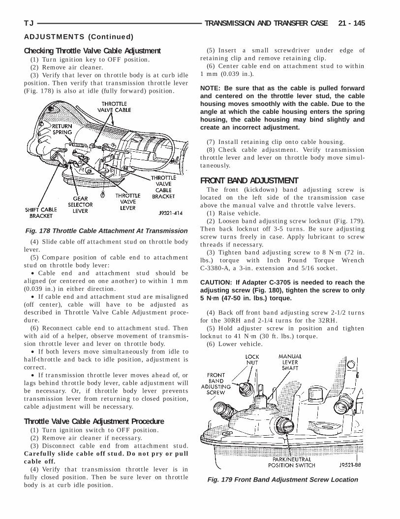
C
p(
l
s
a(
(dd
ws
hc
lbtc
T
Cc
fb
TJ TRANSMISSION AND TRANSFER CASE 21 - 145
ADJUSTMENTS (Continued)
hecking Throttle Valve Cable Adjustment(1) Turn ignition key to OFF position.(2) Remove air cleaner.(3) Verify that lever on throttle body is at curb idle
osition. Then verify that transmission throttle leverFig. 178) is also at idle (fully forward) position.
(4) Slide cable off attachment stud on throttle bodyever.
(5) Compare position of cable end to attachmenttud on throttle body lever:• Cable end and attachment stud should be
ligned (or centered on one another) to within 1 mm0.039 in.) in either direction.
• If cable end and attachment stud are misalignedoff center), cable will have to be adjusted asescribed in Throttle Valve Cable Adjustment proce-ure.(6) Reconnect cable end to attachment stud. Thenith aid of a helper, observe movement of transmis-
ion throttle lever and lever on throttle body.• If both levers move simultaneously from idle to
alf-throttle and back to idle position, adjustment isorrect.• If transmission throttle lever moves ahead of, or
ags behind throttle body lever, cable adjustment wille necessary. Or, if throttle body lever preventsransmission lever from returning to closed position,able adjustment will be necessary.
hrottle Valve Cable Adjustment Procedure(1) Turn ignition switch to OFF position.(2) Remove air cleaner if necessary.(3) Disconnect cable end from attachment stud.arefully slide cable off stud. Do not pry or pullable off.(4) Verify that transmission throttle lever is in
ully closed position. Then be sure lever on throttleody is at curb idle position.
Fig. 178 Throttle Cable Attachment At Transmission
(5) Insert a small screwdriver under edge ofretaining clip and remove retaining clip.
(6) Center cable end on attachment stud to within1 mm (0.039 in.).
NOTE: Be sure that as the cable is pulled forwardand centered on the throttle lever stud, the cablehousing moves smoothly with the cable. Due to theangle at which the cable housing enters the springhousing, the cable housing may bind slightly andcreate an incorrect adjustment.
(7) Install retaining clip onto cable housing.(8) Check cable adjustment. Verify transmission
throttle lever and lever on throttle body move simul-taneously.
FRONT BAND ADJUSTMENTThe front (kickdown) band adjusting screw is
located on the left side of the transmission caseabove the manual valve and throttle valve levers.
(1) Raise vehicle.(2) Loosen band adjusting screw locknut (Fig. 179).
Then back locknut off 3-5 turns. Be sure adjustingscrew turns freely in case. Apply lubricant to screwthreads if necessary.
(3) Tighten band adjusting screw to 8 N·m (72 in.lbs.) torque with Inch Pound Torque WrenchC-3380-A, a 3-in. extension and 5/16 socket.
CAUTION: If Adapter C-3705 is needed to reach theadjusting screw (Fig. 180), tighten the screw to only5 N·m (47-50 in. lbs.) torque.
(4) Back off front band adjusting screw 2-1/2 turnsfor the 30RH and 2-1/4 turns for the 32RH.
(5) Hold adjuster screw in position and tightenlocknut to 41 N·m (30 ft. lbs.) torque.
(6) Lower vehicle.
Fig. 179 Front Band Adjustment Screw Location
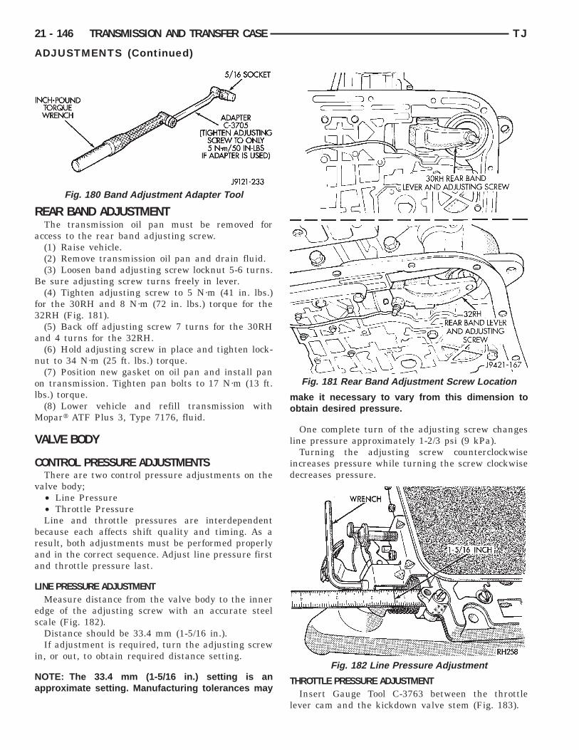
R
a
B
f3
a
n
ol
M
V
C
v
braa
L
es
i
Na
21 - 146 TRANSMISSION AND TRANSFER CASE TJ
ADJUSTMENTS (Continued)
EAR BAND ADJUSTMENTThe transmission oil pan must be removed for
ccess to the rear band adjusting screw.(1) Raise vehicle.(2) Remove transmission oil pan and drain fluid.(3) Loosen band adjusting screw locknut 5-6 turns.e sure adjusting screw turns freely in lever.(4) Tighten adjusting screw to 5 N·m (41 in. lbs.)
or the 30RH and 8 N·m (72 in. lbs.) torque for the2RH (Fig. 181).(5) Back off adjusting screw 7 turns for the 30RH
nd 4 turns for the 32RH.(6) Hold adjusting screw in place and tighten lock-
ut to 34 N·m (25 ft. lbs.) torque.(7) Position new gasket on oil pan and install pan
n transmission. Tighten pan bolts to 17 N·m (13 ft.bs.) torque.
(8) Lower vehicle and refill transmission withopart ATF Plus 3, Type 7176, fluid.
ALVE BODY
ONTROL PRESSURE ADJUSTMENTSThere are two control pressure adjustments on the
alve body;• Line Pressure• Throttle PressureLine and throttle pressures are interdependent
ecause each affects shift quality and timing. As aesult, both adjustments must be performed properlynd in the correct sequence. Adjust line pressure firstnd throttle pressure last.
INE PRESSURE ADJUSTMENTMeasure distance from the valve body to the inner
dge of the adjusting screw with an accurate steelcale (Fig. 182).Distance should be 33.4 mm (1-5/16 in.).If adjustment is required, turn the adjusting screw
n, or out, to obtain required distance setting.
OTE: The 33.4 mm (1-5/16 in.) setting is anpproximate setting. Manufacturing tolerances may
Fig. 180 Band Adjustment Adapter Tool
make it necessary to vary from this dimension toobtain desired pressure.
One complete turn of the adjusting screw changesline pressure approximately 1-2/3 psi (9 kPa).
Turning the adjusting screw counterclockwiseincreases pressure while turning the screw clockwisedecreases pressure.
THROTTLE PRESSURE ADJUSTMENTInsert Gauge Tool C-3763 between the throttle
lever cam and the kickdown valve stem (Fig. 183).
Fig. 181 Rear Band Adjustment Screw Location
Fig. 182 Line Pressure Adjustment
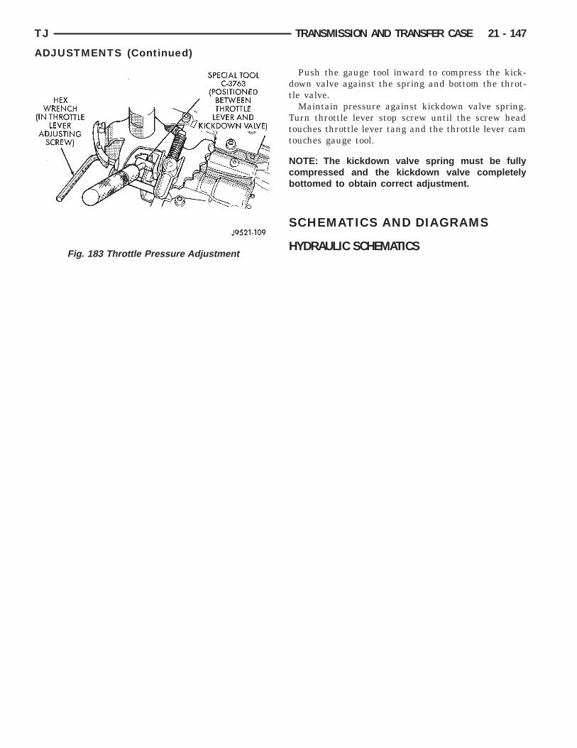
TJ TRANSMISSION AND TRANSFER CASE 21 - 147
ADJUSTMENTS (Continued)
Fig. 183 Throttle Pressure Adjustment
Push the gauge tool inward to compress the kick-down valve against the spring and bottom the throt-tle valve.
Maintain pressure against kickdown valve spring.Turn throttle lever stop screw until the screw headtouches throttle lever tang and the throttle lever camtouches gauge tool.
NOTE: The kickdown valve spring must be fullycompressed and the kickdown valve completelybottomed to obtain correct adjustment.
SCHEMATICS AND DIAGRAMS
HYDRAULIC SCHEMATICS
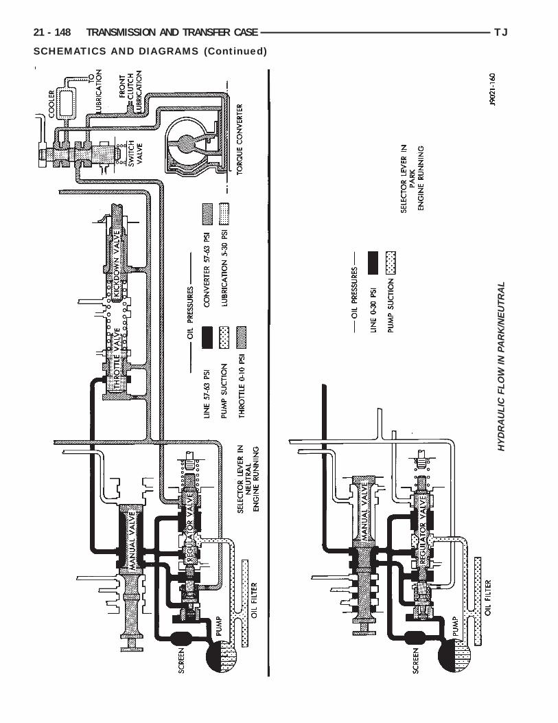
HY
DR
AU
LIC
FLO
WIN
PAR
K/N
EU
TR
AL
21 - 148 TRANSMISSION AND TRANSFER CASE TJ
SCHEMATICS AND DIAGRAMS (Continued)

HY
DR
AU
LIC
FLO
WIN
D-F
IRS
TG
EA
R
TJ TRANSMISSION AND TRANSFER CASE 21 - 149
SCHEMATICS AND DIAGRAMS (Continued)

HY
DR
AU
LIC
FLO
WIN
D-S
EC
ON
DG
EA
R
21 - 150 TRANSMISSION AND TRANSFER CASE TJ
SCHEMATICS AND DIAGRAMS (Continued)

HY
DR
AU
LIC
FLO
WIN
D-T
HIR
DG
EA
R
TJ TRANSMISSION AND TRANSFER CASE 21 - 151
SCHEMATICS AND DIAGRAMS (Continued)
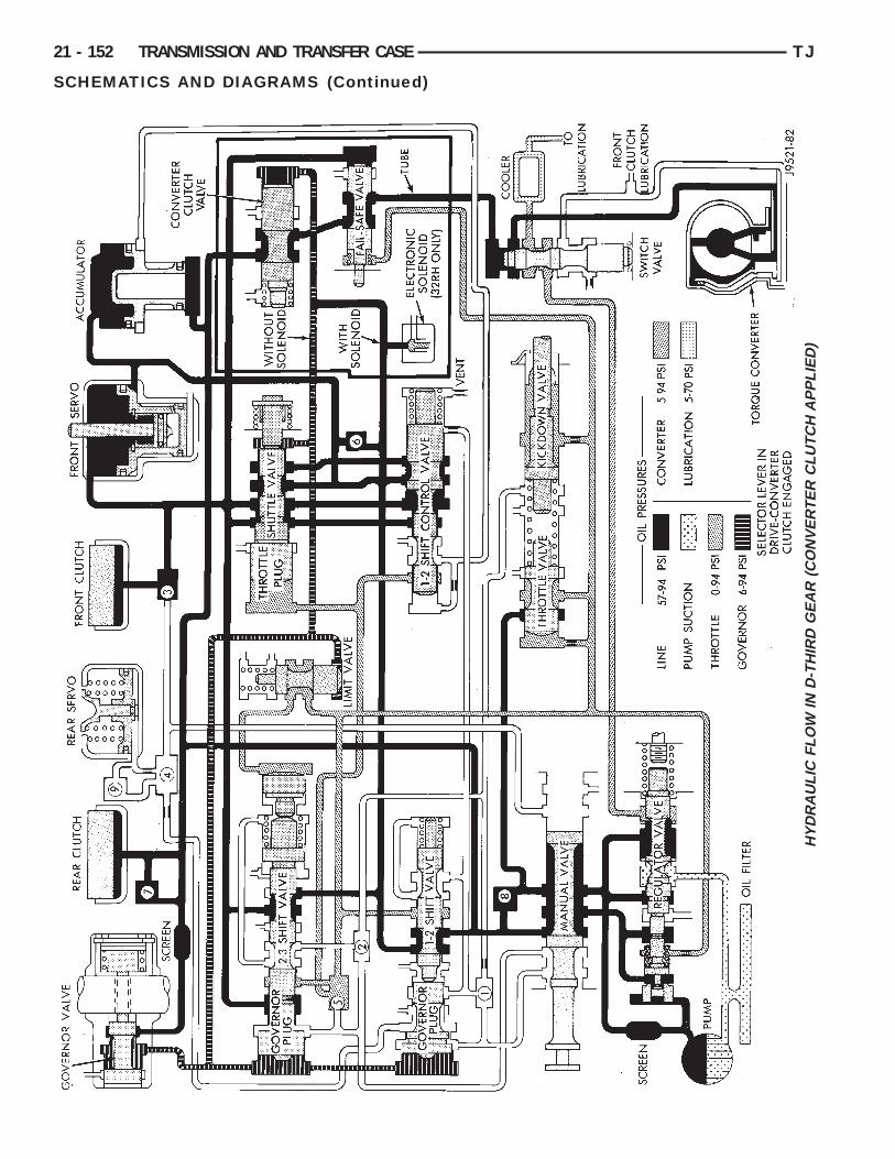
HY
DR
AU
LIC
FLO
WIN
D-T
HIR
DG
EA
R(C
ON
VE
RT
ER
CLU
TC
HA
PP
LIE
D)
21 - 152 TRANSMISSION AND TRANSFER CASE TJ
SCHEMATICS AND DIAGRAMS (Continued)

HY
DR
AU
LIC
FLO
WAT
PAR
TT
HR
OT
TLE
3-2
KIC
KD
OW
N
TJ TRANSMISSION AND TRANSFER CASE 21 - 153
SCHEMATICS AND DIAGRAMS (Continued)
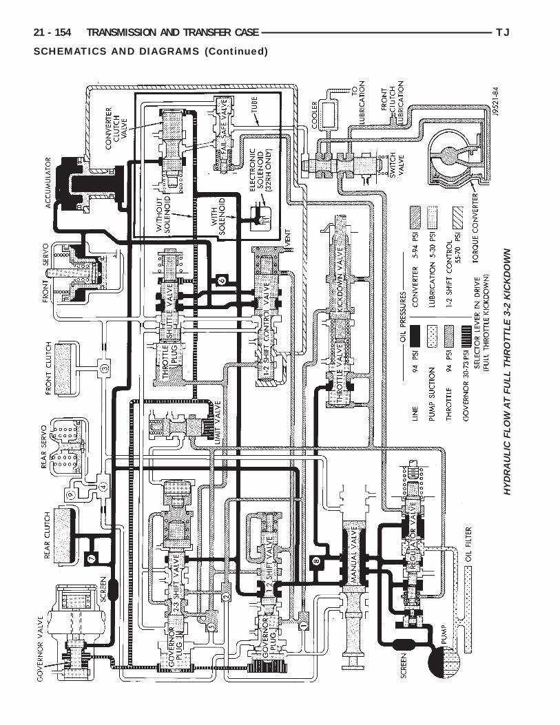
HY
DR
AU
LIC
FLO
WAT
FU
LLT
HR
OT
TLE
3-2
KIC
KD
OW
N
21 - 154 TRANSMISSION AND TRANSFER CASE TJ
SCHEMATICS AND DIAGRAMS (Continued)

HY
DR
AU
LIC
FLO
WIN
MA
NU
AL
SE
CO
ND
TJ TRANSMISSION AND TRANSFER CASE 21 - 155
SCHEMATICS AND DIAGRAMS (Continued)
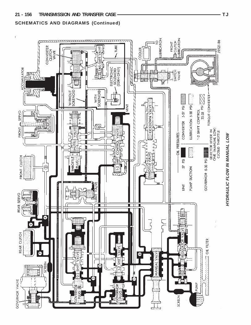
HY
DR
AU
LIC
FLO
WIN
MA
NU
AL
LOW
21 - 156 TRANSMISSION AND TRANSFER CASE TJ
SCHEMATICS AND DIAGRAMS (Continued)
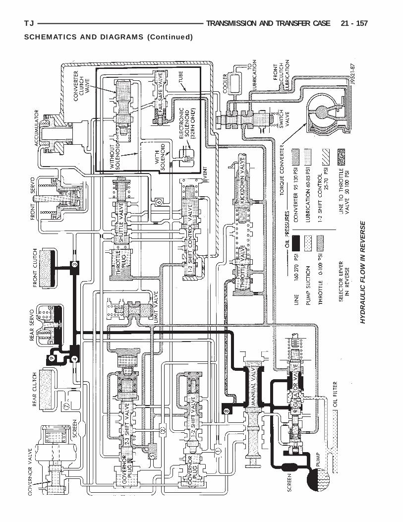
HY
DR
AU
LIC
FLO
WIN
RE
VE
RS
E
TJ TRANSMISSION AND TRANSFER CASE 21 - 157
SCHEMATICS AND DIAGRAMS (Continued)

HY
DR
AU
LIC
FLO
WIN
MA
NU
AL
FIR
ST
GE
AR
(1)
21 - 158 TRANSMISSION AND TRANSFER CASE TJ
SCHEMATICS AND DIAGRAMS (Continued)

HY
DR
AU
LIC
FLO
WIN
MA
NU
AL
SE
CO
ND
GE
AR
(2)
TJ TRANSMISSION AND TRANSFER CASE 21 - 159
SCHEMATICS AND DIAGRAMS (Continued)
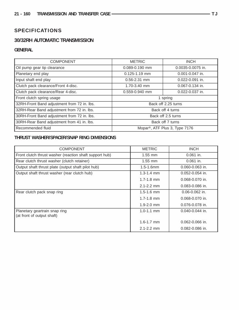
S
3
G
T
21 - 160 TRANSMISSION AND TRANSFER CASE TJ
PECIFICATIONS
0/32RH AUTOMATIC TRANSMISSION
ENERAL
COMPONENT METRIC INCH
Oil pump gear tip clearance 0.089-0.190 mm 0.0035-0.0075 in.
Planetary end play 0.125-1.19 mm 0.001-0.047 in.
Input shaft end play 0.56-2.31 mm 0.022-0.091 in.
Clutch pack clearance/Front 4-disc. 1.70-3.40 mm 0.067-0.134 in.
Clutch pack clearance/Rear 4-disc. 0.559-0.940 mm 0.022-0.037 in.
Front clutch spring usage 1 spring
32RH-Front Band adjustment from 72 in. lbs. Back off 2.25 turns
32RH-Rear Band adjustment from 72 in. lbs. Back off 4 turns
30RH-Front Band adjustment from 72 in. lbs. Back off 2.5 turns
30RH-Rear Band adjustment from 41 in. lbs. Back off 7 turns
Recommended fluid MoparT, ATF Plus 3, Type 7176
HRUST WASHER/SPACER/SNAP RING DIMENSIONS
COMPONENT METRIC INCH
Front clutch thrust washer (reaction shaft support hub) 1.55 mm 0.061 in.
Rear clutch thrust washer (clutch retainer) 1.55 mm 0.061 in.
Output shaft thrust plate (output shaft pilot hub) 1.5-1.6mm 0.060-0.063 in.
Output shaft thrust washer (rear clutch hub) 1.3-1.4 mm 0.052-0.054 in.
1.7-1.8 mm 0.068-0.070 in.
2.1-2.2 mm 0.083-0.086 in.
Rear clutch pack snap ring 1.5-1.6 mm 0.06-0.062 in.
1.7-1.8 mm 0.068-0.070 in.
1.9-2.0 mm 0.076-0.078 in.
Planetary geartrain snap ring(at front of output shaft)
1.0-1.1 mm 0.040-0.044 in.
1.6-1.7 mm 0.062-0.066 in.
2.1-2.2 mm 0.082-0.086 in.

P
T
S
3
TJ TRANSMISSION AND TRANSFER CASE 21 - 161
SPECIFICATIONS (Continued)
RESSURE TEST—ALL
ITEM RANGE PRESSURE
Line pressure (ataccumulator)
Closed throttle 372-414 kPa (54-60 psi).
Front servo Third gear only No more than 21 kPa (3 psi) lower than line pressure.
Rear servo 1 range No more than 21 kPa (3 psi) lower than line pressure.
R range 1103 kPa (160 psi) at idle, builds to 1862 kPa (270 psi)at 1600 rpm.
Governor D range closed throttle Pressure should respond smoothly to changes in mphand return to 0-7 kPa (0-1.5 psi) when stopped withtransmission in D, 1, 2. Pressure above 7 kPa (1.5 psi)at stand still will prevent transmission fromdownshifting.
ORQUE
DESCRIPTION TORQUEBolt, torque convertor . . . . . . . . . 31 N·m (23 ft. lbs.)Bolt/nut, crossmember . . . . . . . . 68 N·m (50 ft. lbs.)Bolt, driveplate to crankshaft . . . 75 N·m (55 ft. lbs.)Plug, front band reaction . . . . . . 17 N·m (13 ft. lbs.)Locknut, front band adj. . . . . . . . 34 N·m (25 ft. lbs.)Switch, park/neutral . . . . . . . . . . 34 N·m (25 ft. lbs.)Bolt, fluid pan . . . . . . . . . . . . . . 17 N·m (13 ft. lbs.)Bolt, oil pump . . . . . . . . . . . . . . . 20 N·m (15 ft. lbs.)Bolt, overrunning clutch cam . . . 17 N·m (13 ft. lbs.)Plug, pressure test port . . . . . . . 14 N·m (10 ft. lbs.)Bolt, reaction shaft support . . . . 20 N·m (15 ft. lbs.)Locknut, rear band . . . . . . . . . . . 41 N·m (30 ft. lbs.)Bolt. speedometer adapter . . . . . . 11 N·m (8 ft. lbs.)Screw, fluid filter . . . . . . . . . . . . . 4 N·m (35 in. lbs.)Bolt, valve body to case . . . . . . 12 N·m (100 in. lbs.)
PECIAL TOOLS
0/32RH TRANSMISSIONS
Remover—6957
Installer—6951
Retainer, Detent Ball and Spring—6583
Snap-ring Plier—6823
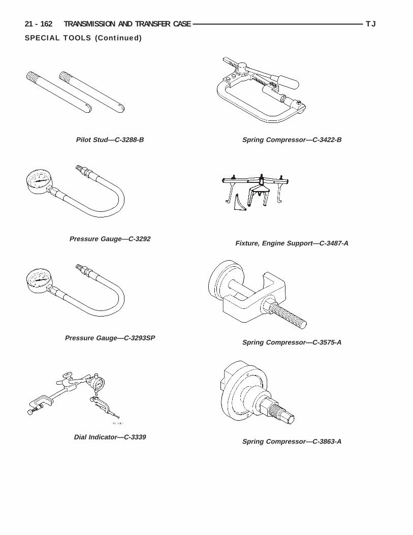
21 - 162 TRANSMISSION AND TRANSFER CASE TJ
SPECIAL TOOLS (Continued)
Pilot Stud—C-3288-B
Pressure Gauge—C-3292
Pressure Gauge—C-3293SP
Dial Indicator—C-3339
Spring Compressor—C-3422-B
Fixture, Engine Support—C-3487-A
Spring Compressor—C-3575-A
Spring Compressor—C-3863-A

TJ TRANSMISSION AND TRANSFER CASE 21 - 163
SPECIAL TOOLS (Continued)
Adapter, Band Adjuster—C-3705
Transmission Repair Stand—C-3750-B
Puller, Slide Hammer—C-3752
Gauge, Throttle Setting—C-3763
Seal Installer—C-3860-A
Bushing Remover/Installer—C-3887-J
Cup, Remover—SP-3633
Remover, Bushing—SP-5301
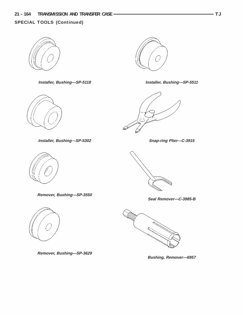
21 - 164 TRANSMISSION AND TRANSFER CASE TJ
SPECIAL TOOLS (Continued)
Installer, Bushing—SP-5118
Installer, Bushing—SP-5302
Remover, Bushing—SP-3550
Remover, Bushing—SP-3629
Installer, Bushing—SP-5511
Snap-ring Plier—C-3915
Seal Remover—C-3985-B
Bushing, Remover—6957
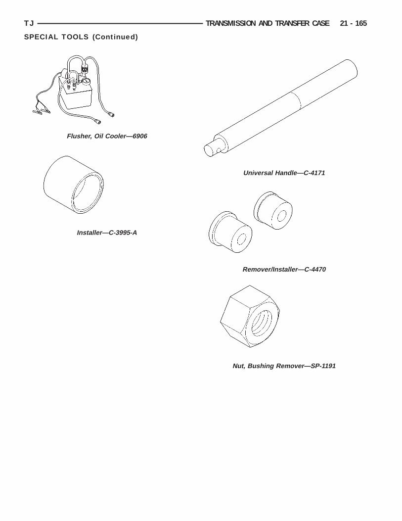
TJ TRANSMISSION AND TRANSFER CASE 21 - 165
SPECIAL TOOLS (Continued)
Flusher, Oil Cooler—6906
Installer—C-3995-A
Universal Handle—C-4171
Remover/Installer—C-4470
Nut, Bushing Remover—SP-1191
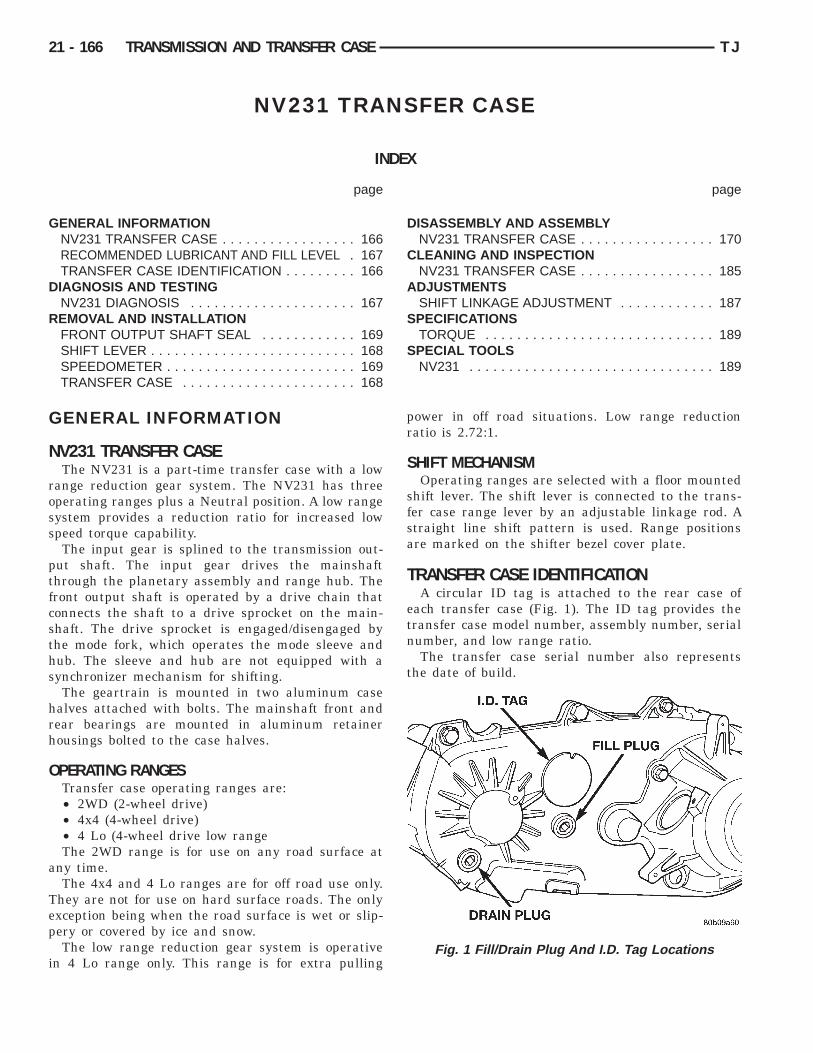
G
D
R
G
N
ross
ptfcsths
hrh
O
a
Tep
i
21 - 166 TRANSMISSION AND TRANSFER CASE TJ
NV231 TRANSFER CASE
INDEX
page page
ENERAL INFORMATIONNV231 TRANSFER CASE . . . . . . . . . . . . . . . . . 166RECOMMENDED LUBRICANT AND FILL LEVEL . 167TRANSFER CASE IDENTIFICATION . . . . . . . . . 166IAGNOSIS AND TESTINGNV231 DIAGNOSIS . . . . . . . . . . . . . . . . . . . . . 167EMOVAL AND INSTALLATIONFRONT OUTPUT SHAFT SEAL . . . . . . . . . . . . 169SHIFT LEVER . . . . . . . . . . . . . . . . . . . . . . . . . . 168SPEEDOMETER . . . . . . . . . . . . . . . . . . . . . . . . 169
TRANSFER CASE . . . . . . . . . . . . . . . . . . . . . . 168DISASSEMBLY AND ASSEMBLYNV231 TRANSFER CASE . . . . . . . . . . . . . . . . . 170
CLEANING AND INSPECTIONNV231 TRANSFER CASE . . . . . . . . . . . . . . . . . 185
ADJUSTMENTSSHIFT LINKAGE ADJUSTMENT . . . . . . . . . . . . 187
SPECIFICATIONSTORQUE . . . . . . . . . . . . . . . . . . . . . . . . . . . . . 189
SPECIAL TOOLSNV231 . . . . . . . . . . . . . . . . . . . . . . . . . . . . . . . 189
ENERAL INFORMATION
V231 TRANSFER CASEThe NV231 is a part-time transfer case with a low
ange reduction gear system. The NV231 has threeperating ranges plus a Neutral position. A low rangeystem provides a reduction ratio for increased lowpeed torque capability.The input gear is splined to the transmission out-
ut shaft. The input gear drives the mainshafthrough the planetary assembly and range hub. Theront output shaft is operated by a drive chain thatonnects the shaft to a drive sprocket on the main-haft. The drive sprocket is engaged/disengaged byhe mode fork, which operates the mode sleeve andub. The sleeve and hub are not equipped with aynchronizer mechanism for shifting.The geartrain is mounted in two aluminum case
alves attached with bolts. The mainshaft front andear bearings are mounted in aluminum retainerousings bolted to the case halves.
PERATING RANGESTransfer case operating ranges are:• 2WD (2-wheel drive)• 4x4 (4-wheel drive)• 4 Lo (4-wheel drive low rangeThe 2WD range is for use on any road surface at
ny time.The 4x4 and 4 Lo ranges are for off road use only.
hey are not for use on hard surface roads. The onlyxception being when the road surface is wet or slip-ery or covered by ice and snow.The low range reduction gear system is operative
n 4 Lo range only. This range is for extra pulling
power in off road situations. Low range reductionratio is 2.72:1.
SHIFT MECHANISMOperating ranges are selected with a floor mounted
shift lever. The shift lever is connected to the trans-fer case range lever by an adjustable linkage rod. Astraight line shift pattern is used. Range positionsare marked on the shifter bezel cover plate.
TRANSFER CASE IDENTIFICATIONA circular ID tag is attached to the rear case of
each transfer case (Fig. 1). The ID tag provides thetransfer case model number, assembly number, serialnumber, and low range ratio.
The transfer case serial number also representsthe date of build.
Fig. 1 Fill/Drain Plug And I.D. Tag Locations

R
cAp
D
N
TJ TRANSMISSION AND TRANSFER CASE 21 - 167
GENERAL INFORMATION (Continued)
ECOMMENDED LUBRICANT AND FILL LEVELRecommended lubricant for the NV231 transfer
ase is Mopart Dexron II, or ATF Plus 3, type 7176.pproximate lubricant fill capacity is 1.2 liters (2.5
ints).IAGNOSIS AND TESTING
The fill and drain plugs are both in the rear case(Fig. 1). Correct fill level is to the bottom edge of thefill plug hole. Be sure the vehicle is level to ensurean accurate fluid level check.
V231 DIAGNOSISDIAGNOSIS CHART
Condition Possible Cause Correction
Transfer case difficult to shift or willnot shift into desired range.
1) Vehicle speed to great to permitshifting.
1) Slow vehicle and shift intodesired range.
2) If vehicle was operated for anextended period in 4H mode on drysurface, driveline torque load maycause difficulty.
2) Stop vehicle and shift transfercase to Neutral position. Transfercase can then be shifted to thedesired mode.
3) Transfer case shift linkagebinding.
3) Repair or replace linkage asnecessary.
4) Insufficient or incorrect lubricant. 4) Drain and refill transfer case withthe correct type and quantity oflubricant.
5) Internal transfer casecomponents binding, worn, ordamaged.
5) Repair or replace components asnecessary.
Transfer case noisy in all drivemodes.
1) Insufficient or incorrect lubricant. 1) Drain and refill transfer case withthe correct type and quantity oflubricant.
Transfer case noisy while in, orjumps out of, 4L mode.
1) Transfer case not completelyengaged in 4L position.
1) Slow vehicle, shift transfer caseto the Neutral position, and thenshift into the 4L mode.
2) Transfer case shift linkage out ofadjustment.
2) Adjust linkage as necessary.
3) Transfer case shift linkage looseor binding.
3) Repair, replace, or tighten linkagecomponents as necessary.
4) Range fork damaged, insertsworn, or fork is binding on the shiftrail.
4) Repair or replace components asnecessary.
5) Low range gear worn ordamaged.
5) Repair or replace components asnecessary.
Lubricant leaking from transfer caseseals or vent.
1) Transfer case overfilled. 1) Drain lubricant to the correctlevel.
2) Transfer case vent closed orrestricted.
2) Clean or replace vent asnecessary.
3) Transfer case seals damaged orinstalled incorrectly.
3) Replace suspect seal.
Abnormal tire wear. 1) Extended operation in 4H modeon dry surfaces.
1) Operate vehicle in 2H mode ondry surfaces.
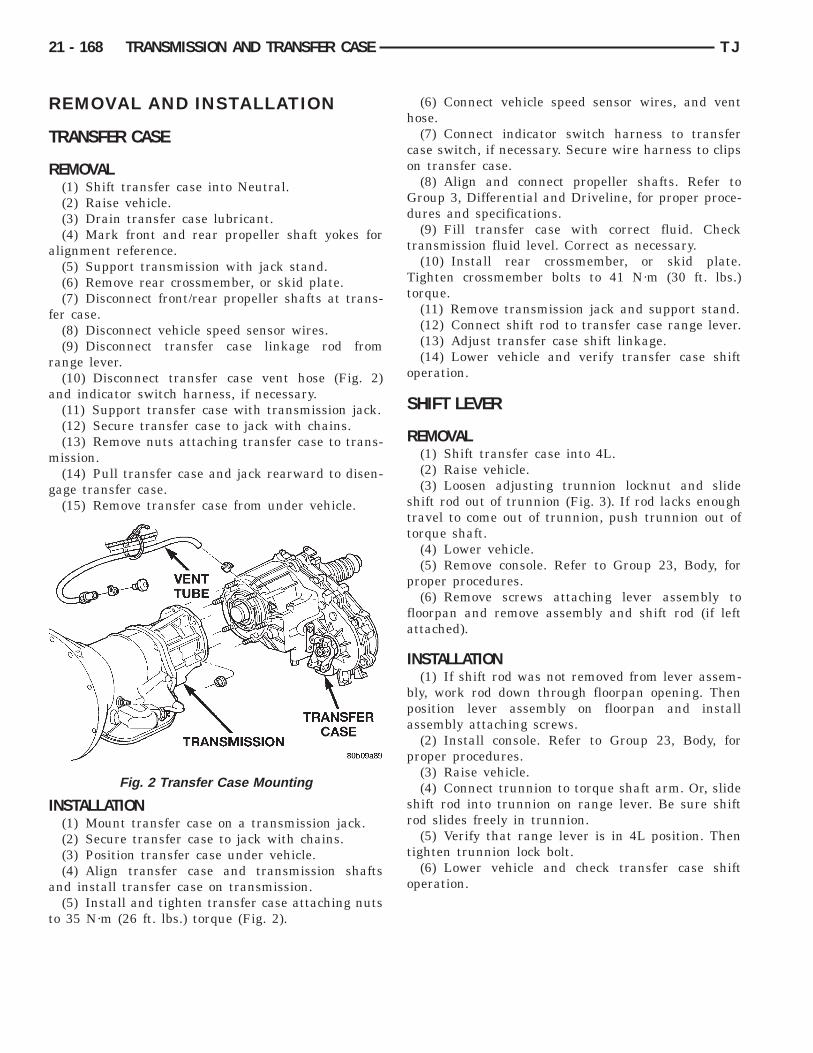
R
T
R
a
f
r
a
m
g
I
a
t
21 - 168 TRANSMISSION AND TRANSFER CASE TJ
EMOVAL AND INSTALLATION
RANSFER CASE
EMOVAL(1) Shift transfer case into Neutral.(2) Raise vehicle.(3) Drain transfer case lubricant.(4) Mark front and rear propeller shaft yokes for
lignment reference.(5) Support transmission with jack stand.(6) Remove rear crossmember, or skid plate.(7) Disconnect front/rear propeller shafts at trans-
er case.(8) Disconnect vehicle speed sensor wires.(9) Disconnect transfer case linkage rod from
ange lever.(10) Disconnect transfer case vent hose (Fig. 2)
nd indicator switch harness, if necessary.(11) Support transfer case with transmission jack.(12) Secure transfer case to jack with chains.(13) Remove nuts attaching transfer case to trans-ission.(14) Pull transfer case and jack rearward to disen-
age transfer case.(15) Remove transfer case from under vehicle.
NSTALLATION(1) Mount transfer case on a transmission jack.(2) Secure transfer case to jack with chains.(3) Position transfer case under vehicle.(4) Align transfer case and transmission shafts
nd install transfer case on transmission.(5) Install and tighten transfer case attaching nuts
o 35 N·m (26 ft. lbs.) torque (Fig. 2).
Fig. 2 Transfer Case Mounting
(6) Connect vehicle speed sensor wires, and venthose.
(7) Connect indicator switch harness to transfercase switch, if necessary. Secure wire harness to clipson transfer case.
(8) Align and connect propeller shafts. Refer toGroup 3, Differential and Driveline, for proper proce-dures and specifications.
(9) Fill transfer case with correct fluid. Checktransmission fluid level. Correct as necessary.
(10) Install rear crossmember, or skid plate.Tighten crossmember bolts to 41 N·m (30 ft. lbs.)torque.
(11) Remove transmission jack and support stand.(12) Connect shift rod to transfer case range lever.(13) Adjust transfer case shift linkage.(14) Lower vehicle and verify transfer case shift
operation.
SHIFT LEVER
REMOVAL(1) Shift transfer case into 4L.(2) Raise vehicle.(3) Loosen adjusting trunnion locknut and slide
shift rod out of trunnion (Fig. 3). If rod lacks enoughtravel to come out of trunnion, push trunnion out oftorque shaft.
(4) Lower vehicle.(5) Remove console. Refer to Group 23, Body, for
proper procedures.(6) Remove screws attaching lever assembly to
floorpan and remove assembly and shift rod (if leftattached).
INSTALLATION(1) If shift rod was not removed from lever assem-
bly, work rod down through floorpan opening. Thenposition lever assembly on floorpan and installassembly attaching screws.
(2) Install console. Refer to Group 23, Body, forproper procedures.
(3) Raise vehicle.(4) Connect trunnion to torque shaft arm. Or, slide
shift rod into trunnion on range lever. Be sure shiftrod slides freely in trunnion.
(5) Verify that range lever is in 4L position. Thentighten trunnion lock bolt.
(6) Lower vehicle and check transfer case shiftoperation.
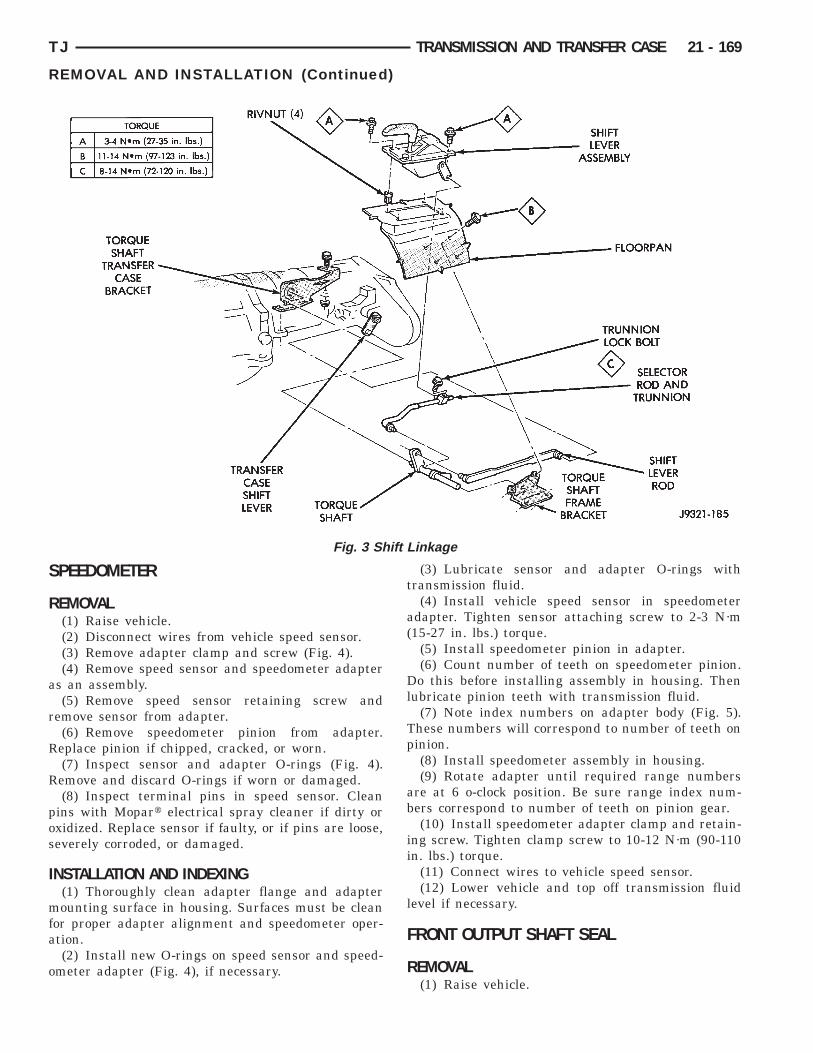
S
R
a
r
R
R
pos
I
mfa
o
TJ TRANSMISSION AND TRANSFER CASE 21 - 169
REMOVAL AND INSTALLATION (Continued)
PEEDOMETER
EMOVAL(1) Raise vehicle.(2) Disconnect wires from vehicle speed sensor.(3) Remove adapter clamp and screw (Fig. 4).(4) Remove speed sensor and speedometer adapter
s an assembly.(5) Remove speed sensor retaining screw and
emove sensor from adapter.(6) Remove speedometer pinion from adapter.eplace pinion if chipped, cracked, or worn.(7) Inspect sensor and adapter O-rings (Fig. 4).emove and discard O-rings if worn or damaged.(8) Inspect terminal pins in speed sensor. Clean
ins with Mopart electrical spray cleaner if dirty orxidized. Replace sensor if faulty, or if pins are loose,everely corroded, or damaged.
NSTALLATION AND INDEXING(1) Thoroughly clean adapter flange and adapterounting surface in housing. Surfaces must be clean
or proper adapter alignment and speedometer oper-tion.(2) Install new O-rings on speed sensor and speed-
meter adapter (Fig. 4), if necessary.
Fig. 3 Sh
(3) Lubricate sensor and adapter O-rings withtransmission fluid.
(4) Install vehicle speed sensor in speedometeradapter. Tighten sensor attaching screw to 2-3 N·m(15-27 in. lbs.) torque.
(5) Install speedometer pinion in adapter.(6) Count number of teeth on speedometer pinion.
Do this before installing assembly in housing. Thenlubricate pinion teeth with transmission fluid.
(7) Note index numbers on adapter body (Fig. 5).These numbers will correspond to number of teeth onpinion.
(8) Install speedometer assembly in housing.(9) Rotate adapter until required range numbers
are at 6 o-clock position. Be sure range index num-bers correspond to number of teeth on pinion gear.
(10) Install speedometer adapter clamp and retain-ing screw. Tighten clamp screw to 10-12 N·m (90-110in. lbs.) torque.
(11) Connect wires to vehicle speed sensor.(12) Lower vehicle and top off transmission fluid
level if necessary.
FRONT OUTPUT SHAFT SEAL
REMOVAL(1) Raise vehicle.
inkage
ift L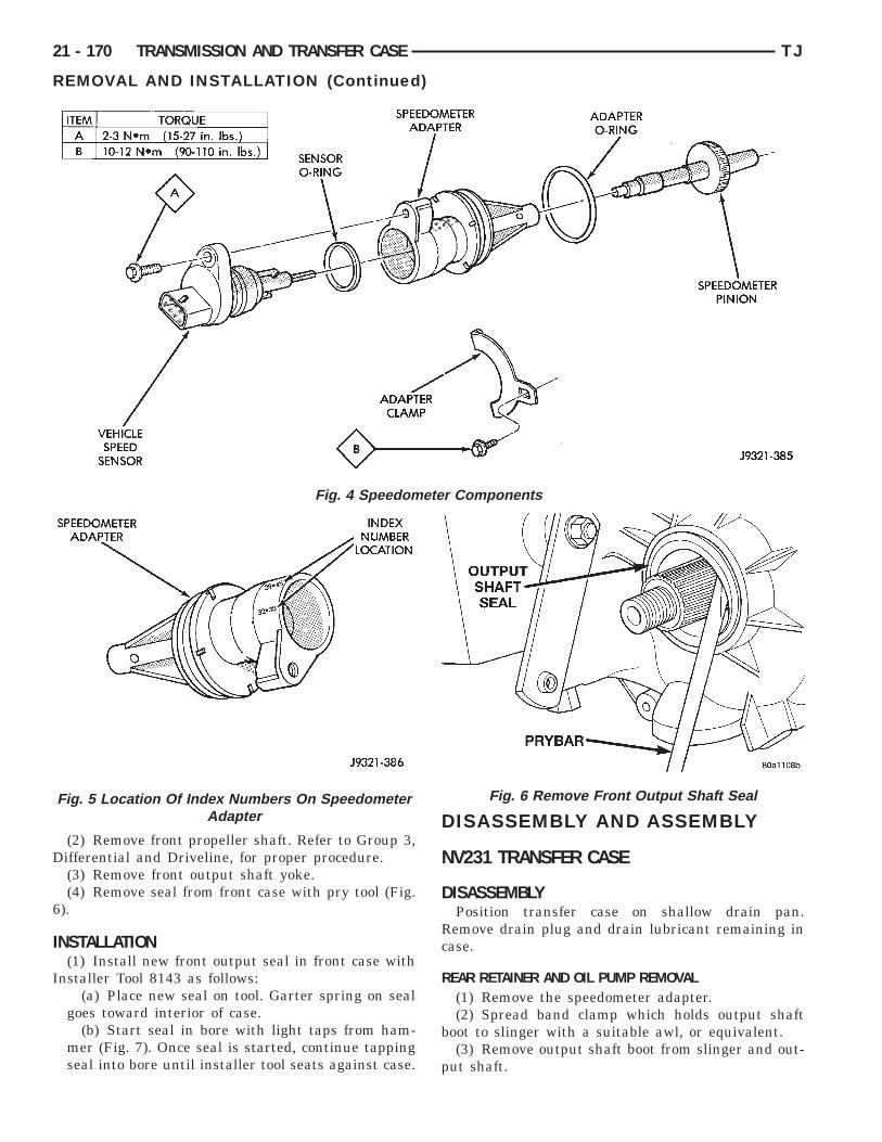
D
6
I
I
21 - 170 TRANSMISSION AND TRANSFER CASE TJ
REMOVAL AND INSTALLATION (Continued)
(2) Remove front propeller shaft. Refer to Group 3,ifferential and Driveline, for proper procedure.(3) Remove front output shaft yoke.(4) Remove seal from front case with pry tool (Fig.
).
NSTALLATION(1) Install new front output seal in front case with
nstaller Tool 8143 as follows:(a) Place new seal on tool. Garter spring on seal
goes toward interior of case.(b) Start seal in bore with light taps from ham-
mer (Fig. 7). Once seal is started, continue tappingseal into bore until installer tool seats against case.
Fig. 4 Speedom
Fig. 5 Location Of Index Numbers On SpeedometerAdapter
DISASSEMBLY AND ASSEMBLYNV231 TRANSFER CASE
DISASSEMBLYPosition transfer case on shallow drain pan.
Remove drain plug and drain lubricant remaining incase.
REAR RETAINER AND OIL PUMP REMOVAL(1) Remove the speedometer adapter.(2) Spread band clamp which holds output shaft
boot to slinger with a suitable awl, or equivalent.(3) Remove output shaft boot from slinger and out-
put shaft.
Components
Fig. 6 Remove Front Output Shaft Seal
eter
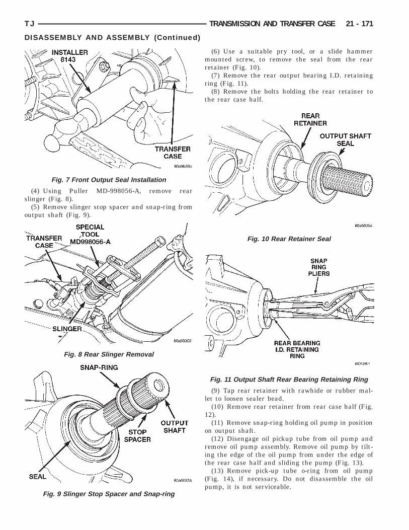
s
o
TJ TRANSMISSION AND TRANSFER CASE 21 - 171
DISASSEMBLY AND ASSEMBLY (Continued)
(4) Using Puller MD-998056-A, remove rearlinger (Fig. 8).(5) Remove slinger stop spacer and snap-ring from
utput shaft (Fig. 9).
Fig. 7 Front Output Seal Installation
Fig. 8 Rear Slinger Removal
Fig. 9 Slinger Stop Spacer and Snap-ring
(6) Use a suitable pry tool, or a slide hammermounted screw, to remove the seal from the rearretainer (Fig. 10).
(7) Remove the rear output bearing I.D. retainingring (Fig. 11).
(8) Remove the bolts holding the rear retainer tothe rear case half.
(9) Tap rear retainer with rawhide or rubber mal-let to loosen sealer bead.
(10) Remove rear retainer from rear case half (Fig.12).
(11) Remove snap-ring holding oil pump in positionon output shaft.
(12) Disengage oil pickup tube from oil pump andremove oil pump assembly. Remove oil pump by tilt-ing the edge of the oil pump from under the edge ofthe rear case half and sliding the pump (Fig. 13).
(13) Remove pick-up tube o-ring from oil pump(Fig. 14), if necessary. Do not disassemble the oilpump, it is not serviceable.
Fig. 10 Rear Retainer Seal
Fig. 11 Output Shaft Rear Bearing Retaining Ring
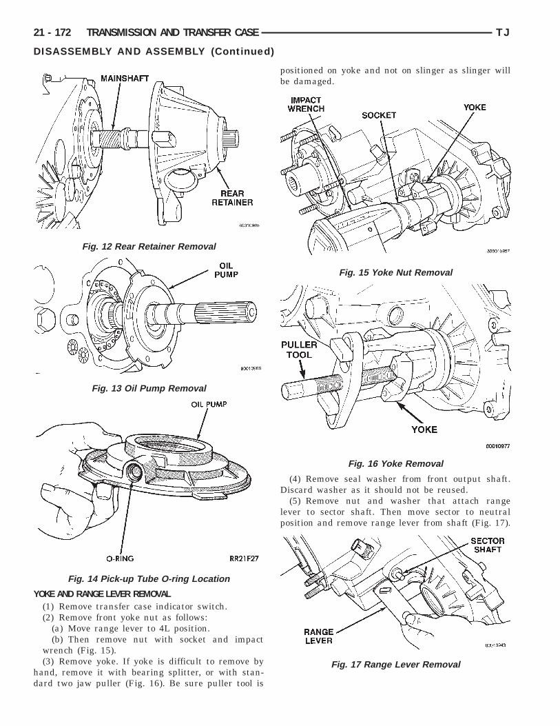
Y
hd
21 - 172 TRANSMISSION AND TRANSFER CASE TJ
DISASSEMBLY AND ASSEMBLY (Continued)
OKE AND RANGE LEVER REMOVAL(1) Remove transfer case indicator switch.(2) Remove front yoke nut as follows:
(a) Move range lever to 4L position.(b) Then remove nut with socket and impact
wrench (Fig. 15).(3) Remove yoke. If yoke is difficult to remove by
and, remove it with bearing splitter, or with stan-ard two jaw puller (Fig. 16). Be sure puller tool is
Fig. 12 Rear Retainer Removal
Fig. 13 Oil Pump Removal
Fig. 14 Pick-up Tube O-ring Location
positioned on yoke and not on slinger as slinger willbe damaged.
(4) Remove seal washer from front output shaft.Discard washer as it should not be reused.
(5) Remove nut and washer that attach rangelever to sector shaft. Then move sector to neutralposition and remove range lever from shaft (Fig. 17).
Fig. 15 Yoke Nut Removal
Fig. 16 Yoke Removal
Fig. 17 Range Lever Removal
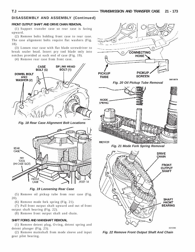
F
u
T1
bn
2
o
S
d
g
Fig. 20 Oil Pickup Tube Removal
Fig. 21 Mode Fork Spring Removal
Fig. 22 Remove Front Output Shaft And Chain
TJ TRANSMISSION AND TRANSFER CASE 21 - 173
DISASSEMBLY AND ASSEMBLY (Continued)
RONT OUTPUT SHAFT AND DRIVE CHAIN REMOVAL(1) Support transfer case so rear case is facing
pward.(2) Remove bolts holding front case to rear case.
he case alignment bolts require flat washers (Fig.8).(3) Loosen rear case with flat blade screwdriver to
reak sealer bead. Insert pry tool blade only intootches provided at each end of case (Fig. 19).(4) Remove rear case from front case.
(5) Remove oil pickup tube from rear case (Fig.0).(6) Remove mode fork spring (Fig. 21).(7) Pull front output shaft upward and out of front
utput shaft bearing (Fig. 22).(8) Remove front output shaft and chain.
HIFT FORKS AND MAINSHAFT REMOVAL(1) Remove detent plug, O-ring, detent spring and
etent plunger (Fig. 23).(2) Remove mainshaft from mode sleeve and input
ear pilot bearing.
Fig. 18 Rear Case Alignment Bolt Locations
Fig. 19 Loosening Rear Case

(e
(
2
M
d
I
(
Fig. 25 Range Fork And Hub Removal
Fig. 27 Sector Bushing And O-Ring Removal
21 - 174 TRANSMISSION AND TRANSFER CASE TJ
DISASSEMBLY AND ASSEMBLY (Continued)
(3) Remove mode fork and sleeve as an assemblyFig. 24). Note position of sleeve for assembly refer-nce. The short side of the sleeve faces upward.(4) Remove range fork and hub as an assembly
Fig. 25). Note fork position for installation reference.(5) Remove shift sector from front case (Fig. 26).(6) Remove shift sector bushing and O-ring (Fig.
7).
AINSHAFT DISASSEMBLY(1) Remove mode hub retaining ring with heavy
uty snap-ring pliers (Fig. 28).(2) Slide mode hub off mainshaft (Fig. 29).(3) Slide drive sprocket off mainshaft (Fig. 30).
NPUT GEAR AND LOW RANGE GEAR REMOVAL(1) Remove front bearing retainer attaching bolts
Fig. 31).
Fig. 23 Detent Plug, Spring And Plunger Removal
Fig. 24 Mode Fork And Sleeve Removal
Fig. 26 Shift Sector Removal

TJ TRANSMISSION AND TRANSFER CASE 21 - 175
DISASSEMBLY AND ASSEMBLY (Continued)
Fig. 28 Mode Hub Retaining Ring Removal
Fig. 29 Mode Hub Removal
Fig. 30 Drive Sprocket Removal
(2) Remove front bearing retainer. Pry retainerloose with pry tool positioned in slots at each end ofretainer (Fig. 32).
(3) Remove front bearing retainer seal. Tap sealout with drift and hammer.
(4) Remove input gear retaining ring with heavyduty snap-ring pliers (Fig. 33)
(5) Place front case in horizontal position. Thenremove input gear and low range gear as an assem-bly (Fig. 34). Tap gear out of bearing with plasticmallet if necessary.
Fig. 31 Front Bearing Retainer Bolts
Fig. 32 Front Bearing Retainer Removal

I
l
r
A
Dj
B
Ccr
Fig. 35 Input Gear Snap-Ring Removal
Fig. 36 Input Gear Retainer Removal
21 - 176 TRANSMISSION AND TRANSFER CASE TJ
DISASSEMBLY AND ASSEMBLY (Continued)
NPUT AND LOW RANGE GEAR DISASSEMBLY(1) Remove snap-ring that retains input gear in
ow range gear (Fig. 35).(2) Remove retainer (Fig. 36).(3) Remove front tabbed thrust washer (Fig. 37).(4) Remove input gear (Fig. 38).(5) Remove rear tabbed thrust washer from low
ange gear (Fig. 39).
SSEMBLYLubricate transfer case components with Mopartexron II automatic transmission fluid or petroleum
elly (where indicated) during assembly.
EARING AND SEAL INSTALLATION
AUTION: The bearing bores in various transferase components contain oil feed holes. Make sureeplacement bearings do not block the holes.
Fig. 33 Removing Input Gear Retaining Ring
Fig. 34 Input Gear And Planetary Carrier Removal
Fig. 37 Front Tabbed Thrust Washer Removal
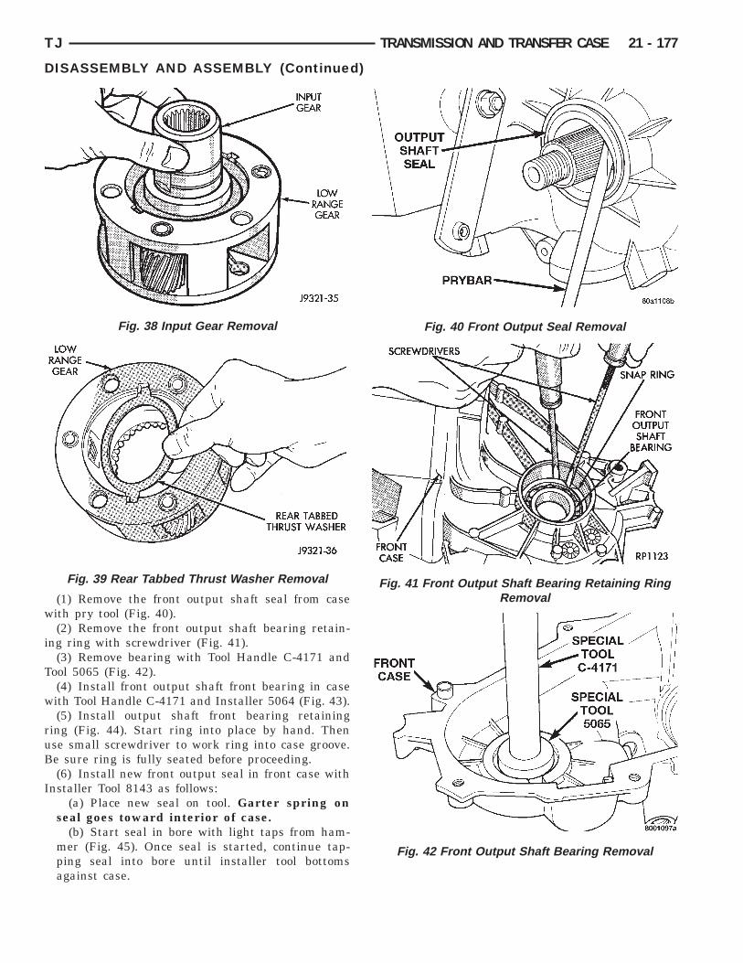
w
i
T
w
ruB
I
Fig. 40 Front Output Seal Removal
Removal
TJ TRANSMISSION AND TRANSFER CASE 21 - 177
DISASSEMBLY AND ASSEMBLY (Continued)
(1) Remove the front output shaft seal from caseith pry tool (Fig. 40).(2) Remove the front output shaft bearing retain-
ng ring with screwdriver (Fig. 41).(3) Remove bearing with Tool Handle C-4171 and
ool 5065 (Fig. 42).(4) Install front output shaft front bearing in caseith Tool Handle C-4171 and Installer 5064 (Fig. 43).(5) Install output shaft front bearing retaining
ing (Fig. 44). Start ring into place by hand. Thense small screwdriver to work ring into case groove.e sure ring is fully seated before proceeding.(6) Install new front output seal in front case with
nstaller Tool 8143 as follows:(a) Place new seal on tool. Garter spring on
seal goes toward interior of case.(b) Start seal in bore with light taps from ham-
mer (Fig. 45). Once seal is started, continue tap-ping seal into bore until installer tool bottomsagainst case.
Fig. 38 Input Gear Removal
Fig. 39 Rear Tabbed Thrust Washer Removal
Fig. 41 Front Output Shaft Bearing Retaining RingFig. 42 Front Output Shaft Bearing Removal
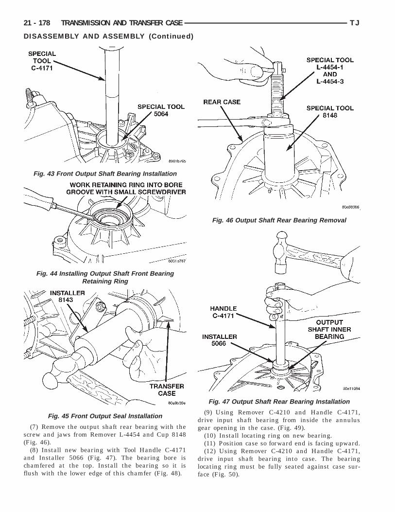
s(
acf
21 - 178 TRANSMISSION AND TRANSFER CASE TJ
DISASSEMBLY AND ASSEMBLY (Continued)
(7) Remove the output shaft rear bearing with thecrew and jaws from Remover L-4454 and Cup 8148Fig. 46).
(8) Install new bearing with Tool Handle C-4171nd Installer 5066 (Fig. 47). The bearing bore ishamfered at the top. Install the bearing so it islush with the lower edge of this chamfer (Fig. 48).
Fig. 43 Front Output Shaft Bearing Installation
Fig. 44 Installing Output Shaft Front BearingRetaining Ring
Fig. 45 Front Output Seal Installation
(9) Using Remover C-4210 and Handle C-4171,drive input shaft bearing from inside the annulusgear opening in the case. (Fig. 49).(10) Install locating ring on new bearing.(11) Position case so forward end is facing upward.(12) Using Remover C-4210 and Handle C-4171,
drive input shaft bearing into case. The bearinglocating ring must be fully seated against case sur-face (Fig. 50).
Fig. 46 Output Shaft Rear Bearing Removal
Fig. 47 Output Shaft Rear Bearing Installation
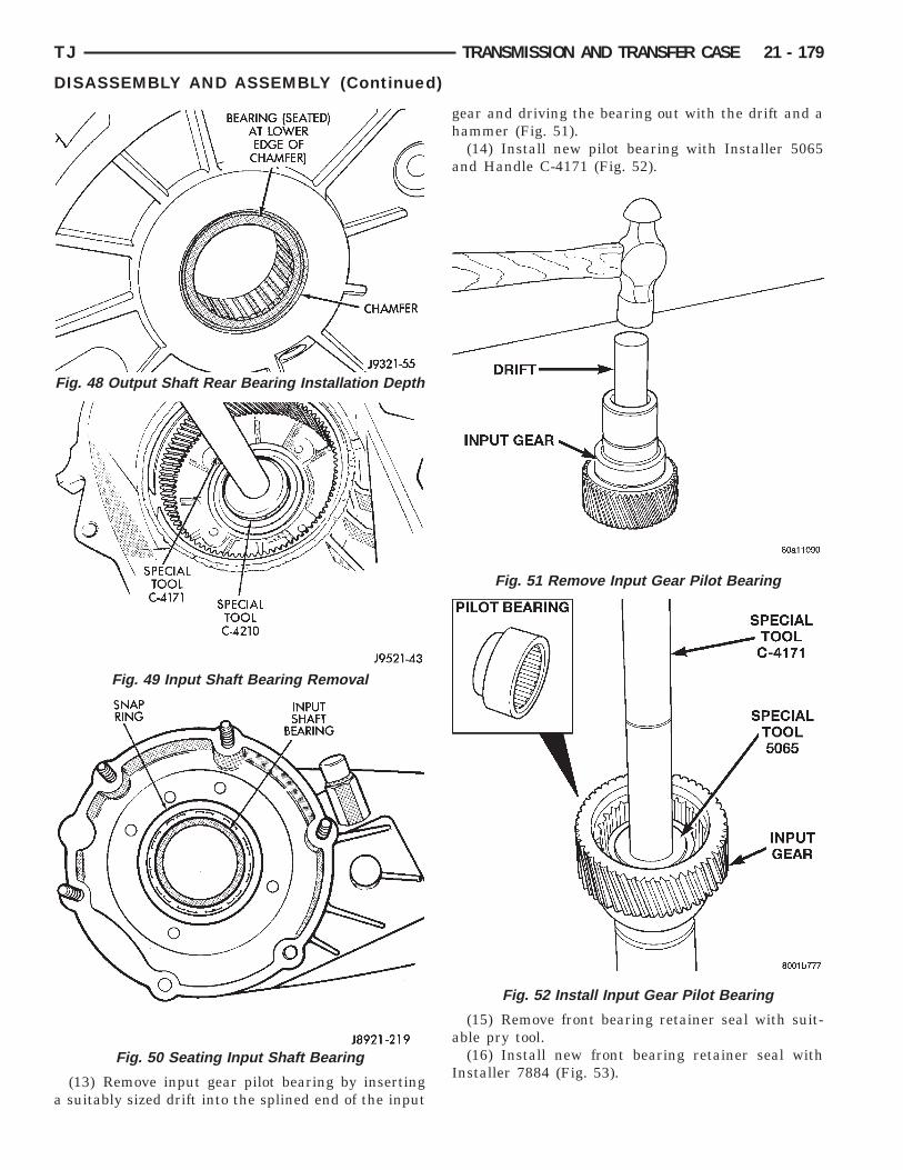
a
TJ TRANSMISSION AND TRANSFER CASE 21 - 179
DISASSEMBLY AND ASSEMBLY (Continued)
(13) Remove input gear pilot bearing by insertingsuitably sized drift into the splined end of the input
Fig. 48 Output Shaft Rear Bearing Installation Depth
Fig. 49 Input Shaft Bearing Removal
Fig. 50 Seating Input Shaft Bearing
gear and driving the bearing out with the drift and ahammer (Fig. 51).
(14) Install new pilot bearing with Installer 5065and Handle C-4171 (Fig. 52).
(15) Remove front bearing retainer seal with suit-able pry tool.
(16) Install new front bearing retainer seal withInstaller 7884 (Fig. 53).
Fig. 51 Remove Input Gear Pilot Bearing
Fig. 52 Install Input Gear Pilot Bearing
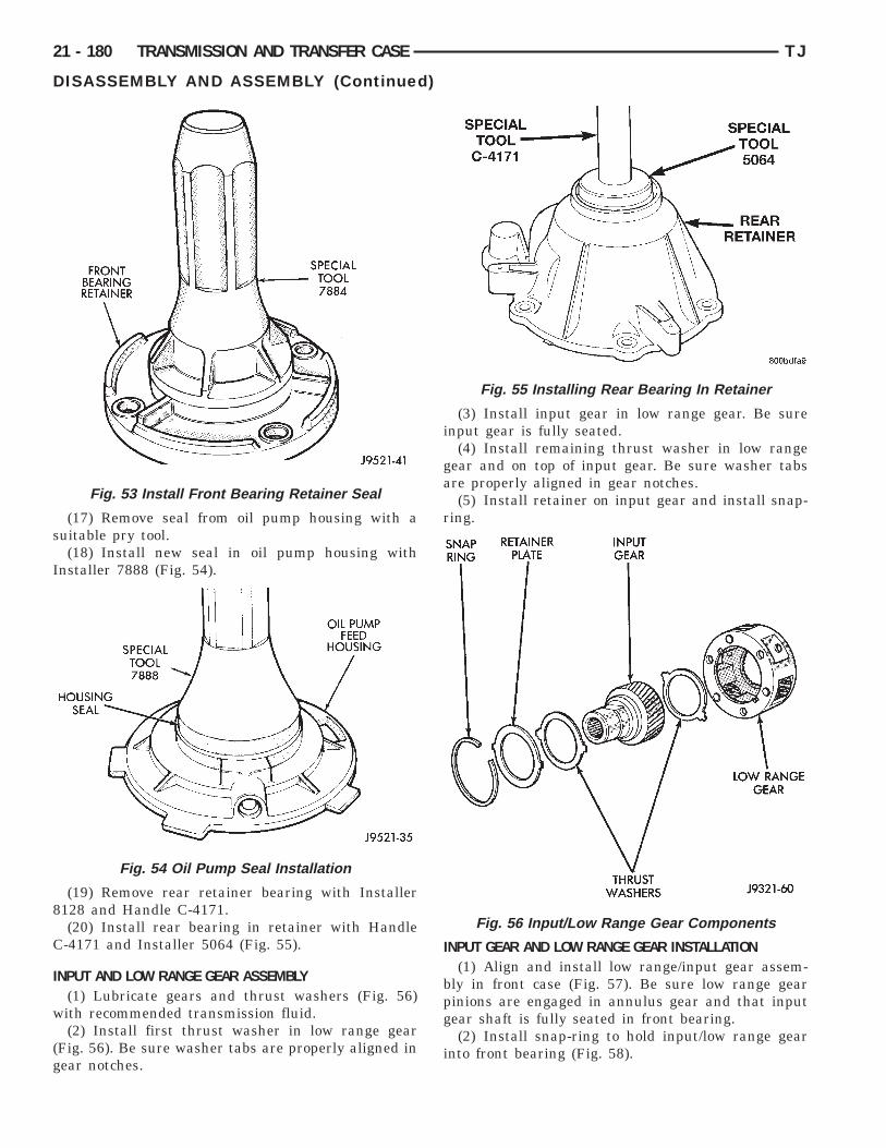
s
I
8
C
I
w
(g
21 - 180 TRANSMISSION AND TRANSFER CASE TJ
DISASSEMBLY AND ASSEMBLY (Continued)
(17) Remove seal from oil pump housing with auitable pry tool.(18) Install new seal in oil pump housing with
nstaller 7888 (Fig. 54).
(19) Remove rear retainer bearing with Installer128 and Handle C-4171.(20) Install rear bearing in retainer with Handle-4171 and Installer 5064 (Fig. 55).
NPUT AND LOW RANGE GEAR ASSEMBLY(1) Lubricate gears and thrust washers (Fig. 56)ith recommended transmission fluid.(2) Install first thrust washer in low range gear
Fig. 56). Be sure washer tabs are properly aligned inear notches.
Fig. 53 Install Front Bearing Retainer Seal
Fig. 54 Oil Pump Seal Installation
(3) Install input gear in low range gear. Be sureinput gear is fully seated.
(4) Install remaining thrust washer in low rangegear and on top of input gear. Be sure washer tabsare properly aligned in gear notches.
(5) Install retainer on input gear and install snap-ring.
INPUT GEAR AND LOW RANGE GEAR INSTALLATION(1) Align and install low range/input gear assem-
bly in front case (Fig. 57). Be sure low range gearpinions are engaged in annulus gear and that inputgear shaft is fully seated in front bearing.
(2) Install snap-ring to hold input/low range gearinto front bearing (Fig. 58).
Fig. 55 Installing Rear Bearing In Retainer
Fig. 56 Input/Low Range Gear Components
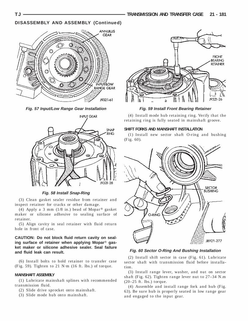
i
mr
h
Cika
(
M
t
TJ TRANSMISSION AND TRANSFER CASE 21 - 181
DISASSEMBLY AND ASSEMBLY (Continued)
(3) Clean gasket sealer residue from retainer andnspect retainer for cracks or other damage.
(4) Apply a 3 mm (1/8 in.) bead of Mopart gasketaker or silicone adhesive to sealing surface of
etainer.(5) Align cavity in seal retainer with fluid return
ole in front of case.
AUTION: Do not block fluid return cavity on seal-ng surface of retainer when applying Mopar T gas-et maker or silicone adhesive sealer. Seal failurend fluid leak can result.
(6) Install bolts to hold retainer to transfer caseFig. 59). Tighten to 21 N·m (16 ft. lbs.) of torque.
AINSHAFT ASSEMBLY(1) Lubricate mainshaft splines with recommended
ransmission fluid.(2) Slide drive sprocket onto mainshaft.(3) Slide mode hub onto mainshaft.
Fig. 57 Input/Low Range Gear Installation
Fig. 58 Install Snap-Ring
(4) Install mode hub retaining ring. Verify that theretaining ring is fully seated in mainshaft groove.
SHIFT FORKS AND MAINSHAFT INSTALLATION(1) Install new sector shaft O-ring and bushing
(Fig. 60).
(2) Install shift sector in case (Fig. 61). Lubricatesector shaft with transmission fluid before installa-tion.
(3) Install range lever, washer, and nut on sectorshaft (Fig. 62). Tighten range lever nut to 27–34 N.m(20–25 ft. lbs.) torque.
(4) Assemble and install range fork and hub (Fig.63). Be sure hub is properly seated in low range gearand engaged to the input gear.
Fig. 59 Install Front Bearing Retainer
Fig. 60 Sector O-Ring And Bushing Installation
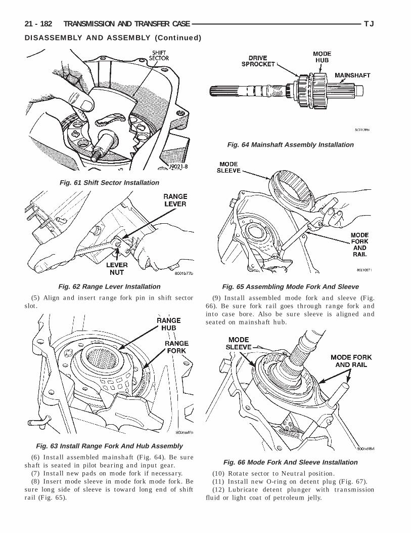
s
s
sr
21 - 182 TRANSMISSION AND TRANSFER CASE TJ
DISASSEMBLY AND ASSEMBLY (Continued)
(5) Align and insert range fork pin in shift sectorlot.
(6) Install assembled mainshaft (Fig. 64). Be surehaft is seated in pilot bearing and input gear.(7) Install new pads on mode fork if necessary.(8) Insert mode sleeve in mode fork mode fork. Be
ure long side of sleeve is toward long end of shiftail (Fig. 65).
Fig. 61 Shift Sector Installation
Fig. 62 Range Lever Installation
Fig. 63 Install Range Fork And Hub Assembly
(9) Install assembled mode fork and sleeve (Fig.66). Be sure fork rail goes through range fork andinto case bore. Also be sure sleeve is aligned andseated on mainshaft hub.
(10) Rotate sector to Neutral position.(11) Install new O-ring on detent plug (Fig. 67).(12) Lubricate detent plunger with transmission
fluid or light coat of petroleum jelly.
Fig. 64 Mainshaft Assembly Installation
Fig. 65 Assembling Mode Fork And Sleeve
Fig. 66 Mode Fork And Sleeve Installation

6
t
F
df
(
s
s
TJ TRANSMISSION AND TRANSFER CASE 21 - 183
DISASSEMBLY AND ASSEMBLY (Continued)
(13) Install detent plunger, spring and plug (Fig.7).(14) Verify that plunger is properly engaged in sec-
or.
RONT OUTPUT SHAFT AND DRIVE CHAIN INSTALLATION(1) Lubricate front output shaft-sprocket assembly,
rive chain, and drive sprocket with transmissionluid.
(2) Assemble drive chain and front output shaftFig. 68).
(3) Start chain on mainshaft drive sprocket.(4) Guide front shaft into bearing and drive
procket onto mainshaft drive gear (Fig. 68).(5) Install mode spring on upper end of mode fork
hift rail (Fig. 69).
Fig. 67 Shift Detent Components
Fig. 68 Installing Drive Chain And Front OutputShaft
OIL PUMP AND REAR CASE ASSEMBLY/INSTALLATION(1) Install magnet in front case pocket (Fig. 70).(2) Assemble oil pickup screen, connecting hose,
and tube.(3) Install new pickup tube O-ring in oil pump
(Fig. 71).
(4) Insert oil pickup tube in oil pump inlet.(5) Position assembled oil pump and pickup tube
in rear case. Be sure pickup screen is securely seatedin case slot. Also be sure oil pump locating tabs areoutside rear case (Fig. 72).
(6) Apply 3 mm (1/8 in.) wide bead of Mopart gas-ket maker or silicone adhesive sealer to mountingflange of front case. Work sealer bead around boltholes.
(7) Lift rear case and oil pump and carefully posi-tion assembly on front case. Be sure case dowels arealigned and that mode fork rail extends through rearcase before seating rear case on front case.
Fig. 69 Install Mode Fork Spring
Fig. 70 Installing Case Magnet

e(
t
Y
s
t(
21 - 184 TRANSMISSION AND TRANSFER CASE TJ
DISASSEMBLY AND ASSEMBLY (Continued)
(8) Install case attaching bolts. Alignment bolts atach end of case are only ones requiring washersFig. 73).
(9) Tighten case bolts to 27-34 N·m (20-25 ft. lbs.)orque.
OKE AND RANGE LEVER INSTALLATION(1) Install indicator switch in front case. Tighten
witch to 20–34 N·m (15–25 ft. lbs.) torque.(2) Install range lever, washer and locknut on sec-
or shaft (Fig. 74). Tighten locknut to 27-34 N·m20-25 ft. lbs.) torque.
Fig. 71 Pickup Tube O-Ring Position
Fig. 72 Oil Pump And Pickup Tube Installation
Fig. 73 Alignment Bolt Location
(3) Install new seal washer on front output shaft(Fig. 76).
(4) Lubricate yoke hub with transmission fluid andinstall yoke on front shaft.
(5) Install new seal washer on front shaft.(6) Install yoke and new yoke nut on front output
shaft (Fig. 75).(7) Tighten yoke nut to 122-176 N·m (90-130 ft.
lbs.) torque. Use Tool C-3281, or similar tool to holdyoke while tightening yoke nut.
Fig. 74 Range Lever Installation
Fig. 75 Output Shaft Yoke Installation
Fig. 76 Yoke Seal Washer Installation

R
Lri
r
s
rn
S
wDC
h
r
TJ TRANSMISSION AND TRANSFER CASE 21 - 185
DISASSEMBLY AND ASSEMBLY (Continued)
EAR RETAINER INSTALLATION(1) Apply bead of Mopart Sealer P/N 82300234, or
octitey Ultra Gray, to mating surface of rearetainer. Sealer bead should be a maximum of 3/16nch.
(2) Install rear retainer on rear case. Tightenetainer bolts to 20–27 N·m (15–20 ft. lbs.) torque.(3) Install rear bearing I.D. retaining ring and
pacer on output shaft.(4) Apply liberal quantity of petroleum jelly to new
ear seal and to output shaft. Petroleum jelly iseeded to protect seal lips during installation.(5) Slide seal onto Seal Protector 6992 (Fig. 77).
lide seal protector and seal onto output shaft.(6) Slide Installer C-4076-B onto seal protectorith the recessed side of the tool toward the seal.rive seal into rear bearing retainer with installer-4076-B and handle MD-998323 (Fig. 78).
(7) Install rear slinger with installer C-4076-A andandle MD-998323 (Fig. 78).(8) Install boot on output shaft slinger and crimp
etaining clamp with tool C-4975-A (Fig. 79).
Fig. 77 Output Shaft Seal and Protector
Fig. 78 Rear Seal Installation
CLEANING AND INSPECTION
NV231 TRANSFER CASEClean the transfer case parts with a standard
parts cleaning solvent. Remove all traces of sealerfrom the cases and retainers with a scraper and 3Mall purpose cleaner. Use compressed air to removesolvent residue from oil feed passages in the casehalves, retainers, gears, and shafts.
The oil pickup screen can be cleaned with solvent.Shake excess solvent from the screen after cleaningand allow it to air dry. Do not use compressed air.
MAINSHAFT/SPROCKET/HUB INSPECTIONInspect the splines on the hub and shaft and the
teeth on the sprocket (Fig. 80). Minor nicks andscratches can be smoothed with an oilstone. However,replace any part that is damaged.
Check the contact surfaces in the sprocket boreand on the mainshaft. Minor nicks and scratches canbe smoothed with 320–400 grit emery cloth but donot try to salvage the shaft if nicks or wear is severe.
INPUT GEAR AND PLANETARY CARRIERCheck the teeth on the gear (Fig. 81). Minor nicks
can be dressed off with an oilstone but replace thegear if any teeth are broken, cracked, or chipped. Thebearing surface on the gear can be smoothed with300–400 grit emery cloth if necessary.
Examine the carrier body and pinion gears forwear or damage. The carrier will have to be replacedas an assembly if the body, pinion pins, or piniongears are damaged.
Check the lock ring and both thrust washers forwear or cracks. Replace them if necessary. Alsoreplace the lock retaining ring if bent, distorted, orbroken.
Fig. 79 Slinger Boot Installation
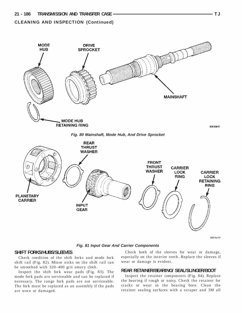
S
sb
mnTa
Hub
21 - 186 TRANSMISSION AND TRANSFER CASE TJ
CLEANING AND INSPECTION (Continued)
HIFT FORKS/HUBS/SLEEVESCheck condition of the shift forks and mode fork
hift rail (Fig. 82). Minor nicks on the shift rail cane smoothed with 320–400 grit emery cloth.Inspect the shift fork wear pads (Fig. 83). Theode fork pads are serviceable and can be replaced ifecessary. The range fork pads are not serviceable.he fork must be replaced as an assembly if the padsre worn or damaged.
Fig. 80 Mainshaft, Mode
Fig. 81 Input Gear An
Check both of the sleeves for wear or damage,especially on the interior teeth. Replace the sleeves ifwear or damage is evident.
REAR RETAINER/BEARING/ SEAL/SLINGER/BOOTInspect the retainer components (Fig. 84). Replace
the bearing if rough or noisy. Check the retainer forcracks or wear in the bearing bore. Clean theretainer sealing surfaces with a scraper and 3M all
, And Drive Sprocket
arrier Components
d C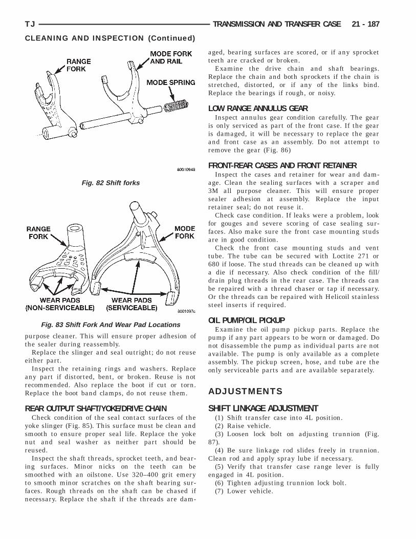
pt
e
arR
R
ysnr
istfn
TJ TRANSMISSION AND TRANSFER CASE 21 - 187
CLEANING AND INSPECTION (Continued)
urpose cleaner. This will ensure proper adhesion ofhe sealer during reassembly.
Replace the slinger and seal outright; do not reuseither part.Inspect the retaining rings and washers. Replace
ny part if distorted, bent, or broken. Reuse is notecommended. Also replace the boot if cut or torn.eplace the boot band clamps, do not reuse them.
EAR OUTPUT SHAFT/YOKE/DRIVE CHAINCheck condition of the seal contact surfaces of the
oke slinger (Fig. 85). This surface must be clean andmooth to ensure proper seal life. Replace the yokeut and seal washer as neither part should beeused.Inspect the shaft threads, sprocket teeth, and bear-
ng surfaces. Minor nicks on the teeth can bemoothed with an oilstone. Use 320–400 grit emeryo smooth minor scratches on the shaft bearing sur-aces. Rough threads on the shaft can be chased ifecessary. Replace the shaft if the threads are dam-
Fig. 82 Shift forks
Fig. 83 Shift Fork And Wear Pad Locations
aged, bearing surfaces are scored, or if any sprocketteeth are cracked or broken.
Examine the drive chain and shaft bearings.Replace the chain and both sprockets if the chain isstretched, distorted, or if any of the links bind.Replace the bearings if rough, or noisy.
LOW RANGE ANNULUS GEARInspect annulus gear condition carefully. The gear
is only serviced as part of the front case. If the gearis damaged, it will be necessary to replace the gearand front case as an assembly. Do not attempt toremove the gear (Fig. 86)
FRONT-REAR CASES AND FRONT RETAINERInspect the cases and retainer for wear and dam-
age. Clean the sealing surfaces with a scraper and3M all purpose cleaner. This will ensure propersealer adhesion at assembly. Replace the inputretainer seal; do not reuse it.
Check case condition. If leaks were a problem, lookfor gouges and severe scoring of case sealing sur-faces. Also make sure the front case mounting studsare in good condition.
Check the front case mounting studs and venttube. The tube can be secured with Loctite 271 or680 if loose. The stud threads can be cleaned up witha die if necessary. Also check condition of the fill/drain plug threads in the rear case. The threads canbe repaired with a thread chaser or tap if necessary.Or the threads can be repaired with Helicoil stainlesssteel inserts if required.
OIL PUMP/OIL PICKUPExamine the oil pump pickup parts. Replace the
pump if any part appears to be worn or damaged. Donot disassemble the pump as individual parts are notavailable. The pump is only available as a completeassembly. The pickup screen, hose, and tube are theonly serviceable parts and are available separately.
ADJUSTMENTS
SHIFT LINKAGE ADJUSTMENT(1) Shift transfer case into 4L position.(2) Raise vehicle.(3) Loosen lock bolt on adjusting trunnion (Fig.
87).(4) Be sure linkage rod slides freely in trunnion.
Clean rod and apply spray lube if necessary.(5) Verify that transfer case range lever is fully
engaged in 4L position.(6) Tighten adjusting trunnion lock bolt.(7) Lower vehicle.
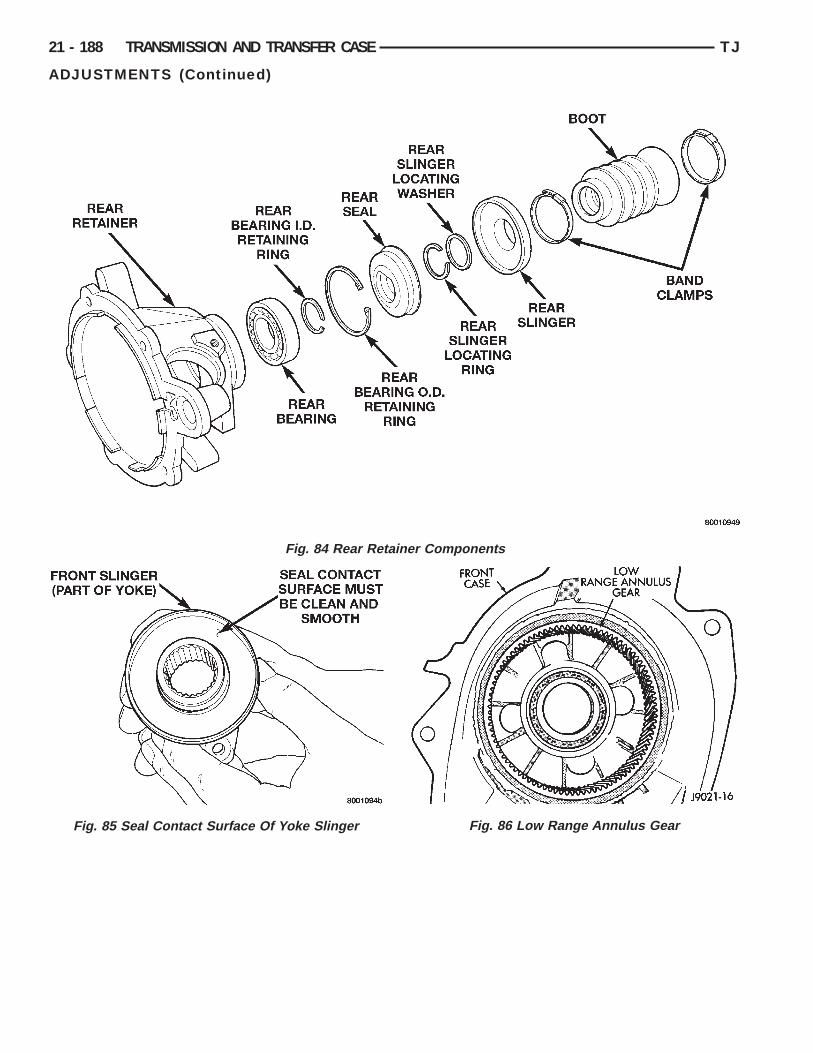
ainer Components
Fig. 86 Low Range Annulus Gear
21 - 188 TRANSMISSION AND TRANSFER CASE TJ
ADJUSTMENTS (Continued)
Fig. 84 Rear Ret
Fig. 85 Seal Contact Surface Of Yoke Slinger

S
T
SPECIAL TOOLS
TJ TRANSMISSION AND TRANSFER CASE 21 - 189
ADJUSTMENTS (Continued)
PECIFICATIONS
ORQUE
DESCRIPTION TORQUEPlug, Detent . . . . . . . . . . 16–24 N·m (12–18 ft. lbs.)Plug, Drain/Fill . . . . . . . . 20–34 N·m (15–20 ft. lbs.)Plug, Drain/Fill . . . . . . . . 40–45 N·m (30–40 ft. lbs.)Bolt, Extension Housing . 35–46 N·m (26–34 ft. lbs.)Bolt, Front Brg. Retainer . . . . . . 21 N·m (16 ft. lbs.)Bolt, Case Half . . . . . . . . 27–34 N·m (20–25 ft. lbs.)Nut, Front Yoke . . . . . 122–176 N·m (90–130 ft. lbs.)Nut, Range Lever . . . . . . 27–34 N·m (20–25 ft. lbs.)Bolt, Rear Retainer . . . . . 35–46 N·m (26–34 ft. lbs.)Nuts, Mounting . . . . . . . . 29–40 N·m (22–30 ft. lbs.)Switch, Indicator . . . . . . . 20–34 N·m (15–25 ft. lbs.)
Fig. 87 Shift Linkage
NV231
Installer—C-4076-B
Puller, Slinger—MD-998056–A
Installer—MD-998323
Seal Protector—6992
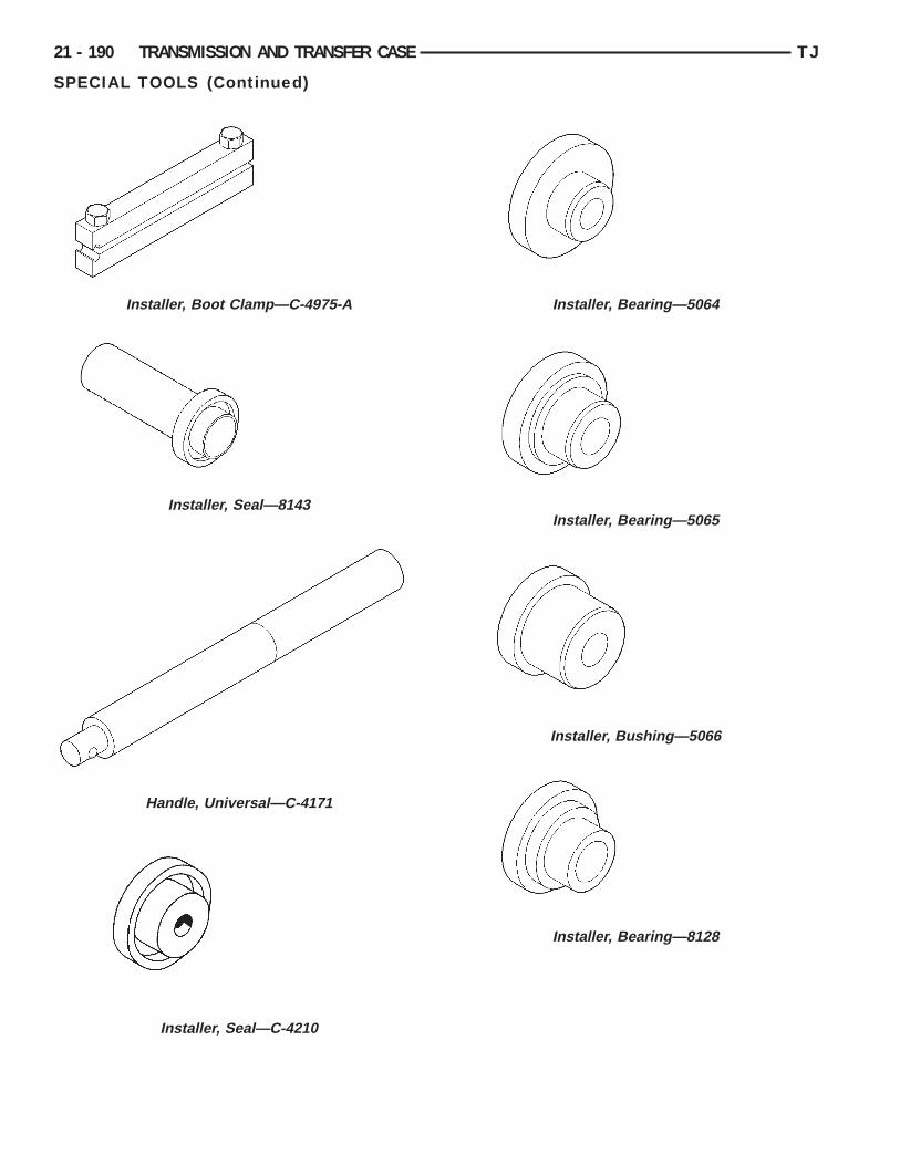
21 - 190 TRANSMISSION AND TRANSFER CASE TJ
SPECIAL TOOLS (Continued)
Installer, Boot Clamp—C-4975-A
Installer, Seal—8143
Handle, Universal—C-4171
Installer, Seal—C-4210
Installer, Bearing—5064
Installer, Bearing—5065
Installer, Bushing—5066
Installer, Bearing—8128
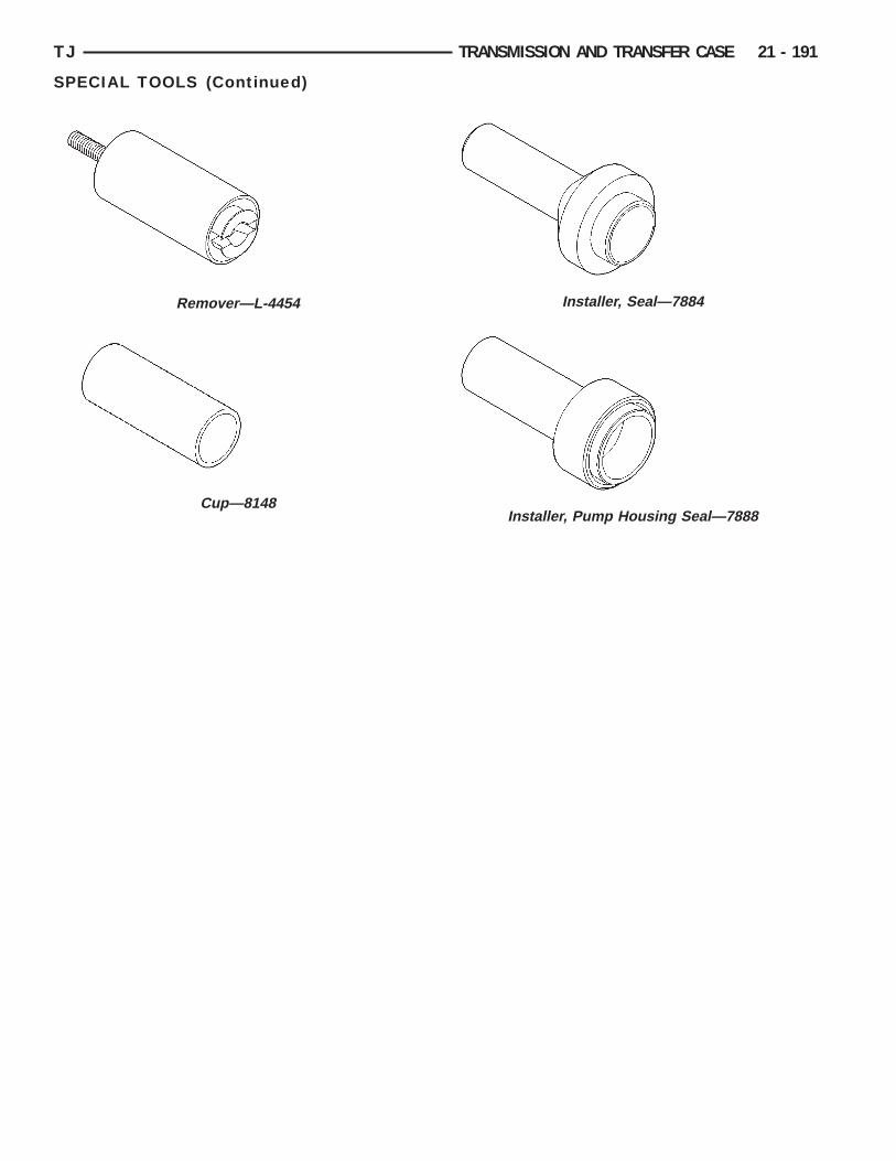
TJ TRANSMISSION AND TRANSFER CASE 21 - 191
SPECIAL TOOLS (Continued)
Remover—L-4454
Cup—8148
Installer, Seal—7884
Installer, Pump Housing Seal—7888