TRANS-SYNCRO AUTO START LOAD SHARE ... - TDE Instruments
155
TRANS-SYNCRO AUTO START LOAD SHARE UNIT FOR GAS/DIESEL/GASOLINE GENERATORS WITH J1939 ECUs User Manual EMKO ELEKTRON K A. . Demirta Org. San. Bolg. Karanfil Sk. No: 6 TR 16369 Bursa / TURKEY Ý Þ þ Phone Faks Url E-mail : +90 224 261 1900 : +90 224 261 1912 : : [email protected] www.emkoelektronik.com.tr [email protected] Introduction Manual. ENG TRANS-SYNCRO 02 V37 09/20
-
Upload
khangminh22 -
Category
Documents
-
view
0 -
download
0
Transcript of TRANS-SYNCRO AUTO START LOAD SHARE ... - TDE Instruments
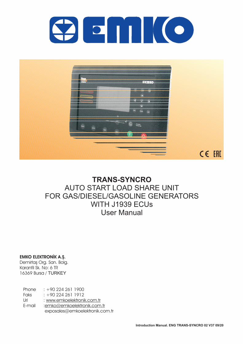
TRANS-SYNCROAUTO START LOAD SHARE UNIT
FOR GAS/DIESEL/GASOLINE GENERATORSWITH J1939 ECUs
User Manual
EMKO ELEKTRON K A. .Demirta Org. San. Bolg.
Karanfil Sk. No: 6 TR
16369 Bursa / TURKEY
Ý Þþ
Phone
Faks
Url
: +90 224 261 1900
: +90 224 261 1912
:
:
www.emkoelektronik.com.tr
Introduction Manual. ENG TRANS-SYNCRO 02 V37 09/20
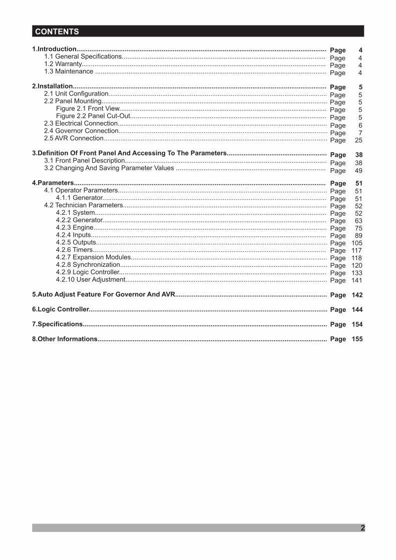
CONTENTS
2
1.Introduction.......................................................................................................................................
2.Installation.........................................................................................................................................
1.1 General Specifications..............................................................................................................1.2 Warranty....................................................................................................................................1.3 Maintenance .............................................................................................................................
Figure 2.2 Panel Cut-Out..........................................................................................................
2.4 Governor Connection.................................................................................................................2.5 AVR Connection.........................................................................................................................
3.1 Front Panel Description.............................................................................................................3.2 Changing And Saving Parameter Values .................................................................................
4.1 Operator Parameters.................................................................................................................4.1.1 Generator.........................................................................................................................
4.2 Technician Parameters..............................................................................................................4.2.1 System.............................................................................................................................4.2.2 Generator.........................................................................................................................4.2.3 Engine..............................................................................................................................4.2.4 Inputs...............................................................................................................................4.2.5 Outputs.............................................................................................................................4.2.6 Timers..............................................................................................................................4.2.7 Expansion Modules..........................................................................................................4.2.8 Synchronization................................................................................................................4.2.9 Logic Controller................................................................................................................4.2.10 User Adjustment.............................................................................................................
2.1 Unit Configuration......................................................................................................................2.2 Panel Mounting..........................................................................................................................
Figure 2.1 Front View................................................................................................................
2.3 Electrical Connection.................................................................................................................
3.Definition Of Front Panel And Accessing To The Parameters......................................................
4.Parameters........................................................................................................................................
5.Auto Adjust Feature For Governor And AVR..................................................................................
6.Logic Controller.................................................................................................................................
7.Specifications....................................................................................................................................
8.Other Informations............................................................................................................................
Page 4
Page 38
Page 6
Page 5
Page 38
Page 5
Page 5Page 5
Page 49
Page 4Page 4Page 4
Page 51Page 51Page 51Page 52Page 52
Page 5
Page 7Page 25
Page 142
Page 63Page 75Page 89Page 105Page 117Page 118Page 120Page 133
Page 144
Page 154
Page 155
Page 141

3
EU DECLARATION OF CONFORMITY
Manufacturer’s Name : EMKO ELEKTRONIK A.S.Manufacturer’s Address : DOSAB, Karanfil Sk., No:6,
16369 Bursa, TURKEY
Product Name :
Type Number : TRANS-SYNCRO
Product Category : Electrical equipment for measurement, control andlaboratory use
This declaration is issued under the sole responsibility of the manufacturer.
The product(s) that are stated above are fully in conformity with the essential requirements ofCouncil Directives:
This declaration is based on the full compliance of the products with the following Europeanstandards:
Synchronising & Load Sharing Unit
When and Where Issued Authorized Signature
2014 / 35 / EU The Low Voltage Directive
2014 / 30 / EU The Electromagnetic Compatibility Directive
EN 61000-6-4:2007 EMC Generic Emission Standard for Industrial Environments
EN 61000-6-2:2005 EMC Generic Immunity Standard for Industrial Environments
EN 61010-1:2010 Safety Requirements for electrical equipment for measurement, controland laboratory use
EN 60947-6-1:2005/A1:2014 Low - voltage switchgear and controlgear - Part 6-1: Multiplefunction equipment - Transfer switching equipment
02 March 2017 Name : Serpil YAKIN
BURSA-TURKEY Position : Quality Manager
nd
1.Introduction
1.1 General Specifications
4
1.2 Warranty
EMKO Elektronik warrants that the equipment delivered is free from defects in material andworkmanship. This warranty is provided for a period of two years. The warranty period starts fromthe delivery date. This warranty is in force if duty and responsibilities which are determined inwarranty document and instruction manual performs by the customer completely.
1.3 Maintenance
Repairs should only be performed by trained and specialized personnel. Cut power to the devicebefore accessing internal parts.Do not clean the case with hydrocarbon-based solvents (Petrol, Trichlorethylene etc.). Use ofthese solvents can reduce the mechanical reliability of the device. Use a cloth dampened in ethylalcohol or water to clean the external plastic case.
TRANS-SYNCRO is a synchronising & load sharing unit for diesel, gas or gasoline generators.The unit is an easy to use multi-generator loadshare system, designed to synchronise up to 32generators including electronic and non-electronic engines.
- Sequential set start
- Manual voltage/frequency adjustment- Direct/Reverse Governor andAVR control
- Volts, frequency and phase matching
The unit monitors J1939 ECU messages and provides remote start/stop control via J1939protocol (supported some ECUs: Volvo EMS2, Volvo EDC4, Perkins, Scania, MAN MFR andstandard messages).
- Multi genset load sharing (up to 32 gensets)- kW and kVAr load sharing- Busbar voltages and frequency measurements- Dead bus sensing- Bus failure detection
- Load dependent automatic start/stop- Equal aging of gensets
-Auto adjust feature for Governor andAVR
- Synchroscope display- Logic Controller functionality for PLC- Black or gray theme selection for 4.3 TFT LCD screen
The unit is extensively programmable through the front panel, with password protection on twolevels. Operational parameters can also be monitored and controlled from a PC via a built-in USBcommunication port.
In the event that the engine fails to start on the first attempt, the attempt will be repeated aprogrammed number of times or until successful.
The unit monitors generator operation and gives warning of any faults that are detected.If a fault is detected, the unit shuts down the engine and shows the failure message on the LCDdisplay and activates the internal sounder.
General Specifications:
"
Ýçindekiler
A visual inspection of this product for possible damage occured during shipment isrecommended before installation. It is your responsibility to ensure that qualified mechanicaland electrical technicians install this product.
If there is danger of serious accident resulting from a failure or defect in this unit , power offthe system and seperate the electrical connection of the device from the system.
Keep the power off until all of the wiring is completed so that electric shock and trouble withthe unit can be prevented.
Before beginning installation of this product, please read the instructionmanual and warnings below carefully.
2.Installation
Ýçindekiler2.1 Unit Configuration
Ýçindekiler2.2 Panel Mounting
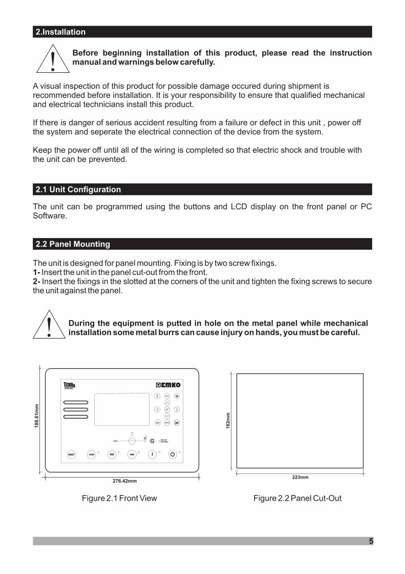
The unit is designed for panel mounting. Fixing is by two screw fixings.Insert the unit in the panel cut-out from the front.Insert the fixings in the slotted at the corners of the unit and tighten the fixing screws to secure
the unit against the panel.
1-2-
During the equipment is putted in hole on the metal panel while mechanicalinstallation some metal burrs can cause injury on hands, you must be careful.
The unit can be programmed using the buttons and LCD display on the front panel or PCSoftware.
5
!
!
Figure 2.1 Front View Figure 2.2 Panel Cut-Out
223mm
16
2m
m
18
8.6
1m
m
276.42mm
LOAD
ON
ü
LOG
PROGESC
MANAUTO TEST
ENGINERUNNING
RESET
2.3 Electrical Connection
6
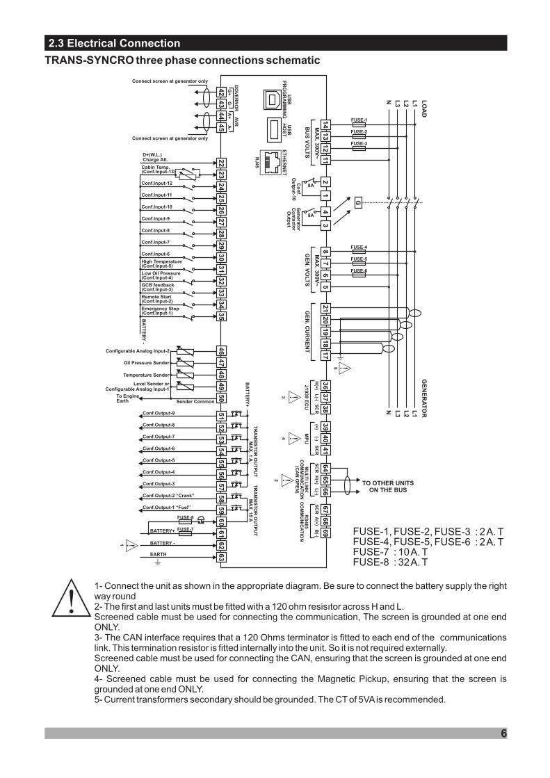
TRANS-SYNCRO three phase connections schematic
c1-
The first and last units must be fitted with a 120 ohm resisýtor across H and L.,
5- Current transformers secondary should be grounded. The CT of 5VA s recommended.
2-
3-
4-
i
Connect the unit as shown in the appropriate diagram. Be sure to connect the battery supply the rightway round
Screened cable must be used for connecting the communication The screen is grounded at one endONLY.
The CAN interface requires that a 120 Ohms terminator is fitted to each end of the communicationslink. This termination resistor is fitted internally into the unit. So it is not required externally.Screened cable must be used for connecting the CAN, ensuring that the screen is grounded at one endONLY.
Screened cable must be used for connecting the Magnetic Pickup, ensuring that the screen isgrounded at one end ONLY.
FUSE-1, FUSE-2, FUSE-3 : 2A. TFUSE-4, FUSE-5, FUSE-6 : 2A. TFUSE-7 : 10A. TFUSE-8 : 32A. T
US
BP
RO
GR
AM
MIN
G
61
BATTERY -
BATTERY+ FUSE-7
1 62
63EARTH
I
57
56
55
54
53
52
51
TR
AN
SIS
TO
R O
UT
PU
TM
AX
. 1A
BA
TT
ER
Y+
Conf.Output-9
Conf.Output-8
Conf.Output-7
Conf.Output-6
Conf.Output-5
Conf.Output-4
Conf.Output-3
22
D+(W.L.)Charge Alt.
23
Cabin Temp.(Conf.Input-13)
24Conf.Input-12
25Conf.Input-11
26Conf.Input-10
27Conf.Input-9
28Conf.Input-8
29Conf.Input-7
30Conf.Input-6
31
High Temperature(Conf.Input-5)
32
Low Oil Pressure(Conf.Input-4)
33
GCB feedback(Conf.Input-3)
34
Remote Start(Conf.Input-2)
35B
AT
TE
RY
-
US
BH
OS
TE
TH
ER
NE
T
RJ
45
4
60
59
58Conf.Output-2 “Crank”
Conf.Output-1 “Fuel”
FUSE-8
TR
AN
SIS
TO
R O
UT
PU
TM
AX
. 15A
46
47
48
49
50
Temperature Sender
Oil Pressure Sender
Sender Common
Configurable Analog Input-2
Level Sender orConfigurable Analog Input-1
3
5
14
L1
GE
NE
RA
TO
R
BU
S V
OLT
S
L2
L3
N
G
Gen
era
tor
Co
nta
cto
rO
utp
ut
FUSE-1
FUSE-4
21
20
19
18
I
13
12
11
FUSE-2
FUSE-3
8A
43
87
65
FUSE-5
FUSE-6
17
L1
L2
L3
N LO
AD
36
H(+
)L
(-)
J1939 E
CU SC
R
37
38
39(+)
(-)
MP
U
SC
R
40
41
64
H(+
)L
(-)S
CR
65
66
69
68
67
A(+
)B
(-)S
CR
42
43
45
G+
G-
A+
A-
GO
VE
RN
OR
AV
R
MU
LTI L
INK
CO
MM
UN
ICA
TIO
N(C
AN
OP
EN
)
RS
48
5C
OM
MU
NIC
AT
ION
c
cc
c
2
c
44
Connect screen at generator only
Connect screen at generator only
Emergency Stop(Conf.Input-1)
To EngineEarth
MA
X. 3
00V
~
GE
N. V
OLT
S
MA
X. 3
00V
~
GE
N. C
UR
RE
NT
Co
nf.
Ou
tpu
t-10
8A
21
TO OTHER UNITSON THE BUS
2.4 Governor Connection
2.4.1 INTERFACING TO GOVERNORS & ENGINE ECUs
2.4.1.1 INTERFACING WITH TRANS-SYNCRO CONTROLLERS
2.4.2 SPECIFICATIONS
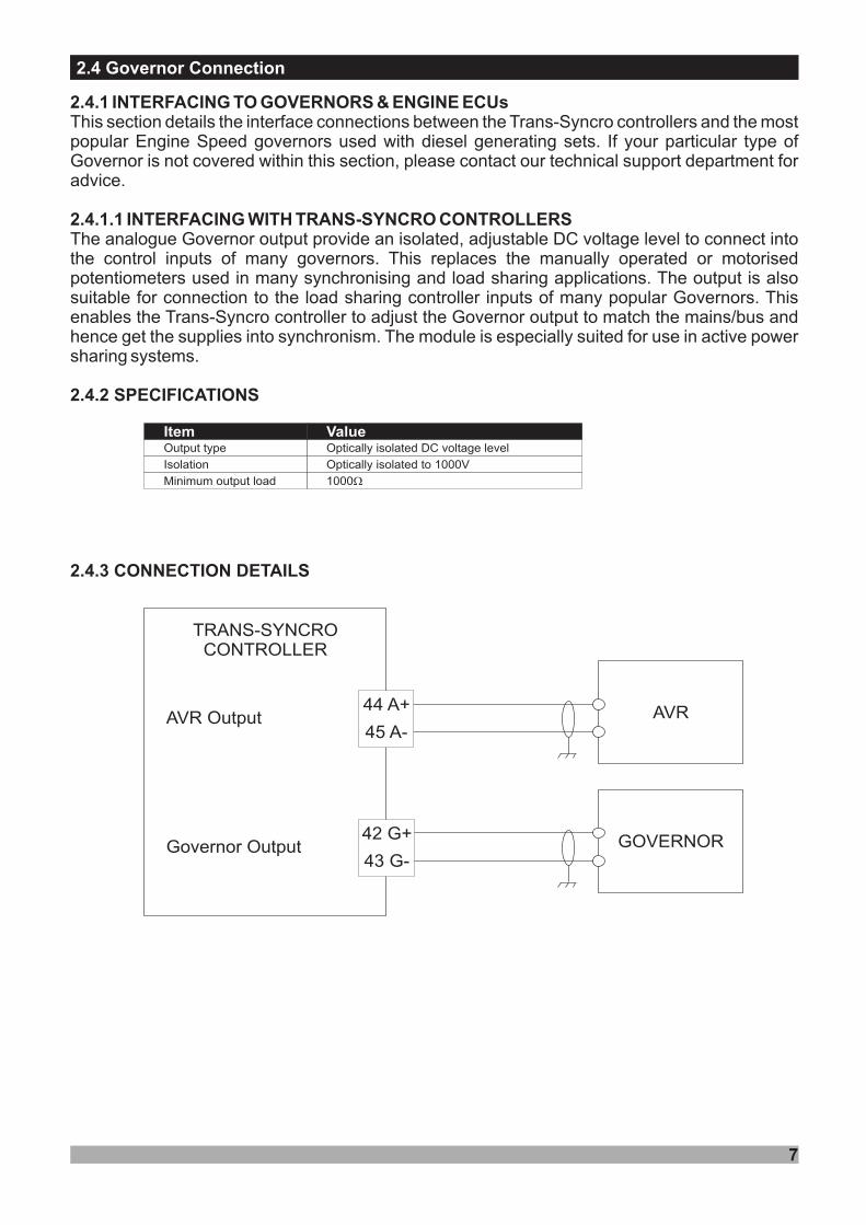
2.4.3 CONNECTION DETAILS
This section details the interface connections between the Trans-Syncro controllers and the mostpopular Engine Speed governors used with diesel generating sets. If your particular type ofGovernor is not covered within this section, please contact our technical support department foradvice.
The analogue Governor output provide an isolated, adjustable DC voltage level to connect intothe control inputs of many governors. This replaces the manually operated or motorisedpotentiometers used in many synchronising and load sharing applications. The output is alsosuitable for connection to the load sharing controller inputs of many popular Governors. Thisenables the Trans-Syncro controller to adjust the Governor output to match the mains/bus andhence get the supplies into synchronism. The module is especially suited for use in active powersharing systems.
Item ValueOutput type Optically isolated DC voltage level
Isolation Optically isolated to 1000V
Minimum output load 1000W
TRANS-SYNCROCONTROLLER
AVR
GOVERNORGovernor Output
AVR Output44 A+
45 A-
42 G+
43 G-
7
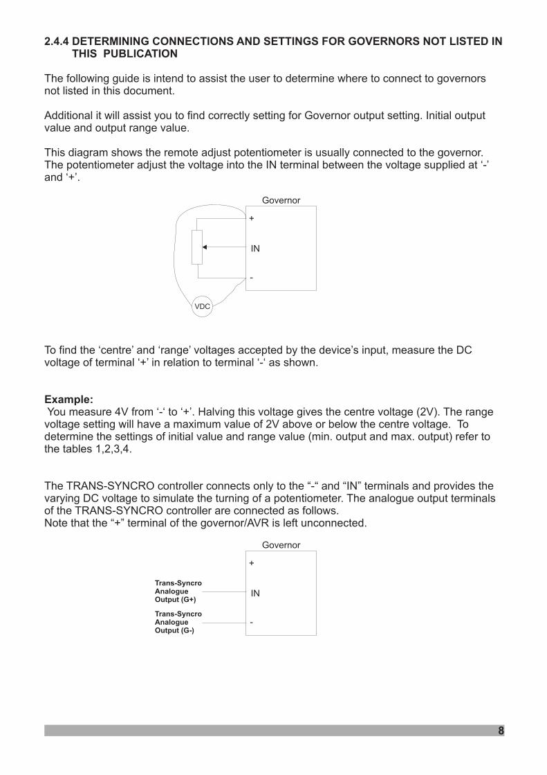
2.4.4 DETERMINING CONNECTIONS AND SETTINGS FOR GOVERNORS NOT LISTED INTHIS PUBLICATION
The following guide is intend to assist the user to determine where to connect to governorsnot listed in this document.
Additional it will assist you to find correctly setting for Governor output setting. Initial outputvalue and output range value.
This diagram shows the remote adjust potentiometer is usually connected to the governor.The potentiometer adjust the voltage into the IN terminal between the voltage supplied at ‘-’and ‘+’.
To find the ‘centre’ and ‘range’ voltages accepted by the device’s input, measure the DCvoltage of terminal ‘+’ in relation to terminal ‘-‘ as shown.
You measure 4V from ‘-‘ to ‘+’. Halving this voltage gives the centre voltage (2V). The rangevoltage setting will have a maximum value of 2V above or below the centre voltage. Todetermine the settings of initial value and range value (min. output and max. output) refer tothe tables 1,2,3,4.
The TRANS-SYNCRO controller connects only to the “-“ and “IN” terminals and provides thevarying DC voltage to simulate the turning of a potentiometer. The analogue output terminalsof the TRANS-SYNCRO controller are connected as follows.Note that the “+” terminal of the governor/AVR is left unconnected.
Example:
VDC
Governor
IN
+
-
Governor
IN
+
-
Trans-SyncroAnalogueOutput (G+)
Trans-SyncroAnalogueOutput (G-)
8
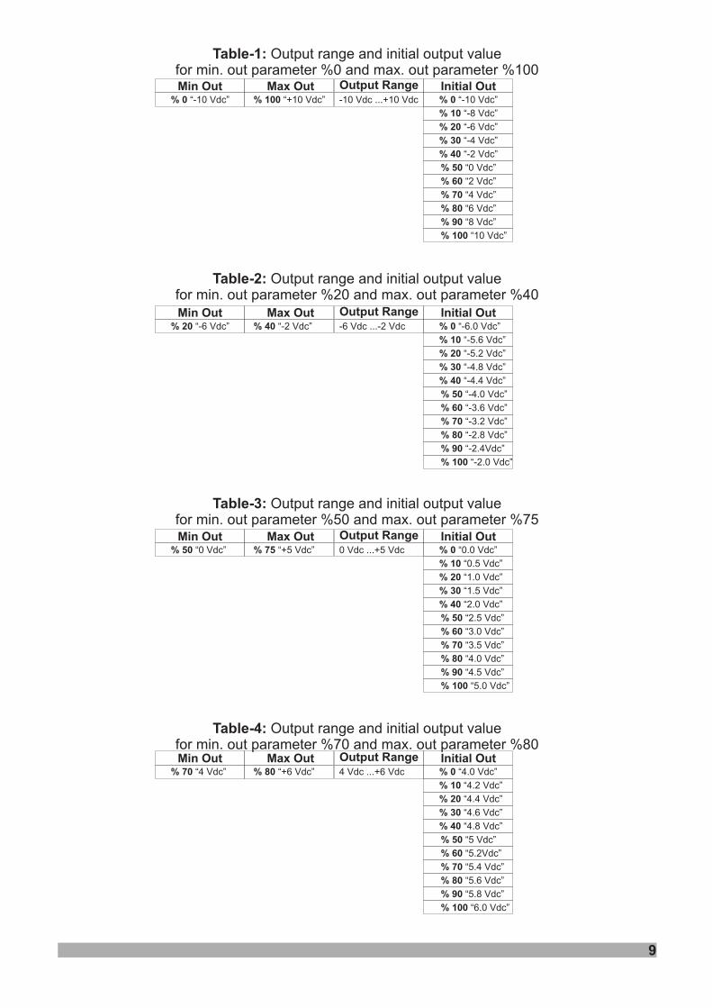
Table-1:
Table-2:
Table-3:
Table-4:
Output range and initial output valuefor min. out parameter %0 and max. out parameter %100
Output range and initial output valuefor min. out parameter %20 and max. out parameter %40
Output range and initial output valuefor min. out parameter %50 and max. out parameter %75
Output range and initial output valuefor min. out parameter %70 and max. out parameter %80
Min Out Max Out Output Range% 0 “-10 Vdc” % 100 “+10 Vdc”
Initial Out-10 Vdc ...+10 Vdc % 0 “-10 Vdc”
% 10 “-8 Vdc”
% 20 “-6 Vdc”
% 30 “-4 Vdc”
% 40 “-2 Vdc”
% 50 “0 Vdc”
% 60 “2 Vdc”
% 70 “4 Vdc”
% 80 “6 Vdc”
% 90 “8 Vdc”
% 100 “10 Vdc”
Min Out Max Out Output Range% 20 “-6 Vdc” % 40 “-2 Vdc”
Initial Out-6 Vdc ...-2 Vdc % 0 “-6.0 Vdc”
% 10 “-5.6 Vdc”
% 20 “-5.2 Vdc”
% 30 “-4.8 Vdc”
% 40 “-4.4 Vdc”
% 50 “-4.0 Vdc”
% 60 “-3.6 Vdc”
% 70 “-3.2 Vdc”
% 80 “-2.8 Vdc”
% 90 “-2.4Vdc”
% 100 “-2.0 Vdc”
Min Out Max Out Output Range% 70 “4 Vdc” % 80 “+6 Vdc”
Initial Out4 Vdc ...+6 Vdc % 0 “4.0 Vdc”
% 10 “4.2 Vdc”
% 20 “4.4 Vdc”
% 30 “4.6 Vdc”
% 40 “4.8 Vdc”
% 50 “5 Vdc”
% 60 “5.2Vdc”
% 70 “5.4 Vdc”
% 80 “5.6 Vdc”
% 90 “5.8 Vdc”
% 100 “6.0 Vdc”
Min Out Max Out Output Range% 50 “0 Vdc” % 75 “+5 Vdc”
Initial Out0 Vdc ...+5 Vdc % 0 “0.0 Vdc”
% 10 “0.5 Vdc”
% 20 “1.0 Vdc”
% 30 “1.5 Vdc”
% 40 “2.0 Vdc”
% 50 “2.5 Vdc”
% 60 “3.0 Vdc”
% 70 “3.5 Vdc”
% 80 “4.0 Vdc”
% 90 “4.5 Vdc”
% 100 “5.0 Vdc”
9
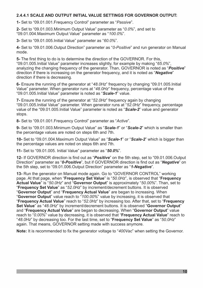
2.4.4.1 SCALE AND OUTPUT INITIAL VALUE SETTINGS FOR GOVERNOR OUTPUT:
1-
2-
3-
4-
5-
6-
7-
8-
9-
10-
11-
12-
13-Frequency Set Value Frequency
Actual Value Governor OutputFrequency Set ValueGovernor Output Frequency Actual ValueGovernor OutputFrequency Actual Value Frequency
Set Value Governor OutputFrequency Actual Value Governor Output
Frequency Actual ValueFrequency Set Value
Note:
Set to “09.01.001.Frequency Control” parameter as “ ”.
Set to “09.01.003.Minimum Output Value” parameter as “ ”, and set to“09.01.004.Maximum Output Value” parameter as “ ”.
Set to “09.01.005.Initial Value” parameter as “ ”.
Set to “09.01.006.Output Direction” parameter as “ ” and run generator on Manualmode.
The first thing to do is to determine the direction of the GOVERNOR. For this,“09.01.005.Initial Value” parameter increases slightly, for example by making “ ”,analyzing the changing frequency of the generator. Than, GOVERNOR is noted as “ ”direction if there is increasing on the generator frequency, and it is noted as “ ”direction if there is decreasing.
Ensure the running of the generator at “ ” frequency by changing “09.01.005.InitialValue” parameter. When generator runs at “ ” frequency, percentage value of the“09.01.005.Initial Value” parameter is noted as “ ” value.
Ensure the running of the generator at “ ” frequency again by changing“09.01.005.Initial Value” parameter. When generator runs at “ ” frequency, percentagevalue of the “09.01.005.Initial Value” parameter is noted as “ ” value and generatorstops.
Set to “09.01.001.Frequency Control” parameter as “ ”.
Set to “09.01.003.Minimum Output Value” as “ ” or “ ” which is smaller thanthe percentage values are noted on steps 6th and 7th.
Set to “09.01.004.Maximum Output Value” as “ ” or “ ” which is bigger thanthe percentage values are noted on steps 6th and 7th.
Set to “09.01.005. Initial Value” parameter as “ ”.
If GOVERNOR direction is find out as “ ” on the 5th step, set to “09.01.006.OutputDirection” parameter as “ ”, but if GOVERNOR direction is find out as “ ” onthe 5th step, set to “09.01.006.Output Direction” parameter as “ ”.
Run the generator on Manual mode again. Go to “GOVERNOR CONTROL” workingpage. At that page, when “ ” is “ ”, is observed that “
” is “ ” and “ ” is approximately “ ”. Than, set to“ ” as “ ” by increment/decrement buttons. It is observed“ ” and “ ” are began to increasing. When“ ” value reach to “ ” value by increasing, it is observed that“ ” reach to “ ” by increasing too. After that, set to “
” as “ ” by increment/decrement buttons. It is observed “ ”and “ ” are began to decreasing. When “ ” valuereach to “ ” value by decreasing, it is observed that “ ” reach to“ ” by decreasing too. For the last time, set to “ ” as “ ”again. That means, GOVERNOR setting made with success anymore.
It is recommended to fix the generator voltage to “ ” when setting the Governor.
Passive
0.0%100.0%
60.0%
0-Positive
65.0%
48.0Hz48.0Hz
52.0Hz52.0Hz
Active
50.0Hz50.0Hz 50.00%
52.0Hz
100.00%52.0Hz
48.0Hz
0.00%48.0Hz 50.0Hz
400Vac
PositiveNegative
Scale-1
Scale-2
Scale-1 Scale-2
Scale-1 Scale-2
50.0%
Positive0-Positive Negative
1-Negative
10
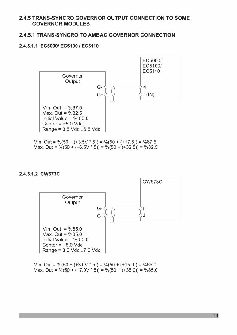
2.4.5 TRANS-SYNCRO GOVERNOR OUTPUT CONNECTION TO SOMEGOVERNOR MODULES
.4.52 .1 TRANS-SYNCRO TO AMBAC GOVERNOR CONNECTION
2.4.5.1.1 EC5000/ EC5100 / EC5110
2.4.5.1.2 CW673C
Min. Out = %(50 + (+3.5V * 5)) = %(50 + (+17.5)) = %67.5Max. Out = %(50 + (+6.5V * 5)) = %(50 + (+32.5)) = %82.5
Min. Out = %(50 + (+3.0V * 5)) = %(50 + (+15.0)) = %65.0Max. Out = %(50 + (+7.0V * 5)) = %(50 + (+35.0)) = %85.0
Min. Out = %67.5Max. Out = %82.5Initial Value = % 50.0Center = +5.0 VdcRange = 3.5 Vdc...6.5 Vdc
GovernorOutput
EC5000/EC5100/EC5110
G-
G+
4
1(IN)
Min. Out = %65.0Max. Out = %85.0Initial Value = % 50.0Center = +5.0 VdcRange = 3.0 Vdc...7.0 Vdc
GovernorOutput
CW673C
G-
G+
H
J
11
2 .2 TRANS-SYNCRO TO GOVERNOR CONNECTION.4.5 BARBAR COLMAN
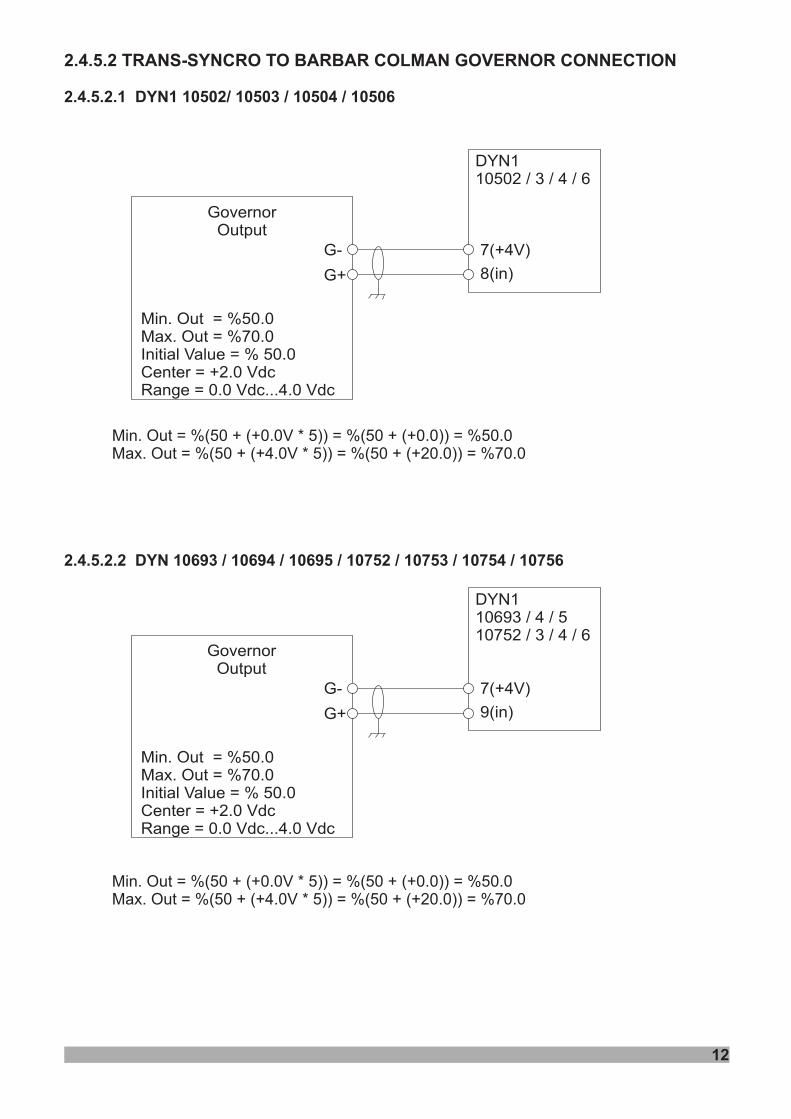
2.4.5.2.1 DYN1 10502/ 10503 / 10504 / 10506
2.4.5.2.2 DYN 10693 / 10694 / 10695 / 10752 / 10753 / 10754 / 10756
Min. Out = %(50 + (+0.0V * 5)) = %(50 + (+0.0)) = %50.0Max. Out = %(50 + (+4.0V * 5)) = %(50 + (+20.0)) = %70.0
Min. Out = %(50 + (+0.0V * 5)) = %(50 + (+0.0)) = %50.0Max. Out = %(50 + (+4.0V * 5)) = %(50 + (+20.0)) = %70.0
DYN110502 / 3 / 4 / 6
Min. Out = %50.0Max. Out = %70.0Initial Value = % 50.0Center = +2.0 VdcRange = 0.0 Vdc...4.0 Vdc
GovernorOutput
G-
G+
7(+4V)
8(in)
DYN110693 / 4 / 510752 / 3 / 4 / 6
Min. Out = %50.0Max. Out = %70.0Initial Value = % 50.0Center = +2.0 VdcRange = 0.0 Vdc...4.0 Vdc
GovernorOutput
G-
G+
7(+4V)
9(in)
12
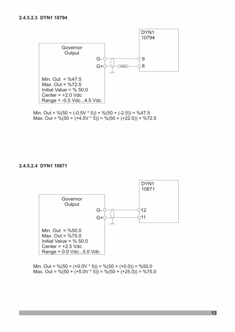
2.4.5.2.3 DYN1 10794
2.4.5.2.4 DYN1 10871
Min. Out = %(50 + (-0.5V * 5)) = %(50 + (-2.5)) = %47.5Max. Out = %(50 + (+4.5V * 5)) = %(50 + (+22.5)) = %72.5
Min. Out = %(50 + (+0.0V * 5)) = %(50 + (+0.0)) = %50.0Max. Out = %(50 + (+5.0V * 5)) = %(50 + (+25.0)) = %75.0
Min. Out = %47.5Max. Out = %72.5Initial Value = % 50.0Center = +2.0 VdcRange = -0.5 Vdc...4.5 Vdc
GovernorOutput
DYN110794
G-
G+
9
8
Min. Out = %50.0Max. Out = %75.0Initial Value = % 50.0Center = +2.5 VdcRange = 0.0 Vdc...5.0 Vdc
GovernorOutput
DYN110871
G-
G+
12
11
13
120kW
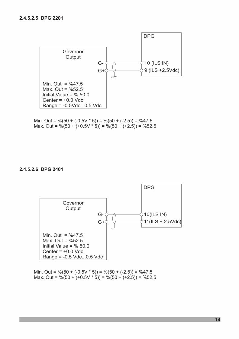
2.4.5.2.5 DPG 2201
2.4.5.2.6 DPG 2401
Min. Out = %(50 + (-0.5V * 5)) = %(50 + (-2.5)) = %47.5Max. Out = %(50 + (+0.5V * 5)) = %(50 + (+2.5)) = %52.5
Min. Out = %(50 + (-0.5V * 5)) = %(50 + (-2.5)) = %47.5Max. Out = %(50 + (+0.5V * 5)) = %(50 + (+2.5)) = %52.5
Min. Out = %47.5Max. Out = %52.5Initial Value = % 50.0Center = +0.0 VdcRange = -0.5Vdc...0.5 Vdc
GovernorOutput
DPG
G-
G+
10 (ILS IN)
9 (ILS +2.5Vdc)
Min. Out = %47.5Max. Out = %52.5Initial Value = % 50.0Center = +0.0 VdcRange = -0.5 Vdc...0.5 Vdc
GovernorOutput
DPG
G-
G+
10(ILS IN)
11(ILS + 2.5Vdc)
14
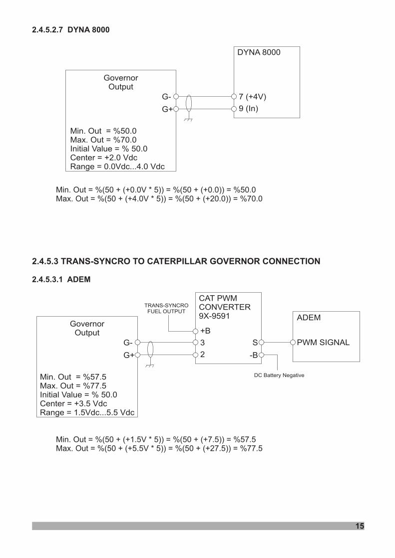
2.4.5.2.7 DYNA 8000
2.4.5.3.1 ADEM
Min. Out = %(50 + (+0.0V * 5)) = %(50 + (+0.0)) = %50.0Max. Out = %(50 + (+4.0V * 5)) = %(50 + (+20.0)) = %70.0
Min. Out = %(50 + (+1.5V * 5)) = %(50 + (+7.5)) = %57.5Max. Out = %(50 + (+5.5V * 5)) = %(50 + (+27.5)) = %77.5
2.4.5.3 TRANS-SYNCRO TO CATERPILLAR GOVERNOR CONNECTION
Min. Out = %50.0Max. Out = %70.0Initial Value = % 50.0Center = +2.0 VdcRange = 0.0Vdc...4.0 Vdc
GovernorOutput
DYNA 8000
G-
G+
7 (+4V)
9 (In)
Min. Out = %57.5Max. Out = %77.5Initial Value = % 50.0Center = +3.5 VdcRange = 1.5Vdc...5.5 Vdc
GovernorOutput
CAT PWMCONVERTER9X-9591
G-
G+
3
2
+B
TRANS-SYNCROFUEL OUTPUT
-B
S PWM SIGNAL
DC Battery Negative
15
ADEM
2 .4 TRANS-SYNCRO TO CUMMINS GOVERNOR CONNECTION.4.5
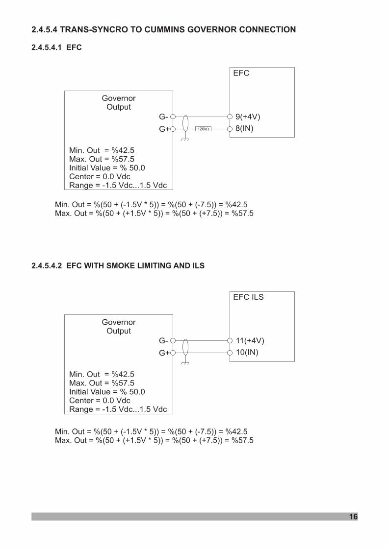
2.4.5.4.1 EFC
2.4.5.4.2 EFC WITH SMOKE LIMITING AND ILS
Min. Out = %(50 + (-1.5V * 5)) = %(50 + (-7.5)) = %42.5Max. Out = %(50 + (+1.5V * 5)) = %(50 + (+7.5)) = %57.5
Min. Out = %(50 + (-1.5V * 5)) = %(50 + (-7.5)) = %42.5Max. Out = %(50 + (+1.5V * 5)) = %(50 + (+7.5)) = %57.5
Min. Out = %42.5Max. Out = %57.5Initial Value = % 50.0Center = 0.0 VdcRange = -1.5 Vdc...1.5 Vdc
GovernorOutput
EFC
G-
G+
9(+4V)
8(IN)
Min. Out = %42.5Max. Out = %57.5Initial Value = % 50.0Center = 0.0 VdcRange = -1.5 Vdc...1.5 Vdc
GovernorOutput
EFC ILS
G-
G+
11(+4V)
10(IN)
120kW
16
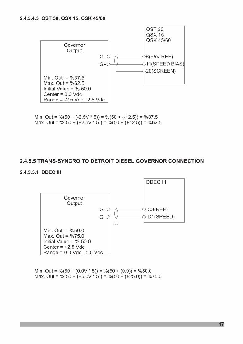
2.4.5.4.3 QST 30, QSX 15, QSK 45/60
2.4.5.5.1 DDEC III
Min. Out = %(50 + (-2.5V * 5)) = %(50 + (-12.5)) = %37.5Max. Out = %(50 + (+2.5V * 5)) = %(50 + (+12.5)) = %62.5
Min. Out = %(50 + (0.0V * 5)) = %(50 + (0.0)) = %50.0Max. Out = %(50 + (+5.0V * 5)) = %(50 + (+25.0)) = %75.0
2.4.5.5 TRANS-SYNCRO TO DETROIT DIESEL GOVERNOR CONNECTION
Min. Out = %37.5Max. Out = %62.5Initial Value = % 50.0Center = 0.0 VdcRange = -2.5 Vdc...2.5 Vdc
GovernorOutput
QST 30QSX 15QSK 45/60
G-
G+
6(+5V REF)
11(SPEED BIAS)
Min. Out = %50.0Max. Out = %75.0Initial Value = % 50.0Center = +2.5 VdcRange = 0.0 Vdc...5.0 Vdc
GovernorOutput
DDEC III
G-
G+
C3(REF)
D1(SPEED)
20(SCREEN)
17
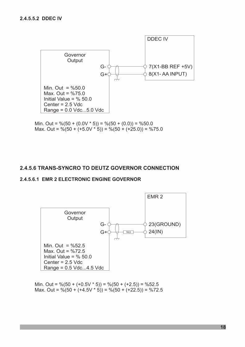
2.4.5.5.2 DDEC IV
2.4.5.6.1 EMR 2 ELECTRONIC ENGINE GOVERNOR
Min. Out = %(50 + (0.0V * 5)) = %(50 + (0.0)) = %50.0Max. Out = %(50 + (+5.0V * 5)) = %(50 + (+25.0)) = %75.0
Min. Out = %(50 + (+0.5V * 5)) = %(50 + (+2.5)) = %52.5Max. Out = %(50 + (+4.5V * 5)) = %(50 + (+22.5)) = %72.5
2.4.5.6 TRANS-SYNCRO TO DEUTZ GOVERNOR CONNECTION
Min. Out = %50.0Max. Out = %75.0Initial Value = % 50.0Center = 2.5 VdcRange = 0.0 Vdc...5.0 Vdc
GovernorOutput
DDEC IV
G-
G+
7(X1-BB REF +5V)
8(X1- AA INPUT)
Min. Out = %52.5Max. Out = %72.5Initial Value = % 50.0Center = 2.5 VdcRange = 0.5 Vdc...4.5 Vdc
GovernorOutput
EMR 2
G-
G+
23(GROUND)
24(IN)1KW
18
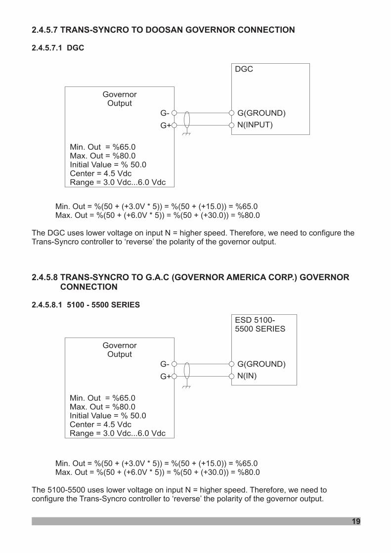
2.4.5.7 TRANS-SYNCRO TO DOOSAN GOVERNOR CONNECTION
2.4.5.8 TRANS-SYNCRO TO G.A.C (GOVERNOR AMERICA CORP.) GOVERNORCONNECTION
2.4.5.7.1 DGC
2.4.5.8.1 5100 - 5500 SERIES
Min. Out = %(50 + (+3.0V * 5)) = %(50 + (+15.0)) = %65.0Max. Out = %(50 + (+6.0V * 5)) = %(50 + (+30.0)) = %80.0
Min. Out = %(50 + (+3.0V * 5)) = %(50 + (+15.0)) = %65.0Max. Out = %(50 + (+6.0V * 5)) = %(50 + (+30.0)) = %80.0
The 5100-5500 uses lower voltage on input N = higher speed. Therefore, we need toconfigure the Trans-Syncro controller to ‘reverse’ the polarity of the governor output.
The DGC uses lower voltage on input N = higher speed. Therefore, we need to configure theTrans-Syncro controller to ‘reverse’ the polarity of the governor output.
Min. Out = %65.0Max. Out = %80.0Initial Value = % 50.0Center = 4.5 VdcRange = 3.0 Vdc...6.0 Vdc
GovernorOutput
DGC
G-
G+
G(GROUND)
N(INPUT)
Min. Out = %65.0Max. Out = %80.0Initial Value = % 50.0Center = 4.5 VdcRange = 3.0 Vdc...6.0 Vdc
GovernorOutput
ESD 5100-5500 SERIES
G-
G+
G(GROUND)
N(IN)
19
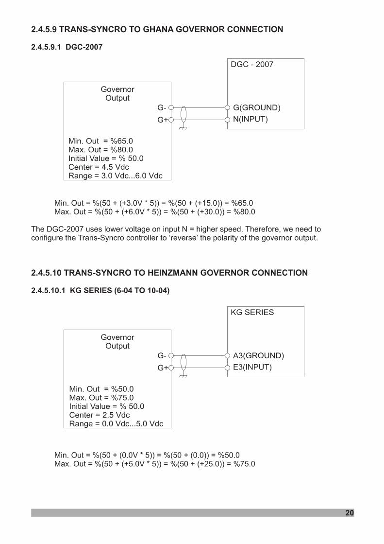
2.4.5.9 TRANS-SYNCRO TO GHANA GOVERNOR CONNECTION
2.4.5.10 TRANS-SYNCRO TO HEINZMANN GOVERNOR CONNECTION
2.4.5.9.1 DGC-2007
2.4.5.10.1 KG SERIES (6-04 TO 10-04)
Min. Out = %(50 + (+3.0V * 5)) = %(50 + (+15.0)) = %65.0Max. Out = %(50 + (+6.0V * 5)) = %(50 + (+30.0)) = %80.0
Min. Out = %(50 + (0.0V * 5)) = %(50 + (0.0)) = %50.0Max. Out = %(50 + (+5.0V * 5)) = %(50 + (+25.0)) = %75.0
The DGC-2007 uses lower voltage on input N = higher speed. Therefore, we need toconfigure the Trans-Syncro controller to ‘reverse’ the polarity of the governor output.
Min. Out = %65.0Max. Out = %80.0Initial Value = % 50.0Center = 4.5 VdcRange = 3.0 Vdc...6.0 Vdc
GovernorOutput
DGC - 2007
G-
G+
G(GROUND)
N(INPUT)
20
Min. Out = %50.0Max. Out = %75.0Initial Value = % 50.0Center = 2.5 VdcRange = 0.0 Vdc...5.0 Vdc
GovernorOutput
KG SERIES
G-
G+
A3(GROUND)
E3(INPUT)

2.4.5.10.2 PANDAROS
2.4.5.11.1 CURSOR 13TE2(WITH SCI BOX)
Min. Out = %(50 + (+0.5V * 5)) = %(50 + (2.5)) = %52.5Max. Out = %(50 + (+4.5V * 5)) = %(50 + (+22.5)) = %72.5
Min. Out = %(50 + (+1.0V * 5)) = %(50 + (+5.0)) = %55.0Max. Out = %(50 + (+4.0V * 5)) = %(50 + (+20.0)) = %70.0
2.4.5.11 TRANS-SYNCRO TO IVECO GOVERNOR CONNECTION
Min. Out = %52.5Max. Out = %72.5Initial Value = % 50.0Center = 2.5 VdcRange = 0.5 Vdc...4.5 Vdc
GovernorOutput
PANDAROS
G-
G+
A3(COMMON)
B3(SYNC IN / AI2)
Min. Out = %55.0Max. Out = %70.0Initial Value = % 50.0Center = 2.5 VdcRange = 1.0 Vdc...4.0 Vdc
GovernorOutput
SCI BOX
G-
G+
12
11(0V)
13(+5V NC)
21
SCR
22
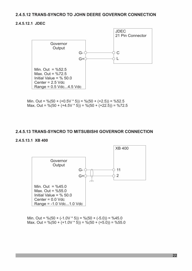
2.4.5.12 TRANS-SYNCRO TO JOHN DEERE GOVERNOR CONNECTION
2.4.5.13 TRANS-SYNCRO TO MITSUBISHI GOVERNOR CONNECTION
2.4.5.12.1 JDEC
2.4.5.13.1 XB 400
Min. Out = %(50 + (+0.5V * 5)) = %(50 + (+2.5)) = %52.5Max. Out = %(50 + (+4.5V * 5)) = %(50 + (+22.5)) = %72.5
Min. Out = %(50 + (-1.0V * 5)) = %(50 + (-5.0)) = %45.0Max. Out = %(50 + (+1.0V * 5)) = %(50 + (+5.0)) = %55.0
Min. Out = %52.5Max. Out = %72.5Initial Value = % 50.0Center = 2.5 VdcRange = 0.5 Vdc...4.5 Vdc
GovernorOutput
JDEC21 Pin Connector
G-
G+
C
L
Min. Out = %45.0Max. Out = %55.0Initial Value = % 50.0Center = 0.0 VdcRange = -1.0 Vdc...1.0 Vdc
GovernorOutput
XB 400
G-
G+
11
2
23
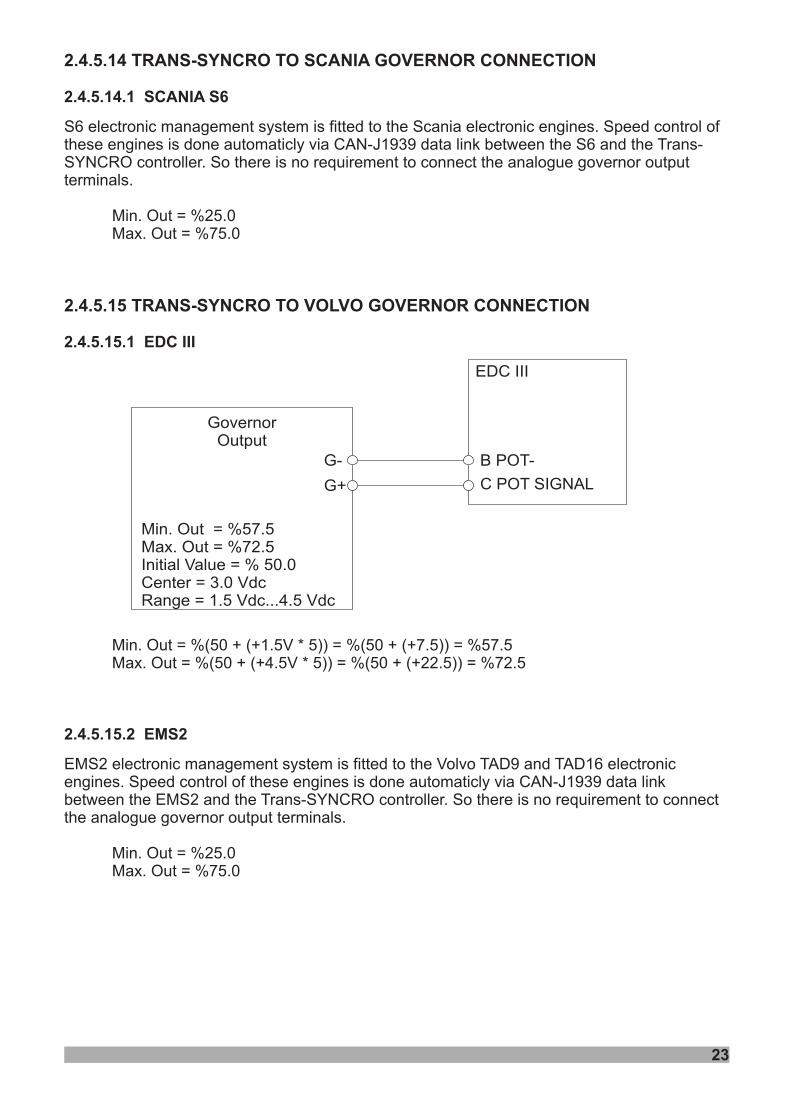
2.4.5.14 TRANS-SYNCRO TO SCANIA GOVERNOR CONNECTION
2.4.5.15 TRANS-SYNCRO TO VOLVO GOVERNOR CONNECTION
2.4.5.14.1 SCANIA S6
2.4.5.15.1 EDC III
2.4.5.15.2 EMS2
S6 electronic management system is fitted to the Scania electronic engines. Speed control ofthese engines is done automaticly via CAN-J1939 data link between the S6 and the Trans-SYNCRO controller. So there is no requirement to connect the analogue governor outputterminals.
Min. Out = %25.0Max. Out = %75.0
Min. Out = %(50 + (+1.5V * 5)) = %(50 + (+7.5)) = %57.5Max. Out = %(50 + (+4.5V * 5)) = %(50 + (+22.5)) = %72.5
EMS2 electronic management system is fitted to the Volvo TAD9 and TAD16 electronicengines. Speed control of these engines is done automaticly via CAN-J1939 data linkbetween the EMS2 and the Trans-SYNCRO controller. So there is no requirement to connectthe analogue governor output terminals.
Min. Out = %25.0Max. Out = %75.0
Min. Out = %57.5Max. Out = %72.5Initial Value = % 50.0Center = 3.0 VdcRange = 1.5 Vdc...4.5 Vdc
GovernorOutput
EDC III
G-
G+
B POT-
C POT SIGNAL
24
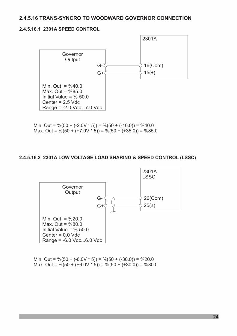
2.4.5.16 TRANS-SYNCRO TO WOODWARD GOVERNOR CONNECTION
2.4.5.16.1 2301A SPEED CONTROL
2.4.5.16.2 2301A LOW VOLTAGE LOAD SHARING & SPEED CONTROL (LSSC)
Min. Out = %(50 + (-2.0V * 5)) = %(50 + (-10.0)) = %40.0Max. Out = %(50 + (+7.0V * 5)) = %(50 + (+35.0)) = %85.0
Min. Out = %(50 + (-6.0V * 5)) = %(50 + (-30.0)) = %20.0Max. Out = %(50 + (+6.0V * 5)) = %(50 + (+30.0)) = %80.0
Min. Out = %40.0Max. Out = %85.0Initial Value = % 50.0Center = 2.5 VdcRange = -2.0 Vdc...7.0 Vdc
GovernorOutput
2301A
G-
G+
16(Com)
15(±)
Min. Out = %20.0Max. Out = %80.0Initial Value = % 50.0Center = 0.0 VdcRange = -6.0 Vdc...6.0 Vdc
GovernorOutput
2301ALSSC
G-
G+
26(Com)
25(±)
2.5.1 INTERFACING TOAUTOMATIC VOLTAGE REGULATORS
2.5.1.1 INTERFACING WITH TRANS-SYNCRO CONTROLLERS
2.5.2 SPECIFICATIONS
2.5.3 CONNECTION DETAILS
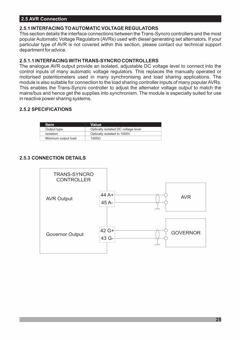
This section details the interface connections between the Trans-Syncro controllers and the mostpopular Automatic Voltage Regulators (AVRs) used with diesel generating set alternators. If yourparticular type of AVR is not covered within this section, please contact our technical supportdepartment for advice.
The analogue AVR output provide an isolated, adjustable DC voltage level to connect into thecontrol inputs of many automatic voltage regulators. This replaces the manually operated ormotorised potentiometers used in many synchronising and load sharing applications. Themodule is also suitable for connection to the load sharing controller inputs of many popularAVRs.This enables the Trans-Syncro controller to adjust the alternator voltage output to match themains/bus and hence get the supplies into synchronism. The module is especially suited for usein reactive power sharing systems.
Item ValueOutput type Optically isolated DC voltage level
Isolation Optically isolated to 1000V
Minimum output load 1000W
25
2.5 AVR Connection
TRANS-SYNCROCONTROLLER
AVR
GOVERNORGovernor Output
AVR Output44 A+
45 A-
42 G+
43 G-
2.5.4 DETERMINING CONNECTIONS AND SETTINGS FOR AVRS NOT LISTED IN THISPUBLICATION
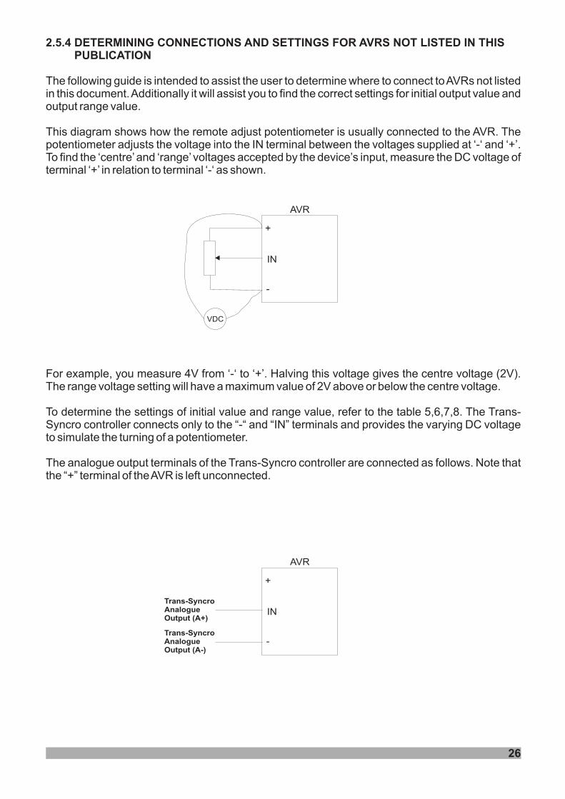
The following guide is intended to assist the user to determine where to connect toAVRs not listedin this document.Additionally it will assist you to find the correct settings for i
This diagram shows how the remote adjust potentiometer is usually connected to the AVR. Thepotentiometer adjusts the voltage into the IN terminal between the voltages supplied at ‘-‘ and ‘+’.To find the ‘centre’and ‘range’ voltages accepted by the device’s input, measure the DC voltage ofterminal ‘+’ in relation to terminal ‘-‘ as shown.
For example, you measure 4V from ‘-‘ to ‘+’. Halving this voltage gives the centre voltage (2V).The range voltage setting will have a maximum value of 2V above or below the centre voltage.
To determine the settings of initial value and range value, refer to the table 5,6,7,8. The Trans-Syncro controller connects only to the “-“ and “IN” terminals and provides the varying DC voltageto simulate the turning of a potentiometer.
The analogue output terminals of the Trans-Syncro controller are connected as follows. Note thatthe “+” terminal of theAVR is left unconnected.
nitial output value andoutput range value.
VDC
AVR
IN
+
-
AVR
IN
+
-
Trans-SyncroAnalogueOutput (A+)
Trans-SyncroAnalogueOutput (A-)
26
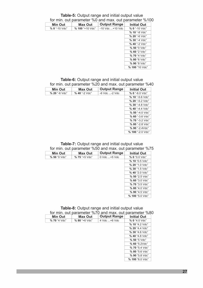
Table-5:
Table-6:
Table-7:
Table-8:
Output range and initial output valuefor min. out parameter %0 and max. out parameter %100
Output range and initial output valuefor min. out parameter %20 and max. out parameter %40
Output range and initial output valuefor min. out parameter %50 and max. out parameter %75
Output range and initial output valuefor min. out parameter %70 and max. out parameter %80
Min Out Max Out Output Range% 0 “-10 Vdc” % 100 “+10 Vdc”
Initial Out-10 Vdc ...+10 Vdc % 0 “-10 Vdc”
% 10 “-8 Vdc”
% 20 “-6 Vdc”
% 30 “-4 Vdc”
% 40 “-2 Vdc”
% 50 “0 Vdc”
% 60 “2 Vdc”
% 70 “4 Vdc”
% 80 “6 Vdc”
% 90 “8 Vdc”
% 100 “10 Vdc”
Min Out Max Out Output Range% 20 “-6 Vdc” % 40 “-2 Vdc”
Initial Out-6 Vdc ...-2 Vdc % 0 “-6.0 Vdc”
% 10 “-5.6 Vdc”
% 20 “-5.2 Vdc”
% 30 “-4.8 Vdc”
% 40 “-4.4 Vdc”
% 50 “-4.0 Vdc”
% 60 “-3.6 Vdc”
% 70 “-3.2 Vdc”
% 80 “-2.8 Vdc”
% 90 “-2.4Vdc”
% 100 “-2.0 Vdc”
Min Out Max Out Output Range% 70 “4 Vdc” % 80 “+6 Vdc”
Initial Out4 Vdc ...+6 Vdc % 0 “4.0 Vdc”
% 10 “4.2 Vdc”
% 20 “4.4 Vdc”
% 30 “4.6 Vdc”
% 40 “4.8 Vdc”
% 50 “5 Vdc”
% 60 “5.2Vdc”
% 70 “5.4 Vdc”
% 80 “5.6 Vdc”
% 90 “5.8 Vdc”
% 100 “6.0 Vdc”
Min Out Max Out Output Range% 50 “0 Vdc” % 75 “+5 Vdc”
Initial Out0 Vdc ...+5 Vdc % 0 “0.0 Vdc”
% 10 “0.5 Vdc”
% 20 “1.0 Vdc”
% 30 “1.5 Vdc”
% 40 “2.0 Vdc”
% 50 “2.5 Vdc”
% 60 “3.0 Vdc”
% 70 “3.5 Vdc”
% 80 “4.0 Vdc”
% 90 “4.5 Vdc”
% 100 “5.0 Vdc”
27
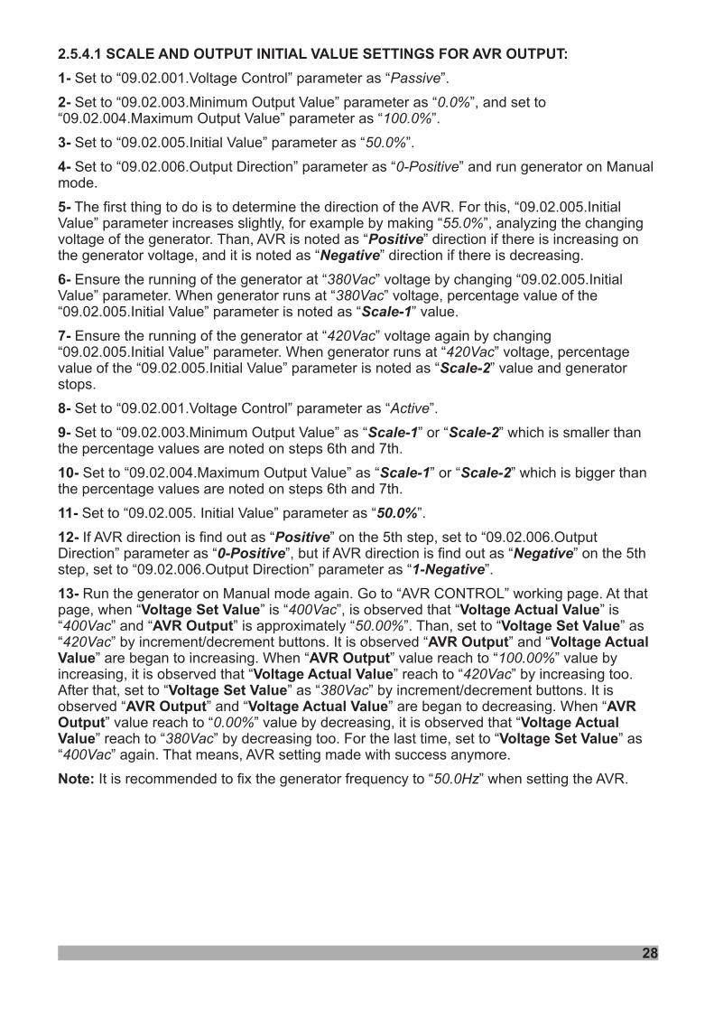
2.5.4.1 SCALE AND OUTPUT INITIAL VALUE SETTINGS FOR AVR OUTPUT:
1-
2-
3-
4-
5-
6-
7-
8-
9-
10-
11-
12-
13-Voltage Set Value Voltage Actual Value
AVR Output Voltage Set ValueAVR Output Voltage Actual
Value AVR OutputVoltage Actual Value
Voltage Set ValueAVR Output Voltage Actual Value AVR
Output Voltage ActualValue Voltage Set Value
Note:
Set to “09.02.001.Voltage Control” parameter as “ ”.
Set to “09.02.003.Minimum Output Value” parameter as “ ”, and set to“09.02.004.Maximum Output Value” parameter as “ ”.
Set to “09.02.005.Initial Value” parameter as “ ”.
Set to “09.02.006.Output Direction” parameter as “ ” and run generator on Manualmode.
The first thing to do is to determine the direction of the AVR. For this, “09.02.005.InitialValue” parameter increases slightly, for example by making “ ”, analyzing the changingvoltage of the generator. Than, AVR is noted as “ ” direction if there is increasing onthe generator voltage, and it is noted as “ ” direction if there is decreasing.
Ensure the running of the generator at “ ” voltage by changing “09.02.005.InitialValue” parameter. When generator runs at “ ” voltage, percentage value of the“09.02.005.Initial Value” parameter is noted as “ ” value.
Ensure the running of the generator at “ ” voltage again by changing“09.02.005.Initial Value” parameter. When generator runs at “ ” voltage, percentagevalue of the “09.02.005.Initial Value” parameter is noted as “ ” value and generatorstops.
Set to “09.02.001.Voltage Control” parameter as “ ”.
Set to “09.02.003.Minimum Output Value” as “ ” or “ ” which is smaller thanthe percentage values are noted on steps 6th and 7th.
Set to “09.02.004.Maximum Output Value” as “ ” or “ ” which is bigger thanthe percentage values are noted on steps 6th and 7th.
Set to “09.02.005. Initial Value” parameter as “ ”.
If AVR direction is find out as “ ” on the 5th step, set to “09.02.006.OutputDirection” parameter as “ ”, but if AVR direction is find out as “ ” on the 5thstep, set to “09.02.006.Output Direction” parameter as “ ”.
Run the generator on Manual mode again. Go to “AVR CONTROL” working page. At thatpage, when “ ” is “ ”, is observed that “ ” is“ ” and “ ” is approximately “ ”. Than, set to “ ” as“ ” by increment/decrement buttons. It is observed “ ” and “
” are began to increasing. When “ ” value reach to “ ” value byincreasing, it is observed that “ ” reach to “ ” by increasing too.After that, set to “ ” as “ ” by increment/decrement buttons. It isobserved “ ” and “ ” are began to decreasing. When “
” value reach to “ ” value by decreasing, it is observed that “” reach to “ ” by decreasing too. For the last time, set to “ ” as
“ ” again. That means, AVR setting made with success anymore.
It is recommended to fix the generator frequency to “ ” when setting the AVR.
Passive
0.0%100.0%
50.0%
0-Positive
55.0%
380Vac380Vac
420Vac420Vac
Active
400Vac400Vac 50.00%420Vac
100.00%420Vac
380Vac
0.00%380Vac
400Vac
50.0Hz
PositiveNegative
Scale-1
Scale-2
Scale-1 Scale-2
Scale-1 Scale-2
50.0%
Positive0-Positive Negative
1-Negative
28
2.5.5 TRANS-SYNCRO AVR OUTPUT CONNECTION TO SOME AVR MODULES
.5.52 .1 TRANS-SYNCRO TO BASLER AVR CONNECTION
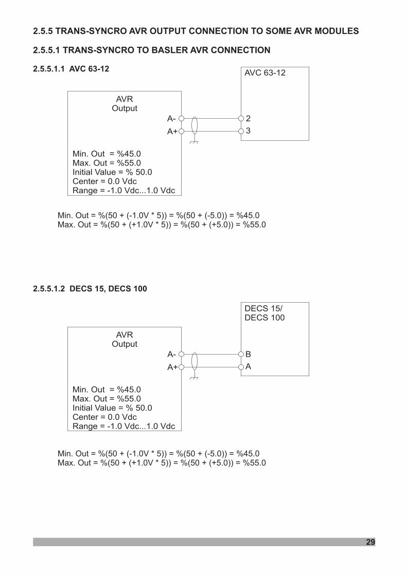
2.5.5.1.1 AVC 63-12
2.5.5.1.2 DECS 15, DECS 100
Min. Out = %(50 + (-1.0V * 5)) = %(50 + (-5.0)) = %45.0Max. Out = %(50 + (+1.0V * 5)) = %(50 + (+5.0)) = %55.0
Min. Out = %(50 + (-1.0V * 5)) = %(50 + (-5.0)) = %45.0Max. Out = %(50 + (+1.0V * 5)) = %(50 + (+5.0)) = %55.0
Min. Out = %45.0Max. Out = %55.0Initial Value = % 50.0Center = 0.0 VdcRange = -1.0 Vdc...1.0 Vdc
AVROutput
AVC 63-12
A-
A+
2
3
Min. Out = %45.0Max. Out = %55.0Initial Value = % 50.0Center = 0.0 VdcRange = -1.0 Vdc...1.0 Vdc
AVROutput
DECS 15/DECS 100
A-
A+
B
A
29
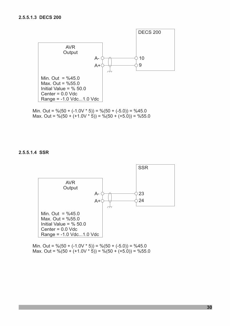
2.5.5.1.3 DECS 200
2.5.5.1.4 SSR
Min. Out = %(50 + (-1.0V * 5)) = %(50 + (-5.0)) = %45.0Max. Out = %(50 + (+1.0V * 5)) = %(50 + (+5.0)) = %55.0
Min. Out = %(50 + (-1.0V * 5)) = %(50 + (-5.0)) = %45.0Max. Out = %(50 + (+1.0V * 5)) = %(50 + (+5.0)) = %55.0
Min. Out = %45.0Max. Out = %55.0Initial Value = % 50.0Center = 0.0 VdcRange = -1.0 Vdc...1.0 Vdc
AVROutput
DECS 200
A-
A+
10
9
Min. Out = %45.0Max. Out = %55.0Initial Value = % 50.0Center = 0.0 VdcRange = -1.0 Vdc...1.0 Vdc
AVROutput
SSR
A-
A+
23
24
30
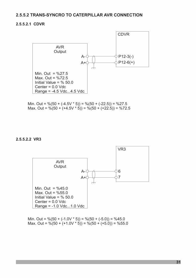
2.5.5.2 TRANS-SYNCRO TO CATERPILLAR AVR CONNECTION
2.5.5.2.1 CDVR
2.5.5.2.2 VR3
Min. Out = %(50 + (-4.5V * 5)) = %(50 + (-22.5)) = %27.5Max. Out = %(50 + (+4.5V * 5)) = %(50 + (+22.5)) = %72.5
Min. Out = %(50 + (-1.0V * 5)) = %(50 + (-5.0)) = %45.0Max. Out = %(50 + (+1.0V * 5)) = %(50 + (+5.0)) = %55.0
Min. Out = %27.5Max. Out = %72.5Initial Value = % 50.0Center = 0.0 VdcRange = -4.5 Vdc...4.5 Vdc
AVROutput
CDVR
A-
A+
P12-3(-)
P12-6(+)
Min. Out = %45.0Max. Out = %55.0Initial Value = % 50.0Center = 0.0 VdcRange = -1.0 Vdc...1.0 Vdc
AVROutput
VR3
A-
A+
6
7
31
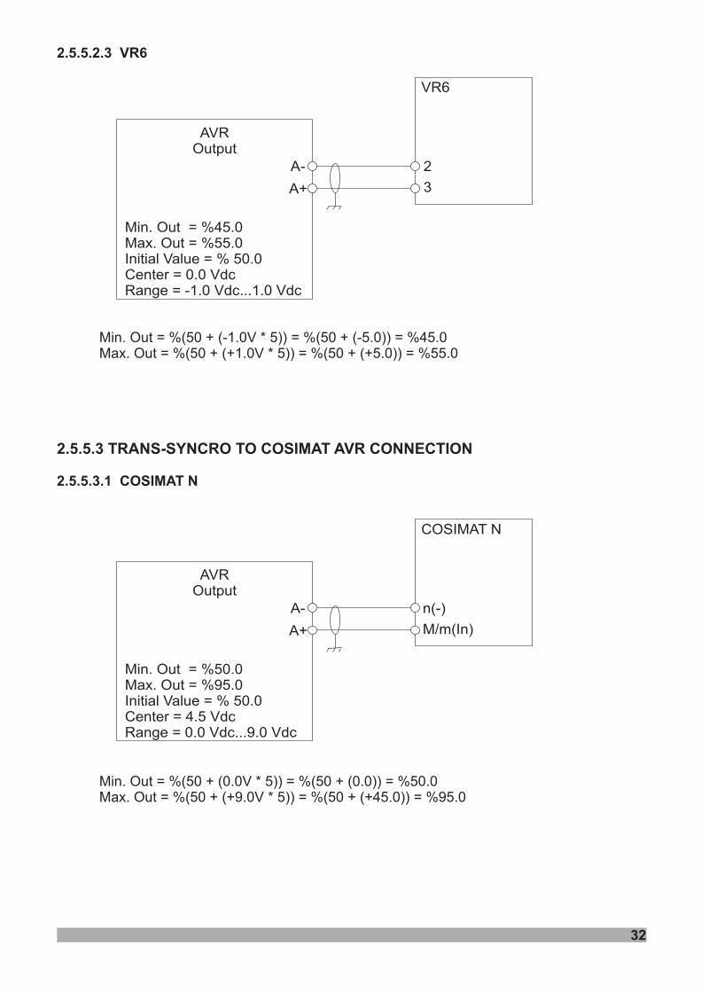
2.5.5.2.3 VR6
2.5.5.3.1 COSIMAT N
Min. Out = %(50 + (-1.0V * 5)) = %(50 + (-5.0)) = %45.0Max. Out = %(50 + (+1.0V * 5)) = %(50 + (+5.0)) = %55.0
Min. Out = %(50 + (0.0V * 5)) = %(50 + (0.0)) = %50.0Max. Out = %(50 + (+9.0V * 5)) = %(50 + (+45.0)) = %95.0
2.5.5.3 TRANS-SYNCRO TO COSIMAT AVR CONNECTION
Min. Out = %45.0Max. Out = %55.0Initial Value = % 50.0Center = 0.0 VdcRange = -1.0 Vdc...1.0 Vdc
AVROutput
VR6
A-
A+
2
3
Min. Out = %50.0Max. Out = %95.0Initial Value = % 50.0Center = 4.5 VdcRange = 0.0 Vdc...9.0 Vdc
AVROutput
COSIMAT N
A-
A+
n(-)
M/m(In)
32
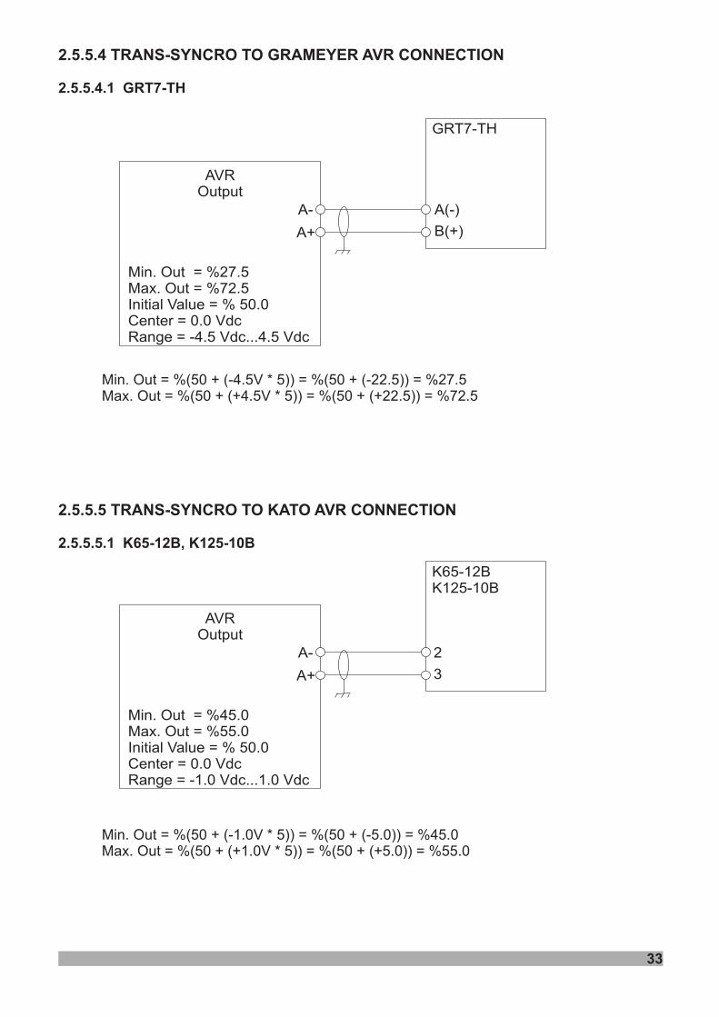
2.5.5.4 TRANS-SYNCRO TO GRAMEYER AVR CONNECTION
2.5.5.5 TRANS-SYNCRO TO KATO AVR CONNECTION
2.5.5.4.1 GRT7-TH
2.5.5.5.1 K65-12B, K125-10B
Min. Out = %(50 + (-4.5V * 5)) = %(50 + (-22.5)) = %27.5Max. Out = %(50 + (+4.5V * 5)) = %(50 + (+22.5)) = %72.5
Min. Out = %(50 + (-1.0V * 5)) = %(50 + (-5.0)) = %45.0Max. Out = %(50 + (+1.0V * 5)) = %(50 + (+5.0)) = %55.0
Min. Out = %27.5Max. Out = %72.5Initial Value = % 50.0Center = 0.0 VdcRange = -4.5 Vdc...4.5 Vdc
AVROutput
GRT7-TH
A-
A+
A(-)
B(+)
Min. Out = %45.0Max. Out = %55.0Initial Value = % 50.0Center = 0.0 VdcRange = -1.0 Vdc...1.0 Vdc
AVROutput
K65-12BK125-10B
A-
A+
2
3
33
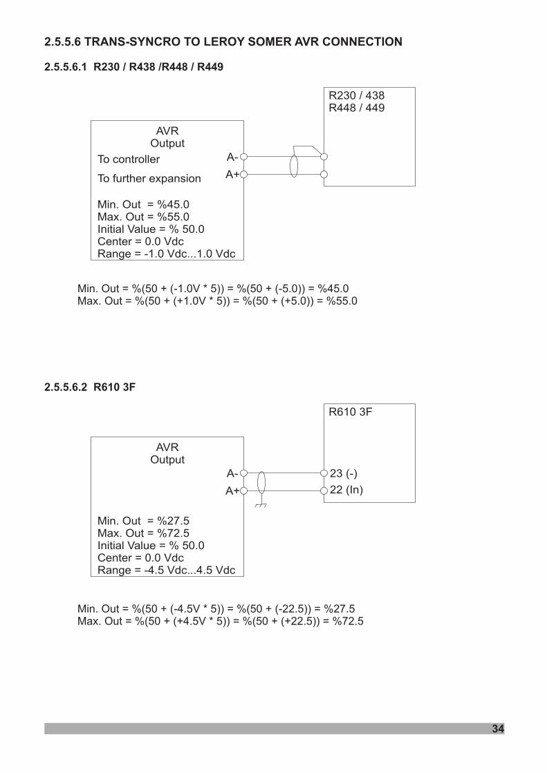
2.5.5.6 TRANS-SYNCRO TO LEROY SOMER AVR CONNECTION
2.5.5.6.1 R230 / R438 /R448 / R449
2.5.5.6.2 R610 3F
Min. Out = %(50 + (-1.0V * 5)) = %(50 + (-5.0)) = %45.0Max. Out = %(50 + (+1.0V * 5)) = %(50 + (+5.0)) = %55.0
Min. Out = %(50 + (-4.5V * 5)) = %(50 + (-22.5)) = %27.5Max. Out = %(50 + (+4.5V * 5)) = %(50 + (+22.5)) = %72.5
Min. Out = %45.0Max. Out = %55.0Initial Value = % 50.0Center = 0.0 VdcRange = -1.0 Vdc...1.0 Vdc
AVROutput
R230 / 438R448 / 449
A-
A+
Min. Out = %27.5Max. Out = %72.5Initial Value = % 50.0Center = 0.0 VdcRange = -4.5 Vdc...4.5 Vdc
AVROutput
R610 3F
A-
A+
23 (-)
22 (In)
To controller
To further expansion
34
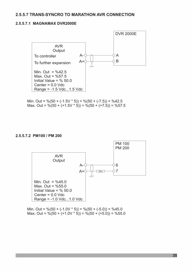
2.5.5.7 TRANS-SYNCRO TO MARATHON AVR CONNECTION
2.5.5.7.1 MAGNAMAX DVR2000E
2.5.5.7.2 PM100 / PM 200
Min. Out = %(50 + (-1.5V * 5)) = %(50 + (-7.5)) = %42.5Max. Out = %(50 + (+1.5V * 5)) = %(50 + (+7.5)) = %57.5
Min. Out = %(50 + (-1.0V * 5)) = %(50 + (-5.0)) = %45.0Max. Out = %(50 + (+1.0V * 5)) = %(50 + (+5.0)) = %55.0
Min. Out = %42.5Max. Out = %57.5Initial Value = % 50.0Center = 0.0 VdcRange = -1.5 Vdc...1.5 Vdc
AVROutput
DVR 2000E
A-
A+
Min. Out = %45.0Max. Out = %55.0Initial Value = % 50.0Center = 0.0 VdcRange = -1.0 Vdc...1.0 Vdc
AVROutput
PM 100PM 200
A-
A+
6
7
To controller
To further expansion
A
B
5KW
35
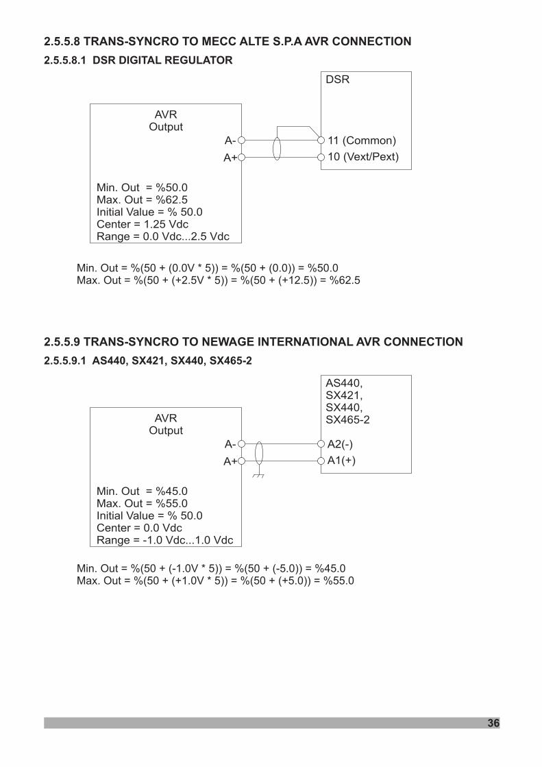
2.5.5.8 TRANS-SYNCRO TO MECC ALTE S.P.A AVR CONNECTION
2.5.5.9 TRANS-SYNCRO TO NEWAGE INTERNATIONAL AVR CONNECTION
2.5.5.8.1 DSR DIGITAL REGULATOR
2.5.5.9.1 AS440, SX421, SX440, SX465-2
Min. Out = %(50 + (0.0V * 5)) = %(50 + (0.0)) = %50.0Max. Out = %(50 + (+2.5V * 5)) = %(50 + (+12.5)) = %62.5
Min. Out = %(50 + (-1.0V * 5)) = %(50 + (-5.0)) = %45.0Max. Out = %(50 + (+1.0V * 5)) = %(50 + (+5.0)) = %55.0
Min. Out = %45.0Max. Out = %55.0Initial Value = % 50.0Center = 0.0 VdcRange = -1.0 Vdc...1.0 Vdc
AVROutput
AS440,SX421,SX440,SX465-2
A-
A+
A2(-)
A1(+)
36
Min. Out = %50.0Max. Out = %62.5Initial Value = % 50.0Center = 1.25 VdcRange = 0.0 Vdc...2.5 Vdc
AVROutput
DSR
A-
A+
11 (Common)
10 (Vext/Pext)
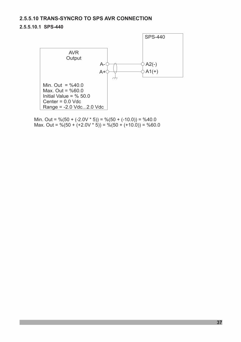
2.5.5.10 TRANS-SYNCRO TO SPS AVR CONNECTION
2.5.5.10.1 SPS-440
Min. Out = %(50 + (-2.0V * 5)) = %(50 + (-10.0)) = %40.0Max. Out = %(50 + (+2.0V * 5)) = %(50 + (+10.0)) = %60.0
Min. Out = %40.0Max. Out = %60.0Initial Value = % 50.0Center = 0.0 VdcRange = -2.0 Vdc...2.0 Vdc
AVROutput
SPS-440
A-
A+
A2(-)
A1(+)
37
LOAD
ON
ü
LOG
PROGESC
MANAUTO TEST
ENGINERUNNING
RESET
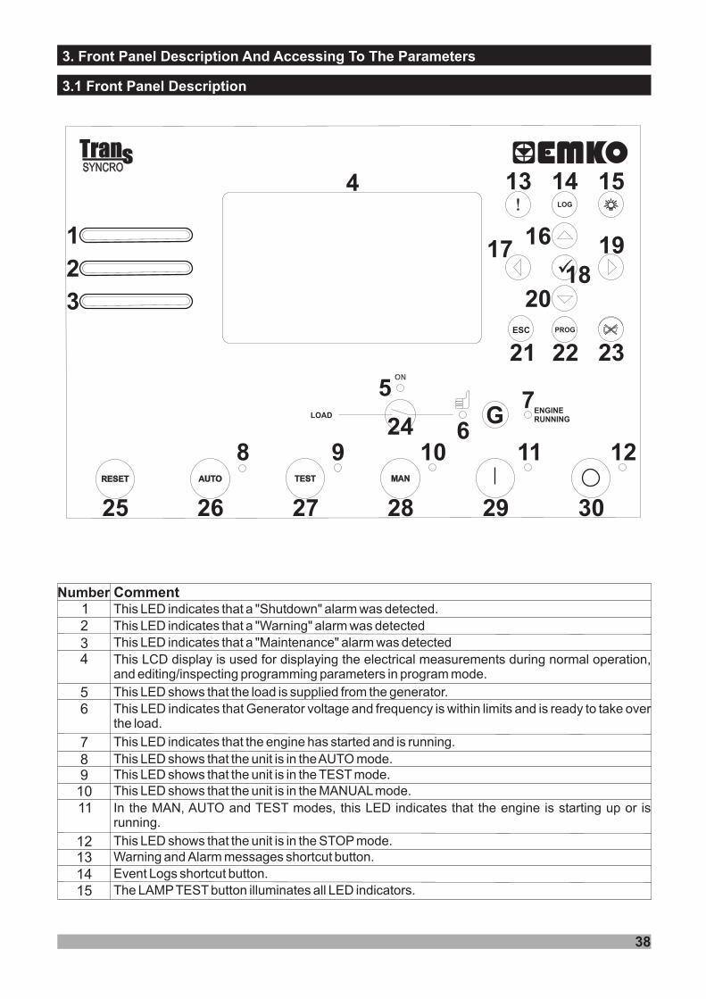
This LED indicates that a "Shutdown" alarm was detected.12
4
56
7
9
12131415
Number Comment
3. Front Panel Description And Accessing To The Parameters
3.1 Front Panel Description
This LED indicates that a "Warning" alarm was detectedThis LED indicates that a "Maintenance" alarm was detected3This LCD display is used for displaying the electrical measurements during normal operation,and editing/inspecting programming parameters in program mode.
Th LED shows that the load is supplied from the generator.is
8
This LED indicates that Generator is within limits and is ready to take overthe load
voltage and frequency.
This LED indicates that the engine has started and is running.
1011
This LED shows that the unit is in theAUTO mode.This LED shows that the unit is in the TEST mode.This LED shows that the unit is in the MANUALmode.In the MAN, AUTO and TEST modes, this LED indicates that the engine is starting up or isrunning.
This LED shows that the unit is in the STOP mode.
38
1
2
3
4
5
67
8 9 10 11 12
13 14 15
Warning and Alarm messages shortcut button.Event Logs shortcut button.The LAMPTEST button illuminates all LED indicators.
161718
19
20
21 22 23
24
25 26 27 28 29 30
20
212223
24252627282930
18
17
Number Comment16 This button is used for showing previous parameters on the currently selected page in
normal operation. In Programming mode, it operates as an Up button (changing cursorposition) or Increment button (increase parameter value).
This button is used for showing previous page in normal operation. In Programming mode, itoperates as an Left button (changing cursor position).
19
This button is used for entering parameter edit section and saving parameter value inprogramming mode.
This button is used for showing next page in normal operation. In Programming mode, itoperates as an Right button (changing cursor position).
This button is used for showing next parameters on the currently selected page in normaloperation. In Programming mode, it operates as an Down button (changing cursor position)or Decrement button (decrease parameter value).
The Escape button is used for exit previous section in programming mode.When this button is pressed, the unit goes into its PROGRAMMING Mode.
This button opens or closes the gen. contactor, only operative when manual mode is selected.This button will reset the controller after a failure has been detected.TheAUTO button is used for changing operating mode of the unit to theAUTO Mode.The TEST button is used for changing operating mode of the unit to the TEST Mode.The MAN button is used for changing operating mode of the unit to the MANUALMode.The START button is used for starting the engine when the unit is in the Manual Mode.
The STOP button is used for changing operating mode of the unit to the STOP Mode.The generator is stopped.
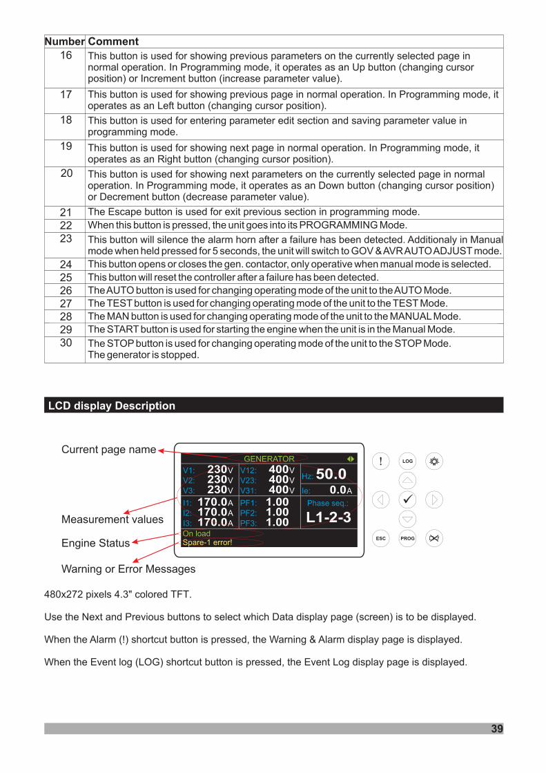
LCD display Description
39
This button will silence the alarm horn after a failure has been detected. Additionalywhen held pressed for 5 seconds, the unit will switch to GOV &AVRAUTOADJUST mode.
in Manualmode
V1: V230V2: V230V3: V230
GENERATOR
I1: A170.0I2: A170.0I3: A170.0
V12: V400V23: V400V31: V400 A0.0Ie:
Hz: 50.0
Phase seq.:
L1-2-3PF1:PF2:PF3:
1.001.001.00
On load
Measurement values
Current page name
480x272 pixels 4.3" colored TFT.
Use the buttons to select which Data display page (screen) is to be displayed.Next and Previous
When the Alarm (!) shortcut button is pressed, the Warning & Alarm display page is displayed.
When the Event log (LOG) shortcut button is pressed, the Event Log display page is displayed.
ü
Warning or Error Messages
Engine Status Spare-1 error!
40
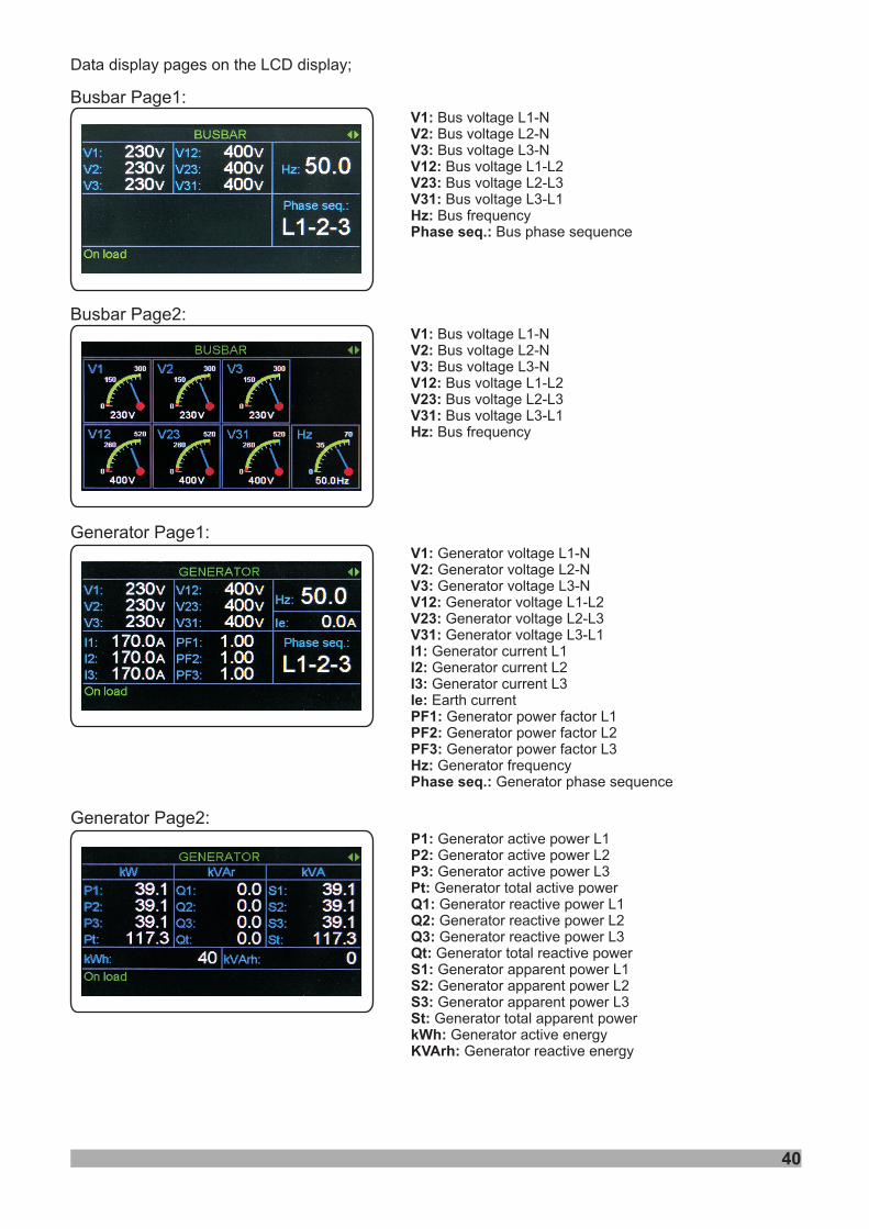
V1:V2:V3:V12:V23:V31:Hz:Phase seq.:
Bus voltage L1-NBus voltage L2-NBus voltage L3-N
Bus voltage L1-L2Bus voltage L2-L3Bus voltage L3-L1
Bus frequencyBus phase sequence
Data display pages on the LCD display;
Busbar Page1:
Generator Page1:V1:V2:V3:
V23:V31:I1:I2:I3:Ie:PF1:PF2:PF3:Hz:Phase seq.:
Generator voltage L1-NGenerator voltage L2-NGenerator voltage L3-N
Generator voltage L2-L3Generator voltage L3-L1
Generator current L1Generator current L2Generator current L3Earth current
Generator power factor L1Generator power factor L2Generator power factor L3
Generator frequencyGenerator phase sequence
V12: Generator voltage L1-L2
Busbar Page2:
Generator Page2:P1:P2:P3:Pt:Q1:Q2:Q3:Qt:S1:S2:S3:St:kWh:KVArh:
Generator active power L1Generator active power L2Generator active power L3Generator total active powerGenerator reactive power L1Generator reactive power L2Generator reactive power L3Generator total reactive powerGenerator apparent power L1Generator apparent power L2Generator apparent power L3Generator total apparent power
Generator active energyGenerator reactive energy
V1:V2:V3:V12:V23:V31:Hz:
Bus voltage L1-NBus voltage L2-NBus voltage L3-N
Bus voltage L1-L2Bus voltage L2-L3Bus voltage L3-L1
Bus frequency
41
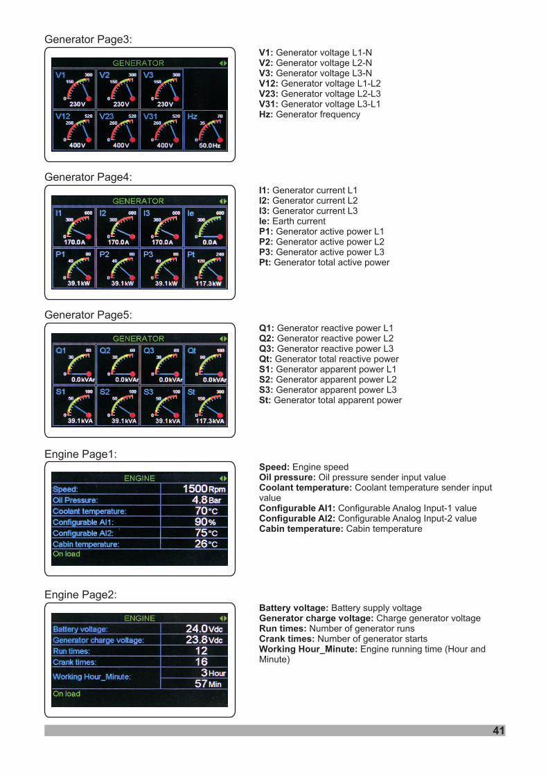
Generator Page3:V1:V2:V3:
V23:V31:Hz:
Generator voltage L1-NGenerator voltage L2-NGenerator voltage L3-N
Generator voltage L2-L3Generator voltage L3-L1
Generator frequency
V12: Generator voltage L1-L2
Generator Page4:I1:I2:I3:Ie:P1:P2:P3:Pt:
Generator current L1Generator current L2Generator current L3Earth currentGenerator active power L1Generator active power L2Generator active power L3Generator total active power
Generator Page5:Q1:Q2:Q3:Qt:S1:S2:S3:St:
Generator reactive power L1Generator reactive power L2Generator reactive power L3Generator total reactive powerGenerator apparent power L1Generator apparent power L2Generator apparent power L3Generator total apparent power
Engine Page1:Speed:Oil pressure:Coolant temperature:
Configurable AI1:Configurable AI2:Cabin temperature:
Engine speedOil pressure sender input value
Coolant temperature sender inputvalue
Configurable Analog Input-1 valueConfigurable Analog Input-2 value
Cabin temperature
Engine Page2:Battery voltage:Generator charge voltage:Run times:Crank times:Working Hour_Minute:
Battery supply voltageCharge generator voltage
Number of generator runsNumber of generator starts
Engine running time (Hour andMinute)
42
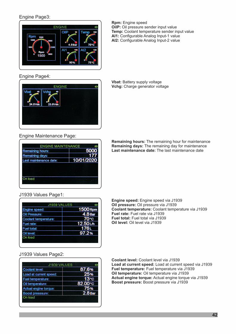
Engine Maintenance Page:Remaining hours:Remaining days:Last maintenance date:
The remaining hour for maintenanceThe remaining day for maintenance
The last maintenance date
J1939 Values Page1:Engine speed:Oil pressure:Coolant temperature:Fuel rate:Fuel total:Oil level:
Engine speed via J1939Oil pressure via J1939
Coolant temperature via J1939Fuel rate via J1939Fuel total via J1939
Oil level via J1939
J1939 Values Page2:Coolant level:Load at current speed:Fuel temperature:Oil temperature:Actual engine torque:Boost pressure:
Coolant level via J1939Load at current speed via J1939
Fuel temperature via J1939Oil temperature via J1939
Actual engine torque via J1939Boost pressure via J1939
Engine Page3:Rpm:OilP:Temp:AI1:AI2:
Engine speedOil pressure sender input value
Coolant temperature sender input valueConfigurable Analog Input-1 valueConfigurable Analog Input-2 value
Engine Page4:Vbat:Vchg:
Battery supply voltageCharge generator voltage
43
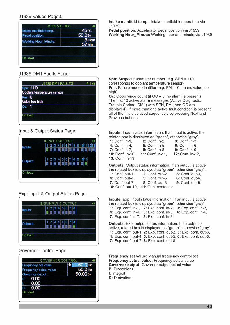
J1939 Values Page3:Intake manifold temp.:
Pedal position:Working Hour_Minute:
Intake manifold temperature viaJ1939
Accelerator pedal position via J1939Working hour and minute via J1939
Input & Output Status Page:
Exp. Input & Output Status Page:
Inputs:
1: 2: 3:4: 5: 6:7: 8: 9:10: 11: 12:13:
Outputs:
1: 2: 3:4: 5: 6:7: 8: 9:10: 11:
Input status information. If an input is active, therelated box is displayed as "green", otherwise "gray”.
Conf. in-1, Conf. in-2, Conf. in-3,Conf. in-4, Conf. in-5, Conf. in-6,Conf. in-7, Conf. in-8, Conf. in-9,Conf. in-10, Conf. in-11, Conf. in-12,Conf. in-13
Output status information. If an output is active,the related box is displayed as "green", otherwise "gray”.
Conf. out-1, Conf. out-2, Conf. out-3,Conf. out-4, Conf. out-5, Conf. out-6,Conf. out-7, Conf. out-8, Conf. out-9,Conf. out-10, Gen. contactor
Inputs:
1: 2: 3:4: 5: 6:7: 8:
Outputs:
1: 2: 3:4: 5: 6:7: 8:
Exp. input status information. If an input is active,the related box is displayed as "green", otherwise "gray”.
Exp. conf. in-1, Exp. conf. in-2, Exp. conf. in-3,Exp. conf. in-4, Exp. conf. in-5, Exp. conf. in-6,Exp. conf. in-7, Exp. conf. in-8.
Exp. output status information. If an output isactive, related box is displayed as "green", otherwise "gray”.
Exp. conf. out-1, Exp. conf. out-2, Exp. conf. out-3,Exp. conf. out-4, Exp. conf. out-5, Exp. conf. out-6,Exp. conf. out-7, Exp. conf. out-8.
J1939 DM1 Faults Page:Spn:
Fmi:
Oc:
Suspect parameter number (e.g. SPN = 110corresponds to coolant temperature sensor)
Failure mode identifier (e.g. FMI = 0 means value toohigh)
Occurrence count (if OC = 0, no alarm is present)The first 10 active alarm messages (Active DiagnosticTrouble Codes - DM1) with SPN, FMI, and OC aredisplayed). If more than one active fault condition is present,all of them is displayed sequencely by pressing Next andPrevious buttons.
Governor Control Page:Frequency set value:Frequency actual value:Governor output:P:I:D:
Manual frequency control setFrequency actual value
Governor output actual valueProportional
IntegralDerivative
44
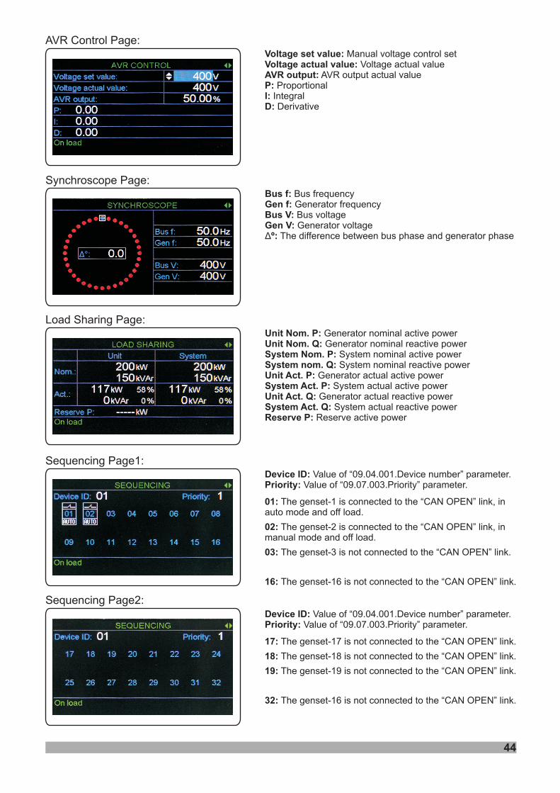
AVR Control Page:Voltage set value:Voltage actual value:AVR output:P:I:D:
Manual voltage control setVoltage actual value
AVR output actual valueProportional
IntegralDerivative
Load Sharing Page:Unit Nom. P:Unit Nom. Q:System Nom. P:System nom. Q:Unit Act. P:System Act. P:Unit Act. Q:System Act. Q:Reserve P:
Generator nominal active powerGenerator nominal reactive power
System nominal active powerSystem nominal reactive power
Generator actual active powerSystem actual active power
Generator actual reactive powerSystem actual reactive power
Reserve active power
Synchroscope Page:
Sequencing Page1:
Sequencing Page2:
Device ID:Priority:
01:
02:
03:
16:
Value of “09.04.001.Device number” parameter.Value of “09.07.003.Priority” parameter.
The genset-1 is connected to the “CAN OPEN” link, inauto mode and off load.
The genset-2 is connected to the “CAN OPEN” link, inmanual mode and off load.
The genset-3 is not connected to the “CAN OPEN” link.
The genset-16 is not connected to the “CAN OPEN” link.
Device ID:Priority:
17:
18:
19:
32:
Value of “09.04.001.Device number” parameter.Value of “09.07.003.Priority” parameter.
The genset-17 is not connected to the “CAN OPEN” link.
The genset-18 is not connected to the “CAN OPEN” link.
The genset-19 is not connected to the “CAN OPEN” link.
The genset-16 is not connected to the “CAN OPEN” link.
Bus f:Gen f:Bus V:Gen V:
º:
Bus frequencyGenerator frequencyBus voltageGenerator voltage
The difference between bus phase and generator phaseÄ
45
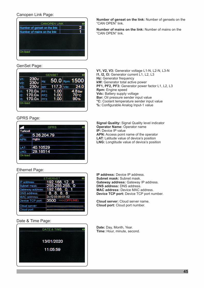
GenSet Page:V1, V2, V3:I1, I2, I3:Hz:kW:PF1, PF2, PF3:Rpm:Vdc:Bar:°C:%:
Generator voltage L1-N, L2-N, L3-NGenerator current L1, L2, L3
Generator frequencyGenerator total active power
Generator power factor L1, L2, L3Engine speed
Battery supply voltageOil pressure sender input value
Coolant temperature sender input valueConfigurable Analog Input-1 value
Canopen Link Page:Number of genset on the link:
Number of mains on the link:
Number of gensets on the“CAN OPEN” link.
Number of mains on the“CAN OPEN” link.
GPRS Page:Signal Quality:Operator Name:IP:APN:LAT:LNG:
Signal Quality level indicatorOperator name
Device IP valueAccess point name of the operator
Latitude value of device’s positionLongtitude value of device’s position
Ethernet Page:IP address:Subnet mask:Gateway address:DNS address:MAC address:Device TCP port:
Cloud server:Cloud port:
Device IP address.Subnet mask.
Gateway IP address.DNS address.Device MAC address.
Device TCP port number.
Cloud server name.Cloud port number.
Date & Time Page:
Date:Time:
Day, Month, Year.Hour, minute, second.

46
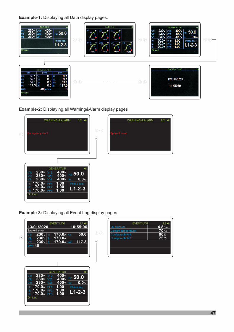
1/2:Emergency stop!:
The first message of current alarms.This message indicates that an
emergency stop alarm has occurred.
1.1:Spare-1 error:
V1, V2, V3:I1, I2, I3:Hz:kW:kWh:
The first page of related event logThis message indicates that a spare-1 alarm
has occurred. (Event history: 13/01/2020 date, 10:55:06time).
Generator voltage L1-N, L2-N, L3-NGenerator current L1, L2, L3
Generator frequencyGenerator total active power
Generator active energy
1.2:Oil pressure:Coolant temperature:
Configurable AI1:Configurable AI2:
The second page of related event logOil pressure sender input value
Coolant temperature sender inputvalue
Configurable Analog Input-1 valueConfigurable Analog Input-2 value
Warning & Alarm Page:
Event Log Page1:
Event Log Page2:
Warning & Alarm display pages on the LCD display;
Event Log display pages on the LCD display;
Emergency stop!
WARNING & ALARM 1/2
13/01/2020
V1: V230
EVENT LOG
kWh: 40
10:55:06
I1: A170.0 50.0Hz:
1.1
Spare-1 error
V2: V230 I2: A170.0V3: V230 I3: A170.0 117.3kW:
Configurable AI1:
EVENT LOG
4.8
90
1.2
Configurable AI2: 75
Oil pressure:
70Coolant temperature:BarºC
%
ºC
Configurable AI1:
EVENT LOG
4.8
90
1.2
Configurable AI2: 75
Oil pressure:
70Coolant temperature:BarºC
%
ºC
13/01/2020
V1: V230
EVENT LOG
kWh: 40
10:55:06
I1: A170.0 50.0Hz:
1.1
Spare-1 error
V2: V230 I2: A170.0V3: V230 I3: A170.0 117.3kW:
47
Example-1: Displaying all pages.Data display
Example-2: Displaying all Warning&Alarm pagesdisplay
Example-3: Displaying all Event Log pagesdisplay
Spare-2 error!
WARNING & ALARM 2/2
V1: V230V2: V230V3: V230
GENERATOR
I1: A170.0I2: A170.0I3: A170.0
V12: V400V23: V400V31: V400 A0.0Ie:
Hz: 50.0
Phase seq.:
L1-2-3PF1:PF2:PF3:
1.001.001.00
On load
V1: V230V2: V230V3: V230
GENERATOR
I1: A170.0I2: A170.0I3: A170.0
V12: V400V23: V400V31: V400 A0.0Ie:
Hz: 50.0
Phase seq.:
L1-2-3PF1:PF2:PF3:
1.001.001.00
On load
Emergency stop!
WARNING & ALARM 1/2
48
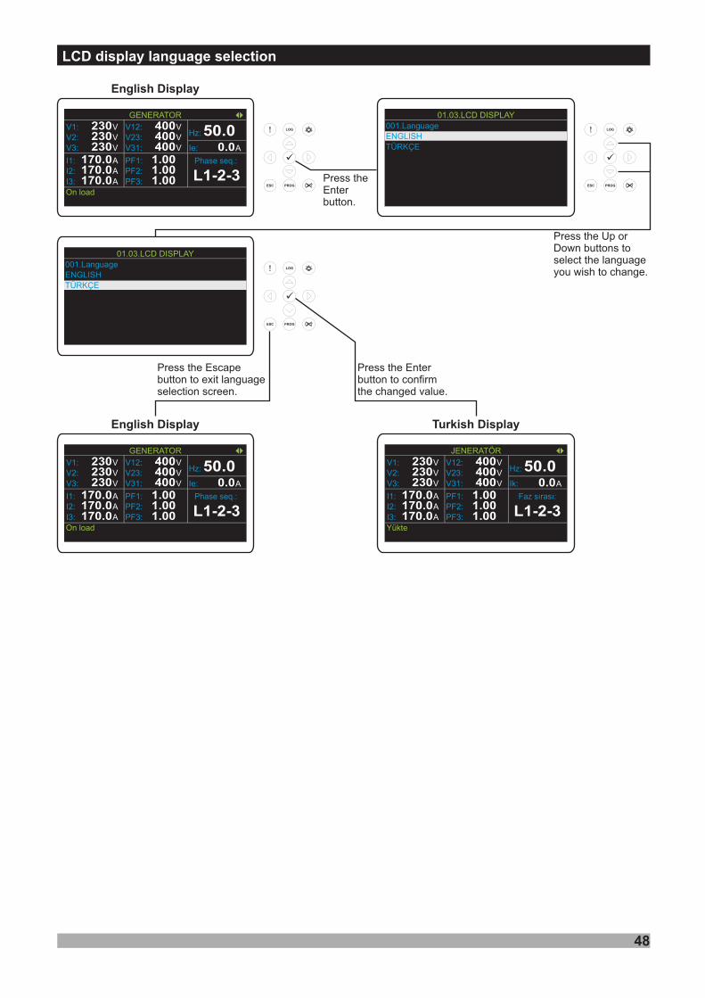
LCD display language selection
001.LanguageENGLISHTÜRKÇE
01.03.LCD DISPLAY
English Display
ü
Press theEnterbutton.
ü
Press the Up orDown buttons toselect the languageyou wish to change.
ü
Press the Enterbutton to confirmthe changed value.
Turkish Display
Press the Escapebutton to exit languageselection screen.
English Display
001.LanguageENGLISHTÜRKÇE
01.03.LCD DISPLAY
V1: V230V2: V230V3: V230
GENERATOR
I1: A170.0I2: A170.0I3: A170.0
V12: V400V23: V400V31: V400 A0.0Ie:
Hz: 50.0
Phase seq.:
L1-2-3PF1:PF2:PF3:
1.001.001.00
On load
V1: V230V2: V230V3: V230
GENERATOR
I1: A170.0I2: A170.0I3: A170.0
V12: V400V23: V400V31: V400 A0.0Ie:
Hz: 50.0
Phase seq.:
L1-2-3PF1:PF2:PF3:
1.001.001.00
On load
V1: V230V2: V230V3: V230
JENERATÖR
I1: A170.0I2: A170.0I3: A170.0
V12: V400V23: V400V31: V400 A0.0Ik:
Hz: 50.0
Faz sýrasý:
L1-2-3PF1:PF2:PF3:
1.001.001.00
Yükte
01.System03.Generator04.Engine05.Inputs06.Outputs07.Timers08.Expansion modules09.Synchronization10.Logic controller
TECHNICIAN SETTING
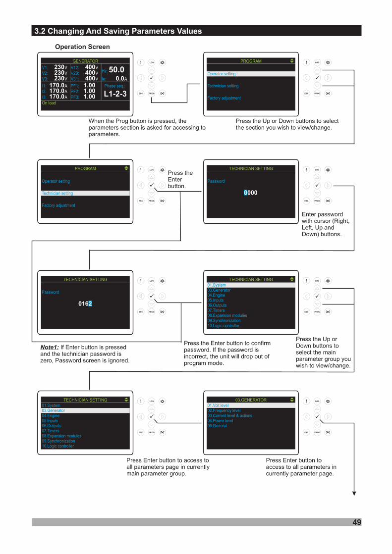
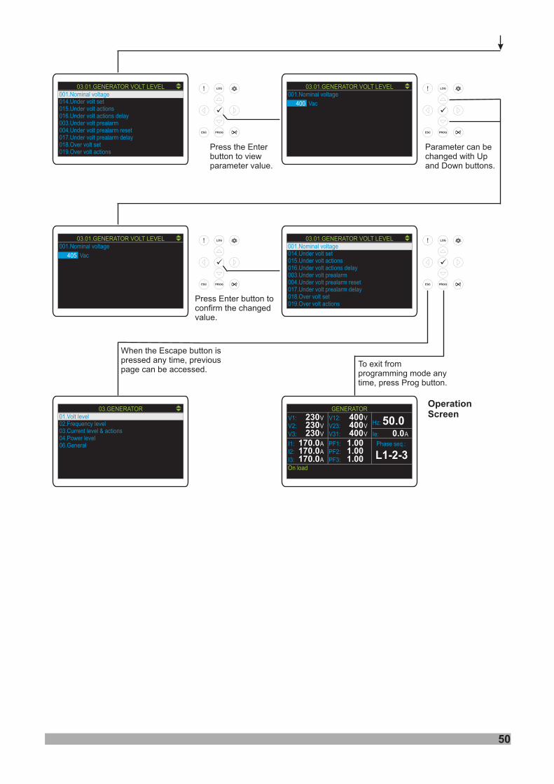
3.2 Changing And Saving Parameters Values
49
Press Enter button toaccess to all parameters incurrently parameter page.
Press Enter button to access toall parameters page in currentlymain parameter group.
Press the Up orDown buttons toselect the mainparameter group youwish to view/change.
Note1: If Enter button is pressedand the technician password iszero, Password screen is ignored.
Enter passwordwith cursor (Right,Left,
) .Up and
Down buttons
Press theEnterbutton.
Press the Up or Down buttons to selectthe section you wish to view/change.
When the Prog button is pressed, theparameters section is asked for accessing toparameters.
Operation Screen
ü
ü
ü
ü
ü
ü
ü
ü
Press the Enter button to confirmpassword. If the password isincorrect, the unit will drop out ofprogram mode.
Operator setting
PROGRAM
Technician setting
Factory adjustment
Operator setting
PROGRAM
Technician setting
Factory adjustment
V1: V230V2: V230V3: V230
GENERATOR
I1: A170.0I2: A170.0I3: A170.0
V12: V400V23: V400V31: V400 A0.0Ie:
Hz: 50.0
Phase seq.:
L1-2-3PF1:PF2:PF3:
1.001.001.00
On load
Password
TECHNICIAN SETTING
0000
Password
TECHNICIAN SETTING
0162
01.System03.Generator04.Engine05.Inputs06.Outputs07.Timers08.Expansion modules09.Synchronization10.Logic controller
TECHNICIAN SETTING01.Volt level02.Frequency level03.Current level & actions04.Power level06.General
03.GENERATOR
50
001.Nominal voltage014.Under volt set015.Under volt actions016.Under volt actions delay003.Under volt prealarm004.Under volt prealarm reset017.Under volt prealarm delay018.Over volt set019.Over volt actions
03.01.GENERATOR VOLT LEVEL
OperationScreen
3. Parametrelerin Ayarlanmasý
ü
ü
ü
ü
To exit fromprogramming mode anytime, press Prog button.
When the Escape button ispressed any time, previouspage can be accessed.
Press Enter button toconfirm the changedvalue.
Parameter can bechanged with Upand Down buttons.
Press the Enterbutton to viewparameter value.
V1: V230V2: V230V3: V230
GENERATOR
I1: A170.0I2: A170.0I3: A170.0
V12: V400V23: V400V31: V400 A0.0Ie:
Hz: 50.0
Phase seq.:
L1-2-3PF1:PF2:PF3:
1.001.001.00
On load
01.Volt level02.Frequency level03.Current level & actions04.Power level06.General
03.GENERATOR
001.Nominal voltage
400
03.01.GENERATOR VOLT LEVEL
Vac
001.Nominal voltage
405
03.01.GENERATOR VOLT LEVEL
Vac
001.Nominal voltage014.Under volt set015.Under volt actions016.Under volt actions delay003.Under volt prealarm004.Under volt prealarm reset017.Under volt prealarm delay018.Over volt set019.Over volt actions
03.01.GENERATOR VOLT LEVEL

4.1 Operator Parameters
51
Note-1: The above generator parameters are explained in the “ ”section.
4.2 Technician Parameters
Note-2: dis = disable
4. Parameters
4.1.1 Generator
600
600
60(dis)
60
600
600
VV
VV
VV
VV
60
60
Min DefaultMax
Under Voltage Set
Nominal Voltage
Under Voltage Pre-Alarm
Under Voltage Pre-Alarm Reset
Over Voltage Pre-Alarm
320
400
340
350
60(dis) 600
60 600
450
430Over Voltage Pre-Alarm Reset
VV
VV
014.Under volt set
001.Nominal voltage
003.Under volt prealarm
004.Under volt prealarm reset
006.Over volt prealarm
007.Over volt prealarm reset
Unit
00 .9 Unbalanve volt set Unbalance Volt Set
03.01.GENERATOR VOLT LEVEL ( )Generator-> levelVolt
0 230 20 VV
600 VV60Over Voltage Set 47001 .8 Over volt set
75.0
75.0
Hz30.0(dis)
Min DefaultMax
Under Frequency Pre-Alarm
Under Frequency Pre-Alarm Reset
Over Frequency Pre-Alarm
Over Frequency Pre-Alarm Reset
45.0
46.0
55.0
54.0
Hz
Hz
Hz
30.0
30.0(dis)
30.0
75.0
75.0
003.Under freq prealarm
004.Under freq prealarm reset
006.Over freq prealarm
007.Over freq prealarm reset
Unit03.02. FREQGENERATOR LEVEL ( )Generator-> levelFrequency
75.0
75.0
Hz30.0Nominal Alternator Frequency 50.0
43.0 Hz
001.Nominal frequency
011.Under freq set Under Frequency Set 30.0
75.0 58.0 Hz01 .5 Over freq set Over Frequency Set 30.0
Min DefaultMax
003.Under current prealarm reset
006.Over current set
007.Over current prealarm
008.Over current prealarm reset
012.Earth fault current set
Unit03.03. CUR LEVELGENERATOR ( )Generator->Current level
001.Under current set
002.Under current prealarm
0
0
9999
9999
0
100
AV
AV
0
0(dis)
0
0
0(dis)
9999
9999
9999
9999
9999
1
dis
5
9999
AV
AV
AV
AV
AV
015.Unbalance load set 0 9999 0 AV
Under Current Pre-Alarm Reset
Under Current Set
Under Current Pre-Alarm
Over Current Set
Over Current Pre-Alarm
Over Current Pre-Alarm Reset
Earth Fault Current Set
Unbalance Load Set
dis
9999
9999
9999
9999
9999
9999
kVA
kVA
kVA
kVA
0
0(dis)
0
0
0(dis)
0
Min DefaultMax
Under SetPower
Under Pre-AlarmPower
Under Pre-Alarm ResetPower
Over SetPower
Over Pre-AlarmPower
0
5
Over Pre-Alarm ResetPower
kVA
kVA
Unit
Reverse Power Pre-Alarm -9999(dis) 0 dis kW
dis
0
0
dis
001. powerUnder set
002. powerUnder prealarm
003. powerUnder prealarm reset
006. powerOver set
007. powerOver prealarm
008. powerOver prealarm reset
019.Reverse power prealarm
03.04. POWERGEN LEVEL ( )Generator->Power level
Excitation Loss Set -9999 0 -100 KVAr014.Excitation loss set
Reverse Power Set -9999 0 -30 kW011.Reverse power set
0-9999Reverse Power Pre-Alarm Reset kW-9990020. powerReverse prealarm reset
4.2 Technician Parameters
52
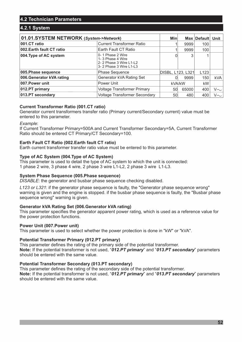
4.2.1 System
Current Transformer Ratio (001.CT ratio)
Earth Fault CT Ratio (002.Earth fault CT ratio)
(004. )
(005. )
(006. )
Power Unit (007.Power unit)
Transformer Primary (012. T primary)
Transformer Secondary (013. T secondary)
Generator current transformers transfer ratio (Primary current/Secondary current) value must beentered to this parameter.
:If Current Transformer Primary=500A and Current Transformer Secondary=5A, Current TransformerRatio should be entered CT Primary/CT Secondary=100.
Earth current transformer transfer ratio value must be entered to this parameter.
: t
:
Example
L123 or L321
Type of AC System Type of AC System
System Phase Sequence Phase sequence
Generator kVA Rating Set Generator kVA rating
This parameter is used to detail the type of AC system to which the unit is connected:1 phase 2 wire, 3 phase 4 wire, 2 phase 3 wire L1-L2, 2 phase 3 wire L1-L3.
he generator and busbar phase sequence checking disabled.
if the generator phase sequence is faulty, the phase sequence wrongwarning is given and the engine is stopped. if the busbar phase sequence is faulty, the usbar phasesequence wrong warning is given.
This parameter specifies the generator apparent power rating, which is used as a reference value forthe power protection functions.
This parameter is used to select whether the power protection is done in "kW" or "kVA".
DISABLE
Potential P
Potential P
This parameter defines the rating of the primary side of the potential transformer.If the potential transformer is not used, “ ” and “ ” parameters
should be entered with the same value.
This parameter defines the rating of the secondary side of the potential transformer.If the potential transformer is not used, “ ” and “ ” parameters
should be entered with the same value.
Note:
Note:
012. T primary 013. T secondary
012. T primary 013. T secondary
P P
P P
"Generator ""B
"
Min DefaultMaxCurrent Transformer Ratio
Earth Fault CT Ratio
001.CT ratio
002.Earth fault CT ratio
012.PT primary
01 .3 PT secondary
004.Type of AC system
005.Phase sequence006.Generator kVA rating
007.Power unit
Unit01.01.SYSTEM NETWORK ( )System->Network
9999
3
9999
65000
480
kVA
1
0
0
50
50
100
1
150
kW
400
400
L123DISBL, L123, L321
99991 100
kVA/kW
Voltage Transformer Primary
Voltage Transformer Secondary
0- 1 Phase 2 Wire1- 3 Phase 4 Wire2- 2 Phase 3 Wire L1-L23- 2 Phase 3 Wire L1-L3
Phase SequenceGenerator kVA Rating Set
Power Unit
VV
VV
53
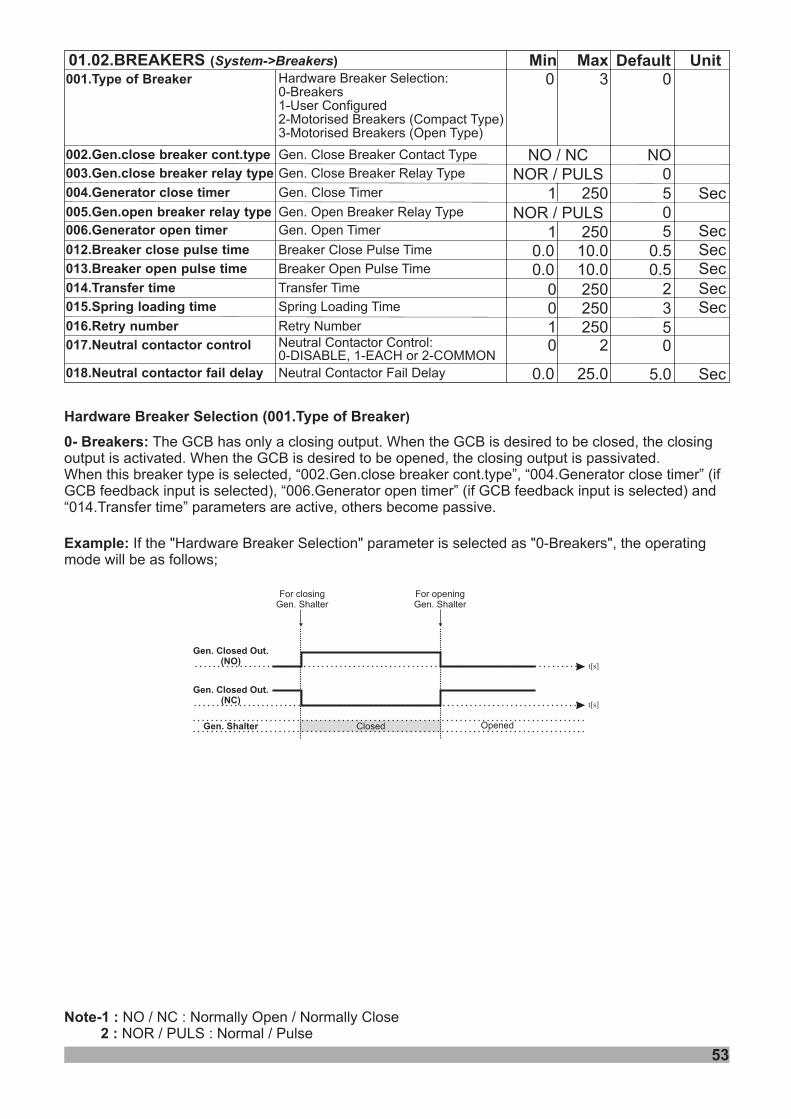
Example: If the "Hardware Breaker Selection" parameter is selected as "0-Breakers", the operatingmode will be as follows;
For closingGen. Shalter
Gen. Closed Out.(NO)
Gen. Closed Out.(NC)
For openingGen. Shalter
ClosedGen. Shalter Opened
t[s]
t[s]
Hardware Breaker Selection (001.Type of Breaker)
0- Breakers: The GCB has only a closing output. When the GCB is desired to be closed, the closingoutput is activated. When the GCB is desired to be opened, the closing output is passivated.When this breaker type is selected, “002.Gen.close breaker cont.type”, “004.Generator close timer” (ifGCB feedback input is selected), “006.Generator open timer” (if GCB feedback input is selected) and“014.Transfer time” parameters are active, others become passive.
Note-1 : NO / NC : Normally Open / Normally Close2 : NOR / PULS : Normal / Pulse
Min Default Unit01.02.BREAKERS ( )System->Breakers Max
Gen. Close Breaker Contact Type
Gen. Close Breaker Relay Type
Gen. Close Timer
0
Gen. Open Breaker Relay Type
0 3
Gen. Open Timer
NO / NC NONOR / PULS
51 2500
Sec0NOR / PULS
0.50.5
10.00.0
25010.010.0
5
300
250250
2
5
5.0
Breaker Close Pulse Time
Breaker Open Pulse Time
Transfer Time
Spring Loading Time
Retry Number
Neutral Contactor Fail Delay
002.Gen.close breaker cont.type
003.Gen.close breaker relay type
004.Generator close timer
005.Gen.open breaker relay type006.Generator open timer
001.Type of Breaker
013.Breaker open pulse time
014.Transfer time
015.Spring loading time
016.Retry number
017.Neutral contactor control
018.Neutral contactor fail delay
012.Breaker close pulse timeSecSecSecSecSec
1
0.0
250
25.0 Sec
Neutral Contactor Control:0-DISABLE, 1-EACH or 2-COMMON
00 2
Hardware Breaker Selection:0-Breakers1-User Configured2-Motorised Breakers (Compact Type)3-Motorised Breakers (Open Type)
54
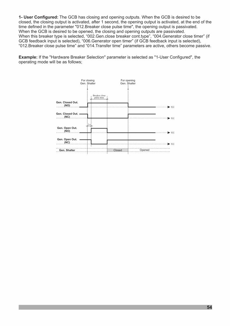
1- User Configured: The GCB has closing and opening outputs. When the GCB is desired to beclosed, the closing output is activated, after 1 second, the opening output is activated, at the end of thetime defined in the parameter "012.Breaker close pulse time", the opening output is passivated.When the GCB is desired to be opened, the closing and opening outputs are passivated.When this breaker type is selected, “002.Gen.close breaker cont.type”, “004.Generator close timer” (ifGCB feedback input is selected), “006.Generator open timer” (if GCB feedback input is selected),“012.Breaker close pulse time” and “014.Transfer time” parameters are active, others become passive.
Example: If the "Hardware Breaker Selection" parameter is selected as "1-User Configured", theoperating mode will be as follows;
Gen. Closed Out.(NO)
Gen. Closed Out.(NC)
ClosedGen. Shalter Opened
t[s]
t[s]
t[s]
t[s]
Gen. Open Out.(NO)
Gen. Open Out.(NC)
1 s
Breaker closepulse time
For closingGen. Shalter
For openingGen. Shalter
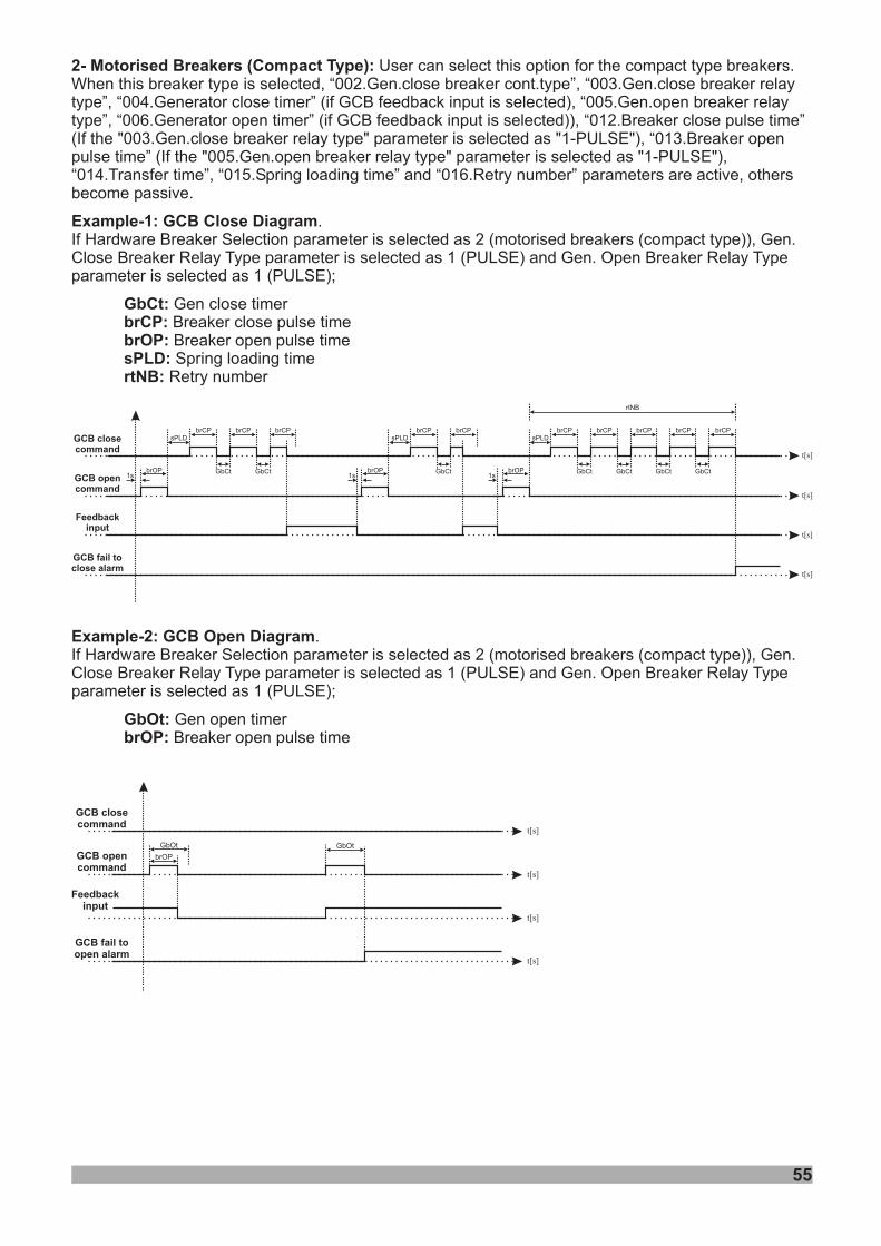
55
1s
GCB closecommand
brOP
brCPsPLD
brCP brCP
GbCt GbCt1s
brOP
brCPsPLD
brCP
GbCt1s
brOP
brCPsPLD
brCP
GbCt
brCP
GbCt
brCP
GbCt
brCP
GbCt
rtNB
GCB opencommand
Feedbackinput
GCB fail toclose alarm
t[s]
t[s]
t[s]
t[s]
GCB closecommand
GbOt
GCB opencommand
Feedbackinput
GCB fail toopen alarm
t[s]
t[s]
t[s]
t[s]
brOP
GbOt
Example-2: GCB Open Diagram
GbOt:brOP:
.If Hardware Breaker Selection parameter is selected as 2 (motorised breakers (compact type)), Gen.Close Breaker Relay Type parameter is selected as 1 (PULSE) and Gen. Open Breaker Relay Typeparameter is selected as 1 (PULSE);
Gen open timerBreaker open pulse time
2- : User can select this option for the compact type breakers.When this breaker type is selected, “002.Gen.close breaker cont.type”, “003.Gen.close breaker relaytype”, “004.Generator close timer” (if GCB feedback input is selected), “005.Gen.open breaker relaytype”, “006.Generator open timer” (if GCB feedback input is selected)), “012.Breaker close pulse time”(If the "003.Gen.close breaker relay type" parameter is selected as "1-PULSE"), “013.Breaker openpulse time” (If the "005.Gen.open breaker relay type" parameter is selected as "1-PULSE"),“014.Transfer time”, “015.Spring loading time” and “016.Retry number” parameters are active, othersbecome passive.
Motorised Breakers (Compact Type)
Example-1: GCB Close Diagram
GbCt:brCP:brOP:sPLD:rtNB:
.If Hardware Breaker Selection parameter is selected as 2 (motorised breakers (compact type)), Gen.Close Breaker Relay Type parameter is selected as 1 (PULSE) and Gen. Open Breaker Relay Typeparameter is selected as 1 (PULSE);
Gen close timerBreaker close pulse timeBreaker open pulse timeSpring loading time
Retry number
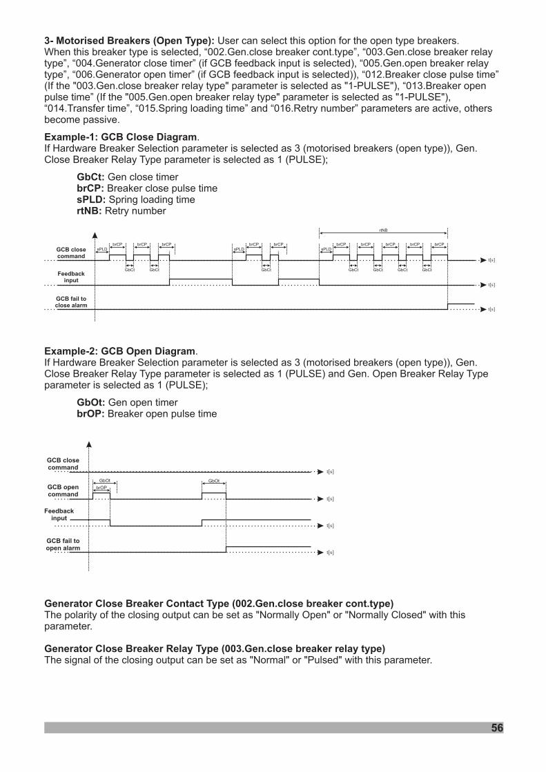
GCB closecommand
brCPsPLD
brCP brCP
GbCt GbCt
brCPsPLD
brCP
GbCt
brCPsPLD
brCP
GbCt
brCP
GbCt
brCP
GbCt
brCP
GbCt
rtNB
Feedbackinput
GCB fail toclose alarm
t[s]
t[s]
t[s]
GCB closecommand
GbOt
GCB opencommand
Feedbackinput
GCB fail toopen alarm
t[s]
t[s]
t[s]
t[s]
brOP
GbOt
Example-2: GCB Open Diagram
GbOt:brOP:
.If Hardware Breaker Selection parameter is selected as 3 (motorised breakers (open type)), Gen.Close Breaker Relay Type parameter is selected as 1 (PULSE) and Gen. Open Breaker Relay Typeparameter is selected as 1 (PULSE);
Gen open timerBreaker open pulse time
3- : User can select this option for the open type breakers.When this breaker type is selected, “002.Gen.close breaker cont.type”, “003.Gen.close breaker relaytype”, “004.Generator close timer” (if GCB feedback input is selected), “005.Gen.open breaker relaytype”, “006.Generator open timer” (if GCB feedback input is selected)), “012.Breaker close pulse time”(If the "003.Gen.close breaker relay type" parameter is selected as "1-PULSE"), “013.Breaker openpulse time” (If the "005.Gen.open breaker relay type" parameter is selected as "1-PULSE"),“014.Transfer time”, “015.Spring loading time” and “016.Retry number” parameters are active, othersbecome passive.
Motorised Breakers (Open Type)
Example-1: GCB Close Diagram
GbCt:brCP:sPLD:rtNB:
.If Hardware Breaker Selection parameter is selected as 3 (motorised breakers (open type)), Gen.Close Breaker Relay Type parameter is selected as 1 (PULSE);
Gen close timerBreaker close pulse timeSpring loading time
Retry number
56
Generator Close Breaker Contact Type (002.Gen.close breaker cont.type)
Generator Close Breaker Relay Type (003.Gen.close breaker relay type)
The polarity of the closing output can be set as "Normally Open" or "Normally Closed" with thisparameter.
The signal of the closing output can be set as "Normal" or "Pulsed" with this parameter.
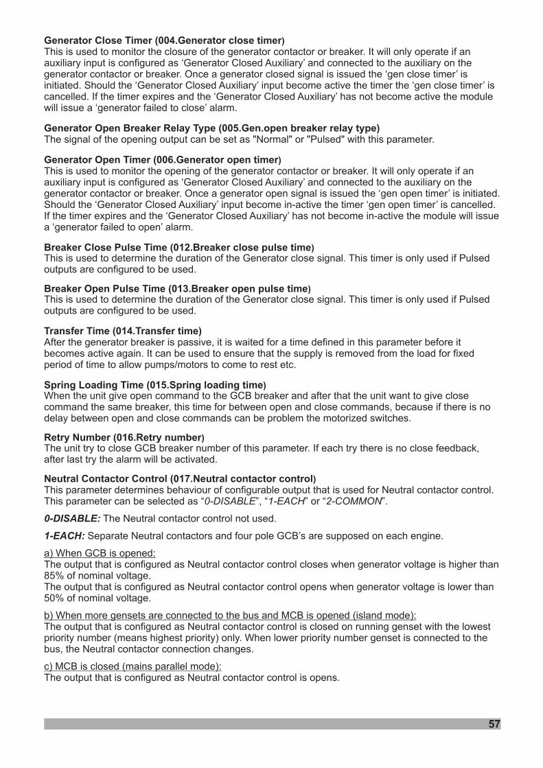
57
Generator Close Timer (004.Generator close timer
Generator Open Breaker Relay Type (005.Gen.open breaker relay type)
Generator Open Timer (006.Generator open timer
Breaker Close Pulse Time (012.Breaker close pulse time
Breaker Open Pulse Time (013.Breaker open pulse time
Transfer Time (014.Transfer time)
Spring Loading Time (015.Spring loading time
Retry Number (016.Retry number
Neutral Contactor Control (017.Neutral contactor control
)
)
)
)
)
)
)
The signal of the opening output can be set as "Normal" or "Pulsed" with this parameter.
After the generator breaker is passive, it is waited for a time defined in this parameter before itbecomes active again.
This parameter determine
This is used to monitor the closure of the generator contactor or breaker. It will only operate if anauxiliary input is configured as ‘Generator Closed Auxiliary’ and connected to the auxiliary on thegenerator contactor or breaker. Once a generator closed signal is issued the ‘gen close timer’ isinitiated. Should the ‘Generator Closed Auxiliary’ input become active the timer the ‘gen close timer’ iscancelled. If the timer expires and the ‘Generator Closed Auxiliary’ has not become active the modulewill issue a ‘generator failed to close’ alarm.
This is used to monitor the opening of the generator contactor or breaker. It will only operate if anauxiliary input is configured as ‘Generator Closed Auxiliary’ and connected to the auxiliary on thegenerator contactor or breaker. Once a generator open signal is issued the ‘gen open timer’ is initiated.Should the ‘Generator Closed Auxiliary’ input become in-active the timer ‘gen open timer’ is cancelled.If the timer expires and the ‘Generator Closed Auxiliary’ has not become in-active the module will issuea ‘generator failed to open’ alarm.
This is used to determine the duration of the Generator close signal. This timer is only used if Pulsedoutputs are configured to be used.
This is used to determine the duration of the Generator close signal. This timer is only used if Pulsedoutputs are configured to be used.
It can be used to ensure that the supply is removed from the load for fixedperiod of time to allow pumps/motors to come to rest etc.
The unit try to close
When the unit give open command to the GCB breaker and after that the unit want to give closecommand the same breaker, this time for between open and close commands, because if there is nodelay between open and close commands can be problem the motorized switches.
GCB breaker number of this parameter. If each try there is no close feedback,after last try the alarm will be activated.
s behaviour of configurable output that is used for Neutral contactor control.This parameter can be selected as “ ”, “ ” or “ ”.
The Neutral contactor control not used.
Separate Neutral contactors and four pole GCB’s are supposed on each engine.
The output that is configured as Neutral contactor control closes when generator voltage is higher than85% of nominal voltage.The output that is configured as Neutral contactor control opens when generator voltage is lower than50% of nominal voltage.
The output that is configured as Neutral contactor control is closed on running genset with the lowestpriority number (means highest priority) only. When lower priority number genset is connected to thebus, the Neutral contactor connection changes.
The output that is configured as Neutral contactor control is opens.
0-DISABLE 1-EACH 2-COMMON
0-DISABLE:
1-EACH:
a) When GCB is opened:
b) When more gensets are connected to the bus and MCB is opened (island mode):
c) MCB is closed (mains parallel mode):
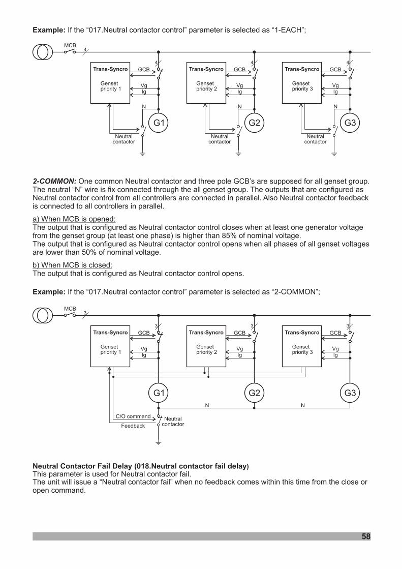
Trans-Syncro Trans-Syncro Trans-Syncro
MCB
G1 G2 G3
Vg Vg Vg
N N N
Neutralcontactor
Neutralcontactor
Neutralcontactor
Ig Ig Ig
GCB GCB GCB
I I I
Gensetpriority 1
Gensetpriority 2
Gensetpriority 3
2-COMMON: One common Neutral contactor and three pole GCB’s are supposed for all genset group.The neutral “N” wire is fix connected through the all genset group. The outputs that are configured asNeutral contactor control from all controllers are connected in parallel. Also Neutral contactor feedbackis connected to all controllers in parallel.
(at least one phase) is higher than 85% of nominal voltage.
a) When MCB is opened:
b) When MCB is closed:
The output that is configured as Neutral contactor control closes when at least one generator voltagefrom the genset groupThe output that is configured as Neutral contactor control opens when all phases of all genset voltagesare lower than 50% of nominal voltage.
The output that is configured as Neutral contactor control opens.
4
4 4 4
Trans-Syncro Trans-Syncro Trans-Syncro
MCB
G1 G2 G3
Vg Vg Vg
Neutralcontactor
Ig Ig Ig
GCB GCB GCB
I
3
3 3 3
N N
Example: If t is selected as “1-EACH”;he “017.Neutral contactor control” parameter
Example: If t is selected as “2-COMMON”;he “017.Neutral contactor control” parameter
Neutral Contactor (018.Neutral contactor fail delayFail Delay )This parameter is used for Neutral contactor fail.The unit “Neutral contactor fail” when no feedback comes within this from the close oropen command.
will issue a time
Feedback
C/O command
Gensetpriority 1
Gensetpriority 2
Gensetpriority 3
58
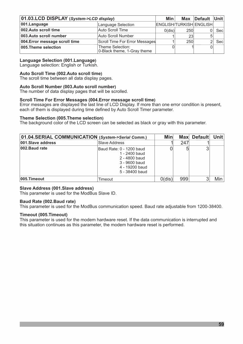
Min Default Unit01.04.SERIAL COMMUNICATION ( )System->Serial Comm. MaxSlave Address 11 247
0 5 3Baud Rate: 0 - 1200 baud1 - 2400 baud2 - 4800 baud3 - 9600 baud4 - 19200 baud5 - 38400 baud
001.Slave address002.Baud rate
59
Slave Address (001.Slave address)
Baud Rate (002.Baud rate)
Timeout (005.Timeout)
This parameter is used for the ModBus Slave ID.
This parameter is used for the ModBus communication speed. Baud rate adjustable from 1200-38400.
This parameter is used for the modem hardware reset. If the data communication is interrupted andthis situation continues as this parameter, the modem hardware reset is performed.
Timeout 0(dis) 999 3005.Timeout Min
Language Selection Language
Scroll Time croll time
Scroll Number croll number
Scroll Time For Error Messages Error message croll time
(001.
Auto (002.Auto s
Auto (003.Auto s
(004. s
Theme Selection (005.Theme selection
)
)
)
)
)
Language selection: English or Turkish.
The scroll time between all data display pages.
The number of data display pages that will be scrolled.
Error messages are displayed the last line of LCD Display. If more than one error condition is present,each of them is displayed during time defined by Auto Scroll Timer parameter.
The background color of the LCD screen can be selected as black or gray with this parameter.
Min Default Unit01.03.LCD DISPLAY ( )System->LCD display MaxLanguage Selection ENGLISH/TURKISH
00(dis)
1
250
23
002.Auto scroll time
003.Auto scroll number
001.Language
Auto Scroll Time
Auto Scroll Number
Scroll Time For Error Messages 20
10
2501
Sec004.Error message scroll time
005.Theme selection
ENGLISH
5Sec
Theme Selection:0-Black theme, 1-Gray theme
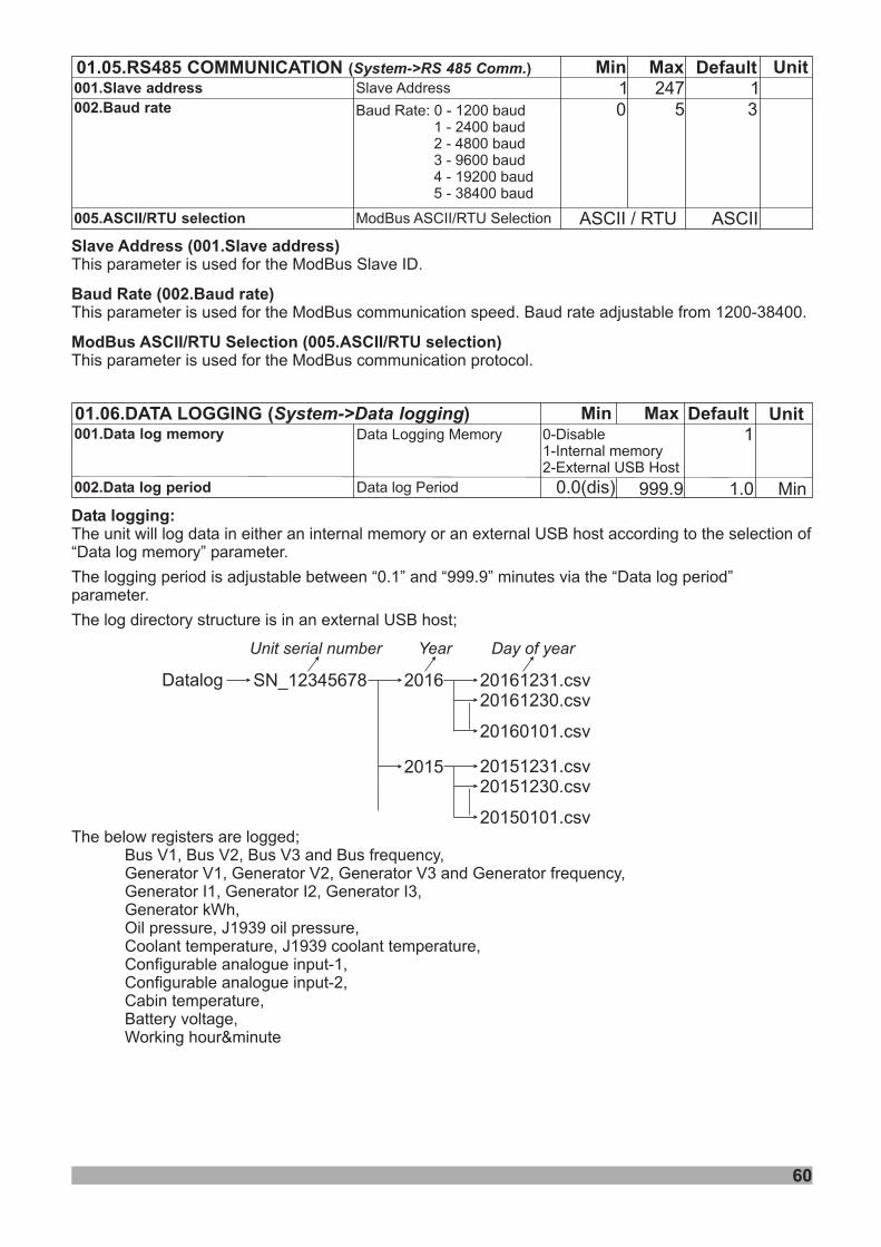
Min Default01.06.DATA LOGGING ( )System->Data logging Max001.Data log memory
Unit
60
1Data Logging Memory
Data log Period 0.0(dis) 999.9 1.0002.Data log period Min
0-Disable1-Internal memory2-External USB Host
Data logging:
“ ”
“ ” “ ” “ ”
;
The unit will log data in either an internal memory or an external USB host according to the selection ofData log memory parameter.
The logging period is adjustable between 0.1 and 999.9 minutes via the Data log periodparameter.
The log directory structure is in an external USB host
SN 12345678_ 2016
2015
20161231.csv20161230.csv
20160101.csv
20151231.csv20151230.csv
20150101.csv
Datalog
Unit serial number Year Day of year
The below registers are logged;, 2, 3 and Bus frequency,
Generator , Generator 2, Generator 3 and Generator frequency,Generator I1, Generator I2, Generator I3,Generator kWh,Oil pressure, J1939 oil pressure,Coolant temperature, J1939 coolant temperature,Configurable analogue input-1,Configurable analogue input-2,Cabin temperature,Battery voltage,Working hour&minute
Bus V1 Bus V Bus VV1 V V
Min Default Unit01.05.RS485 COMMUNICATION ( )System->RS 485 Comm. MaxSlave Address 11 247
0 5 3Baud Rate: 0 - 1200 baud1 - 2400 baud2 - 4800 baud3 - 9600 baud4 - 19200 baud5 - 38400 baud
001.Slave address002.Baud rate
ModBus ASCII/RTU Selection ASCIIASCII / RTU005.ASCII/RTU selection
Slave Address (001.Slave address)
Baud Rate (002.Baud rate)
ModBus ASCII/RTU Selection (005.ASCII/RTU selection)
This parameter is used for the ModBus Slave ID.
This parameter is used for the ModBus communication speed. Baud rate adjustable from 1200-38400.
This parameter is used for the ModBus communication protocol.
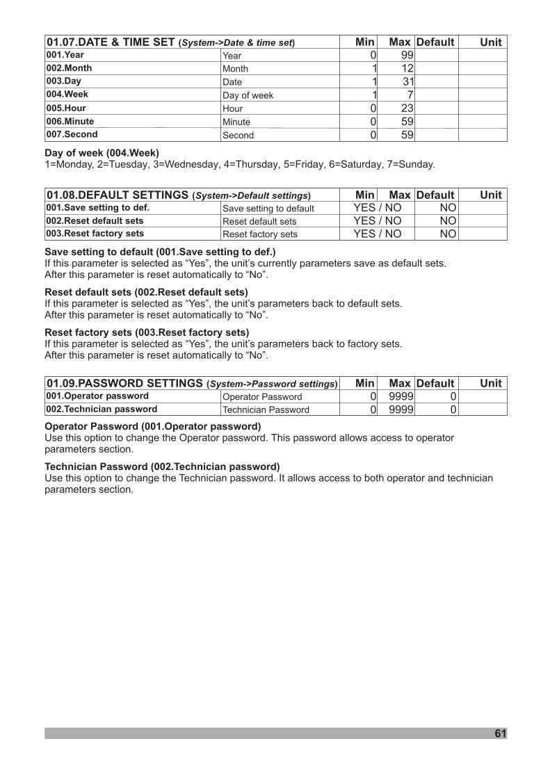
61
Operator Password (001.Operator password)
Technician Password (002.Technician password)
Use this option to change the Operator password. This password allows access to operatorparameters section.
Use this option to change the Technician password. It allows access to both operator and technicianparameters section.
Min Default01.07.DATE & TIME SET ( )System->Date & time set MaxYear
Month
0 991 12
Date 1 31Day of week 1 7Hour 0 23Minute 0 59Second 0 59
001.Year
002.Month
003.Day
004.Week
005.Hour
006.Minute
007.Second
Unit
Min Default Unit01.09.PASSWORD SETTINGS ( )System->Password settings MaxOperator Password
Technician Password
00 99990 9999 0
001.Operator password
002.Technician password
Min Default Unit01.08.DEFAULT SETTINGS ( )System->Default settings MaxSave setting to default
Reset default sets
001.Save setting to def.
002.Reset default sets
YES / NO NO003.Reset factory sets Reset factory sets
YES / NO NOYES / NO NO
Save setting to default (001.Save setting to def.)
Reset default sets (002.Reset default sets)
Reset factory sets (003.Reset factory sets)
If this parameter is selected as “Yes”, the unit’s currently parameters save as default sets.After this parameter is reset automatically to “No”.
If this parameter is selected as “Yes”, the unit’s parameters back to default sets.After this parameter is reset automatically to “No”.
If this parameter is selected as “Yes”, the unit’s parameters back to factory sets.After this parameter is reset automatically to “No”.
Day of week (004.Week)1=Monday, 2= , 3= , 4= , 5= , 6= , 7=Tuesday Wednesday Thursday Friday Saturday Sunday.
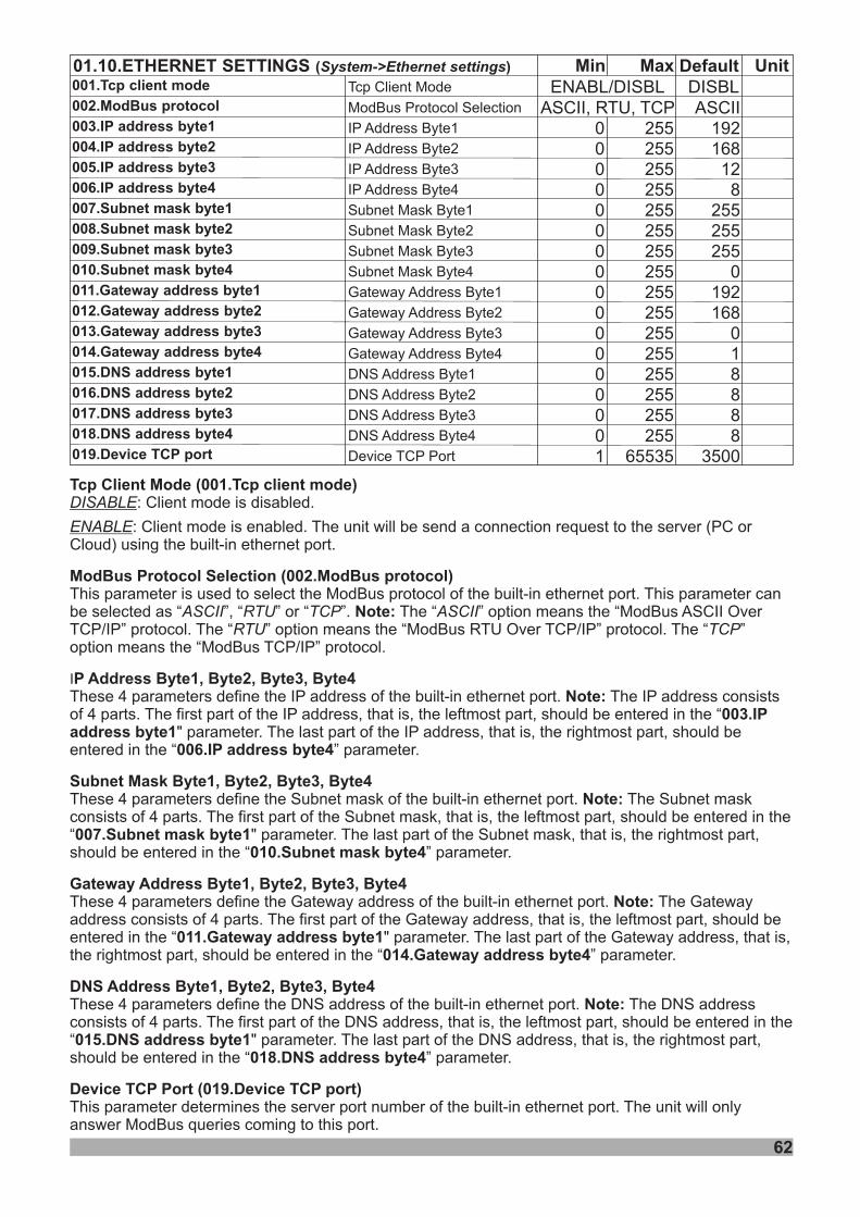
62
Tcp Client Mode (001.Tcp client mode)
ModBus Protocol Selection (002. )
P Address Byte1 Byte Byte Byte4
003.IPaddress byte1
006.IP address byte4
Subnet Mask Byte1 Byte Byte Byte4
007. byte1010. byte4
Gateway Address Byte1 Byte Byte Byte4
011. address byte1014. address byte4
DNS Address Byte1 Byte Byte Byte4
015. address byte1018. address byte4
Device TCP Port (019.Device TCP port)
ModBus protocol
2 3
2 3
2 3
2 3
I
DISABLE
ENABLE
: Cl ent mode s d.
: Cl ent mode s en d. The unit will be send a connection request to the server (PC orCloud) using the built-in ethernet port.
built-inModBus ASCII Over
TCP/IP protocol ModBus RTU Over TCP/IP protocolModBus TCP/IP protocol
built-in
built-in
built-in
built-in
built-in
i i disable
i i able
This parameter is used to select the ModBus protocol of the ethernet port
of the ethernet port
of the ethernet port
of the ethernet port
of the ethernet port
of the ethernet port
. This parameter canbe selected as “ ”, “ ” or “ ”. The “ ” option means the “
” . The “ ” option means the “ ” . The “ ”option means the “ ” .
These 4 parameters define the IP address . The IP address consistsof 4 parts. The first part of the IP address, that is, the leftmost part, should be entered in the “
" parameter. The last part of the IP address, that is, the rightmost part, should beentered in the “ ” parameter.
These 4 parameters define the Subnet mask . The Subnet maskconsists of 4 parts. The first part of the Subnet mask, that is, the leftmost part, should be entered in the“ " parameter. The last part of the Subnet mask, that is, the rightmost part,should be entered in the “ ” parameter.
These 4 parameters define the Gateway address . The Gatewayaddress consists of 4 parts. The first part of the Gateway address, that is, the leftmost part, should beentered in the “ " parameter. The last part of the Gateway address, that is,the rightmost part, should be entered in the “ ” parameter.
These 4 parameters define the DNS address . The DNS addressconsists of 4 parts. The first part of the DNS address, that is, the leftmost part, should be entered in the“ " parameter. The last part of the DNS address, that is, the rightmost part,should be entered in the “ ” parameter.
This parameter determines the server port number . The unit will onlyanswer ModBus queries coming to this port.
ASCII RTU TCP ASCIIRTU TCP
Note:
, , ,Note:
, , ,Note:
Subnet maskSubnet mask
, , ,Note:
GatewayGateway
, , ,Note:
DNSDNS
Min Default Unit01.10.ETHERNET SETTINGS ( )System->Ethernet settings MaxTcp Client Mode001.Tcp client mode
002.ModBus protocol
003.IP address byte1
004.IP address byte2
005.IP address byte3
006.IP address byte4
007.Subnet mask byte1
008.Subnet mask byte2
009.Subnet mask byte3
010.Subnet mask byte4
011.Gateway address byte1
012.Gateway address byte2
013.Gateway address byte3
014.Gateway address byte4
015.DNS address byte1
016.DNS address byte2
017.DNS address byte3
018.DNS address byte4
019.Device TCP port
ENABL/DISBL DISBLModBus Protocol Selection
IP Address Byte1
IP Address Byte2
IP Address Byte3
IP Address Byte4
Subnet Mask Byte1
Subnet Mask Byte2
Subnet Mask Byte3
Subnet Mask Byte4
Gateway Address Byte1
Gateway Address Byte2
Gateway Address Byte3
Gateway Address Byte4
DNS Address Byte1
DNS Address Byte2
DNS Address Byte3
DNS Address Byte4
Device TCP Port
ASCII192168
128
255255255
0192168
018888
3500
ASCII, RTU, TCP00000000000000001
255255255255255255255255255255255255255255255255
65535
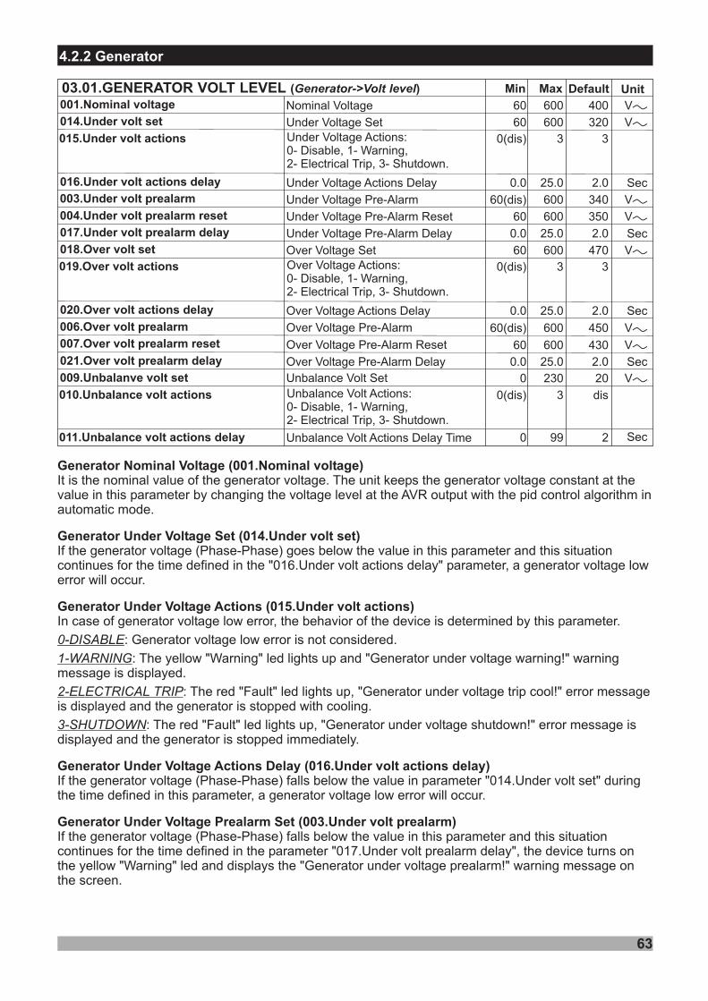
63
4.2.2 Generator
600
25.0
600
60(dis)
60
600
600
VV
VV
VV
VV
60
0.0
60
Min DefaultMax
Under Voltage Set
Under Voltage Actions Delay
Nominal Voltage
Under Voltage Pre-Alarm
Under Voltage Pre-Alarm Reset
Over Voltage Pre-Alarm
320
2.0
400
340
350
60(dis) 600
60 600
450
430Over Voltage Pre-Alarm Reset
VV
VV
014.Under volt set
016. actions delayUnder volt
001.Nominal voltage
003.Under volt prealarm
004.Under volt prealarm reset
006.Over volt prealarm
007.Over volt prealarm reset
Unit
00 .9 Unbalanve volt set Unbalance Volt Set
03.01.GENERATOR VOLT LEVEL ( )Generator-> levelVolt
0 230 20 VV
010.Unbalance volt actions
011.Unbalance volt actions delay
0(dis)
0
3
99
dis
2 SecUnbalance Volt Actions Delay Time
Unbalance Volt :0- , 1- ,2- , 3-
ActionsDisable WarningElectrical Trip Shutdown.
Sec
015. volt actionsUnder 0(dis) 3 3Under Volt :0- , 1- ,2- , 3-
age ActionsDisable WarningElectrical Trip Shutdown.
25.00.0Under Voltage Pre-Alarm Delay 2.001 . delay7 Under volt prealarm Sec
600
25.0
VV60
0.0
Over Voltage Set
Over Voltage Actions Delay
470
2.0
01 .8 Over volt set
020. actions delayOver volt Sec
019. volt actionsOver 0(dis) 3 3Ov age ActionsDisable WarningElectrical Trip Shutdown.
er Volt :0- , 1- ,2- , 3-
25.00.0Over Voltage Pre-Alarm Delay 2.00 . delay21 Over volt prealarm Sec
Generator Nominal Voltage (001.Nominal voltage)
Generator Under Voltage Set (014.Under volt set)
Generator Under Voltage Actions (015.Under volt actions)
Generator Under Voltage Actions Delay (016.Under volt actions delay)
Generator Under Voltage Prealarm Set (003.Under volt prealarm)
It is the nominal value of the generator voltage. The unit keeps the generator voltage constant at thevalue in this parameter by changing the voltage level at the AVR output with the pid control algorithm inautomatic mode.
If the generator voltage (Phase-Phase) goes below the value in this parameter and this situationcontinues for the time defined in the "016.Under volt actions delay" parameter, a generator voltage lowerror will occur.
In case of generator voltage low error, the behavior of the device is determined by this parameter.
: Generator voltage low error is not considered.
: The yellow "Warning" led lights up and "Generator under voltage warning!" warningmessage is displayed.
: The red "Fault" led lights up, "Generator under voltage trip cool!" error messageis displayed and the generator is stopped with cooling.
: The red "Fault" led lights up, "Generator under voltage shutdown!" error message isdisplayed and the generator is stopped immediately.
If the generator voltage (Phase-Phase) falls below the value in parameter "014.Under volt set" duringthe time defined in this parameter, a generator voltage low error will occur.
If the generator voltage (Phase-Phase) falls below the value in this parameter and this situationcontinues for the time defined in the parameter "017.Under volt prealarm delay", the device turns onthe yellow "Warning" led and displays the "Generator under voltage prealarm!" warning message onthe screen.
0-DISABLE
1-WARNING
2-ELECTRICAL TRIP
3-SHUTDOWN
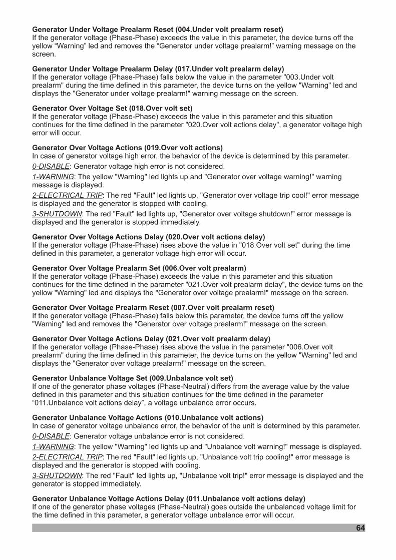
64
Generator Under Voltage Prealarm Reset (004.Under volt prealarm reset)
Generator Under Voltage Prealarm Delay (017.Under volt prealarm delay)
Generator Over Voltage Set (018.Over volt set)
Generator Over Voltage Actions (019.Over volt actions)
Generator Over Voltage Actions Delay (020.Over volt actions delay)
Generator Over Voltage Prealarm Set (006.Over volt prealarm)
Generator Over Voltage Prealarm Reset (007.Over volt prealarm reset)
Generator Over Voltage Actions Delay (021.Over volt prealarm delay)
Generator Unbalance Voltage Set (009.Unbalance volt set)
Generator Unbalance Voltage Actions (010.Unbalance volt actions)
Generator Unbalance Voltage Actions Delay (011.Unbalance volt actions delay)
If the generator voltage (Phase-Phase) exceeds the value in this parameter, the device turns off theyellow “Warning” led and removes the “Generator under voltage prealarm!” warning message on thescreen.
If the generator voltage (Phase-Phase) falls below the value in the parameter "003.Under voltprealarm" during the time defined in this parameter, the device turns on the yellow "Warning" led anddisplays the "Generator under voltage prealarm!" warning message on the screen.
If the generator voltage (Phase-Phase) exceeds the value in this parameter and this situationcontinues for the time defined in the parameter "020.Over volt actions delay", a generator voltage higherror will occur.
In case of generator voltage high error, the behavior of the device is determined by this parameter.
: Generator voltage high error is not considered.
: The yellow "Warning" led lights up and "Generator over voltage warning!" warningmessage is displayed.
: The red "Fault" led lights up, "Generator over voltage trip cool!" error messageis displayed and the generator is stopped with cooling.
: The red "Fault" led lights up, "Generator over voltage shutdown!" error message isdisplayed and the generator is stopped immediately.
If the generator voltage (Phase-Phase) rises above the value in "018.Over volt set" during the timedefined in this parameter, a generator voltage high error will occur.
If the generator voltage (Phase-Phase) exceeds the value in this parameter and this situationcontinues for the time defined in the parameter "021.Over volt prealarm delay", the device turns on theyellow "Warning" led and displays the "Generator over voltage prealarm!" message on the screen.
If the generator voltage (Phase-Phase) falls below this parameter, the device turns off the yellow"Warning" led and removes the "Generator over voltage prealarm!" message on the screen.
If the generator voltage (Phase-Phase) rises above the value in the parameter "006.Over voltprealarm" during the time defined in this parameter, the device turns on the yellow "Warning" led anddisplays the "Generator over voltage prealarm!" message on the screen.
If one of the generator phase voltages (Phase-Neutral) differs from the average value by the valuedefined in this parameter and this situation continues for the time defined in the parameter“011.Unbalance volt actions delay”, a voltage unbalance error occurs.
In case of generator voltage unbalance error, the behavior of the unit is determined by this parameter.
: Generator voltage unbalance error is not considered.
: The yellow "Warning" led lights up and "Unbalance volt warning!" message is displayed.
: The red "Fault" led lights up, "Unbalance volt trip cooling!" error message isdisplayed and the generator is stopped with cooling.
: The red "Fault" led lights up, "Unbalance volt trip!" error message is displayed and thegenerator is stopped immediately.
If one of the generator phase voltages (Phase-Neutral) goes outside the unbalanced voltage limit forthe time defined in this parameter, a generator voltage unbalance error will occur.
0-DISABLE
1-WARNING
2-ELECTRICAL TRIP
3-SHUTDOWN
0-DISABLE
1-WARNING
2-ELECTRICAL TRIP
3-SHUTDOWN
75.0
75.0
Hz30.0(dis)
Min DefaultMax
Under Frequency Pre-Alarm
Under Frequency Pre-Alarm Reset
Over Frequency Pre-Alarm
Over Frequency Pre-Alarm Reset
45.0
46.0
55.0
54.0
Hz
Hz
Hz
30.0
30.0(dis)
30.0
75.0
75.0
003.Under freq prealarm
004.Under freq prealarm reset
006.Over freq prealarm
007.Over freq prealarm reset
Unit03.02. FREQGENERATOR LEVEL ( )Generator-> levelFrequency
75.0
75.0
Hz30.0Nominal Alternator Frequency 50.0
43.0 Hz
001.Nominal frequency
011.Under freq set Under Frequency Set 30.0
25.00.0Under Frequency Actions Delay 2.0013. freq actions delayUnder Sec
01 . actions2 Under freq 0(dis) 3 3Under Frequency :0- , 1- ,2- , 3-
ActionsDisable WarningElectrical Trip Shutdown.
25.00.0Under Frequency Pre-Alarm Delay 2.0014. delayUnder freq prealarm Sec
75.0 58.0 Hz01 .5 Over freq set Over Frequency Set 30.0
25.00.0Over Frequency Actions Delay 2.001 . freq actions delay7 Over Sec
01 . actions6 Over freq 0(dis) 3 3Ov ActionsDisable WarningElectrical Trip Shutdown.
er Frequency :0- , 1- ,2- , 3-
25.00.0Over Frequency Pre-Alarm Delay 2.001 . delay8 Over freq prealarm Sec
65
Generator Nominal Frequency (001.Nominal frequency)
Generator Under Frequency Set (011.Under freq set)
Generator Under Frequency Actions (012.Under freq actions)
Generator Under Frequency Actions Delay (013.Under freq actions delay)
Generator Under Frequency Prealarm Set (003.Under freq prealarm)
Generator Under Frequency Prealarm Reset (004.Under freq prealarm reset)
Generator Under Frequency Prealarm Delay (014.Under freq prealarm delay)
It is the nominal value of the generator frequency. The unit keeps the generator frequency constant atthe value in this parameter by changing the voltage level at the Governor output with the pid controlalgorithm in automatic mode.
If the generator frequency goes below the value in this parameter and this situation continues for thetime defined in the "013.Under freq actions delay" parameter, a generator frequency low error willoccur.
In case of generator frequency low error, the behavior of the device is determined by this parameter.
: Generator frequency low error is not considered.
: The yellow "Warning" led lights up and "Generator under freq. warning!" warningmessage is displayed.
: The red "Fault" led lights up, "Generator under freq. trip cool!" error message isdisplayed and the generator is stopped with cooling.
: The red "Fault" led lights up, "Generator under frequency shutdown!" error message isdisplayed and the generator is stopped immediately.
If the generator frequency falls below the value in the parameter "011.Under freq set" during the timedefined in this parameter, a generator frequency low error will occur.
If the generator frequency falls below the value in this parameter and this situation continues for thetime defined in the parameter "014.Under freq prealarm delay", the device turns on the yellow"Warning" led and displays the "Generator under frequency prealarm!" warning message on thescreen.
If the generator frequency exceeds the value in this parameter, the device turns off the yellow“Warning” led and removes the “Generator under frequency prealarm!” warning message on thescreen.
If the generator frequency falls below the value in the parameter "003.Under freq prealarm" during thetime defined in this parameter, the device turns on the yellow "Warning" led and displays the"Generator under frequency prealarm!" warning message on the screen.
0-DISABLE
1-WARNING
2-ELECTRICAL TRIP
3-SHUTDOWN
66
Generator Over Frequency Set (015.Over freq set)
Generator Over Frequency Actions (016.Over freq actions)
Generator Over Frequency Actions Delay (017.Over freq actions delay)
Generator Over Frequency Prealarm Set (006.Over freq prealarm)
Generator Over Frequency Prealarm Reset (007.Over freq prealarm reset)
Generator Over Frequency Actions Delay (018.Over freq prealarm delay)
If the generator frequency exceeds the value in this parameter and this situation continues for the timedefined in the parameter "017.Over freq actions delay", a generator frequency high error will occur.
In case of generator frequency high error, the behavior of the device is determined by this parameter.
: Generator frequency high error is not considered.
: The yellow "Warning" led lights up and "Generator over frequency warning!" warningmessage is displayed.
: The red "Fault" led lights up, "Generator over frequency trip cool!" errormessage is displayed and the generator is stopped with cooling.
: The red "Fault" led lights up, "Generator over frequency shutdown!" error message isdisplayed and the generator is stopped immediately.
If the generator frequency rises above the value in the "015.Over freq set" during the time defined inthis parameter, a generator frequency high error will occur.
If the generator frequency exceeds the value in this parameter and this situation continues for the timedefined in the parameter "018.Over freq prealarm delay", the device turns on the yellow "Warning" ledand displays the "Generator over frequency prealarm!" warning message on the screen.
If the generator frequency falls below this parameter, the device turns off the yellow "Warning" led andremoves the "Generator over frequency prealarm!" warning message on the screen.
If the generator frequency rises above the value in the parameter "006.Over freq prealarm" during thetime defined in this parameter, the device turns on the yellow "Warning" led and displays the"Generator over frequency prealarm!" warning message on the screen.
0-DISABLE
1-WARNING
2-ELECTRICAL TRIP
3-SHUTDOWN
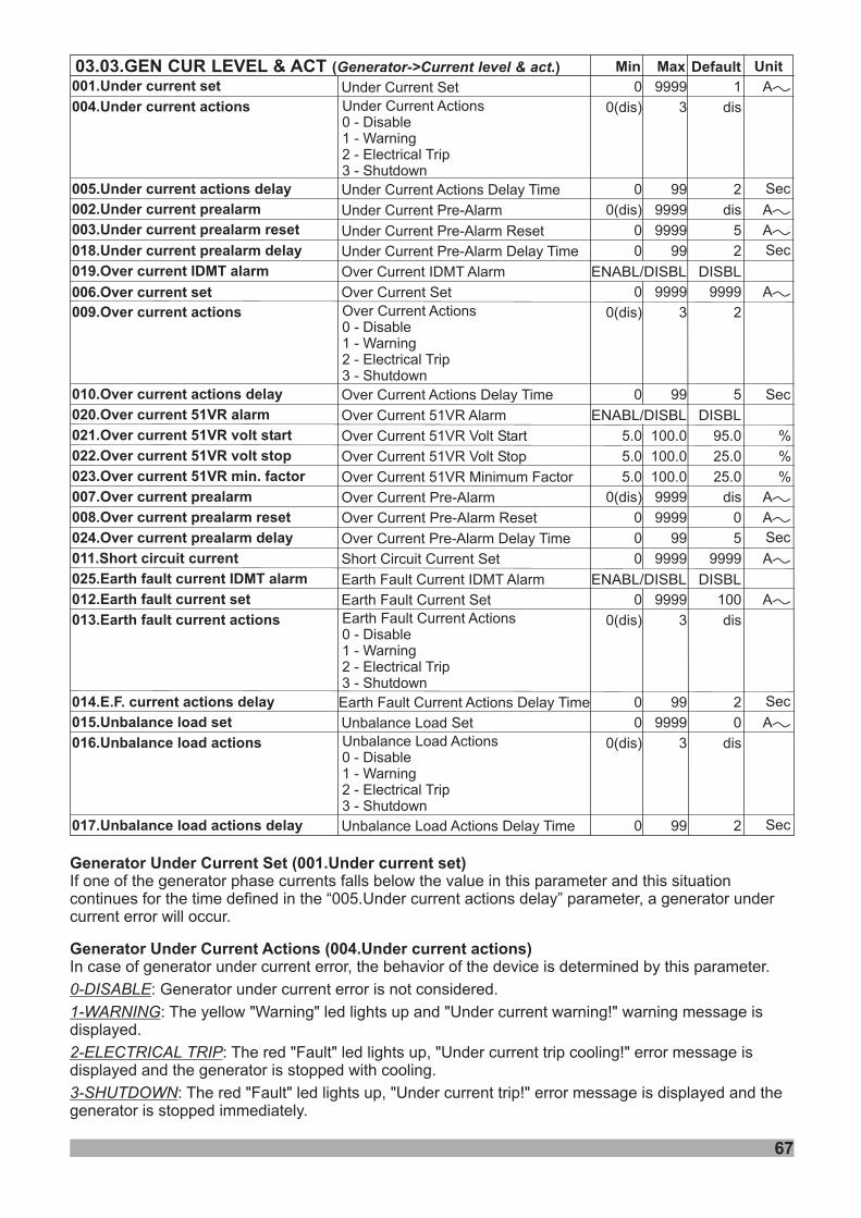
Min DefaultMax
003.Under current prealarm reset
004.Under current actions
005.Under current actions delay
006.Over current set
007.Over current prealarm
008.Over current prealarm reset
009.Over current actions
010.Over current actions delay
011.Short circuit current
012.Earth fault current set
013.Earth fault current actions
014.E.F. current actions delay
Unit03.03. CUR LEVEL & ACTGEN ( )Generator->Current level & act.
001.Under current set
002.Under current prealarm
0
0(dis)
0
0
0
0(dis)
0
9999
3
99
9999
9999
3
99
0
2
5
9999
100
dis
2
AV
AV
AV
0
0(dis)
0
0(dis)
0
0
0(dis)
9999
9999
9999
3
99
9999
9999
1
dis
5
dis
2
9999
AV
AV
AV
AV
AV
Sec
Sec
Sec
015.Unbalance load set
016.Unbalance load actions
017.Unbalance load actions delay
0
0(dis)
0
9999
3
99
0
dis
2
AV
Sec
Under Current Pre-Alarm Reset
Under Current Actions Delay Time
Under Current Set
Under Current Pre-Alarm
Under Current ActionsDisableWarningElectrical TripShutdown
0 -1 -2 -3 -
Over Current Set
Over Current Pre-Alarm
Over Current Pre-Alarm Reset
Over Current Actions Delay Time
Short Circuit Current Set
Earth Fault Current Set
Earth Fault Current Actions Delay Time
Over Current ActionsDisableWarningElectrical TripShutdown
0 -1 -2 -3 -
Earth Fault Current ActionsDisableWarningElectrical TripShutdown
0 -1 -2 -3 -
Unbalance Load Set
Unbalance Load Actions Delay Time
Unbalance Load0 -1 -2 -3 -
ActionsDisableWarningElectrical TripShutdown
dis
0 .Under current prealarm delay18
0 . current19 Over IDMT alarm
0 99 2 SecUnder Current Pre-Alarm Delay Time
Over Current IDMT Alarm ENABL/DISBL DISBL
0 . current20 Over 51VR alarm
0 1. current2 Over 51VR volt start
0 2. current2 Over 51VR volt stop
0 3. current factor2 Over 51VR min.
Over Current 51VR Alarm
Over Current 51VR Volt Start
Over Current 51VR Volt Stop
Over Current 51VR Minimum Factor
ENABL/DISBL DISBL
5.0
5.0
5.0
100.0
100.0
100.0
95.0
25.0
25.0
%
%
%
024.Over current prealarm delay 0 99 5 SecOver Current Pre-Alarm Delay Time
025.Earth fault current IDMT alarm Earth Fault Current IDMT Alarm ENABL/DISBL DISBL
67
Generator Under Current Set (001.Under current set)
Generator Under Current Actions (004.Under current actions)
If one of the generator phase currents falls below the value in this parameter and this situationcontinues for the time defined in the “005.Under current actions delay” parameter, a generator undercurrent error will occur.
In case of generator under current error, the behavior of the device is determined by this parameter.
: Generator under current error is not considered.
: The yellow "Warning" led lights up and "Under current warning!" warning message isdisplayed.
: The red "Fault" led lights up, "Under current trip cooling!" error message isdisplayed and the generator is stopped with cooling.
: The red "Fault" led lights up, "Under current trip!" error message is displayed and thegenerator is stopped immediately.
0-DISABLE
1-WARNING
2-ELECTRICAL TRIP
3-SHUTDOWN
68
Generator Under Current Actions Delay (005.Under current actions delay)
Generator Under Current Prealarm (002.Under current prealarm)
Generator Under Current Prealarm Reset (003.Under current prealarm reset)
Generator Under Current Prealarm Delay (018.Under current prealarm delay)
Generator Over Current IDMT Alarm (019.Over current IDMT alarm)
If one of the generator phase currents goes below the value in the "001.Under current set" parameterfor the time defined in this parameter, a generator under current error will occur.
If one of the generator phase currents falls below the value in this parameter and this situationcontinues for the time defined in the parameter "018.Under current prealarm delay", the device turnson the yellow "Warning" led and displays the "Under current prealarm!" warning message on thescreen.
If all of the generator phase currents exceed the value in this parameter, the device turns off the yellow"Warning" led and removes the "Under current prealarm!" warning message on the display.
If one of the generator phase currents falls below the value in the parameter "002.Under currentprealarm" during the time defined in this parameter, the device turns on the yellow "Warning" led anddisplays the "Under current prealarm!" warning message on the screen.
: If one of the generator phase currents more than the “006.Over current set” parameter andthis condition is go on more than “010.Over current actions delay” parameter, the unit will give an“Over current” alarm.
: If one of the generator phase currents more than the “006.Over current set” parameter andthis condition is go on more than “ ”, the unit will give an “Over current” alarm.
DISABLE
ENABLETripping time
Generator Over Current Set (006.Over current set)
Generator Over Current Actions (009.Over current actions)
Generator Over Current Actions Delay (010.Over current actions delay)
Generator Over Current 51VR Alarm (020.Over current 51VR alarm)
If one of the generator phase currents more than this parameter and this condition is go on more than“010.Over current actions delay” parameter, the unit will give an “Over current” alarm.
In case of generator over current error, the behavior of the device is determined by this parameter.
: Generator over current error is not considered.
: The yellow "Warning" led lights up and "Over current warning!" warning message isdisplayed.
: The red "Fault" led lights up, "Over current trip cooling!" error message isdisplayed and the generator is stopped with cooling.
: The red "Fault" led lights up, "Over current trip!" error message is displayed and thegenerator is stopped immediately.
If one of the generator phase currents rises above the value in the "006.Over current set" parameterfor the time defined in this parameter, a generator over current error will occur.
"Generator Voltage Restrained Overcurrent (51VR)" function is an addition to over current monitoringand decreases the activation level depending on the amount of voltage drop.
: If one of the generator phase currents more than the “006.Over current set” parameter andthis condition is go on more than “010.Over current actions delay” parameter, the unit will give a “Overcurrent” alarm.
: If one of the generator phase currents more than the " " and this condition isgo on more than “010.Over current actions delay” parameter, the unit will give a “Over current” alarm.
The 51VR function reduces the configured over current limit according to the modification factor.The Modification Factor depends on the measured voltage as a percentage of the nominal voltage.It is a characteristic formed by the use of "021.Over current 51VR volt start", "022.Over current 51VRvolt stop" and "023.Over current 51VR min. factor" parameters.
0-DISABLE
1-WARNING
2-ELECTRICAL TRIP
3-SHUTDOWN
DISABLE
ENABLE Effective limit
(“010.Over current actions delay” parameter) x (“006.Over current set” parameter)
(Measured current) - (“006.Over current set” parameter)Tripping time =
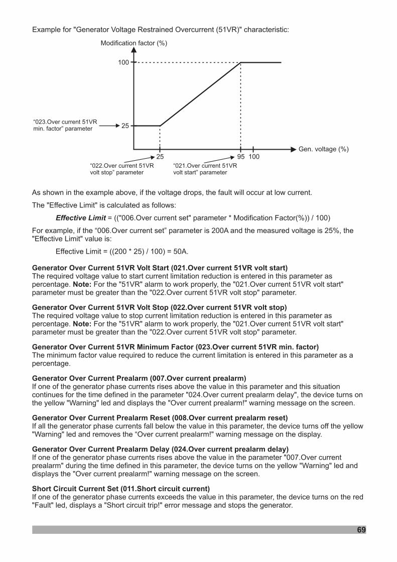
69
As shown in the example above, if the voltage drops, the fault will occur at low current.
The "Effective Limit" is calculated as follows:
= (("006.Over current set" parameter * Modification Factor(%)) / 100)
For example, if the “006.Over current set” parameter is 200A and the measured voltage is 25%, the"Effective Limit" value is:
Effective Limit = ((200 * 25) / 100) = 50A.
The required voltage value to start current limitation reduction is entered in this parameter aspercentage. For the "51VR" alarm to work properly, the "021.Over current 51VR volt start"parameter must be greater than the "022.Over current 51VR volt stop" parameter.
The required voltage value to stop current limitation reduction is entered in this parameter aspercentage. For the "51VR" alarm to work properly, the "021.Over current 51VR volt start"parameter must be greater than the "022.Over current 51VR volt stop" parameter.
The minimum factor value required to reduce the current limitation is entered in this parameter as apercentage.
If one of the generator phase currents rises above the value in this parameter and this situationcontinues for the time defined in the parameter "024.Over current prealarm delay", the device turns onthe yellow "Warning" led and displays the "Over current prealarm!" warning message on the screen.
If all the generator phase currents fall below the value in this parameter, the device turns off the yellow"Warning" led and removes the “Over current prealarm!" warning message on the display.
If one of the generator phase currents rises above the value in the parameter "007.Over currentprealarm" during the time defined in this parameter, the device turns on the yellow "Warning" led anddisplays the "Over current prealarm!" warning message on the screen.
If one of the generator phase currents exceeds the value in this parameter, the device turns on the red"Fault" led, displays a "Short circuit trip!" error message and stops the generator.
Effective Limit
Generator Over Current 51VR Volt Start (021.Over current 51VR volt start)
Note:
Generator Over Current 51VR Volt Stop (022.Over current 51VR volt stop)
Note:
Generator Over Current 51VR Minimum Factor (023.Over current 51VR min. factor)
Generator Over Current Prealarm (007.Over current prealarm)
Generator Over Current Prealarm Reset (008.Over current prealarm reset)
Generator Over Current Prealarm Delay (024.Over current prealarm delay)
Short Circuit Current Set (011.Short circuit current)
Example for "Generator Voltage Restrained Overcurrent (51VR)" characteristic:
Modification factor (%)
Gen. voltage (%)
100
25
25 95 100
“023.Over current 51VRmin. factor” parameter
“022.Over current 51VRvolt stop” parameter
“021.Over current 51VRvolt start” parameter
70
Generator Earth Fault Current IDMT Alarm (025.Earth fault current IDMT alarm)DISABLE
ENABLE
: If the generator neutral current more than the “012.Earth fault current set” parameter andthis condition is go on more than “014.E.F. current actions delay” parameter, the unit will give an “Earthfault” alarm.
: If the generator neutral current more than the “012.Earth fault current set” parameter andthis condition is go on more than “ ”, the unit will give an “Earth fault” alarm.Tripping time
Generator Earth Fault Current Set (012.Earth fault current set)
Generator Earth Fault Current Actions (013.Earth fault current actions)
Generator Earth Fault Current Actions Delay (014.E.F. current actions delay)
Unbalance Load Set (015.Unbalance load set)
Unbalance Load Actions (016.Unbalance load actions)
Unbalance Load Actions Delay (017.Unbalance load actions delay)
If the generator neutral current goes above the value in this parameter and this condition is go on morethan “014.E.F. current actions delay” parameter, the unit will give an “Earth fault” alarm.
In case of earth current error, the behavior of the device is determined by this parameter.
: Earth current error is not considered.
: The yellow "Warning" led lights up and "Earth fault warning!" warning message isdisplayed.
: The red "Fault" led lights up, "Earth fault trip cooling!" error message isdisplayed and the generator is stopped with cooling.
: The red "Fault" led lights up, "Earth fault instant trip!" error message is displayed andthe generator is stopped immediately.
If the generator neutral current rises above the value in the "012.Earth fault current set" parameter forthe time defined in this parameter, a generator earth fault will occur.
If one of the generator phase currents differs from the average value by the value defined in thisparameter and this situation continues for the time defined in the parameter “017.Unbalance loadactions delay”, a current (load) unbalance error occurs.
In case of current (load) unbalance error, the behavior of the device is determined by this parameter.
: Current (load) unbalance error is not considered.
: The yellow "Warning" led lights up and "Unbalance load warning!" warning message isdisplayed.
: The red "Fault" led lights up, "Unbalance load trip cooling!" error message isdisplayed and the generator is stopped with cooling.
: The red "Fault" led lights up, "Unbalance load trip!" error message is displayed andthe generator is stopped immediately.
If one of the generator phase currents goes outside the unbalanced load limit for the time defined inthis parameter, a current (load) unbalance error will occur.
0-DISABLE
1-WARNING
2-ELECTRICAL TRIP
3-SHUTDOWN
0-DISABLE
1-WARNING
2-ELECTRICAL TRIP
3-SHUTDOWN
(“014.E.F. current actions delay” parameter) x (“012.Earth fault curr. set” parameter)
(Measured current) - (“012.Earth fault curr. set” parameter)Tripping time =
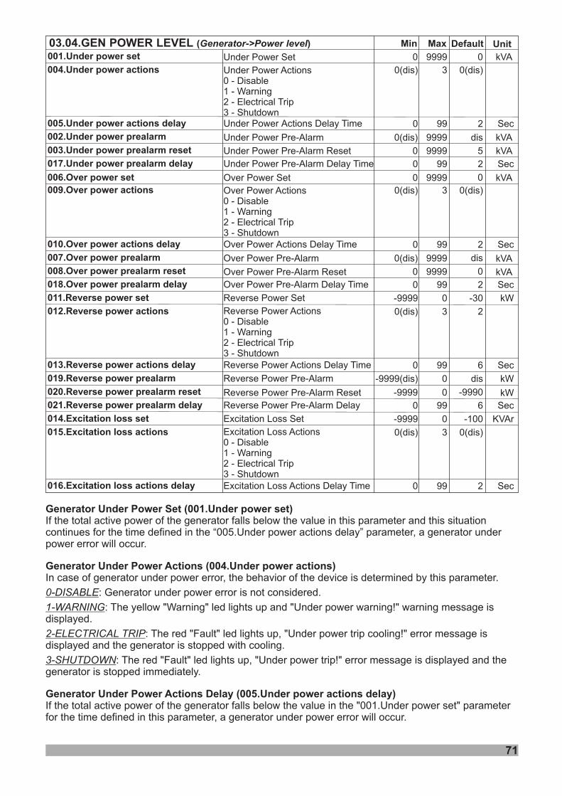
71
9999
9999
9999
9999
9999
9999
kVA
kVA
kVA
kVA
0
0(dis)
0
0
0(dis)
0
Min DefaultMax
Under SetPower
Under Pre-AlarmPower
Under Pre-Alarm ResetPower
Over SetPower
Over Pre-AlarmPower
0
5
Over Pre-Alarm ResetPower
kVA
kVA
Unit
Over Delay TimePower Actions
Reverse Power Pre-Alarm
0
-9999(dis)
99
0
2
dis
Sec
kW
dis
0
0
dis
001. powerUnder set
002. powerUnder prealarm
003. powerUnder prealarm reset
006. powerOver set
007. powerOver prealarm
008. powerOver prealarm reset
010.Over power actions delay
019.Reverse power prealarm
03.04. POWERGEN LEVEL ( )Generator->Power level
Under Delay TimePower Actions
0(dis)
0
3
99
0(dis)
2 Sec
Under ActionsDisableWarningElectrical TripShutdown
Power0 -1 -2 -3 -
004.Under power actions
005.Under power actions delay
0(dis) 3 0(dis)Over ActionsDisableWarningElectrical TripShutdown
Power0 -1 -2 -3 -
009.Over power actions
Excitation Loss Set
Excitation Loss Actions Delay Time
-9999
0(dis)
0
0
3
99
-100
0(dis)
2
KVAr
Sec
Excitation Loss0 -1 -2 -3 -
ActionsDisableWarningElectrical TripShutdown
014.Excitation loss set
01 .Excitation loss5 actions
016.Excitation loss actions delay
Under Pre-Alarm Delay TimePower 0 99 2 Sec017. powerUnder prealarm delay
Over Pre-Alarm Delay TimePower 0 99 2 Sec01 . power8 Over prealarm delay
Reverse Power Set
Reverse Power Actions Delay Time
-9999
0(dis)
0
0
3
99
-30
2
6
kW
Sec
Reverse Power ActionsDisableWarningElectrical TripShutdown
0 -1 -2 -3 -
011.Reverse power set
012.Reverse power actions
013.Reverse power actions delay
0-9999Reverse Power Pre-Alarm Reset kW-9990020. powerReverse prealarm reset
Reverse Power Pre-Alarm Delay 0 99 6 Sec021. powerReverse prealarm delay
Generator Under Power Set (001.Under power set)
Generator Under Power Actions (004.Under power actions)
Generator Under Power Actions Delay (005.Under power actions delay)
If the total active power of the generator falls below the value in this parameter and this situationcontinues for the time defined in the “005.Under power actions delay” parameter, a generator underpower error will occur.
In case of generator under power error, the behavior of the device is determined by this parameter.
: Generator under power error is not considered.
: The yellow "Warning" led lights up and "Under power warning!" warning message isdisplayed.
: The red "Fault" led lights up, "Under power trip cooling!" error message isdisplayed and the generator is stopped with cooling.
: The red "Fault" led lights up, "Under power trip!" error message is displayed and thegenerator is stopped immediately.
If the total active power of the generator falls below the value in the "001.Under power set" parameterfor the time defined in this parameter, a generator under power error will occur.
0-DISABLE
1-WARNING
2-ELECTRICAL TRIP
3-SHUTDOWN
72
Generator Under Power Prealarm (002.Under power prealarm)
Generator Under Power Prealarm Reset (003.Under power prealarm reset)
Generator Under Power Prealarm Delay (017.Under power prealarm delay)
Generator Over Power Set (006.Over power set)
Generator Over Power Actions (009.Over power actions)
Generator Over Power Actions Delay (010.Over power actions delay)
Generator Over Power Prealarm (007.Over power prealarm)
Generator Over Power Prealarm Reset (008.Over power prealarm reset)
Generator Over Power Prealarm Delay (018.Over power prealarm delay)
Generator Reverse Power Set (011.Reverse power set)
Generator Reverse Power Actions (012.Reverse power actions)
If the total active power of the generator falls below the value in this parameter and this situationcontinues for the time defined in the parameter "017.Under power prealarm delay", the device turns onthe yellow "Warning" led and displays the "Under power prealarm!" warning message on the screen.
If the total active power of the generator the value in this parameter, the device turns off theyellow "Warning" led and removes the "Under power prealarm!" warning message on the display.
If the total active power of the generator falls below the value in the parameter "002.Under powerprealarm" during the time defined in this parameter, the device turns on the yellow "Warning" led anddisplays the "Under power prealarm!" warning message on the screen.
If the total active power of the generator more than this parameter and this condition is go on morethan “010.Over power actions delay” parameter, the unit will give an “Over power” alarm.
In case of generator over power error, the behavior of the device is determined by this parameter.
: Generator over power error is not considered.
: The yellow "Warning" led lights up and "Over power warning!" warning message isdisplayed.
: The red "Fault" led lights up, "Over power trip cooling!" error message isdisplayed and the generator is stopped with cooling.
: The red "Fault" led lights up, "Over power trip!" error message is displayed and thegenerator is stopped immediately.
If the total active power of the generator rises above the value in the "006.Over power set" parameterfor the time defined in this parameter, a generator over power error will occur.
If the total active power of the generator rises above the value in this parameter and this situationcontinues for the time defined in the parameter "018.Over power prealarm delay", the device turns onthe yellow "Warning" led and displays the "Over power prealarm!" warning message on the screen.
If the total active power of the generator falls below the value in this parameter, the device turns off theyellow "Warning" led and removes the “Over power prealarm!" warning message on the display.
If the total active power of the generator rises above the value in the parameter "007.Over powerprealarm" during the time defined in this parameter, the device turns on the yellow "Warning" led anddisplays the "Over power prealarm!" warning message on the screen.
If the total active power of the generator (with a negative value) falls below the value in this parameterand this situation continues for the time defined in the “013.Reverse power actions delay” parameter, agenerator reverse power error will occur.
In case of generator reverse power error, the behavior of the device is determined by this parameter.
: Generator reverse power error is not considered.
: The yellow "Warning" led lights up and "Reverse power warning!" warning message isdisplayed.
: The red "Fault" led lights up, "Reverse power trip cooling!" error message isdisplayed and the generator is stopped with cooling.
: The red "Fault" led lights up, "Reverse power trip!" error message is displayed and thegenerator is stopped immediately.
exceeds
0-DISABLE
1-WARNING
2-ELECTRICAL TRIP
3-SHUTDOWN
0-DISABLE
1-WARNING
2-ELECTRICAL TRIP
3-SHUTDOWN
Generator Reverse Power Actions Delay (013.Reverse power actions delay)
Generator Reverse Power Prealarm (019.Reverse power prealarm)
Generator Reverse Power Prealarm Reset (020.Reverse power prealarm reset)
Generator Reverse Power Prealarm Delay (021.Reverse power prealarm delay)
Generator Excitation Loss Set (014.Excitation loss set)
Generator Excitation Loss Actions (015.Excitation loss actions)
Generator Excitation Loss Actions Delay (016.Excitation loss actions delay)
If the total active power of the generator (with a negative value) goes below the value in the"011.Reverse power set" parameter for the time defined in this parameter, a generator reverse powererror will occur.
If the total active power of the generator (with a negative value) falls below the value in this parameterand this situation continues for the time defined in the parameter "021.Reverse power prealarm delay",the device turns on the yellow "Warning" led and displays the "Reverse power prealarm!" warningmessage on the screen.
If the total active power of the generator (with a negative value) the value in this parameter,the device turns off the yellow "Warning" led and removes the "Reverse power prealarm!" warningmessage on the display.
If the total active power of the generator (with a negative value) falls below the value in the parameter"019.Reverse power prealarm" during the time defined in this parameter, the device turns on the yellow"Warning" led and displays the "Reverse power prealarm!" warning message on the screen.
If the total reactive power of the generator (with a negative value) falls below the value in thisparameter and this situation continues for the time defined in the "016.Excitation loss actions delay"parameter, a generator excitation loss error will occur.
In case of generator excitation loss error, the behavior of the device is determined by this parameter.
: Generator excitation loss error is not considered.
: The yellow "Warning" led lights up and "Excitation loss warning!" warning message isdisplayed.
: The red "Fault" led lights up, "Excitation loss trip cooling!" error message isdisplayed and the generator is stopped with cooling.
: The red "Fault" led lights up, "Excitation loss trip!" error message is displayed and thegenerator is stopped immediately.
If the total reactive power of the generator (with a negative value) goes below the value in the"014.Excitation loss set" parameter for the time defined in this parameter, a generator excitation losserror will occur.
exceeds
0-DISABLE
1-WARNING
2-ELECTRICAL TRIP
3-SHUTDOWN
73
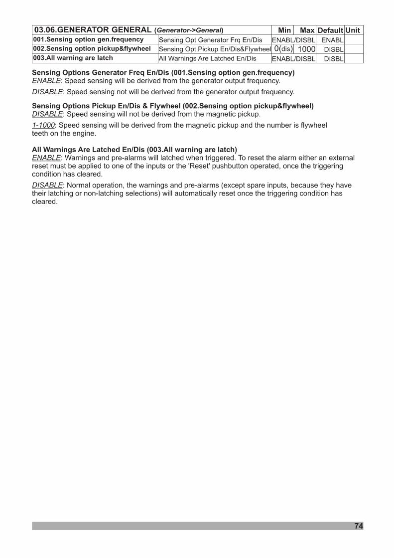
74
Min Default Unit03.06.GENERATOR GENERAL ( )Generator->General Max001.Sensing option gen.frequency ENABLENABL/DISBL
0( )dis DISBL1000002.Sensing option pickup&flywheel
003.All warning are latch ENABL/DISBL DISBL
Sensing Options Generator Freq En/Dis Sensing option gen.frequency
Sensing Options Pickup En/Dis & Flywheel Sensing option pickup&flywheel
All Warnings Are Latched En/Dis All warning are latch
(001. )
(002. )
(003. )
ENABLE
DISABLE
ENABLE
DISABLE
: Speed sensing will be derived from the generator output frequency.
: Speed sensing not will be derived from the generator output frequency.
: Warnings and pre-alarms will latched when triggered. To reset the alarm either an externalreset must be applied to one of the inputs or the 'Reset' pushbutton operated, once the triggeringcondition has cleared.
: Normal operation, the warnings and pre-alarms (except spare inputs, because they havetheir latching or non-latching selections) will automatically reset once the triggering condition hascleared.
DISABLE
1-1000
: Speed sensing will not be derived from the magnetic pickup.
: Speed sensing will be derived from the magnetic pickup and the number is flywheelteeth on the engine.
Sensing Opt Generator Frq En/Dis
Sensing Opt Pickup En/Dis&Flywheel
All Warnings Are Latched En/Dis
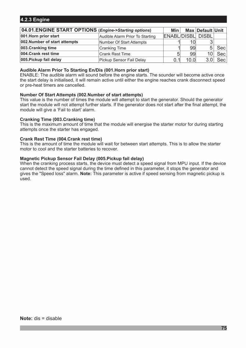
75
Note: dis = disable
4.2.3 Engine
ENABL/DISBL
Sec
Min Default Unit04.01.ENGINE START OPTIONS ( )Engine->Starting options MaxDISBL
35
11
1099
105 993.00.1 10.0
001.Horn prior start
002. startNumber of attempts
003.Cranking time
004.Crank rest time
005. aPickup fail del ySecSec
Audible Alarm Prior To Starting En/DisENABLE: The audible alarm will sound before the engine starts. The sounder will become active oncethe start delay is initialised, it will remain active until either the engine reaches crank disconnect speedor pre-heat timers are cancelled.
Number Of Start Attempts
Cranking Time Cranking time
Crank Rest Time Crank rest time
Magnetic
This value is the number of times the module will attempt to start the generator. Should the generatorstart the module will not attempt further starts. If the generator does not start after the final attempt, themodule will give a ‘Fail to start’ alarm.
This is the amount of time the module will wait for between start attempts. This is to allow the startermotor to cool and the starter batteries to recover.
This is the maximum amount of time that the module will energise the starter motor for during startingattempts once the starter has engaged.
When the cranking process starts, the device must detect a speed signal from MPU input. If the devicecannot detect the speed signal during the time defined in this parameter, it stops the generator andgives the "Speed loss" alarm. This parameter is active if speed sensing from magnetic pickup isused.
Note:
Horn prior start
Number of start attempts
Pickup Sensor Fail Delay Pickup fail delay
(001. )
(002. )
(003. )
(004. )
(005. )
Audible Alarm Prior To Starting
Number Of Start Attempts
Cranking Time
Crank Rest Time
Pickup Sensor Fail Delay
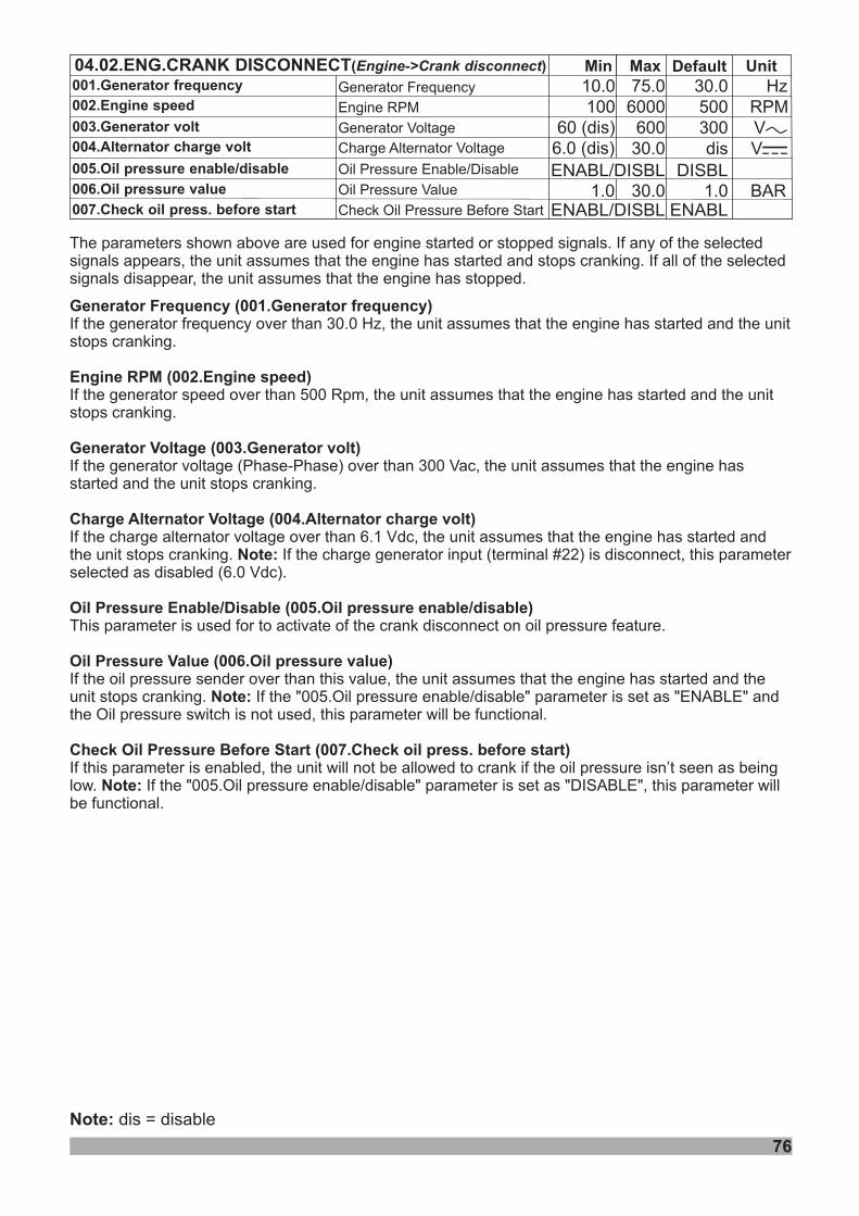
76
Note: dis = disable
04.02.ENG.CRANK DISCONNECT( )Engine->Crank disconnect
001.Generator frequency
002.Engine speed
003.Generator volt
004.Alternator charge volt
Min Default UnitMaxGen Frequencyerator
Generator Voltage
Charge Alternator Voltage
30.010.0 75.0 Hz500100 6000 RPM30060 (dis) 600 VVdis6.0 (dis) 30.0 VZ
Engine RPM
005.Oil pressure enable/disable
006. valueOil pressure
007.Check oil press. before start
Oil Pressure Enable/Disable
Oil Pressure Value
Check Oil Pressure Before Start1.0 30.0 BAR1.0
ENABL/DISBL DISBL
ENABL/DISBL ENABL
The parameters shown above are used for engine started or stopped signals. If any of the selectedsignals appears, the unit assumes that the engine has started and stops cranking. If all of the selectedsignals disappear, the unit assumes that the engine has stopped.
If the generator frequency over than 30.0 Hz, the unit assumes that the engine has started and the unitstops cranking.
If the generator speed over than 500 Rpm, the unit assumes that the engine has started and the unitstops cranking.
If the generator voltage ( ) over than 300 Vac, the unit assumes that the engine hasstarted and the unit stops cranking.
If the charge alternator voltage over than 6.1 Vdc, the unit assumes that the engine has started andthe unit stops cranking. If the charge generator input (terminal #22) is disconnect, this parameterselected as disabled (6.0 Vdc).
This parameter is used for to activate of the crank disconnect on oil pressure feature.
If the oil pressure sender over than this value, the unit assumes that the engine has started and theunit stops cranking. If the "005.Oil pressure enable/disable" parameter is set as "ENABLE" andthe Oil pressure switch is not used, this parameter will be functional.
If this parameter is enabled, the unit will not be allowed to crank if the oil pressure isn’t seen as beinglow. If the "005.Oil pressure enable/disable" parameter is set as "DISABLE", this parameter willbe functional.
Note:
Note:
Note:
Gen Frequency Gen frequency
Engine speed
erator (001. erator )
Engine RPM (002. )
Generator Voltage (003.Generator volt)
Charge Alternator Voltage (004.Alternator charge volt)
Oil Pressure Enable/Disable (005.Oil pressure enable/disable)
Oil Pressure Value (006.Oil pressure value)
Check Oil Pressure Before Start (007.Check oil press. before start)
Phase-Phase
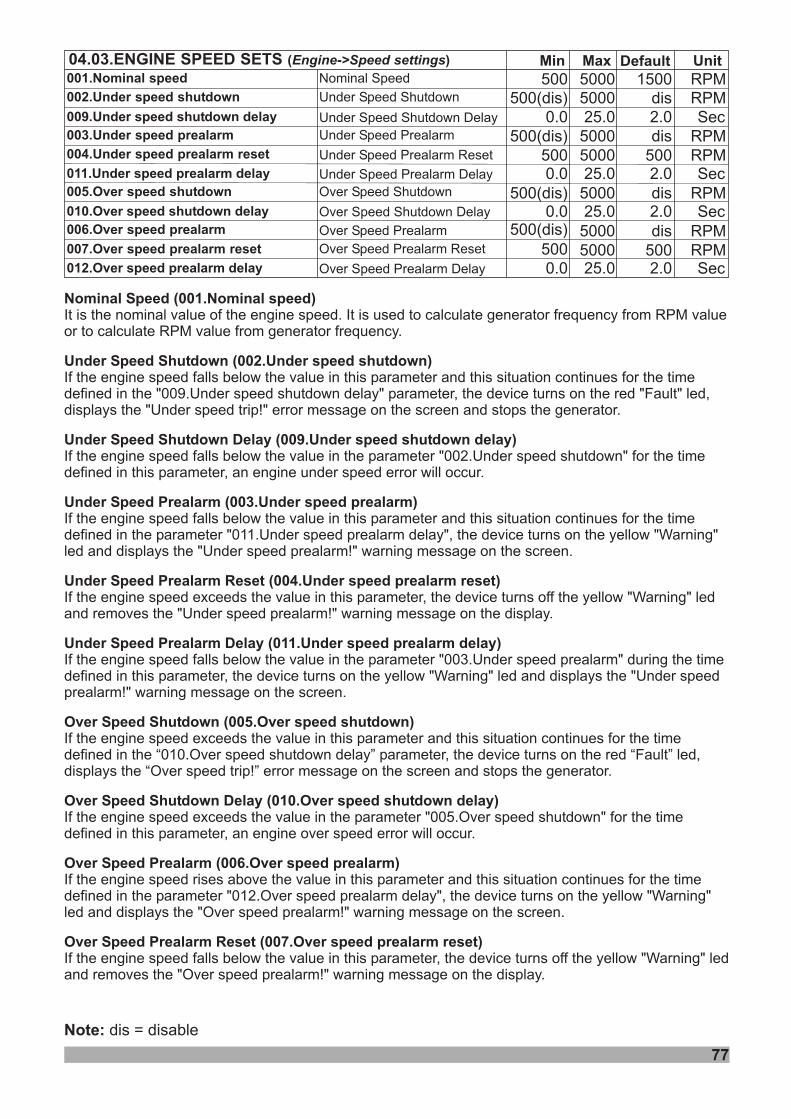
Min Default Unit04.03.ENGINE SPEED SETS ( )Engine->Speed settings Max
Under Speed Shutdown
Under Speed Prealarm
Under Speed Prealarm Reset
dis
Over Speed Shutdown
500(dis) 5000
500(dis) RPM500500 5000
Over Speed Prealarm Reset 500
RPM
RPM
RPM
RPMRPM
5000
500(dis) 5000
50005000
Over Speed Prealarm
002.Under speed shutdown
003.Under speed prealarm
004.Under speed prealarm reset
005.Over speed shutdown
006.Over speed prealarm
007.Over speed prealarm reset 500
Nominal Speed 1500500 5000 RPM001.Nominal speed
dis
dis
dis500(dis)
25.00.0Under Shutdown DelaySpeed 2.00 . delay09 Under speed shutdown Sec
25.00.0Over Shutdown DelaySpeed 2.0010.Ov delayer speed shutdown Sec
25.00.0Under Prealarm DelaySpeed 2.00 . delay11 Under speed prealarm Sec
25.00.0Over Prealarm DelaySpeed 2.00 . delay12 Over speed prealarm Sec
77
Nominal Speed (001.Nominal speed)
Under Speed Shutdown (002.Under speed shutdown)
Under Speed Shutdown Delay (009.Under speed shutdown delay)
Under Speed Prealarm (003.Under speed prealarm)
Under Speed Prealarm Reset (004.Under speed prealarm reset)
Under Speed Prealarm Delay (011.Under speed prealarm delay)
Over Speed Shutdown (005.Over speed shutdown)
Over Speed Shutdown Delay (010.Over speed shutdown delay)
Over Speed Prealarm (006.Over speed prealarm)
Over Speed Prealarm Reset (007.Over speed prealarm reset)
It is the nominal value of the engine speed. It is used to calculate generator frequency from RPM valueor to calculate RPM value from generator frequency.
If the engine speed falls below the value in this parameter and this situation continues for the timedefined in the "009.Under speed shutdown delay" parameter, the device turns on the red "Fault" led,displays the "Under speed trip!" error message on the screen and stops the generator.
If the engine speed falls below the value in the parameter "002.Under speed shutdown" for the timedefined in this parameter, an engine under speed error will occur.
If the engine speed falls below the value in this parameter and this situation continues for the timedefined in the parameter "011.Under speed prealarm delay", the device turns on the yellow "Warning"led and displays the "Under speed prealarm!" warning message on the screen.
If the engine speed exceeds the value in this parameter, the device turns off the yellow "Warning" ledand removes the "Under speed prealarm!" warning message on the display.
If the engine speed falls below the value in the parameter "003.Under speed prealarm" during the timedefined in this parameter, the device turns on the yellow "Warning" led and displays the "Under speedprealarm!" warning message on the screen.
If the engine speed exceeds the value in this parameter and this situation continues for the timedefined in the “010.Over speed shutdown delay” parameter, the device turns on the red “Fault” led,displays the “Over speed trip!” error message on the screen and stops the generator.
If the engine speed exceeds the value in the parameter "005.Over speed shutdown" for the timedefined in this parameter, an engine over speed error will occur.
If the engine speed rises above the value in this parameter and this situation continues for the timedefined in the parameter "012.Over speed prealarm delay", the device turns on the yellow "Warning"led and displays the "Over speed prealarm!" warning message on the screen.
If the engine speed falls below the value in this parameter, the device turns off the yellow "Warning" ledand removes the "Over speed prealarm!" warning message on the display.
Note: dis = disable
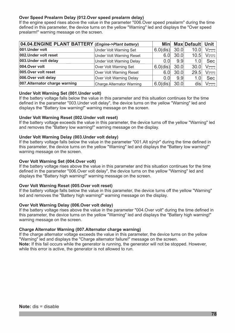
Over Speed Prealarm Delay (012.Over speed prealarm delay)If the engine speed rises above the value in the parameter "006.Over speed prealarm" during the timedefined in this parameter, the device turns on the yellow "Warning" led and displays the "Over speedprealarm!" warning message on the screen.
Min Default04.04.ENGINE PLANT BATTERY ( )Engine->Plant battery Max
10.56.0(dis)
6.030.030.0
1.00.030.06.0(dis) 30.0
1.0dis
9.9
30.09.9
6.0(dis) 30.0
6.00.0
001.Under volt
002. resetUnder volt
003. delayUnder volt
004.Over volt
005. resetOver volt
006. delayOver volt
007.Alternator charge warning
UnitVZVZSec
VZSecVZ
VZ
10.0
29.5
Under Volt Warning Set
Under Volt Warning Reset
Under Volt Warning Delay
Over Volt Warning Set
Over Warning ResetVolt
Over DelayVolt Warning
Charge Alternator Warning
78
Note: dis = disable
Under Volt Warning Set (001.Under volt)
Under Volt Warning Reset (002.Under volt reset)
Under Volt Warning Delay (003.Under volt delay)
Over Volt Warning Set (004.Over volt)
Over Volt Warning Reset (005.Over volt reset)
Over Volt Warning Delay (006.Over volt delay)
Charge Alternator Warning (007.Alternator charge warning)
Note:
If the battery voltage falls below the value in this parameter and this situation continues for the timedefined in the parameter "003.Under volt delay", the device turns on the yellow "Warning" led anddisplays the "Battery low warning!" warning message on the screen.
If the battery voltage exceeds the value in this parameter, the device turns off the yellow "Warning" ledand removes the "Battery low warning!" warning message on the display.
If the battery voltage falls below the value in the parameter "001.Alt sýnýr" during the time defined inthis parameter, the device turns on the yellow "Warning" led and displays the "Battery low warning!"warning message on the screen.
If the battery voltage rises above the value in this parameter and this situation continues for the timedefined in the parameter "006.Over volt delay", the device turns on the yellow "Warning" led anddisplays the "Battery high warning!" warning message on the screen.
If the battery voltage falls below the value in this parameter, the device turns off the yellow "Warning"led and removes the "Battery high warning!" warning message on the display.
If the battery voltage rises above the value in the parameter "004.Over volt" during the time defined inthis parameter, the device turns on the yellow "Warning" led and displays the "Battery high warning!"warning message on the screen.
If the charge alternator voltage exceeds the value in this parameter, the device turns on the yellow"Warning" led and displays the "Charge alternator failure!" message on the screen.
If this fail occurs while the generator is running, the generator will not be stopped. However,while this error is active, the generator is not allowed to run.
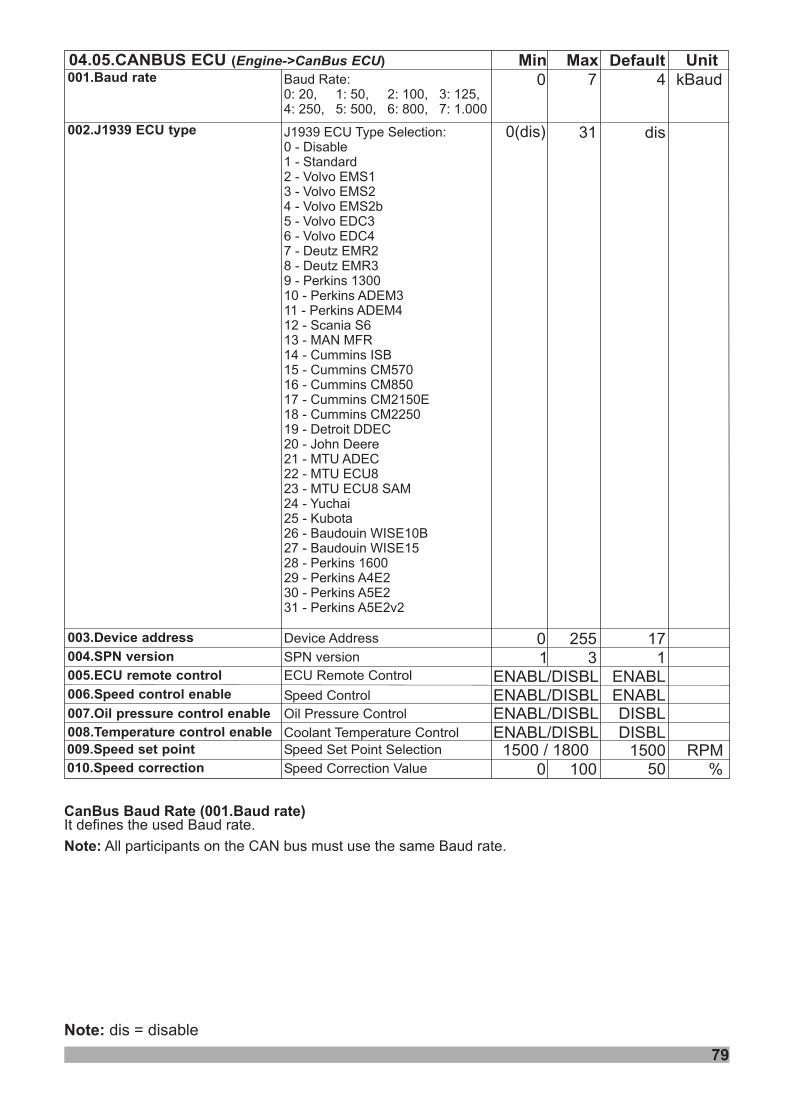
79
04.05.CANBUS ECU ( )Engine->CanBus ECU
001.Baud rate
002.J1939 ECU type
003.Device address
004.SPN version
Min Default UnitMax0 7 4
31 dis
0 255 171 3 1
kBaud
005.ECU remote control
006.Speed control enable
007.Oil pressure control enable
008.Temperature control enable
ENABL
Device Address
0(dis)
SPN version
ECU Remote Control
Speed Control
Oil Pressure Control
Coolant Temperature Control
010.Speed correction 50Speed Correction Value %0 100009.Speed set point 15001500 1800/Speed Set Point Selection RPM
ENABL/DISBLENABL/DISBLENABL/DISBL
ENABL/DISBL
ENABLDISBL
DISBL
J1939 ECU Type Selection:0 - Disable1 - Standard2 - Volvo EMS13 - Volvo EMS24 - Volvo EMS2b5 - Volvo EDC36 - Volvo EDC47 - Deutz EMR28 - Deutz EMR39 - Perkins 130010 - Perkins ADEM311 - Perkins ADEM412 - Scania S613 - MAN MFR14 - Cummins ISB15 - Cummins CM57016 - Cummins CM85017 - Cummins CM2150E18 - Cummins CM225019 - Detroit DDEC20 - John Deere21 - MTU ADEC22 - MTU ECU823 - MTU ECU8 SAM24 - Yuchai25 - Kubota26 - Baudouin WISE10B27 - Baudouin WISE1528 - Perkins 160029 - Perkins A4E230 - Perkins A5E231 - Perkins A5E2v2
Baud Rate:0: 20, 1: 50, 2: 100, 3: 125,4: 250, 5: 500, 6: 800, 7: 1.000
CanBus (001.Baud rate)Baud RateIt defines the used Baud rate.
All participants on the CAN bus must use the same Baud rate.Note:
Note: dis = disable
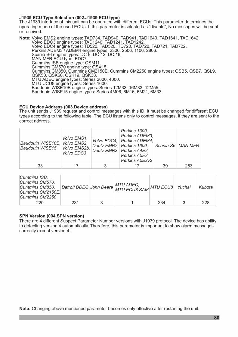
80
Note: Changing above mentioned parameter becomes only effective after restarting the unit.
J1939 ECU Type Selection ( J1939 ECU type)002.The J1939 interface of this unit can be operated with different ECUs. This parameter determines theoperating mode of the used ECUs. If this parameter is selected as “disable”, No messages will be sentor received.
Volvo EMS2 engine types: TAD734, TAD940, TAD941, TAD1640, TAD1641, TAD1642.Volvo EDC3 engine types: TAD1240, TAD1241, TAD1242.Volvo EDC4 engine types: TD520, TAD520, TD720, TAD720, TAD721, TAD722.Perkins ADEM3 / ADEM4 engine types: 2306, 2506, 1106, 2806.Scania S6 engine types: DC 9, DC 12, DC 16.MAN MFR ECU type: EDC7.
engine type: QSM11.engine type: QSX15.
engine types: QSB5, QSB7, QSL9,QSK50, QSK60, QSK19, QSK38.
engine types: Series 2000, 4000.engine types: Series 1600.
engine types: Series 12M33, 16M33, 12M55.engine types: Series 4M06, 6M16, 6M21, 6M33.
Note:
Cummins ISBCummins CM570Cummins CM850, Cummins CM2150E, Cummins CM2250
MTU ADECMTU UCU8Baudouin WISE10BBaudouin WISE15
ECUThe unit sends J1939 request and control messages with this ID. It must be changed for different ECUtypes according to the following table. The ECU listens only to control messages, if they are sent to thecorrect address.
Device Address ( Device address)003.
SPN Version 004.SPN version( )There are 4 different Suspect Parameter Number versions with J1939 protocol. The device has abilityto detecting version 4 automatically. Therefore, this parameter is important to show alarm messagescorrectly except version 4.
17 333 17 39 253
Baudouin WISE10B,Baudouin WISE15
Volvo EMS1,Volvo EMS2,Volvo EMS2b,Volvo EDC3
Volvo EDC4,Deutz EMR2,Deutz EMR3
Perkins 1300,Perkins ADEM3,Perkins ADEM4,Perkins 1600,Perkins A4E2,Perkins A5E2,Perkins A5E2v2
Scania S6 MAN MFR
Cummins ISB,Cummins CM570,Cummins CM850,Cummins CM2150E,Cummins CM2250
220 3
MTU ADEC,MTU ECU8 SAM
MTU ECU8
1 234231
Detroit DDEC John Deere
3
Yuchai
228
Kubota
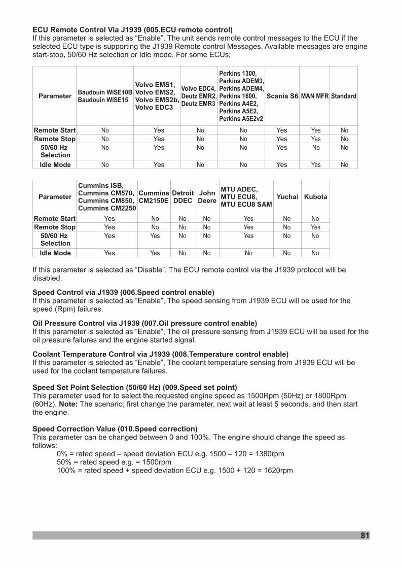
81
ECU Remote Control Via J1939If this parameter is selected as “Enable”, The unit sends remote control messages to the ECU if theselected ECU type is supporting the J1939 Remote control Messages. Available messages are enginestart-stop, 50/60 Hz selection or Idle mode. For some ECUs;
( ECU remote control)005.
Volvo EMS1,Volvo EMS2,Volvo EMS2b,Volvo EDC3
ParameterVolvo EDC4,Deutz EMR2,Deutz EMR3
Perkins 1300,Perkins ADEM3,Perkins ADEM4,Perkins 1600,Perkins A4E2,Perkins A5E2,Perkins A5E2v2
MAN MFR
YesYesYes
Yes
NoNoNo
No
NoNoNo
No
YesYesNo
Yes
Remote StartRemote Stop
50/60 HzSelection
Idle Mode
Scania S6
YesYesYes
Yes
Standard
NoNoNo
No
Parameter
Remote StartRemote Stop
50/60 HzSelection
Idle Mode
Cummins ISB,Cummins CM570,Cummins CM850,Cummins CM2250
MTU ADEC,
MTU ECU8 SAMMTU ECU8, Yuchai
DetroitDDEC
JohnDeere
CumminsCM2150E
YesYesYes
Yes
NoNoYes
Yes
NoNoNo
No
NoNoNo
No
YesYesYes
No
NoNoNo
No
If this parameter is selected as “Disable”, The ECU remote control via the J1939 protocol will bedisabled.
If this parameter is selected as “Enable”, The speed sensing from J1939 ECU will be used for thespeed (Rpm) failures.
If this parameter is selected as “Enable”, The oil pressure sensing from J1939 ECU will be used for theoil pressure failures and the engine started signal.
If this parameter is selected as “Enable”, The coolant temperature sensing from J1939 ECU will beused for the coolant temperature failures.
This parameter used for to select the requested engine speed as 1500Rpm (50Hz) or 1800Rpm(60Hz). The scenario; first change the parameter, next wait at least 5 seconds, and then startthe engine.
This parameter can be changed between 0 and 100%. The engine should change the speed asfollows:
0% = rated speed – speed deviation ECU e.g. 1500 – 120 = 1380rpm50% = rated speed e.g. = 1500rpm100% = rated speed + speed deviation ECU e.g. 1500 + 120 = 1620rpm
(50/60 Hz)
Note:
Speed Control via J1939 ( Speed control enable)
Oil Pressure Control via J1939 ( Oil pressure control enable)
Coolant Temperature Control via J1939 ( Temperature control enable)
Speed Set Point Selection ( Speed set point)
Speed Correction Value ( Speed correction)
006.
007.
008.
009.
010.
Kubota
NoYesNo
No
Baudouin WISE10BBaudouin WISE15
NoNoNo
No
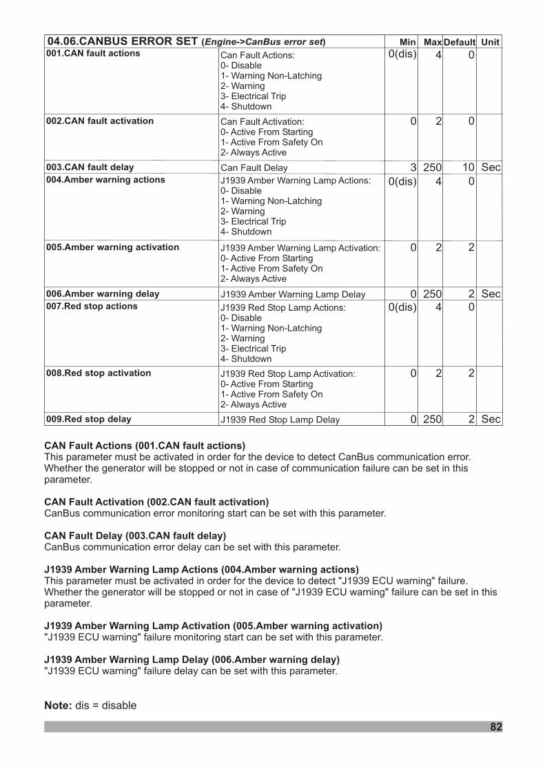
82
Note: dis = disable
Min Default Unit04.06.CANBUS ERROR SET ( )Engine->CanBus error set Max
Can Fault Actions:0- Disable1- Warning Non-Latching2- Warning3- Electrical Trip4- Shutdown
00 2
00(dis) 4
002.CAN fault activation
001.CAN fault actions
SecCan Fault Delay 103 250003.CAN fault delay
Can Fault Activation:0- Active From Starting1- Active From Safety On2- Always Active
J1939 Amber Warning Lamp Actions:0- Disable1- Warning Non-Latching2- Warning3- Electrical Trip4- Shutdown
20 2
00(dis) 4
005.Amber warning activation
004.Amber warning actions
SecJ1939 Amber Warning Lamp Delay 20 250006.Amber warning delay
J1939 Amber Warning Lamp Activation:0- Active From Starting1- Active From Safety On2- Always Active
J1939 Red Stop Lamp Actions:0- Disable1- Warning Non-Latching2- Warning3- Electrical Trip4- Shutdown
20 2
00(dis) 4
008.Red stop activation
007.Red stop actions
SecJ1939 Red Stop Lamp Delay 20 250009.Red stop delay
J1939 Red Stop Lamp Activation:0- Active From Starting1- Active From Safety On2- Always Active
CAN Fault Actions (001.CAN fault actions)
CAN Fault Activation (002.CAN fault activation)
CAN Fault Delay (003.CAN fault delay)
J1939 Amber Warning Lamp Actions (004.Amber warning actions)
J1939 Amber Warning Lamp Activation (005.Amber warning activation)
J1939 Amber Warning Lamp Delay (006.Amber warning delay)
This parameter must be activated in order for the device to detect CanBus communication error.Whether the generator will be stopped or not in case of communication failure can be set in thisparameter.
CanBus communication error monitoring start can be set with this parameter.
CanBus communication error delay can be set with this parameter.
This parameter must be activated in order for the device to detect "J1939 ECU warning" failure.Whether the generator will be stopped or not in case of "J1939 ECU warning" failure can be set in thisparameter.
"J1939 ECU warning" failure monitoring start can be set with this parameter.
"J1939 ECU warning" failure delay can be set with this parameter.
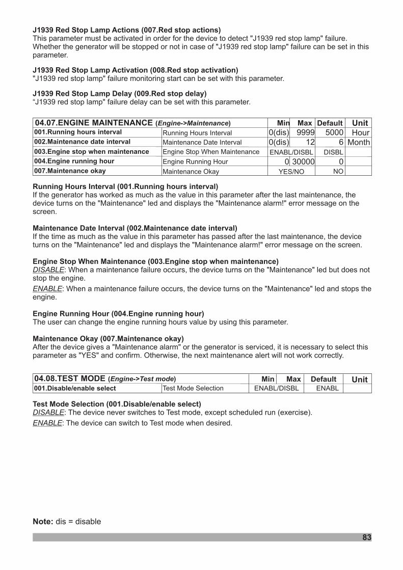
83
Note: dis = disable
Min Default04.08.TEST MODE ( )Engine->Test mode Max Unit001.Disable/enable select ENABLENABL/DISBL
Min Default04.07.ENGINE MAINTENANCE ( )Engine->Maintenance MaxRunning Hours Interval
Maintenance Date Interval
Engine Stop When Maintenance
Engine Running Hour
50000(dis) 9999
ENABL/DISBL
00 30000DISBL
0(dis) 12 6002.Maintenance date interval
003.Engine stop when maintenance
004.Engine running hour
001.Running hours intervalUnitHour
Month
Maintenance Okay NO007.Maintenance okay YES/NO
J1939 Red Stop Lamp Actions (007.Red stop actions)
J1939 Red Stop Lamp Activation (008.Red stop activation)
J1939 Red Stop Lamp Delay (009.Red stop delay)
This parameter must be activated in order for the device to detect "J1939 red stop lamp" failure.Whether the generator will be stopped or not in case of "J1939 red stop lamp" failure can be set in thisparameter.
"J1939 red stop lamp" failure monitoring start can be set with this parameter.
“J1939 red stop lamp" failure delay can be set with this parameter.
Running Hours Interval (001.Running hours interval)
Maintenance Date Interval (002.Maintenance date interval)
Engine Stop When Maintenance (003.Engine stop when maintenance)
Engine Running Hour (004.Engine running hour)
Maintenance Okay (007.Maintenance okay)
If the generator has worked as much as the value in this parameter after the last maintenance, thedevice turns on the "Maintenance" led and displays the "Maintenance alarm!" error message on thescreen.
If the time as much as the value in this parameter has passed after the last maintenance, the deviceturns on the "Maintenance" led and displays the "Maintenance alarm!" error message on the screen.
: When a maintenance failure occurs, the device turns on the "Maintenance" led but does notstop the engine.
: When a maintenance failure occurs, the device turns on the "Maintenance" led and stops theengine.
The user can change the engine running hours value by using this parameter.
After the device gives a "Maintenance alarm" or the generator is serviced, it is necessary to select thisparameter as "YES" and confirm. Otherwise, the next maintenance alert will not work correctly.
DISABLE
ENABLE
Test Mode Selection (001.Disable/enable select)DISABLE
ENABLE
: The device never switches to Test mode, except scheduled run (exercise).
: The device can switch to Test mode when desired.
Test Mode Selection

84
Note: dis = disable
Min DefaultMax
Exercise Disable or Enable
Exercise Start Time on Monday
Exercise Stop Time on Monday
Exercise St Time onart Tuesday
Exercise Stop Time on Tuesday
Exercise St Time onart Wednesday
Exercise Stop Time on Wednesday
Exercise St Time onart Thursday
Exercise Stop Time on Thursday
Exercise Start Time on Friday
Exercise Start Time on Saturday
Exercise Start Time on Sunday
Exercise Stop Time on Friday
Exercise Stop Time on Saturday
Exercise Stop Time on Sunday
001.Disable/enable select
002.Start time on monday
003.Stop time on monday
004. art tuesdaySt time on
005. tuesdayStop time on
006. art wednesdaySt time on
007. wednesdayStop time on
008. art thursdaySt time on
009. thursdayStop time on
010. fridayStart time on
012. saturdayStart time on
014. sundayStart time on
011. fridayStop time on
013. saturdayStop time on
015. sundayStop time on
Unit04.09.EXERCISE ( )Engine->Exercise
23.59
23.59
23.59
23.59
23.59
23.59
23.59
23.59
23.59
23.59
23.59
23.59
23.59
23.59
H.Min
H.Min
H.Min
H.Min
H.Min
H.Min
H.Min
H.Min
H.Min
H.Min
H.Min
H.Min
H.Min
H.Min
0.00
0.00
0.00
0.00
0.00
0.00
0.00
0.00
0.00
0.00
0.00
0.00
0.00
0.00
0.00
0.00
0.00
0.00
0.00
0.00
0.00
0.00
0.00
0.00
0.00
0.00
0.00
0.00
DISBL ENABL/ DISBL
Exercise (001. )Disable or Enable Disable/enable selectDISABLE
ENABLE
: . The unit will not monitor the exercise parameters.
: The unit will monitor the exercise parameters.When the start time of any day is reached, the unit will start the generator.When the stop time of the same day is reached, the unit will stop the generator.
the exercise function forthat day will be passive.
theexercise function for that day will be passive.
Note-1:
Note-2:
If the “Start and Stop time parameters” of any day are set the same,
If the “Start time parameter” of any day is set larger than the “Stop time parameter”,
The exercise function is disabled
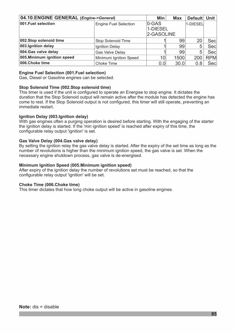
85
Note: dis = disable
Engine Fuel Selection Fuel selection
Stop Solenoid Time Stop solenoid time
(001. )
(002. )
(003. )
(004. )
(005. )
(006. )
Gas, Diesel or Gasoline engines can be selected.
This timer is used if the unit is configured to operate an Energise to stop engine. It dictates theduration that the Stop Solenoid output will remain active after the module has detected the engine hascome to rest. If the Stop Solenoid output is not configured, this timer will still operate, preventing animmediate restart.
This timer dictates that how long choke output will be active in gasoline engines.Choke Time Choke time
Ignition Delay Ignition delay
Gas Valve Delay Gas valve delay
Minimum Ignition Speed Minimum ignition speed
With gas engines often a purging operation is desired before starting. With the engaging of the starterthe ignition delay is started. If the 'min ignition speed' is reached after expiry of this time, theconfigurable relay output 'ignition' is set.
By setting the ignition relay the gas valve delay is started. After the expiry of the set time as long as thenumber of revolutions is higher than the minimum ignition speed, the gas valve is set. When thenecessary engine shutdown process, gas valve is de-energised.
After expiry of the ignition delay the number of revolutions set must be reached, so that theconfigurable relay output 'ignition' will be set.
Min Default Unit04.10.ENGINE GENERAL ( )Engine->General MaxEngine Fuel Selection 1-DIESEL
Stop Solenoid Time 1 2099Ignition Delay 1 599 SecGas Valve Delay 1 599 SecMinimum Ignition Speed 10 2001500 RPM
001.Fuel selection
002.Stop solenoid time
003.Ignition delay
004.Gas valve delay
005.Minimum ignition speed
Sec
006.Choke time Choke Time Sec0.0 0.830.0
0-GAS1-DIESEL2-GASOLINE
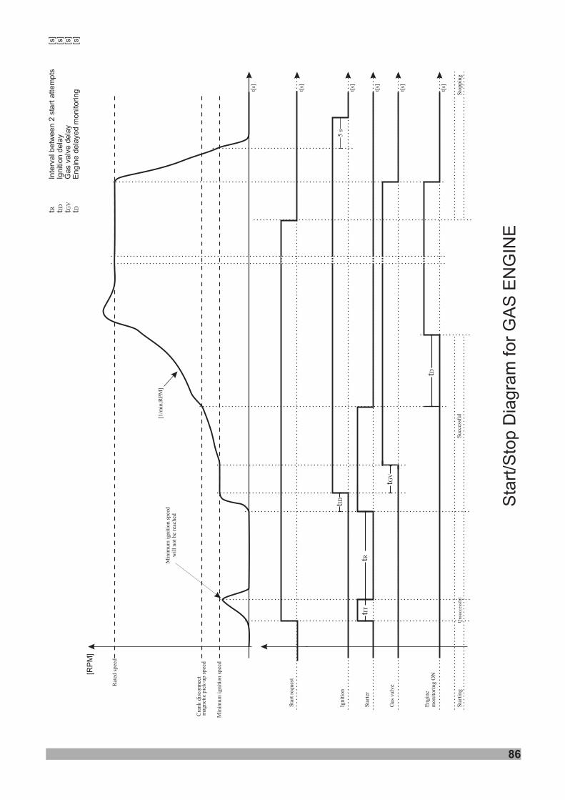
86
Sta
rt r
eques
t
Ignit
ion
Sta
rter
Gas
val
ve
Engin
em
onit
ori
ng O
N
Min
imum
ignit
ion s
pee
d
Rat
ed s
pee
d
[RP
M]
t[s]
t[s]
t[s]
Sta
rtin
gS
toppin
g
Min
imum
ignit
ion s
pee
dw
ill
not
be
reac
hed
[1/m
in]
;RP
M
5 s
Unsu
cces
sful
Succ
essf
ul
t[s]
t[s]
t[s]
tIT
tID
tR
tGV
tD
Cra
nk d
isco
nnec
tm
agnet
ic p
ick-u
p s
pee
d
Sta
rt/S
top D
iagra
m for
GA
S E
NG
INE
t t t tR ID GV
D
[s]
[s]
[s]
[s]
Inte
rval betw
een 2
sta
rt a
ttem
pts
Ignitio
n d
ela
yG
as v
alv
e d
ela
yE
ngin
e d
ela
yed m
onitoring
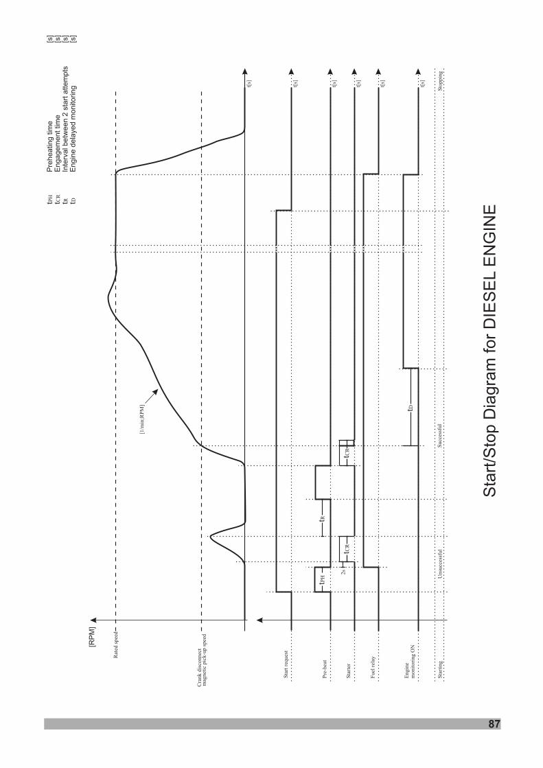
87
Sta
rt r
eques
t
Pre
-hea
t
Sta
rter
Fuel
rel
ay
Engin
em
onit
ori
ng O
N
Rat
ed s
pee
d
[RP
M]
t[s]
Sta
rtin
gU
nsu
cces
sful
Succ
essf
ul
Sto
ppin
g
tPH
2s
[1/m
in]
;RP
M
t[s]
t[s]
t[s]
t[s]
t[s]
tR
t CR
t CR
tD
Cra
nk d
isco
nnec
tm
agnet
ic p
ick-u
p s
pee
d
Sta
rt/S
top D
iagra
m for
DIE
SE
LE
NG
INE
t t t tPH
CR
R D
Pre
heatin
g tim
e[s
]E
ngagem
ent tim
e[s
]In
terv
al b
etw
een 2
sta
rt a
ttem
pts
[s]
Engin
e d
ela
yed m
onito
ring
[s]
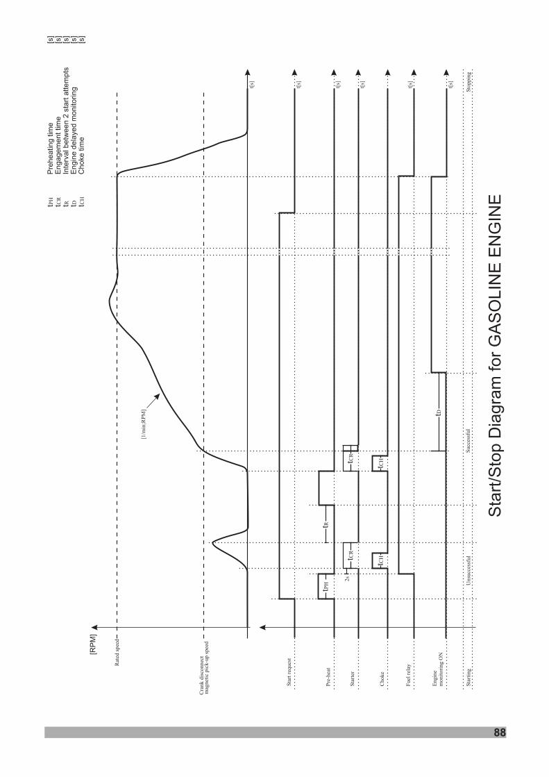
88
Sta
rt/S
top D
iagra
m for
GA
SO
LIN
E E
NG
INE
Sta
rt r
eques
t
Pre
-hea
t
Sta
rter
Fuel
rel
ay
Choke
Engin
em
onit
ori
ng O
N
Rat
ed s
pee
d
[RP
M]
t[s]
Sta
rtin
gU
nsu
cces
sful
Succ
essf
ul
Sto
ppin
g
tPH
2s
[1/m
in]
;RP
M
t[s]
t[s]
t[s]
t[s]
t[s]
tR
tCR
t CR
tD
Cra
nk d
isco
nnec
tm
agnet
ic p
ick-u
p s
pee
d
tCH
tCH
t t t t tPH
CR
R D CH
Pre
heatin
g tim
e[s
]E
ngagem
ent tim
e[s
]In
terv
al b
etw
een 2
sta
rt a
ttem
pts
[s]
Engin
e d
ela
yed m
onito
ring
[s]
Choke
tim
e[s
]
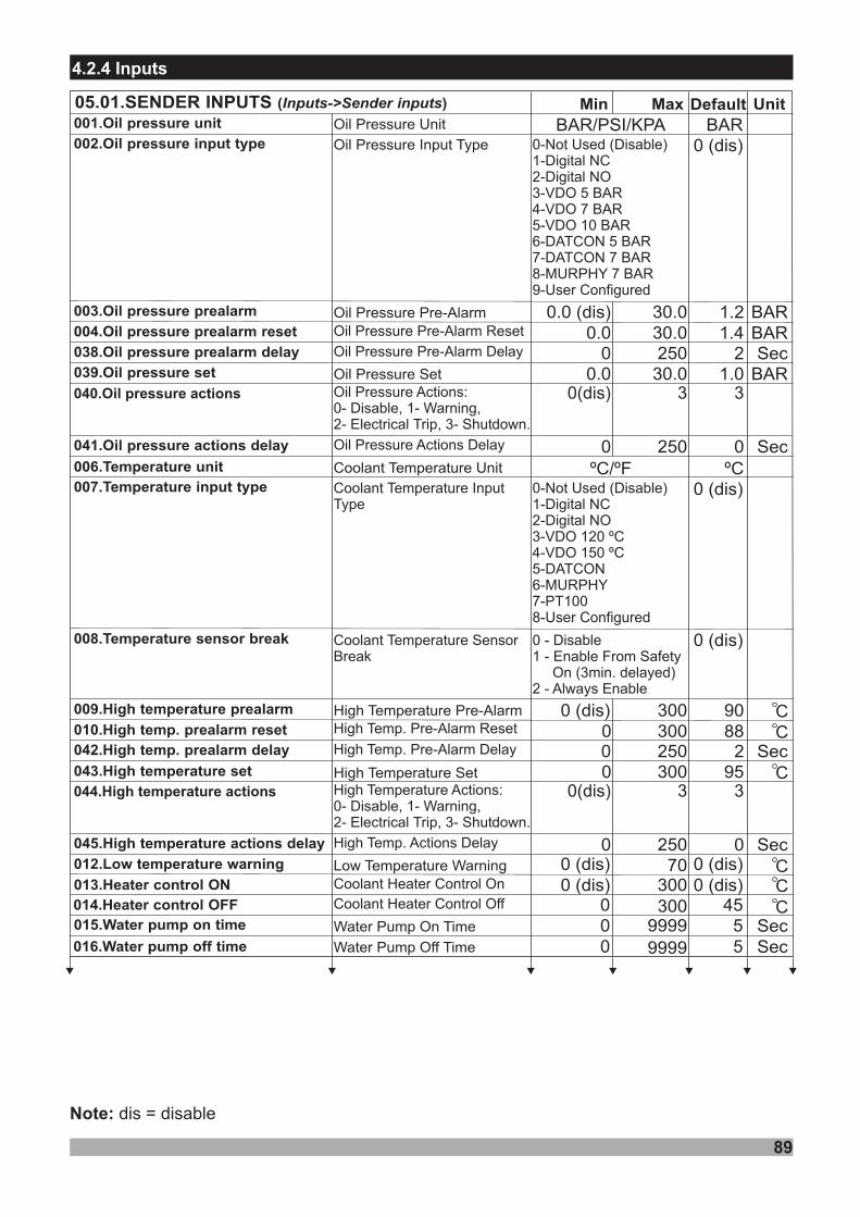
89
4.2.4 Inputs
Min Default Unit05.01.SENDER INPUTS ( )Inputs->Sender inputs Max
Oil Press Input Typeure
Oil Press Pre-Alarmure 1.20.0 (dis) 30.0 BAR1.4
2
0.00
30.0250
BARSec
1.00.0 30.0 BAR
0-Not Used (Disable)1-Digital NC2-Digital NO3-VDO 5 BAR4-VDO 7 BAR5-VDO 10 BAR6-DATCON 5 BAR7-DATCON 7 BAR8-MURPHY 7 BAR9-User Configured
900 (dis) 300880 300
950 300
High Temp Pre-Alarmerature
Oil Pressure Set
High Temp Seterature
CC
C
008.Temperature sensor break
009.High temperature prealarm
010.High temp. prealarm reset
043.High temperature set
007.Temperature input type
039.Oil pressure set
004.Oil pressure prealarm reset
0 .38 Oil pressure prealarm delay
003.Oil pressure prealarm
002.Oil pressure input type
0 (dis) 70Low Temperature Warning C012.Low temperature warning
0 (dis)
0-Not Used (Disable)1-Digital NC2-Digital NO3-4- 55-DATCON6-MURPHY7-PT1008-User Configured
VDO 120 ºCVDO 1 0 ºC
0 (dis)
0 (dis)
Oil Press Uniture001.Oil pressure unit BARBAR/PSI/KPA
Coolant Temp Uniterature006.Temperature unit ºCºC/ºF
0 (dis)0 (dis) 300 C013.Heater control ON
0 300 C014.Heater control OFF 4550 9999Water Pump On Time015.Water pump on time
0 9999Water Pump Off Time Sec016.Water pump off time 5Sec
0 - Disable1 - Enable From Safety
On (3min. delayed)2 - Always Enable
0 (dis)
Coolant Heater Control Off
Coolant Heater Control On
Oil Press Pre-Alarm Reseture
Oil Press Pre-Alarm Delayure
Coolant Temp InputType
erature
High Temp. Pre-Alarm Reset
040. actionsOil pressure 0(dis) 3 3Oil Pressure :0- , 1- ,2- , 3-
ActionsDisable WarningElectrical Trip Shutdown.
00 250 Sec0 . actions41 Oil pressure delay Oil Press Actions Delayure
Coolant Temp SensorBreak
erature
20 250 Sec042.High temp. prealarm delay High Temp. Pre-Alarm Delay
04 . actions4 High temperature 0(dis) 3 3High Temperature ActionsDisable WarningElectrical Trip Shutdown.
:0- , 1- ,2- , 3-
00 250 Sec0 . actions45 High temperature delay High Temp. Actions Delay
Note: dis = disable
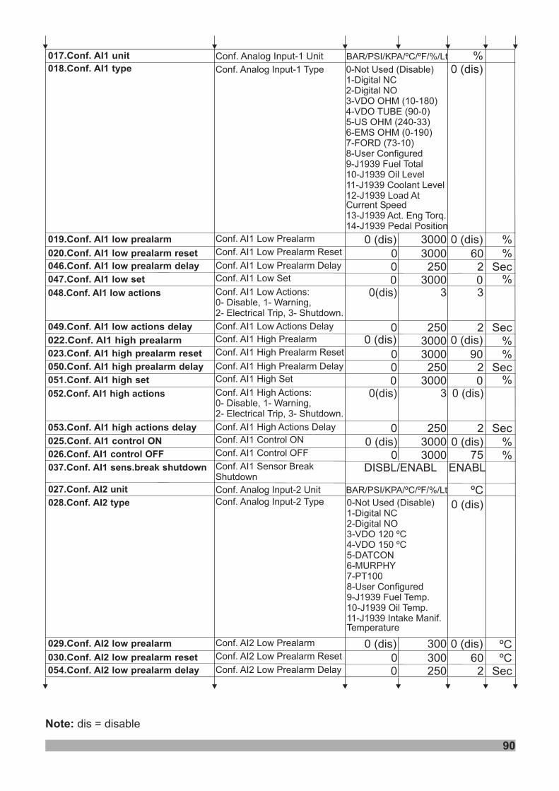
90
0 (dis) 3000 %
018.Conf. AI1 type
019.Conf. AI1 low prealarm
017.Conf. AI1 unit
0 (dis)
0 (dis)
BAR/PSI/KPA/ºC/ºF/%/LtConf. Analog Input-1 Unit
Conf. AI1 Low Prealarm
0-Not Used (Disable)1-Digital NC2-Digital NO3-VDO OHM (10-180)4-VDO TUBE (90-0)5-US OHM (240-33)6-EMS OHM (0-190)7-FORD (73-10)8-User Configured9-J1939 Fuel Total10-J1939 Oil Level11-J1939 Coolant Level12-J1939 Load AtCurrent Speed13-J1939 Act. Eng Torq.14-J1939 Pedal Position
Conf. Analog Input-1 Type
0 %75026.Conf. AI1 control OFF
037.Conf. AI1 sens.break shutdown3000
0 (dis)0 (dis) 3000 %025.Conf. AI1 control ON
3000900 3000
022.Conf. AI1 high prealarm 0 (dis) 0 (dis) %%023.Conf. AI1 high prealarm reset
Conf. AI1 High Prealarm
Conf. AI1 High Prealarm Reset
Conf. AI1 Control ON
Conf. AI1 Control OFF
Conf. AI1 Sensor BreakShutdown
DISBL ENABL/ ENABL
3000 %0047.Conf. AI1 low set 0Conf. AI1 Low Set
0 3000 %60020.Conf. AI1 low prealarm reset Conf. AI1 PrealarmLow Reset
20 250 Sec046.Conf. AI1 low prealarm delay Conf. AI1 Low Prealarm Delay
048. actionsConf. AI1 low 0(dis) 3 3Conf. AI1 Low ActionsDisable WarningElectrical Trip Shutdown.
:0- , 1- ,2- , 3-
20 250 Sec0 . actions49 Conf. AI1 low delay Conf. AI1 Low Actions Delay
20 250 Sec050.Conf. AI1 high prealarm delay Conf. AI1 High Prealarm Delay
3000 %00 .51 Conf. AI1 high set 0Conf. AI1 High Set
0 . actions52 Conf. AI1 high 0(dis) 3 0 (dis)Conf. AI1 High ActionsDisable WarningElectrical Trip Shutdown.
:0- , 1- ,2- , 3-
20 250 Sec0 . actions53 Conf. AI1 high delay Conf. AI1 High Actions Delay
028.Conf. AI2 type
027.Conf. AI2 unit
0-Not Used (Disable)1-Digital NC2-Digital NO3-4- 55-DATCON6-MURPHY7-PT1008-User Configured
VDO 120 ºCVDO 1 0 ºC
9-J1939 Fuel Temp.10-J1939 Oil Temp.11-J1939 Intake Manif.Temperature
0 (dis)
BAR/PSI/KPA/ºC/ºF/%/LtConf. Analog Input-2 TypeConf. Analog Input-2 Unit
0 (dis) 300029. 2Conf. AI low prealarm 0 (dis)Conf. AI2 Low Prealarm
0 300 60030. 2Conf. AI low prealarm reset Conf. AI2 PrealarmLow Reset
20 250 Sec054. 2Conf. AI low prealarm delay Conf. AI2 Low Prealarm Delay
ºC
%
ºC
ºC
Note: dis = disable
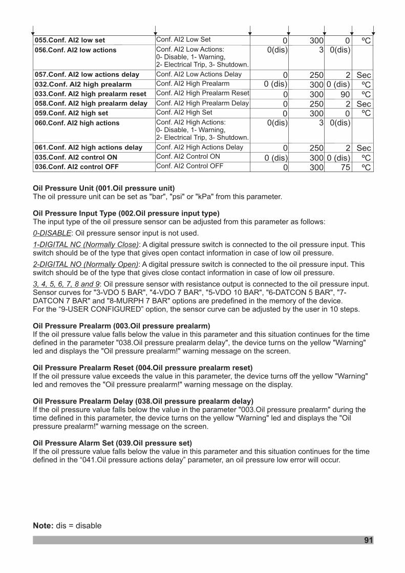
91
Note: dis = disable
0 ºC75036.Conf. AI2 control OFF 3000 (dis)0 (dis) 300 ºC035.Conf. AI2 control ON
300900 300
032. 2Conf. AI high prealarm 0 (dis) 0 (dis) ºCºC033. 2Conf. AI high prealarm reset
Conf. AI2 High Prealarm
Conf. AI2 High Prealarm Reset
Conf. AI2 Control ON
Conf. AI2 Control OFF
3000055. 2Conf. AI low set 0Conf. AI2 Low Set
056. 2 actionsConf. AI low 0(dis) 3 0(dis)Conf. AI2 Low ActionsDisable WarningElectrical Trip Shutdown.
:0- , 1- ,2- , 3-
20 250 Sec057. 2 actionsConf. AI low delay Conf. AI2 Low Actions Delay
20 250 Sec058. 2Conf. AI high prealarm delay Conf. AI2 High Prealarm Delay
300 ºC00 9. 25 Conf. AI high set 0Conf. AI2 High Set
060. 2 actionsConf. AI high 0(dis) 3 0(dis)Conf. AI2 High ActionsDisable WarningElectrical Trip Shutdown.
:0- , 1- ,2- , 3-
20 250 Sec061. 2 actionsConf. AI high delay Conf. AI2 High Actions Delay
ºC
Oil Pressure Unit (001.Oil pressure unit)
Oil Pressure Input Type (002.Oil pressure input type)
Oil Pressure Prealarm (003.Oil pressure prealarm)
Oil Pressure Prealarm Reset (004.Oil pressure prealarm reset)
Oil Pressure Prealarm Delay (038.Oil pressure prealarm delay)
Oil Pressure Alarm Set (039.Oil pressure set)
The oil pressure unit can be set as "bar", "psi" or "kPa" from this parameter.
The input type of the oil pressure sensor can be adjusted from this parameter as follows:
: Oil pressure sensor input is not used.
: A digital pressure switch is connected to the oil pressure input. Thisswitch should be of the type that gives open contact information in case of low oil pressure.
: A digital pressure switch is connected to the oil pressure input. Thisswitch should be of the type that gives close contact information in case of low oil pressure.
: Oil pressure sensor with resistance output is connected to the oil pressure input.Sensor curves for "3-VDO 5 BAR", "4-VDO 7 BAR", "5-VDO 10 BAR", "6-DATCON 5 BAR", "7-DATCON 7 BAR" and "8-MURPH 7 BAR" options are predefined in the memory of the device.For the “9-USER CONFIGURED” option, the sensor curve can be adjusted by the user in 10 steps.
If the oil pressure value falls below the value in this parameter and this situation continues for the timedefined in the parameter "038.Oil pressure prealarm delay", the device turns on the yellow "Warning"led and displays the "Oil pressure prealarm!" warning message on the screen.
If the oil pressure value exceeds the value in this parameter, the device turns off the yellow "Warning"led and removes the "Oil pressure prealarm!" warning message on the display.
If the oil pressure value falls below the value in the parameter "003.Oil pressure prealarm" during thetime defined in this parameter, the device turns on the yellow "Warning" led and displays the "Oilpressure prealarm!" warning message on the screen.
If the oil pressure value falls below the value in this parameter and this situation continues for the timedefined in the “041.Oil pressure actions delay” parameter, an oil pressure low error will occur.
0-DISABLE
1-DIGITAL NC (Normally Close)
2-DIGITAL NO (Normally Open)
3, 4, 5, 6, 7, 8 and 9
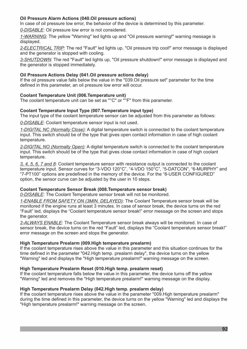
92
Oil Pressure Alarm Actions (040.Oil pressure actions)
Oil Pressure Actions Delay (041.Oil pressure actions delay)
Coolant Temperature Unit (006.Temperature unit)
Coolant Temperature Input Type (007.Temperature input type)
Coolant Temperature Sensor Break (008.Temperature sensor break)
High Temperature Prealarm (009.High temperature prealarm)
High Temperature Prealarm Reset (010.High temp. prealarm reset)
High Temperature Prealarm Delay (042.High temp. prealarm delay)
In case of oil pressure low error, the behavior of the device is determined by this parameter.
: Oil pressure low error is not considered.
: The yellow "Warning" led lights up and "Oil pressure warning!" warning message isdisplayed.
: The red "Fault" led lights up, "Oil pressure trip cool!" error message is displayedand the generator is stopped with cooling.
: The red "Fault" led lights up, "Oil pressure shutdown!" error message is displayed andthe generator is stopped immediately.
If the oil pressure value falls below the value in the "039.Oil pressure set" parameter for the timedefined in this parameter, an oil pressure low error will occur.
The coolant temperature unit can be set as "°C" or "°F" from this parameter.
The input type of the coolant temperature sensor can be adjusted from this parameter as follows:
: Coolant temperature sensor input is not used.
: A digital temperature switch is connected to the coolant temperatureinput. This switch should be of the type that gives open contact information in case of high coolanttemperature.
: A digital temperature switch is connected to the coolant temperatureinput. This switch should be of the type that gives close contact information in case of high coolanttemperature.
: Coolant temperature sensor with resistance output is connected to the coolanttemperature input. Sensor curves for “3-VDO 120°C”, “4-VDO 150°C”, “5-DATCON”, “6-MURPHY” and“7-PT100” options are predefined in the memory of the device. For the “8-USER CONFIGURED”option, the sensor curve can be adjusted by the user in 10 steps.
: .
:In case of sensor break, the device turns on the red
“Fault” led, displays the “Coolant temperature sensor break!” error message on the screen and stopsthe generator.
: . In case ofsensor break, the device turns on the red “Fault” led, displays the “Coolant temperature sensor break!”error message on the screen and stops the generator.
If the coolant temperature rises above the value in this parameter and this situation continues for thetime defined in the parameter "042.High temp. prealarm delay", the device turns on the yellow"Warning" led and displays the "High temperature prealarm!" warning message on the screen.
If the coolant temperature falls below the value in this parameter, the device turns off the yellow"Warning" led and removes the "High temperature prealarm!" warning message on the display.
If the coolant temperature rises above the value in the parameter "009.High temperature prealarm"during the time defined in this parameter, the device turns on the yellow "Warning" led and displays the"High temperature prealarm!" warning message on the screen.
0-DISABLE
1-WARNING
2-ELECTRICAL TRIP
3-SHUTDOWN
0-DISABLE
1-DIGITAL NC (Normally Close)
2-DIGITAL NO (Normally Open)
3, 4, 5, 6, 7 and 8
0-DISABLE
1-ENABLE FROM SAFETY ON (3MIN. DELAYED)
2-ALWAYS ENABLE
The Coolant Temperature sensor break will not be monitored
The Coolant Temperature sensor break will bemonitored if the engine runs at least 3 minutes.
The Coolant Temperature sensor break always will be monitored

93
High Temperature Set (043.High temperature set)
High Temperature Actions (044.High temperature actions)
High Temperature Actions Delay (045.High temperature actions delay)
Low Temperature Warning (012.Low temperature warning)
Coolant Heater Control On (013.Heater control ON)
Coolant Heater Control Off (014.Heater control OFF)
Water Pump On Time (015.Water pump on time)
Water Pump Off Time (016.Water pump off time)
Conf. Analog Input-1 Unit (017.Conf. AI1 unit)
Note:
If the coolant temperature more than this parameter and this condition is go on more than “045.Hightemperature actions delay” parameter, the unit will give a “High coolant temperature” alarm.
Hararet hatasý oluþtuðunda, cihazýn nasýl davranacaðý bu parametre ile aþaðýdaki gibi belirlenir:In case of high coolant temperature error, the behavior of the device is determined by this parameter.
: High coolant temperature error is not considered.
: The yellow "Warning" led lights up and "High temperature warning!" warning message isdisplayed.
: The red "Fault" led lights up, "High temperature trip cool!" error message isdisplayed and the generator is stopped with cooling.
: The red "Fault" led lights up, "High temperature shutdown!" error message isdisplayed and the generator is stopped immediately.
If the coolant temperature rises above the value in the "043.High temperature set" parameter for thetime defined in this parameter, a high coolant temperature error will occur.
If the coolant temperature falls below the value in this parameter, the device turns on the yellow"Warning" led and displays the "Low temperature!" warning message on the screen.
If the coolant temperature falls below the value in this parameter, the output configured as "HeaterControl" becomes active.
If the coolant temperature rises above the value in this parameter, the output configured as “HeaterControl” becomes inactive.
When the heater output is active, the output configured as “Water Pump” is active for the duration ofthis parameter.
When the heater output is active, the output configured as “Water Pump” is inactive for the duration ofthis parameter.
The configurable analog input-1 unit can be set as “bar”, “psi”, “kPa”, “°C”, “°F”, “%” or “Lt” from thisparameter.If the configurable analog input-1 will be used for pressure reading, its unit should be selected as "bar","psi" or "kPa".If the configurable analog input-1 will be used for temperature reading, its unit should be selected as"°C" or "°F".If the configurable analog input-1 will be used for level reading, its unit should be selected as "%" or"Lt".
Since the fuel level is adjusted by default in configurable analog input-1, the default value of thisparameter is "%".
0-DISABLE
1-WARNING
2-ELECTRICAL TRIP
3-SHUTDOWN
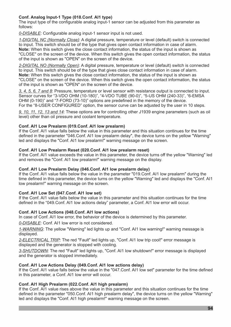
94
Conf. Analog Input-1 Type (018.Conf. AI1 type)
Note:
Note:
Conf. AI1 Low Prealarm (019.Conf. AI1 low prealarm)
Conf. AI1 Low Prealarm Reset (020.Conf. AI1 low prealarm reset)
Conf. AI1 Low Prealarm Delay (046.Conf. AI1 low prealarm delay)
Conf. AI1 Low Set (047.Conf. AI1 low set)
Conf. AI1 Low Actions (048.Conf. AI1 low actions)
Conf. AI1 Low Actions Delay (049.Conf. AI1 low actions delay)
Conf. AI1 High Prealarm (022.Conf. AI1 high prealarm)
The input type of the configurable analog input-1 sensor can be adjusted from this parameter asfollows:
: Configurable analog input-1 sensor input is not used.
: A digital pressure, temperature or level (default) switch is connectedto input. This switch should be of the type that gives open contact information in case of alarm.
When this switch gives the close contact information, the status of the input is shown as"CLOSE" on the screen of the device. When this switch gives the open contact information, the statusof the input is shown as "OPEN" on the screen of the device.
: A digital pressure, temperature or level (default) switch is connectedto input. This switch should be of the type that gives close contact information in case of alarm.
When this switch gives the close contact information, the status of the input is shown as"CLOSE" on the screen of the device. When this switch gives the open contact information, the statusof the input is shown as "OPEN" on the screen of the device.
: Pressure, temperature or level sensor with resistance output is connected to input.Sensor curves for “3-VDO OHM (10-180)”, “4-VDO TUBE (90-0)”, “5-US OHM (240-33)”, “6-EMSAOHM (0-190)” and “7-FORD (73-10)” options are predefined in the memory of the device.For the “8-USER CONFIGURED” option, the sensor curve can be adjusted by the user in 10 steps.
: These options are for controlling other J1939 engine parameters (such as oillevel) other than oil pressure and coolant temperature.
If the Conf. AI1 value falls below the value in this parameter and this situation continues for the timedefined in the parameter "046.Conf. AI1 low prealarm delay", the device turns on the yellow "Warning"led and displays the "Conf. AI1 low prealarm!" warning message on the screen.
If the Conf. AI1 value exceeds the value in this parameter, the device turns off the yellow "Warning" ledand removes the "Conf. AI1 low prealarm!" warning message on the display.
If the Conf. AI1 value falls below the value in the parameter "019.Conf. AI1 low prealarm" during thetime defined in this parameter, the device turns on the yellow "Warning" led and displays the "Conf. AI1low prealarm!" warning message on the screen.
If the Conf. AI1 value falls below the value in this parameter and this situation continues for the timedefined in the “049.Conf. AI1 low actions delay” parameter, a Conf. AI1 low error will occur.
In case of Conf. AI1 low error, the behavior of the device is determined by this parameter.
: Conf. AI1 low error is not considered.
: The yellow "Warning" led lights up and "Conf. AI1 low warning!" warning message isdisplayed.
: The red "Fault" led lights up, "Conf. AI1 low trip cool!" error message isdisplayed and the generator is stopped with cooling.
: The red "Fault" led lights up, "Conf. AI1 low shutdown!" error message is displayedand the generator is stopped immediately.
If the Conf. AI1 value falls below the value in the "047.Conf. AI1 low set" parameter for the time definedin this parameter, a Conf. AI1 low error will occur.
If the Conf. AI1 value rises above the value in this parameter and this situation continues for the timedefined in the parameter "050.Conf. AI1 high prealarm delay", the device turns on the yellow "Warning"led and displays the "Conf. AI1 high prealarm!" warning message on the screen.
0-DISABLE
1-DIGITAL NC (Normally Close)
2-DIGITAL NO (Normally Open)
3, 4, 5, 6, 7 and 8
9, 10, 11, 12, 13 and 14
0-DISABLE
1-WARNING
2-ELECTRICAL TRIP
3-SHUTDOWN
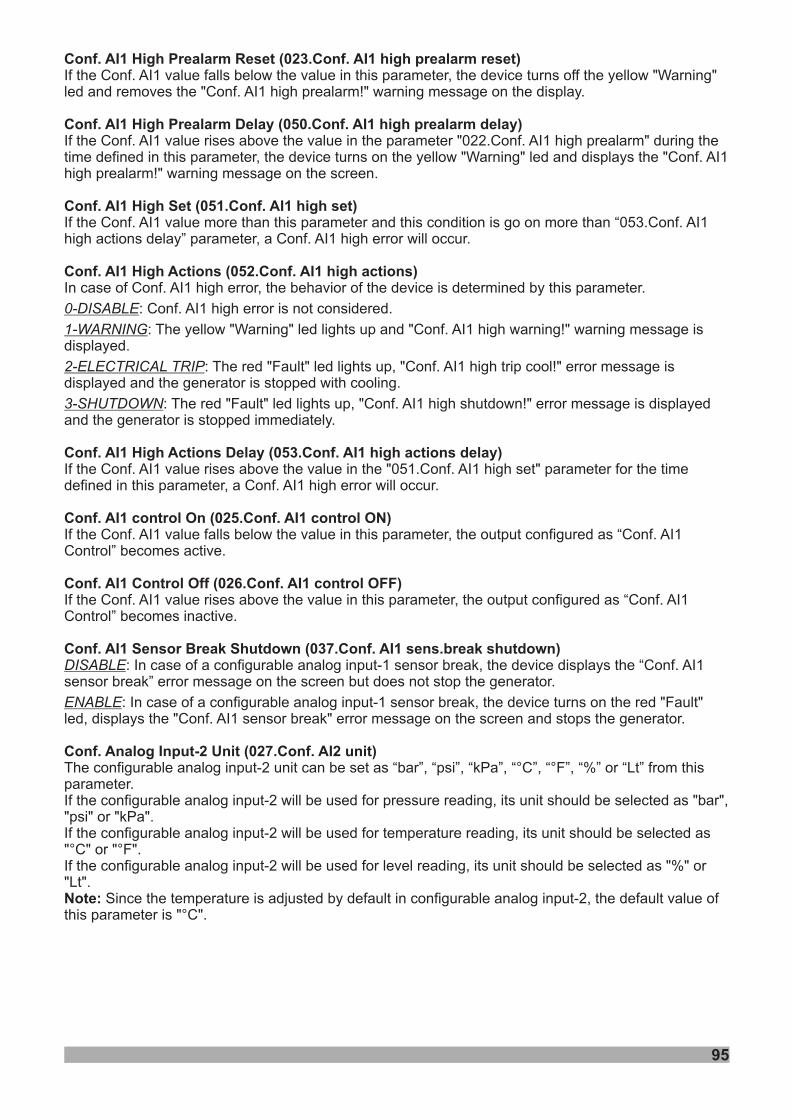
95
Conf. AI1 High Prealarm Reset (023.Conf. AI1 high prealarm reset)
Conf. AI1 High Prealarm Delay (050.Conf. AI1 high prealarm delay)
Conf. AI1 High Set (051.Conf. AI1 high set)
Conf. AI1 High Actions (052.Conf. AI1 high actions)
Conf. AI1 High Actions Delay (053.Conf. AI1 high actions delay)
Conf. AI1 control On (025.Conf. AI1 control ON)
Conf. AI1 Control Off (026.Conf. AI1 control OFF)
Conf. AI1 Sensor Break Shutdown (037.Conf. AI1 sens.break shutdown)
Conf. Analog Input-2 Unit (027.Conf. AI2 unit)
Note:
If the Conf. AI1 value falls below the value in this parameter, the device turns off the yellow "Warning"led and removes the "Conf. AI1 high prealarm!" warning message on the display.
If the Conf. AI1 value rises above the value in the parameter "022.Conf. AI1 high prealarm" during thetime defined in this parameter, the device turns on the yellow "Warning" led and displays the "Conf. AI1high prealarm!" warning message on the screen.
If the Conf. AI1 value more than this parameter and this condition is go on more than “053.Conf. AI1high actions delay” parameter, a Conf. AI1 high error will occur.
In case of Conf. AI1 high error, the behavior of the device is determined by this parameter.
: Conf. AI1 high error is not considered.
: The yellow "Warning" led lights up and "Conf. AI1 high warning!" warning message isdisplayed.
: The red "Fault" led lights up, "Conf. AI1 high trip cool!" error message isdisplayed and the generator is stopped with cooling.
: The red "Fault" led lights up, "Conf. AI1 high shutdown!" error message is displayedand the generator is stopped immediately.
If the Conf. AI1 value rises above the value in the "051.Conf. AI1 high set" parameter for the timedefined in this parameter, a Conf. AI1 high error will occur.
If the Conf. AI1 value falls below the value in this parameter, the output configured as “Conf. AI1Control” becomes active.
If the Conf. AI1 value rises above the value in this parameter, the output configured as “Conf. AI1Control” becomes inactive.
: In case of a configurable analog input-1 sensor break, the device displays the “Conf. AI1sensor break” error message on the screen but does not stop the generator.
: In case of a configurable analog input-1 sensor break, the device turns on the red "Fault"led, displays the "Conf. AI1 sensor break" error message on the screen and stops the generator.
The configurable analog input-2 unit can be set as “bar”, “psi”, “kPa”, “°C”, “°F”, “%” or “Lt” from thisparameter.If the configurable analog input-2 will be used for pressure reading, its unit should be selected as "bar","psi" or "kPa".If the configurable analog input-2 will be used for temperature reading, its unit should be selected as"°C" or "°F".If the configurable analog input-2 will be used for level reading, its unit should be selected as "%" or"Lt".
Since the temperature is adjusted by default in configurable analog input-2, the default value ofthis parameter is "°C".
0-DISABLE
1-WARNING
2-ELECTRICAL TRIP
3-SHUTDOWN
DISABLE
ENABLE
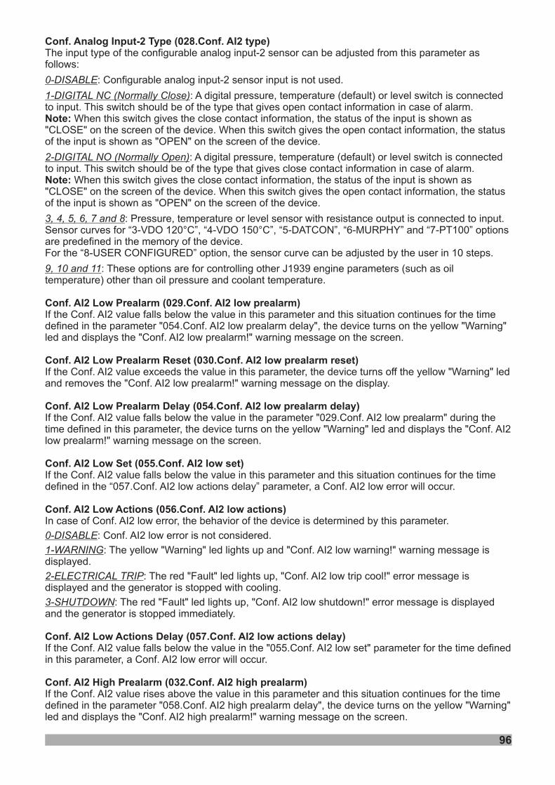
96
Conf. Analog Input-2 Type (028.Conf. AI2 type)
Note:
Note:
Conf. AI2 Low Prealarm (029.Conf. AI2 low prealarm)
Conf. AI2 Low Prealarm Reset (030.Conf. AI2 low prealarm reset)
Conf. AI2 Low Prealarm Delay (054.Conf. AI2 low prealarm delay)
Conf. AI2 Low Set (055.Conf. AI2 low set)
Conf. AI2 Low Actions (056.Conf. AI2 low actions)
Conf. AI2 Low Actions Delay (057.Conf. AI2 low actions delay)
Conf. AI2 High Prealarm (032.Conf. AI2 high prealarm)
The input type of the configurable analog input-2 sensor can be adjusted from this parameter asfollows:
: Configurable analog input-2 sensor input is not used.
: A digital pressure, temperature (default) or level switch is connectedto input. This switch should be of the type that gives open contact information in case of alarm.
When this switch gives the close contact information, the status of the input is shown as"CLOSE" on the screen of the device. When this switch gives the open contact information, the statusof the input is shown as "OPEN" on the screen of the device.
: A digital pressure, temperature (default) or level switch is connectedto input. This switch should be of the type that gives close contact information in case of alarm.
When this switch gives the close contact information, the status of the input is shown as"CLOSE" on the screen of the device. When this switch gives the open contact information, the statusof the input is shown as "OPEN" on the screen of the device.
: Pressure, temperature or level sensor with resistance output is connected to input.Sensor curves for “3-VDO 120°C”, “4-VDO 150°C”, “5-DATCON”, “6-MURPHY” and “7-PT100” optionsare predefined in the memory of the device.For the “8-USER CONFIGURED” option, the sensor curve can be adjusted by the user in 10 steps.
: These options are for controlling other J1939 engine parameters (such as oiltemperature) other than oil pressure and coolant temperature.
If the Conf. AI2 value falls below the value in this parameter and this situation continues for the timedefined in the parameter "054.Conf. AI2 low prealarm delay", the device turns on the yellow "Warning"led and displays the "Conf. AI2 low prealarm!" warning message on the screen.
If the Conf. AI2 value exceeds the value in this parameter, the device turns off the yellow "Warning" ledand removes the "Conf. AI2 low prealarm!" warning message on the display.
If the Conf. AI2 value falls below the value in the parameter "029.Conf. AI2 low prealarm" during thetime defined in this parameter, the device turns on the yellow "Warning" led and displays the "Conf. AI2low prealarm!" warning message on the screen.
If the Conf. AI2 value falls below the value in this parameter and this situation continues for the timedefined in the “057.Conf. AI2 low actions delay” parameter, a Conf. AI2 low error will occur.
In case of Conf. AI2 low error, the behavior of the device is determined by this parameter.
: Conf. AI2 low error is not considered.
: The yellow "Warning" led lights up and "Conf. AI2 low warning!" warning message isdisplayed.
: The red "Fault" led lights up, "Conf. AI2 low trip cool!" error message isdisplayed and the generator is stopped with cooling.
: The red "Fault" led lights up, "Conf. AI2 low shutdown!" error message is displayedand the generator is stopped immediately.
If the Conf. AI2 value falls below the value in the "055.Conf. AI2 low set" parameter for the time definedin this parameter, a Conf. AI2 low error will occur.
If the Conf. AI2 value rises above the value in this parameter and this situation continues for the timedefined in the parameter "058.Conf. AI2 high prealarm delay", the device turns on the yellow "Warning"led and displays the "Conf. AI2 high prealarm!" warning message on the screen.
0-DISABLE
1-DIGITAL NC (Normally Close)
2-DIGITAL NO (Normally Open)
3, 4, 5, 6, 7 and 8
9, 10 and 11
0-DISABLE
1-WARNING
2-ELECTRICAL TRIP
3-SHUTDOWN
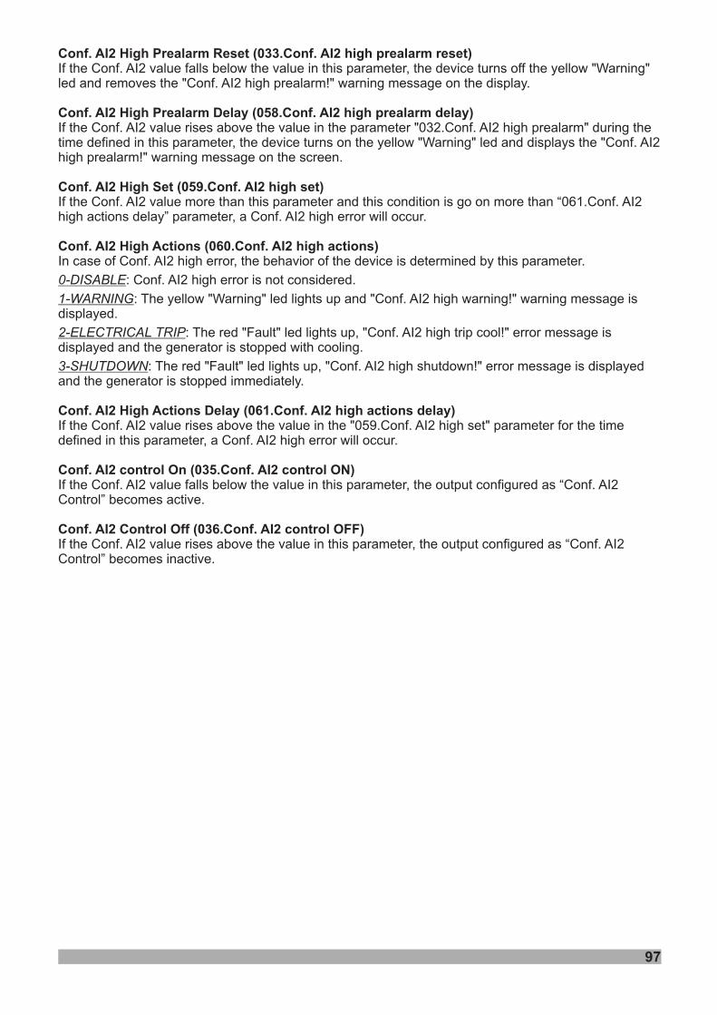
97
Conf. AI2 High Prealarm Reset (033.Conf. AI2 high prealarm reset)
Conf. AI2 High Prealarm Delay (058.Conf. AI2 high prealarm delay)
Conf. AI2 High Set (059.Conf. AI2 high set)
Conf. AI2 High Actions (060.Conf. AI2 high actions)
Conf. AI2 High Actions Delay (061.Conf. AI2 high actions delay)
Conf. AI2 control On (035.Conf. AI2 control ON)
Conf. AI2 Control Off (036.Conf. AI2 control OFF)
If the Conf. AI2 value falls below the value in this parameter, the device turns off the yellow "Warning"led and removes the "Conf. AI2 high prealarm!" warning message on the display.
If the Conf. AI2 value rises above the value in the parameter "032.Conf. AI2 high prealarm" during thetime defined in this parameter, the device turns on the yellow "Warning" led and displays the "Conf. AI2high prealarm!" warning message on the screen.
If the Conf. AI2 value more than this parameter and this condition is go on more than “061.Conf. AI2high actions delay” parameter, a Conf. AI2 high error will occur.
In case of Conf. AI2 high error, the behavior of the device is determined by this parameter.
: Conf. AI2 high error is not considered.
: The yellow "Warning" led lights up and "Conf. AI2 high warning!" warning message isdisplayed.
: The red "Fault" led lights up, "Conf. AI2 high trip cool!" error message isdisplayed and the generator is stopped with cooling.
: The red "Fault" led lights up, "Conf. AI2 high shutdown!" error message is displayedand the generator is stopped immediately.
If the Conf. AI2 value rises above the value in the "059.Conf. AI2 high set" parameter for the timedefined in this parameter, a Conf. AI2 high error will occur.
If the Conf. AI2 value falls below the value in this parameter, the output configured as “Conf. AI2Control” becomes active.
If the Conf. AI2 value rises above the value in this parameter, the output configured as “Conf. AI2Control” becomes inactive.
0-DISABLE
1-WARNING
2-ELECTRICAL TRIP
3-SHUTDOWN
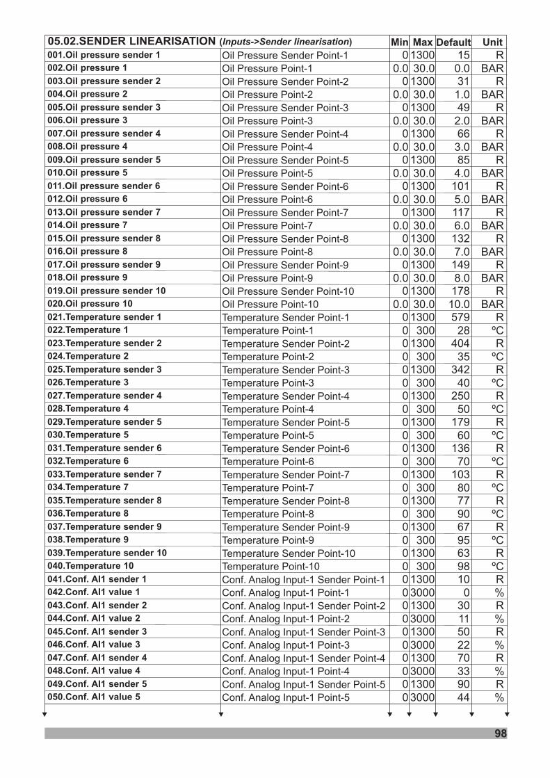
98
Min Default Unit05.02.SENDER LINEARISATION ( )Inputs->Sender linearisation Max15
31
49
66
85
101
117
132
149
178
579
404
342
250
179
136
103
77
67
63
10
30
50
70
90
0
0
0
0
0
0
0
0
0
0
0
0
0
0
0
0
0
0
0
0
0
0
0
0
0
1300
1300
1300
1300
1300
1300
1300
1300
1300
1300
1300
1300
1300
1300
1300
1300
1300
1300
1300
1300
1300
1300
1300
1300
1300
0.0
1.0
2.0
3.0
4.0
5.0
6.0
7.0
8.0
10.0
28
35
40
50
60
70
80
90
95
98
0
11
22
33
44
0.0
0.0
0.0
0.0
0.0
0.0
0.0
0.0
0.0
0.0
0
0
0
0
0
0
0
0
0
0
0
0
0
0
0
BAR
BAR
BAR
BAR
BAR
BAR
BAR
BAR
BAR
BAR
ºC
ºC
ºC
ºC
ºC
ºC
ºC
ºC
ºC
ºC
%
%
%
%
%
R
R
R
R
R
R
R
R
R
R
R
R
R
R
R
R
R
R
R
R
R
R
R
R
R
30.0
30.0
30.0
30.0
30.0
30.0
30.0
30.0
30.0
30.0
300
300
300
300
300
300
300
300
300
300
3000
3000
3000
3000
3000
001.Oil pressure sender 1
003. 2Oil pressure sender
005. 3Oil pressure sender
007. 4Oil pressure sender
009. 5Oil pressure sender
011. 6Oil pressure sender
013. 7Oil pressure sender
015. 8Oil pressure sender
017. 9Oil pressure sender
019. 0Oil pressure sender 1
021.Temperature sender 1
023.Temperature 2sender
025.Temperature 3sender
027.Temperature 4sender
029.Temperature 5sender
031.Temperature 6sender
033.Temperature 7sender
035.Temperature 8sender
037.Temperature 9sender
039.Temperature 0sender 1
041.Conf. AI1 sender 1
043. 2Conf. AI1 sender
045. 3Conf. AI1 sender
047. 4Conf. AI1 sender
049. 5Conf. AI1 sender
002.Oil pressure 1
004. 2Oil pressure
006. 3Oil pressure
008. 4Oil pressure
010. 5Oil pressure
012. 6Oil pressure
014. 7Oil pressure
016. 8Oil pressure
018. 9Oil pressure
020. 0Oil pressure 1
022.Temperature 1
024.Temperature 2
026.Temperature 3
028.Temperature 4
030.Temperature 5
032.Temperature 6
034.Temperature 7
036.Temperature 8
038.Temperature 9
040.Temperature 01
042.Conf. AI1 value 1
044.Conf. AI1 value 2
046.Conf. AI1 value 3
048.Conf. AI1 value 4
050.Conf. AI1 value 5
Oil Pressure Sender Point-1
Oil Pressure Sender Point-2
Oil Pressure Sender Point-3
Oil Pressure Sender Point-4
Oil Pressure Sender Point-5
Oil Pressure Sender Point-6
Oil Pressure Sender Point-7
Oil Pressure Sender Point-8
Oil Pressure Sender Point-9
Oil Pressure Sender Point-10
Temperature Sender Point-1
Temperature Sender Point-2
Temperature Sender Point-3
Temperature Sender Point-4
Temperature Sender Point-5
Temperature Sender Point-6
Temperature Sender Point-7
Temperature Sender Point-8
Temperature Sender Point-9
Temperature Sender Point-10
Oil Pressure Point-1
Oil Pressure Point-2
Oil Pressure Point-3
Oil Pressure Point-4
Oil Pressure Point-5
Oil Pressure Point-6
Oil Pressure Point-7
Oil Pressure Point-8
Oil Pressure Point-9
Oil Pressure Point-10
Temperature Point-1
Temperature Point-2
Temperature Point-3
Temperature Point-4
Temperature Point-5
Temperature Point-6
Temperature Point-7
Temperature Point-8
Temperature Point-9
Temperature Point-10Conf. Analog Input-1 Sender Point-1
Conf. Analog Input-1 Sender Point-2
Conf. Analog Input-1 Sender Point-3
Conf. Analog Input-1 Sender Point-4
Conf. Analog Input-1 Sender Point-5
Conf. Analog Input-1 Point-1
Conf. Analog Input-1 Point-2
Conf. Analog Input-1 Point-3
Conf. Analog Input-1 Point-4
Conf. Analog Input-1 Point-5
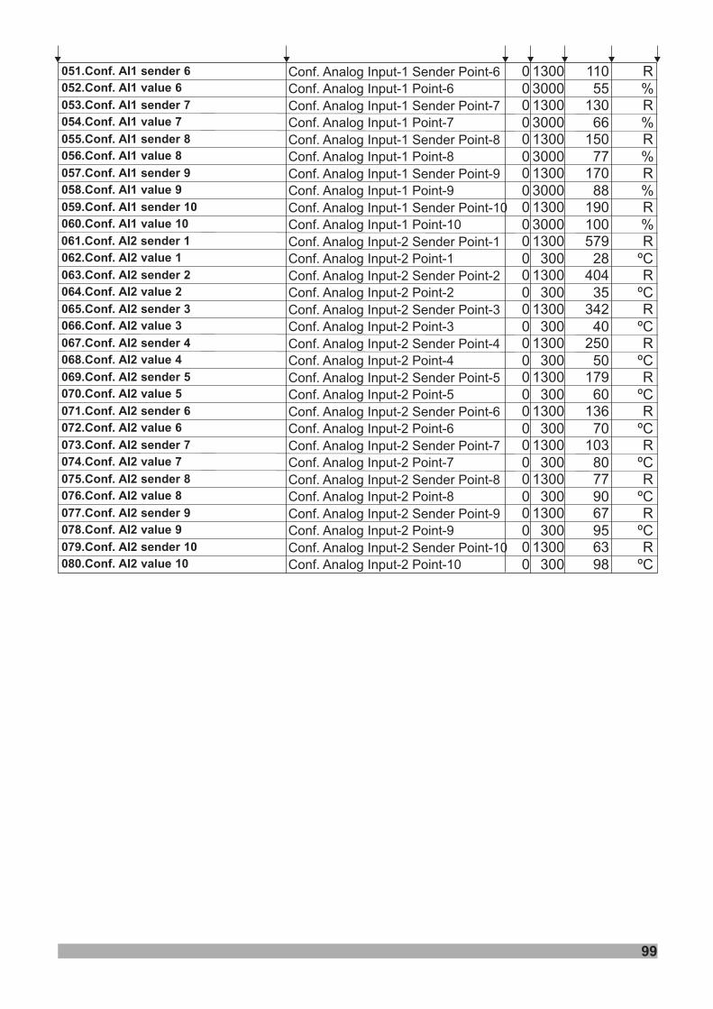
99
110
130
150
170
190
0
0
0
0
0
1300
1300
1300
1300
1300
55
66
77
88
100
0
0
0
0
0
R
R
R
R
R
3000
3000
3000
3000
3000
051.Conf. AI1 sender 6
053.Conf. AI1 sender 7
055.Conf. AI1 sender 8
057.Conf. AI1 sender 9
059.Conf. AI1 sender 10
052.Conf. AI1 value 6
054.Conf. AI1 value 7
056.Conf. AI1 value 8
058.Conf. AI1 value 9
060.Conf. AI1 value 10
579
404
342
250
179
136
103
77
67
63
0
0
0
0
0
0
0
0
0
0
1300
1300
1300
1300
1300
1300
1300
1300
1300
1300
28
35
40
50
60
70
80
90
95
98
0
0
0
0
0
0
0
0
0
0
ºC
%
%
%
%
%
ºC
ºC
ºC
ºC
ºC
ºC
ºC
ºC
ºC
R
R
R
R
R
R
R
R
R
R
300
300
300
300
300
300
300
300
300
300
061.Conf. AI2 sender 1
063. 2Conf. AI2 sender
065. 3Conf. AI2 sender
067. 4Conf. AI2 sender
069. 5Conf. AI2 sender
071. 6Conf. AI2 sender
073. 7Conf. AI2 sender
075. 8Conf. AI2 sender
077. 9Conf. AI2 sender
079. 0Conf. AI2 sender 1
062.Conf. AI2 value 1
064.Conf. AI2 value 2
066.Conf. AI2 value 3
068.Conf. AI2 value 4
070.Conf. AI2 value 5
072.Conf. AI2 value 6
074.Conf. AI2 value 7
076.Conf. AI2 value 8
078.Conf. AI2 value 9
080.Conf. AI2 value 01
Conf. Analog Input-1 Sender Point-6
Conf. Analog Input-1 Sender Point-7
Conf. Analog Input-1 Sender Point-8
Conf. Analog Input-1 Sender Point-9
Conf. Analog Input-1 Sender Point-10
Conf. Analog Input-1 Point-6
Conf. Analog Input-1 Point-7
Conf. Analog Input-1 Point-8
Conf. Analog Input-1 Point-9
Conf. Analog Input-1 Point-10
Conf. Analog Input-2 Sender Point-1
Conf. Analog Input-2 Sender Point-2
Conf. Analog Input-2 Sender Point-3
Conf. Analog Input-2 Sender Point-4
Conf. Analog Input-2 Sender Point-5
Conf. Analog Input-2 Sender Point-6
Conf. Analog Input-2 Sender Point-7
Conf. Analog Input-2 Sender Point-8
Conf. Analog Input-2 Sender Point-9
Conf. Analog Input-2 Sender Point-10
Conf. Analog Input-2 Point-1
Conf. Analog Input-2 Point-2
Conf. Analog Input-2 Point-3
Conf. Analog Input-2 Point-4
Conf. Analog Input-2 Point-5
Conf. Analog Input-2 Point-6
Conf. Analog Input-2 Point-7
Conf. Analog Input-2 Point-8
Conf. Analog Input-2 Point-9
Conf. Analog Input-2 Point-10

100
Min Default Unit05.03.CONF. INPUT-X ( )Inputs->Conf. input-x Max
1
2
20(dis)
10
4
20
0
2500 Sec
0
2
0
28 25
0
001.Dis,user conf.or list
002.Polarity
003.Indication
004.Activation
005.Select from list
006.Active delay
0- Disable1- User Configured2- Select From List0- Normally Open (Close To Activate)1- Normally Close (Open To Activate)
If User Configured0- Status1- Warning Non-Latching2- Warning Latching3- Electrical Trip4- Shutdown
If User Configured0- Active From Starting1- Active From Safety On2- Always Active
If Select From List0-Remote Start On Load1-Remote Start Off Load2-Reserved3-Maintenance Alarm Reset4-Simulate Horn Reset Button5-Simulate Alarm Reset Button6-Simulate Auto Button7-Simulate Test Button8-Simulate Manual Button9-Simulate Start Button10-Simulate Stop Button11-Generator Closed Auxiliary12-Generator Load Inhibit13-Reserved14-Neutral contactor feedback15-Auto Restore Inhibit16-Auto Start Inhibit17-Panel Lock18-Scheduled Runs(Exercise) Inhibited19-Top priority20-Generator Breaker Close21-Generator Breaker Open22-Remote Inhibit23-Being Found Alive24-Unconditional Synchron25-Emergency Stop (for only input-1)25-Remote Speed Up (for only input-2,3,6,7,8,9,10,11,12)25-Low Oil Pressure (for only input-4)25-High Temperature (for only input-5)26-Low Oil Level (for only input-4)26-Emergency Stop No-Latching (foronly input-1)26-Remote Speed Down (for onlyinput-2,3,6,7,8,9,10,11,12)27-Remote Voltage Up (for only input-2,3,6,7,8,9,10,11,12)28-Remote Voltage Down (for onlyinput-2,3,6,7,8,9,10,11,12)
Input active delay
Note-1 : x = 1(input ), 2( ), 3( ), 4( ), 5( ), 6input input input input (input ), 7(input ), 8(input ),9(input ), 10(input ), 11(input ), or 12(input )
dis = disableNote-2 :
-1 -2 -3 -4 -5 -6 -7 -8-9 -10 -11 -12
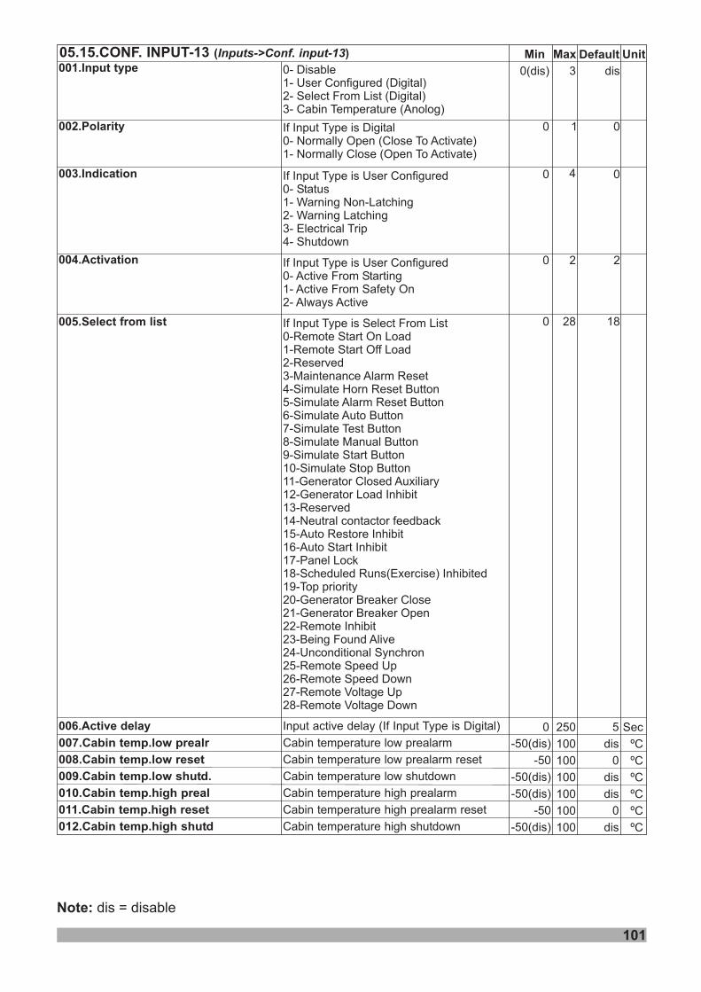
101
Note: dis = disable
Min Default Unit05.15.CONF. INPUT-13 ( )Inputs->Conf. input-13 Max
30(dis)
10
4
20
0
2500 Sec
0
001.Input type
002.Polarity
003.Indication
004.Activation
005.Select from list
006.Active delay
0- Disable1- User Configured (Digital)2- Select From List (Digital)3- Cabin Temperature (Anolog)
If Input Type is Digital0- Normally Open (Close To Activate)1- Normally Close (Open To Activate)
If Input Type is User Configured0- Status1- Warning Non-Latching2- Warning Latching3- Electrical Trip4- Shutdown
If Input Type is User Configured0- Active From Starting1- Active From Safety On2- Always Active
Input active delay (If Input Type is Digital)
If Input Type is Select From List0-Remote Start On Load1-Remote Start Off Load2-Reserved3-Maintenance Alarm Reset4-Simulate Horn Reset Button5-Simulate Alarm Reset Button6-Simulate Auto Button7-Simulate Test Button8-Simulate Manual Button9-Simulate Start Button10-Simulate Stop Button11-Generator Closed Auxiliary12-Generator Load Inhibit13-Reserved14-Neutral contactor feedback15-Auto Restore Inhibit16-Auto Start Inhibit17-Panel Lock18-Scheduled Runs(Exercise) Inhibited19-Top priority20-Generator Breaker Close21-Generator Breaker Open22-Remote Inhibit23-Being Found Alive24-Unconditional Synchron25-Remote Speed Up26-Remote Speed Down27-Remote Voltage Up28-Remote Voltage Down
dis
007.Cabin temp.low prealr
008.Cabin temp.low reset
009.Cabin temp.low shutd.
010.Cabin temp.high preal
011.Cabin temp.high reset
012.Cabin temp.high shutd
5
Cabin temperature low prealarm
Cabin temperature low prealarm reset
Cabin temperature low shutdown
Cabin temperature high prealarm
Cabin temperature high prealarm reset
Cabin temperature high shutdown
100
100
100
100
100
100
ºC
ºC
ºC
ºC
ºC
ºC
dis
0
dis
dis
0
dis
-50(dis)
-50
-50(dis)
-50(dis)
-50
-50(dis)
0
0
2
28 18
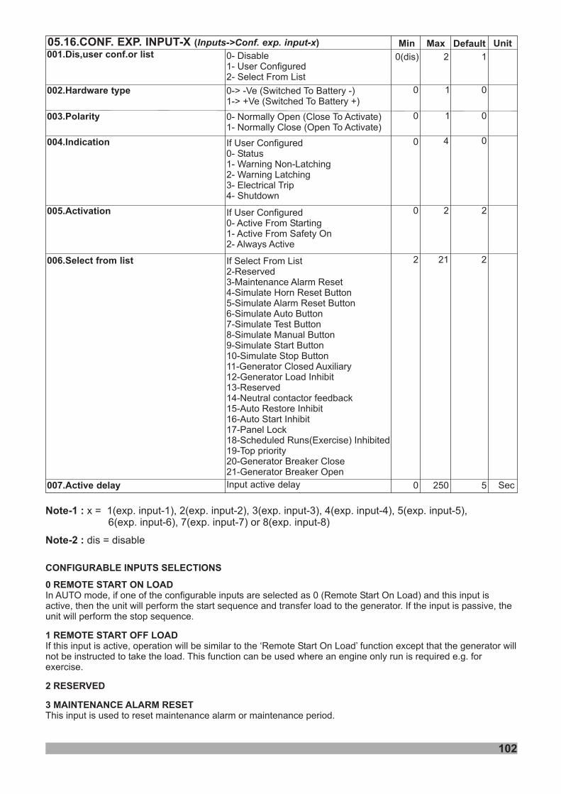
102
Note-1 : x = 1(exp. input ), 2( ), 3( ), 4( ), 5( ),6( )
exp. input exp. input exp. input exp. inputexp. input , 7(exp. input ) or 8(exp. input )
dis = disableNote-2 :
-1 -2 -3 -4 -5-6 -7 -8
Min Default UnitMax
0
2
20(dis)
10
4
20
2
2500 Sec
0
1
0
21 2
5
0- Disable1- User Configured2- Select From List
0- Normally Open (Close To Activate)1- Normally Close (Open To Activate)
If User Configured0- Status1- Warning Non-Latching2- Warning Latching3- Electrical Trip4- Shutdown
If User Configured0- Active From Starting1- Active From Safety On2- Always Active
If Select From List2-Reserved3-Maintenance Alarm Reset4-Simulate Horn Reset Button5-Simulate Alarm Reset Button6-Simulate Auto Button7-Simulate Test Button8-Simulate Manual Button9-Simulate Start Button10-Simulate Stop Button11-Generator Closed Auxiliary12-Generator Load Inhibit13-Reserved14-Neutral contactor feedback15-Auto Restore Inhibit16-Auto Start Inhibit17-Panel Lock18-Scheduled Runs(Exercise) Inhibited19-Top priority20-Generator Breaker Close21-Generator Breaker Open
Input active delay
0100- ( To )1- ( To )
> -Ve Switched Battery -> +Ve Switched Battery +
05.16.CONF. EXP. INPUT-X ( )Inputs->Conf. exp. input-x
001.Dis,user conf.or list
003.Polarity
004.Indication
005.Activation
006.Select from list
007.Active delay
002.Hardware type
CONFIGURABLE INPUTS SELECTIONS
0 REMOTE START ON LOAD
2 RESERVED
3 MAINTENANCE ALARM RESET
In AUTO mode, if one of the configurable inputs are selected as 0 (Remote Start ) and this input isactive, then the unit will perform the start sequence and transfer load to the generator. If the input is passive, theunit will perform the stop sequence.
This input is used to reset maintenance alarm or maintenance period.
On Load
If this input is active, operation will be similar to the ‘Remote Start On Load’ function except that the generator willnot be instructed to take the load. This function can be used where an engine only run is required e.g. forexercise.
1 REMOTE START OFF LOAD
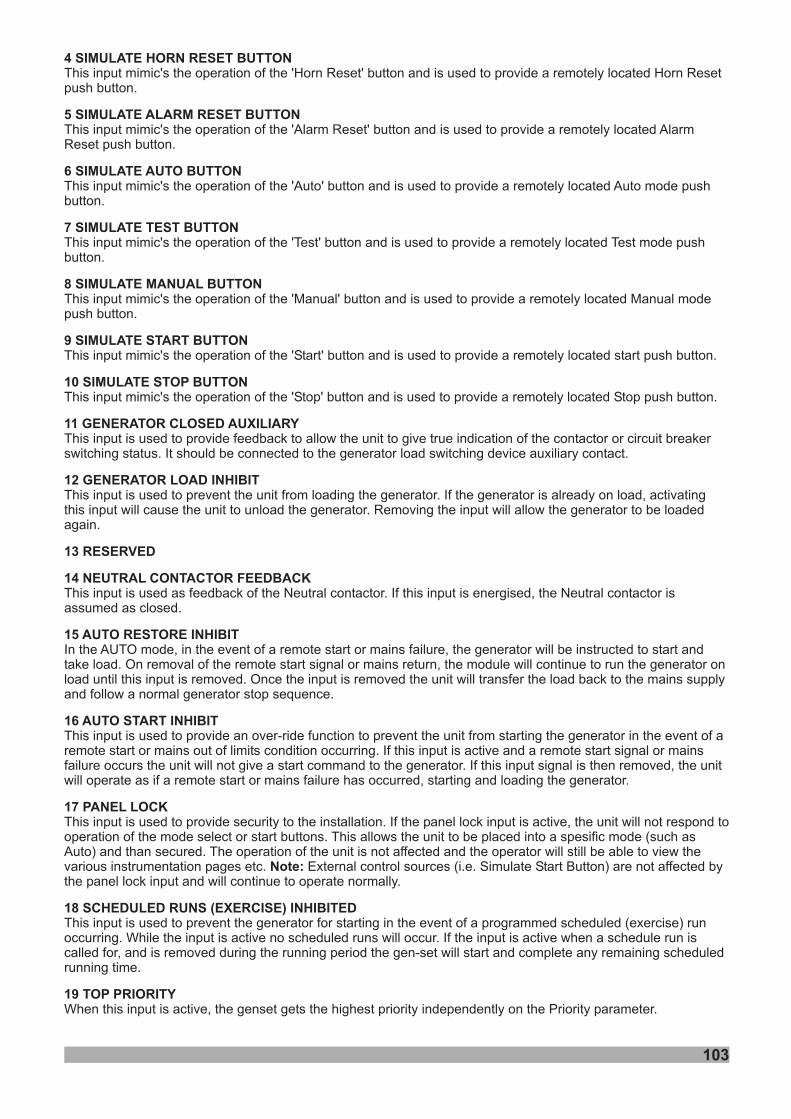
4 SIMULATE HORN RESET BUTTON
5 SIMULATE ALARM RESET BUTTON
6 SIMULATE AUTO BUTTON
7 SIMULATE TEST BUTTON
8 SIMULATE MANUAL BUTTON
9 SIMULATE START BUTTON
10 SIMULATE STOP BUTTON
11 GENERATOR CLOSED AUXILIARY
This input mimic's the operation of the 'Horn Reset' button and is used to provide a remotely located Horn Resetpush button.
This input mimic's the operation of the 'Alarm Reset' button and is used to provide a remotely located AlarmReset push button.
This input mimic's the operation of the 'Auto' button and is used to provide a remotely located Auto mode pushbutton.
This input mimic's the operation of the 'Test' button and is used to provide a remotely located Test mode pushbutton.
This input mimic's the operation of the 'Manual' button and is used to provide a remotely located Manual modepush button.
This input mimic's the operation of the 'Start' button and is used to provide a remotely located start push button.
This input mimic's the operation of the 'Stop' button and is used to provide a remotely located Stop push button.
This input is used to provide feedback to allow the unit to give true indication of the contactor or circuit breakerswitching status. It should be connected to the generator load switching device auxiliary contact.
12 GENERATOR LOAD INHIBIT
13 RESERVED
This input is used to prevent the unit from loading the generator. If the generator is already on load, activatingthis input will cause the unit to unload the generator. Removing the input will allow the generator to be loadedagain.
14 NEUTRAL CONTACTOR FEEDBACK
15 AUTO RESTORE INHIBIT
16 AUTO START INHIBIT
17 PANEL LOCK
Note:
18 SCHEDULED RUNS (EXERCISE) INHIBITED
19 TOP PRIORITY
This input is used as feedback of the Neutral contactor. If this input is energised, the Neutral contactor isassumed as closed.
In the AUTO mode, in the event of a remote start or mains failure, the generator will be instructed to start andtake load. On removal of the remote start signal or mains return, the module will continue to run the generator onload until this input is removed. Once the input is removed the unit will transfer the load back to the mains supplyand follow a normal generator stop sequence.
This input is used to provide an over-ride function to prevent the unit from starting the generator in the event of aremote start or mains out of limits condition occurring. If this input is active and a remote start signal or mainsfailure occurs the unit will not give a start command to the generator. If this input signal is then removed, the unitwill operate as if a remote start or mains failure has occurred, starting and loading the generator.
This input is used to provide security to the installation. If the panel lock input is active, the unit will not respond tooperation of the mode select or start buttons. This allows the unit to be placed into a spesific mode (such asAuto) and than secured. The operation of the unit is not affected and the operator will still be able to view thevarious instrumentation pages etc. External control sources (i.e. Simulate Start Button) are not affected bythe panel lock input and will continue to operate normally.
This input is used to prevent the generator for starting in the event of a programmed scheduled (exercise) runoccurring. While the input is active no scheduled runs will occur. If the input is active when a schedule run iscalled for, and is removed during the running period the gen-set will start and complete any remaining scheduledrunning time.
this input is active, the genset gets the highest priority independently on the Priority parameter.When
103
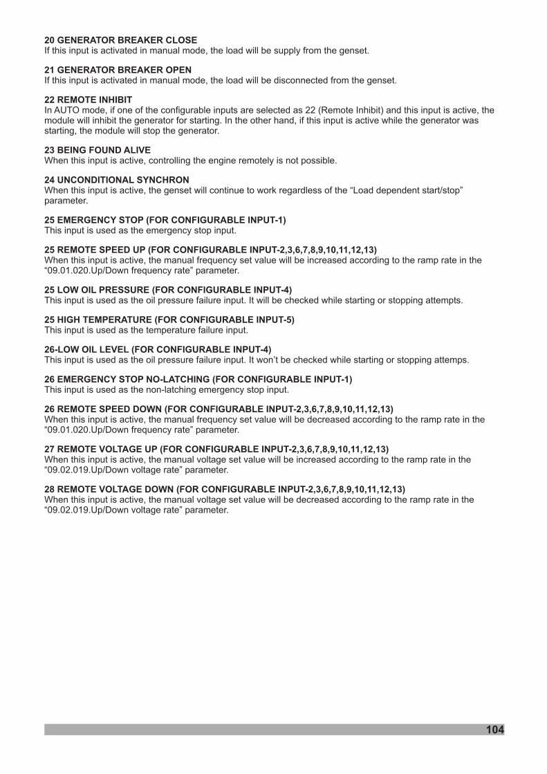
104
20 GENERATOR BREAKER CLOSE
21 GENERATOR BREAKER OPEN
22 REMOTE INHIBIT
23
24 UNCONDITIONAL SYNCHRON
25 EMERGENCY STOP (FOR CONFIGURABLE INPUT-1)
25 REMOTE SPEED UP (FOR CONFIGURABLE INPUT-2,3,6,7,8,9,10,11,12,13)
25 LOW OIL PRESSURE (FOR CONFIGURABLE INPUT-4)
25 HIGH TEMPERATURE (FOR CONFIGURABLE INPUT-5)
(FOR CONFIGURABLE INPUT-4)
26 EMERGENCY STOP NO-LATCHING (FOR CONFIGURABLE INPUT-1)
26 REMOTE SPEED DOWN (FOR CONFIGURABLE INPUT-2,3,6,7,8,9,10,11,12,13)
27 REMOTE VOLTAGE UP (FOR CONFIGURABLE INPUT-2,3,6,7,8,9,10,11,12,13)
28 REMOTE VOLTAGE DOWN (FOR CONFIGURABLE INPUT-2,3,6,7,8,9,10,11,12,13)
If this input is activated in manual mode, the load will be supply from the genset.
If this input is activated in manual mode, the load will be disconnected from the genset.
When this input is active, controlling the engine remotely is not possible.
When
09.01.020.Up/Down frequency rate
09.01.020.Up/Down frequency rate
09.02.019.Up/Down voltage rate
09.02.019.Up/Down voltage rate
In AUTO mode, if one of the configurable inputs are selected as 22 (Remote Inhibit) and this input is active, themodule will inhibit the generator for starting. In the other hand, if this input is active while the generator wasstarting, the module will stop the generator.
this input is active, the genset will continue to work regardless of the “Load dependent start/stop”parameter.
This input is used as the emergency stop input.
When this input is active, the manual frequency set value will be increased according to the ramp rate in the“ ” parameter.
This input is used as the oil pressure failure input. It will be checked while starting or stopping attempts.
This input is used as the temperature failure input.
This input is used as the oil pressure failure input. It won’t be checked while starting or stopping attemps.
This input is used as the non-latching emergency stop input.
When this input is active, the manual frequency set value will be decreased according to the ramp rate in the“ ” parameter.
When this input is active, the manual voltage set value will be increased according to the ramp rate in the“ ” parameter.
When this input is active, the manual voltage set value will be decreased according to the ramp rate in the“ ” parameter.
BEING FOUND ALIVE
26-LOW OIL LEVEL

105
4.2.5 Outputs
Min Default Unit06.01.CONF. OUTPUT-1 ( )Outputs->Conf. output-1 Max
010
1670 49
001.Polarity
002.Function
0- Normally Open (Close To Activate)1- Normally Close (Open To Activate)
0-NOT USED1-AIR FLAP CONTROL2-ALARM RESET3-AUDIBLE ALARM4-AUTO START INHIBIT
6-BATTERY HIGH VOLTAGE7-BATTERY LOW VOLTAGE8-CALLING FOR SCHEDULED RUN(EXERCISE)9-CAN ECU POWER10-CAN ECU STOP11-CHARGE ALTERNATOR FAILURE12-COMMON ALARM13-COMMON ELECTRICAL TRIP ALARM14-COMMON SHUTDOWN ALARM15-COMMON WARNING ALARM16-COOLING FAN AFTER START17-COOLING FAN AFTER STOP18-COOLANT TEMPERATURE HIGH PRE-ALARM19-COOLANT TEMPERATURE HIGH ALARM20-COOLING DOWN TIMER IN PROGRESS21-CRANK RELAY ENERGISED22-DELAYED ALARMS ACTIVE23-DIGITAL INPUT-1 ALARM24-DIGITAL INPUT-2 ALARM25-DIGITAL INPUT-3 ALARM26-DIGITAL INPUT-4 ALARM27-DIGITAL INPUT-5 ALARM28-DIGITAL INPUT-6 ALARM29-DIGITAL INPUT-7 ALARM30-DIGITAL INPUT-8 ALARM31-DIGITAL INPUT-9 ALARM32-DIGITAL INPUT-10 ALARM33-DIGITAL INPUT-11 ALARM34-DIGITAL INPUT-12 ALARM35-DIGITAL INPUT-13 ALARM36-EXPANSION INPUT-1 ALARM37-EXPANSION INPUT-2 ALARM38-EXPANSION INPUT-3 ALARM39-EXPANSION INPUT-4 ALARM40-EXPANSION INPUT-5 ALARM41-EXPANSION INPUT-6 ALARM42-EXPANSION INPUT-7 ALARM43-EXPANSION INPUT-8 ALARM44-EARTH FAULT45-EMERGENCY STOP46-FAIL TO START ALARM47-FAIL TO STOP ALARM48-CONF. AI1 CONTROL49-FUEL RELAY ENERGISED50-GAS ENGINE IGNITION OUTPUT51-GENERATOR AT REST52-GENERATOR AVAILABLE53-GENERATOR CLOSED AUXILIARY54-GENERATOR FAILED TO CLOSE55-GENERATOR FAILED TO OPEN56-GENERATOR HIGH FREQUENCY PRE-ALARM57-GENERATOR HIGH FREQUENCY ALARM58-GENERATOR HIGH VOLTAGE PRE-ALARM59-GENERATOR HIGH VOLTAGE ALARM60-GENERATOR LOAD INHIBIT61-GENERATOR LOW FREQUENCY PRE-ALARM62-GENERATOR LOW FREQUENCY ALARM63-GENERATOR LOW VOLTAGE PRE-ALARM64-GENERATOR LOW VOLTAGE ALARM65-GENERATOR STOPPING66-GENERATOR OPEN BREAKER67-HORN OUTPUT LATCHED68-HORN OUTPUT PULSED69-LAMP TEST70-CONF. AI2 CONTROL71-LOSS OF MAGNETIC PICK-UP SPEED SIGNAL72-LOW TEMPERATURE73-MAINTENANCE DUE ALARM74-75-76-77-78-79-80-81-82-83- FAIL84-NO LOADING COMMAND85-OIL PRESSURE LOW PRE-ALARM86-OIL PRESSURE LOW ALARM87-CONF.AI1.HIGH PRE A88-CONF.AI1.HIGH ALARM89-OVER CURRENT PRE-ALARM90-OVER CURRENT91-OVER POWER PRE-ALARM92-OVER POWER ALARM93-OVERSPEED PRE-ALARM94-OVERSPEED SHUTDOWN95-PANEL LOCK96-PRE-HEAT(during preheat timer)97-PRE-HEAT(until end of cranking)98-PRE-HEAT(until end of warming)99-PRE-HEAT(until end safety on)
5-RESERVED
RESERVEDRESERVEDRESERVEDRESERVEDRESERVEDRESERVEDNEUTRAL CONTACTOR CONTROLRESERVEDRESERVEDNEUTRAL CONTACTOR
- LARM
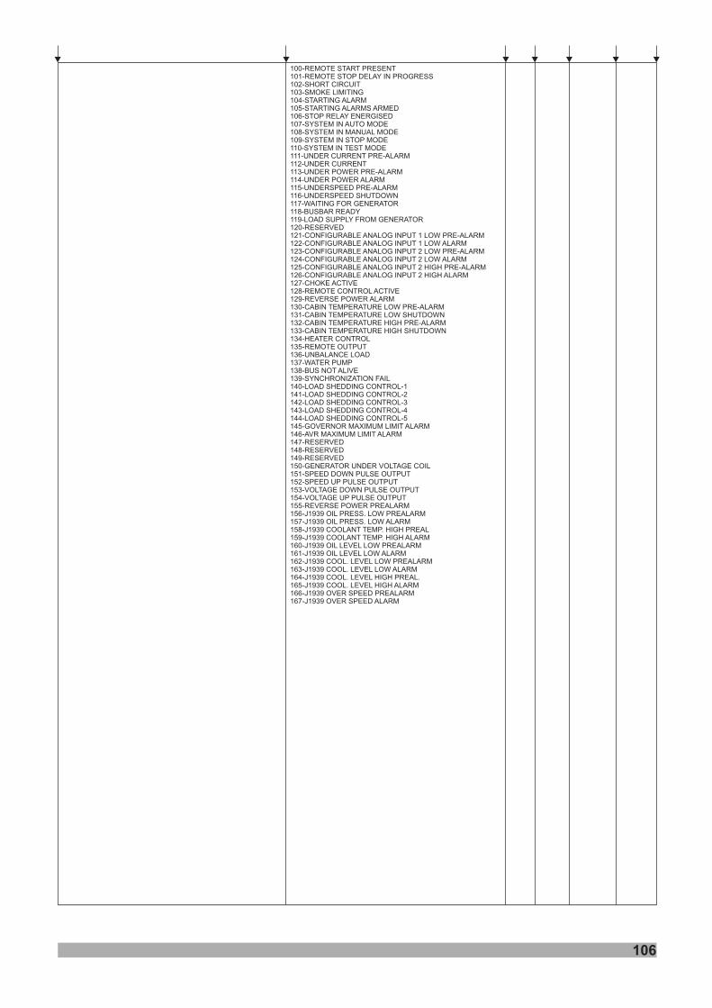
106
100-REMOTE START PRESENT101-REMOTE STOP DELAY IN PROGRESS102-SHORT CIRCUIT103-SMOKE LIMITING104-STARTING ALARM105-STARTING ALARMS ARMED106-STOP RELAY ENERGISED107-SYSTEM IN AUTO MODE108-SYSTEM IN MANUAL MODE109-SYSTEM IN STOP MODE110-SYSTEM IN TEST MODE111-UNDER CURRENT PRE-ALARM112-UNDER CURRENT113-UNDER POWER PRE-ALARM114-UNDER POWER ALARM115-UNDERSPEED PRE-ALARM116-UNDERSPEED SHUTDOWN117-WAITING FOR GENERATOR118-119-LOAD SUPPLY FROM GENERATOR120-121-CONFIGURABLE ANALOG INPUT 1 LOW PRE-ALARM122 CONFIGURABLE ANALOG INPUT 1 LOW ALARM123-CONFIGURABLE ANALOG INPUT 2 LOW PRE-ALARM124-CONFIGURABLE ANALOG INPUT 2 LOW ALARM125-CONFIGURABLE ANALOG INPUT 2 HIGH PRE-ALARM126-CONFIGURABLE ANALOG INPUT 2 HIGH ALARM127-CHOKE ACTIVE128-REMOTE CONTROL ACTIVE129-REVERSE POWER ALARM130-CABIN TEMPERATURE LOW PRE-ALARM131-CABIN TEMPERATURE LOW SHUTDOWN132-CABIN TEMPERATURE HIGH PRE-ALARM133-CABIN TEMPERATURE HIGH SHUTDOWN134-HEATER CONTROL135-REMOTE OUTPUT136-UNBALANCE LOAD137-WATER PUMP138-BUS NOT ALIVE139-SYNCHRONIZATION FAIL140-LOAD SHEDDING CONTROL-1141-LOAD SHEDDING CONTROL-2142-LOAD SHEDDING CONTROL-3143-LOAD SHEDDING CONTROL-4144-LOAD SHEDDING CONTROL-5145-GOVERNOR MAXIMUM LIMIT ALARM146-AVR MAXIMUM LIMIT ALARM147-148-149-150-GENERATOR UNDER VOLTAGE COIL151-SPEED DOWN PULSE OUTPUT152-SPEED UP PULSE OUTPUT153-VOLTAGE DOWN PULSE OUTPUT154-VOLTAGE UP PULSE OUTPUT155-REVERSE POWER PREALARM156-J1939 OIL PRESS. LOW PREALARM157-J1939 OIL PRESS. LOW ALARM158-J1939 COOLANT TEMP. HIGH PREAL159-J1939 COOLANT TEMP. HIGH ALARM160-J1939 OIL LEVEL LOW PREALARM161-J1939 OIL LEVEL LOW ALARM162-J1939 COOL. LEVEL LOW PREALARM163-J1939 COOL. LEVEL LOW ALARM164-J1939 COOL. LEVEL HIGH PREAL.165-J1939 COOL. LEVEL HIGH ALARM166-J1939 OVER SPEED PREALARM167-J1939 OVER SPEED ALARM
BUSBAR READY
RESERVED
-
RESERVEDRESERVEDRESERVED
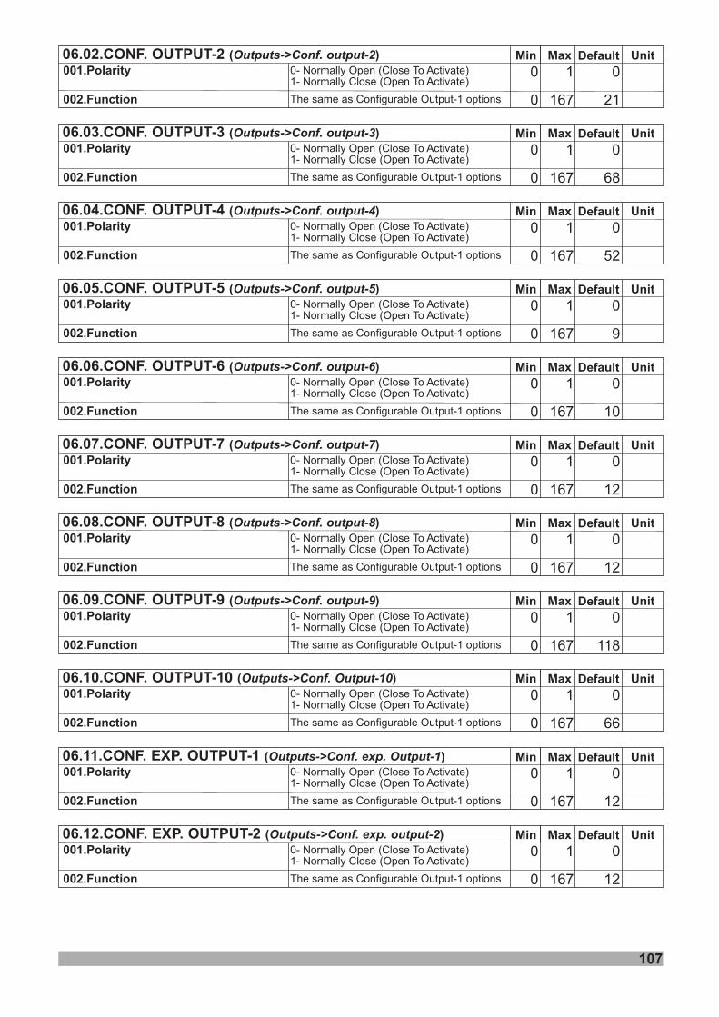
107
Min
Min
Min
Min
Min
Min
Min
Min
Min
Min
Default
Default
Default
Default
Default
Default
Default
Default
Default
Default
Unit
Unit
Unit
Unit
Unit
Unit
Unit
Unit
Unit
Unit
Max
Max
Max
Max
Max
Max
Max
Max
Max
Max
0
0
0
0
0
0
0
0
0
0
1
1
1
1
1
1
1
1
1
1
0
0
0
0
0
0
0
0
0
0
167
167
167
167
167
167
167
167
167
167
0
0
0
0
0
0
0
0
0
0
21
68
52
9
10
12
12
118
12
12
06.02.CONF. OUTPUT-2 ( )Outputs->Conf. output-2
06.03.CONF. OUTPUT-3 ( )Outputs->Conf. output-3
06.04.CONF. OUTPUT-4 ( )Outputs->Conf. output-4
06.05.CONF. OUTPUT-5 ( )Outputs->Conf. output-5
06.06.CONF. OUTPUT-6 ( )Outputs->Conf. output-6
06.07.CONF. OUTPUT-7 ( )Outputs->Conf. output-7
06.08.CONF. OUTPUT-8 ( )Outputs->Conf. output-8
06.09.CONF. OUTPUT-9 ( )Outputs->Conf. output-9
06.11.CONF. EXP. OUTPUT-1 ( )Outputs->Conf. exp. Output-1
06.12.CONF. EXP. OUTPUT-2 ( )Outputs->Conf. exp. output-2
001.Polarity
001.Polarity
001.Polarity
001.Polarity
001.Polarity
001.Polarity
001.Polarity
001.Polarity
001.Polarity
001.Polarity
002.Function
002.Function
002.Function
002.Function
002.Function
002.Function
002.Function
002.Function
002.Function
002.Function
The same as Configurable Output-1 options
0- Normally Open (Close To Activate)1- Normally Close (Open To Activate)
The same as Configurable Output-1 options
0- Normally Open (Close To Activate)1- Normally Close (Open To Activate)
The same as Configurable Output-1 options
0- Normally Open (Close To Activate)1- Normally Close (Open To Activate)
The same as Configurable Output-1 options
0- Normally Open (Close To Activate)1- Normally Close (Open To Activate)
The same as Configurable Output-1 options
0- Normally Open (Close To Activate)1- Normally Close (Open To Activate)
The same as Configurable Output-1 options
0- Normally Open (Close To Activate)1- Normally Close (Open To Activate)
The same as Configurable Output-1 options
0- Normally Open (Close To Activate)1- Normally Close (Open To Activate)
The same as Configurable Output-1 options
0- Normally Open (Close To Activate)1- Normally Close (Open To Activate)
The same as Configurable Output-1 options
0- Normally Open (Close To Activate)1- Normally Close (Open To Activate)
The same as Configurable Output-1 options
0- Normally Open (Close To Activate)1- Normally Close (Open To Activate)
Min Default UnitMax
010
1670 66
06.10.CONF. OUTPUT-10 ( )Outputs->Conf. Output-10
001.Polarity
002.Function The same as Configurable Output-1 options
0- Normally Open (Close To Activate)1- Normally Close (Open To Activate)
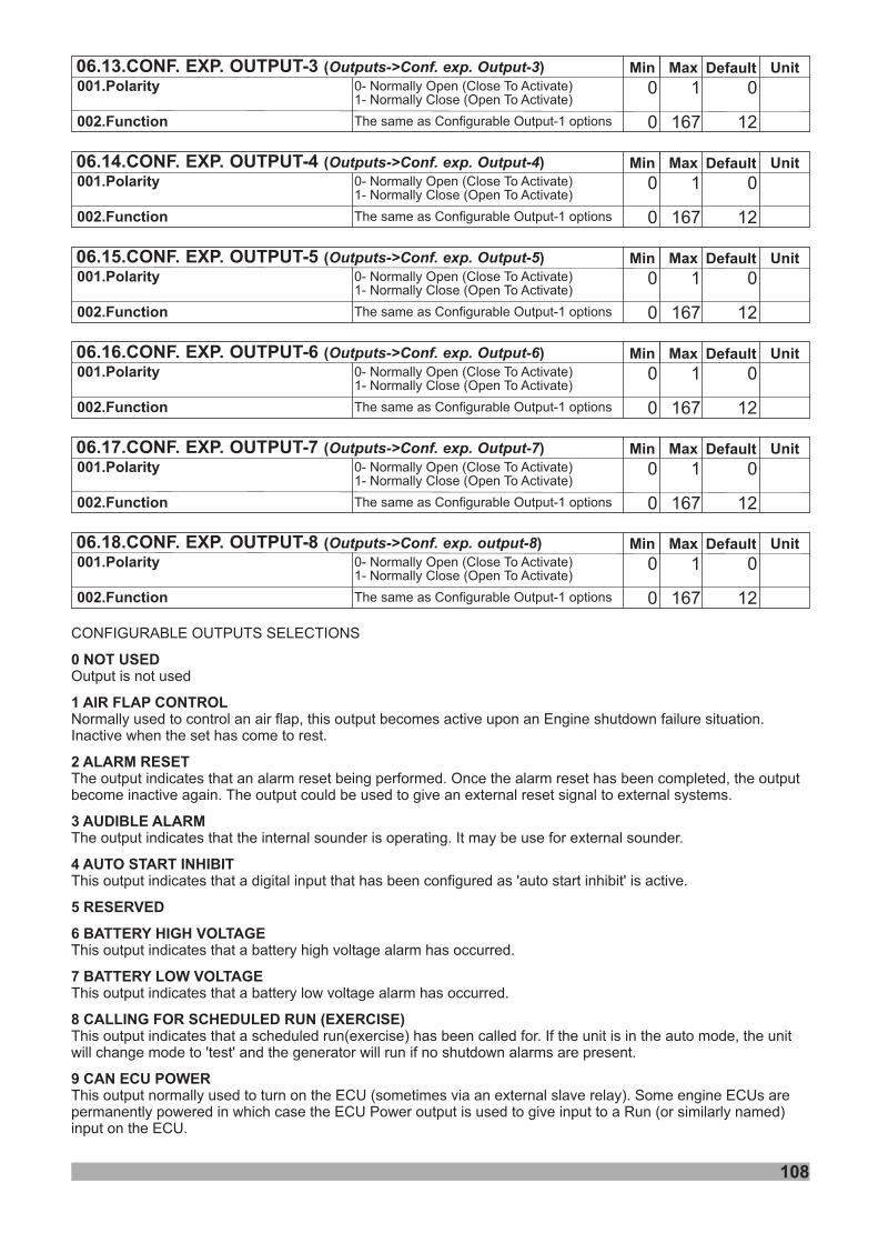
108
Min Default UnitMax
010
1670 12
06.13.CONF. EXP. OUTPUT-3 ( )Outputs->Conf. exp. Output-3
001.Polarity
002.Function The same as Configurable Output-1 options
0- Normally Open (Close To Activate)1- Normally Close (Open To Activate)
Min
Min
Min
Min
Default
Default
Default
Default
Unit
Unit
Unit
Unit
Max
Max
Max
Max
0
0
0
0
1
1
1
1
0
0
0
0
167
167
167
167
0
0
0
0
12
12
12
12
06.14.CONF. EXP. OUTPUT-4 ( )Outputs->Conf. exp. Output-4
06.15.CONF. EXP. OUTPUT-5 ( )Outputs->Conf. exp. Output-5
06.16.CONF. EXP. OUTPUT-6 ( )Outputs->Conf. exp. Output-6
06.17.CONF. EXP. OUTPUT-7 ( )Outputs->Conf. exp. Output-7
001.Polarity
001.Polarity
001.Polarity
001.Polarity
002.Function
002.Function
002.Function
002.Function
The same as Configurable Output-1 options
The same as Configurable Output-1 options
The same as Configurable Output-1 options
The same as Configurable Output-1 options
0- Normally Open (Close To Activate)1- Normally Close (Open To Activate)
0- Normally Open (Close To Activate)1- Normally Close (Open To Activate)
0- Normally Open (Close To Activate)1- Normally Close (Open To Activate)
0- Normally Open (Close To Activate)1- Normally Close (Open To Activate)
Min Default UnitMax
010
1670 12
06.18.CONF. EXP. OUTPUT-8 ( )Outputs->Conf. exp. output-8
001.Polarity
002.Function The same as Configurable Output-1 options
0- Normally Open (Close To Activate)1- Normally Close (Open To Activate)
CONFIGURABLE OUTPUTS SELECTIONS
Output is not used
The output indicates that the internal sounder is operating. It may be use for external sounder.
This output indicates that a digital input that has been configured as 'auto start inhibit' is active.
This output indicates that a battery high voltage alarm has occurred.
This output indicates that a battery low voltage alarm has occurred.
This output indicates that a scheduled run(exercise) has been called for. If the unit is in the auto mode, the unitwill change mode to 'test' and the generator will run if no shutdown alarms are present.
0 NOT USED
3 AUDIBLE ALARM
4 AUTO START INHIBIT
5 RESERVED
6 BATTERY HIGH VOLTAGE
7 BATTERY LOW VOLTAGE
8 CALLING FOR SCHEDULED RUN (EXERCISE)
1 AIR FLAP CONTROL
2 ALARM RESET
9 ECU POWER
Normally used to control an air flap, this output becomes active upon an Engine shutdown failure situation.Inactive when the set has come to rest.
The output indicates that an alarm reset being performed. Once the alarm reset has been completed, the outputbecome inactive again. The output could be used to give an external reset signal to external systems.
This output normally used to turn on the ECU (sometimes via an external slave relay). Some engine ECUs arepermanently powered in which case the ECU Power output is used to give input to a Run (or similarly named)input on the ECU.
CAN
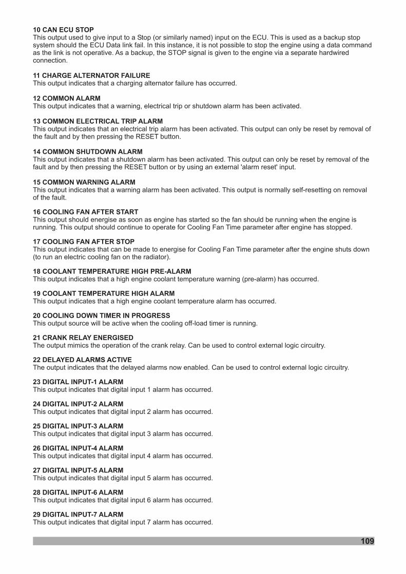
109
10 CAN ECU STOP
11 CHARGE ALTERNATOR FAILURE
12 COMMON ALARM
13 COMMON ELECTRICAL TRIP ALARM
14 COMMON SHUTDOWN ALARM
15 COMMON WARNING ALARM
16 COOLING FAN AFTER START
17 COOLING FAN AFTER STOP
18 COOLANT TEMPERATURE HIGH PRE-ALARM
19 COOLANT TEMPERATURE HIGH ALARM
20 COOLING DOWN TIMER IN PROGRESS
21 CRANK RELAY ENERGISED
22 DELAYED ALARMS ACTIVE
23 DIGITAL INPUT-1 ALARM
ALARM
ALARM
ALARM
ALARM
ALARM
29 DIGITAL INPUT-7 ALARM
This output used to give input to a Stop (or similarly named) input on the ECU. This is used as a backup stopsystem should the ECU Data link fail. In this instance, it is not possible to stop the engine using a data commandas the link is not operative. As a backup, the STOP signal is given to the engine via a separate hardwiredconnection.
This output indicates that a charging alternator failure has occurred.
This output indicates that a warning, electrical trip or shutdown alarm has been activated.
This output indicates that an electrical trip alarm has been activated. This output can only be reset by removal ofthe fault and by then pressing the RESET button.
This output indicates that a shutdown alarm has been activated. This output can only be reset by removal of thefault and by then pressing the RESET button or by using an external 'alarm reset' input.
This output indicates that a warning alarm has been activated. This output is normally self-resetting on removalof the fault.
This output should energise as soon as engine has started so the fan should be running when the engine isrunning. This output should continue to operate for Cooling Fan Time parameter after engine has stopped.
This output indicates that can be made to energise for Cooling Fan Time parameter after the engine shuts down(to run an electric cooling fan on the radiator).
This output indicates that a high engine coolant temperature warning (pre-alarm) has occurred.
This output indicates that a high engine coolant temperature alarm has occurred.
This output source will be active when the cooling off-load timer is running.
The output mimics the operation of the crank relay. Can be used to control external logic circuitry.
The output indicates that the delayed alarms now enabled. Can be used to control external logic circuitry.
This output indicates that digital input 1 alarm has occurred.
alarm has occurred.
alarm has occurred.
alarm has occurred.
alarm has occurred.
alarm has occurred.
This output indicates that digital input 7 alarm has occurred.
24 DIGITAL INPUT-2
25 DIGITAL INPUT-3
26 DIGITAL INPUT-4
27 DIGITAL INPUT-5
28 DIGITAL INPUT-6
This output indicates that digital input 2
This output indicates that digital input 3
This output indicates that digital input 4
This output indicates that digital input 5
This output indicates that digital input 6
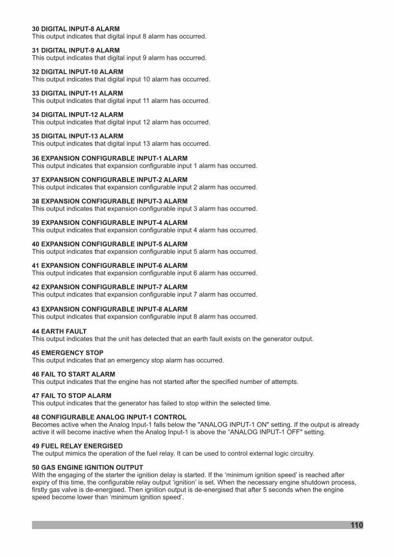
110
30 DIGITAL INPUT-8 ALARM
31 DIGITAL INPUT-9 ALARM
32 DIGITAL INPUT-10 ALARM
33 DIGITAL INPUT-11 ALARM
34 DIGITAL INPUT-12 ALARM
35 DIGITAL INPUT-13 ALARM
36 EXPANSION CONFIGURABLE INPUT-1 ALARM
37 EXPANSION CONFIGURABLE INPUT-2 ALARM
38 EXPANSION CONFIGURABLE INPUT-3 ALARM
39 EXPANSION CONFIGURABLE INPUT-4 ALARM
40 EXPANSION CONFIGURABLE INPUT-5 ALARM
41 EXPANSION CONFIGURABLE INPUT-6 ALARM
42 EXPANSION CONFIGURABLE INPUT-7 ALARM
This output indicates that digital input 8 alarm has occurred.
This output indicates that digital input 9 alarm has occurred.
This output indicates that digital input 10 alarm has occurred.
This output indicates that digital input 11 alarm has occurred.
This output indicates that digital input 12 alarm has occurred.
This output indicates that digital input 13 alarm has occurred.
This output indicates that expansion configurable input 1 alarm has occurred.
This output indicates that expansion configurable input 2 alarm has occurred.
This output indicates that expansion configurable input 3 alarm has occurred.
This output indicates that expansion configurable input 4 alarm has occurred.
This output indicates that expansion configurable input 5 alarm has occurred.
This output indicates that expansion configurable input 6 alarm has occurred.
This output indicates that expansion configurable input 7 alarm has occurred.
43 EXPANSION CONFIGURABLE INPUT-8 ALARM
44 EARTH FAULT
45 EMERGENCY STOP
46 FAIL TO START ALARM
47 FAIL TO STOP ALARM
48 CONFIGURABLE ANALOG INPUT-1 CONTROL
49 FUEL RELAY ENERGISED
50 GAS ENGINE IGNITION OUTPUT
This output indicates that expansion configurable input 8 alarm has occurred.
This output indicates that an emergency stop alarm has occurred.
This output indicates that the engine has not started after the specified number of attempts.
This output indicates that the generator has failed to stop within the selected time.
Becomes active when the Analog Input-1 falls below the "ANALOG INPUT-1 ON" setting. If the output is alreadyactive it will become inactive when the Analog Input-1 is above the “ANALOG INPUT-1 OFF" setting.
The output mimics the operation of the fuel relay. It can be used to control external logic circuitry.
With the engaging of the starter the ignition delay is started. If the ‘minimum ignition speed’ is reached afterexpiry of this time, the configurable relay output ‘ignition’ is set. When the necessary engine shutdown process,firstly gas valve is de-energised. Then ignition output is de-energised that after 5 seconds when the enginespeed become lower than ‘minimum ignition speed’.
This output indicates that the unit has detected that an earth fault exists on the generator output.
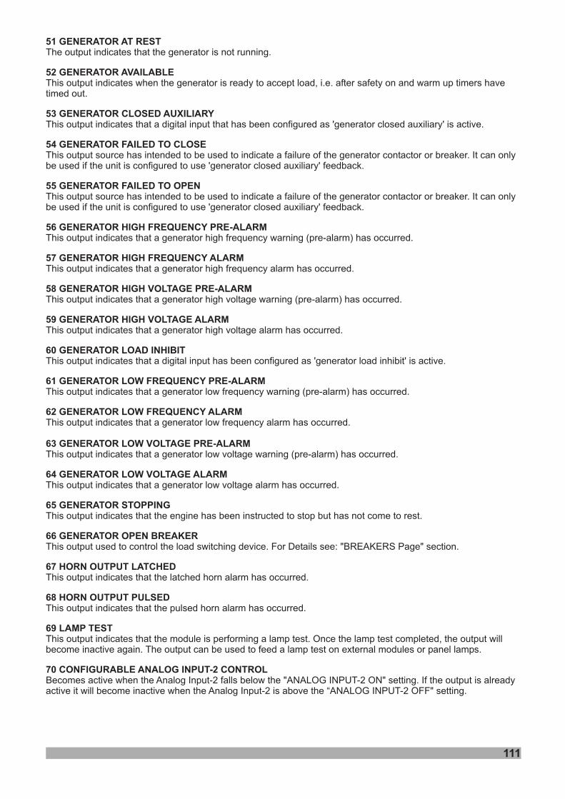
111
51 GENERATOR AT REST
52 GENERATOR AVAILABLE
53 GENERATOR CLOSED AUXILIARY
54 GENERATOR FAILED TO CLOSE
55 GENERATOR FAILED TO OPEN
56 GENERATOR HIGH FREQUENCY PRE-ALARM
57 GENERATOR HIGH FREQUENCY ALARM
58 GENERATOR HIGH VOLTAGE PRE-ALARM
59 GENERATOR HIGH VOLTAGE ALARM
60 GENERATOR LOAD INHIBIT
61 GENERATOR LOW FREQUENCY PRE-ALARM
62 GENERATOR LOW FREQUENCY ALARM
63 GENERATOR LOW VOLTAGE PRE-ALARM
64 GENERATOR LOW VOLTAGE ALARM
65 GENERATOR STOPPING
67 HORN OUTPUT LATCHED
68 HORN OUTPUT PULSED
69 LAMP TEST
70 CONFIGURABLE ANALOG INPUT-2 CONTROL
The output indicates that the generator is not running.
This output indicates when the generator is ready to accept load, i.e. after safety on and warm up timers havetimed out.
This output indicates that a digital input that has been configured as 'generator closed auxiliary' is active.
This output source has intended to be used to indicate a failure of the generator contactor or breaker. It can onlybe used if the unit is configured to use 'generator closed auxiliary' feedback.
This output source has intended to be used to indicate a failure of the generator contactor or breaker. It can onlybe used if the unit is configured to use 'generator closed auxiliary' feedback.
This output indicates that a generator high frequency warning (pre-alarm) has occurred.
This output indicates that a generator high frequency alarm has occurred.
This output indicates that a generator high voltage warning (pre-alarm) has occurred.
This output indicates that a generator high voltage alarm has occurred.
This output indicates that a digital input has been configured as 'generator load inhibit' is active.
This output indicates that a generator low frequency warning (pre-alarm) has occurred.
This output indicates that a generator low frequency alarm has occurred.
This output indicates that a generator low voltage warning (pre-alarm) has occurred.
This output indicates that a generator low voltage alarm has occurred.
This output indicates that the engine has been instructed to stop but has not come to rest.
This output used to control the load switching device. For Details see: "BREAKERS Page" section.
This output indicates that the latched horn alarm has occurred.
This output indicates that the pulsed horn alarm has occurred.
This output indicates that the module is performing a lamp test. Once the lamp test completed, the output willbecome inactive again. The output can be used to feed a lamp test on external modules or panel lamps.
Becomes active when the Analog Input-2 falls below the "ANALOG INPUT-2 ON" setting. If the output is alreadyactive it will become inactive when the Analog Input-2 is above the “ANALOG INPUT-2 OFF" setting.
66 GENERATOR OPEN BREAKER
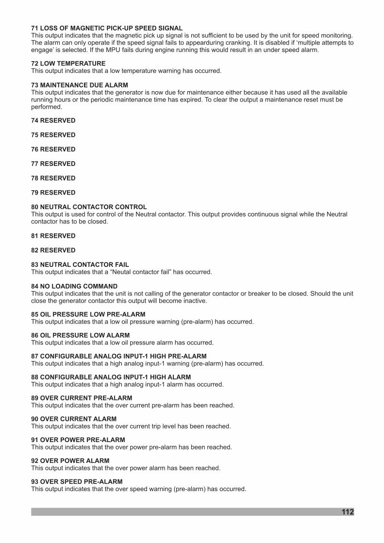
112
71 LOSS OF MAGNETIC PICK-UP SPEED SIGNAL
73 MAINTENANCE DUE ALARM
74 RESERVED
75 RESERVED
76 RESERVED
77 RESERVED
78 RESERVED
79 RESERVED
80 NEUTRAL CONTACTOR CONTROL
81 RESERVED
82 RESERVED
83 NEUTRAL CONTACTOR FAIL
84 NO LOADING COMMAND
85 OIL PRESSURE LOW PRE-ALARM
86 OIL PRESSURE LOW ALARM
87 CONFIGURABLE ANALOG INPUT-1 HIGH PRE-ALARM
88 CONFIGURABLE ANALOG INPUT-1 HIGH ALARM
89 OVER CURRENT PRE-ALARM
90 OVER CURRENT ALARM
91 OVER POWER PRE-ALARM
92 OVER POWER ALARM
93 OVER SPEED PRE-ALARM
This output indicates that the magnetic pick up signal is not sufficient to be used by the unit for speed monitoring.The alarm can only operate if the speed signal fails to appearduring cranking. It is disabled if ‘multiple attempts toengage’ is selected. If the MPU fails during engine running this would result in an under speed alarm.
This output indicates that a low temperature warning has occurred.
This output indicates that the generator is now due for maintenance either because it has used all the availablerunning hours or the periodic maintenance time has expired. To clear the output a maintenance reset must beperformed.
This output is used for control of the Neutral contactor. This output provides continuous signal while the Neutralcontactor has to be closed.
This output indicates that a “Neutal contactor fail” has occurred.
This output indicates that the unit is not calling of the generator contactor or breaker to be closed. Should the unitclose the generator contactor this output will become inactive.
This output indicates that a low oil pressure warning (pre-alarm) has occurred.
This output indicates that a low oil pressure alarm has occurred.
This output indicates that a high analog input-1 warning (pre-alarm) has occurred.
This output indicates that a high analog input-1 alarm has occurred.
This output indicates that the over current pre-alarm has been reached.
This output indicates that the over current trip level has been reached.
This output indicates that the over power pre-alarm has been reached.
This output indicates that the over power alarm has been reached.
This output indicates that the over speed warning (pre-alarm) has occurred.
72 LOW TEMPERATURE
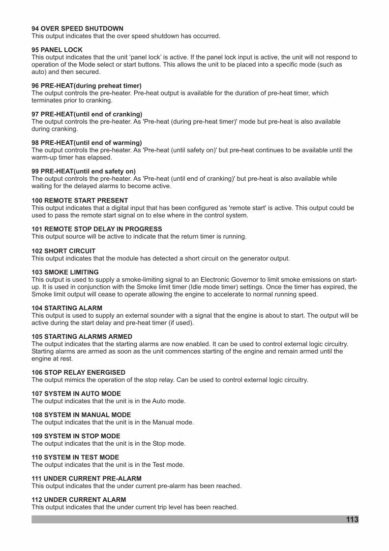
94 OVER SPEED SHUTDOWN
95 PANEL LOCK
96 PRE-HEAT(during preheat timer)
97 PRE-HEAT(until end of cranking)
98 PRE-HEAT(until end of warming)
99 PRE-HEAT(until end safety on)
100 REMOTE START PRESENT
101 REMOTE STOP DELAY IN PROGRESS
This output indicates that the over speed shutdown has occurred.
This output indicates that the unit ‘panel lock’ is active. If the panel lock input is active, the unit will not respond tooperation of the Mode select or start buttons. This allows the unit to be placed into a specific mode (such asauto) and then secured.
The output controls the pre-heater. Pre-heat output is available for the duration of pre-heat timer, whichterminates prior to cranking.
The output controls the pre-heater. As 'Pre-heat (during pre-heat timer)' mode but pre-heat is also availableduring cranking.
The output controls the pre-heater. As 'Pre-heat (until safety on)' but pre-heat continues to be available until thewarm-up timer has elapsed.
The output controls the pre-heater. As 'Pre-heat (until end of cranking)' but pre-heat is also available whilewaiting for the delayed alarms to become active.
This output indicates that a digital input that has been configured as 'remote start' is active. This output could beused to pass the remote start signal on to else where in the control system.
This output source will be active to indicate that the return timer is running.
102 SHORT CIRCUIT
104 STARTING ALARM
105 STARTING ALARMS ARMED
106 STOP RELAY ENERGISED
107 SYSTEM IN AUTO MODE
108 SYSTEM IN MANUAL MODE
109 SYSTEM IN STOP MODE
110 SYSTEM IN TEST MODE
111 UNDER CURRENT PRE-ALARM
112 UNDER CURRENT ALARM
This output indicates that the module has detected a short circuit on the generator output.
This output is used to supply a smoke-limiting signal to an Electronic Governor to limit smoke emissions on start-up. It is used in conjunction with the Smoke limit timer (Idle mode timer) settings. Once the timer has expired, theSmoke limit output will cease to operate allowing the engine to accelerate to normal running speed.
This output is used to supply an external sounder with a signal that the engine is about to start. The output will beactive during the start delay and pre-heat timer (if used).
The output indicates that the starting alarms are now enabled. It can be used to control external logic circuitry.Starting alarms are armed as soon as the unit commences starting of the engine and remain armed until theengine at rest.
The output mimics the operation of the stop relay. Can be used to control external logic circuitry.
The output indicates that the unit is in the Auto mode.
The output indicates that the unit is in the Manual mode.
The output indicates that the unit is in the Stop mode.
The output indicates that the unit is in the Test mode.
This output indicates that the under current pre-alarm has been reached.
This output indicates that the under current trip level has been reached.
103 SMOKE LIMITING
113
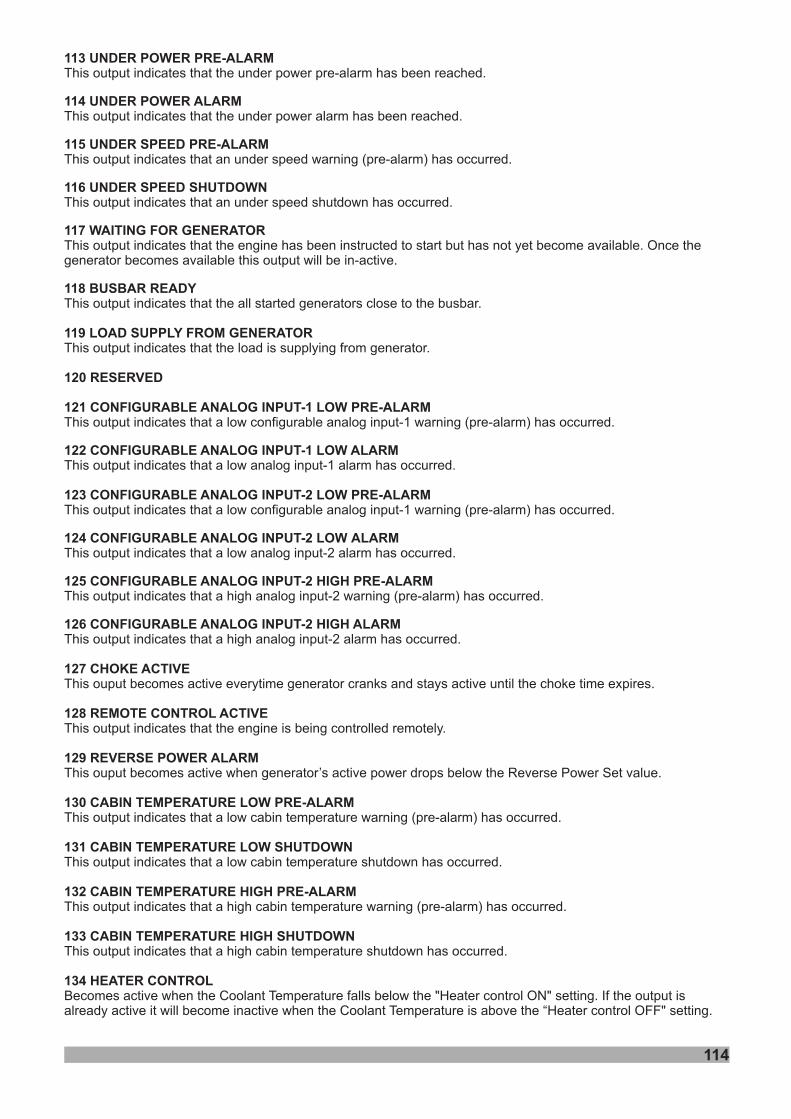
113 UNDER POWER PRE-ALARM
114 UNDER POWER
115 UNDER SPEED PRE-ALARM
116 UNDER SPEED SHUTDOWN
11 WAITING FOR GENERATOR
118 BUSBAR READY
119 LOAD SUPPLY FROM GENERATOR
120 RESERVED
This output indicates that the under power pre-alarm has been reached.
This output indicates that the under power alarm has been reached.
This output indicates that an under speed warning (pre-alarm) has occurred.
This output indicates that an under speed shutdown has occurred.
This output indicates that the engine has been instructed to start but has not yet become available. Once thegenerator becomes available this output will be in-active.
This output indicates that the all started generators close to the busbar.
This output indicates that the load is supplying from generator.
7
ALARM
121 CONFIGURABLE ANALOG INPUT-1 LOW PRE-ALARM
122 CONFIGURABLE ANALOG INPUT-1 LOW ALARM
123 CONFIGURABLE ANALOG INPUT-2 LOW PRE-ALARM
1 CONFIGURABLE ANALOG INPUT-2 LOW ALARM
125 CONFIGURABLE ANALOG INPUT-2 HIGH PRE-ALARM
126 CONFIGURABLE ANALOG INPUT-2 HIGH ALARM
128 REMOTE CONTROL ACTIVE
129 REVERSE POWER ALARM
130 CABIN TEMPERATURE LOW PRE-ALARM
131 CABIN TEMPERATURE LOW SHUTDOWN
132 CABIN TEMPERATURE HIGH PRE-ALARM
133 CABIN TEMPERATURE HIGH SHUTDOWN
134 HEATER CONTROL
This output indicates that a low configurable analog input-1 warning (pre-alarm) has occurred.
This output indicates that a low analog input-1 alarm has occurred.
This output indicates that a low configurable analog input-1 warning (pre-alarm) has occurred.
This output indicates that a low analog input-2 alarm has occurred.
This output indicates that a high analog input-2 warning (pre-alarm) has occurred.
This output indicates that a high analog input-2 alarm has occurred.
This output indicates that the engine is being controlled remotely.
This output indicates that a low cabin temperature warning (pre-alarm) has occurred.
This output indicates that a low cabin temperature shutdown has occurred.
This output indicates that a high cabin temperature warning (pre-alarm) has occurred.
This output indicates that a high cabin temperature shutdown has occurred.
Becomes active when the Coolant Temperature falls below the "Heater control ON" setting. If the output isalready active it will become inactive when the Coolant Temperature is above the “Heater control OFF" setting.
24
127 CHOKE ACTIVEThis ouput becomes active everytime generator cranks and stays active until the choke time expires.
This ouput becomes active when generator’s active power drops below the Reverse Power Set value.
114
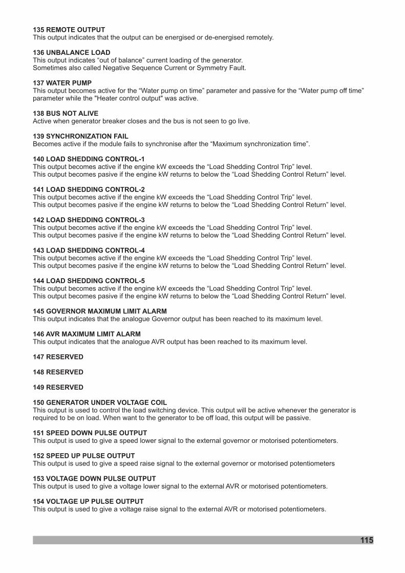
135 REMOTE OUTPUT
136 UNBALANCE LOAD
137 WATER PUMP
153 VOLTAGE DOWN PULSE OUTPUT
154 VOLTAGE UP PULSE OUTPUT
This output indicates that the output can be energised or de-energised remotely.
This output indicates “out of balance” current loading of the generator.Sometimes also called Negative Sequence Current or Symmetry Fault.
This output becomes active for the “Water pump on time” parameter and passive for the “Water pump off time”parameter while the "Heater control output" was active.
This output bThis output b
This output bThis output b
This output bThis output b
This output bThis output b
This output bThis output b
This output is used to control the load switching device. This output will be active whenever the generator isrequired to be on load. When want to the generator to be off load, this output will be passive.
This output is used to give a speed lower signal to the external governor or motorised potentiometers.
This output is used to give a speed raise signal to the external governor or motorised potentiometers
This output is used to give a voltage lower signal to the external AVR or motorised potentiometers.
This output is used to give a voltage raise signal to the external AVR or motorised potentiometers.
138 BUS NOT ALIVE
139 SYNCHRONIZATION FAIL
140 LOAD SHEDDING CONTROL-1
141 LOAD SHEDDING CONTROL-2
142 LOAD SHEDDING CONTROL-3
143 LOAD SHEDDING CONTROL-4
144 LOAD SHEDDING CONTROL-5
145 GOVERNOR MAXIMUM LIMIT ALARM
146 AVR MAXIMUM LIMIT ALARM
147 RESERVED
148 RESERVED
149 RESERVED
150 GENERATOR UNDER VOLTAGE COIL
151 SPEED DOWN PULSE OUTPUT
152 SPEED UP PULSE OUTPUT
Active when generator breaker closes and the bus is not seen to go live.
Becomes active if the module fails to synchronise after the “Maximum synchronization time”.
ecomes active if the engine kW exceeds the “Load Shedding Control Trip” level.ecomes pasive if the engine kW returns to below the “Load Shedding Control Return” level.
ecomes active if the engine kW exceeds the “Load Shedding Control Trip” level.ecomes pasive if the engine kW returns to below the “Load Shedding Control Return” level.
ecomes active if the engine kW exceeds the “Load Shedding Control Trip” level.ecomes pasive if the engine kW returns to below the “Load Shedding Control Return” level.
ecomes active if the engine kW exceeds the “Load Shedding Control Trip” level.ecomes pasive if the engine kW returns to below the “Load Shedding Control Return” level.
ecomes active if the engine kW exceeds the “Load Shedding Control Trip” level.ecomes pasive if the engine kW returns to below the “Load Shedding Control Return” level.
This output indicates that the analogue Governor output has been reached to its maximum level.
This output indicates that the analogue AVR output has been reached to its maximum level.
115
116
155 REVERSE POWER PREALARM
156 J1939 OIL PRESS. LOW PREALARM
157 J1939 OIL PRESS. LOW ALARM
158 J1939 COOLANT TEMP. HIGH PREAL
159 J1939 COOLANT TEMP. HIGH ALARM
160 J1939 OIL LEVEL LOW PREALARM
161 J1939 OIL LEVEL LOW ALARM
162 J1939 COOL. LEVEL LOW PREALARM
163 J1939 COOL. LEVEL LOW ALARM
164 J1939 COOL. LEVEL HIGH PREAL.
165 J1939 COOL. LEVEL HIGH ALARM
166 J1939 OVER SPEED PREALARM
167 J1939 OVER SPEED ALARM
This output indicates that a generator reverse power warning (pre-alarm) has occurred.
This output indicates that a J1939 oil pressure low warning (pre-alarm) has occurred.
This output indicates that a J1939 oil pressure low alarm has occurred.
This output indicates that a J1939 coolant temperature high warning (pre-alarm) has occurred.
This output indicates that a J1939 coolant temperature high alarm has occurred.
This output indicates that a J1939 oil level low warning (pre-alarm) has occurred.
This output indicates that a J1939 oil level low alarm has occurred.
This output indicates that a J1939 coolant level low warning (pre-alarm) has occurred.
This output indicates that a J1939 coolant level low alarm has occurred.
This output indicates that a J1939 coolant level high warning (pre-alarm) has occurred.
This output indicates that a J1939 coolant level high alarm has occurred.
This output indicates that a J1939 over speed warning (pre-alarm) has occurred.
This output indicates that a J1939 over speed alarm has occurred.
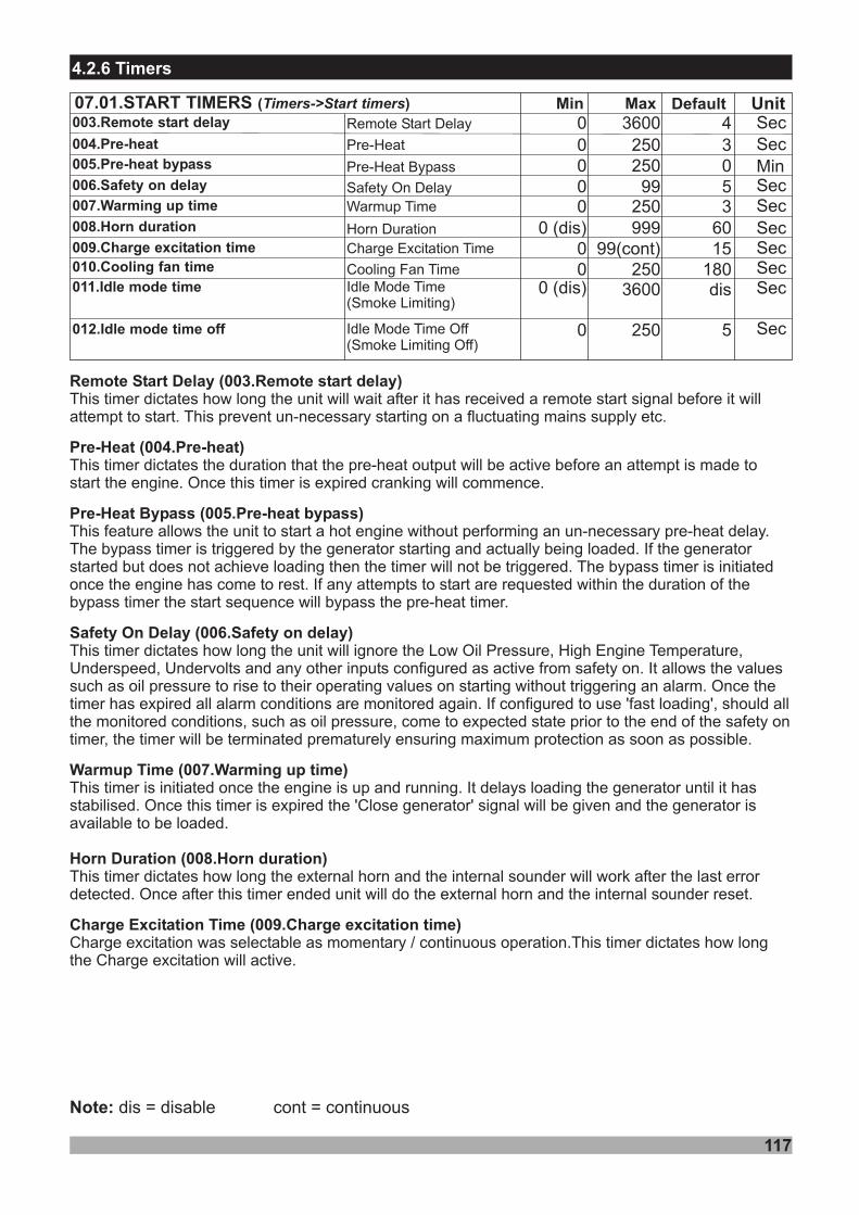
Min Default07.01.START TIMERS ( )Timers->Start timers MaxRemote Start Delay
Pre-Heat
Pre-Heat Bypass
40 360030 25000 250
Safety On Delay 50 99
Horn Duration 600 (dis) 999Charge Excitation Time 150 99(cont)Cooling Fan Time 1800 250
003.Remote start delay
004.Pre-heat
005.Pre-heat bypass
006.Safety on delay
008.Horn duration
009.Charge excitation time010.Cooling fan time
Remote Start Delay (003.Remote start delay)
Pre-Heat (004.Pre-heat)
Pre-Heat Bypass (005.Pre-heat bypass)
Safety On Delay (006.Safety on delay)
Warmup Time (007.Warming up time)
Horn Duration (008.Horn duration)
Charge Excitation Time (009.Charge excitation time)
This timer dictates how long the will wait after it has received a remote start signal before it willattempt to start. This prevent un-necessary starting on a fluctuating mains supply etc.
This timer dictates the duration that the pre-heat output will be active before an attempt is made tostart the engine. Once this timer is expired cranking will commence.
This feature allows the to start a hot engine without performing an un-necessary pre-heat delay.The bypass timer is triggered by the generator starting and actually being loaded. If the generatorstarted but does not achieve loading then the timer will not be triggered. The bypass timer is initiatedonce the engine has come to rest. If any attempts to start are requested within the duration of thebypass timer the start sequence will bypass the pre-heat timer.
This timer dictates how long the will ignore the Low Oil Pressure, High Engine Temperature,Underspeed, Undervolts and any other inputs configured as active from safety on. It allows the valuessuch as oil pressure to rise to their operating values on starting without triggering an alarm. Once thetimer has expired all alarm conditions are monitored again. If configured to use 'fast loading', should allthe monitored conditions, such as oil pressure, come to expected state prior to the end of the safety ontimer, the timer will be terminated prematurely ensuring maximum protection as soon as possible.
This timer dictates how long will work after the last errordetected. Once after this timer ended will do the external horn and the internal sounder reset.
Charge excitation was selectable as momentary / continuous operation.This timer dictates how longthe Charge excitation will active.
unit
unit
unit
This timer is initiated once the engine is up and running. It delays loading the generator until it hasstabilised. Once this timer is expired the 'Close generator' signal will be given and the generator isavailable to be loaded.
the external horn and the internal sounderunit
Unit
Min
SecSec
Sec
SecSecSec
dis3600011.Idle mode time
012.Idle mode time off
Sec
Sec
0 (dis)
0 250 5
Note: dis = disable cont = continuous
117
4.2.6 Timers
Warmup Time 30 250007.Warming up time Sec
Idle Mode Time Off(Smoke Limiting Off)
Idle Mode Time(Smoke Limiting)
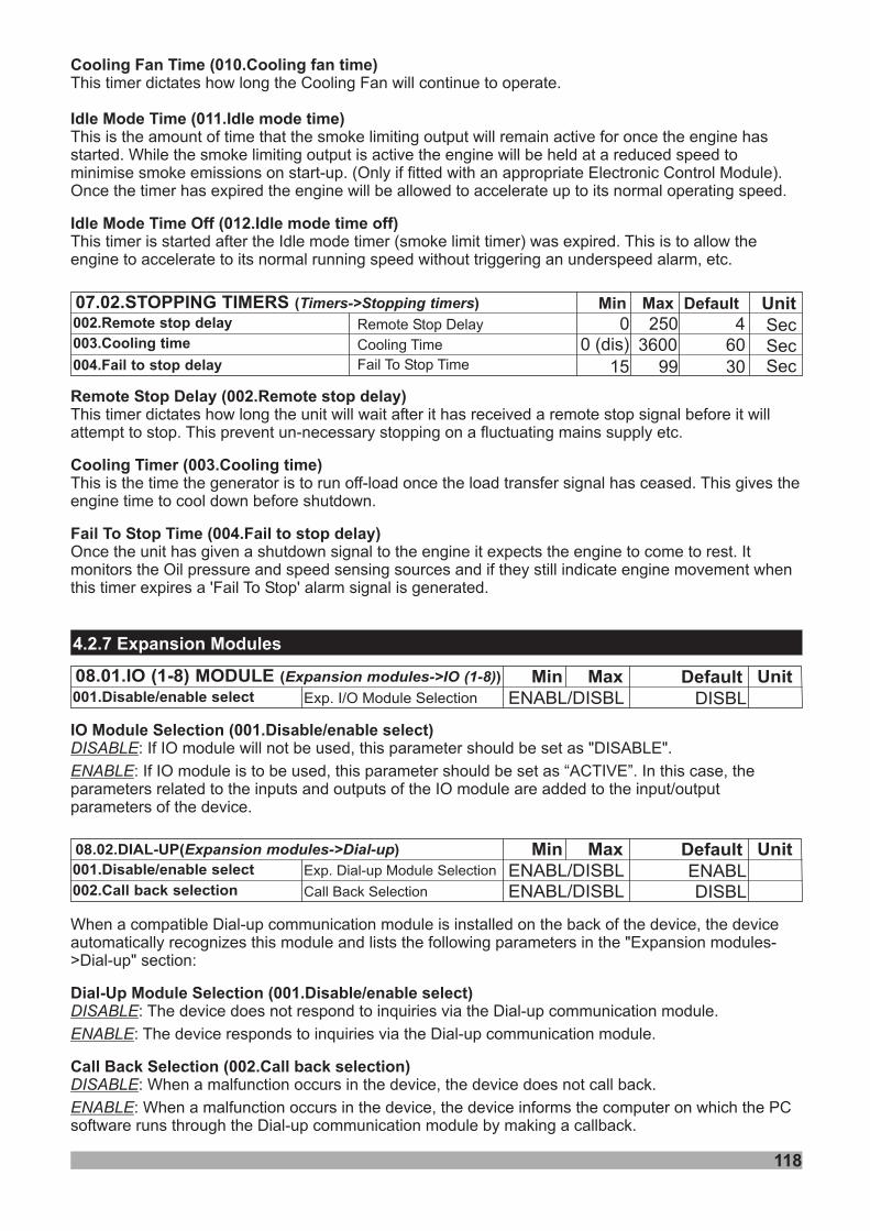
Min Default07.02.STOPPING TIMERS ( )Timers->Stopping timers Max40 250
600 (dis) 3600Remote Stop Delay
Cooling Time
Fail To Stop Time 3015 99
002.Remote stop delay
003.Cooling time
004.Fail to stop delay
Remote Stop Delay (002.Remote stop delay)
Cooling Timer (003.Cooling time)
Fail To Stop Time (004.Fail to stop delay)
This timer dictates how long the unit will wait after it has received a remote stop signal before it willattempt to stop. This prevent un-necessary stopping on a fluctuating mains supply etc.
unit
This is the time the generator is to run off-load once the load transfer signal has ceased. This gives theengine time to cool down before shutdown.
Once the has given a shutdown signal to the engine it expects the engine to come to rest. Itmonitors the Oil pressure and speed sensing sources and if they still indicate engine movement whenthis timer expires a 'Fail To Stop' alarm signal is generated.
UnitSecSecSec
Cooling Fan Time (010.Cooling fan time)
Idle Mode Time (011.Idle mode time)
(012. )Idle Mode Time Off Idle mode time off
This timer dictates how long the Cooling Fan will continue to operate.
This is the amount of time that the smoke limiting output will remain active for once the engine hasstarted. While the smoke limiting output is active the engine will be held at a reduced speed tominimise smoke emissions on start-up. (Only if fitted with an appropriate Electronic Control Module).Once the timer has expired the engine will be allowed to accelerate up to its normal operating speed.
This timer is started after the Idle mode timer (smoke limit timer) was expired. This is to allow theengine to accelerate to its normal running speed without triggering an underspeed alarm, etc.
118
4.2.7 Expansion Modules
08.01.IO (1-8) MODULE ( )Expansion modules->IO (1-8)
Exp I/O Module Selection.001.Disable/enable selectMin DefaultMax
DISBLENABL/DISBL
Unit
08.02.DIAL-UP( )Expansion modules->Dial-up
Exp Module Selection. Dial-up
Call Back Selection
001.Disable/enable select
002.Call back selection
Min DefaultMaxENABL
DISBLENABL/DISBL
ENABL/DISBL
Unit
IO Module Selection (001.Disable/enable select)DISABLE
ENABLE
: If IO module will not be used, this parameter should be set as "DISABLE".
: If IO module is to be used, this parameter should be set as “ACTIVE”. In this case, theparameters related to the inputs and outputs of the IO module are added to the input/outputparameters of the device.
When a compatible Dial-up communication module is installed on the back of the device, the deviceautomatically recognizes this module and lists the following parameters in the "Expansion modules->Dial-up" section:
: The device does not respond to inquiries via the Dial-up communication module.
: The device responds to inquiries via the Dial-up communication module.
: When a malfunction occurs in the device, the device does not call back.
: When a malfunction occurs in the device, the device informs the computer on which the PCsoftware runs through the Dial-up communication module by making a callback.
Dial-Up Module Selection (001.Disable/enable select)
Call Back Selection (002.Call back selection)
DISABLE
ENABLE
DISABLE
ENABLE
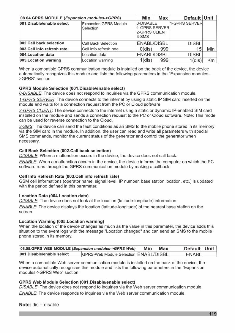
119
Note: dis = disable
08.05.GPRS WEB MODULE (Expansion modules->GPRS Web)
GPRS-Web Module Selection001.Disable/enable selectMin DefaultMax
ENABLENABL/DISBL
Unit
08.04.GPRS MODULE ( )Expansion modules->GPRS
Call Back Selection
Cell info refresh rate
Location data
Location warning
001.Disable/enable select
002.Call back selection
003.Cell info refresh rate
004.Location data
005.Location warning
Min DefaultMax1- SERVERGPRS
DISBL15
1(dis)
0-DISABLE1- SERVER2- CLIENT3-SMS
GPRSGPRS
ENABL/DISBL
0(dis)
1(dis)
Unit
999
999
Min
KmDISBLENABL/DISBL
Expansion ModuleSelection
GPRS
When a compatible GPRS communication module is installed on the back of the device, the deviceautomatically recognizes this module and lists the following parameters in the "Expansion modules->GPRS" section:
: The device does not respond to inquiries via the GPRS communication module.
: The device connects to the internet by using a static IP SIM card inserted on themodule and waits for a connection request from the PC or Cloud software.
: The device connects to the internet using a static or dynamic IP-enabled SIM cardinstalled on the module and sends a connection request to the PC or Cloud software. Note: This modecan be used for reverse connection to the Cloud.
: The device can send the fault conditions as an SMS to the mobile phone stored in its memoryvia the SIM card in the module. In addition, the user can read and write all parameters with specialSMS commands, monitor the current status of the generator and control the generator whennecessary.
: When a malfunction occurs in the device, the device does not call back.
: When a malfunction occurs in the device, the device informs the computer on which the PCsoftware runs through the GPRS communication module by making a callback.
GSM cell informations (operator name, signal level, IP number, base station location, etc.) is updatedwith the period defined in this parameter.
: The device does not look at the location (latitude-longitude) information.
: The device displays the location (latitude-longitude) of the nearest base station on thescreen.
When the location of the device changes as much as the value in this parameter, the device adds thissituation to the event logs with the message "Location changed" and can send an SMS to the mobilephone stored in its memory.
GPRS Module Selection (001.Disable/enable select)
Call Back Selection (002.Call back selection)
Cell Info Refresh Rate (003.Cell info refresh rate)
Location Data (004.Location data)
Location Warning (005.Location warning)
0-DISABLE
1-GPRS SERVER
2-GPRS CLIENT
3-SMS
DISABLE
ENABLE
DISABLE
ENABLE
When a compatible Web server communication module is installed on the back of the device, thedevice automatically recognizes this module and lists the following parameters in the "Expansionmodules->GPRS Web" section:
: The device does not respond to inquiries via the Web server communication module.
: The device responds to inquiries via the Web server communication module.
GPRS Web Module Selection (001.Disable/enable select)DISABLE
ENABLE
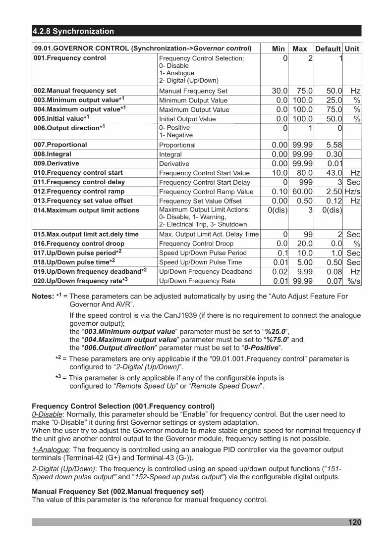
120
4.2.8 Synchronization
Min Default Unit09.01.GOVERNOR CONTROL (Synchronization )->Governor control Max
50.025.075.050.0
0
5.580.300.0143.0
32.500.12
30.00.00.00.0
0
0.000.000.0010.0
00.100.00
002.Manual frequency set
003.Minimum output value*1
004.Maximum output value*1
005.Initial value*1
006.Output direction*1
007.Proportional
008.Integral
009.Derivative
010.Frequency control start
011.Frequency control delay
012.Frequency control ramp
013.Frequency set value offset
Manual Frequency Set
Minimum Output Value
Maximum Output Value
Initial Output Value0- Positive1- Negative
Proportional
Integral
Derivative
Frequency Control Start Value
Frequency Control Start Delay
Frequency Control Ramp Value
Frequency Set Value Offset
75.0100.0100.0100.0
1
99.9999.9999.99
80.0999
60.000.50
Hz%%%
HzSecHz/s
Hz014.Maximum output limit actions
015.Max.output limit act.dely time
016.Frequency control droop
0(dis)
00.0
3
9920.0
0(dis)
20.0
Sec%
Max. Output Limit .Act Delay Time
Frequency Control Droop
Maximum Output Limit :0- , 1- ,2- , 3-
ActionsDisable WarningElectrical Trip Shutdown.
001.Frequency control Frequency Control Selection:0- Disable1- Analogue2- Digital (Up/Down)
10 2
017.Up/Down pulse period*2
018.Up/Down pulse time*2
019.Up/Down frequency deadband*2
020.Up/Down frequency rate*3
0.10.010.020.01
10.05.009 9.9
9 99.9
1.00.500.080.07
SecSecHz
%/s
Speed Up/Down Pulse Period
Speed Up/Down Pulse Time
Up/Down Frequency Deadband
Up/Down Frequency Rate
Frequency Control Selection ( )
Manual Frequency Set ( )
0-Disable
1-Analogue
2-Digital (Up/Down)
:
:
:
Normally, this parameter should be “Enable” for frequency control. But the user need tomake “0-Disable” it during first Governor settings or system adaptation.When the user try to adjust the Governor module to make stable engine speed for nominal frequency ifthe unit give another control output to the Governor module, frequency setting is not possible.
The value of this parameter is the reference for manual frequency control.
001.Frequency control
002.Manual frequency set
The frequency is controlled using an analogue PID controller via the governor outputterminals (Terminal-42 (G+) and Terminal-43 (G-)).
The frequency is controlled using an speed up/down output functions (”and “ ) via the configurable digital outputs.
151-Speed down pulse output” 152-Speed up pulse output”
Notes: =
.
*
*
*
1
2
3
These parameters can be adjusted automatically by using the “Auto Adjust Feature ForGovernor And AVR”.
If the speed control is via the CanJ1939 (if there is no requirement to connect the analoguegovernor output);the “ ” parameter must be set to “ ”,the “ ” parameter must be set to “ ” andthe “ ” parameter must be set to “ ”
=
=
003.Minimum output value %25.0004.Maximum output value %75.0006.Output direction 0-Positive
These parameters are only applicable if the “09.01.001.Frequency control” parameter isconfigured to “ ”.
This parameter is only applicable if any of the configurable inputs isconfigured to “ ” or “ ”.
2-Digital (Up/Down)
Remote Speed Up Remote Speed Down
Minimum Output Value ( )
Maximum Output Value ( )
Output Direction ( )
Proportional (007.Proportional)
Derivative (009.Derivative)
Frequency Control Start Value ( )
Frequency Control Start Delay ( )
Frequency Control Ramp Value ( )
The value of this parameter must be set to the minimum voltage scale of the Governor module.
The value of this parameter must be set to the maximum voltage scale of the Governor module.
: If Trans-Syncro Governor output voltage increases, the generator frequency will increase.if Trans-Syncro Governor output voltage decreases, the generator frequency will decrease.
: If Trans-Syncro Governor output voltage increases, the generator frequency will decrease.if Trans-Syncro Governor output voltage decreases, the generator frequency will increase.
The proportional term produces an output value that is proportional to the current error value. If theproportional gain is too high, the system can become unstable. If the proportional gain is too low, thecontrol action may be too small when responding to system disturbances.
The integral response will continually increase over time unless the error is zero. This parameterpermits the user to adjust how quickly the integral attempts to correct for any offset. If the integral gainconstant is too large, the engine will not stabilize. If the integral gain constant is too small, the enginewill take too long to settle at a steady state.
The derivative action predicts system behavior and thus improves settling time and stability of thesystem. If this parameter is increased, the stability of the system will increase. Essentially this is thebrake for the process.
If the monitored generator frequency has exceed the value of this parameter, the frequency controlleris activated. This prevents to control the frequency before the engine is completing its stabilization.
After the delay time expires the frequency controller is activated.
The ramp value is supplies the controller with the different setpoint values. This value is used to modifyof the rate of the controller’s setpoint value. For the faster change in the setpoint, the greater valuemust entered here.
Initial Output Value ( )
Frequency Set Value Offset ( )
The value entered for this parameter is hold the governor frequency in nominal value until themonitored frequency reaches to the value of parameter of frequency control start.
This parameter is used for while the engine synchronize to the busbar. With this offset, the unitsynchronizes with a positive slip.
0-Positive
1-Negative
003.Minimum output value
004.Maximum output value
005.Initial value
006.Output direction
Integral (008.Integral)
010.Frequency control start
011.Frequency control delay
012.Frequency control ramp
013.Frequency set value offset
014.Maximum output limit actions and 015.Max.output limit act.dely timeIf the analogue Governor output is being driven to its maximum level for the duration of the“015.Max.output limit act.dely time” parameter, the Governor maximum trim alarm is activated.
121
122
Frequency Control Droop (016.Frequency control droop)
During , the manual frequency set value will be increased ordecreased according to the ramp rate in this parameter.
This parameter defines the frequency droop characteristic.
If the “10.04.009.Frequency droop active” Logic function is true, the frequency droopcharacteristic is considered.
Each generator in the system will require the same value to be configured for the droopcharacteristic, so that when the system is stable the active power will be distributed proportionallyamong all generators in relation to their rated power.
:
- Rated active power: 100 kW.
- Rated frequency: 50.0 Hz.
- Droop: 5.0%.
- Active power: 0 kW = 0% of rated active powerFrequency is adjusted to: (50.0 Hz – [5.0% * (0 / 100) * 50.0 Hz]) = 50.0 Hz.
- Active power: 50 kW = 50% of rated active powerFrequency is adjusted to: (50.0Hz – [5.0% * (50 / 100) * 50.0 Hz]) = (50.0 Hz – 1.25 Hz) = 48.75 Hz.
- Active power: 100 kW = 100% of rated active powerFrequency is adjusted to: (50.0Hz – [5.0% * (100 / 100) * 50.0 Hz]) = (50.0 Hz – 2.50 Hz) = 47.50 Hz.
This parameter determines the period of the digital output that configured as “Speed Up/Down PulseOutput”.
This parameter determines the pulse width of the digital output that configured as “Speed Up/DownPulse Output”.
If the measured genset frequency deviates from the frequency setpoint by more than the valueconfigured in this parameter, the unit gives a speed up/down signal. This parameter preventsunnecessary wear at the speed up/down relay contacts.
:The frequency setpoint is configured as 50.0 Hz and this deadband parameter configured as 0.2 Hz.If the measured frequency falls below 49.8 Hz (50.0 - 0.2), the unit gives a speed up pulse signal.If the measured frequency rises above 50.2 Hz (50.0 + 0.2), the unit gives a speed down pulse signal.
Note-1:
Note-2:
Speed Up/Down Pulse Period ( p/Down pulse period)
Speed Up/Down Pulse Time ( p/Down pulse time)
Up/Down Frequency Deadband ( p/Down frequency deadband)
Up/Down Frequency Rate ( p/Down frequency rate)
For example
For example
017.U
018.U
019.U
020.U“ ” control
This parameter is only applicable if any of the configurable inputs is configured to “” or “ ”.
Remote Speed Up/Down
RemoteSpeed Up Remote Speed DownNote:
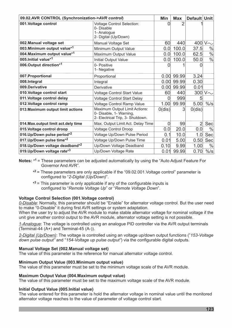
123
Min Default Unit09.02.AVR CONTROL (Synchronization )->AVR control Max
40037.562.550.0
0
3.240.300.01300
55.00
600.00.00.0
0
0.000.000.00
600
1.00
002.Manual voltage set
003.Minimum output value*1
004.Maximum output value*1
005.Initial value*1
006.Output direction*1
007.Proportional
008.Integral
009.Derivative
010.Voltage control start
011.Voltage control delay
012.Voltage control ramp
Manual SetVoltage
Minimum Output Value
Maximum Output Value
Initial Output Value
Proportional
Integral
Derivative
Voltage Control Start Value
Voltage Control Start Delay
Voltage Control Ramp Value
440100.0100.0100.0
1
99.9999.9999.99
440999
99.99
%%%
%/s
VV
VV
013.Maximum output limit actions
014.Max.output limit act.dely time
015.Voltage control droop
0(dis)
0
3
99
0(dis)
2 SecMax. Output Limit .Act Delay Time
Voltage Control Droop
Maximum Output Limit :0- , 1- ,2- , 3-
ActionsDisable WarningElectrical Trip Shutdown.
0.0 20.0 0.0 %
0- Positive1- Negative
001.Voltage control Voltage Control Selection:0- Disable1- Analogue2- Digital (Up/Down)
10 2
016.Up/Down pulse period*2
017.Up/Down pulse time*2
018.Up/Down voltage deadband*2
0.10.010.10
10.05.009 9.9
1.00.501.00
SecSec
%
Voltage Up/Down Pulse Period
Voltage Up/Down Pulse Time
Up/Down Voltage Deadband
019.Up/Down voltage rate*3 0.01 9 99.9 0.70 %/sUp/Down Voltage Rate
Voltage Control Selection ( Voltage )
Manual Voltage Set ( )
Minimum Output Value ( )
Maximum Output Value ( )
0-Disable
1-Analogue
2-Digital (Up/Down)
:
:
:
The value entered for this parameter is hold the alternator voltage in nominal value until the monitoredalternator voltage reaches to the value of parameter of voltage control start.
Normally, this parameter should be “Enable” for alternator voltage control. But the user needto make “0-Disable” it during first AVR settings or system adaptation.When the user try to adjust the AVR module to make stable alternator voltage for nominal voltage if theunit give another control output to the AVR module, alternator voltage setting is not possible.
The value of this parameter is the reference for manual alternator voltage control.
The value of this parameter must be set to the minimum voltage scale of the AVR module.
The value of this parameter must be set to the maximum voltage scale of the AVR module.
Initial Output Value ( )
001. control
002.Manual voltage set
003.Minimum output value
004.Maximum output value
005.Initial value
The voltage is controlled using an analogue PID controller via the AVR output terminals(Terminal-44 (A+) and Terminal-45 (A-)).
The voltage is controlled using an voltage up/down output functions (”and “ ) via the configurable digital outputs.
153-Voltagedown pulse output” 154-Voltage up pulse output”
Notes: = These parameters can be adjusted automatically by using the “Auto Adjust Feature ForGovernor And AVR”.
=
= This parameter is only applicable if any of the configurable inputs isconfigured to “ ” or “ ”.Remote Voltage Up Remote Voltage Down
*
*
*
1
2
3
These parameters are only applicable if the “09.02.001.Voltage control” parameter isconfigured to “ ”.2-Digital (Up/Down)
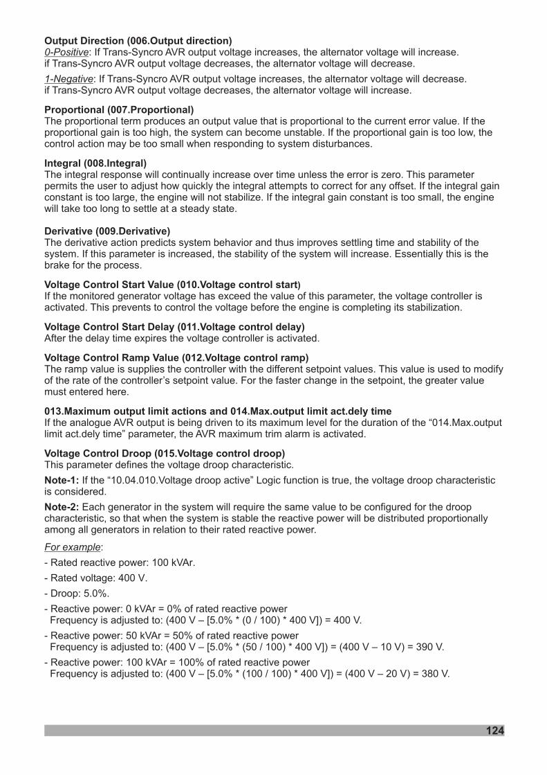
124
Output Direction ( )
Proportional (007.Proportional)
Derivative (009.Derivative)
Voltage Control Start Value (
Voltage Control Start Delay ( )
Voltage Control Ramp Value ( )
0-Positive
1-Negative
: If Trans-Syncro AVR output voltage increases, the will increase.if Trans-Syncro AVR output voltage decreases, the will decrease.
: If Trans-Syncro AVR output voltage increases, the will decrease.if Trans-Syncro AVR output voltage decreases, the will increase.
The proportional term produces an output value that is proportional to the current error value. If theproportional gain is too high, the system can become unstable. If the proportional gain is too low, thecontrol action may be too small when responding to system disturbances.
The integral response will continually increase over time unless the error is zero. This parameterpermits the user to adjust how quickly the integral attempts to correct for any offset. If the integral gainconstant is too large, the engine will not stabilize. If the integral gain constant is too small, the enginewill take too long to settle at a steady state.
The derivative action predicts system behavior and thus improves settling time and stability of thesystem. If this parameter is increased, the stability of the system will increase. Essentially this is thebrake for the process.
If the monitored generator voltage has exceed the value of this parameter, the voltage controller isactivated. This prevents to control the voltage before the engine is completing its stabilization.
After the delay time expires the voltage controller is activated.
The ramp value is supplies the controller with the different setpoint values. This value is used to modifyof the rate of the controller’s setpoint value. For the faster change in the setpoint, the greater valuemust entered here.
alternator voltagealternator voltage
alternator voltagealternator voltage
This parameter defines the voltage droop characteristic.
If the “10.04.010.Voltage droop active” Logic function is true, the voltage droop characteristicis considered.
Each generator in the system will require the same value to be configured for the droopcharacteristic, so that when the system is stable the reactive power will be distributed proportionallyamong all generators in relation to their rated reactive power.
:
- Rated active power: 100 k .
- Rated : .
- Droop: 5.0%.
- ctive power: 0 k = 0% of rated reactive powerFrequency is adjusted to: (400 V – [5.0% * (0 / 100) * 400 V]) = 400 V.
- ctive power: 50 k = 50% of rated reactive powerFrequency is adjusted to: (400 V – [5.0% * (50 / 100) * 400 V]) = (400 V – 10 V) = 390 V.
- ctive power: 100 k = 100% of rated reactive powerFrequency is adjusted to: (400 V – [5.0% * (100 / 100) * 400 V]) = (400 V – 20 V) = 380 V.
Note-1:
Note-2:
For example
re VAr
voltage 400 V
Rea VAr
Rea VAr
Rea VAr
006.Output direction
Integral (008.Integral)
010.Voltage control start
011.Voltage control delay
012.Voltage control ramp
013.Maximum output limit actions and 014.Max.output limit act.dely time
)
If the analogue AVR output is being driven to its maximum level for the duration of the “014.Max.outputlimit act.dely time” parameter, the AVR maximum trim alarm is activated.
Voltage Control Droop (015.Voltage control droop)
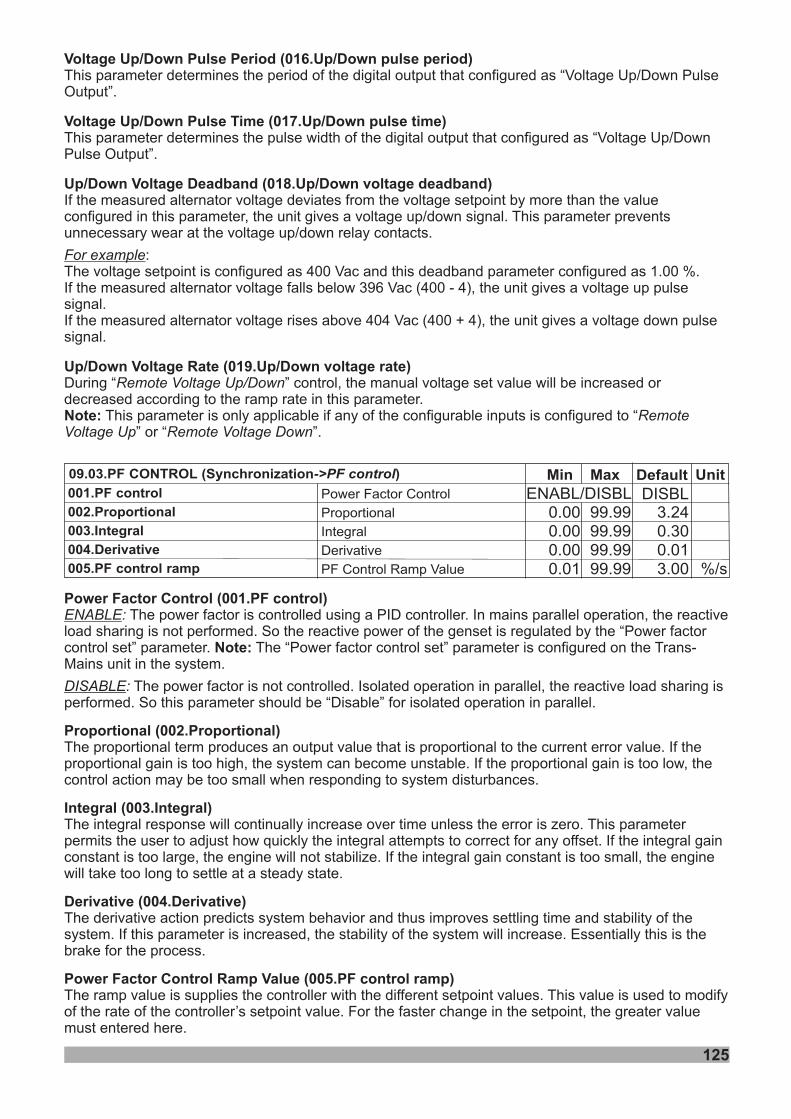
125
Min Default Unit09.03.PF CONTROL (Synchronization )->PF control Max
3.240.300.013.00
0.000.000.000 1.0
001.PF control
002.Proportional
003.Integral
004.Derivative
005.PF control ramp
Power Factor Control
Proportional
Integral
Derivative
PF Control Ramp Value
99.9999.9999.9999.99 %/s
DISBLENABL/DISBL
Power Factor Control ( )
Note:
Proportional (002.Proportional)
Derivative (004.Derivative)
Power Factor Control Ramp Value ( )
ENABLE
DISABLE
:
:
The power factor is controlled using a PID controller. In mains parallel operation, the reactiveload sharing is not performed. So the reactive power of the genset is regulated by the “Power factorcontrol set” parameter. The “Power factor control set” parameter is configured on the Trans-Mains unit in the system.
The power factor is not controlled. Isolated operation in parallel, the reactive load sharing isperformed. So this parameter should be “Disable” for isolated operation in parallel.
The proportional term produces an output value that is proportional to the current error value. If theproportional gain is too high, the system can become unstable. If the proportional gain is too low, thecontrol action may be too small when responding to system disturbances.
The integral response will continually increase over time unless the error is zero. This parameterpermits the user to adjust how quickly the integral attempts to correct for any offset. If the integral gainconstant is too large, the engine will not stabilize. If the integral gain constant is too small, the enginewill take too long to settle at a steady state.
The derivative action predicts system behavior and thus improves settling time and stability of thesystem. If this parameter is increased, the stability of the system will increase. Essentially this is thebrake for the process.
The ramp value is supplies the controller with the different setpoint values. This value is used to modifyof the rate of the controller’s setpoint value. For the faster change in the setpoint, the greater valuemust entered here.
001.PF control
Integral (003.Integral)
005.PF control ramp
Voltage Up/Down Pulse Period ( p/Down pulse period)
Voltage Up/Down Pulse Time ( p/Down pulse time)
Up/Down Voltage Deadband ( p/Down voltage deadband)
Up/Down Voltage Rate ( p/Down voltage rate)
This parameter determines the period of the digital output that configured as “Voltage Up/Down PulseOutput”.
This parameter determines the pulse width of the digital output that configured as “Voltage Up/DownPulse Output”.
If the measured alternator voltage deviates from the voltage setpoint by more than the valueconfigured in this parameter, the unit gives a voltage up/down signal. This parameter preventsunnecessary wear at the voltage up/down relay contacts.
:The voltage setpoint is configured as 400 Vac and this deadband parameter configured as 1.00 %.If the measured alternator voltage falls below 396 Vac (400 - 4), the unit gives a voltage up pulsesignal.If the measured alternator voltage rises above 404 Vac (400 + 4), the unit gives a voltage down pulsesignal.
For example
016.U
017.U
018.U
019.UDuring , the manual voltage set value will be increased ordecreased according to the ramp rate in this parameter.
“ ” control
This parameter is only applicable if any of the configurable inputs is configured to “” or “ ”.
Remote Voltage Up/Down
RemoteVoltage Up Remote Voltage DownNote:
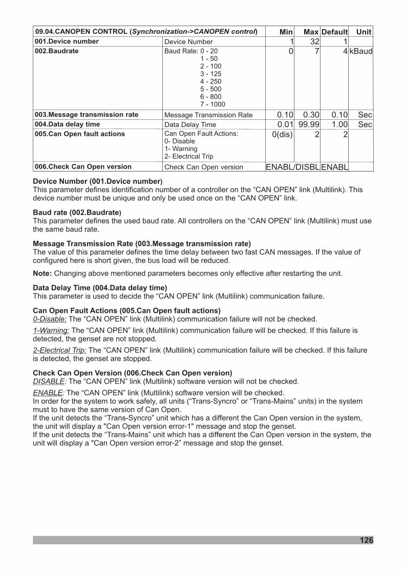
126
SecSec
Min09.04.CANOPEN CONTROL ( )Synchronization->CANOPEN control
14
0.101.00
10
0.100.01
001.Device number
002.Baudrate
003.Message transmission rate
004.Data delay time
005.Can Open fault actions
Device Number
Message Transmission Rate
Data Delay Time
327
0.3099.99
Baud Rate: 0 - 201 - 502 - 1003 - 1254 - 2505 - 5006 - 8007 - 1000
kBaud
DefaultMax Unit
Device Number (
Baud rate (
Note:
This parameter defines identification number of a controller on the “CAN OPEN” link (Multilink). Thisdevice number must be unique and only be used once on the “CAN OPEN” link.
This parameter defines the used baud rate. All controllers on the “CAN OPEN” link (Multilink) must usethe same baud rate.
Changing above mentioned parameters becomes only effective after restarting the unit.
“CAN OPEN” link (Multilink)
“CAN OPEN” link (Multilink)
“CAN OPEN” link (Multilink)
“CAN OPEN” link (Multilink)
“CAN OPEN” link (Multilink)
“CAN OPEN” link (Multilink)
Message Transmission Rate (003.Message transmission rate)
Data Delay Time (004.Data delay time)
Can Open Fault Actions (005.Can Open fault actions)
Check Can Open Version (006.Check Can Open version)
The value of this parameter defines the time delay between two fast CAN messages. If the value ofconfigured here is short given, the bus load will be reduced.
This parameter is used to decide the communication failure.
The communication failure will not be checked.
The communication failure will be checked. If this failure isdetected, the genset are not stopped.
The communication failure will be checked. If this failureis detected, the genset are stopped.
The software version will not be checked.
The software version will be checked.In order for the system to work safely, all units (“Trans-Syncro” or “Trans-Mains” units) in the systemmust to have the same version of Can Open.If the unit detects the “Trans-Syncro” unit which has a different the Can Open version in the system,the unit will display a "Can Open version error-1" message and stop the genset.If the unit detects the “Trans-Mains” unit which has a different the Can Open version in the system, theunit will display a "Can Open version error-2” message and stop the genset.
0-Disable:
1-Warning:
2-Electrical Trip:
DISABLE
ENABLE
:
:
001.Device number
002.Baudrate
)
)
0(dis) 2 2Can Open Fault :0-1-2-
ActionsDisableWarningElectrical Trip
006.Check Can Open version Check Can Open version ENABLENABL/DISBL
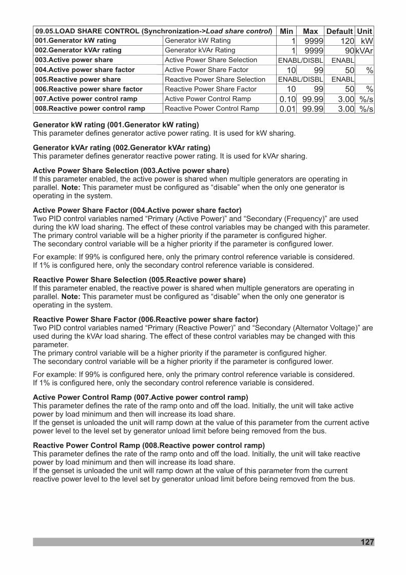
127
Default UnitMaxMin09.05.LOAD SHARE CONTROL (Synchronization )->Load share control
001.Generator kW rating
008.Reactive power control ramp
002.Generator kVAr rating
003.Active power share
004.Active power share factor
005.Reactive power share
006.Reactive power share factor
007.Active power control ramp
Reactive Power Control Ramp
Active Power Control Ramp
Reactive Power Share Factor
Reactive Power Share Selection
Active Power Share Factor
Active Power Share Selection
Generator kVAr Rating
Generator kW Rating
0.100.01
10
10
ENABL/DISBL
ENABL/DISBL
11
99999999
99
9999.9999.99
12090
ENABL
ENABL
503.003.00
50
kWkVAr
%
%%/s%/s
Generator kW rating ( Generator kW rating)
Generator kVAr rating ( Generator kVAr rating)
Active Power Share Selection ( )
Note:
Reactive Power Share Selection ( )
Note:
This parameter defines generator active power rating. It is used for kW sharing.
This parameter defines generator reactive power rating. It is used for kVAr sharing.
If this parameter enabled, the active power is shared when multiple generators are operating inparallel. This parameter must be configured as “disable” when the only one generator isoperating in the system.
If this parameter enabled, the reactive power is shared when multiple generators are operating inparallel. This parameter must be configured as “disable” when the only one generator isoperating in the system.
Active Power Share Factor ( )
Reactive Power Share Factor ( )
Active Power Control Ramp ( )
Reactive Power Control Ramp ( )
Two PID control variables named “Primary (Active Power)” and “Secondary (Frequency)” are usedduring the kW load sharing. The effect of these control variables may be changed with this parameter.The primary control variable will be a higher priority if the parameter is configured higher.The secondary control variable will be a higher priority if the parameter is configured lower.
For example: If 99% is configured here, only the primary control reference variable is considered.If 1% is configured here, only the secondary control reference variable is considered.
Two PID control variables named “Primary (Reactive Power)” and “Secondary (Alternator Voltage)” areused during the kVAr load sharing. The effect of these control variables may be changed with thisparameter.The primary control variable will be a higher priority if the parameter is configured higher.The secondary control variable will be a higher priority if the parameter is configured lower.
For example: If 99% is configured here, only the primary control reference variable is considered.If 1% is configured here, only the secondary control reference variable is considered.
This parameter defines the rate of the ramp onto and off the load. Initially, the unit will take activepower by load minimum and then will increase its load share.If the genset is unloaded the unit will ramp down at the value of this parameter from the current activepower level to the level set by generator unload limit before being removed from the bus.
This parameter defines the rate of the ramp onto and off the load. Initially, the unit will take reactivepower by load minimum and then will increase its load share.If the genset is unloaded the unit will ramp down at the value of this parameter from the currentreactive power level to the level set by generator unload limit before being removed from the bus.
001.
002.
003.Active power share
004.Active power share factor
005.Reactive power share
006.Reactive power share factor
007.Active power control ramp
008.Reactive power control ramp
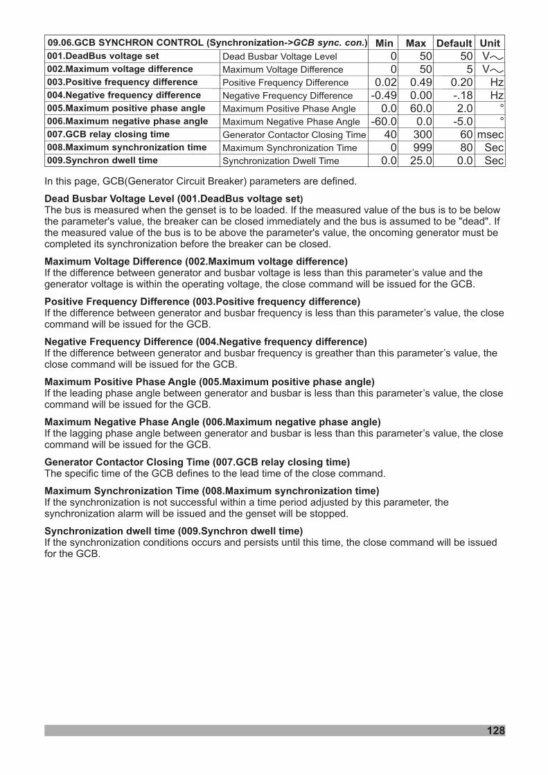
Min Default Unit09.06.GCB SYNCHRON CONTROL (Synchronization )->GCB sync. con. Max50
50.20-.182.0
-5.060800.0
00
0.02-0.49
0.0-60.0
400
0.0
001.DeadBus voltage set
002.Maximum voltage difference
003.Positive frequency difference
004.Negative frequency difference
005.Maximum positive phase angle
006.Maximum negative phase angle
007.GCB relay closing time
008.Maximum synchronization time
009.Synchron dwell time
Dead Busbar Voltage Level
Maximum Voltage Difference
Positive Frequency Difference
Negative Frequency Difference
Maximum Positive Phase Angle
Maximum Negative Phase Angle
Generator Contactor Closing Time
Maximum Synchronization Time
Synchronization Dwell Time
5050
0.490.0060.0
0.030099925.0
HzHz
°°
msecSecSec
VVVV
128
In this page, GCB(Generator Circuit Breaker) parameters are defined.
The bus is measured when the genset is to be loaded. If the measured value of the bus is to be belowthe parameter's value, the breaker can be closed immediately and the bus is assumed to be "dead". Ifthe measured value of the bus is to be above the parameter's value, the oncoming generator must becompleted its synchronization before the breaker can be closed.
Dead Busbar Voltage Level (
Maximum Positive Phase Angle ( )
Maximum Negative Phase Angle ( )
( )
Maximum Voltage Difference ( )
Positive Frequency Difference ( )
Negative Frequency Difference ( )
Generator Contactor Closing Time ( )
Maximum Synchronization Time ( )
If the difference between generator and busbar voltage is less than this parameter’s value and thegenerator voltage is within the operating voltage, the close command will be issued for the GCB.
If the difference between generator and busbar frequency is less than this parameter’s value, the closecommand will be issued for the GCB.
If the difference between generator and busbar frequency is greather than this parameter’s value, theclose command will be issued for the GCB.
If the leading phase angle between generator and busbar is less than this parameter’s value, the closecommand will be issued for the GCB.
If the lagging phase angle between generator and busbar is less than this parameter’s value, the closecommand will be issued for the GCB.
The specific time of the GCB defines to the lead time of the close command.
he close command will be issuedfor the GCB
001.DeadBus voltage set
002.Maximum voltage difference
003.Positive frequency difference
004.Negative frequency difference
005.Maximum positive phase angle
006.Maximum negative phase angle
Synchronization dwell time 009.Synchron dwell time
)
007.GCB relay closing time
008.Maximum synchronization timeIf the synchronization is not successful within a time period adjusted by this parameter, thesynchronization alarm will be issued and the genset will be stopped.
If the synchronization conditions occurs and persists until this time, t.
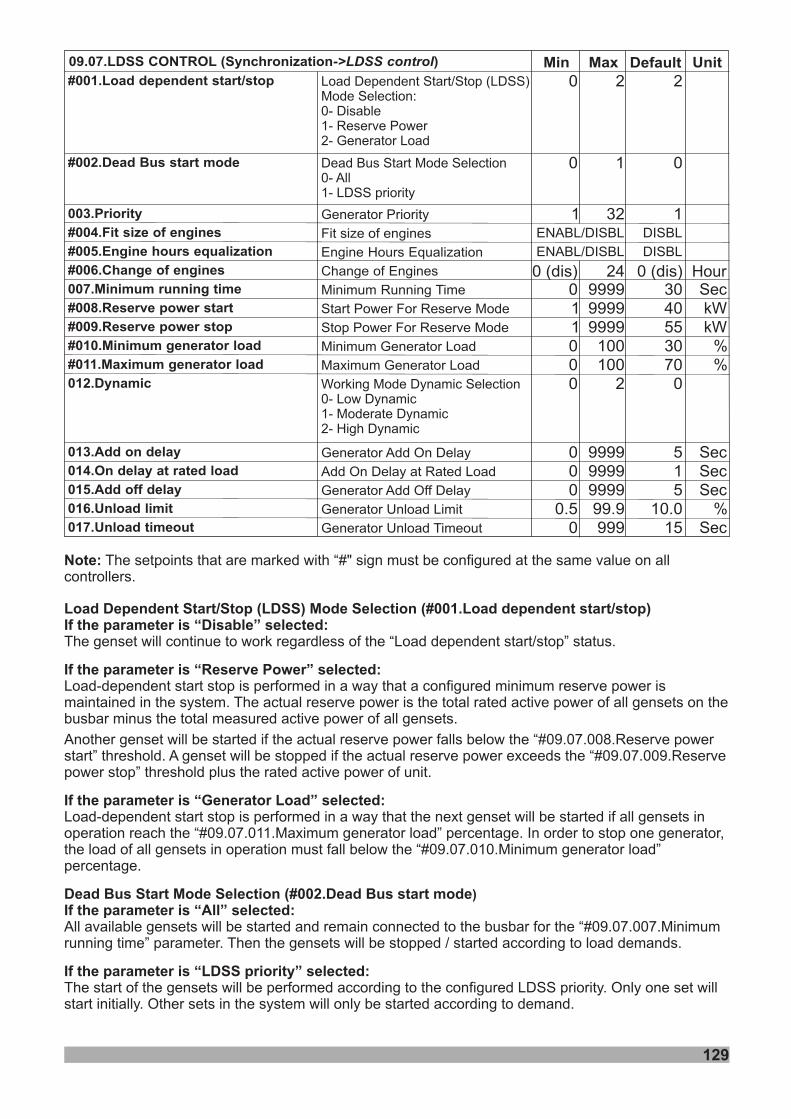
Min Default Unit09.07.LDSS CONTROL (Synchronization )->LDSS control Max2
0
1
3040553070
0
515
10.015
0
0
1
011000
000
0.50
#001.Load dependent start/stop
#002.Dead Bus start mode
003.Priority
#004.Fit size of engines
#005.Engine hours equalization
#006.Change of engines
007.Minimum running time
#008.Reserve power start
#009.Reserve power stop
#010.Minimum generator load
#011.Maximum generator load
012.Dynamic
013.Add on delay
014.On delay at rated load
015.Add off delay
016.Unload limit
017.Unload timeout
Generator Priority
Fit size of engines
Engine Hours Equalization
Change of Engines
Minimum Running Time
Start Power For Reserve Mode
Stop Power For Reserve Mode
Minimum Generator Load
Maximum Generator Load
Generator Add On Delay
Add On Delay at Rated Load
Generator Add Off Delay
Generator Unload Limit
Generator Unload Timeout
2
1
32
999999999999
100100
2
99999999999999.9999
SeckWkW
%%
SecSecSec
%Sec
ENABL/DISBL DISBL
129
ENABL/DISBL DISBL
0 (dis)0 (dis) 24 Hour
Note: The setpoints that are marked with “#" sign must be configured at the same value on allcontrollers.
Load Dependent Start/Stop (LDSS) Mode Selection (#001.Load dependent start/stop)If the parameter is “Disable” selected:
If the parameter is “Reserve Power” selected:
If the parameter is “Generator Load” selected:
Dead Bus Start Mode Selection (#002.Dead Bus start modeIf the parameter is “All” selected:
If the parameter is “LDSS priority” selected:
T
Load-dependent start stop is performed in a way that a configured minimum reserve power ismaintained in the system. The actual reserve power is the total rated active power of all gensets on thebusbar minus the total measured active power of all gensets.
Another genset will be started if the actual reserve power falls below the “#09.07.008.Reserve powerstart” threshold. A genset will be stopped if the actual reserve power exceeds the “#09.07.009.Reservepower stop” threshold plus the rated active power of unit.
Load-dependent start stop is performed in a way that the next genset will be started if all gensets inoperation reach the “#09.07.011.Maximum generator load” percentage. In order to stop one generator,the load of all gensets in operation must fall below the “#09.07.010.Minimum generator load”percentage.
All available gensets will be started and remain connected to the busbar for the “#09.07.007.Minimumrunning time” parameter. Then the gensets will be stopped / started according to load demands.
The start of the gensets will be performed according to the configured LDSS priority. Only one set willstart initially. Other sets in the system will only be started according to demand.
)
he genset will continue to work regardless of the “Load dependent start/stop” status.
Working Mode Dynamic Selection0- Low Dynamic1- Moderate Dynamic2- High Dynamic
Dead Bus Start Mode Selection0- All1- LDSS priority
Load Dependent Start/Stop (LDSS)Mode Selection:0- Disable1- Reserve Power2- Generator Load
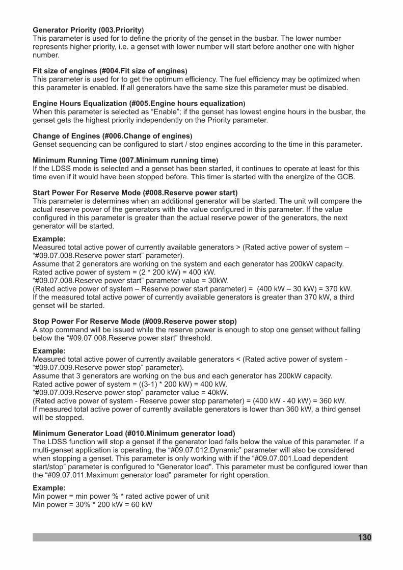
130
Generator Priority (003.Priority
Fit size of engines (#004.Fit size of engines
Engine Hours Equalization (#005.Engine hours equalization
Change of Engines (#006.Change of engines
Minimum Running Time (007.Minimum running time
Start Power For Reserve Mode (# )
Example:
)
)
)
)
)
This parameter is used for to define the priority of the genset in the busbar. The lower numberrepresents higher priority, i.e. a genset with lower number will start before another one with highernumber.
This parameter is used for to get the optimum efficiency. The fuel efficiency may be optimized whenthis parameter is enabled. If all generators have the same size this parameter must be disabled.
If the LDSS mode is selected and a genset has been started, it continues to operate at least for thistime even if it would have been stopped before. This timer is started with the energize of the GCB.
This parameter is determines when an additional generator will be started. The unit will compare theactual reserve power of the generators with the value configured in this parameter. If the valueconfigured in this parameter is greater than the actual reserve power of the generators, the nextgenerator will be started.
Measured total active power of currently available generators > (R –“#09.07.008.Reserve power start” parameter).Assume that 2 generators are working on the system and each generator has 200kW capacity.Rated active power of system = (2 * 200 kW) = 400 kW.“#09.07.008.Reserve power start” parameter value = 30kW.(R – Reserve power start parameter) = (400 kW – 30 kW) = 370 kW.If the measured total active power of currently available generators is greater than 370 kW, a
will be started.
the “#09.07.008.Reserve power start”
Measured total active power of currently available generators“#09.07.009.Reserve power stop” parameterAssume that 3 generators are working on the bus and each generator has 200kW capacity.Rated active power of system = ((3-1) * 200 kW) = 400 kW.“#09.07.009.Reserve power stop” parameter value = 40kW.
Reserve power stop parameterIf measured total active power of currently available generators is lower than 360 kW, a
#09.07.012.Dynamic” parameter#09.07.001.Load dependent
start/stop” parameter#09.07.011.Maximum generator load” parameter
When
Genset sequencing can be configured to start / stop engines according to the time in this parameter
this parameter is selected as “Enable”; if the genset has lowest engine hours in the busbar, thegenset gets the highest priority independently on the Priority parameter.
.
008.Reserve power start
Stop Power For Reserve Mode (#009.Reserve power stop)
Example:
Minimum Generator Load (#010.Minimum generator load)
Example:
ated active power of system
ated active power of systemthird
genset
A stop command will be issued while the reserve power is enough to stop one genset without fallingbelow threshold.
< (Rated active power of system -).
(Rated active power of system - ) = (400 kW - 40 kW) = 360 kW.third genset
will be stopped.
The LDSS function will stop a genset if the generator load falls below the value of this parameter. If amulti-genset application is operating, the “ will also be consideredwhen stopping a genset. This parameter is only working with if the “
is configured to "Generator load". This parameter must be configured lower thanthe “ for right operation.
Min power = min power % * rated active power of unitMin power = 30% * 200 kW = 60 kW
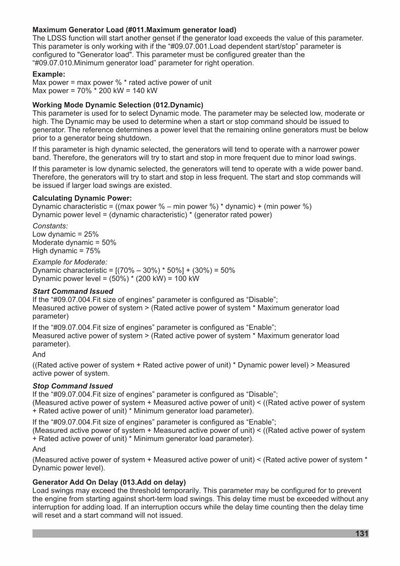
131
Maximum Generator Load (#011.Maximum generator load)
Example:
Working Mode Dynamic Selection (012.Dynamic)
013.Add on delay
The LDSS function will start another genset if the generator load exceeds the value of this parameter.This parameter is only working with if the “ isconfigured to "Generator load". This parameter must be configured greater than the“ for right operation.
Max power = max power % * rated active power of unitMax power = 70% * 200 kW = 140 kW
#09.07.001.Load dependent start/stop” parameter
#09.07.010.Minimum generator load” parameter
This parameter is used for to select Dynamic mode. The parameter may be selected low, moderate orhigh. The Dynamic may be used to determine when a start or stop command should be issued togenerator. The reference determines a power level that the remaining online generators must be belowprior to a generator being shutdown.
If this parameter is high dynamic selected, the generators will tend to operate with a narrower powerband. Therefore, the generators will try to start and stop in more frequent due to minor load swings.
If this parameter is low dynamic selected, the generators will tend to operate with a wide power band.Therefore, the generators will try to start and stop in less frequent. The start and stop commands willbe issued if larger load swings are existed.
Dynamic characteristic = ((max power % – min power %) * dynamic) + (min power %)Dynamic power level = (dynamic characteristic) * (generator rated power)
Low dynamic = 25%Moderate dynamic = 50%High dynamic = 75%
Dynamic characteristic = [(70% – 30%) * 50%] + (30%) = 50%Dynamic power level = (50%) * (200 kW) = 100 kW
If the “#09.07.004.Fit size of engines” parameter is configured as “Disable”;Measured active power of system > (Rated active power of system * Maximum generator loadparameter)
If the “#09.07.004.Fit size of engines” parameter is configured as “Enable”;Measured active power of system > (Rated active power of system * Maximum generator loadparameter).
And
((Rated active power of system + Rated active power of unit) * Dynamic power level) > Measuredactive power of system.
If the “#09.07.004.Fit size of engines” parameter is configured as “Disable”;(Measured active power of system + Measured active power of unit) < ((Rated active power of system+ Rated active power of unit) * Minimum generator load parameter).
If the “#09.07.004.Fit size of engines” parameter is configured as “Enable”;(Measured active power of system + Measured active power of unit) < ((Rated active power of system+ Rated active power of unit) * Minimum generator load parameter).
And
(Measured active power of system + Measured active power of unit) < (Rated active power of system *Dynamic power level).
Load swings may exceed the threshold temporarily. This parameter may be configured for to preventthe engine from starting against short-term load swings. This delay time must be exceeded without anyinterruption for adding load. If an interruption occurs while the delay time counting then the delay timewill reset and a start command will not issued.
Calculating Dynamic Power:
Generator Add On Delay ( )
Constants:
Example for Moderate:
Start Command Issued
Stop Command Issued
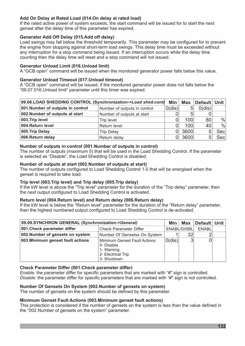
132
Min Default Unit09.08.LOAD SHEDDING CONTROL (Synchronization->Load shed.cont) Max0(dis)
08040
55
0(dis)00000
001.Number of outputs in control
002.Number of outputs at start
003.Trip level
004.Return level
005.Trip Delay
006.Return delay
Number of outputs in control
Number of outputs at start
Trip level
Return level
Trip Delay
Return delay
55
100100
36003600
%%
SecSec
Number of outputs in control (001.Number of outputs in control)
Number of outputs at start (002.Number of outputs at start)
Trip level (003.Trip level) and Trip delay (005.Trip delay)
Return level (004.Return level) and Return delay (006.Return delay)
The number of outputs (maximum 5) that will be used in the Load Shedding Control. If the parameteris selected as “Disable”, the Load Shedding Control is disabled.
The number of outputs configured to Load Shedding Control 1-5 that will be energised when thegenset is required to take load.
If the kW level is above the “Trip level” parameter for the duration of the “Trip delay” parameter, thenthe next output configured to Load Shedding Control is activated.
If the kW level is below the “Return level” parameter for the duration of the “Return delay” parameter,then the highest numbered output configured to Load Shedding Control is de-activated.
Min Default Unit09.09.SYNCHRON GENERAL (Synchronization->General) Max001.Check parameter differ Check Parameter Differ ENABL/DISBL ENABL
Add On Delay at Rated Load (014.On delay at rated load)
Generator Add Off Delay (015.Add off delay)
Generator Unload Limit (016.Unload limit)
Generator Unload Timeout (017.Unload timeout)
If the rated active power of system exceeds, the start command will be issued for to start the nextgenset after the delay time of this parameter has expired.
Load swings may fall below the threshold
a stop command being issued
A “GCB open” command will be issued when the monitored generator power falls below this value.
A “GCB open” command will be issued, if the monitored generator power does not falls below the“09.07.016.Unload limit” parameter until this timer was expired.
temporarily. This parameter may be configured for to preventthe engine from stopping against short-term load swings. This delay time must be exceeded withoutany interruption for . If an interruption occurs while the delay timecounting then the delay time will reset and a stop command will not issued.
002.Number of gensets on system
003.Minimum genset fault actionsNumber Of Gensetss On System
Minimum Genset Fault Actions:0- Disable1- Warning2- Electrical Trip3- Shutdown
21 3200(dis) 3
Check Parameter Differ (001.Check parameter differ)
Number Of Gensets On System (002.Number of gensets on system)
Minimum Genset Fault Actions (003.Minimum genset fault actions)
Enable:Disable:
the parameter differ for specific parameters is controlled.the parameter differ for specific parameters is not controlled.
The number of gensets on the system should be defined by this parameter.
This protection is considered if the number of gensets on the system is less than the value defined inthe “002.Number of gensets on the system” parameter.
that are marked with “#" signthat are marked with “#" sign
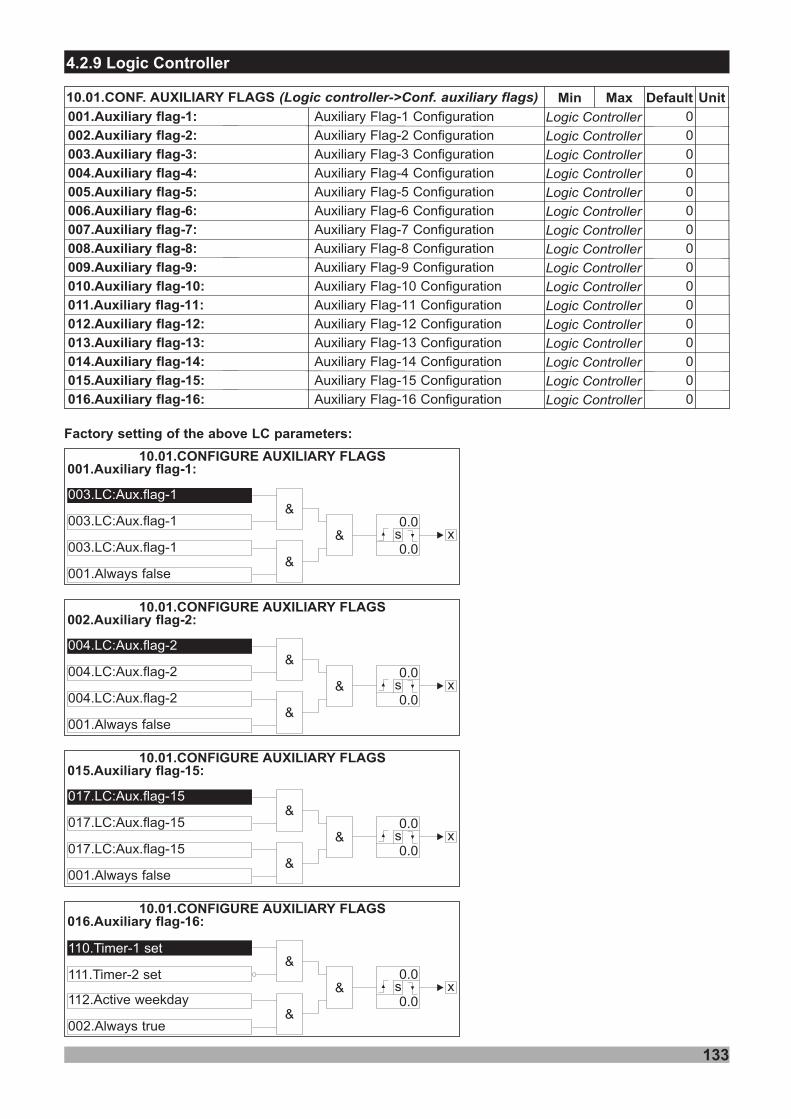
4.2.9 Logic Controller
10.01.CONF. AUXILIARY FLAGS (Logic controller->Conf. auxiliary flags)
001.Auxiliary flag-1:
00 .Auxiliary flag- :2 2
00 .Auxiliary flag- :3 3
00 .Auxiliary flag- :4 4
00 .Auxiliary flag- :5 5
00 .Auxiliary flag- :6 6
00 .Auxiliary flag- :7 7
00 .Auxiliary flag- :8 8
00 .Auxiliary flag- :9 9
0 .Auxiliary flag-1 :10 0
0 .Auxiliary flag-1 :11 1
0 .Auxiliary flag-1 :12 2
0 .Auxiliary flag-1 :13 3
0 .Auxiliary flag-1 :14 4
0 .Auxiliary flag-1 :15 5
0 .Auxiliary flag-1 :16 6
133
Logic Controller
Logic Controller
Logic Controller
Logic Controller
Logic Controller
Logic Controller
Logic Controller
Logic Controller
Logic Controller
Logic Controller
Logic Controller
Logic Controller
Logic Controller
Logic Controller
Logic Controller
Logic Controller
Min Default UnitMax
Auxiliary lag-1F Configuration
Auxiliary lag-F 2 Configuration
Auxiliary lag-F 3 Configuration
Auxiliary lag-F 4 Configuration
Auxiliary lag-F 5 Configuration
Auxiliary lag-F 6 Configuration
Auxiliary lag-F 7 Configuration
Auxiliary lag-F 8 Configuration
Auxiliary lag-F 9 Configuration
Auxiliary lag-1F 0 Configuration
Auxiliary lag-1F 1 Configuration
Auxiliary lag-1F 2 Configuration
Auxiliary lag-1F 3 Configuration
Auxiliary lag-1F 4 Configuration
Auxiliary lag-1F 5 Configuration
Auxiliary lag-1F 6 Configuration
0
0
0
0
0
0
0
0
0
0
0
0
0
0
0
0
001.Auxiliary flag-1:
003.LC:Aux.flag-1
003.LC:Aux.flag-1
003.LC:Aux.flag-1
001.Always false
&
&
&
10.01.CONFIGURE AUXILIARY FLAGS
x0.0
0.0s
002.Auxiliary flag-2:
004.LC:Aux.flag-2
004.LC:Aux.flag-2
004.LC:Aux.flag-2
001.Always false
&
&
&
10.01.CONFIGURE AUXILIARY FLAGS
x0.0
0.0s
015.Auxiliary flag-15:
017.LC:Aux.flag-15
017.LC:Aux.flag-15
017.LC:Aux.flag-15
001.Always false
&
&
&
10.01.CONFIGURE AUXILIARY FLAGS
x0.0
0.0s
Factory setting of the above LC parameters:
016.Auxiliary flag-16:
110.Timer-1 set
111.Timer-2 set
112.Active weekday
002.Always true
&
&
&
10.01.CONFIGURE AUXILIARY FLAGS
x0.0
0.0s
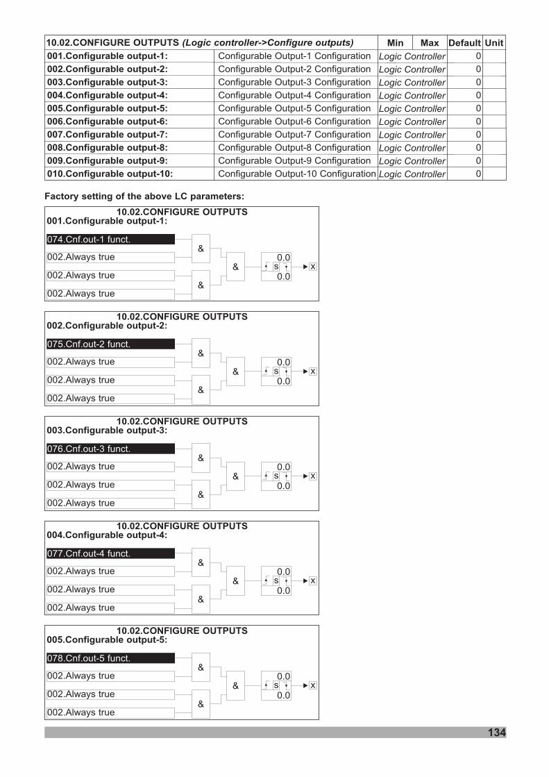
10.02.CONFIGURE OUTPUTS (Logic controller->Configure outputs)
001.Configurable output-1:
00 .Configurable output- :2 2
00 .Configurable output- :3 3
00 .Configurable output- :4 4
00 .Configurable output- :5 5
00 .Configurable output- :6 6
00 .Configurable output- :7 7
00 .Configurable output- :8 8
00 .Configurable output- :9 9
0 .Configurable output-1 :10 0
134
Logic Controller
Logic Controller
Logic Controller
Logic Controller
Logic Controller
Logic Controller
Logic Controller
Logic Controller
Logic Controller
Logic Controller
Min Default UnitMax
Configurable Output-1 Configuration
Configurable Output-2 Configuration
Configurable Output-3 Configuration
Configurable Output-4 Configuration
Configurable Output-5 Configuration
Configurable Output-6 Configuration
Configurable Output-7 Configuration
Configurable Output-8 Configuration
Configurable Output-9 Configuration
Configurable Output-10 Configuration
0
0
0
0
0
0
0
0
0
0
001.Configurable output-1:
002.Configurable output-2:
003.Configurable output-3:
004.Configurable output-4:
005.Configurable output-5:
074.Cnf.out-1 funct.
075.Cnf.out-2 funct.
076.Cnf.out-3 funct.
077.Cnf.out-4 funct.
078.Cnf.out-5 funct.
002.Always true
002.Always true
002.Always true
002.Always true
002.Always true
002.Always true
002.Always true
002.Always true
002.Always true
002.Always true
002.Always true
002.Always true
002.Always true
002.Always true
002.Always true
&
&
&
&
&
&
&
&
&
&
&
&
&
&
&
10.02.CONFIGURE OUTPUTS
10.02.CONFIGURE OUTPUTS
10.02.CONFIGURE OUTPUTS
10.02.CONFIGURE OUTPUTS
10.02.CONFIGURE OUTPUTS
x
x
x
x
x
0.0
0.0
0.0
0.0
0.0
0.0
0.0
0.0
0.0
0.0
s
s
s
s
s
Factory setting of the above LC parameters:
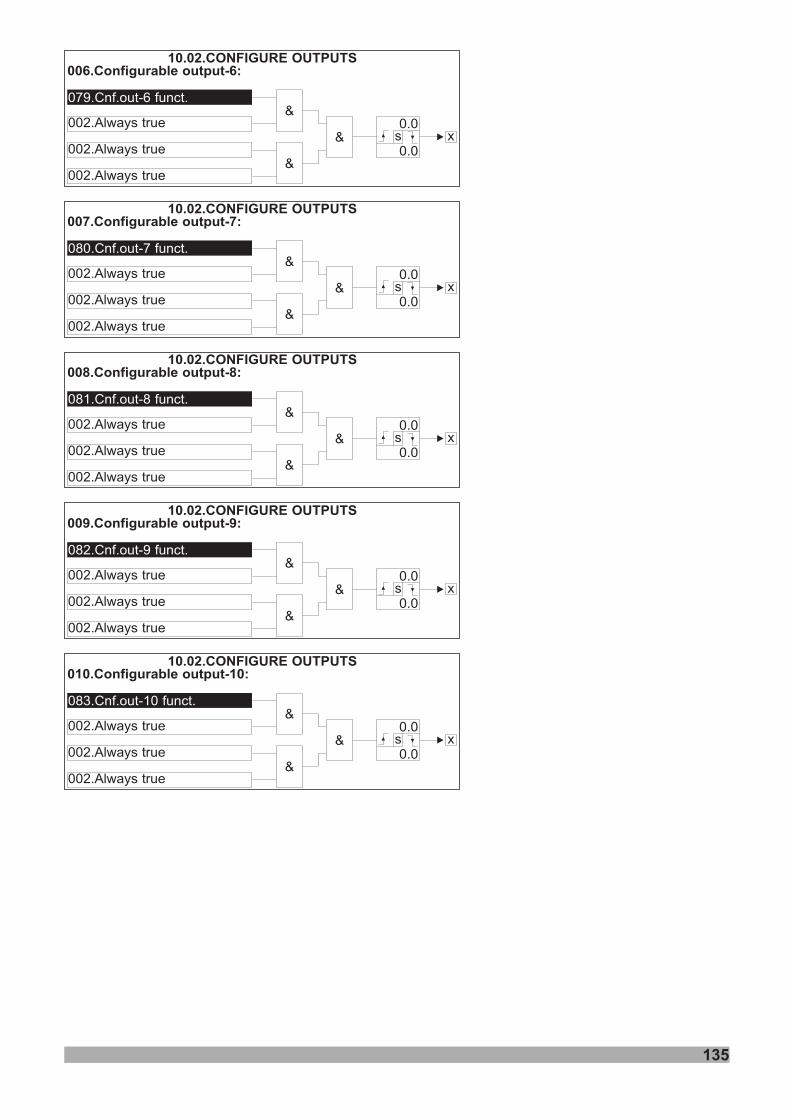
006.Configurable output-6:
007.Configurable output-7:
008.Configurable output-8:
009.Configurable output-9:
010.Configurable output-10:
079.Cnf.out-6 funct.
080.Cnf.out-7 funct.
081.Cnf.out-8 funct.
082.Cnf.out-9 funct.
083.Cnf.out-10 funct.
002.Always true
002.Always true
002.Always true
002.Always true
002.Always true
002.Always true
002.Always true
002.Always true
002.Always true
002.Always true
002.Always true
002.Always true
002.Always true
002.Always true
002.Always true
&
&
&
&
&
&
&
&
&
&
&
&
&
&
&
10.02.CONFIGURE OUTPUTS
10.02.CONFIGURE OUTPUTS
10.02.CONFIGURE OUTPUTS
10.02.CONFIGURE OUTPUTS
10.02.CONFIGURE OUTPUTS
x
x
x
x
x
0.0
0.0
0.0
0.0
0.0
0.0
0.0
0.0
0.0
0.0
s
s
s
s
s
135
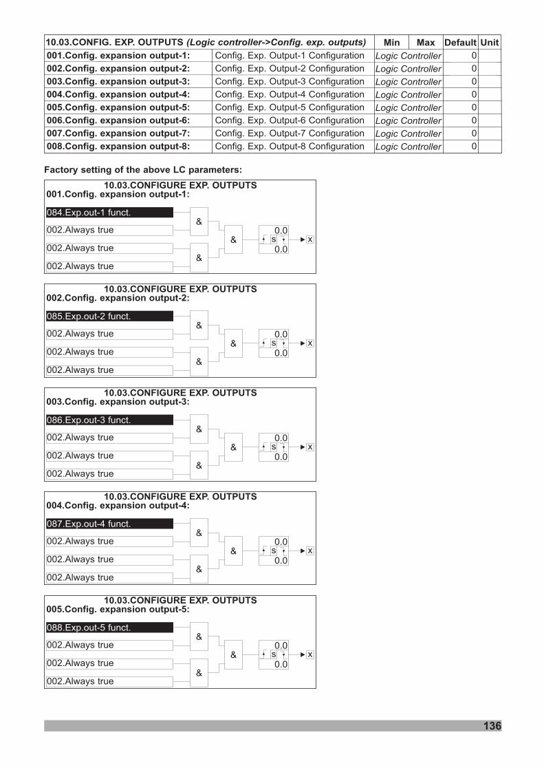
136
10.03.CONFIG. EXP. OUTPUTS (Logic controller->Config. exp. outputs)
001.Config. expansion output-1:
00 .Config. expansion output- :2 2
00 .Config. expansion output- :3 3
00 .Config. expansion output- :4 4
00 .Config. expansion output- :5 5
00 .Config. expansion output- :6 6
00 .Config. expansion output- :7 7
00 .Config. expansion output- :8 8
Logic Controller
Logic Controller
Logic Controller
Logic Controller
Logic Controller
Logic Controller
Logic Controller
Logic Controller
Min Default UnitMax
Config. Exp. Output-1 Configuration
Config. Exp. Output-2 Configuration
Config. Exp. Output-3 Configuration
Config. Exp. Output-4 Configuration
Config. Exp. Output-5 Configuration
Config. Exp. Output-6 Configuration
Config. Exp. Output-7 Configuration
Config. Exp. Output-8 Configuration
0
0
0
0
0
0
0
0
001.Config. expansion output-1:
002.Config. expansion output-2:
003.Config. expansion output-3:
004.Config. expansion output-4:
005.Config. expansion output-5:
084.Exp.out-1 funct.
085.Exp.out-2 funct.
086.Exp.out-3 funct.
087.Exp.out-4 funct.
088.Exp.out-5 funct.
002.Always true
002.Always true
002.Always true
002.Always true
002.Always true
002.Always true
002.Always true
002.Always true
002.Always true
002.Always true
002.Always true
002.Always true
002.Always true
002.Always true
002.Always true
&
&
&
&
&
&
&
&
&
&
&
&
&
&
&
10.03.CONFIGURE EXP. OUTPUTS
10.03.CONFIGURE EXP. OUTPUTS
10.03.CONFIGURE EXP. OUTPUTS
10.03.CONFIGURE EXP. OUTPUTS
10.03.CONFIGURE EXP. OUTPUTS
x
x
x
x
x
0.0
0.0
0.0
0.0
0.0
0.0
0.0
0.0
0.0
0.0
s
s
s
s
s
Factory setting of the above LC parameters:
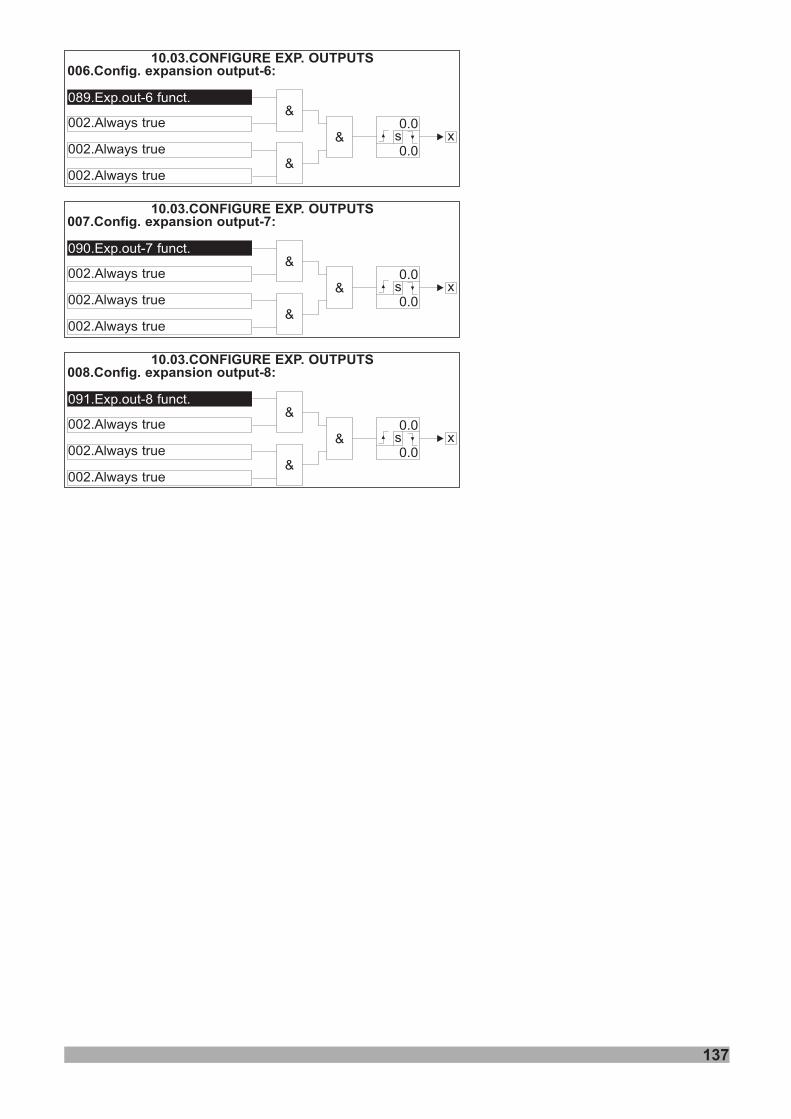
006.Config. expansion output-6:
007.Config. expansion output-7:
008.Config. expansion output-8:
089.Exp.out-6 funct.
090.Exp.out-7 funct.
091.Exp.out-8 funct.
002.Always true
002.Always true
002.Always true
002.Always true
002.Always true
002.Always true
002.Always true
002.Always true
002.Always true
&
&
&
&
&
&
&
&
&
10.03.CONFIGURE EXP. OUTPUTS
10.03.CONFIGURE EXP. OUTPUTS
10.03.CONFIGURE EXP. OUTPUTS
x
x
x
0.0
0.0
0.0
0.0
0.0
0.0
s
s
s
137
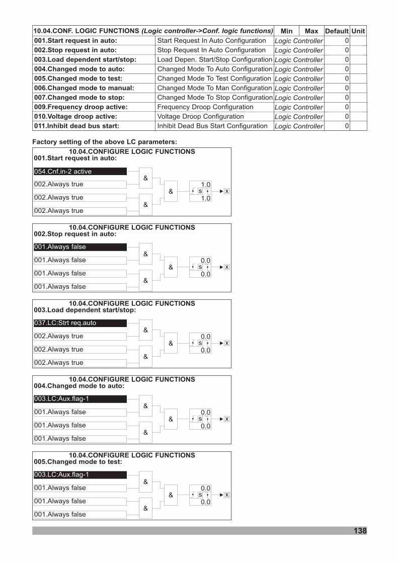
138
10.04.CONF. LOGIC FUNCTIONS (Logic controller->Conf. logic functions)
001.Start request in auto:
00 .Stop request in auto:2
00 .Load dependent start/stop:3
00 .Changed mode to auto:4
00 .Changed mode to test:5
00 .Changed mode to manual:6
00 .Changed mode to stop:7
009.Frequency droop active:
010.Voltage droop active:
011.Inhibit dead bus start:
Logic Controller
Logic Controller
Logic Controller
Logic Controller
Logic Controller
Logic Controller
Logic Controller
Logic Controller
Logic Controller
Logic Controller
Min Default UnitMax
Start Request In Auto Configuration
Stop Request In Auto Configuration
Load Depen. Start/Stop Configuration
Changed Mode To Auto Configuration
Changed Mode To Test Configuration
Changed Mode To Man Configuration
Changed Mode To Stop Configuration
Frequency Droop Configuration
Voltage Droop Configuration
Inhibit Dead Bus Start Configuration
0
0
0
0
0
0
0
0
0
0
001.Start request in auto:
002.Stop request in auto:
054.Cnf.in-2 active
001.Always false
002.Always true
001.Always false
002.Always true
001.Always false
002.Always true
001.Always false
&
&
&
&
&
&
10.04.CONFIGURE LOGIC FUNCTIONS
10.04.CONFIGURE LOGIC FUNCTIONS
x
x
1.0
0.0
1.0
0.0
s
s
Factory setting of the above LC parameters:
003.Load dependent start/stop:
004.Changed mode to auto:
005.Changed mode to test:
037.LC:Strt req.auto
003.LC:Aux.flag-1
003.LC:Aux.flag-1
002.Always true
001.Always false
001.Always false
002.Always true
001.Always false
001.Always false
002.Always true
001.Always false
001.Always false
&
&
&
&
&
&
&
&
&
10.04.CONFIGURE LOGIC FUNCTIONS
10.04.CONFIGURE LOGIC FUNCTIONS
10.04.CONFIGURE LOGIC FUNCTIONS
x
x
x
0.0
0.0
0.0
0.0
0.0
0.0
s
s
s

139
006.Changed mode to manual:
007.Changed mode to stop:
003.LC:Aux.flag-1
003.LC:Aux.flag-1
001.Always false
001.Always false
001.Always false
001.Always false
001.Always false
001.Always false
&
&
&
&
&
&
10.04.CONFIGURE LOGIC FUNCTIONS
10.04.CONFIGURE LOGIC FUNCTIONS
x
x
0.0
0.0
0.0
0.0
s
s
009.Frequency droop active:
010.Voltage droop active:
003.LC:Aux.flag-1
003.LC:Aux.flag-1
001.Always false
001.Always false
001.Always false
001.Always false
001.Always false
001.Always false
&
&
&
&
&
&
10.04.CONFIGURE LOGIC FUNCTIONS
10.04.CONFIGURE LOGIC FUNCTIONS
x
x
0.0
0.0
0.0
0.0
s
s
011.Inhibit dead bus start:
001.Always false
001.Always false
001.Always false
001.Always false
&
&
&
10.04.CONFIGURE LOGIC FUNCTIONS
x0.0
0.0s
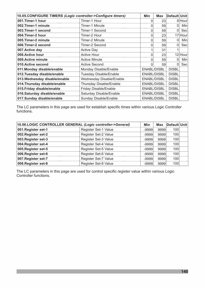
140
10.05.CONFIGURE TIMERS (Logic controller->Configure timers)
001.Timer-1 hour
00 .Timer-1 minute2
00 .Timer-1 second3
00 .Timer- hour4 2
00 .Timer- minute5 2
00 .Timer- second6 2
00 .A7 ctive day
00 .A8 ctive hour
00 .A9 ctive minute
0 .A10 ctive second
0 .11 Monday disable/enable
0 .12 Tuesday disable/enable
0 .13 Wednesday disable/enable
0 .14 Thursday disable/enable
0 .15 Friday disable/enable
0 .16 Saturday disable/enable
0 .17 Sunday disable/enable
0
0
0
0
0
0
1
0
0
0
Min Default UnitMax
Timer-1 ourH
Timer-1 inuteM
Timer-1 econdS
Timer- our2 H
Timer- inute2 M
Timer- econd2 S
Active Day
Active Hour
Active Minute
Active Second
Monday Disable/Enable
Tuesday Disable/Enable
Wednesday Disable/Enable
Thursday Disable/Enable
Friday Disable/Enable
Saturday Disable/Enable
Sunday Disable/Enable
8
0
0
17
0
0
1
12
0
0
DISBL
DISBL
DISBL
DISBL
DISBL
DISBL
DISBL
ENABL/DISBL
ENABL/DISBL
ENABL/DISBL
ENABL/DISBL
ENABL/DISBL
ENABL/DISBL
ENABL/DISBL
Hour
Min
Sec
Hour
Min
Sec
Hour
Min
Sec
23
59
59
23
59
59
31
23
59
59
10.0 .6 LOGIC CONTROLLER GENERAL (Logic controller-> )General
001. -1Register set
00 . -2 Register set 2
00 . -3 Register set 3
00 . -4 Register set 4
00 . -5 Register set 5
00 . -6 Register set 6
00 . -7 Register set 7
00 . -8 Register set 8
-9999
-9999
-9999
-9999
-9999
-9999
-9999
-9999
Min Default UnitMax
Register Set Value-1
Register Set 2 Value-
Register Set 3 Value-
Register Set 4 Value-
Register Set 5 Value-
Register Set 6 Value-
Register Set 7 Value-
Register Set 8 Value-
100
100
100
100
100
100
100
100
9999
9999
9999
9999
9999
9999
9999
9999
The LC parameters in this page are used for establish specific times within various Logic Controllerfunctions.
The LC parameters in this page are used for control pecific register value within various LogicController functions.
s
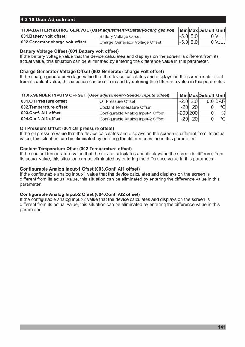
Min Default Unit11.05. OFFSET ( )SENDER INPUTS User adjustment-> offsetSender inputs Max0.0
000
-2 0.-20
-200-20
001.Oil Pressure offset
002.Temperature offset
003.Conf. AI1 offset
004.Conf. AI2 offset
Oil Pressure Offset
Coolant Temperature Offset
Configurable Analog Input-1 Offset
Configurable Analog Input-2 Offset
2 0.20
20020
BARºC
ºC
%
4.2.10 User Adjustment
Min Default Unit11.04. ( )BATTERY&CHRG GEN.VOL & .User adjustment->Battery chrg gen vol Max00
- 05.
- 05.
001.Battery volt offset
002.Generator charge volt offsetBattery Voltage Offset
Charge Generator Voltage Offset
5.05.0
VZVZ
141
Battery Voltage Offset (001.Battery volt offset)
Charge Generator Voltage Offset (002.Generator charge volt offset)
If the battery voltage value that the device calculates and displays on the screen is different from itsactual value, this situation can be eliminated by entering the difference value in this parameter.
If the charge generator voltage value that the device calculates and displays on the screen is differentfrom its actual value, this situation can be eliminated by entering the difference value in this parameter.
Oil Pressure Offset (001.Oil pressure offset)
Coolant Temperature Ofset (002.Temperature offset)
Configurable Analog Input-1 Ofset (003.Conf. AI1 offset)
Configurable Analog Input-2 Ofset (004.Conf. AI2 offset)
If the oil pressure value that the device calculates and displays on the screen is different from its actualvalue, this situation can be eliminated by entering the difference value in this parameter.
If the coolant temperature value that the device calculates and displays on the screen is different fromits actual value, this situation can be eliminated by entering the difference value in this parameter.
If the configurable analog input-1 value that the device calculates and displays on the screen isdifferent from its actual value, this situation can be eliminated by entering the difference value in thisparameter.
If the configurable analog input-2 value that the device calculates and displays on the screen isdifferent from its actual value, this situation can be eliminated by entering the difference value in thisparameter.
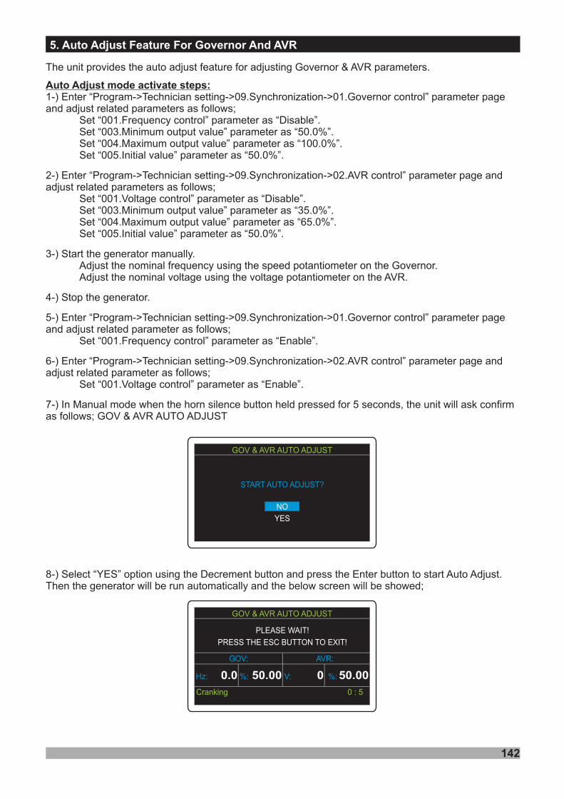
GOV & AVR AUTO ADJUST
PRESS THE ESC BUTTON TO EXIT!
PLEASE WAIT!
GOV: AVR:
Hz: 0.0 %: 50.00 V: 0 %: 50.00
Cranking 0 : 5
142
5. Auto Adjust Feature For Governor And AVR
The unit provides the auto adjust feature for adjusting Governor & AVR parameters.
1-) Enter “Program->Technician setting->09.Synchronization->01.Governor control” parameter pageand adjust related parameters as follows;
Set “001.Frequency control” parameter as “ ”.Set “003.Minimum output value” parameter as “50.0%”.
2-) E
3-) Start the generator manually.Adjust the nominal frequency using the speed potantiometer .Adjust the nominal voltage using the voltage
4-) Stop the generator.
5-)
7-) I when the horn silence button held pressed for 5 seconds, the unit will ask confirmas follows; GOV & AVR AUTO ADJUST
Auto Adjust mode activate steps:
Disable
Set “004.Maximum output value” parameter as “100.0%”.Set “005.Initial value” parameter as “50.0%”.
nter “Program->Technician setting->09.Synchronization->02.AVR control” parameter page andadjust related parameters as follows;
Set “001.Voltage control” parameter as “Disable”.Set “003.Minimum output value” parameter as “35.0%”.Set “004.Maximum output value” parameter as “65.0%”.Set “005.Initial value” parameter as “50.0%”.
on the Governorpotantiometer on the AVR.
Enter “Program->Technician setting->09.Synchronization->01.Governor control” parameter pageand adjust related parameter as follows;
Set “001.Frequency control” parameter as “Enable”.
6-) Enter “Program->Technician setting->09.Synchronization->02.AVR control” parameter page andadjust related parameter as follows;
Set “001.Voltage control” parameter as “Enable”.
n Manual mode
8-) Select “YES” option using the Decrement button and press the Enter button to start Auto Adjust.Then the generator will be run automatically and the below screen will be showed;
GOV & AVR AUTO ADJUST
START AUTO ADJUST?
NO
YES

GOV & AVR AUTO ADJUST
PRESS THE ESC BUTTON TO EXIT!
COMPLETED!
GOV: AVR:
Hz: 0.0 %: 50.00 V: 0 %: 50.00
Wait for start
143
9-) The Auto Adjust process will be completed after approximately two minutes and the below screenwill be showed;
10-) Now the related Governor and AVR parameters are automatically set.
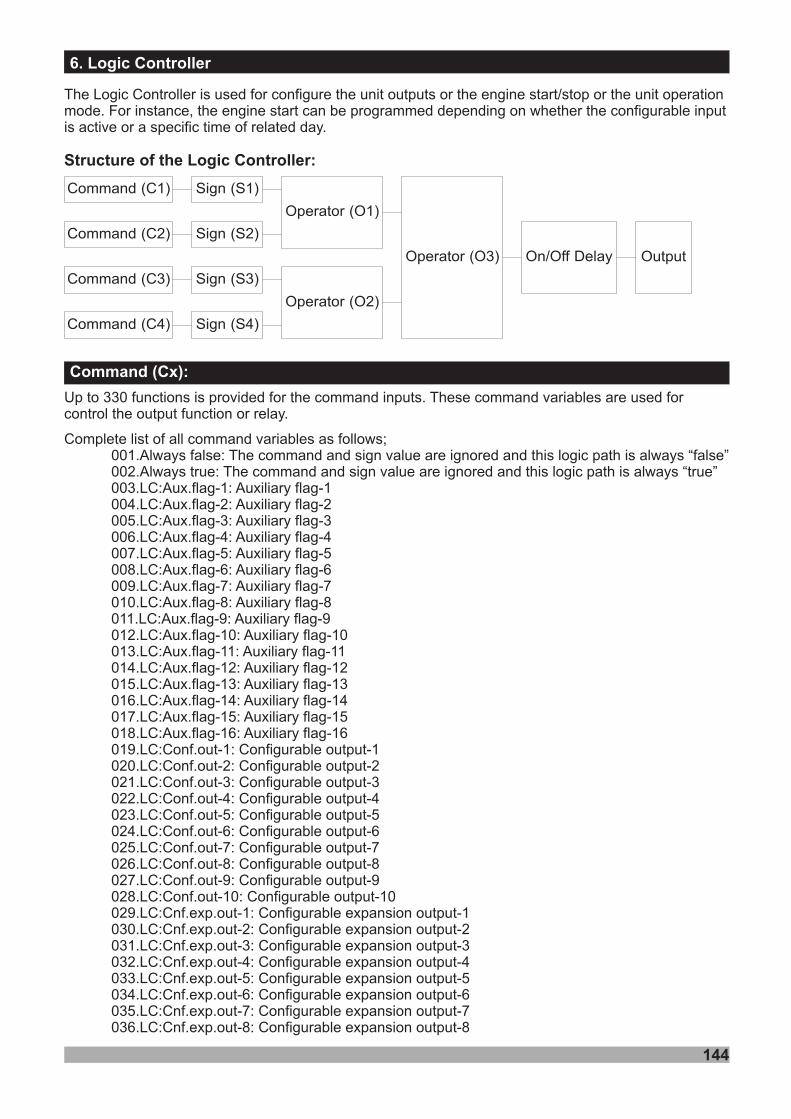
144
6. Logic Controller
The Logic Controller is used for configure the unit outputs or the engine start/stop or the unit operationmode. For instance, the engine start can be programmed depending on whether the configurable inputis active or a specific time of related day.
Structure of the Logic Controller:
Command (C1)
Command (C2)
Command (C3)
Command (C4)
Sign (S1)
Sign (S2)
Sign (S3)
Sign (S4)
Operator (O1)
Operator (O2)
Operator (O3) On/Off Delay Output
Up to 330 functions is provided for the command inputs. These command variables are used forcontrol the output function or relay.
Complete list of all command variables as follows;001.Always false: The command and sign value are ignored and this logic path is always “false”002.Always true: The command and sign value are ignored and this logic path is always “true”003.LC:Aux.flag-1: Auxiliary flag-1004.LC:Aux.flag-2: Auxiliary flag-2005.LC:Aux.flag-3: Auxiliary flag-3006.LC:Aux.flag-4: Auxiliary flag-4007.LC:Aux.flag-5: Auxiliary flag-5008.LC:Aux.flag-6: Auxiliary flag-6009.LC:Aux.flag-7: Auxiliary flag-7010.LC:Aux.flag-8: Auxiliary flag-8011.LC:Aux.flag-9: Auxiliary flag-9012.LC:Aux.flag-10: Auxiliary flag-10013.LC:Aux.flag-11: Auxiliary flag-11014.LC:Aux.flag-12: Auxiliary flag-12015.LC:Aux.flag-13: Auxiliary flag-13016.LC:Aux.flag-14: Auxiliary flag-14017.LC:Aux.flag-15: Auxiliary flag-15018.LC:Aux.flag-16: Auxiliary flag-16019.LC:Conf.out-1: Configurable output-1020.LC:Conf.out-2: Configurable output-2021.LC:Conf.out-3: Configurable output-3022.LC:Conf.out-4: Configurable output-4023.LC:Conf.out-5: Configurable output-5024.LC:Conf.out-6: Configurable output-6025.LC:Conf.out-7: Configurable output-7026.LC:Conf.out-8: Configurable output-8027.LC:Conf.out-9: Configurable output-9028.LC:Conf.out-10: Configurable output-10029.LC:Cnf.exp.out-1: Configurable expansion output-1030.LC:Cnf.exp.out-2: Configurable expansion output-2031.LC:Cnf.exp.out-3: Configurable expansion output-3032.LC:Cnf.exp.out-4: Configurable expansion output-4033.LC:Cnf.exp.out-5: Configurable expansion output-5034.LC:Cnf.exp.out-6: Configurable expansion output-6035.LC:Cnf.exp.out-7: Configurable expansion output-7036.LC:Cnf.exp.out-8: Configurable expansion output-8
Command (Cx):
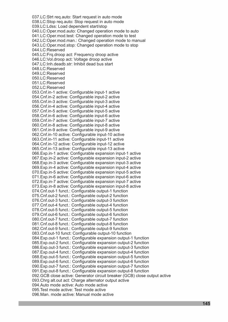
145
037.LC:Strt req.auto: Start request in auto mode038.LC:Stop req.auto: Stop request in auto mode039.LC:Ldss: Load dependent start/stop040.LC:Oper.mod.auto: Changed operation mode to auto041.LC:Oper.mod.test: Changed operation mode to test042.LC:Oper.mod.man.: Changed operation mode to manual043.LC:Oper.mod.stop: Changed operation mode to stop044.LC:Reserved045.LC:Frq.droop act: Frequency droop active046.LC:Vol.droop act: Voltage droop active047.LC:Inh.deadb.str: Inhibit dead bus start048.LC:Reserved049.LC:Reserved050.LC:Reserved051.LC:Reserved052.LC:Reserved053.Cnf.in-1 active: Configurable input-1 active054.Cnf.in-2 active: Configurable input-2 active055.Cnf.in-3 active: Configurable input-3 active056.Cnf.in-4 active: Configurable input-4 active057.Cnf.in-5 active: Configurable input-5 active058.Cnf.in-6 active: Configurable input-6 active059.Cnf.in-7 active: Configurable input-7 active060.Cnf.in-8 active: Configurable input-8 active061.Cnf.in-9 active: Configurable input-9 active062.Cnf.in-10 active: Configurable input-10 active063.Cnf.in-11 active: Configurable input-11 active064.Cnf.in-12 active: Configurable input-12 active065.Cnf.in-13 active: Configurable input-13 active066.Exp.in-1 active: Configurable expansion input-1 active067.Exp.in-2 active: Configurable expansion input-2 active068.Exp.in-3 active: Configurable expansion input-3 active069.Exp.in-4 active: Configurable expansion input-4 active070.Exp.in-5 active: Configurable expansion input-5 active071.Exp.in-6 active: Configurable expansion input-6 active072.Exp.in-7 active: Configurable expansion input-7 active073.Exp.in-8 active: Configurable expansion input-8 active074.Cnf.out-1 funct.: Configurable output-1 function075.Cnf.out-2 funct.: Configurable output-2 function076.Cnf.out-3 funct.: Configurable output-3 function077.Cnf.out-4 funct.: Configurable output-4 function078.Cnf.out-5 funct.: Configurable output-5 function079.Cnf.out-6 funct.: Configurable output-6 function080.Cnf.out-7 funct.: Configurable output-7 function081.Cnf.out-8 funct.: Configurable output-8 function082.Cnf.out-9 funct.: Configurable output-9 function083.Cnf.out-10 funct: Configurable output-10 function084.Exp.out-1 funct.: Configurable expansion output-1 function085.Exp.out-2 funct.: Configurable expansion output-2 function086.Exp.out-3 funct.: Configurable expansion output-3 function087.Exp.out-4 funct.: Configurable expansion output-4 function088.Exp.out-5 funct.: Configurable expansion output-5 function089.Exp.out-6 funct.: Configurable expansion output-6 function090.Exp.out-7 funct.: Configurable expansion output-7 function091.Exp.out-8 funct.: Configurable expansion output-8 function092.GCB close active: Generator circuit breaker (GCB) close output active093.Chrg alt.out act: Charge alternator output active094.Auto mode active: Auto mode active095.Test mode active: Test mode active096.Man. mode active: Manual mode active
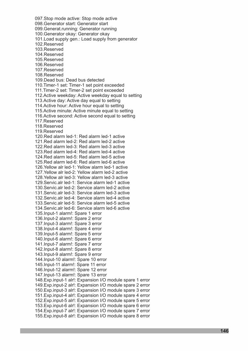
146
097.Stop mode active: Stop mode active098.Generator start: Generator start099.Generat.running: Generator running100.Generator okay: Generator okay101.Load supply gen.: Load supply from generator102.Reserved103.Reserved104.Reserved105.Reserved106.Reserved107.Reserved108.Reserved109.Dead bus: Dead bus detected110.Timer-1 set: Timer-1 set point exceeded111.Timer-2 set: Timer-2 set point exceeded112.Active weekday: Active weekday equal to setting113.Active day: Active day equal to setting114.Active hour: Active hour equal to setting115.Active minute: Active minute equal to setting116.Active second: Active second equal to setting117.Reserved118.Reserved119.Reserved120.Red alarm led-1: Red alarm led-1 active121.Red alarm led-2: Red alarm led-2 active122.Red alarm led-3: Red alarm led-3 active123.Red alarm led-4: Red alarm led-4 active124.Red alarm led-5: Red alarm led-5 active125.Red alarm led-6: Red alarm led-6 active126.Yellow alr led-1: Yellow alarm led-1 active127.Yellow alr led-2: Yellow alarm led-2 active128.Yellow alr led-3: Yellow alarm led-3 active129.Servic.alr led-1: Service alarm led-1 active130.Servic.alr led-2: Service alarm led-2 active131.Servic.alr led-3: Service alarm led-3 active132.Servic.alr led-4: Service alarm led-4 active133.Servic.alr led-5: Service alarm led-5 active134.Servic.alr led-6: Service alarm led-6 active135.Input-1 alarm!: Spare 1 error136.Input-2 alarm!: Spare 2 error137.Input-3 alarm!: Spare 3 error138.Input-4 alarm!: Spare 4 error139.Input-5 alarm!: Spare 5 error140.Input-6 alarm!: Spare 6 error141.Input-7 alarm!: Spare 7 error142.Input-8 alarm!: Spare 8 error143.Input-9 alarm!: Spare 9 error144.Input-10 alarm!: Spare 10 error145.Input-11 alarm!: Spare 11 error146.Input-12 alarm!: Spare 12 error147.Input-13 alarm!: Spare 13 error148.Exp.input-1 alr!: Expansion I/O module spare 1 error149.Exp.input-2 alr!: Expansion I/O module spare 2 error150.Exp.input-3 alr!: Expansion I/O module spare 3 error151.Exp.input-4 alr!: Expansion I/O module spare 4 error152.Exp.input-5 alr!: Expansion I/O module spare 5 error153.Exp.input-6 alr!: Expansion I/O module spare 6 error154.Exp.input-7 alr!: Expansion I/O module spare 7 error155.Exp.input-8 alr!: Expansion I/O module spare 8 error
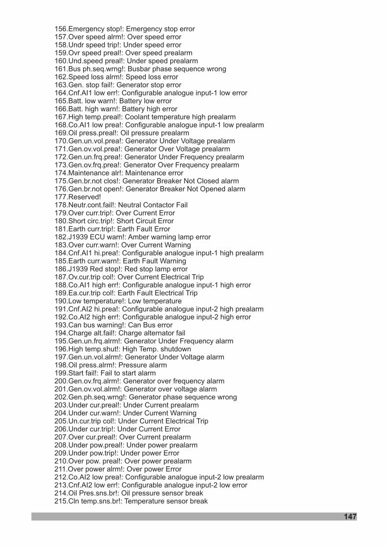
156.Emergency stop!: Emergency stop error157.Over speed alrm!: Over speed error158.Undr speed trip!: Under speed error159.Ovr speed preal!: Over speed prealarm160.Und.speed preal!: Under speed prealarm161.Bus ph.seq.wrng!: Busbar162.Speed loss alrm!: Speed loss error163.Gen. stop fail!: Generator stop error164.Cnf.AI1 low err!: Configurable analogue input-1 low error165.Batt. low warn!: Battery low error166.Batt. high warn!: Battery high error167.High temp.preal!: Coolant temperature high prealarm168.Co.AI1 low prea!: Configurable analogue input-1 low prealarm169.Oil press.preal!: Oil pressure prealarm170.Gen.un.vol.prea!: Generator Under Voltage prealarm
phase sequence wrong
171.Gen.ov.vol.prea!: Generator Over Voltage prealarm172.Gen.un.frq.prea!: Generator Under Frequency prealarm173.Gen.ov.frq.prea!: Generator Over Frequency prealarm174.Maintenance alr!: Maintenance error175.Gen.br.not clos!: Generator Breaker Not Closed alarm176.Gen.br.not open!: Generator Breaker Not Opened alarm177.Reserved!178.Neutr.cont.fail!: Neutral Contactor Fail179.Over curr.trip!: Over Current Error180.Short circ.trip!: Short Circuit Error181.Earth curr.trip!: Earth Fault Error182.J1939 ECU warn!: Amber warning lamp error183.Over curr.warn!: Over Current Warning184.Cnf.AI1 hi.prea!: Configurable analogue input-1 high prealarm185.Earth curr.warn!: Earth Fault Warning186.J1939 Red stop!: Red stop lamp error187.Ov.cur.trip col!: Over Current Electrical Trip188.Co.AI1 high err!: Configurable analogue input-1 high error189.Ea.cur.trip col!: Earth Fault Electrical Trip190.Low temperature!: Low temperature191.Cnf.AI2 hi.prea!: Configurable analogue input-2 high prealarm192.Co.AI2 high err!: Configurable analogue input-2 high error193.Can bus warning!: Can Bus error194.Charge alt.fail!: Charge alternator fail195.Gen.un.frq.alrm!: Generator Under Frequency alarm196.High temp.shut!: High Temp. shutdown197.Gen.un.vol.alrm!: Generator Under Voltage alarm198.Oil press.alrm!: Pressure alarm199.Start fail!: Fail to start alarm200.Gen.ov.frq.alrm!: Generator over frequency alarm201.Gen.ov.vol.alrm!: Generator over voltage alarm202.Gen.ph.seq.wrng!: Generator phase sequence wrong203.Under cur.preal!: Under Current prealarm204.Under cur.warn!: Under Current Warning205.Un.cur.trip col!: Under Current Electrical Trip206.Under cur.trip!: Under Current Error207.Over cur.preal!: Over Current prealarm208.Under pow.preal!: Under power prealarm209.Under pow.trip!: Under power Error210.Over pow. preal!: Over power prealarm211.Over power alrm!: Over power Error212.Co.AI2 low prea!: Configurable analogue input-2 low prealarm213.Cnf.AI2 low err!: Configurable analogue input-2 low error214.Oil Pres.sns.br!: Oil pressure sensor break215.Cln temp.sns.br!: Temperature sensor break
147
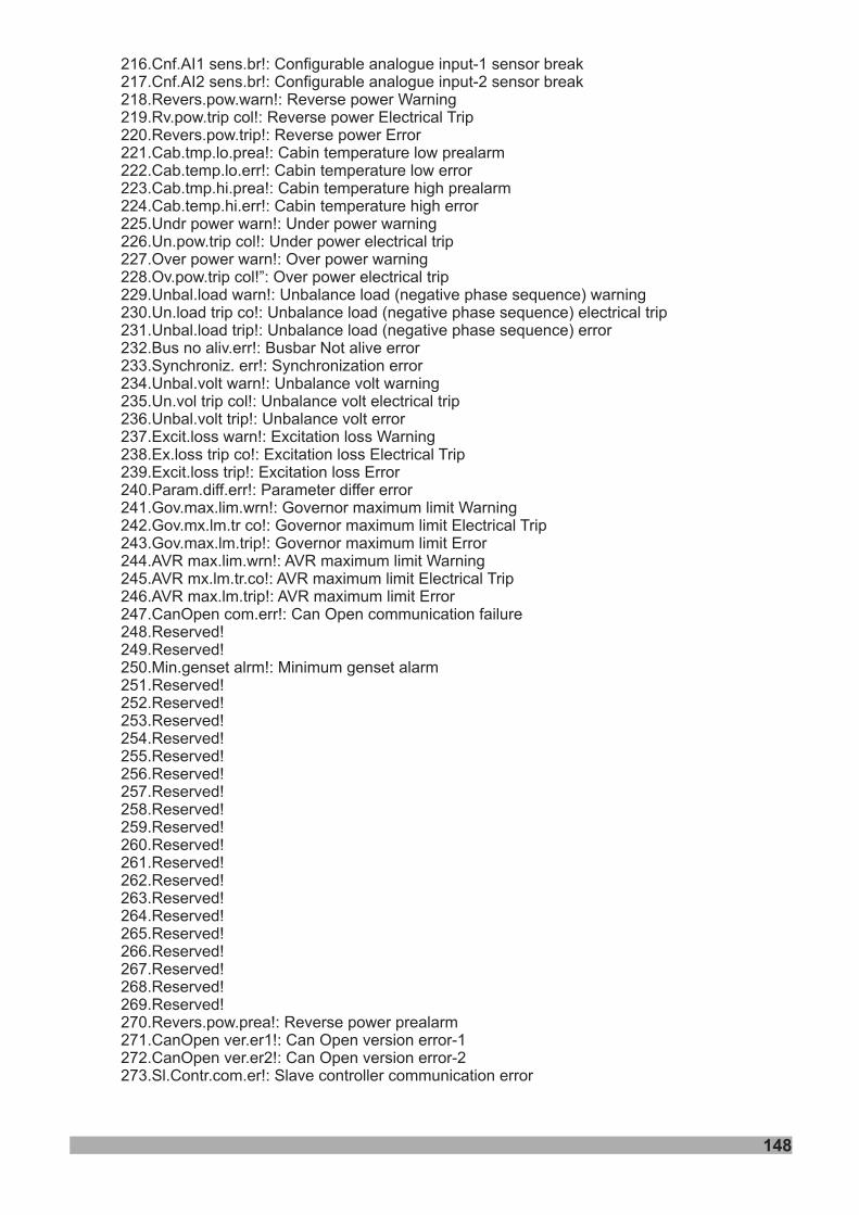
216.Cnf.AI1 sens.br!: Configurable analogue input-1 sensor break217.Cnf.AI2 sens.br!: Configurable analogue input-2 sensor break218.Revers.pow.warn!: Reverse power Warning219.Rv.pow.trip col!: Reverse power Electrical Trip220.Revers.pow.trip!: Reverse power Error221.Cab.tmp.lo.prea!: Cabin temperature low prealarm222.Cab.temp.lo.err!: Cabin temperature low error223.Cab.tmp.hi.prea!: Cabin temperature high prealarm224.Cab.temp.hi.err!: Cabin temperature high error225.Undr power warn!: Under power warning226.Un.pow.trip col!: Under power electrical trip227.Over power warn!: Over power warning228.Ov.pow.trip col!”: Over power electrical trip229.Unbal.load warn!: Unbalance load (negative phase sequence) warning230.Un.load trip co!: Unbalance load (negative phase sequence) electrical trip231.Unbal.load trip!: Unbalance load (negative phase sequence) error232.Bus no aliv.err!: Busbar Not alive error233.Synchroniz. err!: Synchronization error234.Unbal.volt warn!: Unbalance volt warning235.Un.vol trip col!: Unbalance volt electrical trip236.Unbal.volt trip!: Unbalance volt error237.Excit.loss warn!: Excitation loss Warning238.Ex.loss trip co!: Excitation loss Electrical Trip239.Excit.loss trip!: Excitation loss Error240.Param.diff.err!: Parameter differ error241.Gov.max.lim.wrn!: Governor maximum limit Warning242.Gov.mx.lm.tr co!: Governor maximum limit Electrical Trip243.Gov.max.lm.trip!: Governor maximum limit Error244.AVR max.lim.wrn!: AVR maximum limit Warning245.AVR mx.lm.tr.co!: AVR maximum limit Electrical Trip246.AVR max.lm.trip!: AVR maximum limit Error247.CanOpen com.err!: Can Open communication failure248.Reserved!249.Reserved!250.Min.genset alrm!: Minimum genset alarm251.Reserved!252.Reserved!253.Reserved!254.Reserved!255.Reserved!256.Reserved!257.Reserved!258.Reserved!259.Reserved!260.Reserved!261.Reserved!262.Reserved!263.Reserved!264.Reserved!265.Reserved!266.Reserved!267.Reserved!268.Reserved!269.Reserved!270.Revers.pow.prea!: Reverse power prealarm271.CanOpen ver.er1!: Can Open version error-1272.CanOpen ver.er2!: Can Open version error-2273.Sl.Contr.com.er!: Slave controller communication error
148
149
274.RC:Register set1: Register set1 parameter value275.RC:Register set2: Register set2 parameter value276.RC:Register set3: Register set3 parameter value277.RC:Register set4: Register set4 parameter value278.RC:Register set5: Register set5 parameter value279.RC:Register set6: Register set6 parameter value280.RC:Register set7: Register set7 parameter value281.RC:Register set8: Register set8 parameter value282.RC:Bus V1: Bus V1 active value283.RC:Bus V2: Bus V2 active value284.RC:Bus V3: Bus V3 active value285.RC:Bus V12: Bus V12 active value286.RC:Bus V23: Bus V23 active value287.RC:Bus V31: Bus V31 active value288.RC:Bus frequency: Bus frequency active value289.RC:Gen V1: Gen V1 active value290.RC:Gen V2: Gen V2 active value291.RC:Gen V3: Gen V3 active value292.RC:Gen V12: Gen V12 active value293.RC:Gen V23: Gen V23 active value294.RC:Gen V31: Gen V31 active value295.RC:Gen frequency: Gen frequency active value296.RC:Gen I1: Gen I1 active value297.RC:Gen I2: Gen I2 active value298.RC:Gen I3: Gen I3 active value299.RC:Earth Current: Earth Current active value300.RC:Reserved301.RC:Reserved302.RC:Reserved303.RC:Gen P1: Gen P1 active value304.RC:Gen P2: Gen P2 active value305.RC:Gen P3: Gen P3 active value306.RC:Gen P total: Gen P total active value307.RC:Gen Q1: Gen Q1 active value308.RC:Gen Q2: Gen Q2 active value309.RC:Gen Q3: Gen Q3 active value310.RC:Gen Q total: Gen Q total active value311.RC:Gen S1: Gen S1 active value312.RC:Gen S2: Gen S2 active value313.RC:Gen S3: Gen S3 active value314.RC:Gen S total: Gen S total active value315.RC:Gen kWh: Gen kWh active value316.RC:Gen kVArh: Gen kVArh active value317.RC:Engine RPM: Engine RPM active value318.RC:Oil pressure: Oil pressure active value319.RC:Coolant temp: Coolant temperature active value320.RC:Config. AI1: Configurable analog input-1 active value321.RC:Config. AI2: Configurable analog input-2 active value322.RC:Cabin temper.: Cabin temperature active value323.RC:Battery volt: Battery voltage active value324.RC:Gen chrg volt: Generator charge voltage active value325.RC:Run times: Run times active value326.RC:Crank times: Crank times active value327.RC:Working hours: Working hours active value328.RC:Mainten.hours: Next maintenance hours active value329.RC:Mainten. days: Next maintenance days active value330.RC:Reserve power: Reserve power active value
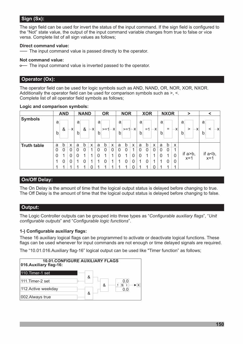
150
The sign field can be used for invert the status of the input command. If the sign field is configured tothe “Not” state value, the output of the input command variable from true to false or viceversa. Complete list of all sign values as follows;
changes
The operator field can be used for logic symbols such as AND, NAND, OR, NOR, XOR, NXORAdditionally the operator field can be used for comparison symbols such as >, <.
.
Complete list of all operator field symbols as follows;
Direct command value:
Not command value:
The input command value is passed directly to the operator.
The input command value is inverted passed to the operator.
Logic and comparison symbols:
AND NAND OR NOR XOR NXORSymbols
Truth table
& & >=1
a a a a a ab b b b b bx x x x x x0 0 0 0 0 00 0 0 0 0 01 1 1 1 1 11 1 1 1 1 1
0 0 0 0 0 01 1 1 1 1 10 0 0 0 0 01 1 1 1 1 1
0 1 0 1 0 10 1 1 0 1 00 1 1 0 1 01 0 1 0 0 1
>=1 =1 = > <
a a a a a a a a
b b b b b b b bxx x x x x x x
> <
if a>b,x=1
if a<b,x=1
The On Delay is the amount of time that the logical output status is delayed before changing to true.The Off Delay is the amount of time that the logical output status is delayed before changing to false.
The Logic Controller outputs can be grouped into three types as “” and “ ”.
“ ”,Configurable auxiliary flags Unitconfigurable outputs Configurable logic functions
Output:
On/Off Delay:
Operator (Ox):
Sign (Sx):
1-) Configurable auxiliary flags:
These 16 auxiliary logical flags can be programmed to activate or deactivate logical functions. Theseflags can be used whenever for input commands are not enough or time delayed signals are required.
The “10.01.016.Auxiliary flag-16” logical output can be used like "Timer function” as follows;
016.Auxiliary flag-16:
110.Timer-1 set
111.Timer-2 set
112.Active weekday
002.Always true
&
&
&
10.01.CONFIGURE AUXILIARY FLAGS
x0.0
0.0s
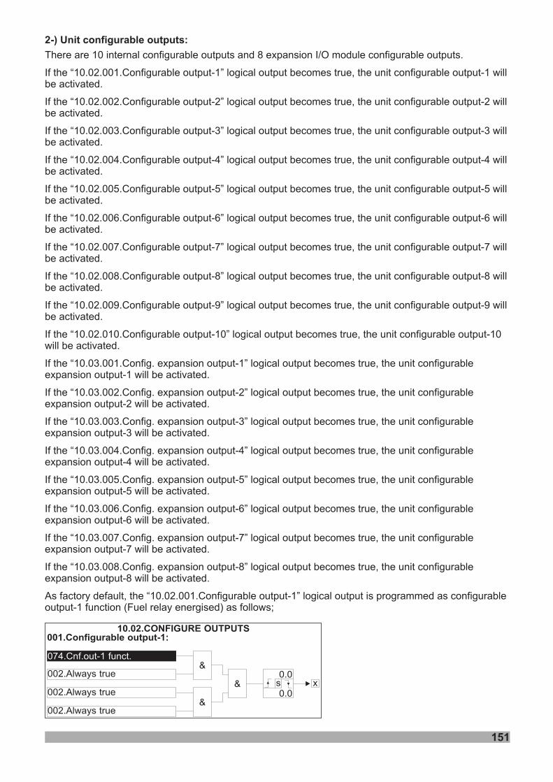
151
There are 10 internal configurable outputs and 8 expansion I/O module configurable outputs.
If the “10.02.001.Configurable output-1” logical output becomes true, the unit configurable output-1 willbe activated.
If the “10.02.002.Configurable output-2” logical output becomes true, the unit configurable output-2 willbe activated.
If the “10.02.003.Configurable output-3” logical output becomes true, the unit configurable output-3 willbe activated.
If the “10.02.004.Configurable output-4” logical output becomes true, the unit configurable output-4 willbe activated.
If the “10.02.005.Configurable output-5” logical output becomes true, the unit configurable output-5 willbe activated.
If the “10.02.006.Configurable output-6” logical output becomes true, the unit configurable output-6 willbe activated.
If the “10.02.008.Configurable output-8” logical output becomes true, the unit configurable output-8 willbe activated.
If the “10.02.009.Configurable output-9” logical output becomes true, the unit configurable output-9 willbe activated.
If the “10.02.010.Configurable output-10” logical output becomes true, the unit configurable output-10will be activated.
If the “10.03.001.Config. expansion output-1” logical output becomes true, the unit configurableexpansion output-1 will be activated.
If the “10.03.002.Config. expansion output-2” logical output becomes true, the unit configurableexpansion output-2 will be activated.
If the “10.03.003.Config. expansion output-3” logical output becomes true, the unit configurableexpansion output-3 will be activated.
If the “10.03.004.Config. expansion output-4” logical output becomes true, the unit configurableexpansion output-4 will be activated.
If the “10.03.005.Config. expansion output-5” logical output becomes true, the unit configurableexpansion output-5 will be activated.
If the “10.03.006.Config. expansion output-6” logical output becomes true, the unit configurableexpansion output-6 will be activated.
If the “10.03.007.Config. expansion output-7” logical output becomes true, the unit configurableexpansion output-7 will be activated.
If the “10.03.008.Config. expansion output-8” logical output becomes true, the unit configurableexpansion output-8 will be activated.
As factory default, the “10.02.001.Configurable output-1” logical output is programmed as configurableoutput-1 function (Fuel relay energised) as follows;
If the “10.02.007.Configurable output-7” logical output becomes true, the unit configurable output-7 willbe activated.
2-) Unit configurable outputs:
001.Configurable output-1:
074.Cnf.out-1 funct.
002.Always true
002.Always true
002.Always true
&
&
&
10.02.CONFIGURE OUTPUTS
x0.0
0.0s
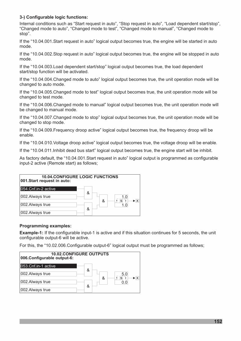
152
3-) Configurable logic functions:
Internal conditions such as “Start request in auto”, “Stop request in auto”, “Load dependent start/stop”,“Changed mode to auto”, “Changed mode to test”, “Changed mode to manual”, “Changed mode tostop”.
If the “10.04.002.Stop request in auto” logical output becomes true, the engine will be stopped in automode.
If the “10.04.003.Load dependent start/stop” logical output becomes true, the load dependentstart/stop function will be activated.
If the “10.04.004.Changed mode to auto” logical output becomes true, the unit operation mode will bechanged to auto mode.
If the “10.04.005.Changed mode to test” logical output becomes true, the unit operation mode will bechanged to test mode.
If the “10.04.006.Changed mode to manual” logical output becomes true, the unit operation mode willbe changed to manual mode.
If the “10.04.007.Changed mode to stop” logical output becomes true, the unit operation mode will bechanged to stop mode.
If the “10.04.009.Frequency droop active” logical output becomes true, the frequency droop will beenable.
If the “10.04.010.Voltage droop active” logical output becomes true, the voltage droop will be enable.
If the “10.04.011.Inhibit dead bus start” logical output becomes true, the engine start will be inhibit.
As factory default, the “10.04.001.Start request in auto” logical output is programmed as configurableinput-2 active (Remote start) as follows;
If the “10.04.001.Start request in auto” logical output becomes true, the engine will be started in automode.
001.Start request in auto:
054.Cnf.in-2 active
002.Always true
002.Always true
002.Always true
&
&
&
10.04.CONFIGURE LOGIC FUNCTIONS
x1.0
1.0s
Programming examples:
Example-1: If the configurable input-1 is active and if this situation continues for 5 seconds, the unitconfigurable output-6 will be active.
For this, the “10.02.006.Configurable output-6” logical output must be programmed as follows;
006.Configurable output-6:
053.Cnf.in-1 active
002.Always true
002.Always true
002.Always true
&
&
&
10.02.CONFIGURE OUTPUTS
x5.0
0.0s
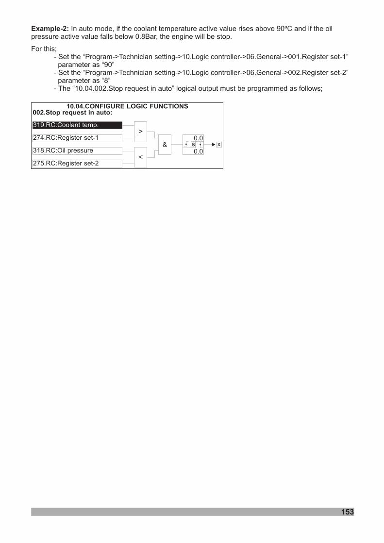
153
Example-2: In auto mode, if the coolant temperature active value rises above 90ºC and if the oilpressure active value falls below 0.8Bar, the engine will be stop.
For this;- Set the “Program->Technician setting->10.Logic controller->06.General->001.Register set-1”parameter as “90”
- Set the “Program->Technician setting->10.Logic controller->06.General->002.Register set-2”parameter as “8”
- The “10.04.002.Stop request in auto” logical output must be programmed as follows;
002.Stop request in auto:
319.RC:Coolant temp.
274.RC:Register set-1
318.RC:Oil pressure
275.RC:Register set-2
>
&
10.04.CONFIGURE LOGIC FUNCTIONS
x0.0
0.0s
<
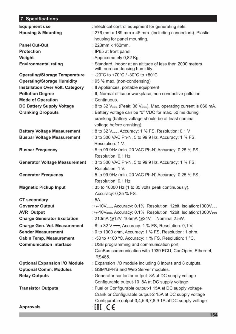
154
7. Specifications
Equipment use
Housing & Mounting
Panel Cut-Out
Protection
Weight
Environmental rating
Operating/Storage Temperature
Operating/Storage Humidity
Installation Over Volt. Category
Pollution Degree
Mode of Operation
Cranking Dropouts
Battery Voltage Measurement
Busbar Voltage Measurement
Busbar Frequency
Generator Voltage Measurement
Generator Frequency
Magnetic Pickup Input
CT secondary
Governor Output
AVR Output
Charge Generator Excitation
Charge Gen. Vol. Measurement
Sender Measurement
Cabin Temp. Measurement
Communication interface
Optional Expansion I/O Module
Optional Comm. Modules
Relay Outputs
Transistor Outputs
Approvals
: Electrical control equipment for generating sets.
: 276 mm x 189 mm x 45 mm. (including connectors)
.
: 223mm x 162mm.
:
: Approximately 0,82 Kg.
:with non-condensing humidity
: -20°C to +70°C / -30°C to +80°C
: 95 % max. (non-condensing)
: II Appliances, portable equipment
: II, Normal office or workplace, non conductive pollution
: Continuous.
: 8 to 32 V (Peak: 36 V ). Max. operating current is 860 mA.
: Battery voltage can be “0” VDC for max. 50 ms during
cranking (battery voltage should be at least nominal
voltage before cranking).
: 8 to 32 V , Accuracy: 1 % FS, Resolution: 0,1 V
: 3
Resolution: 1 V.
: 5 to 99.9Hz (min. 20 VAC Ph-N) Accuracy: 0,25 % FS,
Resolution: 0,1 Hz.
: 3
Resolution: 1 V.
: 5 to 99.9Hz (min. 20 VAC Ph-N) Accuracy: 0,25 % FS,
Resolution: 0,1 Hz.
: 35 to 10000 Hz (1 to 35 volts peak continuously).
Accuracy: 0,25 % FS.
: 5A.
:+/-10V , Accuracy: 0.1%, Resolution: 12bit, Isolation:1000V
:+/-10V , Accuracy: 0.1%, Resolution: 12bit, Isolation:1000V
: 210mA @12V, 105mA @24V. Nominal 2.5W.
: 8 to 32 V , Accuracy: 1 % FS, Resolution: 0,1 V.
: 0 to 1300 ohm, Accuracy: 1 % FS, Resolution: 1 ohm.
: -50 to +100 ºC, Accuracy: 1 % FS, Resolution: 1 ºC.
: USB programming and communication port,
CanBus communication with 1939 ECU, CanOpen, Ethernet,
RS485.
: Expansion I/O module including 8 inputs and 8 outputs.
: GSM/GPRS and Web Server modules.
: Generator contactor output 8A at DC supply voltage
Configurable output-10 8A at DC supply voltage
: Fuel or Configurable output-1 15A at DC supply voltage
Crank or Configurable output-2 15A at DC supply voltage
Configurable output-3,4,5,6,7,8,9 1A at DC supply voltage
:
. Plastic
housing for panel mounting
IP65 at front panel.
Standard, indoor at an altitude of less then 2000 meters.
to 300 VAC Ph-N, 5 to 99.9 Hz. Accuracy: 1 % FS,
to 300 VAC Ph-N, 5 to 99.9 Hz. Accuracy: 1 % FS,
DC Battery Supply Voltage Z Z
Z
Z Z
Z Z
Z
,

155
8. Other Informations
Manufacturer Information:Emko Elektronik Sanayi ve Ticaret A.Þ.Demirtaþ Organize Sanayi Bölgesi Karanfil Sk. No:6 16369BURSA/TURKEY
Phone : +90 224 261 1900Fax : +90 224 261 1912
Repair and maintenance service information:Emko Elektronik Sanayi ve Ticaret A.Þ.Demirtaþ Organize Sanayi Bölgesi Karanfil Sk. No:6 16369BURSA/TURKEYPhone : +90 224 261 1900Fax : +90 224 261 1912
Thank you very much for your preference to use Emko Elektronik
Products.Your Technology Partnerwww.emkoelektronik.com.tr