Trambeam Data - ACCO Material Handling Solutions
224
ACCO Material Handling Solutions 206 LEE STREET, ATTALLA, ALABAMA 35954 256-538-9983, FAX 256-538-8818 E-mail: [email protected] www.accomhs.com USING YOUR ENGINEERING DATA BOOK Your Engineering Data Book contains seven sections and is arranged in a logical sequence for selecting the components of underhung cranes and monorail systems. The BASIC DATA SECTION tells why Trambeam is your best buy and briefly describes the types of Trambeam equip- ment. Ensuing sections provide you with detailed engineer- ing data and specific information for your particular applica- tion. This section also contains two informative publications of the Monorail Manufacturers Association, Inc. One is their SPECIFICATIONS FOR UNDERHUNG CRANES AND MONORAIL SYSTEMS which offers technical and design information for the parties engaged in the marketing, buying or use of such systems. Section 15 of the specifications is a glossary of terms appropriate to the industry and will be help- ful to the experienced engineer as well as the novice. The other publication is their CONSIDERATIONS IN SPECIFY- ING UNDERHUNG CRANES AND MONORAIL SYS- TEMS. This is a compilation of contractual data to be con- sidered in preparing contracts for the purchase of underhung cranes and monorail systems. Both publications are repro- duced with permission of the association. The equipment selection process begins by determining the method of transporting the product to be handled. Hence, the CARRIER SECTION is the first of the technical sections. This section illustrates and describes the many available com- binations of carriers and hoist carriers. Single girder and double girder electric hoist carriers are cataloged for most major hoist manufacturers. The CRANE SECTION follows as the second step in deter- mining equipment for a crane system. Methods for crane selection are described in this section. Tables are included for selecting light duty and standard hand propelled single girder cranes and motor driven single and double girder cranes. The section also includes data on single and double girder transfer cranes, single girder low headroom cranes, Trambeam TR cranes and gantry cranes. The TRACTOR DRIVE SECTION has complete informa- tion on each of the drives available for propelling carriers and cranes. The section also has motor schedules for determining the motor horsepower, complete descriptions of the electrical equipment for controlling motor driven carriers and cranes and data on the National Electric Code and OSHA electrical standards. Determining the size of the runway or monorail track is the next step in the selection process. The TRACK AND FIT- TINGS SECTION describes Trambeam Type SW track and SECTION: BASIC DATA the procedures for calculating track and hanger rod loads. Tables are provided for selecting track size and hanger rod assemblies. Methods for suspending track are shown and dimensional information is provided for determining track elevations and hanger rod lengths. Standard top flange and web fabrication details are also included. The SWITCH SECTION describes and illustrates the Trambeam switches available for monorail systems. The sec- tion illustrates the grouping of switches and provides mini- mum dimension for mainline bypassing and spur tracks. Other monorail accessories such as turntables, crossovers and lift or drop sections are also described. The ELECTRIFICATION SECTION completes your Trambeam Engineering Data Book. It describes the electrifi- cation systems available for powered applications. TRAMBEAM IS YOUR BEST BUY Trambeam crane and monorail systems can be the most versatile equipment you can buy for overhead handling of many materials. They work out of the way of men and machines and achieve maximum use of space by eliminating the need for wide, space consuming aisles necessary when floor handling equipment is used. A Trambeam system combines unique handling and cost advantages because its hoist and carrier is underhung from the monorail or crane. Also, the crane is underhung from runways suspended from the building structure. Because of this design, a Trambeam crane can transfer loads between bays, between cranes or between cranes and monorails. In addition, costs can often be reduced through savings in equip- ment and building costs. e EQUIPMENT SAVINGS are attained by using Trambeam for crane girders and runway and mono- rail tracks. Trambeam track is a composite section combining a vanadium steel lower load carrying flange with mild steel web and top flange plates. The result is a balanced design providing high strength to weight characteristics. Trambeam track provides more strength per pound than conventional structural shapes such as standard !-beams. • BUILDING COST SAVINGS can be realized if run- ways can be installed without major building modi- ----A 9/95 PART OF THE 'fc.FKI GROUP
-
Upload
khangminh22 -
Category
Documents
-
view
1 -
download
0
Transcript of Trambeam Data - ACCO Material Handling Solutions

ACCO Material Handling Solutions206 LEE STREET, ATTALLA, ALABAMA 35954
256-538-9983, FAX 256-538-8818
E-mail: [email protected]
www.accomhs.com
USING YOUR ENGINEERING DATA BOOK
Your Engineering Data Book contains seven sections and is arranged in a logical sequence for selecting the components of underhung cranes and monorail systems.
The BASIC DATA SECTION tells why Trambeam is your best buy and briefly describes the types of Trambeam equipment. Ensuing sections provide you with detailed engineering data and specific information for your particular application. This section also contains two informative publications of the Monorail Manufacturers Association, Inc. One is their SPECIFICATIONS FOR UNDERHUNG CRANES AND MONORAIL SYSTEMS which offers technical and design information for the parties engaged in the marketing, buying or use of such systems. Section 15 of the specifications is a glossary of terms appropriate to the industry and will be helpful to the experienced engineer as well as the novice. The other publication is their CONSIDERATIONS IN SPECIFYING UNDERHUNG CRANES AND MONORAIL SYSTEMS. This is a compilation of contractual data to be considered in preparing contracts for the purchase of underhung cranes and monorail systems. Both publications are reproduced with permission of the association.
The equipment selection process begins by determining the method of transporting the product to be handled. Hence, the CARRIER SECTION is the first of the technical sections. This section illustrates and describes the many available combinations of carriers and hoist carriers. Single girder and double girder electric hoist carriers are cataloged for most major hoist manufacturers.
The CRANE SECTION follows as the second step in determining equipment for a crane system. Methods for crane selection are described in this section. Tables are included for selecting light duty and standard hand propelled single girder cranes and motor driven single and double girder cranes. The section also includes data on single and double girder transfer cranes, single girder low headroom cranes, Trambeam TR cranes and gantry cranes.
The TRACTOR DRIVE SECTION has complete information on each of the drives available for propelling carriers and cranes. The section also has motor schedules for determining the motor horsepower, complete descriptions of the electrical equipment for controlling motor driven carriers and cranes and data on the National Electric Code and OSHA electrical standards.
Determining the size of the runway or monorail track is the next step in the selection process. The TRACK AND FITTINGS SECTION describes Trambeam Type SW track and
SECTION: BASIC DATA
the procedures for calculating track and hanger rod loads. Tables are provided for selecting track size and hanger rod assemblies. Methods for suspending track are shown and dimensional information is provided for determining track elevations and hanger rod lengths. Standard top flange and web fabrication details are also included.
The SWITCH SECTION describes and illustrates the Trambeam switches available for monorail systems. The section illustrates the grouping of switches and provides minimum dimension for mainline bypassing and spur tracks. Other monorail accessories such as turntables, crossovers and lift or drop sections are also described.
The ELECTRIFICATION SECTION completes your Trambeam Engineering Data Book. It describes the electrification systems available for powered applications.
TRAMBEAM IS YOUR BEST BUY
Trambeam crane and monorail systems can be the most versatile equipment you can buy for overhead handling of many materials. They work out of the way of men and machines and achieve maximum use of space by eliminating the need for wide, space consuming aisles necessary when floor handling equipment is used.
A Trambeam system combines unique handling and cost advantages because its hoist and carrier is underhung from the monorail or crane. Also, the crane is underhung from runways suspended from the building structure. Because of this design, a Trambeam crane can transfer loads between bays, between cranes or between cranes and monorails. In addition, costs can often be reduced through savings in equipment and building costs.
e EQUIPMENT SAVINGS are attained by using Trambeam for crane girders and runway and monorail tracks. Trambeam track is a composite section combining a vanadium steel lower load carrying flange with mild steel web and top flange plates. The result is a balanced design providing high strength to weight characteristics. Trambeam track provides more strength per pound than conventional structural shapes such as standard !-beams.
• BUILDING COST SAVINGS can be realized if runways can be installed without major building modi-
----A 9/95
PART OF THE 'fc.FKI GROUP

ACCO Material Handling Solutions206 LEE STREET, ATTALLA, ALABAMA 35954
256-538-9983, FAX 256-538-8818
E-mail: [email protected]
www.accomhs.com
fications. Pre-engineered buildings are particularly suitable for installation of Trambeam cranes and are generally designed so that major modifications are not necessary. A Trambeam crane or monorail system can often minimize installation costs through its relatively light weight and versatility for suspension from the building structure.
EQUIPMENT SELECTION
A wide range of Trambeam equipment is available-hand propelled carriers and cranes, motor driven single or double girder carriers and cranes, straight or curved track monorails, etc. Equipment selection is important and is made in a 6 step procedure that determines the right system for your application:
•
•
•
• •
•
ANALYZE YOUR APPLICATION-determine the sizes, shapes and weights of loads, frequency of lifts and moves and best method of handling, i.e., crane or monorail.
PLAN LOAD HANDLING-determine what belowthe-hook devices may be needed and the weights of these devices.
SELECT HOIST AND CARRIER-hoist is rated to handle the heaviest load plus the weight of any below-the-hook device that may be used.
SELECT CRANE-determine crane catalog number for span and rated load.
SELECT CONTROLS AND ELECTRIFICATIONevaluate operating controls and power supply methods.
SELECT RUNWAY OR MONORAIL TRACK AND SUSPENSION-determine load on track, centers between suspension supports and load on building.
Brief descriptions of the various Trambeam systems follow. Complete and detailed data are provided in ensuing sections.
SECTION: BASIC DATA
TRAMBEAM CRANE SYSTEMS offer complete area coverage. Construction for all Trambeam cranes is essentially the same varying only in rated load and span. All are underhung and have a Trambeam girder fitted to end trucks operating on flexibly suspended (recommended method) or rigidly suspended runways. The hoist and carrier operate on the lower flange of the Trambeam girder. The runways have two and as many additional parallel tracks as may be required to provide the desired area coverage.
•
•
•
•
•
TRAMBEAM SINGLE GIRDER are available for rated loads to 10 tons. They are cataloged as 2-runway cranes with spans to 100' -0". Longer span cranes with multiple runways are also available. Single girder cranes may be hand propelled, hand racked or motor drive.
TRAMBEAM LOW HEADROOM CRANES provide maximum lift by framing the bridge girder into the end trucks. These cranes are limited in span and rated load because of the special girder construction. Also, loads cannot be transferred to other cranes or monorail spurs when the girder is framed into the end truck.
TRAMBEAM DOUBLE GIRDER CRANES are available for rated loads to,.30 tons. They are generally used for heavier loads and longer spans, but may also be used for lighter loads where maximum hook lift is desirable. Double girder cranes are cataloged as 2-runway types with spans to 1 00' -0". Longer span cranes with multiple runways are also available.
TRAMBEAM TRANSFER CRANES provide complete coverage of large areas without rehandling of the load. Interlocking mechanisms on the ends of girders allow loads to be transferred from cranes to monorail spurs or to other cranes. These mechanisms can be either manual or motor operated.
TRAMBEAM GANTRY CRANES are used where a repeated work operation or a particular work area is of an unusual nature. These cranes can be either single or double girder construction and can be hand propelled, hand racked or motor driven.
----A 9/95
PART OF THE 'fc.FKI GROUP

ACCO Material Handling Solutions206 LEE STREET, ATTALLA, ALABAMA 35954
256-538-9983, FAX 256-538-8818
E-mail: [email protected]
www.accomhs.com
•
•
TRAMBEAM TOP RUNNING CRANES are available for applications where a top running runway rail is existing. They are particularly suitable for long span, single girder applications because of the high strength to weight characteristics of the Trambearn girder. They are also available with double girder construction for long spans and heavier rated loads.
TRAMBEAM MONORAIL SYSTEMS move materials over predetermined paths. These systems can handle loads to 10 tons, but are frequently designed to handle relatively light loads. They are ideal for processing of materials where cleaning, painting, plating and other operations can be accomplished without removing the material from the carrier.
•
SECTION: BASIC DATA
TRAMBEAM SWITCHES can be used to increase the flexibility of your monorail system. They increase the versatility of the system by diverting loads, bypassing traffic and connecting spur lines to the main system. All Trambearn switches are of the sliding type and may be manual, electric or air operated.
TRAMBEAM CROSSOVERS, TURNTABLES AND LIFf SECTIONS can also increase the flexibility of your monorail system. Crossovers allow two monorail tracks at the same elevation to cross at right angles and permit carriers to travel through the intersection of the two tracks. Turntables serve a similar purpose except that they rotate the carrier. Lift sections allow for movement of loaded carriers when two or more tracks are at different elevations.
-9/95 ------Acco· .r
PART OF THE KFKI GROUP


ACCO Material Handling Solutions206 LEE STREET, ATTALLA, ALABAMA 35954
256-538-9983, FAX 256-538-8818
E-mail: [email protected]
www.accomhs.com
GENERAL INFORMATION
Trambeam carriers are available for rated loads to 30 tons. They can handle and transport most products manufactured today. Carriers can be equipped with manual or powered hoists or can be attached directly to racks, buckets or similar conveying devices. Selection of the handling device depends on the application.
Carriers are available for single or double girder applications. They can be hand propelled, hand racked or motor driven depending on travel distance, frequency of operation and rated load. When motor driven or equipped with an electric hoist, carriers may be equipped with current collectors as described in the Electrification Section.
Design considerations featured in all Trambeam carriers include: e INDUCTION HARDENED WHEELS in combination
with the hard running surface of Trambeam track maximize system life.
• OPTIMUM CONTACT between the flat tread wheel and flat running tread contribute to ease of operation and long system life.
e PROPORTIONED WHEELBASES provide smooth operation, better load distribution and less effort to move carriers along the track.
e SWIVEL CARRIER HEADS provide better tracking of carriers around curve tracks and through switches of a monorail system.
Trambeam carriers are manufactured using as many standard components as possible to provide quality equipment at a reasonable cost. Where standard components are not suitable for a particular application, special combinations are used to provide equipment best suited for the application. Specifications for wheels, carrier heads and accessories are described on subsequent pages.
SECTION: CARRIERS
Lugs are an optional accessory which limit the drop of a carrier to 1 in. or less in the event of wheel or axle failure. Lugs for single girder carriers are illustrated and described on Page CA-10. Lugs for double girder carriers are similar to those used on crane end trucks.
Carrier heads, while listed separately, are not intended to be used individually as they have a tendency to chatter and hop along the track when loaded. Carrier heads may be purchased separately for assembly into special load bars or racks, but are recommended for use only in pairs.
SINGLE GIRDER CARRIERS may be hand propelled, hand racked or motor driven and are available for rated loads to 10 tons. They are used on single girder cranes and monorail systems. Electric hoist carriers are cataloged for most major hoist manufacturers; specifications and dimensional data for these carriers are provided on Pages CA-ll through CA-39.
Special considerations must be given to most carriers operating on monorails with switches. When a carrier operates on a monorail with Type 3, 4 or 5 switches, it is equipped with switch ears to prevent the carrier from running off incoming tracks in the event a switch is only partially thrown. Switch ears are illustrated and described on Page CA-10. Also, the carrier head load should be checked against the switch carrier head rated load; on some applications, an 8-wheel carrier may be required to reduce the carrier head load to or below the switch rated load.
DOUBLE GIRDER CARRIERS may be hand propelled, hand racked or motor driven, but are usually motor driven. They are available for rated loads to 30 tons and are used on double girder cranes and double track systems. Motor driven carriers are cataloged for most major hoist manufacturers and for rated loads to 15 tons. Specifications and dimensional data for these carriers are provided on Pages CA-38 through CA-53.
-9,95 ------Acco® PART OF THE 'lc.FKI GROUP

ACCO Material Handling Solutions206 LEE STREET, ATTALLA, ALABAMA 35954
256-538-9983, FAX 256-538-8818
E-mail: [email protected]
www.accomhs.com
WHEEL SPECIFICATIONS
A variety of wheel assemblies are available for the many service conditions encountered in Trambeam underhung crane and monorail systems. Flanged wheels are satisfactory for most applications. Flangeless wheels with side guide rollers are used where an application requires high service factors or where speeds are greater than 200 FPM.
Wheels when assembled into carrier heads can be removed for servicing or replacement without removing the carrier head from the track. Wheels used in carrier heads with one piece yokes have removable axles or the axle is short enough to allow removal.
Wheels are machined from steel forgings and are induction hardened to a 45 Rockwell "C" (425 Brinnell) minimum hardness. After hardening, the bore is finished to the bearing manufacturer's recommended tolerance. Axles are alloy steel.
Rated
SECTION: CARRIERS
Bearings provide the minimum B-1 0 bearing life as stated in ANSI MH 27.1 Specifications for Underhung Cranes and Monorail Systems. Bearing life varies with each application and depends on equipment speed and wheel load; consult factory for bearing life on specific applications. Pregreased bearings are factory "lubricated-for-life"; regreasable bearings are furnished with grease fittings in the wheel axles for periodic lubrication. Bearings are designed for a maximum operating temperature of 150 Deg. F; consult factory for higher temperature applications.
Bronze wheels are available for spark-proofing and operation in hazardous locations; consult factory for recommendations.
Wheel assemblies are illustrated on Page CA-3. Dimensions, rated loads and other pertinent data are listed in the table on this page.
Item Load Type Bearing Lubrication Figure A 8 c D Number (Pounds) Number
010261 600 Flanged Single Row Ball 1 11/16 5-1/8 5/8 4 010271 1,000 Flanged Pregreased 2 11116 6-1/8 3/4 5 010272 1,500 Flanged Double Row Ball 2 11/16 6-1/8 3/4 5 010265 2,000 Flanged 3 11/16 6-1/8 3/4 5 010266 2,000 Flangeless Double Row 4 11/16 - 3/4 5 010267 3,250 Flanged Regreasab!e 3 3/4 7-1/2 1 6-1/2 010268 3,250 Flange less Tapered Roller 4 3/4 - 1 6-112 010269 3,750 Flangeless 4 1 1-1/2 8
-9,95 ------Acco® PART OF THE 'lc.FKI GROUP

ACCO Material Handling Solutions206 LEE STREET, ATTALLA, ALABAMA 35954
256-538-9983, FAX 256-538-8818
E-mail: [email protected]
www.accomhs.com
WHEEL SPECIFICATIONS
FIGURE NO. 1
FIGURE NO. 3
Double Row Tapered Roller
Bearing
c-(Axle Dia.)
A
FIGURE NO. 2
c (Axle Dia.}
FIGURE NO. 4
Double Row Tapered Roller
Bearing
-9,95 ------Acco® PART OF THE 'lc.FKI GROUP
SECTION: CARRIERS
ACCO Material Handling Solutions206 LEE STREET, ATTALLA, ALABAMA 35954
256-538-9983, FAX 256-538-8818
E-mail: [email protected]
www.accomhs.com
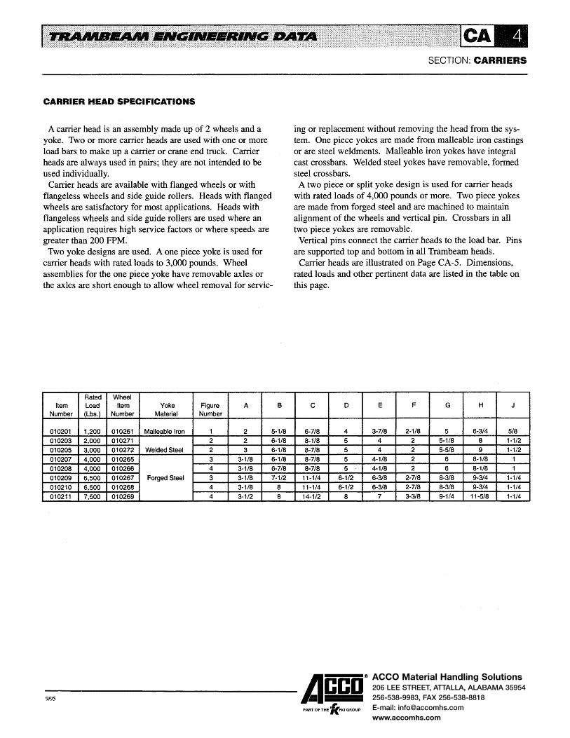
CARRIER HEAD SPECIFICATIONS
A carrier head is an assembly made up of 2 wheels and a yoke. Two or more carrier heads are used with one or more load bars to make up a carrier or crane end truck. Carrier heads are always used in pairs; they are not intended to be used individually.
Carrier heads are available with flanged wheels or with flangeless wheels and side guide rollers. Heads with flanged wheels are satisfactory for most applications. Heads with flangeless wheels and side guide rollers are used where an application requires high service factors or where speeds are greater than 200 FPM.
Two yoke designs are used. A one piece yoke is used for carrier heads with rated loads to 3,000 pounds. Wheel assemblies for the one piece yoke have removable axles or the axles are short enough to allow wheel removal for servic-
Rated Wheel Item Load Item Yoke Figure A
Number (Lbs.) Number Material Number B
010201 1,200 010261 Malleable Iron 1 2 5-1/8
010203 2,000 010271 2 2 6-1/8
010205 3,000 010272 Welded Steel 2 3 6-1/8
010207 4,000 010265 3 3-1/8 6-1/8
010208 4,000 010266 4 3-1/8 6-7/8
010209 6,500 010267 Forged Steel 3 3-1/8 7-1/2
010210 6,500 010268 4 3-1/8 8 010211 7,500 010269 4 3-1/2 8
SECTION: CARRIERS
ing or replacement without removing the head from the system. One piece yokes are made from malleable iron castings or are steel weldments. Malleable iron yokes have integral cast crossbars. Welded steel yokes have removable, formed steel crossbars. A two piece or split yoke design is used for carrier heads
with rated loads of 4,000 pounds or more. Two piece yokes are made from forged steel and are machined to maintain alignment of the wheels and vertical pin. Crossbars in all two piece yokes are removable.
Vertical pins connect the carrier heads to the load bar. Pins are supported top and bottom in all Trambeam heads.
Carrier heads are illustrated on Page CA-5. Dimensions, rated loads and other pertinent data are listed in the table on this page.
c D E F G H J
6-7/8 4 3-7/8 2-1/8 5 6-3/4 5/8
8-1/8 5 4 2 5-1/8 8 1-1/2
8-7/8 5 4 2 5-5/8 9 1-1/2
8-7/8 5 4-1/8 2 6 8-1/8 1
8-7/8 5 4-1/8 2 6 8-1/8 1
11-1/4 6-1/2 6-3/8 2-7/8 8-3/8 9-3/4 1-1/4
11-1/4 6-1/2 6-3/8 2-7/8 8-3/8 9-3/4 1-1/4
14-1/2 8 7 3-3/8 9-1/4 11-5/8 1-1/4
-9,95 ------Acco® ,
PART OF THE 'KFKI GROUP

ACCO Material Handling Solutions206 LEE STREET, ATTALLA, ALABAMA 35954
256-538-9983, FAX 256-538-8818
E-mail: [email protected]
www.accomhs.com
SECTION: CARRIERS
CARRIER HEAD SPECIFICATIONS
FIGURE NO. 1 FIGURE NO .. 2
FIGURE NO. 3 FIGURE NO. 4
B B
-9,95 ------Acco® PART OF THE 'lc.FKI GROUP

ACCO Material Handling Solutions206 LEE STREET, ATTALLA, ALABAMA 35954
256-538-9983, FAX 256-538-8818
E-mail: [email protected]
www.accomhs.com
RACK CARRIERS
Rack carriers are available for direct attachment to racks or similar conveying devices. They are particularly suited for handling parts through production processes and on into storage to await further processing or shipment.
Rack carriers are made up of a carrier head, load bar and a pair of mounting angles. They are cataloged with rated loads of 2,000 and 3,000 pounds. Carriers with rated loads to 6,500 pounds are also available; consult factory for data.
Rack carriers are always used in pairs; they are not intended to be used individually. When used on monorails with curves, the curve radius should not be less than the wheelbase of the two rack carriers.
Carrier Rated Load Carrier Net Weight
Item Number (Pounds) Head (Pounds)
110345 2,000 010203 29
110346 3,000 010205 38
2,400 LBS. RATED LOAD CARRIERS
Item. No. 110302 Eyebolt Type- 35lbs. Net weight. Item. No. 110303 Pin Type- 35 lbs. Net weight.
These carriers are used with hook -on chain hoists. They consist of a load bar, two No. 010201 carrier heads and a suspension assembly. These carriers are suitable for light duty service. No. 110303 carriers are used where headroom is limited and a swivel is not required.
The load bar is fabricated from steel tubing and has provisions for bolting either the eyebolt assembly or pin suspension assembly to the load bar. The eyebolt assembly for the No. 110302 carrier consists of a forged steel eyebolt, spherical washer set, saddle and attaching hardware. The pin assembly for the No. 110303 carrier consists of two side plates, a pin, two cotter pins and attaching hardware.
SECTION: CARRIERS
A B c D E F
5-1/4 9 10-3/4 1-1/8 17/32 45Deg.
5-3/4 10 12-3/4 1-118 17/32 35Deg.
6 13 16"
CAT. No. 110302 CARRIER
CAT. No. 110303 CARRIER
-9,95 ------Acco® PART OF THE 'fc.FKI GROUP
ACCO Material Handling Solutions206 LEE STREET, ATTALLA, ALABAMA 35954
256-538-9983, FAX 256-538-8818
E-mail: [email protected]
www.accomhs.com
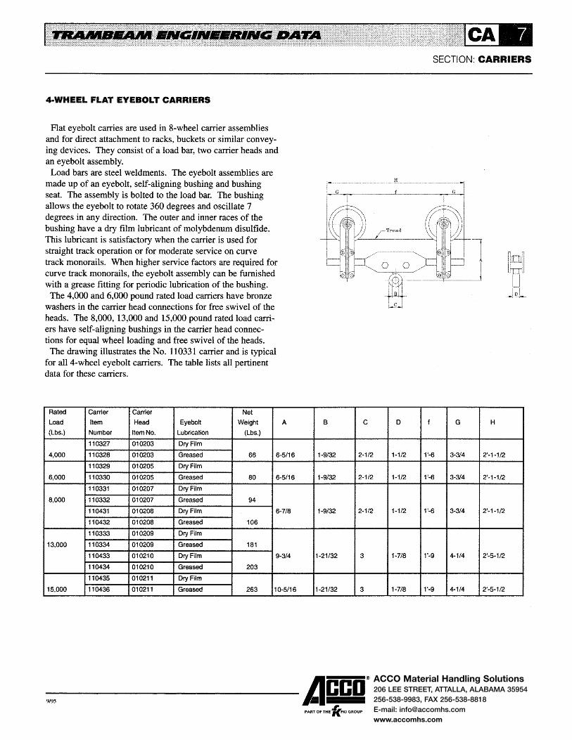
4·WHEEL FLAT EYEBOLT CARRIERS
Flat eyebolt carries are used in 8-wheel carrier assemblies and for direct attachment to racks, buckets or similar conveying devices. They consist of a load bar, two carrier heads and an eyebolt assembly.
Load bars are steel weldments. The eyebolt assemblies are made up of an eyebolt, self-aligning bushing and bushing seat. The assembly is bolted to the load bar. The bushing allows the eyebolt to rotate 360 degrees and oscillate 7 degrees in any direction. The outer and inner races of the bushing have a dry film lubricant of molybdenum disulfide. This lubricant is satisfactory when the carrier is used for straight track operation or for moderate service on curve track monorails. When higher service factors are required for curve track monorails, the eyebolt assembly can be furnished with a grease fitting for periodic lubrication of the bushing.
The 4,000 and 6,000 pound rated load carriers have bronze washers in the carrier head connections for free swivel of the heads. The 8,000, 13,000 and 15,000 pound rated load carriers have self-aligning bushings in the carrier head connections for equal wheel loading and free swivel of the heads. The drawing illustrates the No. 110331 carrier and is typical
for all 4-wheel eyebolt carriers. The table lists all pertinent data for these carriers.
Rated Carrier Carrier Net
Load Item Head Eyebolt Weight
(Lbs.) Number Item No. Lubrication (Lbs.)
110327 010203 Dry Film
A
4,000 110328 010203 Greased 66 6·5/16
110329 010205 Dry Film
6,000 110330 010205 Greased 80 6-5/16
110331 010207 Dry Film
8,000 110332 010207 Greased 94
110431 010208 Dry Film 6-7/8
110432 010208 Greased 106
110333 010209 Dry Film
13,000 110334 010209 Greased 181
110433 010210 Dry Film 9-3/4
110434 010210 Greased 203
110435 010211 Dry Film
15,000 110436 010211 Greased 263 10-5/16
B c
1-9/32 2-1/2
1-9/32 2-1/2
1-9/32 2-1/2
1-21/32 3
1-21/32 3
-9,95 ------Acco®
, PART OF THE 'KFKI GROUP
SECTION: CARRIERS
D f G H
1-1/2 1'-6 3-3/4 2'-1-1/2
1-1/2 1'-6 3·314 2'-1-1/2
1-1/2 1'-6 3-3/4 2'-1-1/2
1-7/8 1'-9 4-1/4 2'-5-1/2
1-7/8 1'-9 4-1/4 2'-5-1/2

ACCO Material Handling Solutions206 LEE STREET, ATTALLA, ALABAMA 35954
256-538-9983, FAX 256-538-8818
E-mail: [email protected]
www.accomhs.com
4·WHEEL PIN TYPE CARRIERS
Pin type carriers are used with hook -on hand chain hoists. They consist of a load bar, two carrier heads and a pin suspension assembly.
Load bars are steel weldments. The pin suspension assembly consists of two steel bars bolted to the side plates of the load bar and a pin.
The 4,000 and 6,000 pound rated load carriers have bronze washers in the carrier head connections for free swivel of the heads. The 8,000, 13,000 and 15,000 pound rated load carriers have self-aligning bushings in the carrier head connections for equal wheel loading and free swivel of the heads.
The drawing illustrates the No. 110312 carrier and is typical for all 4-wheel pin type carriers. The table lists all pertinent data for these carriers.
Rated Carrier Carrier Net
Load Item Head Item Weight A
(Pounds) Number Number (Pounds)
4,000 110306 010203 63 2~5/8
6,000 110309 010205 77
8.000 110312 010207 92 3-1/16
110412 010208 104
13,000 110315 010209 176 5-1/4
110415 010210 198
15,000 110418 010211 258 5-13/16
B c f
1~1/4 2 1'~6
1-1/2 2 1'-6
1-3/4 2 1'-9
1-3/4 2 1'-9
-9,95 ------Acco® ,
PART OF THE 'KFKI GROUP
SECTION: CARRIERS
G H
3~314 2'-1-1/2
3-3/4 2'-1-1/2
4-1/4 2'-5-1/2
4-114 2'-5-1/2

ACCO Material Handling Solutions206 LEE STREET, ATTALLA, ALABAMA 35954
256-538-9983, FAX 256-538-8818
E-mail: [email protected]
www.accomhs.com
8·WHEEL PIN TYPE CARRIERS
Pin type carriers are used with hook-on hand chain hoists. They consist of a connecting load bar, two 4-wheel flat eyebolt carriers and a pin suspension assembly.
Connecting load bars are steel weldments and are pin connected to the 4-wheel eyebolt carriers. The pin suspension assembly consists of a pin and two cotter pins. The 4-wheel carriers have eyebolt bushings with a dry film lubricant of molybdenum disulfide. This lubricant is satisfactory for straight track operation or moderate service on curve track monorails. When higher service factors are required for
Rated Carrier 4-Wheel Net
Load Item Carrier Eyebolt Weight
(Lbs.) Number Item No. Lubrication (Lbs.)
110337 110327 Dry Film
8,000 110338 110328 Greased 185
110339 110329 Dry Film
12,000 110340 110330 Greased 213
110341 110331 Dry Film
16,000 110342 110332 Greased 240
110441 110431 Dry Film
110442 110432 Greased 264
110343 110333 Dry Film
26,000 110344 110334 Greased 471
110443 110433 Dry Film
110444 110434 Greased 515
A
SECTION: CARRIERS
curve track monorails, the eyebolt assembly can be furnished with a grease fitting for periodic lubrication of the bushing.
The 8,000 and 12,000 pound rated load carriers have bronze bushings in the carrier head connection for free swivel of the heads. The 16,000 and 26,000 pound rated load carriers have self-aligning bushings in the carrier head connection for equal wheel loading and free swivel of the heads.
The drawing illustrates the No. 110341 carrier and is typical for all 8-wheel pin type carriers. The table lists all pertinent data for these carriers.
B c e f G H w
9-5/16 1-3/4 2 1'-6 1'-0 3-3/4 4'-7-1/2 2'-6
9-314 1-314 2 1'-6 1'-0 3-314 4'-7-1/2 2'-6
1'-1-7/8 2-1/4 2 1'-9 1'-3 4-1/4 5'-5-1/2 3'-0
-9,95 ------Acco® , PART OF THE 'KFKI GROUP

ACCO Material Handling Solutions206 LEE STREET, ATTALLA, ALABAMA 35954
256-538-9983, FAX 256-538-8818
E-mail: [email protected]
www.accomhs.com
CARRIER ACCESSORIES
SWITCH EARS
All carriers operating on monorails with Type 3, 4 or 5 switches must be equipped with switch ears on each end of the carrier. Switch ears prevent the carrier from running off incoming tracks in the event a switch is only partially thrown. The drawing illustrates the switch ear for the No. 010207 carrier head. Ears for other carrier heads are similar. On motor driven carriers, switch ears are located on the carrier head at the idler end and on the tractor drive at the drive end.
CARRIER LUGS
Lugs are available to limit the drop of the carrier to 1 in. or less in the event of wheel or axle failure. They are optional equipment, but are recommended for heavy or severe duty applications, cab controlled carriers or where hazardous materials, such as molten metal, are being transported. The drawing illustrates the lugs for the No. 010207 carrier head. Lugs for other carrier heads are similar. The lugs are steel weldments and bolt to the carrier head.
-9,95 ------Acco®
, PART OF THE 'KFKI GROUP
SECTION: CARRIERS

ACCO Material Handling Solutions206 LEE STREET, ATTALLA, ALABAMA 35954
256-538-9983, FAX 256-538-8818
E-mail: [email protected]
www.accomhs.com
SINGLE GIRDER ELECTRIC HOIST CARRIERS
Single girder electric hoist carriers are cataloged by (1) rated load and (2) hoist manufacturer. Item numbers have a prefix number indicating the method of propulsion, i.e., 11 for hand propelled and 21 for motor driven carriers. Item numbers on subsequent pages use the 11 prefix number indicating hand propelled carriers. When specifying or ordering motor driven carriers, change the prefix number to 21.
HOIST SPECIFICATIONS
Carriers are cataloged for 112, 1, 2, 3, 5, 7-1/2 and 10 ton rated load hoists and for hoists with the more common lifts and speeds. Carriers for hoists with other rated loads, longer lifts and faster speeds are available; consult factory for carrier data on hoists not listed. Information on hoist lifts and speeds is not included in the data, but is readily available from the hoist manufacturers' catalogs.
Service classifications for electric hoists are defined in ANSI/ ASME HST-lM Performance Standards for Electric Chain Hoists and ANSI/ ASME HST-4M Performance Standards for Overhead Electric Wire Rope Hoists. Hoists should be selected for each application from the data in these standards.
Some carriers require that hoists be furnished with special adaptors. These adaptors have been designed by the hoist manufacturer for direct mounting of carrier heads or 4-wheel carriers to the hoist. The requirement for special adaptors is noted in the hoist data. Hoists must be ordered with the adaptors where indicated.
Hoist dimensions are for single speed hoists operating on 3 phase alternating current. When the hoist has 2-speed or variable speed control or operates on direct current, consult hoist manufacturers' catalog for possible variations in hoist dimensions.
When the hoist cable is single reeved, indicated in the data as 2PS, 4PS or 6PS, the hoist hook follows the cable as it is wound on the drum resulting in the hook not giving a true vertical lift. While the hook movement is not objectionable in many applications, these hoists should not be used where a true vertical lift is specified. Approach dimensions for all
SECTION: CARRIERS
carriers with single reeved hoists are based on the hook being at the mid-point of its travel.
CARRIER SPECIFICATIONS
Carriers may be hand propelled, hand racked or motor driven depending on travel distance, frequency of operation, elevation and rated load. They may be equipped with current collectors as described in the Electrification Section.
Service classifications for carriers are defined in ANSI MH 27.1 Specifications for Underhung Cranes and Monorail Systems. Carriers will generally meet the service classification of the hoist used on the carrier and the requirements of the comparable ANSI MH 27.1 service classification. For Class D carriers with speeds greater than 200 FPM and all Class E severe duty carriers, consult factory for recommendations. The 4-wheel eyebolt carriers used in 8-wheel carriers have
eyebolt bushings with a dry film lubricant of molybdenum disulfide. This lubricant is satisfactory for straight track operation or moderate service on curve track monorails. When higher service factors are required for curve track monorails, the eyebolt assembly can be furnished with a grease fitting for periodic lubrication of the bushing.
The weights shown in the data are the net weights of hand propelled carriers and do not include the tractor drive weight used on motor driven carriers, collectors or other accessories. Tractor drive weights are given in the Tractor Drive Section.
Lugs are available to limit the drop of the carrier to 1 in. or less in the event of wheel or axle failure. Lugs are optional and are described on Page CA-10.
Carrier load bars have a minimum extension beyond the carrier heads to provide the best carrier approach. When the hoist projects beyond the end of the load bar, the approach to the end of the track should be checked and, if necessary, the end stop set in to prevent interference with the building structure or other obstructions. When more than one carrier operates on a system, load bar extensions are recommended to prevent the hoists from hitting.
The National Electric Code requires that monorail carriers be provided with a motor circuit switch. A mainline contac-
-9,95 ------Acco® PART OF THE 'lc.FKI GROUP

ACCO Material Handling Solutions206 LEE STREET, ATTALLA, ALABAMA 35954
256-538-9983, FAX 256-538-8818
E-mail: [email protected]
www.accomhs.com
SINGLE GIRDER ELECTRIC HOIST CARRIERS
tor is also required when the motor circuit switch is not readily accessible from the operating station. An exception to this requirement is allowed where the monorail installation meets all of the following:
1. The unit is floor controlled. 2. The unit is within view of the power supply disconnect
ing means. 3. No fixed work platform has been provided for servicing
the unit.
Motor circuit switches can be provided on hand propelled and motor driven carriers. The mainline contactor, when required, can be provided on the carrier but generally is provided on the hoist.
CARRIERS DRIVES AND CONTROLS
When there are frequent carrier movements or travel distances are long, motor driven carriers will increase productivity. The additional cost for a motor driven carrier will usually pay for itself in a short period of time. Motor driven carriers will also improve employee morale.
Motor driven carriers are identical to hand propelled carriers with the addition of a tractor drive to propel the carrier. Three tractor drives (Nos. 2408, 2409 and 24010) are available to meet a wide range of applications. All are satisfactory for Class D heavy duty service. Complete data on tractor drives, motor control and horsepower requirements are contained in the Tractor Drive Section.
Nominal speeds for single girder carriers are 55 and 90 FPM when No. 24010 drives are used; 100, 125, 150, 175 and 200 FPM when No. 2409 drives are used; and 100, 150, 200, 250 and 300 FPM when No. 2408 drives are used. Special speeds can be furnished upon request.
Wiring and control panels comply with the requirements of OSHA electrical standards and Article 610 of the National Electric Code. Carrier control panels are furnished with motor overcurrent protection, thermal overload relays in 3 phases and NEMA 12 dust-tight enclosure as standard.
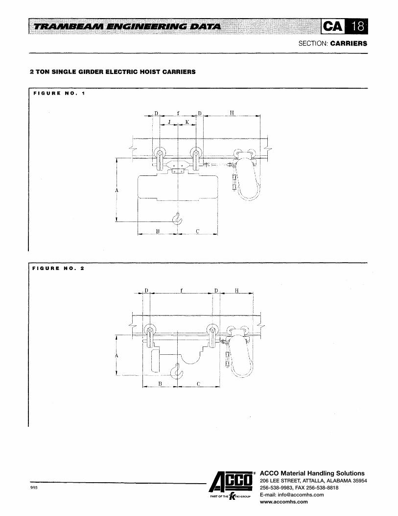
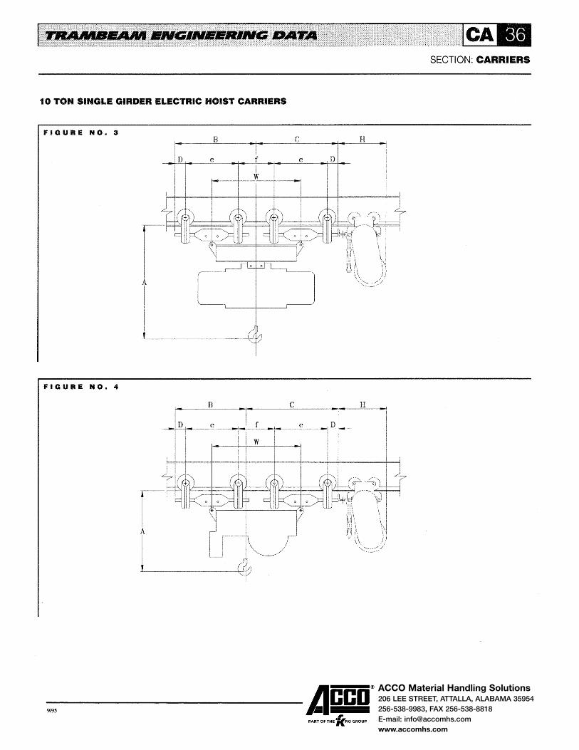
The clearance drawings of single girder carriers on following pages are applicable to hand propelled and motor driven carriers. Dimension 'H' represents the space required for the tractor drive on motor driven carriers with single speed control. Consult factory for dimension 'H' for carriers with 2-speed control.
SECTION: CARRIERS
Motor driven carriers are controlled by ( 1) a pendant push button station, (2) a trailing operator's cab or (3) remotely by a transmitter using radio or infrared control. The push button station may be suspended from the carrier or from a swivel arm on the carrier if the load being handled is bulky. Carriers with trailing cabs are generally controlled from master switches in the cab. Under some copditions it is desirable to use a trailing cab without controls on floor controlled carriers; this arrangement allows the push button station to be raised into the cab and provides both floor and cab control of the carrier.
When carriers operate on cranes, they may be controlled from a push button station or cab on the crane provided the crane is not a transfer crane. For radio control or other special applications, consult factory for recommendations.
CURVE OPERATION
Carriers operating on curve tracks require special consideration. Most of the cataloged motor driven carriers have the tractor drive coupled directly to the carrier load bar or have a short tow link and are satisfactory for straight track operation only. When operating on monorails with curve tracks, motor driven carriers require a tow link or a longer tow link to negotiate the curve tracks. The addition of a tow link or a longer tow link increases dimension 'H'; consult factory for changes in dimension 'H' for curve track operation.
Curve radii should be as large as practical to allow carriers to negotiate curve tracks with the least effort. Curve radii should not be less than the wheelbase of the carrier.
SWITCH OPERATION
Carriers for operation on monorails with switches also require special consideration. Most of the cataloged motor driven carriers require a tow link or a longer tow link for operation through switches.
On monorails with Type 3, 4 or 5 switches, carriers must be equipped with switch ears to prevent the carrier from running off the incoming track in the event a switch is partially thrown. See Page CA-l 0 for illustration and description of switch ears.
The carrier head load should also be checked against the rated load of the switch. On some applications, an 8-wheel carrier may be required to reduce the head load to or below
-9,95 ------Acco® PART OF THE 'fc.FKI GROUP

ACCO Material Handling Solutions206 LEE STREET, ATTALLA, ALABAMA 35954
256-538-9983, FAX 256-538-8818
E-mail: [email protected]
www.accomhs.com
SINGLE GIRDER ELECTRIC HOIST CARRIERS
the switch rated load. Four-wheel hand propelled and motor driven carriers for
close headroom hoists will not, as a general rule, operate through switches because of interference between the hoist frame and stops on Type 4 and 5 switches or because the carrier head load exceeds the switch rating. Use 8-wheel carriers for these hoists when carrier operates through switches. Also, some 7-1/2 ton carriers and all 10 ton carriers will not operate through switches because the carrier head load exceeds the switch rating; consult factory for recommendations when these carriers are to operate through switches.
-9,95 ------A~co® PART OF THE 'KFKI GROUP
SECTION: CARRIERS

ACCO Material Handling Solutions206 LEE STREET, ATTALLA, ALABAMA 35954
256-538-9983, FAX 256-538-8818
E-mail: [email protected]
www.accomhs.com
1/2 TON SINGLE GIRDER ELECTRIC HOIST CARRIERS
FIGURE NO .. 1
LIFT-TECH 'BUDGIT' (CHAIN}
11o5ooo I 1 I o1o2o1
CM LODESTAR (CHAIN)
1102220 1 010201 1102221 1 010201 1102222 1 010201
COFFING MODEL EC (CHAIN) 1109000 I 1 I 010201
P & H ZIP II (CHAIN}
1101020 I 010201
35
35 35 35
35
35
Hoist Model Number
C356~3R;J356-3R
E* F* J* JJ*
EC-1016*;EC1032*
WR-1 021-3;WR-1 028-3 WR-1042-3
A216-11 ;A316-11
FIGURE NO. 2
D
1'-7 1Q-1/8
1'-11-1/4 9 1'-8 9
1'-8-7/8 10-3/4 1'-9-1/2 10-3/4
1'-9-1/4 11-1/4
1'-6-3/8 9
-9,95 ------Acco® PART OF THE 'lc.FKI GROUP
SECTION: CARRIERS
f D H
1o-3t8 I 3 1'-0 1'-8-3/8 I 6 I 6
11 3 1'-0 1'-8-3/8 6 6 11 3 1'-0 1'-8-3/8 6 6
9-1/2 3 1'-0 1'-8-3/8 6 6 9-1/2 3 1'-0 1'-8-3/8 6 6
1'-0-1/8 I 3 1'-0 1'-8-3/8 I 6 I 6
8-7/8 I 3 1'-0 1'-3-7/8 I 6 I 6

ACCO Material Handling Solutions206 LEE STREET, ATTALLA, ALABAMA 35954
256-538-9983, FAX 256-538-8818
E-mail: [email protected]
www.accomhs.com
1/2 TON SINGLE GIRDER ELECTRIC HOIST CARRIERS
R & M TYPE A (WIRE ROPE)
1106801 1 010203 65
1106802 1 010203 65
WRIGHT-WAY (WIRE ROPE)
I 11o1o2o I 1 I o1o2o1 35
Hoist Model No.
3116~11 ;3216-11 3516-11
AF2C-G 1 : AG2C-G 1 DF2C-R1*;DG2C-R1*
S1-1/2-24A15 S1-1/2-24A30 S1-1/2-36A 15 S1-1/2-36A30
115884-1L 110103-20L
AA2B1D1 AA2B2D1
AE2B2D1*;AE283D1 *
2100470;2100550
2200470;2200550
3103510;3103610 3104012*;3104112*
3104212*
KEL 1/2-10L 1551 KEL1/2-10L30S1 KEL 1/2-1 OL60S 1
KEW1/2-19LG15S2 KEW1/2-19LG30S2
2'-4 1'-4-3/8 10-1/8
2'-4 1'-10-1/8 10-3/8
1'-9-5/8
2'-0-3/8 1'-0-1/4 1'-1-1/4
-9,95 ------Acco®
, PART OF THE 'KFKI GROUP
SECTION: CARRIERS
3-314 1'-6 1'-3-7/8 9-3/8 8-5/8
3-314 1 '-6 1'-3-7/8 8-3/8 9-5/8
3 1'-8-3/8 6 6

ACCO Material Handling Solutions206 LEE STREET, ATTALLA, ALABAMA 35954
256-538-9983, FAX 256-538-8818
E-mail: [email protected]
www.accomhs.com
1 TON SINGLE GIRDER ELECTRIC HOIST CARRIERS
!FIGURE NO. 1
B c
COFFING MODEL EC (CHAIN}
11o9oo1 I 1 I o1o2o1 35
Hoist Model Number
D356-3R;K356-3R M356-3R
H* L* LL*
EC-2012*;EC-2016*
WR-201 0-3;WR-2014-3 WR2021-3
WWD-120;WWD-127 WWD-121 ;WWD-128
30**;31** 27**;32**
FIGURE NO .. 2
D
1'-9-1/4
-9,95 ------Acco®
, PART OF THE 'KFKI GROUP
SECTION: CARRIERS
6 6

ACCO Material Handling Solutions206 LEE STREET, ATTALLA, ALABAMA 35954
256-538-9983, FAX 256-538-8818
E-mail: [email protected]
www.accomhs.com
1 TON SINGLE GIRDER ELECTRIC HOIST CARRIERS
P & H ZIP-LIFT (WIRE ROPE)
I 11o1231 I 1 I o1o2o3 I 6s
R & M TYPE A (WIRE ROPE)
1106804 1 010203 65
1106805 1 010203 65
SHEPARD NILES (WIRE ROPE)
1103315 1 010203 65 1103316 1 010203 65 1103513 2 010203 45
WRIGHT-WAY (CHAIN}
I 1101011 I 1 I 010201 35
WRIGHT-WAY (WIRE ROPE}
l1107021 I 1 I o1o2o3 I 65
WRIGHT (WIRE ROPE)
1107232 1 010203 65
1107291 2 010203 45 1107517 2 010203 45
Hoist Model Number
4116-11 ; 4216-11
BD2C-G1 ;BF2C-G1 ED2C-R1 *;EF2C-R1 *
81-1·24A15 81-1-24A30 81-1-36A15 81-1-36A30
15886-1L 110102-20L
BA1C101;BA1C1E1 BA 1 C201 ;BA 1 C2E1
BE1C201*;BE1C301* CE1C2E1* CE1C3E1*
2100630
2200630
3220000 3220150 3243950 3244100
3106012*;3106112* 3232302*
KEL 1-10L 1581 KEL 1-10L3081 KEL 1-10L42S1
KEW1-19LG 1582 KEW1-19LG3082
2'-4
2'-4
2'-7 2'-7 1'-4 1'-5 1'-5
1'-9-5/8
2'-1
2'-10 2'-10 2'-10 2'-10
1'-4-112 1'-9-1/4
1'-o-3/4 1'-o-7/8 I 3-3/4 I 1'-6
1'-4-3/8 10-1/8 3-3/4 1'-6
1 '-10-1/8 10-3/8 3-3/4 1'-6
1'-4-1/2 1'-8-118 3-3/4 1'-6 1'-6-5/8 1'-9-3/8 3-3/4 1'-6 1'-9-1/2 11-6-3/4 3-3/4 2'-6
1'-10-1/2 1'-7-7/8 3-3/4 2'-7-5/8 1'-11-3/4 1'-8-3/8 3-3/4 2'-9-3/8
9-3/8 10-1/2 3 1'-0
1'-0-3/4 1'-1-1/4 I 3-3/4 I 1'-6
2'-1-1/8 2'-3-7/8 3-3/4 1'-6 2'-2-1/8 2'-6-7/8 3-3/4 1'-6 2'-3-1/8 2'-3-7/8 3-3/4 1'-6 2'-4-1/8 2'-6-7/8 3-3/4 1'-6 1'-9-7/8 1'-3-3/8 3-314 2'-5-3/4
1'-5 1'-10-1/2 ** 2'-1-7/8
-9,95 ------Acco® PART OF THE 'lc.FKI GROUP
SECTION: CARRIERS
9 9
1'-3-7/8 9-3/8 8-5/8
1'-3-7/8 8-3/8 9-5/8
1 '-10-7/8 8-3/4 9-1/4 2'-0-7/8 9-1/8 8-7/8 1'-3-7/8 - -1'-3-7/8 -1'-3-7/8 - -
1'-8-3/8 6 6
1'-8-3/8 9 9
2'-5-7/8 8-3/4 9-1/4 2'-7-7/8 7-3/4 10-1/4 2'-5-7/8 8-3/4 9-1/4 2'-7-7/8 7-3/4 10-1/4 1'-3-7/8 - -1'-3-7/8 - -
ACCO Material Handling Solutions206 LEE STREET, ATTALLA, ALABAMA 35954
256-538-9983, FAX 256-538-8818
E-mail: [email protected]
www.accomhs.com
CA SECTION: CARRIERS
2 TON SINGLE GIRDER ELECTRIC HOIST CARRIERS
FIGURE NO. 1
,D f D
J K
FIGURE NO. 2
-9,95 ------Acco® PART OF THE 'lc.FKI GROUP

ACCO Material Handling Solutions206 LEE STREET, ATTALLA, ALABAMA 35954
256-538-9983, FAX 256-538-8818
E-mail: [email protected]
www.accomhs.com
SECTION: CARRIERS
2 TON SINGLE GIRDER ELECTRIC HOIST CARRIERS
Hoist Model Number
LIFT-TECH 'BUDGIT' (CHAIN)
1105003 I 1 I 010205 80 P356-3R;S356-3R 2'-0-1/2 1'-0-3/4 10-3/8 1 3-3/4 1'-6 1'-3-7/8 9 I 9
A* RR*
COFFING MODEL EC (CHAIN)
1109002 I 1 I 010205 85 EC-4006*;EC-4008* 2'-0-1/4 1'-0-3/4 1'-0-1/8 1 3-3/4 1 1'-6 1'-3-7/8 9 9
I COFFING MODEL WR (WIRE ROPE)
1109012 I 1 I 010205 I 80 WR-4014-3;WR-4021-3 2'-7-5/8 1'-5-7/8 1'-7-3/4 1 3-3/4 1'-6 1'-10-7/8 1 9 9
CB2C-K1 ;CD2C-K1 FB2C-R1*;FD2C-R1*
LIFT-TECH SERIES 800 & 900 (WIRE ROPE)
1105225 I 1 I 010205 I 80 I 110101-15L;110101-20L 2'-5-1/8 11-3/8 10-1/4 1 3-3/4 1'-6 1'-3-7/8 1 9-5/a 1 8-3/8
WRIGHT-WAY (CHAIN)
I 1107012 I 1 I 010205 75 2100710 2'-2-1/2 1'-0-3/4 10-1/2 1 3-3/4 1'-6 1'-3-7/8 9 9
KEL2-1 OL7 -1 /2S2 KEL2-1 OL 15S2 KEL2-1 OL21 S2
2 TON CARRIERS CONTINUED ON CA21
-9,95 ------Acco®
, PART OF THE 'KFKI GROUP

ACCO Material Handling Solutions206 LEE STREET, ATTALLA, ALABAMA 35954
256-538-9983, FAX 256-538-8818
E-mail: [email protected]
www.accomhs.com
SECTION: CARRIERS
2 TON SINGLE GIRDER ELECTRIC HOIST CARRIERS
FIGURE NO. 1 FIGURE NO .. 2
D f D H f D H K
c
FIGURE NO. 3 FIGURE NO. 4
B c H
D e e D
-9,95 ------Acco® ,
PART OF THE 'KFKI GROUP

ACCO Material Handling Solutions206 LEE STREET, ATTALLA, ALABAMA 35954
256-538-9983, FAX 256-538-8818
E-mail: [email protected]
www.accomhs.com
2 TON SINGLE GIRDER ELECTRIC HOIST CARRIERS
CHESTER WORM DRIVE (WIRE ROPE) 1109110 2 010207 60
1109200 4 010203 135
ELECTROLIFT (WIRE ROPE) 1108124 2 010205 60
1108203 4 010203 135
R & M TYPE A (WIRE ROPE} 1106806 1 010205 90
1106807 1 010205 90
1106808 3 010203 195
1106809 3 010203 195
1106810 3 010203 195
Hoist Model Number
7002;7006 7002;7006
5836;5826 5836;5826
WWD-141;WWDw147 WWD-142;WWD-148 WWD-141 ;WWD-147 WWD-142;WWD-148
42*; 37* 64*
42*; 37* 64*
S1-2-12A7 S1-2-12A15 S1-2-18A7 S1-2-18A15 S1-2-12A7 S1-2-12A15 S1-2-18A7 S1-2-18A15 S2-2-19A14 S2-2-19A21 S2-2-19A31
2'-3-7/8 1'-2-3/8 2'-3-7/8 1'-3-1/4 2'-9-1/4 1'-6-3/8 2'-9-1/4 1'-7-1/4
2'-1-3/4 1'-9-1/2 2'-7-1/2 2'-2-1/2 2'-5-7/8 1'-6-7/8 2'-8-7/8 1'-9-3/4
2'-0-1/2 1'-5-7/8
2'-0-1/2 1'-9-1/4
2'-8-3/8 2'-5-1/8
2'-8-3/8 2'-4-1/2
2'-9-5/8 2'-3-1/2
2'-6-5/8 3-3/4 -3'-0-1/4 3-3/4 -
2'-10-5/8 3-3/4 1'-6 3'-4-1/4 3-3/4 1'-6
2'-9-1/2 3-3/4 -2'-7-1/4 3-3/4 -3'-1-7/8 3-3/4 1'-6
2'-11 3-3/4 1'-6
8-5/8 3-3/4 -9-1/4 3-3/4 ~
2'-2-3/8 3-3/4 1'-0
2'-3 3-3/4 1'-0
2'-4 3-3/4 1'-0
-9,95 ------Acco® PART OF THE 'lc.FKI GROUP
SECTION: CARRIERS
3'-1-1/2 1 '-3-7/8 - - -3'-8 1 '-3-7/8 - - -
9-1/2 1'-3-7/8 - 2'-3-1/2 1'-4 1'-3-7/8 - - 2'-10
3'-11-1/2 1'-3-7/8 - - -4'-2-1/4 1'-3-7/8 - - -2'-7-1/4 1'-3-7/8 - 4'-1-1/4 2'-7-1/4 1'-3-7/8 - - 4'-1-1/4
5-1/2
1'-6 1'-3-7/8 10-3/8 7-5/8 -
1'-6 1'-3-7/8 9-3/4 8-1/4 -1'-6 1'-3-7/8 - - 2'-6
1'-6 1'-3-7/8 - - 2'-6
1'-6 1'-3-7/8 - - 2'-6
2 TON CARRIERS CONTINUED ON CA23

ACCO Material Handling Solutions206 LEE STREET, ATTALLA, ALABAMA 35954
256-538-9983, FAX 256-538-8818
E-mail: [email protected]
www.accomhs.com
SECTION: CARRIERS
2 TON SINGLE GIRDER ELECTRIC HOIST CARRIERS
FIGURE NO. 1 FIGURE NO. 2
,D H
FIGURE NO. 3 FIGURE NO. 4
B c B
-9,95 ------Acco®
, PART OF THE 'KFKI GROUP

ACCO Material Handling Solutions206 LEE STREET, ATTALLA, ALABAMA 35954
256-538-9983, FAX 256-538-8818
E-mail: [email protected]
www.accomhs.com
2 TON SINGLE GIRDER ELECTRIC HOIST CARRIERS
LIFT~ TECH SERIES 700 (WIRE ROPE)
1105323 1 010207 100
1105403 3 010203 190
Hoist Model Number
316266-17L 316266-24L 316266-17L 316266-24L
SHEPARD NILES- STANDARD HEADROOM (WIRE ROPE) 1103327 1 010205 80 DA1E1H1 1103328 1 010207 90 DA1E2H1 1103329 1 010205 80 DC1E2H1 1103407 3 010203 190 DA1E1H1
DA1E2H1 DC1E2H1
WRIGHT- STANDARD HEADROOM (WIRE ROPE) 1107292 1 010205 85 3106310 1107315 1 010205 85 32251 00;3226000 1107403 3 010203 190 3016310
32251 000;3226000
WRIGHT- LOW HEADROOM (WIRE ROPE)
3'-3 1'-11
3'-10-1/8 2'-3-3/4
2'-9-3/8 1'-9-1/2 2'-9-3/8 2'-0
2'-11-3/8 2'-0 3'-5-3/4 2'-3-1/2 3'-5-3/4 2'-3~3/4
3'-7-1/4 2'-3-3/4
2'-7-7/8 1'-4-7/8 2'-10-1/8 2'-1-1/8 3'-3-7/8 2'-3-5/8
3'-6 2'-3-112
I 1107536 I 2 I o1o2o5 I 6o I 3235702*;3236302* 11'-9-1/4 I 1'-6-1/2
YALE CABLE KING- STANDARD HEADROOM (WIRE ROPE)
1104701 1 010207 95 BEW2-27LG 14S2 3'-1-1/2 1'-10-1/2 BEW2-27LG22S2 3'-1-1/2 1'-10-1/2
1104702 1 010207 95 CEW2-31 LG30S2 3'-2-1/2 2'-1-1/2 CEW2-31 LG47S2 3'-2-1/2 2'-1-1/2
1104703 3 010203 185 BEW2-27LG14S2 3'-8-5/8 2'-4-1/4 8EW2-27LG22S2 3'-8-5/8 2'-4-1/4
1104704 3 010203 185 CEW2-31 LG30S2 3'-9-5/8 2'-4-1/4 CEW2-31 LG47S2 3'-9-5/8 2'-4-1/4
YALE CABLE KING- LOW HEADROOM (WIRE ROPE)
1104705 2 010207 60 BEW2-21 LG 1402* 1'-7 1'-7 (22D2*)
1104706 4 010203 135 8EW2-21 LG 1402* 2'-0 2'-0 (2202*)
2'-4-3/4 3-314
2'-3-3/4 3-3/4
1'-9 3-3/4 1'·11-1/2 3-3/4 1'-11~1/2 3-3/4
2'-4 3-3/4 2'-3-3/4 3-3/4 2'-3-3/4 3-3/4
1'-6-7/8 3-3/4 2'-3-7/8 3-3/4 2'-3-7/8 3-3/4
2'-4 3-3/4
1'-9-5/8
2'-0-1/2 3-3/4 1'-9-1/2 3-3/4
1'-10-1/2 3-3/4 2'-2-1/2 3-3/4 2'-3-1/4 3-3/4 2'-3-1/4 3-3/4 2'-3-1/4 3-3/4 2'-3-1/4 3-3/4
2'-4-1/8 3-3/4
2'-7-1/8 3-3/4
-9,95 ------Acco®
, PART OF THE 'KFKI GROUP
CA SECTION: CARRIERS
- 1'-6 2'-9 9-1/2 8-7/8 -1'-6 1'-0 1'-5-5/8 ~ - 2'-6
- 1 '-6 2'-0-7/8 8-3/4 9-1/4 -- 1'-6 2'-0-7/8 9 9 -- 1'-6 2'-2-7/8 9 9 -
1'-6 1'-0 1'-3-7/8 - - 2'-6 1'-6 1'-0 1'-3-7/8 - - 2'-6 1'-6 1'-0 1'-3-7/8 - - 2'-6
- 1'-6 1'-9-7/8 8-7/8 9-1/8 -1'-6 2'-6-7/8 8-3/4 9-1/4 -
1'-6 1'-0 1'-3-7/8 - - 2'-6 1'-6 1'-0 1'-3-7/8 - - 2'-6
I 2'-2-1/2 l1 '-3-7/8 I
- 1'-6 2'-3-3/4 9-1/2 8-1/2 -M 1'-6 2'-0-1/4 9-1/2 8-1/2 -- 1'-6 2'-1-1/4 9-1/2 8-1/2 -- 1'-6 2'-5-5/8 9-1/2 8-1/2 -
1'-6 1'-0 1'-3-7/8 M - 2'-6 1'-6 1'-0 1'-3-7/8 - - 2'-6 1'-6 1'-0 1'-3-7/8 - - 2'-6 1'-6 1'-0 1'-3-7/8 - - 2'-6
- 3'-1-5/8 1'-8-3/8 - - -1'-6 11-5/8 1'-3-7/8 - - 2'-5-5/8

ACCO Material Handling Solutions206 LEE STREET, ATTALLA, ALABAMA 35954
256-538-9983, FAX 256-538-8818
E-mail: [email protected]
www.accomhs.com
SECTION: CARRIERS
3 TON SINGLE GIRDER ELECTRIC HOIST CARRIERS
FIGURE NO. 1 FIGURE NO. 2
D .D H D H J K
B c
FIGURE NO. 3 FIGURE NO. 4
B c H
-9,95 ------Acco®
, PART OF THE 'KFKI GROUP

ACCO Material Handling Solutions206 LEE STREET, ATTALLA, ALABAMA 35954
256-538-9983, FAX 256-538-8818
E-mail: [email protected]
www.accomhs.com
3 TON SINGLE GIRDER ELECTRIC HOIST CARRIERS
CHESTER WORM DRIVE (WIRE ROPE) 1109120 2 010209 90
1109210 4 010205 160
DETROIT HOIST MODEL M (WIRE ROPE) 1106600 2 010207 60
1106700 4 010203 135
ELECTROLIFT (WIRE ROPE) 1108134 2 010209 90
1108213 4 010205 160
Hoist Model Number
7010;7014 7010;7014
5827 5827
WWD-161 ;WWD-164 WWD-162;WWD-165 WWD-161;WWD-164 WWD-162;WWD-165
M6L * M6LL* M6XL*
M6L *;M6LL *;M6XL
52* 54*
50*;58* 61* 52* 54*
50*;58* 61*
HA2C-N1 ;HC2C-N1 GB2C-T1
P & H HEVf-LIFT- STANDARD HEADROOM (WIRE ROPE) 1101330 1 010209 170 22CF21A 1101334 1 010209 170 13BF11A 1101335 1 010209 170 23BF11A 1101416 3 010205 215 22CF21A
2'-6-1/8 1'-3-1/8 2'-6-1/8 1'-4 2'-9-1/4 1'-6-3/8 2'-9-1/4 1'-7-1/4
2'-3-7/8 1'-1-3/4 2'-3-7/8 1'-4 2'-3-7/8 1'-6-1/4
2'-9 2'-2-1/4
2'-4-5/8 1'-9 2'-4-5/8 1'-8-3/4 2'-4-5/8 1'-9-1/4
2'-10-5/8 2'-3 2'-6-3/8 1'-6-7/8 2'-6-3/8 1'-6-5/8 2'-6-3/8 1'-7-1/8 2'-9-7/8 1'-9-3/4
3'-1 1'-8-3/4 3'-7-1/4 1'-7 3'-7-1/4 1'-10-1/2 3'-5-3/4 2'-4-3/4
2'-7-3/8 4-1/4 -3'-1 4-1/4 -
2'-10-5/8 3-3/4 1'-6 3'-4-1/4 3-3/4 1'-6
1'-0-1/2 3-314 -1'-4 3-3/4 -
1'-5-3/4 3-3/4 -2'-2-1/4 3-3/4 1'-6
2'-10-1/4 4-1/4 -2'-10-1/2 4-1/4 -
3'-2 4-1/4 -2'-8 4-1/4 -
3'-1-7/8 3-3/4 1'-6 3'-2-1/8 3-3/4 1'-6 3'-5-5/8 3-3/4 1'-6
2'-11 3-3/4 1'-6
1'-9-5/8 4-1/4 -1'-9-3/8 4-1/4 -2'-0-7/8 4-1/4 -2'-2-3/4 3-3/4 1'-6
-9,95 ------A~co® PART OF THE 'KFKI GROUP
SECTION: CARRIERS
3'-2 1'-3-7/8 - - -3'-8-1/2 1'-3-7/8 - - -
9-1/2 1'-3-7/7 - - 2'-3-1/2 1'-4 1'-3-7/8 - - 2'-10
1'-5-1/2 1'-3-7/8 - - -2'-0-1/2 1'-3-7/8 - - -
2'-4 1'-3-7/8 - - -9 1'-3-7/8 - - 2'-3
3'-10-3/4 1'-3-7/8 - - -3'-10-3/4 1'-3-7/8 - - -4'-2-3/4 1'-3-7/8 - - -4'-2-1/2 1'-3-7/8 - - -2'-7-1/4 1'-3-7/8 - - 4'-1-1/4 2'-7-1/4 1'-3-7/8 - - 4'-1-114
2'-11-1/4 1'-3-7/8 - - 4'-5-1/4 2'-7-1/4 1'-3-7/8 - - 4'-1-1/4
1'-9 1'-11-7/8 11-1/2 9-1/2 -1'-9 1'-10-7/8 10-1/2 10-1/2 -1'-9 2'-1-7/8 10-1/2 10-1/2 -1'-0 1'-3-7/8 - - 2'-6
3 TON CARRIERS CONTINUED ON CA27

ACCO Material Handling Solutions206 LEE STREET, ATTALLA, ALABAMA 35954
256-538-9983, FAX 256-538-8818
E-mail: [email protected]
www.accomhs.com
SECTION: CARRIERS
3 TON SINGLE GIRDER ELECTRIC HOIST CARRIERS
FIGURE NO. 1 FIGURE NO. 2
D D H
B
FIGURE NO. 3 FIGURE NO. 4
-9,95 ------Acco® PART OF THE 'lc.FKI GROUP

ACCO Material Handling Solutions206 LEE STREET, ATTALLA, ALABAMA 35954
256-538-9983, FAX 256-538-8818
E-mail: [email protected]
www.accomhs.com
3 TON SINGLE GIRDER ELECTRIC HOIST CARRIERS
R & M TYPE A (WIRE ROPE)
1106811 1 010207 105 1106812 1 010207 105 1106813 3 010203 200 1106814 3 010203 200
LIFT-TECH SERIES 700 (WIRE ROPE)
1105336 1 010209 175
1105415 3 010205 220
Hoist Model Number
S2-3-19A 14;S2-3-19A21 S2-3-25A 14;S2-3-25A21 S2-3-19A 14;S2-3-19A21 S2-3-25A 14;S2-3-25A21
316267-40L 316267-49L 316267-40L 316267-49L
SHEPARD NILES- STANDARD HEADROOM (WIRE ROPE)
1103333 1 010207 100 GC1G2J1 KC2G2K1
1103334 1 010209 175 GA1G1J1 KA2G1K1
1103413 3 010203 195 GC1G2J1 KC2G2K1
1103414 3 010205 225 GA1G1J1 KA2G1K1
WRIGHT- STANDARD HEADROOM (WIRE ROPE)
1107324 1 010209 1107325 1 010209 1107413 3 010205
175 175 220
3227950;3228850 3330750;3330900 3227950;3228850 3330750;3330900
3237502* 3337252*
2'-2-1/2 2'-3-1/2 2'-9-5/8 2'-10-5/8
3'-7-1/2 3'-5-1/2 4'-0-1/4
3'-10-1/8
3'-6-1/2 3'-6-1/2 4'-1-7/8 4'-1-7/8 4'-1-5/8 4'-1-5/8 4'-6-5/8 4'-6-5/8
3'-0-1/8 3'-10-1/4 3'-4-7/8
4'-3
1'-10-1/4 1'-8-1/4 3-3/4 2'-3-1/4 1'-8-3/4 3-3/4 2'-3-1/8 2'-4-1/2 3-314
2'-3 2'-4-5/8 3-3/4
1'-9-1/4 2'-6-1/2 4-1/4 1'-11 2'-4-3/4 4-1/4
2'-3-1/8 2'-4-3/8 3-314 2'-4-1/4 2'-3-1/4 3-3/4
2'-6-3/4 2'-5-1/2 3-314 2'-8-1/2 2'-5-1/2 3-3/4 2'-5-114 1'-11 4-1/4
2'-7 1'-11 4-1/4 2'-6-3/4 2'-3-3/4 3-3/4 2'·8-1/2 2'-3-3/4 3-314 2'-6-1/4 2'-1-1/4 3-3/4
2'-7 2'-1-1/4 3-314
2'-2-1/8 2'-6-7/8 4-1/4 1'-11-7/8 2'-4-5/8 4-1/4 2'-2-1/2 2'-5 3-314 2'-3-1/4 2'-4-1/4 3-3/4
-9,95 ------Acco® PART OF THE 'lc.FKI GROUP
SECTION: CARRIERS
- 1'-6 1'-10-1/4 8-3/4 9-1/4 -- 1'-6 1'-10-1/4 8-1/4 9-3/4 -
1'-6 1'-0 1 '-3-7/8 - - 2'-6 1'-6 1'-0 1'-3-7/8 - - 2'-6
- 1'-9 2'-6-7/8 9-114 11-3/4 -- 1'-9 2'-6-7/8 11 10 -
1'-6 1'-0 1'-5-5/8 - - 2'-6 1'-6 1'-0 1'-5-5/8 - - 2'-6
- 1'-6 2'-8-7/8 9 9 -- 1'-6 2'-8-7/8 9 9 -- 1'-9 2'-2-7/8 1'-1 8 -- 1'-9 2'-2-7/8 1'-1 8 -
1'-6 1'-0 1'-8-3/8 - 2'-6 1'-6 1 '-0 1'-8-3/8 - - 2'-6 1'-6 1'-0 1'-3-7/8 - - 2'-6 1'-6 1'-0 1 '-3-7/8 - - 2'-6
- 1'-9 2'-6-7/8 9-1/4 11-3/4 -- 1 '-9 2'-5-7/8 10 11 -
1'-6 1'-0 1'-8-3/8 - - 2'-6 1'-6 1'-0 1'-8-3/8 - - 2'-6
3 TON CARRIERS CONTINUED ON CA29

ACCO Material Handling Solutions206 LEE STREET, ATTALLA, ALABAMA 35954
256-538-9983, FAX 256-538-8818
E-mail: [email protected]
www.accomhs.com
SECTION: CARRIERS
3 TON SINGLE GIRDER ELECTRIC HOIST CARRIERS
FIGURE NO. 1 FIGURE NO. 2
D f D, H
FIGURE NO. 3 FIGURE NO. 4
-9,95 ------Acco®
, PART OF THE 'KFKI GROUP

ACCO Material Handling Solutions206 LEE STREET, ATTALLA, ALABAMA 35954
256-538-9983, FAX 256-538-8818
E-mail: [email protected]
www.accomhs.com
3 TON SINGLE GIRDER ELECTRIC HOIST CARRIERS
YALE KEL (CHAIN)
1104013 1 010207
1104014 3 010203
95
185
Hoist Model Number
KEL3~ 1 OL 1053 KEL3-1 OL 1453 KEL3-1 OL 1 053 KEL3-1 OL 1453
YALE CABLE KING- STANDARD HEADROOM (WIRE ROPE)
1104707 1 010209 175 BEW3-22LG11S4 BEW3-32LG11 S4
1104708 1 010209 175 BEW3-22LG16S2 CEWS-22LG30S2
1104709 3 010205 220 BEW3-22LG11 54 BEW3-32LG11 84
1104710 3 010205 220 BEW3-22LG16S2 CEW3-22LG30S2
YALE CABLE KING -LOW HEADROOM (WIRE ROPE)
1104711 2 010209 90 BEW3X17LG 16D2* (24D2*)
1104712 4 010205 160 BEW3X17LG16D2* (24D2*)
2'-3-7/8 1'-3-7/8 1'-0-1/2 3-3/4 2'-3-7/8 1'-7-1/4 1'-0-1/2 3-3/4
2'-11 2'-3-3/4 2'-3-3/4 3-3/4
3'-3-7/8 2'-3-1/2 2'-1-1/2 4-1/4 3'-3-7/8 2'-11 2'-2 4-1/4 3'-8-7/8 2'-1-1/2 2'-2 4-1/4 3'-9-7/8 2'-1-1/2 2'-2-1/2 4-1/4 3'-8-5/8 2'-4-1/4 2'-3-1/4 3-3/4 3'-8-5/8 2'-3-3/4 2'-3-3/4 3-3/4 4'-1-5/8 2'-4-1/4 2'-3-1/4 3-3/4 4'-2-5/8 2'-4-1/4 2'-3-1/4 3-3/4
2'-0 1'-7-1/2 2'-4-5/8 4-1/4
2'-0 2'-0 2'-7-1/8 3-3/4
-9,95 ------Acco® PART OF THE 'lc.FKI GROUP
CA SECTION: CARRIERS
- 1'-6 1'-3-7/8 9 9 -- 1'-6 1'-3-7/8 9 9 -
1'-6 1'-0 1'-3-7/8 - - 2'-6
- 1'-9 2'-2-1/4 11 10 -- 1'-9 2'-2-1/4 10-1/2 10-1/2 -
1'-9 2'-2-3/4 11 10 -- 1'-9 2'-3-1/4 11 10 -
1'-6 1'-0 1'·3-7/8 - - 2'-6 1'-6 1'-0 1'-3-7/8 - - 2'-6 1'-6 1'-0 1'-3-7/8 - - 2'-6 1'-6 1'-0 1'-3-7/8 - 2'-6
- 3'-1-5/8 1'-8-3/8 - - -
1'-6 11-5/8 1'-3-7/8 - - 2'-5-5/8

ACCO Material Handling Solutions206 LEE STREET, ATTALLA, ALABAMA 35954
256-538-9983, FAX 256-538-8818
E-mail: [email protected]
www.accomhs.com
SECTION: CARRIERS
5 TON SINGLE GIRDER ELECTRIC HOIST CARRIERS
FIGURE NO. 1 FIGURE NO. 2
D f D H
FIGURE NO. 3 FIGURE NO. 4
-9,95 ------Acco® PART OF THE 'fc.FKI GROUP

ACCO Material Handling Solutions206 LEE STREET, ATTALLA, ALABAMA 35954
256-538-9983, FAX 256-538-8818
E-mail: [email protected]
www.accomhs.com
5 TON SINGLE GIRDER ELECTRIC HOIST CARRIERS
Hoist Model Number
CM LODESTAR HEAVYWEIGHT (CHAIN) 1102361 1 010209 190
1102421 3 010205 235
CHESTER WORM DRIVE (WIRE ROPE)
1109130 2 010209 90 1109131 2 010209 90 1109220 4 010207 190 1109221 4 010207 190
7030 7018 7030 7018
5830 5830
WWD-1106;WWD-1109 WWD-11 07;WWD-111 0 WWD-1106;WWD-1109 WWD-1107;WWD-1110
DETROIT HOIST MODEL M (WIRE ROPE) 1106610 2 010209 90
1106710 4 010205 160
M10LL * M10XL * M10XLL*
M10LL *;M10XL* M10XLL*
701* 702*
4'~9~1/4 1 '-3~3/8 3'-7-3/4 1'-3-3/8
5'-2 2'-4-3/8 4'-0-1/2 2'-4-3/8
3'-0-1/8 2'-2-1/2 3'-0-1/8 2'-7 3'-3-3/4 2'-5-3/4 3'-3-3/4 2'-10-1/4
2'-7-5/8 1'-11-1/2 2'-7-5/8 2'-2 2'-7-5/8 2'-6 3'-0-1/2 2'-2-1/4 3'-0-1/2 2'-4-1/4
1'~2-1/4 4~1/4 . 1'-2-114 4-1/4 -2'-3-1/8 3-3/4 1'-6 2'-3-1/8 3-3/4 1'-6
2'-10 4-1/4 -3'-2-1/2 4-1/4 -3'-1-1/4 3-3/4 1'-6 3'-5-3/4 3-3/4 1'-6
1'-11-1/2 4-1/4 -2'-2 4-1/4 -2'-6 4-1/4
2'-2-1/4 3-3/4 1'-6 2'-4-1/4 3-3/4 1'-6
-9,95 ------Acco®
, PART OF THE 'KFKI GROUP
SECTION: CARRIERS
1'-9 1'-3-7/8 11-1/8 9-7/8 -1'-9 1'-3-7/8 11-1/8 9-7/8 -1'-0 1'-3-7/8 - - 2'-6 1'-0 1'-3-7/8 - - 2'-6
4'-4 1'-3-7/8 - -5'-1 1'-3-7/8 - - -
1'-11-1/2 1'-3-7/8 - - 3'-5-1/2 2'-8-1/2 1 '-3-7/8 - - 4'-2-1/2
3'-2-1/2 1'-3-7/8 - - -3'-7-1/2 1'-3-7/8 - - -4'-3-1/2 1'-3-7/8 - - -
9 1'-3-7/8 - - 2'-3 9 1'-3-7/8 - - 2'w3
5 TON CARRIERS CONTINUED ON CA33

ACCO Material Handling Solutions206 LEE STREET, ATTALLA, ALABAMA 35954
256-538-9983, FAX 256-538-8818
E-mail: [email protected]
www.accomhs.com
SECTION: CARRIERS
5 TON SINGLE GIRDER ELECTRIC HOIST CARRIERS
FIGURE NO. 1 FIGURE NO. 2
FIGURE NO .. 3 FIGURE NO. 4
-9,95 ------Acco®
, PART OF THE 'KFKI GROUP

ACCO Material Handling Solutions206 LEE STREET, ATTALLA, ALABAMA 35954
256-538-9983, FAX 256-538-8818
E-mail: [email protected]
www.accomhs.com
5 TON SINGLE GIRDER HOIST CARRIERS
Hoist Model Number
X2-5-18A9;X2·5-18A 14 S3-5-18A15; 18A22; 18A30 S3-5-25A15; 25A22; 25A30
31269-8L 316269-24L 115736-2L
SHEPARD NILES STANDARD HEADROOM (WIRE ROPE) 1103350 1 010209
1103435 3 010205
1103436 3 010207 1103437 3 010207
185
230
255 255
GC1L2K1 KC1L2L1 GC1L2K1 KC1L2L1 GA1L1K1 GA1L2K1
3340252* 3443952*
3'-9-1/4 2'-6-3/4 2'-5-1/2 4-1/4 3'-9-1/4 2'-8-1/2 2'-5-1/2 4-1/4
4'-2 2'-6-3/4 2'-3-3/4 3-3/4 4'-2 2'-8-1/2 2'-3-3/4 3-3/4
4'-7-1/2 2'-6-1/4 2'-1-1/4 3-3/4 4'-7-1/2 2'-7-1/4 2'-3-1/4 3-3/4
-9,95 ------Acco® PART OF THE 'lc.FKI GROUP
SECTION: CARRIERS
1'-9 2'-6-7/8 10-1/2 10-1/2 -- 1'-9 2'-6-7/8 10-1/2 10-1/2 -
1'-6 1'-0 1'-8-3/8 - - 2'-6 1'-6 1'-0 1'-8-3/8 - - 2'-6 1'-6 1'-0 1'-3-7/9 - - 2'-6 1'-6 1'-0 1'-8-3/8 - - 2'-6

ACCO Material Handling Solutions206 LEE STREET, ATTALLA, ALABAMA 35954
256-538-9983, FAX 256-538-8818
E-mail: [email protected]
www.accomhs.com
SECTION: CARRIERS
7 1/2 TON SINGLE GIRDER ELECTRIC HOIST CARRIERS
FIGURE NO. 3
FIGURE NO. 4
-9,95 ------Acco® PART OF THE 'fc.FKI GROUP

ACCO Material Handling Solutions206 LEE STREET, ATTALLA, ALABAMA 35954
256-538-9983, FAX 256-538-8818
E-mail: [email protected]
www.accomhs.com
7 1/2 TON SINGLE GIRDER ELECTRIC HOIST CARRIERS
CHESTER WORM DRIVE (WIRE ROPE)
1109230 4 010209 365
LIFT-TECH SERIES 700- (WIREROPE)
1105451 I 3 I o1o2o9 I 485 I
Hoist Model Number
WWD-1150 WWD-1151 WWD-1152
M15XL * M15XLL*
S3-7-1/2-18A10 18A15; 18A20
3501750;3501900
3446952* 3506152*
3'-6-1/4 3'-6-1/4 3'-6-1/4
1. 4'-6-3/8
SECTION: CARRIERS
2'-7-3/4 3'-3-1/4 4-1/4 1'-9 1'-8-1/2 1'-3-7/8 3'-5-1/2 3'-0-1/4 3'-7-3/4 4-1/4 1'-9 2'-5-1/2 1'-3-7/8 4'-2-1/2 3'-4-1/4 3'-11-3/4 4-1/4 1'-9 3'-1-112 1'-3-7/8 4'-10-1/2
2'-8-'/8 2'-9-3/8 4-1/4 11·-9 I 1'-3
-9,95 ------Acco® ,
PART OF THE 'KFKI GROUP
ACCO Material Handling Solutions206 LEE STREET, ATTALLA, ALABAMA 35954
256-538-9983, FAX 256-538-8818
E-mail: [email protected]
www.accomhs.com
10 TON SINGLE GIRDER ELECTRIC HOIST CARRIERS
FIGURE NO. 3
D
FIGURE NO. 4
e f I w
H
e D
-9,95 ------Acco®
, PART OF THE 'KFKI GROUP
SECTION: CARRIERS

ACCO Material Handling Solutions206 LEE STREET, ATTALLA, ALABAMA 35954
256-538-9983, FAX 256-538-8818
E-mail: [email protected]
www.accomhs.com
SECTION: CARRIERS
10 TON SINGLE GIRDER ELECTRIC HOIST CARRIERS
Hoist Model Number
WWD-1200;WWD-1203 WWD-1201 ;WWD-1204
DY20L*
P & H HEVI-UFT LOW HEADROOM (WIRE ROPE)
1101650 I 3 I 010211 I 560 I 34KN11A*;44KN11A;*54KN11A*
R & M TYPE A (WIRE ROPE)
1106819 I 3 I o1o2o9 I 51o X3-10-18A7; 18A11; 18A14
327372-1L 316308-11 L
SHEPARD NILES- STANDARD HEADROOM (WIRE ROPE)
I 11 03462 I 3 I 010209 I 495 I GB1 L2K1 ;KB1 L2L1
WRIGHT- STANDARD HEADROOM (WIRE ROPE)
11 07 462 3 01 0209 3437650;3437800;3437950
WRIGHT- LOW HEADROOM (WIRE ROPE)
1107652 I 4 I o1o2o9 I 365 I 3507352*
YALE CABLE KING- LOW HEADROOM (WIRE ROPE)
1104723 I 4 I 010211 I 530 I CEW10X20LG8D4*; (1404*)
2'-7-1/4 3'-4-3/4 I 4-1/4 lt'-91 1'-9-1/2 I 1'-3-7/8 I 3'-6-1/2 I
2'-6 2'-10-3/4 I 4-1/4 l1·-9l t'-3 I 1'-3-7/8 I 3'-o
I 3'-4-5/8 I 2'-4-5/8 2'-8-1/2 I 4-t/4 l1·-9l 10-5/8 I 1'-3-7/8 I 2'-7-5/8 I
I 3'-8-1/2 I 2'-4-3/4 3'-o-7/8 I 4-1/4 lt·-91 1'-3-1/8 I 1 '-3-7ts I 3'-o-t/8 I
-9,95 ------Acco® PART OF THE 'lc.FKI GROUP

ACCO Material Handling Solutions206 LEE STREET, ATTALLA, ALABAMA 35954
256-538-9983, FAX 256-538-8818
E-mail: [email protected]
www.accomhs.com
SECTION: CARRIERS
SINGLE GIRDER TWIN HOOK ELECTRIC HOIST CARRIERS
FIGURE NO. 1
H
J
FIGURE NO. 2
e D
-9,95 ------Acco®
, PART OF THE 'KFKI GROUP

ACCO Material Handling Solutions206 LEE STREET, ATTALLA, ALABAMA 35954
256-538-9983, FAX 256-538-8818
E-mail: [email protected]
www.accomhs.com
SINGLE GIRDER TWIN HOOK ELECTRIC HOIST CARRIERS
CHESTER WORM DRIVE (WIRE ROPE} 1 1109300 1 010203
1109310 1 010205 2
1109400 2 010203
1109320 1 010207 3
1109410 2 010203
1109330 1 010209
5 1109420 2 010205
7-1/2 1109430 2 010209
10 1109440 2 010209
*ELECTROLIFT 1/2 1108302 1 010203
1 1108312 1 010203
1108322 1 010205 2
1108402 2 010203
1108332 1 010207 3
1108412 2 010203
1108340 1 010209 5
1108432 2 010207
7-1/2 1108440 2 010209
10 1108450 2 010209
45
60
135
60
135
90
160
365
365
45
45
60
135
60
135
90
190
365
365
Hoist Model Number
WWD-320;WWD-326 WW0-321 ;WWD-327
WWD-340;WWD-343 WW0-341 ;WWD-344 WWD-340;WWD-343 WWD-341 ;WWD-344
WWD-360 WWD-361 WWD-360 WWD-361
WWD-3100;WWD-3103 WWD-31 01 ;WW0-31 04
WWD-3106 WWD-31 OO;WWD-31 03 WW0-31 01 ;WWD-31 04
WWD-3106
WWD-3150 WWD-3151
WWD-3200;WWD-3203 WWD-3201 ;WWD-3204
852;162 853;192
168;163 198;193
165;860 195;861 165;860 195;861
169;166 199;196 169;166 199;196
151 ;153 152;154 151;153 152;154
871 872
874 875
1'-1 0 2'-2-3/4 3-3/4 -1 '-1 0 2'-9-1/4 3-3/4 -2'-2 2'-3-3/4 3-3/4 -2'-2 2'-10-1/4 3-3/4 -
2'-7-1/4 2'-7-3/4 3-3/4 1'-6 2'-7-1/4 3'-2-1/4 3-3/4 1'-6
2'-3-7/8 2'-3-3/4 3-314 -2'-3-7/8 2'-10-1/4 3-3/4 -2'-9-1/4 2'-7-3/4 3-314 1'-6 2'-9-1/4 3'-2-1/4 3-3/4 1'-6
2'-7-1/8 2'-7-1/2 4-1/4 -2'-7-1/8 3'-4-1/2 4-1/4 -
2'-11-1/8 2'-10 4-1/4 -2'-10-1/4 2'-10-3/4 3-3/4 1'-6 2'-10-1/4 3'-7-3/4 3-3/4 1'-6 3'-2-1/4 3'-1-1/4 3-3/4 1'-6
3'-8-1/4 3'-3-1/4 4-1/4 1'-9 3'-8-1/4 3'-11-3/4 4-1/4 1'-9
3'-9-1/4 3'-3-1/4 4-1/4 1'-9 3'-9-1/4 3'-11-3/4 4-1/4 1'-9
1'-10-1/2 1'-11-3/4
~:I -1'-10-1/2 2'-5-3/4 3-3/4 -1 '-11-1/2 1'-11-3/4 3-3/4 -1'-11-1/2 2'-5-3/4 3-3/4 -
2'-4 2'-2-3/4 3-3/4 -2'-4 2'-8-3/4 3-3/4 -
2'-6-3/8 2'-10-3/4 3-3/4 1'-6 2'-6-3/8 3'-4-3/4 3-3/4 1'-6
2'-3-7/8 2'-10-314 3-314 -2'-3-7/8 2'-10-3/4 3-3/4 -2'-6-3/8 3'-6-3/4 3-3/4 1'-6 2'-6-3/8 3'-6-3/4 3-3/4 1'-6
3'-3-1/8 3'-1-1/2 4-1/4 -3'~3-1/8 3'-10-1/2 4-1/4 -3'-3-7/8 3'-8-3/4 3-3/4 1'-6 3'-3-7/8 4'-5-3/4 3-3/4 1'-6
3'-9-3/4 3'-10-3/4 4-1/4 1'-9 3'-9-3/4 4'-7-3/4 4-1/4 1'-9
3'-9-3/4 3'-10-3/4 4-1/4 1'-9 3'-9-3/4 4'-7-3/4 4-1/4 1'-9
-9,95 ------Acco® PART OF THE 'lc.FKI GROUP
SECTION: CARRIERS
3'-10 2'-0-3/4 1'-3-7/8 10-5/8 -4'-11 2'-10-1/2 1'-3-7/8 1'-0-1/4 -4'-0 2'-2-3/4 1'-3-7/8 10-5/8 -5'-1 3'-0-1/2 1'-3-7/8 1'-0-1/4 -1'-8 2'-2-3/4 1'-3-7/8 1'-2-5/8 3'-2 2'-9 3'-0-1/2 1'-3-7/8 1'-4-114 4'-3
4'-0 2'-2-3/4 1'-3-7/8 10-5/8 -5'-1 3'-0-1/2 1'-3-7/8 1'-0-1/4 -1'-8 2'-2-3/4 1'-3-7/8 1 '-2-5/8 3'-2 2'-9 3'-0-1/2 1'-3-7/8 1'-4-1/4 4'-3
4'-6-1/2 2'-10 1'-3-7/8 10-1/4 -6'-0-1/2 4'-1-3/4 1'-3-7/8 11-3/8 -
4'-11-1/2 3'-0 1 '-3-7/8 11-3/4 -2'-2 2'-10 1'-3-7/8 1'-2 3'-8 3'-8 4'-1-3/8 1'-3-7/8 1'-3-1/8 5'-2 2'-7 3'-0 1'-3-7/8 1'-3-1/2 4'-1
2'-4 3'-0 1'-3-7/8 1'·5 rr 3'-9 4'-0-1/2 1'-3-7/8 1 '-7-1/4 -6
2'-4 3'-3 1'-3-7/8 1'-3-1/2 4'-1 3'-9 4'-5-3/4 1'-3-7/8 1 '-4-5/8 5'-6
3'-4 2'-2-1/2 1'-3-7/8 6-314 -4'-4 2'-11 1'-3-7/8 8-1/2 -3'-4 2'-2-1/2 1'-3-7/8 6-3/4 -4'-4 2'-11 V-3-7/8 8-1/2 -
3'-10 2'·8-1/2 1'-3-7/8 6-3/4 -4'-10 3'-5 1'-3-7/8 8-1/2 -2'-2 2'-8-1/2 1'-3-7/8 1 '-2-3/4 3'-8 3'-2 3'-5 1'-3-7/8 1'-4-1/2 4'-8
5'-2 4'-0-1/2 1'-3-7/8 6-3/4 -5'-2 3'-9 1'-3-7/8 8-1/2 -3'-6 4'-0-1/2 1 '-3-7/8 1'-2-3/4 5'-0 3'-6 3'-9 1'-3-7/8 1'-4-1/2 5'-0
5'-6-1/2 4'-1-1/4 1'-3-7/8 8-5/8 -7'-0-1/2 5'-2-3/4 1'-3-7/8 10-7/8 -
3'-10 4'-1-1/4 1'-3-7/8 1'-4-3/8 5'-4 5'-4 5'-2-3/4 1'-3-7/8 1'-6-5/8 6'-10
3'-7 4'-3-1/2 1'-3-7/8 1'-4-3/4 5'-4 5'-1 5'-7-1/2 1'-3-7/8 1'-5-3/4 6'-10
3'-7 4'-3-1/2 1'-3~7/8 1'-4-3/4 5'-4 5'-1 5'-7-1/2 1'-3-7/8 1'-5-3/4 6'-10

ACCO Material Handling Solutions206 LEE STREET, ATTALLA, ALABAMA 35954
256-538-9983, FAX 256-538-8818
E-mail: [email protected]
www.accomhs.com
DOUBLE GIRDER ELECTRIC HOIST CARRIERS
Double girder electric hoist carriers operate on the double girder cranes listed in the Crane Section or on double track systems. They are cataloged by (1) rated load and (2) hoist manufacturer.
HOIST SPECIFICATIONS
Double girder carriers are cataloged for 2, 3~ 5, 7-1/2, 10 and 15 ton rated load hoists and for hoists with the more common lifts and speeds. Carriers for hoists with other rated loads, longer lifts and faster speeds are available; consult factory for carrier data on hoists not listed. Information on hoist lifts and speeds is not included in the data but is readily available from the hoist manufacturers' catalogs.
Service classifications for electric wire rope hoists are defined in ANSI/ ASME HST-4M Performance Standards for Overhead Electric Wire Rope Hoists. Hoists should be selected for each application from the data in this standard.
When the hoist cable is single reeved, indicated in the data as 2PS, 4PS or 6PS, the hoist hook follows the cable as it is wound on the drum resulting in the hook not giving a true vertical lift. While the hook travel is not objectionable in many applications, these hoists should not be used where a true vertical lift is specified. Single reeved hoists are located on the hoist framing to put the hook at the center of the crane girders when the hook is at the mid-point of its travel.
CARRIER SPECIFICATIONS
Double girder carriers may be hand propelled, hand racked or motor driven depending on travel distance, frequency of operation, elevation and rated load; however, they are generally motor driven. The dimensions listed in the data apply to motor driven carriers; consult factory for data on hand propelled or hand racked carriers.
Service classifications for carriers are defined in ANSI MH 27.1 Specifications for Underhung Cranes and Monorail Systems. Carriers will generally meet the service classification of the hoist used on the carrier and also the requirements of the comparable ANSI MH 27.1 service classification. For Class D carriers with speeds greater than 200 FPM and all Class E severe duty carriers, consult factory for recommendations.
Dimension 'N for carriers listed in the data is the headroom required for the hoist. It is measured from the top of
SECTION: CARRIERS
the crane girder at the crane end truck to the upper limit of the hoist hook and provides clearance for the hoist to pass under the crane end trucks. This results in better hook approaches to the ends of the crane girders and also allows the carrier to transfer to another crane or spur tracks on transfer crane applications. In some instances, dimension 'A' can be reduced by raising the hoist; however, because the hoist will not clear the end trucks, hook approaches are usually reduced and the carrier cannot be used for transfer applications. Consult factory for recommendations when it is necessary to reduce dimension 'A'.
Dimension 'N remains constant for most carriers regardless of the crane girder depth. To maintain a constant dimension and to simplify the carrier design, three types of crane girders are used: Type 1 fabricated from Nos. 34037 or 34041 track with a 12-1/2 in. depth at the crane end trucks; Type 2 fabricated from Nos. 34046 through 34076 track with a 16 in. depth at the crane end trucks; and Type 3 fabricated from Nos. 34077 through 34079 track with a 22-1/2 in. depth at the crane end trucks.
Dimension 'A' increases for some carriers operating on cranes with 16-wheel end trucks. This is necessary because the hoist must be lowered to clear the end truck carrier heads. Changes to dimension 'A' for carriers operating on cranes with 16-wheel end trucks are noted in the data.
Dimension 'H' in the data is the distance from the top of the crane girder at the end truck to the bottom of the hoist framing. The dimension can vary with the type of girder. It is shown in the data for carriers operating on Type 2 girders. Changes to dimension 'H' for other types of girders are listed on Page CA-54.
Carrier end truck load bars consist of steel channels, plates and bars welded into a rigid assembly. After welding, the load bars are machined to control vertical elevations and squareness. The 2 and 3 ton rated load carriers have bronze washers in the carrier head connections to provide free swivel of the carrier heads. All other carriers have self-aligning bushings in the carrier head connections to provide equal wheel loading and free swivel of the heads. The 15 ton rated load carriers have self-aligning bushings in the connections of the carrier load bars to the main load bars to provide equal head loading.
The hoist framing is fabricated from steel channels ;<md angles. Spacers are used under the hoist or at the carrier end trucks as required to obtain maximum hook lift by providing minimum clearance between the hoist and crane end trucks.
-9,95 ------Acco®
PART OF THE 'fc.FKI GROUP
ACCO Material Handling Solutions206 LEE STREET, ATTALLA, ALABAMA 35954
256-538-9983, FAX 256-538-8818
E-mail: [email protected]
www.accomhs.com
DOUBLE GIRDER ELECTRIC HOIST CARRIERS
Lugs are available to limit the drop of the carrier end truck to 1 in. or less in the event of wheel or axle failure. Lugs are optional equipment.
CARRIER DRIVES AND CONTROLS
All double girder carriers except those for 15 ton rated load hoists are driven by No. 24011 double girder carrier drives. Carriers or 15 ton rated load hoists are driven by individual No. 24016 carrier drives in each end truck. Standard nominal speeds for these drives are 100, 125, 150, 175 and 200 FPM. Slower speeds are available.
When horsepower requirements exceed the allowable horsepower for the No. 24011 carrier drive , individual No. 24017 carrier drives are used in each end truck.
No. 2408 tractor drives are used to drive carriers for 15 ton rated load hoists when horsepower requirement exceed the allowable horsepower for the No. 24016 carrier drive. They are also used for carrier speeds in excess of 200 FPM.
Complete data on double girder carrier drives, motor control and horsepower requirements are contained in the Tractor Drive Section.
SECTION: CARRIERS
Wiring and control panels for double girder carriers are designed to meet the requirements of Article 610, National Electric Code. Carrier control panels are furnished with fuse protection for carrier motor branch circuit, NEMA 12 enclosure and thermal overload relays in 3 phases as standard.
Double girder carriers are controlled by (1) a pendant push button station, (2) an operator's cab cantilevered from the hoist framing or (3) remotely by a transmitter using radio or infrared control. The push button station may be suspended from the carrier or from a swivel arm on the carrier if the load being handled is bulky. Carriers with cabs are generally controlled from master switches in the cab. Under some conditions, it is desirable to use a cab without controls on floor operated carriers; this arrangement allows the push button station to be raised into the cab and provides both floor and cab control of the carrier.
Most double girder carriers operate on cranes and may be controlled from a push button station or cab on the crane provided it is not a transfer crane. For radio control or other special applications, consult factory for recommendations.
-9,95 ------A~co® PART OF THE 'KFKI GROUP

ACCO Material Handling Solutions206 LEE STREET, ATTALLA, ALABAMA 35954
256-538-9983, FAX 256-538-8818
E-mail: [email protected]
www.accomhs.com
SECTION: CARRIERS
2 TON DOUBLE GIRDER ELECTRIC HOIST CARRIERS
5-1 9-9/16"
f 3-1/8"
-9,95 ------Acco® PART OF THE 'lc.FKI GROUP

ACCO Material Handling Solutions206 LEE STREET, ATTALLA, ALABAMA 35954
256-538-9983, FAX 256-538-8818
E-mail: [email protected]
www.accomhs.com
2 TON DOUBLE GIRDER ELECTRIC HOIST CARRIERS
Catalog
Number
P & H HEVILIFT
2201002
2201003
2201102
22-1103
R&MTYPEZ
2206102
2206103
2206106
2206107
SHEPARD NILES
2203003
2203004
2203005
2203006
2203104
2203105
WRIGHT
2207000
2207001
2207002
YALE
2204203
2204204
2204205
2204302
2204303
880
895
940
955
985
1030
1005
1030
920
945
960
985
955
970
910
920
935
985
1025
1055
1045
1045
Hoist
Catalog Number
22MD11L
22MD21L
32MD11L
32M021L
12BD11G;12BD21G
22BD11G;22BD21G
S2-2-19Z14;S2-2-19Z21
S2-2-19Z31
S2-2-25Z14;S2-2-25Z21
S2-2-25Z31
D2-2-25Z21 ;D2-2-25Z31
02-2-41 Z21 ;02-2-41 Z31
DM1E2G1
OM1E3G1
GM1 E2H1 ;GM2E2J1 ;KM4E2K1
GM1 E3H1 ;GM2E3J1 ;KM4E3K1
DK1E2G1
DK1E3G1
3245940;3246060
3245970;3246090
3246000;3246120
CEW2-240M3002
CEW2-370M30D2
CEW2-480M30D2
BEW2-27BM14S2;BEW2-27BM22S2
BEW2-45BM14S2;BEW2-45BM22S2
2PO 1'-4-1/4 3'-2
2PD 1'-4-112 3'-2
2PD 1'-4-1/4 3'-2
2PD 1'-4-1/2 3'-2
2PS 2'-7 2'-11-1/4
2PS 2'-7 2'-11-1/2
4PS 1'-9-1/2 2'-11-1/2
4PS 1'-1 0-1/2 2'-11-1/2
2PO 2'-4 3'-0-1/8
2PD 2'-4 3'-0-1/8
2PO 1'-6-1/2 2'-9-1/4
2PD 1'-6-1/2 2'-9-1/4
2PD 2'-1 2'-9-1/8
2PD 2'-1 2'-9-1/8
2PO 2'-6-1/2 3'-0
2PO 2'-6-1/2 3'-0
2PO 1'-9-318 2'-10
2PD 1'~9-3/8 2'~10
2PD 1'-9-3/8 2'·10
2PD 1'-6-3/8 3'-4-3/8
2PD 1'-6-3/8 3'-4-3/8
2PO 1'-6-3/8 3'-4-3/8
2PS 2'-8-1/4 3'-3-1/2
2PS 2'-8-1/4 3'-3-1/2
-9,95 ------Acco® PART OF THE 'lc.FKI GROUP
SECTION: CARRIERS
H*
2'-7-1/4 5'-3 7'-0 2'-0-1/2 (1)
2'-7-1/4 5'-3 7'-0 2'-0-1 /2 (1)
2'-7-1/4 5'-3 7'-6 2'-0-1/2 (1)
2'-7-1/4 5'-3 7'-6 2'-0-1/2 (1)
2'-4 4'-9 6'-6 2'-1-1/2 (6)
2'-4 4'-9 7'-0 2'-1-1/2 (6)
2'-9-3/4 5'-3 6'-6 2'-1 (27)
2'-9-3/4 5'-3 8'-0 2'-1 (27)
2'-9-1/8 5'-3 7'-6 2'-2-1/4 (28)
2'-9-1/8 5'-3 8'-0 2'-2-1/4 (28)
2'-6 4'-9 7'-6 2'-0-1/2 (2}
2'-6 4'-9 8'-6 2'-0-1/2 (2)
2'-6-1/8 4'-9 8'-0 2'-2 (5)
2'-6-1/8 4'-9 9'-0 2'-2(5)
2'-6-1/4 5'-0 7'-6 2'-0-1/2 (2)
2'-6-1/4 5'-0 8'-0 2'-0-1/2 (2)
2'-8-1/4 5'-0 8'-0 2'-0-1/2 (1)
2'·8-1/4 5'-0 8'-6 2'-0-1/2 (1)
2'-8-1/4 5'-0 9'-0 2'-0-1/2 (1)
2'-4-7/8 5'-3 7'-6 1'-11-3/8 (1)
2'-4-7/8 5'-3 8'-0 1'·11-3/8 (1)
2'-4-7/8 5'-3 8'-6 1'-11-3/8 (1)
2'-2-3/4 5'-0 7'-0 2'-1-1/2 (4)
2'-2-3/4 5'-0 7'-6 2'-1-1/2 (4)

ACCO Material Handling Solutions206 LEE STREET, ATTALLA, ALABAMA 35954
256-538-9983, FAX 256-538-8818
E-mail: [email protected]
www.accomhs.com
SECTION: CARRIERS
3 TON DOUBLE GIRDER ELECTRIC HOIST CARRIERS
5- 6"
1/8"
-9,95 ------Acco® PART OF THE 'fc.FKI GROUP

ACCO Material Handling Solutions206 LEE STREET, ATTALLA, ALABAMA 35954
256-538-9983, FAX 256-538-8818
E-mail: [email protected]
www.accomhs.com
3 TON DOUBLE GIRDER ELECTRIC HOIST CARRIERS
Catalog Number
LIFT-TECH
2205010 2205011 2205012 2205110 2205111 2205112
P & H HEVI-LIFT
2201012 2201013 2201014 2201015 2201112 2201113
R&MTYPEZ
2206112 2206113 2206116 2206117
SHEPARD NILES
2203015 2203016 2203113 2203114
WRIGHT
2207010 2207011 2207012 2207013
YALE
2204214 2204215 2204216 2204217 2204314 2204315
925 995 990
1015 1060 1015
915 945 935 950 990
1015
1010 1055 1080 1080
990 1010 1035 1065
950 965 960 970
1205 1230 1240 1270 1090 1110
Hoist Catalog Number
312322-17 312322-33;312322-40 312322-49;312322-56 316267-18;316267-88
316267-338;316267-408 316267-178;316267-248
23MF11 L;23MF21 L 33MF11L;33MF21L
32MF11L 42MF11L
22CF21 G;22CF31 G 32CF21 G;32CF31 G
S2-3-19Z14;S2-3-19Z21 S2-3-25Z14;S2-3-25Z21 D2-3-19Z15; D2-3-19Z21 D2-3-26Z15;02-3-26Z21
GM1 G2J1 ;KM2G2K1 ;KM3G2L 1 GM1 G3J1 ;KM2G3K1 ;KM3G3L 1 GK1 G2J1 ;KK2G2K1 ;KK3G2L 1 GK1 G3J1 ;KK2G3K1 ;KK3G3L 1
3246180;3246300 324621 0;3246330 3345440;3345470 3345500;3345530
8EW3X26DM1602;8EW3X26DM2402 CEW3-30DM3002
8EW3X34DM1602;BEW3X34DM2402 CEW3-39DM3002 BEW3-22BM 11 S4
BEW3-22BM16S2;BEW3-228M24S2
2PS 3'-0-1/2 3'-3-1/2 4PS 3'-4-1/8 3'-3-1/2 2PS 3'-0-1/2 3'-3-1/2 4PS 2'-11-7/8 3'-0 4PS 2'-11-7/8 3'-0 2PS 2'-9-3/4 3'-0
2PD 1'-8-1/8 3'-2-3/8 2PD 1'·8-1/8 3'-2-3/8 2PD 1 '-7-5/8 3'-4 2PD 1'-7-5/8 3'-4 4PS 2'-5-1/2 2'-11-1/4 4PS 2'-5-1/2 2'-11-1/4
4PS 1'-9-1/2 2'-11-1/2 4PS 1'-10-1/2 2'-11-1/2 4PD 2'-4 3'-0-1/8 4PD 2'-4 3'-0-1/8
2PD 2'-1 2'~9-1/8
2PD 2'-1 2'-9-1/8 2PD 2'-11-1/2 3'-1-3/8 2PD 2'-11-1/2 3'-1-3/8
2PD 2'-0 2'-10 2PD 2'-0 2'-10 2PD 2'-1 2'-10-3/4 2PD 2'-1 2'-10-3/4
2PD 2'-0-5/8 3'-4-3/8 2PD 1'-9-5/8 3'-4-3/8 2PD 2'-0-5/8 3'-4-3/8 2PD 1'-9-5/8 3'-4-3/8 4PS 2'-8-1/4 3'-3-1/2 2PS 3'-1-1/4 3'-3-1/2
-9,95 ------Acco® PART OF THE 'lc.FKI GROUP
SECTION: CARRIERS
H"'
2'-8-3/4 5'-6 6'-6 2'-0-1/2 (1) 2'-8-3/4 5'-6 8'-0 2'-0-1/2 {1) 2'-8-3/4 5'-6 7'-6 2'-0-1/2 (1) 2'-6-1/4 5'-0 6'-6 2'-5 (3) 2'-6-1/4 5'-0 8'-0 2'-5 (3) 2'-6-1/4 5'-0 6'-6 2'-5 (3)
2'-9-7/8 5'-6 7'-0 2'-0-1/2 (1) 2'-9-7/8 5'-6 8'-0 2'-0-1/2 (1) 2'-8-3/8 5'-6 7'-6 2'-0-1/2 (1) 2'-8-3/8 5'-6 8'-0 2'-0-1/2 (1)
2'-4 4'-9 7'-0 2'-2 (5) 2'-4 4'-9 8'-0 2'-2 (5)
2'-9-3/4 5'-3 6'-6 2'-1 (27) 2'-9-3/4 5'-3 7'-0 2'-1 (27) 2'-9-1/8 5'-3 8'-0 2'-1-1/4 (29) 2'-9-1/8 5'-3 9'-0 2'-1-1/4 (29)
2'-6-1/8 4'-9 8'-0 2'-2 (5) 2'-6-1/8 4'-9 9'-0 2'-2 (5) 2'-7-7/8 5'-3 8'-0 2'-1-1/2 (6) 2'-7-7/8 5'-3 9'-0 2'-1-1/2 (6)
2'-8-1/4 5'-0 8'-6 2'-0-1/2 (1) 2'-8-1/4 5'-0 9'-0 2'-0-1/2 (1) 2'-10-1/2 5'-3 8'-6 2'-0-1/2 (1) 2'-10-1/2 5'-3 9'-0 2'-0-1/2 (1)
2'-4-7/8 5'-3 8'-6 1'-10-1/2 (1) 2'-4-7/8 5'-3 9'-0 1'-1 0-318 (1) 2'-4-7/8 5'-3 9'-0 1'-10-3/8 (1) 2'-4-7/8 5'-3 9'-6 1'-10-3/8 (1) 2'-2-3/4 5'-0 7'-6 2'-1-5/8 (4) 2'-2-3/4 5'-0 7'-6 2'-4 (4)

ACCO Material Handling Solutions206 LEE STREET, ATTALLA, ALABAMA 35954
256-538-9983, FAX 256-538-8818
E-mail: [email protected]
www.accomhs.com
5 TON DOUBLE GIRDER ELECTRIC HOIST CARRIERS
No. 01 Carrier
5-1
l ,
-9,95 ------Acco® PART OF THE 'lc.FKI GROUP
SECTION: CARRIERS
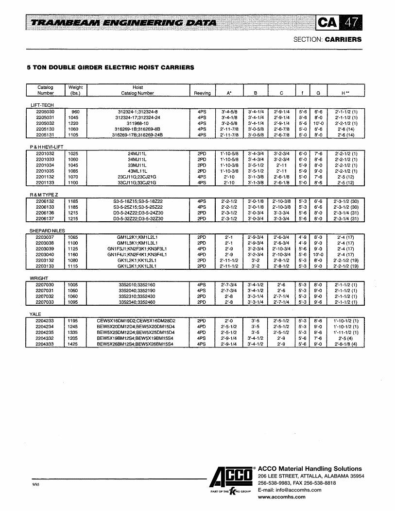
ACCO Material Handling Solutions206 LEE STREET, ATTALLA, ALABAMA 35954
256-538-9983, FAX 256-538-8818
E-mail: [email protected]
www.accomhs.com
5 TON DOUBLE GIRDER ELECTRIC HOIST CARRIERS
Catalog Number
LIFT-TECH 2205030 2205031 2205032 2205130 2205131
P & H HEVI-LIFT 2201032 2201033 2201034 2201035 2201132 2201133
R&MTYPEZ
2206132 2206133 2206136 2206137
SHEPARD NILES
2203037 2203038 2203039 2203040 2203132 2203133
WRIGHT
2207030 2207031 2207032 2207033
YALE
2204233 2204234 2204235 2204332 2204333
960 1045 1220 1060 1105
1025 1060 1045 1085 1070 1100
1185 1185 1215 1215
1065 1100 1125 1160 1080 1115
1005 1060 1060 1095
1195 1245 1335 1205 1425
Hoist Catalog Number
312324-1 ;312324-8 312324-17;312324-24
311968-10 316269-1 8;316269-88
316269-178;316269-248
24MJ11L 34MJ11L 33MJ11L 43ML11L
23CJ11 G;23CJ21 G 33CJ11 G;33CJ21 G
S3-5-18Z15;S3-5-18Z22 S3-5-25Z15;S3-5-25Z22 D3-5-24Z22;D3-5-24Z30 D3-5-32Z22;D3-5-32Z30
GM1 L2K1 ;KM1 L2L 1 GM1 L3K1 ;KM1 L3L 1
GN1 F3J1 ;KN2F3K1 ;KN3F3L 1 GN1 F4J1 ;KN2F4K1 ;KN3F4L 1
GK1 L2K1 ;KK1 L2L 1 GK1 L3K1 ;KK1 L3L 1
335201 0;3352160 3352040;3352190 3352310;3352430 3352340;3352460
CEW5X16DM19D2;CEW5X16DM28D2 BEW5X20DM12D4;BEW5X20DM1504 8EW5X25DM12D4;8EW5X25DM15D4 8EW5X19BM12S4;8EW5X19BM15S4 BEW5X268M12S4;8EW5X26BM15S4
4PS 3'-4-5/8 3'-4-1/4 4PS 3'-4-1/8 3'-4-1/4 4PS 3'-2-5/8 3'-4-1/4 4PS 2'-11-7/8 3'-0-5/8 4PS 2'-11-7/8 3'-0-5/8
2PD 1'-10-5/8 3'-4-3/4 2PD 1'-10-5/8 3'-4-3/4 2PD 1'-10-3/8 3'-5-1/2 2PD 1'-10-3/8 3'-5-1/2 4PS 2'-10 3'-1-3/8 4PS 2'-10 3'-1-3/8
4PS 2'-2-1/2 3'-0-118 4PS 2'-2-1/2 3'-0-1/8 2PD 2'-3-1/2 3'-0-3/4 2PD 2'-3-1/2 3'-0-3/4
2PD 2'-1 2 1•9w3/4 2PD 2'-1 2'-9-3/4 4PD 2'-9 3'-2-3/4 4PD 2'-9 3'-2-3/4 2PD 2'-11-1/2 3'-2 2PD 2'-11-1/2 3'-2
4PS 2'-7-3/4 3'-4-1/2 4PS 2'-7-3/4 3'-4-1/2 2PD 2'-8 3'-3-1/4 2PD 2'-8 3'-3-1/4
2PD 2'-0 3'·5 4PD 2'-5-1/2 3'-5 4PD 2'-5-1/2 3'-5 4PS 2'-9-1/4 3'-4-112 4PS 2'-9-1/4 3'-4-1/2
-9,95 ------Acco®
, PART OF THE 'KFKI GROUP
SECTION: CARRIERS
H**
2'-9-1/4 5'-6 • 6'-6 2'-1-1/2 (1) 2'-9-1/4 5'-6 8'-0 2'-1-1/2 (1) 2'-9-1/4 5'-6 10'-0 2'-2-1/2 (1) 2'-6-7/8 5'-0 6'-6 2'-6 (14) 2'-6-7/8 5'-0 8'-0 2'-6 (14)
3'-2-3/4 6'-0 7'-6 2'·2-1/2 (1) 3'-2-3/4 6'-0 8'-6 2'-2-1/2 (1)
2'-11 5'-9 8'-0 2'-2-1/2 (1) 2'-11 5'-9 9'-0 2'-2-1/2 (1)
2'-6-1/8 5'-0 7'-6 2'-5 (12) 2'-6-1/8 5'-0 8'-6 2'-5 (12)
2'-10-3/8 5'-3 6'-6 2'-3-1/2 (30) 2'-10-3/8 5'-3 6'-6 2'-3-1/2 (30) 3'-3-3/4 5'-6 8'-0 2'-3-1/4 (31) 3'-3-3/4 5'-6 8'-0 2'-3-1/4 (31)
2'-6-3/4 4'-9 8'-0 2'-4 (17) 2'-6-3/4 4'-9 9'-0 2'-4 (17)
2'-10-3/4 5'-6 9'-0 2'-4 (17) 2'-10-3/4 5'-6 10'-0 2'-4 (17) 2'-8-1/2 5'-3 8'-0 2'-2-1/2 (19) 2'-8-1/2 5'-3 9'-0 2'-2-1/2 (19)
2'-6 5'-3 8'-0 2'-1-1/2 (1) 2'-6 5'-3 9'-0 2'-1-1/2 (1)
2'-7-1/4 5'-3 9'-0 2'-1-1/2 (1) 2'-7-1/4 5'-3 9'-6 2'-1-1/2 (1)
2'-5-1/2 5'-3 8'-6 1'-1 0-1/2 (1) 2'-5-1/2 5'-3 9'-0 1'-1 0-1/2 (1) 2'-5-1/2 5'-3 9'-6 1'-11-1/2 (1)
2'-9 5'-6 7'-6 2'-5 (4) 2'-9 5'-6 9'-0 2'-6-1/8 (4)

ACCO Material Handling Solutions206 LEE STREET, ATTALLA, ALABAMA 35954
256-538-9983, FAX 256-538-8818
E-mail: [email protected]
www.accomhs.com
SECTION: CARRIERS
7·1/2 TON DOUBLE GIRDER ELECTRIC HOIST CARRIERS
5-1 6"
1/4"
1 '-8-3/16''
-9,95 ------Acco® ,
PART OF THE 'KFKI GROUP

ACCO Material Handling Solutions206 LEE STREET, ATTALLA, ALABAMA 35954
256-538-9983, FAX 256-538-8818
E-mail: [email protected]
www.accomhs.com
7·1/2 TON DOUBLE GIRDER ELECTRIC HOIST CARRIERS
Catalog Number
2205050 2205051 2205150 2205151
2201052 2201053 2201054 2201055 2201056 2201150 2201151
A&MTYPEZ
2206152
2206153
2206156
2206157
SHEPARD NILES
2203057 2203058 2203059 2203150 2203151
WRIGHT
2207050 2207051 2207052 2207053
YALE
2204254 2204255 2204256 2204257
1465 1760 1415 1615
1490 1540 1535 1560 1580 1405 1450
1570
1630
1695
1675
1420 1465 1490 1425 1470
1325 1385 1430 1475
1660 1705 1685 1695
Hoist Catalog Number
326983-1 326983-20 326794-18
326794-208
34PL21 L;34PL31 L 44PL21 L;44PL31 L
34ML11L 44ML11L 54ML11L
24CL21G;24CL31G 34CL21G;34CL31G
83-7 -1/2-18Z1 0;53-7-1/2-18215 S3-7 -1/2-18220
83-7-1/2-27Z10;S3-7-1/2-27Z15 83-7 -1/2-27Z20
03-7-1/2-1521 0;03-7-1/2-15Z15 03-7-1/2-15220
D3-7-1/2-22Z10;D3-7-1/2-22Z15 03-7 -1/2-22Z20
GN1 H3K1 ;KN1 H3K1 ;KN2H3L 1 GN1 H4K1 ;KN1 H4K1 ;KN2H4L 1 GN1 H5K1 ;KN1 H5K1 ;KN2H5L 1 GL 1 H3K1 ;KL 1 H3K1 ;KL2H3L 1 GL 1 H4K1 ;KL 1 H4K1 ;KL2H4L 1
3463360;346351 0 3463390;3463540 3463660;3463750 3463690;3463780
CEW7-1/2X19DM8D4;CEW7 -1/2X 19DM14D4 CEW7-1/2X25DM8D2;CEW7 -1/2X25DM14D4
DEW7-1/2X28DM33D2 CEW7 -1/2X320M804
6PS 3'-4-1/8 6PS 3'-4-1/8 6PS 3'-0-3/8 6PS 2'-9-7/8
4PD 2'-10-1/4 4PD 2'-10-1/4 2PD 2'-8-7/8 2PD 2'-8-7/8 2PD 2'-8-718 4PS 3'-4-3/4 4P8 3'-4-3/4
4PS 2'-5-1/4
4PS 2'-5-1/4
4PD 3'-0-1/4
4PD 3'-0-1/4
4PD 2'-9 4PD 2'-9 4PD 2'-9 4PD 3'-9 4PD 3'-9
4P8 3'-3-1/4 4PS 3'-3-1/4 2PD 2'-11 2PD 2'-11
4PD 2'-6-5/8 4PD 2'-6-5/8 2PD 2'-6-7/8 4PD 2'-6-5/8
-9,95 ------Acco® PART OF THE 'lc.FKI GROUP
SECTION: CARRIERS
3'-7-3/4 3'-0-3/4 6'-0 8'-0 2'-2-1/2 (11) 3'-7-3/4 3'-0-3/4 6'-0 10'-0 2'-2-1/2 (11) 3'-4-1/8 2'-10-3/8 5'-6 8'-0 2'-7-1/2 (15) 3'-4-1/8 2'-10-3/8 5'-6 10'-6 2'-5 (16)
3'-7-3/4 3'-3-3/4 6'-3 8'-6 2'-4-1/2 (11) 3'-7-3/4 3'-3-3/4 6'-3 9'-0 2'-4-1/2 (11) 3'-8-1/4 3'-3-1/4 6'-3 8'-6 2'-4-1/2 (11) 3'-8-1/4 3'-3-1/4 6'-3 9'-0 2'-4-1/2 (11) 3'-8-1/4 3'-3-1/4 6'-3 9'-6 2'-4-1/2 (11) 3'-2-3/4 2'-8-3/4 5'-3 8'-0 2'-9-1/2 (13) 3'-2-3/4 2'-8-3/4 5'-3 9'-0 2'-9-1/2 (13)
2'-10-1/4 4'-1-1/4 6'-3 6'-6 2'-4-3/4 (32)
2'-10-1/4 4'-1-1/4 6'-3 7'-6 2'-4-3/4 (32)
3'-1-3/4 3'-10-1/4 6'-3 8'-0 2'-9 (13}
3'-1-1/4 3*-10-1/4 6'-3 9'-0 2'-9 {13)
3'-6-1/4 2'-11-1/4 5'-9 9'-0 2'-6 (18) 3'-6-1/4 2'-11-1/4 5'-9 10'-0 2'-6 (18) 3'-6-1/4 2'-11-1/4 5'-9 10'-6 2'-6 (18}
3'-4 2'-10-1/2 5'-6 9'-0 2'-3-1/2 (20) 3'-4 2'-10-1/2 5'-6 10'-0 2'-3-1/2 (20)
3'-9-5/8 2'-10-7/8 6'-0 8'-0 2'-2-1/2 {11) 3'-9-5/8 2'-10-7/8 6'-0 9'-0 2'-2-1/2 (11) 3'-8-1/4 3'-0-1/4 6'-0 9'-6 2'-2-1/2 (11) 3'-8-1/4 3'-0-1/4 6'-0 10'-0 2'-2-1/2 (11)
3'-8-1/4 3'-3-1/4 6'-3 9·-o 2'-1-1/4 (33) 3'-8-1/4 3'-3-1/4 6'-3 10'-0 2'-1-1/4 (33) 3'-8-1/4 3'-3-1/4 6'-3 9'-6 2'-8 (33) 3'-8-1/4 3'-3-1/4 6'-3 10'-6 2'-1-1/4 (33)

ACCO Material Handling Solutions206 LEE STREET, ATTALLA, ALABAMA 35954
256-538-9983, FAX 256-538-8818
E-mail: [email protected]
www.accomhs.com
10 TON DOUBLE GIRDER ELECTRIC HOIST CARRIERS
5-1 G 2
-9,95 ------Acco®
, PART OF THE 'KFKI GROUP
SECTION: CARRIERS

ACCO Material Handling Solutions206 LEE STREET, ATTALLA, ALABAMA 35954
256-538-9983, FAX 256-538-8818
E-mail: [email protected]
www.accomhs.com
10 TON DOUBLE GIRDER ELECTRIC HOIST CARRIERS
Catalog Number
LIFT-TECH
2205080 2205081 2205082
P & H HEVI-LIFT
2201080 2201081 2201082 2201083 2201084
R&MTYPEZ
2206162
2206163 2206164 2206165
SHEPARD NILES
2203080 2203081 2203082
WRIGHT
2207080 2207081 2207082 2207083 2207084
YALE
2204280 2204281 2204282 2204283
1525 1565 1635 1665 1790
1765
1775 1815 1800
1470 1495 1635 1625 1785
1975 1870 2110 1990
Hoist Catalog Number
327374-1 327374-20 327374-40
34PN11 L;34PN21 L 44PN11L;44PN21L
34NN11L 44NN11L 54NN11L
S6-10-17Z11 ;S6-10-17Z15 S6-1 0-17Z22
D3-10-15Z11 ;D3-10-15Z15 06-1 0-22Z11 ;06-1 0-22Z15 06-10-17Z11 ;06-10-17Z15
06-1 0-17Z22
GN1 L3K1 ;KN1 L3L 1 GN1 L4K1 ;KN1 L4L 1 GN1 L5K1 ;KN1 L5L 1
3463840;3463990;3464140 3463870;3464020;3464170 3463900;3464050;3464200
3460870;3460900 3457120;3457150
CEW1 OX20DM8D4;CEW1 OX200M1404 CEW1 0-23DM19D4
CEW1 OX250M8D4;CEW1 OX250M1404 EEW10-30DM1904
4PD 4PD 3PD 3PD 3PD
4PS
4PD 4PD 4PD
4PS 4PS 4PS 4PD 4PD
4PO 4PO 4PD 4PD
3'-7-1/4 3'-7-3/4 3'-7-1/4 3'-7-3/4
3'-1 3'-7-3/4 3'~1 3'-7-3/4 3'-1 3'-7-3/4
2'-10-1/4 4'-2-1/4
3'-0-1/4 4'-2-3/4 3'-0-1/4 4'-2-3/4 3'-1-3/4 4'-2-3/4
3'-8-1/4 3'-9-5/8 3'-8-1/4 3'-9-5/8 3'-8-1/4 3'-9-5/8 3'-3-1/2 3'-9-1/4 3'-3-1/2 3'-9-1/4
3'-0-5/8 3'-8-1/4 3'-1-1/2 3'-9-3/4 3'-0-5/8 3'-8-1/4 3'-1-1/2 3'-9-3/4
-9,95 ------Acco®
, PART OF THE 'KFKI GROUP
SECTION: CARRIERS
3'-6-3/4 6'-6 3'-6-3/4 6'-6 3'-6-3/4 6'-6
3'-6-3/4 6'-6 3'-6-3/4 6'-6 3'-6-3/4 6'-6 3'-6-3/4 6'-6 3'-6-3/4 6'-6
3'-6-1/4 7'-0
2'-8-3/4 7'-0 2'-8-3/4 7'-0 3'-5-3/4 7'-0
3'-7-7/8 6'-9 3'-7-7/8 6'-9 3'-7-7/8 6'-9 3'-8-1/4 6'-9 3'-8-1/4 6'-9
3'-3-1/4 6'-3 3'-10-3/4 7'-0 3'-3-i/4 6'-3
3'-10-3/4 7'-0
8'-6 9'-0 8'-6 9'-0 9'-6
7'-6
8'-0 9'-0 9'-0
8'-6 9'-0 10'-0 9'-0 10'-0
10'-6 9'-6 11'-0 10'-0
H **
2'-4-1/2 (23) 2'-4-1/2 {23) 2'-7-1/2 (23)
2'-4-1/2 (22) 2'-4-1/2 (22) 2'-4-1/2 (22) 2'-4-1/2 (11) 2'-7-1/2 (11)
2'-10-1/4 (13)
2'-10-1/4 (13) 3'-0-1/4 (13)
2'-11 (13)
2'-11 (24) 2'-11 (24) 2'-11 (24)
2'-7 (25) 2'-7 (25) 2'-7 (25) 2'-6 (26) 2'-6 (26)
2'-3-1/4 (22) 2'-3-114 (22) 2'-3-1/4 {22) 2'-3-1/4 (22)

ACCO Material Handling Solutions206 LEE STREET, ATTALLA, ALABAMA 35954
256-538-9983, FAX 256-538-8818
E-mail: [email protected]
www.accomhs.com
15 TON DOUBLE GIRDER ELECTRIC HOIST CARRIERS
11-7 I 1
1/8"
4-1/4"
No. 010209 Carrier Head
1 '-3"
No. 2408 Tractors Are Used When For No. 24016 Drive Or
f
-9,95 ------Acco®
, PART OF THE 'KFKI GROUP
SECTION: CARRIERS
'-2-
Exceed Allowable Excess Of 200 FPM.

ACCO Material Handling Solutions206 LEE STREET, ATTALLA, ALABAMA 35954
256-538-9983, FAX 256-538-8818
E-mail: [email protected]
www.accomhs.com
15 TON DOUBLE GIRDER ELECTRIC HOIST CARRIERS
Catalog Number
2205070 2205071 2205072
P & H HEVI-LIFT 2201074 2201075 2201076 2201077
R&MTYPEZ
2206172
2206173
2206174
2207177
SHEPARD NILES 2203077 2203078 2203079
WRIGHT
2207070 2207071 2207072
YALE 2204273 2204274
3160 3210 3310 3450
2910
2980
3205
3280
Hoist Catalog Number
312363~1
312363-11 312306-1
35PR14L;35PR24L 45PR14L;45PR24L 55PR14L;55PR24L 65PR14L;65PR24L
X6-15-16Z7;X6-15-16Z1 0 X6-15-16Z15
X6-15-25Z7;X6-15-25Z1 0 X6-15-25Z15
X6-15-32Z7;X6-15-32Z1 0 X6-15-32Z15
08-15-33Z11 ; 08-15-33Z15 08-15-33220
MN1 N3M1 ;MN2N3N1 MN1 N4M1 ;MN2N4N1 MN1 N5M1 ;MN2N5N1
3522820 3522850 3522880
DEW15X17DM11 D4;DEW15X17DM1604 DEW15X22DM11 D4;DEW15X22DM16D4
4PD 4PD 4PD 4PD
6PS
6PS
6PS
4PD
4'-2 3'-6-3/4 4'-2 3'-6-3/4 4'-2 3'-6-3/4 4'-2 3'-6-3/4
4'-7-3/4 3'-11-3/4
4'-7-3/4 3'-11-3/4
4'-7-3/4 3'-11-3/4
4'-0-3/4 4'-3-7/8
-9,95 ------Acco® PART OF THE 'lc.FKI GROUP
SECTION: CARRIERS
4'-4-3/4 4'-9 10'-0 3'-0 (7) 6'-0 4'-4-3/4 4'-9 10'-6 3'-0 (7) 6'-0 4'-4-3/4 4'-9 11'-6 3'-0 (7) 6'-0 4'-4-3/4 4'-9 12'-6 3'-0 (7) 6'-0
3'-11-3/4 4'-9 8'-6 4'-1-314 (9) 6'-0
3-11-3/4 4'-9 9'-6 4'-1-3/4 (9) 6'-0
3'-11-3/4 4'-9 10'-6 4'-1-3/4 (9) 6'-0
4'-1-5/8 5'-3 13'-0 3' -9-3/4 (9) 6'-6
3'-0-1/2 (10) 3'-0-1/2 (10) 3'-0-1/2 {10)
3'-1-1/8 (9) 6'-6 3'-1-1/8 (9) 6'-6

ACCO Material Handling Solutions206 LEE STREET, ATTALLA, ALABAMA 35954
256-538-9983, FAX 256-538-8818
E-mail: [email protected]
www.accomhs.com
DIMENSION 'H'
Dimension 'H' in the data is the distance from the top of the crane girder at the end truck to the bottom of the hoist framing for cranes with Type 2 girders. The numbered changes in dimension 'H' noted below correspond to the numerals noted in the data.
1. 'H' is based on Type 2 girders; deduct 3-1/2 in. for Type 1 girders; add 6-1/2 in. for Type 3 girders.
2. 'H' is based on Type 2 girders; deduct 2 in. for Type 1 girders; add 6-1/2 in. for Type 3 girders.
3. 'H' is based on Types 1 and 2 girders; add 2 in. for Type 3 girders.
4. 'H' is based on Types 1 and 2 girders; add 3-1/2 in. for Type 3 girders.
5. 'H' is based on Types 1 and 2 girders; add 5 in. for Type 3 girders.
6. 'H' is based on Types 1 and 2 girders; add 5-1/2 in. for Type 3 girders.
7. 'H' is based on Type 2 girders; add 2-1/2 in. for Type 3 girders.
8. 'H' is based on Type 2 girders; add 3-1/2 in. for Type 3 girders.
9. 'H' is based on Types 2 and 3 girders; add 1 in. when operating on cranes with No. 180114 end trucks.
10. 'H' is based on Type 2 girders; add 2 in. for Type 3 girder.
11. 'H' is based on Type 2 girders; add 6-1/2 in. for Type 3 girders.
12. 'H' is based on Types 1 and 2 girders; add 3 in. for Type 3 girders. Add an additional 2 in. for Type 3 girders for cranes with No. 180112 end trucks; 4 in. for No. 180113 end trucks.
13. Add 5 in. to the 'H' dimension for cranes with No. 180112 end trucks; add 7 in. for cranes with no. 180113 end trucks.
14. 'H' is based on Types 1 and 2 girders; add 2 in. for Type 3 girders. Add an additional3 in. for Type 3 girders for cranes with No. 180112 end trucks; 5 in. for No. 180113 end trucks.
15. 'H' is based on Type 2 girders; add 1-1/2 in. for Type 3 girders. Add an additional 3-1/2 in. for Type 3 girders for cranes with No. 180112 end trucks; 5-1/2 in. for No. 180113 end trucks.
16. 'H' is based on Type 2 girders; add 4 in. for Type 3 girders. Add an additional! in. for Type 3 girders for cranes with No. 180112 end trucks; 3 in. for No. 180113 end trucks.
17. 'H' is based on Types 1 and 2 girders; add 5 in. for Type 3 girders. Add an additional2 in. for Type 3 girders for
SECTION: CARRIERS
18. 'H' is based on Types 1 and 2 girders; add 5 in. for Type 3 girders. Add an additional2 in. for Type 3 girders for cranes with no. 180113 end trucks.
19. 'H' is based on Types 1 and 2 girders; add 5-1/2 in. for Type 3 girders. Add an additional 1-1/2 in. for Type 3 girders for cranes with No. 180113 end trucks.
20. 'H' is based on Type 2 girders; add 5-1/2 in. for Type 3 girders. Add an additionall-1/2 in. for Type 3 girders for cranes with No. 180113 end trucks.
21. 'H' is based on Types 1 and 2 girders. Add 2-1/2 in. for Type 3 girders. Add an additional 2-1/2 in. for cranes with No. 180113 end trucks.
22. 'H' is based on Type 2 girders. Add 2 in. for cranes with Type 2 girders and No. 180113 end trucks. Add 6-1/2 in. for Type 3 girders.
23. 'H' is based on Type 2 girders. Add 1 in. for cranes with Type 2 girders and No. 180113 end trucks. Add 6-1/2 in. for Type 3 girders.
24. 'H' is based on Type 2 girders. Add 2 in. for cranes with Type 2 girders and No. 180113 end trucks. Add 2 in. for Type 3 girders.
25. 'H' is based on Type 2 girders. Add 2 in. for cranes with Type 2 girders and No. 180113 end trucks. Add 4 in. for Type 3 girders.
26. 'H' is based on Type 2 girders. Add 2 in. for cranes with Type 2 girders and No. 180113 end trucks. Add 5 in. for Type 3 girders.
27. 'H' is based on Type 2 girders. Deduct 1 in. for Type 1 girders. Add 3 in. for Type 3 girders.
28. 'H' is based on Types 1 and 2 girders. Add 4-3/4 in. for Type 3 girders.
29. 'H' is based on Types 1 and 2 girders. Add 5-3/4 in. for Type 3 girders.
30. 'H' is based on Types 1 and 2 girders. Add 4-1/2 in. for Type 3 girders. Add an additional 1-1/2 in. for cranes with No. 180112 end trucks and 3-114 in. for No. 180113 end trucks.
31. 'H' is based on Types 1 and 2 girders. Add 4-3/4 in. for Type 3 girders. Add an additional 1-1/2 in. for cranes with No. 180113 end trucks.
32. 'H' is based on Type 2 girders. Add 4-1/4 in. for Type 3 girders. Add an additional 2 in. for cranes with no. 180113 end trucks.
33. 'H' is based on Type 2 girders. Add 1-5/8 in. for Type 3 girders. Add an additional4-1/2 in. for cranes with No. 180112 end trucks and 6-1/4 in. for No. 180113 end trucks.
cranes with No. 180113 end trucks.
-9,95 ------Acco® ,
PART OF THE 'KFKI GROUP

ACCO Material Handling Solutions206 LEE STREET, ATTALLA, ALABAMA 35954
256-538-9983, FAX 256-538-8818
E-mail: [email protected]
www.accomhs.com
GENERAL INFORMATION
Trambeam cranes are available for rated loads to 30 tons. They provide complete plant coverage and are used to move almost every conceivable type of material in practically every industry. Trambeam cranes increase productivity by utilizing overhead space and have the flexibility to meet facilities change and expansion.
All Trambeam cranes are essentially the same in construe· tion and vary only in rated load and span. They consist of a bridge girder fitted to end trucks which operate on the lower flange of the runways. The runways consist of at least two and as many additional tracks as may be required to provide the desired area coverage.
Cranes may use single or double girder construction depending on rated load, span and lift required. They may be hand propelled, hand racked or motor driven depending on travel distance, frequency of operation and rated load. When motor driven, or when electric hoists operate on the crane, they are equipped with conductors and current collectors as described in the Electrification Section.
Trambeam cranes are manufactured with as many standard components as possible to provide quality equipment at a reasonable cost. Where standard components are not suitable for a particular application, special combinations are used to provide the best suited equipment for the application
SINGLE GIRDER CRANES
Single girder cranes are available in two series - light duty and standard. The components for each series have been carefully selected to provide many years of dependable, trouble-free service.
Light duty cranes are always hand propelled and provide maximum economy for light loads and short spans. Specifications for these cranes are given on Pages CR-3 through CR-5.
Standard single girder cranes may be hand propelled, hand racked or motor driven and are available for rated loads to 10 tons. Two-runway cranes are available with spans to 100 feet. Multiple runway cranes are also available. Specifications, dimensional data and selection procedure are
SECTION: CRANES
given on Pages CR-6 through CR-29. Low headroom single girder cranes are available for build
ings with low truss elevations or other obstructions which may restrict the hoist lift. Low headroom cranes provide maximum lift under these conditions; but some flexibility is sacrificed. Specifications and dimensional data on low headroom connections are given on Pages CR-37 and CR-38.
DOUBLE GIRDER CRANES
Double girder cranes are generally used on systems having long spans and where heavier loads are handled. They require minimum headroom and are often used in handling lighter loads where maximum lift is required. Double girder cranes are available for rated loads to 30 tons. Two runways cranes are available with spans to 100 feet. Multiple runway cranes are also available. Specifications, dimensional data and selection procedure are given on Pages CR-40 through CR-61.
TRANSFER CRANES
Transfer cranes are used to transfer loads from area to area, either directly from crane to crane or by fixed transfer sections or spur tracks. Most Trambeam cranes can be furnished as transfer cranes by the addition of interlock mechanisms to the ends of the bridge girders. Specifications and dimensional data are given on Pages CR-30 through CR-36 for single girder transfer cranes and on Pages CR -62 through CR -67 for double girder transfer cranes.
GANTRY CRANES
Trambeam gantry cranes are generally used where a particular work area is of an unusual nature or where an operation is repetitive. Single or double leg construction may be used. Girder construction may be single or double girder depending on the span, rated load and lift required. The gantry leg end truck has double flanged wheels which operate on a rail installed in the floor. Specifications and dimensional data are given on Pages CR-68 through CR-71.
-9,95 ------A~co® PART OF THE 'KFKI GROUP

ACCO Material Handling Solutions206 LEE STREET, ATTALLA, ALABAMA 35954
256-538-9983, FAX 256-538-8818
E-mail: [email protected]
www.accomhs.com
SECTION: CRANES
CODE FOR NUMBERING CRANES
Trambeam cranes are identified by a code numbering system indicating the major components of that particular crane. An explanation is given in the diagram below. In addition to the crane number, the span and overhangs of the bridge girder(s), rated load, speed, type of control, type of drive, motor
horsepower and current characteristics must be indicated when specifying or ordering cranes. Special features such as girder coping, low headroom construction, brakes, etc., Must also be specified.
Means of Propulsion- --------~ ~ ~21 Type of Crane Electrification - - I
Size of Bridge Girder(s) -Type of Crane- --------------.J
Number of Runways - -----------------' Type of End Truck- ------------------'
End Conditions Overall Length- --------------------"
Means of Propulsion: H - Hand Propelled L - Light Duty Hand Propelled M- Motor Driven R - Hand Racked
Type of Electrification: W - Insul-8-Bar T- Tagline F - Festooned
Size of Bridge Girder(s): 11 No. 34011 (8 @ 15.9) 16- No. 34016 (8-1/2 @ 19.4) 21 -No. 34021 (10 @ 22.2) 26- No. 34026 (11-1/2@ 26.3) 31 No. 34031 (13 @ 29.3) 37 - No. 34037 (12-1/2 @ 33.6) 41 -No. 34041 (14 @ 38.5) 46 No. 34046 (16 @ 42.7) 51 -No. 34051 (18 @ 50.3) 56 - No. 34056 (20 @ 55.0) 61- No. 34061 (22-1/2@ 61.4) 66 - No. 34066 (25 @ 67 .8) 71- No. 34071 (27-1/2@ 82.8) 76 - No. 34076 (30 @ 92.0) 77- No. 34077 (32@ 108.6) 78- No. 34078 (36@ 122.1) 79- No. 34079 (40@ 135.6)
Type of Crane: S - Single Girder D- Double Girder
Number of Runways: 2 - Two Runways 3 - Three Runways 4 - Four Runways
TYPE OF END TRUCK; 01 .. 170301 02 - 170302; 1801 02; 180202 03- 170303 04- 170304; 180104; 180204 05- 170305; 180205 06- 170306; 180106; 180206 07- 170307 08- 170308; 170408; 180108; 180208 09 .. 170309; 170409; 180209 12- 170112; 180112; 180212 13- 170313; 180113; 180213 14- 170314; 170414; 180214 15 .. 170315; 170415 16 .. 170416 17- 170417 18 .. 170318; 170418 19- 170319; 170419 20 .. 170320; 170420 21- 170321; 170421 22- 170422 23- 170423
End Conditions: X- Plain End L- Interlock D - Discharge
Overall Length: Exact Overall Length Stated in Feet and Inches
-9,95 ------Acco® PART OF THE 'lc.FKI GROUP
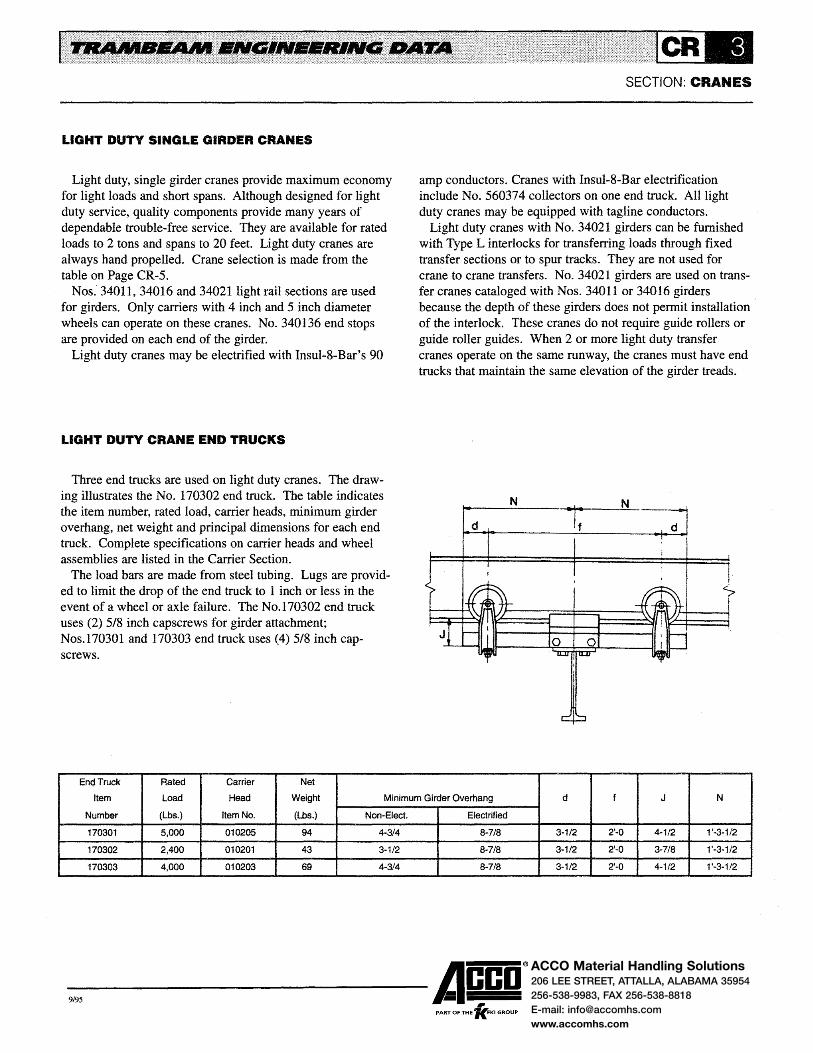
ACCO Material Handling Solutions206 LEE STREET, ATTALLA, ALABAMA 35954
256-538-9983, FAX 256-538-8818
E-mail: [email protected]
www.accomhs.com
LIGHT DUTY SINGLE GIRDER CRANES
Light duty, single girder cranes provide maximum economy for light loads and short spans. Although designed for light duty service, quality components provide many years of dependable trouble-free service. They are available for rated loads to 2 tons and spans to 20 feet. Light duty cranes are always hand propelled. Crane selection is made from the table on Page CR~5.
Nos. 34011, 34016 and 340211ight rail sections are used for girders. Only carriers with 4 inch and 5 inch diameter wheels can operate on these cranes. No. 340136 end stops are provided on each end of the girder.
Light duty cranes may be electrified with lnsul~8-Bar's 90
LIGHT DUTY CRANE END TRUCKS
Three end trucks are used on light duty cranes. The drawing illustrates the No. 170302 end truck. The table indicates the item number, rated load, carrier heads, minimum girder overhang, net weight and principal dimensions for each end truck. Complete specifications on carrier heads and wheel assemblies are listed in the Carrier Section.
The load bars are made from steel tubing. Lugs are provided to limit the drop of the end truck to 1 inch or less in the event of a wheel or axle failure. The No.170302 end truck uses (2) 5/8 inch capscrews for girder attachment; Nos.l70301 and 170303 end truck uses (4) 5/8 inch cap~ screws.
End Truck Rated Carrier Net
SECTION: CRANES
amp conductors. Cranes with lnsul-8-Bar electrification include No. 560374 collectors on one end truck. All light duty cranes may be equipped with tagline conductors.
Light duty cranes with No. 34021 girders can be furnished with Type L interlocks for transferring loads through fixed transfer sections or to spur tracks. They are not used for crane to crane transfers. No. 34021 girders are used on transfer cranes cataloged with Nos. 34011 or 34016 girders because the depth of these girders does not permit installation of the interlock. These cranes do not require guide rollers or guide roller guides. When 2 or more light duty transfer cranes operate on the same runway, the cranes must have end trucks that maintain the same elevation of the girder treads.
N N
Item Load Head Weight Minimum Girder Overhang d f J N
Number (Lbs.) Item No. (Lbs.) Non-Elect. Electrified
170301 5,000 010205 94 4-314 8-718 3-1/2 2'-0 4-1/2 1 '·3-1/2
170302 2,400 010201 43 3-1/2 8-7/8 3-1/2 2'...() 3-7/8 1'-3-1/2
170303 4,000 010203 69 4-3/4 8-7/8 3-1/2 2'-0 4-1/2 1'-3-1/2
-9,95 ------Acco® PART OF THE 'lc.FKI GROUP

ACCO Material Handling Solutions206 LEE STREET, ATTALLA, ALABAMA 35954
256-538-9983, FAX 256-538-8818
E-mail: [email protected]
www.accomhs.com
CLEARANCE DRAWING FOR LIGHT DUTY CRANES
The drawing illustrates the clearance for a light duty crane with 3 conductor Insul-8-Bar electrification. Clearances for a non-electrified crane are the same as shown for the electrified crane. Dimensions f, J and N are shown in the table on Page
SECTION: CRANES
CR-5. To determine dimensions A, Band C, refer to the appropriate clearance drawing in the Carrier Section for the hoist and carrier selected for the crane. See end truck table on Page CR-3 for minimum girder overhangs.
Overall Length
1··0" Span (20 '·O~r Maximum)
(Maximum)
A
B C
-9,95 ------Acco®
, PART OF THE 'KFKI GROUP

ACCO Material Handling Solutions206 LEE STREET, ATTALLA, ALABAMA 35954
256-538-9983, FAX 256-538-8818
E-mail: [email protected]
www.accomhs.com
SELECTION OF LIGHT DUTY CRANES
Light duty cranes are listed by rated load and span. Rated loads are based on a carrier design load which is adequate for most applications. The carrier design load includes hoist and carrier weights, rated load and 15% impact allowance. The design load is indicated in the table.
Crane selection is made by:
Step 1 -Determine actual carrier load (weights of hoist and carrier selected for the crane, rated load and impact
Rated Design Crane Net
Load Load Code Weight
(Tons) (Lbs.) Number (Lbs.)
LW11S202X10 308
LW11S202X12 350
LW11S202X14 391
1/2 1360 LW11S202X16 433
LW11S202X18 464
LW11S202X20 515
LW16S202X22 634
LW11S203X10 369
LW11S203X12 411
LW16S203X14 452
1 2540 LW11S203X16 494
LW16S203X18 598
LW16S203X20 646
LW16S203X22 695
LW11S203X10 369
LW11S203X12 411
LW11S203X14 452
1-1/2 3660 LW16S203X16 550
LW16S203X18 598
LW16S203X20 646
LW21S203X22 756
LW11S201X10 410
LW11S201X12 452
LW16S201X14 542
2 5110 LW16S201X16 591
LW16S201X18 639
LW21S201X20 743
LW21 S201 X22 797
SECTION: CRANES
allowance, if applicable). Step 2 - Select crane from table providing actual load is no greater than the design load.
If the actual load exceeds the 2 ton design load, select a standard single girder crane from the table on Page CR-15.
The weights are based on cranes with 3 conductors of Insul-8-Bar. Cranes are listed with an overall length based on a nominal span between runway tracks and 1 '-0 maximum girder overhangs.
Overall
Span Length f J N
(Ft.) (Ft.)
8 10 2'-0 11-1/2 1'-3-1/2
10 12 2'-0 11-1/2 1'-3-1/2
12 14 2'-0 11-1/2 1'-3-1/2
14 16 2'-0 11-1/2 1'-3-1/2
16 18 2'-0 11-1/2 1'-3-1/2
18 20 2'-0 11-1/2 1'-3-1/2
20 22 2'-0 1'-0 1'-3-1/2
8 10 2'-0 1'-0-1/8 1'-3-1/2
10 12 2'-0 1'-0-1/8 1'-3-1/2
12 14 2'-0 1'-0-1/8 1'-3-1/2
14 16 2'-0 1'-0-1/8 1'-3-1/2
16 18 2'-0 1'-0-5/8 1'-3-1/2
18 20 2'-0 1'-0-5/8 1'-3-1/2
20 22 2'-0 1'-0-5/8 1'-3-1/2
8 10 2'-Q 1'-0-1/8 1'-3-1/2
10 12 2'-0 1'-0-1/8 1'-3-1/2
12 14 2'-0 1 '-0-1/8 1'-3-1/2
14 16 2'-0 1'-0-5/8 1'-3-1/2
16 18 2'-0 1'-0-5/8 1'-3-1/2
18 20 2'-0 1'-0-5/8 1'-3-1/2
20 22 2'-0 1'-2-1/8 1'-3-112
8 10 2'-0 1'-0-1/8 1'-3-1/2
10 12 2'-Q 1'-0-1/8 1'-3-1/2
12 14 2'-0 1'-Q-5/8 1'~3-1/2
14 16 2'-0 1'~0-5/8 1'-3-1/2
16 18 2'-0 1'-0-5/8 1'-3-1/2
18 20 2'-0 1'-2-1/8 1'-3-1/2
20 22 2'-0 1'-2-1/8 1'-3-1/2
-9,95 ------A~co® PART OF THE 'KFKI GROUP

5,000

ACCO Material Handling Solutions206 LEE STREET, ATTALLA, ALABAMA 35954
256-538-9983, FAX 256-538-8818
E-mail: [email protected]
www.accomhs.com
STANDARD SINGLE GIRDER CRANES
Cranes with trucks having 5 inch diameter wheels operate on all sizes of track. Cranes with trucks having 6-1/2 inch or 8 inch diameter wheels operate on heavy rail track sections only. Certain extended wheelbase trucks are limited in track size by the height of the load bar channels. These runway restrictions are noted on Pages CR -11 and CR -12 and in the crane tables.
MOTOR DRIVEN CRANES
When there are frequent crane movements or long travel distances, motor driven cranes will increase productivity. A motor driven crane improves employee morale and will usually pay for itself in a short period of time.
Motor driven, 2-runway cranes are identical to hand propelled cranes with the addition of tractor drives at each end truck and a motor control system. Multiple runway cranes are driven by two or more tractor drives depending on its length, speed and service classification.
Three tractor drives (Nos. 2408, 2409 and 24010) are available to meet a wide range of applications. All are satisfactory for class D heavy duty service. Complete data on tractor drives, motor control and horsepower requirements are contained in the Tractor Drive Section.
Nominal speeds for single girder cranes are 55 and 90 FPM when No. 24010 drives are used; 100, 125, 150 and 200 FPM when No. 2409 drives are used; and 100, 150, 200, 250 and 300 FPM when No. 2408 drives are used. Other speeds can be furnished.
Wiring and control panels comply with the requirements of OSHA electrical standards and Article 610 of the National Electric Code. Wiring is enclosed in rigid conduit insofar as possible. Crane control panels are furnished with fused motor circuit switch, mainline contactor, motor overcurrent protection, thermal overload relays in 3 phases and NEMA 12 dust-tight enclosures as standard.
CRANE ELECTRIFICATION
Crane electrification consists of a combination of power and control conductors. Power conductors supply current to
SECTION: CRANES
the hoist, carrier and any motor operated accessories on the hoist and carrier. Control conductors carry the signals from the operating station to the motor controls.
The number of power conductors depends on the characteristics of the power source. Two power conductors are required for direct current applications. Three power conductors are required for 3 phase alternating current; 4 power conductors are sometimes used for 3 phase alternating current with the 4th conductor used for equipment grounding.
The number of control conductors depends on the location of the operating station, the number of motions being controlled, type of speed control for each motion and control circuit and mainline contactor arrangements.
Three control arrangements are available for motor driven cranes. These arrangements cover the majority of applications and are as follows:
TYPE I control has the operating station on the hoist or carrier. With this arrangement, control conductors are required for the crane motion, mainline contactor and any accessories on the crane. The total number of crane conductors for various combinations of power and crane control used on Type I control is listed in the table on Page CR-8.
TYPE II control has the operating station on the crane. With this arrangement, control conductors are required for the hoist and carrier motions and accessory equipment on the hoist and carrier. The total number of crane conductors for various combinations of power and hoist and carrier control used on Type II control is listed in the table on Page CR-8.
TYPE III control has 2 operating stations. One is located on the crane and operates the crane motion. The other is located on the hoist or carrier and operates the hoist and carrier motions. With this arrangement, control conductors are not required.
The number of conductors listed in the tables on Page CR -8 for Types I and II control is based on (1) a control circuit arrangement which uses 2 transformers and (2) a mainline contactor arrangement which is operated by a maintained contact push button or toggle switch in the operating station.
-9,95 ------Acco® PART OF THE 'lc.FKI GROUP

ACCO Material Handling Solutions206 LEE STREET, ATTALLA, ALABAMA 35954
256-538-9983, FAX 256-538-8818
E-mail: [email protected]
www.accomhs.com
STANDARD SINGLE GIRDER CRANES
The control circuit arrangement requires one transformer in the crane control panel and is sized for the mainline contactor, crane control circuit and any crane accessories. A second transformer is supplied with the hoist and is sized for the hoist and carrier control circuits and any accessories on the hoist and carrier. Other control circuit and mainline contactor arrangements may add to the number of control conductors.
Collectors are required for the carrier to pick up current from the power conductors and supply power to the hoist and carrier motors. They are also required for transferring control functions from the operating stations to the control conductors. The number of carrier collectors is generally the same as the number of crane conductors. On transfer crane applications, tandem collector arrangements are usually required
SECTION:CRANES
to activate the mainline contactor. Insul-8-Bar's 90 amp steel conductor is the standard electri
fication for Trambeam cranes. Complete descriptions of conductor bars, insulating covers, collectors and accessories are in the Electrification Section. Conductor arrangements for single girder cranes are illustrated on Page CR-9.
Open conductors are not recommended as they do not meet the requirements of Article 610 of the National Electric Code.
Single girder cranes, except transfer cranes, may be equipped with festooned electrification; transfer cranes are equipped with rigid conductors to provide continuous power to the hoist and carrier motors as the transfer is made. Festooned electrification is described in the electrification Section.
NUMBER OF CRANE CONDUCTORS
Type I Control Type II Control
3 Phase Alternating Current 3 Phase Alternating Current
Crane 3Power 4Power Hoist Carrier 3 Power 4Power
Control Conductors Conductors Control Control Conductors Conductors
Single Speed 7 8 Single Speed Single Speed 8 9
2~Speed 8 9 2-Speed Single Speed 9 10
5-Speed Single Speed 12 13
Single Speed 2-Speed 9 10
2-Speed 2-Speed 10 11
5-Speed 2-Speed 13 14
-9,95 ------Acco®
, PART OF THE 'KFKI GROUP

ACCO Material Handling Solutions206 LEE STREET, ATTALLA, ALABAMA 35954
256-538-9983, FAX 256-538-8818
E-mail: [email protected]
www.accomhs.com
STANDARD SINGLE GIRDER CRANES
CONDUCTOR ARRANGEMENTS
The drawings illustrate the standard arrangement of power and control conductors for motor driven, single girder cranes with Insul-8-Bar electrification. Power conductors (Ll, L2 and L3) are 6-1/8 inch above the tread for light rail girders (Nos. 34021 through 34031 ). Heavy rail girders (Nos. 34037 through 34079) have the power conductors at 6-1/8 inch above the tread for carriers with 4 inch and 5 inch diameter wheels, 7-3/4 inch for carriers with 6-1/2 inch diameter wheels or 9-112 inch for carriers with 8 inch diameter wheels.
SECTION: CRANES
Control conductors (F, R, ·x and M) are 1-7/8 inch above the tread when the girder is No. 34056 or less. Cranes with No. 34061 or larger girders have the control conductors at the same elevation as the power conductors.
The conductors and supports shown by solid lines indicate the 7 conductor arrangement used with Type I single speed crane control. The dotted lines indicate the location of additional conductors for other control arrangements.
The illustrated arrangements are satisfactory for transfer cranes only when there are no switches in the spur track. When switches are located in the spur track, control conductors must be lowered to clear the switch stops and guards.
TYPICAL FOR NOS. 34021 THROUGH 34056 GIRDERS
Drive Side Of Crane
f I
3"
l1 l2 L3
R .X
3" 4-1/4" 4-1/4" 3" 3" 10-3/4" 10·3/4" 3" 3"
TYPICAL FOR NOS. 34061 THROUGH 34079 GIRDERS
Drive Side Of Crane
6·1/S" For 5" Yiheel8 7-3/4" For 8·1/2" Wheell 9-1/2" For 8" Yiheel8
1-7/8"
3" 3" 3" *4·114" *4·1/4"' 3" 3" 3" 3" 3" * 7·1/4"ForTransferCranes
-9,95 ------Acco® PART OF THE 'lc.FKI GROUP
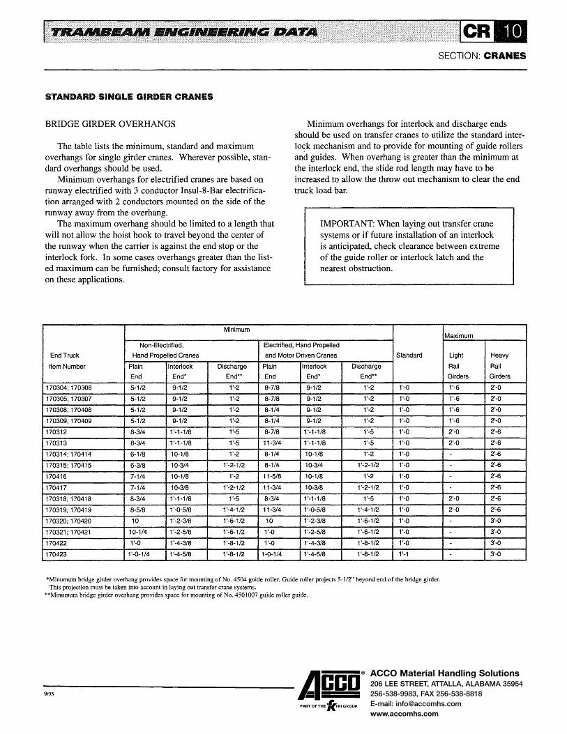
ACCO Material Handling Solutions206 LEE STREET, ATTALLA, ALABAMA 35954
256-538-9983, FAX 256-538-8818
E-mail: [email protected]
www.accomhs.com
STANDARD SINGLE GIRDER CRANES
BRIDGE GIRDER OVERHANGS
The table lists the minimum, standard and maximum overhangs for single girder cranes. Wherever possible, standard overhangs should be used.
Minimum overhangs for electrified cranes are based on runway electrified with 3 conductor Insul-8-Bar electrification arranged with 2 conductors mounted on the side of the runway away from the overhang.
The maximum overhang should be limited to a length that will not allow the hoist hook to travel beyond the center of the runway when the carrier is against the end stop or the interlock fork. In some cases overhangs greater than the listed maximum can be furnished; consult factory for assistance on these applications.
Minimum
SECTION: CRANES
Minimum overhangs for interlock and discharge ends should be used on transfer cranes to utilize the standard interlo~k mechanism and to provide for mounting of guide rollers and guides. When overhang is greater than the minimum at the interlock end, the slide rod length may have to be increased to allow the throw out mechanism to clear the end truck load bar.
IMPORTANT: When laying out transfer crane systems or if future installation of an interlock is anticipated, check clearance between extreme of the guide roller or interlock latch and the nearest obstruction.
Maximum
Non~Eiectrified, Electrified, Hand Propelled
End Truck Hand Propelled Cranes and Motor Driven Cranes Standard Light Heavy
Item Number Plain Interlock Discharge Plain Interlock Discharge Rail Rail
End End* End** End End* End** Girders Girders
170304; 170306 5-1/2 9~1/2 1'-2 8-7/8 9-1/2 1'-2 1'-0 1'-6 2'-0
170305; 170307 5-1/2 9-1/2 1'-2 8-7/8 9-1/2 1'-2 1'-0 1'-6 2'-0
170308; 170408 5-1/2 9-1/2 1'-2 8-1/4 9-1/2 1'-2 1'-0 1'-6 2'-0
170309; 170409 5-1/2 9-1/2 1'-2 8-1/4 9-1/2 1'-2 1'-0 1'-6 2'-0
170312 8-3/4 1'-1-i/8 1'-5 8-7/8 1'-1-1/8 1'-5 1'-0 2'-0 2'-6
170313 8-3/4 1 '-1-118 1'-5 11-3/4 1'-1-1/8 1'-5 1'-0 2'-0 2'-6
170314; 170414 6-1/8 10-1/8 1'-2 8-1/4 =t 1Q-1/8 1'-2 1'-0 - 2'-6
170315; 170415 6-3/8 10-3/4 1'-2-1/2 8-114 10-3/4 1'-2-1/2 1'-0 - 2'-6
170416 7-1/4 10-1/8 1'-2 11-5/8 1 0-1/8 1'-2 1'-0 - 2'-6
170417 7-1/4 10-3/8 1'-2-1/2 11-3/4 10-3/8 1 '-2-1/2 1'-0 - 2'-6
170318; 170418 8- 1'-1-1/8 1'-5 8-3/4 =±1'·1-1/8 1'-5 1'-0 2'-0 2'-6
170319; 170419 8- 1'-0-5/8 1'-4-1/2 11-3/4 1'-0-5/8 1'-4-1/2 1'-0 2'-0 2'-6
170320; 170420 10 1'-2-3/8 1'-6-1/2 10 1'-2-3/8 1'-6-1/2 1'-0 - 3'-0
170321;170421 10-1/4 1'-2-5/8 1'-6-1/2 1'-0 1'-2-5/8 1 '-6-1/2 1'-0 - 3'·0
170422 1'-0 1'-4-3/8 1'-8-1/2 1'-0 1'-4-3/8 1 '-8-1/2 1'-0 - 3'-0
170423 1'-0-1/4 1'-4-5/8 1'-8-1/2 1-0-1/4 1'-4-5/8 1'-8-1/2 1'-1 - 3'-0
*Minumum bridge girder overhang provides space for mounting of No. 4504 guide roller. Guide roller projects 5-1/2" beyond end of the bridge girder. This projection must be taken into account in laying out transfer crane systems.
**Minumum bridge girder overhang provides space for mounting of No. 4501007 guide roller guide.
-9,95 ------Acco® PART OF THE 'fc.FKI GROUP

ACCO Material Handling Solutions206 LEE STREET, ATTALLA, ALABAMA 35954256-538-9983, FAX 256-538-8818E-mail: [email protected]
5/96
STANDARD SINGLE GIRDER CRANES
4-WHEEL END TRUCKS
The drawing illustrates the No. 170308 end truck and is typical for all 4-wheel end trucks. The table indicates the end truck item number, rated load, carrier head,. net weight, minimum size runway track and principal dimensions. See Carrier Section for specifications on carrier heads and wheel assemblies.
Load bars consist of steel channels, plates and bars welded into a rigid assembly. After welding, the load bars are machined to control vertical elevations and squareness and to
End Truck
Item
Number
170304
170305
170306
170307
170308
170408
170309
170408
170314
170414
170315
170415
170416
170417
N
J M= 1'-3-7/8" For No. 24010 Tractor Drive
l '-2-l/2" For No. 2409 Tractor Drive 1 '-11-1/4" For No. 2408 Tractor Drive
Rated Carrier
Load Head
N
Net
Weight
(Pounds) Item No. (Pounds)
4,000 010203 150
4,000 010203 193
6,000 010205 164
6,000 010205 207
8,000 010207 179
8,000 010208 191
8,000 010207 263
8,000 010208 275
13,000 010209 304
13,000 010210 326
13,000 010209 487
13,000 010210 509
15,000 010211 403
15,000 010211 586
SECTION: CRANES
provide interchangeability. A milled slot, provided at the center of the load bar for girder attachment, also serves as the vertical reference for other load bar machining. Lugs are provided in the load bar to limit the drop of the end truck to 1 inch or less in the event of wheel or axle failure.
The 4,000 and 6,000 pound trucks have bronze washers between the underside of the load bar and carrier head yokes for free swivel of the heads. The 8,000, 13,000 and 15,000 pound trucks have self-aligning bushings in the connection between the carrier heads and the load bar to provide equal wheel loading and free swivel of the heads.
M
Minimum
Runway d f J N
Size
34011 3-1/8 4'-0 1-7/8 2'-3-1/8
34011 3-1/8 6'-0 1-7/8 3'-3-1/8
34011 3-1/8 4'-0 1-7/8 2'-3-1/8
34011 3-1/8 6'-0 1-7/8 3'-3-1/8
34011 3-3/4 4'-0 1-7/8 2'-3-3/4
34011 3-3/4 4'-0 1-7/8 2'-3-3/4
34011 3-3/4 6'-0 1-7/8 3'-3-314
34011 3-3/4 6'-0 1-7/8 3'-3-3/4
34037 4-1/4 4'-0 2-1/2 2'-4-1/4
34037 4-1/4 4'-0 2-1/2 2'-4-1/4
34037 4-1/4 7'-0 2-1/2 3'-10-1/4
34037 4-1/4 7'-0 2-1/2 3'-10-1/4
34037 4-1/4 4'-0 2-1/2 2'-4-1/4
34037 4-1/4 7'-0 2-1/2 3'-10-1/4
------Acco® PART OF THE 'lc.FKI GROUP

ACCO Material Handling Solutions206 LEE STREET, ATTALLA, ALABAMA 35954256-538-9983, FAX 256-538-8818E-mail: [email protected]
5/96
STANDARD SINGLE GIRDER CRANES
8-WHEEL END TRUCKS
The drawing illustrates the No. 170318 end truck and is typical for all 8-wheel end trucks. The table indicates the end truck item number, rated load, carrier head, net weight, minimum size of runway track and principal dimensions. See Carrier Section for specifications on carrier heads and wheel assemblies.
Load bars consist of steel channels, plates and bars welded into a rigid assembly. After welding, the load bars are machined to control vertical elevations and squareness and to provide interchangeability. A milled slot, provided at the
End Truck
Item
Number
170312
170313
170318
170418
170319
170419
170320
170420
170321
170421
170422
170423
N
1 '-2-1/2" For No. 2409 Tractor Drive 1 '-11-114" For No. 2408 Tractor Drive
Rated Carrier Net
Load Head Weight
(Pounds) Item No. (Pounds)
12,000 010205 433
12,000 010205 527
16,000 010207 447
16,000 010208 471
16,000 010207 708
16,000 010208 732
26,000 010209 734
26,000 010210 n8
26,000 010209 1,193
26,000 010210 1,237
30,000 010211 1,026
30,000 010211 1,440
N
"
SECTION: CRANES
center of the load bar for girder attachment, also serves as the vertical reference for the load bar machining. Lugs are provided in the load bar to limit the drop of the end truck to 1 inch or less in the event of wheel or axle failure.
The 4-wheel carrier load bars are made from steel plate which is machined to control vertical elevations. Self-aligning bushings are used between the carrier load bars and main load bar to provide equal carrier head loading.
The 12,000 pound trucks have bronze washers between the carrier load bar and carrier heads for free swivel of the carrier heads. All other 8-wheel trucks have self-aligning bushings between the carrier heads and carrier load bar to provide equal wheel loading and free swivel of the heads.
M
Minimum
Runway d e f J N w
Size
34011 3-1/2 1'-0 3'-8 1-7/8 3'-1-1/2 4'-8
34011 3-1/2 1'-0 7'-0 1-7/8 4'-9-1/2 8'-0
34011 3-3/4 1'-0 3'-8 1-7/8 3'-1-3/4 4'-8
34011 3-3/4 1'-0 3'-8 1-7/8 3'-1-3/4 4'-8
34031 3-3/4 1'-0 7'-0 1-7/8 4'-9-3/4 8'-0
34031 3-314 1'-0 7'-0 1-7/8 4'-9-3/4 8'-0
34037 4-1/4 1'-3 4'-6 2-1/2 3'-10-1/4 5'-9
34037 4-1/4 1'-3 4'-6 2-1/2 3'-10-1/4 5'-9
34041 4-1/4 1'-3 8'-9 2-1/2 5'-11-3/4 10'-0
34041 4-1/4 1'-3 8'-9 2-1/2 5'-11-3/4 10'-0
34037 4-1/4 1'-3 4'-6 2-1/2 3'-10-1/4 5'-9
34041 4-1/4 1'-3 8'-0 2-1/2 5'-7-114 9'-3
------Acco® PART OF THE 'lc.FKI GROUP
ACCO Material Handling Solutions206 LEE STREET, ATTALLA, ALABAMA 35954
256-538-9983, FAX 256-538-8818
E-mail: [email protected]
www.accomhs.com
SELECTION OF STANDARD SINGLE GIRDER CRANES
Standard single girder, 2-runway cranes are tabulated on subsequent pages by (1) means of propulsion, (2) number of end truck wheels, (3) rated load and (4) span. The tables prow vide a simple means for crane selection and indicate the crane code number, net weight, minimum runway size and clearance dimensions. End truck wheelbase dimensions are also provided to assist in determining the runway size.
Hand propelled cranes are listed for rated loads of 1, 2 and 3 tons and spans from 12'-0 to 40'-0. Cranes with greater rated load and span or with bridge girder tread elevations greater than 12' -0 are not recommended for hand propelling. Motor driven cranes are listed for rated loads of 1, 2, 3, 5, 7-1/2 and 10 tons.
Crane rated loads are based on a carrier design load which is adequate for most applications. The carrier design load includes: (1) hoist and carrier weights, (2) rated load and (3) 15% impact allowance. The design load is shown in the tables.
Crane selection is made by:
STEP 1 - Determine actual carrier load (weights of hoist and carrier selected for the crane, rated load and impact allowance, if applicable).
STEP 2- Select crane from table providing actual load is no greater than the design load.
If the actual load exceeds the design load, it is necessary to calculate the girder and end truck loads and select the components on the basis of the calculated loads
SECTION: CRANES
Crane code numbers indicate the means of propulsion, type of electrification, bridge girder size, type of end truck and overall length of bridge girder. Page CR-2 provides a complete explanation of the crane code numbering system.
Net weights of hand propelled cranes are for cranes with 3 conductors of Insul-8-Bar. Net weights of motor driven cranes are for cranes with 7 conductors of Insul-8-Bar and motorization with No. 2409 tractor drives. Cranes with No. 2408 drives are approximately 400 pounds heavier than the weight indicated in the tables. Cranes with No. 24010 drives are approximately 120 pounds less than the weight indicated in the tables.
Cranes are listed with an overall length based on a nominal span between runway tracks and 1 '-0 nominal girder overhangs. See Page CR-1 0 for minimum, maximum and standard overhangs when determining the crane span and overall length.
A clearance drawing is provided on the page facing each crane table. The drawings for motor driven cranes locate the control panel elevation for crane with Nos. 34021 through 34056 girders. The horizontal spacing of the panel varies with the type of control and collector arrangement. Consult factory for this dimension if the possibility exists for interference between the panel and building, lights, etc.
Dimension J is the distance between the running treads of the runway track and bridge girder and is shown in the crane tables for full depth bridge girders. The dimension will decrease and provide closer headroom if the bridge girder is coped or low headroom end truck construction is used. See Pages CR-37 and CR-38 for data on coped bridge girders and low headroom cranes.
-9,95 ------Acco® PART OF THE 'lc.FKI GROUP

ACCO Material Handling Solutions206 LEE STREET, ATTALLA, ALABAMA 35954
256-538-9983, FAX 256-538-8818
E-mail: [email protected]
www.accomhs.com
STANDARD SINGLE GIRDER CRANES
CLEARANCE DRAWING FOR HAND PROPELLED CRANES WITH 4-WHEEL END TRUCKS
The drawing illustrates the clearances of a hand propelled crane with 4-wheel end trucks and 3 conductor Insul-8-Bar electrification. Clearances of a non-electrified crane are the same except there is no collector overhang on the end truck. On electrified cranes, the runway end stops at the collector end of the crane should be located a sufficient distance from
2" MinimUm aearance Without lnter1ock; e· Minimum With Interlock But Wlthout Guide Roller; Or 7-1/2,. Mini'nUm With lnter1ock And Guide Aoler
a
SECTION: CRANES
the end of the runway to prevent the collectors from leaving the conductors. When 2 or more electrified cranes operate on the same runway, cranes should be equipped with extension bumpers to prevent the collectors from hitting.
Dimensions f, J, K and N are shown on the facing page. To determine dimensions A, B and C refer to the appropriate clearance drawing in the Carrier Section for the hoist and carrier selected for the crane. See Page CR -10 for minimum, maximum and standard bridge girder overhangs.
A
c
-9,95 ------Acco® ,
PART OF THE 'KFKI GROUP

ACCO Material Handling Solutions206 LEE STREET, ATTALLA, ALABAMA 35954
256-538-9983, FAX 256-538-8818
E-mail: [email protected]
www.accomhs.com
SECTION: CRANES
STANDARD SINGLE GIRDER CRANES
HAND PROPELLED CRANES WITH 4-WHEEL END TRUCKS
HAND PROPELLED CRANES WITH 4-WHEEL END TRUCKS
Rated Design Crane Net Overall Minimum Load Load Code Weight Span Length Runway f J K N
(Tons) (Lbs.) Number (Lbs.) (Ft.) (Ft.) Size
HW16S204X 14 673 12 14 34011 4'-0 10 9-5/8 2'-3-1/8
HW16S204X16 722 14 16 34011 4'-0 10 9-5/8 2'-3-1/8
HW16S204X18 770 16 18 34011 4'-0 10 9-5/8 2'-3-1/8
HW16S204X20 818 18 20 34011 4'-0 10 9-5/8 2'-3-1/8
HW16S204X22 901 20 22 34011 4'-0 10 9-5/8 2'-3-1/8
HW21 S204X24 1016 22 24 34011 4'-0 11-1/2 9-5/8 2'-3-1/8
HW21S204X26 1071 24 26 34011 4'-0 11-1/2 9-5/8 2'-3-1/8
1 2920 HW21S204X28 1125 26 28 34011 4'-0 11-1/2 9-5/8 2'-3-1/8
HW26S204X30 1301 28 30 34011 4'-0 1'-1 9-5/8 2'-3-1/8
HW26S204X32 1364 30 32 34011 4'-0 1'-1 9-5/8 2'-3-1/8
HW31S204X34 1528 32 34 34011 4'-o 1'-2-1/2 9-5/8 2'-3-1/8
HW31S204X36 1596 34 36 34011 4'-0 1'-2-1/2 9-5/8 2'-3-1/8
HW41S204X38 2006 36 38 34011 4'-0 1'-3-1/4 9-5/8 2'-3-1/8 HW46S204X40 2252 38 40 34011 4'-0 1'-5-1/4 9-5/8 2'-3-1/8 HW46S204X42 2347 40 42 34011 4'-0 1'-5-1/4 9-5/8 2'-3-1/8
HW16S206X14 701 12 14 34011 4'-0 10 10-1/8 2'-3-1/8
HW16S206X16 750 14 16 34011 4'-0 10 10-1/8 2'-3-1/8
HW16S206X18 797 16 18 34011 4'-0 10 10-1/8 2'-3-1/8
HW21 S206X20 902 18 20 34011 4'-0 11-1/2 10-1/8 2'-3-1/8 HW21S206X22 991 20 22 34011 4'-0 11-1/2 10-1/8 2'-3-1/8
HW26S206X24 1143 22 24 34011 4'-0 1'-1 10-1/8 2'-3-1/8
HW26S206X26 1205 24 26 34011 4'-0 1 '-1 10-1/8 2'-3-1/8
2 5330 HW31 S206X28 1351 26 28 34011 4'-0 1'-2-1/2 10-1/8 2'-3-1/8 HW31S206X30 1413 28 30 34011 4'-0 1'-2-1/2 10-1/8 2'-3-1/8
HW41S206X32 1776 30 32 34011 4'-0 1'-3-1/4 10-1/8 2'-3-1/8 HW41 S206X34 1862 32 34 34011 4'-Q 1'-3-1/4 10-1/8 2'-3-1/8
HW41 S206X36 1948 34 36 34011 4'-0 1'-3-1/4 10-1/8 2'-3-1/8
HW46S206X38 2186 36 38 34011 4'-0 1'-5-1/4 10-1/8 2'-3-1/8
HW46S206X40 2280 38 40 34011 4'-0 1'·5-1/4 10-1/8 2'-3-1/8 HW51S208X42 2724 40 42 34011 4'-0 1'-7-1/4 9-3/8 2'-3-3/4
HW16S208X14 737 12 14 34011 4'-0 10 9-3/8 2'-3-3/4 HW21S208X16 831 14 16 34011 4'-0 11-1/2 9-3/8 2'-3-3/4
HW21 S208X18 884 16 18 34011 4'-0 11-1/2 9-3/8 2'-3-3/4 HW26S208X20 1020 18 20 34011 4'-0 1'-1 9-3/8 2'-3-3/4 HW26S208X22 1117 20 22 34011 4'-0 1'-1 9-3/8 2'-3-3/4 HW31 S208X24 1252 22 24 34011 4'-0 1'-2-1/2 9-3/8 2'-3-3/4 HW31 S208X26 1315 24 26 34011 4'-0 1'-2-1/2 9-3/8 2'-3-3/4
3 8030 HW41 S208X28 1640 26 28 34011 4'-0 1'-3-1/4 9-3/8 2'-3-3/4 HW41S208X30 1726 28 30 34011 4'-0 1'-3-1/4 9-3/8 2'-3-3/4 HW46S214X32 2191 30 32 34037 4'-0 1 '-5-7/8 8-1/2 2'-4-1/4 HW46S214X34 2285 32 34 34037 4'-0 1'-5-7/8 8-1/2 2'-4-1/4 HW51 S214X36 2652 34 36 34037 4'-0 1'-7-7/8 8-1/2 2'-4-1/4 HW51 S214X38 2759 36 38 34037 4'-0 1'-7-7/8 8-1/2 2'-4-1/4 HW56S214X40 3055 38 40 34037 4'-0 1'-9-7/8 8-1/2 2'-4-1/4 HW56S214X42 3174 40 42 34037 4'-0 1'-9-7/8 8-1/2 2'-4-1/4
-9,95 ------Acco® "" PART OF THE 'KFKI GROUP

ACCO Material Handling Solutions206 LEE STREET, ATTALLA, ALABAMA 35954
256-538-9983, FAX 256-538-8818
E-mail: [email protected]
www.accomhs.com
STANDARD SINGLE GIRDER CRANES
CLEARANCE DRAWING FOR HAND PROPELLED CRANES WITH 8-WHEEL END TRUCKS
The drawing illustrates the clearances of a hand propelled crane with 8-wheel end trucks and 3 conductor Insul-8-Bar electrification. Clearances of a non-electrified crane are the same except there is no collector overhang on the end truck. On electrified cranes, the runway end stops at the collector end of the crane should be located a sufficient distance from
SECTION: CRANES
the end of the runway to prevent the collectors from leaving the conductors. When 2 or more electrified cranes operate on the same runway, cranes should be equipped with extension bumpers to prevent the collectors from hitting.
Dimensions e, f, J, K, N and W are shown on the facing page. To determine dimensions A, B and C, refer to the appropriate clearance drawing in the Carrier Section for the hoist and carrier selected for the crane. See Page CR -10 for minimum, maximum and standard bridge girder overhangs.
Overall Length
Overhang
2" Minimum Clearance Without lntertock Or 7-1 /2" Minimum Wrth Interlock And Guide Roller
8
N
Span
c N K
w
It ""le
-9,95 ------Acco® .1'
PART OF THE 'KFKI GROUP
Overhang
A

ACCO Material Handling Solutions206 LEE STREET, ATTALLA, ALABAMA 35954
256-538-9983, FAX 256-538-8818
E-mail: [email protected]
www.accomhs.com
SECTION: CRANES
STANDARD SINGLE GIRDER CRANES
HAND PROPELLED CRANES WITH 8-WHEEL END TRUCKS
HAND PROPELLED CRANES WITH 8~WHEEL END TRUCKS
Rated Design Crane Net Overall Minimum Load Load Code Weight Span Length Runway e f J K N w
(Tons) (Lbs.) Number (Lbs.) (Ft.) (Ft.) Size
HW16S212X14 1245 12 14 34011 1'-0 3'-8 10 9-1/2 3'-1-i/2 4'-8 HW21S212X16 1339 14 16 34011 1'-0 3'-8 11-1/2 9-1/2 3'-1-1/2 4'-8 HW21 S212X18 1392 16 18 34011 1'-0 3'-8 11-1/2 9-1/2 3'-1-1/2 4'-8 HW26S212X20 1528 18 20 34011 1'-0 3'-8 1'-1 9-1/2 3'-1-1/2 4'-8 HW26S212X22 1624 20 22 34011 1'-0 3'-8 1'-1 9-1/2 3'-1-1/2 4'-8 HW31S212X24 1759 22 24 34011 1'-0 3'-8 1 '-2-1/2 9-1/2 3'-1-1/2 4'-8 HW31S212X26 1822 24 36 34011 1'-0 3'-8 1'-2-1/2 9-1/2 3'-1-1/2 4'-8
3 8030 HW41S212X28 2147 36 28 34011 1'-0 3'-8 1'-3-1/4 9-1/2 3'-1-1/2 4'-8 HW41S212X30 2233 28 30 34011 1'-0 3'-8 1'-3-1/4 9-1/2 3'-1-1/2 4'-8 HW46S212X32 2448 30 32 34011 1'-0 3'-8 1'-5-1/4 9-1/2 3'-1-1/2 4'-8 HW46S212X34 2542 32 34 34011 1'-0 3'-8 1'-5-1/4 9-1/2 3'-1-1/2 4'-8 HW51 S212X36 2909 34 36 34011 1'-0 3'-8 1'-7-1/4 9-1/2 3'-1-1/2 4'-8 HW51S212X38 3016 36 38 34011 1'-0 3'-8 1'-7-114 9-1/2 3'-1-1/2 4'-8 HW56S212X40 3312 38 40 34011 1'-0 3'-8 1'-9-1/4 9-1/2 3'-1-1/2 4'-8 HW56S212X42 3431 40 42 34011 1'-0 3'-8 1'-9-1/4 9-1/2 3'-1-1/2 4'-8
-9,95 ------Acco® PART OF THE 'lc.FKI GROUP

ACCO Material Handling Solutions206 LEE STREET, ATTALLA, ALABAMA 35954
256-538-9983, FAX 256-538-8818
E-mail: [email protected]
www.accomhs.com
STANDARD SINGLE GIRDER CRANES
CLEARANCE DRAWING FOR MOTOR DRIVEN CRANES WITH 4-WHEEL END TRUCKS
The drawing illustrates the clearance of a motor driven crane with 4-wheel end trucks and 7 conductor Insul-8-Bar electrification. Dimensions f, J and N are shown on the facing page. To determine dimensions A, B, And H, refere to
SECTION: CRANES
the appropriate clearance drawing in the Carrier Section for the hoist and carrier selected for the crane. See Page CR -10 for minimum, maximum and standard bridge girder overhangs.
Overall Length
Overhang
2 inch minimum clearance without interlock or 7-1/2 inch minimum with interlock and guide roller.
M
Span
B
N
c
N
Overhang
*Control panel is 7-3/4 inch above top of Nos. 34021 through 34056 girders. Panel is below top of girder for No. 34061 and larger girders.
A
M= 1 '-3-7/8" For No. 24010 Tractor Drive 1 '-2-112" For No. 2409 Tractor Drive 1 '-11-1/4" For No. 2408 Tractor Drive
-9,95 ------Acco® PART OF THE 'lc.FKI GROUP

ACCO Material Handling Solutions206 LEE STREET, ATTALLA, ALABAMA 35954
256-538-9983, FAX 256-538-8818
E-mail: [email protected]
www.accomhs.com
SECTION: CRANES
STANDARD SINGLE GIRDER CRANES
MOTOR DRIVEN CRANES WITH 4-WHEEL END TRUCKS
MOTOR DRIVEN CRANES WITH 4-WHEEL END TRUCKS
Rated Design Crane Net Overall Minimum
Load Load Code Weight Span Length Runway f J N
(Tons) (Lbs.) Number (Lbs.) (Ft.) (Ft.) Size
MW21 S204X22 1523 20 22 34011 4'-0 11-112 2'-3-1/8
MW21 S204X24 1588 22 24 34011 4'-0 11-1/2 2'-3-118
MW21 S204X26 1654 24 26 34011 4'-0 11-1/2 2'-3-1/8
MW26S204X28 1833 26 28 34011 4'-0 1'-0 2'-3-1/8
MW26S204X30 1906 28 30 34011 4'-0 1'-0 2'-3-1/8
MW26S204X32 1980 30 32 34011 4'-0 1'-0 2'-3-1/8
MW31 S204X34 2155 32 34 34011 4'-0 1'-2-1/2 2'-3-1/8
MW31 S204X36 2234 34 36 34011 4'-0 1'-2-1/2 2'-3-1/8
MW41 S206X38 2683 36 38 34011 4'-0 1'-3-1/4 2'-3-1/8
MW41 S206X40 2772 38 40 34011 4'-0 1'-3-1/4 2'-3-1/8
MW46S206X42 3046 40 42 34011 4'-0 1'-5-1/4 2'-3-1/8
1 3180 MW46S207X44 3236 42 44 34011 6'-0 1'-5-1/4 3'-3-1/8
MW51 S207X46 3686 44 46 34011 6'-0 1'-7-1/4 3'-3-1/8
MW51S207X48 3807 46 48 34011 6'-0 1'-7-1/4 3'-3-1/8
MW56S207X50 4161 48 50 34011 6'-0 1'-9-1/4 3'-3-1/8
MW56S207X52 4286 50 52 34011 6'-0 1'-9-1/4 3'-3-1/8
MW56S207X54 4415 52 54 34011 6'-0 1'-9-1/4 3'-3-1/8
MW56S207X56 4545 54 56 34011 6'-0 1'-9-1/4 3'-3-1/8
MW61 S207X58 5046 56 58 34011 6'-0 1'-11-3/4 3'-3-1/8
MW61 S207X60 5187 58 60 34011 6'-0 1'-11-3/4 3'-3-1/8
MW61 S207X62 5364 60 62 34011 6'-0 1'-11-3/4 3'-3-1/8
MW66S215X64 5471 62 64 34037 7'-0 2'-2-7/8 3'-10-1/4
MW66S215X66 6625 64 66 34037 7'-0 2'-2-7/8 3'-10-1/4
MW66S215X68 6780 66 68 34037 7'-0 2'-2-7/8 3'-10-1/4
MW71 S215X70 7991 68 70 34037 7'-0 2'-5-318 3'-10-1/4
MW71S215X72 8177 70 72 34037 7'-0 2'-5-318 3'-10-1/4
MW26S206X22 1642 20 22 34011 4'-0 1'-0 2'-3-1/8
MW26S206X24 1715 22 24 34011 4'-0 1'-0 2'-3-1/8
MW26S206X26 1788 24 26 34011 4'-0 1'-0 2'-3-1/8
MW31 S208X28 1975 26 28 34011 4'-0 1 '-2-1/2 2'-3-3/4
MW31 S208X30 2048 28 30 34011 4'-0 1'-2-1/2 2'-3-3/4
MW41 S208X32 2421 30 32 34011 4'-0 1'-3-1/4 2'-3-3/4
MW41 S208X34 2519 32 34 34011 4'·0 1'-3-1/4 2'-3-3/4
2 5650 MW41 S208X36 2616 34 36 34011 4'·0 1'·3-1/4 2'-3-3/4
MW46S208X38 2865 36 38 34011 4'-0 1'-5-1/4 2'-3-3/4
MW46S208X40 2970 38 40 34011 4'-0 1'-5-1/4 2'-3-3/4
MW51 S208X42 3395 40 42 34011 4'-0 1 '-7-1/4 2'-3-3/4
MW51 S209X44 3679 42 44 34011 6'-0 1'-7-1/4 3'-3-3/4
MW56S209X46 4015 44 46 34011 6'-0 1'-9-1/4 3'-3-3/4
MW56S209X48 4145 46 48 34011 6'-0 1'-9-1/4 3'-3-3/4
MW61 S209X50 4589 48 50 34011 6'-0 1'-11-3/4 3'-3-314
MW61S209X52 4732 50 52 34011 6'-0 1'-11-3/4 3'-3-3/4
-9,95 ------Acco® "" PART OF THE 'KFKI GROUP

ACCO Material Handling Solutions206 LEE STREET, ATTALLA, ALABAMA 35954
256-538-9983, FAX 256-538-8818
E-mail: [email protected]
www.accomhs.com
STANDARD SINGLE GIRDER CRANES
CLEARANCE DRAWING FOR MOTOR DRIVEN CRANES WITH 4-WHEEL END TRUCKS
The drawing illustrates the clearances of a motor driven crane with 4-wheel end trucks and 7 conductor Insul-8-Bar electrification. Dimensions f, J and N are shown on the facing page. To determine dimension A, B, C and H, refer to the
SECTION: CRANES
appropriate clearance drawing in the Carrier Section for the hoist and carrier selected for the crane. See Page CR -10 for minimum, maximum and standard bridge girder overhangs.
Overall Length
Overhang
2 inch minimum clearance without interlock or 7-1/2 inch minimum with interlock and guide roller.
M
Span
B
N
c
N
Overhang
*Control panel is 7-3/4 inch above top of Nos. 34021 through 34056 girders. Panel is below top of girder for No. 34061 and larger girders.
A
M= 1'-3-7/8" For No. 24010 Tractor Drive 1 '-2-1/2, For No. 2409 Tractor Drive 1 '-11-1/4" For No. 2408 Tractor Drive
-9,95 ------Acco® PART OF THE 'lc.FKI GROUP

ACCO Material Handling Solutions206 LEE STREET, ATTALLA, ALABAMA 35954
256-538-9983, FAX 256-538-8818
E-mail: [email protected]
www.accomhs.com
SECTION: CRANES
STANDARD SINGLE GIRDER CRANES
MOTOR DRIVEN CRANES WITH 4-WHEEL END TRUCKS
MOTOR DRIVEN CRANES WITH 4-WHEEL END TRUCKS
Rated Design Crane Net Overall Minimum Load Load Code Weight Span Length Runway f J N (Tons) (Lbs.) Number (Lbs.) (Ft.) (Ft.) Size
MW66S209X54 5214 52 54 34011 6'-0 2'-2-1/4 3'-3~3/4
MW66S209X56 5369 54 56 34011 6'-0 2'-2-1/4 3'-3-3/4
MW66S209X58 5524 56 58 34011 6'-0 2'-2-1/4 3'-3-3/4
MW71 S215X60 7033 58 60 34037 7*-0 2'-5-3/8 3'-10-1/4 2 5650 MW71 S215X62 7652 60 62 34037 7'-0 2'-5-3/8 3'-10-1/4
MW71 S215X64 7437 62 64 34037 7'-0 2'-5-3/8 3'-10-1/4
MW76S215X66 8229 64 66 34037 7'-0 2'-7-7/8 3'-10-1/4
MW76S215X68 8432 66 68 34037 7'-0 2'-7-7/8 3'-10-1/4
MW76S215X70 8628 68 70 34037 7'-0 2'-7-7/8 3'-10-1/4
MW77S215X72 10026 70 72 34037 7'-0 2'-9-7/8 3'-10-1/4
MW37S214X22 2089 20 22 34037 4'-0 1'-2-3/8 2'-4-1/4 MW37S214X24 2177 22 24 34037 4'-0 1 '-2-3/8 2'-4-1/4
MW37S214X26 2260 24 26 34037 4'-0 1'-2-3/8 2'-4-1/4
MW41 S214X28 2464 26 28 34037 4'-0 1'-3-7/8 2'-4-1/4
MW41S214X30 2581 28 30 34037 4'-0 1'-3-7/8 2'-4-1/4
MW46S214X32 2807 30 32 34037 4'-0 1'-5-7/8 2'-4-1/4 MW46S214X34 2912 32 34 34037 4'-0 1'-5-7/8 2'-4-1/4
MW51 S214X36 3290 34 36 34037 4'-0 1'-7-7/8 2'-4-1/4
MW51S214X38 3408 36 38 34037 4'-0 1'-7-7/8 2'-4-1/4 MW56S214X40 3715 38 40 34037 4'-0 1'-9-7/8 2'-4-1/4
MW61S214X42 4114 40 42 34037 4'-0 2'-0-3/8 2'-4-1/4
MW61S215X44 4618 42 44 34037 7'-0 2'-0-3/8 3'-10-1/4
MW61S215X46 4760 44 46 34037 7'-0 2'-0-3/8 3'-10-1/4 3 8290 MW66S215X48 5204 46 48 34037 7'-0 2'-2-7/8 3'-10-1/4
MW66S215X50 5359 48 50 34037 7'-0 2'-2-7/8 3'-10-1/4
MW71S215X52 6299 50 52 34037 7'-0 2'-5-3/8 3'-10-1/4
MW71 S215X54 6484 52 54 34037 7'-0 2'-5-3/8 3'-10-1/4
MW71 S215X56 6664 54 56 34037 7'-0 2'-5-3/8 3'-10·1/4
MW76S215X58 7382 56 58 34037 7'-0 2'-7-7/8 3'-10-1/4
MW76S215X60 7585 58 60 34037 7'-0 2'-7-7/8 3'-10-1/4
MW76S215X62 7823 60 62 34037 7'-0 2'-7-7/8 3'-10-1/4
MW76S215X64 8019 62 64 34037 7'-0 2'-7-7/8 3'-10-1/4
MW77S215X66 9318 64 66 34037 7'-0 2'-9-7/8 3'-10-1/4
MW77S215X68 9561 66 68 34037 7'-0 2'-9-7/8 3'-10-1/4 MW77S215X70 9797 68 70 34037 7'-0 2'-9-7/8 3'-10-1/4
MW77S215X72 10034 70 72 34037 7'-0 2'-9-7/8 3'-10-1/4
-9,95 ------Acco® PART OF THE 'lc.FKI GROUP

ACCO Material Handling Solutions206 LEE STREET, ATTALLA, ALABAMA 35954
256-538-9983, FAX 256-538-8818
E-mail: [email protected]
www.accomhs.com
STANDARD SINGLE GIRDER CRANES
CLEARANCE DRAWING FOR MOTOR DRIVEN CRANES WITH 8-WHEEL END TRUCKS
The drawing illustrates the clearances of a motor driven crane with 8-wheel end trucks and 7 conductor Insul-8-Bar electrification. Dimensions e, f, J, N and W are shown on the facing page. To determine dimension A, B, C and H, refer to
SECTION: CRANES
the appropriate clearance drawing in the Carrier Section for the hoist and carrier selected for the crane. See Page CR -10 for minimum, maximum and standard bridge girder overhangs.
Overall Length
Overhang
2 inch minimum clearance without interlock or 7-1/2 inch minimum with interlock and guide roller.
M= 1~-3-7/8" ForNo. 24010 Tractor Drive 1 ~ -2-112" For No. 2409 Tractor Drive 1 '-11-1/4" For No. 2408 Tractor Drive
M
B
e
Span
c
N
Overhang
*Control panel is 7-3/4 inch above top of Nos. 34021 through 34056 girders. Panel is below top of girder for No. 34061 and larger girders.
N
J
-9,95 ------Acco® .1'
PART OF THE 'KFKI GROUP
A

ACCO Material Handling Solutions206 LEE STREET, ATTALLA, ALABAMA 35954
256-538-9983, FAX 256-538-8818
E-mail: [email protected]
www.accomhs.com
SECTION: CRANES
STANDARD SINGLE GIRDER CRANES
· MOTOR DRIVEN CRANES WITH 8-WHEEL END TRUCKS
MOTOR DRIVEN CRANES WITH 8-WHEEL END TRUCKS
Rated Design Crane Net Overall Minimum
Load Load Code Weight Span Length Runway e f J N w {Tons) (Lbs.) Number (Lbs.) (Ft.) {Ft.) Size
MW66S213X64 6551 62 64 34031 1'-0 7'-0 2'-2-1/4 4'-9-1/2 8'-0
MW66S213X66 6705 64 66 34031 1'-0 7'-0 2'-2-1/4 4'-9-1/2 8'-0
MW66S213X68 6860 66 68 34031 1'-0 7'-0 2'-2-1/4 4'-9-1/2 8'-0
MW71 S213X70 8071 68 70 34031 1'-0 7'-0 2'-4-3/4 4'-9-1/2 a·-o MW71 S213X72 8257 70 72 34031 1'-0 7'-0 2'-4-3/4 4'-9-1/2 8'-0
MW76S213X74 9114 72 74 34031 1'-0 7'-0 2'-7-1/4 4'-9-1/2 8'-0
MW76S213X76 9318 74 76 34031 1'-0 7'-0 2'-7-1/4 4'-9-1/2 8'-0
MW76S213X78 9521 76 78 34031 1'-0 7'-0 2'-7-1/4 4'-9-1/2 8'-0
MW76S213X80 9739 78 80 34031 1'-0 7'-0 2'-7-1/4 4'-9-1/2 8'-0
1 3180 MW77S213X82 11304 80 82 34031 1'-0 7'-0 2'-9-1/4 4'-9-1/2 8'-Q
MW78S221X84 14019 82 84 34041 1'-3 8'-9 3'-1-7/8 5'-11-3/4 10'-0
MW78S221 X86 14282 84 86 34041 1'-3 8'-9 3'-1-7/8 5'-11-3/4 10'-0
MW78S221 xaa 14537 86 88 34041 1'-3 8'-9 3'-1-7/8 5'-11-3/4 10'-0
MW78S221 X90 14899 88 90 34041 1'-3 8'-9 3'-1-7/8 5'-11-3/4 10'-0
MW78S221X92 15063 90 92 34041 1'-3 8'-9 3'-1-7/8 5'-11-3/4 10'-Q
MW79S221 X94 16596 92 94 34041 1'-3 8'-9 3'-5-7/8 5'-11-3/4 10'-0
MW79S221 X96 16886 94 96 34041 1'-3 8'-9 3'-5-7/8 5'-11-3/4 10'-0
MW79S221 X98 17177 96 98 34041 1'-3 8'-9 3'-5-7/8 5'-11-3/4 10'-0
MW79S221X100 174n 98 100 34041 1'-3 8'-9 3'-5-7/8 5'-11-3/4 10'-0
MW79S221X102 17768 100 102 34041 1'-3 8'-9 3'-5-7/8 5'-11-314 10'-0
MW71 S213X64 7517 62 64 34031 1'-0 7'-0 2'-4-3/4 4'-9-1/2 8'-0
MW76S213X66 8309 64 66 34031 1'-0 7'-0 2'-7-1/4 4'-9-112 8'-Q
MW76S213X68 8512 66 68 34031 1'-0 7'-0 2'-7-1/4 4'-9-1/2 8'-Q
MW76S213X70 8708 68 70 34031 1'-0 7'-0 2'-7-1/4 4'-9-1/2 8'-0
MwnS213X72 10106 70 72 34031 1'-0 7'-0 2'-9-1/4 4'-9-1/2 8'-Q
MwnS213X74 10358 72 74 34031 1'-0 7'-0 2'-9-1/4 4'-9-1/2 8'-0
MwnS213X76 10594 74 76 34031 1'-0 7'-0 2'-9-1/4 4'-9-1/2 8'-0
MW77S213X78 10831 76 78 34031 1'-0 7'-0 2'-9-1/4 4'-9-1/2 8'-0
MW77S213X80 11067 78 80 34031 1'-0 7'-0 2'-9-1/4 4'-9-1/2 8'-0
2 5650 MW77S213X82 11303 80 82 34031 1'-0 7'-0 2'-9-1/4 4'-9-1/2 8'-0
MW78S221 X84 14019 82 84 34041 1'-3 8'-9 3'-1-7/8 5'-11-3/4 10'-0
MW78S221 X86 14282 84 86 34041 1'-3 8'-9 3'-1-7/8 5'-11-314 10'-0
MW78S221 X88 14537 86 88 34041 1'-3 8'-9 3'-1-7/8 5'-11-3/4 10'-0
MW78S221 X90 14800 88 90 34041 1'-3 8'-9 3'-1-7/8 5'-11-3/4 10'-Q
MW78S221 X92 15063 90 92 34041 1'-3 8'-9 3'-1-7/8 5'-11-3/4 10'-0
MW79S221 X94 16596 92 94 34041 1'-3 8'-9 3'-5-7/8 5'-11-3/4 10'-0
MW79S221 X96 16886 94 96 34041 1'-3 8'-9 3'-5-7/8 5'-11-3/4 10'-0
MW79S221 X98 17177 96 98 34041 1'-3 8'-9 3'-5-7/8 5'-11-3/4 10'-0
-9,95 ------Acco® PART OF THE 'lc.FKI GROUP
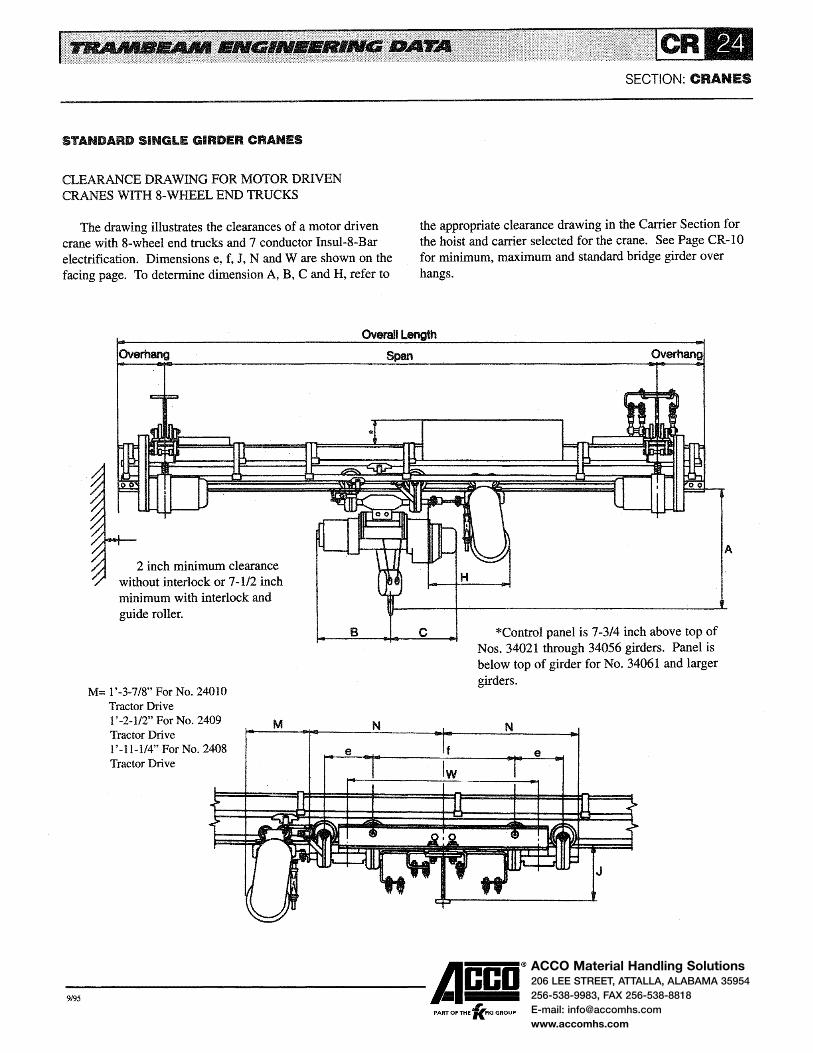
ACCO Material Handling Solutions206 LEE STREET, ATTALLA, ALABAMA 35954
256-538-9983, FAX 256-538-8818
E-mail: [email protected]
www.accomhs.com
STANDARD SINGLE GIRDER CRANES
CLEARANCE DRAWING FOR MOTOR DRIVEN CRANES WITH 8-WHEEL END TRUCKS
The drawing illustrates the clearances of a motor driven crane with 8-wheel end trucks and 7 conductor Insul-8-Bar electrification. Dimensions e, f, J, N and W are shown on the facing page. To determine dimension A, B, C and H, refer to
SECTION: CRANES
the appropriate clearance drawing in the Carrier Section for the hoist and carrier selected for the crane. See Page CR-1 0 for minimum, maximum and standard bridge girder over hangs.
Overall Length
Overhang
2 inch minimum clearance without interlock or 7-1/2 inch minimum with interlock and guide roller.
M= 1 '-3-7/8" For No. 24010 Tractor Drive
Span
B C
1 '-2-1/2" For No. 2409 Tractor Drive
M N
1'-11-1/4" For No. 2408 Tractor Drive
Overhang
*Control panel is 7-3/4 inch above top of Nos. 34021 through 34056 girders. Panel is below top of girder for No. 34061 and larger girders.
N
J
-9,95 ------Acco®
.1' PART OF THE 'KFKI GROUP
A

ACCO Material Handling Solutions206 LEE STREET, ATTALLA, ALABAMA 35954
256-538-9983, FAX 256-538-8818
E-mail: [email protected]
www.accomhs.com
SECTION: CRANES
STANDARD SINGLE GIRDER CRANES
MOTOR DRIVEN CRANES WITH 8-WHEEL END TRUCKS
MOTOR DRIVEN CRANES WITH 8-WHEEL END TRUCKS Rated Design Crane Net Overall Minimum Load Load Code Weight Span Length Runway e f J N w (Tons) (Lbs.) Number (Lbs.) (Ft.) (Ft.) Size
MW37S212X22 2346 20 22 34011 1'-0 3'-8 1'-1-3/4 3'-1-1/2 4'-8 MW37S212X24 2414 22 24 34011 1'-0 3'-8 1'-1-3/4 3'-1-1/2 4'-8 MW37S212X26 2517 24 26 34011 1'-0 3'-8 1'-1-3/4 3'-1-1/2 4'-8 MW41S212X28 2741 26 28 34011 1'-0 3'-8 1'-3-1/4 3'-1-1/2 4'-8 MW41S212X30 2838 28 30 34011 1'-0 3'-8 1'-3-1/4 3'-1-1/2 4'-8 MW46S212X32 3064 30 32 34011 1'-0 3'-8 1'-5-1/4 3'-1-1/2 4'-8 MW46S212X34 3169 32 34 34011 1'-0 3'-8 1'-5-1/4 3'-1-1/2 4'-8 MW51 S212X36 3547 34 36 34011 1'-0 3'-8 1'-7-1/4 3'-1-1/2 4'-8 MW51S212X38 3665 36 38 34011 1'-0 3'-8 1'-7-1/4 3'-1-1/2 4'-8 MW56S212X40 3972 38 40 34011 1'-0 3'-8 1'-9-1/4 3'-1-1/2 4'-8 MW61 S212X42 4371 40 42 34011 1'-0 3'-8 1'-11-314 3'-1-1/2 4'-8 MW61S212X44 4509 42 44 34011 1'-0 3'-8 1'-11-3/4 3'-1-1/2 4'-8 MW61 S212X46 4651 44 46 34011 1'-0 3'-8 1'-11-314 3'-1-1/2 4'-8 MW66S212X48 5095 46 48 34011 1'-0 3'-8 2'-2-1/4 3'-1-1/2 4'-8 MW66S212X50 5438 48 50 34011 1'-0 3'-8 2'-2-1/4 3'-1-1/2 4'-8 MW71 S213X52 6378 50 52 34031 1'-0 7'-0 2'-4-3/4 4'-9-1/2 8'-0 MW71 S213X54 6563 51 54 34031 1'-0 7'-0 2'-4-3/4 4'-9-1/2 8'-0
3 8290 MW71 S213X56 6743 54 56 34031 1'-0 7'-0 2'-4-3/4 4'-9-1/2 8'-0 MW76S213X58 7461 56 58 34031 1'-0 7'-0 2'-7-1/4 4'-9-1/2 8'-0 MW76S213X60 7664 58 60 34031 1'-0 7'-0 2'-7-1/4 4'-9-1/2 8'-0 MW76S213X62 7903 60 62 34031 1'-0 7'-0 2'-7-1/4 4'-9-1/2 8'-0 MW76S213X64 8099 62 64 34031 1'-0 7'-0 2'-7-1/4 4'-9-1/2 8'·0 MWnS213X66 9398 64 66 34031 1'-0 7'-0 2'·9-1/4 4'-9-1/2 8'-0 MwnS219X68 10002 66 68 34031 1'-0 7'-0 2'-9-1/4 4'-9-1/2 8'-0 MwnS219X70 10238 68 70 34031 1'-0 7'-0 2'-9-1/4 4'-9-1/2 8'-0 MwnS219X72 10475 70 72 34031 1'-0 7'-0 2'-9-1/4 4'-9-112 8'-0 MWnS219X74 10719 72 74 34031 1'-0 7'-0 2'·9-1/4 4'-9-112 8'-0 MWnS219X76 10955 74 76 34031 1'-0 7'-0 2'-9-1/4 4'-9-1/2 8'-0 MWnS219X78 11192 76 78 34031 1'-0 7'-0 2'-9-1/4 4'-9-1/2 8'-0 MW78S219X80 12508 78 90 34031 1'-0 7'-0 3'-1-1/4 4'-9-1/2 8'-0 MW78S219X82 12772 80 82 34031 1'-0 7'-0 3'-1-1/4 4'-9-1/2 8'-0 MW78S221 X84 14010 82 84 34041 1'-3 8'-9 3'-1-7/8 5'-11-3/4 10'-0 MW79S221 X86 15434 84 86 34041 1'-3 8'-9 3'-5-7/8 5'-11-314 10'-0 MW79S221X88 15725 86 88 34041 1'-3 8'-9 3'-5-7/8 5'-11-3/4 10'-0 MW79S221X90 16015 88 90 34041 1'-3 8'-9 3'-5-7/8 5'-11-3/4 10'-0
-9,95 ------Acco® PART OF THE 'lc.FKI GROUP
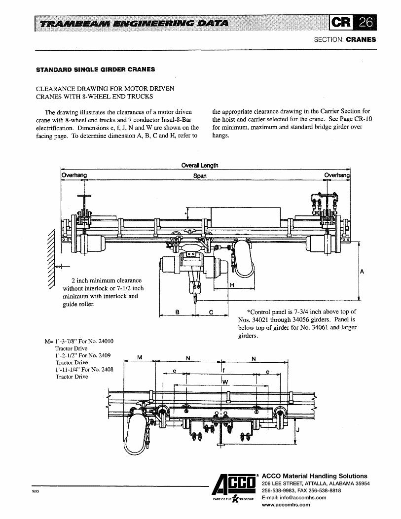
ACCO Material Handling Solutions206 LEE STREET, ATTALLA, ALABAMA 35954
256-538-9983, FAX 256-538-8818
E-mail: [email protected]
www.accomhs.com
STANDARD SINGLE GIRDER CRANES
CLEARANCE DRAWING FOR MOTOR DRIVEN CRANES WITH 8-WHEEL END TRUCKS
The drawing illustrates the clearances of a motor driven crane with 8-wheel end trucks and 7 conductor Insul-8-Bar electrification. Dimensions e, f, J, N and W are shown on the facing page. To determine dimension A, B, C and H, refer to
SECTION: CRANES
the appropriate clearance drawing in the Carrier Section for the hoist and carrier selected for the crane. See Page CR -10 for minimum, maximum and standard bridge girder over hangs.
Overall Length
Overhang
2 inch minimum clearance without interlock or 7-112 inch minimum with interlock and guide roller.
M= 1'-3-7/8" For No. 24010 Tractor Drive 1'-2-112" ForNo. 2409 Tractor Drive 1'-11-l/4" For No. 2408 Tractor Drive
B
N
Span
c
Overhang
*Control panel is 7-3/4 inch above top of Nos. 34021 through 34056 girders. Panel is below top of girder for No. 34061 and larger girders.
N
e
J
-9,95 ------Acco® ,
PART OF THE 'KFKI GROUP
A

ACCO Material Handling Solutions206 LEE STREET, ATTALLA, ALABAMA 35954
256-538-9983, FAX 256-538-8818
E-mail: [email protected]
www.accomhs.com
SECTION: CRANES
STANDARD SINGLE GIRDER CRANES
MOTOR DRIVEN CRANES WITH 8-WHEEL END TRUCKS
MOTOR DRIVEN CRANES WITH 8~WHEEL END TRUCKS
Rated Design Crane Net Overall Minimum
Load Load Code Weight Span Length Runway e f J N w (Tons) (Lbs.) Number (Lbs.) (Ft.) (Ft.) Size
MW41S218X22 2479 20 22 34011 1'-0 3'-8 1'-3-1/4 3'-1-1/2 4'-8
MW41S218X24 2521 22 24 34011 1'-0 3'-8 1'-3-1/4 3'-1-1/2 4'-8
MW46S218X26 2777 24 26 34011 1'-0 3'-8 1'-5-1/4 3'-1-1/2 4'-8
MW46S218X28 2882 26 28 34011 1'-0 3'-8 1'-5~1/4 3'-1-1/2 4'-8
MW51 S218X30 3212 28 30 34011 1'-0 3'-8 1'-7-1/4 3'-1-1/2 4'-8
MW56S218X32 3483 30 32 34011 1'-0 3'-8 1'-9-1/4 3'-1-1/2 4'-8
MW56S218X34 3613 32 34 34011 1'-0 3'-8 1'-9-1/4 3'-1-1/2 4'-8
MW61S218X36 3969 34 36 34011 1'-0 3'-8 1'-11-3/4 3'-1-1/2 4'-8
MW61S218X38 4111 36 38 34011 1'-0 3'-8 1'-11-3/4 3'-1-1/2 4'-8
MW66S218X40 4326 38 40 34011 1'-0 3'-8 2'-2-1/4 3'-1-1/2 4'-8
MW66S218X42 4660 40 42 34011 1'-0 3'-8 2'-2-1/4 3'-1-1/2 4'-8
MW71S218X44 5479 42 44 34011 1'-0 3'-8 2'-4-3/4 3'-1-1/2 4'-8
MW71S218X46 5665 44 46 34011 1'-0 3'-8 2'-4-3/4 3'-1-1/2 4'-8
MW71S218X48 5845 46 48 34011 1'-0 3'-8 2'-4-3/4 3'-1-1/2 4'-8
5 13360 MW76S219X50 7009 48 50 34031 1'-0 7'-Q 2'-7-1/4 4'-9-1/2 8'-0
MW76S219X52 7213 50 52 34031 1'-0 7'-0 2'-7-1/4 4'-9-1/2 8'-0
MW76S219X54 7416 52 54 34031 1'-0 7'-0 2'-7-1/4 4'-9-1/2 8'-0
MW77S220X56 8029 54 56 34037 1'-3 4'-6 2'-9-7/8 3'-10-1/4 5'-9
MW77S220X58 8264 56 58 34037 1'-3 4'-6 2'-9-7/8 3'-10-1/4 5'-9
MW77S221X60 9999 58 60 34041 1'-3 8'-9 2'-9-7/8 5'-11-3/4 10'-0
MW77S221 X62 10276 60 62 34041 1'-3 8'-9 2'-9-7/8 5'-11-314 10'-0
MW77S221 X64 10512 62 64 34041 1'-3 8'-9 2'-9-7/8 5'-11-3/4 10'-0
MW77S221 X66 10749 64 66 34041 1'-3 8'-9 2'-9-7/8 5'-11-3/4 10'-0
MW78S221 X68 11910 66 68 34041 1'-3 8'-9 3'-1-7/8 5'-11-3/4 10'-0
MW78S221 X70 12173 68 70 34041 1'-3 8'-9 3'-1-7/8 5'-11-3/4 10'-Q
MW78S221 X72 13422 70 72 34041 1'-3 8'-9 3'-1-7/8 5'-11-3/4 10'-0
MW79S221 X74 13684 72 74 34041 1'-3 8'-9 3'-5-7/8 5'-11-3/4 10'-0
MW79S221 X76 13982 74 76 34041 1'-3 8'-9 3'-5-7/8 5'-11-3/4 10'-0
MW79S221 X78 14273 76 78 34041 1'-3 8'-9 3'-5-7/8 5'-11-3/4 10'-0
-9,95 ------Acco® PART OF THE 'lc.FKI GROUP

ACCO Material Handling Solutions206 LEE STREET, ATTALLA, ALABAMA 35954
256-538-9983, FAX 256-538-8818
E-mail: [email protected]
www.accomhs.com
STANDARD SINGLE GIRDER CRANES
CLEARANCE DRAWING FOR MOTOR DRIVEN CRANES WITH 8-WHEEL END TRUCKS
The drawing illustrates the clearances of a motor driven crane with 8-wheel end trucks and 7 conductor Insul-8-Bar electrification. Dimensions e, f, J, N and W are shown on the facing page. To determine dimension A, B, C and H, refer to
SECTION: CRANES
the appropriate clearance drawing in the Carrier Section for the hoist and carrier selected for the crane. See Page CR -10 for minimum, maximum and standard bridge girder over hangs.
Overall Length
OVerhang
2 inch minimum clearance without interlock or 7-1/2 inch minimum with interlock and guide roller.
M= 1'-3-7/8" For No. 24010 Tractor Drive 1'-2-112" For No. 2409 Tractor Drive 1'-11-114" For No. 2408 Tractor Drive
M
B
e
Span
c
N
Overhang
*Control panel is 7-3/4 inch above top of Nos. 34021 through 34056 girders. Panel is below top of girder for No. 34061 and larger girders.
N
J
-9,95 ------Acco®
.1' PART OF THE 'KFKI GROUP
A

ACCO Material Handling Solutions206 LEE STREET, ATTALLA, ALABAMA 35954
256-538-9983, FAX 256-538-8818
E-mail: [email protected]
www.accomhs.com
SECTION: CRANES
STANDARD SINGLE GIRDER CRANES
MOTOR DRIVEN CRANES WITH 8-WHEEL END TRUCKS
MOTOR DRIVEN CRANES WITH 8-WHEEL END TRUCKS
Rated Design Crane Net Overall Minimum Load Load Code Weight Span Length Runway e f J N w (Tons} (Lbs.) Number (Lbs.) (Ft.) (Ft.) Size
MW46S220X22 3148 20 22 34037 1'-3 4'-6 1'-5-7/8 3'-10-1/4 5'-9
MW51 S220X24 3436 22 24 34037 1'-3 4'-6 1'-7-7/8 3'-10-1/4 5'-9
MW51 S220X26 3553 24 26 34037 1'-3 4'-6 1'-7-7/8 3'-10-1/4 5'-9
MW56S220X28 3805 26 28 34037 1'-3 4'-6 1 '-9-7/8 3'-10-1/4 5'-9
MW61 S220X30 4126 28 30 34037 1'-3 4'-6 2'-0-3/8 3'-10-1/4 5'-9
MW61 S220X32 4268 30 32 34037 1'-3 4'-6 2'-0-3/8 3'-10-1/4 5'-9
MW66S220X34 4635 32 34 34037 1'-3 4'-6 2'-2-7/8 3'-10-1/4 5'-9
MW66S220X36 4791 34 36 34037 1'-3 4'-6 2'-2-7/8 3'-10-1/4 5'-9
MW71 S220X38 5505 36 38 34037 1'-3 4'-6 2'-5-3/8 3'-10-1/4 5'-9
MW71 S220X40 5689 38 40 34037 1'-3 4'-6 2'-5-3/8 3'-10-1/4 5'-9
MW76S220X42 6261 40 42 34037 1'-3 4'·6 2'-7-7/8 3'-10-1/4 5'-9
7-1/2 19480 MW76S220X44 6464 42 44 34037 1'-3 4'-6 2'-7-7/8 3'-10-1/4 5'-9
MW76S220X46 6667 44 46 34037 1'-3 4'-6 2'-7-7/8 3'-10-1/4 5'-9
MW77S220X48 7667 46 48 34037 1'-3 4'-6 2'-9-7/8 3'-10-1/4 5'-9 MW77S220X50 7898 48 50 34037 1'-3 4'-6 2'-9-7/8 3'-10-1/4 5'-9
MW77S220X52 8134 50 52 34037 1'-3 4'-6 2'-9-7/8 3'-10-1/4 5'-9
MW77S220X54 8371 52 54 34037 1'-3 4'-6 2'-9-7/8 3'-10-1/4 5'-9
MW77S220X56 8613 54 56 34037 1'-3 4'-6 2'-9-7/8 3'-10-1/4 5'-9
MWnS220X58 8849 56 58 34037 1'-3 4'-6 2'-9-7/8 3'-10-114 5'-9
MW78S221X60 10851 58 60 34041 1'-3 8'-9 3'-1-7/8 5'-11-3/4 5'-9 MW78S221 X62 11106 60 62 34041 1'-3 8'-9 3'-1-7/8 5'-11-314 10'-0 MW78S221 X64 11369 62 64 34041 1'-3 8'-9 3'-1-7/8 5'-11-3/4 10'-0
MW79S221 X66 12524 64 66 34041 1'-3 8'-9 3'-5-7/8 5'-11-3/4 10'-0
MW79S221X68 12821 66 68 34041 1'-3 8'-9 3'-5-7/8 5'-11-3/4 10'-0
MW79S221 X70 13104 68 70 34041 1'-3 8'-9 3'-5-7/8 5'-11-3/4 10'-0
MW56S220X22 3424 20 22 34037 1'-3 4'-6 1'-9-7/8 3'-10-1/4 5'-9
MW56S220X24 3553 22 24 34037 1'-3 4'-6 1'-9-7/8 3'-10-1/4 5'-9
MW61 S220X26 3849 24 26 34037 1'-3 4'-6 2'-0-3/8 3'-10-1/4 5'-9 MW61 S220X28 3992 26 28 34037 1'-3 4'-6 2'-0-3/8 3'-10-1/4 5'-9
MW66S220X30 4319 28 30 34037 1'-3 4'-6 2'-2-7/8 3'-10-1/4 5'-9
MW71 S220X32 4957 30 32 34037 1'-3 4'-6 2'-5-3/8 3'-10-1/4 5'-9
MW71 S220X34 5142 32 34 34037 1'-3 4'-6 2'-5-3/8 3'-10-1/4 5'-9
MW71 S220X36 5327 34 36 34037 1'-3 4'-6 2'-5-3/8 3'-10-1/4 5'-9
MW76S222X38 6445 36 38 34037 1'-3 4'-6 2'-7-7/8 3'-10-1/4 5'-9
10 26270 MW76S222X40 6644 38 40 34037 1'-3 4'-6 2'-7-7/8 3'-10-1/4 5'-9
MW77S222X42 7544 40 42 34037 1'-3 4'-6 2'-9-7/8 3'-10-1/4 5'-9 MW77S222X44 7785 42 44 34037 1'-3 4'-6 2'-9-7/8 3'-10-1/4 5'-9
MW77S222X46 8022 44 46 34037 1'-3 4'-6 2'-9-7/8 3'-10-1/4 5'-9
MW77S222X48 8263 46 48 34037 1'-3 4'-6 2'-9-7/8 3'-10-1/4 5'-9
MW77S222X50 8489 48 50 34037 1'-3 4'-6 2'-9-7/8 3'-10-1/4 5'-9
MW78S222X52 9427 50 52 34037 1'-3 4'-6 3'-1-7/8 3'-10-1/4 5'-9
MW78S222X54 9690 52 54 34037 1'-3 4'-6 3'-1-7/8 3'-10-1/4 5'-9 MW78S222X56 9954 54 56 34037 1'-3 4'-6 3'-1-7/8 3'-10-1/4 5'-9
MW79S222X58 11006 56 58 34037 1'-3 4'-6 3'-5-7/8 3'-10-1/4 5'-9
MW79S223X60 12124 58 60 34041 1'-3 8'-0 3'-5-7/8 5'-7-1/4 9'-3
MW79S223X62 13242 60 62 34041 1'-3 8'-0 3'-5-7/8 5'-7-1/4 9'-3
-9,95 ------Acco® "" PART OF THE 'KFKI GROUP

ACCO Material Handling Solutions206 LEE STREET, ATTALLA, ALABAMA 35954
256-538-9983, FAX 256-538-8818
E-mail: [email protected]
www.accomhs.com
SINGLE GIRDER TRANSFER CRANES
Single girder transfer cranes permit the transfer of loads from the area to area, either directly from crane to crane or by fixed transfer sections or spur tracks. They are of the same design as standard single girder cranes with the addition of interlock mechanisms at one or both ends of the girder. The discharge point is a part of the interlocking equipment and is installed at the end of each track where a carrier is to be transferred. Direct interlocking cranes have discharge points installed on one or both ends of the girder depending on the number of cranes to be interlocked.
Forks are provided on interlock mechanisms and discharge points which raise to permit passage of the carrier when the interlock and discharge point are latched. When they are not latched, the forks prevent carriers from being accidentally run off the end of the girder or discharge track.
The throw-out mechanism activates the interlock latch and may be manually or motor operated. Manually operated mechanisms are located on the bridge girder and are operated by pull chains. Motor operated mechanisms are controlled by
INTERLOCK MECHANISM
1 Guide Roller 2 Latch 3 Interlock Fork 4 Slide Rod 5 Slide Rod Bearing 6 Spring 7 Throw-out Mechanism
UNLATCHED POSITION
SECTION: CRANES
a push button station located on the carrier or crane. The drawings show the interlock mechanism in the
unlatched and latched positions and illustrate the operation of the transfer equipment. When the girder is aligned with the discharge track, the forks remain in the down position until the interlock is thrown into the latch position. When the throw-out mechanism is operated, the throat of the latch extends into the discharge point, locking the girder and discharge track in alignment. As the latch extends, it contacts the discharge point forks and the interlock forks contact the discharge point plates, causing both sets of forks to raise. With the throat of the latch engaging the discharge point and the fork in the raised position, the carrier may travel on or off the girder or discharge track. After the carrier has transferred, the latch is retracted by the throw-out mechanism and the forks return to the down position.
Forks are steel castings. The latch is also a steel casting and is held in the extended position by spring pressure. The throw-out mechanism is a direct acting cam arrangement.
DISCHARGE POINT
8 Structural Tie 9 Upper Guide Roller Guide 10 Lower Guide Roller Guide 11 Discharge Point Plate 12 Discharge Fork
LATCHED POSITION
-9,95 ------Acco® PART OF THE 'fc.FKI GROUP

ACCO Material Handling Solutions206 LEE STREET, ATTALLA, ALABAMA 35954
256-538-9983, FAX 256-538-8818
E-mail: [email protected]
www.accomhs.com
SINGLE GIRDER TRANSFER CRANES
INTERLOCKS AND DISCHARGE POINTS
Three types of interlocking equipment are available: Type L interlocks and discharge points for carriers with 4 inch and 5 inch diameter wheels; Type H for carriers with 6-1/2 inch diameter wheels; and Type J for carriers with 8 inch diameter wheels. Item numbers for all interlocks and discharge points are listed on Page CR-32. In laying out transfer crane systems, the same type of interlock and discharge must be used throughout the system.
Type L interlocks are installed only on No. 34021 (10 inch) or larger girders. The depth of Nos. 34011 and 34016 track does not provide clearance for the slide rod bearings and throw-out mechanism. Type L discharge points are installed only on No. 34026 (11-112 inch) or larger girders. The depth of Nos. 34011, 34016 and 34021 tracks does not provide clearance for the forks and discharge plates: however, when used as spur tracks, they can be built up to 11-1/2 inch depth to accommodate the discharge point.
Type H interlocks and discharge points are installed only on heavy rail sections (Nos. 34037 through 34079).
Type J interlocks and discharge points are installed only on No. 34046 (16 inch) or larger girders, transfer tracks and spur tracks. Nos. 34037 and 34041 tracks do not provide clearance for the interlock or discharge point: however, when used as a spur track, they can be built up to 16 inch depth to accommodate the discharge point.
When 2 or more transfer cranes with different size girders operate on the same runway, a constant girder depth must be
Left Hand lnter1ock Assembly
SECTION: CRANES
established at the end trucks to allow the cranes to engage the discharge track. When carriers are motor driven, the girders must also have the same rail tread thickness to allow for operation of the tractor drive on all cranes. The constant girder depth is accomplished by coping the larger girders to the depth of the smaller girder. Minimum depths of coped bridge girders for transfer cranes are:
eNos. 34026 and 34031 girders may be coped to 10 inch depth when cranes are arranged for interlocking through fixed transfer sections or to spur tracks. eNos. 34037 and 34041 girders may be coped to 11-1/2 inch depth when hand pushed carriers with 4 inch Or 5 inch Diameter wheels are used on the system. • Girders with Type H interlocks may be coped to 12-1/2 inch depth. e Girders with Type J interlocks may be coped to 16 inch depth. Manually operated throw-out mechanisms for Type L
interlocks have the hand chains located 2' -2 from centerline of the girder. Type H and J interlock throw-out mechanisms have the hand chains located 3 '-2 from centerline of the girder. Type H throw-outs may be used with Type L interlocks to provide additional clearance between the hand chains and the hoist or carrier. Throw-out mechanisms are located on the side of the girder opposite the brace angles resulting in right and left hand assemblies. The drawing below illustrates these assemblies.
Right Hand Interlock Assembly
2' -2" For Type L Interlock 3' ·2 "For Type Hand J Interlock
-9,95 ------Acco® , PART OF THE 'KFKI GROUP

ACCO Material Handling Solutions206 LEE STREET, ATTALLA, ALABAMA 35954
256-538-9983, FAX 256-538-8818
E-mail: [email protected]
www.accomhs.com
SECTION: CRANES
SINGLE GIRDER TRANSFER CRANES
CATALOG NUMBERS OF INTERLOCKS AND DISCHARGE POINTS
ITEM NUMBERS OF INTERLOCKS AND DISCHARGE POINTS Track Interlocks Discharge Points Item TypeL TypeH TypeJ Type Type Type
Number RHAssem. LHAssem. RHAssem. LHAssem. RHAssem. LHAssem. L H J 34011 8" ,..,. ___ ... ,.,.,.., .... I ................ .................. ----- """"""' ...... ----- ~ ......... _
34016 8-1/2" ----- ----- ............... ................ ............. ----- .. .......... _ ....... -... ~ ...................
34021 10" 450100E 450100F ............... .............. ----- .............. ... ............. .............. -----34026 11-1/2" 450100E 450100F -........ - .................. ----- 45030T ...... _,.. ...... -......
34031 13" 450100E 450100F .............. -·--- 45030T .... ... -...... ...............
34037 12-1/2" 450101E 450101F 450106E 450106F ----- .............. 45030U 45031R -----34041 14" 450101E 450101F 450106E 450106F
____ ... ............. 45030U 450318 . .. _ ...
~~~6 16" 450101E 450101F 450106E 450106F 450109E 450109F 45030U 450318 45033E 34051 18" 450102E 450102F 450107E 450107F 450110E 450110F 45030V 45031T 45033F 34056 20" 450102E 450102F 450107E 450107F 450110E 450110F 45030V 45031T 45033F 34061 22-1/2" 450102E 450102F 450107E 450107F 450110E 450110F 45030V
~ 34066 25" 450102E 450102F 450107E 450107F 450110E 450110F 45030V 34071 27-1/2" 450103E 450103F 450108E 450108F 450112E 450112F 45030W 45031U 45033G 34076 30" 450103E 450103F 450108E 450108F 450112E 450112F 45030W 45031U 45033G 34077 32" 450103E 450103F 450108E 450108F 450112E 450112F 45030W 45031U 45033G 34078 36" 450103E 450103F 450108E 450108F 450112E 450112F 45030W 45031U 45033G 34079 40" 450103E 450103F 450108E 450108F 450112E 450112F 45030W 45031U 45033G
-----Not Available
GUIDE ROLLER ARRANGEMENT
Guide rollers and guide roller guides maintain vertical and horizontal alignment of bridge girders and transfer tracks. The guide roller arrangement allows the transfer crane to pass spur tracks, fixed transfer sections or other transfer cranes without interference. They are recommended for ( 1) hand propelled carriers of more than 2 tons rated load, (2) motor driven carriers, (3) motor driven transfer cranes and (4) all direct interlocking cranes. The guide roller is mounted on the bridge girder and the guide roller guide on the spur track or fixed transfer section.
The roller is machined from alloy steel and operates on a prelubricated double row ball bearing. The roller assembly is mounted in a welded steel bracket. The complete assembly is designated as Item No. 4504.
Two guide roller guides are available. The one piece assembly (Item No. 4501007) is used at the discharge end of direct interlocking cranes. The two piece assembly (Item Nos. 4501004 upper guide and 4501005 lower guide) is used on spur tracks and fixed transfer sections. When a crane is equipped with a guide roller, all connecting spur tracks, fixed transfer sections and direct interlocking cranes must be equipped with guide roller guides.
ELECTRIFIED TRANSFER CRANES
Insul-8-Bar's 90 amp conductor is the standard electrification for transfer cranes. Consult factory for assistance when other types of electrification are used. Transfer cranes generally are not electrified with festooned or tagline electrification.
The power conductor arrangement for transfer cranes is shown in the Electrification Section. The power conductors must be 6-1/8 inch above the tread for Type L interlocks, 7-3/4 inch For Type H interlocks and 9-1/2 inch for Type J interlocks to prevent interference with the latch.
The control conductors on motor driven transfer cranes with Type I control are located 1-7/8 inch above the girder tread for Nos. 34021 through 34056 girders and at the same elevation as the power conductors for No. 34061 and larger girders. If a switch is incorporated in the spur track, the control conductors must be lowered to provide clearance between the control collectors and the switch; consult factory for recommendations on these applications.
The control conductors are not carried through the interlock gap, eliminating the need for control conductors on spur tracks or fixed transfer sections. No. 550491 pickup guides and No. 550278 transfer caps are used at the ends of the con~
-9,95 ------Acco®
, PART OF THE 'KFKI GROUP

ACCO Material Handling Solutions206 LEE STREET, ATTALLA, ALABAMA 35954
256-538-9983, FAX 256-538-8818
E-mail: [email protected]
www.accomhs.com
SINGLE GIRDER TRANSFER CRANES
trol conductors to enable the collectors to leave and pick up the conductors as the carrier moves off and on the transfer crane. Carriers operating on transfer cranes use No. 560395 collectors for the power conductors and No. 560393 self-centering collectors for the control conductors.
All carriers operating on direct interlocking cranes, cranes interlocking through transfer sections, or cranes interlocking at both ends with spur tracks require tandem collectors for the common conductor (X) and the mainline conductor (M) to activate the mainline contactor as the transfer is made. The tandem collector arrangement requires 2 additional No. 560393 collectors.
MOTOR DRIVEN TRANSFER CRANES
Motor driven transfer crane use Types I or III control arrangements as described on Pages CR-7 and CR-8. Accessory equipment can be furnished on motor driven transfer cranes to increase their flexibility and improve their operation. Some accessory equipment is furnished as standard and some as optional.
A limit switch is furnished on the throw-out mechanism as standard on transfer cranes interlocking with spur tracks or fixed transfer sections. The switch interrupts the crane control circuit when the latch is extended and prevents the operator from moving the crane while it is latched to the discharge track.
When a system has 2 or more discharge tracks and 2 or more transfer cranes with Type I control, an auxiliary push button station may be installed on the crane for controlling the crane motion. This enables the operator to move the crane from one discharge track to another without the hoist and carrier being on the crane.
When transfer cranes are arranged for direct crane to crane interlocking it may be desirable to have them travel as a unit when interlocked. This is accomplished by contacts at the ends of the cranes which connect the crane control circuits. A limit switch disconnects the contacts when the cranes are not interlocked allowing the cranes to pass without connect-
SECTION: CRANES
ing their control circuits. Other limit switch arrangements are used to prevent the
crane from traveling when the latch is extended and the crane is not aligned with the other crane. Consult factory for information on limit switch arrangements, clearances and girder overhangs on all direct interlocking cranes.
MOTOR OPERATED INTERLOCKS
Motor operated interlocks can be furnished on all motor driven transfer cranes as optional equipment. The latch and slide rod assembly are the same as used on manually operated interlocks. The throw-out mechanism uses a geannotor and roller chain drive to extend and retract the latch. A magnetic contactor is furnished for control of the gearmotor; limit switches control the movement of the latch and also interrupt the crane motion when the interlock is extended.
The interlock is controlled from 2 additional buttons in the carrier push button station (Type I control) or crane push button station (Type III control) or from an auxiliary push button station suspended from the crane. On cab operated systems, a push button station is mounted in the cab. When controlled from the carrier, 2 additional control conductors are required for the crane electrification and 2 additional control collectors for the carrier.
When transfer cranes with motor operated interlocks are arranged for direct crane to crane interlocking, contacts to connect the crane control circuits may be required to meet the following conditions: ( 1) control of the interlock from either of the 2 interlocked cranes; (2) cranes to travel as a unit when interlocked; and (3) the combination of conditions (1) and (2). When contacts are used, a limit switch is provided to disconnect the contacts when the cranes are not interlocked allowing the cranes to pass without connecting their control circuits. Other limit switches are provided to prevent the crane from traveling when the latch is extended and the crane is not aligned with the other crane. Consult factory for information on limit switch arrangements, clearances and girder overhangs on all direct interlocking cranes where contacts are required.
-9,95 ------A~co® PART OF THE 'KFKI GROUP

ACCO Material Handling Solutions206 LEE STREET, ATTALLA, ALABAMA 35954
256-538-9983, FAX 256-538-8818
E-mail: [email protected]
www.accomhs.com
SINGLE GIRDER TRANSFER CRANE CLEARANCES
SPURTRACKARRANGEMENT
The arrangement of a transfer crane interlocking with a spur track is shown in the drawing. Spur tracks interlocking with the transfer crane are equipped with discharge points and guide roller guides (where applicable).
A structural tie is required between the discharge track and crane runway. The tie maintains the gap between the ends of the discharge track and the girder and permits the crane to pass the discharge track without interference. It also provides the support for the upper guide roller guide. The tie may be bolted or welded to the runway track. It is installed
WALL OR COLUMN
71ft" MINIMUM
WITH GUIDE ROLLER
SECTION: CRANES
with the transfer crane latched to the spur and with a 3/16 inch gap between the ends of the discharge track and girder. When bolting, holes in the runway track are field drilled.
The discharge track is supported from the building structure or steel superstructure adjacent to the structural tie. The structural tie is not designed to support the end of the discharge track.
Bracing of the discharge track is recommended to maintain alignment. The bracing is made in the field to suit the conditions and consists of steel angles installed perpendicular to the track. Bracing is installed after system has been aligned.
"loo----t......,.·----3'-0,..{STANDARD)-----4o! 611 MINIMUM
WITHOUT GUIDE ROLLER
Interlock
Mechanism A B c D E F G
TypeL 8·1/16 3-11/16 7-3/4 10-1/2 10-314 1'-2-5/8 1'-2
TypeH 10-1/8 6-13/16 10-3/8 1'-2-1/4 1'-0-1/2 1'-5-5/8 1'-4-1/2
TypeJ 11-7/8 6-13/16 1'-1-1/8 1'-5-7/8 1'-1-7/8 1'-8-1/8 1'-6-1/2
-9,95 ------Acco® PART OF THE 'lc.FKI GROUP

ACCO Material Handling Solutions206 LEE STREET, ATTALLA, ALABAMA 35954
256-538-9983, FAX 256-538-8818
E-mail: [email protected]
www.accomhs.com
SINGLE GIRDER TRANSFER CRANE CLEARANCES
DIRECT CRANE TO CRANE INTERLOCK ARRANGEMENT
The arrangement of 2 direct interlocking transfer cranes is shown in the drawing. This arrangement is frequently used in an assembly bay area where operations on one side of the bay are different from those on the other side. It provides greater availability of the cranes and permits transfer of loads from one side of the bay to the other.
Consult factory for clearance dimensions when cranes are required to travel as a unit, as girder overhangs may have to be increased to accommodate the control contacts. Data on
SECTION: CRANES
desired control functions, girder and runway track sizes and type of end trucks are required to determine clearances.
Structural ties are required between adjacent runways. These ties maintain the gap between the ends of the girder and permit the cranes to pass without interference. They are located at the support points and at intermediate points as required to maintain a spacing of not more than 1 0' -0 centers. The ties may be bolted or welded to the runway tracks. They are installed with the cranes located directly under the ties with a 3/16 inch gap between the ends of the girders. When bolting, holes in runway track are field drilled.
CONTROl CONTACTS; CONSULT FACTORY FOR BRIDGE GIRDER OVERHANGS AND CRANE ClEARANCES.
L ' E ITO STOP)
F (TO CleAR)
OVERHANG _ __.,....,.__OVERHANG
,....._-----3'·0"' (STANDARD) _____ __..,.
Interlock
Mechanism A B c D E F
TypeL 8-1116 3-11/16 7-3/4 10-1/2 10-314 1'-2-5/8
TypeH 10-118 6-13/16 10-3/8 1'-2-1/4 1'-0-1/2 1'-5-5/8
TypeJ 11-7/8 6-13/16 1'-1-1/8 1'-5-7/8 1'-1-7/8 1'-8-1/8
-9,95 ------Acco® PART OF THE 'lc.FKI GROUP
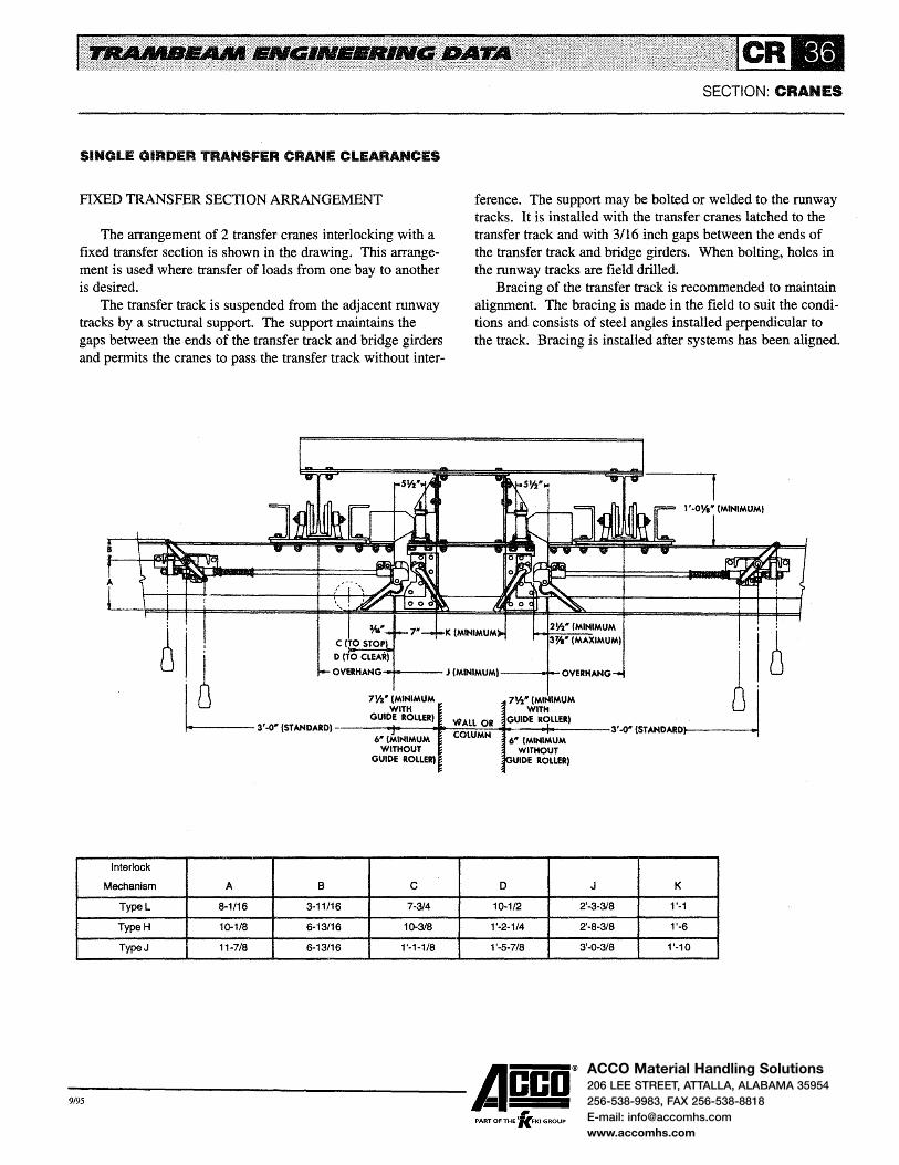
ACCO Material Handling Solutions206 LEE STREET, ATTALLA, ALABAMA 35954
256-538-9983, FAX 256-538-8818
E-mail: [email protected]
www.accomhs.com
SINGLE GIRDER TRANSFER CRANE CLEARANCES
FIXED TRANSFER SECTION ARRANGEMENT
The arrangement of 2 transfer cranes interlocking with a fixed transfer section is shown in the drawing. This arrangement is used where transfer of loads from one bay to another is desired.
The transfer track is suspended from the adjacent runway tracks by a structural support. The support maintains the gaps between the ends of the transfer track and bridge girders and permits the cranes to pass the transfer track without inter-
SECTION: CRANES
ference. The support may be bolted or welded to the runway tracks. It is installed with the transfer cranes latched to the transfer track and with 3/16 inch gaps between the ends of the transfer track and bridge girders. When bolting, holes in the runway tracks are field drilled.
Bracing of the transfer track is recommended to maintain alignment. The bracing is made in the field to suit the conditions and consists of steel angles installed perpendicular to the track. Bracing is installed after systems has been aligned.
' : '6 L 3' .a• 1sr ANDARDl o-ve-RH_A_~_;~;o....,w ..... ~M-·-f_~-,M_l-lu_e_: __ ,~_J ~:::::"'A~~:::-:~"'~:~:-i1~0-7_~~~~-w_; ....... M_•i .... ~ ... N~~:_:~_ve-R-HAN-G
3, .Q" tsrANDARD~
6" (MINIMUM COLUMN 6" (MINIMUM WITHOUT WITHOUT
GUIDE ROLLER) UIDE ROLLER}
Interlock
Mechanism A B c 0 J K
TypeL 8-1/16 3-11/16 7-314 10-1/2 2'-3-318 1'-1
TypeH 10-1/8 6-13/16 1Q-3/8 1'-2-1/4 2'-8-318 1'-6
TypeJ 11-7/8 6-13/16 1'-1-1/8 1'-5-7/8 3'-0-3/8 1'-10
-9,95 ------Acco® PART OF THE 'lc.FKI GROUP

ACCO Material Handling Solutions206 LEE STREET, ATTALLA, ALABAMA 35954
256-538-9983, FAX 256-538-8818
E-mail: [email protected]
www.accomhs.com
LOW HEADROOM SINGLE GIRDER CRANES
Rigid frame, prefabricated buildings are used by many companies for manufacturing and storage. Low headroom cranes are available for these buildings and other buildings with low trusses or obstructions which may restrict the hook lift. Low headroom cranes have the bridge girder framed into the sides of the end trucks and offer maximum lift. However, because the girder is framed into the end truck, carrier end approaches are reduced.
Low headroom construction is used only on standard single girder cranes. It cannot be furnished on light duty cranes. When used with electrically operated hoists or when motor driven, low headroom cranes are equipped with an electrification system as described in the Electrification Section
Low headroom construction can be furnished on one or both ends of the crane. When used on both ends, the crane cannot be used as a transfer crane. When used on one end, the crane can be used as a transfer crane by adding an interlock mechanism to the end with standard construction.
The rated load and span of low headroom cranes are limited because the bridge girder, not being supported from the top flange, is less stable than it is when used on standard canes. Standard low headroom construction is restricted to cranes with No. 34046 (16 inch) or smaller bridge girders and to 4-wheel end trucks with 5 inch or 6-1/2 inch diameter wheels and 8-wheel end trucks with 5 inch diameter wheels. Where greater rated loads and spans are required, special low headroom construction can be designed; consult factory for recommendations.
Low headroom construction consists of a special girder connection and a modification to the end truck. This construction allows the girder to be framed into the end truck load bar and raises the girder by about its depth. Two types of construction are available - one for 4 wheel end trucks and the other for 8-wheel end trucks. Clearance dimensions for low headroom construction are indicated on Page CR-38.
Dimensions between the supporting structure or overhead obstructions and high point of the crane should be checked to allow clearance for control panels, conductor bar supports,
SECTION: CRANES
conduit, etc. Where headroom is critical and the girder must be raised as near as possible to the overhead obstruction, submit complete data on the application to the factory for recommendations.
COPED BRIDGE GIRDERS
The available lift of many single girder cranes can be improved by coping the bridge girder at the end trucks. While not offering as much lift as cranes with low headroom construction, this construction has none of the limitations of the low headroom crane. Carrier approaches are not reduced and cranes with coped girders may be equipped with interlock mechanisms. See Page CR-31 for limitations on coped girders for transfer cranes.
Limitations on the amount of cope are necessary to maintain a stable girder condition. On applications requiring coping below the neutral axis of the girder, a special connection is required between the girder and end truck loadbar. Minimum depths for coped bridge girders are:
No. 34021 - 8-1/2 inch No. 34026 - 8-1/2 inch No. 34031 - 8-1/2 inch No. 34037- 8-112 inch* No. 34041 - 10 inch* No. 34046- 10 inch* No. 34051- 10 inch* No. 34056 - 10 inch* No. 34061 - 10 inch* No. 34066 - 12-1/2 inch No. 34071 - 14 inch No. 34076- 16 inch
*Bridge girders can be coped to this depth only if the carrier has 4 inch Or 5 inch diameter wheels. Minimum girder depth is 11-1/2 inch for carriers with 6-1/2 inch diameter wheels and 12-1/2 inch for carriers with 8 inch diameter wheels. Consult factory for recommendations on coping No. 34077 or larger girders.
-9,95 ------Acco® PART OF THE 'lc.FKI GROUP
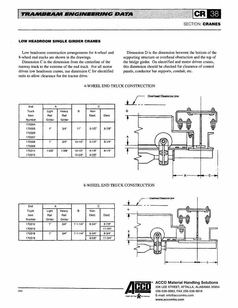
ACCO Material Handling Solutions206 LEE STREET, ATTALLA, ALABAMA 35954
256-538-9983, FAX 256-538-8818
E-mail: [email protected]
www.accomhs.com
LOW HEADROOM SINGLE GIRDER CRANES
Low headroom construction arrangements for 4-wheel and 8-wheel end trucks are shown in the drawings.
Dimension C is the dimension from the centerline of the runway track to the extreme of the end truck. For all motor driven low headroom cranes, use dimension C for electrified units to allow clearance for the tractor drive.
SECTION: CRANES
Dimension D is the dimension between the bottom of the supporting structure or overhead obstruction and the top of the bridge girder. On electrified and motor driven cranes, this dimension should be checked for clearance of control panels, conductor bar supports, conduit, etc.
4·WHEEL END TRUCK CONSTRUCTION
J_Ov-erh-ead-C-Ie-arance Une
End A c Truck Light Heavy B Non-
Item Rail Rail Elect. Elect.
Number Girder Girder
170304
170305 111 3/4" 11" 5·1/2" 8-7/8"
170306
170307
170308 1'' 3/4" 10-1/2" 5-1/2" 8-1/4"
170309
170314 1-5/8" 1-3/8" 10-1/2" 6-1/8" 8-1/4"
170315 10-5/8" 6-3/8"
8-WHEEL END TRUCK CONSTRUCTION
End A c Truck Light Heavy B Non-
Item Rail Rail Elect. Elect.
Number Girder Girder
170312 111 314" 1'-1-1/4" 8-3/4" 8-7/8"
170313 11-3/4"
170318 1" 314" 1'-1-1/4" 8-3/4" 8-3/4"
170319 8-5/8" 11-3/4"
-9,95 ------Acco® PART OF THE 'lc.FKI GROUP

ACCO Material Handling Solutions206 LEE STREET, ATTALLA, ALABAMA 35954
256-538-9983, FAX 256-538-8818
E-mail: [email protected]
www.accomhs.com
HAND RACKED SINGLE GIRDER CRANES
Standard, hand propelled, single girder cranes may be arranged for hand racking by the addition of a squaring shaft drive. Hand racked cranes use 4-wheel extended wheelbase end trucks or 8-wheel end trucks.
These cranes are limited to spans of 42'-0 maximum and to end trucks with 5 inch or 6-l/2 inch diameter wheels. When electric hoists operate on the crane, they are equipped with conductors and current collectors as described in the Electrification Section. They can be used as transfer cranes by the addition of interlock mechanisms.
The drive consists of rubber wheels mounted in each end truck which bear the bottom of the runway and provide traction to propel the crane. The wheels are connected to a squaring shaft by roller chains. The squaring shaft operates
SECTION: CRANES
on self-aligning ball bearing pillow block; the assembly is propelled by ·a hand chain and chain wheel.
The standard location for the hand chain is 2' -0 from the centerline of the end truck as indicated in the drawing. The hand chain may be located at any point between the end trucks when specified. A second hand chain may also be furnished when specified. The hand chain may be located up to 1 '-6 outside of the end truck providing the girder overhang is at least 6 inch beyond the hand chain location.
The arrangement of a hand racked crane is shown in the drawing. Clearances are the same as those shown on preceding pages for a comparable hand propelled crane. Dimension X should be checked for possible interference between the hoist and/or carrier and the hand chain.
Overall Length
Span Overhang
2'-0"
End
Truck Dimension X
Item
Number
170305 170307 1'·0·3/4" 170309 170315
170318 11·1/411
170320 11·31411
-9,95 ------Acco®
, PART OF THE 'KFKI GROUP

ACCO Material Handling Solutions206 LEE STREET, ATTALLA, ALABAMA 35954
256-538-9983, FAX 256-538-8818
E-mail: [email protected]
www.accomhs.com
STANDARD DOUBLE GIRDER CRANES
Standard 2-runway, double girder Trambeam cranes are cataloged for rated loads to 15 tons and for spans to 100' -0. Multiple runway and heavier rated load cranes are available; consult factory for assistance on these applications. Selection of 2-runway double girder cranes is made in accordance with the procedure outlined on Page CR-47.
These cranes may be hand propelled, hand racked or motor driven depending on travel distance, frequency of operation, span, elevation and rated load. However, they are generally motor driven and the data that follows applies to motor driven cranes. When electric hoists operate on the crane, they are equipped with an electrification system as described in the Electrification Section.
Service classifications for cranes are described in ANSI MH 27.1 Specifications for Underhung Cranes and Monorail Systems. Cataloged cranes will generally meet the service classification of the hoist selected to operate on the crane and the requirements of the comparable ANSI MH 27.1 service classification.
For Class D heavy duty cranes with speeds greater than 200 FPM and all class E severe duty cranes, consult factory for recommendations.
Complete specifications for bridge girders, girder connections, end trucks') crane drives and crane electrification are described below and on subsequent pages.
BRIDGE GIRDERS
All heavy rail track sections (Nos. 34037 through 34079) are used for bridge girders of double girder cranes. These sections are described in the Track & Fitting Section.
Three types of bridge girders have been established to: (1) maintain a constant headroom dimension from the top of the girders at the end trucks to the hook in the high position and (2) provide a simplified carrier design. Type 1 girders are fabricated from Nos. 34037 or 34041 track and have a 12-1/2 inch depth at the end trucks. Type 2 girders are fabricated from Nos. 34046 through 34076 track and have a 16 inch depth at the end trucks. Type 3 girders are fabricated from Nos. 34077 through 34079 track and have a 22-1/2 inch depth at the end trucks.
Bridge girder deflection is limited to 1/450 of the span for cranes with spans of 46' -0 or less. For spans greater than 46' -0, the ratio is reduced so that the actual deflection does not exceed 1-1/4 inch
Bridge girders are structurally framed together on the
SECTION: CRANES
gauge of the carrier by steel angles attached to the top flanges. This framing provides lateral stability and maintains the gauge between the girders.
NOTE: Where the depth of the girder cope is large, i.e. No.34076 (30 inch) tracks arranged as Type 2 girders are coped to 16 inch depth at the end trucks, check the clearance above the girder top flanges and bracing for possible interference with the building structure, lights, heaters, etc.
GIRDER CONNECTIONS
Girder connections to the end trucks utilize keys which· are welded to the end truck load bars when the crane is assembled at the factory. The keys are welded into position adjacent to the girder flanges after the load bars have been aligned with the girders. The keys provide a rigid connection which does not rely on the fit of the attaching hardware in the mounting holes.
END TRUCKS
A complete line of end trucks is available with rated loads from 8,000 to 60,000 pounds. The end truck wheel base is variable and depends on the gauge between the bridge girders. The girder gauge may be determined by referring to the appropriate clearance drawing in the Carrier Section for the hoist and carrier selected for the crane.
End truck load bars consist of steel channels, plates and bars which are welded into a rigid assembly. After welding, the load bar is machined to control vertical dimensions and squareness of trucks. Lugs are provided in the load bar to limit the drop of the end truck to 1 inch or less in the event of wheel or axle failure. Cranes with trucks having 5 inch diameter wheels can operate on any size Trambeam track. Cranes with trucks having 6-1/2 inch and 8 inch diameter wheels can operate only on heavy rail track sections. Cranes with No. 180209 end trucks can operate only on No. 34041 or larger track because of the height of the load bar channels. These runway restrictions are noted on Pages CR-44, CR-45 and CR-46 and in the crane tables.
-9,95 ------Acco® ,
PART OF THE 'KFKI GROUP

ACCO Material Handling Solutions206 LEE STREET, ATTALLA, ALABAMA 35954
256-538-9983, FAX 256-538-8818
E-mail: [email protected]
www.accomhs.com
STANDARD DOUBLE GIRDER CRANES
CRANE DRIVES
Double girder cranes are motor driven by tractor drives attached to each end truck. Three drives (Nos. 2408, 2409 and 24010) are available to meet a wide range of applications. All are satisfactory for Class D heavy duty service. Complete data on tractor drives, motor control and horsepower requirements are contained in the Tractor Drive Section.
Nominal speeds for double girder cranes are 55 and 90 FPM when No. 24010 drives are used; 100, 125, 150 and 200 FPM when No. 2409 drives are used; and 100, 150,200,250 and 300 FPM when No. 2408 drives are used. Other speeds can be furnished.
Wiring and control panels comply with the requirements of OSHA electrical standards and Article 610 of the National Electric Code. Wiring is enclosed in rigid conduit insofar as possible. Crane control panels are furnished with fused motor circuit switch, mainline contactor, motor overcurrent protection, thermal overload relays in 3 phases and NEMA 12 dust-tight enclosure as standard.
CRANE ELECTRIFICATION
The crane electrification system for double girder cranes
.. ... . ......... ~--··· '
.... =.:.:::.;.:::::=.:::·:::;.:=/(=::,:· R .............................. c SECTION: CRANES
is similar to that used on single girder cranes and varies only in the location of the conductors. A description of the crane electrification system and the method of determining the number of conductors are contained on Pages CR-7 and CR-8. Standard conductor arrangements are shown on Page CR-42.
Collectors are required for the carrier to pick up current from the power conductors and supply power to the hoist and carrier motors. They are also required for transferring control functions form the operating station to the control conductors. The number of carrier collectors is generally the same as the number of crane conductors. On transfer crane applications, tandem collector arrangements are usually required to activate the mainline contactor.
Insul-8-Bar's 90 amp steel conductor is the standard electrification for double girder cranes. Complete descriptions on conductor bars, insulating covers, collectors and accessories are in the electrification Section.
Double girder cranes, except transfer cranes, may be equipped with festooned electrification. Transfer cranes are equipped with rigid conductors to provide continuous power to the hoist and carrier motors as the transfer is made. Festooned electrification is described in the Electrification Section.
-9,95 ------Acco® PART OF THE 'lc.FKI GROUP

ACCO Material Handling Solutions206 LEE STREET, ATTALLA, ALABAMA 35954
256-538-9983, FAX 256-538-8818
E-mail: [email protected]
www.accomhs.com
STANDARD DOUBLE GIRDER CRANES
CONDUCTOR ARRANGEMENT
The drawing illustrates the standard arrangement of power and control conductors for double girder cranes with Insul-8-Bar electrification. The power (Ll, L2 and L3) and control (F, R, X and M) conductors are 6-1/8 inch above the girder tread for carriers with 5 inch diameter wheels, 7-3/4 inch for
(Drive Side Of Crane
SECTION: CRANES
carriers with 6-1/2 inch diameter wheels or 9-1/2 inch for carriers with 8 inch diameter wheels.
The conductors and supports shown by the solid lines indicate the 7 conductor arrangement used with Type I single speed crane control. The dotted lines indicate the location of additional conductors for other control arrangements.
6-1/8" For 5" Wheels 7-314 11 For6~1/2" Wheels 9-1/2" For 8" Wheels
a• 3" 3" 7-114" 3" 3" 7·1/4" 7·1/4" 3" 3"
TYPICAL FOR ALL GIRDER SIZES
-9,95 ------Acco® , PART OF THE 'KFKI GROUP
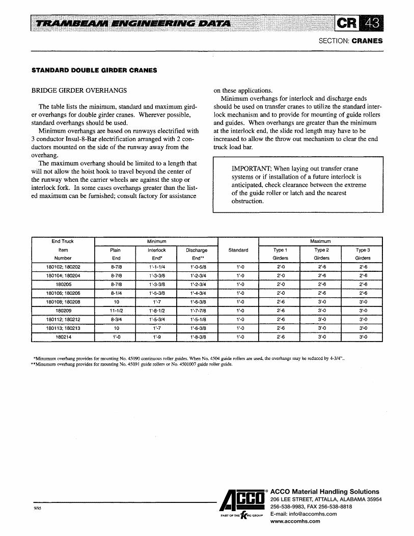
ACCO Material Handling Solutions206 LEE STREET, ATTALLA, ALABAMA 35954
256-538-9983, FAX 256-538-8818
E-mail: [email protected]
www.accomhs.com
STANDARD DOUBLE GIRDER CRANES
BRIDGE GIRDER OVERHANGS
The table lists the minimum, standard and maximum girder overhangs for double girder cranes. Wherever possible, standard overhangs should be used.
Minimum overhangs are based on runways electrified with 3 conductor Insul-8-Bar electrification arranged with 2 conductors mounted on the side of the runway away from the overhang.
The maximum overhang should be limited to a length that will not allow the hoist hook to travel beyond the center of the runway when the carrier wheels are against the stop or interlock fork. In some cases overhangs greater than the listed maximum can be furnished; consult factory for assistance
End Truck Minimum
Item Plain Interlock Discharge
Number End End* End**
180102;180202 8-7/8 1 '~1-1/4 1'-0~5/8
180104;180204 8-7/8 1'-3-3/8 1'-2-3/4
180205 8-7/8 1 '-3-3/8 1'-2-3/4
180106;180206 8-1/4 1'-5-3/8 1'-4-3/4
180108;180208 10 1'-7 1'-6-3/8
180209 11-1/2 1'-8-1/2 1'-7-7/8
180112; 180212 8-3/4 1'-5-3/4 1'-5-1/8
180113;180213 10 1'-7 1'-6-3/8
180214 1'-0 1'-9 1'-8-3/8
SECTION: CRANES
on these applications. Minimum overhangs for interlock and discharge ends
should be used on transfer cranes to utilize the standard interlock mechanism and to provide for mounting of guide rollers and guides. When overhangs are greater than the minimum at the interlock end, the slide rod length may have to be increased to allow the throw out mechanism to clear the end truck load bar.
IMPORTANT; When laying out transfer crane systems or if installation of a future interlock is anticipated, check clearance between the extreme of the guide roller or latch and the nearest obstruction.
Maximum
Standard Type 1 Type2 Type3
Girders Girders Girders
1'-0 2'-0 2'-6 2'-6
1'-0 2'-0 2'-6 2'~6
1'-0 2'-0 2'-6 2'-6
1'-0 2'-0 2'-6 2'-6
1'-0 2'-6 3'-0 3'-0
1'-0 2'-6 3'-0 3'-0
1'-0 2'-6 3'-0 3'-0
1'-0 2'-6 3'-0 3'-0
1'-0 2'-6 3'-0 3'-0
*Minumum overhang provides for mounting No. 45090 continuous roller guides. When No. 4504 guide rollers are used, the overhangs may be reduced by 4-3/4" .. **Minumum overhang provides for mounting No. 45091 guide rollers or No. 4501007 guide roller guide.
-9,95 ------Acco®
, PART OF THE 'KFKI GROUP

ACCO Material Handling Solutions206 LEE STREET, ATTALLA, ALABAMA 35954
256-538-9983, FAX 256-538-8818
E-mail: [email protected]
www.accomhs.com
STANDARD DOUBLE GIRDER CRANES
4-WHEEL END TRUCKS
The drawing illustrates the No. 180102 end truck and is typical for a114-wheel trucks. The table indicates the item number, rated load, carrier head, net weight, minimum size of runway track and principal dimensions. See Carrier Section for specifications on carrier heads and wheel assemblies.
Dimension f is determined by adding dimension h to the girder gauge. The girder gauge is variable and depends on the hoist and carrier selected for the crane. The gauge is determined by referring to the appropriate clearance drawing
SECTION: CRANES
in the Carrier Section. Net weights are based on 6' .. 6 girder gauge. The additional net weight is the additional weight to be added for each 6 inch of gauge over 6' -6 .
Load bars consist of steel channels, plates and bars welded into a rigid assembly. After welding, the load bars are machined to control vertical elevations and squareness. Lugs are provided in the load bar to limit the drop of the end truck to 1 inch or less in the event of wheel or axle failure.
All end trucks have self aligning bushings between the carrier head and the load bar to provide equal wheel loading and free swivel of the heads.
M N Gauge (Variable) N
d~--~~----------------~1 ----.......... ------------~----~d h h 2 2
End Truck
Item
Number
180102
180202
180104
180204
180205
M= 1 '-3-7/8~' For No. 24010 Tractor Drive 1 ~ -2-1/2'' For No. 2409 Tractor Drive 1'-11-114" For No. 2408 Tractor Drive
Rated Carrier Net Weight
Load Head Item 6'-6 Gauge
(Pounds) Number (Pounds)
8,000 010207 283
8,000 010208 295
13,000 010209 657
13,000 010210 679
15,000 010211 757
*Additional net weight of end truck for each 6" of gauge over 6' -6".
*Add'f Minimum
Net Weight Runway
(Pounds) Size
9 34016
9 34016
20 34037
20 34037
20 34037
-9,95 ------Acco®
, PART OF THE 'KFKI GROUP
d
3-3/4
3-314
4-1/4
4-1/4
4-1/4
h J
3'-0 1-1/2
3'-0 1-1/2
4'-0 2-1/8
4'-0 2-1/8
4'-0 2-1/4
N
1'-9-3/4
1'-9-3/4
2'-4-1/4
2'-4-1/4
2'-4-1/4

ACCO Material Handling Solutions206 LEE STREET, ATTALLA, ALABAMA 35954
256-538-9983, FAX 256-538-8818
E-mail: [email protected]
www.accomhs.com
STANDARD DOUBLE GIRDER CRANES
8-WHEEL END TRUCKS
The drawing illustrates the No. 180106 end truck and is typical for all 8-wheel end trucks. The table indicates the item number, rated load, carrier head, net weight, minimum size of runway track and principal dimensions. See Carrier Section for specifications on carrier heads and wheel assemblies.
Dimension f is determined by adding dimension h to the girder gauge. The girder gauge is variable and depends on the hoist and carrier selected for the crane. The gauge is determined by referring to the appropriate clearance drawing in the Carrier Section. Net weights are based on 6' -6 girder
End Truck
M= 1'-3-7/8" For No. 24010 Tractor Drive 1 '-2-112" For No. 2409 Tractor Drive 1 '-11-1/4" For No. 2408 Tractor Drive
Rated Carrier Net Weight *Add'l
SECTION: CRANES
gauge. The additional net weight is the additional weight to be added for each 6 inch of gauge over 6' -6 .
Load bars consist of steel channels, plates and bars welded into a rigid assembly. After welding, the load bars are machined to control vertical elevations and squareness. are provided in the load bar to limit the drop of the end truck to 1 inch or less in the event of wheel or axle failure.
The 4-wheel carrier load bars are made from steel plate which is machined to control vertical elevations. Self-aligning bushings are used between the carrier load bars and main load bar to provide equal carrier head loading. Self-aligning bushings are also used between the carrier heads and carrier load bar to provide equal wheel loading and free swivel of the heads.
Minimum
Item Load Head Item 6'-6 Gauge Net Weight Runway d e h J N
Number (Pounds) Number (Pounds) (Pounds) Size
180106 16,000 010207 720 20 34016 3-3/4 1'-Q 2'-11 1-1/2 2'-9-1/4
180206 16,000 010208 744 20 34016 3-3/4 1'-0 2'-11 1-1/2 2'-9-1/4
180108 26,000 010209 1,031 22 34037 4-1/4 1'-3 3'-0 2-1/8 3'-1-1/4
180208 26,000 010210 1,075 22 34037 4-1/4 1'-3 3'-0 2-1/8 3'-1-1/4
180209 30,000 010211 1,290 21 34041 4-1/4 1'-3 3'-0 2-1/4 3'-1-114
*Additional net weight of end truck for each 6" of gauge over 6'-6".
-9,95 ------Acco® PART OF THE 'lc.FKI GROUP

ACCO Material Handling Solutions206 LEE STREET, ATTALLA, ALABAMA 35954
256-538-9983, FAX 256-538-8818
E-mail: [email protected]
www.accomhs.com
STANDARD DOUBLE GIRDER CRANES
16-WHEELENDTRUCKS
The drawing illustrates the No. 180112 end truck and is typical for alll6-wheel end trucks. The design consists of individual 8-wheel end trucks on each girder; structural ties between the girders maintain the gauge. The table indicates the item number, rated load, carrier head, net weight, minimum size of runway track and principal dimensions of these trucks. See Carrier Section for specifications on carrier heads and wheel assemblies.
Dimension g is determined by subtracting dimension h from the girder gauge. The girder gauge is variable and depends on the hoist and carrier selected for the crane. The gauge is determined by referring to the appropriate clearance
SECTION: CRANES
drawing in the Carrier Section. Load bars consist of steel channels, plates and bars welded
into a rigid assembly. After welding, the load bars are machined to control vertical elevations and squareness. Lugs are provided in the load bar to limit the drop of the end truck to 1 inch or less in the event of wheel or axle failure.
The 4-wheel carrier load bars are made from steel plate which is machined to control vertical elevations. Self-aligning bushings are used between the carrier load bars and main load bar to provide equal carrier head loading. Self-aligning bushings are also used between the carrier heads and carrier load bar to provide equal wheel loading and free swivel of the heads.
M N Gauge (VariabJe N
End Truck
Item
Number
180112
180212
180113
180213
180214
e e
M= 1 '-3-7/8" For No. 24010 Tractor Drive 1 '-2-112" For No. 2409 Tractor Drive 1 '-11-1/4" For No. 2408 Tractor Drive
Rated Carrier Net
Load Head Item Weight
(Pounds) Number (Pounds)
32,000 010207 908
32,000 010208 956
52,000 010209 1,355
52,000 010210 1,443
60,000 010211 2,061
Minimum
Runway d
Size
34016 3-3/4
34016 3-3/4
34037 4-1/4
34037 4-1/4
34037 4-1/4
-9,95 ------Acco® ,
PART OF THE 'KFKI GROUP
e f h J N
1'-Q 3'-Q 5'·0 1~112 2'-9-3/4
1'-Q 3'-0 5'-0 1-1/2 2'-9-3/4
1'-3 3'-0 5'-6 2-1/8 3'-1-1/4
1'-3 3'-0 5'-6 2-1/8 3'-1-1/4
1'-3 3'-0 5'-6 2-1/4 3'-1-1/4

ACCO Material Handling Solutions206 LEE STREET, ATTALLA, ALABAMA 35954
256-538-9983, FAX 256-538-8818
E-mail: [email protected]
www.accomhs.com
SELECTION OF DOUBLE GIRDER CRANES
Standard double girder, 2-runway cranes are tabulated on subsequent pages by: (1) number of end truck wheels, (2) rated load and (3) span. The tables provide a simple means for crane selection and indicate the crane code number, basic crane weight, minimum runway size and clearance dimensions. End truck wheel base dimensions are also provided to assist in determining the runway size.
Cranes are listed for rated loads of 2, 3, 5, 7-1/2, 10 and 15 tons and spans from 28' -0 to 100' -0. Heavier rated load cranes are available; consult factory for data.
Crane rated loads are based on a design load which is adequate for most applications. The design load includes: ( 1) hoist and carrier weights, (2) rated load and (3) 15% impact allowance. The design load is shown in the tables.
Crane selection is made by:
Step 1 - Determine actual load (weights of hoist and carrier selected for the crane, rated load and impact allowance).
Step 2 - Select crane from table providing actual load is no greater than the design load.
If the actual load exceeds the design load, it is necessary to calculate the girder and end truck loads and select the components on the basis of the calculated loads.
Crane code numbers indicate the means of propulsion, type of crane electrification, bridge girder size, type of end truck and overall length of bridge girders. Page CR-2 provides a
SECTION: CRANES
complete explanation of the crane code numbering system. The basic crane weight includes the weight of the bridge
girders, 7 conductors of Insul-8-Bar, end trucks with 6' -6 girder gauge and motorization with No. 2409 tractor drives. It does not include the structural top flange bracing weight as this weight varies with span and girder gauge. Another variable is in the 4-wheel and 8-wheel end truck weight which varies with the girder gauge. The tables on Pages CR -60 and CR -61 list the variable weight factors.
The net weight is determined by adding the weight factor from Pages CR-60 or CR-61 to the basic crane weight shown in the crane tables. Cranes with No. 2408 drives are approximately 400 pounds more than the basic weight indicated in the tables. This additional weight does not affect crane rated load as the drive is independent of the end truck. No. 24010 drives are approximately 120 pounds less than the basic weight indicated in the tables.
Cranes are listed with an overall length based on a nominal spans between runway tracks and 1 '-0 nominal girder overhangs. See Page CR-43 for minimum, maximum and standard girder overhangs when determining the crane span and overall length.
A clearance drawing is provided on the page facing each crane table. The drawings locate the control panel elevation for cranes with Nos. 34037 through 34056 bridge girders. The horizontal spacing of the panel varies with the type of control and collector arrangement. Consult factor for this dimension if the possibility exists for interference between the panel and building structure, lights, etc.
-9,95 ------Acco®
, PART OF THE 'KFKI GROUP

ACCO Material Handling Solutions206 LEE STREET, ATTALLA, ALABAMA 35954
256-538-9983, FAX 256-538-8818
E-mail: [email protected]
www.accomhs.com
STANDARD DOUBLE GIRDER CRANES
CLEARENCE DRAWING FOR CRANES WITH 4-WHEEL END TRUCKS
The drawing illustrates the clearances of a double girder crane with 4-wheel end trucks and 7 conductor Insul-8-Bar electrification. Dimensions h, J, Land N are shown on the facing page. To determine dimensions A, B, C, G and H
Overhang
2 inch minimum clearance without interlock; 7-1/2 inch minimum with interlock and No. 4504 guide roller; or 6 inch minimum with interlock and No. 45090 guide.
M N
M= 1 '-3-7/8" For No. 24010 Tractor Drive 1'-2-1/2" For No. 2409 Tractor Drive 1 '-11-1/4" For No. 2408 Tractor Drive
Overall Length
B
SECTION: CRANES
refer to the appropriate clearance drawing in the Carrier Section for the hoist and carrier selected for the crane. To determine dimension F, add dimension h to the girder gauge (dimension G). See Page CR-43 for minimum, maximum and standard girder overhangs.
c
G
G 2
Overhang
*Panel is 7-3/4 inch above top of Nos. 34037 through 34056 girders; panel is below top of girder for No. 34061 and larger girders.
N
h 2
L
-9,95 ------Acco® PART OF THE 'lc.FKI GROUP
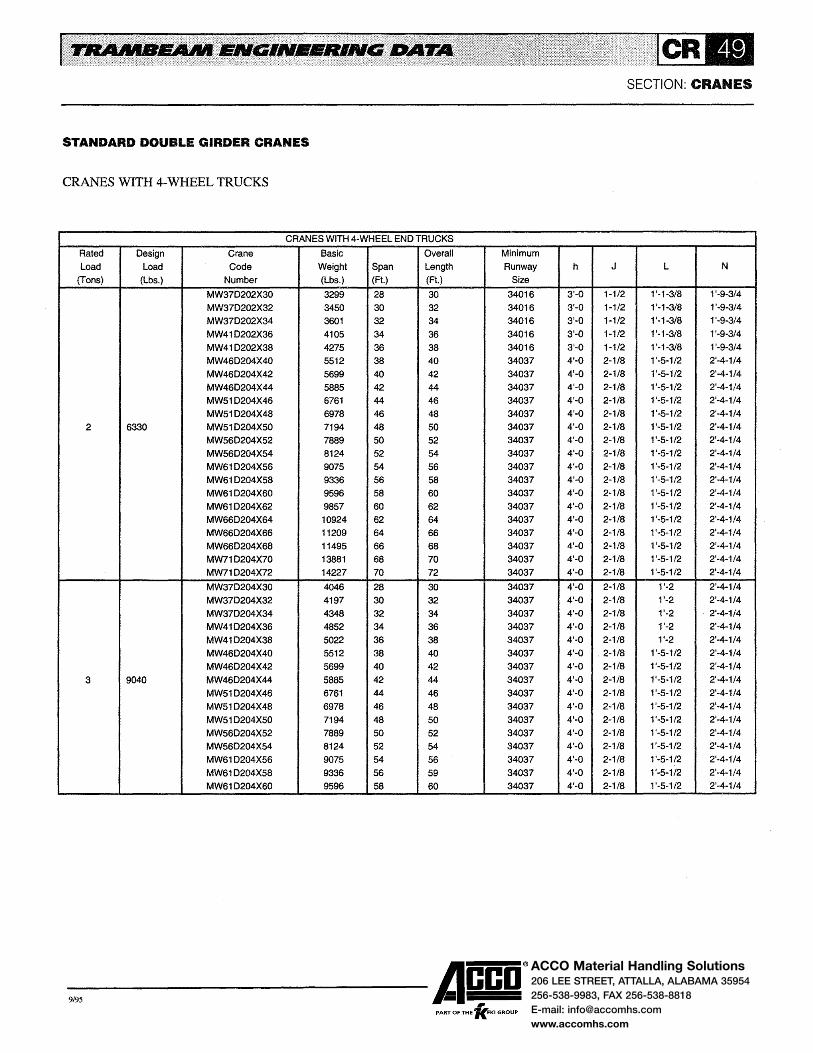
ACCO Material Handling Solutions206 LEE STREET, ATTALLA, ALABAMA 35954
256-538-9983, FAX 256-538-8818
E-mail: [email protected]
www.accomhs.com
SECTION: CRANES
STANDARD DOUBLE GIRDER CRANES
CRANES WITH 4-WHEEL TRUCKS
CRANES WITH 4-WHEEl END TRUCKS
Rated Design Crane Basic Overall Minimum
load load Code Weight Span Length Runway h J l N
(Tons) (lbs.) Number (Lbs.) (Ft.) (Ft.) Size
MW370202X30 3299 28 30 34016 3'-0 1-1/2 1 '-1-3/8 1'-9-3/4
MW37D202X32 3450 30 32 34016 3'-0 1-1/2 1'-1-3/8 1'-9-3/4
MW370202X34 3601 32 34 34016 3'-0 1-1/2 f-1-3/8 1'-9-3/4
MW41 D202X36 4105 34 36 34016 3'-0 1-1/2 1'-1-3/8 1'-9-3/4
MW41 D202X38 4275 36 38 34016 3'-0 1-1/2 1'-1-3/8 1'-9-3/4
MW460204X40 5512 38 40 34037 4'-0 2-1/8 1'-5-1/2 2'-4-1/4
MW460204X42 5699 40 42 34037 4'-0 2-1/8 1'-5-1/2 2'-4-1/4
MW460204X44 5885 42 44 34037 4'-0 2-1/8 1'-5-1/2 2'-4-1/4
MW51 D204X46 6761 44 46 34037 4'-0 2-1/8 1'-5-1/2 2'-4-1/4
MW51 0204X48 6978 46 48 34037 4'-0 2-1/8 1'-5-1/2 2'-4-1/4
2 6330 MW51 0204X50 7194 48 50 34037 4'-0 2-1/8 1'-5-1/2 2'-4-1/4
MW560204X52 7889 50 52 34037 4'-0 2-1/8 1'-5-1/2 2'-4-1/4
MW560204X54 8124 52 54 34037 4'-0 2-1/8 1'-5-1/2 2'-4-1/4
MW61 0204X56 9075 54 56 34037 4'-0 2-1/8 1'-5-1/2 2'·4-1/4
MW61 0204X58 9336 56 58 34037 4'-0 2-1/8 1'-5-1/2 2'-4-1/4
MW61 0204X60 9596 58 60 34037 4'-0 2-1/8 1 '-5-1/2 2'-4-1/4
MW61 0204X62 9857 60 62 34037 4'-0 2-1/8 1'-5-1/2 2'-4-1/4
MW660204X64 10924 62 64 34037 4'-0 2-1/8 1'-5-1/2 2'-4-1/4
MW660204X66 11209 64 66 34037 4'-0 2-1/8 1'-5-1/2 2'-4-1/4
MW660204X68 11495 66 68 34037 4'-0 2-1/8 1'-5-112 2'-4-1/4
MW71 0204X70 13881 68 70 34037 4'-0 2-1/8 1'-5-1/2 2'-4-1/4
MW71 0204X72 14227 70 72 34037 4'-0 2-1/8 1'-5-1/2 2'-4-1/4
MW370204X30 4046 28 30 34037 4'-0 2-1/8 1'-2 2'-4-1/4
MW370204X32 4197 30 32 34037 4'-0 2-1/8 1'-2 2'-4-1/4
MW370204X34 4348 32 34 34037 4'-0 2-1/8 1'-2 2'-4-1/4
MW41 0204X36 4852 34 36 34037 4'-0 2-1/8 1'-2 2'-4-1/4
MW41 D204X38 5022 36 38 34037 4'-0 2-1/8 1'-2 2'-4-1/4
MW460204X40 5512 38 40 34037 4'-0 ' 2-1/8 1'-5-1/2 2'-4-1/4
MW460204X42 5699 40 42 34037 4'-0 2-1/8 1'-5-1/2 2'-4-1/4
3 9040 MW460204X44 5885 42 44 34037 4'-0 2-1/8 1'-5-1/2 2'-4-114
MW51 0204X46 6761 44 46 34037 4'-0 2-1/8 1'-5-1/2 2'-4-1/4
MW51 D204X48 6978 46 48 34037 4'-0 2-1/8 1'-5-1/2 2'-4-1/4
MW510204X50 7194 48 50 34037 4'·0 2-1/8 1'-5-1/2 2'-4-1/4
MW56D204X52 7889 50 52 34037 4'-0 2-1/8 1'-5-1/2 2'-4-1/4
MW560204X54 8124 52 54 34037 4'-0 2-1/8 1'-5-1/2 2'-4-1/4
MW61 D204X56 9075 54 56 34037 4'-0 2-1/8 1'-5-1/2 2'-4-1/4
MW61 0204X58 9336 56 59 34037 4'-0 2-1/8 1'-5-1/2 2'-4-1/4
MW610204X60 9596 58 60 34037 4'-0 2-1/8 1'-5-1/2 2'-4-1/4
-9,95 ------Acco® PART OF THE 'lc.FKI GROUP

ACCO Material Handling Solutions206 LEE STREET, ATTALLA, ALABAMA 35954
256-538-9983, FAX 256-538-8818
E-mail: [email protected]
www.accomhs.com
STANDARD DOUBLE GIRDER CRANES
CLEARANCE DRAWING FOR CRANES WITH 8-WHEEL END TRUCKS
The drawing illustrated the clearances of a motor driven double girder crane with 8-wheel end trucks and 7 conductor Insul-8-Bar electrification. Dimensions e, h, J, Land N are shown on the facing page. To determine dimensions A, B, C, G and H refer to the appropriate clearance drawing in the
2 inch minimum clearance without interlock; 7-1/2 inch minimum with interlock and No. 4504 guide roller; or 6 inch minimum with interlock and No. 45090 guide.
M
e
N
h 2
M= 1'-3-7/8" For No. 24010 Tractor Drive 1 '-2-1/2n For No. 2409 Tractor Drive 1 '-11-1/4" For No. 2408 Tractor Drive
Overall Length
B
G 2
G
SECTION: CRANES
Carrier Section for the hoist and carrier selected for the crane. To determine dimension f, add dimension h to the girder gauge (dimension G). See Page CR-43 for minimum, maximum and standard bridge girder overhangs.
c
G 2
Overhang
*Panel is 7-3/4 inch above top of Nos. 34037 through 34056 girders; panel is below top of girder for No. 34061 and larger girders.
N
e
L
-9,95 ------Acco®
, PART OF THE 'KFKI GROUP

ACCO Material Handling Solutions206 LEE STREET, ATTALLA, ALABAMA 35954
256-538-9983, FAX 256-538-8818
E-mail: [email protected]
www.accomhs.com
SECTION: CRANES
STANDARD DOUBLE GIRDER CRANES
CRANES WITH 8-WHEEL TRUCKS
CRANES WITH 8-WHEEL END TRUCKS Rated Design Crane Basic Overall Minimum Load Load Code Weight Span Length Runway e h J L N
(Tons) (Lbs.) Number (Lbs.) (Ft.) (Ft.) Size MW71 D206X74 14698 72 74 34016 1'-0 2'-11 1-1/2 1'-4-7/8 2'-9-1/4 MW76D206X76 16427 74 76 34016 1'-0 2'-11 1-1/2 1'-4-7/8 2'-9-114 MW760206X78 16810 76 78 34016 1'-0 2'-11 1-1/2 1'-4-7/8 2'-9-1/4 MW760206X80 17211 78 80 34016 1'-0 2'-11 1-1/2 1'-4-7/8 2'-9-1/4 MW760206X82 17594 80 82 34016 1'-0 2'-11 1-1/2 1'-4-7/8 2'-9-1/4 MW770208X84 21387 82 84 34037 1'-3 3'-0 2-1/8 2'-0 3'-1-1/4 MW77D208X86 21836 84 86 34037 1'-3 3'-0 2-1/8 2'-0 3'-1-1/4
2 6330 MW78D208X88 24626 86 88 34037 1'-3 3'-0 2-1/8 2'-0 3'-1-1/4 MW780208X90 25145 88 90 34037 1'-3 3'-0 2-1/8 2'-0 3'-1-1/4 MW780208X92 25647 90 92 34037 1'-3 3'-0 2-1/8 2'-0 3'-1-1/4 MW78D208X94 26150 92 94 34037 1'-3 3'-0 2-1/8 2'-0 3'-1-1/4 MW780208X96 26652 94 96 34037 1'-3 3'-0 2-1/8 2'-0 3'-1-1/4 MW790208X98 29801 96 98 34037 1'-3 3'-0 2-1/8 2'-0 3'-1-1/4
MW790208X1 00 30353 98 100 34037 1'-3 3'-0 2-1/8 2'-0 3'-1-1/4 MW79D208X102 30914 100 102 34037 1'-3 3'-0 2-1/8 2'-0 3'-1-1/4 MW61 0206X62 9984 60 62 34016 1'-0 2'-11 1-1/2 1'-4-7/8 2'-9-1/4 MW660206X64 11051 62 64 34016 1'-0 2'-11 1-1/2 1'-4-7/8 2'-9-1/4 MW66D206X66 11336 64 66 34016 1'-0 2'-11 1-1/2 1'-4-7/8 2'-9-1/4 MW660206X68 11622 66 68 34016 1'-0 2'-11 1-1/2 1'-4-7/8 2'-9-1/4 MW71 0206X70 14007 68 70 34016 1'-0 2'-11 1-1/2 1'-4-7/8 2'-9-1/4 MW71 D206X72 14353 70 72 34016 1'-0 2'-11 1-1/2 1'-4-7/8 2'-9-1/4 MW71 D206X7 4 14698 72 74 34016 1'-0 2'-11 1-1/2 1'-4-7/8 2'-9-1/4 MW760208X76 17069 74 76 34037 1'-3 3'-0 2-1/8 1'-5-1/2 3'-1-1/4 MW760208X78 17451 76 78 34037 1'-3 3'-0 2-1/8 1'-5-1/2 3'-1-114 MW76D208X80 17833 78 80 34037 1'-3 3'-0 2-1/8 1'-5-1/2 3'-1-1/4
3 9040 MW76D208X82 18216 80 82 34037 1'-3 3'-0 2-1/8 1'-5-1/2 3'-1-1/4 MW77D208X84 21387 82 84 34037 1'-3 3'-0 2-1/8 2'-0 3'-1-1/4 MW770208X86 21836 84 86 34037 1'-3 3'-0 2-1/8 2'-0 3'-1-1/4 MW78D208X88 24626 86 88 34037 1'-3 3'-0 2-1/8 2'-0 3'-1-1/4 MW78D208X90 25145 88 90 34037 1'-3 3'-0 2-1/8 2'-0 3'-1-1/4 MW78D208X92 25647 90 92 34037 1'-3 3'-0 2-1/8 2'-0 3'-1-1/4 MW780208X94 26150 92 94 34037 1'-3 3'-0 2-1/8 2'-0 3'-1-1/4 MW780208X96 26652 94 96 34037 1'-3 3'-0 2-1/8 2'-0 3'-1-114 MW79D208X98 29801 96 98 34037 1'-3 3'-0 2-1/8 2'-0 3'-1-1/4
MW790208X1 00 30353 98 100 34037 1'-3 3'-0 2-1/8 2'-0 3'-1-114 MW79D208X102 30914 100 102 34037 1'-3 3'-0 2-1/8 2'-0 3'-1-1/4
-9,95 ------Acco® PART OF THE 'lc.FKI GROUP

ACCO Material Handling Solutions206 LEE STREET, ATTALLA, ALABAMA 35954
256-538-9983, FAX 256-538-8818
E-mail: [email protected]
www.accomhs.com
STANDARD DOUBLE GIRDER CRANES
CLEARANCE DRAWING FOR CRANES WITH 8-WHEEL END TRUCKS
The drawing illustrated the clearances of a motor driven double girder crane with 8-wheel end trucks and 7 conductor Insul-8-Bar electrification. Dimensions e, h, J, L and N are shown on the facing page. To determine dimensions A, B, C, G and H refer to the appropriate clearance drawing in the
Overhang
2 inch minimum clearance without interlock; 7-1/2 inch minimum with interlock and No. 4504 guide roller; or 6 inch minimum with interlock and No. 45090 guide.
M N
M= 1 '-3-7/8" For No. 24010 Tractor Drive 1 '-2-1/2" For No. 2409 Tractor Drive 1 '-11-114" For No. 2408 Tractor Drive
Overall Length
B
G -r
G
SECTION: CRANES
Carrier Section for the hoist and carrier selected for the crane. To determine dimension f, add dimension h to the girder gauge (dimension G). See Page CR-43 for minimum, maximum and standard bridge girder overhangs.
c
G 2
Overhang
*Panel is 7-3/4 inch above top of Nos. 34037 through 34056 girders; panel is below top of girder for No. 34061 and larger girders.
N
-9,95 ------Acco®
PART OF THE 'fc.FKI GROUP
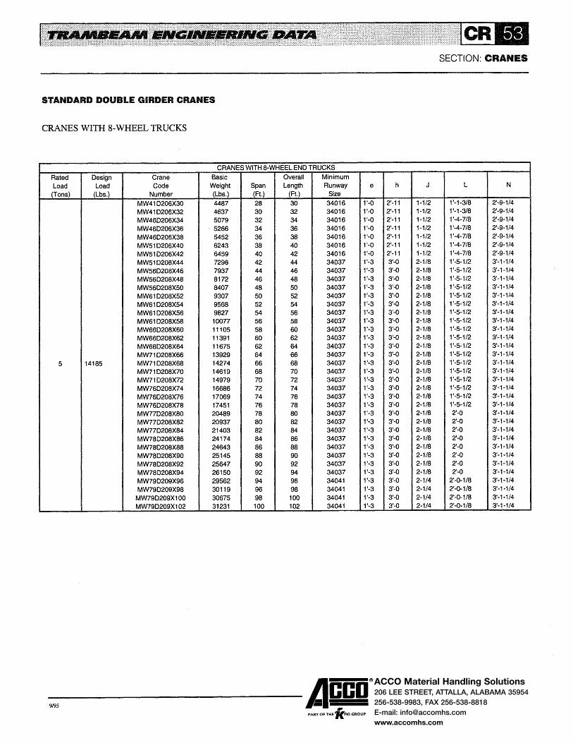
ACCO Material Handling Solutions206 LEE STREET, ATTALLA, ALABAMA 35954
256-538-9983, FAX 256-538-8818
E-mail: [email protected]
www.accomhs.com
SECTION: CRANES
STANDARD DOUBLE GIRDER CRANES
CRANES WITH 8-WHEEL TRUCKS
CRANES WITH 8·WHEEL END TRUCKS
Rated Design Crane Basic Overall Minimum
Load Load Code Weight Span Length Runway e h J L N
(Tons) (Lbs.) Number (Lbs.) (Ft.) (Ft.) Size
MW41 D206X30 4487 28 30 34016 1'·0 2'-11 1-1/2 1'-1-3/8 2'-9-1/4
MW41 D206X32 4637 30 32 34016 1'-0 2'-11 1-1/2 1'-1-3/8 2'-9-1/4
MW46D206X34 5079 32 34 34016 1'-0 2'-11 1-1/2 1'-4-7/8 2'-9-1/4
MW46D206X36 . 5266 34 36 34016 1'-0 2'-11 1-1/2 1'-4-7/8 2'-9-1/4
MW46D206X38 5452 36 38 34016 1'-0 2'-11 1-1/2 1'-4-7/8 2'-9-1/4
MW51 D206X40 6243 38 40 34016 1'-0 2'-11 1-1/2 1'-4-7/8 2'-9-1/4
MW51 D206X42 6459 40 42 34016 1'-0 2'-11 1-1/2 1'-4-7/8 2'-9-1/4
MW51 D208X44 7298 42 44 34037 1'-3 3'-Q 2-1/8 1'-5-1/2 3'-1-1/4
MW560208X46 7937 44 46 34037 1'-3 3'-0 2-1/8 1'-5-1/2 3'-1-1/4
MW56D208X48 8172 46 48 34037 1'-3 3'-0 2-1/8 1'-5-1/2 3'-1-1/4
MW56D208X50 8407 48 50 34037 1'-3 3'-Q 2-1/8 1'-5-1/2 3'-1-1/4
MW61 D208X52 9307 50 52 34037 1'-3 3'-0 2-1/8 1'-5-1/2 3'-1-1/4
MW61 D208X54 9568 52 54 34037 1'-3 3'-0 2-1/8 1'-5-1/2 3'-1-1/4
MW61 0208X56 9827 54 56 34037 1'-3 3'-0 2-1/8 1'-5-1/2 3'-1-1/4
MW61 D208X58 1oon 56 58 34037 1'-3 3'-0 2-1/8 1'-5-1/2 3'-1-1/4
MW66D208XSO 11105 58 60 34037 1'-3 3'-0 2-1/8 1'-5-1/2 3'-1-1/4
MW66D208X62 11391 60 62 34037 1'-3 3'-0 2-1/8 1 '-5-1/2 3'-1-1/4
MW66D208X64 11675 62 64 34037 1'-3 3'-0 2-118 1'-5-1/2 3'-1-1/4
MW71 D208X66 13929 64 66 34037 1'-3 3'-0 2-1/8 1'-5-1/2 3'-1-1/4
5 14185 MW71 D208X68 14274 66 68 34037 1'-3 3'-0 2-1/8 1'-5-1/2 3'-1-1/4
MW71 0208X70 14619 68 70 34037 1'-3 3'-0 2-1/8 1 '-5-1/2 3'-1·1/4
MW71 D208X72 14979 70 72 34037 1'-3 3'-0 2-1/8 1'-5-1/2 3'-1-1/4
MW76D208X74 16686 72 74 34037 1'-3 3'-0 2-1/8 1'-5-1/2 3'-1-1/4
MW76D208X76 17069 74 76 34037 1'-3 3'-0 2-1/8 1'-5-1/2 3'-1-1/4
MW76D208X78 17451 76 78 34037 1 '-3 3'-0 2-1/8 1'-5-1/2 3'-1-1/4
MW77D208X80 20489 78 80 34037 1'-3 3'-0 2-1/8 2'-0 3'-1-1/4
MW77D208X82 20937 80 82 34037 1'-3 3'-0 2-1/8 2'-0 3'-1-114
MW77D208X84 21403 82 84 34037 1'-3 3'-0 2-1/8 2'-0 3'-1-1/4
MW78D208X86 24174 84 86 34037 1'-3 3'-0 2-1/8 2'-0 3'-1-1/4
MW78D208X88 24643 86 88 34037 11-3 3'-0 2-1/8 2'-0 3'-1-1/4
MW78D208X90 25145 88 90 34037 1'-3 3'-0 2-1/8 2'-0 3'-1-1/4
MW78D208X92 25647 90 92 34037 1'-3 3'-0 2-118 2'-Q 3'-1-1/4
MW780208X94 26150 92 94 34037 1'-3 3'-0 2-1/8 2'-0 3'-1-1/4
MW79D209X96 29562 94 96 34041 1'-3 3'-0 2-114 2'-0-1/8 3'-1-1/4
MW79D209X98 30119 96 98 34041 1'-3 3'-0 2-1/4 2'-0-1/8 3'-1-1/4
MW790209X1 00 30675 98 100 34041 1'-3 3'-0 2-1/4 2'·0-1/8 3'-1-1/4
MW790209X102 31231 100 102 34041 1'-3 3'-0 2-1/4 2'-0-1/8 3'-1-1/4
-9,95 ------Acco® "" PART OF THE 'KFKI GROUP

ACCO Material Handling Solutions206 LEE STREET, ATTALLA, ALABAMA 35954
256-538-9983, FAX 256-538-8818
E-mail: [email protected]
www.accomhs.com
STANDARD DOUBLE GIRDER CRANES
CLEARANCE DRAWING FOR CRANES WITH 8-WHEEL END TRUCKS
The drawing illustrates the clearances of a motor driven double girder crane with 8-wheel end trucks and 7 conductor Insul-8-Bar electrification. Dimensions e, h, J, Land N are shown on the facing page. To determine dimensions A, B, C, G and H refer to the appropriate clearance drawing in the
2 inch minimum clearance without interlock; 7-1/2 inch minimum with interlock and No. 4504 guide roller; or 6 inch minimum with interlock and No. 45090 guide.
M N
e
M= 1'-3-7/8" For No. 24010 Tractor Drive 1 '-2-112" For No. 2409 Tractor Drive 1'-11-1/4" For No. 2408 Tractor Drive
Overall Length
B
G
SECTION: CRANES
Carrier Section for the hoist and carrier selected for the crane. To determine dimension f, add dimension h to the girder gauge (dimension G). See Page CR-43 for minimum, maximum and standard girder overhangs.
c
G 2
Overhang
*Panel is 7-3/4 inch above top of Nos. 34037 through 34056 girders; panel is below top of girder for No. 34061 and larger girders.
h -y-
N
e
L
-9,95 ------Acco® PART OF THE 'lc.FKI GROUP

ACCO Material Handling Solutions206 LEE STREET, ATTALLA, ALABAMA 35954
256-538-9983, FAX 256-538-8818
E-mail: [email protected]
www.accomhs.com
SECTION: CRANES
STANDARD DOUBLE GIRDER CRANES
CRANES WITH 8-WHEEL END TRUCKS
CRANES WITH 8-WHEEL END TRUCKS
Rated Design Crane Basic Overall Minimum Load Load Code Weight Span Length Runway e h J L N
(Tons) (Lbs.) Number (Lbs.) (Ft.) (Ft.) Size
MW46D208X30 5333 28 30 34037 1'~3 3'-0 2-1/8 1'-5-1/2 3'-1-1/4 MW46D208X32 5519 30 32 34037 1'-3 3'-0 2-1/8 1'-5-1/2 3'-1-1/4 MW51D208X34 6216 32 34 34037 1'-3 3'-0 2-1/8 1'-5-1/2 3'-1-1/4 MW51 D208X36 6431 34 36 34037 1'-3 3'-0 2-1/8 1'-5-1/2 3'-1-1/4 MW51 D208X38 6648 36 38 34037 1'-3 3'-0 2-1/8 1'-5-1/2 3'-1-1/4 MW56D208X40 7233 38 40 34037 1'-3 3'-0 2-1/8 1'-5-1/2 3'-1-1/4 MW56D208X42 7467 40 42 34037 1'-3 3'-0 2-1/8 1'-5-1/2 3'-1-1/4 MW61 D208X44 8265 42 44 34037 1'-3 3'-0 2-1/8 1'-5-1/2 3'-1-1/4 MW61 D208X46 8525 44 46 34037 1'-3 3'-0 2-1/8 1'-5-1/2 3'-1-1/4 MW61 D208X48 8786 46 48 34037 1'-3 3'-0 2-1/8 1'-5-1/2 3'-1-1/4 MW66D208X50 9687 48 50 34037 1'-3 3'-0 2-1/8 1'-5-1/2 3'-1-1/4
7-1/2 21290 MW66D208X52 9963 50 52 34037 1'-3 3'-0 2-1/8 1'-5-1/2 3'-1-1/4 MW66D208X54 10248 52 54 34037 1'-3 3'-0 2-1/8 1'-5-1/2 3'-1-1/4 MW66D208X56 10534 54 56 34037 1'-3 3'-0 2-1/8 1 '-5-1/2 3'-1-1/4 MW71 D208X58 12559 56 58 34037 1'-3 3'-0 2-1/8 1'-5-1/2 3'-1-1/4 MW71 D208X60 12893 58 60 34037 1'-3 3'-0 2-1/8 1'-5-1/2 3'-1-1/4 MW71 D208X52 13239 60 52 34037 1'-3 3'-0 2-1/8 1'-5-1/2 3'-1-1/4 MW76D209X64 15280 62 64 34041 1'-3 3'-0 2-1/4 1'-5-5/8 3'-1-114 MW76D209X66 15675 64 66 34041 1'-3 3'-0 2-1/4 1'-5-5/8 3'-1-1/4 MW76D209X68 16057 66 68 34041 1'-3 3'-0 2-1/4 1'-5-5/8 3'-1-1/4 MW77D209X70 18764 68 70 34041 1'-3 3'-0 2-1/4 2'-0-1/8 3'-1-1/4 MW77D209X72 19213 70 72 34041 1'-3 3'-0 2-1/4 2'-0-1/8 3'-1-1/4 MW77D209X74 19662 72 74 34041 1'·3 3'-0 2·1/4 2'-0-118 3'·1-1/4
MW51 D209X30 6297 28 30 34041 1'-3 3'-0 2-1/4 1'-5-5/8 3'-1-1/4 MW51 D209X32 6513 30 32 34041 1'-3 3'-0 2-1/4 1'-5-5/8 3'-1-1/4
10 28850 MW56D209X34 7042 32 34 34041 1'·3 3'-0 2-1/4 1'-5-5/8 3'-1-1/4 MW56D209X36 12n 34 36 34041 1'-3 3'-0 2-1/4 1'-5-5/8 3'-1-1/4 MW56D209X38 7512 36 38 34041 1'-3 3'-0 2-114 1'-5-5/8 3'-1-1/4 MW61D209X40 8259 38 40 34041 1'-3 3'-0 2-1/4 1'-5-5/8 3'-1-1/4
-9,95 ------Acco®
, PART OF THE 'KFKI GROUP

ACCO Material Handling Solutions206 LEE STREET, ATTALLA, ALABAMA 35954
256-538-9983, FAX 256-538-8818
E-mail: [email protected]
www.accomhs.com
STANDARD DOUBLE GIRDER CRANES
CLEARANCE DRAWING FOR CRANES WITH 16-WHEELEND TRUCKS
The drawing illustrated the clearances of a motor driven double girder crane with 16-wheel end trucks and 7 conductor Insul-8-Bar electrification. Dimensions e, f, h, J, Land N are shown on the facing page. To determine dimensions A, B, C, G and H refer to the appropriate clearance drawing in
SECTION: CRANES
the Carrier Section for the hoist and carrier selected for the crane. To determine Dimension g, subtract dimension h to the girder gauge (dimension G). See Page CR-43 for minimum, maximum and standard bridge girder overhangs.
Overall length
2 inch minimum clearance without interlock; 7-1/2 inch minimum with interlock and No. 4504 guide roller; or 6 inch minimum with interlock and No. 45090 guide.
M= 1'-3-7/8" For No. 24010 Tractor Drive 1 '-2-1/2" For No. 2409 Tractor Drive 1 '-11-1/4" For No. 2408 Tractor Drive
I A
Ll ~,__-------1-------···· B. ___ ...,.... ___ _::c;;__ __ ----.~ *Panel is 7-3/4 inch above top of
Nos. 34037 through 34056 girders; panel is below top of girder for No. 34061 and larger girders.
-9,95 ------Acco®
"" PART OF THE 'KFKI GROUP

ACCO Material Handling Solutions206 LEE STREET, ATTALLA, ALABAMA 35954
256-538-9983, FAX 256-538-8818
E-mail: [email protected]
www.accomhs.com
SECTION: CRANES
STANDARD DOUBLE GIRDER CRANES
CRANES WITH 16-WHEEL END TRUCKS
CRANES WITH 16-WHEEL END TRUCKS
Rated Design Crane Basic Overall Minimum Load Load Code Weight Span Length Runway e f h J L N
(Tons) (Lbs.) Number (Lbs.) (Ft.) (Ft.) Size
MW78D212X76 21382 74 76 34016 1'-0 3'-0 5'-0 1-1/2 1'-11-3/8 2'-9-3/4 MW78D212X78 21885 76 68 34016 1'-0 3'-0 5'-0 1-1/2 1'-11-3/8 2'-9-3/4 MW78D212X80 22387 68 80 34016 1'-0 3'-0 5'-0 1-1/2 1'-11-3/8 2'-9-3/4 MW78D212X82 22906 80 82 34016 1'-0 3'-0 5'-0 1-1/2 1 '-11-3/8 2'-9-3/4
7-1/2 21290 MW79D213X84 26571 82 84 34037 1'-3 3'-0 5'-6 2-1/8 2'-0 3'-1-1/4 MW79D213X86 27109 84 86 34037 f-3 3'-0 5'-6 2-1/8 2'-0 3'-1-1/4 MW79D213X88 27666 86 88 34037 1'-3 3'-0 5'-6 2-1/8 2'-0 3'-1-1/4 MW79D213X90 28259 88 90 34037 1'-3 3'-0 5'-6 2-1/8 2'-0 3'-1-1/4
MW61D212X42 7755 40 42 34016 1'-0 3'-0 5'-0 1-1/2 1'-4-7/8 2'-9-3/4 MW61 D212X44 8016 42 44 34016 1'-0 3'-0 5'-0 1-1/2 1'-4-7/8 2'-9-3/4 MW66D212X46 8856 44 46 34016 1'-0 3'-0 5'-0 1-1/2 1'-4-7/8 2'-9-3/4 MW66D212X48 9141 46 48 34016 1'-0 3'-0 5'-0 1-1/2 1'-4-7/8 2'-9-3/4 MW71D212X50 10931 48 50 34016 1'-0 3'-0 5'-0 1-1/2 1'-4-7/8 2'-9-3/4 MW71D212X52 11276 50 52 34016 1'-0 3'-0 5'-0 1-1/2 1'-4-7/8 2'-9-3/4 MW71D212X54 11621 52 54 34016 1'-0 3'-0 5'-0 1-1/2 1'-4-7/8 2'-9-3/4 MW71D212X56 11957 54 56 34016 1'-0 3'-0 5'-0 1-1/2 1'-4-7/8 2'-9-3/4 MW76D213X58 14264 56 58 34037 1'-3 3'-0 5'-6 2-1/8 1'-5-1/2 3'-1-114 MW76D213X60 14657 58 60 34037 1'-3 3'-0 5'-6 2-1/8 1'-5-1/2 3'-1-1/4
10 28850 MW76D213X62 15040 60 62 34037 1'-3 3'-0 5'-6 2-1/8 1'-5-1/2 3'-1-1/4 MW77D213X64 17546 62 64 34037 1'-3 3'-0 5'-6 2-1/8 2'-0 3'-1-114 MW77D213X66 18008 64 66 34037 1'-3 3'-0 5'-6 2-1/8 2'-0 3'-1-1/4 MW78D213X68 20293 66 68 34037 1'-3 3'-0 5'-6 2-118 2'-0 3'-1-1/4 MW78D213X70 20769 68 70 34037 1'-3 3'-0 5'-6 2-1/8 2'~0 3'-1-1/4 MW78D213X72 21271 70 72 34037 1'-3 3'-0 5'-6 2-1/8 2'-0 3'-1-1/4 MW78D213X74 21789 72 74 34037 1'-3 3'-0 5'-6 2-1/8 2'-0 3'-1-1/4 MW79D213X76 24343 74 76 34037 1'-3 3'-0 5'-6 2-1/8 2'-0 3'-1-1/4 MW79D213X78 24884 76 78 34037 1'-3 3'-0 5'-6 2-1/8 2'-0 3'-1-1/4 MW79D213X80 25441 78 80 34037 1'-3 3'-0 5'-6 2-1/8 2'-0 3'-1-1/4 MW79D213X82 26030 80 82 34037 1'-3 3'-0 5'-6 2-1/8 2'-0 3'-1-1/4
-9,95 ------Acco®
, PART OF THE 'KFKI GROUP
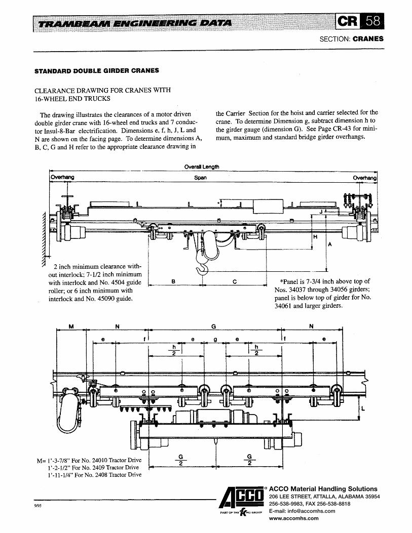
ACCO Material Handling Solutions206 LEE STREET, ATTALLA, ALABAMA 35954
256-538-9983, FAX 256-538-8818
E-mail: [email protected]
www.accomhs.com
STANDARD DOUBLE GIRDER CRANES
CLEARANCE DRAWING FOR CRANES WITH 16-WHEEL END TRUCKS
The drawing illustrates the clearances of a motor driven double girder crane with 16-wheel end trucks and 7 conductor Insul-8-Bar electrification. Dimensions e, f, h, J, Land N are shown on the facing page. To determine dimensions A, B, C, G and H refer to the appropriate clearance drawing in
SECTION: CRANES
the Carrier Section for the hoist and carrier selected for the crane. To determine Dimension g, subtract dimension h to the girder gauge (dimension G). See Page CR-43 for minimum, maximum and standard bridge girder overhangs.
Overall Length
I
out interlock; 7-1/2 inch minimum 2 inch minimum clearance with- L'
with interlock and No. 4504 guide B, __ ----<l....,... ___ ....:c:.__ __ ---..i
roller; or 6 inch minimum with interlock and No. 45090 guide.
M N
e
M= 1'-3-7/8" ForNo. 24010TractorDrive 1 '-2-1/2" For No. 2409 Tractor Drive 1 '-11-1/4" For No. 2408 Tractor Drive
G
e g e
G -r
-9,95 ------Acco® PART OF THE 'lc.FKI GROUP
H A
*Panel is 7-3/4 inch above top of Nos. 34037 through 34056 girders; panel is below top of girder for No. 34061 and larger girders.
N
e

ACCO Material Handling Solutions206 LEE STREET, ATTALLA, ALABAMA 35954
256-538-9983, FAX 256-538-8818
E-mail: [email protected]
www.accomhs.com
SECTION: CRANES
STANDARD DOUBLE GIRDER CRANES
CRANES WITH 16-WHEEL END TRUCKS
CRANES WITH 16-WHEEL END TRUCKS
Rated Design Crane Basic Overall Minimum Load Load Code Weight Span Length Runway e f h J L N
(Tons) (Lbs.) Number (Lbs.) (Ft.) (Ft.} Size
MW56D213X30 6707 28 30 34037 1'·3 3'-0 5'·6 2·118 1'-5·1/2 3'·1·1/4 MW61 D213X32 7351 30 32 34037 1'-3 3'-0 s·-6 2-1/8 1'-5-1/2 3'-1-1/4 MW61 D213X34 7612 32 34 34037 1'·3 3'-0 5'-6 2-118 1'-5-1/2 3'-1-1/4 MW61 D213X36 7864 34 36 34037 1'-3 3'-0 5'-6 2-1/8 1'-5-1/2 3'-1-1/4 MW66D213X38 8611 36 38 34037 1'-3 3'-0 5'-6 2-1/8 1'·5-1/2 3'-1-1/4 MW66D213X40 8897 38 40 34037 1'-3 3'-0 s·-6 2-1/8 1'-5-1/2 3'-1-114 MW71D213X42 10442 40 42 34037 1'-3 3'-0 5'-6 2-1/8 1'-5-1/2 3'-1-1/4 MW71D213X44 10787 42 44 34037 1'-3 3'-0 5'-6 2-1/8 1'-5-1/2 3'-1-1/4 MW71 D213X46 11134 44 46 34037 1'-3 3'-0 5'-6 2-1/8 1'-5-1/2 3'-1-1/4 MW71 D213X48 11469 46 48 34037 1'-3 3'-0 5'-6 2-1/8 1'-5-1/2 3'-1-1/4
15 41380 MW760213X50 12735 48 50 34037 1'-3 3'-0 5'-6 2-1/8 1'-5-1/2 3'-1-1/4 MW76D213X52 13116 50 52 34037 1'-3 3'-0 5'-6 2-1/8 '1 '-5-112 3'-1-1/4 MW760213X54 13509 52 54 34037 1'-3 3'-0 5'-6 2-1/8 1'-5-1/2 3'-1-1/4 MW770213X56 15762 54 56 34037 1'-3 3'-0 5'-6 2-1/8 2'-0 3'-1-1/4 MW770213X58 16189 56 58 34037 1'-3 3'-0 5'-6 2-118 2'-0 3'-1-1/4 MW78D213X60 18257 58 60 34037 1'-3 3'-0 5'-6 2-1/8 2'-0 3'-1-1/4 MW780213X62 18759 60 62 34037 1'-3 3'-0 5'-6 2-1/8 2'-0 3'-1-1/4 MW780213X64 19262 62 64 34037 1'-3 3'-0 5'-6 2-1/8 2'-0 3'-1-114 MW780213X68 19777 84 66 34037 1'-3 3'-0 5'-6 2-1/8 2'-0 3'-1-1/4 MW790213X68 22116 66 68 34037 1'-3 3'-0 5'-6 2-1/8 2'-0 3'-1-1/4 MW790213X70 22659 88 70 34037 1'-3 3'-0 5'-6 2-1/8 2'-0 3'-1-1/4 MW79D213X72 23243 70 72 34037 1'-3 3'·0 5'-6 2-1/8 2'-0 3'-1-1/4
-9,95 ------Acco®
, PART OF THE 'KFKI GROUP

ACCO Material Handling Solutions206 LEE STREET, ATTALLA, ALABAMA 35954
256-538-9983, FAX 256-538-8818
E-mail: [email protected]
www.accomhs.com
STANDARD DOUBLE GIRDER CRANES
WEIGHT FACTORS FOR DOUBLE GIRDER CRANES
The tables on this page and Page CR-61 are used in determining the total weight of double girder cranes. They list the weight of the top flange bracing, the weight of structural ties between the girders for cranes with 16-wheel end trucks and
End
Truck
Span Item
Number 6'-6 7'-0 7'·6 8'-0 8'-6 9'-0 180102 134 160 186 213 238 -180104 134 182 230 278 325 437 180205 134 182 230 278 325 437
Up to 180106 134 183 233 283 332 446 36'-0 180108 134 187 241 295 348 465
180209 134 186 236 288 338 453 180112 321 343 366 389 411 498 180113 321 343 366 389 411 498 180214 321 343 366 389 411 498 180102 163 191 219 248 275 180104 163 213 263 313 362 493 180205 163 213 263 313 362 493
36'-1 180106 163 214 266 318 369 502 to 180108 163 218 274 330 385 521
44'-0 180209 163 216 269 323 375 509 180112 350 374 399 424 448 554 180113 350 374 399 424 448 554 180214 350 374 399 424 448 554 180104 192 244 296 348 399 549 180205 192 244 296 348 399 549
44'-1 180106 192 245 299 353 406 558 to 180108 192 249 307 365 422 577
52'-0 180209 192 247 302 358 412 565 180112 379 405 432 459 485 610 180113 379 405 432 459 485 610 180214 379 405 432 459 485 610 180104 221 275 329 383 436 605 180205 221 275 329 383 436 605
52'-1 180106 221 2 332 388 443 614 to 180108 221 340 400 459 633
62'-Q 180209 221 278 335 393 449 621 180112 408 436 465 494 522 666 180113 408 436 465 494 522 666 180214 408 436 465 494 522 666
SECTION: CRANES
the additional weight of 4-wheel and 8-wheel end trucks when girder gauge is greater than 6'-6. The net crane weight is determined by adding the weight factor to the basic weight shown in the crane tables.
Gauge
9'-6 10'-0 10'-6 11'-0 11 '-6 12'-0 12'-6 13'-0 13'-6
- - - - - - - - -490 541 - - - - - - -490 541 - - - - - - -500 553 - - - - - - -523 580 637 693 980 1047 - -509 563 618 671 956 1021 1084 1149 1212 525 700 733 765 1029 1072 1114 1157 1199 525 700 733 765 1029 1072 1114 1157 1199 525 700 733 765 1029 1072 1114 1157 1199
- - - - - - - - -549 603 - - - - - - -549 603 - - - - - -559 615 - - - - - - -582 642 701 760 1106 1178 - - -568 625 682 738 1082 1152 1220 1290 1359 584 762 797 832 1155 1203 1250 1298 1346 584 762 797 832 1155 1203 1250 1298 1346 584 762 797 832 1155 1203 1250 1298 1346 608 665 - - - - - - -608 665 - - - - - - -618 677 - - - - - - -641 704 765 827 1232 1309 - - -627 687 746 805 1208 1283 1356 1431 1506 643 824 861 899 1281 1334 1386 1439 1493 643 824 861 899 1281 1334 1386 1439 1493 643 824 861 899 1281 1334 1386 1439 1493 667 727 - - - - - - -667 727 - - - - - - -677 739 - - - - - -700 766 829 894 1358 1440 - - -686 749 810 872 1334 1414 1492 1572 1653 702 886 925 966 1407 1492 1522 1580 1640 702 886 925 966 1407 1492 1522 1580 1640 702 886 925 966 1407 1492 1522 1580 1640
-9,95 ------Acco® ,
PART OF THE 'KFKI GROUP

ACCO Material Handling Solutions206 LEE STREET, ATTALLA, ALABAMA 35954
256-538-9983, FAX 256-538-8818
E-mail: [email protected]
www.accomhs.com
STANDARD DOUBLE GIRDER CRANES
End
Truck
Span Item
Number 6'-6 7'-0 7'-6 8-'0 8'-6 9'·0 180104 250 306 362 418 473 661 180205 250 306 362 418 473 661
62'-1 180106 250 307 365 423 480 670 to 180108 250 311 373 435 496 689
72'-0 180209 250 309 368 428 486 677 180112 437 467 498 529 559 722 180113 437 467 498 529 559 722 180214 437 467 498 529 559 722 180106 279 338 398 458 517 726
72'-1 180108 279 342 406 470 533 745 to 180209 279 340 401 463 523 733
82'-0 180112 466 498 531 564 596 778 180113 466 498 531 564 596 778 180214 466 498 531 564 596 778
82'-1 180108 308 373 439 505 570 801 to 180209 308 371 434 498 560 789
92'-0 180112 495 529 564 599 633 834 180113 495 529 564 599 633 834
92'-0 180108 337 404 472 540 607 857 to 180209 337 402 467 533 597 845
100'-0 180112 524 560 597 634 670 890 180113 524 560 597 634 670 890
DOUBLE GIRDER TRANSFER CRANES
Double girder transfer cranes are of the same design as standard double girder cranes with the addition of interlock mechanisms at one or both ends of the girder. Discharge points are installed at the ends of tracks where a carrier is to be transferred.
The interlocks and discharge points used on double girder transfer cranes are similar to those used on single girder cranes. The operation of double girder interlock mechanisms is the same as shown and described on Page CR-30 for single girder interlocks.
Forks are provided on interlock mechanisms and discharge points which raise to permit passage of the carrier when the interlock and discharge point are latched. When they are not latched, the forks prevent carriers from being accidentally run off the end of the girders or discharge tracks.
The throw-out mechanism actuates the interlock latch and may be manually or motor operated. Manually operated mechanisms are located on one of the girders and are operated by pull chains. Motor operated mechanisms are controlled by a push button station located on the carrier or crane.
SECTION: CRANES
WEIGHT FACTORS CONTINUED
Gauge
9'-6 10'-0 10'-6 11'-0 11'-6 12'-0 12'-6 13'-0 13'-6 726 - - - - - - - -726 - - - - - - - -736 - - - - - - - -759 828 893 961 1484 1571 - - -745 811 874 939 1460 1545 1628 1713 1800 761 948 989 1033 1533 1596 1658 1721 1787 761 948 989 1033 1533 1596 1658 1721 1787 761 948 989 1033 1533 1596 1658 1721 1787 795 - - - - -818 890 1028 - - - - -804 873 1006 1586 1676 1764 1854 1947 820 1010 1 1100 1659 1727 1794 1862 1934 820 1010 1 1100 1659 1727 1794 1862 1934 820 1010 1 1100 1659 1727 1794 1862 1934 877 952 1021 1095 - - - - -863 935 1002 1073 1712 1807 1900 1995 2094 879 1072 1117 1167 1785 1858 1930 2003 2081 879 1072 1117 1167 1785 1858 1930 2003 2081 936 1014 1085 1162 - - - - -922 997 1066 1140 1838 1938 2036 2136 2241 938 1134 1181 1234 1911 1989 2066 2144 2228 938 1134 1181 1234 1911 1989 2066 2144 2228
Two or more transfer cranes may be directly interlocked or interlocked through fixed transfer sections. Direct interlocking cranes have discharge points installed on one or both of the cranes depending on the number of cranes to be interlocked.
Double girder transfer cranes use Type I or Type III control arrangements as described on Pages CR-7 and CR-8. Type II control is not used as the control station is on the crane.
INTERLOCKS AND DISCHARGE POINTS
Three types of interlocking equipment are available: Type L interlocks and discharge points for carriers with 5 inch diameter wheels; Type H for carriers with 6-1/2 inch diameter wheels or less; and Type J for carriers with 8 inch diameter wheels or less. In laying out transfer crane systems, the same type of interlock and discharge point must be used throughout the system.
Interlock mechanisms are installed at one or both ends of
-9,95 ------Acco®
, PART OF THE 'KFKI GROUP
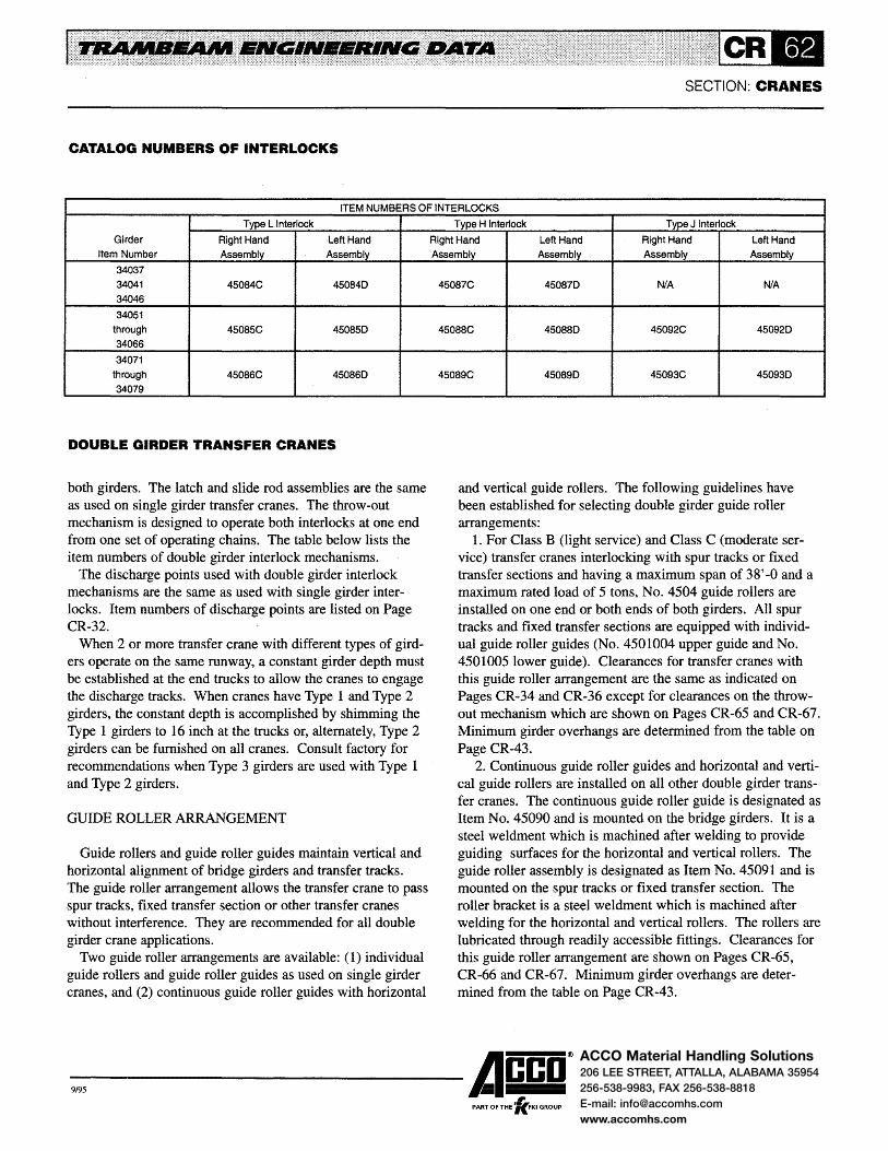
ACCO Material Handling Solutions206 LEE STREET, ATTALLA, ALABAMA 35954
256-538-9983, FAX 256-538-8818
E-mail: [email protected]
www.accomhs.com
SECTION: CRANES
CATALOG NUMBERS OF INTERLOCKS
ITEM NUMBERS OF INTERLOCKS
Type L Interlock
Girder Right Hand Left Hand
Item Number Assembly Assembly
34037
34041 45084C 450840
34046
34051
through 45085C 450850
34066
34071
through 45086C 450860
34079
DOUBLE GIRDER TRANSFER CRANES
both girders. The latch and slide rod assemblies are the same as used on single girder transfer cranes. The throw-out mechanism is designed to operate both interlocks at one end from one set of operating chains. The table below lists the item numbers of double girder interlock mechanisms.
The discharge points used with double girder interlock mechanisms are the same as used with single girder interlocks. Item numbers of discharge points are listed on Page CR-32~
When 2 or more transfer crane with different types of girders operate on the same runway, a constant girder depth must be established at the end trucks to allow the cranes to engage the discharge tracks. When cranes have Type 1 and Type 2 girders, the constant depth is accomplished by shimming the Type 1 girders to 16 inch at the trucks or, alternately, Type 2 girders can be furnished on all cranes. Consult factory for recommendations when Type 3 girders are used with Type 1 and Type 2 girders.
GUIDE ROLLER ARRANGEMENT
Guide rollers and guide roller guides maintain vertical and horizontal alignment of bridge girders and transfer tracks. The guide roller arrangement allows the transfer crane to pass spur tracks, fixed transfer section or other transfer cranes without interference. They are recommended for all double girder crane applications.
Two guide roller arrangements are available: (1) individual guide rollers and guide roller guides as used on single girder cranes, and (2) continuous guide roller guides with horizontal
Type H Interlock Type J Interlock
Right Hand Left Hand Right Hand Left Hand
Assembly Assembly Assembly Assembly
45087C 450870 N/A N/A
45088C 450880 45092C 450920
45089C 450890 45093C 450930
and vertical guide rollers. The following guidelines have been established for selecting double girder guide roller arrangements:
1. For Class B (light service) and Class C (moderate service) transfer cranes interlocking with spur tracks or fixed transfer sections and having a maximum span of 38'-0 and a maximum rated load of 5 tons, No. 4504 guide rollers are installed on one end or both ends of both girders. All spur tracks and fixed transfer sections are equipped with individual guide roller guides (No. 4501004 upper guide and No. 4501005 lower guide). Clearances for transfer cranes with this guide roller arrangement are the same as indicated on Pages CR-34 and CR-36 except for clearances on the throwout mechanism which are shown on Pages CR-65 and CR-67. Minimum girder overhangs are determined from the table on Page CR-43.
2. Continuous guide roller guides and horizontal and vertical guide rollers are installed on all other double girder transfer cranes. The continuous guide roller guide is designated as Item No. 45090 and is mounted on the bridge girders. It is a steel weldment which is machined after welding to provide guiding surfaces for the horizontal and vertical rollers. The guide roller assembly is designated as Item No. 45091 and is mounted on the spur tracks or fixed transfer section. The roller bracket is a steel weldment which is machined after welding for the horizontal and vertical rollers. The rollers are lubricated through readily accessible fittings. Clearances for this guide roller arrangement are shown on Pages CR-65, CR-66 and CR-67. Minimum girder overhangs are determined from the table on Page CR-43.
-9,95 ------Acco® ,
PART OF THE 'KFKI GROUP

ACCO Material Handling Solutions206 LEE STREET, ATTALLA, ALABAMA 35954
256-538-9983, FAX 256-538-8818
E-mail: [email protected]
www.accomhs.com
DOUBLE GIRDER TRANSFER CRANES
ELECTRIFIED TRANSFER CRANES
Insul-8-Bar's 90 amp conductor is the standard electrification for transfer cranes. Consult factory for assistance when other types of electrification are used. Transfer cranes generally are not electrified with festooned or tagline electrification.
The power conductor arrangement for transfer cranes is shown in the Electrification Section. The power conductors must be 6-1/8 inch above the tread for Type L interlocks, 7-3/4 inch for Type H interlocks and 9-1/8 inch for Type J interlocks to prevent interference with the latch.
The control conductors are not carried through the interlock gap eliminating the need for control conductors on spur tracks or fixed transfer sections. No. 550491 pickup guides and No. 450278 transfer caps are used at the ends of the control conductors to enable the collectors to leave and pick up the conductors as the carrier moves off and on the transfer crane. Carriers operating on transfer cranes use No. 560395 collectors for the power conductors and No. 560393 self-centering collectors for the control conductors.
All carriers operating on direct interlocking crane, cranes interlocking through fixed transfer sections or cranes interlocking at both ends with spur tracks require tandem collectors for the common conductor (X) and the mainline contactor conductor (M) to activate the mainline contactor as the transfer is made. The tandem collector arrangement requires 2 additional No. 560393 collectors.
ACCESSORY EQUIPMENT
Accessory equipment can be furnished on double girder transfer cranes to increase their flexibility and improve their operation. Some accessory equipment is furnished as standard and some are optional.
A limit switch is furnished on the throw-out mechanism as standard on transfer cranes interlocking with spur tracks or fixed transfer sections.
The switch interrupts the crane control circuit when the latch is extended and prevents the operator from moving the crane while it is latched to the discharge track.
When a system has 2 or more discharge tracks and 2 or more transfer cranes with Type I control, and auxiliary push button station may be installed on the crane for controlling the crane motion. This enables the operator to move the crane from one discharge track to another without the hoist
SECTION: CRANES
and carrier being on the crane. When transfer cranes are arranged for direct crane to crane
interlocking it may be desirable to have them travel as a unit when interlocked. This is accomplished by contacts at the ends of the cranes switch connect the crane control circuits. A limit switch disconnects the contacts when the cranes are not interlocked allowing the cranes to pass without connecting their control circuits. Other limit switch arrangements are used to prevent the crane from traveling when the latch is extended and the crane is not aligned with the other crane. Consult factory for information on limit switch arrangements, clearances and girder overhangs on all direct interlocking cranes.
MOTOR OPERATED INTERLOCKS
Motor operated interlocks can be furnished on all double girder transfer cranes as optional equipment. The latches and slide rod assemblies are the same as used on manually operated interlocks. The throw-out mechanism uses a gearmotor and roller chain drive to extend and retract the latches. A magnetic contactor is furnished for control of the gearmotor; limit switches control the movement of the latches and also interrupt the crane motion when the interlock is extended.
The interlock is controlled from 2 additional buttons in the carrier push button station (Type I control) or crane push button station (Type III control) or from an auxiliary push button station suspended from the crane. On cab operated systems, a push button is mounted in the cab. When controlled from the carrier, 2 additional control conductors are required for the crane electrification and 2 additional control collectors for the carrier.
When transfer cranes with motor operated interlocks are arranged for direct crane to crane interlocking, contacts to connect the crane control circuits may be required to meet the following conditions: ( 1 )control of the interlock from either of the 2 interlocked cranes; (2) cranes to travel as a unit when interlocked; and (3) the combination of conditions (1) and (2). When contacts are used, a limit switch is provided to disconnect the contacts when the cranes are not interlocked allowing the cranes to pass without connecting their control circuits. Other limit switches are provided to prevent the crane from traveling when latches are extended and the crane is not aligned with the other crane. Consult factory for information on limit switch arrangements, clearances and girder overhangs on all direct interlocking cranes where contacts are used.
-9,95 ------Acco®
, PART OF THE 'KFKI GROUP

ACCO Material Handling Solutions206 LEE STREET, ATTALLA, ALABAMA 35954
256-538-9983, FAX 256-538-8818
E-mail: [email protected]
www.accomhs.com
DOUBLE GIRDER TRANSFER CRANE CLEARANCES
SPUR TRACK ARRANGEMENT
The arrangement of a transfer crane interlocking with a spur track is shown in the drawing. Spur tracks interlocking with the transfer crane are equipped with discharge points and guide rollers.
Structural ties are required between the discharge tracks and crane runway. These ties maintain the gap between the ends of the discharge tracks and girders and permit the crane to pass the discharge tracks without interference. The ties may be bolted or welded to the top flange of the runway track. They are installed with the transfer crane latched to
OVERHANG
WALL OR 6~~' COLUMN (MINIMUM)
SECTION: CRANES
the spur and with a 3/16 inch gap between the ends of the discharge tracks and girders. When bolting, holes in runway tracks are field drilled.
The discharge tracks are supported from the building structure or steel superstructure adjacent to the structural ties. The structural ties are not designed to support the end of the discharge tracks.
Bracing of the discharge tracks is recommended to maintain alignment. The bracing is made in the field to suit the conditions and consists of steel angles installed perpendicular to the tracks. Bracing is installed after system has been aligned.
I *;(MINIMUM)
I
6 3'·0"' (STANDARD}--------Iil"'i
* 11-112 inch minimum with 5 inch wheel end trucks; 14 inch minimum with 6-112 inch or 8 inch wheel end trucks.
A
Interlock Type1 Type2 Type3 c D E F
Mechanism Girders Girders Girders
TypeL 1'-3-3/8 1'·6-7/8 2'-1-3/8 7-314 10-1/2 10·3/4 1'-2-5/8
TypeH 1'-3-3/8 1'-6-7/8 2'-1-3/8 10-318 1'-2-1/4 1'-0-1/2 1'-5-5/8
TypeJ N.A. 1'-6-7/8 2'-1-3/8 1'-1-118 1'-5-7/8 1'-1-7/8 1'-8-1/8
-9,95 ------Acco®
, PART OF THE 'KFKI GROUP

ACCO Material Handling Solutions206 LEE STREET, ATTALLA, ALABAMA 35954
256-538-9983, FAX 256-538-8818
E-mail: [email protected]
www.accomhs.com
DOUBLE GIRDER TRANSFER CRANE CLEARANCES
DIRECT CRANE TO CRANE INTERLOCK ARRANGEMENT
The arrangement of 2 direct interlocking transfer cranes is shown in the drawing. This arrangement is frequently used in an assembly bay area where operations on one side of the bay are different from those on the other side. It provides greater availability of the cranes and permits transfer of loads from one side of the bay to the other.
Consult factory for clearance dimensions when cranes are required to travel as a unit, as girder overhangs may have to be increased to accommodate the control contacts. Data on
SECTION: CRANES
desired control functions, girder and runway track sizes and type of end trucks are required to determine clearances.
Structural ties are required between adjacent runways. These ties maintain the gap between the ends of the girders and permit the cranes to pass without interference. They are located at the support point and intermediate points as required to maintain a tie spacing of not more than 1 0' -0 centers. The ties may be bolted or welded to the top flange of the runway tracks. They are installed with the cranes located directly under the tie and latched with a 3/16 inch gap between the ends of the girders. When bolting, holes in runway tracks are field drilled .
...---1'-2'7V'--.... -------CONTROL CONTACTS; CONSULT FACTORY ,--------+--------+--~;....._-------. FOR BRIDGE GIRDER OVERHANGS AND
Interlock
Mechanism
TypaL
TypeH
TypeJ
I
,..· /
E (TO STOP)
F (TO ClEAR)
C (TO STOP)
D (TO CLEAR,
OVERHANG----t~oo:I,.._..--OVERHANG--_.,..
A
Type 1 Type2 Type3 c Girders Girders Girders
1'-3-3/8 1'-6-7/8 2'-1-3/8 7-3/4
1'-3-3/8 1'-6-7/8 2'-1-3/8 10-3/8
N.A 1'-6-7/8 2'-1-3/8 1'-1-1/8
CRANE CLEARANCES.
D
10-1/2
1'-2-1/4
1'-5-7/8
-9,95 ------Acco® PART OF THE 'lc.FKI GROUP
E
10-3/4
1'-01/2
1'-1-7/8
l I
6
F
11-2-5/8
1'-5-5/8
1•-8-1!8

ACCO Material Handling Solutions206 LEE STREET, ATTALLA, ALABAMA 35954
256-538-9983, FAX 256-538-8818
E-mail: [email protected]
www.accomhs.com
DOUBLE GIRDER TRANSFER CRANE CLEARANCES
FIXED TRANSFER SECTION ARRANGEMENT
The arrangement of 2 transfer cranes interlocking with a fixed transfer section is shown in the drawing. This arrangement is used where transfer of loads from one bay to another is desired.
The transfer tracks are suspended from the adjacent runway tracks by structural supports. The supports maintain the gaps between the ends of transfer tracks and bridge girders and permit the cranes to pass the transfer tracks without interfer-
D (TO CLEAR)
SECTION: CRANES
ence. The supports may be bolted or welded to the top flange of the runway tracks. They are installed with the transfer cranes latched to the transfer tracks with 3/16 inch gaps between the ends of the transfer tracks and bridge girders. When bolting, holes in runway tracks are field drilled.
Bracing of the transfer tracks is recommended to maintain alignment. The bracing is made in the field to suit the conditions and consists of steel angles installed perpendicular to the tracks. Bracing is installed after system has been aligned.
I
OVERHANG .J {MINIMUM)---.....,...-OVERHANG 6 I
6 6" WAll OR 6* I
----+~---+--~:=.:.,_;:=...41-__::_-+---3'·0" (STANDARD)t-----...-1 (MINIMUM) COLUMN · (MINIMUM)
*11-1/2 inch minimum with 5 inch wheel end trucks; 14 inch minimum with 6-112 inch or 8 inch wheel end trucks.
A
Interlock Type1 Type2 TypeS c D J K
Mechanism Girders Girders Girders
Typel 1'-3-3/8 1 '-6-7/8 2'-1-3/8 7-3/4 10-1/2 2'-3-3/8 11-3/8
TypeH 1'-3-3/8 1'-6-7/8 2'-1-3/8 10-3/8 1'-2-1/4 2'-8-3/8 1'-4-1/8
TypeJ N.A. 1'-6-7/8 2'-1-3/8 1'-1-1/8 1'-5-7/8 3'-0-3/8 1'-8-1/8
-9,95 ------Acco® PART OF THE 'fc.FKI GROUP

ACCO Material Handling Solutions206 LEE STREET, ATTALLA, ALABAMA 35954
256-538-9983, FAX 256-538-8818
E-mail: [email protected]
www.accomhs.com
GANTRY CRANES
Trambeam gantry cranes are generally used where no building structure exists for support of the runway or where a single work area or group of work areas are to be serviced repetitively.
One of the more common applications is the installation of single leg gantry cranes in the same bay in which an overhead traveling crane operates. The gantry cranes, generally with a lighter rated load than the overhead crane, handle loads within their individual work area. The overhead crane handles loads in and out of individual work areas and heavy loads over the entire bay. This arrangement increases productivity by eliminating man-hours lost in waiting for crane service. It may also result in fewer overhead cranes being required and a lower initial investment.
Gantry cranes can have single or double leg construction depending on the availability of a structure to support the upper runway. Single leg construction is shown in the drawings on Pages CR-69 and CR-70; double leg construction is shown on Page CR -71. Gantry legs are supported on end trucks operating on ASCE crane rails. Single leg gantry cranes use Trambeam end trucks and runway tracks for the upper runway (See drawing on Page CR-69) or top running end trucks and runways with ASCE rails (See drawing on Page CR -70).
Girder construction can be single or double girder depending on the span, rated load and lift required. Single girder gantry cranes are shown on Pages CR-69 and CR-70; a double girder gantry is shown on Page CR-71.
Gantry cranes are generally motor driven but can be hand propelled or hand racked. Individual drives on each end truck are used on motor driven gantry cranes eliminating the need for a squaring shaft, vertical drive shaft and bevel gearing.
Specifications for bridge girders, girder connections, end trucks, drives, control and electrification are as follows:
e BRIDGE GIRDERS are fabricated from Trambeam heavy rail sections (No. 34037 through No. 34079). They are limited to a maximum carrier head load of 7,500 pounds. Girder deflection is limited to 11600 of the span for cranes having spans of 60' -0" or less. For spans greater than 60' -0", the ratio is reduced so that deflection does not exceed 1-1/4".
SECTION: CRANES
e GIRDER CONNECTIONS at the gantry leg are braced from the girder top flange to the gantry leg. Bolt holes in the bracing, top flange and leg are drilled and reamed in shop assembly. Turned bolts are used for bracing connections to maintain alignment. On single leg gantry cranes, standard girder connections are used for Trambeam end trucks; girder connections for top running end trucks use gusset plates between the trucks and girders and shelf angles welded to the girder web.
e END TRUCKS for gantry legs use double flanged, steel wheels, rotating axles and prelubricated, double row, roller bearings. Cartridge type bearings provide easy removal of wheel assemblies for maintenance or replacement. End trucks are designed to operate on 40 or 60 pound ASCE crane rails.
e DRIVES are located at each end truck. Gantry leg trucks are driven by double reduction, helical gear motoreducers. A roller chain final reduction is used between the motoreducer and the drive axle. The same drive is used for the upper truck of single leg gantry cranes when the upper runway has ASCE rails. Trambeam end trucks for single leg gantry cranes with a Trambeam upper runway are driven by No. 2408 or No. 2409 tractor drives. Motors are furnished with adjustable magnetic disc brakes.
e CONTROL PANELS and wiring comply with OSHA electrical standards and Section 610 of the National Electrical Code. Crane panels are furnished with fused motor circuit switch, mainline contactor, motor overcurrent protection, thermal overload relays in 3 phases and NEMA 12 dust-tight enclosure as standard.
e ELECTRIFICATION consists of Insul-8-Bar conductors as described in the Electrification Section. Standard conductor arrangements as shown on Pages CR -9 and CR -42 are used on single and double girder gantry cranes. Festooned electrification is also available.
The clearance drawings on Pages CR-68, CR-69 and CR-70 illustrate typical gantry crane arrangements. Many of the clearance dimensions are determined by the height of the leg, span and rated load. Consult factory for assistance in determining clearances as these dimensions are not readily cataloged.
-9,95 ------A~co® PART OF THE 'KFKI GROUP

ACCO Material Handling Solutions206 LEE STREET, ATTALLA, ALABAMA 35954
256-538-9983, FAX 256-538-8818
E-mail: [email protected]
www.accomhs.com
GANTRY CRANES
CLEARANCE DRAWING SINGLE LEG, SINGLE GIRDER GANTRY CRANE
~Ov-e-men---g-----------------Ovendl~g~------------------~Ov-~~~
~~~-------------------8~------------------~----~~
1 ' .. 1%11
Roor
*Panel is 7-3/4 inch above top of Nos. 34037 through 34056 girders. Panel is below top of girder for No. 34061 and larger girders. ·
-9,95 ------Acco®
, PART OF THE 'KFKI GROUP
SECTION: CRANES
2 inch minimum clearance without interlock or 7-1/2 inch minimum with interlock and guide roller.

ACCO Material Handling Solutions206 LEE STREET, ATTALLA, ALABAMA 35954
256-538-9983, FAX 256-538-8818
E-mail: [email protected]
www.accomhs.com
SECTION: CRANES
GANTRY CRANES
CLEARANCE DRAWING SINGLE LEG, SINGLE GIRDER GANTRY CRANE
~----------------------Ove~llen~--------------------~ Overhang ~~~---------------------~----------------------~~
1'-1%"
Floor
*Panel is 7-3/4 inch above top of Nos. 34037 through 34056 girders. Panel is below top of girder for No. 34061 and larger girders.
-9,95 ------Acco® PART OF THE 'lc.FKI GROUP
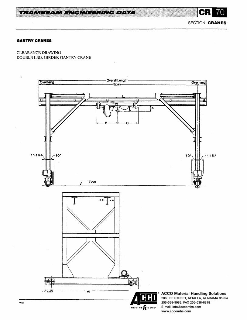
ACCO Material Handling Solutions206 LEE STREET, ATTALLA, ALABAMA 35954
256-538-9983, FAX 256-538-8818
E-mail: [email protected]
www.accomhs.com
SECTION: CRANES
GANTRY CRANES
CLEARANCE DRAWING DOUBLE LEG, GIRDER GANTRY CRANE
~ev~.~~~~----------~------Ovwd~ngffi----------------------~~~~ ~~~---------------------8~----------------------------~~
1 '·1 %"
•••• 181
~~ ~~6 w
-9,95 ------Acco®
, PART OF THE 'KFKI GROUP

ACCO Material Handling Solutions206 LEE STREET, ATTALLA, ALABAMA 35954
256-538-9983, FAX 256-538-8818
E-mail: [email protected]
www.accomhs.com
GENERAL INFORMATION
When there is frequent operation of a carrier or a crane or travel distances are long, motor driven equipment will increase the efficiency of a system by enabling the operator to do more work in less time, with greater accuracy and less fatigue. The additional cost for motor driven equipment will usually pay for itself in a short period of time. Motor driven equipment will also improve employee morale.
Tractor drives propel all motor driven Trambeam carriers and cranes except double girder carriers. Double girder carriers are propelled by modified tractor drives. Traction on all drives is obtained by polyurethane.drive wheels bearing against the bottom of the track. Pressure is applied to the drive wheels by compression springs and is adjustable to provide the necessary traction to propel the unit.
Three tractor drives are available to meet a wide range of applications. All are satisfactory for class A, B, C and D service. They are available with a variety of motors and control systems. Descriptions of the control equipment and systems are provided on Pages TD-1 0 and TD-11.
Specifications and arrangement drawings for each drive are described and illustrated on subsequent pages.
DRIVE WHEELS
Drive wheels for all drives are polyurethane covered. The polyurethane covering combines hardness, resilience and abrasion resistance to provide a superior traction wheel. It has exceptional wear characteristics, high tensile and tear strengths and a high load rating. The tensile and tear strength characteristics contribute to the excellent wearing qualities of the wheel. The high load rating allows high drive wheel pressures. The combination of high drive wheel pressures and high coefficient of friction results in a tractive effort that is double that of comparable steel drive wheels.
All drive wheels have cast iron hubs. The polyurethane covering is machined after it is applied to the wheel for concentricity of the outside diameter and bore. Wheels are keyed to the drive shaft.
SECTION: TRACTOR DRIVES
MOTORS
Motors are crane-hoist type with high slip, high torque characteristics. Class B insulation is furnished as standard on Nos. 2409 and 24010 drives; Class F insulation is standard on No. 2408 drives . Special insulations are available where high ambient temperatures are present or where indicated by the service. Motors are designed for operation on 3 phase, 60 hertz, 230 or 460 volts alternating current as standard; they can be supplied for operation on other current characteristics.
All drives are furnished with totally enclosed, non-ventilated (TENV) motors. TENV motors are rated 30 minutes, 55 Degree C rise above an ambient temperature of 40 Degree C. They are suitable for indoor and outdoor applications and where excessive moisture, vapor, dust, etc. are present.
Squirrel cage motors are used with single speed and adjustable frequency control systems. Multi-speed squirrel cage motors are used with 2-speed control systems. Wound rotor motors are also available and are used with variable speed control systems.
Motor horsepower requirements are listed on Pages TD-8 and TD-9. Page TD-8 lists the horsepower requirements for single motor drives. Page TD-9 lists the horsepower requirements for dual motor drives.
BRAKES
Brakes are available for all motors. They are magnetic disc type and can be furnished as holding or parking brakes. Holding brakes are effective when power to the motors is off; parking brakes are effective only when power is shut off by the mainline contactor. ANSI B30.ll Safety Standards require holding brakes for cab, remote, automatic, pulpit or radio controlled equipment. Holding brakes are not required or recommended for floor controlled equipment as the motors and control systems are designed for plugging service.
Brakes are usually sized for 50% of full load motor torque. Brakes are required for drives operating on monorails with grades and are sized to stop and hold the carrier on the grade.
-9,95 ------Acco®
, PART OF THE 'KFKI GROUP

ACCO Material Handling Solutions206 LEE STREET, ATTALLA, ALABAMA 35954
256-538-9983, FAX 256-538-8818
E-mail: [email protected]
www.accomhs.com
NO. 2408 TRACTOR DRIVE
No. 2408 tractor drives are powered by NEMA D flanged mounted motors driving through fully enclosed double reduction gearing to 10 in. diameter polyurethane drive wheels. Gearing operates in an oil bath. Traction is obtained by the drive wheel bearing against the bottom of the track. Pressure is applied by two compression springs and is adjustable.
Parallel links connect the drive assembly to the 4-wheel carrier assembly and transmit the motor torque directly to the 4-wheel assembly instead of adding to or subtracting from the drive wheel pressure. This results in the drive producing the same draw bar pull for both directions of travel.
These drives are available with 112 through 5 horsepower motors. Nominal speeds are 100, 150,200, 250 and 300
1 1/16"
SECTION: TRACTOR DRIVES
FPM; other speeds can be furnished. They are available with squirrel cage motors and single speed solid state or variable frequency control, multi-speed squirrel cage motors and 2-speed solid state control, and wound rotor motors and variable speed controL Other motor and control systems are available for special applications.
No. 2408J drives are used on all applications except where conductors are at 6-1/8 in. elevation. No. 2408K drives are used where conductors are at 6-1/8 in. elevation.
The drawing provides maximum clearance dimensions for drives without control panels. Consult factory for dimensions of control panels.
5
1 '-8 1/8"
-9,95 ------Acco®
, PART OF THE 'KFKI GROUP

ACCO Material Handling Solutions206 LEE STREET, ATTALLA, ALABAMA 35954
256-538-9983, FAX 256-538-8818
E-mail: [email protected]
www.accomhs.com
NO. 2409 TRACTOR DRIVE
No. 2409 tractor drives are powered by NEMA C face mounted motors driving through double reduction helical gear reducers and a roller chain final reduction to 6 in. diameter polyurethane drive wheels. Traction is obtained by the drive wheel bearing against the bottom of the track. Pressure is applied by a compression spring and is adjustable.
These drives are available with 1/2, 3/4, 1 and 1-1/2 horsepower motors. Nominal speeds are 100, 125, 150 and 200 FPM; slower speeds can be furnished. Drives with 1-1/2
1/2" PIN\
3 3/8"
11/ 18"
1/16" 7
SECTION: TRACTOR DRIVES
HP motors are available for 150 and 200 FPM only. They are available with squirrel cage motors and single speed solid state or variable frequency control and multi-speed squirrel cage motors and 2-speed solid state control.
The drawing provides maximum clearance dimensions. The dotted lines indicate the single speed control panel location for single girder carriers. Consult factory for dimensions of variable frequency and 2-speed control panels.
1 '-8
2'-7 11/ 16"
6"
WITH BRAKE 6"
-9,95 ------Acco® PART OF THE 'lc.FKI GROUP

ACCO Material Handling Solutions206 LEE STREET, ATTALLA, ALABAMA 35954
256-538-9983, FAX 256-538-8818
E-mail: [email protected]
www.accomhs.com
NO. 24010 TRACTOR DRIVE
No. 24010 tractor drives are powered by NEMA C face mounted motors driving through single reduction worm gear reducers to 6 in. diameter polyurethane drive wheels mounted on the output shaft of the reducers. Traction is obtained by the drive wheel bearing against the bottom of the track. Pressure is applied by compression spring and is adjustable.
These drives are available with 1/2, 3/4 and 1 horsepower motors. Nominal speeds are 55 and 90 PPM; slower speeds can be furnished. Drives with 1 HP motors are available for 90 FPM only. They are available with squirrel cage motors and single speed solid state or variable frequency control and
2'-7 11/16"
SECTION: TRACTOR DRIVES
multi-speed squirrel cage motors and 2-speed solid state control.
The drawing provides maximum clearance dimensions. The dotted lines indicate the single speed control panel location for single girder carriers. Consult factory for dimensions of variable frequency and 2-speed control panels.
IMPORTANT: 24010 drives cannot be used on monorails with switches due to inteiference between the worm gear reducer and switch frame.
4"
11/16"
1 '·-5
-9,95 ------Acco®
, PART OF THE 'KFKI GROUP
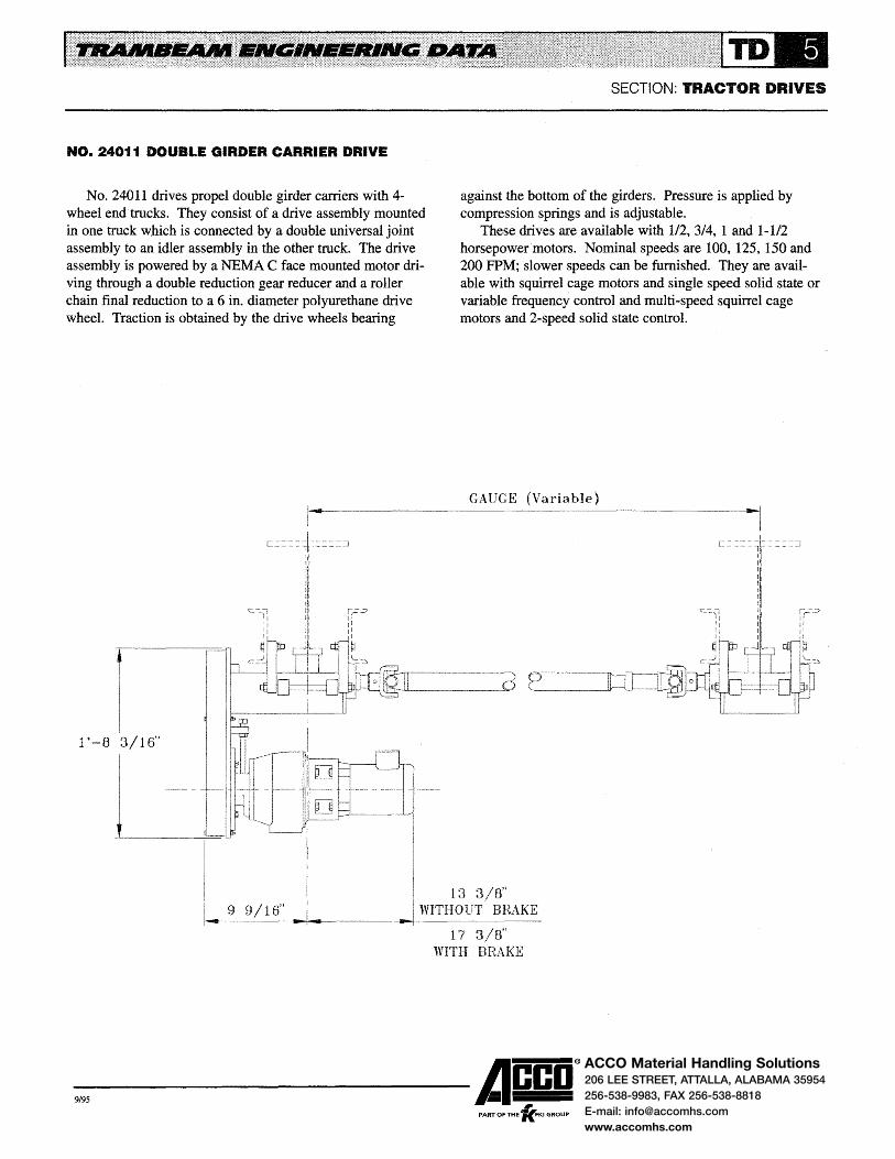
ACCO Material Handling Solutions206 LEE STREET, ATTALLA, ALABAMA 35954
256-538-9983, FAX 256-538-8818
E-mail: [email protected]
www.accomhs.com
NO. 24011 DOUBLE GIRDER CARRIER DRIVE
No. 24011 drives propel double girder carriers with 4-wheel end trucks. They consist of a drive assembly mounted in one truck which is connected by a double universal joint assembly to an idler assembly in the other truck. The drive assembly is powered by a NEMA C face mounted motor driving through a double reduction gear reducer and a roller chain final reduction to a 6 in. diameter polyurethane drive wheel. Traction is obtained by the drive wheels bearing
1 '-8 3/16"
SECTION: TRACTOR DRIVES
against the bottom of the girders. Pressure is applied by compression springs and is adjustable.
These drives are available with 1/2, 3/4, 1 and 1-1/2 horsepowermotors. Nominal speeds are 100, 125, 150 and 200 FPM; slower speeds can be furnished. They are available with squirrel cage motors and single speed solid state or variable frequency control and multi-speed squirrel cage motors and 2-speed solid state control.
GAUGE
-9,95 ------Acco® PART OF THE 'lc.FKI GROUP

ACCO Material Handling Solutions206 LEE STREET, ATTALLA, ALABAMA 35954
256-538-9983, FAX 256-538-8818
E-mail: [email protected]
www.accomhs.com
SECTION:TRACTOR DRIVES
NO. 24016 AND NO. 24017 DOUBLE GIRDER CARRIER DRIVES
No. 24016 drives propel double girder carriers with eight 6-1/2 in. diameter wheel end trucks. No. 24017 drives propel double girder carriers with 4-wheel end trucks where horsepower requirements exceed the rating of No. 24011 drives. Two drives are used - one mounted in each end truck. Each drive is powered by a NEMA C face mounted motor driving through a double reduction helical gear reducer and a roller chain final reduction to a 6 in. diameter polyurethane drive wheel. Traction is obtained by the drive wheels bearing
against the bottom of the girders. Pressure is applied by compression springs and is adjustable.
These drives are available with 112, 3/4, 1 and 1-1/2 horsepower motors. Nominal speeds are 100, 125, 150 and 200 FPM; slower speeds can be furnished.
Drives with 1-1/2 horsepower motors are available for 150 and 200 FPM only. They are available with squirrel cage motors and single speed solid state or variable frequency control and multi-speed squirrel cage motors and 2-speed solid state control.
1 '-8 16"
-9,95 ------Acco®
, PART OF THE 'KFKI GROUP

ACCO Material Handling Solutions206 LEE STREET, ATTALLA, ALABAMA 35954
256-538-9983, FAX 256-538-8818
E-mail: [email protected]
www.accomhs.com
NO. 24012 HAND RACKED TRACTOR DRIVE
No. 24012 hand racked tractor drives are used when operation of a carrier is infrequent and travel distances are short. They are propelled by a hand chain and chain wheel; a roller chain reduction is provided between the chain wheel shaft and drive wheel shaft. These drives have 6 in. diameter
SECTION: TRACTOR DRIVES
polyurethane covered drive wheels. Traction is obtained by the drive wheel bearing against the bottom of the track. Pressure is applied by compression springs and is adjustable.
-9,95 ------Acco® PART OF THE 'lc.FKI GROUP

ACCO Material Handling Solutions206 LEE STREET, ATTALLA, ALABAMA 35954
256-538-9983, FAX 256-538-8818
E-mail: [email protected]
www.accomhs.com
SECTION:TRACTOR DRIVES
HORSEPOWER REQUIREMENTS • SINGLE MOTOR DRIVES
The table lists the maximum total load that a single motor drive at a particular horsepower and speed is capable of moving. Nos. 24010, 2409 and 2408 drives are used for propelling single girder carriers; the No. 24011 drive is used for propelling double girder carriers. The efficiency of the drives has been considered in determining the horsepower.
The total load consists of the rated load and the weights of
the hoist, carrier and accessory equipment (when used). The impact allowance is not considered in determining the total load. After determining the total load and knowing the carrier speed and the type of drive to be used, the motor horsepower of the drive is selected from the table. When the total load falls between those shown in the table, select the greater horsepower.
Horsepower Required
1/2HP 3/4HP 1 HP 1-1/2 HP 2HP 3HP
Speed Maximum Load
(FPM) No. 24010 Drive
55 11,200 16,800 N.A. N.A. N.A. N.A.
90 8,000 12,000 16,000 N.A. N.A. N.A.
No. 2409 Drive
100 9,400 14,100 18,800 N.A. N.A. N.A.
125 7,500 11,300 15,000 i N.A. N.A. N.A.
150 6,200 9,400 12,500 18,800 N.A. N.A.
200 N.A. 7,000 9,400 14,100 N.A. N.A.
No. 2408 Drive
100 9,400 14,100 18,800 28,200 37,700 N.A.
150 6,200 9,400 12,500 18,800 25,100 37,700
200 N.A. 7,000 9,000 14,100 18,800 28,200
250 N.A. N.A. 7,500 11,300 15,000 22,600
300 N.A. N.A. 6,200 9,400 12,500 18,800
No. 24011 Drive
100 9,400 14,100 18,800 28,200 N.A. N.A.
125 7,500 11,300 15,000 22,600 N.A. N.A.
150 6,200 9,400 12,500 18,800 N.A. N.A.
200 N.A. 7,000 9,400 14,100 N.A. N.A.
-9,95 ------Acco®
, PART OF THE 'KFKI GROUP
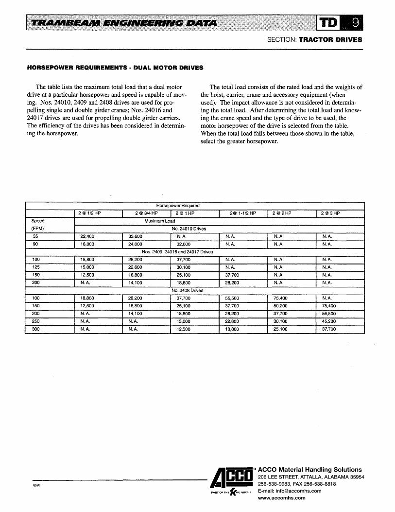
ACCO Material Handling Solutions206 LEE STREET, ATTALLA, ALABAMA 35954
256-538-9983, FAX 256-538-8818
E-mail: [email protected]
www.accomhs.com
SECTION: TRACTOR DRIVES
HORSEPOWER REQUIREMENTS • DUAL MOTOR DRIVES
The table lists the maximum total load that a dual motor drive at a particular horsepower and speed is capable of moving. Nos. 24010, 2409 and 2408 drives are used for propelling single and double girder cranes; Nos. 24016 and 24017 drives are used for propelling double girder carriers. The efficiency of the drives has been considered in determining the horsepower.
Horsepower Required
2@ 1/2HP 2@ 3/4HP 2@ 1 HP
Speed Maximum load
The total load consists of the rated load and the weights of the hoist, carrier, crane and accessory equipment (when used). The impact allowance is not considered in determining the total load. After determining the total load and knowing the crane speed and the type of drive to be used, the motor horsepower of the drive is selected from the table. When the total load falls between those shown in the table, select the greater horsepower.
2@ 1-1/2 HP 2@2HP 2@3HP
(FPM) No. 24010 Drives
55 22,400 33,600 N.A. I N.A. N.A. N.A.
90 16,000 24,000 32,000 N.A. N.A. N.A.
Nos. 2409,24016 and 24017 Drives
100 18,800 28,200 37,700 N.A. N.A. N.A.
125 15,000 22,600 30,100 N.A. N.A. N.A.
150 12,500 18,800 25,100 37,700 N.A. N.A.
200 N.A. 14,100 18,800 28,200 N.A. N.A.
No. 2408 Drives
100 18,800 28,200 37,700 56,500 75,400 N.A.
150 12,500 18,800 25,100 37,700 50,200 75,400
200 N.A. 14,100 18,800 28,200 37,700 56,500
250 N.A. N.A. 15,000 22,600 30,100 45,200
300 N.A. N.A. 12,500 18,800 25,100 37,700
-9,95 ------Acco® PART OF THE 'lc.FKI GROUP

ACCO Material Handling Solutions206 LEE STREET, ATTALLA, ALABAMA 35954
256-538-9983, FAX 256-538-8818
E-mail: [email protected]
www.accomhs.com
CONTROL EQUIPMENT
Control equipment for motor driven Trambeam carriers and cranes consists of an operating station and a control system for the drive motors. The operating station may be a push button station for floor or remote controlled equipment, a transmitter for radio or infrared controlled equipment or master switches for cab controlled equipment. Many types of motor control systems are available with selection depending on type of service, weight and size of load, speeds and precision required in handling.
Three control systems have been designed specifically for Trambeam carriers and cranes - single speed solid state, 2-speed solid state and adjustable frequency. These systems are satisfactory for most applications. Other control systems for special applications are also available.
SINGLE SPEED SOLID STATE MOTOR CONTROL
Single speed motor controls use solid state components for electronic control of squirrel cage motors. It is the most frequently used control for Trambeam carriers and cranes and is recommended for speeds to 200 FPM.
The control supplies a balanced 3 phase, reduced voltage (initial torque) to the motor. The voltage is increased over a preset acceleration time thus gradually applying torque to the motor. The gradual increase of torque provides smooth acceleration which is repeatable under varying load conditions.
Adjustments are provided for setting the initial torque and the time it takes the control to pass full line voltage to the motor. Adjustments are simple to make requiring only a screwdriver.
2-SPEED SOLID STATE MOTOR CONTROL
2-Speed motor controls use solid state components for electronic control of multi-speed squirrel cage motors. It is used where precision spotting of heavier loads is required and
SECTION: TRACTOR DRIVES
is recommended for speeds to 250 FPM. The control is available with 2 to 1 and 3 to 1 ratios of the high to the low speeds.
The control supplies a balanced 3 phase, reduced voltage (initial torque) to either the low or high speed motor winding depending on which speed is selected by the operator. The voltage is increased over a preset acceleration time thus gradually applying torque to the motor. The gradual increase of torque provides smooth acceleration which is repeatable under varying load conditions.
The control switches to a deceleration mode when the motor is switched from high to low speed. In the deceleration mode, reduced voltage is applied to the low speed winding for approximately 2 seconds thereby reducing the motor countertorque. The voltage then increases to full voltage at the rate determined by the time adjustment setting. The deceleration mode provides smooth transition from high to low speed.
Adjustments are provided for setting the initial torque and the time it takes for the control to pass full line voltage. Time adjustments are provided for the acceleration and deceleration modes. Adjustments are simple to make requiring only a screwdriver.
ADJUSTABLE FREQUENCY MOTOR CONTROL
Adjustable frequency motor controls use solid state components for electronic control of squirrel cage motors. It is used to position delicate loads at precise creep speeds. The control provides a 12 to 1 ratio between the high and low speeds. It can be arranged for l, 2 or 3 speeds; speeds can be changed at any time with a built-in potentiometer which allows any speed to be dialed in between 5 and 60 hertz. The control provides smooth acceleration and deceleration, electronic reversing and speed selection and electronic dynamic braking. Consult factory for additional information on specific applications.
-9,95 ------Acco® PART OF THE 'fc.FKI GROUP

ACCO Material Handling Solutions206 LEE STREET, ATTALLA, ALABAMA 35954
256-538-9983, FAX 256-538-8818
E-mail: [email protected]
www.accomhs.com
CONTROL EQUIPMENT
OSHA AND NEC ELECTRICAL STANDARDS
The electrical diagrams on Pages TD-12 and TD-13 illustrate the requirements of the Occupational Safety and Health Act (OSHA) and National Electric Code (NEC) standards. Control panels for Trambeam carriers and cranes comply with these standards.
CONTROL EQUIPMENT
Crane control panels include the following mandatory devices as standard equipment:
eFused motor switch arranged to be locked in the OFF position.
eMainline contactor operated from the crane operating station to open the power circuit to all motors.
eBranch circuit overcurrent protection for the crane motors.
eTbennal overloads in 3 phases for motor running over current protection.
Carrier control panels have branch circuit overcurrent protection for the carrier motor and thermal overloads in 3 phases for motor running overcurrent protection as standard. Most monorail carriers also require a motor circuit switch and a mainline contactor.
The National Electric Code requires that monorail carriers and hand propelled cranes with electric hoists be provided with a motor circuit switch. A mainline contactor is also required when the motor circuit switch is not readily accessible from the operating station. An exception to this requirement is allowed where the installation meets all of the following:
SECTION: TRACTOR DRIVES
1. The unit is floor controlled. 2. The unit is within view of the power supply discon
necting means. 3. No fixed platform has been provided for servicing the
unit. Motor circuit switches can be provided on hand propelled
carriers and cranes and on motor driven carriers where the installation does not meet the conditions stated above. A mainline contactor, when required, can be provided on motor driven carriers; but it is usually provided on the hoist.
CONTROL PANELS AND WIRING
NEMA 12 dust-tight enclosures are furnished as standard for carrier and crane control panels. Special enclosures are available for outdoor applications or where corrosive or explosive vapors or dust are present.
Internal wiring of crane control panels terminates at a terminal block to facilitate field maintenance.
All crane wiring is installed in rigid conduit except at the connections to the control panel and drive motors. At these connections, wiring is installed in flexible liquid-tight metal conduit. Junction boxes, conduit and flexible conduit are compatible with the NEMA 12 control panel.
CURRENT CHARACTERISTICS
Motor driven equipment is furnished for operation on 3 phase, 60 hertz, 230 or 460 volts alternating current with 115 volts in the control circuit. Equipment can be furnished to operate on alternating current with other characteristics or on direct current.
-9,95 ------Acco® PART OF THE 'lc.FKI GROUP

ACCO Material Handling Solutions206 LEE STREET, ATTALLA, ALABAMA 35954
256-538-9983, FAX 256-538-8818
E-mail: [email protected]
www.accomhs.com
ELECTRICAL DIAGRAM • MOTOR DRIVEN CRANE
Runway Conductor Disconnecting ------------+--......,. Means (NEC 610-31)
Overcurrent Protection ----------------+--...! (NEC 610-41)
Crane Disconnecting Means -----------+-__.,. (NEC 610-32)
Overcurrent Protection -------------+---+ (NEC 610-41)
Mainline Contactor; Mandatory Where Crane Disconnecting Means Not Readily Accessible From Operating Station (NEC 610-32)
Branch Circuit Overcurrent ------'--------+--. Protection (NEC 610-42)
Motor Control
Motor Running Overcurrent Protection; Not Mandatory Where Protected By Branch Circuit Overcurrent Device (NEC 610-43)
Mandatory
Optional
Mandatory Generally Furnished By Customer
Crane Motors
SECTION:TRACTOR DRIVES
Runway Conductors
Crane Conductors
I
I I I
Carrier Motor
I
I I
Hoist Motor
Hoist Brake
-9,95 ------Acco® PART OF THE 'fc.FKI GROUP

ACCO Material Handling Solutions206 LEE STREET, ATTALLA, ALABAMA 35954
256-538-9983, FAX 256-538-8818
E-mail: [email protected]
www.accomhs.com
SECTION: TRACTOR DRIVES
ELECTRICAL DIAGRAM • MOTOR DRIVEN MONORAIL CARRIER
Monorail '-'Vl.luu;~.-~.vl Di~;coJnne:cttJag------------+--+ Means (NEC 610-31)
Overcurrent Protection ----------------+--__,..! (NEC 610-41) / Monorail Conductors
--------~~--~.------------
Monorail Disconnecting Me~nmr-------------;-...,. (NEC 610-32)
Overcurrent Protection -----------...........;.......,.. (NEC 610-41)
Mainline Contactor; Mandatory Where Monorail Disconnecting Means Not Readily Accessible From Operating Station (NEC 610-32)
Branch Circuit Overcurrent -----------+-......,. Protection (NEC 61 0-42)
Motor Control -----------------;__...
Motor Running Overcurrent Protection; Not Mandatory Where Protected By Branch Circuit Overcurrent Device (NEC 610-43)
Mandatory
Optional
Mandatory Generally Furnished By Customer
Carrier Motor Hoist Motor
Hoist Brake
-9,95 ------Acco® PART OF THE 'lc.FKI GROUP
N 0 T E:
Monorail Disconnecting Means May Be Omitted Where Installation Meets All Of The Following (NEC 610-32 Exception) a) The Unit Is Floor Controlled. b} The Unit Is Within View Of
The Power Supply Disconnecting Means.
c) No Fixed Work Platform Has Been Provided For Servicing The Unit.

ACCO Material Handling Solutions206 LEE STREET, ATTALLA, ALABAMA 35954
256-538-9983, FAX 256-538-8818
E-mail: [email protected]
www.accomhs.com
GENERAL INFORMATION
The track system is an important factor in the success of underhung crane and monorail applications. It must be capable of supporting the load and also provide long life and the flexibility to meet facilities change. Trambeam track system meets these criteria.
Trambeam track is a composite section featuring: e A rail section of high strength alloy steel in combination
with top flange and web plates of mild steel. The rail and top flange plate are continuously and automatically welded to the web plate.
e The lower load carrying flange of the rail section is rolled to close tolerances and has a flat, raised running surface resulting in less friction and longer track and wheel life.
e A 3-1/4 in. uniform width of the load carrying flange is maintained regardless of the load or depth of track. This permits interchangeability of carriers and provides an efficient and economical overall system.
Trambeam tracks are manufactured using various thicknesses and widths of top flange and web plates and two rail sections. Light rail sections have a 7/16 in. thick load carrying flange. Heavy rail sections have an 11/16 in. thick load carrying flange.
Track and suspension fittings are selected from the data on Page TT-5.
STANDARD TRACK SECTIONS
Eighteen sizes of track are cataloged for runway and monorail tracks and bridge girders. They are satisfactory for most applications. The dimensions and properties for these sections are shown on Pages TT-2, TT-3 and TT-4. Rated load tables are on Pages TT-12, TT-13, TT-14 and TT-15.
OPTIMUM TRACK SECTIONS
Optimum track sections are those where the design criteria are at the allowable maximums and the design is balanced. In most applications standard track sections provide a balanced design; however, because they are cataloged for a wide
SECTION: TRACK & FITTINGS
range of spans, this is not always possible. Where standard track sections are not in balance and the quantity of track warrants an investigation, a computer program is available for optimizing track design.
The program designs the section by tailoring the top flange plate and track height for a specific load and span. It removes unnecessary steel resulting in a weight savings per foot of track and a more economical track system. The program is generally used to design heavy rail sections. It may also be used to design light rail sections for spans longer than cataloged when carrier head loads are relatively light. Consult factory for additional information on optimum track sections and for specific applications.
FLEXIBLE SUSPENSION
Flexible suspension is recommended for all track systems to provide longer track and wheel life and smoother operation. Two types are available. A gimbal suspension system is used for loads up to 40,000 pounds. A bushing system is used for loads in excess of 40,000 pounds.
The gimbal suspension system uses multiplane washers at each end of the hanger rod to provide a gimbal effect that allows free rod movement of 6 degrees in any direction. Hanger rods have rolled threads with the lower nut factory assembled to the rod. The upper nut is adjustable and allows for leveling of the track. A complete description of the gimbal system is provided on Page TT-18.
The bushing suspension system uses spherical thrust bushing at each end of the hanger rod to provide a free rod movement of 6 degrees in any direction. The bushings are basically a spherical ball and socket configuration and are ground, hardened and coated with a dry film lubricant. A complete description of the bushing suspension system is provided on Page TT-19.
Flexibly suspended track systems are laterally and longitudinally braced to limit sway of the hanger rods. Bracing is installed after the track has been aligned and leveled. Additional information on bracing is provided on Page TT-20.
-9,95 ------Acco®
, PART OF THE 'KFKI GROUP

ACCO Material Handling Solutions206 LEE STREET, ATTALLA, ALABAMA 35954
256-538-9983, FAX 256-538-8818
E-mail: [email protected]
www.accomhs.com
8 @ 17.0 5

ACCO Material Handling Solutions206 LEE STREET, ATTALLA, ALABAMA 35954
256-538-9983, FAX 256-538-8818
E-mail: [email protected]
www.accomhs.com
HEAVY RAIL SECTIONS
No. 34037 and Nos. 34041 through 34066 heavy rail sections are used for runway and monorail tracks and bridge girders. No. 34038 sections are used for monorail curves. Dimensions and section properties are shown in the tables.
11/16"
Item Nominal Size
Number and Weight
34037 12·1/2@ 33.6
"'34038 12-1/2@ 30.2
34041 14 @38.5
34046 16 @42.7
34051 18 @50.3
34056 20 @55.0
34061 22-1/2@ 61.4
34066 [email protected]
Item Maximum Area
Number Wheel Dia. (ln.) (ln.X2)
34037 9.888
*34038 8.888
34041 11.318
34046 8 12.568
34051 14.802
34056 16.177
34061 18.052
34066 19.927
SECTION: TRACK & FITTINGS
No. 34037 and Nos. 34041 through 34056 tracks are manufactured in stock lengths of 41, 50 and 60 feet. Nos. 34061 and 34066 tracks are manufactured to order. They are cut to length and fabricated in any length up to 60 feet maximum.
A B c D
12-9/16 8 1/2 5/16
12-9/16 6 112 5/16
14-1/16 8 5/8 5116
16-1/16 9 5/8 5/16
18-1/16 10 5/8 3/8
20-1/16 11 5/8 3/8
22-9/16 12-1/2 5/8 3/8
25-1/16 14 5/8 3/8
Section Modulus (ln.X3) Moment of Neutral
Tension Compression Inertia (ln.X4) Axis(ln.)
34.440 48.781 253.605 7.364
33.251 39.324 226.337 6.807
40.939 65.239 353.731 8.460
49.889 84.012 502.776 10.078
62.307 106.516 710.066 11.396
73.512 130.069 942.276 12.818
88.875 165.152 1303.680 14.669
105.539 204.237 1743.910 16.524
-9,95 ------Acco®
, PART OF THE 'KFKI GROUP
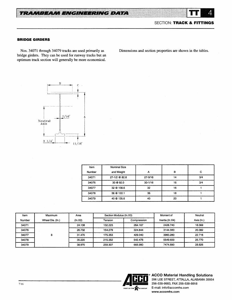
SECTION: TRACK & FITTINGS
BRIDGE GIRDERS
Nos. 34071 through 34079 tracks are used primarily as bridge girders. They can be used for runway tracks but an optimum track section will generally be more economical.
Dimensions and section properties are shown in the tables.
B c
.------1
N~~~(' 7/~ I 3 1/4.. 1 ===r-1
·---+-•e-- 11 I 16"
Item Nominal Size
Number and Weight A B c 34071 27-1/2@ 82.8 27-9/16 14 3/4
34076 30@ 92.0 30-1 /16 16 3/4
34077 32@ 108.6 32 16 1
34078 36@ 122.1 36 18 1
34079 40@ 135.6 40 20 1
Item Maximum Area Section Modulus (ln.X3) Moment of Neutral
Number Wheel Dia. (ln.) (ln.X2) Tension Compression Inertia (ln.X4) Axis(ln.)
34071 24.138 132.223 264.167 2428.740 18.369
34076 26.732 154.279 324.844 3144.560 20.382
34077 8 31 .470 175.353 429.040 3983.280 22.716
34078 35.220 215.352 542.478 5549.600 25.770
34079 38.970 259.307 668.980 7474.890 28.826
A ® ACCO Material Handling Solutions ------------------------- ceo 206 LEE STREET, ATTALLA, ALABAMA 35954
256-538-9983, FAX 256-538-8818
PARToFTH•K••oGoou• E-mail: [email protected] 7/16
www.accomhs.com

5,000

ACCO Material Handling Solutions206 LEE STREET, ATTALLA, ALABAMA 35954
256-538-9983, FAX 256-538-8818
E-mail: [email protected]
www.accomhs.com
SECTION: TRACK & FITTINGS
SIMPLIFIED PROCEDURE FOR TRACK AND HANGER ROD SELECTION
The simplified procedure for selection of track and hanger rod assemblies is used for monorail and crane applications where one carrier or crane operates in a single span. The procedure is:
STEPl Determine the carrier load. For monorail applications, omit Steps 2 and 3 and proceed to Step 4.
STEP2 Distribute the carrier load.
STEP3 Determine the end truck load.
STEP4 Determine the wheelbase (W) from the Carrier or Crane Section.
STEPS Determine the wheelbase to span ratio (WIL).
I l•
WIL I .013
K1 1 .987
K2 .994
W/L .200
K1 .810
K2 .900
WIL .388
K1 .650
K2 .806
WIL .650
K1 .500
K2 .675
.025
.975
.988
.213
.799
.894
.400
.640
.800
.675
.500
.663
.038 .050 .063
.961 .951 .938
.981 .975 .969
.225 .238 .250
.788 .777 .766
.888 .881 .875
.413 .425 .438
.630 .620 .610
.794 .788 .781
.700 .725 .750
.500 .500 .500
.650 .638 .625
.075
.927
.963
.263
.755
.869
.450
.601
.775
.775
.500
.613
.088
.914
.956
.275
.744
.863
.463
.591
.769
.800
.500
.600
STEP6 Select the Kl and K2 conversion factors from the table. When the value of W IL falls between those shown, use K 1 and K2 factors from the column to the left.
STEP7 Calculate the ECL by multiplying the carrier or end truck load by the Kl factor.
STEPS Select track size from tables on Pages TT-12 through TT-15.
STEP9 Calculate the HRL by multiplying the carrier or end truck load by the K2 factor and add the track weight and, when used, the electrification weight.
STEPlO Select hanger rod assemblies from the table on Page TT-16.
A sample calculation is given on Page TT-7.
.100 .113 .125 .138 .150 .163 .175 .188
.903 .891 .879 .867 .856 .844 .833 .821
.950 .944 .938 .931 .925 .919 .913 .906
.288 .300 .313 .325 .338 .350 .363 .375
.733 .723 .712 .701 .691 .681 .670 .660
.856 .850 .844 .838 .831 .825 .819 .813
.475 .488 .500 .525 .550 .575 .600 .625
.581 .572 .562 .544 .526 .508 .500 .500
.763 .756 .750 .738 .725 .713 .700 .688
.825 .850 .875 .900 .925 .950 .975 1.000
.500 .500 .500 .500 .500 .500 .500 .500
.588 .575 .563 .550 .538 .525 .513 .500
-9,95 ------Acco®
, PART OF THE 'KFKI GROUP

ACCO Material Handling Solutions206 LEE STREET, ATTALLA, ALABAMA 35954
256-538-9983, FAX 256-538-8818
E-mail: [email protected]
www.accomhs.com
SAMPLE CALCULATION FOR SIMPLIFIED PROCEDURE
The sample calculation on this page shows how the simplified procedure for track and hanger rod selection is used. It assumes a MW37S212X24, 3 ton, 22 ft.-0 in. span crane operating on a runway with 20 ft.-0 in. suspension centers. The calculations required to size the runway track and hanger rod assemblies are:
STEP 1 - Determine carrier load.
Hoist Weight Carrier Weight Rated Load Impact Allowance (15%)
Carrier Load
STEP 2- Distribute carrier load.
800 lbs. 500 lbs.
6,000 lbs. 900 lbs.
8,200 lbs.
Distributed Carrier Load= 20.5 x 8,200 = 7,640 Ibs. 22
Distributed Carrier Load = 20.5/22 x 8,200
Distributed Carrier Load = 7,640 lbs.
STEP 3 - Determine End Truck Load (P).
Distributed Carrier Load One-Half Crane Weight
7,640 lbs. 1.217lbs. 8,857 lbs.
SECTION: TRACK & FITTINGS
STEP 4 - Determine wheelbase (W) from Crane Section
W = 4 ft.-8 in. or 56 in.
STEP 5- Determine wheelbase to span ratio (W/L).
W IL = 56/240 = .233
STEP 6 - Select conversion factors from table on Page TT-6.
Use conversion factors for W IL = .225
Kl = .788 K2 = .888
STEP 7 - Calculate ECL.
ECL = Kl x P = .788 x 8,857 = 6,979lbs.
STEP 8 - Select track from table on Page TT-12.
Use No. 34026 (11-1/2 in. @ 26.31bs.)
STEP 9 - Calculate HRL.
HRL = K2 x P + Track Weight + Electrification Weight
HRL = .888 X 8,857 + 26.3 X 20 + 4.5 X 20
HRL = 8,481 lbs.
Note: Insul-8-Bar electrification weighs 4.5 lbs./3-bar foot.
STEP 10 - Select suspension fittings from table on Page TT-16.
Use single 3/4 in. diameter hanger rods.
-9,95 ------Acco®
, PART OF THE 'KFKI GROUP

ACCO Material Handling Solutions206 LEE STREET, ATTALLA, ALABAMA 35954
256-538-9983, FAX 256-538-8818
E-mail: [email protected]
www.accomhs.com
FORMULAE FOR TRACK SELECTION
Formulae for 4-wheel, 8-wheel and 16-wheel carriers and end trucks are used to determine track size where two carriers or cranes operate in a single span. They also provide a more exact ECL than the simplified procedure. The 8-wheel formula may be used where two 4-wheel carriers or two cranes with 4-wheel trucks operate in a single span. The 16-wheel formula may be used where two 8-wheel carriers or two cranes with 8-wheel trucks operate in a single span.
Consideration must be given to the loading condition when using the formulae for double girder cranes with large girder gauges. The maximum ECL for some applications may occur when the wheels from one end of the truck are at the middle of the span rather than when the truck is centered on the span. Consult factory for assistance if there is a question on the maximum loading condition.
The procedure for using the formulae is:
STEPl Determine the carrier load. For monorail applications, omit Steps 2 and 3 and proceed to Step 4.
4-WHEEL FORMULA:
ECL = (1- f/2L)2 X p
8-WHEEL FORMULA:
ECL = [(1- f/2L)2- elL] x P
16-WHEEL FORMULA:
ECL = [(1- g/2L)2- f/L- 2e!L] x P
SECTION: TRACK & FITTINGS
STEP2 Distribute the carrier load.
STEP3 Determine the end truck load.
STEP4 Determine wheelbase dimensions from Carrier or Crane Section.
STEPS Determine load distribution.
STEP6 Calculate the ECL from appropriate formula.
STEP7 Select track size from tables on Pages TT-12, TT-13, TT-14 and TT-15.
A sample calculation is given on Page TT-9.
-9,95 ------Acco®
, PART OF THE 'KFKI GROUP

ACCO Material Handling Solutions206 LEE STREET, ATTALLA, ALABAMA 35954
256-538-9983, FAX 256-538-8818
E-mail: [email protected]
www.accomhs.com
SAMPLE CALCULATION FOR FORMULAE
The sample calculation on this page shows how the formulae for track selection are applied. It assumes two MW71S218X46, 5 ton, 44 ft.-0 in. span cranes operating on a runway with 25ft.- 0 in. suspension centers with No. 2409 crane drives toward center of runway. The calculations required to size the runway track are:
STEP 1 - Determine carrier load.
Hoist Weight Carrier Weight Rated Load Impact Allowance ( 15%)
STEP 2 - Distribute carrier load.
900 lbs. 600 lbs.
10,000 lbs. 1.500 lbs.
13,000 lbs.
Distributed Carrier Load= 42.5/44 x 13,000 = 12,557 lbs.
STEP 3 - Determine end truck load.
Distributed Carrier Load 12,557 lbs. One-Half Crane Weight 2.833 lbs.
15,390 lbs.
Note: With 2 cranes operating in a single span, P will be 2 x 15,390 lbs. or 30,780 lbs.
SECTION: TRACK & FITTINGS
STEP 4 - Determine end truck wheelbase dimensions from Crane Section.
e = 1 ft.-0 in. or 12 in. f = 3 ft.-8 in. or 44 in.
g = 3 ft.-2 in. or 38 in.
STEP 5 - Determine load distribution of two cranes in a single span.
STEP 6 - Calculate ECL.
ECL = [(1- g/2L)2- f/L- 2e/L] x P
ECL = [(1 - 38/2 X 300)2 - 44/300 - 2 X 12/300] X 30,780
ECL = 20,007 lbs.
STEP 7 - Select track size from table on Page TI-12.
Use No. 34056 (20 in. @ 55.0 lbs.)
-9,95 ------Acco®
, PART OF THE 'KFKI GROUP
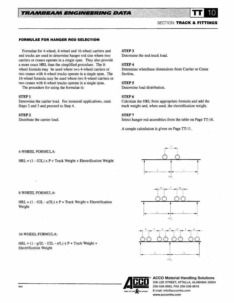
ACCO Material Handling Solutions206 LEE STREET, ATTALLA, ALABAMA 35954
256-538-9983, FAX 256-538-8818
E-mail: [email protected]
www.accomhs.com
FORMULAE FOR HANGER ROD SELECTION
Formulae for 4-wheel, 8-wheel and 16-wheel carriers and end trucks are used to determine hanger rod size where two carriers or cranes operate in a single span. They also provide a more exact HRL than the simplified procedure. The 8-wheel formula may be used where two 4-wheel carriers or two cranes with 4-wheel trucks operate in a single span. The 16-wheel formula may be used where two 8-wheel carriers or two cranes with 8-wheel trucks operate in a single span.
The procedure for using the formulae is:
STEPl Determine the carrier load. For monorail applications, omit Steps 2 and 3 and proceed to Step 4.
STEP2 Distribute the carrier load.
4-WHEEL FORMULA:
HRL = (1- f/2L) x P +Track Weight+ Electrification Weight
8-WHEEL FORMULA:
HRL = (1- f/2L- e/2L) x P +Track Weight+ Electrification Weight
16-WHEELFORMULA:
HRL = (1- g/2L- f/2L- elL) x P +Track Weight+ Electrification Weight
SECTION: TRACK & FITTINGS
STEP3 Determine the end truck load.
STEP4 Determine wheelbase dimensions from Carrier or Crane Section.
STEPS Determine load distribution.
STEP6 Calculate the HRL from appropriate formula and add the track weight and, when used, the electrification weight
STEP7 Select hanger rod assemblies from the table on Page TT-16.
A sample calculation is given on Page TT-11.
HRL
-9,95 ------Acco®
, PART OF THE 'KFKI GROUP

ACCO Material Handling Solutions206 LEE STREET, ATTALLA, ALABAMA 35954
256-538-9983, FAX 256-538-8818
E-mail: [email protected]
www.accomhs.com
SAMPLE CALCULATION FOR FORMULAE
The sample calculation on this page shows how the formulae for hanger rod selection are applied. It assumes the same system used in the sample calculation on Page TT-9. The calculations to size the hanger rods are:
STEP 1 - Determine carrier load.
Same as sample calculation on Page TT-9; carrier load is 13,000 lbs.
STEP 2 - Distribute carrier load.
Same as sample calculation on Page TT-9; distributed carrier load is 12,557 lbs.
STEP 3 Determine end truck load.
Same as sample calculation on Page TT-9; P is 30,780 lbs.
STEP 4 - Determine end truck wheelbase dimensions from Crane Section.
Same as sample calculation on Page TT-9; e = 12 in., f = 44 in., and g = 38 in.
SECTION: TRACK & FITTINGS
STEP 5 - Determine load distribution.
STEP 6 - Calculate HRL.
HRL = (1 - g/2L- f/2L- elL) x P +Track Weight + Electrification Weight
HRL = ( 1 - 38/2 X 300 - 44/2 X 300 - 12/300) X 30,780 + 25 X 55.0 + 25 X 4.5
HRL = 26,850 Ibs.
Note: Track weight of 55.0 lbs./ft. is for No. 34056 track selected in sample calculation on Page TT-9. Insul-8-Bar electrification weighs 4.5 lbs./3-bar foot.
STEP 7 - Select suspension fittings from table on Page TT-16.
Use double 1-1//8 in. diameter hanger rods.
-9,95 ------Acco® PART OF THE 'lc.FKI GROUP

ACCO Material Handling Solutions206 LEE STREET, ATTALLA, ALABAMA 35954
256-538-9983, FAX 256-538-8818
E-mail: [email protected]
www.accomhs.com
8 @ 17.0

ACCO Material Handling Solutions206 LEE STREET, ATTALLA, ALABAMA 35954
256-538-9983, FAX 256-538-8818
E-mail: [email protected]
www.accomhs.com
SECTION: TRACK & FITTINGS
TRACK RATED LOADS • HEAVY RAIL SECTIONS
Maximum ECLat Center of Span (Pounds)
Span No.34037 No. 34041 No.34046 No. 34051 No. 34056 No. 34061 No.34066
(Feet) 12-1/2@ 33.6 14@ 38.5 16@ 42.7 18@ 50.3 20@ 55.0 22~1/2 @ 61.4 [email protected]
12 23,715 T 28,199 T
13 21,859 T 25,993 T
14 20,265 T 24,099 T
15 18,881 T 22,455 T 27,396 T
16 17,669 T 21,015 T 25,642 T
17 16,597 T 19,741 T 24,092 T
18 15,642 T 18,607 T 22,712 T 28,393 T
19 14,022C 17,590 T 21,475 T 26,850 T
20 12,607C 16,673 T 20,360 T 25,458 T 30,080T
21 11,387C 15,842 T 19,349 T 24,197 T 28,594 T
22 10,327C 15,084 T 18,427 T 23,048 T 27,240 T 32,990 T
23 9,401 c 13,922 D 17,584 T 21,996 T 26,002 T 31,495 T
24 8,5850 12,730 D 16,5130 20,7250 24,865 T 30,123 T
25 7,8640 11,6770 15,157 0 19,0280 23,0840 28,858 T 34,333 T
26 7,222C 10,740 0 13,952 c 17,520C 21,263 c 27,400C 32,946T
27 6,648C 9,9040 12,876 c 16,173C 19,6380 25,319 c 31,659 T
28 6,133C 9,1530 11,911 0 14,966C 18,181 0 23,454C 29,368C
29 5,669C 8,4770 11,041 c 13,8790 16,8690 21,776C 27,280C
30 5,2480 7,8660 10,2560 12,896C 15,6830 20,2590 25,3930
31 4,866C 7,3110 9,5430 12,0040 14,608C 18,884 c 23,6830
32 4,5180 6,805 0 8,8930 11,192 c 13,6290 17,6330 22,1270
33 4,2000 6,343 0 8,300C 10,451 0 12,7360 16,491 0 20,7080
34 3,9070 5,9190 7,7570 9,7720 11,917 0 15,446 0 19,409C
35 ................... 5,530 D 7,2580 9,148C 11,1660 14,487C 18,217C
36 .......... -......... 5,171 D 6,798C 8,5740 10,4740 13,6040 17,120 0
37 .......... -....... 4,8390 6,3730 8,043C 9,835C 12,789C 16,108 c 38 ........... ,.. ...... 4,531 0 5,9800 7,552C 9,2440 12,0350 15,173C
39 ..................... __ ....... ___ 5,614C 7,096C 8,6960 11,3360 14,306 c
40 _.,. __ ....... _ 5,2750 6,6720 8,1860 10,6860 13,5000
41 ....................... ... ..., ................ 4,958C 6,2770 7,7110 10,081 0 12,750 0
42 .................. 4,662C 5,908C 7,2680 9,517C 12,051 0
43 -.................. ............. ,.. ....... 4,3850 5,562C 6,8530 8,9900 11,398 c 44 ....................... ................. -- ... ----..... 5,2390 6,464C 8,4960 10,7860
45 .................... .................. ----......... 4,9350 6,0990 8,032C 10,213 0
46 ..................... ------- ... ................... 4,649C 5,756C 7,597C 9,6740
47 ..,._ .... ,.,. ....... ------- ... ............... - ...... -........... 5,4330 7,187C 9,168C
48 .................... ................ - .................. ,.., ------... 5,1280 6,8000 8,6900
49 ... _ ......... ..., ... ........... ,.. ........ .... ..................... 4,8400 6,4350 8,239C
50 ..................... ... ---... -- ... ................... --... -........ 4,5680 6,0900 7,814 c 51 ...................... ..................... ... .................. 4,3100 5,764C 7,410C
52 ................. _ ....................... --...... -..... ... ................. 4,0650 5,4540 7,029C
53 ....................... ...................... ... .......... __ ... 3,8320 5,160C 6,666C
54 .................... ...................... ... ----..... ... .................. 3,6100 4,880C 6,3220
55 ....................... ...................... ........ ____ ... ................ ...-................ 4,6140 5,994C
-9,95 ------Acco® PART OF THE 'lc.FKI GROUP

ACCO Material Handling Solutions206 LEE STREET, ATTALLA, ALABAMA 35954
256-538-9983, FAX 256-538-8818
E-mail: [email protected]
www.accomhs.com
SECTION: TRACK & FITTINGS
TRACK RATED LOADS • BRIDGE GIRDERS
Maximum ECLat Center of Span (Pounds)
Span No. 34071 No. 34076 No. 34077 No. 34078 No. 34079
(Feet) 27-1/2 @ 82.8 30@ 92.0 32@ 108.6 36@ 122.1 40@ 135.6
30 35,498 T
31 33,634C
32 31,446 c 33 29,449C
34 27,623C
35 25,947C 33,693C
36 24,406C 31,715 c 37 22,985C 29,891 c 38 21,671 c 28,206C
39 20,454C 26,645C
40 19,324 c 25,196C 34,392 T
41 18,273 c 23,849C 33,447 T
42 17,293 c 22,594C 32,545 T
43 16,378C 21,422C 31,683 T
44 15,521 c 20,326C 30,857T
45 14,719 c 19,300C 30.065T
46 13,965C 18,336C 29,306 T 36,259T
47 13,257C 17,431 c 28,576 T 35,369T
48 12,590 c 16,578C 27,875 T 34,514 T
49 11,961 c 15,n5C 27,161 c 33,691 T
50 11,366C 15,017 c 25,928C 32,898 T 39,905 T
51 10,804C 14,300C 24,764C 31,707C 38,992 T
52 10,272C 13,622C 23,663C 30,323C 37,789C
53 9,767C 12,979C 22,621 c 29,014C 36,181 c 54 9,288C 12,369C 21,633C 27,773C 34,659C
55 8,832C 11,789 c 20,696C 26,596C 33,215 c 56 8,399C 11,238 c 19,806C 25,478C 31,844C
57 7,986C 10,713 c 18,959C 24,415 c 30,541 c 58 7,592C 10,213C 18,154 c 23,404C 29,302C
59 7,216C 9,736C 17,386 c 22,441 c 28,121 c 60 6,856C 9,280C 16,653 c 21,522 c 26,996C
61 6,512C 8,844C 15,954 c 20,646C 25,923C
62 6,182C 8,427C 15,285C 19,808C 24,898C
63 5,867C 8,027C 14,646C 19,008 c 23,918C
64 5,564C 7,644C 14,034C 18,242 c 22,981 c 65 5,272C 7,276C 13,447 c 17,508 c 22,084C
66 4,993C 6,923C 12,885C 16,804 c 21,224C
67 4,723C 6,584C 12,345 c 16,130 c 20,399C
68 4,464C 6,257C 11,826 c 15,482 c 19,608 c 69 4,214C 5,943C 11,328 c 14,859 c 18,848 c 70 3,974C 5,640C 10,848 c 14,260C 18,117 c
-9,95 ------Acco® PART OF THE 'fc.FKI GROUP

ACCO Material Handling Solutions206 LEE STREET, ATTALLA, ALABAMA 35954
256-538-9983, FAX 256-538-8818
E-mail: [email protected]
www.accomhs.com
SECTION: TRACK & FITTINGS
TRACK RATED LOADS • BRIDGE GIRDERS
Maximum ECLat Center of Span (Pounds)
Span No. 34071 No. 34076 No. 34077 No.34078 No. 34079
(Feet) 27-1/2@ 82.8 30@ 92.0 32@ 108.6 36@ 122.1 40@ 135.6
71 .................. 5,348C 10,387C 13,685C 17,414 c 72 ------- 5,066C 9,942C 13,130C 16,738C
73 ................... _ 4,793C 9,513C 12,595 c 16,086C
74 ------- 4,530C 9,099C 12,080 c 15,459 c 75 .. -.--..... 4,276C 8,700C 11,583C 14,853C
76 ................... 4,029C 8,314C 11,103C 14,269C
77 ..................... 3,791 c 7,941 c 10,639 c 13,704C
78 _..,. __ .,. __
3,560C 7,580C 10,191 c 13,159 c 79 3,336C 7,231 c 9,757C 12,632C
80 ------- 3,118 c 6,893C 9,337C 12,121 c 81 ............ -..... ....................... -----.. - 8,931 c 11,628 c 82 .................... ...................... ----·-- 8,537C 11,150C
83 .................... ...-----... ................... 8,155C 10,686C
84 ------- .................... ........................ 7,784C 10,237C
85 ___ ... ___ ---... --- ------- 7,425C 9,801 c
86 ....................... ...................... _lM __ ..... _ 7,075C 9,378C
87 ..................... ..................... 6,736C 8,967C
88 ...................... ------- ... ..,. _____ 6,406C 8,568C
89 ...................... ____ .. __
....................... 6,086C 8,180C
90 .................. ... ............ __ ------- 5,773C 7,803C
91 ------- ------- .... _ ................. .................... 7,436C
92 ------- ...................... ..................... ------- 7,078C
93 ......... ,.. ......... ·------ .................... ------- 6,730C
94 ..................... ·------ ................... .................... 6,391 c 95 .................... -w•-•-•
........... ___ ----~-- 6,061 c
96 ------- .................. _ ............ -..... ....... -.............. 5,738C
97 .......... ___ ................. _ ...................... ....................... 5,424C
98 ............... ___ ......................... -.................. _,..,._. __ 5,117C
99 ------- .......................... _____ ...... ------- 4,817C
100 .................... ..., ___ ... __ .................. ..,,..,. ____ 4,525C
-9,95 ------Acco®
, PART OF THE 'KFKI GROUP
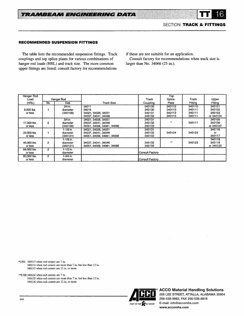
ACCO Material Handling Solutions206 LEE STREET, ATTALLA, ALABAMA 35954
256-538-9983, FAX 256-538-8818
E-mail: [email protected]
www.accomhs.com
RECOMMENDED SUSPENSION FITTINGS
The table lists the recommended suspension fittings. Track couplings and top splice plates for various combinations of hanger rod loads (HRL) and track size. The more common upper fittings are listed; consult factory for recommendations
Hanger Rod Load Hanger Rod (HAL} No. Size Track Size
3/4in. 34011 8,500 lbs. 1 diameter 34016
or less (340108) 34021,34026,34031 34037,34041,34046
314in. 34021,34026,34031 17,000ibs. 2 diameter 34037,34041,34046
or less (340108) 34051,34056,34061,34066 1·1/8 in. 34021,34026,34031
20,0001bs. 1 diameter 34037,34041,34046 or less (340121} 34051,34056,34061,34066
1-1/8 in. 40,0001bs. 2 diameter 34037,34041,34046
or less (340121) 34051,34056,34061,34066 64,0001bs. 2 1-1/2 in.
or less diameter 80,000 lbs. 2 1-3/4 in.
or less diameter
*USE: 340113 when rod centers are 7 in. 340114 when rod centers are more than 7 in. but less than 12 in. 340115 when rod centers are 12 in. or more
**USE:340124 when rod centers are 7 in. 340125 when rod centers are more than 7 in. but less than 12 in. 340126 when rod centers are 12 in. or more
SECTION: TRACK & FITTINGS
if these are not suitable for an application. Consult factory for recommendations when track size is
larger than No. 34066 (25 in.).
Top Track Splice Track Upper
Coupling Plate Fitting Fitting 340130 340112 340110 340101 340130 340113 340111 340102 340131 340113 340111 340103 340132 340113 340111 or340104 340131 340105 340132 * 340111 340106 340133 or340107 340131 340116 340132 340124 340123 or 340133 340117
340118 340132 ** 340123 340119 340133 or340120
Consult Factory
Consult Factory
-9,95 ------Acco®
, PART OF THE 'KFKI GROUP

ACCO Material Handling Solutions206 LEE STREET, ATTALLA, ALABAMA 35954
256-538-9983, FAX 256-538-8818
E-mail: [email protected]
www.accomhs.com
TRAMBEAM CURVES
Curves for monorail systems are made from four sizes of track: Nos. 34011 (8 in.), 34016 (8-1/2 in.), 34021 (10 in.) and 34038 (12-1/2 in.). They are manufactured with 3 ft.-6 in. minimum radius for No. 34011 track and 4 ft.-0 in. minimum radius for Nos. 34016,34021 and 34038 tracks. The tables indicate the standard radii and degree of curvature. Curves with special radii and degree of curvature and reverse curves are also available.
Dimensions and recommended hanger rod spacings are indicated in the tables for 45, 60 and 90 degree curves. Consult factory for dimensions and rod spacings for curve radii and degree of curvature not shown.
Curves are furnished with 6 in. overhangs as standard.
SECTION: TRACK & FITTINGS
Shorter overhangs can be furnished. Longer overhangs can be furnished but should be held to a minimum due to difficulties in handling and shipping. Curves can be furnished with switch preparations at one or both ends as required.
No. 34011 curves have 340500 series numbers; No. 34016 curves have 340800 series numbers; No. 34021 curves have 340600 series numbers; and No. 34038 curves have 340700 series numbers. The tables indicate item numbers for No. 34011 curves. To determine the item number for Nos. 34016, 34021 or 34038 curves, use the appropriate series number, and the last two digits from the item number, i.e., the item number for a 6 ft.-0 in. radius, 90 degree No. 34038 curve is 340706.
45 Degree Curve
Radius Item Number A 8 c 0 E
3'-6 340522 1'·0·5/16 2'-5-11/16 2'-9 22-1/2 Deg. -4'-0 340523 1'-2-1/16 2'-9·15/16 3'-1-11/16 22-1/2 Deg. -6'-0 340526 1'-9-1/16 4'-2-15/16 4'-8-9/16 22-1/2 Deg. -8'-0 340527 2'-4-1/8 5'-7-7/8 6'-3-3/8 22-1/2 Deg. -10'-0 340528 2'-11-1/8 7'-0-7/8 7'-10-1/4 22-1/2 Deg. -
60 Degree Curve
Radius Item Number A 8 c D E
3'-6 340512 1'-9 3'-0-3/8 3'-8 30Deg. -4'-0 340513 2'-0 3'-5-9/16 4'-2-1/4 30Deg. -6'-0 340516 3'-0 5'-2-3/8 6'-3-3/8 30Deg. -8'-0 340517 4'-0 6'-11-1/8 8'-4-112 30Deg. -10'-0 340518 5'-0 8'-7-15/16 1 0'-5-11/16 30Deg. -
90 Degree Curve
Radius Item Number A B c D E
3'-6 340502 3'-6 3'-6 5'-6 45 Deg. -4'-0 340503 4'-0 4'-0 6'-3-3/8 45 Deg. -6'-0 340506 6'-0 6'-0 9'-5-1/8 450eg. -8'-0 340507 8'-0 8'-0 12'-6-13/16 - 30Deg.
10'-0 340508 10'-0 10'-0 15'-8-1/2 - 30Deg.
-9,95 ------Acco®
, PART OF THE 'KFKI GROUP

ACCO Material Handling Solutions206 LEE STREET, ATTALLA, ALABAMA 35954
256-538-9983, FAX 256-538-8818
E-mail: [email protected]
www.accomhs.com
GIMBAL SUSPENSION SYSTEM
The gimbal suspension system uses multiplane washers at each end of the hanger rod to provide a gimbal assembly. The tapered planes on the top surface of the washers are positioned at right angles to the tapered planes on the bottom sur~ face. This allows free rod movement of 6 degrees in any direction.
Two sizes of rods are available - 3/4 inch diameter rated at 8,500 pounds per rod and 1-1/8 inch diameter rated at 20,000 pounds per rod. Single and double rod suspensions are used for hanger rod loads up to 40,000 pounds.
SECTION: TRACK & FITTINGS
The suspension system components consist of: e UPPER FITTING with hardened bearing washer. e ADJUSTABLE UPPER NUT secured by set screw. e GIMBAL WASHERS at each end of the rod. e HANGER ROD of high strength steel with lower nut
factory assembled to the rod by a roll pin. e TRACK HANGER. Detailed information on the components and methods for
determining rod lengths and centers are on subsequent pages.
(Adjustable)
Gimbal Washer
Rod
Hanger
Gimbal
Nut
-9,95 ------Acco®
, PART OF THE 'KFKI GROUP

ACCO Material Handling Solutions206 LEE STREET, ATTALLA, ALABAMA 35954
256-538-9983, FAX 256-538-8818
E-mail: [email protected]
www.accomhs.com
BUSHING SUSPENSION SYSTEM
The bushing suspension system uses spherical thrust bushings at each end of the hanger rod. The bushings have a spherical ball and socket configuration and allow free rod movement of 6 degrees in any direction. The bushings are ground, hardened and coated with a dry film lubricant.
Two sizes of rods are available - 1-1/2 inch diameter rated at 32,000 pounds per rod and 1-3/4 inch diameter rated at 40,000 pounds per rod. Single and double rod suspensions are used for rod loads up to 80,000 pounds.
The bushing suspension system components consist of: e UPPER FITTING with bushing insert.
SECTION: TRACK & FITTINGS
e ADJUSTABLE UPPER NUT secured by jam nut. e SPHERICAL BUSHINGS at each end of the rod. e HANGER ROD of high strength steel with cut threads. e TRACK HANGER with bushing insert. e LOWER NUT field assembled to rod and secured by
cotter pin. The drawing shows a typical double rod bushing suspen
sion assembly. Top splice plates and track couplings can be bolted to the track as shown or welded. Consult factory for detailed information on specific applications.
Upper Fitting
Upper Nut (Adjustable)
Spherical Bushing
Hanger Rod
Track Hanger With Bushing Insert
Bushing
Lower Nut
-9,95 ------Acco®
PART OF THE 'fc.FKI GROUP

ACCO Material Handling Solutions206 LEE STREET, ATTALLA, ALABAMA 35954
256-538-9983, FAX 256-538-8818
E-mail: [email protected]
www.accomhs.com
TRACK BRACING
Bracing of flexibly suspended tracks is required to limit hanger rod sway. It is installed to restrict both lateral and longitudinal movement and always after the system has been aligned and leveled.
On two track runway systems, one track is laterally braced and the other is allowed to float. Both tracks are longitudinally braced. Lateral bracing is usually installed at each support point; longitudinal bracing at each end of each track. On
Lateral bracing using steel angles welded to the supporting structure when track is close to the structure.
Slotted hole in to allow lateral
movement.
Lateral bracing using a steel pin engaging a slotted hole in a steel angle when track is not close to the supporting structure or building column.
SECTION: TRACK & FITTINGS
three track runway systems, the center track is laterally braced and the outer tracks are allowed to float. All three tracks are longitudinally braced.
Bracing is designed and installed to limit the movement of the track system. It is not designed to carry any of the load supported by the hanger rods or to restrict the normal expansion or contraction of the track system. Typical bracing arrangements are shown in the illustrations.
1/8"
Lateral bracing using steel angles bracketed from building column when track is adjacent to column.
Longitudinal bracing using a steel pin engaging a slotted hole in a steel angle.
-9,95 ------Acco®
, PART OF THE 'KFKI GROUP

ACCO Material Handling Solutions206 LEE STREET, ATTALLA, ALABAMA 35954
256-538-9983, FAX 256-538-8818
E-mail: [email protected]
www.accomhs.com
SUSPENSIONS FROM RIGID FRAME BUILDINGS
Pre-engineered, rigid frame buildings can generally be designed for the loads imposed by Trambeam crane systems. They are particularly suitable for installation of Trambeam runways because major modifications to the building are not necessary.
Single rod suspension using a beam clamp clamped to a horizontal bracket supplied with the rigid frame.
Double rod suspension using a special beam saddle welded to the top flange of the rigid frame.
SECTION: TRACK & FITTINGS
Standard upper fittings can usually be utilized for single rod suspension of the runway tracks by minor modification to the building. Double rod suspensions usually require special upper suspension fittings. Typical suspensions are shown in the illustrations.
Single rod suspension using a beam cleat bolted to a horizontal bracket supplied with the rigid frame.
Double rod suspension using a special beam saddle welded to the lower flange and web of the rigid frame.
-9,95 ------Acco®
, PART OF THE 'KFKI GROUP

ACCO Material Handling Solutions206 LEE STREET, ATTALLA, ALABAMA 35954
256-538-9983, FAX 256-538-8818
E-mail: [email protected]
www.accomhs.com
SINGLE 3/4" DIAMETER ROD SUSPENSIONS
Single 3/4 in. hanger rod suspension assemblies are shown in the illustrations. Dimensions for these assemblies are listed in the table. Hanger rod lengths and clearance dimensions for the track system can be readily determined from this information.
Hanger rods are stocked in lengths of 6 in. to 20 in. in 2 in. increments. Dimension 'B' in the table is the distance from the top of the track to the supporting structure with 6 in., 8 in., 10 in. and 12 in. long rods. Dimension 'B' for stock rods
FIGURE N0.1
c
B
No. 340101 Beam Cleat
No. 340108 Series Hanger Rod
Track Hanger
Top Splice Plate
Top B
Track Fig. Upper Track Splice Without Top
Size No. Fitting Hanger Plate A Splice Plate
6 8·1/8
8 10-1/4
34011 1 340101 340110 340112 10 12-1/4
(8) 12 14-1/4
Only 340102 6 10-1/4
340103 8 11-3/4
2 or 340110 340112 10 13-3/4
349104 12 15-3/4
6 8-1/8
8 10-1/4
34016 1 340101 340111 340113 10 12-1/4
(8-1/2) 12 14-1/4
and 340102 6 10-1/4
Larger 340103 8 11-3/4
2 or 340111 340113 10 13-3/4
340104 12 15-3/4
SECTION: TRACK & FITTINGS
not listed can be determined by adjusting dimension 'B' for the 12 in. rod by the difference in rod lengths. On applications where dimension 'B' is specified and is between the values listed in the table, the variation can be taken care of in the track adjustment or special length rods can be furnished.
Dimension 'B' for the 6 in. long rod is the minimum. Double rod suspensions are used where dimension 'B' must be less than that listed.
FIGURE N0.2
With Top
Splice Plate c 8-3/8 1-1/4
10-1/2
12-1/2 1-3/8
14-1/2
10-1/2 3-3/8
12
14 2-7/8
16
8-1/2 1-1/4
10-5/8
12-5/8 1-3/8
14-5/8
10-5/8 3-3/8
12-1/8
14-1/8 2-7/8
16-1/8
No. 340102, 340103 or 340104 Beam Clamp
No. 340108 Series Hanger Rod Track Hanger
Top Splice Plate
Track Adjustment
Total Up Down
2-1/8 3/4 1-3/8
2-1/2 1-114 1-1/4
1-1/2 3/4 3/4
2-3/8 1-1/8 1-1/4
2-1/8 3/4 1-3/8
2-1/2 1-1/4 1-1/4
1-1/2 3/4 3/4
2-3/8 1-1/8 1-114
-9,95 ------Acco®
, PART OF THE 'KFKI GROUP

ACCO Material Handling Solutions206 LEE STREET, ATTALLA, ALABAMA 35954
256-538-9983, FAX 256-538-8818
E-mail: [email protected]
www.accomhs.com
SINGLE 1·1/8" DIAMETER ROD SUSPENSIONS
Single 1-1/8 in. hanger rod suspension assemblies are shown in the illustrations. Dimensions for these assemblies are shown in the table. Hanger rod lengths and clearance dimensions for the track system can be readily determined from this information.
Hanger rods are stocked in lengths of 6 in. to 20 in. in 2 in. increments. Dimension 'B' in the table is the distance from the top of the track to the supporting structure. It is listed for 6 in., 8 in., 10 in. and 12 in. long rods for No. 340116 beam cleat and for 8 in., 10 in. and 12 in. long rods for No. 340117 beam clamp. The 6 in. rod cannot be used with the No.
FIGURE N0.1
c
Figure Upper Track
Number Fitting Hanger
1 340116 340123
2 340117 340123
A
6
8
10
12
8
10
12
No. 340116 Beam Cleat
No. 340121 Series Hanger Rod
No. 340123 Track Hanger
No. 340124 Top Splice Plate
B
Without Top
Splice Plate
9-3/8
10-5/8
12-5/8
14-5/8
10-1/2
12-112
14-1/2
SECTION: TRACK & FITTINGS
340117 clamp. Dimension 'B' for stock rods not listed can be determined by adjusting dimension 'B' for the 12 in. rod by the difference in rod lengths. On applications where dimension 'B' is specified and is between the values listed in the table, the variation may be taken care of in the track adjustment or special length rods can furnished.
Dimension 'B' for the 6 in. long rod with No. 340116 cleat and the 8 in. long rod with No. 340117 clamp are minimums. Double rod suspensions are used where dimension 'B' must be less than that listed.
FIGURE N0.2
With Top c Splice Plate
9-7/8 2-1/8
11-1/8
13-1/8 1-318
15-1/8
11
13 1-1/4
15
No. 340117 Beam Clamp
No. 340121 Series Hanger Rod
No. 340123 Track Hanger
No. 340124 Top Splice Plate
Track Adjustment
Total Up Down
1 1/2 1/2
2-1/2 1-1/4 1-1/4
2-1/4 1-1/8 1-1/8
-9,95 ------Acco®
, PART OF THE 'KFKI GROUP

ACCO Material Handling Solutions206 LEE STREET, ATTALLA, ALABAMA 35954
256-538-9983, FAX 256-538-8818
E-mail: [email protected]
www.accomhs.com
DOUBLE 3/4" DIAMETER ROD SUSPENSIONS
Double 3/4 in. hanger rod suspension assemblies are shown on this page and Page TT-25. Methods for determining hanger rod centers and lengths are provided for all of the cataloged upper fittings.
The dimensions from the support structure to the top of the track and to the top of the rod allow for a total track adjustment of 3 in. - 1-1/2 in. up and 1-1/2 in. down.
Hanger rods are stocked in lengths of 6 in. to 20 in. in 2 in. increments. The calculated rod length will seldom be a stock length. However, the length generally can be increased to a stock length because 8 in. and longer rods have 6 in. of thread. Using a stock rod will increase the down track
A
No. 340106 Beam Saddle
No. 340108 Series Hanger Rod
No. 340114 Top Splice Plate
No. 340111 Track Hanger
Min.)
SECTION: TRACK & FITTINGS
adjustment by the difference in the calculated and stock rod lengths.
Many times the hanger rod centers will calculate to a fraction of an inch. When this occurs, increase rod centers to the next larger 1/2 in. increment to simplify track detailing and fabrication, i.e., 10-1/8 in. calculated rod centers are increased to 10-1/2 in.
Top splice plates are used at all track splices. No. 340113 plates are used for 7 in. rod centers. No. 340114 plates are used for rod centers greater than 7 in. and less than 12 in. No. 340115 plates are used for rod centers of 12 in. or more.
TO DETERMINE ROD CENTERS (Z):
( l) Determine dimension W W = 3/8" + 1/16" per inch ofY
(2) Determine rod centers Z Z=X+2W
TO DETERMINE ROD LENGTH (A):
A=Y + B + 2-3/4"
-9,95 ------Acco® ,
PART OF THE 'KFKI GROUP

ACCO Material Handling Solutions206 LEE STREET, ATTALLA, ALABAMA 35954
256-538-9983, FAX 256-538-8818
E-mail: [email protected]
www.accomhs.com
A
DOUBLE 3/4" DIAMETER ROD SUSPENSIONS
O@ O@
No. 340107 Beam Saddle
No. 340108 Series Hanger Rod
No. 340115 Top Splice Plate
No. 340111 Track Hanger
Min.)
No. 340108 Series Hanger Rod
SECTION: TRACK & FITTINGS
TO DETERMINE ROD CENTERS (Z):
Z=X+T'
TO DETERMINE ROD LENGTH (A):
A= Y + B + 3-l/8"
No. 340105 Beam TO DETERMINE ROD CENTERS (Z): Clamp
Z =X+ 2-1/2"
-~-No. 340114 Top Splice Plate TO DETERMINE ROD LENGTH (A):
B(7" .,...---- No. 340111 Track A=U+B+3"
Hanger
-9,95 ------Acco® PART OF THE 'lc.FKI GROUP

ACCO Material Handling Solutions206 LEE STREET, ATTALLA, ALABAMA 35954
256-538-9983, FAX 256-538-8818
E-mail: [email protected]
www.accomhs.com
DOUBLE 1·1/8" DIAMETER ROD SUSPENSIONS
Double 1-1/8 in. hanger rod suspension assemblies are shown on this page and Page TT-27. Methods for determining rod centers and lengths are provided for all of the cataloged upper fittings.
The dimensions from the support structure to the top of the track and to the top of the rod allow for a total track adjustment of 3 in.- 1-1/2 in. up and 1-1/2 in. down.
Hanger rods are stocked in lengths of 6 in. to 20 in. in 2 in. increments. The calculated hanger rod length will seldom be a stock length. However, the length generally can be increased to a stock length because 8 in. and longer rods have 6 in. of thread Using a stock rod will increase the down
A I
y
l W(l 1/4"
No. 340119 Beam Saddle
No. 340121 Series Hanger Rod
No. 340125 Top Splice Plate
No. 340123 Track Hanger
Min.)
SECTION: TRACK & FITTINGS
track adjustment by the difference in the calculated and stock rod lengths.
Many times the hanger rod centers will calculate to a fraction of an inch. When this occurs, increase rod centers to next larger 1/2 in. increment to simplify track detailing and fabrication, i.e., 10-1/8 in. rod centers are increased to 10-1/2 in.
Top splice plates are used at all track splices. No. 340124 plates are used for 7 in. rod centers. No. 340125 plates are used for rod centers greater than 7 in. and less than 12 in. No. 340126 plates are used for rod centers of 12 in. or more.
TO DETERMINE ROD CENTERS (Z):
(1) Determine dimension W W = 5/8" + 1116" per inch ofY
(2) Determine rod centers Z Z=X+2W
TO DETERMINE ROD LENGTH (A):
A= Y + B + 2-7/8"
-9,95 ------Acco® PART OF THE 'lc.FKI GROUP

ACCO Material Handling Solutions206 LEE STREET, ATTALLA, ALABAMA 35954256-538-9983, FAX 256-538-8818E-mail: [email protected]
5/96
SECTION: TRACK & FITTINGS
DOUBLE 1·1/8" DIAMETER ROD SUSPENSIONS
A
A
,-O @ O @
B(B 3/8"
I
No. 340120 Beam Saddle
No. 340121 Series Hanger Rod
No. 340126 Top Splice Plate
No. 340123 Track Hanger ,
Min.)
No. 340121 Series Hanger Rod
No. 340118 Beam
TO DETERMINE ROD CENTERS (Z):
Z=X+7"
TO DETERMINE ROD LENGTH (A):
A= Y + B + 3-3/8"
Clamp TO DETERMINE ROD CENTERS (Z):
No. 340125 Top Splice Plate
No. 340123 Track Hanger
Z=X+3"
TO DETERMINE ROD LENGTH (A):
A= U + B + 3-5/8"
------Acco® PART OF THE 'lc.FKI GROUP

ACCO Material Handling Solutions206 LEE STREET, ATTALLA, ALABAMA 35954256-538-9983, FAX 256-538-8818E-mail: [email protected]
5/96
SUSPENSION FITTINGS
BEAM CLEAT
I m j ! 1 1/2" l
-$-: I~ I I :- ·n 3" I I t
21/32" Holes
BEAM CLAMP Flange
I 7 ::4 .. ~ 9=~ , I h
I I 3/8" I I I 5 5/8"
I I
SECTION: TRACK & FITTINGS
NO. 340101 BEAM CLEAT- 8,500 LBS. RATED LOAD
This upper fitting connects a 3/4" diameter hanger rod assembly to the support structure. Fitting includes the hardened bearing washer and two 5/8" x 2-l/2" heat treated capscrews, nuts and lock washers for bolting cleat to the support structure.
NO. 340102 BEAM CLAMP- 8,500 LBS. RATED LOAD NO. 340103 BEAM CLAMP - 8,500 LBS. RATED LOAD NO. 340104 BEAM CLAMP- 8,500 LBS. RATED LOAD
These upper fittings connect 3/4" diameter hanger rod assemblies to the support structure by clamping to the lower flange. Fittings include the hardened bearing washer. Clamps are adjustable for flange widths from 3-112" to 12-112" as noted in the table. Flange thickness of support structure is limited to 1" maximum. Consult factory when flange thickness exceeds 1" or flange width exceeds 12-l/2".
Clamp Flange
Cat. No. Width A
340102 9,292C 9-1/2"
340103 7,320C 12-1/2~
340104 5,908C 15"
NO. 340116 BEAM CLEAT - 20,000 LBS. RATED LOAD
This upper fitting connects a 1-1/8" diameter hanger rod assembly to the support structure. Fitting includes the hardened bearing washer and four 3/4" x 2-112" heat treated capscrews, nuts and lock washers for bolting cleat to the support structure.
------Acco® .. PART OF THE KFKI GROUP

ACCO Material Handling Solutions206 LEE STREET, ATTALLA, ALABAMA 35954
256-538-9983, FAX 256-538-8818
E-mail: [email protected]
www.accomhs.com
SUSPENSION FITTINGS
BEAM CLAMP
5" Min. 12"' Max.
BEAM CLAMP
BEAM SADDLE
BEAM SADDLE
SECTION: TRACK & FITTINGS
NO. 340117 BEAM CLAMP - 20,000 LBS. RATED LOAD
This upper fitting connects a 1-1/8" diameter hanger rod assembly to the support structure by clamping to the lower flange. Fitting includes the hardened bearing washer and attaching hardware. Flange width of support structure is limited to 5" minimum and 12" maximum.
NO .. 340105 BEAM CLAMP-17,000 LBS. RATED LOAD NO. 340118 BEAM CLAMP- 40,000 LBS. RATED LOAD
These upper fittings connect double hanger rod assemblies to the support structure. Fittings include hardened bearing washers and hardware for
Max. clamping fitting to the lower flange of the support structure. Hanger rod centers are determined from data on Page TI-25 for the No. 340105 clamp and Page TT-27 for the No. 340118 clamp.
NO. 340106 BEAM SADDLE- 17,000 LBS. RATED LOAD NO. 340119 BEAM SADDLE - 40,000 LBS. RATED LOAD
These upper fittings connect double hanger rod assemblies to the support structure. Fittings include hardened bearing washers and hardware for bolting fitting to the lower flange of the support structure. Hanger rod centers are determined from data on Page TT-24 for the No. 340106 saddle and Page TT-26 for the No. 340119 saddle.
NO. 340107 BEAM SADDLE -17,000 LBS. RATED LOAD NO. 340120 BEAM SADDLE~ 40,000 LBS. RATED LOAD
These upper fittings connect double hanger rod assemblies to the support structure. Fittings include hardened bearing washers and hardware for clamping fitting to the lower flange of the support structure. Hanger rod centers are determined from data on Page TI-25 for the No. 340107 saddle and Page TT-27 for the No. 340120 saddle.
-9,95 ------Acco® ,
PART OF THE 'KFKI GROUP

ACCO Material Handling Solutions206 LEE STREET, ATTALLA, ALABAMA 35954
256-538-9983, FAX 256-538-8818
E-mail: [email protected]
www.accomhs.com
SUSPENSION FITTINGS
HANGER ROD
ill ..., 0
ill ~
p;::
0 s.. 0:: (!.)
bD t!ll c: l=l 0 0 ,...l
,...l ~
i:o ;::: <
c "a:, 0
l:l 0
~ 0 ~
Nominal
Diameter
3/4"
1w1/811
BEARING WASHER
1 5/64" Hole
BEARING WASHER 1 1/2" Hole
SECTION: TRACK & FITTINGS
NO. 340108 3/4" DIAMETER HANGER ROD- 8,500 LBS. RATED LOAD NO. 3401211-1/8" DIAMETER HANGER ROD- 20,000 LBS .. RATED LOAD
The hanger rod assembly consists of a high strength steel rod, an adjustable upper nut secured by a set screw, two gimbal washers and a lower nut factory assembled to the rod by a roll pin. The upper nut and gimbal washers are packaged separately as a kit. Rods are stocked in lengths of 6" to 20" in 2" increments. Longer rods up to 238" are available.
Rods have rolled, unified national threads. The 6" long rods have 4" thread lengths; rods 8" and longer have 6" thread lengths. The threads are protected for shipment by a plastic coating.
The hanger rod item number consists of the series number (340 108 or 340121) and a suffix number indicating rod length, i.e., a 3/4" diameter rod 10" long is designated No. 340108010.
Hanger Rod Hanger Rod
Cat. No. Kit Cat. No. A B c 340108 340109 13/16" 5/8" 3/4"
340121 340122 1-1/8" 7/8" 1-1/8"
NO. 3401011 BEARING WASHER
Bearing washers provide the hardened seat for gimbal washers when 3/4" diameter hanger rods are suspended directly through holes in the building structure. Holes in the building structure are l-5/64" diameter. Bearing washers are always welded to the building structure; washer must be flat after welding and holes in the washer and structure concentric.
NO .. 3401015 BEARING WASHER
Bearing washers provide the hardened seat for gimbal washers when 1-1/8" diameter hanger rods are suspended directly through holes in the building structure. Holes in the building structure are 1-1/2" diameter. Bearing washers are always welded to the building structure; washer must be flat after welding and holes in the washer and structure concentric.
-9,95 ------Acco® ,
PART OF THE 'KFKI GROUP

ACCO Material Handling Solutions206 LEE STREET, ATTALLA, ALABAMA 35954
256-538-9983, FAX 256-538-8818
E-mail: [email protected]
www.accomhs.com
2 3/16”
2 3/16”
3”

TOP SPLICE PLATES
Top splice plates stiffen the top flange of the track at splices. Bolted or welded splice plates can be furnished; however, they are generally bolted to the top flanges.
Dimensions and application of the bolted top splice plates are indicated below. Plates are bolted to the top flanges using
TOP SPLICE PLATE
No. 340112 3/4" ROD SUSPENSIONS
Use on No. 34011 (8") track only and for single rod suspensions.
TOP SPLICE PLATE
r- 11 /16" Holes fo r No. 3401 13 Plate (3/8" plate)
f- 13/,16" Holes for N~. 340124 Plate ~ 1 /lf plate) ' ~
-r·-·-·r-------r·----r-1 1
' ' ' ' 3 1/2" 5 1/2"
I I I I =LJ ._r-c&------4---- --- ----ED---- -- -Eb- -___t_ I 1 I I 1
I
• ~ 1/2' .I. 3 1/2 3 1/2 .I 1'. 1· I
12 1/2" - .
NO. 340113 3/4" ROD SUSPENSIONS NO. 340124 1-1/8" ROD SUSPENSIONS
Use on all track sizes except No. 34011 (8") and for single rod suspensions or double rod suspensions with rods on 7" centers.
SECTION: TRACK & FITTINGS
the hardware furnished with track hangers; additional hardware, if required to complete the splice, is furnished with the plates.
Consult factory for recommendations on welded top splice plates.
TOP SPLICE PLATE
,-- 11/16" Holes for No. 340 114 Pla te {3/8" plate )
~ 13/ 16" Holes for No. 340 125 Plate (1/2" p late) =il , , , ·; r·
~-, -----r-- -- ----r---- -r 1 . . ' ' ' ' 3 1/2 5 1/2
'--~ -~ - ----4----- .. ---4----- 4- _J. I ' ' ' ' -1--1 ! ' I 3 1/2' -~ Variable I 3 1/2 T j'
Variab le
NO. 340114 3/4" ROD SUSPENSIONS NO. 340125 1-1/8" ROD SUSPENSIONS
Use on all track sizes except No. 34011 (8") and for double rod suspensions with rod centers greater than 7" and less than 12".
TOP SPLICE PLATE
11/16" Holes fo r No. 340 115 Plate (3/6" p late}
13/16" Ho les fo r No. 3 40126 Plate ( 1/2" plate )
'. ~ -~ ------1 "1 I ' • 3 1/Z' 5 1/2"
=~ -- 4- =i---J ··lr·l. 3 1/~
1--~-.!!..5!L~
NO. 340115 3/4" ROD SUSPENSIONS NO. 340126 1-1/8" ROD SUSPENSIONS
Use on all track sizes except No. 34011 (8") and for double rod suspensions with rod centers 12" or greater.
------------------------------------------------- 206LEESTREE~ATTALLA,ALABAMA35954 AceD® ACCO Material Handling Solutions
7/16 256-538-9983, FAX 256-538-8818
PARToFTH•K••oGoou• E-mail: [email protected] www.accomhs.com

ACCO Material Handling Solutions206 LEE STREET, ATTALLA, ALABAMA 35954
256-538-9983, FAX 256-538-8818
E-mail: [email protected]
www.accomhs.com
TRACK COUPLINGS
Track couplings maintain web and rail alignment at track splices. Bolted or welded couplings can be furnished. Bolted couplings provide flexibility to meet facility changes. Welded couplings are generally used on systems with high service factors.
Bolted couplings are stocked in four sizes for use with track sizes through No. 34066 (25 in.). Special socket head screws and flat head nuts are used near the rail for wheel clearance. Screws have a nylon insert to secure the nut.
SECTION: TRACK & FITTINGS
Standard bolts, nuts and lock washers are used in the area above the wheels. Two 3/16 in. thick plates are furnished for each coupling.
Welded couplings are made to order for each installation. Holes are provided for make-up bolts to help in aligning and leveling the tracks. Couplings are welded after tracks are aligned; make-up bolts are removed after welding. Two 3/16 in. thick plates are furnished for each coupling.
340130 TRACK COUPLING 340131 TRACK COUPLING 340132 TRACK COUPLING
Use for coupling Nos. 34011 (8") and 34016 (8-112").
340133 TRACK COUPLING
Use for coupling Nos. 34021 (1 0"), 34026 (11-112,') and 34031 (13").
Use for coupling Nos. 34037 (12-1/2"), 34041 (14") and 34046 (16'~).
WELDED TRACK COUPLING
Use for coupling all sizes of track.
Use for coupling Nos. 34051 (18"), 34056 (20"), 34061 (22-1/2'') and
-9,95 ------Acco®
, PART OF THE 'KFKI GROUP

ACCO Material Handling Solutions206 LEE STREET, ATTALLA, ALABAMA 35954
256-538-9983, FAX 256-538-8818
E-mail: [email protected]
www.accomhs.com
COUPLING DIFFERENT SIZE TRACKS
Different sizes of track can be used in a system. This occurs when the support track centers are not the same for the entire system. It frequently occurs in monorail systems because curves are only manufactured in four track sizes.
Coupling arrangement with single hanger rod suspension and larger track coped to the depth of the smaller track. This arrangement is used where the difference in track depths is more than 1-112".
Top Splice Plate
SECTION: TRACK & FITTINGS
Several methods are used for coupling different size tracks: ( 1) the larger track can be coped to the depth of the smaller track; or (2) a spacer can be used to build up the smaller track. Typical coupling arrangements are shown in the illustrations.
Top Splice Plate
Coupling arrangement with single hanger rod suspension and smaller track spaced to the depth of the larger track. This arrangement is generally used where the difference in track depths is l-1/2" or less.
Coupling arrangement with double hanger rod suspension and larger track coped to the depth of the smaller track. This arrangement is generally used where the difference in track depths is 4" or less; consult factory for recommendations when difference is greater than 4".
-9,95 ------Acco® ,
PART OF THE 'KFKI GROUP

ACCO Material Handling Solutions206 LEE STREET, ATTALLA, ALABAMA 35954
256-538-9983, FAX 256-538-8818
E-mail: [email protected]
www.accomhs.com
END STOPS
End stops are required at the ends of travel for all carriers and cranes. The cataloged stops are satisfactory for many applications. Energy absorbing stops are available for carriers and cranes rated for heavier loads and/or traveling at
340136 END STOP
Use for hand propelled carriers and cranes with 4" or 5" diameter wheels.
340138 END STOP
Use for hand propelled or motor driven carriers and cranes with 5" diameter wheels.
ENERGY ABSORBING STOP
Energy Absorbing Stop
Shear Welded
SECTION: TRACK & FITTINGS
higher speeds and for carriers and cranes with 8 in. diameter wheels. Consult factory for recommendations on these applications.
340137 END STOP
Use for hand propelled or motor driven carriers and cranes with 6-1/2" diameter wheels.
Use for hand propelled or motor driven carriers and cranes with 6-112" diameter wheels.
The stop illustrated is one of several available. Energy is absorbed by a rubber pad bonded to the stop. Polyurethane and spring stops are also available. Consult factory for recommendations on applications requiring energy absorbing stops.
-9,95 ------Acco® ,
PART OF THE 'KFKI GROUP

ACCO Material Handling Solutions206 LEE STREET, ATTALLA, ALABAMA 35954
256-538-9983, FAX 256-538-8818
E-mail: [email protected]
www.accomhs.com
TRAMBEAM FABRICATION
Trambeam track is generally fabricated at the factory and is ready for installation when shipped. Standard punching and drilling patterns have been established to simplify preparation of fabrication drawings.
Letter designations have been assigned to the patterns and indicate the type of fabrication:
e D PATTERNS indicate top flange punchings or drillings for track hangers, guide rollers, etc.
SECTION: TRACK & FITTINGS
e DC PATTERNS indicate top flange drillings for curve track suspension.
e E PATTERNS indicate end preparations for tracks and curves entering switches.
e S PATTERNS indicate end stop drillings. e W PATTERNS indicate web punchings or drillings for
track couplings, interlocks and discharge points and conductor bar supports and fabrication of web for interlocks, discharge points and conductor bar at switches.
TOP FLANGE DRILLINGS AND PUNCHING PATTERNS
Top flange drillings and punchings are indicated by open holes. Black dots indicate the center of the hanger rod. Patterns having slotted holes will have round holes when
D·1 01
The D-101 pattern is for the No. 340111 track hanger and No. 340114 top splice plate. It is used at end or intermediate support points for single 3/4" rod suspensions and at all support points for double 3/4" rod suspensions with rod centers greater than 7" and less than 12".
D·1 03
The D-103 pattern is for the No. 340115 top splice plate. It is used at coupling support points for double 3/4" rod suspensions with rod centers of 12u or more.
applied to curves. Patterns for track hangers are dimensioned to the center of the hanger rod and from one end using an end with a coupling preparation as the starting point.
D·1 02
D-1 02 pattern is for the No. 340111 track hanger and No. 340113 top splice plate. It is used at coupling support points for single 3/4" rod suspensions and double 3/4" rod suspensions with 7'' rod centers.
D·1 04
The D-104 pattern is for the No. 340110 track hanger and No. 340112 top splice plate. It is used at coupling support points for single 3/4" rod suspensions of No. 34011 (8") track.
-9,95 ------Acco® ,
PART OF THE 'KFKI GROUP
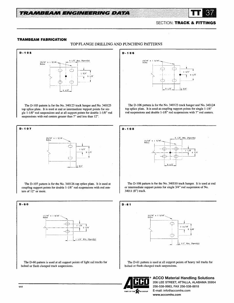
ACCO Material Handling Solutions206 LEE STREET, ATTALLA, ALABAMA 35954
256-538-9983, FAX 256-538-8818
E-mail: [email protected]
www.accomhs.com
SECTION: TRACK & FITTINGS
TRAMBEAM FABRICATION TOP FLANGE DRILLING AND PUNCHING PATTERNS
D·1 OS
The D-105 pattern is for the No. 340123 track hanger and No. 340125 top splice plate. It is used at end or intermediate support points for single 1-118, rod suspensions and at all support points for double l-118" rod suspensions with rod centers greater than 7" and less than 12".
D·1 07
The D-1 07 pattern is for the No. 340126 top splice plate. It is used at coupling support points for double 1-l/8" rod suspensions with rod centers of 12" or more.
D·60
The D-60 pattern is used at all support points of light rail tracks for bolted or flush clamped track suspensions.
D·1 08
The D-106 pattern is for the No. 340123 track hanger and No. 340124 top splice plate. It is used at coupling support points for single 1-1/8" rod suspensions and double 1-l/8" rod suspensions with 7'' rod centers.
D·1 08
The D-108 pattern is for the No. 340110 track hanger. It is used at end or intermediate support points for single 3/4" rod suspension of No. 34011 (8") track.
D·81
The D-61 pattern is used at all support points of heavy rail tracks for bolted or flush clamped track suspensions.
-9,95 ------Acco® ,
PART OF THE 'KFKI GROUP
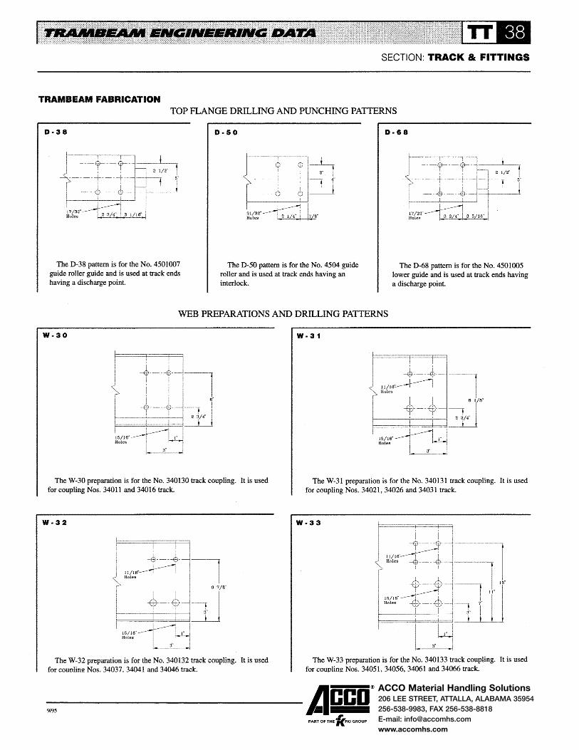
ACCO Material Handling Solutions206 LEE STREET, ATTALLA, ALABAMA 35954
256-538-9983, FAX 256-538-8818
E-mail: [email protected]
www.accomhs.com
SECTION: TRACK & FITTINGS
TRAMBEAM FABRICATION TOP FLANGE DRILLING AND PUNCHING PATTERNS
D-38 D·SO D-68
The D-38 pattern is for the No. 4501007 guide roller guide and is used at track ends having a discharge point
The D-50 pattern is for the No. 4504 guide roller and is used at track ends having an interlock.
The D-68 pattern is for the No. 4501005 lower guide and is used at track ends having a discharge point.
WEB PREPARATIONS AND DRILLING PATTERNS
W·30
The W-30 preparation is for the No. 340130 track coupling. It is used for coupling Nos. 34011 and 34016 track.
W·32
The W-32 preparation is for the No. 340132 track coupling. It is used for counlim! Nos. 34037. 34041 and 34046 track.
W-31
The W-31 preparation is for the No. 340131 track coupling. It is used for coupling Nos. 34021, 34026 and 34031 track.
W-33
The W-33 preparation is for the No. 340133 track coupling. It is used for couoling Nos. 34051. 34056. 34061 and 34066 track.
-9,95 ------Acco®
, PART OF THE 'KFKI GROUP

ACCO Material Handling Solutions206 LEE STREET, ATTALLA, ALABAMA 35954
256-538-9983, FAX 256-538-8818
E-mail: [email protected]
www.accomhs.com
SECTION: TRACK & FITTINGS
TRAMBEAM FABRICATION WEB PREPARATIONS AND DRILLING PATTERNS
W·55
TheW-55 pattern is for the No. 550341 conductor bar support. It is used on Nos. 34051 through 34079 track when carriers or cranes have 4" or 5" diameter wheels and bottom of conductor is 6-1/8" above tread.
W-72
The W-72 pattern is for the No. 550311 conductor bar support. It is used when Type L discharge points are electrified and bottom of conductor is 6-1/8" above tread.
W·75
The W-75 pattern is for the No. 550315 conductor bar support. It is used when Type H interlocks are electrified and bottom of conductor is 7-3/4" above tread.
W·56
TheW-56 pattern is for the No. 550341 conductor bar support. It is used on Nos. 34051 through 34079 track when carriers or cranes have 6-1/2" diameter wheels and bottom of conductor is 7-3/4" above tread.
W·73
The W-73 pattern is for the No. 550311 conductor bar support. It is used when Type H discharge points are electrified and bottom of conductor is 7-3/4'' above tread.
W·90
__..,;;;.-
~ 1/2"
i;e"
The W-90 preparation is used on the ends of all straight and curve tracks incoming to Types 4 and 5 electrified switches when bottom of conductor is 6-118" above tread.
-9,95 ------Acco®
, PART OF THE 'KFKI GROUP
The W-i 14 pattern is for the No. 550496 conductor bar support. It is used on Nos. 34061 through 34079 track when carriers or cranes have 5", 6-1/2" or 8" diameter wheels and bottom of conductor is 11-7/8" above tread.
W·74
The W-74 pattern is for the No. 550315 conductor bar support. It is used when Type L interlocks are electrified and bottom of conductor is 6-1/8" above tread.
W-91
,........._:;:-
i 2 1 /2"
The W -91 preparation is used on the ends of all straight and curve tracks incoming to Types 4 and 5 electrified switches when bottom of conductor is 7 -3/4" above tread.

ACCO Material Handling Solutions206 LEE STREET, ATTALLA, ALABAMA 35954
256-538-9983, FAX 256-538-8818
E-mail: [email protected]
www.accomhs.com
SECTION: TRACK & FITTINGS
TRAMBEAM FABRICATION WEB PREPARATIONS AND DRILLING PATTERNS
The W-70 preparation is for the Type L discharge point It is used on all track sizes. Nos. 34011, 34016 and 34021 must be built up to 11~ 1/2" depth to accommodate this preparation.
W-78
17/32"
13/32"
W-79
17/32''
W-71
The W-71 preparation is for the Type H discharge point. It is used on Nos. 34037 through 34079 tracks.
The W-78 preparation is for the Type L interlock. It is used on Nos. 34021 through 34079 tracks.
The W-79 preparation is for the Type Hinterlock. It is used on Nos. 34037 through 34079 tracks.
-9,95 ------Acco®
, PART OF THE 'KFKI GROUP

ACCO Material Handling Solutions206 LEE STREET, ATTALLA, ALABAMA 35954256-538-9983, FAX 256-538-8818E-mail: [email protected]
2 3/8”
SECTION: TRACK & FITTINGS
TRAMBEAM FABRICATION
END PREPARATION PATTERNS FOR SWITCHES
The ends of all straight and curve tracks incoming to switches are prepared for each switch in the system. The end preparation consists of: ( 1) a straight or angular cut on the end of the track; (2) coping or shimming the end to match the depth of the track in the switch; and (3) drilling holes for
Inlet
attaching track to the stationary frame of the switch. Hardware for attaching track to switch frame is also included. When detailing curve or straight tracks for switches, use the appropriate end preparation indicated in the table.
Outlet Preparation
Type of Switch Preparation Left Hand Straight Right Hand
Type2 E-5 E-6 E-5
Type 3 with 11 in. throw and
Type 3 2-way "Y" with 14 in, throw E-8 E-9 E-8
Type 3 2-way right and left and 3-way with 14" throw E-11 E-12 E-11
Type4and5 E-14 E-15 E-14
Type 7 Crossover and Type 8 Turntable E-20
END STOP DRILLING PATTERNS
s ·1 5·2
I 1---------{~ -----.
! I 1 1/16" r------t-' ____,,_1
9/16" -----LJ Hole
The S-1 pattern is for the No. 340136 end stop.
S-3 S-4
I i
~-~ ----I I
11/16"~ Holes
1 lt
__j
The S-2 pattern is for the No. 340138 end stop.
E-7
E-10
E-13
E-16
l "--'
I • J ! / 8"
---Ed----{ir---~=:1~ T I I 7 / 8"! I
- ·-·· j .. -·t ~~/B" 3 I/4"
~- - -rh __ J I ' I J ,---+- '
l J__j I
11/16" ~-;j ZIB" I Holes ----------j..L! . .:::_.J
The S-3 pattern is for the No. 340139 end stop.
9/ 16" ----l-----1. 1Ji Holes L-~ I 1"
The S-4 pattern is for the No. 340137 end stop.
-9,95 ------Acco®
, PART OF THE 'KFKI GROUP


ACCO Material Handling Solutions206 LEE STREET, ATTALLA, ALABAMA 35954
256-538-9983, FAX 256-538-8818
E-mail: [email protected]
www.accomhs.com
GENERAL INFORMATION
Trambeam switches increase the flexibility of monorail systems by: (1) connecting parallel tracks which permit carriers to transfer from one track to another; (2) providing spur tracks from the mainline; (3) dividing a single track into two or three secondary tracks; or (4) providing bypasses for the mainline.
Trambeam crossovers and turntables further increase the flexibility of a monorail system by allowing two tracks operating at the same elevation to cross - usually at right angles. Lift and drop sections allow a section of track to be raised or lowered. Track openers are available to allow a monorail to operate through doorways.
PLANNING CONSIDERATIONS
The function, location and rated load of the switch are important considerations in selecting switches for a monorail application. Switches are available for 2-way right or left hand, 2-way Y and 3-way operation. The function of the switch is determined by the monorail layout.
Most monorail systems will require additional superstructure to support the switch and the tracks incoming to the switch. Direct bolting of switches to the superstructure is recommended to prevent switch movement as carriers travel through the switch and when the switch is thrown. When supporting from hanger rods, switches must be braced laterally and longitudinally to prevent switch movement. Thus building construction and the space available for supporting the switch are important considerations in locating the switch.
Phase reversals should be avoided when planning an electrified system. This usually can be done by turning the switch 180 degrees in the system layout. If phase reversal cannot be avoided, special considerations must be given to the system electrification and equipment operating on the monorail.
Rated loads for switches are based on the carrier load and the load on the switch frames. The angular cuts on the curve tracks reduce the carrier head load allowed on track with square cut ends. Rated loads for each switch are listed on subsequent pages.
SECTION: SWITCHES
SWITCH CONSTRUCTION
All Trambeam switches are glide type and are available in four sizes- Type 2, 3, 4 and 5. They are made up of two assemblies - the sliding frame and the stationary frame. The sliding frame has a straight track, one or two curve tracks, stops and a latching mechanism. The stationary frame provides the support for the sliding frame. Holes are provided in the stationary frame for switch suspension and for attaching the incoming tracks.
Trambeam switches feature: 8 Short radius curve tracks for close grouping of switches e Spring loaded latches to maintain track alignment as carriers move through the switches. e Stops to protect the open end of incoming tracks when the switch is set against the tracks. 8 Guards to prevent a carrier from running off the switch tracks in the event a switch is thrown with a carrier on the switch. One crossover (Type 7) and one turntable (Type 8) are
cataloged. These units are similar in construction and are made up of a rotating frame and a stationary frame. The crossover has stops to protect the open end of the incoming tracks when the crossover is set against these tracks. The turntable has guards on the stationary frame to allow rotation of the unit with carriers on the turntable track.
Switches, crossovers and turntables can be arranged for manual, air or electric motor operation. Manual switches are operated from pull ropes located on either side of the stationary frame. The control ropes can be mounted on outriggers when the hoist or load is of such proportions as to interfere with the ropes. The ropes can also be located for remote operation when cab controlled carriers operate on the system. Air and electric motor operated switches are controlled from push button stations.
ELECTRIFIED SWITCHES
Type 3, 4 and 5 switches, Type 7 crossovers and Type 8 turntables can be electrified with two, three or four power conductors of Insul-8-Bar electrification. Two conductors are used for direct current applications and for 3 phase alternating current when the monorail track is used as a conductor
-9,95 ------Acco® PART OF THE 'lc.FKI GROUP

ACCO Material Handling Solutions206 LEE STREET, ATTALLA, ALABAMA 35954
256-538-9983, FAX 256-538-8818
E-mail: [email protected]
www.accomhs.com
GENERAL INFORMATION
(see Grounded Rail Systems in the Electrification Section for conditions that allow the track to be used as a conductor). Three conductors are used for 3 phase alternating current applications. Four conductors are used for 3 phase alternating current where a separate ground conductor is desired.
Standard conductor spacing and elevation as shown in the Electrification Section are used for 2-bar and 3-bar switches. Special spacing of the conductors is required for 4-bar switches.
Electrified switches are furnished with 11 inch throw for 2-bar systems and 14 inch throw for 3-bar and 4-bar systems. A wiring harness is furnished on electrified switches to provide power to the conductors on the switch. The harness also serves as a jumper to provide power to the conductors on the incoming tracks.
SECTION: SWITCHES
ACCESSORIES
Optional accessories for switches, crossovers and turntables include:
e Electric baffles to prevent a carrier from contacting the switch when the switch is set against the carrier. Electric baffles are recommended for systems with cab controlled carriers or automatic dispatch carriers.
e Air or electric motor operation. e Signal lights to indicate position of switch. e Hoods for protection against dirt and weather. e Outriggers for control ropes. e Sheaves for remote location of control ropes.
Consult factory for more detailed information on switch accessories.
-9,95 ------Acco® ,
PART OF THE 'KFKI GROUP

ACCO Material Handling Solutions206 LEE STREET, ATTALLA, ALABAMA 35954
256-538-9983, FAX 256-538-8818
E-mail: [email protected]
www.accomhs.com
TYPE 2 SWITCHES
Type 2 switches are satisfactory for Class A or B service. They can be used with any of the light rail tracks (Nos. 34011 through 34031) and with hand propelled carriers hav~ ing 4 inch or 5 inch diameter wheels.
Type 2 switches are available for 2-way right or left hand, 2-way Y or 3-way operation. They have 45 degree outlets on the curve tracks and 6 inch throw. These switches cannot be electrified.
Rated loads for Type 2 switches are:
e 1,500 pounds per carrier head.
e 3,000 pounds on the sliding frame and at the outlets of the stationary frame.
The sliding frame is a welded assembly consisting of a steel plate and straight and curve tracks. A stop is provided on the frame to protect the open end of the incoming track when the switch is set against the track. A spring loaded latch holds the switch tracks in alignment with the incoming tracks as the carrier moves through the switch.
The stationary frame is a welded assembly consisting of structural tees and angles. The structural tees serve as ways for the sliding frame and are lubricated through grease fittings in the sliding frame. Guards are provided on the frame to prevent a carrier from running off the open ends of switch tracks in the event a switch is thrown with a carrier on the sliding frame. Tapped holes are provided in the frame for suspension of the switch. Slotted holes are provided for attaching the incoming tracks.
Type 2 switches are suspended by bolting direct to the superstructure using four 3/4 inch bolts (recommended method) or by four 3/4 inch hanger rods. To determine bolt or hanger rod lengths, allow 5-3/4 inch from the top of the stationary frame to the bottom of the bolt or hanger rod. When suspended from rods, the switch is braced laterally and longitudinally to maintain alignment. Suspension hardware is not included with the switch and is ordered separately.
Incoming tracks are bolted to the stationary frame using two 5/8 inch heat treated capscrews, nuts and lock washers. Slotted holes in the frame help in aligning the system by pro-
SECTION: SWITCHES
viding adjustment for the incoming tracks. Hardware is included with the switch end preparations for the incoming tracks.
Type 2 switch drawings and dimensional data are shown on Pages SW-4, SW-5 and SW-6. Switch suspension holes are indicated by black dots. The drawing and dimensions for the 2-way right hand and left hand switches on Page SW-4 indicate the dimension for Item No. 41051 2-way right hand switch. Dimensions for Item No. 41052 2-way left hand switch are identical; however, the layout is opposite from that shown and the dimensions are reversed about the centerline of the incoming straight tracks.
Suspension points for the incoming straight tracks are established so that the load on the stationary frame does not exceed its rated load of 3,000 pounds. Preferably, the first suspension point should be as close as possible to the stationary frame. The incoming curve tracks should be supported as recommended in the Track & Fittings Section with a minimum of one suspension point on the curve.
Operating handles on the control ropes are located approximately 8 feet below the track. Additional rope can be furnished as required.
Typical switching arrangements and minimum grouping dimensions for Type 2 switches are provided on Page SW-7.
-9,95 ------Acco® PART OF THE 'lc.FKI GROUP

ACCO Material Handling Solutions206 LEE STREET, ATTALLA, ALABAMA 35954
256-538-9983, FAX 256-538-8818
E-mail: [email protected]
www.accomhs.com
SECTION: SWITCHES
TYPE 2 SWITCHES
OUTLINE DRAWING OF CAT. No. 41051 2-WAY RIGHT HAND SWITCH OUTLINE DRAWING OF CAT. No. 41052 2-WAY LEFT HAND SWITCH
The drawing shows the layout and dimensions for the Cat. No. 41051 2-way right hand switch. Dimensions for the Cat. No. 41052left hand switch are identical but the layout is opposite from that shown. (Left hand switch dimensions are reversed about the centerline of the incoming straight tracks.)
--:i:C !!.d 00 %% ww
,........._--~ --+----eoof/ -
The black dots indicate 3/4" -16UNF tapped holes for switch suspension. Four 3/4" diameter hanger rods or bolts are required to support the switch. To determine rod or bolt lengths, allow 5-3/4" from the top of the stationary frame to the bottom of the rod or bolt.
[11------++------r------10 I I
F<lf J
I
-9,95 ------Acco®
, PART OF THE 'KFKI GROUP

ACCO Material Handling Solutions206 LEE STREET, ATTALLA, ALABAMA 35954
256-538-9983, FAX 256-538-8818
E-mail: [email protected]
www.accomhs.com
SECTION: SWITCHES
TYPE 2 SWITCHES
OUTLINE DRAWING OF CAT. NO. 41053 3-WAY SWITCH
The drawing shows the layout and dimensions for the Cat. eter hanger rods or bolts are required to support the switch. To determine rod or bolt length, allow 5-3/4" from the top of the stationary frame to the bottom of the rod or bolt.
No. 41053 3-way switch. The black dots indicate 3/4"-16UNF tapped holes for switch suspension. Four 3/4" diam-
... .!':: 0 :r:
~~ !It - " tO) '1 ...,
-·G. ';.. i41~
"' f il I I
~ ~ .1 r:::""'""' .-- ~----- '10--- ...
j 'I
0 z loU
.... w I
. I \I 't L0t, ~~ I " ""->' ... ~
0: ' ';.. "" l ~ .. , '
- :--~-",~: 0· ', '-...... ......
N ..._ ', ~ ........ ..__
-' .....__.,. -'Qj ..........
I .........
~ ..._ __
--Q
ai ~ r-- r-\1 -----·-= !--!"""-- -·-- r-
l I . ·-
Q. ~0 .a ----~ t---
Lt_~ ........ --.....::; •a Qf I ------- !-------- ~-
'" I ---'I 1-'-__. -.,.1)1 / ..,.,...
/ ·r ---A //"~/ l /I ,.,-
It
-f- /"'' 0.1 v ............ "' \ ~[~ ~ 0~ ;x.j / ,·
0: ;.. (·"' & .......... .I v:· \
r" 0 lit
! ~· _,. ~t -o I ... ' -o.
c.\ t
~------- --- \ .........:. \ .......;_
l~ \ \ \
I + " _L -$ ~ L-..._ .... -
" ;l. ...,
It
~ 0
;--0 z 141 1ft w
Tt t<-... i!E ~ ·I--··· ,. --
;.. -- j " 0 -o. ~
~ ~::. .. ;at
~ ;..
~ ""
-9,95 ------Acco®
, PART OF THE 'KFKI GROUP
.. " r----:§· --~ ..... -
r-
LJ .....
It
~ .... N
i
II I
~
J1 1J
~
ll J
.. ~ ... N
0 ~
•
-Iii !-J ~ -
,..• a'.ll

ACCO Material Handling Solutions206 LEE STREET, ATTALLA, ALABAMA 35954
256-538-9983, FAX 256-538-8818
E-mail: [email protected]
www.accomhs.com
TYPE 2 SWITCHES
OUTLINE DRAWING OF CAT. NO. 41054 2-WAY SWITCH
The drawing shows the layout and dimensions for the Cat. No. 41054 2-way Y switch. The black dots indicate 3/4"-16UNF tapped holes for switch suspension. Four 3/4" diam-
----1."')
Q % w
~ ~~,
, en
I ~
', N ',OJ
I
1 /01 /
Vi /. / A1 ~ /
-/
7
l
~ ~
" It <"! 1."')
';..
t I I I
.r -
I I
....
~ ~' "-.. ...... ' ........ , '~ ............. I ' - I ...... ~,~ !0-.........
- ....... I - - ~0--~
----....... -----. ,..""
~--l / .......----· / ..,.....~' / / ..-
I ./ , ..
."' // //
. ;• /
\ ·;~// rt ...._.:.-- --t--~
~/ ~ ...... :.,. \ ·--w 0 .. .. :c ~ ~ ---oO 2 2 \
... :!t
"'(
SECTION: SWITCHES
eter hanger rods or bolts are required to support the switch. To determine rod or bolt length, allow 5-3/4" from the top of the stationary frame to the bottom of the rod or bolt.
. -r • -- ...... ~· ~ ... ,....
-~
ll>
~ ~ 1."')
I -
I 1t
Q ;:le
% ..
~ I 'i-
w ~ ;... It)
,. ,.:.. ~
) l
-i} ... · ~--~J
-·· -........ to,
~ ~·2
X: h ....
I ¥=:; ·-It 1t ~ ~ ,.
"' ';.. ...
..._.,
l ---~
It -~ l."')
- Q_J lit t;
- ::r: ~ ....
-9,95 ------Acco® , PART OF THE 'KFKI GROUP

ACCO Material Handling Solutions206 LEE STREET, ATTALLA, ALABAMA 35954
256-538-9983, FAX 256-538-8818
E-mail: [email protected]
www.accomhs.com
TYPE 2 SWITCHES
TYPICAL SWITCHING ARRANGEMENTS
The layouts illustrate some of the more frequently used switching arrangements and provide minimum grouping dimensions. The table lists dimensions for the more commonly used curve radii.
c--1*4---
2'·1
i 2'·1 3/4" MIN.
l
I
I
Curve
Radius A 8 c 3'-6 2'-5-11/16 1'-0-5/16 3'-2-11/16
4'-0 2'-9-15/16 1'-2·1/16 3'-6-15/16
6'-0 4'-2-15/16 1'-9-1/16 4'-11-15/16
8'-0 5'-7-7/8 2'-4-1/8 6'·4-7/8
10'-0 7'-0-7/8 2'-11-1/8 7'-9-7/8
SECTION: SWITCHES
Close grouping of switches may require outriggers for remote operation of the control ropes to avoid interference between the ropes on one switch and a carrier leaving an adjacent switch. Consult factory for information on outriggers and remote operation.
r 4'·9 1/2" MIN.
D E F G H
2'-9-5/16 1'-9-5/16 2'·5-11/16 2'·0 4'-0
2'-11-1/16 1'-11-1/16 2'-9-15/16 3'·0 5'-0
3'-6-1/16 2'-6-1/16 4'-2-15/16 4'-0 6'-0
4'-1-1/8 3'-1-1/8 5'-7-7/8 5'-0 7'-0
4'-8-1/8 3'-8-1/8 7'-0-7/8 6'-0 8'-0
-9,95 ------Acco® PART OF THE 'lc.FKI GROUP

ACCO Material Handling Solutions206 LEE STREET, ATTALLA, ALABAMA 35954
256-538-9983, FAX 256-538-8818
E-mail: [email protected]
www.accomhs.com
TYPE 3 SWITCHES
Type 3 switches are satisfactory for Class A, B or C service. They can be used with any of the light rail tracks (Nos. 34011 through 34031) and with hand propelled or motor driven carriers having 4 inch or 5 inch diameter wheels.
Type 3 switches are available for 2-way right or left hand, 2-way Y or 3-way operation. They have 30 degree outlets on the curve tracks. These switches are provided with 11 inch throw for non-electrified and 2-bar electrified systems and 14 inch throw for 3-bar and 4-bar electrified systems.
Rated loads for Type 3 switches are:
• 2,000 pounds per carrier head.
e 4,000 pounds on the sliding frame and at the outlets of the stationary frame.
Type 3 switches may be electrified with 2, 3 or 4 power conductors of Insul-8-Bar electrification. Standard conductor spacing as indicated in the Electrification Section is used for 2-bar and 3-bar switches; special spacing of conductors is required for 4-bar switches. Elevation of conductors is 6-1/8 inch above the track tread for all Type 3 electrified switches. A wiring harness is furnished on electrified switches to provide power to the conductors in the switch. The harness also serves as a jumper to provide power to the conductors on the incoming tracks.
The sliding frame is a welded assembly consisting of structural angles and straight and curve tracks. The frame is supported on four 3 inch diameter wheels. A stop is provided on the frame to protect the open end of the incoming track when the switch is set against the track. A spring loaded latch holds the switch tracks in alignment with the incoming tracks as the carrier moves through the switch.
The stationary frame is a welded assembly consisting of structural beams and channels. The structural beams serve as runways for the wheels on the sliding frame. Guards are provided on the frame to prevent a carrier from running off the open ends of switch tracks in the event a switch is thrown with a carrier on the sliding frame. Holes are provided in the frame for suspension of the switch. Slotted holes are provided for attaching the incoming tracks.
Type 3 switches are suspended by bolting direct to the superstructure using four 3/4 inch bolts (recommended method) or by four 3/4 inch hanger rods. When suspended from rods, the switch is braced laterally and longitudinally to maintain alignment. Suspension hardware is not included with the switch and is ordered separately.
SECTION: SWITCHES
Incoming tracks are bolted to the stationary frame using two 5/8 inch heat treated capscrews, nuts and lockwashers. Slotted holes in the frame help in aligning the system by providing adjustment for the incoming tracks. Hardware is included with the switch end preparations for the incoming tracks.
Type 3 switch drawings and dimensional data are shown on Pages SW-9, SW-10 and SW-11. Switch suspension holes are indicated by the black dots. The drawings illustrate nonelectrified switches; electrified switches have the same dimensions and outlines as shown for the non-electrified switches. The drawing and dimensional data for the 2-way right hand and left hand switches on Page SW-9 indicate the dimensions for 2-way right hand switches with 11 inch and 14 inch throw. Dimensions for left hand switches are identical; however, the layout is opposite from that shown and the dimensions are reversed about the centerline of the incoming straight tracks.
Suspension points for the incoming straight tracks are established so that the load on the stationary frame does not exceed its rated load of 4,000 pounds. Preferably, the first suspension point should be as close as possible to the stationary frame. The incoming curve tracks are supported as recommended in the Track & Fittings Section with a minimum of one suspension point on the curve.
Operating handles on the control ropes are located approximately 8 feet below the track. Additional rope can be furnished as required.
Typical switching arrangements and minimum grouping dimensions for Type 3 switches are provided on Pages SW-12 and SW-13.
-9,95 ------Acco® ,
PART OF THE 'KFKI GROUP

ACCO Material Handling Solutions206 LEE STREET, ATTALLA, ALABAMA 35954
256-538-9983, FAX 256-538-8818
E-mail: [email protected]
www.accomhs.com
SECTION: SWITCHES
TYPE 3 SWITCHES
OUTLINE DRAWING OF 2-WAY RIGHT AND LEFf HAND SWITCHES
The drawing and table indicate the dimensions for 2-way right hand switches with 11" and 14" throw. Dimensions for left hand switches are identical, but the layout is opposite from that shown. (Left hand switch dimensions are reversed about the centerline of the incoming straight tracks.)
The drawing illustrates the non-electrified switch.
~ 3: 0 0 w c.: a: :X: :c .... .... !:... "
ill
! ~- ..... .... --~ :i . :i:.C lfi
f ,l I ··~ Ai.J 0 a-' aa :r: i5~·mai :! I 0 C")N Q
-o. -- " . r"{ .--- !.._ t/Jw ww ~
l, -~ Ql
~
'~ l ......
'h-1--~ ...
rn .o: ~
Qt--. .... ~-"...,1
!,&., ~ .----...
g,. r-~ -dli-~ -
Y-- _Qt I -------......__
CJ
' / - - -
( -3: D.- -3-:o Ocr: cr::C %""" ... lit
'!..!
L 1~ ---a az zw w co-ww . z
Item Number Type of A
Right Hand
Left Hand Electrification (Throw) 8 c D
·r-·
Electrified switches have the same dimensions and outline as shown for the non-electrified switch.
The black dots indicate 13/16" diameter holes for switch suspension. Four 3/4" diameter bolts or hanger rods are required to support the switch. When suspended from rods, the switch is braced laterally and longitudinally to maintain alignment.
I " If-~ --~ C"')
• n
~ -u
~l -~
-i" 3-:o Ocr: cr::c % .... .... _
!..:! .....--a am _, ll .... Q c:o ....
I - t/Jw ~-
_n c:a= -r t.__t' ..
~-:ro 1l J i+--~~ , 1 ---_j:Q.
- ~ n - u
~ ~ u ~ -
Ff ·.n
:~ J It
~ il. 1-----..... .. • (") -
E F G H J K L M N p
41042 41043 Non-Electrified 11 in. 4'-7~1/8 1'-6 2'-6 2'-10 1 '-0-7/8 7·318 1'-7-3/4 2'-8-1/4 1'-8-5/6 2'-8-5/8 1'-3-3/8 1'-6-5/8 1-13116
410342 410343 2-Bar lnsul-8
41056 41057 Non-Electrified 14in. 5'·4-7/8 1'-8-1/2 3'-1-1/4 3'-6-1/4 1 '-5-1/8 10-3/8 2'-3-1/8 3'-4-1/2 1'-11-1/8 3'-3-7/8 1'-7-1/4 11-11 2'-5/8
410356 410357 3-Bar lnsul-8
-9,95 ------Acco® PART OF THE 'lc.FKI GROUP

ACCO Material Handling Solutions206 LEE STREET, ATTALLA, ALABAMA 35954
256-538-9983, FAX 256-538-8818
E-mail: [email protected]
www.accomhs.com
TYPE 3 SWITCHES
OUTLINE DRAWING OF 3-WAY SWITCH
The drawing and table idicate the dimensions for 3-way switches with 11" and 14" throw. The drawing illustrates the non-electrified switch. Electrified switches have the same dimensions and outline as shown for the non-electrified switch.
SECTION: SWITCHES
The black dots indicate 13/16" diameter holes for switch suspension. Four 3/4" diameter bolts or hanger rods are required to support the switch. When suspended from rods, the switch is braced laterally and longitudinally to maintain alignment.
r+-J;
~~~=~~------------~~·--~-------~-----
Item
Number
41044
410344
41058
410358
Type of
00 zz u.tu.t
0~ --lUlU
Electrification
Non-Electrified
2-Bar lnsul-8
Non-Electrified
3-Bar lnsul-8
:a 0 ::r:
~ ~ -~
A
(Throw)
11 in.
14in.
v
f1
B c E F G
7'-4-7/8 3'-4-7/8 2'-10 1'-0-7/8 1 '-7-3/4
9'-1-5/8 4'-3-1/4 3'-6-1/4 1'-5-1/8 1'-7-3/4
-9,95 ------Acco® ,
PART OF THE 'KFKI GROUP
~l ~
r L
D u
r1 q
:lit
n u
d It: :;; ~ q
J K M N p
2'-8-1/4 3'·7-1/2 1'-3-3/8 1'-6-5/8 1-13116
3'-4-112 4'-5-7/8 1'-7-1/4 1'-11 2-5/8

ACCO Material Handling Solutions206 LEE STREET, ATTALLA, ALABAMA 35954
256-538-9983, FAX 256-538-8818
E-mail: [email protected]
www.accomhs.com
TYPE 3 SWITCHES
OUTLINE DRAWING OF 2-WAY Y SWITCH
The drawing and table indicate the dimensions for 2-way Y switches with 11" and 14" throw. The drawing illustrates the non-electrified switch. Electrified switches have the same dimensions and outline as shown for the non-electrified switch.
--------------------~ ~
Item Type of A
Number Electrification (Throw)
SECTION: SWITCHES
The black dots indicate 13/16" diameter holes for switch suspension. Four 3/4" diameter bolts or hanger rods are required to support the switch. When suspended from rods, the switch is braced laterally and longitudinally to maintain alignment.
u
u
B c K
41045 Non-Electrified 11 in. 5'·6-7/8 2'-5-7/8 2'-8-3/8
410345 2-Bar lnsul-8
41059 Non-Electrified 14in. 6'-9-1/8 3'-1 3'-3-112
410359 3-Bar lnsul-8
-9,95 ------Acco® ,
PART OF THE 'KFKI GROUP
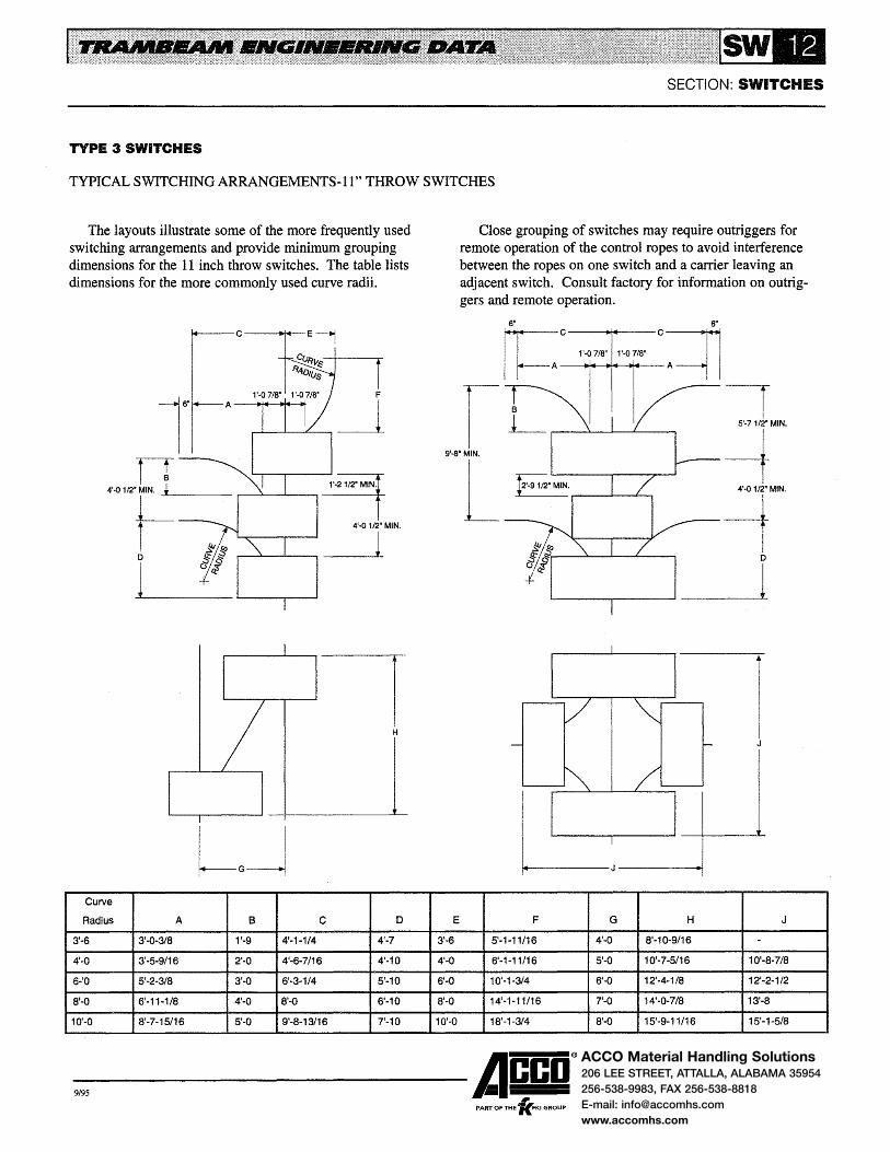
ACCO Material Handling Solutions206 LEE STREET, ATTALLA, ALABAMA 35954
256-538-9983, FAX 256-538-8818
E-mail: [email protected]
www.accomhs.com
SECTION: SWITCHES
TYPE 3 SWITCHES
TYPICAL SWITCHING ARRANGEMENTS-It" THROW SWITCHES
The layouts illustrate some of the more frequently used switching arrangements and provide minimum grouping dimensions for the 11 inch throw switches. The table lists dimensions for the more commonly used curve radii.
4'..()
I
I
Curve
Radius A 8 c 0
3'-6 3'-0-3/8 1'-9 4'-1-1/4 4'-7
4'-0 3'-5-9/16 2'-0 4'-6-7/16 4'-10
6-'0 5'-2-3/8 3'-0 6'-3-1/4 5'-10
8'-0 6'-11-1/8 4'-0 8'-0 6'-10
10'-0 8'-7-15/16 5'-0 9'-8-13/16 7'-10
Close grouping of switches may require outriggers for remote operation of the control ropes to avoid interference between the ropes on one switch and a carrier leaving an adjacent switch. Consult factory for information on outriggers and remote operation.
r c=lls·
1'·0 7/8" 1'..() 7/8" -----to+o~IO!+--tr+ot---
1 5'·7 112• MIN.
9'·8"MIN. -t L 4'-Q 1/2" MIN.
-t D
l
E F G H J
3'-6 5'-1-11/16 4'-0 8'-10-9/16 -4'-0 6'-1-11/16 5'-0 10'-7-5/16 10'-8-7/8
6'-0 10'-1-3/4 6'-0 12'-4-118 12'-2-1/2
8'-0 14'-1-11/16 7'-0 14'-0-7/8 13'-8
10'-0 18'-1-314 8'-0 15'-9-11/16 15'-1-5/8
-9,95 ------Acco® PART OF THE 'lc.FKI GROUP

ACCO Material Handling Solutions206 LEE STREET, ATTALLA, ALABAMA 35954
256-538-9983, FAX 256-538-8818
E-mail: [email protected]
www.accomhs.com
SECTION: SWITCHES
TYPE 3 SWITCHES
TYPICAL SWITCHING ARRANGEMENTS-14'' THROW SWITCHES
The layouts illustrate some of the more frequently used switching arrangements and provide minimum grouping dimensions for the 14 inch throw switches. The table lists dimensions for the more commonly used curve radii.
c--lll*lf--E4
I
I I
Curve
Radius A B c D
3'-6 3'-0-3/8 1'-9 4'-5-1/2 5'-3-1/4
4'-0 3'-5-9116 2'-0 4'-10-11/16 5'-6-1/4
6'-0 5'-2-3/8 3'-0 6'-7-1/2 6'-6-1/4
8'-0 6'-11-1/8 4'-0 8'-4-1/4 7'-6-1/4
10'-0 8'-7-15116 5'-Q 1 0'-1-1/16 8'-6-1/4
E
3'-6
4'-0
6'-0
8'-0
10'-0
Close grouping of switches may require outriggers for remote operation of the control ropes to avoid interference between the ropes on one switch and a carrier leaving an adjacent switch. Consult factory for information on outriggers and remote operation.
1'·5 1/8. 1'·5 1/8"
I 10'·71/2~ MIN.
L I
6'.0 3/4v MIN.
-t 4'·5 3/4" MIN.
-1 D
l
F G H J K
4'-6-3/8 4'-0 9'-0-5/16 - -5'-6-5/16 5'-0 10'-9-1/8 - -9'-6-3/8 6'-0 12'-5-7/8 13'-7 12'-11
13'-6-5/16 7'-0 14'-2-11/16 15'-0-1/2 14'-4-1/2
17'-6-3/8 8'-0 15'-11-7/16 16'-6-1/8 15'-10-1/8
-9,95 ------Acco®
, PART OF THE 'KFKI GROUP
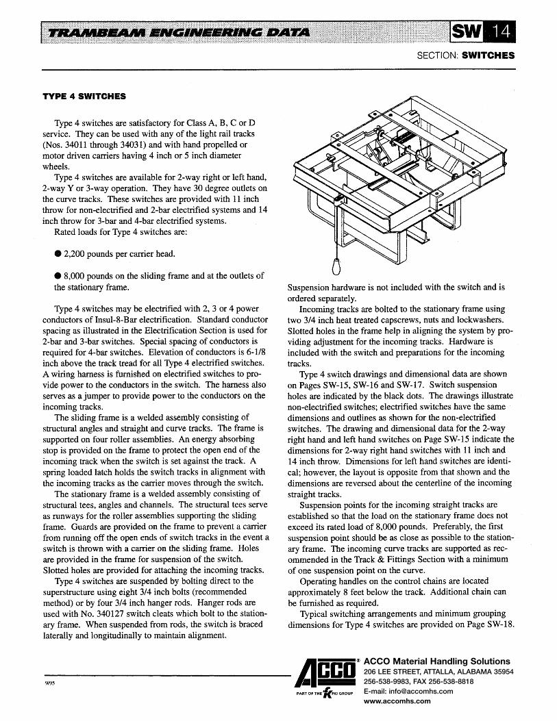
ACCO Material Handling Solutions206 LEE STREET, ATTALLA, ALABAMA 35954
256-538-9983, FAX 256-538-8818
E-mail: [email protected]
www.accomhs.com
TYPE 4 SWITCHES
Type 4 switches are satisfactory for Class A, B, C or D service. They can be used with any of the light rail tracks (Nos. 34011 through 34031) and with hand propelled or motor driven carriers having 4 inch or 5 inch diameter wheels.
Type 4 switches are available for 2-way right or left hand, 2-way Y or 3-way operation. They have 30 degree outlets on the curve tracks. These switches are provided with 11 inch throw for non-electrified and 2-bar electrified systems and 14 inch throw for 3-bar and 4-bar electrified systems.
Rated loads for Type 4 switches are:
e 2,200 pounds per carrier head.
e 8,000 pounds on the sliding frame and at the outlets of the stationary frame.
Type 4 switches may be electrified with 2, 3 or 4 power conductors of Insul-8-Bar electrification. Standard conductor spacing as illustrated in the Electrification Section is used for 2-bar and 3-bar switches. Special spacing of conductors is required for 4-bar switches. Elevation of conductors is 6-1/8 inch above the track tread for all Type 4 electrified switches. A wiring harness is furnished on electrified switches to provide power to the conductors in the switch. The harness also serves as a jumper to provide power to the conductors on the incoming tracks.
The sliding frame is a welded assembly consisting of structural angles and straight and curve tracks. The frame is supported on four roller assemblies. An energy absorbing stop is provided on the frame to protect the open end of the incoming track when the switch is set against the track. A spring loaded latch holds the switch tracks in alignment with the incoming tracks as the carrier moves through the switch.
The stationary frame is a welded assembly consisting of structural tees, angles and channels. The structural tees serve as runways for the roller assemblies supporting the sliding frame. Guards are provided on the frame to prevent a carrier from running off the open ends of switch tracks in the event a switch is thrown with a carrier on the sliding frame. Holes are provided in the frame for suspension of the switch. Slotted holes are provided for attaching the incoming tracks.
Type 4 switches are suspended by bolting direct to the superstructure using eight 3/4 inch bolts (recommended method) or by four 3/4 inch hanger rods. Hanger rods are used with No. 340127 switch cleats which bolt to the stationary frame. When suspended from rods, the switch is braced laterally and longitudinally to maintain alignment.
SECTION: SWITCHES
Suspension hardware is not included with the switch and is ordered separately.
Incoming tracks are bolted to the stationary frame using two 3/4 inch heat treated capscrews, nuts and lockwashers. Slotted holes in the frame help in aligning the system by providing adjustment for the incoming tracks. Hardware is included with the switch and preparations for the incoming tracks.
Type 4 switch drawings and dimensional data are shown on Pages SW-15, SW-16 and SW-17. Switch suspension holes are indicated by the black dots. The drawings illustrate non-electrified switches; electrified switches have the same dimensions and outlines as shown for the non-electrified switches. The drawing and dimensional data for the 2-way right hand and left hand switches on Page SW-15 indicate the dimensions for 2-way right hand switches with 11 inch and 14 inch throw. Dimensions for left hand switches are identical; however, the layout is opposite from that shown and the dimensions are reversed about the centerline of the incoming straight tracks.
Suspension points for the incoming straight tracks are established so that the load on the stationary frame does not exceed its rated load of 8,000 pounds. Preferably, the first suspension point should be as close as possible to the stationary frame. The incoming curve tracks are supported as recommended in the Track & Fittings Section with a minimum of one suspension point on the curve.
Operating handles on the control chains are located approximately 8 feet below the track. Additional chain can be furnished as required.
Typical switching arrangements and minimum grouping dimensions for Type 4 switches are provided on Page SW-18.
-9,95 ------Acco®
, PART OF THE 'KFKI GROUP

ACCO Material Handling Solutions206 LEE STREET, ATTALLA, ALABAMA 35954
256-538-9983, FAX 256-538-8818
E-mail: [email protected]
www.accomhs.com
SECTION: SWITCHES
TYPE 4 SWITCHES
OUTLINE DRAWING OF 2·WAY RIGHT AND LEFf HAND SWITCHES
The drawing and table indicate the dimensions for 2·way right hand switches with 11" and 14" throw. Dimensions for left hand switches are identical, but the layout is opposite from that shown. (Left hand switch dimensions are reversed about the centerline of the incoming straight tracks.)
The drawing illustrates the non-electrified switch. Electrified switches have the same dimensions and outline as
0
i - t-------r-tt-..,..------1 -
I I
Item Number Type of A
Right Hand Left Hand Electrification (Throw)
41012 41013 Non-Electrified 11 in.
410312 410313 2-Bar lnsul-8
41070 41071 Non-Electrified 14in.
410370 410371 3-Bar lnsul-8
shown for the non-electrified switch. The black dots indicate 13/16" diameter holes for switch
suspension. Eight 3/4" diameter bolts or four 3/4" diameter hanger rods are required to support the switch. Hanger rods are used with No. 340127 switch cleats which bolt to the stationary frame. When suspended from rods, the switch is braced laterally and longitudinally to maintain alignment.
..
~
I
B c 0 K L s 4'-5 1'-6-1/4 2'-6-3/4 1'·7-1/4 2'-7-3/4 8-1/2
4'-11 1'-9-1/4 2'-9-3/4 1'-10-1/4 2'-10-3/4 10-1/2
-9,95 ------Acco®
, PART OF THE 'KFKI GROUP

ACCO Material Handling Solutions206 LEE STREET, ATTALLA, ALABAMA 35954
256-538-9983, FAX 256-538-8818
E-mail: [email protected]
www.accomhs.com
TYPE 4 SWITCHES
OUTLINE DRAWING OF 3-WAY SWITCH
The drawing and table indicate the dimensions for 3-way switches with 11" and 14" throw. The drawing illustrates the non-electrified switch. Eectrified switches have the same dimensions and outline as shown for the non-electrified switch.
II:
~------~~------------~ ...;
Item Type of A
Number Electrification (Throw) 8
41016 Non-Electrified 11 in. 7'-3-1/2
410316 2-Bar lnsul-8
41074 Non-Electrified 14in. 8'-3-1/2
410374 3-Bar lnsul-8
SECTION: SWITCHES
The black dots indicate 13/16" diameter holes for switch suspension. Twelve 3/4" diameter bolts or six 3/4" diameter hanger rods are required to support the switch. Hanger rods are used with No. 340127 switch cleats which bolt to the stationary frame. When suspended from rods, the switch is braced laterally and longitudinally to maintain alignment.
u
c K s 3'-5-3/4 3'-6-314 8-1/2
3'-11-314 4'-0-3/4 10-1/2
-9,95 ------Acco® ,
PART OF THE 'KFKI GROUP

ACCO Material Handling Solutions206 LEE STREET, ATTALLA, ALABAMA 35954
256-538-9983, FAX 256-538-8818
E-mail: [email protected]
www.accomhs.com
TYPE 4 SWITCHES
OUTLINE DRAWING OF 2-WAY Y SWITCH
The drawing and table indicate the dimensions for 2-way Y switches with 11" and 14" throw. The drawing illustrates the non-electrified switch. Electricified switches have the same dimensions and outline as shown for the non-electrified switch.
Item Type of A
Number Electrification (Throw)
41020 Non-Electrified 11 in.
410320 2-Bar lnsul-8
41076 Non-Electrified 14in.
410376 3-Bar lnsul-8
SECTION: SWITCHES
The black dots indicate 13116" diameter holes for switch suspension. Ten 3/4" diameter bolts or five 3/4" diameter hanger rods are required to support the switch. Hanger rods are used with No. 340127 switch cleats which bolt to the stationary frame. When suspended from rods~ the switch is braced laterally and longitudinally to maintain alignment.
B c K
5'-5-1/2 2'-6-3/4 2'-7-3/4
5'-11-1/2 2'-9-3/4 2'-10-3/4
-9,95 ------Acco®
, PART OF THE 'KFKI GROUP

ACCO Material Handling Solutions206 LEE STREET, ATTALLA, ALABAMA 35954
256-538-9983, FAX 256-538-8818
E-mail: [email protected]
www.accomhs.com
TYPE 4 SWITCHES
TYPICAL SWITCHING ARRANGEMENTS
The layouts illustrate some of the more frequently used switching arrangements and provide minimum grouping dimensions. The table lists dimensions for the more commonly used curve radii.
c--too+<~t--E4
IT
~ D
1
I
I I
Curve
Radius A B c D E F
3'-6 3'·0-3/8 1'-9 4'-4-11/16 5'-3-1/2 3'-6 4'-7-3/4
4'-0 3'-5-9/16 2'-0 4'-9-7/8 5'-6-1/2 4'-0 5'-7-3/4
6'-0 5'-2-3/8 3'-0 6'-6-11/16 6'-6-1/2 6'-0 9'-7-3/4
8'-0 6'-11-1/8 4'-0 8'-3-7116 7'-6-1/2 8'-0 13'-7-3/4
10'-0 8'-7-15/16 5'-0 10'-0-1/4 8'-6-1/2 10'-0 17'-7-3/4
SECTION: SWITCHES
Close grouping of switches may require outriggers for remote operation of the control ropes to avoid interference between the ropes on one switch and a carrier leaving an adjacent switch. Consult factory for information on outriggers and remote operation.
I p
L
G H
4'-0 9'-3-5/8
5'-0 11'-0-7/16
6'-0 12'-9-3/16
7'-0 14'-6
8'-0 16-2-3/4
J
--
14'-2-3/8
15'-7-7/8
17'-1-1/2
MINIMUM DIMENSIONS
11" Throw
Switches
L = 1'-2-1/2 M:::4'-9
N = 2'-9-1/2
0=6'-4
P= 1 f-1
14"Throw
Switches
L = 1'-7-3/4
M = 5'-2-1/4
N=3'-8
0 = 7'-2-1/2
p = 12'-4-3/4
-9,95 ------Acco® ,
PART OF THE 'KFKI GROUP
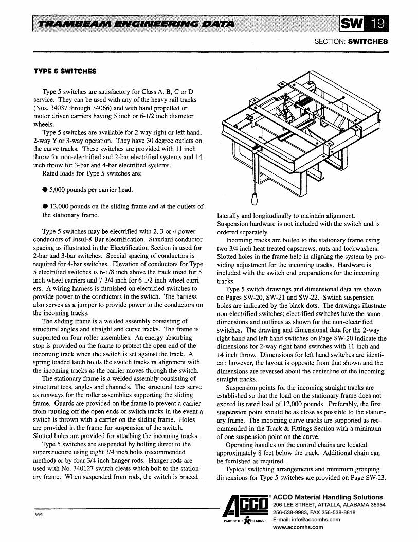
ACCO Material Handling Solutions206 LEE STREET, ATTALLA, ALABAMA 35954
256-538-9983, FAX 256-538-8818
E-mail: [email protected]
www.accomhs.com
TYPE 5 SWITCHES
Type 5 switches are satisfactory for Class A, B, C or D service. They can be used with any of the heavy rail tracks (Nos. 34037 through 34066) and with hand propelled or motor driven carriers having 5 inch or 6-1/2 inch diameter wheels.
Type 5 switches are available for 2-way right or left hand, 2-way Y or 3-way operation. They have 30 degree outlets on the curve tracks. These switches are provided with 11 inch throw for non-electrified and 2-bar electrified systems and 14 inch throw for 3-bar and 4-bar electrified systems.
Rated loads for Type 5 switches are:
e 5,000 pounds per carrier head.
e 12,000 pounds on the sliding frame and at the outlets of the stationary frame.
Type 5 switches may be electrified with 2, 3 or 4 power conductors of Insul-8-Bar electrification. Standard conductor spacing as illustrated in the Electrification Section is used for 2-bar and 3-bar switches. Special spacing of conductors is required for 4-bar switches. Elevation of conductors for Type 5 electrified switches is 6-1/8 inch above the track tread for 5 inch wheel carriers and 7-3/4 inch for 6-1/2 inch wheel carriers. A wiring harness is furnished on electrified switches to provide power to the conductors in the switch. The harness also serves as a jumper to provide power to the conductors on the incoming tracks.
The sliding frame is a welded assembly consisting of structural angles and straight and curve tracks. The frame is supported on four roller assemblies. An energy absorbing stop is provided on the frame to protect the open end of the incoming track when the switch is set against the track. A spring loaded latch holds the switch tracks in alignment with the incoming tracks as the carrier moves through the switch.
The stationary frame is a welded assembly consisting of structural tees, angles and channels. The structural tees serve as runways for the roller assemblies supporting the sliding frame. Guards are provided on the frame to prevent a carrier from running off the open ends of switch tracks in the event a switch is thrown with a carrier on the sliding frame. Holes are provided in the frame for suspension of the switch. Slotted holes are provided for attaching the incoming tracks.
Type 5 switches are suspended by bolting direct to the superstructure using eight 3/4 inch bolts (recommended method) or by four 3/4 inch hanger rods. Hanger rods are used with No. 340127 switch cleats which bolt to the stationary frame. When suspended from rods, the switch is braced
SECTION: SWITCHES
laterally and longitudinally to maintain alignment. Suspension hardware is not included with the switch and is ordered separately.
Incoming tracks are bolted to the stationary frame using two 3/4 inch heat treated capscrews, nuts and lockwashers. Slotted holes in the frame help in aligning the system by providing adjustment for the incoming tracks. Hardware is included with the switch end preparations for the incoming tracks.
Type 5 switch drawings and dimensional data are shown on Pages SW-20, SW-21 and SW-22. Switch suspension holes are indicated by the black dots. The drawings illustrate non-electrified switches; electrified switches have the same dimensions and outlines as shown for the non-electrified switches. The drawing and dimensional data for the 2-way right hand and left hand switches on Page SW-20 indicate the dimensions for 2-way right hand switches with 11 inch and 14 inch throw. Dimensions for left hand switches are identical; however, the layout is opposite from that shown and the dimensions are reversed about the centerline of the incoming straight tracks.
Suspension points for the incoming straight tracks are established so that the load on the stationary frame does not exceed its rated load of 12,000 pounds. Preferably, the first suspension point should be as close as possible to the stationary frame. The incoming curve tracks are supported as recommended in the Track & Fittings Section with a minimum of one suspension point on the curve.
Operating handles on the control chains are located approximately 8 feet below the track. Additional chain can be furnished as required.
Typical switching arrangements and minimum grouping dimensions for Type 5 switches are provided on Page SW-23.
-9,95 ------Acco® PART OF THE 'lc.FKI GROUP

ACCO Material Handling Solutions206 LEE STREET, ATTALLA, ALABAMA 35954
256-538-9983, FAX 256-538-8818
E-mail: [email protected]
www.accomhs.com
SECTION: SWITCHES
TYPE 5 SWITCHES
OUTLINE DRAWING OF 2-WAY RIGHT AND LEFT HAND SWITCHES
The drawing and table indicate the dimensions for 2-way right hand switches with 11" and 14" throw. Dimensions for left hand switches are identical, but the layout is opposite from that shown. (Left hand switch dimensions are reversed about the centerline of the incoming straight tracks.)
The drawing illustrates the non-electrified switch. Electrified switches have the same dimensions and outline as
Q z 1.1,1
..... aU
~~ ~
:::t ... • ~ :...
Item Number Type of A
Right Hand Left Hand Electrification (Throw)
41024 41025 Non-Electrified 11 in.
410324 410325 2-Bar lnsul-8
41078 41079 Non-Electrified 14in.
410378 410379 3-Bar lnsul-8
8
shown for the non-electrified switch. The black dots indicate 13/16" diameter holes for switch
suspension. Eight 3/4" diameter bolts or four 3/4" diameter hanger rods are required to support the switch. Hanger rods are used with No. 340127 switch cleats which bolt to the stationary frame. When suspended from rods, the switch is braced laterally and longitudinally to maintain alignment.
0
u lilt
Q~ lit ~~ t; N
~ ... Co
c 0 K L s 4'~5 1 '-6-1/4 2'-6-3/4 1'-7-1/4 2'-7-3/4 8-112
4'-11 1'-9-1/4 2'-9-3/4 1'-10-1/4 2'-10-3/4 10-1/2
-9,95 ------Acco® ,
PART OF THE 'KFKI GROUP
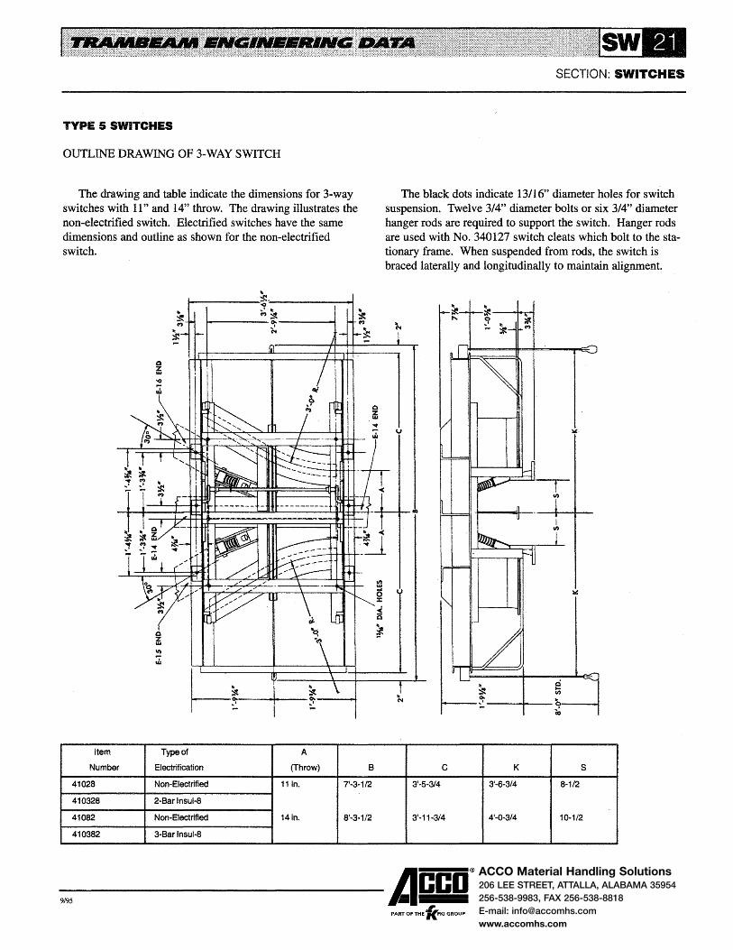
ACCO Material Handling Solutions206 LEE STREET, ATTALLA, ALABAMA 35954
256-538-9983, FAX 256-538-8818
E-mail: [email protected]
www.accomhs.com
TYPE 5 SWITCHES
OUTLINE DRAWING OF 3-WAY SWITCH
The drawing and table indicate the dimensions for 3-way switches with 11" and 14" throw. The drawing illustrates the non-electrified switch. Electrified switches have the same dimensions and outline as shown for the non-electrified switch.
Item
Number
" ~---------~·~----------~ .. • lit ('I') ::I
~-------~------~ N
~~----~----~----~ Type of A
Electrification (Throw) 8
41028 Non-Electrified 11 in. 7'-3-1/2
410328 2-Bar lnsul-8
41082 Non-Electrified 14in. 8'-3-1/2
410382 3-Bar lnsul-8
SECTION: SWITCHES
The black dots indicate 13/16" diameter holes for switch suspension. Twelve 3/4, diameter bolts or six 3/4" diameter hanger rods are required to support the switch. Hanger rods are used with No. 340127 switch cleats which bolt to the stationary frame. When suspended from rods, the switch is braced laterally and longitudinally to maintain alignment.
v
1"1----~----+--i I
c K s s·-s-314 s·-s-314 8-1/2
3'-11-3/4 4'-0-3/4 10-1/2
-9,95 ------Acco®
, PART OF THE 'KFKI GROUP

ACCO Material Handling Solutions206 LEE STREET, ATTALLA, ALABAMA 35954
256-538-9983, FAX 256-538-8818
E-mail: [email protected]
www.accomhs.com
TYPE 5 SWITCHES
OUTLINE DRAWING OF 2-WAY Y SWITCH
The drawing and table indicate the dimensions for 2-way Y switches with 11" and 14" throw. The drawing illustrates the non-electrified switch. Electrified switches have the same dimensions and outline as shown for the non-electrified switch.
..
SECTION: SWITCHES
The black dots indicate 13/16" diameter holes for switch suspension. Ten 3/4" diameter bolts or five 3/4" diameter hanger rods are required to support the switch. Hanger rods are used with No. 340127 switch cleats which bolt to the stationary frame. When suspended from rods, the switch is braced laterally and longitudinally to maintain alignment.
~----------~------------4-~
1'911;
::It 0.------+-t ~
~ .......,...~__,.....-~ --+-:-~ ....
C')
n--------7--+-~--------------~--r
(,!,1
~ ~
::it .., '1
~-~ liD
~'#. It)~ ., '? ::; ';.. ';..
)< u
....
...:.
I I
V) 11.1
0
~~ :z:
Ill: - d ..( ::It ::It 6 0. o:- 11; th ... ~
';.... N .. q Co
Item Type of A
Number Electrification (Throw} B c K
41032 Non-Electrified 11 in. 5'-5-1/2 2'-6-314 2'-7-3/4
410332 2-Bar lnsul-8
41084 Non-Electrified 14in. 5'-11-1/2 2'-9-314 2'-10-3/4
410384 3-Bar lnsul-8
-9,95 ------Acco®
, PART OF THE 'KFKI GROUP

ACCO Material Handling Solutions206 LEE STREET, ATTALLA, ALABAMA 35954
256-538-9983, FAX 256-538-8818
E-mail: [email protected]
www.accomhs.com
TYPE 5 SWITCHES
TYPICAL SWITCHING ARRANGEMENTS
The layouts illustrate some of the more frequently used switching arrangements and provide minimum grouping dimensions. The table lists dimensions for the more commonly used curve radii.
c--fl>l+--
lh-A IT M ...L*---- .--~___.....__---"~
t-= D
1
I
I
Curve
Radius A 8 c D E F
4'-0 3'·5-9/16 2'-0 4'-9-7/8 5'-6-1/2 4'-0 5'-7-314
6'-0 5'-2-3/8 3'-0 6'-6-11/16 6'-6-1/2 6'-0 9'-7-3/4
8'-0 6'-11-1/8 4'-0 8'-3-7/16 7'-6-1/2 8'-0 13'-7-3/4
10'-0 8'-7-15/16 5'-0 10'-0-1/4 8'-6-1/2 17'-7-3/4
12'-0 10'-4-11/16 6'-0 11'-9 9'-6-1/2 12'-0 21'-7-3/4
G
5'-0
6'-0
7'-0
8'-0
9'-0
SECTION: SWITCHES
Close grouping of switches may require outriggers for remote operation of the control ropes to avoid interference between the ropes on one switch and a carrier leaving an adjacent switch. Consult factory for information on outriggers and remote operation.
H J
11'-0-7/16
12'-9-3/16 14'-2-3/8
14'-6 15'-7-7/8
16-2-3/4 17'-1-1/2
17'-11-9/16 18'-7
MINIMUM DIMENSIONS
11"Throw
Switches
L = 1'-2-1/2
M=4'-9
N = 2'-9-1/2
0=6'-4
P= 11'-1
14''Throw
Switches
L = 1'-7-314
M =5'-2-1/4
N=3'-8
0= 7'-2-1/2
p = 12'-4-3/4
-9,95 ------A~co® PART OF THE 'KFKI GROUP

ACCO Material Handling Solutions206 LEE STREET, ATTALLA, ALABAMA 35954
256-538-9983, FAX 256-538-8818
E-mail: [email protected]
www.accomhs.com
TYPE 7 CROSSOVER
Type 7 crossovers are satisfactory for Class A, B or C service. They can be used with any of the light rail sections (Nos. 34011 through 34031) and with hand propelled or motor driven carriers having 4 inch or 5 inch diameter wheels. The Type 7 crossover allows two monorail tracks at the same elevation to cross at right angles. It is not designed to operate with a carrier on the rotating track.
Rated loads for Type 7 crossovers are:
e 2,000 pounds per carrier head.
e 4,000 pounds on the rotating frame and at the outlets of the stationary frame.
Type 7 crossovers may be electrified with 2, 3 or 4 power conductors of Insul-8-Bar electrification. Standard conductor spacing as illustrated in the Electrification Section is used for 2-bar and 3-bar crossovers. Special conductor spacing is required for 4-bar crossovers. Elevation of conductors is 6-1/8 inch above track tread. A wiring harness is furnished on electrified crossovers to provide power to the conductors in the crossover. The harness also serves as a jumper to provide power to the conductors on the incoming tracks.
The rotating frame is a welded assembly consisting of structural channels and plates, a center pin and a straight track. The center pin supports the frame from a thrust bearing in the stationary frame. Stops are provided to protect the open ends of the incoming tracks when the crossover is set against the track. A spring loaded latch holds the crossover
TYPE 8 TURNTABLE
Type 8 turntables are identical to Type 7 crossovers except that guards on the stationary frame allow rotation of the unit with a loaded carrier on the track. They can be used with any of the light rail sections (Nos. 34011 through 34031) and with hand propelled or motor driven carriers having 4 inch or 5 inch diameter wheels and a 21 inch or less wheelbase.
Rated loads for Type 8 turntables are the same as the Type 7 crossovers. They may be electrified with 2, 3 or 4 power
SECTION: SWITCHES
track in alignment with the incoming tracks as the carrier moves through the crossover.
The stationary frame is a welded assembly consisting of structural channels and plates. Four rollers in the frame stabilize the rotating frame. Holes are provided in the frame for suspension of the crossover. Slotted holes are provided for attaching the incoming tracks.
Type 7 crossovers are suspended by bolting direct to the superstructure using sixteen 5/8 inch bolts, nuts and lockwashers. Suspension hardware is not included with the crossover and must be ordered separately.
Incoming tracks are bolted to the stationary frame using four 5/8 inch heat treated capscrews, nuts and lockwashers. Slotted holes in the frame help in aligning the system by providing adjustment for the incoming tracks. Hardware is included with the switch and preparations for the incoming tracks
Suspension points for incoming tracks are established so that the load on the stationary frame does not exceed its rated load of 4,000 pounds. Preferably, the first suspension point should be as close as possible to the stationary frame. If incoming tracks are curved, they are supported as recommended in the Track & Fittings Section.
Operating handles on the control chains are located approximately 8 feet below the track. Additional chain can be furnished as required.
Optional accessories for Type 7 crossovers include electric baffles, air or electric operation, signal lights and protective hoods.
conductors of Insul-8-Bar electrification. Suspension of Type 8 turntables and their incoming tracks is the same as used for Type 7 crossovers.
Special turntables can be provided for applications where monorail tracks cross at an angle different than 90 degrees, carriers have a wheelbase greater than 21 inch, or rated loads are greater than 4,000 pounds. Consult factory for information on these applications.
-9,95 ------Acco® , PART OF THE 'KFKI GROUP

ACCO Material Handling Solutions206 LEE STREET, ATTALLA, ALABAMA 35954
256-538-9983, FAX 256-538-8818
E-mail: [email protected]
www.accomhs.com
TYPE 7 CROSSOVER TYPE 8 TURNTABLE
SECTION: SWITCHES
OUTLINE DRAWING
The drawing illustrates and provides dimensions for a non-electrified Type 7 crossover. Electrified crossovers have the same dimensions and outline as the non-electrified crossover. Dimensions and outline for Type 8 turntables are
identical to those shown but with the addition of guards to the stationary frame.
The black dots indicate 11/16 inch diameter holes for suspension of the crossover. Sixteen 5/8 inch bolts are required to support the crossover .
..__ __ 1 '·10"' ---· t-1---,·1 '·10·-----...
~~· OIA. HOLES 5%"'
~
Type 7 Crossover
Item Number Type of Electrification
41050 Non-Electrified
41035002 2-Bar lnsui-8-Bar
41035003 3-Bar lnsui-8-Bar
E-20 END PREPARATION (TYPICAL ALL INCOMING TRACKS) 1J{l' x 1Jf6'' SLOmD HOLES ARE PUNCHED ON 2~" x 2:!4" CENTERS.
Type 8 Turnable
Item Number Type of Electrification
41048 Non-Electrified
41034802 2-Bar lnsui-8-Bar
41034803 3-Bar lnsui-8-Bar
-9,95 ------Acco®
, PART OF THE 'KFKI GROUP


ACCO Material Handling Solutions206 LEE STREET, ATTALLA, ALABAMA 35954
256-538-9983, FAX 256-538-8818
E-mail: [email protected]
www.accomhs.com
GENERAL INFORMATION
For motor driven systems, electric current must be transferred from the building power source to the moving equipment. To accomplish this, a system of current conductors and collectors, supports and other accessories, known as electrification, is used.
Most Trambeam systems can be electrified to provide the power to the motors of electrically driven equipment. Monorail systems with Type 2 switches cannot be electrified because of space limitations.
Insul-8-Bar enclosed conductors are generally used for electrifying runway track and monorail systems. They are also used for electrifying cranes. Festooned cable conductors are also available and are generally used for electrifying cranes. They may be used for electrifying runway track and monorail systems. Insul-8-Bar and festooned cable systems are briefly described below. Consult factory for data when other electrification systems are specified.
Many underhung crane and monorail systems have been installed using open conductors (without insulating covers) and have operated successfully for many years. However, the National Electric Code now requires that runway conductors be guarded and open conductors are no longer recommended. Consult factory for data when open conductors are required for expansion of existing systems.
INSUL-8-BAR ELECTRIFICATION
Insul-8-Bar electrification is a dependable system for all crane and monorail applications. The conductors are rigid, figure-8 bars furnished in standard lengths and enclosed in specially compounded covers. They are available in ampacities of 90, 110 and 250 amperes and with PVC covers (for temperatures to 160 deg. F), medium heat covers (for temperatures to 250 deg. F), or high heat covers (for temperature to 400 deg. F). See Pages ES-3 through ES-14 for data on conductors, accessories, collectors and arrangements at transfers and switches.
SECTION: ELECTRIFICATION
FESTOONED ELECTRIFICATION
Festooning of electrical cables is an efficient way to deliver electric current to the crane, carrier and hoist motors of a motor driven crane. Flat cables are used for motor driven cranes and are supported from cable carriers operating in a galvanized steel C-track. The conductors are enclosed in a PVC orange colored jacket. Festooned electrification is well suited for use in damp, humid atmospheres.
TAGLINE ELECTRIFICATION
Tagline electrification is used on hand propelled cranes. Round cable is used to supply power to the hoist and is supported by slide rings from a wire. The slide wire is supported at each end by brackets with eyebolts providing wire tension.
CONDUCTOR SELECTION
Insul-8-Bar 90 ampere galvanized steel conductors will be satisfactory for most applications. On applications with larger horsepower motors, long runways or an unusual environment, consideration is given to the following when selecting the conductor and cover:
e AMP A CITY - the current carrying capacity of the conductors expressed in amperes.
e VOLTAGE DROP ~ the arithmetical difference between the voltages at the load and supply ends of the conductor expressed as a percentage of the supply voltage.
e AMBIENT CONDITIONS - the characteristics of the atmosphere in which the system is located.
AMP A CITY for a single carrier or crane is the nameplate full-load ampere rating of the largest motor or
-9,95 ------Acco®
, PART OF THE 'KFKI GROUP

ACCO Material Handling Solutions206 LEE STREET, ATTALLA, ALABAMA 35954
256-538-9983, FAX 256-538-8818
E-mail: [email protected]
www.accomhs.com
INSUL·8·BAR0 ELECTRIFICATION
group of motors for any single motion plus 50% of the nameplate full~ load ampere rating of the next largest motor or group of motors. For multiple carriers or cranes, compute the ampacity for each carrier or crane, add them together and multiply the sum by the demand factor from the table.
Number of Demand
Carriers or Cranes Factor
2 0.95
3 0.91
4 0.87
5 0.84
6 0.81
7 0.78
VOLTAGE DROP increases in direct proportion to the effective length of the conductors. The effective length is the distance from the powerfeed to the end of the conductor run. Powerfeeds are usually located at the center of a system resulting in the effective length being one-half the conductor
ES SECTION: ELECTRIFICATION
length. Additional feed points may be necessary on longer systems to limit the voltage drop. The voltage drop for Insul-8-Bar conductors and 3 phase, 60 hertz, alternating current is shown in the table. Voltage drop is limited to 3% on runways and 2% on crane conductors.
Voltage Drop per 100 Feet of Effective
Length per 1 00 Amperes of Current
Galvanized Steel ~ 90 Amperes 16.20
Galvanized Steel - 110 Amperes 13.40
Stainless Clad Copper - 250 Amperes 2.01
Copper Steel Laminate - 250 Amperes 2.01
AMBIENT CONDITIONS. Temperature is of prime importance in selecting the electrification system. However, high humidity and the presence of chemicals or radiation should also be considered in selecting both the conductor and the cover; consult factory for recommendations on applications with these conditions.
-9,95 ------Acco®
PART OF THE 'lc.FKI GROUP

ACCO Material Handling Solutions206 LEE STREET, ATTALLA, ALABAMA 35954
256-538-9983, FAX 256-538-8818
E-mail: [email protected]
www.accomhs.com
INSUL·8·BAR0 ELECTRIFICATION
Rigid, hollow, figure-8 bars enclosed in specially compounded covers are used as conductors for Insul-8-Bar electrification. They are shipped in 10' lengths with connector pins and covers assembled to the bars. Conductor materials and ratings are:
e GALVANIZED STEEL - 90 and 110 Amperes. e STAINLESS CLAD COPPER LAMINATE -
250 Amperes. e COPPER STEEL LAMINATE - 250 Amperes.
Conductors are available with PVC covers for operating temperatures to 160 deg. F, with medium heat covers for temperatures to 250 deg. F or with high heat covers for temperatures to 400 deg F. Each cover type meets all requirements for plastic electrical insulation and may be used indoors or outdoors. Covers are non-burning and will not support combustion. All conductor bars and covers are dimensionally interchangeable except 90 amperes galvanized steel bar which uses larger diameter connector pins.
Expansion sections are installed every 300 feet for systems using galvanized steel conductors and every 200 feet for systems using stainless clad copper laminate or copper steel laminate conductors. They are factory assembled, ready for installation.
Conductors with PVC covers for curve track are formed to the curve radius in the field. Conductors with medium heat or high heat covers for curve tracks are factory fabricated.
Stainless steel ( 40 ampere rating), formed electrolytic copper (350 ampere rating) and solid copper (500 ampere rating) conductors with PVC, medium heat or high heat covers are also available.
Conductors are suspended from track by supports which clamp to the top flange (Nos. 34011 through 34046 tracks) or bolt to the web (Nos. 34051 through 34079 tracks). Plastic snap-in hanger clamps are provided with each support. They grip the figure-8 shape and support the conductors. Crossbolt steel hanger clamps are used to support conductors on curve track. Recommended support spacing is 5' on straight runs and 3' on curves.
Conductor lengths are joined using a connecting tool which forces the connector pins on one conductor into the adjacent conductor. Connector pins bond the sections mechanically and electrically.
Snap-on joint covers are furnished to provide a continuous cover at the joints.
SECTION: ELECTRIFICATION
1 Conductor Bar 2 Conductor Bar Support 3 Hanger Clamp 4 Powerfeed 5 Joint Cover 6 Power Leads
(By Others) 7 End Cap
Powerfeeds provide taps for connecting the power and control sources to the conductor. They clamp to the upper lobe of the conductor and can be installed at any point along the conductor.
Collectors are sliding shoe type with spring loaded arms to maintain contact shoe pressure. The contact heads articulate and swivel to allow for conductor misalignment. Self-centering collectors are available for discontinuous circuits.
Radi-8-Bar heated conductor systems are available to prevent icing and to de-ice conductors during icing conditions. An insulated heater wire is fed through the lower lobe of the conductor and hollow connector pins in a continuous length. The wire is thermostatically controlled by the ambient temperature. When the temperature falls to +35 deg. F, athermostat closes and operates a contactor to energize the system. Power requirements for the heater systems (when in operation) are from 5 to 15 watts per conductor foot.
-9,95 ------Acco®
, PART OF THE 'KFKI GROUP

ACCO Material Handling Solutions206 LEE STREET, ATTALLA, ALABAMA 35954
256-538-9983, FAX 256-538-8818
E-mail: [email protected]
www.accomhs.com
SECTION: ELECTRIFICATION
INSUL·8·BAR0 ELECTRIFICATION
CONDUCTOR BAR
1.. 10·-o· __ ,
1
•
1
--.;'1sr· l314"1.,...____ 9'-10..112" --- _, _ I
~ ~i § +·~ ITEM NUMBER
With PVC With Medium I Hv:'th High Description
Covers Heat Covers eat Covers
550270 550272 550273 10' long steel bar with steel connector pins and cover factory assembled. RATING: 90 Amperes
Same as No. 550270 galvanized steel bar except with No. 550281 transfer insulator 550271 . . assembled at one end. They are used in the power circuit at interlock and discharge
point gaps.
550422 550250 550445 1 0' long steel bar with steel connector pins and cover factory assembled. RATING: 110 Amperes
Same as No. 550422 galvanized steel bar except with No. 550375 transfer insulator 550407 . .. assembled at one end. They are used in the power circuit at interlock and discharge
point gaps.
550441 550252 550447 1 0' long stainless clad copper laminate with copper connector pins and cover factory assembled. RATING: 250 Amperes
550445 550254 550449 1 0' long copper steel laminate bar with copper conector pins and cover factory assembled. RATING: 250 Amperes
EXPANSION SECTIONS
FLEXIBlE JUMPER
GUIDE ASSEMBlY POWER FEED
~Jr----jillJ] ~f TWO CLAMPS ANCHOR TIGHT--~
ITEM NUMBER
With PVC With Medium With High Description Covers Heat Covers Heat Covers
550274 550275 550276 1 0' long steel bar with steel connector pins, cover, and guide assembly, No. 550437 power feeds and flexible jumper factory assembled. RATING: 90 Amperes
550453 550258 550458 1 0' long steel bar with steel connector pins, cover, guide assembly, No. 550437 power feeds and flexible jumper factory assembled. RATING: 110 Amperes
10' long stainless clad copper ... bar with copper connector cover, guide 550455 550269 550459 assembly, No. 550467 power feeds and flexible jumper factory • RATING:
250Amperes
550456 550260 550460 1 0' long copper steel laminate bar with copper connector pins, cover, guide assembly, No. 550467 power feeds and flexible jumper factory assembled. RATING: 250 Amperes
-9,95 ------Acco® ,
PART OF THE 'KFKI GROUP

ACCO Material Handling Solutions206 LEE STREET, ATTALLA, ALABAMA 35954
256-538-9983, FAX 256-538-8818
E-mail: [email protected]
www.accomhs.com
INSUL·I·BARc ELECTRIFICATION
SNAP·IN HANGER CLAMP
550402
Molded plastic clamps are used for indoor and outdoor applications and for temperatures to 250 Deg. F. They are not recommended for curves.
CROSS·BOLT HANGER CLAMPS
550429
Plated steel clamps are used for indoor applications and are recommended for curves.
550417
Same as No. 550429 except with insulator. They are used for outdoor applications, where ambient conditions warrant additional insulation, and for temperatures to 400 Deg. F.
ANCHOR CLAMP
END COVERS
550400
Plated steel clamps are used on conductor bars at transfer gaps to prevent cover from moving on bar ..
550278
Molded plastic caps used at ends of conductor runs for 90 amp steel bar and temperatures to 300 Deg. F.
550438
Molded plastic caps used at ends of conductor runs for 110 and 250 amp bars and temneratnres to 'JOO Detr. F
POWIERFIEEDS
SECTION: ELECTRIFICATION
550437
Steel clamp type powerfeeds are used for 90/110 amp steel conductors only. For #3 through #0 crimp lugs and temperatures to 160 Deg. F. 550277
Same as 550437 except with high heat case for temperatures to 400 Deg. F.
550467
Copper clamp type powerfeeds are used on systems using #8 through 110 A WG feed wires. For temperatures to 160 Deg. F.
550386
Same as No. 550467 except with high heat case for temperatures to 400 Deg. F.
CONNECTOR PINS
550279
Galvanized steel pin used with 90 amp steel bar.
550280
Galvanized steel transition pin for connecting 90 amp and 110 amp steel bars.
550351
Galvanized steel pin used with 110 amp steel bar.
550383
Copper pins used with stainless clad copper and copper steel laminate bars.
CONNECTOR TOOL
550358
Long handled tool for connecting hollow figure-8 bars.
-9,95 ------Acco® , PART OF THE 'KFKI GROUP

ACCO Material Handling Solutions206 LEE STREET, ATTALLA, ALABAMA 35954
256-538-9983, FAX 256-538-8818
E-mail: [email protected]
www.accomhs.com
INSUL·8·BAR0 ELECTRIFICATION
TRANSFER CAPS
550278
Molded plastic caps used with 90 amp steel bar at conductor gaps of straight switch tracks and with pickup guide for discontinuous circuits. For temperatures to 300 Deg. F.
550282
Same as No. 550278 but with left hand bevel for conductor gaps of curve 'switch tracks.
550283
Same as No. 550278 but with right hand bevel for conductor gaps of curve switch tracks.
550347
Molded plastic caps used with 110 amp steel bar at conductor gaps of straight switch tracks and with pickup guide for discontinuous circuits. For temperatures to 300 Deg. F
550348
Same as No. 550347 but with left hand bevel for conductor gaps of curve switch tracks.
550349
Same as No. 550347 but with right hand bevel for conductor gaps of curve switch tracks.
PICKUP GUIDE
550491
Metal guides used to retrack collectors on conductors of discontinuous circuits. Minimum conductor spacing is 3 in.
SECTION: ELECTRIFICATION
.JOINT COVERS
550421
Plastic covers provide a continuous cover at joints. They are used with PVC covers.
550414
Similar to No. 550421 but are used with medium heat covers for temperatures of 250 Deg. F.
550470
Similar to No. 550421 but are used with high heat covers for temperatures of 400 Deg. F.
TRANSFER INSULATORS
550281
Phenolic insulatros used at each end of power conductors at interlock and discharge point gaps. For 90 amp steel bars only.
550375
Similar to No. 550281 but used with 110 amp steel bars and 250 amp stainless clad copper laminate and copper steel laminate bars.
-9,95 ------Acco®
, PART OF THE 'KFKI GROUP
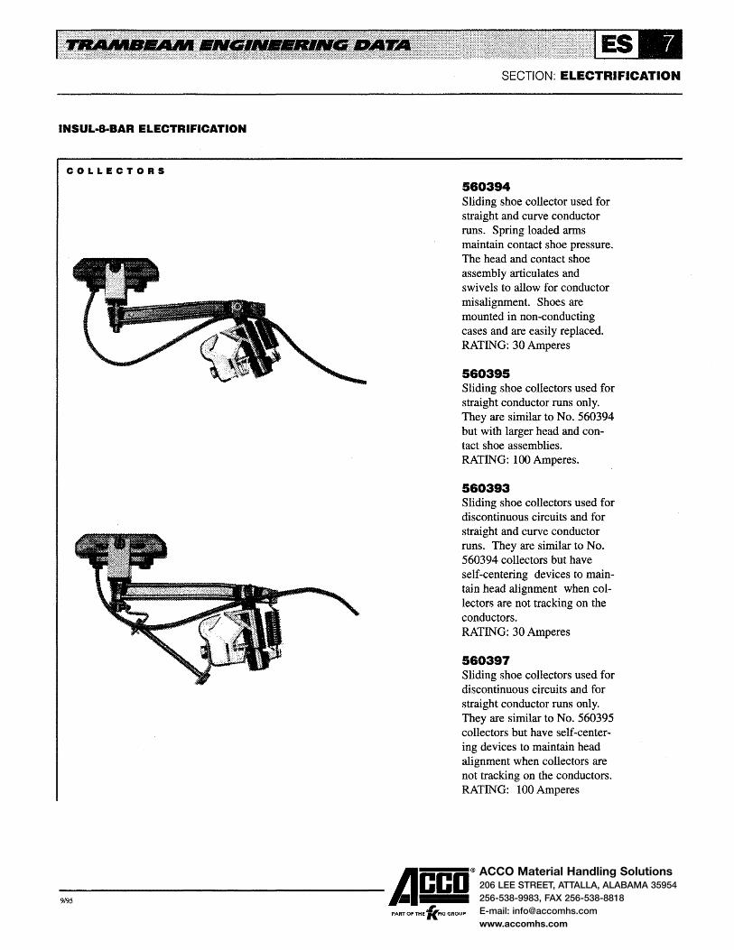
ACCO Material Handling Solutions206 LEE STREET, ATTALLA, ALABAMA 35954
256-538-9983, FAX 256-538-8818
E-mail: [email protected]
www.accomhs.com
INSUL·8·BAR ELECTRIFICATION
COLLECTORS
SECTION: ELECTRIFICATION
560394 Sliding shoe collector used for straight and curve conductor runs. Spring loaded anns maintain contact shoe pressure. The head and contact shoe assembly articulates and swivels to allow for conductor misalignment. Shoes are mounted in non-conducting cases and are easily replaced. RATING: 30 Amperes
580395 Sliding shoe collectors used for straight conductor runs only. They are similar to No. 560394 but with larger head and contact shoe assemblies. RATING: 100 Amperes.
580393 Sliding shoe collectors used for discontinuous circuits and for straight and curve conductor runs. They are similar to No. 560394 collectors but have self-centering devices to maintain head alignment when collectors are not tracking on the conductors. RATING: 30 Amperes
580397 Sliding shoe collectors used for discontinuous circuits and for straight conductor runs only. They are similar to No. 560395 collectors but have self-centering devices to maintain head alignment when collectors are not tracking on the conductors. RATING: lOOAmperes
-9,95 ------Acco®
, PART OF THE 'KFKI GROUP

ACCO Material Handling Solutions206 LEE STREET, ATTALLA, ALABAMA 35954
256-538-9983, FAX 256-538-8818
E-mail: [email protected]
www.accomhs.com
INSUL·8·BAR0 ELECTRIFICATION
COLLECTOR BRACKETS
Collectors are generally supported from brackets bolted to the carrier heads of carriers and crane end trucks. The brackets for crane end trucks match the collectors to the conductor elevations and spacings shown on Page ES-11. Brackets for monorail carriers match the collectors to the conductor elevations and spacings shown on Page ES-12. Brackets for carri-
COLLECTOR & BRACKET
10·7/8"
Collector and bracket assembly for No. 010201 carrier head.
COLLECTOR & BRACKET
Collector and bracket assembly for No. 010207 carrier head.
SECTION: ELECTRIFICATION
ers operating on cranes match the collectors to the conductor elevations and spacings shown in the Crane Section.
The drawings illustrate the brackets for No. 560394 collectors and for conductor elevations of 6-1/8 inch ( 4 inch and 5 inch diameter wheels) and 7-3/4 inch (6-1/2 inch diameter wheels). Dimensions are for the No. 560394 collector. Brackets for No. 560395 collectors are identical to those shown; add 1 inch to the dimensions for the No. 560394 collectors.
COLLECTOR & BRACKET
11·3/4" (No. 1·203) 12·1/4" (No~ 1-205)
Collector and bracket assembly for No. 010203 (shown) or No. 010205 carrier head.
COLLECTOR & BRACKET
11-3/4"
Collector and bracket assembly for No. 010209 carrier head.
-9,95 ------Acco®
, PART OF THE 'KFKI GROUP

ACCO Material Handling Solutions206 LEE STREET, ATTALLA, ALABAMA 35954
256-538-9983, FAX 256-538-8818
E-mail: [email protected]
www.accomhs.com
INSUL·8·BARo ELECTRIFICATION
RUNWAY CONDUCTOR BAR SUPPORTS
SECTION: ELECTRIFICATION
ES-11. The figure number in the tables indicates the type of support.
Runway 3-bar conductor bar supports are selected from the tables by track size and crane end truck operating on the runway.
Consult factory for special supports: (1) when 2 or more cranes with different end trucks operate on the runway and different types of supports are indicated in the tables or (2) when Figure No. 3 supports are indicated and more than one track size is used on the runway
Four types of supports are used and are illustrated on Page
RUNWAY 3·BAR CONDUCTOR BAR SUPPORTS FOR 4 INCH AND 5 INCH DIAMETER WHEEL END TRUCKS
End Truck Item Number
170301' 170302, 170303, 170304, Runway 170305, 170306, 170307, 170308, 170313, 170319, 170419 180102, 180202, 180106
Item 170309, 170312, 170318, 170408, 180206, 180112, 180212 Number 170409, 170418
Support Item Figure Number Support Item Figure Number Support Uem Figure Number Number Page ES -11 Number Page ES-11 Number PageES-11
34011 5503180 1 * - * -34016 550317G 1 ... - 550493L 3 34021 550327J 1 ... - 550493K 3
34026 550327K 1 * 550493J 3 34031 550327W 1 550493S 3 5504938 3 34037 550327F 1 550493R 3 550493R 3 34041 550327M 1 550493T 3 550493T 3 34046 550327X 1 550493U 3 550493U 3
• 34051 550341H 2 550493V 3 ! 550493V 3
• 34056 550341H 2 550493W 3 550493W 3
34061 550341H 2 550496 4 550496 4 34066 550341H 2 550496 4 550496 4
RUNWAY 3·BAR CONDUCTOR BAR SUPPORTS FOR 6·1/2 INCH AND 8 INCH DIAMETER WHEEL END TRUCKS
End Truck Item Number
Runway 170314, 170315, 170320 170416, 170417, 170422, 180104 170321, 170421, 170423, 180209 Item 170414, 170415, 170420 180204, 180205, 180108, 180208
Number 180113, 180213, 180214
Support Item I Figure Number Support Item Figure Number Support Item Figure Number Number Page ES-11 Number Page ES -11 Number Page ES-11
34037 550333C 1 550493R 3 * -34041 550333E 1 550493T 3 550493T 3 34046 550333G 1 550493U 3 550493U 3 34051 550341H 2 550493V 3 550493V 3 34056 550341H 2 550493W 3 550493W 3 34061 I 550341H 2 550496 4 550496 4
34066 I 550341H 2 550496 4 550496 4
* End trucks will not operate on this size track due to interference between load bar and conductor.
-9,95 ------Acco® ,
PART OF THE 'KFKI GROUP

ACCO Material Handling Solutions206 LEE STREET, ATTALLA, ALABAMA 35954
256-538-9983, FAX 256-538-8818
E-mail: [email protected]
www.accomhs.com
INSUL·8·BAR0 ELECTRIFICATION
RUNWAY CONDUCTOR BAR SUPPORTS
Four types of supports are used and are illustrated in the drawings. Support selection is made from the tables on Page ES-10.
The supports cataloged on Page ES-1 0 are furnished with No. 550402 snap-in hanger clamps and are satisfactory for
FIGURE NO. 1
FIGURE NO. 3
2"
3" a• 8"
SECTION: ELECTRIFICATION
indoor applications. Supports with No. 550417 insulated hanger clamps are available for outdoor applications or where ambient conditions warrant additional insulation.
Figure Nos. 1 and 3 supports are furnished with hardware to clamp supports to the top flange of runway tracks. Figure Nos. 2 and 4 supports are furnished with hardware to bolt the supports to the web of runway tracks.
FIGURE NO. 2
FIGURE NO. 4
1-7/8"
-9,95 ------Acco®
, PART OF THE 'KFKI GROUP

ACCO Material Handling Solutions206 LEE STREET, ATTALLA, ALABAMA 35954
256-538-9983, FAX 256-538-8818
E-mail: [email protected]
www.accomhs.com
INSUL·B·BAR0 ELECTRIFICATION
MONORAIL CONDUCTOR BAR SUPPORTS
Supports for Nos. 34011 through 34046 track are furnished with hardware to clamp the support to the track as illustrated in Figure No. 1. Supports for Nos. 34051 through 34066 track are furnished with hardware to bolt the support to the track as illustrated in Figure No.2.
No. 550420 snap-in hanger clamps are furnished with the supports listed in the table and are satisfactory for indoor
FIGURE NO. 1
Monorail
Item Number
34011
34016
34021
34026
34031
34037
34041
34046
34051 Through 34066
Conductor
Elevation
6-1/8 in.
6-1/8 in.
6-1/8 in.
6-1/8 in.
6-1/8 in.
7-314 in.
6-1/8 in.
7-314 in.
6-1/8 in.
7-3/4 in.
6-1/8 in. or
7-3/4 in.
6-1/8" For 5" Wheels 7-3/4" ForS-1/2" Wheels
Figure
Number
1 1
1
1
1
1
1
1
1 1
1
2
SECTION: ELECTRIFICATION
applications. Supports with No. 550417 insulated hanger clamps are available for outdoor applications or where ambient conditions warrant additional insulation.
Supports are available for 2-bar, 3-bar and 4-bar systems. The illustrations show the supports for the 3-bar systems. Supports for 2-bar systems are similar but with one bar mounted on each side of the track. Supports for 4-bar systems are similar but with 2 bars mounted on each side of the track. Supports with special conductor spacings are required for 4-bar systems with switches.
FIGURE NO. 2
Support Item Number
2- Bar 3-Bar
550318C 5503180
550317F 550317G
550321H 550327J
550321J 550327K
550321W 550327W
F 550327F
550330C 550333C
550321L 550327M
550330E 550333E
550321X 550327X
550330G 550333G
550341G 550341H
6-1/8" For 5" Wheels 7-3/4" For 6·1/2" Wheels
4-Bar
550318E
550317H
550329J
550329K
550329W
550329F
550334C
550329M
550334E
550329X
550334G
550341J
-9,95 ------Acco® ,
PART OF THE 'KFKI GROUP

ACCO Material Handling Solutions206 LEE STREET, ATTALLA, ALABAMA 35954
256-538-9983, FAX 256-538-8818
E-mail: [email protected]
www.accomhs.com
INSUL·8·BAR ELECTRIFICATION
SWITCH ELECTRIFICATION
Type 3, 4 and 5 switches can be electrified with 2, 3 or 4 power conductors of Insul-8-Bar electrification. Two conductors are used for direct current and for 3 phase alternating current grounded rail systems. Three conductors are used for 3 phase alternating current systems. Four conductors are used for 3 phase alternating current systems where a separate ground conductor is desired.
Factory assembled wiring harnesses are furnished with electrified switches. Conductors, transfer caps and powerfeeds with flexible jumpers to the harness are also factory assembled on the straight and curve tracks of the switch. Five foot lengths of conductors, transfer caps and powerfeeds are furnished for field installation on tracks incoming to the switch. These conductors are used to jumper the power
LEFT H A.N D
Powerfeed
No. 550283 Transfer Caps at Ends of Curve Bars
No. 550278 Transfer Caps at Ends of Straight Bars
1/4" Gap
Left hand conductor arrangement for 3-bar switch.
SECTION: ELECTRIFICATION
through the wiring harness to the conductors on th~ switch and to the conductors on the other incoming tracks. Conductors for incoming curve tracks are formed to the curve radius in the field.
The conductors on 3-bar systems are not symmetrical. Where more than one switch is in a system, right and left hand conductor arrangements may be required. These arrangements are illustrated in the drawings. When ordering 3-bar switches, specify the required conductor arrangement.
Type 3 and 4 switches have the bottom of the conductors at 6-1/8 inch elevation above the tread. Type 5 switches have the bottom of the conductors at 6-1/8 inch elevation for 4 inch and 5 inch wheel carriers and 7-3/4 inch elevations for 6-1/2 inch wheel carriers. Conductor spacing for 2-bar and 3-bar systems is shown on Page ES-11; 4-bar systems require special spacing.
RIGHT HAND
Powerfeed
No. 550283 Transfer Caps at Ends of Curve Bars
No. 550278 Transfer Caps at Ends of Straight Bars
__.."'.,...._ '114" Gap
Right hand conductor arrangement for 3-bar switch.
-9,95 ------Acco® ,
PART OF THE 'KFKI GROUP
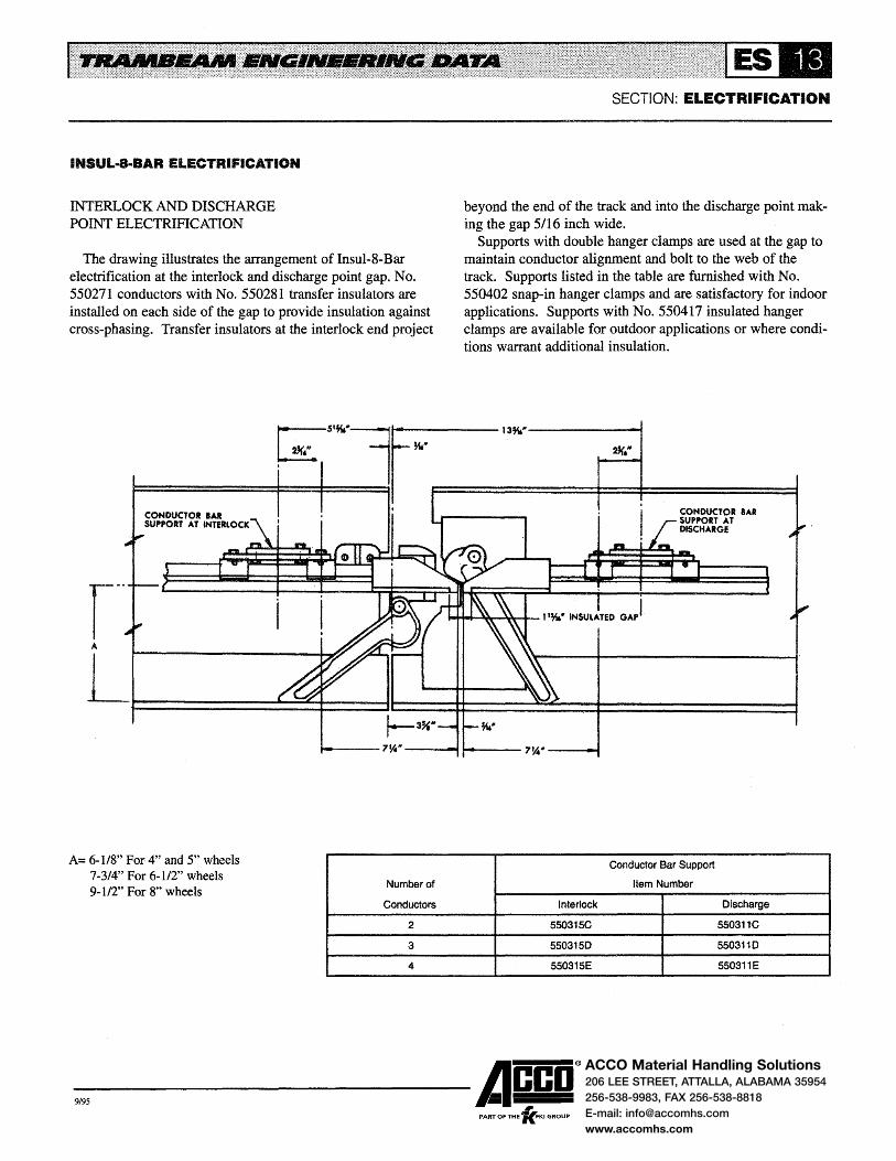
ACCO Material Handling Solutions206 LEE STREET, ATTALLA, ALABAMA 35954
256-538-9983, FAX 256-538-8818
E-mail: [email protected]
www.accomhs.com
INSUL·8·BAR ELECTRIFICATION
INTERLOCK AND DISCHARGE POINT ELECTRIFICATION
The drawing illustrates the arrangement of Insul-8-Bar electrification at the interlock and discharge point gap. No. 550271 conductors with No. 550281 transfer insulators are installed on each side of the gap to provide insulation against cross-phasing. Transfer insulators at the interlock end project
SECTION: ELECTRIFICATION
beyond the end of the track and into the discharge point making the gap 5/16 inch wide.
Supports with double hanger clamps are used at the gap to maintain conductor alignment and bolt to the web of the track. Supports listed in the table are furnished with No. 550402 snap-in hanger clamps and are satisfactory for indoor applications. Supports with No. 550417 insulated hanger clamps are available for outdoor applications or where conditions warrant additional insulation.
c;z5·~·l..,..__M._" ____ 13M."
~==========~==~====~! F==============~==~====~====~
r·· A
CONDUCTOR IAR SUPPORT AT INTERlOCK
CONDUCTOR BAR SUPPORT AT DISCHARGE
L~~~~t~~~~==~ r--3",.
A= 6-1/8" For 4" and 5" wheels 7-3/4" For 6-1/2" wheels 9-1/2" For gn wheels
.,_....---7~"' ----- ,....... ___ 7%" --.......
Number of
Conductors Interlock
2 550315C
3 5503150
4 550315E
-9,95 ------Acco® PART OF THE 'lc.FKI GROUP
Conductor Bar Support
Item Number
Discharge
550311C
5503110
550311E

ACCO Material Handling Solutions206 LEE STREET, ATTALLA, ALABAMA 35954
256-538-9983, FAX 256-538-8818
E-mail: [email protected]
www.accomhs.com
TAGLINE ELECTRIFICATION
1 Flexible Cable 2 Slide Rings 3 Slide Wire 4 Pusher Arm 5 Support Bracket 6 Junction Box and Bracket
(By Others)
Tagline electrification uses flexible cable for the conductors. It is well suited for applications in hazardous locations or where there are corrosive fumes or high humidity in the atmosphere. Tagline is not generally used on systems with curves, switches or interlocks.
Many types of tagline are available. Round or flat cables or separate wires in a neoprene jacket can be used for the conductors. The conductor cable can be supported by slide rings from a wire or by trolleys from a specially rolled track.
The runway tagline system in the illustration consists of 4-conductor round cable suspended by slide rings from a wire. The slide wire is supported at each end from brackets bolted to the top flange of the runway track.
SECTION: ELECTRIFICATION
Eyebolts in the brackets provide adjustment for wire tension. A pusher arm for the crane is recommended to avoid having the crane end truck interfere with the cable or slide wire. Tagline using the slide wire suspension is suitable for use on runways or straight monorails up to 80 feet in length.
Tagline using the slide wire suspension can also be used on cranes with spans to 40' -0". Cranes with spans greater than 40' -0" require a more rigid support for the conductor cables.
Consult factory for information on tagline sustems using flat cables or separate wires in a neoprene jacket or where a more rigid support is required for the conductor cables.
-9,95 ------Acco® , PART OF THE 'KFKI GROUP