Seminari i savjetovanje Katalog seminara 2015 - Festo Didactic
Upload
khangminh22Category
view
9download
0
Training & Didact ic Systems
General Catalog WA2E
WUEKRO
WUEKRO GmbH Catalog WA2E All Rights reserved. Reprint not permitted. Technical change without prior notice
Training & Didactic Systems Catalog WA2E
Equipment for Training and Research for
Vocational Education Schools Technical Schools
Technical Colleges Technical Universities
WUEKRO GmbH Carl-Zeiss-Strasse 10D - 97424 Schweinfurt/ Germany Tel.: + 49 (0) 9721 - 64691 - 0 Fax: + 49 (0) 9721 - 64691 - 20 Internet: www.wuekro.de E-Mail: [email protected]

WUEKRO Contents Section
Preface, Catalog W02E 0
Fundamentals of Electrical Engineering 1
Fundamentals of Electronics 2
Open and Closed-Loop Controls 3
Automation Technology 4
Electrical Machines / Electrical Drive Control Systems 5
Power Electronics 6
Building Management Systems KNX / EIB 7
VDE 0100 Protection Schemes 8
Radio- and Television Technology 9
10 11
Air-conditioning and Refrigeration 12
Photovoltaic 13 14 15
VOIP – Network 16 17
Experimental Manuals and Instruction Manuals 18 19 20
WUEKRO GmbH Katalog WA2E/Table of contents All Rights reserved. Reprint not permitted. Technical changes without prior notice.

WUEKRO
PREFACE The Catalog WA2E contains details of electric equipment for vocational training schools, technical schools, colleges and universities as well as for industrial laboratories and research centers. Besides the equipment listed in this catalog the WUEKRO production program contains a wide series of further equipment which is used in training establishments. Larger power supply systems are built almost exclusively as special versions to suit particular requirements. This catalog WA2E is divided in different parts describing the different technologies and the resp. training systems concerned. Each section can be send as a single catalog on your request.
The large selection of the WUEKRO instruction modules that this system provides means that all the circuits, controls and fundamental experiments common in electrical engineering, electronics, pneumatic control as well as in refrigeration and air-conditioning engineering can be set up quickly and easily and tested in actual practice. The modules and module sets of this catalog cover the whole range of the WUEKRO Training & Didactic Systems in all technical fields. The application range covers vocational training centers, technical colleges and technical universities, as well as technical training centers in industry. The WUEKRO Instruction Systems contain all the necessary standard hardware and training software.
Hardware • • •
• •
•
• • •
Instruction modules Rotating machines Training and demonstration models Compact training units Bench racking and power supply units Miscellaneous accessories
Teachware: Instruction manuals Learning units CBT's (Computer Based Training)
Schweinfurt, Januar 2013
WUEKRO GmbH Catalog WA2E All Rights reserved. Reprint not permitted. Technical changes without prior notice. Page 1

WUEKRO
Instruction Modules
Instruction Modules The design of the instruction modules covers different units such as experimental panels, plug-in modules and plug-in components.
Experimental panels Plug in modules Plug-in components These are made of plastic and are of pearl-white color similar to RAL 9002. They are 297 mm high and approximately 5 mm thick. The width of the panels is 130 mm or wider by a whole number multiple of 65 mm. The height of 297 mm corresponds to the German paper format DIN A4. Hoods are fitted to the rear sides of the panels with some few exceptions due to the design. The items of equipment are either fitted in the panels or mounted on the rear side. the electrical connections are brought out to 4-mm-safety-sockets or 2-mm-socket-outlets on the front of the panels. Standardized mimic diagrams, unit symbols and inscriptions are marked indelibly on the front of the panels. Switches, screw-in fuses, measuring instruments, etc., can be operated and read off the front of the panels. socket outlets are also fitted on the front to provide additional connections for plug-in modules.
These contain interconnected assemblies of active or passive components and are mainly used in electronics. They enable complete experimental set-ups to be established. On the underside of the modules there are 4mm plugs arranged on a 19mm grid pattern which are always employed for mechanical attachment. In many cases the electrical power-supply-connections are also brought to these plugs which are then gold-plated. In addition, many modules have 2mm sockets in the top, or also at the sides, for further electrical connections. The casings of the small modules are mainly made of shatterproof plastic which is transparent on the side parts. The non-transparent parts of the casing are black, apart from a few exceptions. The equipment and circuit symbols on the upper side are white.
It must be possible to change individual resistances and capacitors etc., used primarily in electronics, quickly and easily. These components are therefore fitted in unbreakable transparent plastic housing and connected to external gold-plated 4-mm-plugs.
WUEKRO GmbH Catalog WA2E All Rights reserved. Reprint not permitted. Technical changes without prior notice. Page 2

WUEKRO
Experimental Units
We distinguish - Training and
demonstration models - Compact training units - Bench units
Training and demonstration models
Compact training units Bench units
“Models” are self-contained training units intended for a specific task. The smaller models are set up on benches or are wall-mounted whereas the larger ones stand on the floor and can take up whole rooms.
“Compact training units”, also called “trainers” or “experimenters”, usually come in the form of a carrying case with a handle. When in use they are set up on a bench with the cover removed. Often the cover contains sets of pluggable components for specific applications.
“Bench units” are training units which are replaced on benches when used. These units have complete functional systems in sheet steel housings with carry handles, PVC-feet, ventilation slots and a supply connection cable with a SCHUKO or CEKON plug.
WUEKRO GmbH Catalog WA2E All Rights reserved. Reprint not permitted. Technical changes without prior notice. Page 3

WUEKRO
WUEKRO GmbH Catalog WA2E All Rights reserved. Reprint not permitted. Technical changes without prior notice. Page 4
Bench racking and power supply units For working with instruction modules bench racking and power supply devices are needed. The experimental panels are designed to be inserted into frames or into racks with two or three levels which can be mounted on experimental benches or power supply back uprights.
Experimental benches, the related back uprights and power supply units are not described in this catalog. Information on request. Individual experimental frames, are shown in section 10 of this catalog. Most plug-in instruction modules require assembly panels fitted with plug sockets only in a specific arrangement. Some of the sockets will be interconnected.
Universal assembly panels and the associated portable power supply units as listed in section 10 are used most commonly. References to suitable power supplies will be found in the descriptions of the various kits of equipment in the different sections of this catalog.
Miscellaneous accessories When special accessories are needed for specific fields, they are listed individually in the appropriate chapters.
Normal accessories such as connecting leads, instruction manuals, measuring instrument, etc. are mentioned as part of the kits.
Individual measuring instruments for experimental purposes are listed in section 10 of this catalog.
Experimental manuals and learning units The appropriate experimental instructions are supplied with each kit of equipment. For instruction modules not contained in an assembly kit, the experimental manuals can be ordered separately.
In addition, there are learning units available for training workshops. These are designed so that trainee courses and examinations in accordance with the requirements of the German professional training standards can be conducted without further preparation. Ask for more information about learning units if necessary.
Experimental manuals are listed in section 18 of this catalog.
Protection against touching live parts The instruction module system embodies the following measures offering a high degree of protection against touching live parts when working with electric power within the terms of DIN VDE 0100: All individual items of equipment are placed either in or on the rear of plastic panels.
All experimental panels have rear covers. Access to all of the terminals of the equipment can be gained only from the front through insulated sockets. The 4mm sockets are of the safety type unless they are used exclusively in electronic circuits, in which case the low voltages are not dangerous.
Any unfilled stations remaining in experimental frames should always be plugged with dummy modules or unwanted modules. The experimental setup should always be isolated before any changes are made to the circuitry.
The training systems listed in this catalog can be used in all the fields of training, advanced training as well as training in colleges and universities and can be combined due to the resp. teaching aim.
Therefore our modularized training system enables a specific training with a minimum of investment.

Training & Didactic Systems Fundamentals of Electrical Engineering
Catalog WA2E/01

Page 2 Catalog WA2E/01
Our Services
• Development and production of didactic training systems • Teachware and documetation • Project engineering of complete lab's incl. furnitures and lab equipment • Quotations on custumors demand • Installation, commissioning and training at site
Our Customers • Vocational training schools, technical schools, colleges and universities... • Industrial laboratories for vocational education and higher education
Fields of Technology • Fundamentals of electrical engineering
• Fundamentals of electronics
• Closed loop control technology
• Automation engineering
• Electrical machines / drive control
• Power electronics
• Building management systems
• Protection schemes to VDE 0100
• Radio- and TV technology
• Air conditioning and refrigeration
• Photovoltaic
• Communication technology
• Measuring systems, power supplies, accessories
• Experimental manuals, documentation For further information please contact: WUEKRO GmbH Carl-Zeiss-Strasse 10 D - 97424 Schweinfurt Germany Tel. + 49 (0) 9721-64691-0 Fax: + 49 (0) 9721-64691-20 E-Mail: [email protected] Internet: www.wuekro.de WUEKRO GmbH
All Rights reserved. Reprint not permitted. Technical changes without prior notice.. P00020803S – 12/12

WUEKRO
Catalog WA2E/01 Page 3
Table of Contents Page
Our Service, Our Customers and fields of technology 2 Introduction 4 Instruction modules measuring units 5 Fundamentals of electrical engineering and installation circuits 9 Fundamentals of electrical engineering 14 Installation circuits, basic equipment 16 Bell ringing and entrance call stations 18 Contactor controls 19 Control technology 20 Compact panels 23
Fax - response 28

WUEKRO
Page 4 Catalog WA2E/01
Introduction This range covers experimental panels, accessories and complete kits. Demonstrations and experiments can be carried out in • Fundamentals of electrical
engineering • Wiring circuits • Contactor Controls
The experimental panels are designed for insertion into experimental frames. Dimensions of the panels Height 297mm Width 130mm or wider by whole number multiples of 65mm.
The instruction modules in the following selection table permit experiments to be carried out in any desired arrangement. We recommend that the saaembly kits be used if the experiments are to be conducted in accordance with our experimental manuals.

WUEKRO
Catalog WA2E/01 Page 5
Measuring Instrument Moduls
Moving-coil ammeter
0,6 DC Order-No. W3411-4A
1,5A DC Order-No. W3411-4B
6A DC Order-No. W3411-4C
15A DC Order-No. W3411-4D
Moving-coil voltmeter
25V DC Order-No. W3414-4D
100V DC Order-No. W3414-4C
150V DC Order-No. W3414-4B
250V DC Order-No. W3414-4A
500V DC Order-No. W3414-4E
Movin-iron ammeter
4A Order-No. W3417-4C
6A Order-No. W3417-4D
15A Order-No. W3417-4E
25A Order-No. W3417-4F
40A Order-No. W3417-4G

WUEKRO
Page 6 Catalog WA2E/01
Measuring Instrument Moduls
Movin-iron ammeter for c.t. connection
5/1A Order-No. W3417-4A
25/1A Order-No. W3417-4H
40/1A Order-No. W3417-4J
Moving-iron voltmeter
60V Order-No. W3422-4C
250V Order-No. W3422-4B
400V Order-No. W3422-4A
600V Order-No. W3422-4E
400/100V for c.t. connection Order-No. W3422-4D
Current transformer Rated saturation factor n < 5 Frequency 40...60Hz Power 5VA
10/5A Order-No. W3425-4A
5/1A Order-No. W3425-4B
10/1A Order-No. W3425-4G
Voltage transformer
400 / 100V AC Order-No. W3427-4A

WUEKRO
Catalog WA2E/01 Page 7
Measuring Instrument Moduls
Wattmeter for 3-phase systems with balanced loads 5A, 400V AC, 0...4KW Order-No. W3428-4A
for 3-phase systems with balanced/unbalaced loads 5A, 400V AC, 0...4KW
Order-No. W3428-4B
for 3-phase systems with balanced/unbalaced loads 5A, 400V AC, 0...2KW
Order-No. W3428-4F
W3428-4C
for 3-phase systems with balanced/unbalaced loads 1A, 400V AC, 0...0,5KW
Order-No. W3428-4C
for single-phase AC 5A, 230V AC, 0...2kW
Order-No. W3428-4D
kVar meter for 3-phase systems with balanced/unbalaced loads 5A, 400V AC, 0...4kvar Order-No. W3433-4A
for 3-phase systems with balanced/unbalaced loads 1A, 400V AC, 0...1kvar
Order-No. W3433-4B
Power factor meter for 3-phase systems with balanced/unbalaced loads 400V AC, 5A Order-No. W3434-4A
for 3-phase systems with balanced/unbalaced loads 400V AC, 1A Order-No. W3434-4B
W3435-4A
for single-phase AC 230V AC, 1A Order-No. W3435-4A

WUEKRO
Page 8 Catalog WA2E/01
Measuring Instrument Moduls
Frequency meter 47...53Hz, 230V AC Order-No. W3436-4A
Double- frequency meter 2 x 45...55Hz, 230V AC Order-No. W3437-4A
2 x 45...55Hz, 400V AC Order-No. W3452-4A
double voltmeter 2 x 500V AC Order-No. W3438-4A
Phase sequency indicator Voltage 150...500V AC, Frequency 40...400Hz Order-No. W3443-4A
W3438-4A
Synchroscope 400V AC Order-No. W3440-4A
Single-phase kWh meter 230V AC, 10A Order-No. W3441-4A
W3440-4A
Three-phase kWh meter 400V AC, 10A Order-No. W3442-4A

WUEKRO
Catalog WA2E/01 Page 9
Fundamentals and Wiring Circuits
On/Off switch single-pole, 250V AC, 10A Order-No. W3211-4A
On/Off switch two-pole, 250V AC, 10A Order-No. W3212-4A
W3211-4A
W3212-4A
On/Off switch with orientation glow lamp 1polig, 250V AC, 10A Order-No. W3211-4B
On/Off switch with pilot lamp, 1polig, 250V AC, 10A Order-No. W3211-4C
Two-circuit switch 250V AC, 10A Order-No. W3213-4A
W3213-4A
W3214-4A
Two-way switch 250V AC, 10A Order-No. W3214-4A
Two-way switch with orientation glow lamp 250V AC, 10A Order-No. W3214-4B
Intermediate switch 250V AC, 10A Order-No. W3215-4A
W3215-4A
W3216-4A
SCHUKO-socket outlet 250V AC, 16A 250V DC, 10A Order-No. W3216-4A
Junction Order-No. W3220-4A
Light switch 250V AC, 10A Order-No. W3217-4A
Light switch with glow lamp 250V AC, 10A Order-No. W3218-4A
W3218-4A
W3220-4A
WUEKRO
Page 10 Catalog WA2E/01
Fundamentals and Wiring Circuits
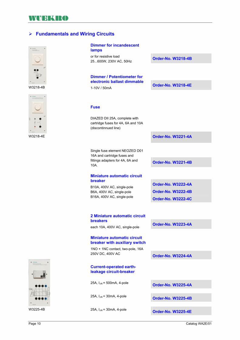
Dimmer for incandescent lamps or for resistive load 25...600W, 230V AC, 50Hz
Order-No. W3218-4B
Dimmer / Potentiometer for electronic ballast dimmable 1-10V / 50mA
Order-No. W3218-4E
Fuse
W3218-4B
W3218-4E
DIAZED DII 25A, complete with cartridge fuses for 4A, 6A and 10A (discontinnued line)
Order-No. W3221-4A
Single fuse element NEOZED D01 16A and cartridge fuses and fittings adapters for 4A, 6A and 10A.
Order-No. W3221-4B
Miniature automatic circuit breaker B10A, 400V AC, single-pole B6A, 400V AC, single-pole B16A, 400V AC, single-pole
Order-No. W3222-4A
Order-No. W3222-4B
Order-No. W3222-4C
2 Miniature automatic circuit breakers each 10A, 400V AC, single-pole
Order-No. W3223-4A
Miniature automatic circuit breaker with auxiliary switch 1NO + 1NC contact, two-pole, 16A 250V DC, 400V AC Order-No. W3224-4A Current-operated earth-leakage circuit-breaker
25A, I∆N = 500mA, 4-pole Order-No. W3225-4A
25A, I∆N = 30mA, 4-pole Order-No. W3225-4B
W3225-4B
25A, I∆N = 30mA, 4-pole Order-No. W3225-4E

WUEKRO
Catalog WA2E/01 Page 11
Fundamentals and Wiring Circuits Current surge relay
operating voltage 230V AC, 50Hz Order-No. W3226-4A
operating voltage 8V AC, 50Hz Order-No. W3226-4B
operating voltage 12V AC, 50Hz Order-No. W3226-4C
W3226-4A
Automatic staircase lighting control switch three- and four-wire connection, 230V AC
Order-No. W3227-4A
Priority switch Order-No. W3227-4B
7-step cooker switch Order-No. W3252-4A
W3227-4A
W3228-4A
Incandescent lamp socket E27 Order-No. W3228-4A
3 Incandescent lamp socket E27 Order-No. W3228-4B
1-10V / 50mA Dimensions (WxHxD) 130x297x65 mm Weight appr. 1,0kg
Dimmer for electronic ballast dimmable Experimental panel with 2mm and 4mm safety-laboratory sockets. For electronic electronic ballast dimmable for dimming a flourescent lamp 36W; Order-No. W3218-4E
Dimensions (WxHxD) 493 x 297 x 65 mm Weight approx. 2,0 kg
Electronic control gear unit dimmable Experimental panel with 2mm and 4mm safety laboratory sockets. Technical data: 1x36W
Order-No. W3218-4F
WUEKRO
Page 12 Catalog WA2E/01
Fundamentals and Wiring Circuits
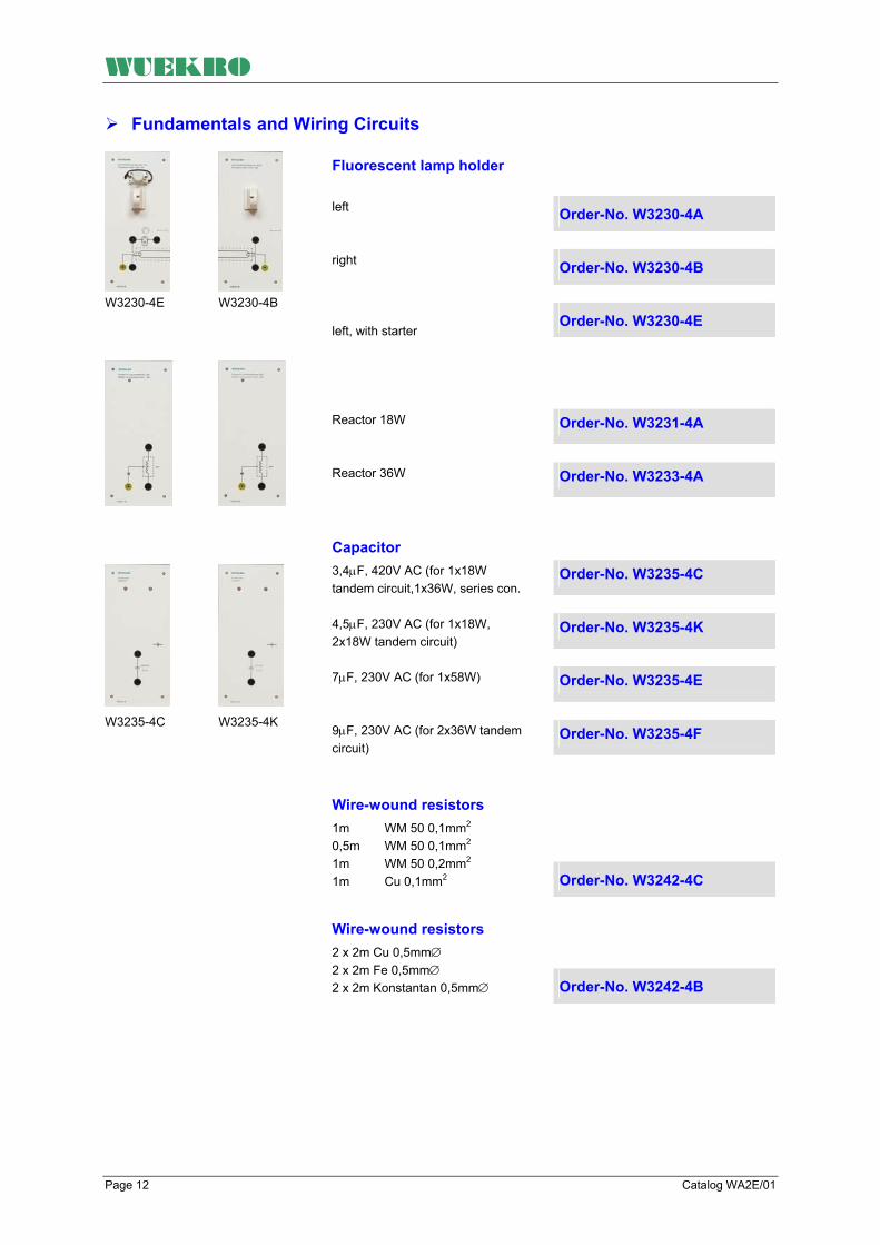
Fluorescent lamp holder
left Order-No. W3230-4A
right Order-No. W3230-4B
W3230-4E
W3230-4B
left, with starter
Order-No. W3230-4E
Reactor 18W Order-No. W3231-4A
Reactor 36W Order-No. W3233-4A
Capacitor
3,4µF, 420V AC (for 1x18W tandem circuit,1x36W, series con.
Order-No. W3235-4C
4,5µF, 230V AC (for 1x18W, 2x18W tandem circuit)
Order-No. W3235-4K
7µF, 230V AC (for 1x58W) Order-No. W3235-4E
W3235-4C
W3235-4K 9µF, 230V AC (for 2x36W tandem circuit)
Order-No. W3235-4F
Wire-wound resistors 1m WM 50 0,1mm2
0,5m WM 50 0,1mm2 1m WM 50 0,2mm2 1m Cu 0,1mm2 Order-No. W3242-4C
Wire-wound resistors 2 x 2m Cu 0,5mm∅ 2 x 2m Fe 0,5mm∅ 2 x 2m Konstantan 0,5mm∅ Order-No. W3242-4B
WUEKRO
Catalog WA2E/01 Page 13
Fundamentals and Wiring Circuits
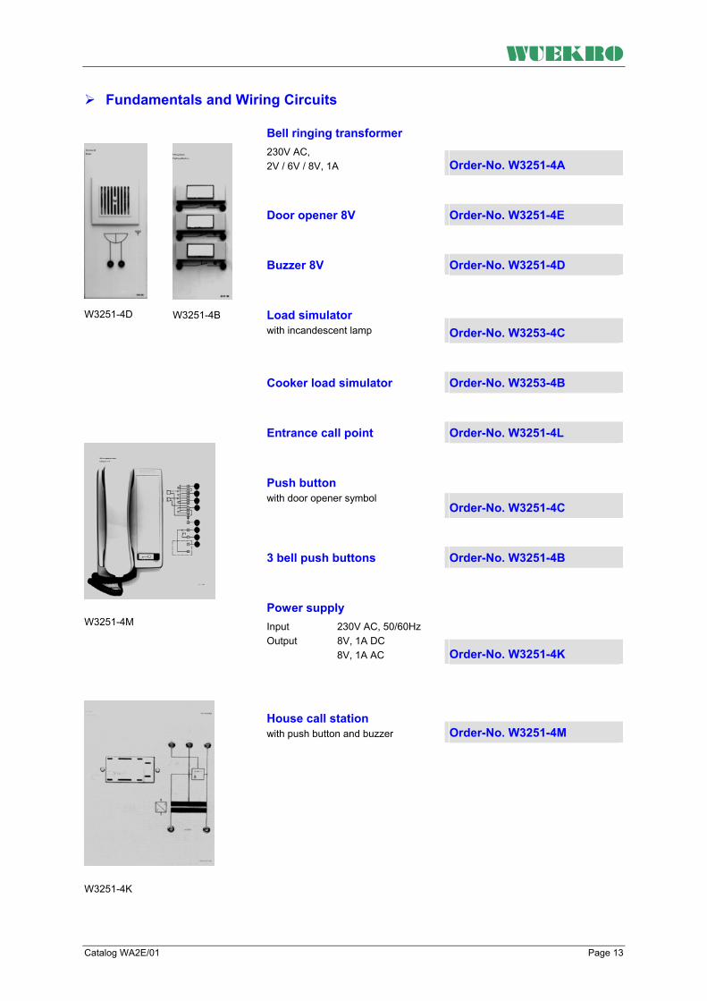
Bell ringing transformer 230V AC, 2V / 6V / 8V, 1A Order-No. W3251-4A
Door opener 8V Order-No. W3251-4E
Buzzer 8V Order-No. W3251-4D
Load simulator with incandescent lamp Order-No. W3253-4C
W3251-4D
W3251-4B
Cooker load simulator Order-No. W3253-4B
Entrance call point Order-No. W3251-4L
Push button with door opener symbol
Order-No. W3251-4C
3 bell push buttons Order-No. W3251-4B
W3251-4M
Power supply Input 230V AC, 50/60Hz Output 8V, 1A DC 8V, 1A AC Order-No. W3251-4K
House call station with push button and buzzer Order-No. W3251-4M
W3251-4K

WUEKRO
Page 14 Catalog WA2E/01
Fundamentals of Electrical Engineering
General The assembly kits are equipped with experimental panels and additional components, as well as laboratory connection leads and the resp. experimental manuals Assembly kits are available for different sections of electrical engineering.
The experimental panels are designed for insertion into experimental frames. The instruction modules are eqipped with 2mm lsockets or 4mm safety sockets. The experimental boxes can be inserted into patchboards.
Dimensions of the experimental panels (H x W) 297x130mm (or wider by whole number multiples of 65mm)
Assembly kit "Fundamentals of Electrical Engineering" Order-No. W3202-4A
The following experiments can be carried out
• The electrical circuit, current
and voltage measurement • Ohm's law • Conductor resistances • Temperature dependence of
resistances • Series connection of
resistances • Parallel connection of
resistances • Group connection of
resistances • Voltage loss in electrical lines
• Electrical power • Electrical work • 7-step cooker switch • Unloaded voltage divider • Thermal efficiency • Inductance with DC and AC
voltages • Series connection of resistive
and inductive reactance • Circuits with capacitors • Series connection of resistive
and capacitive reactance
• Active and reactive power • Series and parallel resonance • Three-phase star connection • Three-phase delta connection • Three-phase power • Single-phase transformer,
transformation ratio • Single-phase transformer, no-
load current, short-circuit current and short-circuit voltage
• Single-phase transformer, efficiency

WUEKRO
Catalog WA2E/01 Page 15
Fundamentals and Wiring Circuits
Assembly kit "Fundamentals of Electrical Engineering"
Equipment of the assembly kit
Experimental panels Qty. Order-No. see page
3 Fuses elements 1 W3311-4B 20
On/Off switch, 3-pole 1 W3313-4A 22
3 Incandescent lamp holders, E27 1 W3228-4B 11
3 Resistors 1 W3344-4B 22
Four-way switch 1 W3343-4B 22
Two-circuit switch 1 W3213-4A 9
Two-way switch 2 W3214-4A 9
7-step cooker switch 1 W3252-4A 11
SCHUKO socket outlet with earthing contact 1 W3216-4A 9
Wire-wound resistors 1 W3242-4B 12
Potentiometer 1 W3347-4A 22
Potentiometer 1 W3347-4C 22
Bell-ringing transformer 1 W3251-4A 13
Pilot light 1 W3337-4C 21
Capacitor 2 W3235-4D 12
Capacitor 1 W3235-4E 12
Reactor, 40W 1 W3233-4A 12
Single-phase kWh meter 1 W3441-4A 8
On/Off switch 2 W3211-4A 9
Star-delta switch, 3-pole 1 W3315-4A 22
Instruction manual 1 W3010-1A
Further Components (included in the kit)
Further required equipment (not included in the kit)
W3202-4Z consisting of: 1 Carbon filament lamp 7 Incandescent lamp 1 Hotplate with 3-step switch 1 Stop watch 1 Immersion heater 1 Fast boiling pot 1 Thermometer 1 coil with 400 windings 1 coil with 800 windings 1 coil with 1600 windings 1 U core with yoke
4 Multimeter 1 Power meter 1 Single-knob measuring bridge 20 safety connecting leads 0,5m 10 safety connecting leads 1m

WUEKRO
Page 16 Catalog WA2E/01
Wiring Circuits, Basic Equipment
Assembly kit " Wiring Circuits, Basic Equipment " Order-No. W3201-4B
The following experiments can be carried out
Opening a circuit with a single-pole switch Opening a circuit with a single-pole switch and SCHUKO socket outlet with earthing contact Opening a circuit with a two-pole switch Series circuit Two-way circuit
Intermediate circuit Circuit with current surge relay Circuits with automatic staircase lighting control switch • Opening a fluorescent lamp
circuit • Opening a circuit with two
fluorescent lamp in lead-lag connection
• Opening a circuit with two fluorescent lamps in tandem connection
• Brightness control of incandescent lamps
• Brightness control of fluorescent lamps
• Current-operated earth-leakage protection
• Conventional protective multiple earthing
• Modern protective multiple earthing

WUEKRO
Catalog WA2E/01 Page 17
Wiring Circuits, Basic Equipment
Assembly kit " Wiring Circuits, Basic Equipment " Order-No. W3201-4B
Equipment of the assembly kit
Experimental panels Qty. Order-No. see page
On/Off switch, 1-pole 1 W3211-4A 9 On/Off switch, 2-pole 1 W3212-4A 9 Two-circuit switch 1 W3213-4A 9 Two-way switch 2 W3214-4A 9 Intermediate switch 1 W3215-4A 9 SCHUKO outlet with earthing contact 1 W3216-4A 9 Light switch 2 W3217-4A 9 Light switch with glow lamp 1 W3218-4A 9 Dimmer for incandescent lamp 1 W3218-4B 9 Junction box 4 W3220-4A 9 1 Fuse element, 25A 1 W3221-4B 10 Current-operated earth-leakage circuit-breaker 1 W3225-4B 10 Current surge relay 1 W3226-4A 11 Automatic staircase lighting control switch 1 W3227-4A 11 Incandescent lamp socket 3 W3228-4A 11 Fluorescent lamp holder, right 2 W3230-4B 12 Fluorescent lamp holder, left, with starter 2 W3230-4E 12 Reactor, 36W 1 W3233-4A 12 Reactor, 18W 2 W3231-4A 12 Dimmer for electronic ballast dimmable 1 W3218-4E 10 Electronic ballast dimmable 1x36W 1 W3218-4F 10 Fluorescent lamp holder, left, for dimmer circ. 1 W3230-4C 12 Fluorescent lamp holder, right, for dimmer circ. 1 W3230-4D 12 Capacitor, 4,5 µF 1 W3235-4D 12 Capacitor, 3,6 µF 1 W3235-4C 12 Load simulator, with incandescent lamp 1 W3253-4C 13 Potentiometer 1 W3347-4D 22 Experimental manual 1 W3010-0B
Further Components (included in the kit)
Further required equipment (not included in the kit)
W3201-4Z consisting of: 3 Incandescent lamp E27; 25W 1 Incandescent lamp E27; 100W 1 Fluorescent lamp 36W 2 Fluorescent lamp 18W 1 Stop watch
1 Multimeter 20 Safety-connecting leads 0,5m 15 Safety-connecting leads 1m
WUEKRO
Page 18 Catalog WA2E/01
Bell Ringing and Entrance Call Stations
Supplementary Kit " Bell Ringing and Entrance Call Stations " Order-No. W3201-4C
The following experiments can be carried out
• Bell with door opener
(1 circuit) • Bell with door opener
(3 circuits)
• 8 V current surge circuit • Entrance call station with 2
house call stations and door opener
Equipment of supplementary kit
Experimental panels Qty. Order-No. see page current surge relay 1 W3226-4B 11 Lighting transformer 1 W3251-4A 13 Buzzer 3 W3251-4D 13 Door opener 1 W3251-4E 13 Push button with door opener symbol 3 W3251-4C 13 3 bell push buttons 1 W3251-4B 13 Entrance call point 1 W3251-4L 13 House call staion 2 W3251-4M 13 Power supply 1 W3251-4K 13

WUEKRO
Catalog WA2E/01 Page 19
Contactor Controls
Assembly kit " Contactor Controls " Order-No. W3201-4D
The following experiments can be carried out
• Trouble-shooting with
contactor controls • Switch-on with contactor • Switch-on with contactor,
trouble shooting • Contactor control with current
surge switch
• Trouble-shooting with contactor controls
• Switch-on with contactor • Switch-on with contactor,
trouble shooting • Contactor control with current
surge switch
• Making up control circuits • Delayed switch-on and
switch-off • Flashing circuit • Alarm system • Traffic light control
Assembly kit "Contactor Controls"
Experimental panels Qty. Order-No. see page
3 Fuses elements 1 W3311-4B 20
Contactor, 3-pole 4 W3321-4A 20
Overcurrent relay 1 W3330-4F 20
Time relay, thermally delayed 2 W3331-4A 20
2 push button switches 2 W3334-4B 21
3 push button switches 1 W3334-4C 21
2 pilot lamps 1 W3337-4B 21
2 limit switches 1 W3340-4B 21
Two-circuit double-interruption switch 1 W3342-4B 22
On/Off switch, 2-pole 1 W3341-4B 22
1 fuse element 1 W3221-4B 10
Current surge relay 1 W3226-4A 11
3-phase asynchronous motor 1 W3365-2A
Motor shaft protection 1
Experimental manual 1 W3010-4B
Further Components (not included in the kit)
25 Safety-connecting leads different lenghts and colors
For further experimental panels, switching gear for control circuits as well as assembly kits "Electrical Machines" we refer to our detailed catalog "Electrical Machines" WA1E/05...

WUEKRO
Page 20 Catalog WA2E/01
Control Engineering
3 Fuses elements with DIAZED cartridges for 4A, 6A, 10A Voltage 3 AC 400V/250V DC (discontinnued line) Order-No. W3311-4A
3 Fuse Elements NEOZED D01with 4mm safety lab sockets. With a triple NEOZED D01 fuse base, cartridge fuses and fittings adapters for 4A, 6A and 10A. Order-No. W3311-4B
W3311-4A
Contactor, 3-pole with auxiliary contacts 2NO+2NC operating voltage 1 AC 230V; 50/60Hz Voltage 500V AC; Current16A
Order-No. W3321-4A
W3321-4A
Overcurrent relay thermally delayed, with auxiliary switch 1NO, 1NC setting range 0,4A – 0,63A Order-No. W3330-4F
W3330-4F
Time relay 1 changeover contact, delayed pickup, operating voltage 1 AC 230V; 50/60Hz Voltage 230V AC Current 4A setting range 1,5 to 30s
Order-No. W3331-4A W3331-4A

WUEKRO
Catalog WA2E/01 Page 21
Control Engineering
2 push button switches "ON" black, with 1NO+1NC, Voltage 1 AC 500V Current 10A "OFF" red with 1NO+1NC, Voltage 500V AC Current 10A Order-No. W3334-4B
W3334-4B
3 push button switches 2x black, 1x red, with each 1NO + 1NC, Voltage 500V AC Current 10A
Order-No. W3334-4C
W3334-4C
2 pilot lights with 2 Incandescent lamps 230V 1 red and 1 green Order-No. W3337-4B
pilot light with 1 incandescent lamp 6V, 2W colour white Order-No. W3337-4C
2 limit switch each 1 NC, Voltage 400V AC Current 16A Order-No. W3340-4B
W3340-4B

WUEKRO
Page 22 Catalog WA2E/01
Control Engineering
On/Off switch, 2-pole 2 pole Switch positions 0 - I - 0 - I Voltage 3 AC 400V/220V DC Current 16A Order-No. W3341-4B
W3341-4B
Two-circuit double interruption switch 2 pole, switch positions 0 - I - 0 - II Voltage 400V AC/230V DC Current 16A Order-No. W3342-4B
On/Off switch, 3-pole Voltage 3 AC 500 V Current 16 A Order-No. W3313-4A
Star-Delta switch, 3-pole Voltage 3 AC 500 V Current 16 A Order-No. W3315-4A
3 Resistors 1 x 100 Ω/1A 1 x 330 Ω/0,6A 1 x 1000 Ω/0,3A Order-No. W3344-4B
Four-way switch, 2-pole 2 pole, switch positions I-II-III-IV Voltage 400V AC / 230V DC Current 16A Order-No. W3343-4B
Potentiometer
160Ω / 1,5A Order-No. W3347-4A
470Ω / 0,4A Order-No. W3347-4C
W3315-4A
W3347-4D
6,8 - 16,8kΩ, 30mA Order-No. W3347-4D

WUEKRO
Catalog WA2E/01 Page 23
Control Engineering Compact-panels The control-engineering compact panels can either be used hanging in an experimental frame or standing on a table.
The ergonomically formed backsided hood is made of powderpainted steelsheet with rubber foot gives the console high stability and slim design.
You can combine a smart price and high variablility with space saving and practical orientated functionality.
Schalter-Kompakt-Experimentierplatte Mit 4mm Sicherheitslaborbuchsen, Jeweils rechts und links zusätzlich als Bus-Terminals für die Durchverbindung zu anderen Kompakt-Experimentierplatten für L1, L2, L3, N und PEon the left and right top end also as bus-terminals for drive-throught-connection for L1, L2, L3, N and PE to other compact panels. The following switches are installed: 1 On/Off-switch, 3-pin 1 Reversing switch 3-pin 1 Star-delta switch, 3-pin 1 Pole-changing switch 3-pin (Dahlander) 1 Pole-changing switch 3-pin (for 2 speeds, 2 separate windings)
With this compact panel you can replace the single experimental panels W3313-4A W3314-4A W3315-4A W3317-4A and W3318-4A contact load 16A/500V~ each. dimensions (WxHxD) approx. 520x297x110mm weight approx. 4,0kg
Order-No. W3319-4A

WUEKRO
Page 24 Catalog WA2E/01
Contactor and relay compact panel with 4mm safety-lab-sockets, on the left and right top end also as bus-terminals for drive-throught-connection for L1, L2, L3, N and PE to other compact panels. The following items are installed: 1 norm-profilrail for line built-units like contactors, motor protection switches, time relays e.g.. In total 20 4-folded groups of 4mm safety-lab-sockets for connecting the built-on equipment (not included).
The auxilary voltage and the neutral conductor can be easily connected through with safety lab jumpers to the next group (not included). As extension you can get a set of adapters and jumpers seperately. dimensions (WxHxD) approx. 520x297x110mm weight approx. 4,0kg
Order-No. W3329-4A
Switch- and control operator panel with 4mm safety-lab-sockets, on the left and right top end also as bus-terminals for drive-throught-connection for L1, L2, L3, N and PE to other compact panels. The following components are installed: - 1 emergency stop interlocked mushroom pushbotton with 2 NC - 3 push-bottons (1x red; 2x black) each 1NO + 1NC - 1 knob-switch latching with 3 switch positions (I-O-II) - 5 LED-indicator lamps (1x red, 2x white, 1x yellow, 1x blue) - 3 mechanical limit switches with 1 make and 1 break contact each
The circuit points are connected to 4mm saftey lab sockets. The auxilary voltage and the neutral coductor can be tapped nearby. With this compact panel you can replace e.g. the single experimental panels W3334-4A (-4B, -4C) W3334-4N W3337-4 X W3338-4 X W3340-4A (-4B) dimensions (WxHxD) approx. 520x297x110mm weight approx. 4,0kg
Order-No. W3339-4A

WUEKRO
Catalog WA2E/01 Page 25

WUEKRO
Page 26 Catalog WA2E/01

WUEKRO
Catalog WA2E/01 Page 27

WUEKRO
Page 28 Catalog WA2E/01
FAX – response to: +49 (0)9721 - 64691 - 20 Sender: Receiver:
Company WUEKRO GmbH Dept. Sales Department Name Street Carl-Zeiss-Strasse 10 City 97424 Schweinfurt / Germany Phone + 49-(0)9721-64691-0 Fax + 49-(0)9721-64691-20 E-Mail [email protected] Internet www.wuekro.de No. of pages incl. this page
Please send the following catalogues to the a.m. address! Fundamentals of electrical Engineering
Installation circuits Bell ringing and entrance call stations Contactor control / Control technology Measurement and control of non-electrical variables
Fundamentels of electronics Analog technology Digital technology Microprocessing technology
Closed loop control technology Analog closed loop control Digital closed loop control
Automation engineering SIMATIC S7-200/300/400 SIMATIC Software and Trainer packages Technology simulators / Models Process control engineering PCS7 AS-Interface Profibus DP Process simulation-software SIMIT SCE LOGO! Mechatronical technology stations Courses on Automation
Electrical machines / Drive controls Electrical Machines 300W Electrical Machines 1000W Electrical Machines 5kW Electrical drive control systems 300W/ 1kW Electrical drive control systems 5kW Networked drive systems Cutaway Models Transformers, Rectifiers and Reactive Power Compensation Courses on drive systems
Power electronics extra low voltage (24V) low voltage (230/400V)
Building management systems KNX/ EIB
VDE 0100 safety measures
Radio- and Television engineering AM/FM – Technology TV Engineering Satellite – Technology
Cooling and air conditioning
Photovoltaic cell tecnology
Communication technology Modulation -/demodulation Fiber optic ISDN trainer (HICOM) ISDN
Measuring systems
Power supply units
Experiment instructions, manuals
Training courses
Remarks:

WUEKRO
Training & Didactic Systems Fundamentals of Electronics Catalog WA2E/02

WUEKRO
Page 2 Catalog WA2E/02
Our Services
• Development and production of didactic training systems • Teachware and documentation • Project engineering of complete lab's incl. furnitures and lab equipment • Quotations on customers demand • Installation, commissioning and training at site
Our Customers • Vocational training schools, technical schools, colleges and universities... • Industrial laboratories for vocational education and higher education
Fields of Technology • Fundamentals of electrical engineering
• Fundamentals of electronics
• Closed loop control technology
• Automation engineering
• Electrical machines / drive control
• Power electronics
• Building management systems
• Protection schemes to VDE 0100
• Radio- and TV technology
• Air conditioning and refrigeration
• Photovoltaic
• Communication technology
• Measuring systems, power supplies, accessories
• Experimental manuals, documentation For further information please contact: WUEKRO GmbH Carl-Zeiss-Strasse 10 D - 97424 Schweinfurt Germany Tel. + 49 (0) 9721-64691-0 Fax: + 49 (0) 9721-64691-20 E-Mail: [email protected] Internet: www.wuekro.de WUEKRO GmbH
All Rights reserved. Reprint not permitted. Technical changes without prior notice. S30020616P – 12/12

WUEKRO
Catalog WA2E/02 Page 3
Table of Contents Page Our Services, Customers and Scope of Supply 2 Introduction 4 Universal Mounting Panel 5 Assembly Kit's 6 Fundamental Laws of electrical Engineering 6 Electronic Components and Fundamentals of Analog Technology 7 Basic Digital Circuits 9 Digital Data Processing 10 Components of Power Electronics 11 Experimental Suitcases 12 Digital Trainer 12 IC-Trainer 13 Universal-Experimenter V 14 Storage Case 15 Fault Simulators 15 Fax – Reply 16
WUEKRO
Page 4 Catalog WA2E/02
Introduction
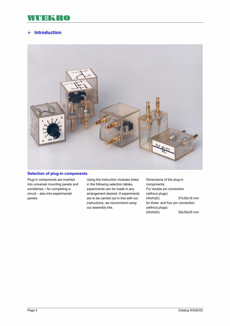
Selection of plug-in components Plug-in components are inserted into universal mounting panels and sometimes – for completing a circuit – also into experimental panels.
Using the instruction modules listed in the following selection tables, experiments can be made in any arrangement desired. If experiments are to be carried out in line with our instructions, we recommend using our assembly kits.
Dimensions of the plug-in components: For double pin connection (without plugs) (WxHxD) 37x35x18 mm for three- and four pin connection (without plugs) (WxHxD) 35x35x35 mm

WUEKRO
Catalog WA2E/02 Page 5
Assembly Kit's
Universal-mounting panel
Dimensions (WxH) 493 x 297 mm Weight approx. 4 kg
The universal mounting panel is equipped with 4-mm-sockets arranged in a 19 mm grid (total of 320 sockets). Every four adjacent sockets are interconnected to form a ring. Provision is also made for gold-plated 2-mm-sockets which are used for the power supply of operational amplifiers (8 plug-in stations). When a module is inserted, it is always connected to the supply voltage with the correct polarity.
The two top and the two bottom rows of sockets are through-connected for power supply purposes. From bottom to top: - 15 V, ground/0 V, + 5 V, + 15 V. The universal mounting panel has a cover for predecting the connections on the rear. For installation on a bench, mounting accessories permitting the panel to be mounted at an angle of 30° is provided on the rear.
Order-No. W5430-1A

WUEKRO
Page 6 Catalog WA2E/02
Assembly kit "Fundamentals of Electrical Engineering“ The following experiments can be carried out The electric circuit Ohm´s law Series connection of ohmic resistors Parallel connection of ohmic resistors Group connection of ohmic resistors Voltage dividers Delta-star transformation Voltage sources Electrical energy, electric power, efficiency
• Power matching • Capacitors • Series and parallel connection of capacitors • Electromagnetism • Conductor circuit and magnetic circuit • Theory of alternating current • AC resistors • AC circuits • Three-phase current
Contents of the assembly kit:
Potentiometer 1 100 Ω linear 1 1 kΩ linear 1 10 kΩ linear Reactors 1 10 mH 1 200 mH Plug-in modules 1 On/Off switch single pin 1 Selector switch single pin 1 W5101-2D 3-phase current source
Order-No. W5101-8H
Resistors 1 1 Ω 1 10 Ω 2 22 Ω 1 47 Ω 2 82 Ω 1 100 Ω 1 120 Ω 1 150 Ω 2 220 Ω 1 330 Ω 1 470 Ω 1 680 Ω 3 1 kΩ 2 1.5 kΩ 1 2.2 kΩ 1 3.3 kΩ 1 4.7 kΩ
Resistors 1 6.8 kΩ 2 10 kΩ 1 22 kΩ 1 33 kΩ 1 47 kΩ 1 68 kΩ 1 82 kΩ 1 100 kΩ 1 1 MΩ Capacitors 1 10nF 1 0.1µF 1 0.47µF 1 1µF 1 2.2µF 2 2200µF
Experimental manual "Fundamentals of Electrical Engineering" Order-No. W3025-7B Set of connecting leads and plugs, consisting of:
2 2-mm connecting leads 30 cm 4 2-mm connecting leads 15 cm
20 connector plugs, 19 mm 4 adapter plugs 3 adapter plugs
10 4-mm connecting leads 25 cm 10 4-mm connecting leads 50 cm
Order-No. W3901-8H Required equipment to carry out the experiments: 1 Universal mounting panel 1 Function Generator 1 Power supply 1 Oscilloscope 3 Multimeter
Alternatively: Universal-Experimenter IV Alternatively: Universal-Experimenter IV Alternatively: Universal-Experimenter IV i.e. 20 MHz/2-channels

WUEKRO
Catalog WA2E/02 Page 7
Assembly Kit "Electronic Components and Fundamentals of Analog Technology"
The following experiments can be carried out: Electronic components Fundamentals of analog technology Resistors • Linear resistors • Potentiometers • Non-linear resistors • PTC resistors • NTC resistors • Varistors Capacitors • Types of design • Electrolytic capacitors • Metallized-paper capacitors • Plastic-film capacitors • Ceramic capacitors • Connections of capacitors to resistors Semiconductor diodes • Doping of semiconductors • Diodes • Application of diodes Bipolar transistors • Input characteristic • Output characteristic • Short-circuit forward current transfer • Reverse voltage transfer ratio characteristic • Four-quadrant family of characteristics of a
transistor Unipolar transistors • Transistor in constant-current source Components with triggering characteristic • Unijunction transistors • Thyristors Optoelectronic components • Extrinsic photoelectric effect • Intrinsic photoelectric effect • Photo-Voltaic effect • Photo-Resistors • Photodiodes • Phototransistors • Optocouplers
Basic diode connections • One-way rectifier connection • Center-tap rectifier connection • Bridge connection • Voltage stabilization via Zener diodes for varying
input voltage • Voltage stabilization via Zener diodes for varying
load impedance • Diode as switch • Voltage doubler connection • Voltage multiplier connection Basic transistor connections • Common-collector connection • Common-emitter connection • Darlington connection • Switching transistor • Alternating voltage amplifier • Direct voltage amplifier Oscillator circuits with transistors • Wien-bridge generator • RC phase-shifting generator • Colpitts oscillator Operational amplifiers • Adjusting the balance of an operational amplifier • Operational amplifiers in power supply • Operational amplifiers as impedance transformers • Operational amplifiers as adders • Operational amplifiers as difference amplifier • Operational amplifiers as inverting alternating
voltage amplifiers • Operational amplifiers in astable flipflop circuits • Operational amplifiers in an oscillator circuit High pass, low pass and band pass • Integrator • Differentiator • High pass • Band pass Application of components with triggering characteristic • Unijunction transistor as pulse generator • Generalized phase control Application of optoelectronic components • Light barrier • Photo-electric lighting controIler

WUEKRO
Page 8 Catalog WA2E/02
Assembly Kit "Electronic Components and Fundamentals of Analog Technology"
Contents of the kit:
Plug-in modules 1 W5101-6C Relay with 2 changeover contacts 1 W5101-4J 2 OP's UA741 1 W5101-6K 2 optocouplers 1 W5101-4L equipped with: 1 field-effect transistor 1 unijunction transistor 1 thyristor 1 Zener diode 10V 2 Si diodes Further components 1 Lamp, red 1 Lamp, green 1 Lamp, adjustable 1 Toggle switch 1 Pushbutton, 1 NC contact 1 Pushbutton, 1 NO contact 1 Coil, 10 mH
Resistors 1 10 Ω 1 22 Ω 1 47 Ω 2 100 Ω 1 220 Ω 1 330 Ω 1 470 Ω 4 1 kΩ 1 2.2 kΩ 1 3.3 kΩ 1 4.7 kΩ 4 10 kΩ 1 22 kΩ 1 33 kΩ 1 47 kΩ 2 100 kΩ 1 220 kΩ 1 330 kΩ 1 470 kΩ 1 1 MΩ Capacitors 1 1 nF/400V 1 4.7 nF/400V 2 10 nF/400V 1 47 nF/400V 3 0.1 µF/160V 1 0.47 µF/160V 1 1 µF/100V 2 10 µF/63V 1 100 µF/40V 1 470 µF/25V 4 1000 µF/25V
Potentiometers 1 100 Ω linear 2 1 kΩ linear 2 10 kΩ linear 1 100 kΩ linear Diodes 4 1N4004 2 1N4148 1 AA 118 1 ZD 4,7V 1 ZPD 5.1V 1 ZPD 9.1V 1 ZF 10V 1 Photodiode 1 LED red 1 LED green Single layer semi conductors 1 Photo Resistor 1 NTC Resistor 1 PTC Resistor 1 VDR Resistor Transistors 2 BC 141 left 1 BC 161 left 1 BC 237 left 1 BC 237 right 1 BF 240 left 1 Photo Transistor BPY 62
Order-No. W5101-8F Experimental manual "Electronic Components" Order-No. W3025-2B Experimental manual "Fundamentals of Analog Technology" Order-No. W3025-3B set of connecting leads and plugs, consisting of:
10 2mm connecting leads 15 cm 6 2mm connecting leads 30 cm
40 connector plugs, 19-mm 4 connector plugs, 38 mm 10 adapter plugs 4 adapter plugs
10 4-mm connecting leads 25 cm 10 4-mm connecting leads 50 cm 2 4mm connecting leads 100 cm Order-No. W3901-8F
Required equipment to carry out the experiments: 1 Universal mounting panel 1 Function generator 1 Power supply 3 Multimeter 1 Oscilloscope
Alternatively: Universal Experimenter V Alternatively: Universal Experimenter V Alternatively: Universal Experimenter V i.e. 20 MHz/2-Channels

WUEKRO
Catalog WA2E/02 Page 9
Assembly Kit "Basic Digital Circuits" The following experiments can be carried out: Basic logic operations AND operation OR operation NOT operation NAND operation NOR operation ExOR operation ExNOR operation Flipflop circuits Astable flipflop Monostable flipflop Bistable flipflop Schmitt trigger circuit
Digital flipflops RS flipflop D flipflop Master-slave flipflop JK flipflop Counters and registers Asynchronous dual up counters Asynchronous dual down counters Asynchronous reversible counters Parallel dual up counters Ring counters Registers
Logic algebra Boolean algebra Karnough map Examination of a digital circuit with the logic analyzer Logic level comparison Integrated circuits Logic family Logic level Digital applications Time and frequency measurement Digital measurement of period length
Contents of the kit Plug-in Modules 1 W5101-5E 2 hexadecimal displays 1 W5101-4F 9 capacitors 1 W5101-4Q 1 monostable flipflop Plug-in components 1 Zener diode ZD 4,7V 1 Diode 1N4004 1 Potentiometer, 1kΩ linear
Plug-in Modules 2 W5101-4M 4 toggle switch (L-H input) 2 W5101-4N 4 LED displays 1 W5101-4W 2 AND/NAND arrays, 2 inputs 1 W5101-4V 2 OR/NOR arrays, 2 inputs 1 W5101-5C 4 inverter 1 W5101-5D 4 EX-OR gates, 2 inputs 1 W5101-5B 4 AND/NAND gates, 2 inputs 1 W5101-5H 1 D flipflop 2 W5101-5K 2 JK flipflop 1 W5101-5V 2 digital chopper
Plug-in Modules 1 W5101-4P 1clock-pulse generator 0 - 10 kHz 1 W5101-5A 4 OR/NOR gates, 2 inputs 1 W5101-4U 1 AND/NAND gates, 4 inputs 1 W5101-4T 1 OR/NOR gates, 4 inputs 1 W5101-6D IC socket 14 pin 1 W5101-6E IC socket 16 pin 1 W5101-4B 9 resistors 1 W5101-4C 9 resistors 1 W5101-4J 2 operational amplifier 1 W5101-5M 1 binary/decimal up/down counter Order-No. W5101-8D
Experimental manual "Basic Digital Circuits" Order-No. W3025-4B set of connecting leads and plugs, consisting of: 20 connector plugs, 19 mm 4 connector plugs, 38 mm 10 adapter plugs 4 adapter plugs
2 4-mm connecting leads 50 cm 2 4-mm connecting leads 100 cm 10 2-mm connecting leads 7,5 cm 10 2-mm connecting leads 15 cm
10 2-mm connecting leads 30 cm 4 2-mm connecting leads 50 cm
Order-No. W3901-8D Required equipment to carry out the experiments: 1 Universal mounting panel 1 Function generator 1 Power supply 3 Multimeter 1 Oscilloscope
Alternatively: Universal Experimenter IV Alternatively: Universal Experimenter IV Alternatively: Universal Experimenter IV i.e. 20 MHz/2-channel oscilloscope

WUEKRO
Page 10 Catalog WA2E/02
Assembly Kit "Digital Data Processing" The following experiments can be carried out: Encoders, decoders, code converters • Octal-to-binary conversion • Binary-to-hexadecimal
conversion • BCD-to-decimal conversion • Decimal-to-binary conversion • Binary-to-BCD conversion Counters and counter applications • Decimal counters • Decimal counters with set
inputs • Hexadecimal counters • Hexadecimal counters with set
inputs
Registers and its applications • Shift registers as memory • 8-bit shift registers • Parallel input - serial output • Serial input - parallel output Analog-to-digital conversion • Analog-to-digital conversion • Digital-to-analog conversion • Digital-to-analog conversion
with R/2R network Multiplexers, demultiplexers • Multiplexers • Demultiplexers • Serial data transmission with
multiplexers and demultiplexers
Digital arithmetic-logic units • Addition of two single-digit
dual numbers • Half-adders • Addition of multi-digit dual
numbers • Full adders • Subtraction of dual numbers • Half subtractor • Subtraction of multi-digit dual
numbers • Full subtractors • Multiplication of dual numbers Basic circuits phase-locked loop • PLL in captured range • PLL as pulse generators
Contents of the kit Plug-in modules 1 W5101-6A 1 PLL circuit 1 W5101-4E 3 potentiometers Plug-in components 1 resistor 10kΩ 1 resistor 22kΩ 1 resistor 220kΩ Capacitors 1 capacitor 4,7 nF 1 capacitor 10 nF 1 capacitor 0,1 nF
Plug-in modules 1 W5101-4U 1-AND/NAND gates, 4 inputs 1 W5101-5B 4-AND/NAND gates, 2 inputs 1 W5101-4W 2-AND/NAND gates, 2 inputs 3 W5101-4T 1-OR/NOR gates, 4 inputs 1 W5101-4V 2-OR/NOR gates, 2 inputs 1 W5101-5A 4-OR/NOR gates, 2 inputs 1 W5101-5D 4-EX/OR gates, 2 inputs 3 W5101-4M 4-toggle switches (L-H input) 3 W5101-4N 4-LED displays 1 W5101-4P 1 clock-pulse generator 0 to 10 kHz 1 W5101-4D 2 R/2R network
Plug-in modules 1 W5101-5C 4 inverters 2 W5101-5K 2-JK flipflop 1 W5101-5E 2 hexadecimal displays 1 W5101-5P 1 BCD/decimal decoder 1 W5101-5M 1 binary/decimal up/down counter 1 W5101-5Q 1 binary/BCD decoder 2 W5101-5L 1 shift register 1 W5101-5T 1 analog/digital converter 1 W5101-5U 1 digital/analog converter 1 W5101-5R 1 multiplexer 1 W5101-5S 1 demultiplexer
Order-No. W5101-8E
Experimental manual "Digital Data Processing" Order-No. W3025-5B Set of connecting leads and plugs, consisting of:
10 2-mm connecting leads 30 cm 4 2-mm connecting leads 50 cm
20 connector plugs, 19 mm 4 connector plugs, 38 mm 10 adapter plugs 4 adapter plugs
2 4-mm connecting leads 50 cm 2 4-mm connecting leads 100 cm 10 2-mm connecting leads 7,5 cm 10 2-mm connecting leads 15 cm Order-No. W3901-8E
Required equipment to carry out the experiments: 1 Universal mounting panel 1 Function generator 1 Power supply 3 Multimeter 1 Oscilloscope
Alternatively: Universal Experimenter V Alternatively: Universal Experimenter V Alternatively: Universal Experimenter V i.e. 20 MHz/2-channel oscilloscope
WUEKRO
Catalog WA2E/02 Page 11
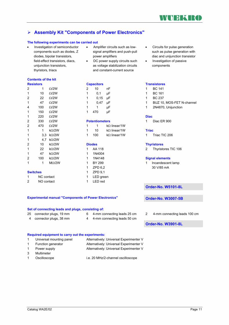
Assembly Kit "Components of Power Electronics" The following experiments can be carried out • Investigation of semiconductor
components such as diodes, Z diodes, bipolar transistors, field-effect transistors, diacs, unijunction transistors, thyristors, triacs
• Amplifier circuits such as low-signal amplifiers and push-pull power amplifiers
• DC power supply circuits such as voltage stabilization circuits and constant-current source
• Circuits for pulse generation such as pulse generation with diac and unijunction transistor
• Investigation of passive components
Contents of the kit Transistores 1 BC 141 1 BC 161 1 BC 237 1 BUZ 10, MOS-FET N-channel 1 2N4870, Unijunction Diac 1 Diac ER 900 Triac 1 Triac TIC 206 Thyristores 2 Thyristores TIC 106 Signal elements 1 Incandescent lamp 30 V/85 mA
Resistors 2 1 Ω/2W 1 10 Ω/2W 2 22 Ω/2W 1 47 Ω/2W 4 100 Ω/2W 1 150 Ω/2W 1 220 Ω/2W 2 330 Ω/2W 2 470 Ω/2W 1 1 kΩ/2W 1 3,3 kΩ/2W 1 4,7 kΩ/2W 2 10 kΩ/2W 1 22 kΩ/2W 1 47 kΩ/2W 2 100 kΩ/2W 1 1 MΩ/2W Switches 1 NC contact 2 NO contact
Capacitors 2 10 nF 1 0,1 µF 1 0,15 µF 1 0,47 µF 1 1 µF 1 470 µF Potentiometers 1 1 kΩ linear/1W 1 10 kΩ linear/1W 1 100 kΩ linear/1W Diodes 1 AA 118 1 1N4004 1 1N4148 1 BY 299 1 ZPD 6,2 1 ZPD 9,1 1 LED green 1 LED red Order-No. W5101-8L
Experimental manual "Components of Power Electronics" Order-No. W3007-5B Set of connecting leads and plugs, consisting of:
2 4-mm connecting leads 100 cm
25 connector plugs, 19 mm 4 connector plugs, 38 mm
6 4-mm connecting leads 25 cm 4 4-mm connecting leads 50 cm
Order-No. W3901-8L Required equipment to carry out the experiments: 1 Universal mounting panel 1 Function generator 1 Power supply 3 Multimeter 1 Oscilloscope
Alternatively: Universal Experimenter V Alternatively: Universal Experimenter V Alternatively: Universal Experimenter V i.e. 20 MHz/2-channel oscilloscope
WUEKRO
Page 12 Catalog WA2E/02
Digital - Trainer
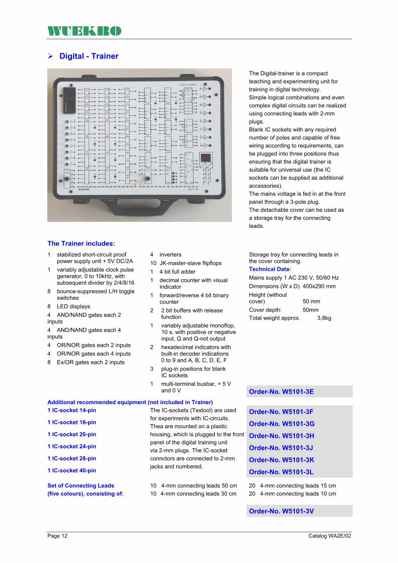
The Digital-trainer is a compact teaching and experimenting unit for training in digital technology. Simple logical combinations and even complex digital circuits can be realized using connecting leads with 2-mm plugs. Blank IC sockets with any required number of poles and capable of free wiring according to requirements, can be plugged into three positions thus ensuring that the digital trainer is suitable for universal use (the IC sockets can be supplied as additional accessories). The mains voltage is fed in at the front panel through a 3-pole plug. The detachable cover can be used as a storage tray for the connecting leads.
The Trainer includes:
Storage tray for connecting leads in the cover containing. Technical Data: Mains supply 1 AC 230 V, 50/60 Hz Dimensions (W x D) 400x290 mm Height (without cover) 50 mm Cover depth: 50mm Total weight approx. 3,8kg
1 stabilized short-circuit proof power supply unit + 5V DC/2A 1 variably adjustable clock pulse generator, 0 to 10kHz, with subsequent divider by 2/4/8/16 8 bounce-suppressed L/H toggle switches 8 LED displays 4 AND/NAND gates each 2 inputs 4 AND/NAND gates each 4 inputs 4 OR/NOR gates each 2 inputs 4 OR/NOR gates each 4 inputs 8 Ex/OR gates each 2 inputs
4 inverters 10 JK-master-slave flipflops 1 4 bit full adder 1 decimal counter with visual indicator 1 forward/reverse 4 bit binary counter 2 2 bit buffers with release function 1 variably adjustable monoflop, 10 s, with positive or negative input, Q and Q-not output 2 hexadecimal indicators with built-in decoder indications 0 to 9 and A, B, C, D, E, F 3 plug-in positions for blank IC sockets 1 multi-terminal busbar, + 5 V and 0 V Order-No. W5101-3E
Additional recommended equipment (not included in Trainer) 1 IC-socket 14-pin Order-No. W5101-3F 1 IC-socket 16-pin Order-No. W5101-3G 1 IC-socket 20-pin Order-No. W5101-3H 1 IC-socket 24-pin Order-No. W5101-3J 1 IC-socket 28-pin Order-No. W5101-3K 1 IC-socket 40-pin
The IC-sockets (Textool) are used for experiments with IC-circuits. Thea are mounted on a plastic housing, which is plugged to the front panel of the digital training unit via 2-mm plugs. The IC-socket connctors are connected to 2-mm jacks and numbered. Order-No. W5101-3L
20 4-mm connecting leads 15 cm 20 4-mm connecting leads 10 cm
Set of Connecting Leads (five colours), consisting of:
10 4-mm connecting leads 50 cm 10 4-mm connecting leads 30 cm
Order-No. W5101-3V

WUEKRO
Catalog WA2E/02 Page 13
IC - Trainer
The IC-trainer is a universally applicable unit for carrying out exercises in digital technology. It can be used in schools and institutes for training and further education and in the training centers of the industry. Each IC socket terminal is numbered and equipped with two 2-mm measurement sockets. All blank IC sockets are fitted with a tensioning facility to enable effortless insertion of ICs. The mains voltage is fed on top through a 3-pole plug. The detachable cover can be used as a storage tray for the connecting leads.
The Trainer includes:
Storage tray for connecting leads in the cover. Technical Data: Mains supply 1 AC 230 V, 50/60 Hz Dimensions (W x D) 400x290mm Height (without cover) 50mm Cover depth: 50mm Total weight approx. 3,8kg All IC sockets are Textool sockets
1 stabilized short-circuit proof power supply unit + 5V DC/1A 1 variably clock pulse generator, 0,5Hz to 10kHz, with subsequent frequency divider by 2/4/8/16 reset key, single pulse 1 monoflop with Q and Q-not outputs 1 rotary switch for 0,1s, 1s and 3s pulse width and switch setting for external wiring of the monoflop 8 bounce-suppressed L/H toggle switches 8 LED displays 1 toggle switch can be wired freely
1 combined pushbutton/toggle switch with Q-output 4 hexadecimal indicators with built –in decoder indicators from 0 to 9, A, B, C, D, E, F 4 blank IC sockets, 14-pole 4 blank IC sockets, 16-pole 1 blank IC sockets, 20-pole 1 blank IC sockets, 24-pole 1 multi-terminal busbar, + 5V and 0V 9 different multi-terminal busbars
Order-No. W5101-3D
20 4-mm connecting leads 15 cm 20 4-mm connecting leads 10 cm
Set of Connecting Leads (five colours), consisting of:
10 4-mm connecting leads 50 cm 10 4-mm connecting leads 30 cm
Order-No. W5101-3V
WUEKRO
Page 14 Catalog WA2E/02
Universal-Experimenter V – Basic Unit
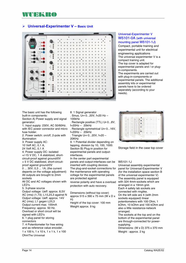
Universal-Experimenter V W5101-0A (with universal mounting panel W5101-1J) Compact, portable training and experimental unit for electrical engineering applications The universal experimenter V is a compact training unit. The top cover is adapted for experimental panels and / or plug-in-components. The experiments are carried out with plug-in-components or experimental panels. The additional assembly kits or experimental panels have to be ordered seperately (according to your needs).
The basic unit has the following built-in components: Section A) Power supply and signal generator: 1. Input supply: 230V, AC 50/60Hz. with IEC power connector and micro fuse holder. 2. Power switch: on/off, 2-pole with illumination 3. Power supply AC: 10 Veff AC, 0,1 A, 24 Veff AC, 0,1 A 4. Power supply DC: isolated +/-15 V DC, 1 A stabilized, short-circuit-proof against ground/0V + 5 V DC stabilized, short-circuit-proof against ground/0V 0 ... 30V; 0,3 ... 1A; (the current depents on the voltage adjustment) All outputs are brought to 2mm sockets All DC and AC voltages shown with LED's. 5. 3-phase source Output voltage: Ueff: approx. 8,5V AC (rms) (1,73); L1/L2/L3 against N Output voltage: Ueff: approx. 14V AC (rms); L1 gegen L2/L3 Output current max. 100mA Frequency: approx. 50 Hz. Overload or short circuit will be signed with LED's 6. 1 plug panel for storing connectors 7. 4 Potentiometer for free wiring and as reference value encoder. 1 x 100 k, 1 x 10 k, 1 x 1 k, 1 x 100 OhmThe Universal
8. 1 Signal generator . Sinus, UPP 0...20V, f=20 Hz – 100kHz . Rectangle positive (TTL) UP 0...8V, f=20Hz – 20kHz . Rectangle symmetrical UPP 0...16V, f=20Hz – 20kHz . Triangle UPP 0...20V, f=20 – 20KHz 9. 1 Potential divider depending on tapping, division by 10, 100, 1000. Section B) Plug-in position for experimental panels and output-interfaces. In the center part experimental panels and output-interfaces can be inserted with coupling devices. The plug-and-socket connections for the maintenance with operating voltage for the experimental panels are protected against reverse polarity and have a overload protection with auto recovery. Dimensions (without top cover) approx 515 x 390 x 75 mm (W x D x H) Height of the top cover: 100 mm Weight approx. 9 kg
Storage field in the case top cover W5101-1J Universal assembly experimental panel for Universal-Experimenter V (for the installation space section B of the universal experimenter V) The assembly panel is equipped with 324 4mm-sockets which are arranged in a 19mm grid. Each 4 safety lab sockets are connected with ringlike. On the left side are 4 (with 2mm sockets equipped) linear potentiometers with 100 Ohm, 1 kOhm, 10 kOhm and 100 kOhm andalso a little resistance-network arranged. The sockets at the top and on the bottom of the experimental panel are through-connected for power-supplying. Dimensions: (W x D) 375 x 370 mm Weight : approx. 2 kg

WUEKRO
Catalog WA2E/02 Page 15
Dimensions (BxTxH) 400x300x80 mm Weight approx. 1 kg
Storage case for plug-in modules. Consisting of 2 shells the bottoms of which are equipped with 10 mm grid panels. Capacity 80 2-pin plug-in modules and 42 4-pin plug-in modules
Order-No. W5101-2Y
Fault Simulators
Supply voltage + 15 V DC Dimensions (HxW) 297x226 mm Weight approx. 1,5 kg
Light barrier Assembled form 4 NPN transistors, receiver: photo-transistor, light source can be switched off by toggle switch. Output with relay whose make contact controls a pilot lamp with non-specified socket. 10 faults are incorporated and can be operated by covered switches.
Order-No. W5433-1K
Supply voltage + 15 V DC Dimensions (HxW) 297x226 mm Weight approx. 1,5 kg
Thermal circuit breaker By actuating a pushbutton switch, a reference temperature is produced in a heating resistor.
This temperature acts on an NTC resistor which in turn activates a differential amplifier. At the output a relay is operated by a transistor stage. The make contact of the relay actuates a visual display. 10 faults are incorporated and can be operated by covered switches.
Order-No. W5433-1L

WUEKRO
Page 16 Catalog WA2E/02
FAX – response to: +49-9721 - 64691 - 20 Sender: Receiver:
Company WUEKRO GmbH Dept. Sales Department Name Street Carl-Zeiss-Strasse 10 City 97424 Schweinfurt / Germany Phone + 49-(0)9721-64691-0 Fax + 49-(0)9721-64691-20 E-Mail [email protected] Internet www.wuekro.de No. of pages
incl. this page
Please send the following cataloges to the a.m. address!
Fundamentals of electrical Engineering
Installation circuits Bell ringing and entrance call stations Contactor circuits/Control technology Measurement and control of non- electrical quantities
Fundamentels of electronics Analog technology Digital technology Microprocessing technology
Closed loop control technology Analog control technology Digital control technology
Automation engineering SIMATIC S7-200/300/400, Software Technology simulators / Models Process control technology PCS7 AS-Interface Process simulation-software SIMIT LOGO!
Electrical machines / Drive controls 300W - Program 1000W - Program 5kW - Program Electr. drive control 300W/1000W Electr. drive control 5kW
Power electronics extra low voltage (24V) low voltage (230/400V)
Building management systems KNX / EIB
Protection schemes to VDE 0100
Radio- and TV technology AM/FM - Technology TV Technology Satellite - Technology
Air conditioning and refrigeration
Photovoltaic
Communication technology Modulation -/demodulation technology Optical fibre HICOM communication systems
Measuring systems, power supplies, Accessories
Experimental manuals, documentation, books
Remarks:

WUEKRO
Training & Didactic Systems
Control Technology
Catalog WA2E/03

WUEKRO
Page 2 Catalog WA2E/03
Our Services
• Development and production of didactic training systems • Teachware and documentation • Project engineering of complete lab's incl. furnitures and lab equipment • Quotations on custumors demand • Installation, commissioning and training at site
Our Customers • Vocational training schools, technical schools, colleges and universities... • Industrial laboratories for vocational education and higher education
Fields of Technology • Fundamentals of electrical engineering
• Fundamentals of electronics
• Closed loop control technology
• Automation engineering
• Electrical machines / drive control
• Power electronics
• Building management systems
• Protection schemes to VDE 0100
• Radio- and TV technology
• Air conditioning and refrigeration
• Photovoltaic
• Communication technology
• Measuring systems, power supplies, accessories
• Experimental manuals, documentation For further information please contact: WUEKRO GmbH Carl-Zeiss-Strasse 10 D – 97424 Schweinfurt Deutschland Tel. + 49 (0) 9721-64691-0 Fax: + 49 (0) 9721-64691-20 E-Mail: [email protected] Internet: www.wuekro.de WUEKRO GmbH
All Rights reserved. Reprint not permitted. Technical changes without prior notice.. S30020716P – 12/12

WUEKRO
Catalog WA2E/03 Page 3
Table of Contents PageOur Services, Customers and Scope of Supply 2 Introduction 4 Experimental panels control technology 5 Assembly kit control technology (experimental panel system) 9 Digital control technology with SIPART DR 21 10 Experimental Panels with SIPART DR 21 12 Simulator Panel and Level and flow control simulator 14 Complete Training Unit with DR 21 14 Notes 15 Fax - Reply 16

WUEKRO
Page 4 Catalog WA2E/03
Introduction Closed-loop control equipment is of central significance covering many technical disciplines. This applies particularly in mechanical and electrical engineering, in production and process technology, in plant and systems technology where such equipment is indispensable.
In the automation field, important optimization tasks would be quite impossible to solve without closed-loop control technology. In line with its increasing importance, closed-loop control has become a basic subject in professional training and further education for many professions.
In the newly formulated training curricula, this technology has been given a role covering a number of subjects in the syllabuses for training in industry and the crafts.

WUEKRO
Catalog WA2E/03 Page 5
Experimental panels Control Technology
General Demonstrations and experiments ranging from simple closed-loop control circuits up to complicated control systems can be carried out. Different combinations of experiments can be carried out with the instruction modules in the following selection table. We recommend that the following kits be used if the experimental program is to be carried out in accordance with our instruction manual.
The panels are designed for insertion in experimental frames. Storage cabinets or drawer inserts are available for accommodating un-used panels. For all panels the operating voltage is ±15 V DC, and the signal voltage ±10 V DC.
The power 2-mm supply connection sockets are approx. 20 mm from the upper edge and the under edge interconnected. The power supply can be realized by means of connection plugs if the experimental panels are located side by side. Dimensions of the panels Height 297 mm Width 130 mm or integral multiples thereof 65mm.
Linear controlled system 1
Limiting circuits B+ and B-: Positive and negative limiting, steplessly adjustable between 0 and + 100 % Common to Gp and VZ1/integral element LED display to indicate operation of limiting circuit Output circuit: 1 Inverting output 1 Non-inverting output Dimensions (WxHxD) 260x297x65 mm Weight approx. 1 kg
Technical data Input circuit: 1 Enable input "0" signal path enabled "1" signal path blocked
3 Inputs with smoothing circuit, Tgl = 1 ms 3 Inputs without smoothing circuit 1 Switched disturbance input Proportional element Gp : Gp = 0 to 10, stepless adjustable and VZ1 delay/integral element: Switch selectable between integral element and VZ1 delay Ti
or τ = 0 to 500 ms selectable in 8 steps Selectable time factor x 1 or x 0,01
Order-No. W5302-2A
Common to Gp and VZ1-/integral element LED display to indicate operation of limiting circuit Output circuit: 1 Inverting output 1 Non-inverting output Dimensions (WxHxD) 260x297x65 mm Weight approx. 1 kg
Linear controlled system 2 Input circuit: 1 Enable input "0" signal path enabled "1" signal path blocked 3 Inputs with input smoothing circuit, Tgl = 1 ms 3 Inputs without smoothing circuit 1 Switched disturbance input Proportional element Gp : Gp = 0 to 10, stepless adjustable and
VZ1 delay/integral element: Switch selectable between integral element and VZ1 delay Ti or τ = 0 to 5 s selectable in 8 steps Selectable time factor: x 1 or x 0,01 Limiting circuits B+ and B-: Positive and negative limiting, steplessly adjustable between 0 and +100 %
Order-No. W5302-2B

WUEKRO
Page 6 Catalog WA2E/03
Experimental panels Control Technology
Linear controlled system 3
LED display to indicate operation of limiting circuit Output circuit: 1 Inverting output 1 Non-inverting output Dimensions (WxHxD) 260x297x65 mm Weight approx. 1 kg
Input circuit: 1 Enable input "0" signal path enabled "1" signal path blocked 3 Inputs with smoothing circuit, Tgl = 1 ms 3 Inputs without smoothing circuit 1 Switched disturbance input Proportional element Gp : Gp = 0 to 10, stepless adjustable
and VZ1 delay/integral element: Switch selectable between integral element and VZ1 delay Ti
or τ = 0 to 5 s selectable in 8 steps Selectable time factor: x 1 or x 0,01 Limiting circuits B+ and B-: Positive and negative limiting, steplessly adjustable between 0 and +100 % Common to Gp and VZ1 delay/ integral element Order-No. W5302-2C
Selectable time factor: x 1 or 100
Sampling time selectable in 8 steps, TA = 0,5/1/2/4/6/8/10/20 ms Minimum value of sampling time: 0,01 x Tt Dimensions (WxHxD) 260x297x65 mm Weight approx. 1 kg
Non-linear controlled systems Hysteresis: Hysteresis steplessly adjustable between 10 and 100 %
Dead zone: Dead zone steplessly adjustable between 10 and 100 %
Dead time: Dead time selectable in 8 steps, Tt = 5/10/20/40/60/80/100/200 ms
Order-No. W5302-2D
Dimensions (WxHxD) 130x297x65 mm Weight approx. 1 kg
Limiters Positive and negative limiting of output signal: Steplessly adjustable between 0 and +100 % and between 0 and –100 %
Order-No. W5302-2E
Change = 10 % of an external quantity Keying of changes via pushbutton Setpoint/disturbance value output limited to the maximum/minimum value. Dimensions (WxHxD) 130x297x65 mm Weight approx. 1 kg
Setpoint/disturbance value The reference and disturbance variables are set with a 10-turn potentiometer with reversible polarity: Steplessly adjustable between 0 and 100 % with selector switch ± polarity Keying in small changes: Change = 10 % of nominal value
Order-No. W5302-2F

WUEKRO
Catalog WA2E/03 Page 7
Experimental panels Control Technology
Dimensions (WxHxD) 130x297x65 mm Weight approx. 0,5 kg
Control deviation The control deviation is formed at a summation point. The smoothing circuits at the input can be switched in or out. Smoothing time constant: Tgl = 5 ms
Inputs: 3 Non-inverting inputs 3 Inverting inputs Output: Sum of inputs
Order-No. W5302-2G
The limits of the individual functions cannot be larger than the summation limit. The function switches keep the functions at zero in the OFF state. The enable input blocks the controllers at signal '1' and enables them at signal '0.' Dimensions (WxHxD) 260x297x65 mm Weight approx. 1 kg
Continuous-action controllers The controllers comprise the following components: P component Gain steplessly adjustable between 0 and 10 and can additionally be changed by factor 0,1. The output variable can be steplessly limited between 0 and + 100 %, and between 0 and - 100 %. LEDs indicate the limiting action.
I component The introgression time is adjustable in 8 steps between 0,1, 0,2, 0,3, 0,5, 1, 2, 5 and 10 s or reduced to 0,01 times the value. The output variable is continuously adjustable between 0 and + 100 %, and between 0 and - 100 %. LEDs indicate the limiting action. D component The differential time is adjustable in 8 steps between 0,01, 0,02, 0,03, 0,05, 0,1, 0,2, 0,5 and1 s or reduced to 0,01 time the value. The output variable is continuously adjustable between 0 and + 100 %, and between 0 and - 100 %. LEDs indicate the limiting action. Each of the three components can be switched in at the summation point. The common output is continuously adjustable between 0 and + 100 %, and between 0 and - 100 %. LEDs indicate the limiting action.
Order-No. W5302-2H

WUEKRO
Page 8 Catalog WA2E/03
Experimental panels Control Technology
Dimensions (WxHxD) 130x297x65 mm Weight approx. 1 kg
Two-step controller The two-step controller only accepts the +100 %, 0% and –100 % values at its output. Its operating values can be set by an hysteresis which is continuously adjustable between 0 % and ± 50 % of the rated input value.
Order-No. W5302-2J
The smoothing constant Tgl is adjustable between 0,5 and 2 s, and can be reduced to 0,01 times the value. The feedback action is continuously adjustable between 0 and 100 % via gain factor Gp. Dimensions (WxHxD) 260x297x65 mm Weight approx. 1 kg
Three-step controller The three-step controller accepts the +100 %, 0% and –100 % values at its output depending on the sign of its input.
The controller operating values are continuously adjustable between 0,5 % and 50 % of the input value. The hysteresis is dynamic in each direction in order to prevent fast activation and deactivation if the input signal approaches the set operating value. The line-side smoothing element prevents operation in the case of signal peaks at the input. A smoothing element is also provided in the feedback loop to allow for follow-up effects.
Order-No. W5302-2K
Dimensions (WxHxD) 260x297x65 mm Weight approx. 1 kg
Overload/start module The experimental panel contain 9 positive and 9 negative inputs for overload indication of the process elements connected (10 LED outputs). Also installed is a START/ZERO feature which, when activated, discharges the capacitors connected.
Order-No. W5302-2L

WUEKRO
Catalog WA2E/03 Page 9
Assembly kit Control Technology
Assembly kit "Fundamentals of control technology" (Experimental panels) Order-No. W5302-8A
The following experiments can be carried out Fixed-value control • Voltage regulation • Level control • pH control • Temperature control Follow-up control • Rotational speed control • Current control • Position control • Velocity control Cascade control • with secondary current control • with secondary flow control • with secondary level control
The controlled systems may have the following transfer functions: Linear transfer functions • Proportional element with gain • Proportional element with first-
order delay • Integral element • Characteristics Not-linear transfer functions • Dead time • Hysteresis • Dead band
Higher-order controlled systems can be configured by interconnecting several function units. The controllers may have the following transfer functions: Linear transfer functions • P controller • I controller • D controller • PI controller • PD controller • PID controller Non-linear transfer functions • Two-step controller • Three-step controller
The following equipment is necessary to carry out these experiments:
1 Linear system 1 Order-No. W5302-2A
1 Linear system 2 Order-No. W5302-2B
1 Linear system 3 Order-No. W5302-2C
1 non-linear system Order-No. W5302-2D
1 Limiter Order-No. W5302-2E
1 Setpoint/disturbance variable Order-No. W5302-2F
1 Control deviation Order-No. W5302-2G
2 Continuous-action controller Order-No. W5302-2H
1 Two-step controller Order-No. W5302-2J
1 Three-step controller Order-No. W5302-2K
1 Overload/start module Order-No. W5302-2L Further components (included in the kit)
Additional equipment required (not included in the kit)
1 Experimental manual "Fundamentals of Control Technology" W3021-7B
2 Multimeter with center zero 1 20-MHz/2-channel-oscillos- cope 1 Set of measuring leads and plug connectors.
1 Compensograph X-T or 1 Compensograph X-T with time offset compensation

WUEKRO
Page 10 Catalog WA2E/03
Training System for closed-loop control technology
General The following components form an integral unit in one casing:
This is the state-of-the-art training unit containing really everything needed for practice-oriented and continuing education and training in closed-loop control technology. SIPART DR 21 compact controller experimental panel with serial communications interface (e.g. for PC, programmable controllers
• Experimental panel function generator
• Experimental panel power supply unit for controlled-system simulators
• Replaceable experimental panels with controlled-system simulators
The SIPART DR 21 compact controller experimental panels and the controlled-system simulators (board size DIN A4) can also be inserted in experimental frames.

WUEKRO
Catalog WA2E/03 Page 11
Closed-Loop Control Technology with Controller SIPART DR21
Compactly packaged digital control technology, without programming knowledge
Combination of continuous and step-action controllers
Operating, programming, configuring
Flexible configuration for training
The core of the WUEKRO DR 21 system is the SIPART DR 21 controller. This represents the compact packaging of the industrial experience gathered in digital control technology. An additionally integrated limit value module makes two controllers out of one. Thus, WUEKRO DR 21 is an ideal combination of the two main controller types available in practice: The continuous controller providing a continuous output current signal (output voltage signal), used mainly for pneumatic and hydraulic actuators. The step-action controller with a stepping output which is optionally programmable as a three-step controller for electrical actuators or as a two-step controller (e.g. for cooling and heating).
A large number of off-the-shelf controller functions are already stored in the program memory of the SIPART DR 21. Without the operator having any special programming knowledge, the desired functions can be selected, combined to form a task-related program and stored safe from the effects of, for example, a power fail. The changeover from operator control to the programming or configuring level takes place in steps. It is possible to change directly form the programming level to process operation and via programming from the configuring level. And for all this, no special programming unit is required, neither is any special software knowledge.
The SIPART DR 21 controller is configurable for many operating modes, such as: • Fixed setpoint control • Fixed setpoint control with
feed-forward control at the input or output
• Follow-up control • Synchronized control • Ratio control • Feed forward control with
function generator (pulse, sine wave, square wave)
• System identification (step function, step response).
But SIPART DR 21 has even more to offer: it is configurable as a P, PI, PID or PD controller and its control algorithm can also be switched off. The unit can then be used as: • Ratio station • Process indicator • Automatic and manual control
unit
DR 21 controller External controlled systems provide a direct link with practice. The Training unit DR 21 enables you to install controlled-system simulators on DIN A4 experimental panels into the housing or the directly connect separate control models (For order numbers see overview)

WUEKRO
Page 12 Catalog WA2E/03
Experimental panels Control Technology with Controller SIPART DR21
The process controller is programmable as: • Constant value controller • Constant value controller with
disturbance variable addition at the in- and output
• DDC-back-up Constant value controller
• Follow-up controller with or without internal / external changeover
• Synchronizing controller • Ratio controller Furthermore, the unit is suitable as ratio-station, Master-controller and process indicator. An additional adjustable DC voltage supply 0 – 10 V with step-function is integrated in the experimental panel. Dimensions (W x H x D) 195x297x300 mm Weight approx. 2 kg
SIPART DR 21 controller Continuous (K) or switching (S) mode Serial interface V.24 (RS-232C) 2 additional voltage inputs Controllable DC voltage 0 to 10 V, built in an experimental panel, height 297 mm for insertion into a compact unit or experimental frame. All connections are brought out to 2-mm-sockets: • Continuous output
0 – 20 mA or • 0 – 10 V • External setpoint variable and
Setpoint generator as current or voltage
• Binary in/output • serial interface for connection
to PC or superordinated system
Order-No. W4610-4A
Dimensions (WxHxD) 65x297x200 mm Weight approx. 3 kg
Order-No. W4610-4N
Power supply designed as experimental panel height 297 mm for insertion into a compact unit or experimental frame. All connections are brought out to 2-mm-sockets. Input voltage 1 AC 230 V 50/60 Hz Output voltages +15 V / 1,5 A -15 V / 1,5 A 24 V / 0,5 A

WUEKRO
Catalog WA2E/03 Page 13
Experimental panels Control Technology with Controller SIPART DR21
Dimensions (WxHxD) 130x297x565 mm Weight approx. 0,3 kg
Function generator designed as experimental panel height 297 mm for insertion into a compact unit or experimental frame. All connections are brought out to 2mm sockets. Frequency range 0,1...1 KHz Signal forms DC voltage with step function, sine and square wave, offset control Amplitude 0...10 V Order-No. W4610-4F
Set connection leads
with 2 mm plugs for the compact unit SIPART DR 20 Order-No. W4610-1M
Dimensions (WxHxD) 195x297x65 mm Weight approx. 1,0 kg
Universal controlled system equipped with: 1 Proportional-action element 1 Integral-action element 4 First-order time delay elements 1 Linear valve characteristic element 1 Equal-percentage value characteristic element prepared for lag element W4610-2C
Order-No. W4610-4C
Lag-element Adjustable from 1 to 60 s Applicable only in connection with W4610-4C Order-No. W4610-2C
Dimensions (WxHxD) 130x297x65 mm Weight approx. 0,6 kg
Temperature control Including heater and Pt 100 temperature sensor.
Order-No. W4610-4D

WUEKRO
Page 14 Catalog WA2E/03
Experimental panels Control Technology with Controller SIPART DR21
Technical data Supply voltage ± 15 V Inputs- Binary 0/24 V or 0/5 V Analog 0 ... 10 V Outputs 0 ... 10 V actual value Filling level 0 ... 10 V actual value discharge rate Dimensions (WxHxD) 260x297x65 mm Weight approx. 0,6 kg
Technology simulator Filling level controller This simulator is the electronic model of a level control system in which the volume discharged in a particular time depends on the level (PT1-system).
Order-No. W4760-1M
Complete Training with Controller SIPART DR21
SITRAIN DR21 compact unit with controlled-system simulators Dimensions (WxHxD) 650x320x280 mm Weight approx. 14 kg
Order-No. W4610-2K Compact unit SIPART DR 21 consisting of desk-top housing with the following experimental panels installed: 1 Process controller SIPART DR 21 Order-No. W4610-4A 1 Power supply unit Order-No. W4610-4N
1 Function generator Order-No. W4610-4F
1 Universal controlled system Order-No. W4610-4C
1 Lag element Order-No. W4610-2C
1 Controlled system for temperature Order-No. W4610-4D
1 Experimental manual V246 "Control Technology with SIPART DR 21" Order-No. W3024-6A

WUEKRO
Catalog WA2E/03 Page 15
Notes

WUEKRO
Page 16 Catalog WA2E/03
FAX – Response to: +49 (0)9721 - 64691 - 20 Sender: Receiver:
Company WUEKRO GmbH Dept. Sales Department Name Street Carl-Zeiss-Strasse 10 City 97424 Schweinfurt / Germany Phone + 49-(0)9721-64691-0 Fax + 49-(0)9721-64691-20 E-Mail [email protected] Internet www.wuekro.de No. of pages incl. this page
Please send the following catalogues to the a.m. address! Fundamentals of electrical Engineering
Installation circuits Bell ringing and entrance call stations Contactor control / Control technology Measurement and control of non-electrical variables
Fundamentels of electronics Analog technology Digital technology Microprocessing technology
Closed loop control technology Analog closed loop control Digital closed loop control
Automation engineering SIMATIC S7-200/300/400, Software Technology simulators / Models Process control engineering PCS7 AS-Interface Profibus DP Process simulation-software SIMIT LOGO! Mechatronical technology stations Courses on Automation
Electrical machines / Drive controls Electrical Machines 300W Electrical Machines 1000W Electrical Machines 5kW Electrical drive control systems 300W/ 1kW Electrical drive control systems 5kW Networked drive systems Cutaway Models Transformers, Rectifiers and Reactive Power Compensation Courses on drive systems
Power electronics extra low voltage (24V) low voltage (230/400V)
Building management systems KNX / EIB
VDE 0100 safety measures
Radio- and Television engineering AM/FM – Technology TV Engineering
Satellite – Technology
Cooling and air conditioning
Photovoltaic cell tecnology
Communication technology Modulation -/demodulation Fiber optic ISDN trainer (HICOM) ISDN
Measuring systems
Power supply units
Experiment instructions, manuals
Training courses
Remarks:
WUEKRO
Training & Didactic Systems Automation Technology with SIMATIC S7
Catalog WA2E/04.01

WUEKRO
Our Services
• Development and production of didactic training systems • Teachware and documentation • Project engineering of complete lab's incl. furniture and lab equipment • Quotations on customer's demand
Installation, commissioning and training at site •
Our Customers • Vocational training schools, technical schools, colleges and universities... • Industrial laboratories for vocational education and higher education
Fields of Technology • Fundamentals of electrical engineering
• Fundamentals of electronics
• Closed loop control technology
• Automation engineering
• Electrical machines / drive control
• Power electronics
• Building management systems
• Protection schemes to VDE 0100
• Radio- and TV technology
• Air conditioning and refrigeration
• Photovoltaic
• Communication technology
• Measuring systems, power supplies, accessories
• Experimental manuals, documentation For further information please contact: WUEKRO GmbH Carl-Zeiss-Strasse 10 D – 97424 Schweinfurt Germany Tel. + 49 (0) 9721-64691-0 Fax: + 49 (0) 9721-64691-20 E-Mail: [email protected] Internet: www.wuekro.de WUEKRO GmbH
All Rights reserved. Reprint not permitted. Technical changes without prior notice.. E04051624M – 05/16
Page 2 Catalog WA2E/04.01

WUEKRO
Table of Contents Page
Our Services, Customers and Scope of Supply 2 Training System Automation Technology 4 Introduction 5 LOGO! Experimenters with LOGO! –BA08 6 Experimenter panel with LOGO! - BA08 7 Experimenters with SIMATIC S7-1200 8 Experimenters for Electrical Engineering with SIMATIC S7-1200 9 Experimenters for Metal Engineering with SIMATIC S7-1200 10 Experimental Console with SIMATIC S7-1200, S7-1200 Extensions 11 Training Units with SIMATIC S7-300 in Rack Design 12 Experimental consoles with SIMATIC S7-300 16 Training Units with SIMATIC S7-1500 in Rack Design 19 Experimental consoles with SIMATIC S7-1500 23 TP700 Touchpanel 25 SIMATIC S7-1500 Experimental Case 26 SIMATIC PCS7 Experimental Rack 28 Simulation Modules for older WUEKRO SIMATIC S7-300 Experimental Racks or Consoles
29
Programming Software 32 Programming Devices – Siemens Field PG 34 Accessories – Leads/Plugs 36 Accessories – Manuals/Documentation 36 Experiment Instructions 37 System Introduction for SIMATIC S7 38
Catalog WA2E/04.01 Page 3
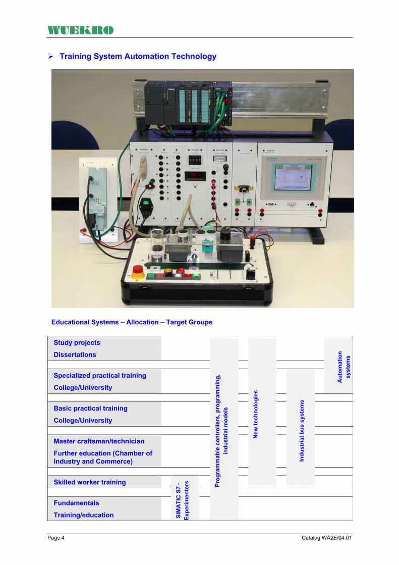
WUEKRO
Training System Automation Technology
Educational Systems – Allocation – Target Groups
Study projects
Dissertations
Specialized practical training
College/University
Aut
omat
ion
syst
ems
Basic practical training
College/University
Master craftsman/technician
Further education (Chamber of Industry and Commerce)
Skilled worker training
New
tech
nolo
gies
In
dust
rial b
us s
yste
ms
Fundamentals
Training/education
SIM
ATI
C S
7 -
Expe
rimen
ters
Prog
ram
mab
le c
ontr
olle
rs, p
rogr
amm
ing,
in
dust
rial m
odel
s
Page 4 Catalog WA2E/04.01

WUEKRO
Introduction Learning targets are reached with our training systems. •
• •
•
•
•
•
• • • • • • • •
• •
• • • • • • •
Structure of numerical systems
Declaration of variables Methods of PLC representation with FBL, LAD, STL, Graph 7, SCL according to standard IEC 1131-3
Getting to know program execution procedures
Getting to know the function groups of a PLC and their principles of operation according to standard IEC 1131-1,2
Basic logic operations with a PLC
Logic controls with dynamic responseCounters and comparators with/without storage function Sequential controls with mode sectionSequencers Operating status messages process- or time-oriented
Analog value processing Word processing Digital closed-loop control Autonomous modules Drive/position control Startup, maintenance Industrial networking Fundamentals of open communications
Process visualization/control Fault diagnostics without/with visualization systems
The concept The aim of the new IEC 1131 standard is to attain a worldwide unified system in the field of PLC technology. The programming languages are standardized in part 3. The standard encompasses the ladder diagram (LAD), function block language (FBL), sequence language (SL), statement list (STL), and structured text (ST). PLC systems are an integral component of automation today. SIMATIC S7 has taken the lead by offering a basic system for the entire field of automation. SIMATIC S7 is the platform for
PLC Man-machine interface Industrial networking Process control engineering Automation computers Measurement and control DP and Profinet applications
A great advantage for the user is the fact that this knowledge, once attained, can also be put to use in the other fields of technology. The goal of our training concept for the different fields of automation is to provide
- Vocational schools - Colleges - Universities - Places of training and
further education with the theoretical and practical prerequisites leading to trainees’ and students’ complete understanding of modern automation technology.
In general, there are two ways in which you can fulfill your training needs: 1. By working with the low-cost
experimenter consoles and the technology simulators.
2. By working with the modular rack system, the technology simulators and models.
Here you can choose from the modules which are tailored to your curriculum. Our program is rounded off with the model industrial bus system, the modular automation system aimed at engineering schools and colleges/universities. Practical experiment instructions Experiment instruction manuals on the individual modules, which have been compiled by specially trained and qualified employees, are available for use. In general, the experiment instructions consist of three parts: Part 1 Introduces the training needs and provides the basic theory. Part 2 Contains the programming and test tasks. Part 3 Contains solutions to part 2. This keeps the time for test preparations to a minimum and offers a way of checking the results.
Catalog WA2E/04.01 Page 5

WUEKRO
Experimenter with LOGO! –0BA8
Experimenter E with integrated universal simulator electrical engineering
Order-No. W4724-4A
Order-No. W4724-4B
Experimenter M with integrated universal simulator metal engineering
Basic configuration Industrial equipment 1 Micro SPS LOGO! 8
12/24RCE with Ethernet interface
1 LOGO! DM8 extension 4Di/4DO
Simulation 12 digital inputs DI lead to momentary-contact / maintained-contact switch and to 4-mm-safety sockets. 8 digital outputs lead to to 4-mm-safety sockets, additionally signal statuses by LED. Power supply outout 24V DC lead to 4mm safety lab sockets. The ethernet connection is easy to reach on the front panel. Measurements (W x H x D) 420 x 150 x 300mm Weight approx. 5 kg
Experimenter E with integrated universal simulator electrical engineering This Experimenter is especially convenient for PLC basic education in electrical engineering. The experiments are worked out curriculum based. The Experimenter is equipped with the Micro-PLC LOGO! –0BA8 and an integraed universal simulator with different overlay-masks. The in- and outputs from the LOGO! are internally connected to the simulationfield-matrix from the experimenter and additionally lead to 4mm safety lab sockets as well as to a 37-pin D-SUB-socket. Included are 11 different overlayer-masks mit exercises up from an easy logic control to a sequencial control. Fan control Tank filling device Star-delta-starting-up Gate control Roadworks traffic light Pump control Furnace door controller Traffic light control Starter control Embossing machine Buffer store By exchanging the different text overlays, only the LED'S, which are assigned to a specific exercise, are uncovered..
Training concepts: • Cyclic program processing • Logic circuits • Interlocking circuit • Sequential circuit • Different memories • Pulse generator, edge evaluation • Clock generator • ON/OFF delay • Counters and comparators • Up/down counter • BCD coding pulse count store • Signal preprocessing • Initializing pulse generator/pulse
contact • Structured programming • Status diagram • Process and timed sequence
control system • Mode sections • Sequencers • Step enabling conditions • Word output
Experimental panel with LOGO! –BA08
Page 6 Catalog WA2E/04.01

WUEKRO
Basic configuration: Industrial equipment 1 Micro SPS LOGO! 8 12/24RCE with Ethernet . interface 1 LOGO! DM8 extension 4Di/4DO 12 digital inputs DI lead to momentary-contact / maintained-contact switch and to 4-mm-safety sockets. 8 digital outputs lead to to 4-mm-safety sockets, additionally signal statuses by LED. Power supply outout 24V DC lead to 4mm safety lab sockets as well as to a 37-pin D-SUB-socket. The ethernet connection is easy to reach on the front panel.
Order-No. W4452-1A Experimental panel with DIN-A4-height for hang-up in experimental frames or laying on an ergonomical console hood to the table work surface Simulation module: DI-module: 12 digital inputs (thereof 4 useable as analog inputs) are connected on momentary-contact/ maintained-contact switch and to 4mm safety lab sockets.
Bestell-Nr. W4452-1B Same as W4452-1A but with extension module LOGO! AM2 with 2 analog outouts, lead to 4mm safety lab sockets. Bestell-Nr. W4452-2B
Extension module for connecting the LOGO! 8 with th KNX-bus (see our KNX experimental panels in catalog WA02/07 Experimental panel with enwrapped mounted LOGO! 8 communication module KNX CMK2000. Transparent thermoformed plastic hood. Dimensions (WxHxD) 130x297x65mm Weight approx. 0,5kg
DO-module: 8 digital outputs are connected to 4 mm MC-safety sockets, signal statuses by LED PS-module: inlet connector for non-heating apparatus, short circuit protection, fuse and illuminated on-off switch 24V / 2,5A on 4 mm MC-safety sockets 37-pin D-SUB connector interconnected to LOGO! modules with 12 DI and 8 DO
Bestell-Nr. W4452-1P Wie W4452-1A jedoch zusätzlich mit Erweiterungsmodul LOGO! AM2 RTD mit 2 PT100 Analogeingängen, herausgeführt auf 4mm SI-Laborbuchsen Bestell-Nr. W4724-1Z
Extension-panel with 5-fold switch SIMATIC XB005
Also included: supply connection cable 2m, operator´s guide 1 inlet connector for non-heating apparatus, shor circuit protection fuse and illuminated on-off-switch for mains-voltage-connection 230V, Measurements (W x H x D)
290x297x130mm
Weght approx. 2kg Bestell-Nr. W4452-1U
SIMATIC HMI Touchpanel KTP400 for LOGO!8. 4“ TFT Display, 65536 Farben und 4 Funktionstasten on a DIN-A4 experimental panel. Power supply 24VDC with 4mm safety-lab-sockets. USB- and Profinet connection lead to front panel.
Catalog WA2E/04.01 Page 7

WUEKRO
Experimenters with SIMATIC S7-1200
General The experimenters have a compact design and are conceived according to the motto “set up, switch on, training". This makes a mobile use in multiple locations possible. All cases are equipped with a mains plug with fuse for external connection to the mains voltage of 230 V and a mains connecting lead (approx. 2 m). 22 (14 onboard, 8 extension) digital inputs DI in total; 14 digital inputs DI brought out to momentary-contact/maintained-contact switches and 4-mm safety lab sockets 18 (10 onboard, 8 extension) digital inputs DI in total; 10 digital outputs DO brought out to 4-mm safety lab sockets, indicated with LED. The inputs and outputs of the SIMATIC S7-1214C are also internally wired to the simulation panel matrix of the experimenter. 24-V power supply brought out to 4-mm safety lab sockets; all this in- and outputs and power supply additionally to a 37pin D-SUB-jack.. The Ethernet-interface is brought out to a front-socket. Two analogue values (0 … 10V DC) can be simulated with 2 Potentiometers wired to 4mm safety sockets. Also supplied are 11 different overlays with examples for training, from the straightforward logic control to sequential control.
Page 8 Catalog WA2E/04.01

WUEKRO
Experimenters for Electrical Engineering with SIMATIC S7-1200 Training content: • • • • • •
• • • • •
• •
• • •
• • • • •
• • • • • • • • • •
Cyclic program processing Logic operators Interlock circuit Sequence control Storage types Pulse generators, edge evaluation
Clock generator ON/OFF delay Counters and comparators Up/down counter BCD coding/pulse count memory
Signal preprocessing Initializing pulse generator/pulse contact
Structured programming Status diagram Process-oriented/time-oriented sequential control
Mode sections Sequencers Step enabling conditions Word messages
Basic equipment Industrial components 1 Micro PLC SIMATIC S7-1214C, 50 KByte RAM, Onboard 14DI DC /10DO Relais Simulation panel 22 (14 onboard, 8 extension) digital inputs DI in total; 14 digital inputs DI brought out to momentary-contact/maintained-contact switches and 4-mm safety lab sockets 18 (10 onboard, 8 extension) digital inputs DI in total; 10 digital outputs DO brought out to 4-mm safety lab sockets 24-V power supply brought out to 4-mm safety lab sockets. The Ethernet-interface is brought out to a front-socket.
Dimensions (W x H x D) 420x150x300 mm
Weight approx. 5 kg
Experimenter E with integrated universal simulator Electrical Engineering This experimenter is especially suited for fundamental PLC training in the vocational field electrical engineering. The experiments have been aligned with the curriculum. The experimenter is equipped with the Micro-PLC SIMATIC S7-1214C and an integrated universal simulator with overlays. The inputs and outputs of the SIMATIC S7-1214C are internally wired to the simulation panel matrix of the experimenter, brought out to 4-mm safety lab sockets and additionally to a 37pin D-SUB-jack. Also supplied are 11 different overlays with examples for training, from the straightforward logic control to sequential control.
Starter control Furnace door control Embossing machine Pump control Star-delta start-up Fan control Roadwork traffic light Traffic light control Gate control Buffer store Tank filling device
By replacing the overlays, the LEDs assigned to the respective exercise become visible.
Order-No. W4724-4A
Overlays 11 overlays are part of delivery
• • • • • • • • • •
Starter control Furnace door control Embossing machine Pump control Star-delta start-up Fan control Roadwork traffic light Traffic light control Gate control Buffer store
Tank filling device to be seen on the picture of W4724-4A above.
Catalog WA2E/04.01 Page 9

WUEKRO
Experimenters for Metal Engineering with SIMATIC S7-1200
Training content: • •
•
• • •
• • • • •
• • • • • • • • • • •
Electropneumatics Electropneumatic signal flow chart
Safety conditions in installations with electropneumatics
Logic operators Interlock circuit Process-oriented/time-oriented sequential control
Storage types Counters and comparators Structured programming Status diagram Step enabling conditions
Dimensions (W x H x D) 420x150x300 mm Weight approx. 5 kg
Basic equipment Industrial components 2 Micro PLC SIMATIC S7-1214C, 50 KByte RAM, Onboard 14DI DC /10DO Relais Simulation panel 22 (14 onboard, 8 extension) digital inputs DI in total; 14 digital inputs DI brought out to momentary-contact/maintained-contact switches and 4-mm safety lab sockets 18 (10 onboard, 8 extension) digital inputs DI in total; 10 digital outputs DO brought out to 4-mm safety lab sockets 24-V power supply brought out to 4-mm safety lab sockets. The Ethernet-interface is brought out to a front-socket.
Experimenter M with integrated universal simulator Metal Engineering This experimenter is especially suited for fundamental PLC training in the vocational field Metal Engineering. The experiments have been aligned with the curriculum and contain training subjects in the field of electropneumatics. The experimenter is equipped with the Micro-PLC SIMATIC S7-1214C and an integrated universal simulator with overlays. The inputs and outputs of the SIMATIC S7-1214C are internally wired to the simulation panel matrix of the experimenter brought out to 4-mm safety lab sockets and additionally to a 37pin D-SUB-jack The scope of supply includes 11 different overlays with examples, ranging from simple logic control to sequential control.
Parcel lifting Sorting unit Allotment device Quality testing device Silo control for 2 bulk goods Stamp device Press with protection cage Parcel lifting with sorter Positioning unit Shaping station Distribution unit
By replacing the overlays, the LEDs assigned to the respective exercise become visible.
Order-No. W4724-4B
Overlays Part of delivery of W4724-4B
• • • • • • • • • •
Parcel lifting Sorting unit Allotment device Quality testing device Silo control for 2 bulk goods Stamp device Press with protection cage Parcel lifting with sorter Positioning unit Shaping station
Distribution unit not illustrated
Page 10 Catalog WA2E/04.01
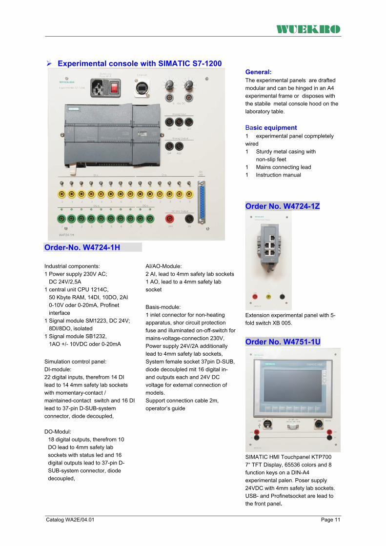
WUEKRO
Experimental console with SIMATIC S7-1200
Order-No. W4724-1H
Industrial components: 1 Power supply 230V AC; DC 24V/2,5A 1 central unit CPU 1214C, 50 Kbyte RAM, 14DI, 10DO, 2AI 0-10V oder 0-20mA, Profinet interface 1 Signal module SM1223, DC 24V; 8DI/8DO, isolated 1 Signal module SB1232, 1AO +/- 10VDC oder 0-20mA
Simulation comtrol panel: DI-module: 22 digital inputs, therefrom 14 DI lead to 14 4mm safety lab sockets with momentary-contact / maintained-contact switch and 16 DI lead to 37-pin D-SUB-system connector, diode decoupled, DO-Modul:
18 digital outputs, therefrom 10 DO lead to 4mm safety lab sockets with status led and 16 digital outputs lead to 37-pin D-SUB-system connector, diode decoupled,
AI/AO-Module: 2 AI, lead to 4mm safety lab sockets 1 AO, lead to a 4mm safety lab socket
Basis-module: 1 inlet connector for non-heating apparatus, shor circuit protection fuse and illuminated on-off-switch for mains-voltage-connection 230V, Power supply 24V/2A additionally lead to 4mm safety lab sockets, System female socket 37pin D-SUB, diode decoulpled mit 16 digital in- and outputs each and 24V DC voltage for external connection of models. Support connection cable 2m, operator’s guide
General: The experimental panels are drafted modular and can be hinged in an A4 experimental frame or disposes with the stabile metal console hood on the laboratory table. Basic equipment 1 experimental panel copmpletely wired 1 Sturdy metal casing with non-slip feet 1 Mains connecting lead 1 Instruction manual
Order No. W4724-1Z
Extension experimental panel with 5-fold switch XB 005. Order No. W4751-1U
SIMATIC HMI Touchpanel KTP700 7“ TFT Display, 65536 colors and 8 function keys on a DIN-A4 experimental palen. Poser supply 24VDC with 4mm safety lab sockets. USB- and Profinetsocket are lead to the front panel.
Catalog WA2E/04.01 Page 11

WUEKRO
Training Units with SIMATIC S7-300 in Rack Design Racks in general The training units in rack design have a semimodular structure and can be retrofitted with expansion modules. The number of possible expansions depends on the basic configuration of the rack.
The racks are especially suited for an individual arrangement. They may be retrofitted with communications processors for PROFIBUS or AS-Interface or also with special function modules (FM).
The width of the simulation module depends on the SIMATIC S7-300 module above and corresponds to: 1 WU = 40 mm By default, the training racks are equipped with 4-mm safety lab sockets.
Basic configuration of training unit with S7-300 1 Training rack, completely wired, out of steel sheet with scratch- resistant powder coating 1 Mains connecting lead 1 Mounting channel 1 Signal routing module I/O Switch 1 Operating instructions
SIMATIC Experimental Rack W4734-1H CPU 314C-2PN/DP, 24DI, 16 DO, 5 AI, 2AO, Word
Word-module: 16 DI on numerical setter, BCD encoded and 16 DO are connected to 5digit 7-segment display, BCD encoded digit display 0 –9, A-F switch for decimal or hexadecimal display on-off switch (to avoid mistakes between DI/DO in-/outputfileds and word processing) PS-module: inlet connector for non-heating apparatus, short circuit protection, fuse and illuminated on-off switch 24 V on 4-mm-safety sockets for external use 1 x 37-pin D-SUB connector interconnected to S7 modules with 16 DI and 16 DO each power supply connection cable WxDxH approx. 50x22x54 cm
The training-set is equipped with: Industrial components:
1 Power supply unit 115/230 VAC (47-63Hz); DC 24V 1 Central processing unit S7-300 CPU 314C-2PN/DP, Working memory 192KB RAM, 24 Digital Inputs, 16 Digital Outputs, 5 Analog Inputs, 2 Analog Outputs, High speed counters 1 Signal Module SM323 16DI/16DO 1. Interface PROFINET 2. Interface Profibus DP 1 Micro-Memory-Card 512 kbyte Digital-connections: 32 digital inputs are connected on momentary-contact/ maintained- contact switch and to 4-mm- safety sockets, signal statuses by LED
16 digital outputs are connected to 4- mm-safety sockets, signal statuses by LED Analog connections: 4 analog inputs, are connected to 4-mm-safety sockets. Internal or external voltage infeed individually per channel choosable 4 potentiometer ±10V steplessly adjustable for infeed of analogue values, 1 Analog Input for Resistance or PTP connected to 4-mm-safety sockets. 2 analog output connected to 4-
mm-safety sockets, 1 LCD measuring device for all AI individually switchable onto each input; 1 LCD measuring device for all AO individually switchable onto AO1 or AO2 Order No. W4734-1H
Page 12 Catalog WA2E/04.01
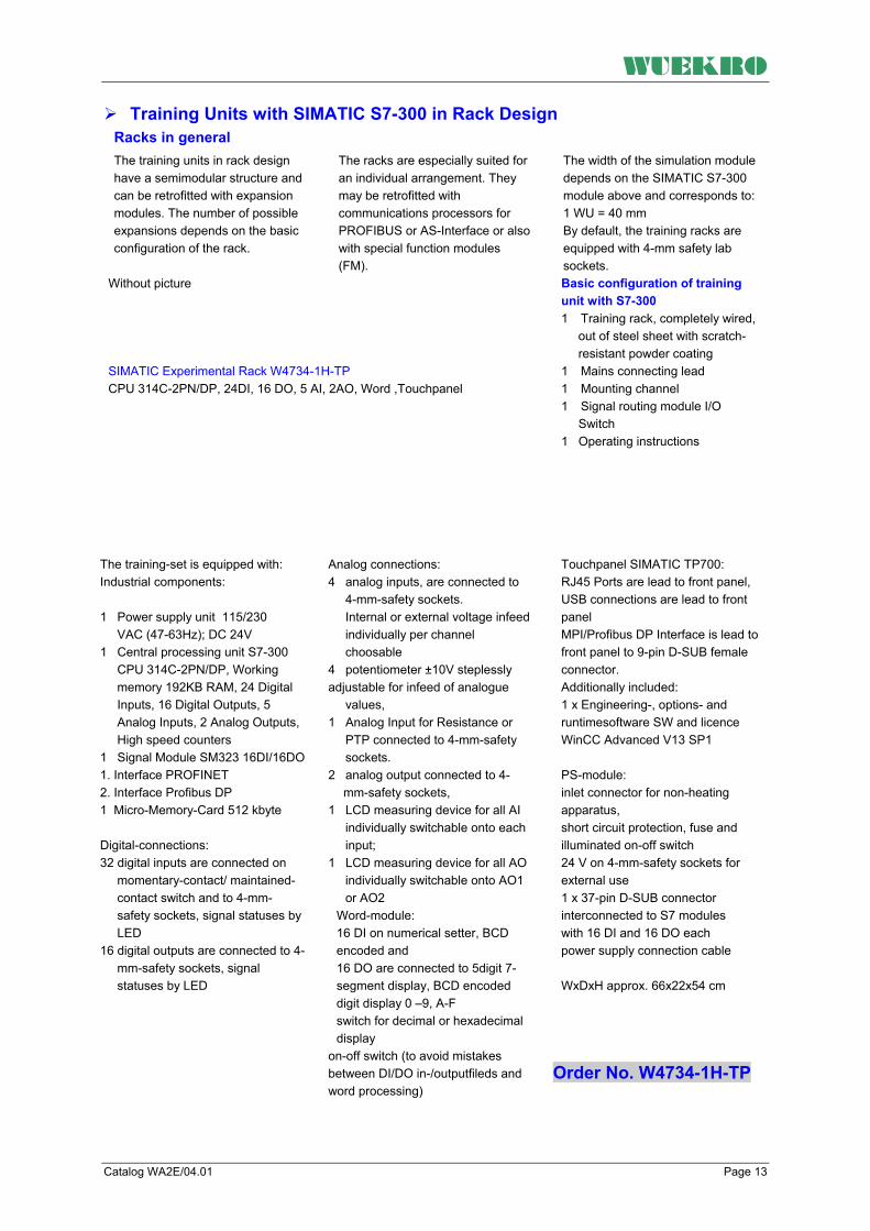
WUEKRO
Training Units with SIMATIC S7-300 in Rack Design Racks in general The training units in rack design have a semimodular structure and can be retrofitted with expansion modules. The number of possible expansions depends on the basic configuration of the rack.
The racks are especially suited for an individual arrangement. They may be retrofitted with communications processors for PROFIBUS or AS-Interface or also with special function modules (FM).
The width of the simulation module depends on the SIMATIC S7-300 module above and corresponds to: 1 WU = 40 mm By default, the training racks are equipped with 4-mm safety lab sockets.
Without picture SIMATIC Experimental Rack W4734-1H-TP CPU 314C-2PN/DP, 24DI, 16 DO, 5 AI, 2AO, Word ,Touchpanel
Basic configuration of training unit with S7-300 1 Training rack, completely wired, out of steel sheet with scratch- resistant powder coating 1 Mains connecting lead 1 Mounting channel 1 Signal routing module I/O Switch 1 Operating instructions
Touchpanel SIMATIC TP700: RJ45 Ports are lead to front panel, USB connections are lead to front panel MPI/Profibus DP Interface is lead to front panel to 9-pin D-SUB female connector. Additionally included: 1 x Engineering-, options- and runtimesoftware SW and licence WinCC Advanced V13 SP1
PS-module: inlet connector for non-heating apparatus, short circuit protection, fuse and illuminated on-off switch 24 V on 4-mm-safety sockets for external use 1 x 37-pin D-SUB connector interconnected to S7 modules with 16 DI and 16 DO each power supply connection cable WxDxH approx. 66x22x54 cm
The training-set is equipped with: Industrial components:
1 Power supply unit 115/230 VAC (47-63Hz); DC 24V 1 Central processing unit S7-300 CPU 314C-2PN/DP, Working memory 192KB RAM, 24 Digital Inputs, 16 Digital Outputs, 5 Analog Inputs, 2 Analog Outputs, High speed counters 1 Signal Module SM323 16DI/16DO 1. Interface PROFINET 2. Interface Profibus DP 1 Micro-Memory-Card 512 kbyte Digital-connections: 32 digital inputs are connected on momentary-contact/ maintained- contact switch and to 4-mm- safety sockets, signal statuses by LED 16 digital outputs are connected to 4- mm-safety sockets, signal statuses by LED
Analog connections: 4 analog inputs, are connected to 4-mm-safety sockets. Internal or external voltage infeed individually per channel choosable 4 potentiometer ±10V steplessly adjustable for infeed of analogue values, 1 Analog Input for Resistance or PTP connected to 4-mm-safety sockets. 2 analog output connected to 4-
mm-safety sockets, 1 LCD measuring device for all AI individually switchable onto each input; 1 LCD measuring device for all AO individually switchable onto AO1 or AO2
Word-module: 16 DI on numerical setter, BCD encoded and 16 DO are connected to 5digit 7-segment display, BCD encoded digit display 0 –9, A-F switch for decimal or hexadecimal display
on-off switch (to avoid mistakes between DI/DO in-/outputfileds and word processing)
Order No. W4734-1H-TP
Catalog WA2E/04.01 Page 13

WUEKRO
Training Units with SIMATIC S7-300 in Rack Design Racks in general The training units in rack design have a semimodular structure and can be retrofitted with expansion modules. The number of possible expansions depends on the basic configuration of the rack.
The racks are especially suited for an individual arrangement. They may be retrofitted with communications processors for PROFIBUS or AS-Interface or also with special function modules (FM).
The width of the simulation module depends on the SIMATIC S7-300 module above and corresponds to: 1 WU = 40 mm By default, the training racks are equipped with 4-mm safety lab sockets.
Basic configuration of training unit with S7-300 1 Training rack, completely wired, out of steel sheet with scratch- resistant powder coating 1 Mains connecting lead 1 Mounting channel 1 Signal routing module I/O Switch 1 Operating instructions
SIMATIC Experimental Rack W4734-1E CPU 314C-2PN/DP, 24DI, 16 DO, 5 AI, 2AO
PS-module: inlet connector for non-heating apparatus, short circuit protection, fuse and illuminated on-off switch 24 V on 4-mm-safety sockets for external use 1 x 37-pin D-SUB connector interconnected to S7 modules with 16 DI and 16 DO each power supply connection cable WxDxH approx. 50x22x54 cm
The training-set is equipped with: Industrial components:
1 Power supply unit 115/230 VAC (47-63Hz); DC 24V 1 Central processing unit S7-300 CPU 314C-2PN/DP, Working memory 192KB RAM, 24 Digital Inputs, 16 Digital Outputs, 5 Analog Inputs, 2 Analog Outputs, High speed counters 1 Signal Module SM323 16DI/16DO 1. Interface PROFINET 2. Interface Profibus DP 1 Micro-Memory-Card 512 kbyte Digital-connections: 32 digital inputs are connected on momentary-contact/ maintained- contact switch and to 4-mm- safety sockets, signal statuses by LED
16 digital outputs are connected to 4- mm-safety sockets, signal statuses by LED Analog connections: 4 analog inputs, are connected to 4-mm-safety sockets. Internal or external voltage infeed individually per channel choosable 4 potentiometer ±10V steplessly adjustable for infeed of analogue values, 1 Analog Input for Resistance or PTP connected to 4-mm-safety sockets. 2 analog output connected to 4-
mm-safety sockets, 1 LCD measuring device for all AI individually switchable onto each input; 1 LCD measuring device for all AO individually switchable onto AO1 or AO2
Order No. W4734-1E
Page 14 Catalog WA2E/04.01
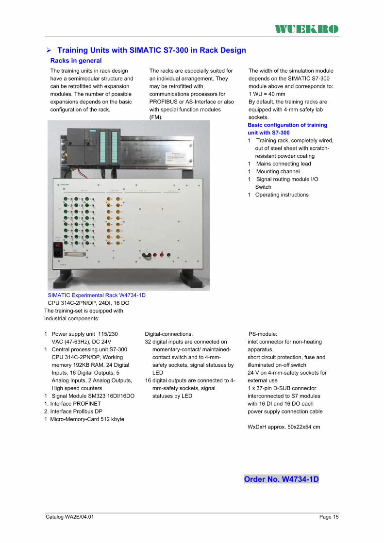
WUEKRO
Training Units with SIMATIC S7-300 in Rack Design Racks in general The training units in rack design have a semimodular structure and can be retrofitted with expansion modules. The number of possible expansions depends on the basic configuration of the rack.
The racks are especially suited for an individual arrangement. They may be retrofitted with communications processors for PROFIBUS or AS-Interface or also with special function modules (FM).
The width of the simulation module depends on the SIMATIC S7-300 module above and corresponds to: 1 WU = 40 mm By default, the training racks are equipped with 4-mm safety lab sockets.
Basic configuration of training unit with S7-300 1 Training rack, completely wired, out of steel sheet with scratch- resistant powder coating 1 Mains connecting lead 1 Mounting channel 1 Signal routing module I/O Switch 1 Operating instructions
SIMATIC Experimental Rack W4734-1D CPU 314C-2PN/DP, 24DI, 16 DO
PS-module:
inlet connector for non-heating apparatus, short circuit protection, fuse and illuminated on-off switch 24 V on 4-mm-safety sockets for external use 1 x 37-pin D-SUB connector interconnected to S7 modules with 16 DI and 16 DO each power supply connection cable WxDxH approx. 50x22x54 cm
The training-set is equipped with: Industrial components:
1 Power supply unit 115/230 VAC (47-63Hz); DC 24V 1 Central processing unit S7-300 CPU 314C-2PN/DP, Working memory 192KB RAM, 24 Digital Inputs, 16 Digital Outputs, 5 Analog Inputs, 2 Analog Outputs, High speed counters 1 Signal Module SM323 16DI/16DO 1. Interface PROFINET 2. Interface Profibus DP 1 Micro-Memory-Card 512 kbyte
Digital-connections: 32 digital inputs are connected on momentary-contact/ maintained- contact switch and to 4-mm- safety sockets, signal statuses by LED 16 digital outputs are connected to 4- mm-safety sockets, signal statuses by LED
Order No. W4734-1D
Catalog WA2E/04.01 Page 15

WUEKRO
Experimental consoles with SIMATIC S7-300 General: The experimental panels are drafted modular and can be hinged in an A4 experimental frame or disposes with the stabile metal console hood on the laboratory table. Basic equipment 1 experimental panel comppletely . wired 1 Sturdy metal casing with non-slip feet 1 Mains connecting lead 1 Instruction manual
Word-module: 16 DI on numerical setter, BCD encoded and 16 DO are connected to 5digit 7 – segment display, BCD encoded digit display 0 –9, A-F, switch for decimal or hexadecimal display on-off switch (to avoid mistakes between DI/DO in-/outputfileds
and word processing)
Basis-module: 1 inlet connector for non-heating apparatus, shor circuit protection fuse and illuminated on-off-switch for mains-voltage-connection 230V, Power supply 24V/2A additionally lead to 4mm safety lab sockets, System female socket 37pin D-SUB, diode decoulpled mit 16 digital in- and outputs each and 24V DC voltage for external connection of models. Support connection cable 2m, operator’s guide Order No. W4734-2H
Industrial components: 1 Power supply 230V AC; DC 24V/5A. 1 central prcessing unit CPU 314C-2PN/DP, 24DI/16DO, 4AI/2AO, 192 KByte RAM, 1 Micro-Memory-Card 512 kB, 2 front connectors for simulation device 40pol., 1 system profile-rail
Simulation control panel: Digital-connection: 24 digital inputs, lead to simulation panel with momentary-contact / maintained-contact switch and 4- mm-safety lab sockets, status-led, and 16 DI lead to 37-pin D-SUB- system connector, diode decoupled. 16 digital outputs leat to simulation panel with 4mm safety lab sockets
with status led and 16 DO lead to 37-pin D-SUB-system connector, diode decoupled,
Analog connections: 4 analog inputs, are connected to 4-mm-safety sockets. Internal or external voltage infeed individually per channel choosable 4 potentiometer ±10V steplessly adjustable for infeed of analogue values, 1 Analog Input for Resistance or PTP connected to 4-mm-safety sockets. 2 analog output connected to 4-
mm-safety sockets, 1 LCD measuring device for all AI switchable onto each input; 1 LCD measuring device for all AO individually switchable onto AO1 or AO2
Page 16 Catalog WA2E/04.01

WUEKRO
Experimental consoles with SIMATIC S7-300 General: The experimental panels are drafted modular and can be hinged in an A4 experimental frame or disposes with the stabile metal console hood on the laboratory table. Basic equipment 1 experimental panel comppletely . wired 1 Sturdy metal casing with non-slip feet 1 Mains connecting lead 1 Instruction manual
Basis-module: 1 inlet connector for non-heating apparatus, shor circuit protection fuse and illuminated on-off-switch for mains-voltage-connection 230V, Power supply 24V/2A additionally lead to 4mm safety lab sockets, System female socket 37pin D-SUB, diode decoulpled mit 16 digital in- and outputs each and 24V DC voltage for external connection of models. Support connection cable 2m, operator’s guide
Order No. W4734-2E
Industrial components: 1 Power supply 230V AC; DC 24V/5A. 1 central prcessing unit CPU 314C-2PN/DP, 24DI/16DO, 4AI/2AO, 192 KByte RAM, 1 Micro-Memory-Card 512 kB, 2 front connectors for simulation device 40pol., 1 system profile-rail
Simulation control panel: Digital-connection: 24 digital inputs, lead to simulation panel with momentary-contact / maintained-contact switch and 4- mm-safety lab sockets, status-led, and 16 DI lead to 37-pin D-SUB- system connector, diode decoupled. 16 digital outputs leat to simulation panel with 4mm safety lab sockets
with status led and 16 DO lead to 37-pin D-SUB-system connector, diode decoupled,
Analog connections: 4 analog inputs, are connected to 4-mm-safety sockets. Internal or external voltage infeed individually per channel choosable 4 potentiometer ±10V steplessly adjustable for infeed of analogue values, 1 Analog Input for Resistance or PTP connected to 4-mm-safety sockets. 2 analog output connected to 4-
mm-safety sockets, 1 LCD measuring device for all AI switchable onto each input; 1 LCD measuring device for all AO individually switchable onto AO1 or AO2
Catalog WA2E/04.01 Page 17

WUEKRO
Experimental consoles with SIMATIC S7-300 General: The experimental panels are drafted modular and can be hinged in an A4 experimental frame or disposes with the stabile metal console hood on the laboratory table. Basic equipment 1 experimental panel comppletely . wired 1 Sturdy metal casing with non-slip feet 1 Mains connecting lead 1 Instruction manual
Industrial components: 1 Power supply 230V AC; DC 24V/5A. 1 central prcessing unit CPU 314C-2PN/DP, 24DI/16DO, 4AI/2AO, 192 KByte RAM, 1 Micro-Memory-Card 512 kB, 2 front connectors for simulation device 40pol., 1 system profile-rail
Simulation control panel: Digital-connection: 24 digital inputs, lead to simulation panel with momentary-contact / maintained-contact switch and 4- mm-safety lab sockets, status-led, and 16 DI lead to 37-pin D-SUB- system connector, diode decoupled. 16 digital outputs leat to simulation panel with 4mm safety lab sockets
with status led and 16 DO lead to 37-pin D-SUB-system connector, diode decoupled,
Basis-module: 1 inlet connector for non-heating apparatus, shor circuit protection fuse and illuminated on-off-switch for mains-voltage-connection 230V, Power supply 24V/2A additionally lead to 4mm safety lab sockets, System female socket 37pin D-SUB, diode decoulpled mit 16 digital in- and outputs each and 24V DC voltage for external connection of models. Support connection cable 2m, operator’s guide Order No. W4734-2D
Experimental panel SIMATIC CSM1277 Experimental panel with Compact Switch Modul CSM1277 to connect up to 3 external components via industrial Ethernet bus with 10/100MBit/s. 2 safety lab sockets 4mm for 24V DC power supply are led out to the frontside of the panel with protection against polarity reversal. Dimensions 130x297x65mm
Bestell-Nr. W4724-1Z
Budget priced Touch Panel SIMATIC HMI KTP700 Basic for SIMATIC S7-CPU’s with WINCC Basic V13/Step7 Basic V13 software.
One Profinet- and one USB Inter-face, connectedt to the front panel gives easy bus access. Universal Color-Panel for standards with PROFINET; 7" WIDESCREEN -TFT-Display (LED display dimmable),
65536 Colours resolution 800 x 480 Pixel ; Resistive analog touch RAM: 10 MB Power supply via 4mm Si-Lab sockets 24VDC. Inclusive Open Source Software Dimensions (experimental panel): 260x297x65mm (WxHxD) Weight appr. 2 kg
Bestell-Nr. W4751-1U
Page 18 Catalog WA2E/04.01

WUEKRO
Training Units with SIMATIC S7-1500 in Rack Design
Basic configuration of training unit with S7-1500 1 Training rack, completely wired, out of steel sheet with scratch- resistant powder coating 1 Mains connecting lead 1 Mounting channel 1 Signal routing module I/O Switch 1 Operating instructions
SIMATIC Experimental Rack W4715-1K CPU 1512C-1PN, 32DI, 16DO, 5AI, 2AO
Word-module: 16 DI on numerical setter, BCD encoded and 16 DO are connected to 5digit 7-segment display, BCD encoded digit display 0 –9, A-F switch for decimal or hexadecimal display on-off switch selection switch for bit- or wordwise use (to avoid mistakes between DI/DO in-/outputfileds and word processing) PS-module: inlet connector for non-heating apparatus, short circuit protection, fuse and illuminated on-off switch 24 V on 4-mm-safety sockets for external use 1 x 37-pin D-SUB connector interconnected to S7 modules with 16 DI and 16 DO each power supply connection cable
WxDxH approx. 50x22x57 cm
Industrial components: 1 Power supply unit 85-264 VAC (47-63Hz); DC 24V 1 Central processing unit S7-1500 CPU 1512C-1 PN, Working memory 250KB for program, 1MB for Data. 32 Digital Inputs 32 Digital Outputs 5 Analog Inputs, 2 Analog Outputs 6 High speed counters 1. Interface PROFINET IRT mit 2 Port Switch; 48ns Bit-Performance 1 Micro-Memory-Card 24 MB 2 Front connectors 1 SIMATIC S7-1500 system rail
Digital-connections: 24 digital inputs are connected on momentary-contact/ maintained- contact switch and to 4-mm- safety sockets, signal statuses by LED
16 digital outputs are connected to 4- mm-safety sockets, signal statuses by LED Analog connections: 4 analog inputs, are connected to 4-mm-safety sockets. Internal or external voltage infeed individually per channel choosable 1 analog input for R/RTD for resistance/resistance thermometer measurement. 4 potentiometer ±10V steplessly adjustable for infeed of analogue values, 1 Analog Input for Resistance or PTP connected to 4-mm-safety sockets. 2 analog output connected to 4-
mm-safety sockets, 1 LCD measuring device for all AI individually switchable onto each input; 1 LCD measuring device for all AO individually switchable onto AO1 or AO2
Order No. W4715-1K
Catalog WA2E/04.01 Page 19
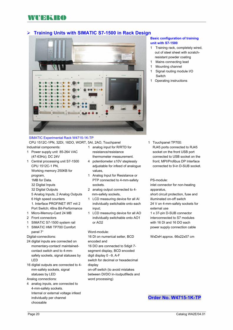
WUEKRO
Training Units with SIMATIC S7-1500 in Rack Design Basic configuration of training unit with S7-1500 1 Training rack, completely wired, out of steel sheet with scratch- resistant powder coating 1 Mains connecting lead 1 Mounting channel 1 Signal routing module I/O Switch 1 Operating instructions
SIMATIC Experimental Rack W4715-1K-TP CPU 1512C-1PN, 32DI, 16DO, WORT, 5AI, 2AO, Touchpanel
1 Touchpanel TP700: RJ45 ports connected to RJ45 socket on the front USB port connected to USB socket on the front; MPI/Profibus DP Interface connected to 9-in D-SUB socket.
PS-module: inlet connector for non-heating apparatus, short circuit protection, fuse and illuminated on-off switch 24 V on 4-mm-safety sockets for external use 1 x 37-pin D-SUB connector interconnected to S7 modules with 16 DI and 16 DO each power supply connection cable WxDxH approx. 66x22x57 cm
Industrial components: 1 Power supply unit 85-264 VAC (47-63Hz); DC 24V 1 Central processing unit S7-1500 CPU 1512C-1 PN, Working memory 250KB for program, 1MB for Data. 32 Digital Inputs 32 Digital Outputs 5 Analog Inputs, 2 Analog Outputs 6 High speed counters 1. Interface PROFINET IRT mit 2 Port Switch; 48ns Bit-Performance 1 Micro-Memory-Card 24 MB 2 Front connectors 1 SIMATIC S7-1500 system rail 1 SIMATIC HMI TP700 Comfort panel 7“ Digital-connections: 24 digital inputs are connected on momentary-contact/ maintained- contact switch and to 4-mm- safety sockets, signal statuses by LED 16 digital outputs are connected to 4- mm-safety sockets, signal statuses by LED Analog connections: 4 analog inputs, are connected to 4-mm-safety sockets. Internal or external voltage infeed individually per channel choosable
1 analog input for R/RTD for resistance/resistance thermometer measurement. 4 potentiometer ±10V steplessly adjustable for infeed of analogue values, 1 Analog Input for Resistance or PTP connected to 4-mm-safety sockets. 2 analog output connected to 4-
mm-safety sockets, 1 LCD measuring device for all AI individually switchable onto each input; 1 LCD measuring device for all AO individually switchable onto AO1 or AO2 Word-module: 16 DI on numerical setter, BCD encoded and 16 DO are connected to 5digit 7-segment display, BCD encoded digit display 0 –9, A-F switch for decimal or hexadecimal display on-off switch (to avoid mistakes between DI/DO in-/outputfileds and word processing)
Order No. W4715-1K-TP
Page 20 Catalog WA2E/04.01

WUEKRO
Training Units with SIMATIC S7-1500 in Rack Design
Basic configuration of training unit with S7-1500 1 Training rack, completely wired, out of steel sheet with scratch- resistant powder coating 1 Mains connecting lead 1 Mounting channel 1 Signal routing module I/O Switch 1 Operating instructions
SIMATIC Experimental Rack W4715-1F CPU 1512C-1PN, 32DI, 16DO, 5AI, 2AO
PS-module:
inlet connector for non-heating apparatus, short circuit protection, fuse and illuminated on-off switch 24 V on 4-mm-safety sockets for external use 1 x 37-pin D-SUB connector interconnected to S7 modules with 16 DI and 16 DO each power supply connection cable WxDxH approx. 50x22x57 cm
Industrial components: 1 Power supply unit 85-264 VAC (47-63Hz); DC 24V 1 Central processing unit S7-1500 CPU 1512C-1 PN, Working memory 250KB for program, 1MB for Data. 32 Digital Inputs 32 Digital Outputs 5 Analog Inputs, 2 Analog Outputs 6 High speed counters 1. Interface PROFINET IRT mit 2 Port Switch; 48ns Bit-Performance 1 Micro-Memory-Card 24 MB 2 Front connectors 1 SIMATIC S7-1500 system rail
Digital-connections: 24 digital inputs are connected on momentary-contact/ maintained- contact switch and to 4-mm- safety sockets, signal statuses by LED
16 digital outputs are connected to 4- mm-safety sockets, signal statuses by LED Analog connections: 4 analog inputs, are connected to 4-mm-safety sockets. Internal or external voltage infeed individually per channel choosable 1 analog input for R/RTD for resistance/resistance thermometer measurement. 4 potentiometer ±10V steplessly adjustable for infeed of analogue values, 1 Analog Input for Resistance or PTP connected to 4-mm-safety sockets. 2 analog output connected to 4-
mm-safety sockets, 1 LCD measuring device for all AI individually switchable onto each input; 1 LCD measuring device for all AO individually switchable onto AO1 or AO2
Order No. W4715-1F
Catalog WA2E/04.01 Page 21

WUEKRO
Training Units with SIMATIC S7-1500 in Rack Design
Basic configuration of training unit with S7-1500 1 Training rack, completely wired, out of steel sheet with scratch- resistant powder coating 1 Mains connecting lead 1 Mounting channel 1 Signal routing module I/O Switch 1 Operating instructions
SIMATIC Experimental Rack W4715-1F CPU 1512C-1PN, 32DI, 16DO, 5AI, 2AO
Industrial components: 1 Power supply unit 85-264 VAC (47-63Hz); DC 24V 1 Central processing unit S7-1500 CPU 1512C-1 PN, Working memory 250KB for program, 1MB for Data. 32 Digital Inputs 32 Digital Outputs 5 Analog Inputs, 2 Analog Outputs 6 High speed counters 1. Interface PROFINET IRT mit 2 Port Switch; 48ns Bit-Performance 1 Micro-Memory-Card 24 MB 2 Front connectors 1 SIMATIC S7-1500 system rail
Digital-connections: 24 digital inputs are connected on momentary-contact/ maintained- contact switch and to 4-mm- safety sockets, signal statuses by LED
16 digital outputs are connected to 4- mm-safety sockets, signal statuses by LED PS-module:
inlet connector for non-heating apparatus, short circuit protection, fuse and illuminated on-off switch 24 V on 4-mm-safety sockets for external use 1 x 37-pin D-SUB connector interconnected to S7 modules with 16 DI and 16 DO each power supply connection cable
WxDxH approx. 50x22x57 cm
Order No. W4715-1C
Page 22 Catalog WA2E/04.01

WUEKRO
Experimental consoles with SIMATIC S7-1500 Basic equipment 1 experimental panel comppletely . wired 1 Sturdy metal casing with non-slip feet 1 Mains connecting lead
1 Instruction manual
SIMATIC - Experimental Console CPU 1512C-1PN, 32DI, 16DO, 5AI, 2AO WORD, ANALOG The SIMATIC-Compactpanel is a space-saving and for the practice for vocational purposes optimized for exercises with SIMATIC S7-1500 with various bus-systems. The compact-panel ist completely wired and equipped with a trovidur frontpanel for mounting in a DIN-A4 experimental frame and a backsided cover hood of sheet steel mit scartchproof paint. The training-set is equipped with: Industrial components:
3 Power supply unit 85-264 VAC
(47-63Hz); DC 24V 4 Central processing unit S7-
1500 CPU 1512C-1 PN, Working memory 250KB for program, 1MB for Data. 32 Digital Inputs, 32 Digital Outputs 5 Analog Inputs, 2 Analog Outputs 6 High speed counters
5 Interface PROFINET IRT mit 2
Port Switch; 48ns Bit-Performance 6 Micro-Memory-Card 24 MB 7 Front connectors
1 SIMATIC S7-1500 system rail
Digital-connections: 32 digital inputs are connected on momentary-contact/ maintained-contact switch and to 4-mm-safety sockets, signal statuses by LED 32 digital outputs, of which 16 are connected to 4-mm-safety sockets, signal statuses by LED Analog connections 4 analog inputs, are connected to 4-mm-safety sockets, free choosable for voltage or currency measurements. Internal or external voltage infeed individually per channel choosable 4 potentiometer ±10V steplessly adjustable for infeed of analogue values, 1 analog input for R/RTD for resistance/resistance thermometer measurement. 2 analog output connected to 4-mm-safety socket, 1 LCD measuring device for all AI individually switchable onto each input; 1 LCD measuring device for all AO individually switchable onto AO1 and AO2:
Word-module: 16 DI on numerical setter, BCD encoded and 16 DO are connected to 5digit 7-segment display, BCD encoded digit display 0 –9, A-F, switch for decimal or hexadecimal display on-off switch, selection switch for bit- or wordwise use (to avoid mistakes between DI/DO in-/outputfileds and word processing) PS-module: inlet connector for non-heating apparatus, short circuit protection, fuse and illuminated on-off switch 24 V on 4-mm-safety sockets for external use 3 x 37-pin D-SUB connector interconnected to S7 modules with 16 DI and 16 DO each power supply connection cable operator´s guide
Order No. W4715-2K
Catalog WA2E/04.01 Page 23

WUEKRO
Experimental consoles with SIMATIC S7-1500 Basic equipment 1 experimental panel comppletely . wired 1 Sturdy metal casing with non-slip feet 1 Mains connecting lead
1 Instruction manual
SIMATIC - Experimental Console CPU 1512C-1PN, 32DI, 16DO, 5AI, 2AO, ANALOG The SIMATIC-Compactpanel is a space-saving and for the practice for vocational purposes optimized for exercises with SIMATIC S7-1500 with various bus-systems. The compact-panel ist completely wired and equipped with a trovidur frontpanel for mounting in a DIN-A4 experimental frame and a backsided cover hood of sheet steel mit scartchproof paint. The training-set is equipped with: Industrial components: 1 Power supply unit 85-264 VAC (47-63Hz); DC 24V 1 Central processing unit S7-1500 CPU 1512C-1 PN, Working memory 250KB for program, 1MB for Data. 32 Digital Inputs, 32 Digital Outputs 5 Analog Inputs, 2 Analog Outputs 6 High speed counters
1. Interface PROFINET IRT mit 2 Port Switch; 48ns Bit-Performance
1 Micro-Memory-Card 24 MB 3 Front connectors 1 SIMATIC S7-1500 system rail
Digital-connections: 32 digital inputs are connected on momentary-contact/ maintained-contact switch and to 4-mm-safety sockets, signal statuses by LED 32 digital outputs, of which 16 are connected to 4-mm-safety sockets, signal statuses by LED Analog connections 4 analog inputs, are connected to 4-mm-safety sockets, free choosable for voltage or currency measurements. Internal or external voltage infeed individually per channel choosable 4 potentiometer ±10V steplessly adjustable for infeed of analogue values, 1 analog input for R/RTD for resistance/resistance thermometer measurement. 2 analog output connected to 4-mm-safety socket, 1 LCD measuring device for all AI individually switchable onto each input; 1 LCD measuring device for all AO individually switchable onto AO1 and AO2:
PS-module: inlet connector for non-heating apparatus, short circuit protection, fuse and illuminated on-off switch 24 V on 4-mm-safety sockets for external use 3 x 37-pin D-SUB connector interconnected to S7 modules with 16 DI and 16 DO each power supply connection cable operator´s guide
Order No. W4715-2F
Page 24 Catalog WA2E/04.01
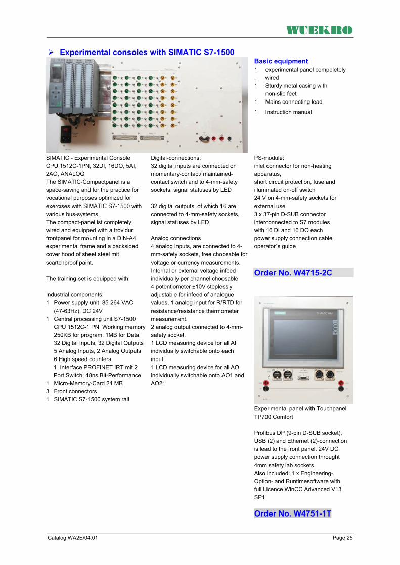
WUEKRO
Experimental consoles with SIMATIC S7-1500
Basic equipment 1 experimental panel comppletely . wired 1 Sturdy metal casing with non-slip feet 1 Mains connecting lead
1 Instruction manual
SIMATIC - Experimental Console CPU 1512C-1PN, 32DI, 16DO, 5AI, 2AO, ANALOG The SIMATIC-Compactpanel is a space-saving and for the practice for vocational purposes optimized for exercises with SIMATIC S7-1500 with various bus-systems. The compact-panel ist completely wired and equipped with a trovidur frontpanel for mounting in a DIN-A4 experimental frame and a backsided cover hood of sheet steel mit scartchproof paint. The training-set is equipped with: Industrial components: 1 Power supply unit 85-264 VAC (47-63Hz); DC 24V 1 Central processing unit S7-1500 CPU 1512C-1 PN, Working memory 250KB for program, 1MB for Data. 32 Digital Inputs, 32 Digital Outputs 5 Analog Inputs, 2 Analog Outputs 6 High speed counters
1. Interface PROFINET IRT mit 2 Port Switch; 48ns Bit-Performance
1 Micro-Memory-Card 24 MB 3 Front connectors 1 SIMATIC S7-1500 system rail
Digital-connections: 32 digital inputs are connected on momentary-contact/ maintained-contact switch and to 4-mm-safety sockets, signal statuses by LED 32 digital outputs, of which 16 are connected to 4-mm-safety sockets, signal statuses by LED Analog connections 4 analog inputs, are connected to 4-mm-safety sockets, free choosable for voltage or currency measurements. Internal or external voltage infeed individually per channel choosable 4 potentiometer ±10V steplessly adjustable for infeed of analogue values, 1 analog input for R/RTD for resistance/resistance thermometer measurement. 2 analog output connected to 4-mm-safety socket, 1 LCD measuring device for all AI individually switchable onto each input; 1 LCD measuring device for all AO individually switchable onto AO1 and AO2:
PS-module: inlet connector for non-heating apparatus, short circuit protection, fuse and illuminated on-off switch 24 V on 4-mm-safety sockets for external use 3 x 37-pin D-SUB connector interconnected to S7 modules with 16 DI and 16 DO each power supply connection cable operator´s guide
Order No. W4715-2C
Experimental panel with Touchpanel TP700 Comfort Profibus DP (9-pin D-SUB socket), USB (2) and Ethernet (2)-connection is lead to the front panel. 24V DC power supply connection throught 4mm safety lab sockets. Also included: 1 x Engineering-, Option- and Runtimesoftware with full Licence WinCC Advanced V13 SP1
Order No. W4751-1T
Catalog WA2E/04.01 Page 25

WUEKRO
SIMATIC - Experimental case
SIMATIC – Experimental case with CPU S7-1516, 32DI, 16DO, WORD, ANALOG with integrated Touchpanel TP700 and universal simulator. The SIMATIC universal case is a compact, portable training and experimental unit for PLC and HMI applications.
The training-set is equipped with: Industrial components 1 power supply module PM1507, 120/230 VAC; DC 24V/8A, 1 Central Processing Unit SIMATIC S7-1500 CPU 1516-3 PN/DP, 1MB RAM for programme, 5MB RAM for data. 1st Interface: PROFINET with 2 port switch 2nd Interface: ETHERNET 3rd Interface: PROFIBUS 1 SIMATIC S7-1500 Digital Input Module 32DI 1 SIMATIC S7-1500 Digital Output Module 32DO, DC24V/0,5A 1 SIMATIC S7-1500 Analog Input Module 8AI 1 SIMATIC S7-1500 Analog Output Module 4AO 1 Micro-Memory-Card 24 MB 4 front-plugs for SM 40pin 1 rail 1 SIMATIC HMI TP700 COMFORT, COMFORT PANEL 7“ with PROFINET and MPI/PROFIBUS DP INTERFACE (Panel with integrated switch with 2x RJ45 Port)
Simulation module: - DI-module: 32 digital inputs connected on momentary-contact/ maintained- contact switch and to 4 mm MC- safety sockets, signal statuses by LED - DO-module: 32 digital outputs of which 16 are connected to 4 mm MC-safety sockets, signal statuses by LED Word-module: 16 DI on numerical setter, BCD encoded and 16 DO are connected to 4digit 7- segment display, BCD encoded digit display 0 –9, A-F, switch for decimal or hexadecimal display on-off switch AI/AO-module: 8 analog inputs, are connected to 4- mm-safety sockets, 2 potentiometer ±10V steplessly adjustable for infeed of analogue values, 4 analog output connected to 4-mm- safety socket, 2 measuring device ±10V with zero point center
Touchpanel TP700: RJ45 ports connected to RJ45 socket on the front USB port connected to USB socket on the front MPI/Profibus DP Interface connected to 9-in D-SUB socket. Also included in package: 1 x Engineering-, Options- and Runtimesoftware SW und Licence WinCC Advanced V13 SP1 Universal simulator The inbuilt universal simulator is especially suitable for the basic PLC training in the professional field of electrical engineering. The experiments are tailored for the curriculum of vocational education. The inputs and outputs are internally wired to the simulation field matrix of the case. The universal simulator is equipped with an operater panel and the simulator with text overlays . So it can also used for Digital Technique and Microprozessor Technique.
Page 26 Catalog WA2E/04.01

WUEKRO
Design: The 5 digital inputs for the simulator are brought out to 4 mm safety sockets. Delivery includes 11 different text overlays with exercises dealing with the simple logic control as well as with the more difficult sequence control system. · Fan control · Tank filling device · Star-delta starting up · Gate control ·Roadworks traffic light · Pump control · Starter control · Furnace door controller · Traffic light control · Buffer store · Embossing machine By exchanging the different text overlays, the LED'S, which are assigned to a specific exercise, are uncovered.
Training concepts in compination with SIMATIC Experimenter console: Cyclic program processing Logic circuits Interlocking circuit Sequential circuit Different memories Pulse generator, edge evaluation Clock generator ON/OFF delay Counters and comparators Up/down counter BCD coding pulse count store Signal preprocessing Initializing pulse generator/pulse contact Structured programming Status diagram Process and timed sequence control system Mode sections Sequencers Step enabling conditions Word output
inlet connector for non-heating apparatus, short circuit protection, fuse and illuminated on-off switch 24V / 5A on 4 mm MC-safety sockets 37-pin D-SUB connector interconnected to S7 modules with 16 DI and 16 DO supply connection cable 2m, operator´s guide Measures: Case bottom 545 x 395 x 150 mm (b x h x t) Case cover 545 x 395 x 125 mm (b x h x t) Case closed 545 x 395 x 235 mm (b x h x t) Weight: 13,5 kg
Order No. W4715-0A
Catalog WA2E/04.01 Page 27

WUEKRO
Programmable Logic Control
SIMATIC PCS7 Microbox 427C ET200M, 2x DI/DO, ANALOG-I/O-Module
Equipment PS-module: Inlet connector for non-heating apparatus 230 V AC , short circuit protection, fuse and illuminated on-of switch 24 V / 5A on 4 mm safety-sockets 32 DI on 37-pin D-SUB connector 32 DO on 37-pin D-SUB connector Touchpanel TP700: SIMATIC HMI TP700 Comfort touch panel, 7" widescreen TFT display Supply connection cable , Operator´s guide english
1 SIMATIC PCS 7 AS RTX AUTOMATION SYSTEM BASED ON IPC427C, CORE2 DUO 1.2 GHZ, 800 MHZ FSB, 3MB SLC, 2 GB DDR3 1066 SODIMM RAM, 4 GB COMPACT-FLASH CHANGEABLE, CP5611 ONBOARD, WINDOWS EMBEDDED STANDARD 2009, WINAC RTX 2010 SOFTWARE CONTROLLER, RUNTIME LICENSE AS PO100 PREINSTALLED FOR PCS 7 OPERATING, APPLICABLE EX PCS 7 V7.1 SP2 OR HIGHER 1 Digital-Input SM 321, 32 DI; DC 24V 1 Digital-Output SM 322, 32 DO; DC 24V;0,5A 1 Analog-Input SM 331, 8 AI; 14 Bit; U/I/Resistor/PT 100 1 Analog-Output SM 332, 8 AO, 11/12 Bit, U/I 1 DP Slave Interface Module IM153-2 1 Power Supply module PS 407, 10A, AC 120/230V, DC 5V/10A 1 SITOP, PSU100M, Basic Line, DC 24 V / 20 A 1 backup battery 3,6 V/2,3 Ah
Simulation modules: DI-module: 32 digital inputs, of which 16 DI are connected on momentary-contact/ maintained-contact switch and to 4 mm MC-safety sockets, signal statuses by LED DO-module: 32 digital outputs, of which 16 DO are connected to 4 mm MC-safety sockets, signal statuses by LED AI - module: 8 analog inputs, are connected to 4mm safety-sockets, 1 potentiometer steplessly adjustable, voltage +/-10V or current 4 -20mA AO - module: 8 analog outputs, are connected to 4mm safety-sockets , 1 digital measuring device, voltage +/-10V or current 0 -20mA,
Order-No. W4748-1D-PCS7
Page 28 Catalog WA2E/04.01
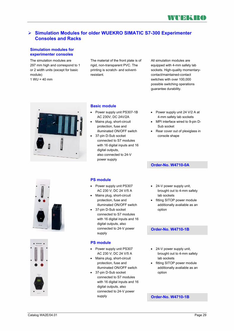
WUEKRO
Simulation Modules for older WUEKRO SIMATIC S7-300 Experimenter Consoles and Racks
Simulation modules for experimenter consoles The simulation modules are 297 mm high and correspond to 1 or 2 width units (except for basic module) 1 WU = 40 mm
The material of the front plate is of rigid, non-transparent PVC. The printing is scratch- and solvent-resistant.
All simulation modules are equipped with 4-mm safety lab sockets. High-quality momentary-contact/maintained-contact switches with over 100,000 possible switching operations guarantee durability.
•
•
•
Power supply unit 24 V/2 A at 4-mm safety lab sockets
MPI interface wired to 9-pin D-Sub socket
Rear cover out of plexiglass in console shape
Basic module •
•
•
Power supply unit PS307-1B AC 230V; DC 24V/2A
Mains plug, short-circuit protection, fuse and illuminated ON/OFF switch
37-pin D-Sub socket connected to S7 modules with 16 digital inputs and 16 digital outputs, also connected to 24-V power supply
Order-No. W4710-0A
•
•
24-V power supply unit, brought out to 4-mm safety lab sockets
fitting SITOP power module additionally avaliable as an option
PS module •
•
•
Power supply unit PS307 AC 230 V; DC 24 V/5 A
Mains plug, short-circuit protection, fuse and illuminated ON/OFF switch
37-pin D-Sub socket connected to S7 modules with 16 digital inputs and 16 digital outputs, also connected to 24-V power supply
Order-No. W4710-1B
•
•
24-V power supply unit, brought out to 4-mm safety lab sockets
fitting SITOP power module additionally avaliable as an option
PS module •
•
•
Power supply unit PS307 AC 230 V; DC 24 V/5 A
Mains plug, short-circuit protection, fuse and illuminated ON/OFF switch
37-pin D-Sub socket connected to S7 modules with 16 digital inputs and 16 digital outputs, also connected to 24-V power supply Order-No. W4710-1B
Catalog WA2E/04.01 Page 29
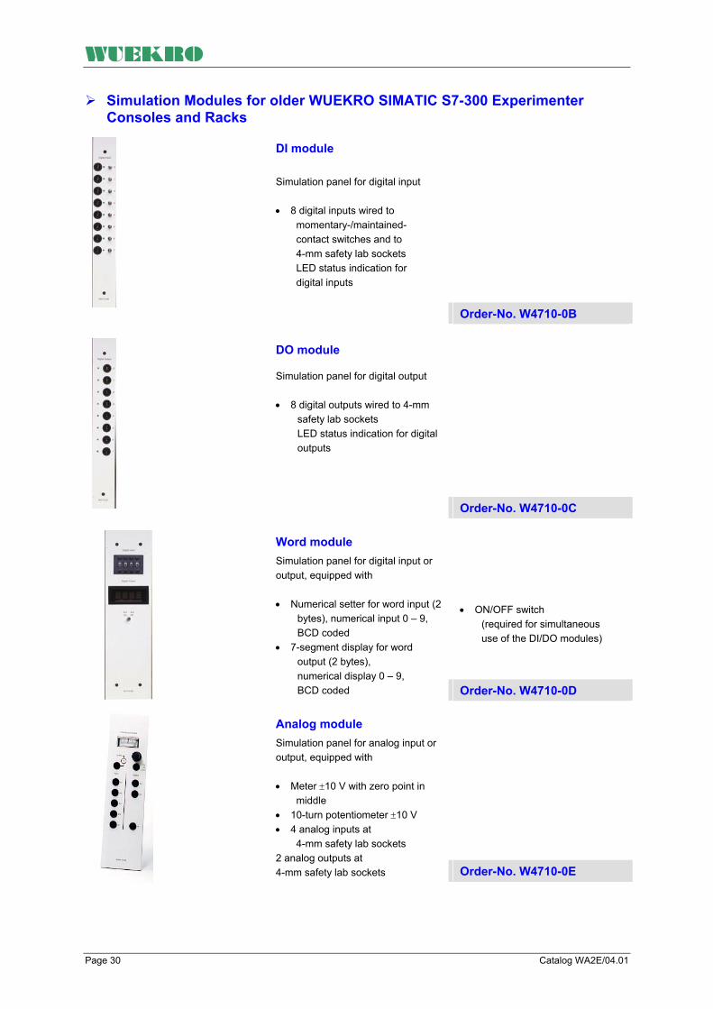
WUEKRO
Simulation Modules for older WUEKRO SIMATIC S7-300 Experimenter Consoles and Racks
DI module Simulation panel for digital input • 8 digital inputs wired to
momentary-/maintained-contact switches and to 4-mm safety lab sockets LED status indication for digital inputs
Order-No. W4710-0B
DO module
Simulation panel for digital output • 8 digital outputs wired to 4-mm
safety lab sockets LED status indication for digital outputs
Order-No. W4710-0C
• ON/OFF switch
(required for simultaneous use of the DI/DO modules)
Word module Simulation panel for digital input or output, equipped with • Numerical setter for word input (2
bytes), numerical input 0 – 9, BCD coded
• 7-segment display for word output (2 bytes), numerical display 0 – 9, BCD coded Order-No. W4710-0D
Analog module Simulation panel for analog input or output, equipped with •
• •
Meter ±10 V with zero point in middle
10-turn potentiometer ±10 V 4 analog inputs at 4-mm safety lab sockets
2 analog outputs at 4-mm safety lab sockets Order-No. W4710-0E
Page 30 Catalog WA2E/04.01

WUEKRO
Simulation Modules for older WUEKRO SIMATIC S7-300 Experimenter Consoles
4 digital inputs (special channels for integrated functions: (Sonderkanäle für integrierte Funktionen: Zähler, Frequenz-messung, Alarmeingänge, Positionieren) herausgeführt auf Simulationsfeld mit 4-mm-Sicherheitslaborbuchsen Nur für Verwendung in Verbindung mit CPU 314C
Analog module Simulation panel for analog input or output, equipped with •
• •
•
Meter ±10 V with zero point in middle
10-turn potentiometer ±10 V 4 analog inputs at 4-mm safety lab sockets
2 analog outputs at 4-mm safety lab sockets
Order-No. W4710-0L
Analog module with SM 334 •
•
• •
•
Analog module SM334 with 4 AI and 2 AO with measuring ranges 0 to 10 V and 0 to 20 mA
Simulation panel for analog input or output, equipped with
Meter ±10 V with zero point in middle
10-turn potentiometer ±10 V 4 analog inputs at 4-mm safety lab sockets
2 analog outputs at 4-mm safety lab sockets Order-No. W4710-2E
• 24-V power supply unit,
brought out to 4-mm safety lab sockets
PS module •
•
•
Power supply unit PS307 AC 230 V; DC 24 V/5 A
Mains plug, short-circuit protection, fuse and illuminated ON/OFF switch
37-pin D-Sub socket connected to S7 modules with 16 digital inputs and 16 digital outputs, also connected to 24-V power supply Order-No. W4710-1B
Catalog WA2E/04.01 Page 31

WUEKRO
Programming Software
STEP 7 Software for Training STEP 7 Professional To be used only for industrial schools and training centers 1 x Combo-license for interchangeable usage TIA PORTAL of: SIMATIC STEP 7 PROFESSIONAL 2010/V13 SP1 COMBO STEP 7 PROFESSIONAL V13 or STEP 7 PROFESIONAL 2010 SR4,
DISTRIBUTED SAFETY V5.4, S7-TECHNOLOGY V4.2, FLOATING LICENSE FUER 1 USER SW AND DOCU ON DVD, CLASS A 6 LANGUAGES: GE,EN,IT,FR,SP,CH; EXECUTABLE UNDER WINDOWS 7 (32 BIT, 64 BIT);
For configuration of SIMATIC S7-1500/1200/300/400/WINAC, SIMATIC Basic Panels. FOR EDUCATIONAL PURPOSES ONLY.
Order-No. W4700-5B
SIMATIC S7 Trainer Package 12 Classroom-Licence !!! To be used only for non-industrial training centers !!! 12 classroom licenses STEP 7 Professional V13 SP1 with STL, FBD and AD: 12 x Combo-Lizenz for usage either of SIMATIC STEP 7 Professional V13 (KOP, FUP, AWL), S7-GRAPH, S7-SCL, S7-PLCSIM or SIMATIC STEP 7 Professional 2010 SR4; STEP 7 V5.5 SP4 (KOP, FUP, AWL), S7-GRAPH V5.3 SP7, S7-SCL V5.3 SP6, S7-PLCSIM V5.4 SP5
also 12 x Combo-Lizencences for changeable usage of SIMATIC STEP 7 Safety Advanced V13 SP1 or SIMATIC S7-Distributed Safety 5.4 SP5 Update 1 12 x SINAMICS Startdrive V13 SP1* für SINAMICS G120 CONTROL UNIT CU240E-2 CU250S-2 (mit Firmware V4.6) 1x SIMIT SIMULATION FRAMEWORK Demoversion V8.1 Licences only for STEP 7 Professional 2010 SR4 12 x SIMATIC S7-IMAP V3.0 SP3 12 x SIMATIC S7-Technology V4.2 SP3
3 x 20 Software for Students, SIMATIC STEP 7 Prof., valid for 1 year from first usage For configuration of SIMATIC S7-1500/1200/300/400/WINAC, SIMATIC Basic Panels. FOR EDUCATIONAL PURPOSES ONLY Executable under Windows 7 (32bit, 64bit) all contents are identical to the industrial version STEP7 Professional
Order-No. W4700-5A
Page 32 Catalog WA2E/04.01

WUEKRO
SIMATIC S7 Trainer Package UPGRADE Upgrade from STEP7 Prof. <2010 & <V12 !!! To be used only for non-industrial training centers !!! For the upgrade of already existing former versions of the SIMATIC S7 trainer Package 12 classroom licenses STEP 7 Professional V13 SP1 with STL, FBD and AD: 12 x Combo-Lizenz for usage either of SIMATIC STEP 7 Professional V13 (KOP, FUP, AWL), S7-GRAPH, S7-SCL, S7-PLCSIM
or SIMATIC STEP 7 Professional 2010 SR4; STEP 7 V5.5 SP4 (KOP, FUP, AWL), S7-GRAPH V5.3 SP7, S7-SCL V5.3 SP6, S7-PLCSIM V5.4 SP5 also 12 x Combo-Lizencences for changeable usage of SIMATIC STEP 7 Safety Advanced V13 SP1 or SIMATIC S7-Distributed Safety 5.4 SP5 Update 1 12 x SINAMICS Startdrive V13 SP1* für SINAMICS G120 CONTROL UNIT CU240E-2 CU250S-2 (mit Firmware V4.6) 1x SIMIT SIMULATION FRAMEWORK Demoversion V8.1
Lizcences only for STEP 7 Professional 2010 SR4 12 x SIMATIC S7-IMAP V3.0 SP3 12 x SIMATIC S7-Technology V4.2 SP3 3 x 20 Software for Students, SIMATIC STEP 7 Prof., valid for 1 year from first usage For configuration of SIMATIC S7-1500/1200/300/400/WINAC, SIMATIC Basic Panels. FOR EDUCATIONAL PURPOSES ONLY Executable under Windows 7 (32bit, 64bit) all contents are identical to the industrial version STEP7 Professional
Order-No. W4700-5U
SIMATIC S7 SoftwareSTEP 7 BASIC V13
SIMATIC S7, STEP 7 BASIC V13 SINGLE LICENSE, E-SW, Software and documentation on DVD, licence Key on USB-Stick,
multi-lingual (DE,EN), runs under Windows7 (32/64Bit) and Windows8 SP1 (64Bit)
W4700-5C Programming Software – Manuals/Accessories
PC adapter USB
for connection of PC with S7-300/-400,C7, M7 for PC with free USB slot incl . USB-cable (5m) suitable with WIN2000 or XP Order-No. W4700-4M
Catalog WA2E/04.01 Page 33

WUEKRO
Programming Devices
SIMATIC FIELD PG M4
SIMATIC Field PG M4: The benchmark in compactness, robustness and performance Mobile engineering in the industrial environment. The Field PG is perfect for harsh industrial applications because of its rugged yet attractive industrial design. Powerful processors and high-speed RAM provide this rugged laptop with high performance among the most demanding applications. You also benefit from wireless technology, a brilliant display, and other carefully designed features.
Overview The mobile, industry-compatible programming device with powerful Intel Core i processor technology. Optimal for commissioning, service and maintenance of automation systems. Industrial notebook with wireless technology, large 15.6" widescreen display, long battery service life, high-speed RAM, and integral data backup concept. With all commonly used interfaces for industrial applications.
Application The Field PG M3 is the optimal tool for automation engineering. It can be used in the commissioning, service and maintenance of automation systems. Thanks to its outstanding specifications, it can also be used in the office area.
Design All the interfaces required are directly available on the device; no external connection components (I-Cable, I-Box) are necessary 5 integral USB interfaces, 1 interface can be used as high current in each interface block; external hard disks with a high starting current are easy to connect. DDR3 memory technology with 1066 MHz system cycle;
for significantly faster access to data. 15.6" widescreen display (16:9 format), LED backlighting, non-reflective with high luminance for the perfect overview even with numerous windows; the brightness can be adapted to the ambient lighting conditions using hotkeys. Powerful integrated graphics; also ideally suited to applications with demanding graphics. Integral WLAN with antennas specially designed for the Field PG M3. The integrated wireless LAN is approved for operation in Europe (CE), USA, (FCC), Canada (IC) and China (CCC). For operation outside these countries, the relevant national regulations must be observed. Hard disk with serial ATA interface (150 Mbit/s) and high speed (5400 rpm); easily replaced to support rapid changeover between different software versions or operating systems. Powerful lithium ion rechargeable battery (71 Wh) for several hours of operation Keyboard with hotkeys; fast access to display settings, setting the computer in standby or hibernate mode, adjusting the loudspeaker and disabling the computer, etc. Built-in loudspeakers User-friendly touchpad Rugged magnesium injection-molded enclosure. New, dark coloration; significantly less sensitive to dirt
Scope of delivery/accessories Pre-installed operating system: Windows XP Professional English MultiLanguage (32-bit) or Windows 7 Ultimate, 32-bit (Eng, Ger., Fr., Sp., It. selectable) or Windows 7 Ultimate, 64-bit (Eng., Ger., Fr., Sp., It. selectable); Note: STEP 5 and STEP 7-Micro/Win are not pre-installed and do not run under Windows 7 Pre-installed software STEP 7 Professional, STEP 7 Professional (TIA Portal), WinCC flexible Advanced, WinCC Advanced (TIA Portal), STEP 7 Micro/Win and STEP 5
Note: The software is activated via the license keys to be purchased separately.
Function Integral WLAN with antennas specially designed for the Field PG M3. The integral wireless LAN is approved for operation in Europe (CE), USA (FCC), Canada (IC), and China (CCC). For operation outside these countries, the relevant national regulations must be observed. Bluetooth. Dual display technology; supports the extended desktop with two screens with separate resolutions.
Page 34 Catalog WA2E/04.01

WUEKRO
Programming Devices
This order number always entitles the actual premium full equipped field PG with the faster processor and full software equipped.
Field PG Programming Device Premium The Field PG’s have a continued update cycle. Please ask for the newest technical specs and software configurations.
Order-No. W4781-5A
Field PG Programming
Device Standard The Field PG’s have a continued update cycle. Please ask for the newest technical specs and software configurations.
This order number always entitles the actual full equipped field PG with the slower processor and full software equipped.
Order-No. W4781-5C
Field PG Programming Device Premium + standard software configuration The Field PG’s have a continued update cycle. Please ask for the newest technical specs and software configurations.
This order number always entitles the actual full equipped field PG with the faster processor and standard software configuration equipped.
Order-No. W4781-5B
This order number always entitles the actual full equipped field PG with the slower processor and full software equipped.
Field PG Programming Device Standard + standard software configuration The Field PG’s have a continued update cycle. Please ask for the newest technical specs and software configurations. Order-No. W4781-5D
Catalog WA2E/04.01 Page 35

WUEKRO
Accessories – Leads and Plugs
Connecting lead
32 A/250 V, black, 100 cm long, with 4-mm safety plug Order-No. W3907-3E
Connecting lead
32 A/250 V, red, 100 cm long, with 4-mm safety plug Order-No. W3907-3F
Adapter
4-mm plug/2-mm socket for the connection of 2-mm connecting leads Order-No. W3942-2A
Connecting lead
37-pin D-SUB plugs on both sides, 1.5 m long, for the connection of technology simulators to SIMATIC S7 training devices Order-No. W4760-8A
Connector plug for PROFIBUS
up to 12 Mbit/s, 90-degree cable attachment, terminating resistor with disconnecting function, without PG socket Order-No. W3947-1A
Connector plug for PROFIBUS
up to 12 Mbit/s, 90-degree cable attachment, terminating resistor with disconnecting function, with PG socket Order-No. W3947-1B
PROFIBUS lead
Bus lead 2-wire, shielded, special design for quick assembly, length: 20 m Order-No. W3947-2A
PROFIBUS lead
Bus lead 2-wire, shielded, special design for quick assembly, length: 50 m Order-No. W3947-2B
PROFIBUS lead
Bus lead 2-wire, shielded, special design for quick assembly, length: 100 m Order-No. W3947-2C
Accessories – Manuals
Manual collection on CD, multilingual
Includes S7-200/300/400, M7-300/400, C7, Step7, engineering software, SIMATIC DP, SIMATIC HMI, SIMATIC NET Order-No. W3048-3C
Page 36 Catalog WA2E/04.01

WUEKRO
Experiment Instructions
Practical experiment instructions
Experiment instruction manuals for all SIMATIC training systems, which have been compiled by specially trained and qualified employees, are available for use.
In general, the experiment instructions consist of three parts: Part 1: Fundamentals Introduces the training needs and provides the basic theory Part 2: Experiments Contains the experiments like programming and test tasks Part 3: Solutions Contains solutions to Part 2, offers ways of checking the results and thus reduces the time for preparation
Experiment instructions
V173 SIMATIC S7-300 Order-No. W3017-3B
V174 Digital Control II with SIMATIC S7 Order-No. W3017-4B
V175 Digital Control I with SIMATIC S7 Order-No. W3017-5B
V178 PROFIBUS DP Order-No. W3017-8B
V179 Universal Simulator Electrical Engineering Order-No. W3017-9B
V186 S7-SIM Programming Course 1 Order-No. W3018-6B
V187 Universal Simulator Digital/Analog Technology Order-No. W3018-7B
V189 Universal Simulator Metal Engineering Order-No. W3018-9B
Catalog WA2E/04.01 Page 37

WUEKRO
System Introduction for SIMATIC S7
Basic training SIMATIC S7 3-5 days training 8 learning units each (45 min) incl. training documentation In the practical programming exercises available simulators and applications are integrated. Individual quotation upon request. If required also on site.
Training contents: 1. System information about
SIMATIC S7 and about STEP7 / TIA-Portal - Scope of application →
function within SIMATIC automation family
- Method of operation and functions
- Setup - Startup - Bus interfacing via MPI
and Profibus 2. Introduction to STEP7 / TIA-
Portal programming based on an easy example - Setting up a project - Configuring the SIMATIC
station - Writing program block OB1 - Testing and storing
program block OB1
3. Programming language STEP7 / TIA-Portal with programming exercises - Directory structure and
general notes - Archiving and
documenting the program - Addressing and program
representation (LAD, SFC and STL)
- Program structure - Program blocks (OB, FB,
FC and DB)
- Basic logic operations: AND, OR, exclusive OR Storage elements, R-S FF Edge operations Direct processing of RLO Loading and transfer operations Counting and comparisonoperations Timing functions and integratedclock memory Program organization and jump functions
Page 38 Catalog WA2E/04.01

WUEKRO
WUEKRO GmbH Carl Zeiss Str. 10 D-97424 Schweinfurt Germany Phone: +49 (0) 9721 64691-0 Fax: +49 (0) 9721 64691-20 Email: [email protected] Internet: wuekro.de
Catalog WA2E/04.01 Page 39

WUEKRO
Page 40 Catalog WA2E/04.01
FAX – Reply to: +49 (0)9721 - 64691 - 20 Sender: Receiver:
Company WUEKRO GmbH Dept. Sales Department Name Street Carl-Zeiss-Strasse 10 City 97424 Schweinfurt / Germany Phone + 49-(0)9721-64691-0 Fax + 49-(0)9721-64691-20 E-Mail [email protected] Internet www.wuekro.de No. of pages
incl. this page
Please send the following catalogues to the a.m. address!
Fundamentals of electrical Engineering
Installation circuits Bell ringing and entrance call stations Contactor circuits/Control technology Measurement and control of non- electrical quantities
Fundamentels of electronics Analog technology Digital technology Microprocessing technology
Closed loop control technology Analog control technology Digital control technology
Automation engineering SIMATIC S7-200/300/400, Software Technology simulators / Models Process control technology PCS7 AS-Interface Process simulation-software PROSIM 95 LOGO!
Electrical machines / Drive controls 300W - range 1000W - range 5kW - range Electr. drive control 300W/1000W Electr. drive control 5kW
Power electronics extra low voltage (24V) low voltage (230/400V)
Building management systems KNX / EIB
Protection schemes to VDE 0100
Radio- and TV technology AM/FM - Technology TV Technology Satellite - Technology
Air conditioning and refrigeration
Photovoltaic
Communication technology Modulation -/demodulation technology Optical fibre HICOM communication systems
Measuring systems, power supplies, Accessories
Experimental manuals, documentation, books
Remarks:

WUEKRO
Training & Didactic Systems Automation Technology with SIMATIC S7 Technology Stations/Simulators/Models
Catalog WA2E/04.02

WUEKRO
Page 2 Catalog WA2E/04.02
Our Services • Development and production of didactic training systems • Teachware and documentation • Project engineering of complete lab's incl. furniture and lab equipment • Quotations on customer's demand • Installation, commissioning and training at site
Our Customers • Vocational training schools, technical schools, colleges and universities... • Industrial laboratories for vocational education and higher education
Fields of Technology • Fundamentals of electrical engineering
• Fundamentals of electronics
• Closed loop control technology
• Automation engineering
• Electrical machines / drive control
• Power electronics
• Building management systems
• Protection schemes to VDE 0100
• Radio- and TV technology
• Air conditioning and refrigeration
• Photovoltaic
• Communication technology
• Measuring systems, power supplies, accessories
• Experimental manuals, documentation For further information please contact: WUEKRO GmbH Carl-Zeiss-Strasse 10 D - 97424 Schweinfurt Germany Tel. + 49 (0) 9721-64691-0 Fax: + 49 (0) 9721-64691-20 E-Mail: [email protected] Internet: www.wuekro.de WUEKRO GmbH
All Rights reserved. Reprint not permitted. Technical changes without prior notice.. S30020521P – 01/13

WUEKRO
Catalog WA2E/04.02 Page 3
Table of Contents Page Our Services 2 Table of Contents 3 Training System Automation Technology 4 Introduction 5 Technology Simulators/General 6 Technology Simulators without Storage Function 6 Technology Simulators with Storage Function 7 Technology Simulators with Dynamic Response 8 Technology Simulators with Counters and Comparators 9 Technology Simulators Sequential Controls 10 Technology Simulators for Closed-Loop Control 12 Universal Simulators 14 Universal Simulator Electrical Engineering 14 Universal Simulator Mechanical Engineering 15 Plant Simulator Analog/Digital technology 16 Models 18 Conveyor Belt Model 18 Pneumatic Sheet bending Model 19 Elevator Model, 3 Storages 20 Conveyor Belt Compact Case 21 RFID Supplementary Kit 21 RFID Technology Set 21 Technology Stations 22 Technology Station Loading and Handling 22 Technology Station Conveyor Belt 23 Technology Station Measuring and Handling 24 Belt Technology Station High-Bay Warehouse 25 Accessories - Leads/Plugs 26 Experiment Instructions 27 Fax-Reply 28

WUEKRO
Page 4 Catalog WA2E/04.02
Training System Automation Technology
Educational Systems – Allocation – Target Groups Study projects Dissertations
Specialized practical training College/University
Aut
omat
ion
syst
ems
Basic practical training
College/University
Master craftsman/technician
Further education (Chamber of Industry and Commerce)
Skilled worker training N
ew te
chno
logi
es
Indu
stria
l bus
sys
tem
s
Fundamentals Training/education
SIM
ATI
C S
7 -
Expe
rimen
ter
Prog
ram
mab
le c
ontr
olle
rs, p
rogr
amm
ing,
in
dust
rial m
odel
s

WUEKRO
Catalog WA2E/04.02 Page 5
Introduction Your learning needs will be fulfilled with our training systems • Structure of numerical systems • Declaration of variables • Methods of PLC representation with FBL, LAD, STL, Graph 7, SCL according to standard IEC 1131-3 • Getting to know program execution procedures • Getting to know the function groups of a PLC and their principles of operation according to standard IEC 1131-1,2 • Basic logic operations with a PLC • Logic controls with dynamic response Counters and comparators with/without storage function Sequential controls with mode section Sequencers Operating status messages Process-oriented or time- oriented • Analog value processing • Word processing • Digital closed-loop control • Autonomous modules • Drive/position control • Startup, maintenance • Industrial networking • Fundamentals of open communications • Process visualization/control • Fault diagnostics without/with visualization systems
The concept The aim of the new IEC 1131 standard is to attain a worldwide unified system in the field of PLC technology. The programming languages are standardized in part 3. The standard encompasses the ladder diagram (LAD), function block language (FBL), sequence language (SL), statement list (STL), and structured text (ST). PLC systems are an integral component of automation today. SIMATIC S7 has taken the lead by offering a basic system for the entire field of automation. SIMATIC S7 is the platform for • PLC • Man-machine interface • Industrial networking • Process control engineering • Automation computers • Measurement and control • DP applications A great advantage for the user is the fact that this knowledge, once attained, can also be put to use in the other fields of technology. The goal of our training concept for the different fields of automation is to provide - Vocational schools - Colleges - Universities - Places of training and further education with the theoretical and practical prerequisites leading to trainees’ and students’ complete under-standing of modern automation technology.
In general, there are two ways in which you can fulfill your training needs: 1. By working with the low-cost
experimenter consoles and the technology simulators.
2. By working with the modular rack system, the technology simulators and models.
Here you can choose from the modules which are tailored to your curriculum. Our program is rounded off with the model industrial bus system, the modular automation system aimed at engineering schools and colleges/universities. Practical experiment instructions Experiment instruction manuals on the individual modules, which have been compiled by specially trained and qualified employees, are available for use. In general, the experiment instructions consist of three parts: Part 1 Introduces the training needs and provides the basic theory. Part 2 Contains the programming and test tasks. Part 3 Contains solutions to part 2. This keeps the time for test preparations to a minimum and offers a way of checking the results.

WUEKRO
Page 6 Catalog WA2E/04.02
Technology Simulators
General Technology diagrams in 3-D simplify the understanding of the illustrated process and optimize the periods of training. High-intensity LEDs symbolize sensors, actuators and operating states.
The material of the frontplate is of rigid, non-transparent PVC. The printing is scratch and solvent-resistant due to a double layer of protective lacquer. High-quality momentary-contact/maintained-contact switches with over 100,000 switching operations guarantee durability.
Thus, technology simulators with 3-D are a low-cost training alternative to models.
Logic controls without storage function
Logic controls without storage function are based on the application and combination of the basic logic functions: • NOT • AND • OR
Training content • Cyclic program processing • Introduction of flags • Structures of numerical systems Number of inputs: 4 Number of outputs: 8
Seven-segment display technology simulator The seven-segment display indicates the digits 0 to 9. The respective decimal value in BCD code (8-4-2-1) has to be set by the momentary-contact/maintained-contact switches on the PLC training unit. The single segments are discretely controlled for each number.
Order-No. W4760-1A
Training content • Control analysis • Logic operations • Status messages Number of inputs: 4 Number of outputs: 7
Reaction vessel technology simulator A chemical process takes place at a certain temperature and under a certain pressure. Limiting values for temperature and pressure are simulated by switches. The actuators for heating, cooling-water and safety valve are used to control the three plant states.
Order-No. W4760-1B

WUEKRO
Catalog WA2E/04.02 Page 7
Technology Simulators
Logic controls with storage function
Many control tasks require a storage function.
This is available where a fleeting signal state is retained, i.e. stored.
Training content • Interlock circuit • Sequence control • Storage types Number of inputs: 6 Number of outputs: 3
Tank-filling device technology simulator Three storage tanks with sensors for “full” and “empty” indication are to be discharged in a random order. One tank with “empty” indication is to be filled until “full” is indicated. But only one tank is to be permanently filled. The tanks are to be filled in the same order in which they were emptied.
Order-No. W4760-1C
Training content • Truth table • Pulse generator • ON/OFF delay • Process register Number of inputs: 2 Number of outputs: 4
Pump control technology simulator Four motor-driven pumps deliver water from a suction tank into a pipeline. By switching the four pumps on and off in stages, the pressure in the mains is kept constant. The requirement is for the operating time of the pumps and the switching frequency to be as uniform as possible. Before switching the next stage on and off, an appropriate delay time is required. Order-No. W4760-1D
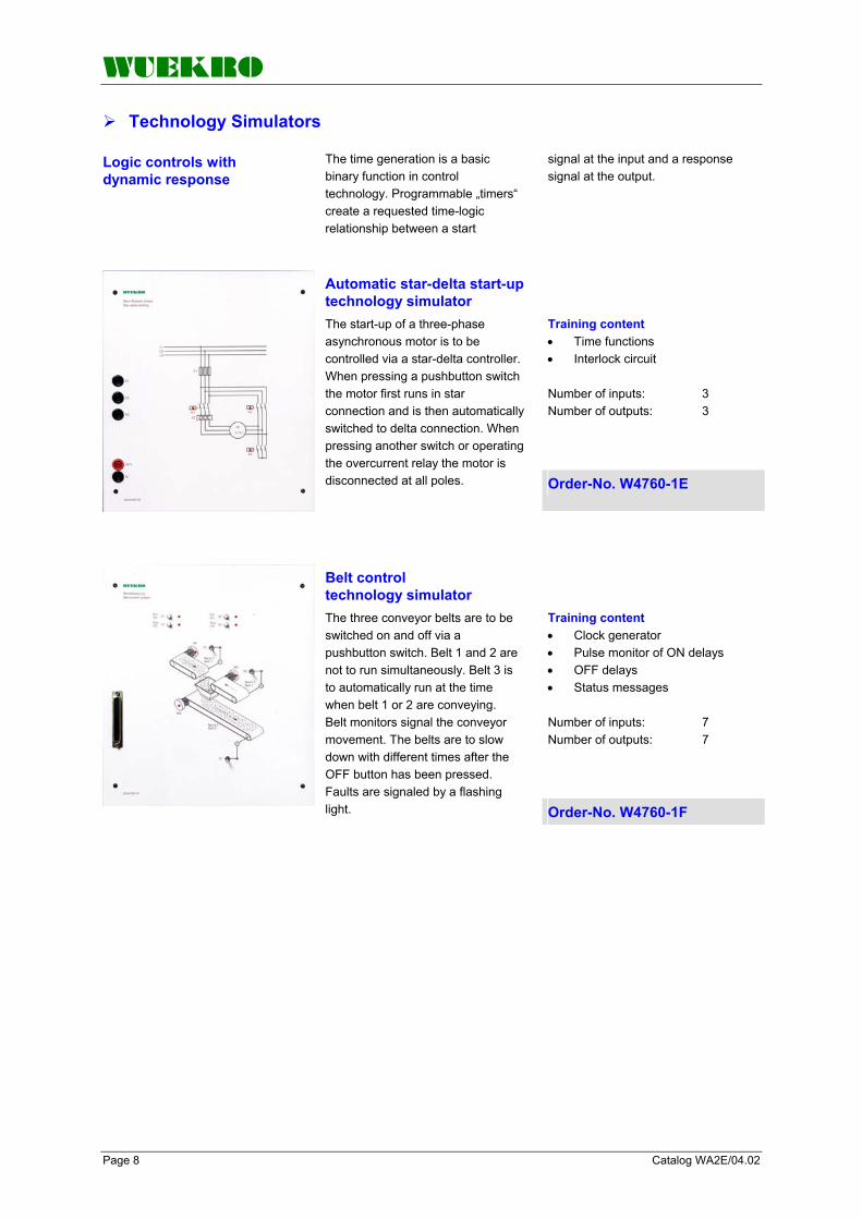
WUEKRO
Page 8 Catalog WA2E/04.02
Technology Simulators
Logic controls with dynamic response
The time generation is a basic binary function in control technology. Programmable „timers“ create a requested time-logic relationship between a start
signal at the input and a response signal at the output.
Training content • Time functions • Interlock circuit Number of inputs: 3 Number of outputs: 3
Automatic star-delta start-up technology simulator The start-up of a three-phase asynchronous motor is to be controlled via a star-delta controller. When pressing a pushbutton switch the motor first runs in star connection and is then automatically switched to delta connection. When pressing another switch or operating the overcurrent relay the motor is disconnected at all poles. Order-No. W4760-1E
Training content • Clock generator • Pulse monitor of ON delays • OFF delays • Status messages Number of inputs: 7 Number of outputs: 7
Belt control technology simulator The three conveyor belts are to be switched on and off via a pushbutton switch. Belt 1 and 2 are not to run simultaneously. Belt 3 is to automatically run at the time when belt 1 or 2 are conveying. Belt monitors signal the conveyor movement. The belts are to slow down with different times after the OFF button has been pressed. Faults are signaled by a flashing light. Order-No. W4760-1F

WUEKRO
Catalog WA2E/04.02 Page 9
Technology Simulators
Controls with counters and comparators
A certain set of values is often acquired by summating pulse. The corresponding pulses are passed to a counter which summates the received pulses.
Based on the compare functions, two digital values are compared with one another. The result of the comparison is binary and can be further processed.
Training content • Counters and comparators • BCD coding/pulse count memory • Clock generator Number of inputs: 1 Number of outputs: 5
Traffic light control technology simulator A pedestrian crossing is regulated by traffic lights. During the day, the system operates automatically by permanently repeating a switch cycle. During the night, only the amber signal is required to flash in order to warn drivers.
Order-No. W4760-1G
Training content • Up/down counter • Signal preprocessing • Initializing pulse generator/pulse contact • Pulse count memory • Status diagram Number of inputs: 6 Number of outputs: 5
Automatic pill filling device technology simulator An automatic pill filling device is to continuously fill a variable number of pills into tubes. The required number of pills is to be preselected by pressing a pushbutton. A con-veyor belt moves the empty tube into the filling position. The number of pills to be filled is counted by a light barrier. When the desired amount of pills is reached, the next empty tube is to be positioned. When preselecting the amount of pills or stopping the machine, the last filling operation must first be completed. Order-No. W4760-1H
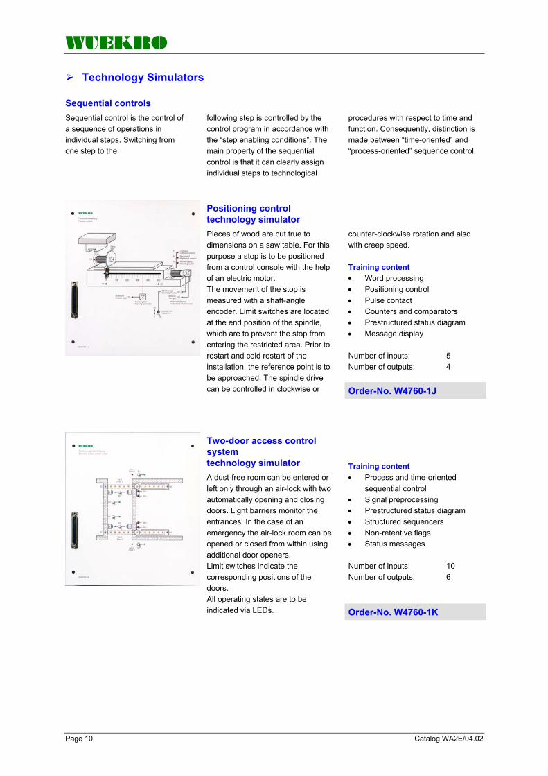
WUEKRO
Page 10 Catalog WA2E/04.02
Technology Simulators
Sequential controls
Sequential control is the control of a sequence of operations in individual steps. Switching from one step to the
following step is controlled by the control program in accordance with the “step enabling conditions”. The main property of the sequential control is that it can clearly assign individual steps to technological
procedures with respect to time and function. Consequently, distinction is made between “time-oriented” and “process-oriented” sequence control.
counter-clockwise rotation and also with creep speed. Training content • Word processing • Positioning control • Pulse contact • Counters and comparators • Prestructured status diagram • Message display Number of inputs: 5 Number of outputs: 4
Positioning control technology simulator Pieces of wood are cut true to dimensions on a saw table. For this purpose a stop is to be positioned from a control console with the help of an electric motor. The movement of the stop is measured with a shaft-angle encoder. Limit switches are located at the end position of the spindle, which are to prevent the stop from entering the restricted area. Prior to restart and cold restart of the installation, the reference point is to be approached. The spindle drive can be controlled in clockwise or Order-No. W4760-1J
Training content • Process and time-oriented sequential control • Signal preprocessing • Prestructured status diagram • Structured sequencers • Non-retentive flags • Status messages Number of inputs: 10 Number of outputs: 6
Two-door access control system technology simulator A dust-free room can be entered or left only through an air-lock with two automatically opening and closing doors. Light barriers monitor the entrances. In the case of an emergency the air-lock room can be opened or closed from within using additional door openers. Limit switches indicate the corresponding positions of the doors. All operating states are to be indicated via LEDs. Order-No. W4760-1K

WUEKRO
Catalog WA2E/04.02 Page 11
Technology Simulators
Training content • Process-oriented sequential control • Mode sections • Step enabling conditions • Protection against restart • Controlled shutdown of a system Number of inputs: 15 Number of outputs: 5
Embossing machine automatic simulator A workpiece that has been released from the hopper is pushed into a machining station where it is to be embossed for 3 s. A nozzle blows the blank out and an ejector pushes the workpiece into a collecting container. An operator panel as used in industry controls the operating modes “automatic” and “manual with inching mode”. The final positions of the electropneumatically operated valves are automatically indicated by the limit switches. Internal electronics automatically simulate the valve feed. Order-No. W4760-1L
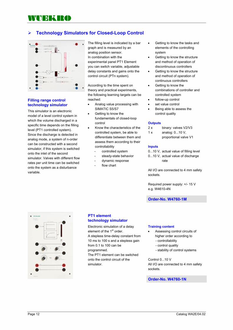
WUEKRO
Page 12 Catalog WA2E/04.02
Technology Simulators for Closed-Loop Control
Filling range control technology simulator This simulator is an electronic model of a level control system in which the volume discharged in a specific time depends on the filling level (PT1 controlled system). Since the discharge is detected in analog mode, a system of n-order can be constructed with a second simulator, if this system is switched onto the inlet of the second simulator. Valves with different flow rates per unit time can be switched onto the system as a disturbance variable.
The filling level is indicated by a bar graph and is measured by an analog position sensor. In combination with the experimental panel PT1 Element you can switch variable, adjustable delay constants and gains onto the control circuit (PTn system). According to the time spent on theory and practical experiments, the following learning targets can be reached: • Analog value processing with SIMATIC S5/S7 • Getting to know the fundamentals of closed-loop control • Know the characteristics of the controlled system, be able to differentiate between them and assess them according to their controllability
- controlled system - steady-state behavior - dynamic response - flow chart
• Getting to know the tasks and elements of the controlling system • Getting to know the structure and method of operation of discontinuous controllers • Getting to know the structure and method of operation of continuous controllers • Getting to know the combinations of controller and controlled system • follow-up control • set value control • Being able to assess the control quality Outputs 2 x binary: valves V2/V3 1 x analog: 0...10 V, proportional valve V1 Inputs 0...10 V, actual value of filling level 0...10 V, actual value of discharge rate All I/O are connected to 4 mm safety sockets. Required power supply: +/- 15 V e.g. W4610-4N
Order-No. W4760-1M
Training content • Assessing control circuits of higher order according to
- controllability - control quality - stability of control systems
Control 0...10 V All I/O are connected to 4 mm safety sockets.
PT1 element technology simulator Electronic simulation of a delay element of the 1st order. A stepless time-delay constant from 10 ms to 100 s and a stepless gain from 0.1 to 100 can be programmed. The PT1 element can be switched onto the control circuit of the simulator.
Order-No. W4760-1N

WUEKRO
Catalog WA2E/04.02 Page 13
Technology Simulators for Closed-Loop Control
Technical specifications Input voltage 1AC 230 V , 50 / 60 Hz Output voltage + 15 V / 1,5 A - 15 V / 1,5 A 24 V / 0,5 A Dimensions (WxHxD) 130x297x100 mm Weight approx. 3 kg
DC power supply Suitable for the supply of two filling level control technology simulators. designed as experimental panel height 297 mm for insertion into a compact unit or experimental frame. All connections are brought out to 4-mm-safety-sockets.
Order-No. W4610-4N
Experiment instructions V 175 “Digital Control I” with SIMATIC S7 Part 1: Fundamentals of digital control Part 2: Experiments from two- position control to continuous-action control Part 3: Solutions
Experiment instructions V 174 “Digital Control II” with SIMATIC S7 Part 1: Design study PID controller Part 2: Experiments, setting procedures Part 3: Solutions
Order-No. W3017-5B Order-No. W3017-4B

WUEKRO
Page 14 Catalog WA2E/04.02
Universal Simulators
Universal simulator electrical engineering
Teaching content (in conjunction with SIMATIC training units) • Cyclic program processing • Logic operations • Interlock circuit • Sequential circuit • Storage types • Pulse generator • Edge evaluation • Clock generator • ON/OFF delay • Counters and comparators • Up/down counter • BCD coding/pulse count memory • Signal processing • Initializing pulse generator/pulse contact • Status diagram • Process-oriented/time-oriented sequential control • Mode sections • Sequencers • Step enabling conditions • Word messages
This simulator is especially suited for fundamental PLC training in the vocational field electrical engineering. The experiments have been aligned with the curriculum. The universal simulator is equipped with operator panel and simulator including overlays, and operates in a voltage range from 5 V...24 V DC. It is thus also suitable for applications from the fields of digital and microprocessor technology. Design Power +5V…24V is supplied via 4 mm safety sockets or 2 mm sockets, respectively. There are 8 freely assignable momentary-contact/maintained-contact switches mounted on the operator panel. The connectors of the switches are brought out to 4 mm safety sockets and to 2 mm sockets.
The 5 digital inputs for the simulator are also wired to 4 mm safety sockets and to 2 mm sockets. The scope of supply includes 11 different overlays with examples, ranging from simple logic control to sequential control. • Fan control • Tank filling device • Star-delta start-up • Gate control • Roadwork traffic light • Pump control • Starter control • Oven door control • Traffic light control • Buffer control • Sheet bending device By replacing the overlays, the LEDs assigned to the respective exercise become visible.
Order-No. W4760-2A
• Programming tasks for universal simulator W4760-2A with solutions for instructor and teacher, English
Experiment instructions V 179 Universal simulator Electrical Engineering
• Programming to standard IEC 1131-3 • Configuration of control tasks • Instructions for setup and programming • Example of a consistent configuration Order-No. W3017-9B

WUEKRO
Catalog WA2E/04.02 Page 15
Universal Simulators
Universal simulator Metal Engineering
Teaching content (in conjunction with SIMATIC training units) • Electropneumatics • Electropneumatic signal flow diagram • Safety conditions in installations with electropneumatics • Logic operations • Interlock circuit • Process-oriented/time-oriented sequential control • Storage types • Counters and comparators • Structured programming • Status diagram • Step enabling conditions
This simulator is especially suited for fundamental PLC training in the vocational field metal engineering. The experiments have been aligned with the curriculum. The universal simulator is equipped with operator panel and simulator including overlays, and operates in a voltage range from 5 V...24 V DC. It is thus also suitable for applications from the fields of digital and microprocessor technology. Design Power (+ 5 V ... 24 V) is supplied via 4 mm safety sockets or 2 mm sockets, respectively. There are 8 freely assignable momentary-contact/maintained-contact switches mounted on the operator panel. The connectors of the switches are brought out to 4 mm safety sockets and to 2 mm sockets.
The 8 digital inputs for the simulator are also wired to 4 mm safety sockets and to 2 mm sockets. The scope of supply includes 11 different overlays with examples, ranging from simple logic control to sequential control. • Punching device • Lifting unit for packages • Stamping device • Lifting unit with sorting unit • Positioning unit • Forming station • Press with safety installation • Silo control for 2 bulk goods • Quality testing installation • Distribution unit • Sorting unit By replacing the overlays, the LEDs assigned to the respective exercise become visible.
Order-No. W4760-2B
• Programming tasks for universal simulator W4760-2B with solutions for instructor and teacher, English
Experiment instructions V 189 Universal simulator Metal Engineering
• Programming to standard IEC 1131-3 • Configuration of control tasks • Instructions for setup and programming • Example of a consistent configuration Order-No. W3018-9B

WUEKRO
Page 16 Catalog WA2E/04.02
Universal Simulators
Plant Simulator Analog/Digital technology
Basic Unit Set of Overlays
V1 – Silo control V2 – Goods lift V3 – Traffic lights
V4 – 3-phase automatic starter V5 – Dahlander circuit V6 – Reversing contactor circuit
V7 – Star-delta circuit V8 – Running light V9 – Drink vending machinet
V10 – Reaction vessel V11 – Mixing unit V12 – Latching circuit
V13 – Multi storey car park V14 – Compressed air net V15 – Sequence control unit
V16 – Conveyor control V17 – Automatic tablet filler V18 – Tank filling system
V19 – Embossing machine V20 – Pump control

WUEKRO
Catalog WA2E/04.02 Page 17
Universal Simulators
• Process and timed sequence control system • Mode sections • Sequencers • Step enabling conditions • Word output • Analog value processing • Getting to know the fundamentals of closed-loop control • Getting to know the tasks and elements of the controlling system • Getting to know the structure and method of operation of discontinuous controllers • Getting to know combination of controller and controlled system Technical data: 12 digital inputs on 4-mm safety lab sockets 12 digital outputs on 4-mm safety lab sockets 2 analog inputs on 4-mm safety lab sockets 2 analog outputs variable via potentiometers (0 - 10V) wires on 4- mm safety lab sockets 6 momentary-contact/ maintained- contact switch with LED status indicator 2 momentary-contact/ maintained- contact switch 1 Bargraph - display with 6 limit switches 1 system connector for 16 digital inputs and 16 digital outputs Power supply: 24 V DC Dimensions: (W x H x D) 390 x 297 x 100mm Weight: approx. 5 kg
Plant Simulator Analog/Digital Technology The universal simulator is especially suitable for the basic PLC training in the professional field of electrical engineering and metal-working technology. The experiments are tailored for the curriculum of vocational education. The inputs and outputs are internally wired to the simulation field matrix of the simulator and additionally connected to 4-mm safty lab sockets. The digital Inputs and Outputs are connected to a 37-pin D-SUB connector for an easy interconnection to SIMATIC Training-equipment. By exchanging the different text overlays, the sockets, switches, potentiometer and LED's, which are assigned to a specific exercise, are uncovered. This makes sure a clear setup of the exercises and avoids mistakes. Analog setpoint values can be adjusted by two potentiometers. The necessary power supply 24V can be supplied via 4-mm-safety sockets. The Universal Simulator can be used as an experimental panel in combination with an experimental frame or as an table-top unit.
Delivery includes 20 different text overlays with exercises dealing with the simple logic control, as well as analog value processing. • Silo control • Goods lift • Traffic lights • Three phase automatic starter • Dahlander circuit • Reversing contactor circuit • Star-delta circuit • Running light • Drink vending machine • Reaction vessel • Mixing unit • Latching circuit • Multi-storey car park • Compressed air net • Sequence control circuit • Conveyor control • Automatic tablet filler • Tank filling system • Embossing machine simulator • Pump control Training content • Cyclic program processing • Logic circuits • Interlocking circuit • Sequential circuit • Different memories • Pulse generator, edge evaluation • Clock generator • ON/OFF delay • Counters and comparators • Up/down counter • BCD coding pulse count store • Signal preprocessing • Initializing pulse generator/pulse contact • Structured programming • Status diagram Order-No. W4760-2C
Experiment instructions V 187 " Plant Simulator"
• Programming acc. to standard IEC 1131-3 • Projecting of controls • One task for each overlay
• Programming tasks for plant simulator W4760-2C with solutions for teacher, english language
Order-No. W3018-7B

WUEKRO
Page 18 Catalog WA2E/04.02
Models for Training Units with SIMATIC S7
Industrial application Models of complex industrial installations ensure that training is close to practice and are suitable for imparting specific fundamental
knowledge in the fields electrotechnical engineering, pneumatics, material flow, design and sensor technology.
The purpose is to learn to deal with technical devices in a technical way using the proper instruments.
Training content Material flow technology Startup Troubleshooting Maintenance Process-oriented sequential control Sequencer programming
Conveyor belt model For training in programmable logic control and material flow technology.
Consists of aluminum profile rails and a built-on 24 V DC industrial motor, spherically seated concave belt rollers, non-slip, rubber-coated fabric belt. Connection to SIMATIC training unit via 37-pin D-SUB plug.
Order-No. W4761-1B
Consists of: 2 sensors: inductive S=15 mm optical 3 transport containers out of aluminum, black plastic and white plastic 2 fastening angles
Supplementary kit Sensor Technology Supplementary kit Sensor Technology for conveyor belt model W4761-1B.
All cable ends are fitted with 2 mm connectors.
Order-No. W3545-6J
Connecting lead With 37-pin subminiature D-SUB plug (model side) and 1 x 37-pin D-SUB plug for connection to the SIMATIC S7 training units. Order-No. W4760-8A

WUEKRO
Catalog WA2E/04.02 Page 19
Models for Training Units with SIMATIC S7
Training content • Reading and applying pneumatic circuit diagram • Creating sequencer • Process-oriented sequential control system • Getting to know safety-related precautions in electro- pneumatic installations Number of inputs: 8 Number of outputs: 6 Experiment instructions are part of the scope of delivery.
Pneumatic model Sheet Bending Device Sheet is to be bent by means of three 5/2-way valves, which are electropneumatically actuated on both sides. The device is to be wired up using the pneumatic circuit diagram, and the control program is to be created. The device can be isolated by a pneumatic Emergency-Stop switch. All terminals are wired to 4 mm safety sockets. For operation, a compressed-air supply of 6 bar is required. The maximum sheet thickness which can be processed is 0.5 mm.
Order-No. W4761-1C
Technical specifications: Supply voltage 1 AC 230 V 50/60 Hz Power 340 W Volume 4 l/340 W Output 56 l/min Admissible operating pressure 8 bar Weight approx. 20 kg
Compressor Fits the pneumatic model W4761-1C.
Order-No. W3545-8A
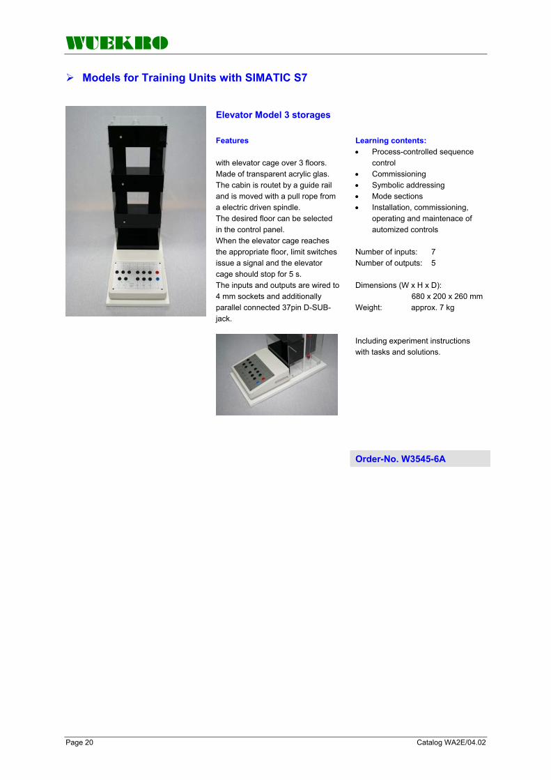
WUEKRO
Page 20 Catalog WA2E/04.02
Models for Training Units with SIMATIC S7
Elevator Model 3 storages Features with elevator cage over 3 floors. Made of transparent acrylic glas. The cabin is routet by a guide rail and is moved with a pull rope from a electric driven spindle. The desired floor can be selected in the control panel. When the elevator cage reaches the appropriate floor, limit switches issue a signal and the elevator cage should stop for 5 s. The inputs and outputs are wired to 4 mm sockets and additionally parallel connected 37pin D-SUB-jack.
Learning contents: • Process-controlled sequence control • Commissioning • Symbolic addressing • Mode sections • Installation, commissioning, operating and maintenace of automized controls Number of inputs: 7 Number of outputs: 5 Dimensions (W x H x D): 680 x 200 x 260 mm Weight: approx. 7 kg Including experiment instructions with tasks and solutions.
Order-No. W3545-6A
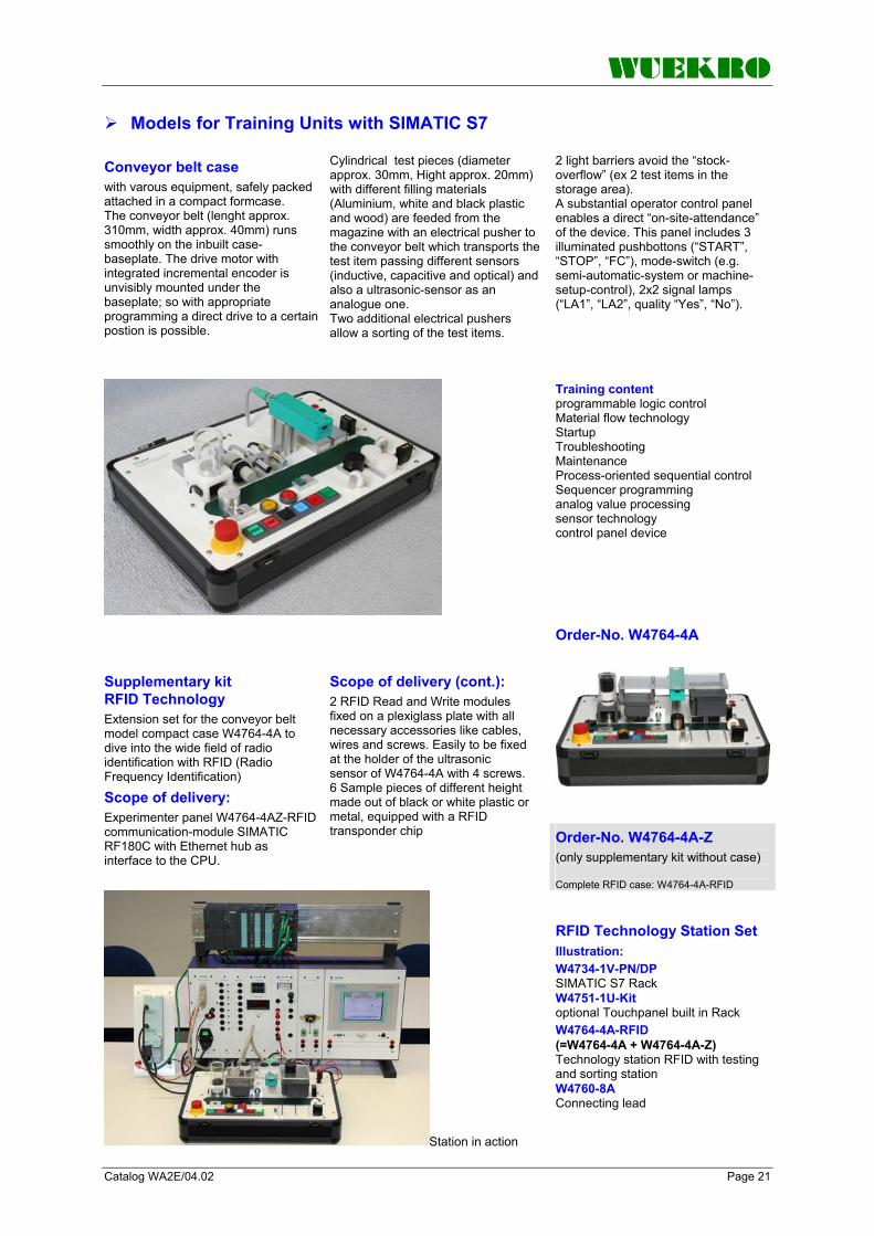
WUEKRO
Catalog WA2E/04.02 Page 21
Models for Training Units with SIMATIC S7 Conveyor belt case with varous equipment, safely packed attached in a compact formcase. The conveyor belt (lenght approx. 310mm, width approx. 40mm) runs smoothly on the inbuilt case-baseplate. The drive motor with integrated incremental encoder is unvisibly mounted under the baseplate; so with appropriate programming a direct drive to a certain postion is possible.
Cylindrical test pieces (diameter approx. 30mm, Hight approx. 20mm) with different filling materials (Aluminium, white and black plastic and wood) are feeded from the magazine with an electrical pusher to the conveyor belt which transports the test item passing different sensors (inductive, capacitive and optical) and also a ultrasonic-sensor as an analogue one. Two additional electrical pushers allow a sorting of the test items.
2 light barriers avoid the “stock-overflow” (ex 2 test items in the storage area). A substantial operator control panel enables a direct “on-site-attendance” of the device. This panel includes 3 illuminated pushbottons (“START”, “STOP”, “FC”), mode-switch (e.g. semi-automatic-system or machine-setup-control), 2x2 signal lamps (“LA1”, “LA2”, quality “Yes”, “No”).
Training content programmable logic control Material flow technology Startup Troubleshooting Maintenance Process-oriented sequential control Sequencer programming analog value processing sensor technology control panel device Order-No. W4764-4A
Supplementary kit RFID Technology Extension set for the conveyor belt model compact case W4764-4A to dive into the wide field of radio identification with RFID (Radio Frequency Identification)
Scope of delivery: Experimenter panel W4764-4AZ-RFID communication-module SIMATIC RF180C with Ethernet hub as interface to the CPU.
Scope of delivery (cont.): 2 RFID Read and Write modules fixed on a plexiglass plate with all necessary accessories like cables, wires and screws. Easily to be fixed at the holder of the ultrasonic sensor of W4764-4A with 4 screws. 6 Sample pieces of different height made out of black or white plastic or metal, equipped with a RFID transponder chip
Order-No. W4764-4A-Z (only supplementary kit without case) Complete RFID case: W4764-4A-RFID
Station in action
RFID Technology Station Set Illustration: W4734-1V-PN/DP SIMATIC S7 Rack W4751-1U-Kit optional Touchpanel built in Rack W4764-4A-RFID (=W4764-4A + W4764-4A-Z) Technology station RFID with testing and sorting station W4760-8A Connecting lead
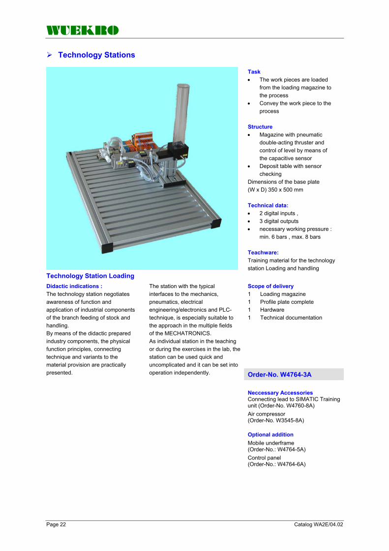
WUEKRO
Page 22 Catalog WA2E/04.02
Technology Stations
Technology Station Loading
Task • The work pieces are loaded
from the loading magazine to the process
• Convey the work piece to the process
Structure • Magazine with pneumatic
double-acting thruster and control of level by means of the capacitive sensor
• Deposit table with sensor checking
Dimensions of the base plate (W x D) 350 x 500 mm Technical data: • 2 digital inputs , • 3 digital outputs • necessary working pressure :
min. 6 bars , max. 8 bars Teachware: Training material for the technology station Loading and handling
Scope of delivery 1 Loading magazine 1 Profile plate complete 1 Hardware 1 Technical documentation
Didactic indications : The technology station negotiates awareness of function and application of industrial components of the branch feeding of stock and handling. By means of the didactic prepared industry components, the physical function principles, connecting technique and variants to the material provision are practically presented.
The station with the typical interfaces to the mechanics, pneumatics, electrical engineering/electronics and PLC-technique, is especially suitable to the approach in the multiple fields of the MECHATRONICS. As individual station in the teaching or during the exercises in the lab, the station can be used quick and uncomplicated and it can be set into operation independently. Order-No. W4764-3A
Neccessary Accessories Connecting lead to SIMATIC Training unit (Order-No. W4760-8A) Air compressor (Order-No. W3545-8A) Optional addition Mobile underframe (Order-No.: W4764-5A) Control panel (Order-No.: W4764-6A)

WUEKRO
Catalog WA2E/04.02 Page 23
Technology Stations
Technology Station Conveyer Belt
Scope of delivery 2 sensors 1 reactive proximity switch, switching distance 15 mm 1 optical proximity switch, 18 mm diameter switching distance 60–400 mm 2 fixing brackets for sensors 1 brief description 1 technical documentation 1 STEP-7 program Mounted on mounting panel (W x D) 650 x 500 mm
Order-No. W4764-3B
Construction Programmable logic controls and material flow technology. Made of aluminum profiles and equipped with a built-on 24V industrial D.C. motor, incremental encoder, spherically seated concave ball-bearing, conveyor drums, a slip-resistant rubberized proofed textile belt, the speed of the belt can be controlled by means of a potentiometer or additional 0 to 10 V DC analog input, 2 switches for changing the direction left/right in setting-up mode. 37-pin D-SUB connector to connect conveyor belt to SIMATIC Training Equipment.
Learning contents • material flow technology • commissioning • fault location • maintenance • process controlled sequence control • sequencer programming • analog value processing
Neccessary Accessories Connecting lead to SIMATIC Training unit (Order-No. W4760-8A) Air compressor (Order-No. W3545-8A) Optional addition Mobile underframe (Order-No.: W4764-5A) Control panel (Order-No.: W4764-6A) Pusher, pneumatic (Order-No. W3545-6H) Pusher, electric (Order-No. W3545-6E)

WUEKRO
Page 24 Catalog WA2E/04.02
Technology Stations
Technology Station Measuring and Handling
Task: • Thickness measuring with digital sensor • Convey the work piece to the next process Structure: • Underframe with pneumatic lifting platform • Analog thickness measuring • Pneumatic pick and place with a pair of gripper jaws Technical data 8 digital inputs, 6 digital outputs 1 analog output 0-10V Necessary working pressure : min. 6 bars , max. 8 bars Teachware Training material for the technology station measuring and handling Scope of delivery 1 Analog thickness measuring 1 Pneumatic lifting platform 1 Pneumatic arm 1 Profile plate complete 1 Hardware 1 Technical documentation
Order-No. W4764-1C
The technology station measuring and handling negotiates awareness of function and application of industrial components of the branch handling and material selection. Learning contents The station with its coupling interfaces to other stations is suitable for learning the terms e.g. recognition of signals, signal processing and evaluation in training.
For example of optimization of conveying distance and a collision free movement, it will be shown, that the contradictory requirements in a mechanical system can also be controlled. The technology station can be combined and be used quick and uncomplicated and it can be set into operation independently
Neccessary Accessories Connecting lead to SIMATIC Training unit (Order-No. W4760-8A) Air compressor (Order-No. W3545-8A) Optional addition Mobile underframe (Order-No.: W4764-5A) Control panel (Order-No.: W4764-6A)

WUEKRO
Catalog WA2E/04.02 Page 25
Technology Stations
Technology Station High-Bay Warehouse
Z-axis The Z-axis is pneumatically controlled by a torsion-free cylinder and has only got 2 states. "Gone-in" is the transport position of the work pieces and "gone-out", the work pieces are put down or picked up. The position of the Z-axis is collected with a reed switch at the cylinder. An angular gripper at the cylinder piston picks up the work pieces for the transport. The position "gripper closed" is collected with an inductive sensor. Technical Data Signal transmitters: 3 cylinder switches 1 fork light barriers 1 path-measuring sensor 4 micro switches Actuators: 2 5/2-directional control valves, monostable 4 relays as reversing contactor circuit. Compressed air not oiled from 4 up to 6 bar Power supply 24V DC Installation 37-pin. D-Sub-plug Valve island Maintenance unit with manual valve Work pieces: 1 Cylinder Ø30 x 20 mm Dimensions: 350+150 x 500 x 450 Scope of delivery: Technical documentation + PLC S7 programm "getting started"
Order-No. W4764-3R
High-Bay Warehouse, only electrically driven Order-No. W4764-3R-Z-EL
General With the high shelf storing, you can store 20 work pieces of a diameter Ø 30 mm and of 20 mm height with a 3-axis handling system in 4 floors with 5 storing places each. The work pieces are picked up (placed) from a position being in a distance of 85 mm next to the assembly plate by a pneumatic gripper. The 3-axis handling system consists of 2 electrically driven axis and one pneumatically driven axis. Construction • AL-T-slot plate 350x500x30 mm with one T-slot 8 mm, in a 25 mm grid • 25-channel data interface • 2 relay functional modules as reversing contactor circuit • Maintenance unit with manual valve • Valve island with 2 5/2 directional control valves, monostable • High shelf store made out off aluminum elements with 20 storing places and 3-axis handling system
Function X-axis: The X-axis is driven with a d. c. motor 24V DC via a relay functional module. The final positions are protected with a micro switch as final position switch. At the same time, this switch is available as DU at the control and can be used as reference point. The positioning is done with a fork light barrier in defined positions for the deposit positions and the take-over (transfer). The correction of the transfer position is done by positioning of the whole high-shelf storing in X-direction. For the collection of the position the usual DU of a PLC (SPS) are sufficient. Y-axis: The Y-axis has got the same drive as the X-axis. The positioning is done with a linear sensor with direct path measuring. The sensor reacts to a magnetic signal transmitter (metal strip at the axis). The impulse distance is approx. 0,4 mm. With the evaluation of the channels A and B you can reach a positioning accuracy of 0,2 mm. For the collection of the impulses a counter input of the control is necessary.
Neccessary Accessories Connecting lead to SIMATIC Training unit (Order-No. W4760-8A) Air compressor (Order-No. W3545-8A) Optional addition Mobile underframe (Order-No.: W4764-5A) Control panel (Order-No.: W4764-6A) Work pieces (Order-No.: W4764-5B)

WUEKRO
Page 26 Catalog WA2E/04.02
Accessories - Leads/Plugs
Connecting lead
32 A/250 V, black, 100 cm long, with 4 mm safety plug Order-No. W3907-3E
Connecting lead
32 A/250 V, red, 100 cm long, with 4 mm safety plug Order-No. W3907-3F
Adapter
4 mm plug/2 mm socket for connection of 2 mm connecting leads Order-No. W3942-2A
Connecting lead
37-pin D-SUB plug on both sides, 1.5 m long, for connection of technology simulators to SIMATIC S7 training units
Order-No. W4760-8A
(W X H X D): 15,8 X 54 X 34 mm Terminat. resistor with isolat. function without PG socket
Connector for PROFIBUS SIMATIC DP, Bus Connector for PROFIBUS up to 12 MBIT/S 90 degree angle outgoing cable
Order-No. W3947-1A
(W X H X D): 15,8 X 54 X 34 mm Terminat. resistor with isolat. function with PG socket
Connector for PROFIBUS SIMATIC DP, Bus Connector for PROFIBUS up to 12 MBIT/S 90 degree angle outgoing cable
Order-No. W3947-1B
shielded special design for rapid installation, 20 m
PROFIBUS – Cable SIMATIC NET, PB FC Standard Bus Cable, 2-Wire,
Order-No. W3947-2A
shielded special design for rapid installation, 50 m
PROFIBUS – Cable SIMATIC NET, PB FC Standard Bus Cable, 2-Wire,
Order-No. W3947-2B
shielded special design for rapid installation, 100 m
PROFIBUS – Cable SIMATIC NET, PB FC Standard Bus Cable, 2-Wire,
Order-No. W3947-2C
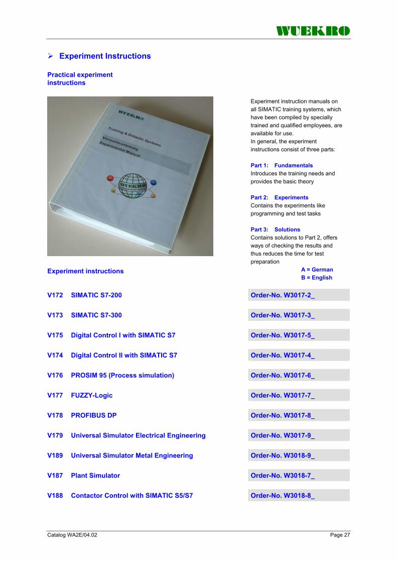
WUEKRO
Catalog WA2E/04.02 Page 27
Experiment Instructions
Practical experiment instructions
Experiment instruction manuals on all SIMATIC training systems, which have been compiled by specially trained and qualified employees, are available for use. In general, the experiment instructions consist of three parts: Part 1: Fundamentals Introduces the training needs and provides the basic theory Part 2: Experiments Contains the experiments like programming and test tasks Part 3: Solutions Contains solutions to Part 2, offers ways of checking the results and thus reduces the time for test preparation
Experiment instructions A = German B = English
V172 SIMATIC S7-200 Order-No. W3017-2_
V173 SIMATIC S7-300 Order-No. W3017-3_
V175 Digital Control I with SIMATIC S7 Order-No. W3017-5_
V174 Digital Control II with SIMATIC S7 Order-No. W3017-4_
V176 PROSIM 95 (Process simulation) Order-No. W3017-6_
V177 FUZZY-Logic Order-No. W3017-7_
V178 PROFIBUS DP Order-No. W3017-8_
V179 Universal Simulator Electrical Engineering Order-No. W3017-9_
V189 Universal Simulator Metal Engineering Order-No. W3018-9_
V187 Plant Simulator Order-No. W3018-7_
V188 Contactor Control with SIMATIC S5/S7 Order-No. W3018-8_

WUEKRO
Page 28 Catalog WA2E/04.02
FAX – response to: +49 (0)9721 - 64691 - 20 Sender: Receiver:
Company WUEKRO GmbH Dept. Sales Department Name Street Carl-Zeiss-Strasse 10 City 97424 Schweinfurt/ Germany Phone + 49-(0)9721-64691-0 Fax + 49-(0)9721-64691-20 E-Mail [email protected] Internet www.wuekro.de No. of pages incl. this page
Please send the following catalogues to the a.m. address! Fundamentals of electrical Engineering
Installation circuits Bell ringing and entrance call stations Contactor control / Control technology Measurement and control of non-electrical variables
Fundamentels of electronics Analog technology Digital technology Microprocessing technology
Closed loop control technology Analog closed loop control Digital closed loop control
Automation engineering SIMATIC S7-200/300/400, Software Technology simulators / Models Process control engineering PCS7 AS-Interface Profibus DP Process simulation-software SIMIT LOGO! Mechatronical technology stations Courses on Automation
Electrical machines / Drive controls Electrical Machines 300W Electrical Machines 1000W Electrical Machines 5kW Electrical drive control systems 300W/ 1kW Electrical drive control systems 5kW Networked drive systems Cutaway Models Transformers, Rectifiers and Reactive Power Compensation Courses on drive systems
Power electronics extra low voltage (24V) low voltage (230/400V)
Building management systems KNX / EIB
VDE 0100 safety measures
Radio- and Television engineering AM/FM – Technology TV Engineering
Satellite – Technology
Cooling and air conditioning
Photovoltaic cell tecnology
Communication technology Modulation -/demodulation Fiber optic ISDN trainer (HICOM) ISDN
Measuring systems
Power supply units
Experiment instructions, manuals
Training courses
Remarks:
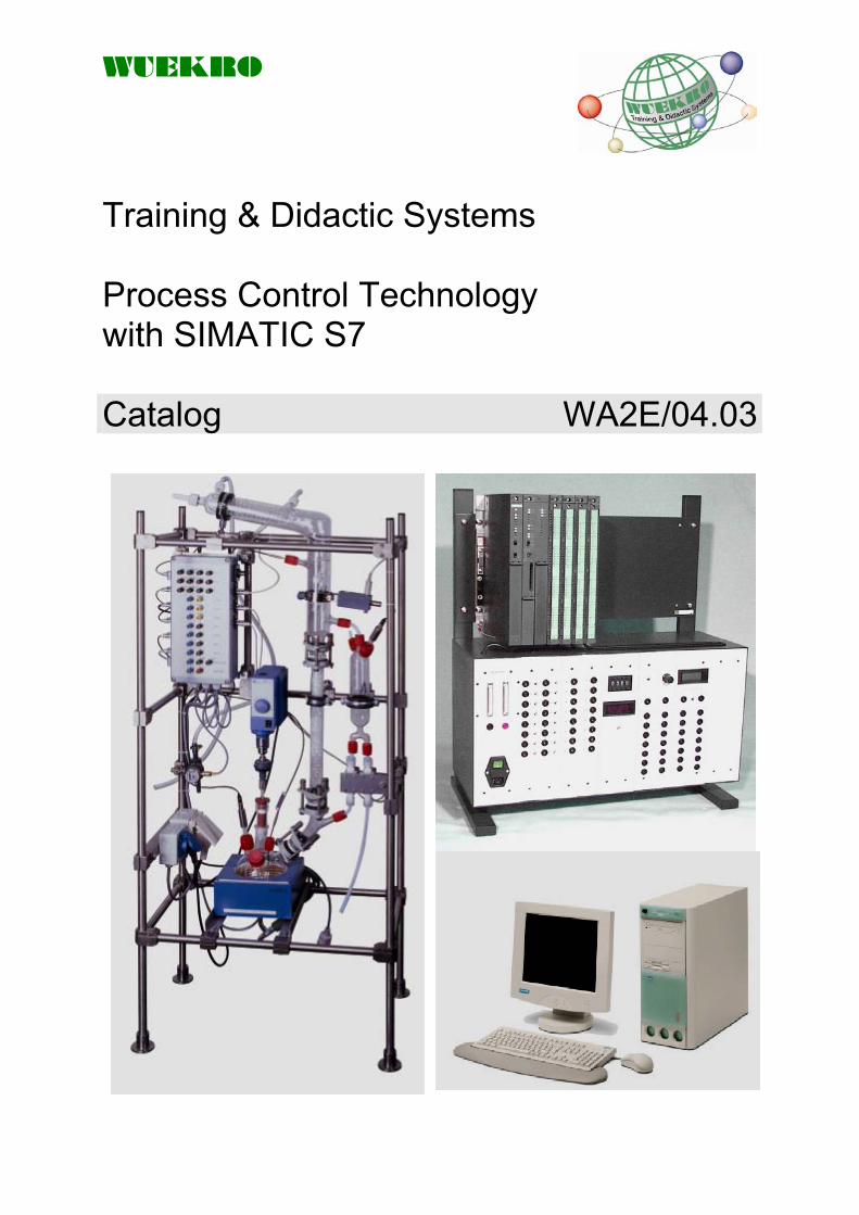
WUEKRO
Training & Didactic Systems Process Control Technology with SIMATIC S7 Catalog WA2E/04.03

WUEKRO
Page 2 Catalog WA2E/04.03
Our Services
• Development and production of didactic training systems • Teachware and documentation • Project engineering of complete lab's incl. furniture and lab equipment • Quotations on customer's demand • Installation, commissioning and training at site
Our Customers • Vocational training schools, technical schools, colleges and universities... • Industrial laboratories for vocational education and higher education
Fields of Technology • Fundamentals of electrical engineering
• Fundamentals of electronics
• Closed loop control technology
• Automation engineering
• Electrical machines / drive control
• Power electronics
• Building management systems
• Protection schemes to VDE 0100
• Radio- and TV technology
• Air conditioning and refrigeration
• Photovoltaic
• Communication technology
• Measuring systems, power supplies, accessories
• Experimental manuals, documentation For further information please contact: WUEKRO GmbH Carl-Zeiss-Strasse 10 D - 97424 Schweinfurt Germany Tel. + 49 (0) 9721-64691-0 Fax: + 49 (0) 9721-64691-20 E-Mail: [email protected] Internet: www.wuekro.de WUEKRO GmbH
All Rights reserved. Reprint not permitted. Technical changes without prior notice.. S30020708P – 01/13

WUEKRO
Catalog WA2E/04.03 Page 3
Table of Contents Page Our Services, Customers and Scope of Supply 2 Model for Process Control Engineering 4 Plant Description 4 1.1. Processes, Process Parameters, Media 6
1.2 Equipment Configuration 6 1.3. Technical Data 6 1.4. Specifications of the Materials Used 6
1.5. Field Measuring and Control Technology 7
1.6. Features of Connector Module 7 Programmable Logic Control SIMATIC S7-400 8 Software 9 Accessories 9 Personal Computer 10 Fax - Reply 12

WUEKRO
Page 4 Catalog WA2E/04.03
Model for Process Control Engineering - General
The model for process control engineering, a laboratory distillation plant, promotes the understanding of the functioning of sequential control systems by developing and programming simple sequential control systems. So, when creating a sequential control for example – regardless whether in the laboratory (automation of experimental or test processes) or in production (automation of production processes) – reaction processes are split up into very small successive steps. This way the student learns to think in those single steps the control unit is using.
Order-No. W5211-1A
1. Plant Description This model in lab size is meant to represent the batch distillation principle, which is one of the most frequently used dissociation methods of distillation in process engineering. The control and switching processes using temperature, clock cycle and level monitoring, which are important in large and small plants, are combined with a programmable logic control on an operation and automation level and are controlled and activated in logical order.
The subsequent control board level with PC visualization, open-loop and closed-loop control including documentation is supposed to explain the application of instrument boards as practiced in industry. The laboratory distillation plant is made from a chemically resistant special glass (borosilicate glass 3.3) in order to offer a full view and to make it possible to observe the experimental process in detail.
The 2-l distillation flask with external heating represents the often used distillation vessel out of steel, steel/enamel or special alloys. Sensors for temperature and level monitoring are brought in via the various nozzles.

WUEKRO
Catalog WA2E/04.03 Page 5
Model for Process Control Engineering – Plant Description
Continued from 1. Plant Description Possibilities of application A stirrer with drive motor in a stirring duct that is tight enough for normal operation is provided for mixing and for preventing delays in boiling. The still-head can easily be emptied via the drain cock. The subsequently attached distillation column can be used to show the principle of multiple distillation by forming several steam-liquid equilibriums which each correspond to a theoretical dissociation stage. By taking samples from the reaction flask and taking out a distillate sample the efficiency of the distillative dissociation can be determined analytically. As in industry, the electronically controlled column head is used for regulating the liquid load of the column for optimizing the distillative dissociation. The secondary, graduated distillate receiver permits a volume/time measurement for determining the distillate quantity per time unit. By on-off valves the distillate can be returned for another distillation or used for taking samples.
The very frequently used control of the sump heating by a Pt 100 resistance thermometer in the distillation mixture is demonstrated. Level monitoring is necessary in all plants for safety reasons. The reflux ratio in the column is controlled by a magnetically actuated liquid funnel, which sets the completely condensed liquid to reflux or removal according to the clock cycle. The head temperature is important in order to remove different fractions one after the other as separate fractions using temperature control. For safety reasons, the flow meter in the cooling water shows an alarm indication when the reflux of the cooling water has been interrupted behind the cooler. Atmospheric distillation is applied wherever no decomposition can occur caused by temperature. Vacuum distillation requires a considerably higher effort but has the effect that distillation takes place under gentler conditions.
Possibilities of application Simple distillations of mixtures from 2 or 3 components with a boiling point difference of greater 10 °C. Determination of the efficiency of columns packed by geometry and material using a known standard distillation mixture. Influencing dissociation by means of the reflux ratio using different clock cycles for reflux and removal. Simple reactions with 2 components and subsequent distillative dissociation of a highly volatile reactant. Representation of the distillation results in trend diagrams or tables.

WUEKRO
Page 6 Catalog WA2E/04.03
Model for Process Control Engineering – Technical Data
1.1. Processes, Process Parameters, Media The distillation equipment has been conceived as a demonstration model for the automation of switching and controlling processes with the SIMATIC PCS 7.
The design with the materials DURAN and PTFE ensures a high degree of resistance to all kinds of media.
Materials Borosilicate glass PTFE Operating temp. max. 180 °C Oper. pressure -1/0.1 bar Resistance to temperature change: 100 K
1.2. Equipment Configuration The plant consists of the following components: Accessories • Packed column - K1 • Still-head - B1
- Heating hood - H1/H2 - Column head as liquid
separator with condenser - W1
- Distillate receiver - B2 Stirrer - R1
• Mounting frame • Field measuring and control
technology • Connector module
• Piping elements • Spindle valve • Flanged joints and seals • Filling bodies • Automatic valves • Connecting pieces and
adapters • Ducts for sensors
1.3. Technial data Operating pressure -1/0.1 bar Operating temp. max. 180°C Nominal volumes: still-head (B1) - 1000 ml distillate receiver (B2) - 250 ml Exchanger surface: condenser (W1) - 0.10 m² Heating capacity: heating hood (H1/H2) - 400 W 2 heating zones Max. coolant pressure: condenser (W2) - 2 bar (overpressure)
Column K: Packed column DN 25 x 300 mm Filling bodies - Raschig rings 4 x 4 mm Stirrer: type RW 16 basic Driving power: 75/35 W Power at the stirrer shaft: 53 W Output torque: 30 Ncm Output speed: 40 ... 1200 rpm max. 800 rpm admissible Electric connection: 230 V/50 Hz Stirrer type: blade stirrer
Dimensions (BxHxT) 650x1500x400 mm Weight approx. 65 kg
1.4. Specifications of the Materials Used Glass components: • Borosilicate glass 3.3 (DURAN) • Resistance to temperature change: 120 K • Chemically resistant • Transparent, non-porous surface • Catalytically indifferent
• Stirrer closure glass/PTFE • Stirrer glass/PTFE • Seals PTFE • Spindle valves glass/PTFE • Frame elements high-grade steel tubes

WUEKRO
Catalog WA2E/04.03 Page 7
Model for Process Control Engineering – Technical Data
1.5. Field Measuring and Control Technology
TI 1 Pt 100 in still-head, 4-wire type, class A TI 2 Pt 100 in column head, 4-wire type, class A TI 3 Pt 100 in heating hood, overtemperature protection, 4-wire type, class A LIS 4Optical level switch in distillate receiver, Level monitoring "Maximum", Change of sensitivity by turning the setting screw at the sensor side, (clockwise = raising sensitivity, counter-clockwise = lowering sensitivity)
LIS 5 Optical level switch in still- head, Level monitoring "Minimum", Change of sensitivity by turning the setting screw at the sensor side, (clockwise = raising sensitivity, counter-clockwise = lowering sensitivity) FIS 6 Flow rate watchdog for cooling water Change of sensitivity by adjusting the setting screw at the front side of the sensor (behind the cover screw)
(clockwise = raising sensitivity, counter-clockwise = lowering sensitivity) KS 7 Reflux separating control by electromagnet (dead = reflux) HS 8 Stirrer control MV1 Electromagnetic valve for returning the distillate to the still-head (dead = closed) MV2 Electromagnetic valve for emptying the distillate receiver (dead = closed) H1 Lower heating zone H2 Upper Heating zone
1.6. Features of Connector Module The main function of the module consists in the conditioning of signals and it serves as plug-in board for the communication with the PLC. a) Pt100 3 x Pt100 in four-wire design (high-grade steel sheath) Connection of sensors via Lemosa plugs (4-pin) 4 x laboratory sockets each per Pt100 b) Filling levels 2 x optical level sensors in three-wire design ("+", "-", switching output) Connection of sensors via Lemosa plugs (3-pin) Supply with 24 V DC (from PLC) Switching output and "-" each brought out to lab sockets When filling level reached = output signal activated c) Cooling water monitoring 1 x calorimetric sensor in three-wire design ("+", "-", switching output), Connection of sensor via Lemosa plug (3-pin) Supply with 24 V DC (from PLC)
Switching output and "-" brought out to lab sockets when throughflow sufficient = output signal activated d) Connection reflux separator coil (two-wire) 1 x reflux separator control magnet, connection of the magnet via Lemosa plug (two-pin), 24 V DC switching voltage at the lab sockets for KFS7 (control of coupling relay), dead = reflux position, live = distillate position e) Connection of magnetic valves 2 x electromagnetic valves DN5, Connection of valves via Lemosa plug (two-pin), 24 V DC switching voltage at the lab sockets for MV1 and MV2 (control of coupling relays), dead = closed f) Connection of heating hood The heating hood consists of two heating zones of 200 W each Connection of heating hood via multipole power connector in field
24 V DC switching voltage for each heating zone (control of coupling relay, common ground), lab sockets for "-", "H1", "H2" H1= 24 V DC lower heating zone ON H2 = 24 V DC upper heating zone ON g) Connection of stirrer motor Socket outlet (with ground contact) for connecting a lab stirrer in the field - 24 V DC switching voltage for stirrer motor ON/OFF (control of coupling relay) Lab sockets for "-" and "HS8" - HS10 = 24 V DC stirrer motor ON Further lab sockets: Voltage supply 24 V DC from PLC ⇒ connector module: a LAB SOCKET each in red and blue General connector design: Side part: Lemosa sockets and outlet Front part: safety lab sockets (divided by color)

WUEKRO
Page 8 Catalog WA2E/04.03
Programmable Logic Control
SIMATIC PCS7 AS414-3 Rack S7-414-3, 2x DI/DO, ANALOG-I/O-Module
Equipment PS-module: Inlet connector for non-heating apparatus 230 V AC , short circuit protection, fuse and illuminated on-of switch 24 V / 5A on 4 mm safety-sockets 32 DI on 37-pin D-SUB connector 32 DO on 37-pin D-SUB connector Supply connection cable 2m, Operator´s guide english
Industrial components: 1 SIMATIC CPU S7 414-3 Central Processing Unit, 2,8 MByte RAM 1 Digital-Input SM 421, 32 DI; DC 24V 1 Digital-Output SM 422, 32 DO; DC 24V;0,5A 1 Analog-Input SM 431, 8 AI; 14 Bit; U/I/Resistor/PT 100 1 Analog-Output SM 432, 8 AO, 13 Bit, U/I 1 Power Supply module PS 407, 10A, AC 120/230V, DC 5V/10A 1 SITOP, Power 5, Basic Line, DC 24 V / 5 A 1 Backup batterie 3,6 V/1,9 Ah for PS 405, 4 A/10 A/20 A and PS 407 4 A/10 A/20 A 1 UR2 RACK, centralized and distributed with 9 slots
Simulation modules: DI-module: 32 digital inputs, of which 16 DI are connected on momentary-contact/ maintained-contact switch and to 4 mm MC-safety sockets, signal statuses by LED DO-module: 32 digital outputs, of which 16 DO are connected to 4 mm MC-safety sockets, signal statuses by LED AI - module: 8 analog inputs, are connected to 4mm safety-sockets, 1 potentiometer steplessly adjustable, voltage +/-10V or current 4 -20mA AO - module: 8 analog outputs, are connected to 4mm safety-sockets , 1 digital measuring device, voltage +/-10V or current 0 -20mA, Order-No. W4745-1D-PCS7

WUEKRO
Catalog WA2E/04.03 Page 9
Software
PCS 7 Trainer Package V5 3 licences
consisting of:
PCS 7 (Trainer Paket) 1 x D-J-C: PCS 7 V7.1 SP3 1 x DVD: PDM Device Library 1/2009 1 x DVD: Microsoft Service Packs & Tools 2009.01 1 x Paper: Certificate of License (A5E00276662) 1 x Paper: Produktinformation PCS 7 V7.1 SP3 1 x Stick: License Key Memory Stick
Order-No. W4700-8A
PC adapter USB for connection of PC with S7-300/-400,C7, M7 for PC with free USB slot incl . USB-cable (5m) suitable with WIN2000 or XP Order-No. W4700-4M
Cooling water reservoir with electrical water-pump
Container for cooling water tank for operation of the process control model. The container contains a 20 liter tank with submersible-pump (12 V DC). The mains voltage is supplid by an integrated power supply.
The control of the PLC is realized by a control relay (24 V DC). The length of the connecting tubes to the model for the forward and backward movement is 3m each
The mains supply is connected via inlet connector for non-heating apparatus 230 V AC Dimensions (W x H x D): 340x340x450mm
Order-No. W5211-1P
Set of connecting leads
For connecting the process control model (W5211-1A),
consisting of: 10 leads black; length 300cm, with 4-mm safety laboratory plug connectors 10 leads red; length 300cm, with 4-mm safety laboratory plug connectors Order-No. W3901-0P
Getting Started Project "Lab and Destillation unit"
Recommendation: Commissioning, System introduction and short training through our experts, duration: 1 day
"Getting Started – PCS 7" Application program with one example for introduction and commission of the destillation unit
Consisting of: 1 CD ROM 1 Brief manual
Order-No. W3050-3A

WUEKRO
Page 10 Catalog WA2E/04.03
Personal Computer
Please contact us for actual models. We also can give you the needed hardware- and software specifications for local purchase.

WUEKRO
Catalog WA2E/04.03 Page 11

WUEKRO
Page 12 Catalog WA2E/04.03
FAX – Reply to: +49 (0)9721 / 64691 - 20 Sender: Receiver: Company WUEKRO GmbH Dept. Sales Department Name Street Carl-Zeiss-Strasse 10 City 97424 Schweinfurt / Germany Phone + 49-(0)9721-64691-0 Fax + 49-(0)9721-64691-20 E-Mail [email protected] Internet www.wuekro.de
Please send the following catalogues to the a.m. address!
Fundamentals of electrical Engineering Installation circuits Bell ringing and entrance call stations Contactor control / Control technology Measurement and control of non-electrical variables
Fundamentels of electronics Analog technology Digital technology Microprocessing technology
Closed loop control technology Analog closed loop control Digital closed loop control
Automation engineering SIMATIC S7-200/300/400, Software Technology simulators / Models Process control engineering PCS7 AS-Interface Profibus DP Process simulation-software PROSIM 95 LOGO! Mechatronical technology stations Courses on Automation
Electrical machines / Drive controls Electrical Machines 300W Electrical Machines 1000W Electrical Machines 5kW Electrical drive control systems 300W / 1kW Electrical drive control systems 5kW Networked drive systems Cutaway Models Transformers, Rectifiers and Reactive Power Compensation Courses on drive systems
Power electronics extra low voltage (24V) low voltage (230/400V)
Building management systems KNX / EIB
VDE 0100 safety measures
Radio- and Television engineering AM/FM – Technology TV Engineering Satellite – Technology
Cooling and air conditioning
Photovoltaic cell technology
Communication technology Modulation -/demodulation Fiber optic ISDN Trainer (HICOM) ISDN
Measuring systems
Power supply units
Experiment instructions, manuals
Training Courses
Remarks:
Catalog WA2E/05.01 Page 1
Training & Didactic Systems Electrical Machines 300 W
Catalog WA2E/05.01

Page 2 Catalog WA2E/05.01
Our Services • Development and production of didactic training systems • Teachware and documentation • Project engineering of complete lab's incl. furnitures and lab equipment • Quotations on customers demand • Installation, commissioning and training at site
Our Customers • Vocational training schools, technical schools, colleges and universities... • Industrial laboratories for vocational education and higher education
Fields of Technology • Fundamentals of electrical engineering
• Fundamentals of electronics
• Closed loop control technology
• Automation engineering
• Electrical machines / drive control
• Power electronics
• Building management systems
• Protection schemes to VDE 0100
• Radio- and TV technology
• Air conditioning and refrigeration
• Photovoltaic
• Communication technology
• Measuring systems, power supplies, accessories
• Experimental manuals, documentation For further information please contact: WUEKRO - GmbH Carl-Zeiss-Strasse 10 D – 97424 Schweinfurt Germany Tel. + 49 (0) 9721-64691-0 Fax: + 49 (0) 9721-64691-20 E-Mail: [email protected] Internet: www.wuekro.de WUEKRO - GmbH
All Rights reserved. Reprint not permitted. Technical changes without prior notice.. L20060630B – 01/13

Catalog WA2E/05.01 Page 3
Table of Contents PageOur Services, Customers and Fields of Technology 2 Training System Electrical Machines 300 W 4 Introduction 5 Training concept 6 Load facilities, drivers, measuring equipment, features and design 8 Electrical machines 300 W 9 DC-machines 9 Single-phase and three-phase induction machines 300 W 11 Braking equipment 300 W 13 Software "DRIVECOACH" 14 Control units 15 Accessories electrical machines 17 Base frames, Controller 17 Accessories, switch gear 19 Standard-training system electrical machines 300 W 25 Components of standard training system 300 W 26 Fax - reply 28

Page 4 Catalog WA2E/05.01
Training System Electrical Machines 300 W
Training Systems - Assignment – Target audience Project Theses
Diploma Theses
Practicals College / University
Continuing Education Practical Training College/University
Master craftsman / Technician Further Training at Chamber of commerce
Skilled Worker Training
5
kW R
ange
Fundamentals Vocational education school / Education in Industry
300
W
Ran
ge
10
00 W
Ran
ge
Catalog WA2E/05.01 Page 5
Foreword If you can analyze problems systematically and understand interrelation-ships, you'll have no difficulty in coping with future developments - in any field of technology. As your partner for training systems, we can provide you with the technical equipment you require for this purpose including the necessary know-how in the form of comprehensive instruction manuals, training documentation and extensive configuring and design aids. Systematic analysis in the field of electrical machines means learning about the behavior of electrical machines through exact measuring exercises and evaluation of the characteristics recorded. This includes comprehension of basic electric circuits such as star-delta connections, stator-resistance starting circuits etc. and the ability to connect these with the specific problems of the individual machine types.
Understanding interrelationships means to view the electrical machines in their relation to drive engineering and automatic control engineering: • Which electrical machine is
best suited for a specific application problem?
• Which control method should be used with an individual machine in order to ensure that the drive meets the highest requirements e.g. relative to dynamic response or control accuracy?
We see it as our task to help you answer these and similar questions on a practical basis and to provide suitable experimental equipment for scientific studies. Our training system gives you almost unlimited freedom, i.e. you can pick and choose elements to create your own "personal" training strategy. If you have an entire room at your disposal for use as a machine laboratory and if you attach importance to characteristics of "large" machines, the system of your choice would be our machines in the range up to 5 kW1). This system is especially suited for use at technical colleges and universities. Experimental sockets ensure operational safety even with equipment from this output range2). 1) Larger machines available on request. 2) For technical reasons, no experimental sockets are used with machines > 5 kW.
If the transport capability of the machines is a criterion besides the characteristics, the machines from the 1 kW range are right for you. They offer an ideal compromise between electrical operating behavior and low weight, which is also reflected in their extremely high cost effectiveness. This system can be used from basic training to practicals at technical colleges or universities and beyond. If due to the training situation you have to pay special attention to aspects such as mobility, training outside of technical rooms and space requirements, you will decide in favor of our 300 W machine range. Regardless which of the three systems you eventually choose, you will have devices at your disposal that are tailor-made for your individual requirements.
Page 6 Catalog WA2E/05.01
The Training Concept The Aim The aim of our training concept for the field of electrical machines is to provide • vocational schools • technical colleges • universities and • in-firm training centers with systems for teaching the theoretical and practical knowledge which trainees and students require to learn and understand modern know-how about electrical machines and their control methods. The machines we use are purely industrial equipment whose charac-teristics have been idealized only in exceptional cases, e.g. induction machine with slipring rotor. This applies for the 300 W range, the 1000 W range as well as the 5 kW range. You can choose between different DC machines, AC machines, three-phase machines as well as special machines such as the DC and three-phase compound machine.
Brakes and Measuring Sytems The available brake assemblies include magnetic powder brakes, eddy-current brakes and dynamometers. The setpoint for the brakes can be input either via front panel or PC, and characteristics can be traced either via recorder or also via PC, where a soft-ware specifically designed for the machine range facilitates the process. While modules M1 to M5 focus on the electrical machine and its elementary control possibilities, modules M6 to M8 deal with technically expanded control methods up to the three-phase AC power controller SIKOSTART in combination with the squirrel-cage induction machine. Module M9 is devoted to the subject area of reactive-power compensation. The following matrix provides an overview of possible combinations of machine type and control method:
Practical instruction manuals Instruction manuals designed by didactically trained specialists are available for our 300 W and 1000 W training systems. These instruction manuals generally consist of 3 sections: Section 1: General section for intro-ducing the trainees to the objectives of the training program and providing basic theoretical knowledge. Section 2: Trainee's section containing measuring exercises. Value tables, diagrams and oscillograms must be filled out by the student or created on the PC. Section 3: Instructor's section contain-ing the answers to questions in section 2. The purpose of this section is to reduce valuable preparation time and provide a check for instructors. Whether you choose machines from the 300 W or the 1000 W range, we can provide you with reliable instruction manuals for the appropriate system.

Catalog WA2E/05.01 Page 7
The Training Concept
The Training Aim The concept The System • DC machines • Single-phase motors
- with running capacitor, - with starting and running
capacitor - resistance start
• Asynchronous and synchronous polyphase machines
• Special machines
The "Electrical Machines" training system allows you to teach the aims listed with 300-W machines, 1-kW machines and also with machines up to 5-kW (higher-power machines on request). Depending on customer requirements, we can supply either single machines or complete systems with machines, loading facilities, drivers and measuring equipment. Specially prepared technical literature forms the basis of theory teaching.
Our "Electrical Machines" training system consists of the following individual components: • 300-W machines • 1000-W machines • Machines up to 5 kW • Loading facilities • Drivers • Measuring equipment
300 W machines 1000 W machines Machines up to 5 kW Our 300-W machines are used primarily for training purposes in industry, trade and technical colleges. They are a handy size and can be easily assembled and dismantled. These "small" machines are "big" on electrical operating characteristics. They are industrial machines whose characteristics have only been modified for teaching purposes in exceptional cases. This is why they are also well suited to basic practical teaching in technical colleges and universities.
This is the ideal "middle ground" between the "small" 300-W machine and the "large" machines in the performance range up to 5 kW. Thanks to its low weight, compact dimensions and excellent electrical characteristics, this machine offers more universality of use than any other machine type.
If a machine laboratory is to be equipped and if practice-orientation is the main priority, this performance range is to be recommended. Demanding practical tests, engineering exams and certificate exams can all be set up easily in conjunction with these industrial drives.

Page 8 Catalog WA2E/05.01
Load facilities, Drivers, Measuring Equipment
Load facilities Drivers Measuring Equipment Brakes are available in the form of magnetic powder brakes and rotating eddy-current retarders (300-W and 1000-W range). They have been adapted exactly to the electrical machines. If the machine is to be subjected to both motive power loading and rheostatic loading, a DC dynamo-meter is recommended as loading facility (300-W, 1000-W and 5-kW ranges). All load facilities are equipped with optical indicating instruments, standardized analog outputs and interfaces for computer links.
The constantly increasing requirements of drive technology mean that modern converter equipment is required in addition to contactor equipment. Digital converters for polyphase machines, analog and microprocessor-controlled converters for DC drives, special equipment for servo and stepper motors finish off the machines as compact and intelligent drive units.
Measuring equipment as the interface between man and machine is of central significance in study and training. There is a correspondingly comprehensive and high-quality range of measured value processing systems and output devices available. Whether you are making measurements with a multimeter or a multifunction meter, recording characteristic curves via value tables or PC, or carrying out torque acquisition via current, foil strain gauge or torque metering shaft, there is measuring equipment available for all your requirements.
Features and Design
General The experimental machines feature the IM B 3 design with one shaft end and correspond to the VDE regulations 0530. The 300 W and 1000 W machines are equipped with: • an experimental terminal
board. The ends of the windings brought out to the terminal board are connected to 4-mm-safety-socket outlets. The socket outlets are arranged on a plastic board in the same way as the connections of a normal terminal board of an industrial machine. The plastic board features the conventional industrial machine terminal designations.
• A PTC thermistor in order to protect the machines against thermal overload. This obviates overheating resulting from overload, high switching frequency, single phasing, large deviations in voltage, excessively high coolant temperatures or obstructed coolant flow. The leads of the thermistors are connected to 2-mm-socket-outlets in order to avoid faulty connections.
• A baseplate to compensate for differences in shaft height and to facilitate replacement of the machines. The baseplate features a guide mechanism on the underside for setting it onto the slide of the baseframe.
• A toothed gear coupling half which is identical for all machines and brake assemblies within each range. The coupling halves are connected to each other over an elastic adapter piece. This type of coupling and baseplate design allows you to combine any two machines to form one motor generator set as well as to couple each machine to the brake assemblies without having to change the coupling or the baseplate.
In order to keep the noise level low, preference has been given to machines with rated speeds of 1500 rev/min.
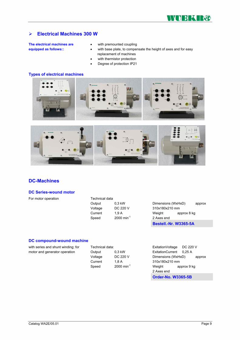
Catalog WA2E/05.01 Page 9
Electrical Machines 300 W The electrical machines are equipped as follows::
• with premounted coupling • with base plate, to compensate the height of axes and for easy
replacement of machines • with thermistor protection • Degree of protection IP21
Types of electrical machines
DC-Machines
DC Series-wound motor Dimensions (WxHxD) approx 310x180x210 mm Weight approx 8 kg 2 Axes end
For motor operation Technical data Output 0,3 kW Voltage DC 220 V Current 1,9 A Speed 2000 min-1
Bestell.-Nr. W3365-5A
DC compound-wound machine ExitationVoltage DC 220 V ExitationCurrent 0,25 A Dimensions (WxHxD) approx 310x180x210 mm Weight approx 9 kg 2 Axes end
with series and shunt winding; for motor and generator operation
Technical data: Output 0,3 kW Voltage DC 220 V Current 1,8 A Speed 2000 min-1 Order-No. W3365-5B

Page 10 Catalog WA2E/05.01
DC-Machines
DC shunt-wound machine Exitation voltage DC 220 V Exitation current 0,3 A Dimensions (WxHxD) approx 310x180x210 mm Weight approx 8 kg 2 Axes end
for motor and generator operation
Technical data:: Output 0,3 kW Voltage DC 220 V Current 1,8 A Speed 2000 min-1
Order-No. W3365-5C
DC shunt-wound machine, same as W3365-5C
with built-on tachogenerator (Voltage 30 V / 1000 min-1 ) Order-No. W3365-5G
Special DC compound machine with series, shunt and compound features ExitationVoltage DC 220 V ExitationCurrent 0,25 A Dimensions (WxHxD) approx 310x180x210 mm Weight approx 11 kg 2 Axes end
for motor and generator operation
Technical data:: Output 0,3 kW Voltage DC 220 V Current 1,8 A Speed 2000 min-1
Order-No. W3365-5V
DC shunt-wound machine, cradle-mounted ExitationVoltage 200 V ExitationCurrent 0,3 A Resolution pulse generator 120 pulses./rev. Weight approx. 18 kg
for motor- und generator operation, incl. baseframe; torque recorded via strain gauge, speed recorded optoelectronically
Technical data:: Generatoroperation Output 0,4 kW Voltage 150 V Current 2,5 A Speed 1500 min-1 Motoroperation Output 0,4 kW Voltage 150 V Current 3,4 A Speed 1440 min-1
Order-No. W3365-1H

Catalog WA2E/05.01 Page 11
AC Machines, single and 3-phase 300 W
Single-phase squirrel-cage AC motor with starting and running capacitor Capacity CB 14 µF Weight approx 7 kg 1 Axes end
Adapted industrial standard machine Technical data:: Output 0,37 kW Cos ϕ 0,95
Voltage 1AC 230 V / 50 Hz Current 2,65 A Speed 1395 min-1 Capacity CA 25 µF Order-No. W3365-3B
Single-phase squirrel-cage motor with auxiliary starting winding Weight approx 7 kg 1 Axes end
Technical data:: Output 0,20 kW Cos ϕ 0,7
Voltage 1AC 230 V / 50 Hz Current 2,6 A Speed 1380 min-1 Order-No. W3365-3C
Single-phase repulsion motor Weight approx 8 kg 2 Axes end
with single brush rocker and special brush-shifting gear at the bearing plate Technical data:: Output 0,25 kW Cos ϕ 0,69
Voltage 1AC 230 V / 50 Hz 1AC 115V / 50Hz Current 2,9 A 5,8 A Speed 2100..0..2100 min-1 Order-No. W3365-3D
Single-phase split-pole motor Weight approx 7kg 2 Axes end
Technical data:: Output 0,12 kW Cos ϕ 0,6
Voltage 1AC 230 V / 50 Hz Current 3,2 A Speed 2700 min-1 Order-No. W3365-3E
Universal motor Weight approx 8 kg 2 Axes end
for optional operation at AC or DC Technical data:: Output 0,2 kW
Voltage 230V/50Hz,DC 140V Current 3,0 A, 2,5A Speed 3000 min-1 Order-No. W3365-3F
Three-phase squirrel-cage induction motor Weight approx 7 kg 1 Axes end
Adapted industrial standard machine for star-delta-operation Technical data:: Output 0,25 kW Cos ϕ 0,78
Voltage 3AC 400 V / 50 Hz 3AC 692 V / 50 Hz Current 0,77 A / 0,45 A Speed 1350 min-1 Order-No. W3365-2A
Three-phase squirrel-cage induction motor Weight approx 7 kg 1 Axes end
Adapted industrial standard machine for star-delta-operation Technical data:: Output 0,27 kW Cos ϕ 0,70
Voltage 3AC 230 V / 50 Hz 3AC 400 V / 50 Hz Current 1,32 A / 0,76 A Speed 1380 min-1 Order-No. W3365-2M

Page 12 Catalog WA2E/05.01
AC Machines, 3-phase 300 W
Three-phase two-speed pole-changing induction motor Weight approx 8 kg 1 Axes end
with squirrel-cage rotor (Dahlander circuit) Technical data:: Output 0,3 kW / 0,43 kW
Cos ϕ 0,73 / 0,8 Voltage 3AC 400 V / 50 Hz Current 1,0 A / 1,1 A Speed 1400 min-1 ,,2800 min-1
Order-No. W3365-2B
Three-phase two-speed pole-changing induction motor Weight approx 8 kg 1 Axes end
with squirrel-cage rotor and two separate windings Technical data:: Output 0,11 kW / 0,2 kW
Cos ϕ 0,71 / 0,72 Voltage 3AC 400 V / 50 Hz Current 0,6 A / 0,7 A Speed 880 min-1,1390 min-1
Order-No. W3365-2G
Three-phase induction motor with slipring rotor Locked rotor voltage 95 V Rotor current 2,3 A Weight approx 9 kg 2 Axes end
Slipring area covered with plexi-glass Technical data:: Output 0,27 kW
Cos ϕ 0,72 Voltage 3AC 230 V / 50 Hz 3AC 400 V / 50 Hz Current 2,0 A / 1,16 A Speed 1340 min-1 Order-No. W3365-2C
Special three-phase compound machine Rotor voltage AC 107 V DC 20 V Rotor current AC 1,7 A / DC 4,0A Weight approx 8 kg 2 Axes end
with slippring rotor, area covered with plexi-glass, synchronizable speed-torque-function with pronounced pull-up torque Technical data:: Output 0,27 kW
Cos ϕ 1 / 0,70 Voltage 3AC 230 V / 50 Hz 3AC 400 V / 50 Hz Current 1,44 A / 0,83 A Speed 1500 min-1 1340 min-1 Order-No. W3365-2V
Three-phase synchronous machine with salient pole rotor Weight approx 8 kg 2 Axes end
and damper winding; for motor and generator operation Technical data:: Output 0,3 kW Cos ϕ 1 / 0,80
Voltage 3AC 400 V / 50 Hz Current 0,43 A Speed 1500 min-1 Exitation voltage DC 140 V Exitation current 0,55 A
Order-No. W3365-4A
Three-phase synchronous machine with non-salient pole rotor Exitation current 0,95 A Weight approx 8 kg 2 Axes end
and damper winding; for motor and generator operation Technical data:: Output 0,3 kW Cos ϕ 0,97
Voltage 3AC 230 V / 50Hz 3AC 400 V / 50 Hz Current 1,14 A / 0,66 A Speed 1500 min-1 Exitation voltage DC 150 V Order-No. W3365-4B
Reluctancemotor Weight approx 7 kg 2 Axes end
Three-phase synchronous machine without excitation, with squirrel cage rotor and salient poles Technical data:: Output 0,25 kW
Cos ϕ 0,45 Voltage 3AC 400 V / 50 Hz Current 1,5 A Speed 1500 min-1 Order-No. W3365-4C

Catalog WA2E/05.01 Page 13
Braking Equipment 300 W
Compact braking unit 300 W
Designed as magnetic powder brake with open-loop and closed-loop controls and measuring device, with analog display of speed and switch-selectable torque or calculated output. Torque and speed can be recorded in three different operating modes: a) Open-loop control mode (manual control) b) Closed-loop speed control Recording of brake torque as a function of speed. The speed can be preselected on the setpoint potentiometer and is maintained at a constant value by the built-in control loop. c) Automatic mode The brake is applied to the test object automatically until it stops. The speed/torque characteristic can be traced on an x-y recorder. In addition, analog outputs for speed, torque and calculated output are available The terminals for temperature monitoring of the test object are connected to 2 mm sockets. The magnetic powder brake is suitable for multiple tracings of the motor characteristic. With analog inputs for control of the braking unit via PC.
Technical data: Maximum braking torque 5 Nm Speed 1500 min-1, max. 3000 min-1
Anschluß Voltage 1AC 230 V/50 Hz via main plug Dimensions (WxHxD) 310x180x250 mm Weight etwa 7 kg
Order-No. W3365-1E
Eddy current brake 300 W
Installed on a baseframe with cradle-mounted housing. Suitable for loading a motor of the same rating up to starting torque (including measurement of the breakdown and mean starting torque); for operation in both directions of rotation with electronic torque load cell (strain gauge). Speed recorded optoelectronically via forked light barrier. A ventilator ensures that the brake can be operated continuously at the rated data indicated With built-in temperature monitor, with fitted half-coupling and transparent coupling cover; with torsionally rigid baseframe, mounted on vibration dampers; with draw spindles and slide guide for rapid fitting and removal of experimental machines. Control and measurement are carried out by means of the associated control unit: In addition to the eddy-current brake, an experimental machine in the 300 W range can be mounted on the baseframe.
Technical data: Braking power at 1500 min-1 300W Braking power at 3000 min-1 400W Exitation voltage 0 – 180 V DC Exitation current 1,8 A Weight etwa 23 kg
Order-No. W3365-1F
Measuring and control interface for compact braking unit The measuring and control interface provides the connection between PC and the magnetic powder brakes. Analog inputs max. ±10V Analog outputs max. ±10V Digital inputs 5 - 24V DC Supply voltage 1 AC 230V
The measuring and control interface consists of 8 digital inputs and outputs, 4 analog inputs and 2 analog outputs as well as an RS-232 interface. The analog and digital inputs and outputs are brought out to 2mm sockets.
Order-No. W3644-4L

Page 14 Catalog WA2E/05.01
Software Modul "DRIVECOACH" Software module „DRIVECOACH“ for tracing characteristics on electrical machines. DRIVECOACH is a software program for operating the magnetic powder brakes, eddy current brakes and dynamometers. A measuring and control interface connects the unit to a PC and is necessary for picking the operating data with the software program. Operation of the software without connecting the measuring and control interface is not possible. Note: The software module "DRIVECOACH" is included in the scope of delivery of W3375-6F. Performance features: Setting possibilities: The operating modes such as closed-loop speed, torque or current control for the terminal device (dynamometer, eddy-current brake) can be set via the measuring and control interface. The ramps to pass can be preselected relative to lower range value, limit value and rate of rise according to the current operating mode. The serial interface is adjustable. Dimensioning of measured quantities: The measured quantities are dimensioned automatically or by querying the hardware. The following values are possible: Speed 4000 min-1 Torque 0 - 4 Nm Current 0- 2 A Tracing characteristics: After setting or transferring the operating data or the ramps, the tracing of a characteristic can be triggered via the start button in a window. The following measured values can be recorded: With operating mode closed-loop speed control: Torque, ourrent, output With operating mode closed-loop torque control: Speed, ourrent, output With operating mode closed-loop current control: Speed, torque, output The diagrams can be saved in appropriate files and then printed. The software module "DRIVECOACH" runs under WINDOWS. 95/98/NT. Operating mode load diagrammes: with the operation mode diagrammes five different kind of diagrammes can be selected and recorded: • constant Speed-torque-diagram • constant Speed-torque-diagram with mit polarity reversal • Linear Speed-torque-diagram • squared Speed-torque-diagram • Inverse Speed-torque-diagram The characteristic parameters are variable with the mouse or can be entered into a text field. A modification of the constant factors is also possible in the current operation. A red signal point announces the operating point of the drive on the characteristic. Hard- und Software coordination For operation with the powder brake W3365-1E / W3375-1E the external measuring and control unit W3644-4L is necessary as well as the software modul "DRIVECOACH". For operation with the eddy current brake or the dynamometer, the measuring and control unit W3375-6F is necessary. Order-No. W3644-6A

Catalog WA2E/05.01 Page 15
Modular control units 300 W Modular control unit
General The modular control unit provides the control for eddy-current brakes and dynamometers from the 300 W ranges. The basic unit consists of a fixed-wired 19" housing as well as the plug-in module "Display and Measuring Unit". The other plug-in modules can be selected as required for the individual application. The "Measuring and Control Interface" module serves for connecting the control unit system to the PC. Thus, you can start measurement processes from the PC, display the characteristics passed on the screen and print them on a printer.
Control unit for eddy-current brake and dynamometer Technical data: Analog output 1. Speed 400 U/min = 1 V 2. Torque 0,4 Nm = 1 V 3. Output 300 W = 1 V Supply voltage 1 AC 230 V/50 Hz via main plug Weight etwa 6 kg
The basic unit of the modular control unit consists of a completely wired 19" housing and the plug-in module „Display and Measuring Unit“. Speed and either torque or calculated output as selected are digitally displayed via LCD's. The maximum speed is adjustable and can be displayed by pressing a button. Zero adjustment as well as calibration are performed via potentiometers.
Order-No. W3375-6A
Control unit for eddy-current brake and dynamometer, controlling module The rate of rise of the ramp can also be set. LEDs provide signals for „Enabled“, „Disabled“, „Brake fault“, „Motor fault“, „Mains fault“, and „Start ramp“. The measuring process is started with a button. With 2-mm-sockets for „Motor temperature“ and „Penlift“. Weight approx.: 0.6 kg
Plug-in module for modular control unit W3375-6A. You can select between closed-loop speed, torque and current control. Lower range value and limit value of the measurements to be run are preselected via potentiometers. The selected values can be displayed using a button.
Order-No. 3375-6C
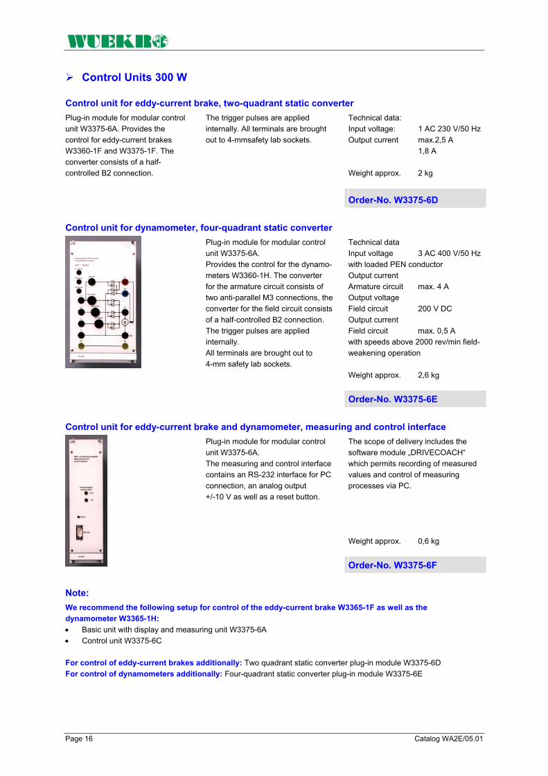
Page 16 Catalog WA2E/05.01
Control Units 300 W
Control unit for eddy-current brake, two-quadrant static converter Technical data: Input voltage: 1 AC 230 V/50 Hz Output current max.2,5 A 1,8 A Weight approx. 2 kg
Plug-in module for modular control unit W3375-6A. Provides the control for eddy-current brakes W3360-1F and W3375-1F. The converter consists of a half-controlled B2 connection.
The trigger pulses are applied internally. All terminals are brought out to 4-mmsafety lab sockets.
Order-No. W3375-6D
Control unit for dynamometer, four-quadrant static converter Technical data Input voltage 3 AC 400 V/50 Hz with loaded PEN conductor Output current Armature circuit max. 4 A Output voltage Field circuit 200 V DC Output current Field circuit max. 0,5 A with speeds above 2000 rev/min field-weakening operation Weight approx. 2,6 kg
Plug-in module for modular control unit W3375-6A. Provides the control for the dynamo-meters W3360-1H. The converter for the armature circuit consists of two anti-parallel M3 connections, the converter for the field circuit consists of a half-controlled B2 connection. The trigger pulses are applied internally. All terminals are brought out to 4-mm safety lab sockets.
Order-No. W3375-6E
Control unit for eddy-current brake and dynamometer, measuring and control interface The scope of delivery includes the software module „DRIVECOACH“ which permits recording of measured values and control of measuring processes via PC. Weight approx. 0,6 kg
Plug-in module for modular control unit W3375-6A. The measuring and control interface contains an RS-232 interface for PC connection, an analog output +/-10 V as well as a reset button.
Order-No. W3375-6F
Note: We recommend the following setup for control of the eddy-current brake W3365-1F as well as the dynamometer W3365-1H: • Basic unit with display and measuring unit W3375-6A • Control unit W3375-6C
For control of eddy-current brakes additionally: Two quadrant static converter plug-in module W3375-6D For control of dynamometers additionally: Four-quadrant static converter plug-in module W3375-6E

Catalog WA2E/05.01 Page 17
Accessories for Electrical Machines 300 W
Baseframe for motor-generator set Dimensions (LxWxH) 750x230x40 mm Weight approx. 8,5 kg
for mounting two experimental machines with baseplates, torsionally rigid design, mounted on vibration dampers, with draw spindles; slide and slide guide for rapid fitting and removal of experimental machines, with transparent coupling cover. Order-No. W3360-8A
Rotor controller Weight etwa 2 kg
For the rotor-locking of machines from the 300 W range, such as for example for use of the three-phase induction motor with slipring rotor as three-phase transformer. Designed as gearbox with handwheel. With half-coupling and coupling cover, with baseplate for setup and centering on the baseframe.
Order-No. W3360-2D
Controller Degree of protection IP 10 Resistance 3 x 8,2 Ω Current 3,5 A Weight approx 6 kg
for starting the three-phase induction motor with slipring rotor and reducing the speed by 50 % at constant torque, designed as rotary rheostat with limit switch for 300 W, installed in housing with circuit diagram on front. All terminals are brought out to 4-mm safety lab sockets.
Order-No. W3360-8B
Single-coil slide resistor Degree of protection IP 10 Resistance 1400 Ω Current 0,12 ... 1,2 A Weight approx. 3 kg
for adjustable single-phase loading. With cover, rubber feet and earthing screw. Terminals brought out to 4-mm safety lab sockets.
Order-No. W3360-8E
Single-coil slide resistor Degree of protection IP 10 Resistance 2300 Ω Current 0,1 ... 0,9 A Weight approx 3 kg
for adjustable single-phase loading. With cover, rubber feet and earthing screw. Terminals brought out to 4-mm safety lab sockets. Order-No. W3360-8F
Single-coil slide resistor Degree of protection IP 10 Resistance 430 Ω Current 0,5 A Weight approx 3 kg
for adjustable single-phase loading. With cover, rubber feet and earthing screw. Terminals brought out to 4-mm safety lab sockets. Order-No. W3360-8G

Page 18 Catalog WA2E/05.01
Accessories for Electrical Machines 300 W
Single-coil fixed resistor Degree of protection IP 10 Resistance 98 Ω Current 1,6 A Weight approx 3 kg
for single-phase loading. With cover, rubber feet and earthing screw. Terminals brought out to 4-mm safety lab sockets. Order-No. W3360-8K
Single-coil slide resistor Degree of protection IP 10 Resistance 320 Ω Current 1,1 A Weight approx 3 kg
for adjusting the excitation of the three-phase synchronous machine or the DC shunt-wound machine and DC compound-wound machine;
With cover, rubber feet and earthing screw. Terminals brought out to 4-mm safety lab sockets.
Order-No. W3360-8D
Controller Degree of protection IP 10 Resistance 68 Ω Current 2,35 A Weight approx 5 kg
For starting DC motors and reducing the speed by 50% at constant torque,
Designed as rotary rheostat with limit switch (300 W), installed in housing with circuit diagram on front.
Order-No. W3360-8C
Excitation unit Technical data Degree of protection IP 10 Supply voltage 1 AC 230 V/ 50/60 Hz via feeder cable, 2m in length, with earthing-pin plug Output- voltage/current 0 – 230 V DC / 2 A Weight approx. 5 kg
with adjustable direct voltage output; for excitation of experi-mental machines from the 200 W and 1000 W ranges.
The direct voltage output is supplied over a variable transformer and a load-side rectifier. Protective resistors for the field windings are fitted in parallel to the output terminals.
Order-No. W3360-1N

Catalog WA2E/05.01 Page 19
Accessories for Electrical Machines 300 W All accessories are equipped with 4-mm-safety-lab-sockets
Dimensions (HxW) 297x130 mm Weight approx. 1,4 kg
1 NEOZED fuse element with cartridge fuses for 4 A, 6 A, 10 A Voltage 3 AC 400 V 250 V DC Current 16 A Order-No. W3221-4B
Dimensions (HxW) 297x260 mm Weight approx. 1,0 kg
3 Incandescent lamp holders E27
Order-No. W3228-4B
Dimensions (HxW) 297x130 mm Weight approx. 1,4 kg
Order-No. W3311-4B
3 NEOZED fuse elements NEOZED, with cartridge fuses for 4 A, 6 A, 10 A Voltage 3 AC 400 V / 250 V DC Current 16 A
Motor-protection circuit-breaker 3 pin, Current max. 16 A Voltage 3 AC 500V
Dimensions (HxW) 297x130 mm Weight approx. 0,5 kg
Setting range 0,45 - 0,63 A Order-No. W3312-4H
Setting range 0,7 – 1 A Order-No. W3312-4A
W3312-4A Setting range 2,2 – 3,2 A Order-No. W3312-4C
On/Off-switch 3-pin Voltage 3 AC 500 V Current 16 A
Dimensions (HxW) 297x130 mm Weight approx. 0,9 kg
Order-No. W3313-4A
Dimensions (HxW) 297x130 mm Weight approx. 0,9 kg
Reversing switch 3-pin, Voltage 3 AC 500 V Current 16 A
Order-No. W3314-4A
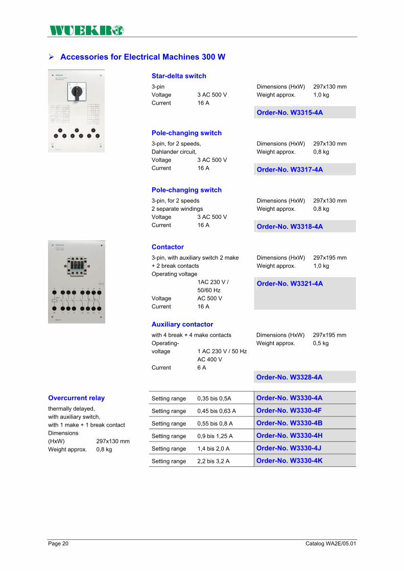
Page 20 Catalog WA2E/05.01
Accessories for Electrical Machines 300 W
Dimensions (HxW) 297x130 mm Weight approx. 1,0 kg
Star-delta switch 3-pin Voltage 3 AC 500 V Current 16 A
Order-No. W3315-4A
Dimensions (HxW) 297x130 mm Weight approx. 0,8 kg
Pole-changing switch 3-pin, for 2 speeds, Dahlander circuit, Voltage 3 AC 500 V Current 16 A Order-No. W3317-4A
Dimensions (HxW) 297x130 mm Weight approx. 0,8 kg
Pole-changing switch 3-pin, for 2 speeds 2 separate windings Voltage 3 AC 500 V Current 16 A Order-No. W3318-4A
Dimensions (HxW) 297x195 mm Weight approx. 1,0 kg
Contactor 3-pin, with auxiliary switch 2 make + 2 break contacts Operating voltage 1AC 230 V / 50/60 Hz Voltage AC 500 V Current 16 A
Order-No. W3321-4A
Dimensions (HxW) 297x195 mm Weight approx. 0,5 kg
Auxiliary contactor with 4 break + 4 make contacts Operating- voltage 1 AC 230 V / 50 Hz AC 400 V Current 6 A
Order-No. W3328-4A
Setting range 0,35 bis 0,5A Order-No. W3330-4A
Setting range 0,45 bis 0,63 A Order-No. W3330-4F
Setting range 0,55 bis 0,8 A Order-No. W3330-4B
Setting range 0,9 bis 1,25 A Order-No. W3330-4H
Setting range 1,4 bis 2,0 A Order-No. W3330-4J
Overcurrent relay thermally delayed, with auxiliary switch, with 1 make + 1 break contact Dimensions (HxW) 297x130 mm Weight approx. 0,8 kg
Setting range 2,2 bis 3,2 A Order-No. W3330-4K

Catalog WA2E/05.01 Page 21
Accessories for Electrical Machines 300 W
Dimensions (HxW) 297x130 mm Weight etwa 0,9 kg
Time relay, delayed pickup 1 changeover contact
Operating- voltage 1 AC 230 V / 50/60 Hz Voltage 1AC 230 V Current 3 A Setting range 1,5 to 30 s Order-No. W3331-4A
Dimensions (HxW) 297x130 mm Weight etwa 0,9 kg
Time relay delayed drop-out
Operating- Voltage 1 AC 230 V/ 50/60 Hz Voltage AC 230 V Current 3 A Setting range 0,05 bis 100 s Order-No. W3331-4C
Starting capacitor including discharge resistor
Voltage 1 AC 450 V/50 Hz Capacity 94 µF
Order-No. W3333-4A
Starting capacitor including discharge resistor
Voltage 1 AC 450 V/50 Hz Capacity 22 µF
Order-No. W3333-4B
Voltage 1 AC 450 V/50 Hz
Capacity 3 x 1 µF Order-No. W3333-4C
Capacity 3 x 3,3 µF Order-No. W3333-4D
3 capacitors including discharge resistor
Capacity 3 x 4,7 µF Order-No. W3333-4E
Dimensions (HxW) 297x130 mm Weight approx. 0,9 kg
Pushbutton switch with 1 make + 1 break contact Technical data Voltage 1 AC 500 V Current 10 A
Order-No. W3334-4A
Dimensions (HxW) 297x130 mm Weight approx. 0,9 kg
2 pushbutton switches „ON“ black with 1 make + 1 break contact „OFF“ red with 1 make + 1 break contact Technical data: Voltage 500 V AC Current 10 A
Order-No. W3334-4B
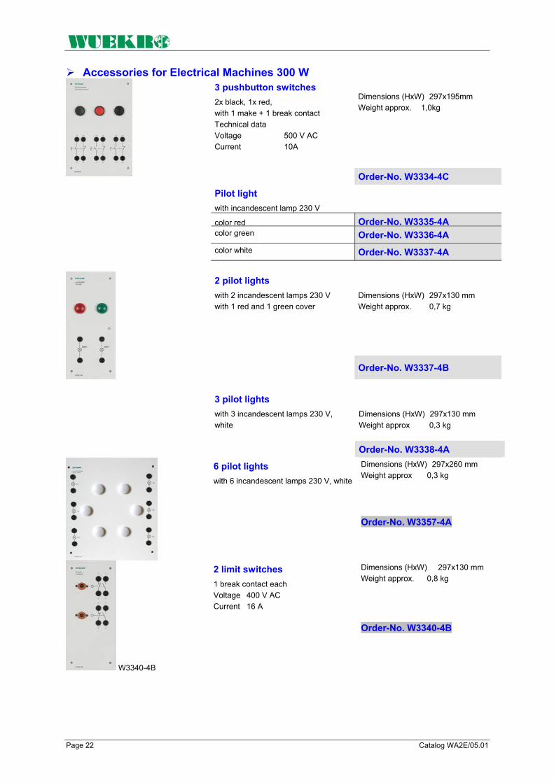
Page 22 Catalog WA2E/05.01
Accessories for Electrical Machines 300 W Dimensions (HxW) 297x195mm Weight approx. 1,0kg
3 pushbutton switches 2x black, 1x red, with 1 make + 1 break contact Technical data Voltage 500 V AC Current 10A
Order-No. W3334-4C
Pilot light with incandescent lamp 230 V
color red Order-No. W3335-4A color green Order-No. W3336-4A color white Order-No. W3337-4A
Dimensions (HxW) 297x130 mm Weight approx. 0,7 kg
2 pilot lights with 2 incandescent lamps 230 V with 1 red and 1 green cover
Order-No. W3337-4B
Dimensions (HxW) 297x130 mm Weight approx 0,3 kg
3 pilot lights with 3 incandescent lamps 230 V, white
Order-No. W3338-4A Dimensions (HxW) 297x260 mm Weight approx 0,3 kg
6 pilot lights with 6 incandescent lamps 230 V, white
Order-No. W3357-4A
Dimensions (HxW) 297x130 mm Weight approx. 0,8 kg
W3340-4B
2 limit switches 1 break contact each Voltage 400 V AC Current 16 A
Order-No. W3340-4B

Catalog WA2E/05.01 Page 23
Accessories for Electrical Machines 300 W
On/off switch 2-pin Switch positions 0 - I - 0 - I Voltage AC 400/220 V DC Current 16 A
Order-No. W3341-4B
Dimensions (HxW) 297x130 mm Weight approx. 0,65 kg Order-No. W3341-4B
Dimensions (HxW) 297x130 mm Weight approx 0,9 kg
On/off switch 2-pin Switch positions 0 - I - 0 - I Voltage AC 400/220 V DC Current 16 A
Two-circuit double-interruption switch 2-pin; Switch positions 0 - I - 0 - II Voltage AC 400/230 V DC Current 16 A
Order-No. W3342-4B
Two-circuit double-interruption switch 3-pin;datas same as W3342-4B
Order-No. W3342-4E
Dimensions (HxW) 297x130 mm Weight approx 0,8 kg
4-way switch 2-pin Switch positions I - Il - lll - IV Voltage AC 400 V/230 V DC Current 16 A Order-No. W3343-4B
Dimensions (HxW) 297x130 mm Weight approx 0,3 kg
3 Resistors 1 x 10 Ω / 0,5 A 1 x 20 Ω / 0,5 A 1 x 50 Ω / 0,5 A
Order-No. W3344-4A
Weight approx 2,5 kg
3 Resistors 1 x 100 Ω / 1 A 1 x 330 Ω / 0,6 A 1 x 1000 Ω / 0,3 A Order-No. W3344-4B
Dimensions (HxW) 297x130 mm Weight approx 1,5 kg
6 Resistors Resistance 6 x 3,9 Ω Output 6 x 10 W
Order-No. W3345-4B

Page 24 Catalog WA2E/05.01
Accessories for Electrical Machines 300 W
Double frequency meter Frequency 2 x 45 - 55 Hz
Dimensions (HxW) 297x130 mm Weight approx. 1,6 kg
Voltage 230V Order-No. W3437-4A
Voltage 400V Order-No. W3452-4A
Dimensions (HxW) 297x130 mm Weight approx 1,5 kg
Double voltmeter Voltage 2 x AC 500 V/ 15 - 65 Hz
Order-No. W3438-4A
Dimensions (HxW) 297x260 mm Weight approx 4,7 kg
Synchroscope Voltage AC 400 V
Order-No. W3440-4A

Catalog WA2E/05.01 Page 25
Standard Training System Electrical Machines 300 W
With the "Standard Training System ", the following experiments can be carried out:
1. DC Machines DC series-wound motor: • Motor operation • Measuring current, voltage,
speed, torque • Tracing characteristics DC shunt-wound machine: • Motor operation, self-excited • Motor operation, separately
excited • Generator operation, self-
excited • Generator operation,
separately excited • Measuring current, voltage,
resistance, speed, torque • Tracing characteristics DC compound-wound machine: • Motor operation • Generator operation • Measuring current, voltage,
speed, torque • Tracing characteristics
2. Single-Phase AC Machines Measuring current, voltage, speed, torque and output as well as tracing characteristics on: • Single-phase squirrel-cage
motor with starting and running capacitor
• Single-phase squirrel-cage motor with auxiliary starting winding
• Repulsion motor • Universal motor
3. Induction motors Measuring current, voltage, speed, torque and output as well as tracing characteristics on: • Three-phase squirrel-cage
induction motor suitable for star-delta starting
• Three-phase two-speed pole-changing induction motor with squirrel-cage rotor (Dahlander circuit)
• Three-phase pole-changing induction motor with squirrel-cage rotor with two separate windings
• Three-phase induction motor with slipring rotor
With three-phase squirrel-cage induction motors additionally: • Switch-on with motor
protection • Reversal • Star-delta starting • Stator-resistance starting
circuit • Operation at single-phase
mains • Reactive-power compensation • Pole-changing Dahlander • Pole-changing two separate
windings • Efficiency measurement With three-phase induction machines with slipring rotors additionally: • Starting circuits
4. Synchronous machines Measuring current, voltage, speed, torque and output as well as tracing characteristics on: • Measuring current, voltage,
speed, torque and output as well as tracing characteristics on:
• Three-phase synchronous machine with salient pole rotor and damper winding
• Mains synchronization • Isolated operation

Page 26 Catalog WA2E/05.01
Standard Training System Electrical Machines 300 W
The following components are required to carry out these experiments:
1 W3228-4B 3 Incandescent lamps E27
1 W3221-4B 1 NEOZED-fuse element
4 W3311-4B 3 NEOZED fuse elements
1 W3312-4A Motor-protection circuit-breaker
1 W3312-4C Motor-protection circuit-breaker
1 W3312-4H Motor-protection circuit-breaker
3 W3313-4A On/off switch 3-pin
4 W3341-4B On/off switch 2-pin
1 W3342-4E Two-circuit double- interruption switch, 3-pin
1 W3314-4A Reversing switch 3-pin
1 W3315-4A Star-delta switch 3-pin
1 W3317-4A Pole-changing switch
5 W3321-4A Contactor 3-phase
1 W3328-4A Auxiliary contactor
2 W3330-4B ÜberCurrentrelais
2 W3330-4F Overcurrent relay
2 W3330-4H Overcurrent relay
1 W3330-4J Overcurrent relay
2 W3331-4A Time relay 1 changeover contact
2 W3334-4B 2 Pushbutton switches
1 W3334-4C 3 Pushbutton switches
1 W3337-4B 2 Pilot lights
1 W3340-4B 2 Limit switches
1 W3333-4D 3 Capacitors
1 W3357-4A 6 Pilot lights
1 W3345-4B 6 Resistors
1 W3365-1E Compact braking unit
1 W3360-8A Baseframe
1 W3365-2A Three-phase squirrel-cage induction motor
1 W3365-2B Three-phase two-speed pole- changing induction motor
1 W3365-2C Three-phase induction motor with slippring rotor
1 W3365-3B Single-phase squirrel-cage AC motor with starting and running capacitor
1 W3365-3C Single-phase squirrel-cage motor with auxiliary starting winding
1 W3365-3F Universalmotor
1 W3365-4A Synchronous machine with salient pole rotor
1 W3365-5A DC series wound machine
1 W3365-5B DC compound wound machine
1 W3365-5C DC shunt wound machine
1 W3365-2D Rotor controler
1 W3360-8B Controllerr
1 W3360-8C Controllerr
1 W3360-8D Single-coil slide resistor
1 W3360-8E Single-coil slide resistor
1 W3360-8F Single-coil slide resistor
1 W3360-8K Single-coil fixed resistor
3 W3901-0A Set Connecting leads
1 W3010-7B V107 Experimental manual, "Connecting and Measuring el. Machines 300 W"

Catalog WA2E/05.01 Page 27
Standard Training System Electrical Machines 300 W
To be continued ..necessary equipment Recommended Lab equipment
Proposal: Measuring instruments
1 W3428-4C Experimental panel Wattmeter
1 W3428-4D Experimental panel Wattmeter
1 W3434-4B Experimental panel Power factor meter
1 W3435-4A Experimental panel Power factor meter
2 W3422-4A Experimental panel Moving iron voltmeter
1 W3436-4A Experimental panel Frequency meterr
4 Multimeter
1 Phase sequence indicator
Synchronizing Instruments
1 W3438-4A Double voltmeter
1 W3452-4A Double frequency mete
1 W3440-4A Synchroscope
Further experimental panels and machines
1 W3365-3D Repulsion motor
1 W3365-3F Universal motor
1 W3365-4B Three-phase synchronous machine with cylindrical rotor
1 W3365-4C Three-phase synchronous machine with reluctance rotor
1 W3365-2G Three-phase two-speed pole- changing induction motor 2 separate windings
1 W3318-4A Pole changing switch 3 pins, for 2 speeds 2 separate windings
1 W2700-1A Standard experimental set-up Power Engineering with power supplies, SCHUKO sockets and experimental frame

Page 28 Catalog WA2E/05.01
FAX – Reply to: +49 (0) 9721 / 64691 - 20 Sender: Receiver: Company WUEKRO – GmbH
Dept. Sales Department Name Street Carl-Zeiss-Strasse 10 City 97424 Schweinfurt / Germany Phone + 49-(0)9721-64691-0 Fax + 49-(0)9721-64691-20 E-Mail [email protected] Internet www.wuekro.de No. of pages incl. this page
Please send the following catalogues to the a.m. address! Fundamentals of electrical Engineering
Installation circuits Bell ringing and entrance call stations Contactor control / Control technology Measurement and control of non-electrical variables
Fundamentels of electronics Analog technology Digital technology Microprocessing technology
Closed loop control technology Analog closed loop control Digital closed loop control
Automation engineering SIMATIC S7-200/300/400, Software Technology simulators / Models Process control engineering PCS7 AS-Interface Profibus DP Process simulation-software SIMIT LOGO! Mechatronical technology stations Courses on Automation
Electrical machines / Drive controls Electrical Machines 300W Electrical Machines 1000W Electrical Machines 5kW Electrical drive control systems 300W/ 1kW Electrical drive control systems 5kW Networked drive systems Cutaway Models Transformers, Rectifiers and Reactive Power Compensation Courses on drive systems
Power electronics extra low voltage (24V) low voltage (230/400V)
Building management systems KNX / EIB
VDE 0100 safety measures
Radio- and Television engineering AM/FM – Technology TV Engineering
Satellite – Technology
Cooling and air conditioning
Photovoltaic cell tecnology
Communication technology Modulation -/demodulation Fiber optic ISDN trainer (HICOM) ISDN
Measuring systems
Power supply units
Experiment instructions, manuals
Training courses
Remarks:
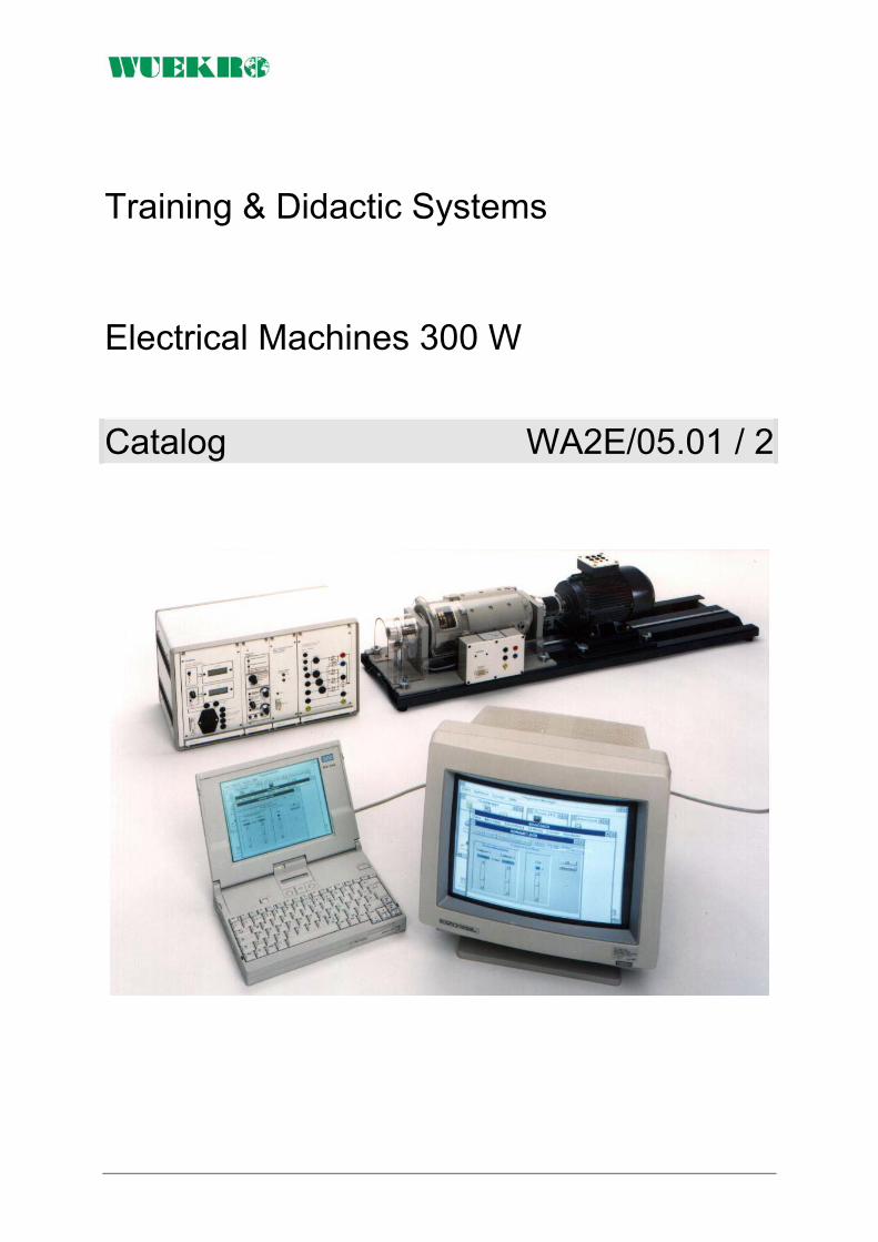
Training & Didactic Systems Electrical Machines 300 W
Catalog WA2E/05.01 / 2

Seite 2 Catalog WA2E/05.01 / 2
Our Services
• Development and production of didactic training systems • Teachware and documentation • Project engineering of complete lab's incl. furnitures and lab equipment • Quotations on customers demand • Installation, commissioning and training at site
Our Customers • Vocational training schools, technical schools, colleges and universities... • Industrial laboratories for vocational education and higher education
Fields of Technology • Fundamentals of electrical engineering
• Fundamentals of electronics
• Closed loop control technology
• Automation engineering
• Electrical machines / drive control
• Power electronics
• Building management systems
• Protection schemes to VDE 0100
• Radio- and TV technology
• Air conditioning and refrigeration
• Photovoltaic
• Communication technology
• Measuring systems, power supplies, accessories
• Experimental manuals, documentation For further information please contact: WUEKRO GmbH Carl-Zeiss-Strasse 10 D - 97424 Schweinfurt Germany Tel. + 49 (0) 9721-64691-0 Fax: + 49 (0) 9721-64691-20 E-Mail: [email protected] Internet: www.wuekro.de WUEKRO GmbH
All Rights reserved. Reprint not permitted. Technical changes without prior notice.. B20020323B – 01/13

Catalog WA2E/05.01 / 2 Seite 3
Electrical Machines 300 W The electrical machines are equipped as follows:
• with premounted coupling • with base plate, to compensate the height of axes and for easy
replacement of machines • with thermistor protection on 2-mm sockets • with circuit diagram on front • with all connections brought out to 4-mm safety laboratory sockets • type of construction B3, unless otherwise specified • all machines in degree of protection IP 21
Types of electrical machines
The electrical machines of the 300 W class of this catalog WA1E/05.01 / 2 are fully compatible to the 200 W program of catalog WA1E/05.01 in reference to: - the baseplate and the placement on the baseframe - the height of the axes and the coupling device - the use of braking equipment and control units - the use of accessories

Seite 4 Catalog WA2E/05.01 / 2
Single phase machines class 300 W
Single-phase squirrel-cage AC motor with starting and running capacitor adapted industrial standard machine Dim. (BxHxT) ca. 310x180x210 mm Weight ca. 8 kg 1 Axes end
Technical data: Output 0,37 kW Cos ϕ 0,93 Voltage 1AC 230 V / 50 Hz Current 2,6 A Speed 1400 min-1
Capacity CA 50 - 63 µF Capacity CB 20 µF
Order-No. W3365-3B
Single-phase squirrel-cage motor with auxiliary starting winding Dim. (BxHxT) ca. 310x180x210 mm Weight ca. 8 kg 1 Axes end
Technical data: Output 0,20 kW Cos ϕ 0,7 Voltage 1AC 230 V / 50 Hz Current 2,6 A Speed 1380 min-1
Order-No. W3365-3C
Single-phase repulsion motor with single brush rocker and special brush-shifting gear at the bearing plateDim. (BxHxT) ca. 310x180x210 mm Weight ca. 8 kg 2 Axes ends
Technical data: Output 0,25 kW Cos ϕ 0,69 Voltage 1AC 230 V / 50 Hz 1AC 115V / 50Hz Current 2,9 A 5,8 A Speed 2100..0..2100 min-1 Order-No. W3365-3D
Single-phase split-pole motor Dim. (BxHxT) ca. 310x180x210 mm Weight ca. 8 kg 1 Axes end
Technical data: Output 0,12 kW Cos ϕ 0,6 Voltage 1AC 230 V / 50 Hz Current 3,2 A Speed 2700 min-1
Order-No. W3365-3E
Universal motor Dim. (BxHxT) ca. 310x180x210 mm Weight ca. 8 kg 2 Axes ends
for optional operation at AC or DC voltage
Technical data: Output 0,2 kW Voltage 1AC 230 V / 50 Hz DC 140 V Current 3,0 A 2,5 A Speed 3000 min-1 Order-No. W3365-3F

Catalog WA2E/05.01 / 2 Seite 5
Three phase machines class 300 W
Three-phase induction motor with squirrel cage rotor adapted industrial standard machine for star-delta-operation Dim. (BxHxT) ca. 310x180x210 mm Weight ca. 8 kg 1 Axes end
Technical data: Output 0,25 kW Cos ϕ 0,78 Voltage 3AC 400 V / 50 Hz 3AC 692 V / 50 Hz Current 0,77 A / 0,45 A Speed 1350 min-1
Order-No. W3365-2A
Three-phase induction motor with squirrel cage rotor Dim. (BxHxT) ca. 310x180x210 mm Weight ca. 8 kg 1 Axes end
for star-delta-operation with pronounced stalling torque
Technical data: Output 0,27 kW Cos ϕ 0,70 Voltage 3AC 400 V / 50 Hz 3AC 692 V / 50 Hz Current 1,0 A / 0,58 A Speed 1350 min-1 Order-No. W3365-2K
Three-phase induction motor with squirrel cage rotor adapted industrial standard machine for star-delta-operation Dim. (BxHxT) ca. 310x180x210 mm Weight ca. 8 kg 1 Axes end
Technical data: Output 0,27 kW Cos ϕ 0,70 Voltage 3AC 230 V / 50 Hz 3AC 400 V / 50 Hz Current 1,34 A / 0,77 A Speed 1380 min-1
Order-No. W3365-2M
Three-phase induction motor with squirrel cage rotor Dahlander circuit Dim. (BxHxT) ca. 310x180x210 mm Weight ca. 8 kg 1 Axes end
Technical data: Output 0,25 kW / 0,37 kW Cos ϕ 0,62 / 0,75 Voltage 3AC 400 V / 50 Hz Current 1,0 A / 1,1 A Speed 1400 min-1 2800 min-1
Order-No. W3365-2B
Three-phase induction motor with squirrel cage rotor with two separate windings Dim. (BxHxT) ca. 310x180x210 mm Weight ca. 8 kg 1 Axes end
Technical data: Output 0,12 kW / 0,18 kW Cos ϕ 0,56 / 0,61 Voltage 3AC 400 V / 50 Hz Current 0,72 A / 0,77 A Speed 930 min-1 1420 min-1
Order-No. W3365-2G
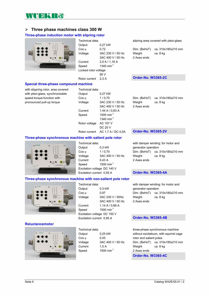
Seite 6 Catalog WA2E/05.01 / 2
Three phase machines class 300 W Three-phase induction motor with slipring rotor
slipring area covered with plexi-glass Dim. (BxHxT) ca. 310x180x210 mm Weight ca. 8 kg 2 Axes ends
Technical data: Output 0,27 kW Cos ϕ 0,72 Voltage 3AC 230 V / 50 Hz 3AC 400 V / 50 Hz Current 2,0 A / 1,16 A Speed 1340 min-1
Locked rotor voltage 95 V Rotor current 2,3 A Order-No. W3365-2C
Special three-phase compound machine Dim. (BxHxT) ca. 310x180x210 mm Weight ca. 8 kg 2 Axes ends
with slippring rotor, area covered with plexi-glass, synchronizable speed-torque-function with pronounced pull-up torque
Technical data: Output 0,27 kW Cos ϕ 1 / 0,70 Voltage 3AC 230 V / 50 Hz 3AC 400 V / 50 Hz Current 1,44 A / 0,83 A Speed 1500 min-1 1340 min-1
Rotor voltage AC 107 V DC 20 V Rotor current AC 1,7 A / DC 4,0A Order-No. W3365-2V
Three-phase synchronous machine with salient pole rotor with damper winding; for motor and generator operation Dim. (BxHxT) ca. 310x180x210 mm Weight ca. 8 kg 2 Axes ends
Technical data: Output 0,3 kW Cos ϕ 1 / 0,70 Voltage 3AC 400 V / 50 Hz Current 0,43 A Speed 1500 min-1 Excitation voltage DC 140 V Excitation current 0,55 A Order-No. W3365-4A
Three-phase synchronous machine with non-salient pole rotor with damper winding; for motor and generator operation Dim. (BxHxT) ca. 310x180x210 mm Weight ca. 8 kg 2 Axes ends
Technical data: Output 0,3 kW Cos ϕ 0,97 Voltage 3AC 230 V / 50Hz 3AC 400 V / 50 Hz Current 1,14 A / 0,66 A Speed 1500 min-1 Excitation voltage DC 150 V Excitation current 0,95 A Order-No. W3365-4B
Reluctancemotor three-phase synchronous machine without excitatiuon, with squirrel cage rotor and salient poles Dim. (BxHxT) ca. 310x180x210 mm Weight ca. 8 kg 2 Axes ends
Technical data: Output 0,25 kW Cos ϕ 0,45 Voltage 3AC 400 V / 50 Hz Current 1,5 A Speed 1500 min-1
Order-No. W3365-4C

Catalog WA2E/05.01 / 2 Seite 7
DC machines class 300 W DC series-wound machine
for motor operation Dim. (BxHxT) ca. 310x180x210 mm Weight ca. 8 kg 2 Axes ends
Technical data: Output 0,3 kW Voltage DC 220 V Current 1,9 A Speed 2000 min-1 Order-No. W3365-5A
DC compound-wound machine with series and shunt winding for motor and generator operation Dim. (BxHxT) ca. 310x180x210 mm Weight ca. 8 kg 2 Axes ends
Technical data: Output 0,3 kW Voltage DC 220 V Current 1,8 A Speed 2000 min-1 Excitation voltage DC 220 V Excitation current 0,25 A Order-No. W3365-5B
DC shunt-wound machine for motor and generator operation Dim. (BxHxT) ca. 310x180x210 mm Weight ca. 8 kg 2 Axes ends
Technical data: Output 0,3 kW Voltage DC 220 V Current 1,8 A Speed 2000 min-1 Excitation voltage DC 220 V Excitation current 0,3 A Order-No. W3365-5C
DC shunt-wound machine, same as W3365-5C
with built-on tachogenerator (Voltage 30 V / 1000 min-1) Order-No. W3365-5G
Special DC compound machine with series, shunt and compound features for motor and generator operation
Technical data: Output 0,3 kW Voltage DC 220 V Current 1,8 A Speed 2000 min-1
Excitation voltage DC 220 V Excitation current 0,25 A Order-No. W3365-5V
Servo machine class 300 W AC-Servomotor three phase
Weight approx. 6 kg
Technical data: Static torque 1 Nm Nominal current 1,2 A Nominal power 0,47 kW Speed 6000 min -1
Order-No. W3365-4S

Seite 8 Catalog WA2E/05.01 / 2
FAX – Reply to: +49 (0)9721 / 64691 - 20 Sender: Receiver:
Company WUEKRO GmbH Dept. Sales Department Name Street Carl-Zeiss-Strasse 10 City 97424 Schweinfurt / Germany Phone + 49-(0)9721-64691-0 Fax + 49-(0)9721-64691-20 E-Mail [email protected] Internet www.wuekro.de
Please send the following catalogues to the a.m. address!
Fundamentals of electrical Engineering Installation circuits Bell ringing and entrance call stations Contactor control / Control technology Measurement and control of non-electrical variables
Fundamentels of electronics Analog technology Digital technology Microprocessing technology
Closed loop control technology Analog closed loop control Digital closed loop control
Automation engineering SIMATIC S7-200/300/400, Software Technology simulators / Models Process control engineering PCS7 AS-Interface Profibus DP LOGO! Mechantronical technology stations Courses on Automation
Electrical machines / Drive controls Electrical Machines 300W Electrical Machines 1000W Electrical Machines 5kW Electrical drive control systems 300W / 1kW Electrical drive control systems 5kW Networked drive systems Cutaway Models Transformers, Rectifiers and Reactive Power Compensation Courses on drive systems
Power electronics extra low voltage (24V) low voltage (230/400V)
Building management systems KNX / EIB
VDE 0100 safety measures
Radio- and Television engineering AM/FM – Technology TV Engineering
Satellite – Technology
Cooling and air conditioning
Photovoltaic cell tecnology
Communication technology Modulation -/demodulation Fiber optic ISDN trainer (HICOM) ISDN
Measuring systems
Power supply units
Experiment instructions, manuals
Training courses
Remarks:

Training & Didactic Systems Electrical Machines 1000 W
Catalog WA2E/05.02

Catalog WA2E/05.02 Page 2
Our Services
• Development and production of didactic training systems • Teachware and documetation • Project engineering of complete lab's incl. furnitures and lab equipment • Quotations on custumors demand • Installation, commissioning and training at site
Our Customers • Vocational training schools, technical schools, colleges and universities... • Industrial laboratories for vocational education and higher education
Fields of Technology • Fundamentals of electrical engineering
• Fundamentals of electronics
• Closed loop control technology
• Automation engineering
• Electrical machines / drive control
• Power electronics
• Building management systems
• Protection schemes to VDE 0100
• Radio- and TV technology
• Air conditioning and refrigeration
• Photovoltaic
• Communication technology
• Measuring systems, power supplies, accessories
• Experimental manuals, documentation For further information please contact: WUEKRO GmbH Carl-Zeiss-Strasse 10 D - 97424 Schweinfurt Germany Tel. + 49 (0) 9721-64691-0 Fax: + 49 (0) 9721-64691-20 E-Mail: [email protected] Internet: www.wuekro.de WUEKRO GmbH
All Rights reserved. Reprint not permitted. Technical changes without prior notice.. B10020515B – 01/13

Catalog WA2E/05.02 Page 3
Table of Contents Seite
Our Services, Customers and Fields of Technology 2 Training System Electrical Machines 1000 W 4 Introduction 5 Training concept 6 Load facilities, drivers, measuring equipment, features and design 8 Electrical machines 1000 W 9 DC-machines 9 Single-phase and three-phase induction machines 1000 W 11 Braking equipment 1000 W 13 Software "DRIVECOACH" 14 Control units 15 Accessories electrical machines 17 Base frames, Controller 17 Accessories, switch gear 19 Standard-training system electrical machines 1000 W 25 Components of standard training system 1000 W 26 Fax - reply 28

Catalog WA2E/05.02 Page 4
Training System Electrical Machines 1000 W
Training Systems - Assignment – Target audience Project Theses
Diploma Theses
Practicals College / University
Continuing Education Practical Training College/University
Master craftsman / Technician Further Training at Chamber of commerce
Skilled Worker Training
5
kW R
ange
Fundamentals Vocational education school / Education in Industry
300
W
Ran
ge
10
00 W
Ran
ge
Catalog WA2E/05.02 Page 5
Foreword If you can analyze problems systematically and understand interrelation-ships, you'll have no difficulty in coping with future developments - in any field of technology. As your partner for training systems, we can provide you with the technical equipment you require for this purpose including the necessary know-how in the form of comprehensive instruction manuals, training documentation and extensive configuring and design aids. Systematic analysis in the field of electrical machines means learning about the behavior of electrical machines through exact measuring exercises and evaluation of the characteristics recorded. This includes comprehension of basic electric circuits such as star-delta connections, stator-resistance starting circuits etc. and the ability to connect these with the specific problems of the individual machine types.
Understanding interrelationships means to view the electrical machines in their relation to drive engineering and automatic control engineering: • Which electrical machine is
best suited for a specific application problem?
• Which control method should be used with an individual machine in order to ensure that the drive meets the highest requirements e.g. relative to dynamic response or control accuracy?
We see it as our task to help you answer these and similar questions on a practical basis and to provide suitable experimental equipment for scientific studies. Our training system gives you almost unlimited freedom, i.e. you can pick and choose elements to create your own "personal" training strategy. If you have an entire room at your disposal for use as a machine laboratory and if you attach importance to characteristics of "large" machines, the system of your choice would be our machines in the range up to 5 kW1). This system is especially suited for use at technical colleges and universities. Experimental sockets ensure operational safety even with equipment from this output range2). 1) Larger machines available on request. 2) For technical reasons, no experimental sockets are used with machines > 5 kW.
If the transport capability of the machines is a criterion besides the characteristics, the machines from the 1 kW range are right for you. They offer an ideal compromise between electrical operating behavior and low weight, which is also reflected in their extremely high cost effectiveness. This system can be used from basic training to practicals at technical colleges or universities and beyond. If due to the training situation you have to pay special attention to aspects such as mobility, training outside of technical rooms and space requirements, you will decide in favor of our 300 W machine range. Regardless which of the three systems you eventually choose, you will have devices at your disposal that are tailor-made for your individual requirements.

Catalog WA2E/05.02 Page 6
The Training Concept The Aim The aim of our training concept for the field of electrical machines is to provide • vocational schools • technical colleges • universities and • in-firm training centers with systems for teaching the theoretical and practical knowledge which trainees and students require to learn and understand modern know-how about electrical machines and their control methods. The machines we use are purely industrial equipment whose charac-teristics have been idealized only in exceptional cases, e.g. induction machine with slipring rotor. This applies for the 300 W range, the 1000 W range as well as the 5 kW range. You can choose between different DC machines, AC machines, three-phase machines as well as special machines such as the DC and three-phase compound machine.
Brakes and Measuring Sytems The available brake assemblies include magnetic powder brakes, eddy-current brakes and dynamometers. The setpoint for the brakes can be input either via front panel or PC, and characteristics can be traced either via recorder or also via PC, where a soft-ware specifically designed for the machine range facilitates the process. While modules M1 to M5 focus on the electrical machine and its elementary control possibilities, modules M6 to M8 deal with technically expanded control methods up to the three-phase AC power controller SIKOSTART in combination with the squirrel-cage induction machine. Module M9 is devoted to the subject area of reactive-power compensation. The following matrix provides an overview of possible combinations of machine type and control method:
Practical instruction manuals Instruction manuals designed by didactically trained specialists are available for our 300 W and 1000 W training systems. These instruction manuals generally consist of 3 sections: Section 1: General section for intro-ducing the trainees to the objectives of the training program and providing basic theoretical knowledge. Section 2: Trainee's section containing measuring exercises. Value tables, diagrams and oscillograms must be filled out by the student or created on the PC. Section 3: Instructor's section contain-ing the answers to questions in section 2. The purpose of this section is to reduce valuable preparation time and provide a check for instructors. Whether you choose machines from the 300 W or the 1000 W range, we can provide you with reliable instruction manuals for the appropriate system.

Catalog WA2E/05.02 Page 7
The Training Concept
The Training Aim The concept The System • DC machines • Single-phase motors
- with running capacitor, - with starting and running
capacitor - resistance start
• Asynchronous and synchronous polyphase machines
• Special machines
The "Electrical Machines" training system allows you to teach the aims listed with 300-W machines, 1-kW machines and also with machines up to 5-kW (higher-power machines on request). Depending on customer requirements, we can supply either single machines or complete systems with machines, loading facilities, drivers and measuring equipment. Specially prepared technical literature forms the basis of theory teaching.
Our "Electrical Machines" training system consists of the following individual components: • 300-W machines • 1000-W machines • Machines up to 5 kW • Loading facilities • Drivers • Measuring equipment
300 W machines 1000 W machines Machines up to 5 kW Our 300-W machines are used primarily for training purposes in industry, trade and technical colleges. They are a handy size and can be easily assembled and dismantled. These "small" machines are "big" on electrical operating characteristics. They are industrial machines whose characteristics have only been modified for teaching purposes in exceptional cases. This is why they are also well suited to basic practical teaching in technical colleges and universities.
This is the ideal "middle ground" between the "small" 300-W machine and the "large" machines in the performance range up to 5 kW. Thanks to its low weight, compact dimensions and excellent electrical characteristics, this machine offers more universality of use than any other machine type.
If a machine laboratory is to be equipped and if practice-orientation is the main priority, this performance range is to be recommended. Demanding practical tests, engineering exams and certificate exams can all be set up easily in conjunction with these industrial drives.

Catalog WA2E/05.02 Page 8
Load facilities, Drivers, Measuring Equipment
Load facilities Drivers Measuring Equipment Brakes are available in the form of magnetic powder brakes and rotating eddy-current retarders (300-W and 1000-W range). They have been adapted exactly to the electrical machines. If the machine is to be subjected to both motive power loading and rheostatic loading, a DC dynamo-meter is recommended as loading facility (300-W, 1000-W and 5-kW ranges). All load facilities are equipped with optical indicating instruments, standardized analog outputs and interfaces for computer links.
The constantly increasing requirements of drive technology mean that modern converter equipment is required in addition to contactor equipment. Digital converters for polyphase machines, analog and microprocessor-controlled converters for DC drives, special equipment for servo and stepper motors finish off the machines as compact and intelligent drive units.
Measuring equipment as the interface between man and machine is of central significance in study and training. There is a correspondingly comprehensive and high-quality range of measured value processing systems and output devices available. Whether you are making measurements with a multimeter or a multifunction meter, recording characteristic curves via value tables or PC, or carrying out torque acquisition via current, foil strain gauge or torque metering shaft, there is measuring equipment available for all your requirements.
Features and Design General The experimental machines feature the IM B 3 design with one shaft end and correspond to the VDE regulations 0530. The 300 W and 1000 W machines are equipped with: • an experimental terminal
board. The ends of the windings brought out to the terminal board are connected to 4-mm-safety-socket outlets. The socket outlets are arranged on a plastic board in the same way as the connections of a normal terminal board of an industrial machine. The plastic board features the conventional industrial machine terminal designations.
• A PTC thermistor in order to protect the machines against thermal overload. This obviates overheating resulting from overload, high switching frequency, single phasing, large deviations in voltage, excessively high coolant temperatures or obstructed coolant flow. The leads of the thermistors are connected to 2-mm-socket-outlets in order to avoid faulty connections.
• A baseplate to compensate for differences in shaft height and to facilitate replacement of the machines. The baseplate features a guide mechanism on the underside for setting it onto the slide of the baseframe.
• A toothed gear coupling half which is identical for all machines and brake assemblies within each range. The coupling halves are connected to each other over an elastic adapter piece. This type of coupling and baseplate design allows you to combine any two machines to form one motor generator set as well as to couple each machine to the brake assemblies without having to change the coupling or the baseplate.
In order to keep the noise level low, preference has been given to machines with rated speeds of 1500 rev/min.

Catalog WA2E/05.02 Page 9
Electrical Machines 1000 W The electrical machines are equipped as follows::
• with premounted coupling • with base plate, to compensate the height of axes and for easy
replacement of machines • with thermistor protection
Types of electrical machines
DC-Machines
DC Series-wound motor Weight approx. 36 kg
Technical data Degree of protection IP 21 Output 1,3 kW Voltage 220 V Current 7,5 A Speed 1500 min-1
Order-No. W3375-5A
DC Compound-wound machine with series and shunt winding; for motor and generator operation Technical data Degree of protection IP 21 Motor operation Output 0,8 kW Voltage 220 V Current 4,4 A Speed 1500 min-1
Generator operation Output 1 kW Voltage 220 V Current 4,6 A Speed 1500 min-1 Shunt winding Field voltage 220 V Field current 0,3 A Weight approx. ca. 36 kg Order-No. W3375-5B

Catalog WA2E/05.02 Page 10
DC-Machines 1000 W
DC shunt-wound machine for motor and generator operation Technical data Degree of protection IP 21 Motor operation Output 1 kW Voltage 220 V Current 5,3 A / 5,5 A Speed 1500 min-1
Generator operation Output 1 kW Voltage 220 V Current 4,4 A Speed 1500 min-1
Shunt winding Field voltage 220 V Field current 0,3 A Weight approx. ca. 36 kg
Order-No. W3375-5C (picture W3375-5G)
DC shunt-wound machine
Same as W3375-5C but with built-on tachogenerator
Voltage 30 V / 1000 min-1 Order-No. W3375-5G
DC shunt-wound machine Field voltage 110 V Field current 1,2 A With built-on tachogenerator Voltage 20 V/1000 min-1 Weight approx. 36 kg
for motor and generator operation Technical data Degree of protection IP 21 Motor operation Output 1,1 / 1,0 / 0,8 kW Voltage 330 / 275 / 220 V Current 4,0 / 4,8 / 6,0 A
Speed 1500 min-1 Generator operation Output 0,8 kW Voltage 220 V Current 0,8 A Speed 1500 min-1
Order-No. W3375-5D
Special DC compound machine with series, shunt and compound features for motor and generator operation Technical data Degree of protection IP 21 Shunt winding- Output 1 kW Voltage 220 V Current 6 A Speed 1650 min-1
Field voltage 220 V Field current 1,5 A
Compound-output 1 kW Voltage 220 V Current 6 A Speed 1450 min-1 Field voltage 220 V Field current 1,26 A Series-output 1 kW Voltage 220 V Current 9 A Speed 1000 min-1
Weight approx. 40 kg
Order-No. W3375-5V
DC shunt-wound machine, cradle-mounted for motor- und generator operation, incl. baseframe; torque recorded via strain gauge, speed recorded optoelectronically Technical data Degree of protection IP 21 Generator operation Output 1 - 2 kW Voltage 150 - 300 V Current 8,5 A Speed 1500 - 3000min-
1
Motor operation Output 1 - 2 kW Voltage 150 - 300 V Current 8,5 A Speed 1440 - 2800 min-1 Field voltage 200 V DC Field current 0,65 A Resolution pulse generator 120 pulses./rev Weight approx. 31 kg
Order-No. W3375-1H

Catalog WA2E/05.02 Page 11
AC Machines, single and 3-phase 1000 W Single-phase squirrel-cage AC motor with starting and running capacitor
Technical data Degree of protection IP 21 Output 0,8 kW Voltage 1 AC 230 V / 50 Hz Current 4,8 A Speed 1420 min-1
Weight approx. 11 kg
Order-No. W3375-3B
Single-phase squirrel-cage motor with auxiliary starting winding
Single-phase squirrel-cage motor with auxiliary starting winding · with premounted coupling · with base plate, to compensate the height of axes and for easy replacement of machines · with thermistor protection
Technical data Degree of protection IP 21 Output 0,7 kW Voltage 1 AC 230 V / 50 Hz Current 6,4 A Speed 1430 min-1
Weight approx. 12 kg
Order-No. W3375-3C
Single-phase repulsion motor
with single brush rocker and special brush-shifting gear at the bearing plate Technical data Degree of protection IP 21 Output 0,8 kW
Voltage 1 AC 230 V / 50 Hz Current 9,4 A Speed 2800..0..2800 min-1 Weight approx. 25 kg
Order-No. W3375-3D
Three-phase squirrel-cage induction motor
for star-delta-operation Technical data W3375-2A Degree of protection IP 21 Output 1,1 kW Voltage 3 AC 400 V / 50 Hz 3 AC 690 V / 50 Hz Current 2,6 A / 1,5 A Speed 1400 min-1
for star-delta-operation Technical data W3375-2A Voltage 230/400 V / 50 Hz Current 3,3 A / 2,4 A Speed 1400 min-1
Weight approx. 14 kg
Order-No. W3375-2A / -2M
Three-phase two-speed pole-changing induction motor with squirrel-cage rotor
(Dahlander circuit) Technical data Degree of protection IP 21 Output 0,7 kW / 0,9 kW Voltage 3 AC 400 V / 50 Hz Current 1,8 A / 2,1 A Speed 1390 min-1 / 2810 min-1 Weight approx. 11 kg
Order-No. W3375-2B
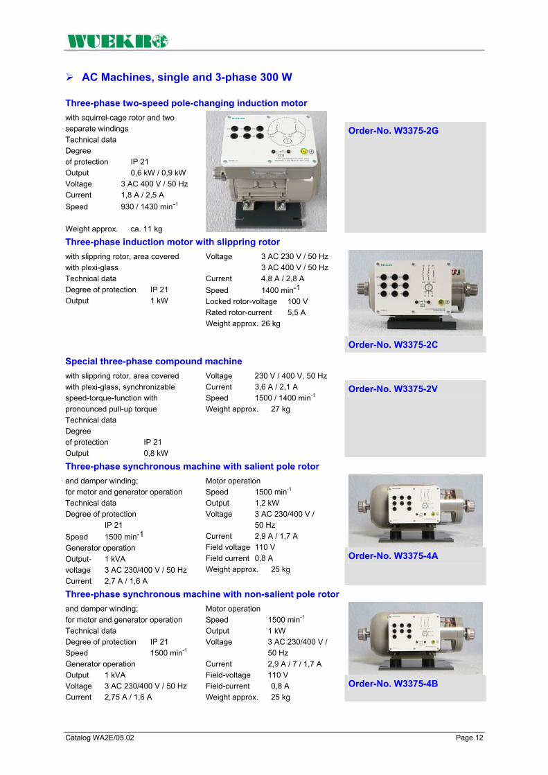
Catalog WA2E/05.02 Page 12
AC Machines, single and 3-phase 300 W
Three-phase two-speed pole-changing induction motor with squirrel-cage rotor and two
separate windings Technical data Degree of protection IP 21 Output 0,6 kW / 0,9 kW Voltage 3 AC 400 V / 50 Hz Current 1,8 A / 2,5 A Speed 930 / 1430 min-1
Weight approx. ca. 11 kg
Order-No. W3375-2G
Three-phase induction motor with slippring rotor with slippring rotor, area covered with plexi-glass Technical data Degree of protection IP 21 Output 1 kW
Voltage 3 AC 230 V / 50 Hz 3 AC 400 V / 50 Hz Current 4,8 A / 2,8 A Speed 1400 min-1
Locked rotor-voltage 100 V Rated rotor-current 5,5 A Weight approx. 26 kg
Order-No. W3375-2C
Special three-phase compound machine with slippring rotor, area covered
with plexi-glass, synchronizable speed-torque-function with pronounced pull-up torque Technical data Degree of protection IP 21 Output 0,8 kW
Voltage 230 V / 400 V, 50 Hz Current 3,6 A / 2,1 A Speed 1500 / 1400 min-1 Weight approx. 27 kg
Order-No. W3375-2V
Three-phase synchronous machine with salient pole rotor and damper winding; for motor and generator operation Technical data Degree of protection IP 21 Speed 1500 min-1
Generator operation Output- 1 kVA voltage 3 AC 230/400 V / 50 Hz Current 2,7 A / 1,6 A
Motor operation Speed 1500 min-1 Output 1,2 kW Voltage 3 AC 230/400 V / 50 Hz Current 2,9 A / 1,7 A Field voltage 110 V Field current 0,8 A Weight approx. 25 kg
Order-No. W3375-4A
Three-phase synchronous machine with non-salient pole rotor and damper winding; for motor and generator operation Technical data Degree of protection IP 21 Speed 1500 min-1
Generator operation Output 1 kVA Voltage 3 AC 230/400 V / 50 Hz Current 2,75 A / 1,6 A
Motor operation Speed 1500 min-1 Output 1 kW Voltage 3 AC 230/400 V / 50 Hz Current 2,9 A / 7 / 1,7 A Field-voltage 110 V Field-current 0,8 A Weight approx. 25 kg
Order-No. W3375-4B

Catalog WA2E/05.02 Page 13
Braking Equipment 1000 W
Compact braking unit 1000 W
Designed as magnetic powder brake with open-loop and closed-loop controls and measuring device, with analog display of speed and switch-selectable torque or calculated output. Torque and speed can be recorded in three different operating modes: a) Open-loop control mode (manual control) b) Closed-loop speed control Recording of brake torque as a function of speed. The speed can be preselected on the setpoint potentiometer and is maintained at a constant value by the built-in control loop. c) Automatic mode The brake is applied to the test object automatically until it stops. The speed/torque characteristic can be traced on an x-y recorder. In addition, analog outputs for speed, torque and calculated output are available The terminals for temperature monitoring of the test object are connected to 2 mm sockets. The magnetic powder brake is suitable for multiple tracings of the motor characteristic. With analog inputs for control of the braking unit via PC.
Technical data Maximum braking torque 25 Nm Speed 1500 min-1, max. 3000 min-1
Supply-voltage 1AC 230 V/50 Hz Dimensions (WxHxD) 310x250x340 mm Weight approx. 14 kg
Order-No. W3375-1E
Eddy current brake 1000 W
Installed on a baseframe with cradle-mounted housing. Suitable for loading a motor of the same rating up to starting torque (including measurement of the breakdown and mean starting torque); for operation in both directions of rotation with electronic torque load cell (strain gauge). Speed recorded optoelectronically via forked light barrier. A ventilator ensures that the brake can be operated continuously at the rated data indicated With built-in temperature monitor, with fitted half-coupling and transparent coupling cover; with torsionally rigid baseframe, mounted on vibration dampers; with draw spindles and slide guide for rapid fitting and removal of experimental machines. Control and measurement are carried out by means of the associated control unit: In addition to the eddy-current brake, an experimental machine in the 1000 W range can be mounted on the baseframe.
Technical data Degree of protection IP 21 Braking power at 1500 min-1 1,3 kW Braking power at 3000 min-1 1,5 kW Field voltage 0 - 180 V DC Field current 2,5 A Weight approx. 45 kg Order-No. W3375-1F
Measuring and control interface The measuring and control interface provides the connection between PC and the magnetic powder brakes. Analog inputs max. ±10V Analog outputs max. ±10V Digital inputs 5 - 24V DC Supply voltage 1 AC 230V
The measuring and control interface consists of 8 digital inputs and outputs, 4 analog inputs and 2 analog outputs as well as an RS-232 interface. The analog and digital inputs and outputs are brought out to 2mm sockets.
Order-No. W3644-4L

Catalog WA2E/05.02 Page 14
Software Modul "DRIVECOACH" Software module „DRIVECOACH“ for tracing characteristics on electrical machines. DRIVECOACH is a software program for operating the magnetic powder brakes, eddy current brakes and dynamometers. A measuring and control interface connects the unit to a PC and is necessary for picking the operating data with the software program. Operation of the software without connecting the measuring and control interface is not possible. Note: The software module "DRIVECOACH" is included in the scope of delivery of W3375-6F. Performance features: Setting possibilities: The operating modes such as closed-loop speed, torque or current control for the terminal device (dynamometer, eddy-current brake) can be set via the measuring and control interface. The ramps to pass can be preselected relative to lower range value, limit value and rate of rise according to the current operating mode. The serial interface is adjustable. Dimensioning of measured quantities: The measured quantities are dimensioned automatically or by querying the hardware. The following values are possible: Speed 4000 min-1 Torque 0 - 20 Nm Current 0- 10 A Tracing characteristics: After setting or transferring the operating data or the ramps, the tracing of a characteristic can be triggered via the start button in a window. The following measured values can be recorded: With operating mode closed-loop speed control: Torque, ourrent, output With operating mode closed-loop torque control: Speed, ourrent, output With operating mode closed-loop current control: Speed, torque, output The diagrams can be saved in appropriate files and then printed. The software module "DRIVECOACH" runs under WINDOWS. 95/98/NT. Operating mode load diagrammes: with the operation mode diagrammes five different kind of diagrammes can be selected and recorded: • constant Speed-torque-diagram • constant Speed-torque-diagram with mit polarity reversal • Linear Speed-torque-diagram • squared Speed-torque-diagram • Inverse Speed-torque-diagram The characteristic parameters are variable with the mouse or can be entered into a text field. A modification of the constant factors is also possible in the current operation. A red signal point announces the operating point of the drive on the characteristic. Hard- und Software coordination For operation with the powder brake W3360-1E the external measuring and control unit W3644-4L is necessary as well as the software modul "DRIVECOACH". For operation with the eddy current brake or the dynamometer, the measuring and control unit W3375-6F is necessary. Order-No. W3644-6A

Catalog WA2E/05.02 Page 15
Modular control Units 1000 W Modular control unit
General The modular control unit provides the control for eddy-current brakes and dynamometers from the 1000 W ranges. The basic unit consists of a fixed-wired 19" housing as well as the plug-in module "Display and Measuring Unit". The other plug-in modules can be selected as required for the individual application. The "Measuring and Control Interface" module serves for connecting the control unit system to the PC. Thus, you can start measurement processes from the PC, display the characteristics passed on the screen and print them on a printer.
Control unit for eddy-current brake and dynamometer Technical data Analog outputs 1. Speed 400 U/min = 1 V 2. Torque 2 Nm = 1 V 3. Output 300 W = 1 V Supply-voltage 1 AC 230 V/50 Hz via mains plug Weight approx. 6 kg
The basic unit of the modular control unit consists of a completely wired 19" housing and the plug-in module „Display and Measuring Unit“. Speed and either torque or calculated output as selected are digitally displayed via LCD's. The maximum speed is adjustable and can be displayed by pressing a button. Zero adjustment as well as calibration are performed via potentiometers.
Order-No. W3375-6A
Control unit for eddy-current brake and dynamometer, controlling module The rate of rise of the ramp can also be set. LEDs provide signals for „Enabled“, „Disabled“, „Brake fault“, „Motor fault“, „Mains fault“, and „Start ramp“. The measuring process is started with a button. With 2-mm-sockets for „Motor temperature“ and „Penlift“. Weight approx.: 0.6 kg
Plug-in module for modular control unit W3375-6A. You can select between closed-loop speed, torque and current control. Lower range value and limit value of the measurements to be run are preselected via potentiometers. The selected values can be displayed using a button.
Order-No. 3375-6C

Catalog WA2E/05.02 Page 16
Control Units 1000 W
Control unit for eddy-current brake, two-quadrant static converter Technical data Input voltage 1 AC 230 V/50 Hz Output current max.2,5 A Weight approx. 2 kg
Plug-in module for modular control unit W3375-6A. Provides the control for eddy-current brakes W3360-1F and W3375-1F. The converter consists of a half-controlled B2 connection.
The trigger pulses are applied internally. All terminals are brought out to 4-mmsafety lab sockets. Technical data: Input voltage 1 AC 230 V /50 Hz
Order-No. W3375-6D
Control unit for dynamometer, four-quadrant static converter Technical data Input voltage 3 AC 400 V/50 Hz with loaded PEN conductor Output current Armature circuit max. 4 A Output voltage Field circuit 200 V DC Output current Field circuit max. 0,5 A with speeds above 2000 rev/min field-weakening operation Weight approx. 2,6 kg
Plug-in module for modular control unit W3375-6A. Provides the control for the dynamo-meters W3360-1H. The converter for the armature circuit consists of two anti-parallel M3 connections, the converter for the field circuit consists of a half-controlled B2 connection. The trigger pulses are applied internally. All terminals are brought out to 4-mm safety lab sockets.
Order-No. W3375-6E
Control unit for eddy-current brake and dynamometer, measuring and control interface The scope of delivery includes the software module „DRIVECOACH“ which permits recording of measured values and control of measuring processes via PC. Weight approx. 0,6 kg
Plug-in module for modular control unit W3375-6A. The measuring and control interface contains an RS-232 interface for PC connection, an analog output +/-10 V as well as a reset button.
Order-No. W3375-6F
Note: We recommend the following setup for control of the eddy-current brake W3375-1F as well as the dynamometer W3375-1H: • Basic unit with display and measuring unit W3375-6A • Control unit W3375-6C
For control of eddy-current brakes additionally: Two quadrant static converter plug-in module W3375-6D For control of dynamometers additionally: Four-quadrant static converter plug-in module W3375-6E
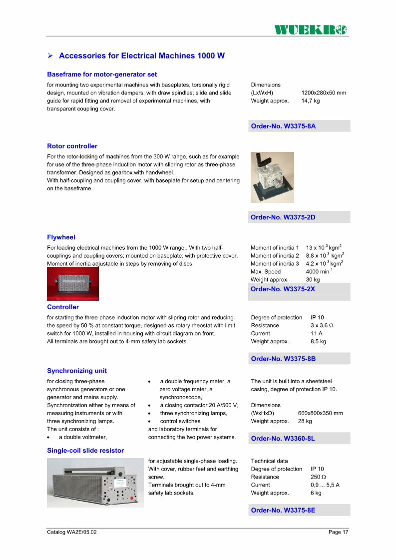
Catalog WA2E/05.02 Page 17
Accessories for Electrical Machines 1000 W
Baseframe for motor-generator set Dimensions (LxWxH) 1200x280x50 mm Weight approx. 14,7 kg
for mounting two experimental machines with baseplates, torsionally rigid design, mounted on vibration dampers, with draw spindles; slide and slide guide for rapid fitting and removal of experimental machines, with transparent coupling cover.
Order-No. W3375-8A
Rotor controller
For the rotor-locking of machines from the 300 W range, such as for example for use of the three-phase induction motor with slipring rotor as three-phase transformer. Designed as gearbox with handwheel. With half-coupling and coupling cover, with baseplate for setup and centering on the baseframe.
Order-No. W3375-2D
Flywheel Moment of inertia 1 13 x 10-3 kgm2 Moment of inertia 2 8,8 x 10⁻³ kgm2 Moment of inertia 3 4,2 x 10⁻³ kgm2 Max. Speed 4000 min-1 Weight approx. 30 kg
For loading electrical machines from the 1000 W range.. With two half-couplings and coupling covers; mounted on baseplate; with protective cover. Moment of inertia adjustable in steps by removing of discs
Order-No. W3375-2X
Controller Degree of protection IP 10 Resistance 3 x 3,6 Ω Current 11 A Weight approx. 8,5 kg
for starting the three-phase induction motor with slipring rotor and reducing the speed by 50 % at constant torque, designed as rotary rheostat with limit switch for 1000 W, installed in housing with circuit diagram on front. All terminals are brought out to 4-mm safety lab sockets.
Order-No. W3375-8B
Synchronizing unit The unit is built into a sheetsteel casing, degree of protection IP 10. Dimensions (WxHxD) 660x800x350 mm Weight approx. 28 kg
for closing three-phase synchronous generators or one generator and mains supply. Synchronization either by means of measuring instruments or with three synchronizing lamps. The unit consists of : • a double voltmeter,
• a double frequency meter, a zero voltage meter, a synchronoscope,
• a closing contactor 20 A/500 V, • three synchronizing lamps, • control switches and laboratory terminals for connecting the two power systems. Order-No. W3360-8L
Single-coil slide resistor Technical data Degree of protection IP 10 Resistance 250 Ω Current 0,9 ... 5,5 A Weight approx. 6 kg
for adjustable single-phase loading. With cover, rubber feet and earthing screw. Terminals brought out to 4-mm safety lab sockets.
Order-No. W3375-8E

Catalog WA2E/05.02 Page 18
Accessories for Electrical Machines 1000 W
Single-coil slide resistors for adjustable single-phase loading. With cover, rubber feet and earthing screw. Terminals brought out to 4mm safety lab sockets.
Single-coil slide resistor Weight approx. 3 kg
Degree of protection IP 10 Resistor 1000 Ω Current 0,25 ... 1,5 A Order-No. W3375-8F
Single-coil slide resistor Weight approx. 3 kg
Degree of protection IP 10 Resistor 98 Ω Current 1,6 A Order-No. W3375-8G
Single-coil fixed resistor Weight approx. 3 kg
Degree of protection IP 10 Resistor 10 Ω Current 4 A Order-No. W3375-8K
Single-coil slide resistor Weight approx. 3 kg
for adjusting the excitation of the three-phase synchronous machine or the DC shunt-wound machine and DC compound-wound machine;
Degree of protection IP 10 Resistor 200 Ω Current 2 A
Order-No. W3375-8D
Controller Weight approx. 7 kg
for starting DC motors and reducing the speed by 50% at constant torque, designed as rotary rheostat with limit switch, installed in housing with circuit diagram on front.
Degree of protection IP 10 Resistor 18 Ω Current 10 A
Order-No. W3375-8C
Excitation unit Technical data Degree of protection IP 10 Supply voltage 1 AC 230 V/ 50/60 Hz via feeder cable, 2m in length, with earthing-pin plug Output- voltage/current 0 – 230 V DC / 2 A Weight approx. 5 kg
with adjustable direct voltage output; for excitation of experi-mental machines from the 300 W and 1000 W ranges.
The direct voltage output is supplied over a variable transformer and a load-side rectifier. Protective resistors for the field windings are fitted in parallel to the output terminals.
Order-No. W3360-1N

Catalog WA2E/05.02 Page 19
Accessories for Electrical Machines 1000 W
All accessories are equipped with 4-mm-safety-lab-sockets
Dimensions (HxW) 297x130 mm Weight approx. 0,5 kg
1 NEOZED fuse element with cartridge fuses for 4 A, 6 A, 10 A Voltage 3 AC 400 V 250 V DC Current 25 A Order-No. W3221-4B
Weight approx. 0,5 kg
3 Incandescent lamp holders E27
Order-No. W3228-4B
Dimensions (HxW) 297x130 mm Weight approx. 0,9 kg
3 fuse elements NEOZED, with cartridge fuses for 4 A, 6 A, 10 A Voltage 3 AC 400 V / 250 V DC Current 16 A
Order-No. W3311-4A
Motor-protection circuit-breaker 3-pin, Current max. 16 A
Dimensions (HxW) 297x130 mm Weight approx. 0,5 kg
Setting range 1 – 1,6 A Order-No. W3312-4B
Setting range 1,6 – 2,5 A Order-No. W3312-4G
Setting range 2,5 – 4 A Order-No. W3312-4C
Setting range 4 – 6,3 A Order-No. W3312-4F
Setting range 6,3 – 10 A Order-No. W3312-4D
Weight approx. 0,9 kg
On/Off-switch 3-pin Voltage 3 AC 500 V Current 16 A Order-No. W3313-4A
Weight approx. 0,9 kg
Reversing switch 3-pin, Voltage 3 AC 500 V Current 16 A
Order-No. W3314-4A

Catalog WA2E/05.02 Page 20
Accessories for Electrical Machines 1000 W
Weight approx. 1,0 kg
Star-delta switch 3-pin Voltage 3 AC 500 V Current 16 A Order-No. W3315-4A
Weight approx. 0,8 kg
Pole-changing switch 3-pin, for 2 speeds, Dahlander circuit, Voltage 3 AC 500 V Current 16 A
Order-No. W3317-4A
Weight approx. 0,8 kg
Pole-changing switch 3-pin, for 2 speeds 2 separate windings Voltage 3 AC 500 V Current 16 A
Order-No. W3318-4A
Dimensions (WxH) 195x297 mm Weight approx. 1,0 kg
Contactor 3-pin, with auxiliary switch 2 make + 2 break contacts Operating voltage 1AC 230 V / 50/60 Hz Voltage AC 500 V Current 16 A Order-No. W3321-4A
Dimensions (WxH) 195x297 mm Weight approx. 0,5 kg
Auxiliary contactor with 4 break + 4 make contacts Operating- voltage 1 AC 230 V / 50 Hz AC 400 V Current 6 A
Order-No. W3328-4A
Overcurrent relay
Setting range 1,6 bis 2,5 A Order-No. W3330-4J
Setting range 2,5 bis 4 A Order-No. W3330-4K
Setting range 4 bis 6,3 A Order-No. W3330-4L
Setting range 6,3 bis 10 A Order-No. W3330-4M
thermally delayed, with auxiliary switch, with 1 make + 1 break contact Dimensions (HxW) 297x130 mm Weight approx. 0,8 kg

Catalog WA2E/05.02 Page 21
Accessories for Electrical Machines 1000 W
Dimensions (HxW) 297x130 mm Weight approx. 0,9 kg
Time relay, delayed pickup 1 changeover contact
Operating- voltage 1 AC 230 V / 50/60 Hz Voltage 1AC 230 V Current 3 A Setting range 1,5 to 30 s Order-No. W3331-4A
Dimensions (HxW) 297x130 mm Weight approx. 0,9 kg
Time relay delayed drop-out
Operating- Voltage 1 AC 230 V/ 50/60 Hz Voltage AC 230 V Current 3 A Setting range 0,05 bis 100 s Order-No. W3331-4C
Starting capacitor including discharge resistor
Voltage 1 AC 450 V/50 Hz Capacity 22 µF
Order-No. W3333-4A
Starting capacitor including discharge resistor
Voltage 1 AC 450 V/50 Hz Kapazität 22 µF
Order-No. W3333-4B
3 capacitors
Voltage 1 AC 450 V/50 Hz
Capacity 3 x 1 µF Order-No. W3333-4C
Capacity 3 x 3,3 µF Order-No. W3333-4D
including discharge resistor
W3333-4D Capacity 3 x 4,7 µF Order-No. W3333-4E
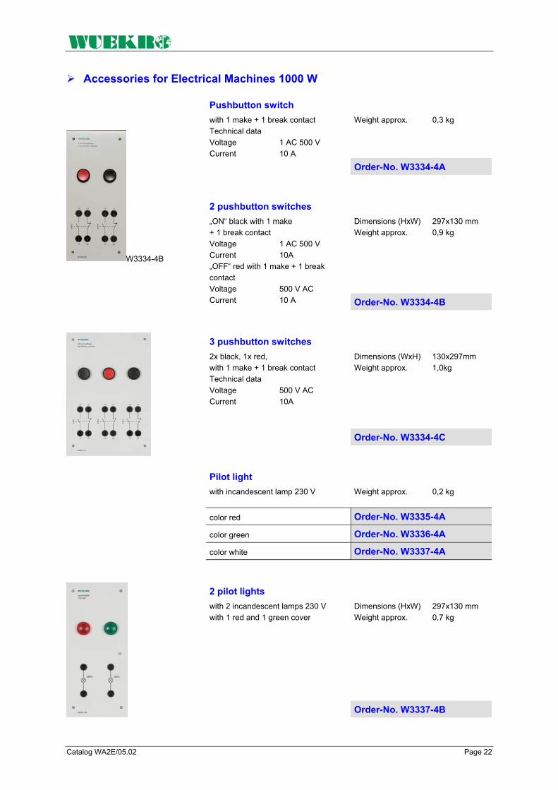
Catalog WA2E/05.02 Page 22
Accessories for Electrical Machines 1000 W
Weight approx. 0,3 kg
Pushbutton switch with 1 make + 1 break contact Technical data Voltage 1 AC 500 V Current 10 A
Order-No. W3334-4A
Dimensions (HxW) 297x130 mm Weight approx. 0,9 kg
W3334-4B
2 pushbutton switches „ON“ black with 1 make + 1 break contact Voltage 1 AC 500 V Current 10A „OFF“ red with 1 make + 1 break contact Voltage 500 V AC Current 10 A Order-No. W3334-4B
Dimensions (WxH) 130x297mm Weight approx. 1,0kg
3 pushbutton switches 2x black, 1x red, with 1 make + 1 break contact Technical data Voltage 500 V AC Current 10A
Order-No. W3334-4C
Pilot light with incandescent lamp 230 V
Weight approx. 0,2 kg
color red Order-No. W3335-4A color green Order-No. W3336-4A color white Order-No. W3337-4A
Dimensions (HxW) 297x130 mm Weight approx. 0,7 kg
2 pilot lights with 2 incandescent lamps 230 V with 1 red and 1 green cover
Order-No. W3337-4B

Catalog WA2E/05.02 Page 23
Accessories for Electrical Machines 1000 W
Weight approx. 0,3 kg
3 pilot lights with 3 incandescent lamps 230 V, white Order-No. W3338-4A
Weight approx. 0,3 kg
6 pilot lights with 6 incandescent lamps 230 V, white
Order-No. W3357-4A
Dimensions (HxW) 297x130 mm Weight approx. 0,8 kg
2 limit switches 1 break contact each Voltage 400 V AC Current 16 A
Order-No. W3340-4B
Dimensions (HxW) 297x130 mm Weight approx. 0,65 kg
On/off switch 2-pin Switch positions 0 - I - 0 - I Voltage AC 400/220 V DC Current 16 A
Order-No. W3341-4B
Dimensions (HxW) 297x130 mm Weight approx. 0,9 kg
Two-circuit double-interruption switch 2-pin; Switch positions 0 - I - 0 - II Voltage AC 400/230 V DC Current 16 A Order-No. W3342-4B
Dimensions (WxH) 260x297 mm Weight approx. 4,7 kg
Synchroscope Voltage AC 400 V
Order-No. W3440-4A
Weight approx. 0,5 kg
Two-circuit double-interruption switch 3-pin; Switch positions 0 - I - 0 - II Voltage AC 400/220 V DC Current 16 A
Order-No. W3342-4E
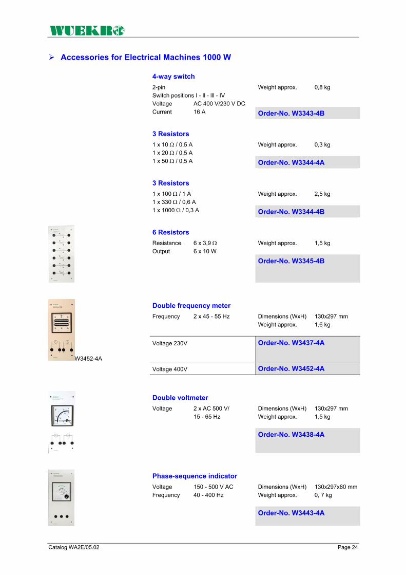
Catalog WA2E/05.02 Page 24
Accessories for Electrical Machines 1000 W
Weight approx. 0,8 kg
4-way switch 2-pin Switch positions I - Il - lll - IV Voltage AC 400 V/230 V DC Current 16 A Order-No. W3343-4B
Weight approx. 0,3 kg
3 Resistors 1 x 10 Ω / 0,5 A 1 x 20 Ω / 0,5 A 1 x 50 Ω / 0,5 A Order-No. W3344-4A
Weight approx. 2,5 kg
3 Resistors 1 x 100 Ω / 1 A 1 x 330 Ω / 0,6 A 1 x 1000 Ω / 0,3 A Order-No. W3344-4B
Weight approx. 1,5 kg
6 Resistors Resistance 6 x 3,9 Ω Output 6 x 10 W
Order-No. W3345-4B
Double frequency meter Frequency 2 x 45 - 55 Hz
Dimensions (WxH) 130x297 mm Weight approx. 1,6 kg
W3452-4A
Voltage 230V Order-No. W3437-4A
Voltage 400V Order-No. W3452-4A
Dimensions (WxH) 130x297 mm Weight approx. 1,5 kg
Double voltmeter Voltage 2 x AC 500 V/ 15 - 65 Hz
Order-No. W3438-4A
Dimensions (WxH) 130x297x60 mmWeight approx. 0, 7 kg
Phase-sequence indicator Voltage 150 - 500 V AC Frequency 40 - 400 Hz
Order-No. W3443-4A

Catalog WA2E/05.02 Page 25
Standard Training System Electrical Machines 1000 W
With the "Standard Training System Electrical Machines 1000W", the following experiments can be carried out:
1. DC Machines DC series-wound motor: • Motor operation • Measuring current, voltage,
speed, torque • Tracing characteristics DC shunt-wound machine: • Motor operation, self-excited • Motor operation, separately
excited • Generator operation, self-
excited • Generator operation,
separately excited • Measuring current, voltage,
resistance, speed, torque • Tracing characteristics DC compound-wound machine: • Motor operation • Generator operation • Measuring current, voltage,
speed, torque • Tracing characteristics
2. Single-Phase AC Machines Measuring current, voltage, speed, torque and output as well as tracing characteristics on: • Single-phase squirrel-cage
motor with starting and running capacitor
• Single-phase squirrel-cage motor with auxiliary starting winding
• Repulsion motor
3. Induction motors Measuring current, voltage, speed, torque and output as well as tracing characteristics on: • Three-phase squirrel-cage
induction motor suitable for star-delta starting
• Three-phase two-speed pole-changing induction motor with squirrel-cage rotor (Dahlander circuit)
• Three-phase pole-changing induction motor with squirrel-cage rotor with two separate windings
• Three-phase induction motor with slipring rotor
With three-phase squirrel-cage induction motors additionally: • Switch-on with motor
protection • Reversal • Star-delta starting • Stator-resistance starting
circuit • Operation at single-phase
mains • Reactive-power compensation • Pole-changing Dahlander • Pole-changing two separate
windings • Efficiency measurement With three-phase induction machines with slipring rotors additionally: • Starting circuits
4. Synchronous machines Measuring current, voltage, speed, torque and output as well as tracing characteristics on: • Measuring current, voltage,
speed, torque and output as well as tracing characteristics on:
• Three-phase synchronous machine with salient pole rotor and damper winding
• Mains synchronization • Isolated operation
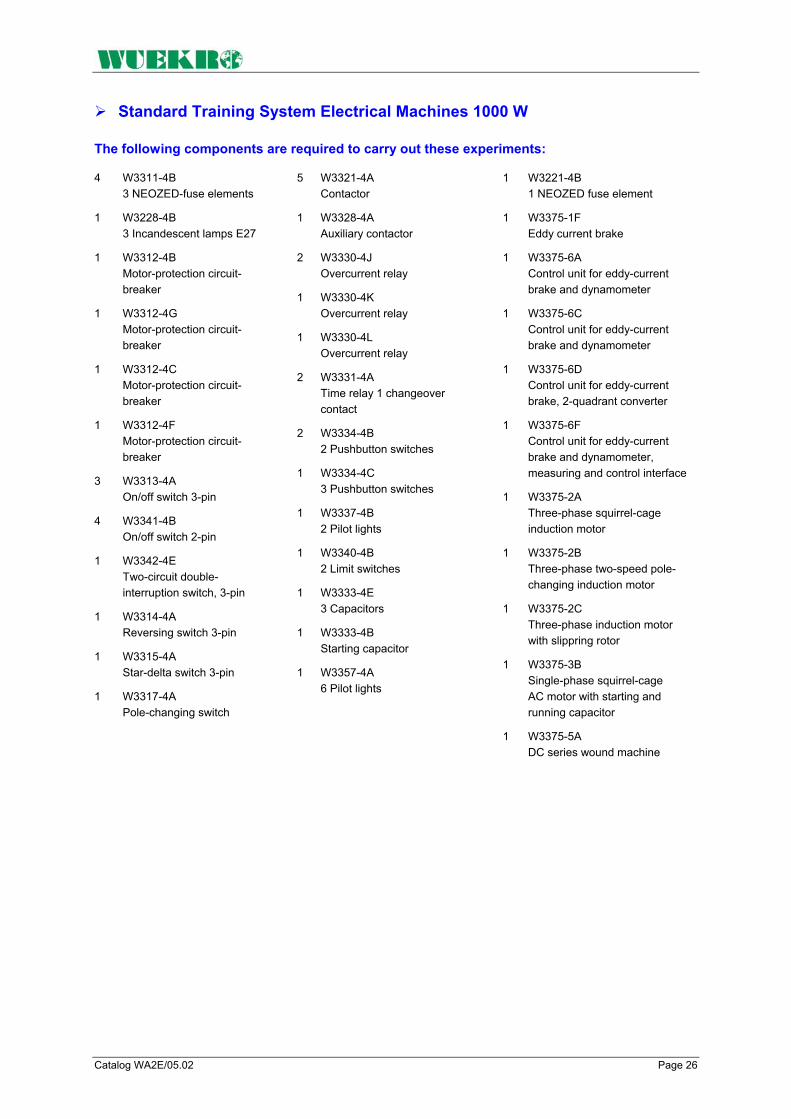
Catalog WA2E/05.02 Page 26
Standard Training System Electrical Machines 1000 W
The following components are required to carry out these experiments:
4 W3311-4B 3 NEOZED-fuse elements
1 W3228-4B 3 Incandescent lamps E27
1 W3312-4B Motor-protection circuit- breaker
1 W3312-4G Motor-protection circuit- breaker
1 W3312-4C Motor-protection circuit- breaker
1 W3312-4F Motor-protection circuit- breaker
3 W3313-4A On/off switch 3-pin
4 W3341-4B On/off switch 2-pin
1 W3342-4E Two-circuit double- interruption switch, 3-pin
1 W3314-4A Reversing switch 3-pin
1 W3315-4A Star-delta switch 3-pin
1 W3317-4A Pole-changing switch
5 W3321-4A Contactor
1 W3328-4A Auxiliary contactor
2 W3330-4J Overcurrent relay
1 W3330-4K Overcurrent relay
1 W3330-4L Overcurrent relay
2 W3331-4A Time relay 1 changeover contact
2 W3334-4B 2 Pushbutton switches
1 W3334-4C 3 Pushbutton switches
1 W3337-4B 2 Pilot lights
1 W3340-4B 2 Limit switches
1 W3333-4E 3 Capacitors
1 W3333-4B Starting capacitor
1 W3357-4A 6 Pilot lights
1 W3221-4B 1 NEOZED fuse element
1 W3375-1F Eddy current brake
1 W3375-6A Control unit for eddy-current brake and dynamometer
1 W3375-6C Control unit for eddy-current brake and dynamometer
1 W3375-6D Control unit for eddy-current brake, 2-quadrant converter
1 W3375-6F Control unit for eddy-current brake and dynamometer, measuring and control interface
1 W3375-2A Three-phase squirrel-cage induction motor
1 W3375-2B Three-phase two-speed pole- changing induction motor
1 W3375-2C Three-phase induction motor with slippring rotor
1 W3375-3B Single-phase squirrel-cage AC motor with starting and running capacitor
1 W3375-5A DC series wound machine

Catalog WA2E/05.02 Page 27
Standard - Training System Electrical Maschines 1000 W
to be continued ...necessary equipment Recommended Lab equipment
1 W3375-3C Single-phase squirrel-cage motor with auxiliary starting winding
1 W3375-4A Synchronous machine with salient pole rotor
1 W3375-4B Synchronous machine with non salient pole rotor
1 W3375-5B DC compound wound machine
1 W3375-5C DC shunt-wound machine
1 W3375-8B Controller
1 W3375-8C Controller
1 W3375-8D Single-coil slide resistor
1 W3375-8E Single-coil slide resistor
1 W3375-8F Single-coil slide resistor
1 W3375-8K Single-coil fixed resistor
1 W3375-8H 3-phase coil slide resistor
1 W3644-3D Inductive loading
1 W3644-3F Capacitive loading
1 W3428-4F Wattmeter
1 W3428-4D Wattmeter
1 W3434-4A Power factor meter
1 W3435-4A Power factor meter
1 W3443-4A Phase-sequence indicator
2 W3422-4A Moving-iron voltmeter
1 W3438-4A Double voltmeter
1 W3436-4A Frequency meter
1 W3452-4A Double frequency meter
1 W3440-4A Synchroscope
3 W3901-0A Set Connecting leads
1 W3010-8B V108 Experimental manual, "Connecting and Measuring el. Machines 1000 W"
1 W2700-1A Standard experimental set-up Power Engineering with power supplies, SCHUKO sockets and experimental frame

Catalog WA2E/05.02 Page 28
FAX – reply to: +49 (0)9721-64691 - 20 Sender: Receiver:
Company WUEKRO GmbH Dept. Sales Department Name Street Carl-Zeiss-Strasse 10 City 97424 Schweinfurt / Germany Phone + 49-(0)9721-64691-0 Fax + 49-(0)9721-64691-20 E-Mail [email protected] Internet www.wuekro.de No. of pages
incl. this page
Please send the following catalogues to the a.m. address!
Fundamentals of electrical Engineering
Installation circuits Bell ringing and entrance call stations Contactor circuits/Control technology Measurement and control of non- electrical quantities
Fundamentels of electronics Analog technology Digital technology Microprocessing technology
Closed loop control technology Analog control technology Digital control technology
Automation engineering SIMATIC S7-200/300/400, Software Technology simulators / Models Process control technology PCS7 AS-Interface Process simulation-software PROSIM 95 LOGO!
Electrical machines / Drive controls 300W - range 1000W - range 5kW - range Electr. drive control 300W/1000W Electr. drive control 5kW
Power electronics extra low voltage (24V) low voltage (230/400V)
Building management systems KNX / EIB
Protection schemes to VDE 0100
Radio- and TV technology AM/FM - Technology TV Technology Satellite - Technology
Air conditioning and refrigeration
Photovoltaic
Communication technology Modulation -/demodulation technology Optical fibre HICOM communication systems
Measuring systems, power supplies, Accessories
Experimental manuals, documentation, books
Remarks:
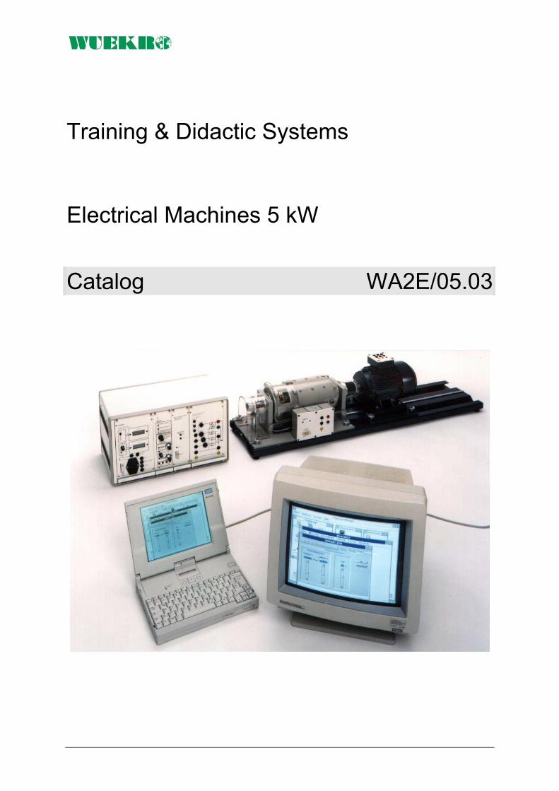
Training & Didactic Systems Electrical Machines 5 kW
Catalog WA2E/05.03

Page 2 Catalog WA2E/05.03
Our Services
• Development and production of didactic training systems • Teachware and documentation • Project engineering of complete lab's incl. furniture and lab equipment • Quotations on customer's demand • Installation, commissioning and training at site
Our Customers • Vocational training schools, technical schools, colleges and universities... • Industrial laboratories for vocational education and higher education
Fields of Technology • Fundamentals of electrical engineering
• Fundamentals of electronics
• Closed loop control technology
• Automation engineering
• Electrical machines / drive control
• Power electronics
• Building management systems
• Protection schemes to VDE 0100
• Radio- and TV technology
• Air conditioning and refrigeration
• Photovoltaic
• Communication technology
• Measuring systems, power supplies, accessories
• Experimental manuals, documentation For further information please contact: WUEKRO GmbH Carl-Zeiss-Strasse 10 D - 97424 Schweinfurt Germany Tel. + 49 (0) 9721-64691-0 Fax: + 49 (0) 9721-64691-20 E-Mail: [email protected] Internet: www.wuekro.de WUEKRO GmbH
All Rights reserved. Reprint not permitted. Technical changes without prior notice.. B10020515B – 01/13

Catalog WA2E/05.03 Page 3
Table of Contents Page Our Services, Customers and Scope of Supply 2 Training System Electrical Machines 5 kW 4 Introduction 5 Training Concept 6 Load Facilities, Drivers, Measuring Equipment 8 Electrical Machines 5 kW 9 DC-Machines 9 3-phase – Asynchronous Machines 11 3-phase – Synchronous Machines 12 Measuring Units / Loads 13 Accessories for für Electrical Machines 16 Experiments – Standard – Training System Electrical Machines 5 kW 22 Units - Standard – Training System Electrical Machines 5 kW 23 Fax - Reply 24

Page 4 Catalog WA2E/05.03
Training System Electrical Machines 5 kW
Training Systems – Assignment – Target audience
Project Theses
Diploma Theses
Practicals College / University
Continuing Education Practical Training College/University
Master craftsman / Technician Further Training at Chamber of commerce
Skilled Worker Training
5
kW R
ange
Fundamentals Vocational education school / Education in Industry
200
W
Ran
ge
10
00 W
Ran
ge

Catalog WA2E/05.03 Page 5
Introduction If you can analyze problems systematically and understand interrelation-ships, you'll have no difficulty in coping with future developments - in any field of technology. As your partner for training systems, we can provide you with the technical equipment you require for this purpose including the necessary know-how in the form of comprehensive instruction manuals, training documentation and extensive configuring and design aids. Systematic analysis in the field of electrical machines means learning about the behavior of electrical machines through exact measuring exercises and evaluation of the characteristics recorded. This includes comprehension of basic electric circuits such as star-delta connections, stator-resistance starting circuits etc. and the ability to connect these with the specific problems of the individual machine types.
Understanding interrelationships means to view the electrical machines in their relation to drive engineering and automatic control engineering: • Which electrical machine is
best suited for a specific application problem?
• Which control method should be used with an individual machine in order to ensure that the drive meets the highest requirements e.g. relative to dynamic response or control accuracy?
We see it as our task to help you answer these and similar questions on a practical basis and to provide suitable experimental equipment for scientific studies. Our training system gives you almost unlimited freedom, i.e. you can pick and choose elements to create your own "personal" training strategy. If you have an entire room at your disposal for use as a machine laboratory and if you attach importance to characteristics of "large" machines, the system of your choice would be our machines in the range up to 5 kW1). This system is especially suited for use at technical colleges and universities. Experimental sockets ensure operational safety even with equipment from this output range2). 1) Larger machines available on request. 2) For technical reasons, no experimental sockets are used with machines > 5 kW.
If the transport capability of the machines is a criterion besides the characteristics, the machines from the 1 kW range are right for you. They offer an ideal compromise between electrical operating behavior and low weight, which is also reflected in their extremely high cost effectiveness. This system can be used from basic training to practicals at technical colleges or universities and beyond. If due to the training situation you have to pay special attention to aspects such as mobility, training outside of technical rooms and space requirements, you will decide in favor of our 200 W machine range. Regardless which of the three systems you eventually choose, you will have devices at your disposal that are tailor-made for your individual requirements.

Page 6 Catalog WA2E/05.03
Training Concept The Aim The aim of our training concept for the field of electrical machines is to provide • vocational schools • technical colleges • universities and • in-firm training centers with systems for teaching the theoretical and practical knowledge which trainees and students require to learn and understand modern know-how about electrical machines and their control methods. The machines we use are purely industrial equipment whose charac-teristics have been idealized only in exceptional cases, e.g. induction machine with slipring rotor. This applies for the 200 W range, the 1000 W range as well as the 5 kW range. You can choose between different DC machines, AC machines, three-phase machines as well as special machines such as the DC and three-phase compound machine.
Brakes and Measuring Sytems The available brake assemblies include magnetic powder brakes, eddy-current brakes and dynamometers. The setpoint for the brakes can be input either via front panel or PC, and characteristics can be traced either via recorder or also via PC, where a soft-ware specifically designed for the machine range facilitates the process. While modules M1 to M5 focus on the electrical machine and its elementary control possibilities, modules M6 to M8 deal with technically expanded control methods up to the three-phase AC power controller SIKOSTART in combination with the squirrel-cage induction machine. Module M9 is devoted to the subject area of reactive-power compensation. The following matrix provides an overview of possible combinations of machine type and control method:
Practical instruction manuals Instruction manuals designed by didactically trained specialists are available for our 200 W and 1000 W training systems. These instruction manuals generally consist of 3 sections: Section 1: General section for intro-ducing the trainees to the objectives of the training program and providing basic theoretical knowledge. Section 2: Trainee's section containing measuring exercises. Value tables, diagrams and oscillograms must be filled out by the student or created on the PC. Section 3: Instructor's section containing the answers to questions in section 2. The purpose of this section is to reduce valuable preparation time and provide a check for instructors. Whether you choose machines from the 200 W or the 1000 W range, we can provide you with reliable instruction manuals for the appropriate system.

Catalog WA2E/05.03 Page 7
Training Concept
The Training Aim The concept The System • DC machines • Single-phase motors
- with running capacitor, - with starting and running
capacitor - resistance start
• Asynchronous and synchronous polyphase machines
• Special machines
The "Electrical Machines" training system allows you to teach the aims listed with 300-W machines, 1-kW machines and also with machines up to 5-kW (higher-power machines on request). Depending on customer requirements, we can supply either single machines or complete systems with machines, loading facilities, drivers and measuring equipment. Specially prepared technical literature forms the basis of theory teaching.
Our "Electrical Machines" training system consists of the following individual components: • 300-W machines • 1000-W machines • Machines up to 5 kW • Loading facilities • Drivers • Measuring equipment
300 W machines 1000 W machines Machines up to 5 kW Our 300-W machines are used primarily for training purposes in industry, trade and technical colleges. They are a handy size and can be easily assembled and dismantled. These "small" machines are "big" on electrical operating characteristics. They are industrial machines whose characteristics have only been modified for teaching purposes in exceptional cases. This is why they are also well suited to basic practical teaching in technical colleges and universities.
This is the ideal "middle ground" between the "small" 300-W machine and the "large" machines in the performance range up to 5 kW. Thanks to its low weight, compact dimensions and excellent electrical characteristics, this machine offers more universality of use than any other machine type.
If a machine laboratory is to be equipped and if practice-orientation is the main priority, this performance range is to be recommended. Demanding practical tests, engineering exams and certificate exams can all be set up easily in conjunction with these industrial drives.

Page 8 Catalog WA2E/05.03
Loads, Drivers, Measuring Equipment
Load facilities Drivers Measuring Equipment Brakes are available in the form of magnetic powder brakes and rotating eddy-current retarders (300-W and 1000-W range). They have been adapted exactly to the electrical machines. If the machine is to be subjected to both motive power loading and rheostatic loading, a DC dynamo-meter is recommended as loading facility (300-W, 1000-W and 5-kW ranges). All load facilities are equipped with optical indicating instruments, standardized analog outputs and interfaces for computer links.
The constantly increasing requirements of drive technology mean that modern converter equipment is required in addition to contactor equipment. Digital converters for polyphase machines, analog and microprocessor-controlled converters for DC drives, special equipment for servo and stepper motors finish off the machines as compact and intelligent drive units.
Measuring equipment as the interface between man and machine is of central significance in study and training. There is a correspondingly comprehensive and high-quality range of measured value processing systems and output devices available. Whether you are making measurements with a multimeter or a multifunction meter, recording characteristic curves via value tables or PC, or carrying out torque acquisition via current, foil strain gauge or torque metering shaft, there is measuring equipment available for all your requirements.
Features and Design
General The experimental machines feature the IM B 3 design with one shaft end and correspond to the VDE regulations 0530. The 5 kW machines are equipped with: • an experimental terminal
board. The ends of the windings brought out to the terminal board are connected to 4-mm-safety-socket outlets. The socket outlets are arranged on a plastic board in the same way as the connections of a normal terminal board of an industrial machine. The plastic board features the conventional industrial machine terminal designations.
• A PTC thermistor in order to protect the machines against thermal overload. This obviates overheating resulting from overload, high switching frequency, single phasing, large deviations in voltage, excessively high coolant temperatures or obstructed coolant flow. The leads of the thermistors are connected to 2-mm-socket-outlets in order to avoid faulty connections.
• A baseplate to compensate for differences in shaft height and to facilitate replacement of the machines. The baseplate features a guide mechanism on the underside for setting it onto the slide of the baseframe.
• A toothed gear coupling half which is identical for all machines and brake assemblies within each range. The coupling halves are connected to each other over an elastic adapter piece. This type of coupling and baseplate design allows you to combine any two machines to form one motor generator set as well as to couple each machine to the brake assemblies without having to change the coupling or the baseplate.
In order to keep the noise level low, preference has been given to machines with rated speeds of 1500 rev/min.

Catalog WA2E/05.03 Page 9
Electrical Machines 5 kW The electrical machines are equipped as follows::
• with premounted coupling • with base plate, to compensate the height of axes and for easy
replacement of machines • with thermistor protection
Types of electrical machines 5kW
DC - Machines
DC Series-wound machine Weight approx. 135 kg
Technical data Degree of Protection IP 21 Output 5 kW
Voltage 420 V Current 15 A Speed 1500 min-1 Bestell.-Nr. W3377-5A
DC Compound-wound machine Shunt winding: Field voltage 310 V Field current 1,0 A Weight approx. 135 kg
with series and shunt winding; for motor and generator operation Technical data Degree of Protection IP 21 Motor operation Output 5 kW Voltage 420 V Current 14 A Speed 1500 min-1
Generator operation Output 5 kW Voltage 400 V Current 12,5 A Speed 1500 min-1
Order-No. W3377-5B

Page 10 Catalog WA2E/05.03
DC - Machines 5 kW
DC Shunt-wound machine Shunt winding Field voltage 310 V Field current 1,1 A Weight approx. 135 kg
for motor and generator operation Technical data Degree of Protection IP 21 Motor operation Output 5 kW Voltage 420 V Current 14 A Speed 1500 min-1
Generator operation Output 5 kW Voltage 400 V Current 12,5 A Speed 1500 min-1
Order-No. W3377-5C
DC Shunt-wound machine
with built-on tachogenerator Voltage 30 V / 1000 min-1 Order-No. W3377-5G
DC Shunt-wound machine, cradle-mounted Motor operation Output 10 kW Voltage 420 V Current 28 A Speed 1500 min-1 Field voltage 310 V Field current 1,3 A Resolution of tachogenerator 30 V / 1000 min-1 Weight approx. 185 kg
for motor- und generator operation, torque recorded via strain gauge, speed recorded via DC tacho-generator
Technical data Degree of Protection IP 21 Generator operation Output 10 kW Voltage 400 V Current 25 A Speed 1500 min-1
Order-No. W3377-1H

Catalog WA2E/05.03 Page 11
3-phase – Asynchronous Machines 5 kW
Three-phase squirrel-cage induction motor Weight approx. 60 kg
for star-delta-operation Technical data Degree of Protection IP 21 Output 5 kW
Voltage 3 AC 230 V / 400 V / 50 Hz Current 11 A Speed 1445 min-1 Order-No. W3377-2A
Three-phase two-speed pole-changing induction motor Weight approx. 60 kg
with squirrel-cage rotor (Dahlander circuit) Technical data Degree of Protection IP 21 Output 4,7 kW / 5,7 kW
Voltage 3 AC 400 V / 50 Hz Current 10 A / 11,5 A Speed 1450 min-1 / 2900 min-1
Order-No. W3377-2B
Three-phase two-speed pole-changing induction motor Weight approx. 60 kg
with squirrel-cage rotor and two separate windings Technical data Degree of Protection IP 21 Output 3 kW / 4 kW
Voltage 3 AC 400 V / 50 Hz Current 8,5 A / 9 A Speed 965 / 1430 min-1
Order-No. W3377-2G
Three-phase induction motor with slippring rotor Weight approx. 80 kg
with slippring rotor, area covered with plexi-glass Technical data Degree of Protection IP 21 Output 5 kW
Voltage 3 AC 400 V / 50 Hz Current 11,5 A Speed 1435 min-1
Locked rotor voltage 180 V Rated rotor- current 18,5 A
Order-No. W3377-2C
Page 12 Catalog WA2E/05.03
3-phase – Synchronous Machines 5 kW
Three-phase synchronous machine with salient pole rotor Weight approx. 120 kg
and damper winding; for motor and generator operation Technical data Degree of Protection IP 21 Speed 1500 min-1
Generator operation Output 5 kVA Voltage 3 AC 400 V 50 Hz Current 7,3 A
Motor operation Speed 1500 min-1 Output 5 kW Voltage 3 AC 400 V 50 Hz Current 9,5 A Field voltage 110 V Field current 3,2 A
Order-No. W3377-4A
Three-phase synchronous machine with non-salient pole rotor Weight approx. 120 kg
and damper winding; for motor and generator operation Technical data Degree of Protection IP 21 Speed 1500 min-1
Generator operation Output 4,5 kVA Voltage 3 AC 400 V 50Hz Current 8,1 A
Motor operation Speed 1500 min-1 Output 4,5 kW Voltage 3 AC 400 V 50 Hz Current 8,8 A Field voltage 110 V Field current 3,4 A
Order-No. W3377-4B

Catalog WA2E/05.03 Page 13
Measuring Equipment / Loads
The following subjects can be taught by using the standard training system with electrical machines 5kW • Setup and commissioning of a
testing station for electrical machines. Various DC, synchronous and induction machines as well as a DC dynamometer are available.
• Determining the suitability of specific machines for diverse drive requirements
• Determining the advantages/limitations of controlling machines with modern electronic power converters
• Incorporating and applying PC measuring technology
• Studying drives with the aid of conventional or PC measuring technology
Converter SIMOREG DC-Master
Technical data: Rated supply voltage 3AC 400V Rated frequency 45 to 65Hz Rated DC voltage 420 V Rated direct current 30 A Overload for 5 min. 1,5 - times x rated current Rated output 12 kW Rated DC voltage field max. 325 V Rated direct current field 5 A Dimensions (HxWxD) 800x500x450 mm Weight approx. 30 kg
In circulating-current-free, inverse-parallel connection (B6) A (B6) C, with digital closed-loop control (16 bit microprocessor) for feeding a DC motor with a maximum output of 6kW. Suitable for four-quadrant drives with regulated field supply. The compact converter is operated via an integrated parameterization unit (display and keyboard). Operating statuses and faults are indicated. With RS 232 serial interface. Mounted in a rack-type sheet-steel housing. Plastic front panel with mimic diagram and designations. Order-No. W3643-1M

Page 14 Catalog WA2E/05.03
Measuring Equipment / Loads
Technical data Generator operation: Braking power 10 kW Voltage 400 V Current ca. 25 A Speed 1500 min-1 Motor operation: Output 10 kW Voltage 420 V Current ca. 28 A Speed 1500 min-1 Field voltage 310 V Field current ca. 1,3 A Degree of Protection IP 21 Weight approx. 185 kg
DC shunt-wound machine cradle-mounted Speed adjustable via armature control from 100 to 1500 rev/min at constant torque and via field weak-ening from 1500 to 3000 rev/min at constant output; with built-on electric torque load cell (strain gauge); with tachogenerator and pulse generator combination fitted on the non-drive end (30 V/1000 rev/min 1024 pulses/rev); with built-in temperature monitor (trigger temperature approx. 90 °C) and fitted half-coupling. Associated control unit W3643-1M.
Order-No. W3377-1H
Outputs: Analog outputs for speed, torque and calculated output; brought out to 4-mm-safety-lab-sockets Speed 3000 min-1 = 10 V Torque 60 Nm = 10 V Output 10 kW = 10 V The 9-pole Sub D-cable is in the scope of delivery.
Measuring and evaluating unit Measuring and evaluating unit for speed, torque and calculated output for the dynamometer W3377-1H. With display on 3 digital measuring instruments with LCD.
Technical data Supply voltage 1 AC 230 V/ 50 Hz Inputs: Speed and torque actual values from terminal board of the DC dynamometer via prepared measuring leads. The prepared measuring leads are included in the scope of delivery.
Order-No. W3377-1V
Output voltage 0 – 5 V Accuracy under 1 % Error of linearity ± 0,2 % Minimum time of reaction under 1 µs Power supply ± 15 V/150 mA Dimensions (WxHxD) 260x297x100 mm Weight approx.: 0.8 kg
Transducer (voltage)
Experimental panel for floating measurements of DC, AC and
pulse voltages; with electrical isolation between primary and secondary circuits. The panel features 3 built-in transducers with 4 different measuring ranges. The voltage inputs are brought out to 4mm safety lab sockets, the voltage outputs to 2mm sockets and BNC sockets. The power supply inputs are brought out to 2mm sockets. Technical data Input voltage max. 500/400/250/100 V switch-selectable Order-No. W3644-4J

Catalog WA2E/05.03 Page 15
Measuring Equipment / Loads
Technical data: Input current max. 12,5 A Output voltage 0 – 5 V Accuracy under 1 % Error of linearity under 0,1 % Minimum time of reaction under 1 µs Power supply ± 15 V/50 mA Dimensions (WxHxD) 297x130x60 mm Weight approx. 0,5 kg
Precision measuring transducer (current, 12,5 A)
Experimental panel for floating measurements of DC, AC and pulse voltages; with electrical isolation between primary and secondary circuits. The panel features 3 built-in transducers with 4 different measuring ranges. The voltage inputs are brought out to 4mm safety lab sockets, the voltage outputs to 2mm sockets and BNC sockets. The power supply inputs are brought out to 2mm sockets. Order-No. W3410-4C
Technical data: Input current max. 25 A Output voltage 0 – 5 V Accuracy under 1 % Error of linearity under 0,1 % Minimum time of reaction under 1 µs Power supply ± 15 V/50 mA Dimensions (WxHxD) 297x130x60 mm Weight approx. 0,5 kg
Precision measuring transducer (current, 25 A)
Experimental panel for floating measurements of DC, AC and pulse voltages; with electrical isolation between primary and secondary circuits. The panel features 3 built-in transducers with 4 different measuring ranges. The voltage inputs are brought out to 4mm safety lab sockets, the voltage outputs to 2mm sockets and BNC sockets. The power supply inputs are brought out to 2mm sockets.
Order-No. W3410-4D
Technical data: Input current max. 50 A Output voltage 0 – 5 V Accuracy under 1 % Error of linearity under 0,1 % Minimum time of reaction under 1 µs Power supply ± 15 V/50 mA Dimensions (WxHxD) 297x130x60 mm Weight approx. 0,5 kg
Precision measuring transducer (current, 50 A)
Experimental panel for floating measurements of DC, AC and pulse voltages; with electrical isolation between primary and secondary circuits. The panel features 3 built-in transducers with 4 different measuring ranges. The voltage inputs are brought out to 4mm safety lab sockets, the voltage outputs to 2mm sockets and BNC sockets. The power supply inputs are brought out to 2mm sockets.
Order-No. W3410-4E

Page 16 Catalog WA2E/05.03
Accessories for Electrical Machines 5 kW
Baseframe Dimensions (WxHxD) 2200x460x200 mm Weight approx.: 120 kg
Baseframe for mounting the dynamometer, an experimental machine and a flywheel, or two experimental machines and a measuring shaft.
Torsionally rigid design, galvanized; mounted on vibration dampers; with draw spindles and baseplate guide for rapid fitting and removal of experimental machines; with coupling cover. Order-No. W3377-8A
Rotor controller Weight approx. 25 kg
For the rotor-locking of machines from the 5 kW range, such as for example for use of the three-phase induction motor with slipring rotor as three-phase transformer. Designed as gearbox with handwheel. With half-coupling and coupling cover, with baseplate for setup and centering on the baseframe. Order-No. W3377-2D
Controller Degree of Protection IP 20 Voltage 180 V Current 18,5 A Weight approx. 15 kg
for starting the three-phase induction motor with slipring rotor and reducing the speed by 50 % at constant torque, designed as step resistor with pulse contact, installed in housing with circuit diagram on front. All terminals are brought out to 4-mm safety lab sockets.
Order-No. W3377-8B
Load resistor Degree of Protection IP 20 Voltage 400 V Current 0,12 ... 12,5 A Weight approx. 40 kg
for adjustable loading of the DC machines as well as for adjustable single-phase loading of the 3-phase synchronous machines
with integrated 6-step-cam-operated switch as corse adjustment and integrated slide resistor as fine adjustment
Order-No. W3377-8E

Catalog WA2E/05.03 Page 17
Accessories for Electrical Machines 5 kW
Single-coil slide Resistor Weight approx. 5 kg
for adjusting the excitation of the DC machines. With cover, rubber feet and earthing screw. Terminals brought out to 4-mm safety lab sockets.
Degree of Protection IP 20 Resistor 470 Ω Voltage 310 V Current 1,1 - 0,44 A
Order-No. W3377-8F
Double-coil fixed Resistor Weight approx. 10 kg
As stator-resistor for 3-phase squirrel cage induction motor. With cover, rubber feet and earthing screw. Terminals brought out to 4-mm safety lab sockets.
Degree of Protection IP 20 Resistor 12 Ω Voltage 2 AC 400 V Current 11 A Operating time 10 s at 15 operations/h Order-No. W3377-8K
Single-coil fixed Resistor Weight approx. 10 kg
for adjusting the excitation of the synchronous machines. Field regulation 1 : 2,5 With cover, rubber feet and earthing screw. Terminals brought out to 4-mm safety lab sockets.
Degree of Protection IP 20 Voltage 110 V Resistor 56 Ω Current 3,2 - 1,3 A
Order-No. W3377-8D
Single-coil fixed Resistor Weight approx. 5 kg
As starting resistor for W3377-8F, if the field voltage is 400 V. With cover, rubber feet and earthing screw. Terminals brought out to 4-mm safety lab sockets.
Degree of Protection IP 20 Resistor 82 Ω Current 1,1 A
Order-No. W3377-8V
Controller Weight approx. 15 kg
for starting DC motors and reducing the speed by 50% at constant torque. With cover, rubber feet and earthing screw. Terminals brought out to 4-mm safety lab sockets.
Degree of Protection IP 20 Voltage 400 V Current 15 A
Order-No. W3377-8C
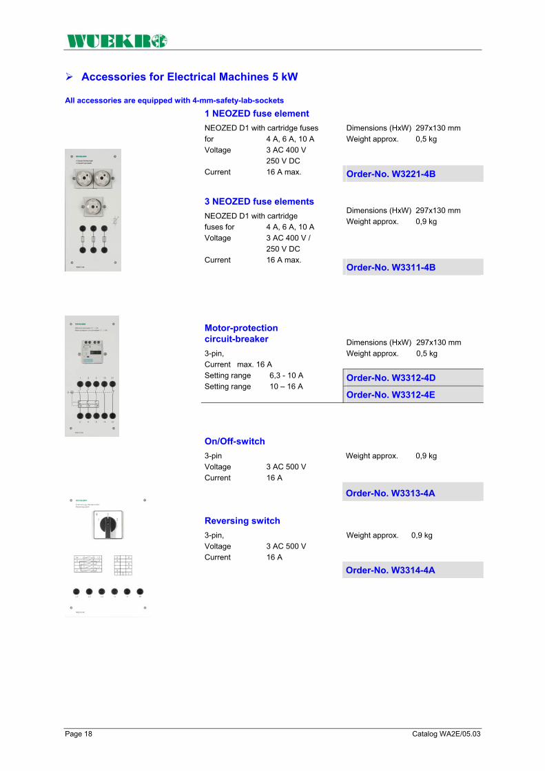
Page 18 Catalog WA2E/05.03
Accessories for Electrical Machines 5 kW All accessories are equipped with 4-mm-safety-lab-sockets
Dimensions (HxW) 297x130 mm Weight approx. 0,5 kg
1 NEOZED fuse element NEOZED D1 with cartridge fuses for 4 A, 6 A, 10 A Voltage 3 AC 400 V 250 V DC Current 16 A max. Order-No. W3221-4B
Dimensions (HxW) 297x130 mm Weight approx. 0,9 kg
3 NEOZED fuse elements NEOZED D1 with cartridge fuses for 4 A, 6 A, 10 A Voltage 3 AC 400 V / 250 V DC Current 16 A max.
Order-No. W3311-4B
Dimensions (HxW) 297x130 mm Weight approx. 0,5 kg
Order-No. W3312-4D
Motor-protection circuit-breaker 3-pin, Current max. 16 A Setting range 6,3 - 10 A Setting range 10 – 16 A
Order-No. W3312-4E
On/Off-switch 3-pin Voltage 3 AC 500 V Current 16 A
Weight approx. 0,9 kg
Order-No. W3313-4A
Reversing switch 3-pin, Voltage 3 AC 500 V Current 16 A
Weight approx. 0,9 kg
Order-No. W3314-4A
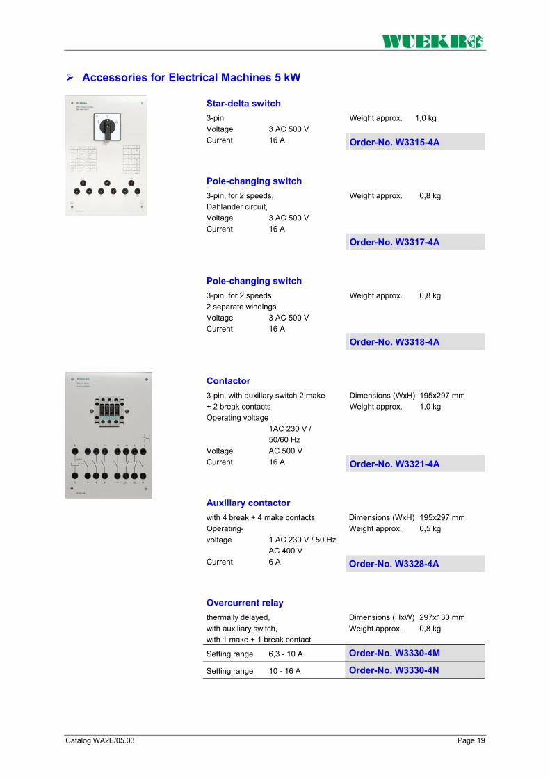
Catalog WA2E/05.03 Page 19
Accessories for Electrical Machines 5 kW
Weight approx. 1,0 kg
Star-delta switch 3-pin Voltage 3 AC 500 V Current 16 A Order-No. W3315-4A
Weight approx. 0,8 kg
Pole-changing switch 3-pin, for 2 speeds, Dahlander circuit, Voltage 3 AC 500 V Current 16 A
Order-No. W3317-4A
Weight approx. 0,8 kg
Pole-changing switch 3-pin, for 2 speeds 2 separate windings Voltage 3 AC 500 V Current 16 A
Order-No. W3318-4A
Dimensions (WxH) 195x297 mm Weight approx. 1,0 kg
Contactor 3-pin, with auxiliary switch 2 make + 2 break contacts Operating voltage 1AC 230 V / 50/60 Hz Voltage AC 500 V Current 16 A Order-No. W3321-4A
Dimensions (WxH) 195x297 mm Weight approx. 0,5 kg
Auxiliary contactor with 4 break + 4 make contacts Operating- voltage 1 AC 230 V / 50 Hz AC 400 V Current 6 A Order-No. W3328-4A
Overcurrent relay thermally delayed, with auxiliary switch, with 1 make + 1 break contact
Dimensions (HxW) 297x130 mm Weight approx. 0,8 kg
Setting range 6,3 - 10 A Order-No. W3330-4M
Setting range 10 - 16 A Order-No. W3330-4N
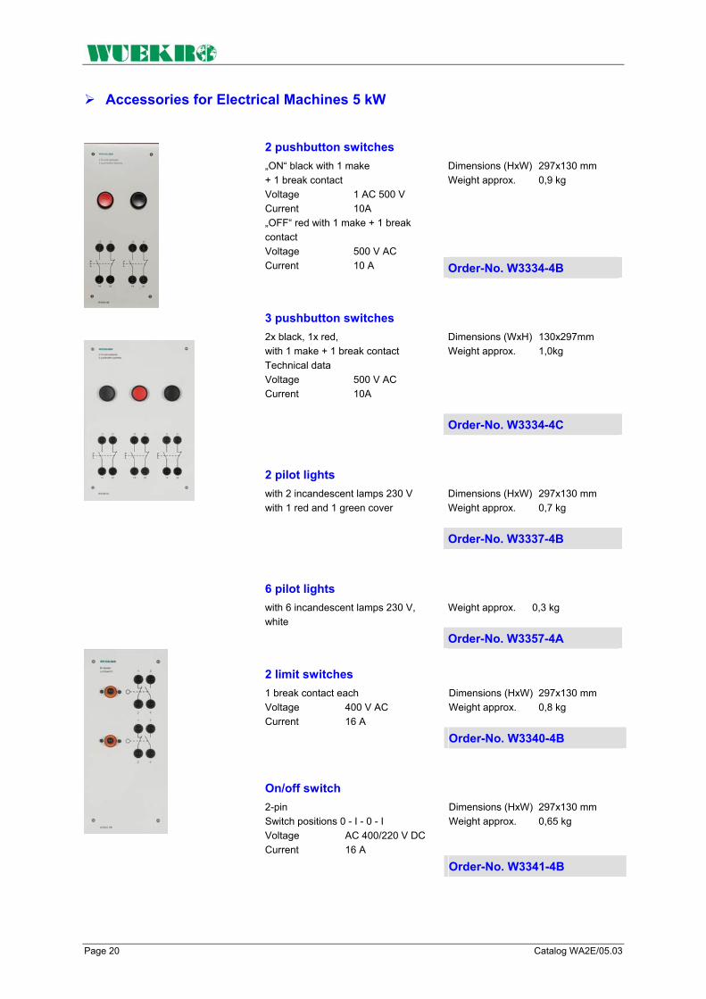
Page 20 Catalog WA2E/05.03
Accessories for Electrical Machines 5 kW
Dimensions (HxW) 297x130 mm Weight approx. 0,9 kg
2 pushbutton switches „ON“ black with 1 make + 1 break contact Voltage 1 AC 500 V Current 10A „OFF“ red with 1 make + 1 break contact Voltage 500 V AC Current 10 A Order-No. W3334-4B
Dimensions (WxH) 130x297mm Weight approx. 1,0kg
3 pushbutton switches 2x black, 1x red, with 1 make + 1 break contact Technical data Voltage 500 V AC Current 10A
Order-No. W3334-4C
Dimensions (HxW) 297x130 mm Weight approx. 0,7 kg
2 pilot lights with 2 incandescent lamps 230 V with 1 red and 1 green cover
Order-No. W3337-4B
6 pilot lights with 6 incandescent lamps 230 V, white
Weight approx. 0,3 kg
Order-No. W3357-4A
Dimensions (HxW) 297x130 mm Weight approx. 0,8 kg
2 limit switches 1 break contact each Voltage 400 V AC Current 16 A
Order-No. W3340-4B
Dimensions (HxW) 297x130 mm Weight approx. 0,65 kg
On/off switch 2-pin Switch positions 0 - I - 0 - I Voltage AC 400/220 V DC Current 16 A
Order-No. W3341-4B

Catalog WA2E/05.03 Page 21
Accessories for Electrical Machines 5 kW
Dimensions (HxW) 297x130 mm Weight approx. 0,65 kg
On/off switch 2-pin, Switch positions 0 - I - 0 - I Voltage AC 500 / 440 V DC Current 40 A
Order-No. W3341-4C
Dimensions (HxW) 297x130 mm Weight approx. 0,9 kg
Two-circuit double-interruption switch 2-pin, Switch positions 0 - I - 0 - II Voltage AC 500 / 440 V DC Current 40 A
Order-No. W3342-4C
Dimensions (HxW) 297x130 mm Weight approx. 0,9 kg
Two-circuit double-interruption switch 3-pin, Switch positions 0 - I - 0 - II Voltage AC 400 / 220 V DC Current 16 A
Order-No. W3342-4E
Dimensions (WxH) 260x297 mm Weight approx. 4,7 kg
Synchroscope Voltage AC 400 V
Order-No. W3440-4A
Dimensions (WxH) 130x297 mm Weight approx. 1,6 kg
Double frequency meter Frequenz 2 x 45 bis 55 Hz Voltage AC 400V
Order-No. W3452-4A
Dimensions (WxH) 130x297 mm Weight approx. 1,5 kg
Double voltmeter Technical data Voltage 2 x AC 500 V/ 15-65 Hz
Order-No. W3438-4A
Dimensions (WxH) 130x297 mm Weight approx. 0, 7 kg
Phase-sequence indicator Technical data Voltage 150 bis 500 V AC Frequenz 40 bis 400 Hz
Order-No. W3443-4A
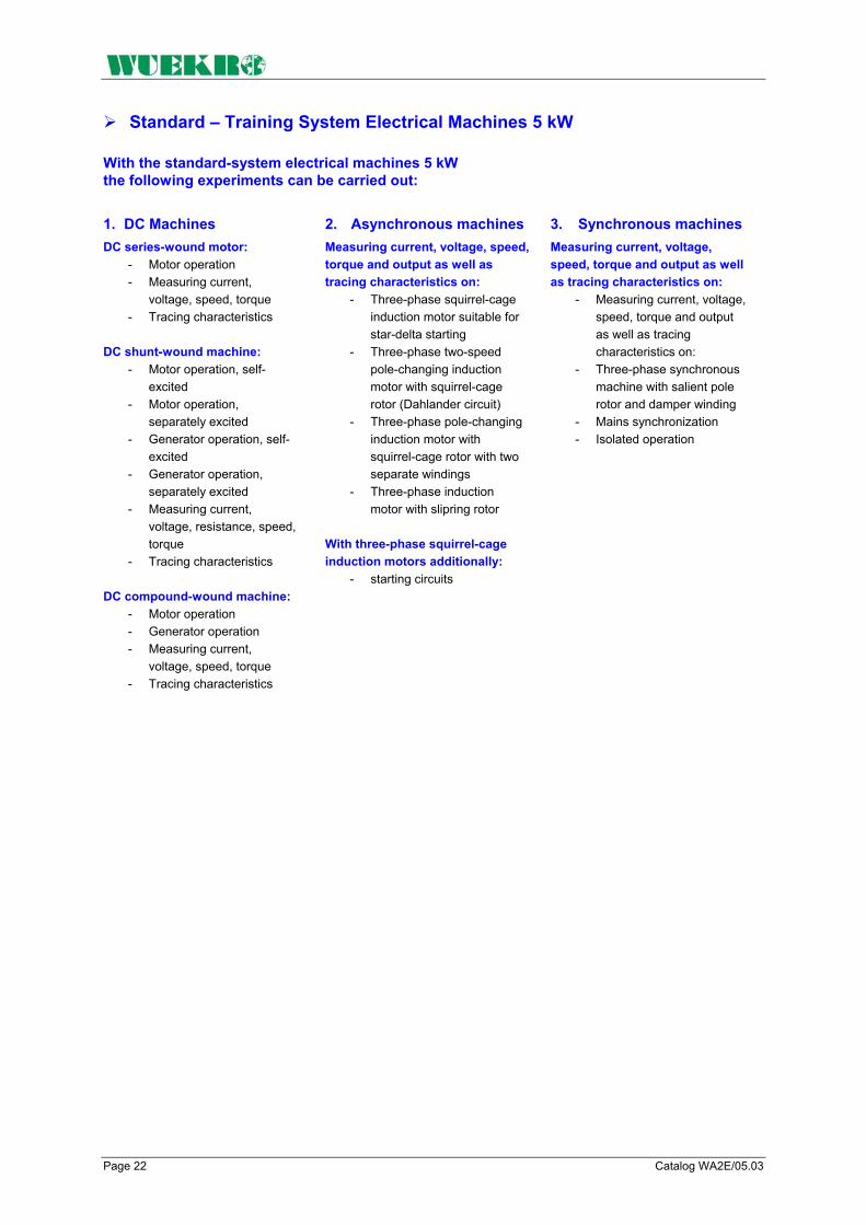
Page 22 Catalog WA2E/05.03
Standard – Training System Electrical Machines 5 kW
With the standard-system electrical machines 5 kW the following experiments can be carried out:
1. DC Machines DC series-wound motor:
- Motor operation - Measuring current,
voltage, speed, torque - Tracing characteristics
DC shunt-wound machine:
- Motor operation, self-excited
- Motor operation, separately excited
- Generator operation, self-excited
- Generator operation, separately excited
- Measuring current, voltage, resistance, speed, torque
- Tracing characteristics DC compound-wound machine:
- Motor operation - Generator operation - Measuring current,
voltage, speed, torque - Tracing characteristics
2. Asynchronous machines Measuring current, voltage, speed, torque and output as well as tracing characteristics on:
- Three-phase squirrel-cage induction motor suitable for star-delta starting
- Three-phase two-speed pole-changing induction motor with squirrel-cage rotor (Dahlander circuit)
- Three-phase pole-changing induction motor with squirrel-cage rotor with two separate windings
- Three-phase induction motor with slipring rotor
With three-phase squirrel-cage induction motors additionally:
- starting circuits
3. Synchronous machines Measuring current, voltage, speed, torque and output as well as tracing characteristics on:
- Measuring current, voltage, speed, torque and output as well as tracing characteristics on:
- Three-phase synchronous machine with salient pole rotor and damper winding
- Mains synchronization - Isolated operation

Catalog WA2E/05.03 Page 23
Standard – Training System Electrical Machines 5 kW
The following components are required:
1 W3377-1H DC shunt-wound machine
1 W3377-8A Baseframe
1 W3643-1M SIMOREG K converter
1 W3377-1V Measuring unit
1 W3644-4J transducer (voltage)
1 W3410-4D transducer (current)
1 W3410-4E transducer (current)
1 W3377-2D Rotor controller
1 W3377-5A DC series-wound machine
1 W3377-5B DC compound-wound machine
1 W3377-5C DC shunt-wound machine
1 W3377-2A Three-phase squirrel-cage induction motor
1 W3377-2B Three-phase two-speed pole-changing induction motor
1 W3377-2G Three-phase pole-changing induction motor
1 W3377-2C Three-phase induction motor with slipring rotor
1 W3377-4A Three-phase synchronous machine
1 W3377-4B Three-phase synchronous machine
1 W3377-8C Controller
3 W3377-8E Single-coil slide resistor
1 W3377-8V Single-coil fixed resistor
1 W3377-8F Single-coil slide resistor
1 W3377-8K Double-coil fixed resistor
1 W3377-8B Controller
1 W3377-8D Single-coil slide resistor
2 W3311-4B 3 fuse elements
3 W3341-4C On/off switch
1 W3342-4C Two-circuit double- interruption switch
3 W3334-4B 2 pushbutton switches
1 W3312-4E Motor-protection circuit- breaker
2 W3313-4A On/off switch
1 W3314-4A Reversing switch
1 W3342-4E Two-circuit double- interruption switch
1 W3315-4A Star-delta switch
1 W3317-4A Pole-changing switch
5 W3321-4B Contactor
1 W3328-4A Auxiliary contactor
2 W3330-4N Overcurrent relay
2 W3330-4M Overcurrent relay
1 W3331-4B Time relay
1 W3334-4C 3 pushbutton switches
1 W3340-4B 2 limit switches
1 W3337-4B 2 pilot lamps
3 W3341-4B On/off switch
1 W3221-4A 1 fuse element
1 W3312-4D Motor protection circuit breaker
3 W3311-4A 3 fuse elements
1 W3342-4E Two-circuit double- interruption switch
1 W3357-4A 6 pilot lights
1 W3436-4A Frequency meter
3 W5431-1A Moving Coil Demonstration Multimeter
1 W5431-1C Electronic Power Meter
1 W5431-1D Electronic Phase Angle/Power Factor Meter
1 W3440-4A Synchroscope
1 W3438-4A Double voltmeter
1 W3452-4A Double frequency meter
1 W3443-4A Phase-sequence indicator
1 W3010-8B V108 Experimental manual Connecting and Measuring Electrical Machines
3 W3901-0A Set Connecting leads

Page 24 Catalog WA2E/05.03
FAX – Reply to: +49 (0)9721 - 64691 - 20 Sender: Receiver:
Company WUEKRO GmbH Dept. Sales Department Name Street Carl-Zeiss-Strasse 10 City 97424 Schweinfurt / Germany Phone + 49-(0)9721-64691-0 Fax + 49-(0)9721-64691-20 E-Mail [email protected] Internet www.wuekro.de No. of pages
incl. this page
Please send the following catalogues to the a.m. address!
Fundamentals of electrical Engineering
Installation circuits Bell ringing and entrance call stations Contactor circuits/Control technology Measurement and control of non- electrical quantities
Fundamentels of electronics Analog technology Digital technology Microprocessing technology
Closed loop control technology Analog control technology Digital control technology
Automation engineering SIMATIC S7-200/300/400, Software Technology simulators / Models Process control technology PCS7 AS-Interface Process simulation-software PROSIM 95 LOGO!
Electrical machines / Drive controls 300W - range 1000W - range 5kW - range Electr. drive control 300W/1000W Electr. drive control 5kW
Power electronics extra low voltage (24V) low voltage (230/400V)
Building management systems KNX / EIB
Protection schemes to VDE 0100
Radio- and TV technology AM/FM - Technology TV Technology Satellite - Technology
Air conditioning and refrigeration
Photovoltaic
Communication technology Modulation -/demodulation technology Optical fibre HICOM communication systems
Measuring systems, power supplies, Accessories
Experimental manuals, documentation, books
Remarks:

Training & Didactic Systems Electrical Drive Systems 300 W/1000 W
Catalog WA2E/05.04

Page 2 Catalog WA2E/05.04
Our Services
• Development and production of didactic training systems • Teachware and documentation • Project engineering of complete lab's incl. furniture and lab equipment • Quotations on customer's demand • Installation, commissioning and training at site
Our Customers • Vocational training schools, technical schools, colleges and universities... • Industrial laboratories for vocational education and higher education
Fields of Technology • Fundamentals of electrical engineering
• Fundamentals of electronics
• Closed loop control technology
• Automation engineering
• Electrical machines / drive control
• Power electronics
• Building management systems
• Protection schemes to VDE 0100
• Radio- and TV technology
• Air conditioning and refrigeration
• Photovoltaic
• Communication technology
• Measuring systems, power supplies, accessories
• Experimental manuals, documentation For further information please contact: WUEKRO GmbH Carl-Zeiss-Strasse 10 D – 97424 Schweinfurt Germany Tel. + 49 (0) 9721-64691-0 Fax: + 49 (0) 9721-64691-20 E-Mail: [email protected] Internet: www.wuekro.de WUEKRO GmbH
All Rights reserved. Reprint not permitted. Technical changes without prior notice.. B20020611B – 01/13

Catalog WA2E/05.04 Page 3
Table of Contents Page Our Services, Customers and Scope of Supply 2 Training System Electrical Drive Systems 300 W / 1000 W 4 Introduction / Training Concept 5 DC Drive Technology - didactical industrial unit 6 AC Drives Technology – didactical industrial unit 8 Electrical Drive Systems – 1000 W Test Station 10 Measuring Equipment, Load Facilities 11 Control Units 13 Software “DriveCoach” 15 Test Units 16 DC Drive System 16 Servo Drive System 18 Standard Variable-Speed AC Drive System 20 Standard AC Drive Control System 22 Stepping Motor Drive System 24 Accessories - Measuring Equipment 26 Notes 27 Fax – Reply 28

Page 4 Catalog WA2E/05.04
Training System Electrical Drive Systems 300 W / 1000 W
Training Systems – Assignment – Target audience Project Theses
Diploma Theses
Practicals College / University
Continuing Education Practical Training College / University
Master craftsman / Technician Further Training at Chamber of Commerce
Skilled Worker Training
5
kW R
ange
Fundamentals Vocational education school / Education in Industry
300
W
Ran
ge
10
00 W
Ran
ge

Catalog WA2E/05.04 Page 5
Introduction, Training Concept If you can analyze problems systematically and understand interrelationships, you'll have no difficulty in coping with future developments - in any field of technology. As your partner for training systems, we can provide you with the technical equipment you require for this purpose including the necessary know-how in the form of comprehensive instruction manuals, training documentation and extensive configuring and design aids.
Systematic analysis in the field of power electronics means learning about basic circuits, such as DC chopper controllers and AC power controllers, through specially designed measuring exercises and understanding the operating principle of devices and the real behavior of components. Understanding interrelationships means to see power electronics in terms of their relationship with drive and control systems.
• How can I apply open-loop and closed-loop controls in electric drives to achieve virtually no-loss operation?
• Which power electronics components can be combined to form drive units which meet special technical requirements such as, for example, good dynamic response, special speed/torque response, surge load, etc.
Our task should be to help you to answer these and similar questions on a practical basis and to provide suitable experimental equipment for scientific studies.
The aim The subject area Practice oriented
experimental manuals The aim of our training concept for power electronics and drive systems with closed-loop control is to provide
- vocational schools - technical colleges - universities and
in-firm training center with systems for teaching the theoretical and practical knowledge which trainees and students require to learn and understand morn industrial technology.
Two options are also available for the subject area “Drive systems with closed-loop control”, regardless of which system you wish to use for teaching power electronics, i.e. 1. Specially designed industrial
training equipment on 230 / 400 V basis
2. A 230 / 400 V panel system Both systems can either be operated with 300 W or with 1000 W machines. A system with "open end" is available with our Test Station 1000 W. This Test Station is based on the standard system with 1000 W electrical machines, so that already available machines can be operated with the current actuators. With "open end" means, that all actuators can optionally be connected to PROFIBUS DP and therfore integrated in an automation system. With visualization systems like WIN CC all functions can be operated and monitored.
You can order instruction manuals for the training systems. These manuals are written by experienced training staff and specialists with teaching knowledge. The instruction manuals generally consist of 3 sections: Section 1: General section for introducing the trainees to the objectives of the training program and providing basic theoretical knowledge. Section 2: Trainee's section containing measuring exercises. Value tables, diagrams and oscilloscope displays must be filled out by the student. Section 3: Instructor's section containing the answers to questions in Section 2. The purpose of this section is to reduce valuable preparation time and provide a check for trainers, teachers and instructors.

Page 6 Catalog WA2E/05.04
AC Drive System - didactic industrial unit
MICRO MASTER frequency converter
The industrial device is built as an experimental panel, also suitable as bench unit, with a plastic front panel with mimic diagram and designations. All connectors for the power sections are brought out to 4mm safety lab sockets. Connectors for open and closed-loop control are brought out to 2mm sockets. Also avaliable is the Micro Master as a rack-version in 3-phase-input configuration.
Sinus modulated pulse converter with microprocessor controller for generation of frequency- and voltage-variable output voltage for standard-asynchronous machines. The 3-phase voltage system is converted into a DC voltage via a B6-rectifier circuit and smoothed by means of a intermediate capacitor. A pulse width modulated AC power controller generates a 3-phase voltage system with variable frequency and voltage amplitude. In connection to an asynchronous machine it leads to an sinusoidal motor current, which hold the stray losses at a small value and generates a good rotational accuracy.
The generated energy is picked up by pulse resistors (4-quadrant drive) The microprocessor calculates e.g. operates the sinusoidal-modulation pulses, operating orders, signals, setpoints and adjustable parameter. The parameters can be set in a simple way and are displayed by a LED-display. During operation the frequency-actual value of the AC power controller is displayed, in malfunction the fault. Open-loop and closed-loop control by means of actuatorless FCC (Flux Current Control) and V/Hz characteristic. A RS 485 interface allows the connection to 2-wire bus.
MicroMaster frequency converter 1000W, 3-phase Technical data: Input voltage 3AC 400 V Frequency 50 / 60 Hz Output voltage 3AC 0 - 400 V Motor output max. 1500 W Output frequency 0 - 650 Hz Pulse frequency max. 16 kHz Overload for 60s 50 % Brake rating max. 1600 W for 12 s Dimensions (WxHxD) 390x297x175 mm Weight approx. 5.5 kg
MicroMaster frequency converter 1000W, 1-phase Technical data: Input voltage 1AC 230 V Frequency 50 / 60 Hz Output voltage 3AC 0 – 230 V Motor output max. 1100 W Output frequency 0 - 650 Hz Pulse frequency max. 16 kHz Overload for 60s 50 % Brake rating max. 1600 W for 12 s Dimensions (WxHxD) 390x297x165 mm Weight approx. 4.5 kg
MicroMaster frequency converter 300W, 1-phase Technical data: Input voltage 1AC 230 V Frequency 50 / 60 Hz Output voltage 3AC 0 - 230 V Motor output max. 350 W Output frequency 0 - 650 Hz Pulse frequency max. 16 kHz Overload for 60s 50 % Brake rating max. 800 W for 12 s Dimensions (WxHxD) 390x297x150 mm Weight approx. 3.5 kg
Order-No. W3643-4S Order-No. W3643-4N Order-No. W3643-4M MicroMaster frequency converter like before, but with communication interface for Profibus-DP.
Order-No. W3643-4S-DP Order-No. W3643-4N-DP Order-No. W3643-4M-DP

Catalog WA2E/05.04 Page 7
AC Drive System - didactic industrial unit
Three-phase induction motor with squirrel cage rotor adapted industrial standard machine for star-delta-operation • with premounted coupling • with base plate, to compensate
the height of axes and for easy replacement of machines
• with thermistor protection on 2mm sockets
• with connections brought out to 4mm safety lab sockets
Technical data: Output 0,25 kW / 1,0 kW Voltage 3AC 230 V / 50 Hz 3AC 400 V / 50 Hz Current 1,34 A / 0,77 A (300W) 3,3 A / 2,4 A (1kW) Speed 1350 min-1 (300 W) 1400 min-1 (1 kW) degree of protection IP 21 1 Axes end
Order-No. W3365-2M (300W) Order-No. W3375-2M (1000W)
Zubehör Frequenzumrichter MICRO MASTER Operatorbedienung
- For Configuration, Backup and parametrization of the frequency converter Micromaster via Operator Panel. - For Configuration, Backup and parametrization of the frequency converter Micromaster via SIMOVIS Software and a PC.
- operator module OPM 2 - interface cable PC - OPM 2 - suitable power supply - Software SIMOVIS - extensive manual Getting Started
Order-No. W3643-4V
Assembly kit “Variable-Speed DC Drives”
The following experiments can be carried out:
The following components are required (incl. in the kit):
Further components are required (not incl. in the kit):
2 Multimeter alternative 2 Multimeter as Demonstration instruments W5431-1B
1 2-channel oscilloscope 20 MHz with 2 probes
1 Power supply ±15 V DC for transducer
Order-No. W3643-0C (300W)
• Motor speed characteristics at frequency converter
• Motor torque characteristics at frequency converter
• voltage boost with low IR compensation
• Setting of ramp-up and ramp-down times
• Specification of frequency setpoint
• Methods of switching on and switching off at the converter
• Selection of voltage/frequency characteristics
• DC braking
• comparison of the open-loop and closed-loop control by means of actuatorless FCC (Flux Current Control) and V/Hz characteristic.
1 Frequency converter MICRO MASTER W3643-4M (300 W) W3643-4S (1000 W)
1 3-phase induction motor W3365-2M (300 W) W3375-2M (1000 W)
1 Baseframe W3360-8A (300 W) W3375-8A (1000 W)
1 Compact braking unit W3360-1E (300 W) W3375-1E (1000 W)
1 Voltage transducer W3644-4J
1 Current transducer W3410-4B (300 W) W3410-4C (1000 W)
1 Experimental manual W3007-7B
1 Set connecting leads W3901-0B Order-No. W3643-0D (1000W)

Page 8 Catalog WA2E/05.04
Electrical Drive System - 1000 W Test Station
General description The 1000 W drive control test station enables to investigate operational functions in the field of electrical drive controls. Different high dynamic drive control systems (servo drives) can be compared with conventional drive systems.
The following motor / converter combinations are available: 1. External excitated DC shunt-
wound machine with the converter SIMOREG DC-Master
2. 3-phase servo motor with shaft position encoder and voltage link AC concerter SIMOVERT MASTERDRIVES MC
3. Standard-asynchronous machine with rotary pulse generator and voltage link AC concerter SIMOVERT MASTERDRIVES VC.
4. Standard-asynchronous machine with controller SIKOSTART.
5. 3-phase stepping-motor with positioning control
A DC shunt wound machine, cradle mounted with integrated speed-torque detector is used as standard load. With the modular control unit the mode of operation and the setpoint can be set. The actual value is available at the front panel and via RS 232-interface. If only motor operation is required, so the magnetic powder brake or the eddy current brake can be used instead of using the DC shunt-wound machine, cradle mounted. The machines are delivered complete with coupling and accessories for adjustment and mounted on a stabile base frame construction with especially prepared surface. A guide rail enables to replace different machines without repetition of adjustment.
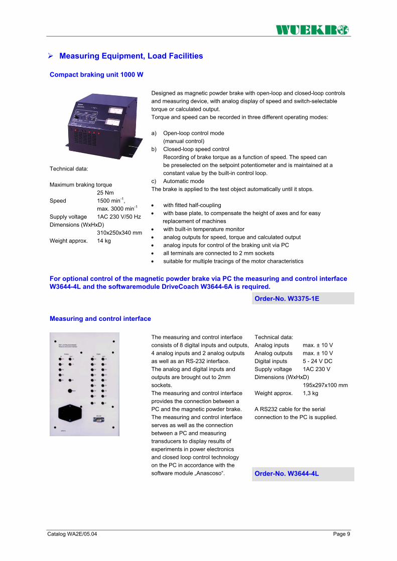
Catalog WA2E/05.04 Page 9
Measuring Equipment, Load Facilities
Compact braking unit 1000 W
Technical data: Maximum braking torque 25 Nm Speed 1500 min-1, max. 3000 min-1
Supply voltage 1AC 230 V/50 Hz Dimensions (WxHxD) 310x250x340 mm Weight approx. 14 kg
Designed as magnetic powder brake with open-loop and closed-loop controls and measuring device, with analog display of speed and switch-selectable torque or calculated output. Torque and speed can be recorded in three different operating modes: a) Open-loop control mode (manual control) b) Closed-loop speed control Recording of brake torque as a function of speed. The speed can be preselected on the setpoint potentiometer and is maintained at a constant value by the built-in control loop. c) Automatic mode The brake is applied to the test object automatically until it stops. • with fitted half-coupling • with base plate, to compensate the height of axes and for easy
replacement of machines • with built-in temperature monitor • analog outputs for speed, torque and calculated output • analog inputs for control of the braking unit via PC • all terminals are connected to 2 mm sockets • suitable for multiple tracings of the motor characteristics
For optional control of the magnetic powder brake via PC the measuring and control interface W3644-4L and the softwaremodule DriveCoach W3644-6A is required.
Order-No. W3375-1E
Measuring and control interface
Technical data: Analog inputs max. ± 10 V Analog outputs max. ± 10 V Digital inputs 5 - 24 V DC Supply voltage 1AC 230 V Dimensions (WxHxD) 195x297x100 mm Weight approx. 1,3 kg A RS232 cable for the serial connection to the PC is supplied.
The measuring and control interface consists of 8 digital inputs and outputs, 4 analog inputs and 2 analog outputs as well as an RS-232 interface. The analog and digital inputs and outputs are brought out to 2mm sockets. The measuring and control interface provides the connection between a PC and the magnetic powder brake. The measuring and control interface serves as well as the connection between a PC and measuring transducers to display results of experiments in power electronics and closed loop control technology on the PC in accordance with the software module „Anascoso“. Order-No. W3644-4L

Page 10 Catalog WA2E/05.04
Measuring Equipment, Load Facilities
Eddy current brake, cradle mounted 1000 W
Technical data: Braking power at 1500 min-1:1,3 kW Braking power at 3000 min-1:1,5 kW Field voltage DC 0 – 180 V Field current 2,5 A Degree of protection IP 21 Weight approx. 45 kg
The eddy current brake is suitable for loading a motor of the same rating up to starting torque (including measurement of the breakdown and mean starting torque) and for operation in both directions of rotation. • mounted on vibration dampers on a torsionally rigid baseframe
baseframe with cradle-mounted housing • with fitted half-coupling and transparent coupling cover • with base plate, to compensate the height of axes and for easy
replacement of machines • with built-in temperature monitor • with electronic torque load cell (strain gauge) • speed recorded optoelectronically via forked light barrier • a ventilator ensures that the brake can be operated continuously at the
rated data indicated • all connections brought out to 4mm safety laboratory sockets
To control the eddy current brake the control units W3375-6A, W3375-6C, W3375-6D, W3375-6F (incl. softwaremodule DriveCoach W3644-6A) is required.
Order-No. W3375-1F
Dynamometer DC shunt-wound machine, cradle mounted 1000 W
Technical data:
The DC shunt-wound machine is suitable for motor and generator loading of a motor of the same output and for operation in both directions of rotation. • mounted on vibration dampers on a torsionally rigid baseframe
baseframe with cradle-mounted housing • with fitted half-coupling and transparent coupling cover • with base plate, to compensate the height of axes and for easy
replacement of machines • with built-in temperature monitor • with electronic torque load cell (strain gauge) • speed recorded optoelectronically via forked light barrier • a ventilator ensures that the brake can be operated continuously at the
rated data indicated • all connections brought out to 4mm safety laboratory sockets
Generator operation Output 1 - 2 kW Voltage 150 - 300 V Current 8,5 A Speed 1500 - 3000 min-1
Motor operation Output 1 - 2 kW Voltage 150 - 300 V Current 8,5 A Speed 1400 - 2800 min-1
Field voltage DC 200 V field current 0,65 A Resolution pulse generator 120 Imp./min-1 Degree of protection IP 21 Weight approx. 31 kg
To control the dynamometer the control units W3375-6A, W3375-6C, W3375-6E W3375-6F (incl. softwaremodule DriveCoach W3644-6A) is required.
Order-No. W3375-1H

Catalog WA2E/05.04 Page 11
Control Unit for Measuring Equipment, Load Facilities
Modular control unit
General The modular control unit provides the control for eddy-current brakes and dynamometers from the 300 W / 1000 W ranges. The basic unit consists of a fixed-wired 19" housing as well as the plug-in module "Display and Measuring Unit". The other plug-in modules can be selected as required for the individual application. The "Measuring and Control Interface" module serves for connecting the control unit system to the PC. Thus, you can start measurement processes from the PC, display the characteristics passed on the screen and print them on a printer.
Control unit for eddy-current brake and dynamometer, controlling module Technical data: Analog outputs 1. Speed 400 U/min = 1 V 2. Torque 0,6 Nm = 1 V (300W) 2,0 Nm = 1 V (1000W)3. Output 300 W = 1 V Supply-voltage 1AC 230 V / 50 Hz via mains plug Weight approx. 6 kg
The basic unit of the modular control unit consists of a completely wired 19" housing and the plug-in module „Display and Measuring Unit“. Speed and either torque or calculated output as selected are digitally displayed via LCD's. The maximum speed is adjustable and can be displayed by pressing a button. Zero adjustment as well as calibration are performed via potentiometers. All terminals are brought out to 4mm safety lab sockets. Order-No. W3375-6A
Control unit for eddy-current brake and dynamometer, controlling module The rate of rise of the ramp can also be set. LEDs provide signals for „Enabled“, „Disabled“, „Brake fault“, „Motor fault“, „Mains fault“, and „Start ramp“. The measuring process is started with a button. With 2-mm-sockets for „Motor temperature“ and „Penlift“. Weight approx. 0.6 kg
Plug-in module for modular control unit W3375-6A. You can select between closed-loop speed, torque and current control. Lower range value and limit value of the measurements to be run are preselected via potentiometers. The selected values can be displayed using a button.
Order-No. W3375-6C
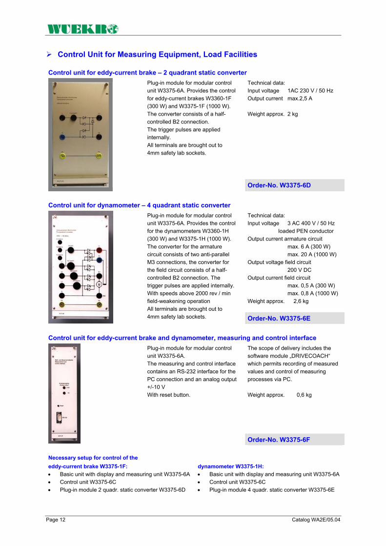
Page 12 Catalog WA2E/05.04
Control Unit for Measuring Equipment, Load Facilities
Control unit for eddy-current brake – 2 quadrant static converter Technical data: Input voltage 1AC 230 V / 50 Hz Output current max.2,5 A Weight approx. 2 kg
Plug-in module for modular control unit W3375-6A. Provides the control for eddy-current brakes W3360-1F (300 W) and W3375-1F (1000 W). The converter consists of a half-controlled B2 connection. The trigger pulses are applied internally. All terminals are brought out to 4mm safety lab sockets.
Order-No. W3375-6D
Control unit for dynamometer – 4 quadrant static converter Technical data: Input voltage 3 AC 400 V / 50 Hz loaded PEN conductor Output current armature circuit max. 6 A (300 W) max. 20 A (1000 W) Output voltage field circuit 200 V DC Output current field circuit max. 0,5 A (300 W) max. 0,8 A (1000 W) Weight approx. 2,6 kg
Plug-in module for modular control unit W3375-6A. Provides the control for the dynamometers W3360-1H (300 W) and W3375-1H (1000 W). The converter for the armature circuit consists of two anti-parallel M3 connections, the converter for the field circuit consists of a half-controlled B2 connection. The trigger pulses are applied internally. With speeds above 2000 rev / min field-weakening operation All terminals are brought out to 4mm safety lab sockets. Order-No. W3375-6E
Control unit for eddy-current brake and dynamometer, measuring and control interface The scope of delivery includes the software module „DRIVECOACH“ which permits recording of measured values and control of measuring processes via PC. Weight approx. 0,6 kg
Plug-in module for modular control unit W3375-6A. The measuring and control interface contains an RS-232 interface for the PC connection and an analog output +/-10 V With reset button.
Order-No. W3375-6F Necessary setup for control of the eddy-current brake W3375-1F: • Basic unit with display and measuring unit W3375-6A • Control unit W3375-6C • Plug-in module 2 quadr. static converter W3375-6D
dynamometer W3375-1H: • Basic unit with display and measuring unit W3375-6A • Control unit W3375-6C • Plug-in module 4 quadr. static converter W3375-6E

Catalog WA2E/05.04 Page 13
Softwaremodule DRIVECOACH Software module „DRIVECOACH“ for tracing characteristics on electrical machines. DRIVECOACH is a software program for operating the magnetic powder brakes, eddy current brakes and dynamometers. A measuring and control interface connects the unit to a PC and is necessary for picking the operating data with the software program. Operation of the software without connecting the measuring and control interface is not possible. Note: The software module "DRIVECOACH" is included in the scope of delivery of W3375-6F. Performance features: Setting possibilities: The operating modes such as closed-loop speed, torque or current control for the terminal device (dynamometer, eddy-current brake) can be set via the measuring and control interface. The ramps to pass can be preselected relative to lower range value, limit value and rate of rise according to the current operating mode. The measured quantities are dimensioned automatically or by querying the hardware. The following values are possible: Speed 4000 min-1 Torque 0 – 6 Nm (300 W) 0 – 20 Nm (1000 W) Current 0 – 3 A (300 W) 0 – 10 A (1000 W) Tracing characteristics: After setting or transferring the operating data or the ramps, the tracing of a characteristic can be triggered via the start button in a window. The following measured values can be recorded: With operating mode closed-loop speed control: Torque, ourrent, output With operating mode closed-loop torque control: Speed, ourrent, output With operating mode closed-loop current control: Speed, torque, output The diagrams can be saved in appropriate files and then printed. Operating mode load diagrammes: with the operation mode diagrammes five different kind of diagrammes can be selected and recorded: • constant Speed-torque-diagram • constant Speed-torque-diagram with mit polarity reversal • Linear Speed-torque-diagram • squared Speed-torque-diagram • Inverse Speed-torque-diagram The characteristic parameters are variable with the mouse or can be entered into a text field. A modification of the constant factors is also possible in the current operation. A red signal point announces the operating point of the drive on the characteristic. Hard- und Software coordination For operation with the compact braking unit the external measuring and control unit W3644-4L is necessary. For operation with the eddy current brake or the dynamometer, the measuring and control unit W3375-6F as a plug-in module for the modular control unit is necessary. The software module "DRIVECOACH" runs under WINDOWS. 95/98/ME/NT/2000/XP. Supplied on disk. Order-No. W3644-6A

Page 14 Catalog WA2E/05.04
Brake assembly with servo-motor on a frequency converter with PC-connection and data recording of speed and torque
SINAMICS S120 (with SIMOTION D) + servomotor
Converter SIMOREG DC Master
The software has the following adjustment-possibilities: The operating modes of speed or torque control can be selected. The ramps can be pre-adjusted with reference to the final value according to the selected operating mode. The motor characteristics like rated current, rated speed, maximum speed as well as rated torque of the servomotor and the rated current of the controller can be chosen with the installation of the testing stand. On the drive control panel can be preset the ramp-time (1 ... 65535 ms), the main nominal value and the additional nominal value (-100% ... + 100%) of the rated speed. Drive On/Off, preset possibilities for speed or torque-control, main nominal value On/Off and additional main nominal value On/Off as well as fault confirmation are pre selected via PC. Measurement data can be preselected and indicated on the screen for nominal and real speed as well as nominal and real torque. The sampling rate for the motor data screening can be preselected by 1, 10, 100 ms and 1 or 10 s. For the sampling of motor data a start-stop button is on the screen. Export function of the data to other computer programs (e.g. MS Excel) is just another mouse click away.. The software modul "DRIVECOACH SIM" is running under WINDOWS XP.
SINAMICS S120 1,5 kW, power feeding in network; frequency converter with SIMOTION D module Siemens state of the art frequency inverter with digital control for 3-phase induction machines and servo motors (sine wave commutation). Four-quadrant operation is realized by using the integrated brake resistor and regulated infeed/regenerative feedback functions for preventing undesirable reactions on the supply allows recovery of braking energy and ensuring greater stability against line fluctuations. The power stack PM340 of inverter uses IGBT modules. The inverter is operated via computer by ethernet connection with the software "DRIVE COACH SIM" that includes the integrated parameterization unit (display and keyboard) and control elements. Operating statuses and faults are indicated. Additionally the inbuilt control unit CU320 PN offers another ethernet interface for operation via PC.
. Operation modes: 1. Open-loop control by means of V/Hz characteristic 2. Sensorless vector control 3. Vector control with sensor (actual value by optical encoder) Mounted in a rack-type sheet-steel housing. Front panel with block diagram, manual control elements, signal and power sockets and test jacks." All device connections with a voltage over 36V are led out on 4-mm-security sockets. All connections with a tension less than 36 V are led out on 2-mm sockets. Technical data: Rated supply voltage: 3AC 380 - 480V Rated frequency: 47 to 63 Hz DC link voltage: DC 510 to 650V Output voltage: 3AC 0 to rated supply voltage Output frequency: 0 to 650Hz Rated output current: 4,1 A Pulse frequency: 4 to 8 kHz Rated motor power: 1,5 kW Overload: 8,2 A Dimensions (H x W x D): 530 x 350 x 320 mm Weight approx.: 20 kg The control software "DRIVE COACH SIM" for characteristic curve recording on electrical machines is part of delivery. This software offers clearly arranged display layout and measurement data export function for handling the recorded measured data. Order-No.
W3643-4H + W3375-4S

Catalog WA2E/05.04 Page 15
Power Converter SIMOREG DC Master 15A
Technical data: Rated supply voltage: 3AC 400 V Rated frequency: 45 to 65 Hz Rated DC voltage: 420 V Rated direct current: 15 A Overload: max. 1,8 rated direct current Rated output: 6kW Rated DC voltage field: max. 325 V Rated direct current field: 3 A Dimensions (H x W x D): 530 x 600 x 320 mm Weight approx. 20kg
4Q-Power converter in circulating-current-free inverse-parallel connection (B6) with digital closed-loop control for feeding a DC motor. Additional to the main converter a regulated field supply is integrated. The converter is operated by an integrated parameterization unit (display and keyboard) and control elements. Operating statuses and faults are indicated. Additionally a serial interface RS 232 for operation via PC is available. Mounted in a rack-type sheet-steel housing, Front panel with block diagram, manual control elements, signal and power sockets and test jacks." All device connections with a voltage greater 36 V are led out on 4-mm-security sockets. All connections with a tension less than 36 V are led out on 2-mm sockets.
Order-No. W3643-1L
SIMOREG power converter as before, additioanally with communication interface for Profibus-DP Order-No. W3643-1L-DP
DC shunt-wound machine
for motor and generator operation • with premounted coupling • with base plate, to compensate
the height of axes and for easy replacement of machines
• with thermistor protection on 2mm sockets
• with connections brought out to 4mm safety lab sockets
with built-on tachogenerator voltage 20V / 1000 rev / min
Technical data: Motor operation: Output 1.1 / 1.0 / 0.8 kW Voltage 330 / 275 / 220 V Current 4.0 / 4.8 / 6.0 A Speed 1500 rev / min Generator operation: Output 0.8 kW Voltage 220 V Current 3.6 A Speed 1500 rev/min Field voltage 110 V Field current 1.2 A degree of protection IP 21 2 Axes ends
Order-No. W3375-5D

Page 16 Catalog WA2E/05.04
Test Unit DC Drive System
Assembly Kit “Test Unit DC drive system” The following experiments can be carried out:
The following components are required (incl. in the kit):
Further components are required (not incl. in the kit):
2 Multimeter alternative 2 Multimeter as Demonstration instrument W5431-1B
1 2-channel oscilloscope 20 MHz with 2 probes
1 Power supply ±15 V DC for measuring transducers
• Motor speed characteristics at converter
• Principle of operation of reversible converter in circulating-current-free, inverse-parallel connection
• Operating the DC motor in open-loop control mode
• Operating the DC motor in closed-loop control mode
• Speed controller as P controller
• Speed controller as PI controller
• Matching the Simoreg K and the driven machine according to setting instructions
• Matching the SIMOREG K at the driven machine according to analysis of controlled system and optimization methods used in control engineering
• Speed control, torque- and current control
• Dynamic behavior of the drive system at set point and disturbance change
1 SIMOREG DC-Master W3643-1L
1 DC machine W3375-5D
1 DC shunt-wound machine, W3375-1H
1 Control unit W3375-6A, -6C, -6E, -6F
1 Voltage transducer W3644-4J
1 Current transducer W3410-4B
1 Current transducer W3410-4C
1 Experimental manual W3007-4A
1 Set connecting leads W3901-0B
Order-No. W3643-0L

Catalog WA2E/05.04 Page 17
Test Unit Servo Drive System
Converter SINAMICS S120
Technical data: Rated supply voltage: 3AC 380 - 480V Rated frequency: 47 to 63 Hz DC link voltage: DC 510 to 650V Output voltage: 3AC 0 to rated supply voltage Output frequency: 0 to 650Hz Rated output current: 4,1 A Pulse frequency: 4 to 8 kHz Rated motor power: 1,5 kW Overload: 8,2 A Dimensions (H x W x D): 530 x 350 x 320 mm Weight approx.: 20 kg
Frequency inverter with digital control for 3-phase induction machines and servo motors (sine wave commutation). Four-quadrant operation is realized by using the integrated brake resistor. The power stack PM340 of inverter uses IGBT modules. The inverter is operated by an integrated parameterization unit (display and keyboard) and control elements.
Operating statuses and faults are indicated. Additionally on control unit CU310 PN an Ethernet interface for operation via PC is available.Operation modes: 1. Open-loop control by means of V/Hz characteristic 2. Sensorless vector control 3. Vector control with sensor (actual value by optical encoder) "Mounted in a rack-type sheet-steel housing Front panel with block diagram, manual control elements, signal and power sockets and test jacks." All device connections with a voltage greater 36 V are led out on 4-mm-security sockets. All connections with a tension less than 36 V are led out on 2-mm sockets.
Order-No. W3643-4H
3-Phase Servo Motor
Technical data: Static torque 5,2 Nm Nominal current 2,6 A Nominal power 1,1 kW Speed 2000 min-1 degree of protection IP 21 1 Axes end incl. Sensor cable
Permanent magnet excited synchronous machine working in connection with the frequency converter SIMOVERT MASTER-DRIVES MC as brushless DC motor. • with premounted coupling • with base plate, to compensate
the height of axes and for easy replacement of machines
• with thermistor protection Electronic commutation, arc free via rotor transmission sensor, resolution 2048 pulses per rotation, constant acceleration torque up to max. speed. Order-No. W3375-4S

Page 18 Catalog WA2E/05.04
Test Unit Standard AC Drive Control System
SICOSTART three-phase AC power controller
Technical data: Supply voltage 1AC 230 V Input voltage 3AC 400 V Output voltage 0 - 400 V Rated current 5,5 A Rated output 2,2 kW Ramp time 0 - 180 s Starting voltage 20 - 100 % Current limitation 0,5 - 6 x le
Dimensions (WxHxD) 390x297x150 mm Weight approx. 3,5 kg
Possible adjustments: • Ramp time • Starting voltage • Limiting current • Deceleration time
Functions are DC braking, break-away pulse, energy saving, emergency start and operation via RS-232 interface. The industrial device is built as an experimental panel, also suitable as bench unit, with a plastic front panel with mimic diagram and designations. All connectors for the power sections are brought out to 4mm safety lab sockets. Connectors for open and closed-loop control are brought out to 2mm sockets. Order-No. W3643-4P
PC selection program
(included in the scope of delivery of the instruction manual W3007-8B) The PC program automatically selects the proper SIKOSTART type for a given speed- torque characteristic of the working machine to be driven and a given motor type. The PC program makes it possible to optimize the start-up and run- down process according to para-meters to be set at the SIKOSTART.
The simulation of start-up provides insights in the speed- torque characteristics of load, motor at full-voltage start and motor with control by the SIKOSTART three-phase AC power controller. The display of the voltage and current characteristics over time during start-up facilitate the evaluation of the parameters set.
The following load characteristics are stored: • Constant torque characteristic
Linear speed-torque characteristic
• Square-law speed-torque characteristic
• Freely selectable speed-torque characteristic
The PC selection program runs under MS-DOS.
PC communication program (included in the scope of delivery of the instruction manual W3007-8B) The PC communication program is an aid for starting up the "SIKOSTART drive". With this program it is also possible to control the motor and to monitor operating values such as motor current and heat sink temperature from the PC. The values for starting voltage, ramp time, limiting current etc. can be entered and saved in the SIKOSTART as numeric values.
Furthermore, up to three independent parameter sets can be entered, for example for the operation of Dahlander and pole-switching motors. The individual functions are: 1. Program start 2. Parameter input
- Selection of the number of parameter sets
- Programming the switch functions
- Entering the values for breakaway pulse, reduced-voltage start-up and stop, limiting current, DC brakes and pump stop
3. Saving the parameter sets in the EEPROM of SIKOSTART 4. Monitoring and control
- Observing the LED indicators on the monitor
- Display of current input, heat sink temperature, SIKOSTART heating and number of starts carried out since the last application of supply voltage
5. Overview of characteristic values
- Reading the order number, the rated current and the ambient temperature set

Catalog WA2E/05.04 Page 19
Test Unit Standard AC Drive Control System
Assembly Kit “Test unit standard AC drive system, controlled” The subject area "Motor Control with SIKOSTART" includes configuring, commissioning & optimizing drives with standard induction machines. Functions such as reduced-voltage start, energy savings during partial-load operation, reduced-voltage stop, pump stop & DC braking available.
The behavior of the induction machine during start-up in stationary operation and during run-down can be adjusted to various load types (loads with constant speed-torque characteristic, linearly or squarely progressing speed-torque characteristic & with 1/n declining speed-torque characteristic).
Possible Proceedings: 1) Configuring the drive with the aid of the PC selection program, manual parametertransfer 2) Configuring the drive using the PC communication program, automatic parametertransfer
The following experiments can be carried out:
The following components are required (incl. in the kit):
Further components are required (not incl. in the kit):
1 Voltmeter W3422-4A
1 Current indicator W3417-4D
1 Multimeter alternative 1 Multimeter as demonstration instrument W5431-1B
1 Dual-trace 20 MHz oscilloscope with 2 probes
1 Power supply ±15 V DC for measuring transducers
• Setup, connection and startup of an industrial three-phase AC power controller drive under consideration of various loading cases
• Understanding the possibilities and limitations of an induction machine drive with three-phase AC power controller
• Connection, Setup and startup of the industrial standard drive control system
• Parameterization of the drive via PC and at the unit
• Adapting the drive to different loading cases
• Guided configuring of a drive via PC selection program
• Observation and evaluation of starting and decelerating processes using measuring instruments and oscilloscope evaluations (also possible via PC)
1 SIKOSTART power controller W3643-4P
1 Three-phase induction motor W3375-2A
1 Baseframe W3375-8A
1 DC shunt-wound machine, W3375-1H
1 Control unit W3375-6A, -6C, -6E, -6F
1 Flywheel W3375-2X
1 Voltage transducer W3644-4J
1 Current transducer W3410-4C
2 3 DIAZED fuses W3311-4A
1 Motor-protection circuit-breaker W3312-4C
2 Contactor W3321-4A
1 Overload relay W3330-4K
1 Auxiliary contactor W3328-4A
1 On/Off switch W3341-4B
2 2 pushbutton switches W3334-4B
1 Instruction manual W3007-8B
1 Set of connecting leads W3901-0B Order-No. W3643-0P

Page 20 Catalog WA2E/05.04
Accessories - Measuring Equipment
Precision measuring transducer (voltage)
Technical data Input voltage max. 500 / 400 / 250 / 100 V switch-selectable Output voltage 0 – 5 V Accuracy under 1 % Error of linearity under 0,1 % Minimum time of reaction under 1 µs Power supply ±15 V / 150 mA Dimensions (WxHxD) 260x297x100 mm Weight approx. 0.8 kg
Experimental panel for floating measurements of DC, AC and pulse voltages; with electrical isolation between primary and secondary circuits. The panel features 3 built-in transducers with 4 different measuring ranges. The voltage inputs are brought out to 4mm safety lab sockets, the voltage outputs to 2mm sockets and BNC sockets. The power supply inputs are brought out to 2mm sockets.
Order-No. W3644-4J
Precision measuring transducer (current)
Experimental panel for floating measurements of DC, AC and pulse voltages; with electrical isolation between primary and secondary circuits. The panel features 1 built-in transducer. The current input is brought out to 4mm safety lab sockets, the output to 2mm sockets and BNC sockets. The power supply inputs are brought out to 2mm sockets.
(current, max. 5 A) Technical data: Input current max. 5 A Output voltage 0 – 5 V Accuracy under 1 % Error of linearity under 0,1 % Minimum time of reaction under 1 µs Power supply ± 15 V / 50 mA Dimensions (WxHxD) 130x297x60 mm Weight approx. 0,5 kg
Order-No. W3410-4B
(current, max. 12 A) Technical data: Input current max. 12 A Output voltage 0 – 5 V Accuracy under 1 % Error of linearity under 0,1 % Minimum time of reaction under 1 µs Power supply ± 15 V / 50 mA Dimensions (WxHxD) 130x297x60 mm Weight approx. 0,5 kg
(current, max. 25 A) Technical data: Input current max. 25 A Output voltage 0 – 5 V Accuracy under 1 % Error of linearity under 0,1 % Minimum time of reaction under 1 µs Power supply ± 15 V / 50 mA Dimensions (WxHxD) 130x297x60 mm Weight approx. 0,5 kg
Order-No. W3410-4C Order-No. W3410-4D

Catalog WA2E/05.04 Page 21
Notes

Page 22 Catalog WA2E/05.04

Catalog WA2E/05.04 Page 23

Page 24 Catalog WA2E/05.04
FAX – Reply to: +49 (0)9721 / 64691 - 20
Sender: Receiver:
Company WUEKRO GmbH
Dept. Sales Department Name Street Carl-Zeiss-Strasse 10 City 97424 Schweinfurt / Germany Phone + 49-(0)9721-64691-0 Fax + 49-(0)9721-64691-20 E-Mail [email protected] Internet www.wuekro.de
Please send the following catalogues to the a.m. address!
Fundamentals of electrical engineering Installation circuits Bell ringing and entrance call stations Contactor control / Control technology Measurement and control of non-electrical variables
Fundamentals of electronics Analog technology Digital technology Microprocessing technology
Closed loop control technology Analog closed loop control Digital closed loop control
Automation engineering SIMATIC S7-200/300/400, software Technology simulators / models Process control engineering PCS7 AS-Interface Profibus DP Process simulation-software PROSIM 95 LOGO! Mechatronical technology stations Courses on automation
Electrical machines / drive controls Electrical Machines 300W Electrical Machines 1000W Electrical Machines 5kW Electrical drive control systems 300W / 1kW Electrical drive control systems 5kW Networked drive systems Cutaway models Transformers, rectifiers and reactive power compensation Courses on drive systems
Power electronics extra low voltage (24V) low voltage (230/400V)
Building management systems KNX / EIB
VDE 0100 safety measures
Radio- and television engineering AM/FM technology TV engineering
Satellite technology
Cooling and air conditioning
Photovoltaic cell technology
Communication technology Modulation -/demodulation Fiber optic Telecommunication system trainer (HICOM) ISDN
Laboratory equipment, connecting leads, accessories
Power supply units
Demonstration measuring instruments
Measuring instruments
Experiment instructions, experiment manuals
Training courses
Remarks:
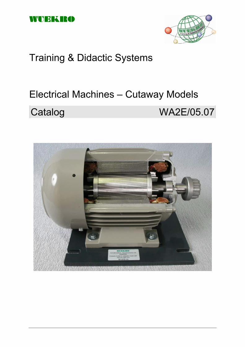
WUEKRO
Training & Didactic Systems Electrical Machines – Cutaway Models
Catalog WA2E/05.07

WUEKRO
Page 2 Catalog WA2E/05.07
Our Services • Development and production of didactic training systems • Teachware and documentation • Project engineering of complete lab's incl. furniture and lab equipment • Quotations on customer's demand • Installation, commissioning and training at site
Our Customers • Vocational training schools, technical schools, colleges and universities... • Industrial laboratories for vocational education and higher education
Fields of Technology • Fundamentals of electrical engineering
• Fundamentals of electronics
• Closed loop control technology
• Automation engineering
• Electrical machines / drive control
• Power electronics
• Building management systems
• Protection schemes to VDE 0100
• Radio- and TV technology
• Air conditioning and refrigeration
• Photovoltaic
• Communication technology
• Measuring systems, power supplies, accessories
• Experimental manuals, documentation For further information please contact: WUEKRO GmbH Carl-Zeiss-Strasse 10 D - 97424 Schweinfurt Germany Tel. + 49 (0) 9721-64691-0 Fax: + 49 (0) 9721-64691-20 E-Mail: [email protected] Internet: www.wuekro.de WUEKRO GmbH
All Rights reserved. Reprint not permitted. Technical changes without prior notice.. S00020822P – 01/13
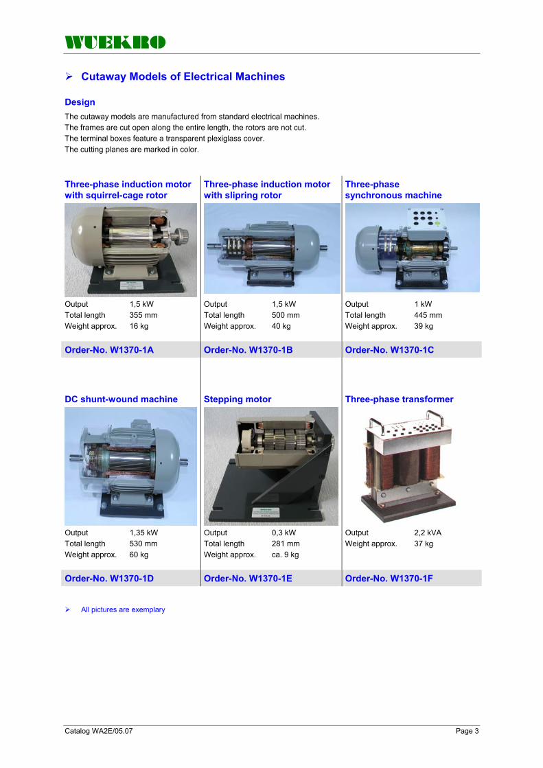
WUEKRO
Catalog WA2E/05.07 Page 3
Cutaway Models of Electrical Machines
Design
The cutaway models are manufactured from standard electrical machines. The frames are cut open along the entire length, the rotors are not cut. The terminal boxes feature a transparent plexiglass cover. The cutting planes are marked in color.
Three-phase induction motor with squirrel-cage rotor
Three-phase induction motor with slipring rotor
Three-phase synchronous machine
Output 1,5 kW Total length 355 mm Weight approx. 16 kg
Output 1,5 kW Total length 500 mm Weight approx. 40 kg
Output 1 kW Total length 445 mm Weight approx. 39 kg
Order-No. W1370-1A Order-No. W1370-1B Order-No. W1370-1C
DC shunt-wound machine Stepping motor Three-phase transformer
Output 1,35 kW Total length 530 mm Weight approx. 60 kg
Output 0,3 kW Total length 281 mm Weight approx. ca. 9 kg
Output 2,2 kVA Weight approx. 37 kg
Order-No. W1370-1D Order-No. W1370-1E Order-No. W1370-1F
All pictures are exemplary

WUEKRO
Page 4 Catalog WA2E/05.07
FAX – response to: +49 (0)9721 - 64691 - 20 Sender: Receiver:
Company WUEKRO GmbH Dept. Sales Department Name Street Carl-Zeiss-Strasse 10 City 97424 Schweinfurt / Germany Phone + 49-(0)9721-64691-0 Fax + 49-(0)9721-64691-20 E-Mail [email protected] Internet www.wuekro.de No. of pages incl. this page
Please send the following catalogues to the a.m. address! Fundamentals of electrical Engineering
Installation circuits Bell ringing and entrance call stations Contactor control / Control technology Measurement and control of non-electrical variables
Fundamentels of electronics Analog technology Digital technology Microprocessing technology
Closed loop control technology Analog closed loop control Digital closed loop control
Automation engineering SIMATIC S7-200/300/400, Software Technology simulators / Models Process control engineering PCS7 AS-Interface Profibus DP Process simulation-software SIMIT LOGO! Mechatronical technology stations Courses on Automation
Electrical machines / Drive controls Electrical Machines 300W Electrical Machines 1000W Electrical Machines 5kW Electrical drive control systems 300W/ 1kW Electrical drive control systems 5kW Networked drive systems Cutaway Models Transformers, Rectifiers and Reactive Power Compensation Courses on drive systems
Power electronics extra low voltage (24V) low voltage (230/400V)
Building management systems KNX / EIB
VDE 0100 safety measures
Radio- and Television engineering AM/FM – Technology TV Engineering
Satellite – Technology
Cooling and air conditioning
Photovoltaic cell tecnology
Communication technology Modulation -/demodulation Fiber optic ISDN trainer (HICOM) ISDN
Measuring systems
Power supply units
Experiment instructions, manuals
Training courses
Remarks:

Training & Didactic Systems Transformers, Rectifiers and Reactive-Power Compensation
Catalog WA1E/05.08

Page 2 Catalog WA1E/05.08
Our Services
• Development and production of didactic training systems • Teachware and documentation • Project engineering of complete lab's incl. furniture and lab equipment • Quotations on customer's demand • Installation, commissioning and training at site
Our Customers • Vocational training schools, technical schools, colleges and universities... • Industrial laboratories for vocational education and higher education
Fields of Technology • Fundamentals of electrical engineering
• Fundamentals of electronics
• Closed loop control technology
• Automation engineering
• Electrical machines / drive control
• Power electronics
• Building management systems
• Protection schemes to VDE 0100
• Radio- and TV technology
• Air conditioning and refrigeration
• Photovoltaic
• Communication technology
• Measuring systems, power supplies, accessories
• Experimental manuals, documentation For further information please contact: WUEKRO GmbH Carl- Zeiss-Strasse 10 D - 97424 Schweinfurt Germany Tel. + 49 (0) 9721-64691-0 Fax: + 49 (0) 9721-64691-20 E-Mail: [email protected] Internet: www.wuekro.de WUEKRO GmbH
All Rights reserved. Reprint not permitted. Technical changes without prior notice.. N00020725G – 01/13

Catalog WA1E/05.08 Page 3
Table of Contents PageOur Services, Customers and Scope of Supply 2 General 4 Transformers - "Static Electrical Machines" 4 Diode Panel 5 Assembly kit "Transformer- and Rectifier Circuits" 5 Reactive-Power Compensation 6 Fax - Reply 8

Page 4 Catalog WA1E/05.08
Static Electrical Machines, Transformers
General
The following subject areas can be taught using the "Static Electrical Machines" training system: • Single-phase transformer, general, types of loads • Three-phase transformer, general, types of loads • Rectifier, general, method of operation • Transformer- and rectifier cirrcuits
Three-phase transformer
Primary voltage 3 AC 400 V with tapping at 230 V Secondary voltage 2 part-windings each 110 V Frequency 50/60 Hz Weight approx. 9 kg
with separate windings The secondary voltage can be tapped in steps. All terminals are connected to 4 mm safety lab sockets. Technical data: Degree of protection IP 00 Apparent power 250 VA
Order-No. W3360-6C
Single-phase isolating transformer
Weight approx. 4.5 kg
with separate windings The secondary voltage can be tapped in steps. All terminals are connected to 4 mm safety lab sockets.
Technical data: Degree of protection IP 00 Apparent power 100 VA Primary voltage 1 AC 230 V Secondary voltage 1 AC 12 V; 1 AC 24 V Frequency 50 Hz Order-No. W3348-4B
Single-phase variable transformer
Weight approx. 7 kg
with separate windings Settings via rotary button with scale, with connecting lead, approx. 2 m in length, with earthing-pin plug. All terminals are connected to 4-mm-safety-lab-sockets.
Technical data: Degree of protection IP 00 Output 300 VA Primary voltage 220 V Secondary voltage 250 V Frequency 50 Hz
Order-No. W3360-6B
Three-phase isolating transformer
Secondary windings Voltages/ 3 x 24 V/6 A currents 3 x 127 V/6 A 3 x 230 V/6 A 3 x 400 V/4 A star-connected, neutral brought out Dimensions (WxHXD) 420x300x 220 mm Weight approx. 35 kg
Installed in a sheet-steel housing with carrying handles Technical data: Output 2.8 kVA Primary windings open Voltages 3 x 230/400 V
Order-No. W3644-2A
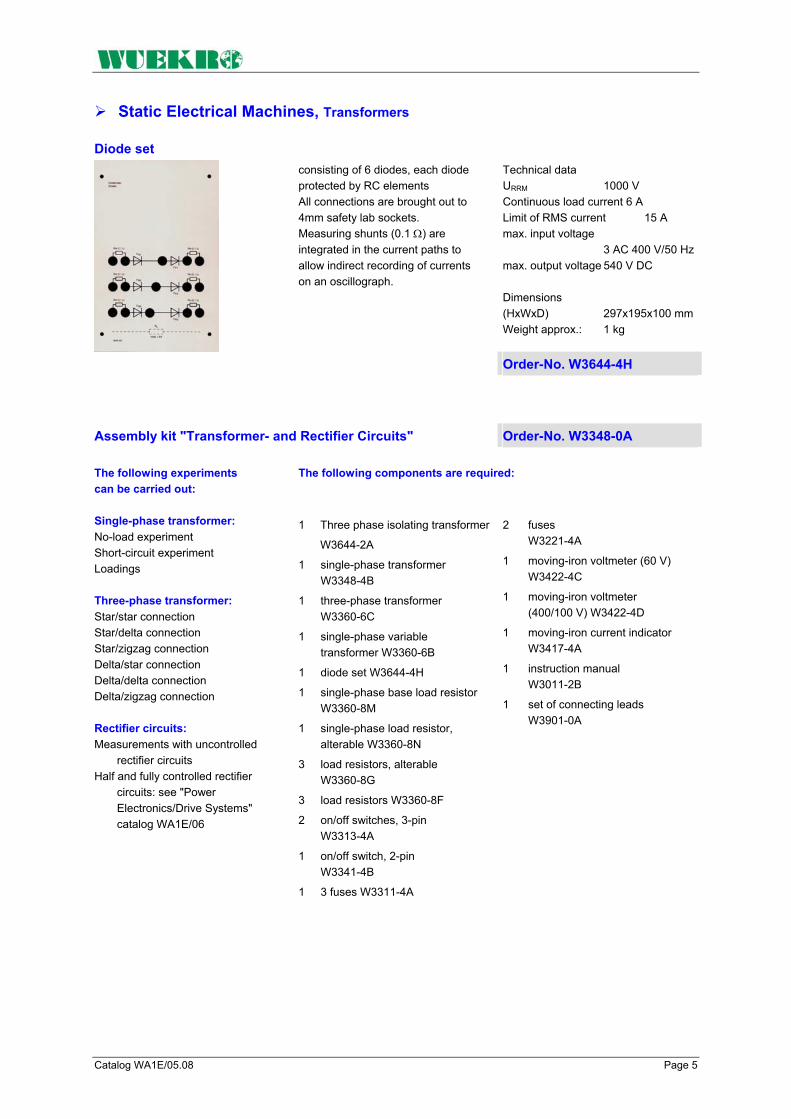
Catalog WA1E/05.08 Page 5
Static Electrical Machines, Transformers
Diode set
Technical data URRM 1000 V Continuous load current 6 A Limit of RMS current 15 A max. input voltage 3 AC 400 V/50 Hz max. output voltage 540 V DC Dimensions (HxWxD) 297x195x100 mm Weight approx.: 1 kg
consisting of 6 diodes, each diode protected by RC elements All connections are brought out to 4mm safety lab sockets. Measuring shunts (0.1 Ω) are integrated in the current paths to allow indirect recording of currents on an oscillograph.
Order-No. W3644-4H
Assembly kit "Transformer- and Rectifier Circuits" Order-No. W3348-0A The following experiments can be carried out:
The following components are required:
Single-phase transformer: No-load experiment Short-circuit experiment Loadings Three-phase transformer: Star/star connection Star/delta connection Star/zigzag connection Delta/star connection Delta/delta connection Delta/zigzag connection Rectifier circuits: Measurements with uncontrolled
rectifier circuits Half and fully controlled rectifier
circuits: see "Power Electronics/Drive Systems" catalog WA1E/06
1 Three phase isolating transformer
W3644-2A
1 single-phase transformer W3348-4B
1 three-phase transformer W3360-6C
1 single-phase variable transformer W3360-6B
1 diode set W3644-4H
1 single-phase base load resistor W3360-8M
1 single-phase load resistor, alterable W3360-8N
3 load resistors, alterable W3360-8G
3 load resistors W3360-8F
2 on/off switches, 3-pin W3313-4A
1 on/off switch, 2-pin W3341-4B
1 3 fuses W3311-4A
2 fuses W3221-4A
1 moving-iron voltmeter (60 V) W3422-4C
1 moving-iron voltmeter (400/100 V) W3422-4D
1 moving-iron current indicator W3417-4A
1 instruction manual W3011-2B
1 set of connecting leads W3901-0A
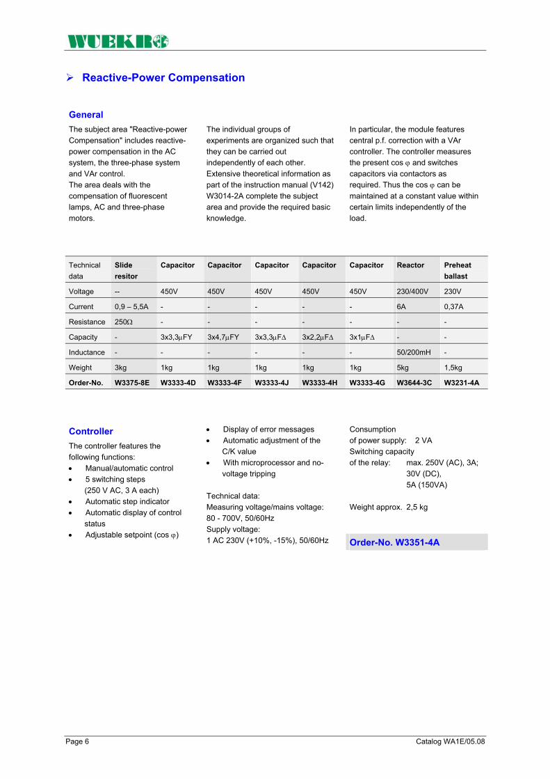
Page 6 Catalog WA1E/05.08
Reactive-Power Compensation
General The subject area "Reactive-power Compensation" includes reactive-power compensation in the AC system, the three-phase system and VAr control. The area deals with the compensation of fluorescent lamps, AC and three-phase motors.
The individual groups of experiments are organized such that they can be carried out independently of each other. Extensive theoretical information as part of the instruction manual (V142) W3014-2A complete the subject area and provide the required basic knowledge.
In particular, the module features central p.f. correction with a VAr controller. The controller measures the present cos ϕ and switches capacitors via contactors as required. Thus the cos ϕ can be maintained at a constant value within certain limits independently of the load.
Technical data
Slide resitor
Capacitor Capacitor Capacitor Capacitor Capacitor Reactor Preheat ballast
Voltage -- 450V 450V 450V 450V 450V 230/400V 230V
Current 0,9 – 5,5A - - - - - 6A 0,37A
Resistance 250Ω - - - - - - -
Capacity - 3x3,3µFY 3x4,7µFY 3x3,3µF∆ 3x2,2µF∆ 3x1µF∆ - -
Inductance - - - - - - 50/200mH -
Weight 3kg 1kg 1kg 1kg 1kg 1kg 5kg 1,5kg
Order-No. W3375-8E W3333-4D W3333-4F W3333-4J W3333-4H W3333-4G W3644-3C W3231-4A
Consumption of power supply: 2 VA Switching capacity of the relay: max. 250V (AC), 3A; 30V (DC), 5A (150VA) Weight approx. 2,5 kg
Controller The controller features the following functions: • Manual/automatic control • 5 switching steps
(250 V AC, 3 A each) • Automatic step indicator • Automatic display of control
status • Adjustable setpoint (cos ϕ)
• Display of error messages • Automatic adjustment of the
C/K value • With microprocessor and no-
voltage tripping Technical data: Measuring voltage/mains voltage: 80 - 700V, 50/60Hz Supply voltage: 1 AC 230V (+10%, -15%), 50/60Hz Order-No. W3351-4A

Catalog WA1E/05.08 Page 7
Assembly Kit Reactive-Power Compensation
The following experiments can be carried out:
The following components are required to carry out these experiments:
Power factor cos ϕ at loads with: ohmic resistance coil series connection of ohmic
resistance and coil parallel connection of ohmic
resistance and capacitor series connection of ohmic
resistance and capacitor Carrying out reactive-power
compensation at an AC motor Compensation in the three-phase
system star connection delta connection
Individual p.f. correction of a three-phase motor
Group p.f. correction of two three-phase motors of fluorescent lamps
Central p.f. correction with VAr controller
1 slide resistor W3375-8E
1 smoothing reactor W3644-3C
1 capacitors 3 x 3.3 µF W3333-4D
1 capacitors 3 x 4.7 µF W3333-4F
1 capacitors 3 x 3.3 µF W3333-4J
1 capacitors 3 x 2.2 µF W3333-4H
1 capacitors 3 x 1.0 µF W3333-4G
3 20 W reactor W3231-4A
3 fluorescent lamp holder left W3230-4E
3 fluorescent lamp holder right W3230-4B
1 300 W single-phase AC motor W3365-3B
1 compact braking unit W3360-1D
1 baseframe W3360-8A
4 on/off switch W3313-4A
2 300 W three-phase motor W3365-2A
1 5/5 A current transformer W3349-4A
1 3 fuse elements W3311-4A
1 VAr controller W3351-4A
4 3-pole contactor W3321-4A
1 wattmeter, single-phase W5431-1C
1 power factor meter, single phase W5431-1D
1 wattmeter, three-phase W3428-4C
1 three-phase power factor meter W3434-4A
1 three-phase varmeter W3433-4A
1 instruction manual W3014-2B
1 set of connecting leads W3901-0A

Page 8 Catalog WA1E/05.08
FAX – Reply to: +49 (0)9721 - 64691 - 20 Sender: Receiver:
Company WUEKRO GmbH Dept. Sales Department Name Street Carl-Zeiss-Strasse 10 City 97424 Schweinfurt / Germany Phone + 49-(0)9721-64691-0 Fax + 49-(0)9721-64691-20 E-Mail [email protected] Internet www.wuekro.de No. of pages
incl. this page
Please send the following catalogues to the a.m. address!
Fundamentals of electrical Engineering
Installation circuits Bell ringing and entrance call stations Contactor circuits/Control technology Measurement and control of non- electrical quantities
Fundamentels of electronics Analog technology Digital technology Microprocessing technology
Closed loop control technology Analog control technology Digital control technology
Automation engineering SIMATIC S7-200/300/400, Software Technology simulators / Models Process control technology PCS7 AS-Interface Process simulation-software PROSIM 95 LOGO!
Electrical machines / Drive controls 300W - range 1000W - range 5kW - range Electr. drive control 300W/1000W Electr. drive control 5kW
Power electronics extra low voltage (24V) low voltage (230/400V)
Building management systems KNX / EIB
Protection schemes to VDE 0100
Radio- and TV technology AM/FM - Technology TV Technology Satellite - Technology
Air conditioning and refrigeration
Photovoltaic
Communication technology Modulation -/demodulation technology Optical fibre HICOM communication systems
Measuring systems, power supplies, Accessories
Experimental manuals, documentation, books
Remarks:

WUEKRO
Training & Didactic Systems Power Electronics
Catalog WA2E/06

WUEKRO
Page 2 Catalog WA2E/06
Our Services
• Development and production of didactic training systems • Teachware and documentation • Project engineering of complete lab's incl. furniture and lab equipment • Quotations on customer's demand • Installation, commissioning and training at site
Our Customers • Vocational training schools, technical schools, colleges and universities... • Industrial laboratories for vocational education and higher education
Fields of Technology • Fundamentals of electrical engineering
• Fundamentals of electronics
• Closed loop control technology
• Automation engineering
• Electrical machines / drive control
• Power electronics
• Building management systems
• Protection schemes to VDE 0100
• Radio- and TV technology
• Air conditioning and refrigeration
• Photovoltaic
• Communication technology
• Measuring systems, power supplies, accessories
• Experimental manuals, documentation For further information please contact: WUEKRO GmbH Carl-Zeiss-Strasse 10 D – 97424 Schweinfurt Germany Tel. + 49 (0) 9721-64691-0 Fax: + 49 (0) 9721-64691-20 E-Mail: [email protected] Internet: www.wuekro.de WUEKRO GmbH
All Rights reserved. Reprint not permitted. Technical changes without prior notice..

WUEKRO
Catalog WA2E/06 Page 3
Table of Contents Page Our Services, Customers and Scope of Supply 2 Introduction 4 Training Concept 5 Training Systems – Attachment – Targets 6 Power Electronics 7 Compact Panel 7 Experimental Panels 10 Accessories - Loads 22 Resistive Loads 22 Reactive / capacitive loads 23 Measuring Equipment, Hardware / Software 24 Fax - Reply 28

WUEKRO
Page 4 Catalog WA2E/06
Introduction
If you can analyze problems systematically and understand interrelationships, you'll have no difficulty in coping with future developments – in any field of technology. As your partner for training systems, we can provide you with the technical equipment you require for this purpose including comprehensive instruction manuals and training documentation. Systematic analysis in the field of power electronics means learning about basic circuits, such as DC chopper controllers and AC power controllers, through specially designed measuring exercises and understanding the operating principle of devices and the real behavior of components. Understanding interrelationships means to see power electronics in terms of their relationship with drive and control systems. • How can I apply open-loop
and closed-loop controls in electric drives to achieve virtually no-loss operation?
• Which power electronics components can be combined to form drive units which meet special technical requirements such as, for example, good dynamic response, special speed/torque response, surge load, etc.
Our task should be to help you to answer these and similar questions on a practical basis and to provide suitable experimental equipment for scientific studies. Our training system gives you almost unlimited freedom, i.e. you can pick and choose elements to create your own “personal” training strategy. If you attach particular importance to training with a supply voltage of 230/440 V, then you will want to use either our modular panel system or our specially designed “didactic” industrial equipment. If you require an extra-low supply voltage for training purposes and if criteria such as mobility, tuition outside proper training laboratories and lack of space need to be taken into account, then you can choose between a compact panel and a modular “case” system.
The case system is identical in design to the 230/440V panels. Robust design, integrated laboratory power supply and excellent storage facilities are just some of its outstanding features. The compact panel is an exceptionally low-price, space-saving training device which can be expanded by the industrial drive system equipment if required. So regardless which of the 3 systems you eventually choose (or you might even decide to combine 2 systems), you will have a range of training equipment which is tailor-made for your individual requirements.

WUEKRO
Catalog WA2E/06 Page 5
Training Concept
The aim Practice oriented experimental manuals
The aim of our training concept for power electronics and drive systems with closed-loop control is to provide
- vocational schools - technical colleges - universities and
in-firm training center with systems for teaching the theoretical and practical knowledge which trainees and students require to learn and understand more on industrial technology. There are basically two systems available for teaching power electronics: 1. A 230/400 V panel system for
learning fundamental principles or
2. A 24 V system for learning fundamental principles
One of two different variants of the 24 V system can be selected: 2a) The compact panel which can be used to teach all syllabuses relating to power electronics 2b) A “case” system which is identical to the 230/400 V system in didactical terms
You can order instruction manuals for modules 1/8. These manuals are written by experienced training staff and specialists with teaching knowledge. The instruction manuals generally consist of 3 sections: Section 1: General section for introducing the trainees to the objectives of the training program and providing basic theoretical knowledge. Section 2: Trainee's section containing measuring exercises. Value tables, diagrams and oscilloscope displays must be filled out by the student. Section 3: Instructor's section containing the answers to questions in Section 2. The purpose of this section is to reduce valuable preparation time and provide a check for trainers, teachers and instructors. Whether you choose the experimenter, the compact panel or the 230/400 V panels or racks, we can provide you with reliable instruction manuals for the appropriate system.

WUEKRO
Page 6 Catalog WA2E/06
Training Systems – Attachment – Targets
Power electronics Compact panel Modules 1 - 4
Experimental panels Modules 1 - 5
Modules Module 1
Module 2 Module 3 Module 4 Module 5
Learning about power electronics components, measuring characteristics
Assembling and learning about uncontrolled and controlled rectifier circuits
Assembling and learning about different types of DC chopper controller circuit
Assembling and learning about two different circuits for implementing an AC power controller
Assembling and learning about circuits for implementing inverter operation
Projects
Theses
Practicals
College/University
Continuing Education
Practical Training
College/University
Training as craftsman Basic principles School/Education
Com
pact
Pan
el
Exp
erim
enta
l Pan
els
Did
actic
Indu
stria
l Equ
ipm
ent
Exp
erim
enta
l Pan
els
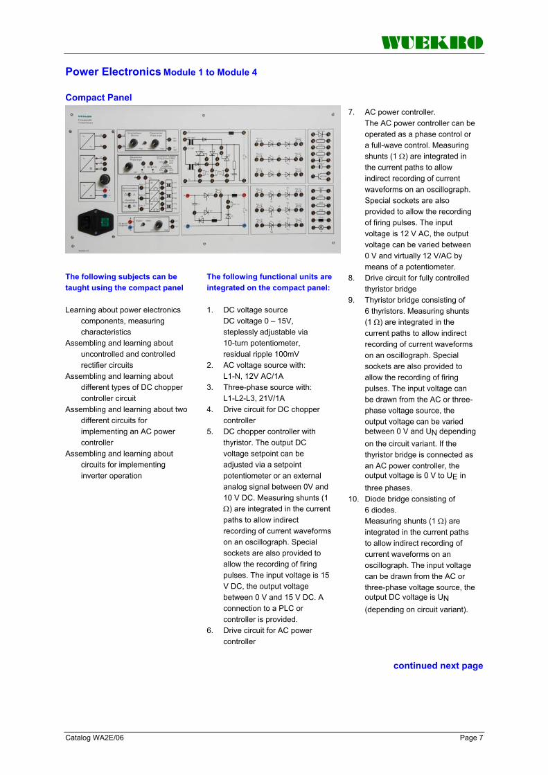
WUEKRO
Catalog WA2E/06 Page 7
Power Electronics Module 1 to Module 4
Compact Panel
The following subjects can be taught using the compact panel
The following functional units are integrated on the compact panel:
Learning about power electronics
components, measuring characteristics
Assembling and learning about uncontrolled and controlled rectifier circuits
Assembling and learning about different types of DC chopper controller circuit
Assembling and learning about two different circuits for implementing an AC power controller
Assembling and learning about circuits for implementing inverter operation
1. DC voltage source DC voltage 0 – 15V, steplessly adjustable via 10-turn potentiometer, residual ripple 100mV
2. AC voltage source with: L1-N, 12V AC/1A
3. Three-phase source with: L1-L2-L3, 21V/1A
4. Drive circuit for DC chopper controller
5. DC chopper controller with thyristor. The output DC voltage setpoint can be adjusted via a setpoint potentiometer or an external analog signal between 0V and 10 V DC. Measuring shunts (1 Ω) are integrated in the current paths to allow indirect recording of current waveforms on an oscillograph. Special sockets are also provided to allow the recording of firing pulses. The input voltage is 15 V DC, the output voltage between 0 V and 15 V DC. A connection to a PLC or controller is provided.
6. Drive circuit for AC power controller
7. AC power controller. The AC power controller can be operated as a phase control or a full-wave control. Measuring shunts (1 Ω) are integrated in the current paths to allow indirect recording of current waveforms on an oscillograph. Special sockets are also provided to allow the recording of firing pulses. The input voltage is 12 V AC, the output voltage can be varied between 0 V and virtually 12 V/AC by means of a potentiometer.
8. Drive circuit for fully controlled thyristor bridge
9. Thyristor bridge consisting of 6 thyristors. Measuring shunts (1 Ω) are integrated in the current paths to allow indirect recording of current waveforms on an oscillograph. Special sockets are also provided to allow the recording of firing pulses. The input voltage can be drawn from the AC or three-phase voltage source, the output voltage can be varied between 0 V and UN depending on the circuit variant. If the thyristor bridge is connected as an AC power controller, the output voltage is 0 V to UE in three phases.
10. Diode bridge consisting of 6 diodes. Measuring shunts (1 Ω) are integrated in the current paths to allow indirect recording of current waveforms on an oscillograph. The input voltage can be drawn from the AC or three-phase voltage source, the output DC voltage is UN (depending on circuit variant).
continued next page

WUEKRO
Page 8 Catalog WA2E/06
Power Electronics Module 1 to Module 4
... Compact panel
The compact panel can be mounted in an experimental frame or used as a bench unit. The panel can be expanded by a motor-generator system if required. Technical data Mains supply 230 V AC/50 Hz via connector for non- heating apparatus Dimensions (HxWxD) 297x520x150 mm Weight approx. 4.5 kg
11. Ohmic resistors: To provide ohmic loading of the power electronics circuits and to permit construction of further circuits, the compact panel is equipped with the following resistors: 3 x 50 Ω resistors 2 x 470 Ω resistors 1 x 100 Ω resistor
12. Inductors: To provide inductive loading of the power electronics circuits, the compact panel is equipped with a 10 mH inductor.
13. Capacitors: To provide capacitive loading of the power electronics circuits, the compact panel is equipped with a 100 nF capacitor and with two electrolytic capacitors (100 µF and 1000 µF).
14. Other components: A BD 139 transistor and a Z diode with 10 V reverse voltage. A light for indication of current direction and voltage identification.
Order-No. W3644-4G
Technical data Inductance 5 x 50 mH Voltage 30 V Current 1 A Dimensions (WxHxD) 130x297x150 mm Weight approx. 1,5 kg
Smoothing reactor Supplementary panel to compact panel W3644-4G. With 5 smoothing reactors, the connections are brought out to 2mm sockets. The experimental panel can be fitted into an experimental frame or used as a bench type unit.
Order-No. W3644-4K

WUEKRO
Catalog WA2E/06 Page 9
Power Electronics Module 1 to Module 4
Assembly kit “Power Electronics with the Compact Panel” Order-No. W3644-0A
The following experiments can be carried out
The following components are required to carry out these experiments (incl. in the kit):
Required accessories (not included in the kit)
• Tracing of characteristics of Z diode and transistor, tracing of characteristics of diodes and thyristors. Principle of firing and turning off thyristors. Construction of simple voltage stabilization circuits with Z diode and Z diode with transistor as exercises to learn fundamental principles of power electronics.
• DC chopper controller with thyristor. Understanding the principle of capacitor turn-off, operating principle of ring-around circuit and free-wheeling diode, evaluation of switching performance
• AC power controller AC power controller as phase control, AC power controller as full-wave control, triggering of thyristor and triac
• Investigation of rectifier circuits - Uncontrolled rectifier
circuits, connection types M1, M3, B2, B6
- Half-controlled rectifier circuits, connection types B2, B6
- Fully controlled rectifier circuits, connection types M1, M3, B2, B6
- Plotting of control characteristics and evaluation of switching performance
• Investigation of rectifier circuits in inverter operation
1 Compact Panel for Power Electronics W3644-4G
1 V076 Experimental manual Power Electronics with the Compact Board, English W3007-6B
1 Set Connecting leads W3901-0C
1 Smoothing reactor W3644-4K
2 Multimeter
1 Dual-Oscilloscope 20MHz with two probes
1 Powermeter
1 Phase-angle meter

WUEKRO
Page 10 Catalog WA2E/06
Power Electronics Module 1
Modules of power electronics and their basic circuits An assembly kit "Modules of power electronics and their basic circuits" can be configured individually, to meet the specific requirements of the training The Modules of power electronics and their basic circuits for extra-low voltage comprises a DC and AC power supply, universal mounting panel and, depending on the degree of expansion of the assembly kit, various sets of components, trigger and loads.
Depending on the degree of expansion of the kit, the following subjects can be taught: • Investigation of passive
components • Tracing of characteristics of
diodes, transistors, diacs, triacs, etc.
• Principle of thyristor firing and turn-off
• Simple stabilization circuits
with Z diode and transistor • Investigation of an integrated
module for AC power controller application
The outputs (2 mm and 4 mm jacks) of the function generator, DC and three-phase current sources are short-circuit-proof and some LED-monitored. Mechanical data The front panel of the Generator Board is made of 5 mm thick white (RAL9002) plastic. The mimic diagrams, device symbols and labels are permanently attached to the panel fronts according to the prevailing standards. On the back the experimental panels have a solid metal case. Dimensions / weights 260x297x100mm(wxhxd) weight: approx. 3,2 kg
AC/DC/3ph Power supply All-in-one: All power supplies for principles of electrical engineering/electronics on one Board. With additional function generator. With integrated three-phase current source. All outputs short-circuit-proof. All outputs are brought to 4mm as well as 2mm plug sockets.
Technical Data: - Mains voltage: 230VAC/115VAC (110 V AC) 50 ... 60 Hz; approx. 70 VA- DC voltages: +15 V (+/- 5 %); 1 A -15 V (+/- 5 %); 1 A 0 ... 30 V; 0.3 ... 1 A (the current depends on the set voltage) - AC voltages 10 V AC; 100 mA 24 V AC; 100 mA - Three-phase current generator Phase voltage: approx. 8,5V(rms) Line voltage: approx. 15 V (rms) Line current: max. 100 mA Frequency: approx. 50 Hz - Function generator Sinewave: U(pp): 0 ... 20 V, f = 20 Hz ... 100 kHz. Squarewave, positive: U(p): 0... 8 V, f = 20 Hz ... 20 kHz, V = 2 (duty cycle) Squarewave, symmetrical: U(PP): 0 ... 16 V, f = 20 Hz ... 20 kHz, V = 2 (duty cycle) Order-No. W5430-1K
Technical data Input voltage 230 V, 50/60 Hz Output voltages 2 x 0 – 24 V, 1 A AC steplessly adjustable Both outputs can be connected in series by means of 19-mm-connectors Dimensions (HxWxD) 297x226x110 mm Weight approx. 4kg
AC Power supply The input voltage is supplied via a rear-mounted, fuse socket for non-heating apparatus with fuse and illuminated line switch. The output voltages are brought out to 4-mm-sockets.
Order-No. W5430-1J
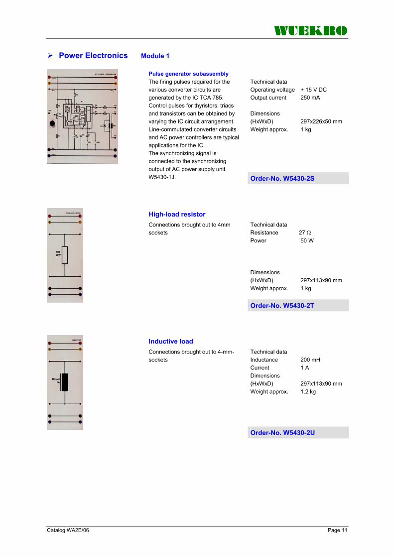
WUEKRO
Catalog WA2E/06 Page 11
Power Electronics Module 1
Technical data Operating voltage + 15 V DC Output current 250 mA Dimensions (HxWxD) 297x226x50 mm Weight approx. 1 kg
Pulse generator subassembly The firing pulses required for the various converter circuits are generated by the IC TCA 785. Control pulses for thyristors, triacs and transistors can be obtained by varying the IC circuit arrangement. Line-commutated converter circuits and AC power controllers are typical applications for the IC. The synchronizing signal is connected to the synchronizing output of AC power supply unit W5430-1J. Order-No. W5430-2S
Technical data Resistance 27 Ω Power 50 W Dimensions (HxWxD) 297x113x90 mm Weight approx. 1 kg
High-load resistor Connections brought out to 4mm sockets
Order-No. W5430-2T
Technical data Inductance 200 mH Current 1 A Dimensions (HxWxD) 297x113x90 mm Weight approx. 1.2 kg
Inductive load Connections brought out to 4-mm-sockets
Order-No. W5430-2U
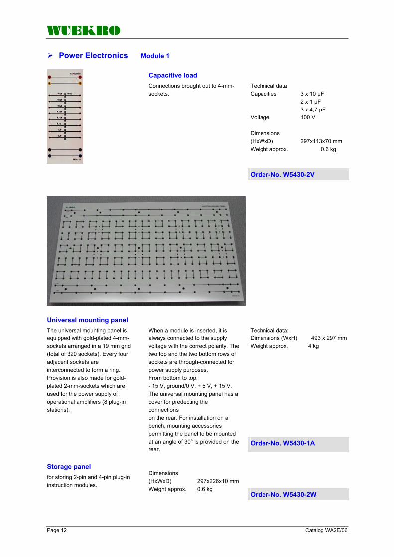
WUEKRO
Page 12 Catalog WA2E/06
Power Electronics Module 1
Technical data Capacities 3 x 10 µF 2 x 1 µF 3 x 4,7 µF Voltage 100 V Dimensions (HxWxD) 297x113x70 mm Weight approx. 0.6 kg
Capacitive load Connections brought out to 4-mm-sockets.
Order-No. W5430-2V
Universal mounting panel Technical data: Dimensions (WxH) 493 x 297 mmWeight approx. 4 kg
The universal mounting panel is equipped with gold-plated 4-mm-sockets arranged in a 19 mm grid (total of 320 sockets). Every four adjacent sockets are interconnected to form a ring. Provision is also made for gold-plated 2-mm-sockets which are used for the power supply of operational amplifiers (8 plug-in stations).
When a module is inserted, it is always connected to the supply voltage with the correct polarity. The two top and the two bottom rows of sockets are through-connected for power supply purposes. From bottom to top: - 15 V, ground/0 V, + 5 V, + 15 V. The universal mounting panel has a cover for predecting the connections on the rear. For installation on a bench, mounting accessories permitting the panel to be mounted at an angle of 30° is provided on the rear.
Order-No. W5430-1A
Storage panel for storing 2-pin and 4-pin plug-in instruction modules.
Dimensions (HxWxD) 297x226x10 mm Weight approx. 0.6 kg
Order-No. W5430-2W

WUEKRO
Catalog WA2E/06 Page 13
Power Electronics Module 1
Assembly kit "Components of Power Electronics" (large set) Order-No. W5101-8L
Mainly in the field of electronics Resistors, Capacitors etc. have to be changed quickly and without difficulties. Those components therefore are fixed in transparent, unbreakable housings and be connected to the circuit by means of 4-mm-hard-gold-plated plugs.
Plug-in components consisting of the following plug-in components: Resistors 2 1Ω/2W 1 10Ω/2W 2 22Ω/2W 1 47Ω/2W 4 100Ω/2W 1 150Ω/2W 1 220Ω/2W 2 330Ω/2W 2 470Ω/2W 1 1kΩ/2W 1 3,3kΩ/2W 1 4,7kΩ/2W 2 10kΩ/2W 1 22kΩ/2W 1 47kΩ/2W 2 100kΩ/2W 1 1MΩ/2W
Capacitors 2 10nF 1 0,1µF 1 0,15µF 1 0,47µF 1 1µF 1 Elco 470µF Potentiometers 1 1kΩ linear/1W 1 10kΩ linear/1W 1 100kΩ linear/1W Switches 1 NC contact 2 NO contact Diodes 1 AA 118 1 1N4004 1 1N4148 1 BY 299 1 ZPD 6,2 1 ZPD 9,1 1 LED green 1 LED red Signal elements 1 Incandescent lamp 30 V/85 mA
Transistores 1 BC 141 1 BC 161 1 BC 237 1 BUZ 10, MOS-FET N-channel 1 2N4870, Unijunction Diac 1 Diac ER 900 Triac 1 Triac TIC 206 Thyristores 2 Thyristores TIC 106 Set of connecting leads and connectors 25 connectors 19mm 4 connectors 38mm 6 connecting leads 25cm for 4mm sockets 2 x red, 2 x black, 2 x blue 4 connecting leads 50cm for 4mm sockets 2 x red, 2 x black 2 connecting leads 100cm for 4mm sockets 1 x red,1 x black

WUEKRO
Page 14 Catalog WA2E/06
Power Electronics Module 1
Assembly kit "Components of power electronics" (small set) Order-No. W5101-8N With the assembly kit W5101-8N there can be investigated passive components of power electronics, furthermore semi-conductor components as diodes, Z diodes, bipolar transistors, FET, unijunction transistors and diacs. consisting of the following plug-in components Resistors 1 1Ω/2W 1 10Ω/2W 1 47Ω/2W 1 100Ω/2W 1 220Ω/2W 1 330Ω/2W 1 470Ω/2W 1 1kΩ/2W 1 22kΩ/2W 1 47kΩ/2W 1 100kΩ/2W Capacitors 1 1µF 1 electrolyt. 470µF Potentiometers 1 1kΩ linear/1W 1 10kΩ linear/1W
Switches 2 NC contact Diodes 1 AA 118 1 1N4004 1 1N4148 1 BY 299 1 ZPD 6,2 1 ZPD 9,1 Transistors 1 BC 141 1 BC 161 1 BC 237 1 BUZ 10, MOS-FET N-channel 1 2N4870, unijunction Diac 1 diac ER 900
Set of connecting leads and connectors 13 connectors 19 mm 2 connectors 38 mm 3 connecting leads 25 cm for 4-mm-sockets 1 x red, 1 x black, 1 x blue 2 connecting leads 50 cm for 4-mm-sockets 1 x red, 1 x black 2 connecting leads 100 cm for 4-mm-sockets 1 x red,1 x black
Assembly kit "Components of power electronics" The assembly kit W5101-8P completes the assembly kit W5101-8N to assembly kit W5101-8L Order-No. W5101-8P consisting of the following plug-in components Resistors 1 1Ω/2W 2 22Ω/2W 3 100Ω/2W 1 150Ω/2W 1 330Ω/2W 1 470Ω/2W 1 3,3kΩ/2W 1 4,7kΩ/2W 2 10kΩ/2W 1 100kΩ/2W 1 1MΩ/2W
Capacitors 2 10nF 1 0,1µF 1 0,15µF 1 0,47µF Potentiometers 1 100kΩ linear/1W Switches 1 NO contact Diodes 1 LED green 1 LED red
Triac 1 triac TIC 206 Thyristors 2 thyristors TIC 106 Set of connecting leads and connectors 12 connectors 19 mm 2 connectors 38 mm 3 connecting leads 25 cm for 4-mm-sockets 1 x red, 1 x black, 1 x blue 2 connecting leads 50 cm for 4-mm-sockets 1 x red,1 x black

WUEKRO
Catalog WA2E/06 Page 15
Power Electronics Module 1
Assembly kit " Power electronics Modules" Order-No. W5101-8X
The following experiments can be carried out
The following components are required to carry out these experiments (included in the kit)
Required accessories (not including in the assembly kit)
• Investigation of passive components
• Investigation of semiconductor components such as diodes, Z diodes, bipolar transistors, field-effect transistors, diacs, unijunction transistors, thyristors, triacs
• Amplifier circuits such as low-signal amplifiers and push-pull power amplifiers
• DC power supply circuits such as voltage stabilization circuits and constant-current source
• Circuits for pulse generation such as pulse generation with diac and unijunction transistor
1 DC power supply W5430-1H
1 AC power supply W5430-1J
1 Universal mounting panel W5430-1S
1 Storage panel W5430-2W
1 Inductance W5430-2U 1 High load resistor
W5430-2T 1 Assembly kit "Components" incl. connecting leads W5101-8L
alternative 1 Assembly kit "Components" (small set) W5101-8N
1 Supplementary kit (to assembly kit "Components" (small set)) W5101-8P
1 Experimental manual W3007-5A
2 Multimeter
1 2-channel-Oscilloscope 20MHz with 2 probes
1 Powermeter
1 Phase-angle meter

WUEKRO
Page 16 Catalog WA2E/06
Power Electronics Module 1
Subassembly kit "Firing Pulse TCA 785“ Order-No. W5101-8Y
The following experiments can be carried out
The following components are required: (incl. in the kit)
Required accessories (not included in the kit)
• Investigation of IC TCA 785 • TCA 785 as drive
subassembly for - thyristor - 2 thyristors (AC power
controller)
1 Experimental panel DC power supply W5430-1H
1 Experimental panel AC power supply W5430-1J
1 Universal mounting panel W5430-1T
1 Subassembly kit „Firing Pulse TCA 785“ with plug-in components W5101-8M
1 Pulse generator subassembly + 2 thyristors TIC 106 W5430-2S
1 High load resistor W5430-2T
1 Inductive load W5430-2U
1 Experimental manual W3007-5A
2 Multimeter
1 2-channel oscilloscope 20MHz with 2 probes
Subassembly kit „Firing Pulse TCA 785“ consisting of the
following plug-in modules and accessories Order-No. W5101-8M
Resistors 3 100Ω/2W 2 220Ω/2W 1 2,7kΩ/2W 1 150kΩ/2W Potentiometers 1 4,7kΩ/1W 1 100kΩ/1W Capacitors 1 1nF 1 10nF 1 47nF 1 68nF Diodes 3 1N4004
Transformer 1 ZKB418 IC 1 IC-socket 16-pin (Textool) 1 IC TCA785 Connecting leads and plugs 1 Connector 38 mm 15 Connector 19 mm 10 Adapter connectors black 3 2-mm leads 25 cm, black 2 2-mm leads 50 cm, black 14 2-mm leads 15 cm, 12 x black, 1 x red, 1 x blue

WUEKRO
Catalog WA2E/06 Page 17
Power Electronics Module 2
Rectifier Circuits
Technical data URRM 1000 V Continuous load current 6 A Limit of RMS current 15 A max. input voltage 3 AC 400 V/ 50 Hz max. output voltage 540 V DC Dimensions (HxWxD) 297x195x100 mm Weight approx.: 1 kg
Diode set consisting of 6 diodes, each diode protected by RC elements All connections are brought out to 4-mm-safety lab sockets. Measuring shunts (0.1 Ω) are integrated in the current paths to allow indirect recording of currents on an oscillograph.
Order-No. W3644-4H
Line-commutated thyristor set as compact unit, consisting of: The connectors of the power section are brought out to 4mm sockets. The maximum input voltage is 400V three-phase; the maximum output voltage is approximately 540V DC. The heat sinks are rated for a continuous load current of 6A. Technical data input voltage 1 AC/3 AC 230/400 V/50/60 Hz Current 6 A DC Output voltage max. 540 V DC Dimensions (HxWxD) 297x390x100 mm Weight approx. 4 kg
- 3 line-commutated single-phase bridges with trigger sets
- Power supply unit to provide the voltage for the different units as well as the synchronize AC voltage
- setpoint potentiometer for the controlled operation
- AC actual value sensor Measuring shunts (0.1 Ω) are integrated in the current paths to allow indirect recording of currents on an oscillograph. With additional analog input 0 – 10 V DC for connection of external controllers or PLC (brought out to 2-mm-sockets)
The angle is displayed digitally and can be set to a maximum or minimum limit, with connectors to oscillograph the firing pulses. The pulse sequence can be set to single or double pulse by means of a changeover switch. A second changeover switch is likewise used to enable the firing pulses. A third changeover switch is used for the Synchronization in Y or ∆. Potentiometer enables to limit the firing angle in the rectifier operation as well as in the AC controller operation. The thyristor set contains 3 commutating reactors.
Order-No. W3644-4F

WUEKRO
Page 18 Catalog WA2E/06
Power Electronics Module 2
Assembly Kit “Rectifier Circuits” Order-No. W3644-0B
The following experiments can be carried out:
The following components are required to carry out these experiments (incl. in the kit):
The following components are required to carry out these experiments (not included in the kit):
• Investigation of uncontrolled rectifier circuits, connection types M1, M3, B2, B6
• Investigation of half-controlled rectifier circuits, connection types B2, B6
• Investigation of fully controlled rectifier circuits, connection types M1, M3, B2, B6
• Fully controlled rectifier circuit in inverter operation
• Investigation of AC power controller, three- phase AC power controller
1 Line-commutated thyristor set W3644-4F
1 Diode panel W3644-4H
1 Load resistor single-phase W3375-8E
1 Load resistor 3-phase W3375-8H
1 Load inductor W3644-3C
1 Load inductor 3-phase W3644-3D
1 Load capacity 3-phase W3644-3F
1 Measuring transducer (voltage) W3644-4J
1 Measuring transducer (current) W3410-4B
1 Experimental manual W3007-3A
1 Set Connecting leads W3901-0B
2 Multimeter
1 2-channel oscilloscope 20MHz with 2 probes
1 Powermeter
1 Power supply ±15V DC for measuring transducern
(W4610-4N)
3 BNC – BNC leads
3 Adapter BNC – safety connecting leads

WUEKRO
Catalog WA2E/06 Page 19
Power Electronics Module 3
DC chopper controller circuits
Technical data Input voltage 1 AC 230 V/50 Hz Output voltage 320 V DC Current load max. 5 A DC in bridge connection (B2) Output power supply Voltage ±15 V DC Current 1 A Dimensions (WxHxD) 297x195x100 mm Weight approx. 4 kg
Power Supply The power supply for the DC chopper controller panels consists of an uncontrolled B2 connection with loadside capacitor. The power supply module feeds the DC chopper control as well as the measuring transducers. The in- and outputs of the power section are brought out to 4mm safety sockets, for the control electronics to 2-mm-sockets.
Order-No. W3644-4B
Technical data Input voltage max. 320 V DC Output voltage to max. 300 V DC Current load 5 A Clock frequency 200 Hz Control voltage ±15 V DC Dimensions (WxHxD) 297x195x100 mm Weight approx.: 2.5 kg
DC chopper controller with thyristor The output voltage can be varied virtually by means of a potentiometer or an external analog signal. Measuring shunts (0.1 Ω) are integrated in the current paths to allow indirect recording of currents on an oscilloscope. The in- and outputs of the power section are brought out to 4-mm-safety-sockets, for the control electronics to 2-mm-sockets. Order-No. W3644-4C
Technical data Input voltage max. 320 V DC Output voltage 0 to max. 300 V DC Current load 5 A clock frequency 2 kHz control voltage ±15 V DC Dimensions (WxHxD) 297x195x100 mm Weight approx. 2 kg
DC Chopper controller with transistor The input voltage can be varied virtually by means of a potentiometer or an analog signal (0V...10 V DC). Measuring shunts (0.1 Ω) are integrated in the current path to allow indirect recording of currents on an oscillograph. The in- and outputs of the power section are brought out to 4-mm- safety sockets, for the control electronics to 2-mm-sockets.
Order-No. W3644-4D

WUEKRO
Page 20 Catalog WA2E/06
Power Electronics Module 3
Order-No. W3644-0C (300W) Assembly kit "DC chopper Controller Circuits"
Order-No. W3644-0D (1000W)
The following experiments can be carried out:
The following components are required (incl. in the kit):
Further required components (not included in the assembly kit):
• DC chopper controller with thyristor: - Oscillograph-recording and
measurement of input voltages and currents, and output voltages and currents.
- Oscillograph-recording of valve voltages and currents. Understanding the principle of capacitor turn-off operating principle of the ring-around circuit and free-wheeling diode.
- Evaluation of switching performance.
- Recording and allocation of firing pulses.
• DC chopper controller with Bi-polar-transistor: - Oscillograph-recording and
measurement of input voltages and currents, and output voltages and currents.
- Oscillograph-recording of valve voltages and currents. Operating principle of the free-wheeling arm.
- Evaluation of switching performance.
- Understanding the various drive circuits for transistors and thyristors.
• DC chopper controller with IGBT-transistor: - Oscillograph-recording and
measurement of input voltages and currents, and output voltages and currents.
- Oscillograph-recording of valve voltages and currents. Operating principle of the free-wheeling arm.
- Evaluation of switching performance.
1 Power Supply DC chopper W3644-4B
1 DC chopper with thyristor W3644-4C
1 DC chopper with IGBT W3644-4D
1 DC machine W3365-5C (300-W-Progr.) W3375-5C (1000-W-Progr.)
1 Baseframe for motor-generator set W3360-8A (300-W-Progr.) W3375-8A (1000-W-Progr.) 1 compact braking unit W3365-1E (300-W-Progr.) W3375-1E (1000-W-Progr.)
1 Excitation unit W3360-1N
1 Precision measuring transducer (voltage) W3644-4J
1 Precision measuring transducer (current) W3410-4B (300-W-Progr.) W3410-4C (1000-W-Progr.)
1 On/Off switch, 2-pin W3341-4B
1 Experimental manual W3007-1B
1 Set Connecting leads
W3901-0B
3 Multimeter
1 2-channel oscilloscope 20MHz with 2 probes
1 Power supply ±15V DC for transducers (W4610-4N).
3 BNC – BNC leads
3 Adapter BNC – safety connecting leads

WUEKRO
Catalog WA2E/06 Page 21
Power Electronics Module 4
AC Power Controller Circuits
AC Power Controller Technical data Input voltage 1 AC 230 V/50 Hz Output voltage 1 AC 0 – 230 V/50 Hz current load max. 5 A Dimensions (WxHxD) 297x195x100 mm Weight approx. 2 kg
The power section of the AC power controller consists of 2 thyristors and a triac. The phase angle and the ON time can be varied by means of a potentiometer or an external analog signal (0V...10V DC). A changeover switch is used to select the "Full-wave control" and "Phase control" modes. The firing pulses can be sensed in an isolated circuit. The synchronizing voltage can be tapped in an isolated circuit.
The in- and outputs of the power section are brought out to 4-mm-safety sockets, for the control electronics to 2-mm-sockets. A smoothing inductor RC protective elements are provided. Measuring shunts (0.1 Ω) are integrated in the current paths to allow indirect recording of currents on an oscillograph.
Order-No. W3644-4E
Assembly kit "AC power controller" Order-No. W3644-0E
The following experiments can be carried out:
The following components are required (incl. in the kit):
Further required components (not incl. in the kit):
• Phase control with 2 thyristors • Phase control with triac • Full-wave control with 2
thyristor • Full-wave control with triac
1 AC power controller W3644-4E
1 Universal machine W3365-3F
1 Baseframe for motor-generator set W3360-8A
2 Incandescent lamp with socket W3228-4A
1 Precision measuring transducer (voltage) W3644-4J
1 Precision measuring transducer (current) W3410-4B (300-W-Progr.)
1 Experimental manual W3007-2A
1 Set connecting leads W3901-0B
2 Multimeter
alternative 2 Multimeter as Demonstration instruments W5431-1B
1 2-channel oscilloscope 20MHz with 2 probes
1 Power supply ±15V DC for transducers
3 BNC – BNC leads
3 Adapter BNC – safety connecting leads
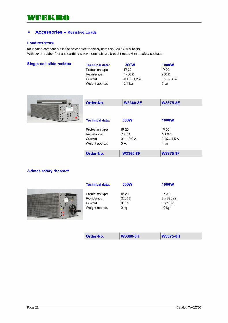
WUEKRO
Page 22 Catalog WA2E/06
Accessories – Resistive Loads
Load resistors for loading components in the power electronics systems on 230 / 400 V basis. With cover, rubber feet and earthing screw, terminals are brought out to 4-mm-safety-sockets.
Single-coil slide resistor Technical data: 300W 1000W Protection type Resistance Current Weight approx.
IP 20 1400 Ω 0,12…1,2 A 2,4 kg
IP 20 250 Ω 0.9…5,5 A 6 kg
Order-No. W3360-8E W3375-8E
Technical data: 300W 1000W Protection type Resistance Current Weight approx.
IP 20 2300 Ω 0,1…0,9 A 3 kg
IP 20 1000 Ω 0.25…1,5 A 4 kg
Order-No. W3360-8F W3375-8F 3-times rotary rheostat
Technical data: 300W 1000W Protection type Resistance Current Weight approx.
IP 20 2200 Ω 0,3 A 9 kg
IP 20 3 x 330 Ω 3 x 1,5 A 10 kg
Order-No. W3360-8H W3375-8H

WUEKRO
Catalog WA2E/06 Page 23
Accessories – Reactive / capacitive loads
Technical data Inductance 200 mH Current 5 A Dimensions (WxHxD) 195x297x172 mm Weight approx. 8.5 kg
Inductive Load Coil for placing inductive load on components in the power electronics system on 230/400 V basis. All terminals are brought out to 4-mm-safety sockets.
Order-No. W3644-3C
Technical data Inductance 100/400 mH Current 14/7 A Dimensions (WxHxD) 170x290x160 mm Weight approx. 20 kg
Inductive Load
Coil for placing inductive load on components in the power electronics system on 230/400 V basis. All terminals are brought out to 4-mm-safety sockets.
Order-No. W3642-4U
Technical data Inductance 3 x 100 mH Current 1,5 A Dimensions (WxHxD) 260x297x100 mm Weight approx. 2.6 kg
Inductive Load Coil for placing inductive load on components in the power electronics system on 230/400 V basis. All terminals are brought out to 2 4-mm-safety-sockets.
Order-No. W3644-3D
Technical data Capacity 3 x 2µF / 450V AC 3 x 4µF / 450V AC 3 x 8µF / 450V AC Dimensions (W x H x D) 260x297x100mm Weight approx. 2.0kg
Capacitive Loading for capacitive load of the components from the power electronics system and electrical machines. Terminals brought out to 4-mm-safety-sockets.
Order-No. W3644-3F
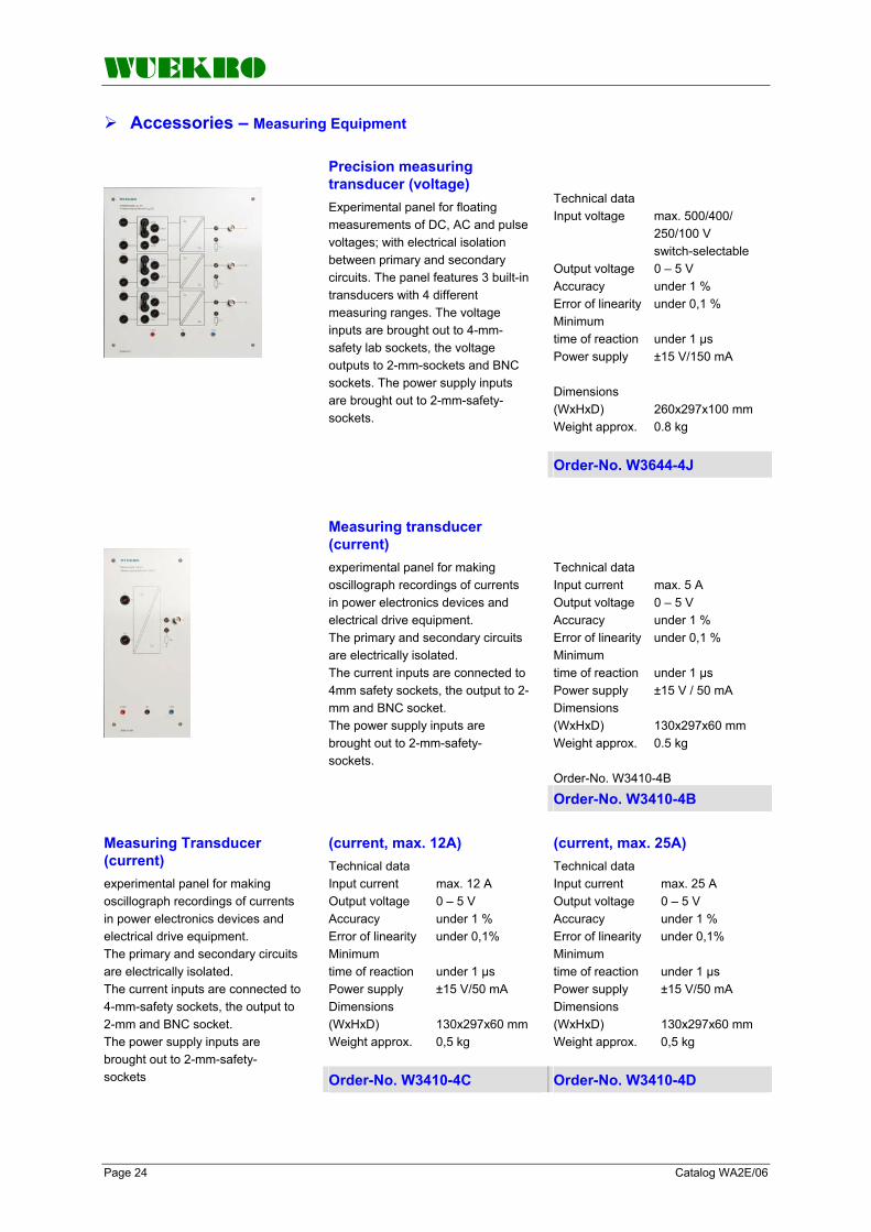
WUEKRO
Page 24 Catalog WA2E/06
Accessories – Measuring Equipment
Technical data Input voltage max. 500/400/ 250/100 V switch-selectable Output voltage 0 – 5 V Accuracy under 1 % Error of linearity under 0,1 % Minimum time of reaction under 1 µs Power supply ±15 V/150 mA Dimensions (WxHxD) 260x297x100 mm Weight approx. 0.8 kg
Precision measuring transducer (voltage) Experimental panel for floating measurements of DC, AC and pulse voltages; with electrical isolation between primary and secondary circuits. The panel features 3 built-in transducers with 4 different measuring ranges. The voltage inputs are brought out to 4-mm-safety lab sockets, the voltage outputs to 2-mm-sockets and BNC sockets. The power supply inputs are brought out to 2-mm-safety-sockets.
Order-No. W3644-4J
Technical data Input current max. 5 A Output voltage 0 – 5 V Accuracy under 1 % Error of linearity under 0,1 % Minimum time of reaction under 1 µs Power supply ±15 V / 50 mA Dimensions (WxHxD) 130x297x60 mm Weight approx. 0.5 kg Order-No. W3410-4B
Measuring transducer (current) experimental panel for making oscillograph recordings of currents in power electronics devices and electrical drive equipment. The primary and secondary circuits are electrically isolated. The current inputs are connected to 4mm safety sockets, the output to 2-mm and BNC socket. The power supply inputs are brought out to 2-mm-safety- sockets.
Order-No. W3410-4B
(current, max. 12A) Technical data Input current max. 12 A Output voltage 0 – 5 V Accuracy under 1 % Error of linearity under 0,1% Minimum time of reaction under 1 µs Power supply ±15 V/50 mA Dimensions (WxHxD) 130x297x60 mm Weight approx. 0,5 kg
(current, max. 25A) Technical data Input current max. 25 A Output voltage 0 – 5 V Accuracy under 1 % Error of linearity under 0,1% Minimum time of reaction under 1 µs Power supply ±15 V/50 mA Dimensions (WxHxD) 130x297x60 mm Weight approx. 0,5 kg
Measuring Transducer (current) experimental panel for making oscillograph recordings of currents in power electronics devices and electrical drive equipment. The primary and secondary circuits are electrically isolated. The current inputs are connected to 4-mm-safety sockets, the output to 2-mm and BNC socket. The power supply inputs are brought out to 2-mm-safety- sockets Order-No. W3410-4C Order-No. W3410-4D

WUEKRO
Catalog WA2E/06 Page 25
Accessories – Measuring Equipment
Technical data Analog inputs max. ± 10 V Analog outputs max. ± 10 V Digital inputs 5 – 24 V DC Mains supply 1 AC 230 V/50 Hz via connector for non-heating apparatus Dimensions (HxWxD) 195x297x100 mm Weight approx. 1.3 kg
Measuring and control interface The measuring and control interface consists of 8 digital inputs and outputs, 4 analog inputs and 2 analog outputs as well as an RS-232 interface. The analog and digital inputs and outputs are brought out to 2-mm-sockets. The measuring and control interface provides the connection between PC and the magnetic powder brakes. Order-No. W3644-4L

WUEKRO
Page 26 Catalog WA2E/06

WUEKRO
Catalog WA2E/06 Page 27

WUEKRO
Page 28 Catalog WA2E/06
FAX – response to: +49 (0)9721 - 64691 - 20 Sender: Receiver:
Company WUEKRO GmbH
Dept. Sales Department Name Street Carl-Zeiss-Strasse 10 City 97424 Schweinfurt / Germany Phone + 49-(0)9721-64691-0 Fax + 49-(0)9721-64691-20 E-Mail [email protected] Internet www.wuekro.de No. of pages incl. this page
Please send the following catalogues to the a.m. address! Fundamentals of electrical Engineering
Installation circuits Bell ringing and entrance call stations Contactor control / Control technology Measurement and control of non-electrical variables
Fundamentels of electronics Analog technology Digital technology Microprocessing technology
Closed loop control technology Analog closed loop control Digital closed loop control
Automation engineering SIMATIC S7-200/300/400, Software Technology simulators / Models Process control engineering PCS7 AS-Interface Profibus DP Process simulation-software SIMIT LOGO! Mechatronical technology stations Courses on Automation
Electrical machines / Drive controls Electrical Machines 300W Electrical Machines 1000W Electrical Machines 5kW Electrical drive control systems 300W/ 1kW Electrical drive control systems 5kW Networked drive systems Cutaway Models Transformers, Rectifiers and Reactive Power Compensation Courses on drive systems
Power electronics extra low voltage (24V) low voltage (230/400V)
Building management systems KNX / EIB
VDE 0100 safety measures
Radio- and Television engineering AM/FM – Technology TV Engineering
Satellite – Technology
Cooling and air conditioning
Photovoltaic cell tecnology
Communication technology Modulation -/demodulation Fiber optic ISDN trainer (HICOM) ISDN
Measuring systems
Power supply units
Experiment instructions, manuals
Training courses
Remarks:

Training & Didactic Systems Building Service Management System KNX / EIB
Catalog WA2E/07.01
Catalog WA1E/07.01

ÓWUEKRO GmbH Catalog WA1E/07.01 All rights reserved. Reprinting, also in excerpts, is not permitted. Subject to change without prior notice.
Ø Our Range of Educational Services
Consulting, planning, delivery and commissioning with introductory training in the following fields:
Instruction module systems for power engineering
Ø Fundamentals and wiring circuits Ø Protective measures acc. to DIN....VDE 0100 Ø Connecting and measuring with electrical machines Ø Transformers and rectifier circuits Ø Measurement of non-electrical quantities
Instruction module systems and equipment for electronics
Ø Fundamentals of electronics, electronic components, analog technology Ø Digital technology, information processing Ø Trainers for radio and TV technology Ø Demonstration oscilloscope Ø Fault simulators Ø Experimental microcomputer 8085 Ø Closed-loop control technology
Training equipment
Ø Process and control circuit simulator
Experimental systems „Automation Technology”
Ø Programmable controllers PLC SIMATIC S5/S7 Ø Building m anagem ent system s KNX / EIB
Experimental machines
Ø Programs for 200 W and 1000 W including brake assemblies and control units, dynamometers, eddy-current brakes, loading modules, cutaway models and special machines of any rating
Complete laboratory equipment for
Ø Electrical machines Ø Power electronics, drive and control engineering Ø Programmable control technology
Complete training workshops for professions in the field of electrical engineering
Experiment instructions, training software
For further information please contact WUEKRO GmbH Carl Zeiss str. 10 D – 97424 Schweinfurt Germany Phone: + 49 (0) 9721-64691-0 Fax: + 49 (0) 9721-64691-20 Internet: http://www.wuekro.de E-mail: [email protected] Edition 06/2013

Table of Contents Page
Introduction to KNX / EIB 4
Configuration Proposals for KNX / EIB 5
KNX / EIB Compact Panel 9
KNX / EIB Rack Version 10
KNX / EIB Experimenter with Simulator 11
KNX / EIB Experimental Panels 12
Teachware (Experiment Instructions, Specialized Books) 28
Software (ETS, ETS Demo, CBT Training Software) 30
Accessories 34
Notes 35
Our Range of Educational Services 36
3

Introduction In general The KNX / EIB is a distributed data bus system for flexible service management in functional and residential buildings. Every storey, every room is individually supplied according to its requirements and conditions with the optimum electrical power for the respective time of day. This new technology revolutionizes electrical installation, is easy to comprehend and easy to implement. It saves time because planning is PC-based and much fewer leads must be laid during installation. As all components are optimally matched to one another, buildings with an KNX / EIB installation consume considerably fewer resources and thus work more economically as traditional systems. What is more, the system can be quickly and easily adapted when the layout of the room changes by simply re-assigning devices and components. How does the KNX / EIB work? All switches, pushbuttons and controls (sensors) are connected to the bus line by bus couplers. The bus line is a two-wire MSR lead that runs through the whole building. If a pushbutton is actuated for example, a command telegram with a specific address goes on the bus line.
Address assignment Every bus station is provided with a teaching button with an LED at its coupler. When this button is pressed, the physical address sent by the PC is applied and acknowledged. Functional interaction is reached by allocating the group address. This address is sent by the sensor together with the telegram and is received by all bus couplers with the same group address. The time load on the bus line is very low here. With event-controlled transmission a signal is only sent when a sensor is actuated, so the bus line is used only for a short time. The addressed actuators (relays, contactors, binary outputs, etc.) that are also connected to the bus line via their bus couplers receive the commands, but only those actuators or that actuator group will be activated which have been specified in the telegram address.
Adaptation to changed rooms It is especially relevant for functional buildings that a displacement of partition walls, which is often necessary there for organizational reasons, does not require the removal or a new laying of leads. By means of a PC, the sensors and actuators can be assigned new group addresses that correspond to the new room layout, e.g. relations between light switches and lamps, from anywhere in the bus network. So it is a prerequisite that all sensors and actuators obtain a physical address. Thus they can receive all further inputs like group addresses and parameters and can also be queried specifically, e.g. in the line of diagnostics during maintenance.
WUEKRO experimenters After these words of introduction on building service management systems you will find experimenters and training units for the training and education on the KNX / EIB on the following pages.
4
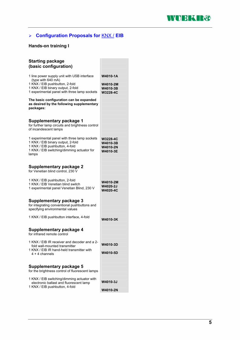
Configuration Proposals for KNX / EIB
Hands-on training I
Starting package (basic configuration) 1 line power supply unit with USB interface
(type with 640 mA) 1 KNX / EIB pushbutton, 2-fold 1 KNX / EIB binary output, 2-fold 1 experimental panel with three lamp sockets The basic configuration can be expanded as desired by the following supplementary packages: Supplementary package 1 for further lamp circuits and brightness control of incandescent lamps 1 experimental panel with three lamp sockets 1 KNX / EIB binary output, 2-fold 1 KNX / EIB pushbutton, 4-fold 1 KNX / EIB switching/dimming actuator for lamps Supplementary package 2 for Venetian blind control, 230 V 1 KNX / EIB pushbutton, 2-fold 1 KNX / EIB Venetian blind switch 1 experimental panel Venetian Blind, 230 V Supplementary package 3 for integrating conventional pushbuttons and specifying environmental values 1 KNX / EIB pushbutton interface, 4-fold Supplementary package 4 for infrared remote control 1 KNX / EIB IR receiver and decoder and a 2-
fold wall-mounted transmitter 1 KNX / EIB IR hand-held transmitter with
4 + 4 channels Supplementary package 5 for the brightness control of fluorescent lamps 1 KNX / EIB switching/dimming actuator with
electronic ballast and fluorescent lamp 1 KNX / EIB pushbutton, 4-fold
W4010-1A W4010-2M W4010-3B W3228-4C W3228-4C W4010-3B W4010-2N W4010-3E W4010-2M W4020-2J W4020-4C W4010-3K W4010-3D W4010-5D W4010-3J W4010-2N
5
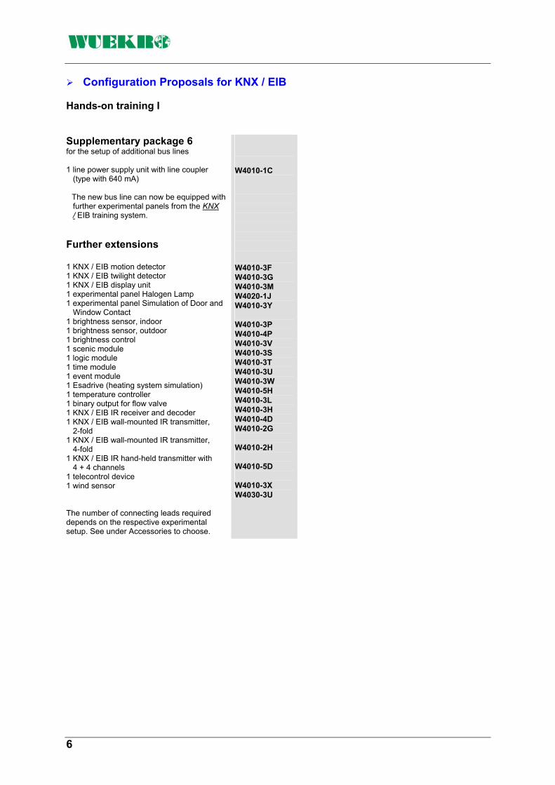
Configuration Proposals for KNX / EIB
Hands-on training I
Supplementary package 6 for the setup of additional bus lines 1 line power supply unit with line coupler
(type with 640 mA) The new bus line can now be equipped with further experimental panels from the KNX / EIB training system.
Further extensions 1 KNX / EIB motion detector 1 KNX / EIB twilight detector 1 KNX / EIB display unit 1 experimental panel Halogen Lamp 1 experimental panel Simulation of Door and
Window Contact 1 brightness sensor, indoor 1 brightness sensor, outdoor 1 brightness control 1 scenic module 1 logic module 1 time module 1 event module 1 Esadrive (heating system simulation) 1 temperature controller 1 binary output for flow valve 1 KNX / EIB IR receiver and decoder 1 KNX / EIB wall-mounted IR transmitter,
2-fold 1 KNX / EIB wall-mounted IR transmitter,
4-fold 1 KNX / EIB IR hand-held transmitter with
4 + 4 channels 1 telecontrol device 1 wind sensor The number of connecting leads required depends on the respective experimental setup. See under Accessories to choose.
W4010-1C W4010-3F W4010-3G W4010-3M W4020-1J W4010-3Y W4010-3P W4010-4P W4010-3V W4010-3S W4010-3T W4010-3U W4010-3W W4010-5H W4010-3L W4010-3H W4010-4D W4010-2G W4010-2H W4010-5D W4010-3X W4030-3U
6

Configuration Proposals for KNX / EIB
Hands-on training II
Basic configuration 1 line power supply unit with USB interface
(type with 640 mA) 1 KNX / EIB pushbutton, 4-fold 1 KNX / EIB binary output, 4-fold 1 experimental panel Storey Lighting With this basic configuration 4 groups of lamps can be controlled. Supplementary package 1 for 6 additional groups of lamps 1 KNX / EIB binary output, 4-fold 1 KNX / EIB binary output, 2-fold 1 KNX / EIB pushbutton, 4-fold 1 KNX / EIB pushbutton, 2-fold Supplementary package 2 Dimming of incandescent lamps 1 KNX / EIB switching/dimming actuator 1 KNX / EIB pushbutton, 2-fold Supplementary package 3 Twilight detector and motion detector 1 KNX / EIB twilight detector 1 KNX / EIB motion detector The hands-on training II can also be expanded by the supplementary packages 2 to 6 of hands-on training I. The number of the connecting leads required depends on the respective experimental setup. See under Accessories to choose.
W4010-1A W4010-2N W4010-3C W4020-1H W4010-3C W4010-3B W4010-2N W4010-2M W4010-3E W4010-2M W4010-3G W4010-3F
7

Configuration Proposals for KNX / EIB
Hands-on training III
Basic configuration 1 line power supply unit with USB interface
(type with 640 mA) 1 storey lighting 1 KNX / EIB pushbutton, 2-fold 1 KNX / EIB pushbutton, 4-fold 1 binary output, 4-fold 1 binary output, 2-fold Supplementary package 1 Venetian blind control 1 Venetian blind simulation with light-emitting diodes 1 KNX / EIB Venetian blind switch 1 KNX / EIB pushbutton, 2-fold 1 wind sensor 1 binary input, 4-fold Supplementary package 2 Infrared remote control 1 KNX / EIB IR receiver and decoder incl. 2-fold wall-mounted transmitter 1 KNX / EIB IR hand-held transmitter with
4 + 4 channels Supplementary package 3 Setup of additional bus lines 1 line power supply unit with line coupler (type with 640 mA) The new bus line can now be equipped with further experimental panels from the KNX / EIB training system.
The number of the connecting leads required depends on the respective experimental setup. See under Accessories to choose.
W4010-1A W4020-1H W4010-2M W4010-2N W4010-3C W4010-3B W4020-1C W4020-2J W4010-2M W4030-3U W4010-3A W4010-3D W4010-5D W4010-1C
8

KNX / EIB Experimenter with Simulator
Venetian blind simulation with LED The Venetian blind simulation shows the position of the blind by an LED strip indicator and the blind strip position by single LEDs. The contacts of the binary outputs are wired to 4-mm safety lab sockets. By a sideways attached mains plug with fine wire fuse and switch, the mains voltage is led internally to safety lab sockets. Included are: 1 mains connecting lead 8 glow lamps, 230 V 1 connecting lead PC - RS 232 Dimensions of the case (W x H x D): 520 x 375 x 175 mm Weight approx.: 7 kg
KNX / EIB Experimenter The KNX / EIB experimenter is integrated in a sturdy case with a powdered look in anthracite. The main parts of the case are black ABS plates with two locks. The lid can be detached and is fitted with a carrying handle.
The following KNX / EIB components are integrated in the case bottom: 1 power supply unit
(type with 640 mA) 1 USB interface 2 binary output, 2-fold 1 binary input, 4-fold 2 bus coupler 1 time switch, dual-channel 1 twilight detector 1 switching/dimming actuator 1 Venetian blind switch By connectors the bus is wired to all bus stations. By using 2-mm sockets as an open bus interface further external bus stations may be connected easily.
Into the control panel the following elements have been incorporated: 1 pushbutton, 1-fold 1 pushbutton, 2-fold 1 pushbutton, 4-fold 1 temperature controller 1 display unit 5 bus coupler 1 motion detector
The detachable lid of the ready-to-use KNX / EIB experimenter houses two simulation modules for learning the basic possibilities of the building services management system by way of experiments. Room lighting simulation On the simulation panel a storey of a building with several rooms including corridor and staircase is represented. The partition walls are pluggable permitting the simulation of changes in the room in an easy manner. All 8 incandescent lamps (E14) can be connected to the respective actuator using safety lab sockets. To allow a better overview, N and PE are already wired internally.
Order-No. W4006-0C
9

KNX / EIB compact-case
Also included : 1 mains connecting lead 4 incandescent lamps Dimensions of the case (W x H x D): 420 x 340 x 135 mm Weight approx.: 5 kg
KNX / EIB Compact case The KNX / EIB compact case is a space-saving and especially cost-effective variant for starting with building services management systems. Especially the extremely short setting-up time has to be mentioned as an advantage. Several experiments for Brightness control, Alarm messages on the bus sent by a motion controller etc. can be worked out. It consists of the following components: 1 line power supply unit (type with 160 mA) including reactor 1 USB interface 1 binary input, 4-fold 1 binary output, 4-fold 1 scenic module
Room lighting simulation consisting of 4 incandescent lamps and pluggable partition walls for a fast change of the room layout. 1 4-fold pushbutton with separate bus coupler and integrated dimmer (1-channel) 1 top-hat rail with integrated data bus In order to facilitate the connection of further modules it is possible to connect these via a Phoenix plug connection. All 230 V-connections brought out to 4-mm safety lab sockets. An open bus-interface for additional KNX-components is realized with 2mm sockets
Order-No. W4006-2S
10

KNX / EIB Experimental Panels
Experimenter panels in general: The experimental panels are made from plastic. The color is white similar to RAL 9002. They are 297 mm high (DIN A4) and about 5 mm thick. The width is 130 mm or has been expanded by integer multiples of 65 mm. On the back the experimental panels have hoods out of transparent plastic. The devices and components are built into the panels or mounted on the back. The transfer of the bus signals is implemented by female 2-mm connectors. All terminals for the mains voltage are wired to 4-mm safety lab sockets. The simulation panels are supplied with voltage via the bus. The mimic diagrams, device symbols and labels are permanently attached to the panel fronts according to the prevailing standards.
11

KNX / EIB Experimental Panels
parameterization and diagnosis of the bus stations (connecting lead included in scope of delivery). The data bus is glued into the top-hat rail and estab-lishes the connection by means of the pressure contacts of the KNX / EIB devices. The connector constitutes the transi-tion from the data bus to the bus lines (2-mm sockets). Mains connection via switch, fuse, mains plug and 2-m lead. Width: 260 mm
KNX / EIB Line Power Supply Unit with USB Built-in components: Power supply with integrated reactor and USB-connetor. The power supply unit generates the system voltage required for the KNX / EIB and feeds it into the bus line by means of the reactor. Primary nominal voltage: AC 230 V +10% -15%, 50 Hz Secondary nominal voltage: DC 29 V +/- 1 V Secondary nominal current: 640 mA The reactor prevents a short circuit of the data telegrams on the bus line caused by the power supply. The USB interface enables the connection of the PC for addressing, Order-No. W4010-1A
The data bus is glued into the top-hat rail and establishes the connection by means of the pressure contacts of the KNX / EIB devices. The connector constitutes the transi-tion from the data bus to the bus lines (2-mm sockets). Mains connection via switch, fuse, mains plug and 2-m lead. Width: 260 mm
not illustrated
KNX / EIB Line Power Supply Built-in components: Data bus, reactor, connector and power supply. The power supply unit generates the system voltage required for the KNX / EIB and feeds it into the bus line by means of the reactor. Primary nominal voltage: AC 230 V +10% -15%, 50 Hz Secondary nominal voltage: DC 29 V +/- 1 V Secondary nominal current: 640 mA The reactor prevents a short circuit of the data telegrams on the bus line caused by the power supply. Order-No. W4010-1B
The connecting lead is part of the scope of delivery. Width: 130 mm
not illustrated
KNX / EIB USB Interface: Enables the link-up of the PC or laptop for addressing, parameterization and diagnosis via a 9-pin Sub D socket. The USB interface is connected to a bus coupler and can be switched into the bus at any place.
Order-No. W4010-1R
12
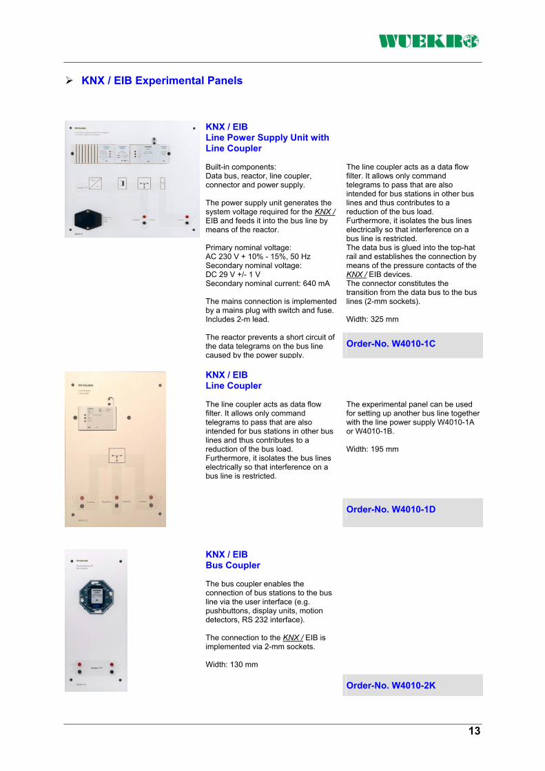
KNX / EIB Experimental Panels
The line coupler acts as a data flow filter. It allows only command telegrams to pass that are also intended for bus stations in other bus lines and thus contributes to a reduction of the bus load. Furthermore, it isolates the bus lines electrically so that interference on a bus line is restricted. The data bus is glued into the top-hat rail and establishes the connection by means of the pressure contacts of the KNX / EIB devices. The connector constitutes the transition from the data bus to the bus lines (2-mm sockets). Width: 325 mm
KNX / EIB Line Power Supply Unit with Line Coupler Built-in components: Data bus, reactor, line coupler, connector and power supply. The power supply unit generates the system voltage required for the KNX / EIB and feeds it into the bus line by means of the reactor. Primary nominal voltage: AC 230 V + 10% - 15%, 50 Hz Secondary nominal voltage: DC 29 V +/- 1 V Secondary nominal current: 640 mA The mains connection is implemented by a mains plug with switch and fuse. Includes 2-m lead. The reactor prevents a short circuit of the data telegrams on the bus line caused by the power supply.
Order-No. W4010-1C
The experimental panel can be used for setting up another bus line together with the line power supply W4010-1A or W4010-1B. Width: 195 mm
KNX / EIB Line Coupler The line coupler acts as data flow filter. It allows only command telegrams to pass that are also intended for bus stations in other bus lines and thus contributes to a reduction of the bus load. Furthermore, it isolates the bus lines electrically so that interference on a bus line is restricted.
Order-No. W4010-1D
KNX / EIB Bus Coupler The bus coupler enables the connection of bus stations to the bus line via the user interface (e.g. pushbuttons, display units, motion detectors, RS 232 interface). The connection to the KNX / EIB is implemented via 2-mm sockets. Width: 130 mm
Order-No. W4010-2K
13

KNX / EIB Experimental Panels
The display field features an LED that can be used as a locating light, etc. In the labeling field the operating function can be described in plain text or by pictographs. The pushbutton is designed as a rocker with neutral middle position. Width: 130 mm
KNX / EIB Pushbutton, 1-fold Pushbutton and bus coupler are separate. That has the advantage that the pushbutton does not have to be removed from the bus coupler when the physical address is programmed. Via the bus coupler the pushbutton outputs commands to actuators for defined ON/OFF switching, for the dimming of lamps, for moving Venetian blind strips up/down or adjusting them, etc. by using a corresponding application program. Order-No. W4010-2L
The display field features two LEDs that can be used as locating lights, etc. In the labeling field the operating functions can be described in plain text or by pictographs. The control area is designed as a double rocker with neutral middle position. Width: 130 mm
KNX / EIB Pushbutton, 2-fold Pushbutton and bus coupler are separate. That has the advantage that the pushbutton does not have to be removed from the bus coupler when the physical address is programmed. Via the bus coupler the pushbutton outputs commands to actuators for defined ON/OFF switching, for the dimming of lamps, for moving Venetian blind strips up/down or adjusting them, etc. by using a corresponding application program. Order-No. W4010-2M
In the labeling field the operating functions can be described in plain text or by pictographs. The control area is designed as a rocker with neutral middle position by which four channels can be controlled. The active channel is always selected by one of the preselection keys. Width: 130 mm
KNX / EIB Pushbutton, 4-fold Functions are the same as for the 2-fold pushbutton. Pushbutton and bus coupler are separate. That has the advantage that the pushbutton does not have to be removed from the bus coupler when the physical address is programmed. The display field features four LEDs that can be used for preselection or status display, etc.
Order-No. W4010-2N
Width: 130 mm
not illustrated
Pushbutton Pushbutton, 250 V~, 10 A, wired to 4-mm safety lab sockets. The pushbutton can be used in conjunction with binary input W4010-3A.
Order-No. W3217-4B
14

KNX / EIB Experimental Panels
The 4-fold binary input is delivered including connector. Width: 130 mm
KNX / EIB Binary Input, 4-fold Binary input for four independent 230-V maintained-contact/momentary-contact switching signals that are converted into bus telegrams. Thus, up to four conventional 230-V pushbuttons (e.g. W3217-4B) can be integrated into the bus system. Order-No. W4010-3A
The 2-fold binary output is delivered including connector. Width: 130 mm
KNX / EIB Binary Output, 2-fold Binary output for switching two independent groups of electrical loads. Can be used as time switch or time relay. Nominal voltage: AC 230 V, 50 / 60 HzCurrent switched per output: 6 A for ohmic load Switching capacity per output: 1000 Watts for incandescent lamps
Order-No. W4010-3B
Nominal voltage: AC 230 V, 50/60 Hz Current switched per output: 6 A for ohmic load Switching capacity per output: 1000 Watts for incandescent lamps The 4-fold binary output is delivered including connector. Width: 260 mm
KNX / EIB Binary Output, 4-fold By its four outputs, the binary output panel can switch four independent groups of electrical loads. Depending on the application program, the binary output can be used for direct ON/OFF switching, etc. The switching behavior can be set as normally closed or normally open contact.
Order-No. W4010-3C
15

KNX / EIB Experimental Panels
not illustrated
The experimental panel contains: 1 pushbutton interface 1 conventional installation
pushbutton for illumination or Venetian blind control
3 pushbuttons for environmental variables (brightness, wind speed and temperature)
Width: 130 mm
KNX / EIB Pushbutton Interface, 4-fold The pushbutton interface is used for connecting up to four conventional pushbuttons with floating contacts. The required scanning voltage is directly supplied by the pushbutton interface. The connection is implemented by eight strands of wire that are twisted in pairs and are permanently attached to the pushbutton interface. Depending on the application program, the connected pushbuttons can be used to output commands to actuators for a defined turn-on/turn-off, for dimming lamps or for driving blinds or adjusting blind strips. Order-No. W4010-3K
KNX / EIB IR Receiver/Decoder and Wall-mounted IR Transmitter For the remote control of actuators, the wall-mounted IR transmitter sends out infrared signals that are picked up by the IR receiver and transferred to the IR decoder, which converts them into the corresponding bus telegrams.
Thus the wall-mounted IR transmitter can be used to output commands to actuators for a defined turn-on/turn-off or dimming of lamps or for driving blinds up/down or adjusting blind strips. Width: 130 mm
Order-No. W4010-3D
Order-No. for single orders:
KNX / EIB IR Receiver/Decoder
Order-No. W4010-4D
KNX / EIB Wall-mounted IR Transmitter, 2-fold
Order-No. W4010-4G
16

KNX / EIB Experimental Panels
Transmitter range: approx. 20 m Batteries 4 x LR03 (1.5 V) (not included in scope of delivery)
KNX / EIB Hand-held IR Transmitter 4 + 4 Channels The hand-held IR transmitter can be used in conjunction with the experimental panels W4010-3D or W4010-4D. Up to eight different groups of actuators can be controlled.
Order-No. W4010-5D
Mains voltage: AC 230 V +10% / -15% Nominal power: 215 Watts Width: 325 mm
KNX / EIB Switching/Dimming Actuator For switching and dimming incandescent lamps and low-voltage halogen lamps (via electronic transformers). With integrated bus coupler, short-circuit and overload protection. The turn-on characteristics, the memory function and the dimming speed can be defined by the user.
Order-No. W4010-3E
Several functions can be parameterized like switch-on/switch-off or dimming of a fluorescent lamp, or setting a specific, programmed brightness value. Width: 390 mm
KNX / EIB Switching/Dimming Actuator for Fluorescent Lamps With built-in electronic ballast and fluorescent lamp. The switching/dimming actuator controls the fluorescent lamp by means of the DC 10 V control connector of the electronic ballast (EVG Dynamic). The control voltage is supplied by the ballast EVG Dynamic.
Order-No. W4010-3J
17

KNX / EIB Experimental Panels
2 shielding wings for reducing the detection angles (left and right) and two rotary switches for setting the reset time and the response threshold. The dusk response threshold is infinitely adjustable. The experimental panel Motion Detector is delivered including the bus coupler. The application software for the PEHA motion detector is available in the Siemens product database. Width: 130 mm
KNX / EIB Motion Detector, PEHA The motion detector is a proximity switch which responds to changes in temperature. It is used for detecting people in its area of supervision and applies bus couplers and a respective application program to output switching commands to actuators such as binary outputs for switching groups of lamps, or to signaling units. Angle of detection: max. 180 degrees, adjustable Range: approx. 10 m Reset time: 3 s ... 6 min, adjustable Controls: 1 changeover switch (OFF, permanent ON, automatic)
Order-No. W4010-3F
By means of this signal, additional actuators (e.g. Venetian blind control) can be activated. Switching capacity: 690 VA Current switched: 3 A cos ϕ 0.6 The link-up to the Powernet® EIB or the KNX / EIB is implemented by a binary input.
Wind Sensor The Busch-Jaeger wind sensor is driven by a fan. The rotating speed of the fan can be set by a potentiometer. The switching value of the wind sensor can also be adjusted. At the wind speed set, an output (normally open contact) is activated for 3 min.
Order-No. W4030-3U
18
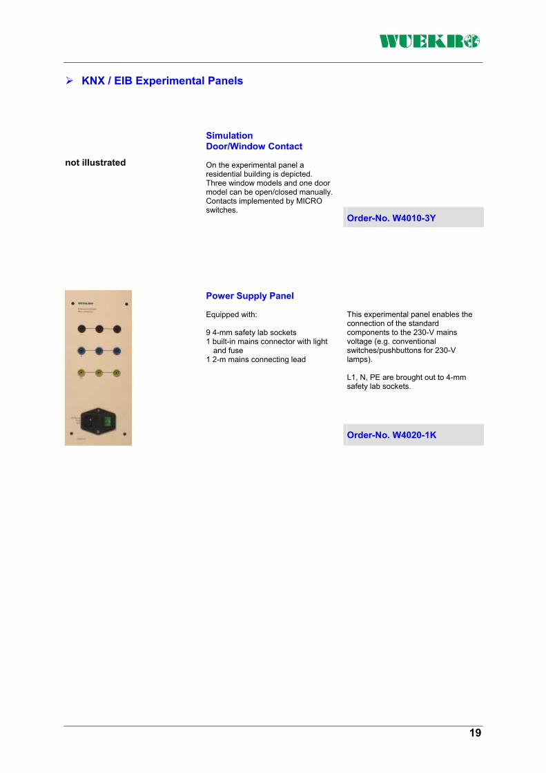
KNX / EIB Experimental Panels
not illustrated
Simulation Door/Window Contact On the experimental panel a residential building is depicted. Three window models and one door model can be open/closed manually. Contacts implemented by MICRO switches. Order-No. W4010-3Y
This experimental panel enables the connection of the standard components to the 230-V mains voltage (e.g. conventional switches/pushbuttons for 230-V lamps). L1, N, PE are brought out to 4-mm safety lab sockets.
Power Supply Panel Equipped with: 9 4-mm safety lab sockets 1 built-in mains connector with light
and fuse 1 2-m mains connecting lead
Order-No. W4020-1K
19

KNX / EIB Experimental Panels
When the brightness value set is exceeded, an "OFF" telegram is sent and the LED goes off. Setting range 2...300 Lux or 200...20000 Lux Action two-step Hysteresis Factor 1.3 of the ON value Display elements 1 red LED Controls 1 rotary switch for changing the setting range The experimental panel Twilight Detector is delivered including the photo-sensor, the bus coupler and the connector. Width: 130 mm
KNX / EIB Twilight Detector, Grässlin Via the bus coupler and by means of a corresponding application program the 1-channel twilight detector outputs brightness-dependent commands to actuators for switching on/off lamps or for driving blinds up/down, etc. The brightness is measured by the photo-sensor which is connected to the twilight detector by a lead. The twilight detector has two ranges where the desired brightness value can be set by a potentiometer. If the brightness value set is not reached, the built-in LED lights up and the twilight detector sends an "ON" telegram via the bus coupler
Order-No. W4010-3G
processed for daylight evaluation by the brightness module W4010-3V. Setting range: 0 ... 16 000 Lux.
Width: 130 mm
KNX / EIB Brightness Sensor, outdoor The brightness sensor is used for measuring the outdoor brightness and consists of a converter and photo-sensor. The brightness value measured by the photo-sensor is output to the KNX / EIB via the converter and can be
Order-No. W4010-4P
Various application programs such as calibration, continuous light or two-step control and read-out of the brightness value are available. Setting range: 150 ... 1 950 Lux Width: 130 mm
KNX / EIB Brightness Sensor The brightness sensor is used for measuring the brightness and consists of a converter and photo-sensor. The converter receives the brightness value measured by the photo-sensor and controls the illumination using the KNX / EIB.
Order-No. W4010-3P
20

KNX / EIB Experimental Panels
When dimming is adjusted manually, e.g. by a switch, the corresponding brightness characteristic is adapted to the new indoor brightness required. After the lighting is switched ON/OFF the next time, the original characteristic is activated again. Each light control can also be operated as a two-step control with hysteresis, i.e. the indoor lighting is not dimmed but switched ON/OFF via binary output devices, etc. in relation to the outdoor brightness. Width: 130 mm
not illustrated
KNX / EIB Brightness Control The brightness control features 10 independent light controls which operate the indoor lighting according to the outdoor brightness. For each light control a separate brightness characteristic can be input according to which dimming commands are calculated and sent to dimmers. The actual outdoor brightness value, which is identical for all ten light controls, is measured by the brightness sensor (W4010-3P or W4010-4P) and sent to the brightness control module.
Order-No. W4010-3V
For each scenic module up to eight group addresses can be stored that can be assigned to the four scenes. Width: 130 mm
KNX / EIB Scenic Module Up to four different scenes can be stored. A scene may consist of switching/dimming settings for lamps and of limit positions for blinds that can be queried by pressing a button when required. It can also be stored in a scene whether the heating or the ventilation is switched on or off, whether the room temperature is to be set to a new value or whether a new brightness command value is to be sent to the constant light stabilizer.
Order-No. W4010-3S
21

KNX / EIB Experimental Panels
AND, OR operations 4 inverters Telegram multiplication Width: 130 mm
KNX / EIB Logic Module The logic module is used to combine binary signals that can be sent and received via telegrams. Currently, three application programs are available:
Order-No. W4010-3T
The module features 4 inputs and 4 outputs which can be inverted. ON/OFF delays Staircase lighting (time switch) Disabling the inputs is possible. Width: 130 mm
KNX / EIB Time Module The time module is used for the time-related control of binary signals that can be sent and received via telegrams.
Order-No. W4010-3U
These calendar entries/daily programs can contain up to 300 time jobs. It is possible to send up to 60 texts with 14 characters each to the KNX / EIB. Width: 130 mm
KNX / EIB Event Module The application program manages up to 255 communication objects. Up to 60 event programs, which can receive up to 200 event jobs, can be programmed. For the daily programs and the calendar entries the event module needs the timing element Time Master. The event module manages 100 calendar entries/daily programs. Order-No. W4010-3W
22

KNX / EIB Experimental Panels
The terminals are wired to 4 mm safety sockets. The control at the bus coupler can be implemented by the experimental panel Temperature Controller W4010-3L. Width: 195 mm
KNX / EIB Binary Output for Flow Valve The binary output is built into the experimental panel together with the bus coupler. Both parts are connected by a ribbon cable with plug connector. By the two 230 V AC/6 A outputs electrothermal servo-drives for heating valves can be operated, etc.
Order-No. W4010-3H
The clearly arranged and intuitive control panel features 5 LEDs for the operating states Normal, Standby, Night, Freeze/Heat Protection and Dew Point Alert. A presence switch is used for switching over between comfort and standby mode and a rotary button for shifting the basic setpoint. Width: 130 mm
KNX / EIB Temperature Controller Bus coupler and temperature controller are separate. The temperature controller can be used as a two-step controller (thermostat) or as a continuous controller (P or PI controller) for pure heating as well as for combined heating and cooling operation. Via the bus coupler and using a corresponding application program, the controller outputs switching commands to actuators such as binary output W4010-3H for activating electrothermal servo-drives (two-step control). Order-No. W4010-3L
Forced setting, e.g. freeze protection (set by parameter) There is a running light on the experimental panel showing the inflow quantity as it runs forward. The speed of the running light is proportional to the inflow quantity. Two light-emitting diodes indicate the valve function (opening/closing). Width: 195 mm
KNX / EIB Esadrive Esadrive designates the electromotive, proportional EIB servo-drive with integrated bus coupler for standard radiator valves. The servo-drive has the following functions: Automatic synchronization of the drive (calibration to 0%) Setpoint after commissioning (set by parameter) Automatic flushing of the valve (set by parameter)
Order-No. W4010-5H
23

KNX / EIB Experimental Panels
The different messages can be se-lected at the display unit by pressing a key. Bus coupler and display unit are separate. Number of messages: 8 (freely assignable) Number of characters per message: one-line 10, two-line 20 Width: 130 mm
KNX / EIB Display Unit The display unit is used for displaying user-programmable messages. A message usually consists of perma-nently stored text and several wildcards which are replaced by text segments or information according to the data from the bus. Depending on the parameter setting it is possible to assign alarm functions to the mes-sages. The display unit consists of a two-line LCD display. Messages can be displayed in one or two lines.
Order-No. W4010-3M
Power is supplied via the bus voltage. Bus interfacing via 9-pin Sub D plug. The connecting lead to the bus coupler is part of the scope of delivery.Fits to: Venetian blind switch W4020-2J Width: 130 mm
not illustrated
Venetian Blind Simulation with LEDs The blind simulation with LEDs for blind and blind strip control is a cost-effective and space-saving alternative to the 230-V blind W4020-4C. According to the height of the blind, yellow, rectangular LEDs light up. Red LEDs show the respective inclination of the strips.
Order-No. W4020-1C
Channel B is wired to 4-mm safety lab sockets for connecting the original blind (230 V) W4020-4C. Width: 130 mm
KNX / EIB Venetian Blind Switch The blind switch controls 2 independ-ent drives for UP/DOWN and switches the strips step-by-step to OPEN or CLOSE triggered by sensors. Channel A is wired to a 9-pin Sub D plug for controlling the experimental panel Venetian Blind Simulation W4020-1C.
Order-No. W4020-2J
24

KNX / EIB Experimental Panels
Venetian Blind, 230 V
The blind is mounted on a transparent plastic panel which can be hung into the experimental rack. It is driven by an original blind motor. It is controlled via experimental panel Venetian Blind Switch W4020-2J (channel B). The functions Up, Down, Stop or Strip Adjustment are possible. Connection is implemented by 1 m long lab leads with 4-mm safety lab sockets. Width: 605 mm
Order-No. W4020-4C
These actuators can be arranged around the experimental panel in a experimental rack with 3 rows. Possible experiments: Commissioning of the individual rooms with various actuators. Adaptation of the installation to the changed room utilization (assignment of group addresses). Influencing the illumination using motion detectors or brightness sensors and load management. Width: 325 mm
Storey Lighting On the experimental panel a storey of a building with several rooms including corridor and staircase is represented. The partition walls are pluggable permitting the simulation of changes in the room in an easy manner. By addressing the sensors and actuators anew, they can be adapted to the current situation. All 11 incandescent lamps (E14) can be connected to the respective actuator using safety lab sockets. To allow a better overview, N and PE are already wired internally. The storey lighting model can be controlled by various actuators like the 2-fold binary output, the 4-fold binary output or the switching/dimming actuator. Order-No. W4020-1H
The incandescent lamps are not included in the scope of delivery! Width: 130 mm
not illustrated
E 14 Lamp Sockets Three lamp sockets are wired to 4-mm safety lab sockets.
Order-No. W3228-4C
25

KNX / EIB Experimental Panels
Width: 130 mm
Halogen Lamp The input of the electronic transformer is wired to 4-mm safety lab sockets. The output is further connected to the halogen lamp via 2-mm sockets.
Order-No. W4020-1J
A status query of the loads and the respective device functions is possible. This information is communicated by voice output. A code number protects from unauthorized switching. Alarm functions can also be set.
not illustrated
KNX / EIB Telecontrol Device The telecontrol device connects the KNX / EIB to the telephone network. Via the telephone, electrical loads can be switched directly and using the bus.Messages from conventional signal inputs and messages from the bus can be transmitted to various destination numbers by phone.
Order-No. W4010-3X
26

Teachware
Order-No. W3005-1B
Experiment instructions KNX / EIB V051 Detailed experiment instructions with exercises, solutions, descriptions of the software parameter settings and wiring diagrams. Excerpt from experiment instructions KNX / EIB W3005-1B
27

Software Training Program on the KNX / EIB (European Installation Bus) Fundamentals of the EIB Technology Topology Telegrams Bus stations Installation
Training program on the KNX / EIB
The training program European Installation Bus is suited for learners as well as for advanced students who want to learn and repeat the theoretical basics of the EIB field. The teaching subjects are imparted by spoken texts (audio files) in order to avoid having to read long texts on the screen.
Mnemonic sentences, important formulae, summaries and exercises are also displayed on the screen though.
A lot of animations, videos and interaction in the training program is supposed to increase the learning effect. Review questions are posed during the teaching process as well as at the end of each learning step. During the exercises the program reacts to each response of the student with a respective feedback.
The training program is available in German and English.
28

Software Training Program on the KNX / EIB (European Installation Bus)
Training program on the EIB
Training program on the EIB
Order-No. W4000-2B
29

Accessories Connecting leads of 0.5 mm2 with 2-mm plugs (bus line) Length/color 7.5 cm black 7.5 cm red 30 cm black 30 cm red 60 cm black 60 cm red 100 cm black 100 cm red
Order-No. W3903-1E W3903-1F W3903-3E W3903-3F W3903-8E W3903-8F W3903-5E W3903-5F
Connecting leads of 2.5 mm2 with 4-mm safety lab plugs Length/color 25 cm black 25 cm blue 50 cm black 50 cm blue 50 cm green/yellow 100 cm black 100 cm blue 100 cm green/yellow 150 cm black 150 cm blue
Order-No. W3907-1E W3907-1G W3907-2E W3907-2G W3907-2H W3907-3E W3907-3G W3907-3H W3907-4E W3907-4G
30

Notes:
31

32
FAX – response to: +49 (0)972 1 - 64691 - 20
Sender: Receiver: Company WUEKRO GmbH
Dept. Sales Department Name Street Carl-Zeiss-Strasse 10 City 97424 Schweinfurt / Germany Phone + 49-(0)9721-64691-0 Fax + 49-(0)9721-64691-20 E-Mail [email protected] Internet www.wuekro.de No. of pages incl. this page ý Please send the following catalogues to the a.m. address! ¨ Fundamentals of electrical Engineering ¨ Installation circuits ¨ Bell ringing and entrance call stations ¨ Contactor control / Control technology ¨ Measurement and control of non-electrical variables ¨ Fundamentels of electronics ¨ Analog technology ¨ Digital technology ¨ Microprocessing technology
¨ Closed loop control technology ¨ Analog closed loop control ¨ Digital closed loop control
¨ Automation engineering ¨ SIMATIC S7-200/300/400, Software ¨ Technology simulators / Models ¨ Process control engineering PCS7 ¨ AS-Interface ¨ Profibus DP ¨ Process simulation-software SIMIT ¨ LOGO ! ¨ Mechatronical technology stations ¨ Courses on Automation
¨ Electrical machines / Drive controls ¨ Electrical Machines 300W ¨ Electrical Machines 1000W ¨ Electrical Machines 5kW ¨ Electrical drive control systems 300W/ 1kW ¨ Electrical drive control systems 5kW ¨ Networked drive systems ¨ Cutaway Models ¨ Transformers, Rectifiers and Reactive Power Compensation ¨ Courses on drive systems
¨ Power electronics ¨ extra low voltage (24V) ¨ low voltage (230/400V)
¨ Building management systems ¨ KNX / EIB
¨ VDE 0100 safety measures
¨ Radio- and Television engineering ¨ AM/FM – Technology ¨ TV Engineering ¨ ¨ Satellite – Technology
¨ Cooling and air conditioning
¨ Photovoltaic cell tecnology
¨ Communication technology ¨ Modulation -/demodulation ¨ Fiber optic ¨ ISDN trainer (HICOM) ¨ ISDN
¨ Measuring systems
¨ Power supply units
¨ Experiment instructions, manuals
¨ Training courses
Remarks:

WUEKRO
Training & Didactic Systems Protection Schemes DIN VDE 0100
Catalog WA2E/08

WUEKRO
Page 2 Catalog WA2E/08
Our Services
• Development and production of didactic training systems • Teachware and documentation • Project engineering of complete lab's incl. furnitures and lab equipment • Quotations on customers demand • Installation, commissioning and training at site
Our Customers • Vocational training schools, technical schools, colleges and universities... • Industrial laboratories for vocational education and higher education
Fields of Technology • Fundamentals of electrical engineering
• Fundamentals of electronics
• Closed loop control technology
• Automation engineering
• Electrical machines / drive control
• Power electronics
• Building management systems
• Protection schemes to VDE 0100
• Radio- and TV technology
• Air conditioning and refrigeration
• Photovoltaic
• Communication technology
• Measuring systems, power supplies, accessories
• Experimental manuals, documentation For further information please contact: WUEKRO GmbH Carl-Zeiss-Strasse 10 D - 97424 Schweinfurt Germany Tel. + 49 (0) 9721-64691-0 Fax: + 49 (0) 9721-64691-20 E-Mail: [email protected] Internet: www.wuekro.de WUEKRO GmbH
All Rights reserved. Reprint not permitted. Technical changes without prior notice.. S30020616P – 01/13

WUEKRO
Catalog WA2E/08 Page 3
Table of Contents Page Our Services, Customers and Scope of Supply 2 Introduction 4 Protection Schemes according to DIN VDE 0100 Part 410 4 Foreword, Concept, Learning contents / Experiments 4 System-types, Testing and measuring 5 Demonstration Board 6 Assembly Kit with Experimental Panels 7 Notes 14 Fax - Reply 16

WUEKRO
Page 4 Catalog WA2E/08
Protection against electrical shock in accordance to DIN VDE 0100 Part 410
Foreword Concept Learning contents / Experiments
Our Training Systems program “Protection Schemes to VDE 0100” is suitable to show the design, principle of operation and performance of the circuits protecting against indirect contact with the live parts specified in DIN VDE 0100 Part 410. The limits of the effectiveness of the individual protective measures are to be determined by measurements to ensure that the trainers understand the regulations specified. Protection schemes are continuos to be adapted to the newest technology, there fore we have enhanced our resp. training systems. For our experimental-panel system and the demonstration board we use commercially available test gear. VDE 0100 Training System is usable for testing protection schemes in electrical systems. By alternating the earth-resistors faults can be simulated and located. The results are useful to ensure the practical work of the trainees.
Demonstration Board 230 V for teachers and instructors with practical oriented experiments for theoretical lessons Experimental-Panel System 230 V for the students to carry out several experiments to get familiarized with the different systems of protection schemes. The Complete Concept Decisive for this specified training system is the didactical structure of the complete training system. All circuits are printed with the same layout. Therefore the panels can be continued for the relevant experiments.
The following learning contents are adapted to the professions in the field of electrical engineering and can be performed by using the demonstration board as well as the experimental panels. Introduction accident prevention regulations Guidelines for the performance of experiments Direct/indirect contact Protection against accidential contact with live parts Protection against electrical shock when touching exposed conduction parts Protection extra-low voltage / purpose extra-low voltage protection by means of extra-low voltage Exception of effectiveness functions of extra-low voltage Safety Separation Safety separation at a metal conductive location Safety separation with two loads Protection by Disconnection Tripping behaviour of circuit breakers Tripping behaviour of residual-current devices Protective measures in the TN-System Protection by disconnection with overcurrent protection devices in a TN-C-System Protection by disconnection with overcurrent protection devices and various PEN resistances restrictions on effectiveness

WUEKRO
Catalog WA2E/08 Page 5
Protection against electrical shock in accordance to DIN VDE 0100 Part 410 TN system types Main equipotential bonding • Enhancing the protective
function • Equipotential bonding and
foundation earthing • Residual-current device in the
TN system • Residual current device in the
TN system when PE has an open circuit
Protective measures in the TT System • Residual-current device in the
TT system • Residual-current device in the
TT system N/PE connectiohn downstream of the residual-current-operated circuit breaker
• Residual-current device in the TT system – effects of inadequate (defective) equipotential bonding
Protective measures in the IT System • Types – priciples of operation • Effect of cable capacitances
on the protective function • Double short circuit to frame in
the IT system • Fault signals from the earth-
leakage monitor Tests for protective measures • Test measures for installations • Overview of measurements for
testing protective measures
Measurement Methods for testing protective measures • Measuring the voltage drop on
an earth electrode • Measuring the earth-electrode
resistance • Measuring the voltage shape
of the resistance area, step-voltage
• Measuring the loop impedance ZL and the breaking current Ib
• Measuring UCLmax and REEmax of the r.c.d. protection in the TT system
• Measuring the insulation resistance

WUEKRO
Page 6 Catalog WA2E/08
Demonstration Board "Protection Schemes against electrical shock in accordance with DIN VDE 0100 Part 410
VDE-Demonstration Board 230V
To carry out all experiments we recommend two multimeters and one protectice schemes measuring unit. These instruments are not included the scope of supply. The components of the demonstration board are in accordance with the components used in the experimental panels system W2812-0A Dimensions (WxHxD) 650x900x250 mm Weight approx. 50 kg
The VDE-Demostration board is built into a metal sheet cabinet with two lockable frontdoors, the front-panel is white.
The board can be set up on a bench. Scope of delivery including 1 Demo-board 230 V 1 Experimental manual W3006-3B 20 plug-connectors 4 mm 15 safety-connecting-leads 4 mm The concept of the VDE-demon-stration board is according to the training regulations. To minimize the preparation for the experiments the design is a compact housing and includes all relevant components.
Order-No. W2812-1A
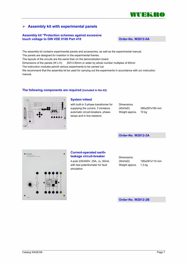
WUEKRO
Catalog WA2E/08 Page 7
Assembly kit with experimental panels
Assembly kit "Protection schemes against excessive touch voltage to DIN VDE 0100 Part 410 Order-No. W2812-0A The assembly kit contains experimental panels and accessories, as well as the experimental manual. The panels are designed for insertion in the experimental frames. The layouts of the circuits are the same than on the demonstration board. Dimensions of the panels (W x H) 297x130mm or wider by whole number multiples of 65mm The instruction modules permit various experiments to be carried out. We recommend that the assembly kit be used for carrying out the experiments in accordance with our instruction manual.
The following components are required (included in the kit)
Dimensions (WxHxD) 390x297x190 mm Weight approx. 10 kg
System infeed with built-in 3-phase transformer for supplying the current, 3 miniature automatic circuit-breakers, phase-lamps and in line resistors
Order-No. W2812-2A
Dimensions (WxHxD) 195x297x110 mm Weight approx. 1,3 kg
Current-operated earth-leakage circuit-breaker 4-pole 230/400V, 25A, ∆In 30mA, with test potentiometer for fault simulation
Order-No. W2812-2B

WUEKRO
Page 8 Catalog WA2E/08
Assembly kit with experimental panels
Dimensions (WxHxD) 195x297x1100 mm Weight approx. 0,8 kg
Earth electrode resistor 39 Ω, for simulation of earth rods
Order-No. W2812-2C
Dimensions (WxHxD) 260x297x110 mm Weight approx. 1,2 kg
Equipotential bonding for adjustment of different contact resistances
Order-No. W2812-2D
Dimensions (WxHxD) 195x297x110 mm Weight approx. 3,4 kg
Safety Separation Transformer 230/230 V CB 1-pole 0.5 A, C
Order-No. W2812-2E
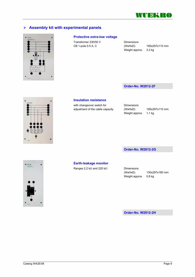
WUEKRO
Catalog WA2E/08 Page 9
Assembly kit with experimental panels
Dimensions (WxHxD) 195x297x110 mm Weight approx. 3,3 kg
Protective extra-low voltage Transformer 230/50 V CB 1-pole 0.5 A, C
Order-No. W2812-2F
Dimensions (WxHxD) 195x297x110 mm Weight approx. 1,1 kg
Insulation resistance with changeover switch for adjustment of the cable capacity
Order-No. W2812-2G
Dimensions (WxHxD) 130x297x180 mm Weight approx. 0,8 kg
Earth-leakage monitor Ranges 2,2 kΩ and 220 kΩ
Order-No. W2812-2H
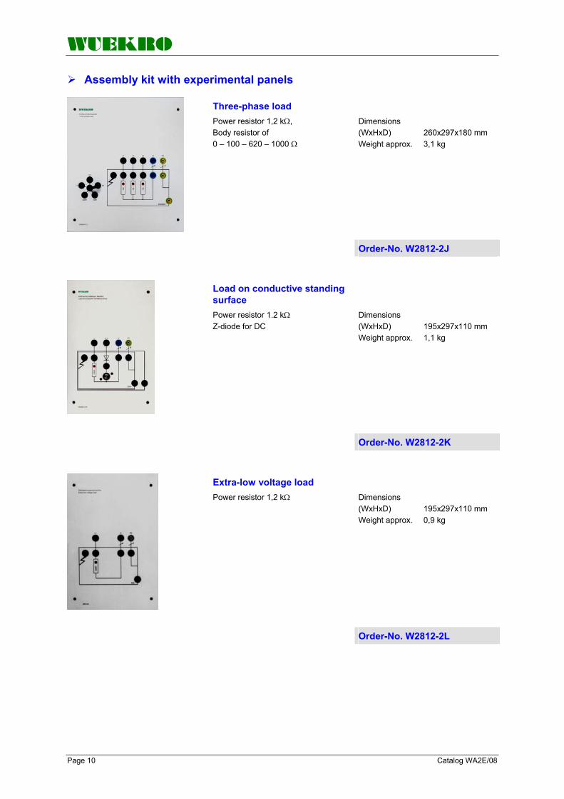
WUEKRO
Page 10 Catalog WA2E/08
Assembly kit with experimental panels
Dimensions (WxHxD) 260x297x180 mm Weight approx. 3,1 kg
Three-phase load Power resistor 1,2 kΩ, Body resistor of 0 – 100 – 620 – 1000 Ω
Order-No. W2812-2J
Load on conductive standing surface Power resistor 1.2 kΩ Z-diode for DC
Dimensions (WxHxD) 195x297x110 mm Weight approx. 1,1 kg
Order-No. W2812-2K
Extra-low voltage load Power resistor 1,2 kΩ
Dimensions (WxHxD) 195x297x110 mm Weight approx. 0,9 kg
Order-No. W2812-2L
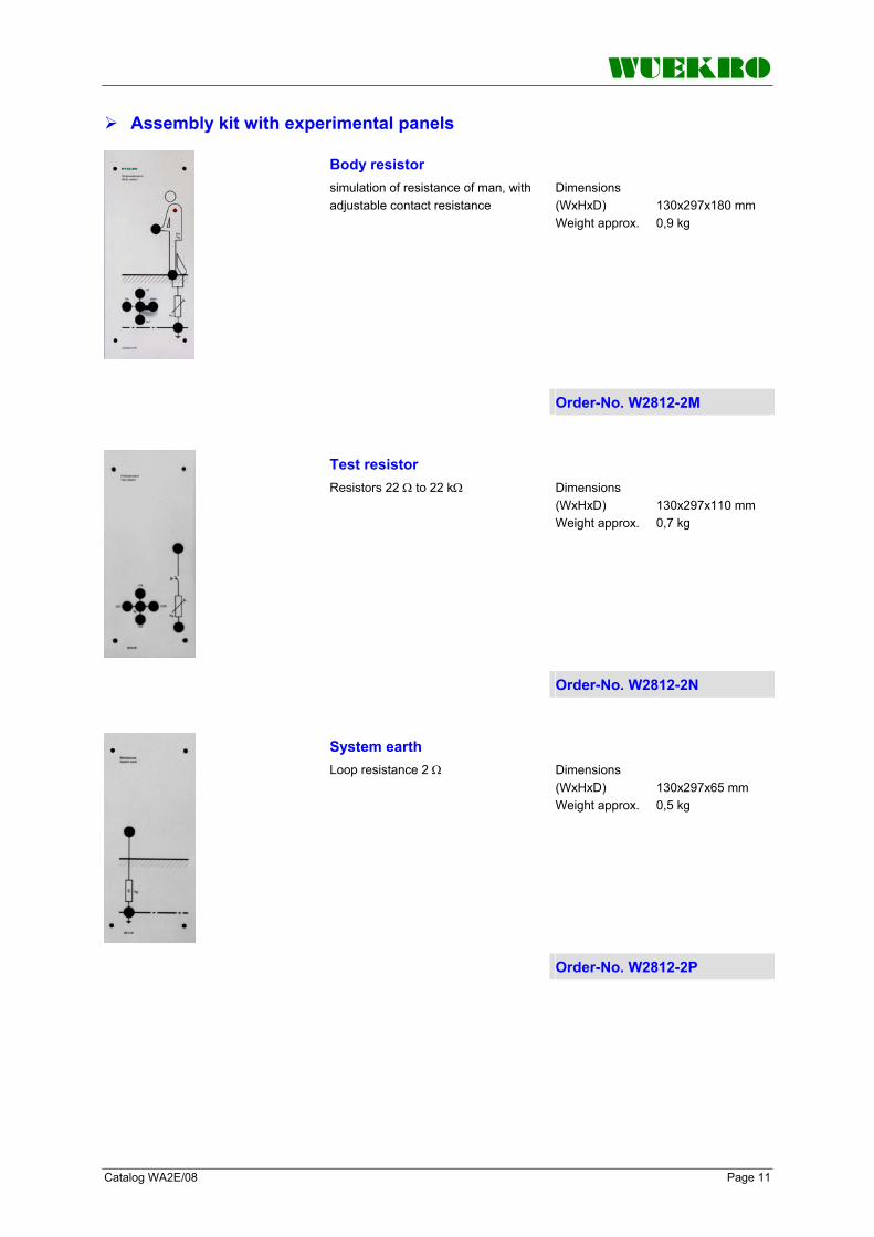
WUEKRO
Catalog WA2E/08 Page 11
Assembly kit with experimental panels
Body resistor simulation of resistance of man, with adjustable contact resistance
Dimensions (WxHxD) 130x297x180 mm Weight approx. 0,9 kg
Order-No. W2812-2M
Dimensions (WxHxD) 130x297x110 mm Weight approx. 0,7 kg
Test resistor Resistors 22 Ω to 22 kΩ
Order-No. W2812-2N
Dimensions (WxHxD) 130x297x65 mm Weight approx. 0,5 kg
System earth Loop resistance 2 Ω
Order-No. W2812-2P
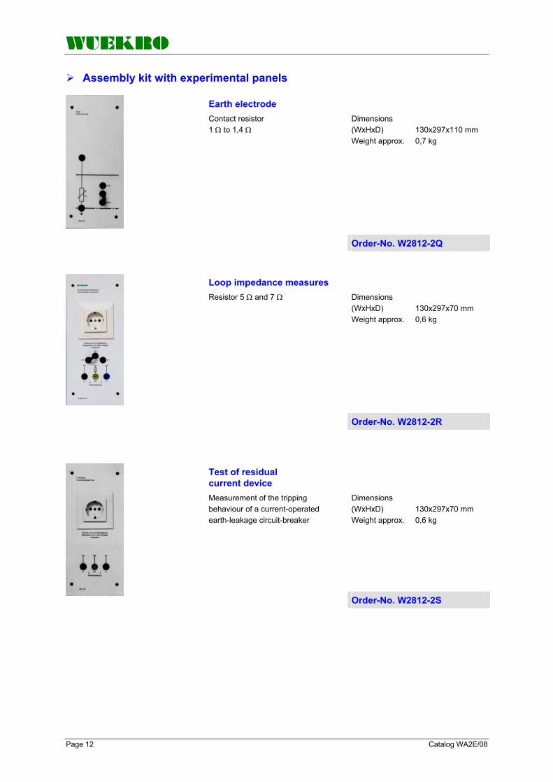
WUEKRO
Page 12 Catalog WA2E/08
Assembly kit with experimental panels
Dimensions (WxHxD) 130x297x110 mm Weight approx. 0,7 kg
Earth electrode Contact resistor 1 Ω to 1,4 Ω
Order-No. W2812-2Q
Dimensions (WxHxD) 130x297x70 mm Weight approx. 0,6 kg
Order-No. W2812-2R
Loop impedance measures Resistor 5 Ω and 7 Ω
Dimensions (WxHxD) 130x297x70 mm Weight approx. 0,6 kg
Test of residual current device Measurement of the tripping behaviour of a current-operated earth-leakage circuit-breaker
Order-No. W2812-2S

WUEKRO
Catalog WA2E/08 Page 13
Assembly kit with experimental panels
Dimensions (WxHxD) 130x297x70 mm Weight approx. 0,6 kg
Insulation measures Measurements between L1 – PE and N – PE with different resistances
Order-No. W2812-2T
Further components, (included in the kit)
Further components (not included in the kit)
15 plug connectors 4-mm 15 safety-connecting leads 0.3 m 20 safety-connecting leads 0.5 m 10 safety-connecting leads 1 m
2 multimeters 1 test instrument for protection schemes

WUEKRO
Page 14 Catalog WA2E/08
Notes

WUEKRO
Catalog WA2E/08 Page 15
Notes

WUEKRO
Page 16 Catalog WA2E/08
FAX – response to: +49 (0)9721 - 64691 - 20 Sender: Receiver:
Company WUEKRO GmbH Dept. Sales Department Name Street Carl-Zeiss-Strasse 10 City 97424 Schweinfurt / Germany Phone + 49-(0)9721-64691-0 Fax + 49-(0)9721-64691-20 E-Mail [email protected] Internet www.wuekro.de No. of pages incl. this page
Please send the following catalogues to the a.m. address! Fundamentals of electrical Engineering
Installation circuits Bell ringing and entrance call stations Contactor control / Control technology Measurement and control of non-electrical variables
Fundamentels of electronics Analog technology Digital technology Microprocessing technology
Closed loop control technology Analog closed loop control Digital closed loop control
Automation engineering SIMATIC S7-200/300/400, Software Technology simulators / Models Process control engineering PCS7 AS-Interface Profibus DP Process simulation-software SIMIT LOGO! Mechatronical technology stations Courses on Automation
Electrical machines / Drive controls Electrical Machines 300W Electrical Machines 1000W Electrical Machines 5kW Electrical drive control systems 300W/ 1kW Electrical drive control systems 5kW Networked drive systems Cutaway Models Transformers, Rectifiers and Reactive Power Compensation Courses on drive systems
Power electronics extra low voltage (24V) low voltage (230/400V)
Building management systems KNX / EIB
VDE 0100 safety measures
Radio- and Television engineering AM/FM – Technology TV Engineering Satellite – Technology
Cooling and air conditioning
Photovoltaic cell tecnology
Communication technology Modulation -/demodulation Fiber optic ISDN trainer (HICOM) ISDN
Measuring systems
Power supply units
Experiment instructions, manuals
Training courses
Remarks:
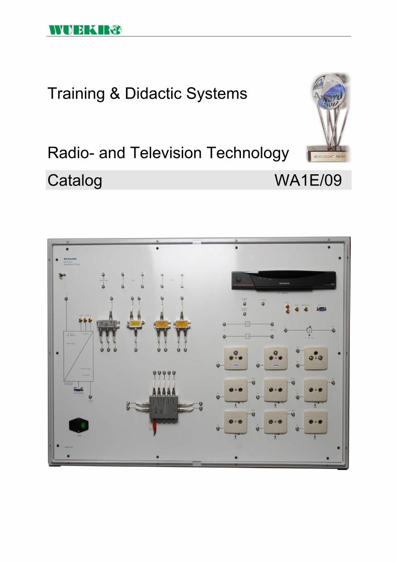
Training & Didactic Systems Radio- and Television Technology
Catalog WA1E/09

Page 2 Catalog WA2E/09
Our Services
• Development and production of didactic training systems • Teachware and documentation • Project engineering of complete lab's incl. furniture and lab equipment • Quotations on customer's demand • Installation, commissioning and training at site
Our Customers • Vocational training schools, technical schools, colleges and universities... • Industrial laboratories for vocational education and higher education
Fields of Technology • Fundamentals of electrical engineering
• Fundamentals of electronics
• Closed loop control technology
• Automation engineering
• Electrical machines / drive control
• Power electronics
• Building management systems
• Protection schemes to VDE 0100
• Radio- and TV technology
• Air conditioning and refrigeration
• Photovoltaic
• Communication technology
• Measuring systems, power supplies, accessories
• Experimental manuals, documentation For further information please contact: WUEKRO GmbH Carl-zeiss-Strasse 10 D – 97424 Schweinfurt Germany Tel. + 49 (0) 9721-64691-0 Fax: + 49 (0) 9721-64691-20 E-Mail: [email protected] Internet: www.wuekro.de WUEKRO GmbH
All Rights reserved. Reprint not permitted. Technical changes without prior notice. B20020111B – 08/13

Catalog WA2E/09 Page 3
Table of Contents Page Our Services, Customers and Fields of Technology 2 Table of Contents 3 Introduction 4 HI-FI AM/FM Radio Trainer 5 Satellite Aerial Trainer 6 Fax reply 8

Page 4 Catalog WA2E/09
Introduction Our Radio- and Television Training Systems are especially designed for basic and advanced training in the field of television and radio engineering. They allow to show and work on fundamental priciples and operating behavior to be demonstated and explained.
Realistic exercises show how to various faults can be pinpointed and rectified. The models take the form of fully operational television and radio sets as well as antenna systems with high picture and sound quality, allowing them to be used for audio-visual training purposes as well. for example
A variety of further training systems are available, please contact us for information.

Catalog WA2E/09 Page 5
Hi-Fi AM/FM Radio Trainer
Demonstration model for Hi-fi AM/FM radio and amplifier engineering
The following functional groups are incorporated
Fault simulator
The radio trainer is a portable training unit in a case with convertible cover. All stages are shown on the front panel as detailed block diagrams. Circuit diagram, waveforms and voltages at the 2mm test points are printed on the front plate. All circuits are protected against short circuits to avoid damages of the circuits. Buoilt in AM and FM tuner with stereo decoder and integrated loudspeakers. Also a sinewave generator and a plug in field for the included AM/FM Transmitter is built in. Under a lockable cover 15 typically faults for trouble shooting can be simulated by microswitches.
Technical Data: Technical data: AM (540-1600 kHz) FM (88-108 MHz) PLL Demodulator Mono/Stereo switch Potentiometers for volume, treble, bass and balance 2 x 5 watts output power Power connection: 230 V, 50 to 60 Hz Dimensions (W x D x H): 400 x 290 x 100mm Total weight approx. 3,8 kg
Order-No. W5405-2A

Page 6 Catalog WA2E/09
Satellite Aerial Trainer
General description The satellite aerial receiver is a demonstration model which covers the following ranges of the analogue satellite technique by example of a so called "two eye" unit • Reception of 2 satellites • Individual aerial single and
multiple reception • Central aerial single and multiple
reception • SAT-TV channel processing
(digital) • SAT-IF distribution • External signal infeed of
monitoring camera or VCR • Decoder terminal use • additional infeed of terrestrial
aerial frequencies
Technical Description
The demonstration board is built in a stabile steel case with a surface area of 1000x700 mm. The imprinted connection diagram facilitates the mapping. The following components are integrated: 1 SAT-ZF Multiswitch with 5 inputs and 4 outputs 1 digital processing unit für 2 free configurable channels 1 Universal-LNC 1 SAT-ZF test pattern generator 1 Twin-Receiver
Order-No. W5401-2B

Catalog WA2E/09 Page 7

Page 8 Catalog WA2E/09
FAX – Reply to: +49 (0)9721 / 64691 - 20
Sender: Receiver:
Company WUEKRO GmbH Dept. Sales Department Name Street Carl-Zeiss-Strasse 10 City 97424 Schweinfurt / Germany Phone + 49-(0)9721-64691-0 Fax + 49-(0)9721-64691-20 E-Mail [email protected] Internet www.wuekro.de
Please send the following catalogues to the a.m. address!
Fundamentals of electrical Engineering Installation circuits Bell ringing and entrance call stations Contactor control / Control technology Measurement and control of non-electrical variables
Fundamentels of electronics Analog technology Digital technology Microprocessing technology
Closed loop control technology Analog closed loop control Digital closed loop control
Automation engineering SIMATIC S7-200/300/400, Software Technology simulators / Models Process control engineering PCS7 AS-Interface Profibus DP Process simulation-software PROSIM 95 LOGO! Mechantronical technology stations Courses on Automation
Electrical machines / Drive controls Electrical Machines 300W Electrical Machines 1000W Electrical Machines 5kW Electrical drive control systems 300W / 1kW Electrical drive control systems 5kW Networked drive systems Cutaway Models Transformers, Rectifiers and Reactive Power Compensation Courses on drive systems
Power electronics extra low voltage (24V) low voltage (230/400V)
Building management systems KNX / EIB
VDE 0100 safety measures
Radio- and Television engineering AM/FM – Technology TV Engineering Satellite – Technology
Cooling and air conditioning
Photovoltaic cell tecnology
Communication technology Modulation -/demodulation Fiber optic ISDN trainer (HICOM) ISDN
Measuring systems
Power supply units
Experiment instructions, manuals
Training courses
Remarks:

WUEKRO
Training & Didactic Systems Refrigeration and Air-Conditioning
Catalog WA2E/12

WUEKRO
Page 2 Catalog WA2E/12
Our Services
• Development and production of didactic training systems • Teachware and documentation • Project engineering of complete lab's incl. furniture and lab equipment • Quotations on customer's demand • Installation, commissioning and training at site
Our Customers
• Vocational training schools, technical schools, colleges and universities... • Industrial laboratories for vocational education and higher education
Fields of Technology
• Fundamentals of electrical engineering • Fundamentals of electronics • Closed loop control technology • Automation engineering • Electrical machines / drive control • Power electronics • Building management systems • Protection schemes to VDE 0100 • Radio- and TV technology • Air conditioning and refrigeration • Photovoltaic • Communication technology • Measuring systems, power supplies, accessories • Experimental manuals, documentation
For further information please contact: WUEKRO GmbH Carl-Zeiss-Strasse 10 D - 97424 Schweinfurt Germany Tel. + 49 (0) 9721-64691-0 Fax: + 49 (0) 9721-64691-20 E-Mail: [email protected] Internet: www.wuekro.de WUEKRO GmbH
All Rights reserved. Reprint not permitted. Technical changes without prior notice.. S30020616P 01/13

WUEKRO
Catalog WA2E/12 Page 3
Contents Page Our Services 2 Introduction 4 Experimental Station Refrigeration and Air-Conditioning 5 Basic Set Refrigeration and Air-Conditioning 7 Extension Set Refrigeration and Air-Conditioning 9 Set of Accessories 10 Measuring Instruments 11 Fax-Reply 12

WUEKRO
Page 4 Catalog WA2E/12
Introduction
This new developed experimental station for refrigeration and air-conditioning training permits refrigeration and air-conditioning tests to be conducted in the normal cooling, air-conditioning and deep-freeze ranges, the electrical circuits to be set up, and measurements to be taken. A test group should comprise not more than 2-3 trainees for each experimental station.
Experimental panels
The experimental panels consist of plastic sheets with etched symbols, on which the respective equipment is attached on the front side. The devices are equipped with quick-connectors for connection of the refrigerant lines.
The Electrical connection occures over 4-mm safety terminals. In order to ensure secure fastening, e.g. when handling the connection lines.
Dimensions of the panels (H x W): 297x130mm or wider by a whole number multiple of 65mm.

WUEKRO
Catalog WA2E/12 Page 5
Experimental Station Refrigeration and Air-Conditioning
Design
The „Refrigeration and Air-Conditioning“ experimental station consists basically of a lab bench with back upright section, power supply and evaporator frame, and a trolley for the condensing unit. The tests are conducted by using experimental panels. The experimental panels can quickly clamped by setting the upper sectional rail and fixing this rail with thumb bolts.
They are interconnected by refrigerant-resistant flexible lines, the electrical connection being made by highly flexible leads with 4mm safety plugs. The experimental station is available with a basic set of experimental panels and devices, as well as an additional extension set.
The basic equipment allows technical refrigeration instruction which is oriented on the required level of training. By means of the additional equipment, more complex experiments can be performed for advanced training.
Experimental place with power supply and evaporator frame
Order No.W2700-3A
Possible measurements and analyses:
• Different refrigerant flow rates • power consumption • capacity measurements • pressure drop rate in
regulators and refrigerant conducting pipes
• variable heat fluxes on the evaporator and condenser
• net refrigeration capacity
• heat equilvalent • compressor capacity and
liequefaction pressure • operational overheating on
thermostatic butterfly valves • over or undercharging with
refrigerant plant • fault analysis during
installation and commissioning
• setting of all switchgear and
regulators • pressure and temperature
measurements • start-up problems of
compressor motors and their elimination
• damage to compressors due to superheated refrigerant.

WUEKRO
Page 6 Catalog WA2E/12
Experimental Station Refrigeration and Air-Conditioning
Experimental place with power supply and evaporator frame
Order No. W2700-3A
Consisting of:
1 Experimental bench W: 1800 D: 900 H: 780 mm 1 Lower cabinet for mobile use 3 drawers and central lock W: 420 D: 555 H: 545 mm 1 Trolley for the bench-type compressor and condensing unit. W:900 D: 600 H: 780 mm 1 Lower cabinet with 2 drawers for fitting under the trolley. 3 Organisation modules for drawers 1 Back upright for accommoding 3 power supply panels W: 1800 D: 320 H: 155 mm
1 Power supply panel for 1-ph. connection, with key-operated switch, and 16 A circuit-breaker, indicator light, 2 SCHUKO socket, outlets and 3 laboratory terminals. With 25 A current- operated e.l.c.b, sensitivity= 30mA 1 Power supply panel with 1 „emergency off“ pushbutton 1 „ON“ switch with illuminated rocker 4 SCHUKO socket outles 1 Power supply panel with 3 SCHUKO sockets without power connection 1 distribution board with 15 safety sockets 1 switch with illuminated rocker 3 safety sockets with line voltage
1 Flat evaporator with two fans, built in in a case for mounting on the top of the back upright design like the experimental place. with additional cold insulation, transparent frontpanel adjustable in height, and two injection facilities. W: 490 D: 320 H: 530 mm 1 Experimental frame 2 tiers The experimental modules can quickly clamped by setting the upper section rail and fixing this rail with thumb bolts. W: 1220 D: 250 H: 720 mm
Compressor and condensing unit mounted on portable base, consisting of: Compressor, condenser, refrigerant receiver and butterfly valves. Electrical connection via SCHUKO sockets. For refrigerant R 22
Order No. W7301-1A Like W7301-1B, but for refrigerant R 134 a
Order No. W7301-1B

WUEKRO
Catalog WA2E/12 Page 7
Basic Set Refrigeration and Air-Conditioning
Basic Set Refrigeration and Air-Conditioning Order No. W7301-0A
For conducting the following experiments in the normal cooling range, air-conditioning range and deep-freeze range:
• Simple refrigeration cycle with manually operated control valve (3 experiments)
• Simple refrigeration cycle with capillary tube feed (6 experiments)
• Simple refrigeration cycle with automatic control valve (6 experiments)
• Simple refrigeration cycle with thermostatic control valve (6 experiments)
• Simple refrigeration cycle controlled by evaporator and/or room thermostat (6 experiments)
• Simple refrigeration cycle with variable refrigerant com-pounds and pressure drops (1 experiment)
• Simple refrigeration cycle - start-up and fault-finding (1 experiment)

WUEKRO
Page 8 Catalog WA2E/12
Basic Set Refrigeration and Air-Conditioning
Basic Set Refrigeration and Air-Conditioning Order No. W7301-0A
The basic set is consisting of the following equipment
Experimental Panels Quantity Order number
Inspection glass with filter drier 1 W7301-2A
Mass flowmeter 1 W7301-2B
Refrigeration manometer (pressure gauge) 1 W7301-2C
Refrigeration manometer (Suction gauge) 1 W7301-2D
Valve set 80 mm 1 W7301-2E
Superheater 1 W7301-2F
Flow restrictor 1 W7301-2G
Automatic flow restrictor 1 W7301-2H
ON/OFF switch, 3pole 1 W3313-4A
Electrical control unit, -5 to +25° C including sensor 1 W7301-2J
Electronic control unit, -25 to +5° C including sensor 1 W7301-2K
Extensive instruction manuel 1 W3011-1A
Accessories for basic set consisting of:
Order No.: W7301-8A
Capillaries, matched to condensing unit 2
Substitute filter drier 3
Refrigeration-resistant flexible lines, length 915mm, 5/8“ dia 4
Refrigeration-resistant flexible lines, length 1800mm, 5/8“ dia. 2
Refrigeration-resistant flexible lines, length 915mm, 7/16“ dia. 6
Refrigeration-resistant flexible lines, length 1800mm, 7/16“ dia 2
Gaskets, 7/16“ 20
Gaskets, 5/8“ 20
Sundries jointing pieces etc.
Saftey connecting leads, highly flexible, with plug 4mm, length 0.5m, black.
20
dito, length 1.0m, black 20
dito, length 1.5m, black 5
dito, length 1.0m, blue 5
dito, length 1.0m, green-yellow 5

WUEKRO
Catalog WA2E/12 Page 9
Extension Set Refrigeration and Air-Conditioning
Extension Set Refrigeration and Air-Conditioning Order No. W7302-0A
For conducting the following experiments in conjunction with the basic set
• extended refrigeration cycles with constant evaporator-pressure regulators (3 experiments)
• extended refrigeration cycles with suction pressure regulator (2 experiments)
• extended refrigeration cycle with start-up relief (3 experiments)
• extended refrigeration cycle with hot-gas bypass regulator (3 experiments)
• extended refrigeration cycle with liquid trap (1 experiment)
• extended refrigeration cycle with temperature regulator (3 experiments)
• extended refrigeration cycle with electric evaporator defrosting (3 experiments)
• extended refrigeration cycle with periodic defrosting of evaporator (3 experiments)
• extended refrigeration cycle with four-way reversing valve (1 experiment)
• extended refrigeration cycle with hot-gas bypass regulation and injection valve (1 experiment)
Extension Set Refrigeration and Air-Conditioning Order No. W7302-0A
The extension set is consisting of the following equipment
Experimental panels Quantity Order number
Manual-operated through valve 6mm 1 W7302-2A
Temperature regulator 1 W7302-2B
Evaporator pressure regulator 1 W7302-2C
Suction pressure regulator 1 W7302-2D
Hot-steam bypass (capacity regulator) 1 W7302-2E
4-way reversing valve 1 W7302-2F
Injection valve 1 W7302-2G
Moisture separator 1 W7302-2H
Defrosting time relay 1 W7302-2J
Electrical control unit -5 to + 25° C 1 W7302-2K
Solenoid valve 6 mm 2 W7302-2L
Time relay, 0,5 to 20s, delayed pickup 1 W3331-4A
3-pole contactor 16A, auxiliary switch with 2 make and 2 break contacts
1 W3321-4A
Auxiliary contactor 6A, 4 make and 4 break contacts 1 W3328-4A

WUEKRO
Page 10 Catalog WA2E/12
Set of Accessories
Set of accessories for 1 to 5 work stations, for refrigerant R 22
Order No. W7302-8A
Consisting of:
Description Quantity
Mobile charging station 1
Extaction valve 1
Vacuum meter 1
Electronic temperature meter 1
Acid tester 1
Liquid for testing proposes 1
Recording manometer, -1 to 24 bar, complete with measuring disc
1
Electronic leakage detector unit 1
Refrigerant cylinder with 14kg refrigerant R 22 1
Set of accessories for 1 to 5 work stations, for refrigerant R 134 a
Order No. W7302-8B
Consisting of:
Description Quantity
Mobile charging station 1
Extaction valve 1
Vacuum meter 1
Electronic temperature meter 1
Acid tester 1
Liquid for testing proposes 1
Recording manometer, -1 to 24 bar, complete with measuring disc
1
Electronic leakage detector unit 1
Refrigerant cylinder with 14kg refrigerant R 134 a 1

WUEKRO
Catalog WA2E/12 Page 11
Measuring Instruments
For conducting the tests the following measuring instruments are also necessary:
- DCV: 400 mV/4/40/400/1000 V ± 0,8 % + 1 dgt.; 100 µV
- ACV: 4/40/400/700 V ± 1,0 % + 5 dgt.; 1 mV
- DCA: 400 µA/4/40/400mA/10 A ± 1 % + 2 dgt.; 100 µA
- ACA: 400 µA/4/40/400mA/ 10 A; ± 1,5 % + 5 dgt.; 100 µA
- Ohm: 400 O/4/40/400 kO/ 4/40 MO; ± 1,0 % + 2 dgt.; 0,1 O
- Cap.: 4/40/400nF/4/40/ 400 µF/4/40 mF; ± 4 % + 3 dgt.; 1 pF
- Freq.: 4/40/400 kHz/4/40/ 400 MHz; ± 0,1 % + 3 dgt ; 1 Hz
- Temp.: -40°C ... +1000°C ± 1 % + 3 dgt.; 1°C
Battery: 9 V-Battery
Dimensions (W x H x D): 100 x 210 x 45 mm
Weight: 330 g
Order No. P3315 USB
Profi-Digital-Multimeter with USB, 3 3/4-digit This digital multimeter has autorange and manual range options and dual-display, with maximum reading 3999 displayed in 40 analogue bars inscale making the measured value to be seen clearly and indicating the trend of changing quickly. In addition to the conventional measuring functions, there is new breakthrough in frequency test with maximum range of 400 MHz. Optical standard serial port is equipped with this meter for easy connection with computer to realize macro recording and monitoring and capture of transient dynamic data, displaying change of waveform during the measurement, providing data and evidence to engineering technicians for scientific research. A highly applied digital multimeter of high performance with full input protection and display backlight. The basic functions can be selected by push button keys easily and automatic range selection for DCV-, ACV-, DCA-, ACA-, ohm-, diode-, continuity-, capacitance-, frequency- and temperature measuring-function.
• 40 segment analogue bargraph display
• Auto power off, low battery display
• Data hold and max/min mode
• Relative function
• Diodetest
• Backlight
• Safety: EN 61010-1; CAT III 1000 V; CAT IV 600 V
Accessories: test leads, test clips, type K temperature probe, battery, USB-interface cable, software for Windows 95/98/2000/XP/NT/Vista/7 and manual.

WUEKRO
Page 12 Catalog WA2E/12
FAX – Reply to: +49 (0)9721 - 64691 - 20 Sender: Receiver: Company WUEKRO GmbH Dept. Sales Department Name Street Carl-Zeiss-Strasse 10 City 97424 Schweinfurt / Germany Phone + 49-(0)9721-64691-0 Fax + 49-(0)9721-64691-20 E-Mail [email protected] Internet www.wuekro.de No. of pages
incl. this page
Please send the following catalogues to the a.m. address!
Fundamentals of electrical Engineering Installation circuits Bell ringing and entrance call stations Contactor control / Control technology Measurement and control of non-electrical variables
Fundamentels of electronics Analog technology Digital technology Microprocessing technology
Closed loop control technology Analog closed loop control Digital closed loop control
Automation engineering SIMATIC S7-200/300/400, Software Technology simulators / Models Process control engineering PCS7 AS-Interface Profibus DP Process simulation-software SIMIT LOGO! Mechatronical technology stations Courses on Automation
Electrical machines / Drive controls Electrical Machines 300W Electrical Machines 1000W Electrical Machines 5kW Electrical drive control systems 300W/ 1kW Electrical drive control systems 5kW Networked drive systems Cutaway Models Transformers, Rectifiers and Reactive Power Compensation Courses on drive systems
Power electronics extra low voltage (24V) low voltage (230/400V)
Building management systems KNX / EIB
VDE 0100 safety measures
Radio- and Television engineering AM/FM – Technology TV Engineering Satellite – Technology
Cooling and air conditioning
Photovoltaic cell tecnology
Communication technology Modulation -/demodulation Fiber optic ISDN trainer (HICOM) ISDN
Measuring systems
Power supply units
Experiment instructions, manuals
Training courses
Remarks:

WUEKRO
Training & Didactic Systems Photovoltaic Cell Technology
Catalog WA2E/13

WUEKRO
Page 2 Catalog WA2E/13
Our Services
• Development and production of didactic training systems • Teachware and documentation • Project engineering of complete lab's incl. furniture and lab equipment • Quotations on customer's demand • Installation, commissioning and training at site
Our Customers • Vocational training schools, technical schools, colleges and universities... • Industrial laboratories for vocational education and higher education
Fields of Technology • Fundamentals of electrical engineering
• Fundamentals of electronics
• Closed loop control technology
• Automation engineering
• Electrical machines / drive control
• Power electronics
• Building management systems
• Protection schemes to VDE 0100
• Radio- and TV technology
• Air conditioning and refrigeration
• Photovoltaic
• Communication technology
• Measuring systems, power supplies, accessories
• Experimental manuals, documentation
For further information please contact: WUEKRO GmbH Carl-Zeiss-Strasse 10 D - 97424 Schweinfurt Germany Tel. + 49 (0) 9721-64691-0 Fax: + 49 (0) 9721-64691-20 E-Mail: [email protected] Internet: www.wuekro.de WUEKRO GmbH
All Rights reserved. Reprint not permitted. Technical changes without prior notice.. S20030616P – 01/13

WUEKRO
Catalog WA2E/13 Page 3
Contents Page Our Services 2 Introduction 3 Photovoltaic Lab bench and Standby Power Supply 4 Experimental Panels 5 Accessories 9 Fax Reply 12 Introduction
Photovoltaics - a Regenerative Energy source
Fields of application
Generally speaking, photovoltaics is the conversion of sunlight into electric power by means of photovoltaic cells. By connecting photovoltaic cells in series, and parallel, various voltages or currents can be reached, as with batteries. Photovoltaics – the elegant way to convert solar energy into ppower. The enormous efforts of our economy in the field of photovoltaic cell development has resulted in remarkable progress in the past 30 years so that nowadays photovoltaic cells with an efficiency of 20% can be produced.
• Miniature generators for watches and pocket calculators
• Power supply for house and camping
• Traffic engineering (solarmobiles, ticket machiones, emergency telephones)
• Power supply for isolated farms or for irrigation systems
• Interconnected power plants
Characteristic features Setup of photovoltaic systems• Simplicity of systems • Almost maintenance-free,
therefore low service costs • Non-polluting • Large range of application,
from the milliwatt range up to the megawatt range
Solar modules can supply directly to the load. This direct coupling, however, is rarely used due to high losses of efficiency and because of strongly varying power output. The following basic setup provides independence of the varying solar irridiation for the load: • Photovoltaic generator
(consists of one or more modules)
• Charge regulator
• Protective equipment (overvoltage, charge and anti-discharge protectors)
• Battery (buffer store) • Loads (pumps, fans,
decentralized controlling and monitoring equipment, etc.)
All system components are to be coordinated so that the electric power generated can be converted, stored and consumed best. The typical behavior (I/U characteristic) of the photovoltaic generator is to be taken into account here in order to take advantage of the optimum operating point, i.e. to work with the best efficiency possible. As all other fields of modern technology in photovoltaics, too, practice-oriented training that corresponds to the state of the art shall be provided for future specialists. The WUEKRO Photovoltaic training and didactic system on photovoltaics which is available as • Compact experimental panel • Experimental box system and • Experimental panel system meets these requirements.

WUEKRO
Page 4 Catalog WA2E/13
Trainining Equipment
Photovoltaic Lab bench and Standby Power Supply
Instruction and experimenting systems for setting up a photovoltaic power system in isolated operation. The modular construction with equipment used in practice is especially suited for the practice-oriented training of the future.
As a training project this instruction system permits the setup of a complete power system for general and emergency lighting.
Not only the unamentals in photovoltaic cell technology but also the project-oriented application of basic electrotechnical knowledge together with practice-oriented special knowledge of power engineering, measuring and lighting technology are trained.

WUEKRO
Catalog WA2E/13 Page 5
Experimental Panels The experimental panels consists of white colored plastic, they are 297mm high and can be hung on DIN A4 rack. The experimental panels possess covers on the back for preventing that live parts are touched. Mimic diagrams, device symbols and captions are attached to the panel fronts according to standards and in a durable form enabling easy transition from technical drawing to the setup of circuits. The panels are fitted with 4-mm safety lab sockets and designed for 12 V DC and 230 V AC range.
The experimental panel system, like the box system, has the didactic advantage that only devices currently needed are applied. The experimental panels are equally suited for demonstration in theoretical courses as for practical training experiments.
As ELCB-protected plugs are mainly used for the interconnection of the panels, the students have a "clear view" on the experiment panels
The following experiments can be performed with the experimental panel system
Measurements at the solar module
• With different illuminance values
• With different angles of incidence
• With cold and heated module • With covered module • Calculation of internal
resistance of the solar panel as source of charge
• Characteristic curves of photovoltaic cells
Measuring technology
• Calculation of isolated systems
• Application of rms measuring instruments and osscilloscopes, measurement of voltage, current, frequency and periods
• Calculation of the loop resistance for battery systems with longer leads
• Intrinsic of consumption • Current and voltage
measurement during loading of the battery and when connecting a load
Safety devices
• Overvoltage protector; how 12V loads can be protected against overvoltage
• Reverse voltage protection • Meaning of discharging device
at the module • Functioning of charge
regulator; monitoring of charge, overcharge, charge status
• Protection again discharge of battery by the solar panel, and protection against excessive discharge by the load
• Short-circuit devices of the system
• Practical applications in domestic electrical installation to VDE directives, calculation of distribution fuses and load MCBs
• Function of flat-battery protector and determination of cut-off voltage
Stand-by power supply
• Installation and setup of system and standby power supply for emegency lighting
• Switch-over to inverter operation in case of system trouble by means of a phase-failure relay
Inverter
• Range of application, efficiency and functioning of inverters, and the corressponding safety technology
• Phase-commutated inverters Batteries
• Solar, lead acid, nickel-cadmium batteries
• Charge and discharge, self discharge, efficiency of batteries
• Interconnection of batteries
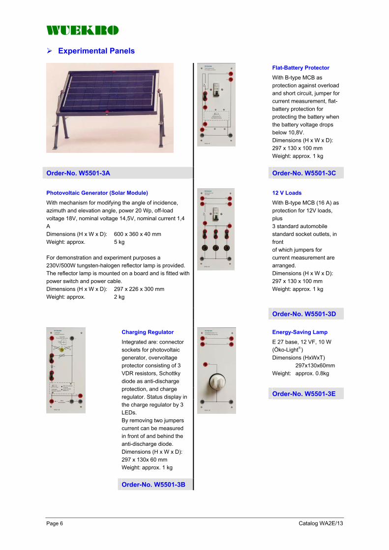
WUEKRO
Page 6 Catalog WA2E/13
Experimental Panels
Flat-Battery Protector
With B-type MCB as protection against overload and short circuit, jumper for current measurement, flat-battery protection for protecting the battery when the battery voltage drops below 10,8V. Dimensions (H x W x D): 297 x 130 x 100 mm Weight: approx. 1 kg
Order-No. W5501-3A
Order-No. W5501-3C
Photovoltaic Generator (Solar Module)
With mechanism for modifying the angle of incidence, azimuth and elevation angle, power 20 Wp, off-load voltage 18V, nominal voltage 14,5V, nominal current 1,4 A Dimensions (H x W x D): 600 x 360 x 40 mm Weight: approx. 5 kg For demonstration and experiment purposes a 230V/500W tungsten-halogen reflector lamp is provided. The reflector lamp is mounted on a board and is fitted with power switch and power cable. Dimensions (H x W x D): 297 x 226 x 300 mm Weight: approx. 2 kg
12 V Loads
With B-type MCB (16 A) as protection for 12V loads, plus 3 standard automobile standard socket outlets, in front of which jumpers for current measurement are arranged. Dimensions (H x W x D): 297 x 130 x 100 mm Weight: approx. 1 kg
Order-No. W5501-3D
Energy-Saving Lamp
E 27 base, 12 VF, 10 W (Öko-Light ) Dimensions (HxWxT) 297x130x60mm Weight: approx. 0.8kg
Order-No. W5501-3E
Charging Regulator
Integrated are: connector sockets for photovoltaic generator, overvoltage protector consisting of 3 VDR resistors, Schottky diode as anti-discharge protection, and charge regulator. Status display in the charge regulator by 3 LEDs. By removing two jumpers current can be measured in front of and behind the anti-discharge diode. Dimensions (H x W x D): 297 x 130x 60 mm Weight: approx. 1 kg
Order-No. W5501-3B

WUEKRO
Catalog WA2E/13 Page 7
Experimental Panel
Start Relay
For inverter startup. With jumpers for current measurement as well as connector sockets for the inverter, 12V emergency lighting with escape route symbol. Dimensions (H x W x D): 297 x 130 x 60 mm Weight: approx. 1 kg
230V General Lighting 230V Load with E 14 base including lamp (230V, 25W) for general lighting. With socket outlet for loads. The earthing contact must be sperately provided by a safety socket, pickoff power 230V, 200 VA. Dimensions (HxWxD): 297x130x60 mm Weight: approx. 0,9kg
Order-No. W5501-3F
Order-No. W5501-3J
System Selector With connector sockets for the inverter output voltage as well as contactor for system transfer of the inverter output voltage. With emergency lighting including escape route symbol, lamp with E 14 base, 230V, 15W. Dimensions (H x W x D): 297 x 130 x 100mm Weight: approx. 1,2 kg
IR Motion Detector Range 10 m, angular detection range 1100
current switched 10 A, time setting from 10 s to 10 min, NO contact, e.g. for energy safing lamp. Connection is implemented by 2 leads instead of the jumper between panel „12V Energy-Safing Lamp“, includes 3 connecting leads of 1m. Dimensions (H x w x D): 297 x 130 x 60 mm Weight: approx. 0,9 kg
Order-No. W5501-3H Order-No. W5501-3L
Phase-Failure Relay Picks up on failure of phase 1. Phase failure can be simulated by a toggle switch. With contactor relay for controlling system transfer and further switching operations. Dimensions (H x W x D): 297 x 130 x 100 mm Weight: approx. 1,2 kg
Order-No. W5501-3G

WUEKRO
Page 8 Catalog WA2E/13
Experimental Panels
DC / AC Inverter
Input voltage 12 V, output voltage 230 V, frequency 50 Hz +/- 1 Hz, output power 200 VA. Overvoltage and undervoltage cut-off. Standby indication by green LED. The output voltage is indicated by a glow lamp. Dimensions (H x w x D): 297 x 195 x 100 mm Weight: approx. 3 kg
Wind-driven Generator with additional Charge Regulator
Upon request
Order-No. W5501-3K
Assembly Kit for Experimental Panels
Including solar module and one set of connecting leads as well as one set of experiment instructions with tasks and solutions.
Order-No. W5501-0C
The assembly kit consists of the following experimental panels:
1 W5501-3A 1 W5501-3B 1 W5501-3C 1 W5501-3D 1 W5501-3E 1 W5501-3F 1 W5501-3G 1 W5501-3H 1 W5501-3J 1 W5501-3K Optionally, the IR motion detector, order-no. W5501-3L, is available
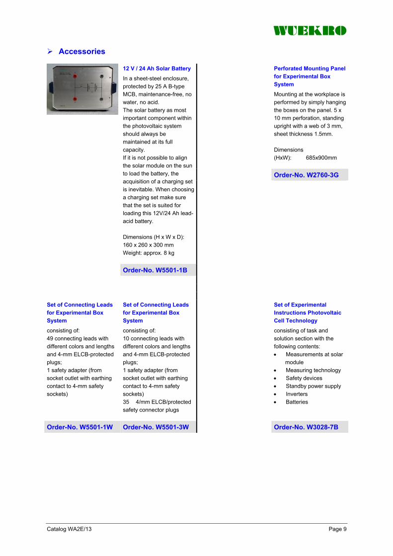
WUEKRO
Catalog WA2E/13 Page 9
Accessories
Perforated Mounting Panel for Experimental Box System
Mounting at the workplace is performed by simply hanging the boxes on the panel. 5 x 10 mm perforation, standing upright with a web of 3 mm, sheet thickness 1.5mm. Dimensions (HxW): 685x900mm
Order-No. W2760-3G
12 V / 24 Ah Solar Battery
In a sheet-steel enclosure, protected by 25 A B-type MCB, maintenance-free, no water, no acid. The solar battery as most important component within the photovoltaic system should always be maintained at its full capacity. If it is not possible to align the solar module on the sun to load the battery, the acquisition of a charging set is inevitable. When choosing a charging set make sure that the set is suited for loading this 12V/24 Ah lead-acid battery. Dimensions (H x W x D): 160 x 260 x 300 mm Weight: approx. 8 kg
Order-No. W5501-1B
Set of Connecting Leads for Experimental Box System
consisting of: 49 connecting leads with different colors and lengths and 4-mm ELCB-protected plugs; 1 safety adapter (from socket outlet with earthing contact to 4-mm safety sockets)
Set of Connecting Leads for Experimental Box System
consisting of: 10 connecting leads with different colors and lengths and 4-mm ELCB-protected plugs; 1 safety adapter (from socket outlet with earthing contact to 4-mm safety sockets) 35 4/mm ELCB/protected safety connector plugs
Set of Experimental Instructions Photovoltaic Cell Technology
consisting of task and solution section with the following contents: • Measurements at solar
module • Measuring technology • Safety devices • Standby power supply • Inverters • Batteries
Order-No. W5501-1W Order-No. W5501-3W Order-No. W3028-7B

WUEKRO
Page 10 Catalog WA2E/13

WUEKRO
Catalog WA2E/13 Page 11

WUEKRO
Page 12 Catalog WA2E/13
FAX – Reply to: +49 (0)9721 / 64691 - 20 Sender: Receiver:
Please send the following catalogues to the a.m. address! Fundamentals of electrical Engineering
Installation circuits Bell ringing and entrance call stations Contactor control / Control technology Measurement and control of non-electrical variables
Fundamentels of electronics Analog technology Digital technology Microprocessing technology
Closed loop control technology Analog closed loop control Digital closed loop control
Automation engineering SIMATIC S7-200/300/400, Software Technology simulators / Models Process control engineering PCS7 AS-Interface Profibus DP Process simulation-software SIMIT LOGO! Mechatronical technology stations Courses on Automation
Electrical machines / Drive controls Electrical Machines 300W Electrical Machines 1000W Electrical Machines 5kW Electrical drive control systems 300W / 1kW Electrical drive control systems 5kW Networked drive systems Cutaway Models Transformers, Rectifiers and Reactive Power Compensation Courses on drive systems
Power electronics extra low voltage (24V) low voltage (230/400V)
Building management systems KNX / EIB
VDE 0100 safety measures
Radio- and Television engineering AM/FM – Technology TV Engineering Satellite – Technology
Cooling and air conditioning
Photovoltaic cell tecnology
Communication technology Modulation -/demodulation Fiber optic ISDN trainer (HICOM) ISDN
Measuring systems
Power supply units
Experiment instructions, manuals
Training courses
Remarks:
Company WUEKRO GmbH Dept. Sales Department Name Street Carl-Zeiss-Strasse 10 City 97424 Schweinfurt / Germany Phone + 49-(0)9721-64691-0 Fax + 49-(0)9721-64691-20 E-Mail [email protected] Internet www.wuekro.de

WUEKRO
Training & Didactic Systems Communication Technology
Catalog WA2E/16

WUEKRO
Page 2 Catalog WA2E/16
Our Services
• Development and production of didactic training systems • Teachware and documentation • Project engineering of complete lab's incl. furniture and lab equipment • Quotations on customer's demand • Installation, commissioning and training at site
Our Customers
• Vocational training schools, technical schools, colleges and universities... • Industrial laboratories for vocational education and higher education
Fields of Technology
• Fundamentals of electrical engineering
• Fundamentals of electronics
• Closed loop control technology
• Automation engineering
• Electrical machines / drive control
• Power electronics
• Building management systems
• Protection schemes to VDE 0100
• Radio- and TV technology
• Air conditioning and refrigeration
• Photovoltaic
• Communication technology
• Measuring systems, power supplies, accessories
• Experimental manuals, documentation For further information please contact:
WUEKRO GmbH Carl-Zeiss-Strasse 10 D - 97424 Schweinfurt Germany Tel. + 49 (0) 9721-64691-0 Fax: + 49 (0) 9721-64691-20 E-Mail: [email protected] Internet: www.wuekro.de
WUEKRO GmbH
All Rights reserved. Reprint not permitted. Technical changes without prior notice.. S30020617P – 01/13

WUEKRO
Catalog WA2E/16 Page 3
Content Page Introduction 4 Modulation 5 Demodulation 7 Transmission Technology 9 Fibre Optic Technology 11 Coaxial-Board 15 Phased-Locked-Loop (PLL) 16 Fax-Reply 20

WUEKRO
Page 4 Catalog WA2E/16
Introduction Discussions, letters, telephone calls and magazines, as well as radio- and television service – no day is without communications. The communications systems are more and more significant, beside the “normal” telephone conversation, the communications systems take care also for the fast growing services like BTX, Telefax, PC-networks, for application in the industry, administration and last but not least in the private sector.
To teach and train this wide sector of technology efficiently, we offer a training system that meets the demands of the curriculi as well as the demands of practice.
The training concept
The training concept is a determined concept in which the training sets, the teachware and the resp. training courses are offered. The training concept is of modular design, therefor the individual training aims can be integrated

WUEKRO
Catalog WA2E/16 Page 5
Communications - Modulation Modulation Board
• All the important modulations on one Board
• Experiment setup time reduced to a minimum
• Built-in power supply (short-circuit-proof)
• Integrated clock generator with synchonised carrier and modulation frequencies to provide static oscilloscope images
• Expandable with the DEMODULATION BOARD
Modulation Board Function groups (Section 1) Function groups (Section 2)
The MODULATION BOARD offers a training and demonstration system for the major analog and digital modulation techniques.
• modulators with all the necessary measuring points
The following modulation techniques can be studied
Application
• Amplitude Modulation (AM) • Single Sideband Modulation
(SSB) • Frequency Modulation (FM) • Phase Modulation (PM) • Pulse Amplitude Modulation
(PAM) • Pulse Code Modulation (PCM) • Pulse Frequency Modulation
(PFM) • Pulse Phase Modulation
(PPM) • Delta Modulation (DM) • Amplitude Shift Keying (ASK) • Frequency Shift Keying (FSK) • Phase Shift Keying (PSK)
• Clock generator (quartzcontrolled) with frequency dividers for generating the carrier and modulation signals.
• The signals are therefore in synch and enable "frozen" images to be displayed with the oscilloscope. They can be tapped as squarewave and sinewave signals and can be altered in amplitude. The clock generator also supplies a trigger signal, switching signal for the delta modulator and a synchronised signal for the process control of the PCM modulator
• Signal button, for simple examination of the digital modulation techniques, with electronic debounce and optical indication by an LED
• DC voltage source, adjustable, for generating static, analog modulation signals
• Summer, for adding up to 3 signals
• Amplifier, variable gain, for matching external modulation signals such as from the microphone for example.
The MODULATION BOARD can be converted into a portable training unit by simply screwing it into a Box (Type 4280.20) All the experiments can be conducted directly in the Box. Dust-free storage and protection against transport damages are further advantages of the Box version.
WUEKRO
Page 6 Catalog WA2E/16
Communications - Modulation Technical data
Mains connection Voltage 230V AC/115V AC (110V), 50/60 Hz, 50VA DC voltage output (short-circuit-proof) +/-15V/0.15A ; +5V/0.2A, for conn-ecting external devices. Signal source Sinewave: Upp < 5V, f = 0.5/1/2/20kHz Squarewave: Up < 5V, f = 0.25/0.5/1/2/20kHz Trigger signal: 250Hz Summer With three inputs, short-circuitproof output DC voltage adjustabie 0 ... approx. +/-2.5V 0 ... approx. +/-1.5V
Signal button Wìth TTL output Amplifier, variable gain Vu 0 ... 2.5 FM / PM / PFM fo = 20kHz fn = DC ... 3.4kHz PAM/PCM Two channels AD converter; 8 bits with LED indicator. Bits 20 and 27 can be switched off. Frame frequency: approx.16kHz Sampling frequency: approx. 8kHz AM Uin pp ≥ 5V Bandpass: 15 ... 25kHz Low pass: 0 ... 20kHz
Adapter field Serves for adapting 4mm to 2mm connections and for plugging two adapters (BNC socket → two 4mm connectors) Board (4280) Dimensions (W x H x D) 532x297x90mm Weight approx. 3,6kg Box (4280.20) Dimensions (W x H x D) 580x450x155mm Weight approx. 6,8kg
Board Order-No. W4280
Box Order-No. W4280.20 Recommended Accessories
1 Set of connecting plugs and leads Order-No. W4280.1 Manual "Modulation Techniques / Modulators" Order-No. WV0130 Extensions
DEMODULATION BOARD Order-No. W4281
TRANSMITTERBOARD Order-No. W4282
RECEIVERBOARD Order-No. W4283

WUEKRO
Catalog WA2E/16 Page 7
Communications - Demodulation Demodulation Board
• All the important demodulators on one Board
• For extending the range of experiments in connection with the MODULATION BOARD (Type 4280)
• Reduces experiment setup times to a minimum
• Built-in power supply (short-circuit-proof)
• Additional output jacks for power supply to other units
Demodulation Board The following modulation modes
can be demodulated Furnishing
The DEMODULATION BOARD offers a training and demonstration system for extending the range of experiments in connection with the MODULATION BOARD (WType 4280) All output signals of the MODULATION BOARD can be demodulated with the DEMODULATION BOARD.
• AM / SSB Demodulation with envelope demodulator, coherent demodulation
• FM Demodulation with PLL, counting discriminator and C-discriminator
• PM Demodulation with FM demodulators and series circuited integrator
• PAM Demodulation with dual channel demultiplexer and series cicuited low pass
• PCM PCM demodulator • PFM Demodulation with low
pass • DM Demodulation with
integrator • PSK Demodulation with
reference phase • FSK Demodulation with PLL
loop and Schmitt trigger • ASK Demodulation with AM
demodulators and low pass and series circuited Schmitt trigger
The DEMODULATION BOARD contains a built-in power supply unit for internal power supply and is therefore electrically isolated from the MODULATION BOARD. +/-15 V and +5 V can be tapped off at 4 mm jacks for supplying power to additionally connectable transmission paths and sources of interference between the modulator and the demodulator. An audio frequency amplifier with loudspeaker is integrated in the Board for acoustic checking of the demodulated signals. To conduct the experiments, the DEMODULATION BOARD is placed on a table or suspended in experi-mental frame for demonstration purposes. Additionally the DEMODULATION BOARD can be converted into a portable training unit by simply screwing it into a box (Type W4280.20) All the experiments can be conducted directly in the box. Dust free storage and protection against transport damages are further advantages of the box version.
WUEKRO
Page 8 Catalog WA2E/16
Communications - Demodulation Technical data
Mains connection
230/115V AC; 50/60Hz 50VA DC voltage output (short-circuit-proof) for connecting external devices +/-15V/0,15A; +5V/0,2A AM/ASK
• Envelope demodulator • Half-wave and full-wave
rectifiers, switchable, with additional RC wiring.
• A low pass can also be used alternatively to the RC wiring.
• Recovery of the digital input signals by Schmitt-trigger
AM / SSB/PSK
• Coherent demodulation by multiplier
• Generator for carrier generation, adjustable frequency
• Phase shifter, adjustable FM/PM/FSK
• Counting discriminator • C-discriminator with constant
voltage source
PAM/PCM
• Two channels • DA converter, 8 bits with LED
dísplay • Buffer memory • Frame frequency: approx.16
kHz • Sampling frequency of the
PAM: approx. 8 kHz, can be replugged to 4 kHz to prove the sampling theorem.
The control signal for the demultiplexer can be inverted; this makes it possible to switch over the two channels. PLL
• For demodulation of the FM and FSK
Integrator
For phase modulation (PM) and delta modulation (DM) Schmitt-Trigger
• For recovery of the digital signals in ASK, FSK and PSK
Low Pass Filter
• Band width: fg =3,4kHz • Summer, for adding up 2
signals • Loudspeaker, volume
adjustable; connectable with 2-mm plugs
Dimensions
Board (4281) (W x H x D) 532x297x90mm Weight approx. 3,6kg Box (4281 + 4281.20) (W x H x D) 580x450x155mm Weight approx. 6,8kg
Board Order-No. W4281
Box Order-No. W4280.20 Recommended Accessories
1 Set of connecting plugs and leads Order-No. W4280.1
Manual "Modulation Techniques / Modulators" Order-No. WV0130 Extension
MODULATION BOARD Order-No. W4280
TRANSMITTER BOARD Order-No. W4282
RECEIVER BOARD Order-No. W4283

WUEKRO
Catalog WA2E/16 Page 9
Communications – Transmission Technology General
Universal training system for the transmission of signals with optical fibres, infrared link or connection line. Can be used with the MODULATION BOARD and the DEMODULATION BOARD
Also very suitable to perform experiments with usual commercial generators and measuring instruments. With analog and digital channel suitable for all fundamental experiments of the fibre optics technology.
With two built-in transmit diodes of different wavelengths. Two amplifiers and different terminating resistors allow experiments with coaxial lines. Can be extended with an Optical Bench and with the COAXIAL BOARD
The following experiments can be performed
Additional Experiments
• Difference in transmission of signals between optical fibres, infrared link or connection line
• Setting of the operating point to transmit diodes
• Characteristics of transmit diodes
• Attenuation measuring of optical fibres of different length
• Sensibility to interference of different transmission links
• Transmission of TTL signals through optical fibres
• with the optical bench • infrared transmission • Transmission with lines, e.g.
with the COAXIAL BOARD
Transmitter Board Technical data
- Analog amplifier for fibre optic transmiossion, with adjustable gain and setting of the operation point
- TTL-channel with Schmitt trigger and matching circuit for the transmit diode
- 1 transmit diode red (660nm) - 1 Sendediode, infrared (820nm) - Transmission field for additional
transmit diode - Line driver with different,
additional connectable resistors
Fibre optic transmission
- 1 LED: 660 nm, red - 1 LED: 820 nm, infrared - External LED: pluggable (e.g.
infrared-plug-in module for wireless transmission)
Analog transmission
- amplifier vu 0,1...2 - DC-offset adjustable with
potentiometer - Frequency range approx.
0...80kHz Digital transmission
- TTL-input; Schmitt trigger; matchning circuit for transmit diode
- transmission rate: max. 200kHz Amplifier
- input resistor: 75Ω, connectable with 2mm plug
- output resistor: 37,5/50/ 75/150Ω, connectable with 2-mm plug
- Frequency range: 5MHz - Operating voltage: ± 15V, + 5V
Dimensions (W x H x D) 133x297x110mm Weight approx. 0,7kg
Order-No..W4282

WUEKRO
Page 10 Catalog WA2E/16
Communications – Transmission Technology Receiver Board
Technical data
- Fibre optic receive diode, fixed - Reception field for additional
receive diode - Analog amplifier, DC offset and
gain adjustable - TTL-channel, composed of a
comparator with adjustable operating treshold and subsequent Schmitt trigger
- Amplifier with additionaly connectable input resistors
Fibre optic transmission
- receive diode: SFH 202, fixed - external receive diode:
pluggable (e.g. for wireless transmission)
Analog transmission
- DC-offset: adjustable with potentiometer
- amplifier vu = approx.1...6
- Frequency range: 0 ... 80kHz Digital transmission
- Comparator and Schmitt trigger with TTL-output
- transmission rate max. 200kHz Amplifier
- input resistor: 37,5/50/75/150Ω, connectable with 2mm plug
- output resistor 75Ω - frequency range approx.
0... 5MHz - Operating voltage: ± 15V, + 5V
Dimensions (W x H x D) 133x297x110mm Weight approx. 0,7kg
Order-No. W4283 Necessary Accessories (not included in scope of supply)
IR-Transmitter Module IR-Receiving Module 1 Set Connecting plugs and leads
Order-No. W4282.4 Order-No. W4283.4 Order-No. W4280.1
Manual "Modulation Technique / Demodulators" Order-No. WV0131 Extensions
MODULATION BOARD Order-No. W4280
DEMODULATIONSBOARD Order-No. W4281
RECEIVERBOARD Order-No. W4283

WUEKRO
Catalog WA2E/16 Page 11
Communication – Fibre Optics Technology General
The Fibre Optics Training System offers a comprehensive program for conducting experiments in the field of opto-electronic communications. The training systems is suitable for both demonstrations and practical experiments. • For plastic and glass fibres • With built-in transmit diodes of
different wavelengths • Characteristic recording and
attenuation measurement also possible with DC voltage
• Coupling attenuations can be simulated directly on the Optical Bench
• Additional experiments with laser diode
Essential components of the Fibre Optics Training system: • Fibre Optic Transmitter board
with integrated transmit diodes • Fibre Optics Receiver Board
with integrated receive diodes • Optical Fibres
plastic and glass fibres • Laser with accessories • Optical Bench • Storage of transmission and
receiving modules
A variety of types of Optic Fibres to be connected to the transmitter and receiver are available as transmission media. The system therefore offers the possibility of various Optic Fibres and thus setting up a variety of fibre optic transmission lines to investigate the influence of the individual transmission parameters in experiments. A laser diode makes it possible to compare the performance characteristics of such diodes with those of conventional luminescent diodes. The system can be extended with an Optical Bench. The Optical Bench makes it possible to show the particular connecting problems in the field of fibre optic technique in the experiments. Moreover the Optical Bench is used for experiments with the laser diode. The training system and the accompanying experiment manual “Fibre optics” (WV 0134) have been designed to impressively demonstrate the advantage of this technique over conventional transmission media
Subjects dealt with the experiments section of the experimental manual • Experiments on fibre optics
with plastic fibre • Characteristics of transmit
diodes • Attenuation of plastic fibres
and connectors • Transmission of TTL signals • Immunity of interference of the
optical fibre • Measurement of propagation
time • Experiments in fibre optics
with laser diode • Fibre optic experiments with
glass fibres

WUEKRO
Page 12 Catalog WA2E/16
Communication – Fibre Optics Technology Fibre Optic Transmitter Board
Technical data
Mains connection 230V AC; 50...60Hz;20VA Inputs (via2mm jacks) 1 analog/ 1 digital Optical outputs 660nm / 850nm (plastic fibre) 850nm (glass fibre, ST-standard) Electrical output (via 2mm jacks) With preceding driver cicuit for connecting a two-wire line or coaxial cable for comparative measurements on fibre optic transmission path. Output impedance: 50Ω / 75Ω Function groups Sinewave generator: f = 1kHz, Upp =3V Squarewave generator: f = 10kHz (TTL) Pulse generator: impulse duration 400ns Patch field and power supply for plug-in transformer to simulate interferences Patch field for Laser Modul Accessories 1 mains lead Dimensions (W x H x D) 266x297x110mm Weight approx.: 1,9kg
Order-No. W4290
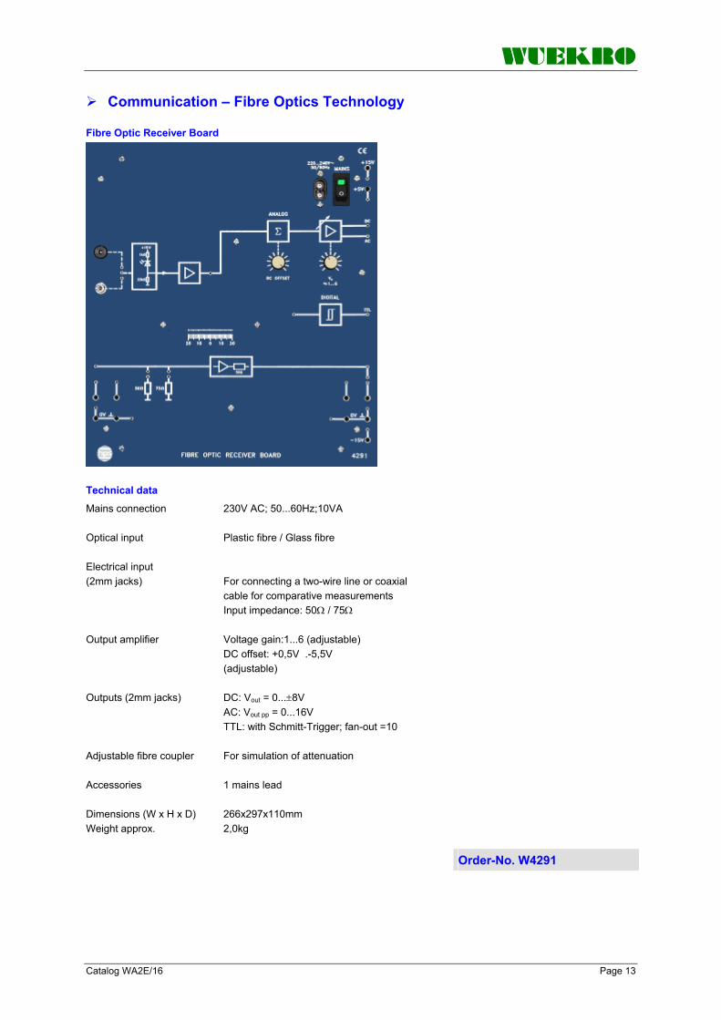
WUEKRO
Catalog WA2E/16 Page 13
Communication – Fibre Optics Technology Fibre Optic Receiver Board
Technical data
Mains connection 230V AC; 50...60Hz;10VA Optical input Plastic fibre / Glass fibre Electrical input (2mm jacks) For connecting a two-wire line or coaxial cable for comparative measurements Input impedance: 50Ω / 75Ω Output amplifier Voltage gain:1...6 (adjustable) DC offset: +0,5V .-5,5V (adjustable) Outputs (2mm jacks) DC: Vout = 0...±8V AC: Vout pp = 0...16V TTL: with Schmitt-Trigger; fan-out =10 Adjustable fibre coupler For simulation of attenuation Accessories 1 mains lead Dimensions (W x H x D) 266x297x110mm Weight approx. 2,0kg
Order-No. W4291

WUEKRO
Page 14 Catalog WA2E/16
Communication – Fibre Optics Technology Lasermodul
The Laser Module can be plugged into the patch field of the Fibre Optic Transmitter Board. It is used in conjunction with the plastic fibre. With the integrated monitor diode it is possible to measure the transmitted light. The wave length of the laser diode is 670nm In combination with the plastic fibres reflector measurements are possible. Housing dimensions: 57x38x35mm (WxDxH) Weight 50g
Order-No. W4290.70 Optical Bench
The Optical Bench is used to simulate faults that can occur on fibre optic links or at fibre optic connections and which lead to increased attenuation: inter-face gap, lateral offset, angular offset. It is suitable for accepting optical fibres with a diameter of approx. 1mm The xperiments with the laser likewise done in combination with the Optical Bench. For this, the laser will be mounted on the rotation part of the Optical Bench. Dimensions: 266 x 297 x 130 mm (WxHxD) Weight approx: 1,8 kg
Order-No. W4185 Necessary Accessories (not included in scope of supply) Set of Accessories consisting of: Plastic fibres: 20m, 5m und 0,5m Glass fibres: 20m und 1m Optical coupling for glass fibres Connecting plugs, 2mm (12 pieces) Coils: N = 900 and N = 100 Tape-wound core (pair) Connecting lines, 2mm (8 pieces)
Order-No. W4290.1 Necessary Accesories
Manual “Fibre optic Technology" Order-No. WV0134
Optical Powermeter Order-No. W4190
Multimeter
Oszilloscop 20MHz

WUEKRO
Catalog WA2E/16 Page 15
Communication – Coaxial - Board
• Training Board for experiments with a screened line
• Line length 50m, divided in2x25m
• With incorporated LEDs for demonstration of standing waves in a line
• Incorporated terminating resistor, adjustable
• Several COAXIAL BOARD's can be connected one after the other to simulate longer lines
General The following experiments can be
performed Technical data
The COAXIAL BOARD offers a screened line which allows to impressively prove all regularities of electric lines in experiments in the following fields: • Communications technology • Transmission technology • Electric energy transmission • Data transmission
• Evaluation of the electric data of a line
• Attenuation characteristic of a line
• Frequency dependence of a line
• Input resistance of a line (no-load, short-circuit, matched)
• Transit times and phase displacements on a line
• Standing waves on a line • Transmission behaviour of a
line • Error detection • Pulse behaviour (transit time,
reflection)
• Length of the coaxial line: 50 m, divided in 2 x 25 m
• Inductance: 0.4 µH/m • Capacity: 100 pF/m • Resistance: 300 Ω/km +/-60 Ω • Characteristic impedance:
50 Ω+/-2 Ω • Terminating resistor: 0 ... 470 Ω,
continuously adjustable • Shunt: 1 Ω, for current
measuring • 2 LEDs to verify standing
waves • 1 kΩ dropping resistor for
simulation of mismatches Dimensions : 133 x 297 x 110 mm (W x H x D) Weight: 1.25 kg
Order-No. W4284 Necessary Accessories (not included in scope of supply)
Experiment manual: „Experiments with Screened Lines“ Order-No. WV 0135
Connecting plugs and leads
Oscilloscope 20 MHz
Function generator
Multimeter
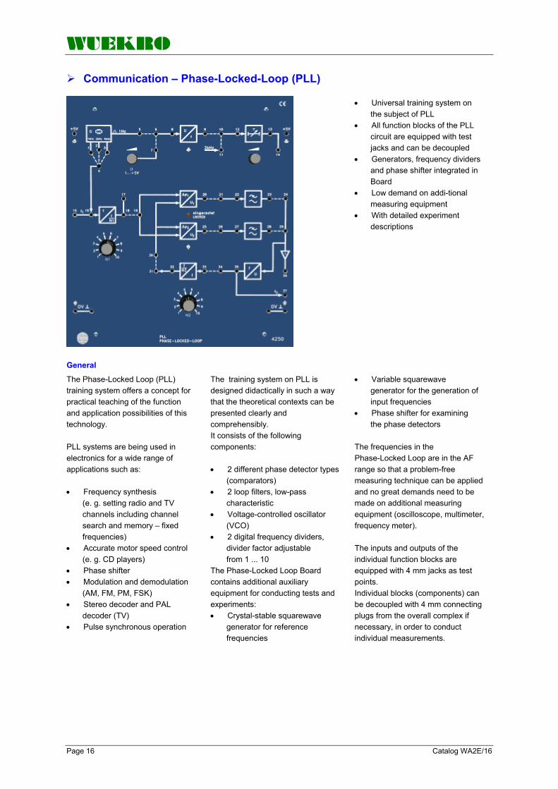
WUEKRO
Page 16 Catalog WA2E/16
Communication – Phase-Locked-Loop (PLL)
• Universal training system on the subject of PLL
• All function blocks of the PLL circuit are equipped with test jacks and can be decoupled
• Generators, frequency dividers and phase shifter integrated in Board
• Low demand on addi-tional measuring equipment
• With detailed experiment descriptions
General
The Phase-Locked Loop (PLL) training system offers a concept for practical teaching of the function and application possibilities of this technology. PLL systems are being used in electronics for a wide range of applications such as: • Frequency synthesis
(e. g. setting radio and TV channels including channel search and memory – fixed frequencies)
• Accurate motor speed control (e. g. CD players)
• Phase shifter • Modulation and demodulation
(AM, FM, PM, FSK) • Stereo decoder and PAL
decoder (TV) • Pulse synchronous operation
The training system on PLL is designed didactically in such a way that the theoretical contexts can be presented clearly and comprehensibly. It consists of the following components: • 2 different phase detector types
(comparators) • 2 loop filters, low-pass
characteristic • Voltage-controlled oscillator
(VCO) • 2 digital frequency dividers,
divider factor adjustable from 1 ... 10
The Phase-Locked Loop Board contains additional auxiliary equipment for conducting tests and experiments: • Crystal-stable squarewave
generator for reference frequencies
• Variable squarewave generator for the generation of input frequencies
• Phase shifter for examining the phase detectors
The frequencies in the Phase-Locked Loop are in the AF range so that a problem-free measuring technique can be applied and no great demands need to be made on additional measuring equipment (oscilloscope, multimeter, frequency meter). The inputs and outputs of the individual function blocks are equipped with 4 mm jacks as test points. Individual blocks (components) can be decoupled with 4 mm connecting plugs from the overall complex if necessary, in order to conduct individual measurements.

WUEKRO
Catalog WA2E/16 Page 17
Communication – Phase-Locked-Loop (PLL) Technical data
Squarewave generator (crystal-stable) Frequency: 1 Hz; 1 kHz; 2 kHz; 4 kHz DC voltage source Voltage: 1 V ... 5 V (adjustable with potentiometer) Voltage-controlled oscillator Input voltage: 0 ... +5 V Output voltage: +5 V (symmetrical squarewave) Output frequency: approx. 20 Hz ... 6 kHz Comparator (phase detector) Type I: phase sensitive (XOR) Type II: phase and frequency sensitive (JK flip- flops with charging pump via tristate) Low pass (loop filter) Type I: RC low pass (approx. 300 Hz) Type II: R/RC low pass (approx. 3 Hz) 2 frequency dividers Factor: N1 and N2 = 1 ... 10 (adjustable with rotary switch) Phase shifter cp = -7°... -230° or +7°... +230° (adjustable with potentiometer); referred to 2 kHz Operating voltage +5 V DC/150 mA and current: (through external power supply) LED for displaying lock-in state of the PLL circuit Measuring amplifier (impedance converter) Dimensions 266 x 297 x 110 mm (W x H x D) Weight 1.3 kg
Order-No. W4250 Necessary Accessories (not included in scope of supply
Experimental manual: "Phase-Locked Loop" Order-No. WV0068
5 V Power supply board Order-No. W1002.3
Plugs for Power supply Order-No. W9101
Connecting plugs and leads Order-No. W9102.2
Oscilloscope 20 MHz
Frequency meter
Multimeter

WUEKRO
Page 18 Catalog WA2E/16
Notes:

WUEKRO
Catalog WA2E/16 Page 19
Notes:

WUEKRO
Page 20 Catalog WA2E/16
FAX – Reply to: +49 (0)9721 - 64621 - 20 Sender: Receiver:
Company WUEKRO GmbH Dept. Sales Department Name Street Carl-Zeiss-Strasse 10 City 97424 Schweinfurt / Germany Phone + 49-(0)9721-64691-0 Fax + 49-(0)9721-64691-20 E-Mail [email protected] Internet www.wuekro.de No. of pages
incl. this page
Please send the following catalogues to the a.m. address!
Fundamentals of electrical Engineering
Installation circuits Bell ringing and entrance call stations Contactor control / Control technology Measurement and control of non-electrical variables
Fundamentels of electronics Analog technology Digital technology Microprocessing technology
Closed loop control technology Analog closed loop control Digital closed loop control
Automation engineering SIMATIC S7-200/300/400, Software Technology simulators / Models Process control engineering PCS7 AS-Interface Profibus DP Process simulation software SIMIT LOGO! Mechatronical technology stations Courses on Automation
Electrical machines / Drive controls Electrical Machines 300W Electrical Machines 1000W Electrical Machines 5kW Electrical drive control systems 300W / 1kW Electrical drive control systems 5kW Networked drive systems Cutaway Models Transformers, Rectifiers and Reactive Power Compensation Courses on drive systems
Power electronics extra low voltage (24V) low voltage (230/400V)
Building management systems KNX / EIB
VDE 0100 safety measures
Radio- and Television engineering AM/FM – Technology TV Engineering Satellite – Technology
Cooling and air conditioning
Photovoltaic cell tecnology
Communication technology Modulation -/demodulation Fiber optic ISDN trainer (HICOM) ISDN
Measuring systems
Power supply units
Experiment instructions, manuals
Training courses
Remarks:
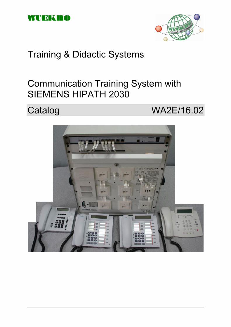
WUEKRO
Training & Didactic Systems
Communication Training System with SIEMENS HIPATH 2030
Catalog WA2E/16.02

WUEKRO
Page 2 Catalog WA2E/16.02
Training System Siemens HIPATH 2030 The communication training system SIEMENS HIPATH includes an actual communication platform (or PABX) for short and medium companies. It is an ISDN and Voice-over-IP "Communication Server" that handles telephone calls as well as fax and data calls and the access to the Internet; guaranteeing the ISDN lines towards the public network to be used best. The training unit can also be operated without ISDN connection to the public telephone systems (isolated operation).
One set is suitable for max. 2 students and adapted to the curriculum for vocational training schools and technical institutes in the field of communication. The SIEMENS HIPATH Trainer is much more than a trainer for a „small PABX“. The configuration software which is included in the trainingssystem is suitable for the whole range of HIPATH PABX. This means that the same software is used for communication platforms up to 500 extensions.
This may sound complicated for beginners, but an easy getting started manual with screenshots of the necessary settings or the possbility to programm the PABX by telephone leads the student to successfull experiments.
The PABX "SIEMENS HIPATH 2030" is mounted on in stable 19” metal training rack. All ports are wired to 2-mm plugs. Different faults can be set to enlarge the understanding of the wiring.
A clearly arranged simulation board includes an intercom, a dooropen relay and telecommunication interfaces like TAE or Western or IAE (or local standard according to the customers requirements). The wiring of the internal ISDN S0-Bus can be studied easily.
All Interfaces are additionally brought out to 2mm plugs. Measurements can be carried out during a phone call when the telephone is connected to the western port.
A set of telephones with different protocolls is included. By using the recommended measuring instruments, the d-channel of the S0 bus can be traced and a S0 bus test for installation can be done.

WUEKRO
Catalog WA2E/16.02 Page 3
Technical Specification / Scope of Supply
Features: With the network- and ISDN trainer the following teaching and learning content can be adepted:
- Installation of telecommunication system (HiPath 2030 including basic development 4So / LAN / 2 a/b) - Installation / commissioning of "voice over IP" end devices and system telephones - Programming of the telecommunication system by computer - Modifications in the programming structure and equipment configuration - Fault diagnostics in programming and wiring - Measurements of ISDN So-Bus - Measurements and fault diagnostics of analogue (a/b) and digital ports (ISDN) - Measurements and fault diagnostics of network in CAT6 and CAT7 (optional order no. W3820-1H-Z) - optional remote maintenance for SIEMENS SIMATIC S7 components of automation technology
The training-system is highly suitable for practical operators like technician for communication electronics, service technicians, network admins and engineers.
Technical data (components included in the system): The telecommunication system SIEMENS HiPath 2030 V1.0 is built in a stabile 19"-training rack. All analogue and ISDN-Ports as well as all the LAN Ports of the HiPath 2030 are patched back-sided on the front panel with RJ45 plugs. All analogue and ISDN ports of the telecommunication system are wired at established connector units like IAE, TAE etc., which are placed on the front panel. The data connectors for cat.6 computers and voice-over-IP-telephones are also mounted on the front panel and are patched directly to the telephone system . In the basic configuration the following interfaces are avaliable: 4 LAN networking connectors (2 outlet sockets with 2 different connectors each) 2 (a/b) (via 2 TAE2x6NFF telephone sockets) 4 (So) on the telephone system; 3 (So) at the front panel Additionally lots of signals can be tapped on 2mm sockets for measurement exercises, also during dial-up or an existing connection. A door intercommunication system with 2 doorbell-knobs and alarm bell as analogue extension is integrated. With the door-opening function of the telecommunication system a real door-opener will be controlled. The mains-supply is at the lower part of the rack with a fused rubber connector with illuminated switch. 27 fault switches are avaliable For the line-network of analogue a/b and ISDN-So-connections as well as for door opener, door intercommunication system and bell transformer. These switches simulate in practical experience real common faults like wire interruption, short cuts and connection permutation (chaotical and pairwise) and permit measurements to locate and clear these faults.
Order-No. W3820-1H
Set of 2-mm-connecting leads
consisting of: (different colours) 8 x 2mm connecting leads; L=30cm
32 x 2mm connecting leads; L=60cm Order-No. W3820-1V
Optional patch field
assembled in W3820-1H - only available together with W3820-1H -
19" path panel with 16 RJ45 sockets integrated in the front of VOIP trainer W3820-1H. Patched to the HIPATH maodule and the simulation front. For the 4 LAN outputs of the HIPATH 2030 are available 8 inputs associated with 8 outputs connected pairwise with different length of wires.
7 pairs of such sockets are prepared with common faults out of daily service practice. This allows exercises in measuring and maintenance service in the network of CAT6 and CAT7. Also included for the test-exercises is a FLUKE MicroScanner² Cable Verifierand 7 patchcables of different length and colour and a crossover patchcable.
Order-No. W3820-1H-Z

WUEKRO
Page 4 Catalog WA2E/16.02
ISDN Measuring Instrument for HiPath trainingssystem
3UNT - An overview: Ergonomic design with integrated telephone (test handset design) Tests the S-interface in TE, and NT operation with monitoring of the U and analogue interfaces in TE mode Optimized user interface with softkeys, cursor keys and direct-mode keys Automatic test sequence at the press of a button (Autotest) Integrate a PC as a user interface for performing traces as well as generating access commissioning reports (ARGUS®WINplus) and handling protocol decoding (ARGUS®WINanalyse), as an alternative you can also send the commissioning report directly to a printer Internal storage of test results Intelligent supply design with power-down mode and power management, supply from the S-bus, U-interface, battery, power pack or power supply Future-proof thanks to the Flash-ROM technology - simple software updates from a PC 3UNT - the U-interface and analogue line functions: U-interface with 4B3T or 2B1Q Measurements of the U-interface voltages incl. OK evaluation; U-interface operation functions like the S-bus Analogue-interface with DTMF and pulse dialling with flash function (80, 120, 240 or 600 ms), loop resistance: 470 Ohm Automatic detection of the analogue interface characteristics Voltage measurement on the analogue line (with receiver on or off-hook) Telephony functions on the analogue line such as S-bus display of the call number (CLIP)
3UNT- the S-bus functions S-interface in accordance with the CCITT I.420 - various operating modes: TE-mode (terminal simulation), NT-mode (network simulation), monitor (passively monitor the S-bus with online recording of the data on a PC) Automatic detection of the protocol and access configuration when switched on: Point-to-Point or Point-to-Multipoint, DSS1, 1TR6, BILINGUAL or NO Protocol, with display of Layers 1 and 2 and the B-channel status (free/busy) Automatic service test: an automatic check of which ISDN services are available on the send and receive sides of the access Automatic test of the supplementary services 1TR6: supplementary service test; DSS1: automatic tests of CLIP, CLIR, COLP, COLR, HOLD, TP and CFU, test of CW, Charges displayed during and at the end of the call, CFB, CFNR, call back when busy (CCBS) and CW (Call Waiting), with an incoming call the subaddress (SUB) and user text (UUS) will be displayed, and keypad commands are also supported Bus status interrogation with query, display and clearing of the active call diversions CFU, CFB, CFNR for all services Automatic X.31(D) test: Is the supplementary service "Packet data in D-channel" available and which TEI-values are assigned to the access, simulation of a X.31(D)-terminal up to the X.25-network? Telephony function with hotkey dialling, call number memory for 10 numbers or for keypad commands to program the PBX, the calling and called numbers are displayed for incoming calls, the B-channel is selectable, dialling with en-bloc or overlap signalling Terminal or network simulation for the various ISDN services Displays the most important cause for the disconnect in clear text
In network simulation it is possible to manually enter the date to perform year 2000 tests on PBXs or servers, and to send charges (AOC,D/E) A bit error rate test BERT can be made in an extended to call to oneself or in an end-to-end BERT, the number of bit errors and the bit error rate will be displayed, BERT with selectable Good/Bad threshold and OK/Not OK evaluation, bit pattern in accordance with ITU-T O.150, adjustable measurement time, loop-box function for B-channels and all services Testing ISDN permanent circuits: Telephone function, B-channel B1 or B2 selectable, BERT B-channel B1 or B2 selectable, loop-box function for B-channels Layer 1 tests and bus feed: Measurement and evaluation of the phantom voltage (OK, NORMal or Restricted Power) and the ISDN signal send and receive levels of the NTBA or the PBX Wiring tests: Check the bus terminating resistor, determine whether there is a short circuit or the wires are swapped? If yes, which wires? Displayed in clear text. Technical features: Power Supply: alternatively fed from ISDN S-bus, supplied by standard batteries (3 x 1.5V Mignon AA) or from the power supply Keypad: 16-key keypad, 2 cursor keys, 3 softkeys LC-Display: 4 lines with 16 characters, backlit 5 LEDs for displaying the status (ISDN-Layer 1, 2, 3, Activity, Trace Activity, Line Power) Dimensions: H 230 mm W 72 mm D 30mm Standard package: Device with batteries, mains adapter (9V), S-bus cable, U-interface cable, analogue cable, test-adapter for wiring tests, ARGUS® WINplus PC software, English manual, carrying strap with practical clips to on the case, transport bag
Order-No. W3820-0T

WUEKRO
Catalog WA2E/16.02 Page 5

WUEKRO
Page 6 Catalog WA2E/16.02

WUEKRO
Catalog WA2E/16.02 Page 7

WUEKRO
Page 8 Catalog WA2E/16.02
FAX – Reply to: +49 (0)9721 / 64691 - 20 Sender: Receiver:
Company WUEKRO GmbH Dept. Sales Department Name Street Carl-Zeiss-Strasse 10 City 97424 Schweinfurt/ Germany Phone + 49-(0)9721-64691-0 Fax + 49-(0)9721-64691-20 E-Mail [email protected] Internet www.wuekro.de
Please send the following catalogues to the a.m. address!
Fundamentals of electrical Engineering Installation circuits Bell ringing and entrance call stations Contactor control / Control technology Measurement and control of non-electrical variables
Fundamentels of electronics Analog technology Digital technology Microprocessing technology
Closed loop control technology Analog closed loop control Digital closed loop control
Automation engineering SIMATIC S7-200/300/400, Software Technology simulators / Models Process control engineering PCS7 AS-Interface Profibus DP Process Simulation Software SIMIT LOGO! Mechatronical technology stations Courses on Automation
Electrical machines / Drive controls Electrical Machines 300W Electrical Machines 1000W Electrical Machines 5kW Electrical drive control systems 300W / 1kW Electrical drive control systems 5kW Networked drive systems Cutaway Models Transformers, Rectifiers and Reactive Power Compensation Courses on drive systems
Power electronics extra low voltage (24V) low voltage (230/400V)
Building management systems KNX / EIB
VDE 0100 safety measures
Radio- and Television engineering AM/FM – Technology TV Engineering Satellite – Technology
Cooling and air conditioning
Photovoltaic cell tecnology
Communication technology Modulation -/demodulation Fibre optic ISDN trainer (HICOM) ISDN test device
Measuring systems
Power supply units
Experiment instructions, manuals
Training courses
Remarks:

WUEKRO
Training & Didactic Systems Experiment Instructions
Catalog WA2E/18

WUEKRO
Page 2 Catalog WA2E/18
Our Services
• Development and production of didactic training systems • Teachware and documentation • Project engineering of complete lab's incl. furnitures and lab equipment • Quotations on customers demand • Installation, commissioning and training at site
Our Customers • Vocational training schools, technical schools, colleges and universities... • Industrial laboratories for vocational education and higher education
Fields of Technology • Fundamentals of electrical engineering
• Fundamentals of electronics
• Closed loop control technology
• Automation engineering
• Electrical machines / drive control
• Power electronics
• Building management systems
• Protection schemes to VDE 0100
• Radio- and TV technology
• Air conditioning and refrigeration
• Photovoltaic
• Communication technology
• Measuring systems, power supplies, accessories
• Experimental manuals For further information please contact: WUEKRO GmbH Carl-Zeiss-Strasse 10 D - 97424 Schweinfurt Germany Tel. + 49 (0) 9721-64691-0 Fax: + 49 (0) 9721-64691-20 E-Mail: [email protected] Internet: www.wuekro.de WUEKRO GmbH
All Rights reserved. Reprint not permitted. Technical changes without prior notice.. S30020619P – 01/13

WUEKRO
Catalog WA2E/18 Page 3
Table of Contents Page
Our Service, Our Customers and fields of technology 2 Introduction 4 Summary of experiment instructions 5 and 6 Contents of experiment instructions 7 to 31 Fax - Reply 32

WUEKRO
Page 4 Catalog WA2E/18
Introduction Our experiment instructions are an essential part of our training concepts. We offer them for instructors and teachers dealing with • electrical trades, • metal-working trades and • scientific trades. In cooperation with the training workshops, vocational schools and colleges for higher technical training, our experiment instructions have been tailored to the learning objectives and the teaching tools developed by us. As the mediator between theory and practice they help the instructor, teacher and the student. Instructors and teachers are spared the preparation time in everyday teaching, and the student is assisted in his work by clearly formulated standards.
The modular design of our experiment instructions allows instructors and teachers to make a selection according to learning fields and objectives. Optimum matching to the particular level of knowledge of the trainees is thus ensured.
On the following pages you will find an overview of our experiment instructions with the teaching fields and objectives to be imparted.

WUEKRO
Catalog WA2E/18 Page 5
Summary of experiment instructions Order No. Page
V051 KNX / EIB W3005-1B 7
V063 Protection Schemes to DIN VDE 0100 W3006-3B 7
V071 DC Chopper Regulators W3007-1B 8
V072 Power Electronics in AC Systems W3007-2B 8
V073 Line-Commutated Thyristor Stack and Diode Board W3007-3B 9
V074 Variable-Speed DC Drives W3007-4B 9
V075 Fundamental Principles of Power Electronics W3007-5B 10
V076 Power Electronics with the Compact Board W3007-6B 10
V077 Variable-Speed Three-Phase Drives using the MicroMaster® Frequency Converter
W3007-7B 11
V078 SIKOSTART 3RW22 W3007-8B 11
V081 Power Electronics with Experimenter IV W3008-1B 12
V100 Installation circuits W3010-0B 12
V101 Fundamentals of electrical engineering for the field of power engineering
W3011-0B 13
V104 Control Schemes with Contactors W3010-4B 13
V107 Connecting and Measuring electrical Machines 300W/ 300W W3010-7B 14
V108 Connecting and Measuring electrical Machines 1000W W3010-8B 15
V111 Experimental station for refrigeration and air conditioning W3011-1B 16
V112 Transformer and rectifier circuits W3011-2B 17
V118 Measurement and Control of NON-ELECTRICAL Quantities W3011-8B 17
V142 Reactive-Power Compensation W3014-2B 18
V172 Programmable Logic Controllers SIMATIC S7-200 with Simulators
W4760-1D/1E/1G
W3017-2B 19
V173 Programmable Logic Controllers SIMATIC S7-300 W3017-3B 19
V174 Digital Control 2 with SIMATIC S7-300 W3017-4B 20
V175 Digital Control 1 with SIMATIC S7-300 W3017-5B 20
V176 Process Simulation PROSIM 95 withSIMATIC S7 W3017-6B 21
V179 Universalsimulator Electrical Technology with SIMATIC S7-300 W3017-9B 21
V183 Conveyor belt control W3018-3B 21
V184 Experimenter with SIMATIC S7-200, Electrical Technology W3018-4B 21
V185 Experimenter with SIMATIC S7-200, Metal- Working Technology W3018-5B 22
V187 Plant Simulator with SIMATIC S7-300 W3018-7B 22
V188 Contactor Control with SIMATIC S7/S5 W3018-8B 22
V189 Universalsimulator Metal- Technology with SIMATIC S7-300 W3018-9B 22
V211 Video-Trainer W3018-8B 23
V215 Aerial Engineering W3021-5B 23
V216 The Fundamentals of Closed-Loop Control Box System W3021-6B 23
V220 Colour Generator Training Unit W3022-0B 24
V224 Demonstration Model for HiFi FM/AM Radio and Amplifier Engineering W3022-4B 24
V225 Training Model for Colour Television Engineering
"Multi Standard System with IR Remote Control"
W3022-5B 25

WUEKRO
Page 6 Catalog WA2E/18
Summary of experiment instructions Order-No. Pag
V226 Demonstration Oszilloscope 20 MHz W3022-6B 26
V227 Radio and Amplifier Engineering "AM-Receiver" W3022-7B 26
V228 Radio and Amplifier Engineering "FM-Receiver ” W3022-8B 27
V246 Closed-loop control engineering with the controller model SITRAIN DR 20
W3024-6B 27
V252 Electronic Components W3025-2B 28
V253 Fundamentals of Basic Analog Circuits W3025-3B 28
V254 Basic Digital Circuits W3025-4B 29
V255 Digital Data Processing W3025-5B 29
V257 Fundamentals of Electrical Engineering W3025-7B 30
V287 Photovoltaic Cell Technology W3028-7B 30
V282 Universal - Experimenter V W3028-2B 31

WUEKRO
Catalog WA2E/18 Page 7
Experiment instructions for practice-oriented training V051 V063
KNX / EIB Contents: Basic configuration (Starting package) Fundamentals of EIB-programming with the ETS 2 software. Task1 Association of a sensor with a actor. Task 2 Changing of an existing configuration. Learning the advantages of an installation wired with a bussystem compared with a conventional wired installation.Task 3 Fundamentals of time functions. Task 4 Extensions of time functions. Supplementary package 1 EIB-programming with ETS 2 software. Task5 Further lamp circuits and brightness control. Task 6 Further lamp circuits and brightness control incl. differentiation of Bit and Byte orders. Supplementary package 2 EIB-programming with ETS 2 software. Task 7 Venetion blind control Supplementary package 3 EIB-programming with ETS 2 software. Task 8 Integrating conventional components in KNX / EIB projects. Supplementary package 4 EIB-programming with ETS 2 software. Task 9 Fundamentals of IR control. Task 10 Extension of IR control Supplementary package 5 EIB-programming with ETS 2 software. Task 11 Switching and dimming of flouescent lamp. Supplementary package 6 EIB-programming with ETS 2 software. Task 12 Setup of additional buslines with line coupler Further extensions 1 Task 13 Fundamentals motion dedector Task 14 Extension motion dedector Further extensions 2 Task 15 Twilight dedector Further extensions 3 Task 16 Fundamentals display unit Task 17 Extension display unit
Protection Schemes to DIN VDE 0100 Contents: Preface, Experimental setup, guidelines for conducting the experiments, Accident prevention guidelines TOPIC 1:Direct / Indirect contact E1.1 Protection against direct contact E1.2 Protection against indirect contact TOPIC 2:Safety-/ functional extra-low voltage E2.1 Protection by extra low voltage E2.2 Protection by extra low voltage – restrictions on effectiveness E2.1 Functional extra low voltage TOPIC 3:Safety separation E3.1 Safety separation E3.1 Safety separation at a metal conductive location E3.1 Safety separation with two loads TOPIC 4:Protection by disconnection E4.1 Tripping behaviour of circuit-breakers E4.2 Tripping behaviour of residual-current devices TOPIC 5:Protective measures in the TN system E5.1 Protection by disconnection with overcurrent protection devices in a TN-C-S system E5.2 Protection by disconnection with overcurrent protection devices and various PEN resistances – restrictions on effectiveness E5.3 TN system types E5.4 Main equipotential bonding – enhancing the protective function in the TN system by equipotential bonding and foundation earthing E5.5 Residual-current device in the TN system E5.6 Residual-current device in the TN system when PE has an open circuit TOPIC 6:Protective measures in the TT system E6.1 Residual-current device in the TT system E6.2 Residual-current device in the TT system – N/PE connection downstream of the residual-current- operated circuit-breaker E6.3 Residual-current device in the TT system–effects of inadequate (defective) equipotential bonding TOPIC 7:Protective measures in the IT system E7.1 Types – principle of operation E7.2 Effect of cable capacitances on protective function E7.3 Double short circuit to frame in the IT system E7.4 Fault signals from the earth-leakage monitor TOPIC 8:Tests for protective measures E8.1 Test measures for installations E8.2 Overview of measurements TOPIC 9:Methods for testing protective measures E9.1 Measuring the voltage drop at an earth electrode E9.2 Measuring the earth electrode resistance E9.3 Measuring the voltage shape of the resistance area, step voltage E9.4 Measuring loop impedance ZL; breaking current Ib E9.5 Measuring UCLmax and REEmax of the r.c.d. protection in the TT system E9.6 Measuring the insulation resistance of cables in consumer's installations Solutions
Order No. W3005-1A German Order No. W3005-1B English
Order No. W3006-3A German Order No. W3006-3B English

WUEKRO
Page 8 Catalog WA2E/18
Experiment instructions for practice-oriented training V071 V072 DC Chopper Regulators Contents 1. DC Chopper redgulators 1.1 Introduction 1.2 Principle of operation of DC chopper regulators 1.3 Functional description of the thyristor DC chopper regulator 1.4 Functional description of the Darlington DC chopper regulator 2. Putting DC chopper regulators into servise 2.1 Procedures 2.2 Thyristor DC chopper regulators: list of equipment2.3 Measuring setup: Thyristor DC chopper regulator 2.4 Darlington DC chopper regulators: list of equipment 2.5 Measuring setup: Darlington DC chopper regulator 2.5.1 Front view of the Darlington DC chopper regulator3. Measurements on the thyristor chopper 3.1 Establishing the power characteristics of a thyristor DC chopper regulator 3.2 Measurements at various points on the thyristor DC chopper regulator 4. Measurements on the Darlington DC chopper regulator 4.1 Power characteristics of a Darlington DC chopper regulator 4.2 Measurements at various points on the Darlington DC chopper regulator 5. Solutions to the questions and exercises 5.1 Answers to the thyristor chopper regulator questions 5.2 Answers to Darlington chopper regulator questions
Power Electronics in AC Systems Contents 1. Power electronics in AC systems 1.1 Introduction 1.2 Components used in power electronics 1.3 Function of phase control 1.4 Function of full-wave control 1.5 Protective circuitry for power semiconductors 1.6 System perturbation with phase control 2. Start-up procedures 2.1 Function and start-up of the training model 3. Measurements for phase control 3.1 Phase control with a thyristor 3.2 Phase control with two thyristors in inverse- parallel connection 3.3 Phase control with triac 4. Measurements for full-wave control 4.1 Full-wave control with thyristors 4.2 Full-wave control with a triac 5. Solutions 5.1 Power electronics in AC power systems 5.2 Phase control 5.3 Full-wave control
Order No. W3007-1A German Order No. W3007-1B English
Order No. W3007-2A German Order No. W3007-2B English
WUEKRO
Catalog WA2E/18 Page 9
Experiment instructions for practice-oriented training V073 V074 Line-Commutated Thyristor Stack and Diode Board Contents 1. Theory Section 1.1 Theoretical principles of uncontrolled, half- controlled and fully controlled converter circuits 1.1.1 Basic terms used in thyristor circuitry 1.1.2 Basic terms used in electronic power circuitry 1.1.3 Overview of characteristics and fields of application of selected rectifier circuits 1.1.4 Remarks and information on measurements 1.1.5 Symbols and subscripts used in formulars 1.2 Equipment-related fundamentals 1.2.1 The configuration and function of the diode board W3644-4H 1.2.2 The configuration and function of the line- commutated thyristor stack W3644-4F 1.2.3 Measurements with the isolation amplifier W3644-4J 1.2.4 Safety rules 1.2.5 Full equipment list 2. Practical Section 2.1 Uncontrolled rectifier circuits 2.1.1 Uncontrolled single-pulse rectifier (M1 circuit) 2.1.2 Uncontrolled three-pulse center-tap circuit (M3 circuit) 2.1.3 Uncontrolled two-pulse bridge circuit (B2 circuit) 2.1.4 Uncontrolled six-pulse bridge circuit (B6 circuit) 2.2 Fully controlled rectifier circuits 2.2.1 Controlled one-pulse rectifier (M1C circuit) 2.2.2 Fully controlled three-pulse center-tap circuit (M3C circuit) 2.2.3 Fully controlled two-pulse bridge circuit (B2C circuit) 2.2.4 Fully controlled six-pulse bridge circuit (B6C circuit) 2.3 Half-controlled rectifier circuits 2.3.1 Half-controlled two-pulse bridge circuit (B2HZ circuit) 2.3.2 Half-controlled two-pulse bridge circuit / single- pole half-controlled on the cathode side (B2HK circuit) 2.3.3 Half-controlled six-pulse bridge circuit (B6HK circuit) 2.4 AC power controller (W1 circuit in the phase control mode) 2.5 Fully controlled three-phase power controller (W3 circuit) 2.6 Rectifier circuits in inverter duty (with the B6C circuit as an example) 3. Solutions
Variable-Speed DC Drives Contents 1. Variable-speed DC drives 1.1 Introduction 2. Design and principle of operation of converters 2.1 Converter-fed DC drives 2.2. Power section of the converter 2.3. The control response of the converter 3. Startup of the SIMOREG-K converter 3.1. The training model 3.2. Adjusting the converter according to the setting instructions 4. Measurements with the converter 4.1 Performance of the drive with current controller 4.2. Performance of the drive with inner current-loop speed control as a P controller 4.3 Performance of the drive with inner current-loop speed control as a PI controller 4.4. The SIMOREG converter in four-quadrant operation
Order No. W3007-3A German Order No. W3007-3B English
Order No. W3007-4A German Order No. W3007-4B English

WUEKRO
Page 10 Catalog WA2E/18
Experiment instructions for practice-oriented training V075 V076 Fundamental Principles of Power Electronics Contents Introduction 1. Power electronics components 1.1 Passive components 1.1.1 Ohmic resistor 1.1.2 Capacitor 1.1.3 Coil 1.2 Semiconductor components 1.2.1 Diode 1.2.2 Zener diode 1.2.3 Bipolar transistor 1.2.4 Field-effect transistor 1.2.5 Unijunction transistor 1.2.6 Diac 1.2.7 Thyristor 1.2.8. triac 2. Amplifier circuits 2.1 Small-signal amplifier as emitter circuit 2.2 Push-pull power amplifier 3. DC power supply circuits 3.1 Parallel stabilization with Z diode and load resistor 3.2 Parallel satbilization with Z diode and transistor 3.3 Series stabilization with Z diode and transistor 3.4 Constant-current source with Z diode and transistor 4. Pulse generation circuits 4.1 Pulse generation with diac 4.2 Pulse generation with unijunction transistor 5. Gate trigger pulse module with TCA 785 5.1 Construction of gate trigger pulse circuit with
TCA 785 5.2 Measurements on fully assembled gate trigger pulse module 5.3 AC power controller with gate trigger pulse module 6. Solutions
Power Electronics with the Compact Board Contents 1. General Notes 1.1 The Design and Function of Compact Board 1.2 Measurement Notes 1.3 Safety Guidelines 1.4 Complete Component List 1.5 Symbols and Indices Used 1.6 Basic Principles of Thyristors 1.7 Basic Principles of Power Electronics Circuit Engineering 2. Stabilization Circuits 2.1 Component Requirements of the Compact Board 2.2 Possible Experiments 3. The Thyristor DC Controller 3.1 Basic Theory 3.2 Practical Section 3.3 Solutions 4. The AC Controller 4.1 Basic Theory 4.2 Practical Section 4.2.1 The Thyristor AC Controller in Phase Control Mode 4.2.2 The Triac AC Controller in Phase Control Mode 4.2.3 The Thyristor AC Controller in Full-Wave Mode 4.2.4 The Triac AC Controller in Full-Wave Mode 5 Rectifier Circuits 5.1 Basic Theory 5.2 Practical section 5.2.1 The uncontrolled Two-Pulse Bridge Circuit (B2) 5.2.2 The Fully-Controlled Two-Pulse Bridge Circuit (B2C) 5.2.3 The Half-Controlled Two-Pulse Bridge Circuit (B2HZ) 5.2.4 The Fully-Controlled Six-Pulse Bridge Circuit (B6C) 6 The Three-Phase Controllers 6.1 Basic Theory 6.2 Practical Section 7. The Fully-Controlled Six-Pulse Bridge Circuit in Inverter Mode 7.1 Basic Theory 7.2 Practical Section Solutions
Order No. W3007-5A German Order No. W3007-5B English
Order No. W3007-6A German Order No. W3007-6B English

WUEKRO
Catalog WA2E/18 Page 11
Experiment instructions for practice-oriented training V077 V078 Variable-Speed Three-Phase Drives using the MicroMaster® Frequency Converter Contents 1. General 1.1 The design and function of MicroMaster 1.2 Main characteristics and performance features of the MicroMaster® 1.3 Design and function of compact braking system 1.4 Safety requirements 1.5 Full equipment list 1.6 Fundamentals of converter-fed three-phase drive system 1.6.1 The types of variable-speed three-phase drive 1.6.2 Design and method of operation of DC-link frequency converters 1.6.3 Operational performance of the converter-fed three-phase induction machine 1.6.4 The parameter set of frequency converters 1.6.5 Fields of application for converter-fed three-phase drives 2. Startup of the MicroMaster frequency converter 2.1 Startup procedure 2.2 Entering of parameters for frequency converter 2.3 Error messages and operating value displays 3. Instructions for the experiments 3.1 Methods of setting the frequency setpoint / principles of parameter input 3.1.1 Theory section 3.1.2 Practical section 3.2 Setting the ramp-up and ramp-down time / electronic reversal 3.2.1 Theory section, 3.2.2 Practical section 3.3 DC braking / displaying the operating values of the frequency converter 3.3.1 Theory section, 3.3.2 Practical section 3.4 Selecting the voltage-frequency characteristic / flux current control (FCC) 3.4.1 Theory section, 3.4.2 Practical section 3.5 Speed-related behaviour of the converter-fed
three-phase induction machine at no load and at different frequencies
3.5.1 Theory section, 3.5.2 Practical section 3.6 Speed-torque characteristic response of the
converter-fed three-phase induction machine at variable load and frequency and with a linear U/f characteristics (armature control range)
3.6.1 Theory section, 3.6.2 Practical section 3.7 General performance of the converter drive under
load with a constant torque, variable frequency and various U/f characteristics
3.7.1 Theory section, 3.7.2 Practical section 3.8 General behaviour of the converter drive with
constant power output, variable frequency and linear U/f characteristic (field waekening range)
3.8.1 Theory section, 3.8.2 Practical section 3.9 Operation of the frequency converter with variable pulse frequencies 3.9.1 Theory section, 3.9.2 Practical section Solutions
"SIKOSTART 3RW22" Contents Accident and damage prevention 1. Introduction 2. Comparison of SIKOSTART and conventional types of starter 2.1 Principles 2.2 Conventional starting methods for three-phase asynchronous motors 2.3 Soft start with SIKOSTART 2.4 Exercise 1 3. SIKOSTART 3RW22 (training unit W3643-4P) 3.1 Mode of operation 3.2 Unit type(s) 3.3 Operating modes, protection and control functions 4. Project planning 4.1 Introduction to the projecting planning software 4.2 Project planning of different methods of starting with SIKOSTART 4.2.1 Notes on optimizing a drive 4.2.2 Square-law increasing load torque (Exercise 2) 4.2.3 Constant load torque (Exercise 3 to Exercise 5) 4.2.4 Linear load torque (Exercise 6) 4.2.5 Inversely proportional reducing load torque (Exercise 7) 5. Implementation 5.1 Connecting SIKOSTART 5.2 Essential remarks concerning the practical exercises 5.3 Manual setting of the starting parameters 5.3.1 Description of the control elements 5.3.2 Practice in the manual entry of parameters (Exercise 8) 5.4 Setting the starting parameters by means of software 5.4.1 General information on COM SIKOSTART software 5.4.2 Description of the COM SIKOSTART software 5.4.3 Practice in the entry of parameters using software Exercise 9 and Exercise 10 6. Circuit variations 6.1 Stopping modes / energy-saving mode 6.2 Actuating methods 6.3 Relay outputs 6.4 Main circuit 6.5 Exercise on the subject of circuit variations 6.5.1 Actuation as a contactor / energy-saving mode (Exercise 11) 6.5.2 Automatic mode (Exercise 12) 6.5.3 Pushbutton actuation / soft start (Exercise 13) 6.5.4 With bridging contactor and braking contactor / DC braking (Exercise 14) 7. Solutions
Order No. W3007-7A German Order No. W3007-7B English
Order No. W3007-8A German Order No. W3007-8B English

WUEKRO
Page 12 Catalog WA2E/18
Experiment instructions for practice-oriented training V081 V100 Power Electronics with Experimenter IV Contents 1. Introduction 2. Devices 2.1 Three-phase current source 2.2 6-pulse trigger set 2.3 Diode set 2.4 Thyristor set 2.5 Diode-thyristor set 2.6 AC power controller 2.7 DC chopper with thyristor 2.8 DC chopper with transistor 3. Rectifier connections 3.1 Non-controlled rectifier connections 3.1.1 One-pulse center-tap connection (M1 connection)3.1.2 Three-pulse center-tap connection (M3 connection) 3.1.3 Two-pulse connection (B2 connection) 3.1.4 Six-pulse bridge connection (B6 connection) 3.2 Fully controlled rectifier connections 3.2.1 One-pulse center-tap connection (M1C connection) 3.2.2 Three-pulse center-tap connection (M3C connection) 3.2.3 Two-pulse bridge connection (B2C connection) 3.2.4 Six-pulse bridge connection (B6C connection) 3.3 Half-controlled rectifier connections 3.3.1 Asymmetrical half-controlled two-pulse bridge connection (B2HZ) 3.3.2 Symmetrical half-controlled two-pulse bridge connection (B2HK) 3.3.3 Half-controlled six-pulse bridge connection (B6HK) 3.4 Rectifier connection in inverter operation 3.4.1 Inverter with M1C connection 3.4.2 Inverter with B6C connection 4. AC power controllers 4.1 AC power controller for phase angle control 4.2 AC power controller for fullwave control 5. DC choppers 5.1 DC chopper with thyristor 5.2 Dc chopper with transistor Solutions
Installation circuits Contents General safety precautions General remarks for performance of experiments and details of technical data Equipment list and allocation for individual tests E1 On/Off circuit with single-pole switch E2 On/Off circuit with single-pole switch and Schuko socket E3 On/Off circuit with two-pole switch E4 Multiway circuit E5 Two-way circuit E6 Intermediate cross-circuit E7 Circuit with current-surge relay (coil voltage 230V) E8 Circuit with automatic time switch for staircase lighting (3-core connection) E9 Circuit with automatic time switch for staircase lighting (4-core connection) E10 On/Off circuit with fluorescent lamp E11 On/Off circuit with two fluorescent lamp in lead- lag connection E12 On/Off circuit with two fluorescent lamp in tandem connection E13 Brightness control of incandescent lamps E14 Brightness control of fluorescent lamps E15 Measuring the current at the earth-leakage circuit-breaker E16 Protective multiple earthing, classical (TN-C system) E17 Protective multiple earthing, modern (TN-C system) E18 Bell and door opener unit for single connection E19 Bell and door opener unit for three connection E20 Door intercom system with 2 house stations and door opener V21 Circuit with current-surge relay (coil voltage 8V) Solutions
Order No. W3008-1A German Order No. W3008-1B English
Order No. W3010-0A German Order No. W3010-0B English

WUEKRO
Catalog WA2E/18 Page 13
Experiment instructions for practice-oriented training V101 V104 Fundamentals of electrical engineering for the field of power engineering Contents Important rules for accident prevention Fundamentals of Electrical Engineering for the Field of Power Engineering List of components Tabular summary over components for each and every one experiment E 1 Electrical circuit, current measurement and voltage measurement E 2 Ohm`s law E 3 Conductor resistance E 4 Variation of resistances with temperature E 5 Series connection of resistances E 6 Parallel connection of resistances E 7 Group connection of resistances E 8 Voltage drops in electric lines E 9A Electrical power at constant voltage E 9B Electrical power at various voltages E 10 Electrical work E 11 7-step cooker switch E 12 Unload voltage divider E 13 Thermal efficiency E 14 Inductances with direct voltage and alternating voltage E 15 Series connection of resistance and inductive reactance E 16 Connection of capacitors E 17 Series connection of resistance and capacitive reactance E 18 Active power and reactive power E 19 Series resonance E 20 Parallel resonance E 21 Three-phase star connection E 22 Three-phase delta connection E 23 Three-phase AC power E 24 Single-phase transformer – transformation ratio E 25 Single-phase transformer, no-load current, short- circuit current and impedance voltage E 26 Single-phase transformer - efficiency Solutions
Control Schemes with Contactors Contents Notes on accident prevention Notes on how to carry out the experiments 1. Experiment panels required 2. Trouble Shooting in Control Circuits 3. Closing with contactor 4. Trouble shooting 5. Contactor control with current surge switch 6. Setting-up of Control Circuits 7. Detection and Elimination of Incorrect Connections 8. Sequence control with contactors 9. Reversal control with contactors 10. Trouble shooting 11. Setting-up of Control Circuits 12. Delayed switch-on and switch –off 13. Flasher circuit 14. Alarm system 15. Traffic light control
Order No. W3010-1A German Order No. W3010-1B English
Order No. W3010-4A German Order No. W3010-4B English

WUEKRO
Page 14 Catalog WA2E/18
Experiment instructions for practice-oriented training V107 Connecting and Measuring electrical Machines 200W / 300W Summary of Contents Notes on accident prevention Directions for the execution of experiments Parts list and experimental set-ups for equipment Three-phase squirrel cage induction motor Basic circuits Switching on using a motor-protection circuit breaker (measurements) Switching on using a contactor Changing direction of rotation using a reversing switch Changing direction of rotation using a contactor (measurements) Star-delta starting circuits Starting with a star-delta switch (measurements) Star-delta starting using a contactor (measurements) Stator-resistance starting circuit Automatic starting using a contactor Reversal using a control switch (measurements) Reversal using a control switch (recording characteristics) Operating characteristics Switching on using a motor-protection circuit-breaker Single-phase operation Changing direction of rotation using a reversing switch Switching on using a control switch/Steinmetz circuit (measurements)/ (recording characteristics) PF correction PF correction (measurements)/(recording characteristics) Three-phase pole-changing induction motor Dahlander circuit Switching on using a pole-changing switch (measurements)/ (recording characteristics) Switching on using a contactor Changing direction of rotation using a contactor Separate windings Switching on using a pole-changing switch and contactor (measurements)/ (recording characteristics) Switching on using a contactor (various circuits) Changing direction of rotation using a contactor Three-phase slipring induction machine Basic circuit Starting using a controller (measurements) Starting using a contactor Operating characteristics Starting using a controller Single-phase machines Basic circuit Single-phase motor with running capacitor (measurements)Single-phase motor with starting and running capacitor (measurements) Single-phase motor with auxiliary starting winding (measurements) Single-phase motor with auxiliary starting winding and pushbutton control Single-phase repulsion motor Universal motor (measurements) Operating characteristics Single-phase motor with running capacitor Single-phase motor with starting and running capacitor
Synchronous machine Basic circuit (motor operation) Changing direction of rotation using a reversing switch (measurements) Starting using a contactor Switching on using a contactor Operating characteristics (motor operation) Synchronous motor with salient pole rotor Synchronous motor without excitation (reluctance motor) Generator operation Three-phase synchronous generator: Island operation Three-phase synchronous generator system synchronization: Operating characteristics DC series-wound machine Basic circuit, operation characteristics Motor operation with change of direction of rotation (measurements)/ (recording characteristics) Motor operation with on/off switch DC shunt-wound machine, self-excited Basic circuit Motor operation (measurements) Generator operation (measurements) Operating characteristics Motor operation Generator operation DC shunt-wound machine with separate excitation Basic circuit Motor operation (measurements) Generator operation (measurements) Operating characteristics Motor operation Generator operation DC compound-wound machine Basic circuit Motor operation (measurements) Generator operation (measurements) Operating characteristics Motor operation Generator operation Solutions
Order No. W3010-7A German Order No. W3010-7B English

WUEKRO
Catalog WA2E/18 Page 15
Experiment instructions for practice-oriented training V108 Connecting and Measuring electrical Machines 1000W Summary of Contents Notes on accident prevention Directions for the execution of experiments Parts list and experimental set-ups for equipment Three-phase squirrel cage induction motor Basic circuits Switching on using a motor-protection circuit breaker (measurements) Switching on using a contactor Changing direction of rotation using a reversing switch Changing direction of rotation using a contactor (measurements) Star-delta starting circuits Starting with a star-delta switch (measurements) Star-delta starting using a contactor (measurements) Stator-resistance starting circuit Automatic starting using a contactor Reversal using a control switch (measurements) Reversal using a control switch (recording characteristics) Operating characteristics Switching on using a motor-protection circuit-breaker Single-phase operation Changing direction of rotation using a reversing switch Switching on using a control switch/Steinmetz circuit (measurements)/ (recording characteristics) PF correction PF correction (measurements)/(recording characteristics) Three-phase pole-changing induction motor Dahlander circuit Switching on using a pole-changing switch (measurements)/ (recording characteristics) Switching on using a contactor Changing direction of rotation using a contactor Separate windings Switching on using a pole-changing switch and contactor (measurements)/ (recording characteristics) Switching on using a contactor (various circuits) Changing direction of rotation using a contactor Three-phase slipring induction machine Basic circuit Starting using a controller (measurements) Starting using a contactor Operating characteristics Starting using a controller Single-phase machines Basic circuit Single-phase motor with running capacitor (measurements)Single-phase motor with starting and running capacitor (measurements) Single-phase motor with auxiliary starting winding (measurements) Single-phase motor with auxiliary starting winding and pushbutton control Single-phase repulsion motor Universal motor (measurements) Operating characteristics Single-phase motor with running capacitor Single-phase motor with starting and running capacitor
Synchronous machine Basic circuit (motor operation) Changing direction of rotation using a reversing switch (measurements) Starting using a contactor Switching on using a contactor Operating characteristics (motor operation) Synchronous motor with salient pole rotor Synchronous motor without excitation (reluctance motor) Generator operation Three-phase synchronous generator: Island operation Three-phase synchronous generator system synchronization: Operating characteristics DC series-wound machine Basic circuit, operation characteristics Motor operation with change of direction of rotation (measurements)/ (recording characteristics) Motor operation with on/off switch DC shunt-wound machine, self-excited Basic circuit Motor operation (measurements) Generator operation (measurements) Operating characteristics Motor operation Generator operation DC shunt-wound machine with separate excitation Basic circuit Motor operation (measurements) Generator operation (measurements) Operating characteristics Motor operation Generator operation DC compound-wound machine Basic circuit Motor operation (measurements) Generator operation (measurements) Operating characteristics Motor operation Generator operation Solutions
Order No. W3010-8A German Order No. W3010-8B English

WUEKRO
Page 16 Catalog WA2E/18
Experiment instructions for practice-oriented training V111 Experimental station for refrigeration and air conditioning Contens: For conducting the following experiments in the normal cooling range, air-conditioning range and deep-freeze range: • Simple refrigeration cycle with manually operated
control valve (3 experiments)
• Simple refrigeration cycle with capillary tube feed (6 experiments)
• Simple refrigeration cycle with automatic control valve(6 experiments)
• Simple refrigeration cycle with thermostatic control valve (6 experiments)
• Simple refrigeration cycle controlled by evaporator and/or room thermostat (6 experiments)
• Simple refrigeration cycle with variable refrigerant com-pounds and pressure drops (1 experiment)
• Simple refrigeration cycle - start-up and fault-finding (1 experiment)
Extended Experiments: • Extended refrigeration cycles with constant
evaporator-pressure regulators (3 experiments)
• Extended refrigeration cycles - with suction pressure regulator (2 experiments)
• Extended refrigeration cycle with start-up relief (3 experiments)
• Extended refrigeration cycle with hot-gas bypass regulator (3 experiments)
• Extended refrigeration cycle with liquid trap (1 experiment)
• Extended refrigeration cycle with temperature regulator (3 experiments)
• Extended refrigeration cycle with electric evaporator defrosting (3 experiments)
• Extended refrigeration cycle with periodic defrosting of evaporator (3 experiments)
• Extended refrigeration cycle with four-way reversing valve (1 experiment)
• Extended refrigeration cycle with hot-gas bypass regulation and injection valve (1 experiment)
Order No. W3011-1A German Order No. W3011-1B English
WUEKRO
Catalog WA2E/18 Page 17
Experiment instructions for practice-oriented training V112 V118 Transformer and rectifier circuits Contents: General notes on accident prevention General instructions applicable to all experiments General notes on performing experiments and technical data List of equipment and relevant experiments List of experiments and experimental panels required Single-phase transformer - general E1 Single-phase transformer - no-load E2 Single-phase transformer - short-circuit E3 Single-phase transformer - loading Three-phase transformer, general Transformation ratio Vector groups Power with three-phase transformers E4 Star/star connection E5 Star/delta connection E6 Star/zigzag connection E7 Delta/star connection E8 Delta/delta connection E9 Delta/zigzag connection Rectifier, general, Mode of operation Measuring current and voltage E10 Half-wave connection M1 E11 Full-wave connection M2 E12 Bridge connection B2 E13 Three-phase star connection M3 E14 Three-phase bridge connection B6 Solutions
Measurement and Control of NON-ELECTRICAL Quantities Contents: Introduction Alphabetical list of symbols used List of components used 1. Basic Principles of Measuring non-electrical Quantities 1.1 Introduction 1.2 Methods of measurement 1.3 Sensors 2. Operational Amplifier 2.1 Introduction 2.2 Internal circuitry of operational amplifier 2.3 Compensating for the effect of closed-circuit current 2.4 Negative feedback 2.5 Difference amplification 2.6 Types of amplifier 3. Temperature Controlled System 3.1 Introduction 3.2 Description of experiment 4. Potentiometric Position Sensor 4.1 Introduction 4.2 Description of experiment 5. Capacitive Position Sensor 5.1 Introduction 5.2 Description of experiment 6. Inductive Position Sensor 6.1 Introduction 6.2 Description of experiment 7. Strain Gauge 7.1 Introduction 7.2 Description of experiment 8. pH Measurement 8.1 Introduction 8.2 Description of experiment 9. Humidity Measurement 9.1 Introduction 9.2 Valvo hygrometer 9.3 Description of experiment 10. Brightness Measurement 10.1 Introduction 10.2 Description of experiment Literature
Order No. W3011-2A German Order No. W3011-2B English
Order No. W3011-8A German Order No. W3011-8B English

WUEKRO
Page 18 Catalog WA2E/18
Experiment instructions for practice-oriented training V142 Reactive-Power Compensation Contents: 1. Introduction 2. Emergence reactive current 2.1 Disadvantage of reactive current 2.2 Regulation of the power factor cos ϕ 3. Behavior of ac resistors 3.1 Ohmic resistance 3.2 Ideal coil 3.3 Ideal capacitor 4. Experiments of reactive power compensation
in ac circuit 4.1 Carrying out the power factor of ac resistors 4.1.1 Ohmic resistor 4.1.2 Inductivity 4.1.3 Series connection of ohmic resistance and coil 4.1.4 Series connection of ohmic resistance and
capacitor 4.1.5 Parallel connection of high ohmic resistance and
capacitor 4.1.6 Parallel connection of low ohmic resistance and
capacitor 4.2 Compenation on fluorescent lamps 4.2.1 Parallel compensation 4.2.2 Lead lag connection (series compensation) 4.3 Compensation on an AC motor 4.4 Control of learning objectives 5. Experiments of reactive-power compensation
in the three-phase system 5.1 Capacitors in the three-phase system,
star connection 5.2 Capacitors in the three-phase system,
delta connection 5.3 Applications and connections 5.4 Individual power-factor correction 5.4.1 Individual power-factor correction of three-phase
motor 5.4.2 control of learning objectives 5.5 Group power-factor correction 5.5.1 Group power-factor correction of two three-phase
motors 5.5.2 Group power-factor correction of fluorescent
lamps 5.5.3 Control of learning objectives 5.6 Central power-factor correction with VAr controller 5.7 Control of learning objectives 6. Solutions
Order No. W3014-2A German Order No. W3014-2B English
WUEKRO
Catalog WA2E/18 Page 19
Experiment instructions for practice-oriented training V172 V173 Programmable Logic Controllers SIMATIC S7-200 with Simulators W4760-1D/1E/1G Contents: Traffic Light Control Task
The control sequence for the traffic light system at a pedestrian crossing is to be implemented for day and night operation with a programmable logic control. From the functional description provided the assignment list, the macrostructure, the functional block diagram and the statement list are to be supplemented or drawn up, respectively. The function-tested control program is to be saved and documented.
Pump Control Task
The control sequence for a pump system is to be implemented with a programmable logic control. From the functional description provided the assignment list, the macrostructure, the function block diagram and the statement list are to be supplemented or drawn up, respectively. The function-tested control program is to be saved and documented.
Star-delta Start-up Task
The control sequence for an automatic star-delta start-up of a three-phase asynchronous motor is to be implemented with a programmable logic control. From the functional description provided the assignment list, the macrostructure, the function block diagram and the statement list are to be supplemented or drawn up, respectively. The function-tested control program is to be saved and documented.
Programmable Logic Controllers SIMATIC S7-300 Contents: 1. Preface 2. The standard IEC 1131 for PLC 3. Structure and Function of a PLC 4. Programming language STEP7 4.1. General comments on the programming language STEP7 4.2. Control instruction 4.3. Addressing 4.4. Program generation 4.5. Bit Memories 4.6. Data blocks 4.7. Converting STEP5⇒STEP7 5. Basic Instructions 5.1. Assign 5.2. AND - Instruction 5.3. OR - Instruction 5.4. AND- before OR- Instruction 5.5. OR- before AND- Instruction 5.6. Negate Binary Input 5.7. Exclusive- OR- Instruction 5.8. Interrogation of Outputs 5.9. Output with Memory 5.10 Flip Flops 5.11 Edge Detection 5.12 RLO Instructions 5.13 Load and Transfer Instructions 5.14 Counter Instructions 5.15 Comparison Instructions 5.16 Timer Instructions 5.17 Program Control Instructions 5.18 Jump Instructions 5.19 Null Instructions 6. Sequence control systems 6.1. Scheme of a Sequence control 6.2. Components of a Sequence control system 6.3. Method of representation 7. Configuring 7.1. Sequence of Configuring in principle 7.2. Sequence of Configuring with an Example 7.3. Safety requirements Tasks: Task 1 Seven-segment display Task 2 Reaction vessel Task 3 Tank-filling device Task 4 Pump control Task 5 Automatic star-delta start-up Task 6 Belt control Task 7 Traffic light control Task 8 Automatic pill filling device Task 9 Fundamentals of position control Task 10 Two-door access control Task 11 Embossing machine Solutions
Order No. W3017-2A German Order No. W3017-2B English
Order No. W3017-3A German Order No. W3017-3B English

WUEKRO
Page 20 Catalog WA2E/18
Experiment instructions for practice-oriented training V174 V175 Digital Control 2 with SIMATIC S7-300 Contents: 1. Introduction 2. Controller Design PID controller 2.1. Design steps 2.2. The PI controller as a special case of a PID controller2.3. Adjustment of the PI controller with optimum of absolute value 2.4. Adjustment of the PI controller with symmetrical optimum 2.5. Tu-Tg- Approximation 2.6. Adjustment of the PI controller with Ziegler- Nichols 2.7. Adjustment of the PI controller with Chien, Hrones and Reswick 2.8. Adjustment of the PI controller with root locus curve 2.9. Adjustment of the PI controller with Bode diagramm 3. Description of the Test Set-up 3.1. Description of the Level control 3.2. Description of the PT1-element 3.3. Description of the Programmable Logic Controller 3.4. Wiring of the Test Set-up 3.5. Mathematical Description of the resulting Control line 4. Programming of the S7-300 with STEP7 V2.x/V3.x 4.1. Programming and Parameterization of the S7-300 with STEP7 V2.x/V3.x 4.2. Standard-Control with S7-300 and STEP7 V2.x/V3.x 5. Standard PID Control 5.1. Adjustment of the PI controller with optimum of absolute value 5.2. Adjustment of the PI controller with symmetrical optimum 5.3. Tu-Tg- Approximation 5.4. Adjustment of the PI controller with Ziegler- Nichols 5.5. Adjustment of the PI controller with Chien, Hrones and Reswick 5.6. Adjustment of the PI controller with root locus curve 5.7. Adjustment of the PI controller with Bode diagramm 6. Solution Standard PID Control 6.1. Adjustment of the PI controller with optimum of absolute value 6.2. Adjustment of the PI controller with symmetrical optimum 6.3. Tu-Tg- Approximation 6.4. Adjustment of the PI controller with Ziegler- Nichols 6.5. Adjustment of the PI controller with Chien, Hrones and Reswick 6.6. Adjustment of the PI controller with root locus curve 6.7. Adjustment of the PI controller with Bode diagramm 6.8. STEP7-Programs
Digital Control 1 with SIMATIC S7-300 Contents: 1. Task 1 1.1 On-off control of a tank filling level 1.2 Solution 2. Task 2 2.1 Continuous control of a filling level 2.1.1 Starting of continuous control and fault clearing with: 2.1.1.1 STEP7 V1.x 2.1.1.2 STEP7 V2.x/3.x 2.1.1.3 STEP7 V5.x 2.1.2 Time response of process variable x 2.1.2.1 P-controller 2.1.2.2 PI-controller 2.1.2.3 PI-controller with optimum control parameters 2.2 Solution – Continuous control of a filling level 2.2.1 Time response of process variable x 2.2.1.1 P-controller 2.2.1.2 PI-controller 2.2.1.3 PI-controller with optimum control parameters
Order No. W3017-4A German Order No. W3017-4B English
Order No. W3017-5A German Order No. W3017-5B English

WUEKRO
Catalog WA2E/18 Page 21
Experiment instructions for practice-oriented training V176 V179 Process Simulation PROSIM 95 with SIMATIC S7 Contents: 1. Introduction 2. Triggering Seven-segment Display 3. Control of a Tank Filling System 4. Control of a Set of Traffic Lights 5. Traffic Lights Control Traffic Pacer 6. Sorting Plant Control 7. Racking Plant Control 1 8. Racking Plant Control 2 9. Level Control 10. Reactor Control 11. Press Control 12. Bending Equipment Control 13. Star-Delta Starting 14. Starter Control 15. Control of a Sorting Plant (High-bay Warehouse) 16. Control of a Production Facility 17. Positioning Control
Universalsimulator Electrical Technology with SIMATIC S7-300 Contents: Task 1: Fan control Task 2: Tank level control Task 3: Gate control Task 4: Furnace door controller Task 5: Pump control Task 6: Star-delta startup Task 7: Starter control Task 8: Construction site traffic light Task 9: Embossing machine Task 10: Backup control Task 11: Traffic light control
Order No. W3017-6A German Order No. W3017-6B English
Order No. W3017-9A German Order No. W3017-9B English
V183 V184 Belt conveyor control Contents: Task The control sequence for the conveyor belt is to be implemented with a programmable logic controller. From the assignment lists and the functional descriptions the statement lists are to be drawn up. The function-tested control programm is to be saved and documented.
Experimenter with SIMATIC S7-200, Electrical Technology Contents: Task 1: Fan control Task 2: Tank level control Task 3: Gate control Task 4: Furnace door controller Task 5: Pump control Task 6: Star-delta startup Task 7: Starter control Task 8: Construction site traffic light Task 9: Embossing machine Task 10: Buffer store Task 11: Traffic light control
Order No. W3018-3A German Order No. W3018-3B English
Order No. W3018-4A German Order No. W3018-4B English
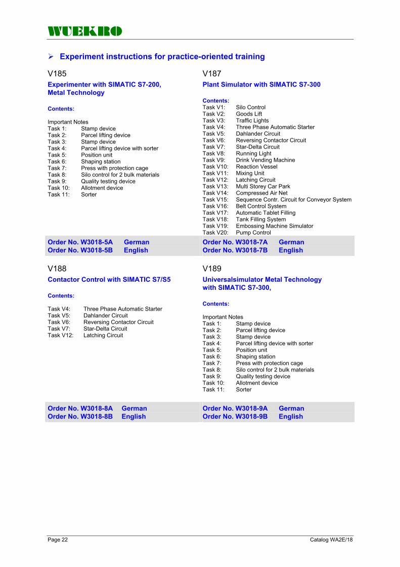
WUEKRO
Page 22 Catalog WA2E/18
Experiment instructions for practice-oriented training V185 V187 Experimenter with SIMATIC S7-200, Metal Technology Contents: Important Notes Task 1: Stamp device Task 2: Parcel lifting device Task 3: Stamp device Task 4: Parcel lifting device with sorter Task 5: Position unit Task 6: Shaping station Task 7: Press with protection cage Task 8: Silo control for 2 bulk materials Task 9: Quality testing device Task 10: Allotment device Task 11: Sorter
Plant Simulator with SIMATIC S7-300 Contents: Task V1: Silo Control Task V2: Goods Lift Task V3: Traffic Lights Task V4: Three Phase Automatic Starter Task V5: Dahlander Circuit Task V6: Reversing Contactor Circuit Task V7: Star-Delta Circuit Task V8: Running Light Task V9: Drink Vending Machine Task V10: Reaction Vessel Task V11: Mixing Unit Task V12: Latching Circuit Task V13: Multi Storey Car Park Task V14: Compressed Air Net Task V15: Sequence Contr. Circuit for Conveyor System Task V16: Belt Control System Task V17: Automatic Tablet Filling Task V18: Tank Filling System Task V19: Embossing Machine Simulator Task V20: Pump Control
Order No. W3018-5A German Order No. W3018-5B English
Order No. W3018-7A German Order No. W3018-7B English
V188 V189 Contactor Control with SIMATIC S7/S5 Contents: Task V4: Three Phase Automatic Starter Task V5: Dahlander Circuit Task V6: Reversing Contactor Circuit Task V7: Star-Delta Circuit Task V12: Latching Circuit
Universalsimulator Metal Technology with SIMATIC S7-300, Contents: Important Notes Task 1: Stamp device Task 2: Parcel lifting device Task 3: Stamp device Task 4: Parcel lifting device with sorter Task 5: Position unit Task 6: Shaping station Task 7: Press with protection cage Task 8: Silo control for 2 bulk materials Task 9: Quality testing device Task 10: Allotment device Task 11: Sorter
Order No. W3018-8A German Order No. W3018-8B English
Order No. W3018-9A German Order No. W3018-9B English
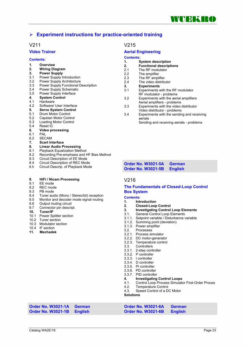
WUEKRO
Catalog WA2E/18 Page 23
Experiment instructions for practice-oriented training V211 V215
Aerial Engineering Contents: 1. System description 2. Functional descriptions 2.1 The RF modulator 2.2 The amplifier 2.3 The RF amplifier 2.4 The video distributor 3. Experiments 3.1 Experiments with the RF modulator RF modulator - problems 3.2 Experiments with the aerial amplifiers Aerial amplifiers - problems 3.3 Experiments with the video distributor Video distributor - problems 3.4 Experiments with the sending and receiving aerials Sending and receiving aerials - problems
Video Trainer
Contents: 1. Overview 2. Wiring Diagram 3. Power Supply 3.1 Power Supply Introduction 3.2 Power Supply Architecture 3.3 Power Supply Functional Description 3.4 Power Supply Schematic 3.5 Power Supply Interface 4. System Control 4.1 Hardware 4.2 Software/ User Interface 5. Servo System Control 5.1 Drum Motor Control 5.2 Capstan Motor Control 5.3 Loading Motor Control 5.4 Reset IC 6. Video processing 6.1 PAL 6.2 SECAM 7. Scart Interface 8. Linear Audio Processing 8.1 Playback Equalization Method 8.2 Recording Pre-emphasis and HF Bias Method 8.3 Circuit Description of EE Mode 8.4 Circuit Description of REC Mode 8.5 Circuit Descrip. of Playback Mode
Order No. W3021-5A German Order No. W3021-5B English
V216 9. HiFi / Nicam Processing
9.1 EE mode 9.2 REC mode 9.3 PB mode 9.4 Tuner audio (Mono / Stereo/bil) reception 9.5 Monitor and decoder mode signal routing 9.6 Output muting circuit 9.7 Connector pin descript. 10. Tuner/IF 10.1 Power Splitter section 10.2 Tuner section 10.3 Modulator section 10.4 IF section 11. Mechadek
The Fundamentals of Closed-Loop Control Box System Contents: 1. Introduction 2. Closed-Loop Control 3. Investigating Control Loop Elements 3.1. General Control Loop Elements 3.1.1. Setpoint variable / Disturbance variable 3.1.2. Summing point (deviation) 3.1.3. Power amplifier 3.2. Processes 3.2.1. Process simulator 3.2.2. DC motor-generator 3.2.3. Temperature control 3.3. Controllers 3.3.1. 2-step controller 3.3.2. P controller 3.3.3. I controller 3.3.4. D controller 3.3.5. PI controller 3.3.6. PD controller 3.3.7. PID controller 4. Investigating Control Loops 4.1. Control Loop Process Simulator First-Order Proces 4.2. Temperature Control 4.3. Speed Control of a DC Motor Solutions
Order No. W3021-1A German Order No. W3021-1B English
Order No. W3021-6A German Order No. W3021-6B English

WUEKRO
Page 24 Catalog WA2E/18
Experiment instructions for practice-oriented training V220 V224 Colour Generator Training Unit Contents: • General • Actuators • Operating instructions • Grid pattern function • Colour area function • Colour bar function • X/Y operation • Vector diagram • Reduced signals • Colour mixture • Four-vector fields • External gating (colour bar) • External gating (red, green, blue) • Opening the training unit • Tuning the training unit • RF modulator • Technical data • Circuit diagram
Demonstration Model for HiFi FM/AM Radio and Amplifier Engineering Contents 1. Introduction/Startup 1.1 Health and Safely at Work 1.2 Startup 1.3 Test Equipment required 1.4 Summary of features and brief description of the various stages in the radio demonstration model 1.4.1 AM stage 1.4.2 FM tuner and the digital frequency indicator 1.4.3 IF stage 1.4.4 Stereo decoder 1.4.5 AF stage 1.4.6 Right hand output stage 1.4.7 Power supply 2. Preliminary remarks on radio transmission techniques 2.1 AM-Amplitude Modulation 2.2 FM transmission techniques 2.3 Stereo Reception 3. Circuit Description/ Servicing/ Circuit diagram 3.1 AM-Stage 3.2 FM Stage 3.2.1 Digital Frequency Display for AM and FM 3.3 IF Stage 3.4 Stereo Decoder 3.5 AF-Stage 3.6 Output stage 3.7 Power supply 4. Description of faults 4.1 AM stage 4.2 FM stage 4.3 IF stage 4.4 Stereo decoder 4.5 AF stage 4.6 Output stage 4.7 Power supply 5. Circuit diagrams 5.1 AM stage 5.2 FM stage 5.3 IF stage 5.4 Stereo decoder 5.5 AF stage 5.6a Output stage, right channel 5.6b Output stage, left channel 5.7 Power supply
Order No. W3022-0A German Order No. W3022-0B English
Order No. W3022-4A German Order No. W3022-4B English

WUEKRO
Catalog WA2E/18 Page 25
Experiment instructions for practice-oriented training V225 Training Model Colour Television Engineering"Multi Standard System w. IR Remote Control"Contents: 1. Circuitry description 1.1 Tuner W5403-2K 1.1.1 General 1.1.2 Signal path in VHF-1 1.1.3 Band selection 1.1.4 Tuner control circuit 1.1.5 Tuning 1.1.6 Delayed control voltage 1.1.7 Measurement on the IIC bus 1.1.8 Generation of the intermediate frequency 1.1.9 Servicing 1.2 IF amplifier W5403-2L 1.2.1 General 1.2.2 Description of the IF stage 1.2.3 Signal of the video carrier 1.2.4 Composite video signal 1.2.5 Video selection 1.2.6 Euro-AV output 1.2.7 Tuner control 1.2.8 Servicing 1.2.8.1 Aligning the sound IF for standard 0 1.2.8.2 Aligning the sound IF for standard 4 1.2.8.3 Frequency check 1.3 Colour stage W5403-2M 1.3.1 General 1.3.2 TDA 4555 1.3.3 TDA 3505 1.3.4 TDA 4565 1.3.5 Composite video signal path 1.3.6 Standard control circuit 1.3.7 Identification circuit 1.3.8 Colour subcarrier oscillator with PLL and chroma control 1.3.9 Delay line F3009 1.3.10 Obtaining the FB-Y and FR-Y signals 1.3.11 Y-signal 1.3.12 -(R-Y), -(B-Y) and Y signal processing in the TDA 3505 video combination 1.3.13 Circuitry description 1.3.14 Servicing 1.3.14.1 PAL 4.4 MHz standard 0 1.3.14.2 Y-signal 1.3.14.3 PAL delay 1.3.14.4 NTSC 5.5 MHz standard 3 1.3.14.5 SECAM standard 0 1.3.14.6 SECAM colour switch 1.3.14.7 Tuning DR and dB 1.4 RGB stages W5403-2N 1.4.1 General 1.4.2 Servicing 1.5 Audio stage W5403-2Q 1.5.1 General 1.6 Horizontal / Vertical stage W5403-2R 1.6.1 Preface 1.6.1.1 Synchronous pulse gain 1.6.1.2 Fundamental demands 1.6.1.3 TDA 2579 circuit
1.6.2 Vertical stage 1.6.2.1 Description 1.6.2.2 Flyback generator 1.6.3 Horizontal stage 1.6.3.1 Description 1.6.3.2 Horizontal deflection current 1.6.3.3 High voltage 1.6.3.4 Focussing voltage 1.6.3.5 Heating voltage 1.6.3.6 Beam current limiting 1.6.3.7 Protective circuit 1.6.3.8 Phosphor dot suppression 1.6.3.9 Servicing 1.7 Power supply unit 1.7.1 Primary side 1.7.2 Secondary side 1.7.3 Overvoltage and overload protection 1.7.4 Servicing 1.8 Control unit W5403-2P 1.8.1 General 1.8.2 Microcomputer SDA 2023 1.8.3 IIC bus 1.8.4 EEPROM SDA 2526 1.8.5 Power supply 1.8.6 Oscillator frequency 1.8.7 Standby circuit 1.8.8 Infrared signals 1.8.9 Programme display 1.8.10 Keyboard scan, instruction input 1.9 Remote control unit 1.9.1 General 1.9.2 Functional description 1.9.2.1 Power supply 1.9.2.2 Clock generation 1.9.2.3 Infrared output 1.9.2.4 Input matrix 1.9.2.5 Additional instruction codes 1.9.2.6 Message format 1.9.2.7 Measurement and representation of a message 1.9.2.8 Instruction format 1.9.2.9 Transmission of the infrared signal 1.9.2.10 Protection against user errors 2. Fault list 2.1 Tuner W5403-2K 2.2 IF amplifier W5403-2L 2.3 Colour stage W5403-2M 2.4 RGB stage W5403-2N 2.5 Control unit W5403-2P 2.6 Audio stage W5403-2 2.7 Horizontal/vertical stage W5403-2R 3. Operating instructions 3.1 Safety requirements 4. Circuit diagrams and circuit diagram symbols
Order No. W3022-5A German Order No. W3022-5B English

WUEKRO
Page 26 Catalog WA2E/18
Experiment instructions for practice-oriented training V226 V227 DEMONSTRATION OSZILLOSCOPE 20 MHz Contents: 1. INTRODUCTION, BASIC FUNCTIONS, MEASURING INSTRUMENTS REQUIRED 1.1 Introduction 1.2 Basic functions 1.3 Measuring and test instruments 2. BLOCK DIAGRAM OF SITRAIN 410 2.1 Vertical deflection 2.2 Horizontal deflection 2.3 Unblanking circuit (Z-axis) 2.4 Power supply
Radio and Amplifier Engineering "AM-Receiver" Contents: 1 System interconnection diagram 2 AM preamplifier W5432-1A
Circuit description 3 AM stage W5432-1B
Circuit description Service AM stage
4 Volume/tone control W5432-1C 5 AF output stage W5432-1N
Circuit description 6 Tuner stage with frequency display W5432-1G 7 Power supply unit W5432-3B 8 Circuit Diagrams 9 Fault list, Fault descriptions, Test questions
Order No. W3022-6A German Order No. W3022-6B English
Order No. W3022-7A German Order No. W3022-7B English
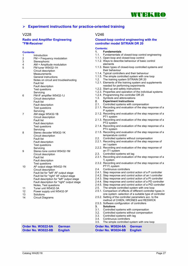
WUEKRO
Catalog WA2E/18 Page 27
Experiment instructions for practice-oriented training V228 V246 Radio and Amplifier Engineering "FM-Receiver Contents: 1 Introduction 2 FM = Frequency modulation 3 Stereophonic 4 AM = Amplitude modulation 5 FM tuner W5432-1H
Circuit description Measurements General instructions Notes on circuit and troubleshooting Fault list Fault description Test questions Servicing
6 FM-IF amplifier W5432-1J Circuit description Fault list Fault description Test questions Servicing
7 AM stage W5432-1B Circuit description Fault list Fault description Test questions Servicing
8 Stereo decoder W5432-1K Circuit description Fault list Fault description Test questions Servicing
9 Stereo tone control W5432-1M Circuit description Fault list Fault description Test questions
10 AF output stage W5432-1N Circuit description Fault list for "left" AF output stage Fault list for "right" AF output stage Fault description for "left" output stage Fault description for "right" output stage Notes, Test questions
11 Tuner unit W5432-3A 12 Power supply unit W5432-3F 13 Solutions 14 Circuit Diagrams
Closed-loop control engineering with the controller model SITRAIN DR 20 Contents: 1. Fundamentals 1.1. Fundamentals of closed-loop control engineering 1.1.1. Open-loop and closed-loop control 1.1.2. Ways to describe behaviour of basic control elements 1.1.3. Basic types of closed-loop controlled systems and their behaviour 1.1.4. Typical controllers and their behaviour 1.1.5. The simple controlled system with one loop 1.2. The training system SITRAIN DR 20 1.2.1. Elements of the training system and supplements needed for performing experiments 1.2.2. Start-up and safety instructions 1.2.3. Properties and operation of the individual systems 1.2.4. Programming the controller DR 20 1.3. Symbols and abbreviations 2. Experiment Instructions 2.1. Controlled systems with compensation 2.1.1. Recording and evaluation of the step response of a P system 2.1.2. Recording and evaluation of the step response of a PT1 system 2.1.3. Recording and evaluation of the step response of a PT2 system 2.1.4. Recording and evaluation of the step response of a PTn system 2.1.5. Recording and evaluation of the step response of a temperature control 2.2. Controlled systems without compensation 2.2.1. Recording and evaluation of the step response of an I system 2.2.2. Recording and evaluation of the step response of an IT1 system 2.3. Controlled systems wit lag 2.3.1. Recording and evaluation of the step response of a Tt system 2.3.2. Recording and evaluation of the step response of a PT1Tt system 2.4. Continuous controllers 2.4.1. Step response and control action of a P controller 2.4.2. Step response and control action of an I controller 2.4.3. Step response and control action of a PI controller 2.4.4. Step response and control action of a PD controller 2.4.5. Step response and control action of a PID controller 2.5. The simple controlled system with one loop 2.5.1. Comparison of effects of different controller types in one system -selection of a suitable type of controller 2.5.2. Setting of the controller parameters acc. to the method of CHIEN, HRONES and RESWICK 2.5.3. Software configuration of controllers 3. Solutions 3.1. Controlled systems with compensation 3.2. Controlled systems without compensation 3.3. Controlled systems with lag 3.4. Continuous controllers 3.5. The simple controlled system with one loop
Order No. W3022-8A German Order No. W3022-8B English
Order No. W3024-6A German Order No. W3024-6B English

WUEKRO
Page 28 Catalog WA2E/18
Experiment instructions for practice-oriented training V252 V253 Electronic Components Contents: Foreword Introduction Alphabetical list of abbreviations used 1. Resistors Linear resistors Trimmers Non-linear resistors PTC thermistors NTC thermistor Voltage-dependent resistors (varistors) Exercise 2. Capacitors Types of construction Electrolytic capacitors Metallized-paper capacitors Metallized-plastic capacitors Ceramic capacitors Circuits with capacitors and resistors Exercises 3. Semiconductor diodes Doping of semiconductors Diodes (rectifier diodes) Application of diodes Exercises 4. Bipolar transistors Input characteristic Output characteristic Current control characteristic Reverse voltage transfer ratio characteristic Fourquadrant representation Exercises 5. Unipolar transistors Transistor in constant current source Exercises 6. Components with bistabile characteristics Unijunction-Transistor Exercise: UJT input characteristic Thyristor Exercise: Static thyristor characteristics 7. Optoelectronic components Photoelectric emission Internal photoelectric effect Barrier-layer photoelectric effect Photoresistor Photodiodes Phototransistors Optocouplers Exercises Solutions
Fundamentals of Basic Analog Circuits Contents: Introduction Alphabetical list of abbreviations used 1. Basic diode circuits Exercise Single-way rectifier circuit Exercise Centre-tap rectifier circuit Exercise Bridge circuit Exercise Voltage stabilization by means of zener diodes with variable input voltage Exercise Voltage stabilization by means of zener diodes with variable load resistance Exercise Diode as a switch Exercise Voltage doubler circuit Exercise Voltage multiplier circuit 2. Basic transistor circuits Exercise Common-collector circuit Exercise Common-emitter circuit Exercise Darlington circuit Exercise Switching transistor Exercise AC amplifier Exercise DC amplifier 3. Oscillator circuits with transistors Exercise Wien-bridge generator Exercise RC phase-shifting generator Exercise Colpitts oscillator 4. Operational amplifiers Exercise Setting the balance of an operational amplifier Exercise Power supply with operational amplifier Exercise Operational amplifier as impedance transformer Exercise Operational amplifier as adder Exercise Operational amplifier as difference amplifier Exercise Operational amplifier as inverting AC amplifier Exercise Astable multivibrator with operational amplifier Exercise Oscillator circuit with operational amplifier 5. High pass, low pass and bandpass Exercise Integrating circuit Exercise Measurements with low pass Exercise Differentiating circuit Exercise Measurements with high pass Exercise Measurements with bandpass 6. Applications of components with bistabile characteristics Exercise Unijunction transistor (UJT) as pulse generator Exercise Phase control circuit 7. Applications of optoelectronic components Exercise Photoelectric barrier Exercise Photoelectric lighting controller Solutions
Order No. W3025-2A German Order No. W3025-2B English
Order No. W3025-3A German Order No. W3025-3B English

WUEKRO
Catalog WA2E/18 Page 29
Experiment instructions for practice-oriented training V254 V255 Basic Digital Circuits Contents: Foreword Introduction Alphabetical list of Abbreviations used 1. Basic logic circuit AND gate OR gate NOT gate NAND gate NOR gate EX-OR gate EX-NOR gate 2. Trigger circuits Astable trigger circuit Monostable trigger circuit Bistable trigger circuit Schmitt trigger 3. Digital storage elements RS flip-flop D flip-flop Master-slave flip-flop Edge-triggered JK storage element 4. Counters and registers Asynchronous binary counters Asynchronous counting-down binary counters Asynchronous counter with reversing the counting direction Synchronous counting-up binary counter Ring counter Register 5. Switching algebra Boolean algebra Karnough-Veitch-Diagram Examination of a digital circuit using the logic analyzer 6. Comparison of logic levels Integrated circuits Logic families Logic level 7. Digital applications Measurement of time and frequency Digital measurement of period Solutions
Digital Data Processing Contents: Foreword Introduction Alphabetical List of Abbreviations used 1. Encoder, Decoder, Code Converter Exercise: Octal/binary conversion Exercise: Binary/hexadecimal conversion Exercise: BCD/decimal conversion Exercise: Decimal/binary conversion Exercise: Binary/BCD conversion 2. Counters and their Application Exercise: Decimal counter Exercise: Decimal counter with set inputs Exercise: Hexadecimal counter Exercise: Hexadecimal counter with set impulse 3. Register and their Application Exercise: Shift register as memory Exercise: 8-bit shift register Parallel input – serial output Exercise: Parallel input – serial output Serial input – parallel output Exercise: Serial input – parallel output 4. Basic Phase-Locked loop Circuits Exercise: PLL in capture range Exercise: PLL as clock generator 5. Analog / Digital Conversion Digital / Analog Conversion Exercise: Analog / digital conversion Exercise: Digital / analog conversion Digital / analog conversion with the R/2R network Exercise: Digital / analog conversion with the R/2R network 6. Digital Arithmetic Logic Units Addition of two single-digit binary numbers Exercise: Half-adder Addition of multi-digit binary numbers Exercise: Full adder Subtraction of binary numbers Exercise: Half-subtractor Subtraction of multi-digit binary numbers Exercise: Full subtractor Multiplication of binary numbers Exercise: Multiplication of binary numbers 7. Multiplexers, Demultiplexers Exercise: Multiplexers Exercise: Demultiplexers Exercise: Serial data transmission with multiplexers and demultiplexers Solutions
Order No. W3025-4A German Order No. W3025-4B English
Order No. W3025-5A German Order No. W3025-5B English

WUEKRO
Page 30 Catalog WA2E/18
Experiment instructions for practice-oriented training V257 V287 Fundamentals of Electrical Engineering Contents: • Introduction • Summary of symbols Part I: Experiment groups • The electrical circuit • Ohm's law • Series circuit • Parallel circuit • Series-parallel connection of resistors • Potential dividers • Delta-star conversion • Voltage sources • Electrical energy, electric power, efficiency • Power adjustment • Capacitors • Capacitors connected in series and in parallel • Electromagnetism • Electric circuit and magnetic circuit • Theory of alternating currents • AC resistance and reactance • AC circuits • Three-phase current Part II: Solutions
Photovoltaic Cell Technology Contents: 1. Introduction 1.1.1 Isolated operation 1.1.2 Emergency lighting 1.1.3 Power generation 1.1.4 Space technology 1.1.5 Traffic technology 1.2 Storage possibilities 1.2.1 Battery 1.2.2 Further possibilities 1.3 Listing of boxes, measuring instruments and accessories 2. Characteristic values of a solar module 2.1 Off-load 2.1.1 Off-load voltage, short-circuit current and power 2.1.1.1 Variation of lighting intensity 2.1.1.2 Variation of illuminated surface 2.1.1.3 Variation of angle of light incidence 2.1.1.4 Variation of temperature 2.1.2 Internal resistance 2.2 On-load 2.2.1 Output characteristic I = f(U) 2.2.2 Power characteristic, MPP 3. Interconnection of solar modules 3.1 Parallel connection 3.2 Series connection 4. Protective installations 4.1 Overvoltage protector 4.2 Short-circuit protection for solar generators 4.3 Short-circuit protection for storage batteries 4.4 Anti-discharge protector 4.5 Flat-battery protector 4.6 Selectivity 5. Development of a circuit diagram 5.1 Photovoltaic system with battery and inverter 5.2 Network and standby power supply Annex: Description of modules and accessories Solutions
Order No. W3025-7A German Order No. W3025-7B English
Order No. W3028-7A German Order No. W3028-7B English

WUEKRO
Catalog WA2E/18 Page 31
Experiment instructions for practice-oriented training V282 Universal - Experimenter IV Contents: 1. Functional description of the W5101-0A basic equipment 1.1 Functional units 1.1.1 Power supply unit 1.1.2 Setpoint disturbance generator 1.1.3 Voltmeter 1.1.4 Module location for controlled systems 1.1.5 Power amplifier 1.1.6 Optocouplers 2. Basic experiments with discrete components 2.1 Fundamentals 2.2 Functional description of the W5101-0M experiment board for transistors 2.3 Experiments 2.3.1 Experiment: diode characteristic 2.3.2 Experiment: Zener diode characteristic 2.3.3 Experiment: transistor characteristic 2.3.3.1 Input characteristics 2.3.4 Transistor as a switch with Darlington connection 2.4 Results for 2.3 3. Basic experiments in analog electronics 3.1 Fundamentals of operational amplifiers 3.1.1 Offset current 3.1.2 Offset voltage 3.1.3 Operational amplifier configurations 3.2 General calculations for the circuitry 3.3 Functional description of the experiment boards 3.3.1 Operational amplifier I (W5101-0B) 3.3.2 Operational amplifier II (W5101-0C) 3.3.3 Operational amplifier III (W5101-0D) 3.3.4 Operational amplifier IV (W5101-0E) 3.4 Experiments 3.4.1 Inverting amplifier 3.4.2 Noninverting amplifier 3.4.3 Differential amplifier 3.4.4 Passive input smoothing 3.4.5 Active smoothing with continuous gain variation 3.4.6 Summing element 3.4.7 Current source 3.4.8 Inverting amplifier connected to AC voltage 3.4.9 Astable multivibrator 3.4.10 PI controller 3.4.11 Integrator 3.4.12 Division of two voltages 3.4.13 Gain changeover with FET switches 3.4.14 Current measurement 3.4.15 Integrator and differentiator in series 3.5 Results for 3.4
4. Basic experiments in control engineering 4.1 Motor-generator system 4.1.1 Functional description of the WA5101-0R experiment board 4.1.2 System gain 4.1.3 Transient function 4.1.4 Speed control circuits 4.1.5 Results 4.2 Light system 4.2.1 Functional description of experiment board W5101-0U 4.2.2 System gain 4.2.2.1 Experimental setup to determine the system gain 4.2.3 Light control circuit 4.2.3.1 Experimental setup to connect the light control circuit 4.2.4 Results 4.3 Temperature control 4.3.1 Functional description of experiment board W5101-0S 4.3.2 System gain 4.3.2.1 Experimental setup to determine the system gain 4.3.3 Temperature control circuit 4.3.3.1 Experimental setup to connect the temperature control circuit 4.3.4 Results 4.4 Servo drive system 4.4.1 Functional description of experiment board W5101-0T 4.4.2 System gain 4.4.2.1 Experimental setup: servo drive to determine the system gain 4.4.3 Servo-control system 4.4.3.1 Experimental setup to connect the servo-control system 4.4.4 Results 5. Basic experiments in digital electronics 5.1 Logic operations 5.1.1 AND operation 5.1.2 OR operation 5.1.3 NOT operation 5.1.4 NAND operation 5.1.5 NOR operations 5.1.6 Exclusive-OR operation (EX-OR, XOR) 5.1.7 Exclusive-NOR operation (EX-NOR, XNOR) 5.2 Edge-triggered JK flipflop 5.3 D flipflop 5.4 Counters 5.5 Results for 5.1 to 5.4
Order No. W3028-2A German Order No. W3028-2B English

WUEKRO
Page 32 Catalog WA2E/18
FAX – Reply to: +49 (0)9721 / 64691 - 20 Sender: Receiver:
Company WUEKRO GmbH Dept. Sales Department Name Street Carl-Zeiss-Strasse 10 City 97424 Schweinfurt / Germany Phone + 49-(0)9721-64691-0 Fax + 49-(0)9721-64691-20 E-Mail [email protected] Internet www.wuekro.de
Please send the following catalogues to the a.m. address!
Fundamentals of electrical Engineering Installation circuits Bell ringing and entrance call stations Contactor control / Control technology Measurement and control of non-electrical variables
Fundamentels of electronics Analog technology Digital technology Microprocessing technology
Closed loop control technology Analog closed loop control Digital closed loop control
Automation engineering SIMATIC S7-200/300/400, Software Technology simulators / Models Process control engineering PCS7 AS-Interface Profibus DP Process simulation-software PROSIM 95 LOGO! Mechatronical technology stations Courses on Automation
Electrical machines / Drive controls Electrical Machines 300W Electrical Machines 1000W Electrical Machines 5kW Electrical drive control systems 300W/ 1kW Electrical drive control systems 5kW Networked drive systems Cutaway Models Transformers, Rectifiers and Reactive Power Compensation Courses on drive systems
Power electronics extra low voltage (24V) low voltage (230/400V)
Building management systems KNX / EIB
VDE 0100 safety measures
Radio- and Television engineering AM/FM – Technology TV Engineering Satellite – Technology
Cooling and air conditioning
Photovoltaic cell tecnology
Communication technology Modulation -/demodulation Fiber optic ISDN trainer (HICOM) ISDN
Measuring systems
Power supply units
Experiment instructions, manuals
Training courses
Remarks:

ÿ Our Services
• Development and production of didactic training systems• Teachware and documentation• Project engineering of complete lab's incl. furniture and lab equipment• Quotations on customer's demand• Installation, commissioning and training at site
ÿ Our Customers
• Vocational training schools, technical schools, colleges and universities...• Industrial laboratories for vocational education and higher education
ÿ Fields of Technology
• Fundamentals of electrical engineering
• Fundamentals of electronics
• Closed loop control technology
• Automation engineering
• Electrical machines / drive control
• Power electronics
• Building management systems
• Protection schemes to VDE 0100
• Radio- and TV technology
• Air conditioning and refrigeration
• Photovoltaic
• Communication technology
• Measuring systems, power supplies, accessories
• Experimental manuals, documentation
For further information please contact:
WUEKRO GmbH Carl-Zeiss-Strasse 10D - 97424 SchweinfurtGermanyTel. + 49 (0) 9721-64691-0Fax: + 49 (0) 9721-64691-20E-Mail: [email protected]: www.wuekro.de
WUEKRO GmbH All Rights reserved. Reprint not permitted. Technical changes without prior notice.
WUEKRO

ÿ FAX – Reply to: +49 (0)9721 / 64691 - 20Sender: Receiver:
Company WUEKRO GmbH Dept. Sales DepartmentName
Street Carl-Zeiss-Strasse 10City 97424 Schweinfurt / GermanyPhone + 49-(0)9721-64691-0Fax + 49-(0)9721-64691-20E-Mail [email protected] www.wuekro.de
˝ Please send the following catalogues to the a.m. address!® Fundamentals of electrical Engineering
® Installation circuits® Bell ringing and entrance call stations® Contactor control / Control technology® Measurement and control of
non-electrical variables® Fundamentels of electronics
® Analog technology® Digital technology® Microprocessing technology
® Closed loop control technology® Analog closed loop control® Digital closed loop control
® Automation engineering® SIMATIC S7-200/300/400, Software® Technology simulators / Models® Process control engineering PCS7® AS-Interface® Profibus DP® Process simulation-software PROSIM 95® LOGO!® Mechantronical technology stations® Courses on Automation
® Electrical machines / Drive controls® Electrical Machines 300W® Electrical Machines 1000W® Electrical Machines 5kW® Electrical drive control systems 300W / 1kW® Electrical drive control systems 5kW® Networked drive systems® Cutaway Models® Transformers, Rectifiers and Reactive
Power Compensation® Courses on drive systems
® Power electronics® extra low voltage (24V)® low voltage (230/400V)
® Building management systems® KNX / EIB
® VDE 0100 safety measures
® Radio- and Television engineering® AM/FM – Technology® TV Engineering® ® Satellite – Technology
® Cooling and air conditioning
® Photovoltaic cell tecnology
® Communication technology® Modulation -/demodulation® Fiber optic® ISDN trainer (HICOM)® ISDN
® Measuring systems
® Power supply units
® Experiment instructions, manuals
® Training courses
Remarks:
WUEKRO
Copyright © 2022 FDOKUMEN