TRADELINE Catalog - Building Controls Group
932
Environmental and Combustion Controls 24th Edition Product Catalog TRADELINE Catalog
-
Upload
khangminh22 -
Category
Documents
-
view
0 -
download
0
Transcript of TRADELINE Catalog - Building Controls Group

Environmental and Combustion Controls24th Edition Product Catalog
TRADELINE Catalog
customer.honeywell.com 70-6910
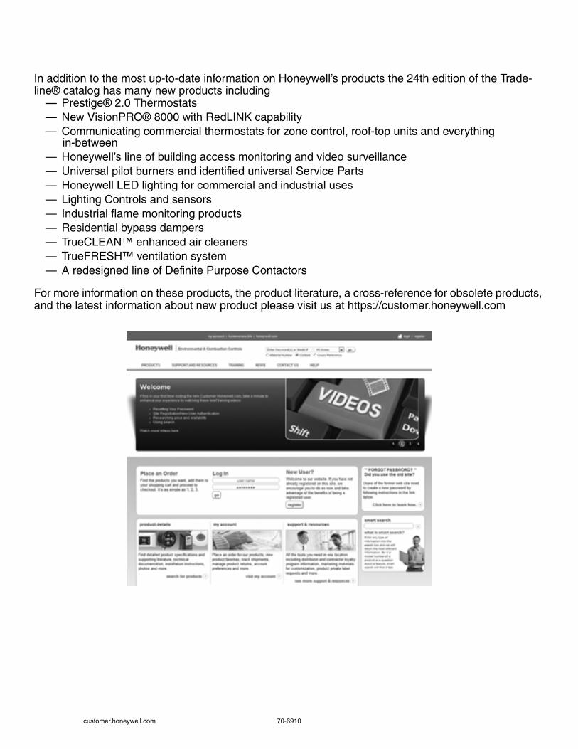
In addition to the most up-to-date information on Honeywell’s products the 24th edition of the Trade-line® catalog has many new products including
— Prestige® 2.0 Thermostats— New VisionPRO® 8000 with RedLINK capability— Communicating commercial thermostats for zone control, roof-top units and everything
in-between— Honeywell’s line of building access monitoring and video surveillance— Universal pilot burners and identified universal Service Parts— Honeywell LED lighting for commercial and industrial uses— Lighting Controls and sensors— Industrial flame monitoring products— Residential bypass dampers— TrueCLEAN™ enhanced air cleaners— TrueFRESH™ ventilation system— A redesigned line of Definite Purpose Contactors
For more information on these products, the product literature, a cross-reference for obsolete products, and the latest information about new product please visit us at https://customer.honeywell.com

Table of Contents
70-6910 i
Model Number Index ................................................................... iiiSubject Index.............................................................................. viiISO 9001 ................................................................................... xv
General Information ................................................................. xviReference Information ............................................................ xviiiAuthorized Distributors............................................................ xxiv
Home Control Thermostats and ZoningElectric Heat Thermostats .......................................................... 1Programmable Thermostats....................................................... 6Non-Programmable Thermostats ............................................. 22RedLINK Wireless Products..................................................... 32Temperature Sensors............................................................... 35Freeze Warning........................................................................ 36Thermostat Parts and Accessories .......................................... 37
Thermostat Guards ................................................................... 39TrueZONE Zoning Panels and Kits........................................... 41Zone Control Panel Accessories............................................... 43Bypass Dampers....................................................................... 44Zone Control Dampers.............................................................. 45Zone Control Damper Accessories ........................................... 50
Indoor Air QualityTrueCLEAN Enhanced Air Cleaner.......................................... 51Electronic Air Cleaners............................................................. 53Media Air Cleaners................................................................... 55Replacement Media Filters....................................................... 58Air Cleaner Parts and Accessories........................................... 62Electronic Air Cleaner Filters.................................................... 65TrueDRY Dehumidification System.......................................... 68TrueSTEAM Humidification System ......................................... 73TrueEASE Humidifiers ............................................................. 75Bypass Humidifers ................................................................... 76
Humidifier Replacement Pads and Filters................................. 78Sail Switches............................................................................. 79Digital IAQ Control .................................................................... 80Humidity Controllers.................................................................. 81Ultraviolet Air Treatment Systems ............................................ 83TrueFRESH Ventilation System................................................ 86Fresh Air Ventilation System..................................................... 94Supply Air Ventilation Products................................................. 95Carbon Monoxide Alarm ........................................................... 96
Residential Combustion ControlsCombination Gas Controls ....................................................... 97Gas Valve Selection Guide .................................................... 114SmartValve System Controls ................................................. 116SmartValve Selection Guide .................................................. 119Gas Valves Parts and Accessories ........................................ 120Thermocouples and Thermopiles........................................... 122Thermopiles and Thermocouples Selection Guide ................ 123Pilot Burners........................................................................... 124Pilot Burner Parts and Accessories........................................ 127Ignition Pilot Modules ............................................................. 129Ignition Pilot Modules Selection Guide................................... 133Gas Ignition Module Accessories ........................................... 134Igniter Bracket Replacement Cross Reference ...................... 135Igniters and Sensors .............................................................. 136Pressure Switches.................................................................. 137Electronic Fan Timers ............................................................ 138
Contactors............................................................................... 139Contactors Selection Guide .................................................... 146Relays ..................................................................................... 148Relays Parts and Accessories ................................................ 152Electric Heat Sequencer Selection Guide............................... 154Fan Centers ............................................................................ 156Fan Center Selection Guide.................................................... 157Transformers........................................................................... 158Transformer Selection Guide .................................................. 164Oil Primaries Cross Reference ............................................... 165Oil Primaries ........................................................................... 166Flame Detectors...................................................................... 168Magnetic Valves...................................................................... 169Fan and Limit Controllers........................................................ 170Aquastat Controllers ............................................................... 171Well Assemblies...................................................................... 184
Hydronic ControlsAQUATROL Zoning System................................................... 185Hydronic Switching Relays..................................................... 194Transformers for Hydronic Controls ....................................... 198Residential Heating Valves and Actuators ............................. 199Motorized Zone Valves........................................................... 202Manifold Zone Valves............................................................. 215AquaPUMP Hydronic Circulating Pump ................................. 216Differential Pressure Regulators ............................................ 217
Air Vents and Eliminators........................................................ 218Backflow Preventers ............................................................... 226Boiler Fill Valves ..................................................................... 227Thermometers and Gauges .................................................... 228Residential Expansion Tanks.................................................. 229Thermostatic Radiator Valves and Actuators.......................... 232Commercial Expansion Tanks ................................................ 244
Water ControlsMixing Valves ......................................................................... 247Pressure Regulating Valves ................................................... 258Water Sediment Filters........................................................... 263
Water Filters............................................................................ 264Backwash Controls ................................................................. 266
Building AutomationExcel 5000 System................................................................. 267WEBs-AX System .................................................................. 279WEBs-AX Security System .................................................... 293Access and Video Systems.................................................... 304WEBs R2 System................................................................... 310Spyder Controllers.................................................................. 312
Stryker Controllers .................................................................. 314Building Automation Appliances ............................................. 315Lighting Controls ..................................................................... 317LED Lighting ........................................................................... 319Light Commercial Building Systems ....................................... 325Legacy Building Systems........................................................ 334

Table of Contents
ii customer.honeywell.com 70-6910
Commercial ComponentsRefrigeration Controllers ......................................................... 339Sail Switches........................................................................... 341Manual Switches..................................................................... 341Temperature Controllers ......................................................... 342Commercial Rectangular Dampers......................................... 361Commercial Round Dampers.................................................. 364Direct Coupled Damper Actuators—Non-Spring Return......... 366Direct Coupled Damper Actuator—Spring Return .................. 375Direct Coupled Damper Actuators—Fire and Smoke ............. 390Direct Coupled Damper Actuators—Accessories ................... 395Economizer Logic Modules..................................................... 404Economizer Damper Actuators ............................................... 407Economizer Sensors............................................................... 409Modutrol IV Motors.................................................................. 412Kit Mounted Motors................................................................. 438Damper and Valve Linkages................................................... 440Carbon Dioxide (CO2) Sensors .............................................. 446Current Switches..................................................................... 448Dew-Point Sensor ................................................................... 451Humidity Sensors.................................................................... 452Pressure Sensors ................................................................... 455Temperature Sensors ............................................................. 457Submeters............................................................................... 480Fan Coil Thermostats.............................................................. 487Wireless Occupancy Solutions ............................................... 492
Line Volt Thermostats............................................................. 494Proportional Thermostats ....................................................... 500Programmable Thermostats ................................................... 501Programmable Commercial Thermostats............................... 506Communicating Thermostats.................................................. 511Timers..................................................................................... 519Pressure-regulated Control Valves......................................... 520Control Ball Valves ................................................................. 524Butterfly Control Valves .......................................................... 534Flanged Globe Valves ............................................................ 543Globe Valve Accessories and Replacement Parts ................. 553Cage Valves ........................................................................... 556Cartridge Globe Valves .......................................................... 557Cartridge Cage Valves ........................................................... 562Fan Coil Valves ...................................................................... 571Cartridge Globe Valve Actuators ............................................ 574VC Valve Actuators ................................................................ 576Fan Coil Actuators .................................................................. 580Direct Coupled Valve Actuators.............................................. 582Valve Actuator Accessories.................................................... 587SmartVFD COMPACT............................................................ 588SmartVFD HVAC.................................................................... 592SmartVFD HVAC and SmartVFD BYPASS............................ 595VFD Core................................................................................ 610Variable Frequency Drives ..................................................... 613
Pneumatic ControlsPneumatic Humidstats ............................................................ 643Pneumatic Thermostats .......................................................... 646Pneumatic Transducers .......................................................... 660Pneumatic Velocity Sensors/Controllers................................. 661Pneumatic Temperature Controllers ....................................... 663Pneumatic Pressure Controllers ............................................. 667Pneumatic Humidity Sensors.................................................. 674Pneumatic Temperature Sensors ........................................... 675
Pneumatic Relays................................................................... 678Pneumatic Switches ............................................................... 688Pneumatic Damper Actuators................................................. 695Pneumatic Valve Actuators .................................................... 707Pneumatic Valves................................................................... 711Pneumatic Gauges ................................................................. 727Pneumatic Accessories .......................................................... 728Pneumatic Definitions and Abbreviations ............................... 734
Commercial/Industrial Combustion ControlsProduct Selection Matrix ......................................................... 737Microprocessor Burner Controls ............................................. 756SOLA Controllers .................................................................... 786SOLA Displays........................................................................ 788SOLA Program Module........................................................... 790ControLinks Fuel Air Control System...................................... 791Delphi Combustion System..................................................... 796Advanced Burner Controls...................................................... 798Network Interface Communications ........................................ 799Flame Amplifiers ..................................................................... 800Flame Rods and Flame Rod Holders...................................... 803Flame Detectors...................................................................... 805Pilot Burners ........................................................................... 817Commercial Hydronic Controllers ........................................... 820Ignition Transformers .............................................................. 821
Firing Rate Motors and Linkages............................................ 823Diaphragm Gas Valves........................................................... 824Butterfly Gas Valves ............................................................... 830Gas Valve Actuators............................................................... 832Industrial Gas Valves.............................................................. 839Pilot Gas Valves ..................................................................... 846Solenoid Gas Valves .............................................................. 847Servo Regulated Gas Valves ................................................. 850Venturi Mixing Unit ................................................................. 852Pressure Switches.................................................................. 853Pressure and Limit Controllers ............................................... 856Modernization and Replacement............................................ 865Electromechanical Burner Controls ........................................ 868Reset Temperature Controls .................................................. 873Testers and Demonstrators .................................................... 876
Industrial Flame MonitoringSignal Processors ................................................................... 879Industrial Flame Monitoring Accessories ................................ 882
Flame Detectors ..................................................................... 888
Training MaterialsDVD/Videotapes ..................................................................... 891Training Booklets .................................................................... 892Programmed Instruction Books............................................... 893Service Publications................................................................ 894Classroom Training................................................................. 895
FSG Textbook ........................................................................ 896Reference Manuals ................................................................ 897Lab Trainers ........................................................................... 899Ordering Information............................................................... 901
Warranty ........................................................... Inside Back cover

Model Number
70-6910 iii
Numerics123514A..................... 65-0093 .......................... 877133392A..................... 60-0074 .......................... 845133393A..................... 60-0074 .......................... 845137253A..................... 60-0074 .......................... 845198162 ....................... 63-2230 .......................... 4342001-100-090-EC.... 62-86-25-10 ....................... 796203659 ....................... 65-0093 .......................... 877220736 ....................... 63-2228 .......................... 43432003971-002 ............ 66-1184 .......................... 79032003971-003 ............ 66-1184 .......................... 79050001464-006 ............ 66-1184 .......................... 79050001464-007 ............ 66-1184 .......................... 79050017460 ................... 62-0233 .......................... 434
AA7800......................... 65-0289 .......................... 876ABC900...................... 63-9751 .......................... 798AM-1 Series ............... 62-3098 .......................... 247AM-1-020 RP ............. 62-3103 .......................... 251AM-1-025 RP ............. 62-3103 .......................... 251AMCU-001RP .................. ................................. 251AMX Series ................ 62-3074 .......................... 252AMX300 Series .......... 63-9876 .......................... 254AP5027-30 ................. 69-1581 .......................... 137AP5208-30 ................. 69-1581 .......................... 137AP5210-30 ................. 69-1581 .......................... 137AQ1000TN2 ............... 63-9379 .......................... 193AQ1000TP2 ............. 69-2245EF ........................ 193AQ2000 ...................... 63-9686 ..................191, 192AQ250........................ 68-0306 .......................... 185AQ251........................ 69-1974 .......................... 187AQ252........................ 69-1986 .......................... 188AQ25400B.................. 69-1987 .......................... 189AQ255........................ 69-1981 .......................... 190AQ257........................ 69-1981 .......................... 190AQ25A........................ 69-2119 .......................... 186AT120......................... 68-0054 .......................... 158AT140......................... 68-0054 ...50, 158, 159, 198AT150......................... 68-0054 ..................159, 160AT175......................... 68-0054 ..................159, 160AT40........................... 60-2254 .......................... 161AT72........................... 60-2254 .......................... 161AT87........................... 60-2254 .......................... 162AT88........................... 60-2254 .......................... 163
BBP700 ........................ 62-3089 .......................... 226BP900 ........................ 62-3088 .......................... 226
CC437D,E..................... 60-2320 .......................... 853C554........................... 60-2148 .......................... 168C6097......................... 65-0237 .......................... 854C7005......................... 60-2033 .......................... 819C7007......................... 60-2024 .......................... 803C7008......................... 60-2024 .......................... 803C7009......................... 60-2024 .......................... 804C7012......................... 60-2398 .......................... 805C7021......................... 63-2590 .......................... 457C7023......................... 63-2590 .......................... 460C7024......................... 65-0156 .......................... 807C7027......................... 60-2026 .......................... 808C7031......................... 63-2590 ..................458, 461C7035......................... 60-2026 .......................... 809C7041......................... 63-2590 ..................458, 462C7044......................... 60-2026 .......................... 808C7046......................... 60-2350 .......................... 463C7061......................... 65-0223 .......................... 810C7076......................... 95-8269 .......................... 812C7089...................... 69-2493EFS ......................... 35C7089R................... 69-2493EFS ......................... 33C7100......................... 60-2521 .......................... 463C7130......................... 63-2044 .......................... 464C7150......................... 63-2072 .......................... 409C7170......................... 63-2045 .......................... 464C7189...................... 69-1710EFS ...................33, 35C7189R................... 69-2493EFS ......................... 33C7232......................... 63-2571 .......................... 446C7250......................... 62-0335 .......................... 409
C7262 ......................... 62-0353 ...........................447C7400A,C ................... 63-2140 ...........................410C7400S.....................63-1365EF ........................410C7600 ......................... 63-2418 ...........................411C7632 ......................... 63-2615 ...........................447C7660 .......................63-2670EF ........................411C7735 ......................69-1521EFS .................. 35, 43C7750 ......................... 95-7508 ...........................465C7770 ......................... 74-2868 ...........................465C7772 ......................... 68-0213 ...........................466C7776 ......................... 74-2868 ...........................467C7778 ......................... 74-2868 ...........................467C7915 ......................... 65-0292 ...........................815C7927 ......................... 60-2026 ...........................813C7961 ......................... 65-0267 ...........................814C7962 ......................... 65-0277 ...........................815C8600A.....................69-1513EF ..........................96CARE.......................... 74-5136 ...........................268CLEPAS ..................... 77-2070 ...........................688CP980................. 75-7270, 77-9869 ...................661CR7890 ...................... 65-0259 ...........................756CSP ............................ 63-2650 ...........................448CSS ............................ 63-2650 ...........................448CTP ............................ 63-2654 ...........................450CTS ............................ 63-2654 ...........................450
DD05T........................... 67-7196 ...........................258D1 Series.................... 63-2671 ...........................361D146M........................ 62-3019 ...........................217D2 Series.................... 63-2598 ...........................362D3 Series.................... 63-2598 ...........................362D690 ........................... 63-2577 ...........................364DG115EZIAQ ............. 69-2072 .............................80DH120 ........................ 50-1015 .............................68DH65 .......................... 50-1015 .............................68DH90 .......................... 50-1015 .............................68DM7600 ...................... 63-2237 ...........................365DP1025....................... 69-0881 ...........................140DP1030....................... 69-0881 .................. 140, 144DP1040....................... 69-0881 ...........................140DP2020....................... 69-0881 ...........................141DP2030....................... 69-0881 .................. 141, 144DP2040....................... 69-0881 .................. 141, 144DP3030....................... 69-0881 ...........................142DP3040....................... 69-0881 ...........................142DP3050....................... 69-0881 ...........................142DP3060....................... 69-0881 ...........................142DP307......................... 69-0881 ...........................142DP3090....................... 69-0881 ...........................142DP3AUX ..................... 69-0881 ...........................145DP4040....................... 69-0881 ...........................143DR-SEC-BAC ................... .................................298DS05........................... 62-3041 ...........................259DS06........................... 62-3052 ...........................260
EEA122A ...................... 62-3038 .................. 219, 220EA79........................... 62-3034 ...........................218EC7820....................... 66-2040 ...........................757EC7823....................... 66-2031 ...........................761EC7890....................... 66-2032 ...........................771EC7895A .................... 65-0205 ...........................772Excel 100.................. 95-2035-2 .........................272Excel 50...................... 74-3668 ...........................272Excel 800.................... 63-1326 .................. 270, 271
FF100 .........................68-0239EF ..........................57F200 .........................68-0238EF ..........................55F300 ........................... 69-0756 .............................53F74C........................... 62-3061 ...........................263F76S ........................... 62-3015 ...........................264FC100......................... 50-1312 .............................58FC200......................... 50-1312 .............................58FC2200....................... 50-1312 .............................58FC2400....................... 50-1312 .............................58FC40R ........................ 50-1312 .............................60FF06 ........................... 62-3060 ...........................265FH8000....................68-0308EFS .........................51
FM450.........................62-3087 .......................... 227FR8000 ................... 68-0308EFS ......................... 59FSP1535 .....................95-6910 .......................... 878FSP5004 .....................60-0219 .......................... 878FSP5075A...................95-8271 .......................... 872FV180 .........................62-3086 .......................... 221FV180A .......................62-3086 .......................... 221FV183 .........................62-3086 .......................... 221
HH10 Series ..................63-2715 .......................... 480H20 Green ..................63-1369 .......................... 481H20 Series ..................63-2716 .......................... 481H32 Series ..................63-4530 .......................... 482H46C........................ 69-1000EF .......................... 81H46E ........................ 69-1000EF .......................... 81H50 Series ..................63-2717 .......................... 483H600A .........................60-2089 ............................ 82H6062 .............................. ................................... 80H7012 .........................74-1868 .......................... 452H7015B .......................63-2583 .......................... 452H7625 .........................63-1305 .......................... 453H7635 ..........................H7635 ........................... 453H7655 .........................63-2166 .......................... 453H8908A .................... 69-1341EF .......................... 81H8908B .................... 69-1341EF .......................... 81H8908C.................... 69-1341EF .......................... 81HCRB..........................63-1372 .......................... 611HCRD..........................63-4380 .......................... 610HE100 ...................... 69-2414EF .......................... 75HE150 ...................... 69-2414EF .......................... 75HE200 ...................... 69-2414EF .......................... 75HE225A.......................68-0244 ............................ 76HE225B.......................68-0244 ............................ 76HE250 ...................... 69-2414EF .......................... 75HE265A.......................68-0244 ............................ 76HE265B.......................68-0244 ............................ 76HE300 ...................... 69-2414EF .......................... 75HIDR ...........................63-2718 .......................... 484HM506 ........................50-9692 ............................ 73HM509 ........................50-9692 ............................ 73HM512 ........................50-9692 ............................ 73HP970 .........................77-1003 .......................... 643HP971 .........................77-9833 .......................... 674HP972 .........................77-9834 .......................... 644HSS.............................63-2711 .......................... 451HVC0001 ................ 69-2316EFS ......................... 95HVC0002 ................ 69-2316EFS ......................... 95HVFDCD .....................62-0312 .......................... 588HVFDSB .....................63-4520 .......................... 595HVFDSD .....................63-4520 .......................... 592HZ221 .........................69-2200 ............................ 42HZ311 ..................... 69-2069EFS ......................... 42HZ322 .........................68-3072 ............................ 41HZ432 .........................68-3071 ............................ 41
IIO-16-H .......................95-7756 .......................... 286IO-34-H .......................95-7753 .......................... 286
LL4006 ..........................60-2104 .......................... 171L4008 ..........................60-2104 .......................... 173L4029 ..........................60-2263 .......................... 170L404F..........................71-2429 .......................... 856L404T,V ......................71-2429 .......................... 858L4079 ..........................60-2156 .......................... 859L4081 ..........................60-2105 .......................... 176L408J ..........................65-0287 .......................... 860L4103 ..........................60-2344 .......................... 174L480 ............................60-2203 .......................... 339L482 ............................95-7432 .......................... 339L6006 ..........................60-2104 .......................... 172L6008 ..........................60-2104 .......................... 173L6081 ..........................60-2105 .......................... 176L7224 ..........................69-1957 .......................... 177L8100 ..........................60-2336 .......................... 175L8124 ..........................60-2061 .......................... 178L8148 ..........................60-2278 .......................... 180L91 ..............................60-2152 .......................... 861
Model Number
iv customer.honeywell.com 70-6910
LP907......................... 77-9231 .......................... 646LP914......................... 77-9268 .......................... 675LP915......................... 77-9268 .......................... 676LP916....................... 95-5559EF ........................ 647LP920......................... 77-9873 .......................... 663
MM4185 ........................ 63-2627 .......................... 416M436 .......................... 60-2119 .......................... 438M6063 ...................... 95C-10887 ........................ 200M6184 ........................ 63-2629 .......................... 418M6194 ........................ 63-2629 .......................... 418M6284 ........................ 63-2629 ..................419, 420M6285 ........................ 63-2629 ..................421, 422M6294 ........................ 63-2629 ..................419, 420M6410 ........................ 62-0100 .......................... 574M6415 ........................ 63-2100 .......................... 407M6435 ........................ 62-0100 .......................... 575M7164 ........................ 63-2640 .......................... 424M7215 ........................ 63-2556 .......................... 407M7274 ........................ 63-7098 .......................... 425M7284 ........................ 63-2640 .......................... 426M7285 ........................ 63-2640 .......................... 426M7286 ........................ 63-2640 .......................... 426M7294 ........................ 63-2640 .......................... 426M7410 ........................ 62-0100 .......................... 574M7415 ........................ 63-2100 .......................... 407M7435 ........................ 62-0100 .......................... 575M7685 ........................ 63-2203 .......................... 428M8185 ........................ 63-2627 .......................... 416M835 .......................... 60-2120 .......................... 438M836 .......................... 60-2119 .......................... 438M8405 ........................ 63-2100 .......................... 407M8415 ........................ 63-2100 .......................... 407M847 ........................ 95C-10190 ........................ 439M847D...................... 95C-10905 .......................... 50M9164 ........................ 63-2631 .......................... 429M9174 ........................ 63-2631 .......................... 429M9175 ........................ 63-2631 .......................... 431M9182 ........................ 63-2631 .......................... 432M9184 ........................ 63-2631 .......................... 429M9185 ........................ 63-2631 .......................... 431M9194 ........................ 63-2631 .......................... 429M9484D,E,F ............... 63-1157 .......................... 823M9494D,F .................. 63-1157 .......................... 823MF020 ......................... 000670 ........................... 798ML4115 ...................... 63-2540 .......................... 390ML4125 ...................... 63-2567 .......................... 389ML4135 ...................... 63-2567 .......................... 387ML6161 ...................... 63-2209 .......................... 366ML6174 ...................... 63-2209 .......................... 368ML6420 ...................... 63-2533 .......................... 582ML6421 ...................... 63-2515 .......................... 583ML6425 ...................... 63-2516 .......................... 584ML6984 .................... 95C-10939 ........................ 585ML7161 ...................... 63-2209 .......................... 366ML7174 ...................... 63-2209 .......................... 368ML7420 ...................... 63-2533 .......................... 582ML7421 ...................... 63-2515 .......................... 583ML7425 ...................... 63-2516 .......................... 584ML7984 .................... 95C-10939 ........................ 586ML7999A.................... 65-0239 .......................... 793ML7999B.................... 65-0264 .......................... 794ML8115 ...................... 63-2540 .......................... 390ML8125 ...................... 63-2567 .......................... 389ML8135 ...................... 63-2567 .......................... 387MLH01........................ 62-0296 .......................... 456MLH050...................... 62-0296 .......................... 456MLH150...................... 62-0296 .......................... 456MLH300...................... MLH300 .......................... 456MLH500...................... 62-0296 .......................... 456MMU........................... 63-4531 .......................... 480MN6105...................... 63-2632 ..................369, 370MN6110...................... 63-2632 ..................370, 371MN6120...................... 63-2588 .......................... 372MN6134...................... 63-2588 .......................... 374MN7220...................... 63-2587 .......................... 372MN7234...................... 63-2587 .......................... 374MN7505...................... 63-2633 ..................369, 370MN7510...................... 63-2633 ..................370, 371MP516........................ 77-9247 .......................... 696
MP909D...................... 77-9870 ...........................697MP909E,H .................. 77-9030 ...........................698MP913 .............................. .................................700MP918A,B .................. 95-6075 ...........................701MP920 ........................ 77-6087 ...........................703MP953C,D .................. 77-3001 ...........................707MP953E,F................... 77-3001 ...........................708MP958 ........................ 95-7541 ...........................709MS3103 ...................... 63-1336 ...........................375MS3105 ...................... 63-1336 ...........................379MS4103 ...................... 63-1336 ...........................375MS4105 ...................... 63-2607 ...........................379MS4110 ...................... 63-2607 ...........................381MS4120 ...................... 63-2607 ...........................385MS4120F .................... 63-2584 ...........................393MS4209F .................... 63-2578 ...........................392MS4309F .................... 63-2578 ...........................392MS4620F .................... 63-2584 ...........................393MS4709F .................... 63-2578 ...........................392MS4809F .................... 63-2578 ...........................392MS7403 ...................... 63-1336 ...........................375MS7405 ...................... 63-1336 ...........................379MS7503 ...................... 63-1336 ...........................375MS7505 ...................... 63-2607 ...........................379MS7510 ...................... 63-2607 ...........................381MS7520 ...................... 63-2607 ...........................385MS8103 ...................... 63-1336 ...........................375MS8105 ...................... 63-1336 ...........................379MS8110 ...................... 63-1296 ...........................381MS8120 ...................... 63-2607 ...........................385MS8120F .................... 63-4513 ...........................393MS8209F .................... 63-2578 ...........................392MS8309F .................... 63-2578 ...........................392MT100C....................95C-10682 .........................243MT110C....................95C-10682 .........................243MT4 .....................EN0B0490-GE51 ....................215MV876 ........................ 62-3061 ...........................266MX Series ................... 62-3079 ...........................256MZV Series................. 62-3099 .................. 214, 215
NN05 Series.................. 63-2632 ...........................369N10 Series.................. 63-2633 ...........................371N20 Series.................. 63-2588 ...........................372N34 Series.................. 63-2587 ...........................374NXL............................. 63-1319 ...........................617NXP ............................ 63-1319 ...........................613NXS ............................ 63-1319 ...........................614
PP222 ........................... 67-7147 ...........................880P522 ........................... 67-7147 ...........................880P643 ........................... 77-9269 ...........................689P658 ........................... 77-9829 ...........................690P7640 ......................... 63-1306 ...........................455P7810 ......................... 65-0285 ...........................863PC3F1558 .................. 68-3083 ...........................216PC3F2699 .................. 68-3084 ...........................216PC3F4344 .................. 68-3085 ...........................216PM7910 ...................... 65-0300 ...........................790POPUP ....................... 50-1312 .............................59PopUP ........................ 50-1312 ...................... 58, 59PP901......................... 77-9243 ...........................667PP902......................... 95-2945 ...........................667PP903......................... 77-9234 ...........................669PP904......................... 77-9275 ...........................670PP905......................... 75-5537 ...........................671PP97........................... 77-9233 ...........................672PUB ............................ 63-1328 ...........................312PUL............................. 63-2685 ...........................312PV Series.................... 50-9337 .................. 223, 224PVB .................................. .................................313PVL ................................... .................................313PWT100...................... 63-1327 ...........................456PWT250...................... 63-1327 ...........................456PWT50........................ 63-1327 ...........................456PWT-BV...................... 63-2693 ...........................456
QQ100 ...........................60-2135 ..................440, 823Q179A,B .....................60-2032 .......................... 817Q179C,D .....................60-2359 .......................... 818Q181 ...........................60-2124 .......................... 435Q209 ...........................63-2226 .......................... 435Q298 ...........................60-2001 .......................... 440Q313 ...........................60-2087 .......................... 122Q314 ...........................60-2075 ..................124, 125Q3200 .........................69-2334 .......................... 136Q327 ...........................60-2075 .......................... 126Q340 ...........................60-2087 .......................... 122Q345 ...........................68-0094 ..................124, 126Q347 ...........................60-1018 .......................... 136Q348 ...........................60-0653 .......................... 124Q354 ...........................60-0033 .......................... 136Q390 ...........................60-2087 .......................... 123Q5001 .........................63-2425 .......................... 442Q5020 .........................63-2552 .......................... 443Q5022 .........................62-3109 .......................... 444Q520 ...........................60-0183 .......................... 871Q605 ...........................63-2263 .......................... 441Q607 ...........................60-2123 .......................... 436Q624 ...........................60-2049 .......................... 821Q633 ...........................60-2023 .......................... 148Q651 ...........................60-2016 .......................... 499Q652 ...........................63-2159 .......................... 822Q667 ................................ ................................. 334Q7002 .........................63-2551 .......................... 395Q7130 .........................63-2235 .......................... 437Q7230 .........................63-2235 .......................... 437Q7330 .........................63-2235 .......................... 437Q769 ...........................63-2463 .......................... 408Q7740 .........................74-2858 .......................... 274Q7750 .........................74-2950 .......................... 274Q7751A.......................95-7510 .......................... 274Q7751F ............................ ................................. 274Q7751G ........................... ................................. 274Q7751H.......................74-3963 .......................... 274Q7751J .......................63-4514 .......................... 274Q7752B.......................74-3067 .......................... 275Q7752C.......................63-2630 .......................... 275Q7770 .........................95-7700 .......................... 327Q7800A.......................65-0084 .......................... 778Q7800B.......................65-0084 .......................... 778Q7999A.......................65-0240 .......................... 792QM4520A....................65-0211 .......................... 799
RR182 ...........................60-2481 .......................... 194R24 .......................... 63-1321ES ........................ 148R4222 .........................60-2056 .......................... 149R4225 .........................60-2165 .......................... 150R4795 .........................60-2285 .......................... 868R700 ...........................67-7147 .......................... 881R7120 .........................66-1193 .......................... 776R7140 .........................63-9362 .......................... 777R724 ...........................95-8270 .......................... 801R7247 .........................95-8270 .......................... 801R7249 .........................95-8270 .......................... 801R7284 ..................... 69-2467EFS ....................... 166R7476 .........................95-8270 .......................... 801R7795 .........................66-2001 ..................866, 869R7824 .........................65-0109 .......................... 800R7847 .........................65-0109 .......................... 800R7848 .........................65-0109 .......................... 800R7849 .........................65-0109 .......................... 800R7851 .........................65-0109 .......................... 800R7852 .........................65-0109 .......................... 800R7861 .........................65-0109 .......................... 800R7886 .........................65-0109 .......................... 800R7910A .......................66-1174 ..................786, 787R7911 .........................66-1174 ..................786, 787R7999A .......................65-0238 .......................... 791R7999B .......................65-0238 .......................... 791R8182 .........................68-0105 .......................... 183R8184 .........................68-0111 .......................... 167R8184 ..........................R8184 ............................ 166R8225 .........................60-2165 .......................... 150R8229 .........................60-0761 .......................... 150
Model Number
70-6910 v
R8239......................... 60-2023 .......................... 156R8246......................... 60-0581 .......................... 145R8285......................... 68-0088 .......................... 156R8330......................... 60-0327 .......................... 151R841........................ 95C-10090B ....................... 151R845........................... 60-2481 .......................... 195R847........................... 60-2481 .......................... 194R856........................... 60-2171 .......................... 195R8845U...................... 68-0215 .......................... 196RA116 ........................ 68-0119 .......................... 167RA117 ........................ 68-0119 .......................... 167RA832 ........................ 60-2481 .......................... 195RA889A...................... 68-0216 .......................... 197RA89 .......................... 60-2481 .......................... 195RA890 ........................ 60-2034 .......................... 865RA890F...................... 60-2034 .......................... 869RA890G ..................... 60-2035 .......................... 870REM1000 ................ 69-2591EFS ......................... 33REM5000 ................ 69-2054EFS ......................... 33RM7800...................... 66-2028 ..................759, 760RM7823...................... 66-2031 .......................... 761RM7824A ................... 65-0155 .......................... 762RM7838A ................... 66-1087 .......................... 763RM7838B ................... 66-1094 .......................... 764RM7838B ................... 66-1152 .......................... 765RM7838C................... 66-1094 .......................... 764RM7838C................... 66-1152 .......................... 765RM7840...................... 66-2027 ..................766, 767RM7845A ................... 66-1147 .......................... 768RM7885...................... 66-2035 .......................... 768RM7888A ................... 65-0175 .......................... 769RM7890...................... 66-1195 .......................... 770RM7890...................... 66-2032 .......................... 771RM7895...................... 66-2026 .......................... 867RM7895A ................... 65-0205 .......................... 772RM7896...................... 66-2026 .......................... 773RM7897A ................... 66-1151 ..................774, 775RM7897C................... 66-1151 ..................774, 775RP418 ...................... 95-6046EF ........................ 678RP470 ........................ 77-9852 .......................... 679RP471 ........................ 77-9848 .......................... 680RP522 ........................ 67-7147 .......................... 880RP531 ........................ 67-7147 .......................... 879RP532 ........................ 67-7147 .......................... 879RP670 ........................ 77-9851 .......................... 681RP7517 ...................... 95-7269 .......................... 660RP818 ...................... 95-6046EF ........................ 678RP913 ........................ 77-9378 .......................... 682RP920 ........................ 74-5576 .......................... 664RP922 ........................ 77-5053 .......................... 682RP970 ........................ 77-9850 .......................... 683RP971 ........................ 77-9849 .......................... 684RP972 ........................ 77-9831 .......................... 685RP973 ........................ 77-9847 .......................... 686RP975 ........................ 77-9846 .......................... 687
SS03 Series.................. 63-1336 .......................... 375S05 Series.................. 63-2607 .......................... 379S10 Series.................. 63-2607 .......................... 381S20 Series.................. 63-2607 .......................... 385S256........................... 67-7147 .......................... 890S437........................... 60-2186 .......................... 341S443........................... 60-2122 .......................... 436S550........................... 67-7147 .......................... 890S552........................... 67-7147 .......................... 889S637........................... 60-2186 .......................... 341S688........................... 60-2013 ............................ 79S688........................... 60-2103 .......................... 341S700........................... 67-7147 .......................... 888S7760......................... 74-2972 .......................... 329S7800......................... 65-0090 .......................... 780S7810A ...................... 65-0091 .......................... 781S7810M...................... 65-0249 .......................... 781S7820......................... 65-0095 .......................... 782S7830......................... 66-2033 .......................... 783S7910......................... 66-1175 .......................... 788S7999D ...................... 65-0315 .......................... 789S7999D1048 .............. 65-0321 .......................... 792S800........................... 67-7147 .......................... 888
S8610U....................... 68-0135 ...........................129S87 ............................. 68-0039 ...........................130S89 ............................. 68-0066 ...........................131S8910 ......................... 68-0161 ...........................131S963B......................... 60-2122 ...........................338SEC-ENC-H................ 95-7747 ...........................303SEC-H-201 ................. 74-5081 ...........................296SEC-H-600 ................. 74-5081 ...........................296SEC-H-INT-KP ................. .................................301SEC-H-R2R ................ 95-7749 ...........................297SP470.......................95-7236EF ........................692SP970......................... 77-9845 ...........................694ST6008 ....................... 68-3002 ...........................519ST71 ........................... 60-0148 ...........................870ST7800B..................... 65-0167 ...........................784ST795 ......................... 65-0043 ...........................870ST82 ........................... 68-0090 ...........................152ST9103 ....................... ST9103 ...........................138ST9120 .....................69-2252EF ........................138SV173......................... 63-9479 ...........................225SV9501....................... 69-1270 ...........................116SV9502....................... 69-1270 ...........................116SV9510....................... 69-2014 ...........................117SV9520....................... 69-2014 ...........................117SV9541....................... 69-2012 ...........................118SV9601....................... 69-1270 ...........................116SV9602....................... 69-1270 ...........................116SV9641....................... 69-2012 ...........................118SXB35 ........................ 63-1339 ...........................485SXB36 ........................ 63-1339 ...........................485SXB40 ........................ 63-1340 ...........................486SXB50 ........................ 63-1340 ...........................486SXBC-1....................... 63-1342 ...........................486SXBC-5....................... 63-1342 ...........................486SymmetrE................... 63-4515 ...........................268
TT100 ....................EN0H-2018GE25 ...................239T104 ........................... 62-3004 .................. 235, 236T4031A ....................... 60-2177 ...........................340T4031C....................... 63-2035 ...........................342T4039 ......................... 60-2241 ...........................487T4054 ......................... 60-2173 ...........................344T410 .........................68-0145EF ............................3T4398 ......................... 69-1604 ...............................4T451 .........................95C-10903 ........................494T475 ........................... 60-2219 ...........................873T498 .........................95C-10686 ............................3T6031A ....................... 60-2177 ...........................340T6031C,D,F ................ 63-2035 ...........................342T6031E ....................... 63-2118 ...........................343T6051 ......................... 63-1093 ...........................495T6052 ......................... 63-1093 ...........................495T6054 ......................... 60-2173 ...........................345T6069 .......................95C-10678 ........................488T6169 .......................95C-10679 ........................489T631A, B, C ................ 60-2214 ...........................346T631F,G ..................... 60-2509 ...........................347T651 ........................... 63-2051 ...........................494T675A,B...................... 60-2200 ...........................348T675F ......................... 60-2213 ...........................351T678A ......................... 60-2200 ...........................348T678B ......................... 60-2207 ...........................874T678C,E,F .................. 60-2215 ...........................352T7022 ......................... 60-0247 ...........................467T7047 ......................... 60-2174 ...........................468T7067 ......................... 60-2421 .................. 334, 337T7079 ......................... 63-2572 ...........................353T7080 ......................... 60-2527 ...........................335T7350 ......................... 63-2605 ...........................509T7350H....................... 63-2605 ...........................511T7351F ....................... 63-9630 ...........................510T7560 ......................... 74-3097 ...........................469T775 ........................... 63-1318 . 354, 356, 458, 470T7750 ......................... 95-7505 ...........................472T7771 ......................... 63-2617 ...........................472T8034 ......................69-1944EFS .........................29T812 ........................69-1606ESF .........................31T822 ........................69-2251EFS .........................30T827K ......................69-2251EFS .........................30
T834........................ 69-1944EFS ......................... 29T8775..........................68-0279 ............................ 28T87K,N.................... 69-1958EFS ......................... 28T915............................60-2201 .......................... 357T921............................60-2242 .......................... 500T991A .........................60-2196 .......................... 358T991B .........................63-1102 .......................... 874T991E,F ......................60-2176 .......................... 875TB6575 .......................63-1323 .......................... 490TB6980 .......................62-0238 .......................... 500TB7100 .......................63-2675 ....................15, 508TB7200 .......................63-2708 .......................... 512TB7220 .......................63-2635 ....................14, 507TB7300 .......................63-2709 .......................... 513TB7600 .......................63-2706 .......................... 515TB7980 .......................63-4370 .......................... 500TB8220 .......................63-2625 ....................13, 506TB8575 .......................63-1323 .......................... 490TB-WALL ....................63-2712 .......................... 473TG510 .........................68-0104 ............................ 39TG511 .........................68-0104 ............................ 39TG512 .........................68-0104 ............................ 40TH1100 ........ 69-1971EFS, 69-2607EFS .............. 27TH1100 ................... 69-2607EFS ......................... 26TH1210 ........ 69-1971EFS, 69-2607EFS .............. 27TH1210 ................... 69-2607EFS ......................... 26TH2110 ................... 69-1969EFS ......................... 21TH2110 ........ 69-2608EFS, 69-1969EFS .............. 20TH2210 ................... 69-1968EFS ......................... 21TH2210 ........ 69-2608EFS, 69-1969EFS .............. 20TH3110 ................... 69-1776EFS ......................... 25TH3210 ................... 69-1776EFS ......................... 25TH4110 ......... 69-1760EFS, 69-1773EF ............... 20TH4210 ......... 69-1760EFS, 69-1773ES ............... 20TH5110 ................... 69-1923EFS ......................... 24TH5220 ................... 69-1923EFS ......................... 24TH5320 ................... 69-1923EFS ...................24, 25TH5320 ........ 69-2093EFS, 69-2094EFS .............. 23TH6110 .................... 69-1778EF .......................... 19TH6220 .................... 69-1778EF .......................... 19TH6320 .................... 69-1778EF .......................... 19TH6320 ........ 69-2093EFS, 69-2094EFS .............. 17TH6320WF.............. 69-2736EFS ......................... 18TH8110 .......................68-0280 ............... 9, 12, 504TH8320 .......................68-0280 ......................9, 504TH8320WF........69-2734, 69-2735EF .................. 10TH8321 .......................68-0280 ............... 9, 12, 504TH9421 .......................68-0287 ............................ 11THM4000 ................ 69-2313EFS ......................... 34THM5320 ................ 69-2091EFS ...................17, 23THM5421 ....................68-0311 ............. 10, 11, 505THM6000R.............. 69-2567EFS ......................... 32THX9321.....................68-0311 ......................8, 503THX9421.....................68-0311 ......................7, 502TK300 Series ..............62-3080 .......................... 230TL116A .......................67-6536 .............................. 1TL7235........................69-1802 .............................. 2TL8100A .................. 69-2018ES ............................ 2TL8130A ................. 69-1804EFS ........................... 1TL8230A ................. 69-1804EFS ........................... 1TLM1110................. 69-2475EFS ........................... 5TP9600 .......................74-5594 .......................... 649TP9610 .......................74-5595 .......................... 649TP9620 .......................74-5596 .......................... 649TP9630 .......................74-5597 .......................... 649TP970 .........................77-1003 .......................... 650TP971 .........................77-9824 .......................... 652TP972 .........................77-9825 .......................... 654TP973 .........................77-9826 .......................... 655TP974 .........................77-9827 .......................... 677TP975 .........................95-7152 .......................... 656TR20 Series ............. 63-1321ES ........................ 473TR20 ...........................63-1321 .......................... 473TR40 ...........................63-1389 .......................... 478TR42 ...........................63-1389 .......................... 478TR75 ...........................63-1322 .......................... 479TRN.............................50-1312 ............................ 61TRN.............................68-3070 ............................ 61TS812 ..................... 69-1606ESF ......................... 31TX Series ....................62-3082 .......................... 229
Model Number
vi customer.honeywell.com 70-6910
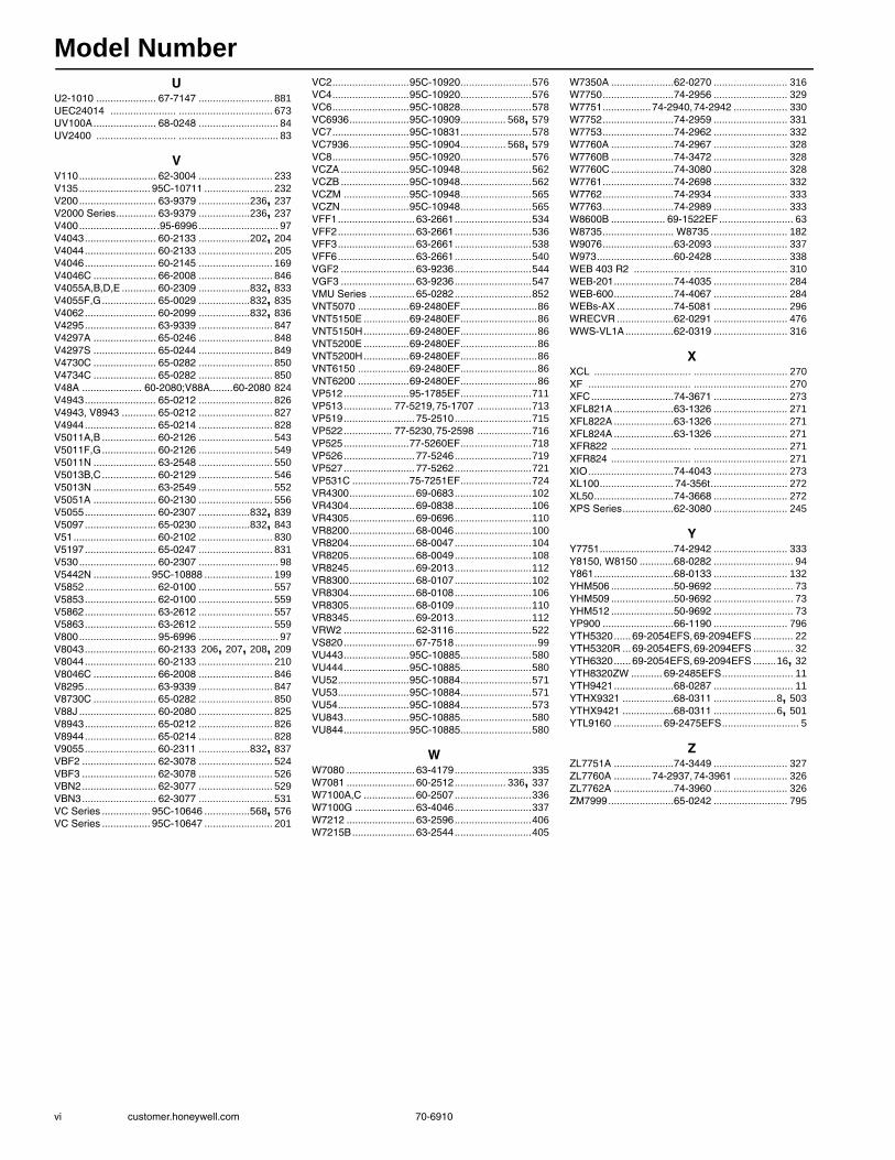
UU2-1010 ..................... 67-7147 .......................... 881UEC24014 ....................... ................................. 673UV100A...................... 68-0248 ............................ 84UV2400 ............................ ................................... 83
VV110........................... 62-3004 .......................... 233V135......................... 95C-10711 ........................ 232V200........................... 63-9379 ..................236, 237V2000 Series.............. 63-9379 ..................236, 237V400........................... .95-6996 ............................ 97V4043......................... 60-2133 ..................202, 204V4044......................... 60-2133 .......................... 205V4046......................... 60-2145 .......................... 169V4046C ...................... 66-2008 .......................... 846V4055A,B,D,E ............ 60-2309 ..................832, 833V4055F,G................... 65-0029 ..................832, 835V4062......................... 60-2099 ..................832, 836V4295......................... 63-9339 .......................... 847V4297A ...................... 65-0246 .......................... 848V4297S ...................... 65-0244 .......................... 849V4730C ...................... 65-0282 .......................... 850V4734C ...................... 65-0282 .......................... 850V48A ..................... 60-2080;V88A........60-2080 824V4943......................... 65-0212 .......................... 826V4943, V8943 ............ 65-0212 .......................... 827V4944......................... 65-0214 .......................... 828V5011A,B ................... 60-2126 .......................... 543V5011F,G................... 60-2126 .......................... 549V5011N ...................... 63-2548 .......................... 550V5013B,C................... 60-2129 .......................... 546V5013N ...................... 63-2549 .......................... 552V5051A ...................... 60-2130 .......................... 556V5055......................... 60-2307 ..................832, 839V5097......................... 65-0230 ..................832, 843V51............................. 60-2102 .......................... 830V5197......................... 65-0247 .......................... 831V530........................... 60-2307 ............................ 98V5442N .................... 95C-10888 ........................ 199V5852......................... 62-0100 .......................... 557V5853......................... 62-0100 .......................... 559V5862......................... 63-2612 .......................... 557V5863......................... 63-2612 .......................... 559V800........................... 95-6996 ............................ 97V8043......................... 60-2133 206, 207, 208, 209V8044......................... 60-2133 .......................... 210V8046C ...................... 66-2008 .......................... 846V8295......................... 63-9339 .......................... 847V8730C ...................... 65-0282 .......................... 850V88J ........................... 60-2080 .......................... 825V8943......................... 65-0212 .......................... 826V8944......................... 65-0214 .......................... 828V9055......................... 60-2311 ..................832, 837VBF2 .......................... 62-3078 .......................... 524VBF3 .......................... 62-3078 .......................... 526VBN2.......................... 62-3077 .......................... 529VBN3.......................... 62-3077 .......................... 531VC Series ................. 95C-10646 ................568, 576VC Series ................. 95C-10647 ........................ 201
VC2...........................95C-10920 .........................576VC4...........................95C-10920 .........................576VC6...........................95C-10828 .........................578VC6936.....................95C-10909 ................ 568, 579VC7...........................95C-10831 .........................578VC7936.....................95C-10904 ................ 568, 579VC8...........................95C-10920 .........................576VCZA ........................95C-10948 .........................562VCZB ........................95C-10948 .........................562VCZM .......................95C-10948 .........................565VCZN........................95C-10948 .........................565VFF1........................... 63-2661 ...........................534VFF2........................... 63-2661 ...........................536VFF3........................... 63-2661 ...........................538VFF6........................... 63-2661 ...........................540VGF2 .......................... 63-9236 ...........................544VGF3 .......................... 63-9236 ...........................547VMU Series ................ 65-0282 ...........................852VNT5070 ..................69-2480EF ...........................86VNT5150E ................69-2480EF ...........................86VNT5150H................69-2480EF ...........................86VNT5200E ................69-2480EF ...........................86VNT5200H................69-2480EF ...........................86VNT6150 ..................69-2480EF ...........................86VNT6200 ..................69-2480EF ...........................86VP512.......................95-1785EF .........................711VP513................. 77-5219, 75-1707 ...................713VP519......................... 75-2510 ...........................715VP522................. 77-5230, 75-2598 ...................716VP525.......................77-5260EF .........................718VP526......................... 77-5246 ...........................719VP527......................... 77-5262 ...........................721VP531C ....................75-7251EF .........................724VR4300....................... 69-0683 ...........................102VR4304....................... 69-0838 ...........................106VR4305....................... 69-0696 ...........................110VR8200....................... 68-0046 ...........................100VR8204....................... 68-0047 ...........................104VR8205....................... 68-0049 ...........................108VR8245....................... 69-2013 ...........................112VR8300....................... 68-0107 ...........................102VR8304....................... 68-0108 ...........................106VR8305....................... 68-0109 ...........................110VR8345....................... 69-2013 ...........................112VRW2 ......................... 62-3116 ...........................522VS820......................... 67-7518 .............................99VU443.......................95C-10885 .........................580VU444.......................95C-10885 .........................580VU52.........................95C-10884 .........................571VU53.........................95C-10884 .........................571VU54.........................95C-10884 .........................573VU843.......................95C-10885 .........................580VU844.......................95C-10885 .........................580
WW7080 ........................ 63-4179 ...........................335W7081 ........................ 60-2512 .................. 336, 337W7100A,C .................. 60-2507 ...........................336W7100G ..................... 63-4046 ...........................337W7212 ........................ 63-2596 ...........................406W7215B...................... 63-2544 ...........................405
W7350A ......................62-0270 .......................... 316W7750.........................74-2956 .......................... 329W7751................. 74-2940, 74-2942 ................... 330W7752.........................74-2959 .......................... 331W7753.........................74-2962 .......................... 332W7760A ......................74-2967 .......................... 328W7760B ......................74-3472 .......................... 328W7760C ......................74-3080 .......................... 328W7761.........................74-2698 .......................... 332W7762.........................74-2934 .......................... 333W7763.........................74-2989 .......................... 333W8600B ................... 69-1522EF .......................... 63W8735......................... W8735 ........................... 182W9076.........................63-2093 .......................... 337W973...........................60-2428 .......................... 338WEB 403 R2 .................... ................................. 310WEB-201.....................74-4035 .......................... 284WEB-600.....................74-4067 .......................... 284WEBs-AX ....................74-5081 .......................... 296WRECVR ....................62-0291 .......................... 476WWS-VL1A.................62-0319 .......................... 316
XXCL .................................. ................................. 270XF .................................... ................................. 270XFC.............................74-3671 .......................... 273XFL821A .....................63-1326 .......................... 271XFL822A .....................63-1326 .......................... 271XFL824A .....................63-1326 .......................... 271XFR822 ............................ ................................. 271XFR824 ............................ ................................. 271XIO..............................74-4043 .......................... 273XL100.......................... 74-356t ........................... 272XL50............................74-3668 .......................... 272XPS Series..................62-3080 .......................... 245
YY7751..........................74-2942 .......................... 333Y8150, W8150 ............68-0282 ............................ 94Y861............................68-0133 .......................... 132YHM506 ......................50-9692 ............................ 73YHM509 ......................50-9692 ............................ 73YHM512 ......................50-9692 ............................ 73YP900 .........................66-1190 .......................... 796YTH5320...... 69-2054EFS, 69-2094EFS .............. 22YTH5320R ...69-2054EFS, 69-2094EFS .............. 32YTH6320...... 69-2054EFS, 69-2094EFS ........16, 32YTH8320ZW ........... 69-2485EFS ......................... 11YTH9421.....................68-0287 ............................ 11YTHX9321 ..................68-0311 ......................8, 503YTHX9421 ..................68-0311 ......................6, 501YTL9160 ................. 69-2475EFS ........................... 5
ZZL7751A .....................74-3449 .......................... 327ZL7760A ............. 74-2937, 74-3961 ................... 326ZL7762A .....................74-3960 .......................... 326ZM7999.......................65-0242 .......................... 795

Subject Index
70-6910 vii
Numerics7800 SERIES 737–785
Accessories 785Data ControlBus Module 781Expanded Annunciator 783Keyboard Display Module 780ModBus Module 781Primary Control Modernization 867Purge Timers 784Remote Reset Module 782Replacement Parts 785Wiring subbases 778
AAccess and Video Systems 304–309
Accessories 308Cameras 304–306DVRs 304Lenses 307Licensing 304Mounting 308Power supplies 309
AccessoriesAccess and Video Systems 308Air Cleaners 62, 62–63
AIRWATCH Indicator 63Air Vents 220AquaPUMP 216AQUATROL Zoning System 192Cartridge Cage Valves 570Cartridge Globe Valves 560Combination Gas Controls 120–121Commercial Thermostats 510Damper and Valve Linkages 445Direct Coupled Damper Actuators 395–403Direct Coupled Valve Actuators 587Economizer Actuators 408Environmental Control Systems 338Excel 5000 System 275–278Fan and Limit Controllers 170Foot Mounted Motors 433Gas Ignition Module 134Globe Valves 553Industrial Flame Monitoring 882–886Kit Mounted Motors 439LonWorks Bus 274–275Magnetic Valves 169Modutrol IV Motors 433Pilot Burners, Residential 127Pneumatic 728–733Pneumatic Damper Actuators 705–706Pneumatic Pressure Controllers 673Pneumatic Relays 687Pneumatic Sensors 677Pneumatic Temperature Controllers 666Pneumatic Thermostats 658Pneumatic Valves 725Pneumatic Velocity Controls 662Relays 152Residential Thermostats 37–38Residential Ventilation 86Sail Switch 79Spyder Controllers 313Thermostatic Radiator Valves 242Thermostats
Communicating 517Digital Fan Coil 518RTU/Heat Pump 518Zoning 517
Fan Coil 491Line Volt 499Proportional 500Wireless Occupancy Solutions 493
TrueDRY 71–72TrueEASE 75TrueFRESH 86TrueSTEAM 74WEBs-AX Controllers 286Zone Control Dampers 50Zone Control Panel 43Zoning Dampers 49
Actuators 793–838ControLinks 793
Direct Coupled 794
Universal 793Dampers 333, 438, 439
Economizers 407–408Signal Adapters 408
Fire and Smoke applications 390–394Non-Spring Return 366–374Pneumatic 695–706
Accessories 705–706Piping Diagrams 704Replacement Parts 705–706Torque Ratings 695Unit Ventilator 696Variable Volume 700
Spring Return 375–389Delphi Combustion System 796Diverting Valve 232Flanged Globe Valves 543–555Fluid Power 832–838
Accessories 838Manual Reset Safety Shut-off 835Modulating 837Off-Lo-Hi 836On-Off 833Replacement Parts 838Selection Chart 832
Gas Valves 832–838Selection Chart 832
Residential Heating 199–201Thermostatic Mixing Valve 232Thermostatic Radiator 232–243Valves
Cartridge Globe 574Direct Coupled 580Fan Coil 580–581Pneumatic 707–710
Coil 707–708Replacement Parts 710
VC Series 576–579Fail Safe Proportional 579Proportional 578Two-position 576
AGA xviiAir Cleaners
Accessories 62–63AIRWATCH 63
Electronic 53–54Filters 65–67
EAC Media Post 65High Efficiency 53Power Supply 67Pressure Drop 54
FiltersHEPA 61TrueCLEAN 59
Media 55–56Filters 58–61
Perfect Fit 61POPUP 59Residential 58Return Grille 60
High Efficiency 55Pressure Drop 55, 57Replacement Filters 58–61
Power Supply 67TrueCLEAN 51–52
Air Eliminators 218–225Hydronic 224SuperVent 223, 224
Air PurifierAirBRIGHT 83
Air Vents 218–225Accessories 220Automatic 219–220, 221Capacities 218Commercial 221EARD 95for Heating Systems 220for Heating Systems and Cooling Systems 222for Hot Water Systems 221for Non-Heating Systems 219for Steam Systems 221Replacement Parts 220, 225Residential 221Universal 221
AirBRIGHT 83
Airstream Insertion Thermostat 646Alarms
Carbon Monoxide 96Ambistat Controller 342Approval agencies xviiAquaPUMP 216
Accessories 216Aquastat Controllers 171–183
Combination 183High Limit 174Multiple 176Oil Electronic 177Remote Bulb 173Triple Relay 178
Wiring 179AQUATROL Zoning System 185–193
Accessories 192Boiler Control 185, 187Mixing 189Relay Control 185, 186Replacement Control Modules 191Replacement Parts 192Replacement Zoning Modules 191Temperature Injection Control 189Thermostats 193Universal Injection/Mixing 188Zoning Expansion 190
Australia Gas Association xviiAuxiliary Potentiometer 435
BBackflow Preventers 226
Installation 226Ball Valves 524–533
Flanged 524, 526Threaded 529, 531Three-way 526, 531Two-way 524, 529
Boiler ControlElectronic 185, 187Mixing 188Relay 185Universal Injection 188
Boiler Fill Valves 227Building Automation 267–338Building Automation Appliances 315–316Burner and Boiler Controls
Training Booklets 892Burner Controls 798
Fireye Replacement 776Oxygen Sensor 798
Burner management systems 879–887Butterfly Control Valves 534–542
Three-way 536, 538, 540Two-way 534, 536
Butterfly Gas Valves 830–831Gas or Air 830Replacement Parts 830
Bypass Damper 44Replacement Parts 44
Bypass Humidifiers 76–77
CCadmium Sulfide Flame Detectors 168Cage Valves 556Cameras
Access and Video Systems 304–306Canadian Standards Association xviiCarbon Monoxide Alarm 96Cartridge Cage Valves 562–570
Three-way 565Two-way 562VC Series 568
Cartridge Changing Procedure 243Cartridge Globe Valve Actuators 574, 575Cartridge Globe Valves 557–561
Three-way 559Two-way 557
CE Mark xviiChangeover Temperature Controller 352Combination Gas Controls 97–121

Subject Index
viii customer.honeywell.com 70-6910
Accessories 120–121Continuous Pilot 100Direct Ignition 108, 110Intermittent Pilot 104, 106Millivoltage 99Replacement Parts 120–121SmartValves 116–119Standing Pilot 102Universal Electronic Ignition 112
Commercial Expansion Tanks 244–245Sizing 244
Commercial Hydronic Controllers 820Accessories 820
Commercial ThermostatsCommunicating
Accessories 518Digital Fan Coil 513
ProgrammableAccessories 510
Commercial VisionPRO® 13CommercialPRO 7000 Thermostat 507CommercialPRO® 14, 507Communicating Thermostats 193, 511–518
CommercialDigital Fan Coil 513
Accessories 518Commercial Accessories 517Hydronic 193RTU/Heat Pump Accessories 518Zoning 512
Accessories 517Compact I/O 273Configurable 317Contactors 139–147
1 pole 140, 1442 pole 141, 1443 pole 1424 pole 143Auxiliary Switches 145Definite Purpose 139–147
Deluxe 140–143Economy 144
Economy 144–147Electric Heat 145
Selection Guide 147Order Number Guide 139Selection Guide 146
Continuous Pilot Gas Control 100Wiring 101
Control Ball Valves 524–533Control Panel 185–189
Hydronic Zoning System 185–192ControLinks Fuel Air Control System 791–795
Accessories 794, 795Controller 791Demonstrator 899Direct Coupled Actuator 794Display Demo 899System Configuration Software 795System Display 792Universal Actuator 793Wiring Subbase 792
ControllersAquastat 171–183
Combination 183High Limit 174Multiple 176Oil Electronic 177Remote Bulb 173Triple Relay 178
CVAHU 329Digital IAQ
HumidiPRO 80TrueIAQ 80
Excel 100 272Excel 15 328Excel 50 272Excel 800 270Fan Coil 331HumidiPRO 80Humidity 81–82Hydronic 333Lighting
Stryker Configurable 317
Limit 336Refrigeration 339–340
Temperature 340Spyder 312–313Temperature
Ambistat 342Changeover 352Crop-Trol 351Discharge Air 336Discharge Water 337Farm 346Line Voltage 345NEMA IV 347Proportional 357–359Remote
Accessories 360Remote Bulb 348
Accessories 359Parts 360
Reset 873–875Dual Bulb 874Outdoor 873, 874Proportional 875
Return Air 344Solid State Remote 353Special Stand-Alone 356Stand-Alone 354Unit Thermostats 343
Type definition xviUnit Vent 332VAV Unit 330, 333WEBs R2 System 310–311WEBs-AX 284–292WEBs-AX Security 296WEBs-AX Suite 284–286
Accessories 286WebStat 316WebVision 316
Controls 185–245Hydronic 185–245Pneumatic 643–736
Conversion factors xxConversion of pressure units xixCovers
TP9600 Series Thermostats 657TP970 Series Thermostats 657
Crop-Trol Controller 351Cross Reference
CP980 662Electric Heat Sequencer 155Igniter Bracket Replacement 135Line Volt Thermostats 497Oil Primaries 164, 165Residential Gas Valves 115V2000 to V100 236Velocity Sensor Controller 662
CSA xviiCVAHU Controllers 329
DDamper Actuators 333
AccessoriesCompatibility Chart 396, 397
Economizers 407–408Signal Adapters 408
Fast Acting 389, 390, 392, 393Fire and Smoke applications 390–394Non-Spring Return 366–374Pneumatic 695–706
Accessories 705–706Piping Diagrams 704Replacement Parts 705–706Torque Ratings 695Unit Ventilator 696Variable Volume 700
Spring Return 375–389Damper and Valve Linkages
Accessories 445Butterfly Valves 440Economizer Motors 440Modutrol IV Motors 442Modutrol Motors 441Tandem 444
Dampers 44Bypass 44Rectangular 361–363
Flange options 361, 362Round 364–365Volume control 362Zone Control 45–49
Round 45, 46Data Acquisition Module 799Definite Purpose Contactors 139–147
1 pole 140, 1442 pole 141, 1443 pole 1424 pole 143
Definitions, Pneumatic 734–736Dehumidification
TrueDRY 68–72Accessories 71–72
Delphi Combustion System 796–797Accessories 797Actuator 796Replacement Parts 797
Diaphragm Gas Valves 824–829Accessories 829High Temperature 825On/Off 826Pressure Regulating 827, 828Replacement Parts 829
Differential Pressure Regulators 217Capacities 217
Digital Bath Fan Control 95Digital IAQ Control
HumidiPRO 80TrueIAQ 80
Digital Temperature Indicator 337Direct Coupled Actuators
Dampers 366–403Accessories 395–403Fire and Smoke applications 390–394Non-Spring Return 366–374Spring Return 375–389
Valves 582–587Tandem Linkage 444
Direct Ignition Gas Control 113Wiring 109, 111
DirectConnectInstallation 253Pressure Drop 253, 254Thermostatic Mixing Valves 252Thermostatic Mixing Valves Kits 254
DisplaysExcel 15 329WEBs-AX 290
Distributors7800 Series xxivAuthorized Distributors xxivAuthorized Systems xxivCombustion Solutions xxivCommercial Controls xxivControLinks™ xxiv
DVD 891Heating Controls 891
DVRsAccess and Video Systems 304
EEARD Fresh Air Damper 95Economizer Sensors 409–411Economizer Systems 891
Training DVD 891Economizers 404–411
Damper Actuators 407–408Linkages 440Signal Adapters 408
Logic Modules 404–406Demand Control Ventilation 406Enhanced 405JADE 404PC Interface 405Replacement Parts 406
Sensors 409–411Enthalpy 410Humidity 411
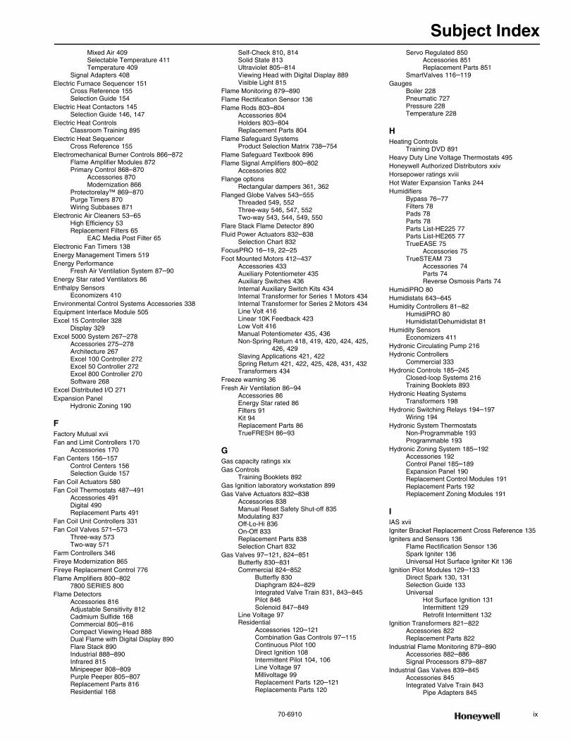
Subject Index
70-6910 ix
Mixed Air 409Selectable Temperature 411Temperature 409
Signal Adapters 408Electric Furnace Sequencer 151
Cross Reference 155Selection Guide 154
Electric Heat Contactors 145Selection Guide 146, 147
Electric Heat ControlsClassroom Training 895
Electric Heat SequencerCross Reference 155
Electromechanical Burner Controls 866–872Flame Amplifier Modules 872Primary Control 868–870
Accessories 870Modernization 866
Protectorelay™ 869–870Purge Timers 870Wiring Subbases 871
Electronic Air Cleaners 53–65High Efficiency 53Replacement Filters 65
EAC Media Post Filter 65Electronic Fan Timers 138Energy Management Timers 519Energy Performance
Fresh Air Ventilation System 87–90Energy Star rated Ventilators 86Enthalpy Sensors
Economizers 410Environmental Control Systems Accessories 338Equipment Interface Module 505Excel 15 Controller 328
Display 329Excel 5000 System 267–278
Accessories 275–278Architecture 267Excel 100 Controller 272Excel 50 Controller 272Excel 800 Controller 270Software 268
Excel Distributed I/O 271Expansion Panel
Hydronic Zoning 190
FFactory Mutual xviiFan and Limit Controllers 170
Accessories 170Fan Centers 156–157
Control Centers 156Selection Guide 157
Fan Coil Actuators 580Fan Coil Thermostats 487–491
Accessories 491Digital 490Replacement Parts 491
Fan Coil Unit Controllers 331Fan Coil Valves 571–573
Three-way 573Two-way 571
Farm Controllers 346Fireye Modernization 865Fireye Replacement Control 776Flame Amplifiers 800–802
7800 SERIES 800Flame Detectors
Accessories 816Adjustable Sensitivity 812Cadmium Sulfide 168Commercial 805–816Compact Viewing Head 888Dual Flame with Digital Display 890Flare Stack 890Industrial 888–890Infrared 815Minipeeper 808–809Purple Peeper 805–807Replacement Parts 816Residential 168
Self-Check 810, 814Solid State 813Ultraviolet 805–814Viewing Head with Digital Display 889Visible Light 815
Flame Monitoring 879–890Flame Rectification Sensor 136Flame Rods 803–804
Accessories 804Holders 803–804Replacement Parts 804
Flame Safeguard SystemsProduct Selection Matrix 738–754
Flame Safeguard Textbook 896Flame Signal Amplifiers 800–802
Accessories 802Flange options
Rectangular dampers 361, 362Flanged Globe Valves 543–555
Threaded 549, 552Three-way 546, 547, 552Two-way 543, 544, 549, 550
Flare Stack Flame Detector 890Fluid Power Actuators 832–838
Selection Chart 832FocusPRO 16–19, 22–25Foot Mounted Motors 412–437
Accessories 433Auxiliary Potentiometer 435Auxiliary Switches 436Internal Auxiliary Switch Kits 434Internal Transformer for Series 1 Motors 434Internal Transformer for Series 2 Motors 434Line Volt 416Linear 10K Feedback 423Low Volt 416Manual Potentiometer 435, 436Non-Spring Return 418, 419, 420, 424, 425,
426, 429Slaving Applications 421, 422Spring Return 421, 422, 425, 428, 431, 432Transformers 434
Freeze warning 36Fresh Air Ventilation 86–94
Accessories 86Energy Star rated 86Filters 91Kit 94Replacement Parts 86TrueFRESH 86–93
GGas capacity ratings xixGas Controls
Training Booklets 892Gas Ignition laboratory workstation 899Gas Valve Actuators 832–838
Accessories 838Manual Reset Safety Shut-off 835Modulating 837Off-Lo-Hi 836On-Off 833Replacement Parts 838Selection Chart 832
Gas Valves 97–121, 824–851Butterfly 830–831Commercial 824–852
Butterfly 830Diaphgram 824–829Integrated Valve Train 831, 843–845Pilot 846Solenoid 847–849
Line Voltage 97Residential
Accessories 120–121Combination Gas Controls 97–115Continuous Pilot 100Direct Ignition 108Intermittent Pilot 104, 106Line Voltage 97Millivoltage 99Replacement Parts 120–121Replacements Parts 120
Servo Regulated 850Accessories 851Replacement Parts 851
SmartValves 116–119Gauges
Boiler 228Pneumatic 727Pressure 228Temperature 228
HHeating Controls
Training DVD 891Heavy Duty Line Voltage Thermostats 495Honeywell Authorized Distributors xxivHorsepower ratings xviiiHot Water Expansion Tanks 244Humidifiers
Bypass 76–77Filters 78Pads 78Parts 78Parts List-HE225 77Parts List-HE265 77TrueEASE 75
Accessories 75TrueSTEAM 73
Accessories 74Parts 74Reverse Osmosis Parts 74
HumidiPRO 80Humidistats 643–645Humidity Controllers 81–82
HumidiPRO 80Humidistat/Dehumidistat 81
Humidity SensorsEconomizers 411
Hydronic Circulating Pump 216Hydronic Controllers
Commercial 333Hydronic Controls 185–245
Closed-loop Systems 216Training Booklets 893
Hydronic Heating SystemsTransformers 198
Hydronic Switching Relays 194–197Wiring 194
Hydronic System ThermostatsNon-Programmable 193Programmable 193
Hydronic Zoning System 185–192Accessories 192Control Panel 185–189Expansion Panel 190Replacement Control Modules 191Replacement Parts 192Replacement Zoning Modules 191
IIAS xviiIgniter Bracket Replacement Cross Reference 135Igniters and Sensors 136
Flame Rectification Sensor 136Spark Igniter 136Universal Hot Surface Igniter Kit 136
Ignition Pilot Modules 129–133Direct Spark 130, 131Selection Guide 133Universal
Hot Surface Ignition 131Intermittent 129Retrofit Intermittent 132
Ignition Transformers 821–822Accessories 822Replacement Parts 822
Industrial Flame Monitoring 879–890Accessories 882–886Signal Processors 879–887
Industrial Gas Valves 839–845Accessories 845Integrated Valve Train 843
Pipe Adapters 845
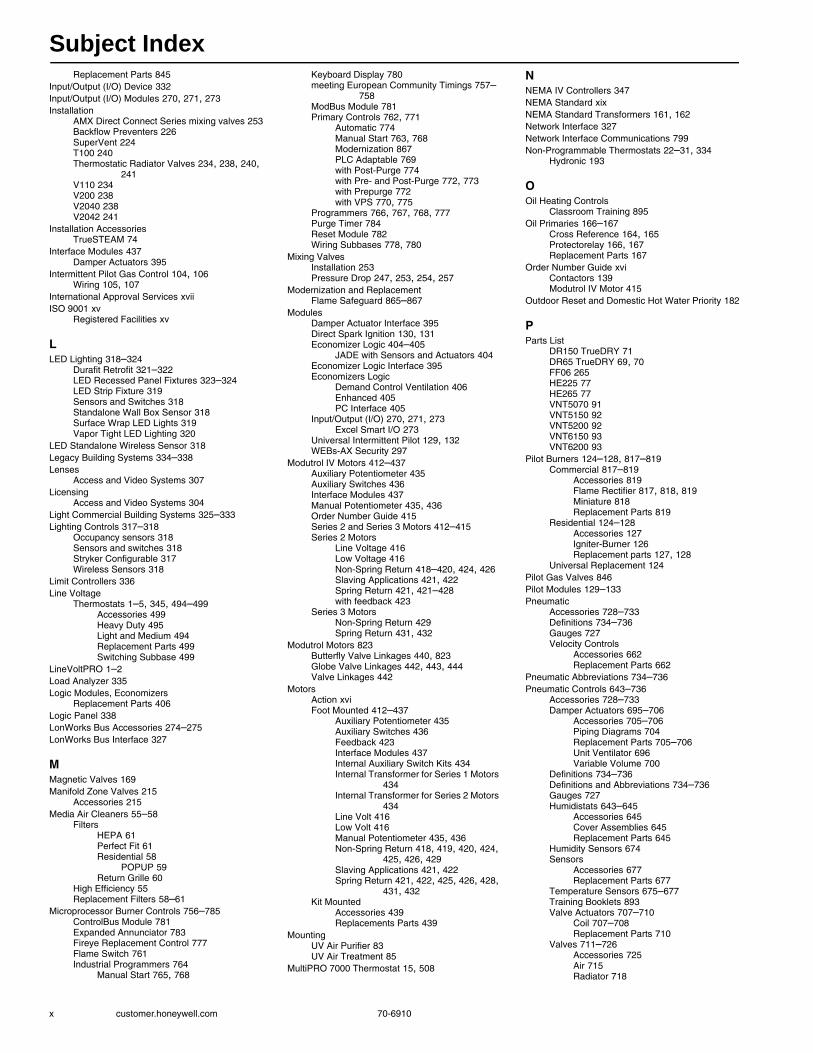
Subject Index
x customer.honeywell.com 70-6910
Replacement Parts 845Input/Output (I/O) Device 332Input/Output (I/O) Modules 270, 271, 273Installation
AMX Direct Connect Series mixing valves 253Backflow Preventers 226SuperVent 224T100 240Thermostatic Radiator Valves 234, 238, 240,
241V110 234V200 238V2040 238V2042 241
Installation AccessoriesTrueSTEAM 74
Interface Modules 437Damper Actuators 395
Intermittent Pilot Gas Control 104, 106Wiring 105, 107
International Approval Services xviiISO 9001 xv
Registered Facilities xv
LLED Lighting 318–324
Durafit Retrofit 321–322LED Recessed Panel Fixtures 323–324LED Strip Fixture 319Sensors and Switches 318Standalone Wall Box Sensor 318Surface Wrap LED Lights 319Vapor Tight LED Lighting 320
LED Standalone Wireless Sensor 318Legacy Building Systems 334–338Lenses
Access and Video Systems 307Licensing
Access and Video Systems 304Light Commercial Building Systems 325–333Lighting Controls 317–318
Occupancy sensors 318Sensors and switches 318Stryker Configurable 317Wireless Sensors 318
Limit Controllers 336Line Voltage
Thermostats 1–5, 345, 494–499Accessories 499Heavy Duty 495Light and Medium 494Replacement Parts 499Switching Subbase 499
LineVoltPRO 1–2Load Analyzer 335Logic Modules, Economizers
Replacement Parts 406Logic Panel 338LonWorks Bus Accessories 274–275LonWorks Bus Interface 327
MMagnetic Valves 169Manifold Zone Valves 215
Accessories 215Media Air Cleaners 55–58
FiltersHEPA 61Perfect Fit 61Residential 58
POPUP 59Return Grille 60
High Efficiency 55Replacement Filters 58–61
Microprocessor Burner Controls 756–785ControlBus Module 781Expanded Annunciator 783Fireye Replacement Control 777Flame Switch 761Industrial Programmers 764
Manual Start 765, 768
Keyboard Display 780meeting European Community Timings 757–
758ModBus Module 781Primary Controls 762, 771
Automatic 774Manual Start 763, 768Modernization 867PLC Adaptable 769with Post-Purge 774with Pre- and Post-Purge 772, 773with Prepurge 772with VPS 770, 775
Programmers 766, 767, 768, 777Purge Timer 784Reset Module 782Wiring Subbases 778, 780
Mixing ValvesInstallation 253Pressure Drop 247, 253, 254, 257
Modernization and ReplacementFlame Safeguard 865–867
ModulesDamper Actuator Interface 395Direct Spark Ignition 130, 131Economizer Logic 404–405
JADE with Sensors and Actuators 404Economizer Logic Interface 395Economizers Logic
Demand Control Ventilation 406Enhanced 405PC Interface 405
Input/Output (I/O) 270, 271, 273Excel Smart I/O 273
Universal Intermittent Pilot 129, 132WEBs-AX Security 297
Modutrol IV Motors 412–437Auxiliary Potentiometer 435Auxiliary Switches 436Interface Modules 437Manual Potentiometer 435, 436Order Number Guide 415Series 2 and Series 3 Motors 412–415Series 2 Motors
Line Voltage 416Low Voltage 416Non-Spring Return 418–420, 424, 426Slaving Applications 421, 422Spring Return 421, 421–428with feedback 423
Series 3 MotorsNon-Spring Return 429Spring Return 431, 432
Modutrol Motors 823Butterfly Valve Linkages 440, 823Globe Valve Linkages 442, 443, 444Valve Linkages 442
MotorsAction xviFoot Mounted 412–437
Auxiliary Potentiometer 435Auxiliary Switches 436Feedback 423Interface Modules 437Internal Auxiliary Switch Kits 434Internal Transformer for Series 1 Motors
434Internal Transformer for Series 2 Motors
434Line Volt 416Low Volt 416Manual Potentiometer 435, 436Non-Spring Return 418, 419, 420, 424,
425, 426, 429Slaving Applications 421, 422Spring Return 421, 422, 425, 426, 428,
431, 432Kit Mounted
Accessories 439Replacements Parts 439
MountingUV Air Purifier 83UV Air Treatment 85
MultiPRO 7000 Thermostat 15, 508
NNEMA IV Controllers 347NEMA Standard xixNEMA Standard Transformers 161, 162Network Interface 327Network Interface Communications 799Non-Programmable Thermostats 22–31, 334
Hydronic 193
OOil Heating Controls
Classroom Training 895Oil Primaries 166–167
Cross Reference 164, 165Protectorelay 166, 167Replacement Parts 167
Order Number Guide xviContactors 139Modutrol IV Motor 415
Outdoor Reset and Domestic Hot Water Priority 182
PParts List
DR150 TrueDRY 71DR65 TrueDRY 69, 70FF06 265HE225 77HE265 77VNT5070 91VNT5150 92VNT5200 92VNT6150 93VNT6200 93
Pilot Burners 124–128, 817–819Commercial 817–819
Accessories 819Flame Rectifier 817, 818, 819Miniature 818Replacement Parts 819
Residential 124–128Accessories 127Igniter-Burner 126Replacement parts 127, 128
Universal Replacement 124Pilot Gas Valves 846Pilot Modules 129–133Pneumatic
Accessories 728–733Definitions 734–736Gauges 727Velocity Controls
Accessories 662Replacement Parts 662
Pneumatic Abbreviations 734–736Pneumatic Controls 643–736
Accessories 728–733Damper Actuators 695–706
Accessories 705–706Piping Diagrams 704Replacement Parts 705–706Unit Ventilator 696Variable Volume 700
Definitions 734–736Definitions and Abbreviations 734–736Gauges 727Humidistats 643–645
Accessories 645Cover Assemblies 645Replacement Parts 645
Humidity Sensors 674Sensors
Accessories 677Replacement Parts 677
Temperature Sensors 675–677Training Booklets 893Valve Actuators 707–710
Coil 707–708Replacement Parts 710
Valves 711–726Accessories 725Air 715Radiator 718
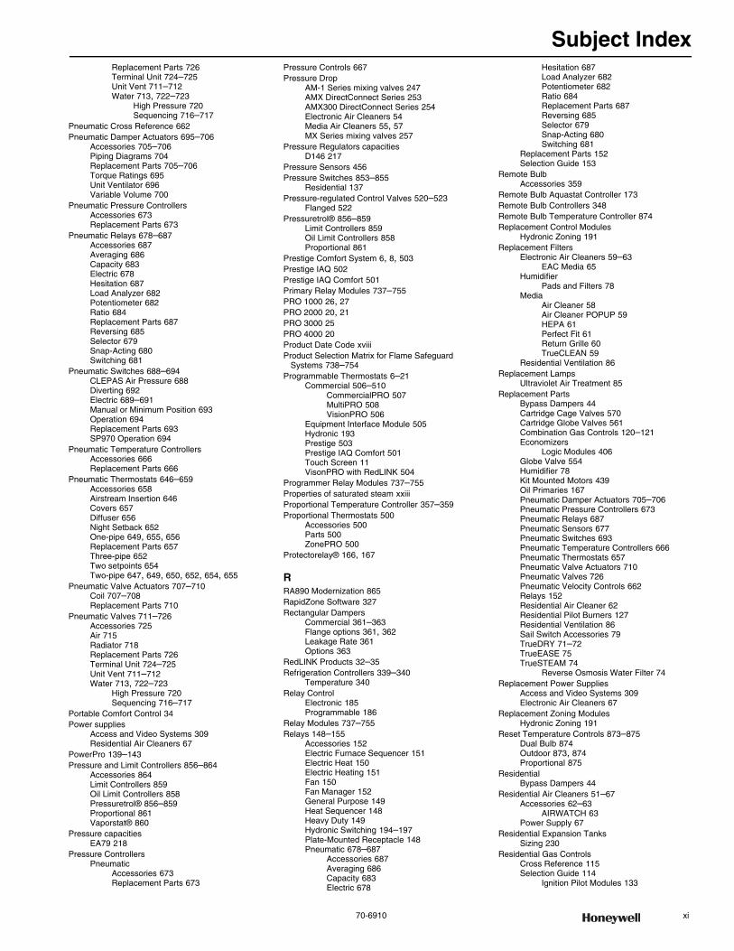
Subject Index
70-6910 xi
Replacement Parts 726Terminal Unit 724–725Unit Vent 711–712Water 713, 722–723
High Pressure 720Sequencing 716–717
Pneumatic Cross Reference 662Pneumatic Damper Actuators 695–706
Accessories 705–706Piping Diagrams 704Replacement Parts 705–706Torque Ratings 695Unit Ventilator 696Variable Volume 700
Pneumatic Pressure ControllersAccessories 673Replacement Parts 673
Pneumatic Relays 678–687Accessories 687Averaging 686Capacity 683Electric 678Hesitation 687Load Analyzer 682Potentiometer 682Ratio 684Replacement Parts 687Reversing 685Selector 679Snap-Acting 680Switching 681
Pneumatic Switches 688–694CLEPAS Air Pressure 688Diverting 692Electric 689–691Manual or Minimum Position 693Operation 694Replacement Parts 693SP970 Operation 694
Pneumatic Temperature ControllersAccessories 666Replacement Parts 666
Pneumatic Thermostats 646–659Accessories 658Airstream Insertion 646Covers 657Diffuser 656Night Setback 652One-pipe 649, 655, 656Replacement Parts 657Three-pipe 652Two setpoints 654Two-pipe 647, 649, 650, 652, 654, 655
Pneumatic Valve Actuators 707–710Coil 707–708Replacement Parts 710
Pneumatic Valves 711–726Accessories 725Air 715Radiator 718Replacement Parts 726Terminal Unit 724–725Unit Vent 711–712Water 713, 722–723
High Pressure 720Sequencing 716–717
Portable Comfort Control 34Power supplies
Access and Video Systems 309Residential Air Cleaners 67
PowerPro 139–143Pressure and Limit Controllers 856–864
Accessories 864Limit Controllers 859Oil Limit Controllers 858Pressuretrol® 856–859Proportional 861Vaporstat® 860
Pressure capacitiesEA79 218
Pressure ControllersPneumatic
Accessories 673Replacement Parts 673
Pressure Controls 667Pressure Drop
AM-1 Series mixing valves 247AMX DirectConnect Series 253AMX300 DirectConnect Series 254Electronic Air Cleaners 54Media Air Cleaners 55, 57MX Series mixing valves 257
Pressure Regulators capacitiesD146 217
Pressure Sensors 456Pressure Switches 853–855
Residential 137Pressure-regulated Control Valves 520–523
Flanged 522Pressuretrol® 856–859
Limit Controllers 859Oil Limit Controllers 858Proportional 861
Prestige Comfort System 6, 8, 503Prestige IAQ 502Prestige IAQ Comfort 501Primary Relay Modules 737–755PRO 1000 26, 27PRO 2000 20, 21PRO 3000 25PRO 4000 20Product Date Code xviiiProduct Selection Matrix for Flame Safeguard
Systems 738–754Programmable Thermostats 6–21
Commercial 506–510CommercialPRO 507MultiPRO 508VisionPRO 506
Equipment Interface Module 505Hydronic 193Prestige 503Prestige IAQ Comfort 501Touch Screen 11VisonPRO with RedLINK 504
Programmer Relay Modules 737–755Properties of saturated steam xxiiiProportional Temperature Controller 357–359Proportional Thermostats 500
Accessories 500Parts 500ZonePRO 500
Protectorelay® 166, 167
RRA890 Modernization 865RapidZone Software 327Rectangular Dampers
Commercial 361–363Flange options 361, 362Leakage Rate 361Options 363
RedLINK Products 32–35Refrigeration Controllers 339–340
Temperature 340Relay Control
Electronic 185Programmable 186
Relay Modules 737–755Relays 148–155
Accessories 152Electric Furnace Sequencer 151Electric Heat 150Electric Heating 151Fan 150Fan Manager 152General Purpose 149Heat Sequencer 148Heavy Duty 149Hydronic Switching 194–197Plate-Mounted Receptacle 148Pneumatic 678–687
Accessories 687Averaging 686Capacity 683Electric 678
Hesitation 687Load Analyzer 682Potentiometer 682Ratio 684Replacement Parts 687Reversing 685Selector 679Snap-Acting 680Switching 681
Replacement Parts 152Selection Guide 153
Remote BulbAccessories 359
Remote Bulb Aquastat Controller 173Remote Bulb Controllers 348Remote Bulb Temperature Controller 874Replacement Control Modules
Hydronic Zoning 191Replacement Filters
Electronic Air Cleaners 59–63EAC Media 65
HumidifierPads and Filters 78
MediaAir Cleaner 58Air Cleaner POPUP 59HEPA 61Perfect Fit 61Return Grille 60TrueCLEAN 59
Residential Ventilation 86Replacement Lamps
Ultraviolet Air Treatment 85Replacement Parts
Bypass Dampers 44Cartridge Cage Valves 570Cartridge Globe Valves 561Combination Gas Controls 120–121Economizers
Logic Modules 406Globe Valve 554Humidifier 78Kit Mounted Motors 439Oil Primaries 167Pneumatic Damper Actuators 705–706Pneumatic Pressure Controllers 673Pneumatic Relays 687Pneumatic Sensors 677Pneumatic Switches 693Pneumatic Temperature Controllers 666Pneumatic Thermostats 657Pneumatic Valve Actuators 710Pneumatic Valves 726Pneumatic Velocity Controls 662Relays 152Residential Air Cleaner 62Residential Pilot Burners 127Residential Ventilation 86Sail Switch Accessories 79TrueDRY 71–72TrueEASE 75TrueSTEAM 74
Reverse Osmosis Water Filter 74Replacement Power Supplies
Access and Video Systems 309Electronic Air Cleaners 67
Replacement Zoning ModulesHydronic Zoning 191
Reset Temperature Controls 873–875Dual Bulb 874Outdoor 873, 874Proportional 875
ResidentialBypass Dampers 44
Residential Air Cleaners 51–67Accessories 62–63
AIRWATCH 63Power Supply 67
Residential Expansion TanksSizing 230
Residential Gas ControlsCross Reference 115Selection Guide 114
Ignition Pilot Modules 133
Subject Index
xii customer.honeywell.com 70-6910
Thermopiles and Thermocouples 123Retrofit
Durafit LED 321Round Dampers 46
Return Air Controller 344Round Dampers
Commercial 364–365Residential 44–46
Round Thermostat 28
SSail Switches 79, 341
Accessories 79Selection Chart
Industrial Gas Valves and Fluid Actuators 832Selection Guide
Contactors 146Electric Heat Contactors 147Electric Heat Sequencer 154, 155Fan Center 157Ignition Pilot Modules 133Relays 153Residential Gas Valves 114SmartValve 119Thermopiles and Thermocouples 123Transformers 164
Selection MatrixFlame Safeguard Systems 737–754
Sensors 409–411, 446–486Carbon Dioxide 446–447Current 448–450Dewpoint 451Economizer 409–411Economizers
Enthalpy 410Humidity 411Mixed Air 409Selectable Temperature 411Temperature 409
Flame rectification 136Humidity 452–454
Transducers 452Pneumatic
Humidity 674Temperature 675–677
Pressure 455–456Temperature 457–479
Accessories 461, 463, 468, 478Air 463, 467Duct Mounted 463, 465, 466, 467Electronic 461Immersion 464Indoor 35Outdoor 35Replacement Parts 461, 474Return Air 35Wall Module 469, 472, 473Wall Mounted 464Wireless 476Wireless Kits 475Zio Modules 477–479
Setback Thermostat 652Signal Adapters
Economizers 408Signal Processors 879–887
1 Channel 8812 Channels and Keypad 880Combination DC 881Flame Rod 879WATCHDOGIII Flare Stack 880
Slave Motors 421, 422SmartValves 116–119
Selection Guide 119SmartVFD COMPACT 588–591
Accessories 609SmartVFD HVAC 592–594
Accessories 609SmartVFD HVAC and SmartVFD BYPASS 595–609Software
CARE 268ControLinks System Configuration 795LonSpec Configuration 326LonStation 326
RapidZone 327SymmetrE 268WEBs R2 310WEBs-AX Platform 291WEBs-AX Security Enterprise 295WEBs-AX System 280
SOLA Controllers 786–787Accessories 790Parts 790Program Module 790
SOLA Displays 788–789Solenoid Gas Valves 847–849
Accessories 849Normally Open 849Replacement Parts 849Safety Shut-off 848
Solid State Remote Temperature Controller 353Special Stand-Alone Controllers 356Spyder Controllers 312–313
Accessories 313Stand-Alone Controllers 354Standing Pilot Gas Control
Wiring 103Steam
Properties of saturated steam xxiiiSteam valve selection xxiSteam Valves
Calculations of Factor A xxiCv final Calculation xxiiProperties of saturated steam
valves xxiiiSubbase 334
Switching 334Submeters 480–486
Data Recorder 484Integration Nodes 486Networked Power Meters 485
SuiperVentInstallation 224
Supply Air Ventilation 94–95Digital Fan Control 95EARD 95Fresh Air 94Wireless and Filter Boost Remote 95
SurveillanceVideo 307
SwitchesPneumatic 688–694
CLEPAS Air Pressure 688Diverting 692Electric 689–691Manual or Minimum Position 693Operation 694Replacement Parts 693SP970 Operation 694
Switching Subbase 499SymmetrE Building Management System 268
TTandem Linkages 444Tanks
Commercial Expansion 244Sizing 244
Residential Expansion 229–231Temperature Controllers 342–360
Ambistat 342Changeover 352Crop-Trol 351Discharge Air 336Discharge Water 337Farm 346Line Voltage Thermostat 345NEMA IV Controllers 347Pneumatic
Accessories 666Replacement Parts 666
Proportional 357–359Remote Bulb 348
Accessories 359Parts 360
Remote ControllerAccessories 360
Reset 873–875
Dual Bulb 874Outdoor 873, 874Proportional 875
Return Air 344Solid State Remote 353Special Stand-Alone 356Stand-Alone 354Unit Thermostat 343Utility Line Voltage 345
Temperature Indicator 337Temperature Sensors
Economizers 409Selectable 411
Indoor 35Outdoor 35Return Air 35
Testers and Demonstrators 876–8787800 SERIES 876Flame Simulator 878Primary Controls Tester 878Replacement Parts 876, 878SOLA Demonstrators 877
ThermocouplesUniversal 122
Thermocouples and Thermopiles 122–123Accessories 123Selection Guide 123
ThermometersThreaded 228with Thermowells 228
ThermopilesReplacement Generators 122
Thermostat Guards 39–40Thermostatic Radiator Valves
Cartridge balancing 242Cartridge Balancing Procedure 242Cartridge Changing Procedure 243Cross Reference 236Installation 234, 238, 240
Steam 241Thermostats 334
Accessories 37–38Communicating 511–518
Accessories 517Commercial
Digital Fan Coil 513Accessories 518
Hydronic 193Programmable 511RTU/Heat Pump
Accessories 518Zoning 512
Accessories 517Dual Setpoint 335Economy 3Electric Heat 1–5Fan Coil 487–491Hydronic 193Line Volt
Cross Reference 497Switching Subbase 499
Line Voltage 345Heavy Duty 495Light and Medium Duty 494Switching Subbase 499
Mercury Free 29–30Modulating/Floating 500Non-Programmable 22–31, 334Pneumatic
Accessories 658Airstream Insertion 646
Programmable 1–2, 6–21Commercial 506–510
Accessories 510CommercialPRO 507MultiPRO 508VisionPRO 506
Equipment Interface Module 505Prestige 503Prestige IAQ 502Prestige IAQ Comfort 501Touch Screen 11VisionPRO with RedLINK 504
Proportional 500Accessories 500
Subject Index
70-6910 xiii
Parts 500ZonePRO 500
Round 28Setback 652Unit 343Wireless 22, 23Wireless Occupancy 492–493
Thermostats, Pneumatic 646–659Accessories 658Covers 657Diffuser 656Night Setback 652One-pipe 649, 655, 656Replacement Parts 657Three-pipe 652Two setpoints 654Two-pipe 647, 649, 650, 652, 654, 655
TimersEnergy Management 519
Transformers 158–164Circuit Breaker 160General Purpose 158, 159Hydronic Heating Controls 198NEMA Standard 161, 162Selection Guide 164Universal Stripped-Down 161
Tridicators 228TrueCLEAN 51–52
Filters 59Wiring 51
TrueDRY 68–71Accessories 71Dehumidification System 68Parts List-DR150 71Parts List-DR65 69, 70
TrueEASE 75Accessories 75
TrueFRESH 86–93Accessories 86Energy Performance 87–90Filters 91Parts List
VNT5070 91VNT5150 92VNT5200 92VNT6150 93VNT6200 93
Ventilation Performance 87–90TrueIAQ 80TrueSTEAM 73–74
Installation Accessories 74Parts 74Reverse Osmosis 74
TrueZONE 41, 42, 44
UUltraviolet Air Treatment 83–85
AirBRIGHT Odor Absorption 83Replacement Lamp 85UV Air Purifier 83
Underwriters Laboratories Inc xviiof Canada xvii
Unit Thermostat Controller 343Unit Vent Controllers 332UV Air System
Mounting 83, 85
VV2000 Series
Cartridge Balancing Procedure 242Valve Actuators
Cartridge Globe 574, 575Direct Coupled 582–587
Linear 585, 586Non-Spring Return 582, 583Spring Return 584
Fan Coil 580–581Pneumatic 707–710
Coil 707–708Replacement Parts 710
VS Series 576–579Fail Safe Proportional 579
Proportional 578Two-position 576
Valve and Actuator Assemblies 568Valves 534, 824–851
Boiler Fill 227Butterfly Control 534–542
Three-way 538, 540Two-way 534, 536
Cage 556Cartridge Cage 562–570
Three-way 565Two-way 562VC Series 568
Cartridge Globe 557–561Three-way 559Two-way 557
Control Ball 524–533Flanged 524, 526Threaded 529, 531Three-way 526, 531Two-way 524, 529
Diverting 232Replacement Cartridges 232
Fan Coil 571–573Three-way 573Two-way 571
Flanged Globe 543–552Three-way 546, 547, 552Two-way 543, 544, 549, 550
Gas 824–851Commercial 824–852
Butterfly 830Diaphgram 824–829Integrated Valve Train 831, 843–
845Pilot 846Solenoid 847–849
Residential 97–115Accessories 120–121Direct Ignition 108, 110Intermittent Pilot 104, 106Line Voltage 97Low Voltage 97Millivoltage 99Replacement Parts 120–121Universal Electronic Ignition 112
SmartValves 116–119Industrial 839–845Magnetic 169
Accessories 169Manifold Zone 215
Accessories 215Mixing 247–257
Accessories 250AM-1 Series 247–251AMX Series 252–255Diverting 256MX Series 256–257Proportional Mixing 256Replacement Cartridges 232Replacement Parts 251, 255, 257Thermostatic 247, 252–254
Motorized ZoneLine Voltage 202–205Low Voltage 206–210Replacement Parts 211–213Zone Valves
Motorized 202–214Pilot Gas 846Pneumatic
Accessories 725Air 715Radiator 718Replacement Parts 726Terminal Unit 724–725Unit Vent 711–712Water 713, 722–723
High Pressure 720Sequencing 716–717
Pressure Regulating 258–262Accessories 261, 262Compact Design 258DialSet 259–261Replacement Parts 261, 262
Pressure-regulated Control Valves 520–523Flanged 522
Residential GasCross Reference Guide 115Selection Guide 114
Residential Heating 199–201Servo Regulated Gas
Accessories 851Replacement Parts 851
Servo Regulated Gas/Air 850Solenoid Gas 847–849
Accessories 849Normally Open 849Replacement Parts 849Safety Shut-off 848
SteamCalculations of Factor A xxiCv final Calculation xxii
ThermostaticAccessories 243
Thermostatic Mixing 232Thermostatic Radiator 232–243
Accessories 242Cartridge Balancing 242Cross Reference 236
Variable Frequency Drives 613–641Accessories 641Replacement Parts 641with Bypass 617–641
VAV Controllers 330VC Series
Actuators 576–579Fail Safe Proportional 579Proportional 578Two-position 576
Velocity ControlAccessories 662Replacement Parts 662
Ventilation PerformanceFresh Air Ventilation System 87–90
Ventilation Systems 86–94Accessories 86Filters 86Kit 94Replacement Parts 86TrueFRESH 86–93
Venturi Mixing Unit 852VFD CORE 610–612
Accessories 612Bypass Assemblies 611
Video Surveillance 307Video Systems 304–309
Accessories 308Cameras 304–306DVRs 304Lenses 307Licensing 304Mounting 308Power supplies 309
VisionPRO 9–13VisionPRO 8000 506VisionPRO IAQ 11VisionPRO with RedLINK 504
WWater Controls 247–266Water Filter
Parts List 265Water Filters 263–266
Accessories 266Backwash Controls 266Replacement Parts 266Reversing 263
WEBs R2 System 310–311Controllers 310–311
WEBs-AXControllers 284–292Displays 290
WEBs-AX Security 293–303Compact Security Solution 298Controllers 296Enclosures and Power Supplies 303Modules 297Readers and Keypads 300–301Request to Exit Devices 302
Subject Index
xiv customer.honeywell.com 70-6910
WEBs-AX SuiteControllers 284–286
Accessories 286WEBs-AX System 279–292
Architecture 279Software Platform 280
WebStat® Controller 316WebVision Controller 316Well Assemblies 184Winter Watchman 36Wireless
Portable Comfort Control 34Wireless Occupancy Solutions 492–493
Accessories 493Replacement Parts 493
Wireless Thermostats 22, 23Wireless Vent and Filter Boost Remote 95Wiring 113
FH8000A 51FH8000F 51L8124 179
ML4115, ML8115, MS4209F, MS4309F, MS4709F, MS4809F, MS8209F, MS8309F 391
ML4135, ML8135, ML4125, ML8125 388ML6161, ML7161, ML6174, ML7174 367MN6105, MN7505, MN6110, MN7510 370MN6120, MN7220, MN6134, MN7234 373MS3103, MS3105, MS4103, MS4105,
MS7403, MS7405, MS7503, MS7505, MS8103, MS8105 376
MS4110, MS4120, MS7510, MS7520, MS8110, MS8120 383
MS4120F, MS4620F, MS8120F 394R847 194VR4304 107VR4305 111VR8200 101VR8204 105VR8205 109VR8245 113VR8300 103VR8305 111VR8354 113
ZZone Control Damper Accessories 50Zone Control Panel
Accessories 43Zone Valves
Manifold 215Motorized
Line Voltage 202–205Low Voltage 206–210Replacement Parts 211–213
ZonePRO 500Zoning
Wireless Adapter 34Zoning Dampers 47–49
Accessories 49Zoning System
Hydronic 185–192Accessories 192Replacement Parts 192
Thermostats 193Z-Wave Touch Screen 11

ISO 9001
70-6910 xv
Honeywell Environmental and Combustion Controls Maintains ISO 9001:2008 Registration
What is ISO?ISO is the International Organization for Standardization. ISO standards used to apply only to manufacturing, but now can be applied to many types of businesses. This promotes a common standard for accessing systems worldwide.
What does ISO 9001 registration involve?ISO 9001 is part of the ISO 9000 family. Registration is evidence that a Quality Management System has been put in place to ver-ify that customer requirements are being identified and met. This means that an Organization has demonstrated the capabil-ity to define, document, and control the processes that define the product or service being supplied. Continuous improvement is assured through the preventive and corrective actions that result from a comprehensive system of Internal Audits and Agency (3rd party) Audits.
Registration focuses on the concept of companies using a pro-cess approach to quality management. ISO requires that com-panies meet some very specific requirements, which include defining the process used and controls for each level of every process, from design, through delivery of the finished product or service. Systems, procedures and documentation are required for all processes.
Each facility must be registered separately since it is the quality management system of each facility that is registered, not the products that are manufactured by the system.
Characteristics of ISO Compliant BusinessesISO Management system standards provide the organization with a model to follow in setting up and operating the manage-ment system. This model incorporates the features on which experts in the field have reached a consensus as representing the international state of the art. A management system, which follows the model - or “conforms to the standard” - is built on a firm foundation of state-of-the-art practices. It is a well-orga-nized operation with trained and motivated people. It continually rethinks how it runs its business and focuses on meeting and exceeding customer specifications through eliminating non-value-added functions.
It welcomes outside auditors who review its processes and ensure continual improvement against a universally recognized standard of performance.
What does Honeywell ISO registration offer you?It offers the confidence and peace of mind that the Honeywell quality system requires production processes that meet highest
standards for consistency and control, which translates to con-sistent product quality.
Honeywell ISO Registered FacilitiesMany of the products described in this catalog are built in ISO registered facilities.
The following facilities are registered under ISO 9001:2008 registered by Quality Management Institute; Certificate # CERT-0067107:
ACS ECC – Golden Valley Facility1985 Douglas Drive NorthGolden Valley, MN 55422-3992USAFile No: 014498
Honeywell International ACS ECC (West Coast Operations)2055 Dublin DriveSan Diego, CA 92154-8203USAFile No: 014499
Honeywell International Manufacturas de Chihuahua S de RL de CVAvenida Cristobal Colon #11364 Complejo Ind. Chihuahua Chihuahua, C.P. 31136MéxicoFile No: 014501
Honeywell International ACS ECC (Mexhon)Mexhon S.A. de C.V. Blvd. Insurgentes No. 8503-2Tijuana, Baja, CAMéxicoFile No: 014504
Honeywell International Inc., A Delaware Corporation ACS ECC304 S. Chicago AvenueFreeport, IL 61032USAFile No: 014587
Honeywell International Inc., A Delaware Corporation25 E. Spring StreetFreeport, IL 61032USAFile No: 014588
Honeywell International Manufacturas de Chihuahua S de RL de CVAve. Parque Industrial Juárez #3328Parque Industrial JuárezJuárez, Chihuahua 32630MéxicoFile No: 1065696
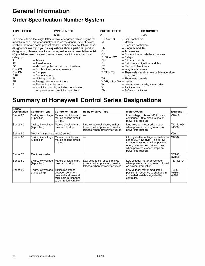
General Information
xvi customer.honeywell.com 70-6910
Order Specification Number System
The type letter is the single letter, or two letter group, which begins the model number. This letter usually indicates the general type of device involved, however, some product model numbers may not follow these designations exactly. If you have questions about a particular product designation, please contact your Honeywell sales representative. A list of type letters used is shown below (some may fit in more than one category):A —Testers.AT —Transformers.BC —Microcomputer burner control system.C or CS —Combustion controls; sensors.D or DM —Dampers.DSP —Demonstrators.EL —Lighting controls.ER —Energy recovery ventilators.F —Electronic air cleaners.H —Humidity controls, including combination
temperature and humidity controllers.
L, LA or LS —Limit controllers.M —Motors.P —Pressure controllers.PM —Program modules.Q —Accessories.QS —Communication interface modules.R, RA or RW —Relays.RM —Primary controls.S —Switches and ignition modules.ST —Electronic fan timers.SV —Integrated controls.T, TA or TS —Thermostats and remote bulb temperature
controllers.TG —Thermostat guards.V, VR, VS or VW—Valves.W —Load control panels, accessories.Y —Package sets.ZM —Software packages.
Summary of Honeywell Control Series Designations
TYPE LETTER TYPE NUMBER SUFFIX LETTER OS NUMBERV 4055 A 1007
Series Designation Controller Type Controller Action Relay or Valve Type Motor Action ExampleSeries 20 3-wire, low voltage
(2-position)Makes circuit to start; makes second circuit to stop.
— Low voltage; rotates 180 to open, continues 180 to close; stops on power interruption.
V2045
Series 40 2 wire, line voltage (2-position)
Makes circuit to start; breaks it to stop.
Line voltage coil circuit; makes (opens) when powered; breaks (closes) when power interrupted.
Line voltage; motor drives open when powered; spring returns on power interruption.
T42, L4064, L4008
Series 50 Mechanical (nonelectrical) series. V5011Series 60 3-wire, line voltage
(2-position)Makes circuit to start; makes second circuit to stop.
— Old style—line voltage equivalent to series 20. New style—line or low voltage drives open when powered open; reverses and drives closed when powered closed; stops on power interruption.
M6284
Series 70 Electronic series. M7285, C7031
Series 80 2-wire, low voltage (2-position)
Makes circuit to start; breaks it to stop.
Low voltage coil circuit; makes (opens) when powered; breaks (closes) when power interrupted.
Low voltage; motor drives open when powered; spring return closed on power interruption.
T87, L8124
Series 90 3-wire, low voltage (modulating)
Varies resistance between common terminal and two end terminals in response to controlled variable.
— Low voltage; motor modulates position in response to changes in controlled variable signaled by controller.
T921, M9164, W899
General Information
70-6910 xvii
Approval BodiesMost of the devices described in this catalog have been approved or
listed by one or more of the approval bodies listed below.
Underwriters Laboratories Inc.Underwriters Laboratories Inc., is a Limited Liability Corporation
(LLC) that examines and tests devices, systems and materials. Its membership represents a broad cross section of industry, education, and government.
Field inspectors for Underwriters Laboratories Inc., do not normally inspect equipment installed on job sites, but restrict their activities entirely to periodic inspections of products coming off manufacturers' assembly lines.
The three general categories of acceptance of a product by Underwriters Laboratories Inc., are:1. Listing2. Component Recognition3. Classification
Listed devices are structurally and functionally complete and suitable for field installation.
Component Recognized devices are incomplete in some way that makes them unsuitable for general field installation. They are intended to be factory installed as part of some other piece of equipment.Classified devices or products have been evaluated as to specific hazards only.Underwriters Laboratories of Canada can also provide certification services to Canadian standards, which is displayed as a “c” adjacent to the UL mark (cUL).
CSA - Canadian Standards AssociationThe Canadian Standards Association is a not-for-profit, membership-
based, non-governmental organization which provides a national standardizing body for Canada.
The Canadian Standards Association Testing Laboratories, inaugurated in May 1940, is a division of the Canadian Standards Association, and is recognized as a testing and investigating agency by Inspection Authorities and by Fire Marshals and Fire Commissioners throughout Canada.
The Canadian Standards Association Laboratories test and examine electrical products submitted for approval in compliance with pertinent Canadian Standards Association codes and standards.
The Canadian Standards Association now includes International Approval Services (IAS).
CSA can also provide certification services to UL standards, which is indicated by a “US” adjacent to the CSA mark.
International Approval Services—U.S.IAS, now part of CSA and no longer known as IAS, is the testing
organization of the American gas industry with laboratories in Cleveland, Ohio and Irvine, Calif. The CSA sponsors the American National Standards Institute Z21 and Z83 Committees on standards for gas-fired equipment.
Any manufacturer of gas appliances or gas appliance accessories may submit their products to the Laboratories and secure certification of their designs upon compliance with the appropriate national standards. Upon such compliance, the manufacturer is granted an Appliance Certificate or an Accessory Certificate and is permitted to display the trademarked Laboratories' Certification Seal or trademarked Laboratories' Certification Symbol on the appliance or accessory.
International Approval Services—CanadaIAS, now part of CSA and no longer known as IAS, represents all
segments of the Canadian gas industry, has been accredited by the
Standards Council of Canada and the Standards Advisory Committee to prepare National Standards in the area of equipment for use with natural gas and propane. CSA has laboratories in Toronto, Canada.
Each standard is intended to be used within the scope of the standard by the manufacturing sector, those applying the equipment or those respons ble for its application. It is the responsibility of the user to determine in each case that the standard is suitable for the application.
IAS operates a certification program for gas appliances, equipment, and accessories.
Canadian Gas Association (CGA), is now part of CSA and is no longer known as CGA, although some legacy products still may display the CGA mark.
American Gas Association (AGA) is also now part of CSA and is no longer known as AGA, although some legacy products still may display the AGA mark.
Factory MutualFactory Mutual is an association of mutual insurance companies
dedicated to loss prevention. Through its research arm, the Factory Mutual Research Corporation, it investigates means of preventing and minimizing fire and other losses. Factory Mutual Laboratories test and approve two broad categories of devices and materials:1. Those used for the control or prevention of property damage.2. Those that in themselves would present serious hazards if not prop-
erly designed.Factory Mutual Acceptance refers to a specific installation or
arrangement of equipment. Installations using approved devices, if found satisfactory following review of plans and inspection of completed work, are “accepted”.
A continuing follow-up program is carried out through periodic plant inspections and reports of performance in actual use.
CE Mark (“Conformité Européene” European Self-Certification mark)
CE marking is mandatory for products covered by one or more Directives. The manufacturer must apply the CE mark and declare conformity to the applicable Directives in order to bring a product on the market in the European Community. CE marking requirements vary from Directive to Directive, and even within Directives.
Some of the Directives (e.g. Gas Appliance Directive) require third party testing by Notified Bodies, in which case a product surveillance contract with a Notified Body is also mandatory. Other Directives can be satisfied by Declarations of Conformity provided by the manufacturer as a result of internal testing and documentation.
C-TickThe Australian C-Tick mark is intended for use on products that
comply with EMC standards. The C-Tick mark is a certification trademark registered to the ACA by the Trademarks Office and is only to be used in accordance with conditions laid down by the ACA (Australian Communications Authority). The C-Tick mark is valid for both countries and may be applied by either a New Zealand supplier or an Australian supplier.
AGA – Australia Gas AssociationAGA reviews a product’s CE Mark EMC report and/or Declarations
and issues a certificate allowing import into Australia and New Zealand.The approved product will bear the C-Tick mark with the assigned
number of the importer.
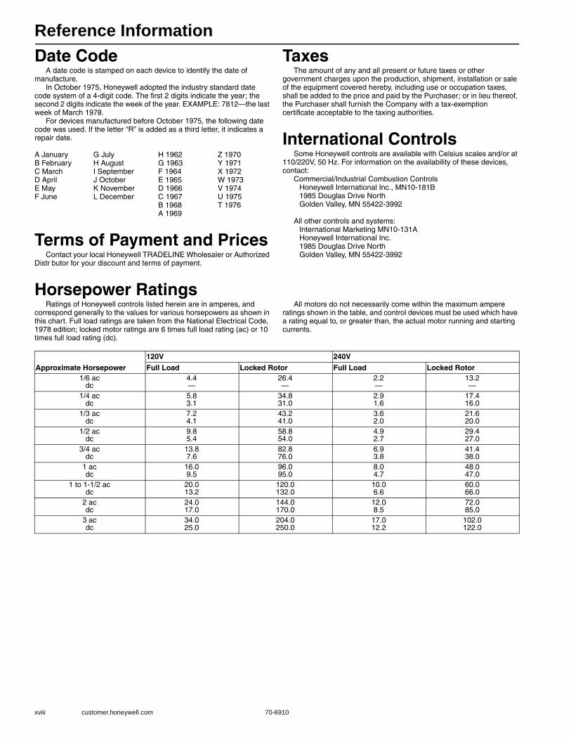
Reference Information
xviii customer.honeywell.com 70-6910
Date CodeA date code is stamped on each device to identify the date of
manufacture.In October 1975, Honeywell adopted the industry standard date
code system of a 4-digit code. The first 2 digits indicate the year; the second 2 digits indicate the week of the year. EXAMPLE: 7812—the last week of March 1978.
For devices manufactured before October 1975, the following date code was used. If the letter “R” is added as a third letter, it indicates a repair date.
A January G July H 1962 Z 1970B February H August G 1963 Y 1971C March I September F 1964 X 1972 D April J October E 1965 W 1973E May K November D 1966 V 1974F June L December C 1967 U 1975
B 1968 T 1976A 1969
Terms of Payment and PricesContact your local Honeywell TRADELINE Wholesaler or Authorized
Distr butor for your discount and terms of payment.
TaxesThe amount of any and all present or future taxes or other
government charges upon the production, shipment, installation or sale of the equipment covered hereby, including use or occupation taxes, shall be added to the price and paid by the Purchaser; or in lieu thereof, the Purchaser shall furnish the Company with a tax-exemption certificate acceptable to the taxing authorities.
International ControlsSome Honeywell controls are available with Celsius scales and/or at
110/220V, 50 Hz. For information on the availability of these devices, contact:
Commercial/Industrial Combustion Controls Honeywell International Inc., MN10-181B1985 Douglas Drive NorthGolden Valley, MN 55422-3992
All other controls and systems:International Marketing MN10-131AHoneywell International Inc.1985 Douglas Drive NorthGolden Valley, MN 55422-3992
Horsepower RatingsRatings of Honeywell controls listed herein are in amperes, and
correspond generally to the values for various horsepowers as shown in this chart. Full load ratings are taken from the National Electrical Code, 1978 edition; locked motor ratings are 6 times full load rating (ac) or 10 times full load rating (dc).
All motors do not necessarily come within the maximum ampere ratings shown in the table, and control devices must be used which have a rating equal to, or greater than, the actual motor running and starting currents.
Approximate Horsepower
120V 240V
Full Load Locked Rotor Full Load Locked Rotor1/6 ac
dc4.4—
26.4—
2.2—
13.2—
1/4 acdc
5.83.1
34.831.0
2.91.6
17.416.0
1/3 acdc
7.24.1
43.241.0
3.62.0
21.620.0
1/2 acdc
9.85.4
58.854.0
4.92.7
29.427.0
3/4 acdc
13.87.6
82.876.0
6.93.8
41.438.0
1 acdc
16.09.5
96.095.0
8.04.7
48.047.0
1 to 1-1/2 acdc
20.013.2
120.0132.0
10.06.6
60.066.0
2 acdc
24.017.0
144.0170.0
12.08.5
72.085.0
3 acdc
34.025.0
204.0250.0
17.012.2
102.0122.0

Reference Information
70-6910 xix
NEMA Standard Classification Code for Flame Safeguard EnclosuresNEMA 1—General purpose. for indoor protection, where conditions are not unusually severe.NEMA 2—Driptight. Designed to exclude falling moisture or dirt. Particularly applicable to cooling rooms, laundries, etc., where condensation is prevalent. For indoor use.NEMA 3—Weather Resistant (weatherproof). For outdoor use; designed to withstand all normal exposure to natural elements. Controls mounted on pullout racks for easy access. With rain hood and weather seals.NEMA 4—Watertight. Withstands water pressure from 1 in. hose nozzle, 65 gallons per minute, from distance of not less than 10 ft for five minutes. Suitable for maritime applications, breweries, etc.NEMA 5—Dust-tight. Equipped with dust-tight gaskets. Suitable for mills and other high-dust atmospheres.
NEMA 6—Submers ble. For submerged operation under specified pressures and time.NEMA 7—Hazardous Locations, National Electrical Code Class 1 (circuit breaks in air).NEMA 8—Hazardous Locations, National Electrical Code Class 1 (circuit breaks immersed in oil).NEMA 9—Hazardous Locations, National Electrical Code Class 2.NEMA 10—Explosion-proof. Meets U.S. Bureau of Mines requirements for explosive atmospheres.NEMA 11—Acid or Fume Resistant. Provides for immersion of enclosed equipment in oil.NEMA 12—IIndustrial Use. Excludes oils, dust, moisture, to satisfy individual requirements.
Conversion of Pressure Units(Convert by multiplying value in known pressure units by factor listed under required pressure unit.)
Absolute Pressure = Gauge Pressure +14.74 psi.
CapacitiesMost gas capacities listed in this catalog are stated for natural gas,
based on 1,000 Btu per cu ft, 0.64 sp. gr. nat. gas, at a pressure drop of 1.0 in. w.c. (37.3 MJ/m3, 0.64 sp. gr. at a pressure drop of 0.25 kPa).
To calculate the Btu/h capacity for other gases, multiply the listed Btu/h capacity by the conversion factor.
a Nominal conversion factor for range of total heat value.For gases not listed in table, use one of the following formulas:
Known Pressure Unit
Required Pressure Unit
Kilo-pascals
Pounds per sq in.
Ounces per sq in.
Millimeters of Mercury
Kilograms per sq cm
Inches of Water
Inches of Mercury
Feet of Water
Centimeters of Water
Centimeters of Water 0.0981 0.0142 0.227 0.735 0.000999 0.394 0.0289 0.0328 —Feet of Water 2.99 0.433 6.94 22.4 0.0305 12.0 0.883 — 30.5Inches of Mercury 3.39 0.491 7.86 25.4 0.0345 13.6 — 1.13 34.6Inches of Water 0.249 0.0361 0.578 1.87 0.00254 — 0.0735 0.0833 2.54Kilograms per sq cm 98.1 14.2 228.0 735.0 — 394.0 29.0 32.8 1000.0Millimeters of Mercury 0.133 0.0193 0.308 — 0.00136 0.535 0.0394 0.0446 1.36Ounces per sq in. 0.431 0.0625 — 8.24 0.00439 1.73 0.128 0.144 4.40Pounds per sq in. 6.89 — 16.0 51.7 0.0703 27.7 2.04 2.31 70.4Kilo pascals — 0.145 2.32 7.52 0.010 4.02 0.295 0.334 10.2
Total Heating Value for Gas X
At sp. gr.Conversion Factor (multiply)Btu/cu ft MJ/m3
500 to 800 18.7 to 29.8 0.60 0.516a
800 to 950 29.8 to 35.4 0.70 0.765a
2500 93.3 1.53 (LP gas) 1.62
or
ListedÑBtu/h Capacity(0.64 sp. gr.)
Btu/cu ft (MJ/m3 gas X) 1000 Btu/cu ft (37.3 MJ/m3
Btu/h Capacity gas X=0.64
sp. gr. gas X
Btu/h Capacity(gas A)
Btu/cu ft (MJ/m3) gas BBtu/cu ft (MJ/m3) gas A
Btu/h Capacity gas B=sp. gr. gas A
sp. gr. gas BM18317
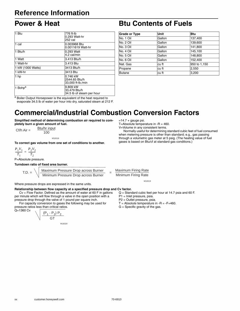
Reference Information
xx customer.honeywell.com 70-6910
Power & Heat
a Boiler Output Horsepower is the equivalent of the heat required to evaporate 34.5 lb of water per hour into dry, saturated steam at 212 F.
Btu Contents of Fuels
Commercial/Industrial Combustion Conversion FactorsSimplified method of determining combustion air required to com-pletely burn a given amount of fuel.
To correct gas volume from one set of conditions to another.
P=Absolute pressure.
=14.7 + gauge psi.T=Absolute temperature in -R = 460.V=Volume in any consistent terms.
Normally useful for determining standard cubic feet of fuel consumed when metering pressure is other than standard; e.g., gas passing through a volumetric gas meter at 5 psig. (The heating value of fuel gases is based on Btu/cf at standard gas conditions.)
Turndown ratio of fixed area burner.
Where pressure drops are expressed in the same units.
Relationship between flow capacity at a specified pressure drop and Cv factor.Cv = Flow Factor. Defined as the amount of water at 60 F in gallons
per minute which will flow through a valve in the open position with a pressure drop through the valve of 1 pound per square inch.
For capacity conversion to gases the following may be used for pressure ratios less than critical ratios.Q=1360 Cv
Q = Standard cubic feet per hour at 14.7 psia and 60 F.P1 = Inlet pressure, psia.P2 = Outlet pressure, psia.T = Absolute temperature in -R = -F+460.G = Specific gravity of the gas.
1 Btu 776 ft-lb0.293 Watt-hr252 cal
1 cal 0.003968 Btu0.0011619 Watt-hr
1 Btu/h 0.293 Watt4.2 cal/min
1 Watt 3.413 Btu/h1 Watt-hr 3.413 Btu1 kW (1000 Watts) 3413 Btu/h1 kW-hr 3413 Btu1 hp 0.746 kW
2544.65 Btu/h33,000 ft-lb./min
1 Bohpa 9.809 kW33,479 Btu/h34.5 lb of steam per hour
Grade or Type Unit BtuNo. 1 Oil Gallon 137,400No. 2 Oil Gallon 139,600No. 3 Oil Gallon 141,800No. 4 Oil Gallon 145,100No. 5 Oil Gallon 148,800No. 6 Oil Gallon 152,400Nat. Gas cu ft 950 to 1,150Propane cu ft 2,550Butane cu ft 3,200
Cf/h Air = Btu/hr input100
M18318
P1V1T1
------------P2V2
T2------------=
Maximum Pressure Drop across Burner Minimum Pressure Drop across Burner
T.D. = Maximum Firing RateMinimum Firing Rate
=
M18319
(P1 - P2) P2GT
M18320

Reference Information
70-6910 xxi
Steam Valve SelectionThere are five steps in choosing the appropriate steam valve:
1. Determine the steam medium temperature, pressure, and the pressure drop across the valve. (This is often deter-mined using inlet vs. outlet pressures. For example, a valve with a 75 psi inlet and a 50 psi outlet would have a pressure drop of 25 psi.)
2. Using this information (and Tables 1and 2), calculate the Cv or select the pipe size.
3. Check the average pressure and the temperature to determine the quality of the steam medium. The quality of the steam is:• Saturated• Superheated
4. Establish the required valve body configuration for the application. This is typically fixed by the particular applica-tion and is often part of the design specifications. Stan-dard body configurations are:• Two-way—Straight-through—Angle Body
5. See valve and actuator Product Overview Table and indi-vidual catalog pages.
NOTE: Traditionally, steam valves use a linear flow character-istic, but equal percentage characteristics are used in Europe.
All steam valves are two-way valves. There are two valve opera-tion control types; two-position (open/closed) and modulating (proportional).
Two-PositionTwo-position steam valves are typically selected based on the pipe size of the line, which is matched to the coil to deliver the amount of steam required at design conditions. For example, if the pipe size is three inches in diameter, you would select a three inch steam valve. Delivered heat is a function of steam pressure, valve capacity index (Cv), and the percentage open time of the valve (duty cycle). The condensed steam may be returned to the boiler by active or passive methods.
ModulatingTwo-way modulating steam valves are typically used to throttle the flow of steam in proportion to the load. Similar to water valves, when sizing a modulating valve for steam, consider the pressure throughout the valve travel. The pressure drop must be large enough so that, as the valve starts to close, it can diminish the flow. If this is not accomplished, the valve is not able to maintain control throughout its entire range of travel. However, a pressure drop that is too large causes noisy valve operation and decreases the life-span of the valve.
Calculating CvTo determine the appropriate Cv rating, one must know:
Supply pressure (psi)
Valve differential pressure (Δp)
Flow rate (lb/hr)
Q = Quantity of Steam (pounds per hour)v = specific volume of steam (cubic feet per pound) at the
average pressure in the valve63.5 = scaling constantΔp = pressure drop in psi
When Btu/hr (heat output) is known:Using the supply pressure, differential pressure and the Table 1, determine the value of Factor A for the application. Then using Factor A, the flow rate and Table 2, determine the Cv for the application.
Table 1. Calculations of Factor A for Steam Valves
CvQ v
63.5 pΔ---------------------=
Supply(psig)
Return Pressure (psig) Supply(Bar)0 1 2 3 4 5 6 7 8 9 10 11 12 15 20 25 30 40 50 60 70
2 4.0 5.5 0.13 3.2 3.9 5.4 0 24 2.7 3.1 3.7 5.2 0 35 2.4 2.7 3.0 3.7 5.1 0 36 2.2 2.3 2.6 2.9 3.6 5.0 0.47 2.0 2.1 2.3 2.5 2.9 3.5 4.9 0 58 1.8 1.9 2.1 2.2 2.5 2.8 3.4 4.8 0.69 1.7 1.8 1.9 2.0 2.2 2.4 2.8 3.3 4.7 0.610 1.6 1.7 1.7 1.8 2.0 2.1 2.4 2.7 3.3 4.6 0.711 1.5 1.6 1.6 1.7 1.8 1.9 2.1 2.3 2.6 3.2 4.5 0 812 1.4 1.5 1.5 1.6 1.7 1.8 1.9 2.0 2.3 2.6 3.1 4.4 0 815 1.2 1.3 1.3 1.3 1.4 1.4 1.5 1.6 1.7 1.8 1.9 2.1 2.5 1 020 1.0 1.0 1.0 1.1 1.1 1.1 1.1 1.2 1.2 1.3 1.3 1.4 1.4 1.8 1.425 0.9 0.9 0.9 0.9 0.9 0.9 0.9 1.0 1.0 1.0 1.0 1.1 1.1 1.2 1.7 1.730 0.8 0.8 0.8 0.8 0.8 0.8 0.8 0.8 0.8 0.8 0.9 0.9 0.9 1.0 1.1 1.6 2.140 0.7 0.7 0.7 0.6 0.6 0.6 0.6 0.6 0.6 0.7 0.7 0.7 0.7 0.7 0.8 0.9 1.0 2 850 0.6 0.6 0.6 0.6 0.6 0.6 0.6 0.5 0.5 0.5 0.5 0.5 0.6 0.6 0.6 0.6 0.7 0.9 3.460 0.5 0.5 0.5 0.5 0.5 0.5 0.5 0.5 0.5 0.5 0.5 0.5 0.5 0.5 0.5 0.5 0.5 0.6 0.9 4.170 0.4 0.4 0.4 0.4 0.4 0.4 0.4 0.4 0.4 0.4 0.4 0.4 0.4 0.4 0.4 0.4 0.5 0.5 0.6 0.8 4 880 0.4 0.4 0.4 0.4 0.4 0.4 0.4 0.4 0.4 0.4 0.4 0.4 0.4 0.4 0.4 0.4 0.4 0.4 0.5 0.6 0 8 5 5
.00 .07 .14 .21 .28 .34 .41 .48 .55 .62 .69 .76 .83 1.03 1.38 1.72 2.07 2.76 3.45 4.14 4.83Return Pressure (Bar)
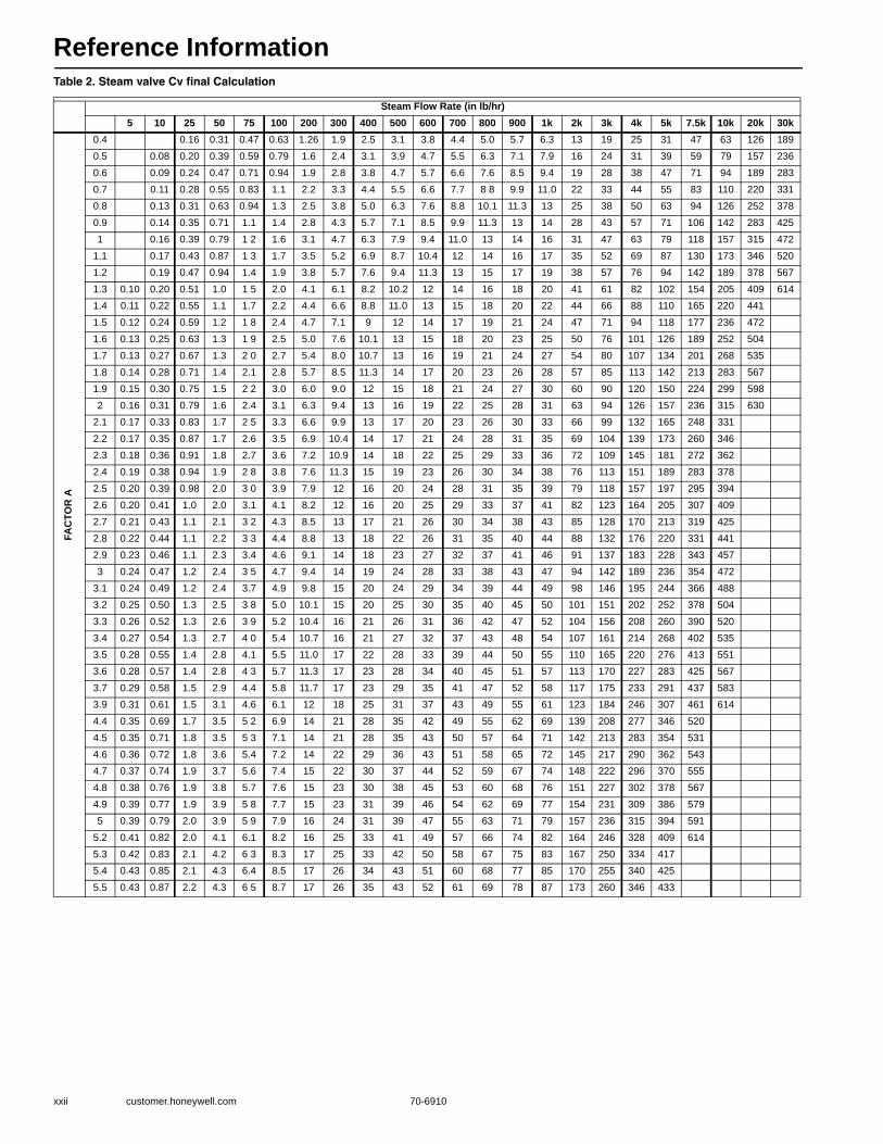
Reference Information
xxii customer.honeywell.com 70-6910
Table 2. Steam valve Cv final Calculation
Steam Flow Rate (in lb/hr)5 10 25 50 75 100 200 300 400 500 600 700 800 900 1k 2k 3k 4k 5k 7.5k 10k 20k 30k
FAC
TOR
A
0.4 0.16 0.31 0.47 0.63 1.26 1.9 2.5 3.1 3.8 4.4 5.0 5.7 6.3 13 19 25 31 47 63 126 1890.5 0.08 0.20 0.39 0.59 0.79 1.6 2.4 3.1 3.9 4.7 5.5 6.3 7.1 7.9 16 24 31 39 59 79 157 2360.6 0.09 0.24 0.47 0.71 0.94 1.9 2.8 3.8 4.7 5.7 6.6 7.6 8.5 9.4 19 28 38 47 71 94 189 2830.7 0.11 0.28 0.55 0.83 1.1 2.2 3.3 4.4 5.5 6.6 7.7 8 8 9.9 11.0 22 33 44 55 83 110 220 3310.8 0.13 0.31 0.63 0.94 1.3 2.5 3.8 5.0 6.3 7.6 8.8 10.1 11.3 13 25 38 50 63 94 126 252 3780.9 0.14 0.35 0.71 1.1 1.4 2.8 4.3 5.7 7.1 8.5 9.9 11.3 13 14 28 43 57 71 106 142 283 4251 0.16 0.39 0.79 1 2 1.6 3.1 4.7 6.3 7.9 9.4 11.0 13 14 16 31 47 63 79 118 157 315 472
1.1 0.17 0.43 0.87 1 3 1.7 3.5 5.2 6.9 8.7 10.4 12 14 16 17 35 52 69 87 130 173 346 5201.2 0.19 0.47 0.94 1.4 1.9 3.8 5.7 7.6 9.4 11.3 13 15 17 19 38 57 76 94 142 189 378 5671.3 0.10 0.20 0.51 1.0 1 5 2.0 4.1 6.1 8.2 10.2 12 14 16 18 20 41 61 82 102 154 205 409 6141.4 0.11 0.22 0.55 1.1 1.7 2.2 4.4 6.6 8.8 11.0 13 15 18 20 22 44 66 88 110 165 220 4411.5 0.12 0.24 0.59 1.2 1 8 2.4 4.7 7.1 9 12 14 17 19 21 24 47 71 94 118 177 236 4721.6 0.13 0.25 0.63 1.3 1 9 2.5 5.0 7.6 10.1 13 15 18 20 23 25 50 76 101 126 189 252 5041.7 0.13 0.27 0.67 1.3 2 0 2.7 5.4 8.0 10.7 13 16 19 21 24 27 54 80 107 134 201 268 5351.8 0.14 0.28 0.71 1.4 2.1 2.8 5.7 8.5 11.3 14 17 20 23 26 28 57 85 113 142 213 283 5671.9 0.15 0.30 0.75 1.5 2 2 3.0 6.0 9.0 12 15 18 21 24 27 30 60 90 120 150 224 299 5982 0.16 0.31 0.79 1.6 2.4 3.1 6.3 9.4 13 16 19 22 25 28 31 63 94 126 157 236 315 630
2.1 0.17 0.33 0.83 1.7 2 5 3.3 6.6 9.9 13 17 20 23 26 30 33 66 99 132 165 248 3312.2 0.17 0.35 0.87 1.7 2.6 3.5 6.9 10.4 14 17 21 24 28 31 35 69 104 139 173 260 3462.3 0.18 0.36 0.91 1.8 2.7 3.6 7.2 10.9 14 18 22 25 29 33 36 72 109 145 181 272 3622.4 0.19 0.38 0.94 1.9 2 8 3.8 7.6 11.3 15 19 23 26 30 34 38 76 113 151 189 283 3782.5 0.20 0.39 0.98 2.0 3 0 3.9 7.9 12 16 20 24 28 31 35 39 79 118 157 197 295 3942.6 0.20 0.41 1.0 2.0 3.1 4.1 8.2 12 16 20 25 29 33 37 41 82 123 164 205 307 4092.7 0.21 0.43 1.1 2.1 3 2 4.3 8.5 13 17 21 26 30 34 38 43 85 128 170 213 319 4252.8 0.22 0.44 1.1 2.2 3 3 4.4 8.8 13 18 22 26 31 35 40 44 88 132 176 220 331 4412.9 0.23 0.46 1.1 2.3 3.4 4.6 9.1 14 18 23 27 32 37 41 46 91 137 183 228 343 4573 0.24 0.47 1.2 2.4 3 5 4.7 9.4 14 19 24 28 33 38 43 47 94 142 189 236 354 472
3.1 0.24 0.49 1.2 2.4 3.7 4.9 9.8 15 20 24 29 34 39 44 49 98 146 195 244 366 4883.2 0.25 0.50 1.3 2.5 3 8 5.0 10.1 15 20 25 30 35 40 45 50 101 151 202 252 378 5043.3 0.26 0.52 1.3 2.6 3 9 5.2 10.4 16 21 26 31 36 42 47 52 104 156 208 260 390 5203.4 0.27 0.54 1.3 2.7 4 0 5.4 10.7 16 21 27 32 37 43 48 54 107 161 214 268 402 5353.5 0.28 0.55 1.4 2.8 4.1 5.5 11.0 17 22 28 33 39 44 50 55 110 165 220 276 413 5513.6 0.28 0.57 1.4 2.8 4 3 5.7 11.3 17 23 28 34 40 45 51 57 113 170 227 283 425 5673.7 0.29 0.58 1.5 2.9 4.4 5.8 11.7 17 23 29 35 41 47 52 58 117 175 233 291 437 5833.9 0.31 0.61 1.5 3.1 4.6 6.1 12 18 25 31 37 43 49 55 61 123 184 246 307 461 6144.4 0.35 0.69 1.7 3.5 5 2 6.9 14 21 28 35 42 49 55 62 69 139 208 277 346 5204.5 0.35 0.71 1.8 3.5 5 3 7.1 14 21 28 35 43 50 57 64 71 142 213 283 354 5314.6 0.36 0.72 1.8 3.6 5.4 7.2 14 22 29 36 43 51 58 65 72 145 217 290 362 5434.7 0.37 0.74 1.9 3.7 5.6 7.4 15 22 30 37 44 52 59 67 74 148 222 296 370 5554.8 0.38 0.76 1.9 3.8 5.7 7.6 15 23 30 38 45 53 60 68 76 151 227 302 378 5674.9 0.39 0.77 1.9 3.9 5 8 7.7 15 23 31 39 46 54 62 69 77 154 231 309 386 5795 0.39 0.79 2.0 3.9 5 9 7.9 16 24 31 39 47 55 63 71 79 157 236 315 394 591
5.2 0.41 0.82 2.0 4.1 6.1 8.2 16 25 33 41 49 57 66 74 82 164 246 328 409 6145.3 0.42 0.83 2.1 4.2 6 3 8.3 17 25 33 42 50 58 67 75 83 167 250 334 4175.4 0.43 0.85 2.1 4.3 6.4 8.5 17 26 34 43 51 60 68 77 85 170 255 340 4255.5 0.43 0.87 2.2 4.3 6 5 8.7 17 26 35 43 52 61 69 78 87 173 260 346 433
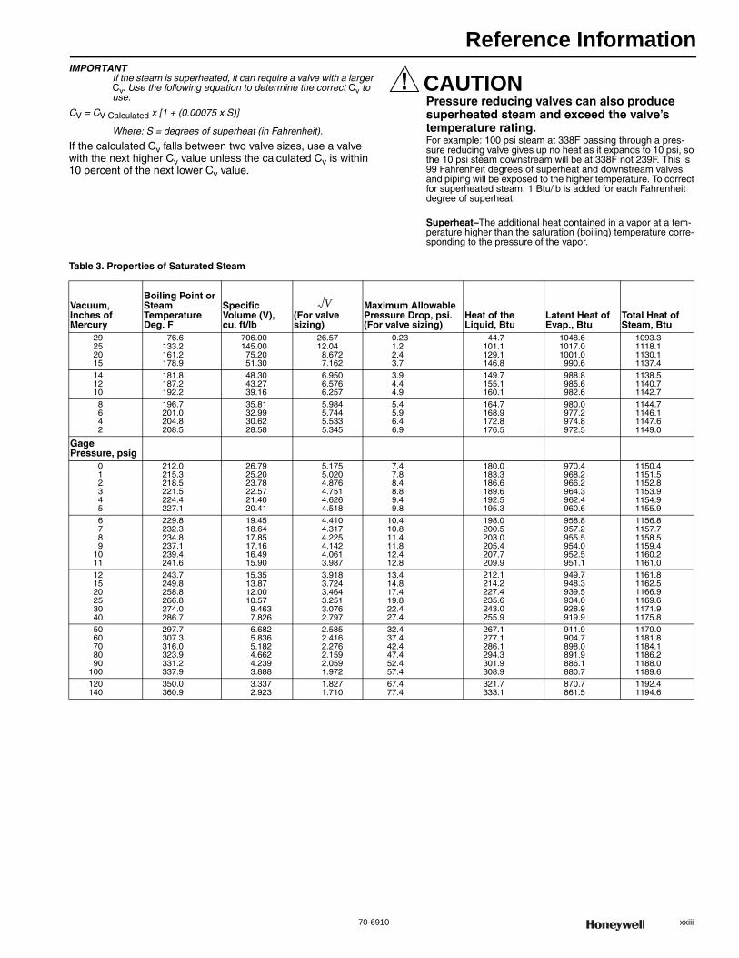
Reference Information
70-6910 xxiii
IMPORTANTIf the steam is superheated, it can require a valve with a larger Cv. Use the following equation to determine the correct Cv to use:
CV = CV Calculated x [1 + (0.00075 x S)]
Where: S = degrees of superheat (in Fahrenheit).
If the calculated Cv falls between two valve sizes, use a valve with the next higher Cv value unless the calculated Cv is within 10 percent of the next lower Cv value.
CAUTIONPressure reducing valves can also produce superheated steam and exceed the valve’s temperature rating. For example: 100 psi steam at 338F passing through a pres-sure reducing valve gives up no heat as it expands to 10 psi, so the 10 psi steam downstream will be at 338F not 239F. This is 99 Fahrenheit degrees of superheat and downstream valves and piping will be exposed to the higher temperature. To correct for superheated steam, 1 Btu/ b is added for each Fahrenheit degree of superheat.
Superheat–The additional heat contained in a vapor at a tem-perature higher than the saturation (boiling) temperature corre-sponding to the pressure of the vapor.
Table 3. Properties of Saturated Steam
Vacuum, Inches of Mercury
Boiling Point or Steam Temperature Deg. F
Specific Volume (V),cu. ft/lb
(For valve sizing)
Maximum Allowable Pressure Drop, psi. (For valve sizing)
Heat of the Liquid, Btu
Latent Heat of Evap., Btu
Total Heat of Steam, Btu
29252015
76.6133.2161.2178.9
706.00145.00
75.2051.30
26.5712.04
8.6727.162
0.231.22.43.7
44.7101.1129.1146.8
1048.61017.01001.0990.6
1093.31118.11130.11137.4
141210
181.8187.2192.2
48.3043.2739.16
6.9506.5766.257
3.94.44.9
149.7155.1160.1
988.8985.6982.6
1138.51140.71142.7
8642
196.7201.0204.8208.5
35.8132.9930.6228.58
5.9845.7445.5335.345
5.45.96.46.9
164.7168.9172.8176.5
980.0977.2974.8972.5
1144.71146.11147.61149.0
Gage Pressure, psig
012345
212.0215.3218.5221.5224.4227.1
26.7925.2023.7822.5721.4020.41
5.1755.0204.8764.7514.6264.518
7.47.88.48.89.49.8
180.0183.3186.6189.6192.5195.3
970.4968.2966.2964.3962.4960.6
1150.41151.51152.81153.91154.91155.9
6789
1011
229.8232.3234.8237.1239.4241.6
19.4518.6417.8517.1616.4915.90
4.4104.3174.2254.1424.0613.987
10.410.811.411.812.412.8
198.0200.5203.0205.4207.7209.9
958.8957.2955.5954.0952.5951.1
1156.81157.71158.51159.41160.21161.0
121520253040
243.7249.8258.8266.8274.0286.7
15.3513.8712.0010.57
9.4637.826
3.9183.7243.4643.2513.0762.797
13.414.817.419.822.427.4
212.1214.2227.4235.6243.0255.9
949.7948.3939.5934.0928.9919.9
1161.81162.51166.91169.61171.91175.8
5060708090
100
297.7307.3316.0323.9331.2337.9
6.6825.8365.1824.6624.2393.888
2.5852.4162.2762.1592.0591.972
32.437.442.447.452.457.4
267.1277.1286.1294.3301.9308.9
911.9904.7898.0891.9886.1880.7
1179.01181.81184.11186.21188.01189.6
120140
350.0360.9
3.3372.923
1.8271.710
67.477.4
321.7333.1
870.7861.5
1192.41194.6
V
Authorized Distributors
xxiv customer.honeywell.com 70-6910
Honeywell Authorized DistributorsCertain Honeywell product lines are available only through
authorized distributors. Authorized distributors have chosen to make a commitment to representing Honeywell controls. They are committed to excellence:
• in education, by providing continuing training in HVAC industry developments to their employees.• in application, by choosing the right system for each application.• in marketing, by providing customers with accurate information and efficient service.
7800 SERIES DistributorsFor commercial and industrial burner and boiler controls and
systems, and 7800 SERIES burner controls.
Authorized Systems DistributorsComplete access to building automation systems, standalone
controls and commercial field device products.
Combustion Solutions DistributorsFor commercial and industrial combustion solutions and
components.
Commercial Controls DistributorsAccess to light commercial building automation systems, standalone
controls and commercial field device products.
ControLinks™ RepresentativesFor ControLinks Products.
FOR YOUR CONVENIENCEFor more information about authorized distributors or for the
name of a particular outlet in your area, use our toll-free number.
1-800-345-6770
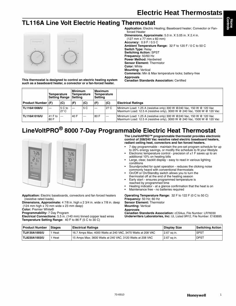
Electric Heat Thermostats
70-6910 1
Hom
e C
ontrols
TL116A Line Volt Electric Heating Thermostat
This thermostat is designed to control an electric heating system such as a baseboard heater, a convector or a fan-forced heater.
Application: Electric Heating; Baseboard heater; Convector or Fan-forced Heater
Dimensions, Approximate: 5.0 in. X 3.05 in. X 2.4 in. (127 mm x 77 mm x 60 mm)
Accuracy: 0.9 F / 0.5 C Ambient Temperature Range: 32 F to 120 F / 0 C to 50 C Switch Type: RelaySwitching Action: SPSTFrequency: 50/60 HzPower Method: HardwiredSensor Element: ThermistorColor: WhiteMounting: VerticalComments: Min & Max temperature locks; battery-freeApprovalsCanadian Standards Association: Certified
LineVoltPRO® 8000 7-Day Programmable Electric Heat ThermostatThe LineVoltPRO™ programmable thermostat provides electronic control of 208/240 Vac resistive rated electric baseboard heaters, radiant ceiling heat, convectors and fan forced heaters.• 7 day programmable - maintain the pre-set program schedule for up
to 20% energy savings, or modify the schedule to fit your lifestyle • Electronic temperature control - precision of ±1 F saves up to an
additional 10% on heating bills • Large, clear, backlit display - easy to read in various lighting
conditions • Soundproofed for quiet operation - reduces the clicking noise
commonly heard with conventional thermostats • On/Off or On/Standby switch allows you to turn the
thermostat off at the end of the heating season • Early start - ensures programmed temperature is
reached by programmed time • Heating indicator - at a glance confirmation that the heat is on • Maintenance free - no batteries required
Application: Electric baseboards, convectors and fan forced heaters (resistive rated loads).
Dimensions, Approximate: 4 7/8 in. high x 2 3/4 in. wide x 7/8 in. deep (124 mm high x 70 mm wide x 23 mm deep) Color: Premier White®Programmability: 7 Day ProgramElectrical Connections: 5.5 in. (140 mm) tinned copper lead wiresTemperature Setting Range: 40 F to 86 F (5 C to 30 C)
Operating Temperature Range: 32 F to 122 F (0 C to 50 C) Frequency: 50 Hz; 60 HzSensor Element: ThermistorMounting: VerticalApprovalsCanadian Standards Association: cCSAus, File Number: LR76030Underwriters Laboratories, Inc: UL Listed 9R12, File Number: E183695
Product Number
Temperature Setting Range
Minimum Temperature Setting
Maximum Temperature Setting
Electrical Ratings(F) (C) (F) (C) (F) (C)
TL116A1008/U — 5 C to 27 C
— 5 C — 27 C Minimum Load: 1.25 A (resistive only) 300 W @240 Vac, 150 W @ 120 Vac Maximum Load: 12.5 A (resistive only), 3000 W @ 240 Vac, 1500 W @ 120 Vac
TL116A1016/U 41 F to 80 F
— 40 F — 80 F — Minimum Load: 1.25 A (resistive only) 300 W @240 Vac, 150 W @ 120 Vac Maximum Load: 12.5 A (resistive only), 3000 W @ 240 Vac, 1500 W @ 120 Vac
Product Number Stages Electrical Ratings Display Size Switching Action
TL8130A1005/U 1 Heat 16.7 Amps Max; 4000 Watts at 240 VAC, 3470 Watts at 208 VAC 2.67 sq in. SPST
TL8230A1003/U 1 Heat 15 Amps Max; 3600 Watts at 240 VAC, 3120 Watts at 208 VAC 2.67 sq in. DPST
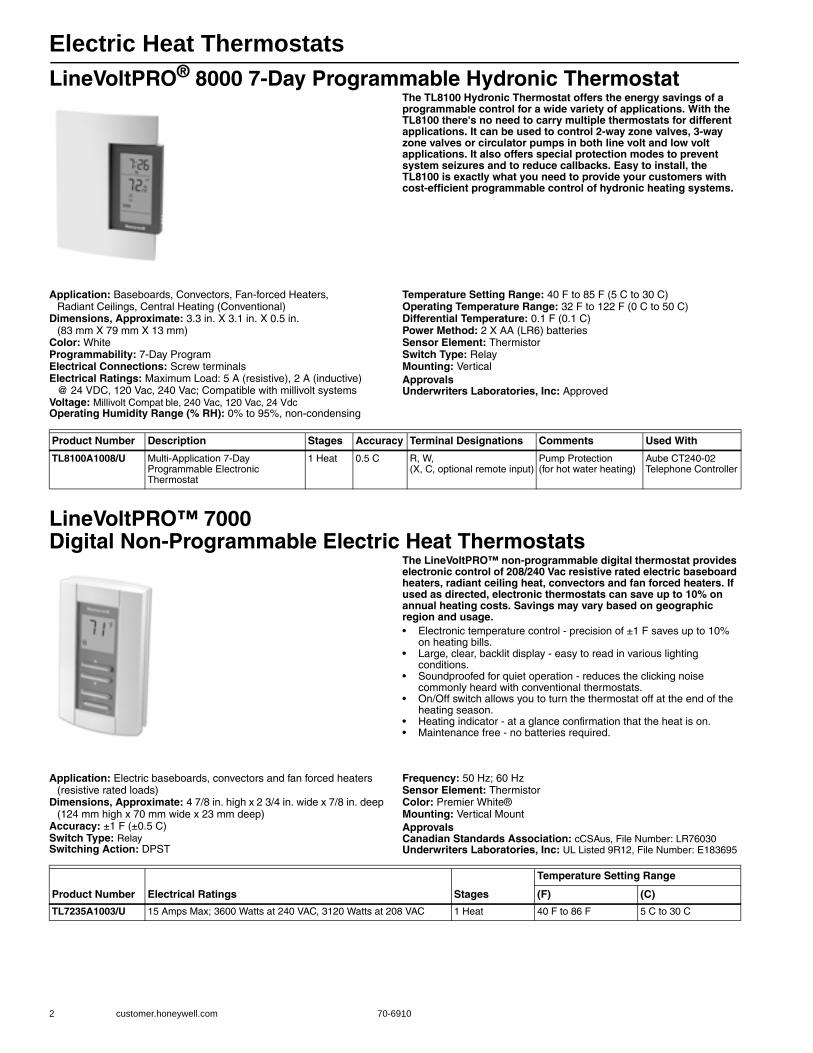
Electric Heat Thermostats
2 customer.honeywell.com 70-6910
LineVoltPRO® 8000 7-Day Programmable Hydronic ThermostatThe TL8100 Hydronic Thermostat offers the energy savings of a programmable control for a wide variety of applications. With the TL8100 there's no need to carry multiple thermostats for different applications. It can be used to control 2-way zone valves, 3-way zone valves or circulator pumps in both line volt and low volt applications. It also offers special protection modes to prevent system seizures and to reduce callbacks. Easy to install, the TL8100 is exactly what you need to provide your customers with cost-efficient programmable control of hydronic heating systems.
Application: Baseboards, Convectors, Fan-forced Heaters, Radiant Ceilings, Central Heating (Conventional)
Dimensions, Approximate: 3.3 in. X 3.1 in. X 0.5 in.(83 mm X 79 mm X 13 mm)
Color: WhiteProgrammability: 7-Day ProgramElectrical Connections: Screw terminalsElectrical Ratings: Maximum Load: 5 A (resistive), 2 A (inductive)
@ 24 VDC, 120 Vac, 240 Vac; Compatible with millivolt systemsVoltage: Millivolt Compat ble, 240 Vac, 120 Vac, 24 VdcOperating Humidity Range (% RH): 0% to 95%, non-condensing
Temperature Setting Range: 40 F to 85 F (5 C to 30 C) Operating Temperature Range: 32 F to 122 F (0 C to 50 C) Differential Temperature: 0.1 F (0.1 C) Power Method: 2 X AA (LR6) batteriesSensor Element: ThermistorSwitch Type: RelayMounting: VerticalApprovalsUnderwriters Laboratories, Inc: Approved
LineVoltPRO™ 7000 Digital Non-Programmable Electric Heat Thermostats
The LineVoltPRO™ non-programmable digital thermostat provides electronic control of 208/240 Vac resistive rated electric baseboard heaters, radiant ceiling heat, convectors and fan forced heaters. If used as directed, electronic thermostats can save up to 10% on annual heating costs. Savings may vary based on geographic region and usage.• Electronic temperature control - precision of ±1 F saves up to 10%
on heating bills. • Large, clear, backlit display - easy to read in various lighting
conditions. • Soundproofed for quiet operation - reduces the clicking noise
commonly heard with conventional thermostats. • On/Off switch allows you to turn the thermostat off at the end of the
heating season. • Heating indicator - at a glance confirmation that the heat is on. • Maintenance free - no batteries required.
Application: Electric baseboards, convectors and fan forced heaters (resistive rated loads)
Dimensions, Approximate: 4 7/8 in. high x 2 3/4 in. wide x 7/8 in. deep (124 mm high x 70 mm wide x 23 mm deep)
Accuracy: ±1 F (±0.5 C) Switch Type: RelaySwitching Action: DPST
Frequency: 50 Hz; 60 HzSensor Element: ThermistorColor: Premier White®Mounting: Vertical MountApprovalsCanadian Standards Association: cCSAus, File Number: LR76030Underwriters Laboratories, Inc: UL Listed 9R12, File Number: E183695
Product Number Description Stages Accuracy Terminal Designations Comments Used With
TL8100A1008/U Multi-Application 7-Day Programmable Electronic Thermostat
1 Heat 0.5 C R, W, (X, C, optional remote input)
Pump Protection (for hot water heating)
Aube CT240-02 Telephone Controller
Product Number Electrical Ratings Stages
Temperature Setting Range
(F) (C)
TL7235A1003/U 15 Amps Max; 3600 Watts at 240 VAC, 3120 Watts at 208 VAC 1 Heat 40 F to 86 F 5 C to 30 C
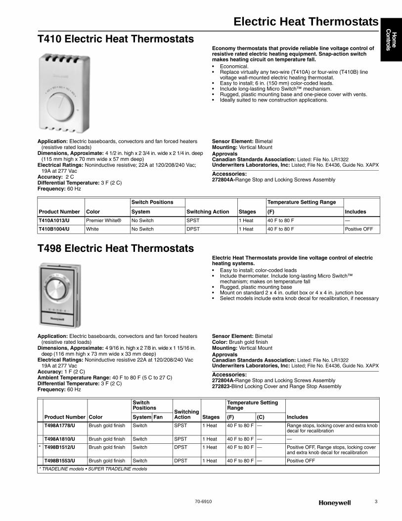
Electric Heat Thermostats
70-6910 3
Hom
e C
ontrols
T410 Electric Heat ThermostatsEconomy thermostats that provide reliable line voltage control of resistive rated electric heating equipment. Snap-action switch makes heating circuit on temperature fall.• Economical. • Replace virtually any two-wire (T410A) or four-wire (T410B) line
voltage wall-mounted electric heating thermostat. • Easy to install; 6 in. (150 mm) color-coded leads. • Include long-lasting Micro Switch™ mechanism. • Rugged, plastic mounting base and one-piece cover with vents. • Ideally suited to new construction applications.
Application: Electric baseboards, convectors and fan forced heaters (resistive rated loads)
Dimensions, Approximate: 4 1/2 in. high x 2 3/4 in. wide x 2 1/4 in. deep (115 mm high x 70 mm wide x 57 mm deep)
Electrical Ratings: Noninductive resistive; 22A at 120/208/240 Vac;19A at 277 Vac
Accuracy: 2 CDifferential Temperature: 3 F (2 C) Frequency: 60 Hz
Sensor Element: BimetalMounting: Vertical MountApprovalsCanadian Standards Association: Listed: File No. LR1322Underwriters Laboratories, Inc: Listed; File No. E4436, Guide No. XAPX
Accessories:272804A-Range Stop and Locking Screws Assembly
T498 Electric Heat ThermostatsElectric Heat Thermostats provide line voltage control of electric heating systems.• Easy to install; color-coded leads • Include thermometer. Include long-lasting Micro Switch™
mechanism; makes on temperature fall • Rugged, plastic mounting base • Mount on standard 2 x 4 in. outlet box or 4 x 4 in. junction box • Select models include extra knob decal for recalibration, if necessary
Application: Electric baseboards, convectors and fan forced heaters (resistive rated loads)
Dimensions, Approximate: 4 9/16 in. high x 2 7/8 in. wide x 1 15/16 in. deep (116 mm high x 73 mm wide x 33 mm deep)
Electrical Ratings: Noninductive resistive 22A at 120/208/240 Vac 19A at 277 Vac
Accuracy: 1 F (2 C) Ambient Temperature Range: 40 F to 80 F (5 C to 27 C) Differential Temperature: 3 F (2 C) Frequency: 60 Hz
Sensor Element: BimetalColor: Brush gold finishMounting: Vertical MountApprovalsCanadian Standards Association: Listed: File No. LR1322Underwriters Laboratories, Inc: Listed; File No. E4436, Guide No. XAPX
Accessories:272804A-Range Stop and Locking Screws Assembly272823-Blind Locking Cover and Range Stop Assembly
Product Number Color
Switch Positions
Switching Action Stages
Temperature Setting Range
IncludesSystem (F)
T410A1013/U Premier White® No Switch SPST 1 Heat 40 F to 80 F —
T410B1004/U White No Switch DPST 1 Heat 40 F to 80 F Positive OFF
Product Number Color
Switch Positions
Switching Action Stages
Temperature Setting Range
IncludesSystem Fan (F) (C)
T498A1778/U Brush gold finish Switch SPST 1 Heat 40 F to 80 F — Range stops, locking cover and extra knob decal for recalibration
T498A1810/U Brush gold finish Switch SPST 1 Heat 40 F to 80 F — —
* T498B1512/U Brush gold finish Switch DPST 1 Heat 40 F to 80 F — Positive OFF, Range stops, locking cover and extra knob decal for recalibration
T498B1553/U Brush gold finish Switch DPST 1 Heat 40 F to 80 F — Positive OFF
* TRADELINE models • SUPER TRADELINE models
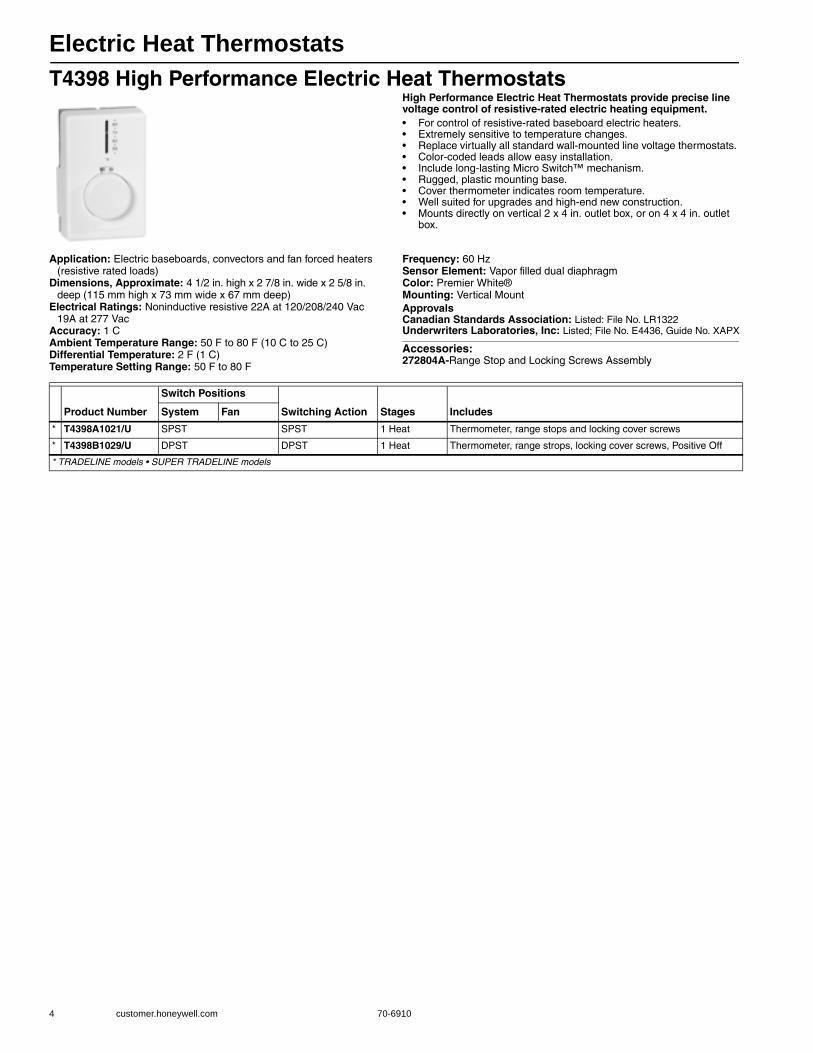
Electric Heat Thermostats
4 customer.honeywell.com 70-6910
T4398 High Performance Electric Heat ThermostatsHigh Performance Electric Heat Thermostats provide precise line voltage control of resistive-rated electric heating equipment.• For control of resistive-rated baseboard electric heaters. • Extremely sensitive to temperature changes. • Replace virtually all standard wall-mounted line voltage thermostats. • Color-coded leads allow easy installation. • Include long-lasting Micro Switch™ mechanism. • Rugged, plastic mounting base. • Cover thermometer indicates room temperature. • Well suited for upgrades and high-end new construction. • Mounts directly on vertical 2 x 4 in. outlet box, or on 4 x 4 in. outlet
box.
Application: Electric baseboards, convectors and fan forced heaters (resistive rated loads)
Dimensions, Approximate: 4 1/2 in. high x 2 7/8 in. wide x 2 5/8 in. deep (115 mm high x 73 mm wide x 67 mm deep)
Electrical Ratings: Noninductive resistive 22A at 120/208/240 Vac 19A at 277 Vac
Accuracy: 1 CAmbient Temperature Range: 50 F to 80 F (10 C to 25 C) Differential Temperature: 2 F (1 C) Temperature Setting Range: 50 F to 80 F
Frequency: 60 HzSensor Element: Vapor filled dual diaphragmColor: Premier White®Mounting: Vertical MountApprovalsCanadian Standards Association: Listed: File No. LR1322Underwriters Laboratories, Inc: Listed; File No. E4436, Guide No. XAPX
Accessories:272804A-Range Stop and Locking Screws Assembly
Product Number
Switch Positions
Switching Action Stages IncludesSystem Fan
* T4398A1021/U SPST SPST 1 Heat Thermometer, range stops and locking cover screws
* T4398B1029/U DPST DPST 1 Heat Thermometer, range strops, locking cover screws, Positive Off
* TRADELINE models • SUPER TRADELINE models
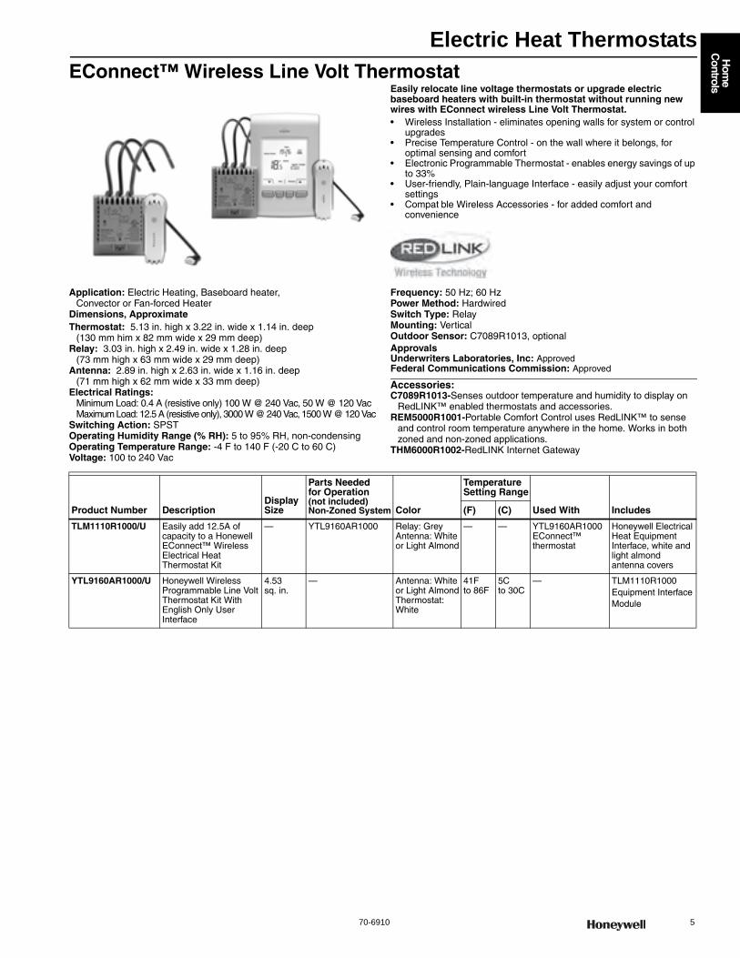
Electric Heat Thermostats
70-6910 5
Hom
e C
ontrols
EConnect™ Wireless Line Volt ThermostatEasily relocate line voltage thermostats or upgrade electric baseboard heaters with built-in thermostat without running new wires with EConnect wireless Line Volt Thermostat.• Wireless Installation - eliminates opening walls for system or control
upgrades • Precise Temperature Control - on the wall where it belongs, for
optimal sensing and comfort • Electronic Programmable Thermostat - enables energy savings of up
to 33% • User-friendly, Plain-language Interface - easily adjust your comfort
settings • Compat ble Wireless Accessories - for added comfort and
convenience
Application: Electric Heating, Baseboard heater, Convector or Fan-forced Heater
Dimensions, ApproximateThermostat: 5.13 in. high x 3.22 in. wide x 1.14 in. deep
(130 mm him x 82 mm wide x 29 mm deep)Relay: 3.03 in. high x 2.49 in. wide x 1.28 in. deep
(73 mm high x 63 mm wide x 29 mm deep)Antenna: 2.89 in. high x 2.63 in. wide x 1.16 in. deep
(71 mm high x 62 mm wide x 33 mm deep)Electrical Ratings:
Minimum Load: 0.4 A (resistive only) 100 W @ 240 Vac, 50 W @ 120 VacMaximum Load: 12.5 A (resistive only), 3000 W @ 240 Vac, 1500 W @ 120 Vac
Switching Action: SPSTOperating Humidity Range (% RH): 5 to 95% RH, non-condensingOperating Temperature Range: -4 F to 140 F (-20 C to 60 C) Voltage: 100 to 240 Vac
Frequency: 50 Hz; 60 HzPower Method: HardwiredSwitch Type: RelayMounting: VerticalOutdoor Sensor: C7089R1013, optionalApprovalsUnderwriters Laboratories, Inc: ApprovedFederal Communications Commission: Approved
Accessories:C7089R1013-Senses outdoor temperature and humidity to display on
RedLINK™ enabled thermostats and accessories.REM5000R1001-Portable Comfort Control uses RedLINK™ to sense
and control room temperature anywhere in the home. Works in both zoned and non-zoned applications.
THM6000R1002-RedLINK Internet Gateway
Product Number DescriptionDisplay Size
Parts Needed for Operation (not included) Non-Zoned System Color
Temperature Setting Range
Used With Includes(F) (C)
TLM1110R1000/U Easily add 12.5A of capacity to a Honewell EConnect™ Wireless Electrical Heat Thermostat Kit
— YTL9160AR1000 Relay: GreyAntenna: White or Light Almond
— — YTL9160AR1000 EConnect™ thermostat
Honeywell Electrical Heat Equipment Interface, white and light almond antenna covers
YTL9160AR1000/U Honeywell Wireless Programmable Line Volt Thermostat Kit With English Only User Interface
4.53 sq. in.
— Antenna: White or Light AlmondThermostat: White
41Fto 86F
5C to 30C
— TLM1110R1000 Equipment Interface Module
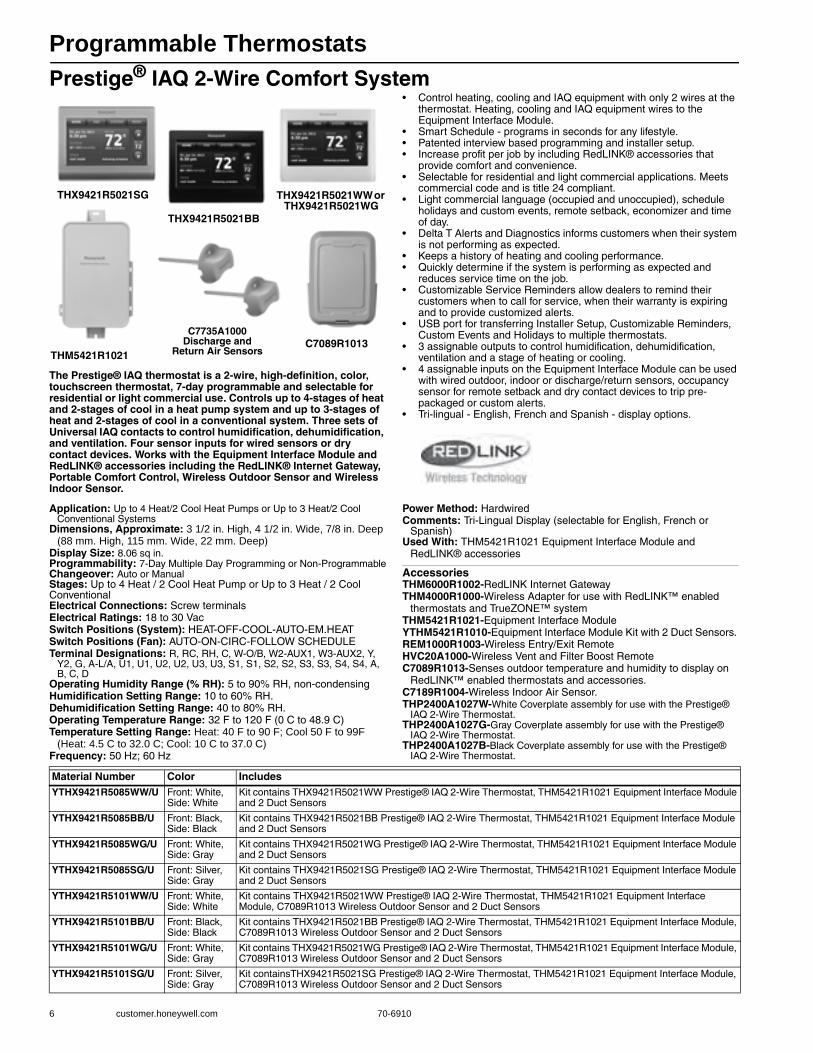
Programmable Thermostats
6 customer.honeywell.com 70-6910
Prestige® IAQ 2-Wire Comfort System
The Prestige® IAQ thermostat is a 2-wire, high-definition, color, touchscreen thermostat, 7-day programmable and selectable for residential or light commercial use. Controls up to 4-stages of heat and 2-stages of cool in a heat pump system and up to 3-stages of heat and 2-stages of cool in a conventional system. Three sets of Universal IAQ contacts to control humidification, dehumidification, and ventilation. Four sensor inputs for wired sensors or dry contact devices. Works with the Equipment Interface Module and RedLINK® accessories including the RedLINK® Internet Gateway, Portable Comfort Control, Wireless Outdoor Sensor and Wireless Indoor Sensor.
• Control heating, cooling and IAQ equipment with only 2 wires at the thermostat. Heating, cooling and IAQ equipment wires to the Equipment Interface Module.
• Smart Schedule - programs in seconds for any lifestyle.• Patented interview based programming and installer setup.• Increase profit per job by including RedLINK® accessories that
provide comfort and convenience.• Selectable for residential and light commercial applications. Meets
commercial code and is title 24 compliant.• Light commercial language (occupied and unoccupied), schedule
holidays and custom events, remote setback, economizer and time of day.
• Delta T Alerts and Diagnostics informs customers when their system is not performing as expected.
• Keeps a history of heating and cooling performance. • Quickly determine if the system is performing as expected and
reduces service time on the job.• Customizable Service Reminders allow dealers to remind their
customers when to call for service, when their warranty is expiring and to provide customized alerts.
• USB port for transferring Installer Setup, Customizable Reminders, Custom Events and Holidays to multiple thermostats.
• 3 assignable outputs to control humidification, dehumidification, ventilation and a stage of heating or cooling.
• 4 assignable inputs on the Equipment Interface Module can be used with wired outdoor, indoor or discharge/return sensors, occupancy sensor for remote setback and dry contact devices to trip pre-packaged or custom alerts.
• Tri-lingual - English, French and Spanish - display options.
Application: Up to 4 Heat/2 Cool Heat Pumps or Up to 3 Heat/2 Cool Conventional Systems
Dimensions, Approximate: 3 1/2 in. High, 4 1/2 in. Wide, 7/8 in. Deep (88 mm. High, 115 mm. Wide, 22 mm. Deep)
Display Size: 8.06 sq in.Programmability: 7-Day Multiple Day Programming or Non-ProgrammableChangeover: Auto or ManualStages: Up to 4 Heat / 2 Cool Heat Pump or Up to 3 Heat / 2 Cool ConventionalElectrical Connections: Screw terminalsElectrical Ratings: 18 to 30 VacSwitch Positions (System): HEAT-OFF-COOL-AUTO-EM.HEATSwitch Positions (Fan): AUTO-ON-CIRC-FOLLOW SCHEDULETerminal Designations: R, RC, RH, C, W-O/B, W2-AUX1, W3-AUX2, Y,
Y2, G, A-L/A, U1, U1, U2, U2, U3, U3, S1, S1, S2, S2, S3, S3, S4, S4, A, B, C, D
Operating Humidity Range (% RH): 5 to 90% RH, non-condensingHumidification Setting Range: 10 to 60% RH.Dehumidification Setting Range: 40 to 80% RH.Operating Temperature Range: 32 F to 120 F (0 C to 48.9 C) Temperature Setting Range: Heat: 40 F to 90 F; Cool 50 F to 99F
(Heat: 4.5 C to 32.0 C; Cool: 10 C to 37.0 C) Frequency: 50 Hz; 60 Hz
Power Method: HardwiredComments: Tri-Lingual Display (selectable for English, French or
Spanish)Used With: THM5421R1021 Equipment Interface Module and
RedLINK® accessories
AccessoriesTHM6000R1002-RedLINK Internet GatewayTHM4000R1000-Wireless Adapter for use with RedLINK™ enabled
thermostats and TrueZONE™ systemTHM5421R1021-Equipment Interface ModuleYTHM5421R1010-Equipment Interface Module Kit with 2 Duct Sensors. REM1000R1003-Wireless Entry/Exit RemoteHVC20A1000-Wireless Vent and Filter Boost RemoteC7089R1013-Senses outdoor temperature and humidity to display on
RedLINK™ enabled thermostats and accessories.C7189R1004-Wireless Indoor Air Sensor.THP2400A1027W-White Coverplate assembly for use with the Prestige®
IAQ 2-Wire Thermostat. THP2400A1027G-Gray Coverplate assembly for use with the Prestige®
IAQ 2-Wire Thermostat. THP2400A1027B-Black Coverplate assembly for use with the Prestige®
IAQ 2-Wire Thermostat.
THX9421R5021SG THX9421R5021WW or THX9421R5021WG
THX9421R5021BB
THM5421R1021C7089R1013
C7735A1000Discharge and
Return Air Sensors
Material Number Color IncludesYTHX9421R5085WW/U Front: White,
Side: WhiteKit contains THX9421R5021WW Prestige® IAQ 2-Wire Thermostat, THM5421R1021 Equipment Interface Module and 2 Duct Sensors
YTHX9421R5085BB/U Front: Black, Side: Black
Kit contains THX9421R5021BB Prestige® IAQ 2-Wire Thermostat, THM5421R1021 Equipment Interface Module and 2 Duct Sensors
YTHX9421R5085WG/U Front: White, Side: Gray
Kit contains THX9421R5021WG Prestige® IAQ 2-Wire Thermostat, THM5421R1021 Equipment Interface Module and 2 Duct Sensors
YTHX9421R5085SG/U Front: Silver, Side: Gray
Kit contains THX9421R5021SG Prestige® IAQ 2-Wire Thermostat, THM5421R1021 Equipment Interface Module and 2 Duct Sensors
YTHX9421R5101WW/U Front: White, Side: White
Kit contains THX9421R5021WW Prestige® IAQ 2-Wire Thermostat, THM5421R1021 Equipment Interface Module, C7089R1013 Wireless Outdoor Sensor and 2 Duct Sensors
YTHX9421R5101BB/U Front: Black, Side: Black
Kit contains THX9421R5021BB Prestige® IAQ 2-Wire Thermostat, THM5421R1021 Equipment Interface Module, C7089R1013 Wireless Outdoor Sensor and 2 Duct Sensors
YTHX9421R5101WG/U Front: White, Side: Gray
Kit contains THX9421R5021WG Prestige® IAQ 2-Wire Thermostat, THM5421R1021 Equipment Interface Module, C7089R1013 Wireless Outdoor Sensor and 2 Duct Sensors
YTHX9421R5101SG/U Front: Silver, Side: Gray
Kit containsTHX9421R5021SG Prestige® IAQ 2-Wire Thermostat, THM5421R1021 Equipment Interface Module, C7089R1013 Wireless Outdoor Sensor and 2 Duct Sensors

Programmable Thermostats
70-6910 7
Hom
e C
ontrols
Prestige® IAQ 2-Wire Thermostat
The Prestige® IAQ thermostat is a 2-wire, high-definition, color, touchscreen thermostat, 7-day programmable and selectable for residential or light commercial use. Controls up to 4-stages of heat and 2-stages of cool in a heat pump system and up to 3-stages of heat and 2-stages of cool in a conventional system. Three sets of Universal IAQ contacts to control humidification, dehumidification, and ventilation. Four sensor inputs for wired sensors or dry contact devices. Works with the Equipment Interface Module and RedLINK® accessories including the RedLINK® Internet Gateway, Portable Comfort Control, Wireless Outdoor Sensor and Wireless Indoor Sensor.
• Control heating, cooling and IAQ equipment with only 2 wires at the thermostat. Heating, cooling and IAQ equipment wires to the Equipment Interface Module.
• Smart Schedule - programs in seconds for any lifestyle.• Patented interview based programming and installer setup.• RedLINK® wireless communication.• Increase profit per job by including RedLINK® accessories that
provide comfort and convenience.• Selectable for residential and light commercial applications. Meets
commercial code and is title 24 compliant• Light commercial language (occupied and unoccupied), schedule
holidays and custom events, remote setback, economizer and time of day.
• Delta T Alerts and Diagnostics informs customers when their system is not performing as expected.
• All Prestige® IAQ kits come standard with a return and discharge air temperature sensor to measure Delta T.
• Keeps a searchable history of alerts and setting changes to the thermostat to determine if there is a system malfunction or if the issue was caused by user error. Saves time in troubleshooting.
• Keeps a history of heating and cooling performance. • Quickly determine if the system is performing as expected and
reduces service time on the job.• Customizable Service Reminders allow dealers to remind their
customers when to call for service, when their warranty is expiring and to provide customized alerts.
• USB port for transferring Installer Setup, Customizable Reminders, Custom Events and Holidays to multiple thermostats.
• USB port for adding the dealer's full color business logo on the screen.
• 3 assignable outputs to control humidification, dehumidification, ventilation and a stage of heating or cooling.
• 4 assignable inputs on the Equipment Interface Module can be used with wired outdoor, indoor or discharge/return sensors, occupancy sensor for remote setback and dry contact devices to trip pre-packaged or custom alerts.
• Tri-lingual - English, French and Spanish - display options.
Application: Up to 4 Heat/2 Cool Heat Pumps or Up to 3 Heat/2 Cool Conventional Systems
Dimensions, Approximate: 3 1/2 in. High, 4 1/2 in. Wide, 7/8 in. Deep (88 mm. High, 115 mm. Wide, 22 mm. Deep)
Display Size: 8.06 sq in.Programmability: 7-Day Multiple Day Programming or Non-ProgrammableChangeover: Auto or ManualStages: See Equipment Interface ModuleElectrical Connections: Screw terminalsElectrical Ratings: 18 to 30 VacTerminal Designations: R, C then RedLINK to Equipment Interface
ModuleOperating Humidity Range (% RH): 5 to 90% RH, non-condensingHumidification Setting Range: 10 to 60% RH.Dehumidification Setting Range: 40 to 80% RH.Operating Temperature Range: 32 F to 120 F (0 C to 48.9 C) Temperature Setting Range: Heat: 40 F to 90 F; Cool 50 F to 99F
(Heat: 4.5 C to 32.0 C; Cool: 10 C to 37.0 C) Frequency: 50 Hz; 60 HzPower Method: HardwiredComments: Tri-Lingual Display (selectable for English, French or
Spanish)
Accessories:REM5000R1001-Portable Comfort Control uses RedLINK™ to sense
and control room temperature anywhere in the home. Works in both zoned and non-zoned applications.
C7089R1013-Senses outdoor temperature and humidity to display on RedLINK™ enabled thermostats and accessories.
THM6000R1002-RedLINK Internet GatewayTHM4000R1000-Wireless Adapter for use with RedLINK™ enabled
thermostats and TrueZONE™ systemTHM5421R1021-Equipment Interface ModuleYTHM5421R1010-Equipment Interface Module Kit with 2 Duct Sensors. REM1000R1003-Wireless Entry/Exit RemoteHVC20A1000-Wireless Vent and Filter Boost RemoteC7189R1004-Wireless Indoor Air Sensor.THP2400A1027W-White Coverplate assembly for use with the Prestige®
IAQ 2-Wire Thermostat. THP2400A1027G-Gray Coverplate assembly for use with the Prestige®
IAQ 2-Wire Thermostat. THP2400A1027B-Black Coverplate assembly for use with the Prestige®
IAQ 2-Wire Thermostat.
THX9421R5021SG
THX9421R5021WW or THX9421R5021WG
THX9421R5021BB
Material Number ColorSwitch Positions (System) Switch Positions (Fan) Used With
THX9421R5021WW/U Front: White, Side: White
HEAT-OFF-COOL-AUTO-EM.HEAT
AUTO-ON-CIRC-FOLLOW SCHEDULE
THM5421R1021 Equipment Interface Module and RedLINK® accessories
THX9421R5021BB/U Front: Black, Side: Black
HEAT-OFF-COOL-AUTO-EM.HEAT
AUTO-ON-CIRC-FOLLOW SCHEDULE
THM5421R1021 Equipment Interface Module and RedLINK® accessories
THX9421R5021WG/U Front: White, Side: Gray
HEAT-OFF-COOL-AUTO-EM.HEAT
AUTO-ON-CIRC-FOLLOW SCHEDULE
THM5421R1021 Equipment Interface Module and RedLINK® accessories
THX9421R5021SG/U Front: Silver, Side: Gray
HEAT-OFF-COOL-AUTO-EM.HEAT
AUTO-ON-CIRC-FOLLOW SCHEDULE
THM5421R1021 Equipment Interface Module and RedLINK® accessories
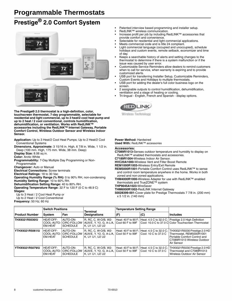
Programmable Thermostats
8 customer.honeywell.com 70-6910
Prestige® 2.0 Comfort System
The Prestige® 2.0 thermostat is a high-definition, color, touchscreen thermostat, 7-day programmable, selectable for residential and light commercial, up to 3 heat/2 cool heat pump and up to 2 heat / 2 cool conventional, controls humidification, dehumidification, or ventilation. Works with RedLINK™ accessories including the RedLINK™ Internet Gateway, Portable Comfort Control, Wireless Outdoor Sensor and Wireless Indoor Sensor.
• Patented interview based programming and installer setup.• RedLINK™ wireless communication.• Increase profit per job by including RedLINK™ accessories that
provide comfort and convenience.• Selectable for residential and light commercial applications.• Meets commercial code and is title 24 compliant.• Light commercial language (occupied and unoccupied), schedule
holidays and custom events, remote setback, economizer and time of day.
• Keeps a searchable history of alerts and setting changes to the thermostat to determine if there is a system malfunction or if the issue was caused by user error.
• Customizable Service Reminders allow dealers to remind customers when to call for service, when warranty is expiring and to provide customized alerts.
• USB port for transferring Installer Setup, Customizable Reminders, Custom Events and Holidays to multiple thermostats.
• USB port for adding the dealer's full color business logo on the screen.
• 2 assignable outputs to control humidification, dehumidification, ventilation and a stage of heating or cooling.
• Tri-lingual - English, French and Spanish - display options.
Application: Up to 3 Heat/2 Cool Heat Pumps; Up to 2 Heat/2 Cool Conventional Systems
Dimensions, Approximate: 3 15/16 in. High, 6 7/8 in. Wide, 1 1/2 in. Deep (100 mm. High, 175 mm. Wide, 38 mm. Deep)
Display Size: 8.06 sq in.Color: Arctic WhiteProgrammability: 7-Day Multiple Day Programming or Non-
ProgrammableChangeover: Auto or ManualElectrical Connections: Screw terminalsElectrical Ratings: 18 to 30 VacOperating Humidity Range (% RH): 0 to 90% RH, non-condensingHumidity Setting Range: 10 to 60% RH.Dehumidification Setting Range: 40 to 80% RH.Operating Temperature Range: 32 F to 120 F (0 C to 48.9 C) Stages:
Up to 3 Heat / 2 Cool Heat Pump orUp to 2 Heat / 2 Cool Conventional
Frequency: 50 Hz; 60 Hz
Power Method: HardwiredUsed With: RedLINK™ accessories
Accessories:C7089R1013-Senses outdoor temperature and humidity to display on
RedLINK™ enabled thermostats and accessories.C7189R1004-Wireless Indoor Air Sensor.HVC20A1000-Wireless Vent and Filter Boost RemoteREM1000R1003-Wireless Entry/Exit RemoteREM5000R1001-Portable Comfort Control uses RedLINK™ to sense
and control room temperature anywhere in the home. Works in both zoned and non-zoned applications.
THM4000R1000-Wireless Adapter for use with RedLINK™ enabled thermostats and TrueZONE™ system
THP9045A1023-WireSaverTHM6000R1002-RedLINK Internet Gateway50028399-001-Cover plate for Prestige Thermostats 7 7/8 in. (200 mm)
x 5 1/2 in. (140 mm)
Product Number
Switch PositionsTerminal Designations
Temperature Setting Range
IncludesSystem Fan (F) (C)
THX9321R5030/U HEAT-OFF-COOL-AUTO-EM.HEAT
AUTO-ON-CIRC-FOLLOW SCHEDULE
R, RC, C, W-O/B, W2-AUX/E, Y, Y2, G, A-L/A, K, U1 U1, U2 U2
Heat: 40 F to 90 F; Cool 60 F to 99F
Heat: 4.5 C to 32.0 C; Cool: 10.0 C to 37.0 C
Prestige 2.0 High Definition Color Touchscreen Thermostat
YTHX9321R5061/U HEAT-OFF-COOL-AUTO-EM.HEAT
AUTO-ON-CIRC-FOLLOW SCHEDULE
R, RC, C, W-O/B, W2-AUX/E, Y, Y2, G, A-L/A, K, U1 U1, U2 U2
Heat: 40 F to 90 F; Cool 50 F to 99F
Heat: 4.5 C to 32.0 C; Cool: 10 C to 37.0 C
THX9321R5030 Prestige 2.0 HD Thermostat, REM5000R1001 Portable Comfort Control and C7089R1013 Wireless Outdoor Air Sensor
YTHX9321R5079/U HEAT-OFF-COOL-AUTO-EM.HEAT
AUTO-ON-CIRC-FOLLOW SCHEDULE
R, RC, C, W-O/B, W2-AUX/E, Y, Y2, G, A-L/A, K, U1 U1, U2 U2
Heat: 40 F to 90 F; Cool 50 F to 99F
Heat: 4.5 C to 32.0 C; Cool: 10 C to 37.0 C
THX9321R5030 Prestige 2.0 HD Thermostat and C7089R1013 Wireless Outdoor Air Sensor

Programmable Thermostats
70-6910 9
Hom
e C
ontrols
VisionPRO® 8000 with RedLINK™
VisionPRO® 8000 with RedLINK™ is a 7 day programmable touchscreen thermostat that is selectable for residential or light commercial use. The thermostat can be wired directly to the equipment, used with the THM5421R1021 Equipment Interface Module or used with the THM4000R1000 TrueZONE Wireless Adapter. Works with the RedLINK™ accessories including the RedLINK™ Internet Gateway, Portable Comfort Control, Wireless Outdoor Sensor, Wireless Indoor Sensor, Wireless Entry/Exit Remote and Wireless Vent and Filter Boost Remote.• Thermostat works standalone or with a THM5421R1021 Equipment
Interface Module or with a TrueZONE Wireless Adapter.• Smart Schedule - programs in seconds for any lifestyle.• Patented interview based programming and installer setup.• RedLINK™ wireless communication.• Increase profit per job by including RedLINK™ accessories that
provide comfort and convenience.• Selectable for residential and light commercial applications. Meets
commercial code and is title 24 compliant.
• Light commercial - commercial language (occupied and unoccupied), schedule holidays and custom events, remote setback, economizer and time of day. Remote Setback requires THM5421R1021 Equipment Interface Module.
• Plain language setup, no manual needed.• Keeps a searchable history of alerts and setting changes to the
thermostat to determine if there is a system malfunction or if the issue was caused by a user error. Saves time in troubleshooting.
• Customizable Service Reminders allow dealers to remind their customers when it is time to call for service, when their warranty is expiring and to provide customized alerts.
• MicroSD port for copying the Installer Setup, Customizable Reminders, Custom Events and Holidays to multiple thermostats.
• MicroSD port for adding the dealer's contact information on the screen.
• 1 assignable output on the TH8321 model to control humidification, dehumidification, ventilation or a stage of heating/cooling.
• 3 assignable outputs on the Equipment Interface Module to control humidification, dehumidification, ventilation or a stage of heating/cooling. The TH8110 and TH8320 models require the use of a Wireless Indoor Sensor to control humidification and dehumidification.
• 1 assignable input can be used with a wired outdoor, indoor or discharge sensor.
• 4 assignable inputs on the Equipment Interface Module can be used with wired outdoor, indoor or discharge/return sensors, occupancy sensor for remote setback and dry contact devices to trip pre-packaged or custom alerts.
• Dual powered - battery or hardwired (C wire).
Applications: Residential or commercial use. 7 day programmable. Works standalone or with the THM5421R1021 Equipment Interface Module.
Dimensions, Approximate: 4 5/8 in. High, 4 15/16 in. Wide, 1 1/8 in. Deep (118 mm. High, 126 mm. Wide, 29 mm. Deep)
Display Size: 10 sq in.Color: Arctic WhiteProgrammability: 7-Day Multiple Day Programming or Non-ProgrammableChangeover: Auto or ManualElectrical Ratings: 18 to 30 Vac or 750 mVFrequency: 50 Hz; 60 HzElectrical Connections: Screw terminalsOperating Humidity Range (% RH): 5 to 90% RH, non-condensingHumidification Setting Range: 10 to 60% RH.Dehumidification Setting Range: 40 to 80% RH.Operating Temperature Range (F): 32 F to 120 F (0 C to 48.9 C)Temperature Setting Range: Heat: 40 F to 90 F; Cool 50 F to 99F,
(Heat: 4.5 C to 32.0 C; Cool: 10 C to 37.0 C)Power Method: Battery or HardwiredUsed With: Used with optional THM5421R1021 Equipment Interface
Module and RedLINK® accessories
Accessories:REM5000R1001-Portable Comfort Control uses RedLINK™ to sense
and control room temperature anywhere in the home. Works in both zoned and non-zoned applications.
THM6000R1002-RedLINK Internet GatewayTHM4000R1000-Wireless Adapter for use with RedLINK™ enabled
thermostats and TrueZONE™ systemTHM5421R1021-Equipment Interface ModuleYTHM5421R1010-Equipment Interface Module Kit with 2 Duct Sensors. REM1000R1003-Wireless Entry/Exit RemoteHVC20A1000-Wireless Vent and Filter Boost RemoteC7089R1013-Senses outdoor temperature and humidity to display on
RedLINK™ enabled thermostats and accessories.C7189R1004-Wireless Indoor Air Sensor. THP2400A1019-Coverplate assembly for use with the RedLINK®
VisionPRO®. Includes a coverplate, bracket for j-boxes and mounting hardware. Coverplate is 5-3/4 in. x 6-5/32 in.
Material NumberTerminal Designations Stages
Switch Positions (System)
Switch Positions (Fan) Includes
TH8321R1001/U R, RC, C, W-O/B, W2-AUX/E, Y, Y2, G, A-L/A, K, U1 U1, S1 S1
Up to 3 Heat / 2 Cool Heat Pump or Up to 2 Heat / 2 Cool Conventional when used standalone. Up to 4 Heat / 2 Cool Heat Pump or Up to 3 Heat / 2 Cool Conventional when used with the Equipment Interface Module.
HEAT-OFF-COOL-AUTO-EM.HEAT
AUTO-ON-CIRC-FOLLOW SCHEDULE
Includes a set of Universal IAQ contacts to control humidification, dehumidification or ventilation.
TH8320R1003/U R, RC, C, W-O/B, W2-AUX/E, Y, Y2, G, A-L/A, K, S1 S1
Up to 3 Heat / 2 Cool Heat Pump or Up to 2 Heat / 2 Cool Conventional when used standalone. Up to 4 Heat / 2 Cool Heat Pump or Up to 3 Heat / 2 Cool Conventional when used with the Equipment Interface Module.
HEAT-OFF-COOL-AUTO-EM.HEAT
AUTO-ON-CIRC-FOLLOW SCHEDULE
—
TH8110R1008/U R, RC, C, W-O/B, Y, G, K, S1 S1
Up to 1 Heat / 1 Cool Heat Pump or Up to 1 Heat / 1 Cool Conventional when used standalone. Up to 4 Heat / 2 Cool Heat Pump or Up to 3 Heat / 2 Cool Conventional when used with the Equipment Interface Module.
HEAT-OFF-COOL-AUTO
AUTO-ON-CIRC-FOLLOW SCHEDULE
—
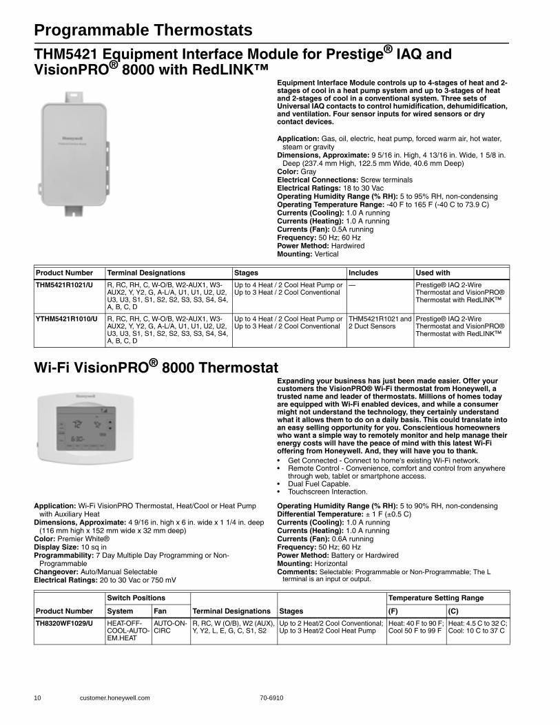
Programmable Thermostats
10 customer.honeywell.com 70-6910
THM5421 Equipment Interface Module for Prestige® IAQ and VisionPRO® 8000 with RedLINK™
Equipment Interface Module controls up to 4-stages of heat and 2-stages of cool in a heat pump system and up to 3-stages of heat and 2-stages of cool in a conventional system. Three sets of Universal IAQ contacts to control humidification, dehumidification, and ventilation. Four sensor inputs for wired sensors or dry contact devices.
Application: Gas, oil, electric, heat pump, forced warm air, hot water, steam or gravity
Dimensions, Approximate: 9 5/16 in. High, 4 13/16 in. Wide, 1 5/8 in. Deep (237.4 mm High, 122.5 mm Wide, 40.6 mm Deep)
Color: GrayElectrical Connections: Screw terminalsElectrical Ratings: 18 to 30 VacOperating Humidity Range (% RH): 5 to 95% RH, non-condensingOperating Temperature Range: -40 F to 165 F (-40 C to 73.9 C) Currents (Cooling): 1.0 A runningCurrents (Heating): 1.0 A runningCurrents (Fan): 0.5A runningFrequency: 50 Hz; 60 HzPower Method: HardwiredMounting: Vertical
Wi-Fi VisionPRO® 8000 ThermostatExpanding your business has just been made easier. Offer your customers the VisionPRO® Wi-Fi thermostat from Honeywell, a trusted name and leader of thermostats. Millions of homes today are equipped with Wi-Fi enabled devices, and while a consumer might not understand the technology, they certainly understand what it allows them to do on a daily basis. This could translate into an easy selling opportunity for you. Conscientious homeowners who want a simple way to remotely monitor and help manage their energy costs will have the peace of mind with this latest Wi-Fi offering from Honeywell. And, they will have you to thank.• Get Connected - Connect to home's existing Wi-Fi network. • Remote Control - Convenience, comfort and control from anywhere
through web, tablet or smartphone access. • Dual Fuel Capable. • Touchscreen Interaction.
Application: Wi-Fi VisionPRO Thermostat, Heat/Cool or Heat Pump with Auxiliary Heat
Dimensions, Approximate: 4 9/16 in. high x 6 in. wide x 1 1/4 in. deep (116 mm high x 152 mm wide x 32 mm deep)
Color: Premier White®Display Size: 10 sq in Programmability: 7 Day Multiple Day Programming or Non-
ProgrammableChangeover: Auto/Manual SelectableElectrical Ratings: 20 to 30 Vac or 750 mV
Operating Humidity Range (% RH): 5 to 90% RH, non-condensingDifferential Temperature: ± 1 F (±0.5 C) Currents (Cooling): 1.0 A runningCurrents (Heating): 1.0 A runningCurrents (Fan): 0.6A runningFrequency: 50 Hz; 60 HzPower Method: Battery or HardwiredMounting: HorizontalComments: Selectable: Programmable or Non-Programmable; The L
terminal is an input or output.
Product Number Terminal Designations Stages Includes Used with
THM5421R1021/U R, RC, RH, C, W-O/B, W2-AUX1, W3-AUX2, Y, Y2, G, A-L/A, U1, U1, U2, U2, U3, U3, S1, S1, S2, S2, S3, S3, S4, S4, A, B, C, D
Up to 4 Heat / 2 Cool Heat Pump or Up to 3 Heat / 2 Cool Conventional
— Prestige® IAQ 2-Wire Thermostat and VisionPRO® Thermostat with RedLINK™
YTHM5421R1010/U R, RC, RH, C, W-O/B, W2-AUX1, W3-AUX2, Y, Y2, G, A-L/A, U1, U1, U2, U2, U3, U3, S1, S1, S2, S2, S3, S3, S4, S4, A, B, C, D
Up to 4 Heat / 2 Cool Heat Pump or Up to 3 Heat / 2 Cool Conventional
THM5421R1021 and 2 Duct Sensors
Prestige® IAQ 2-Wire Thermostat and VisionPRO® Thermostat with RedLINK™
Product Number
Switch Positions
Terminal Designations Stages
Temperature Setting Range
System Fan (F) (C)
TH8320WF1029/U HEAT-OFF-COOL-AUTO-EM.HEAT
AUTO-ON-CIRC
R, RC, W (O/B), W2 (AUX), Y, Y2, L, E, G, C, S1, S2
Up to 2 Heat/2 Cool Conventional; Up to 3 Heat/2 Cool Heat Pump
Heat: 40 F to 90 F; Cool 50 F to 99 F
Heat: 4.5 C to 32 C; Cool: 10 C to 37 C

Programmable Thermostats
70-6910 11
Hom
e C
ontrols
Z-Wave Touch Screen Programmable ThermostatVisionPRO Z-Wave offers you top-of-the-line features like touchscreen interaction, a real-time clock, and a large, easy-to-read backlit display.Color: Premier White®Changeover: Auto or ManualElectrical Ratings: 18 to 30 Vac
VisionPRO® IAQ Total Home Comfort SystemThe VisionPRO IAQ touchscreen universal programmable thermostat provides electronic control of 24 Vac heating and cooling systems in addition to humidification, dehumidification and ventilation all with just 3 wires to the thermostat.• Advanced dual-fuel control • Three wires to the living space allows for easy equipment upgrade
without having to run additional thermostat wire • Thermostat connects with Equipment Interface Module or
EnviraZONE panel to control temperature, humidification, dehumidification and ventilation from a single point in the home
• Automatically raises humidity levels throughout all rooms in the home, moisturizing air to prevent symptoms of dryness and to protect hardwood flooring and woodwork
• Removes air pollutants by exchanging the stale air in a house with fresh, filtered air better than having an open window
Dimensions, Approximate: 4 9/16 in. high x 6 in. wide x 1 1/4 in. deep(116 mm x 152 mm x 32 mm)
Color: Premier White®Programmability: 7 Day Multiple Day Programming or Non-
ProgrammableChangeover: Auto/Manual SelectableElectrical Ratings: THM5421 is rated 20 to 30 VacHumidity Setting Range: Dehumid.: 40 to 80% RH, Humid.: 10 to 60%
RHOperating Humidity Range (% RH): 5 to 90% RH, non-condensingTemperature Setting Range: Cooling: 60 F to 99 F (15 C to 37 C),
Heating: 40 F to 90 F (4.5 C to 32 C)Differential Temperature: ± 1 F (±0.5 C) Power Method: Communicating
Sensor Element: ThermistorSwitch Type: Yes, optionalOutdoor Sensor: Yes, optionalRemote Sensor: Yes, optionalComments: Includes Humidification Control with or without Frost
Protection, Dehumidification using Whole House Dehumidifier or Air Conditioning with High or Low speed fan, Advanced Patented Ventilation Control and Advanced Dual Fuel Heat Pump Control
Accessories:32003796-001-Premier White® cover plate 7 7/8 in. x 5 1/2 in.
(200 mm x 140 mm)C7089U1006-Remote Outdoor SensorC7189U1005-Remote Indoor Sensor
Product Number Programmability Terminal Designations
YTH8320ZW1007/U Universal Programming from 7 Day to Non-Programmable R, RC, C, W-O/B, W2-E/Aux, Y, Y2, G, L, K, S1, S2
Product Number Application StagesDisplay Size Mounting
Switch Positions
Terminal Designations Used With IncludesSystem Fan
TH9421C1004/U Conventional and Heat Pump systems
Up to 3 Heat/2 Cool Conventional; Up to 4 Heat/2 Cool Heat Pump
10 sq in. Horizontal HEAT-OFF-COOL-AUTO-EM.HEAT
AUTO-ON-CIRC
1, 2, 3 THM5421C1008 Equipment Interface Module
Thermostat only
THM5421C1008/U Heat/Cool or Heat Pump with Auxiliary Heat
Up to 3 Heat/2 Cool Conventional; Up to 4 Heat/2 Cool Heat Pump
— Vertical — — 1, 2, 3, C, R, Rc, Rh, R, W1-O/B, W2-Aux, W3-Aux2, Y, Y2, G, L, Out1, Out2, In1, In2, Dats1, Dats2, Hum1, Hum2, Dhm1, Dhm2, Vnt1, Vnt2
TH9421 VisionPRO IAQ Thermostat
Equipment Interface Module Only
YTH9421C1002/U Heat/Cool or Heat Pump with Auxiliary Heat
Up to 3 Heat/2 Cool Conventional Up to 4 Heat/2 Cool Heat Pump
10 sq in. Horizontal HEAT-OFF-COOL-AUTO-EM.HEAT
AUTO-ON-CIRC
— TH9421C1004 Thermostat and THM5421C1008 Equipment Interface Module
YTH9421C1010/U Heat/Cool or Heat Pump with Auxiliary Heat
Up to 3 Heat/2 Cool Conventional Up to 4 Heat/2 Cool Heat Pump
10 sq in. Horizontal HEAT-OFF-COOL-AUTO-EM.HEAT
AUTO-ON-CIRC
— TH9421C1004 Thermostat, THM5421C1008 Equipment Interface Module and C7089U1006 Outdoor Temperature Sensor
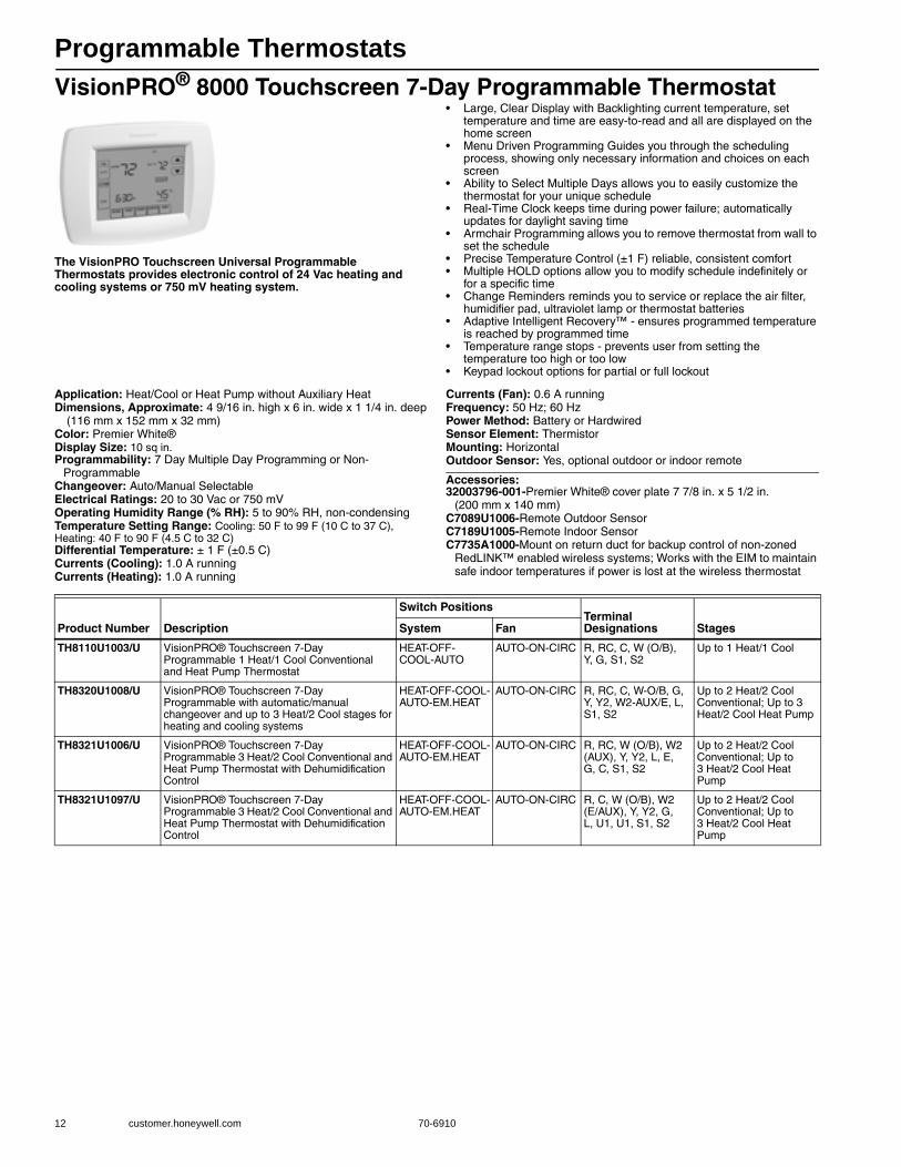
Programmable Thermostats
12 customer.honeywell.com 70-6910
VisionPRO® 8000 Touchscreen 7-Day Programmable Thermostat
The VisionPRO Touchscreen Universal Programmable Thermostats provides electronic control of 24 Vac heating and cooling systems or 750 mV heating system.
• Large, Clear Display with Backlighting current temperature, set temperature and time are easy-to-read and all are displayed on the home screen
• Menu Driven Programming Guides you through the scheduling process, showing only necessary information and choices on each screen
• Ability to Select Multiple Days allows you to easily customize the thermostat for your unique schedule
• Real-Time Clock keeps time during power failure; automatically updates for daylight saving time
• Armchair Programming allows you to remove thermostat from wall to set the schedule
• Precise Temperature Control (±1 F) reliable, consistent comfort • Multiple HOLD options allow you to modify schedule indefinitely or
for a specific time • Change Reminders reminds you to service or replace the air filter,
humidifier pad, ultraviolet lamp or thermostat batteries • Adaptive Intelligent Recovery™ - ensures programmed temperature
is reached by programmed time • Temperature range stops - prevents user from setting the
temperature too high or too low • Keypad lockout options for partial or full lockout
Application: Heat/Cool or Heat Pump without Auxiliary HeatDimensions, Approximate: 4 9/16 in. high x 6 in. wide x 1 1/4 in. deep
(116 mm x 152 mm x 32 mm) Color: Premier White®Display Size: 10 sq in.Programmability: 7 Day Multiple Day Programming or Non-
ProgrammableChangeover: Auto/Manual SelectableElectrical Ratings: 20 to 30 Vac or 750 mVOperating Humidity Range (% RH): 5 to 90% RH, non-condensingTemperature Setting Range: Cooling: 50 F to 99 F (10 C to 37 C), Heating: 40 F to 90 F (4.5 C to 32 C)Differential Temperature: ± 1 F (±0.5 C) Currents (Cooling): 1.0 A runningCurrents (Heating): 1.0 A running
Currents (Fan): 0.6 A runningFrequency: 50 Hz; 60 HzPower Method: Battery or HardwiredSensor Element: ThermistorMounting: HorizontalOutdoor Sensor: Yes, optional outdoor or indoor remote
Accessories:32003796-001-Premier White® cover plate 7 7/8 in. x 5 1/2 in.
(200 mm x 140 mm)C7089U1006-Remote Outdoor SensorC7189U1005-Remote Indoor SensorC7735A1000-Mount on return duct for backup control of non-zoned
RedLINK™ enabled wireless systems; Works with the EIM to maintain safe indoor temperatures if power is lost at the wireless thermostat
Product Number Description
Switch PositionsTerminal Designations StagesSystem Fan
TH8110U1003/U VisionPRO® Touchscreen 7-Day Programmable 1 Heat/1 Cool Conventional and Heat Pump Thermostat
HEAT-OFF-COOL-AUTO
AUTO-ON-CIRC R, RC, C, W (O/B), Y, G, S1, S2
Up to 1 Heat/1 Cool
TH8320U1008/U VisionPRO® Touchscreen 7-Day Programmable with automatic/manual changeover and up to 3 Heat/2 Cool stages for heating and cooling systems
HEAT-OFF-COOL-AUTO-EM.HEAT
AUTO-ON-CIRC R, RC, C, W-O/B, G, Y, Y2, W2-AUX/E, L, S1, S2
Up to 2 Heat/2 Cool Conventional; Up to 3 Heat/2 Cool Heat Pump
TH8321U1006/U VisionPRO® Touchscreen 7-Day Programmable 3 Heat/2 Cool Conventional and Heat Pump Thermostat with Dehumidification Control
HEAT-OFF-COOL-AUTO-EM.HEAT
AUTO-ON-CIRC R, RC, W (O/B), W2 (AUX), Y, Y2, L, E, G, C, S1, S2
Up to 2 Heat/2 Cool Conventional; Up to 3 Heat/2 Cool Heat Pump
TH8321U1097/U VisionPRO® Touchscreen 7-Day Programmable 3 Heat/2 Cool Conventional and Heat Pump Thermostat with Dehumidification Control
HEAT-OFF-COOL-AUTO-EM.HEAT
AUTO-ON-CIRC R, C, W (O/B), W2 (E/AUX), Y, Y2, G, L, U1, U1, S1, S2
Up to 2 Heat/2 Cool Conventional; Up to 3 Heat/2 Cool Heat Pump

Programmable Thermostats
70-6910 13
Hom
e C
ontrols
Commercial VisionPRO® 8000
The TB8220 Commercial VisionPRO 8000 Touchscreen Programmable Thermostat is an effortless, seven day programmable thermostat that provides universal system compatibility, precise comfort control and is easy to program. The TB8220 provides temperature control for gas, oil, electric and heat pumps for up to 2 heat, 2 cool systems.
• Large, clear display with backlight shows the current and set temperature and time even in the dark
• Menu-driven programming make setup effortless • Beautiful ergonomic design is smart and sophisticated to
match your customers' lifestyle • Touchscreen interaction Real-time clock keeps time during
power failures and automatically updates to daylight savings • Saving Changes notification lets you know when the
schedule changes have been saved • Change reminders let you know when to replace the batteries • Holiday Override options allow you to override the
program schedule, as desired • Speedy same--schedule programming--no need to copy multiple days • Armchair programming allows you to remove the
thermostat from the wall for programming
Dimensions in inches (millimeters) Application: 24 Vac heating and cooling systems; Heat Pump Systems; Conventional systems; Packaged RTU
Color: Premier White®Network Communications: NoneComments: The L-terminal is an input only Selectable programmable or
non-programmable.Includes A terminal to enable an economizer or control a lighting panel when used as a time of day relay
Accessories:C7041B2005-20K ohm NTC Temperature Sensor with 6 in. insertionC7041B2013-20K ohm NTC Temperature Sensor with 12 in. insertionC7041C2003-20K ohm NTC Temperature Sensor with 18 in. insertionC7041P2004-20K ohm NTC Stainless Steel Button Sensor, 11/16 in. dia.C7089U1006-Remote Outdoor SensorC7189U1005-Remote Indoor SensorC7770A1006-6 in. Duct Probe for Return Air 20 K ohm NTC
non-linear Temperature SensorC7772A1004-20 K ohm NTC non-linear Wall Flush Mount
Temperature Sensor without logoC7772A1012-20 K ohm NTC non-linear Wall Flush Mount
Temperature Sensor with Honeywell logoTR21-20 K ohm NTC non-linear Temperature Wall ModuleTR21-A-10 K ohm NTC non-linear Temperature Wall Module
(for averaging only)W7212A1009-Series 72 Economizer Logic Module with
Demand Control Ventilation32003796-001-Premier White® cover plate 7 7/8 in. x 5 1/2 in.
(200 mm x 140 mm)
\M22421
6 (152)
THERMOSTAT
4-9/16(116)
3-3/8 (86)WALLPLATE
3-3/8 (86)
THERMOSTATAND WALLPLATE
1-3/8 (35)
Product Number
Switch PositionTerminal Designations Stages
Setting Temperature Range
System Fan (F) (C)
TB8220U1003/U HEAT-OFF-COOL-AUTO-EM.HEAT
AUTO-ON R, Rc, W (O/B), W2 (W1), Y, Y2, L, A, G, C, S1, S2
Up to 2 Heat/2 Cool Conventional; Up to 3 Heat/2 Cool Heat Pump
Heat: 40 F to 90 F; Cool: 50 F to 99 F
Heat: 4.5 C to 32 C; Cool: 10 C to 37 C
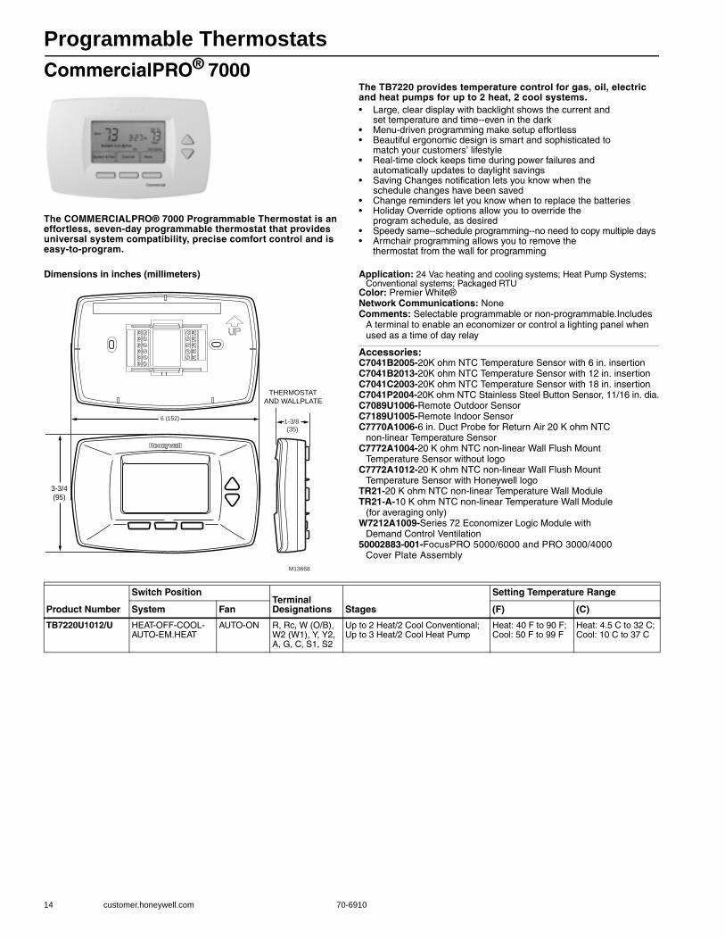
Programmable Thermostats
14 customer.honeywell.com 70-6910
CommercialPRO® 7000
The COMMERCIALPRO® 7000 Programmable Thermostat is an effortless, seven-day programmable thermostat that provides universal system compatibility, precise comfort control and is easy-to-program.
The TB7220 provides temperature control for gas, oil, electric and heat pumps for up to 2 heat, 2 cool systems.• Large, clear display with backlight shows the current and
set temperature and time--even in the dark • Menu-driven programming make setup effortless • Beautiful ergonomic design is smart and sophisticated to
match your customers’ lifestyle • Real-time clock keeps time during power failures and
automatically updates to daylight savings • Saving Changes notification lets you know when the
schedule changes have been saved • Change reminders let you know when to replace the batteries • Holiday Override options allow you to override the
program schedule, as desired • Speedy same--schedule programming--no need to copy multiple days • Armchair programming allows you to remove the
thermostat from the wall for programming
Dimensions in inches (millimeters) Application: 24 Vac heating and cooling systems; Heat Pump Systems; Conventional systems; Packaged RTU
Color: Premier White®Network Communications: NoneComments: Selectable programmable or non-programmable.Includes
A terminal to enable an economizer or control a lighting panel when used as a time of day relay
Accessories:C7041B2005-20K ohm NTC Temperature Sensor with 6 in. insertionC7041B2013-20K ohm NTC Temperature Sensor with 12 in. insertionC7041C2003-20K ohm NTC Temperature Sensor with 18 in. insertionC7041P2004-20K ohm NTC Stainless Steel Button Sensor, 11/16 in. dia.C7089U1006-Remote Outdoor SensorC7189U1005-Remote Indoor SensorC7770A1006-6 in. Duct Probe for Return Air 20 K ohm NTC
non-linear Temperature SensorC7772A1004-20 K ohm NTC non-linear Wall Flush Mount
Temperature Sensor without logoC7772A1012-20 K ohm NTC non-linear Wall Flush Mount
Temperature Sensor with Honeywell logoTR21-20 K ohm NTC non-linear Temperature Wall ModuleTR21-A-10 K ohm NTC non-linear Temperature Wall Module
(for averaging only)W7212A1009-Series 72 Economizer Logic Module with
Demand Control Ventilation50002883-001-FocusPRO 5000/6000 and PRO 3000/4000
Cover Plate AssemblyM13668
3-3/4
(95)
THERMOSTAT
AND WALLPLATE
1-3/8
(35)
6 (152)
Product Number
Switch PositionTerminal Designations Stages
Setting Temperature Range
System Fan (F) (C)
TB7220U1012/U HEAT-OFF-COOL-AUTO-EM.HEAT
AUTO-ON R, Rc, W (O/B), W2 (W1), Y, Y2, A, G, C, S1, S2
Up to 2 Heat/2 Cool Conventional; Up to 3 Heat/2 Cool Heat Pump
Heat: 40 F to 90 F; Cool: 50 F to 99 F
Heat: 4.5 C to 32 C; Cool: 10 C to 37 C
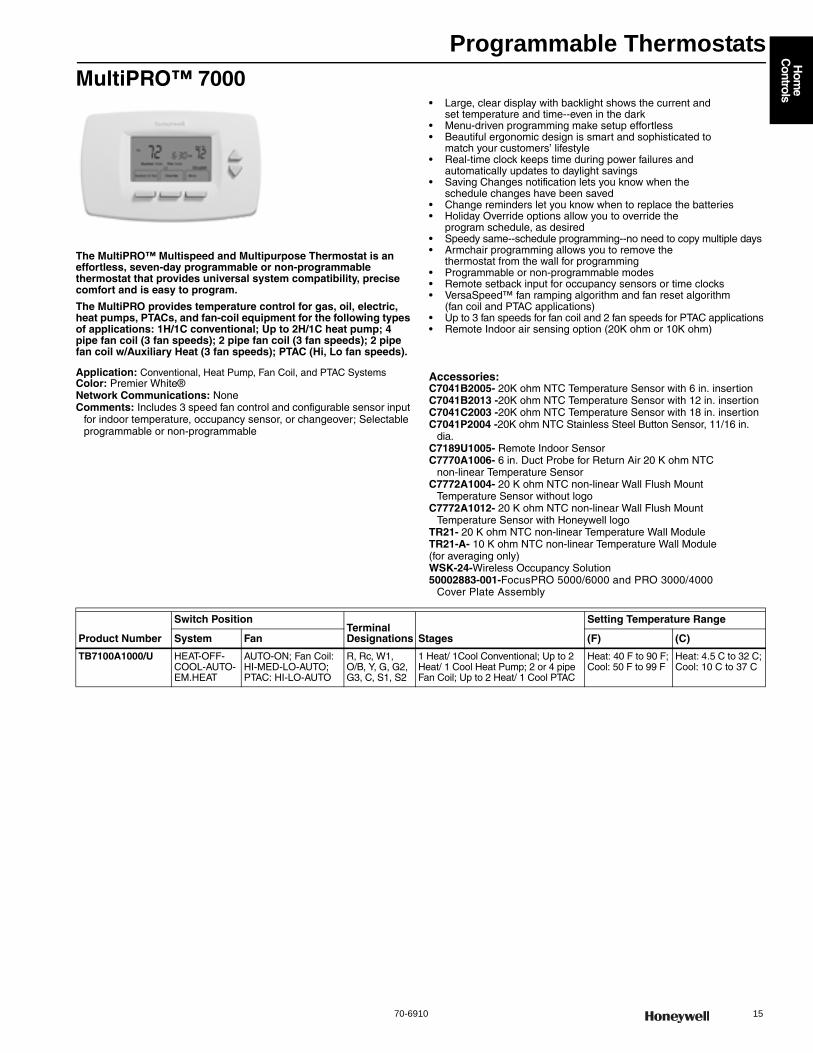
Programmable Thermostats
70-6910 15
Hom
e C
ontrols
MultiPRO™ 7000
The MultiPRO™ Multispeed and Multipurpose Thermostat is an effortless, seven-day programmable or non-programmable thermostat that provides universal system compatibility, precise comfort and is easy to program.
The MultiPRO provides temperature control for gas, oil, electric, heat pumps, PTACs, and fan-coil equipment for the following types of applications: 1H/1C conventional; Up to 2H/1C heat pump; 4 pipe fan coil (3 fan speeds); 2 pipe fan coil (3 fan speeds); 2 pipe fan coil w/Auxiliary Heat (3 fan speeds); PTAC (Hi, Lo fan speeds).
• Large, clear display with backlight shows the current and set temperature and time--even in the dark
• Menu-driven programming make setup effortless • Beautiful ergonomic design is smart and sophisticated to
match your customers’ lifestyle • Real-time clock keeps time during power failures and
automatically updates to daylight savings • Saving Changes notification lets you know when the
schedule changes have been saved • Change reminders let you know when to replace the batteries • Holiday Override options allow you to override the
program schedule, as desired • Speedy same--schedule programming--no need to copy multiple days • Armchair programming allows you to remove the
thermostat from the wall for programming • Programmable or non-programmable modes • Remote setback input for occupancy sensors or time clocks • VersaSpeed™ fan ramping algorithm and fan reset algorithm
(fan coil and PTAC applications) • Up to 3 fan speeds for fan coil and 2 fan speeds for PTAC applications • Remote Indoor air sensing option (20K ohm or 10K ohm)
Application: Conventional, Heat Pump, Fan Coil, and PTAC SystemsColor: Premier White®Network Communications: NoneComments: Includes 3 speed fan control and configurable sensor input
for indoor temperature, occupancy sensor, or changeover; Selectable programmable or non-programmable
Accessories:C7041B2005- 20K ohm NTC Temperature Sensor with 6 in. insertionC7041B2013 -20K ohm NTC Temperature Sensor with 12 in. insertionC7041C2003 -20K ohm NTC Temperature Sensor with 18 in. insertionC7041P2004 -20K ohm NTC Stainless Steel Button Sensor, 11/16 in.
dia.C7189U1005- Remote Indoor SensorC7770A1006- 6 in. Duct Probe for Return Air 20 K ohm NTC
non-linear Temperature SensorC7772A1004- 20 K ohm NTC non-linear Wall Flush Mount
Temperature Sensor without logoC7772A1012- 20 K ohm NTC non-linear Wall Flush Mount
Temperature Sensor with Honeywell logoTR21- 20 K ohm NTC non-linear Temperature Wall ModuleTR21-A- 10 K ohm NTC non-linear Temperature Wall Module (for averaging only)WSK-24-Wireless Occupancy Solution50002883-001-FocusPRO 5000/6000 and PRO 3000/4000
Cover Plate Assembly
Product Number
Switch PositionTerminal Designations Stages
Setting Temperature Range
System Fan (F) (C)
TB7100A1000/U HEAT-OFF-COOL-AUTO-EM.HEAT
AUTO-ON; Fan Coil: HI-MED-LO-AUTO; PTAC: HI-LO-AUTO
R, Rc, W1, O/B, Y, G, G2, G3, C, S1, S2
1 Heat/ 1Cool Conventional; Up to 2 Heat/ 1 Cool Heat Pump; 2 or 4 pipe Fan Coil; Up to 2 Heat/ 1 Cool PTAC
Heat: 40 F to 90 F; Cool: 50 F to 99 F
Heat: 4.5 C to 32 C; Cool: 10 C to 37 C

Programmable Thermostats
16 customer.honeywell.com 70-6910
Wireless FocusPRO® 6000Everything you need to relocate thermostat or upgrade equipment without running new wires• WIRELESS FOCUSPRO® THERMOSTAT: Same great features of
the FocusPRO® thermostat - now wireless. Installs in minutes. Can display outdoor temperature and humidity. 1 year battery life. 2 month low battery warning. Dual Fuel enabled -requires C7089R1013 wireless outdoor sensor (sold separately).
• EQUIPMENT INTERFACE MODULE (EIM): All HVAC equipment is wired to the module. Module receives communication from the wireless devices.
• RETURN AIR SENSOR: Works with the Equipment Interface Module to maintain safe indoor temperatures if power is lost at the wireless thermostat. Maintains 62 F for heating and 82 F for cooling.
• REDLINK™ WIRELESS TECHNOLOGY: Powered by RedLINK™ reliability. No interference with other wireless devices in the home.
Application: Gas, oil, electric, heat pump, forced warm air, hot water, steam or gravity
Electrical Ratings: Equipment Interface Module--18 to 30 Vac, 50 Hz; 60 Hz
Changeover: Auto/Manual SelectableCurrent (Cooling): 1.0 A runningCurrent (Heating): 1.0 A runningCurrent (Fan): 0.6 A runningPower Method: Thermostat--Battery
Accessories:50002883-001-FOCUSPRO® 5000/6000 and PRO 3000/4000 Cover Plate
Assembly50007298-001-12 pack of medium coverplates (5 in. x 6 7/8 in.)C7089R1013-Senses outdoor temperature and humidity to display on
RedLINK™ enabled thermostats and accessories.REM5000R1001-Use the Portable Comfort Control anywhere in the home
to experience a new level of comfort and convenience.
Replacement Parts:50007072-001-Replacement Battery Holder for FocusPRO TH5220,
TH5320, TH6110, TH6220, and TH6320 Thermostat
Product Number
Switch PositionsTerminal Designations Stages IncludesSystem Fan
YTH6320R1001/U HEAT-OFF-COOL-AUTO-EM.HEAT
AUTO-ON
C, R, Rc, Rh, W-O/B, W2-Aux/E, Y, Y2, G, L, RAS
Up to 3 Heat/2 Cool Heat Pump or Up to 2 Heat/2 Cool Conventional
TH6320R1004 Wireless FocusPRO® 5-1-1 Programmable Thermostat;THM5320R1000 Equipment Interface Module;C7735A1000 Return Air Sensor
YTH6320R1114/U HEAT-OFF-COOL-AUTO-EM.HEAT
AUTO-ON
C, R, Rc, Rh, W-O/B, W2-Aux/E, Y, Y2, G, L, RAS
Up to 3 Heat/2 Cool Heat Pump or Up to 2 Heat/2 Cool Conventional
THM6000R1002 RedLINK Internet Gateway;TH6320R1004 Wireless FocusPRO® 5-1-1 Programmable Thermostat;THM5320R1000 Equipment Interface ModuleC7735A1000 Return Air Sensor
YTH6320R1122/U HEAT-OFF-COOL-AUTO-EM.HEAT
AUTO-ON
C, R, Rc, Rh, W-O/B, W2-Aux/E, Y, Y2, G, L, RAS
Up to 3 Heat / 2 Cool Heat Pump or Up to 2 Heat / 2 Cool Conventional
THM6000R1002 RedLINK Internet GatewayTH6320R1004 Wireless FocusPRO® 5-1-1 Programmable Thermostat C7089R1013 Wireless Outdoor Sensor THM5320R1000 Equipment Interface Module C7735A1000 Return Air Sensor

Programmable Thermostats
70-6910 17
Hom
e C
ontrols
Wireless FocusPRO® 6000
Easily add a zone to a TrueZONE® system without running new wires. Choose from programmable or non-programmable.
• Powered by RedLINK™ reliability • No interference with other wireless devices in the home • Works with compatible RedLINK™ enabled devices • Same great features of the FocusPRO thermostat now wireless • Installs in minutes • Can display outdoor temperature and humidity • 1 year battery life • 2 month low battery warning • Dual Fuel enabled - requires THM5320R1000 Equipment Interface
Module and C7089R1013 Wireless Outdoor Sensor (sold separately)
Application: Gas, oil, electric, heat pump, forced warm air, hot water, steam or gravity
Dimensions, Approximate: 3 9/16 in. High X 5 13/16 in. Wide X 1 1/2 in. Deep (91 mm High X 147 mm Wide X 38 mm Deep)
Changeover: Auto/Manual SelectableOperating Humidity Range (% RH): 5 to 90% RH, non-condensingTemperature Setting Range: Heat: 40 F to 90 F; Cool: 50 F to 99 F
(Heat: 4.5 C to 32 C; Cool: 10 C to 37 C)Differential Temperature: ± 1 F (±0.5 C) Power Method: BatterySensor Element: ThermistorColor: Premier White®Mounting: HorizontalComments: Thermostat is also available in kits for zoned and
non-zoned systems
Accessories:REM5000R1001-Portable Comfort Control uses RedLINK™ to sense
and control room temperature anywhere in the home. Works in both zoned and non-zoned applications.
C7089R1013-Senses outdoor temperature and humidity to display on RedLINK™ enabled thermostats and accessories.
C7735A1000-Mount on return duct for backup control of non-zoned RedLINK™ enabled wireless systems. Works with the EIM to maintain safe indoor temperatures if power is lost at the wireless thermostat.
50002883-001-FocusPRO 5000/6000 and PRO 3000/4000 Cover Plate Assembly
50007298-001-12 pack of medium coverplates (5 in. x 6 7/8 in.)
Replacement Parts:50007072-001-Replacement Battery Holder for FocusPRO TH5220,
TH5320, TH6110, TH6220, and TH6320 Thermostat
THM5320 Equipment Interface ModuleEasily relocate thermostat or upgrade equipment without running new wires using this module and a wireless FocusPRO® thermostat.• Powered by RedLINK™ reliability • No interference with other wireless devices in the home • Works with TH6320R1004 or TH5320R1002 Wireless FocusPRO
thermostats • Input for Return Air Sensor • Quick-connect terminal blocks • LEDs for power and system status
Application: Gas, oil, electric, heat pump, forced warm air, hot water, steam or gravity
Dimensions, Approximate: 8 1/8 in. high x 8 in. wide x 1 7/8 in. deep (206 mm high x 203 mm wide x 47 mm deep)
Electrical Ratings: 18 to 30 Vac, 50/60 HzOperating Humidity Range (% RH): 5 to 95% RH, non-condensingCooling: 1.0 A runningHeating: 1.0 A runningFan: 0.6 A runningColor: Gray
Accessories:C7735A1000-Mount on return duct for backup control of non-zoned
RedLINK™ enabled wireless systems. Works with the EIM to maintain safe indoor temperatures if power is lost at the wireless thermostat.
C7089R1013-Senses outdoor temperature and humidity to display on RedLINK™ enabled thermostats and accessories.
REM5000R1001-Portable Comfort Control uses RedLINK™ to sense and control room temperature anywhere in the home. Works in both zoned and non-zoned applications.
THM6000R1002-RedLINK Internet Gateway
Product Number
Switch Positions
StagesParts Needed for Operation (not included) - TrueZONE® System
Parts Needed for Operation (not included) - Non-Zoned SystemSystem Fan
TH6320R1004/U HEAT-OFF-COOL-AUTO-EM.HEAT
AUTO-ON
Up to 3 Heat/2 Cool Heat Pump or Up to 2 Heat/2 Cool Conventional
HZ432 or HZ322 TrueZONE panel; THM4000R1000 Wireless Adapter
THM5320R1000 Equipment Interface Module
Product NumberTerminal Designations Stages Description
Parts Needed for Operation (not included) Comments
THM5320R1000/U C, R, Rc, Rh, W-O/B, W2-Aux/E, Y, Y2, G, L, RAS
Up to 3 Heat/2 Cool Heat Pump or Up to 2 Heat/2 Cool Conventional
Controls up to 3 heat /2 cool heat pump systems or up to 2 heat/2 cool conventional systems when used with the wireless FocusPRO® thermostat.
TH6320R1004 or TH5320R1002 Wireless FocusPRO® Thermostat
Equipment Interface Module is also available in kits
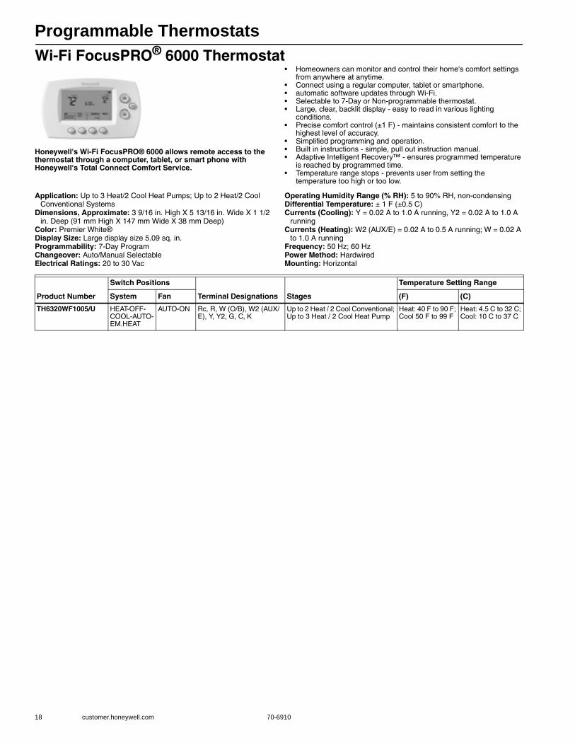
Programmable Thermostats
18 customer.honeywell.com 70-6910
Wi-Fi FocusPRO® 6000 Thermostat
Honeywell's Wi-Fi FocusPRO® 6000 allows remote access to the thermostat through a computer, tablet, or smart phone with Honeywell's Total Connect Comfort Service.
• Homeowners can monitor and control their home's comfort settings from anywhere at anytime.
• Connect using a regular computer, tablet or smartphone. • automatic software updates through Wi-Fi. • Selectable to 7-Day or Non-programmable thermostat. • Large, clear, backlit display - easy to read in various lighting
conditions. • Precise comfort control (±1 F) - maintains consistent comfort to the
highest level of accuracy. • Simplified programming and operation. • Built in instructions - simple, pull out instruction manual. • Adaptive Intelligent Recovery™ - ensures programmed temperature
is reached by programmed time. • Temperature range stops - prevents user from setting the
temperature too high or too low.
Application: Up to 3 Heat/2 Cool Heat Pumps; Up to 2 Heat/2 Cool Conventional Systems
Dimensions, Approximate: 3 9/16 in. High X 5 13/16 in. Wide X 1 1/2 in. Deep (91 mm High X 147 mm Wide X 38 mm Deep)
Color: Premier White®Display Size: Large display size 5.09 sq. in.Programmability: 7-Day ProgramChangeover: Auto/Manual SelectableElectrical Ratings: 20 to 30 Vac
Operating Humidity Range (% RH): 5 to 90% RH, non-condensingDifferential Temperature: ± 1 F (±0.5 C) Currents (Cooling): Y = 0.02 A to 1.0 A running, Y2 = 0.02 A to 1.0 A
runningCurrents (Heating): W2 (AUX/E) = 0.02 A to 0.5 A running; W = 0.02 A
to 1.0 A runningFrequency: 50 Hz; 60 HzPower Method: HardwiredMounting: Horizontal
Product Number
Switch Positions
Terminal Designations Stages
Temperature Setting Range
System Fan (F) (C)
TH6320WF1005/U HEAT-OFF-COOL-AUTO-EM.HEAT
AUTO-ON Rc, R, W (O/B), W2 (AUX/E), Y, Y2, G, C, K
Up to 2 Heat / 2 Cool Conventional; Up to 3 Heat / 2 Cool Heat Pump
Heat: 40 F to 90 F; Cool 50 F to 99 F
Heat: 4.5 C to 32 C; Cool: 10 C to 37 C

Programmable Thermostats
70-6910 19
Hom
e C
ontrols
FocusPRO® 6000 5-1-1 Day Programmable Thermostat
The FocusPRO® programmable thermostat provides electronic control of 24 Vac conventional and heat pump systems or 750 mV heating systems.
• Selectable to 5-1-1 (Weekdays, Saturday, Sunday) or 5-2 (Weekdays, Weekend) programmable thermostat
• Large, clear, backlit display - easy to read in various lighting conditions
• Display size options - available in large screen or standard • Precise comfort control (±1 F) - maintains consistent comfort to
the highest level of accuracy • Simplified programming and operation • Easy change battery door - flip out door allows for easy battery
replacement without removing or disassembling the thermostat • Built in instructions - simple, pull out instruction manual • Adaptive Intelligent Recovery™ - ensures programmed temperature
is reached by programmed time • Temperature range stops - prevents user from setting the
temperature too high or too low
Dimensions, Approximate: 3 9/16 in. High X 5 13/16 in. Wide X 1 1/2 in. Deep (91 mm High X 147 mm Wide X 38 mm Deep)
Color: Premier White®Programmability: 5-1-1 Day Program or 5-2 Day ProgramChangeover: Auto/Manual SelectableElectrical Ratings: 20 to 30 Vac or 750 mVVoltage: 20 to 30 Vac or 750 mVOperating Humidity Range (% RH): 5 to 90% RH, non-condensingDifferential Temperature: ± 1 F (±0.5 C) Currents (Cooling): 0.02 A to 1.0 A runningCurrents (Heating): 0.02 A to 1.0 A runningCurrents (Fan): 0.02 A to 0.5 A running
Frequency: 50 Hz; 60 HzPower Method: Battery or HardwiredSensor Element: ThermistorMounting: Horizontal
Accessories:50002883-001-FocusPRO 5000/6000 and PRO 3000/4000 and
Horizontal PRO 1000/2000 Cover Plate Assembly50007298-001-12 pack of medium coverplates (5 in. x 6 7/8 in.)
Replacement Parts:50007072-001-Replacement Battery Holder for FocusPRO TH5220,
Product Number Application
Switch PositionsTerminal Designations Stages
Temperature Setting Range
CommentsSystem Fan (C) (F)
TH6110D1005/U Heat/Cool or Heat Pump without Auxiliary Heat
HEAT-OFF-COOL-AUTO
AUTO-ON Rc, R, W (O/B), Y, G, C
Up to 1 Heat/1 Cool
Heat: 4.5 C to 32 C; Cool: 10 C to 37 C
Heat: 40 F to 90 F; Cool: 50 F to 99 F
Standard display size 3.75 sq. in.
TH6110D1021/U HEAT-OFF-COOL-AUTO
AUTO-ON Rc, R, W (O/B), Y, G, C
Heat: 4.5 C to 32 C; Cool: 10 C to 37 C
Heat: 40 F to 90 F; Cool: 50 F to 99 F
Large display size 5.09 sq. in.
TH6220D1002/U Heat/Cool or Heat Pump with Auxiliary Heat
HEAT-OFF-COOL-AUTO-EM.HEAT
AUTO-ON R, RC, C, W-O/B, G, Y, W2-AUX/E, Y2-L
Up to 2 Heat/1 Cool Heat Pump or Up to 2 Heat/2 Cool Conventional
Heat: 4.5 C to 32 C; Cool: 10 C to 37 C
Heat: 40 F to 90 F; Cool: 50 F to 99 F
Standard display size 3.75 sq. in.
TH6220D1028/U HEAT-OFF-COOL-AUTO-EM.HEAT
AUTO-ON R, RC, C, W-O/B, G, Y, W2-AUX/E, Y2-L
Heat: 4.5 C to 32 C; Cool: 10 C to 37 C
Heat: 40 F to 90 F; Cool: 50 F to 99 F
Large display size 5.09 sq. in.
TH6320U1000/U HEAT-OFF-COOL-AUTO-EM.HEAT
AUTO-ON Rc, R, W (O/B), W2 (AUX/E), Y, Y2, G, L, C
Up to 3 Heat / 2 Cool Heat Pump or Up to 2 Heat / 2 Cool Conventional
Heat: 4.5 C to 32 C; Cool: 10 C to 37 C
Heat: 40 F to 90 F; Cool: 50 F to 99 F
Large display size 5.09 sq. in.
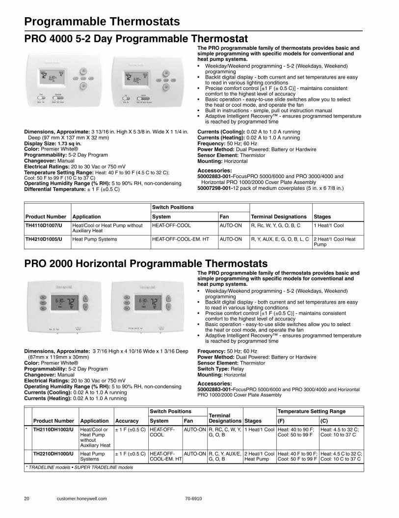
Programmable Thermostats
20 customer.honeywell.com 70-6910
PRO 4000 5-2 Day Programmable ThermostatThe PRO programmable family of thermostats provides basic and simple programming with specific models for conventional and heat pump systems.• Weekday/Weekend programming - 5-2 (Weekdays, Weekend)
programming • Backlit digital display - both current and set temperatures are easy
to read in various lighting conditions • Precise comfort control [±1 F (± 0.5 C)] - maintains consistent
comfort to the highest level of accuracy • Basic operation - easy-to-use slide switches allow you to select
the heat or cool mode, and operate the fan • Built in instructions - simple, pull out instruction manual • Adaptive Intelligent Recovery™ - ensures programmed temperature
is reached by programmed time
Dimensions, Approximate: 3 13/16 in. High X 5 3/8 in. Wide X 1 1/4 in. Deep (97 mm X 137 mm X 32 mm)
Display Size: 1.73 sq in.Color: Premier White®Programmability: 5-2 Day ProgramChangeover: ManualElectrical Ratings: 20 to 30 Vac or 750 mVTemperature Setting Range: Heat: 40 F to 90 F (4.5 C to 32 C); Cool: 50 F to 99 F (10 C to 37 C)Operating Humidity Range (% RH): 5 to 90% RH, non-condensingDifferential Temperature: ± 1 F (±0.5 C)
Currents (Cooling): 0.02 A to 1.0 A runningCurrents (Heating): 0.02 A to 1.0 A runningFrequency: 50 Hz; 60 HzPower Method: Dual Powered: Battery or HardwireSensor Element: ThermistorMounting: Horizontal
Accessories:50002883-001-FocusPRO 5000/6000 and PRO 3000/4000 and
Horizontal PRO 1000/2000 Cover Plate Assembly50007298-001-12 pack of medium coverplates (5 in. x 6 7/8 in.)
PRO 2000 Horizontal Programmable ThermostatsThe PRO programmable family of thermostats provides basic and simple programming with specific models for conventional and heat pump systems.• Weekday/Weekend programming - 5-2 (Weekdays, Weekend)
programming • Backlit digital display - both current and set temperatures are easy
to read in various lighting conditions • Precise comfort control [±1 F (±0.5 C)] - maintains consistent
comfort to the highest level of accuracy • Basic operation - easy-to-use slide switches allow you to select
the heat or cool mode, and operate the fan • Adaptive Intelligent Recovery™ - ensures programmed temperature
is reached by programmed time
Dimensions, Approximate: 3 7/16 High x 4 10/16 Wide x 1 3/16 Deep (87mm x 119mm x 30mm)
Color: Premier White®Programmability: 5-2 Day ProgramChangeover: ManualElectrical Ratings: 20 to 30 Vac or 750 mVOperating Humidity Range (% RH): 5 to 90% RH, non-condensingCurrents (Cooling): 0.02 A to 1.0 A runningCurrents (Heating): 0.02 A to 1.0 A running
Frequency: 50 Hz; 60 HzPower Method: Dual Powered: Battery or HardwireSensor Element: ThermistorSwitch Type: RelayMounting: Horizontal
Accessories:50002883-001-FocusPRO 5000/6000 and PRO 3000/4000 and Horizontal PRO 1000/2000 Cover Plate Assembly
Product Number Application
Switch Positions
Terminal Designations StagesSystem Fan
TH4110D1007/U Heat/Cool or Heat Pump without Auxiliary Heat
HEAT-OFF-COOL AUTO-ON R, Rc, W, Y, G, O, B, C 1 Heat/1 Cool
TH4210D1005/U Heat Pump Systems HEAT-OFF-COOL-EM. HT AUTO-ON R, Y, AUX, E, G, O, B, L, C 2 Heat/1 Cool Heat Pump
Product Number Application Accuracy
Switch PositionsTerminal Designations Stages
Temperature Setting Range
System Fan (F) (C)
* TH2110DH1002/U Heat/Cool or Heat Pump without Auxiliary Heat
± 1 F (±0.5 C) HEAT-OFF-COOL
AUTO-ON R, RC, C, W, Y, G, O, B
1 Heat/1 Cool Heat: 40 to 90 F; Cool: 50 to 99 F
Heat: 4.5 to 32 C; Cool: 10 to 37 C
TH2210DH1000/U Heat Pump Systems
± 1 F (±0.5 C) HEAT-OFF-COOL-EM. HT
AUTO-ON R, C, Y, AUX/E, G, O, B
2 Heat/1 Cool Heat Pump
Heat: 40 F to 90 F; Cool: 50 F to 99 F
Heat: 4.5 C to 32 C; Cool: 10 C to 37 C
* TRADELINE models • SUPER TRADELINE models
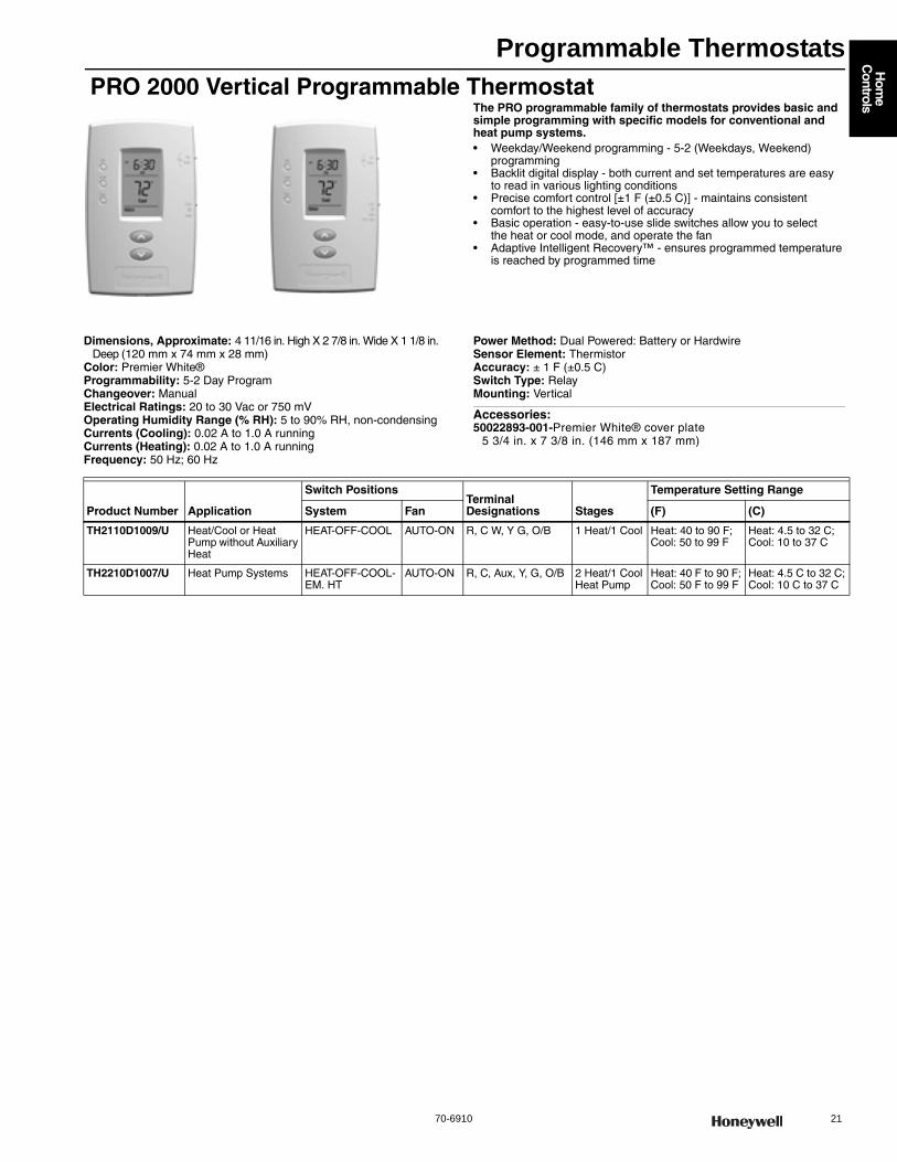
Programmable Thermostats
70-6910 21
Hom
e C
ontrols
PRO 2000 Vertical Programmable ThermostatThe PRO programmable family of thermostats provides basic and simple programming with specific models for conventional and heat pump systems.• Weekday/Weekend programming - 5-2 (Weekdays, Weekend)
programming• Backlit digital display - both current and set temperatures are easy
to read in various lighting conditions • Precise comfort control [±1 F (±0.5 C)] - maintains consistent
comfort to the highest level of accuracy • Basic operation - easy-to-use slide switches allow you to select
the heat or cool mode, and operate the fan • Adaptive Intelligent Recovery™ - ensures programmed temperature
is reached by programmed time
Dimensions, Approximate: 4 11/16 in. High X 2 7/8 in. Wide X 1 1/8 in. Deep (120 mm x 74 mm x 28 mm)
Color: Premier White®Programmability: 5-2 Day ProgramChangeover: ManualElectrical Ratings: 20 to 30 Vac or 750 mVOperating Humidity Range (% RH): 5 to 90% RH, non-condensingCurrents (Cooling): 0.02 A to 1.0 A runningCurrents (Heating): 0.02 A to 1.0 A runningFrequency: 50 Hz; 60 Hz
Power Method: Dual Powered: Battery or HardwireSensor Element: ThermistorAccuracy: ± 1 F (±0.5 C)Switch Type: RelayMounting: Vertical
Accessories:50022893-001-Premier White® cover plate
5 3/4 in. x 7 3/8 in. (146 mm x 187 mm)
Product Number Application
Switch PositionsTerminal Designations Stages
Temperature Setting Range
System Fan (F) (C)
TH2110D1009/U Heat/Cool or Heat Pump without Auxiliary Heat
HEAT-OFF-COOL AUTO-ON R, C W, Y G, O/B 1 Heat/1 Cool Heat: 40 to 90 F; Cool: 50 to 99 F
Heat: 4.5 to 32 C; Cool: 10 to 37 C
TH2210D1007/U Heat Pump Systems HEAT-OFF-COOL-EM. HT
AUTO-ON R, C, Aux, Y, G, O/B 2 Heat/1 Cool Heat Pump
Heat: 40 F to 90 F; Cool: 50 F to 99 F
Heat: 4.5 C to 32 C; Cool: 10 C to 37 C
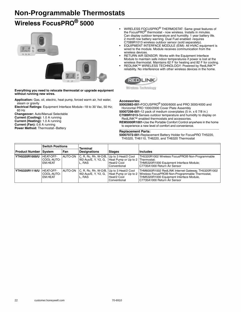
Non-Programmable Thermostats
22 customer.honeywell.com 70-6910
Wireless FocusPRO® 5000
Everything you need to relocate thermostat or upgrade equipment without running new wires.
• WIRELESS FOCUSPRO® THERMOSTAT: Same great features of the FocusPRO® thermostat - now wireless. Installs in minutes. Can display outdoor temperature and humidity. 1 year battery life. 2 month low battery warning. Dual Fuel enabled -requires C7089R1013 wireless outdoor sensor (sold separately).
• EQUIPMENT INTERFACE MODULE (EIM): All HVAC equipment is wired to the module. Module receives communication from the wireless devices.
• RETURN AIR SENSOR: Works with the Equipment Interface Module to maintain safe indoor temperatures if power is lost at the wireless thermostat. Maintains 62 F for heating and 82 F for cooling.
• REDLINK™ WIRELESS TECHNOLOGY: Powered by RedLINK™ reliability. No interference with other wireless devices in the home.
Application: Gas, oil, electric, heat pump, forced warm air, hot water, steam or gravity
Electrical Ratings: Equipment Interface Module--18 to 30 Vac, 50 Hz; 60 Hz
Changeover: Auto/Manual SelectableCurrent (Cooling): 1.0 A runningCurrent (Heating): 1.0 A runningCurrent (Fan): 0.6 A runningPower Method: Thermostat--Battery
Accessories:50002883-001-FOCUSPRO® 5000/6000 and PRO 3000/4000 and
Horizontal PRO 1000/2000 Cover Plate Assembly50007298-001-12 pack of medium coverplates (5 in. x 6 7/8 in.)C7089R1013-Senses outdoor temperature and humidity to display on
RedLINK™ enabled thermostats and accessories.REM5000R1001-Use the Portable Comfort Control anywhere in the home
to experience a new level of comfort and convenience.
Replacement Parts:50007072-001-Replacement Battery Holder for FocusPRO TH5220,
TH5320, TH6110, TH6220, and TH6320 Thermostat
Product Number
Switch PositionsTerminal Designations Stages IncludesSystem Fan
YTH5320R1000/U HEAT-OFF-COOL-AUTO-EM.HEAT
AUTO-ON C, R, Rc, Rh, W-O/B, W2-Aux/E, Y, Y2, G, L, RAS
Up to 3 Heat/2 Cool Heat Pump or Up to 2 Heat/2 Cool Conventional
TH5320R1002 Wireless FocusPRO® Non-Programmable Thermostat; THM5320R1000 Equipment Interface Module; C7735A1000 Return Air Sensor
YTH5320R1116/U HEAT-OFF-COOL-AUTO-EM.HEAT
AUTO-ON C, R, Rc, Rh, W-O/B, W2-Aux/E, Y, Y2, G, L, RAS
Up to 3 Heat/2 Cool Heat Pump or Up to 2 Heat/2 Cool Conventional
THM6000R1002 RedLINK Internet Gateway, TH5320R1002 Wireless FocusPRO® Non-Programmable Thermostat, THM5320R1000 Equipment Interface Module, C7735A1000 Return Air Sensor
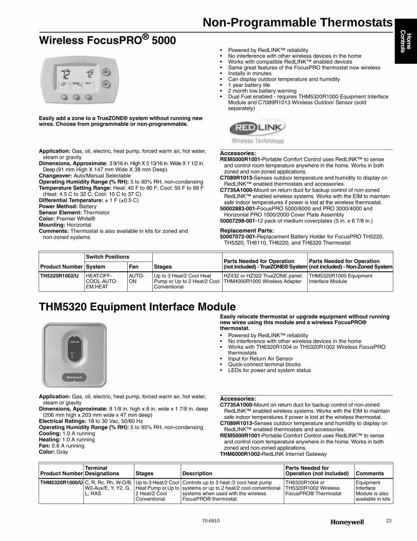
Non-Programmable Thermostats
70-6910 23
Hom
e C
ontrols
Wireless FocusPRO® 5000
Easily add a zone to a TrueZONE® system without running new wires. Choose from programmable or non-programmable.
• Powered by RedLINK™ reliability • No interference with other wireless devices in the home • Works with compatible RedLINK™ enabled devices • Same great features of the FocusPRO thermostat now wireless • Installs in minutes • Can display outdoor temperature and humidity • 1 year battery life • 2 month low battery warning • Dual Fuel enabled - requires THM5320R1000 Equipment Interface
Module and C7089R1013 Wireless Outdoor Sensor (sold separately)
Application: Gas, oil, electric, heat pump, forced warm air, hot water, steam or gravity
Dimensions, Approximate: 3 9/16 in. High X 5 13/16 in. Wide X 1 1/2 in. Deep (91 mm High X 147 mm Wide X 38 mm Deep)
Changeover: Auto/Manual SelectableOperating Humidity Range (% RH): 5 to 90% RH, non-condensingTemperature Setting Range: Heat: 40 F to 90 F; Cool: 50 F to 99 F
(Heat: 4.5 C to 32 C; Cool: 10 C to 37 C)Differential Temperature: ± 1 F (±0.5 C) Power Method: BatterySensor Element: ThermistorColor: Premier White®Mounting: HorizontalComments: Thermostat is also available in kits for zoned and
non-zoned systems
Accessories:REM5000R1001-Portable Comfort Control uses RedLINK™ to sense
and control room temperature anywhere in the home. Works in both zoned and non-zoned applications.
C7089R1013-Senses outdoor temperature and humidity to display on RedLINK™ enabled thermostats and accessories.
C7735A1000-Mount on return duct for backup control of non-zoned RedLINK™ enabled wireless systems. Works with the EIM to maintain safe indoor temperatures if power is lost at the wireless thermostat.
50002883-001-FocusPRO 5000/6000 and PRO 3000/4000 and Horizontal PRO 1000/2000 Cover Plate Assembly
50007298-001-12 pack of medium coverplates (5 in. x 6 7/8 in.)
Replacement Parts:50007072-001-Replacement Battery Holder for FocusPRO TH5220,
TH5320, TH6110, TH6220, and TH6320 Thermostat
THM5320 Equipment Interface ModuleEasily relocate thermostat or upgrade equipment without running new wires using this module and a wireless FocusPRO® thermostat.• Powered by RedLINK™ reliability • No interference with other wireless devices in the home • Works with TH6320R1004 or TH5320R1002 Wireless FocusPRO
thermostats • Input for Return Air Sensor • Quick-connect terminal blocks • LEDs for power and system status
Application: Gas, oil, electric, heat pump, forced warm air, hot water, steam or gravity
Dimensions, Approximate: 8 1/8 in. high x 8 in. wide x 1 7/8 in. deep (206 mm high x 203 mm wide x 47 mm deep)
Electrical Ratings: 18 to 30 Vac, 50/60 HzOperating Humidity Range (% RH): 5 to 95% RH, non-condensingCooling: 1.0 A runningHeating: 1.0 A runningFan: 0.6 A runningColor: Gray
Accessories:C7735A1000-Mount on return duct for backup control of non-zoned
RedLINK™ enabled wireless systems. Works with the EIM to maintain safe indoor temperatures if power is lost at the wireless thermostat.
C7089R1013-Senses outdoor temperature and humidity to display on RedLINK™ enabled thermostats and accessories.
REM5000R1001-Portable Comfort Control uses RedLINK™ to sense and control room temperature anywhere in the home. Works in both zoned and non-zoned applications.
THM6000R1002-RedLINK Internet Gateway
Product Number
Switch Positions
StagesParts Needed for Operation (not included) - TrueZONE® System
Parts Needed for Operation (not included) - Non-Zoned SystemSystem Fan
TH5320R1002/U HEAT-OFF-COOL-AUTO-EM.HEAT
AUTO-ON
Up to 3 Heat/2 Cool Heat Pump or Up to 2 Heat/2 Cool Conventional
HZ432 or HZ322 TrueZONE panel; THM4000R1000 Wireless Adapter
THM5320R1000 Equipment Interface Module
Product NumberTerminal Designations Stages Description
Parts Needed for Operation (not included) Comments
THM5320R1000/U C, R, Rc, Rh, W-O/B, W2-Aux/E, Y, Y2, G, L, RAS
Up to 3 Heat/2 Cool Heat Pump or Up to 2 Heat/2 Cool Conventional
Controls up to 3 heat /2 cool heat pump systems or up to 2 heat/2 cool conventional systems when used with the wireless FocusPRO® thermostat.
TH6320R1004 or TH5320R1002 Wireless FocusPRO® Thermostat
Equipment Interface Module is also available in kits
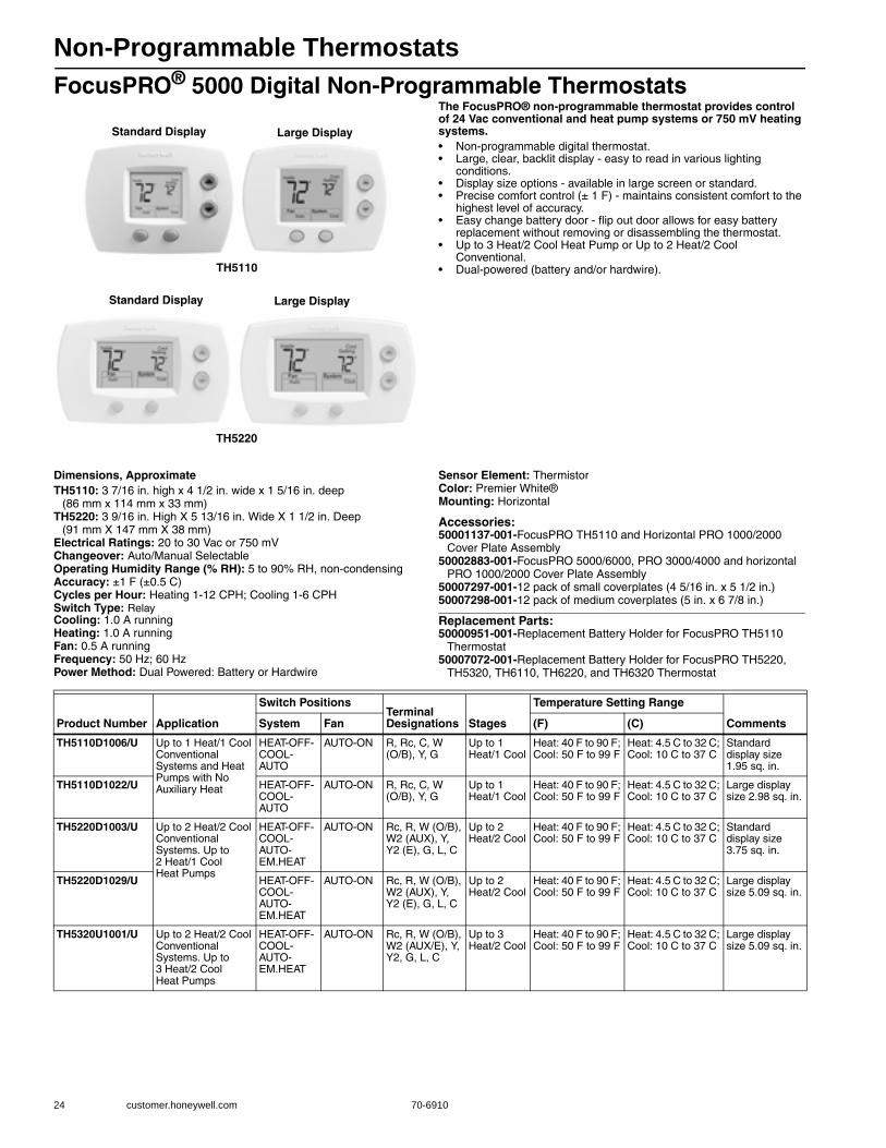
Non-Programmable Thermostats
24 customer.honeywell.com 70-6910
FocusPRO® 5000 Digital Non-Programmable ThermostatsThe FocusPRO® non-programmable thermostat provides control of 24 Vac conventional and heat pump systems or 750 mV heating systems.• Non-programmable digital thermostat. • Large, clear, backlit display - easy to read in various lighting
conditions. • Display size options - available in large screen or standard. • Precise comfort control (± 1 F) - maintains consistent comfort to the
highest level of accuracy. • Easy change battery door - flip out door allows for easy battery
replacement without removing or disassembling the thermostat. • Up to 3 Heat/2 Cool Heat Pump or Up to 2 Heat/2 Cool
Conventional. • Dual-powered (battery and/or hardwire).
Dimensions, ApproximateTH5110: 3 7/16 in. high x 4 1/2 in. wide x 1 5/16 in. deep
(86 mm x 114 mm x 33 mm)TH5220: 3 9/16 in. High X 5 13/16 in. Wide X 1 1/2 in. Deep
(91 mm X 147 mm X 38 mm)Electrical Ratings: 20 to 30 Vac or 750 mVChangeover: Auto/Manual SelectableOperating Humidity Range (% RH): 5 to 90% RH, non-condensingAccuracy: ±1 F (±0.5 C) Cycles per Hour: Heating 1-12 CPH; Cooling 1-6 CPHSwitch Type: RelayCooling: 1.0 A runningHeating: 1.0 A runningFan: 0.5 A runningFrequency: 50 Hz; 60 HzPower Method: Dual Powered: Battery or Hardwire
Sensor Element: ThermistorColor: Premier White®Mounting: Horizontal
Accessories:50001137-001-FocusPRO TH5110 and Horizontal PRO 1000/2000
Cover Plate Assembly 50002883-001-FocusPRO 5000/6000, PRO 3000/4000 and horizontal
PRO 1000/2000 Cover Plate Assembly50007297-001-12 pack of small coverplates (4 5/16 in. x 5 1/2 in.)50007298-001-12 pack of medium coverplates (5 in. x 6 7/8 in.)
Replacement Parts:50000951-001-Replacement Battery Holder for FocusPRO TH5110
Thermostat50007072-001-Replacement Battery Holder for FocusPRO TH5220,
TH5320, TH6110, TH6220, and TH6320 Thermostat
Standard Display Large Display
TH5110
TH5220
Standard Display Large Display
Product Number Application
Switch PositionsTerminal Designations Stages
Temperature Setting Range
CommentsSystem Fan (F) (C)
TH5110D1006/U Up to 1 Heat/1 Cool Conventional Systems and Heat Pumps with No Auxiliary Heat
HEAT-OFF-COOL-AUTO
AUTO-ON R, Rc, C, W (O/B), Y, G
Up to 1 Heat/1 Cool
Heat: 40 F to 90 F; Cool: 50 F to 99 F
Heat: 4.5 C to 32 C; Cool: 10 C to 37 C
Standard display size 1.95 sq. in.
TH5110D1022/U HEAT-OFF-COOL-AUTO
AUTO-ON R, Rc, C, W (O/B), Y, G
Up to 1 Heat/1 Cool
Heat: 40 F to 90 F; Cool: 50 F to 99 F
Heat: 4.5 C to 32 C; Cool: 10 C to 37 C
Large display size 2.98 sq. in.
TH5220D1003/U Up to 2 Heat/2 Cool Conventional Systems. Up to 2 Heat/1 Cool Heat Pumps
HEAT-OFF-COOL-AUTO-EM.HEAT
AUTO-ON Rc, R, W (O/B), W2 (AUX), Y, Y2 (E), G, L, C
Up to 2 Heat/2 Cool
Heat: 40 F to 90 F; Cool: 50 F to 99 F
Heat: 4.5 C to 32 C; Cool: 10 C to 37 C
Standard display size 3.75 sq. in.
TH5220D1029/U HEAT-OFF-COOL-AUTO-EM.HEAT
AUTO-ON Rc, R, W (O/B), W2 (AUX), Y, Y2 (E), G, L, C
Up to 2 Heat/2 Cool
Heat: 40 F to 90 F; Cool: 50 F to 99 F
Heat: 4.5 C to 32 C; Cool: 10 C to 37 C
Large display size 5.09 sq. in.
TH5320U1001/U Up to 2 Heat/2 Cool Conventional Systems. Up to 3 Heat/2 Cool Heat Pumps
HEAT-OFF-COOL-AUTO-EM.HEAT
AUTO-ON Rc, R, W (O/B), W2 (AUX/E), Y, Y2, G, L, C
Up to 3 Heat/2 Cool
Heat: 40 F to 90 F; Cool: 50 F to 99 F
Heat: 4.5 C to 32 C; Cool: 10 C to 37 C
Large display size 5.09 sq. in.
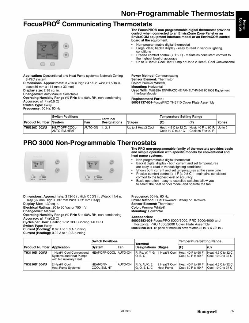
Non-Programmable Thermostats
70-6910 25
Hom
e C
ontrols
FocusPRO® Communicating ThermostatsThe FocusPRO® non-programmable digital thermostat provides control when connected to an EnviraZone Zone Panel or an EnviraCOM equipment interface model or an EnviraCOM control board at the equipment.• Non-programmable digital thermostat • Large, clear, backlit display - easy to read in various lighting
conditions • Precise comfort control (± 1½ F) - maintains consistent comfort to
the highest level of accuracy • Up to 3 Heat/2 Cool Heat Pump or Up to 2 Heat/2 Cool Conventional
Application: Conventional and Heat Pump systems; Network Zoning 3H/2C system
Dimensions, Approximate: 3 7/16 in. high x 4 1/2 in. wide x 1 5/16 in. deep (86 mm x 114 mm x 33 mm)
Display size: 2.98 sq. in.Changeover: Auto/Manual SelectableOperating Humidity Range (% RH): 5 to 90% RH, non-condensingAccuracy: ±1 F (±0.5 C) Switch Type: RelayFrequency: 50 Hz; 60 Hz
Power Method: CommunicatingSensor Element: ThermistorColor: Premier White®Mounting: HorizontalUsed With: W8835A ENVIRAZONE PANELTHM5421C1008 Equipment
Interface Module
Replacement Parts:50001137-001-FocusPRO TH5110 Cover Plate Assembly
PRO 3000 Non-Programmable ThermostatsThe PRO non-programmable family of thermostats provides basic and simple operation with specific models for conventional and heat pump systems.• Non-programmable digital thermostat • Backlit digital display - both current and set temperatures
are easy to read in various lighting conditions • Shows both current and set temperatures at the same time • Precise comfort control [± 1 F (± 0.5 C)] - maintains consistent
comfort to the highest level of accuracy • Basic operation - easy-to-use slide switches allow you
to select the heat or cool mode, and operate the fan
Dimensions, Approximate: 3 13/16 in. High X 5 3/8 in. Wide X 1 1/4 in. Deep (97 mm High X 137 mm Wide X 32 mm Deep)
Display Size: 1.32 sq in.Electrical Ratings: 20 to 30 Vac or 750 mVChangeover: ManualOperating Humidity Range (% RH): 5 to 90% RH, non-condensingAccuracy: ±1 F (±0.5 C) Cycles per Hour: Heating 1-12 CPH; Cooling 1-6 CPHSwitch Type: RelayCurrent (Cooling): 0.02 A to 1.0 A runningCurrent (Heating): 0.02 A to 1.0 A running
Frequency: 50 Hz; 60 HzPower Method: Dual Powered: Battery or HardwireSensor Element: ThermistorColor: Premier White®Mounting: Horizontal
Accessories:50002883-001-FocusPRO 5000/6000, PRO 3000/4000 and
Horizontal PRO 1000/2000 Cover Plate Assembly50007298-001-12 pack of medium coverplates (5 in. x 6 7/8 in.)
Product Number
Switch PositionsTerminal Designations Stages
Temperature Setting Range
ZonesSystem Fan (C) (F)
TH5320C1002/U HEAT-OFF-COOL-AUTO-EM.HEAT
AUTO-ON 1, 2, 3 Up to 3 Heat/2 Cool Heat: 4.5 C to 32 C; Cool: 10 C to 37 C
Heat: 40 F to 90 F; Cool: 50 F to 99 F
Up to 9
Product Number Application
Switch PositionsTerminal Designations Stages
Temperature Setting Range
System Fan (F) (C)
TH3110D1008/U 1 Heat/1 Cool Conventional Systems and Heat Pumps with No Auxiliary Heat
HEAT-OFF-COOL AUTO-ON R, Rc, W, Y, G, O, B, C
1 Heat/1 Cool Heat: 40 F to 90 F; Cool: 50 F to 99 F
Heat: 4.5 C to 32 C; Cool: 10 C to 37 C
TH3210D1004/U 2 Heat/1 Cool Heat Pump Systems
HEAT-OFF-COOL-EM. HT
AUTO-ON R, Y, AUX, E, G, O, B, L, C
2 Heat/1 Cool Heat Pump
Heat: 40 F to 90 F; Cool: 50 F to 99 F
Heat: 4.5 C to 32 C; Cool: 10 C to 37 C

Non-Programmable Thermostats
26 customer.honeywell.com 70-6910
PRO 1000 Horizontal Non-Programmable ThermostatsThe PRO non-programmable family of thermostats provides basic and simple operation with specific models for conventional and heat pump systems.• Non-programmable digital thermostat • Easy-to-read backlit display - easy to read in various lighting
conditions • Precise comfort control [±1 F (±0.5 C)] - maintains consistent
comfort to the highest level of accuracy • Basic operation - easy-to-use slide switches allow you
to select the heat or cool mode, and operate the fan
Dimensions, Approximate: 3 7/16 in. High x 4 10/16 in. Wide x 1 3/16 in. Deep (87mm High x 119mm Wide x 30mm Deep)
Display Size: 1.32 sq in.Electrical Ratings: 20 to 30 Vac or 750 mVChangeover: ManualOperating Humidity Range (% RH): 5 to 90% RH, non-condensingAccuracy: ±1 F (±0.5 C) Cycles per Hour: Heating 2-6 CPHSwitch Type: RelayHeating: 0.02 A to 1.0 A running
Frequency: 50 Hz; 60 HzPower Method: Dual Powered: Battery or HardwireSensor Element: ThermistorColor: Premier White®Mounting: Horizontal
Accessories:50002883-001-FocusPRO 5000/6000 and PRO 3000/4000 and
Horizontal PRO 1000/2000 Cover Plate Assembly
Product Number Application
Switch Positions Terminal Designations Stages
Temperature Setting Range
CommentsSystem Fan (F) (C)
TH1100DH1004/U Heat Only HEAT-OFF — R, C, W, 1 Heat Selectable Heat: 40 F to 90 F or 35 F to 90 F
Selectable Heat 4.5 C to 32 or 1.5 C to 32 C
Adjustable Temperature Scale: Standard selection of 40 to 90F or Garage selection of 35 to 90F
TH1110DH1003/U 1 Heat/1 Cool Conventional Systems and Heat Pumps with No Auxiliary Heat
HEAT-OFF-COOL
AUTO-ON R, RC, C, W, Y, G, O, B
1 Heat/1 Cool
Heat: 40 F to 90 F; Cool: 50 F to 99 F
Heat: 4.5 C to 32 C; Cool: 10 C to 37 C
—
TH1210DH1001/U 2 Heat/1 Cool Heat Pump Systems
HEAT-OFF-COOL-EM. HT
AUTO-ON R, C, Y, AUX/E, G, O, B
2 Heat/1 Cool Heat Pump
Heat: 40 F to 90 F; Cool: 50 F to 99 F
Heat: 4.5 C to 32 C; Cool: 10 C to 37 C
—
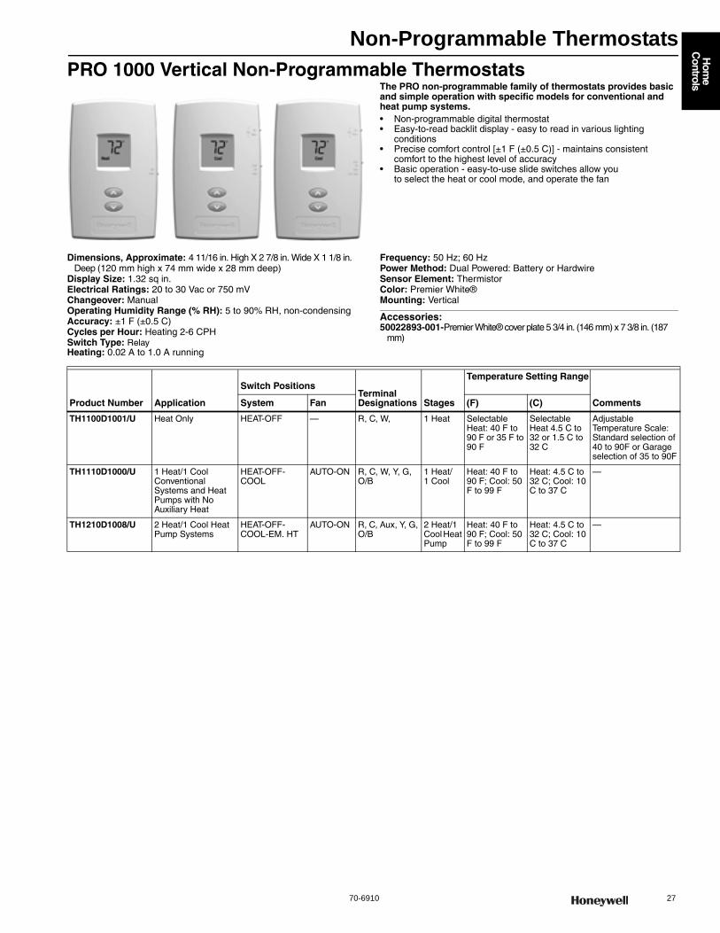
Non-Programmable Thermostats
70-6910 27
Hom
e C
ontrols
PRO 1000 Vertical Non-Programmable ThermostatsThe PRO non-programmable family of thermostats provides basic and simple operation with specific models for conventional and heat pump systems.• Non-programmable digital thermostat • Easy-to-read backlit display - easy to read in various lighting
conditions • Precise comfort control [±1 F (±0.5 C)] - maintains consistent
comfort to the highest level of accuracy • Basic operation - easy-to-use slide switches allow you
to select the heat or cool mode, and operate the fan
Dimensions, Approximate: 4 11/16 in. High X 2 7/8 in. Wide X 1 1/8 in. Deep (120 mm high x 74 mm wide x 28 mm deep)
Display Size: 1.32 sq in.Electrical Ratings: 20 to 30 Vac or 750 mVChangeover: ManualOperating Humidity Range (% RH): 5 to 90% RH, non-condensingAccuracy: ±1 F (±0.5 C) Cycles per Hour: Heating 2-6 CPHSwitch Type: RelayHeating: 0.02 A to 1.0 A running
Frequency: 50 Hz; 60 HzPower Method: Dual Powered: Battery or HardwireSensor Element: ThermistorColor: Premier White®Mounting: Vertical
Accessories:50022893-001-Premier White® cover plate 5 3/4 in. (146 mm) x 7 3/8 in. (187
mm)
Product Number Application
Switch PositionsTerminal Designations Stages
Temperature Setting Range
CommentsSystem Fan (F) (C)
TH1100D1001/U Heat Only HEAT-OFF — R, C, W, 1 Heat Selectable Heat: 40 F to 90 F or 35 F to 90 F
Selectable Heat 4.5 C to 32 or 1.5 C to 32 C
Adjustable Temperature Scale: Standard selection of 40 to 90F or Garage selection of 35 to 90F
TH1110D1000/U 1 Heat/1 Cool Conventional Systems and Heat Pumps with No Auxiliary Heat
HEAT-OFF-COOL
AUTO-ON R, C, W, Y, G, O/B
1 Heat/1 Cool
Heat: 40 F to 90 F; Cool: 50 F to 99 F
Heat: 4.5 C to 32 C; Cool: 10 C to 37 C
—
TH1210D1008/U 2 Heat/1 Cool Heat Pump Systems
HEAT-OFF-COOL-EM. HT
AUTO-ON R, C, Aux, Y, G, O/B
2 Heat/1 Cool Heat Pump
Heat: 40 F to 90 F; Cool: 50 F to 99 F
Heat: 4.5 C to 32 C; Cool: 10 C to 37 C
—
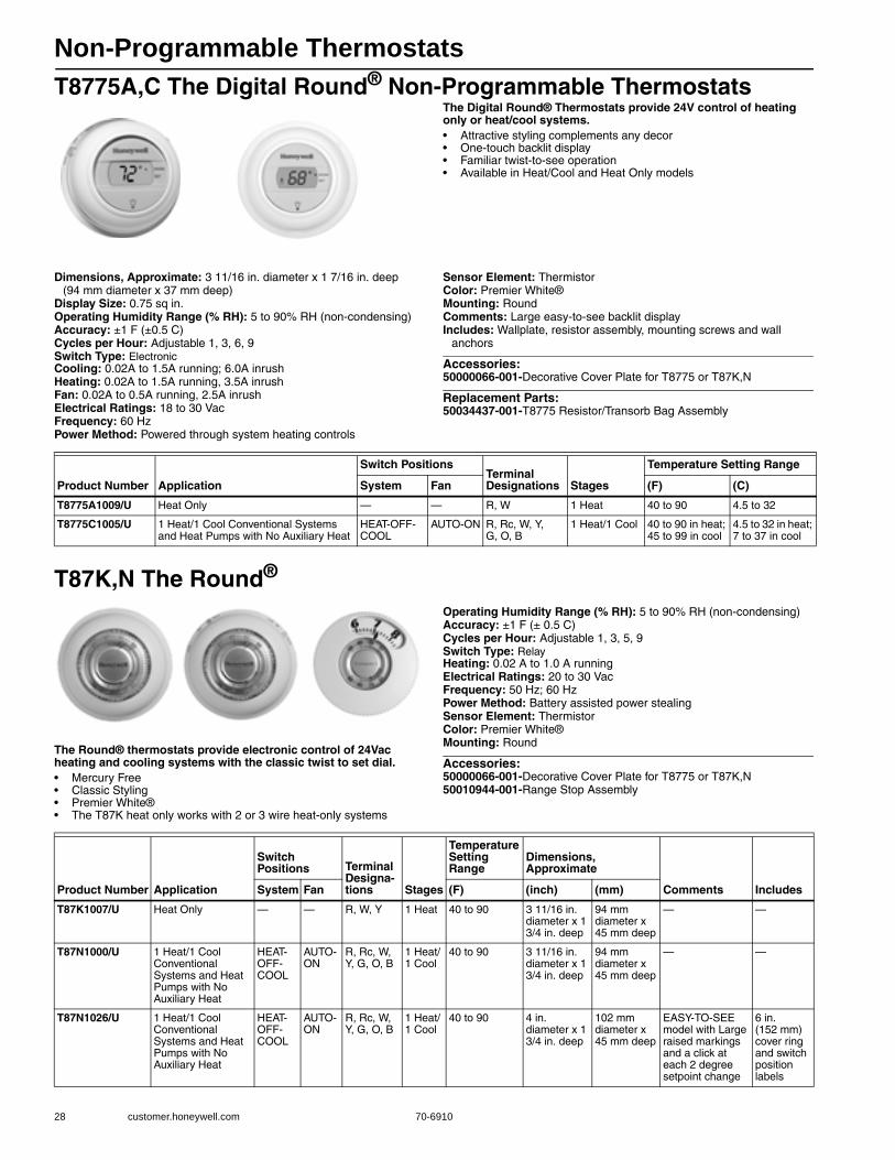
Non-Programmable Thermostats
28 customer.honeywell.com 70-6910
T8775A,C The Digital Round® Non-Programmable ThermostatsThe Digital Round® Thermostats provide 24V control of heating only or heat/cool systems.• Attractive styling complements any decor • One-touch backlit display • Familiar twist-to-see operation • Available in Heat/Cool and Heat Only models
Dimensions, Approximate: 3 11/16 in. diameter x 1 7/16 in. deep (94 mm diameter x 37 mm deep)
Display Size: 0.75 sq in.Operating Humidity Range (% RH): 5 to 90% RH (non-condensing)Accuracy: ±1 F (±0.5 C) Cycles per Hour: Adjustable 1, 3, 6, 9Switch Type: ElectronicCooling: 0.02A to 1.5A running; 6.0A inrushHeating: 0.02A to 1.5A running, 3.5A inrushFan: 0.02A to 0.5A running, 2.5A inrushElectrical Ratings: 18 to 30 VacFrequency: 60 HzPower Method: Powered through system heating controls
Sensor Element: ThermistorColor: Premier White®Mounting: RoundComments: Large easy-to-see backlit displayIncludes: Wallplate, resistor assembly, mounting screws and wall
anchors
Accessories:50000066-001-Decorative Cover Plate for T8775 or T87K,N
Replacement Parts:50034437-001-T8775 Resistor/Transorb Bag Assembly
T87K,N The Round®
The Round® thermostats provide electronic control of 24Vac heating and cooling systems with the classic twist to set dial.• Mercury Free • Classic Styling • Premier White® • The T87K heat only works with 2 or 3 wire heat-only systems
Operating Humidity Range (% RH): 5 to 90% RH (non-condensing)Accuracy: ±1 F (± 0.5 C) Cycles per Hour: Adjustable 1, 3, 5, 9Switch Type: RelayHeating: 0.02 A to 1.0 A runningElectrical Ratings: 20 to 30 VacFrequency: 50 Hz; 60 HzPower Method: Battery assisted power stealingSensor Element: ThermistorColor: Premier White®Mounting: Round
Accessories:50000066-001-Decorative Cover Plate for T8775 or T87K,N50010944-001-Range Stop Assembly
Product Number Application
Switch PositionsTerminal Designations Stages
Temperature Setting Range
System Fan (F) (C)
T8775A1009/U Heat Only — — R, W 1 Heat 40 to 90 4.5 to 32
T8775C1005/U 1 Heat/1 Cool Conventional Systems and Heat Pumps with No Auxiliary Heat
HEAT-OFF-COOL
AUTO-ON R, Rc, W, Y, G, O, B
1 Heat/1 Cool 40 to 90 in heat; 45 to 99 in cool
4.5 to 32 in heat; 7 to 37 in cool
Product Number Application
Switch Positions Terminal
Designa-tions Stages
Temperature Setting Range
Dimensions, Approximate
Comments IncludesSystem Fan (F) (inch) (mm)
T87K1007/U Heat Only — — R, W, Y 1 Heat 40 to 90 3 11/16 in. diameter x 1 3/4 in. deep
94 mm diameter x 45 mm deep
— —
T87N1000/U 1 Heat/1 Cool Conventional Systems and Heat Pumps with No Auxiliary Heat
HEAT-OFF-COOL
AUTO-ON
R, Rc, W, Y, G, O, B
1 Heat/1 Cool
40 to 90 3 11/16 in. diameter x 1 3/4 in. deep
94 mm diameter x 45 mm deep
— —
T87N1026/U 1 Heat/1 Cool Conventional Systems and Heat Pumps with No Auxiliary Heat
HEAT-OFF-COOL
AUTO-ON
R, Rc, W, Y, G, O, B
1 Heat/1 Cool
40 to 90 4 in. diameter x 1 3/4 in. deep
102 mm diameter x 45 mm deep
EASY-TO-SEE model with Large raised markings and a click at each 2 degree setpoint change
6 in. (152 mm) cover ring and switch position labels
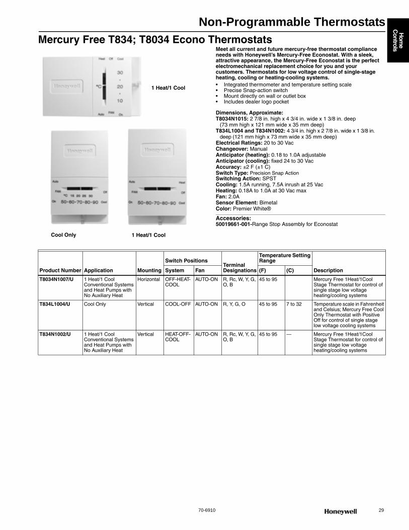
Non-Programmable Thermostats
70-6910 29
Hom
e C
ontrols
Mercury Free T834; T8034 Econo ThermostatsMeet all current and future mercury-free thermostat compliance needs with Honeywell’s Mercury-Free Econostat. With a sleek, attractive appearance, the Mercury-Free Econostat is the perfect electromechanical replacement choice for you and your customers. Thermostats for low voltage control of single-stage heating, cooling or heating-cooling systems.• Integrated thermometer and temperature setting scale • Precise Snap-action switch • Mount directly on wall or outlet box • Includes dealer logo pocket
Dimensions, Approximate: T8034N1015: 2 7/8 in. high x 4 3/4 in. wide x 1 3/8 in. deep
(73 mm high x 121 mm wide x 35 mm deep)T834L1004 and T834N1002: 4 3/4 in. high x 2 7/8 in. wide x 1 3/8 in.
deep (121 mm high x 73 mm wide x 35 mm deep)Electrical Ratings: 20 to 30 VacChangeover: ManualAnticipator (heating): 0.18 to 1.0A adjustableAnticipator (cooling): fixed 24 to 30 VacAccuracy: ±2 F (±1 C) Switch Type: Precision Snap ActionSwitching Action: SPSTCooling: 1.5A running, 7.5A inrush at 25 VacHeating: 0.18A to 1.0A at 30 Vac maxFan: 2.0ASensor Element: BimetalColor: Premier White®
Accessories:50019661-001-Range Stop Assembly for Econostat
Cool Only 1 Heat/1 Cool
1 Heat/1 Cool
Product Number Application Mounting
Switch PositionsTerminal Designations
Temperature Setting Range
DescriptionSystem Fan (F) (C)
T8034N1007/U 1 Heat/1 Cool Conventional Systems and Heat Pumps with No Auxiliary Heat
Horizontal OFF-HEAT-COOL
AUTO-ON R, Rc, W, Y, G, O, B
45 to 95 Mercury Free 1Heat/1Cool Stage Thermostat for control of single stage low voltage heating/cooling systems
T834L1004/U Cool Only Vertical COOL-OFF AUTO-ON R, Y, G, O 45 to 95 7 to 32 Temperature scale in Fahrenheit and Celsius; Mercury Free Cool Only Thermostat with Positive Off for control of single stage low voltage cooling systems
T834N1002/U 1 Heat/1 Cool Conventional Systems and Heat Pumps with No Auxiliary Heat
Vertical HEAT-OFF-COOL
AUTO-ON R, Rc, W, Y, G, O, B
45 to 95 — Mercury Free 1Heat/1Cool Stage Thermostat for control of single stage low voltage heating/cooling systems
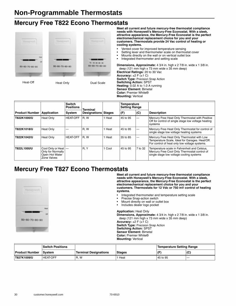
Non-Programmable Thermostats
30 customer.honeywell.com 70-6910
Mercury Free T822 Econo ThermostatsMeet all current and future mercury-free thermostat compliance needs with Honeywell’s Mercury-Free Econostat. With a sleek, attractive appearance, the Mercury-Free Econostat is the perfect electromechanical replacement choice for you and your customers. Thermostats provide 24 Vac control of heating or cooling systems.• Vented cover for improved temperature sensing • Setting lever and thermometer scale on thermostat cover • Mounts directly on the wall or on vertical outlet box • Integrated thermometer and setting scale
Dimensions, Approximate: 4 3/4 in. high x 2 7/8 in. wide x 1 3/8 in. deep (121 mm high x 73 mm wide x 35 mm deep)
Electrical Ratings: 20 to 30 VacAccuracy: ±2 F (±1 C) Switch Type: Precision Snap ActionSwitching Action: SPSTHeating: 0.02 A to 1.0 A runningSensor Element: BimetalColor: Premier White®Mounting: Vertical
Mercury Free T827 Econo ThermostatsMeet all current and future mercury-free thermostat compliance needs with Honeywell’s Mercury-Free Econostat. With a sleek, attractive appearance, the Mercury-Free Econostat is the perfect electromechanical replacement choice for you and your customers. Thermostats for 12 Vdc or 750 mV control of heating systems.• Integrated thermometer and temperature setting scale • Precise Snap-action switch • Mount directly on wall or outlet box • Includes dealer logo pocket
Application: Heat OnlyDimensions, Approximate: 4 3/4 in. high x 2 7/8 in. wide x 1 3/8 in.
deep (121 mm high x 73 mm wide x 35 mm deep) Accuracy: ±2 F (±1 C) Switch Type: Precision Snap ActionSwitching Action: SPSTSensor Element: BimetalColor: Premier White®Mounting: Vertical
Heat Only Dual ScaleHeat-Off
Product Number Application
Switch Positions
Terminal Designations Stages
Temperature Setting Range
DescriptionSystem (F) (C)
T822K1000/U Heat Only HEAT-OFF R, W 1 Heat 45 to 95 — Mercury Free Heat Only Thermostat with Positive Off for control of single stage low voltage heating systems
T822K1018/U Heat Only — R, W 1 Heat 45 to 95 — Mercury Free Heat Only Thermostat for control of single stage low voltage heating systems
T822K1042/U Heat Only HEAT-OFF R, W 1 Heat 35 to 85 — Mercury Free Heat Only Thermostat with Low Temperature Scale, Ideal for Garages. Heat/Off. For control of heat only low voltage systems.
T822L1000/U Cool Only or Heat Only for Normally Open Hot Water Zone Valves
— R, Y 1 Cool 45 to 95 7 to 32 Temperature scale in Fahrenheit and Celsius, Mercury Free Cool Only Thermostat control of single stage low voltage cooling systems
Product Number
Switch Positions
Terminal Designations Stages
Temperature Setting Range
System (F) (C)
T827K1009/U HEAT-OFF R, W 1 Heat 45 to 95 —
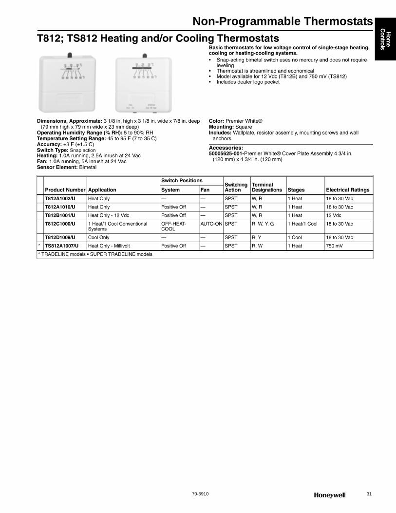
Non-Programmable Thermostats
70-6910 31
Hom
e C
ontrols
T812; TS812 Heating and/or Cooling ThermostatsBasic thermostats for low voltage control of single-stage heating, cooling or heating-cooling systems.• Snap-acting bimetal switch uses no mercury and does not require
leveling • Thermostat is streamlined and economical • Model available for 12 Vdc (T812B) and 750 mV (TS812) • Includes dealer logo pocket
Dimensions, Approximate: 3 1/8 in. high x 3 1/8 in. wide x 7/8 in. deep (79 mm high x 79 mm wide x 23 mm deep)
Operating Humidity Range (% RH): 5 to 90% RHTemperature Setting Range: 45 to 95 F (7 to 35 C)Accuracy: ±3 F (±1.5 C) Switch Type: Snap actionHeating: 1.0A running, 2.5A inrush at 24 VacFan: 1.0A running, 5A inrush at 24 VacSensor Element: Bimetal
Color: Premier White®Mounting: SquareIncludes: Wallplate, resistor assembly, mounting screws and wall
anchors
Accessories:50005625-001-Premier White® Cover Plate Assembly 4 3/4 in.
(120 mm) x 4 3/4 in. (120 mm)
Product Number Application
Switch PositionsSwitching Action
Terminal Designations Stages Electrical RatingsSystem Fan
T812A1002/U Heat Only — — SPST W, R 1 Heat 18 to 30 Vac
T812A1010/U Heat Only Positive Off — SPST W, R 1 Heat 18 to 30 Vac
T812B1001/U Heat Only - 12 Vdc Positive Off — SPST W, R 1 Heat 12 Vdc
T812C1000/U 1 Heat/1 Cool Conventional Systems
OFF-HEAT-COOL
AUTO-ON SPST R, W, Y, G 1 Heat/1 Cool 18 to 30 Vac
T812D1009/U Cool Only — — SPST R, Y 1 Cool 18 to 30 Vac
* TS812A1007/U Heat Only - Millivolt Positive Off — SPST R, W 1 Heat 750 mV
* TRADELINE models • SUPER TRADELINE models
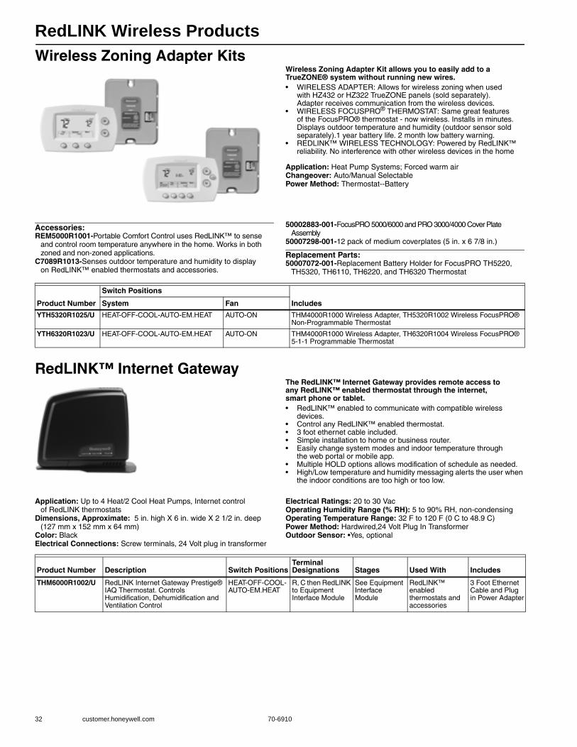
RedLINK Wireless Products
32 customer.honeywell.com 70-6910
Wireless Zoning Adapter KitsWireless Zoning Adapter Kit allows you to easily add to a TrueZONE® system without running new wires.• WIRELESS ADAPTER: Allows for wireless zoning when used
with HZ432 or HZ322 TrueZONE panels (sold separately). Adapter receives communication from the wireless devices.
• WIRELESS FOCUSPRO® THERMOSTAT: Same great features of the FocusPRO® thermostat - now wireless. Installs in minutes. Displays outdoor temperature and humidity (outdoor sensor sold separately).1 year battery life. 2 month low battery warning.
• REDLINK™ WIRELESS TECHNOLOGY: Powered by RedLINK™ reliability. No interference with other wireless devices in the home
Application: Heat Pump Systems; Forced warm airChangeover: Auto/Manual SelectablePower Method: Thermostat--Battery
Accessories:REM5000R1001-Portable Comfort Control uses RedLINK™ to sense
and control room temperature anywhere in the home. Works in both zoned and non-zoned applications.
C7089R1013-Senses outdoor temperature and humidity to display on RedLINK™ enabled thermostats and accessories.
50002883-001-FocusPRO 5000/6000 and PRO 3000/4000 Cover Plate Assembly
50007298-001-12 pack of medium coverplates (5 in. x 6 7/8 in.)
Replacement Parts:50007072-001-Replacement Battery Holder for FocusPRO TH5220,
TH5320, TH6110, TH6220, and TH6320 Thermostat
RedLINK™ Internet GatewayThe RedLINK™ Internet Gateway provides remote access to any RedLINK™ enabled thermostat through the internet, smart phone or tablet.• RedLINK™ enabled to communicate with compatible wireless
devices. • Control any RedLINK™ enabled thermostat. • 3 foot ethernet cable included. • Simple installation to home or business router. • Easily change system modes and indoor temperature through
the web portal or mobile app. • Multiple HOLD options allows modification of schedule as needed. • High/Low temperature and humidity messaging alerts the user when
the indoor conditions are too high or too low.
Application: Up to 4 Heat/2 Cool Heat Pumps, Internet control of RedLINK thermostats
Dimensions, Approximate: 5 in. high X 6 in. wide X 2 1/2 in. deep (127 mm x 152 mm x 64 mm)
Color: BlackElectrical Connections: Screw terminals, 24 Volt plug in transformer
Electrical Ratings: 20 to 30 VacOperating Humidity Range (% RH): 5 to 90% RH, non-condensingOperating Temperature Range: 32 F to 120 F (0 C to 48.9 C) Power Method: Hardwired,24 Volt Plug In TransformerOutdoor Sensor: •Yes, optional
Product Number
Switch Positions
IncludesSystem Fan
YTH5320R1025/U HEAT-OFF-COOL-AUTO-EM.HEAT AUTO-ON THM4000R1000 Wireless Adapter, TH5320R1002 Wireless FocusPRO® Non-Programmable Thermostat
YTH6320R1023/U HEAT-OFF-COOL-AUTO-EM.HEAT AUTO-ON THM4000R1000 Wireless Adapter, TH6320R1004 Wireless FocusPRO® 5-1-1 Programmable Thermostat
Product Number Description Switch PositionsTerminal Designations Stages Used With Includes
THM6000R1002/U RedLINK Internet Gateway Prestige® IAQ Thermostat. Controls Humidification, Dehumidification and Ventilation Control
HEAT-OFF-COOL-AUTO-EM.HEAT
R, C then RedLINK to Equipment Interface Module
See Equipment Interface Module
RedLINK™ enabled thermostats and accessories
3 Foot Ethernet Cable and Plug in Power Adapter

RedLINK Wireless Products
70-6910 33
Hom
e C
ontrols
C7089R Wireless Outdoor SensorSenses outdoor temperature and humidity to display on RedLINK™ enabled thermostats and accessories.• Powered by RedLINK™ reliability • No interference with other wireless devices in the home • Reliable performance in all climates • Installs in minutes • Up to 5 year battery life • 2 month low battery warning • Battery warning displayed on RedLINK™ enabled thermostats • Includes 2 AA Lithium batteries and mounting hardware
Application: Outdoor SensorDimensions, Approximate: (with mounting bracket) 5 in. high x 3 1/2
in. wide x 1 11/16 in. deep ((with mounting bracket) 127 mm high x 89 mm wide x 43 mm deep)
Color: GrayOperating Humidity Range (% RH): 0 to 100% RH, condensing
Operating Temperature Range: -40 F to 140 F (-40 C to 60 C) Power Method: BatterySensor Element: ThermistorMounting: Mounts on a vertical wall with supplied bracket and
mounting hardware
C7189R Wireless Indoor Air SensorThe Wireless Indoor Sensor(s) is used to change the sensing location of the thermostat. Sense temperature and humidity remotely, average temperature, and humidify and dehumidify in separate locations.• The Wireless Indoor Sensor(s) is used to change the sensing
location of the thermostat.• Sense temperature and humidity remotely. • Average temperature • Control temperature and humidity in separate locations. • Humidify and dehumidify in separate locations. For example,
humidify on the main level and dehumidify in the crawl space. • Up to 6 Wireless Indoor Sensors per thermostat.
Application: Wireless Indoor Air SensorDimensions, Approximate: 2 7/8 in. high x 1 7/8 in. wide x 15/16 in. deep
(73 mm x 48 mm x 24 mm) Color: Arctic WhiteOperating Humidity Range (% RH): 5 to 90% RH, non-condensing
Operating Temperature Range: 0 F to 120 F (-17.8 C to 48.9 C) (35 F to 114 F (1.7 C to 45.6 C) for optimal battery life)
Power Method: BatteryMounting: Mounts on a vertical wall with supplied bracket
and mounting hardware
REM1000 RedLINK™ Wireless Entry/Exit RemoteApplication: Heating and Cooling systems, RedLINK Thermostat
AccessoryDimensions, Approximate : 6 1/4 in. high x 3 1/8 in. wide x 1 5/8 in.
deep (159 mm high x 79 mm wide x 41 mm deep)Used With: RedLINK™ enabled thermostats and accessoriesColor: WhiteOperating Humidity Range (% RH): 5 to 90% RH, non-condensingOperating Temperature Range : 35 F to 114 F (1.7 C to 45.6 C) for
optimal battery lifeSensor Element: ThermistorPower Method: Battery, Lithium Coin Cell
Accessories:HVC20A1000-Wireless Vent and Filter Boost Remote
Product Number Comments Used With Includes
C7089R1013/U Wireless Outdoor Sensor is also available in kits
RedLINK™ enabled thermostats and accessories
2 AA Lithium Batteries and mounting hardware
Product Number Description Used With Includes
C7189R1004/U Senses indoor temperature and humidity Prestige® IAQ, Prestige® 2.0 and VisionPRO with RedLINK™ Thermostats
2 AAA alkaline batteries and mounting hardware
Product Number Description
REM1000R1003/U RedLINK Wireless Entry/Exit Remote
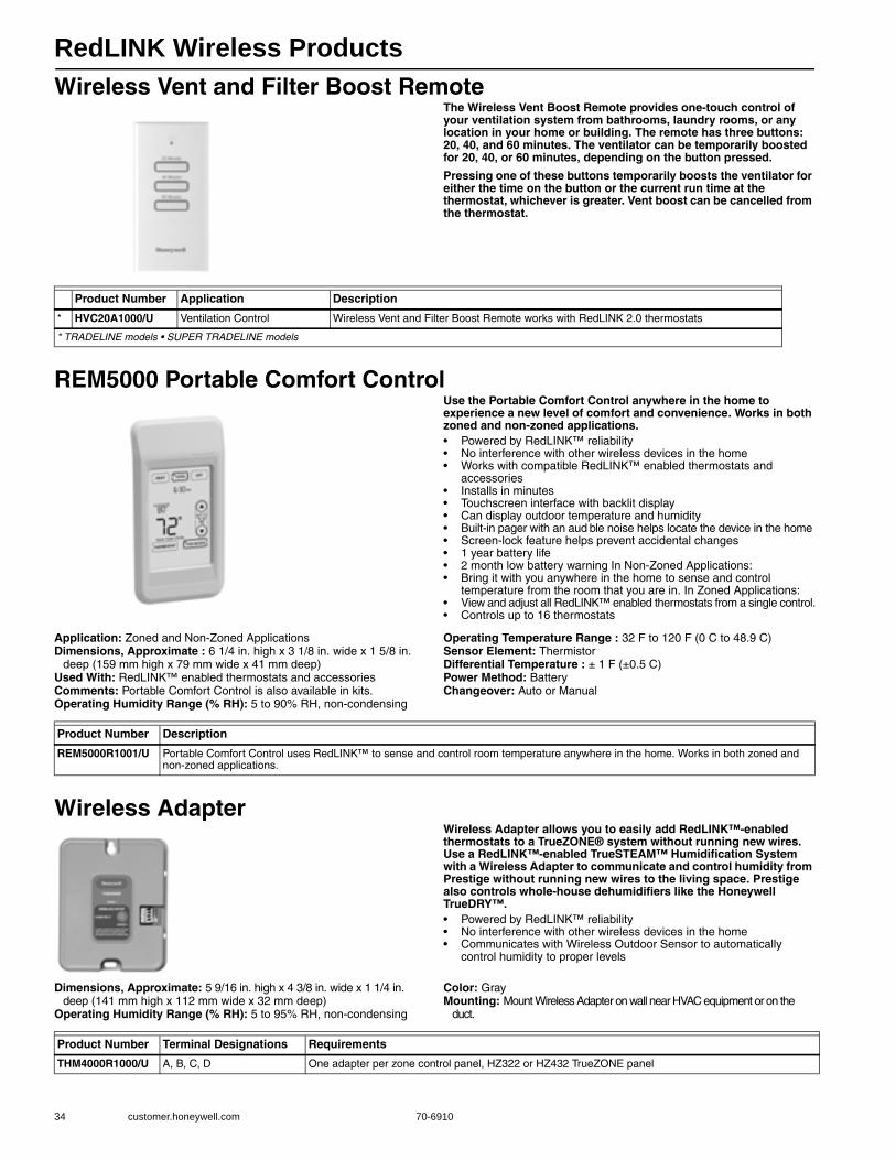
RedLINK Wireless Products
34 customer.honeywell.com 70-6910
Wireless Vent and Filter Boost RemoteThe Wireless Vent Boost Remote provides one-touch control of your ventilation system from bathrooms, laundry rooms, or any location in your home or building. The remote has three buttons: 20, 40, and 60 minutes. The ventilator can be temporarily boosted for 20, 40, or 60 minutes, depending on the button pressed.
Pressing one of these buttons temporarily boosts the ventilator for either the time on the button or the current run time at the thermostat, whichever is greater. Vent boost can be cancelled from the thermostat.
REM5000 Portable Comfort ControlUse the Portable Comfort Control anywhere in the home to experience a new level of comfort and convenience. Works in both zoned and non-zoned applications.• Powered by RedLINK™ reliability • No interference with other wireless devices in the home • Works with compatible RedLINK™ enabled thermostats and
accessories • Installs in minutes • Touchscreen interface with backlit display • Can display outdoor temperature and humidity • Built-in pager with an aud ble noise helps locate the device in the home • Screen-lock feature helps prevent accidental changes • 1 year battery life • 2 month low battery warning In Non-Zoned Applications: • Bring it with you anywhere in the home to sense and control
temperature from the room that you are in. In Zoned Applications: • View and adjust all RedLINK™ enabled thermostats from a single control.• Controls up to 16 thermostats
Application: Zoned and Non-Zoned ApplicationsDimensions, Approximate : 6 1/4 in. high x 3 1/8 in. wide x 1 5/8 in.
deep (159 mm high x 79 mm wide x 41 mm deep)Used With: RedLINK™ enabled thermostats and accessoriesComments: Portable Comfort Control is also available in kits.Operating Humidity Range (% RH): 5 to 90% RH, non-condensing
Operating Temperature Range : 32 F to 120 F (0 C to 48.9 C)Sensor Element: ThermistorDifferential Temperature : ± 1 F (±0.5 C)Power Method: BatteryChangeover: Auto or Manual
Wireless AdapterWireless Adapter allows you to easily add RedLINK™-enabled thermostats to a TrueZONE® system without running new wires. Use a RedLINK™-enabled TrueSTEAM™ Humidification System with a Wireless Adapter to communicate and control humidity from Prestige without running new wires to the living space. Prestige also controls whole-house dehumidifiers like the Honeywell TrueDRY™.• Powered by RedLINK™ reliability • No interference with other wireless devices in the home • Communicates with Wireless Outdoor Sensor to automatically
control humidity to proper levels
Dimensions, Approximate: 5 9/16 in. high x 4 3/8 in. wide x 1 1/4 in. deep (141 mm high x 112 mm wide x 32 mm deep)
Operating Humidity Range (% RH): 5 to 95% RH, non-condensing
Color: GrayMounting: Mount Wireless Adapter on wall near HVAC equipment or on the
duct.
Product Number Application Description
* HVC20A1000/U Ventilation Control Wireless Vent and Filter Boost Remote works with RedLINK 2.0 thermostats
* TRADELINE models • SUPER TRADELINE models
Product Number Description
REM5000R1001/U Portable Comfort Control uses RedLINK™ to sense and control room temperature anywhere in the home. Works in both zoned and non-zoned applications.
Product Number Terminal Designations Requirements
THM4000R1000/U A, B, C, D One adapter per zone control panel, HZ322 or HZ432 TrueZONE panel
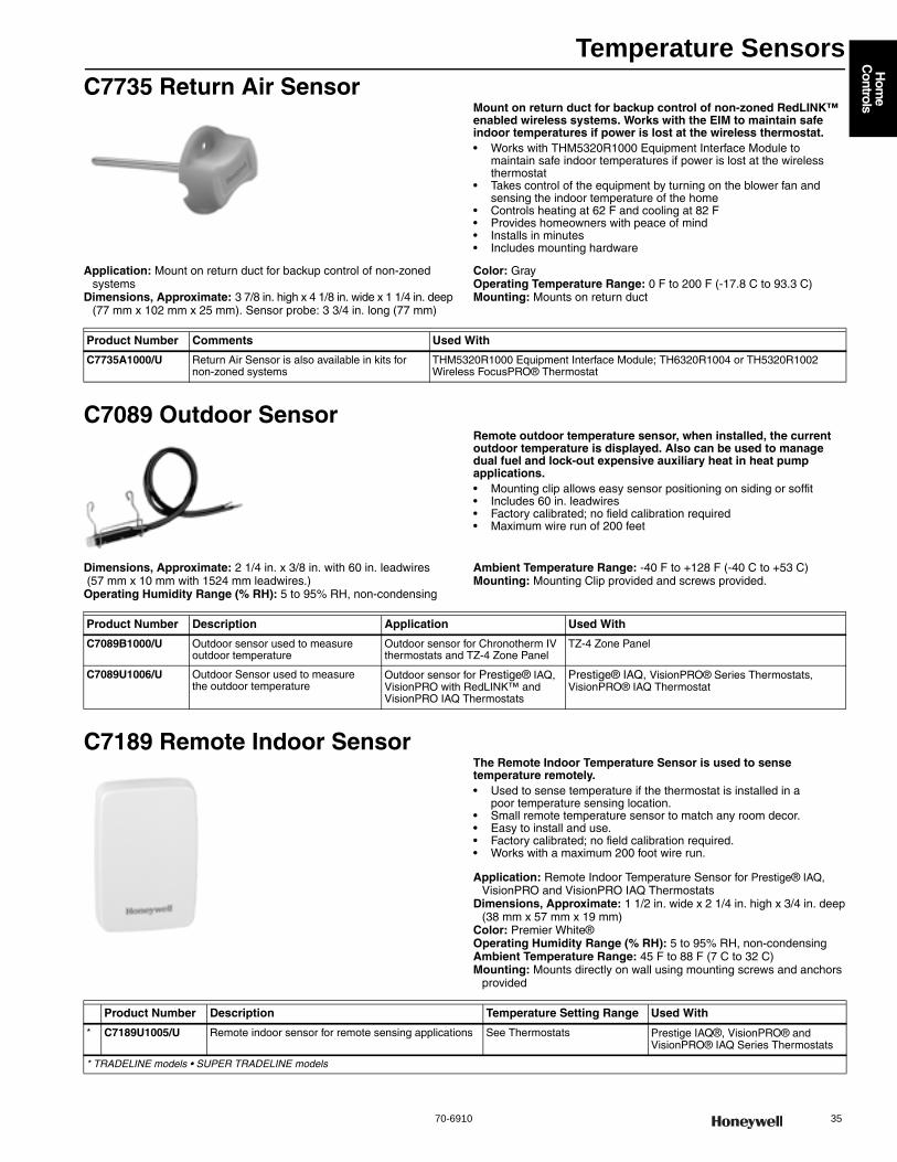
Temperature Sensors
70-6910 35
Hom
e C
ontrols
C7735 Return Air SensorMount on return duct for backup control of non-zoned RedLINK™ enabled wireless systems. Works with the EIM to maintain safe indoor temperatures if power is lost at the wireless thermostat.• Works with THM5320R1000 Equipment Interface Module to
maintain safe indoor temperatures if power is lost at the wireless thermostat
• Takes control of the equipment by turning on the blower fan and sensing the indoor temperature of the home
• Controls heating at 62 F and cooling at 82 F • Provides homeowners with peace of mind • Installs in minutes • Includes mounting hardware
Application: Mount on return duct for backup control of non-zoned systems
Dimensions, Approximate: 3 7/8 in. high x 4 1/8 in. wide x 1 1/4 in. deep (77 mm x 102 mm x 25 mm). Sensor probe: 3 3/4 in. long (77 mm)
Color: GrayOperating Temperature Range: 0 F to 200 F (-17.8 C to 93.3 C) Mounting: Mounts on return duct
C7089 Outdoor SensorRemote outdoor temperature sensor, when installed, the current outdoor temperature is displayed. Also can be used to manage dual fuel and lock-out expensive auxiliary heat in heat pump applications.• Mounting clip allows easy sensor positioning on siding or soffit • Includes 60 in. leadwires • Factory calibrated; no field calibration required • Maximum wire run of 200 feet
Dimensions, Approximate: 2 1/4 in. x 3/8 in. with 60 in. leadwires (57 mm x 10 mm with 1524 mm leadwires.) Operating Humidity Range (% RH): 5 to 95% RH, non-condensing
Ambient Temperature Range: -40 F to +128 F (-40 C to +53 C) Mounting: Mounting Clip provided and screws provided.
C7189 Remote Indoor SensorThe Remote Indoor Temperature Sensor is used to sense temperature remotely.• Used to sense temperature if the thermostat is installed in a
poor temperature sensing location. • Small remote temperature sensor to match any room decor. • Easy to install and use. • Factory calibrated; no field calibration required. • Works with a maximum 200 foot wire run.
Application: Remote Indoor Temperature Sensor for Prestige® IAQ,VisionPRO and VisionPRO IAQ Thermostats
Dimensions, Approximate: 1 1/2 in. wide x 2 1/4 in. high x 3/4 in. deep(38 mm x 57 mm x 19 mm)
Color: Premier White®Operating Humidity Range (% RH): 5 to 95% RH, non-condensingAmbient Temperature Range: 45 F to 88 F (7 C to 32 C) Mounting: Mounts directly on wall using mounting screws and anchors
provided
Product Number Comments Used With
C7735A1000/U Return Air Sensor is also available in kits for non-zoned systems
THM5320R1000 Equipment Interface Module; TH6320R1004 or TH5320R1002 Wireless FocusPRO® Thermostat
Product Number Description Application Used With
C7089B1000/U Outdoor sensor used to measure outdoor temperature
Outdoor sensor for Chronotherm IV thermostats and TZ-4 Zone Panel
TZ-4 Zone Panel
C7089U1006/U Outdoor Sensor used to measure the outdoor temperature
Outdoor sensor for Prestige® IAQ, VisionPRO with RedLINK™ and VisionPRO IAQ Thermostats
Prestige® IAQ, VisionPRO® Series Thermostats, VisionPRO® IAQ Thermostat
Product Number Description Temperature Setting Range Used With
* C7189U1005/U Remote indoor sensor for remote sensing applications See Thermostats Prestige IAQ®, VisionPRO® and VisionPRO® IAQ Series Thermostats
* TRADELINE models • SUPER TRADELINE models
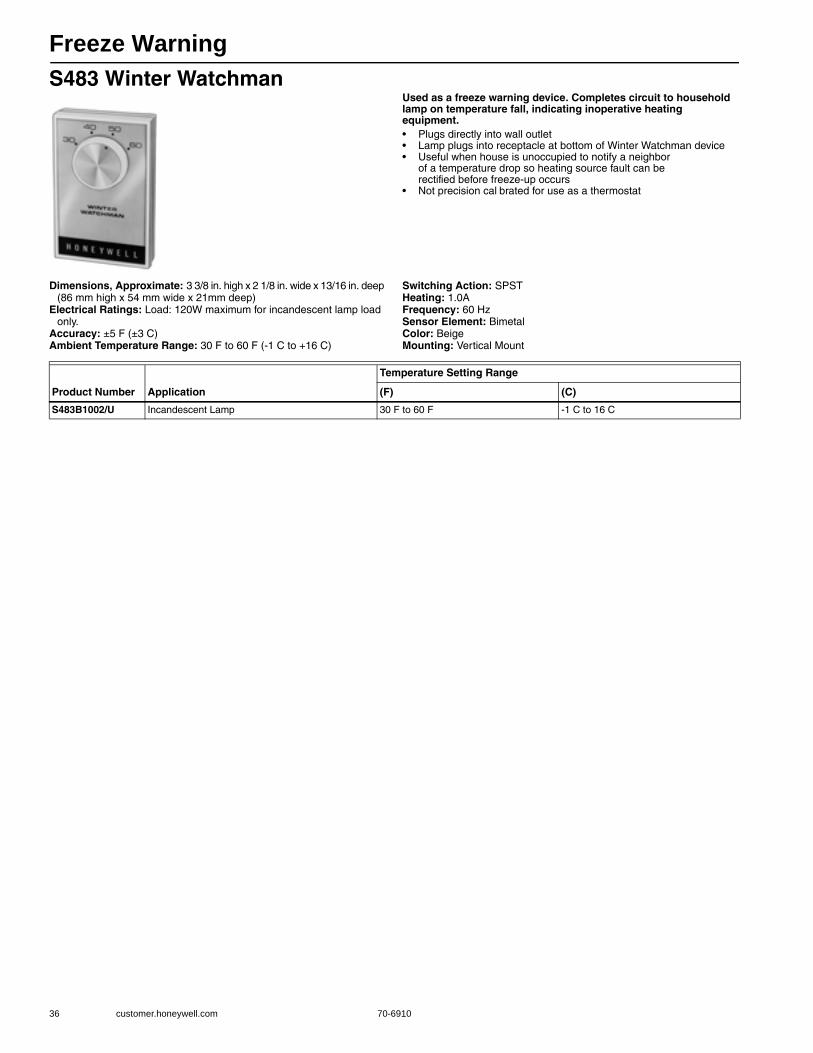
Freeze Warning
36 customer.honeywell.com 70-6910
S483 Winter WatchmanUsed as a freeze warning device. Completes circuit to household lamp on temperature fall, indicating inoperative heating equipment.• Plugs directly into wall outlet • Lamp plugs into receptacle at bottom of Winter Watchman device • Useful when house is unoccupied to notify a neighbor
of a temperature drop so heating source fault can be rectified before freeze-up occurs
• Not precision cal brated for use as a thermostat
Dimensions, Approximate: 3 3/8 in. high x 2 1/8 in. wide x 13/16 in. deep (86 mm high x 54 mm wide x 21mm deep)
Electrical Ratings: Load: 120W maximum for incandescent lamp load only.
Accuracy: ±5 F (±3 C) Ambient Temperature Range: 30 F to 60 F (-1 C to +16 C)
Switching Action: SPSTHeating: 1.0AFrequency: 60 HzSensor Element: BimetalColor: BeigeMounting: Vertical Mount
Product Number Application
Temperature Setting Range
(F) (C)
S483B1002/U Incandescent Lamp 30 F to 60 F -1 C to 16 C
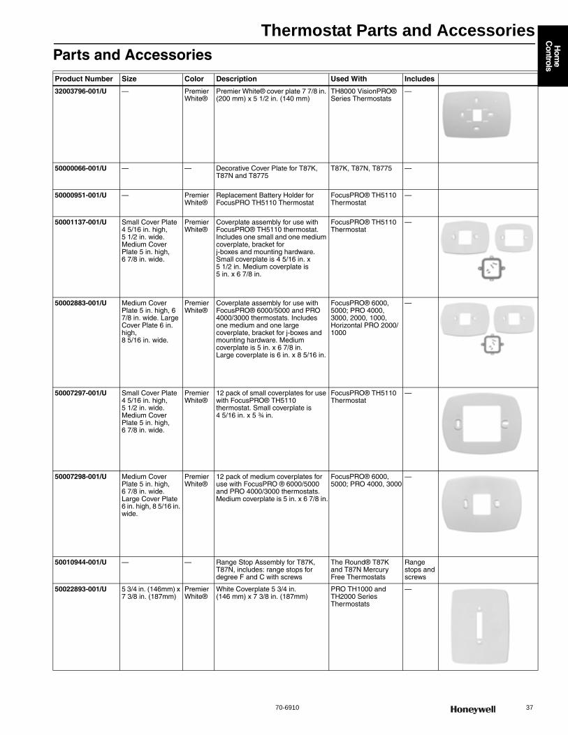
Thermostat Parts and Accessories
70-6910 37
Hom
e C
ontrols
Parts and AccessoriesProduct Number Size Color Description Used With Includes
32003796-001/U — Premier White®
Premier White® cover plate 7 7/8 in. (200 mm) x 5 1/2 in. (140 mm)
TH8000 VisionPRO® Series Thermostats
—
50000066-001/U — — Decorative Cover Plate for T87K, T87N and T8775
T87K, T87N, T8775 —
50000951-001/U — Premier White®
Replacement Battery Holder for FocusPRO TH5110 Thermostat
FocusPRO® TH5110 Thermostat
—
50001137-001/U Small Cover Plate 4 5/16 in. high, 5 1/2 in. wide. Medium Cover Plate 5 in. high, 6 7/8 in. wide.
Premier White®
Coverplate assembly for use with FocusPRO® TH5110 thermostat. Includes one small and one medium coverplate, bracket for j-boxes and mounting hardware. Small coverplate is 4 5/16 in. x 5 1/2 in. Medium coverplate is 5 in. x 6 7/8 in.
FocusPRO® TH5110 Thermostat
—
50002883-001/U Medium Cover Plate 5 in. high, 6 7/8 in. wide. Large Cover Plate 6 in. high, 8 5/16 in. wide.
Premier White®
Coverplate assembly for use with FocusPRO® 6000/5000 and PRO 4000/3000 thermostats. Includes one medium and one large coverplate, bracket for j-boxes and mounting hardware. Medium coverplate is 5 in. x 6 7/8 in. Large coverplate is 6 in. x 8 5/16 in.
FocusPRO® 6000, 5000; PRO 4000, 3000, 2000, 1000, Horizontal PRO 2000/1000
—
50007297-001/U Small Cover Plate 4 5/16 in. high, 5 1/2 in. wide. Medium Cover Plate 5 in. high, 6 7/8 in. wide.
Premier White®
12 pack of small coverplates for use with FocusPRO® TH5110 thermostat. Small coverplate is 4 5/16 in. x 5 ¾ in.
FocusPRO® TH5110 Thermostat
—
50007298-001/U Medium Cover Plate 5 in. high, 6 7/8 in. wide. Large Cover Plate 6 in. high, 8 5/16 in. wide.
Premier White®
12 pack of medium coverplates for use with FocusPRO ® 6000/5000 and PRO 4000/3000 thermostats. Medium coverplate is 5 in. x 6 7/8 in.
FocusPRO® 6000, 5000; PRO 4000, 3000
—
50010944-001/U — — Range Stop Assembly for T87K, T87N, includes: range stops for degree F and C with screws
The Round® T87K and T87N Mercury Free Thermostats
Range stops and screws
50022893-001/U 5 3/4 in. (146mm) x 7 3/8 in. (187mm)
Premier White®
White Coverplate 5 3/4 in. (146 mm) x 7 3/8 in. (187mm)
PRO TH1000 and TH2000 Series Thermostats
—
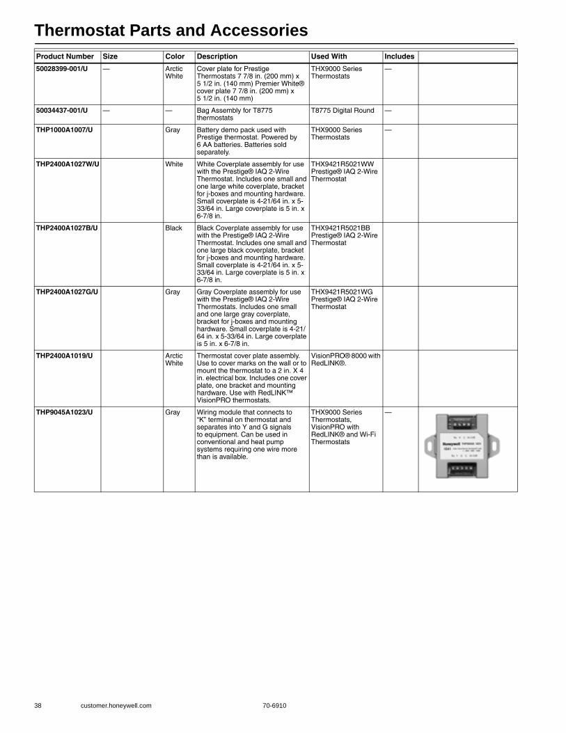
Thermostat Parts and Accessories
38 customer.honeywell.com 70-6910
50028399-001/U — Arctic White
Cover plate for Prestige Thermostats 7 7/8 in. (200 mm) x 5 1/2 in. (140 mm) Premier White® cover plate 7 7/8 in. (200 mm) x 5 1/2 in. (140 mm)
THX9000 Series Thermostats
—
50034437-001/U — — Bag Assembly for T8775 thermostats
T8775 Digital Round —
THP1000A1007/U Gray Battery demo pack used with Prestige thermostat. Powered by 6 AA batteries. Batteries sold separately.
THX9000 Series Thermostats
—
THP2400A1027W/U White White Coverplate assembly for use with the Prestige® IAQ 2-Wire Thermostat. Includes one small and one large white coverplate, bracket for j-boxes and mounting hardware. Small coverplate is 4-21/64 in. x 5-33/64 in. Large coverplate is 5 in. x 6-7/8 in.
THX9421R5021WW Prestige® IAQ 2-Wire Thermostat
THP2400A1027B/U Black Black Coverplate assembly for use with the Prestige® IAQ 2-Wire Thermostat. Includes one small and one large black coverplate, bracket for j-boxes and mounting hardware. Small coverplate is 4-21/64 in. x 5-33/64 in. Large coverplate is 5 in. x 6-7/8 in.
THX9421R5021BB Prestige® IAQ 2-Wire Thermostat
THP2400A1027G/U Gray Gray Coverplate assembly for use with the Prestige® IAQ 2-Wire Thermostats. Includes one small and one large gray coverplate, bracket for j-boxes and mounting hardware. Small coverplate is 4-21/64 in. x 5-33/64 in. Large coverplate is 5 in. x 6-7/8 in.
THX9421R5021WG Prestige® IAQ 2-Wire Thermostat
THP2400A1019/U Arctic White
Thermostat cover plate assembly. Use to cover marks on the wall or to mount the thermostat to a 2 in. X 4 in. electrical box. Includes one cover plate, one bracket and mounting hardware. Use with RedLINK™ VisionPRO thermostats.
VisionPRO® 8000 with RedLINK®.
THP9045A1023/U Gray Wiring module that connects to “K” terminal on thermostat and separates into Y and G signals to equipment. Can be used in conventional and heat pump systems requiring one wire more than is available.
THX9000 Series Thermostats, VisionPRO with RedLINK® and Wi-Fi Thermostats
—
Product Number Size Color Description Used With Includes

Thermostat Guards
70-6910 39
Hom
e C
ontrols
TG510 Versaguard Universal Thermostat GuardsThe Versaguard® Universal Thermostat Guards cover wall thermostats and protect against tampering, damage and unauthorized adjustment of thermostat settings.• Unique double-wall construction provides extra measure
of tamper-resistance. • Used in both new and existing applications. • Tamper-resistant lock; key cannot be removed unless in locked
position. • All models mount vertically or horizontally on wall or exposed
junction box. • Vents in guard base allow airflow for optimum thermostat
performance.
Inside Height: 4 7/16 in. (113 mm) Inside Width: 4 7/16 in. (113 mm) Outside Height: 5 7/8 in. (149 mm) Outside Width: 5 7/8 in. (149 mm)
Outside Depth: 2 1/2 in. (64 mm)
Accessories:191990A-Replacement Keys (set of 2) for TG509, TG510, TG511 and TG512
TG511 Versaguard Universal Thermostat GuardsThe Versaguard® Universal Thermostat Guards cover wall thermostats and protect against tampering, damage and unauthorized adjustment of thermostat settings.• Unique double-wall construction provides extra measure
of tamper-resistance. • Used in both new and existing applications. • Tamper-resistant lock; key cannot be removed unless in locked
position. • All models mount vertically or horizontally on wall or exposed
junction box. • Vents in guard base allow airflow for optimum thermostat
performance.
Inside Height: 5 1/16 in. (129 mm) Inside Width: 6 1/16 in. (154 mm) Outside Height: 6 1/2 in. (165 mm) Outside Width: 7 1/2 in. (191 mm)
Outside Depth: 2 15/16 in. (75 mm)
Accessories:191990A-Replacement Keys (set of 2) for TG509, TG510, TG511 and TG512
Product Number Size ColorRing Base Color
Wallplate Color Description Used With
* TG510A1001/U small Clear Acrylic
clear acrylic Opaque Polystyrene
Small universal thermostat guard Clear cover, clear base opaque wallplate Fits T87 RS TX400
T87 and others of similar size
TG510D1005/U small Painted metal
opaque polystyrene
Opaque Polystyrene
Small Universal Thermostat Guard with Beige painted steel cover, opaque ring base and wallplate
T87 and others of similar size
* TRADELINE models • SUPER TRADELINE models
Product Number Size ColorRing Base Color
Wallplate Color Description Used With
* TG511A1000/U medium Clear Acrylic
clear acrylic Opaque Polystyrene
Medium Universal Thermostat Guard with clear cover and base, and opaque wallplate Fits T822, T834, T8034, T841, T874 with Q674, WR1F46, and others
TH3000 Series, TH4000 Series, TH5000 Series, TH6000 Series, TH8000 Series, Others thermostats of similar size
TG511D1004/U medium Painted metal
opaque polystyrene
Opaque Polystyrene
Medium Universal Thermostat Guard with Beige painted steel cover, opaque ring base and wallplate Fits T822, T834, T8034, T841, T874 with Q674, and others
TH3000 Series, TH4000 Series, TH5000 Series, TH6000 Series, TH8000 Series, Others thermostats of similar size
* TRADELINE models • SUPER TRADELINE models

Thermostat Guards
40 customer.honeywell.com 70-6910
TG512 Versaguard Universal Thermostat GuardsThe Versaguard® Universal Thermostat Guards cover wall thermostats and protect against tampering, damage and unauthorized adjustment of thermostat settings.• Unique double-wall construction provides extra measure
of tamper-resistance. • Used in both new and existing applications. • Tamper-resistant lock; key cannot be removed unless in locked
position. • All models mount vertically or horizontally on wall or exposed
junction box. • Vents in guard base allow airflow for optimum thermostat
performance.
Inside Height: 5 7/8 in. (149 mm) Inside Width: 8 3/8 in. (213 mm) Outside Height: 7 1/4 in. (184 mm) Outside Width: 9 3/4 in. (248 mm)
Outside Depth: 3 3/8 in. (86 mm)
Accessories:191990A-Replacement Keys (set of 2) for TG509, TG510, TG511 and TG512
Product Number Size ColorRing Base Color
Wallplate Color Description Used With
* TG512A1009/U large Clear Acrylic
clear plastic Opaque Polystyrene
Large Universal Thermostat Guard with clear cover and base, and opaque wallplate Fits T8082, T8085, T8600, and most electronic thermostats
TH5000 Series, TH6000 Series, TH8000 Series, Others thermostats of similar size
TG512D1003/U large Painted metal
opaque polystyrene
Opaque Polystyrene
Large Universal Thermostat Guard with Beige painted steel cover, opaque ring base and wallplate Fits T8082, T8085, T8600, and most electronic thermostats
TH5000 Series, TH6000 Series, TH8000 Series, Others thermostats of similar size
* TRADELINE models • SUPER TRADELINE models
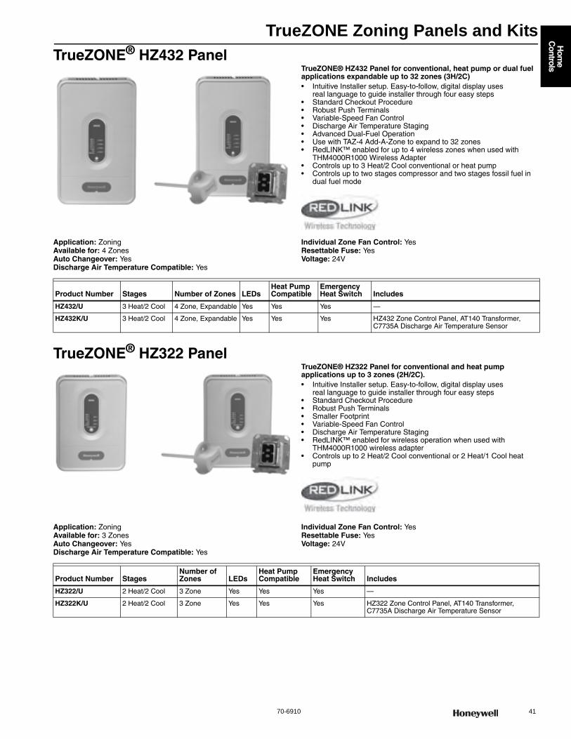
TrueZONE Zoning Panels and Kits
70-6910 41
Hom
e C
ontrols
TrueZONE® HZ432 PanelTrueZONE® HZ432 Panel for conventional, heat pump or dual fuel applications expandable up to 32 zones (3H/2C)• Intuitive Installer setup. Easy-to-follow, digital display uses
real language to guide installer through four easy steps • Standard Checkout Procedure • Robust Push Terminals • Variable-Speed Fan Control • Discharge Air Temperature Staging • Advanced Dual-Fuel Operation • Use with TAZ-4 Add-A-Zone to expand to 32 zones• RedLINK™ enabled for up to 4 wireless zones when used with
THM4000R1000 Wireless Adapter• Controls up to 3 Heat/2 Cool conventional or heat pump • Controls up to two stages compressor and two stages fossil fuel in
dual fuel mode
Application: ZoningAvailable for: 4 ZonesAuto Changeover: YesDischarge Air Temperature Compatible: Yes
Individual Zone Fan Control: YesResettable Fuse: YesVoltage: 24V
TrueZONE® HZ322 PanelTrueZONE® HZ322 Panel for conventional and heat pump applications up to 3 zones (2H/2C).• Intuitive Installer setup. Easy-to-follow, digital display uses
real language to guide installer through four easy steps • Standard Checkout Procedure • Robust Push Terminals • Smaller Footprint • Variable-Speed Fan Control • Discharge Air Temperature Staging • RedLINK™ enabled for wireless operation when used with
THM4000R1000 wireless adapter• Controls up to 2 Heat/2 Cool conventional or 2 Heat/1 Cool heat
pump
Application: ZoningAvailable for: 3 ZonesAuto Changeover: YesDischarge Air Temperature Compatible: Yes
Individual Zone Fan Control: YesResettable Fuse: YesVoltage: 24V
Product Number Stages Number of Zones LEDsHeat Pump Compatible
Emergency Heat Switch Includes
HZ432/U 3 Heat/2 Cool 4 Zone, Expandable Yes Yes Yes —
HZ432K/U 3 Heat/2 Cool 4 Zone, Expandable Yes Yes Yes HZ432 Zone Control Panel, AT140 Transformer, C7735A Discharge Air Temperature Sensor
Product Number StagesNumber of Zones LEDs
Heat Pump Compatible
Emergency Heat Switch Includes
HZ322/U 2 Heat/2 Cool 3 Zone Yes Yes Yes —
HZ322K/U 2 Heat/2 Cool 3 Zone Yes Yes Yes HZ322 Zone Control Panel, AT140 Transformer, C7735A Discharge Air Temperature Sensor
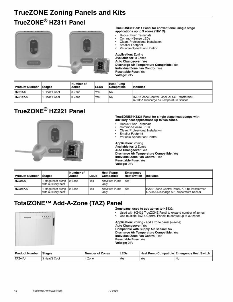
TrueZONE Zoning Panels and Kits
42 customer.honeywell.com 70-6910
TrueZONE® HZ311 PanelTrueZONE® HZ311 Panel for conventional, single stage applications up to 3 zones (1H/1C).• Robust Push Terminals • Common-Sense LEDs • Clean, Professional Installation • Smaller Footprint • Variable-Speed Fan Control
Application: ZoningAvailable for: 3 ZonesAuto Changeover: YesDischarge Air Temperature Compatible: YesIndividual Zone Fan Control: YesResettable Fuse: YesVoltage: 24V
TrueZONE® HZ221 PanelTrueZONE® HZ221 Panel for single stage heat pumps with auxiliary heat applications up to two zones.• Robust Push Terminals • Common-Sense LEDs • Clean, Professional Installation • Smaller Footprint • Variable-Speed Fan Control
Application: ZoningAvailable for: 2 ZonesAuto Changeover: YesDischarge Air Temperature Compatible: YesIndividual Zone Fan Control: YesResettable Fuse: YesVoltage: 24V
TotalZONE™ Add-A-Zone (TAZ) PanelZone panel used to add zones to HZ432.• Used with HZ432 TrueZONE Panel to expand number of zones • Use multiple TAZ-4 Control Panels to control up to 32 zones
Application: Zoning - add a zone panel (4-zone)Auto Changeover: YesCompatible with Supply Air Sensor: NoDischarge Air Temperature Compatible: YesIndividual Zone Fan Control: YesResettable Fuse: YesVoltage: 24V
Product Number StagesNumber of Zones LEDs
Heat Pump Compatible Includes
HZ311/U 1 Heat/1 Cool 3 Zone Yes No —
HZ311K/U 1 Heat/1 Cool 3 Zone Yes No HZ311 Zone Control Panel, AT140 Transformer, C7735A Discharge Air Temperature Sensor
Product Number StagesNumber of Zones LEDs
Heat Pump Compatible
Emergency Heat Switch Includes
HZ221/U 1 stage heat pump with auxiliary heat
2 Zone Yes Yes/Heat Pump Only
Yes —
HZ221K/U 1 stage heat pump with auxiliary heat
2 Zone Yes Yes/Heat Pump Only
Yes HZ221 Zone Control Panel, AT140 Transformer, C7735A Discharge Air Temperature Sensor
Product Number Stages Number of Zones LEDs Heat Pump Compatible Emergency Heat Switch
TAZ-4/U 3 Heat/2 Cool 4 Zone Yes Yes No
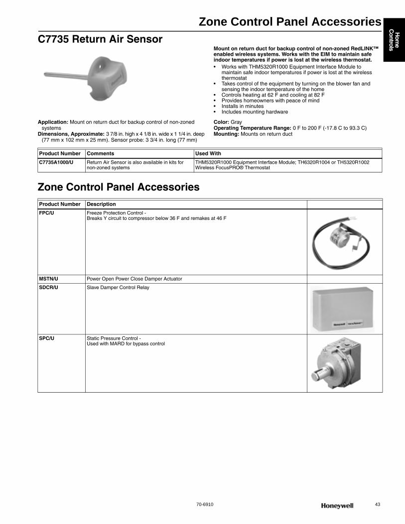
Zone Control Panel Accessories
70-6910 43
Hom
e C
ontrols
C7735 Return Air Sensor Mount on return duct for backup control of non-zoned RedLINK™ enabled wireless systems. Works with the EIM to maintain safe indoor temperatures if power is lost at the wireless thermostat.• Works with THM5320R1000 Equipment Interface Module to
maintain safe indoor temperatures if power is lost at the wireless thermostat
• Takes control of the equipment by turning on the blower fan and sensing the indoor temperature of the home
• Controls heating at 62 F and cooling at 82 F • Provides homeowners with peace of mind • Installs in minutes • Includes mounting hardware
Application: Mount on return duct for backup control of non-zoned systems
Dimensions, Approximate: 3 7/8 in. high x 4 1/8 in. wide x 1 1/4 in. deep (77 mm x 102 mm x 25 mm). Sensor probe: 3 3/4 in. long (77 mm)
Color: GrayOperating Temperature Range: 0 F to 200 F (-17.8 C to 93.3 C) Mounting: Mounts on return duct
Zone Control Panel Accessories
Product Number Comments Used With
C7735A1000/U Return Air Sensor is also available in kits for non-zoned systems
THM5320R1000 Equipment Interface Module; TH6320R1004 or TH5320R1002 Wireless FocusPRO® Thermostat
Product Number Description
FPC/U Freeze Protection Control - Breaks Y circuit to compressor below 36 F and remakes at 46 F
MSTN/U Power Open Power Close Damper Actuator
SDCR/U Slave Damper Control Relay
SPC/U Static Pressure Control - Used with MARD for bypass control
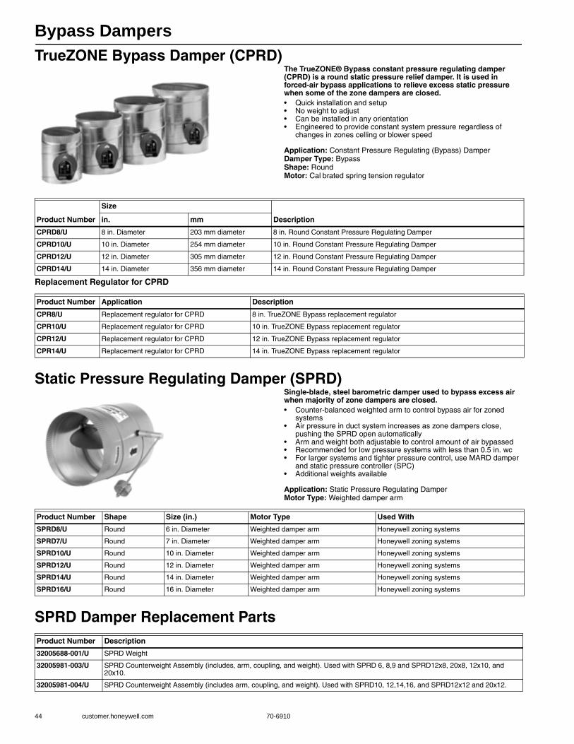
Bypass Dampers
44 customer.honeywell.com 70-6910
TrueZONE Bypass Damper (CPRD)The TrueZONE® Bypass constant pressure regulating damper (CPRD) is a round static pressure relief damper. It is used in forced-air bypass applications to relieve excess static pressure when some of the zone dampers are closed.• Quick installation and setup• No weight to adjust• Can be installed in any orientation• Engineered to provide constant system pressure regardless of
changes in zones celling or blower speed
Application: Constant Pressure Regulating (Bypass) DamperDamper Type: BypassShape: RoundMotor: Cal brated spring tension regulator
Replacement Regulator for CPRD
Static Pressure Regulating Damper (SPRD)Single-blade, steel barometric damper used to bypass excess air when majority of zone dampers are closed.• Counter-balanced weighted arm to control bypass air for zoned
systems • Air pressure in duct system increases as zone dampers close,
pushing the SPRD open automatically • Arm and weight both adjustable to control amount of air bypassed • Recommended for low pressure systems with less than 0.5 in. wc • For larger systems and tighter pressure control, use MARD damper
and static pressure controller (SPC) • Additional weights available
Application: Static Pressure Regulating DamperMotor Type: Weighted damper arm
SPRD Damper Replacement Parts
Product Number
Size
Descriptionin. mm
CPRD8/U 8 in. Diameter 203 mm diameter 8 in. Round Constant Pressure Regulating Damper
CPRD10/U 10 in. Diameter 254 mm diameter 10 in. Round Constant Pressure Regulating Damper
CPRD12/U 12 in. Diameter 305 mm diameter 12 in. Round Constant Pressure Regulating Damper
CPRD14/U 14 in. Diameter 356 mm diameter 14 in. Round Constant Pressure Regulating Damper
Product Number Application Description
CPR8/U Replacement regulator for CPRD 8 in. TrueZONE Bypass replacement regulator
CPR10/U Replacement regulator for CPRD 10 in. TrueZONE Bypass replacement regulator
CPR12/U Replacement regulator for CPRD 12 in. TrueZONE Bypass replacement regulator
CPR14/U Replacement regulator for CPRD 14 in. TrueZONE Bypass replacement regulator
Product Number Shape Size (in.) Motor Type Used With
SPRD8/U Round 6 in. Diameter Weighted damper arm Honeywell zoning systems
SPRD7/U Round 7 in. Diameter Weighted damper arm Honeywell zoning systems
SPRD10/U Round 10 in. Diameter Weighted damper arm Honeywell zoning systems
SPRD12/U Round 12 in. Diameter Weighted damper arm Honeywell zoning systems
SPRD14/U Round 14 in. Diameter Weighted damper arm Honeywell zoning systems
SPRD16/U Round 16 in. Diameter Weighted damper arm Honeywell zoning systems
Product Number Description
32005688-001/U SPRD Weight
32005981-003/U SPRD Counterweight Assembly (includes, arm, coupling, and weight). Used with SPRD 6, 8,9 and SPRD12x8, 20x8, 12x10, and 20x10.
32005981-004/U SPRD Counterweight Assembly (includes arm, coupling, and weight). Used with SPRD10, 12,14,16, and SPRD12x12 and 20x12.
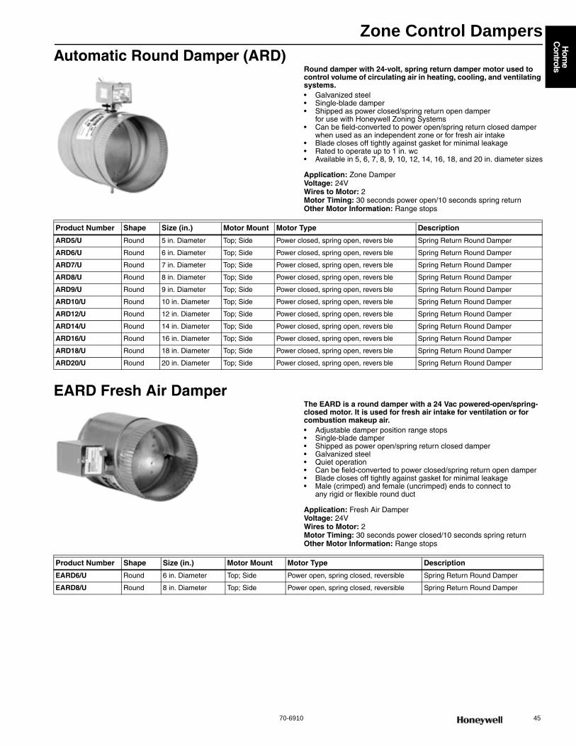
Zone Control Dampers
70-6910 45
Hom
e C
ontrols
Automatic Round Damper (ARD)Round damper with 24-volt, spring return damper motor used to control volume of circulating air in heating, cooling, and ventilating systems.• Galvanized steel • Single-blade damper • Shipped as power closed/spring return open damper
for use with Honeywell Zoning Systems • Can be field-converted to power open/spring return closed damper
when used as an independent zone or for fresh air intake • Blade closes off tightly against gasket for minimal leakage • Rated to operate up to 1 in. wc • Available in 5, 6, 7, 8, 9, 10, 12, 14, 16, 18, and 20 in. diameter sizes
Application: Zone DamperVoltage: 24VWires to Motor: 2Motor Timing: 30 seconds power open/10 seconds spring returnOther Motor Information: Range stops
EARD Fresh Air DamperThe EARD is a round damper with a 24 Vac powered-open/spring-closed motor. It is used for fresh air intake for ventilation or for combustion makeup air.• Adjustable damper position range stops • Single-blade damper • Shipped as power open/spring return closed damper • Galvanized steel • Quiet operation • Can be field-converted to power closed/spring return open damper • Blade closes off tightly against gasket for minimal leakage • Male (crimped) and female (uncrimped) ends to connect to
any rigid or flexible round duct
Application: Fresh Air DamperVoltage: 24VWires to Motor: 2Motor Timing: 30 seconds power closed/10 seconds spring returnOther Motor Information: Range stops
Product Number Shape Size (in.) Motor Mount Motor Type Description
ARD5/U Round 5 in. Diameter Top; Side Power closed, spring open, revers ble Spring Return Round Damper
ARD6/U Round 6 in. Diameter Top; Side Power closed, spring open, revers ble Spring Return Round Damper
ARD7/U Round 7 in. Diameter Top; Side Power closed, spring open, revers ble Spring Return Round Damper
ARD8/U Round 8 in. Diameter Top; Side Power closed, spring open, revers ble Spring Return Round Damper
ARD9/U Round 9 in. Diameter Top; Side Power closed, spring open, revers ble Spring Return Round Damper
ARD10/U Round 10 in. Diameter Top; Side Power closed, spring open, revers ble Spring Return Round Damper
ARD12/U Round 12 in. Diameter Top; Side Power closed, spring open, revers ble Spring Return Round Damper
ARD14/U Round 14 in. Diameter Top; Side Power closed, spring open, revers ble Spring Return Round Damper
ARD16/U Round 16 in. Diameter Top; Side Power closed, spring open, revers ble Spring Return Round Damper
ARD18/U Round 18 in. Diameter Top; Side Power closed, spring open, revers ble Spring Return Round Damper
ARD20/U Round 20 in. Diameter Top; Side Power closed, spring open, revers ble Spring Return Round Damper
Product Number Shape Size (in.) Motor Mount Motor Type Description
EARD6/U Round 6 in. Diameter Top; Side Power open, spring closed, reversible Spring Return Round Damper
EARD8/U Round 8 in. Diameter Top; Side Power open, spring closed, reversible Spring Return Round Damper
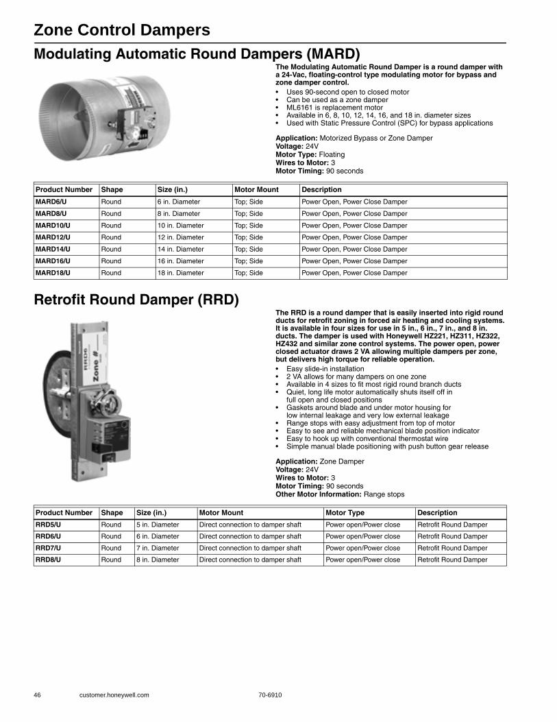
Zone Control Dampers
46 customer.honeywell.com 70-6910
Modulating Automatic Round Dampers (MARD)The Modulating Automatic Round Damper is a round damper with a 24-Vac, floating-control type modulating motor for bypass and zone damper control.• Uses 90-second open to closed motor • Can be used as a zone damper • ML6161 is replacement motor • Available in 6, 8, 10, 12, 14, 16, and 18 in. diameter sizes • Used with Static Pressure Control (SPC) for bypass applications
Application: Motorized Bypass or Zone DamperVoltage: 24VMotor Type: FloatingWires to Motor: 3Motor Timing: 90 seconds
Retrofit Round Damper (RRD)The RRD is a round damper that is easily inserted into rigid round ducts for retrofit zoning in forced air heating and cooling systems. It is available in four sizes for use in 5 in., 6 in., 7 in., and 8 in. ducts. The damper is used with Honeywell HZ221, HZ311, HZ322, HZ432 and similar zone control systems. The power open, power closed actuator draws 2 VA allowing multiple dampers per zone, but delivers high torque for reliable operation.• Easy slide-in installation • 2 VA allows for many dampers on one zone • Available in 4 sizes to fit most rigid round branch ducts • Quiet, long life motor automatically shuts itself off in
full open and closed positions • Gaskets around blade and under motor housing for
low internal leakage and very low external leakage • Range stops with easy adjustment from top of motor • Easy to see and reliable mechanical blade position indicator • Easy to hook up with conventional thermostat wire • Simple manual blade positioning with push button gear release
Application: Zone DamperVoltage: 24VWires to Motor: 3Motor Timing: 90 secondsOther Motor Information: Range stops
Product Number Shape Size (in.) Motor Mount Description
MARD6/U Round 6 in. Diameter Top; Side Power Open, Power Close Damper
MARD8/U Round 8 in. Diameter Top; Side Power Open, Power Close Damper
MARD10/U Round 10 in. Diameter Top; Side Power Open, Power Close Damper
MARD12/U Round 12 in. Diameter Top; Side Power Open, Power Close Damper
MARD14/U Round 14 in. Diameter Top; Side Power Open, Power Close Damper
MARD16/U Round 16 in. Diameter Top; Side Power Open, Power Close Damper
MARD18/U Round 18 in. Diameter Top; Side Power Open, Power Close Damper
Product Number Shape Size (in.) Motor Mount Motor Type Description
RRD5/U Round 5 in. Diameter Direct connection to damper shaft Power open/Power close Retrofit Round Damper
RRD6/U Round 6 in. Diameter Direct connection to damper shaft Power open/Power close Retrofit Round Damper
RRD7/U Round 7 in. Diameter Direct connection to damper shaft Power open/Power close Retrofit Round Damper
RRD8/U Round 8 in. Diameter Direct connection to damper shaft Power open/Power close Retrofit Round Damper
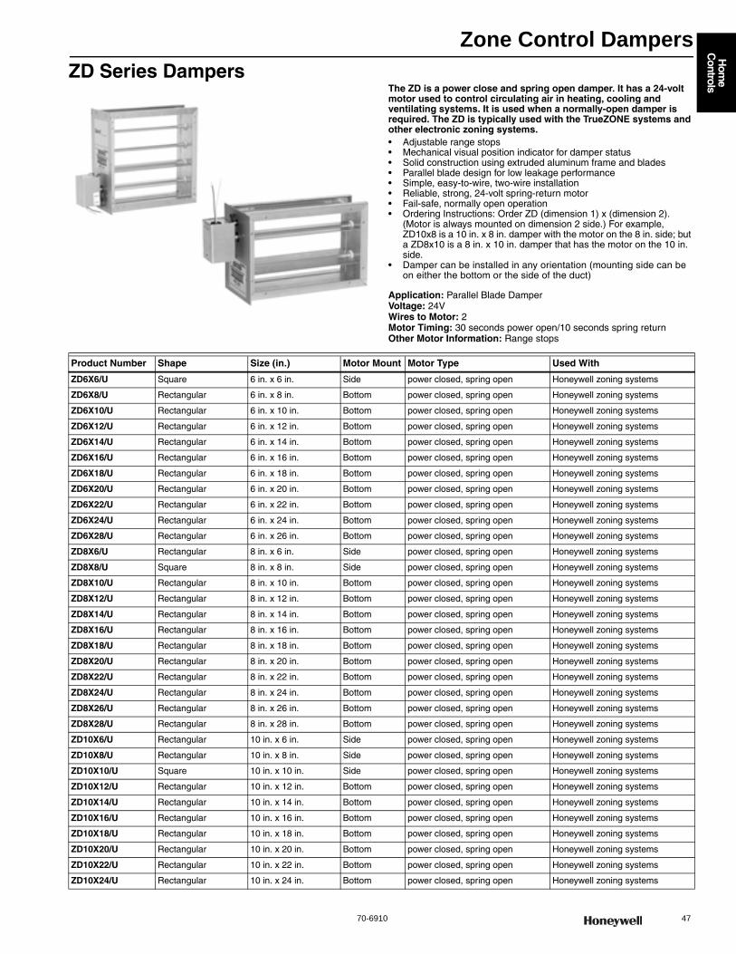
Zone Control Dampers
70-6910 47
Hom
e C
ontrols
ZD Series DampersThe ZD is a power close and spring open damper. It has a 24-volt motor used to control circulating air in heating, cooling and ventilating systems. It is used when a normally-open damper is required. The ZD is typically used with the TrueZONE systems and other electronic zoning systems.• Adjustable range stops • Mechanical visual position indicator for damper status • Solid construction using extruded aluminum frame and blades • Parallel blade design for low leakage performance • Simple, easy-to-wire, two-wire installation • Reliable, strong, 24-volt spring-return motor • Fail-safe, normally open operation • Ordering Instructions: Order ZD (dimension 1) x (dimension 2).
(Motor is always mounted on dimension 2 side.) For example, ZD10x8 is a 10 in. x 8 in. damper with the motor on the 8 in. side; but a ZD8x10 is a 8 in. x 10 in. damper that has the motor on the 10 in. side.
• Damper can be installed in any orientation (mounting side can be on either the bottom or the side of the duct)
Application: Parallel Blade DamperVoltage: 24VWires to Motor: 2Motor Timing: 30 seconds power open/10 seconds spring returnOther Motor Information: Range stops
Product Number Shape Size (in.) Motor Mount Motor Type Used With
ZD6X6/U Square 6 in. x 6 in. Side power closed, spring open Honeywell zoning systems
ZD6X8/U Rectangular 6 in. x 8 in. Bottom power closed, spring open Honeywell zoning systems
ZD6X10/U Rectangular 6 in. x 10 in. Bottom power closed, spring open Honeywell zoning systems
ZD6X12/U Rectangular 6 in. x 12 in. Bottom power closed, spring open Honeywell zoning systems
ZD6X14/U Rectangular 6 in. x 14 in. Bottom power closed, spring open Honeywell zoning systems
ZD6X16/U Rectangular 6 in. x 16 in. Bottom power closed, spring open Honeywell zoning systems
ZD6X18/U Rectangular 6 in. x 18 in. Bottom power closed, spring open Honeywell zoning systems
ZD6X20/U Rectangular 6 in. x 20 in. Bottom power closed, spring open Honeywell zoning systems
ZD6X22/U Rectangular 6 in. x 22 in. Bottom power closed, spring open Honeywell zoning systems
ZD6X24/U Rectangular 6 in. x 24 in. Bottom power closed, spring open Honeywell zoning systems
ZD6X28/U Rectangular 6 in. x 26 in. Bottom power closed, spring open Honeywell zoning systems
ZD8X6/U Rectangular 8 in. x 6 in. Side power closed, spring open Honeywell zoning systems
ZD8X8/U Square 8 in. x 8 in. Side power closed, spring open Honeywell zoning systems
ZD8X10/U Rectangular 8 in. x 10 in. Bottom power closed, spring open Honeywell zoning systems
ZD8X12/U Rectangular 8 in. x 12 in. Bottom power closed, spring open Honeywell zoning systems
ZD8X14/U Rectangular 8 in. x 14 in. Bottom power closed, spring open Honeywell zoning systems
ZD8X16/U Rectangular 8 in. x 16 in. Bottom power closed, spring open Honeywell zoning systems
ZD8X18/U Rectangular 8 in. x 18 in. Bottom power closed, spring open Honeywell zoning systems
ZD8X20/U Rectangular 8 in. x 20 in. Bottom power closed, spring open Honeywell zoning systems
ZD8X22/U Rectangular 8 in. x 22 in. Bottom power closed, spring open Honeywell zoning systems
ZD8X24/U Rectangular 8 in. x 24 in. Bottom power closed, spring open Honeywell zoning systems
ZD8X26/U Rectangular 8 in. x 26 in. Bottom power closed, spring open Honeywell zoning systems
ZD8X28/U Rectangular 8 in. x 28 in. Bottom power closed, spring open Honeywell zoning systems
ZD10X6/U Rectangular 10 in. x 6 in. Side power closed, spring open Honeywell zoning systems
ZD10X8/U Rectangular 10 in. x 8 in. Side power closed, spring open Honeywell zoning systems
ZD10X10/U Square 10 in. x 10 in. Side power closed, spring open Honeywell zoning systems
ZD10X12/U Rectangular 10 in. x 12 in. Bottom power closed, spring open Honeywell zoning systems
ZD10X14/U Rectangular 10 in. x 14 in. Bottom power closed, spring open Honeywell zoning systems
ZD10X16/U Rectangular 10 in. x 16 in. Bottom power closed, spring open Honeywell zoning systems
ZD10X18/U Rectangular 10 in. x 18 in. Bottom power closed, spring open Honeywell zoning systems
ZD10X20/U Rectangular 10 in. x 20 in. Bottom power closed, spring open Honeywell zoning systems
ZD10X22/U Rectangular 10 in. x 22 in. Bottom power closed, spring open Honeywell zoning systems
ZD10X24/U Rectangular 10 in. x 24 in. Bottom power closed, spring open Honeywell zoning systems
Zone Control Dampers
48 customer.honeywell.com 70-6910
ZD10X26/U Rectangular 10 in. x 26 in. Bottom power closed, spring open Honeywell zoning systems
ZD10X28/U Rectangular 10 in. x 28 in. Bottom power closed, spring open Honeywell zoning systems
ZD12X6/U Rectangular 12 in. x 6 in. Side power closed, spring open Honeywell zoning systems
ZD12X8/U Rectangular 12 in. x 8 in. Side power closed, spring open Honeywell zoning systems
ZD12X10/U Rectangular 12 in. x 10 in. Side power closed, spring open Honeywell zoning systems
ZD12X12/U Square 12 in. x 12 in. Side power closed, spring open Honeywell zoning systems
ZD12X14/U Rectangular 12 in. x 14 in. Bottom power closed, spring open Honeywell zoning systems
ZD12X16/U Rectangular 12 in. x 16 in. Bottom power closed, spring open Honeywell zoning systems
ZD12X18/U Rectangular 12 in. x 18 in. Bottom power closed, spring open Honeywell zoning systems
ZD12X20/U Rectangular 12 in. x 20 in. Bottom power closed, spring open Honeywell zoning systems
ZD12X22/U Rectangular 12 in. x 22 in. Bottom power closed, spring open Honeywell zoning systems
ZD12X24/U Rectangular 12 in. x 24 in. Bottom power closed, spring open Honeywell zoning systems
ZD12X26/U Rectangular 12 in. x 26 in. Bottom power closed, spring open Honeywell zoning systems
ZD12X28/U Rectangular 12 in. x 28 in. Bottom power closed, spring open Honeywell zoning systems
ZD14X6/U Rectangular 14 in. x 6 in. Side power closed, spring open Honeywell zoning systems
ZD14X8/U Rectangular 14 in. x 8 in. Side power closed, spring open Honeywell zoning systems
ZD14X10/U Rectangular 14 in. x 10 in. Side power closed, spring open Honeywell zoning systems
ZD14X12/U Rectangular 14 in. x 12 in. Side power closed, spring open Honeywell zoning systems
ZD14X14/U Square 14 in. x 14 in. Side power closed, spring open Honeywell zoning systems
ZD14X16/U Rectangular 14 in. x 16 in. Bottom power closed, spring open Honeywell zoning systems
ZD14X18/U Rectangular 14 in. x 18 in. Bottom power closed, spring open Honeywell zoning systems
ZD14X20/U Rectangular 14 in. x 20 in. Bottom power closed, spring open Honeywell zoning systems
ZD14X22/U Rectangular 14 in. x 22 in. Bottom power closed, spring open Honeywell zoning systems
ZD14X24/U Rectangular 14 in. x 24 in. Bottom power closed, spring open Honeywell zoning systems
ZD14X26/U Rectangular 14 in. x 26 in. Bottom power closed, spring open Honeywell zoning systems
ZD14X28/U Rectangular 14 in. x 28 in. Bottom power closed, spring open Honeywell zoning systems
ZD16X6/U Rectangular 16 in. x 6 in. Side power closed, spring open Honeywell zoning systems
ZD16X8/U Rectangular 16 in. x 8 in. Side power closed, spring open Honeywell zoning systems
ZD16X10/U Rectangular 16 in. x 10 in. Side power closed, spring open Honeywell zoning systems
ZD16X12/U Rectangular 16 in. x 12 in. Side power closed, spring open Honeywell zoning systems
ZD16X14/U Rectangular 16 in. x 14 in. Side power closed, spring open Honeywell zoning systems
ZD16X16/U Square 16 in. x 16 in. Side power closed, spring open Honeywell zoning systems
ZD16X18/U Rectangular 16 in. x 18 in. Bottom power closed, spring open Honeywell zoning systems
ZD16X20/U Rectangular 16 in. x 20 in. Bottom power closed, spring open Honeywell zoning systems
ZD16X22/U Rectangular 16 in. x 22 in. Bottom power closed, spring open Honeywell zoning systems
ZD16X24/U Rectangular 16 in. x 24 in. Bottom power closed, spring open Honeywell zoning systems
ZD16X26/U Rectangular 16 in. x 26 in. Bottom power closed, spring open Honeywell zoning systems
ZD18X6/U Rectangular 18 in. x 6 in. Side power closed, spring open Honeywell zoning systems
ZD18X8/U Rectangular 18 in. x 8 in. Side power closed, spring open Honeywell zoning systems
ZD18X10/U Rectangular 18 in. x 10 in. Side power closed, spring open Honeywell zoning systems
ZD18X12/U Rectangular 18 in. x 12 in. Side power closed, spring open Honeywell zoning systems
ZD18X14/U Rectangular 18 in. x 14 in. Side power closed, spring open Honeywell zoning systems
ZD18X16/U Rectangular 18 in. x 16 in. Side power closed, spring open Honeywell zoning systems
ZD18X18/U Square 18 in. x 18 in. Side power closed, spring open Honeywell zoning systems
ZD18X20/U Rectangular 18 in. x 20 in. Bottom power closed, spring open Honeywell zoning systems
ZD18X22/U Rectangular 18 in. x 22 in. Bottom power closed, spring open Honeywell zoning systems
ZD18X24/U Rectangular 18 in. x 24 in. Bottom power closed, spring open Honeywell zoning systems
ZD18X26/U Rectangular 18 in. x 26 in. Bottom power closed, spring open Honeywell zoning systems
ZD20X6/U Rectangular 20 in. x 6 in. Side power closed, spring open Honeywell zoning systems
ZD20X8/U Rectangular 20 in. x 8 in. Side power closed, spring open Honeywell zoning systems
ZD20X10/U Rectangular 20 in. x 10 in. Side power closed, spring open Honeywell zoning systems
Product Number Shape Size (in.) Motor Mount Motor Type Used With
Zone Control Dampers
70-6910 49
Hom
e C
ontrols
Zoning Damper AccessoriesApplication: Accessory
ZD20X12/U Rectangular 20 in. x 12 in. Side power closed, spring open Honeywell zoning systems
ZD20X14/U Rectangular 20 in. x 14 in. Side power closed, spring open Honeywell zoning systems
ZD20X16/U Rectangular 20 in. x 16 in. Side power closed, spring open Honeywell zoning systems
ZD20X18/U Rectangular 20 in. x 18 in. Side power closed, spring open Honeywell zoning systems
ZD20X20/U Square 20 in. x 20 in. Side power closed, spring open Honeywell zoning systems
ZD20X22/U Rectangular 20 in. x 22 in. Bottom power closed, spring open Honeywell zoning systems
ZD20X24/U Rectangular 20 in. x 24 in. Bottom power closed, spring open Honeywell zoning systems
ZD22X6/U Rectangular 22 in. x 6 in. Side power closed, spring open Honeywell zoning systems
ZD22X8/U Rectangular 22 in. x 8 in. Side power closed, spring open Honeywell zoning systems
ZD22X10/U Rectangular 22 in. x 10 in. Side power closed, spring open Honeywell zoning systems
ZD22X12/U Rectangular 22 in. x 12 in. Side power closed, spring open Honeywell zoning systems
ZD22X14/U Rectangular 22 in. x 14 in. Side power closed, spring open Honeywell zoning systems
ZD22X16/U Rectangular 22 in. x 16 in. Side power closed, spring open Honeywell zoning systems
ZD22X18/U Rectangular 22 in. x 18 in. Side power closed, spring open Honeywell zoning systems
ZD22X20/U Rectangular 22 in. x 20 in. Side power closed, spring open Honeywell zoning systems
ZD22X22/U Square 22 in. x 22 in. Side power closed, spring open Honeywell zoning systems
ZD22X24/U Rectangular 22 in. x 24 in. Bottom power closed, spring open Honeywell zoning systems
ZD24X6/U Rectangular 24 in. x 6 in. Side power closed, spring open Honeywell zoning systems
ZD24X8/U Rectangular 24 in. x 8 in. Side power closed, spring open Honeywell zoning systems
ZD24X10/U Rectangular 24 in. x 10 in. Side power closed, spring open Honeywell zoning systems
ZD24X12/U Rectangular 24 in. x 12 in. Side power closed, spring open Honeywell zoning systems
ZD24X14/U Rectangular 24 in. x 14 in. Side power closed, spring open Honeywell zoning systems
ZD24X16/U Rectangular 24 in. x 16 in. Side power closed, spring open Honeywell zoning systems
ZD24X18/U Rectangular 24 in. x 18 in. Side power closed, spring open Honeywell zoning systems
ZD24X20/U Rectangular 24 in. x 20 in. Side power closed, spring open Honeywell zoning systems
ZD24X22/U Rectangular 24 in. x 22 in. Side power closed, spring open Honeywell zoning systems
ZD24X24/U Square 24 in. x 24 in. Side power closed, spring open Honeywell zoning systems
ZD26X8/U Rectangular 26 in. x 8 in. Side power closed, spring open Honeywell zoning systems
ZD26X10/U Rectangular 26 in. x 10 in. Side power closed, spring open Honeywell zoning systems
ZD26X12/U Rectangular 26 in. x 12 in. Side power closed, spring open Honeywell zoning systems
ZD26X14/U Rectangular 26 in. x 14 in. Side power closed, spring open Honeywell zoning systems
ZD26X16/U Rectangular 26 in. x 16 in. Side power closed, spring open Honeywell zoning systems
ZD26X18/U Rectangular 26 in. x 18 in. Side power closed, spring open Honeywell zoning systems
ZD26X20/U Rectangular 26 in. x 20 in. Side power closed, spring open Honeywell zoning systems
ZD28X6/U Rectangular 28 in. x 6 in. Side power closed, spring open Honeywell zoning systems
ZD28X8/U Rectangular 28 in. x 8 in. Side power closed, spring open Honeywell zoning systems
ZD28X10/U Rectangular 28 in. x 10 in. Side power closed, spring open Honeywell zoning systems
ZD28X12/U Rectangular 28 in. x 12 in. Side power closed, spring open Honeywell zoning systems
ZD28X14/U Rectangular 28 in. x 14 in. Side power closed, spring open Honeywell zoning systems
ZD28X16/U Rectangular 28 in. x 16 in. Side power closed, spring open Honeywell zoning systems
ZD28X20/U Rectangular 28 in. x 18 in. Side power closed, spring open Honeywell zoning systems
Product Number Shape Size (in.) Motor Mount Motor Type Used With
Product Number Description Includes
32006184-001/U Filler strip kit used to install ZD dampers in odd sized ducts 1 1/8 in. x 3/4 in. adhesive-backed foam strips
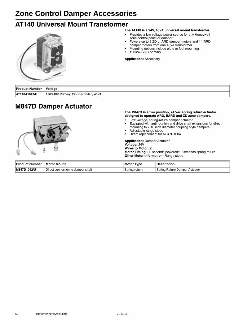
Zone Control Damper Accessories
50 customer.honeywell.com 70-6910
AT140 Universal Mount TransformerThe AT140 is a 24V, 40VA universal mount transformer.• Provides a low voltage power source for any Honeywell
zone control panel or damper • Powers up to 5 ZD or ARD damper motors and 14 RRD
damper motors from one 40VA transformer • Mounting options include plate or foot mounting • 120/240 VAC primary
Application: Accessory
M847D Damper ActuatorThe M847D is a two position, 24 Vac spring return actuator designed to operate ARD, EARD and ZD zone dampers.• Low voltage, spring-return damper actuator • Equipped with anti-rotation and drive shaft extensions for direct
mounting to 7/16 inch diameter coupling style dampers • Adjustable range stops • Direct replacement for M847D1004
Application: Damper ActuatorVoltage: 24VWires to Motor: 2Motor Timing: 30 seconds powered/10 seconds spring returnOther Motor Information: Range stops
Product Number Voltage
AT140A1042/U 120/240V Primary, 24V Secondary 40VA
Product Number Motor Mount Motor Type Description
M847D1012/U Direct connection to damper shaft Spring return Spring Return Damper Actuator
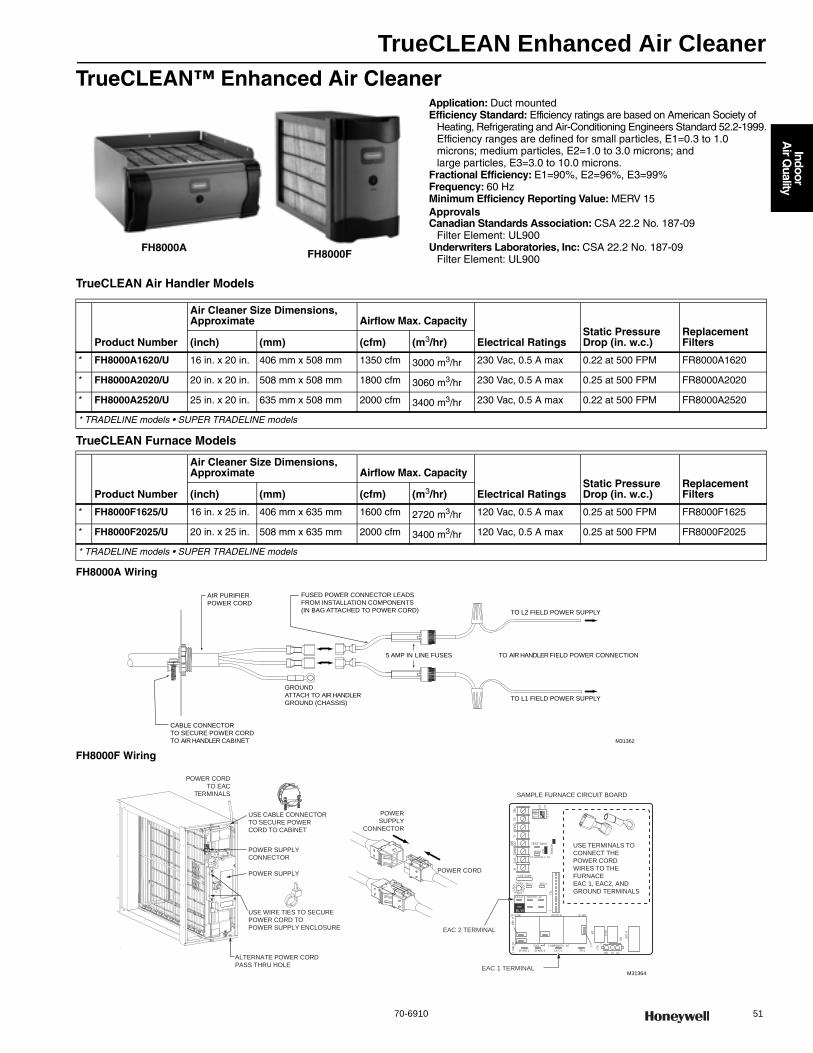
TrueCLEAN Enhanced Air Cleaner
70-6910 51
Indoor
Air Q
uality
TrueCLEAN™ Enhanced Air CleanerApplication: Duct mountedEfficiency Standard: Efficiency ratings are based on American Society of
Heating, Refrigerating and Air-Conditioning Engineers Standard 52.2-1999.Efficiency ranges are defined for small particles, E1=0.3 to 1.0 microns; medium particles, E2=1.0 to 3.0 microns; and large particles, E3=3.0 to 10.0 microns.
Fractional Efficiency: E1=90%, E2=96%, E3=99%Frequency: 60 HzMinimum Efficiency Reporting Value: MERV 15ApprovalsCanadian Standards Association: CSA 22.2 No. 187-09
Filter Element: UL900Underwriters Laboratories, Inc: CSA 22.2 No. 187-09
Filter Element: UL900
TrueCLEAN Air Handler Models
TrueCLEAN Furnace Models
FH8000A Wiring
FH8000F Wiring
FH8000AFH8000F
Product Number
Air Cleaner Size Dimensions, Approximate Airflow Max. Capacity
Electrical RatingsStatic Pressure Drop (in. w.c.)
Replacement Filters(inch) (mm) (cfm) (m3/hr)
* FH8000A1620/U 16 in. x 20 in. 406 mm x 508 mm 1350 cfm 3000 m3/hr 230 Vac, 0.5 A max 0.22 at 500 FPM FR8000A1620
* FH8000A2020/U 20 in. x 20 in. 508 mm x 508 mm 1800 cfm 3060 m3/hr 230 Vac, 0.5 A max 0.25 at 500 FPM FR8000A2020
* FH8000A2520/U 25 in. x 20 in. 635 mm x 508 mm 2000 cfm 3400 m3/hr 230 Vac, 0.5 A max 0.22 at 500 FPM FR8000A2520
* TRADELINE models • SUPER TRADELINE models
Product Number
Air Cleaner Size Dimensions, Approximate Airflow Max. Capacity
Electrical RatingsStatic Pressure Drop (in. w.c.)
Replacement Filters(inch) (mm) (cfm) (m3/hr)
* FH8000F1625/U 16 in. x 25 in. 406 mm x 635 mm 1600 cfm 2720 m3/hr 120 Vac, 0.5 A max 0.25 at 500 FPM FR8000F1625
* FH8000F2025/U 20 in. x 25 in. 508 mm x 635 mm 2000 cfm 3400 m3/hr 120 Vac, 0.5 A max 0.25 at 500 FPM FR8000F2025
* TRADELINE models • SUPER TRADELINE models
FUSED POWER CONNECTOR LEADS
FROM INSTALLATION COMPONENTS
(IN BAG ATTACHED TO POWER CORD)
AIR PURIFIER
POWER CORD
TO AIR HANDLER FIELD POWER CONNECTION
TO L2 FIELD POWER SUPPLY
TO L1 FIELD POWER SUPPLY
5 AMP IN LINE FUSES
GROUND
ATTACH TO AIR HANDLER
GROUND (CHASSIS)
CABLE CONNECTOR
TO SECURE POWER CORD
TO AIR HANDLER CABINET M31362
SAMPLE FURNACE CIRCUIT BOARD
POWER CORD
TO EAC
TERMINALS
USE CABLE CONNECTOR
TO SECURE POWER
CORD TO CABINET
POWER SUPPLY
CONNECTOR
POWER SUPPLY
USE WIRE TIES TO SECURE
POWER CORD TO
POWER SUPPLY ENCLOSURE
LHTOFFDLY
ON
OF
FW2
BLW
EAC 1 TERMINAL
Y1
DH
UM
GC
OM
24VW
W1
Y/Y
2R
TEST TW N
HUM
1 2
3
PL
T
AC
RD
J
0 5-AMP024 V AC
FUSE 3-AMP
SEC-1 SEC-2
PL1
NEUTRA -L2
1
EA C-2
BHT/CLRBH /LOR BL WR
COOL
SP ARE-1 SP ARE-2
1-AMP@115 V AC
EA C-1 PR-1
DR
HS
R
DM
HLO
R
PL2
1
HSI HI LO
STATUS
C
ODELE
D
EAC 2 TERMINAL
H H
EA
LO H
EA
T
L1
USE TERMINALS TO
CONNECT THE
POWER CORD
WIRES TO THE
FURNACE
EAC 1, EAC2, AND
GROUND TERMINALS
POWER
SUPPLY
CONNECTOR
POWER CORD
ALTERNATE POWER CORD
PASS THRU HOLE
M31364

TrueCLEAN Enhanced Air Cleaner
52 customer.honeywell.com 70-6910
Dimensions in inches (millimeters)
FH8000A
FH8000F
M34704
7/16 (11) TYPICAL TOP & BOTTOM
DB
E
F
3/8 (9.5) TYPICAL TOP & BOTTOM
1-1/2 (38)
1-3/16(30)
A
C
G
1-3/16(30)
1-3/16(30)
A
C
G
E
F1-15/16
(49)
1-3/16(30)
DB
1-3/16(30)
1-3/16(30)
DIMENSIONS FH8000A1620 FH8000A2020 FH8000A2520 FH8000F1625 FH8000F2025
A 18-5/8 (473) 22-1/8 (562) 25-5/8 (651) 18-3/8 (467) 21-7/8 (556)
B 15-3/8 (391) 18-7/8 (479) 22-3/8 (568) 15-1/8 (384) 18-5/8 (473)
C 13-1/8 (333) 13-1/8 (333) 13-1/8 (333) 11-1/8 (283) 11-1/8 (283)
D 17-5/8 (448) 21-1/8 (537) 24-5/8 (626) 17-1/2 (445) 21 (533)
E 19-7/8 (505) 19-7/8 (505) 19-7/8 (505) 22-1/8 (562) 22-1/8 (562)
F 22-1/4 (565) 22-1/4 (565) 22-1/4 (565) 25-1/4 (641) 25-1/4 (641)
G 11-1/4 (286) 11-1/4 (286) 11-1/4 (286) — —
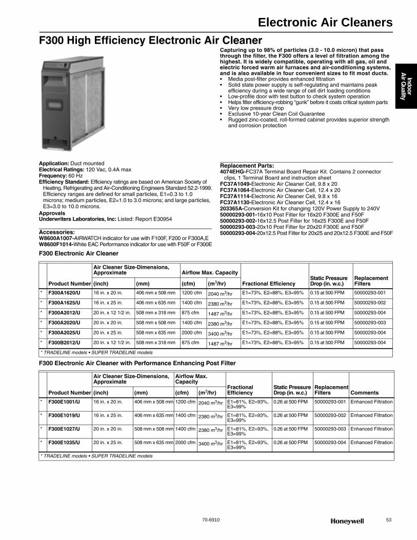
Electronic Air Cleaners
70-6910 53
Indoor
Air Q
uality
F300 High Efficiency Electronic Air CleanerCapturing up to 98% of particles (3.0 - 10.0 micron) that pass through the filter, the F300 offers a level of filtration among the highest. It is widely compatible, operating with all gas, oil and electric forced warm air furnaces and air-conditioning systems, and is also available in four convenient sizes to fit most ducts.• Media post-filter provides enhanced filtration • Solid state power supply is self-regulating and maintains peak
efficiency during a wide range of cell dirt loading conditions • Low-profile door with test button to check system operation • Helps filter efficiency-robbing “gunk” before it coats critical system parts • Very low pressure drop • Exclusive 10-year Clean Coil Guarantee • Rugged zinc-coated, roll-formed cabinet provides superior strength
and corrosion protection
Application: Duct mountedElectrical Ratings: 120 Vac, 0.4A maxFrequency: 60 HzEfficiency Standard: Efficiency ratings are based on American Society of
Heating, Refrigerating and Air-Conditioning Engineers Standard 52.2-1999.Efficiency ranges are defined for small particles, E1=0.3 to 1.0 microns; medium particles, E2=1.0 to 3.0 microns; and large particles, E3=3.0 to 10.0 microns.
ApprovalsUnderwriters Laboratories, Inc: Listed: Report E30954
Accessories:W8600A1007-AIRWATCH indicator for use with F100F, F200 or F300A,EW8600F1014-White EAC Performance indicator for use with F50F or F300E
Replacement Parts:4074EHG-FC37A Terminal Board Repair Kit. Contains 2 connector
clips, 1 Terminal Board and instruction sheetFC37A1049-Electronic Air Cleaner Cell, 9.8 x 20FC37A1064-Electronic Air Cleaner Cell, 12.4 x 20FC37A1114-Electronic Air Cleaner Cell, 9.8 x 16FC37A1130-Electronic Air Cleaner Cell, 12.4 x 16203365A-Conversion Kit for changing 120V Power Supply to 240V50000293-001-16x10 Post Filter for 16x20 F300E and F50F50000293-002-16x12.5 Post Filter for 16x25 F300E and F50F50000293-003-20x10 Post Filter for 20x20 F300E and F50F50000293-004-20x12.5 Post Filter for 20x25 and 20x12.5 F300E and F50F
F300 Electronic Air Cleaner
F300 Electronic Air Cleaner with Performance Enhancing Post Filter
Product Number
Air Cleaner Size-Dimensions, Approximate Airflow Max. Capacity
Fractional EfficiencyStatic Pressure Drop (in. w.c.)
Replacement Filters(inch) (mm) (cfm) (m3/hr)
* F300A1620/U 16 in. x 20 in. 406 mm x 508 mm 1200 cfm 2040 m3/hr E1=73%, E2=88%, E3=95% 0.15 at 500 FPM 50000293-001
* F300A1625/U 16 in. x 25 in. 406 mm x 635 mm 1400 cfm 2380 m3/hr E1=73%, E2=88%, E3=95% 0.15 at 500 FPM 50000293-002
* F300A2012/U 20 in. x 12 1/2 in. 508 mm x 318 mm 875 cfm 1487 m3/hr E1=73%, E2=88%, E3=95% 0.15 at 500 FPM 50000293-004
* F300A2020/U 20 in. x 20 in. 508 mm x 508 mm 1400 cfm 2380 m3/hr E1=73%, E2=88%, E3=95% 0.15 at 500 FPM 50000293-003
* F300A2025/U 20 in. x 25 in. 508 mm x 635 mm 2000 cfm 3400 m3/hr E1=73%, E2=88%, E3=95% 0.15 at 500 FPM 50000293-004
* F300B2012/U 20 in. x 12 1/2 in. 508 mm x 318 mm 875 cfm 1487 m3/hr E1=73%, E2=88%, E3=95% 0.15 at 500 FPM 50000293-004
* TRADELINE models • SUPER TRADELINE models
Product Number
Air Cleaner Size-Dimensions, Approximate
Airflow Max.Capacity
Fractional Efficiency
Static Pressure Drop (in. w.c.)
Replacement Filters Comments(inch) (mm) (cfm) (m3/hr)
* F300E1001/U 16 in. x 20 in. 406 mm x 508 mm 1200 cfm 2040 m3/hr E1=81%, E2=93%, E3=99%
0.26 at 500 FPM 50000293-001 Enhanced Filtration
* F300E1019/U 16 in. x 25 in. 406 mm x 635 mm 1400 cfm 2380 m3/hr E1=81%, E2=93%, E3=99%
0.26 at 500 FPM 50000293-002 Enhanced Filtration
* F300E1027/U 20 in. x 20 in. 508 mm x 508 mm 1400 cfm 2380 m3/hr E1=81%, E2=93%, E3=99%
0.26 at 500 FPM 50000293-003 Enhanced Filtration
* F300E1035/U 20 in. x 25 in. 508 mm x 635 mm 2000 cfm 3400 m3/hr E1=81%, E2=93%, E3=99%
0.26 at 500 FPM 50000293-004 Enhanced Filtration
* TRADELINE models • SUPER TRADELINE models
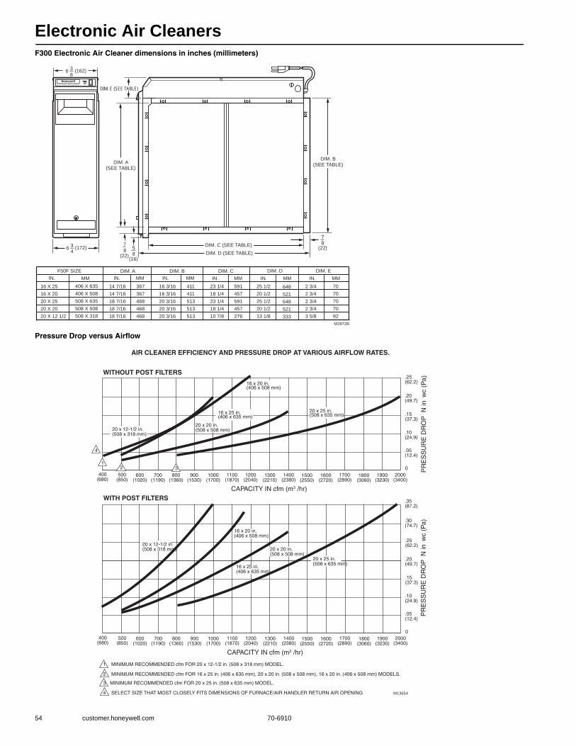
Electronic Air Cleaners
54 customer.honeywell.com 70-6910
F300 Electronic Air Cleaner dimensions in inches (millimeters)
Pressure Drop versus Airflow
M2872B
F50F SIZE
IN.
16 X 25
16 X 20
20 X 25
20 X 20
20 X 12 1/2
MM
406 X 635
406 X 508
508 X 635
508 X 508
508 X 318
DIM. A
14 7/16
14 7/16
18 7/16
18 7/16
18 7/16
367
367
468
468
468
DIM. B
16 3/16
16 3/16
20 3/16
20 3/16
20 3/16
411
411
513
513
513
23 1/4
18 1/4
23 1/4
18 1/4
10 7/8
DIM. C
591
457
591
457
276
DIM. D
25 1/2
20 1/2
25 1/2
20 1/2
13 1/8
648
521
648
521
333
DIM. C (SEE TABLE)
DIM. D (SEE TABLE)
DIM. B(SEE TABLE)
DIM. A(SEE TABLE)
7
8(22)
5
8(16)
63
4(172)
7
8(22)
IN. MM IN. MM IN. MM IN. MM
DIM. E (SEE TABLE)ELECTRON C AIR CLEANER
3
8(162)6
DIM. E
2 3/4
2 3/4
2 3/4
2 3/4
3 5/8
70
70
70
70
92
IN. MM
700(1190)
800(1360)
900(1530)
1000(1700)
1100(1870)
1200(2040)
1300(2210)
1400(2380)
1500(2550)
1600(2720)
1700(2890)
1800(3060)
1900(3230)
2000(3400)
.25(62.2)
.20(49.7)
.15(37.3)
.10(24.9)
.05(12.4)
0 PR
ES
SU
RE
DR
OP
N in
wc
(Pa)
600(1020)
500(850)
400(680)
4
CAPACITY IN cfm (m3 /hr)
1 MINIMUM RECOMMENDED cfm FOR 20 x 12-1/2 in. (508 x 318 mm) MODEL.
2 MINIMUM RECOMMENDED cfm FOR 16 x 25 in. (406 x 635 mm), 20 x 20 in. (508 x 508 mm), 16 x 20 in. (406 x 508 mm) MODELS.
3 MINIMUM RECOMMENDED cfm FOR 20 x 25 in. (508 x 635 mm) MODEL.
4 SELECT SIZE THAT MOST CLOSELY FITS DIMENSIONS OF FURNACE/AIR HANDLER RETURN AIR OPENING M13654
700(1190)
800(1360)
900(1530)
1000(1700)
1100(1870)
1200(2040)
1300(2210)
1400(2380)
1500(2550)
1600(2720)
1700(2890)
1800(3060)
1900(3230)
2000(3400)
.25(62.2)
.20(49.7)
.15(37.3)
.10(24.9)
.05(12.4)
0
PR
ES
SU
RE
DR
OP
N in
wc
(Pa)
600(1020)
500(850)
400(680)
20 x 12-1/2 in.(508 x 318 mm) 20 x 20 in.
(508 x 508 mm)
16 x 25 in.(406 x 635 mm)
16 x 20 in.(406 x 508 mm)
20 x 25 in.(508 x 635 mm)
20 x 12-1/2 in.(508 x 318 mm)
16 x 25 in.(406 x 635 mm)
16 x 20 in.(406 x 508 mm)
12 3
20 x 25 in.(508 x 635 mm)
AIR CLEANER EFFICIENCY AND PRESSURE DROP AT VARIOUS AIRFLOW RATES.
WITHOUT POST FILTERS
WITH POST FILTERS
.30(74.7)
.35(87.2)
CAPACITY IN cfm (m3 /hr)
20 x 20 in.(508 x 508 mm)
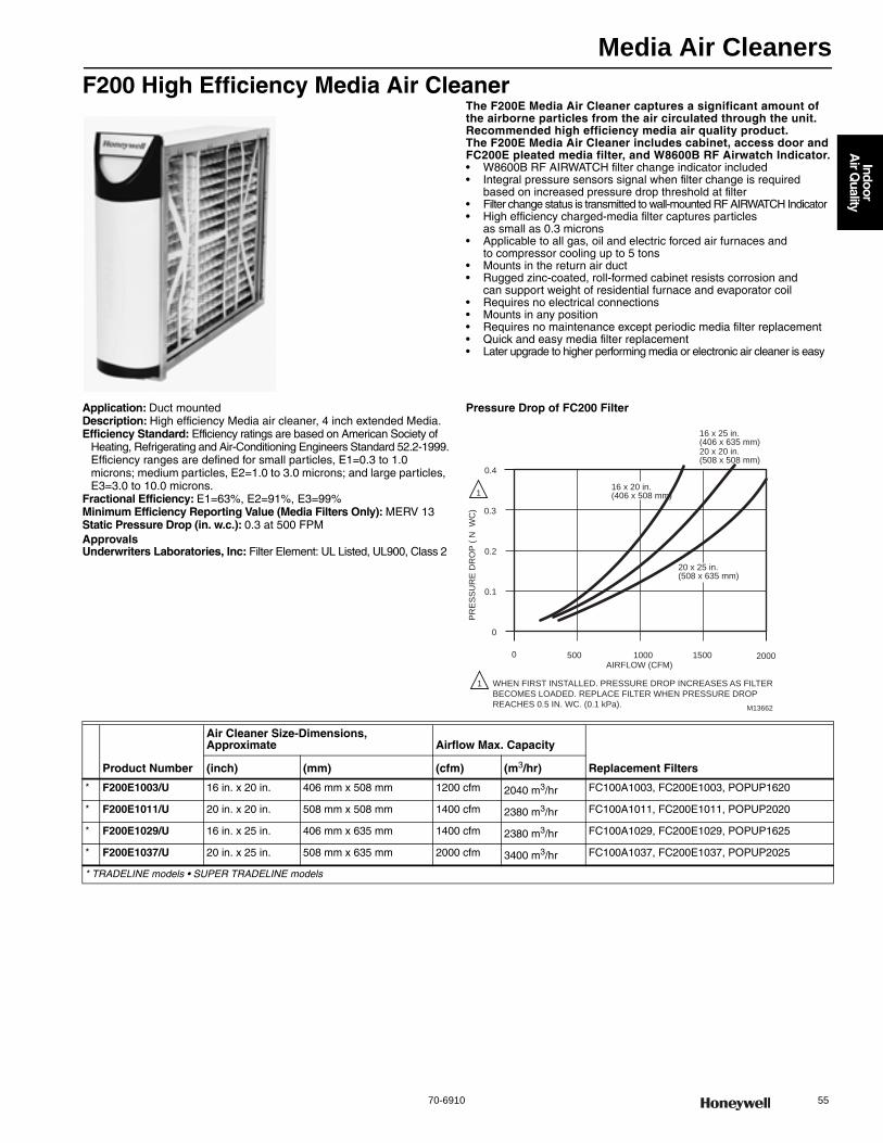
Media Air Cleaners
70-6910 55
Indoor
Air Q
uality
F200 High Efficiency Media Air CleanerThe F200E Media Air Cleaner captures a significant amount of the airborne particles from the air circulated through the unit. Recommended high efficiency media air quality product. The F200E Media Air Cleaner includes cabinet, access door and FC200E pleated media filter, and W8600B RF Airwatch Indicator.• W8600B RF AIRWATCH filter change indicator included • Integral pressure sensors signal when filter change is required
based on increased pressure drop threshold at filter • Filter change status is transmitted to wall-mounted RF AIRWATCH Indicator • High efficiency charged-media filter captures particles
as small as 0.3 microns • Applicable to all gas, oil and electric forced air furnaces and
to compressor cooling up to 5 tons • Mounts in the return air duct • Rugged zinc-coated, roll-formed cabinet resists corrosion and
can support weight of residential furnace and evaporator coil • Requires no electrical connections • Mounts in any position • Requires no maintenance except periodic media filter replacement • Quick and easy media filter replacement • Later upgrade to higher performing media or electronic air cleaner is easy
Application: Duct mountedDescription: High efficiency Media air cleaner, 4 inch extended Media.Efficiency Standard: Efficiency ratings are based on American Society of
Heating, Refrigerating and Air-Conditioning Engineers Standard 52.2-1999.Efficiency ranges are defined for small particles, E1=0.3 to 1.0 microns; medium particles, E2=1.0 to 3.0 microns; and large particles, E3=3.0 to 10.0 microns.
Fractional Efficiency: E1=63%, E2=91%, E3=99%Minimum Efficiency Reporting Value (Media Filters Only): MERV 13Static Pressure Drop (in. w.c.): 0.3 at 500 FPMApprovalsUnderwriters Laboratories, Inc: Filter Element: UL Listed, UL900, Class 2
Pressure Drop of FC200 Filter
0 500 1000 1500 2000
0
0.1
0.2
0.3
0.4P
RE
SS
UR
E D
RO
P (
N W
C)
AIRFLOW (CFM)
M13662
WHEN FIRST INSTALLED. PRESSURE DROP INCREASES AS FILTER
BECOMES LOADED. REPLACE FILTER WHEN PRESSURE DROP
REACHES 0.5 IN. WC. (0.1 kPa).
1
1
20 x 25 in.(508 x 635 mm)
20 x 20 in.(508 x 508 mm)
16 x 25 in.(406 x 635 mm)
16 x 20 in.(406 x 508 mm)
Product Number
Air Cleaner Size-Dimensions, Approximate Airflow Max. Capacity
Replacement Filters(inch) (mm) (cfm) (m3/hr)
* F200E1003/U 16 in. x 20 in. 406 mm x 508 mm 1200 cfm 2040 m3/hr FC100A1003, FC200E1003, POPUP1620
* F200E1011/U 20 in. x 20 in. 508 mm x 508 mm 1400 cfm 2380 m3/hr FC100A1011, FC200E1011, POPUP2020
* F200E1029/U 16 in. x 25 in. 406 mm x 635 mm 1400 cfm 2380 m3/hr FC100A1029, FC200E1029, POPUP1625
* F200E1037/U 20 in. x 25 in. 508 mm x 635 mm 2000 cfm 3400 m3/hr FC100A1037, FC200E1037, POPUP2025
* TRADELINE models • SUPER TRADELINE models

Media Air Cleaners
56 customer.honeywell.com 70-6910
F200 High Efficiency Media Air Cleaner dimensions in inches (millimeters)
F100 Media Air Cleaner dimensions in inches (millimeters)
M14784C
F200E SIZE
IN.
16 X 25
16 X 20
20 X 25
20 X 20
MM
406 X 635
406 X 508
508 X 635
508 X 508
DIM. A
14 7/16
14 7/16
18 7/16
18 7/16
367
367
468
468
DIM. B
16 3/16
16 3/16
20 3/16
20 3/16
411
411
513
513
23 1/4
18 1/4
23 1/4
18 1/4
DIM. C
591
457
591
457
DIM. D
25
20
25
20
648
521
648
521
DIM. C (SEE TABLE)
DIM. D (SEE TABLE)
DIM. B(SEE TABLE)
1-1/8 (29)
7/8(22)
IN. MM IN. MM IN. MM IN. MM
2-1/2(63)
DIM. A(SEE
TABLE)
7/8(22)
5/8(16)
6-3/4(171)
M14710D
F100 SIZE
IN.
16 X 25
16 X 20
20 X 25
20 X 20
25 X 20
25 X 22
MM
406 X 635
406 X 508
508 X 635
508 X 508
635 X 508
635 X 559
DIM. A
14 7/16
14 7/16
18 7/16
18 7/16
23 5/16
23 5/16
367
367
468
468
592
592
DIM. B
16 3/16
16 3/16
20 3/16
20 3/16
25 1/8
25 1/8
411
411
513
513
638
638
23 1/4
18 1/4
23 1/4
18 1/4
18 3/8
20 1/4
DIM. C
591
457
591
457
467
514
DIM. D
25 1/2
20 1/2
25 1/2
20 1/2
20 5/8
22 1/2
648
521
648
521
524
572
DIM. C (SEE TABLE)
DIM. D (SEE TABLE)
DIM. B(SEE TABLE)DIM. A
(SEE TABLE)
1-1/8 (29)
7/8(22)
5/8(16)
6-3/4(171)
7/8(22)
IN. MM IN. MM IN. MM IN. MM
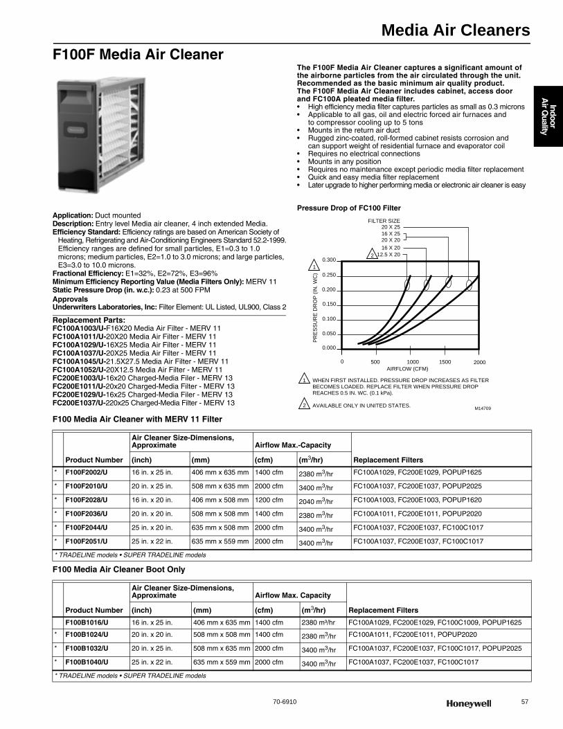
Media Air Cleaners
70-6910 57
Indoor
Air Q
uality
F100F Media Air CleanerThe F100F Media Air Cleaner captures a significant amount of the airborne particles from the air circulated through the unit. Recommended as the basic minimum air quality product. The F100F Media Air Cleaner includes cabinet, access door and FC100A pleated media filter.• High efficiency media filter captures particles as small as 0.3 microns• Applicable to all gas, oil and electric forced air furnaces and
to compressor cooling up to 5 tons • Mounts in the return air duct • Rugged zinc-coated, roll-formed cabinet resists corrosion and
can support weight of residential furnace and evaporator coil • Requires no electrical connections • Mounts in any position• Requires no maintenance except periodic media filter replacement • Quick and easy media filter replacement • Later upgrade to higher performing media or electronic air cleaner is easy
Application: Duct mountedDescription: Entry level Media air cleaner, 4 inch extended Media.Efficiency Standard: Efficiency ratings are based on American Society of
Heating, Refrigerating and Air-Conditioning Engineers Standard 52.2-1999.Efficiency ranges are defined for small particles, E1=0.3 to 1.0 microns; medium particles, E2=1.0 to 3.0 microns; and large particles, E3=3.0 to 10.0 microns.
Fractional Efficiency: E1=32%, E2=72%, E3=96%Minimum Efficiency Reporting Value (Media Filters Only): MERV 11Static Pressure Drop (in. w.c.): 0.23 at 500 FPMApprovalsUnderwriters Laboratories, Inc: Filter Element: UL Listed, UL900, Class 2
Replacement Parts:FC100A1003/U-F16X20 Media Air Filter - MERV 11FC100A1011/U-20X20 Media Air Filter - MERV 11FC100A1029/U-16X25 Media Air Filter - MERV 11FC100A1037/U-20X25 Media Air Filter - MERV 11FC100A1045/U-21.5X27.5 Media Air Filter - MERV 11FC100A1052/U-20X12.5 Media Air Filter - MERV 11FC200E1003/U-16x20 Charged-Media Filer - MERV 13FC200E1011/U-20x20 Charged-Media Filter - MERV 13FC200E1029/U-16x25 Charged-Media Filer - MERV 13FC200E1037/U-220x25 Charged-Media Filter - MERV 13
Pressure Drop of FC100 Filter
F100 Media Air Cleaner with MERV 11 Filter
F100 Media Air Cleaner Boot Only
0 500 1000 1500 2000
0.000
0.050
0.100
0.150
0.200
0.250
0.30012.5 X 20
16 X 20
16 X 2520 X 20
20 X 25FILTER SIZE
PR
ES
SU
RE
DR
OP
(IN
. WC
)
AIRFLOW (CFM)
M14709
WHEN FIRST INSTALLED. PRESSURE DROP INCREASES AS FILTERBECOMES LOADED. REPLACE FILTER WHEN PRESSURE DROPREACHES 0.5 IN. WC. (0.1 kPa).
AVAILABLE ONLY IN UNITED STATES.
2
1
1
2
Product Number
Air Cleaner Size-Dimensions, Approximate Airflow Max.-Capacity
Replacement Filters(inch) (mm) (cfm) (m3/hr)
* F100F2002/U 16 in. x 25 in. 406 mm x 635 mm 1400 cfm 2380 m3/hr FC100A1029, FC200E1029, POPUP1625
* F100F2010/U 20 in. x 25 in. 508 mm x 635 mm 2000 cfm 3400 m3/hr FC100A1037, FC200E1037, POPUP2025
* F100F2028/U 16 in. x 20 in. 406 mm x 508 mm 1200 cfm 2040 m3/hr FC100A1003, FC200E1003, POPUP1620
* F100F2036/U 20 in. x 20 in. 508 mm x 508 mm 1400 cfm 2380 m3/hr FC100A1011, FC200E1011, POPUP2020
* F100F2044/U 25 in. x 20 in. 635 mm x 508 mm 2000 cfm 3400 m3/hr FC100A1037, FC200E1037, FC100C1017
* F100F2051/U 25 in. x 22 in. 635 mm x 559 mm 2000 cfm 3400 m3/hr FC100A1037, FC200E1037, FC100C1017
* TRADELINE models • SUPER TRADELINE models
Product Number
Air Cleaner Size-Dimensions, Approximate Airflow Max. Capacity
Replacement Filters(inch) (mm) (cfm) (m3/hr)
F100B1016/U 16 in. x 25 in. 406 mm x 635 mm 1400 cfm 2380 m³/hr FC100A1029, FC200E1029, FC100C1009, POPUP1625
* F100B1024/U 20 in. x 20 in. 508 mm x 508 mm 1400 cfm 2380 m3/hr FC100A1011, FC200E1011, POPUP2020
* F100B1032/U 20 in. x 25 in. 508 mm x 635 mm 2000 cfm 3400 m3/hr FC100A1037, FC200E1037, FC100C1017, POPUP2025
* F100B1040/U 25 in. x 22 in. 635 mm x 559 mm 2000 cfm 3400 m3/hr FC100A1037, FC200E1037, FC100C1017
* TRADELINE models • SUPER TRADELINE models
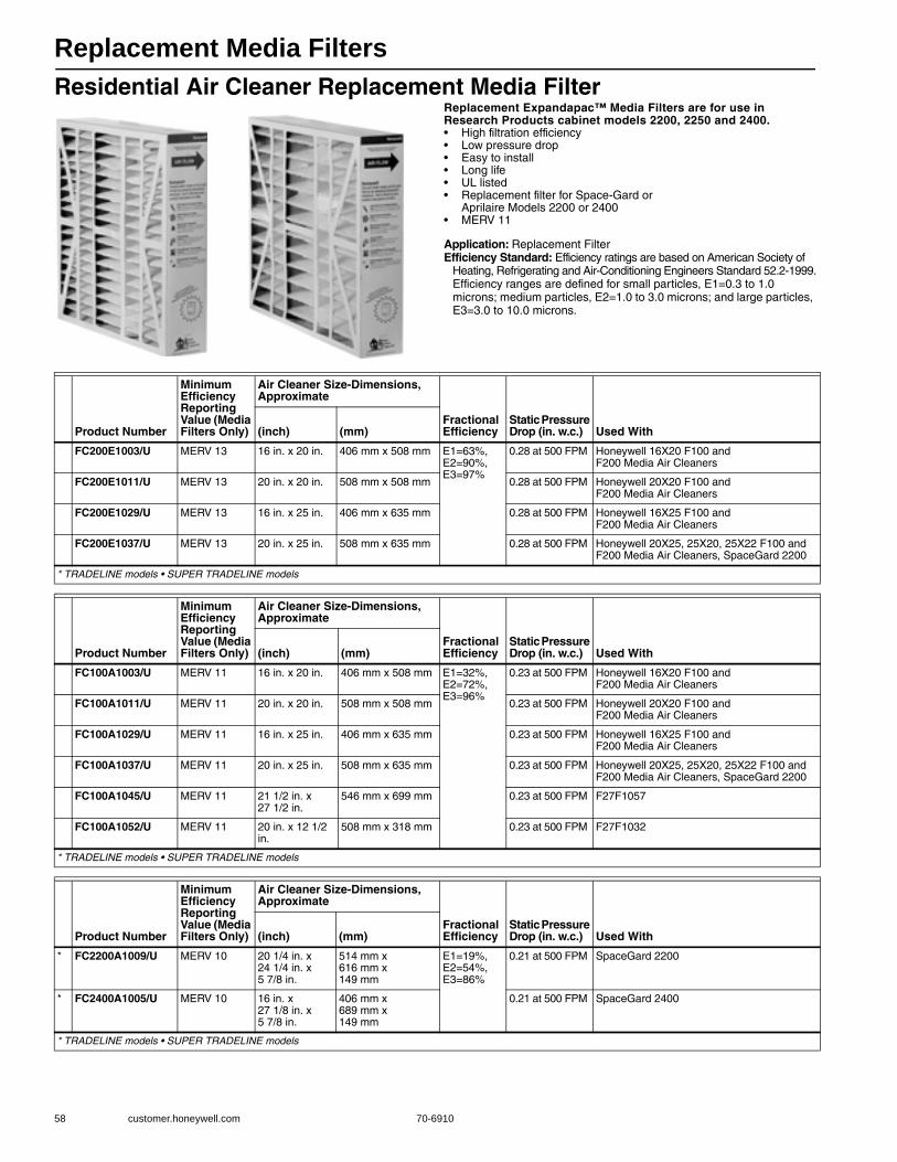
Replacement Media Filters
58 customer.honeywell.com 70-6910
Residential Air Cleaner Replacement Media FilterReplacement Expandapac™ Media Filters are for use in Research Products cabinet models 2200, 2250 and 2400.• High filtration efficiency• Low pressure drop• Easy to install• Long life• UL listed• Replacement filter for Space-Gard or
Aprilaire Models 2200 or 2400• MERV 11
Application: Replacement FilterEfficiency Standard: Efficiency ratings are based on American Society of
Heating, Refrigerating and Air-Conditioning Engineers Standard 52.2-1999.Efficiency ranges are defined for small particles, E1=0.3 to 1.0 microns; medium particles, E2=1.0 to 3.0 microns; and large particles, E3=3.0 to 10.0 microns.
Product Number
Minimum Efficiency Reporting Value (Media Filters Only)
Air Cleaner Size-Dimensions, Approximate
Fractional Efficiency
Static Pressure Drop (in. w.c.) Used With(inch) (mm)
FC200E1003/U MERV 13 16 in. x 20 in. 406 mm x 508 mm E1=63%, E2=90%, E3=97%
0.28 at 500 FPM Honeywell 16X20 F100 and F200 Media Air Cleaners
FC200E1011/U MERV 13 20 in. x 20 in. 508 mm x 508 mm 0.28 at 500 FPM Honeywell 20X20 F100 and F200 Media Air Cleaners
FC200E1029/U MERV 13 16 in. x 25 in. 406 mm x 635 mm 0.28 at 500 FPM Honeywell 16X25 F100 and F200 Media Air Cleaners
FC200E1037/U MERV 13 20 in. x 25 in. 508 mm x 635 mm 0.28 at 500 FPM Honeywell 20X25, 25X20, 25X22 F100 and F200 Media Air Cleaners, SpaceGard 2200
* TRADELINE models • SUPER TRADELINE models
Product Number
Minimum Efficiency Reporting Value (Media Filters Only)
Air Cleaner Size-Dimensions, Approximate
Fractional Efficiency
Static Pressure Drop (in. w.c.) Used With(inch) (mm)
FC100A1003/U MERV 11 16 in. x 20 in. 406 mm x 508 mm E1=32%, E2=72%, E3=96%
0.23 at 500 FPM Honeywell 16X20 F100 and F200 Media Air Cleaners
FC100A1011/U MERV 11 20 in. x 20 in. 508 mm x 508 mm 0.23 at 500 FPM Honeywell 20X20 F100 and F200 Media Air Cleaners
FC100A1029/U MERV 11 16 in. x 25 in. 406 mm x 635 mm 0.23 at 500 FPM Honeywell 16X25 F100 and F200 Media Air Cleaners
FC100A1037/U MERV 11 20 in. x 25 in. 508 mm x 635 mm 0.23 at 500 FPM Honeywell 20X25, 25X20, 25X22 F100 and F200 Media Air Cleaners, SpaceGard 2200
FC100A1045/U MERV 11 21 1/2 in. x 27 1/2 in.
546 mm x 699 mm 0.23 at 500 FPM F27F1057
FC100A1052/U MERV 11 20 in. x 12 1/2 in.
508 mm x 318 mm 0.23 at 500 FPM F27F1032
* TRADELINE models • SUPER TRADELINE models
Product Number
Minimum Efficiency Reporting Value (Media Filters Only)
Air Cleaner Size-Dimensions, Approximate
Fractional Efficiency
Static Pressure Drop (in. w.c.) Used With(inch) (mm)
* FC2200A1009/U MERV 10 20 1/4 in. x 24 1/4 in. x 5 7/8 in.
514 mm x 616 mm x 149 mm
E1=19%, E2=54%, E3=86%
0.21 at 500 FPM SpaceGard 2200
* FC2400A1005/U MERV 10 16 in. x 27 1/8 in. x 5 7/8 in.
406 mm x 689 mm x 149 mm
0.21 at 500 FPM SpaceGard 2400
* TRADELINE models • SUPER TRADELINE models

Replacement Media Filters
70-6910 59
Indoor
Air Q
uality
TrueCLEAN™ Replacement Filter
Residential Air Cleaner POPUP™ Replacement Media FilterHoneywell PopUP filters store flat and pop into shape for installation.• Save space on the truck • Less damage during storage • Save time on assembly • So easy you can sell over-the-counter to homeowners
without worry of mistakes • Compact shape makes PopUP easy to ship • No combs, pleat spacers or end caps
Application: Replacement Filter Efficiency Standard: Efficiency ratings are based on American Society of
Heating, Refrigerating and Air-Conditioning Engineers Standard 52.2-1999.Efficiency ranges are defined for small particles, E1=0.3 to 1.0 microns; medium particles, E2=1.0 to 3.0 microns; and large particles, E3=3.0 to 10.0 microns.
Product Number
Air Cleaner Size Dimensions, Approximate Airflow Max. CapacityStatic Pressure Drop (in. w.c.) Used With(inch) (mm) (cfm) (m3/hr)
* FR8000A1620/U 16 in. x 20 in. 406 mm x 508 mm 1350 cfm 3000 m3/hr 0.22 at 500 FPM FH8000A1620
* FR8000A2020/U 20 in. x 20 in. 508 mm x 508 mm 1800 cfm 3060 m3/hr 0.25 at 500 FPM FH8000A2020
* FR8000A2520/U 25 in. x 20 in. 635 mm x 508 mm 2000 cfm 3400 m3/hr 0.22 at 500 FPM FH8000A2520
* FR8000F1625/U 16 in. x 25 in. 406 mm x 635 mm 1600 cfm 2720 m3/hr 0.25 at 500 FPM FH8000F1625
* FR8000F2025/U 20 in. x 25 in. 508 mm x 635 mm 2000 cfm 3400 m3/hr 0.25 at 500 FPM FH8000F2025
* TRADELINE models • SUPER TRADELINE models
Product Number
Minimum Efficiency Reporting Value (Media Filters Only)
Air Cleaner Size-Dimensions, Approximate
Used With(inch) (mm)
POPUP1620/U MERV 11 16 in. x 20 in. 406 mm x 508 mm Honeywell 16X20 F100 and F200 Media Air Cleaners
POPUP1625/U MERV 11 16 in. x 25 in. 406 mm x 635 mm Honeywell 16X25 F100 and F200 Media Air Cleaners
POPUP2020/U MERV 11 20 in. x 20 in. 508 mm x 508 mm Honeywell 20X20 F100 and F200 Media Air Cleaners
POPUP2025/U MERV 11 20 in. x 25 in. 508 mm x 635 mm Honeywell 20X25 F100 and F200 Media Air Cleaners. Does not work with 25X20 or 25X22 Media Air Cleaners.
* POPUP2200/U MERV 11 20 1/4 in. x 24 1/4 in. x 5 7/8 in.
514 mm x 616 mm x 149 mm
SpaceGard 2200, 2120, 2250, Lennox PMAC20, GeneralAire AC-1
* POPUP2400/U MERV 11 16 in. x 27 1/8 in. x 5 7/8 in.
406 mm x 689 mm x 149 mm
SpaceGard 2400, 2140, Lennox PMAC12
* TRADELINE models • SUPER TRADELINE models

Replacement Media Filters
60 customer.honeywell.com 70-6910
Return Grille Media Air FilterThe Return Grille Filter provides high efficiency, long life alternative to a 1 in. filter. It captures a significant amount of the airborne particles in the air that circulates through the filter.• Mounts in most return filter grilles • Pleated for greater media capacity • Low pressure drop provides a comfortable air flow • Maintains equipment efficiency longer than standard filters • FC40 is MERV 10
Application: Return GrillEfficiency Standard: Efficiency ratings are based on American Society of
Heating, Refrigerating and Air-Conditioning Engineers Standard 52.2-1999.Efficiency ranges are defined for small particles, E1=0.3 to 1.0 microns; medium particles, E2=1.0 to 3.0 microns; and large particles, E3=3.0 to 10.0 microns.
Fractional Efficiency: E1=31%, E2=61%, E3=86%Static Pressure Drop (in. w.c.): 0.12 at 300FPM
Dimensions in inches (millimeters)
Product NumberMinimum Efficiency Reporting Value (Media Filters Only)
Air Cleaner Size-Dimensions, Approximate Airflow Max. Capacity
(inch) (mm) (cfm) (m3/hr)FC40R1003/U MERV 10 20 in. x 20 in. 508 mm x 508 mm 1150 cfm 1950 m3/hr
FC40R1011/U MERV 10 20 in. x 25 in. 508 mm x 635 mm 1450 cfm 2460 m3/hr
FC40R1029/U MERV 10 20 in. x 30 in. 508 mm x 762 mm 1800 cfm 3060 m3/hr
FC40R1037/U MERV 10 12 in. x 24 in. 305 mm x 610 mm 800 cfm 1360 m3/hr
FC40R1045/U MERV 10 14 in. x 25 in. 356 mm x 635 mm 1000 cfm 1700 m3/hr
FC40R1052/U MERV 10 16 in. x 20 in. 406 mm x 508 mm 900 cfm 1530 m3/hr
FC40R1060/U MERV 10 16 in. x 25 in. 406 mm x 635 mm 1150 cfm 1950 m3/hr
FC40R1078/U MERV 10 24 in. x 24 in. 610 mm x 610 mm 1700 cfm 2890 m3/hr
FC40R1094/U MERV 10 12 in. x 12 in. 305 mm x 305 mm 350 cfm 590 m3/hr
FC40R1102/U MERV 10 14 in. x 14 in. 356 mm x 356 mm 500 cfm 850 m3/hr
FC40R1110/U MERV 10 14 in. x 20 in. 356 mm x 508 mm 750 cfm 1270 m3/hr
FC40R1128/U MERV 10 14 in. x 24 in. 356 mm x 610 mm 950 cfm 1610 m3/hr
FC40R1136/U MERV 10 18 in. x 24 in. 457 mm x 610 mm 1250 cfm 2120 m3/hr
FC40R1144/U MERV 10 20 in. x 24 in. 508 mm x 610 mm 1400 cfm 2380 m3/hr
FC40R1169/U MERV 10 14 in. x 30 in. 356 mm x 762 mm 1200 cfm 2040 m3/hr
FC40R1177/U MERV 10 24 in. x 30 in. 610 mm x 762 mm 2050 cfm 3480 m3/hr
FC40R1185/U MERV 10 18 in. x 18 in. 457 mm x 457 mm 950 cfm 850 m3/hr
FC40R1830/U MERV 10 18 in. x 30 in. 457 mm x 762 mm 1550 cfm 2610 m3/hr
M18953D
Size A B C D E
DIMENSIONS IN. (MM)
DIME
3/4(19)
A
B
D
C
20 X 20 (508 x 508) 19-3/4 (502) 19-3/4 (502) 18-1/2 (470) 18-1/2 (470) 4-3/8 (111)
20 X 25 (508 x 635) 19-3/4 (502) 24-3/4 (629) 18-1/2 (470) 23-1/2 (597) 4-3/8 (111)
20 X 30 (508 x 762) 19-3/4 (502) 29-3/4 (756) 18-1/2 (470) 28-1/2 (724) 4-3/8 (111)
12 X 24 (305 X 610) 11-3/4 (298) 23-3/4 (603) 10-1/2 (266) 22-1/2 (571) 4-3/8 (111)
14 X 25 (356 X 635) 13-3/4 (349) 24-3/4 (629) 12-1/2 (317) 23-1/2 (596) 4-3/8 (111)
16 X 20 (406 X 508) 15-3/4 (400) 19-3/4 (502) 14-1/2 (368) 18-1/2 (470) 4-3/8 (111)
16 X 25 (406 X 635) 15-3/4 (400) 24-3/4 (629) 14-1/2 (368) 23-1/2 (596) 4-3/8 (111)
24 X 24 (610 X 610) 23-3/4 (603) 23-3/4 (603) 22-1/2 (571) 22-1/2 (571) 4-3/8 (111)
12 X 12 (305 X 305) 11-3/4 (298) 11-3/4 (298) 10-1/2 (266) 10-1/2 (266) 4-3/8 (111)
14 X 14 (356 X 356) 13-3/4 (349) 13-3/4 (349) 12-1/2 (317) 12-1/2 (317) 4-3/8 (111)
14 X 20 (356 X 508) 13-3/4 (349) 19-3/4 (502) 10-1/2 (266) 18-1/2 (470) 4-3/8 (111)
14 X 24 (356 x 610) 13-3/4 (349) 23-3/4 (603) 12-1/2 (317) 22-1/2 (571) 4-3/8 (111)
18 X 24 (457 x 610) 17-3/4 (451) 23-3/4 (603) 16-1/2 (419) 22-1/2 (571) 4-3/8 (111)
20 X 24 (508 x 610) 19-3/4 (502) 23-3/4 (603) 18-1/2 (470) 22-1/2 (571) 4-3/8 (111)
14 X 30 (356 X 762) 13-3/4 (349) 29-3/4 (756) 12-1/2 (317) 28-1/2 (724) 4-3/8 (111)
24 X 30 (610 X 762) 23-3/4 (603) 29-3/4 (756) 22-1/2 (571) 28-1/2 (724) 4-3/8 (111)
18 X 18 (457 X 457) 17-3/4 (451) 17-3/4 (451) 16-1/2 (419) 16-1/2 (419) 4-3/8 (111)
18 X 30 (457 X 762) 17-3/4 (451) 29-3/4 (756) 16-1/2 (419) 28-1/2 (724) 4-3/8 (111)
ProductNumbersFC40R1003
FC40R1011
FC40R1029
FC40R1037
FC40R1045
FC40R1052
FC40R1060
FC40R1078
FC40R1094
FC40R1102
FC40R1110
FC40R1128
FC40R1136
FC40R1144
FC40R1169
FC40R1177
FC40R1185
FC40R1830
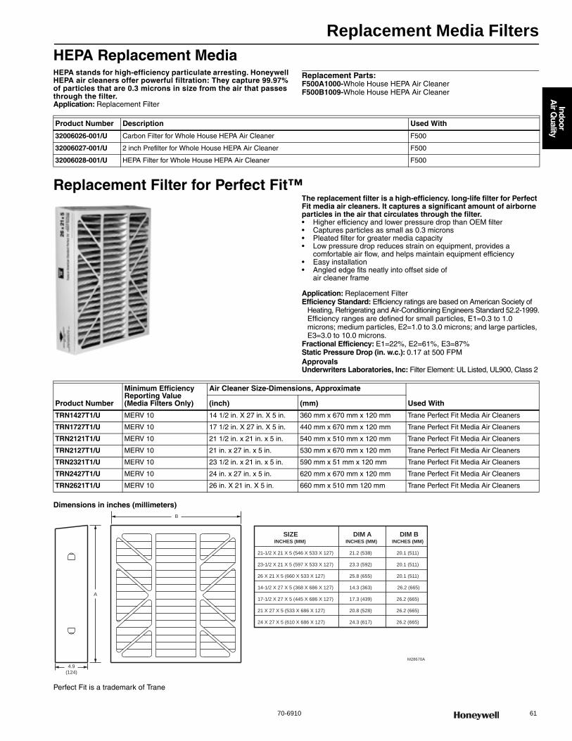
Replacement Media Filters
70-6910 61
Indoor
Air Q
uality
HEPA Replacement MediaHEPA stands for high-efficiency particulate arresting. Honeywell HEPA air cleaners offer powerful filtration: They capture 99.97% of particles that are 0.3 microns in size from the air that passes through the filter.Application: Replacement Filter
Replacement Parts:F500A1000-Whole House HEPA Air CleanerF500B1009-Whole House HEPA Air Cleaner
Replacement Filter for Perfect Fit™The replacement filter is a high-efficiency. long-life filter for Perfect Fit media air cleaners. It captures a significant amount of airborne particles in the air that circulates through the filter.• Higher efficiency and lower pressure drop than OEM filter • Captures particles as small as 0.3 microns • Pleated filter for greater media capacity • Low pressure drop reduces strain on equipment, provides a
comfortable air flow, and helps maintain equipment efficiency • Easy installation • Angled edge fits neatly into offset side of
air cleaner frame
Application: Replacement FilterEfficiency Standard: Efficiency ratings are based on American Society of
Heating, Refrigerating and Air-Conditioning Engineers Standard 52.2-1999.Efficiency ranges are defined for small particles, E1=0.3 to 1.0 microns; medium particles, E2=1.0 to 3.0 microns; and large particles, E3=3.0 to 10.0 microns.
Fractional Efficiency: E1=22%, E2=61%, E3=87%Static Pressure Drop (in. w.c.): 0.17 at 500 FPMApprovalsUnderwriters Laboratories, Inc: Filter Element: UL Listed, UL900, Class 2
Dimensions in inches (millimeters)
Perfect Fit is a trademark of Trane
Product Number Description Used With
32006026-001/U Carbon Filter for Whole House HEPA Air Cleaner F500
32006027-001/U 2 inch Prefilter for Whole House HEPA Air Cleaner F500
32006028-001/U HEPA Filter for Whole House HEPA Air Cleaner F500
Product Number
Minimum Efficiency Reporting Value (Media Filters Only)
Air Cleaner Size-Dimensions, Approximate
Used With(inch) (mm)
TRN1427T1/U MERV 10 14 1/2 in. X 27 in. X 5 in. 360 mm x 670 mm x 120 mm Trane Perfect Fit Media Air Cleaners
TRN1727T1/U MERV 10 17 1/2 in. X 27 in. X 5 in. 440 mm x 670 mm x 120 mm Trane Perfect Fit Media Air Cleaners
TRN2121T1/U MERV 10 21 1/2 in. x 21 in. x 5 in. 540 mm x 510 mm x 120 mm Trane Perfect Fit Media Air Cleaners
TRN2127T1/U MERV 10 21 in. x 27 in. x 5 in. 530 mm x 670 mm x 120 mm Trane Perfect Fit Media Air Cleaners
TRN2321T1/U MERV 10 23 1/2 in. x 21 in. x 5 in. 590 mm x 51 mm x 120 mm Trane Perfect Fit Media Air Cleaners
TRN2427T1/U MERV 10 24 in. x 27 in. x 5 in. 620 mm x 670 mm x 120 mm Trane Perfect Fit Media Air Cleaners
TRN2621T1/U MERV 10 26 in. X 21 in. X 5 in. 660 mm x 510 mm 120 mm Trane Perfect Fit Media Air Cleaners
4.9
(124)
M28670A
A
B
SIZE DIM A DIM B INCHES (MM) INCHES (MM) INCHES (MM)
21-1/2 X 21 X 5 (546 X 533 X 127) 21.2 (538) 20.1 (511)
23-1/2 X 21 X 5 (597 X 533 X 127) 23.3 (592) 20.1 (511)
26 X 21 X 5 (660 X 533 X 127) 25.8 (655) 20.1 (511)
14-1/2 X 27 X 5 (368 X 686 X 127) 14.3 (363) 26.2 (665)
17-1/2 X 27 X 5 (445 X 686 X 127) 17.3 (439) 26.2 (665)
21 X 27 X 5 (533 X 686 X 127) 20.8 (528) 26.2 (665)
24 X 27 X 5 (610 X 686 X 127) 24.3 (617) 26.2 (665)

Air Cleaner Parts and Accessories
62 customer.honeywell.com 70-6910
Residential Air Cleaner Parts and AccessoriesProduct Number Description Used With
136434AA/U 20 in. Replacement Ionizer wire for F50A, F50E, F50F, F57A, B, F58F and F70C —
136434BA/U 16 in. Replacement Ionizer wire for F50A, F50E, F50F, F59A —
136518/U F50F, F58C,F Cell Key —
137266/U F50F and F58F Cell Handle —
137980A/U Test Button Assembly for F50A, F50E, F50F, or F58C,F F50
138889A/U Contact Board Assembly for F58C, F59A, F70C, F90, or F50E F50, F59
190912A/U F52C,D,E,F or F57A,B Contact Board Assembly F52
202668/U 20 inch Ionizer Grid —
203321/U ON/OFF Switch for F50F, F52F, or F58F F52
203329A/U F50F, F58F Rear Terminal Board Assembly F50
203329B/U F50F, F58F Front Terminal Board Assembly F50
203366/U Round insulator for FC37A,B Cells FC37
203368/U Prefilter for 16X25 - F50F, F300, no spring clips F300, F50
203369/U Prefilter for 20X25 inch and 20X12-1/2 inch F50F, F300, no spring clip F300, F50
203370/U Prefilter for 20X20 - F50F, F300, no spring clip F300, F50
203371/U Prefilter for 16X25 - F50, F300 F300, F50
203372/U Prefilter for 20X25 inch and 20X12-1/2 inch F50, F300, or F58C,F F300, F50
203373/U Prefilter for 20X20 - F50, F300 F300, F50
207631/U Door Latch, F52F F52
208536/U Prefilter for F52F 1-Cell F52
208537/U Prefilter for F52F 2-Cell F52
208543/U interlock Switch, F52F F52
209989/U Prefilter for 16X20 F50, F300 F300, F50
32004876-001/U 20 inch F200E Door, RF transmitter F200
32004876-002/U 16 inch F200E Door, RF transmitter F200
32004930-001/U 25 inch Power Pack Cover, White - F300E F300
4074EHG/U FC37A Terminal Board Repair Kit. Contains 2 connector clips, 1 Terminal Board and instruction sheet
FC37A
4074ETD/U Line Cord and Strain Relief F50
4074ETE/U F50F, F52F, F58F Neon Light Assembly, includes lens and wire tie F50, F52
4074ETG/U F50F and F58F Interlock bracket and switch F50
4074ETH/U Air Flow Switch Bag Assembly, with pin connections, for F50 air cleaners F50
4074EYS/U F50F Neon Light Assembly F50
4074EZB/U Air Flow Switch Bag Assembly with molex plug connection. F300E, F50F, AFS F300, F50F
50053268-001/U TrueCLEAN Replacement Enhancement Module FH8000F1625
50053268-002/U TrueCLEAN Replacement Enhancement Module FH8000F2025
50053268-003/U TrueCLEAN Replacement Enhancement Module FH8000A1620
50053268-004/U TrueCLEAN Replacement Enhancement Module FH8000A2020
50053268-005/U TrueCLEAN Replacement Enhancement Module FH8000A2520
50053268-006/U TrueCLEAN Replacement Door FH8000F1625
50053268-007/U TrueCLEAN Replacement Door FH8000F2025
50053268-008/U TrueCLEAN Replacement Door FH8000A1620
50053268-009/U TrueCLEAN Replacement Door FH8000A2020
50053268-010/U TrueCLEAN Replacement Door FH8000A2520
50053268-011/U TrueCLEAN Replacement Screen FH8000F1625
50053268-012/U TrueCLEAN Replacement Screen FH8000F2025
50053268-013/U TrueCLEAN Replacement Screen FH8000A1620
50053268-014/U TrueCLEAN Replacement Screen FH8000A2020
50053268-015/U TrueCLEAN Replacement Screen FH8000A2520
50053268-016/U TrueCLEAN Replacement Power Cord FH8000F
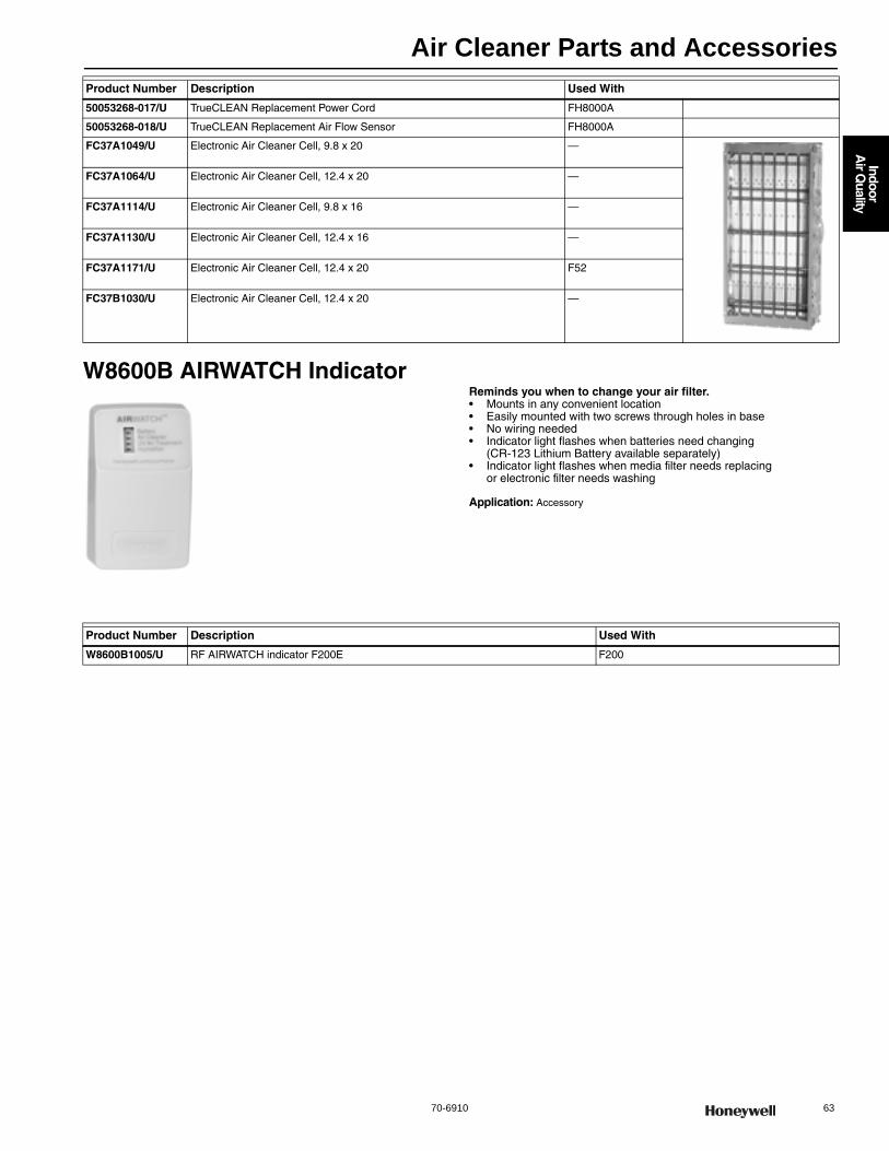
Air Cleaner Parts and Accessories
70-6910 63
Indoor
Air Q
uality
W8600B AIRWATCH IndicatorReminds you when to change your air filter.• Mounts in any convenient location • Easily mounted with two screws through holes in base • No wiring needed• Indicator light flashes when batteries need changing
(CR-123 Lithium Battery available separately) • Indicator light flashes when media filter needs replacing
or electronic filter needs washing
Application: Accessory
50053268-017/U TrueCLEAN Replacement Power Cord FH8000A
50053268-018/U TrueCLEAN Replacement Air Flow Sensor FH8000A
FC37A1049/U Electronic Air Cleaner Cell, 9.8 x 20 —
FC37A1064/U Electronic Air Cleaner Cell, 12.4 x 20 —
FC37A1114/U Electronic Air Cleaner Cell, 9.8 x 16 —
FC37A1130/U Electronic Air Cleaner Cell, 12.4 x 16 —
FC37A1171/U Electronic Air Cleaner Cell, 12.4 x 20 F52
FC37B1030/U Electronic Air Cleaner Cell, 12.4 x 20 —
Product Number Description Used With
Product Number Description Used With
W8600B1005/U RF AIRWATCH indicator F200E F200
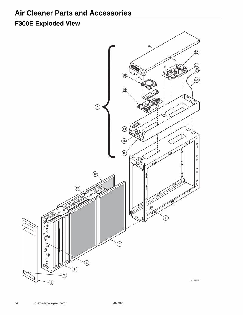
Air Cleaner Parts and Accessories
64 customer.honeywell.com 70-6910
F300E Exploded View
M18846E
1
2
3
4
5
6
7
8
10
11
12
13
14
15
16
17
18
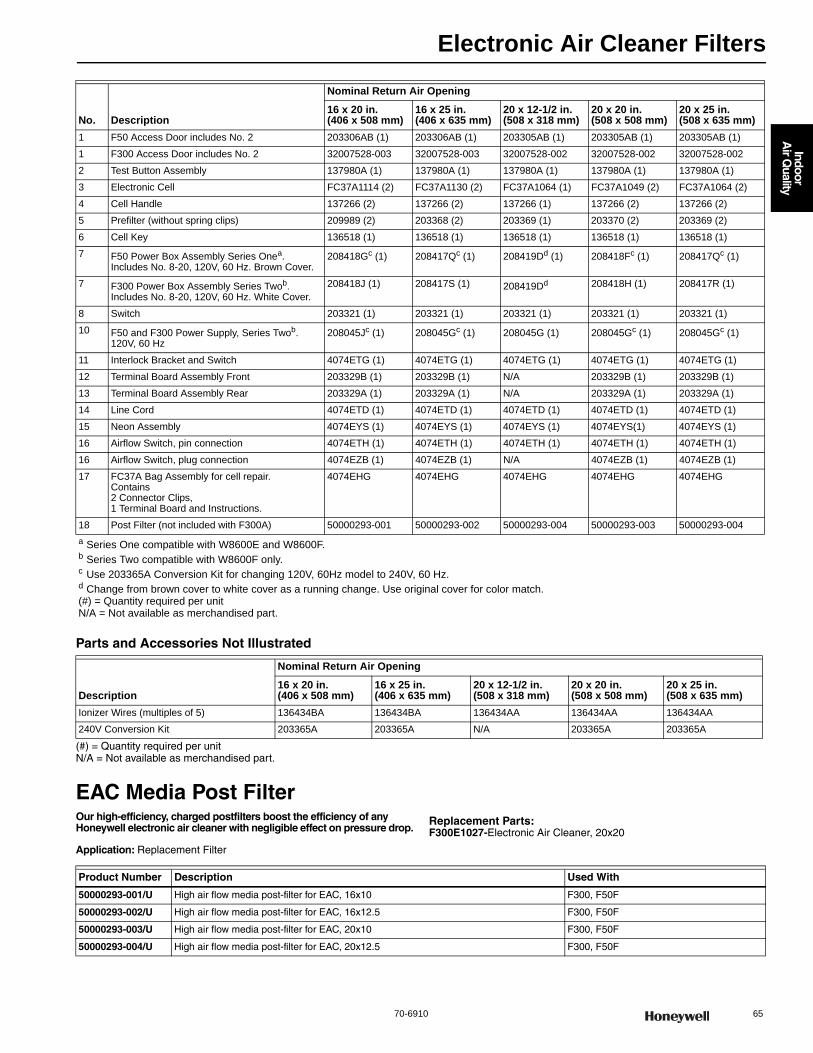
Electronic Air Cleaner Filters
70-6910 65
Indoor
Air Q
uality
Parts and Accessories Not Illustrated
(#) = Quantity required per unit N/A = Not available as merchandised part.
EAC Media Post FilterOur high-efficiency, charged postfilters boost the efficiency of any Honeywell electronic air cleaner with negligible effect on pressure drop.
Application: Replacement Filter
Replacement Parts:F300E1027-Electronic Air Cleaner, 20x20
No. Description
Nominal Return Air Opening
16 x 20 in.(406 x 508 mm)
16 x 25 in.(406 x 635 mm)
20 x 12-1/2 in.(508 x 318 mm)
20 x 20 in.(508 x 508 mm)
20 x 25 in.(508 x 635 mm)
1 F50 Access Door includes No. 2 203306AB (1) 203306AB (1) 203305AB (1) 203305AB (1) 203305AB (1)
1 F300 Access Door includes No. 2 32007528-003 32007528-003 32007528-002 32007528-002 32007528-002
2 Test Button Assembly 137980A (1) 137980A (1) 137980A (1) 137980A (1) 137980A (1)
3 Electronic Cell FC37A1114 (2) FC37A1130 (2) FC37A1064 (1) FC37A1049 (2) FC37A1064 (2)
4 Cell Handle 137266 (2) 137266 (2) 137266 (1) 137266 (2) 137266 (2)
5 Prefilter (without spring clips) 209989 (2) 203368 (2) 203369 (1) 203370 (2) 203369 (2)
6 Cell Key 136518 (1) 136518 (1) 136518 (1) 136518 (1) 136518 (1)
7 F50 Power Box Assembly Series Onea. Includes No. 8-20, 120V, 60 Hz. Brown Cover.
208418Gc (1) 208417Qc (1) 208419Dd (1) 208418Fc (1) 208417Qc (1)
7 F300 Power Box Assembly Series Twob. Includes No. 8-20, 120V, 60 Hz. White Cover.
208418J (1) 208417S (1) 208419Dd 208418H (1) 208417R (1)
8 Switch 203321 (1) 203321 (1) 203321 (1) 203321 (1) 203321 (1)
10 F50 and F300 Power Supply, Series Twob. 120V, 60 Hz
208045Jc (1) 208045Gc (1) 208045G (1) 208045Gc (1) 208045Gc (1)
11 Interlock Bracket and Switch 4074ETG (1) 4074ETG (1) 4074ETG (1) 4074ETG (1) 4074ETG (1)
12 Terminal Board Assembly Front 203329B (1) 203329B (1) N/A 203329B (1) 203329B (1)
13 Terminal Board Assembly Rear 203329A (1) 203329A (1) N/A 203329A (1) 203329A (1)
14 Line Cord 4074ETD (1) 4074ETD (1) 4074ETD (1) 4074ETD (1) 4074ETD (1)
15 Neon Assembly 4074EYS (1) 4074EYS (1) 4074EYS (1) 4074EYS(1) 4074EYS (1)
16 Airflow Switch, pin connection 4074ETH (1) 4074ETH (1) 4074ETH (1) 4074ETH (1) 4074ETH (1)
16 Airflow Switch, plug connection 4074EZB (1) 4074EZB (1) N/A 4074EZB (1) 4074EZB (1)
17 FC37A Bag Assembly for cell repair.Contains2 Connector Clips, 1 Terminal Board and Instructions.
4074EHG 4074EHG 4074EHG 4074EHG 4074EHG
18 Post Filter (not included with F300A) 50000293-001 50000293-002 50000293-004 50000293-003 50000293-004a Series One compatible with W8600E and W8600F.b Series Two compatible with W8600F only.c Use 203365A Conversion Kit for changing 120V, 60Hz model to 240V, 60 Hz.d Change from brown cover to white cover as a running change. Use original cover for color match.(#) = Quantity required per unit N/A = Not available as merchandised part.
Description
Nominal Return Air Opening
16 x 20 in.(406 x 508 mm)
16 x 25 in.(406 x 635 mm)
20 x 12-1/2 in.(508 x 318 mm)
20 x 20 in.(508 x 508 mm)
20 x 25 in.(508 x 635 mm)
Ionizer Wires (multiples of 5) 136434BA 136434BA 136434AA 136434AA 136434AA
240V Conversion Kit 203365A 203365A N/A 203365A 203365A
Product Number Description Used With
50000293-001/U High air flow media post-filter for EAC, 16x10 F300, F50F
50000293-002/U High air flow media post-filter for EAC, 16x12.5 F300, F50F
50000293-003/U High air flow media post-filter for EAC, 20x10 F300, F50F
50000293-004/U High air flow media post-filter for EAC, 20x12.5 F300, F50F
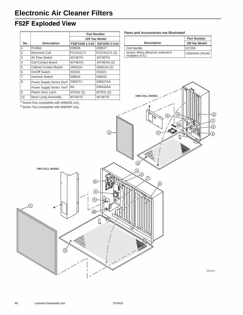
Electronic Air Cleaner Filters
66 customer.honeywell.com 70-6910
F52F Exploded View
a Series One compatible with W8600E only.b Series Two compatible with W8600F only.
Parts and Accessories not Illustrated
No. Description
Part Number120 Vac Model
F52F1048 1-Cell 52F1055 2-Cell1 Prefilter 208536 208537
2 Electronic Cell FC37A1171 FC37A1171 (2)
3 Air Flow Switch 4074ETH 4074ETH
4 Cell Contact Board 4074EHG 4074EHG (2)
5 Cabinet Contact Board 190912A 190912A (2)
6 On/Off Switch 203321 203321
7 Interlock Switch 208543 208543
8 Power Supply Series Onea 208427J 208427AA
Power Supply Series Twob NA 208416AA
9 Plastic Door Latch 207631 (2) 207631 (2)
10 Neon Lamp Assembly 4074ETE 4074ETE
DescriptionPart Number120 Vac Model
Cell Handle 137266
Ionizer Wires (Must be ordered in multiples of 5.)
136434AA (9/cell)
M23211C
7
6
1
9
2
5
3
10
8
TWO-CELL MODEL
ONE-CELL MODEL
4
6
1
9
10
8
54
3
2
7

Electronic Air Cleaner Filters
70-6910 67
Indoor
Air Q
uality
Residential Air Cleaners Replacement Power SupplyElectronic Air Cleaner Replacement Power Supply
Model Voltage
Nominal Cell SizeOld Power Supply Cross Reference
Universal Power Supply (No Box)
Universal Power Supply (With Box)in. mm
F300A, F300E 120 Vac 20 x 12.5 508 x 318 208419A PS1201A00 PS1201B12
16 x 20 406 x 508 208418J PS1201B20
16 x 25 406 x 635 208417S PS1201B25
20 x 20 508 x 508 208418H PS1201B20
20 x 25 508 x 635 208417R PS1201B25
F300B 240 Vac 20 x 12.5 508 x 318 208419E PS2401A00 PS2401B12
F50AF50E
120 Vac 16 x 25 406 x 635 — PS1201C01 —
20 x 20 508 x 508 — —
20 x 25 508 x 635 — —
20 x 12.5 508 x 318 — PS1201C02 —
240 Vac 16 x 25 406 x 635 — PS2401C00 —
20 x 20 508 x 508 — —
20 x 25 508 x 635 — —
20 x 12.5 508 x 318 — —
220 Vac/50 Hz 16 x 25 406 x 635 — —
F50F 120 Vac 20 x 12.5 508 x 318 208419E PS1201A00 —
16 x 20 406 x 508 208418E, 208418K —
16 x 25 406 x 635 208417B —
20 x 20 508 x 508 208418A, 208418L —
20 x 25 508 x 635 208417A —
240 Vac 20 x 12.5 508 x 318 208419C PS2401A00 PS2401B12CE
16 x 20 406 x 508 — —
16 x 25 406 x 635 208417P —
20 x 20 508 x 508 — —
20 x 25 508 x 635 208417N PS2401B25
F52C (One-Cell) 120 Vac 20 x 12.5 508 x 318 — PS1201C02 —
220-240 Vac 20 x 12.5 508 x 318 — PS2401C00 —
F52D (Two-Cell) 120 Vac 20 x 25 508 x 635 — PS1201C02 —
220-240 Vac 20 x 25 508 x 635 — PS2401C00 —
F52F 120 Vac 12.5 x 20 317.5x508 208416AA PS1201C02 PS1201C00
120 Vac/60 Hz 20 x 25 508 x 635 208416AB PS1201C02 PS1201C00
F54C 120 Vac 20 x 25 508 x 635 — PS1201C02 —
220-240 Vac 20 x 25 508 x 635 — PS2401C00 —
F55AF55E
120 Vac 16 x 25 406 x 635 — PS1201C02 —
20 x 25 508 x 635 — —
240 Vac 16 x 25 406 x 635 — PS2401C00 —
20 x 25 508 x 635 — —
F56A 120 Vac 16 x 12.5 406 x 318 — PS1201C02 —
F57A (Two-Cell) 120 Vac 20 x 25 508 x 635 — PS1201C02 —
F57B (One- Cell) 120 Vac 20 x 12.5 508 x 318 — PS1201C02 —
F57B 220-240V, 50 Hz 20 x 12.5 508 x 318 — PS2401C00 —
F58A, F58E 120 Vac 16 X 25 406 x 635 — PS1201C02 —
F59A 120 Vac 16 x 12.5 406 x 318 — PS1201C02 —
220 Vac/50 Hz 16 x 12.5 406 x 318 — PS2401C00 —
F70C 120 Vac 20 x 25 508 x 635 — PS1201C00 —

TrueDRY Dehumidification System
68 customer.honeywell.com 70-6910
TrueDRY™ Dehumidification SystemsThe Honeywell TrueDRY dehumidifiers provide great value to contractors and homeowners by doing more with less energy. Our compact units have the smallest footprint in their class; come with an anti-corrosion e-coating coil and now, according to ENERGY STAR's performance testing, they are among the most efficient in the industry.• Removes 65/90/120 pints of water per day from the indoor air • Built-in fresh air supply • Energy Star 3.0 Rated• E-Coated Coil delivers longer life and increased efficiency.• Improved design to reduce noise and save space.• 65 pint model offers on-board dehumidistat
Application: Dehumidifier
DR65A dimensions in Inches (millimeters)
DR90A dimensions in Inches (millimeters)
DR120A dimensions in Inches (millimeters)
Product Number
Capacity Plenum Opening (Diameter)
Amps. Includes Weight (lb)(pints per day)
(gallons per day)
(liters per day) (inch) (mm)
DR65A2000/U 65 pints per day
8 3/25 gal per day
30 L per day
8 in. collars 203 mm collar 5.2 Amps Four leveling feet with rubber isolation pads.
55 lb
DR90A2000/U 90 pints per day
11 1/4 gal per day
45 L per day
10 in. collars; 6 in. ventilation collar
254 mm collars; 152 mm vent collar
5.9 Amps Four leveling feet with rubber isolation pads.
82 lb
DR120A2000/U 120 pints per day
15 gal per day
57 L per day
10 in. collars; 6 in. ventilation collar
254 mm collars; 152 mm vent collar
7.3 Amps Four leveling feet with rubber isolation pads.
90 lb
M29763
28-1/2 (724)12 (305)
12(305)
8 INCH (203)DIAMETER
3 3/16
(81) 33 7/16 (849)
3 3/16
(81)
21 9/32
(541)
14 3/8 (365)
M28840
25-13/16 (656)
21(533)
19-3/8(492)
M34710
14-3/8(365)
3-3/16(81)
3-3/16(81)
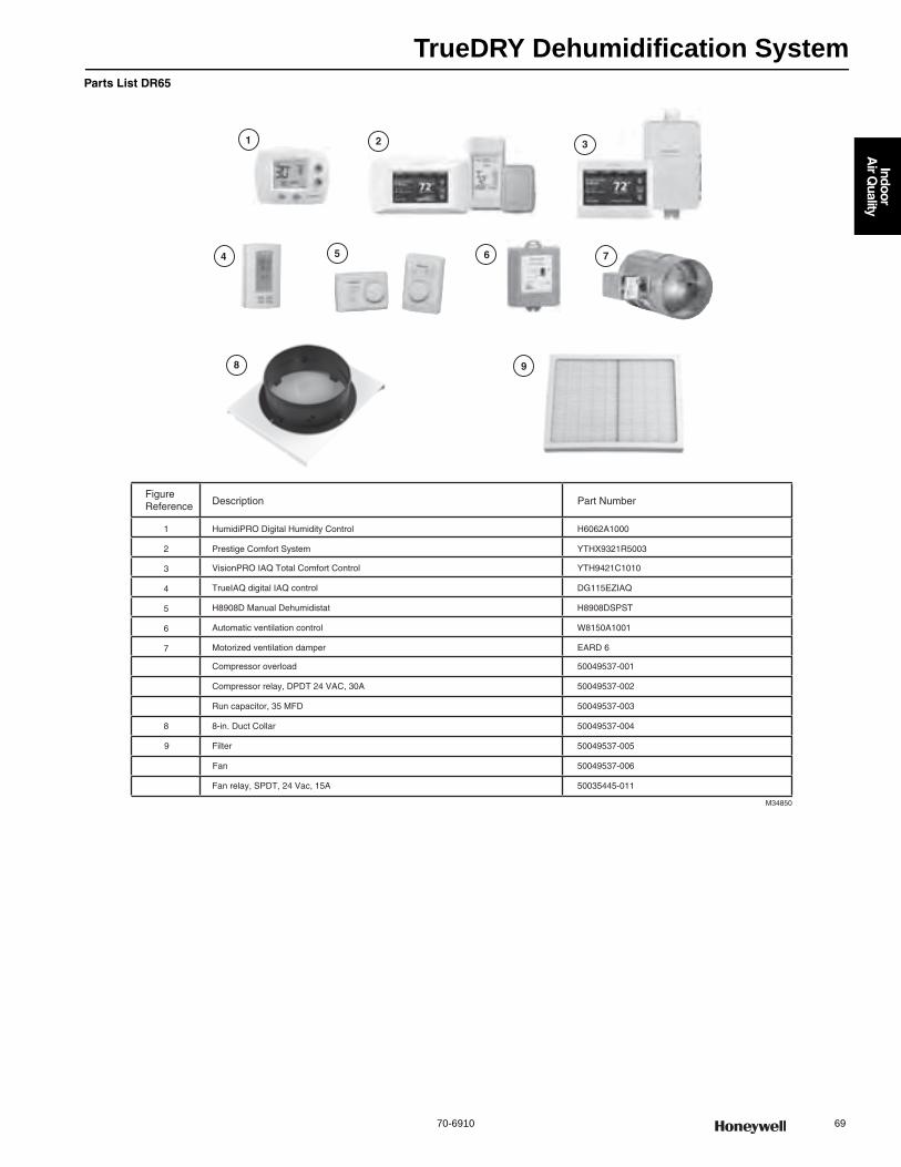
TrueDRY Dehumidification System
70-6910 69
Indoor
Air Q
uality
Parts List DR65
FigureReference Description Part Number
1 HumidiPRO Digital Humidity Control H6062A1000
2 Prestige Comfort System YTHX9321R5003
3
4
VisionPRO IAQ Total Comfort Control YTH9421C1010
5
TrueIAQ digital IAQ control DG115EZIAQ
6
H8908D Manual Dehumidistat H8908DSPST
7
Automatic ventilation control W8150A1001
Motorized ventilation damper EARD 6
Compressor overload 50049537-001
Compressor relay, DPDT 24 VAC, 30A 50049537-002
Run capacitor, 35 MFD 50049537-003
8 8-in. Duct Collar 50049537-004
9 Filter 50049537-005
Fan 50049537-006
Fan relay, SPDT, 24 Vac, 15A 50035445-011
M34850
75 6
2
4
3
8 9
1
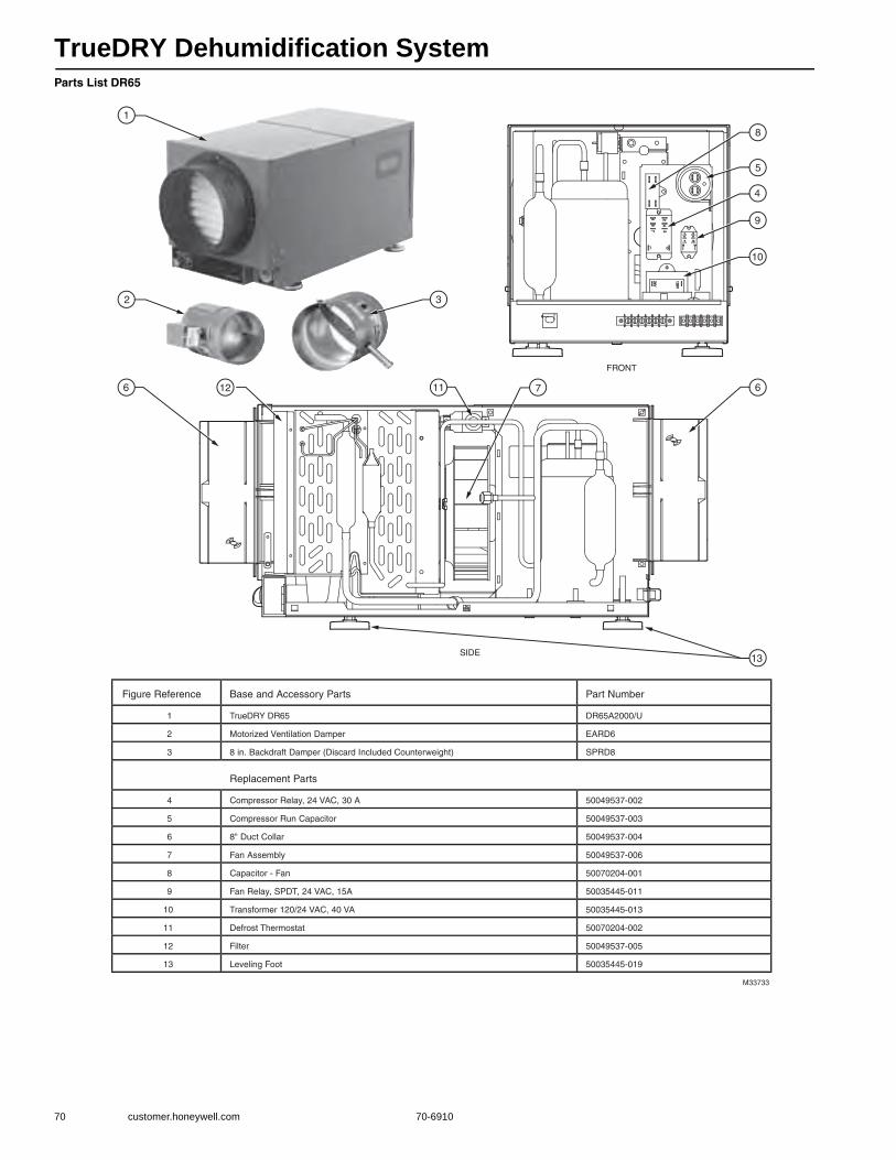
TrueDRY Dehumidification System
70 customer.honeywell.com 70-6910
Parts List DR65
8
5
4
9
10
6 12
13
11 67
M33733
FRONT
SIDE
1
32
Figure Reference Base and Accessory Parts Part Number
1 TrueDRY DR65 DR65A2000/U
2 Motorized Ventilation Damper EARD6
3 8 in. Backdraft Damper (Discard Included Counterweight) SPRD8
Replacement Parts
4 Compressor Relay, 24 VAC, 30 A 50049537-002
5 Compressor Run Capacitor 50049537-003
6 8" Duct Collar 50049537-004
7 Fan Assembly 50049537-006
8 Capacitor - Fan 50070204-001
9 Fan Relay, SPDT, 24 VAC, 15A 50035445-011
10 Transformer 120/24 VAC, 40 VA 50035445-013
11 Defrost Thermostat 50070204-002
12 Filter 50049537-005
13 Leveling Foot 50035445-019
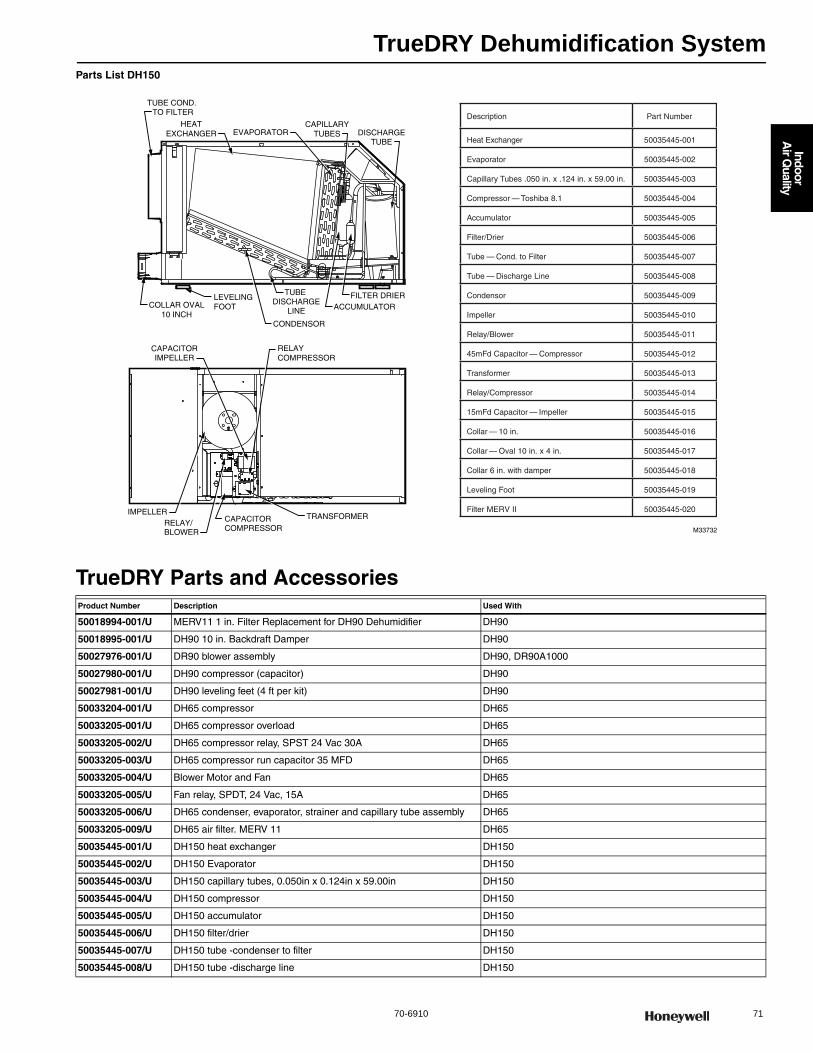
TrueDRY Dehumidification System
70-6910 71
Indoor
Air Q
uality
Parts List DH150
TrueDRY Parts and AccessoriesProduct Number Description Used With
50018994-001/U MERV11 1 in. Filter Replacement for DH90 Dehumidifier DH90
50018995-001/U DH90 10 in. Backdraft Damper DH90
50027976-001/U DR90 blower assembly DH90, DR90A1000
50027980-001/U DH90 compressor (capacitor) DH90
50027981-001/U DH90 leveling feet (4 ft per kit) DH90
50033204-001/U DH65 compressor DH65
50033205-001/U DH65 compressor overload DH65
50033205-002/U DH65 compressor relay, SPST 24 Vac 30A DH65
50033205-003/U DH65 compressor run capacitor 35 MFD DH65
50033205-004/U Blower Motor and Fan DH65
50033205-005/U Fan relay, SPDT, 24 Vac, 15A DH65
50033205-006/U DH65 condenser, evaporator, strainer and capillary tube assembly DH65
50033205-009/U DH65 air filter. MERV 11 DH65
50035445-001/U DH150 heat exchanger DH150
50035445-002/U DH150 Evaporator DH150
50035445-003/U DH150 capillary tubes, 0.050in x 0.124in x 59.00in DH150
50035445-004/U DH150 compressor DH150
50035445-005/U DH150 accumulator DH150
50035445-006/U DH150 filter/drier DH150
50035445-007/U DH150 tube -condenser to filter DH150
50035445-008/U DH150 tube -discharge line DH150
TRANSFORMER
RELAYCOMPRESSOR
HEATEXCHANGER
CONDENSOR
EVAPORATOR
CAPACITORCOMPRESSOR
FILTER DRIER
DISCHARGETUBE
ACCUMULATOR
CAPILLARYTUBES
M33732
TUBE COND. TO FILTER
TUBE DISCHARGE
LINECOLLAR OVAL
10 INCH
LEVELINGFOOT
IMPELLERRELAY/BLOWER
CAPACITORIMPELLER
Description Part Number
Heat Exchanger 50035445-001
Evaporator 50035445-002
Capillary Tubes .050 in. x .124 in. x 59.00 in. 50035445-003
Compressor — Toshiba 8.1 50035445-004
Accumulator 50035445-005
Filter/Drier 50035445-006
Tube — Cond. to Filter 50035445-007
Tube — Discharge Line 50035445-008
Condensor 50035445-009
Impeller 50035445-010
Relay/Blower 50035445-011
45mFd Capacitor — Compressor 50035445-012
Transformer 50035445-013
Relay/Compressor 50035445-014
15mFd Capacitor — Impeller 50035445-015
Collar — 10 in. 50035445-016
Collar — Oval 10 in. x 4 in. 50035445-017
Collar 6 in. with damper 50035445-018
Leveling Foot 50035445-019
Filter MERV II 50035445-020
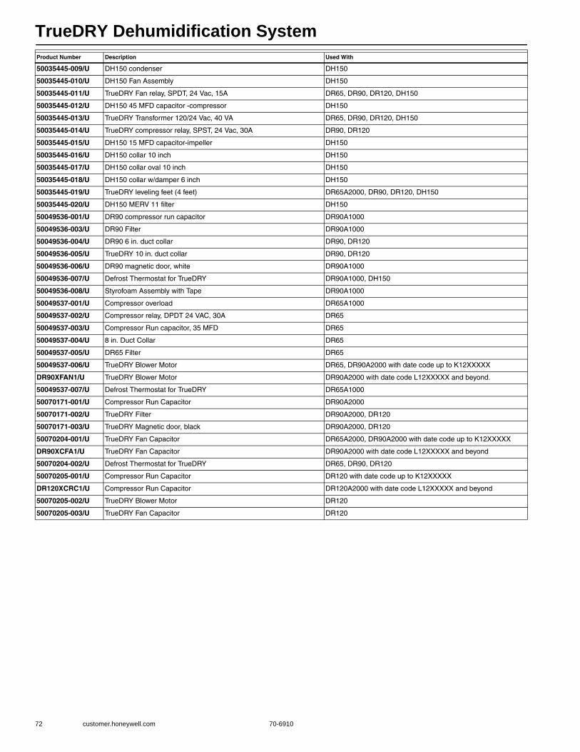
TrueDRY Dehumidification System
72 customer.honeywell.com 70-6910
50035445-009/U DH150 condenser DH150
50035445-010/U DH150 Fan Assembly DH150
50035445-011/U TrueDRY Fan relay, SPDT, 24 Vac, 15A DR65, DR90, DR120, DH150
50035445-012/U DH150 45 MFD capacitor -compressor DH150
50035445-013/U TrueDRY Transformer 120/24 Vac, 40 VA DR65, DR90, DR120, DH150
50035445-014/U TrueDRY compressor relay, SPST, 24 Vac, 30A DR90, DR120
50035445-015/U DH150 15 MFD capacitor-impeller DH150
50035445-016/U DH150 collar 10 inch DH150
50035445-017/U DH150 collar oval 10 inch DH150
50035445-018/U DH150 collar w/damper 6 inch DH150
50035445-019/U TrueDRY leveling feet (4 feet) DR65A2000, DR90, DR120, DH150
50035445-020/U DH150 MERV 11 filter DH150
50049536-001/U DR90 compressor run capacitor DR90A1000
50049536-003/U DR90 Filter DR90A1000
50049536-004/U DR90 6 in. duct collar DR90, DR120
50049536-005/U TrueDRY 10 in. duct collar DR90, DR120
50049536-006/U DR90 magnetic door, white DR90A1000
50049536-007/U Defrost Thermostat for TrueDRY DR90A1000, DH150
50049536-008/U Styrofoam Assembly with Tape DR90A1000
50049537-001/U Compressor overload DR65A1000
50049537-002/U Compressor relay, DPDT 24 VAC, 30A DR65
50049537-003/U Compressor Run capacitor, 35 MFD DR65
50049537-004/U 8 in. Duct Collar DR65
50049537-005/U DR65 Filter DR65
50049537-006/U TrueDRY Blower Motor DR65, DR90A2000 with date code up to K12XXXXX
DR90XFAN1/U TrueDRY Blower Motor DR90A2000 with date code L12XXXXX and beyond.
50049537-007/U Defrost Thermostat for TrueDRY DR65A1000
50070171-001/U Compressor Run Capacitor DR90A2000
50070171-002/U TrueDRY Filter DR90A2000, DR120
50070171-003/U TrueDRY Magnetic door, black DR90A2000, DR120
50070204-001/U TrueDRY Fan Capacitor DR65A2000, DR90A2000 with date code up to K12XXXXX
DR90XCFA1/U TrueDRY Fan Capacitor DR90A2000 with date code L12XXXXX and beyond
50070204-002/U Defrost Thermostat for TrueDRY DR65, DR90, DR120
50070205-001/U Compressor Run Capacitor DR120 with date code up to K12XXXXX
DR120XCRC1/U Compressor Run Capacitor DR120A2000 with date code L12XXXXX and beyond
50070205-002/U TrueDRY Blower Motor DR120
50070205-003/U TrueDRY Fan Capacitor DR120
Product Number Description Used With
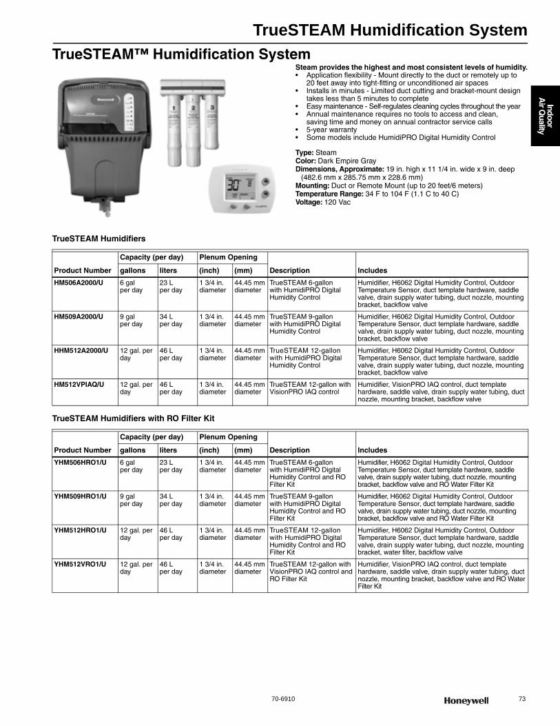
TrueSTEAM Humidification System
70-6910 73
Indoor
Air Q
uality
TrueSTEAM™ Humidification SystemSteam provides the highest and most consistent levels of humidity.• Application flexibility - Mount directly to the duct or remotely up to
20 feet away into tight-fitting or unconditioned air spaces • Installs in minutes - Limited duct cutting and bracket-mount design
takes less than 5 minutes to complete • Easy maintenance - Self-regulates cleaning cycles throughout the year • Annual maintenance requires no tools to access and clean,
saving time and money on annual contractor service calls • 5-year warranty• Some models include HumidiPRO Digital Humidity Control
Type: SteamColor: Dark Empire GrayDimensions, Approximate: 19 in. high x 11 1/4 in. wide x 9 in. deep
(482.6 mm x 285.75 mm x 228.6 mm) Mounting: Duct or Remote Mount (up to 20 feet/6 meters)Temperature Range: 34 F to 104 F (1.1 C to 40 C) Voltage: 120 Vac
TrueSTEAM Humidifiers
TrueSTEAM Humidifiers with RO Filter Kit
Product Number
Capacity (per day) Plenum Opening
Description Includesgallons liters (inch) (mm)
HM506A2000/U 6 gal per day
23 L per day
1 3/4 in. diameter
44.45 mm diameter
TrueSTEAM 6-gallon with HumidiPRO Digital Humidity Control
Humidifier, H6062 Digital Humidity Control, Outdoor Temperature Sensor, duct template hardware, saddle valve, drain supply water tubing, duct nozzle, mounting bracket, backflow valve
HM509A2000/U 9 gal per day
34 L per day
1 3/4 in. diameter
44.45 mm diameter
TrueSTEAM 9-gallon with HumidiPRO Digital Humidity Control
Humidifier, H6062 Digital Humidity Control, Outdoor Temperature Sensor, duct template hardware, saddle valve, drain supply water tubing, duct nozzle, mounting bracket, backflow valve
HHM512A2000/U 12 gal. per day
46 L per day
1 3/4 in. diameter
44.45 mm diameter
TrueSTEAM 12-gallon with HumidiPRO Digital Humidity Control
Humidifier, H6062 Digital Humidity Control, Outdoor Temperature Sensor, duct template hardware, saddle valve, drain supply water tubing, duct nozzle, mounting bracket, backflow valve
HM512VPIAQ/U 12 gal. per day
46 L per day
1 3/4 in. diameter
44.45 mm diameter
TrueSTEAM 12-gallon with VisionPRO IAQ control
Humidifier, VisionPRO IAQ control, duct template hardware, saddle valve, drain supply water tubing, duct nozzle, mounting bracket, backflow valve
Product Number
Capacity (per day) Plenum Opening
Description Includesgallons liters (inch) (mm)
YHM506HRO1/U 6 gal per day
23 L per day
1 3/4 in. diameter
44.45 mm diameter
TrueSTEAM 6-gallon with HumidiPRO Digital Humidity Control and RO Filter Kit
Humidifier, H6062 Digital Humidity Control, Outdoor Temperature Sensor, duct template hardware, saddle valve, drain supply water tubing, duct nozzle, mounting bracket, backflow valve and RO Water Filter Kit
YHM509HRO1/U 9 gal per day
34 L per day
1 3/4 in. diameter
44.45 mm diameter
TrueSTEAM 9-gallon with HumidiPRO Digital Humidity Control and RO Filter Kit
Humidifier, H6062 Digital Humidity Control, Outdoor Temperature Sensor, duct template hardware, saddle valve, drain supply water tubing, duct nozzle, mounting bracket, backflow valve and RO Water Filter Kit
YHM512HRO1/U 12 gal. per day
46 L per day
1 3/4 in. diameter
44.45 mm diameter
TrueSTEAM 12-gallon with HumidiPRO Digital Humidity Control and RO Filter Kit
Humidifier, H6062 Digital Humidity Control, Outdoor Temperature Sensor, duct template hardware, saddle valve, drain supply water tubing, duct nozzle, mounting bracket, water filter, backflow valve
YHM512VRO1/U 12 gal. per day
46 L per day
1 3/4 in. diameter
44.45 mm diameter
TrueSTEAM 12-gallon with VisionPRO IAQ control and RO Filter Kit
Humidifier, VisionPRO IAQ control, duct template hardware, saddle valve, drain supply water tubing, duct nozzle, mounting bracket, backflow valve and RO Water Filter Kit
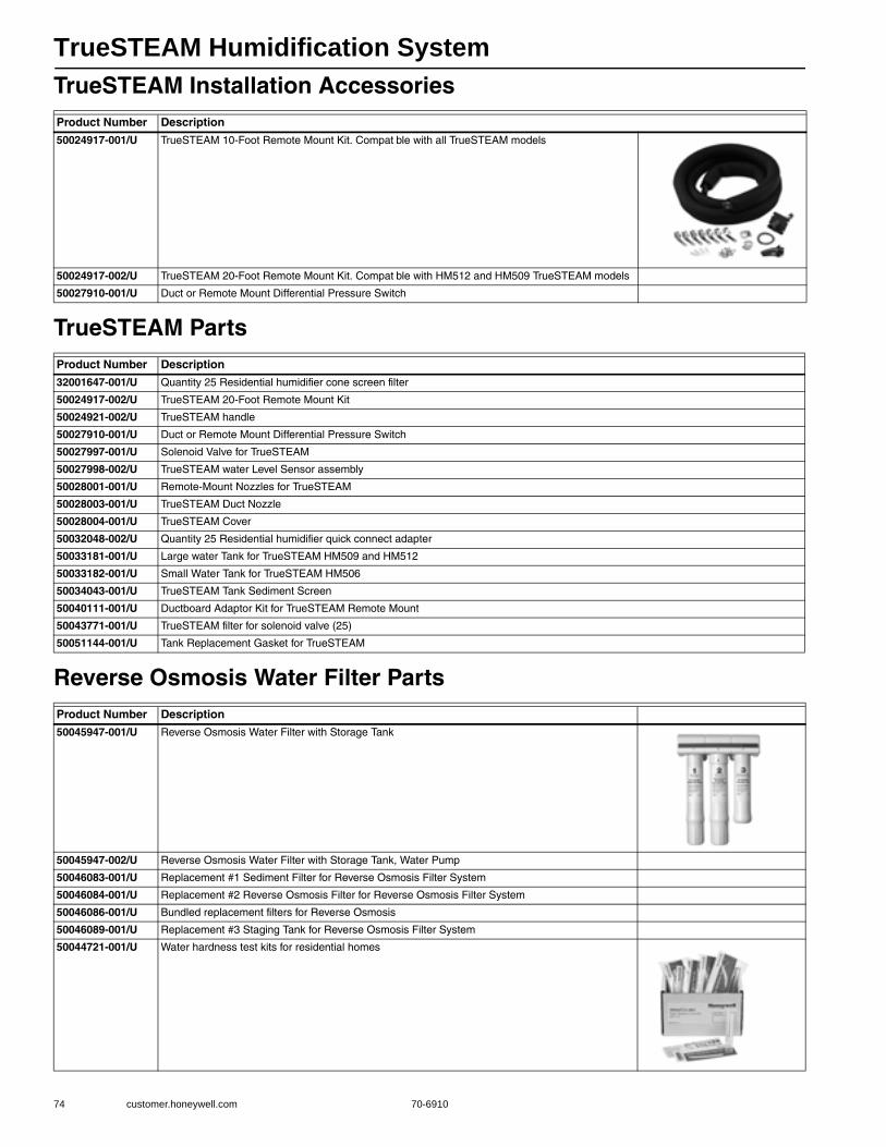
TrueSTEAM Humidification System
74 customer.honeywell.com 70-6910
TrueSTEAM Installation Accessories
TrueSTEAM Parts
Reverse Osmosis Water Filter Parts
Product Number Description
50024917-001/U TrueSTEAM 10-Foot Remote Mount Kit. Compat ble with all TrueSTEAM models
50024917-002/U TrueSTEAM 20-Foot Remote Mount Kit. Compat ble with HM512 and HM509 TrueSTEAM models
50027910-001/U Duct or Remote Mount Differential Pressure Switch
Product Number Description
32001647-001/U Quantity 25 Residential humidifier cone screen filter
50024917-002/U TrueSTEAM 20-Foot Remote Mount Kit
50024921-002/U TrueSTEAM handle
50027910-001/U Duct or Remote Mount Differential Pressure Switch
50027997-001/U Solenoid Valve for TrueSTEAM
50027998-002/U TrueSTEAM water Level Sensor assembly
50028001-001/U Remote-Mount Nozzles for TrueSTEAM
50028003-001/U TrueSTEAM Duct Nozzle
50028004-001/U TrueSTEAM Cover
50032048-002/U Quantity 25 Residential humidifier quick connect adapter
50033181-001/U Large water Tank for TrueSTEAM HM509 and HM512
50033182-001/U Small Water Tank for TrueSTEAM HM506
50034043-001/U TrueSTEAM Tank Sediment Screen
50040111-001/U Ductboard Adaptor Kit for TrueSTEAM Remote Mount
50043771-001/U TrueSTEAM filter for solenoid valve (25)
50051144-001/U Tank Replacement Gasket for TrueSTEAM
Product Number Description
50045947-001/U Reverse Osmosis Water Filter with Storage Tank
50045947-002/U Reverse Osmosis Water Filter with Storage Tank, Water Pump
50046083-001/U Replacement #1 Sediment Filter for Reverse Osmosis Filter System
50046084-001/U Replacement #2 Reverse Osmosis Filter for Reverse Osmosis Filter System
50046086-001/U Bundled replacement filters for Reverse Osmosis
50046089-001/U Replacement #3 Staging Tank for Reverse Osmosis Filter System
50044721-001/U Water hardness test kits for residential homes
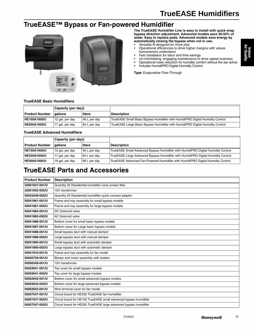
TrueEASE Humidifiers
70-6910 75
Indoor
Air Q
uality
TrueEASE™ Bypass or Fan-powered HumidifierThe TrueEASE Humidifier Line is easy to install with quick snap bypass direction adjustment. Advanced models save 30-50% of water. Easy to replace pads. Advanced models save energy by automatically closing the bypass when not in use.• Versatile fit designed for more jobs • Operational efficiencies to drive higher margins with values
homeowners understand • Fast installation for labor and time savings • Un-intimidating, engaging maintenance to drive repeat business • Operational noise reduction for humidity comfort without the ear aches• Includes HumidiPRO Digital Humidity Control
Type: Evaporative Flow-Through
TrueEASE Basic Humidifiers
TrueEASE Advanced Humidifiers
TrueEASE Parts and Accessories
Product Number
Capacity (per day))
Descriptiongallons liters
HE100A1000/U 12 gal. per day 46 L per day TrueEASE Small Basic Bypass Humidifier with HumidiPRO Digital Humidity Control
HE200A1000/U 17 gal. per day 64 L per day TrueEASE Large Basic Bypass Humidifier with HumidiPRO Digital Humidity Control
Product Number
Capacity (per day))
Descriptiongallons liters
HE150A1005/U 12 gal. per day 46 L per day TrueEASE Small Advanced Bypass Humidifier with HumidiPRO Digital Humidity Control
HE250A1005/U 17 gal. per day 64 L per day TrueEASE Large Advanced Bypass Humidifier with HumidiPRO Digital Humidity Control
HE300A1005/U 18 gal. per day 68 L per day TrueEASE Advanced Fan-Powered Humidifier with HumidiPRO Digital Humidity Control
Product Number Description
32001647-001/U Quantity 25 Residential humidifier cone screen filter
32001652-002/U 10V transformer
50032048-002/U Quantity 25 Residential humidifier quick connect adapter
50041861-001/U Frame and tray assembly for small bypass models
50041861-002/U Frame and tray assembly for large bypass models
50041883-001/U DC Solenoid valve
50041883-002/U AC Solenoid valve
50041886-001/U Bottom cover for small basic bypass models
50041887-001/U Bottom cover for Large basic bypass models
50041888-001/U Small bypass duct with manual damper
50041888-002/U Large bypass duct with manual damper
50041890-001/U Small bypass duct with automatic damper
50041890-002/U Large bypass duct with automatic damper
50041919-001/U Frame and tray assembly for fan model
50045729-001/U Blower and motor assembly with isolator
50050349-001/U 15V transformer
50052641-001/U Top cover for small bypass models
50052641-002/U Top cover for large bypass models
50052642-001/U Bottom cover for small advanced bypass models
50052642-002/U Bottom cover for large advanced bypass models
50052653-001/U Wire terminal cover for fan model
50057547-001/U Circuit board for HE300 TrueEASE fan humidifier
50057547-002/U Circuit board for HE150 TrueEASE small advanced bypass humidifier
50057547-003/U Circuit board for HE250 TrueEASE large advanced bypass humidifier

Bypass Humidifers
76 customer.honeywell.com 70-6910
HE225; HE265 Bypass Flow-through HumidifierBypass Flow-through Humidifiers use the warm air furnace blower to provide whole house humidification.• Humidifier pad is coated with AGION antimicrobial agent • Preassembled for quicker installation • Small footprint, light weight and reversible components allow
for easy mounting on either warm air supply or cold air return of any forced air furnace
• Interior components designed for quick maintenance and service • Option of automatic humidity control or standard humidistat • Standard tested per ARI Standard 610
Dimensions in inches (millimeters) Type: Evaporative Flow-ThroughDimensions, Approximate: 13 9/16 in. high x 12 in. wide x 9 1/8 in. deep
(345 mm high x 305 mm wide x 232 mm deep) Color: White and BlueMounting: Duct mountVoltage: 24 VacFrequency: 60 HzElectrical Ratings: 0.5AApprovalsUnderwriters Laboratories, Inc: UL/cUL Listed Report E185662
M23245
9-1/4 (235)
12 (305)
15-5/16(390)
13-9/16 (345)
16-3/4
(425)
6 (152) DIAMETER
HE265
Product Number
Capacity (per day) Plenum Opening
Mounting Includesgallons liters (inch) (mm)
HE225H8908/U 12 gal. per day
46 L per day
9 7/16 in. high x 9 5/18 in. wide
241 mm high x 238 mm wide
Duct or Remote Mount (up to 20 feet/6 meters)
Humidifier, summer shut-off damper humidifier pad, mounting template, self-piercing saddle valve 24 Vac transformer and wire, H8908 humidistat
HE265H8908/U 17 gal. per day
64 L per day
12 5/8 in. high x 9 3/4 in. wide
321 mm high x 248 mm wide
Duct or Remote Mount (up to 20 feet/6 meters)
Humidifier, summer shut-off damper humidifier pad, mounting template, self-piercing saddle valve 24 Vac transformer and wire, H8908 humidistat
HE225A1014/U 12 gal. per day
46 L per day
9 7/16 in. high x 9 5/18 in. wide
241 mm high x 238 mm wide
Duct mount Humidifier, summer shut-off damper humidifier pad, mounting template, self-piercing saddle valve 24 Vac transformer and wire, H8908 humidistat, and bypass installation materials
HE265A1234/U 17 gal. per day
64 L per day
12 5/8 in. high x 9 3/4 in. wide
321 mm high x 248 mm wide
Duct mount Humidifier, summer shut-off damper humidifier pad, mounting template, self-piercing saddle valve 24 Vac transformer and wire, H8908 humidistat, and bypass installation materials
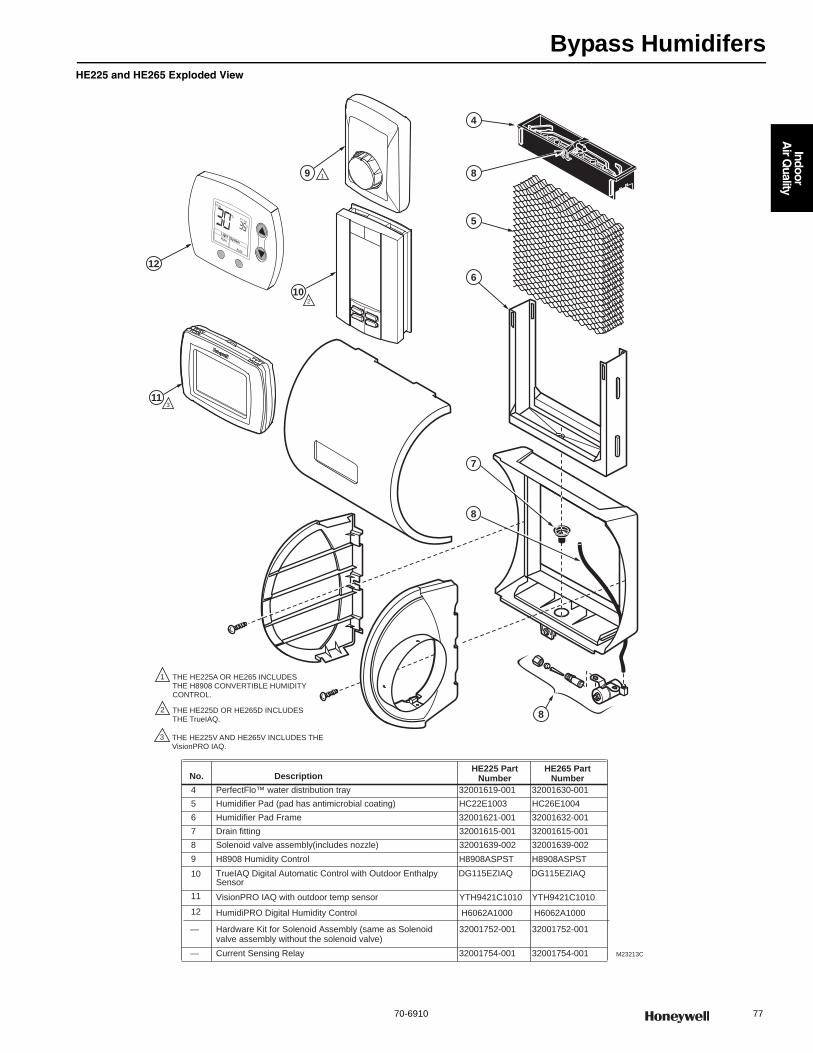
Bypass Humidifers
70-6910 77
Indoor
Air Q
uality
HE225 and HE265 Exploded View
No. DescriptionHE225 Part
Number HE265 Part
Number4 PerfectFlo™ water distribution tray 32001619-001 32001630-001
5 Humidifier Pad (pad has antimicrobial coating) HC22E1003 HC26E1004
6 Humidifier Pad Frame 32001621-001 32001632-001
7 Drain fitting 32001615-001 32001615-001
8 Solenoid valve assembly (includes nozzle) 32001639-002 32001639-002
9
10
H8908 Humidity Control H8908ASPST H8908ASPST
TrueIAQ Digital Automatic Control with Outdoor Enthalpy Sensor
DG115EZIAQ DG115EZIAQ
— Hardware Kit for Solenoid Assembly (same as Solenoid valve assembly without the solenoid valve)
32001752-001 32001752-001
— Current Sensing Relay 32001754-001 32001754-001 M23213C
9
6
7
5
4
8
10
8
8
1
2
1
THE HE225A OR HE265 INCLUDES THE H8908 CONVERTIBLE HUMIDITYCONTROL.
2 THE HE225D OR HE265D INCLUDES THE TrueIAQ.
11 VisionPRO IAQ with outdoor temp sensor
11
YTH9421C1010 YTH9421C1010
3
3 THE HE225V AND HE265V INCLUDES THE VisionPRO IAQ.
S t ing
Light Auto
Auto
System
%
R l BR l B
Ins de
%
12
12 HumidiPRO Digital Humidity Control H6062A1000 H6062A1000
Humidifier Replacement Pads and Filters
78 customer.honeywell.com 70-6910
Humidifier Replacement Pads and Filters
Humidifier Parts
Product Number Description Includes Used With
32000146-001/U HE120 Replacement Humidifier Pad (includes clips)
— HE120
50028044-001/U Plumb in-line scale and sediment filter with quick-connect fittings.
1 filter All Honeywell steam and evaporative humidifiers; also fits AprilAire evaporative models
HC22A1007/U HE220 Humidifier Pad Standard Humidifier Pad Honeywell HE220, HE225, Aprilaire Models 110, 220, 550, 558
HC22E1003/U HE225 Humidifier Pad with AgION™ Coating
AgION Antimicrobial Humidifier Pad
Honeywell HE220, HE225, Aprilaire Models 110, 220, 550, 558
HC26A1008/U HE260 Humidifier Pad Standard Humidifier Pad Honeywell HE260, HE265, HE360, HE365, Aprilaire 350, 360, 560, 568, 600, 700, 760, 768
HC26E1004/U HE265 Humidifier Pad with AgION™ Coating
AgION Antimicrobial Humidifier Pad
Honeywell HE260, HE265, HE360, HE365, Aprilaire 350, 360, 560, 568, 600, 700, 760, 769
Product Number Description Used With
32000132-001/U HE120 24 Vac Motor HE120
32000136-001/U HE120 Float Valve HE120
32000156-001/U HE420 Fan Wiring Assembly HE420
32000408-001/U HE360, HE365 Feed Tube Nozzle HE360, HE365
32000429-001/U HE360, HE365 Fan Blade HE360, HE365
32001615-001/U HE220, HE225, HE260, HE265, HE360, HE365 Drain Fitting HE220, HE225, HE260, HE265, HE360, HE365
32001616-001/U HE120, HE220, HE225, HE260, HE265, HE360, HE365 Saddle Valve Assembly HE120, HE220, HE225, HE260, HE265, HE360, HE365
32001619-001/U HE220, HE225, HE360A1001 PerfectFlo™ Water Distribution Tray HE220, HE225, HE360
32001621-001/U HE220, HE225 Humidifier Pad Frame HE220, HE225
32001630-001/U HE260, HE265, HE360, HE365 PerfectFlo™ Water Distr bution Tray HE260, HE265, HE360, HE365
32001632-001/U HE260, HE265, HE360, HE365 Humidifier Pad Frame HE260, HE265, HE360, HE365
32001639-002/U HE220, HE225, HE260, HE265 Solenoid Valve Assembly (includes water feed tube and nozzle)
HE220, HE225, HE260, HE265
32001652-001/U HE220, HE225, HE260, HE265 Transformer (10VA) HE260, HE265, HE360, HE365
32001676-001/U HE360, HE365 Printed Wiring Board Assembly HE360, HE365
32001676-001/U HE360, HE365 Printed Wiring Board Assembly HE360, HE365
32001752-001/U HE220, HE225, HE260, HE265, HE360, HE365 Hardware Kit for Solenoid Assembly (does not include solenoid valve)
HE220, HE225, HE260, HE265, HE360, HE365
32001754-001/U Current Sensing Relay HE220, HE225, HE260, HE265, HE360, HE365
32001876-001/U HE360, HE365 Solenoid Valve Assembly (includes water feed tube) HE360, HE365
32006450-001/U HE440 Filter Pack HE440
32006451-001/U HE440 Chlorine Filter HE440
50018841-001/U Mounting Bracket for HE420 HE420
50018847-001/U SPDT Relay for HE420 HE420
50019240-001/U In-line Chlorine Filter used with a HE420 HE420
50020012-001/U Mounting Bracket for TrueSTEAM —
50027997-001/U Solenoid Valve for TrueSTEAM —
50028001-001/U Remote-Mount Nozzles for TrueSTEAM —
50028003-001/U TrueSTEAM Duct Nozzle —
50028004-001/U TrueSTEAM Cover —
50033181-001/U Large water Tank for TrueSTEAM HM509 and HM512 HM509; HM512
50033182-001/U Small Water Tank for TrueSTEAM HM506 HM506
50040111-001/U Ductboard Adaptor Kit for TrueSTEAM Remote Mount —
50043683-001/U Water Backflow Prevention Valve with Manual Water Shutoff. For use with TrueSTEAM
—
50051144-001/U Tank Replacement Gasket for TrueSTEAM —
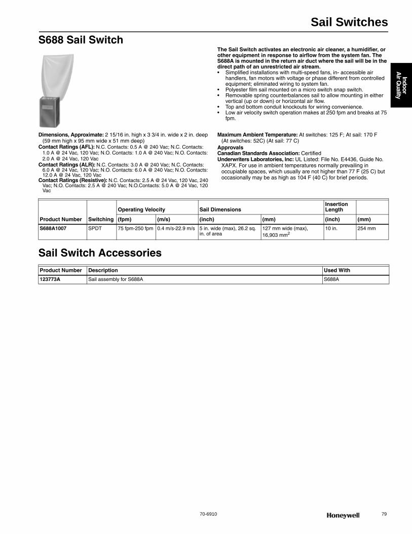
Sail Switches
70-6910 79
Indoor
Air Q
uality
S688 Sail SwitchThe Sail Switch activates an electronic air cleaner, a humidifier, or other equipment in response to airflow from the system fan. The S688A is mounted in the return air duct where the sail will be in the direct path of an unrestricted air stream.• Simplified installations with multi-speed fans, in- accessible air
handlers, fan motors with voltage or phase different from controlled equipment; eliminated wiring to system fan.
• Polyester film sail mounted on a micro switch snap switch. • Removable spring counterbalances sail to allow mounting in either
vertical (up or down) or horizontal air flow. • Top and bottom conduit knockouts for wiring convenience. • Low air velocity switch operation makes at 250 fpm and breaks at 75
fpm.
Dimensions, Approximate: 2 15/16 in. high x 3 3/4 in. wide x 2 in. deep (59 mm high x 95 mm wide x 51 mm deep)
Contact Ratings (AFL): N.C. Contacts: 0.5 A @ 240 Vac; N.C. Contacts: 1.0 A @ 24 Vac, 120 Vac; N.O. Contacts: 1.0 A @ 240 Vac; N.O. Contacts: 2.0 A @ 24 Vac, 120 Vac
Contact Ratings (ALR): N.C. Contacts: 3.0 A @ 240 Vac; N.C. Contacts: 6.0 A @ 24 Vac, 120 Vac; N.O. Contacts: 6.0 A @ 240 Vac; N.O. Contacts: 12.0 A @ 24 Vac, 120 Vac
Contact Ratings (Resistive): N.C. Contacts: 2.5 A @ 24 Vac, 120 Vac, 240 Vac; N.O. Contacts: 2.5 A @ 240 Vac; N.O.Contacts: 5.0 A @ 24 Vac, 120 Vac
Maximum Ambient Temperature: At switches: 125 F; At sail: 170 F (At switches: 52C) (At sail: 77 C)
ApprovalsCanadian Standards Association: CertifiedUnderwriters Laboratories, Inc: UL Listed: File No. E4436, Guide No.
XAPX. For use in ambient temperatures normally prevailing in occupiable spaces, which usually are not higher than 77 F (25 C) but occasionally may be as high as 104 F (40 C) for brief periods.
Sail Switch Accessories
Product Number Switching
Operating Velocity Sail DimensionsInsertion Length
(fpm) (m/s) (inch) (mm) (inch) (mm)
S688A1007 SPDT 75 fpm-250 fpm 0.4 m/s-22.9 m/s 5 in. wide (max), 26.2 sq. in. of area
127 mm wide (max), 16,903 mm2
10 in. 254 mm
Product Number Description Used With
123773A Sail assembly for S688A S688A

Digital IAQ Control
80 customer.honeywell.com 70-6910
HumidiPRO™ Digital Humidity Control
Easy to use, digital control of your home’s humidification or dehumidification. HumidiPRO™ will automatically adjust settings
for changes in outdoor temperature to ensure no condensation will appear in your home (window protection).• Automatic humidification (window protection) with included outdoor
sensor• Manual humidification control• Manual dehumidification control• Dehumidifier compressor protection• Large, digital backlit display• Simple, intuitive programming• RH% and outdoor temperature cal bration• Adjustable high and low range stops (10-90%)• Automatically detects presence of outdoor sensor to set control to
Automatic or Manual Mode
Application: Provides humidity control for whole-house humidifiers and dehumidifiers
Type: DigitalMounting: Return air duct mount (recommended), wall mount
Voltage: 24 Vac constantTerminal Designations: C, R, U, U, S, SPower: Hardwire
TrueIAQ® Automatic Digital IAQ ControlIntegrate control of you home's humidification, dehumidification, ventilation and even bathroom fans into a single device with Honeywell's TrueIAQ control. TrueIAQ allows you to program your air quality and fan settings individually, or as a system for increased comfort and energy savings. Plus, TrueIAQ will automatically adjust settings for changes in outside temperature and humidity, and provides maintenance reminders to help keep your equipment operating at peak efficiency. For true indoor air quality control, choose TrueIAQ.• Setting changes can be made easily with the touch of a button.• Manages humidification, dehumidification, ventilation and bathroom
fans from a central point in your home• Simultaneously displays both indoor and outdoor temperature and
humidity levels on-screen • Automatically adjusts inside settings based on outdoor conditions • Include individual air quality enhancements to your system with
TrueIAQ, or integrate them all as part of a total air quality system• Intuitive digital backlit display
Application: Provides humidity control for ducts, greenhouses, computer rooms, printing and photographic laboratories, and other applications where electronic accuracy, as well as remote sensing, is desired
Type: Steam
Mounting: Duct or Remote Mount (up to 20 feet)Temperature Range: (1.1 C to 40 C) Voltage: 24 Vac
Product Number Humidity Range Setting (% RH) Color Used With
H6062A1000/U Manual Mode - 10- 90% (Adjustable)Automatic Mode - 20-60% (35% Default)
Premier White TrueEASE, TrueSTEAM, all dry-contact humidifiers and dehumidifiers
Product Number
Operating Humidity Range (% RH) Electrical Ratings Color Includes Used With
DG115EZIAQ/U 95% RH at 95 F, non-condensing
2.0A at 24 Vac, humidifier, dehumidifier, vent contacts
White TrueIAQ control and outdoor sensor for temperature and humidity
Outdoor temp/humidity sensor (included)
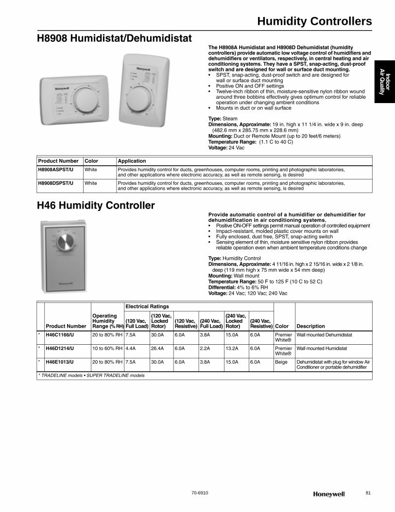
Humidity Controllers
70-6910 81
Indoor
Air Q
uality
H8908 Humidistat/DehumidistatThe H8908A Humidistat and H8908D Dehumidistat (humidity controllers) provide automatic low voltage control of humidifiers and dehumidifiers or ventilators, respectively, in central heating and air conditioning systems. They have a SPST, snap-acting, dust-proof switch and are designed for wall or surface duct mounting.• SPST, snap-acting, dust-proof switch and are designed for
wall or surface duct mounting • Positive ON and OFF settings • Twelve-inch ribbon of thin, moisture-sensitive nylon ribbon wound
around three bobbins effectively gives optimum control for reliable operation under changing ambient conditions
• Mounts in duct or on wall surface
Type: SteamDimensions, Approximate: 19 in. high x 11 1/4 in. wide x 9 in. deep
(482.6 mm x 285.75 mm x 228.6 mm) Mounting: Duct or Remote Mount (up to 20 feet/6 meters)Temperature Range: (1.1 C to 40 C) Voltage: 24 Vac
H46 Humidity ControllerProvide automatic control of a humidifier or dehumidifier for dehumidification in air conditioning systems.• Positive ON-OFF settings permit manual operation of controlled equipment • Impact-resistant, molded plastic cover mounts on wall • Fully enclosed, dust free, SPST, snap-acting switch • Sensing element of thin, moisture sensitive nylon ribbon provides
reliable operation even when ambient temperature conditions change
Type: Humidity ControlDimensions, Approximate: 4 11/16 in. high x 2 15/16 in. wide x 2 1/8 in.
deep (119 mm high x 75 mm wide x 54 mm deep) Mounting: Wall mountTemperature Range: 50 F to 125 F (10 C to 52 C) Differential: 4% to 6% RHVoltage: 24 Vac; 120 Vac; 240 Vac
Product Number Color Application
H8908ASPST/U White Provides humidity control for ducts, greenhouses, computer rooms, printing and photographic laboratories, and other applications where electronic accuracy, as well as remote sensing, is desired
H8908DSPST/U White Provides humidity control for ducts, greenhouses, computer rooms, printing and photographic laboratories, and other applications where electronic accuracy, as well as remote sensing, is desired
Product Number
Operating Humidity Range (% RH)
Electrical Ratings
Color Description(120 Vac, Full Load)
(120 Vac, Locked Rotor)
(120 Vac, Resistive)
(240 Vac, Full Load)
(240 Vac, Locked Rotor)
(240 Vac, Resistive)
* H46C1166/U 20 to 80% RH 7.5A 30.0A 6.0A 3.8A 15.0A 6.0A Premier White®
Wall mounted Dehumidistat
* H46D1214/U 10 to 60% RH 4.4A 26.4A 6.0A 2.2A 13.2A 6.0A Premier White®
Wall mounted Humidistat
* H46E1013/U 20 to 80% RH 7.5A 30.0A 6.0A 3.8A 15.0A 6.0A Beige Dehumidistat with plug for window Air Conditioner or portable dehumidifier
* TRADELINE models • SUPER TRADELINE models
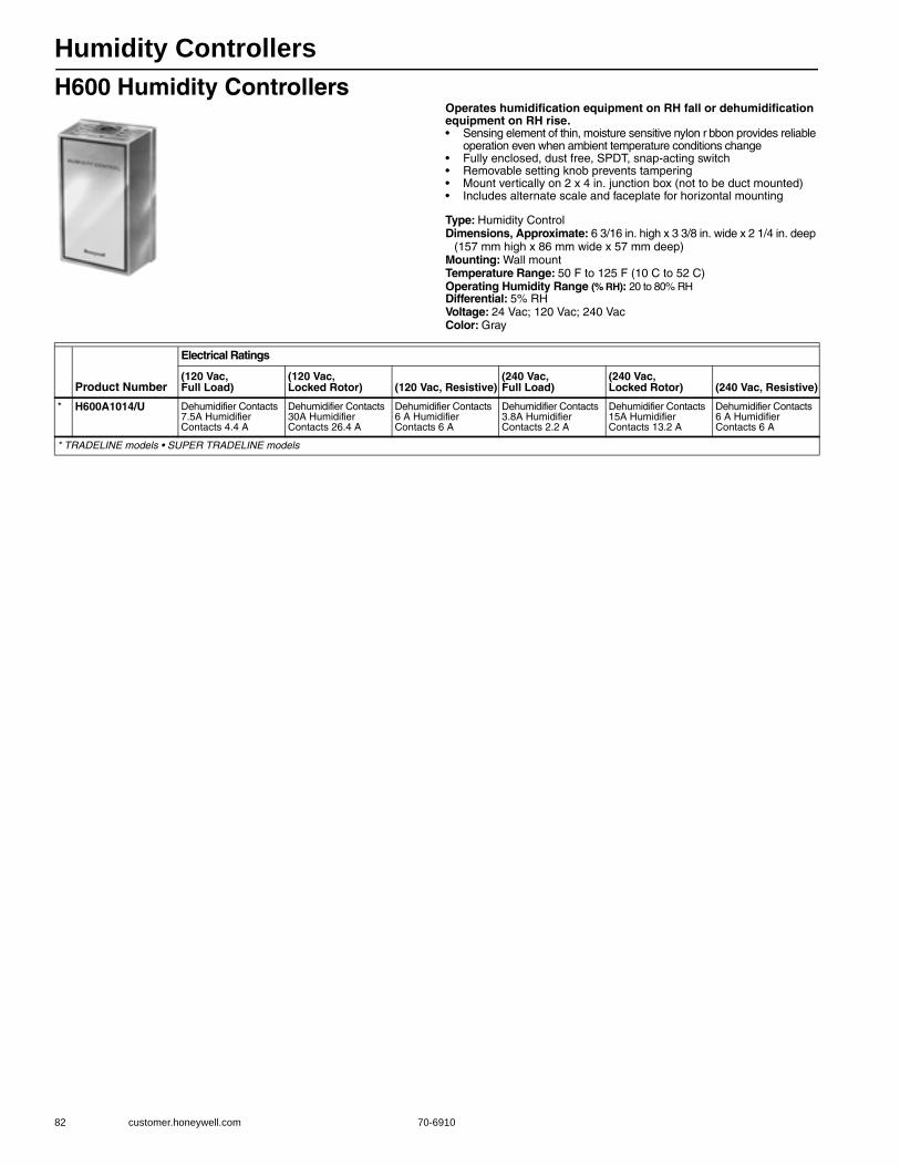
Humidity Controllers
82 customer.honeywell.com 70-6910
H600 Humidity ControllersOperates humidification equipment on RH fall or dehumidification equipment on RH rise.• Sensing element of thin, moisture sensitive nylon r bbon provides reliable
operation even when ambient temperature conditions change • Fully enclosed, dust free, SPDT, snap-acting switch • Removable setting knob prevents tampering • Mount vertically on 2 x 4 in. junction box (not to be duct mounted) • Includes alternate scale and faceplate for horizontal mounting
Type: Humidity ControlDimensions, Approximate: 6 3/16 in. high x 3 3/8 in. wide x 2 1/4 in. deep
(157 mm high x 86 mm wide x 57 mm deep) Mounting: Wall mountTemperature Range: 50 F to 125 F (10 C to 52 C)Operating Humidity Range (% RH): 20 to 80% RH Differential: 5% RHVoltage: 24 Vac; 120 Vac; 240 VacColor: Gray
Product Number
Electrical Ratings
(120 Vac, Full Load)
(120 Vac, Locked Rotor) (120 Vac, Resistive)
(240 Vac, Full Load)
(240 Vac, Locked Rotor) (240 Vac, Resistive)
* H600A1014/U Dehumidifier Contacts 7.5A Humidifier Contacts 4.4 A
Dehumidifier Contacts 30A Humidifier Contacts 26.4 A
Dehumidifier Contacts 6 A Humidifier Contacts 6 A
Dehumidifier Contacts 3.8A Humidifier Contacts 2.2 A
Dehumidifier Contacts 15A Humidifier Contacts 13.2 A
Dehumidifier Contacts 6 A Humidifier Contacts 6 A
* TRADELINE models • SUPER TRADELINE models
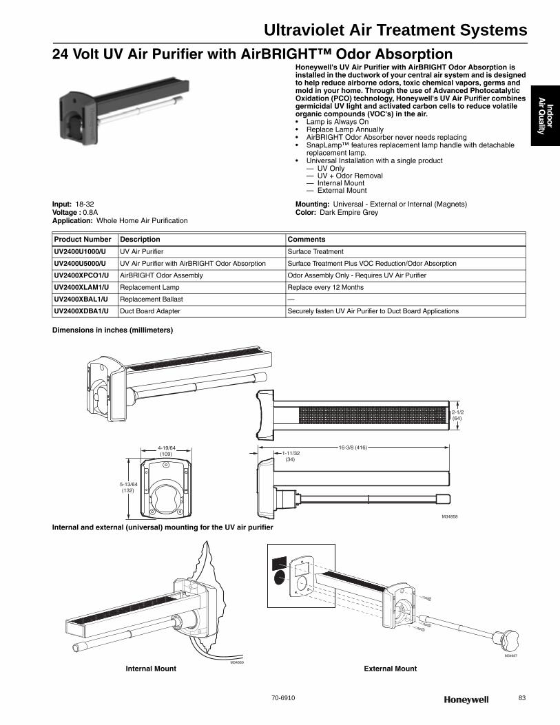
Ultraviolet Air Treatment Systems
70-6910 83
Indoor
Air Q
uality
24 Volt UV Air Purifier with AirBRIGHT™ Odor AbsorptionHoneywell's UV Air Purifier with AirBRIGHT Odor Absorption is installed in the ductwork of your central air system and is designed to help reduce airborne odors, toxic chemical vapors, germs and mold in your home. Through the use of Advanced Photocatalytic Oxidation (PCO) technology, Honeywell's UV Air Purifier combines germicidal UV light and activated carbon cells to reduce volatile organic compounds (VOC's) in the air.• Lamp is Always On• Replace Lamp Annually• AirBRIGHT Odor Absorber never needs replacing• SnapLamp™ features replacement lamp handle with detachable
replacement lamp.• Universal Installation with a single product
— UV Only— UV + Odor Removal— Internal Mount— External Mount
Input: 18-32 Voltage : 0.8AApplication: Whole Home Air Purification
Mounting: Universal - External or Internal (Magnets)Color: Dark Empire Grey
Dimensions in inches (millimeters)
Internal and external (universal) mounting for the UV air purifier
Product Number Description Comments
UV2400U1000/U UV Air Purifier Surface Treatment
UV2400U5000/U UV Air Purifier with AirBRIGHT Odor Absorption Surface Treatment Plus VOC Reduction/Odor Absorption
UV2400XPCO1/U AirBRIGHT Odor Assembly Odor Assembly Only - Requires UV Air Purifier
UV2400XLAM1/U Replacement Lamp Replace every 12 Months
UV2400XBAL1/U Replacement Ballast —
UV2400XDBA1/U Duct Board Adapter Securely fasten UV Air Purifier to Duct Board Applications
2-1/2(64)
M34858
4-19/64(109)
5-13/64(132)
1-11/32(34)
16-3/8 (416)
M34687
M34660
Internal Mount External Mount
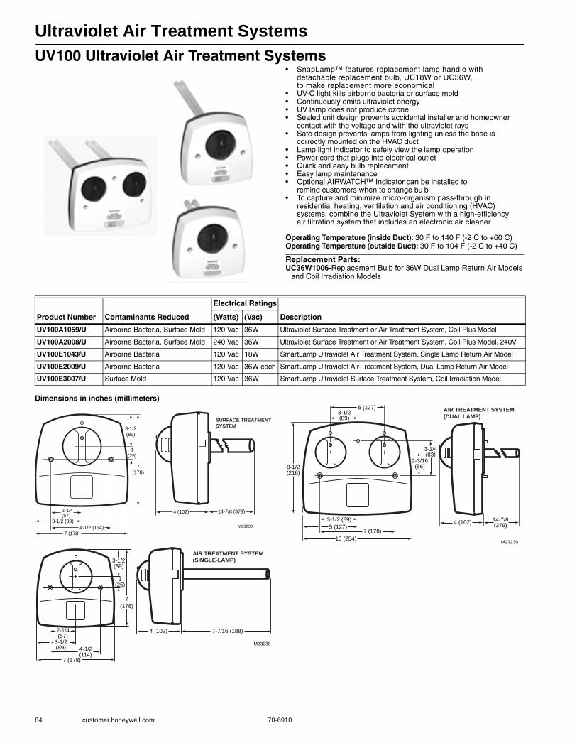
Ultraviolet Air Treatment Systems
84 customer.honeywell.com 70-6910
UV100 Ultraviolet Air Treatment Systems• SnapLamp™ features replacement lamp handle with
detachable replacement bulb, UC18W or UC36W, to make replacement more economical
• UV-C light kills airborne bacteria or surface mold • Continuously emits ultraviolet energy • UV lamp does not produce ozone • Sealed unit design prevents accidental installer and homeowner
contact with the voltage and with the ultraviolet rays • Safe design prevents lamps from lighting unless the base is
correctly mounted on the HVAC duct • Lamp light indicator to safely view the lamp operation • Power cord that plugs into electrical outlet • Quick and easy bulb replacement • Easy lamp maintenance • Optional AIRWATCH™ Indicator can be installed to
remind customers when to change bu b • To capture and minimize micro-organism pass-through in
residential heating, ventilation and air conditioning (HVAC) systems, combine the Ultraviolet System with a high-efficiency air filtration system that includes an electronic air cleaner
Operating Temperature (inside Duct): 30 F to 140 F (-2 C to +60 C) Operating Temperature (outside Duct): 30 F to 104 F (-2 C to +40 C)
Replacement Parts:UC36W1006-Replacement Bulb for 36W Dual Lamp Return Air Models
and Coil Irradiation Models
Dimensions in inches (millimeters)
Product Number Contaminants Reduced
Electrical Ratings
Description(Watts) (Vac)
UV100A1059/U Airborne Bacteria, Surface Mold 120 Vac 36W Ultraviolet Surface Treatment or Air Treatment System, Coil Plus Model
UV100A2008/U Airborne Bacteria, Surface Mold 240 Vac 36W Ultraviolet Surface Treatment or Air Treatment System, Coil Plus Model, 240V
UV100E1043/U Airborne Bacteria 120 Vac 18W SmartLamp Ultraviolet Air Treatment System, Single Lamp Return Air Model
UV100E2009/U Airborne Bacteria 120 Vac 36W each SmartLamp Ultraviolet Air Treatment System, Dual Lamp Return Air Model
UV100E3007/U Surface Mold 120 Vac 36W SmartLamp Ultraviolet Surface Treatment System, Coil Irradiation Model
2-1/4 (57)
3-1/2 (89)
4-1/2 (114)
7 (178)
1
(25)
7
(178)
3-1/2
(89)
4 (102) 14-7/8 (379)
M23230
SURFACE TREATMENT SYSTEM
2-1/4(57)
3-1/2(89) 4-1/2
(114)7 (178)
1(25)
7
(178)
3-1/2(89)
4 (102) 7-7/16 (188)
M23238
AIR TREATMENT SYSTEM (SINGLE-LAMP)
3-1/2 (89)
5 (127)7 (178)
10 (254)
2-3/16(56)8-1/2
(216)
3-1/4(83)
4 (102) 14-7/8(379)
M23239
3-1/2(89)
5 (127) AIR TREATMENT SYSTEM(DUAL LAMP)
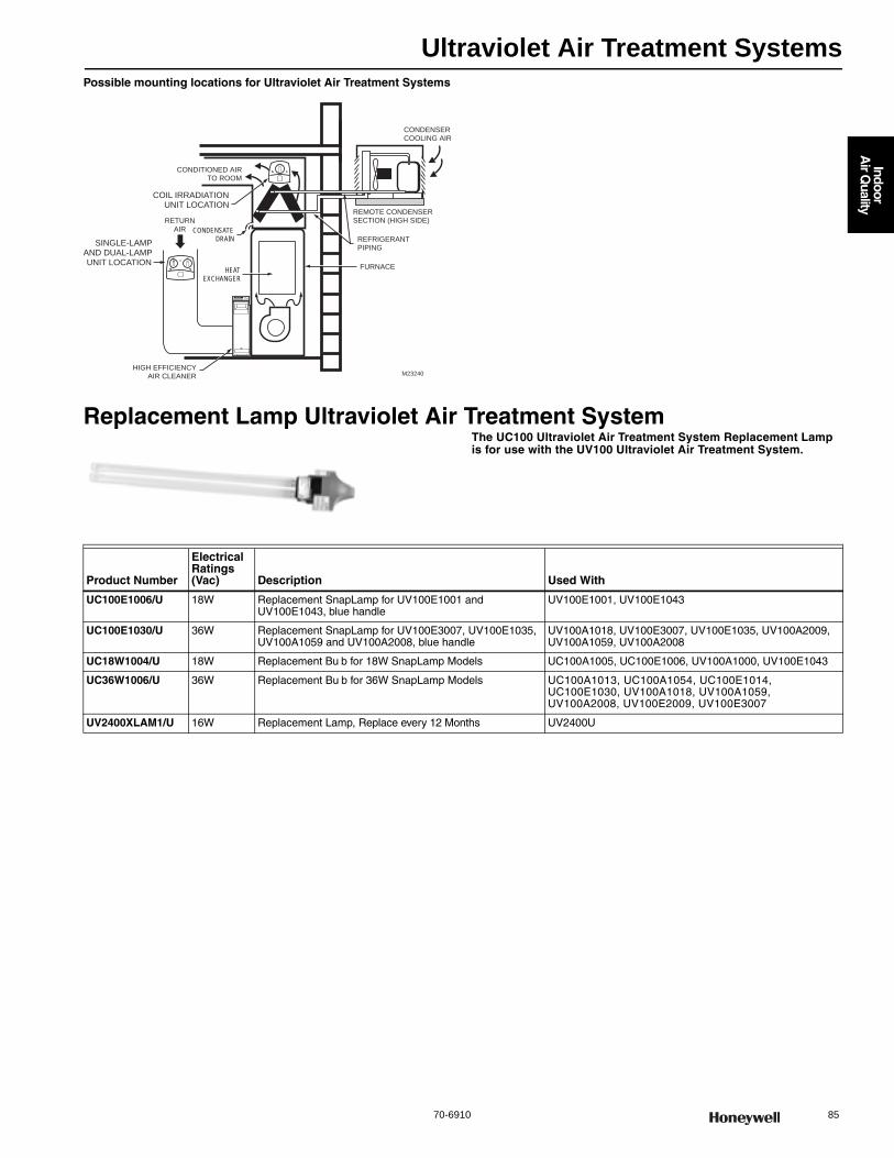
Ultraviolet Air Treatment Systems
70-6910 85
Indoor
Air Q
uality
Possible mounting locations for Ultraviolet Air Treatment Systems
Replacement Lamp Ultraviolet Air Treatment SystemThe UC100 Ultraviolet Air Treatment System Replacement Lamp is for use with the UV100 Ultraviolet Air Treatment System.
CONDITIONED AIRTO ROOM
HEATEXCHANGER
RETURNAIR
FURNACE
CONDENSATEDRAIN
CONDENSERCOOLING AIR
REMOTE CONDENSERSECTION (HIGH SIDE)
REFRIGERANTPIPING
SINGLE-LAMPAND DUAL-LAMPUNIT LOCATION
COIL IRRADIATIONUNIT LOCATION
M23240HIGH EFFICIENCY
AIR CLEANER
Product Number
Electrical Ratings (Vac) Description Used With
UC100E1006/U 18W Replacement SnapLamp for UV100E1001 and UV100E1043, blue handle
UV100E1001, UV100E1043
UC100E1030/U 36W Replacement SnapLamp for UV100E3007, UV100E1035, UV100A1059 and UV100A2008, blue handle
UV100A1018, UV100E3007, UV100E1035, UV100A2009, UV100A1059, UV100A2008
UC18W1004/U 18W Replacement Bu b for 18W SnapLamp Models UC100A1005, UC100E1006, UV100A1000, UV100E1043
UC36W1006/U 36W Replacement Bu b for 36W SnapLamp Models UC100A1013, UC100A1054, UC100E1014, UC100E1030, UV100A1018, UV100A1059, UV100A2008, UV100E2009, UV100E3007
UV2400XLAM1/U 16W Replacement Lamp, Replace every 12 Months UV2400U
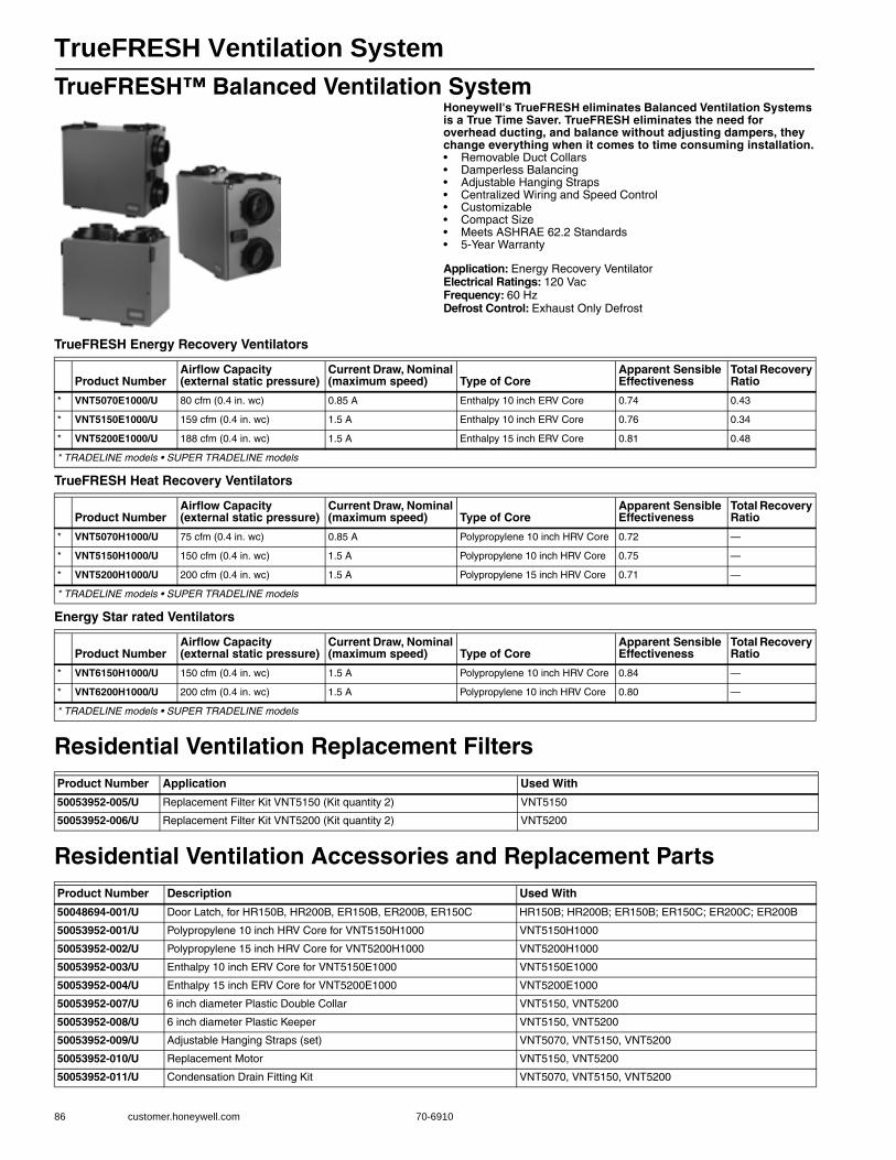
TrueFRESH Ventilation System
86 customer.honeywell.com 70-6910
TrueFRESH™ Balanced Ventilation SystemHoneywell's TrueFRESH eliminates Balanced Ventilation Systems is a True Time Saver. TrueFRESH eliminates the need for overhead ducting, and balance without adjusting dampers, they change everything when it comes to time consuming installation.• Removable Duct Collars • Damperless Balancing • Adjustable Hanging Straps • Centralized Wiring and Speed Control • Customizable • Compact Size • Meets ASHRAE 62.2 Standards • 5-Year Warranty
Application: Energy Recovery VentilatorElectrical Ratings: 120 VacFrequency: 60 HzDefrost Control: Exhaust Only Defrost
TrueFRESH Energy Recovery Ventilators
TrueFRESH Heat Recovery Ventilators
Energy Star rated Ventilators
Residential Ventilation Replacement Filters
Residential Ventilation Accessories and Replacement Parts
Product NumberAirflow Capacity (external static pressure)
Current Draw, Nominal (maximum speed) Type of Core
Apparent Sensible Effectiveness
Total Recovery Ratio
* VNT5070E1000/U 80 cfm (0.4 in. wc) 0.85 A Enthalpy 10 inch ERV Core 0.74 0.43
* VNT5150E1000/U 159 cfm (0.4 in. wc) 1.5 A Enthalpy 10 inch ERV Core 0.76 0.34
* VNT5200E1000/U 188 cfm (0.4 in. wc) 1.5 A Enthalpy 15 inch ERV Core 0.81 0.48
* TRADELINE models • SUPER TRADELINE models
Product NumberAirflow Capacity (external static pressure)
Current Draw, Nominal (maximum speed) Type of Core
Apparent Sensible Effectiveness
Total Recovery Ratio
* VNT5070H1000/U 75 cfm (0.4 in. wc) 0.85 A Polypropylene 10 inch HRV Core 0.72 —
* VNT5150H1000/U 150 cfm (0.4 in. wc) 1.5 A Polypropylene 10 inch HRV Core 0.75 —
* VNT5200H1000/U 200 cfm (0.4 in. wc) 1.5 A Polypropylene 15 inch HRV Core 0.71 —
* TRADELINE models • SUPER TRADELINE models
Product NumberAirflow Capacity (external static pressure)
Current Draw, Nominal (maximum speed) Type of Core
Apparent Sensible Effectiveness
Total Recovery Ratio
* VNT6150H1000/U 150 cfm (0.4 in. wc) 1.5 A Polypropylene 10 inch HRV Core 0.84 —
* VNT6200H1000/U 200 cfm (0.4 in. wc) 1.5 A Polypropylene 10 inch HRV Core 0.80 —
* TRADELINE models • SUPER TRADELINE models
Product Number Application Used With
50053952-005/U Replacement Filter Kit VNT5150 (Kit quantity 2) VNT5150
50053952-006/U Replacement Filter Kit VNT5200 (Kit quantity 2) VNT5200
Product Number Description Used With
50048694-001/U Door Latch, for HR150B, HR200B, ER150B, ER200B, ER150C HR150B; HR200B; ER150B; ER150C; ER200C; ER200B
50053952-001/U Polypropylene 10 inch HRV Core for VNT5150H1000 VNT5150H1000
50053952-002/U Polypropylene 15 inch HRV Core for VNT5200H1000 VNT5200H1000
50053952-003/U Enthalpy 10 inch ERV Core for VNT5150E1000 VNT5150E1000
50053952-004/U Enthalpy 15 inch ERV Core for VNT5200E1000 VNT5200E1000
50053952-007/U 6 inch diameter Plastic Double Collar VNT5150, VNT5200
50053952-008/U 6 inch diameter Plastic Keeper VNT5150, VNT5200
50053952-009/U Adjustable Hanging Straps (set) VNT5070, VNT5150, VNT5200
50053952-010/U Replacement Motor VNT5150, VNT5200
50053952-011/U Condensation Drain Fitting Kit VNT5070, VNT5150, VNT5200
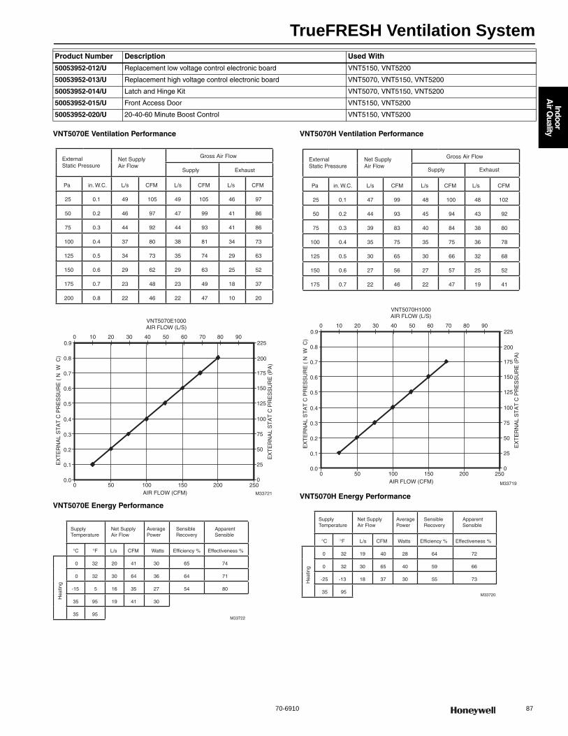
TrueFRESH Ventilation System
70-6910 87
Indoor
Air Q
uality
VNT5070E Ventilation Performance
VNT5070E Energy Performance
VNT5070H Ventilation Performance
VNT5070H Energy Performance
50053952-012/U Replacement low voltage control electronic board VNT5150, VNT5200
50053952-013/U Replacement high voltage control electronic board VNT5070, VNT5150, VNT5200
50053952-014/U Latch and Hinge Kit VNT5070, VNT5150, VNT5200
50053952-015/U Front Access Door VNT5150, VNT5200
50053952-020/U 20-40-60 Minute Boost Control VNT5150, VNT5200
Product Number Description Used With
0.0
0.1
0.2
0.3
0.4
0.5
0.6
0.7
0.8
0 50 100 150 2000
25
50
75
100
125
150
175
2250 10 20 30 40 50 60 70 80 90
VNT5070E1000AIR FLOW (L/S)
AIR FLOW (CFM) M33721
250
0.9
200
ExternalStatic Pressure
Net SupplyAir Flow
Gross Air Flow
Supply Exhaust
Pa in. W.C. L/s CFM L/s CFM L/s CFM
25 0.1 49 105 49 105 46 97
50 0.2 46 97 47 99 41 86
75 0.3 44 92 44 93 41 86
100 0.4 37 80 38 81 34 73
125 0.5 34 73 35 74 29 63
150 0.6 29 62 29 63 25 52
175 0.7 23 48 23 49 18 37
200 0.8 22 46 22 47 10 20
EX
TE
RN
AL
ST
AT
C P
RE
SS
UR
E (
N W
C)
EX
TE
RN
AL
ST
AT
C P
RE
SS
UR
E (
PA
)
M33722
SupplyTemperature
Net SupplyAir Flow
AveragePower
SensibleRecovery
ApparentSensible
°C °F L/s CFM Watts Efficiency % Effectiveness %
Hea
ting
0 32 20 41 30 65 74
0 32 30 64 36 64 71
-15 5 16 35 27 54 80
35 95 19 41 30
35 95
0.0
0.1
0.2
0.3
0.4
0.5
0.6
0.7
0.8
0 50 100 150 2000
25
50
75
100
125
150
175
2250 10 20 30 40 50 60 70 80 90
VNT5070H1000AIR FLOW (L/S)
AIR FLOW (CFM) M33719
250
0.9
200
ExternalStatic Pressure
Net SupplyAir Flow
Gross Air Flow
Supply Exhaust
Pa in. W.C. L/s CFM L/s CFM L/s CFM
25 0.1 47 99 48 100 48 102
50 0.2 44 93 45 94 43 92
75 0.3 39 83 40 84 38 80
100 0.4 35 75 35 75 36 78
125 0.5 30 65 30 66 32 68
150 0.6 27 56 27 57 25 52
175 0.7 22 46 22 47 19 41
EX
TE
RN
AL
ST
AT
C P
RE
SS
UR
E (
N W
C)
EX
TE
RN
AL
ST
AT
C P
RE
SS
UR
E (
PA
)
M33720
SupplyTemperature
Net SupplyAir Flow
AveragePower
SensibleRecovery
ApparentSensible
°C °F L/s CFM Watts Efficiency % Effectiveness %
Hea
ting
0 32 19 40 28 64 72
0 32 30 65 40 59 66
-25 -13 18 37 30 55 73
35 95

TrueFRESH Ventilation System
88 customer.honeywell.com 70-6910
VNT5150E Ventilation Performance
VNT5150E Energy Performance
VNT5150H Ventilation Performance
VNT5150H Energy Performance
VNT5150E1000AIR FLOW (L/S)
AIR FLOW (CFM) M33727
0.0
0.1
0.2
0.3
0.4
0.5
0.6
0.7
0.8
0 50 100 150 200 2500
25
50
75
100
125
150
175
200
NET SUPPLY AIR FLOW
ExternalStatic Pressure
Net SupplyAir Flow
Gross Air Flow
Supply Exhaust
Pa in. W.C. L/s CFM L/s CFM L/s CFM
25 0.1 97 207 99 210 99 211
50 0.2 89 189 91 193 91 193
75 0.3 88 187 84 179 84 178
100 0.4 75 159 76 162 76 162
125 0.5 70 148 71 150 69 147
150 0.6 62 131 63 133 62 131
175 0.7 55 116 55 118 55 117
200 0.8 49 104 50 106 48 102
225 0.9 42 90 43 91 43 92
250 1.0 36 77 37 78 40 86
275 1.1 32 68 32 69 32 69
EX
TE
RN
AL S
TA
TC
PR
ES
SU
RE
(N
W C
)
EX
TE
RN
AL S
TA
TC
PR
ES
SU
RE
(P
A)
0 10 20 30 40 50 60 70 80 90 100 110
M33728
SupplyTemperature
Net SupplyAir Flow
°C °F L/s CFM Watts Efficiency % Effectiveness %
He
atin
g
0 32 24 51 58 65 76
0 32 38 80 76 65 73
0 32 56 118 96 62 70
-15 5 26 55 59 52 78
35 95 30 64 66
AveragePower
SensibleRecovery
ApparentSensible
M33717
VNT5150H1000AIR FLOW (L/S)
0
0.2
0 50 100 150 200 2500
25
50
75
100
125
150
175
200
225
250
275
300
NET SUPPLY AIR FLOW
AIR FLOW (CFM)
0.1
0.3
0.4
0.5
0.6
0.7
0.8
ExternalStatic Pressure
Net SupplyAir Flow
Gross Air Flow
Supply Exhaust
Pa in. W.C. L/s CFM L/s CFM L/s CFM
25 0.1 91 193 91 194 103 217
50 0.2 84 178 85 179 95 201
75 0.3 77 163 77 163 86 183
100 0.4 71 150 71 151 80 169
125 0.5 63 133 63 134 71 152
150 0.6 57 120 57 121 66 138
175 0.7 51 109 51 109 57 121
200 0.8 46 96 46 96 50 106
225 0.9 40 85 40 86 43 91
250 1 35 75 36 75 39 82
EX
TE
RN
AL
ST
AT
C P
RE
SS
UR
E (
N W
C)
EX
TE
RN
AL
ST
AT
C P
RE
SS
UR
E (
PA
)
0 10 20 30 40 50 60 70 80 90 100 110
M33718
SupplyTemperature
Net SupplyAir Flow
AveragePower
SensibleRecovery
ApparentSensible
°C °F L/s CFM Watts Efficiency % Effectiveness %
Hea
ting
0 32 31 65 72 66 75
0 32 39 83 80 63 72
0 32 50 107 94 60 67
-25 -13 36 76 72 56 73
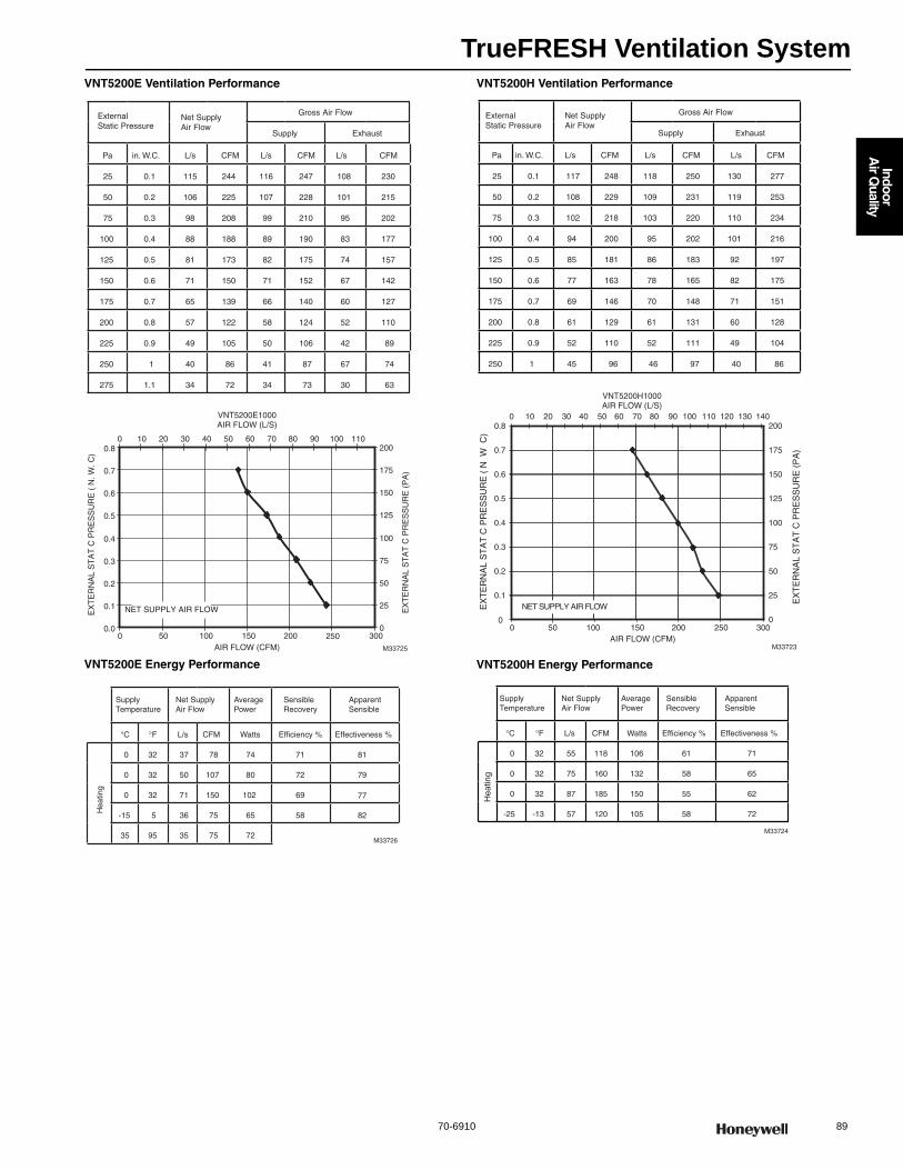
TrueFRESH Ventilation System
70-6910 89
Indoor
Air Q
uality
VNT5200E Ventilation Performance
VNT5200E Energy Performance
VNT5200H Ventilation Performance
VNT5200H Energy Performance
0.0
0.1
0.2
0.3
0.4
0.5
0.6
0.7
0.8
0 50 100 150 200 3000
25
50
75
100
125
150
175
2000 10 20 30 40 50 60 70 80 90 100 110
VNT5200E1000AIR FLOW (L/S)
NET SUPPLY AIR FLOW
AIR FLOW (CFM) M33725
250
ExternalStatic Pressure
Net SupplyAir Flow
Gross Air Flow
Supply Exhaust
Pa in. W.C. L/s CFM L/s CFM L/s CFM
25 0.1 115 244 116 247 108 230
50 0.2 106 225 107 228 101 215
75 0.3 98 208 99 210 95 202
100 0.4 88 188 89 190 83 177
125 0.5 81 173 82 175 74 157
150 0.6 71 150 71 152 67 142
175 0.7 65 139 66 140 60 127
200 0.8 57 122 58 124 52 110
225 0.9 49 105 50 106 42 89
250 1 40 86 41 87 67 74
275 1.1 34 72 34 73 30 63
EX
TE
RN
AL
ST
AT
C P
RE
SS
UR
E (
N. W
. C)
EX
TE
RN
AL
ST
AT
C P
RE
SS
UR
E (
PA
)
M33726
SupplyTemperature
Net SupplyAir Flow
AveragePower
SensibleRecovery
ApparentSensible
°C °F L/s CFM Watts Efficiency % Effectiveness %
Hea
ting
0 32 37 78 74 71 81
0 32 50 107 80 72 79
0 32 71 150 102 69 77
-15 5 36 75 65 58 82
35 95 35 75 72
VNT5200H1000AIR FLOW (L/S)
0
0.1
0.2
0.3
0.4
0.5
0.6
0.7
0.8
0 50 100 150 200 250 3000
25
50
75
100
125
150
175
200
EX
TE
RN
AL
ST
AT
C P
RE
SS
UR
E (
N W
C)
NET SUPPLY AIR FLOW
AIR FLOW (CFM)
EX
TE
RN
AL
ST
AT
C P
RE
SS
UR
E (
PA
)
M33723
ExternalStatic Pressure
Net SupplyAir Flow
Gross Air Flow
Supply Exhaust
Pa in. W.C. L/s CFM L/s CFM L/s CFM
25 0.1 117 248 118 250 130 277
50 0.2 108 229 109 231 119 253
75 0.3 102 218 103 220 110 234
100 0.4 94 200 95 202 101 216
125 0.5 85 181 86 183 92 197
150 0.6 77 163 78 165 82 175
175 0.7 69 146 70 148 71 151
200 0.8 61 129 61 131 60 128
225 0.9 52 110 52 111 49 104
250 1 45 96 46 97 40 86
0 10 20 30 40 50 60 70 80 90 100 110 120 130 140
M33724
SupplyTemperature
Net SupplyAir Flow
AveragePower
SensibleRecovery
ApparentSensible
°C °F L/s CFM Watts Efficiency % Effectiveness %
Hea
ting
0 32 55 118 106 61 71
0 32 75 160 132 58 65
0 32 87 185 150 55 62
-25 -13 57 120 105 58 72
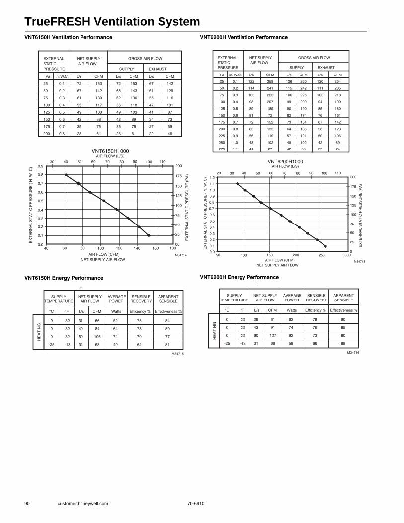
TrueFRESH Ventilation System
90 customer.honeywell.com 70-6910
VNT6150H Ventilation Performance
VNT6150H Energy Performance
VNT6200H Ventilation Performance
VNT6200H Energy Performance
EX
TE
RN
AL
ST
AT
C P
RE
SS
UR
E (
N W
C)
EX
TE
RN
AL
ST
AT
C P
RE
SS
UR
E (
PA
)
AIR FLOW (CFM) M34714
NET SUPPLY AIR FLOW
EXTERNAL NET SUPPLY GROSS AIR FLOWSTATIC AIR FLOW PRESSURE SUPPLY EXHAUST
Pa in. W.C. L/s CFM L/s CFM L/s CFM
25 0.1 72 153 72 153 67 142
50 0.2 67 142 68 143 61 129
75 0.3 61 130 62 130 55 116
100 0.4 55 117 55 118 47 101
125 0.5 49 103 49 103 41 87
150 0.6 42 88 42 89 34 73
175 0.7 35 75 35 75 27 59
200 0.8 28 61 28 61 22 46
0.0
0.1
0.2
0.3
0.4
0.6
0.7
0.9
0.8
60 80 120 180
25
50
75
100
125
150
175
20030 40 50 60 70 80 90 100 110
VNT6150H1000AIR FLOW (L/S)
16000
0.5
40 100 140
M34715
gy
SUPPLYTEMPERATURE
NET SUPPLYAIR FLOW
AVERAGEPOWER
SENSIBLERECOVERY
APPARENTSENSIBLE
°C °F L/s CFM Watts Efficiency % Effectiveness %
HE
AT
NG
0 32 31 66 52 75 84
0 32 40 84 64 73 80
0 32 50 106 74 70 77
-25 -13 32 68 49 62 81
EX
TE
RN
AL
ST
AT
C P
RE
SS
UR
E (
N. W
. C)
EX
TE
RN
AL
ST
AT
C P
RE
SS
UR
E (
PA
)
0.0
0.1
0.2
0.3
0.4
0.6
1.0
0.9
1.1
50 100 150 200 300
25
50
75
100
125
150
175
20020 30 40 50 60 70 80 90 100 110
VNT6200H1000AIR FLOW (L/S)
AIR FLOW (CFM) M34713
2500
0.5
NET SUPPLY AIR FLOW
0.7
0.8
1.2
EXTERNAL NET SUPPLY GROSS AIR FLOWSTATIC AIR FLOW PRESSURE SUPPLY EXHAUST
Pa in. W.C. L/s CFM L/s CFM L/s CFM
25 0.1 122 258 126 260 120 254
50 0.2 114 241 115 242 111 235
75 0.3 105 223 106 225 103 218
100 0.4 98 207 99 209 94 199
125 0.5 89 189 90 190 85 180
150 0.6 81 72 82 174 76 161
175 0.7 72 152 73 154 67 142
200 0.8 63 133 64 135 58 123
225 0.9 56 119 57 121 50 106
250 1.0 48 102 48 102 42 89
275 1.1 41 87 42 88 35 74
M34716
gy
SUPPLYTEMPERATURE
NET SUPPLYAIR FLOW
AVERAGEPOWER
SENSIBLERECOVERY
APPARENTSENSIBLE
°C °F L/s CFM Watts Efficiency % Effectiveness %
HE
AT
NG
0 32 29 61 62 78 90
0 32 43 91 74 76 85
0 32 60 127 92 73 80
-25 -13 31 66 59 66 88
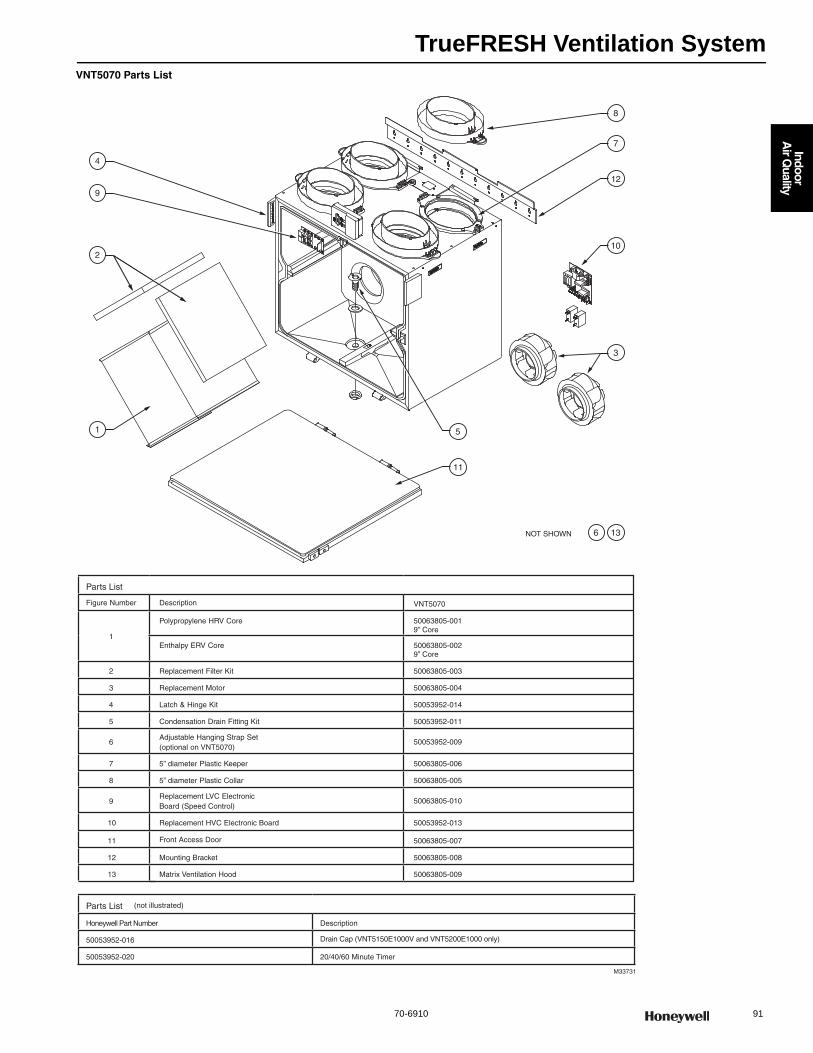
TrueFRESH Ventilation System
70-6910 91
Indoor
Air Q
uality
VNT5070 Parts List
M33731
Parts List
Figure Number Description VNT5070
1
Polypropylene HRV Core 50063805-0019” Core
Enthalpy ERV Core 50063805-0029” Core
2 Replacement Filter Kit 50063805-003
3 Replacement Motor 50063805-004
4 Latch & Hinge Kit 50053952-014
5 Condensation Drain Fitting Kit 50053952-011
6Adjustable Hanging Strap Set (optional on VNT5070)
50053952-009
7 5” diameter Plastic Keeper 50063805-006
8 5” diameter Plastic Collar 50063805-005
9Replacement LVC Electronic Board (Speed Control)
50063805-010
10 Replacement HVC Electronic Board 50053952-013
11 Front Access Door 50063805-007
12 Mounting Bracket 50063805-008
13 Matrix Ventilation Hood 50063805-009
Parts List (not illustrated)
Honeywell Part Number Description
50053952-016 Drain Cap (VNT5150E1000V and VNT5200E1000 only)
50053952-020 20/40/60 Minute Timer
NOT SHOWN
11
5
3
10
12
7
8
136
2
1
9
4

TrueFRESH Ventilation System
92 customer.honeywell.com 70-6910
VNT5150 and VNT5200 Parts List
M33729
Parts List
Figure Number Description VNT5150 VNT5200
1Polypropylene HRV Core 50053952-001 10” Core 50053952-002 15” Core
Enthalpy ERV Core 50053952-003 10” Core 50053952-004 15” Core
2 Replacement Filter Kit 50053952-005 50053952-006
3 Replacement Motor 5053952-010
4 Latch & Hinge Kit 50053952-014
5 Condensation Drain Fitting Kit 50053952-011
6 Adjustable Hanging Strap Set (optional on VNT5070) 50053952-009
7 6" diameter Plastic Keeper 50053952-008
8 6" diameter Plastic Double Collar 50053952-007
9 Replacement LVC Electronic Board (Speed Control) 50053952-012
10 Replacement HVC Electronic Board 50053952-013
11 Front Access Door 50053952-015
Parts List (not illustrated)
Honeywell Part Number Description
50053952-016 Drain Cap (VNT5150E1000V and VNT5200E1000 only)
50053952-020 20/40/60 Minute Timer
3 5
4
2
1
11
6
7
8
3
10
9
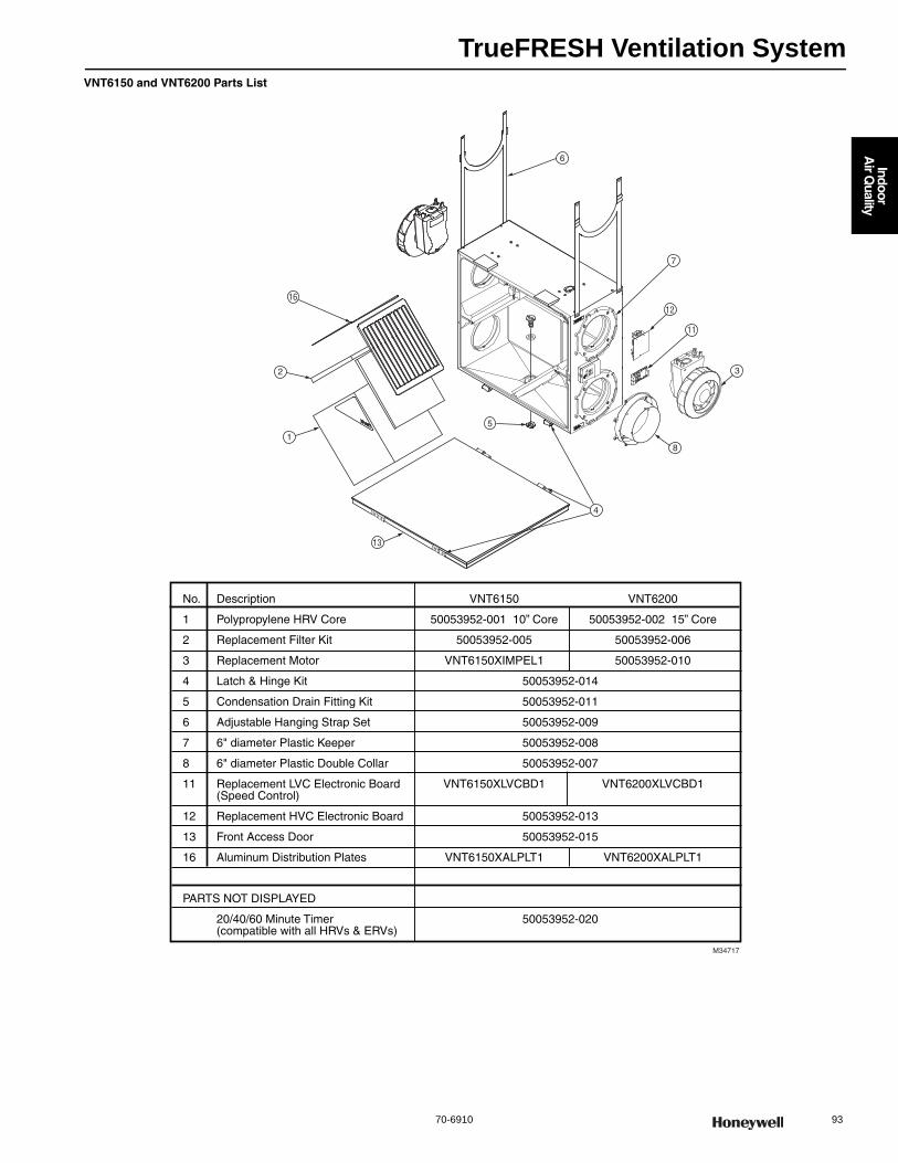
TrueFRESH Ventilation System
70-6910 93
Indoor
Air Q
uality
VNT6150 and VNT6200 Parts List
7
12
11
3
8
6
5
4
16
2
1
13
M34717
No. Description VNT6150 VNT6200
1 Polypropylene HRV Core 50053952-001 10” Core 50053952-002 15” Core
2 Replacement Filter Kit 50053952-005 50053952-006
3 Replacement Motor VNT6150XIMPEL1 50053952-010
4 Latch & Hinge Kit 50053952-014
5 Condensation Drain Fitting Kit 50053952-011
6 Adjustable Hanging Strap Set 50053952-009
7 6" diameter Plastic Keeper 50053952-008
8 6" diameter Plastic Double Collar 50053952-007
11 Replacement LVC Electronic Board VNT6150XLVCBD1 VNT6200XLVCBD1 (Speed Control)
12 Replacement HVC Electronic Board 50053952-013
13 Front Access Door 50053952-015
16 Aluminum Distribution Plates VNT6150XALPLT1 VNT6200XALPLT1
PARTS NOT DISPLAYED
20/40/60 Minute Timer 50053952-020 (compatible with all HRVs & ERVs)
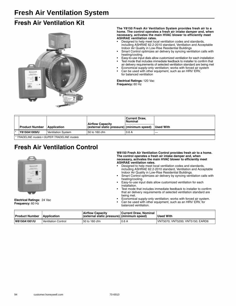
Fresh Air Ventilation System
94 customer.honeywell.com 70-6910
Fresh Air Ventilation KitThe Y8150 Fresh Air Ventilation System provides fresh air to a home. The control operates a fresh air intake damper and, when necessary, activates the main HVAC blower to efficiently meet ASHRAE ventilation rates.• Designed to help meet local ventilation codes and standards,
including ASHRAE 62.2-2010 standard, Ventilation and Acceptable Indoor Air Quality in Low-Rise Residential Buildings
• Smart Control optimizes air delivery by syncing ventilation calls with heating/cooling.
• Easy-to-use input dials allow customized ventilation for each installation • Test mode that includes immediate feedback to installer to confirm that
air delivery requirements of selected ventilation standard are being met • Economical supply-only ventilation; works with forced air system • Can be used with other equipment, such as an HRV/ ERV,
for balanced ventilation
Electrical Ratings: 120 VacFrequency: 60 Hz
Fresh Air Ventilation Control
Electrical Ratings: 24 VacFrequency: 60 Hz
W8150 Fresh Air Ventilation Control provides fresh air to a home. The control operates a fresh air intake damper and, when necessary, activates the main HVAC blower to efficiently meet ASHRAE ventilation rates. • Designed to help meet local ventilation codes and standards,
including ASHRAE 62.2-2010 standard, Ventilation and Acceptable Indoor Air Quality in Low-Rise Residential Buildings.
• Smart Control optimizes air delivery by syncing ventilation calls with heating/cooling.
• Easy-to-use input dials allow customized ventilation for each installation.
• Test mode that includes immediate feedback to installer to confirm that air delivery requirements of selected ventilation standard are being met.
• Economical supply-only ventilation; works with forced air system.• Can be used with other equipment, such as an HRV/ ERV, for
balanced ventilation.
Product Number ApplicationAirflow Capacity (external static pressure)
Current Draw, Nominal
Used With(minimum speed)
* Y8150A1009/U Ventilation System 50 to 160 cfm 0.6 A —
* TRADELINE models • SUPER TRADELINE models
Product Number ApplicationAirflow Capacity (external static pressure)
Current Draw, Nominal(minimum speed) Used With
W8150A1001/U Ventilation Control 50 to 160 cfm 0.6 A VNT5070; VNT5200; VNT5150; EARD6
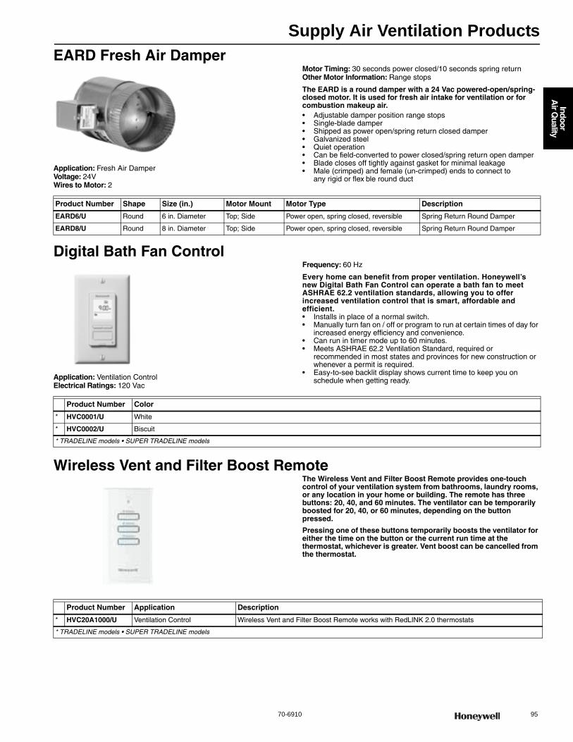
Supply Air Ventilation Products
70-6910 95
Indoor
Air Q
uality
EARD Fresh Air Damper
Application: Fresh Air DamperVoltage: 24VWires to Motor: 2
Motor Timing: 30 seconds power closed/10 seconds spring returnOther Motor Information: Range stops
The EARD is a round damper with a 24 Vac powered-open/spring-closed motor. It is used for fresh air intake for ventilation or for combustion makeup air.• Adjustable damper position range stops • Single-blade damper • Shipped as power open/spring return closed damper • Galvanized steel • Quiet operation • Can be field-converted to power closed/spring return open damper • Blade closes off tightly against gasket for minimal leakage • Male (crimped) and female (un-crimped) ends to connect to
any rigid or flex ble round duct
Digital Bath Fan Control
Application: Ventilation ControlElectrical Ratings: 120 Vac
Frequency: 60 Hz
Every home can benefit from proper ventilation. Honeywell’s new Digital Bath Fan Control can operate a bath fan to meet ASHRAE 62.2 ventilation standards, allowing you to offer increased ventilation control that is smart, affordable and efficient.• Installs in place of a normal switch. • Manually turn fan on / off or program to run at certain times of day for
increased energy efficiency and convenience. • Can run in timer mode up to 60 minutes. • Meets ASHRAE 62.2 Ventilation Standard, required or
recommended in most states and provinces for new construction or whenever a permit is required.
• Easy-to-see backlit display shows current time to keep you on schedule when getting ready.
Wireless Vent and Filter Boost RemoteThe Wireless Vent and Filter Boost Remote provides one-touch control of your ventilation system from bathrooms, laundry rooms, or any location in your home or building. The remote has three buttons: 20, 40, and 60 minutes. The ventilator can be temporarily boosted for 20, 40, or 60 minutes, depending on the button pressed.
Pressing one of these buttons temporarily boosts the ventilator for either the time on the button or the current run time at the thermostat, whichever is greater. Vent boost can be cancelled from the thermostat.
Product Number Shape Size (in.) Motor Mount Motor Type Description
EARD6/U Round 6 in. Diameter Top; Side Power open, spring closed, reversible Spring Return Round Damper
EARD8/U Round 8 in. Diameter Top; Side Power open, spring closed, reversible Spring Return Round Damper
Product Number Color
* HVC0001/U White
* HVC0002/U Biscuit
* TRADELINE models • SUPER TRADELINE models
Product Number Application Description
* HVC20A1000/U Ventilation Control Wireless Vent and Filter Boost Remote works with RedLINK 2.0 thermostats
* TRADELINE models • SUPER TRADELINE models
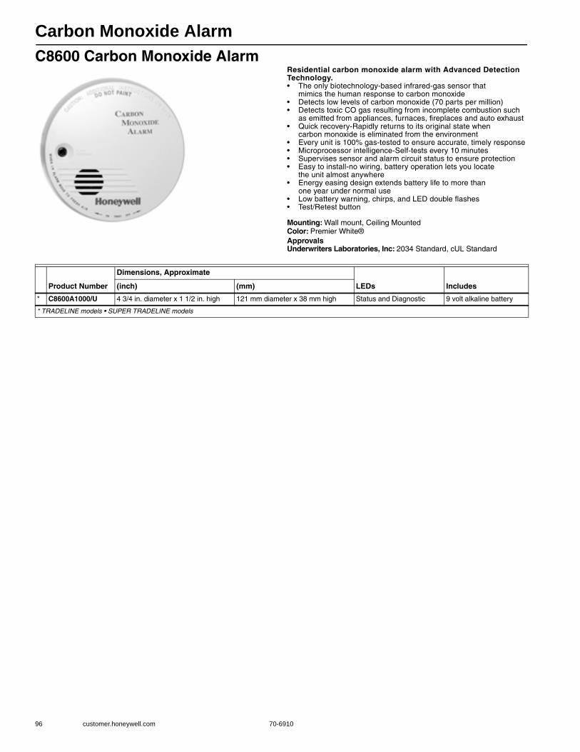
Carbon Monoxide Alarm
96 customer.honeywell.com 70-6910
C8600 Carbon Monoxide AlarmResidential carbon monoxide alarm with Advanced Detection Technology.• The only biotechnology-based infrared-gas sensor that
mimics the human response to carbon monoxide • Detects low levels of carbon monoxide (70 parts per million) • Detects toxic CO gas resulting from incomplete combustion such
as emitted from appliances, furnaces, fireplaces and auto exhaust • Quick recovery-Rapidly returns to its original state when
carbon monoxide is eliminated from the environment • Every unit is 100% gas-tested to ensure accurate, timely response • Microprocessor intelligence-Self-tests every 10 minutes • Supervises sensor and alarm circuit status to ensure protection • Easy to install-no wiring, battery operation lets you locate
the unit almost anywhere • Energy easing design extends battery life to more than
one year under normal use • Low battery warning, chirps, and LED double flashes • Test/Retest button
Mounting: Wall mount, Ceiling MountedColor: Premier White®ApprovalsUnderwriters Laboratories, Inc: 2034 Standard, cUL Standard
Product Number
Dimensions, Approximate
LEDs Includes(inch) (mm)
* C8600A1000/U 4 3/4 in. diameter x 1 1/2 in. high 121 mm diameter x 38 mm high Status and Diagnostic 9 volt alkaline battery
* TRADELINE models • SUPER TRADELINE models

Combination Gas Controls
70-6910 97
R
esidential C
ombustion C
ontrols
V400 Line Voltage; V800 Low Voltage Combination Gas ControlsUsed on gas fired standing pilot appliances with 30 mV thermocouple. These gas controls include a manual gas valve, safety shutoff, single millivoltage automatic operator, pressure regulator, pilot gas filter and flow adjustment, pressure tapping, and thermocouple connector. • Include pilot flow adjustment screw. • Easy to install, adjust and service; all adjustments and connections
are accessible from top of control. • Add separate energy cutoff (ECO) where codes call for dual safety
shutoff. • Complete safety shutoff on pilot flame failure. • LITE-RITE (OFF-PILOT-ON) lighting sequence. • ECO connector for V800 models. Part No. 392451-1.
Type: Single StageBody Pattern: Straight-through, multi-tapped with 1/2 in. right and left
outlets pluggedType of Gas: NaturalCapacity @ 1 in. p.d.
250,000 BTU/hr Nat Gas 1/2” x 3/4” Inlet x Outlet;335,000 BTU/hr Nat Gas 3/4” x 3/4” Inlet x Outlet
Ignition Type: Standing PilotPressure Ratings: 1/2 psi (3.5 kPa) Pressure Tapping: 1/8 in. NPT with plugAmbient Temperature Range: 32 F to 175 F (0 C to 79 C)Frequency: 60 HzPilot Gas Outlet: Compression fitting for 1/4 in. OD tubingMounting: 0 to 90 degrees in any direction from the upright position of
the gas control knob, including vertically.
ApprovalsUnderwriters Laboratories, Inc: UL Component Recognized.
MCCZ2.MH5323CSA International: 112395
Accessories:390427A-3/4 inch x 1/2 inch reducer bushing for valves390427B-1/2 inch x 3/8 inch reducer bushing for valves390427E-Two 3/4 in. NPT x 1/2 in. NPT reducer bushings390795-Remote gas cock knob and instruction sheet391936-LP to Natural Gas Conversion kit, including regulator spring,
O-ring, screw and cap391937-Natural Gas to LP Conversion kit, including regulator spring,
O-ring, screw and cap392451-1-ECO (energy cutoff) connector for 1/4 inch (6 mm) quick-
connect
Product NumberElectrical Ratings
Opening Character-istics (standard, step)
Inlet/Outlet Size (in.)
Pressure Regulator Setting
Includes(psi) (kPa)
V400A1095/U 120 Vac Standard 3/4 in. x 3/4 in.
3.5 in. wc 0.87 kPa Two 3/4 in. x 1/2 in.; One 1/2 x 3/8 in. Reducer Bushing/Adapters
V800A1070/U 24 Vac Standard 1/2 in. x 3/4 in.
3.5 in. wc 0.87 kPa One 1/2 in. x 3/8 in. reducer bushing; One 3/4 in. x 1/2 in. reducer bushing; Q340 Thermocouple; Natural to LP Conversion Kit
V800A1088/U 24 Vac Standard 3/4 in. x 3/4 in.
3.5 in. wc 0.87 kPa One 1/2 in. x 3/8 in. reducer bushing; Two 3/4 in. x 1/2 in. reducer bushings; Q340 Thermocouple; Natural to LP Conversion Kit
V800A1476/U 24 Vac Standard 1/2 in. x 3/4 in.
3.5 in. wc 0.87 kPa One 3/4 in. x 1/2 in. reducer bushing
V800A1591/U 24 Vac Standard 3/4 in. x 3/4 in.
3.5 in. wc 0.87 kPa Natural to LP Conversion Kit; Two 3/4 x 1/2 in. reducer bushings
V800C1052/U 24 Vac Step Opening 3/4 in. x 3/4 in.
Full Rate: 3.5 in. wc; Step Setting: 0.9 in. wc
Full Rate: 0.87 kPa; Step Setting: 0.22 kPa
Two 3/4 x 1/2 in.; One 1/2 x 3/8 in. Reducer Bushing/Adapters

Combination Gas Controls
98 customer.honeywell.com 70-6910
Dimensions in inches (millimeters)
Pressure Regulators–Standard and Step OpeningServo gas pressure regulator for add-on or replacement use on Honeywell V400,V800, VR400, VR800 and VR8440 Combination gas controls. Utilizing the servo principle of operation, it controls burner manifold pressure by repositioning the main valve diaphragm.• Interchangeable and adapt to all pipe sizes and capacities. • Mount on top surface of control. Installation and adjustment readily
accomplished with a screwdriver.
Mounting: Top surface of combination gas control (two mounting screws and a gasket).
Pressure Ratings: 1/2 psi (3.5 kPa) Temperature Range: -40 F to +175 F (-40 C to +79 C)
PILOT CONNECTION
COMP. FITTING
FOR 1/4 O.D. TUBING
PRESSURE
TAP 1/8 NPT
MOUNTING
HOLES (2)
NO. 10-32 X
.25 DEEP
3-3/4 (95)
SWING
RADIUS
3-3/4 (95)
SWING
RADIUS
5/16 (8)
3-1/2
(89)
1-1/4
(32)
4-3/4
(121)
5/16 (8)
5/16 (8)
2-9/16
(65)
4-1/16 (103)
3-3/16 (81)
1-7/16
(37)
1-3/16
(37)
1-7/8
(48)
WITH V5306 (ILLUSTRATED), V5307 OR 5390 PRESSURE REGULATOR: 24V MODELS–3-1/2 (89), 120V MODEL–3-5/8 (92)
MANUAL MODELS–2-13/16 (71), FOR V5308 ADD 5/8 (16) TO DIMENSIONS GIVEN.
SIDE OUTLETS–LEFT AND RIGHT HAND. STANDARD ONLY ON TRADELINE MODELS.
CONTROL WITH 24V VALVE OPERATOR SHOWN. LINE VOLT MODEL HAS COVER FOR CONDUIT CONNECTION (TOP SURFACE).
ECO CONNECTOR ON STANDARD CAPACITY V800 ONLY.
1
1
2
2
3
3
4
4
M16547A
Product Number Type of GasOpening Characteristics (standard, step) Pressure Regulator Setting
V5306B1009/U Natural Standard Opening 3.5 in. wc; adj. range 3-5 in. wc
V5306B1033/U LP Standard Opening 11.0 in. wc; adj. range 8-12 in. wc

Combination Gas Controls
70-6910 99
R
esidential C
ombustion C
ontrols
VS820 Millivoltage Combination Gas ControlsThese gas controls combine a Lite-Rite manual gas cock, safety shutoff Pilotstat assembly, millivoltage automatic valve operator, and optional gas pressure regulator. They require the use of a 750 mV Powerpile generator (thermopile). The generator, heated by the pilot burner flame, provides the electrical energy to operate the combination gas control. A millivoltage thermostat with suitable accessory controls completes the automatic control system for the heating appliance.• Include pilot flow adjustment screw. • Easy to install, adjust and service; all adjustments and connections
are accessible from top of control. • Add separate energy cutoff (ECO) where codes call for dual safety
shutoff. • Complete safety shutoff on pilot flame failure. • LITE-RITE (OFF-PILOT-ON) lighting sequence.
Application: Self-powered automatic control. Use with 750 mV pilot generator.
Dimensions, Approximate: 4 3/4 in. high x 4 1/16 in. wide x 3 3/16 in. deep (121 mm high x 103 mm wide x 81 mm deep)
Body Pattern: Straight-through. multi-tapped with 1/2 in. right and left outlets plugged, except as noted.
Capacity: 1/2 x 1/2 inlet x outlet: 225,000 BTU/hr 1 in. PD; 23,000 BTU/hr minimum; 225,000 BTU/hr maximum1/2 x 3/4 inlet x outlet: 250,000 BTU/hr 1 in. PD;23,000 BTU/hr minimum; 290,000 BTU/hr maximum3/4 x 3/4 inlet x outlet: 335,000 BTU/hr 1 in. PD;34,000 BTU/hr minimum; 425,000 BTU/hr maximum
Pressure Ratings: 1/2 psi (3.5 kPa) Pressure Tapping: 1/8 in. npt with plug.Temperature Range: 32 F to 175 F (0 C to 79 C) Electrical Ratings: 750 mVPilot Gas Outlet: Compression fitting for 1/4 in. OD tubing.
Electrical Connections: Terminal block has 3 combination screw and 1/4 in. quick connect terminals.
Mounting: 0 to 90 degrees in any direction from the upright position of the gas control knob, including vertically.
ApprovalsUnderwriters Laboratories, Inc: UL Component Recognized MH5323CSA International: 112395
Accessories:390427A-3/4 inch x 1/2 inch reducer bushing for valves390427B-1/2 inch x 3/8 inch reducer bushing for valves390427E-Two 3/4 in. NPT x 1/2 in. NPT reducer bushings390795-Remote gas cock knob and instruction sheet391936-LP to Natural Gas Conversion kit, including regulator spring,
O-ring, screw and cap391937-Natural Gas to LP Conversion kit, including regulator spring,
O-ring, screw and cap392451-1-ECO (energy cutoff) connector for 1/4 inch (6 mm) quick-
connects
Product NumberType of Gas
Pressure Regulator
Inlet/Outlet Size (in.)
Pressure Regulator Setting
Includes(psi) (kPa)
VS820A1047/U Natural Standard 1/2 in. x 3/4 in. NPT with 1/2 in. NPT side outlets
3.5 in. wc Reg. Set/3-5 in. Adj. Range
0.87 kPa One 3/4 in. x 1/2 in. reducer bushing; One 1/2 in. x 3/8 in. reducer bushing
VS820A1054/U Natural Standard 3/4 in. x 3/4 in. NPT with 1/2 in. NPT side outlets
3.5 in. wc Reg. Set/3-5 in. Adj. Range
0.87 kPa Two 3/4 in. x 1/2 in. reducer bushings; One 1/2 in. x 3/8 in. reducer bushing
VS820A1088/U Natural Standard 3/4 in. x 3/4 in. NPT with 1/2 in. NPT side outlets
3.5 in. wc Reg. Set/3-5 in. Adj. Range
0.87 kPa Remote Rod Adapter Knob; One Natural to LP Conversion Kit; Two 3/4 in. x 1/2 in. reducer bushings; One 1/2 in. x 3/8 in. reducer bushing
VS820A1336/U LP Standard 3/4 in. x 3/4 in. NPT with 1/2 in. NPT side outlets
10.0 in. wc Reg. Set/8-12 in. Adj. Range
2.49 kPa One 1/2 in. x 3/8 in. reducer bushing; Two 3/4 in. x 1/2 in. reducer bushings
VS820C1100/U Natural Step Opening
3/4 in. x 3/4 in. NPT with 1/2 in. NPT side outlets
Step: 0.9 in. wc non-adjustable; Full rate: 3.5 in. wc, 3-5 in. adjustable
Step: 0.22 kPa; Full rate: 0.87 kPa
One 1/2 in. x 3/8 in. reducer bushing; Two 3/4 in. x 1/2 in. reducer bushings
U VS820M1309/U Natural Standard 3/4 in. x 3/4 in. NPT with 1/2 in. NPT side outlets
3.5 in. wc 0.87 kPa Remote Rod Adapter knob; Natural to LP Gas Conversion Kit; Two 3/4 in. to 1/2 in. reducer bushings; One 1/2 in. x 3/8 in. reducer bushing
U Universal Service Part

Combination Gas Controls
100 customer.honeywell.com 70-6910
VR8200 Continuous Pilot Dual Automatic Valve Combination Gas Controls
Combination gas controls for use in 24 Vac, gas-fired, standing pilot appliances with capacities from 20 to 200 cfh.• Controls include manual valve, two automatic operators, servo
pressure regulator and pilot adjustment. • Compact size. • Provide two automatic valves. • Solenoid-operated first automatic valve opens on thermostat call for
heat; closes when call for heat ends. • Diaphragm-operated second automatic valve opens under control of
regulator; closes if gas or power supply is interrupted. • Meet codes requiring dual safety shutoff. • Natural to LP and LP to Natural conversion kits available for standard
and slow opening gas valves. • LITE-RITE (OFF-PILOT-ON) lighting sequence. • All adjustments, wiring connections and pilot outlet are accessible
from top of control. • Adjustable servo regulator effectively maintains almost constant gas
output pressure under wide fluctuations in gas supply pressure. • Compat ble with ECO connector.
Type: Single StageBody Pattern: Straight-throughType of Gas: NaturalCapacity: 130,000 BTU/hr 1 in. PD; 20,000 BTU/hr minimum
200,000 BTU/hr maximumAnticipator Setting: 0.5 AIgnition Type: Standing PilotPressure Ratings: 1/2 psi (3.5 kPa) Pressure Tapping: 1/8 in. NPT with plugAmbient Temperature Range: 0 F to 175 F (-18 C to +79 C)Electrical Ratings: 24 VacFrequency: 60 HzPilot Gas Outlet: Compression fitting for 1/4 in. OD tubingElectrical Connections: Combination screw and 1/4 in. male quick
connects.Mounting: 0 to 90 degrees in any direction from the upright position of
the gas control knob, including vertically.ApprovalsAustralian Gas Association: 4717CSA International: 112395Underwriters Laboratories, Inc: UL Component Recognized
MCCZ2.MH5323.
Accessories:390427A-3/4 inch x 1/2 inch reducer bushing for valves390427B-1/2 inch x 3/8 inch reducer bushing for valves390427E-Two 3/4 in. NPT x 1/2 in. NPT reducer bushings392877-1/4 inch barbed vent fitting393200-1-ECO connector bag assembly, includes ECO adapter with 1/4
inch (6 mm) quick-connects393690-4-Flange Kit bag assembly, includes 3/4 in. straight flange,
O-ring, and hex screws.393690-13-Flange Kit bag assembly, includes 1/2 inch angle flange,
O-ring, 9/64 inch hex screws and 9/64 inch hex wrench393690-15-Flange Kit bag assembly, includes 3/4 inch angle flange,
O-ring, 9/64 inch hex screws and 9/64 inch hex wrench393691-Single Stage Natural Gas to LP Conversion kit, including
regulator spring, screw and cap394588-Single Stage LP to Natural Gas Conversion kit, including
regulator spring, screw and cap395253-1-Single Stage Natural Conversion kit (5 in. wc to 7 in. wc
adjustable).
Product Number
Opening Characteristics (standard, step)
Inlet/Outlet Size (in.)
Pressure Regulator Setting
Includes(psi) (kPa)
VR8200A2124/U Standard 1/2 in. x 1/2 in. 3.5 in. wc 0.87 kPa One 3/4 in. straight flange; One 1/2 in. x 3/8 in. reducer bushing; Q340 Thermocouple; Natural to LP Conversion Kit
VR8200A2132/U Standard 1/2 in. x 1/2 in. 3.5 in. wc 0.87 kPa One 3/4 in. straight flange; One 1/2 in. x 3/8 in. reducer bushing; Natural to LP Conversion Kit
VR8200A2744/U Standard 1/2 in. x 1/2 in. 3.5 in. wc 0.87 kPa One 1/2 in. x 3/8 in. reducer bushing; One 3/4 in. straight flange with O-ring screws and wrench, Natural to LP gas conversion kit; One 3/4 in. angle flange
VR8200H1251/U Slow Opening 1/2 in. x 1/2 in. 3.5 in. wc 0.87 kPa One 3/4 in. straight flange; One 1/2 in. x 3/8 in. reducer bushing; Natural to LP Conversion Kit
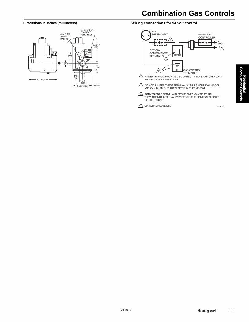
Combination Gas Controls
70-6910 101
R
esidential C
ombustion C
ontrols
Dimensions in inches (millimeters) Wiring connections for 24 volt control
M7495A
1 (25)
4 in. (102)
SWING
RADIUS
1/4 in. QUICK-
CONNECT
TERMINALS
1 (25)
(13)
(13)
PV
PV/MVMV
4-1/16 (104)
1/2
1/2
2-11/16 (69)
3-15/16(99)
1-7/16(36)
L1 (HOT)
L21
24VTHERMOSTAT
OPTIONALCONVENIENCETERMINALS TH/TR
TH
TR GAS CONTROLTERMINALS
HIGH LIMITCONTROLLER
POWER SUPPLY. PROVIDE DISCONNECT MEANS AND OVERLOADPROTECTION AS REQUIRED.
DO NOT JUMPER THESE TERMINALS. THIS SHORTS VALVE COILAND CAN BURN OUT ANTICIPATOR IN THERMOSTAT.
CONVENIENCE TERMINALS SERVE ONLY AS A TIE POINT. THEY ARE NOT INTERNALLY WIRED TO THE CONTROL CIRCUIT OR TO GROUND.
OPTIONAL HIGH LIMIT.
1
2
3
4
2
3
4
M2915C

Combination Gas Controls
102 customer.honeywell.com 70-6910
VR4300 Line Voltage; VR8300 Low Voltage Standing Pilot Dual Automatic Valve Combination Gas Control
Combination gas control for use in 24 Vac, 120 Vac, gas-fired, standing pilot appliances with capacities from 30 to 300 cfh.• Control includes safety shutoff, manual valve, two automatic
operators, pressure regulator and pilot adjustment. • Compact size. • Provides two automatic valves. • Solenoid operated first automatic valve opens on thermostat call for
heat, closes when call for heat ends. • Diaphragm-operated second automatic valve opens under control of
regulator; closes if gas or power supply is interrupted. • Meets codes requiring dual safety shut-off. • Natural to LP and LP to Natural conversion kits available for standard
and slow opening gas valves. • All adjustments, wiring connections and pilot outlet are accessible
from top of control. • Adjustable servo regulator effectively maintains almost constant gas
output pressure under wide fluctuations in gas supply pressure. • Compat ble with ECO connector. • LITE-RITE (OFF-PILOT-ON) lighting sequence.
Type: Single StageBody Pattern VR4300 : Straight-through with flange VR8300: Straight through with integral tapping; with flangeType of Gas: NaturalCapacity 1/2 x 3/4 inlet x outlet: 190,000 BTU/hr 1 in. PD;
30,000 BTU/hr minimum; 290,000 BTU/hr maximum 3/4 x 3/4 inlet x outlet: 200,000 BTU/hr 1 in. PD;
30,000 BTU/hr minimum; 300,000 BTU/hr maximumIgnition Type: Standing PilotPressure Ratings: 1/2 psi (3.5 kPa) Pressure Tapping: 1/8 in. NPT with plugAmbient Temperature Range: 0 F to 175 F (-18 C to +79 C)Pilot Gas Outlet: Compression fitting for 1/4 in. OD tubingElectrical Connections 24 Vac models: 1/4 in. male quick connects 120 Vac models: 21 in. leadwiresMounting: 0 to 90 degrees in any direction from the upright position of
the gas control knob, including vertically.
ApprovalsAustralian Gas Association: 4717CSA International: 112395Underwriters Laboratories, Inc: UL Component Recognized
MCCZ2.MH5323.
Accessories:390427A-3/4 inch x 1/2 inch reducer bushing for valves390427B-1/2 inch x 3/8 inch reducer bushing for valves390427E-Two 3/4 in. NPT x 1/2 in. NPT reducer bushings392877-1/4 inch barbed vent fitting393200-1-ECO connector bag assembly, includes ECO adapter with 1/4
inch (6 mm) quick-connects393690-4-Flange Kit bag assembly, includes 3/4 in. straight flange,
O-ring, and hex screws.393690-13-Flange Kit bag assembly, includes 1/2 inch angle flange,
O-ring, 9/64 inch hex screws and 9/64 inch hex wrench393690-15-Flange Kit bag assembly, includes 3/4 inch angle flange,
O-ring, 9/64 inch hex screws and 9/64 inch hex wrench393691-Single Stage Natural Gas to LP Conversion kit, including
regulator spring, screw and cap394588-Single Stage LP to Natural Gas Conversion kit, including
regulator spring, screw and cap395253-1-Single Stage Natural Conversion kit (5 in. wc to 7 in. wc
adjustable).
Product NumberElectrical Ratings
Opening Character-istics (standard, step) Frequency
Anticipator Setting
Inlet/Outlet Size (in.)
Pressure Regulator Setting
Includes(psi) (kPa)
VR4300A4502/U 120 Vac Standard 60 Hz 0.13 A 3/4 in. straight flange x 3/4 in.
3.5 in. wc 0.87 kPa One 1/2 in. x 3/8 in. reducer bushing; Two 3/4 x 1/2 in. reducer bushings; Natural to LP gas conversion kit.
VR8300A3500/U 24 Vac Standard 60 Hz 0.7 A 1/2 in. x 3/4 in. 3.5 in. wc 0.87 kPa One 3/4 x 1/2 in. reducer bushing; Natural to LP gas conversion kit.
VR8300A3518/U 24 Vac Standard 60 Hz 0.7 A 1/2 in. x 3/4 in. 3.5 in. wc 0.87 kPa One 3/4 x 1/2 in. reducer bushing 3/4 in. straight flange; ECO adapter; Q340 thermocouple with adapters; Natural to LP gas conversion kit.
VR8300A4508/U 24 Vac Standard 60 Hz 0.7 A 3/4 in. straight flange x 3/4 in.
3.5 in. wc 0.87 kPa Two 3/4 x 1/2 in. reducer bushings; Natural to LP gas conversion kit.
VR8300A4516/U 24 Vac Standard 60 Hz 0.7 A 3/4 in. straight flange x 3/4 in.
3.5 in. wc 0.87 kPa Two 3/4 x 1/2 in. reducer bushing; ECO adapter; Q340 thermocouple with adapters; Natural to LP gas conversion kit.
VR8300C4506/U 24 Vac Step Opening
60 Hz 0.7 A 3/4 in. straight flange x 3/4 in.
Full Rate: 3.5 in. wc; Step Setting: 0.9 in. wc
Full Rate: 0.87 kPa; Step Setting: 0.22 kPa
Two 3/4 x 1/2 in. reducer bushings
U Universal Service Part

Combination Gas Controls
70-6910 103
R
esidential C
ombustion C
ontrols
Dimensions in inches (millimeters) Wiring connections for 24 volt control
Wiring connections for 120 volt control
VR8300H4501/U 24 Vac Slow Opening
60 Hz 0.7 A 3/4 in. straight flange x 3/4 in.
3.5 in. wc 0.87 kPa —
U VR8300M4406/U 24 Vac Standard 50 Hz; 60 Hz
0.7 A 3/4 in. x 3/4 in. 3.5 in. wc 0.87 kPa Q340 thermocouple; Two 3/4 in. to 1/2 in. reducer bushings; One natural to LP conversion kit
Product NumberElectrical Ratings
Opening Character-istics (standard, step) Frequency
Anticipator Setting
Inlet/Outlet Size (in.)
Pressure Regulator Setting
Includes(psi) (kPa)
U Universal Service Part
3-15/16
(99)
1-7/16
(36)
2-3/16
(56)
2-11/16 (69)
4-1/16 (104)
4 IN. (102) MAX
SWING RADIUS
(FOR FLANGE
MOUNTING)
8-32 TAPPED (4)
M23233
1/4 INCH QUICK-CONNECT TERMINALS
1 (25)
1 (25) 1/2(13)
1
(25)
1/2(13)
THTR
1
1
2
FLANGE FACTORY MOUNTED ON 3/4 X 3/4 INCH
MODELS ONLY.
STEP-OPEN MODELS ONLY.
2
L1
(HOT)
L21
24V
THERMOSTAT
OPTIONAL
CONVENIENCE
TERMINALSTH/TR
TH
TR GAS CONTROL
TERMINALS
HIGH LIMIT
CONTROLLER
POWER SUPPLY. PROVIDE DISCONNECT MEANS AND OVERLOAD
PROTECTION AS REQUIRED.
DO NOT JUMPER THESE TERMINALS. THIS SHORTS VALVE COIL
AND CAN BURN OUT ANTICIPATOR IN THERMOSTAT.
CONVENIENCE TERMINALS SERVE ONLY AS A TIE POINT.
THEY ARE NOT INTERNALLY WIRED TO THE CONTROL CIRCUIT
OR TO GROUND.
OPTIONAL HIGH LIMIT.
1
2
3
4
2
3
4
M2915A
120V
THERMOSTAT
POWER SUPPLY. PROVIDE DISCONNECT MEANS
AND OVERLOAD PROTECTION AS REQUIRED.
DO NOT JUMPER THESE TERMINALS. THIS
SHORTS VALVE COIL AND MAY BURN OUT
ANTICIPATOR IN THERMOSTAT.
OPTIONAL HIGH LIMIT.
L1
(HOT)
L2
HIGH LIMIT
CONTROLLER
M3092B
GAS CONTROL
TERMINALS
L2
L1
1
1
2
2
3
3
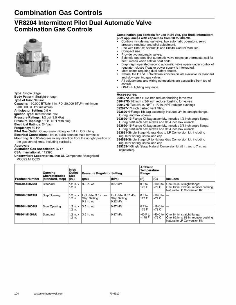
Combination Gas Controls
104 customer.honeywell.com 70-6910
VR8204 Intermittent Pilot Dual Automatic Valve Combination Gas Controls
Combination gas controls for use in 24 Vac, gas-fired, intermittent pilot appliances with capacities from 20 to 200 cfh.• Controls include manual valve, two automatic operators, servo
pressure regulator and pilot adjustment. • Use with S86F,H; S8600F,H and S8610 Control Modules. • Compact size. • Provide two automatic valves. • Solenoid operated first automatic valve opens on thermostat call for
heat; closes when call for heat ends. • Diaphragm operated second automatic valve opens under control of
regulator; closes if gas or power supply is interrupted. • Meet codes requiring dual safety shutoff. • Natural to LP and LP to Natural conversion kits available for standard
and slow opening gas valves. • All adjustments and wiring connections are accessible from top of
control. • ON-OFF lighting sequence.
Type: Single StageBody Pattern: Straight-throughType of Gas: NaturalCapacity: 150,000 BTU/hr 1 in. PD; 20,000 BTU/hr minimum
200,000 BTU/hr maximumAnticipator Setting: 0.5 AIgnition Type: Intermittent PilotPressure Ratings: 1/2 psi (3.5 kPa) Pressure Tapping: 1/8 in. NPT with plugElectrical Ratings: 24 VacFrequency: 60 HzPilot Gas Outlet: Compression fitting for 1/4 in. OD tubingElectrical Connections: 1/4 in. quick-connect male terminalsMounting: 0 to 90 degrees in any direction from the upright position of
the gas control knob, including vertically.ApprovalsAustralian Gas Association: 4717CSA International: 112395Underwriters Laboratories, Inc: UL Component Recognized
MCCZ2.MH5323.
Accessories:390427A-3/4 inch x 1/2 inch reducer bushing for valves390427B-1/2 inch x 3/8 inch reducer bushing for valves390427E-Two 3/4 in. NPT x 1/2 in. NPT reducer bushings392877-1/4 inch barbed vent fitting393690-4-Flange Kit bag assembly, includes 3/4 in. straight flange,
O-ring, and hex screws.393690-13-Flange Kit bag assembly, includes 1/2 inch angle flange,
O-ring, 9/64 inch hex screws and 9/64 inch hex wrench393690-15-Flange Kit bag assembly, includes 3/4 inch angle flange,
O-ring, 9/64 inch hex screws and 9/64 inch hex wrench393691-Single Stage Natural Gas to LP Conversion kit, including
regulator spring, screw and cap394588-Single Stage LP to Natural Gas Conversion kit, including
regulator spring, screw and cap395253-1-Single Stage Natural Conversion kit (5 in. wc to 7 in. wc
adjustable).
Product Number
Opening Characteristics (standard, step)
Inlet/Outlet Size (in.)
Pressure Regulator Setting
Ambient Temperature Range
Includes(psi) (kPa) (F) (C)
VR8204A2076/U Standard 1/2 in. x 1/2 in.
3.5 in. wc 0.87 kPa 0 F to 175 F
-18 C to +79 C
One 3/4 in. straight flange; One 1/2 in. x 3/8 in. reducer bushing; Natural to LP Conversion Kit
VR8204C1019/U Step Opening 1/2 in. x 1/2 in.
Full Rate: 3.5 in. wc; Step Setting: 0.9 in. wc
Full Rate: 0.87 kPa; Step Setting: 0.22 kPa
0 F to 175 F
-18 C to +79 C
—
VR8204H1006/U Slow Opening 1/2 in. x 1/2 in.
3.5 in. wc 0.87 kPa 0 F to 175 F
-18 C to +79 C
—
VR8204M1091/U Standard 1/2 in. x 1/2 in.
3.5 in. wc 0.87 kPa -40 F to +175 F
-40 C to +79 C
One 3/4 in. straight flange; One 1/2 in. x 3/8 in. reducer bushing; Natural to LP Conversion Kit
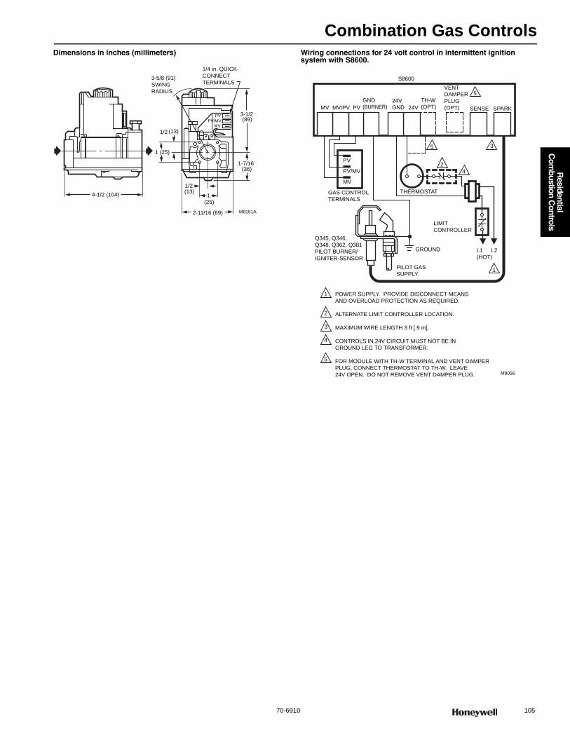
Combination Gas Controls
70-6910 105
R
esidential C
ombustion C
ontrols
Dimensions in inches (millimeters) Wiring connections for 24 volt control in intermittent ignition system with S8600.
M8151A
3-1/2
1-7/16
2-11/16 (69)
1
(25)
1/2(13)
3-5/8 (91)
SWING
RADIUS
1/4 in. QUICK-
CONNECT
TERMINALS
1 (25)
1/2 (13)
4-1/2 (104)
PV
PV/MVMV
(36)
(89)
MV MV/PV PV
GND
(BURNER)24V
GND 24V SPARK
S8600
POWER SUPPLY. PROVIDE DISCONNECT MEANS
AND OVERLOAD PROTECTION AS REQUIRED.
ALTERNATE LIMIT CONTROLLER LOCATION.
MAXIMUM WIRE LENGTH 3 ft [.9 m].
CONTROLS IN 24V CIRCUIT MUST NOT BE IN
GROUND LEG TO TRANSFORMER.
FOR MODULE WITH TH-W TERMINAL AND VENT DAMPER
PLUG, CONNECT THERMOSTAT TO TH-W. LEAVE
24V OPEN. DO NOT REMOVE VENT DAMPER PLUG.
1
2
3
4
5
M9056
GROUND
PILOT GAS
SUPPLY
2
4
3
Q345, Q346,
Q348, Q362, Q381
PILOT BURNER/
IGNITER-SENSOR
L1
(HOT)
1
L2
LIMIT
CONTROLLER
THERMOSTAT
5
TH-W
(OPT)
VENT
DAMPER
PLUG
(OPT)
5
GAS CONTROL
TERMINALS
PV
PV/MV
MV
SENSE
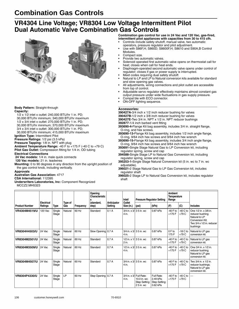
Combination Gas Controls
106 customer.honeywell.com 70-6910
VR4304 Line Voltage; VR8304 Low Voltage Intermittent PilotDual Automatic Valve Combination Gas Controls
Combination gas control for use in 24 Vac and 120 Vac, gas-fired, intermittent pilot appliances with capacities from 30 to 415 cfh.• Controls include safety shutoff, manual valve, two automatic
operators, pressure regulator and pilot adjustment. • Use with S86F,H; S860D; S8600F,H; S8610 and S90A,B Control
Modules. • Compact size. • Provide two automatic valves. • Solenoid operated first automatic valve opens on thermostat call for
heat; closes when call for heat ends. • Diaphragm-operated second automatic valve opens under control of
regulator; closes if gas or power supply is interrupted. • Meet codes requiring dual safety shutoff. • Natural to LP and LP to Natural conversion kits available for standard
and slow opening gas valves. • All adjustments, wiring connections and pilot outlet are accessible
from top of control. • Adjustable servo regulator effectively maintains almost constant gas
output pressure under wide fluctuations in gas supply pressure. • Compat ble with ECO connector. • ON-OFF lighting sequence.
Body Pattern: Straight-throughCapacity:
1/2 x 1/2 inlet x outlet: 240,000 BTU/hr 1 in. PD; 30,000 BTU/hr minimum; 340,000 BTU/hr maximum1/2 x 3/4 inlet x outlet: 270,000 BTU/hr 1 in. PD;30,000 BTU/hr minimum; 370,000 BTU/hr maximum3/4 x 3/4 inlet x outlet: 300,000 BTU/hr 1 in. PD;30,000 BTU/hr minimum; 415,000 BTU/hr maximum
Ignition Type: Intermittent PilotPressure Ratings: 1/2 psi (3.5 kPa) Pressure Tapping: 1/8 in. NPT with plugAmbient Temperature Range: -40 F to +175 F (-40 C to +79 C)Pilot Gas Outlet: Compression fitting for 1/4 in. OD tubingElectrical Connections 24 Vac models: 1/4 in. male quick connects 120 Vac models: 21 in. leadwiresMounting: 0 to 90 degrees in any direction from the upright position of
the gas control knob, including vertically.ApprovalsAustralian Gas Association: 4717CSA International: 112395Underwriters Laboratories, Inc: Component Recognized
MCCZ2.MH5323
Accessories:390427A-3/4 inch x 1/2 inch reducer bushing for valves390427B-1/2 inch x 3/8 inch reducer bushing for valves390427E-Two 3/4 in. NPT x 1/2 in. NPT reducer bushings392877-1/4 inch barbed vent fitting393690-4-Flange Kit bag assembly, includes 3/4 in. straight flange,
O-ring, and hex screws.393690-13-Flange Kit bag assembly, includes 1/2 inch angle flange,
O-ring, 9/64 inch hex screws and 9/64 inch hex wrench393690-15-Flange Kit bag assembly, includes 3/4 inch angle flange,
O-ring, 9/64 inch hex screws and 9/64 inch hex wrench393691-Single Stage Natural Gas to LP Conversion kit, including
regulator spring, screw and cap394588-Single Stage LP to Natural Gas Conversion kit, including
regulator spring, screw and cap395253-1-Single Stage Natural Conversion kit (5 in. wc to 7 in. wc
adjustable). 396021-2 Stage Natural Gas to LP Gas Conversion kit, includes
regulator shaft396025-2 Stage LP to Natural Gas Conversion kit, includes regulator
shaft
Product NumberElectrical Ratings Type
Type of Gas Frequency
Opening Characteristics (standard, step)
Anticipator Setting
Inlet/Outlet Size (in.)
Pressure Regulator Setting
Ambient Temperature Range
Includes(psi) (kPa) (F) (C)
VR4304M4519/U 120 Vac Single Stage
Natural 60 Hz Standard 0.1 A 3/4 in. x 3/4 in.
3 5 in. wc 0.87 kPa -40 F to +175 F
-40 C to +79 C
One 1/2 in. x 3/8 in. reducer bushing; Natural to LP Conversion Kit; Two 3/4 x 1/2 in. reducer bushings
VR8304H4503/U 24 Vac Single Stage
Natural 60 Hz Slow Opening 0.7 A 3/4 in. x 3/4 in.
3 5 in. wc 0.87 kPa 0 F to 175 F
-18 C to +79 C
Natural to LP gas conversion kit.
VR8304M2501/U 24 Vac Single Stage
Natural 60 Hz Standard 0.7 A 1/2 in. x 1/2 in.
3 5 in. wc 0.87 kPa -40 F to +175 F
-40 C to +79 C
Natural to LP gas conversion kit.
VR8304M3509/U 24 Vac Single Stage
Natural 60 Hz Standard 0.7 A 1/2 in. x 3/4 in.
3 5 in. wc 0.87 kPa -40 F to +175 F
-40 C to +79 C
One 3/4 in. x 1/2 in. reducer bushing; Natural to LP gas conversion kit.
VR8304M4507/U 24 Vac Single Stage
Natural 60 Hz Standard 0.7 A 3/4 in. x 3/4 in.
3 5 in. wc 0.87 kPa -40 F to +175 F
-40 C to +79 C
Two 3/4 in. x 1/2 in. reducer bushings; Natural to LP gas conversion kit.
VR8304P4330/U 24 Vac Single Stage
LP 60 Hz Step Opening 0.7 A 3/4 in. x 3/4 in.
Full Rate:10.0 in. wc; Step Setting: 2 5 in. wc
Full Rate:2.49 kPa;Step Setting: 0.62 kPa
-40 F to +175 F
-40 C to +79 C
—
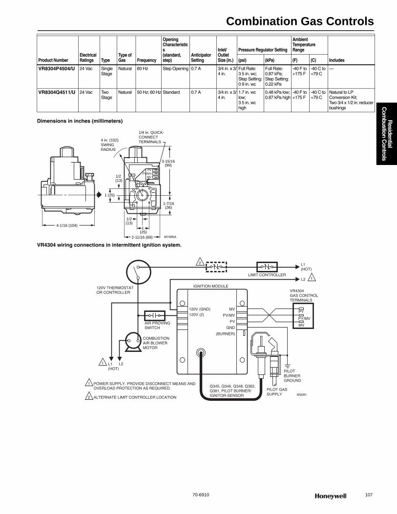
Combination Gas Controls
70-6910 107
R
esidential C
ombustion C
ontrols
Dimensions in inches (millimeters)
VR4304 wiring connections in intermittent ignition system.
VR8304P4504/U 24 Vac Single Stage
Natural 60 Hz Step Opening 0.7 A 3/4 in. x 3/4 in.
Full Rate: 3 5 in. wc; Step Setting: 0 9 in. wc
Full Rate: 0.87 kPa; Step Setting: 0.22 kPa
-40 F to +175 F
-40 C to +79 C
—
VR8304Q4511/U 24 Vac Two Stage
Natural 50 Hz; 60 Hz Standard 0.7 A 3/4 in. x 3/4 in.
1.7 in. wc low;3 5 in. wc high
0.48 kPa low;0.87 kPa high
-40 F to +175 F
-40 C to +79 C
Natural to LP Conversion Kit; Two 3/4 x 1/2 in. reducer bushings
Product NumberElectrical Ratings Type
Type of Gas Frequency
Opening Characteristics (standard, step)
Anticipator Setting
Inlet/Outlet Size (in.)
Pressure Regulator Setting
Ambient Temperature Range
Includes(psi) (kPa) (F) (C)
M7495A
1 (25)
4 in. (102)
SWING
RADIUS
1/4 in. QUICK-
CONNECT
TERMINALS
1 (25)
(13)
(13)
PV
PV/MVMV
4-1/16 (104)
1/2
1/2
2-11/16 (69)
3-15/16(99)
1-7/16(36)
PY
PY/MV
MV
120V THERMOSTATOR CONTROLLER
AIR PROVINGSWITCH
COMBUSTIONAIR BLOWERMOTOR
L1(HOT)
L2
IGNITION MODULE
LIMIT CONTROLLER
L1(HOT)
L2
VR4304GAS CONTROLTERMINALS
PILOTBURNERGROUND
PILOT GASSUPPLY
Q345, Q346, Q348, Q362,Q381, PILOT BURNER/IGNITOR-SENSOR
120V (GND)120V (2)
MV
PV/MV
PV
GND
(BURNER)
POWER SUPPLY. PROVIDE DISCONNECT MEANS AND OVERLOAD PROTECTION AS REQUIRED.
ALTERNATE LIMIT CONTROLLER LOCATION
1
1
1
2
2
M3091
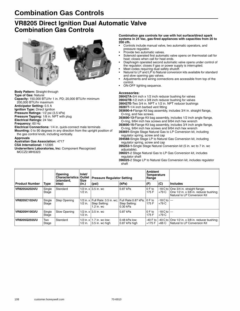
Combination Gas Controls
108 customer.honeywell.com 70-6910
VR8205 Direct Ignition Dual Automatic Valve Combination Gas Controls
Combination gas controls for use with hot surface/direct spark systems in 24 Vac, gas-fired appliances with capacities from 20 to 200 cfh.• Controls include manual valve, two automatic operators, and
pressure regulator. • Provide two automatic valves. • Solenoid operated first automatic valve opens on thermostat call for
heat; closes when call for heat ends. • Diaphragm operated second automatic valve opens under control of
the regulator; closes if gas or power supply is interrupted. • Meet codes requiring dual safety shutoff. • Natural to LP and LP to Natural conversion kits available for standard
and slow opening gas valves. • Adjustments and wiring connections are accessible from top of the
control. • ON-OFF lighting sequence.
Body Pattern: Straight-throughType of Gas: NaturalCapacity: 150,000 BTU/hr 1 in. PD; 20,000 BTU/hr minimum
200,000 BTU/hr maximumAnticipator Setting: 0.5 AIgnition Type: Direct IgnitionPressure Ratings: 1/2 psi (3.5 kPa) Pressure Tapping: 1/8 in. NPT with plugElectrical Ratings: 24 VacFrequency: 60 HzElectrical Connections: 1/4 in. quick-connect male terminalsMounting: 0 to 90 degrees in any direction from the upright position of
the gas control knob, including vertically.ApprovalsAustralian Gas Association: 4717CSA International: 112395Underwriters Laboratories, Inc: Component Recognized
MCCZ2.MH5323
Accessories:390427A-3/4 inch x 1/2 inch reducer bushing for valves390427B-1/2 inch x 3/8 inch reducer bushing for valves390427E-Two 3/4 in. NPT x 1/2 in. NPT reducer bushings392877-1/4 inch barbed vent fitting393690-4-Flange Kit bag assembly, includes 3/4 in. straight flange,
O-ring, and hex screws.393690-13-Flange Kit bag assembly, includes 1/2 inch angle flange,
O-ring, 9/64 inch hex screws and 9/64 inch hex wrench393690-15-Flange Kit bag assembly, includes 3/4 inch angle flange,
O-ring, 9/64 inch hex screws and 9/64 inch hex wrench393691-Single Stage Natural Gas to LP Conversion kit, including
regulator spring, screw and cap394588-Single Stage LP to Natural Gas Conversion kit, including
regulator spring, screw and cap395253-1-Single Stage Natural Conversion kit (5 in. wc to 7 in. wc
adjustable). 396021-2 Stage Natural Gas to LP Gas Conversion kit, includes
regulator shaft396025-2 Stage LP to Natural Gas Conversion kit, includes regulator
shaft
Product Number Type
Opening Characteristics (standard, step)
Inlet/Outlet Size (in.)
Pressure Regulator Setting
Ambient Temperature Range
Includes(psi) (kPa) (F) (C)
VR8205A2024/U Single Stage
Standard 1/2 in. x 1/2 in.
3.5 in. wc 0.87 kPa 0 F to 175 F
-18 C to +79 C
One 3/4 in. straight flange; One 1/2 in. x 3/8 in. reducer bushing; Natural to LP Conversion Kit
VR8205C1024/U Single Stage
Step Opening 1/2 in. x 1/2 in.
Full Rate: 3.5 in. wc; Step Setting:1.2 in. wc
Full Rate:0.87 kPa;Step Setting:0.30 kPa
0 F to 175 F
-18 C to +79 C
—
VR8205H1003/U Single Stage
Slow Opening 1/2 in. x 1/2 in.
3.5 in. wc 0.87 kPa 0 F to 175 F
-18 C to +79 C
—
VR8205Q2555/U Two Stage
Standard 1/2 in. x 1/2 in.
1.7 in. wc low; 3.5 in. wc high
0.48 kPa low; 0.87 kPa high
-40 F to +175 F
-40 C to +66 C
One 1/2 in. x 3/8 in. reducer bushing; Natural to LP Conversion Kit
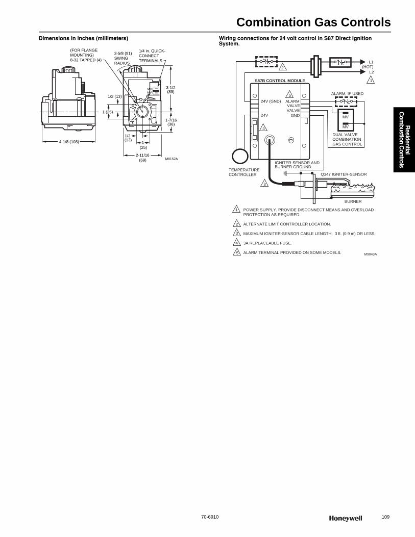
Combination Gas Controls
70-6910 109
R
esidential C
ombustion C
ontrols
Dimensions in inches (millimeters) Wiring connections for 24 volt control in S87 Direct Ignition System.
M8152A
1
(25)
3-5/8 (91)
SWING
RADIUS
(FOR FLANGE
MOUNTING)
8-32 TAPPED (4)
1/4 in. QUICK-
CONNECT
TERMINALS
1 (25)
MVMV
1-7/16(36)
3-1/2(89)
1/2 (13)
1/2 (13)
2-11/16
(69)
4-1/8 (108)
24V
24V (GND)
S87B CONTROL MODULE
ALARMVALVEVALVE
GND
TEMPERATURE CONTROLLER
POWER SUPPLY. PROVIDE DISCONNECT MEANS AND OVERLOAD PROTECTION AS REQUIRED.
ALTERNATE LIMIT CONTROLLER LOCATION.
MAXIMUM IGNITER-SENSOR CABLE LENGTH: 3 ft. (0.9 m) OR LESS.
3A REPLACEABLE FUSE.
ALARM TERMINAL PROVIDED ON SOME MODELS. M9043A
MV
MV
L1(HOT)
L2
1
2
1
2
3
DUAL VALVECOMBINATIONGAS CONTROL
Q347 IGNITER-SENSOR
BURNER
4
4
5
IGNITER-SENSOR AND BURNER GROUND
3
5
ALARM, IF USED
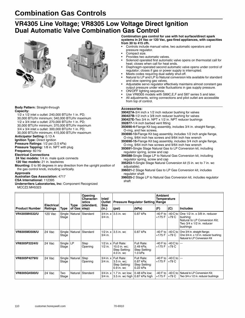
Combination Gas Controls
110 customer.honeywell.com 70-6910
VR4305 Line Voltage; VR8305 Low Voltage Direct Ignition Dual Automatic Valve Combination Gas Control
Combination gas control for use with hot surface/direct spark systems in 24 Vac or 120 Vac, gas-fired appliances, with capacities from 30 to 415 cfh.• Controls include manual valve, two automatic operators and
pressure regulator. • Compact size. • Provides two automatic valves. • Solenoid operated first automatic valve opens on thermostat call for
heat; closes when call for heat ends. • Diaphragm-operated second automatic valve opens under control of
regulator; closes if gas or power supply is interrupted. • Meets codes requiring dual safety shut-off. • Natural to LP and LP to Natural conversion kits available for standard
and slow opening gas valves. • Adjustable servo regulator effectively maintains almost constant gas
output pressure under wide fluctuations in gas supply pressure. • ON/OFF lighting sequence.• Use VR8305 models with S89C,E,F and S87 series 5 and later. • All adjustments, wiring connections and pilot outlet are accessible
from top of control.
Body Pattern: Straight-throughCapacity:
1/2 x 1/2 inlet x outlet: 240,000 BTU/hr 1 in. PD; 30,000 BTU/hr minimum; 340,000 BTU/hr maximum1/2 x 3/4 inlet x outlet: 270,000 BTU/hr 1 in. PD;30,000 BTU/hr minimum; 370,000 BTU/hr maximum3/4 x 3/4 inlet x outlet: 300,000 BTU/hr 1 in. PD;30,000 BTU/hr minimum; 415,000 BTU/hr maximum
Anticipator Setting: 0.13 AIgnition Type: Direct IgnitionPressure Ratings: 1/2 psi (3.5 kPa) Pressure Tapping: 1/8 in. NPT with plugFrequency: 60 HzElectrical Connections 24 Vac models: 1/4 in. male quick connects 120 Vac models: 21 in. leadwiresMounting: 0 to 90 degrees in any direction from the upright position of
the gas control knob, including vertically.ApprovalsAustralian Gas Association: 4717CSA International: 112395Underwriters Laboratories, Inc: Component Recognized
MCCZ2.MH5323
Accessories:390427A-3/4 inch x 1/2 inch reducer bushing for valves390427B-1/2 inch x 3/8 inch reducer bushing for valves390427E-Two 3/4 in. NPT x 1/2 in. NPT reducer bushings392877-1/4 inch barbed vent fitting393690-4-Flange Kit bag assembly, includes 3/4 in. straight flange,
O-ring, and hex screws.393690-13-Flange Kit bag assembly, includes 1/2 inch angle flange,
O-ring, 9/64 inch hex screws and 9/64 inch hex wrench393690-15-Flange Kit bag assembly, includes 3/4 inch angle flange,
O-ring, 9/64 inch hex screws and 9/64 inch hex wrench393691-Single Stage Natural Gas to LP Conversion kit, including
regulator spring, screw and cap394588-Single Stage LP to Natural Gas Conversion kit, including
regulator spring, screw and cap395253-1-Single Stage Natural Conversion kit (5 in. wc to 7 in. wc
adjustable). 396021-2 Stage Natural Gas to LP Gas Conversion kit, includes
regulator shaft396025-2 Stage LP to Natural Gas Conversion kit, includes regulator
shaft
Product NumberElectrical Ratings Type
Type of Gas
Opening Character-istics (standard, step)
Inlet/Outlet Size (in.)
Pressure Regulator Setting
Ambient Temperature Range
Includes(psi) (kPa) (F) (C)
VR4305M4532/U 120 Vac Single Stage
Natural Standard 3/4 in. x 3/4 in.
3.5 in. wc 0.87 kPa -40 F to +175 F
-40 C to +79 C
One 1/2 in. x 3/8 in. reducer bushing; Natural to LP Conversion Kit; Two 3/4 x 1/2 in. reducer bushings
VR8305M3506/U 24 Vac Single Stage
Natural Standard 1/2 in. x 3/4 in.
3.5 in. wc 0.87 kPa -40 F to +175 F
-40 C to +79 C
One 3/4 in. straight flange; One 3/4 in. x 1/2 in. reducer bushing; Natural to LP Conversion Kit
VR8305P2224/U 24 Vac Single Stage
LP Step Opening
1/2 in. x 1/2 in.
Full Rate: 10.0 in. wc; Step Setting: 4.0 in. wc
Full Rate: 2.49 kPa; Step Setting: 1.0 kPa
-40 F to +175 F
-40 C to +79 C
—
VR8305P4279/U 24 Vac Single Stage
Natural Step Opening
3/4 in. x 3/4 in.
Full Rate: 3.5 in. wc; Step Setting: 0.9 in. wc
Full Rate:0.87 kPa; Step Setting: 0.22 kPa
-40 F to +175 F
-40 C to +79 C
—
VR8305Q4500/U 24 Vac Two Stage
Natural Standard 3/4 in. x 3/4 in.
1.7 in. wc low; 3.5 in. wc high
0.48 kPa low; 0.87 kPa high
-40 F to +175 F
-40 C to +79 C
Natural to LP Conversion Kit; Two 3/4 x 1/2 in. reducer bushings

Combination Gas Controls
70-6910 111
R
esidential C
ombustion C
ontrols
Dimensions in inches (millimeters)
Wiring Connections in S87 Direct Ignition System for 24 volt control.
Wiring Connections in S87 Direct Ignition System for 120 volt control.
M7496A
1 (25)
(13)
4 in. (102)
SWING
RADIUS
(FOR FLANGE
MOUNTING)
8-32 TAPPED (4)
1/4 in. QUICK-
CONNECT
TERMINALS
1 (25)
(13)
MVMV
4-1/16 (104)
1/2
3-15/16
(99)
1-7/16(36)
1/2
2-11/16 (69)
24V
24V (GND)
S87B CONTROL MODULE
ALARMVALVEVALVE
GND
TEMPERATURE CONTROLLER
POWER SUPPLY. PROVIDE DISCONNECT MEANS AND OVERLOAD PROTECTION AS REQUIRED.
ALTERNATE LIMIT CONTROLLER LOCATION.
MAXIMUM IGNITER-SENSOR CABLE LENGTH: 3 ft. (0.9 m) OR LESS.
3A REPLACEABLE FUSE.
ALARM TERMINAL PROVIDED ON SOME MODELS. M9043A
MV
MV
L1(HOT)
L2
1
2
1
2
3
DUAL VALVECOMBINATIONGAS CONTROL
Q347 IGNITER-SENSOR
BURNER
4
4
5
IGNITER-SENSOR AND BURNER GROUND
3
5
ALARM, IF USED
24V
24V (GND)
IGNITION MODULE
LIMIT CONTROLLER
VALVEVALVE
GND
TEMPERATURE CONTROLLER
POWER SUPPLY. PROVIDE DISCONNECT MEANS AND OVERLOAD PROTECTION AS REQUIRED.
ALTERNATE LIMIT CONTROLLER LOCATION.M3088
L1(HOT)
L2
1
2
12
VR8305COMBINATIONGAS CONTROL
Q347 IGNITER-SENSOR
BURNER
L1
L2

Combination Gas Controls
112 customer.honeywell.com 70-6910
VR8245; VR8345 Low Voltage Universal Electronic Ignition Combination Gas Control
Universal electronic ignition combination gas control for use with direct spark ignition, hot surface ignition or intermittent pilot ignition in 24 Vac, gas-fired appliances, with capacities from 20 to 200 cfh (VR8245M) or 30 to 415 cfh (VR8345M).• Control includes manual valve, two automatic operators, pressure
regulator, pilot adjustment, pilot plug and ignition adapter.• Replaces virtually any IP, HSI, or DSI gas control.• For use with natural or manufactured gas or LP gas.• Includes converter kit to adapt from natural to LP gas.• Compact size.• All adjustments and wiring connections accessible from top of
control.• Four-inch swing radius allows easy rotation into position inside the
tightest furnace vestibules.• Clearly marked, keyed terminal block allows quick attachment of
wires and IP/DSI/HSI jumper.• Internal inlet screen blocks contaminants in gas line from entering
valve.
Body Pattern: Straight-throughCapacity:
1/2 x 1/2 inlet x outlet: 240,000 BTU/hr 1 in. PD; 30,000 BTU/hr minimum; 340,000 BTU/hr maximum3/4 x 3/4 inlet x outlet: 300,000 BTU/hr 1 in. PD;30,000 BTU/hr minimum; 415,000 BTU/hr maximum
Ignition Type: Direct Ignition; Intermittent PilotPressure Ratings: 1/2 psi (3.5 kPa)Pressure Tapping: 1/8 in. NPT with plugAmbient Temperature Range: -40 F to +175 F (-40 C to +79 C)
Electrical Ratings: 24 VacFrequency: 50 Hz; 60 HzElectrical Connections: 1/4 in. quick-connect male terminalsMounting: 0 to 90 degrees in any direction from the upright position of
the gas control knob, including vertically.ApprovalsCSA International: 112395Underwriters Laboratories, Inc: Component Recognized
MCCZ2.MH5323
Product Number TypeType of Gas
Opening Characteristics (standard, step)
Inlet/Outlet Size (in.)
Pressure Regulator Setting
Includes(psi) (kPa)
U VR8245M2530/U Single Stage Natural or LP
Standard 1/2 in. x 1/2 in. 3.5 in. wc 0.9 kPa Natural to LP Conversion Kit;One 1/2 x 3/8 in.reducer bushing
U VR8345K4809/U Single Stage Natural or LP
Slow Opening 3/4 in. x 3/4 in 3.5 in. wc 0.87 kPa Natural to LP Conversion Kit; Two 3/4 x 1/2 in. reducer bushings
U VR8345M4302/U Single Stage Natural Standard 3/4 in. x 3/4 in. 3.5 in. wc 0.87 kPa Natural to LP Conversion Kit; Two 3/4 x 1/2 in. reducer bushings
U VR8345Q4563/U Two Stage Natural Standard 3/4 in. x 3/4 in. 1.7 in. wc low; 3.5 in. wc high
0.48 kPa low; 0.87 kPa high
Natural to LP Conversion Kit; Two 3/4 x 1/2 in. reducer bushings
U Universal Service Part
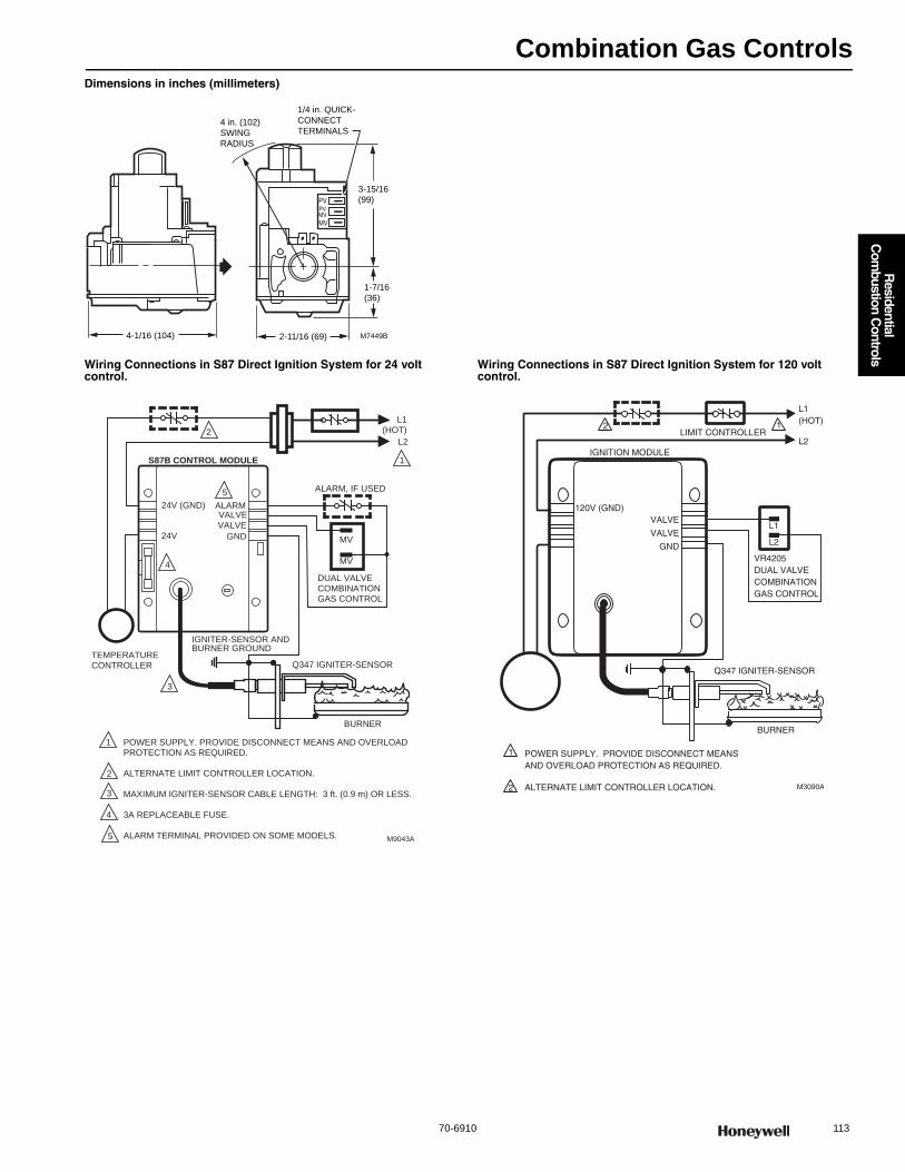
Combination Gas Controls
70-6910 113
R
esidential C
ombustion C
ontrols
Dimensions in inches (millimeters)
Wiring Connections in S87 Direct Ignition System for 24 volt control.
Wiring Connections in S87 Direct Ignition System for 120 volt control.
M7449B
4 in. (102)
SWING
RADIUS
1/4 in. QUICK-
CONNECT
TERMINALS
MVMV
PVPV
3-15/16
(99)
1-7/16
(36)
2-11/16 (69)4-1/16 (104)
24V
24V (GND)
S87B CONTROL MODULE
ALARMVALVEVALVE
GND
TEMPERATURE CONTROLLER
POWER SUPPLY. PROVIDE DISCONNECT MEANS AND OVERLOAD PROTECTION AS REQUIRED.
ALTERNATE LIMIT CONTROLLER LOCATION.
MAXIMUM IGNITER-SENSOR CABLE LENGTH: 3 ft. (0.9 m) OR LESS.
3A REPLACEABLE FUSE.
ALARM TERMINAL PROVIDED ON SOME MODELS. M9043A
MV
MV
L1(HOT)
L2
1
2
1
2
3
DUAL VALVECOMBINATIONGAS CONTROL
Q347 IGNITER-SENSOR
BURNER
4
4
5
IGNITER-SENSOR AND BURNER GROUND
3
5
ALARM, IF USED
IGNITION MODULE
L1(HOT)
L2LIMIT CONTROLLER
Q347 IGNITER-SENSOR
120V (GND)VALVE
VALVE
GND
POWER SUPPLY. PROVIDE DISCONNECT MEANS AND OVERLOAD PROTECTION AS REQUIRED.
ALTERNATE LIMIT CONTROLLER LOCATION. M3090A
BURNER
VR4205DUAL VALVE COMBINATIONGAS CONTROL
L2
L1
2 1
1
2
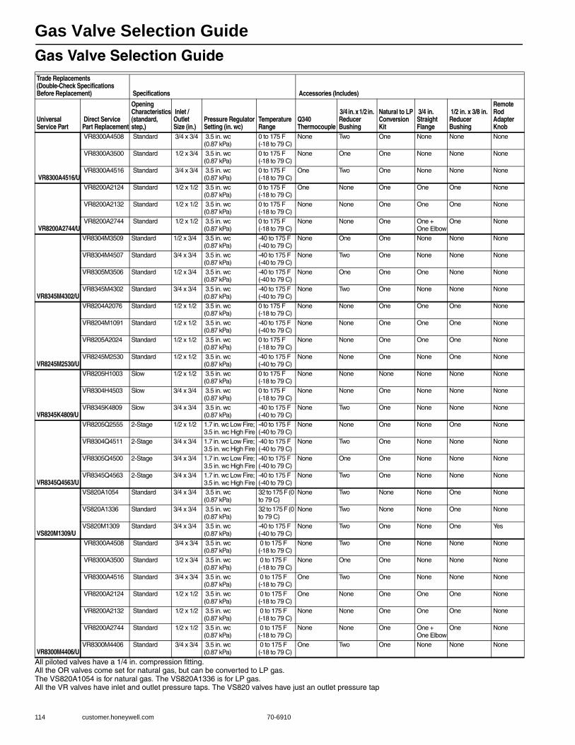
Gas Valve Selection Guide
114 customer.honeywell.com 70-6910
Gas Valve Selection Guide
All piloted valves have a 1/4 in. compression fitting.All the OR valves come set for natural gas, but can be converted to LP gas.The VS820A1054 is for natural gas. The VS820A1336 is for LP gas.All the VR valves have inlet and outlet pressure taps. The VS820 valves have just an outlet pressure tap
Trade Replacements(Double-Check Specifications Before Replacement) Specifications Accessories (Includes)
Universal Service Part
Direct Service Part Replacement
Opening Characteristics (standard, step,)
Inlet / Outlet Size (in.)
Pressure Regulator Setting (in. wc)
Temperature Range
Q340 Thermocouple
3/4 in. x 1/2 in. Reducer Bushing
Natural to LP Conversion Kit
3/4 in. Straight Flange
1/2 in. x 3/8 in. Reducer Bushing
Remote Rod Adapter Knob
VR8300A4516/U
VR8300A4508 Standard 3/4 x 3/4 3.5 in. wc (0.87 kPa)
0 to 175 F (-18 to 79 C)
None Two One None None None
VR8300A3500 Standard 1/2 x 3/4 3.5 in. wc (0.87 kPa)
0 to 175 F (-18 to 79 C)
None One One None None None
VR8300A4516 Standard 3/4 x 3/4 3.5 in. wc (0.87 kPa)
0 to 175 F (-18 to 79 C)
One Two One None None None
VR8200A2744/U
VR8200A2124 Standard 1/2 x 1/2 3.5 in. wc (0.87 kPa)
0 to 175 F (-18 to 79 C)
One None One One One None
VR8200A2132 Standard 1/2 x 1/2 3.5 in. wc (0.87 kPa)
0 to 175 F (-18 to 79 C)
None None One One One None
VR8200A2744 Standard 1/2 x 1/2 3.5 in. wc (0.87 kPa)
0 to 175 F (-18 to 79 C)
None None One One +One Elbow
One None
VR8345M4302/U
VR8304M3509 Standard 1/2 x 3/4 3.5 in. wc (0.87 kPa)
-40 to 175 F (-40 to 79 C)
None One One None None None
VR8304M4507 Standard 3/4 x 3/4 3.5 in. wc (0.87 kPa)
-40 to 175 F (-40 to 79 C)
None Two One None None None
VR8305M3506 Standard 1/2 x 3/4 3.5 in. wc (0.87 kPa)
-40 to 175 F (-40 to 79 C)
None One One One None None
VR8345M4302 Standard 3/4 x 3/4 3.5 in. wc (0.87 kPa)
-40 to 175 F (-40 to 79 C)
None Two One None None None
VR8245M2530/U
VR8204A2076 Standard 1/2 x 1/2 3.5 in. wc (0.87 kPa)
0 to 175 F (-18 to 79 C)
None None One One One None
VR8204M1091 Standard 1/2 x 1/2 3.5 in. wc (0.87 kPa)
-40 to 175 F (-40 to 79 C)
None None One One One None
VR8205A2024 Standard 1/2 x 1/2 3.5 in. wc (0.87 kPa)
0 to 175 F (-18 to 79 C)
None None One One One None
VR8245M2530 Standard 1/2 x 1/2 3.5 in. wc (0.87 kPa)
-40 to 175 F (-40 to 79 C)
None None One None One None
VR8345K4809/U
VR8205H1003 Slow 1/2 x 1/2 3.5 in. wc (0.87 kPa)
0 to 175 F (-18 to 79 C)
None None None None None None
VR8304H4503 Slow 3/4 x 3/4 3.5 in. wc (0.87 kPa)
0 to 175 F (-18 to 79 C)
None None One None None None
VR8345K4809 Slow 3/4 x 3/4 3.5 in. wc (0.87 kPa)
-40 to 175 F (-40 to 79 C)
None Two One None None None
VR8345Q4563/U
VR8205Q2555 2-Stage 1/2 x 1/2 1.7 in. wc Low Fire; 3.5 in. wc High Fire
-40 to 175 F (-40 to 79 C)
None None One None One None
VR8304Q4511 2-Stage 3/4 x 3/4 1.7 in. wc Low Fire; 3.5 in. wc High Fire
-40 to 175 F (-40 to 79 C)
None Two One None None None
VR8305Q4500 2-Stage 3/4 x 3/4 1.7 in. wc Low Fire; 3.5 in. wc High Fire
-40 to 175 F (-40 to 79 C)
None One One None None None
VR8345Q4563 2-Stage 3/4 x 3/4 1.7 in. wc Low Fire; 3.5 in. wc High Fire
-40 to 175 F (-40 to 79 C)
None Two One None None None
VS820M1309/U
VS820A1054 Standard 3/4 x 3/4 3.5 in. wc (0.87 kPa)
32 to 175 F (0 to 79 C)
None Two None None One None
VS820A1336 Standard 3/4 x 3/4 3.5 in. wc (0.87 kPa)
32 to 175 F (0 to 79 C)
None Two None None One None
VS820M1309 Standard 3/4 x 3/4 3.5 in. wc (0.87 kPa)
-40 to 175 F (-40 to 79 C)
None Two One None One Yes
VR8300M4406/U
VR8300A4508 Standard 3/4 x 3/4 3.5 in. wc (0.87 kPa)
0 to 175 F (-18 to 79 C)
None Two One None None None
VR8300A3500 Standard 1/2 x 3/4 3.5 in. wc (0.87 kPa)
0 to 175 F (-18 to 79 C)
None One One None None None
VR8300A4516 Standard 3/4 x 3/4 3.5 in. wc (0.87 kPa)
0 to 175 F (-18 to 79 C)
One Two One None None None
VR8200A2124 Standard 1/2 x 1/2 3.5 in. wc (0.87 kPa)
0 to 175 F (-18 to 79 C)
One None One One One None
VR8200A2132 Standard 1/2 x 1/2 3.5 in. wc (0.87 kPa)
0 to 175 F (-18 to 79 C)
None None One One One None
VR8200A2744 Standard 1/2 x 1/2 3.5 in. wc (0.87 kPa)
0 to 175 F (-18 to 79 C)
None None One One +One Elbow
One None
VR8300M4406 Standard 3/4 x 3/4 3.5 in. wc (0.87 kPa)
0 to 175 F (-18 to 79 C)
One Two One None None None
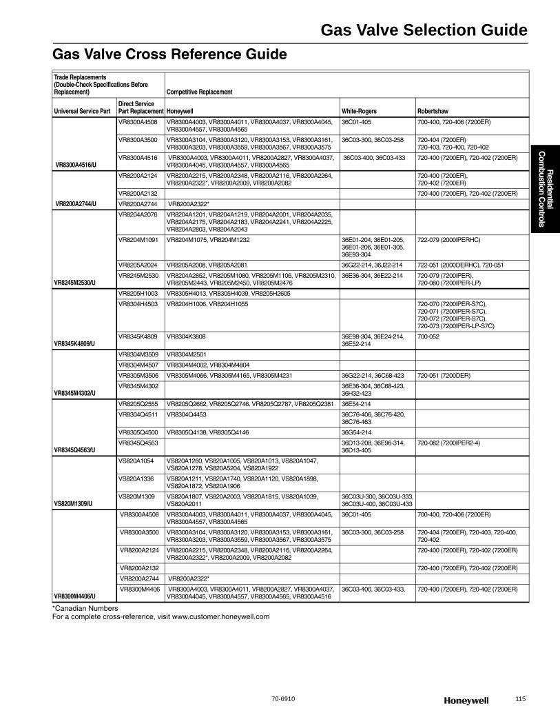
Gas Valve Selection Guide
70-6910 115
R
esidential C
ombustion C
ontrols
Gas Valve Cross Reference Guide
*Canadian NumbersFor a complete cross-reference, visit www.customer.honeywell.com
Trade Replacements (Double-Check Specifications Before Replacement) Competitive Replacement
Universal Service PartDirect Service Part Replacement Honeywell White-Rogers Robertshaw
VR8300A4516/U
VR8300A4508 VR8300A4003, VR8300A4011, VR8300A4037, VR8300A4045, VR8300A4557, VR8300A4565
36C01-405 700-400, 720-406 (7200ER)
VR8300A3500 VR8300A3104, VR8300A3120, VR8300A3153, VR8300A3161, VR8300A3203, VR8300A3559, VR8300A3567, VR8300A3575
36C03-300, 36C03-258 720-404 (7200ER) 720-403, 720-400, 720-402
VR8300A4516 VR8300A4003, VR8300A4011, VR8200A2827, VR8300A4037, VR8300A4045, VR8300A4557, VR8300A4565
36C03-400, 36C03-433 720-400 (7200ER), 720-402 (7200ER)
VR8200A2744/U
VR8200A2124 VR8200A2215, VR8200A2348, VR8200A2116, VR8200A2264, VR8200A2322*, VR8200A2009, VR8200A2082
720-400 (7200ER), 720-402 (7200ER)
VR8200A2132 720-400 (7200ER), 720-402 (7200ER)
VR8200A2744 VR8200A2322*
VR8245M2530/U
VR8204A2076 VR8204A1201, VR8204A1219, VR8204A2001, VR8204A2035, VR8204A2175, VR8204A2183, VR8204A2241, VR8204A2225, VR8204A2803, VR8204A2043
VR8204M1091 VR8204M1075, VR8204M1232 36E01-204, 36E01-205, 36E01-206, 36E01-305, 36E93-304
722-079 (2000IPERHC)
VR8205A2024 VR8205A2008, VR8205A2081 36G22-214, 36J22-214 722-051 (2000DERHC), 720-051
VR8245M2530 VR8204A2852, VR8205M1080, VR8205M1106, VR8205M2310, VR8205M2443, VR8205M2450, VR8205M2476
36E36-304, 36E22-214 720-079 (7200IPER), 720-080 (7200IPER-LP)
VR8345K4809/U
VR8205H1003 VR8305H4013, VR8305H4039, VR8205H2605
VR8304H4503 VR8204H1006, VR8204H1055 720-070 (7200IPER-S7C), 720-071 (7200IPER-S7C), 720-072 (7200IPER-S7C), 720-073 (7200IPER-LP-S7C)
VR8345K4809 VR8304K3808 36E98-304, 36E24-214, 36E52-214
700-052
VR8345M4302/U
VR8304M3509 VR8304M2501
VR8304M4507 VR8304M4002, VR8304M4804
VR8305M3506 VR8305M4066, VR8305M4165, VR8305M4231 36G22-214, 36C68-423 720-051 (7200DER)
VR8345M4302 36E36-304, 36C68-423, 36H32-423
VR8345Q4563/U
VR8205Q2555 VR8205Q2662, VR8205Q2746, VR8205Q2787, VR8205Q2381 36E54-214
VR8304Q4511 VR8304Q4453 36C76-406, 36C76-420, 36C76-463
VR8305Q4500 VR8305Q4138, VR8305Q4146 36G54-214
VR8345Q4563 36D13-208, 36E96-314, 36D13-405
720-082 (7200IPER2-4)
VS820M1309/U
VS820A1054 VS820A1260, VS820A1005, VS820A1013, VS820A1047, VS820A1278, VS820A5204, VS820A1922
VS820A1336 VS820A1211, VS820A1740, VS820A1120, VS820A1898, VS820A1872, VS820A1906
VS820M1309 VS820A1807, VS820A2003, VS820A1815, VS820A1039, VS820A2011
36C03U-300, 36C03U-333, 36C03U-400, 36C03U-433
VR8300M4406/U
VR8300A4508 VR8300A4003, VR8300A4011, VR8300A4037, VR8300A4045, VR8300A4557, VR8300A4565
36C01-405 700-400, 720-406 (7200ER)
VR8300A3500 VR8300A3104, VR8300A3120, VR8300A3153, VR8300A3161, VR8300A3203, VR8300A3559, VR8300A3567, VR8300A3575
36C03-300, 36C03-258 720-404 (7200ER), 720-403, 720-400, 720-402
VR8200A2124 VR8200A2215, VR8200A2348, VR8200A2116, VR8200A2264, VR8200A2322*, VR8200A2009, VR8200A2082
720-400 (7200ER), 720-402 (7200ER)
VR8200A2132 720-400 (7200ER), 720-402 (7200ER)
VR8200A2744 VR8200A2322*
VR8300M4406 VR8300A4003, VR8300A4011, VR8200A2827, VR8300A4037, VR8300A4045, VR8300A4557, VR8300A4565, VR8300A4516
36C03-400, 36C03-433, 720-400 (7200ER), 720-402 (7200ER)

SmartValve System Controls
116 customer.honeywell.com 70-6910
SV9501; SV9502; SV9601; SV9602 SmartValve® SystemThe SmartValve® System Controls combine gas flow control and electronic intermittent pilot sequencing functions into a single unit. This product family offers several different intermittent pilot sequences for a wide range of applications. The specific application of the SmartValve System is the responsibility of the appliance manufacturer. They are directly compatible with the Q3450 or Q3480 Intermittent Pilot burners used with the original controls on the appliance.• Suitable for a wide range of gas-fired appliances including residential
furnaces, roof-top furnaces, residential boilers, unit heaters, infrared heaters, space heaters and commercial cooking units.
• Replaces SV9500, SV9501, SV9502, SV9601, and SV9602 controls as noted below.
• Ignition sequence includes timed trial for ignition.
Dimensions, Approximate: 3.2 in. wide x 4.9 in. high x 4.1 in.long (81 mm wide x124 mm high x 104 mm long.)
Body Pattern: Straight-throughCapacity:
1/2 x 1/2 inlet x outlet: 150 ft3/hr (4.2 m3/hr) 1 in. PD; 20 ft3/hr (0.6 m3/hr) minimum; 200 ft3/hr (5.7 m3/hr) maximum3/4 x 3/4 inlet x outlet: 300 ft3/hr (8.5 m3/hr)1 in. PD;30 ft3/hr (0.8 m3/hr); 415 ft3/hr (11.8 m3/hr) maximum
Pilot Gas Outlet: YesElectrical Ratings: 24 VacFrequency: 50 Hz; 60 HzFlame Failure Response Time (sec): 1.6 sec @ 3 μAFlame Sense: Electrode
Flame Sense: Two RodIgnition Sequence: Intermittent PilotIgnition Source: PilotIgnition System Type: Intermittent Hot Surface Pilot IgnitionIgnition Trial Time: 90 secIgnition Trials To Lockout: continuous retryPressure Ratings: 1/2 psi (3.45 kPa) Pressure Tapping: 1/8 in. - NPTTypical Ignition Hardware: Q3450 or Q3480Mounting: 0 to 90 degrees in any direction from the upright position of
the gas control knob, including vertically.ApprovalsCSA International: 112395
Product NumberType of Gas
Opening Characteristics (standard, step)
Inlet/Outlet Size (in.)
Pressure Regulator Setting
Ambient Temperature Range
PrePurge Includes(psi) (kPa) (F) (C)
U SV9501M2528/U Natural Standard 1/2 in. x 1/2 in. NPT
3.5 in. wc 0.87 kPa -40 F to +175 F
-40 C to +79 C
None —
U SV9501M8129/U Natural Fast-Fast 1/2 in. x 1/2 in. NPT
3.4 in. wc 0.87 kPa -40 F to +175 F
-40 C to +79 C
None —
U SV9502H2522/U Natural Slow 1/2 in. x 1/2 in. NPT
3.2 in. wc 0.80 kPa 0 F to +175 F
-18 C to +79 C
15 sec —
U SV9601M4571/U Natural Standard 3/4 in. x 3/4 in. NPT.
3.5 in. wc 0.87 kPa -40 F to +175 F
-40 C to +79 C
None Two 3/4 in. x 1/2 in. reducer bushings;An LP conversion kit.
U SV9602P4816/U Natural Step 3/4 in. x 3/4 in. NPT.
Full Rate: 3.5 in. wc; Step Setting: 0.7 in. wc
Full Rate: 0.87 kPa; Step Setting: 0.17 kPa
-40 F to +175 F
-40 C to +79 C
30 sec —
U SV9602P4824/U Natural Step 3/4 in. x 3/4 in. NPT.
Full Rate: 3.5 in. wc; Step Setting: 0.7 in. wc
Full Rate: 0.87 kPa; Step Setting: 0.17 kPa
-40 F to +175 F
-40 C to +79 C
30 sec —
U SV9602P4832/U LP Step 3/4 in. x 3/4 in. NPT.
Full Rate: 10.0 in. wc; Step Setting: 2.5 in. wc
Full Rate: 2.49 kPa; Step Setting: 0.62 kPa
-40 F to +175 F
-40 C to +79 C
30 sec —
U SV9602P4840/U LP Step 3/4 in. x 3/4 in. NPT.
Full Rate: 10.0 in. wc; Step Setting: 2.5 in. wc
Full Rate: 2.49 kPa; Step Setting: 0.62 kPa
-40 F to +175 F
-40 C to +79 C
30 sec —
U Universal Service Part
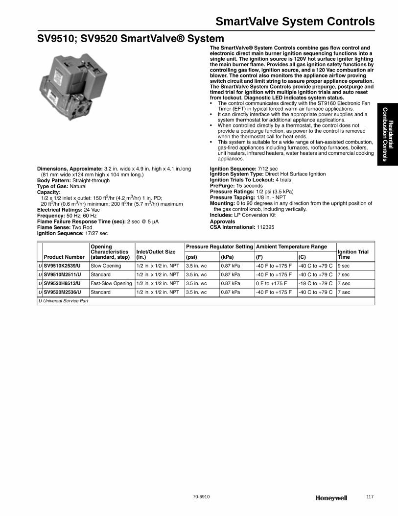
SmartValve System Controls
70-6910 117
R
esidential C
ombustion C
ontrols
SV9510; SV9520 SmartValve® SystemThe SmartValve® System Controls combine gas flow control and electronic direct main burner ignition sequencing functions into a single unit. The ignition source is 120V hot surface igniter lighting the main burner flame. Provides all gas ignition safety functions by controlling gas flow, ignition source, and a 120 Vac combustion air blower. The control also monitors the appliance airflow proving switch circuit and limit string to assure proper appliance operation. The SmartValve System Controls provide prepurge, postpurge and timed trial for ignition with multiple ignition trials and auto reset from lockout. Diagnostic LED indicates system status.• The control communicates directly with the ST9160 Electronic Fan
Timer (EFT) in typical forced warm air furnace applications. • It can directly interface with the appropriate power supplies and a
system thermostat for additional appliance applications. • When controlled directly by a thermostat, the control does not
provide a postpurge function, as power to the control is removed when the thermostat call for heat ends.
• This system is suitable for a wide range of fan-assisted combustion, gas-fired appliances including furnaces, rooftop furnaces, boilers, unit heaters, infrared heaters, water heaters and commercial cooking appliances.
Dimensions, Approximate: 3.2 in. wide x 4.9 in. high x 4.1 in.long (81 mm wide x124 mm high x 104 mm long.)
Body Pattern: Straight-throughType of Gas: NaturalCapacity:
1/2 x 1/2 inlet x outlet: 150 ft3/hr (4.2 m3/hr) 1 in. PD; 20 ft3/hr (0.6 m3/hr) minimum; 200 ft3/hr (5.7 m3/hr) maximum
Electrical Ratings: 24 VacFrequency: 50 Hz; 60 HzFlame Failure Response Time (sec): 2 sec @ 5 μAFlame Sense: Two RodIgnition Sequence: 17/27 sec
Ignition Sequence: 7/12 secIgnition System Type: Direct Hot Surface IgnitionIgnition Trials To Lockout: 4 trialsPrePurge: 15 secondsPressure Ratings: 1/2 psi (3.5 kPa) Pressure Tapping: 1/8 in. - NPTMounting: 0 to 90 degrees in any direction from the upright position of
the gas control knob, including vertically.Includes: LP Conversion KitApprovalsCSA International: 112395
Product Number
Opening Characteristics (standard, step)
Inlet/Outlet Size (in.)
Pressure Regulator Setting Ambient Temperature RangeIgnition Trial Time(psi) (kPa) (F) (C)
U SV9510K2539/U Slow Opening 1/2 in. x 1/2 in. NPT 3.5 in. wc 0.87 kPa -40 F to +175 F -40 C to +79 C 9 sec
U SV9510M2511/U Standard 1/2 in. x 1/2 in. NPT 3.5 in. wc 0.87 kPa -40 F to +175 F -40 C to +79 C 7 sec
U SV9520H8513/U Fast-Slow Opening 1/2 in. x 1/2 in. NPT 3.5 in. wc 0.87 kPa 0 F to +175 F -18 C to +79 C 7 sec
U SV9520M2536/U Standard 1/2 in. x 1/2 in. NPT 3.5 in. wc 0.87 kPa -40 F to +175 F -40 C to +79 C 7 sec
U Universal Service Part
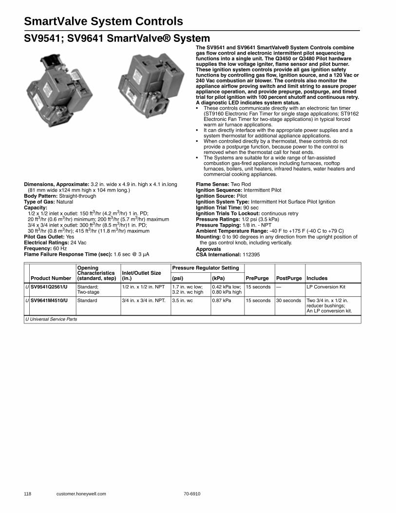
SmartValve System Controls
118 customer.honeywell.com 70-6910
SV9541; SV9641 SmartValve® SystemThe SV9541 and SV9641 SmartValve® System Controls combine gas flow control and electronic intermittent pilot sequencing functions into a single unit. The Q3450 or Q3480 Pilot hardware supplies the low voltage igniter, flame sensor and pilot burner. These ignition system controls provide all gas ignition safety functions by controlling gas flow, ignition source, and a 120 Vac or 240 Vac combustion air blower. The controls also monitor the appliance airflow proving switch and limit string to assure proper appliance operation, and provide prepurge, postpurge, and timed trial for pilot ignition with 100 percent shutoff and continuous retry. A diagnostic LED indicates system status.• These controls communicate directly with an electronic fan timer
(ST9160 Electronic Fan Timer for single stage applications; ST9162 Electronic Fan Timer for two-stage applications) in typical forced warm air furnace applications.
• It can directly interface with the appropriate power supplies and a system thermostat for additional appliance applications.
• When controlled directly by a thermostat, these controls do not provide a postpurge function, because power to the control is removed when the thermostat call for heat ends.
• The Systems are suitable for a wide range of fan-assisted combustion gas-fired appliances including furnaces, rooftop furnaces, boilers, unit heaters, infrared heaters, water heaters and commercial cooking appliances.
Dimensions, Approximate: 3.2 in. wide x 4.9 in. high x 4.1 in.long (81 mm wide x124 mm high x 104 mm long.)
Body Pattern: Straight-throughType of Gas: NaturalCapacity:
1/2 x 1/2 inlet x outlet: 150 ft3/hr (4.2 m3/hr) 1 in. PD; 20 ft3/hr (0.6 m3/hr) minimum; 200 ft3/hr (5.7 m3/hr) maximum3/4 x 3/4 inlet x outlet: 300 ft3/hr (8.5 m3/hr)1 in. PD;30 ft3/hr (0.8 m3/hr); 415 ft3/hr (11.8 m3/hr) maximum
Pilot Gas Outlet: YesElectrical Ratings: 24 VacFrequency: 60 HzFlame Failure Response Time (sec): 1.6 sec @ 3 μA
Flame Sense: Two RodIgnition Sequence: Intermittent PilotIgnition Source: PilotIgnition System Type: Intermittent Hot Surface Pilot IgnitionIgnition Trial Time: 90 secIgnition Trials To Lockout: continuous retryPressure Ratings: 1/2 psi (3.5 kPa) Pressure Tapping: 1/8 in. - NPTAmbient Temperature Range: -40 F to +175 F (-40 C to +79 C) Mounting: 0 to 90 degrees in any direction from the upright position of
the gas control knob, including vertically.ApprovalsCSA International: 112395
Product Number
Opening Characteristics (standard, step)
Inlet/Outlet Size (in.)
Pressure Regulator Setting
PrePurge PostPurge Includes(psi) (kPa)
U SV9541Q2561/U Standard; Two-stage
1/2 in. x 1/2 in. NPT 1.7 in. wc low; 3.2 in. wc high
0.42 kPa low; 0.80 kPa high
15 seconds — LP Conversion Kit
U SV9641M4510/U Standard 3/4 in. x 3/4 in. NPT. 3.5 in. wc 0.87 kPa 15 seconds 30 seconds Two 3/4 in. x 1/2 in. reducer bushings; An LP conversion kit.
U Universal Service Parts
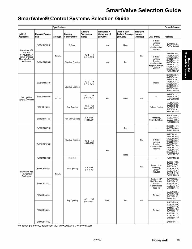
SmartValve Selection Guide
70-6910 119
R
esidential C
ombustion C
ontrols
SmartValve® Control Systems Selection Guide
For a complete cross-reference, visit www.customer.honeywell.com
Specifications Cross-Reference
Ignition/Application
Universal Service Part Gas Type
Opening Characteristics
Ambient Temperature Range
Natural to LP Conversion Kit (Included
3/4 in. x 1/2 in. Reducer Bushings (Included)
Extension Harness (Included) OEM Brands Replaces
Intermittent HSI Pilot with
Combustion Air Control and Limit Monitoring Forced
Air Furnace
SV9541Q2561/U
Natural
2-Stage
-40 to 175 F(-40 to 79 C)
Yes None
No
ICP, Heil, Tempstar, Arcoaire,
Comfortmaker, KeepRite
SV9540Q2464, SV9541Q3098
SV9641M4510/U Standard Opening Yes Two
ICP, Heil, Tempstar, Arcoaire,
Comfortmaker, KeepRite, Mestek,
Slant Fin
SV9541M2094, SV9540M2229, SV9540M2260, SV9640M4116, SV9640M4124, SV9540M2278, SV9540M2245, SV9640M3126, SV9640M4132
Direct Ignition, General Application
SV9510M2511/U
Natural
Standard Opening
-40 to 175 F(-40 to 79 C)
Yes None No
Modine
SV9510M2347, SV9510M2362, SV9410M2902, SV9510M2412, SV9510M2354, SV9410M2910, SV9510M2388, SV9510M2420
SV9520M2536/U -40 to 175 F(-40 to 79 C) —
SV9420M2331, SV9520M2403, SV9420M2323
SV9510K2539/U Slow Opening -40 to 175 F(-40 to 79 C) Roberts Gordon
SV9510H2228, SV9510K2133, SV9510K2158, SV9510K2141, SV9510K2166
SV9520H8513/U Fast-Slow Opening 0 to 175 F(-18 to 79C)
Armstrong, Concord, AirEase
SV9520H8042, SV9520H8034, SV9520H8067, SV9520H8026
Intermittent HSI Pilot, General
Application
SV9601M4571/U
Natural
Standard Opening -40 to 175 F (-40 to 79C)
Yes
Two
No
—SV9601M4167, SV9601M3003, SV9601M4225
SV9501M2528/U
None
ICP, Heil, Tempstar, Arcoaire,
Comfortmaker, KeepRite
SV9501M2031, SV9501M2049, SV9501M2056, SV9501M2080, SV9501M2239, SV9501M2700, SV9501M2718, SV9501M2726, SV9501M2734,SV9501M2742
SV9501M8129/U Fast-Fast
Yes
— SV9501M8103
SV9502H2522/U Slow Opening 0 to 175 F (-18 to 79)
Laars, Utica, Armstrong, Concord, AireEase
SV9502H1706, SV9501H2409, SV9501H2417, SV9501H2425, SV9502H2704, SV9501H3415, SV9501H3423
SV9602P4816/U
Step Opening -40 to 175 F (-40 to 79 C) None Two Yes
Burnham, ICP, Heil, Tempstar,
Arcoaire, Comfortmaker,
KeepRite
SV9501P2004, SV9601P4107, SV9501P2053, SV9502P2101, SV9602P4105
SV9602P4824/U Burnham
SV9501P2087, SV9601P4172,SV9502P2127,SV9602P4121
SV9602P4832/U Burnham
SV9501P2020, SV9501P2046, SV9601P4149, SV9601P4164, SV9502P2119, SV9502P2135, SV9602P4113, SV9602P4139
SV9602P4840/U — SV9601P4115
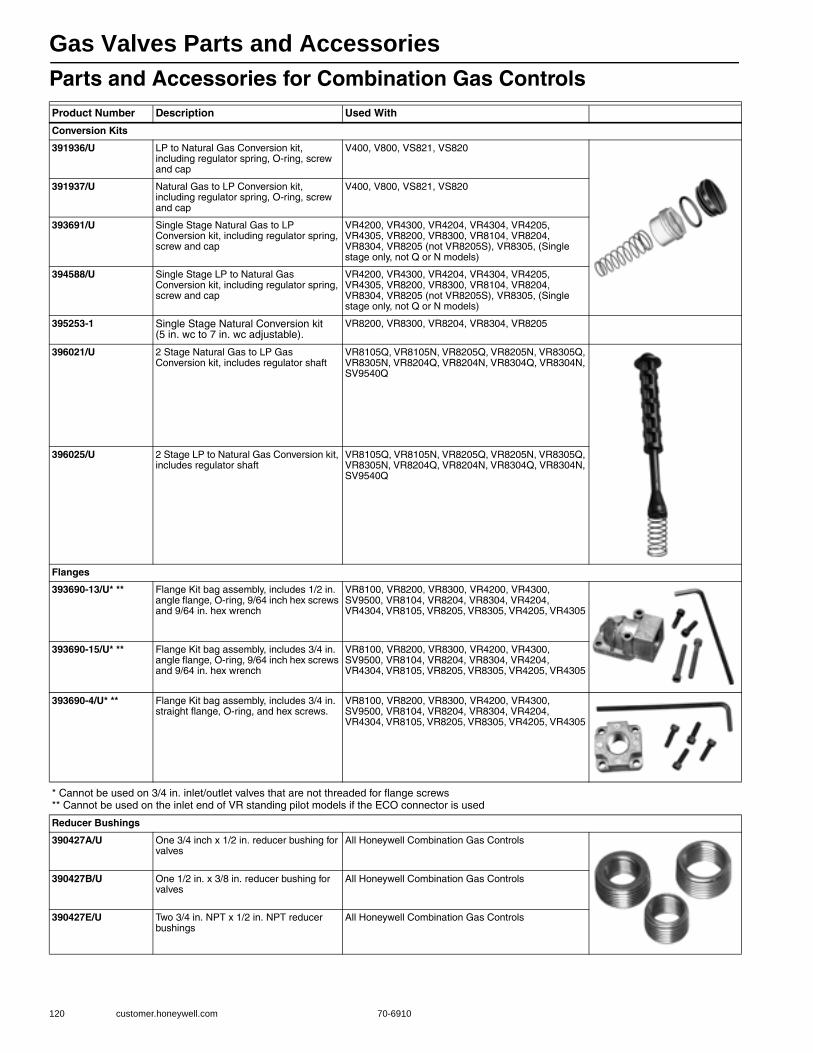
Gas Valves Parts and Accessories
120 customer.honeywell.com 70-6910
Parts and Accessories for Combination Gas ControlsProduct Number Description Used With
Conversion Kits
391936/U LP to Natural Gas Conversion kit, including regulator spring, O-ring, screw and cap
V400, V800, VS821, VS820
391937/U Natural Gas to LP Conversion kit, including regulator spring, O-ring, screw and cap
V400, V800, VS821, VS820
393691/U Single Stage Natural Gas to LP Conversion kit, including regulator spring, screw and cap
VR4200, VR4300, VR4204, VR4304, VR4205, VR4305, VR8200, VR8300, VR8104, VR8204, VR8304, VR8205 (not VR8205S), VR8305, (Single stage only, not Q or N models)
394588/U Single Stage LP to Natural Gas Conversion kit, including regulator spring, screw and cap
VR4200, VR4300, VR4204, VR4304, VR4205, VR4305, VR8200, VR8300, VR8104, VR8204, VR8304, VR8205 (not VR8205S), VR8305, (Single stage only, not Q or N models)
395253-1 Single Stage Natural Conversion kit (5 in. wc to 7 in. wc adjustable).
VR8200, VR8300, VR8204, VR8304, VR8205
396021/U 2 Stage Natural Gas to LP Gas Conversion kit, includes regulator shaft
VR8105Q, VR8105N, VR8205Q, VR8205N, VR8305Q, VR8305N, VR8204Q, VR8204N, VR8304Q, VR8304N, SV9540Q
396025/U 2 Stage LP to Natural Gas Conversion kit, includes regulator shaft
VR8105Q, VR8105N, VR8205Q, VR8205N, VR8305Q, VR8305N, VR8204Q, VR8204N, VR8304Q, VR8304N, SV9540Q
Flanges
393690-13/U* ** Flange Kit bag assembly, includes 1/2 in. angle flange, O-ring, 9/64 inch hex screws and 9/64 in. hex wrench
VR8100, VR8200, VR8300, VR4200, VR4300, SV9500, VR8104, VR8204, VR8304, VR4204, VR4304, VR8105, VR8205, VR8305, VR4205, VR4305
393690-15/U* ** Flange Kit bag assembly, includes 3/4 in. angle flange, O-ring, 9/64 inch hex screws and 9/64 in. hex wrench
VR8100, VR8200, VR8300, VR4200, VR4300, SV9500, VR8104, VR8204, VR8304, VR4204, VR4304, VR8105, VR8205, VR8305, VR4205, VR4305
393690-4/U* ** Flange Kit bag assembly, includes 3/4 in. straight flange, O-ring, and hex screws.
VR8100, VR8200, VR8300, VR4200, VR4300, SV9500, VR8104, VR8204, VR8304, VR4204, VR4304, VR8105, VR8205, VR8305, VR4205, VR4305
* Cannot be used on 3/4 in. inlet/outlet valves that are not threaded for flange screws** Cannot be used on the inlet end of VR standing pilot models if the ECO connector is used
Reducer Bushings
390427A/U One 3/4 inch x 1/2 in. reducer bushing for valves
All Honeywell Combination Gas Controls
390427B/U One 1/2 in. x 3/8 in. reducer bushing for valves
All Honeywell Combination Gas Controls
390427E/U Two 3/4 in. NPT x 1/2 in. NPT reducer bushings
All Honeywell Combination Gas Controls
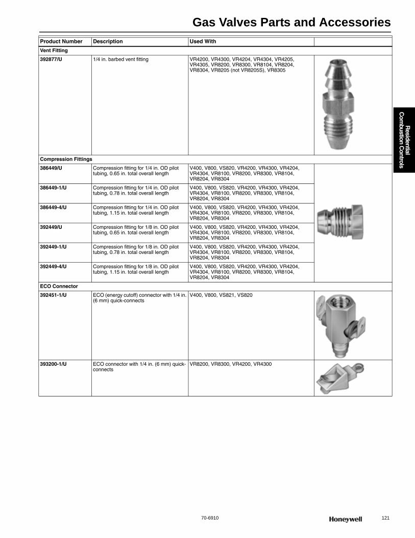
Gas Valves Parts and Accessories
70-6910 121
R
esidential C
ombustion C
ontrols
Vent Fitting
392877/U 1/4 in. barbed vent fitting VR4200, VR4300, VR4204, VR4304, VR4205, VR4305, VR8200, VR8300, VR8104, VR8204, VR8304, VR8205 (not VR8205S), VR8305
Compression Fittings
386449/U Compression fitting for 1/4 in. OD pilot tubing, 0.65 in. total overall length
V400, V800, VS820, VR4200, VR4300, VR4204, VR4304, VR8100, VR8200, VR8300, VR8104, VR8204, VR8304
386449-1/U Compression fitting for 1/4 in. OD pilot tubing, 0.78 in. total overall length
V400, V800, VS820, VR4200, VR4300, VR4204, VR4304, VR8100, VR8200, VR8300, VR8104, VR8204, VR8304
386449-4/U Compression fitting for 1/4 in. OD pilot tubing, 1.15 in. total overall length
V400, V800, VS820, VR4200, VR4300, VR4204, VR4304, VR8100, VR8200, VR8300, VR8104, VR8204, VR8304
392449/U Compression fitting for 1/8 in. OD pilot tubing, 0.65 in. total overall length
V400, V800, VS820, VR4200, VR4300, VR4204, VR4304, VR8100, VR8200, VR8300, VR8104, VR8204, VR8304
392449-1/U Compression fitting for 1/8 in. OD pilot tubing, 0.78 in. total overall length
V400, V800, VS820, VR4200, VR4300, VR4204, VR4304, VR8100, VR8200, VR8300, VR8104, VR8204, VR8304
392449-4/U Compression fitting for 1/8 in. OD pilot tubing, 1.15 in. total overall length
V400, V800, VS820, VR4200, VR4300, VR4204, VR4304, VR8100, VR8200, VR8300, VR8104, VR8204, VR8304
ECO Connector
392451-1/U ECO (energy cutoff) connector with 1/4 in. (6 mm) quick-connects
V400, V800, VS821, VS820
393200-1/U ECO connector with 1/4 in. (6 mm) quick- connects
VR8200, VR8300, VR4200, VR4300
Product Number Description Used With
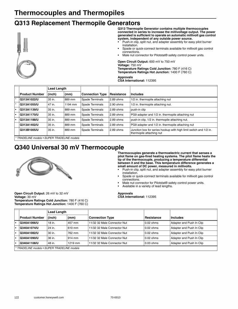
Thermocouples and Thermopiles
122 customer.honeywell.com 70-6910
Q313 Replacement Thermopile GeneratorsQ313 Thermopile Generator contains multiple thermocouples connected in series to increase the millivoltage output. The power generated is sufficient to operate an automatic millivolt gas control system, independent of any outside power source.• Push-in clip, split nut, and adapter assembly for easy pilot burner
installation. • Spade or quick-connect terminals available for millivolt gas control
connections. • Male nut connector for Pilotstat® safety control power units.
Open Circuit Output: 600 mV to 750 mVVoltage: 750 mVTemperature Ratings Cold Junction: 780 F (416 C) Temperature Ratings Hot Junction: 1400 F (760 C)
ApprovalsCSA International: 112395
Q340 Universal 30 mV ThermocoupleThermocouples generate a thermoelectric current that senses a pilot flame on gas-fired heating systems. The pilot flame heats the tip of the thermocouple, producing a temperature differential between it and the base. This temperature difference generates a small amount of DC power, measured in millivolts.• Push-in clip, split nut, and adapter assembly for easy pilot burner
installation. • Spade or quick-connect terminals available for millivolt gas control
connections. • Male nut connector for Pilotstat® safety control power units. • Available in a variety of lead lengths.
Open Circuit Output: 26 mV to 32 mVVoltage: 30 mVTemperature Ratings Cold Junction: 780 F (416 C) Temperature Ratings Hot Junction: 1400 F (760 C)
ApprovalsCSA International: 112395
Product Number
Lead Length
Connection Type Resistance Includes(inch) (mm)
* Q313A1022/U 35 in. 889 mm Spade Terminals 2.89 ohms 1/2 in. thermopile attaching nut
* Q313A1055/U 47 in. 1194 mm Spade Terminals 2.90 ohms 1/2 in. thermopile attaching nut.
• Q313A1139/U 35 in. 889 mm Spade Terminals 2.89 ohms push-in clip
• Q313A1170/U 35 in. 889 mm Spade Terminals 2.89 ohms PG9 adapter and 1/2 in. thermopile attaching nut
• Q313A1188/U 35 in. 889 mm Spade Terminals 2.89 ohms push-in clip, 1/2 in. thermopile attaching nut.
Q313A1402/U 35 in. 889 mm Spade Terminals 2.89 ohms PG9 adapter and 1/2 in. thermopile attaching nut
Q313B1005/U 35 in. 889 mm Spade Terminals 2.89 ohms Junction box for series hookup with high limit switch and 1/2 in. thermopile attaching nut
* TRADELINE models • SUPER TRADELINE models
Product Number
Lead Length
Connection Type Resistance Includes(inch) (mm)
• Q340A1066/U 18 in. 457 mm 11/32 32 Male Connector Nut 0.02 ohms Adapter and Push In Clip
• Q340A1074/U 24 in. 610 mm 11/32 32 Male Connector Nut 0.02 ohms Adapter and Push In Clip
• Q340A1082/U 30 in. 762 mm 11/32 32 Male Connector Nut 0.02 ohms Adapter and Push In Clip
• Q340A1090/U 36 in. 914 mm 11/32 32 Male Connector Nut 0.02 ohms Adapter and Push In Clip
• Q340A1108/U 48 in. 1219 mm 11/32 32 Male Connector Nut 0.03 ohms Adapter and Push In Clip
* TRADELINE models • SUPER TRADELINE models

Thermopiles and Thermocouples Selection Guide
70-6910 123
R
esidential C
ombustion C
ontrols
Q390 ThermocoupleThermocouples generate a thermoelectric current that senses a pilot flame on gas-fired heating systems. The pilot flame heats the tip of the thermocouple, producing a temperature differential between it and the base. This temperature difference generates a small amount of DC power, measured in millivolts.• Push-in clip, split nut, and adapter assembly for easy pilot burner
installation. • Spade or quick-connect terminals available for millivolt gas control
connections. • Male nut connector for Pilotstat® safety control power units. • Available in a variety of lead lengths.
Open Circuit Output: 26 mV to 32 mVVoltage: 30 mVTemperature Ratings Cold Junction: 780 F (416 C) Temperature Ratings Hot Junction: 1400 F (760 C)
ApprovalsCSA International: 112395
Thermocouple and Thermopile Accessories
Thermopiles and Thermocouples Selection Guide
Product Number
Lead Length
Connection Type Resistance Includes(inch) (mm)
* Q390A1046/U 24 in. 610 mm 11/32 32 Male Connector Nut 0.02 ohms Adapter and Push In Clip
* Q390A1053/U 30 in. 762 mm 11/32 32 Male Connector Nut 0.02 ohms Adapter and Push In Clip
* Q390A1061/U 36 in. 914 mm 11/32 32 Male Connector Nut 0.02 ohms Adapter and Push In Clip
* Q390A1095/U 18 in. 457 mm 11/32 32 Male Connector Nut 0.02 ohms Adapter and Push In Clip
* Q390A1103/U 48 in. 1219 mm 11/32 32 Male Connector Nut 0.03 ohms Adapter and Push In Clip
* TRADELINE models • SUPER TRADELINE models
Product Number Description
394530/U Thermocouple Tester Assembly
Thermocouples
Lead Length (in.) US Super Tradeline Tradeline Canada Tradeline White-Rodgers Robertshaw HuskyJohnson Controls
18 Q340A1066/U Q390A1095/U Q340A1405/U H06E-518, H06E-18 — K16BT-18 K19AT-18
24 Q340A1074/U Q390A1046/U Q340A1413/U H06E-524, H06E-24 1970-24, 1980-24 K16BT-24 K19AT-24
30 Q340A1082/U Q390A1053/U Q340A1421/U H06E-530, H06E-30 1970-30 K16BT-30 K19AT-30
36 Q340A1090/U Q390A1061/U Q340A1439/U H06E-536, H06E-36 1970-36, 1980-36 K16BT-36 K19AT-36
48 Q340A1108/U Q390A1103/U Q340A1447/U H06E-548, H06E-48 — K16BT-48 K19AT-48
Thermopiles
Model Item Lead Length (in.) Connections Tradeline/Super Tradeline Notes
Q313
Q313A1022/U 35 Nut & Spade Terminal Tradeline —
Q313A1139/U 35 Clip & Spade Terminal Super Tradeline Push-In Clip
Q313A1170/U 35 Clip & Spade Terminal Super Tradeline PG9 Adapter
Q313A1188/U 35 Nut & Spade Terminal Super Tradeline Push-In Clip, 1/2 in. Attaching Nut
Q313A1055/U 47 Nut & Spade Terminal Tradeline 1/2 in. Attaching Nut

Pilot Burners
124 customer.honeywell.com 70-6910
Universal Pilot Burners
Universal Pilot Burners make replacing pilot burners easier than ever. With four pilots, contractors can replace over 100 different models. This means fewer stocking trips and more money in your pocket.
Tip Style: SingleAeration: Non-primaryDirection of Front Tip : Adjustable Left, Right, and CenterMounting Bracket: UCompression Fitting Size: 1/4 in. and 1/8 in.Type of Gas: Natural; LP
Tip Style BatwingAeration: PrimaryDirection of Front Tip : Dual wing - 1 in. wing spanMounting Bracket: UCompression Fitting Size: 1/4 in. and 1/8 in.Type of Gas: Natural; LP
Q314U
Q345U
Q3451U
Q348U
Product NumberCompression Fitting Length Orifice2
Lead Length
Includes Used With in. mm
U Q314U1001/U 0.65 in. BCR-18; BBR-10; CAR-12; CAR-13; BBR-8
— — BCR-18, BBR-10, CAR-12, CAR-13, BBR-8 orifices, Standard and low BTU hoods, Adjustable tip style, Universal mounting bracket
Q309, Q340, Q390, Q313
U Q345U1005/U 1/8 in. compression fitting = 1.15 in.1/4 in. compression fitting = 0.78 in.
BCR-20; BCR-18; BBR-12; BBR-11
— — BCR-20, BCR-18, BBR-12, BBR-11 orifices, Adjustable tip style, Universal mounting bracket
S8600F, S8600H, S8600M, S8610F, S8610H, S8610M, S8610U, S8660D, S8660E, S8670D, S8670E
U Q3451U1000/U 1.15 in. BCR-20; BCR-18; BBR-12; BBR-11; BCR-10
36 in. and 55 in.
915 mm and 1397 mm
BCR-20, BCR-18, BBR-12, BBR-11, BCR-10 orifices, Adjustable tip style, Universal mounting bracket, 36 in. and 55 in. igniter lead lengths
S8600F, S8600H, S8600M, S8610F, S8610H, S8610M, S8610U, S8660D, S8660E, S8670D, S8670E
U Universal Service Parts
Product NumberCompression Fitting Length Orifice2 Includes Used With
U Q348U1009/U 0.65 in. NE22, KF24, A26, KR14
NE22, KF24, A26, KR14 orifices, 1 in. batwing, Universal mounting bracket
S8600F, S8600H, S8600M, S8610F, S8610H, S8610M, S8610U, S8660D, S8660E, S8670D, S8670E
U Universal Service Parts
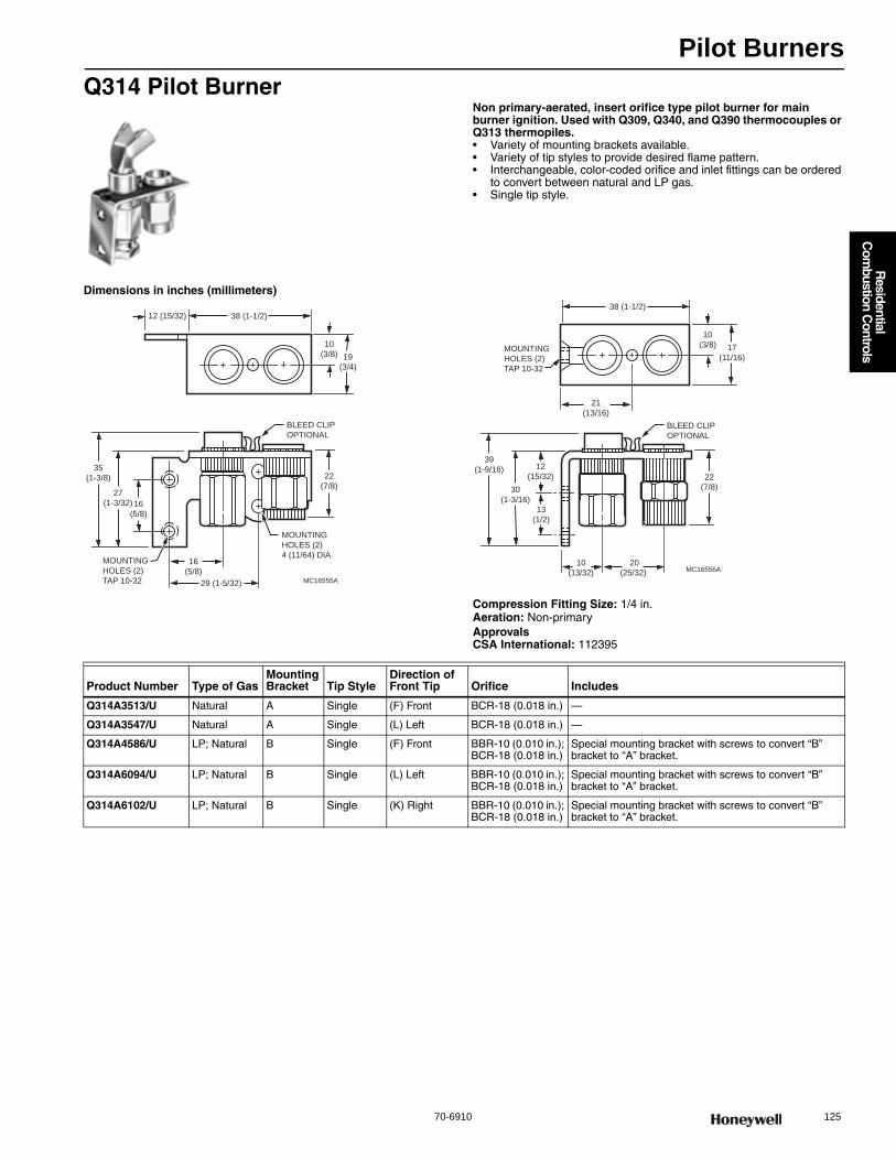
Pilot Burners
70-6910 125
R
esidential C
ombustion C
ontrols
Q314 Pilot BurnerNon primary-aerated, insert orifice type pilot burner for main burner ignition. Used with Q309, Q340, and Q390 thermocouples or Q313 thermopiles.• Variety of mounting brackets available. • Variety of tip styles to provide desired flame pattern. • Interchangeable, color-coded orifice and inlet fittings can be ordered
to convert between natural and LP gas. • Single tip style.
Dimensions in inches (millimeters)
Compression Fitting Size: 1/4 in.Aeration: Non-primaryApprovalsCSA International: 112395
12 (15/32) 38 (1-1/2)
10
(3/8) 19
(3/4)
16
(5/8)
27
(1-3/32)
35
(1-3/8)
16
(5/8)
29 (1-5/32)
22
(7/8)
MOUNTING
HOLES (2)
4 (11/64) DIA.
BLEED CLIP
OPTIONAL
MOUNTING
HOLES (2)
TAP 10-32 MC16555A
38 (1-1/2)
10
(3/8) 17
(11/16)MOUNTING
HOLES (2)
TAP 10-32
30
(1-3/16)
39
(1-9/16) 12
(15/32)
13
(1/2)
10
(13/32)
20
(25/32)
22
(7/8)
BLEED CLIP
OPTIONAL
MC16556A
21
(13/16)
Product Number Type of GasMounting Bracket Tip Style
Direction of Front Tip Orifice Includes
Q314A3513/U Natural A Single (F) Front BCR-18 (0.018 in.) —
Q314A3547/U Natural A Single (L) Left BCR-18 (0.018 in.) —
Q314A4586/U LP; Natural B Single (F) Front BBR-10 (0.010 in.); BCR-18 (0.018 in.)
Special mounting bracket with screws to convert “B” bracket to “A” bracket.
Q314A6094/U LP; Natural B Single (L) Left BBR-10 (0.010 in.); BCR-18 (0.018 in.)
Special mounting bracket with screws to convert “B” bracket to “A” bracket.
Q314A6102/U LP; Natural B Single (K) Right BBR-10 (0.010 in.); BCR-18 (0.018 in.)
Special mounting bracket with screws to convert “B” bracket to “A” bracket.
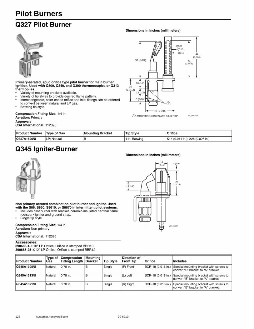
Pilot Burners
126 customer.honeywell.com 70-6910
Q327 Pilot Burner
Primary-aerated, spud orifice type pilot burner for main burner ignition. Used with Q309, Q340, and Q390 thermocouples or Q313 thermopiles.• Variety of mounting brackets available. • Variety of tip styles to provide desired flame pattern. • Interchangeable, color-coded orifice and inlet fittings can be ordered
to convert between natural and LP gas. • Batwing tip style.
Compression Fitting Size: 1/4 in.Aeration: PrimaryApprovalsCSA International: 112395
Dimensions in inches (millimeters)
Q345 Igniter-Burner
Non primary-aerated combination pilot burner and ignitor. Used with the S86, S860, S8610, or S8670 in intermittent pilot systems.• Includes pilot burner with bracket, ceramic-insulated Kanthal flame
rod/spark igniter and ground strap. • Single tip style.
Compression Fitting Size: 1/4 in.Aeration: Non-primaryApprovalsCSA International: 112395
Accessories:390686-1-.010" LP Orifice. Orifice is stamped BBR10390686-25-.012" LP Orifice. Orifice is stamped BBR12
Dimensions in inches (millimeters)
1
1
13 (1/2)
13 (1/2)
40 (1-9/16)
38 (1-1/2)
5 (3/16)
30
(1-3/16)
MOUNTING HOLES ARE 10-32 TAP.
Q309
Q310
Q313
41
(1-5/8)
44
(1-3/4)
MC16554A
Product Number Type of Gas Mounting Bracket Tip Style Orifice
Q327A1626/U LP; Natural B 1 in. Batwing K14 (0.014 in.); A26 (0.026 in.)
14
(9/16)
30
(1-3/16)
MC16560A
3 (1/8)
13 (1/2)
Product NumberType of Gas
Compression Fitting Length
Mounting Bracket Tip Style
Direction of Front Tip Orifice Includes
Q345A1305/U Natural 0.78 in. B Single (F) Front BCR-18 (0.018 in.) Special mounting bracket with screws to convert “B” bracket to “A” bracket.
Q345A1313/U Natural 0.78 in. B Single (L) Left BCR-18 (0.018 in.) Special mounting bracket with screws to convert “B” bracket to “A” bracket.
Q345A1321/U Natural 0.78 in. B Single (K) Right BCR-18 (0.018 in.) Special mounting bracket with screws to convert “B” bracket to “A” bracket.
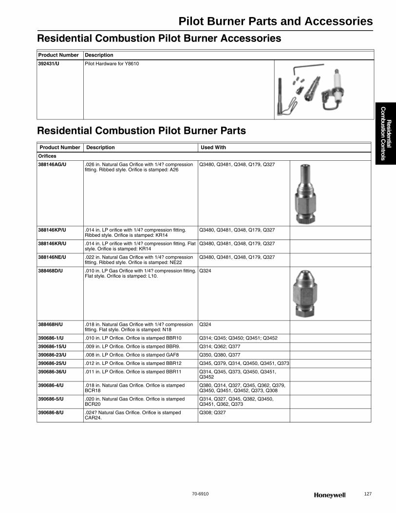
Pilot Burner Parts and Accessories
70-6910 127
R
esidential C
ombustion C
ontrols
Residential Combustion Pilot Burner Accessories
Residential Combustion Pilot Burner Parts
Product Number Description
392431/U Pilot Hardware for Y8610
Product Number Description Used With
Orifices
388146AG/U .026 in. Natural Gas Orifice with 1/4? compression fitting. Ribbed style. Orifice is stamped: A26
Q3480, Q3481, Q348, Q179, Q327
388146KP/U .014 in. LP orifice with 1/4? compression fitting. Ribbed style. Orifice is stamped: KR14
Q3480, Q3481, Q348, Q179, Q327
388146KR/U .014 in. LP orifice with 1/4? compression fitting. Flat style. Orifice is stamped: KR14
Q3480, Q3481, Q348, Q179, Q327
388146NE/U .022 in. Natural Gas Orifice with 1/4? compression fitting. Ribbed style. Orifice is stamped: NE22
Q3480, Q3481, Q348, Q179, Q327
388468D/U .010 in. LP Gas Orifice with 1/4? compression fitting. Flat style. Orifice is stamped: L10.
Q324
388468H/U .018 in. Natural Gas Orifice with 1/4? compression fitting. Flat style. Orifice is stamped: N18
Q324
390686-1/U .010 in. LP Orifice. Orifice is stamped BBR10 Q314; Q345; Q3450; Q3451; Q3452
390686-15/U .009 in. LP Orifice. Orifice is stamped BBR9. Q314; Q362; Q377
390686-23/U .008 in. LP Orifice. Orifice is stamped GAF8 Q350, Q380, Q377
390686-25/U .012 in. LP Orifice. Orifice is stamped BBR12 Q345, Q379, Q314, Q3450, Q3451, Q373
390686-36/U .011 in. LP Orifice. Orifice is stamped BBR11 Q314, Q345, Q373, Q3450, Q3451, Q3452
390686-4/U .018 in. Natural Gas Orifice. Orifice is stamped BCR18
Q380, Q314, Q327, Q345, Q362, Q379, Q3450, Q3451, Q3452, Q373, Q308
390686-5/U .020 in. Natural Gas Orifice. Orifice is stamped BCR20
Q314, Q327, Q345, Q382, Q3450, Q3451, Q362, Q373
390686-8/U .024? Natural Gas Orifice. Orifice is stamped CAR24.
Q308; Q327

Pilot Burner Parts and Accessories
128 customer.honeywell.com 70-6910
Compression Fittings
386449/U Compression fitting for 1/4 inch OD pilot tubing, 0.65 inch total overall length
Honeywell pilot burner assemblies for standing pilot and intermittent pilot applications
386449-1/U Compression fitting for 1/4 inch OD pilot tubing, 0.78 inch total overall length
Honeywell pilot burner assemblies for standing pilot and intermittent pilot applications
386449-4/U Compression fitting for 1/4 inch OD pilot tubing, 1.15 inch total overall length
Honeywell pilot burner assemblies for standing pilot and intermittent pilot applications
392449/U Compression fitting for 1/8 inch OD pilot tubing, 0.65 inch total overall length
Honeywell pilot burner assemblies for standing pilot and intermittent pilot applications
392449-1/U Compression fitting for 1/8 inch OD pilot tubing, 0.78 inch total overall length
Honeywell pilot burner assemblies for standing pilot and intermittent pilot applications
392449-4/U Compression fitting for 1/8 inch OD pilot tubing, 1.15 inch total overall length
Honeywell pilot burner assemblies for standing pilot and intermittent pilot applications
SmartValve Flame Rod Assemblies
Q3400A1024/U 30 in. Igniter Flame Rod Assembly Q3450, Q3480 hot surface pilot burner
Q3400A1081/U 36 in. Igniter Flame Rod Assembly Q3450, Q3480 hot surface pilot burner
Product Number Description Used With
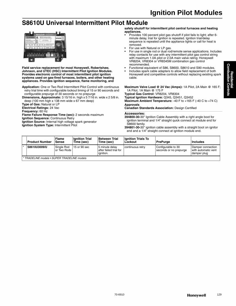
Ignition Pilot Modules
70-6910 129
R
esidential C
ombustion C
ontrols
S8610U Universal Intermittent Pilot Module
Field service replacement for most Honeywell, Robertshaw, Johnson, and UTEC (HSC) Intermittent Pilot Ignition Modules. Provides electronic control of most intermittent pilot ignition systems used on gas-fired furnaces, boilers, and other heating appliances. Provides ignition sequence, flame monitoring, and
safety shutoff for intermittent pilot central furnaces and heating appliances. • Provides 100 percent pilot gas shutoff if pilot fails to light; after 6-
minute delay, trial for ignition is repeated. Ignition trial/delay sequence is repeated until the appliance lights or call for heat is removed.
• For use with Natural or LP gas. • For use in single rod or dual rod/remote sense applications. Includes
relay contacts for use with any intermittent pilot gas control string with maximum 1.0A pilot or 2.0A main valve rating; Honeywell VR8204, VR8304 or VR8345M combination gas control recommended.
• Functional equivalent of S86, S8600, S8610 and S90 modules. • Includes spark cable adapters to allow field replacement of both
Honeywell and competitive controls without replacing existing spark cable.
Application: One or Two Rod Intermittent Pilot Control with continuous retry trial time with configurable lockout timing of 15 or 90 seconds and configurable prepurge of 30 seconds or no prepurge
Dimensions, Approximate: 3 15/16 in. high x 5 7/16 in. wide x 2 5/8 in. deep (100 mm high x 138 mm wide x 67 mm deep)
Type of Gas: Natural or LPElectrical Ratings: 24 VacFrequency: 60 HzFlame Failure Response Time (sec): 2 seconds maximumIgnition Sequence: Continuous RetryIgnition Source: Internal high voltage spark generatorIgnition System Type: Intermittent Pilot
Maximum Valve Load @ 24 Vac (Amps): 1A Pilot, 2A Main @ 165 F; 1A Pilot, 1A Main @ 175 F
Typical Gas Control: VR8204, VR8304Typical Ignition Hardware: Q345, Q3451, Q3452Maximum Ambient Temperature: -40 F to +165 F (-40 C to +74 C) ApprovalsCanadian Standards Association: Design Certified
Accessories:394800-30-30" Ignition Cable Assembly with a right angle boot for
ignition terminal and 1/4” straight quick connect at module end for S8600 family.
394801-30-30" ignition cable assembly with a straight boot on ignitor end and a 1/4” straight connect at ignition module end.
Product NumberFlame Sense
Ignition Trial Time (sec)
Between Trial Time (sec)
Ignition Trials To Lockout PrePurge Includes
* S8610U3009/U Single Rod or Two Rods
15 or 90 sec 5 minute delay after failed trial for ignition.
continuous retry Configurable to 30 seconds or no prepurge
Damper connection with automatic vent damper plug
* TRADELINE models • SUPER TRADELINE models
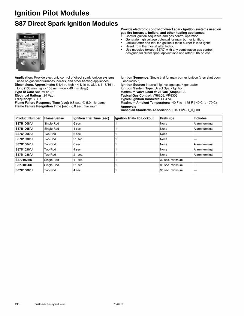
Ignition Pilot Modules
130 customer.honeywell.com 70-6910
S87 Direct Spark Ignition ModulesProvide electronic control of direct spark ignition systems used on gas fire furnaces, boilers, and other heating appliances.• Control ignition sequence and gas control operation. • Generate high voltage potential for main burner ignition. • Lockout after one trial for ignition if main burner fails to ignite. • Reset from thermostat after lockout. • Use modules (except S87C) with any combination gas control
designed for direct spark applications and rated 2.0A or less.
Application: Provide electronic control of direct spark ignition systems used on gas fired furnaces, boilers, and other heating appliances.
Dimensions, Approximate: 5 1/4 in. high x 4 1/16 in. wide x 1 15/16 in. long (133 mm high x 103 mm wide x 49 mm deep)
Type of Gas: Natural or LPElectrical Ratings: 24 VacFrequency: 60 HzFlame Failure Response Time (sec): 0.8 sec. @ 5.0 microampFlame Failure Re-ignition Time (sec): 0.8 sec. maximum
Ignition Sequence: Single trial for main burner ignition (then shut down and lockout)
Ignition Source: Internal high voltage spark generatorIgnition System Type: Direct Spark IgnitionMaximum Valve Load @ 24 Vac (Amps): 2ATypical Gas Control: VR8205, VR8305Typical Ignition Hardware: Q347AMaximum Ambient Temperature: -40 F to +175 F (-40 C to +79 C) ApprovalsCanadian Standards Association: File 112491_0_000
Product Number Flame Sense Ignition Trial Time (sec) Ignition Trials To Lockout PrePurge Includes
S87B1008/U Single Rod 6 sec. 1 None Alarm terminal
S87B1065/U Single Rod 4 sec. 1 None Alarm terminal
S87C1006/U Two Rod 6 sec. 1 None —
S87C1030/U Two Rod 21 sec. 1 None —
S87D1004/U Two Rod 6 sec. 1 None Alarm terminal
S87D1020/U Two Rod 4 sec. 1 None Alarm terminal
S87D1038/U Two Rod 21 sec. 1 None Alarm terminal
S87J1026/U Single Rod 11 sec. 1 30 sec. minimum —
S87J1034/U Single Rod 21 sec. 1 30 sec. minimum —
S87K1008/U Two Rod 4 sec. 1 30 sec. minimum —
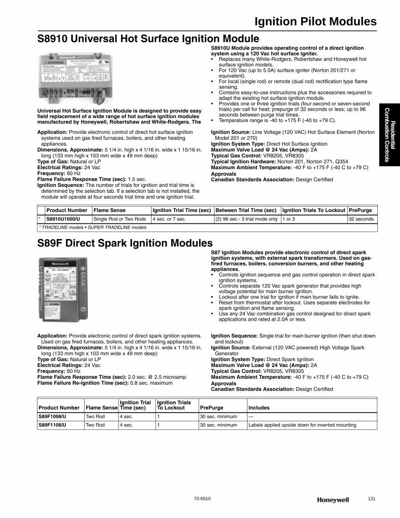
Ignition Pilot Modules
70-6910 131
R
esidential C
ombustion C
ontrols
S8910 Universal Hot Surface Ignition Module
Universal Hot Surface Ignition Module is designed to provide easy field replacement of a wide range of hot surface ignition modules manufactured by Honeywell, Robertshaw and White-Rodgers. The
S8910U Module provides operating control of a direct ignition system using a 120 Vac hot surface igniter.• Replaces many White-Rodgers, Robertshaw and Honeywell hot
surface ignition models. • For 120 Vac (up to 5.0A) surface igniter (Norton 201/271 or
equivalent). • For local (single rod) or remote (dual rod) rectification type flame
sensing. • Contains easy-to-use instructions plus the accessories required to
adapt the existing hot surface ignition module. • Provides one or three ignition trials (four-second or seven-second
trials) per call for heat; prepurge of 32 seconds or less; up to 96 seconds between purge trial times.
• Temperature range is -40 to +175 F (-40 to +79 C).
Application: Provide electronic control of direct hot surface ignition systems used on gas fired furnaces, boilers, and other heating appliances.
Dimensions, Approximate: 5 1/4 in. high x 4 1/16 in. wide x 1 15/16 in. long (133 mm high x 103 mm wide x 49 mm deep)
Type of Gas: Natural or LPElectrical Ratings: 24 VacFrequency: 60 HzFlame Failure Response Time (sec): 1.5 sec.Ignition Sequence: The number of trials for ignition and trial time is
determined by the selection tab. If a selection tab is not installed, the module will operate at four seconds trial time and one ignition trial.
Ignition Source: Line Voltage (120 VAC) Hot Surface Element (Norton Model 201 or 270)
Ignition System Type: Direct Hot Surface IgnitionMaximum Valve Load @ 24 Vac (Amps): 2ATypical Gas Control: VR8205, VR8305Typical Ignition Hardware: Norton 201, Norton 271, Q354Maximum Ambient Temperature: -40 F to +175 F (-40 C to +79 C) ApprovalsCanadian Standards Association: Design Certified
S89F Direct Spark Ignition ModulesS87 Ignition Modules provide electronic control of direct spark ignition systems, with external spark transformers. Used on gas-fired furnaces, boilers, conversion burners, and other heating appliances.• Controls ignition sequence and gas control operation in direct spark
ignition systems. • Controls separate 120 Vac spark generator that provides high
voltage potential for main burner ignition. • Lockout after one trial for ignition if main burner fails to ignite. • Reset from thermostat after lockout. Uses separate electrodes for
spark ignition and flame sensing. • Use any 24 Vac combination gas control designed for direct spark
applications and rated at 2.0A or less.
Application: Provide electronic control of direct spark ignition systems. Used on gas fired furnaces, boilers, and other heating appliances.
Dimensions, Approximate: 5 1/4 in. high x 4 1/16 in. wide x 1 15/16 in. long (133 mm high x 103 mm wide x 49 mm deep)
Type of Gas: Natural or LPElectrical Ratings: 24 VacFrequency: 60 HzFlame Failure Response Time (sec): 2.0 sec. @ 2.5 microampFlame Failure Re-ignition Time (sec): 0.8 sec. maximum
Ignition Sequence: Single trial for main burner ignition (then shut down and lockout)
Ignition Source: External (120 VAC powered) High Voltage Spark Generator
Ignition System Type: Direct Spark IgnitionMaximum Valve Load @ 24 Vac (Amps): 2ATypical Gas Control: VR8205, VR8305Maximum Ambient Temperature: -40 F to +175 F (-40 C to +79 C) ApprovalsCanadian Standards Association: Design Certified
Product Number Flame Sense Ignition Trial Time (sec) Between Trial Time (sec) Ignition Trials To Lockout PrePurge
* S8910U1000/U Single Rod or Two Rods 4 sec. or 7 sec. (2) 96 sec.- 3 trial mode only 1 or 3 32 seconds
* TRADELINE models • SUPER TRADELINE models
Product Number Flame SenseIgnition Trial Time (sec)
Ignition Trials To Lockout PrePurge Includes
S89F1098/U Two Rod 4 sec. 1 30 sec. minimum —
S89F1106/U Two Rod 4 sec. 1 30 sec. minimum Labels applied upside down for inverted mounting
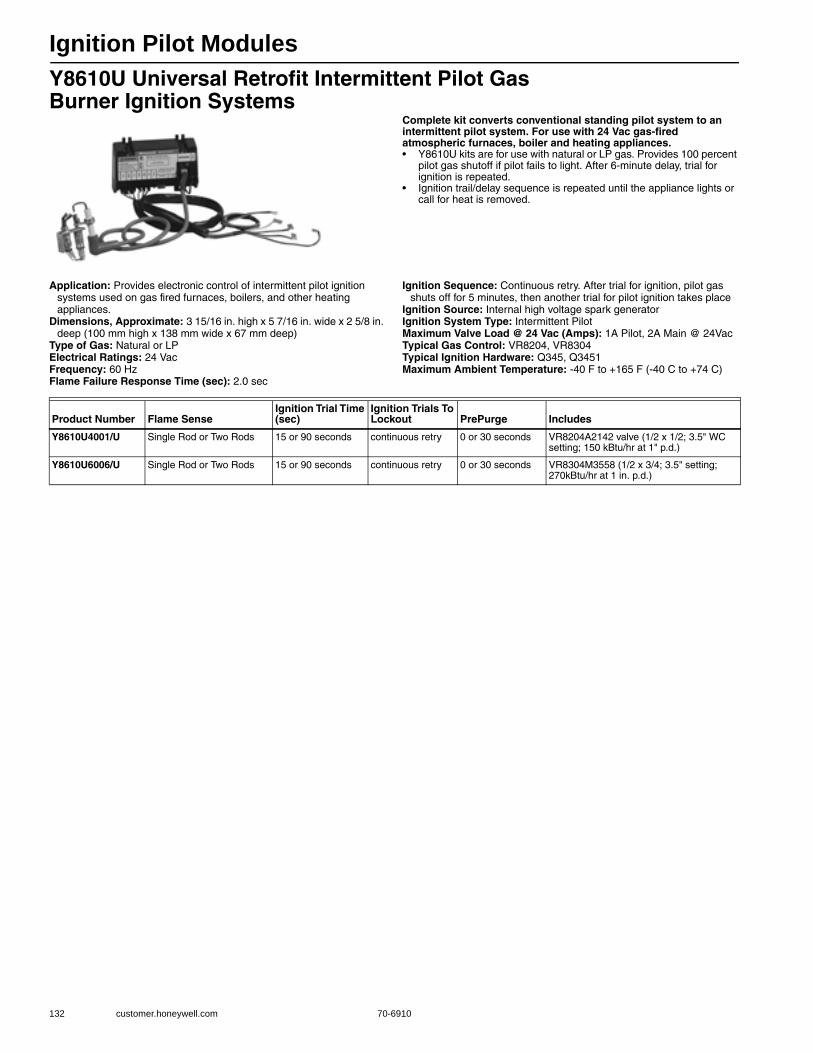
Ignition Pilot Modules
132 customer.honeywell.com 70-6910
Y8610U Universal Retrofit Intermittent Pilot Gas Burner Ignition Systems
Complete kit converts conventional standing pilot system to an intermittent pilot system. For use with 24 Vac gas-fired atmospheric furnaces, boiler and heating appliances.• Y8610U kits are for use with natural or LP gas. Provides 100 percent
pilot gas shutoff if pilot fails to light. After 6-minute delay, trial for ignition is repeated.
• Ignition trail/delay sequence is repeated until the appliance lights or call for heat is removed.
Application: Provides electronic control of intermittent pilot ignition systems used on gas fired furnaces, boilers, and other heating appliances.
Dimensions, Approximate: 3 15/16 in. high x 5 7/16 in. wide x 2 5/8 in. deep (100 mm high x 138 mm wide x 67 mm deep)
Type of Gas: Natural or LPElectrical Ratings: 24 VacFrequency: 60 HzFlame Failure Response Time (sec): 2.0 sec
Ignition Sequence: Continuous retry. After trial for ignition, pilot gas shuts off for 5 minutes, then another trial for pilot ignition takes place
Ignition Source: Internal high voltage spark generatorIgnition System Type: Intermittent PilotMaximum Valve Load @ 24 Vac (Amps): 1A Pilot, 2A Main @ 24VacTypical Gas Control: VR8204, VR8304Typical Ignition Hardware: Q345, Q3451Maximum Ambient Temperature: -40 F to +165 F (-40 C to +74 C)
Product Number Flame SenseIgnition Trial Time (sec)
Ignition Trials To Lockout PrePurge Includes
Y8610U4001/U Single Rod or Two Rods 15 or 90 seconds continuous retry 0 or 30 seconds VR8204A2142 valve (1/2 x 1/2; 3.5" WC setting; 150 kBtu/hr at 1" p.d.)
Y8610U6006/U Single Rod or Two Rods 15 or 90 seconds continuous retry 0 or 30 seconds VR8304M3558 (1/2 x 3/4; 3.5" setting; 270kBtu/hr at 1 in. p.d.)

Ignition Pilot Modules Selection Guide
70-6910 133
R
esidential C
ombustion C
ontrols
Ignition Pilot Modules Selection Guide
Notes:1. Ignition SequenceC = Continuous retry - After trial for ignition, pilot gas shuts off for 5 minutes, then another trial for pilot ignition takes place.P = The number of trials for ignition and trial time is determined by the selection tab. If a selection tab is not installed, the module will operate at four
seconds trial time and one ignition trial.
For a complete cross-reference, visit www.customer.honeywell.com
Applications Timings
Universal Service Part Ignition System Flame Sensor
Ignition Sequence (Note 1)
Ignition Trials To Lockout (Note 1) Ignition Trial Time Between Trial Time Pre-Purge
Flame Failure Response Time
S8910U1000/U Line Volt Hot Surface Ignition 1 or 2 Rods P 1 or 3 Field
Selectable4 sec. or 7 sec. Field Selectable
96 sec., 3 Trial Mode Only 32 sec. 1.5 sec
S8610U3009/U Intermittent Pilot 1 or 2 Rods C C 15 sec. or 90 sec. Field Selectable
5 Minute Delay After Failed Trial for Ignition
0 sec. or 30 sec. Field Selectable
2.0 sec. max.
Y8610U4001/U Intermittent Pilot 1 or 2 Rods C C 15 sec. or 90 sec. Field Selectable
5 Minute Delay After Failed Trial for Ignition 0 sec. 2.0 sec.
Y8610U6006/U Intermittent Pilot Single Rod C C 15 sec. or 90 sec. Field Selectable
5 Minute Delay After Failed Trial for Ignition 0 sec. 2.0 sec. max.
Features and Functions Cross-Reference
Universal Service Part Type of Gas
Ignition Source
Typical Ignition Hardware Includes Honeywell White-Rodgers Robertshaw
Johnson Controls
S8910U1000/U Nat or LP Switched Line Voltage
Norton 201, Norton 271, Hot
Surface Elements, Q354
Flame Rod
—
S89C1004, S89C1007, S89C1012, S89C1046, S89C1087, S89C1103, S89D1002, S89G1005, S89F1011, S89G1013, S89G1021, S89G1029, S89G1047, S89H1003,
S89H1011, S89H1029, S89J1008, S890D1006, S890G1003, S890G1037, S89H1002,
S890H1010
50E47 1-79, 101-179, 201-279, 301-379; 5047F1-79,
101-179, 201-279, 301-379
HS780-17NL 104A, 306A, 308A; HS780-17NR 104A, 306A, 308A; HS780-34NL 108A, 304A, 306A, 308A, 312A; HS780-34NR 104A, 306A, 308A, 312A; HS780-
34PL 308A
—
S8610U3009/U Nat or LP Internal Q345, Q3451, Q3452
Internal Damper
Connector
S86 Series, S90 Series, S8600 Series, S8610 Series, S8620 Series, S8660 Series, S8670
Series, S8680J1004
50D49-350, 50D49-360, 50D49-361, 50D50-843,
50D-401
710-713, 710-715, 735-737, 780-002, 780-003, 780-701, 780-715, 780-735,780-736, 780-737, 780-845, SP710,
SP715, SP720, SP730, SP735, SP750 Series
CSA42, 43, 44, 45, 46, 48, 49;
G60, G65, G67, G770
Series
Y8610U4001/U Nat or LP Internal Adapter for Pilot Burner Included
Internal Damper
ConnectorY8610U3029 — — —
Y8610U6006/U Nat or LP Internal Adapter for Pilot Burner Included
Internal Damper
ConnectorY8610U3003 — — —

Gas Ignition Module Accessories
134 customer.honeywell.com 70-6910
Gas Ignition Module AccessoriesProduct Number Description Used With
392125-1/U 25" ignition cable assembly with a right angle boot on the igniter end and a straight boot on the module end. For use with the S86/S87 family.
S86/S87 family;
392125-2/U 36" ignition cable assembly with a right angle boot on the igniter end and a straight boot on the module end. For use with the S86/S87 family.
S86/S87 family;
392125-5/U 18" ignition cable assembly with a right angle boot on the igniter end and a straight boot on the module end. For use with the S86/S87 family.
S86/S87 family;
393044/U Y86 Wiring Harness Assembly Y86
394800-30/U 30" Ignition Cable Assembly with a right angle boot for ignition terminal and 1/4” straight quick connect at module end for S8600 family.
S8600 family;
394800-36/U 36" Ignition Cable Assembly with a right angle boot for ignition terminal and 1/4” straight quick connect at module end for S8600 family.
S8600 family;
394801-30/U 30" ignition cable assembly with a straight boot on ignitor end and a 1/4” straight connect at ignition module end.
S8600 family;
394803-2/U 36" High Temperature right angle boot and cable Assembly for S8600 family
S8600 family;
4074EPM/U Rajah adapter for S8600 family S8600 family;
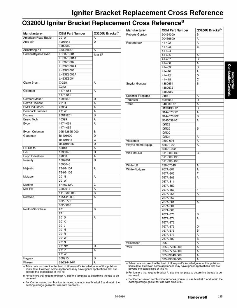
Igniter Bracket Replacement Cross Reference
70-6910 135
R
esidential C
ombustion C
ontrols
Q3200U Igniter Bracket Replacement Cross Referencea
Manufacturer OEM Part Number Q3200U Bracketb
American Road Equip. 201W AArco Air 1096048 D
1380680Armstrong Air 38322B001 ACarrier/Bryant/Payne LH33ZS001 B or Ec
LH33ZS001ALH33ZS002LH33ZS002ALH33ZS003LH33ZS003ALH33ZS004
Claire Bros. C-238 AC242
Coleman 1474-051 A1474-052
Comfort Maker 1096048 DDetroit Radiant 201D ADMO Industries 20834 ADornback Furnace 271W ADucane 20015201 BEnero Tech 10399 AEvcon 1474-051 A
1474-052Evcon Coleman 025-32625-000 BGoodman B1401009 D
B1401018 CB1401018S D
HB Smith 50018 AHeil 1096048 DHupp Industries 09050 AIntercity 1009604 D
1096048Majestic 75-92-104 A
75-92-105Metzger 201N A
201WModine 5H76032A CMor-Flo 3200618 A
511-330-193 BNordyne 105141000 A
632-0770632-0880
Norton/St Gobain 201 B271201D A201K201L201N201R201W271N271NM D271P A271W
Raypak 600915 BRheem 62-22441-01 Aa Table data is correct to the best of Honeywell’s knowledge as of this publica-
tion’s date. However, some appliances may have igniter applications that are beyond the capabilities of this kit.
b For igniters that require bracket A, use the template to determine the tab to be removed.
c For Carrier sealed combustion furnaces, you must use bracket E and retain the existing orange gasket for use with bracket E.
Roberts Gordon 90434300 B90436600 A
Robertshaw 41-402 A41-403 B41-40441-405 A41-407 B41-408 A41-409 B41-410 A41-412 D41-418 C
Snyder General 1380654 B13806721380680
Superior Fireplace 94851 ATempstar 1096048 DTrane 340039P01 A
B138196P01 BB144676P01 AB144676P02 BB340039P01 AIGN23IGN26 BIGN30IGN34 A
Viessman 9302-094 AWayne Home Equip. 62821-001 A
62821-002Weil McLain 511-330-139 B
511-330-190511-330-193
White LB 120-07549 AWhite-Rodgers 767A-301 A
767A-303 F767A-306 A767A-311767A-350767A-353 F767A-354 A767A-357 F767A-361 A767A-364767A-366767A-370 B767A-371 A767A-372767A-373 D767A-376 B767A-377 A767A-382 B
Williamson 9050 AYork 025-27766-000 A
025-27774-000 A025-29043-000 A025-29050-000 A
Manufacturer OEM Part Number Q3200U Bracketb
a Table data is correct to the best of Honeywell’s knowledge as of this publica-tion’s date. However, some appliances may have igniter applications that are beyond the capabilities of this kit.
b For igniters that require bracket A, use the template to determine the tab to be removed.
c For Carrier sealed combustion furnaces, you must use bracket E and retain the existing orange gasket for use with bracket E.
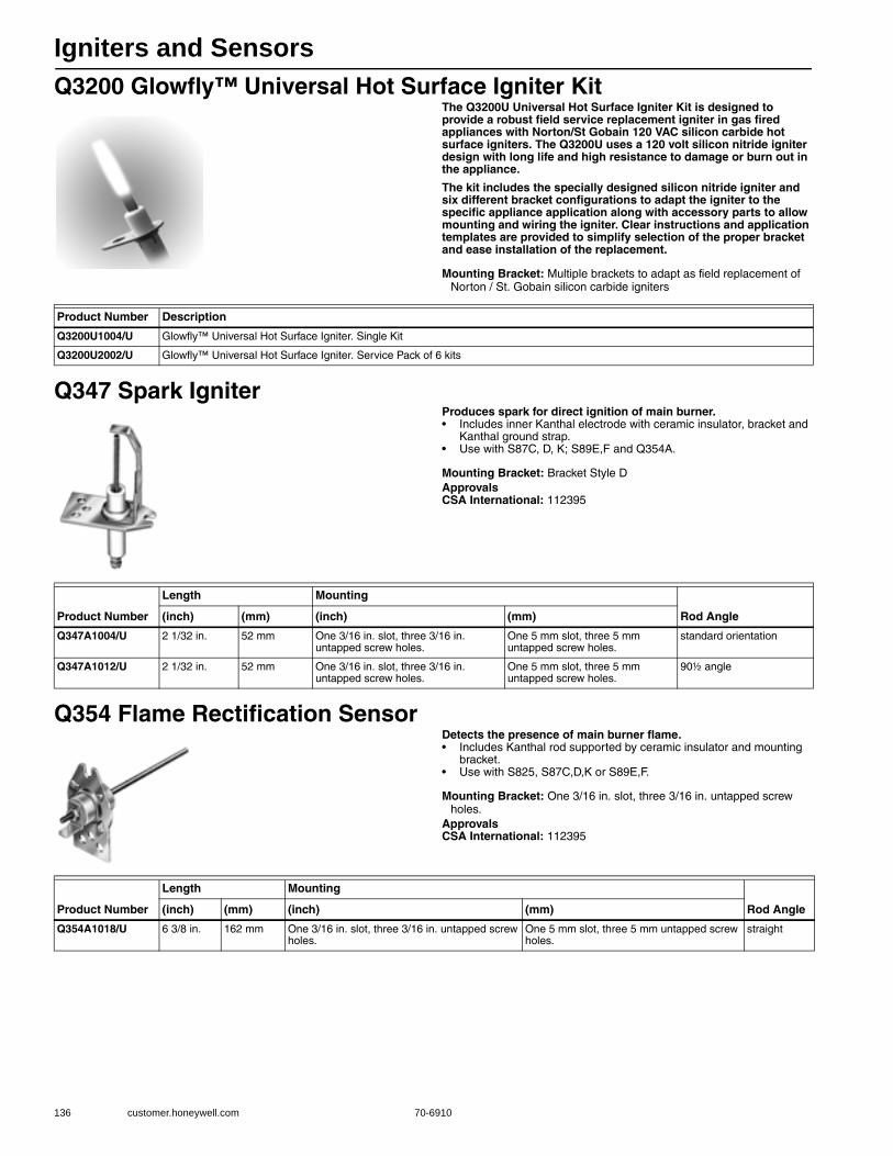
Igniters and Sensors
136 customer.honeywell.com 70-6910
Q3200 Glowfly™ Universal Hot Surface Igniter KitThe Q3200U Universal Hot Surface Igniter Kit is designed to provide a robust field service replacement igniter in gas fired appliances with Norton/St Gobain 120 VAC silicon carbide hot surface igniters. The Q3200U uses a 120 volt silicon nitride igniter design with long life and high resistance to damage or burn out in the appliance.
The kit includes the specially designed silicon nitride igniter and six different bracket configurations to adapt the igniter to the specific appliance application along with accessory parts to allow mounting and wiring the igniter. Clear instructions and application templates are provided to simplify selection of the proper bracket and ease installation of the replacement.
Mounting Bracket: Multiple brackets to adapt as field replacement of Norton / St. Gobain silicon carbide igniters
Q347 Spark IgniterProduces spark for direct ignition of main burner.• Includes inner Kanthal electrode with ceramic insulator, bracket and
Kanthal ground strap. • Use with S87C, D, K; S89E,F and Q354A.
Mounting Bracket: Bracket Style DApprovalsCSA International: 112395
Q354 Flame Rectification SensorDetects the presence of main burner flame.• Includes Kanthal rod supported by ceramic insulator and mounting
bracket. • Use with S825, S87C,D,K or S89E,F.
Mounting Bracket: One 3/16 in. slot, three 3/16 in. untapped screw holes.
ApprovalsCSA International: 112395
Product Number Description
Q3200U1004/U Glowfly™ Universal Hot Surface Igniter. Single Kit
Q3200U2002/U Glowfly™ Universal Hot Surface Igniter. Service Pack of 6 kits
Product Number
Length Mounting
Rod Angle(inch) (mm) (inch) (mm)
Q347A1004/U 2 1/32 in. 52 mm One 3/16 in. slot, three 3/16 in. untapped screw holes.
One 5 mm slot, three 5 mm untapped screw holes.
standard orientation
Q347A1012/U 2 1/32 in. 52 mm One 3/16 in. slot, three 3/16 in. untapped screw holes.
One 5 mm slot, three 5 mm untapped screw holes.
90½ angle
Product Number
Length Mounting
Rod Angle(inch) (mm) (inch) (mm)
Q354A1018/U 6 3/8 in. 162 mm One 3/16 in. slot, three 3/16 in. untapped screw holes.
One 5 mm slot, three 5 mm untapped screw holes.
straight
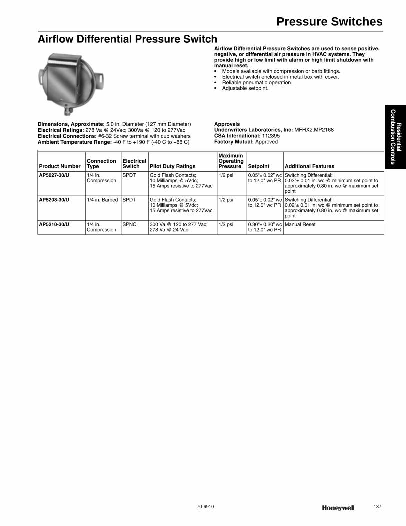
Pressure Switches
70-6910 137
R
esidential C
ombustion C
ontrols
Airflow Differential Pressure SwitchAirflow Differential Pressure Switches are used to sense positive, negative, or differential air pressure in HVAC systems. They provide high or low limit with alarm or high limit shutdown with manual reset.• Models available with compression or barb fittings. • Electrical switch enclosed in metal box with cover. • Reliable pneumatic operation.• Adjustable setpoint.
Dimensions, Approximate: 5.0 in. Diameter (127 mm Diameter) Electrical Ratings: 278 Va @ 24Vac; 300Va @ 120 to 277VacElectrical Connections: #6-32 Screw terminal with cup washersAmbient Temperature Range: -40 F to +190 F (-40 C to +88 C)
ApprovalsUnderwriters Laboratories, Inc: MFHX2.MP2168CSA International: 112395Factory Mutual: Approved
Product NumberConnection Type
Electrical Switch Pilot Duty Ratings
Maximum Operating Pressure Setpoint Additional Features
AP5027-30/U 1/4 in. Compression
SPDT Gold Flash Contacts; 10 Milliamps @ 5Vdc; 15 Amps resistive to 277Vac
1/2 psi 0.05“± 0.02” wc to 12.0" wc PR
Switching Differential: 0.02"± 0.01 in. wc @ minimum set point to approximately 0.80 in. wc @ maximum set point
AP5208-30/U 1/4 in. Barbed SPDT Gold Flash Contacts; 10 Milliamps @ 5Vdc; 15 Amps resistive to 277Vac
1/2 psi 0.05“± 0.02" wc to 12.0" wc PR
Switching Differential:0.02“± 0.01 in. wc @ minimum set point to approximately 0.80 in. wc @ maximum set point
AP5210-30/U 1/4 in. Compression
SPNC 300 Va @ 120 to 277 Vac; 278 Va @ 24 Vac
1/2 psi 0.30“± 0.20” wc to 12.0" wc PR
Manual Reset
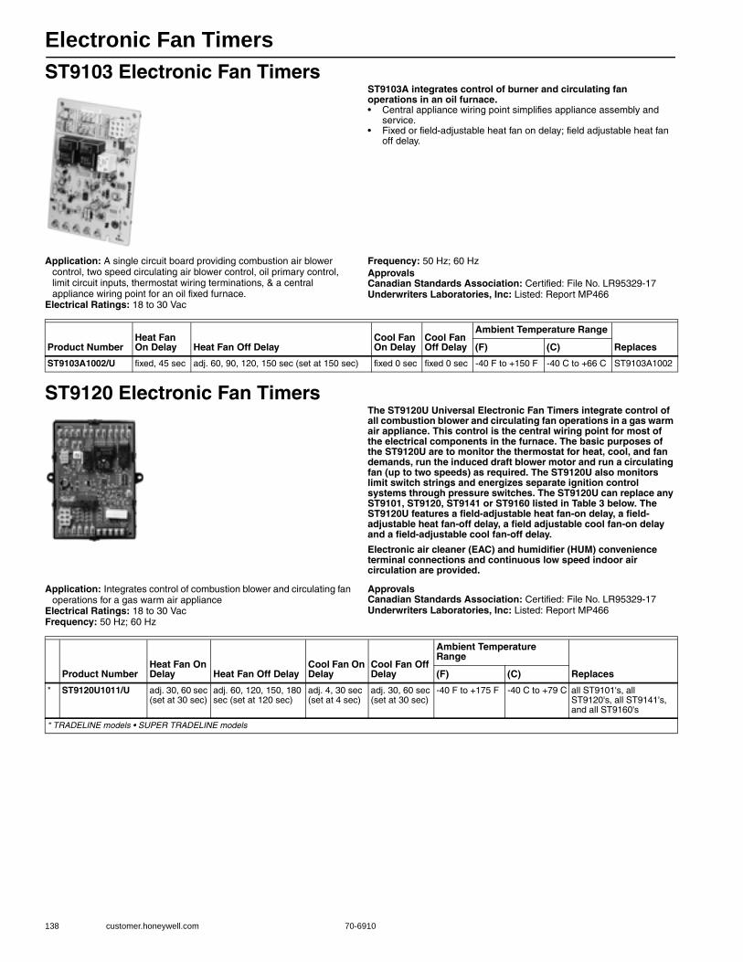
Electronic Fan Timers
138 customer.honeywell.com 70-6910
ST9103 Electronic Fan TimersST9103A integrates control of burner and circulating fan operations in an oil furnace.• Central appliance wiring point simplifies appliance assembly and
service. • Fixed or field-adjustable heat fan on delay; field adjustable heat fan
off delay.
Application: A single circuit board providing combustion air blower control, two speed circulating air blower control, oil primary control, limit circuit inputs, thermostat wiring terminations, & a central appliance wiring point for an oil fixed furnace.
Electrical Ratings: 18 to 30 Vac
Frequency: 50 Hz; 60 HzApprovalsCanadian Standards Association: Certified: File No. LR95329-17Underwriters Laboratories, Inc: Listed: Report MP466
ST9120 Electronic Fan TimersThe ST9120U Universal Electronic Fan Timers integrate control of all combustion blower and circulating fan operations in a gas warm air appliance. This control is the central wiring point for most of the electrical components in the furnace. The basic purposes of the ST9120U are to monitor the thermostat for heat, cool, and fan demands, run the induced draft blower motor and run a circulating fan (up to two speeds) as required. The ST9120U also monitors limit switch strings and energizes separate ignition control systems through pressure switches. The ST9120U can replace any ST9101, ST9120, ST9141 or ST9160 listed in Table 3 below. The ST9120U features a field-adjustable heat fan-on delay, a field-adjustable heat fan-off delay, a field adjustable cool fan-on delay and a field-adjustable cool fan-off delay.
Electronic air cleaner (EAC) and humidifier (HUM) convenience terminal connections and continuous low speed indoor air circulation are provided.
Application: Integrates control of combustion blower and circulating fan operations for a gas warm air appliance
Electrical Ratings: 18 to 30 VacFrequency: 50 Hz; 60 Hz
ApprovalsCanadian Standards Association: Certified: File No. LR95329-17Underwriters Laboratories, Inc: Listed: Report MP466
Product NumberHeat Fan On Delay Heat Fan Off Delay
Cool Fan On Delay
Cool Fan Off Delay
Ambient Temperature Range
Replaces(F) (C)
ST9103A1002/U fixed, 45 sec adj. 60, 90, 120, 150 sec (set at 150 sec) fixed 0 sec fixed 0 sec -40 F to +150 F -40 C to +66 C ST9103A1002
Product NumberHeat Fan On Delay Heat Fan Off Delay
Cool Fan On Delay
Cool Fan Off Delay
Ambient Temperature Range
Replaces(F) (C)
* ST9120U1011/U adj. 30, 60 sec (set at 30 sec)
adj. 60, 120, 150, 180 sec (set at 120 sec)
adj. 4, 30 sec (set at 4 sec)
adj. 30, 60 sec (set at 30 sec)
-40 F to +175 F -40 C to +79 C all ST9101's, all ST9120's, all ST9141's, and all ST9160's
* TRADELINE models • SUPER TRADELINE models
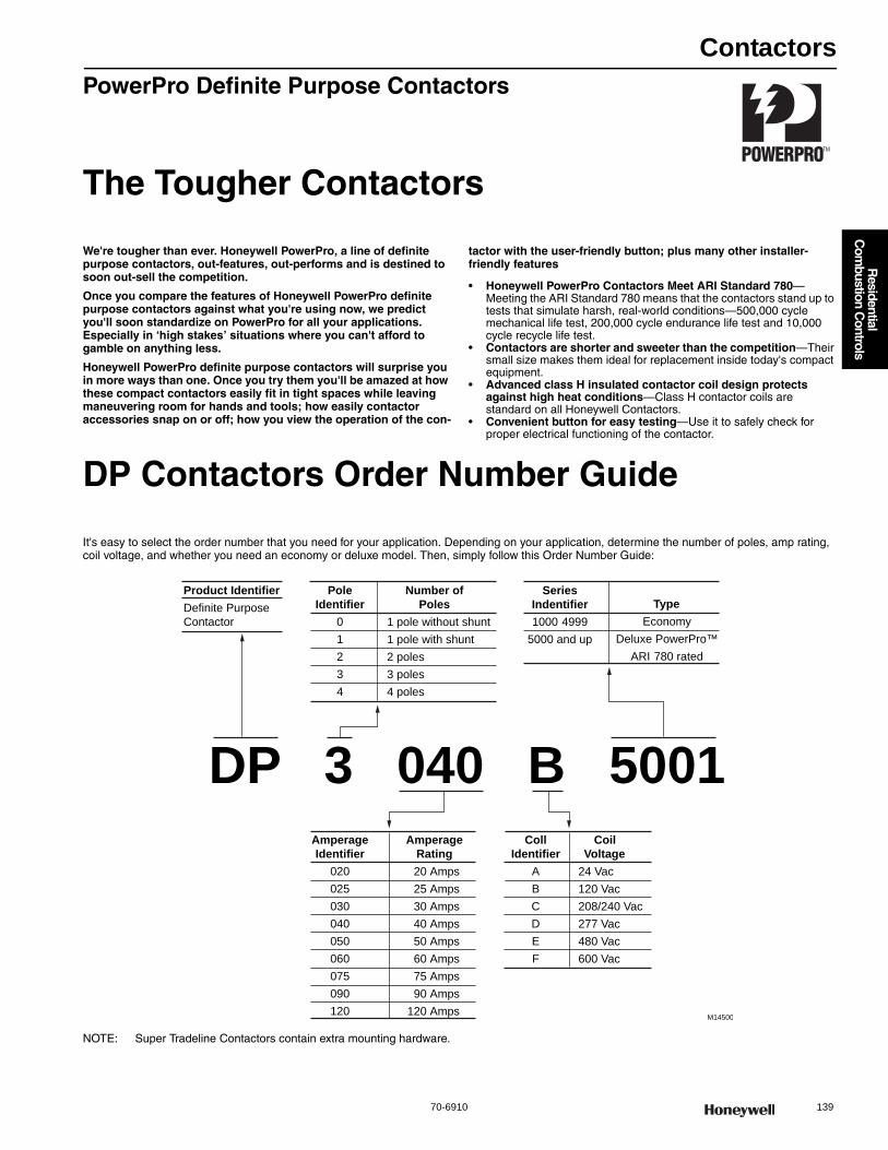
Contactors
70-6910 139
R
esidential C
ombustion C
ontrols
PowerPro Definite Purpose Contactors
The Tougher Contactors
We're tougher than ever. Honeywell PowerPro, a line of definite purpose contactors, out-features, out-performs and is destined to soon out-sell the competition.
Once you compare the features of Honeywell PowerPro definite purpose contactors against what you're using now, we predict you'll soon standardize on PowerPro for all your applications. Especially in ‘high stakes’ situations where you can't afford to gamble on anything less.
Honeywell PowerPro definite purpose contactors will surprise you in more ways than one. Once you try them you'll be amazed at how these compact contactors easily fit in tight spaces while leaving maneuvering room for hands and tools; how easily contactor accessories snap on or off; how you view the operation of the con-
tactor with the user-friendly button; plus many other installer-friendly features
• Honeywell PowerPro Contactors Meet ARI Standard 780—Meeting the ARI Standard 780 means that the contactors stand up to tests that simulate harsh, real-world conditions—500,000 cycle mechanical life test, 200,000 cycle endurance life test and 10,000 cycle recycle life test.
• Contactors are shorter and sweeter than the competition—Their small size makes them ideal for replacement inside today's compact equipment.
• Advanced class H insulated contactor coil design protects against high heat conditions—Class H contactor coils are standard on all Honeywell Contactors.
• Convenient button for easy testing—Use it to safely check for proper electrical functioning of the contactor.
DP Contactors Order Number Guide
It's easy to select the order number that you need for your application. Depending on your application, determine the number of poles, amp rating, coil voltage, and whether you need an economy or deluxe model. Then, simply follow this Order Number Guide:
NOTE: Super Tradeline Contactors contain extra mounting hardware.
Product IdentifierDefinite Purpose
Contactor
PoleIdentifier
0
1
2
3
4
Number ofPoles
AmperageIdentifier
020
025
030
040
050
060
075
090
120
AmperageRating
CollIdentifier
A
B
C
D
E
F
CoilVoltage
SeriesIndentifier1000 4999
5000 and up
TypeEconomy
Deluxe PowerPro™
ARI 780 rated
M14500
24 Vac
120 Vac
208/240 Vac
277 Vac
480 Vac
600 Vac
20 Amps
25 Amps
30 Amps
40 Amps
50 Amps
60 Amps
75 Amps
90 Amps
120 Amps
1 pole without shunt
1 pole with shunt
2 poles
3 poles
4 poles
DP 3 040 B 5001
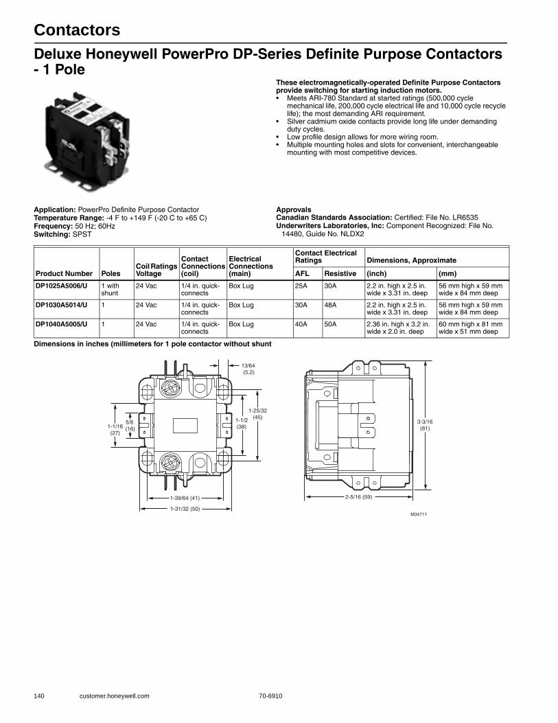
Contactors
140 customer.honeywell.com 70-6910
Deluxe Honeywell PowerPro DP-Series Definite Purpose Contactors - 1 Pole
These electromagnetically-operated Definite Purpose Contactors provide switching for starting induction motors.• Meets ARI-780 Standard at started ratings (500,000 cycle
mechanical life, 200,000 cycle electrical life and 10,000 cycle recycle life); the most demanding ARI requirement.
• Silver cadmium oxide contacts provide long life under demanding duty cycles.
• Low profile design allows for more wiring room. • Multiple mounting holes and slots for convenient, interchangeable
mounting with most competitive devices.
Application: PowerPro Definite Purpose ContactorTemperature Range: -4 F to +149 F (-20 C to +65 C) Frequency: 50 Hz; 60HzSwitching: SPST
ApprovalsCanadian Standards Association: Certified: File No. LR6535Underwriters Laboratories, Inc: Component Recognized: File No.
14480, Guide No. NLDX2
Dimensions in inches (millimeters for 1 pole contactor without shunt
Product Number PolesCoil Ratings Voltage
Contact Connections (coil)
Electrical Connections (main)
Contact Electrical Ratings Dimensions, Approximate
AFL Resistive (inch) (mm)
DP1025A5006/U 1 with shunt
24 Vac 1/4 in. quick-connects
Box Lug 25A 30A 2.2 in. high x 2.5 in. wide x 3.31 in. deep
56 mm high x 59 mm wide x 84 mm deep
DP1030A5014/U 1 24 Vac 1/4 in. quick-connects
Box Lug 30A 48A 2.2 in. high x 2.5 in. wide x 3.31 in. deep
56 mm high x 59 mm wide x 84 mm deep
DP1040A5005/U 1 24 Vac 1/4 in. quick-connects
Box Lug 40A 50A 2.36 in. high x 3.2 in. wide x 2.0 in. deep
60 mm high x 81 mm wide x 51 mm deep
3-3/16(81)
2-5/16 (59)
1-31/32 (50)
1-39/64 (41)
13/64 (5.2)
1-1/2(38)
1-25/32(45)
1-1/16(27)
5/8 (16)
M34711

Contactors
70-6910 141
R
esidential C
ombustion C
ontrols
Deluxe Honeywell PowerPro DP-Series Definite Purpose Contactors - 2 Pole
These electromagnetically-operated Definite Purpose Contactors provide switching for starting induction motors.• Meets ARI-780 Standard at started ratings (500,000 cycle
mechanical life, 200,000 cycle electrical life and 10,000 cycle recycle life); the most demanding ARI requirement.
• Silver cadmium oxide contacts provide long life under demanding duty cycles.
• Low profile design allows for more wiring room. • Multiple mounting holes and slots for convenient, interchangeable
mounting with most competitive devices.
Application: PowerPro Definite Purpose ContactorTemperature Range: -4 F to +149 F (-20 C to +65 C) Frequency: 50 Hz; 60HzSwitching: DPST
ApprovalsCanadian Standards Association: Certified: File No. LR6535Underwriters Laboratories, Inc: Component Recognized: File No.
14480, Guide No. NLDX2
Dimensions in inches (millimeters) for 2 Pole 25- 40 Amp Contactor
Product Number PolesCoil Ratings Voltage
Contact Connections (coil)
Electrical Connections (main)
Contact Electrical Ratings Dimensions, Approximate
AFL Resistive (inch) (mm)
DP2020A5022/U 2 24 Vac 1/4 in. quick-connects Box Lug 30A 25A 2.2 in. high x 2.5 in. wide x 3.31 in. deep
56 mm high x 59 mm wide x 84 mm deepDP2020B5039/U 2 120 Vac 1/4 in. quick-connects Box Lug 20A 25A
DP2030A5005/U 2 24 Vac 1/4 in. quick-connects Box Lug 30A 40A 3.25 in. high x 3.63 in. wide x 3.8 in. deep
83 mm high x 67 mm wide x 95 mm deepDP2030A5013/U 2 24 Vac 1/4 in. quick-connects Box Lug 30A 40A
DP2030B5004/U 2 120 Vac 1/4 in. quick-connects Box Lug 30A 40A 2.2 in. high x 2.5 in. wide x 3.31 in. deep
56 mm high x 59 mm wide x 84 mm deepDP2030B5012/U 2 120 Vac 1/4 in. quick-connects Box Lug 30A 40A
DP2030C5003/U 2 208 Vac/240 Vac 1/4 in. quick-connects Box Lug 30A 40A
DP2030C5011/U 2 208 Vac/240 Vac 1/4 in. quick-connects Box Lug 30A 40A
DP2030D5002/U 2 277 Vac 1/4 in. quick-connects Box Lug 30A 40A
DP2040A5004/U 2 24 Vac 1/4 in. quick-connects Box Lug 40A 48A 2.36 in. high x 3.2 in. wide x 2.0 in. deep
60 mm high x 81 mm wide x 51 mm deepDP2040B5003/U 2 120 Vac 1/4 in. quick-connects Box Lug 40A 50A
DP2040C5002/U 2 208 Vac/240 Vac 1/4 in. quick-connects Box Lug 50A 50A
3-3/16(81)
2-5/16 (59)
1-31/32 (50)
1-39/64 (41)
13/64 (5.2)
1-1/2(38)
1-25/32(45)
M34720
1-1/16(27)
5/8 (16)
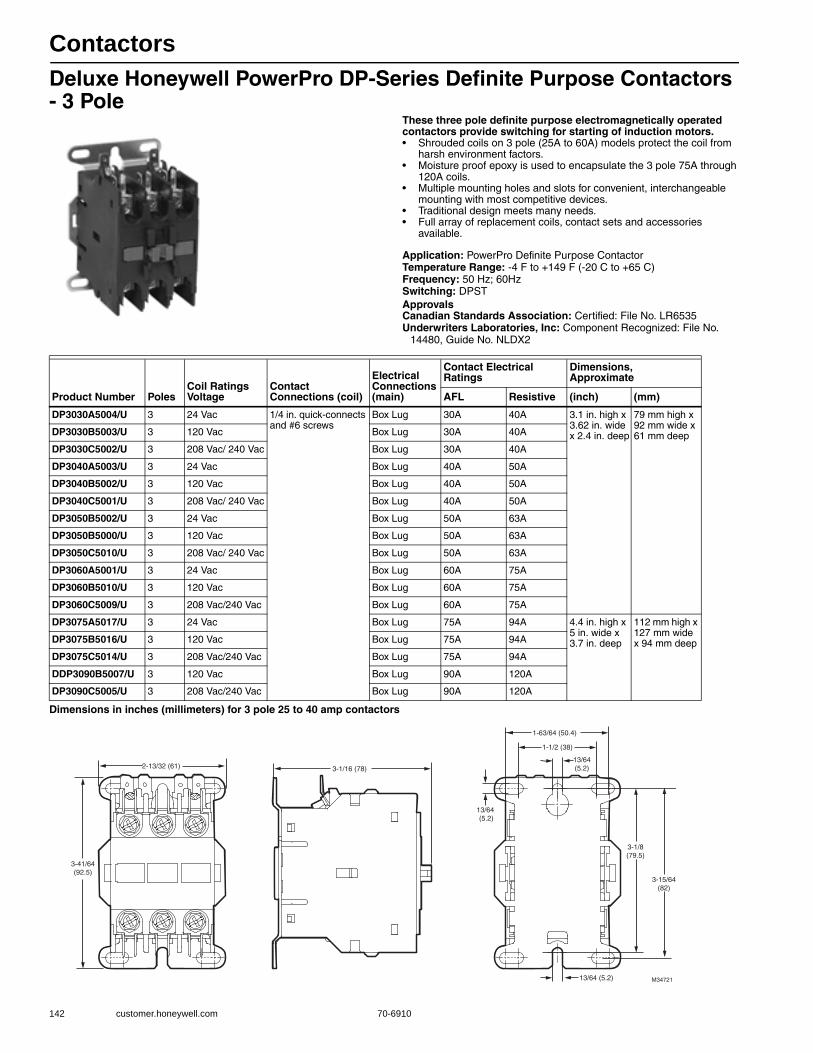
Contactors
142 customer.honeywell.com 70-6910
Deluxe Honeywell PowerPro DP-Series Definite Purpose Contactors - 3 Pole
These three pole definite purpose electromagnetically operated contactors provide switching for starting of induction motors.• Shrouded coils on 3 pole (25A to 60A) models protect the coil from
harsh environment factors. • Moisture proof epoxy is used to encapsulate the 3 pole 75A through
120A coils. • Multiple mounting holes and slots for convenient, interchangeable
mounting with most competitive devices. • Traditional design meets many needs. • Full array of replacement coils, contact sets and accessories
available.
Application: PowerPro Definite Purpose ContactorTemperature Range: -4 F to +149 F (-20 C to +65 C) Frequency: 50 Hz; 60HzSwitching: DPSTApprovalsCanadian Standards Association: Certified: File No. LR6535Underwriters Laboratories, Inc: Component Recognized: File No.
14480, Guide No. NLDX2
Dimensions in inches (millimeters) for 3 pole 25 to 40 amp contactors
Product Number PolesCoil Ratings Voltage
Contact Connections (coil)
Electrical Connections (main)
Contact Electrical Ratings
Dimensions, Approximate
AFL Resistive (inch) (mm)
DP3030A5004/U 3 24 Vac 1/4 in. quick-connects and #6 screws
Box Lug 30A 40A 3.1 in. high x 3.62 in. wide x 2.4 in. deep
79 mm high x 92 mm wide x 61 mm deepDP3030B5003/U 3 120 Vac Box Lug 30A 40A
DP3030C5002/U 3 208 Vac/ 240 Vac Box Lug 30A 40A
DP3040A5003/U 3 24 Vac Box Lug 40A 50A
DP3040B5002/U 3 120 Vac Box Lug 40A 50A
DP3040C5001/U 3 208 Vac/ 240 Vac Box Lug 40A 50A
DP3050B5002/U 3 24 Vac Box Lug 50A 63A
DP3050B5000/U 3 120 Vac Box Lug 50A 63A
DP3050C5010/U 3 208 Vac/ 240 Vac Box Lug 50A 63A
DP3060A5001/U 3 24 Vac Box Lug 60A 75A
DP3060B5010/U 3 120 Vac Box Lug 60A 75A
DP3060C5009/U 3 208 Vac/240 Vac Box Lug 60A 75A
DP3075A5017/U 3 24 Vac Box Lug 75A 94A 4.4 in. high x 5 in. wide x 3.7 in. deep
112 mm high x 127 mm wide x 94 mm deepDP3075B5016/U 3 120 Vac Box Lug 75A 94A
DP3075C5014/U 3 208 Vac/240 Vac Box Lug 75A 94A
DDP3090B5007/U 3 120 Vac Box Lug 90A 120A
DP3090C5005/U 3 208 Vac/240 Vac Box Lug 90A 120A
3-1/8(79.5)
3-1/16 (78)
3-41/64(92.5)
M3472113/64 (5.2)
13/64(5.2)
13/64 (5.2)
3-15/64(82)
2-13/32 (61)
1-63/64 (50.4)
1-1/2 (38)

Contactors
70-6910 143
R
esidential C
ombustion C
ontrols
Deluxe Honeywell PowerPro DP-Series Definite Purpose Contactors - 4 Pole
Definite purpose four (40A) pole contactors provide switching for across-the-line starting of induction motors.• Shrouded coils on 3 pole (25A to 60A) models protect the coil from
harsh environment factors. • Moisture proof epoxy is used to encapsulate the 3 pole 75A through
120A coils. • Multiple mounting holes and slots for convenient, interchangeable
mounting with most competitive devices. • Traditional design meets many needs.• Full array of replacement coils, contact sets and accessories
available.
Application: PowerPro Definite Purpose ContactorTemperature Range: -4 F to +149 F (-20 C to +65 C)Frequency: 50 Hz; 60HzSwitching: DPST
ApprovalsCanadian Standards Association: Certified: File No. LR6535Underwriters Laboratories, Inc: Component Recognized: File No.
14480, Guide No. NLDX2
Product Number PolesCoil Ratings Voltage
Contact Connections (coil)
Electrical Connections (main)
Contact Electrical Ratings Dimensions, Approximate
AFL Resistive (inch) (mm)
DP4040A5002/U 4 24 Vac 1/4 in. quick-connects and #6 screws
Box Lug 40A 50A 2.76 in. high x 3.75 in. wide x 3.43 in. deep
70 mm high x 95 mm wide x 97 mm deep
DP4040B5001/U 4 120 Vac 1/4 in. quick-connects and #6 screws
Box Lug 40A 50A 2.76 in. high x 3.75 in. wide x 3.43 in. deep
70 mm high x 95 mm wide x 97 mm deep
DP4040C5009/U 4 120 Vac 1/4 in. quick-connects and #6 screws
Box Lug 40A 50A 2.76 in. high x 3.75 in. wide x 3.43 in. deep
70 mm high x 95 mm wide x 97 mm deep
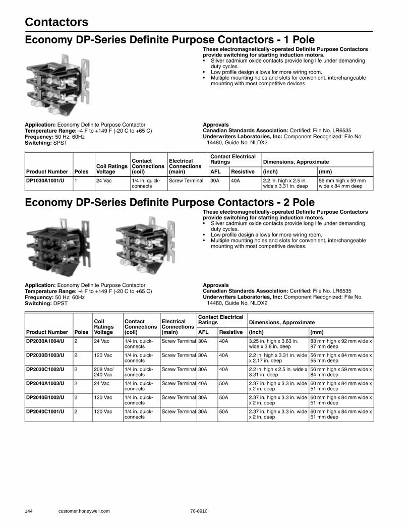
Contactors
144 customer.honeywell.com 70-6910
Economy DP-Series Definite Purpose Contactors - 1 PoleThese electromagnetically-operated Definite Purpose Contactors provide switching for starting induction motors.• Silver cadmium oxide contacts provide long life under demanding
duty cycles. • Low profile design allows for more wiring room. • Multiple mounting holes and slots for convenient, interchangeable
mounting with most competitive devices.
Application: Economy Definite Purpose ContactorTemperature Range: -4 F to +149 F (-20 C to +65 C) Frequency: 50 Hz; 60HzSwitching: SPST
ApprovalsCanadian Standards Association: Certified: File No. LR6535Underwriters Laboratories, Inc: Component Recognized: File No.
14480, Guide No. NLDX2
Economy DP-Series Definite Purpose Contactors - 2 PoleThese electromagnetically-operated Definite Purpose Contactors provide switching for starting induction motors.• Silver cadmium oxide contacts provide long life under demanding
duty cycles. • Low profile design allows for more wiring room. • Multiple mounting holes and slots for convenient, interchangeable
mounting with most competitive devices.
Application: Economy Definite Purpose ContactorTemperature Range: -4 F to +149 F (-20 C to +65 C) Frequency: 50 Hz; 60HzSwitching: DPST
ApprovalsCanadian Standards Association: Certified: File No. LR6535Underwriters Laboratories, Inc: Component Recognized: File No.
14480, Guide No. NLDX2
Product Number PolesCoil Ratings Voltage
Contact Connections (coil)
Electrical Connections (main)
Contact Electrical Ratings Dimensions, Approximate
AFL Resistive (inch) (mm)
DP1030A1001/U 1 24 Vac 1/4 in. quick-connects
Screw Terminal 30A 40A 2.2 in. high x 2.5 in. wide x 3.31 in. deep
56 mm high x 59 mm wide x 84 mm deep
Product Number Poles
Coil Ratings Voltage
Contact Connections (coil)
Electrical Connections (main)
Contact Electrical Ratings Dimensions, Approximate
AFL Resistive (inch) (mm)
DP2030A1004/U 2 24 Vac 1/4 in. quick-connects
Screw Terminal 30A 40A 3.25 in. high x 3.63 in. wide x 3.8 in. deep
83 mm high x 92 mm wide x 97 mm deep
DP2030B1003/U 2 120 Vac 1/4 in. quick-connects
Screw Terminal 30A 40A 2.2 in. high x 3.31 in. wide x 2.17 in. deep
56 mm high x 84 mm wide x 55 mm deep
DP2030C1002/U 2 208 Vac/ 240 Vac
1/4 in. quick-connects
Screw Terminal 30A 40A 2.2 in. high x 2.5 in. wide x 3.31 in. deep
56 mm high x 59 mm wide x 84 mm deep
DP2040A1003/U 2 24 Vac 1/4 in. quick-connects
Screw Terminal 40A 50A 2.37 in. high x 3.3 in. wide x 2 in. deep
60 mm high x 84 mm wide x 51 mm deep
DP2040B1002/U 2 120 Vac 1/4 in. quick-connects
Screw Terminal 30A 50A 2.37 in. high x 3.3 in. wide x 2 in. deep
60 mm high x 84 mm wide x 51 mm deep
DP2040C1001/U 2 120 Vac 1/4 in. quick-connects
Screw Terminal 30A 50A 2.37 in. high x 3.3 in. wide x 2 in. deep
60 mm high x 84 mm wide x 51 mm deep
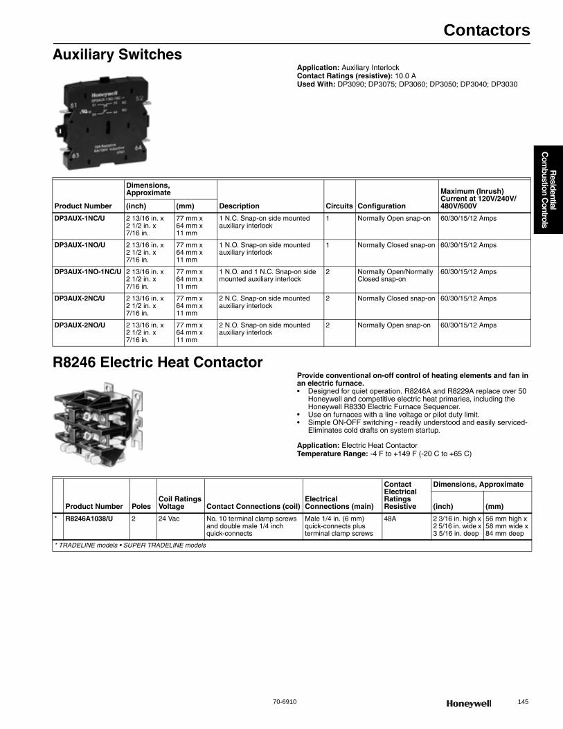
Contactors
70-6910 145
R
esidential C
ombustion C
ontrols
Auxiliary SwitchesApplication: Auxiliary InterlockContact Ratings (resistive): 10.0 AUsed With: DP3090; DP3075; DP3060; DP3050; DP3040; DP3030
R8246 Electric Heat ContactorProvide conventional on-off control of heating elements and fan in an electric furnace.• Designed for quiet operation. R8246A and R8229A replace over 50
Honeywell and competitive electric heat primaries, including the Honeywell R8330 Electric Furnace Sequencer.
• Use on furnaces with a line voltage or pilot duty limit. • Simple ON-OFF switching - readily understood and easily serviced-
Eliminates cold drafts on system startup.
Application: Electric Heat ContactorTemperature Range: -4 F to +149 F (-20 C to +65 C)
Product Number
Dimensions, Approximate
Description Circuits Configuration
Maximum (Inrush) Current at 120V/240V/480V/600V(inch) (mm)
DP3AUX-1NC/U 2 13/16 in. x 2 1/2 in. x 7/16 in.
77 mm x 64 mm x 11 mm
1 N.C. Snap-on side mounted auxiliary interlock
1 Normally Open snap-on 60/30/15/12 Amps
DP3AUX-1NO/U 2 13/16 in. x 2 1/2 in. x 7/16 in.
77 mm x 64 mm x 11 mm
1 N.O. Snap-on side mounted auxiliary interlock
1 Normally Closed snap-on 60/30/15/12 Amps
DP3AUX-1NO-1NC/U 2 13/16 in. x 2 1/2 in. x 7/16 in.
77 mm x 64 mm x 11 mm
1 N.O. and 1 N.C. Snap-on side mounted auxiliary interlock
2 Normally Open/Normally Closed snap-on
60/30/15/12 Amps
DP3AUX-2NC/U 2 13/16 in. x 2 1/2 in. x 7/16 in.
77 mm x 64 mm x 11 mm
2 N.C. Snap-on side mounted auxiliary interlock
2 Normally Closed snap-on 60/30/15/12 Amps
DP3AUX-2NO/U 2 13/16 in. x 2 1/2 in. x 7/16 in.
77 mm x 64 mm x 11 mm
2 N.O. Snap-on side mounted auxiliary interlock
2 Normally Open snap-on 60/30/15/12 Amps
Product Number PolesCoil Ratings Voltage Contact Connections (coil)
Electrical Connections (main)
Contact Electrical RatingsResistive
Dimensions, Approximate
(inch) (mm)
* R8246A1038/U 2 24 Vac No. 10 terminal clamp screws and double male 1/4 inch quick-connects
Male 1/4 in. (6 mm) quick-connects plus terminal clamp screws
48A 2 3/16 in. high x 2 5/16 in. wide x 3 5/16 in. deep
56 mm high x 58 mm wide x 84 mm deep
* TRADELINE models • SUPER TRADELINE models
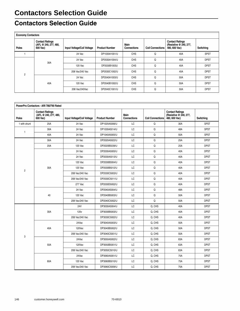
Contactors Selection Guide
146 customer.honeywell.com 70-6910
Contactors Selection Guide
Economy Contactors
Poles
Contact Ratings (AFL @ 240, 277, 480, 600 Vac) Input Voltage/Coil Voltage Product Number
Main Connections Coil Connections
Contact Ratings (Resistive @ 240, 277, 480, 600 Vac) Switching
1
30A
24 Vac DP1030A1001/U CHS Q 40A SPST
2
24 Vac DP2030A1004/U CHS Q 40A DPST
120 Vac DP2030B1003U CHS Q 40A DPST
208 Vac/240 Vac DP2030C1002/U CHS Q 40A DPST
40A
24 Vac DP2040A1003/U CHS Q 50A DPST
120 Vac DP2040B1002/U CHS Q 50A DPST
208 Vac/240Vac DP2040C1001/U CHS Q 50A DPST
PowerPro Contactors - ARI 780/790 Rated
Poles
Contact Ratings (AFL @ 240, 277, 480, 600 Vac) Input Voltage/Coil Voltage Product Number
Main Connections Coil Connections
Contact Ratings (Resistive @ 240, 277, 480, 600 Vac) Switching
1 with shunt 25A 24 Vac DP1025A5006/U LC Q 30A SPST
130A 24 Vac DP1030A5014/U LC Q 48A SPST
40A 24 Vac DP1040A5005/U LC Q 50A SPST
2
30A 24 Vac DP2020A5022/U LC Q 25A DPST
20A 120 Vac DP2020B5039/U LC Q 25A DPST
30A
24 Vac DP2030A5005/U LC Q 40A DPST
24 Vac DP2030A5013/U LC Q 40A DPST
120 Vac DP2030B5004/U LC Q 40A DPST
120 Vac DP2030B5012/U LC Q 40A DPST
208 Vac/240 Vac DP2030C5003/U LC Q 40A DPST
208 Vac/240 Vac DP2030C5011/U LC Q 40A DPST
277 Vac DP2030D5002/U LC Q 40A DPST
40
24 Vac DP2040A5004/U LC Q 48A DPST
120 Vac DP2040B5003/U LC Q 50A DPST
208 Vac/240 Vac DP2040C5002/U LC Q 50A DPST
3
30A
24V DP3030A5004/U LC Q, CHS 40A DPST
120v DP3030B5003/U LC Q, CHS 40A DPST
208 Vac/240 Vac DP3030C5002/U LC Q, CHS 40A DPST
40A
24Vac DP3040A5003/U LC Q, CHS 50A DPST
120Vac DP3040B5002/U LC Q, CHS 50A DPST
208 Vac/240 Vac DP3040C5001/U LC Q, CHS 50A DPST
50A
24Vac DP3050A5002/U LC Q, CHS 63A DPST
120Vac DP3050B5001/U LC Q, CHS 63A DPST
208 Vac/240 Vac DP3050C5010/U LC Q, CHS 63A DPST
60A
24Vac DP3060A5001/U LC Q, CHS 75A DPST
120 Vac DP3060B5010/U LC Q, CHS 75A DPST
208 Vac/240 Vac DP3060C5009/U LC Q, CHS 75A DPST

Contactors Selection Guide
70-6910 147
R
esidential C
ombustion C
ontrols
3
75A
24Vac DP3075A5017/U LC Q, CHS 94A DPST
120 Vac DP3075B5016/U LC Q, CHS 94A DPST
208 Vac/240 Vac DP3075C5015/U LC Q, CHS 94A DPST
90A120 Vac DP3090B5007/U LC Q, CHS 120A DPST
208 Vac/240 Vac DP3090C5006/U LC Q, CHS 120A DPST
4 40A
24 Vac DP4040A5002/U LC Q, CHS 50A DPST
120 Vac DP4040B5001/U LC Q, CHS 50A DPST
208 Vac/240 Vac DP4040C5010/U LC Q, CHS 50A DPST
Connectors:
CHS - #10-32 Combination Head Screw
LC - Lug Connector
Q - Quick Connect
S - # 6 Screw
SS - Sems Screw
TCS - Terminal Clamp Screw
Temp Rating: -4F to 149F
Approvals: UL, CSA
ARI -780: 500,000 cycle mechanical life; 200,000 cycle electrical life; 10,000 cycle recycle life
Electric Heat Contactor
Poles
Contact Ratings (AFL @ 240, 277, 480, 600 Vac)
Input Voltage/Coil Voltage Product Number
Dimensions (in.) H x W x D
Main Connections
Coil Connections
Contact Ratings (Resistive @ 240/277, 480, 600 Vac) Special Features
2 30 24 Vac R8246A1038 2.2 x 2 3 x 3.3 Q,S TCS,Q 48A @ 240/277 Vac
First Pole Resistive Only, Second Pole Resistive/Inductive Combined. ARI 780/790 rated.
Connectors:
CHS - #10-32 Combination Head Screw
LC - Lug Connector
Q - Quick Connect
S - # 6 Screw
SS - Sems Screw
TCS - Terminal Clamp Screw
Temp Rating: -4F to 149F
Approvals: UL, CSA
ARI -780: 500,000 cycle mechanical life; 200,000 cycle electrical life; 10,000 cycle recycle life
PowerPro Contactors - ARI 780/790 Rated
Poles
Contact Ratings (AFL @ 240, 277, 480, 600 Vac) Input Voltage/Coil Voltage Product Number
Main Connections Coil Connections
Contact Ratings (Resistive @ 240, 277, 480, 600 Vac) Switching
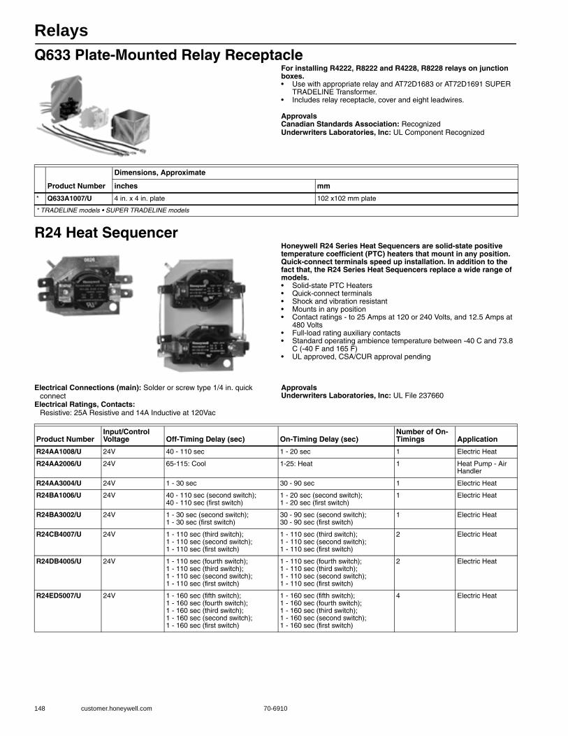
Relays
148 customer.honeywell.com 70-6910
Q633 Plate-Mounted Relay ReceptacleFor installing R4222, R8222 and R4228, R8228 relays on junction boxes.• Use with appropriate relay and AT72D1683 or AT72D1691 SUPER
TRADELINE Transformer. • Includes relay receptacle, cover and eight leadwires.
ApprovalsCanadian Standards Association: RecognizedUnderwriters Laboratories, Inc: UL Component Recognized
R24 Heat SequencerHoneywell R24 Series Heat Sequencers are solid-state positive temperature coefficient (PTC) heaters that mount in any position. Quick-connect terminals speed up installation. In addition to the fact that, the R24 Series Heat Sequencers replace a wide range of models.• Solid-state PTC Heaters • Quick-connect terminals • Shock and vibration resistant • Mounts in any position • Contact ratings - to 25 Amps at 120 or 240 Volts, and 12.5 Amps at
480 Volts • Full-load rating auxiliary contacts • Standard operating ambience temperature between -40 C and 73.8
C (-40 F and 165 F) • UL approved, CSA/CUR approval pending
Electrical Connections (main): Solder or screw type 1/4 in. quick connect
Electrical Ratings, Contacts: Resistive: 25A Resistive and 14A Inductive at 120Vac
ApprovalsUnderwriters Laboratories, Inc: UL File 237660
Product Number
Dimensions, Approximate
inches mm
* Q633A1007/U 4 in. x 4 in. plate 102 x102 mm plate
* TRADELINE models • SUPER TRADELINE models
Product NumberInput/Control Voltage Off-Timing Delay (sec) On-Timing Delay (sec)
Number of On-Timings Application
R24AA1008/U 24V 40 - 110 sec 1 - 20 sec 1 Electric Heat
R24AA2006/U 24V 65-115: Cool 1-25: Heat 1 Heat Pump - Air Handler
R24AA3004/U 24V 1 - 30 sec 30 - 90 sec 1 Electric Heat
R24BA1006/U 24V 40 - 110 sec (second switch); 40 - 110 sec (first switch)
1 - 20 sec (second switch); 1 - 20 sec (first switch)
1 Electric Heat
R24BA3002/U 24V 1 - 30 sec (second switch); 1 - 30 sec (first switch)
30 - 90 sec (second switch); 30 - 90 sec (first switch)
1 Electric Heat
R24CB4007/U 24V 1 - 110 sec (third switch); 1 - 110 sec (second switch); 1 - 110 sec (first switch)
1 - 110 sec (third switch); 1 - 110 sec (second switch); 1 - 110 sec (first switch)
2 Electric Heat
R24DB4005/U 24V 1 - 110 sec (fourth switch); 1 - 110 sec (third switch); 1 - 110 sec (second switch); 1 - 110 sec (first switch)
1 - 110 sec (fourth switch); 1 - 110 sec (third switch); 1 - 110 sec (second switch); 1 - 110 sec (first switch)
2 Electric Heat
R24ED5007/U 24V 1 - 160 sec (fifth switch); 1 - 160 sec (fourth switch); 1 - 160 sec (third switch); 1 - 160 sec (second switch); 1 - 160 sec (first switch)
1 - 160 sec (fifth switch); 1 - 160 sec (fourth switch); 1 - 160 sec (third switch); 1 - 160 sec (second switch); 1 - 160 sec (first switch)
4 Electric Heat
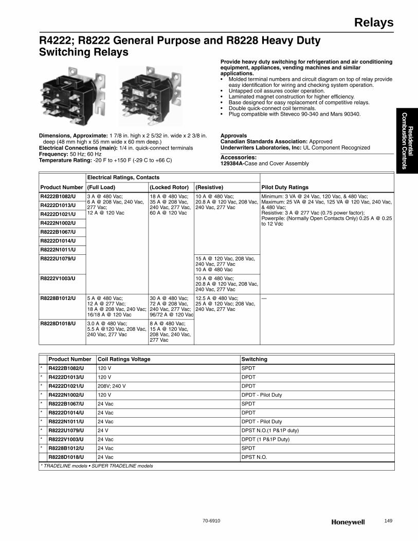
Relays
70-6910 149
R
esidential C
ombustion C
ontrols
R4222; R8222 General Purpose and R8228 Heavy Duty Switching Relays
Provide heavy duty switching for refrigeration and air conditioning equipment, appliances, vending machines and similar applications.• Molded terminal numbers and circuit diagram on top of relay provide
easy identification for wiring and checking system operation. • Untapped coil assures cooler operation. • Laminated magnet construction for higher efficiency. • Base designed for easy replacement of competitive relays. • Double quick-connect coil terminals. • Plug compatible with Steveco 90-340 and Mars 90340.
Dimensions, Approximate: 1 7/8 in. high x 2 5/32 in. wide x 2 3/8 in. deep (48 mm high x 55 mm wide x 60 mm deep.)
Electrical Connections (main): 1/4 in. quick-connect terminalsFrequency: 50 Hz; 60 HzTemperature Rating: -20 F to +150 F (-29 C to +66 C)
ApprovalsCanadian Standards Association: ApprovedUnderwriters Laboratories, Inc: UL Component Recognized
Accessories:129384A-Case and Cover Assembly
Product Number
Electrical Ratings, Contacts
Pilot Duty Ratings(Full Load) (Locked Rotor) (Resistive)
R4222B1082/U 3 A @ 480 Vac; 6 A @ 208 Vac, 240 Vac, 277 Vac; 12 A @ 120 Vac
18 A @ 480 Vac; 35 A @ 208 Vac, 240 Vac, 277 Vac, 60 A @ 120 Vac
10 A @ 480 Vac; 20.8 A @ 120 Vac, 208 Vac, 240 Vac, 277 Vac
Minimum: 3 VA @ 24 Vac, 120 Vac, & 480 Vac; Maximum: 25 VA @ 24 Vac, 125 VA @ 120 Vac, 240 Vac, & 480 Vac; Resistive: 3 A @ 277 Vac (0.75 power factor); Powerpile: (Normally Open Contacts Only) 0.25 A @ 0.25 to 12 Vdc
R4222D1013/U
R4222D1021/U
R4222N1002/U
R8222B1067/U
R8222D1014/U
R8222N1011/U
R8222U1079/U 15 A @ 120 Vac, 208 Vac, 240 Vac, 277 Vac10 A @ 480 Vac
R8222V1003/U 10 A @ 480 Vac; 20.8 A @ 120 Vac, 208 Vac, 240 Vac, 277 Vac
R8228B1012/U 5 A @ 480 Vac; 12 A @ 277 Vac; 18 A @ 208 Vac, 240 Vac; 16/18 A @ 120 Vac
30 A @ 480 Vac; 72 A @ 208 Vac, 240 Vac, 277 Vac; 96/72 A @ 120 Vac
12.5 A @ 480 Vac; 25 A @ 120 Vac; 208 Vac, 240 Vac, 277 Vac
—
R8228D1018/U 3.0 A @ 480 Vac; 5.5 A @120 Vac, 208 Vac, 240 Vac, 277 Vac
8 A @ 480 Vac; 15 A @ 120 Vac, 208 Vac, 240 Vac, 277 Vac
Product Number Coil Ratings Voltage Switching
* R4222B1082/U 120 V SPDT
* R4222D1013/U 120 V DPDT
* R4222D1021/U 208V; 240 V DPDT
* R4222N1002/U 120 V DPDT - Pilot Duty
* R8222B1067/U 24 Vac SPDT
* R8222D1014/U 24 Vac DPDT
* R8222N1011/U 24 Vac DPDT - Pilot Duty
* R8222U1079/U 24 V DPST N.O.(1 P&1P duty)
* R8222V1003/U 24 Vac DPDT (1 P&1P Duty)
* R8228B1012/U 24 Vac SPDT
R8228D1018/U 24 Vac DPST N.O.
* TRADELINE models • SUPER TRADELINE models

Relays
150 customer.honeywell.com 70-6910
R4225; R8225 Fan RelayProvide general purpose and heavy duty switching for refrigeration and air conditioning equipment, appliances, vending machines and similar applications.• Molded terminal numbers and circuit diagram on top of relay provide
easy identification for wiring and checking system operation. • Untapped coil assures cooler operation. • Laminated magnet construction for higher efficiency. • Base designed for easy replacement of competitive relays. • Double quick-connect coil terminals. • Plug compatible with Steveco 90-340 and Mars 90340.
Dimensions, Approximate: 2 11/16 in. high x 2 1/2 in. wide x 3 7/16 in. deep (68 mm high x 64 mm wide x 87 mm deep)
Electrical Connections (main): LeadwiresFrequency: 60 HzTemperature Rating: 115 F (46 C)
ApprovalsCanadian Standards Association: Certified: File No. LR95329-1Underwriters Laboratories, Inc: UL Listed: File No. E14480, Vol. 1.
Sec. 3, Guide No. NLDX
Accessories:129384A-Case and Cover Assembly
R8229 Electric Heat RelayNormally Closed Relays And Contactors For Load Control Systems.• Close and leave load operating in case of wiring or control problem,
or relay malfunction. • Consume no power while load is powered; require power only to
shed load. • Operate directly from a pilot duty rated relay in the load control
system.
Electrical Connections (main): #10 combination head screwsFrequency: 60 HzTemperature Rating: -40 F to +165 F (-40 C to +74 C) Electrical Ratings (Contacts):
Full Load: 2.8 A @ 600Vac; 3.5 A @ 480Vac; 7.0 A @ 120 Vac, 208 Vac, 240 Vac, 277 VacLocked Rotor: 14 A @ 600 Vac; 17.5 A @ 480 Vac; 35 A @ 120 Vac, 208 Vac, 240 Vac, 277 VacResistive: 10.0 A @ 600 Vac; 12.5 A @480 Vac; 25 A @ 120 Vac, 208 Vac, 240 Vac, 277 Vac
ApprovalsCanadian Standards Association: RecognizedUnderwriters Laboratories, Inc: UL Component Recognized
Dimensions in inches (millimeters)
Product Number Coil Ratings Voltage Switching
Electrical Ratings, Contacts
(Full Load) (Locked Rotor) (Resistive)
* R8225A1017/U 24 Vac SPDT N.O. 8.0A, N.C., 7.0A, Aux. 2.0A @ 240 Vac; N.O. 14.0A, N.C. 14.0A, Aux. 3.0A @ 120 Vac
N.O. 48.0 A, N.C. 42.0 A, Aux. 12.0 A @ 240 Vac; N.O. 84.0 A, N.C. 84.0 A, Aux. 18.0 A @ 120 Vac
N.O. 8.0 A, N.C. 7.0 A, Aux. 2.0 A @ 240 Vac; N.O. 16.0 A, N.C. 14.0 A, Aux. 3.0 A @ 120 Vac
R8225D1003/U 24 Vac DPST N.O. N.O. 8.0 A, Aux. 2.0 A @ 240 Vac; N.O. 14.0 A, Aux. 3.0 A @ 120 Vac
N.O. 48.0 A, Aux. 12.0 A @ 240 Vac; N.O. 84.0 A, Aux. 18.0 A @ 120 Vac
N.O. 8.0 A, Aux. 2.0 A @ 240 Vac;N.O. 16.0 A, Aux. 3.0 A @ 120 Vac
* TRADELINE models • SUPER TRADELINE models
41 (1-5/8)
6 (1/4)
(2)
5 (3/16)
(2)
8 (5/16)
6 (7/32)MC16622A
39
(1-17/32)
Product Number Coil Ratings Voltage Frequency Switching Includes
R8229A1005/U 24 Vac 60 Hz DPST —
• R8229A1021/U 24 Vac 60 Hz DPST Extra Mounting Hardware
* TRADELINE models • SUPER TRADELINE models
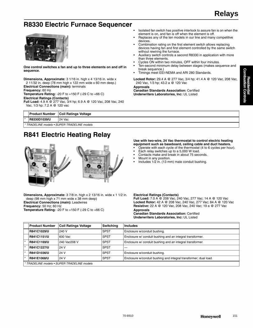
Relays
70-6910 151
R
esidential C
ombustion C
ontrols
R8330 Electric Furnace Sequencer
One control switches a fan and up to three elements on and off in sequence.
• Isolated fan switch has positive interlock to assure fan is on when the element is on, and fan is off when the element is off.
• Replaces any of the ten models in our line and many competitive devices.
• Combination rating on the first element switch allows replacing devices having fan and first element controlled by the same switch without rewiring the furnace.
• Auxiliary switch controls a second R8330 in application with more than three elements.
• Cycles ON within two minutes, OFF within four minutes. • Ten-second minimum delay between stages (makes sequence and
break sequence.) • Timings meet EEI-NEMA and ARI 280 Standards.
Dimensions, Approximate: 3 1/16 in. high x 4 13/16 in. wide x 2 11/32 in. deep (78 mm high x 122 mm wide x 60 mm deep.)
Electrical Connections (main): terminalsFrequency: 60 HzTemperature Rating: -20 F to +150 F (-29 C to +66 C) Electrical Ratings (Contacts)Full Load: 4.9 A @ 277 Vac, 3/4 hp; 6.9 A @ 120 Vac, 208 Vac, 240
Vac, 1/3 hp; 7.2 A @ 120 vac
Locked Rotor: 29.4 A @ 277 Vac, 3/4 hp; 41.4 A @ 120 Vac, 208 Vac, 240 Vac, 1/3 hp; 43.2 a @ 120 Vac
ApprovalsCanadian Standards Association: CertifiedUnderwriters Laboratories, Inc: UL Listed
R841 Electric Heating RelayUse with two-wire, 24 Vac thermostat to control electric heating equipment such as baseboard, ceiling cable and duct heaters.• Operate with each cycle of the thermostat (4 to 6 cycles per hour). • Each relay switches up to a 5,000 W load. • Contacts make and break in about 75 seconds. • Mount in any position. • Includes 1/2 in. (13 mm) male conduit bushing.
Dimensions, Approximate: 3 7/8 in. high x 2 13/16 in. wide x 1 1/2 in. deep (98 mm high x 71 mm wide x 38 mm deep)
Electrical Connections (main): LeadwiresFrequency: 50 Hz; 60 HzTemperature Rating: -20 F to +150 F (-29 C to +66 C)
Electrical Ratings (Contacts)Full Load: 7.0 A @ 208 Vac, 240 Vac, 277 Vac; 14 A @ 120 VacLocked Rotor: 42 A @ 208 Vac, 240 Vac, 277 Vac; 84 A @ 120 VacResistive: 22 A @ 120 Vac, 208 Vac, 240 Vac; 19 a @ 277 VacApprovalsCanadian Standards Association: CertifiedUnderwriters Laboratories, Inc: UL Listed
Product Number Coil Ratings Voltage
* R8330D1039/U 24 Vac
* TRADELINE models • SUPER TRADELINE models
Product Number Coil Ratings Voltage Switching Includes
R841C1029/U 240 V SPST Enclosure w/conduit bushing.
R841C1151/U 600 Vac SPST Enclosure w/ conduit bushing and an integral transformer.
* R841C1169/U 240 Vac208 V SPST Enclosure w/ conduit bushing and an integral transformer.
* R841C1227/U 24 V SPST —
* R841D1036/U 24 V SPST Enclosure w/conduit bushing.
* R841E1068/U 24 V SPST Enclosure w/conduit bushing and integral transformer; dual load.
* TRADELINE models • SUPER TRADELINE models
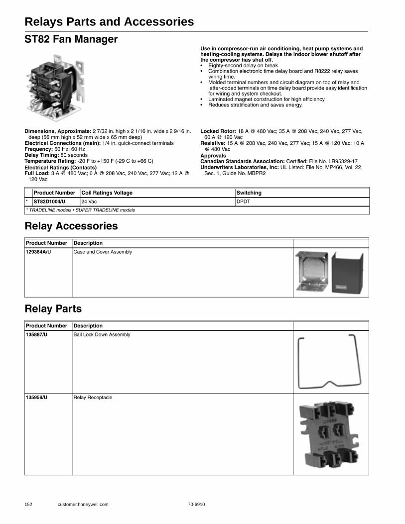
Relays Parts and Accessories
152 customer.honeywell.com 70-6910
ST82 Fan ManagerUse in compressor-run air conditioning, heat pump systems and heating-cooling systems. Delays the indoor blower shutoff after the compressor has shut off.• Eighty-second delay on break. • Combination electronic time delay board and R8222 relay saves
wiring time. • Molded terminal numbers and circuit diagram on top of relay and
letter-coded terminals on time delay board provide easy identification for wiring and system checkout.
• Laminated magnet construction for high efficiency. • Reduces stratification and saves energy.
Dimensions, Approximate: 2 7/32 in. high x 2 1/16 in. wide x 2 9/16 in. deep (56 mm high x 52 mm wide x 65 mm deep)
Electrical Connections (main): 1/4 in. quick-connect terminalsFrequency: 50 Hz; 60 HzDelay Timing: 80 secondsTemperature Rating: -20 F to +150 F (-29 C to +66 C) Electrical Ratings (Contacts)Full Load: 3 A @ 480 Vac; 6 A @ 208 Vac, 240 Vac, 277 Vac; 12 A @
120 Vac
Locked Rotor: 18 A @ 480 Vac; 35 A @ 208 Vac, 240 Vac, 277 Vac, 60 A @ 120 Vac
Resistive: 15 A @ 208 Vac, 240 Vac, 277 Vac; 15 A @ 120 Vac; 10 A @ 480 Vac
ApprovalsCanadian Standards Association: Certified: File No. LR95329-17Underwriters Laboratories, Inc: UL Listed: File No. MP466, Vol. 22,
Sec. 1, Guide No. MBPR2
Relay Accessories
Relay Parts
Product Number Coil Ratings Voltage Switching
* ST82D1004/U 24 Vac DPDT
* TRADELINE models • SUPER TRADELINE models
Product Number Description
129384A/U Case and Cover Assembly
Product Number Description
135887/U Bail Lock Down Assembly
135959/U Relay Receptacle
Relays Parts and Accessories
70-6910 153
R
esidential C
ombustion C
ontrols
Relays Selection Guide
Relays
Input Voltage/Coil Voltage Switching Product Number
Full Load Amp Rating Frequency Dimensions (in.) H x W X D
Electrical Connections (main) Special Features
24 V
DPST N.O. R8228D1018/U 5.5 A 1 7/8 x 2 5/32 x 2 3/8 Q —
DPDT (1 P&1PDuty) R8222V1003/U
12
A 1 7/8 x 2 5/32 x 2 3/8 Q —
DPDT - Pilot Duty R8222N1011/U A 1 7/8 x 2 5/32 x 2 3/8 Q Pilot Duty
DPDT R8222D1014/U A 1 7/8 x 2 5/32 x 2 3/8 Q —
DPDT ST82D1004/U A 2 7/32 x 2 1/16 x 2 9/16 Q 80 sec shut off delay
SPDT R8222B1067/U A 1 7/8 x 2 5/32 x 2 3/8 Q —
120 V
DPDT - Pilot Duty R4222N1002/U A 1 7/8 x 2 5/32 x 2 3/8 Q —
DPDT R4222D1013/U A 1 7/8 x 2 5/32 x 2 3/8 Q —
SPDT R4222B1082/U A 1 7/8 x 2 5/32 x 2 3/8 Q —
208V/240V DPDT R4222D1021/U A 1 7/8 x 2 5/32 x 2 3/8 Q —
24VSPDT R8225A1017/U
14
B 2 11/16 x 2 1/2 x 3 7/16 L —
DPST N.O. R8225D1003/U B 2 11/16 x 2 1/2 x 3 7/16 L —
120 V SPDT, 1 N.O., 1 N.C. R4225A1008/U B 2 11/16 x 2 1/2 x 3 7/16 L —
24 V SPDT R8228B1012/U 18 A 1 7/8 x 2 5/32 x 2 3/8 Q —
Frequency: A - 60Hz/50Hz; B - 60Hz, C - 50 Hz SPST Single Pole Single Throw
Approvals: UL, CSA DPST Double Pole Single Throw
Temp Rating: -20 F to +150 F; 115 F max for R8225 DPDT Double Pole Double Throw
Connectors: CHS - Combination Head Screw; L - Leadwires; Q - Quick connect; T - Terminals SPDT Single Pole Double Throw
Electric Heat Sequencer Selection Guide
154 customer.honeywell.com 70-6910
Electric Heat Sequencer Selection Guide
Electric Heat Relays
Input Voltage/Coil Voltage Switching Product Number
Full Load Amp Rating Frequency
Dimensions (in.) H x W X D
Electrical Connections (main) Special Features
24V DPSTR8229A1005/U
7B 2 3/16 x 2 3/32 x 2 1/4 CHS —
R8229A1021/U B 2 3/16 x 2 3/32 x 2 1/4 CHS Extra Mounting Hardware
24V SPST R841D1036/U
14
A 3 7/8 x 2 13/16 x 1 1/2 L 18A resistive @ 120/208/240VAC. Requires Transformer. Canada - replaces R841D1028
208/240V SPST R841C1169/U A 3 7/8 x 2 13/16 x 1 1/2 L 18A resistive @ 120/208/240VAC. Integral Transformer. Canada - replaces R841C1029
240V SPST R841E1068/U A 3 7/8 x 2 13/16 x 1 1/2 L 22A resistive @120/208/240VAC. Dual Load/integral transformer
347V SPST R841C1144/U A 3 7/8 x 2 13/16 x 1 1/2 L 18A resistive @120/208/240VAC. Integral Transformer. Canada
600V SPST R841C1151/U A 3 7/8 x 2 13/16 x 1 1/2 L 18A resistive @120/208/240VAC. Integral Transformer. Canada
Electric Furnace Sequencer
Input Voltage/Coil Voltage Product Number Full Load Amp Rating Frequency Dimensions (in.) H x W X D Electrical Connections (main)
24V R8330D1039/U 7.2 B 3 1/16 x 4 13/16 x 2 11/32 T
Electric Heat Contactor
Input Voltage/Coil Voltage Switching Product Number Full Load Amp Rating Dimensions (in.) H x W X D Electrical Connections (main)
24V DPST R8246A1038/U 30 2-3/16 x 2-1/4 x 3-5/16 Q,S
Frequency: A - 60Hz/50Hz; B - 60Hz, C - 50 Hz SPST Single Pole Single Throw
Approvals: UL, CSA DPST Double Pole Single Throw
Temp Rating: -20 F to +150 F; 115 F max for R8225 DPDT Double Pole Double Throw
Connectors: CHS - Combination Head Screw; L - Leadwires; Q - Quick connect; T - Terminals SPDT Single Pole Double Throw
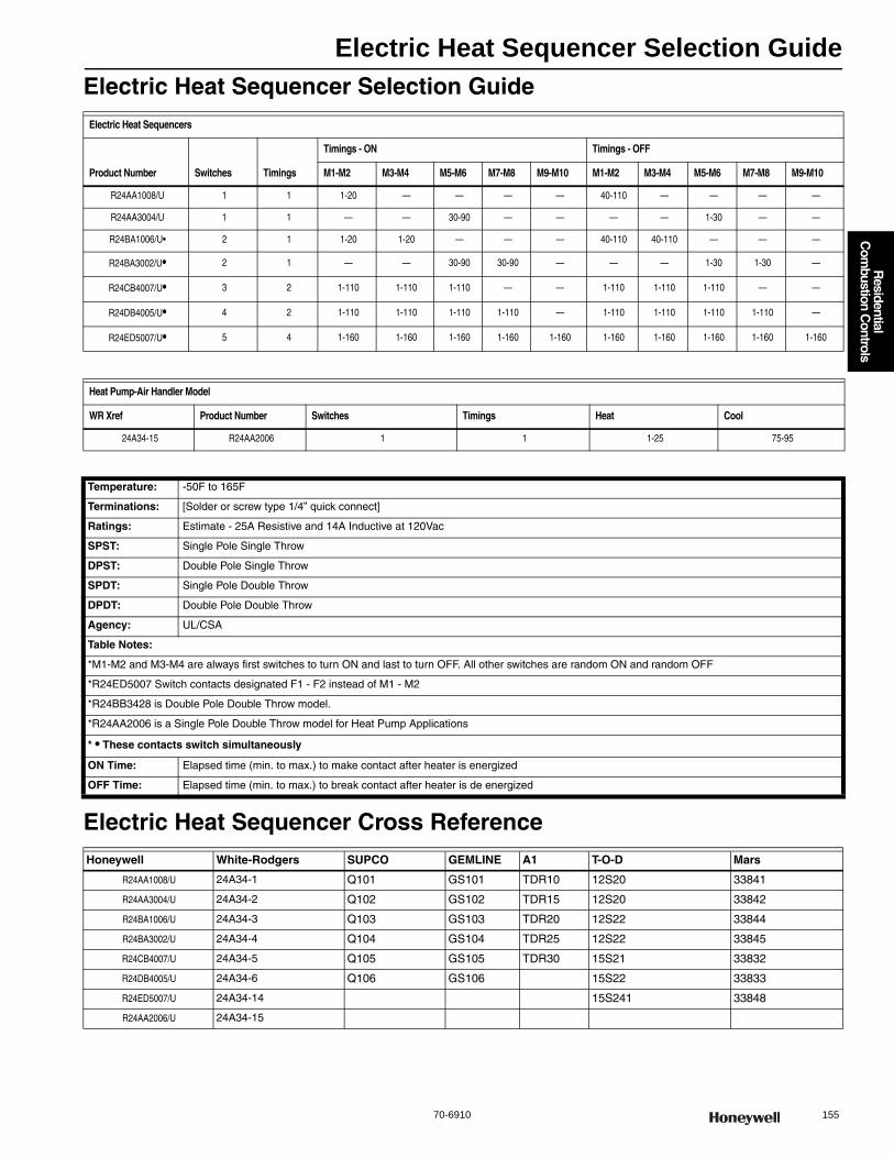
Electric Heat Sequencer Selection Guide
70-6910 155
R
esidential C
ombustion C
ontrols
Electric Heat Sequencer Selection Guide
Electric Heat Sequencer Cross Reference
Electric Heat Sequencers
Product Number Switches Timings
Timings - ON Timings - OFF
M1-M2 M3-M4 M5-M6 M7-M8 M9-M10 M1-M2 M3-M4 M5-M6 M7-M8 M9-M10
R24AA1008/U 1 1 1-20 — — — — 40-110 — — — —
R24AA3004/U 1 1 — — 30-90 — — — — 1-30 — —
R24BA1006/U• 2 1 1-20 1-20 — — — 40-110 40-110 — — —
R24BA3002/U• 2 1 — — 30-90 30-90 — — — 1-30 1-30 —
R24CB4007/U• 3 2 1-110 1-110 1-110 — — 1-110 1-110 1-110 — —
R24DB4005/U• 4 2 1-110 1-110 1-110 1-110 — 1-110 1-110 1-110 1-110 —
R24ED5007/U• 5 4 1-160 1-160 1-160 1-160 1-160 1-160 1-160 1-160 1-160 1-160
Heat Pump-Air Handler Model
WR Xref Product Number Switches Timings Heat Cool
24A34-15 R24AA2006 1 1 1-25 75-95
Temperature: -50F to 165F
Terminations: [Solder or screw type 1/4” quick connect]
Ratings: Estimate - 25A Resistive and 14A Inductive at 120Vac
SPST: Single Pole Single Throw
DPST: Double Pole Single Throw
SPDT: Single Pole Double Throw
DPDT: Double Pole Double Throw
Agency: UL/CSA
Table Notes:
*M1-M2 and M3-M4 are always first switches to turn ON and last to turn OFF. All other switches are random ON and random OFF
*R24ED5007 Switch contacts designated F1 - F2 instead of M1 - M2
*R24BB3428 is Double Pole Double Throw model.
*R24AA2006 is a Single Pole Double Throw model for Heat Pump Applications
* • These contacts switch simultaneously
ON Time: Elapsed time (min. to max.) to make contact after heater is energized
OFF Time: Elapsed time (min. to max.) to break contact after heater is de energized
Honeywell White-Rodgers SUPCO GEMLINE A1 T-O-D Mars
R24AA1008/U 24A34-1 Q101 GS101 TDR10 12S20 33841
R24AA3004/U 24A34-2 Q102 GS102 TDR15 12S20 33842
R24BA1006/U 24A34-3 Q103 GS103 TDR20 12S22 33844
R24BA3002/U 24A34-4 Q104 GS104 TDR25 12S22 33845
R24CB4007/U 24A34-5 Q105 GS105 TDR30 15S21 33832
R24DB4005/U 24A34-6 Q106 GS106 15S22 33833
R24ED5007/U 24A34-14 15S241 33848
R24AA2006/U 24A34-15

Fan Centers
156 customer.honeywell.com 70-6910
R8239 Control CenterInclude NEMA standard transformer for excellent voltage control. Provide low voltage control of line voltage fan motors and auxiliary circuits in heating, cooling or heating-cooling circuits.• NEMA standard Type D transformer (included) powers low voltage
control systems. • Provide overload protection for transformer. • Convenient connections for thermostat, and heating-cooling
equipment wiring. • Mount on standard 4 x 4 junction box. • Can be mounted in any indoor location without additional enclosure. • Relay is easily replaced without disturbing wiring. • Include relay enclosures.
Dimensions, Approximate: 4 1/2 in. high, 4 3/16 in. wide, 3 3/32 in. deep (114 mm high, 106 mm wide, 79 mm deep)
Electrical Ratings (W): 12 W maximumFrequency: 60 HzCoil Ratings (inrush): 20 VA maximum, 17 VA nominal.Coil Ratings (sealed): 10 VA maximum, 9 VA nominalApprovalsCanadian Standards Association: CertifiedNEMA Standard: NEMA Standard DC20-1992
Underwriters Laboratories, Inc: UL Listed
R8285 Control CenterProvides low voltage control of line voltage fan motors and auxiliary circuits in heating, cooling, or air conditioning systems.• Transformer powers low voltage control systems and provides
overload protection. • Low voltage terminal board provides convenient connections for
thermostat and heating/cooling equipment wiring. • Mounts on standard 4 x 4 in. junction box. • Relay is easily replaced without disturbing wiring.
Dimensions, Approximate: 4 3/16 in. high, 4 1/2 in. wide, 2 13/16 in. deep. (106 mm high, 114 mm wide, 71 mm deep)
Electrical Ratings (W): 11 W maximumFrequency: 60 HzApprovalsCanadian Standards Association: Certified: File No. LR95329-17Underwriters Laboratories, Inc: UL Component Recognized; File No.
E4436, Vol.15, Sec.1, Guide No.XAPX2
Product Number
Electrical Ratings
(120 Vac, Full Load)
(120 Vac, Locked Rotor)
(240 Vac, Full Load)
(240 Vac, Locked Rotor)
R8239A1052/U 12A 72A 6.9A 41.4A
R8239B1076/U 12A 72A 6.9A 41.4A
Product Number Application Horsepower VoltagePower Supply (Vac)
Power Supply (Secondary)
Switching Action Includes
* R8239A1052/U For single-or two speed fan. 3/4 HP 120 Vac 40 VA 26.5 V SPDT R8222B
• R8239B1076/U For system with F50 Electronic Air Cleaner humidifier and blower motor.
3/4 HP 208 Vac; 240 Vac; 120 Vac
50 VA 26.5 V DPDT R8222D
* TRADELINE models • SUPER TRADELINE models
Product Number
Electrical Ratings
(120 Vac, Full Load)
(120 Vac, Locked Rotor)
(240 Vac, Full Load)
(240 Vac, Locked Rotor)
R8285A1048/U 12A 72A 6A 35A
R8285B1053/U 12A 72A 6A 35A
R8285D5001/U 12A 72A 6A 35A
Product Number ApplicationHorse- power Voltage
Power Supply (Vac)
Power Supply (Secondary)
Switching Action Includes
* R8285A1048/U For single-or two speed fan. 3/4 HP 120 Vac 40 VA 26.5 V SPDT R8222B
* R8285B1053/U For “Total Comfort” applications with electronic air cleaner, humidifier and blower motor.
3/4 HP 208 Vac; 240 Vac; 120 Vac
40 VA 26.5 V DPDT R8222D
R8285D5001/U For Hydronic Applications; use with SV9600 SmartValve™ System and other systems that require 50 VA capacity.
3/4 HP 120 Vac 50 VA 26.5 V DPST (One Power Rated, One Pilot Duty)
R8222U
* TRADELINE models • SUPER TRADELINE models

Fan Center Selection Guide
70-6910 157
R
esidential C
ombustion C
ontrols
Fan Center Selection Guide
Fan Centers
Electrical Ratings- VA
Electrical Ratings - Input Voltage Switching Product Number NEMA
Dimensions (in.) H x W X D
Main Connections
Secondary Connections Frequency
Special Features
40VA 120 Vac
DPDT R8239B1043/U Yes 4 1/2 x 4 3/16 x 3 3/32 L L A Super Tradeline
DPST R8239D1007/U Yes 4 1/2 x 4 3/16 x 3 3/32 L L A —
DPST (1 Power, 1 Pilot)
R8239D1015/U Yes 4 1/2 x 4 3/16 x 3 3/32 L L A Tradeline
SPDT R8239A1052/U Yes 4 1/2 x 4 3/16 x 3 3/32 L L A Tradeline
SPDT R8239A1003/U Yes 4 1/2 x 4 3/16 x 3 3/32 L L A —
50VA120 Vac|240 Vac|208 Vac
DPDT R8239B1076/U Yes 4 1/2 x 4 3/16 x 3 3/32 L L A Super Tradeline
40VA
120 Vac SPDT R8285A1048/U No 4 3/16 x 4 1/2 x 2 13/16 L L A Tradeline
120 Vac|240 Vac|208 Vac
DPDT R8285B1053/U No 4 3/16 x 4 1/2 x 2 13/16 L L A Tradeline
50VA 120 Vac DPDT R8285D5001/U No 4 3/16 x 4 1/2 x 2 13/16 L L A —
Frequency: A - 60Hz/50Hz; B - 60Hz
Approvals: UL, CSA
Temp Rating: -20 F to +105 F
Connectors: L - Leadwires
Mounting: Standard 4 X 4 in. junction box
SuperTradeline models include extra hardware.
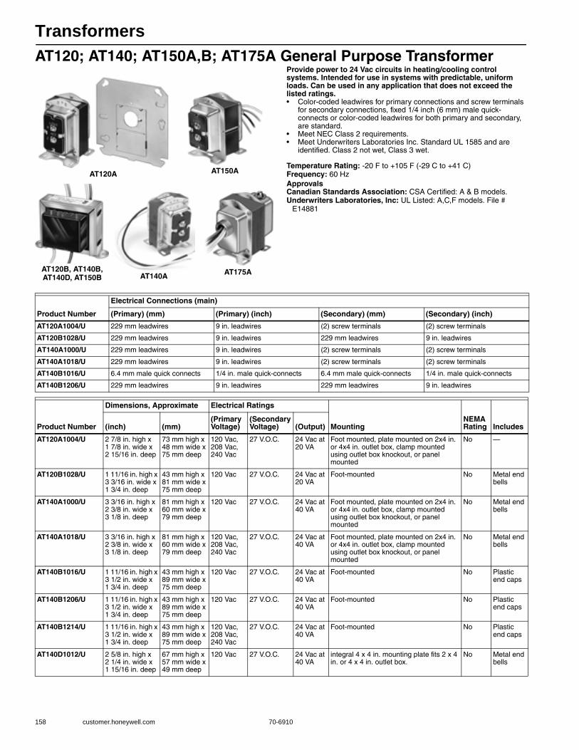
Transformers
158 customer.honeywell.com 70-6910
AT120; AT140; AT150A,B; AT175A General Purpose TransformerProvide power to 24 Vac circuits in heating/cooling control systems. Intended for use in systems with predictable, uniform loads. Can be used in any application that does not exceed the listed ratings.• Color-coded leadwires for primary connections and screw terminals
for secondary connections, fixed 1/4 inch (6 mm) male quick-connects or color-coded leadwires for both primary and secondary, are standard.
• Meet NEC Class 2 requirements. • Meet Underwriters Laboratories Inc. Standard UL 1585 and are
identified. Class 2 not wet, Class 3 wet.
Temperature Rating: -20 F to +105 F (-29 C to +41 C) Frequency: 60 HzApprovalsCanadian Standards Association: CSA Certified: A & B models.Underwriters Laboratories, Inc: UL Listed: A,C,F models. File #
E14881
AT120A AT150A
AT140A AT175AAT120B, AT140B,AT140D, AT150B
Product Number
Electrical Connections (main)
(Primary) (mm) (Primary) (inch) (Secondary) (mm) (Secondary) (inch)
AT120A1004/U 229 mm leadwires 9 in. leadwires (2) screw terminals (2) screw terminals
AT120B1028/U 229 mm leadwires 9 in. leadwires 229 mm leadwires 9 in. leadwires
AT140A1000/U 229 mm leadwires 9 in. leadwires (2) screw terminals (2) screw terminals
AT140A1018/U 229 mm leadwires 9 in. leadwires (2) screw terminals (2) screw terminals
AT140B1016/U 6.4 mm male quick connects 1/4 in. male quick-connects 6.4 mm male quick-connects 1/4 in. male quick-connects
AT140B1206/U 229 mm leadwires 9 in. leadwires 229 mm leadwires 9 in. leadwires
Product Number
Dimensions, Approximate Electrical Ratings
MountingNEMA Rating Includes(inch) (mm)
(Primary Voltage)
(Secondary Voltage) (Output)
AT120A1004/U 2 7/8 in. high x 1 7/8 in. wide x 2 15/16 in. deep
73 mm high x 48 mm wide x 75 mm deep
120 Vac, 208 Vac, 240 Vac
27 V.O.C. 24 Vac at 20 VA
Foot mounted, plate mounted on 2x4 in. or 4x4 in. outlet box, clamp mounted using outlet box knockout, or panel mounted
No —
AT120B1028/U 1 11/16 in. high x 3 3/16 in. wide x 1 3/4 in. deep
43 mm high x 81 mm wide x 75 mm deep
120 Vac 27 V.O.C. 24 Vac at 20 VA
Foot-mounted No Metal end bells
AT140A1000/U 3 3/16 in. high x 2 3/8 in. wide x 3 1/8 in. deep
81 mm high x 60 mm wide x 79 mm deep
120 Vac 27 V.O.C. 24 Vac at 40 VA
Foot mounted, plate mounted on 2x4 in. or 4x4 in. outlet box, clamp mounted using outlet box knockout, or panel mounted
No Metal end bells
AT140A1018/U 3 3/16 in. high x 2 3/8 in. wide x 3 1/8 in. deep
81 mm high x 60 mm wide x 79 mm deep
120 Vac, 208 Vac, 240 Vac
27 V.O.C. 24 Vac at 40 VA
Foot mounted, plate mounted on 2x4 in. or 4x4 in. outlet box, clamp mounted using outlet box knockout, or panel mounted
No Metal end bells
AT140B1016/U 1 11/16 in. high x 3 1/2 in. wide x 1 3/4 in. deep
43 mm high x 89 mm wide x 75 mm deep
120 Vac 27 V.O.C. 24 Vac at 40 VA
Foot-mounted No Plastic end caps
AT140B1206/U 1 11/16 in. high x 3 1/2 in. wide x 1 3/4 in. deep
43 mm high x 89 mm wide x 75 mm deep
120 Vac 27 V.O.C. 24 Vac at 40 VA
Foot-mounted No Plastic end caps
AT140B1214/U 1 11/16 in. high x 3 1/2 in. wide x 1 3/4 in. deep
43 mm high x 89 mm wide x 75 mm deep
120 Vac, 208 Vac, 240 Vac
27 V.O.C. 24 Vac at 40 VA
Foot-mounted No Plastic end caps
AT140D1012/U 2 5/8 in. high x 2 1/4 in. wide x 1 15/16 in. deep
67 mm high x 57 mm wide x 49 mm deep
120 Vac 27 V.O.C. 24 Vac at 40 VA
integral 4 x 4 in. mounting plate fits 2 x 4 in. or 4 x 4 in. outlet box.
No Metal end bells

Transformers
70-6910 159
R
esidential C
ombustion C
ontrols
Dimensions in inches (millimeters)
AT140 General Purpose Transformer for Hydronic Heating ControlsProvide power to 24 Vac circuits in heating/cooling control systems. Intended for use in systems with predictable, uniform loads. Can be used in any application that does not exceed the listed ratings.• Color-coded leadwires for primary connections and screw terminals
for secondary connections, fixed 1/4 inch (6 mm) male quick-connects or color-coded leadwires for both primary and secondary, are standard.
• Meet NEC Class 2 requirements. • Meet Underwriters Laboratories Inc. Standard UL 1585 and are
identified. Class 2 not wet, Class 3 wet.
Temperature Rating: -20 F to +105 F (-29 C to +41 C) Frequency: 60 HzElectrical Connections (main):
Primary: 9 in. leadwires (229 mm leadwires)Secondary: (2) screw terminals
ApprovalsCanadian Standards Association: CSA Certified: A & B models.Underwriters Laboratories, Inc: UL Listed: A,C,F models. File #
E14881
AT150A1007/U 1 11/16 in. high x 3 3/16 in. wide x 1 3/4 in. deep
43 mm high x 81 mm wide x 75 mm deep
120 Vac, 208 Vac, 240 Vac
27.5 V.O.C. 24 Vac at 50 VA
Foot mounted, plate mounted on 2x4 in. or 4x4 in. outlet box, clamp mounted using outlet box knockout, or panel mounted
No Metal end bells
AT150B1146/U 1 11/16 in. high x 3 1/2 in. wide x 1 3/4 in. deep
43 mm high x 89 mm wide x 75 mm deep
120 Vac, 208 Vac, 240 Vac
— 24 Vac at 50 VA
Foot-mounted No —
AT150B1252/U 1 11/16 in. high x 3 1/2 in. wide x 1 3/4 in. deep
43 mm high x 89 mm wide x 75 mm deep
277 Vac 27.5 V.O.C. 24 Vac at 50 VA
Foot-mounted No Plastic end caps
AT175A1008/U 3 3/16 in. high x 2 3/8 in. wide x 3 5/8 deep
81 mm high x 60 mm wide x 92 mm deep
120 Vac, 208 Vac, 240 Vac
27.5 V.O.C. 24 Vac at 75 VA
Foot mounted, plate mounted on 2x4 in. or 4x4 in. outlet box, clamp mounted using outlet box knockout, or panel mounted
NEMA type E
Metal end bells
Product Number
Dimensions, Approximate Electrical Ratings
MountingNEMA Rating Includes(inch) (mm)
(Primary Voltage)
(Secondary Voltage) (Output)
3-1/16 (78)
1-3/4
(44)
2 (51)1-1/16
(27)
PLATE MOUNTED AT THE
LAMINATIONS (3/4 ABOVE
PLATE MOUNTING)
MOUNTING PLATE
2-1/4
(57)
2-3/8
(60)
3-7/32
82
FOOT MOUNTED
D
2-15/16 (76)
PLATE OR OUTLET BOX
MOUNTED AT CLAMP
ON END BELL (ALL
ABOVE PLATE MOUNTING)
M17509A
2-3/8
(60)
1/4(6)
3-3/8 (86)
3-3/8(86)
4-3/16(106)
2(51)
3 -1/4 (83)5/16 (8)
1/8 (3)
1/8(3)
Product Number
Dimensions, Approximate Electrical Ratings
Mounting(inch) (mm)(Primary Voltage)
(Secondary Voltage) (Output)
AT140A1034/U 3 3/16 in. high x 2 3/8 in. wide x 3 1/8 in. deep
81 mm high x 60 mm wide x 79 mm deep
120 Vac 27 V.O.C. 24 Vac at 20 VA
Foot mounted, plate mounted on 2x4 in. or 4x4 in. outlet box, clamp mounted using outlet box knockout, or panel mounted
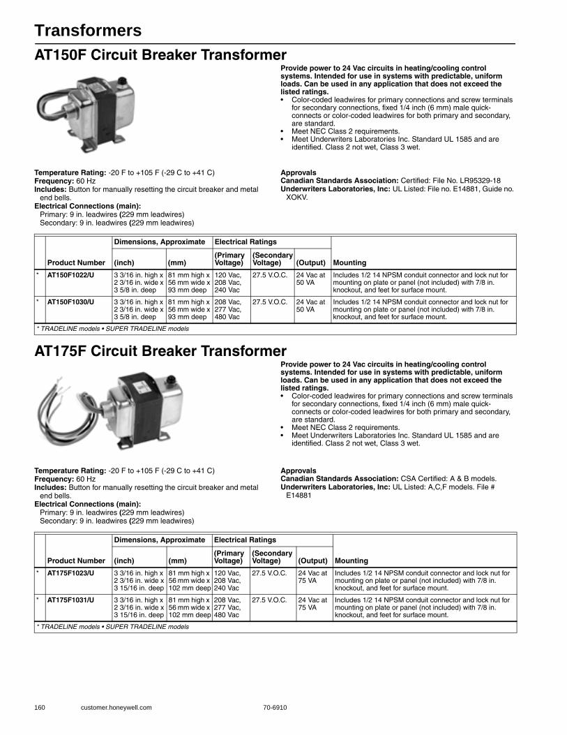
Transformers
160 customer.honeywell.com 70-6910
AT150F Circuit Breaker TransformerProvide power to 24 Vac circuits in heating/cooling control systems. Intended for use in systems with predictable, uniform loads. Can be used in any application that does not exceed the listed ratings.• Color-coded leadwires for primary connections and screw terminals
for secondary connections, fixed 1/4 inch (6 mm) male quick-connects or color-coded leadwires for both primary and secondary, are standard.
• Meet NEC Class 2 requirements. • Meet Underwriters Laboratories Inc. Standard UL 1585 and are
identified. Class 2 not wet, Class 3 wet.
Temperature Rating: -20 F to +105 F (-29 C to +41 C) Frequency: 60 HzIncludes: Button for manually resetting the circuit breaker and metal
end bells.Electrical Connections (main):
Primary: 9 in. leadwires (229 mm leadwires)Secondary: 9 in. leadwires (229 mm leadwires)
ApprovalsCanadian Standards Association: Certified: File No. LR95329-18Underwriters Laboratories, Inc: UL Listed: File no. E14881, Guide no.
XOKV.
AT175F Circuit Breaker TransformerProvide power to 24 Vac circuits in heating/cooling control systems. Intended for use in systems with predictable, uniform loads. Can be used in any application that does not exceed the listed ratings.• Color-coded leadwires for primary connections and screw terminals
for secondary connections, fixed 1/4 inch (6 mm) male quick-connects or color-coded leadwires for both primary and secondary, are standard.
• Meet NEC Class 2 requirements. • Meet Underwriters Laboratories Inc. Standard UL 1585 and are
identified. Class 2 not wet, Class 3 wet.
Temperature Rating: -20 F to +105 F (-29 C to +41 C) Frequency: 60 HzIncludes: Button for manually resetting the circuit breaker and metal
end bells.Electrical Connections (main):
Primary: 9 in. leadwires (229 mm leadwires)Secondary: 9 in. leadwires (229 mm leadwires)
ApprovalsCanadian Standards Association: CSA Certified: A & B models.Underwriters Laboratories, Inc: UL Listed: A,C,F models. File #
E14881
Product Number
Dimensions, Approximate Electrical Ratings
Mounting(inch) (mm)(Primary Voltage)
(Secondary Voltage) (Output)
* AT150F1022/U 3 3/16 in. high x 2 3/16 in. wide x 3 5/8 in. deep
81 mm high x 56 mm wide x 93 mm deep
120 Vac, 208 Vac, 240 Vac
27.5 V.O.C. 24 Vac at 50 VA
Includes 1/2 14 NPSM conduit connector and lock nut for mounting on plate or panel (not included) with 7/8 in. knockout, and feet for surface mount.
* AT150F1030/U 3 3/16 in. high x 2 3/16 in. wide x 3 5/8 in. deep
81 mm high x 56 mm wide x 93 mm deep
208 Vac, 277 Vac, 480 Vac
27.5 V.O.C. 24 Vac at 50 VA
Includes 1/2 14 NPSM conduit connector and lock nut for mounting on plate or panel (not included) with 7/8 in. knockout, and feet for surface mount.
* TRADELINE models • SUPER TRADELINE models
Product Number
Dimensions, Approximate Electrical Ratings
Mounting(inch) (mm)(Primary Voltage)
(Secondary Voltage) (Output)
* AT175F1023/U 3 3/16 in. high x 2 3/16 in. wide x 3 15/16 in. deep
81 mm high x 56 mm wide x 102 mm deep
120 Vac, 208 Vac, 240 Vac
27.5 V.O.C. 24 Vac at 75 VA
Includes 1/2 14 NPSM conduit connector and lock nut for mounting on plate or panel (not included) with 7/8 in. knockout, and feet for surface mount.
* AT175F1031/U 3 3/16 in. high x 2 3/16 in. wide x 3 15/16 in. deep
81 mm high x 56 mm wide x 102 mm deep
208 Vac, 277 Vac, 480 Vac
27.5 V.O.C. 24 Vac at 75 VA
Includes 1/2 14 NPSM conduit connector and lock nut for mounting on plate or panel (not included) with 7/8 in. knockout, and feet for surface mount.
* TRADELINE models • SUPER TRADELINE models
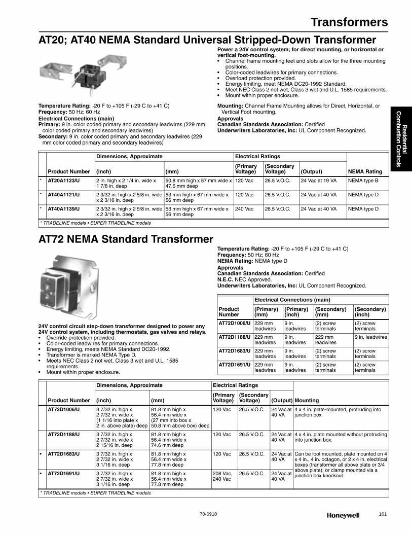
Transformers
70-6910 161
R
esidential C
ombustion C
ontrols
AT20; AT40 NEMA Standard Universal Stripped-Down TransformerPower a 24V control system; for direct mounting, or horizontal or vertical foot-mounting.• Channel frame mounting feet and slots allow for the three mounting
positions. • Color-coded leadwires for primary connections. • Overload protection provided. • Energy limiting, meet NEMA DC20-1992 Standard. • Meet NEC Class 2 not wet, Class 3 wet and U.L. 1585 requirements. • Mount within proper enclosure.
Temperature Rating: -20 F to +105 F (-29 C to +41 C) Frequency: 50 Hz; 60 HzElectrical Connections (main)Primary: 9 in. color coded primary and secondary leadwires (229 mm
color coded primary and secondary leadwires)Secondary: 9 in. color coded primary and secondary leadwires (229
mm color coded primary and secondary leadwires)
Mounting: Channel Frame Mounting allows for Direct, Horizontal, or Vertical Foot mounting.
ApprovalsCanadian Standards Association: CertifiedUnderwriters Laboratories, Inc: UL Component Recognized.
AT72 NEMA Standard Transformer
24V control circuit step-down transformer designed to power any 24V control system, including thermostats, gas valves and relays.• Override protection provided. • Color-coded leadwires for primary connections. • Energy limiting, meets NEMA Standard DC20-1992. • Transformer is marked NEMA Type D. • Meets NEC Class 2 not wet, Class 3 wet and U.L. 1585
requirements. • Mount within proper enclosure.
Temperature Rating: -20 F to +105 F (-29 C to +41 C) Frequency: 50 Hz; 60 HzNEMA Rating: NEMA type DApprovalsCanadian Standards Association: CertifiedN.E.C. NEC Approved.Underwriters Laboratories, Inc: UL Component Recognized.
Product Number
Dimensions, Approximate Electrical Ratings
NEMA Rating(inch) (mm)(Primary Voltage)
(Secondary Voltage) (Output)
* AT20A1123/U 2 in. high x 2 1/4 in. wide x 1 7/8 in. deep
50.8 mm high x 57 mm wide x 47.6 mm deep
120 Vac 26.5 V.O.C. 24 Vac at 19 VA NEMA type B
* AT40A1121/U 2 3/32 in. high x 2 5/8 in. wide x 2 3/16 in. deep
53 mm high x 67 mm wide x 56 mm deep
120 Vac 26.5 V.O.C. 24 Vac at 40 VA NEMA type D
* AT40A1139/U 2 3/32 in. high x 2 5/8 in. wide x 2 3/16 in. deep
53 mm high x 67 mm wide x 56 mm deep
240 Vac 26.5 V.O.C. 24 Vac at 40 VA NEMA type D
* TRADELINE models • SUPER TRADELINE models
Product Number
Electrical Connections (main)
(Primary) (mm)
(Primary) (inch)
(Secondary) (mm)
(Secondary) (inch)
AT72D1006/U 229 mm leadwires
9 in. leadwires
(2) screw terminals
(2) screw terminals
AT72D1188/U 229 mm leadwires
9 in. leadwires
229 mm leadwires
9 in. leadwires
AT72D1683/U 229 mm leadwires
9 in. leadwires
(2) screw terminals
(2) screw terminals
AT72D1691/U 229 mm leadwires
9 in. leadwires
(2) screw terminals
(2) screw terminals
Product Number
Dimensions, Approximate Electrical Ratings
Mounting(inch) (mm)(Primary Voltage)
(Secondary Voltage) (Output)
AT72D1006/U 3 7/32 in. high x 2 7/32 in. wide x (1 1/16 into plate x 2 in. above plate) deep
81.8 mm high x 56.4 mm wide x (27 mm into box x 50.8 mm above box) deep
120 Vac 26.5 V.O.C. 24 Vac at 40 VA
4 x 4 in. plate-mounted, protruding into junction box
AT72D1188/U 3 7/32 in. high x 2 7/32 in. wide x 2 15/16 in. deep
81.8 mm high x 56.4 mm wide x 74.6 mm deep
120 Vac 26.5 V.O.C. 24 Vac at 40 VA
4 x 4 in. plate mounted without protruding into junction box.
• AT72D1683/U 3 7/32 in. high x 2 7/32 in. wide x 3 1/16 in. deep
81.8 mm high x 56.4 mm wide x 77.8 mm deep
120 Vac 26.5 V.O.C. 24 Vac at 40 VA
Can be foot mounted, plate mounted on 4 x 4 in., 4 in. octagon, or 2 x 4 in. electrical boxes (transformer all above plate or 3/4 above plate); or clamp mounted via a junction box knockout.• AT72D1691/U 3 7/32 in. high x
2 7/32 in. wide x 3 1/16 in. deep
81.8 mm high x 56.4 mm wide x 77.8 mm deep
208 Vac, 240 Vac
26.5 V.O.C. 24 Vac at 40 VA
* TRADELINE models • SUPER TRADELINE models
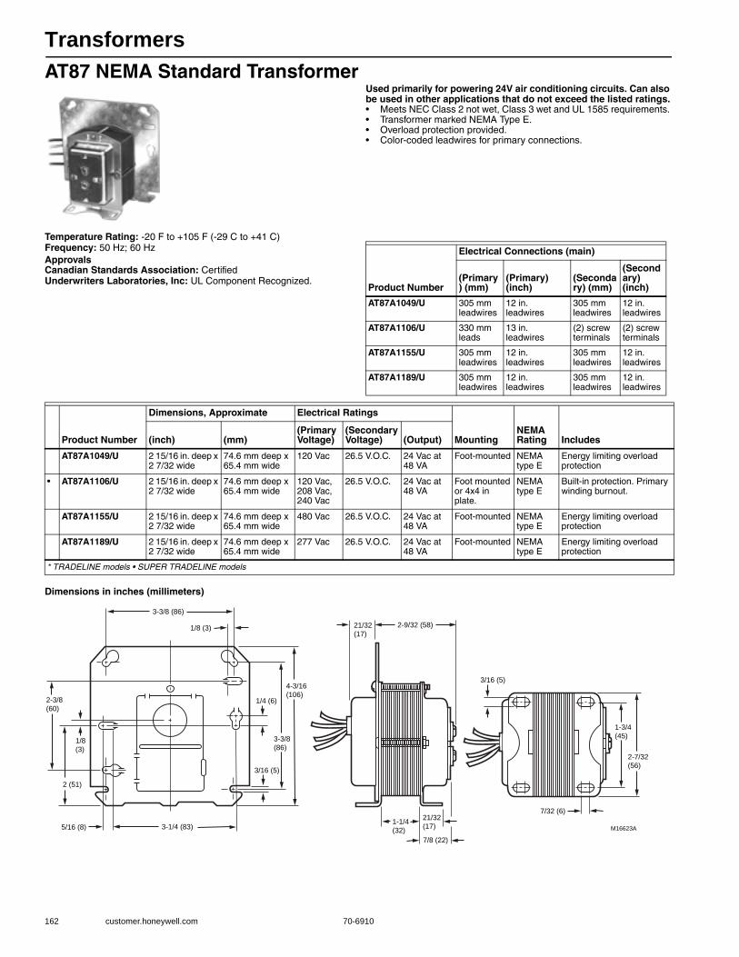
Transformers
162 customer.honeywell.com 70-6910
AT87 NEMA Standard TransformerUsed primarily for powering 24V air conditioning circuits. Can also be used in other applications that do not exceed the listed ratings.• Meets NEC Class 2 not wet, Class 3 wet and UL 1585 requirements. • Transformer marked NEMA Type E. • Overload protection provided. • Color-coded leadwires for primary connections.
Temperature Rating: -20 F to +105 F (-29 C to +41 C) Frequency: 50 Hz; 60 HzApprovalsCanadian Standards Association: CertifiedUnderwriters Laboratories, Inc: UL Component Recognized.
Dimensions in inches (millimeters)
Product Number
Electrical Connections (main)
(Primary) (mm)
(Primary) (inch)
(Secondary) (mm)
(Secondary) (inch)
AT87A1049/U 305 mm leadwires
12 in. leadwires
305 mm leadwires
12 in. leadwires
AT87A1106/U 330 mm leads
13 in. leadwires
(2) screw terminals
(2) screw terminals
AT87A1155/U 305 mm leadwires
12 in. leadwires
305 mm leadwires
12 in. leadwires
AT87A1189/U 305 mm leadwires
12 in. leadwires
305 mm leadwires
12 in. leadwires
Product Number
Dimensions, Approximate Electrical Ratings
MountingNEMA Rating Includes(inch) (mm)
(Primary Voltage)
(Secondary Voltage) (Output)
AT87A1049/U 2 15/16 in. deep x 2 7/32 wide
74.6 mm deep x 65.4 mm wide
120 Vac 26.5 V.O.C. 24 Vac at 48 VA
Foot-mounted NEMA type E
Energy limiting overload protection
• AT87A1106/U 2 15/16 in. deep x 2 7/32 wide
74.6 mm deep x 65.4 mm wide
120 Vac, 208 Vac, 240 Vac
26.5 V.O.C. 24 Vac at 48 VA
Foot mounted or 4x4 in plate.
NEMA type E
Built-in protection. Primary winding burnout.
AT87A1155/U 2 15/16 in. deep x 2 7/32 wide
74.6 mm deep x 65.4 mm wide
480 Vac 26.5 V.O.C. 24 Vac at 48 VA
Foot-mounted NEMA type E
Energy limiting overload protection
AT87A1189/U 2 15/16 in. deep x 2 7/32 wide
74.6 mm deep x 65.4 mm wide
277 Vac 26.5 V.O.C. 24 Vac at 48 VA
Foot-mounted NEMA type E
Energy limiting overload protection
* TRADELINE models • SUPER TRADELINE models
3-3/8 (86)
1/8 (3)
4-3/16
(106)
3-3/8
(86)
1/4 (6)
3/16 (5)
3-1/4 (83)5/16 (8)
2 (51)
1/8
(3)
2-3/8
(60)
21/32
(17)
2-9/32 (58)
1-1/4
(32)
21/32
(17)
7/8 (22)
7/32 (6)
1-3/4
(45)
2-7/32
(56)
3/16 (5)
M16623A
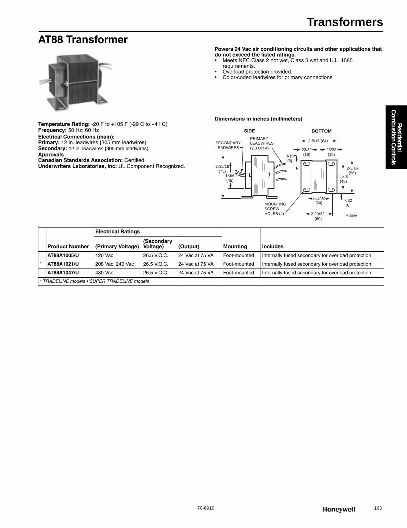
Transformers
70-6910 163
R
esidential C
ombustion C
ontrols
AT88 TransformerPowers 24 Vac air conditioning circuits and other applications that do not exceed the listed ratings.• Meets NEC Class 2 not wet, Class 3 wet and U.L. 1585
requirements. • Overload protection provided. • Color-coded leadwires for primary connections.
Temperature Rating: -20 F to +105 F (-29 C to +41 C) Frequency: 50 Hz; 60 HzElectrical Connections (main):Primary: 12 in. leadwires (305 mm leadwires)Secondary: 12 in. leadwires (305 mm leadwires)ApprovalsCanadian Standards Association: CertifiedUnderwriters Laboratories, Inc: UL Component Recognized.
Dimensions in inches (millimeters)
23/32
(19)
23/32
(19)
PRIMARY
LEADWIRES
(2,3 OR 4)
SECONDARY
LEADWIRES
M 994A
MOUNTING
SCREW
HOLES (4)
SIDE BOTTOM
3/16
(5)
2-15/16
(75)1-3/4
(45)
3-5/16 (84)
2-23/32
(69)
2-11/32
(60)7/32
(6)
2-3/16
(56)1-3/4
(45)
Product Number
Electrical Ratings
Mounting Includes(Primary Voltage)(Secondary Voltage) (Output)
AT88A1005/U 120 Vac 26.5 V.O.C. 24 Vac at 75 VA Foot-mounted Internally fused secondary for overload protection.
* AT88A1021/U 208 Vac, 240 Vac 26.5 V.O.C. 24 Vac at 75 VA Foot-mounted Internally fused secondary for overload protection.
AT88A1047/U 480 Vac 26.5 V.O.C. 24 Vac at 75 VA Foot-mounted Internally fused secondary for overload protection.
* TRADELINE models • SUPER TRADELINE models
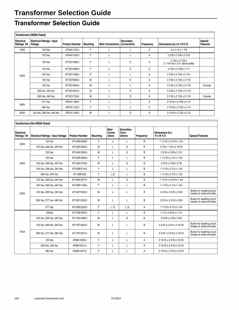
Transformer Selection Guide
164 customer.honeywell.com 70-6910
Transformer Selection Guide
Transformers (NEMA Rated)
Electrical Ratings- VA
Electrical Ratings - Input Voltage Product Number Mounting Main Connections
Secondary Connections Frequency Dimensions (in.) H x W X D
Special Features
19VA 120 Vac AT20A1123/U F L L A 2 x 2 1/4 x 1 7/8
40VA
120 Vac AT40A1162/U F L L A 2 3/32 x 2 5/8 x 2 3/16
120 Vac AT72D1006/U P L S A 3 7/32 x 2 7/32 x (1 1/16 into x 2 in. above plate)
120 Vac AT72D1089/U F L S A 3 7/32 x 2 7/32 x 3 1/1
120 Vac AT72D1188/U P L L A 3 7/32 x 2 7/32 x 2 15/1
120 Vac AT72D1683/U M L S A 3 7/32 x 2 7/32 x 3 1/16
120 Vac AT72D1956/U M L L A 3 7/32 x 2 7/32 x 3 1/16 Canada
208 Vac, 240 Vac AT72D1691/U M L S A 3 7/32 x 2 7/32 x 3 1/16
208 Vac, 240 Vac AT72D1733/U M L S A 3 7/32 x 2 7/32 x 3 1/16 Canada
48VA277 Vac AT87A1189/U F L L A 2 15/16 x 2 7/32 x 2 1/4
480 Vac AT87A1155/U F L L A 2 15/16 x 2 7/32 x 2 1/4
50VA 120 Vac, 208 Vac, 240 Vac AT87A1106/U M L S A 2 15/16 x 2 7/32 x 2 1/4
Transformers (Not NEMA Rated)
Electrical Ratings- VA Electrical Ratings - Input Voltage Product Number Mounting
Main Conne-ctions
Secondary Conn-ections Frequency
Dimensions (in.) H x W X D Special Features
20VA120 Vac AT120B1028/U F L L B 1 11/16 x 3 3/16 x 1 3/4
120 Vac, 208 Vac, 240 Vac AT120A1004/U M L S B 2 7/8 x 1 7/8 x 2 15/16
40VA
120 Vac AT140A1000/U M L S B 3 3/16 x 2 3/8 x 3 1/8
120 Vac AT140B1206/U F L L B 1 11/16 x 3 1/2 x 1 3/4
120 Vac, 208 Vac, 240 Vac AT140A1018/U M L S B 3 3/16 x 2 3/8 x 3 1/8
120 Vac, 208 Vac, 240 Vac AT140B1214/U F L L B 1 11/16 x 3 1/2 x 1 3/4
208 Vac, 240 Vac AT140B1024 F L,Q L B 1 11/16 x 3 1/2 x 1 3/4
50VA
120 Vac, 208 Vac, 240 Vac AT150A1007/U M L S B 1 11/16 x 3 3/16 x 1 3/4
120 Vac, 208 Vac, 240 Vac AT150B1146/U F L L B 1 11/16 x 3 1/2 x 1 3/4
120 Vac, 208 Vac, 240 Vac AT150F1022/U M L L B 3 3/16 x 2 3/16 x 3 5/8 Button for resetting circuit breaker & metal end bells
208 Vac, 277 Vac, 480 Vac AT150F1030/U M L L B 3 3/16 x 2 3/16 x 3 5/8 Button for resetting circuit breaker & metal end bells
277 Vac AT150B1252/U F L, Q L, Q A 1 11/16 x 3 1/2 x 1 3/4
75VA
120Vac AT175B1055/U F L L B 2 1/3 x 3 9/16 x 2 1/3
120 Vac, 208 Vac, 240 Vac AT175A1008/U M L S B 3 3/16 x 2 3/8 x 3 5/8
120 Vac, 208 Vac, 240 Vac AT175F1023/U M L L B 3 3/16 x 2 3/16 x 3 15/16 Button for resetting circuit breaker & metal end bells
208 Vac, 277 Vac, 480 Vac AT175F1031/U M L L B 3 3/16 x 2 3/16 x 3 15/16 Button for resetting circuit breaker & metal end bells
120 Vac AT88A1005/U F L L A 2 15/16 x 2 3/16 x 3 5/16
208 Vac, 240 Vac AT88A1021/U F L L A 2 15/16 x 2 3/16 x 3 5/16
480 Vac AT88A1047/U F L L A 2 15/16 x 2 3/16 x 3 5/16
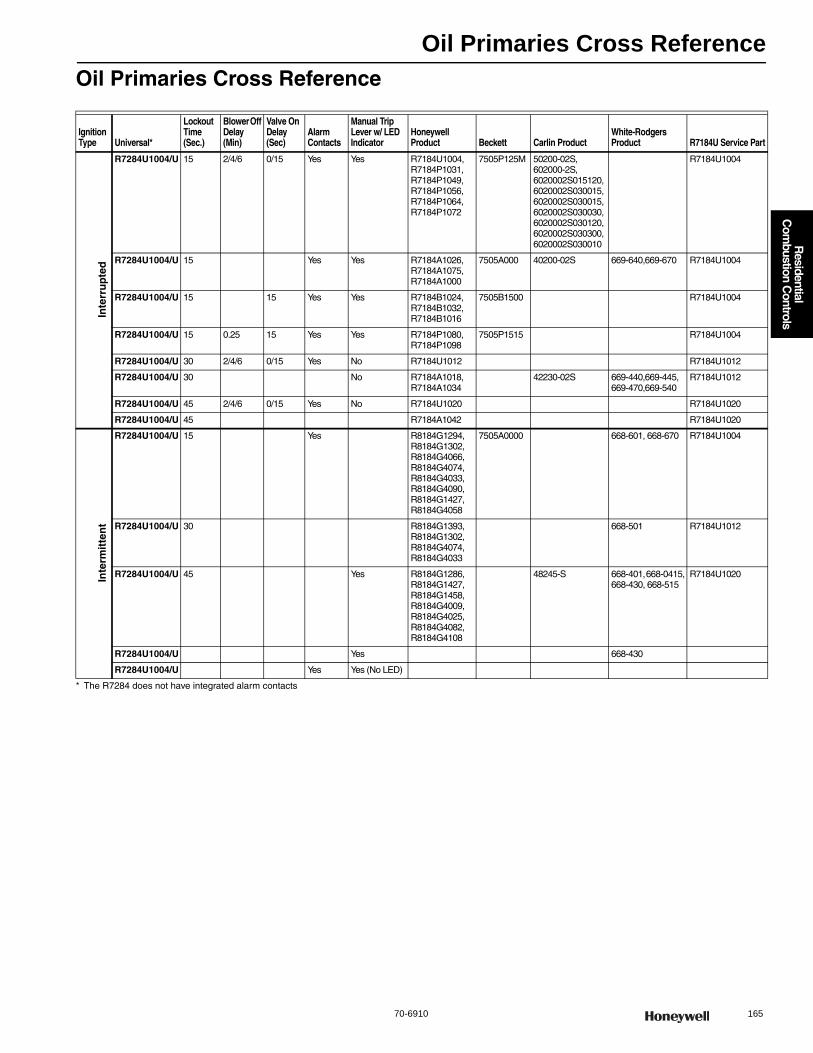
Oil Primaries Cross Reference
70-6910 165
R
esidential C
ombustion C
ontrols
Oil Primaries Cross Reference
* The R7284 does not have integrated alarm contacts
Ignition Type Universal*
Lockout Time (Sec.)
Blower Off Delay (Min)
Valve On Delay (Sec)
Alarm Contacts
Manual Trip Lever w/ LED Indicator
Honeywell Product Beckett Carlin Product
White-Rodgers Product R7184U Service Part
Inte
rru
pte
d
R7284U1004/U 15 2/4/6 0/15 Yes Yes R7184U1004, R7184P1031, R7184P1049, R7184P1056, R7184P1064, R7184P1072
7505P125M 50200-02S, 602000-2S, 6020002S015120, 6020002S030015, 6020002S030015, 6020002S030030, 6020002S030120, 6020002S030300, 6020002S030010
R7184U1004
R7284U1004/U 15 Yes Yes R7184A1026, R7184A1075, R7184A1000
7505A000 40200-02S 669-640,669-670 R7184U1004
R7284U1004/U 15 15 Yes Yes R7184B1024, R7184B1032, R7184B1016
7505B1500 R7184U1004
R7284U1004/U 15 0.25 15 Yes Yes R7184P1080, R7184P1098
7505P1515 R7184U1004
R7284U1004/U 30 2/4/6 0/15 Yes No R7184U1012 R7184U1012
R7284U1004/U 30 No R7184A1018, R7184A1034
42230-02S 669-440,669-445, 669-470,669-540
R7184U1012
R7284U1004/U 45 2/4/6 0/15 Yes No R7184U1020 R7184U1020
R7284U1004/U 45 R7184A1042 R7184U1020
Inte
rmit
ten
t
R7284U1004/U 15 Yes R8184G1294, R8184G1302, R8184G4066, R8184G4074, R8184G4033, R8184G4090, R8184G1427, R8184G4058
7505A0000 668-601, 668-670 R7184U1004
R7284U1004/U 30 R8184G1393, R8184G1302, R8184G4074, R8184G4033
668-501 R7184U1012
R7284U1004/U 45 Yes R8184G1286, R8184G1427, R8184G1458, R8184G4009, R8184G4025, R8184G4082, R8184G4108
48245-S 668-401, 668-0415, 668-430, 668-515
R7184U1020
R7284U1004/U Yes 668-430
R7284U1004/U Yes Yes (No LED)
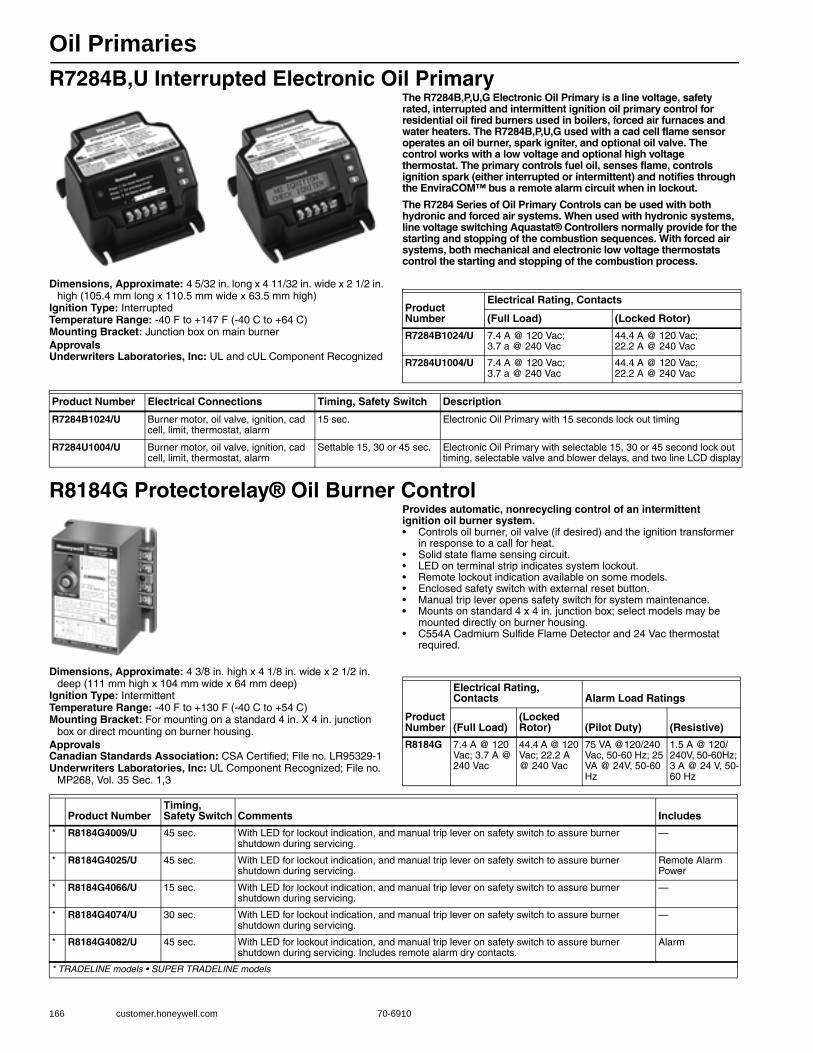
Oil Primaries
166 customer.honeywell.com 70-6910
R7284B,U Interrupted Electronic Oil PrimaryThe R7284B,P,U,G Electronic Oil Primary is a line voltage, safety rated, interrupted and intermittent ignition oil primary control for residential oil fired burners used in boilers, forced air furnaces and water heaters. The R7284B,P,U,G used with a cad cell flame sensor operates an oil burner, spark igniter, and optional oil valve. The control works with a low voltage and optional high voltage thermostat. The primary controls fuel oil, senses flame, controls ignition spark (either interrupted or intermittent) and notifies through the EnviraCOM™ bus a remote alarm circuit when in lockout.
The R7284 Series of Oil Primary Controls can be used with both hydronic and forced air systems. When used with hydronic systems, line voltage switching Aquastat® Controllers normally provide for the starting and stopping of the combustion sequences. With forced air systems, both mechanical and electronic low voltage thermostats control the starting and stopping of the combustion process.
Dimensions, Approximate: 4 5/32 in. long x 4 11/32 in. wide x 2 1/2 in. high (105.4 mm long x 110.5 mm wide x 63.5 mm high)
Ignition Type: InterruptedTemperature Range: -40 F to +147 F (-40 C to +64 C) Mounting Bracket: Junction box on main burnerApprovalsUnderwriters Laboratories, Inc: UL and cUL Component Recognized
R8184G Protectorelay® Oil Burner ControlProvides automatic, nonrecycling control of an intermittent ignition oil burner system.• Controls oil burner, oil valve (if desired) and the ignition transformer
in response to a call for heat. • Solid state flame sensing circuit. • LED on terminal strip indicates system lockout. • Remote lockout indication available on some models. • Enclosed safety switch with external reset button. • Manual trip lever opens safety switch for system maintenance. • Mounts on standard 4 x 4 in. junction box; select models may be
mounted directly on burner housing. • C554A Cadmium Sulfide Flame Detector and 24 Vac thermostat
required.
Dimensions, Approximate: 4 3/8 in. high x 4 1/8 in. wide x 2 1/2 in. deep (111 mm high x 104 mm wide x 64 mm deep)
Ignition Type: IntermittentTemperature Range: -40 F to +130 F (-40 C to +54 C) Mounting Bracket: For mounting on a standard 4 in. X 4 in. junction
box or direct mounting on burner housing.ApprovalsCanadian Standards Association: CSA Certified; File no. LR95329-1Underwriters Laboratories, Inc: UL Component Recognized; File no.
MP268, Vol. 35 Sec. 1,3
Product Number
Electrical Rating, Contacts
(Full Load) (Locked Rotor)
R7284B1024/U 7.4 A @ 120 Vac; 3.7 a @ 240 Vac
44.4 A @ 120 Vac; 22.2 A @ 240 Vac
R7284U1004/U 7.4 A @ 120 Vac; 3.7 a @ 240 Vac
44.4 A @ 120 Vac; 22.2 A @ 240 Vac
Product Number Electrical Connections Timing, Safety Switch Description
R7284B1024/U Burner motor, oil valve, ignition, cad cell, limit, thermostat, alarm
15 sec. Electronic Oil Primary with 15 seconds lock out timing
R7284U1004/U Burner motor, oil valve, ignition, cad cell, limit, thermostat, alarm
Settable 15, 30 or 45 sec. Electronic Oil Primary with selectable 15, 30 or 45 second lock out timing, selectable valve and blower delays, and two line LCD display
Product Number
Electrical Rating, Contacts Alarm Load Ratings
(Full Load)(Locked Rotor) (Pilot Duty) (Resistive)
R8184G 7.4 A @ 120 Vac; 3.7 A @ 240 Vac
44.4 A @ 120 Vac; 22.2 A @ 240 Vac
75 VA @120/240 Vac, 50-60 Hz; 25 VA @ 24V, 50-60 Hz
1.5 A @ 120/240V, 50-60Hz; 3 A @ 24 V, 50-60 Hz
Product NumberTiming, Safety Switch Comments Includes
* R8184G4009/U 45 sec. With LED for lockout indication, and manual trip lever on safety switch to assure burner shutdown during servicing.
—
* R8184G4025/U 45 sec. With LED for lockout indication, and manual trip lever on safety switch to assure burner shutdown during servicing.
Remote Alarm Power
* R8184G4066/U 15 sec. With LED for lockout indication, and manual trip lever on safety switch to assure burner shutdown during servicing.
—
* R8184G4074/U 30 sec. With LED for lockout indication, and manual trip lever on safety switch to assure burner shutdown during servicing.
—
* R8184G4082/U 45 sec. With LED for lockout indication, and manual trip lever on safety switch to assure burner shutdown during servicing. Includes remote alarm dry contacts.
Alarm
* TRADELINE models • SUPER TRADELINE models

Oil Primaries
70-6910 167
R
esidential C
ombustion C
ontrols
R8184M Protectorelay® Oil Burner ControlOperates the oil burner and oil valve (if desired) in response to a call for heat from a low voltage control circuit.• Ignition is on whenever the burner is on (intermittent ignition-also
called constant ignition). • Solid state flame sensing circuit. • External button to manually reset safety switch after lockout. • Enclosed safety switch must be manually reset after safety
shutdown. • R8184M includes 40 VA transformer and Y and G terminals for
connection of cooling equipment. • Mounts on standard 4 x 4 in. junction box. • C554A Cadmium Sulfide Flame Detector and a 24 Vac thermostat
required.
Dimensions, Approximate: 4 3/8 in. high x 4 1/8 in. wide x 2 1/2 in. deep (111 mm high x 104 mm wide x 64 mm deep)
Ignition Type: IntermittentTemperature Range: -40 F to +130 F (-40 C to +54 C) ApprovalsUnderwriters Laboratories, Inc: UL Component Recognized; File no.
MP268, guide no. MCCZ2
RA116; RA117 Protectorelay® ControlsOne-piece, stack-mounted oil burner primary controls that cycle the burner on and shut down the burner on flame loss or system malfunction.• Combine a Protectorelay® unit for cycling the burner and a
Pyrostat® flame detector for sensing temperature changes of flue gases up to 1000 F (556 C).
• Manual reset of safety switch required after ignition failure completely shuts off main burner.
• Include manual trip safety switch to assure burner shutdown during servicing.
• Mount with flange for mounting on curved or flat surfaces. • Use with line voltage or 24 Vac Control Circuit.
Dimensions, Approximate: 6 in. high x 5 3/16 in. wide x 3 3/16 in. deep (152 mm high x 132 mm wide x 81 mm deep)
Ignition Type: Intermittent
ApprovalsCanadian Standards Association: CSA Certified; File no. LR95329-1Underwriters Laboratories, Inc: UL Listed; File no.MP268, Guide no.
MCCZ
Oil Primary Control Parts
Product Number
Electrical Rating, Contacts
(Full Load) (Locked Rotor)
R8184M1051/U 7.4 A @ 120 Vac; 3.7 a @ 240 Vac
44.4 A @ 120 Vac; 22.2 A @ 240 Vac
Product NumberTiming, Safety Switch Mounting Bracket Description
* R8184M1051/U 45 sec. Mounts on standard 4 x 4 in. junction box Protectorelay® Oil Burner Control with 45 seconds lock out timing
* TRADELINE models • SUPER TRADELINE models
Product NumberTiming, Safety Switch Mounting Bracket Description
* RA116A1055/U 75 sec. Nominal Mount with flange for mounting on curved or flat surfaces.
Protectorelay® Oil Burner Control with 75 seconds lock out timing
* RA117A1047/U 75 sec. Nominal Mount with flange for mounting on curved or flat surfaces.
Protectorelay® Oil Burner Control with 75 seconds lock out timing
* TRADELINE models • SUPER TRADELINE models
Product Number Description
120320/U Replacement Cell Assembly, 400-1600 Ohm Sensitivity
130367/U Replacement Cell Assembly, 400-1000 Ohm Sensitivity
32611/U Grommet (Bulk Mdse)
4074BJS/U Oil line mounting bracket assembly, including nut and screw
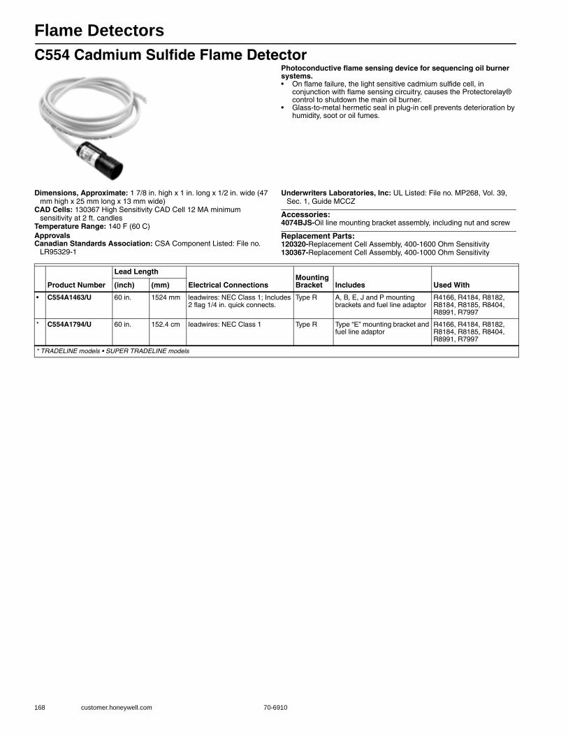
Flame Detectors
168 customer.honeywell.com 70-6910
C554 Cadmium Sulfide Flame DetectorPhotoconductive flame sensing device for sequencing oil burner systems.• On flame failure, the light sensitive cadmium sulfide cell, in
conjunction with flame sensing circuitry, causes the Protectorelay® control to shutdown the main oil burner.
• Glass-to-metal hermetic seal in plug-in cell prevents deterioration by humidity, soot or oil fumes.
Dimensions, Approximate: 1 7/8 in. high x 1 in. long x 1/2 in. wide (47 mm high x 25 mm long x 13 mm wide)
CAD Cells: 130367 High Sensitivity CAD Cell 12 MA minimum sensitivity at 2 ft. candles
Temperature Range: 140 F (60 C) ApprovalsCanadian Standards Association: CSA Component Listed: File no.
LR95329-1
Underwriters Laboratories, Inc: UL Listed: File no. MP268, Vol. 39, Sec. 1, Guide MCCZ
Accessories:4074BJS-Oil line mounting bracket assembly, including nut and screw
Replacement Parts:120320-Replacement Cell Assembly, 400-1600 Ohm Sensitivity130367-Replacement Cell Assembly, 400-1000 Ohm Sensitivity
Product Number
Lead Length
Electrical ConnectionsMounting Bracket Includes Used With(inch) (mm)
• C554A1463/U 60 in. 1524 mm leadwires: NEC Class 1; Includes 2 flag 1/4 in. quick connects.
Type R A, B, E, J and P mounting brackets and fuel line adaptor
R4166, R4184, R8182, R8184, R8185, R8404, R8991, R7997
* C554A1794/U 60 in. 152.4 cm leadwires: NEC Class 1 Type R Type “E” mounting bracket and fuel line adaptor
R4166, R4184, R8182, R8184, R8185, R8404, R8991, R7997
* TRADELINE models • SUPER TRADELINE models
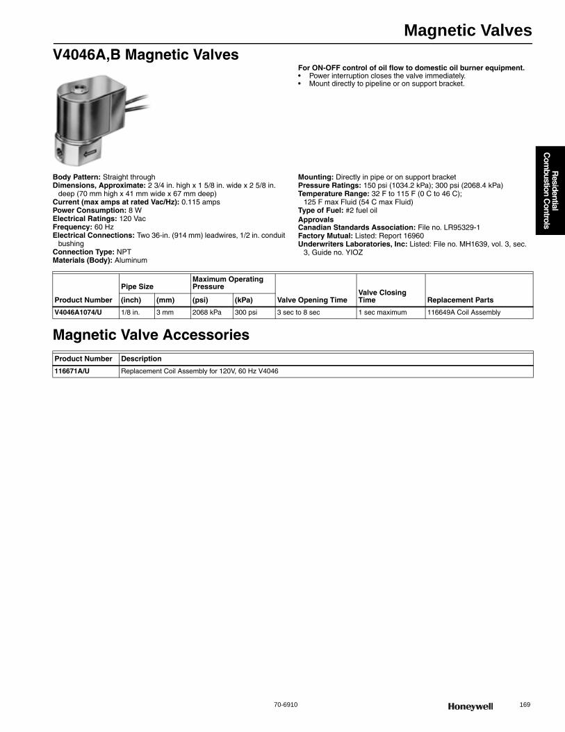
Magnetic Valves
70-6910 169
R
esidential C
ombustion C
ontrols
V4046A,B Magnetic ValvesFor ON-OFF control of oil flow to domestic oil burner equipment.• Power interruption closes the valve immediately. • Mount directly to pipeline or on support bracket.
Body Pattern: Straight throughDimensions, Approximate: 2 3/4 in. high x 1 5/8 in. wide x 2 5/8 in.
deep (70 mm high x 41 mm wide x 67 mm deep) Current (max amps at rated Vac/Hz): 0.115 ampsPower Consumption: 8 WElectrical Ratings: 120 VacFrequency: 60 HzElectrical Connections: Two 36-in. (914 mm) leadwires, 1/2 in. conduit
bushingConnection Type: NPTMaterials (Body): Aluminum
Mounting: Directly in pipe or on support bracketPressure Ratings: 150 psi (1034.2 kPa); 300 psi (2068.4 kPa) Temperature Range: 32 F to 115 F (0 C to 46 C);
125 F max Fluid (54 C max Fluid) Type of Fuel: #2 fuel oilApprovalsCanadian Standards Association: File no. LR95329-1Factory Mutual: Listed: Report 16960Underwriters Laboratories, Inc: Listed: File no. MH1639, vol. 3, sec.
3, Guide no. YIOZ
Magnetic Valve Accessories
Product Number
Pipe SizeMaximum Operating Pressure
Valve Opening TimeValve Closing Time Replacement Parts(inch) (mm) (psi) (kPa)
V4046A1074/U 1/8 in. 3 mm 2068 kPa 300 psi 3 sec to 8 sec 1 sec maximum 116649A Coil Assembly
Product Number Description
116671A/U Replacement Coil Assembly for 120V, 60 Hz V4046
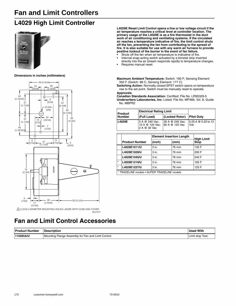
Fan and Limit Controllers
170 customer.honeywell.com 70-6910
L4029 High Limit ControllerL4029E Reset Limit Control opens a line or low voltage circuit if the air temperature reaches a critical level at controller location. The primary usage of the L4029E is as a fire thermostat in the duct work of air conditioning and ventilating systems. If the circulated air reaches a temperature indicative of fire, the limit control shuts off the fan, preventing the fan from contributing to the spread of fire. It is also suitable for use with any warm air furnace to provide positive lockout of the burner in the event of fan failure.• Shuts off the fan when air temperature is indicative of fire. • Internal snap-acting switch actuated by a bimetal strip inserted
directly into the air stream responds rapidly to temperature changes. • Requires manual reset.
Dimensions in inches (millimeters)Maximum Ambient Temperature: Switch: 190 F; Sensing Element:
350 F (Switch: 88 C; Sensing Element: 177 C) Switching Action: Normally closed SPST switch opens on temperature
rise to the set point. Switch must be manually reset to operate.ApprovalsCanadian Standards Association: Certified: File No. LR95329-5Underwriters Laboratories, Inc: Listed: File No. MP466, Vol. 8, Guide
No. MBPR2
Fan and Limit Control Accessories
59 (2-5/16)
24(15/16)
30(1-3/16)
1
44(1-23/32)
37(1-7/16)
37(1-7/16)
45(1-25/32)
5(3/16)
11(7/16)
37(1-7/16)
67(2-5/8)
11(7/16)
13(1/2)
2(1/16)
24(15/16)
82(3-7/32)
95(3-3/4)
5(3/16)
70(2-3/4)
83 (3-1/4)6
(7/32) 40(1-9/16)17
(11/16)
MC27077
10 DIA.(3/8)
1 5 (3/16 ) DIAMETER MOUNTING HOLES L4029E WITH CASE AND COVER.
Product Number
Electrical Rating Limit
Pilot Duty(Full Load) (Locked Rotor)
L4029E 5 A @ 240 Vac; 10 A @ 120 Vac; 2 A @ 30 Vac
30 A @ 240 Vac; 60 A @ 120 Vac
0.25 A @ 0.25 to 12 Vdc
Product Number
Element Insertion LengthHigh Limit Stop(inch) (mm)
L4029E1011/U 3 in. 76 mm 135 F
L4029E1029/U 3 in. 76 mm 200 F
L4029E1045/U 3 in. 76 mm 240 F
* L4029E1219/U 3 in. 76 mm 165 F
* L4029E1227/U 3 in. 76 mm 125 F
* TRADELINE models • SUPER TRADELINE models
Product Number Description Used With
110265A/U Mounting Flange Assembly for Fan and Limit Control Limit stop Tool;
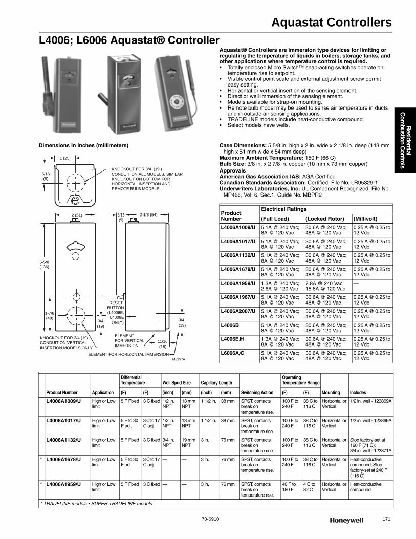
Aquastat Controllers
70-6910 171
R
esidential C
ombustion C
ontrols
L4006; L6006 Aquastat® ControllerAquastat® Controllers are immersion type devices for limiting or regulating the temperature of liquids in boilers, storage tanks, and other applications where temperature control is required.• Totally enclosed Micro Switch™ snap-acting switches operate on
temperature rise to setpoint. • Vis ble control point scale and external adjustment screw permit
easy setting. • Horizontal or vertical insertion of the sensing element. • Direct or well immersion of the sensing element. • Models available for strap-on mounting. • Remote bulb model may be used to sense air temperature in ducts
and in outside air sensing applications. • TRADELINE models include heat-conductive compound. • Select models have wells.
Dimensions in inches (millimeters) Case Dimensions: 5 5/8 in. high x 2 in. wide x 2 1/8 in. deep (143 mm high x 51 mm wide x 54 mm deep)
Maximum Ambient Temperature: 150 F (66 C) Bulb Size: 3/8 in. x 2 7/8 in. copper (10 mm x 73 mm copper) ApprovalsAmerican Gas Association IAS: AGA CertifiedCanadian Standards Association: Certified: File No. LR95329-1Underwriters Laboratories, Inc: UL Component Recognized: File No.
MP466, Vol. 6, Sec.1, Guide No. MBPR2
M8957A
KNOCKOUT FOR 3/4 (19 )
CONDUIT ON ALL MODELS. SIMILAR
KNOCKOUT ON BOTTOM FOR
HORIZONTAL INSERTION AND
REMOTE BULB MODELS.
1 (25)
5/16
(8)
2 (51) 2-1/8 (54)
5-5/8
(136)
1-7/8
(48)
3/16
(5)
RESET
BUTTON
(L4006E,
L4008E
ONLY)
KNOCKOUT FOR 3/4 (19)
CONDUIT ON VERTICAL
INSERTION MODELS ONLY
ELEMENT FOR HORIZONTAL IMMERSION
3/4
(19)
ELEMENT
FOR VERTICAL
IMMERSION11/16
(18)
3/4
(19)
Product Number
Electrical Ratings
(Full Load) (Locked Rotor) (Millivolt)
L4006A1009/U 5.1A @ 240 Vac; 8A @ 120 Vac
30.6A @ 240 Vac; 48A @ 120 Vac
0.25 A @ 0.25 to 12 Vdc
L4006A1017/U 5.1A @ 240 Vac; 8A @ 120 Vac
30.6A @ 240 Vac; 48A @ 120 Vac
0.25 A @ 0.25 to 12 Vdc
L4006A1132/U 5.1A @ 240 Vac; 8A @ 120 Vac
30.6A @ 240 Vac; 48A @ 120 Vac
0.25 A @ 0.25 to 12 Vdc
L4006A1678/U 5.1A @ 240 Vac; 8A @ 120 Vac
30.6A @ 240 Vac; 48A @ 120 Vac
0.25 A @ 0.25 to 12 Vdc
L4006A1959/U 1.3A @ 240 Vac; 2.6A @ 120 Vac
7.8A @ 240 Vac; 15.6A @ 120 Vac
—
L4006A1967/U 5.1A @ 240 Vac; 8A @ 120 Vac
30.6A @ 240 Vac; 48A @ 120 Vac
0.25 A @ 0.25 to 12 Vdc
L4006A2007/U 5.1A @ 240 Vac; 8A @ 120 Vac
30.6A @ 240 Vac; 48A @ 120 Vac
0.25 A @ 0.25 to 12 Vdc
L4006B 5.1A @ 240 Vac; 8A @ 120 Vac
30.6A @ 240 Vac; 48A @ 120 Vac
0.25 A @ 0.25 to 12 Vdc
L4006E,H 1.3A @ 240 Vac; 8A @ 120 Vac
30.6A @ 240 Vac; 48A @ 120 Vac
0.25 A @ 0.25 to 12 Vdc
L6006A,C 5.1A @ 240 Vac; 8A @ 120 Vac
30.6A @ 240 Vac; 48A @ 120 Vac
0.25 A @ 0.25 to 12 Vdc
Product Number Application
Differential Temperature Well Spud Size Capillary Length
Switching Action
Operating Temperature Range
Mounting Includes(F) (F) (inch) (mm) (inch) (mm) (F) (F)
L4006A1009/U High or Low limit
5 F Fixed 3 C fixed 1/2 in. NPT
13 mm NPT
1 1/2 in. 38 mm SPST, contacts break on temperature rise.
100 F to 240 F
38 C to 116 C
Horizontal or Vertical
1/2 in. well - 123869A
L4006A1017/U High or Low limit
5 F to 30 F adj.
3 C to 17 C adj.
1/2 in. NPT
13 mm NPT
1 1/2 in. 38 mm SPST, contacts break on temperature rise.
100 F to 240 F
38 C to 116 C
Horizontal or Vertical
1/2 in. well - 123869A
L4006A1132/U High or Low limit
5 F Fixed 3 C fixed 3/4 in. NPT
19 mm NPT
3 in. 76 mm SPST, contacts break on temperature rise.
100 F to 240 F
38 C to 116 C
Horizontal or Vertical
Stop factory-set at 160 F (71 C); 3/4 in. well - 123871A
* L4006A1678/U High or Low limit
5 F to 30 F adj.
3 C to 17 C adj.
— — 3 in. 76 mm SPST, contacts break on temperature rise.
100 F to 240 F
38 C to 116 C
Horizontal or Vertical
Heat-conductive compound; Stop factory-set at 240 F (116 C)
* L4006A1959/U High or Low limit
5 F Fixed 3 C fixed — — 3 in. 76 mm SPST, contacts break on temperature rise.
40 F to 180 F
4 C to 82 C
Horizontal or Vertical
Heat-conductive compound
* TRADELINE models • SUPER TRADELINE models
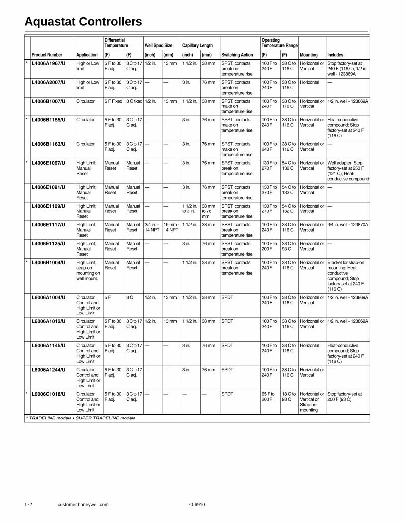
Aquastat Controllers
172 customer.honeywell.com 70-6910
* L4006A1967/U High or Low limit
5 F to 30 F adj.
3 C to 17 C adj.
1/2 in. 13 mm 1 1/2 in. 38 mm SPST, contacts break on temperature rise.
100 F to 240 F
38 C to 116 C
Horizontal or Vertical
Stop factory-set at 240 F (116 C); 1/2 in. well - 123869A
L4006A2007/U High or Low limit
5 F to 30 F adj.
3 C to 17 C adj.
— — 3 in. 76 mm SPST, contacts break on temperature rise.
100 F to 240 F
38 C to 116 C
Horizontal —
L4006B1007/U Circulator 5 F Fixed 3 C fixed 1/2 in. 13 mm 1 1/2 in. 38 mm SPST, contacts make on temperature rise.
100 F to 240 F
38 C to 116 C
Horizontal or Vertical
1/2 in. well - 123869A
* L4006B1155/U Circulator 5 F to 30 F adj.
3 C to 17 C adj.
— — 3 in. 76 mm SPST, contacts make on temperature rise.
100 F to 240 F
38 C to 116 C
Horizontal or Vertical
Heat-conductive compound; Stop factory-set at 240 F (116 C)
L4006B1163/U Circulator 5 F to 30 F adj.
3 C to 17 C adj.
— — 3 in. 76 mm SPST, contacts make on temperature rise.
100 F to 240 F
38 C to 116 C
Horizontal or Vertical
—
* L4006E1067/U High Limit; Manual Reset
Manual Reset
Manual Reset
— — 3 in. 76 mm SPST, contacts break on temperature rise.
130 F to 270 F
54 C to 132 C
Horizontal or Vertical
Well adapter; Stop factory-set at 250 F (121 C); Heat-conductive compound
L4006E1091/U High Limit; Manual Reset
Manual Reset
Manual Reset
— — 3 in. 76 mm SPST, contacts break on temperature rise.
130 F to 270 F
54 C to 132 C
Horizontal or Vertical
—
L4006E1109/U High Limit; Manual Reset
Manual Reset
Manual Reset
— — 1 1/2 in. to 3 in.
38 mm to 76 mm
SPST, contacts break on temperature rise.
130 F to 270 F
54 C to 132 C
Horizontal or Vertical
—
L4006E1117/U High Limit; Manual Reset
Manual Reset
Manual Reset
3/4 in. - 14 NPT
19 mm - 14 NPT
1 1/2 in. 38 mm SPST, contacts break on temperature rise.
100 F to 240 F
38 C to 116 C
Horizontal or Vertical
3/4 in. well - 123870A
L4006E1125/U High Limit; Manual Reset
Manual Reset
Manual Reset
— — 3 in. 76 mm SPST, contacts break on temperature rise.
100 F to 200 F
38 C to 93 C
Horizontal or Vertical
—
* L4006H1004/U High Limit; strap-on mounting on well mount.
Manual Reset
Manual Reset
— — 1 1/2 in. 38 mm SPST, contacts break on temperature rise.
100 F to 240 F
38 C to 116 C
Horizontal or Vertical
Bracket for strap-on mounting; Heat-conductive compound; Stop factory-set at 240 F (116 C)
L6006A1004/U Circulator Control and High Limit or Low Limit
5 F 3 C 1/2 in. 13 mm 1 1/2 in. 38 mm SPDT 100 F to 240 F
38 C to 116 C
Horizontal or Vertical
1/2 in. well - 123869A
L6006A1012/U Circulator Control and High Limit or Low Limit
5 F to 30 F adj.
3 C to 17 C adj.
1/2 in. 13 mm 1 1/2 in. 38 mm SPDT 100 F to 240 F
38 C to 116 C
Horizontal or Vertical
1/2 in. well - 123869A
L6006A1145/U Circulator Control and High Limit or Low Limit
5 F to 30 F adj.
3 C to 17 C adj.
— — 3 in. 76 mm SPDT 100 F to 240 F
38 C to 116 C
Horizontal Heat-conductive compound; Stop factory-set at 240 F (116 C)
L6006A1244/U Circulator Control and High Limit or Low Limit
5 F to 30 F adj.
3 C to 17 C adj.
— — 3 in. 76 mm SPDT 100 F to 240 F
38 C to 116 C
Horizontal or Vertical
—
* L6006C1018/U Circulator Control and High Limit or Low Limit
5 F to 30 F adj.
3 C to 17 C adj.
— — — — SPDT 65 F to 200 F
18 C to 93 C
Horizontal or Vertical or Strap-on-mounting
Stop factory-set at 200 F (93 C)
Product Number Application
Differential Temperature Well Spud Size Capillary Length
Switching Action
Operating Temperature Range
Mounting Includes(F) (F) (inch) (mm) (inch) (mm) (F) (F)
* TRADELINE models • SUPER TRADELINE models

Aquastat Controllers
70-6910 173
R
esidential C
ombustion C
ontrols
L4008; L6008 Remote Bulb ControllerAquastat® Controllers are immersion type devices for limiting or regulating the temperature of liquids in boilers, storage tanks, and other applications where temperature control is required.• Remote temperature sensing element detects and responds rapidly
to temperature changes. • Totally enclosed Micro Switch™ snap-acting switch. • Vis ble control point scale and external adjustment screw permit
easy setting. • Horizontal or vertical mounting of the remote element into boiler,
tank, or other container. • Case mounts to a vertical surface.
Dimensions in inches (millimeters)Case Dimensions: 5 5/8 in. high x 2 in. wide x 2 1/8 in. deep (143 mm
high x 51 mm wide x 54 mm deep) Maximum Ambient Temperature: 150 F (66 C) Bulb Size: 3/8 in. x 2 7/8 in. copper (10 mm x 73 mm copper) ApprovalsCanadian Standards Association: Certified: File No. LR95329-1Underwriters Laboratories, Inc: UL Component Recognized: File No.
MP466, Vol. 6, Sec.1, Guide No. MBPR2
SENSING
ELEMENT
CAPILLARY
3/8 (10) 1-1/4
(32)ALTERNATE POSITION
OF SENSING ELEMENT
CAPILLARY
13/64
(5) (3)
MOUNTING
HOLE FOR
3/16 IN. (5 MM)
SCREW (3)
15/16(24)
4-3/16
(106)
ALTERNATE POSITION
OF SENSING ELEMENT
CAPILLARY
M8823
Product Number
Electrical Ratings
(Full Load) (Locked Rotor) (Millivolt)
L4008A,B,EL6008A
5.1A @ 240 Vac; 8A @ 120 Vac
30.6A @ 240 Vac; 48A @ 120 Vac
0.25 A @ 0.25 to 12 Vdc
Product Number Application
Differential Temperature
Capillary Length
Switching Action
Operating Temperature Range
Mounting Includes(F) (F) (inch) (F) (F)
L4008A1015/U High or Low limit
5 F to 30 F adj.
3 C to 17 C adj.
66 in. SPST, contacts break on temperature rise.
100 F to 240 F
38 C to 116 C
Horizontal or Vertical
5 1/2 ft (1.7 m) capillary
L4008A1130/U High or Low limit
5 F to 30 F adj.
3 C to 17 C adj.
120 in. SPST, contacts break on temperature rise.
130 F to 270 F
54 C to 132 C
Horizontal or Vertical
Stop factory-set at 200 F (93 C)10 ft (3.04 m) capillary
L4008B1013/U Circulator 5 F to 30 F adj.
3 C to 17 C adj.
66 in. SPST, contacts make on temperature rise.
100 F to 240 F
38 C to 116 C
Horizontal or Vertical
5 1/2 ft (1.7 m) capillary
* L4008E1156/U High Limit; Manual Reset
Manual Reset
Manual Reset
66 in. SPST, contacts break on temperature rise.
130 F to 270 F
54 C to 132 C
Horizontal or Vertical
5 1/2 ft (1.7 m) capillary; Stop factory-set at 250 F (121 C); Heat-conductive compound
* L4008E1305/U High Limit; Manual Reset
Manual Reset
Manual Reset
66 in. SPST, contacts break on temperature rise.
100 F to 240 F
38 C to 116 C
Horizontal or Vertical
Stop factory-set at 240 F (116 C)
L4008E1313/U High Limit; Manual Reset
Manual Reset
Manual Reset
66 in. SPST, contacts break on temperature rise.
100 F to 200 F
38 C to 116 C
Horizontal or Vertical
—
* L6008A1192/U Circulator Control and Low Limit
5 F to 30 F adj.
3 C to 17 C adj.
— SPDT 100 F to 240 F
38 C to 116 C
Horizontal or Vertical
Stop factory-set at 240 F (116 C)66 in. capillary
L6008A1242/U Circulator Control and Low Limit
5 F to 30 F adj.
3 C to 17 C adj.
— SPDT 100 F to 200 F
38 C to 93 C
Horizontal or Vertical
66 in. capillary
* TRADELINE models • SUPER TRADELINE models
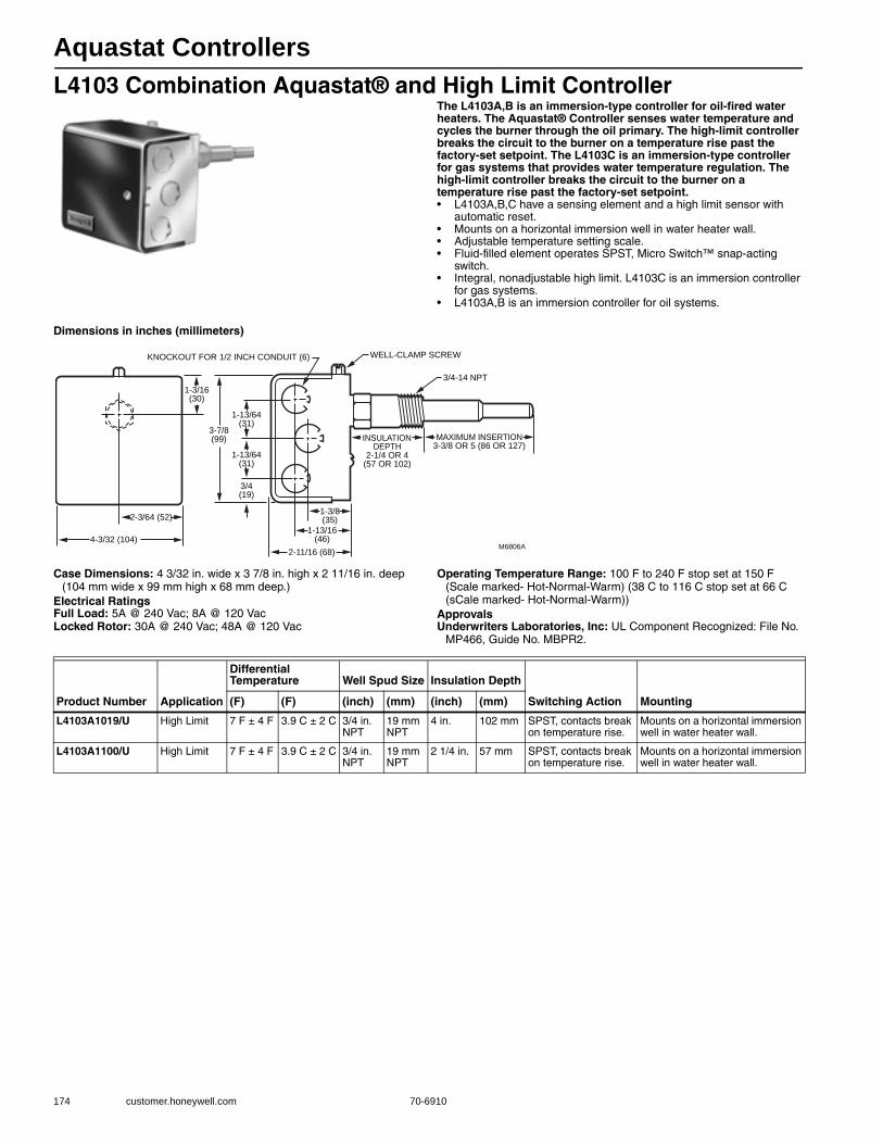
Aquastat Controllers
174 customer.honeywell.com 70-6910
L4103 Combination Aquastat® and High Limit ControllerThe L4103A,B is an immersion-type controller for oil-fired water heaters. The Aquastat® Controller senses water temperature and cycles the burner through the oil primary. The high-limit controller breaks the circuit to the burner on a temperature rise past the factory-set setpoint. The L4103C is an immersion-type controller for gas systems that provides water temperature regulation. The high-limit controller breaks the circuit to the burner on a temperature rise past the factory-set setpoint.• L4103A,B,C have a sensing element and a high limit sensor with
automatic reset. • Mounts on a horizontal immersion well in water heater wall. • Adjustable temperature setting scale. • Fluid-filled element operates SPST, Micro Switch™ snap-acting
switch. • Integral, nonadjustable high limit. L4103C is an immersion controller
for gas systems. • L4103A,B is an immersion controller for oil systems.
Dimensions in inches (millimeters)
Case Dimensions: 4 3/32 in. wide x 3 7/8 in. high x 2 11/16 in. deep (104 mm wide x 99 mm high x 68 mm deep.)
Electrical RatingsFull Load: 5A @ 240 Vac; 8A @ 120 VacLocked Rotor: 30A @ 240 Vac; 48A @ 120 Vac
Operating Temperature Range: 100 F to 240 F stop set at 150 F (Scale marked- Hot-Normal-Warm) (38 C to 116 C stop set at 66 C (sCale marked- Hot-Normal-Warm))
ApprovalsUnderwriters Laboratories, Inc: UL Component Recognized: File No.
MP466, Guide No. MBPR2.
M6806A
MAXIMUM INSERTION3-3/8 OR 5 (86 OR 127)
INSULATIONDEPTH
2-1/4 OR 4(57 OR 102)
1-3/8(35)
1-13/16(46)
1-3/16(30)
KNOCKOUT FOR 1/2 INCH CONDUIT (6) WELL-CLAMP SCREW
1-13/64(31)
3-7/8(99)
1-13/64(31)
2-3/64 (52)
4-3/32 (104)
2-11/16 (68)
3/4(19)
3/4-14 NPT
Product Number Application
Differential Temperature Well Spud Size Insulation Depth
Switching Action Mounting(F) (F) (inch) (mm) (inch) (mm)
L4103A1019/U High Limit 7 F ± 4 F 3.9 C ± 2 C 3/4 in. NPT
19 mm NPT
4 in. 102 mm SPST, contacts break on temperature rise.
Mounts on a horizontal immersion well in water heater wall.
L4103A1100/U High Limit 7 F ± 4 F 3.9 C ± 2 C 3/4 in. NPT
19 mm NPT
2 1/4 in. 57 mm SPST, contacts break on temperature rise.
Mounts on a horizontal immersion well in water heater wall.

Aquastat Controllers
70-6910 175
R
esidential C
ombustion C
ontrols
L8100 Aquastat® ControllerL8100A,B, and C are immersion type controllers for regulating and limiting the tank temperature in water heaters. As the water temperature rises past the setpoint, the controller switches off the gas valve.• Regulates temperature and provides energy cutoff (ECO) action on
a temperature rise past the setpoint. • Includes a second sensing element that senses average water
temperature to minimize stacking. • Fluid-filled element operates Micro Switch™ SPST snap-acting
switch. • ECO switch interrupts the thermocouple circuit or main valve before
tank reaches 210 F (99 C) maximum temperature. • Includes factory-installed immersion well on controller. • Internal adjustment screw. • Special switch terminal provides three-wire hookup from Aquastat®
controller to gas valve.
Dimensions in inches (millimeters)
Case Dimensions: 5 5/8 in. high x 2 in. wide x 2 1/8 in. deep (136 mm high x 51 mm wide x 54 mm deep)
Temperature Rating (ECO) Energy Cutoff: 190 FElectrical RatingsMillivolt: 2A maximum at 24 Vac.Maximum Ambient Temperature: Maximum Tank: 210 F (Maximum
Tank: 99 C) Operating Temperature Range: 100 F to 180 F (38 C to 82 C) Differential Temperature: Controller: 5 F, fixed. Energy Cutoff Switch: 20
F, fixed (Controller: 3 C fixed; Energy Cutoff Switch: 11 C fixed.) ApprovalsAmerican Gas Association IAS: Design Certified: Report Number 23-
11BUnderwriters Laboratories, Inc: UL Component Recognized: File No.
MP466, Guide No. MBPR2
1/2 OR 3/4 — 14 NPT
C
BA
M4746
CONTROLLER WELL REMOTE WELL
A INSULATION DEPTH
B INSERTION DEPTH
C WELL DIAMETER
IN. MM
2-1/4
5
7/16
57
127
11
1-1/2 OR 2-1/2
3
7/16
38 OR 64
76
11
TANK WALL
IN. MM
Product Number Application
Bulb SizeCapillary Length Insulation Depth
Switching Action Mounting Includes(inch) (mm) (inch) (inch) (mm)
L8100B1037/U High Limit 3/8 in. 10 mm 42 in. controller well: 2 1/4 in. remote well: 1 1/2 or 2 1/2 in.
controller well: 57 mm, remote well: 38 mm or 64 mm
SPST, contacts break on temperature rise.
Immersion Well
—
L8100B1094/U High Limit 3/8 in. 10 mm 54 in. controller well: 2 1/4 in. remote well: 1 1/2 or 2 1/2 in.
controller well: 57 mm, remote well: 38 mm or 64 mm
SPST, contacts break on temperature rise.
Immersion Well
Two zinc plated wells and one well clamp for remote well.
L8100B1128/U High Limit 3/8 in. 10 mm 39 in. 1 1/2 in. 38 mm SPST, contacts break on temperature rise.
Immersion Well
—

Aquastat Controllers
176 customer.honeywell.com 70-6910
L4081; L6081 Multiple Aquastat® ControllersHigh limit, low limit and/or circulator controllers used to regulate boiler water temperature in gas- or oil-fired hydronic heating systems.• An immersion type liquid-filled sensing element actuates two snap
switches. • One switch operates as a high limit control. • The other switch operates as a low limit and/or circulator control,
depending on the model. • Controller may be mounted in any positioning and needs no leveling. • Separate, easy-to-read, calibrated dial and setpoint adjustments for
each switch. • Differential adjustment on low limit or circulator switch. • All adjustments accessible inside front cover. • Push-in terminals for quick connecting. • Single sensing element for easy installation. • One SPST and one SPDT snap switches act independently at
respective temperature settings.
Dimensions in inches (millimeters)
Electrical Ratings (ignition): Transformer Load: 360 VAMaximum Ambient Temperature: 150 F at switches; 265 F at sensing
element (66 C at switches; 129 C at sensing element) Operating Range, High Limit: 130 F to 240 F (54 C to 116 C) Operating Range, Low Limit: 110 F to 220 F (43 C to 104 C) Operating Humidity Range (% RH): 0 to 95% RH, non-condensingApprovalsCanadian Standards Association: Certified: File No. LR95329-1Underwriters Laboratories, Inc: UL Listed: File No. MP466, Vol. 12,
Sec. 4, Guide No. MBPR2
Product Number
Electrical Ratings
(AFL) (AFL)
L4081A,B 0.25 A @ 0.25 to 12 Vdc
5.1A @ 240 Vac; 8A @ 120 Vac
30.6A @ 240 Vac; 48A @ 120 Vac
L6081A 0.25 A @ 0.25 to 12 Vdc
5.1A @ 240 Vac; 8A @ 120 Vac
30.6A @ 240 Vac; 48A @ 120 Vac
Product Number Application
Differential Temperature Insulation Depth Spud Size
Switching Action Mounting(F) (inch) (mm) (inch)
L4081A1023/U High and Low limit
High limit: 10 F fixed; low limit: 10-25 F adj.
1 1/2 in. 38 mm SPST: High & Low Limit
Horizontal —
L4081B1047/U High Limit and Circulator
High limit: 10 F fixed; low limit: 10-25 F adj.
1 1/2 in. 38 mm SPST: High Limit & Circulator
Horizontal —
L4081B1096/U High Limit and Circulator
10 F fixed 3 in. 76 mm — SPST: High Limit & Circulator
Horizontal —
* L6081A1036/U High and Low limit
High limit: 10 F fixed; low limit: 10-25 F adj.
1 1/2 in. to 4 in. 38 mm — Horizontal —
* TRADELINE models • SUPER TRADELINE models
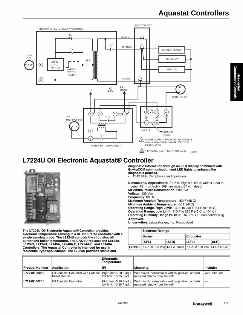
Aquastat Controllers
70-6910 177
R
esidential C
ombustion C
ontrols
L7224U Oil Electronic Aquastat® Controller
The L7224U Oil Electronic Aquastat® Controller provides electronic temperature sensing in a UL limit-rated controller with a single sensing probe. The L7224U controls the circulator, oil burner and boiler temperature. The L7224U replaces the L8124A, L8124C, L7124U, L7148A, L7248A,C, L7224A,C, and L8148A Controllers. The Aquastat Controller is intended for use in residential-type applications. The L7224U provides status and
diagnostic information through an LED display combined with EnviraCOM communication and LED lights to enhance the diagnostic process.• 2012 DOE Compliance and operation
Dimensions, Approximate: 7 1/8 in. high x 4 1/4 in. wide x 2 5/8 in. deep (181 mm high x 109 mm wide x 67 mm deep)
Maximum Power Consumption: 2000 VAVoltage: 120 VacFrequency: 60 HzMaximum Ambient Temperature: 150 F (66 C) Minimum Ambient Temperature: -30 F (-9 C) Operating Range, High Limit: 130 F to 240 F (54 C to 116 C) Operating Range, Low Limit: 110 F to 220 F (43 C to 104 C) Operating Humidity Range (% RH): 0 to 95% RH, non-condensingApprovalsUnderwriters Laboratories, Inc: Recognized
M8855
L1
(HOT)L2 1
2
1
2
POWER SUPPLY. PROVIDE DISCONNECT
MEANS AND OVERLOAD PROTECTION
AS REQUIRED.
B TERMINALS ARE TAB TERMINALS.
SOLID
STATE
SWITCHSAFETY
SWITCH
HEATER
B2 4 3 1
B
RR
W
BURNER MOTOR
OIL VALVE
IGNITION
SS
1K
1K2
1K1
F
F
T
T
R4184D PROTECTORELAY™ CONTROL
JUNCTION BOX
BLACK
ORANGE
WHITE
CIRCULATOR
L6081AJUMPER
ADDED
24V
THERMOSTAT
1R
1R1
RA89A SWITCHING RELAY
CAD
CELL
Electrical Ratings
Burner Circulator
(AFL) (ALR) (AFL) (ALR)
L7224R 7.4 A @ 120 Vac 44.4 A inrush 7.4 A @ 120 Vac 44.4 A inrush
Product Number Application
Differential Temperature
Mounting Includes(F)
L7224R1000/U Oil Aquastat Controller with Outdoor Reset Module
High limit: 5-20 F adj.; low limit: 10-25 F adj.
Well mount, horizontal or vertical position, or flush mounted remote from the well.
W8735S1000
L7224U1002/U Oil Aquastat Controller High limit: 5-20 F adj.; low limit: 10-25 F adj.
Well mount, horizontal or vertical position, or flush mounted remote from the well.
—
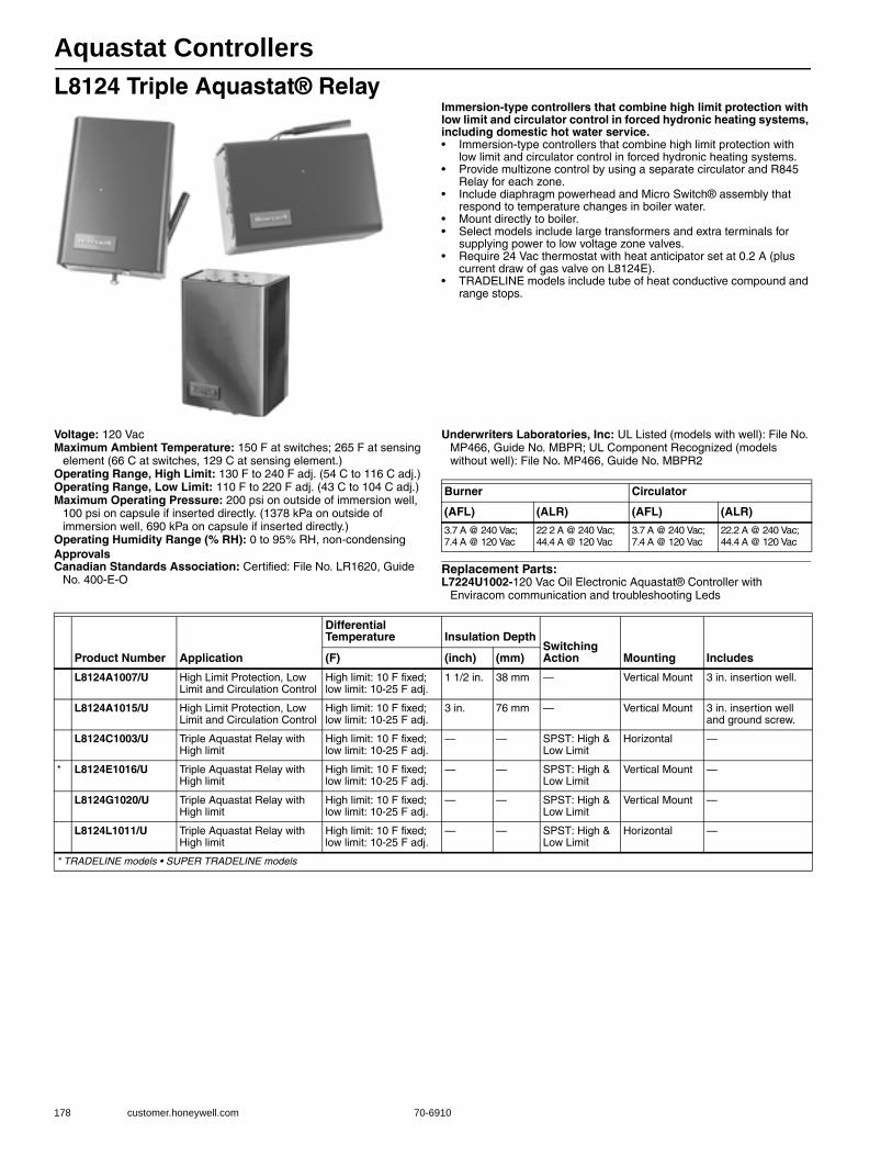
Aquastat Controllers
178 customer.honeywell.com 70-6910
L8124 Triple Aquastat® RelayImmersion-type controllers that combine high limit protection with low limit and circulator control in forced hydronic heating systems, including domestic hot water service.• Immersion-type controllers that combine high limit protection with
low limit and circulator control in forced hydronic heating systems. • Provide multizone control by using a separate circulator and R845
Relay for each zone. • Include diaphragm powerhead and Micro Switch® assembly that
respond to temperature changes in boiler water. • Mount directly to boiler. • Select models include large transformers and extra terminals for
supplying power to low voltage zone valves. • Require 24 Vac thermostat with heat anticipator set at 0.2 A (plus
current draw of gas valve on L8124E). • TRADELINE models include tube of heat conductive compound and
range stops.
Voltage: 120 VacMaximum Ambient Temperature: 150 F at switches; 265 F at sensing
element (66 C at switches, 129 C at sensing element.) Operating Range, High Limit: 130 F to 240 F adj. (54 C to 116 C adj.) Operating Range, Low Limit: 110 F to 220 F adj. (43 C to 104 C adj.) Maximum Operating Pressure: 200 psi on outside of immersion well,
100 psi on capsule if inserted directly. (1378 kPa on outside of immersion well, 690 kPa on capsule if inserted directly.)
Operating Humidity Range (% RH): 0 to 95% RH, non-condensingApprovalsCanadian Standards Association: Certified: File No. LR1620, Guide
No. 400-E-O
Underwriters Laboratories, Inc: UL Listed (models with well): File No. MP466, Guide No. MBPR; UL Component Recognized (models without well): File No. MP466, Guide No. MBPR2
Replacement Parts:L7224U1002-120 Vac Oil Electronic Aquastat® Controller with
Enviracom communication and troubleshooting Leds
Burner Circulator
(AFL) (ALR) (AFL) (ALR)
3.7 A @ 240 Vac; 7.4 A @ 120 Vac
22 2 A @ 240 Vac; 44.4 A @ 120 Vac
3.7 A @ 240 Vac; 7.4 A @ 120 Vac
22.2 A @ 240 Vac; 44.4 A @ 120 Vac
Product Number Application
Differential Temperature Insulation Depth
Switching Action Mounting Includes(F) (inch) (mm)
L8124A1007/U High Limit Protection, Low Limit and Circulation Control
High limit: 10 F fixed; low limit: 10-25 F adj.
1 1/2 in. 38 mm — Vertical Mount 3 in. insertion well.
L8124A1015/U High Limit Protection, Low Limit and Circulation Control
High limit: 10 F fixed; low limit: 10-25 F adj.
3 in. 76 mm — Vertical Mount 3 in. insertion well and ground screw.
L8124C1003/U Triple Aquastat Relay with High limit
High limit: 10 F fixed; low limit: 10-25 F adj.
— — SPST: High & Low Limit
Horizontal —
* L8124E1016/U Triple Aquastat Relay with High limit
High limit: 10 F fixed; low limit: 10-25 F adj.
— — SPST: High & Low Limit
Vertical Mount —
L8124G1020/U Triple Aquastat Relay with High limit
High limit: 10 F fixed; low limit: 10-25 F adj.
— — SPST: High & Low Limit
Vertical Mount —
L8124L1011/U Triple Aquastat Relay with High limit
High limit: 10 F fixed; low limit: 10-25 F adj.
— — SPST: High & Low Limit
Horizontal —
* TRADELINE models • SUPER TRADELINE models

Aquastat Controllers
70-6910 179
R
esidential C
ombustion C
ontrols
Dimensions in inches (millimeters)
M8802
L1
(HOT)
L21
1
2
2
POWER SUPPLY. PROVIDE DISCONNECT MEANS AND
OVERLOAD PROTECTION AS REQUIRED.
CONTROL CASE MUST BE CONNECTED TO EARTH GROUND.
USE GROUNDING SCREW PROVIDED.
B1 IS 1/4 IN. TAB TERMINAL.
LINE VOLTAGE
OIL BURNER
RELAY OR
GAS VALVE
LINE VOLTAGE
CIRCULATOR
C2
C1
B2
B1R
B
HIGH
LIMIT
ZC
ZR
1K1BRW
LOW LIMIT/
CIRCULATOR
1K
2
1
G
TT
L8124A,C
LOW VOLTAGE
THERMOSTAT
1K2 3
3
M8803
L1
(HOT)
L21
3
1
2
3
2
POWER SUPPLY. PROVIDE DISCONNECT MEANS AND
OVERLOAD PROTECTION AS REQUIRED.
CONTROL CASE MUST BE CONNECTED TO EARTH GROUND.
USE GROUNDING SCREW PROVIDED.
B1 IS 1/4 IN. TAB TERMINAL.
LOW VOLTAGE
GAS VALVE
(eg, VR8300)
LINE VOLTAGE
CIRCULATOR
C2
C1
B2
B1
R
B
HIGH
LIMIT
Z
1K1BRW
LOW LIMIT/
CIRCULATOR
1K2
1
G
TTV
L8124E
LOW VOLTAGE
THERMOSTAT
1K2
TR
TH
M1795B
L1
(HOT)
L2 1
1
2
3
4
3
2
4
POWER SUPPLY. PROVIDE DISCONNECT MEANS AND
OVERLOAD PROTECTION AS REQUIRED.
UP TO TWO V8043F ZONE VALVES CAN BE POWERED WITH
L8124G,L. ADD ADDITIONAL TRANSFORMER FOR EVERY
TWO OR LESS VALVES.
CONTROL CASE MUST BE CONNECTED TO EARTH GROUND.
USE GROUNDING SCREW PROVIDED.
B1 IS 1/4 IN. TAB TERMINAL.
LINE VOLTAGE
OIL BURNER
RELAY OR
GAS VALVE
LINE VOLTAGE
CIRCULATOR
B2
C2
C1
ZR
B1R
B
HIGH
LIMIT
Z
1K1
BRW
LOW LIMIT/
CIRCULATOR
1K
2
1
G
TTV
L8124G,L
ZONE 1
THERMOSTAT
1K2
V8043F
TH
TRTH TR
ZONE 2
THERMOSTAT
V8043F
TH
TRTH TR
ZC

Aquastat Controllers
180 customer.honeywell.com 70-6910
L8148 Aquastat® RelayImmersion-type controllers that combine high limit protection with switching relay control of burner and circulator motors.• High limit opens burner circuit only. • Include transformer and accessory terminals for adding a remote low
limit controller. • Case available for horizontal or vertical mounting. • Requires a 24 Vac thermostat with heat anticipator set at 0.2A. • TRADELINE models include well adapter, tube of heat conductive
compound and range stops.
Dimensions in inches (millimeters)
Anticipator Setting: 0.2 AVoltage: 120 VacFrequency: 60 HzElectrical Connections: Quick-Connect / Screw
Maximum Ambient Temperature: 150 F with 1.2 A 24 V load; 77 F with 1.4 A 24 V load (66 C with 1.2 A 24 V load; 25 C with 1.4 A 24 V load)
Setpoint Temperature Range: 240 F (116 C) Operating Range, High Limit: 120 F to 240 F (54 C to 116 C) Maximum Operating Pressure: Immersion Well: 255 psi (Immersion
Well: 1757 kPa) Operating Humidity Range (% RH): 0 to 95% RH, non-condensingCapillary Length: 4 1/2 in. (114 mm)Switching Action: SPST: High Limit & CirculatorApprovalsCanadian Standards Association: Certified: File No. LR1620, Guide
No. 400-E-OUnderwriters Laboratories, Inc: UL Listed: File No. MP466, Vol. 13,
Sec. 2, Guide No. MBPR2.Electrical Ratings:(burner millivolt): 0.25 A @ 1/4 to 12 Vdc(circulator AFL): 3.7 A @ 240 Vac; 7.4 A @ 120 Vac(circulator ALR): 22.2 A @ 240 Vac; 44.4 A @ 120 Vac
Product Number
Electrical Ratings
(AFL) (burner AFL) (burner ALR)
L8148A — — Line Voltage: 7.4 A @ 120 Vac; 3.7 A @ 240 Vac
Line Voltage: 44.4 A @ 120 Vac; 22.7 A @ 240 Vac
L8148E 0 25 A @ 0.25 to 12 Vdc
22.2A @ 240 Vac; 44.4A @ 120 Vac
Low Voltage: 0.8 A max. @ 24 Vac;Line Voltage: 7.4 A @ 120 Vac; 3.7 A @ 240 Vac
Line Voltage: 44.4 A @ 120 Vac; 22.7 A @ 240 Vac
L8148J — — 3.7 A @ 240 Vac; 7.4 A @ 120 Vac
22 2 A @ 240 Vac; 44.4 A @ 120 Vac
Product Number Application
Differential Temperature Insulation Depth
Mounting Includes(F) (inch) (mm)
* L8148A1017/U High Limit 8 F fixed 1 1/2 in. to 3 in. less well
38 mm to 76 mm less well
Horizontal —
* L8148E1265/U High Limit 15 F fixed 1 1/2 in. to 3 in. less well
38 mm to 76 mm less well
Vertical Mount
Molex® plug for use with vent damper, includes heat-conductive compound.Molex® plug for use with vent damper, includes heat-conductive compound.
L8148E1299/U High Limit 15 F fixed 1 1/2 in. to 3 in. less well
38 mm to 76 mm less well
Vertical Mount
50 VA transformer and heat conductive compound.
* L8148J1009/U Aquastat Relay 8 F fixed 1 1/2 in. to 3 in. less well.
38 mm to 76 mm less well
Horizontal or Vertical
—
* TRADELINE models • SUPER TRADELINE models
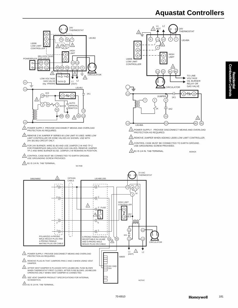
Aquastat Controllers
70-6910 181
R
esidential C
ombustion C
ontrols
L1
(HOT)
L2
1
1
4
5
5
1
2
3
4
5
23
POWER SUPPLY. PROVIDE DISCONNECT MEANS AND OVERLOAD
PROTECTION AS REQUIRED.
REMOVE Z-W JUMPER IF SERIES 60 LOW LIMIT IS USED. WIRE LOW
LIMIT CONTROLLER OR ZONE VALVES AS SHOWN. USE WITH
24V (B1-B3) CIRCUIT ONLY.
FOR 24V BURNER, WIRE B1-B3 AND USE JUMPER Z-W AND TP-Z.
FOR POWERPILE® (MILLIVOLTAGE) GAS VALVES, REMOVE JUMPER
TP-Z AND WIRE BURNER B1-B2. JUMPER Z-W REMAINS IN POSITION.
CONTROL CASE MUST BE CONNECTED TO EARTH GROUND.
USE GROUNDING SCREW PROVIDED.
B1 IS 1/4 IN. TAB TERMINAL.
L6006
LOW LIMIT
CONTROLLER
POWERPILE®MILLIVOLTAGEGAS VALVE
PP
PP TH2
TH1
W
R
R
R
B
B
B
24V
THERMOSTAT
L8148J
CIRCULATOR
G
G
L1
L1
L2B3B2B1
HIGH
LIMIT
TP
TV TW
Z
C1 C2
TR TH
THTR
LOW VOLTAGE
GAS VALVE
(eg, VR8300)
1K3
TP
Z W T
TV
1K2
AUTO
MANUAL
SWITCH
1K1
C1
C2B3 B2 B1
L2
L8148J
M1793B
C1 C2 B1 B2
R
W
B
G L1 L2 T T
3
B
R
L1
L2
G
T T 3
C1
C2 B2 B1
JUMPER
1K 1K2
1K1
B R
L6006
LOW LIMIT
CONTROLLER
L1
HOT
L2
24V
THERMOSTAT
L8148A
HIGH
LIMIT
TO LINE
VOLTAGE
OIL BURNER
RELAY OR
GAS VALVECIRCULATOR
POWER SUPPLY. PROVIDE DISCONNECT MEANS AND OVERLOAD
PROTECTION AS REQUIRED.
REMOVE JUMPER WHEN ADDING L6006 LOW LIMIT CONTROLLER.
CONTROL CASE MUST BE CONNECTED TO EARTH GROUND.
USE GROUNDING SCREW PROVIDED.
B1 IS 1/4 IN. TAB TERMINAL.
1
2
3
4
4
1
2
3
M2842A
L8148A
4
24V GND24V
S8600
L1
(HOT)L21
1
2
3
4
5
L8148E1265
4
2
3
3
FUSE
5
1
2
5
6-PRONG FEMALE MOLEX
RECEPTABLE IN L8148E
AND 5-PRONG MALE
MOLEX PLUG ON CABLE
1K1
B1 B2 L1
C1 C2
L2
CIRCULATOR
POLARIZED 4-PRONG
MALE MOLEX PLUG AND
4-PRONG FEMALE
MATING PLUG ON CABLE
1
2
3
4
24 VAC
THERMOSTAT
D892/M892 4 197516A
CABLE
POWER SUPPLY. PROVIDE DISCONNECT MEANS AND OVERLOAD
PROTECTION AS REQUIRED.
REMOVE PLUG-IN THAT JUMPERS PINS 2 AND 3 WHEN USING VENT
DAMPER.
AFTER VENT DAMPER IS PLUGGED INTO L8148E1265, FUSE BLOWS
WHEN THERMOSTAT FIRST CLOSES. AFTER FUSE BLOWS, L8148E1265
OPERATES ONLY WHEN VENT DAMPER IS CONNECTED.
SEE VENT DAMPER PRODUCT SPECIFICATIONS FOR INTERNAL
SCHEMATICS.
B1 IS 1/4 IN. TAB TERMINAL.
M2763C
1K2
HIGH LIMIT
CONTROLLER
R
B
TV W T
1KZ
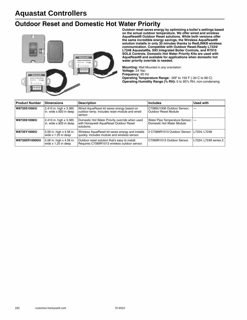
Aquastat Controllers
182 customer.honeywell.com 70-6910
Outdoor Reset and Domestic Hot Water PriorityOutdoor reset saves energy by optimizing a boiler’s settings based on the actual outdoor temperature. We offer wired and wireless AquaReset® Outdoor Reset solutions. While both versions offer the same incredible energy savings, the Wireless AquaReset® solution installs in only 30 minutes thanks to RedLINK® wireless communication. Compatible with Outdoor Reset-Ready L7224/L7248 Aquastat®s, S93 Integrated Boiler Controls, and R7910 SOLA Controls. Domestic Hot Water Priority Kits are used with AquaReset® and available for applications when domestic hot water priority override is needed.
Mounting: Wall Mounted in any orientationVoltage: 24 VacFrequency: 60 HzOperating Temperature Range: -30F to 150 F (-34 C to 66 C) Operating Humidity Range (% RH): 0 to 95% RH, non-condensing
Product Number Dimensions Description Includes Used with
W8735S1000/U 2.410 in. high x 3.385 in. wide x.920 in deep
Wired AquaReset kit saves energy based on outdoor temp. Includes reset module and wired sensor.
C7089U1006 Outdoor Sensor; Outdoor Reset Module
—
W8735S1008/U 2.410 in. high x 3.385 in. wide x.920 in deep
Domestic Hot Water Priority override when used with Honeywell AquaReset Outdoor Reset solutions.
Water Pipe Temperature Sensor; Domestic Hot Water Module
—
W8735Y1000/U 5.56 in. high x 4.56 in. wide x 1.25 in deep
Wireless AquaReset kit saves energy and installs quickly. Includes module and wireless sensor.
2 C7089R1013 Outdoor Sensor L7224; L7248
W8735ER10000/U 5.56 in. high x 4.56 in. wide x 1.25 in deep
Outdoor reset solution that's easy to install. Requires C7089R1013 wireless outdoor sensor.
C7089R1013 Outdoor Sensor L7224; L7248 series 2
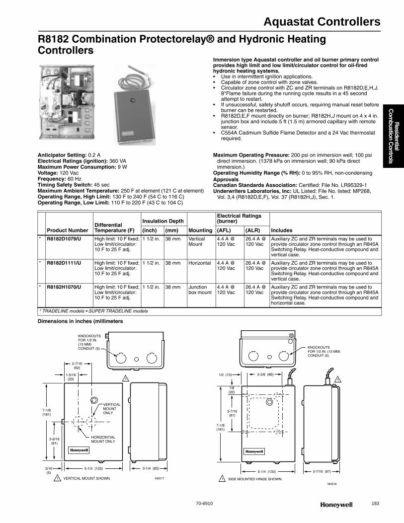
Aquastat Controllers
70-6910 183
R
esidential C
ombustion C
ontrols
R8182 Combination Protectorelay® and Hydronic Heating Controllers
Immersion type Aquastat controller and oil burner primary control provides high limit and low limit/circulator control for oil-fired hydronic heating systems.• Use in intermittent ignition applications. • Capable of zone control with zone valves. • Circulator zone control with ZC and ZR terminals on R8182D,E,H,J.
8*Flame failure during the running cycle results in a 45 second attempt to restart.
• If unsuccessful, safety shutoff occurs, requiring manual reset before burner can be restarted.
• R8182D,E,F mount directly on burner; R8182H,J mount on 4 x 4 in. junction box and include 5 ft (1.5 m) armored capillary with remote sensor.
• C554A Cadmium Sulfide Flame Detector and a 24 Vac thermostat required.
Anticipator Setting: 0.2 AElectrical Ratings (ignition): 360 VAMaximum Power Consumption: 9 WVoltage: 120 VacFrequency: 60 HzTiming Safety Switch: 45 secMaximum Ambient Temperature: 250 F at element (121 C at element) Operating Range, High Limit: 130 F to 240 F (54 C to 116 C) Operating Range, Low Limit: 110 F to 220 F (43 C to 104 C)
Maximum Operating Pressure: 200 psi on immersion well; 100 psi direct immersion. (1378 kPa on immersion well; 90 kPa direct immersion.)
Operating Humidity Range (% RH): 0 to 95% RH, non-condensingApprovalsCanadian Standards Association: Certified: File No. LR95329-1Underwriters Laboratories, Inc: UL Listed: File No. listed: MP268,
Vol. 3,4 (R8182D,E,F), Vol. 37 (R8182H,J), Sec. 1.
Dimensions in inches (millimeters
Product NumberDifferential Temperature (F)
Insulation Depth
Mounting
Electrical Ratings (burner)
Includes(inch) (mm) (AFL) (ALR)
* R8182D1079/U High limit: 10 F fixed; Low limit/circulator: 10 F to 25 F adj.
1 1/2 in. 38 mm Vertical Mount
4.4 A @ 120 Vac
26.4 A @ 120 Vac
Auxiliary ZC and ZR terminals may be used to provide circulator zone control through an R845A Switching Relay. Heat-conductive compound and vertical case.
* R8182D1111/U High limit: 10 F fixed; Low limit/circulator: 10 F to 25 F adj.
1 1/2 in. 38 mm Horizontal 4.4 A @ 120 Vac
26.4 A @ 120 Vac
Auxiliary ZC and ZR terminals may be used to provide circulator zone control through an R845A Switching Relay. Heat-conductive compound and vertical case.
* R8182H1070/U High limit: 10 F fixed; Low limit/circulator: 10 F to 25 F adj.
1 1/2 in. 38 mm Junction box mount
4.4 A @ 120 Vac
26.4 A @ 120 Vac
Auxiliary ZC and ZR terminals may be used to provide circulator zone control through an R845A Switching Relay. Heat-conductive compound and horizontal case.
* TRADELINE models • SUPER TRADELINE models
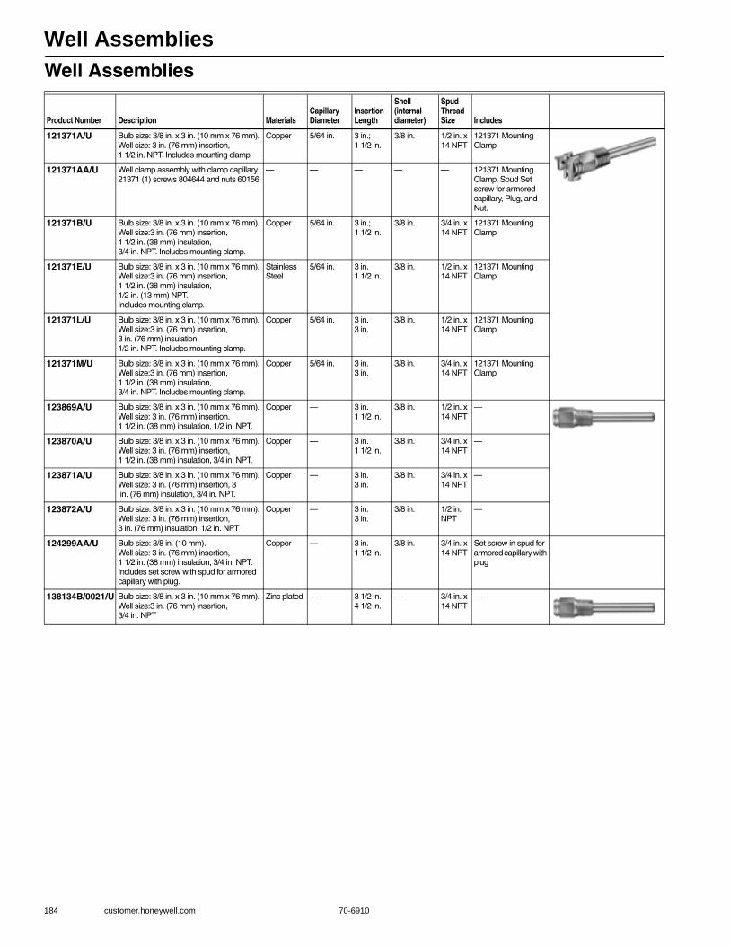
Well Assemblies
184 customer.honeywell.com 70-6910
Well Assemblies
Product Number Description MaterialsCapillary Diameter
Insertion Length
Shell (internal diameter)
Spud Thread Size Includes
121371A/U Bulb size: 3/8 in. x 3 in. (10 mm x 76 mm). Well size: 3 in. (76 mm) insertion, 1 1/2 in. NPT. Includes mounting clamp.
Copper 5/64 in. 3 in.; 1 1/2 in.
3/8 in. 1/2 in. x 14 NPT
121371 Mounting Clamp
121371AA/U Well clamp assembly with clamp capillary 21371 (1) screws 804644 and nuts 60156
— — — — — 121371 Mounting Clamp, Spud Set screw for armored capillary, Plug, and Nut.
121371B/U Bulb size: 3/8 in. x 3 in. (10 mm x 76 mm). Well size:3 in. (76 mm) insertion, 1 1/2 in. (38 mm) insulation, 3/4 in. NPT. Includes mounting clamp.
Copper 5/64 in. 3 in.; 1 1/2 in.
3/8 in. 3/4 in. x 14 NPT
121371 Mounting Clamp
121371E/U Bulb size: 3/8 in. x 3 in. (10 mm x 76 mm). Well size:3 in. (76 mm) insertion, 1 1/2 in. (38 mm) insulation, 1/2 in. (13 mm) NPT. Includes mounting clamp.
Stainless Steel
5/64 in. 3 in.1 1/2 in.
3/8 in. 1/2 in. x 14 NPT
121371 Mounting Clamp
121371L/U Bulb size: 3/8 in. x 3 in. (10 mm x 76 mm). Well size:3 in. (76 mm) insertion, 3 in. (76 mm) insulation, 1/2 in. NPT. Includes mounting clamp.
Copper 5/64 in. 3 in.3 in.
3/8 in. 1/2 in. x 14 NPT
121371 Mounting Clamp
121371M/U Bulb size: 3/8 in. x 3 in. (10 mm x 76 mm). Well size:3 in. (76 mm) insertion, 1 1/2 in. (38 mm) insulation, 3/4 in. NPT. Includes mounting clamp.
Copper 5/64 in. 3 in.3 in.
3/8 in. 3/4 in. x 14 NPT
121371 Mounting Clamp
123869A/U Bulb size: 3/8 in. x 3 in. (10 mm x 76 mm). Well size: 3 in. (76 mm) insertion, 1 1/2 in. (38 mm) insulation, 1/2 in. NPT.
Copper — 3 in.1 1/2 in.
3/8 in. 1/2 in. x 14 NPT
—
123870A/U Bulb size: 3/8 in. x 3 in. (10 mm x 76 mm). Well size: 3 in. (76 mm) insertion, 1 1/2 in. (38 mm) insulation, 3/4 in. NPT.
Copper — 3 in.1 1/2 in.
3/8 in. 3/4 in. x 14 NPT
—
123871A/U Bulb size: 3/8 in. x 3 in. (10 mm x 76 mm). Well size: 3 in. (76 mm) insertion, 3 in. (76 mm) insulation, 3/4 in. NPT.
Copper — 3 in.3 in.
3/8 in. 3/4 in. x 14 NPT
—
123872A/U Bulb size: 3/8 in. x 3 in. (10 mm x 76 mm). Well size: 3 in. (76 mm) insertion, 3 in. (76 mm) insulation, 1/2 in. NPT
Copper — 3 in.3 in.
3/8 in. 1/2 in. NPT
—
124299AA/U Bulb size: 3/8 in. (10 mm). Well size: 3 in. (76 mm) insertion, 1 1/2 in. (38 mm) insulation, 3/4 in. NPT. Includes set screw with spud for armored capillary with plug.
Copper — 3 in.1 1/2 in.
3/8 in. 3/4 in. x 14 NPT
Set screw in spud for armored capillary with plug
138134B/0021/U Bulb size: 3/8 in. x 3 in. (10 mm x 76 mm). Well size:3 in. (76 mm) insertion, 3/4 in. NPT
Zinc plated — 3 1/2 in.4 1/2 in.
— 3/4 in. x 14 NPT
—

AQUATROL Zoning System
70-6910 185
H
ydronic C
ontrols
AQ250 Electronic Relay Boiler Control Panel for Hydronic Zoning System
The AQ250 family of AQUATROL Boiler Controls provides simplified, energy-efficient control of single temperature, residential hydronic heating systems. The AQ250 easily converts a single zone heating system into a room-by-room comfort control system, or upgrades a basic, relay-logic zoning system to intelligent Zone of Greatest Demand control for increased energy efficiency with reduced boiler cycling. AQ250 boiler controls can
ensure ample supply of hot water for both space heating and priority generation of domestic hot water for bathing, dishes and laundry.• Controls up to 2 stages of heat from a single thermostat. • Use with AQ1000 2-wire communicating thermostats, or most dry
contact digital thermostats. • Zoning Control for up to 4 zones as shipped; can be expanded to a
total of 16 zones with AQ255 or AQ257 expansion zoning panels and up to 64 zones when used with AQ254 Add-A-Temp panels.
• Line or low-voltage output for zoning equipment (pumps or valves). • Zone synchronization through Zone or Greatest Demand control. • Domestic hot water priority and priority override protection.• Boiler short cycling protection. • Boiler post purge.• Freeze protection.• Pump/valve exercise.• Boiler shock prevention from cold water returning to boiler. • Automated test feature for quick start-up and simplified
troubleshooting.• Integral 38 VA transformer with self-resetting electronic fuse.
Application: Boiler control for zoned hydronic systemsDimensions, Approximate: 13 in wide x 8 in. high x 3 3/8 in deep (33
cm wide x 20.3 cm high x 8.5 cm deep) Power Supply: 120V/60HzUser Interface (Setting, Programming): (DIP Switches) Electrical Connections (Line Voltage): Wire-clamp screw terminals,
Maximum 2 x 14 AWG each on line voltage terminalsControl and Zoning Panel Temperature Rating: 32 F to 130 F (0 C to
55 C) Thermostat Compatibility: AQ1000 Series 2-wire communicating
thermostats and most digital thermostatsZone Module Thermostat input: Low voltage, Class II, 2-wire polarity-
insensitive, digital communicating with power link to AQ1000 series thermostat.
Boiler Heat Post Purge: 30 seconds (sent to DHW tank or Zone of Greatest Demand - selectable)
Boiler (T-T) Output Rating: 24 Vac, 0.5A, 12VADHW Pump/Valve Output Rating: 120 Vac/250 Vac 5A, 1/3HPDHW Demand Input: External dry contacts connection onlyPump/Valve exercise: 30 seconds per 2 weeks of space heating
inactivity
Auxiliary Pump Output Rating: Dry contact output, 120 Vac/250 Vac 5A, 1/3 HP
Zone Output Contact Rating: Pumps: 120 Vac/250 Vac, 5A, 1/3 HPValves: 24 Vac, 0.5 A, 12 VAZR-ZC Contact Rating: 120 to 240 Vac, 1/3 HPSensor Temperature Rating: -58 F to +230 F (-50 C to +110 C) Supply/Return Sensor: Lead Length: 10 ft. (3050 mm). 10 kilohm NTC
thermistor at 25 C (77 F) ±0.5F (±0.3C) up to 500 ft (150 M) using 18 AWG or larger wire
Heat Demand (Thermostat R-W) Input: External dry contacts connection only
B-B Communication Bus Terminals: Low voltage, Class II, 2-wire polarity-insensitive, digital communicating link to other Control or Zoning modules.
R-C Input (on Control and Zoning Modules): 24 Vac Class IIR-C Output (on transformer): 38 VA, 24 Vac Class IIOperating Humidity Range (% RH): 5 to 90% RH, non-condensingWeight: 4.9 lbs (2.3 kg) ApprovalsCanadian Standards Association: CSA C/US Certified to CSA and
UL Standards, File No. LR76030
Product NumberType of Zoning Devices Controlled
Number of Zones Controlled
Boiler Pump Output Rating Replacement Parts
* AQ25042B/U Zone pumps or 2-wire valves (line voltage)
4 120 Vac/250 Vac 5A, 1/3HP
AQ15000B boiler control module; AQ12C11 supply/return/mixed loop sensor; AQ10X38 24 Vac 38 VA transformer; AQ15540B 4-zone pump expansion module
* AQ25044B/U Zone valves with end switches
4 120 Vac/250 Vac 5A, 1/3HP
AQ15000B boiler control module; AQ15740B 4-zone valve with end switch expansion module; AQ12C11 supply/return/mixed loop sensor; AQ10X38 24 Vac 38 VA transformer
* TRADELINE models • SUPER TRADELINE models
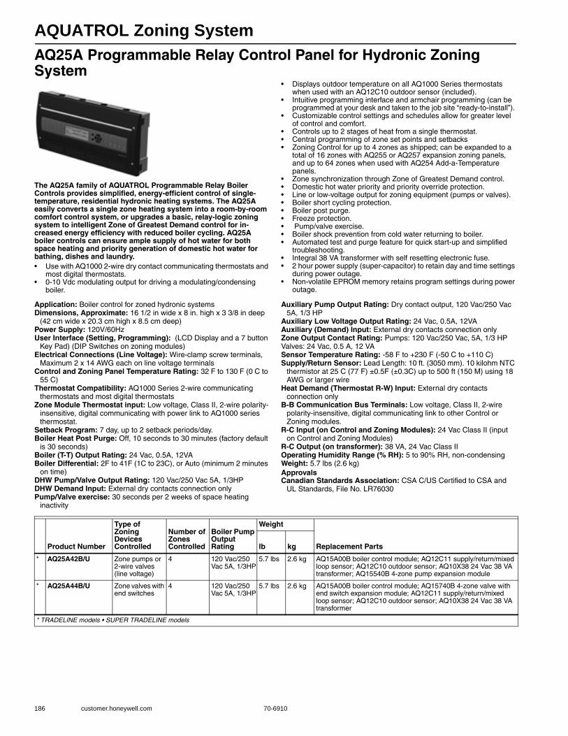
AQUATROL Zoning System
186 customer.honeywell.com 70-6910
AQ25A Programmable Relay Control Panel for Hydronic Zoning System
The AQ25A family of AQUATROL Programmable Relay Boiler Controls provides simplified, energy-efficient control of single-temperature, residential hydronic heating systems. The AQ25A easily converts a single zone heating system into a room-by-room comfort control system, or upgrades a basic, relay-logic zoning system to intelligent Zone of Greatest Demand control for in-creased energy efficiency with reduced boiler cycling. AQ25A boiler controls can ensure ample supply of hot water for both space heating and priority generation of domestic hot water for bathing, dishes and laundry.• Use with AQ1000 2-wire dry contact communicating thermostats and
most digital thermostats. • 0-10 Vdc modulating output for driving a modulating/condensing
boiler.
• Displays outdoor temperature on all AQ1000 Series thermostats when used with an AQ12C10 outdoor sensor (included).
• Intuitive programming interface and armchair programming (can be programmed at your desk and taken to the job site “ready-to-install”).
• Customizable control settings and schedules allow for greater level of control and comfort.
• Controls up to 2 stages of heat from a single thermostat. • Central programming of zone set points and setbacks • Zoning Control for up to 4 zones as shipped; can be expanded to a
total of 16 zones with AQ255 or AQ257 expansion zoning panels, and up to 64 zones when used with AQ254 Add-a-Temperature panels.
• Zone synchronization through Zone of Greatest Demand control. • Domestic hot water priority and priority override protection. • Line or low-voltage output for zoning equipment (pumps or valves). • Boiler short cycling protection. • Boiler post purge. • Freeze protection. • Pump/valve exercise. • Boiler shock prevention from cold water returning to boiler. • Automated test and purge feature for quick start-up and simplified
troubleshooting. • Integral 38 VA transformer with self resetting electronic fuse. • 2 hour power supply (super-capacitor) to retain day and time settings
during power outage. • Non-volatile EPROM memory retains program settings during power
outage.
Application: Boiler control for zoned hydronic systemsDimensions, Approximate: 16 1/2 in wide x 8 in. high x 3 3/8 in deep
(42 cm wide x 20.3 cm high x 8.5 cm deep) Power Supply: 120V/60HzUser Interface (Setting, Programming): (LCD Display and a 7 button
Key Pad) (DIP Switches on zoning modules) Electrical Connections (Line Voltage): Wire-clamp screw terminals,
Maximum 2 x 14 AWG each on line voltage terminalsControl and Zoning Panel Temperature Rating: 32 F to 130 F (0 C to
55 C) Thermostat Compatibility: AQ1000 Series 2-wire communicating
thermostats and most digital thermostatsZone Module Thermostat input: Low voltage, Class II, 2-wire polarity-
insensitive, digital communicating with power link to AQ1000 series thermostat.
Setback Program: 7 day, up to 2 setback periods/day.Boiler Heat Post Purge: Off, 10 seconds to 30 minutes (factory default
is 30 seconds)Boiler (T-T) Output Rating: 24 Vac, 0.5A, 12VABoiler Differential: 2F to 41F (1C to 23C), or Auto (minimum 2 minutes
on time)DHW Pump/Valve Output Rating: 120 Vac/250 Vac 5A, 1/3HPDHW Demand Input: External dry contacts connection onlyPump/Valve exercise: 30 seconds per 2 weeks of space heating
inactivity
Auxiliary Pump Output Rating: Dry contact output, 120 Vac/250 Vac 5A, 1/3 HP
Auxiliary Low Voltage Output Rating: 24 Vac, 0.5A, 12VAAuxiliary (Demand) Input: External dry contacts connection onlyZone Output Contact Rating: Pumps: 120 Vac/250 Vac, 5A, 1/3 HPValves: 24 Vac, 0.5 A, 12 VASensor Temperature Rating: -58 F to +230 F (-50 C to +110 C) Supply/Return Sensor: Lead Length: 10 ft. (3050 mm). 10 kilohm NTC
thermistor at 25 C (77 F) ±0.5F (±0.3C) up to 500 ft (150 M) using 18 AWG or larger wire
Heat Demand (Thermostat R-W) Input: External dry contacts connection only
B-B Communication Bus Terminals: Low voltage, Class II, 2-wire polarity-insensitive, digital communicating link to other Control or Zoning modules.
R-C Input (on Control and Zoning Modules): 24 Vac Class II (input on Control and Zoning Modules)
R-C Output (on transformer): 38 VA, 24 Vac Class IIOperating Humidity Range (% RH): 5 to 90% RH, non-condensingWeight: 5.7 lbs (2.6 kg) ApprovalsCanadian Standards Association: CSA C/US Certified to CSA and
UL Standards, File No. LR76030
Product Number
Type of Zoning Devices Controlled
Number of Zones Controlled
Boiler Pump Output Rating
Weight
Replacement Partslb kg
* AQ25A42B/U Zone pumps or 2-wire valves (line voltage)
4 120 Vac/250 Vac 5A, 1/3HP
5.7 lbs 2.6 kg AQ15A00B boiler control module; AQ12C11 supply/return/mixed loop sensor; AQ12C10 outdoor sensor; AQ10X38 24 Vac 38 VA transformer; AQ15540B 4-zone pump expansion module
* AQ25A44B/U Zone valves with end switches
4 120 Vac/250 Vac 5A, 1/3HP
5.7 lbs 2.6 kg AQ15A00B boiler control module; AQ15740B 4-zone valve with end switch expansion module; AQ12C11 supply/return/mixed loop sensor; AQ12C10 outdoor sensor; AQ10X38 24 Vac 38 VA transformer
* TRADELINE models • SUPER TRADELINE models
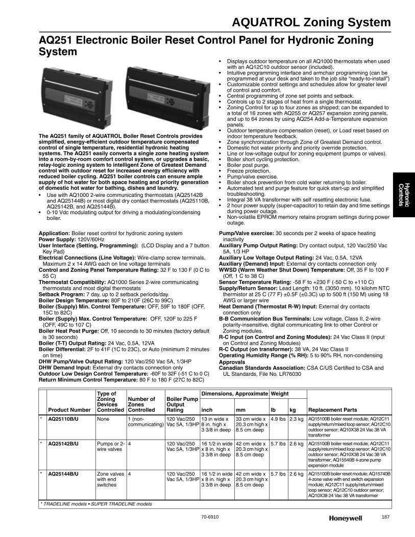
AQUATROL Zoning System
70-6910 187
H
ydronic C
ontrols
AQ251 Electronic Boiler Reset Control Panel for Hydronic Zoning System
The AQ251 family of AQUATROL Boiler Reset Controls provides simplified, energy-efficient outdoor temperature compensated control of single temperature, residential hydronic heating systems. The AQ251 easily converts a single zone heating system into a room-by-room comfort control system, or upgrades a basic, relay-logic zoning system to intelligent Zone of Greatest Demand control with outdoor reset for increased energy efficiency with reduced boiler cycling. AQ251 boiler controls can ensure ample supply of hot water for both space heating and priority generation of domestic hot water for bathing, dishes and laundry.• Use with AQ1000 2-wire communicating thermostats (AQ25142B
and AQ25144B) or most digital dry contact thermostats (AQ25110B, AQ25142B, and AQ25144B).
• 0-10 Vdc modulating output for driving a modulating/condensing boiler.
• Displays outdoor temperature on all AQ1000 thermostats when used with an AQ12C10 outdoor sensor (included).
• Intuitive programming interface and armchair programming (can be programmed at your desk and taken to the job site “ready-to-install”)
• Customizable control settings and schedules allow for greater level of control and comfort.
• Central programming of zone set points and setback. • Controls up to 2 stages of heat from a single thermostat. • Zoning Control for up to four zones as shipped; can be expanded to
a total of 16 zones with AQ255 or AQ257 expansion zoning panels, and up to 64 zones by using AQ254 Add-a-Temperature expansion panels.
• Outdoor temperature compensation (reset), or Load reset based on indoor temperature feedback.
• Zone synchronization through Zone of Greatest Demand control. • Domestic hot water priority and priority override protection. • Line or low-voltage output for zoning equipment (pumps or valves). • Boiler short cycling protection. • Boiler post purge. • Freeze protection. • Pump/valve exercise. • Boiler shock prevention from cold water returning to boiler. • Automated test and purge feature for quick start-up and simplified
troubleshooting. • Integral 38 VA transformer with self resetting electronic fuse. • 2 hour power supply (super-capacitor) to retain day and time settings
during power outage. • Non-volatile EPROM memory retains program settings during power
outage.
Application: Boiler reset control for hydronic zoning systemPower Supply: 120V/60HzUser Interface (Setting, Programming): (LCD Display and a 7 button
Key Pad) Electrical Connections (Line Voltage): Wire-clamp screw terminals,
Maximum 2 x 14 AWG each on line voltage terminalsControl and Zoning Panel Temperature Rating: 32 F to 130 F (0 C to
55 C) Thermostat Compatibility: AQ1000 Series 2-wire communicating
thermostats and most digital thermostatsSetback Program: 7 day, up to 2 setback periods/day.Boiler Design Temperature: 80F to 210F (26C to 99C) Boiler (Supply) Min. Control Temperature: OFF, 59F to 180F (OFF,
15C to 82C) Boiler (Supply) Max. Control Temperature: OFF, 120F to 225 F
(OFF, 49C to 107 C)Boiler Heat Post Purge: Off, 10 seconds to 30 minutes (factory default
is 30 seconds)Boiler (T-T) Output Rating: 24 Vac, 0.5A, 12VABoiler Differential: 2F to 41F (1C to 23C), or Auto (minimum 2 minutes
on time)DHW Pump/Valve Output Rating: 120 Vac/250 Vac 5A, 1/3HPDHW Demand Input: External dry contacts connection onlyOutdoor Low Design Control Temperature: -60F to 32F (-51 C to 0 C) Return Minimum Control Temperature: 80 F to 180 F (27C to 82C)
Pump/Valve exercise: 30 seconds per 2 weeks of space heating inactivity
Auxiliary Pump Output Rating: Dry contact output, 120 Vac/250 Vac 5A, 1/3 HP
Auxiliary Low Voltage Output Rating: 24 Vac, 0.5A, 12VAAuxiliary (Demand) Input: External dry contacts connection onlyWWSD (Warm Weather Shut Down) Temperature: Off, 35 F to 100 F
(Off, 1 C to 38 C) Sensor Temperature Rating: -58 F to +230 F (-50 C to +110 C) Supply/Return Sensor: Lead Length: 10 ft. (3050 mm). 10 kilohm NTC
thermistor at 25 C (77 F) ±0.5F (±0.3C) up to 500 ft (150 M) using 18 AWG or larger wire
Heat Demand (Thermostat R-W) Input: External dry contacts connection only
B-B Communication Bus Terminals: Low voltage, Class II, 2-wire polarity-insensitive, digital communicating link to other Control or Zoning modules.
R-C Input (on Control and Zoning Modules): 24 Vac Class II (input on Control and Zoning Modules)
R-C Output (on transformer): 38 VA, 24 Vac Class IIOperating Humidity Range (% RH): 5 to 90% RH, non-condensingApprovalsCanadian Standards Association: CSA C/US Certified to CSA and
UL Standards, File No. LR76030
Product Number
Type of Zoning Devices Controlled
Number of Zones Controlled
Boiler Pump Output Rating
Dimensions, Approximate Weight
Replacement Partsinch mm lb kg
* AQ25110B/U None 1 (non-communicating)
120 Vac/250 Vac 5A, 1/3HP
13 in wide x 8 in. high x 3 3/8 in deep
33 cm wide x 20.3 cm high x 8.5 cm deep
4.9 lbs 2.3 kg AQ15100B boiler reset module; AQ12C11 supply/return/mixed loop sensor; AQ12C10 outdoor sensor; AQ10X38 24 Vac 38 VA transformer
* AQ25142B/U Pumps or 2-wire valves
4 120 Vac/250 Vac 5A, 1/3HP
16 1/2 in wide x 8 in. high x 3 3/8 in deep
42 cm wide x 20.3 cm high x 8.5 cm deep
5.7 lbs 2.6 kg AQ15100B boiler reset module; AQ12C11 supply/return/mixed loop sensor; AQ12C10 outdoor sensor; AQ10X38 24 Vac 38 VA transformer; AQ15540B 4-zone pump expansion module
* AQ25144B/U Zone valves with end switches
4 120 Vac/250 Vac 5A, 1/3HP
16 1/2 in wide x 8 in. high x 3 3/8 in deep
42 cm wide x 20.3 cm high x 8.5 cm deep
5.7 lbs 2.6 kg AQ15100B boiler reset module; AQ15740B 4-zone valve with end switch expansion module; AQ12C11 supply/return/mixed loop sensor; AQ12C10 outdoor sensor; AQ10X38 24 Vac 38 VA transformer
* TRADELINE models • SUPER TRADELINE models
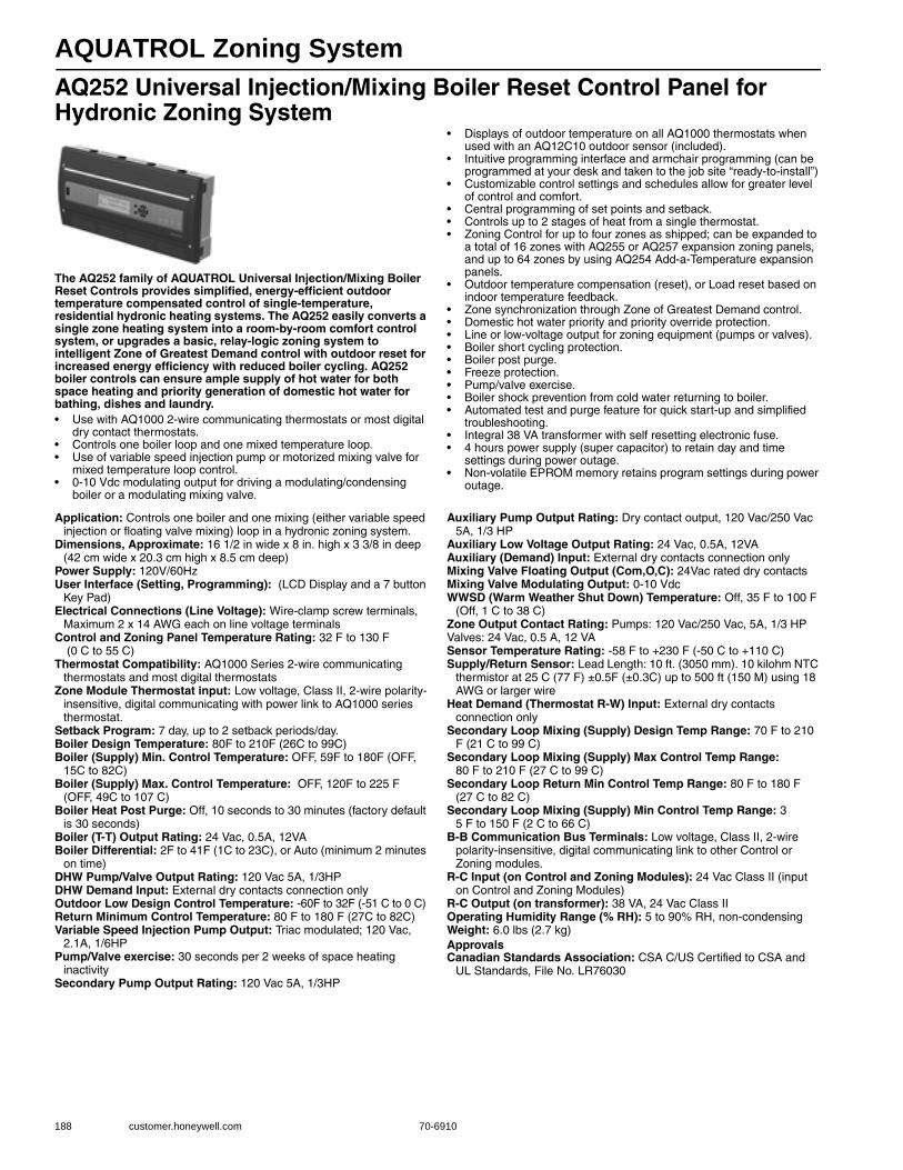
AQUATROL Zoning System
188 customer.honeywell.com 70-6910
AQ252 Universal Injection/Mixing Boiler Reset Control Panel for Hydronic Zoning System
The AQ252 family of AQUATROL Universal Injection/Mixing Boiler Reset Controls provides simplified, energy-efficient outdoor temperature compensated control of single-temperature, residential hydronic heating systems. The AQ252 easily converts a single zone heating system into a room-by-room comfort control system, or upgrades a basic, relay-logic zoning system to intelligent Zone of Greatest Demand control with outdoor reset for increased energy efficiency with reduced boiler cycling. AQ252 boiler controls can ensure ample supply of hot water for both space heating and priority generation of domestic hot water for bathing, dishes and laundry.• Use with AQ1000 2-wire communicating thermostats or most digital
dry contact thermostats. • Controls one boiler loop and one mixed temperature loop. • Use of variable speed injection pump or motorized mixing valve for
mixed temperature loop control. • 0-10 Vdc modulating output for driving a modulating/condensing
boiler or a modulating mixing valve.
• Displays of outdoor temperature on all AQ1000 thermostats when used with an AQ12C10 outdoor sensor (included).
• Intuitive programming interface and armchair programming (can be programmed at your desk and taken to the job site “ready-to-install”)
• Customizable control settings and schedules allow for greater level of control and comfort.
• Central programming of set points and setback.• Controls up to 2 stages of heat from a single thermostat. • Zoning Control for up to four zones as shipped; can be expanded to
a total of 16 zones with AQ255 or AQ257 expansion zoning panels, and up to 64 zones by using AQ254 Add-a-Temperature expansion panels.
• Outdoor temperature compensation (reset), or Load reset based on indoor temperature feedback.
• Zone synchronization through Zone of Greatest Demand control. • Domestic hot water priority and priority override protection. • Line or low-voltage output for zoning equipment (pumps or valves). • Boiler short cycling protection. • Boiler post purge. • Freeze protection. • Pump/valve exercise. • Boiler shock prevention from cold water returning to boiler. • Automated test and purge feature for quick start-up and simplified
troubleshooting. • Integral 38 VA transformer with self resetting electronic fuse. • 4 hours power supply (super capacitor) to retain day and time
settings during power outage. • Non-volatile EPROM memory retains program settings during power
outage.
Application: Controls one boiler and one mixing (either variable speed injection or floating valve mixing) loop in a hydronic zoning system.
Dimensions, Approximate: 16 1/2 in wide x 8 in. high x 3 3/8 in deep (42 cm wide x 20.3 cm high x 8.5 cm deep)
Power Supply: 120V/60HzUser Interface (Setting, Programming): (LCD Display and a 7 button
Key Pad) Electrical Connections (Line Voltage): Wire-clamp screw terminals,
Maximum 2 x 14 AWG each on line voltage terminalsControl and Zoning Panel Temperature Rating: 32 F to 130 F
(0 C to 55 C) Thermostat Compatibility: AQ1000 Series 2-wire communicating
thermostats and most digital thermostatsZone Module Thermostat input: Low voltage, Class II, 2-wire polarity-
insensitive, digital communicating with power link to AQ1000 series thermostat.
Setback Program: 7 day, up to 2 setback periods/day.Boiler Design Temperature: 80F to 210F (26C to 99C) Boiler (Supply) Min. Control Temperature: OFF, 59F to 180F (OFF,
15C to 82C) Boiler (Supply) Max. Control Temperature: OFF, 120F to 225 F
(OFF, 49C to 107 C)Boiler Heat Post Purge: Off, 10 seconds to 30 minutes (factory default
is 30 seconds)Boiler (T-T) Output Rating: 24 Vac, 0.5A, 12VABoiler Differential: 2F to 41F (1C to 23C), or Auto (minimum 2 minutes
on time)DHW Pump/Valve Output Rating: 120 Vac 5A, 1/3HPDHW Demand Input: External dry contacts connection onlyOutdoor Low Design Control Temperature: -60F to 32F (-51 C to 0 C) Return Minimum Control Temperature: 80 F to 180 F (27C to 82C) Variable Speed Injection Pump Output: Triac modulated; 120 Vac,
2.1A, 1/6HPPump/Valve exercise: 30 seconds per 2 weeks of space heating
inactivitySecondary Pump Output Rating: 120 Vac 5A, 1/3HP
Auxiliary Pump Output Rating: Dry contact output, 120 Vac/250 Vac 5A, 1/3 HP
Auxiliary Low Voltage Output Rating: 24 Vac, 0.5A, 12VAAuxiliary (Demand) Input: External dry contacts connection onlyMixing Valve Floating Output (Com,O,C): 24Vac rated dry contactsMixing Valve Modulating Output: 0-10 VdcWWSD (Warm Weather Shut Down) Temperature: Off, 35 F to 100 F
(Off, 1 C to 38 C) Zone Output Contact Rating: Pumps: 120 Vac/250 Vac, 5A, 1/3 HPValves: 24 Vac, 0.5 A, 12 VASensor Temperature Rating: -58 F to +230 F (-50 C to +110 C) Supply/Return Sensor: Lead Length: 10 ft. (3050 mm). 10 kilohm NTC
thermistor at 25 C (77 F) ±0.5F (±0.3C) up to 500 ft (150 M) using 18 AWG or larger wire
Heat Demand (Thermostat R-W) Input: External dry contacts connection only
Secondary Loop Mixing (Supply) Design Temp Range: 70 F to 210 F (21 C to 99 C)
Secondary Loop Mixing (Supply) Max Control Temp Range: 80 F to 210 F (27 C to 99 C)
Secondary Loop Return Min Control Temp Range: 80 F to 180 F (27 C to 82 C)
Secondary Loop Mixing (Supply) Min Control Temp Range: 35 F to 150 F (2 C to 66 C)
B-B Communication Bus Terminals: Low voltage, Class II, 2-wire polarity-insensitive, digital communicating link to other Control or Zoning modules.
R-C Input (on Control and Zoning Modules): 24 Vac Class II (input on Control and Zoning Modules)
R-C Output (on transformer): 38 VA, 24 Vac Class IIOperating Humidity Range (% RH): 5 to 90% RH, non-condensingWeight: 6.0 lbs (2.7 kg) ApprovalsCanadian Standards Association: CSA C/US Certified to CSA and
UL Standards, File No. LR76030
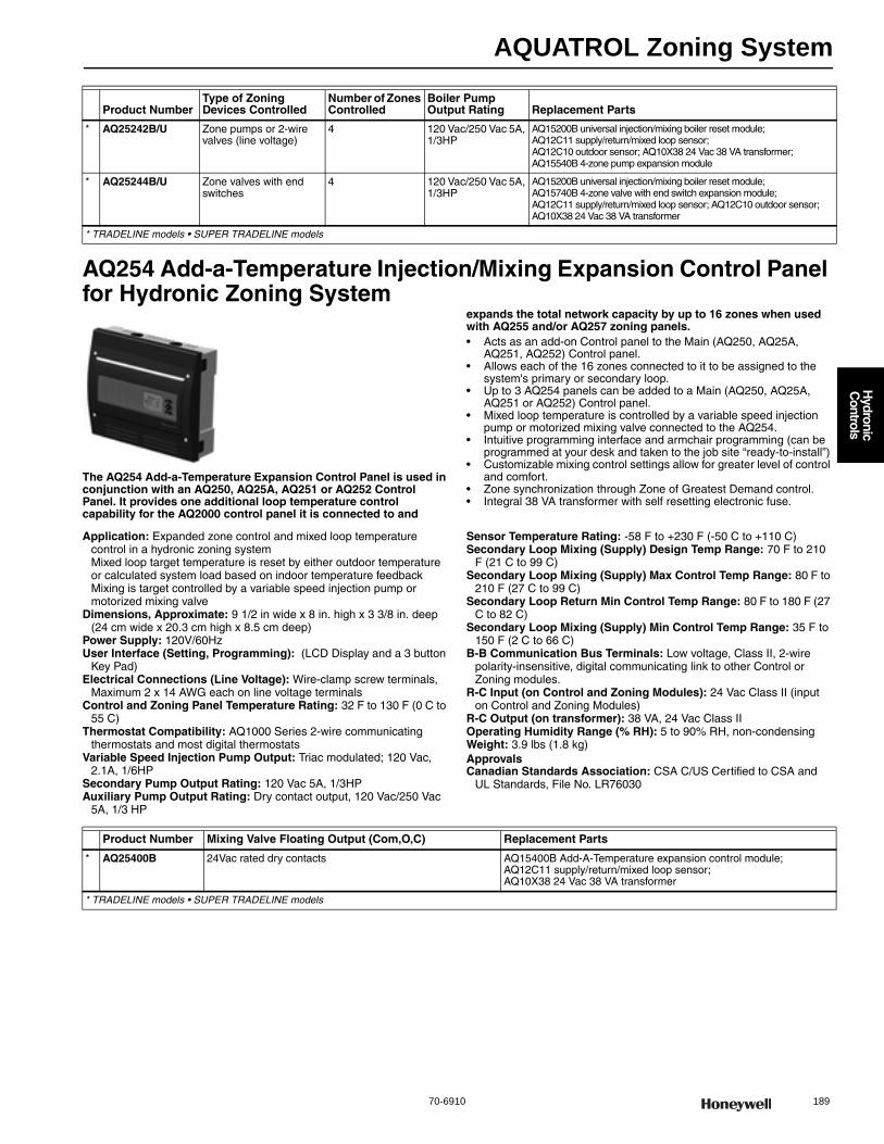
AQUATROL Zoning System
70-6910 189
H
ydronic C
ontrols
AQ254 Add-a-Temperature Injection/Mixing Expansion Control Panel for Hydronic Zoning System
The AQ254 Add-a-Temperature Expansion Control Panel is used in conjunction with an AQ250, AQ25A, AQ251 or AQ252 Control Panel. It provides one additional loop temperature control capability for the AQ2000 control panel it is connected to and
expands the total network capacity by up to 16 zones when used with AQ255 and/or AQ257 zoning panels.• Acts as an add-on Control panel to the Main (AQ250, AQ25A,
AQ251, AQ252) Control panel. • Allows each of the 16 zones connected to it to be assigned to the
system's primary or secondary loop. • Up to 3 AQ254 panels can be added to a Main (AQ250, AQ25A,
AQ251 or AQ252) Control panel. • Mixed loop temperature is controlled by a variable speed injection
pump or motorized mixing valve connected to the AQ254. • Intuitive programming interface and armchair programming (can be
programmed at your desk and taken to the job site “ready-to-install”) • Customizable mixing control settings allow for greater level of control
and comfort. • Zone synchronization through Zone of Greatest Demand control. • Integral 38 VA transformer with self resetting electronic fuse.
Application: Expanded zone control and mixed loop temperature control in a hydronic zoning systemMixed loop target temperature is reset by either outdoor temperature or calculated system load based on indoor temperature feedbackMixing is target controlled by a variable speed injection pump or motorized mixing valve
Dimensions, Approximate: 9 1/2 in wide x 8 in. high x 3 3/8 in. deep (24 cm wide x 20.3 cm high x 8.5 cm deep)
Power Supply: 120V/60HzUser Interface (Setting, Programming): (LCD Display and a 3 button
Key Pad) Electrical Connections (Line Voltage): Wire-clamp screw terminals,
Maximum 2 x 14 AWG each on line voltage terminalsControl and Zoning Panel Temperature Rating: 32 F to 130 F (0 C to
55 C) Thermostat Compatibility: AQ1000 Series 2-wire communicating
thermostats and most digital thermostatsVariable Speed Injection Pump Output: Triac modulated; 120 Vac,
2.1A, 1/6HPSecondary Pump Output Rating: 120 Vac 5A, 1/3HPAuxiliary Pump Output Rating: Dry contact output, 120 Vac/250 Vac
5A, 1/3 HP
Sensor Temperature Rating: -58 F to +230 F (-50 C to +110 C) Secondary Loop Mixing (Supply) Design Temp Range: 70 F to 210
F (21 C to 99 C) Secondary Loop Mixing (Supply) Max Control Temp Range: 80 F to
210 F (27 C to 99 C) Secondary Loop Return Min Control Temp Range: 80 F to 180 F (27
C to 82 C) Secondary Loop Mixing (Supply) Min Control Temp Range: 35 F to
150 F (2 C to 66 C) B-B Communication Bus Terminals: Low voltage, Class II, 2-wire
polarity-insensitive, digital communicating link to other Control or Zoning modules.
R-C Input (on Control and Zoning Modules): 24 Vac Class II (input on Control and Zoning Modules)
R-C Output (on transformer): 38 VA, 24 Vac Class IIOperating Humidity Range (% RH): 5 to 90% RH, non-condensingWeight: 3.9 lbs (1.8 kg) ApprovalsCanadian Standards Association: CSA C/US Certified to CSA and
UL Standards, File No. LR76030
Product NumberType of Zoning Devices Controlled
Number of Zones Controlled
Boiler Pump Output Rating Replacement Parts
* AQ25242B/U Zone pumps or 2-wire valves (line voltage)
4 120 Vac/250 Vac 5A, 1/3HP
AQ15200B universal injection/mixing boiler reset module; AQ12C11 supply/return/mixed loop sensor; AQ12C10 outdoor sensor; AQ10X38 24 Vac 38 VA transformer; AQ15540B 4-zone pump expansion module
* AQ25244B/U Zone valves with end switches
4 120 Vac/250 Vac 5A, 1/3HP
AQ15200B universal injection/mixing boiler reset module; AQ15740B 4-zone valve with end switch expansion module; AQ12C11 supply/return/mixed loop sensor; AQ12C10 outdoor sensor; AQ10X38 24 Vac 38 VA transformer
* TRADELINE models • SUPER TRADELINE models
Product Number Mixing Valve Floating Output (Com,O,C) Replacement Parts
* AQ25400B 24Vac rated dry contacts AQ15400B Add-A-Temperature expansion control module; AQ12C11 supply/return/mixed loop sensor; AQ10X38 24 Vac 38 VA transformer
* TRADELINE models • SUPER TRADELINE models
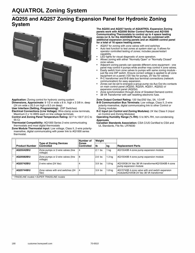
AQUATROL Zoning System
190 customer.honeywell.com 70-6910
AQ255 and AQ257 Zoning Expansion Panel for Hydronic Zoning System
The AQ255 and AQ257 family of AQUATROL Expansion Zoning panels work with AQ2000 Boiler Control Panels and AQ1000 Communicating Thermostats to control up to 4 space heating zones (or 8, for the AQ25582B Panel). Can be combined with additional expansion zoning panels and an AQ2000 control panel for a total of 16 space heating zones.• AQ257 for zoning with zone valves with end switches • Auto test function to test zones at system start up. It allows for
operator controlled testing of zones; includes pause/restart capability.
• LED lights for visual diagnostic of zone operation. • Allows zoning with either “Normally Open” or “Normally Closed”
zone valves. • Adjacent zoning panels can operate different zone equipment - one
panel may control 4 pumps while another may control 4 zone valves. • Easily switch from zone valves to pumps with same zoning module -
just flip one DIP switch. Ensure correct voltage is applied to all zone equipment on a panel (120 Vac for pumps, 24 Vac for valves)
• R-C transformer and B-B data bus terminal connections (network communication) for easy expansion.
• Zones can be set to energize a group pump via Aux Out dry contacts on main control panel (AQ250, AQ25A, AQ251, AQ252) or expansion control panel (AQ254).
• Zone synchronization through Zone of Greatest Demand control. • 38 VA Transformer with self resetting electronic fuse.
Application: Zoning control for hydronic zoning systemDimensions, Approximate: 9 1/2 in wide x 8 in. high x 3 3/8 in. deep
(24 cm wide x 20.3 cm high x 8.5 cm deep) User Interface (Setting, Programming): (DIP Switches) Electrical Connections (Line Voltage): Wire-clamp screw terminals,
Maximum 2 x 14 AWG each on line voltage terminalsControl and Zoning Panel Temperature Rating: 32 F to 130 F (0 C to
55 C) Thermostat Compatibility: AQ1000 Series 2-wire communicating
thermostats and most digital thermostatsZone Module Thermostat input: Low voltage, Class II, 2-wire polarity-
insensitive, digital communicating with power link to AQ1000 series thermostat.
Zone Output Contact Rating: 120 Vac/250 Vac, 5A, 1/3 HPB-B Communication Bus Terminals: Low voltage, Class II, 2-wire
polarity-insensitive, digital communicating link to other Control or Zoning modules.
R-C Input (on Control and Zoning Modules): 24 Vac Class II (input on Control and Zoning Modules)
Operating Humidity Range (% RH): 5 to 90% RH, non-condensingApprovalsCanadian Standards Association: CSA C/US Certified to CSA and
UL Standards, File No. LR76030
Product NumberType of Zoning Devices Controlled
Number of Zones Controlled
Weight
Replacement Partslb kg
* AQ25542B/U Zone pumps or 2-wire valves (line voltage)
4 2.1 bs 1 kg AQ15540B 4-zone pump expansion module
* AQ25582B/U Zone pumps or 2-wire valves (line voltage)
8 2.6 bs 1.3 kg AQ15540B 4-zone pump expansion module
* AQ25742B/U 2-wire valve (24 Vac) 4 3.9 bs 1.8 kg AQ10X38 24 Vac 38 VA transformerAQ15540B 4-zone pump expansion module
* AQ25744B/U Zone valves with end switches (24 Vac)
4 3.9 bs 1.8 kg AQ15740B 4-zone valve with end switch expansion moduleAQ10X38 24 Vac 38 VA transformer
* TRADELINE models • SUPER TRADELINE models

AQUATROL Zoning System
70-6910 191
H
ydronic C
ontrols
AQ2000 Series Replacement Control Modules
Replacement control modules for AQ2000 panels
Application: Replacement boiler control module for AQ250User Interface (Setting, Programming): (DIP Switches)
Electrical Connections (Line Voltage): Wire-clamp screw terminals, Maximum 2 x 14 AWG each on line voltage terminals
Control and Zoning Panel Temperature Rating: 32 F to 130 F (0 C to 55 C)
Boiler Heat Post Purge: Off, 10 seconds to 30 minutes (factory default is 30 seconds)
Boiler (T-T) Output Rating: 24 Vac, 0.5A, 12VABoiler Differential: 2F to 41F (1C to 23C), or Auto (minimum 2 minutes
on time)DHW Demand Input: External dry contacts connection onlyPump/Valve exercise: 30 seconds per 2 weeks of space heating
inactivityHeat Demand (Thermostat R-W) Input: External dry contacts
connection onlyB-B Communication Bus Terminals: Low voltage, Class II, 2-wire
polarity-insensitive, digital communicating link to other Control or Zoning modules.
R-C Input (on Control and Zoning Modules): 24 Vac Class II (input on Control and Zoning Modules)
Operating Humidity Range (% RH): 5 to 90% RH, non-condensingApprovalsCanadian Standards Association: CSA C/US Certified to CSA and
UL Standards, File No. LR76030
AQ2000 Series Replacement Zoning Modules
Replacement Zoning Modules for AQ2000 panels
Application: Replacement 4 zone pump expansion module for AQ25542
Dimensions, Approximate: 3 1/2 in wide x 2 1/2 in high x 4 1/4 in deep (9 cm wide x 94 cm high x 10.09 cm deep)
User Interface (Setting, Programming): (DIP Switches)
Electrical Connections (Line Voltage): Wire-clamp screw terminals, Maximum 2 x 14 AWG each on line voltage terminals
Control and Zoning Panel Temperature Rating: 32 F to 130 F (0 C to 55 C)
Thermostat Compatibility: AQ1000 Series 2-wire communicating thermostats and most digital thermostats
Zone Module Thermostat input: Low voltage, Class II, 2-wire polarity-insensitive, digital communicating with power link to AQ1000 series thermostat.
Zone Output Contact Rating: 120 Vac/250 Vac, 5A, 1/3 HPB-B Communication Bus Terminals: Low voltage, Class II, 2-wire
polarity-insensitive, digital communicating link to other Control or Zoning modules.
R-C Input (on Control and Zoning Modules): 24 Vac Class II (input on Control and Zoning Modules)
Operating Humidity Range (% RH): 5 to 90% RH, non-condensingWeight: 0.6 lb (0.3 kg) ApprovalsCanadian Standards Association: CSA C/US Certified to CSA and
UL Standards, File No. LR76030
Product NumberMixing Valve Floating Output (Com,O,C)
Mixing Valve Modulating Output
User Interface (Setting, Programming)
Dimensions, Approximate Weight
inch mm lb kg
AQ15000B/U — — DIP Switches 3 1/2 in wide x 2 1/2 in high x 4 1/4 in wide
9 cm wide x 94 cm high x 10.09 cm deep
0.5 lb 0.23 kg
AQ15100B/U — 0-10 Vdc to boiler LCD Display and a 7 button Key Pad
7 1/8 in wide x 2 1/2 in high x 4 1/4 in deep
18 cm wide x 94 cm high x 10.09 cm deep
1.0 lbs 0.5 kg
AQ15200B/U 24Vac rated dry contacts 0-10 Vdc to boiler or mixing valve
LCD Display and a 7 button Key Pad
7 1/8 in wide x 2 1/2 in high x 4 1/4 in deep
18 cm wide x 94 cm high x 10.09 cm deep
1.0 lbs 0.5 kg
AQ15400B/U 24Vac rated dry contacts 0-10 Vdc to mixing valve LCD Display and a 3 button Key Pad
3 1/2 in wide x 2 1/2 in high x 4 1/4 in deep
9 cm wide x 94 cm high x 10.09 cm deep
0.7 lb 0.3 kg
AQ15A00B/U — 0-10 Vdc to boiler LCD Display and a 7 button Key Pad
7 1/8 in wide x 2 1/2 in high x 4 1/4 in deep
18 cm wide x 94 cm high x 10.09 cm deep
1.0 lbs 0.5 kg
Product Number Type of Zoning Devices Controlled Number of Zones Controlled User Interface (Setting, Programming)
AQ15540B/U Zone pumps or 2-wire valves (line voltage) 4 DIP Switches
AQ15740B/U Zone valves with end switches 4 DIP Switches
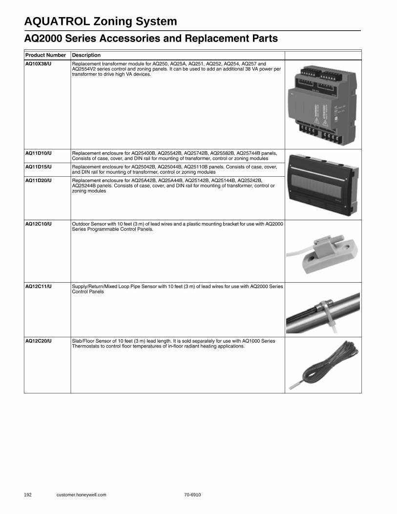
AQUATROL Zoning System
192 customer.honeywell.com 70-6910
AQ2000 Series Accessories and Replacement PartsProduct Number Description
AQ10X38/U Replacement transformer module for AQ250, AQ25A, AQ251, AQ252, AQ254, AQ257 and AQ2554V2 series control and zoning panels. It can be used to add an additional 38 VA power per transformer to drive high VA devices.
AQ11D10/U Replacement enclosure for AQ25400B, AQ25542B, AQ25742B, AQ25582B, AQ25744B panels, Consists of case, cover, and DIN rail for mounting of transformer, control or zoning modules
AQ11D15/U Replacement enclosure for AQ25042B, AQ25044B, AQ25110B panels. Consists of case, cover, and DIN rail for mounting of transformer, control or zoning modules
AQ11D20/U Replacement enclosure for AQ25A42B, AQ25A44B, AQ25142B, AQ25144B, AQ25242B, AQ25244B panels. Consists of case, cover, and DIN rail for mounting of transformer, control or zoning modules
AQ12C10/U Outdoor Sensor with 10 feet (3 m) of lead wires and a plastic mounting bracket for use with AQ2000 Series Programmable Control Panels.
AQ12C11/U Supply/Return/Mixed Loop Pipe Sensor with 10 feet (3 m) of lead wires for use with AQ2000 Series Control Panels
AQ12C20/U Slab/Floor Sensor of 10 feet (3 m) lead length. It is sold separately for use with AQ1000 Series Thermostats to control floor temperatures of in-floor radiant heating applications.
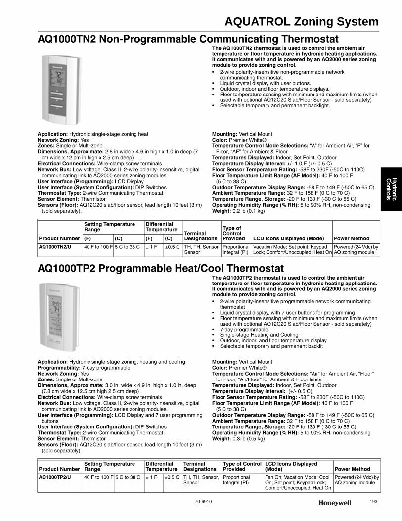
AQUATROL Zoning System
70-6910 193
H
ydronic C
ontrols
AQ1000TN2 Non-Programmable Communicating ThermostatThe AQ1000TN2 thermostat is used to control the ambient air temperature or floor temperature in hydronic heating applications. It communicates with and is powered by an AQ2000 series zoning module to provide zoning control.• 2-wire polarity-insensitive non-programmable network
communicating thermostat. • Liquid crystal display with user buttons. • Outdoor, indoor and floor temperature displays. • Floor temperature sensing with minimum and maximum limits (when
used with optional AQ12C20 Slab/Floor Sensor - sold separately)• Selectable temporary and permanent backlight.
Application: Hydronic single-stage zoning heatNetwork Zoning: YesZones: Single or Multi-zoneDimensions, Approximate: 2.8 in wide x 4.6 in high x 1.0 in deep (7
cm wide x 12 cm in high x 2.5 cm deep) Electrical Connections: Wire-clamp screw terminalsNetwork Bus: Low voltage, Class II, 2-wire polarity-insensitive, digital
communicating link to AQ2000 series zoning modules.User Interface (Programming): LCD DisplayUser Interface (System Configuration): DIP SwitchesThermostat Type: 2-wire Communicating ThermostatSensor Element: ThermistorSensors (Floor): AQ12C20 slab/floor sensor, lead length 10 feet (3 m)
(sold separately).
Mounting: Vertical MountColor: Premier White®Temperature Control Mode Selections: “A” for Ambient Air, “F” for
Floor, “AF” for Ambient & Floor.Temperatures Displayed: Indoor, Set Point, OutdoorTemperature Display Interval: +/- 1.0 F (+/- 0.5 C) Floor Sensor Temperature Rating: -58F to 230F (-50C to 110C) Floor Temperature Limit Range (AF Model): 40 F to 100 F
(5 C to 38 C) Outdoor Temperature Display Range: -58 F to 149 F (-50C to 65 C) Ambient Temperature Range: 32 F to 158 F (0 C to 70 C) Temperature Range, Storage: -20 F to 130 F (-30 C to 55 C) Operating Humidity Range (% RH): 5 to 90% RH, non-condensingWeight: 0.2 lb (0.1 kg)
AQ1000TP2 Programmable Heat/Cool ThermostatThe AQ1000TP2 thermostat is used to control the ambient air temperature or floor temperature in hydronic heating applications. It communicates with and is powered by an AQ2000 series zoning module to provide zoning control.• 2-wire polarity-insensitive programmable network communicating
thermostat • Liquid crystal display, with 7 user buttons for programming • Floor temperature sensing with minimum and maximum limits (when
used with optional AQ12C20 Slab/Floor Sensor - sold separately) • 7-day programmable • Single-stage Heating and Cooling • Outdoor, indoor, and floor temperature display • Selectable temporary and permanent backlit
Application: Hydronic single-stage zoning, heating and coolingProgrammability: 7-day programmableNetwork Zoning: YesZones: Single or Multi-zoneDimensions, Approximate: 3.0 in. wide x 4.9 in. high x 1.0 in. deep
(7.8 cm wide x 12.5 cm high 2.5 cm deep) Electrical Connections: Wire-clamp screw terminalsNetwork Bus: Low voltage, Class II, 2-wire polarity-insensitive, digital
communicating link to AQ2000 series zoning modules.User Interface (Programming): LCD Display and 7 user programming
buttonsUser Interface (System Configuration): DIP SwitchesThermostat Type: 2-wire Communicating ThermostatSensor Element: ThermistorSensors (Floor): AQ12C20 slab/floor sensor, lead length 10 feet (3 m)
(sold separately).
Mounting: Vertical MountColor: Premier White®Temperature Control Mode Selections: “Air” for Ambient Air, “Floor”
for Floor, “Air/Floor” for Ambient & Floor limitsTemperatures Displayed: Indoor, Set Point, OutdoorTemperature Display Interval: (+/- 0.5 C) Floor Sensor Temperature Rating: -58F to 230F (-50C to 110C) Floor Temperature Limit Range (AF Model): 40 F to 100 F
(5 C to 38 C) Outdoor Temperature Display Range: -58 F to 149 F (-50C to 65 C) Ambient Temperature Range: 32 F to 158 F (0 C to 70 C) Temperature Range, Storage: -20 F to 130 F (-30 C to 55 C) Operating Humidity Range (% RH): 5 to 90% RH, non-condensingWeight: 0.3 lb (0.5 kg)
Product Number
Setting Temperature Range
Differential Temperature
Terminal Designations
Type of Control Provided LCD Icons Displayed (Mode) Power Method(F) (C) (F) (C)
AQ1000TN2/U 40 F to 100 F 5 C to 38 C ± 1 F ±0.5 C TH, TH, Sensor, Sensor
Proportional Integral (PI)
Vacation Mode; Set point; Keypad Lock; Comfort/Unoccupied; Heat On
Powered (24 Vdc) by AQ zoning module
Product NumberSetting Temperature Range
Differential Temperature
Terminal Designations
Type of Control Provided
LCD Icons Displayed (Mode) Power Method
AQ1000TP2/U 40 F to 100 F 5 C to 38 C ± 1 F ±0.5 C TH, TH, Sensor, Sensor
Proportional Integral (PI)
Fan On; Vacation Mode; Cool On; Set point; Keypad Lock; Comfort/Unoccupied; Heat On
Powered (24 Vdc) by AQ zoning module
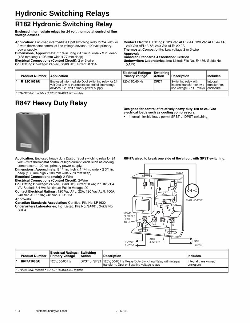
Hydronic Switching Relays
194 customer.honeywell.com 70-6910
R182 Hydronic Switching RelayEnclosed intermediate relays for 24 volt thermostat control of line voltage devices.
Application: Enclosed intermediate Dpdt switching relay for 24 volt 2 or 3 wire thermostat control of line voltage devices. 120 volt primary power supply.
Dimensions, Approximate: 5 1/4 in. long x 4 1/4 in. wide x 3 in. deep (133 mm long x 108 mm wide x 77 mm deep)
Electrical Connections (Control Circuit): 2 or 3-wireCoil Ratings: Voltage: 24 Vac, 50/60 Hz; Current: 0.35A
Contact Electrical Ratings: 120 Vac AFL: 7.4A; 120 Vac ALR: 44.4A; 240 Vac AFL: 3.7A; 240 Vac ALR: 22.2A
Thermostat Compatibility: Low voltage 2 or 3-wireApprovalsCanadian Standards Association: CertifiedUnderwriters Laboratories, Inc: Listed: File No. E4436, Guide No.
XAPX
R847 Heavy Duty RelayDesigned for control of relatively heavy duty 120 or 240 Vac electrical loads such as cooling compressors.• Internal, flexible leads permit SPST or DPST switching.
Application: Enclosed heavy duty Dpst or Spst switching relay for 24 volt 2-wire thermostat control of high-current loads such as cooling compressors. 120 volt primary power supply.
Dimensions, Approximate: 5 1/4 in. high x 4 1/4 in. wide x 2 3/4 in. deep (133 mm high x 108 mm wide x 70 mm deep)
Electrical Connections (main): 2-WireElectrical Connections (Control Circuit): 2-WireCoil Ratings: Voltage: 24 Vac, 50/60 Hz; Current: 0.4A; Inrush: 21.4
VA; Sealed: 8.4 VA; Maximum Pull-in Voltage: 20Contact Electrical Ratings: 120 Vac AFL: 22A; 120 Vac ALR: 100A;
240 Vac AFL: 10A; 240 Vac ALR: 50AApprovalsCanadian Standards Association: Certified: File No. LR1620Underwriters Laboratories, Inc: Listed: File No. SA481, Guide No.
SDF4
R847A wired to break one side of the circuit with SPST switching.
Product Number ApplicationElectrical Ratings: Primary Voltage
Switching Action Description Includes
* R182C1051/U Enclosed intermediate Dpdt switching relay for 24 volt 2 or 3 wire thermostat control of line voltage devices. 120 volt primary power supply.
120V, 50/60 Hz DPDT Switching relay with internal transformer, two line voltage SPDT relays
Integral transformer, enclosure
* TRADELINE models • SUPER TRADELINE models
M16562
POWER
SUPPLY
MOVE
FLEXIBLE
LEAD
TO L1
THERMOSTAT
R847A
T T
L1 3 4L2
LOADADD
JUMPER
Product NumberElectrical Ratings: Primary Voltage
Switching Action Description Includes
* R847A1085/U 120V, 50/60 Hz DPST or SPST 120V, 50/60 Hz Heavy Duty Switching Relay with integral transform, Dpst or Spst line voltage relays
Integral transformer, enclosure
* TRADELINE models • SUPER TRADELINE models
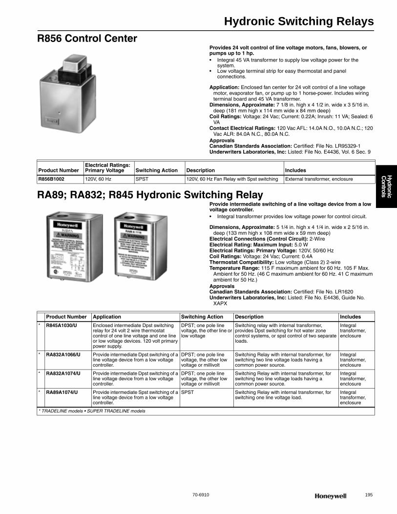
Hydronic Switching Relays
70-6910 195
H
ydronic C
ontrols
R856 Control CenterProvides 24 volt control of line voltage motors, fans, blowers, or pumps up to 1 hp.• Integral 45 VA transformer to supply low voltage power for the
system. • Low voltage terminal strip for easy thermostat and panel
connections.
Application: Enclosed fan center for 24 volt control of a line voltage motor, evaporator fan, or pump up to 1 horse-power. Includes wiring terminal board and 45 VA transformer.
Dimensions, Approximate: 7 1/8 in. high x 4 1/2 in. wide x 3 5/16 in. deep (181 mm high x 114 mm wide x 84 mm deep)
Coil Ratings: Voltage: 24 Vac; Current: 0.22A; Inrush: 11 VA; Sealed: 6 VA
Contact Electrical Ratings: 120 Vac AFL: 14.0A N.O., 10.0A N.C.; 120 Vac ALR: 84.0A N.C., 80.0A N.C.
ApprovalsCanadian Standards Association: Certified: File No. LR95329-1Underwriters Laboratories, Inc: Listed: File No. E4436, Vol. 6 Sec. 9
RA89; RA832; R845 Hydronic Switching RelayProvide intermediate switching of a line voltage device from a low voltage controller.• Integral transformer provides low voltage power for control circuit.
Dimensions, Approximate: 5 1/4 in. high x 4 1/4 in. wide x 2 5/16 in. deep (133 mm high x 108 mm wide x 59 mm deep)
Electrical Connections (Control Circuit): 2-WireElectrical Rating: Maximum Input: 5.0 WElectrical Ratings: Primary Voltage: 120V, 50/60 HzCoil Ratings: Voltage: 24 Vac; Current: 0.4AThermostat Compatibility: Low voltage (Class 2) 2-wireTemperature Range: 115 F maximum ambient for 60 Hz. 105 F Max.
Ambient for 50 Hz. (46 C maximum ambient for 60 Hz. 41 C maximum ambient for 50 Hz.)
ApprovalsCanadian Standards Association: Certified: File No. LR1620Underwriters Laboratories, Inc: Listed: File No. E4436, Guide No.
XAPX
Product NumberElectrical Ratings: Primary Voltage Switching Action Description Includes
R856B1002 120V, 60 Hz SPST 120V, 60 Hz Fan Relay with Spst switching External transformer, enclosure
Product Number Application Switching Action Description Includes
* R845A1030/U Enclosed intermediate Dpst switching relay for 24 volt 2 wire thermostat control of one line voltage and one line or low voltage devices. 120 volt primary power supply.
DPST; one pole line voltage, the other line or low voltage
Switching relay with internal transformer, provides Dpst switching for hot water zone control systems, or spst control of two separate loads.
Integral transformer, enclosure
* RA832A1066/U Provide intermediate Dpst switching of a line voltage device from a low voltage controller.
DPST; one pole line voltage, the other low voltage or millivolt
Switching Relay with internal transformer, for switching two line voltage loads having a common power source.
Integral transformer, enclosure
* RA832A1074/U Provide intermediate Dpst switching of a line voltage device from a low voltage controller.
DPST; one pole line voltage, the other low voltage or millivolt
Switching Relay with internal transformer, for switching two line voltage loads having a common power source.
Integral transformer, enclosure
* RA89A1074/U Provide intermediate Spst switching of a line voltage device from a low voltage controller.
SPST Switching Relay with internal transformer, for switching one line voltage load.
Integral transformer, enclosure
* TRADELINE models • SUPER TRADELINE models
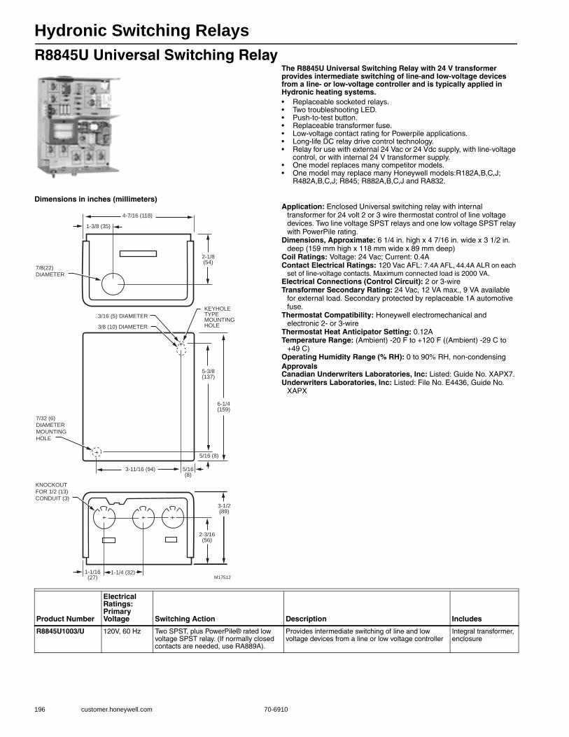
Hydronic Switching Relays
196 customer.honeywell.com 70-6910
R8845U Universal Switching RelayThe R8845U Universal Switching Relay with 24 V transformer provides intermediate switching of line-and low-voltage devices from a line- or low-voltage controller and is typically applied in Hydronic heating systems.• Replaceable socketed relays. • Two troubleshooting LED. • Push-to-test button. • Replaceable transformer fuse. • Low-voltage contact rating for Powerpile applications. • Long-life DC relay drive control technology. • Relay for use with external 24 Vac or 24 Vdc supply, with line-voltage
control, or with internal 24 V transformer supply. • One model replaces many competitor models. • One model may replace many Honeywell models:R182A,B,C,J;
R482A,B,C,J; R845; R882A,B,C,J and RA832.
Dimensions in inches (millimeters)Application: Enclosed Universal switching relay with internal
transformer for 24 volt 2 or 3 wire thermostat control of line voltage devices. Two line voltage SPST relays and one low voltage SPST relay with PowerPile rating.
Dimensions, Approximate: 6 1/4 in. high x 4 7/16 in. wide x 3 1/2 in. deep (159 mm high x 118 mm wide x 89 mm deep)
Coil Ratings: Voltage: 24 Vac; Current: 0.4AContact Electrical Ratings: 120 Vac AFL: 7.4A AFL, 44.4A ALR on each
set of line-voltage contacts. Maximum connected load is 2000 VA.Electrical Connections (Control Circuit): 2 or 3-wireTransformer Secondary Rating: 24 Vac, 12 VA max., 9 VA available
for external load. Secondary protected by replaceable 1A automotive fuse.
Thermostat Compatibility: Honeywell electromechanical and electronic 2- or 3-wire
Thermostat Heat Anticipator Setting: 0.12ATemperature Range: (Ambient) -20 F to +120 F ((Ambient) -29 C to
+49 C) Operating Humidity Range (% RH): 0 to 90% RH, non-condensingApprovalsCanadian Underwriters Laboratories, Inc: Listed: Guide No. XAPX7.Underwriters Laboratories, Inc: Listed: File No. E4436, Guide No.
XAPX
7/32 (6)
DIAMETER
MOUNTING
HOLE
KNOCKOUT
FOR 1/2 (13)
CONDUIT (3)
1-1/16(27)
1-1/4 (32)
2-3/16(56)
3-1/2(89)
3-11/16 (94) 5/16(8)
5/16 (8)
6-1/4(159)
5-3/8(137)
1-3/8 (35)
4-7/16 (118)
2-1/8(54)
3/16 (5) DIAMETER
3/8 (10) DIAMETER
7/8(22)
DIAMETER
KEYHOLE TYPEMOUNTING HOLE
M17512
Product Number
Electrical Ratings: Primary Voltage Switching Action Description Includes
R8845U1003/U 120V, 60 Hz Two SPST, plus PowerPile® rated low voltage SPST relay. (If normally closed contacts are needed, use RA889A).
Provides intermediate switching of line and low voltage devices from a line or low voltage controller
Integral transformer, enclosure

Hydronic Switching Relays
70-6910 197
H
ydronic C
ontrols
RA889A Switching RelayThe RA889A Switching Relay with 24 V controller provides intermediate switching of line- and low-voltage devices from a line- or low-voltage controller and is typically applied in Hydronic heating systems.• High load switching capability. • Troubleshooting LED. • Push-to-test button. • Replaceable transformer fuse. • Long-life DC relay drive control technology. • Relay for use with external 24 Vac or 24 Vdc supply, with line-voltage
control, or with internal 24 V transformer supply. • One model replaces many Honeywell models. • Secondary of transformer protected by replaceable 1A automotive
fuse.
Dimensions in inches (millimeters)Application: Provide intermediate Spdt and Spst switching of line- and
low-voltage devices from a line- or low-voltage controller.Transformer Secondary Rating: 24 Vac, 12 VA max., 9 VA available
for external load. Secondary protected by replaceable 1A automotive fuse.
Thermostat Compatibility: Honeywell electromechanical and electronic 2- or 3-wire
Thermostat Heat Anticipator Setting: 0.12ATemperature Range: (Ambient) -20 F to +120 F ((Ambient) -29 C to
+49 C) Operating Humidity Range (% RH): 0 to 90% RH, non-condensingContact Electrical Ratings: 120 Vac AFL: 15A; 120 Vac ALR: 30A.ApprovalsCanadian Underwriters Laboratories, Inc: Listed: Guide No. XAPX7.Underwriters Laboratories, Inc: Listed: File No. E4436, Guide No.
XAPX
7/32 (6)
DIAMETER
MOUNTING
HOLE
KNOCKOUT
FOR 1/2 (13)
CONDUIT (3)
1-1/16(27)
1-1/4 (32)
2-3/16(56)
3-1/2(89)
3-11/16 (94) 5/16(8)
5/16 (8)
6-1/4(159)
5-3/8(137)
1-3/8 (35)
4-7/16 (118)
2-1/8(54)
3/16 (5) DIAMETER
3/8 (10) DIAMETER
7/8(22)
DIAMETER
KEYHOLE TYPEMOUNTING HOLE
M17512
Product NumberElectrical Ratings: Primary Voltage Switching Action Description Includes
RA889A1001/U 120V, 60 Hz SPDT, plus PowerPile® rated low voltage SPST relay
Enclosed switching relay with internal transformer, Spdt line voltage relay, plus Spst low voltage relay with Powerpile rating. 120V/60Hz 15 AFL/30 ALR ratings one line voltage contacts.
Integral transformer, enclosure
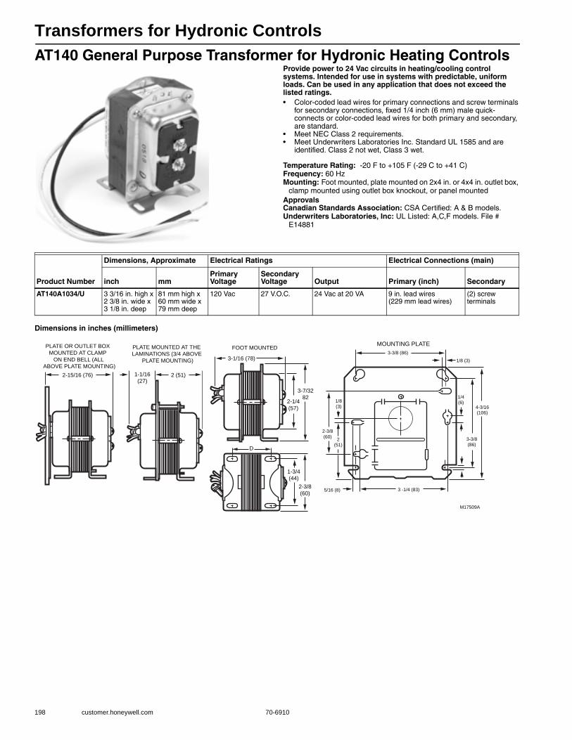
Transformers for Hydronic Controls
198 customer.honeywell.com 70-6910
AT140 General Purpose Transformer for Hydronic Heating ControlsProvide power to 24 Vac circuits in heating/cooling control systems. Intended for use in systems with predictable, uniform loads. Can be used in any application that does not exceed the listed ratings.• Color-coded lead wires for primary connections and screw terminals
for secondary connections, fixed 1/4 inch (6 mm) male quick-connects or color-coded lead wires for both primary and secondary, are standard.
• Meet NEC Class 2 requirements. • Meet Underwriters Laboratories Inc. Standard UL 1585 and are
identified. Class 2 not wet, Class 3 wet.
Temperature Rating: -20 F to +105 F (-29 C to +41 C) Frequency: 60 HzMounting: Foot mounted, plate mounted on 2x4 in. or 4x4 in. outlet box,
clamp mounted using outlet box knockout, or panel mountedApprovalsCanadian Standards Association: CSA Certified: A & B models.Underwriters Laboratories, Inc: UL Listed: A,C,F models. File #
E14881
Dimensions in inches (millimeters)
Product Number
Dimensions, Approximate Electrical Ratings Electrical Connections (main)
inch mmPrimary Voltage
Secondary Voltage Output Primary (inch) Secondary
AT140A1034/U 3 3/16 in. high x 2 3/8 in. wide x 3 1/8 in. deep
81 mm high x 60 mm wide x 79 mm deep
120 Vac 27 V.O.C. 24 Vac at 20 VA 9 in. lead wires (229 mm lead wires)
(2) screw terminals
3-1/16 (78)
1-3/4
(44)
2 (51)1-1/16
(27)
PLATE MOUNTED AT THE
LAMINATIONS (3/4 ABOVE
PLATE MOUNTING)
MOUNTING PLATE
2-1/4
(57)
2-3/8
(60)
3-7/32
82
FOOT MOUNTED
D
2-15/16 (76)
PLATE OR OUTLET BOX
MOUNTED AT CLAMP
ON END BELL (ALL
ABOVE PLATE MOUNTING)
M17509A
2-3/8
(60)
1/4(6)
3-3/8 (86)
3-3/8(86)
4-3/16(106)
2(51)
3 -1/4 (83)5/16 (8)
1/8 (3)
1/8(3)
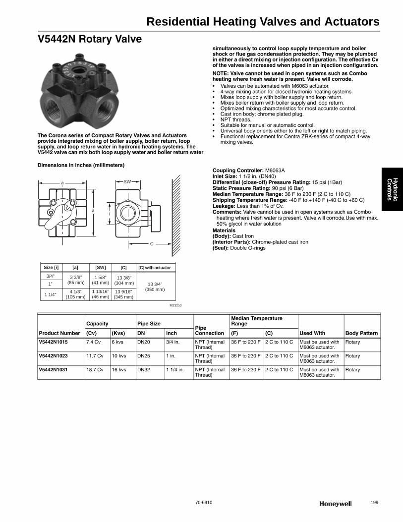
Residential Heating Valves and Actuators
70-6910 199
H
ydronic C
ontrols
V5442N Rotary Valve
The Corona series of Compact Rotary Valves and Actuators provide integrated mixing of boiler supply, boiler return, loop supply, and loop return water in hydronic heating systems. The V5442 valve can mix both loop supply water and boiler return water
simultaneously to control loop supply temperature and boiler shock or flue gas condensation protection. They may be plumbed in either a direct mixing or injection configuration. The effective Cv of the valves is increased when piped in an injection configuration.
NOTE: Valve cannot be used in open systems such as Combo heating where fresh water is present. Valve will corrode.• Valves can be automated with M6063 actuator. • 4-way mixing action for closed hydronic heating systems. • Mixes loop supply with boiler supply and loop return. • Mixes boiler return with boiler supply and loop return. • Optimized mixing characteristics for most accurate control. • Cast iron body; chrome plated plug. • NPT threads. • Suitable for manual or automatic control. • Universal body orients either to the left or right to match piping. • Functional replacement for Centra ZRK-series of compact 4-way
mixing valves.
Dimensions in inches (millimeters)Coupling Controller: M6063AInlet Size: 1 1/2 in. (DN40) Differential (close-off) Pressure Rating: 15 psi (1Bar)Static Pressure Rating: 90 psi (6 Bar)Median Temperature Range: 36 F to 230 F (2 C to 110 C) Shipping Temperature Range: -40 F to +140 F (-40 C to +60 C) Leakage: Less than 1% of Cv.Comments: Valve cannot be used in open systems such as Combo
heating where fresh water is present. Valve will corrode.Use with max. 50% glycol in water solution
Materials(Body): Cast Iron(Interior Parts): Chrome-plated cast iron(Seal): Double O-rings
a
a
SW
C
i
M23253
Size [i] [a] [C]
3/4”
1”
1 1/4”
3 3/8” (85 mm)
1 5/8” (41 mm)
[SW]
13 3/8” (304 mm)
[C] with actuator
13 3/4” (350 mm)
4 1/8” (105 mm)
1 13/16” (46 mm)
13 9/16” (345 mm)
Product Number
Capacity Pipe SizePipe Connection
Median Temperature Range
Used With Body Pattern(Cv) (Kvs) DN inch (F) (C)
V5442N1015 7.4 Cv 6 kvs DN20 3/4 in. NPT (Internal Thread)
36 F to 230 F 2 C to 110 C Must be used with M6063 actuator.
Rotary
V5442N1023 11.7 Cv 10 kvs DN25 1 in. NPT (Internal Thread)
36 F to 230 F 2 C to 110 C Must be used with M6063 actuator.
Rotary
V5442N1031 18.7 Cv 16 kvs DN32 1 1/4 in. NPT (Internal Thread)
36 F to 230 F 2 C to 110 C Must be used with M6063 actuator.
Rotary
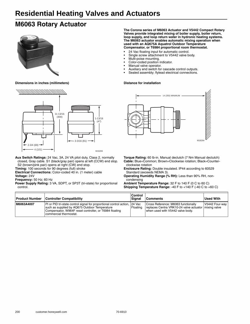
Residential Heating Valves and Actuators
200 customer.honeywell.com 70-6910
M6063 Rotary ActuatorThe Corona series of M6063 Actuator and V5442 Compact Rotary Valves provide integrated mixing of boiler supply, boiler return, loop supply, and loop return water in hydronic heating systems. The M6063 actuator enables automatic mixing operation when used with an AQ675A Aquatrol Outdoor Temperature Compensator, or T6984 proportional room thermostat.• 24 Vac floating input for automatic control. • Single screw attachment to V5442 valve body. • Multi-poise mounting. • Color-coded position indicator. • Manual valve operator. • Auxiliary end switch for cascade control outputs. • Sealed assembly; flylead electrical connections.
Dimensions in inches (millimeters) Distance for installation
Aux Switch Ratings: 24 Vac, 3A, 24 VA pilot duty, Class 2, normally closed, Gray cable. S1 (black/gray pair) opens at left (CCW) end stop. S2 (brown/pink pair) opens at right (CW) end stop.
Timing: 100 seconds for 90 degrees (full) strokeElectrical Connections: Color-coded 40 in. (1 meter) cableVoltage: 24VFrequency: 50 Hz; 60 HzPower Supply Rating: 3 VA, SDPT, or SP3T (tri-state) for proportional
control.
Torque Rating: 60 lb-in. Manual declutch (7 Nm Manual declutch) Cable: Blue=Common; Brown=Clockwise rotation; Black=Counter-
clockwise rotationEnclosure Rating: Double insulated. IP44 according to 60529
Standard (exceeds NEMA 3).Operating Humidity Range (% RH): Less than 90% RH, non-
condensingAmbient Temperature Range: 32 F to 140 F (0 C to 60 C) Shipping Temperature Range: -40 F to +140 F (-40 C to +60 C)
4 (101)
2-3/4 (69)
11-13/16
(300)
3-3/16 (81)
1-13/16
(47)
M18265
M18264
14 (350) MINIMUM
Product Number Controller CompatibilityControl Signal Comments Used With
M6063A4007 PI or PID tri-state control signal for proportional control action, such as supplied by AQ675 Outdoor Temperature Compensator, W964F reset controller, or T6984 floating commercial thermostat.
24 Vac Floating
Cross Reference: M6063 functionally replaces Centra VRK10-24 valve actuator when used with V5442 valve body.
V5442 Four-way mixing valve

Residential Heating Valves and Actuators
70-6910 201
H
ydronic C
ontrols
VC Series ValvesControl central heating and/or cooling systems, fan coil systems, radiators and convectors. Depending on the model selected, it can be controlled by either a low or line voltage SPST or SPDT or floating controller such as a room thermostat, Aquastat control, or flow switch.• Two-way or three-way valves. • Minimal actuator power consumption. • Double insulated actuator. • Quick-connect or one-meter cable electrical connections available. • Safe for use with potable water. • Quick and easy replacement of moving parts. • Actuator head installation does not require draining the system. • On/Off models with six second nominal timing (floating/modulating
models available with 120 second timing).
Dimensions, Approximate: 3 9/16 in high x 2 3/4 in wide x 3 3/4 in long (111 mm high x 68 mm wide x 89 mm long)
Coupling Controller: IntegralAux Switch Ratings: 24 Vac, 2.2A pilot duty, Class 2, SPDTTiming: 120 secControl Signal: 24 Vac FloatingElectrical Connections: Color-coded 40 in. (1 meter) cableVoltage: 24VFrequency: 50 Hz; 60 Hz
Power Supply Rating: 6 VA, SPDT, or SP3T (tri-state) for proportional control.
Differential (close-off) Pressure Rating: 60 psi (4 Bar)Static Pressure Rating: 300 psi (20 Bar)Median Temperature Range: 34 F to 203 F (1 C to 95 C) Ambient Temperature Range: 32 F to 140 F (0 C to 60 C) Shipping Temperature Range: -40 F to +150 F (-40 C to +65 C) Materials(Body): Bronze
Product NumberController Compatibility
CapacityFlow Characteristic
Pipe SizePipe Connection Comments
Body Pattern(Cv) (Kvs) inch DN
VC6831AA1111/U PI or PID tri-state control signal for proportional control action, such as supplied by AQ675 Outdoor Temperature Compensator, W964F reset controller, or T6984 floating commercial thermostat.
3.2 Cv 2.7 kvs Linear 1/2 in. DN15 Sweat Use with max. 50% glycol in water solution
Two-way
VC6831AM1111/U 4.6 Cv 3.9 kvs Linear 3/4 in. DN20 Sweat Use with max. 50% glycol in water solution
Two-way
VC6831ML6111/U 5.9 Cv 5.1 kvs Linear 3/4 in. DN20 Sweat Use with max. 50% glycol in water solution
Three-way
VC6831MS6111/U 6.6 Cv 5.7 kvs Linear 1 in. DN25 Sweat Use with max. 50% glycol in water solution
Three-way
VC6831ZZ11/U — — Linear — — — Actuator only Two-way
VC8715AA1000/U 24V SPST, Series 80 3.5 Cv 3.0 kvs Linear 1/2 in. DN15 Sweat Use with max. 50% glycol in water solution
Two-way
VC8715AM1000/U 5.8 Cv 5.0 kvs Quick Open 3/4 in. DN20 Sweat Use with max. 50% glycol in water solution
Two-way
VC8715AS1000/U 7.0 Cv 6 kvs Quick Open 1 in. DN25 Sweat Use with max. 50% glycol in water solution
Two-way
VC8715ZZ11/U — — Quick Open — — — Actuator only Two-way
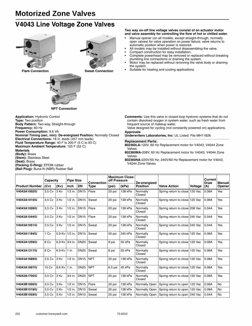
Motorized Zone Valves
202 customer.honeywell.com 70-6910
V4043 Line Voltage Zone ValvesTwo way on-off line voltage valves consist of an actuator motor and valve assembly for controlling the flow of hot or chilled water.• Manual opener (on all models, except straight-through, normally
open valves) for valve operation on power failure; valve returns to automatic position when power is restored.
• All models may be installed without disassembling the valve. • Compact construction for easy installation. • Complete powerhead may be removed or replaced without breaking
plumbing line connections or draining the system. • Motor may be replaced without removing the valve body or draining
the system. • Suitable for heating and cooling applications.
Application: Hydronic ControlType: Two positionBody Pattern: Two-way, Straight-throughFrequency: 60 HzPower Consumption: 9.6 VANominal Timing (sec, min): De-energized Position: Normally ClosedElectrical Connections: 18 in. leads (457 mm leads) Fluid Temperature Range: 40 F to 200 F (5 C to 93 C) Maximum Ambient Temperature: 125 F (52 C) Materials(Body): Brass(Stem): Stainless Steel(Seat): Brass(Packing O-Ring): EPDM rubber(Ball Plug): Buna-N (NBR) Rubber Ball
Comments: Use this valve in closed loop hydronic systems that do not contain dissolved oxygen in system water, such as fresh water from frequent source of makeup water.Valve designed for cycling (not constantly powered on) applications.
ApprovalsUnderwriters Laboratories, Inc: UL Listed: File MH11826
Replacement Parts:802360LA-120V, 60 Hz Replacement motor for V4043, V4044 Zone
Valves802360MA-208V, 60 Hz Replacement motor for V4043, V4044 Zone
Valves802360NA-220V/50 Hz; 240V/60 Hz Replacement motor for V4043,
V4044 Zone Valves
Flare Connection Sweat Connection
NPT Connection
Product Number
Capacity Pipe SizeConnection Type
Maximum Close-off Pressure
De-energized Position Valve Action Voltage
Current Draw (A)
Manual Opener(Cv) (Kv) inch DN (psi) (kPa)
V4043A1002/U 3.5 Cv 3 Kv 1/2 in. DN15 Flare 20 psi 138 kPa Normally Closed
Spring return to close 120 Vac 0.08A Yes
V4043A1010/U 3.5 Cv 3 Kv 1/2 in. DN15 Sweat 20 psi 138 kPa Normally Closed
Spring return to close 120 Vac 0.08A Yes
V4043A1028/U 3.5 Cv 3 Kv 1/2 in. DN15 Flare 20 psi 138 kPa Normally Closed
Spring return to close 208 Vac 0.04A Yes
V4043A1044/U 3.5 Cv 3 Kv 1/2 in. DN15 Flare 20 psi 138 kPa Normally Closed
Spring return to close 240 Vac 0.04A Yes
V4043A1051/U 3.5 Cv 3 Kv 1/2 in. DN15 Sweat 20 psi 138 kPa Normally Closed
Spring return to close 240 Vac 0.04A Yes
V4043A1184/U 1 Cv 0.9 Kv 1/2 in. DN15 Sweat 50 psi 345 kPa Normally Closed
Spring return to close 120 Vac 0.08A Yes
V4043A1259/U 8 Cv 6.9 Kv 3/4 in. DN20 Sweat 8 psi 55 kPa Normally Closed
Spring return to close 120 Vac 0.08A Yes
V4043A1317/U 8 Cv 6.9 Kv 1 in. DN25 Sweat 8 psi 55 kPa Normally Closed
Spring return to close 120 Vac 0.08A Yes
V4043A1689/U 3.5 Cv 3 Kv 1/2 in. DN15 NPT 20 psi 138 kPa Normally Closed
Spring return to close 120 Vac 0.08A Yes
V4043A1697/U 10 Cv 8.6 Kv 1 in. DN25 NPT 6.5 psi 45 kPa Normally Closed
Spring return to close 120 Vac 0.08A Yes
V4043A1705/U 3.5 Cv 3 Kv 3/4 in. DN20 NPT 20 psi 138 kPa Normally Closed
Spring return to close 120 Vac 0.08A Yes
V4043B1000/U 3.5 Cv 3 Kv 1/2 in. DN15 Flare 20 psi 138 kPa Normally Open Spring return to open 120 Vac 0.08A No
V4043B1018/U 3.5 Cv 3 Kv 1/2 in. DN15 Sweat 20 psi 138 kPa Normally Open Spring return to open 120 Vac 0.08A No
V4043B1059/U 3.5 Cv 3 Kv 1/2 in. DN15 Sweat 20 psi 138 kPa Normally Open Spring return to open 240 Vac 0.04A No

Motorized Zone Valves
70-6910 203
H
ydronic C
ontrols
Dimensions in inches (millimeters)
AUTO MAN OPEN
A B
AUTO MAN OPEN
A B
AUTO MAN OPEN
A B
AUTO MAN OPEN
A
AB
AB
B
HEIGHT NEEDED TO REMOVE COVER.
DIMENSIONS FOR 1/2 IN. COPPER TUBING.
DIMENSIONS FOR 3/4 IN COPPER TUBING.
DIMENSIONS FOR 1 IN. COPPER TUBING.
4-7/8 IN. (124) MAX ON V8034F WITH TERMINAL BOARD ENCLOSURE.
V4034B AND V8043B VALVES THAT ARE NORMALLY OPEN IN THE
DE-ENERGIZED POSITION HAVE NO MANUAL LEVER. THE VALVES
ALSO HAVE A REVERSED POWERHEAD WHERE THE LEADWIRES
EXIT THE POWERHEAD ABOVE THE B (OUTLET) PORT RATHER
THAN ABOVE THE A (INLET) PORT.
REFER TO MOUNTING INSTRUCTIONS.
OPENING FOR 1/2 IN. CONDUIT ON MANUAL LEVER SIDE FOR
V4043, V8043; OPENING ON OPPOSITE SIDE FOR V4044, V8044.
1
1
6
7
8
1
6
5
2
3
4
8
1
4 3 2
7
2
3
4
7
8
7 7
1
2
3
4
5
6
7
8
M10175
V4043, V8043 SWEAT COPPER CONNECTION MODELS V4044, V8044 SWEAT COPPER CONNECTION MODELS
V4044, V8044 FLARE-FITTING MODELS V4043, V8043 FLARE-FITTING MODELS
V8043 INVERTED FLARE MODELS
2-3/8
(60)
7/8 DIA.
(22)
7/8 DIA.
(22)
1-1/2
(38)
5-1/4
(133)
5-1/4
(133)
15/32
(12)
IN OUT
INLET
OUT
3-1/2 (89)
1-3/4
(44)
3/8
(10)
3/8
(10)
3/8
(10)
1-3/4
(44)
1-9/16
(40)
1-3/4
(44)
3-1/8
(79)
3-1/2
(89) 1-7/8
(47)
3-11/16
(94)
1-9/16
(40)
3/8
(10)
1-3/4
(44)
3-1/8
(79)
3-1/2
(89) 1-7/8
(47)
3-11/16
(94)
2-3/8
(60)
5-1/4
(133)
1-3/4
(44)
1-3/4
(44)
1-7/8 (48)
1-11/16 (43)
1-1/2 (38)
2-3/8
(60)
1-3/4
(44)
1-3/4
(44)
3-1/8
(79)
2-1/4
(57)
7/8
(22)
3-1/8
(79)
3-1/2 (89)
1-3/4
(44)
1-3/4
(44)
2-11/32
(59) 2-11/32
(59)
2-11/32
(59)
2-11/32
(59)
1-13/16
(46)
3-5/8 (92)
15/32
(12)
2-3/8 (60)
1-1/2
(38)
5-1/4
(133)
OUT IN
IN
INLET
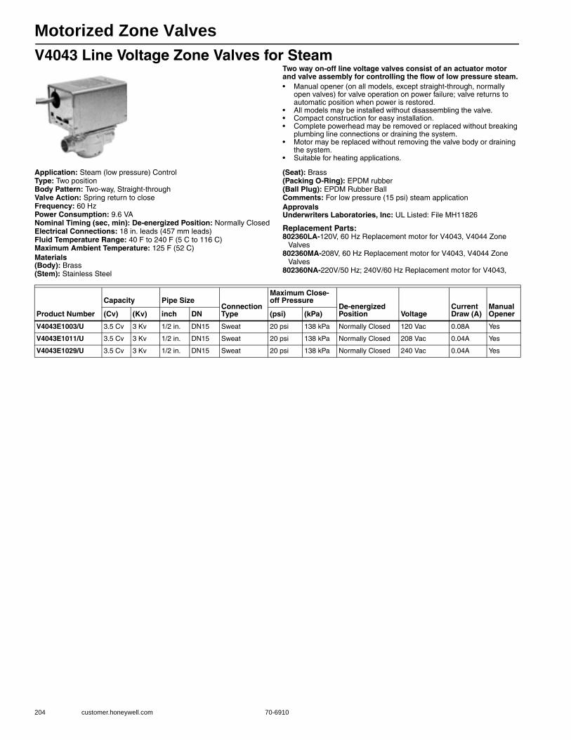
Motorized Zone Valves
204 customer.honeywell.com 70-6910
V4043 Line Voltage Zone Valves for SteamTwo way on-off line voltage valves consist of an actuator motor and valve assembly for controlling the flow of low pressure steam.• Manual opener (on all models, except straight-through, normally
open valves) for valve operation on power failure; valve returns to automatic position when power is restored.
• All models may be installed without disassembling the valve. • Compact construction for easy installation. • Complete powerhead may be removed or replaced without breaking
plumbing line connections or draining the system. • Motor may be replaced without removing the valve body or draining
the system. • Suitable for heating applications.
Application: Steam (low pressure) ControlType: Two positionBody Pattern: Two-way, Straight-throughValve Action: Spring return to closeFrequency: 60 HzPower Consumption: 9.6 VANominal Timing (sec, min): De-energized Position: Normally ClosedElectrical Connections: 18 in. leads (457 mm leads) Fluid Temperature Range: 40 F to 240 F (5 C to 116 C) Maximum Ambient Temperature: 125 F (52 C) Materials(Body): Brass(Stem): Stainless Steel
(Seat): Brass(Packing O-Ring): EPDM rubber(Ball Plug): EPDM Rubber BallComments: For low pressure (15 psi) steam applicationApprovalsUnderwriters Laboratories, Inc: UL Listed: File MH11826
Replacement Parts:802360LA-120V, 60 Hz Replacement motor for V4043, V4044 Zone
Valves802360MA-208V, 60 Hz Replacement motor for V4043, V4044 Zone
Valves802360NA-220V/50 Hz; 240V/60 Hz Replacement motor for V4043,
Product Number
Capacity Pipe SizeConnection Type
Maximum Close-off Pressure
De-energized Position Voltage
Current Draw (A)
Manual Opener(Cv) (Kv) inch DN (psi) (kPa)
V4043E1003/U 3.5 Cv 3 Kv 1/2 in. DN15 Sweat 20 psi 138 kPa Normally Closed 120 Vac 0.08A Yes
V4043E1011/U 3.5 Cv 3 Kv 1/2 in. DN15 Sweat 20 psi 138 kPa Normally Closed 208 Vac 0.04A Yes
V4043E1029/U 3.5 Cv 3 Kv 1/2 in. DN15 Sweat 20 psi 138 kPa Normally Closed 240 Vac 0.04A Yes
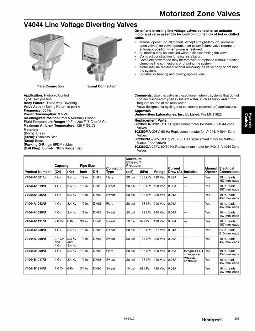
Motorized Zone Valves
70-6910 205
H
ydronic C
ontrols
V4044 Line Voltage Diverting ValvesOn-off and diverting line voltage valves consist of an actuator motor and valve assembly for controlling the flow of hot or chilled water.• Manual opener (on all models, except straight-through, normally
open valves) for valve operation on power failure; valve returns to automatic position when power is restored.
• All models may be installed without disassembling the valve. • Compact construction for easy installation. • Complete powerhead may be removed or replaced without breaking
plumbing line connections or draining the system. • Motor may be replaced without removing the valve body or draining
the system. • Suitable for heating and cooling applications.
Application: Hydronic ControlType: Two positionBody Pattern: Three-way, DivertingValve Action: Spring Return to port AFrequency: 60 HzPower Consumption: 9.6 VADe-energized Position: Port A Normally ClosedFluid Temperature Range: 40 F to 200 F (5 C to 93 C) Maximum Ambient Temperature: 125 F (52 C) Materials(Body): Brass(Stem): Stainless Steel(Seat): Brass(Packing O-Ring): EPDM rubber(Ball Plug): Buna-N (NBR) Rubber Ball
Comments: Use this valve in closed loop hydronic systems that do not contain dissolved oxygen in system water, such as fresh water from frequent source of makeup water.Valve designed for cycling (not constantly powered on) applications.
ApprovalsUnderwriters Laboratories, Inc: UL Listed: File MH11826
Replacement Parts:802360LA-120V, 60 Hz Replacement motor for V4043, V4044 Zone
Valves802360MA-208V, 60 Hz Replacement motor for V4043, V4044 Zone
Valves802360NA-220V/50 Hz; 240V/60 Hz Replacement motor for V4043,
V4044 Zone Valves802360QA-277V, 50/60 Hz Replacement motor for V4043, V4044 Zone
Valves
Flare Connection Sweat Connection
Product Number
Capacity Pipe SizeConnection Type
Maximum Close-off Pressure
VoltageCurrent Draw (A) Includes
Manual Opener
Electrical Connections(Cv) (Kv) inch DN (psi) (kPa)
V4044A1001/u 4 Cv 3.4 Kv 1/2 in. DN15 Flare 20 psi 138 kPa 120 Vac 0.08A — Yes 18 in. leads; 457 mm leads
V4044A1019/U 4 Cv 3.4 Kv 1/2 in. DN15 Sweat 20 psi 138 kPa 120 Vac 0.08A — Yes 18 in. leads; 457 mm leads
V4044A1035/U 4 Cv 3.4 Kv 1/2 in. DN15 Sweat 20 psi 138 kPa 208 Vac 0.04A — Yes 18 in. leads; 457 mm leads
V4044A1043/U 4 Cv 3.4 Kv 1/2 in. DN15 Flare 20 psi 138 kPa 240 Vac 0.04A — Yes 18 in. leads; 457 mm leads
V4044A1050/U 4 Cv 3.4 Kv 1/2 in. DN15 Sweat 20 psi 138 kPa 240 Vac 0.04A — Yes 18 in. leads; 457 mm leads
V4044A1191/U 7.0 Cv 6 Kv 3/4 in. DN20 Sweat 10 psi 69 kPa 120 Vac 0.08A — Yes 18 in. leads; 457 mm leads
V4044A1258/U 4 Cv 3.4 Kv 1/2 in. DN15 Sweat 20 psi 138 kPa 277 Vac 0.04A — Yes 24 in. leads610 mm leads
V4044A1290/U 2.7 Cv and 4 Cv
2.3 Kv and 3.4 Kv
1/2 in. DN15 Sweat 20 psi 138 kPa 120 Vac 0.08A — Yes 18 in. leads; 457 mm leads
V4044B1009/U 4 Cv 3.4 Kv 1/2 in. DN15 Flare 20 psi 138 kPa 120 Vac 0.08A Integral SPDT changeover Aquastat controller
Yes 18 in. leads; 457 mm leads
V4044B1017/U 4 Cv 3.4 Kv 1/2 in. DN15 Sweat 20 psi 138 kPa 120 Vac 0.08A Yes 18 in. leads; 457 mm leads
V4044B1314/U 7.0 Cv 6 Kv 3/4 in. DN20 Sweat 10 psi 69 kPa 120 Vac 0.08A Yes 18 in. leads; 457 mm leads
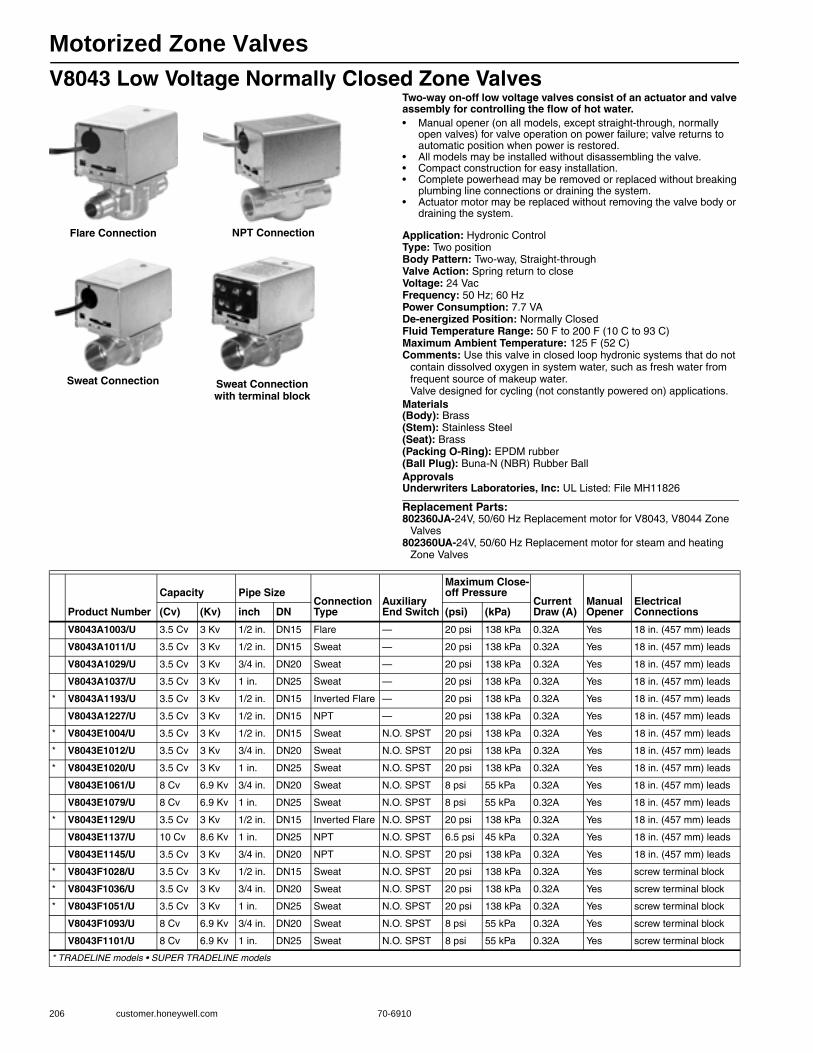
Motorized Zone Valves
206 customer.honeywell.com 70-6910
V8043 Low Voltage Normally Closed Zone ValvesTwo-way on-off low voltage valves consist of an actuator and valve assembly for controlling the flow of hot water.• Manual opener (on all models, except straight-through, normally
open valves) for valve operation on power failure; valve returns to automatic position when power is restored.
• All models may be installed without disassembling the valve. • Compact construction for easy installation. • Complete powerhead may be removed or replaced without breaking
plumbing line connections or draining the system. • Actuator motor may be replaced without removing the valve body or
draining the system.
Application: Hydronic ControlType: Two positionBody Pattern: Two-way, Straight-throughValve Action: Spring return to closeVoltage: 24 VacFrequency: 50 Hz; 60 HzPower Consumption: 7.7 VADe-energized Position: Normally ClosedFluid Temperature Range: 50 F to 200 F (10 C to 93 C) Maximum Ambient Temperature: 125 F (52 C) Comments: Use this valve in closed loop hydronic systems that do not
contain dissolved oxygen in system water, such as fresh water from frequent source of makeup water.Valve designed for cycling (not constantly powered on) applications.
Materials(Body): Brass(Stem): Stainless Steel(Seat): Brass(Packing O-Ring): EPDM rubber(Ball Plug): Buna-N (NBR) Rubber BallApprovalsUnderwriters Laboratories, Inc: UL Listed: File MH11826
Replacement Parts:802360JA-24V, 50/60 Hz Replacement motor for V8043, V8044 Zone
Valves802360UA-24V, 50/60 Hz Replacement motor for steam and heating
Zone Valves
NPT Connection
Sweat Connection with terminal block
Flare Connection
Sweat Connection
Product Number
Capacity Pipe SizeConnection Type
Auxiliary End Switch
Maximum Close-off Pressure
Current Draw (A)
Manual Opener
Electrical Connections(Cv) (Kv) inch DN (psi) (kPa)
V8043A1003/U 3.5 Cv 3 Kv 1/2 in. DN15 Flare — 20 psi 138 kPa 0.32A Yes 18 in. (457 mm) leads
V8043A1011/U 3.5 Cv 3 Kv 1/2 in. DN15 Sweat — 20 psi 138 kPa 0.32A Yes 18 in. (457 mm) leads
V8043A1029/U 3.5 Cv 3 Kv 3/4 in. DN20 Sweat — 20 psi 138 kPa 0.32A Yes 18 in. (457 mm) leads
V8043A1037/U 3.5 Cv 3 Kv 1 in. DN25 Sweat — 20 psi 138 kPa 0.32A Yes 18 in. (457 mm) leads
* V8043A1193/U 3.5 Cv 3 Kv 1/2 in. DN15 Inverted Flare — 20 psi 138 kPa 0.32A Yes 18 in. (457 mm) leads
V8043A1227/U 3.5 Cv 3 Kv 1/2 in. DN15 NPT — 20 psi 138 kPa 0.32A Yes 18 in. (457 mm) leads
* V8043E1004/U 3.5 Cv 3 Kv 1/2 in. DN15 Sweat N.O. SPST 20 psi 138 kPa 0.32A Yes 18 in. (457 mm) leads
* V8043E1012/U 3.5 Cv 3 Kv 3/4 in. DN20 Sweat N.O. SPST 20 psi 138 kPa 0.32A Yes 18 in. (457 mm) leads
* V8043E1020/U 3.5 Cv 3 Kv 1 in. DN25 Sweat N.O. SPST 20 psi 138 kPa 0.32A Yes 18 in. (457 mm) leads
V8043E1061/U 8 Cv 6.9 Kv 3/4 in. DN20 Sweat N.O. SPST 8 psi 55 kPa 0.32A Yes 18 in. (457 mm) leads
V8043E1079/U 8 Cv 6.9 Kv 1 in. DN25 Sweat N.O. SPST 8 psi 55 kPa 0.32A Yes 18 in. (457 mm) leads
* V8043E1129/U 3.5 Cv 3 Kv 1/2 in. DN15 Inverted Flare N.O. SPST 20 psi 138 kPa 0.32A Yes 18 in. (457 mm) leads
V8043E1137/U 10 Cv 8.6 Kv 1 in. DN25 NPT N.O. SPST 6.5 psi 45 kPa 0.32A Yes 18 in. (457 mm) leads
V8043E1145/U 3.5 Cv 3 Kv 3/4 in. DN20 NPT N.O. SPST 20 psi 138 kPa 0.32A Yes 18 in. (457 mm) leads
* V8043F1028/U 3.5 Cv 3 Kv 1/2 in. DN15 Sweat N.O. SPST 20 psi 138 kPa 0.32A Yes screw terminal block
* V8043F1036/U 3.5 Cv 3 Kv 3/4 in. DN20 Sweat N.O. SPST 20 psi 138 kPa 0.32A Yes screw terminal block
* V8043F1051/U 3.5 Cv 3 Kv 1 in. DN25 Sweat N.O. SPST 20 psi 138 kPa 0.32A Yes screw terminal block
V8043F1093/U 8 Cv 6.9 Kv 3/4 in. DN20 Sweat N.O. SPST 8 psi 55 kPa 0.32A Yes screw terminal block
V8043F1101/U 8 Cv 6.9 Kv 1 in. DN25 Sweat N.O. SPST 8 psi 55 kPa 0.32A Yes screw terminal block
* TRADELINE models • SUPER TRADELINE models
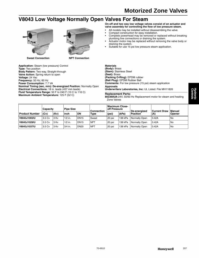
Motorized Zone Valves
70-6910 207
H
ydronic C
ontrols
V8043 Low Voltage Normally Open Valves For SteamOn-off and two way low voltage valves consist of an actuator and valve assembly for controlling the flow of low pressure steam.• All models may be installed without disassembling the valve. • Compact construction for easy installation. • Complete powerhead may be removed or replaced without breaking
plumbing line connections or draining the system. • Actuator motor may be replaced without removing the valve body or
draining the system. • Suitable for use 15 psi low pressure steam application.
Application: Steam (low pressure) ControlType: Two positionBody Pattern: Two-way, Straight-throughValve Action: Spring return to openVoltage: 24 VacFrequency: 50 Hz; 60 HzPower Consumption: 7.7 VANominal Timing (sec, min): De-energized Position: Normally OpenElectrical Connections: 18 in. leads (457 mm leads) Fluid Temperature Range: 50 F to 240 F (10 C to 116 C) Maximum Ambient Temperature: 125 F (52 C)
Materials(Body): Brass(Stem): Stainless Steel(Seat): Brass(Packing O-Ring): EPDM rubber(Ball Plug): EPDM Rubber BallComments: For low pressure (15 psi) steam applicationApprovalsUnderwriters Laboratories, Inc: UL Listed: File MH11826
Replacement Parts:802360UA-24V, 50/60 Hz Replacement motor for steam and heating
Zone Valves
NPT ConnectionSweat Connection
Product Number
Capacity Pipe SizeConnection Type
Maximum Close-off Pressure
De-energized Position
Current Draw (A)
Manual Opener(Cv) (Kv) inch DN (psi) (kPa)
V8043J1003/U 3.5 Cv 3 Kv 1/2 in. DN15 Sweat 20 psi 138 kPa Normally Open 0.42A No
V8043J1029/U 3.5 Cv 3 Kv 1/2 in. DN15 NPT 20 psi 138 kPa Normally Open 0.42A No
V8043J1037/U 3.5 Cv 3 Kv 3/4 in. DN20 NPT 20 psi 138 kPa Normally Open 0.42A No

Motorized Zone Valves
208 customer.honeywell.com 70-6910
V8043 Low Voltage Normally Open Zone ValvesOn-off and two-way low voltage valves consist of an actuator and valve assembly for controlling the flow of hot water.• All models may be installed without disassembling the valve. • Compact construction for easy installation. • Complete powerhead may be removed or replaced without breaking
plumbing line connections or draining the system. • Actuator motor may be replaced without removing the valve body or
draining the system. • No Manual opener
ApplicationHydronic ControlType: Two positionBody Pattern: Two-way, Straight-throughValve Action: Spring return to openVoltage: 24 VacPower Consumption: 7.7 VANominal Timing (sec, min): De-energized Position: Normally OpenElectrical Connections: 18 in. leads (457 mm leads) Fluid Temperature Range: 40 F to 200 F (5 C to 93 C) Maximum Ambient Temperature: 125 F (52 C) Comments: Use this valve in closed loop hydronic systems that do not
contain dissolved oxygen in system water, such as fresh water from frequent source of makeup water.Valve designed for cycling (not constantly powered on) applications.
Materials(Body): Brass(Stem): Stainless Steel(Seat): Brass(Packing O-Ring): EPDM rubber(Ball Plug): Buna-N (NBR) Rubber BallApprovalsUnderwriters Laboratories, Inc: UL Listed: File MH11826
Replacement Parts:802360JA-24V, 50/60 Hz Replacement motor for V8043, V8044 Zone
Valves802360UA-24V, 50/60 Hz Replacement motor for steam and heating
Zone Valves
NPT ConnectionSweat Connection
Product Number
Capacity Pipe SizeConnection Type
Maximum Close-off Pressure
De-energized Position Frequency
Current Draw (A)
Manual Opener(Cv) (Kv) inch DN (psi) (kPa)
V8043B1019/U 3.5 Cv 3 Kv 1/2 in. DN15 Sweat 20 psi 138 kPa Normally Open 60 Hz 0.32A No
V8043B1027/U 3.5 Cv 3 Kv 3/4 in. DN20 Sweat 20 psi 138 kPa Normally Open 60 Hz 0.32A No
V8043B1076/U 3.5 Cv 3 Kv 3/4 in. DN20 NPT 20 psi 138 kPa Normally Open 50 Hz; 60 Hz 0.32A No
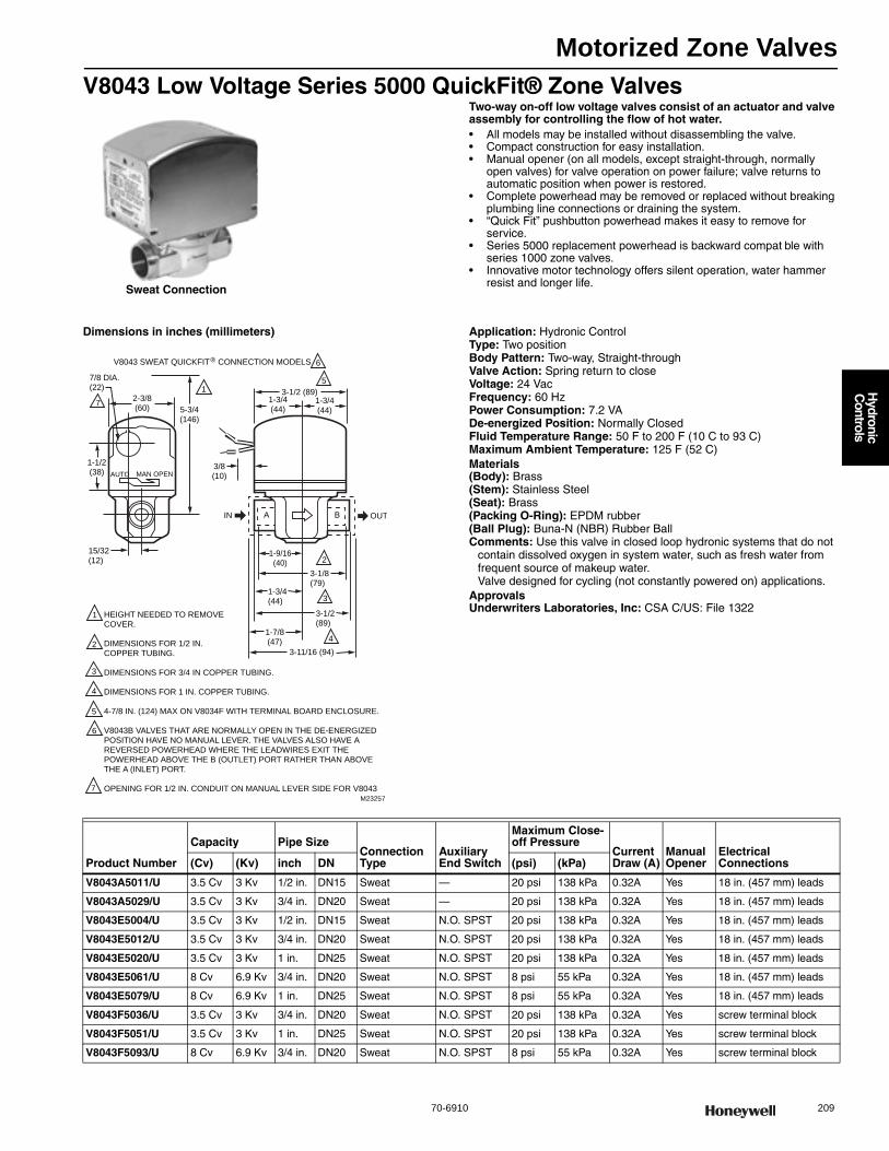
Motorized Zone Valves
70-6910 209
H
ydronic C
ontrols
V8043 Low Voltage Series 5000 QuickFit® Zone ValvesTwo-way on-off low voltage valves consist of an actuator and valve assembly for controlling the flow of hot water.• All models may be installed without disassembling the valve. • Compact construction for easy installation. • Manual opener (on all models, except straight-through, normally
open valves) for valve operation on power failure; valve returns to automatic position when power is restored.
• Complete powerhead may be removed or replaced without breaking plumbing line connections or draining the system.
• “Quick Fit” pushbutton powerhead makes it easy to remove for service.
• Series 5000 replacement powerhead is backward compat ble with series 1000 zone valves.
• Innovative motor technology offers silent operation, water hammer resist and longer life.
Dimensions in inches (millimeters) Application: Hydronic ControlType: Two positionBody Pattern: Two-way, Straight-throughValve Action: Spring return to closeVoltage: 24 VacFrequency: 60 HzPower Consumption: 7.2 VADe-energized Position: Normally ClosedFluid Temperature Range: 50 F to 200 F (10 C to 93 C) Maximum Ambient Temperature: 125 F (52 C) Materials(Body): Brass(Stem): Stainless Steel(Seat): Brass(Packing O-Ring): EPDM rubber(Ball Plug): Buna-N (NBR) Rubber BallComments: Use this valve in closed loop hydronic systems that do not
contain dissolved oxygen in system water, such as fresh water from frequent source of makeup water.Valve designed for cycling (not constantly powered on) applications.
ApprovalsUnderwriters Laboratories, Inc: CSA C/US: File 1322
Sweat Connection
AUTO MAN OPEN
A B
HEIGHT NEEDED TO REMOVE COVER.
DIMENSIONS FOR 1/2 IN. COPPER TUBING.
DIMENSIONS FOR 3/4 IN COPPER TUBING.
DIMENSIONS FOR 1 IN. COPPER TUBING.
4-7/8 IN. (124) MAX ON V8034F WITH TERMINAL BOARD ENCLOSURE.
V8043B VALVES THAT ARE NORMALLY OPEN IN THE DE-ENERGIZED POSITION HAVE NO MANUAL LEVER. THE VALVES ALSO HAVE A REVERSED POWERHEAD WHERE THE LEADWIRES EXIT THE POWERHEAD ABOVE THE B (OUTLET) PORT RATHER THAN ABOVE THE A (INLET) PORT.
OPENING FOR 1/2 IN. CONDUIT ON MANUAL LEVER SIDE FOR V8043
1
7
1
6
5
2
3
42
3
4
5
6
7
M23257
V8043 SWEAT QUICKFIT CONNECTION MODELS
2-3/8(60)
7/8 DIA.(22)
1-1/2(38)
5-3/4(146)
15/32(12)
IN OUT
3-1/2 (89)1-3/4(44)
3/8(10)
1-3/4(44)
1-9/16(40)
1-3/4(44)
3-1/8(79)
3-1/2(89)
1-7/8(47)
3-11/16 (94)
®
Product Number
Capacity Pipe SizeConnection Type
Auxiliary End Switch
Maximum Close-off Pressure
Current Draw (A)
Manual Opener
Electrical Connections(Cv) (Kv) inch DN (psi) (kPa)
V8043A5011/U 3.5 Cv 3 Kv 1/2 in. DN15 Sweat — 20 psi 138 kPa 0.32A Yes 18 in. (457 mm) leads
V8043A5029/U 3.5 Cv 3 Kv 3/4 in. DN20 Sweat — 20 psi 138 kPa 0.32A Yes 18 in. (457 mm) leads
V8043E5004/U 3.5 Cv 3 Kv 1/2 in. DN15 Sweat N.O. SPST 20 psi 138 kPa 0.32A Yes 18 in. (457 mm) leads
V8043E5012/U 3.5 Cv 3 Kv 3/4 in. DN20 Sweat N.O. SPST 20 psi 138 kPa 0.32A Yes 18 in. (457 mm) leads
V8043E5020/U 3.5 Cv 3 Kv 1 in. DN25 Sweat N.O. SPST 20 psi 138 kPa 0.32A Yes 18 in. (457 mm) leads
V8043E5061/U 8 Cv 6.9 Kv 3/4 in. DN20 Sweat N.O. SPST 8 psi 55 kPa 0.32A Yes 18 in. (457 mm) leads
V8043E5079/U 8 Cv 6.9 Kv 1 in. DN25 Sweat N.O. SPST 8 psi 55 kPa 0.32A Yes 18 in. (457 mm) leads
V8043F5036/U 3.5 Cv 3 Kv 3/4 in. DN20 Sweat N.O. SPST 20 psi 138 kPa 0.32A Yes screw terminal block
V8043F5051/U 3.5 Cv 3 Kv 1 in. DN25 Sweat N.O. SPST 20 psi 138 kPa 0.32A Yes screw terminal block
V8043F5093/U 8 Cv 6.9 Kv 3/4 in. DN20 Sweat N.O. SPST 8 psi 55 kPa 0.32A Yes screw terminal block
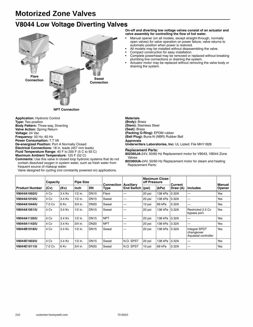
Motorized Zone Valves
210 customer.honeywell.com 70-6910
V8044 Low Voltage Diverting ValvesOn-off and diverting low voltage valves consist of an actuator and valve assembly for controlling the flow of hot water.• Manual opener (on all models, except straight-through, normally
open valves) for valve operation on power failure; valve returns to automatic position when power is restored.
• All models may be installed without disassembling the valve. • Compact construction for easy installation. • Complete powerhead may be removed or replaced without breaking
plumbing line connections or draining the system. • Actuator motor may be replaced without removing the valve body or
draining the system.
Application: Hydronic ControlType: Two positionBody Pattern: Three-way, DivertingValve Action: Spring ReturnVoltage: 24 VacFrequency: 50 Hz; 60 HzPower Consumption: 7.7 VADe-energized Position: Port A Normally ClosedElectrical Connections: 18 in. leads (457 mm leads) Fluid Temperature Range: 40 F to 200 F (5 C to 93 C) Maximum Ambient Temperature: 125 F (52 C) Comments: Use this valve in closed loop hydronic systems that do not
contain dissolved oxygen in system water, such as fresh water from frequent source of makeup water.Valve designed for cycling (not constantly powered on) applications.
Materials(Body): Brass(Stem): Stainless Steel(Seat): Brass(Packing O-Ring): EPDM rubber(Ball Plug): Buna-N (NBR) Rubber BallApprovalsUnderwriters Laboratories, Inc: UL Listed: File MH11826
Replacement Parts:802360JA-24V, 50/60 Hz Replacement motor for V8043, V8044 Zone
Valves802360UA-24V, 50/60 Hz Replacement motor for steam and heating
Replacement Parts:
NPT Connection
Flare Connection Sweat
Connection
Product Number
Capacity Pipe SizeConnection Type
Auxiliary End Switch
Maximum Close-off Pressure
Current Draw (A) Includes
Manual Opener(Cv) (Kv) inch DN (psi) (kPa)
V8044A1002/U 4 Cv 3.4 Kv 1/2 in. DN15 Flare — 20 psi 138 kPa 0.32A — Yes
V8044A1010/U 4 Cv 3.4 Kv 1/2 in. DN15 Sweat — 20 psi 138 kPa 0.32A — Yes
V8044A1044/U 7.0 Cv 6 Kv 3/4 in. DN20 Sweat — 10 psi 69 kPa 0.32A — Yes
V8044A1051/U 4 Cv 3.4 Kv 1/2 in. DN15 Sweat — 20 psi 138 kPa 0.32A Restricted 2.5 Cv bypass port.
Yes
V8044A1135/U 4 Cv 3.4 Kv 1/2 in. DN15 NPT — 20 psi 138 kPa 0.32A — Yes
V8044A1143/U 4 Cv 3.4 Kv 3/4 in. DN20 NPT — 20 psi 138 kPa 0.32A — Yes
V8044B1018/U 4 Cv 3.4 Kv 1/2 in. DN15 Sweat — 20 psi 138 kPa 0.32A Integral SPDT changeover Aquastat controller
Yes
V8044E1003/U 4 Cv 3.4 Kv 1/2 in. DN15 Sweat N.O. SPST 20 psi 138 kPa 0.32A — Yes
V8044E1011/U 7.0 Cv 6 Kv 3/4 in. DN20 Sweat N.O. SPST 10 psi 69 kPa 0.32A — Yes
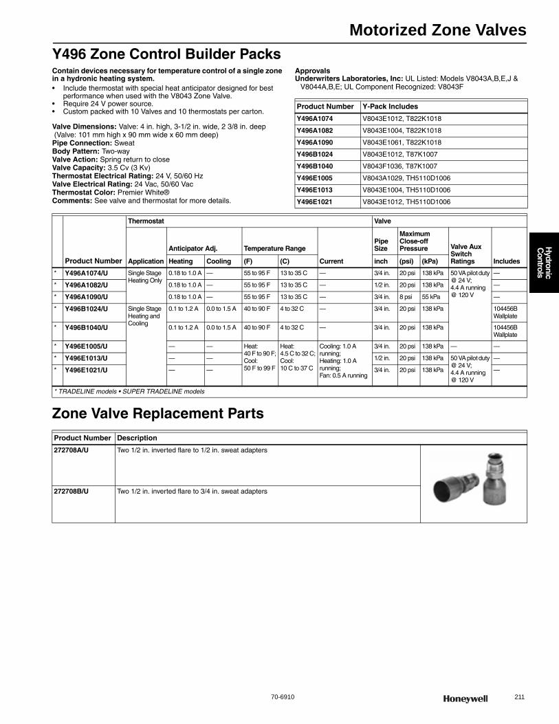
Motorized Zone Valves
70-6910 211
H
ydronic C
ontrols
Y496 Zone Control Builder PacksContain devices necessary for temperature control of a single zone in a hydronic heating system.• Include thermostat with special heat anticipator designed for best
performance when used with the V8043 Zone Valve. • Require 24 V power source. • Custom packed with 10 Valves and 10 thermostats per carton.
Valve Dimensions: Valve: 4 in. high, 3-1/2 in. wide, 2 3/8 in. deep (Valve: 101 mm high x 90 mm wide x 60 mm deep) Pipe Connection: SweatBody Pattern: Two-wayValve Action: Spring return to closeValve Capacity: 3.5 Cv (3 Kv)Thermostat Electrical Rating: 24 V, 50/60 HzValve Electrical Rating: 24 Vac, 50/60 VacThermostat Color: Premier White®Comments: See valve and thermostat for more details.
ApprovalsUnderwriters Laboratories, Inc: UL Listed: Models V8043A,B,E,J &
V8044A,B,E; UL Component Recognized: V8043F
Zone Valve Replacement Parts
Product Number Y-Pack Includes
Y496A1074 V8043E1012, T822K1018
Y496A1082 V8043E1004, T822K1018
Y496A1090 V8043E1061, T822K1018
Y496B1024 V8043E1012, T87K1007
Y496B1040 V8043F1036, T87K1007
Y496E1005 V8043A1029, TH5110D1006
Y496E1013 V8043E1004, TH5110D1006
Y496E1021 V8043E1012, TH5110D1006
Product Number
Thermostat Valve
Application
Anticipator Adj. Temperature Range
Current
Pipe Size
Maximum Close-off Pressure Valve Aux
Switch Ratings IncludesHeating Cooling (F) (C) inch (psi) (kPa)
* Y496A1074/U Single Stage Heating Only
0.18 to 1.0 A — 55 to 95 F 13 to 35 C — 3/4 in. 20 psi 138 kPa 50 VA pilot duty @ 24 V; 4.4 A running @ 120 V
—
* Y496A1082/U 0.18 to 1.0 A — 55 to 95 F 13 to 35 C — 1/2 in. 20 psi 138 kPa —
* Y496A1090/U 0.18 to 1.0 A — 55 to 95 F 13 to 35 C — 3/4 in. 8 psi 55 kPa —
* Y496B1024/U Single Stage Heating and Cooling
0.1 to 1.2 A 0.0 to 1.5 A 40 to 90 F 4 to 32 C — 3/4 in. 20 psi 138 kPa 104456B Wallplate
* Y496B1040/U 0.1 to 1.2 A 0.0 to 1.5 A 40 to 90 F 4 to 32 C — 3/4 in. 20 psi 138 kPa 104456B Wallplate
* Y496E1005/U — — Heat: 40 F to 90 F; Cool: 50 F to 99 F
Heat: 4.5 C to 32 C; Cool: 10 C to 37 C
Cooling: 1.0 A running; Heating: 1.0 A running; Fan: 0.5 A running
3/4 in. 20 psi 138 kPa — —
* Y496E1013/U — — 1/2 in. 20 psi 138 kPa 50 VA pilot duty @ 24 V; 4.4 A running @ 120 V
—
* Y496E1021/U — — 3/4 in. 20 psi 138 kPa —
* TRADELINE models • SUPER TRADELINE models
Product Number Description
272708A/U Two 1/2 in. inverted flare to 1/2 in. sweat adapters
272708B/U Two 1/2 in. inverted flare to 3/4 in. sweat adapters

Motorized Zone Valves
212 customer.honeywell.com 70-6910
Zone Valves Replacement HeadsMaximum Ambient Temperature: 125 F (52 C)
Product Number Description
Electrical Connection Location Voltage
Fre-quency
Aux Switch Ratings
Used With Valve Action
Used With Valve
40003916-021/U 24 Vac, 50/60 Hz Replacement head for V8043A
Same side of manual lever
24 Vac 50 Hz; 60 Hz
— Spring return to close
Two-way
40003916-023/U 240 Vac, 50 Hz Replacement head for V4043A, 240V, 50Hz
Same side of manual lever
240 Vac 50 Hz — Spring return to close
Two-way
40003916-024/U 120 Vac, 60 Hz Replacement head for V4043A
Same side of manual lever
120 Vac 60 Hz — Spring return to close
Two-way
40003916-025/U 24 Vac, 50/60 Hz Replacement head with End Switch for V8044E
Same side of manual lever
24 Vac 50 Hz; 60 Hz
4.4 A running @ 120 V; 50 VA pilot duty @ 24 V
Spring return to close “A” port
Diverting
40003916-026/U 24 Vac, 50/60 Hz Replacement head with End Switch for V8043E
Same side of manual lever
24 Vac 50 Hz; 60 Hz
4.4 A running @ 120 V; 50 VA pilot duty @ 24 V
Spring return to close
Two-way
40003916-027/U 24 Vac, 50/60 Hz, N.O. Replacement head for V8043B
Same side of manual lever
24 Vac 50 Hz; 60 Hz
— Spring return to open
Two-way
40003916-030/U 240 Vac, 60 Hz, N.O. Replacement actuator for V4043B
Same side of manual lever
240 Vac 60 Hz — Spring return to open
Two-way
40003916-031/U 120 Vac, 60 Hz, N.O. Replacement head for V4043B
Same side of manual lever
120 Vac 60 Hz — Spring return to open
Two-way
40003916-032/U 24 Vac, 50/60 Hz Replacement head for V8044A
On opposite side of manual lever
24 Vac 50 Hz; 60 Hz
— Spring return to close “A” port
Diverting
40003916-035/U 220/240 Vac, 50/60 Hz On opposite side of manual lever
240 Vac; 220 Vac
50 Hz; 60 Hz
— Spring return to close “A” port
Diverting
40003916-036/U 120 Vac, 60 Hz Replacement head for V4044
On opposite side of manual lever
120V 60 Hz — Spring return to close “A” port
Diverting
40003916-037/U 24 Vac, 50/60 Hz Replacement head for V8044B, With Aquastat Switch
On opposite side of manual lever
24 Vac 50 Hz; 60 Hz
— Spring return to close “A” port
Diverting
40003916-040/U 120 Vac, 60 Hz Replacement head for V8044B, With Aquastat Switch
On opposite side of manual lever
120 Vac 60 Hz — Spring return to close “A” port
Diverting
40003916-041/U 120 Vac, 60 Hz Replacement head for V4043E, Steam Valve
Same side of manual lever
120 Vac 60 Hz — Spring return to close
Two-way
40003916-043/U 24 Vac, 50/60 Hz Replacement head with End Switch for V8044E
Same side of manual lever
24 Vac 50 Hz; 60 Hz
4.4 A running @ 120 V; 50 VA pilot duty @ 24 V
Spring return to close “A” port
Diverting
40003916-044/U 24 Vac, 50/60 Hz Replacement head for V8044B, with Aquastat
Same side of manual lever
24 Vac 50 Hz; 60 Hz
— Spring return to close “A” port
Diverting
40003916-045/U 120 Vac, 60 Hz Replacement head for V4044B, with Aquastat
Same side of manual lever
120 Vac 60 Hz — Spring return to close “A” port
Diverting
40003916-046/U 24 Vac, 50/60 Hz Replacement head for V8044A
Same side of manual lever
24 Vac 50 Hz; 60 Hz
— Spring return to close “A” port
Diverting
40003916-047/U 120 Vac, 60 Hz Replacement head for V4044A, 120V, 60Hz, with 96" leads
Same side of manual lever
120 Vac 60 Hz — Spring return to close “A” port
Diverting
40003916-048/U 24 Vac, 50/60 Hz Replacement head for V8043F, With End Switch
Same side of manual lever
24 Vac 50 Hz; 60 Hz
4.4 A running @ 120 V; 50 VA pilot duty @ 24 V
Spring return to close
Two-way
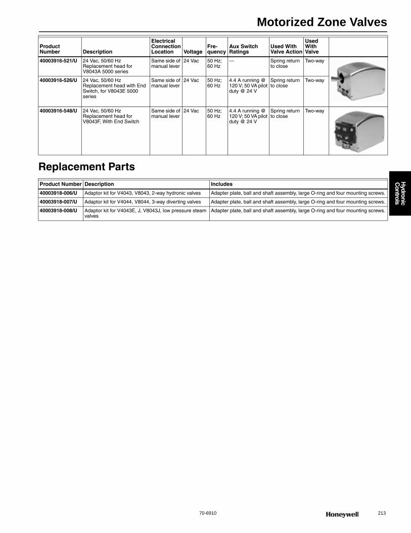
Motorized Zone Valves
70-6910 213
H
ydronic C
ontrols
Replacement Parts
40003916-521/U 24 Vac, 50/60 Hz Replacement head for V8043A 5000 series
Same side of manual lever
24 Vac 50 Hz; 60 Hz
— Spring return to close
Two-way
40003916-526/U 24 Vac, 50/60 Hz Replacement head with End Switch, for V8043E 5000 series
Same side of manual lever
24 Vac 50 Hz; 60 Hz
4.4 A running @ 120 V; 50 VA pilot duty @ 24 V
Spring return to close
Two-way
40003916-548/U 24 Vac, 50/60 Hz Replacement head for V8043F, With End Switch
Same side of manual lever
24 Vac 50 Hz; 60 Hz
4.4 A running @ 120 V; 50 VA pilot duty @ 24 V
Spring return to close
Two-way
Product Number Description Includes
40003918-006/U Adaptor kit for V4043, V8043, 2-way hydronic valves Adapter plate, ball and shaft assembly, large O-ring and four mounting screws.
40003918-007/U Adaptor kit for V4044, V8044, 3-way diverting valves Adapter plate, ball and shaft assembly, large O-ring and four mounting screws.
40003918-008/U Adaptor kit for V4043E, J, V8043J, low pressure steam valves
Adapter plate, ball and shaft assembly, large O-ring and four mounting screws.
Product Number Description
Electrical Connection Location Voltage
Fre-quency
Aux Switch Ratings
Used With Valve Action
Used With Valve
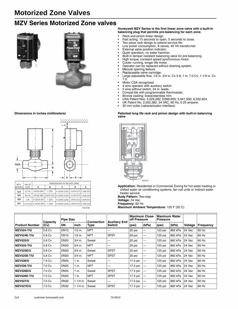
Motorized Zone Valves
214 customer.honeywell.com 70-6910
MZV Series Motorized Zone valvesHoneywell MZV Series is the first linear zone valve with a built-in balancing plug that permits pre-balancing for each zone.• Rack and pinion linear design. • Fast acting, 15 seconds to open, 5 seconds to close. • Two piece rack design to extend service life. • Low power consumption, 8 valves, 40 VA transformer. • External valve position indicator. • Quiet operation, no water hammer. • Built-in tamper resistant balancing valve for pre-balancing. • High torque, constant speed synchronous motor. • Cooler running, longer life motor. • Operator can be replaced without draining system. • Manual opening feature. • Replaceable valve cartridge. • Large adjustable flow, 1/2 in. 3/4 in. Cv 5.8; 1 in. 7.0 Cv; 1-1/4 in. Cv
7.0. • Motor CSA recognized. • 4 wire operator with auxiliary switch. • 2 wire without switch, 24 in. leads. • Compat ble with programmable thermostats. • Bronze casting; brass/stainless trim. • USA Patent Nos. 5,529,282; D369,650; 5,941,500; 6,032,924. • UK Patent No. 2,052,382. 24 VAC, 60 Hz, 0.25 ampere. • 30 mm collar (valve/actuator interface)
Dimensions in inches (millimeters) Patented long life rack and pinion design with built-in balancing valve
Application: Residential or Commercial Zoning for hot water heating or chilled water air conditioning systems, fan coil units or indirect water heater service.
Body Pattern: Two-wayVoltage: 24 VacFrequency: 60 HzMaximum Ambient Temperature: 125 F (52 C)
DIMENSIONS IN INCHES (MM)
1/2 IN. 3-5/16 (84)
3-5/16 (84)
3-13/16 (97)
3-13/16 (97)
1 (25)
13/16 (21)
1 (25)
1 (25)
4-13/16 (122)
4-13/16 (122)
4-13/16 (122)
4-13/16 (122)
11/16 (17)
11/16 (17)
13/16 (21)
13/16 (21)
3/4 IN.
1 IN.
1-1/4 IN.
M23259B
1-5/8 (41)
1-5/8 (41)
1-5/8 (41)
1-5/8 (41)
C
B
A ED
SIZE
1 IN.
3/4
525
VALVE
SIZE
MZV
SERIES
524525
526
527
A B C D E
M18311
Product NumberCapacity(Cv)
Pipe SizeConnection Type
Auxiliary End Switch
Maximum Close-off Pressure
Maximum Water Pressure
Voltage FrequencyDN inch (psi) (kPa) (psi) (kPa)
MZV524-T/U 5.8 Cv DN15 1/2 in. NPT — 20 psi — 125 psi 862 kPa 24 Vac 60 Hz
MZV524E-T/U 5.8 Cv DN15 1/2 in. NPT SPST 20 psi — 125 psi 862 kPa 24 Vac 60 Hz
MZV525/U 5.8 Cv DN20 3/4 in. Sweat — 20 psi — 125 psi 862 kPa 24 Vac 60 Hz
MZV525-T/U 5.8 Cv DN20 3/4 in. NPT — 20 psi — 125 psi 862 kPa 24 Vac 60 Hz
MZV525E/U 5.8 Cv DN20 3/4 in. Sweat SPST 20 psi — 125 psi 862 kPa 24 Vac 60 Hz
MZV525E-T/U 5.8 Cv DN20 3/4 in. NPT SPST 20 psi — 125 psi 862 kPa 24 Vac 60 Hz
MZV526/U 7.0 Cv DN25 1 in. Sweat — 17.5 psi — 125 psi 862 kPa 24 Vac 60 Hz
MZV526-T/U 7.0 Cv DN25 1 in. NPT — 17.5 psi — 125 psi 862 kPa 24 Vac 60 Hz
MZV526E/U 7.0 Cv DN25 1 in. Sweat SPST 17.5 psi — 125 psi 862 kPa 24 Vac 60 Hz
MZV526E-T/U 7.0 Cv DN25 1 in. NPT SPST 17.5 psi — 125 psi 862 kPa 24 Vac 60 Hz
MZV527/U 7.0 Cv DN32 1 1/4 in. Sweat — 17.5 psi — 125 psi 862 kPa 24 Vac 60 Hz
MZV527E/U 7.0 Cv DN32 1 1/4 in. Sweat SPST 17.5 psi — 125 psi 862 kPa 24 Vac 60 Hz
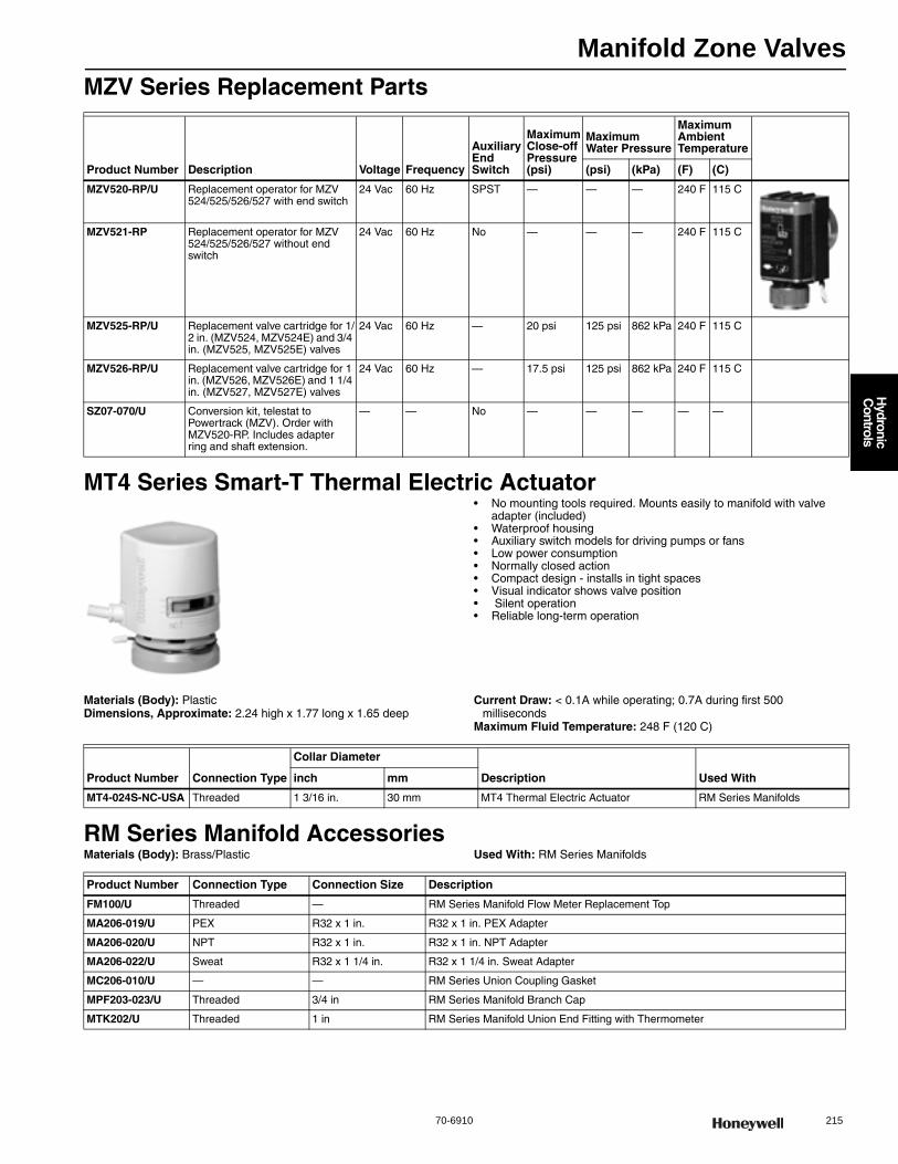
Manifold Zone Valves
70-6910 215
H
ydronic C
ontrols
MZV Series Replacement Parts
MT4 Series Smart-T Thermal Electric Actuator• No mounting tools required. Mounts easily to manifold with valve
adapter (included) • Waterproof housing • Auxiliary switch models for driving pumps or fans • Low power consumption • Normally closed action • Compact design - installs in tight spaces • Visual indicator shows valve position • Silent operation • Reliable long-term operation
Materials (Body): PlasticDimensions, Approximate: 2.24 high x 1.77 long x 1.65 deep
Current Draw: < 0.1A while operating; 0.7A during first 500 milliseconds
Maximum Fluid Temperature: 248 F (120 C)
RM Series Manifold AccessoriesMaterials (Body): Brass/Plastic Used With: RM Series Manifolds
Product Number Description Voltage Frequency
Auxiliary End Switch
Maximum Close-off Pressure(psi)
Maximum Water Pressure
Maximum Ambient Temperature
(psi) (kPa) (F) (C)
MZV520-RP/U Replacement operator for MZV 524/525/526/527 with end switch
24 Vac 60 Hz SPST — — — 240 F 115 C
MZV521-RP Replacement operator for MZV 524/525/526/527 without end switch
24 Vac 60 Hz No — — — 240 F 115 C
MZV525-RP/U Replacement valve cartridge for 1/2 in. (MZV524, MZV524E) and 3/4 in. (MZV525, MZV525E) valves
24 Vac 60 Hz — 20 psi 125 psi 862 kPa 240 F 115 C
MZV526-RP/U Replacement valve cartridge for 1 in. (MZV526, MZV526E) and 1 1/4 in. (MZV527, MZV527E) valves
24 Vac 60 Hz — 17.5 psi 125 psi 862 kPa 240 F 115 C
SZ07-070/U Conversion kit, telestat to Powertrack (MZV). Order with MZV520-RP. Includes adapter ring and shaft extension.
— — No — — — — —
Product Number Connection Type
Collar Diameter
Description Used Withinch mm
MT4-024S-NC-USA Threaded 1 3/16 in. 30 mm MT4 Thermal Electric Actuator RM Series Manifolds
Product Number Connection Type Connection Size Description
FM100/U Threaded — RM Series Manifold Flow Meter Replacement Top
MA206-019/U PEX R32 x 1 in. R32 x 1 in. PEX Adapter
MA206-020/U NPT R32 x 1 in. R32 x 1 in. NPT Adapter
MA206-022/U Sweat R32 x 1 1/4 in. R32 x 1 1/4 in. Sweat Adapter
MC206-010/U — — RM Series Union Coupling Gasket
MPF203-023/U Threaded 3/4 in RM Series Manifold Branch Cap
MTK202/U Threaded 1 in RM Series Manifold Union End Fitting with Thermometer
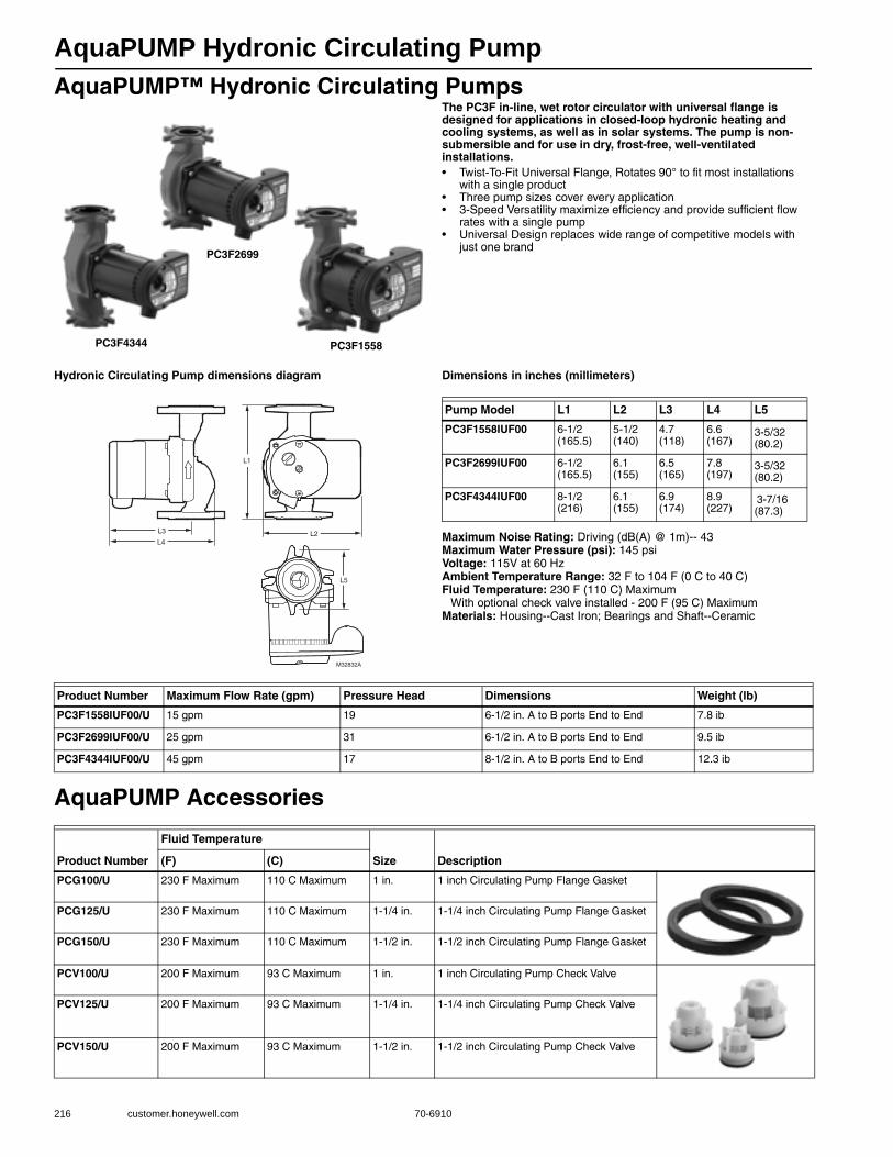
AquaPUMP Hydronic Circulating Pump
216 customer.honeywell.com 70-6910
AquaPUMP™ Hydronic Circulating PumpsThe PC3F in-line, wet rotor circulator with universal flange is designed for applications in closed-loop hydronic heating and cooling systems, as well as in solar systems. The pump is non-submersible and for use in dry, frost-free, well-ventilated installations.• Twist-To-Fit Universal Flange, Rotates 90° to fit most installations
with a single product • Three pump sizes cover every application• 3-Speed Versatility maximize efficiency and provide sufficient flow
rates with a single pump• Universal Design replaces wide range of competitive models with
just one brand
Hydronic Circulating Pump dimensions diagram Dimensions in inches (millimeters)
Maximum Noise Rating: Driving (dB(A) @ 1m)-- 43Maximum Water Pressure (psi): 145 psiVoltage: 115V at 60 HzAmbient Temperature Range: 32 F to 104 F (0 C to 40 C)Fluid Temperature: 230 F (110 C) Maximum
With optional check valve installed - 200 F (95 C) Maximum Materials: Housing--Cast Iron; Bearings and Shaft--Ceramic
AquaPUMP Accessories
PC3F4344
PC3F2699
PC3F1558
M32832A
L2L4
L3
L1
L5
Pump Model L1 L2 L3 L4 L5
PC3F1558IUF00 6-1/2 (165.5)
5-1/2 (140)
4.7 (118)
6.6 (167)
3-5/32
(80.2)
PC3F2699IUF00 6-1/2 (165.5)
6.1 (155)
6.5 (165)
7.8 (197)
3-5/32
(80.2)
PC3F4344IUF00 8-1/2 (216)
6.1 (155)
6.9 (174)
8.9 (227)
3-7/16 (87.3)
Product Number Maximum Flow Rate (gpm) Pressure Head Dimensions Weight (lb)
PC3F1558IUF00/U 15 gpm 19 6-1/2 in. A to B ports End to End 7.8 ib
PC3F2699IUF00/U 25 gpm 31 6-1/2 in. A to B ports End to End 9.5 ib
PC3F4344IUF00/U 45 gpm 17 8-1/2 in. A to B ports End to End 12.3 ib
Product Number
Fluid Temperature
Size Description (F) (C)
PCG100/U 230 F Maximum 110 C Maximum 1 in. 1 inch Circulating Pump Flange Gasket
PCG125/U 230 F Maximum 110 C Maximum 1-1/4 in. 1-1/4 inch Circulating Pump Flange Gasket
PCG150/U 230 F Maximum 110 C Maximum 1-1/2 in. 1-1/2 inch Circulating Pump Flange Gasket
PCV100/U 200 F Maximum 93 C Maximum 1 in. 1 inch Circulating Pump Check Valve
PCV125/U 200 F Maximum 93 C Maximum 1-1/4 in. 1-1/4 inch Circulating Pump Check Valve
PCV150/U 200 F Maximum 93 C Maximum 1-1/2 in. 1-1/2 inch Circulating Pump Check Valve
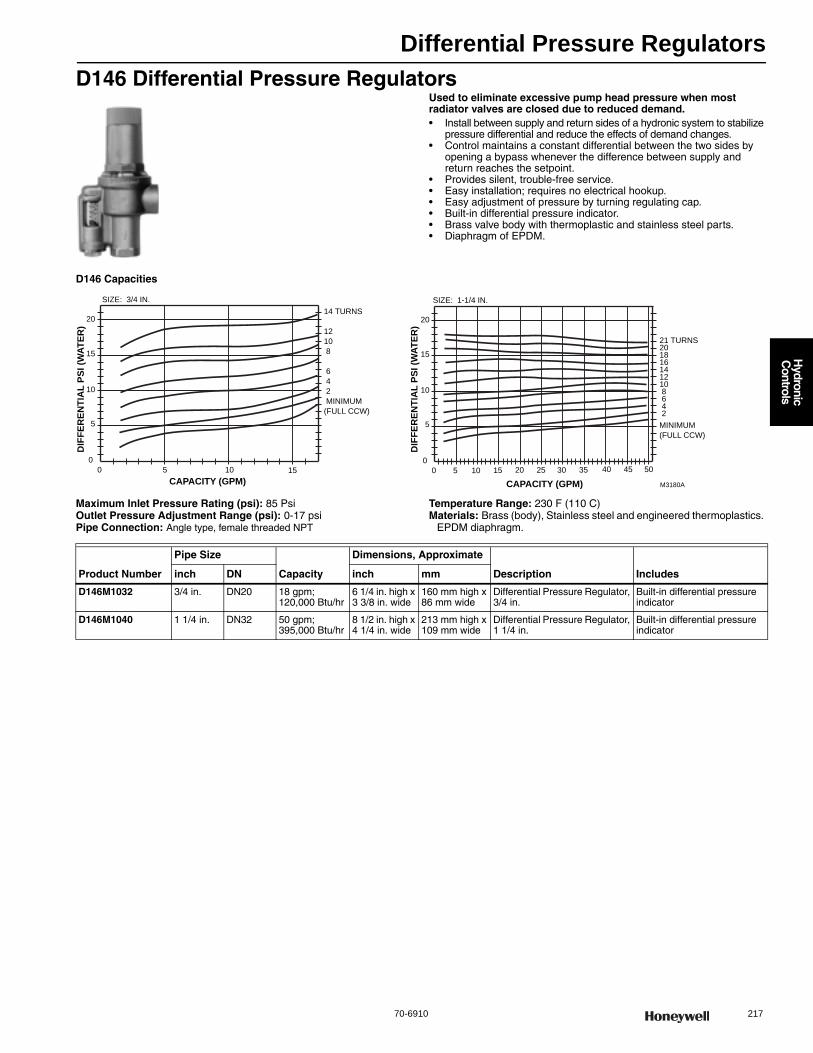
Differential Pressure Regulators
70-6910 217
H
ydronic C
ontrols
D146 Differential Pressure RegulatorsUsed to eliminate excessive pump head pressure when most radiator valves are closed due to reduced demand.• Install between supply and return sides of a hydronic system to stabilize
pressure differential and reduce the effects of demand changes. • Control maintains a constant differential between the two sides by
opening a bypass whenever the difference between supply and return reaches the setpoint.
• Provides silent, trouble-free service. • Easy installation; requires no electrical hookup. • Easy adjustment of pressure by turning regulating cap. • Built-in differential pressure indicator. • Brass valve body with thermoplastic and stainless steel parts. • Diaphragm of EPDM.
D146 Capacities
Maximum Inlet Pressure Rating (psi): 85 PsiOutlet Pressure Adjustment Range (psi): 0-17 psiPipe Connection: Angle type, female threaded NPT
Temperature Range: 230 F (110 C) Materials: Brass (body), Stainless steel and engineered thermoplastics.
EPDM diaphragm.
10
14 TURNS
12
10
8
6
4
2
MINIMUM
(FULL CCW)
5
0
CAPACITY (GPM)
DIF
FER
ENTI
AL
PSI (
WAT
ER)
0 5 10 15
15
20
SIZE: 3/4 IN.
10
21 TURNS201816141210 8 6 4 2 5
0
CAPACITY (GPM)
DIF
FER
ENTI
AL
PSI (
WAT
ER)
M3180A
0 5 10 15
15
20
SIZE: 1-1/4 IN.
20 25 30 35 40 45 50
MINIMUM
(FULL CCW)
Product Number
Pipe Size
Capacity
Dimensions, Approximate
Description Includesinch DN inch mm
D146M1032 3/4 in. DN20 18 gpm; 120,000 Btu/hr
6 1/4 in. high x 3 3/8 in. wide
160 mm high x 86 mm wide
Differential Pressure Regulator, 3/4 in.
Built-in differential pressure indicator
D146M1040 1 1/4 in. DN32 50 gpm; 395,000 Btu/hr
8 1/2 in. high x 4 1/4 in. wide
213 mm high x 109 mm wide
Differential Pressure Regulator, 1 1/4 in.
Built-in differential pressure indicator

Air Vents and Eliminators
218 customer.honeywell.com 70-6910
EA79 Industrial Air VentsThe Honeywell EA79 Industrial Air Vent purges air from high pressure mains and equipment in hot or cold closed water systems.• Built-in shutoff valve for servicing without system shutdown. • Built-in vacuum breaker. • Removable float/valve assembly for easy servicing. • Safety drain connection and vent cap with leakage guard. • Brass shell construction. • Internal parts made of corrosion-resistant and chemical-resistant
materials for use with water systems containing propylene glycol, mineral oils, or petroleum-based oils. Replaces Hoffman # 79 or Dole # 75 Vents.
• Maintains quiet and efficient operation.
Dimensions in inches (millimeters)
EA79 capabilities
EA79 construction
Application: HydronicsCorrosion Resistant: Internal parts made of corrosion-resistant and
chemical-resistant materials for use with hydronic systems that may contain concentrations of propylene or ethylene glycol.
Maximum Operating Temperature: 250 F (120C) Maximum Operating Pressure: 150 psi (1034 kPa)
Accessories:Q122A1001-Safe waste connector (M20 thread connection)
Replacement Parts:P79B1003-Replacement O-ring, cover and internals for EA79A1004
5
(128)
4-11/16 (120)
M6095D
3/4 INCH
NPT EXTERNAL
THREAD
1/2 INCH NPT
INTERNAL THREAD
OPEN CLOSED
CAUTION! ! Device may be hot
Do not use tools to adjust the e damage to vent may result us only to adjust vent A wrench only on hex during installation
1/2 (12)
1-7/8 (48)
M2760B
250
300
200
150
100
50
0
CU
BIC
FE
ET
/HO
UR
0 10 20 30 40 50 60 70 80 90 100 110 120 130 140 150
PRESSURE (PSI)
M6096B
BLACK COVER ASSEMBLY
SEAT AREA—MAKE SURE AREA IS FREE OF DIRT AND DEBRIS.
OUTER RING
RED VENTCAP WITHLEAKAGE GUARD
O-RING
SPRING
VENT LEVER
FLOAT
Product Number Connection Type Connection Size Description
EA79A1004 3/4 in. male NPT pipe thread with 1/2 in. female NPT pipe thread 3/4 in. Industrial automatic air vent
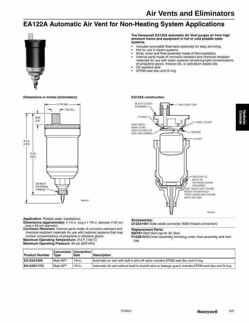
Air Vents and Eliminators
70-6910 219
H
ydronic C
ontrols
EA122A Automatic Air Vent for Non-Heating System Applications
The Honeywell EA122A Automatic Air Vent purges air from high pressure mains and equipment in hot or cold potable water systems.• Includes removable float/valve assembly for easy servicing. • Not for use in steam systems. • Body, cover and float assembly made of thermoplastics. • Internal parts made of corrosion-resistant and chemical-resistant
materials for use with water systems containing light concentrations of propylene glycol, mineral oils, or petroleum-based oils.
• Oil resistant seal. • EPDM seat disc and O-ring.
Dimensions in inches (millimeters) EA122A construction
Application: Potable water installationsDimensions (approximate): 5 1/4 in. long x 1 7/8 in. diameter (133 mm
long x 48 mm diameter)Corrosion Resistant: Internal parts made of corrosion-resistant and
chemical-resistant materials for use with hydronic systems that may contain concentrations of propylene or ethylene glycol.
Maximum Operating Temperature: 212 F (100 C) Maximum Operating Pressure: 90 psi (620 kPa)
Accessories:Q122A1001-Safe waste connector (M20 thread connection)
Replacement Parts:900761-Red Vent cap for Air VentP122B1010-Cover assembly including cover, float assembly and vent
cap
M5491D
1/8 INCH
EXTERNAL
THREAD
9/16
(14)
5-1/4
(133)
4-3/4
(121)
1-7/8 (48)
7/16 (11)
M6585C
SHUTOFF IS
BUILT-IN.
NO DRAIN-DOWN
REQUIRED.
JUST TWIST AND YOU'RE
READY TO SERVICE!
TWIST AGAIN AND YOU'RE
BACK ON LINE.
RED VENT CAP
VENT LEVER
SPRING
BLACK COVER
ASSEMBLY
O-RING
SEAT AREA—
MAKE SURE
AREA IS FREE OF
DIRT AND DEBRIS.
FLOAT
Product NumberConnection Type
Connection Size Description
EA122A1028 Male NPT 1/8 in. Automatic air vent with built-in shut off valve; includes EPDM seat disc and O-ring.
EA122B117/U Male NPT 1/8 in. Automatic Air vent without build-in shutoff valve or leakage guard; includes EPDM seat disc and O-ring.
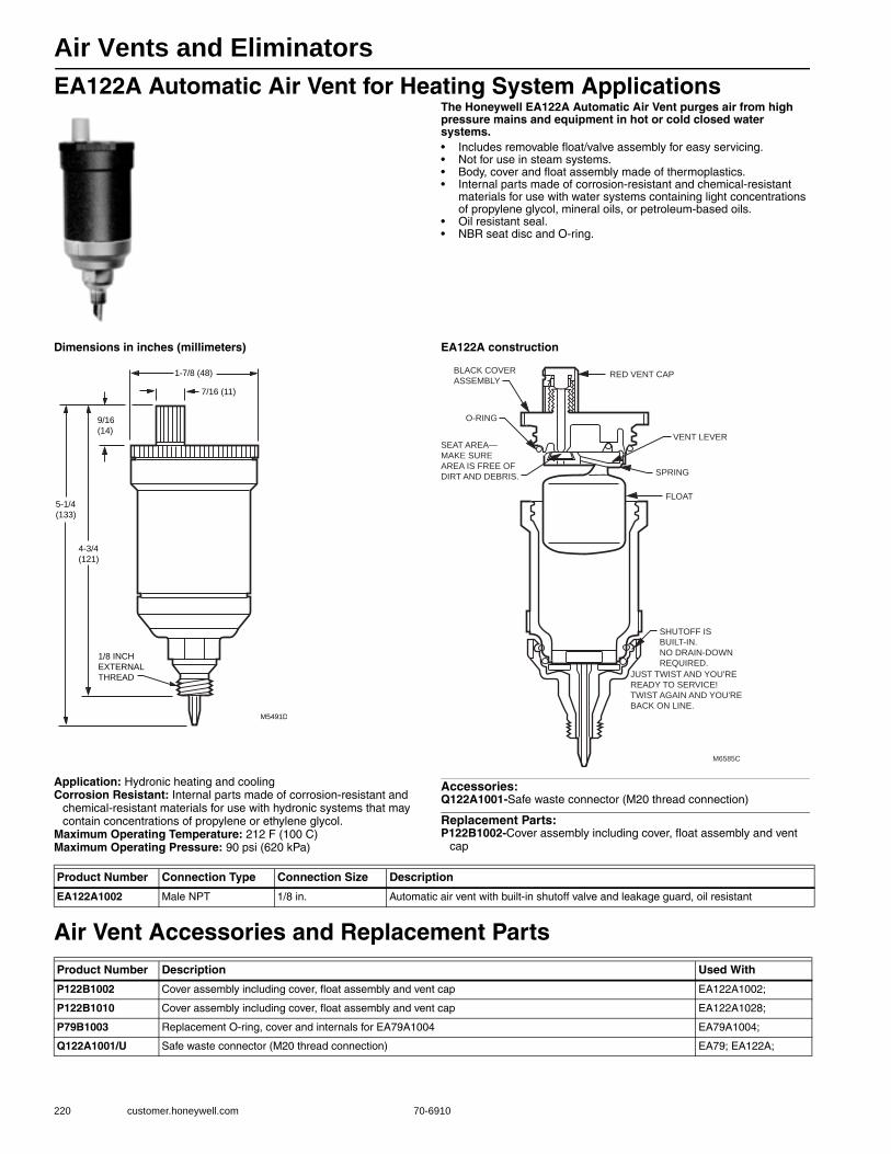
Air Vents and Eliminators
220 customer.honeywell.com 70-6910
EA122A Automatic Air Vent for Heating System ApplicationsThe Honeywell EA122A Automatic Air Vent purges air from high pressure mains and equipment in hot or cold closed water systems.• Includes removable float/valve assembly for easy servicing. • Not for use in steam systems. • Body, cover and float assembly made of thermoplastics. • Internal parts made of corrosion-resistant and chemical-resistant
materials for use with water systems containing light concentrations of propylene glycol, mineral oils, or petroleum-based oils.
• Oil resistant seal. • NBR seat disc and O-ring.
Dimensions in inches (millimeters) EA122A construction
Application: Hydronic heating and coolingCorrosion Resistant: Internal parts made of corrosion-resistant and
chemical-resistant materials for use with hydronic systems that may contain concentrations of propylene or ethylene glycol.
Maximum Operating Temperature: 212 F (100 C) Maximum Operating Pressure: 90 psi (620 kPa)
Accessories:Q122A1001-Safe waste connector (M20 thread connection)
Replacement Parts:P122B1002-Cover assembly including cover, float assembly and vent
cap
Air Vent Accessories and Replacement Parts
M5491D
1/8 INCH
EXTERNAL
THREAD
9/16
(14)
5-1/4
(133)
4-3/4
(121)
1-7/8 (48)
7/16 (11)
M6585C
SHUTOFF IS
BUILT-IN.
NO DRAIN-DOWN
REQUIRED.
JUST TWIST AND YOU'RE
READY TO SERVICE!
TWIST AGAIN AND YOU'RE
BACK ON LINE.
RED VENT CAP
VENT LEVER
SPRING
BLACK COVER
ASSEMBLY
O-RING
SEAT AREA—
MAKE SURE
AREA IS FREE OF
DIRT AND DEBRIS.
FLOAT
Product Number Connection Type Connection Size Description
EA122A1002 Male NPT 1/8 in. Automatic air vent with built-in shutoff valve and leakage guard, oil resistant
Product Number Description Used With
P122B1002 Cover assembly including cover, float assembly and vent cap EA122A1002;
P122B1010 Cover assembly including cover, float assembly and vent cap EA122A1028;
P79B1003 Replacement O-ring, cover and internals for EA79A1004 EA79A1004;
Q122A1001/U Safe waste connector (M20 thread connection) EA79; EA122A;
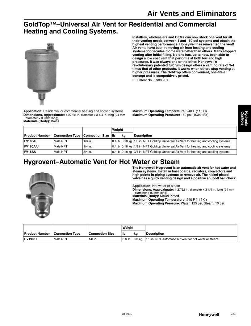
Air Vents and Eliminators
70-6910 221
H
ydronic C
ontrols
GoldTop™–Universal Air Vent for Residential and Commercial Heating and Cooling Systems.
Installers, wholesalers and OEMs can now stock one vent for all their venting needs between 1 and 150 psi systems and obtain the highest venting performance. Honeywell has reinvented the vent! Air vents have been removing air from heating and cooling systems for decades. Some were better than others. Many stopped venting after initial filling. No one has, up to now, been able to design a low cost vent that performs at both low and high pressures. It was always one or the other. Honeywell's revolutionary patented fulcrum design offers a venting rate of 3-4 times that of other products. It works when others stop venting at higher pressures. The GoldTop offers convenient, one-fits-all concept and is competitively priced.• Patent No. 5,988,201.
Application: Residential or commercial heating and cooling systemsDimensions, Approximate: 1 27/32 in. diameter x 3 1/4 in. long (24 mm
diameter x 83 mm long)Materials (Body): Brass
Maximum Operating Temperature: 240 F (115 C) Maximum Operating Pressure: 150 psi (1034 kPa)
Hygrovent–Automatic Vent for Hot Water or SteamThe Honeywell Hygrovent is an automatic air vent for hot water and steam systems. Install in baseboards, radiators, convectors and high points in piping systems to remove air. The nickel-plated valve has a quick venting design and a positive shut-off ball check.
Application: Hot water or steamDimensions, Approximate: 1 27/32 in. diameter x 3 1/4 in. long (24 mm
diameter x 83 mm long)Materials (Body): Nickel PlatedMaximum Operating Temperature: 240 F (115 C) Maximum Operating Pressure: Water: 125 psi; Steam: 10 psi
Product Number Connection Type Connection Size
Weight
Descriptionlb kg
FV180/U Male NPT 1/8 in. 0.4 b 0.18 kg 1/8 in. NPT Goldtop Universal Air Vent for heating and cooling systems
FV180A/U Male NPT 1/4 in. 0.4 b 0.18 kg 1/4 in. NPT Goldtop Universal Air Vent for heating and cooling systems
FV183/U Male NPT 3/4 in. 0.4 b 0.18 kg 3/4 in. NPT Goldtop Universal Air Vent for heating and cooling systems
Product Number Connection Type Connection Size
Weight
Descriptionlb kg
HV190/U Male NPT 1/8 in. 0.6 lb 0.3 kg 1/8 in. NPT Automatic Air Vent for hot water or steam
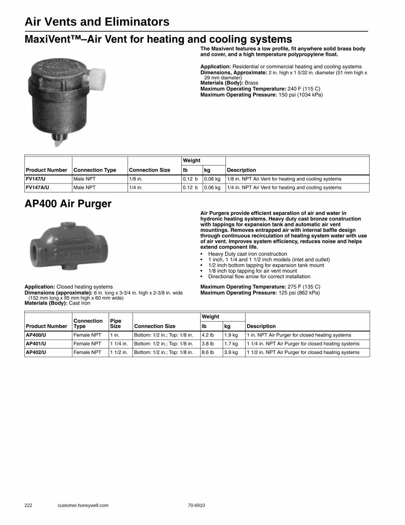
Air Vents and Eliminators
222 customer.honeywell.com 70-6910
MaxiVent™–Air Vent for heating and cooling systemsThe Maxivent features a low profile, fit anywhere solid brass body and cover, and a high temperature polypropylene float.
Application: Residential or commercial heating and cooling systemsDimensions, Approximate: 2 in. high x 1 5/32 in. diameter (51 mm high x
29 mm diameter)Materials (Body): BrassMaximum Operating Temperature: 240 F (115 C) Maximum Operating Pressure: 150 psi (1034 kPa)
AP400 Air PurgerAir Purgers provide efficient separation of air and water in hydronic heating systems. Heavy duty cast bronze construction with tappings for expansion tank and automatic air vent mountings. Removes entrapped air with internal baffle design through continuous recirculation of heating system water with use of air vent. Improves system efficiency, reduces noise and helps extend component life.• Heavy Duty cast iron construction • 1 inch, 1 1/4 and 1 1/2 inch models (inlet and outlet)• 1/2 inch bottom tapping for expansion tank mount • 1/8 inch top tapping for air vent mount • Directional flow arrow for correct installation
Application: Closed heating systemsDimensions (approximate): 6 in. long x 3-3/4 in. high x 2-3/8 in. wide
(152 mm long x 95 mm high x 60 mm wide)Materials (Body): Cast Iron
Maximum Operating Temperature: 275 F (135 C) Maximum Operating Pressure: 125 psi (862 kPa)
Product Number Connection Type Connection Size
Weight
Descriptionlb kg
FV147/U Male NPT 1/8 in. 0.12 b 0.06 kg 1/8 in. NPT Air Vent for heating and cooling systems
FV147A/U Male NPT 1/4 in. 0.12 b 0.06 kg 1/4 in. NPT Air Vent for heating and cooling systems
Product NumberConnection Type
Pipe Size Connection Size
Weight
Descriptionlb kg
AP400/U Female NPT 1 in. Bottom: 1/2 in.; Top: 1/8 in. 4.2 lb 1.9 kg 1 in. NPT Air Purger for closed heating systems
AP401/U Female NPT 1 1/4 in. Bottom: 1/2 in.; Top: 1/8 in. 3.8 lb 1.7 kg 1 1/4 in. NPT Air Purger for closed heating systems
AP402/U Female NPT 1 1/2 in. Bottom: 1/2 in.; Top: 1/8 in. 8.6 lb 3.9 kg 1 1/2 in. NPT Air Purger for closed heating systems
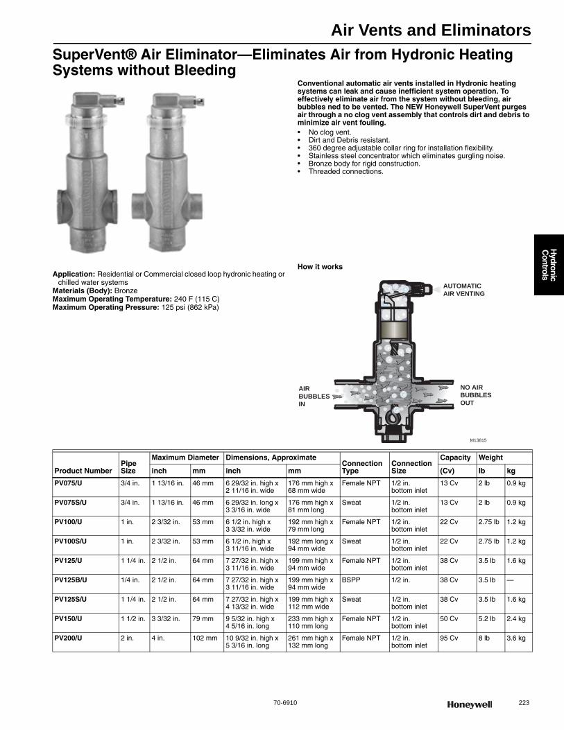
Air Vents and Eliminators
70-6910 223
H
ydronic C
ontrols
SuperVent® Air Eliminator—Eliminates Air from Hydronic Heating Systems without Bleeding
Conventional automatic air vents installed in Hydronic heating systems can leak and cause inefficient system operation. To effectively eliminate air from the system without bleeding, air bubbles ned to be vented. The NEW Honeywell SuperVent purges air through a no clog vent assembly that controls dirt and debris to minimize air vent fouling.• No clog vent. • Dirt and Debris resistant. • 360 degree adjustable collar ring for installation flexibility. • Stainless steel concentrator which eliminates gurgling noise. • Bronze body for rigid construction. • Threaded connections.
Application: Residential or Commercial closed loop hydronic heating or chilled water systems
Materials (Body): BronzeMaximum Operating Temperature: 240 F (115 C) Maximum Operating Pressure: 125 psi (862 kPa)
How it works
AUTOMATIC AIR VENTING
AIR BUBBLES IN
NO AIR BUBBLES OUT
M13815
Product NumberPipe Size
Maximum Diameter Dimensions, ApproximateConnection Type
Connection Size
Capacity Weight
inch mm inch mm (Cv) lb kg
PV075/U 3/4 in. 1 13/16 in. 46 mm 6 29/32 in. high x 2 11/16 in. wide
176 mm high x 68 mm wide
Female NPT 1/2 in. bottom inlet
13 Cv 2 lb 0.9 kg
PV075S/U 3/4 in. 1 13/16 in. 46 mm 6 29/32 in. long x 3 3/16 in. wide
176 mm high x 81 mm long
Sweat 1/2 in. bottom inlet
13 Cv 2 lb 0.9 kg
PV100/U 1 in. 2 3/32 in. 53 mm 6 1/2 in. high x 3 3/32 in. wide
192 mm high x 79 mm long
Female NPT 1/2 in. bottom inlet
22 Cv 2.75 lb 1.2 kg
PV100S/U 1 in. 2 3/32 in. 53 mm 6 1/2 in. high x 3 11/16 in. wide
192 mm long x 94 mm wide
Sweat 1/2 in.bottom inlet
22 Cv 2.75 lb 1.2 kg
PV125/U 1 1/4 in. 2 1/2 in. 64 mm 7 27/32 in. high x 3 11/16 in. wide
199 mm high x 94 mm wide
Female NPT 1/2 in. bottom inlet
38 Cv 3.5 lb 1.6 kg
PV125B/U 1/4 in. 2 1/2 in. 64 mm 7 27/32 in. high x 3 11/16 in. wide
199 mm high x 94 mm wide
BSPP 1/2 in. 38 Cv 3.5 lb —
PV125S/U 1 1/4 in. 2 1/2 in. 64 mm 7 27/32 in. high x 4 13/32 in. wide
199 mm high x 112 mm wide
Sweat 1/2 in. bottom inlet
38 Cv 3.5 lb 1.6 kg
PV150/U 1 1/2 in. 3 3/32 in. 79 mm 9 5/32 in. high x 4 5/16 in. long
233 mm high x 110 mm long
Female NPT 1/2 in.bottom inlet
50 Cv 5.2 lb 2.4 kg
PV200/U 2 in. 4 in. 102 mm 10 9/32 in. high x 5 3/16 in. long
261 mm high x 132 mm long
Female NPT 1/2 in. bottom inlet
95 Cv 8 lb 3.6 kg
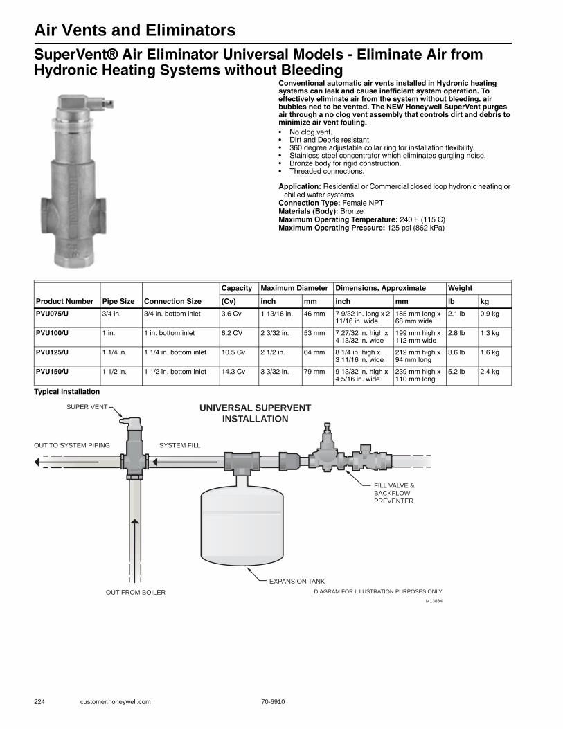
Air Vents and Eliminators
224 customer.honeywell.com 70-6910
SuperVent® Air Eliminator Universal Models - Eliminate Air from Hydronic Heating Systems without Bleeding
Conventional automatic air vents installed in Hydronic heating systems can leak and cause inefficient system operation. To effectively eliminate air from the system without bleeding, air bubbles ned to be vented. The NEW Honeywell SuperVent purges air through a no clog vent assembly that controls dirt and debris to minimize air vent fouling.• No clog vent. • Dirt and Debris resistant. • 360 degree adjustable collar ring for installation flexibility. • Stainless steel concentrator which eliminates gurgling noise. • Bronze body for rigid construction. • Threaded connections.
Application: Residential or Commercial closed loop hydronic heating or chilled water systems
Connection Type: Female NPTMaterials (Body): BronzeMaximum Operating Temperature: 240 F (115 C) Maximum Operating Pressure: 125 psi (862 kPa)
Typical Installation
Product Number Pipe Size Connection Size
Capacity Maximum Diameter Dimensions, Approximate Weight
(Cv) inch mm inch mm lb kg
PVU075/U 3/4 in. 3/4 in. bottom inlet 3.6 Cv 1 13/16 in. 46 mm 7 9/32 in. long x 2 11/16 in. wide
185 mm long x 68 mm wide
2.1 lb 0.9 kg
PVU100/U 1 in. 1 in. bottom inlet 6.2 CV 2 3/32 in. 53 mm 7 27/32 in. high x 4 13/32 in. wide
199 mm high x 112 mm wide
2.8 lb 1.3 kg
PVU125/U 1 1/4 in. 1 1/4 in. bottom inlet 10.5 Cv 2 1/2 in. 64 mm 8 1/4 in. high x 3 11/16 in. wide
212 mm high x 94 mm long
3.6 lb 1.6 kg
PVU150/U 1 1/2 in. 1 1/2 in. bottom inlet 14.3 Cv 3 3/32 in. 79 mm 9 13/32 in. high x 4 5/16 in. wide
239 mm high x 110 mm long
5.2 lb 2.4 kg
UNIVERSAL SUPERVENTINSTALLATION
OUT TO SYSTEM PIPING SYSTEM FILL
OUT FROM BOILER
EXPANSION TANK
DIAGRAM FOR ILLUSTRATION PURPOSES ONLY.
FILL VALVE &
BACKFLOW
PREVENTER
SUPER VENT
M13834
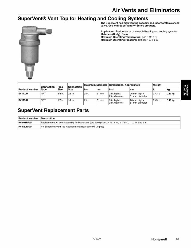
Air Vents and Eliminators
70-6910 225
H
ydronic C
ontrols
SuperVent® Vent Top for Heating and Cooling SystemsThe Supervent has high venting capacity and incorporates a check valve. Use with SuperVent PV Series products.
Application: Residential or commercial heating and cooling systemsMaterials (Body): BrassMaximum Operating Temperature: 240 F (115 C) Maximum Operating Pressure: 150 psi (1034 kPa)
SuperVent Replacement Parts
Product NumberConnection Type
Pipe Size
Connection Size
Maximum Diameter Dimensions, Approximate Weight
inch mm inch mm lb kg
SV173/U NPT 3/8 in. 3/8 in. 2 in. 51 mm 3 in. high x 2 in. diameter
76 mm high x 51 mm diameter
0.43 b 0.19 kg
SV175/U NPT 1/2 in. 1/2 in. 2 in. 51 mm 3 in. high x 2 in. diameter
76 mm high x 51 mm diameter
0.43 b 0.19 kg
Product Number Description
PV-001RP/U Replacement Air Vent Assembly for PowerVent (pre 2004) size 3/4 in., 1 in., 1 1/4 in., 1 1/2 in. and 2 in.
PV-020RP/U PV SuperVent Vent Top Replacement (New Style 90 Degree)
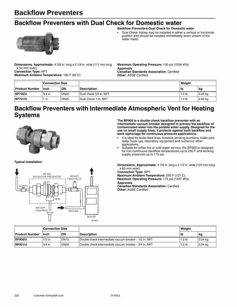
Backflow Preventers
226 customer.honeywell.com 70-6910
Backflow Preventers with Dual Check for Domestic waterBackflow Preventers-Dual Check for Domestic water• Dual Check Valves may be installed in either a vertical or horizontal
position and should be installed immediately down stream of the water meter.
Dimensions, Approximate: 4 3/8 in. long x 2 1/8 in. wide (111 mm long x 54 mm wide)
Connection Type: NPTMaximum Ambient Temperature: 180 F (82 C)
Maximum Operating Pressure: 150 psi (1034 kPa) ApprovalsCanadian Standards Association: CertifiedOther: ASSE Certified
Backflow Preventers with Intermediate Atmospheric Vent for Heating Systems
The BP900 is a double check backflow preventer with an intermediate vacuum breaker designed to prevent the backflow of contaminated water into the potable water supply. Designed for the use on small supply lines, it protects against both backflow and back siphonage for continuous pressure applications.• It is ideal for boiler feed lines, livestock drinking fountains, trailer park
water hook-ups, laboratory equipment and numerous other applications.
• Suitable for either hot or cold water service, the BP900 is designed for non-continuous backflow temperatures up to 250 F and working supply pressures up to 175 psi.
Typical InstallationDimensions, Approximate: 4 7/8 in. long x 2 1/2 in. wide (124 mm long
x 63 mm wide) Connection Type: NPTMaximum Ambient Temperature: 250 F (121 C) Maximum Operating Pressure: 175 psi (1207 kPa) ApprovalsCanadian Standards Association: CertifiedOther: ASSE Certified
Product Number
Connection Size
Description
Weight
inch DN lb kg
BP700/U 3/4 in. DN20 Dual check 3/4 in. NPT 1.0 lb 0.45 kg
BP701/U 1 in. DN25 Dual Check 1 in. NPT 1.4 lb 0.64 kg
SUPPLY
AIR GAP REQUIRED
BP 900 BACKFLOW PREVENTER BOILER
FEED VALVE
VENT
RETURN
BOILER
INLET
M23854
Product Number
Connection Size
Description
Weight
inch DN lb kg
BP900/U 1/2 in. DN15 Double check intermediate vacuum breaker - 1/2 in. NPT 1.2 lb 0.54 kg
BP901/U 3/4 in. DN20 Double check intermediate vacuum breaker - 3/4 in. NPT 1.2 lb 0.54 kg

Boiler Fill Valves
70-6910 227
H
ydronic C
ontrols
FM Boiler Fill ValvesPressure regulating valve for automatic control of boiler feed water and other pressure reducing applications. Especially constructed for expansion tank mounting.• Fast fill feature. • Built in check valve.
Application: Fast fill pressure regulating boiler feed valve with check valve.
Connection Type: NPTInlet Connection Size: 1/2 in.Pipe Size: 1/2 in.Materials (Body): BrassMaximum Ambient Temperature: 212 F (100 C)
Product Number
Inlet Connection Type
Maximum Operating Pressure Regulating
Pressure Range (psi)
FAST Fill
Dimensions, Approximate (inch)
Weight (lb) Description(psi) (kPa)
FM450/U Sweat or Threaded
150 psi 1034 kPa 4 psi to 60 psi yes 4 1/8 in. high x 5 5/16 in. long
1.8 lb 1/2 in. sweat union pressure reducing valve, includes union nut and both sweat and NPT tailpiece
FM911/U Sweat or Threaded
150 psi 1034 kPa 4 psi to 60 psi yes — 4 lb 1/2 in. NPT Backflow preventer and boiler fill valve assembly, includes union nut and both sweat and NPT tailpiece
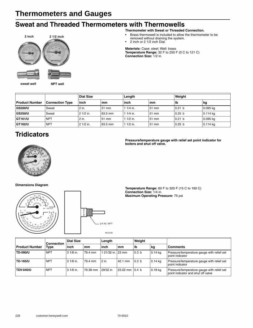
Thermometers and Gauges
228 customer.honeywell.com 70-6910
Sweat and Threaded Thermometers with ThermowellsThermometer with Sweat or Threaded Connection.• Brass thermowell is included to allow the thermometer to be
removed without draining the system. • 2 inch or 2 1/2 inch Dial.
Materials: Case: steel; Well: brassTemperature Range: 32 F to 250 F (0 C to 121 C) Connection Size: 1/2 in.
TridicatorsPressure/temperature gauge with relief set point indicator for boilers and shut off valve.
Dimensions DiagramTemperature Range: 60 F to 320 F (15 C to 160 C) Connection Size: 1/4 in.Maximum Operating Pressure: 75 psi
Product Number Connection Type
Dial Size Length Weight
inch mm inch mm lb kg
GS200/U Sweat 2 in. 51 mm 1 1/4 in. 51 mm 0.21 b 0.095 kg
GS250/U Sweat 2 1/2 in. 63.5 mm 1 1/4 in. 51 mm 0.25 b 0.114 kg
GT161/U NPT 2 in. 51 mm 1 1/2 in. 51 mm 0.21 b 0.095 kg
GT162/U NPT 2 1/2 in. 63.5 mm 1 1/2 in. 51 mm 0.25 b 0.114 kg
¡F ¡C
psi feet H O2
PR
ESSURE
TE
MPERATURE
M23258
1/4 IN. NPT
16
016
0
120
0080
60
140160 180 200 220
240
260
280
300
32
0
10080
60
4020
160
140
120
6020
40
120
10080
60
40
2
Product NumberConnection Type
Dial Size Length Weight
Commentsinch mm inch mm lb kg
TD-090/U NPT 3 1/8 in. 79.4 mm 1 21/32 in. 23 mm 0.3 b 0.14 kg Pressure/temperature gauge with relief set point indicator
TD-165/U NPT 3 1/8 in. 79.4 mm 2 in. 42.1 mm 0.3 b 0.14 kg Pressure/temperature gauge with relief set point indicator
TDV-040/U NPT 3 1/8 in. 79.38 mm 29/32 in 23.02 mm 0.4 b 0.18 kg Pressure/temperature gauge with relief set point indicator and shut off valve
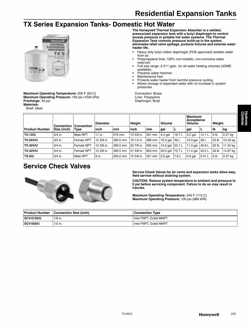
Residential Expansion Tanks
70-6910 229
H
ydronic C
ontrols
TX Series Expansion Tanks- Domestic Hot WaterThe Honeywell Thermal Expansion Absorber is a welded, pressurized expansion tank with a butyl diaphragm to control excess pressure in potable hot water systems. The Thermal Expansion Tank controls pressure build-up in the system, eliminates relief valve spillage, protects fixtures and extends water heater life.• Heavy duty butyl rubber diaphragm (FDA approved) isolates water
from air. • Polypropylene liner, 100% non-metallic, non-corrosive water
reservoir. • Full size range: 2-211 gals., for all water heating volumes (ASME
available). • Prevents water hammer. • Maintenance free. • Protects water heater from harmful pressure cycling. • Allows storage of expanded water with no increase in system
pressures.
Maximum Operating Temperature: 200 F (93 C) Maximum Operating Pressure: 150 psi (1034 kPa) Precharge: 40 psiMaterials:
Shell: Steel
Connection: Brass Liner: Polypylene Diaphragm: Butyl
Service Check ValvesService Check Valves for air vents and expansion tanks allow easy field service without draining system.
CAUTION: Reduce system temperature to ambient and pressure to 0 psi before servicing component. Failure to do so may result in injuries.
Maximum Operating Temperature: 240 F (115 C) Maximum Operating Pressure: 100 psi (689 kPA)
Product NumberConnection Size (inch)
Connection Type
Diameter Height Volume
Maximum Acceptance Volume Weight
inch mm inch mm gal L gal L lb kg
TX-12/U 3/4 in. Male NPT 11 in. 279 mm 12 5/8 in. 321 mm 4.4 gal 16.7 L 3.2 gal 12.1 L 5 lb 2.27 kg
TX-25V/U 3/4 in. Female NPT 15 3/8 in. 390.5 mm 19 1/4 in. 489 mm 10.3 gal 39 L 10.3 gal 39 L 23 lb 10.43 kg
TX-30V/U 3/4 in. Female NPT 15 3/8 in. 390.5 mm 23 7/8 in. 606 mm 14.0 gal 53.1 L 11.3 gal 42.8 L 25 lb 11.34 kg
TX-42V/U 3/4 in. Female NPT 15 3/8 in. 390.5 mm 31 5/8 in. 803 mm 20.0 gal 75.7 L 11.4 gal 43.2 L 33 lb 14.97 kg
TX-5/U 3/4 in. Male NPT 8 in. 203.2 mm 12 5/8 in. 321 mm 2.0 gal 7.6 L 0.9 gal 3.41 L 5 lb 2.27 kg
Product Number Connection Size (inch) Connection Type
SCV-0125/U 1/8 in. Inlet FNPT, Outlet MNPT
SCV-050/U 1/2 in. Inlet FNPT, Outlet MNPT

Residential Expansion Tanks
230 customer.honeywell.com 70-6910
TK300 Series Expansion Tanks- HeatingHoneywell Expansion Tanks are designed to absorb hot water expansion in closed heating systems. They are equipped with butyl diaphragms to separate the air from the system water (glycol). The tanks are a welded, not clamped design. Pre-pressurized at 12 psi, the tank keeps fluids circulating and maintains minimum system pressure. Honeywell tanks resist waterlogging, loss of pressure through relief valve spills, loss of BTUs and reduce circulator running time. Use the super efficient Honeywell PowerVent or air vents to remove air and micro-bubbles from the system for maximum performance.• Butyl/EPDM diaphragm- 9 times better than natural rubber• Deep-drawn steel tank• Controls system pressure• Air-tight cushion-factory pre-charged to 12 psig and 100% tested
Maximum Operating Temperature: 240 F (115 C) Maximum Operating Pressure: 100 psi (689 kPA)
Materials: steel shell, heavy duty butyl diaphragmConnection Type: Male NPTComments: Heating
Expansion Tank Sizing based on BTU’s
Product NumberConnection Size (inch)
Diameter Height VolumeMaximum Acceptance Volume Weight
inch mm inch mm gal L gal L lb kg
TK300-15/U 1/2 in. 8 in. 203.2 mm 12 5/8 in. 321 mm 2.0 gal 7.6 L 1 gal 3.8 L 5 b 2.3 kg
TK300-30/U 1/2 in. 11 in. 279 mm 15 1/2 in. 394 mm 4.4 gal 16.7 L 2.5 gal 9.5 L 9 b 4.1 kg
TK300-60/U 1/2 in. 11 in. 279 mm 23 in. 584 mm 7.6 gal 28.8 L 2.5 gal 9.5 L 14 lb 6.4 kg
TK300-90/U 1/2 in. 15 3/8 in. 390.5 mm 21 in. 533 mm 14.0 gal 53.1 L 11.5 gal 40.1 L 23 lb 10.4 kg
Boiler Type of Radiation
Net Output in 1000’s of BTU/Hr
Finned Tube Baseboard or Radiant Panel
Convectors or Unit Heaters Radiators Cast Iron Baseboard Cast Iron
MBH Use Model Use Model Use Model Use Model25 TK300-15 TK300-15 TK300-15 TK300-1550 TK300-15 TK300-15 TK300-30 TK300-3075 TK300-30 TK300-30 TK300-30 TK300-60100 TK300-30 TK300-30 TK300-60 TK300-60125 TK300-30 TK300-60 TK300-60 TK300-90150 TK300-30 TK300-60 TK300-90 TK300-90175 TK300-60 TK300-60 XPS-030V XPS-030V200 TK300-60 TK300-60 XPS-030V XPS-030V250 TK300-60 TK300-90 XPS-030V XPS-040V300 TK300-90 XPS-030V XPS-030V XPS-040V350 XPS-030V XPS-030V XPS-040V XPS-060V400 XPS-030V XPS-040V XPS-040V XPS-060V
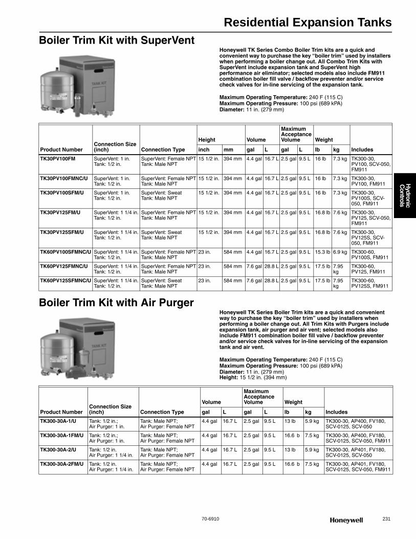
Residential Expansion Tanks
70-6910 231
H
ydronic C
ontrols
Boiler Trim Kit with SuperVentHoneywell TK Series Combo Boiler Trim kits are a quick and convenient way to purchase the key “boiler trim” used by installers when performing a boiler change out. All Combo Trim Kits with SuperVent include expansion tank and SuperVent high performance air eliminator; selected models also include FM911 combination boiler fill valve / backflow preventer and/or service check valves for in-line servicing of the expansion tank.
Maximum Operating Temperature: 240 F (115 C) Maximum Operating Pressure: 100 psi (689 kPA) Diameter: 11 in. (279 mm)
Boiler Trim Kit with Air PurgerHoneywell TK Series Boiler Trim kits are a quick and convenient way to purchase the key “boiler trim” used by installers when performing a boiler change out. All Trim Kits with Purgers include expansion tank, air purger and air vent; selected models also include FM911 combination boiler fill valve / backflow preventer and/or service check valves for in-line servicing of the expansion tank and air vent.
Maximum Operating Temperature: 240 F (115 C) Maximum Operating Pressure: 100 psi (689 kPA) Diameter: 11 in. (279 mm)Height: 15 1/2 in. (394 mm)
Product NumberConnection Size (inch) Connection Type
Height Volume
Maximum Acceptance Volume Weight
Includesinch mm gal L gal L lb kg
TK30PV100FM SuperVent: 1 in.Tank: 1/2 in.
SuperVent: Female NPTTank: Male NPT
15 1/2 in. 394 mm 4.4 gal 16.7 L 2.5 gal 9.5 L 16 lb 7.3 kg TK300-30, PV100, SCV-050, FM911
TK30PV100FMNC/U SuperVent: 1 in.Tank: 1/2 in.
SuperVent: Female NPTTank: Male NPT
15 1/2 in. 394 mm 4.4 gal 16.7 L 2.5 gal 9.5 L 16 lb 7.3 kg TK300-30, PV100, FM911
TK30PV100SFM/U SuperVent: 1 in.Tank: 1/2 in.
SuperVent: SweatTank: Male NPT
15 1/2 in. 394 mm 4.4 gal 16.7 L 2.5 gal 9.5 L 16 lb 7.3 kg TK300-30, PV100S, SCV-050, FM911
TK30PV125FM/U SuperVent: 1 1/4 in.Tank: 1/2 in.
SuperVent: Female NPTTank: Male NPT
15 1/2 in. 394 mm 4.4 gal 16.7 L 2.5 gal 9.5 L 16.8 lb 7.6 kg TK300-30, PV125, SCV-050, FM911
TK30PV125SFM/U SuperVent: 1 1/4 in.Tank: 1/2 in.
SuperVent: SweatTank: Male NPT
15 1/2 in. 394 mm 4.4 gal 16.7 L 2.5 gal 9.5 L 16.8 lb 7.6 kg TK300-30, PV125S, SCV-050, FM911
TK60PV100SFMNC/U SuperVent: 1 1/4 in.Tank: 1/2 in.
SuperVent: Female NPTTank: Male NPT
23 in. 584 mm 4.4 gal 16.7 L 2.5 gal 9.5 L 15.3 lb 6.9 kg TK300-60, PV100S, FM911
TK60PV125FMNC/U SuperVent: 1 1/4 in.Tank: 1/2 in.
SuperVent: Female NPTTank: Male NPT
23 in. 584 mm 7.6 gal 28.8 L 2.5 gal 9.5 L 17.5 lb 7.95 kg
TK300-60, PV125, FM911
TK60PV125SFMNC/U SuperVent: 1 1/4 in.Tank: 1/2 in.
SuperVent: SweatTank: Male NPT
23 in. 584 mm 7.6 gal 28.8 L 2.5 gal 9.5 L 17.5 lb 7.95 kg
TK300-60, PV125S, FM911
Product NumberConnection Size (inch) Connection Type
Volume
Maximum Acceptance Volume Weight
Includesgal L gal L lb kg
TK300-30A-1/U Tank: 1/2 in.; Air Purger: 1 in.
Tank: Male NPT; Air Purger: Female NPT
4.4 gal 16.7 L 2.5 gal 9.5 L 13 lb 5.9 kg TK300-30, AP400, FV180, SCV-0125, SCV-050
TK300-30A-1FM/U Tank: 1/2 in.; Air Purger: 1 in.
Tank: Male NPT; Air Purger: Female NPT
4.4 gal 16.7 L 2.5 gal 9.5 L 16.6 b 7.5 kg TK300-30, AP400, FV180, SCV-0125, SCV-050, FM911
TK300-30A-2/U Tank: 1/2 in.Air Purger: 1 1/4 in.
Tank: Male NPT; Air Purger: Female NPT
4.4 gal 16.7 L 2.5 gal 9.5 L 13 lb 5.9 kg TK300-30, AP401, FV180, SCV-0125, SCV-050
TK300-30A-2FM/U Tank: 1/2 in.Air Purger: 1 1/4 in.
Tank: Male NPT; Air Purger: Female NPT
4.4 gal 16.7 L 2.5 gal 9.5 L 16.6 b 7.5 kg TK300-30, AP401, FV180, SCV-0125, SCV-050, FM911
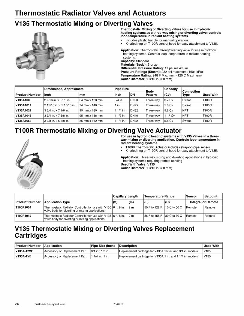
Thermostatic Radiator Valves and Actuators
232 customer.honeywell.com 70-6910
V135 Thermostatic Mixing or Diverting ValvesThermostatic Mixing or Diverting Valves for use in hydronic heating systems as a three-way mixing or diverting valve; controls loop temperature in radiant heating systems.• Includes plastic handle for manual operation. • Knurled ring on T100R control head for easy attachment to V135.
Application: Thermostatic mixing/diverting valve for use in hydronic heating systems. Controls loop temperature in radiant heating systems.
Capacity: StandardMaterials (Body): BronzeDifferential Pressure Rating: 17 psi maximumPressure Ratings (Steam): 232 psi maximum (1601 kPa) Temperature Rating: 248 F Maximum (120 C Maximum) Collar Diameter: 1 3/16 in. (30 mm)
T100R Thermostatic Mixing or Diverting Valve ActuatorFor use in hydronic heating systems with V135 Valves in a three-way mixing or diverting application. Controls loop temperature in radiant heating systems.• T100R Thermostatic Actuator includes strap-on-pipe sensor. • Knurled ring on T100R control head for easy attachment to V135.
Application: Three-way mixing and diverting applications in hydronic heating systems requiring remote sensing
Used With Valve: V135Collar Diameter: 1 3/16 in. (30 mm)
V135 Thermostatic Mixing or Diverting Valves Replacement Cartridges
Product Number
Dimensions, Approximate Pipe SizeBody Pattern
CapacityConnection Type Used Withinch mm inch DN (Cv)
V135A1006 2 9/16 in. x 5 1/8 in. 64 mm x 128 mm 3/4 in. DN20 Three-way 3.7 Cv Sweat T100R
V135A1014 2 15/16 in. x 5 13/16 in. 74 mm x 148 mm 1 in. DN25 Three-way 5.8 Cv Sweat T100R
V135A1022 3 3/4 in. x 7 1/8 in. 95 mm x 180 mm 1 1/4 in. DN32 Three-way 5.8 Cv NPT T100R
V135A1048 3 3/4 in. x 7 3/8 in. 95 mm x 188 mm 1 1/2 in. DN40 Three-way 11.7 Cv NPT T100R
V135A1063 3 3/8 in. x 6 3/8 in. 86 mm x 162 mm 1 1/4 in. DN32 Three-way 5.8 Cv Sweat T100R
Product Number Application Type
Capillary Length Temperature Range Sensor Setpoint
(ft) (m) (F) (C) Integral or Remote
T100R1004 Thermostatic Radiator Controller for use with V135 valve body for diverting or mixing applications.
6 ft. 8 in. 2 m 50 F to 122 F 10 C to 50 C Remote Remote
T100R1012 Thermostatic Radiator Controller for use with V135 valve body for diverting or mixing applications.
6 ft. 8 in. 2 m 86 F to 158 F 30 C to 70 C Remote Remote
Product Number Application Pipe Size (inch) Description Used With
V135A-12VE Accessory or Replacement Part 3/4 in.; 1/2 in. Replacement cartridge for V135A 1/2 in. and 3/4 in. models V135
V135A-1VE Accessory or Replacement Part 1 1/4 in.; 1 in. Replacement cartridge for V135A 1 in. and 1 1/4 in. models V135
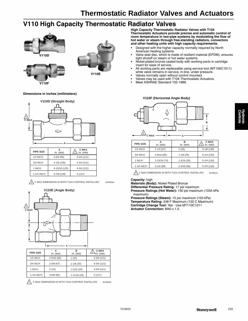
Thermostatic Radiator Valves and Actuators
70-6910 233
H
ydronic C
ontrols
V110 High Capacity Thermostatic Radiator ValvesHigh Capacity Thermostatic Radiator Valves with T104 Thermostatic Actuators provide precise and automatic control of room temperature in two-pipe systems by modulating the flow of hot water or steam through free-standing radiators, convectors and other heating units with high capacity requirements.• Designed with the higher capacity normally required by North
American heating systems. • Valve seat disc, which is made of resilient material (EPDM), ensures
tight shutoff on steam or hot water systems. • Nickel-plated bronze casted body with working parts in cartridge
insert for ease of service. • All working parts are replaceable using service tool (MT100C1011)
while valve remains in service, in-line, under pressure. • Valves normally open without control mounted. • Valves may be used with T104 Thermostatic Actuators. • Meet ASHRAE Standard 102-1989.
Dimensions in inches (millimeters)
Capacity: highMaterials (Body): Nickel Plated BronzeDifferential Pressure Rating: 17 psi maximumPressure Ratings (Hot Water): 150 psi maximum (1034 kPa
maximum) Pressure Ratings (Steam): 15 psi maximum (103 kPa) Temperature Rating: 248 F Maximum (120 C Maximum) Cartridge Change Tool: Yes - Use MT110C1011Actuator Connection: M40 x 1.5
V110D
V110F
V110E
A
M18959A
C MAX
V110D (Straight Body)
PIPE SIZEA
IN. (MM)
C MAXIN. (MM)1
1 C MAX DIMENSION IS WITH T104 CONTROL INSTALLED.
1/2 INCH
3/4 INCH
1 INCH
1-1/4 INCH
3-3/4 (95)
4-1/8 (105)
4-15/16 (125)
5-7/8 (149)
4-3/4 (121)
4-3/4 (121)
4-3/4 (121)
5 (127)
1
A
M18960A
B
C MAX
V110E (Angle Body)
PIPE SIZEA
IN. (MM)
BIN. (MM)
1
C MAXIN. (MM)
1 (25)
1-1/8 (29)
1-5/16 (33)
1-11/16 (43)
1
1
C MAX DIMENSION IS WITH T104 CONTROL INSTALLED.
1/2 INCH
3/4 INCH
1 INCH
1-1/4 INCH
2-9/16 (65)
2-5/8 (67)
3 (76)
3-5/8 (90)
4-3/4 (121)
4-3/4 (121)
4-3/4 (121)
5 (127)
A
M18961A
B
C MAX
PIPE SIZEA
IN. (MM)
BIN. (MM) 1
1 C MAX DIMENSION IS WITH T104 CONTROL INSTALLED.
1/2 INCH
3/4 INCH
1 INCH
1-1/4 INCH
2-1/4 (57)
2-9/16 (65)
2-15/16 (74)
3-1/2 (89)
5-1/8 (130)
5-1/4 (133)
5-1/4 (133)
5-1/4 (133)
C MAXIN. (MM)
1 (25)
1-1/8 (29)
1-3/16 (30)
2-3/16 (56)
V110F (Horizontal Angle Body)
1

Thermostatic Radiator Valves and Actuators
234 customer.honeywell.com 70-6910
Typical Installations
Product Number Application
Pipe Size
Body Pattern
CapacityConnection Type Used Withinch DN (Cv) (Btu/hr-steam)
V110D1000/U Precise and automatic control of room temperature in two-pipe systems by modulating the flow of hot water or steam through high capacity heating units.
1/2 in. DN15 Straight 4.6 Cv 127,000 Btu/hr Threaded T104
V110D1008/U 3/4 in. DN20 Straight 5.8 Cv 162,000 Btu/hr Threaded T104
V110D1016/U 1 in. DN25 Straight 7.0 Cv 193,000 Btu/hr Threaded T104
V110D1024/U 1 1/4 in. DN32 Straight 8 Cv 193,000 Btu/hr Threaded T104
V110D5001/U 1/2 in. DN15 Straight 4.6 Cv 127,000 Btu/hr Sweat T104
V110D5009/U 3/4 in. DN20 Straight 5.8 Cv 162,000 Btu/hr Sweat T104
V110D5017/U 1 in. DN25 Straight 7.0 Cv 193,000 Btu/hr Sweat T104
V110E1004/U Precise and automatic control of room temperature in two-pipe systems by modulating the flow of hot water or steam through high capacity heating units when used with T104 Thermostatic Actuators
1/2 in. DN15 Angle 4.6 Cv 127,000 Btu/hr Threaded T104
V110E1012/U 3/4 in. DN20 Angle 5.8 Cv 162,000 Btu/hr Threaded T104
V110E1020/U 1 in. DN25 Angle 7.0 Cv 193,000 Btu/hr Threaded T104
V110E1028/U 1 1/4 in. DN32 Angle 8 Cv 193,000 Btu/hr Threaded T104
V110E5005/U 1/2 in. DN15 Angle 4.6 Cv 127,000 Btu/hr Sweat T104
V110E5013/U 3/4 in. DN20 Angle 5.8 Cv 162,000 Btu/hr Sweat T104
V110F1002/U 1/2 in. DN15 Horizontal Angle 4.6 Cv 127,000 Btu/hr Threaded T104
V110F1010/U 3/4 in. DN20 Horizontal Angle 5.8 Cv 162,000 Btu/hr Threaded T104
V110F1018/U 1 in. DN25 Horizontal Angle 7.0 Cv 193,000 Btu/hr Threaded T104
V110F1026/U 1 1/4 in. DN32 Horizontal Angle 8 Cv 193,000 Btu/hr Threaded T104
V110F5003/U 1/2 in. DN15 Horizontal Angle 4.6 Cv 127,000 Btu/hr Sweat T104
V110F5011/U 3/4 in. DN20 Horizontal Angle 5.8 Cv 162,000 Btu/hr Sweat T104
M3190 M4640M4638
M4632
M12935
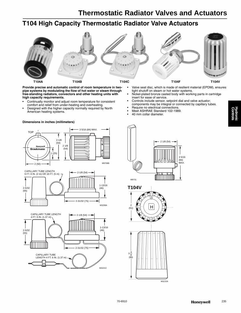
Thermostatic Radiator Valves and Actuators
70-6910 235
H
ydronic C
ontrols
T104 High Capacity Thermostatic Radiator Valve Actuators
Provide precise and automatic control of room temperature in two-pipe systems by modulating the flow of hot water or steam through free-standing radiators, convectors and other heating units with high capacity requirements.• Continually monitor and adjust room temperature for consistent
comfort and relief from under-heating and overheating. • Designed with the higher capacity normally required by North
American heating systems.
• Valve seat disc, which is made of resilient material (EPDM), ensures tight shutoff on steam or hot water systems.
• Nickel-plated bronze casted body with working parts in cartridge insert for ease of service.
• Controls include sensor, setpoint dial and valve actuator; components may be integral or connected by capillary tubes.
• Require no electrical connections. • Meet ASHRAE Standard 102-1989. • 40 mm collar diameter.
Dimensions in inches (millimeters)
T104A T104B T104C T104F T104V
3 5/16 (84) MAX.
2 1/8
(54)
M9708B
2-1/8
(54)
1 (25)
2 (50)
TOP
CAPILLARY TUBE LENGTH6 FT. 6 IN. (2 m) OR 16 FT. (5 m)
M3208A
2-5/32(55)
2-1/8 (54)
2-31/32 (75)
1-13/16(46)
CAPILLARY TUBE LENGTH4 FT. 6 IN. (1.37 m)
M3221C
CAPILLARY TUBE LENGTH 4 FT. 6 IN. (1.37 m)
2-31/32 (75)
2-5/32(55)
2-1/8 (54)
1-13/16(46)
3 5/16
(84)
MAX.
2 1/8 (54)
M9731
3
(86)
38
M3215A
2(51) H
4
T104V
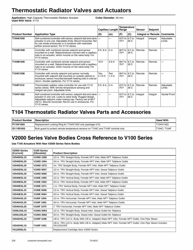
Thermostatic Radiator Valves and Actuators
236 customer.honeywell.com 70-6910
Application: High Capacity Thermostatic Radiator ActuatorUsed With Valve: V110
Collar Diameter: 40 mm
T104 Thermostatic Radiator Valves Parts and Accessories
V2000 Series Valve Bodies Cross Reference to V100 SeriesUse T100 Actuators With New V2000 Series Valve Bodies
Product Number Application Type
Capillary LengthTemperature Range Sensor Setpoint
Comments(ft) (m) (F) (C) Integral or Remote
T104A1040 Self-contained controller with sensor, setpoint dial and valve actuator in one unit. Adjustable limits. Mount horizontal. Not for use inside enclosures or in locations with restricted airflow around sensor. For V110 valves.
— — 43 F to 79 F
6 C to 26 C
Integral Integral Adjustable Limits
T104B1038 Controller with combined remote setpoint and sensor mounted on a wall. Setpoint/sensor connect with a capillary tube to an actuator, which mounts on the valve body. For V110 valves.
6 ft. 8 in. 2 m 48 F to 79 F
9 C to 26 C
Remote Remote —
T104B1046 Controller with combined remote setpoint and sensor mounted on a wall. Setpoint/sensor connect with a capillary tube to an actuator, which mounts on the valve body. For V110 valves.
16 ft 4.9 m 48 F to 79 F
9 C to 26 C
Remote Remote —
T104C1036 Controller with remote setpoint and sensor normally mounted with setpoint dial mounted on outside cabinet or enclosure; sensor mounted beneath heating coils in cold air return. Double capillaries. For V110 valves.
Two 4 1/2 ft
Two 1.4 m
48 F to 79 F
9 C to 26 C
Remote Remote —
T104F1512 Thermostatic radiator valve controller for use with V110 series valves. With remote temperature sensing and integral set point. Adjustable limits.
6 ft. 8 in. 2 m 43 F to 79 F
6 C to 26 C
Remote Remote Adjustable Limits
T104V1422 Self-contained controller with sensor, setpoint dial and valve actuator in one unit. Locks to valve body. Rugged design. Adjustable setpoint under locking cap. Factory set at 68 F (20 C). Mounts horizontal. Not for use in enclosures. For V110 valves.
— — 43 F to 79 F
6 C to 26 C
Integral Integral Vandal Proof
Product Number Description Used With
P110V1003 Replacement Locking Ring for T104V1422 only (package of 5) T104V1422;
G111B1053 Bulb guard to protect remote temperature sensors on T104C and T104F controls only T104C; T104F
V2000 Series (Current)
V100 Series (Obsolete) Product Description
V2040DSL15 V100D 1056 1/2 in. TRV Straight Body, Female NPT Inlet, Male NPT Tailpiece Outlet
V2040DSL20 V100D 1064 3/4 in. TRV Straight Body, Female NPT Inlet, Male NPT Tailpiece Outlet
V2040DSL25 V100D 1072 1in. TRV Straight Body, Female NPT Inlet, Male NPT Tailpiece Outlet
V2043DSL15 V100D 5057 1/2 in. TRV Straight Body, Female NPT Inlet, Sweat Tailpiece Outlet
V2043DSL20 V100D 5065 3/4 in. TRV Straight Body, Female NPT Inlet, Sweat Tailpiece Outlet
V2040ESL15 V100E 1055 1/2 in. TRV Vertical Body, Female NPT Inlet, Male NPT Tailpiece Outlet
V2040ESL20 V100E 1063 3/4 in. TRV Vertical Body, Female NPT Inlet, Male NPT Tailpiece Outlet
V2040ESL25 V100E 1071 1 in. TRV Vertical Body, Female NPT Inlet, Male NPT Tailpiece Outlet
V2043ESL15 V100E 5056 1/2 in. TRV Vertical Body, Female NPT Inlet, Sweat Tailpiece Outlet
V2043ESL20 V100E 5064 3/4 in. TRV Vertical Body, Female NPT Inlet, Sweat Tailpiece Outlet
V2040ASL15 V100F 1054 1/2 in. TRV Horizontal, Female NPT Inlet, Male NPT Tailpiece Outlet
V2040ASL20 V100F 1062 3/4 in. TRV Horizontal, Female NPT Inlet, Male NPT Tailpiece Outlet
V2040ASL25 V100F 1070 1” TRV Horizontal, Female NPT Inlet, Male NPT Tailpiece Outlet
V200LDSL15 V100G 5054 1/2 in. TRV Straight Body, Sweat Inlet, Sweat Outlet No Tailpiece
V200LDSL20 V100G 5062 3/4 in. TRV Straight Body, Sweat Inlet, Sweat Outlet No Tailpiece
V2042HSL10 V100P 1046 1/8 in. TRV (1/2 in. Body With 1/8 in. Adapter) Male NPT Inlet, Female NPT Outlet. One Pipe Steam
V2043HSL10 Y100P 10011/8 in. TRV (1/2 in. Body With 1/8 in. Adapter) Male NPT Inlet, Female NPT Outlet. One Pipe Steam Includes SA123A1003
VS1200SL01 Replacement Cartridge New V2000 Series
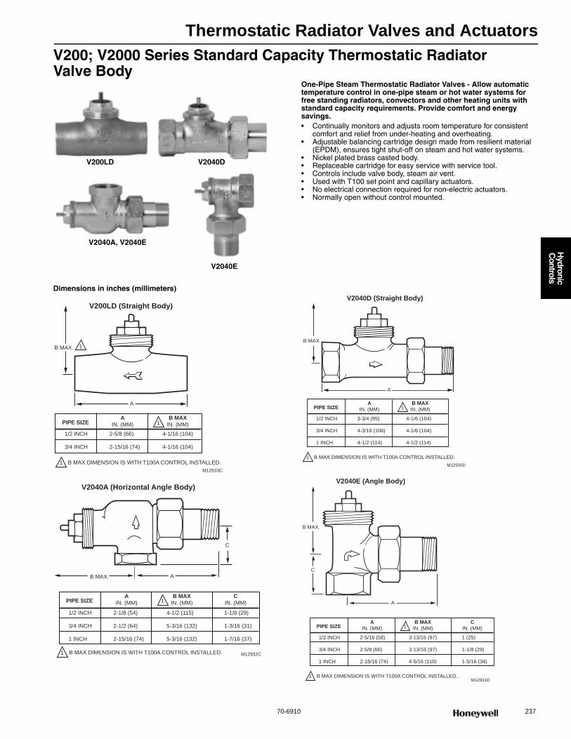
Thermostatic Radiator Valves and Actuators
70-6910 237
H
ydronic C
ontrols
V200; V2000 Series Standard Capacity Thermostatic Radiator Valve Body
One-Pipe Steam Thermostatic Radiator Valves - Allow automatic temperature control in one-pipe steam or hot water systems for free standing radiators, convectors and other heating units with standard capacity requirements. Provide comfort and energy savings.• Continually monitors and adjusts room temperature for consistent
comfort and relief from under-heating and overheating. • Adjustable balancing cartridge design made from resilient material
(EPDM), ensures tight shut-off on steam and hot water systems. • Nickel plated brass casted body. • Replaceable cartridge for easy service with service tool. • Controls include valve body, steam air vent. • Used with T100 set point and capillary actuators. • No electrical connection required for non-electric actuators. • Normally open without control mounted.
Dimensions in inches (millimeters)
V200LD V2040D
V2040E
V2040A, V2040E
A
M12933C
B MAX.
V200LD (Straight Body)
PIPE SIZEA
IN. (MM)
B MAXIN. (MM)
1
1
1 B MAX DIMENSION IS WITH T100A CONTROL INSTALLED.
1/2 INCH
3/4 INCH
2-5/8 (66)
2-15/16 (74)
4-1/16 (104)
4-1/16 (104)
A
M12932C
C
B MAX.
V2040A (Horizontal Angle Body)
PIPE SIZEA
IN. (MM)
B MAXIN. (MM)1
1 B MAX DIMENSION IS WITH T100A CONTROL INSTALLED.
1/2 INCH
3/4 INCH
1 INCH
2-1/8 (54)
2-1/2 (64)
2-15/16 (74)
4-1/2 (115)
5-3/16 (132)
5-3/16 (132)
CIN. (MM)
1-1/8 (29)
1-3/16 (31)
1-7/16 (37)
A
M12930D
B MAX.
V2040D (Straight Body)
PIPE SIZEA
IN. (MM)
B MAXIN. (MM)1
1 B MAX DIMENSION IS WITH T100A CONTROL INSTALLED.
1/2 INCH
3/4 INCH
1 INCH
3-3/4 (95)
4-3/16 (106)
4-1/2 (114)
4-1/6 (104)
4-1/6 (104)
4-1/2 (114)
A
M12931D
C
B MAX.
V2040E (Angle Body)
PIPE SIZEA
IN. (MM)
B MAXIN. (MM)1
1 B MAX DIMENSION IS WITH T100A CONTROL INSTALLED.
1/2 INCH
3/4 INCH
1 INCH
2-5/16 (58)
2-5/8 (66)
2-15/16 (74)
3-13/16 (97)
3-13/16 (97)
4-5/16 (110)
CIN. (MM)
1 (25)
1-1/8 (29)
1-5/16 (34)
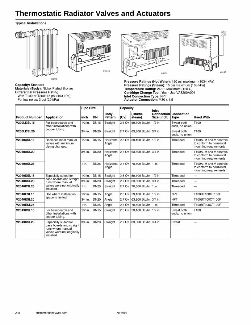
Thermostatic Radiator Valves and Actuators
238 customer.honeywell.com 70-6910
Typical Installations
Capacity: StandardMaterials (Body): Nickel Plated BronzeDifferential Pressure Rating:
With T100 or T200: 15 psi (103 kPa)For low noise: 3 psi (20 kPa)
Pressure Ratings (Hot Water): 150 psi maximum (1034 kPa) Pressure Ratings (Steam): 15 psi maximum (103 kPa) Temperature Rating: 248 F Maximum (120 C) Cartridge Change Tool: Yes - Use VA8200A001Inlet Connection Type: NPT Actuator Connection: M30 x 1.5
M4632
M4640M4638
M3190
Product Number Application
Pipe Size
Body Pattern
CapacityInlet Connection Size (inch)
Connection Type Used Withinch DN (Cv)
(Btu/hr-steam)
V200LDSL15 For baseboards and other installations with copper tubing.
1/2 in. DN15 Straight 2.5 Cv 59,100 Btu/hr 1/2 in. Sweat both ends, no union
T100
V200LDSL20 3/4 in. DN20 Straight 2.7 Cv 63,800 Btu/hr 3/4 in. Sweat both ends, no union
T100
V2040ASL15 Replaces most manual valves with minimum piping changes.
1/2 in. DN15 Horizontal Angle
2.5 Cv 59,100 Btu/hr 1/2 in. Threaded T100A, M and V controls to conform to horizontal mounting requirements
V2040ASL20 3/4 in. DN20 Horizontal Angle
2.7 Cv 63,800 Btu/hr 3/4 in. Threaded T100A, M and V controls to conform to horizontal mounting requirements
V2040ASL25 1 in. DN25 Horizontal Angle
2.7 Cv 70,500 Btu/hr 1 in. Threaded T100A, M and V controls to conform to horizontal mounting requirements
V2040DSL15 Especially suited for base boards and straight runs where manual valves were not originally installed.
1/2 in. DN15 Straight 2.5 Cv 59,100 Btu/hr 1/2 in. Threaded —
V2040DSL20 3/4 in. DN20 Straight 2.7 Cv 63,800 Btu/hr 3/4 in. Threaded —
V2040DSL25 1 in. DN25 Straight 2.7 Cv 70,500 Btu/hr 1 in. Threaded —
V2040ESL15 Use where installation space is limited
1/2 in. DN15 Angle 2.5 Cv 59,100 Btu/hr 1/2 in. NPT T100BT100CT100F
V2040ESL20 3/4 in. DN20 Angle 2.7 Cv 63,800 Btu/hr 3/4 in. NPT T100BT100CT100F
V2040ESL25 1 in. DN25 Angle 2.7 Cv 70,500 Btu/hr 1 in. Threaded T100BT100CT100F
V2043DSL15 For baseboards and other installations with copper tubing.
1/2 in. DN15 Straight 2.5 Cv 59,100 Btu/hr 1/2 in. Sweat both ends, no union
T100
V2043DSL20 Especially suited for base boards and straight runs where manual valves were not originally installed.
3/4 in. DN20 Straight 2.7 Cv 63,800 Btu/hr 3/4 in. Sweat —
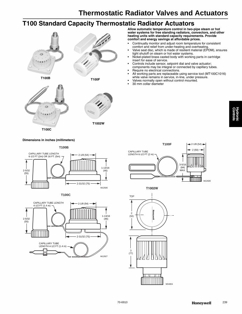
Thermostatic Radiator Valves and Actuators
70-6910 239
H
ydronic C
ontrols
T100 Standard Capacity Thermostatic Radiator ActuatorsAllow automatic temperature control in two-pipe steam or hot water systems for free standing radiators, convectors, and other heating units with standard capacity requirements. Provide comfort and energy savings at affordable prices.• Continually monitor and adjust room temperature for consistent
comfort and relief from under-heating and overheating. • Valve seat disc, which is made of resilient material (EPDM), ensures
tight shutoff on steam or hot water systems. • Nickel-plated brass casted body with working parts in cartridge
insert for ease of service. • Controls include sensor, setpoint dial and valve actuator;
components may be integral or connected by capillary tubes. • Require no electrical connections. • All working parts are replaceable using service tool (MT100C1016)
while valve remains in service, in-line, under pressure. • Valves normally open without control mounted. • 30 mm collar diameter
Dimensions in inches (millimeters)
T100B
T100C
T1002W
T100F
CAPILLARY TUBE LENGTH6-1/2 FT (2m) OR 16 FT. (5m)
M12926
2-5/32(55)
2-1/8 (54)
2-31/32 (75)
1-13/16(46)
T100B
CAPILLARY TUBE LENGTH4-1/2 FT (1.4 m)
M12927
CAPILLARY TUBE LENGTH 4-1/2 FT (1.4 m)
2-31/32 (75)
2-5/32(55)
2-1/8 (54)
1-13/16(46)
T100C
3-5/16
(84)
MAX.
M12928
2-1/8 (54)
CAPILLARY TUBE LENGTH 6-1/2 FT (2 m)
2 (50)
T100F
3(77)
2(50)
M34804
TOP
T1002W

Thermostatic Radiator Valves and Actuators
240 customer.honeywell.com 70-6910
Typical Installation
Application: Standard Capacity Thermostatic Radiator ActuatorUsed With Valve: V100, V2000
Collar Diameter: 30 mm
M4631
M12937
M3190M4638
M12935
Product Number Application Type
Capillary Length
Temperature Range Sensor Setpoint
Replaces Comments(ft) (m) (F) (C) Integral or Remote
T1002W0NA A self-contained control with sensor, setpoint dial and valve actuator in one unit. Mounts horizontal. Not for use inside enclosures or where airflow around sensor is restricted. Adjustable limits.
— — 43 F to 79 F
6 C to 26 C
Integral Integral American Steam - 02-100-00. Taco - 5202. Danfoss RA2000 - 013G8200. Ammark - 72. TM Macon - TM B22000. NT Macon - NTB B24000. (in combination with V2000)
Adjustable Limits
T100B1035 A control with combined remote setpoint and sensor mounted on wall. Connected by a capillary tube to an actuator, which is mounted on the valve body.
6 1/2 ft 2 m 48 F to 79 F
9 C to 26 C
Remote Remote American Steam - 02-300-00. Taco - 5206. Danfoss RA2000 - 013G8262. Ammark - 76. TM Macon - TML B42000. NT Macon - NTL B45000. (in combination with V2000)
—
T100B1043 A control with combined remote setpoint and sensor mounted on wall. Connected by a capillary tube to an actuator, which is mounted on the valve body.
16 ft 5 m 48 F to 79 F
9 C to 26 C
Remote Remote Taco - 5207. Danfoss RA2000 - 013G8265. Ammark - 76L. (in combination with V2000)
—
T100C1026 A control with remote setpoint and sensor mounted with setpoint dial on outside of heating cabinet; sensor mounted beneath heating coils in cold air return. Dual capillary.
Two 4 1/2 ft
Two 1.4 m
48 F to 79 F
9 C to 26 C
Remote Remote American Steam - 02-320-00. Taco - 5211. Danfoss RA2000 - 013G8233. Ammark - 74. TM Macon - TMLZ B52000. NT Macon - NTL B55000. (in combination with V2000)
—
T100F1395 A control with remote temperature sensing and integral set point. Adjustable limits.
6 ft. 8 in.
2 m 43 F to 79 F
6 C to 26 C
Integral Integral American Steam - 02-120-00. Taco - 5203. Danfoss RA2000 - 013G8202. Ammark - 73. TM Macon - TMZ B32000. NT Macon - NTZ B35000.(in combination with V2000)
Adjustable Limits
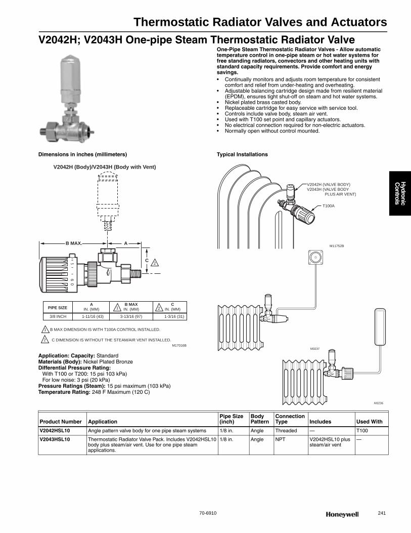
Thermostatic Radiator Valves and Actuators
70-6910 241
H
ydronic C
ontrols
V2042H; V2043H One-pipe Steam Thermostatic Radiator ValveOne-Pipe Steam Thermostatic Radiator Valves - Allow automatic temperature control in one-pipe steam or hot water systems for free standing radiators, convectors and other heating units with standard capacity requirements. Provide comfort and energy savings.• Continually monitors and adjusts room temperature for consistent
comfort and relief from under-heating and overheating. • Adjustable balancing cartridge design made from resilient material
(EPDM), ensures tight shut-off on steam and hot water systems. • Nickel plated brass casted body. • Replaceable cartridge for easy service with service tool. • Controls include valve body, steam air vent. • Used with T100 set point and capillary actuators.• No electrical connection required for non-electric actuators. • Normally open without control mounted.
Dimensions in inches (millimeters)
Application: Capacity: StandardMaterials (Body): Nickel Plated BronzeDifferential Pressure Rating:
With T100 or T200: 15 psi 103 kPa)For low noise: 3 psi (20 kPa)
Pressure Ratings (Steam): 15 psi maximum (103 kPa) Temperature Rating: 248 F Maximum (120 C)
Typical Installations
M17016B
56
0
B MAX. A
C
PIPE SIZEA
IN. (MM)
B MAXIN. (MM)1
1 B MAX DIMENSION IS WITH T100A CONTROL INSTALLED.
3/8 INCH 1-11/16 (43) 3-13/16 (97)
CIN. (MM)
1-3/16 (31)
V2042H (Body)/V2043H (Body with Vent)
2
2
2 C DIMENSION IS WITHOUT THE STEAM/AIR VENT INSTALLED.
0
54
M3236
M11752B
V2042H (VALVE BODY)
V2043H (VALVE BODY
PLUS AIR VENT)
T100A
M3237
Product Number ApplicationPipe Size (inch)
Body Pattern
Connection Type Includes Used With
V2042HSL10 Angle pattern valve body for one pipe steam systems 1/8 in. Angle Threaded — T100
V2043HSL10 Thermostatic Radiator Valve Pack. Includes V2042HSL10 body plus steam/air vent. Use for one pipe steam applications.
1/8 in. Angle NPT V2042HSL10 plus steam/air vent
—
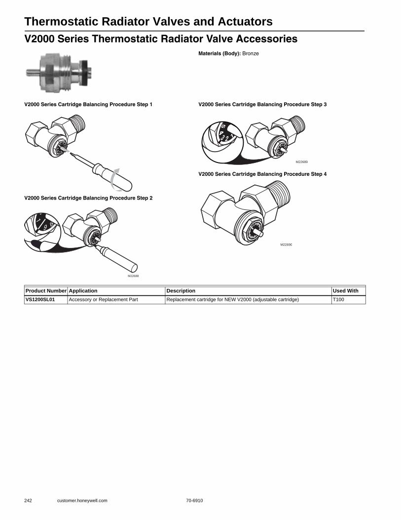
Thermostatic Radiator Valves and Actuators
242 customer.honeywell.com 70-6910
V2000 Series Thermostatic Radiator Valve AccessoriesMaterials (Body): Bronze
V2000 Series Cartridge Balancing Procedure Step 1
V2000 Series Cartridge Balancing Procedure Step 2
V2000 Series Cartridge Balancing Procedure Step 3
V2000 Series Cartridge Balancing Procedure Step 4
M22688
M22689
M22690
Product Number Application Description Used WithVS1200SL01 Accessory or Replacement Part Replacement cartridge for NEW V2000 (adjustable cartridge) T100
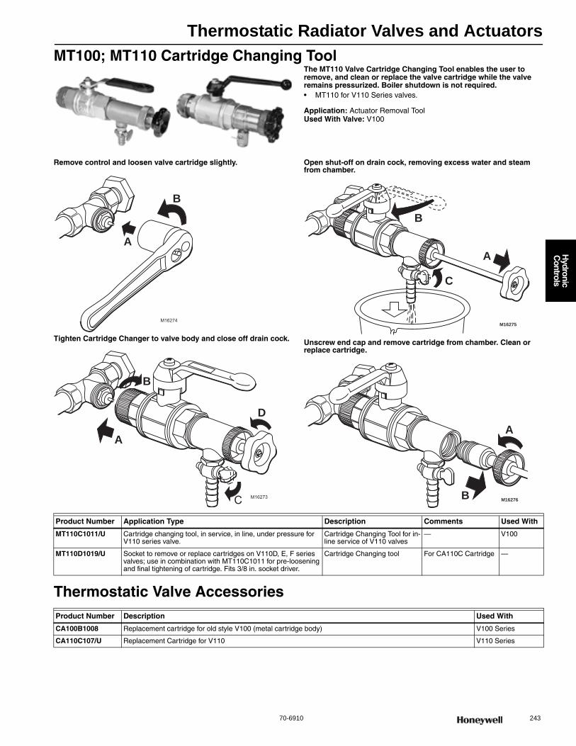
Thermostatic Radiator Valves and Actuators
70-6910 243
H
ydronic C
ontrols
MT100; MT110 Cartridge Changing ToolThe MT110 Valve Cartridge Changing Tool enables the user to remove, and clean or replace the valve cartridge while the valve remains pressurized. Boiler shutdown is not required.• MT110 for V110 Series valves.
Application: Actuator Removal ToolUsed With Valve: V100
Remove control and loosen valve cartridge slightly.
Tighten Cartridge Changer to valve body and close off drain cock.
Open shut-off on drain cock, removing excess water and steam from chamber.
Unscrew end cap and remove cartridge from chamber. Clean or replace cartridge.
Thermostatic Valve Accessories
M16274
A
B
M16273
A
B
C
D
M16275
A
B
C
M16276
A
B
Product Number Application Type Description Comments Used With
MT110C1011/U Cartridge changing tool, in service, in line, under pressure for V110 series valve.
Cartridge Changing Tool for in-line service of V110 valves
— V100
MT110D1019/U Socket to remove or replace cartridges on V110D, E, F series valves; use in combination with MT110C1011 for pre-loosening and final tightening of cartridge. Fits 3/8 in. socket driver.
Cartridge Changing tool For CA110C Cartridge —
Product Number Description Used With
CA100B1008 Replacement cartridge for old style V100 (metal cartridge body) V100 Series
CA110C107/U Replacement Cartridge for V110 V110 Series
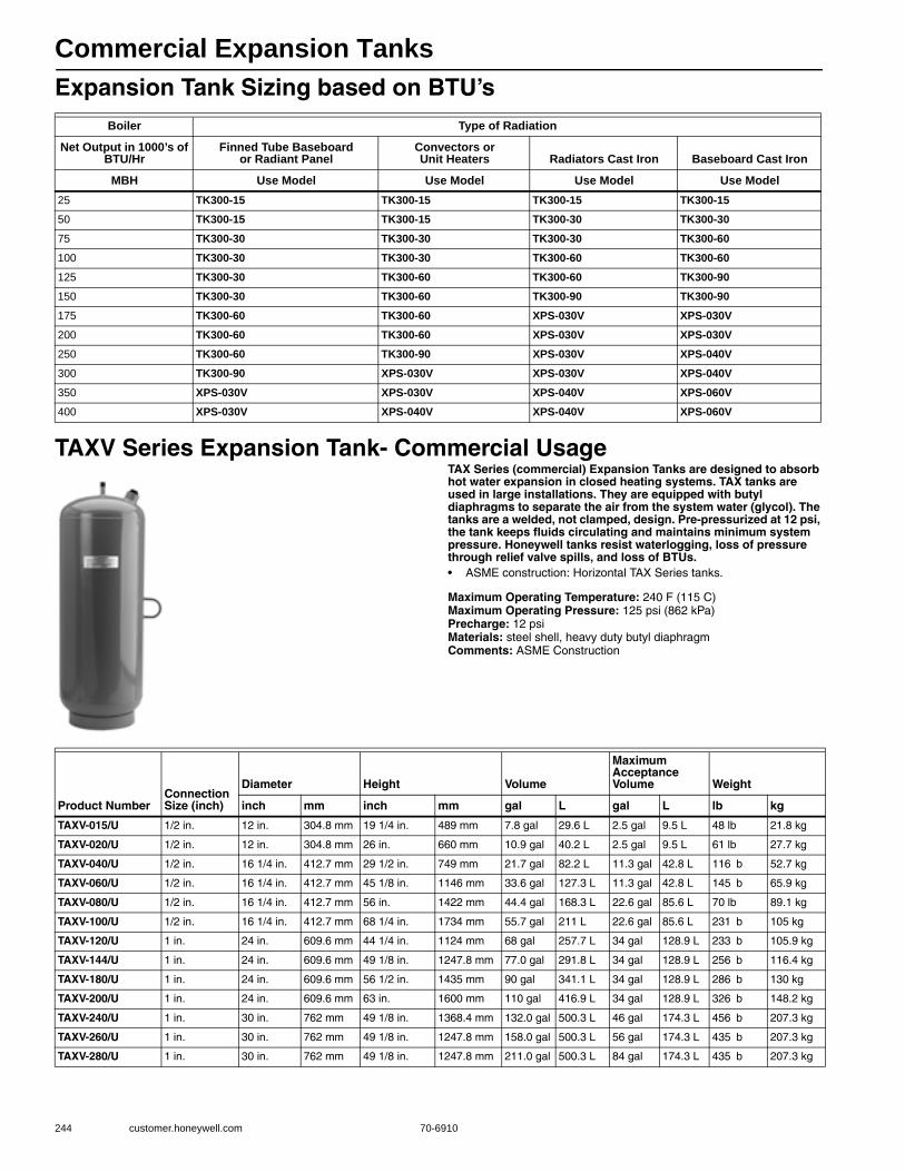
Commercial Expansion Tanks
244 customer.honeywell.com 70-6910
Expansion Tank Sizing based on BTU’s
TAXV Series Expansion Tank- Commercial UsageTAX Series (commercial) Expansion Tanks are designed to absorb hot water expansion in closed heating systems. TAX tanks are used in large installations. They are equipped with butyl diaphragms to separate the air from the system water (glycol). The tanks are a welded, not clamped, design. Pre-pressurized at 12 psi, the tank keeps fluids circulating and maintains minimum system pressure. Honeywell tanks resist waterlogging, loss of pressure through relief valve spills, and loss of BTUs.• ASME construction: Horizontal TAX Series tanks.
Maximum Operating Temperature: 240 F (115 C) Maximum Operating Pressure: 125 psi (862 kPa) Precharge: 12 psiMaterials: steel shell, heavy duty butyl diaphragmComments: ASME Construction
Boiler Type of Radiation
Net Output in 1000’s of BTU/Hr
Finned Tube Baseboard or Radiant Panel
Convectors or Unit Heaters Radiators Cast Iron Baseboard Cast Iron
MBH Use Model Use Model Use Model Use Model25 TK300-15 TK300-15 TK300-15 TK300-1550 TK300-15 TK300-15 TK300-30 TK300-3075 TK300-30 TK300-30 TK300-30 TK300-60100 TK300-30 TK300-30 TK300-60 TK300-60125 TK300-30 TK300-60 TK300-60 TK300-90150 TK300-30 TK300-60 TK300-90 TK300-90175 TK300-60 TK300-60 XPS-030V XPS-030V200 TK300-60 TK300-60 XPS-030V XPS-030V250 TK300-60 TK300-90 XPS-030V XPS-040V300 TK300-90 XPS-030V XPS-030V XPS-040V350 XPS-030V XPS-030V XPS-040V XPS-060V400 XPS-030V XPS-040V XPS-040V XPS-060V
Product NumberConnection Size (inch)
Diameter Height Volume
Maximum Acceptance Volume Weight
inch mm inch mm gal L gal L lb kg
TAXV-015/U 1/2 in. 12 in. 304.8 mm 19 1/4 in. 489 mm 7.8 gal 29.6 L 2.5 gal 9.5 L 48 lb 21.8 kg
TAXV-020/U 1/2 in. 12 in. 304.8 mm 26 in. 660 mm 10.9 gal 40.2 L 2.5 gal 9.5 L 61 lb 27.7 kg
TAXV-040/U 1/2 in. 16 1/4 in. 412.7 mm 29 1/2 in. 749 mm 21.7 gal 82.2 L 11.3 gal 42.8 L 116 b 52.7 kg
TAXV-060/U 1/2 in. 16 1/4 in. 412.7 mm 45 1/8 in. 1146 mm 33.6 gal 127.3 L 11.3 gal 42.8 L 145 b 65.9 kg
TAXV-080/U 1/2 in. 16 1/4 in. 412.7 mm 56 in. 1422 mm 44.4 gal 168.3 L 22.6 gal 85.6 L 70 lb 89.1 kg
TAXV-100/U 1/2 in. 16 1/4 in. 412.7 mm 68 1/4 in. 1734 mm 55.7 gal 211 L 22.6 gal 85.6 L 231 b 105 kg
TAXV-120/U 1 in. 24 in. 609.6 mm 44 1/4 in. 1124 mm 68 gal 257.7 L 34 gal 128.9 L 233 b 105.9 kg
TAXV-144/U 1 in. 24 in. 609.6 mm 49 1/8 in. 1247.8 mm 77.0 gal 291.8 L 34 gal 128.9 L 256 b 116.4 kg
TAXV-180/U 1 in. 24 in. 609.6 mm 56 1/2 in. 1435 mm 90 gal 341.1 L 34 gal 128.9 L 286 b 130 kg
TAXV-200/U 1 in. 24 in. 609.6 mm 63 in. 1600 mm 110 gal 416.9 L 34 gal 128.9 L 326 b 148.2 kg
TAXV-240/U 1 in. 30 in. 762 mm 49 1/8 in. 1368.4 mm 132.0 gal 500.3 L 46 gal 174.3 L 456 b 207.3 kg
TAXV-260/U 1 in. 30 in. 762 mm 49 1/8 in. 1247.8 mm 158.0 gal 500.3 L 56 gal 174.3 L 435 b 207.3 kg
TAXV-280/U 1 in. 30 in. 762 mm 49 1/8 in. 1247.8 mm 211.0 gal 500.3 L 84 gal 174.3 L 435 b 207.3 kg
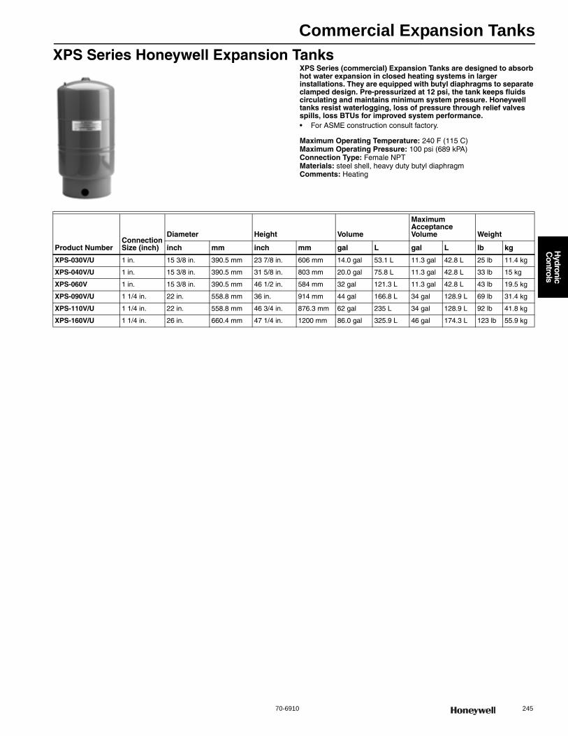
Commercial Expansion Tanks
70-6910 245
H
ydronic C
ontrols
XPS Series Honeywell Expansion TanksXPS Series (commercial) Expansion Tanks are designed to absorb hot water expansion in closed heating systems in larger installations. They are equipped with butyl diaphragms to separate clamped design. Pre-pressurized at 12 psi, the tank keeps fluids circulating and maintains minimum system pressure. Honeywell tanks resist waterlogging, loss of pressure through relief valves spills, loss BTUs for improved system performance.• For ASME construction consult factory.
Maximum Operating Temperature: 240 F (115 C) Maximum Operating Pressure: 100 psi (689 kPA) Connection Type: Female NPTMaterials: steel shell, heavy duty butyl diaphragmComments: Heating
Product NumberConnection Size (inch)
Diameter Height Volume
Maximum Acceptance Volume Weight
inch mm inch mm gal L gal L lb kg
XPS-030V/U 1 in. 15 3/8 in. 390.5 mm 23 7/8 in. 606 mm 14.0 gal 53.1 L 11.3 gal 42.8 L 25 lb 11.4 kg
XPS-040V/U 1 in. 15 3/8 in. 390.5 mm 31 5/8 in. 803 mm 20.0 gal 75.8 L 11.3 gal 42.8 L 33 lb 15 kg
XPS-060V 1 in. 15 3/8 in. 390.5 mm 46 1/2 in. 584 mm 32 gal 121.3 L 11.3 gal 42.8 L 43 lb 19.5 kg
XPS-090V/U 1 1/4 in. 22 in. 558.8 mm 36 in. 914 mm 44 gal 166.8 L 34 gal 128.9 L 69 lb 31.4 kg
XPS-110V/U 1 1/4 in. 22 in. 558.8 mm 46 3/4 in. 876.3 mm 62 gal 235 L 34 gal 128.9 L 92 lb 41.8 kg
XPS-160V/U 1 1/4 in. 26 in. 660.4 mm 47 1/4 in. 1200 mm 86.0 gal 325.9 L 46 gal 174.3 L 123 lb 55.9 kg

246 customer.honeywell.com 70-6910
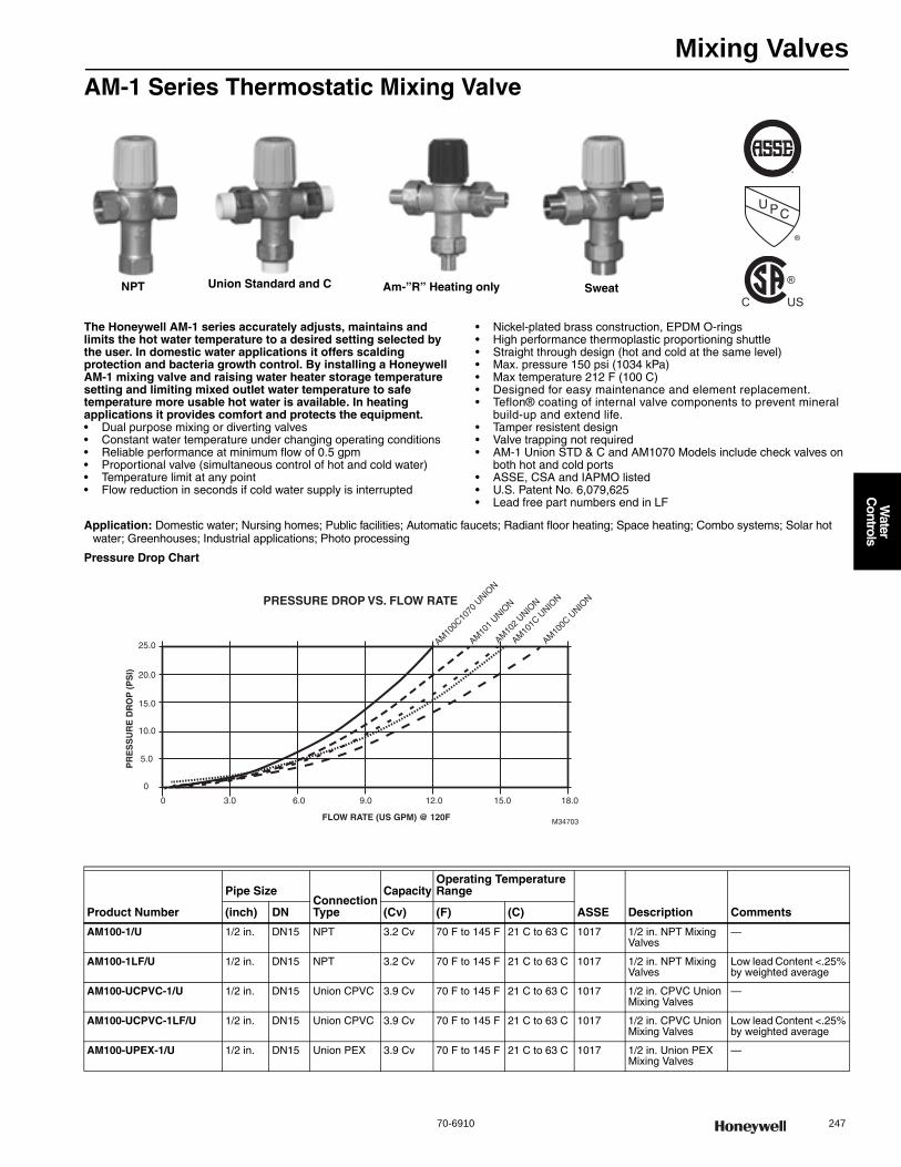
Mixing Valves
70-6910 247
Water
Controls
AM-1 Series Thermostatic Mixing Valve
The Honeywell AM-1 series accurately adjusts, maintains and limits the hot water temperature to a desired setting selected by the user. In domestic water applications it offers scalding protection and bacteria growth control. By installing a Honeywell AM-1 mixing valve and raising water heater storage temperature setting and limiting mixed outlet water temperature to safe temperature more usable hot water is available. In heating applications it provides comfort and protects the equipment.• Dual purpose mixing or diverting valves • Constant water temperature under changing operating conditions • Reliable performance at minimum flow of 0.5 gpm • Proportional valve (simultaneous control of hot and cold water) • Temperature limit at any point • Flow reduction in seconds if cold water supply is interrupted
• Nickel-plated brass construction, EPDM O-rings • High performance thermoplastic proportioning shuttle • Straight through design (hot and cold at the same level) • Max. pressure 150 psi (1034 kPa)• Max temperature 212 F (100 C) • Designed for easy maintenance and element replacement.• Teflon® coating of internal valve components to prevent mineral
build-up and extend life. • Tamper resistent design • Valve trapping not required • AM-1 Union STD & C and AM1070 Models include check valves on
both hot and cold ports • ASSE, CSA and IAPMO listed • U.S. Patent No. 6,079,625• Lead free part numbers end in LF
Application: Domestic water; Nursing homes; Public facilities; Automatic faucets; Radiant floor heating; Space heating; Combo systems; Solar hot water; Greenhouses; Industrial applications; Photo processing
Pressure Drop Chart
U PC
®
®
C USNPT Union Standard and C Am-”R” Heating only Sweat
0 6.0 9.0 12.0 15.0 18.0
0
5.0
10.0
15.0
20.0
25.0
3.0
FLOW RATE (US GPM) @ 120F
PR
ES
SU
RE
DR
OP
(P
SI)
M34703
PRESSURE DROP VS. FLOW RATE
AM10
2 UNIO
N
AM10
1 UNIO
N
AM10
1C U
NION
AM10
0C10
70 U
NION
AM10
0C U
NION
Product Number
Pipe SizeConnection Type
CapacityOperating Temperature Range
ASSE Description Comments(inch) DN (Cv) (F) (C)
AM100-1/U 1/2 in. DN15 NPT 3.2 Cv 70 F to 145 F 21 C to 63 C 1017 1/2 in. NPT Mixing Valves
—
AM100-1LF/U 1/2 in. DN15 NPT 3.2 Cv 70 F to 145 F 21 C to 63 C 1017 1/2 in. NPT Mixing Valves
Low lead Content <.25% by weighted average
AM100-UCPVC-1/U 1/2 in. DN15 Union CPVC 3.9 Cv 70 F to 145 F 21 C to 63 C 1017 1/2 in. CPVC Union Mixing Valves
—
AM100-UCPVC-1LF/U 1/2 in. DN15 Union CPVC 3.9 Cv 70 F to 145 F 21 C to 63 C 1017 1/2 in. CPVC Union Mixing Valves
Low lead Content <.25% by weighted average
AM100-UPEX-1/U 1/2 in. DN15 Union PEX 3.9 Cv 70 F to 145 F 21 C to 63 C 1017 1/2 in. Union PEX Mixing Valves
—
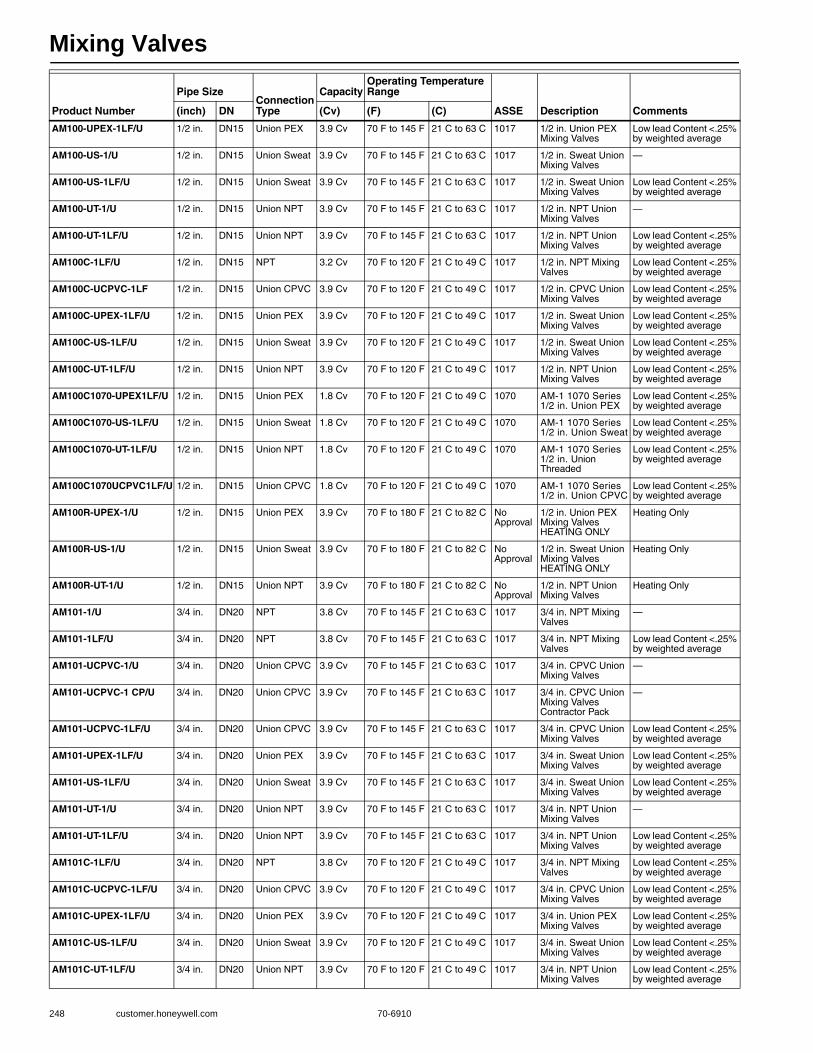
Mixing Valves
248 customer.honeywell.com 70-6910
AM100-UPEX-1LF/U 1/2 in. DN15 Union PEX 3.9 Cv 70 F to 145 F 21 C to 63 C 1017 1/2 in. Union PEX Mixing Valves
Low lead Content <.25% by weighted average
AM100-US-1/U 1/2 in. DN15 Union Sweat 3.9 Cv 70 F to 145 F 21 C to 63 C 1017 1/2 in. Sweat Union Mixing Valves
—
AM100-US-1LF/U 1/2 in. DN15 Union Sweat 3.9 Cv 70 F to 145 F 21 C to 63 C 1017 1/2 in. Sweat Union Mixing Valves
Low lead Content <.25% by weighted average
AM100-UT-1/U 1/2 in. DN15 Union NPT 3.9 Cv 70 F to 145 F 21 C to 63 C 1017 1/2 in. NPT Union Mixing Valves
—
AM100-UT-1LF/U 1/2 in. DN15 Union NPT 3.9 Cv 70 F to 145 F 21 C to 63 C 1017 1/2 in. NPT Union Mixing Valves
Low lead Content <.25% by weighted average
AM100C-1LF/U 1/2 in. DN15 NPT 3.2 Cv 70 F to 120 F 21 C to 49 C 1017 1/2 in. NPT Mixing Valves
Low lead Content <.25% by weighted average
AM100C-UCPVC-1LF 1/2 in. DN15 Union CPVC 3.9 Cv 70 F to 120 F 21 C to 49 C 1017 1/2 in. CPVC Union Mixing Valves
Low lead Content <.25% by weighted average
AM100C-UPEX-1LF/U 1/2 in. DN15 Union PEX 3.9 Cv 70 F to 120 F 21 C to 49 C 1017 1/2 in. Sweat Union Mixing Valves
Low lead Content <.25% by weighted average
AM100C-US-1LF/U 1/2 in. DN15 Union Sweat 3.9 Cv 70 F to 120 F 21 C to 49 C 1017 1/2 in. Sweat Union Mixing Valves
Low lead Content <.25% by weighted average
AM100C-UT-1LF/U 1/2 in. DN15 Union NPT 3.9 Cv 70 F to 120 F 21 C to 49 C 1017 1/2 in. NPT Union Mixing Valves
Low lead Content <.25% by weighted average
AM100C1070-UPEX1LF/U 1/2 in. DN15 Union PEX 1.8 Cv 70 F to 120 F 21 C to 49 C 1070 AM-1 1070 Series 1/2 in. Union PEX
Low lead Content <.25% by weighted average
AM100C1070-US-1LF/U 1/2 in. DN15 Union Sweat 1.8 Cv 70 F to 120 F 21 C to 49 C 1070 AM-1 1070 Series 1/2 in. Union Sweat
Low lead Content <.25% by weighted average
AM100C1070-UT-1LF/U 1/2 in. DN15 Union NPT 1.8 Cv 70 F to 120 F 21 C to 49 C 1070 AM-1 1070 Series 1/2 in. Union Threaded
Low lead Content <.25% by weighted average
AM100C1070UCPVC1LF/U 1/2 in. DN15 Union CPVC 1.8 Cv 70 F to 120 F 21 C to 49 C 1070 AM-1 1070 Series 1/2 in. Union CPVC
Low lead Content <.25% by weighted average
AM100R-UPEX-1/U 1/2 in. DN15 Union PEX 3.9 Cv 70 F to 180 F 21 C to 82 C No Approval
1/2 in. Union PEX Mixing Valves HEATING ONLY
Heating Only
AM100R-US-1/U 1/2 in. DN15 Union Sweat 3.9 Cv 70 F to 180 F 21 C to 82 C No Approval
1/2 in. Sweat Union Mixing Valves HEATING ONLY
Heating Only
AM100R-UT-1/U 1/2 in. DN15 Union NPT 3.9 Cv 70 F to 180 F 21 C to 82 C No Approval
1/2 in. NPT Union Mixing Valves
Heating Only
AM101-1/U 3/4 in. DN20 NPT 3.8 Cv 70 F to 145 F 21 C to 63 C 1017 3/4 in. NPT Mixing Valves
—
AM101-1LF/U 3/4 in. DN20 NPT 3.8 Cv 70 F to 145 F 21 C to 63 C 1017 3/4 in. NPT Mixing Valves
Low lead Content <.25% by weighted average
AM101-UCPVC-1/U 3/4 in. DN20 Union CPVC 3.9 Cv 70 F to 145 F 21 C to 63 C 1017 3/4 in. CPVC Union Mixing Valves
—
AM101-UCPVC-1 CP/U 3/4 in. DN20 Union CPVC 3.9 Cv 70 F to 145 F 21 C to 63 C 1017 3/4 in. CPVC Union Mixing Valves Contractor Pack
—
AM101-UCPVC-1LF/U 3/4 in. DN20 Union CPVC 3.9 Cv 70 F to 145 F 21 C to 63 C 1017 3/4 in. CPVC Union Mixing Valves
Low lead Content <.25% by weighted average
AM101-UPEX-1LF/U 3/4 in. DN20 Union PEX 3.9 Cv 70 F to 145 F 21 C to 63 C 1017 3/4 in. Sweat Union Mixing Valves
Low lead Content <.25% by weighted average
AM101-US-1LF/U 3/4 in. DN20 Union Sweat 3.9 Cv 70 F to 145 F 21 C to 63 C 1017 3/4 in. Sweat Union Mixing Valves
Low lead Content <.25% by weighted average
AM101-UT-1/U 3/4 in. DN20 Union NPT 3.9 Cv 70 F to 145 F 21 C to 63 C 1017 3/4 in. NPT Union Mixing Valves
—
AM101-UT-1LF/U 3/4 in. DN20 Union NPT 3.9 Cv 70 F to 145 F 21 C to 63 C 1017 3/4 in. NPT Union Mixing Valves
Low lead Content <.25% by weighted average
AM101C-1LF/U 3/4 in. DN20 NPT 3.8 Cv 70 F to 120 F 21 C to 49 C 1017 3/4 in. NPT Mixing Valves
Low lead Content <.25% by weighted average
AM101C-UCPVC-1LF/U 3/4 in. DN20 Union CPVC 3.9 Cv 70 F to 120 F 21 C to 49 C 1017 3/4 in. CPVC Union Mixing Valves
Low lead Content <.25% by weighted average
AM101C-UPEX-1LF/U 3/4 in. DN20 Union PEX 3.9 Cv 70 F to 120 F 21 C to 49 C 1017 3/4 in. Union PEX Mixing Valves
Low lead Content <.25% by weighted average
AM101C-US-1LF/U 3/4 in. DN20 Union Sweat 3.9 Cv 70 F to 120 F 21 C to 49 C 1017 3/4 in. Sweat Union Mixing Valves
Low lead Content <.25% by weighted average
AM101C-UT-1LF/U 3/4 in. DN20 Union NPT 3.9 Cv 70 F to 120 F 21 C to 49 C 1017 3/4 in. NPT Union Mixing Valves
Low lead Content <.25% by weighted average
Product Number
Pipe SizeConnection Type
CapacityOperating Temperature Range
ASSE Description Comments(inch) DN (Cv) (F) (C)

Mixing Valves
70-6910 249
Water
Controls
AM101C1070-UPEX1LF 3/4 in. DN20 Union PEX 1.8 Cv 70 F to 120 F 21 C to 49 C 1070 AM-1 1070 Series 3/4 in. Union PEX
Low lead Content <.25% by weighted average
AM101C1070-US-1LF 3/4 in. DN20 Union Sweat 1.8 Cv 70 F to 120 F 21 C to 49 C 1070 AM-1 1070 Series 3/4 in. Union Sweat
Low lead Content <.25% by weighted average
AM101C1070-UT-1LF 3/4 in. DN20 Union NPT 1.8 Cv 70 F to 120 F 21 C to 49 C 1070 AM-1 1070 Series 3/4 in. Union Threaded
Low lead Content <.25% by weighted average
AM101C1070UCPVC1LF 3/4 in. DN20 Union CPVC 1.8 Cv 70 F to 120 F 21 C to 49 C 1070 AM-1 1070 Series 3/4 in. Union CPVC
Low lead Content <.25% by weighted average
AM101R-UPEX-1/U 3/4 in. DN20 Union PEX 3.9 Cv 70 F to 180 F 21 C to 82 C No Approval
3/4 in. Union PEX Mixing Valves HEATING OLY
Heating Only
AM101R-US-1/U 3/4 in. DN20 Union Sweat 3.9 Cv 70 F to 180 F 21 C to 82 C No Approval
3/4 in. Sweat Union Mixing Valves HEATING OLY
Heating Only
AM101R-UT-1/U 3/4 in. DN20 Union NPT 3.9 Cv 70 F to 180 F 21 C to 82 C No Approval
3/4 in. NPT Union Mixing Valves HEATING ONLY
Heating Only
AM102-1/U 1 in. DN25 NPT 4.3 Cv 70 F to 145 F 21 C to 63 C 1017 1 in. NPT Mixing Valves
—
AM102-1LF/U 1 in. DN25 NPT 4.3 Cv 70 F to 145 F 21 C to 63 C 1017 1 in. NPT Mixing Valves
Low lead Content <.25% by weighted average
AM102-US-1/U 1 in. DN25 Union Sweat 3.9 Cv 70 F to 145 F 21 C to 63 C 1017 1 in. Sweat Union Mixing Valves
—
AM102-US-1LF/U 1 in. DN25 Union Sweat 3.9 Cv 70 F to 145 F 21 C to 63 C 1017 1 in. Sweat Union Mixing Valves
Low lead Content <.25% by weighted average
AM102-UT-1/U 1 in. DN25 Union NPT 3.9 Cv 70 F to 145 F 21 C to 63 C 1017 1 in. NPT Union Mixing Valves
—
AM102-UT-1LF/U 1 in. DN25 Union NPT 3.9 Cv 70 F to 145 F 21 C to 63 C 1017 1 in. NPT Union Mixing Valves
Low lead Content <.25% by weighted average
AM102C-1LF/U 1 in. DN25 NPT 4.3 Cv 70 F to 120 F 21 C to 49 C 1017 1 in. NPT Mixing Valves
Low lead Content <.25% by weighted average
AM102C-US-1LF/U 1 in. DN25 Union Sweat 3.9 Cv 70 F to 120 F 21 C to 49 C 1017 1 in. Sweat Union Mixing Valves
Low lead Content <.25% by weighted average
AM102C-UT-1LF/U 1 in. DN25 Union NPT 3.9 Cv 70 F to 120 F 21 C to 49 C 1017 1 in. NPT Union Mixing Valves
Low lead Content <.25% by weighted average
AM102C1070-US-1LF 1 in. DN25 Union Sweat 1.8 Cv 70 F to 120 F 21 C to 49 C 1070 AM-1 1070 Series 1" Union Sweat
Low lead Content <.25% by weighted average
AM102C1070-UT-1LF 1 in. DN25 Union NPT 1.8 Cv 70 F to 120 F 21 C to 49 C 1070 AM-1 1070 Series 1" Union Threaded
Low lead Content <.25% by weighted average
AM102R-US-1/U 1 in. DN25 Union Sweat 3.9 Cv 70 F to 180 F 21 C to 82 C No Approval
1 in. Sweat Union Mixing Valves HEATING ONLY
Heating Only
AM102R-UT-1/U 1 in. DN25 Union NPT 3.9 Cv 70 F to 180 F 21 C to 82 C No Approval
1 in. NPT Union Mixing Valves HEATING ONLY
Heating Only
Product Number
Pipe SizeConnection Type
CapacityOperating Temperature Range
ASSE Description Comments(inch) DN (Cv) (F) (C)

Mixing Valves
250 customer.honeywell.com 70-6910
Mixing Valve Accessories
Product Number
Pipe SizeConnection Type
Operating Temperature Range
Description Comments(inch) DN (F) (C)
AM08-024LF/U 1/2 in. DN15 Union NPT — — 1/2 in. NPT Union kit. Includes three 1/2 in. NPT Tailpieces. Low lead Content <.25% by weighted average
AM08-038/U 1/2 in. DN15 Union Sweat — — 1/2 in. AM-1 Sweat Union, Single tailpiece, Nut, Gasket
—
AM08-039/U 3/4 in. DN20 Union Sweat — — 3/4 in. Aquamix Sweat Union, Single tailpiece, Nut, Gasket
—
AM08-040/U 1 in. DN25 Union Sweat — — 1 in. Aquamix Sweat Union, Single tailpiece, Nut, Gasket, Retainer
—
AM08-041/U 1/2 in. DN15 Union NPT — — 1/2 in. Aquamix NPT Union, Single tailpiece, Nut, Gasket
—
AM08-042/U 3/4 in. DN20 Union NPT — — 3/4 in. Aquamix NPT Union, Single tailpiece, Nut, Gasket, Retainer
—
AM08-043/U 1 in. DN25 Union NPT — — 1 in. Aquamix NPT Union, Single tailpiece, Nut, Gasket, Retainer
—
AM09-061/U 3/4 in. DN15 Sweat — — 3/4 in. Sweat Tailpiece —
AM206-041/U 1/2 in. DN20 PEX — — 1/2 in. PEX union kit. Includes tailpiece, union nut and gasket
—
AM206-042/U 3/4 in. DN20 PEX — — 3/4 in. PEX union kit. Includes tailpiece, union nut and gasket
—
CVT-050/U 1/2 in. DN15 NPT — — 1/2 in. female NPT x 1/2 in. male NPT Check Adapter. For AM-1 NPT valves
CVT-075/U 3/4 in. DN20 NPT — — 3/4 in. female NPT x 3/4 in. Check Adapter. For AM-1 NPT valves
TS205-064/U Use with All Mixing Valves
Adhesive strip
110 F to 140 F 43 C to 60 C Thermal Temperature Indicator Strip for Mixing Valve Setup and Outlet Temperature Monitoring. Included in all AM-1 Series STD and C models and AMX Series. Available as separate item
TS206-080/U Use with All Mixing Valves
Adhesive strip
105 F to 180 F 41 C to 82 C Thermal Temperature Indicator Strip for Mixing Valve Setup and Outlet Temperature Monitoring. Included in all AM-1 Series R models. Available as separate item
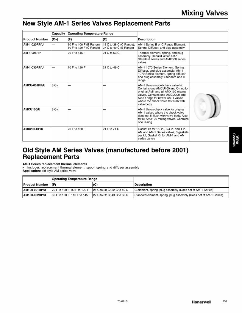
Mixing Valves
70-6910 251
Water
Controls
New Style AM-1 Series Valves Replacement Parts
Old Style AM Series Valves (manufactured before 2001) Replacement PartsAM-1 Series replacement thermal elements• Includes replacement thermal element, spool, spring and diffuser assemblyApplication: old style AM series valve
Product Number
Capacity Operating Temperature Range
Description(Cv) (F) (C)
AM-1-020RP/U — 60 F to 100 F (B Range); 80 F to 120 F (C Range)
15 C to 38 C (C Range); 27 C to 49 C (B Range)
AM-1 Series B or C Range Element, Spring, Diffuser, and plug assembly
AM-1-025RP 70 F to 145 F 21 C to 63 C Thermal element, spring, and plug assembly. Rebuild kit for AM-1 Standard series and AMX300 series valves
AM-1-030RP/U — 70 F to 120 F 21 C to 49 C AM-1 1070 Series Element, Spring, Diffuser, and plug assembly; AM-1 1070 Series element, spring diffuser and plug assembly; Standard and R range
AMCU-001RP/U 8 Cv — — AM-1 Union model check valve kit. Contains one AMCU100 and O-ring for original AM1 and all AMX100 mixing valves. Contains one AMCU200 and two O-rings for newer AM-1 valves where the check valve fits flush with valve body.
AMCU100/U 8 Cv — — AM-1 Union check valve for original AM-1 valves where the check valve does not fit flush with valve body. Also for all AMX100 mixing valves. Contains one O-ring
AMU200-RP/U 70 F to 160 F 21 F to 71 C Gasket kit for 1/2 in., 3/4 in. and 1 in. AM and AM-1 Series valves; 3 gaskets per kit; Gasket Kit for AM-1 and AM series valves
Product Number
Operating Temperature Range
Description(F) (C)
AM100-001RP/U 70 F to 100 F; 90 F to 120 F 21 C to 38 C; 32 C to 49 C C element, spring, plug assembly (Does not fit AM-1 Series)
AM100-002RP/U 80 F to 180 F; 110 F to 145 F 27 C to 82 C; 43 C to 63 C Standard element, spring, plug assembly (Does not fit AM-1 Series)
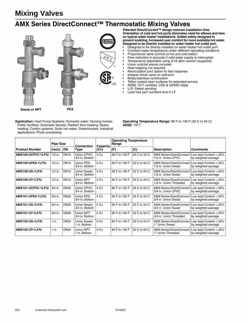
Mixing Valves
252 customer.honeywell.com 70-6910
AMX Series DirectConnect™ Thermostatic Mixing ValvesPatented DirectConnect™ design reduces installation time. Orientation of cold and hot ports eliminates need for elbows and tees on typical water heater installations. Added safety designed to prevent scalding. Increased user comfort for more available hot water. Designed to be directly installed on water heater hot outlet port.• Designed to be directly installed on water heater hot outlet port.• Constant water temperature under different operating conditions • Proportional valve (control of hot and cold water) • Flow reduction in seconds if cold water supply is interrupted • Temperature adjustable using 3/16 allen wrench (supplied) • Union nuts/tail pieces included • Heat trapping not required • Recirculation port option for fast response • Integral check valve on cold port • Brass/stainless construction • Teflon coated wear surfaces for extended service • ASSE 1017 certified, CSA & IAPMO listed • U.S. Patent pending• Lead free part numbers end in LF
Application: Heat Pump Systems; Domestic water; Nursing homes; Public facilities; Automatic faucets; Radiant floor heating; Space heating; Combo systems; Solar hot water; Greenhouses; Industrial applications; Photo processing
Operating Temperature Range: 90 F to 130 F (32 C to 54 C) ASSE: 1017
U PC
®
®
C US
Sweat or NPT PEX
Product Number
Pipe SizeConnection Type
Capacity(Cv)
Operating Temperature Range
Description Comments(inch) DN (F) (C)
AMX100-UCPVC-1LF/U 1/2 in. DN15 Union CPVC, 3/4 in. Bottom
4 Cv 90 F to 130 F 32 C to 54 C AMX Series DirectConnect 1/2 in. Union CPVC
Low lead Content <.25% by weighted average
AMX100-UPEX-1LF/U 1/2 in. DN15 Union PEX, 3/4 in. Bottom
4 Cv 90 F to 130 F 32 C to 54 C AMX Series DirectConnect 1/2 in. Union Sweat
Low lead Content <.25% by weighted average
AMX100-US-1LF/U 1/2 in. DN15 Union Sweat, 3/4 in. Bottom
4 Cv 90 F to 130 F 32 C to 54 C AMX Series DirectConnect 1/2 in. Union Sweat
Low lead Content <.25% by weighted average
AMX100-UT-1LF/U 1/2 in. DN15 Union NPT, 3/4 in. Bottom
4 Cv 90 F to 130 F 32 C to 54 C AMX Series DirectConnect 1/2 in. Union Threaded
Low lead Content <.25% by weighted average
AMX101-UCPVC-1LF/U 3/4 in. DN20 Union CPVC, 3/4 in. Bottom
4 Cv 90 F to 130 F 32 C to 54 C AMX Series DirectConnect 3/4 in. Union CPVC
Low lead Content <.25% by weighted average
AMX101-UPEX-1LF/U 3/4 in. DN20 Union PEX, 3/4 in. Bottom
4 Cv 90 F to 130 F 32 C to 54 C AMX Series DirectConnect 3/4 in. Union Sweat
Low lead Content <.25% by weighted average
AMX101-US-1LF/U 3/4 in. DN20 Union Sweat, 3/4 in. Bottom
4 Cv 90 F to 130 F 32 C to 54 C AMX Series DirectConnect 3/4 in. Union Sweat
Low lead Content <.25% by weighted average
AMX101-UT-1LF/U 3/4 in. DN20 Union NPT, 3/4 in. Bottom
4 Cv 90 F to 130 F 32 C to 54 C AMX Series DirectConnect 3/4 in. Union Threaded
Low lead Content <.25% by weighted average
AMX102-US-1LF/U 1 in. DN25 Union Sweat, 1 in. Bottom
4 Cv 90 F to 130 F 32 C to 54 C AMX Series DirectConnect 1" Union Sweat
Low lead Content <.25% by weighted average
AMX102-UT-1LF/U 1 in. DN25 Union NPT, 1 in. Bottom
4 Cv 90 F to 130 F 32 C to 54 C AMX Series DirectConnect 1" Union Threaded
Low lead Content <.25% by weighted average
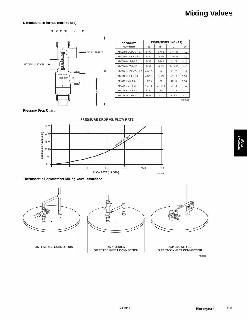
Mixing Valves
70-6910 253
Water
Controls
Dimensions in inches (millimeters)
Pressure Drop Chart
Thermostatic Replacement Mixing Valve Installation
PRODUCTNUMBER
DIMENSIONS (INCHES)A B C D
RECIRCULATION
ADJUSTMENT
R
M
H
C
AMX Ser es
ASSE 1017
D C
B
A
M27478B
AMX100-UCPVC-1-LF 3-1/2 8-7/16 2-11/16 1-1/2
AMX100-UPEX-1-LF 3-1/2 8-5/8 2-15/16 1-1/2
AMX100-US-1-LF 3-1/2 8-3/16 2-1/2 1-1/2
AMX100-UT-1-LF 3-1/2 8-1/2 2-13/16 1-1/2
AMX101-UCPVC-1-LF 4-3/16 9 2-1/2 1-1/2
AMX101-UPEX-1-LF 4-3/16 9-3/16 2-11/16 1-1/2
AMX101-US-1-LF 4-3/16 9 2-1/2 1-1/2
AMX101-UT-1-LF 4-3/16 9-11/16 3-1/2 1-1/2
AMX102-US-1-LF 4-1/2 10 3-1/2 1-1/2
AMX102-UT-1-LF 4-1/2 10.3 3-13/16 1-1/2
0 6.0 9.0 12.0 15.0 18.0
0
5.0
10.0
15.0
20.0
25.0
3.0
FLOW RATE (US GPM)
PR
ES
SU
RE
DR
OP
(P
SI)
AMX100 @ 120 F
M34702
PRESSURE DROP VS. FLOW RATE
M31168
AM-1 SERIES CONNECTION AMX SERIESDIRECTCONNECT CONNECTION
AMX 300 SERIESDIRECTCONNECT CONNECTION
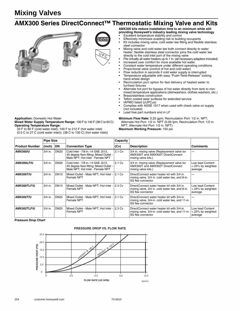
Mixing Valves
254 customer.honeywell.com 70-6910
AMX300 Series DirectConnect™ Thermostatic Mixing Valve and KitsAMX300 kits reduce installation time to an minimum while still providing Honeywell's industry leading mixing valve technology• Excellent temperature stability and control • Effectively minimizes scalding risk to building occupants • Kit includes mixing valve, cold water tee fitting and flexible stainless
steel connector • Mixing valve and cold water tee both connect directly to water
heater; flexible stainless steel connector joins the cold water tee directly to the cold inlet port of the mixing valve
• Fits virtually all water heaters up to 1 in. (all necessary adapters included) • Increased user comfort for more available hot water. • Constant water temperature under different operating conditions • Proportional valve (control of hot and cold water) • Flow reduction in seconds if cold water supply is interrupted • Temperature adjustable with easy “Push-Twist-Release” locking
hand wheel design • Recirculation port option for fast delivery of heated water to
furthest fixtures • Alternate hot port for bypass of hot water directly from tank to non-
mixed temperature applications (dishwashers, clothes washers, etc.) • Brass/stainless construction • Teflon coated wear surfaces for extended service • IAPMO listed (cUPCus)• Complies with ASSE 1017 when used with check valve on supply
(not included)• Lead free part numbers end in LF
Application: Domestic Hot WaterMixed Water Supply Temperature Range: 100 F to 145 F (38 C to 63 C) Operating Temperature Range:
33 F to 80 F (cold water inlet); 100 F to 212 F (hot water inlet)(0.5 C to 27 C (cold water inlet)); (38 C to 100 C) (hot water inlet))
Minimum Flow Rate: 0.25 gpm; Recirculation Port: 1/2 in. NPT; Alternate Hot Port: 1/2 in. NPT (0.95 lpm; Recirculation Port: 1/2 in. NPT; Alternate Hot Port: 1/2 in. NPT)
Maximum Working Pressure: 150 psi
Pressure Drop Chart
U PC
®
Product Number
Pipe Size
Connection Type
Capacity
Description Comments(inch) DN (Cv)
AMX300/U 3/4 in. DN20 Cold Inlet - 7/8 in.-14 SAE J513, 45 degree flare fitting; Mixed Outlet - Male NPT; Hot Inlet - Female NPT
2.1 Cv 3/4 in. mixing valve (Replacement valve tor AMX300T and AMX302T DirectConnect mixing valve kits.)
—
AMX300LF/U 3/4 in. DN20 Cold Inlet - 7/8 in.-14 SAE J513, 45 degree flare fitting; Mixed Outlet - Male NPT; Hot Inlet - Female NPT
2.1 Cv 3/4 in. mixing valve (Replacement valve tor AMX300T and AMX302T DirectConnect mixing valve kits.)
Low lead Content <.25% by weighted average
AMX300T/U 3/4 in. DN15 Mixed Outlet - Male NPT; Hot Inlet - Female NPT
2.1 Cv DirectConnect water heater kit with 3/4 in. mixing valve, 3/4 in. cold water tee, and 8-in. SS flex connector
—
AMX300TLF/U 3/4 in. DN15 Mixed Outlet - Male NPT; Hot Inlet - Female NPT
2.3 Cv DirectConnect water heater kit with 3/4 in. mixing valve, 3/4 in. cold water tee, and 8-in. SS flex connector
Low lead Content <.25% by weighted average
AMX302T/U 3/4 in. DN25 Mixed Outlet - Male NPT; Hot Inlet - Female NPT
2.1 Cv DirectConnect water heater kit with 3/4-in. mixing valve, 3/4-in. cold water tee, and 11-in. SS flex connector
—
AMX302TLF/U 3/4 in. DN25 Mixed Outlet - Male NPT; Hot Inlet - Female NPT
2.3 Cv DirectConnect water heater kit with 3/4-in. mixing valve, 3/4-in. cold water tee, and 11-in. SS flex connector
Low lead Content <.25% by weighted average
0 6.0 9.0 12.0
0
5.0
10.0
15.0
20.0
25.0
3.0
FLOW RATE (US GPM)
PR
ES
SU
RE
DR
OP
(P
SI)
AMX300T @ 100 F
AMX300T @ 120 F
M34701
PRESSURE DROP VS. FLOW RATE

Mixing Valves
70-6910 255
Water
Controls
AMX Series DirectConnect Replacement PartsOperating Temperature Range: 90 F to 130 F (32 C to 54 C)
Product Number
Pipe Size
Connection Type Description(inch) (DN)
AMCU100 — AM-1 Union check valve for original AM-1 valves where the check valve does not fit flush with valve body. Contains one O-ring. Also for all AMX100 mixing valves.
AMX-001RP/U — — — AMX element, spring, plug assembly. For AMX100 series valves.
AM-1-025RP/U — — — Thermal element, spring, and plug assembly. Rebuild kit for AM-1 “Standard” (70 -145F; 21-49C) series and AMX300 series valves
AMX300/U 3/4 in. DN20 Cold Inlet - 7/8 in.-14 SAE J513, 45 degree flare fitting; Mixed Outlet - Male NPT; Hot Inlet - Female NPT
3/4 in. mixing valve Replacement valve tor AMX300T and AMX302T DirectConnect mixing valve kits.Capacity 2.1 Cv
AMX300LF/U 3/4 in. DN20 Cold Inlet - 7/8 in.-14 SAE J513, 45 degree flare fitting; Mixed Outlet - Male NPT; Hot Inlet - Female NPT
3/4 in. mixing valve Replacement valve tor AMX300T and AMX302T DirectConnect mixing valve kits. Low lead Content <.25% by weighted averageCapacity 2.1 Cv
AMX300-008/U — — NPT Replacement 8" flex connector for AMX300T
AMX300-011/U — — NPT Replacement 11" flex connector for AMX300T
AMX300-34T/U 3/4 in. DN20 NPT Replacement cold water Tee for AMX300T and AMX302T
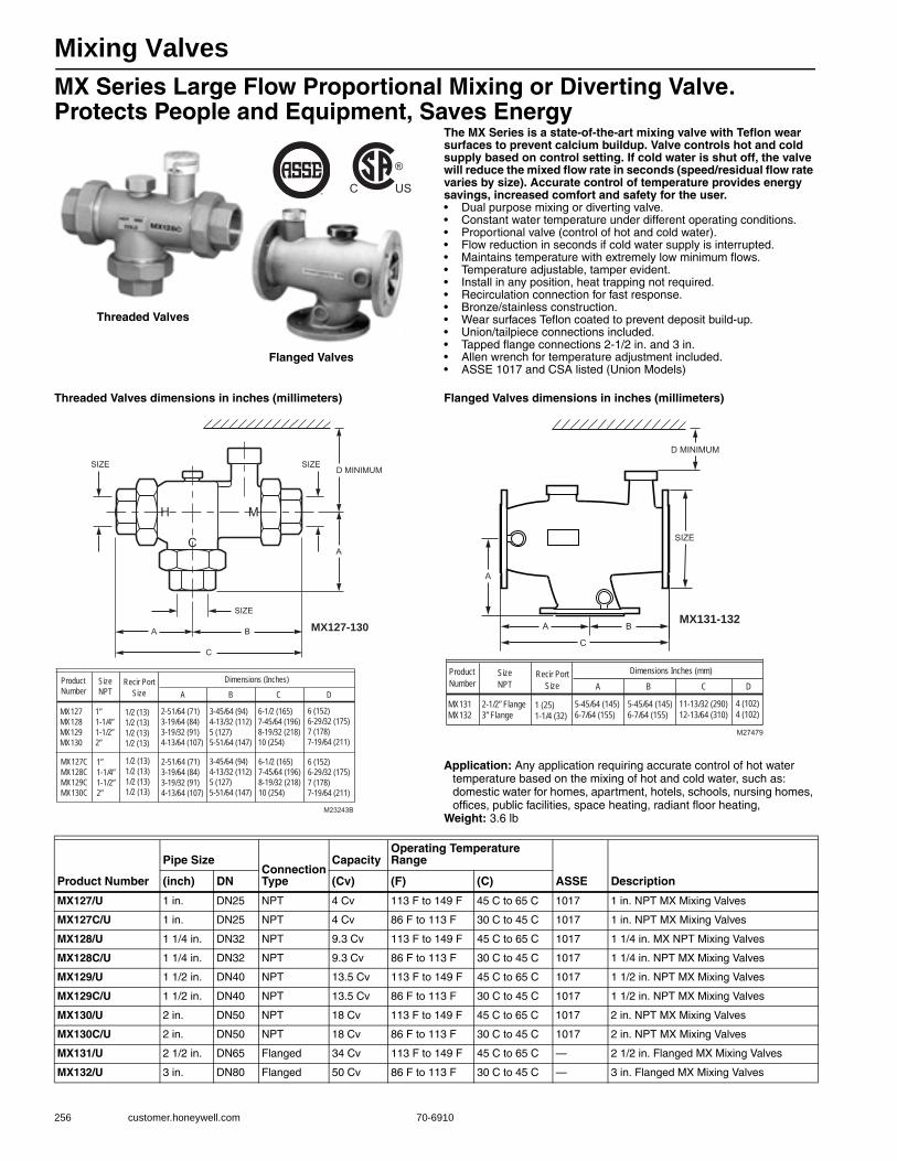
Mixing Valves
256 customer.honeywell.com 70-6910
MX Series Large Flow Proportional Mixing or Diverting Valve. Protects People and Equipment, Saves Energy
The MX Series is a state-of-the-art mixing valve with Teflon wear surfaces to prevent calcium buildup. Valve controls hot and cold supply based on control setting. If cold water is shut off, the valve will reduce the mixed flow rate in seconds (speed/residual flow rate varies by size). Accurate control of temperature provides energy savings, increased comfort and safety for the user.• Dual purpose mixing or diverting valve. • Constant water temperature under different operating conditions. • Proportional valve (control of hot and cold water). • Flow reduction in seconds if cold water supply is interrupted. • Maintains temperature with extremely low minimum flows. • Temperature adjustable, tamper evident. • Install in any position, heat trapping not required. • Recirculation connection for fast response. • Bronze/stainless construction. • Wear surfaces Teflon coated to prevent deposit build-up. • Union/tailpiece connections included. • Tapped flange connections 2-1/2 in. and 3 in. • Allen wrench for temperature adjustment included.• ASSE 1017 and CSA listed (Union Models)
Threaded Valves dimensions in inches (millimeters) Flanged Valves dimensions in inches (millimeters)
Application: Any application requiring accurate control of hot water temperature based on the mixing of hot and cold water, such as: domestic water for homes, apartment, hotels, schools, nursing homes, offices, public facilities, space heating, radiant floor heating,
Weight: 3.6 lb
®
C US
Threaded Valves
Flanged Valves
M23243B
SIZE
SIZE SIZE
A
D MINIMUM
B A
C
H
C
M
MX127-130
ProductNumber
Size NPT
Dimensions (Inches)
MX127MX128MX129MX130
1”1-1/4”1-1/2”2”
2-51/64 (71)3-19/64 (84)3-19/32 (91)4-13/64 (107)
3-45/64 (94)4-13/32 (112)5 (127)5-51/64 (147)
6-1/2 (165)7-45/64 (196)8-19/32 (218)10 (254)
6 (152) 6-29/32 (175)7 (178)7-19/64 (211)
2-51/64 (71)3-19/64 (84)3-19/32 (91)4-13/64 (107)
3-45/64 (94)4-13/32 (112)5 (127)5-51/64 (147)
6-1/2 (165)7-45/64 (196)8-19/32 (218)10 (254)
6 (152) 6-29/32 (175)7 (178)7-19/64 (211)
A B C DRecir Port
Size
1/2 (13)1/2 (13)1/2 (13)1/2 (13)
1/2 (13)1/2 (13)1/2 (13)1/2 (13)
MX127CMX128CMX129CMX130C
1”1-1/4”1-1/2”2”
M27479
MX131-132
ProductNumber
Size NPT
Dimensions Inches (mm)
MX131MX132
2-1/2” Flange3” Flange
5-45/64 (145)6-7/64 (155)
5-45/64 (145)6-7/64 (155)
11-13/32 (290)12-13/64 (310)
4 (102) 4 (102)
A B C D
BA
C
A
D MINIMUM
SIZE
Recir PortSize
1 (25)1-1/4 (32)
Product Number
Pipe SizeConnection Type
CapacityOperating Temperature Range
ASSE Description(inch) DN (Cv) (F) (C)
MX127/U 1 in. DN25 NPT 4 Cv 113 F to 149 F 45 C to 65 C 1017 1 in. NPT MX Mixing Valves
MX127C/U 1 in. DN25 NPT 4 Cv 86 F to 113 F 30 C to 45 C 1017 1 in. NPT MX Mixing Valves
MX128/U 1 1/4 in. DN32 NPT 9.3 Cv 113 F to 149 F 45 C to 65 C 1017 1 1/4 in. MX NPT Mixing Valves
MX128C/U 1 1/4 in. DN32 NPT 9.3 Cv 86 F to 113 F 30 C to 45 C 1017 1 1/4 in. NPT MX Mixing Valves
MX129/U 1 1/2 in. DN40 NPT 13.5 Cv 113 F to 149 F 45 C to 65 C 1017 1 1/2 in. NPT MX Mixing Valves
MX129C/U 1 1/2 in. DN40 NPT 13.5 Cv 86 F to 113 F 30 C to 45 C 1017 1 1/2 in. NPT MX Mixing Valves
MX130/U 2 in. DN50 NPT 18 Cv 113 F to 149 F 45 C to 65 C 1017 2 in. NPT MX Mixing Valves
MX130C/U 2 in. DN50 NPT 18 Cv 86 F to 113 F 30 C to 45 C 1017 2 in. NPT MX Mixing Valves
MX131/U 2 1/2 in. DN65 Flanged 34 Cv 113 F to 149 F 45 C to 65 C — 2 1/2 in. Flanged MX Mixing Valves
MX132/U 3 in. DN80 Flanged 50 Cv 86 F to 113 F 30 C to 45 C — 3 in. Flanged MX Mixing Valves
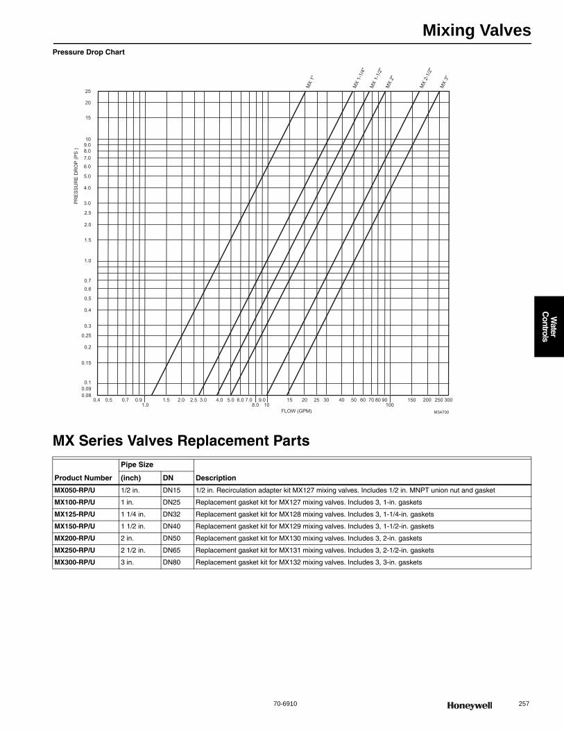
Mixing Valves
70-6910 257
Water
Controls
Pressure Drop Chart
MX Series Valves Replacement Parts
Product Number
Pipe Size
Description(inch) DN
MX050-RP/U 1/2 in. DN15 1/2 in. Recirculation adapter kit MX127 mixing valves. Includes 1/2 in. MNPT union nut and gasket
MX100-RP/U 1 in. DN25 Replacement gasket kit for MX127 mixing valves. Includes 3, 1-in. gaskets
MX125-RP/U 1 1/4 in. DN32 Replacement gasket kit for MX128 mixing valves. Includes 3, 1-1/4-in. gaskets
MX150-RP/U 1 1/2 in. DN40 Replacement gasket kit for MX129 mixing valves. Includes 3, 1-1/2-in. gaskets
MX200-RP/U 2 in. DN50 Replacement gasket kit for MX130 mixing valves. Includes 3, 2-in. gaskets
MX250-RP/U 2 1/2 in. DN65 Replacement gasket kit for MX131 mixing valves. Includes 3, 2-1/2-in. gaskets
MX300-RP/U 3 in. DN80 Replacement gasket kit for MX132 mixing valves. Includes 3, 3-in. gaskets
1.00.90.70.50.4
1.0
0.7
0.6
0.5
0.4
0.3
0.25
0.2
0.15
0.10.090.08
1.5
2.0
2.5
3.0
4.0
5.0
6.0
7.08.09.010
15
20
25
PR
ES
SU
RE
DR
OP
(PS
)
FLOW (GPM) M34700
1.5 2.0 2.5 3.0 4.0 5.0 6.0 7.08.0
9.010
15 20 25 30 40 50 60 70 80 90100
MX
3"
150 200 250 300
MX
2-1/
2"
MX
2"
MX
1-1/
2"
MX
1-1/
4"
MX
1"
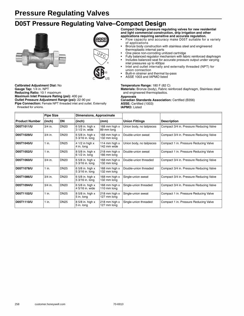
Pressure Regulating Valves
258 customer.honeywell.com 70-6910
D05T Pressure Regulating Valve–Compact DesignCompact Design pressure regulating valves for new residential and light commercial construction, drip irrigation and other applications requiring sensitive and accurate regulation.• Flow capacity and accuracy make D05T suitable for a variety
of applications • Bronze body construction with stainless steel and engineered
thermoplastic internal parts • One piece non-corroding unitized cartridge • Fully balanced regulator mechanism with fabric reinforced diaphragm • Includes balanced seat for accurate pressure output under varying
inlet pressures up to 400psi • Inlet and outlet internally and externally threaded (NPT) for
union connection • Built-in strainer and thermal by-pass • ASSE 1003 and IAPMO listed
Calibrated Adjustment Dial: NoGauge Tap: 1/4 in. NPTReducing Ratio: 10:1 maximumMaximum Inlet Pressure Rating (psi): 400 psiOutlet Pressure Adjustment Range (psi): 22-90 psiPipe Connection: Female NPT threaded inlet and outlet. Externally
threaded for unions.
Temperature Range: 180 F (82 C) Materials: Bronze (body), Fabric reinforced diaphragm, Stainless steel
and engineered thermoplastics.ApprovalsCanadian Standards Association: Certified (B356)ASSE: Certified (1003)IAPMO: Listed
U PC
®
®
C US
Product Number
Pipe Size Dimensions, Approximate
Union Fittings Description(inch) DN (inch) (mm)
D05T1011/U 3/4 in. DN20 6 5/8 in. high x 3 1/2 in. wide
168 mm high x 89 mm long
Union body, no tailpieces Compact 3/4 in. Pressure Reducing Valve
D05T1029/U 3/4 in. DN20 6 5/8 in. high x 5 3/16 in. long
168 mm high x 132 mm long
Double-union sweat Compact 3/4 in. Pressure Reducing Valve
D05T1045/U 1 in. DN25 4 1/2 in high x 4 in. long
114 mm high x 142 mm wide
Union body, no tailpieces Compact 1 in. Pressure Reducing Valve
D05T1052/U 1 in. DN25 8 5/8 in. high x 6 1/2 in. long
218 mm high x 166 mm long
Double-union sweat Compact 1 in. Pressure Reducing Valve
D05T1060/U 3/4 in. DN20 6 5/8 in. high x 5 3/16 in. long
168 mm high x 132 mm long
Double-union threaded Compact 3/4 in. Pressure Reducing Valve
D05T1078/U 1 in. DN25 6 5/8 in. high x 5 3/16 in. long
168 mm high x 132 mm long
Double-union threaded Compact 3/4 in. Pressure Reducing Valve
D05T1086/U 3/4 in. DN20 6 5/8 in. high x 5 3/16 in. long
168 mm high x 132 mm long
Single-union sweat Compact 3/4 in. Pressure Reducing Valve
D05T1094/U 3/4 in. DN20 6 5/8 in. high x 4 5/16 in. wide
168 mm high x 110 mm long
Single-union threaded Compact 3/4 in. Pressure Reducing Valve
D05T1102/U 1 in. DN25 8 5/8 in. high x 5 in. long
218 mm high x 127 mm long
Single-union sweat Compact 1 in. Pressure Reducing Valve
D05T1110/U 1 in. DN25 8 5/8 in. high x 5 in. long
218 mm high x 127 mm long
Single-union threaded Compact 1 in. Pressure Reducing Valve
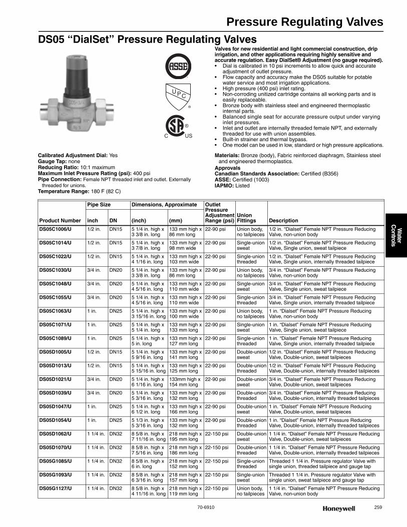
Pressure Regulating Valves
70-6910 259
Water
Controls
DS05 “DialSet” Pressure Regulating ValvesValves for new residential and light commercial construction, drip irrigation, and other applications requiring highly sensitive and accurate regulation. Easy DialSet® Adjustment (no gauge required).• Dial is calibrated in 10 psi increments to allow quick and accurate
adjustment of outlet pressure. • Flow capacity and accuracy make the DS05 suitable for potable
water service and most irrigation applications. • High pressure (400 psi) inlet rating. • Non-corroding unitized cartridge contains all working parts and is
easily replaceable. • Bronze body with stainless steel and engineered thermoplastic
internal parts. • Balanced single seat for accurate pressure output under varying
inlet pressures. • Inlet and outlet are internally threaded female NPT, and externally
threaded for use with union assemblies. • Built-in strainer and thermal bypass. • One model can be used in low, standard or high pressure applications.
Calibrated Adjustment Dial: YesGauge Tap: noneReducing Ratio: 10:1 maximumMaximum Inlet Pressure Rating (psi): 400 psiPipe Connection: Female NPT threaded inlet and outlet. Externally
threaded for unions. Temperature Range: 180 F (82 C)
Materials: Bronze (body), Fabric reinforced diaphragm, Stainless steel and engineered thermoplastics.
ApprovalsCanadian Standards Association: Certified (B356)ASSE: Certified (1003)IAPMO: Listed
U PC
®
®
C US
Product Number
Pipe Size Dimensions, Approximate Outlet Pressure Adjustment Range (psi)
Union Fittings Descriptioninch DN (inch) (mm)
DS05C1006/U 1/2 in. DN15 5 1/4 in. high x 3 3/8 in. long
133 mm high x 86 mm long
22-90 psi Union body, no tailpieces
1/2 in. “Dialset” Female NPT Pressure Reducing Valve, non-union body
DS05C1014/U 1/2 in. DN15 5 1/4 in. high x 3 7/8 in. long
133 mm high x 98 mm wide
22-90 psi Single-union sweat
1/2 in. “Dialset” Female NPT Pressure Reducing Valve, Single union, sweat tailpiece
DS05C1022/U 1/2 in. DN15 5 1/4 in. high x 4 1/16 in. long
133 mm high x 103 mm wide
22-90 psi Single-union threaded
1/2 in. “Dialset” Female NPT Pressure Reducing Valve, Single union, internally threaded tailpiece
DS05C1030/U 3/4 in. DN20 5 1/4 in. high x 3 3/8 in. long
133 mm high x 86 mm long
22-90 psi Union body, no tailpieces
3/4 in. “Dialset” Female NPT Pressure Reducing Valve, non-union body
DS05C1048/U 3/4 in. DN20 5 1/4 in. high x 4 5/16 in. long
133 mm high x 110 mm wide
22-90 psi Single-union sweat
3/4 in. “Dialset” Female NPT Pressure Reducing Valve, Single union, sweat tailpiece
DS05C1055/U 3/4 in. DN20 5 1/4 in. high x 4 5/16 in. long
133 mm high x 110 mm wide
22-90 psi Single-union threaded
3/4 in. “Dialset” Female NPT Pressure Reducing Valve, Single union, internally threaded tailpiece
DS05C1063/U 1 in. DN25 5 1/4 in. high x 3 15/16 in. long
133 mm high x 100 mm wide
22-90 psi Union body, no tailpieces
1 in. “Dialset” Female NPT Pressure Reducing Valve, non-union body
DS05C1071/U 1 in. DN25 5 1/4 in. high x 5 1/4 in. long
133 mm high x 133 mm long
22-90 psi Single-union sweat
1 in. “Dialset” Female NPT Pressure Reducing Valve, Single union, sweat tailpiece
DS05C1089/U 1 in. DN25 5 1/4 in. high x 5 in. long
133 mm high x 127 mm long
22-90 psi Single-union threaded
1 in. “Dialset” Female NPT Pressure Reducing Valve, Single union, internally threaded tailpiece
DS05D1005/U 1/2 in. DN15 5 1/4 in. high x 5 9/16 in. long
133 mm high x 141 mm long
22-90 psi Double-union sweat
1/2 in. “Dialset” Female NPT Pressure Reducing Valve, Double-union, sweat tailpieces
DS05D1013/U 1/2 in. DN15 5 1/4 in. high x 5 15/16 in. long
133 mm high x 125 mm long
22-90 psi Double-union threaded
1/2 in. “Dialset” Female NPT Pressure Reducing Valve, Double-union, internally threaded tailpieces
DS05D1021/U 3/4 in. DN20 5 1/4 in. high x 6 1/16 in. long
133mm high x 154 mm long
22-90 psi Double-union sweat
3/4 in. “Dialset” Female NPT Pressure Reducing Valve, Double-union, sweat tailpieces
DS05D1039/U 3/4 in. DN20 5 1/4 in. high x 5 3/16 in. long
133 mm high x 132 mm long
22-90 psi Double-union threaded
3/4 in. “Dialset” Female NPT Pressure Reducing Valve, Double-union, internally threaded tailpieces
DS05D1047/U 1 in. DN25 5 1/4 in. high x 6 1/2 in. long
133 mm high x 166 mm long
22-90 psi Double-union sweat
1 in. “Dialset” Female NPT Pressure Reducing Valve, Double-union, sweat tailpieces
DS05D1054/U 1 in. DN25 5 1/3 in. high x 5 3/16 in. long
133 mm high x 132 mm long
22-90 psi Double-union threaded
1 in. “Dialset” Female NPT Pressure Reducing Valve, Double-union, internally threaded tailpieces
DS05D1062/U 1 1/4 in. DN32 8 5/8 in. high x 7 11/16 in. long
218 mm high x 195 mm long
22-150 psi Double-union sweat
1 1/4 in. “Dialset” Female NPT Pressure Reducing Valve, Double-union, sweat tailpieces
DS05D1070/U 1 1/4 in. DN32 8 5/8 in. high x 7 5/16 in. long
218 mm high x 186 mm long
22-150 psi Double-union threaded
1 1/4 in. “Dialset” Female NPT Pressure Reducing Valve, Double-union, internally threaded tailpieces
DS05G1085/U 1 1/4 in. DN32 8 5/8 in. high x 6 in. long
218 mm high x 152 mm long
22-150 psi Single-union threaded
Threaded 1 1/4 in. Pressure regulator Valve with single union, threaded tailpiece and gauge tap
DS05G1093/U 1 1/4 in. DN32 8 5/8 in. high x 6 3/16 in. long
218 mm high x 157 mm long
22-150 psi Single-union sweat
Threaded 1 1/4 in. Pressure regulator Valve with single union, sweat tailpiece and gauge tap
DS05G1127/U 1 1/4 in. DN32 8 5/8 in. high x 4 11/16 in. long
218 mm high x 119 mm long
22-150 psi Union body, no tailpieces
1 1/4 in. “Dialset” Female NPT Pressure Reducing Valve, non-union body

Pressure Regulating Valves
260 customer.honeywell.com 70-6910
DS06 “DialSet” Pressure Regulating ValvesHigh quality pressure regulating valve that maintains a constant outlet pressure over a wide range of inlet supply pressures. Includes calibrated outlet pressure set dial that allows outlet pressure adjustments without the use of a gauge in most applications. Easy DialSet® Adjustment (no gauge required)• Ideally suited for potable water and irrigation applications requiring
accurate regulation. • Wide outlet pressure range, high inlet pressure, and compact design
allow flexibility in installation and application. • Non-corroding unitized cartridge contains all working parts and is
easily replaceable. • Includes built-in strainer and thermal bypass. • Balanced seat construction provides superior pressure regulation. • Gauge tapped.
Calibrated Adjustment Dial: YesGauge Tap: 1/4 in. NPT (two, one on each side of body)Reducing Ratio: 10:1 maximumMaximum Inlet Pressure Rating (psi): 400 psiOutlet Pressure Adjustment Range (psi): 22-130 psiPipe Connection: Female NPT threaded inlet and outlet. Externally
threaded for unionsTemperature Range: 180 F (82 C)
Materials: Bronze (body), Fabric reinforced diaphragm, Stainless steel and engineered thermoplastics
ApprovalsCanadian Standards Association: Certified (B356)ASSE: Certified (1003)IAPMO: Listed
U PC
®
®
C US
Product Number
Pipe Size Dimensions, ApproximateUnion Fittings Description(inch) DN (inch) (mm)
DS06D1003/U 1 1/2 in. DN40 11 13/16 in. high x 9 3/8 in. long
299 mm high x 238 mm long
Double-union sweat
1 1/2 in. “Dialset” Female NPT Pressure Reducing Valve, Double-union, sweat tailpieces
DS06D1011/U 1 1/2 in. DN40 11 13/16 in. high x 9 3/16 in. long
299 mm high x 233 mm long
Double-union threaded
1 1/2 in. “Dialset” Female NPT Pressure Reducing Valve, Double-union, internally threaded tailpieces
DS06D1029/U 2 in. DN50 11 13/16 in. high x 10 3/16 in. long
299 mm high x 257 mm long
Double-union sweat
2 in. “Dialset” Female NPT Pressure Reducing Valve, Double-union, sweat tailpieces
DS06D1037/U 2 in. DN50 11 13/16 in. high x 9 5/16 in. long
299 mm high x 237 mm long
Double-union threaded
2 in. “Dialset” Female NPT Pressure Reducing Valve, Double-union, internally threaded tailpieces
DS06G1000/U 1 1/2 in. DN40 11 13/16 in. high x 7 13/16 in. long
299 mm high x 198 mm long
Single-union threaded
Threaded 1 1/2 in. Pressure regulator Valve
DS06G1018/U 1 1/2 in. DN40 11 13/16 in. high x 7 7/8 in. long
299 mm high x 201 mm long
Single-union sweat
Sweat 1 1/2 in. Pressure regulator Valve
DS06G1026/U 2 in. DN50 11 13/16 in. high x 7 7/8 in. long
299 mm high x 200 mm long
Single-union threaded
Threaded 2 in. Pressure regulator Valve
DS06G1034/U 2 in. DN50 11 13/16 in. high x 8 5/16 in. long
299 mm high x 211 mm long
Single-union sweat
Sweat 2 in. Pressure regulator Valve
DS06G1042/U 1 1/2 in. DN40 11 13/16 in. high x 6 3/8 in. long
299 mm high x 162 mm long
Union body, no tailpieces
1 1/2 in. “Dialset” Female NPT Pressure Reducing Valve, non-union body
DS06G1059/U 2 in. DN50 11 13/16 in. high x 6 3/8 in. long
299 mm high x 162 mm long
Union body, no tailpieces
2 in. “Dialset” Female NPT Pressure Reducing Valve, non-union body
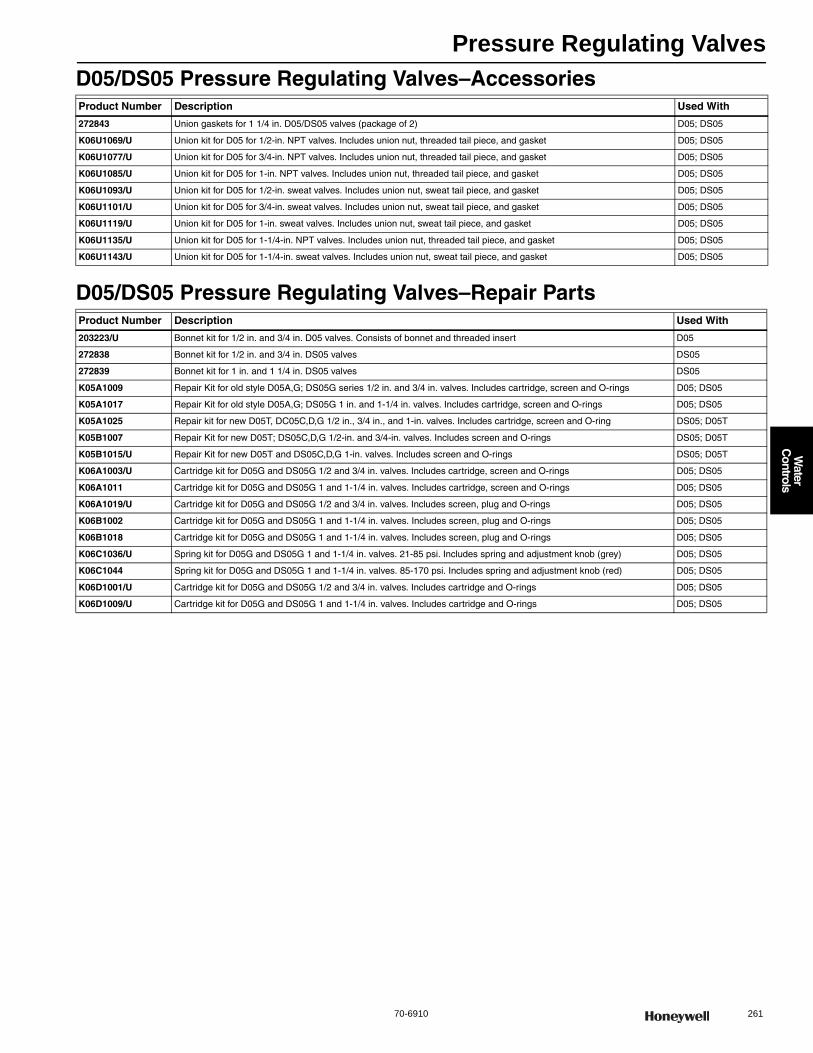
Pressure Regulating Valves
70-6910 261
Water
Controls
D05/DS05 Pressure Regulating Valves–Accessories
D05/DS05 Pressure Regulating Valves–Repair Parts
Product Number Description Used With
272843 Union gaskets for 1 1/4 in. D05/DS05 valves (package of 2) D05; DS05
K06U1069/U Union kit for D05 for 1/2-in. NPT valves. Includes union nut, threaded tail piece, and gasket D05; DS05
K06U1077/U Union kit for D05 for 3/4-in. NPT valves. Includes union nut, threaded tail piece, and gasket D05; DS05
K06U1085/U Union kit for D05 for 1-in. NPT valves. Includes union nut, threaded tail piece, and gasket D05; DS05
K06U1093/U Union kit for D05 for 1/2-in. sweat valves. Includes union nut, sweat tail piece, and gasket D05; DS05
K06U1101/U Union kit for D05 for 3/4-in. sweat valves. Includes union nut, sweat tail piece, and gasket D05; DS05
K06U1119/U Union kit for D05 for 1-in. sweat valves. Includes union nut, sweat tail piece, and gasket D05; DS05
K06U1135/U Union kit for D05 for 1-1/4-in. NPT valves. Includes union nut, threaded tail piece, and gasket D05; DS05
K06U1143/U Union kit for D05 for 1-1/4-in. sweat valves. Includes union nut, sweat tail piece, and gasket D05; DS05
Product Number Description Used With
203223/U Bonnet kit for 1/2 in. and 3/4 in. D05 valves. Consists of bonnet and threaded insert D05
272838 Bonnet kit for 1/2 in. and 3/4 in. DS05 valves DS05
272839 Bonnet kit for 1 in. and 1 1/4 in. DS05 valves DS05
K05A1009 Repair Kit for old style D05A,G; DS05G series 1/2 in. and 3/4 in. valves. Includes cartridge, screen and O-rings D05; DS05
K05A1017 Repair Kit for old style D05A,G; DS05G 1 in. and 1-1/4 in. valves. Includes cartridge, screen and O-rings D05; DS05
K05A1025 Repair kit for new D05T, DC05C,D,G 1/2 in., 3/4 in., and 1-in. valves. Includes cartridge, screen and O-ring DS05; D05T
K05B1007 Repair Kit for new D05T; DS05C,D,G 1/2-in. and 3/4-in. valves. Includes screen and O-rings DS05; D05T
K05B1015/U Repair Kit for new D05T and DS05C,D,G 1-in. valves. Includes screen and O-rings DS05; D05T
K06A1003/U Cartridge kit for D05G and DS05G 1/2 and 3/4 in. valves. Includes cartridge, screen and O-rings D05; DS05
K06A1011 Cartridge kit for D05G and DS05G 1 and 1-1/4 in. valves. Includes cartridge, screen and O-rings D05; DS05
K06A1019/U Cartridge kit for D05G and DS05G 1/2 and 3/4 in. valves. Includes screen, plug and O-rings D05; DS05
K06B1002 Cartridge kit for D05G and DS05G 1 and 1-1/4 in. valves. Includes screen, plug and O-rings D05; DS05
K06B1018 Cartridge kit for D05G and DS05G 1 and 1-1/4 in. valves. Includes screen, plug and O-rings D05; DS05
K06C1036/U Spring kit for D05G and DS05G 1 and 1-1/4 in. valves. 21-85 psi. Includes spring and adjustment knob (grey) D05; DS05
K06C1044 Spring kit for D05G and DS05G 1 and 1-1/4 in. valves. 85-170 psi. Includes spring and adjustment knob (red) D05; DS05
K06D1001/U Cartridge kit for D05G and DS05G 1/2 and 3/4 in. valves. Includes cartridge and O-rings D05; DS05
K06D1009/U Cartridge kit for D05G and DS05G 1 and 1-1/4 in. valves. Includes cartridge and O-rings D05; DS05

Pressure Regulating Valves
262 customer.honeywell.com 70-6910
D06/DS06 Pressure Regulating Valves–Accessories
D06/DS06 Pressure Regulating Valves–Repair Parts
Product Number Description Used With
272858/U Union Gasket for 1 1/2 in. D06 and DS06G valves DS06G; D06
272859/U Union gaskets for 2-in. D06 and DS06 valves D06; DS06
K06U1037/U Union kit for D06 for 1-1/2-in. NPT valves. Includes one each union nut, NPT internally threaded tailpiece, and gasket
D06; DS06
K06U1045/U Union kit for D06 for 2-in. NPT valves. Includes one each union nut, NPT internally threaded tailpiece, and gasket D06; DS06
K06U5034/U Union kit for D06 for 1-1/2-in. sweat valves. Includes one each union nut, sweat tail piece, and gasket D06; DS06
K06U5042/U Union kit for D06 for 2-in. sweat valves. Includes one each union nut, sweat tail piece, and gasket D06; DS06
Product Number Description Used With
0900153/U Bonnet Kit For 1 and 1 1/4 in D06 only D06
0900154 Bonnet Assembly 1 1/2 in. and 2 in. —
0900368/U Bonnet Assembly for 1/2 in. and 3/4 in. D06 Valves D06
272867 Bonnet kit for 1-1/2 in. and 2 in. DS06 valves DS06
K06B1030 Cartridge kit for D06G and DS06G 1-1/2-in. and 2-in. valves. Includes strainer, support and 2 O-rings D06; DS06
K06C1060 Spring kit for D06G and DS06G 1-1/2 and 2 in. valves. 21-85 psi. Includes spring and adjustment knob (grey) D06; DS06
K06D1017 Cartridge kit for D06G and DS06G 1-1/2 and 2 in. valves. Includes cartridge and O-rings D06; DS06
K06D1044 Cartridge kit for D06G,T,U and DS06G 1-1/2-in. and 2in. valves. Includes cartridge, screen and O-rings D06; DS06
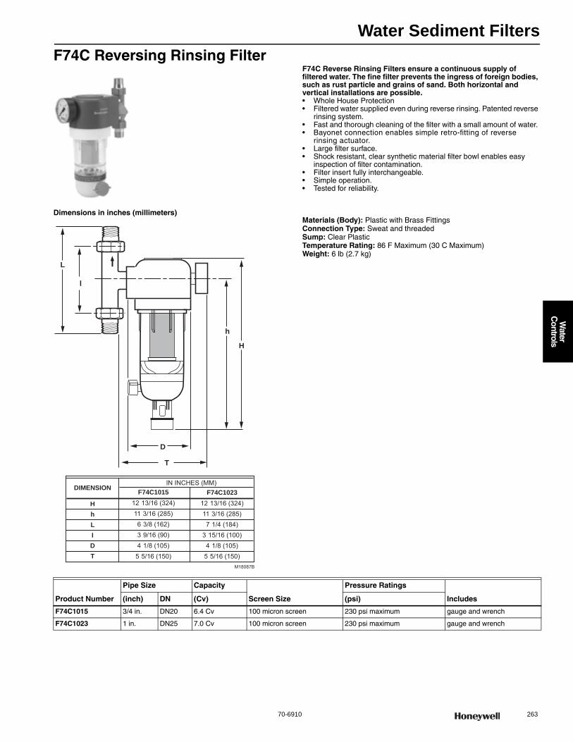
Water Sediment Filters
70-6910 263
Water
Controls
F74C Reversing Rinsing FilterF74C Reverse Rinsing Filters ensure a continuous supply of filtered water. The fine filter prevents the ingress of foreign bodies, such as rust particle and grains of sand. Both horizontal and vertical installations are possible.• Whole House Protection• Filtered water supplied even during reverse rinsing. Patented reverse
rinsing system. • Fast and thorough cleaning of the filter with a small amount of water. • Bayonet connection enables simple retro-fitting of reverse
rinsing actuator. • Large filter surface. • Shock resistant, clear synthetic material filter bowl enables easy
inspection of filter contamination. • Filter insert fully interchangeable. • Simple operation. • Tested for reliability.
Dimensions in inches (millimeters)Materials (Body): Plastic with Brass FittingsConnection Type: Sweat and threadedSump: Clear PlasticTemperature Rating: 86 F Maximum (30 C Maximum) Weight: 6 lb (2.7 kg)
H
l
L
D
T
DIMENSIONIN INCHES (MM)
F74C101512 13/16 (324)H 12 13/16 (324)11 3/16 (285)h 11 3/16 (285)6 3/8 (162)L 7 1/4 (184)3 9/16 (90)I 3 15/16 (100)4 1/8 (105)D 4 1/8 (105)
5 5/16 (150)T 5 5/16 (150)
F74C1023
M18087B
h
Product Number
Pipe Size Capacity
Screen Size
Pressure Ratings
Includes(inch) DN (Cv) (psi)
F74C1015 3/4 in. DN20 6.4 Cv 100 micron screen 230 psi maximum gauge and wrench
F74C1023 1 in. DN25 7.0 Cv 100 micron screen 230 psi maximum gauge and wrench
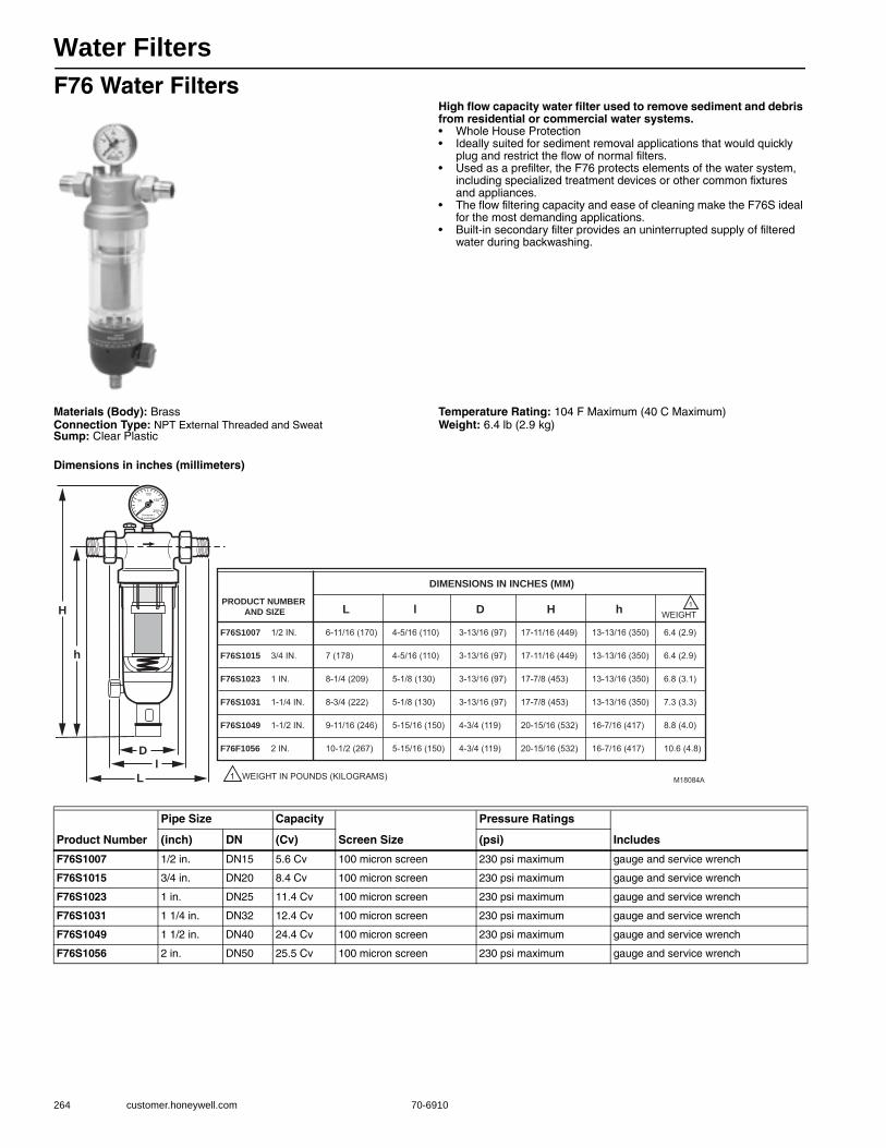
Water Filters
264 customer.honeywell.com 70-6910
F76 Water FiltersHigh flow capacity water filter used to remove sediment and debris from residential or commercial water systems.• Whole House Protection• Ideally suited for sediment removal applications that would quickly
plug and restrict the flow of normal filters. • Used as a prefilter, the F76 protects elements of the water system,
including specialized treatment devices or other common fixtures and appliances.
• The flow filtering capacity and ease of cleaning make the F76S ideal for the most demanding applications.
• Built-in secondary filter provides an uninterrupted supply of filtered water during backwashing.
Materials (Body): BrassConnection Type: NPT External Threaded and SweatSump: Clear Plastic
Temperature Rating: 104 F Maximum (40 C Maximum) Weight: 6.4 lb (2.9 kg)
Dimensions in inches (millimeters)
Product Number
Pipe Size Capacity
Screen Size
Pressure Ratings
Includes(inch) DN (Cv) (psi)
F76S1007 1/2 in. DN15 5.6 Cv 100 micron screen 230 psi maximum gauge and service wrench
F76S1015 3/4 in. DN20 8.4 Cv 100 micron screen 230 psi maximum gauge and service wrench
F76S1023 1 in. DN25 11.4 Cv 100 micron screen 230 psi maximum gauge and service wrench
F76S1031 1 1/4 in. DN32 12.4 Cv 100 micron screen 230 psi maximum gauge and service wrench
F76S1049 1 1/2 in. DN40 24.4 Cv 100 micron screen 230 psi maximum gauge and service wrench
F76S1056 2 in. DN50 25.5 Cv 100 micron screen 230 psi maximum gauge and service wrench
F76S1007 1/2 IN. 6-11/16 (170) 4-5/16 (110) 3-13/16 (97) 17-11/16 (449) 13-13/16 (350) 6.4 (2.9)
F76S1015 3/4 IN. 7 (178) 4-5/16 (110) 3-13/16 (97) 17-11/16 (449) 13-13/16 (350) 6.4 (2.9)
F76S1023 1 IN. 8-1/4 (209) 5-1/8 (130) 3-13/16 (97) 17-7/8 (453) 13-13/16 (350) 6.8 (3.1)
F76S1031 1-1/4 IN. 8-3/4 (222) 5-1/8 (130) 3-13/16 (97) 17-7/8 (453) 13-13/16 (350) 7.3 (3.3)
F76S1049 1-1/2 IN. 9-11/16 (246) 5-15/16 (150) 4-3/4 (119) 20-15/16 (532) 16-7/16 (417) 8.8 (4.0)
F76F1056 2 IN. 10-1/2 (267) 5-15/16 (150) 4-3/4 (119) 20-15/16 (532) 16-7/16 (417) 10.6 (4.8)
PRODUCT NUMBER AND SIZE L l D H h
1 WEIGHT IN POUNDS (KILOGRAMS)
DIMENSIONS IN INCHES (MM)
100
150
200
50
Honeywe lB aukmann
H
h
Dl
L M18084A
1WEIGHT
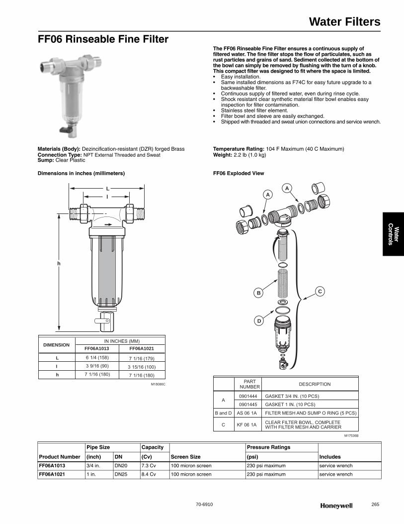
Water Filters
70-6910 265
Water
Controls
FF06 Rinseable Fine FilterThe FF06 Rinseable Fine Filter ensures a continuous supply of filtered water. The fine filter stops the flow of particulates, such as rust particles and grains of sand. Sediment collected at the bottom of the bowl can simply be removed by flushing with the turn of a knob. This compact filter was designed to fit where the space is limited.• Easy installation. • Same installed dimensions as F74C for easy future upgrade to a
backwashable filter. • Continuous supply of filtered water, even during rinse cycle. • Shock resistant clear synthetic material filter bowl enables easy
inspection for filter contamination. • Stainless steel filter element. • Filter bowl and sleeve are easily exchanged.• Shipped with threaded and sweat union connections and service wrench.
Materials (Body): Dezincification-resistant (DZR) forged BrassConnection Type: NPT External Threaded and SweatSump: Clear Plastic
Temperature Rating: 104 F Maximum (40 C Maximum) Weight: 2.2 lb (1.0 kg)
Dimensions in inches (millimeters) FF06 Exploded View
h
l L
M18086C
DIMENSIONIN INCHES (MM)
FF06A1013
6 1/4 (158)L 7 1/16 (179)3 9/16 (90)I 3 15/16 (100)
7 1/16 (180)h 7 1/16 (180)
FF06A1021
M17536B
AA
C
D
B
PARTNUMBER DESCRIPTION
A0901444 GASKET 3/4 IN. (10 PCS)
0901445 GASKET 1 IN. (10 PCS)
B and D AS 06 1A FILTER MESH AND SUMP O RING (5 PCS)
C KF 06 1A CLEAR FILTER BOWL, COMPLETE WITH FILTER MESH AND CARRIER
Product Number
Pipe Size Capacity
Screen Size
Pressure Ratings
Includes(inch) DN (Cv) (psi)
FF06A1013 3/4 in. DN20 7.3 Cv 100 micron screen 230 psi maximum service wrench
FF06A1021 1 in. DN25 8.4 Cv 100 micron screen 230 psi maximum service wrench
Backwash Controls
266 customer.honeywell.com 70-6910
Water Sediment Filter Parts and Accessories
MV876 Automatic Backwash ControlThe MV876B Automatic-Backwash Control is available as an accessory. This control is fitted to the drain valve and is programmed by the user to automatically perform the backwash function according to the desired interval.• Bayonet fitting simplifies upgrade to automatic backwash. • 16 field-selectable backwash intervals (from every four minutes to
once every three months) eliminate need for external timer. • Connections for external control on the MV876 provide for use in
automated systems and differential pressure control. • MV876 can be manually activated to initiate backwash. • Battery (AA) backup to insure completion of backwash cycle in
spite of power loss.
Dimensions, Approximate: 6 in. high, 2-3/4 in wide, 6-5/16 in. deep (152 mm high, 70mm wide, 160 mm deep)
Electrical Ratings: 24 Vac, 10 W
Product Number Description Used With
0900747 Sump O-ring for F76S Water Filter 1 1/2 in. F76S
0900748 Sump O-ring for F76S water filter 1/2 in. to 1 in. F76S
0901444 Union gasket for 1/2 in. or 3/4 in. connections F76S; FF06; F74C
0901445 Union gasket for 1 in. connections F76S; FF06; F74C
0901446 Union gasket for 1-1/4 in. connections F76S
0901447 Union gasket for 1-1/2 in. connections F76S
0901448/U Union gasket for 2 in. connections F76S
AF11S-1A 100 Micron Screen kit for F76S Water Filter 1/2 in. to 1-1/4 in. F76S
AF11S-1B/U 20 Micron Screen kit for F76S Water Filter 1/2 in. to 1-1/4 in. F76S
AF11S-1C 50 Micron Screen kit for F76S Water Filter 1/2 in. to 1-1/4 in. F76S
AF11S-1D 200 Micron Screen kit for F76S Water Filter 1/2 in. to 1-1/4 in. F76S
AF11S-11/2A 100 Micron Screen kit for F76S Water Filter 1 1/2 in. to 2 in. F76S
AF11S-11/2B 20 Micron Screen kit for F76S Water Filter 1 1/2 in. to 2 in. F76S
AF11S-11/2C 50 Micron Screen kit for F76S Water Filter 1 1/2 in. to 2 in. F76S
AF11S-11/2D 200 Micron Screen kit for F76S Water Filter 1 1/2 in. to 2 in. F76S
AF74-1A Insert Filter 100 Micron Screen F74C
AS06-1A Filter mesh and sump O-ring (5 pcs) FF06
FT09RS-1A Bronze Sump for F76S Water Filter 1/2 in. to 1-1/4 in. F76S
KF11S-1A Clear Plastic Sump (bowl) for F76S Water Filter 1/2 in. to 1-1/4 in. F76S
KH11S-1A Ball Valve for F76S water filter 1/2 in. to 2 in. F76S
KF11S-11/2A Clear Plastic Sump (bowl) for F76S Water Filter 1 1/2 in. to 2 in. F76S
Product Number Backwash Intervals DisplayElectrical Connections
Cycle Time (sec)
Battery Back-up Description
MV876B1018 16 Adjustable intervals from 4 min to 3 months
Digital Remote Activation 20 sec Yes, 4xAA Automatic backwash control, fits 1/2 in. to 2 in. F76S models and F74C models
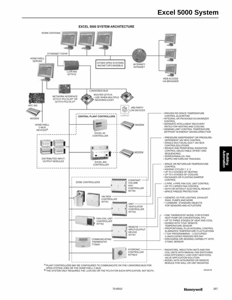
Excel 5000 System
70-6910 267
B
uilding A
utomation
Excel 5000 System
268 customer.honeywell.com 70-6910
Controller Tools
The Excel CARE and Live CARE software packages are graphic tools to easily and quickly create and simulate application programs that run controllers in EXCEL 5000® Systems. Users can perform these functions without extensive knowledge of a programming language. Users systematically select control system graphic elements such as lighting and Heating, Ventilating, and Air Conditioning (HVAC) equipment and create control sequences in a Microsoft® Windows® environment. CARE
software validates as the designer works, thus keeping the process free of errors. Work is completed quickly and efficiently. As part of the design process, CARE automatically creates comprehensive documentation and materials listings.
NOTE: All CARE products require a signed SOFTWARE LICENSE AGREEMENT prior to purchase. Ordering CARE via this website does not guarantee that you are approved for the purchase. Honeywell reserves the right to refuse shipment, if appropriate.• Point-and-click programming • Schematic drawing • Control strategy • Switching logic • Time function • Mathematical editor • Standard library. • Documentation • Control program simulation • Applicable to EXCEL 5000 System controllers • Password security
Application: ToolApplication Size: Small to LargeBuilding Management Interface: EBI; SymmetrE; XBSNetwork Communications: C-Bus; LonWorks BusCompatible with: Excel 5000 System Controllers
SymmetrEThe Honeywell SymmetrE™ building management system redefines what to expect from monitoring and control of your heating, ventilation and air conditioning equipment. The scalable, open SymmetrE™ system brings your building's occupant needs, operational issues and budget pressures into perfect balance. You get an unparalleled solution that helps simplify facility management, boost productivity and reduce costs. NOTE: All CARE products require a signed SymmetrE™ LICENSE AGREEMENT prior to purchase. Ordering SymmetrE™ via this website does not guarantee that you are approved for the purchase. Honeywell reserves the right to refuse shipment, if appropriate.The Honeywell SymmetrE™ PC workstation redefines what to expect from monitoring and controlling your building management system. The scalable, open SymmetrE™ software brings your building's occupant needs, operational issues and budget pressures into perfect balance. You get an unparalleled solution that helps simplify facility management, boost productivity and reduce costs.NOTE: All SymmetrE™ products require a signed SymmetrE™ LICENSE AGREEMENT prior to purchase. Ordering SymmetrE™ via this website does not guarantee that you are approved for the purchase. Honeywell reserves the right to refuse shipment, if appropriate.SymmetrE™ is a highly configurable PC workstation providing an efficient and reliable way of ensuring the comfort of people and the effective operation of buildings and facilities. Used with the Excel 5000 Building Management System it provides a complete solution to access information and the control needs of one or more buildings.
SymmetrE™ integrates using Open System Standards and Internet and Intranet applications. This allows you to choose the best field solutions for your building and to integrate information into SymmetrE™ seamlessly for further processing, reporting and distribution. SymmetrE™ provides operators, supervisors, and managers with a sophisticated web-style operator interface to enable personnel to easily monitor and control buildings at one or more sites.The SymmetrE™ Server runs on the multi-user, multi tasking, industry standard, Windows 2000 Professional and Windows XP Professional platforms. The SymmetrE™ Server runs application software that communicates to field controllers and updates a real time database. The SymmetrE™ Server can also act as the file server for displays and historical data collection and archiving.• Total solution for Heating, Ventilation & Air conditioning Building
Management Systems. • Integration with a diverse range of devices, Internet and Intranet
sources allowing intelligent management of key facility information. • Uses Industry standard hardware and Windows® 2000 Professional
and Windows XP® Professional Operating Systems • Supports the leading open standards: BACnet®, LONMARK®,
ODBC, OPC®, AdvanceDDE and Modbus®. • Easy-to-use web-style interface reduces operator training costs and
puts the user in control of every situation. • Designed and developed to International Standard ISO® 9001:2000
for quality assurance.
Application: Workstation SoftwareBuilding Management Interface: SymmetrE
SymmetrE R410 - Workstations
Product Number DescriptionCommissioning Software Output Type Used With Includes
CARE-80-LNS CARE: Graphic Programming Tool
CARE Graphical Interface Excel 5000 System Controllers
USB Drive with full installation of CARE 8 with voucher number
PROTPLUG-UP CARE: Graphic Programming Tool Upgrade
CARE Graphical Interface Excel 5000 System Controllers
USB Drive with CARE 8 upgrade
Product Number Description
SYM-IF-XL5DIRDIAL/U EXCEL 5000 Dial-up
SYM-NW-OPCSERV/U OPC Server
SYM-IF-OPCCL/U OPC Client Interface

Excel 5000 System
70-6910 269
B
uilding A
utomation
SymmetrE R410 - Software/Media
SymmetrE R410 - Upgrades
SymmetrE R410 - Options
SymmetrE R310 Workstation
SymmetrE R310 - Options
Product Number Description
SYM-BASE01/U SymmetrE R410 Base Package 1
SYM-BASE02/U SymmetrE R410 Base Package 2
SYM-BASE03/U SymmetrE R410 Base Package 3
SYM-ZZDVD410/U SymmetrE R410 Software on DVD
Product Number Description
SYM-UPGDR1/U SYM Upgrade Unit - Release Minus 1
SYM-UPGDR2/U SYM Upgrade Unit - Release Minus 2
SYM-UPGDR3/U SYM Upgrade Unit - Release Minus 3
SYM-UPGDRX/U SYM Upgrade Unit - Release Minus X
Product Number Description
SYM-DBP00250/U 250 Point Adder to Database Size
SYM-OPEASYMB/U Easy Mobile Services
SYM-IF-BACNET/U BACnet Client (R200 and later)
SYM-IF-MODBUS/U Modbus Interface
SYM-OP-ALMPAG/U Alarm Pager
SYM-OP-BACSERV/U BACnet Server (R200 and later)
SYM-OP-DTXL/U OPC Data Transfer - Local
SYM-OP-LNS/U LNS Server
SYM-OP-LNSUPG/U LNS Database Upgrade for systems with existing LNS Database
Product Number Description
SYM-DB2-5-EXP/U Expansion Pack - 250 to 500 point DB
SYM-DB5-10-EXP/U Expansion pack - 500 to 1000 Point DB
SYM-DB10-20-EXP/U Expansion pack - 1000 to 2000 Point DB
SYM-DB20-35-EXP/U Expansion pack - 2000 to 3500 Point DB
SYM-DB35-50-EXP/U Expansion pack - 3500 to 5000 Point DB
SYM-DB50-75-EXP/U Expansion pack - 5000 to 7500 Point DB
SYM-DB75-10K-EXP/U Expansion Pack - 7500 to 10,000 point DB
SYM-DB10K-15K-EXP/U Expansion Pack - 10,000 to 15,000 point DB
SYM-DB15K-20K-EXP/U Expansion Pack - 15,000 to 20,000 point DB
SYM-IF-ADVDDECL/U Advance DDE Interface
SYM-IF-BAC/U BACnet Client (R200 and later)
SYM-IF-OPCCL/U OPC Client Interface
SYM-IF-XL5DIRDIAL/U EXCEL 5000 Dial-up
SYM-NW-OPCSERV/U OPC Server
Product Number Description
SYM-IF-BACNET/U BACnet Client (R200 and later)
SYM-IF-MODBUS/U Modbus Interface
SYM-OP-ALMPAG/U Alarm Pager
SYM-OP-BACSERV/U BACnet Server (R200 and later)
SYM-OP-DTXL/U OPC Data Transfer - Local
SYM-OP-LNS/U LNS Server
SYM-OP-LNSUPG/U LNS Database Upgrade for systems with existing LNS Database
SYM-STB-UP-STN/U Upgrade Browser client to full station client, R310 ONLY
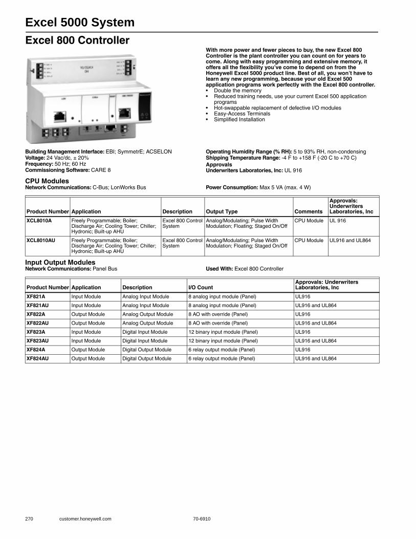
Excel 5000 System
270 customer.honeywell.com 70-6910
Excel 800 ControllerWith more power and fewer pieces to buy, the new Excel 800 Controller is the plant controller you can count on for years to come. Along with easy programming and extensive memory, it offers all the flexibility you’ve come to depend on from the Honeywell Excel 5000 product line. Best of all, you won’t have to learn any new programming, because your old Excel 500 application programs work perfectly with the Excel 800 controller.• Double the memory • Reduced training needs, use your current Excel 500 application
programs • Hot-swappable replacement of defective I/O modules • Easy-Access Terminals • Simplified Installation
Building Management Interface: EBI; SymmetrE; ACSELONVoltage: 24 Vac/dc, ± 20%Frequency: 50 Hz; 60 HzCommissioning Software: CARE 8
Operating Humidity Range (% RH): 5 to 93% RH, non-condensingShipping Temperature Range: -4 F to +158 F (-20 C to +70 C) ApprovalsUnderwriters Laboratories, Inc: UL 916
CPU ModulesNetwork Communications: C-Bus; LonWorks Bus Power Consumption: Max 5 VA (max. 4 W)
Input Output ModulesNetwork Communications: Panel Bus Used With: Excel 800 Controller
Product Number Application Description Output Type Comments
Approvals: Underwriters Laboratories, Inc
XCL8010A Freely Programmable; Boiler; Discharge Air; Cooling Tower; Chiller; Hydronic; Built-up AHU
Excel 800 Control System
Analog/Modulating; Pulse Width Modulation; Floating; Staged On/Off
CPU Module UL 916
XCL8010AU Freely Programmable; Boiler; Discharge Air; Cooling Tower; Chiller; Hydronic; Built-up AHU
Excel 800 Control System
Analog/Modulating; Pulse Width Modulation; Floating; Staged On/Off
CPU Module UL916 and UL864
Product Number Application Description I/O CountApprovals: Underwriters Laboratories, Inc
XF821A Input Module Analog Input Module 8 analog input module (Panel) UL916
XF821AU Input Module Analog Input Module 8 analog input module (Panel) UL916 and UL864
XF822A Output Module Analog Output Module 8 AO with override (Panel) UL916
XF822AU Output Module Analog Output Module 8 AO with override (Panel) UL916 and UL864
XF823A Input Module Digital Input Module 12 binary input module (Panel) UL916
XF823AU Input Module Digital Input Module 12 binary input module (Panel) UL916 and UL864
XF824A Output Module Digital Output Module 6 relay output module (Panel) UL916
XF824AU Output Module Digital Output Module 6 relay output module (Panel) UL916 and UL864

Excel 5000 System
70-6910 271
B
uilding A
utomation
Excel Distributed I/OWith more power and fewer pieces to buy, the new Excel 800 Controller is the plant controller you can count on for years to come. Along with easy programming and extensive memory, it offers all the flexibility you’ve come to depend on from the Honeywell Excel 5000 product line. Best of all, you won’t have to learn any new programming, because your old Excel 500 application programs work perfectly with the Excel 800 controller.• Double the memory • Reduced training needs, use your current Excel 500 application
programs • Hot-swappable replacement of defective I/O modules • Easy-Access Terminals • Simplified Installation
Application: Distributed I/OBuilding Management Interface: EBI; SymmetrE; ACSELONCommissioning Software: CARE 8Used With: Excel 800 Controller
Product Number DescriptionNetwork Communications I/O Count Comments
Approvals: Underwriters Laboratories, Inc
XFL821A Distr buted I/O - Analog input module
LonWorks Bus 8 analog input module (LON)
— UL916
XFL821AU Distr buted I/O - Analog input module
LonWorks Bus 8 analog input module (LON)
— UL916 and UL864
XFL822A Distr buted I/O - Analog output module
LonWorks Bus 8 analog output module (LON)
— UL916
XFL822AU Distr buted I/O - Analog output module
LonWorks Bus 8 analog output module (LON)
— UL916 and UL864
XFL823A Distr buted I/O - Digital input module
LonWorks Bus 12 binary input module (LON)
Includes 12 LEDs UL916
XFL823AU Distr buted I/O - Digital input module
LonWorks Bus 12 binary input module (LON)
Includes 12 LEDs UL916 and UL864
XFL824A Distr buted I/O - Digital output module
LonWorks Bus 6 relay output module (LON)
— UL916
XFL824AU Distr buted I/O - Digital output module
LonWorks Bus 6 relay output module (LON)
— UL916 and UL864
XFLR822A Analog output manual override module
LonWorks Bus 8 AO with override (LON) The manual override module works even if the CPU is not working.
UL916
XFLR822AU Analog output manual override module
LonWorks Bus 8 AO with override (LON) The manual override module works even if the CPU is not working.
UL916 and UL864
XFLR824A Digital output manual override module
LonWorks Bus 6 relays with override (LON)
The manual override module works even if the CPU is not working.
UL916
XFLR824AU Digital output manual override module
LonWorks Bus 6 relays with override (LON)
The manual override module works even if the CPU is not working.
UL916 and UL864
XFR822A Analog output manual override module
Panel Bus 8 AO with override (Panel)
The manual override module works even if the CPU is not working.
UL916
XFR822AU Analog output manual override module
Panel Bus 8 AO with override (Panel)
The manual override module works even if the CPU is not working.
UL916 and UL864
XFR824A Digital output manual override module
Panel Bus 6 relays with override (Panel)
The manual override module works even if the CPU is not working.
UL916
XFR824AU Digital output manual override module
Panel Bus 6 relays with override (Panel)
The manual override module works even if the CPU is not working.
UL916 and UL864
XFR825A Actuator output module Panel Bus Actuator output module (Panel)
— UL916
XFR825AU Actuator output module Panel Bus Actuator output module (Panel)
— UL916 and UL864
XFU830A Mixed I/O Module Panel Bus 8 analog input module (Panel); 8AI's, 12DI's, 8AO's, 6RO's
— UL916

Excel 5000 System
272 customer.honeywell.com 70-6910
Excel 100 ControllerThe Excel 100 Controllers are direct-digital control, microprocessor-based, programmable controllers that manage building functions.• Stand-alone or networked operation for flexible use or expansion. • CARE generated application programs for comprehensive control
strategies. • Analog or digital inputs and outputs for flexible point use. • Multiple operator interface options for local or easy on-site changes. • Point trending for timely information. • Alarm handling facility to locally display the problem and remote dial
out to act on it. • Battery-backed RAM data to keep controller programming in place
during power outage. • Bus-Wide MMI provides local viewing/modification of point
information of all controllers attached to the Communication Bus.
Dimensions, Approximate: 9.25 in. high x 7.56 in. wide x 2.83 in. deep (235 mm high x 192 mm wide x 72 mm deep)
Application: Programmable ControllerBuilding Management Interface: EBI; SymmetrE; ACSELONCommissioning Software: CAREVoltage: 24 Vac/VdcFrequency: 50 Hz; 60 HzPower Consumption: 25 VA Max.
Operating Temperature Range: 32 F to 122 F (0 C to 50 C) Operating Humidity Range (% RH): 5 to 90% RH, non-condensingShipping Temperature Range: -4 F to +140 F (-20 C to +60 C) ApprovalsCE: ApprovedFederal Communications Commission: Meets FCC Part 15, Subpart J
for Class A equipmentUnderwriters Laboratories, Inc: Form UL916
Excel 50 ControllersA compact, programmable controller that manages small building control applications. Available with or without operator interface. Provides perfect solution for managing small building control applications and HVAC equipment control applications.• Direct communication to C-bus & LonWorks bus and/or modems. • DIN rail or panel door mounting. • Available with or without operator interface. • Stand-alone or networked operation. • CARE-generated application programs; ability to reuse available
CARE applications. • Flash-EPROM for efficient downloads. • Wiring simplicity: accessible and removable screw terminal blocks. • Capacitor-backed RAM; no battery required.
Dimensions, Approximate: 5.90 in. high x 7.79 in. wide x 3.19 in. deep (150 mm high x 198 mm wide x 81 mm deep)
Application: Built-up AHU, Chiller, Cooling Tower, Boiler, Freely Programmable
Building Management Interface: EBI; SymmetrE; ACSELONCommissioning Software: CAREVoltage: 24 Vac ± 20%Frequency: 50 Hz; 60 HzPower Consumption: 72 VA, if fully equipped
Operating Temperature Range: 32 F to 122 F (0 C to 50 C) Operating Humidity Range (% RH): 5 to 93% RH, non-condensingShipping Temperature Range: -4 F to +158 F (-20 C to +70 C) ApprovalsCE: ApprovedFederal Communications Commission: Meets FCC Part 15, Subpart J
for Class A equipmentUnderwriters Laboratories, Inc: Form UL916
Product Number DescriptionNetwork Communications I/O Count Output Type Comments
XL100CU Freely Programmable DDC controller
C-Bus 12 UO; 12 UI; 12 DI
0-10 Vdc, 20mA —
Product Number DescriptionNetwork Communications I/O Count Output Type Comments Includes
XL50A-UMMIPCCBLON Freely Programmable DDC controller, with operator interface
C-Bus; LonWorks Bus
4 DI, 8 UI, 4 UO, 6 DOs
Analog/Modulating; Pulse Width Modulation; Floating; Staged On/Off
Includes Operator Interface
C-Bus/LonWorks Bus communication card
XL50A-UPCCBLON Freely Programmable DDC controller
C-Bus; LonWorks Bus
4 DI, 8 UI, 4 UO, 6 DOs
Analog/Modulating; Pulse Width Modulation; Floating; Staged On/Off
Does not have Operator Interface
C-Bus/LonWorks Bus communication card
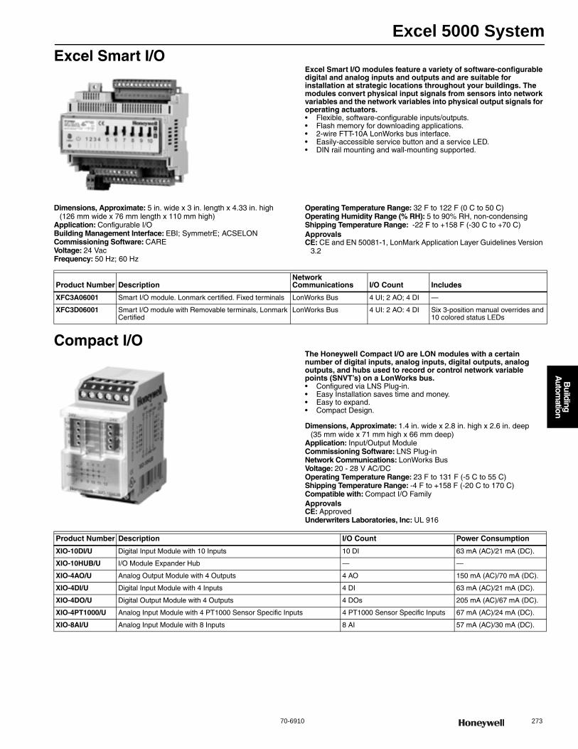
Excel 5000 System
70-6910 273
B
uilding A
utomation
Excel Smart I/OExcel Smart I/O modules feature a variety of software-configurable digital and analog inputs and outputs and are suitable for installation at strategic locations throughout your buildings. The modules convert physical input signals from sensors into network variables and the network variables into physical output signals for operating actuators.• Flexible, software-configurable inputs/outputs. • Flash memory for downloading applications. • 2-wire FTT-10A LonWorks bus interface. • Easily-accessible service button and a service LED. • DIN rail mounting and wall-mounting supported.
Dimensions, Approximate: 5 in. wide x 3 in. length x 4.33 in. high(126 mm wide x 76 mm length x 110 mm high)
Application: Configurable I/OBuilding Management Interface: EBI; SymmetrE; ACSELONCommissioning Software: CAREVoltage: 24 VacFrequency: 50 Hz; 60 Hz
Operating Temperature Range: 32 F to 122 F (0 C to 50 C) Operating Humidity Range (% RH): 5 to 90% RH, non-condensingShipping Temperature Range: -22 F to +158 F (-30 C to +70 C) ApprovalsCE: CE and EN 50081-1, LonMark Application Layer Guidelines Version
3.2
Compact I/OThe Honeywell Compact I/O are LON modules with a certain number of digital inputs, analog inputs, digital outputs, analog outputs, and hubs used to record or control network variable points (SNVT’s) on a LonWorks bus.• Configured via LNS Plug-in. • Easy Installation saves time and money. • Easy to expand. • Compact Design.
Dimensions, Approximate: 1.4 in. wide x 2.8 in. high x 2.6 in. deep (35 mm wide x 71 mm high x 66 mm deep)
Application: Input/Output ModuleCommissioning Software: LNS Plug-inNetwork Communications: LonWorks BusVoltage: 20 - 28 V AC/DCOperating Temperature Range: 23 F to 131 F (-5 C to 55 C) Shipping Temperature Range: -4 F to +158 F (-20 C to 170 C) Compatible with: Compact I/O FamilyApprovalsCE: ApprovedUnderwriters Laboratories, Inc: UL 916
Product Number DescriptionNetwork Communications I/O Count Includes
XFC3A06001 Smart I/O module. Lonmark certified. Fixed terminals LonWorks Bus 4 UI; 2 AO; 4 DI —
XFC3D06001 Smart I/O module with Removable terminals, Lonmark Certified
LonWorks Bus 4 UI: 2 AO: 4 DI Six 3-position manual overrides and 10 colored status LEDs
Product Number Description I/O Count Power Consumption
XIO-10DI/U Digital Input Module with 10 Inputs 10 DI 63 mA (AC)/21 mA (DC).
XIO-10HUB/U I/O Module Expander Hub — —
XIO-4AO/U Analog Output Module with 4 Outputs 4 AO 150 mA (AC)/70 mA (DC).
XIO-4DI/U Digital Input Module with 4 Inputs 4 DI 63 mA (AC)/21 mA (DC).
XIO-4DO/U Digital Output Module with 4 Outputs 4 DOs 205 mA (AC)/67 mA (DC).
XIO-4PT1000/U Analog Input Module with 4 PT1000 Sensor Specific Inputs 4 PT1000 Sensor Specific Inputs 67 mA (AC)/24 mA (DC).
XIO-8AI/U Analog Input Module with 8 Inputs 8 AI 57 mA (AC)/30 mA (DC).

Excel 5000 System
274 customer.honeywell.com 70-6910
LonWorks Bus AccessoriesProduct Number Description Used With
Q7740A1008/U Two way repeater with connections for two network segments LonMark Controllers
Q7740B1006/U Four way repeater with connections for four network segments LonMark Controllers
Q7750A2003 Excel 10 Zone Manager LonMark Controllers
Q7751A2010/U Excel 10 router used for connection with four network segments, FT-10/FT-10
LonMark Controllers
Q7751A2028/U Excel 10 router used for connection with four network segments, TP-1250/FT-10
LonMark Controllers
Q7751E1005/U I.LON 10-TP/FT - 10 CHANNEL LonMark Controllers
Q7751F1011/U I.LON 100 - TP/FT - 10 NO MODEM Firmware version e3 LonMark Controllers
Q7751F1029/U I.LON 100 - TP/FT - 10 With MODEM Firmware version e3 LonMark Controllers
Q7751G2009/U I.LON 600 FT - 10 LonMark Controllers
Q7751G2017/U I.LON 600 XF1250 LonMark Controllers
Q7751H2007/U PCLTA-21/TP-1250 —
Q7751H2015/U PCLTA-21/FT-10 —
Q7751J2002/U MPR-50 Multi-Port Router —
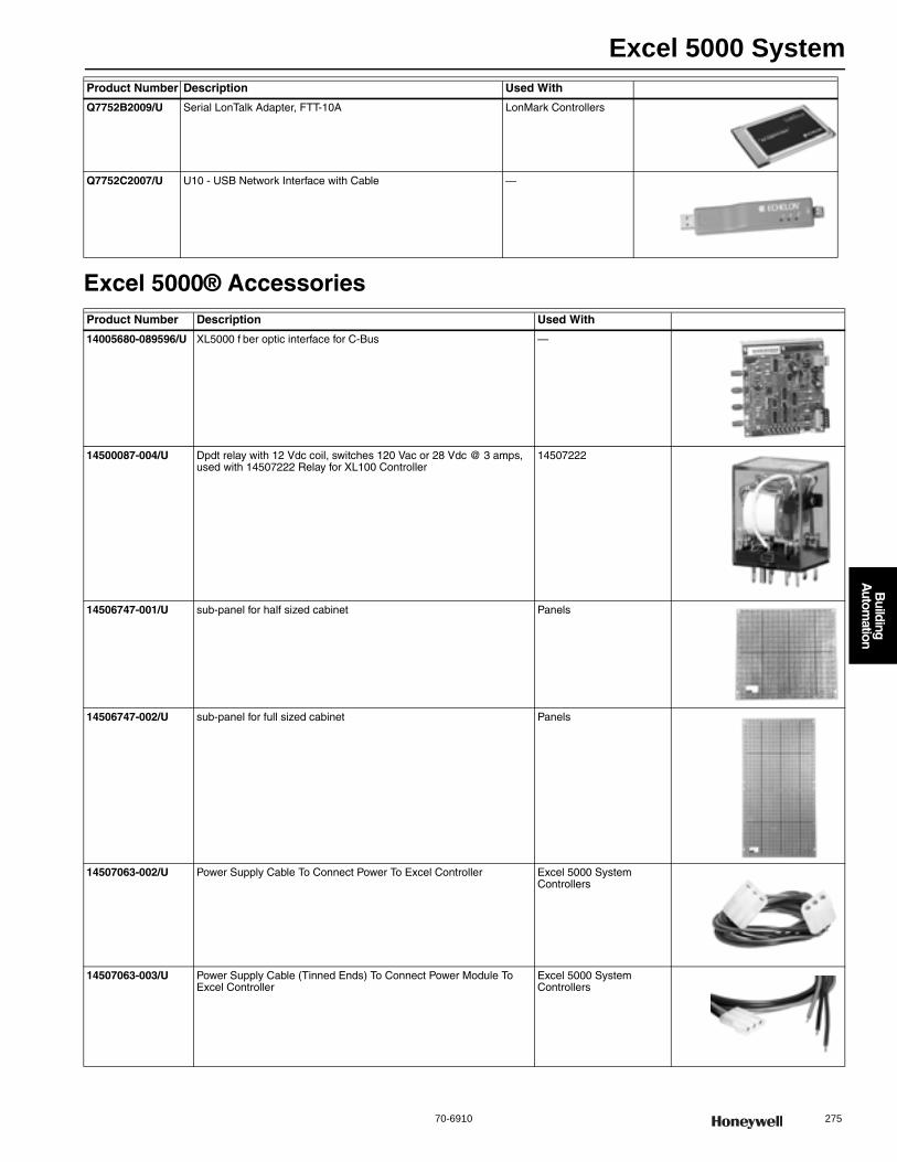
Excel 5000 System
70-6910 275
B
uilding A
utomation
Excel 5000® Accessories
Q7752B2009/U Serial LonTalk Adapter, FTT-10A LonMark Controllers
Q7752C2007/U U10 - USB Network Interface with Cable —
Product Number Description Used With
14005680-089596/U XL5000 f ber optic interface for C-Bus —
14500087-004/U Dpdt relay with 12 Vdc coil, switches 120 Vac or 28 Vdc @ 3 amps, used with 14507222 Relay for XL100 Controller
14507222
14506747-001/U sub-panel for half sized cabinet Panels
14506747-002/U sub-panel for full sized cabinet Panels
14507063-002/U Power Supply Cable To Connect Power To Excel Controller Excel 5000 System Controllers
14507063-003/U Power Supply Cable (Tinned Ends) To Connect Power Module To Excel Controller
Excel 5000 System Controllers
Product Number Description Used With

Excel 5000 System
276 customer.honeywell.com 70-6910
14507222-001/U Relay Module, Four Relays. Includes Hand-Off-Auto Switches and LEDs
Excel 500/600 Controller; Excel 100B
14507222-002/U Relay Module, Four Relays. Includes LEDs 14507222
14507287-001/U Power Module, 120 Vac Input, 50 VA Controller Transformer with Convertible Outlet and Breaker
Excel 5000 System Controllers
14507287-002/U Power Module, 120 Vac Input, 50 VA Controller Transformer Plus 100 VA Accessory Transformer With Convertible Outlet and Breaker
Excel 5000 System Controllers
14507287-003/U Power Module, 120 Vac Input, 50 VA Controller Transformer Plus 100 VA Accessory Transformer and 24 Vdc Accessory Transformer With Convertible Output and Breaker
Excel 5000 System Controllers
14507287-004/U Power Module, 220/240 Vac Input, 50 VA Controller Transformer, with Convertible Outlet and Breaker
Excel 5000 System Controllers
14507287-005/U Power Module, 220/240 Vac Input, 50 VA Controller Transformer Plus 100 VA Accessory Transformer with Convertible Outlet and Breaker
Excel 5000 System Controllers
14507287-006/U Power Module, 220/240 Vac Input, 50 VA Controller Transformer Plus 100 VA Accessory Transformer and 24 Vdc Accessory Transformer with Convert ble Outlet and Breaker
Excel 5000 System Controllers
14507287-007/U 50 VA Excel 5000 access power module for Excel 5000 applications Excel 5000 System Controllers
Product Number Description Used With

Excel 5000 System
70-6910 277
B
uilding A
utomation
14507324-001/U High speed, c-bus network repeater, panel mount (without cover) to extend bus length.
Excel 5000 System Controllers
14507324-002/U High speed, c-bus network repeater, field mount (with cover) to extend bus length.
Excel 5000 System Controllers
14507547-001/U C-bus to DB-25 connector cable, to connect internal RS-485 adapter board to C-bus.
Excel 5000 System Controllers
14507549-001/U External RS-485 adaptor module to directly connect a PC to a C-bus C-Bus
14507551-001/U Cable assembly, com port to adapter module, 30 in. 14507549
14507551-002/U Cable assembly, com port to adapter module, 10 ft 14507549
14507552-001/U Cable assembly, power to adapter module, used with C-Bus and XBS, 11 inches long
14507549
14507552-002/U Cable assembly, power to adapter module, used with C-Bus and XBS, 15 inches long
14507549
206317A/U Excel 10 termination module, FTT-10 Excel 10 Controllers
207912/U Track mounting for a W7751A, B Excel 10
32000180-004/U Replacement cable for use with Q7752B2009 Q7752B2009
32002516-001/U Cable to connect Serial LonTalk adapter to Audio-type bus connection on LonMark Controller
LonMark Controllers
Product Number Description Used With
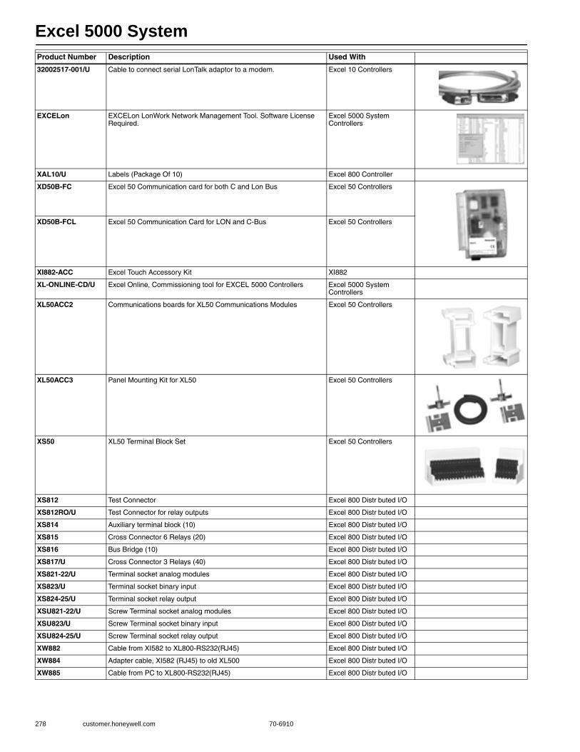
Excel 5000 System
278 customer.honeywell.com 70-6910
32002517-001/U Cable to connect serial LonTalk adaptor to a modem. Excel 10 Controllers
EXCELon EXCELon LonWork Network Management Tool. Software License Required.
Excel 5000 System Controllers
XAL10/U Labels (Package Of 10) Excel 800 Controller
XD50B-FC Excel 50 Communication card for both C and Lon Bus Excel 50 Controllers
XD50B-FCL Excel 50 Communication Card for LON and C-Bus Excel 50 Controllers
XI882-ACC Excel Touch Accessory Kit XI882
XL-ONLINE-CD/U Excel Online, Commissioning tool for EXCEL 5000 Controllers Excel 5000 System Controllers
XL50ACC2 Communications boards for XL50 Communications Modules Excel 50 Controllers
XL50ACC3 Panel Mounting Kit for XL50 Excel 50 Controllers
XS50 XL50 Terminal Block Set Excel 50 Controllers
XS812 Test Connector Excel 800 Distr buted I/O
XS812RO/U Test Connector for relay outputs Excel 800 Distr buted I/O
XS814 Auxiliary terminal block (10) Excel 800 Distr buted I/O
XS815 Cross Connector 6 Relays (20) Excel 800 Distr buted I/O
XS816 Bus Bridge (10) Excel 800 Distr buted I/O
XS817/U Cross Connector 3 Relays (40) Excel 800 Distr buted I/O
XS821-22/U Terminal socket analog modules Excel 800 Distr buted I/O
XS823/U Terminal socket binary input Excel 800 Distr buted I/O
XS824-25/U Terminal socket relay output Excel 800 Distr buted I/O
XSU821-22/U Screw Terminal socket analog modules Excel 800 Distr buted I/O
XSU823/U Screw Terminal socket binary input Excel 800 Distr buted I/O
XSU824-25/U Screw Terminal socket relay output Excel 800 Distr buted I/O
XW882 Cable from XI582 to XL800-RS232(RJ45) Excel 800 Distr buted I/O
XW884 Adapter cable, XI582 (RJ45) to old XL500 Excel 800 Distr buted I/O
XW885 Cable from PC to XL800-RS232(RJ45) Excel 800 Distr buted I/O
Product Number Description Used With
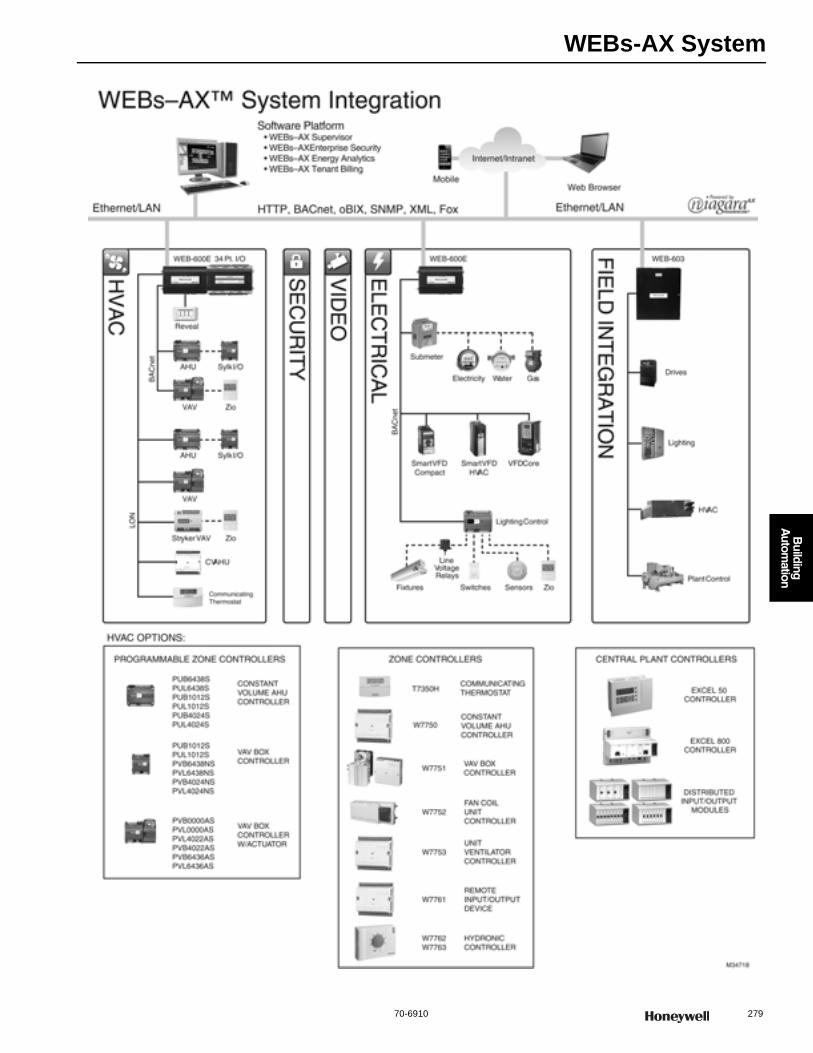
WEBs-AX System
70-6910 279
B
uilding A
utomation
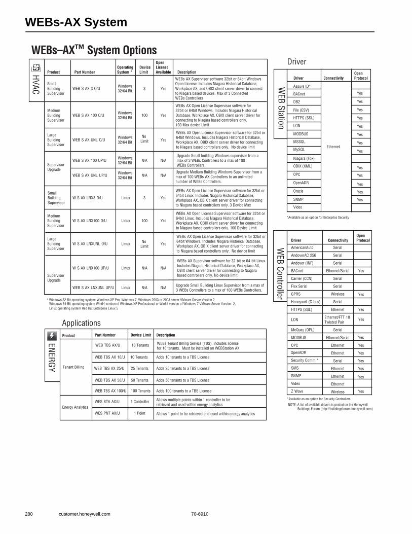
WEBs-AX System
280 customer.honeywell.com 70-6910
WEBs–AX™ System Options
HVAC
Driver
WEB Station
*Available as an option for Enterprise Security
*Available as an option for Security Controllers
NOTE: A list of available drivers is posted on the Honeywell Buildings Forum (http://buildingsforum.honeywell.com)
ENERGY
ApplicationsProduct Part Number Device Limit Description
Tenant Billing
WEB TBS AX/U WEBs Tenant Billing Service (TBS), includes license for 10 tenants. Must be installed on WEBStation AX
WEB TBS AX 10/U Adds 10 tenants to a TBS License
WEB TBS AX 25/U Adds 25 tenants to a TBS License
WEB TBS AX 50/U Adds 50 tenants to a TBS License
WEB TBS AX 100/U 100 Tenants Adds 100 tenants to a TBS License
Energy AnalyticsWES STA AX/U 1 Controller Allows multiple points within 1 controller to be
retrieved and used within energy analytics
WES PNT AX/U 1 Point Allows 1 point to be retrieved and used within energy analytics
50 Tenants
10 Tenants
25 Tenants
10 Tenants
Driver Connectivity
Open
Protocol WEB Controller
AmericanAuto Serial
AndoverAC 256 Serial
Andover (INF) Serial
BACnet Ethernet/Serial Yes
Carrier (CCN) Serial
Flex Serial Serial
GPRS Wireless
Honeywell (C bus) Serial
HTTPS (SSL) Ethernet
LON Ethernet/FTT 10 Twisted Pair
McQuay (OPL) Serial
MODBUS Ethernet/Serial
OPC Ethernet
OpenADR Ethernet
Security Comm.* Serial
SMS Ethernet
SNMP Ethernet
Video Ethernet
Z Wave Wireless
Yes
Yes
Yes
Yes
Yes
Yes
Yes
Yes
Yes
Driver Connectivity
Open
Protocol
Yes
Yes
Yes
Yes
Yes
Yes
Yes
Yes
Yes
Yes
Ethernet
Yes
Yes
Yes
Assure ID*
BACnet
DB2
File (CSV)
HTTPS (SSL)
LON
MODBUS
MSSQL
MySQL
Niagara (Fox)
OBIX (XML)
OPC
OpenADR
Oracle
SNMP
Video
a Windows 32-Bit operating system: Windows XP Pro, Windows 7, Windows 2003 or 2008 server VMware Server Version 2 Windows 64-Bit operating system Win64 version of Windows XP Professional or Win64 version of Windows 7 VMware Server Version 2, Linux operating system Red Hat Enterprise Linux 5
Product Part Number
Operating
System aDevice
Limit
Open
License
Available Description
Yes
Small Building Supervisor
WEB S AX 3 O/U Windows 32/64 Bit 3 Yes
WEBs AX Supervisor software 32bit or 64bit Windows Open License. Includes Niagara Historical Database, Workplace AX, and OBIX client server driver to connect to Niagara based devices. Max of 3 Connected WEBs Controllers
Medium Building Supervisor
WEB S AX 100 O/U Windows 32/64 Bit 100 Yes
WEBs AX Open License Supervisor software for 32bit or 64bit Windows. Includes Niagara Historical Database, Workplace AX, OBIX client server driver for connecting to Niagara based controllers only. 100 Max device Limit.
Large Building Supervisor
WEB S AX UNL O/U Windows 32/64 Bit
No Limit Yes
WEBs AX Open License Supervisor software for 32bit or 64bit Windows. Includes Niagara Historical Database, Workplace AX, OBIX client server driver for connecting to Niagara based controllers only. No device limit
Supervisor Upgrade
WEB S AX 100 UP/U Windows 32/64 Bit N/A N/A
Upgrade Small building Windows supervisor from a max of 3 WEBs Controllers to a max of 100 WEBs Controllers.
WEB S AX UNL UP/U Windows 32/64 Bit N/A N/A
Upgrade Medium Building Windows Supervisor from a max of 100 WEBs AX Controllers to an unlimited number of WEBs Controllers.
Small Building Supervisor
W S AX LNX3 O/U Linux 3 Yes
WEBs AX Open License Supervisor software for 32bit or 64bit Linux. Includes Niagara Historical Database, Workplace AX, OBIX client server driver for connecting to Niagara based controllers only. 3 Device Max
Medium Building Supervisor
W S AX LNX100 O/U 100 Yes
WEBs AX Open License Supervisor software for 32bit or 64bit Linux. Includes Niagara Historical Database, Workplace AX, OBIX client server driver for connecting to Niagara based controllers only. 100 Device Limit
Large Building Supervisor
W S AX LNXUNL O/U Yes
WEBs AX Open License Supervisor software for 32bit or 64bit Windows. Includes Niagara Historical Database, Workplace AX, OBIX client server driver for connecting to Niagara based controllers only. No device limit
Supervisor Upgrade
W S AX LNX100 UP/U N/A N/A
WEBs AX Supervisor software for 32 bit or 64 bit Linux.Includes Niagara Historical Database, Workplace AX, OBIX client server driver for connecting to Niagara based controllers only. No device limit.
WEB S AX LNXUNL UP/U N/A N/A Upgrade Small Building Linux Supervisor from a max of 3 WEBs Controllers to a max of 100 WEBs Controllers.
Linux
Linux
Linux
Linux
No Limit

WEBs-AX System
70-6910 281
B
uilding A
utomation
Controllers
Platform Memory I/O
Open
License Description
WEB 201 64/128 MB64 MB Flash O
The WEB 201 standard features include Niagara station and Web User Interface Standard drivers include oBIX client/server and Niagara Network (Fox) client/server .
WEB 600 128/256 MB128 MB Flash
Din16/34 O
The WEB 600 standard features include Niagara station and Web User Interface. Standard drivers include oBIX client/server and Niagara Network (Fox) client/server Requires AX release 3.2 or higher.
WEB 603 128 MB128 MB Flash
6 Universal Inputs, 4 Form C RelayOutputs
O
O
The WEB 603 standard features include Web User Interface and Niagara Connectivity, and oBIX Client/Server driver. Includes steel wall mountable enclosure with 120V power supply. Can host either a WEB R2 station 2.301.535 or higher or a WEBs AX station release 3.6.47 or higher.
WEB 645 128 MB128 MB Flash
The WEB 645 standard features include Niagara Station, Web User Interface and WEBs Connectivity, and oBIX Client/Server driver. Includes steel wall mountable enclosure with 120V power supply. Can host either a WEB R2 station 2.301.535 or higher or a WEBs AX station release 3.6.47 or higher.
WEB 700 1 GB1 GB Flash Ext. 16 O
The WEB 700 standard features include Niagara station and Web User Interface. Standard drivers include oBIX client/server and Niagara Network (Fox) client/server. Requires AX Release 3.5 or higher
SEC H 201 128 MB RAM/64 MB Flash •
SEC H 600 128 MB RAM/64 MB Flash
6 Supervised Inputs, 4 Form C RelayOutputs, and 3 Digital Inputs
•
Includes WEBs Security Appliance, Web UI and the following standard drivers: oBIX client/server, Niagara Network (Fox) client/server and BACNet IP Server, and BACNet IP Server. Supports up to 32 card readers, 20,000 personnel records and 50,000 transactional history records and security/BAS from single controller
Includes WEBs Security Appliance, Web UI and the following standard drivers: oBIX client/server, Niagara Network (Fox) client/server and BACNet IP Server, and BACNet IP Server. Supports up to 16 card readers, 5,000 personnel records and 10,000 transactional history records and security/BAS from single controller
O Open licensed controller is optional• Controller comes standard with open license
6 Supervised Inputs, 4 Form C RelayOutputs, and 3 Digital Inputs
—
Din16/34
Communication Ports
2 10/100 MB Ethernet ports, NDIO port and 2 communication card option slots, 2 serial (RS232, RS485)
2 10/100 MB Ethernet ports, NDIO port and 2 communication card option slots, 1 USB, 2 serial (RS232, RS485)
2 10/100 MB Ethernet ports2 serial (RS 232, RS 485) 1 LonWorks port FTT 10A1 Option slot
2 10/100 MB Ethernet ports,2 RJ 45 Connectors for RS 232 port4 Screw Terminal RS 485 ports1 Communication Card Option Slot
2 Gigabit Ethernet ports, 2 standard communication card slots, 2 serial (RS232, RS485)
Connections for 2 Card Readers, includes 2 10/100 MB Ethernet ports, (1) RS 485 serial port, (1) RS 232 serial port, and 2 communication card option slots
Connections for 2 Card Readers, 2 10/100 MB Ethernet ports, (1) RS 485 serial port, (1) RS 232 serial port, and 2 communication card option slots
WEB 600E O
The WEB 600E standard features include WEBs AX station and Web User Interface and SRAM Module. Standard drivers include oBIX Client / Server and Niagara Network (Fox) Client / Server. The WEB 600E is designed for Battery less operation and DIN rail mounting. Requires release 3.6.47 or higher
2 10/100 MB Ethernet ports NDIO Port2 serial (RS 232, RS 485)2 Communication card option slots
128 MB128 MB Flash
Din16/34
WEB RB 603 128 MB128 MB Flash
6 Universal Inputs, 4 Form C RelayOutputs
O
O
Direct fit replacement circuit board for a WEB 403 controller, with matching connector sockets for unplug replug installation with existing controller wiring. The WEB RB 603 standard features include Web User Interface and Niagara Connectivity, and oBIX Client/Server driver. The unit can host either a WEB R2 station 2.301.535 or higher or a WEBs AX station release 3.6.47 or higher.
WEB RB 645 128 MB128 MB Flash
Direct fit replacement circuit board for a WEB 545 controller, with matching connector sockets for unplug replug installation with existing controller wiring. The WEB 645 standard features include Niagara Station, Web User Interface and WEBs Connectivity, and oBIX Client/Server driver. The unit can host either a WEB R2 station 2.301.535 or higher or a WEBs AX station release 3.6.47 or higher..
—
2 10/100 MB Ethernet ports2 serial (RS 232, RS 485) 1 LonWorks port FTT 10A1 Option slot
2 10/100 MB Ethernet ports,2 RJ 45 Connectors for RS 232 port4 Screw Terminal RS 485 ports1 Communication Card Option Slot
Product Part Number
Operating
System
Device
Limit
Open
License
Available Description
Security Small Building Supervisor
SEC H ENT 6/U Windows 32/64 Bit 6 No
WEBs AX Security SBS, includes enterprise security application with 32 reader license, both MySQL and MS SQL Server database drivers and oBIX client/server driver for connecting to Niagara based controllers only. 6 Controller and 64 Reader Limit.
Security Medium Building Supervisor
SEC H ENT 100/U Windows 32/64 Bit 100 No
Security Supervisor with MySQL and MS SQL Includes enterprise security application with 32 reader license, WEBs AX Security Supervisor, both MySQL and MS SQL Server database drivers and oBIX client/server driver for connecting to Niagara based controllers only. Max of 100 Security Controllers.
Security Large Building Supervisor
SEC H ENT 250/U Windows 32/64 Bit 250 No
Security Large System Supervisor with MySQL and MS SQL. Includes enterprise security application with 32 reader license, WEBs AX Security, and both MySQL and MS SQL Server database drivers. 250 Controller Limit. Includes OBIX client/server driver for connecting to Niagara based controllers only.
Supervisor Upgrade
SEC H U 100/U Windows 32/64 Bit N/A N/A
Security ENT upgrade. Upgrade an existing SEC H ENT 6 SBS Security Supervisor to a SEC H ENT 100 Security Supervisor. Supervisor requires additional reader licenses to expand system capacity.
SEC H U 250/U Windows 32/64 Bit N/A N/A Security ENT upgrade. Upgrade an existing SEC H ENT 100 Security AX Supervisor to a SEC H ENT 250
Large System Security Supervisor. Supervisor requires additional reader licenses to expand system capacity.
SECURITY

WEBs-AX System
282 customer.honeywell.com 70-6910
Product Options Part Number
Serial/
Wireless/
Twisted Pair Description
Reveal small display(color & grayscale)
LCD CT043A100/U Serial Color LCD Touchscreen
LCD GT043A100/U Serial Grayscale LCD Touchscreen
I/O modules din mount (16/34 points), remote (16)
IO 16 H/U Serial Includes 8 Universal Inputs, 4 Form A Relay Outputs, and 4 0 10 VDC Analog Outputs. 16 Point I/O Module
IO 34 H/U Serial Includes 16 Universal Inputs, 10 Form A Relay Outputs, and 8 0 10 VDC Analog Outputs. This IO 34 also contains an on board 24V AC/DC power supply
IO 16 REM H/U Serial Includes 8 Universal Inputs, 4 Form A Relay Outputs, and 4 0 10 VDC Analog Outputs.
SEC H RIO/U Serial Security Remote I/O
SEC H R2R/U Serial Security Remote Reader
Option Cards
NPB 2X RS485/U Serial RS 485 Card
NPB GPRS H/U Wireless GPRS Modem Card
NPB GPRS W H/U Wireless GPRS Modem Kit
NPB LON/U LON Card
NPB MDM/U Twisted Pair Modem Card
NPB RS232/U Serial RS 232 Card
NPB ZWAVE/U Z wave Card
NPB SED 001/U Wireless Sedona Card
NPB SRAM/U N/A SRAM Battery less Card
NPB WIFI/U Wifi Card
TB VWG APP 1014/U Wireless Wireless Zigbee Card
Wireless
Wireless
Twisted Pair
Accessories

WEBs-AX System
70-6910 283
B
uilding A
utomation
Controller
ModelbCommunication
ProtocolaEquipment
Type UI DI AO DO
Velocity Pressure
Sensor (Microbridge)
Series 60
Floating Actuator
PUB6438S PUB6438S ILC BACnet MS/TP Unitary NO NO
PUL6438SPUL6438S ILC LonWorks
3
3
3
3
3
3
NO NO
PVB6438NSPVB6438NS ILC YES NO
PVL6438NS PVL6438NS ILC YES NO
PVB6436ASPVB6436AS ILC
YES YES
PVL6436AS PVL6436AS ILC YES YES
PUL1012S ILC NO NOPUB1012SPUB1012S ILCPUL4024SPUL4024S ILC NO NOPUB4024SPUB4024S ILCPVL4024NSPVL4024NS ILC YES NOPVB4024NSPVB4024NS ILCPVL0000ASPVL0000AS ILC VAV YES YESPVB0000ASPVB0000AS ILCPVL4022ASPVL4022AS ILC YES YESPVB4022ASPVB4022AS ILC
UI - Universal Input, DI - Digital Input, AO - Analog Output, and DO - Digital Output a BACnet models BTL listedb Spyder Individually Licensed Controller (ILC) is a fully programmable controller for any Niagara
AX Framework® platform providing the greatest flexibility for expansion on any Niagara
AX platform.
c One Universal Input (UI-1*) is user selectable as a fast digital pulse meter
WEBs–AX™ System HVAC Controllers Options
OutputsInputs
Model ApplicationWall
ModuleResistive Voltage
Dry Contact
Digital
Bypass
Button
Integrated
Actuator Relay Analog LED
W7750A CVAHU • •2 1
W7750B CVAHU
6
W7750C
W7753 Unit Ventilator
1
• •44 2 8 1
• •44 2 5 3 1
•
• • •
•42
2
1
2 8
42
1
8
4 1
W7761 Remote Input/Output
W7751H VAV
W7751B/D/F VAV
W7752 FCU
W7762/3 Hydronic Controller
T7350H Communicating Thermostat
• Comes standard
Configurable Field Controllers
Unitary
Unitary
Unitary
VAV
VAV
Programmable Field Controllers
Advanced Configurable Field Controllers
VAV
VAV
VAV
VAV
8
8
8
8
6
6
2
2
4
4
0
1
2
2
2
0
4
4
4
4
4
4
0
0
0
0
0
6
6
6
6
6
6
1c
4c
4c
0
4c
BACnet MS/TP
BACnet MS/TP
BACnet MS/TP
BACnet MS/TP
LonWorks
LonWorks
LonWorks
LonWorks
LonWorks
LonWorks
LonWorks
BACnet MS/TP
BACnet MS/TP
BACnet MS/TP
PUL1012S
Triac
Model
Communication
Protocol
Equipment
Type UI DI AO DO
Velocity Pressure
Sensor (Microbridge)
Series 60
Floating Actuator
CVL4024NS VAV1
CVL4022AS VAV1
LonWorks
LonWorks
VAV
VAV
YES NO2 404
YES YES2 204
CVAHU
8
1 4
3•
•
• 1 1
• 2 1 3 •
8
1
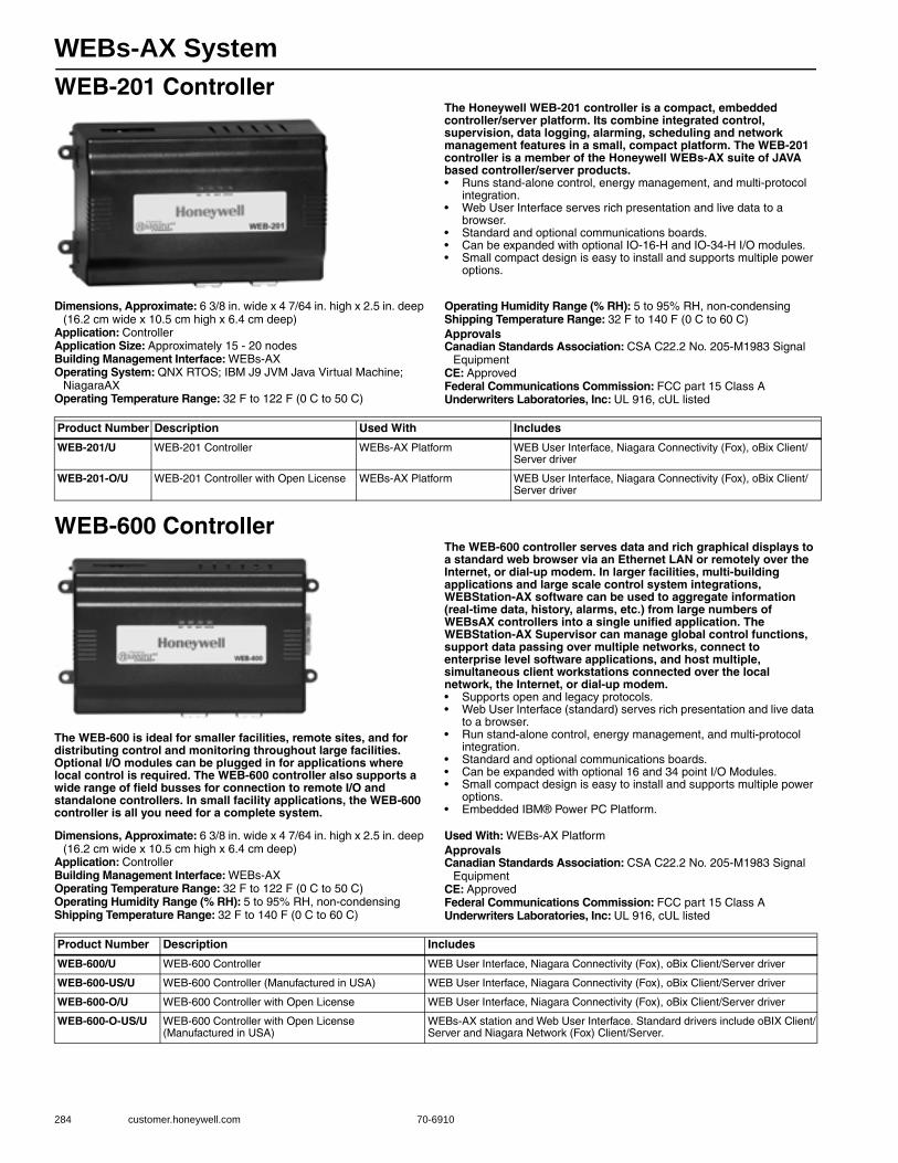
WEBs-AX System
284 customer.honeywell.com 70-6910
WEB-201 ControllerThe Honeywell WEB-201 controller is a compact, embedded controller/server platform. Its combine integrated control, supervision, data logging, alarming, scheduling and network management features in a small, compact platform. The WEB-201 controller is a member of the Honeywell WEBs-AX suite of JAVA based controller/server products.• Runs stand-alone control, energy management, and multi-protocol
integration.• Web User Interface serves rich presentation and live data to a
browser.• Standard and optional communications boards.• Can be expanded with optional IO-16-H and IO-34-H I/O modules.• Small compact design is easy to install and supports multiple power
options.
Dimensions, Approximate: 6 3/8 in. wide x 4 7/64 in. high x 2.5 in. deep (16.2 cm wide x 10.5 cm high x 6.4 cm deep)
Application: ControllerApplication Size: Approximately 15 - 20 nodesBuilding Management Interface: WEBs-AXOperating System: QNX RTOS; IBM J9 JVM Java Virtual Machine;
NiagaraAXOperating Temperature Range: 32 F to 122 F (0 C to 50 C)
Operating Humidity Range (% RH): 5 to 95% RH, non-condensingShipping Temperature Range: 32 F to 140 F (0 C to 60 C) ApprovalsCanadian Standards Association: CSA C22.2 No. 205-M1983 Signal
EquipmentCE: ApprovedFederal Communications Commission: FCC part 15 Class AUnderwriters Laboratories, Inc: UL 916, cUL listed
WEB-600 Controller
The WEB-600 is ideal for smaller facilities, remote sites, and for distributing control and monitoring throughout large facilities. Optional I/O modules can be plugged in for applications where local control is required. The WEB-600 controller also supports a wide range of field busses for connection to remote I/O and standalone controllers. In small facility applications, the WEB-600 controller is all you need for a complete system.
The WEB-600 controller serves data and rich graphical displays to a standard web browser via an Ethernet LAN or remotely over the Internet, or dial-up modem. In larger facilities, multi-building applications and large scale control system integrations, WEBStation-AX software can be used to aggregate information (real-time data, history, alarms, etc.) from large numbers of WEBsAX controllers into a single unified application. The WEBStation-AX Supervisor can manage global control functions, support data passing over multiple networks, connect to enterprise level software applications, and host multiple, simultaneous client workstations connected over the local network, the Internet, or dial-up modem.• Supports open and legacy protocols.• Web User Interface (standard) serves rich presentation and live data
to a browser.• Run stand-alone control, energy management, and multi-protocol
integration.• Standard and optional communications boards.• Can be expanded with optional 16 and 34 point I/O Modules. • Small compact design is easy to install and supports multiple power
options.• Embedded IBM® Power PC Platform.
Dimensions, Approximate: 6 3/8 in. wide x 4 7/64 in. high x 2.5 in. deep (16.2 cm wide x 10.5 cm high x 6.4 cm deep)
Application: ControllerBuilding Management Interface: WEBs-AXOperating Temperature Range: 32 F to 122 F (0 C to 50 C) Operating Humidity Range (% RH): 5 to 95% RH, non-condensingShipping Temperature Range: 32 F to 140 F (0 C to 60 C)
Used With: WEBs-AX PlatformApprovalsCanadian Standards Association: CSA C22.2 No. 205-M1983 Signal
EquipmentCE: ApprovedFederal Communications Commission: FCC part 15 Class AUnderwriters Laboratories, Inc: UL 916, cUL listed
Product Number Description Used With Includes
WEB-201/U WEB-201 Controller WEBs-AX Platform WEB User Interface, Niagara Connectivity (Fox), oBix Client/Server driver
WEB-201-O/U WEB-201 Controller with Open License WEBs-AX Platform WEB User Interface, Niagara Connectivity (Fox), oBix Client/Server driver
Product Number Description Includes
WEB-600/U WEB-600 Controller WEB User Interface, Niagara Connectivity (Fox), oBix Client/Server driver
WEB-600-US/U WEB-600 Controller (Manufactured in USA) WEB User Interface, Niagara Connectivity (Fox), oBix Client/Server driver
WEB-600-O/U WEB-600 Controller with Open License WEB User Interface, Niagara Connectivity (Fox), oBix Client/Server driver
WEB-600-O-US/U WEB-600 Controller with Open License (Manufactured in USA)
WEBs-AX station and Web User Interface. Standard drivers include oBIX Client/Server and Niagara Network (Fox) Client/Server.
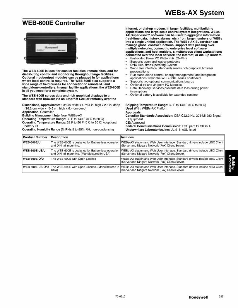
WEBs-AX System
70-6910 285
B
uilding A
utomation
WEB-600E Controller
The WEB-600E is ideal for smaller facilities, remote sites, and for distributing control and monitoring throughout large facilities. Optional input/output modules can be plugged in for applications where local control is required. The WEB-600E also supports a wide range of field busses for connection to remote I/O and standalone controllers. In small facility applications, the WEB-600E is all you need for a complete system.
The WEB-600E serves data and rich graphical displays to a standard web browser via an Ethernet LAN or remotely over the
Internet, or dial-up modem. In larger facilities, multibuilding applications and large-scale control system integrations, WEBs-AX Supervisor™ software can be used to aggregate information (real-time data, history, alarms, etc.) from large numbers of WEBs into a single unified application. The WEBs-AX Supervisor can manage global control functions, support data passing over multiple networks, connect to enterprise level software applications, and host multiple, simultaneous client workstations connected over the local network, the Internet, or dial-up modem.• Embedded PowerPC Platform@ 524MHz• Supports open and legacy protocols• QNX Real-time Operating System• Web User interface (standard) serves rich graphical browser
presentations• Run stand-alone control, energy management, and integration
applications within the WEB-600E series controllers• Supports two optional communications boards• Optional 16 and 34 point I/O Modules• Data Recovery Services prevents data loss during power
interruptions• Optional battery is available for extended runtime
Dimensions, Approximate: 6 3/8 in. wide x 4 7/64 in. high x 2.5 in. deep (16.2 cm wide x 10.5 cm high x 6.4 cm deep)
Application: ControllerBuilding Management Interface: WEBs-AXOperating Temperature Range: 32 F to 140 F (0 C to 60 C)Operating Temperature Range: 32 F to 50 F (0 C to 50 C) w/optional
battery kitOperating Humidity Range (% RH): 5 to 95% RH, non-condensing
Shipping Temperature Range: 32 F to 140 F (0 C to 60 C)Used With: WEBs-AX PlatformApprovalsCanadian Standards Association: CSA C22.2 No. 205-M1983 Signal
EquipmentCE: ApprovedFederal Communications Commission: FCC part 15 Class AUnderwriters Laboratories, Inc: UL 916, cUL listed
Product Number Description Includes
WEB-600E/U The WEB-600E is designed for Battery less operation and DIN rail mounting.
WEBs-AX station and Web User Interface. Standard drivers include oBIX Client /Server and Niagara Network (Fox) Client/Server.
WEB-600E-US/U The WEB-600E is designed for Battery less operation and DIN rail mounting. (Manufactured in USA)
WEBs-AX station and Web User Interface. Standard drivers include oBIX Client/Server and Niagara Network (Fox) Client/Server.
WEB-600E-O/U The WEB-600E with Open License WEBs-AX station and Web User Interface. Standard drivers include oBIX Client /Server and Niagara Network (Fox) Client/Server.
WEB-600E-US-O/U The WEB-600E with Open License. (Manufactured in USA)
WEBs-AX station and Web User Interface. Standard drivers include oBIX Client/Server and Niagara Network (Fox) Client/Server.

WEBs-AX System
286 customer.honeywell.com 70-6910
WEB-201/WEB-600/WEB-600E AccessoriesBuilding Management Interface: WEBs-AXOperating Humidity Range (% RH): 5 to 95% RH, non-condensingUsed With: WEB-201; WEB-600ApprovalsCanadian Standards Association: CSA C22.2 No. 205-M1983 Signal
Equipment
WEB-201/WEB-600/WEB-600E DriversBuilding Management Interface: WEBs
IO-16-H IO-34-HNPB-PWR-H
Product Number Application Description I/O Count
Operating Temperature Range
Power Input Includes
Approvals:
(F) (C)
Underwriters Laboratories, Inc CE
ENC-H-001/U Enclosure WEBs Small Enclosure — — — 120 Vac 24 Vac Power Supply — —
ENC-H-002/U Enclosure WEBs Large Enclosure — — — 120 Vac 24 Vac Power Supply — —
ENC-H-BPK-1/U Enclosure WEBs Small Enclosure Backplate (8 in. X 11 in.)
— — — — — — —
ENC-H-BPK-2/U Enclosure WEBs Large Enclosure Backplate (11 in. X 11 in.)
— — — — — — —
IO-16-H/U Input/Output Expansion Module
16 Point Input/Output Expansion Module
8 UI, 4 DO (Relay),4 AO
32 F to 122 F
0 C to 50 C
— — UL 916, cUL listed
Approved
IO-16-H-US/U Input/Output Expansion Module
16 Point Input / Output Expansion Module (Manufactured in USA)
8 UI, 4 DO (Relay),4 AO
32 F to 122 F
0 C to 50 C
— — UL 916, cUL listed
Approved
IO-16-REM-H/U Input/Output Expansion Module
16 Point Input / Output Expansion Module
8 UI, 4 DO (Relay),4 AO
32 F to 122 F
0 C to 50 C
— — UL 916, cUL listed
Approved
IO-34-H/U Input/Output Expansion Module
34 Point Input/Output Expansion Module
16 UI, 10 DO (Relay), 8 AO
32 F to 122 F
0 C to 50 C
— Internally dedicated 24 Volt Power Supply
UL 916, cUL listed
Approved
IO-34-H-US/U Input/Output Expansion Module
34 Point Input/Output Expansion Module (Manufactured in USA)
16 UI, 10 DO (Relay), 8 AO
32 F to 122 F
0 C to 50 C
— Internally dedicated 24 Volt Power Supply
UL 916, cUL listed
Approved
NPB-GPRS-H/U Modem Option Card
WEBs Cellular Modem without SIM Card
— — — — — — —
NPB-GPRS-W-H/U Modem Option Card
WEBs Cellular Modem with Wyless SIM Card
— — — — — — —
NPB-MDM/U Optional Communications Card
56kbps Modem with one RJ-11 connector for WEB-201/600
— 32 F to 122 F
0 C to 50 C
— — UL 916, cUL listed
Approved
NPB-PWR-H/U Power Module 24 Volt DIN mounted power module
— 32 F to 122 F
0 C to 50 C
— — UL 916, cUL listed Approved
NPB-PWR-UN-H/U Power Module 90 - 263 V AC 50/60 Hz Auto sensing Power Supply Module, DIN Rail Mountable
— 32 F to 122 F
0 C to 50 C
— — UL 916, cUL listed Approved
NPB-WPM-US/U Power Adaptor Wall Power Adaptor - US Plug type
— 32 F to 122 F
0 C to 50 C
— — UL 916, cUL listed Approved
Product Number Application Description Used With
NPM-128/U Software-Driver WEB-201 Memory Expansion License from 64 to 128 MB WEB-201 Platform
NPM-256MB/U Software-Driver WEB-600 Memory Expansion License from 128 to 256 MB WEB-600 Platform
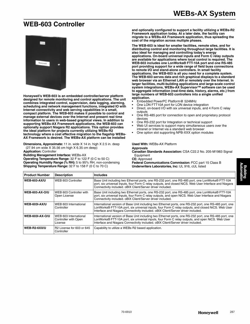
WEBs-AX System
70-6910 287
B
uilding A
utomation
WEB-603 Controller
Honeywell’s WEB-603 is an embedded controller/server platform designed for remote monitoring and control applications. The unit combines integrated control, supervision, data logging, alarming, scheduling and network management functions, integrated IO with Internet connectivity and web serving capabilities in a small, compact platform. The WEB-603 makes it possible to control and manage external devices over the Internet and present real time information to users in web-based graphical views. In addition to supporting WEBs-AX Framework applications, the WEB-603 can optionally support Niagara R2 applications. This option provides the ideal platform for projects currently utilizing WEBs-R2 technology where a cost effective migration to the flagship WEBs-AX Framework is desired. The WEBs-AX platform can be installed
and optionally configured to support a facility utilizing a WEBs-R2 Framework application today. At a later date, the facility can migrate to a WEBs-AX Framework application, thus spreading the cost of the migration across multiple phases.
The WEB-603 is ideal for smaller facilities, remote sites, and for distributing control and monitoring throughout large facilities. It is also ideal for managing and controlling today’s energy applications. On-board universal inputs and Form C relay outputs are available for applications where local control is required. The WEB-603 includes one LonWorks® FTT-10A port and one RS-485 port providing support for a wide range of field buss connections to remote I/O and stand-alone controllers. In small facility applications, the WEB-603 is all you need for a complete system. The WEB-603 serves data and rich graphical displays to a standard web browser via an Ethernet LAN or remotely over the Internet. In larger facilities, multi-building applications and large-scale control system integrations, WEBs-AX Supervisor™ software can be used to aggregate information (real-time data, history, alarms, etc.) from large numbers of WEB-603 controllers into a single unified application.• Embedded PowerPC Platform@ 524MHz• One LON FTT10A port for LON device integration• Direct, on-board I/O with six universal inputs, and 4 Form C relay
outputs• One RS-485 port for connection to open and proprietary protocol
devices• One RS-232 port for Integration or technical support• Web UI services to support many simultaneous users over the
intranet or Internet via a standard web browser• One option slot supporting NPB-XXX option modules
Dimensions, Approximate: 11 in. wide X 14 in. high X 2.5 in. deep (27.94 cm wide X 35.56 cm high X 6.35 cm deep)
Application: ControllerBuilding Management Interface: WEBs-AXOperating Temperature Range: 32 F to 122 F (0 C to 50 C)Operating Humidity Range (% RH): 5 to 95% RH, non-condensingShipping Temperature Range: 32 F to 158 F (0 C to 70 C)
Used With: WEBs-AX PlatformApprovalsCanadian Standards Association: CSA C22.2 No. 205-M1983 Signal
EquipmentCE: ApprovedFederal Communications Commission: FCC part 15 Class BUnderwriters Laboratories, Inc: UL 916, cUL listed
Product Number Description Includes
WEB-603-AX/U WEB 603 Controller Base Unit including two Ethernet ports, one RS-232 port, one RS-485 port, one LonWorks® FTT-10A port, six universal inputs, four Form C relay outputs, and closed NiCS. Web User Interface and Niagara Connectivity included. oBIX Client/Server driver included.
WEB-603-AX-O/U WEB 603 Controller with Open License
Base Unit including two Ethernet ports, one RS-232 port, one RS-485 port, one LonWorks® FTT-10A port, six universal inputs, four Form C relay outputs, and open NiCS. Web User Interface and Niagara Connectivity included. oBIX Client/Server driver included.
WEB-603I-AX/U WEB 603 International Controller
International version of Base Unit including two Ethernet ports, one RS-232 port, one RS-485 port, one LonWorks® FTT-10A port, six universal inputs, four Form C relay outputs, and closed NiCS. Web User Interface and Niagara Connectivity included. oBIX Client/Server driver included.
WEB-603I-AX-O/U WEB 603 International Controller with Open License
International version of Base Unit including two Ethernet ports, one RS-232 port, one RS-485 port, one LonWorks® FTT-10A port, six universal inputs, four Form C relay outputs, and open NiCS. Web User Interface and Niagara Connectivity included. oBIX Client/Server driver included.
WEB-R2-6XX/U R2 License for 603 or 645 Controller
Capability to utilize a WEBs R2 based application.
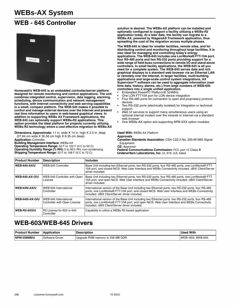
WEBs-AX System
288 customer.honeywell.com 70-6910
WEB - 645 Controller
Honeywell’s WEB-645 is an embedded controller/server platform designed for remote monitoring and control applications. The unit combines integrated control, supervision, data logging, alarming, scheduling, device communication and network management functions, with Internet connectivity and web serving capabilities in a small, compact platform. The WEB 645 makes it possible to control and manage external devices over the Internet and present real time information to users in web-based graphical views. In addition to supporting WEBs AX Framework applications, the WEB-645 can optionally support WEBs-R2 applications. This option provides the ideal platform for projects currently utilizing WEBs-R2 technology where a cost effective migration to WEBs-AX
solution is desired. The WEBs-AX platform can be installed and optionally configured to support a facility utilizing a WEBs-R2 application today. At a later date, the facility can migrate to a WEBs-AX, powered by NiagaraAX Framework application, thus spreading the cost of the migration across multiple phases.
The WEB-645 is ideal for smaller facilities, remote sites, and for distributing control and monitoring throughout large facilities. It is also ideal for managing and controlling today’s energy applications. The WEB-645 includes one LonWorks® FTT-10A port, four RS-485 ports and two RS-232 ports providing support for a wide range of field buss connections to remote I/O and stand-alone controllers. In small facility applications, the WEB-645 is all you need for a complete system. The WEB-645 serves data and rich graphical displays to a standard web browser via an Ethernet LAN or remotely over the Internet. In larger facilities, multi-building applications and large-scale control system integrations, AX Supervisor™ software can be used to aggregate information (real-time data, history, alarms, etc.) from large numbers of WEB-645 controllers into a single unified application.• Embedded PowerPC Platform@ 524MHz• One LON FTT10A port for LON device integration• Four RS-485 ports for connection to open and proprietary protocol
devices• Two RS-232 ports (electrically isolated) for Integration or technical
support• Web UI services to support many simultaneous users using an
optional internal modem over the intranet or Internet via a standard web browser
• One WEBs-AX option slot supporting NPB-XXX option modules
Dimensions, Approximate: 11 in. wide X 14 in. high X 2.5 in. deep (27.94 cm wide X 35.56 cm high X 6.35 cm deep)
Application: ControllerBuilding Management Interface: WEBs-AXOperating Temperature Range: 32 F to 122 F (0 C to 50 C)Operating Humidity Range (% RH): 5 to 95% RH, non-condensingShipping Temperature Range: 32 F to 158 F (0 C to 70 C)
Used With: WEBs-AX PlatformApprovalsCanadian Standards Association: CSA C22.2 No. 205-M1983 Signal
EquipmentCE: ApprovedFederal Communications Commission: FCC part 15 Class BUnderwriters Laboratories, Inc: UL 916, cUL listed
WEB-603/WEB-645 Drivers
Product Number Description Includes
WEB-645-AX/U WEB 645 Controller Base Unit including two Ethernet ports, two RS-232 ports, four RS-485 ports, one LonWorks® FTT-10A port, and closed NiCS. Web User Interface and WEBs Connectivity included. oBIX Client/Server driver included.
WEB-645-AX-O/U WEB 645 Controller with Open License
Base Unit including two Ethernet ports, two RS-232 ports, four RS-485 ports, one LonWorks® FTT-10A port, and open NiCS. Web User Interface and WEBs Connectivity included. oBIX Client/Server driver included.
WEB-645I-AX/U WEB 645 International Controller
International version of the Base Unit including two Ethernet ports, two RS-232 ports, four RS-485 ports, one LonWorks® FTT-10A port, and closed NiCS. Web User Interface and WEBs Connectivity included. oBIX Client/Server driver included.
WEB-645I-AX-O/U WEB 645 International Controller with Open License
International version of the Base Unit including two Ethernet ports, two RS-232 ports, four RS-485 ports, one LonWorks® FTT-10A port, and open NiCS. Web User Interface and WEBs Connectivity included. oBIX Client/Server driver included.
WEB-R2-6XX/U R2 License for 603 or 645 Controller
Capability to utilize a WEBs R2 based application.
Product Number Application Description Used With
NPM-256MB/U Software-Driver Upgrade RAM memory to 256 MB DDR. WEB--603; WEB-645
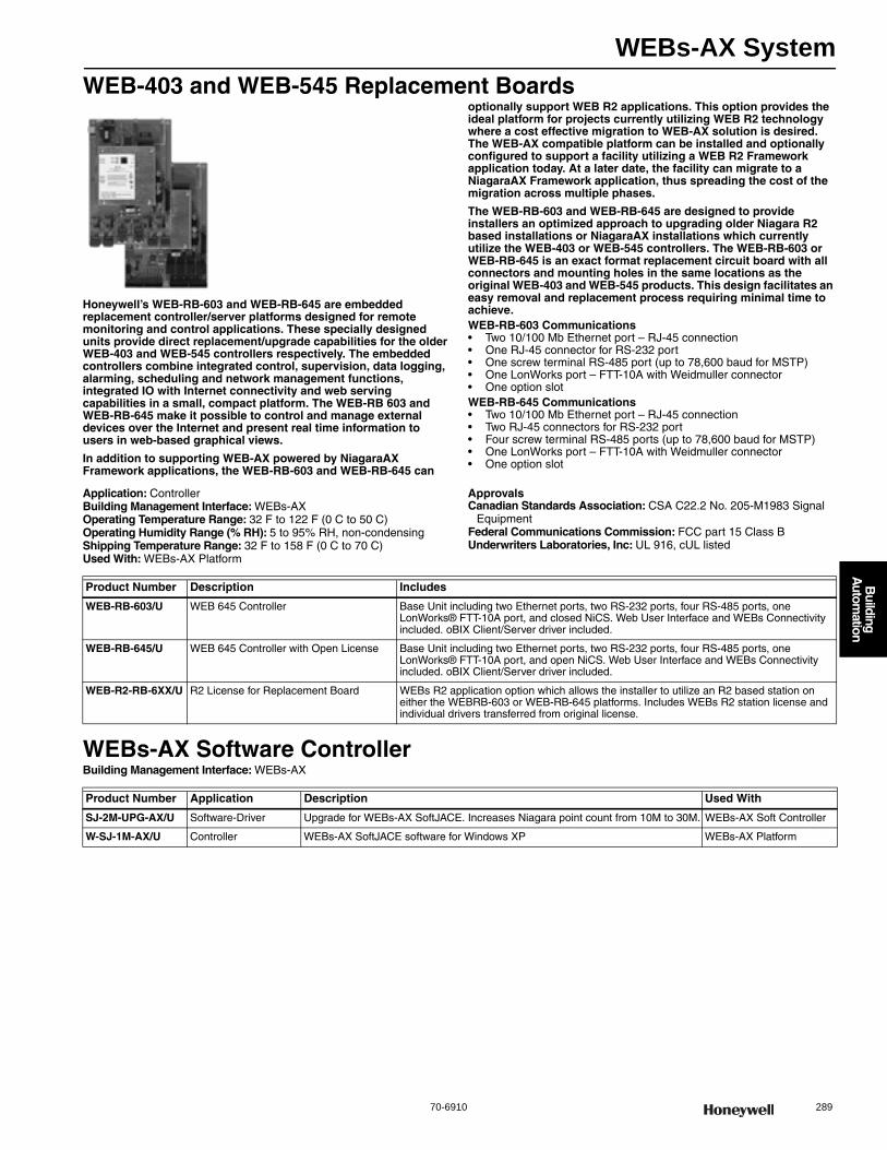
WEBs-AX System
70-6910 289
B
uilding A
utomation
WEB-403 and WEB-545 Replacement Boards
Honeywell’s WEB-RB-603 and WEB-RB-645 are embedded replacement controller/server platforms designed for remote monitoring and control applications. These specially designed units provide direct replacement/upgrade capabilities for the older WEB-403 and WEB-545 controllers respectively. The embedded controllers combine integrated control, supervision, data logging, alarming, scheduling and network management functions, integrated IO with Internet connectivity and web serving capabilities in a small, compact platform. The WEB-RB 603 and WEB-RB-645 make it possible to control and manage external devices over the Internet and present real time information to users in web-based graphical views.
In addition to supporting WEB-AX powered by NiagaraAX Framework applications, the WEB-RB-603 and WEB-RB-645 can
optionally support WEB R2 applications. This option provides the ideal platform for projects currently utilizing WEB R2 technology where a cost effective migration to WEB-AX solution is desired. The WEB-AX compatible platform can be installed and optionally configured to support a facility utilizing a WEB R2 Framework application today. At a later date, the facility can migrate to a NiagaraAX Framework application, thus spreading the cost of the migration across multiple phases.
The WEB-RB-603 and WEB-RB-645 are designed to provide installers an optimized approach to upgrading older Niagara R2 based installations or NiagaraAX installations which currently utilize the WEB-403 or WEB-545 controllers. The WEB-RB-603 or WEB-RB-645 is an exact format replacement circuit board with all connectors and mounting holes in the same locations as the original WEB-403 and WEB-545 products. This design facilitates an easy removal and replacement process requiring minimal time to achieve.WEB-RB-603 Communications• Two 10/100 Mb Ethernet port – RJ-45 connection• One RJ-45 connector for RS-232 port• One screw terminal RS-485 port (up to 78,600 baud for MSTP)• One LonWorks port – FTT-10A with Weidmuller connector• One option slotWEB-RB-645 Communications• Two 10/100 Mb Ethernet port – RJ-45 connection• Two RJ-45 connectors for RS-232 port• Four screw terminal RS-485 ports (up to 78,600 baud for MSTP)• One LonWorks port – FTT-10A with Weidmuller connector• One option slot
Application: ControllerBuilding Management Interface: WEBs-AXOperating Temperature Range: 32 F to 122 F (0 C to 50 C)Operating Humidity Range (% RH): 5 to 95% RH, non-condensingShipping Temperature Range: 32 F to 158 F (0 C to 70 C)Used With: WEBs-AX Platform
ApprovalsCanadian Standards Association: CSA C22.2 No. 205-M1983 Signal
EquipmentFederal Communications Commission: FCC part 15 Class BUnderwriters Laboratories, Inc: UL 916, cUL listed
WEBs-AX Software ControllerBuilding Management Interface: WEBs-AX
Product Number Description Includes
WEB-RB-603/U WEB 645 Controller Base Unit including two Ethernet ports, two RS-232 ports, four RS-485 ports, one LonWorks® FTT-10A port, and closed NiCS. Web User Interface and WEBs Connectivity included. oBIX Client/Server driver included.
WEB-RB-645/U WEB 645 Controller with Open License Base Unit including two Ethernet ports, two RS-232 ports, four RS-485 ports, one LonWorks® FTT-10A port, and open NiCS. Web User Interface and WEBs Connectivity included. oBIX Client/Server driver included.
WEB-R2-RB-6XX/U R2 License for Replacement Board WEBs R2 application option which allows the installer to utilize an R2 based station on either the WEBRB-603 or WEB-RB-645 platforms. Includes WEBs R2 station license and individual drivers transferred from original license.
Product Number Application Description Used With
SJ-2M-UPG-AX/U Software-Driver Upgrade for WEBs-AX SoftJACE. Increases Niagara point count from 10M to 30M. WEBs-AX Soft Controller
W-SJ-1M-AX/U Controller WEBs-AX SoftJACE software for Windows XP WEBs-AX Platform

WEBs-AX System
290 customer.honeywell.com 70-6910
WEBs-AX Platform - Displays
Reveal™ is an easy-to-operate and robust operator unit for the entire range of WEBs-AX and ComfortPoint (CP) supervisory Controllers.
Reveal’s touch-panel operation screens allow for easy and self-explanatory operation by finger-tip.
User-configurable fast-access lists can contain selected data points, time programs, and parameters, thus permitting plant oriented and customer-oriented operation.
Reveal uses Honeywell's patent pending EZ-Nav™ technology to provide real-time status information on an easy-to-use, wall-mounted touch-screen LCD. Reveal has a 480 x 272, High Definition, 24-bit Full Color backlit LCD display. It is also available in a 16-level Extended Temperature gray-scale display. Both displays have a viewing area of 8 in2 (51.6 cm2).
Reveal has customizable user screens, multi-language capability, and permission-based access control. With these features it provides site personnel the ability to quickly and conveniently access setpoint changes, local alarm data, and other system information.
This device can be configured through the WEBs or ComfortPoint (CP) workbench/supervisor using a software driver.• Multi Language capable• Password protection • Upgrade of installed systems• System-wide information access • Multiple Displays for a single Controller• Protocol independent• Maintenance free• Network security
Dimensions, Approximate: 6 9/16 in. long x 3 11/16 in. wide x 1 7/16 in. deep (167 mm long x 93 mm wide x 36 mm deep)
Application: DisplayBuilding Management Interface: WEBsOperating System: Windows CECommissioning Software: WEBs AXVoltage: 24 Vac
Operating Humidity Range (% RH): 5 to 95% RH, non-condensingShipping Temperature Range: -4 F to +140 F (-20 C to +60 C) ApprovalsCanadian Standards Association: CertifiedCE: CE MarkFederal Communications Commission: FCC part 15 Class B
requirements
WEBs-AX Platform - Drivers for ControllersApplication: Software-DriverBuilding Management Interface: WEBs-AX
Used With: WEBs-AX Controllers
Product Number DescriptionNetwork Communications Output Type
Operating Temperature Range
Used With(F) (C)
LCD-CT043A100/U Reveal Color Touchscreen
1 RS 485 Graphical Interface
14 F to 122 F
-10 C to +50 C
WEB-NXS; WEB-600; WEB-201; WEB-5R-AX; WEB-403; WEB-545; WEB NX Controller
LCD-GT043A100/U Reveal Grayscale Touchscreen
1 RS 485 Graphical Interface
-4 F to 158 F
-20 C to 70 C
WEB-NXS; WEB-600; WEB-201; WEB-5R-AX; WEB-403; WEB-545; WEB NX Controller
Product Number Description
DR-AAMPHP-AX/U American Automatrix PHP Driver over RS-232 or RS-485
DR-AAMPUP-AX/U American Automatrix PUP Driver over RS-232 or RS-485
DR-AC256-AX/U AC256 Driver
DR-AINF-AX/U Anfover Infinity Driver for WEBs-AX controllers
DR-BAC-CLI-AX/U BACnet IP Client Driver over Ethernet
DR-BAC-EXP-AX/U BACnet server option (export=true) to add to client
DR-BAC-SRV-AX/U BACNet Server includes BACNet IP Client
DR-CBUS-AX/U C-Bus Driver for Niagara AX
DR-FLX-AX/U Flex Driver over RS-232 or RS-485
DR-GLOBAL-AX/U Enables control of IR controlled AV equipment via an RS-323 connection to a Global Cache FC module
DR-HELVAR-AX/U Helvar Lighting Control Driver
DR-HORTS-AX/U Driver for European Hortsmann meters
DR-JOSAM-AX/U Josam Grease Trap Sensor Driver
DR-LANGOVN-AX/U Lang Oven over RS-232 or RS-485
DR-LON-IP-AX/U LON over IP Driver
DR-LONDRIV-AX/U LONworks FTT10 Driver
DR-MBUS232-AX/U M-Bus RS-232 Driver
DR-MDB-AX/U Driver for Modbus RTU or ASCII over RS-485 or RS232

WEBs-AX System
70-6910 291
B
uilding A
utomation
WEBs-AX Platform - SoftwareApplication Size: SoftwareBuilding Management Interface: WEBs-AX
Used With: WEBs-AX Platform
WEBs-AX Platform - Supervisor SoftwareApplication Size: SoftwareBuilding Management Interface: WEBs-AX
Used With: WEBs-AX Platform
DR-MDB-S-AX/U Data server to Modbus Master devices over RS485
DR-MDB-TCP-AX/U Driver for Modbus TCP (25 node limit recommended)
DR-MDB-TS-AX/U Data server to Modbus Master devices over TCP
DR-MSTP-AX/U MSTP BACnet communications via RS-485 port
DR-SIMADR-AX/U AX controller driver for OPENADR client connectivity to DRAS server
DR-SIMADR-1/U AX controller driver for one additional Openadr client connectivity to DRAS server. DR-SIMADR-AX must be already present on host
DR-SMSALRM-AX/U Enables SMS alarms to be sent to any mobile phone via a GSM/GPRS modem connected to the RS-232
DR-SNMP-AX/U Driver for importing data from SNMP compliant devices. Also exports WEBs alarms to SNMP devices.
DR-VDROOT-AX/U VeederRoot Driver
DR-ZWAVE-AX/U Z-WAVE software driver allows serial communication to Z-WAVE option card or third party Z-WAVE controller. Requires AX Release 3.5 or higher.
WEB-AX-EMB/U Embedded WEBPro-AX tool
WEB-U-AX/U Revision Upgrade for WEBs-AX Controller
Product Number Description
Product Number Description
W-ALARM-CONSL/U WEBs-AX Alarm Console software for Windows XP
WEB-S-AX-W/U AX Workbench
WEBS-DVD/U WEBs-AX Software Master DVD
Product Number Description
WEB-S-AX-3-O/U WEBs-AX Supervisor software 32bit or 64bit Windows Open License. Includes Niagara Historical Database, Workplace AX, and oBIX client-server driver to connect to Niagara based devices. Max of 3 Connected WEBs Controllers
WEB-S-AX-100-O/U WEBs-AX Open License Supervisor software for 32bit or 64bit Windows. Includes Niagara Historical Database, Workplace AX, oBIX client-server driver for connecting to Niagara based controllers only. 100 Max device Limit.
WEB-S-AX-UNL-O/U WEBs-AX Open License Supervisor software for 32bit or 64bit Windows. Includes Niagara Historical Database, Workplace AX, oBIX client-server driver for connecting to Niagara based controllers only. No device limit.
WEB-S-AX-100-UP/U Upgrade Small building Windows supervisor from a max of 3 WEBs Controllers to a max of 100 WEBs Controllers.
WEB-S-AX-UNL-UP/U Upgrade Medium Building Windows Supervisor from a max of 100 WEBs-AX Controllers to an unlimited number of WEBs Controllers.
W-S-AX-LNX3-O/U WEBs-AX Open License Supervisor software for 32bit or 64bit Linux. Includes Niagara Historical Database, Workplace AX, OBIX client-server driver for connecting to Niagara based controllers only. 3 Device Max
W-S-AX-LNX100-O/U WEBs-AX Open License Supervisor software for 32bit or 64bit Linux. Includes Niagara Historical Database, Workplace AX, OBIX client-server driver for connecting to Niagara based controllers only. 100 Device Limit
W-S-AX-LNXUNL-O/U WEBs-AX Supervisor software for 32-bit or 64-bit Linux. Includes Niagara Historical Database, Workplace AX, OBIX client-server driver for connecting to Niagara based controllers only. No device limit.
W-S-AX-LNX100-UP/U Upgrade Small Building Linux Supervisor from a max of 3 WEBs Controllers to a max of 100 WEBs Controllers
W-S-AX-LNXUNL-UP/U Upgrade Medium building Linux supervisor from a max of 100 WEBs Controllers to unlimited connectivity (as many WEBs Controllers as the PC can handle)
WEBs-AX System
292 customer.honeywell.com 70-6910
WEBs-AX Platform - Drivers for SupervisorsApplication: Software-DriverBuilding Management Interface: WEBs-AX
Used With: WEBs-AX Supervisors
WEBs-AX Platform - AccessoriesApplication Size: Accessory-Parts Building Management Interface: WEBs-AX
WEBs Platform - AccessoriesBuilding Management Interface: WEBs
Product Number Description
DR-NS-BAC-500/U Additional 500 point block for WEBStation-AX BACnet driver
DR-NS-BACNET/U BACnet Client/Server Driver
DR-NS-BAC-CLI/U BACnet IP Client Driver for the AX Supervisor; Includes license for 500 BACnet points
DR-NS-BAC-SRV/U BACnet IP Server for the AX Supervisor
DR-NS-BAC-SRV-UP/U Adds BACnet export functions to a BACnet IP Client Driver for the AX Supervisor
DR-NS-BAC-CL-UP/U Adds BACnet IP client functions to a BACnet IP Server for the AX Supervisor; Includes license for 500 BACnet points
DR-NS-BAC-OWS/U Adds BACnet Operator Workstation (OWS) to the AX Supervisor. Requires the BACnet IP Client Driver
DR-NS-BAC-AWS/U Adds BACnet Advanced Workstation (AWS) to the AX Supervisor. Requires the BACnet IP Client Driver
DR-NS-BAC-AWS-UP/U Upgrade from an Operator Workstation (OWS) to an Advanced Workstation (AWS)
DR-NS-MDB-500/U Additional 500 point block for WEBStation-AX MDB TCP Driver
DR-NS-MDB-AX/U AX Supervisor Modbus TCP Driver
DR-NS-OBIX-AX/U AX Supervisor oBix Driver
DR-NS-OBIX500/U Additional 500 point block for AX Supervisor oBix Driver
DR-NS-OPC-500/U Additional 500 point block for WEBStation-AX OPC Client Driver
DR-NS-OPC-AX/U AX Supervisor OPC Driver
DR-NS-SIMADR-AX/U AX controller driver for Openadr client connectivity to DRAS server
DR-NS-SIMADR-1/U AX controller driver for one additional Openadr client connectivity to DRAS server. DR-SIMADR-AX must be already present on host
DR-NS-SNMP-500/U Additional 500 point block for WEBStation-AX SNMP Driver
DR-NS-SNMP-AX/U AX Supervisor SNMP Driver
S-DB-CSV/U File Network Device Driver for importing CSV files
S-DB-DB2/U WEBStation-AX driver for DB2 database
S-DB-MYSQL/U WEBStation-AX driver for Microsoft MySQL database
S-DB-ORCL/U WEBStation-AX driver for Oracle database
S-DB-SQL/U WEBStation-AX driver for Microsoft SQL database
SUP-U-AX/U Revision Upgrade for WEBStation-AX Supervisor
WES-PNT-AX/U WEBs Energy Analytics Point License. Licenses one point for monitoring on a WEBs-AX Supervisor
WES-STA-AX/U WEBs Energy Analytics Station License. Licenses one controller station connection to Energy Analytics with unlimited points.
Product Number Description Used With
H-GPRS-CBL-EXT/U GPRS Modem Extension Cable WEB-201; WEB-600
H-GPRS-SIM-W/U Wysless SIM card for GPRS Modem WEB-201; WEB-600
NPB-BATTERY/U Replacement Battery Assembly for WEB-201 and WEB-600 Controllers WEB-201; WEB-600
Product Number Application Description Used With
50000276-014/U Battery Replacement Battery For WEB 4 Series and WEB 5 Series Controller
WEB-403; WEB-545
H10027/U Accessory-Parts WEB5 RS-485 3-position Connector Plug WEB-201; WEB-600; WEB-403; WEB-545
H10139/U Accessory-Parts 6 Position Input/output Connector WEB-201; WEB-600; WEB-403; WEB-545
H10140/U Accessory-Parts Weidmuller 3-position Straight Connector WEB-201; WEB-600; WEB-403; WEB-545
H10181/U Accessory-Parts 10 Foot Silver Satin Cable (Male RJ-45 both ends) WEB-201; WEB-600; WEB-403; WEB-545
H10598/U Accessory-Parts 2 Position Connector for IO-34-H and WEB IO-34 WEB-201; WEB-600; WEB-403; WEB-545
H10599/U Accessory-Parts 12 Position Connector for IO-34-H and WEB-IO-34 WEB-201; WEB-600; WEB-403; WEB-545
H10600/U Accessory-Parts 15 Position Connector for IO-34-H And WEB IO-34 WEB-201; WEB-600; WEB-403; WEB-545

WEBs-AX Security System
70-6910 293
B
uilding A
utomation
Honeywell Security PortfolioFlexibility is the key to Honeywell WEBs-AX™ Security, which is built on the NiagaraAX Framework®. Whether you need single site or enterprise access control, intrusion detection, video surveillance or a combination of all, WEBs-AX Security has the solution for you.
WEBs-AX Security can work as a standalone system or integrate easily with other WEBs-AX products as well as third-party devices for informa-tion-sharing on the enterprise level.
WEBs-AX Security Solution Options— WEBs-AX Enterprise Security—A comprehensive security
and access control system for one or more facilities and integration with existing building systems including HVAC, lighting, video, and energy analysis. Ideal for single medium to large facilities or multi-site facilities.
— WEBs-AX Standalone Security—An out-of-the-box, Web-enabled solution for access control, intrusion detection, and video surveillance. Ideal for small to medium sized facilities.
— WEBs-AX Compact Security—A cost effective solution for integrating access control, security, video surveillance, and
building automation systems. A cost-effective solution for small to medium sized facilities.
— WEBs-AX Integrated Video—Video drivers that provide an open video framework designed to integrate with diverse manufacturer IP and analog devices and protocols.
— Energy Analytics—An enterprise energy monitoring application designed to help manage energy in one or more facilities. Energy Analytics is a software solution that provides easy to understand, easy to configure reports that identify where, when, and how energy is used and provides cost analysis scenarios to allow the facility manager to make informed buying decisions.
WEBs-AX Security Solutions
Facility DoorsOpen System Integration Capable Solution Selection Information
Single Facility < 32 No Standalone Security See Security Controllers on page 294
Single Facility < 16 Yes Compact Security See Security Controller with Compact Drivers on page 294
Single Facility 32+ Yes Enterprise Security See Security Controllers (page 294); Security with Compact Drivers (page 294) and Enterprise Security (page 295)
Multiple Facility Unlimited Yes Enterprise Security

WEBs-AX Security System
294 customer.honeywell.com 70-6910
WEBs-AX Security Controllers Selection
* A total of 15 modules can be connected to the SEC-H-600 in any combination. Points and reader counts depend on mix of reader modules up to a maximum of 120 I/O regardless of number of modules.
** Any combination of Video Drivers can be added to enable a maximum of 16 cameras per controller.
WEBs-AX Compact Security Selection
* A total of 16 modules can be connected to the SEC-H-600 in any combination. Points and reader counts depend on mix of reader modules.** A total of 15 modules can be connected to the SEC-H-600 in any combination. Points and reader counts depend on mix of reader modules.
Features and Options SEC-H-600 SEC-H-201
Controllers SEC-H-600 SEC-H-201
Card Readers 32* 16
Digital Input/Output Points 120/120* 64/64
Remote Reader Modules (R2R) 15* 7
Remote I/O Modules (RIO) 15* 8
Intrusion Keypads 6 2
Personnel 20,000 5,000
Access Rights 250 100
Access Zones 50 10
Intrusion Zones 25 5
On-line Historical Records 50,000 10,000
Simultaneous System Users 10 5
Video Drivers
DR-JAC-DED-AX/U **Dedicated Micros DVR & 4 Cameras
N/A
DR-JAC-AXS-4/U **4 Axis IP Cameras N/A
DR-JAC-MLS-4/U **4 Mileston NVR Cameras N/A
DR-JAC-RPD-4/U **Connect 4 cameras via Rapid Eye DVR
N/A
Integration Options Video (Cameras) 16 N/A
Features and OptionsDR-SEC-LON (LON Focus)
DR-SEC-BAC (BACnet Focus)
DR-SEC-LON-FTT
DR-SEC-BAC-MSTP
DR-SEC-BAC-TCP
DR-SEC-MDB-RTU
DR-SEC-MDB-TCP
Controller SEC-H-600
Security Capabilities
Card Readers 16*
Digital Inputs/Output Points 120/120*
Remote Reader Modules (R2R) 15**
Remote I/O Modules (RIO) 15**
Intrusion Keypads 2
Personnel 20,000
Access Zones 50
Intrusion Zones 25
On-line Historical Records 50,000
Point Histories No Limit No Limit 300 300 300 300 300
Simultaneous System Users 10
Video Drivers
DR-JAC-DED-AX/U Dedicated Micros DVR & 4 Cameras
DR-JAC-AXS-4/U 4 Axis IP Cameras
DR-JAC-MLS-4/U 4 Milestone NVR Cameras
DR-JAC-RPD-4/U Connect 4 cameras via Rapid Eye DVR
Open Device/Points Supported
LonWorks Devices/Points 60 / 2000 5 / 100 60 / 2000
BACnet Devices/Points (IP or MSTP) 5 / 100 60 / 2000 60 / 2000
BACnet IP Devices/Points 60 / 2000
Modbus TCP Devices/Points 5 / 100 5 / 100 60 / 2000
Modbus RTU Devices/Points 5 / 100 5 / 100 60 / 2000
SNMP (over Ethernet) Devices/Points 5 / 100 5 / 100
Integration Capabilities
Video (Cameras) 16 Cameras
HVAC .
Lighting .
Other Open Systems .
WEBs-AX Security System
70-6910 295
B
uilding A
utomation
WEBs-AX™ Enterprise Security SoftwareWEBs-AX Enterprise Security is a comprehensive access control and security management solution, built on a truly open, IP based platform. Developed using the NiagaraAX Framework, WEBs-AX Enterprise Security provides unparalleled interoperability within traditional security environments and extends seamlessly to create a unified, intelligent building by integrating with today’s diverse facility systems including environmental controls, lighting, energy management, and video
Enterprise Security provides scalability ranging from single door solutions to multi-building/multi-campus deployments. Entirely accessible from any standard web browser, the solution provides flexible access into the system any time, anywhere, while liberating end users from dedicated client workstations in the traditional client /server model. WEBs-AX Enterprise Security is open – open architecture, open framework, open distribution, and open protocol support.
• Truly open solution-connectivity via oBIX, BACnet, SNMP, Modbus, Lon, and other optional non-proprietary protocols
• Web based security application – easily managed via a standard browser anytime, anywhere
• Supports database connectivity to MS SQL Server 2003 and MySQL• Distributed architecture for increased reliability and control at remote
locations• Centrally managed card holder and credential database • Quick click access to video playback related to individual alarm
events• UL-294 and CE listed systems • Advanced occupancy restriction rules through access zone
functionality• Alarm Escalation• Scheduled unlock on first validation• Elevator control• Live credential enrollment from any card reader• Intrusion detection• Configurable Operator Access Levels• Simultaneous support for multiple credential formats
System Capacities
Personnel Card ReadersAccess Rights Schedules
Access Zones
On-Line History Records
Simultaneous System Users
AreaControllers
IntegratedCameras
1,000,000 10,000 25,000 25,000 25,000 25,000,000 25 500 No Limit
Product Number Description
WEBs-AX Enterprise Security Server Software
SEC-H-ENT-6/U WEBs-AX Security SBS, includes enterprise security application with 32 reader license, both MySQL and MS SQL Server database drivers and OBIX client/server driver for connecting to Niagara based controllers only. 6 Controller and 64 Reader Limit.
SEC-H-ENT-100/U Security Supervisor with MySQL and MS SQL Includes enterprise security application with 32 reader license, WEBs-AX Security Supervisor, both MySQL and MS SQL Server database drivers and OBIX client/server driver for connecting to Niagara based controllers only. Max of 100 Security Controllers.
SEC-H-ENT-250/U Security Large System Supervisor with MySQL and MS SQL. Includes enterprise security application with 32 reader license, WEBs-AX Security, and both MySQL and MS SQL Server database drivers. 250 Controller Limit. Includes OBIX client/server driver for connecting to Niagara based controllers only.
SEC-H-U-100/U Security ENT upgrade. Upgrade an existing SEC-H-ENT-6 SBS Security Supervisor to a SEC-H-ENT-100 Security Supervisor. Supervisor requires additional reader licenses to expand system capacity.
SEC-H-U-250/U Security ENT upgrade. Upgrade an existing SEC-H-ENT-100 Security AX Supervisor to a SEC-H-ENT-250 Large System Security Supervisor. Supervisor requires additional reader licenses to expand system capacity.
SEC-H-REV-6/U New release software upgrade for Enterprise Security Small Building Supervisor. Price includes all applications and drivers licensed for the Supervisor. Upgrades the Supervisor to the current release.
SEC-H-REV-100/U New release software upgrade for Enterprise Security Supervisor. Price includes all applications and drivers licensed for the Supervisor. Upgrades the Supervisor to the current release.
SEC-H-REV-250/U New release software upgrade for Enterprise Security Large System Supervisor. Price includes all applications and drivers licensed for the Supervisor. Upgrades the Supervisor to the current release.
SEC-H-ENT-6-MA/U Annual software maintenance agreement when purchased with any Security Small Building Supervisor. Includes new and interim releases for one year from date of purchase.
SEC-H-ENT-100-MA/U Annual software maintenance agreement when purchased with any Enterprise Security Supervisor. Includes new and interim releases for one year from date of purchase.
SEC-H-ENT-250-MA/U Annual software maintenance agreement when purchased with any Large Scale Enterprise Security Supervisor. Includes new and interim releases for one year from date of purchase.
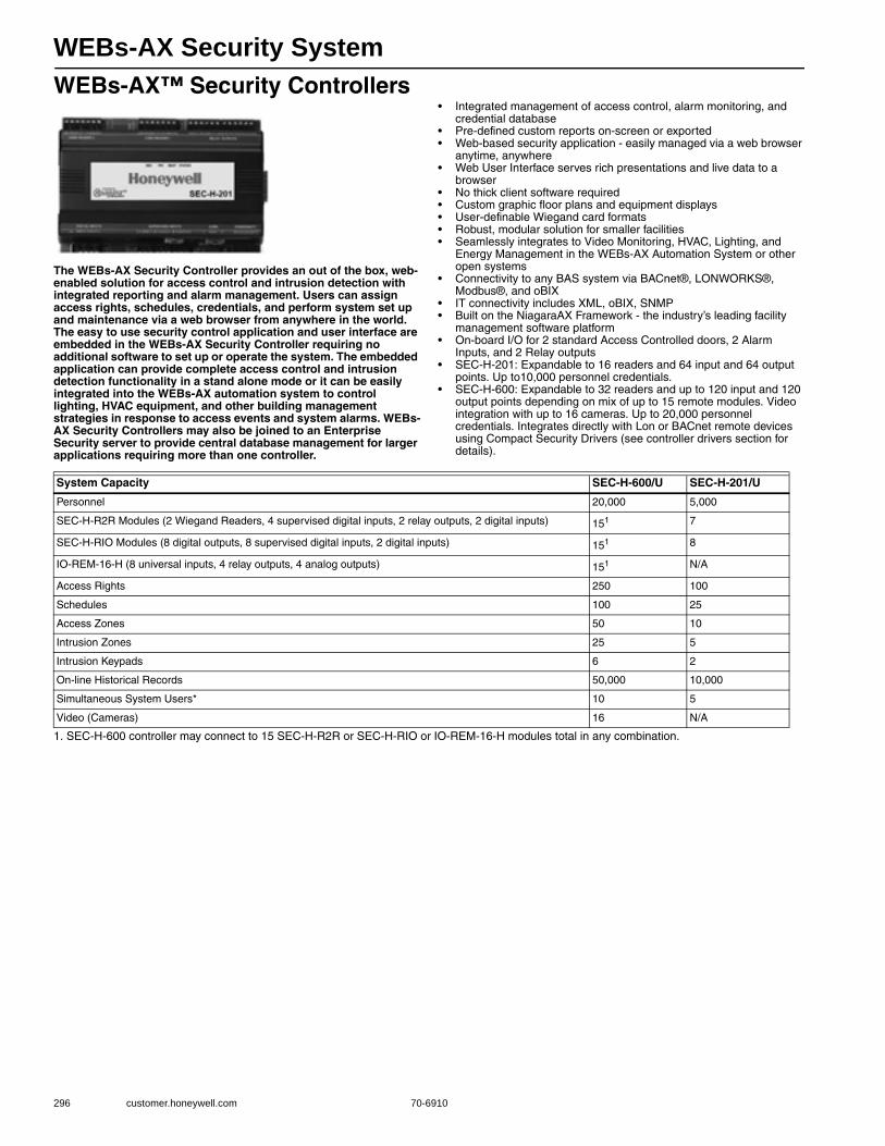
WEBs-AX Security System
296 customer.honeywell.com 70-6910
WEBs-AX™ Security Controllers
The WEBs-AX Security Controller provides an out of the box, web-enabled solution for access control and intrusion detection with integrated reporting and alarm management. Users can assign access rights, schedules, credentials, and perform system set up and maintenance via a web browser from anywhere in the world. The easy to use security control application and user interface are embedded in the WEBs-AX Security Controller requiring no additional software to set up or operate the system. The embedded application can provide complete access control and intrusion detection functionality in a stand alone mode or it can be easily integrated into the WEBs-AX automation system to control lighting, HVAC equipment, and other building management strategies in response to access events and system alarms. WEBs-AX Security Controllers may also be joined to an Enterprise Security server to provide central database management for larger applications requiring more than one controller.
• Integrated management of access control, alarm monitoring, and credential database
• Pre-defined custom reports on-screen or exported• Web-based security application - easily managed via a web browser
anytime, anywhere• Web User Interface serves rich presentations and live data to a
browser• No thick client software required• Custom graphic floor plans and equipment displays• User-definable Wiegand card formats• Robust, modular solution for smaller facilities• Seamlessly integrates to Video Monitoring, HVAC, Lighting, and
Energy Management in the WEBs-AX Automation System or other open systems
• Connectivity to any BAS system via BACnet®, LONWORKS®, Modbus®, and oBIX
• IT connectivity includes XML, oBIX, SNMP• Built on the NiagaraAX Framework - the industry’s leading facility
management software platform• On-board I/O for 2 standard Access Controlled doors, 2 Alarm
Inputs, and 2 Relay outputs• SEC-H-201: Expandable to 16 readers and 64 input and 64 output
points. Up to10,000 personnel credentials.• SEC-H-600: Expandable to 32 readers and up to 120 input and 120
output points depending on mix of up to 15 remote modules. Video integration with up to 16 cameras. Up to 20,000 personnel credentials. Integrates directly with Lon or BACnet remote devices using Compact Security Drivers (see controller drivers section for details).
1. SEC-H-600 controller may connect to 15 SEC-H-R2R or SEC-H-RIO or IO-REM-16-H modules total in any combination.
System Capacity SEC-H-600/U SEC-H-201/U
Personnel 20,000 5,000
SEC-H-R2R Modules (2 Wiegand Readers, 4 supervised digital inputs, 2 relay outputs, 2 digital inputs) 151 7
SEC-H-RIO Modules (8 digital outputs, 8 supervised digital inputs, 2 digital inputs) 151 8
IO-REM-16-H (8 universal inputs, 4 relay outputs, 4 analog outputs) 151 N/A
Access Rights 250 100
Schedules 100 25
Access Zones 50 10
Intrusion Zones 25 5
Intrusion Keypads 6 2
On-line Historical Records 50,000 10,000
Simultaneous System Users* 10 5
Video (Cameras) 16 N/A
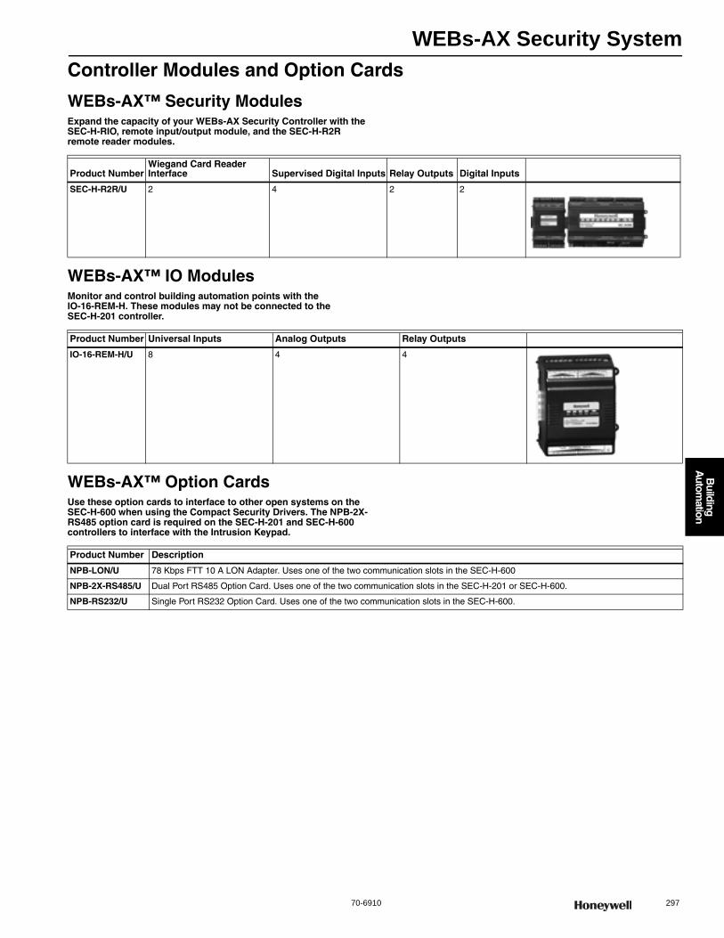
WEBs-AX Security System
70-6910 297
B
uilding A
utomation
Controller Modules and Option Cards
WEBs-AX™ Security ModulesExpand the capacity of your WEBs-AX Security Controller with the SEC-H-RIO, remote input/output module, and the SEC-H-R2R remote reader modules.
WEBs-AX™ IO ModulesMonitor and control building automation points with the IO-16-REM-H. These modules may not be connected to the SEC-H-201 controller.
WEBs-AX™ Option CardsUse these option cards to interface to other open systems on the SEC-H-600 when using the Compact Security Drivers. The NPB-2X-RS485 option card is required on the SEC-H-201 and SEC-H-600 controllers to interface with the Intrusion Keypad.
Product NumberWiegand Card Reader Interface Supervised Digital Inputs Relay Outputs Digital Inputs
SEC-H-R2R/U 2 4 2 2
Product Number Universal Inputs Analog Outputs Relay Outputs
IO-16-REM-H/U 8 4 4
Product Number Description
NPB-LON/U 78 Kbps FTT 10 A LON Adapter. Uses one of the two communication slots in the SEC-H-600
NPB-2X-RS485/U Dual Port RS485 Option Card. Uses one of the two communication slots in the SEC-H-201 or SEC-H-600.
NPB-RS232/U Single Port RS232 Option Card. Uses one of the two communication slots in the SEC-H-600.
WEBs-AX Security System
298 customer.honeywell.com 70-6910
Compact Security Solution DriversWEBs Compact Security Solution provides a cost effective solution for integrating access control, security, video surveillance, and building automation on the SEC-H-600 platform. A Lon or BACnet Focused Driver Option Pack determines the mix of controlled devices that can be integrated onto the platform. The embedded WEBs-AX security control application allows thin-client
configuration of the access control and security functions. WEBs-AX Workbench software is required for configuration of the HVAC devices. Note that card reader and personnel record capacities are reduced when using the Compact Security Drivers. Option cards to interface with BACnet, Lon, Modbus, and SNMP are ordered separately.
Compact Security Solution System Capacities
1. Maximum of 15 modules (SEC-H-RIO and SEC-H-R2R) per SEC-H-600.2. Up to 16 readers or 120 I/O points, depending on module combination.
DR-SEC-BAC/U
LON Devices/Points (TP/FT-10) 5 Devices/100 Points
BACnet Devices/Points (IP or MSTP) 60 Devices/2000 Points
Modbus TCP or RTU 5 Devices/100 Points
SNMP (over Ethernet) 5 Devices/100 Points
Remote I/O modules (SEC-H-RIO) 151
Remote Reader Modules (SEC-H-R2R) 151
Digital Input/Output Points 120 inputs/ 120 outputs2
Card Readers 162
Intrusion Keypads (SEC-H-INT-KP) 4
Personnel Records 10,000
History Records 50,000

WEBs-AX Security System
70-6910 299
B
uilding A
utomation
Video Integration DriversWEBs-AX Integrated Video is an open video framework solution designed to integrate diverse manufacturer devices and protocols into a unified, smart facility management system. Built on the NiagaraAX Framework®, WEBs-AX Video integrates with IP and analog based systems to create complete interoperability between video, security, lighting, energy management, and building automation for any facility.• Bi-directional alarming interface between NiagaraAX stations and
video products.• NiagaraAX alarms can initiate events in video subsystem.• Video system events such as video motion detection and camera
loss alarms can be processed as standard Niagara alarms.• Automatically redirect camera and start video recording based on
events or alarms.
• Create video system alarm record and associate recorded video for instant look-up.
• Initiate control logic sequences such as lighting control, building lockdown, etc.
• Ability to view live video through NiagaraAX graphical user experience.
• Supports pan, tilt, zoom, iris, and focus camera control.• Query video subsystem for stored video and playback by time and
date.• Integrated video playback with Niagara alarm console.• Customizable user experience through extensive video widget library
(PX pages).
WEBs-AX™ Platforms Supported for Video Integration Drivers (Requires NiagaraAX Build 3.4 or later)
NOTE: Axis IP Camera drivers do not support video playback, they are used for live viewing only. To integrate recording of IP cameras, use a sup-ported DVR with IP interface.
Product Number Product Restrictions
W-SJ-1M-AX/U WEBs SoftJACE No Set Limit
SEC-H-600/U WEBs Expanded Security Controller Maximum of 16 cameras
WEB-600-O/U WEB 600 Controller with Open License Maximum of 16 cameras, requires NPM-256 memory option.
WEB-600-US/U WEB 600 Controller (Manufactured in USA) Maximum of 16 cameras, requires NPM-256 memory option.
WEB-600-O-US/U WEB 600 Controller with Open License (Manufactured in USA) Maximum of 16 cameras, requires NPM-256 memory option.
Part# Description
DR-SUP-RPD-AX/U Base driver for RapidEye video DVR for WEBs-AX Supervisor. Includes license for 16 cameras.
DR-SUP-RPD-4/U Additional 4 camera block for WEBs-AX Supervisor RapidEye video driver.
DR-JAC-RPD-4/U RapidEye camera driver. Includes license for 4 cameras on SEC-H-600 or WEB-600
DR-SUP-DED-AX/U Base Driver for Dedicated Micros DVR for WEBs Supervisor, WEBs SoftJACE, or Enterprise Security. Includes support for up to 16 cameras.
DR-SUP-DED-4/U Additional 4 camera license for Dedicated Micros DVR on WEBs Supervisor, WEBs SoftJACE, or Enterprise Security.
DR-JAC-DED-AX/U Driver for Dedicated Micros DVR and 4 cameras on SEC-H-600 or WEB-600.
DR-SUP-AXS-AX/U* Base Driver for Axis IP Cameras for WEBs Supervisor, WEBs SoftJACE, or Enterprise Security. Supports for up to 16 cameras.
DR-SUP-AXS-4/U* Additional 4 camera license for Axis IP cameras on WEBs Supervisor, WEBs SoftJACE, or Enterprise Security.
DR-JAC-AXS-4/U* Driver for 4 Axis IP Cameras on SEC-H-600 or WEB-600.
DR-SUP-MLS-4/U WEB Supervisor Video Driver for 4 additional Axis cameras
DR-SUP-MLS-AX/U WEB Supervisor BASE Video Driver for Axis Cameras
DR-JAC-MLS-4/U WEB Video Driver for 4 Axis cameras
DR-SEC-BAC/U BACnet focused Driver Pack
DR-SEC-LON/U LON focused Driver Pack
DR-SEC-LON-FTT/U Lonworks Driver to extend the standard SEC-H-600 to building automation applications which supports 60 Lonworks devices, 2000 points, 300 histories, and limits the Security Jace to 16 readers. Driver includes 78 Kbps FTT 10 A LON® adapter (LON® Card).
DR-SEC-BAC-MSTP/U BACnet MS/TP Driver. Requires a separately purchased NPB-2X-RS485 RS-485 option card
DR-SEC-BAC-TCP/U BACnet TCP Driver to extend the standard SEC-H-600 to building automation applications which supports 60 BACnet devices, 2000 points, 300 histories, and limits the Security Jace to 16 readers.
DR-SEC-MDB-RTU/U Modbus RTU Driver to extend the standard SEC-H-600 to building automation applications which supports 60 Modbus devices, 2000 points, 300 histories, and limits the Security Jace to 16 readers.
DR-SEC-MDB-TCP/U Modbus TCP Driver to extend the standard SEC-H-600 to building automation applications which supports 60 Modbus devices, 2000 points, 300 histories, and limits the Security Jace to 16 readers.
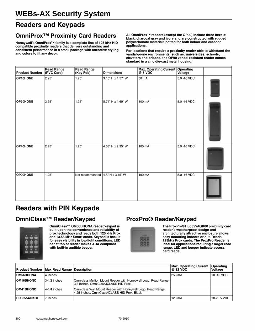
WEBs-AX Security System
300 customer.honeywell.com 70-6910
Readers and Keypads
OmniProx™ Proximity Card ReadersHoneywell’s OmniProx™ family is a complete line of 125 kHz HID compatible proximity readers that delivers outstanding and consistent performance in a small package with attractive styling and colors to fit any décor.
All OmniProx™ readers (except the OP90) include three bezels: black, charcoal gray and ivory and are constructed with rugged polycarbonate materials potted for both indoor and outdoor applications.
For locations that require a proximity reader able to withstand the vandal-prone environments, such as: universities, schools, elevators and prisons, the OP90 vandal resistant reader comes standard in a zinc die-cast metal housing.
Readers with PIN Keypads
OmniClass™ Reader/KeypadOmniClass™ OM56BHONA reader/keypad is built upon the convenience and reliability of prox technology and reads both 125 kHz Prox and 13.56 MHz Smart cards. Keypad is backlit for easy visibility in low-light conditions. LED bar at top of reader makes ADA compliant with built-in audible beeper.
ProxPro® Reader/KeypadThe ProxPro® Hu5355AGK00 proximity card reader’s weatherproof design and architecturally attractive enclosure allows easy mounting indoors or out. Reads 125kHz Prox cards. The ProxPro Reader is ideal for applications requiring a larger read range. LED and beeper indicate access card reads.
Product NumberRead Range (PVC Card)
Read Range(Key Fob) Dimensions
Max. Operating Current @ 5 VDC
Operating Voltage
OP10HONE 2.25” 1.25” 3.15” H x 1.57” W 50 mA 5.0 -16 VDC
OP30HONE 2.25” 1.25” 5.71” H x 1.69” W 100 mA 5.0 -16 VDC
OP40HONE 2.25” 1.25” 4.33” H x 2.95” W 100 mA 5.0 -16 VDC
OP90HONE 1.25” Not recommended 4.5” H x 3.15” W 100 mA 5.0 -16 VDC
Product Number Max Read Range DescriptionMax. Operating Current @ 12 VDC
Operating Voltage
OM56BHONA 4 inches 253 mA 10 -16 VDC
OM16BHONC 3-1/2 inches Omniclass Mullion Mount Reader with Honeywell Logo. Read Range 3.5 Inches, OmniClass/iCLASS HID Prox.
OM41BHONC 4-1/4 inches Omniclass Wall Mount Reader with Honeywell Logo. Read Range 4.25 Inches, OmniClass/iCLASS HID Prox. Black
HU5355AGK00 7 inches 120 mA 10-28.5 VDC
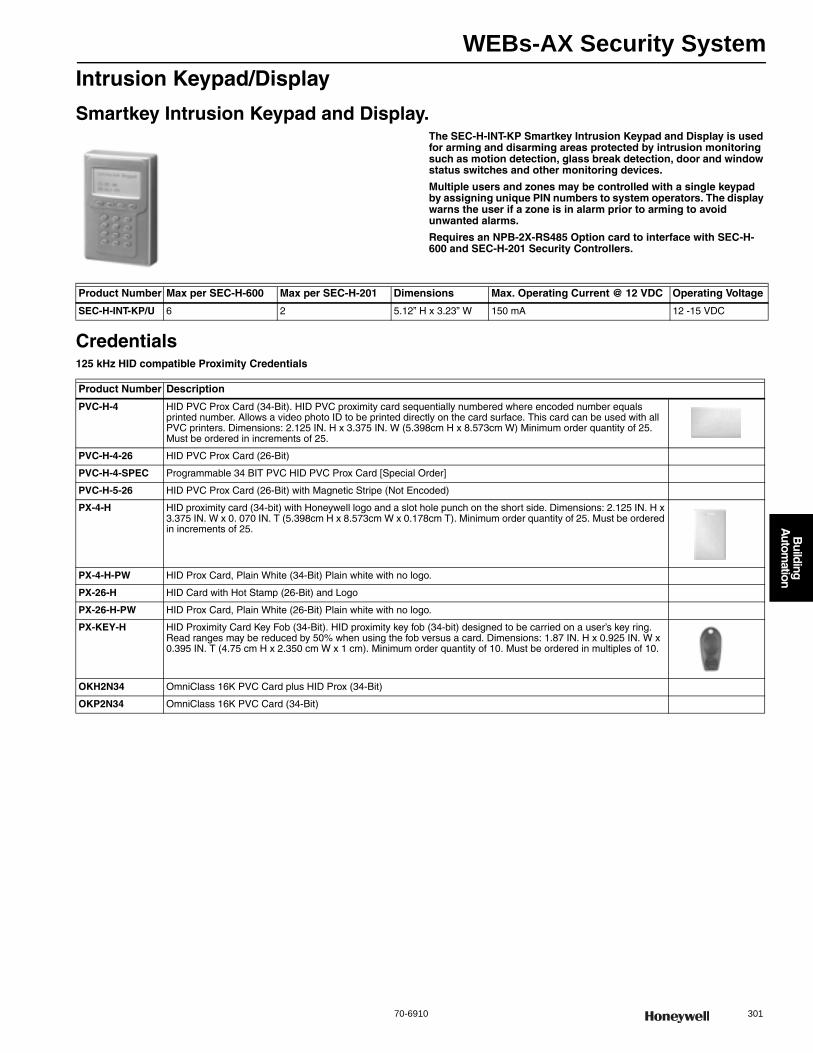
WEBs-AX Security System
70-6910 301
B
uilding A
utomation
Intrusion Keypad/Display
Smartkey Intrusion Keypad and Display.The SEC-H-INT-KP Smartkey Intrusion Keypad and Display is used for arming and disarming areas protected by intrusion monitoring such as motion detection, glass break detection, door and window status switches and other monitoring devices.
Multiple users and zones may be controlled with a single keypad by assigning unique PIN numbers to system operators. The display warns the user if a zone is in alarm prior to arming to avoid unwanted alarms.
Requires an NPB-2X-RS485 Option card to interface with SEC-H-600 and SEC-H-201 Security Controllers.
Credentials125 kHz HID compatible Proximity Credentials
Product Number Max per SEC-H-600 Max per SEC-H-201 Dimensions Max. Operating Current @ 12 VDC Operating Voltage
SEC-H-INT-KP/U 6 2 5.12” H x 3.23” W 150 mA 12 -15 VDC
Product Number Description
PVC-H-4 HID PVC Prox Card (34-Bit). HID PVC proximity card sequentially numbered where encoded number equals printed number. Allows a video photo ID to be printed directly on the card surface. This card can be used with all PVC printers. Dimensions: 2.125 IN. H x 3.375 IN. W (5.398cm H x 8.573cm W) Minimum order quantity of 25. Must be ordered in increments of 25.
PVC-H-4-26 HID PVC Prox Card (26-Bit)
PVC-H-4-SPEC Programmable 34 BIT PVC HID PVC Prox Card [Special Order]
PVC-H-5-26 HID PVC Prox Card (26-Bit) with Magnetic Stripe (Not Encoded)
PX-4-H HID proximity card (34-bit) with Honeywell logo and a slot hole punch on the short side. Dimensions: 2.125 IN. H x 3.375 IN. W x 0. 070 IN. T (5.398cm H x 8.573cm W x 0.178cm T). Minimum order quantity of 25. Must be ordered in increments of 25.
PX-4-H-PW HID Prox Card, Plain White (34-Bit) Plain white with no logo.
PX-26-H HID Card with Hot Stamp (26-Bit) and Logo
PX-26-H-PW HID Prox Card, Plain White (26-Bit) Plain white with no logo.
PX-KEY-H HID Proximity Card Key Fob (34-Bit). HID proximity key fob (34-bit) designed to be carried on a user’s key ring. Read ranges may be reduced by 50% when using the fob versus a card. Dimensions: 1.87 IN. H x 0.925 IN. W x 0.395 IN. T (4.75 cm H x 2.350 cm W x 1 cm). Minimum order quantity of 10. Must be ordered in multiples of 10.
OKH2N34 OmniClass 16K PVC Card plus HID Prox (34-Bit)
OKP2N34 OmniClass 16K PVC Card (34-Bit)
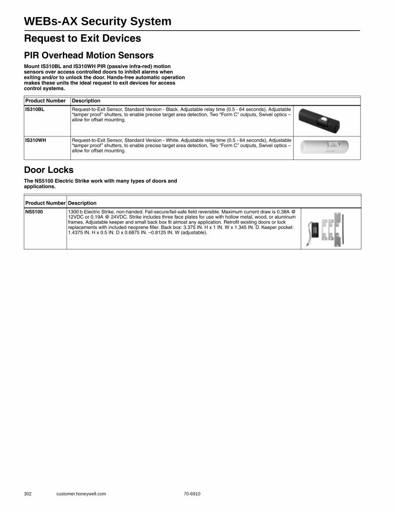
WEBs-AX Security System
302 customer.honeywell.com 70-6910
Request to Exit Devices
PIR Overhead Motion SensorsMount IS310BL and IS310WH PIR (passive infra-red) motion sensors over access controlled doors to inhibit alarms when exiting and/or to unlock the door. Hands-free automatic operation makes these units the ideal request to exit devices for access control systems.
Door LocksThe NS5100 Electric Strike work with many types of doors and applications.
Product Number Description
IS310BL Request-to-Exit Sensor, Standard Version - Black. Adjustable relay time (0.5 - 64 seconds), Adjustable “tamper proof” shutters, to enable precise target area detection, Two “Form C” outputs, Swivel optics – allow for offset mounting.
IS310WH Request-to-Exit Sensor, Standard Version - White. Adjustable relay time (0.5 - 64 seconds), Adjustable “tamper proof” shutters, to enable precise target area detection, Two “Form C” outputs, Swivel optics – allow for offset mounting.
Product Number Description
NS5100 1300 b Electric Strike, non-handed. Fail-secure/fail-safe field reversible. Maximum current draw is 0.38A @ 12VDC or 0.19A @ 24VDC. Strike includes three face plates for use with hollow metal, wood, or aluminum frames. Adjustable keeper and small back box fit almost any application. Retrofit existing doors or lock replacements with included neoprene filler. Back box: 3.375 IN. H x 1 IN. W x 1.345 IN. D. Keeper pocket: 1.4375 IN. H x 0.5 IN. D x 0.6875 IN. –0.8125 IN. W (adjustable).
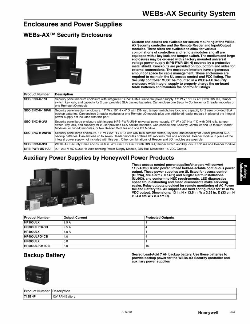
WEBs-AX Security System
70-6910 303
B
uilding A
utomation
Enclosures and Power Supplies
WEBs-AX™ Security EnclosuresCustom enclosures are available for secure mounting of the WEBs-AX Security controller and the Remote Reader and Input/Output modules. Three sizes are available to allow for various combinations of controllers and remote modules and all are equipped with a key lock and tamper switch. The medium and large enclosures may be ordered with a factory mounted universal voltage power supply (NPB-PWR-UN-H) covered by a protective metal shield. Knockouts are provided on top, bottom and sides for external connections. The enclosure interiors have a generous amount of space for cable management. These enclosures are required to maintain the UL access control and FCC listing. The Security controller MUST be mounted in a WEBs-AX Security enclosure with integral supply to properly charge the on-board NiMH batteries and maintain the controller listings.
Auxiliary Power Supplies by Honeywell Power ProductsThese access control power supplies/chargers will convert 115VAC/60Hz into power limited field-selectable continuous power output. These power supplies are UL listed for access control (UL294), fire alarm (UL1481) and burglar alarm installations (UL603), and conform to NEC requirements. LED diagnostics speed troubleshooting and fused disconnects make servicing easier. Relay outputs provided for remote monitoring of AC Power fail and Battery fail. All supplies are field configurable for 12 or 24 VDC output. Dimensions: 13 in. H x 13.5 in. W x 3.25 in. D (33 cm H x 34.3 cm W x 8.3 cm D).
Backup Battery Sealed Lead-Acid 7 AH backup battery. Use these batteries to provide backup power for the WEBs-AX Security controller and auxiliary power supplies
Product Number DescriptionSEC-ENC-H-1/U Security panel medium enclosure with integral NPB-PWR-UN-H universal power supply. 17” W x 15” H x 4” D with DIN rail, tamper
switch, key lock, and capacity for 2 user provided SLA backup batteries. Can enclose one Security Controller, or 2 reader modules or one Remote I/O module.
SEC-ENC-H-1NP/U Security panel medium enclosure. 17” W x 15” H x 4” D with DIN rail, tamper switch, key lock, and capacity for 2 user provided SLA backup batteries. Can enclose 2 reader modules or one Remote I/O module plus one additional reader module in place of the integral power supply not included with this part.
SEC-ENC-H-2/U Security panel large enclosure with integral NPB-PWR-UN-H universal power supply. 17” W x 22” H x 4” D with DIN rails, tamper switch, key lock, and capacity for 2 user provided SLA backup batteries. Can enclose one Security Controller and up to four Reader Modules, or two I/O modules, or two Reader Modules and one I/O Module.
SEC-ENC-H-2NP/U Security panel large enclosure. 17” W x 22” H x 4” D with DIN rails, tamper switch, key lock, and capacity for 2 user provided SLA backup batteries. Can enclose up to seven Reader modules or three I/O modules plus one additional Reader module in place of the integral power supply not included with this part. Other combinations of Reader and I/O modules are poss ble.
SEC-ENC-H-3/U WEBs-AX Security Small enclosure 6 in. W x 9 in. H x 4 in. D with DIN rail, tamper switch and key lock. Encloses one Reader module.
NPB-PWR-UN-H/U 90 - 263 V AC 50/60 Hz Auto sensing Power Supply Module, DIN Rail Mountable 15 VDC Output.
Product Number Output Current Protected OutputsHP300ULX 2.5 A 1
HP300ULPD4CB 2.5 A 4
HP400ULX 4.0 A 1
HP400ULPD4CB 4.0 4
HP600ULX 6.0 1
HP600ULPD16CB 6.0 16
Product Number Description
712BNP 12V 7AH Battery
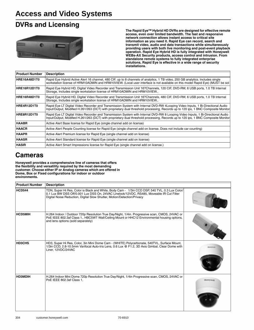
Access and Video Systems
304 customer.honeywell.com 70-6910
DVRs and LicensingThe Rapid Eye™ Hybrid HD DVRs are designed for effective remote access, even over limited bandwidth. The fast and responsive network connection allows instant access to critical site information as you need it. Rapid Eye can record, search and transmit video, audio and data transactions while simultaneously providing users with both live monitoring and post-event playback operation. Rapid Eye Hybrid HD is fully integrated with Honeywell WEBs-AX Security products, access control and intrusion. From standalone remote systems to fully integrated enterprise solutions, Rapid Eye is effective in a wide range of security installations.
CamerasHoneywell provides a comprehensive line of cameras that offers the flexibility and versatility required by the most demanding customer. Choose either IP or Analog cameras which are offered in Dome, Box or Fixed configurations for indoor or outdoor environments.
Product Number Description
HRE16A48D1T0 Rapid Eye Hybrid Active Alert 16 channel, 480 CIF, up to 8 channels of analytics, 1 TB video, 250 GB analytics. Includes single workstation license of HRM10ADMIN and HRM10VIEW. (Local user interface is not available on this model Rapid Eye) (MUST be sol
HRE16R12D1T0 Rapid Eye Hybrid HD, Digital Video Recorder and Transmission Unit 16?Channels, 120 CIF, DVD-RW, 6 USB ports, 1.0 TB Internal Storage, Includes single workstation license of HRM10ADMIN and HRM10VIEW.,
HRE16R48D1T0 Rapid Eye Hybrid HD, Digital Video Recorder and Transmission Unit 16?Channels, 480 CIF, DVD-RW, 6 USB ports, 1.0 TB Internal Storage, Includes single workstation license of HRM10ADMIN and HRM10VIEW.,
HRE4R12D1T0 Rapid Eye LT Digital Video Recorder and Transmission System with Internal DVD-RW 4Looping Video Inputs, 1 Bi-Directional Audio Input/Output, Modified H.261/263 (DCT) with proprietary dual threshold processing, Records up to 120 ips, 1 BNC Composite Monitor
HRE8R12D1T0 Rapid Eye LT Digital Video Recorder and Transmission System with Internal DVD-RW 8 Looping Video Inputs, 1 Bi-Directional Audio Input/Output, Modified H.261/263 (DCT) with proprietary dual threshold processing, Records up to 120 ips, 1 BNC Composite Monitor
HAABR Active Alert Base license for Rapid Eye (single channel add on license)
HAACR Active Alert People Counting license for Rapid Eye (single channel add on license. Does not include car counting)
HAAPR Active Alert Premium license for Rapid Eye (single channel add on license)
HAASR Active Alert Standard license for Rapid Eye (single channel add on license)
HASIR Active Alert Smart Impressions license for Rapid Eye (single channel add on license.)
Product Number Description
HCD544 TDN, Super Hi Res, Color is Black and White, Body Cam - 1/3in CCD DSP, 540 TVL, 0.3 Lux Color/0.1 Lux BW DSS Off/0.001 Lux DSS On, 24VAC Linelock/12VDC, RS485, Moveable IR Cut Filter Digital Noise Reduction, Digital Slow Shutter, Motion/Detection/Privacy
HCD5MIH H.264 Indoor / Outdoor 720p Resolution True Day/Night, 1/4in. Progressive scan, CMOS, 24VAC or PoE IEEE 802.3af Class 1,. HBC5WT Wall/Ceiling Mount or HHC12 Environmental housing options, and lens options (sold separately)
HD3CHS HD3, Super Hi Res, Color, 3in Mini Dome Cam - (WHITE) Polycarbonate, 540TVL, Surface Mount, 1/3in CCD, 2.8-10.5mm Varifocal Auto-Iris Lens, 0.6 Lux @ F1.2, 3D Axis Gimbal, Clear Dome with Liner, 12VDC/24VAC
HD3MDIH H.264 Indoor Mini Dome 720p Resolution True Day/Night, 1/4in Progressive scan, CMOS, 24VAC or PoE IEEE 802.3af Class 1,

Access and Video Systems
70-6910 305
B
uilding A
utomation
HD3MDIP True Day/Night Dome Network Camera, 540 TVL, 3.3-12 mm VFAI, 12 VDC/24 VAC or PoE IEEE 802.3af,
HD4DIRS Rugged Mini-Dome Camera with Infrared
HD4MDIH H.264 Rugged Indoor/Outdoor 720p Resolution True Day/Night, 3.3-12 mm VFAI lens with removable IR cut filter, 1/4in Progressive scan, CMOS, 24VAC or PoE IEEE 802.3af Class 1
HD4MDIP True Day/Night Vandal Dome Network Camera, 540 TVL, 3.3-12 mm VFAI, 12 VDC/24 VAC or PoE IEEE 802.3af,
HD4US HD4 TDN Ultra Wide Dynamic, Super Hi Res, DPS, Color Mini Dome Cam 690 TVL, Vandal Resistant, 0.4 lux @ F1.5 for true color representation in daytime and black and white at night, 3-D axis gimbal bracket,
HD50P Super Hi Res, Color Mini Dome Cam, 600 HTVL, 1/3in CCD Sensor, 3.8 mm Fixed lens, SBLC (Super Back Light Compensation) Vandal Resistant, 12 VDC
HD51P Super Hi Res, Color Mini Dome Cam, 600 TVL, 1/3in CCD Sensor, 3.8-9.5 mm VFAI lens, OSD (On Screen Display), Privacy Zone / Mirror Function, Built-in Breather Vent to prevent condensation, Motion Detection, SBLC (Super Back Light Compensation), Digital No
HD61 IR Std Res, S/W D/N, Mini Dome Cam - 20 LED, Surface Mount, 1/3in Sony Super HAD CCD, 380 TVL, 4-9mm Manual Auto-Iris lens, 12 VDC
HD73P Super Hi Res, TDN Mini Dome Cam, 600 TVL, 1/3 Inch CCD Sensor, 3.8 - 9.5 mm VFAI, TDN (True Day/Night -moveable IR Cut Filter) Intelligent IR Technology (Built in LEDs), Privacy Zone / Mirror Function, Motion Detection, SBLC (Super Back Light Compensation
Product Number Description

Access and Video Systems
306 customer.honeywell.com 70-6910
HDVANDASW ACUIX ES, In-ceiling mount with Smoke Lower Dome and White Trim Ring. Hi-Resolution Color Camera (>470TVL) and 18X Zoom. OSD, 24 privacy zones, Video over coax, 2 contact inputs
HDVANSBC ACUIX ES, Surface mount with Clear Lower Dome. Hi-Resolution Color Camera (>470TVL) and 18X Zoom. OSD, 24 privacy zones, Video over coax and over UTP, 8 contact inputs, can be converted to Pendant mount with HDCM1
HDXANDDSW ACUIX IP, In-ceiling mount with Smoked Lower Dome and White Trim Ring. Hi-Resolution Color Camera with Electronic Image Stabilization (>470TVL) and 18X Zoom. Video and Data over TC/IP.
HDXANPDSW ACUIX, IP WHITE Indoor Pendant with Smoked Lower Dome and White Trim Ring. Hi-Resolution Color Camera (>470TVL) and 18X Zoom. Video over coax and data over 2-conductor cable OR Video over coax and data by VCL up-the-coax protocol OR Video over UTP and dat
HDXFNRACW ACUIX, Outdoor Rugged Pendant with Clear Lower Dome and White Trim Ring. Hi-Resolution Wide Dynamic and True Day/Night Camera (>530TVL) and 26X Zoom. Includes 24Vac Heater and Blower. Video over coax and data over 2-conductor cable OR Video over coax and
HDXFNRDCW ACUIX IP, Outdoor Rugged Pendant with Clear Lower Dome and White Trim Ring. Hi-Resolution Wide Dynamic and True Day/Night Camera (>530TVL) and 26X Zoom. Includes 24Vac Heater and Blower. Video and Data over TC/IP. Includes 24Vac Heater and Blower.
HDXFNWDCW ACUIX IP, Outdoor Pendant with Clear Lower Dome and White Trim Ring. Hi-Resolution True Day/Night Camera (>530TVL) and 26X Zoom. Includes 24Vac Heater and Blower. Video and Data over TC/IP. Includes 24Vac Heater and Blower. Does not include Dome mount
HDXGNWACW ACUIX, Outdoor Pendant with Clear Lower Dome and White Trim Ring. Hi-Resolution Wide-Dynamic Range and True Day/Night Camera with Electronic Image Stabilization (>540TVL) and 35X Zoom. Includes 24Vac Heater and Blower. Video over coax and data over 2-conductor cable
HDXGNWDCW ACUIX IP, Outdoor Pendant with Clear Lower Dome and White Trim Ring. Hi-Resolution Wide-Dynamic Range and True Day/Night Camera with Electronic Image Stabilization (>540TVL) and 35X Zoom. Includes 24Vac Heater and Blower. Video and Data over TC/IP.
HDXJNDASW ACUIX, In-ceiling mount with Smoked Lower Dome and White Trim Ring. Hi-Resolution Wide Dynamic and True Day/Night Camera (>530TVL) and 18X Zoom.Video over coax and data over 2-conductor cable OR Video over coax and data by VCL up-the-coax protocol OR V
HDXJNDDSW ACUIX IP, In-ceiling mount with Smoked Lower Dome and White Trim Ring. Hi-Resolution Wide Dynamic and True Day/Night Camera (>530TVL) and 18X Zoom.Video and Data over TC/IP.
HDXJNPASW ACUIX, WHITE Indoor Pendant with Smoked Lower Dome and White Trim Ring. Hi-Resolution Wide Dynamic and True Day/Night Camera (>530TVL) and 18X Zoom. Video over coax and data over 2-conductor cable OR Video over coax and data by VCL up-the-coax protocol OR
HDXJNPDSW ACUIX IP, WHITE Indoor Pendant with Smoked Lower Dome and White Trim Ring. Hi-Resolution Wide Dynamic and True Day/Night Camera (>530TVL) and 18X Zoom. Video and Data over TC/IP.
Product Number Description
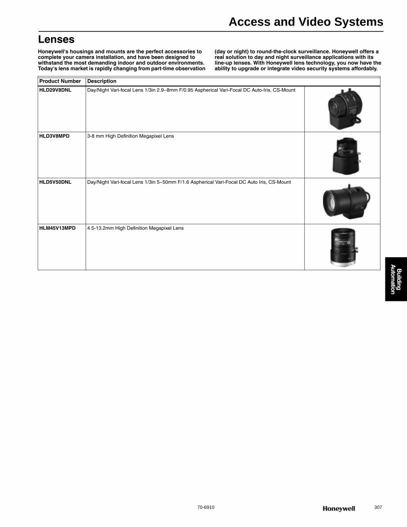
Access and Video Systems
70-6910 307
B
uilding A
utomation
LensesHoneywell's housings and mounts are the perfect accessories to complete your camera installation, and have been designed to withstand the most demanding indoor and outdoor environments. Today's lens market is rapidly changing from part-time observation
(day or night) to round-the-clock surveillance. Honeywell offers a real solution to day and night surveillance applications with its line-up lenses. With Honeywell lens technology, you now have the ability to upgrade or integrate video security systems affordably.
Product Number Description
HLD29V8DNL Day/Night Vari-focal Lens 1/3in 2.9~8mm F/0.95 Aspherical Vari-Focal DC Auto-Iris, CS-Mount
HLD3V8MPD 3-8 mm High Definition Megapixel Lens
HLD5V50DNL Day/Night Vari-focal Lens 1/3in 5~50mm F/1.6 Aspherical Vari-Focal DC Auto Iris, CS-Mount
HLM45V13MPD 4.5-13.2mm High Definition Megapixel Lens
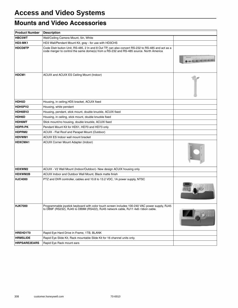
Access and Video Systems
308 customer.honeywell.com 70-6910
Mounts and Video AccessoriesProduct Number Description
HBC5WT Wall/Ceiling Camera Mount, 5in, White
HD3-MK1 HD3 Wall/Pendant Mount Kit, gray - for use with HD3CHS
HDCD8TP Code Distr bution Unit, RS-485, 2 In and 8 Out TP, can also convert RS-232 to RS-485 and act as a code merger to control the same dome(s) from a RS-232 and RS-485 source. North America
HDCM1 ACUIX and ACUIX ES Ceiling Mount (Indoor)
HDH5D Housing, in ceiling,HD5 bracket, ACUIX fixed
HDH5PV2 Housing, white pendant
HDH6BV2 Housing, pendant, stick mount, double knuckle, ACUIX fixed
HDH6D Housing, in ceiling, stick mount, double knuckle fixed
HDH6MT Stick mount/no housing, double knuckle, ACUIX fixed
HDPR-PK Pendant Mount Kit for HD51, HD70 and HD73 only
HDPRM2 ACUIX - Flat Roof and Parapet Mount (Outdoor)
HDVWM1 ACUIX ES Indoor wall mount bracket
HDXCMA1 ACUIX Corner Mount Adapter (Indoor)
HDXWM2 ACUIX - V2 Wall Mount (Indoor/Outdoor)- New design ACUIX housing only
HDXWM2B ACUIX Indoor and Outdoor Wall Mount, Black matte finish
HJC4000 PTZ and DVR controller, cables and 10.8 to 13.2 VDC, 1A power supply, NTSC
HJK7000 Programmable joystick keyboard with color touch screen includes 100-240 VAC power supply, RJ45 to DB9F (RS232), RJ45 to DB9M (RS422), RJ45 network cable, RJ11 4x6 r bbon cable.
HREHD1T0 Rapid Eye Hard Drive in Frame, 1TB, BLANK
HRMSLIDE Rapid Eye Slide Kit, Rack mountable Slide Kit for 16 channel units only.
HRPSARE2EARS Rapid Eye Rack mount ears
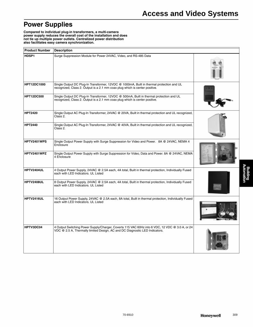
Access and Video Systems
70-6910 309
B
uilding A
utomation
Power SuppliesCompared to individual plug-in transformers, a multi-camera power supply reduces the overall cost of the installation and does not tie up multiple power outlets. Centralized power distribution also facilitates easy camera synchronization.
Product Number Description
HDSP1 Surge Suppression Module for Power 24VAC, Video, and RS-485 Data
HPT12DC1000 Single Output DC Plug-In Transformer, 12VDC @ 1000mA, Built in thermal protection and UL recognized, Class 2. Output is a 2.1 mm coax plug which is center positive.
HPT12DC500 Single Output DC Plug-In Transformer, 12VDC @ 500mA, Built in thermal protection and UL recognized, Class 2. Output is a 2.1 mm coax plug which is center positive.
HPT2420 Single Output AC Plug-In Transformer, 24VAC @ 20VA, Built in thermal protection and UL recognized, Class 2.
HPT2440 Single Output AC Plug-In Transformer, 24VAC @ 40VA, Built in thermal protection and UL recognized, Class 2.
HPTV2401WPS Single Output Power Supply with Surge Suppression for Video and Power. 8A @ 24VAC, NEMA 4 Enclosure
HPTV2401WPZ Single Output Power Supply with Surge Suppression for Video, Data and Power. 8A @ 24VAC, NEMA 4 Enclosure
HPTV2404UL 4 Output Power Supply, 24VAC @ 2.5A each, 4A total, Built in thermal protection, Individually Fused each with LED Indicators. UL Listed
HPTV2408UL 8 Output Power Supply, 24VAC @ 2.5A each, 4A total, Built in thermal protection, Individually Fused each with LED Indicators. UL Listed
HPTV2416UL 16 Output Power Supply, 24VAC @ 2.5A each, 8A total, Built in thermal protection, Individually Fused each with LED Indicators. UL Listed
HPTV3DC04 4 Output Switching Power Supply/Charger, Coverts 115 VAC 60Hz into 6 VDC, 12 VDC @ 3.0 A, or 24 VDC @ 2.5 A, Thermally limited Design, AC and DC Diagnostic LED Indicators.
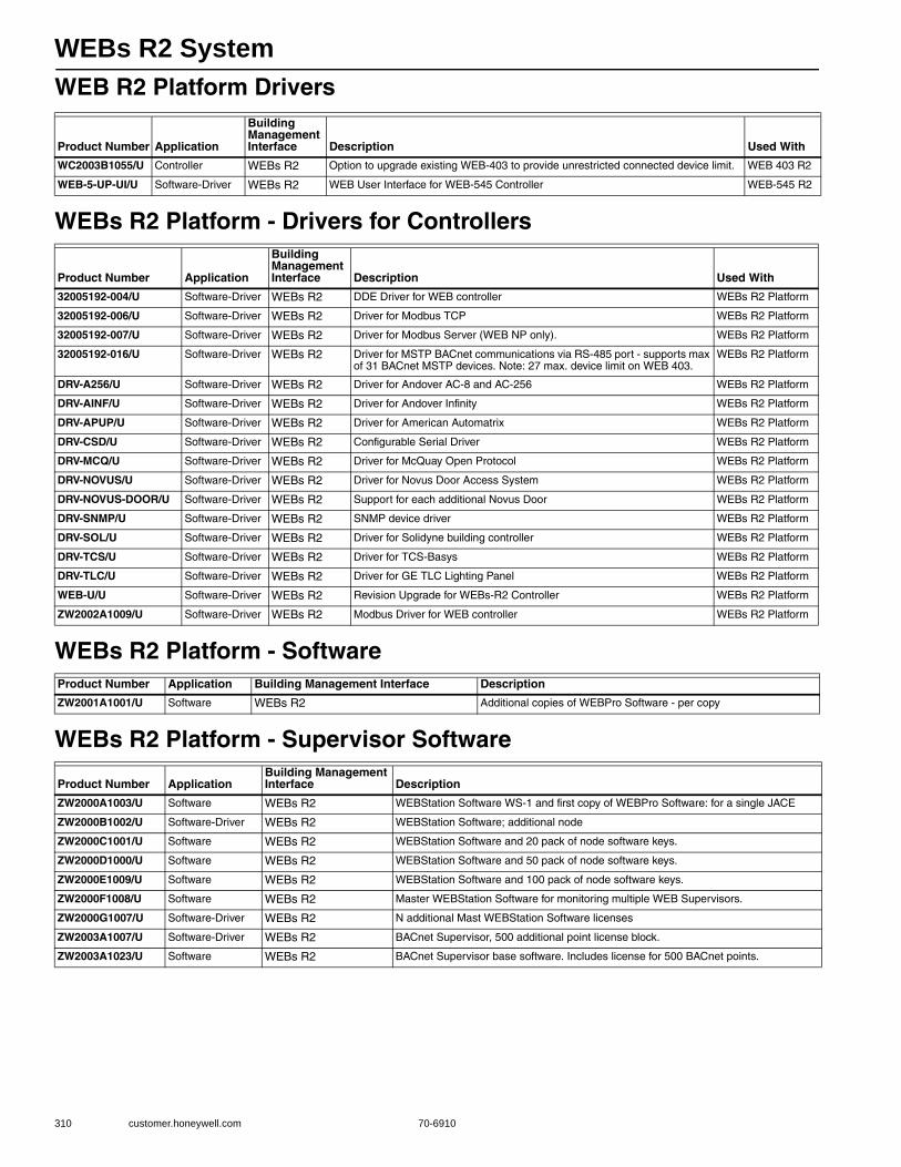
WEBs R2 System
310 customer.honeywell.com 70-6910
WEB R2 Platform Drivers
WEBs R2 Platform - Drivers for Controllers
WEBs R2 Platform - Software
WEBs R2 Platform - Supervisor Software
Product Number Application
Building Management Interface Description Used With
WC2003B1055/U Controller WEBs R2 Option to upgrade existing WEB-403 to provide unrestricted connected device limit. WEB 403 R2
WEB-5-UP-UI/U Software-Driver WEBs R2 WEB User Interface for WEB-545 Controller WEB-545 R2
Product Number Application
Building Management Interface Description Used With
32005192-004/U Software-Driver WEBs R2 DDE Driver for WEB controller WEBs R2 Platform
32005192-006/U Software-Driver WEBs R2 Driver for Modbus TCP WEBs R2 Platform
32005192-007/U Software-Driver WEBs R2 Driver for Modbus Server (WEB NP only). WEBs R2 Platform
32005192-016/U Software-Driver WEBs R2 Driver for MSTP BACnet communications via RS-485 port - supports max of 31 BACnet MSTP devices. Note: 27 max. device limit on WEB 403.
WEBs R2 Platform
DRV-A256/U Software-Driver WEBs R2 Driver for Andover AC-8 and AC-256 WEBs R2 Platform
DRV-AINF/U Software-Driver WEBs R2 Driver for Andover Infinity WEBs R2 Platform
DRV-APUP/U Software-Driver WEBs R2 Driver for American Automatrix WEBs R2 Platform
DRV-CSD/U Software-Driver WEBs R2 Configurable Serial Driver WEBs R2 Platform
DRV-MCQ/U Software-Driver WEBs R2 Driver for McQuay Open Protocol WEBs R2 Platform
DRV-NOVUS/U Software-Driver WEBs R2 Driver for Novus Door Access System WEBs R2 Platform
DRV-NOVUS-DOOR/U Software-Driver WEBs R2 Support for each additional Novus Door WEBs R2 Platform
DRV-SNMP/U Software-Driver WEBs R2 SNMP device driver WEBs R2 Platform
DRV-SOL/U Software-Driver WEBs R2 Driver for Solidyne building controller WEBs R2 Platform
DRV-TCS/U Software-Driver WEBs R2 Driver for TCS-Basys WEBs R2 Platform
DRV-TLC/U Software-Driver WEBs R2 Driver for GE TLC Lighting Panel WEBs R2 Platform
WEB-U/U Software-Driver WEBs R2 Revision Upgrade for WEBs-R2 Controller WEBs R2 Platform
ZW2002A1009/U Software-Driver WEBs R2 Modbus Driver for WEB controller WEBs R2 Platform
Product Number Application Building Management Interface Description
ZW2001A1001/U Software WEBs R2 Additional copies of WEBPro Software - per copy
Product Number ApplicationBuilding Management Interface Description
ZW2000A1003/U Software WEBs R2 WEBStation Software WS-1 and first copy of WEBPro Software: for a single JACE
ZW2000B1002/U Software-Driver WEBs R2 WEBStation Software; additional node
ZW2000C1001/U Software WEBs R2 WEBStation Software and 20 pack of node software keys.
ZW2000D1000/U Software WEBs R2 WEBStation Software and 50 pack of node software keys.
ZW2000E1009/U Software WEBs R2 WEBStation Software and 100 pack of node software keys.
ZW2000F1008/U Software WEBs R2 Master WEBStation Software for monitoring multiple WEB Supervisors.
ZW2000G1007/U Software-Driver WEBs R2 N additional Mast WEBStation Software licenses
ZW2003A1007/U Software-Driver WEBs R2 BACnet Supervisor, 500 additional point license block.
ZW2003A1023/U Software WEBs R2 BACnet Supervisor base software. Includes license for 500 BACnet points.

WEBs R2 System
70-6910 311
B
uilding A
utomation
WEBs R2 Platform - Drivers for Supervisors
Product Number Application
Building Management Interface Description Used With
32005192-012/U Software-Driver WEBs R2 License for an additional client for the WEBs R2 Alarm Service. WEBs R2 Platform
32005192-015/U Software-Driver WEBs R2 Proteus Alarm Service for Eagle Maintenance Management Software. Runs on any WEBs R2 Supervisor.
WEBs R2 Platform
32005192-017/U Software-Driver WEBs R2 SQL Driver for Web Supervisor, OPC Supervisor or BACnet Supervisor. Does not include MS SQL Server Software.
WEBs R2 Platform
32005192-021/U Software-Driver WEBs R2 Tenant Billing Service. Runs on any Web Supervisor. WEBs R2 Platform
WS-MTCP-500/U Software-Driver WEBs R2 Modbus 500 Point Addition WEBs R2 Platform
WS-OPC-500/U Software-Driver WEBs R2 OPC 500 Point Addition WEBs R2 Platform
WS-ORCL/U Software-Driver WEBs R2 Oracle Driver WEBs R2 Platform
WS-OSD/U Software-Driver WEBs R2 Open System Driver WEBs R2 Platform
WS-SNMP-500/U Software-Driver WEBs R2 SNMP 500 Point Addition WEBs R2 Platform

Spyder Controllers
312 customer.honeywell.com 70-6910
Spyder Programmable ControllersThe Spyder Family of controllers are for use in VAV (Variable Air Volume) and Unitary HVAC control applications. Each controller communicates via either LONWORKS® or BACnet MS/TP network communications. Each controller provides flexible, universal inputs (UI) for external sensors, digital inputs (DI), and a combination of analog outputs (AO) and digital Triac outputs (DO). The Sylk Bus is included in each controller which enables connection to other Sylk enabled devices. These controllers provide many options and advanced system features that allow state-of-the-art commercial building control. Each controller is programmable and configurable using the NIAGARA AX FRAMEWORK® software.
Dimensions, Approximate: 5.45 in. high x 6.85 in. wide x 2.26 in. deep (138.4 mm high x 174 mm wide x 57.4 mm deep)
Application Size: Small to LargeCommissioning Software: WEBs AXVoltage: 24 Vac with a valid range of 20 to 30 VacFrequency: 50 Hz; 60 HzOperating Humidity Range (% RH): 5 to 95% RH, non-condensingSetpoint Temperature Range: ProgrammableOperating Temperature Range: -40 F to 150 F (-40 C to 65.5 C)Shipping Temperature Range: -40 F to 150 F (-40 C to 65.5 C) Compatible with: WEBs AX
Comments: Onboard 20 VDC power supplyApprovalsCanadian Standards Association: CertifiedCE: ApprovedFederal Communications Commission: FCC Part 15, Subpart B,
Class BUnderwriters Laboratories, Inc: UL 916
Accessories:TR70-Zio LCD Wall Module (Temperature)TR70-H-Zio LCD Wall Module (Temperature & Humidity)
Product Number DescriptionNetwork Communications I/O Count
Power Consumption Output Type Includes
PUB1012S-ILC/U Spyder ILC Programmable Unitary Controller
BACnet MS/TP 1 UI, 0 DI, 1 AO, 2 DO
5 VA Pulse Width Modulation, Floating, Staged On/Off
—
PUB1012S/U Spyder Programmable Unitary Controller
BACnet MS/TP 1 UI, 0 DI, 1 AO, 2 DO
5 VA Pulse Width Modulation, Floating, Staged On/Off
—
PUB4024S-ILC/U Spyder ILC Programmable Unitary Controller
BACnet MS/TP 4 UI, 0 DI, 2 AO, 4 DO
5 VA Pulse Width Modulation, Floating, Staged On/Off
—
PUB4024S/U Spyder Programmable Unitary Controller
BACnet MS/TP 4 UI, 0 DI, 2 AO, 4 DO
5 VA Pulse Width Modulation, Floating, Staged On/Off
—
PUB6438S-ILC-US/U Spyder ILC Programmable Unitary Controller
BACnet MS/TP 6 UI, 4 DI, 3 AO, 8 DO
5 VA Pulse Width Modulation, Floating, Staged On/Off
—
PUB6438S-ILC/U Spyder ILC Programmable Unitary Controller
BACnet MS/TP 6 UI, 4 DI, 3 AO, 8 DO
5 VA Pulse Width Modulation, Floating, Staged On/Off
—
PUB6438S/U Spyder Programmable Unitary Controller
BACnet MS/TP 6 UI, 4 DI, 3 AO, 8 DO
5 VA Pulse Width Modulation, Floating, Staged On/Off
—
PUB6438SR Spyder Programmable Unitary Controller
BACnet 6 UI, 4 DI, 3 AO, 8 DO
5 VA Relay DO's, Staged On/Off —
PUB6438SR-ILC Spyder ILC Programmable Unitary Controller
BACnet 6 UI, 4 DI, 3 AO, 8 DO
5 VA Relay DO's, Staged On/Off —
PUL1012S-ILC/U Spyder ILC Programmable Unitary Controller
LonWorks 1 UI, 0 DI, 1 AO, 2 DO
5 VA Pulse Width Modulation, Floating, Staged On/Off
—
PUL1012S/U Spyder Programmable Unitary Controller
LonWorks 1 UI, 0 DI, 1 AO, 2 DO
5 VA Pulse Width Modulation, Floating, Staged On/Off
—
PUL4024S-ILC/U Spyder ILC Programmable Unitary Controller
LonWorks 4 UI, 0 DI, 2 AO, 4 DO
5 VA Pulse Width Modulation, Floating, Staged On/Off
—
PUL4024S/U Spyder Programmable Unitary Controller
LonWorks 4 UI, 0 DI, 2 AO, 4 DO
5 VA Pulse Width Modulation, Floating, Staged On/Off
—
PUL6438S-ILC/U Spyder ILC Programmable Unitary Controller
LonWorks 6 UI, 4 DI, 3 AO, 8 DO
5 VA Pulse Width Modulation, Floating, Staged On/Off
—
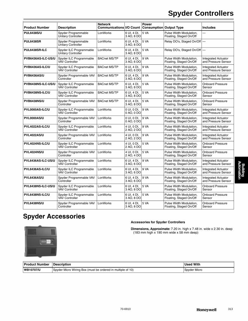
Spyder Controllers
70-6910 313
B
uilding A
utomation
Spyder AccessoriesAccessories for Spyder Controllers
Dimensions, Approximate: 7.20 in. high x 7.48 in. wide x 2.30 in. deep (183 mm high x 190 mm wide x 58 mm deep)
PUL6438S/U Spyder Programmable Unitary Controller
LonWorks 6 UI, 4 DI, 3 AO, 8 DO
5 VA Pulse Width Modulation, Floating, Staged On/Off
—
PUL6438SR Spyder Programmable Unitary Controller
LonWorks 6 UI, 4 DI, 3 AO, 8 DO
5 VA Relay DO's, Staged On/Off —
PUL6438SR-ILC Spyder ILC Programmable Unitary Controller
LonWorks 6 UI, 4 DI, 3 AO, 8 DO
5 VA Relay DO's, Staged On/Off —
PVB6436AS-ILC-US/U Spyder ILC Programmable VAV Controller
BACnet MS/TP 6 UI, 4 DI, 3 AO, 6 DO
9 VA Pulse Width Modulation, Floating, Staged On/Off
Integrated Actuator and Pressure Sensor
PVB6436AS-ILC/U Spyder ILC Programmable VAV Controller
BACnet MS/TP 6 UI, 4 DI, 3 AO, 6 DO
9 VA Pulse Width Modulation, Floating, Staged On/Off
Integrated Actuator and Pressure Sensor
PVB6436AS/U Spyder Programmable VAV Controller
BACnet MS/TP 6 UI, 4 DI, 3 AO, 6 DO
9 VA Pulse Width Modulation, Floating, Staged On/Off
Integrated Actuator and Pressure Sensor
PVB6438NS-ILC-US/U Spyder ILC Programmable VAV Controller
BACnet MS/TP 6 UI, 4 DI, 3 AO, 8 DO
5 VA Pulse Width Modulation, Floating, Staged On/Off
Onboard Pressure Sensor
PVB6438NS-ILC/U Spyder ILC Programmable VAV Controller
BACnet MS/TP 6 UI, 4 DI, 3 AO, 8 DO
5 VA Pulse Width Modulation, Floating, Staged On/Off
Onboard Pressure Sensor
PVB6438NS/U Spyder Programmable VAV Controller
BACnet MS/TP 6 UI, 4 DI, 3 AO, 8 DO
5 VA Pulse Width Modulation, Floating, Staged On/Off
Onboard Pressure Sensor
PVL0000AS-ILC/U Spyder ILC Programmable VAV Controller
LonWorks 0 UI, 0 DI, 0 AO, 0 DO
9 VA Pulse Width Modulation, Floating, Staged On/Off
Integrated Actuator and Pressure Sensor
PVL0000AS/U Spyder Programmable VAV Controller
LonWorks 0 UI, 0 DI, 0 AO, 0 DO
9 VA Pulse Width Modulation, Floating, Staged On/Off
Integrated Actuator and Pressure Sensor
PVL4022AS-ILC/U Spyder ILC Programmable VAV Controller
LonWorks 4 UI, 0 DI, 2 AO, 2 DO
9 VA Pulse Width Modulation, Floating, Staged On/Off
Integrated Actuator and Pressure Sensor
PVL4022AS/U Spyder Programmable VAV Controller
LonWorks 4 UI, 0 DI, 2 AO, 2 DO
9 VA Pulse Width Modulation, Floating, Staged On/Off
Integrated Actuator and Pressure Sensor
PVL4024NS-ILC/U Spyder ILC Programmable VAV Controller
LonWorks 4 UI, 0 DI, 2 AO, 4 DO
5 VA Pulse Width Modulation, Floating, Staged On/Off
Onboard Pressure Sensor
PVL4024NS/U Spyder Programmable VAV Controller
LonWorks 4 UI, 0 DI, 2 AO, 4 DO
5 VA Pulse Width Modulation, Floating, Staged On/Off
Onboard Pressure Sensor
PVL6436AS-ILC-US/U Spyder ILC Programmable VAV Controller
LonWorks 6 UI, 4 DI, 3 AO, 6 DO
9 VA Pulse Width Modulation, Floating, Staged On/Off
Integrated Actuator and Pressure Sensor
PVL6436AS-ILC/U Spyder ILC Programmable VAV Controller
LonWorks 6 UI, 4 DI, 3 AO, 6 DO
9 VA Pulse Width Modulation, Floating, Staged On/Off
Integrated Actuator and Pressure Sensor
PVL6436AS/U Spyder Programmable VAV Controller
LonWorks 6 UI, 4 DI, 3 AO, 6 DO
9 VA Pulse Width Modulation, Floating, Staged On/Off
Integrated Actuator and Pressure Sensor
PVL6438NS-ILC-US/U Spyder ILC Programmable VAV Controller
LonWorks 6 UI, 4 DI, 3 AO, 8 DO
5 VA Pulse Width Modulation, Floating, Staged On/Off
Onboard Pressure Sensor
PVL6438NS-ILC/U Spyder ILC Programmable VAV Controller
LonWorks 6 UI, 4 DI, 3 AO, 8 DO
5 VA Pulse Width Modulation, Floating, Staged On/Off
Onboard Pressure Sensor
PVL6438NS/U Spyder Programmable VAV Controller
LonWorks 6 UI, 4 DI, 3 AO, 8 DO
5 VA Pulse Width Modulation, Floating, Staged On/Off
Onboard Pressure Sensor
Product Number DescriptionNetwork Communications I/O Count
Power Consumption Output Type Includes
Product Number Description Used With
WB10707/U Spyder Micro Wiring Box (must be ordered in multiple of 10) Spyder Micro
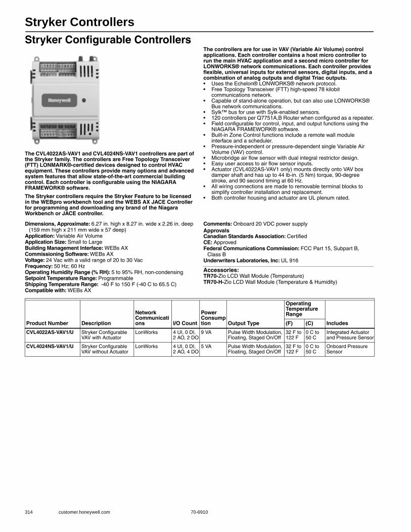
Stryker Controllers
314 customer.honeywell.com 70-6910
Stryker Configurable Controllers
The CVL4022AS-VAV1 and CVL4024NS-VAV1 controllers are part of the Stryker family. The controllers are Free Topology Transceiver (FTT) LONMARK®-certified devices designed to control HVAC equipment. These controllers provide many options and advanced system features that allow state-of-the-art commercial building control. Each controller is configurable using the NIAGARA FRAMEWORK® software.
The Stryker controllers require the Stryker Feature to be licensed in the WEBpro workbench tool and the WEBS AX JACE Controller for programming and downloading any brand of the Niagara Workbench or JACE controller.
The controllers are for use in VAV (Variable Air Volume) control applications. Each controller contains a host micro controller to run the main HVAC application and a second micro controller for LONWORKS® network communications. Each controller provides flexible, universal inputs for external sensors, digital inputs, and a combination of analog outputs and digital Triac outputs.• Uses the Echelon® LONWORKS® network protocol.• Free Topology Transceiver (FTT) high-speed 78 kilobit
communications network.• Capable of stand-alone operation, but can also use LONWORKS®
Bus network communications.• Sylk™ bus for use with Sylk-enabled sensors.• 120 controllers per Q7751A,B Router when configured as a repeater.• Field configurable for control, input, and output functions using the
NIAGARA FRAMEWORK® software.• Built-in Zone Control functions include a remote wall module
interface and a scheduler.• Pressure-independent or pressure-dependent single Variable Air
Volume (VAV) control.• Microbridge air flow sensor with dual integral restrictor design.• Easy user access to air flow sensor inputs.• Actuator (CVL4022AS-VAV1 only) mounts directly onto VAV box
damper shaft and has up to 44 lb-in. (5 Nm) torque, 90-degree stroke, and 90 second timing at 60 Hz.
• All wiring connections are made to removable terminal blocks to simplify controller installation and replacement.
• Both controller housing and actuator are UL plenum rated.
Dimensions, Approximate: 6.27 in. high x 8.27 in. wide x 2.26 in. deep (159 mm high x 211 mm wide x 57 deep)
Application: Variable Air VolumeApplication Size: Small to LargeBuilding Management Interface: WEBs AXCommissioning Software: WEBs AXVoltage: 24 Vac with a valid range of 20 to 30 VacFrequency: 50 Hz; 60 HzOperating Humidity Range (% RH): 5 to 95% RH, non-condensingSetpoint Temperature Range: ProgrammableShipping Temperature Range: -40 F to 150 F (-40 C to 65.5 C) Compatible with: WEBs AX
Comments: Onboard 20 VDC power supplyApprovalsCanadian Standards Association: CertifiedCE: ApprovedFederal Communications Commission: FCC Part 15, Subpart B,
Class BUnderwriters Laboratories, Inc: UL 916
Accessories:TR70-Zio LCD Wall Module (Temperature)TR70-H-Zio LCD Wall Module (Temperature & Humidity)
Product Number Description
Network Communications I/O Count
Power Consumption Output Type
Operating Temperature Range
Includes(F) (C)
CVL4022AS-VAV1/U Stryker Configurable VAV with Actuator
LonWorks 4 UI, 0 DI, 2 AO, 2 DO
9 VA Pulse Width Modulation, Floating, Staged On/Off
32 F to 122 F
0 C to 50 C
Integrated Actuator and Pressure Sensor
CVL4024NS-VAV1/U Stryker Configurable VAV without Actuator
LonWorks 4 UI, 0 DI, 2 AO, 4 DO
5 VA Pulse Width Modulation, Floating, Staged On/Off
32 F to 122 F
0 C to 50 C
Onboard Pressure Sensor

Building Automation Appliances
70-6910 315
B
uilding A
utomation
INTERNET
SMARTVAV
M16831
REMOTEMANAGEMENT
PC WITH WEB BROWSER
ETHERNET LAN
LONWorks®
WEBVISION CONTROLLER
EXCEL 15CCONTROLLER
EXCEL 10CVAHU UV T7350SmartVFD
INTERNET
REMOTEMANAGEMENT
PC WITH WEB BROWSER
ETHERNET LAN
LONWorks®
WEBSTATCONTROLLER
T7350 T7350 T7350 T7350
SUITE 1 SUITE 2 SUITE 3 SUITE 4

Building Automation Appliances
316 customer.honeywell.com 70-6910
WebStat Controller
WebStat allows you to step up from standalone thermostat control to the automated T7350 communicating thermostat platform
without incurring any excessive direct digital control (DDC) cost or complexity. Automation features include web control, alarming, trending, scheduling, network accessibility, and floor plans. Operational savings are enabled by remote monitoring, alarming, floor plan visuals and thermostat assignment privileges for tenants, facility managers and contractors. WebStat keeps control simple by allowing Internet accessibility and flexibility for assigning user privileges.• Remote Monitoring • Remote Programming • Up to 20 T7350H Thermostats • Plug-and-Play Setup • Universal Programming, Commissioning and Graphics Tool • Alarm Email Notification • Trending • Thermostat Self-Discovery • Wiring Diagram Generation Tool
Dimensions, Approximate: 6 3/8 in. wide x 4 7/64 in. high x 2.5 in. deep (16.2 cm wide x 10.5 cm high x 6.4 cm deep)
Application: ControllerApplication Size: Up to 20 T7350H Thermostats with free software
upgradeOperating Temperature Range: 32 F to 122 F (0 C to 50 C) Operating Humidity Range (% RH): 5 to 95% RH, non-condensing
Shipping Temperature Range: 32 F to 140 F (0 C to 60 C) ApprovalsCanadian Standards Association: CSA C22.2 No. 205-M1983 Signal
EquipmentCE: ApprovedFederal Communications Commission: FCC part 15 Class AUnderwriters Laboratories, Inc: UL 916, cUL listed
WebVision Controller
WebVision is a low cost building manager with remote monitoring and programming that allows complete HVAC system management from a single interface. It is a step-up from WebStat to extend the scope beyond automated T7350 communicating thermostats to
support HVAC zone and unitary controllers. It also adds several new features such as Demand Limit Control (DLC) for energy savings. Without incurring any excessive direct digital control (DDC) cost or complexity, WebVision offers operational savings by Internet accessibility, remote monitoring, alarming, and device assignment privileges for tenants, facility managers and contractors.• Web-based monitoring, control, commissioning and programming of
up to 120 LON devices • Easy installation (plug-and-play setup) of embedded software • Single universal tool for device configuration and customization of
graphics • Alarms, Schedules and Trends to completely manage building
automation system • Demand Limit Control (DLC) and VAV Balancing • Different user profiles - Contractor, Facility Manager and Tenant to
give customized access
Dimensions, Approximate: 6 3/8 in. wide x 4 7/64 in. high x 2.5 in. deep (16.2 cm wide x 10.5 cm high x 6.4 cm deep)
Application: Building Automation Appliance; ControllerApplication Size: Up to 120 LON devices, including EXCEL 10s,
EXCEL 15C, T7350, and VFDsOperating Temperature Range: 32 F to 122 F (0 C to 50 C) Operating Humidity Range (% RH): 5 to 95% RH, non-condensing
Shipping Temperature Range: 32 F to 140 F (0 C to 60 C) ApprovalsCanadian Standards Association: CSA C22.2 No. 205-M1983 Signal
EquipmentCE: ApprovedFederal Communications Commission: FCC part 15 Class AUnderwriters Laboratories, Inc: UL 916, cUL listed
Product Number DescriptionNetwork Communications
Commissioning Software Used With Compatible with: Includes
W7350A1000/U WebStat Controller LonWorks WebStat LonWorks bus T7350H Communicating Thermostats
Lon Card and Power Supply
Product Number DescriptionNetwork Communications
Commissioning Software Used With Compatible with: Includes
WWS-VL1A1000/U WebVision Controller
LonWorks WebVision LonWorks bus
Excel 10s; Excel 15C; T7350H Communicating Thermostats;
Pre-installed LON card and Power Supply
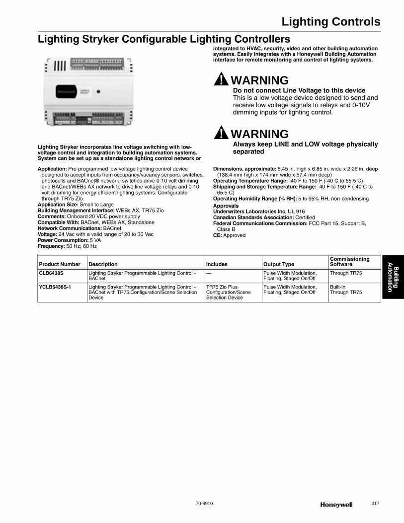
Lighting Controls
70-6910 317
B
uilding A
utomation
Lighting Stryker Configurable Lighting Controllers
Lighting Stryker incorporates line voltage switching with low-voltage control and integration to building automation systems. System can be set up as a standalone lighting control network or
integrated to HVAC, security, video and other building automation systems. Easily integrates with a Honeywell Building Automation interface for remote monitoring and control of lighting systems.
WARNINGDo not connect Line Voltage to this deviceThis is a low voltage device designed to send and receive low voltage signals to relays and 0-10V dimming inputs for lighting control.
WARNINGAlways keep LINE and LOW voltage physically separated
Application: Pre-programmed low voltage lighting control device designed to accept inputs from occupancy/vacancy sensors, switches, photocells and BACnet® network, switches drive 0-10 volt dimming and BACnet/WEBs AX network to drive line voltage relays and 0-10 volt dimming for energy efficient lighting systems. Configurable through TR75 Zio.
Application Size: Small to LargeBuilding Management Interface: WEBs AX, TR75 ZioComments: Onboard 20 VDC power supplyCompatible With: BACnet, WEBs AX, StandaloneNetwork Communications: BACnetVoltage: 24 Vac with a valid range of 20 to 30 VacPower Consumption: 5 VAFrequency: 50 Hz; 60 Hz
Dimensions, approximate: 5.45 in. high x 6.85 in. wide x 2.26 in. deep (138.4 mm high x 174 mm wide x 57.4 mm deep)
Operating Temperature Range: -40 F to 150 F (-40 C to 65.5 C)Shipping and Storage Temperature Range: -40 F to 150 F (-40 C to
65.5 C)Operating Humidity Range (% RH): 5 to 95% RH, non-condensingApprovalsUnderwriters Laboratories Inc. UL 916Canadian Standards Association: CertifiedFederal Communications Commission: FCC Part 15, Subpart B,
Class BCE: Approved
Product Number Description Includes Output TypeCommissioning Software
CLB6438S Lighting Stryker Programmable Lighting Control - BACnet
— Pulse Width Modulation, Floating, Staged On/Off
Through TR75
YCLB6438S-1 Lighting Stryker Programmable Lighting Control - BACnet with TR75 Configuration/Scene Selection Device
TR75 Zio Plus Configuration/Scene Selection Device
Pulse Width Modulation, Floating, Staged On/Off
Built-In Through TR75
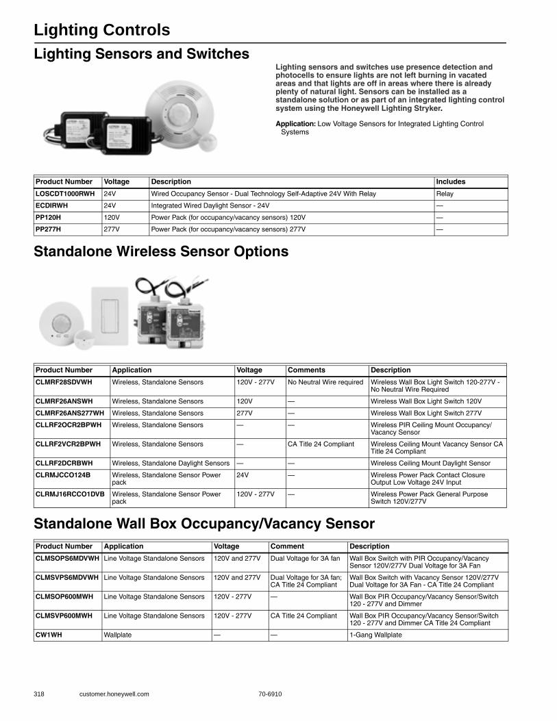
Lighting Controls
318 customer.honeywell.com 70-6910
Lighting Sensors and SwitchesLighting sensors and switches use presence detection and photocells to ensure lights are not left burning in vacated areas and that lights are off in areas where there is already plenty of natural light. Sensors can be installed as a standalone solution or as part of an integrated lighting control system using the Honeywell Lighting Stryker.
Application: Low Voltage Sensors for Integrated Lighting Control Systems
Standalone Wireless Sensor Options
Standalone Wall Box Occupancy/Vacancy Sensor
Product Number Voltage Description Includes
LOSCDT1000RWH 24V Wired Occupancy Sensor - Dual Technology Self-Adaptive 24V With Relay Relay
ECDIRWH 24V Integrated Wired Daylight Sensor - 24V —
PP120H 120V Power Pack (for occupancy/vacancy sensors) 120V —
PP277H 277V Power Pack (for occupancy/vacancy sensors) 277V —
Product Number Application Voltage Comments Description
CLMRF28SDVWH Wireless, Standalone Sensors 120V - 277V No Neutral Wire required Wireless Wall Box Light Switch 120-277V - No Neutral Wire Required
CLMRF26ANSWH Wireless, Standalone Sensors 120V — Wireless Wall Box Light Switch 120V
CLMRF26ANS277WH Wireless, Standalone Sensors 277V — Wireless Wall Box Light Switch 277V
CLLRF2OCR2BPWH Wireless, Standalone Sensors — — Wireless PIR Ceiling Mount Occupancy/Vacancy Sensor
CLLRF2VCR2BPWH Wireless, Standalone Sensors — CA Title 24 Compliant Wireless Ceiling Mount Vacancy Sensor CA Title 24 Compliant
CLLRF2DCRBWH Wireless, Standalone Daylight Sensors — — Wireless Ceiling Mount Daylight Sensor
CLRMJCCO124B Wireless, Standalone Sensor Power pack
24V — Wireless Power Pack Contact Closure Output Low Voltage 24V Input
CLRMJ16RCCO1DVB Wireless, Standalone Sensor Power pack
120V - 277V — Wireless Power Pack General Purpose Switch 120V/277V
Product Number Application Voltage Comment Description
CLMSOPS6MDVWH Line Voltage Standalone Sensors 120V and 277V Dual Voltage for 3A fan Wall Box Switch with PIR Occupancy/Vacancy Sensor 120V/277V Dual Voltage for 3A Fan
CLMSVPS6MDVWH Line Voltage Standalone Sensors 120V and 277V Dual Voltage for 3A fan; CA Title 24 Compliant
Wall Box Switch with Vacancy Sensor 120V/277V Dual Voltage for 3A Fan - CA Title 24 Compliant
CLMSOP600MWH Line Voltage Standalone Sensors 120V - 277V — Wall Box PIR Occupancy/Vacancy Sensor/Switch 120 - 277V and Dimmer
CLMSVP600MWH Line Voltage Standalone Sensors 120V - 277V CA Title 24 Compliant Wall Box PIR Occupancy/Vacancy Sensor/Switch 120 - 277V and Dimmer CA Title 24 Compliant
CW1WH Wallplate — — 1-Gang Wallplate

LED Lighting
70-6910 319
B
uilding A
utomation
Industrial LED-Strip Fixture
The Honeywell Strip LED Lighting Luminaire is a robust LED lighting fixture for surface mounting. The casing is formed from 1mm Zintec steel, making the battens lightweight and easy to fit. Available in varying lengths.
• High-intensity LEDs• Choice of multiple color temperatures for a variety of applications• 2ft or 4ft versions available • Direct replacement for T8 or T12 fluorescent strip luminaires• Solid-state, modular construction with zero mercury • Designed with polarized end caps for safe, easy installation • Direct light distr bution to enhance efficiency, comfort and safety• International certification including UL, PSE, CE, VDE & CCC • 50,000 hour lamp life • 5-year limited warranty• ± 30-degree directional allocation of light, providing greater coverage• Energy savings, long life and reduced maintenance cost • External LED drivers for safety, heat dissipation and longer life
Beam Angle: Adjustable 120 ±30Input Voltage: 120V - 277VLumen Maintenance: 98% @ 5,000 hrsLamp Life (hours): 50,000 hrs (Rated - 30% Depreciation @ 50,000 hrs)Color Rendering Index: >80Tube Diameter: 1.172 inBase: Medium Bi-Pin (G13)
Power Factor: > 0.97Comments: Industrial StripsOperating Temperature Range: -4 F to 113 F (-20 C to 45 C)Materials: Housing – steel, Lamp tube – glass/plasticWarranty: 5 YearsApprovalsUnderwriters Laboratories, Inc: cULus Listed
Industrial LED-Surface Wrap Fixture
Honeywell Surface Wrap LED Lighting Luminaire protects and diffuses the LED lamps for lighting of general areas. The Surface Wrap Luminaire resists dust and insects and the diffuser is manufactured in flame retardant acrylic. The 1.0 mm bright steel
casing is electrostatic powder coated ensuring environmental durability.• Diffused lighting• 2ft or 4ft versions available• Choice of multiple color temperatures for a variety of applications• Direct replacement for T8 or T12 fluorescent wrap luminaires• Solid-state, modular construction with zero mercury• Designed with polarized end caps for safe, easy installation• Direct light distr bution to enhance efficiency, comfort and safety• 50,000 hour lamp life• 5-year limited warranty• ±30-degree directional allocation of light, providing greater coverage• Energy savings, long life and reduced maintenance cost• External LED drivers for safety, heat dissipation and longer life
Beam Angle: Adjustable 120 ±30Input Voltage: 120V - 277VLumen Maintenance: 98% @ 5,000 hrsLamp Life (hours): 50,000 hrs (Rated - 30% Depreciation @ 50,000 hrs)Color Rendering Index: >80Tube Diameter: 1.172 inPower Factor: > 0.97
Comments: Surface WrapsOperating Temperature Range: -4 F to 113 F (-20 C to 45 C)Materials: Housing – steel, Lamp tube – glass/plasticWarranty: 5 YearsApprovalsUnderwriters Laboratories, Inc : cULus Listed
Product Number
Length
Lamps Color Temperature (K) Lumen Output (lm) Nominal Wattsft mm
HLED1005 2 ft 609.6 mm 2 lamps 3500K 1251 lm 20W
HLED1006 2 ft 609.6 mm 2 lamps 4100K 1278 lm 20W
HLED1007 2 ft 609.6 mm 2 lamps 5000K 1302 lm 20W
HLED1009 4 ft 1219.2 mm 1 lamp 3500K >1100 lm 18W
HLED1010 4 ft 1219.2 mm 1 lamp 4100K >1100 lm 18W
HLED1011 4 ft 1219.2 mm 1 lamp 5000K >1100 lm 18W
HLED1014 4 ft 1219.2 mm 2 lamps 3500K 2247 lm 36W
HLED1015 4 ft 1219.2 mm 2 lamps 4100K 2362 lm 36W
HLED1016 4 ft 1219.2 mm 2 lamps 5000K 2481 lm 36W
Product Number
Length
LampsColor Temperature (K) Lumen Output (lm) Nominal Wattsft mm
HLED1061 4 ft 1219.2 mm 2 lamps 3500K 2241 lm 36W
HLED1062 4 ft 1219.2 mm 2 lamps 4100K 2247 lm 36W
HLED1063 4 ft 1219.2 mm 2 lamps 5000K 2320 lm 36W
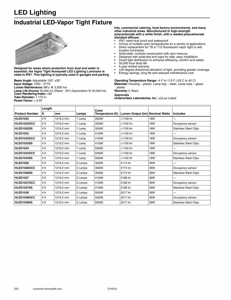
LED Lighting
320 customer.honeywell.com 70-6910
Industrial LED-Vapor Tight Fixture
Designed for areas where protection from dust and water is essential, the Vapor Tight Honeywell LED Lighting Luminaire is rated to IP67. This lighting is typically used in garages and parking
lots, commercial catering, food factory environments, and many other industrial areas. Manufactured in high-strength polycarbonate with a white finish, with a reeded polycarbonate standard diffuser.• IP67 rated dust proof and waterproof• Choice of multiple color temperatures for a variety of applications• Direct replacement for T8 or T12 fluorescent vapor tight or wet
location luminaires• Solid-state, modular construction with zero mercury• Designed with polarized end caps for safe, easy installation• Direct light distribution to enhance efficiency, comfort and safety • 50,000 hour lamp life • 5-year limited warranty • ±30 degree directional allocation of light, providing greater coverage • Energy savings, long life and reduced maintenance cost
Beam Angle: Adjustable 120° ±30°Input Voltage: 120V - 277VLumen Maintenance: 98% @ 5,000 hrsLamp Life (hours): 50,000 hrs (Rated - 30% Depreciation @ 50,000 hrs)Color Rendering Index: >80Tube Diameter: 1.172 inPower Factor: > 0.97
Operating Temperature Range: -4 F to 113 F (-20 C to 45 C)Materials: Housing – plastic, Lamp tray – steel, Lamp tube – glass/
plasticWarranty: 5 YearsApprovalsUnderwriters Laboratories, Inc : cULus Listed
Product Number
Length
LampsColor Temperature (K) Lumen Output (lm) Nominal Watts Includesft mm
HLED1032 4 ft 1219.2 mm 1 Lamp 3500K >1100 lm 18W —
HLED1032OCC 4 ft 1219.2 mm 1 Lamp 3500K >1100 lm 18W Occupancy sensor
HLED1032SS 4 ft 1219.2 mm 1 Lamp 3500K >1100 lm 18W Stainless Steel Clips
HLED1033 4 ft 1219.2 mm 1 Lamp 4100K >1100 lm 18W —
HLED1033OCC 4 ft 1219.2 mm 1 Lamp 4100K >1100 lm 18W Occupancy sensor
HLED1033SS 4 ft 1219.2 mm 1 Lamp 4100K >1100 lm 18W Stainless Steel Clips
HLED1034 4 ft 1219.2 mm 1 Lamp 5000K >1100 lm 18W —
HLED1034OCC 4 ft 1219.2 mm 1 Lamp 5000K >1100 lm 18W Occupancy sensor
HLED1034SS 4 ft 1219.2 mm 1 Lamp 5000K >1100 lm 18W Stainless Steel Clips
HLED1036 4 ft 1219.2 mm 2 Lamps 3500K 2174 lm 36W —
HLED1036OCC 4 ft 1219.2 mm 2 Lamps 3500K 2174 lm 36W Occupancy sensor
HLED1036SS 4 ft 1219.2 mm 2 Lamps 3500K 2174 lm 36W Stainless Steel Clips
HLED1037 4 ft 1219.2 mm 2 Lamps 4100K 2188 lm 36W —
HLED1037OCC 4 ft 1219.2 mm 2 Lamps 4100K 2188 lm 36W Occupancy sensor
HLED1037SS 4 ft 1219.2 mm 2 Lamps 4100K 2188 lm 36W Stainless Steel Clips
HLED1038 4 ft 1219.2 mm 2 Lamps 5000K 2217 lm 36W —
HLED1038OCC 4 ft 1219.2 mm 2 Lamps 5000K 2217 lm 36W Occupancy sensor
HLED1038SS 4 ft 1219.2 mm 2 Lamps 5000K 2217 lm 36W Stainless Steel Clips

LED Lighting
70-6910 321
B
uilding A
utomation
Honeywell Durafit LED - Retrofit Kits
Honeywell Durafit LED Retrofit Kits are designed to convert a standard 2- or 4-foot fluorescent lighting fixture into a more efficient, longer-lasting LED lighting fixture.
Saving energy of up to 50% is just one of the many benefits of Honeywell Durafit LED Retrofit kits. They also cut replacement and maintenance costs through their long service life. The mercury-free design helps protect the environment and reduce disposal costs.
• High-Intensity, Dimmable LEDs (0 - 10 V or Lutron EcoSystem®)• A choice of color temperatures – 3000K (warm white), 3500K (soft
white), 4000K (white), 5000K (daylight) – for a variety of applications • 10W, 18W and 23W power ratings• 2 ft & 4 ft lengths available in 1-, 2-, 3- and 4-lamp retrofit kits• Direct replacement for T8 or T12 fluorescent lamps when used with
Honeywell or Lutron EcoSystem® external LED drivers• Choice of 0-10V or Lutron EcoSystem® dimming• Solid-state, modular construction with zero mercury• Designed with polarized end caps for safe, easy installation• Direct light distr bution to enhance efficiency, comfort and safety• International certification including UL, PSE, CE, VDE & CCC• 50,000 hour lamp life• 5-year limited warranty• Energy savings, long life and reduced maintenance cost• External drivers for advanced features including 0-10V and Lutron
EcoSystem® dimming & improved thermal management
Input Voltage: 120V - 277VLumen Maintenance: 98% @ 5,000 hrsLamp Life (hours): 50,000 hrs (Rated - 30% Depreciation @ 50,000 hrs)Color Rendering Index: >80Tube Diameter: T9 - 1.125 inBase: Medium Bi-Pin (G13)Power Factor: > 0.97
Operating Temperature Range: -4 F to 113 F (-20 C to 45 C)Materials: Lamp Tube – UV Stabilized Polycarbonate/AluminumWarranty: 5 YearsUsed With: Honeywell LED Driver 0-10V Dimming ApprovalsUnderwriters Laboratories, Inc : cULus Listed
Product Number
Length
LampsColor Temperature (K)
Nominal Watts Used Withft mm
HLEDRL121830H30 2 ft 609.6 mm 1 Lamp 3000K 10W Honeywell LED Driver 0-10V Dimming 300mA
HLEDRL121835H30 2 ft 609.6 mm 1 Lamp 3500K 10W Honeywell LED Driver 0-10V Dimming 300mA
HLEDRL121850H30 2 ft 609.6 mm 1 Lamp 5000K 10W Honeywell LED Driver 0-10V Dimming 300mA
HLEDRL121840H30 2 ft 609.6 mm 1 Lamp 4000K 10W Honeywell LED Driver 0-10V Dimming 300mA
HLEDRL122830H30 2 ft 609.6 mm 2 Lamps 3000K 20W Honeywell LED Driver 0-10V Dimming 300mA
HLEDRL122835H30 2 ft 609.6 mm 2 Lamps 3500K 20W Honeywell LED Driver 0-10V Dimming 300mA
HLEDRL122840H30 2 ft 609.6 mm 2 Lamps 4000K 20W Honeywell LED Driver 0-10V Dimming 300mA
HLEDRL122850H30 2 ft 609.6 mm 2 Lamps 5000K 20W Honeywell LED Driver 0-10V Dimming 300mA
HLEDRL141830H54 4 ft 1219.2 mm 1 Lamp 3000K 18W Honeywell LED Driver 0-10V Dimming 540mA
HLEDRL141830H72 4 ft 1219.2 mm 1 Lamp 3000K 25W Honeywell LED Driver 0-10V Dimming 720mA
HLEDRL141835H54 4 ft 1219.2 mm 1 Lamp 3500K 18W Honeywell LED Driver 0-10V Dimming 540mA
HLEDRL141835H72 4 ft 1219.2 mm 1 Lamp 3500K 25W Honeywell LED Driver 0-10V Dimming 720mA
HLEDRL141840H54 4 ft 1219.2 mm 1 Lamp 4000K 18W Honeywell LED Driver 0-10V Dimming 540mA
HLEDRL141840H72 4 ft 1219.2 mm 1 Lamp 4000K 25W Honeywell LED Driver 0-10V Dimming 720mA
HLEDRL141850H54 4 ft 1219.2 mm 1 Lamp 5000K 18W Honeywell LED Driver 0-10V Dimming 540mA
HLEDRL141850H72 4 ft 1219.2 mm 1 Lamp 5000K 25W Honeywell LED Driver 0-10V Dimming 720mA
HLEDRL142830H54 4 ft 1219.2 mm 2 Lamps 3000K 36W Honeywell LED Driver 0-10V Dimming 540mA
HLEDRL142830H72 4 ft 1219.2 mm 2 Lamps 3000K 50W Honeywell LED Driver 0-10V Dimming 720mA
HLEDRL142835H54 4 ft 1219.2 mm 2 Lamps 3500K 36W Honeywell LED Driver 0-10V Dimming 540mA
HLEDRL142835H72 4 ft 1219.2 mm 2 Lamps 3500K 50W Honeywell LED Driver 0-10V Dimming 720mA
HLEDRL142840H54 4 ft 1219.2 mm 2 Lamps 4000K 36W Honeywell LED Driver 0-10V Dimming 540mA
HLEDRL142840H72 4 ft 1219.2 mm 2 Lamps 4000K 50W Honeywell LED Driver 0-10V Dimming 720mA
HLEDRL142850H54 4 ft 1219.2 mm 2 Lamps 5000K 36W Honeywell LED Driver 0-10V Dimming 540mA
HLEDRL142850H72 4 ft 1219.2 mm 2 Lamps 5000K 50W Honeywell LED Driver 0-10V Dimming 720mA
HLEDRL143830H54 4 ft 1219.2 mm 3 Lamps 3000K 54W Honeywell LED Driver 0-10V Dimming 540mA
HLEDRL143830H72 4 ft 1219.2 mm 3 Lamps 3000K 75W Honeywell LED Driver 0-10V Dimming 720mA
HLEDRL143835H54 4 ft 1219.2 mm 3 Lamps 3500K 54W Honeywell LED Driver 0-10V Dimming 540mA
HLEDRL143835H72 4 ft 1219.2 mm 3 Lamps 3500K 75W Honeywell LED Driver 0-10V Dimming 720mA
HLEDRL143840H54 4 ft 1219.2 mm 3 Lamps 4000K 54W Honeywell LED Driver 0-10V Dimming 540mA
HLEDRL143840H72 4 ft 1219.2 mm 3 Lamps 4000K 75W Honeywell LED Driver 0-10V Dimming 720mA

LED Lighting
322 customer.honeywell.com 70-6910
Honeywell Durafit LED with Lutron 3D Ecosystem DriverInput Voltage: 120V - 277VLumen Maintenance: 98% @ 5,000 hrsLamp Life (hours): 50,000 hrs (Rated - 30% Depreciation @ 50,000 hrs)Color Rendering Index: >80Tube Diameter: T9 - 1.125 inBase: Medium Bi-Pin (G13)Power Factor: > 0.97
Operating Temperature Range: -4 F to 113 F (-20 C to 45 C)Materials: Lamp Tube – UV Stabilized Polycarbonate/AluminumWarranty: 5 YearsUsed With: Lutron 3D EcoSystem LED DriverApprovalsUnderwriters Laboratories, Inc : cULus Listed
HLEDRL143850H54 4 ft 1219.2 mm 3 Lamps 5000K 54W Honeywell LED Driver 0-10V Dimming 540mA
HLEDRL143850H72 4 ft 1219.2 mm 3 Lamps 5000K 75W Honeywell LED Driver 0-10V Dimming 720mA
HLEDRL144830H54 4 ft 1219.2 mm 4 Lamps 3000K 72W Honeywell LED Driver 0-10V Dimming 540mA
HLEDRL144830H72 4 ft 1219.2 mm 4 Lamps 3000K 100W Honeywell LED Driver 0-10V Dimming 720mA
HLEDRL144835H54 4 ft 1219.2 mm 4 Lamps 3500K 72W Honeywell LED Driver 0-10V Dimming 540mA
HLEDRL144835H72 4 ft 1219.2 mm 4 Lamps 3500K 100W Honeywell LED Driver 0-10V Dimming 720mA
HLEDRL144840H54 4 ft 1219.2 mm 4 Lamps 4000K 72W Honeywell LED Driver 0-10V Dimming 540mA
HLEDRL144840H72 4 ft 1219.2 mm 4 Lamps 4000K 100W Honeywell LED Driver 0-10V Dimming 720mA
HLEDRL144850H54 4 ft 1219.2 mm 4 Lamps 5000K 72W Honeywell LED Driver 0-10V Dimming 540mA
HLEDRL144850H72 4 ft 1219.2 mm 4 Lamps 5000K 100W Honeywell LED Driver 0-10V Dimming 720mA
Product Number
Length
LampsColor Temperature (K)
Nominal Watts Used Withft mm
Product Number
Length
Lamps Color Temperature (K) Nominal Wattsft mm
HLEDRL121830L3D 2 ft 609.6 mm 1 Lamp 3000K 10W
HLEDRL121835L3D 2 ft 609.6 mm 1 Lamp 3500K 10W
HLEDRL121840L3D 2 ft 609.6 mm 1 Lamp 4000K 10W
HLEDRL121850L3D 2 ft 609.6 mm 1 Lamp 5000K 10W
HLEDRL122830L3D 2 ft 609.6 mm 2 Lamps 3000K 20W
HLEDRL122835L3D 2 ft 609.6 mm 2 Lamps 3500K 20W
HLEDRL122840L3D 2 ft 609.6 mm 2 Lamps 4000K 20W
HLEDRL122850L3D 2 ft 609.6 mm 2 Lamps 5000K 20W
HLEDRL123830L3D 2 ft 609.6 mm 3 Lamps 3000K 30W
HLEDRL123835L3D 2 ft 609.6 mm 3 Lamps 3500K 30W
HLEDRL123840L3D 2 ft 609.6 mm 3 Lamps 4000K 30W
HLEDRL123850L3D 2 ft 609.6 mm 3 Lamps 5000K 30W
HLEDRL124830L3D 2 ft 609.6 mm 4 Lamps 3000K 40W
HLEDRL124835L3D 2 ft 609.6 mm 4 Lamps 3500K 40W
HLEDRL124840L3D 2 ft 609.6 mm 4 Lamps 4000K 40W
HLEDRL124850L3D 2 ft 609.6 mm 4 Lamps 5000K 40W
HLEDRL141830L3D 4 ft 1219.2 mm 1 Lamp 3000K 18W
HLEDRL141835L3D 4 ft 1219.2 mm 1 Lamp 3500K 18W
HLEDRL141840L3D 4 ft 1219.2 mm 1 Lamp 4000K 18W
HLEDRL141850L3D 4 ft 1219.2 mm 1 Lamp 5000K 18W
HLEDRL142830L3D 4 ft 1219.2 mm 2 Lamps 3000K 36W
HLEDRL142835L3D 4 ft 1219.2 mm 2 Lamps 3500K 36W
HLEDRL142840L3D 4 ft 1219.2 mm 2 Lamps 4000K 36W
HLEDRL142850L3D 4 ft 1219.2 mm 2 Lamps 5000K 36W
HLEDRL143830L3D 4 ft 1219.2 mm 3 Lamps 3000K 54W
HLEDRL143835L3D 4 ft 1219.2 mm 3 Lamps 3500K 54W
HLEDRL143840L3D 4 ft 1219.2 mm 3 Lamps 4000K 54W
HLEDRL143850L3D 4 ft 1219.2 mm 3 Lamps 5000K 54W
HLEDRL144830L3D 4 ft 1219.2 mm 4 Lamps 3000K 72W
HLEDRL144835L3D 4 ft 1219.2 mm 4 Lamps 3500K 72W
HLEDRL144840L3D 4 ft 1219.2 mm 4 Lamps 4000K 72W
HLEDRL144850L3D 4 ft 1219.2 mm 4 Lamps 5000K 72W
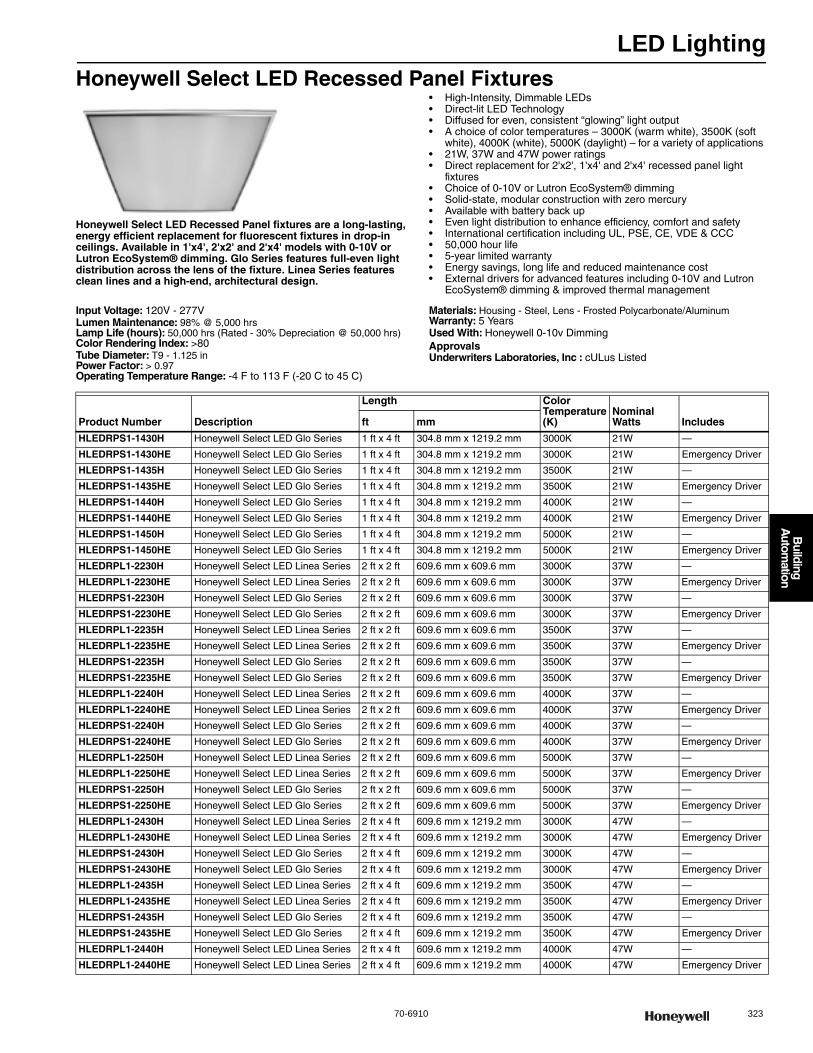
LED Lighting
70-6910 323
B
uilding A
utomation
Honeywell Select LED Recessed Panel Fixtures
Honeywell Select LED Recessed Panel fixtures are a long-lasting, energy efficient replacement for fluorescent fixtures in drop-in ceilings. Available in 1'x4', 2'x2' and 2'x4' models with 0-10V or Lutron EcoSystem® dimming. Glo Series features full-even light distribution across the lens of the fixture. Linea Series features clean lines and a high-end, architectural design.
• High-Intensity, Dimmable LEDs• Direct-lit LED Technology• Diffused for even, consistent “glowing” light output• A choice of color temperatures – 3000K (warm white), 3500K (soft
white), 4000K (white), 5000K (daylight) – for a variety of applications • 21W, 37W and 47W power ratings• Direct replacement for 2'x2', 1'x4' and 2'x4' recessed panel light
fixtures• Choice of 0-10V or Lutron EcoSystem® dimming• Solid-state, modular construction with zero mercury• Available with battery back up• Even light distribution to enhance efficiency, comfort and safety• International certification including UL, PSE, CE, VDE & CCC• 50,000 hour life• 5-year limited warranty• Energy savings, long life and reduced maintenance cost• External drivers for advanced features including 0-10V and Lutron
EcoSystem® dimming & improved thermal management
Input Voltage: 120V - 277VLumen Maintenance: 98% @ 5,000 hrsLamp Life (hours): 50,000 hrs (Rated - 30% Depreciation @ 50,000 hrs)Color Rendering Index: >80Tube Diameter: T9 - 1.125 inPower Factor: > 0.97Operating Temperature Range: -4 F to 113 F (-20 C to 45 C)
Materials: Housing - Steel, Lens - Frosted Polycarbonate/Aluminum Warranty: 5 YearsUsed With: Honeywell 0-10v DimmingApprovalsUnderwriters Laboratories, Inc : cULus Listed
Product Number Description
Length Color Temperature (K)
Nominal Watts Includesft mm
HLEDRPS1-1430H Honeywell Select LED Glo Series 1 ft x 4 ft 304.8 mm x 1219.2 mm 3000K 21W —
HLEDRPS1-1430HE Honeywell Select LED Glo Series 1 ft x 4 ft 304.8 mm x 1219.2 mm 3000K 21W Emergency Driver
HLEDRPS1-1435H Honeywell Select LED Glo Series 1 ft x 4 ft 304.8 mm x 1219.2 mm 3500K 21W —
HLEDRPS1-1435HE Honeywell Select LED Glo Series 1 ft x 4 ft 304.8 mm x 1219.2 mm 3500K 21W Emergency Driver
HLEDRPS1-1440H Honeywell Select LED Glo Series 1 ft x 4 ft 304.8 mm x 1219.2 mm 4000K 21W —
HLEDRPS1-1440HE Honeywell Select LED Glo Series 1 ft x 4 ft 304.8 mm x 1219.2 mm 4000K 21W Emergency Driver
HLEDRPS1-1450H Honeywell Select LED Glo Series 1 ft x 4 ft 304.8 mm x 1219.2 mm 5000K 21W —
HLEDRPS1-1450HE Honeywell Select LED Glo Series 1 ft x 4 ft 304.8 mm x 1219.2 mm 5000K 21W Emergency Driver
HLEDRPL1-2230H Honeywell Select LED Linea Series 2 ft x 2 ft 609.6 mm x 609.6 mm 3000K 37W —
HLEDRPL1-2230HE Honeywell Select LED Linea Series 2 ft x 2 ft 609.6 mm x 609.6 mm 3000K 37W Emergency Driver
HLEDRPS1-2230H Honeywell Select LED Glo Series 2 ft x 2 ft 609.6 mm x 609.6 mm 3000K 37W —
HLEDRPS1-2230HE Honeywell Select LED Glo Series 2 ft x 2 ft 609.6 mm x 609.6 mm 3000K 37W Emergency Driver
HLEDRPL1-2235H Honeywell Select LED Linea Series 2 ft x 2 ft 609.6 mm x 609.6 mm 3500K 37W —
HLEDRPL1-2235HE Honeywell Select LED Linea Series 2 ft x 2 ft 609.6 mm x 609.6 mm 3500K 37W Emergency Driver
HLEDRPS1-2235H Honeywell Select LED Glo Series 2 ft x 2 ft 609.6 mm x 609.6 mm 3500K 37W —
HLEDRPS1-2235HE Honeywell Select LED Glo Series 2 ft x 2 ft 609.6 mm x 609.6 mm 3500K 37W Emergency Driver
HLEDRPL1-2240H Honeywell Select LED Linea Series 2 ft x 2 ft 609.6 mm x 609.6 mm 4000K 37W —
HLEDRPL1-2240HE Honeywell Select LED Linea Series 2 ft x 2 ft 609.6 mm x 609.6 mm 4000K 37W Emergency Driver
HLEDRPS1-2240H Honeywell Select LED Glo Series 2 ft x 2 ft 609.6 mm x 609.6 mm 4000K 37W —
HLEDRPS1-2240HE Honeywell Select LED Glo Series 2 ft x 2 ft 609.6 mm x 609.6 mm 4000K 37W Emergency Driver
HLEDRPL1-2250H Honeywell Select LED Linea Series 2 ft x 2 ft 609.6 mm x 609.6 mm 5000K 37W —
HLEDRPL1-2250HE Honeywell Select LED Linea Series 2 ft x 2 ft 609.6 mm x 609.6 mm 5000K 37W Emergency Driver
HLEDRPS1-2250H Honeywell Select LED Glo Series 2 ft x 2 ft 609.6 mm x 609.6 mm 5000K 37W —
HLEDRPS1-2250HE Honeywell Select LED Glo Series 2 ft x 2 ft 609.6 mm x 609.6 mm 5000K 37W Emergency Driver
HLEDRPL1-2430H Honeywell Select LED Linea Series 2 ft x 4 ft 609.6 mm x 1219.2 mm 3000K 47W —
HLEDRPL1-2430HE Honeywell Select LED Linea Series 2 ft x 4 ft 609.6 mm x 1219.2 mm 3000K 47W Emergency Driver
HLEDRPS1-2430H Honeywell Select LED Glo Series 2 ft x 4 ft 609.6 mm x 1219.2 mm 3000K 47W —
HLEDRPS1-2430HE Honeywell Select LED Glo Series 2 ft x 4 ft 609.6 mm x 1219.2 mm 3000K 47W Emergency Driver
HLEDRPL1-2435H Honeywell Select LED Linea Series 2 ft x 4 ft 609.6 mm x 1219.2 mm 3500K 47W —
HLEDRPL1-2435HE Honeywell Select LED Linea Series 2 ft x 4 ft 609.6 mm x 1219.2 mm 3500K 47W Emergency Driver
HLEDRPS1-2435H Honeywell Select LED Glo Series 2 ft x 4 ft 609.6 mm x 1219.2 mm 3500K 47W —
HLEDRPS1-2435HE Honeywell Select LED Glo Series 2 ft x 4 ft 609.6 mm x 1219.2 mm 3500K 47W Emergency Driver
HLEDRPL1-2440H Honeywell Select LED Linea Series 2 ft x 4 ft 609.6 mm x 1219.2 mm 4000K 47W —
HLEDRPL1-2440HE Honeywell Select LED Linea Series 2 ft x 4 ft 609.6 mm x 1219.2 mm 4000K 47W Emergency Driver
LED Lighting
324 customer.honeywell.com 70-6910
Honeywell Select LED Recessed Panel Fixtures with Lutron 3D EcoSystem LED DriverInput Voltage: 120V - 277VLumen Maintenance: 98% @ 5,000 hrsLamp Life (hours): 50,000 hrs (Rated - 30% Depreciation @ 50,000 hrs)Color Rendering Index: >80Tube Diameter: T9 - 1.125 inPower Factor: > 0.97Operating Temperature Range: -4 F to 113 F (-20 C to 45 C)
Materials: Housing - Steel, Lens - Frosted Polycarbonate/Aluminum Warranty: 5 YearsUsed With: Lutron 3D EcoSystem LED DriverApprovalsUnderwriters Laboratories, Inc : cUL us Listed
HLEDRPS1-2440H Honeywell Select LED Glo Series 2 ft x 4 ft 609.6 mm x 1219.2 mm 4000K 47W —
HLEDRPS1-2440HE Honeywell Select LED Glo Series 2 ft x 4 ft 609.6 mm x 1219.2 mm 4000K 47W Emergency Driver
HLEDRPL1-2450H Honeywell Select LED Linea Series 2 ft x 4 ft 609.6 mm x 1219.2 mm 5000K 47W —
HLEDRPL1-2450HE Honeywell Select LED Linea Series 2 ft x 4 ft 609.6 mm x 1219.2 mm 5000K 47W Emergency Driver
HLEDRPS1-2450H Honeywell Select LED Glo Series 2 ft x 4 ft 609.6 mm x 1219.2 mm 5000K 47W —
HLEDRPS1-2450HE Honeywell Select LED Glo Series 2 ft x 4 ft 609.6 mm x 1219.2 mm 5000K 47W Emergency Driver
Product Number Description
Length Color Temperature (K)
Nominal Watts Includesft mm
Product Number Description
Length Color Temperature (K)
Nominal Watts Includesft mm
HLEDRPS1-1430L Honeywell Select LED Glo Series 1 ft x 4 ft 304.8 mm x 1219.2 mm 3000K 21W —
HLEDRPS1-1430LE Honeywell Select LED Glo Series 1 ft x 4 ft 304.8 mm x 1219.2 mm 3000K 21W Emergency Driver
HLEDRPS1-1435L Honeywell Select LED Glo Series 1 ft x 4 ft 304.8 mm x 1219.2 mm 3500K 21W —
HLEDRPS1-1435LE Honeywell Select LED Glo Series 1 ft x 4 ft 304.8 mm x 1219.2 mm 3500K 21W Emergency Driver
HLEDRPS1-1440L Honeywell Select LED Glo Series 1 ft x 4 ft 304.8 mm x 1219.2 mm 4000K 21W —
HLEDRPS1-1440LE Honeywell Select LED Glo Series 1 ft x 4 ft 304.8 mm x 1219.2 mm 4000K 21W Emergency Driver
HLEDRPS1-1450L Honeywell Select LED Glo Series 1 ft x 4 ft 304.8 mm x 1219.2 mm 5000K 21W —
HLEDRPS1-1450LE Honeywell Select LED Glo Series 1 ft x 4 ft 304.8 mm x 1219.2 mm 5000K 21W Emergency Driver
HLEDRPL1-2230L Honeywell Select LED Linea Series 2 ft x 2 ft 609.6 mm x 609.6 mm 3000K 37W —
HLEDRPL1-2230LE Honeywell Select LED Linea Series 2 ft x 2 ft 609.6 mm x 609.6 mm 3000K 37W Emergency Driver
HLEDRPS1-2230L Honeywell Select LED Glo Series 2 ft x 2 ft 609.6 mm x 609.6 mm 3000K 37W —
HLEDRPS1-2230LE Honeywell Select LED Glo Series 2 ft x 2 ft 609.6 mm x 609.6 mm 3000K 37W Emergency Driver
HLEDRPL1-2235L Honeywell Select LED Linea Series 2 ft x 2 ft 609.6 mm x 609.6 mm 3500K 37W —
HLEDRPL1-2235LE Honeywell Select LED Linea Series 2 ft x 2 ft 609.6 mm x 609.6 mm 3500K 37W Emergency Driver
HLEDRPS1-2235L Honeywell Select LED Glo Series 2 ft x 2 ft 609.6 mm x 609.6 mm 3500K 37W —
HLEDRPS1-2235LE Honeywell Select LED Glo Series 2 ft x 2 ft 609.6 mm x 609.6 mm 3500K 37W Emergency Driver
HLEDRPL1-2240L Honeywell Select LED Linea Series 2 ft x 2 ft 609.6 mm x 609.6 mm 4000K 37W —
HLEDRPL1-2240LE Honeywell Select LED Linea Series 2 ft x 2 ft 609.6 mm x 609.6 mm 4000K 37W Emergency Driver
HLEDRPS1-2240L Honeywell Select LED Glo Series 2 ft x 2 ft 609.6 mm x 609.6 mm 4000K 37W —
HLEDRPS1-2240LE Honeywell Select LED Glo Series 2 ft x 2 ft 609.6 mm x 609.6 mm 4000K 37W Emergency Driver
HLEDRPL1-2250L Honeywell Select LED Linea Series 2 ft x 2 ft 609.6 mm x 609.6 mm 5000K 37W —
HLEDRPL1-2250LE Honeywell Select LED Linea Series 2 ft x 2 ft 609.6 mm x 609.6 mm 5000K 37W Emergency Driver
HLEDRPS1-2250L Honeywell Select LED Glo Series 2 ft x 2 ft 609.6 mm x 609.6 mm 5000K 37W —
HLEDRPS1-2250LE Honeywell Select LED Glo Series 2 ft x 2 ft 609.6 mm x 609.6 mm 5000K 37W Emergency Driver
HLEDRPL1-2430L Honeywell Select LED Linea Series 2 ft x 4 ft 609.6 mm x 1219.2 mm 3000K 47W —
HLEDRPL1-2430LE Honeywell Select LED Linea Series 2 ft x 4 ft 609.6 mm x 1219.2 mm 3000K 47W Emergency Driver
HLEDRPS1-2430L Honeywell Select LED Glo Series 2 ft x 4 ft 609.6 mm x 1219.2 mm 3000K 47W —
HLEDRPS1-2430LE Honeywell Select LED Glo Series 2 ft x 4 ft 609.6 mm x 1219.2 mm 3000K 47W Emergency Driver
HLEDRPL1-2435L Honeywell Select LED Linea Series 2 ft x 4 ft 609.6 mm x 1219.2 mm 3500K 47W —
HLEDRPL1-2435LE Honeywell Select LED Linea Series 2 ft x 4 ft 609.6 mm x 1219.2 mm 3500K 47W Emergency Driver
HLEDRPS1-2435L Honeywell Select LED Glo Series 2 ft x 4 ft 609.6 mm x 1219.2 mm 3500K 47W —
HLEDRPS1-2435LE Honeywell Select LED Glo Series 2 ft x 4 ft 609.6 mm x 1219.2 mm 3500K 47W Emergency Driver
HLEDRPL1-2440L Honeywell Select LED Linea Series 2 ft x 4 ft 609.6 mm x 1219.2 mm 4000K 47W —
HLEDRPL1-2440LE Honeywell Select LED Linea Series 2 ft x 4 ft 609.6 mm x 1219.2 mm 4000K 47W Emergency Driver
HLEDRPS1-2440L Honeywell Select LED Glo Series 2 ft x 4 ft 609.6 mm x 1219.2 mm 4000K 47W —
HLEDRPS1-2440LE Honeywell Select LED Glo Series 2 ft x 4 ft 609.6 mm x 1219.2 mm 4000K 47W Emergency Driver
HLEDRPL1-2450L Honeywell Select LED Linea Series 2 ft x 4 ft 609.6 mm x 1219.2 mm 5000K 47W —
HLEDRPL1-2450LE Honeywell Select LED Linea Series 2 ft x 4 ft 609.6 mm x 1219.2 mm 5000K 47W Emergency Driver
HLEDRPS1-2450L Honeywell Select LED Glo Series 2 ft x 4 ft 609.6 mm x 1219.2 mm 5000K 47W —
HLEDRPS1-2450LE Honeywell Select LED Glo Series 2 ft x 4 ft 609.6 mm x 1219.2 mm 5000K 47W Emergency Driver

Light Commercial Building Systems
70-6910 325
B
uilding A
utomation
INTRANET
LIGHT COMMERCIAL BUILDING SYSTEMS ARCHITECTURE
• LONSTATION FRONT-END SOFTWARE• LONSPEC CONFIGURATION SOFTWARE
ETHERNET TCP/IP
M23219
EXCEL 15BBUILDING MANAGER
LONWORKS BUS
RAPIDLINK
EXCEL 15ABUILDING MANAGER
COMMANDDISPLAY
ZONE CONTROLLER
ZONE CONTROLLER
ZONE CONTROLLER
EXCEL 15CPLANTCONTROLLER
RAPIDZONE™
CONSTANTVOLUME AHU CONTROLLERW7750
ZONE CONTROLLERS
VAV BOXCONTROLLERW7751 UNIT
VENTILATOR CONTROLLERW7753
FAN COILUNIT CONTROLLERW7752 REMOTE
INPUT/OUTPUTDEVICE W7761
COMMUNICATINGTHERMOSTATT7350H HYDRONIC
CONTROLLERW7762/3
INTERNET/INTRANET
WEB ACCESS VIA BROWSER
WEB ACCESS VIA BROWSER

Light Commercial Building Systems
326 customer.honeywell.com 70-6910
LonSpec Configuration Software
Excel LONSPEC is a windows based software application for the configuration, commissioning, check out, and monitoring of the Light Commercial Building Solution (LCBS). The LCBS includes the Excel 15A Building Manager, Excel 15C Plant Controller, Excel 10 Constant Volume Air Handling Unit (CVAHU), Excel 10 Variable Volume Air Handling Unit (VAV), Remote Input/Output (RIO) device, and Unit Vent (UV), Excel 15 Command Display (CD), the T7300F/Q7300H Series 2000 Commercial Thermostats with Communicating Subbases, and T7350H Communication Thermostat, Q7790A
Wireless LonWorks® Receiver with T7790C Wireless Wall Module and Honeywell Variable Frequency Drive.• Easy-to-use drag-and-drop setup of LONWORKS® Networks and
devices. • Excel 10 application-specific controllers come pre-configured to the
most common settings, yet allow quick modifications of parameters for your application.
• Easy and intuitive configuration of entire control loops. • No line-by-line programming needed. • Automatic and customizable data sharing between controllers on a
network. • On-line operation with monitoring and diagnostic and manual
functions. • Convenient right-click floating menus for quick access to LonSpec
functions. • On-line help includes a Quick Start tutorial for system startup. • Quickly replicates multiple copies of controllers for repetitive
applications. • Remote access allows monitoring and diagnosis of system problems
without the inconvenience and expense of service calls. • Automatic discovery of nodes on a network reduces engineering
time.
Application: SoftwareBuilding Management Interface: LonWorks BusNetwork Communications: LonWorks Bus
LonStation SoftwareLONSTATION. Software is a Windows® based application/PC workstation used for monitoring and managing the Light Commercial Building Solution (LCBS) controllers.• Easy-to-use drag and drop setup of LonWorks networks and
devices. • Configuration, monitoring and binding of LCBS devices. • Familiar Windows platform user interface Training available through
the Honeywell Authorized Trainer Program.
Application: SoftwareBuilding Management Interface: LonStationNetwork Communications: LonWorks Bus
Product Number Description System Requirements Used With Comments
ZL7760A1020/U LonSpec - Software 5.1.0 128 MB RAM, 100 MB disk drive, 500 MHz microprocessor, Microsoft Windows 2000 or XP
T7350H Thermostat, Excel 10 family of controllers, Excel 15 family of controllers
Excel LonSpec
Product Number Description Commissioning Software Comments
ZL7762A1026/U LonStation - Software 5.1.0 LonSpec Excel LonStation
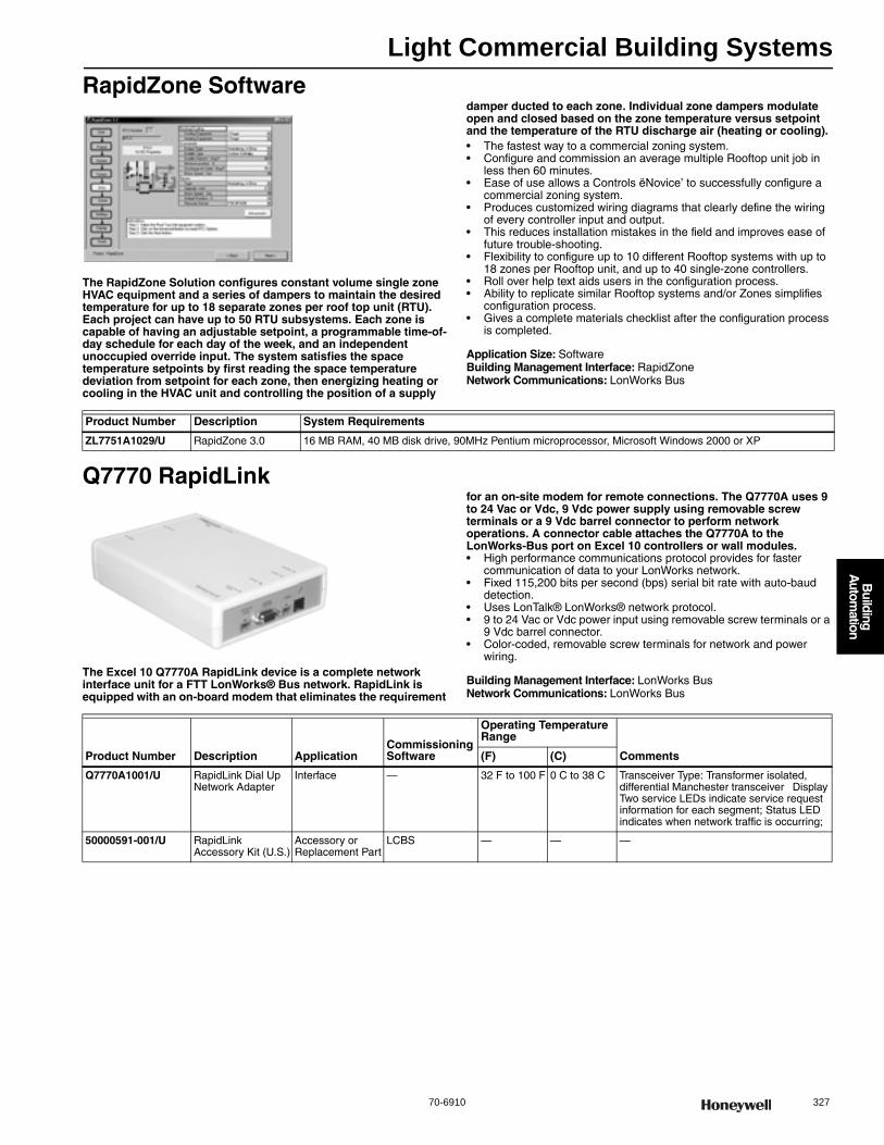
Light Commercial Building Systems
70-6910 327
B
uilding A
utomation
RapidZone Software
The RapidZone Solution configures constant volume single zone HVAC equipment and a series of dampers to maintain the desired temperature for up to 18 separate zones per roof top unit (RTU). Each project can have up to 50 RTU subsystems. Each zone is capable of having an adjustable setpoint, a programmable time-of-day schedule for each day of the week, and an independent unoccupied override input. The system satisfies the space temperature setpoints by first reading the space temperature deviation from setpoint for each zone, then energizing heating or cooling in the HVAC unit and controlling the position of a supply
damper ducted to each zone. Individual zone dampers modulate open and closed based on the zone temperature versus setpoint and the temperature of the RTU discharge air (heating or cooling).• The fastest way to a commercial zoning system. • Configure and commission an average multiple Rooftop unit job in
less then 60 minutes. • Ease of use allows a Controls ëNovice’ to successfully configure a
commercial zoning system. • Produces customized wiring diagrams that clearly define the wiring
of every controller input and output. • This reduces installation mistakes in the field and improves ease of
future trouble-shooting. • Flexibility to configure up to 10 different Rooftop systems with up to
18 zones per Rooftop unit, and up to 40 single-zone controllers. • Roll over help text aids users in the configuration process. • Ability to replicate similar Rooftop systems and/or Zones simplifies
configuration process. • Gives a complete materials checklist after the configuration process
is completed.
Application Size: SoftwareBuilding Management Interface: RapidZoneNetwork Communications: LonWorks Bus
Q7770 RapidLink
The Excel 10 Q7770A RapidLink device is a complete network interface unit for a FTT LonWorks® Bus network. RapidLink is equipped with an on-board modem that eliminates the requirement
for an on-site modem for remote connections. The Q7770A uses 9 to 24 Vac or Vdc, 9 Vdc power supply using removable screw terminals or a 9 Vdc barrel connector to perform network operations. A connector cable attaches the Q7770A to the LonWorks-Bus port on Excel 10 controllers or wall modules.• High performance communications protocol provides for faster
communication of data to your LonWorks network. • Fixed 115,200 bits per second (bps) serial bit rate with auto-baud
detection. • Uses LonTalk® LonWorks® network protocol. • 9 to 24 Vac or Vdc power input using removable screw terminals or a
9 Vdc barrel connector. • Color-coded, removable screw terminals for network and power
wiring.
Building Management Interface: LonWorks BusNetwork Communications: LonWorks Bus
Product Number Description System Requirements
ZL7751A1029/U RapidZone 3.0 16 MB RAM, 40 MB disk drive, 90MHz Pentium microprocessor, Microsoft Windows 2000 or XP
Product Number Description ApplicationCommissioning Software
Operating Temperature Range
Comments(F) (C)
Q7770A1001/U RapidLink Dial Up Network Adapter
Interface — 32 F to 100 F 0 C to 38 C Transceiver Type: Transformer isolated, differential Manchester transceiver Display Two service LEDs indicate service request information for each segment; Status LED indicates when network traffic is occurring;
50000591-001/U RapidLink Accessory Kit (U.S.)
Accessory or Replacement Part
LCBS — — —
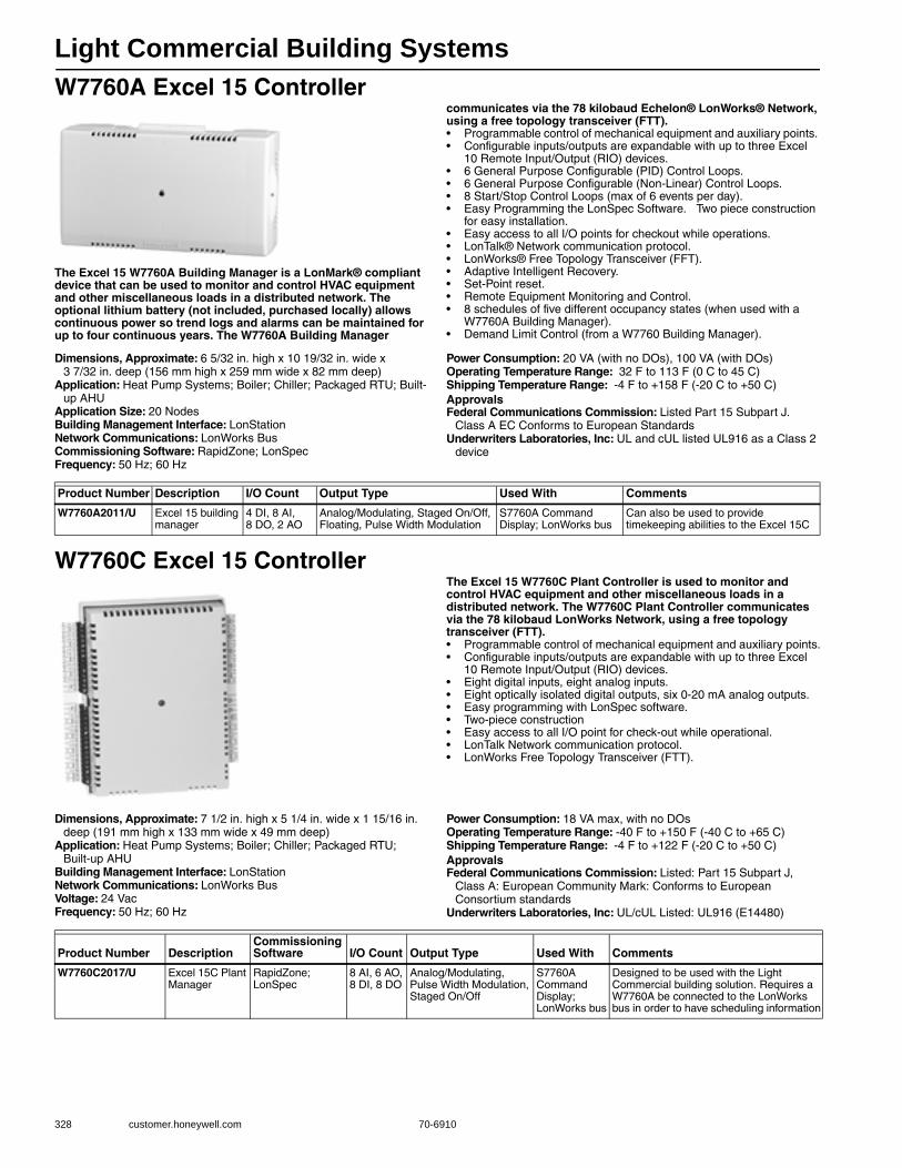
Light Commercial Building Systems
328 customer.honeywell.com 70-6910
W7760A Excel 15 Controller
The Excel 15 W7760A Building Manager is a LonMark® compliant device that can be used to monitor and control HVAC equipment and other miscellaneous loads in a distributed network. The optional lithium battery (not included, purchased locally) allows continuous power so trend logs and alarms can be maintained for up to four continuous years. The W7760A Building Manager
communicates via the 78 kilobaud Echelon® LonWorks® Network, using a free topology transceiver (FTT).• Programmable control of mechanical equipment and auxiliary points. • Configurable inputs/outputs are expandable with up to three Excel
10 Remote Input/Output (RIO) devices. • 6 General Purpose Configurable (PID) Control Loops. • 6 General Purpose Configurable (Non-Linear) Control Loops. • 8 Start/Stop Control Loops (max of 6 events per day). • Easy Programming the LonSpec Software. Two piece construction
for easy installation. • Easy access to all I/O points for checkout while operations. • LonTalk® Network communication protocol. • LonWorks® Free Topology Transceiver (FFT). • Adaptive Intelligent Recovery. • Set-Point reset. • Remote Equipment Monitoring and Control. • 8 schedules of five different occupancy states (when used with a
W7760A Building Manager). • Demand Limit Control (from a W7760 Building Manager).
Dimensions, Approximate: 6 5/32 in. high x 10 19/32 in. wide x 3 7/32 in. deep (156 mm high x 259 mm wide x 82 mm deep)
Application: Heat Pump Systems; Boiler; Chiller; Packaged RTU; Built-up AHU
Application Size: 20 NodesBuilding Management Interface: LonStationNetwork Communications: LonWorks BusCommissioning Software: RapidZone; LonSpecFrequency: 50 Hz; 60 Hz
Power Consumption: 20 VA (with no DOs), 100 VA (with DOs)Operating Temperature Range: 32 F to 113 F (0 C to 45 C) Shipping Temperature Range: -4 F to +158 F (-20 C to +50 C) ApprovalsFederal Communications Commission: Listed Part 15 Subpart J.
Class A EC Conforms to European StandardsUnderwriters Laboratories, Inc: UL and cUL listed UL916 as a Class 2
device
W7760C Excel 15 ControllerThe Excel 15 W7760C Plant Controller is used to monitor and control HVAC equipment and other miscellaneous loads in a distributed network. The W7760C Plant Controller communicates via the 78 kilobaud LonWorks Network, using a free topology transceiver (FTT).• Programmable control of mechanical equipment and auxiliary points.• Configurable inputs/outputs are expandable with up to three Excel
10 Remote Input/Output (RIO) devices.• Eight digital inputs, eight analog inputs.• Eight optically isolated digital outputs, six 0-20 mA analog outputs.• Easy programming with LonSpec software.• Two-piece construction• Easy access to all I/O point for check-out while operational.• LonTalk Network communication protocol.• LonWorks Free Topology Transceiver (FTT).
Dimensions, Approximate: 7 1/2 in. high x 5 1/4 in. wide x 1 15/16 in. deep (191 mm high x 133 mm wide x 49 mm deep)
Application: Heat Pump Systems; Boiler; Chiller; Packaged RTU; Built-up AHU
Building Management Interface: LonStationNetwork Communications: LonWorks BusVoltage: 24 VacFrequency: 50 Hz; 60 Hz
Power Consumption: 18 VA max, with no DOsOperating Temperature Range: -40 F to +150 F (-40 C to +65 C) Shipping Temperature Range: -4 F to +122 F (-20 C to +50 C) ApprovalsFederal Communications Commission: Listed: Part 15 Subpart J,
Class A: European Community Mark: Conforms to European Consortium standards
Underwriters Laboratories, Inc: UL/cUL Listed: UL916 (E14480)
Product Number Description I/O Count Output Type Used With Comments
W7760A2011/U Excel 15 building manager
4 DI, 8 AI, 8 DO, 2 AO
Analog/Modulating, Staged On/Off, Floating, Pulse Width Modulation
S7760A Command Display; LonWorks bus
Can also be used to provide timekeeping abilities to the Excel 15C
Product Number DescriptionCommissioning Software I/O Count Output Type Used With Comments
W7760C2017/U Excel 15C Plant Manager
RapidZone; LonSpec
8 AI, 6 AO, 8 DI, 8 DO
Analog/Modulating, Pulse Width Modulation, Staged On/Off
S7760A Command Display; LonWorks bus
Designed to be used with the Light Commercial building solution. Requires a W7760A be connected to the LonWorks bus in order to have scheduling information
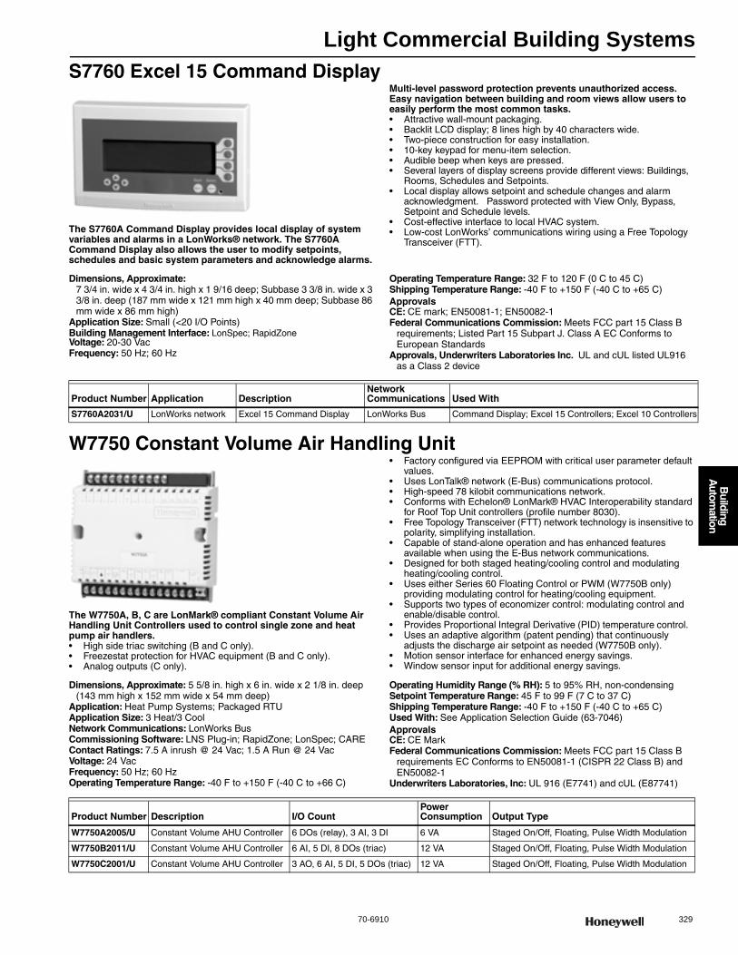
Light Commercial Building Systems
70-6910 329
B
uilding A
utomation
S7760 Excel 15 Command Display
The S7760A Command Display provides local display of system variables and alarms in a LonWorks® network. The S7760A Command Display also allows the user to modify setpoints, schedules and basic system parameters and acknowledge alarms.
Multi-level password protection prevents unauthorized access. Easy navigation between building and room views allow users to easily perform the most common tasks.• Attractive wall-mount packaging. • Backlit LCD display; 8 lines high by 40 characters wide. • Two-piece construction for easy installation. • 10-key keypad for menu-item selection. • Audible beep when keys are pressed. • Several layers of display screens provide different views: Buildings,
Rooms, Schedules and Setpoints. • Local display allows setpoint and schedule changes and alarm
acknowledgment. Password protected with View Only, Bypass, Setpoint and Schedule levels.
• Cost-effective interface to local HVAC system. • Low-cost LonWorks’ communications wiring using a Free Topology
Transceiver (FTT).
Dimensions, Approximate: 7 3/4 in. wide x 4 3/4 in. high x 1 9/16 deep; Subbase 3 3/8 in. wide x 3 3/8 in. deep (187 mm wide x 121 mm high x 40 mm deep; Subbase 86 mm wide x 86 mm high)
Application Size: Small (<20 I/O Points)Building Management Interface: LonSpec; RapidZoneVoltage: 20-30 VacFrequency: 50 Hz; 60 Hz
Operating Temperature Range: 32 F to 120 F (0 C to 45 C) Shipping Temperature Range: -40 F to +150 F (-40 C to +65 C) ApprovalsCE: CE mark; EN50081-1; EN50082-1Federal Communications Commission: Meets FCC part 15 Class B
requirements; Listed Part 15 Subpart J. Class A EC Conforms to European Standards
Approvals, Underwriters Laboratories Inc. UL and cUL listed UL916 as a Class 2 device
W7750 Constant Volume Air Handling Unit
The W7750A, B, C are LonMark® compliant Constant Volume Air Handling Unit Controllers used to control single zone and heat pump air handlers.• High side triac switching (B and C only). • Freezestat protection for HVAC equipment (B and C only). • Analog outputs (C only).
• Factory configured via EEPROM with critical user parameter default values.
• Uses LonTalk® network (E-Bus) communications protocol. • High-speed 78 kilobit communications network. • Conforms with Echelon® LonMark® HVAC Interoperability standard
for Roof Top Unit controllers (profile number 8030). • Free Topology Transceiver (FTT) network technology is insensitive to
polarity, simplifying installation. • Capable of stand-alone operation and has enhanced features
available when using the E-Bus network communications. • Designed for both staged heating/cooling control and modulating
heating/cooling control. • Uses either Series 60 Floating Control or PWM (W7750B only)
providing modulating control for heating/cooling equipment. • Supports two types of economizer control: modulating control and
enable/disable control. • Provides Proportional Integral Derivative (PID) temperature control. • Uses an adaptive algorithm (patent pending) that continuously
adjusts the discharge air setpoint as needed (W7750B only). • Motion sensor interface for enhanced energy savings. • Window sensor input for additional energy savings.
Dimensions, Approximate: 5 5/8 in. high x 6 in. wide x 2 1/8 in. deep (143 mm high x 152 mm wide x 54 mm deep)
Application: Heat Pump Systems; Packaged RTUApplication Size: 3 Heat/3 CoolNetwork Communications: LonWorks BusCommissioning Software: LNS Plug-in; RapidZone; LonSpec; CAREContact Ratings: 7.5 A inrush @ 24 Vac; 1.5 A Run @ 24 VacVoltage: 24 VacFrequency: 50 Hz; 60 HzOperating Temperature Range: -40 F to +150 F (-40 C to +66 C)
Operating Humidity Range (% RH): 5 to 95% RH, non-condensingSetpoint Temperature Range: 45 F to 99 F (7 C to 37 C) Shipping Temperature Range: -40 F to +150 F (-40 C to +65 C) Used With: See Application Selection Guide (63-7046)ApprovalsCE: CE MarkFederal Communications Commission: Meets FCC part 15 Class B
requirements EC Conforms to EN50081-1 (CISPR 22 Class B) and EN50082-1
Underwriters Laboratories, Inc: UL 916 (E7741) and cUL (E87741)
Product Number Application DescriptionNetwork Communications Used With
S7760A2031/U LonWorks network Excel 15 Command Display LonWorks Bus Command Display; Excel 15 Controllers; Excel 10 Controllers
Product Number Description I/O CountPower Consumption Output Type
W7750A2005/U Constant Volume AHU Controller 6 DOs (relay), 3 AI, 3 DI 6 VA Staged On/Off, Floating, Pulse Width Modulation
W7750B2011/U Constant Volume AHU Controller 6 AI, 5 DI, 8 DOs (triac) 12 VA Staged On/Off, Floating, Pulse Width Modulation
W7750C2001/U Constant Volume AHU Controller 3 AO, 6 AI, 5 DI, 5 DOs (triac) 12 VA Staged On/Off, Floating, Pulse Width Modulation
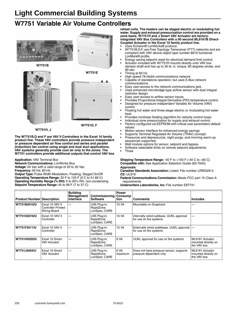
Light Commercial Building Systems
330 customer.honeywell.com 70-6910
W7751 Variable Air Volume Controllers
The W7751B,D and F are VAV II Controllers in the Excel 10 family product line. These VAV controllers provide pressure independent or pressure dependent air flow control and series and parallel (induction) fan control using single and dual duct applications. VAV systems generally provide cool air only to the zones. The W7751 controllers provide additional outputs that control VAV box
reheat coils. The heaters can be staged electric or modulating hot water. Supply and exhaust pressurization control are provided on a zone basis. W7751H and J Smart VAV Actuator are factory-integrated VAV Box Controllers with a 90 second ML6161B Direct-Coupled Actuator in the Excel 10 family product line.• Uses Echelon® LonWorks® protocol. • W7751B,D,F use Free Topology Transceiver (FTT) networks and are
compliant with VAV device object type number 8010 functional LonMark® profile.
• Energy saving setpoint reset for electrical demand limit control. • Actuator included with W7751H mounts directly onto VAV box
damper shaft and has up to 35 lb. in. torque, 90 degrees stroke, and 90 sec.
• Timing at 60 Hz. • High speed 78 kilobit communications network. • Capable of standalone operation, but uses E-Bus network
communications. • Easy user-access to the network communications jack. • Uses enhanced microbridge-type airflow sensor with dual integral
restrictor design. • Easy user-access to airflow sensor inputs. • Provides Proportional Integral Derivative (PID) temperature control. • Designed for pressure independent Variable Air Volume (VAV)
control. • Floating hot water and three-stage electric or modulating hot water
heat. • Provides nonlinear floating algorithm for velocity control loops. • Individual zone pressurization for supply and exhaust control. • Factory configured via EEPROM with critical user parameters default
values. • Motion sensor interface for enhanced energy savings. • Supports Terminal Regulated Air Volume (TRAV) concept. • Pressurize and depressurize, night purge, and morning warm-up
sequences supported. • Wall module options for sensor, setpoint and bypass. • Software selectable limits on remote setpoint adjustments. • Three
Application: VAV Terminal BoxNetwork Communications: LonWorks BusVoltage: 24 Vac with a valid range of 20 to 30 VacFrequency: 50 Hz; 60 HzOutput Type: Pulse Width Modulation, Floating, Staged On/OffOperating Temperature Range: 32 F to 125 F (0 C to 51.66 C) Operating Humidity Range (% RH): 5 to 95% RH, non-condensingSetpoint Temperature Range: 45 to 99 F (7 to 37 C)
Shipping Temperature Range: -40 F to +150 F (-40 C to +65 C) Compatible with: See Application Selection Guide (63-7045)ApprovalsCanadian Standards Association: Listed: File number LR95329-3CE: UL916Federal Communications Commission: Meets FCC part 15 Class A
requirementsUnderwriters Laboratories, Inc: File number E87741
W7751B
W7751E
W7751D, FW7751H, J
Product Number Description
Building Management Interface
Commissioning Software
Power Consumption Comments Includes
W7751B2010/U Excel 10 VAV II Controller Printed Wiring Board
— LNS Plug-in; RapidZone; LonSpec; CARE
10 VA Mountable on Snaptrack —
W7751D2016/U Excel 10 VAV II Controller
— LNS Plug-in; RapidZone; LonSpec; CARE
10 VA Internally wired subbase, UUKL approval for use on fire systems
—
W7751F2011/U Excel 10 VAV II Controller
— LNS Plug-in; RapidZone; LonSpec; CARE
10 VA Externally wired subbbase, UUKL approval for use on fire systems
—
W7751H2025/U Excel 10 Smart VAV Actuator
— LNS Plug-in; RapidZone; LonSpec; CARE
6 VA UUKL approval for use on fire systems ML6161 Actuator mounted directly on the VAV box
W7751J2004/U Excel 10 Smart VAV Actuator
— LNS Plug-in; RapidZone; LonSpec; CARE
6 VA maximum
Does not have pressure sensor, supports pressure dependent only
ML6161 Actuator mounted directly on the VAV box

Light Commercial Building Systems
70-6910 331
B
uilding A
utomation
W7752 Fan Coil Unit Controllers
The W7752 Fan Coil Unit Controllers provide room temperature control for two and four pipe fan coil units with optional electric
heating coils and can control single, two or three speed fans. Timing and inter-lock features make the W7752 suitable for systems using electric heat and compressors.• LonMark® Fan Coil Unit HVAC profile #8020. • Stand-alone operation or on high-speed 78 kilobit Echelon® Bus (E-
Bus) network direct connection of thermal actuators, fan switch, electric heat.
• Factory-configured default parameters. • Wide range of supported valves and actuators. • Interlocks and time delays to protect equipment. • Slim design fits into narrow fan coil units. • Terminations all on one side allow controller to be positioned at back
of fan coil unit. • Integral 115 Vac or 230 Vac transformer.
Dimensions, Approximate: 4 1/8 in. high x 10 1/8 in. wide x 2 1/2 in. deep (101 mm high x 257 mm wide x 60 mm deep)
Application: Fan Coil UnitApplication Size: 3 Heat/3 Cool; 2-pipe; 4-pipeNetwork Communications: LonWorks BusCommissioning Software: LNS Plug-in; RapidZone; LonSpec; CAREVoltage: 115 Vac (+10%, -15%)Frequency: 50 Hz; 60 HzPower Consumption: 30 VA maximum
Operating Temperature Range: 32 F to 122 F (0 C to 50 C) Operating Humidity Range (% RH): 5 to 95% RH, non-condensingSetpoint Temperature Range: 32 F to 104 F (0 C to 40 C) Shipping Temperature Range: -40 F to +150 F (-40 C to +70 C) Used With: See Application Selection Guide (63-7043)ApprovalsCE: CE mark; EN50081-1; EN50082-1Federal Communications Commission: Meets FCC part 15 Class B
requirements
Product Number Description I/O Count Output Type Comments Includes
W7752D2007 Fan Coil Unit Controllers
3 AI, 1 DI, 1 DO (3 speed fan control), 2 AO (H/C triacs), 1 DO
Staged On/Off, Floating, Pulse Width Modulation
115 Vac power with electric heat relay
250 Vac 10A electric reheat relay and 3 fan speed relays
W7752G2000 Fan Coil Unit Controllers
3 AI, 1 DI, 1 DO (3 speed fan control), 2 AO (H/C triacs), 1 DO
Staged On/Off, Floating, Pulse Width Modulation
115 Vac power without electric heat relay
3 fan speed relays
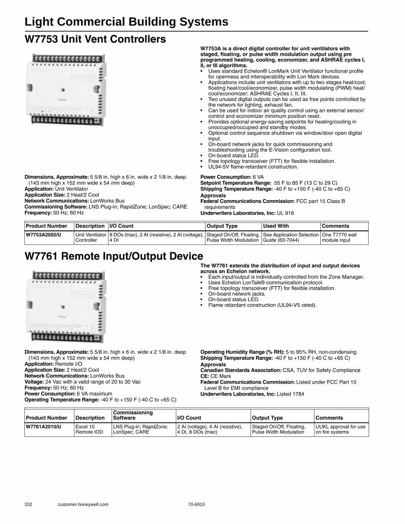
Light Commercial Building Systems
332 customer.honeywell.com 70-6910
W7753 Unit Vent ControllersW7753A is a direct digital controller for unit ventilators with staged, floating, or pulse width modulation output using pre programmed heating, cooling, economizer, and ASHRAE cycles I, II, or III algorithms.• Uses standard Echelon® LonMark Unit Ventilator functional profile
for openness and interoperability with Lon Mark devices. • Applications include unit ventilators with up to two stages heat/cool;
floating heat/cool/economizer, pulse width modulating (PWM) heat/cool/economizer; ASHRAE Cycles I, II, III.
• Two unused digital outputs can be used as free points controlled by the network for lighting, exhaust fan.
• Can be used for indoor air quality control using an external sensor/control and economizer minimum position reset.
• Provides optional energy-saving setpoints for heating/cooling in unoccupied/occupied and standby modes.
• Optional control sequence shutdown via window/door open digital input.
• On-board network jacks for quick commissioning and troubleshooting using the E-Vision configuration tool.
• On-board status LED. • Free topology transceiver (FTT) for flexible installation. • UL94-5V flame-retardant construction.
Dimensions, Approximate: 5 5/8 in. high x 6 in. wide x 2 1/8 in. deep (143 mm high x 152 mm wide x 54 mm deep)
Application: Unit VentilatorApplication Size: 2 Heat/2 CoolNetwork Communications: LonWorks BusCommissioning Software: LNS Plug-in; RapidZone; LonSpec; CAREFrequency: 50 Hz; 60 Hz
Power Consumption: 6 VASetpoint Temperature Range: 55 F to 85 F (13 C to 29 C) Shipping Temperature Range: -40 F to +150 F (-40 C to +65 C) ApprovalsFederal Communications Commission: FCC part 15 Class B
requirementsUnderwriters Laboratories, Inc: UL 916
W7761 Remote Input/Output DeviceThe W7761 extends the distribution of input and output devices across an Echelon network.• Each input/output is individually controlled from the Zone Manager. • Uses Echelon LonTalk® communication protocol. • Free topology transceiver (FTT) for flexible installation. • On-board network jacks. • On-board status LED. • Flame retardant construction (UL94-V5 rated).
Dimensions, Approximate: 5 5/8 in. high x 6 in. wide x 2 1/8 in. deep (143 mm high x 152 mm wide x 54 mm deep)
Application: Remote I/OApplication Size: 2 Heat/2 CoolNetwork Communications: LonWorks BusVoltage: 24 Vac with a valid range of 20 to 30 VacFrequency: 50 Hz; 60 HzPower Consumption: 6 VA maximumOperating Temperature Range: -40 F to +150 F (-40 C to +65 C)
Operating Humidity Range (% RH): 5 to 95% RH, non-condensingShipping Temperature Range: -40 F to +150 F (-40 C to +65 C) ApprovalsCanadian Standards Association: CSA, TUV for Safety ComplianceCE: CE MarkFederal Communications Commission: Listed under FCC Part 15
Level B for EMI complianceUnderwriters Laboratories, Inc: Listed 1784
Product Number Description I/O Count Output Type Used With Comments
W7753A2002/U Unit Ventilator Controller
8 DOs (triac), 2 AI (resistive), 2 AI (voltage), 4 DI
Staged On/Off, Floating, Pulse Width Modulation
See Application Selection Guide (63-7044)
One T7770 wall module input
Product Number DescriptionCommissioning Software I/O Count Output Type Comments
W7761A2010/U Excel 10 Remote IOD
LNS Plug-in; RapidZone; LonSpec; CARE
2 AI (voltage), 4 AI (resistive), 4 DI, 8 DOs (triac)
Staged On/Off, Floating, Pulse Width Modulation
UUKL approval for use on fire systems
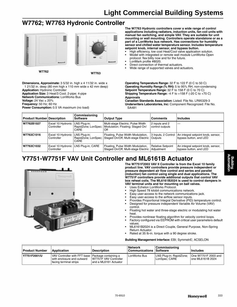
Light Commercial Building Systems
70-6910 333
B
uilding A
utomation
W7762; W7763 Hydronic ControllerThe W7763 Hydronic controllers cover a wide range of control applications including radiators, induction units, fan coil units with manual fan switching, and simple VAV. They are suitable for unit mounting or wall mounting. Controllers operate standalone or as a part of a LonWorks bus network. Has connections for humidity sensor and chilled water temperature sensor. Includes temperature setpoint knob, internal sensor, and bypass button.• High efficiency, low cost Heat/Cool valve application solution. • Model with integrated or remote wall module LonWorks Open
protocol: flex bility now and for the future. • LonMark profile #8020. • Direct connection of thermal actuators. • Wide range of supported valves and actuators.
Dimensions, Approximate: 3 5/32 in. high x 4 11/32 in. wide x 1 21/32 in. deep (80 mm high x 110 mm wide x 42 mm deep)
Application: Hydronic ControllerApplication Size: 3 Heat/3 Cool; 2-pipe; 4-pipeNetwork Communications: LonWorks BusVoltage: 24 Vac ± 20%Frequency: 50 Hz; 60 HzPower Consumption: 0.5 VA maximum (no load)
Operating Temperature Range: 32 F to 122 F (0 C to 50 C) Operating Humidity Range (% RH): 5 to 95% RH, non-condensingSetpoint Temperature Range: 32 F to 158 F (0 C to 70 C) Shipping Temperature Range: -4 F to +158 F (-20 C to +70 C) ApprovalsCanadian Standards Association: Listed: File No. LR95329-3Underwriters Laboratories, Inc: Component Recognized: File No.
SA481
Y7751-W7751F VAV Unit Controller and ML6161B ActuatorThe W7751F2003 VAV II Controller is from the Excel 10 family product line. VAV controllers provide pressure independent or pressure dependent air flow control and series and parallel (induction) fan control using single and dual applications. The W7751F controllers provide additional outputs that control VAV box reheat coils. The ML6161B2024 is used to control dampers in VAV terminal units and for mounting on ball valves.• Uses Echelon LonWorks Protocol. • High Speed 78 kilobit communications network. • Easy user-access to the network communications jack. • Easy user-access to the airflow sensor inputs. • Provides Proportional Integral Derivative (PID) temperature control. • Designed for pressure independent Variable Air Volume (VAV)
control. • Floating hot water and three-stage electric or modulating hot water
heat. • Provides nonlinear floating algorithm for velocity control loops. • Factory configured via EEPROM with critical user parameters default
values. • ML6161B2024 is a Direct Couple, General Purpose, Non-Spring
Return Actuator. • Rated at 35 lb-in. torque with a 90 degree stroke.
Building Management Interface: EBI; SymmetrE; ACSELON
W7762 W7763
Product Number DescriptionCommissioning Software Output Type Comments Includes
W7762B1027 Excel 10 Hydronic Controller
LNS Plug-in; RapidZone; LonSpec; CARE
Multi-stage Electric; Pulse Width Modulation; Floating; Staged On/Off
2 inputs and 2 control outputs
—
W7763C1016 Excel 10 Hydronic Controller
LNS Plug-in; RapidZone; LonSpec; CARE
Floating, Pulse Width Modulation, Staged On/Off, Multi-stage Electric
3 Inputs, 2 Control Outputs
An integral setpoint knob, sensor, bypass button, and LED
W7763C1032 Excel 10 Hydronic Controller
LNS Plug-in; CARE Floating, Pulse Width Modulation, Staged On/Off, Multi-stage Electric
Relative Setpoint Adjustment
An integral setpoint knob, sensor, bypass button, and LED
Product Number Application DescriptionNetwork Communications
Commissioning Software Includes
Y7751F2001/U VAV Controller with FFT base with enclosure and outward facing terminal strips
Package containing a W7751F VAV Controller and a ML6161 Actuator
LonWorks Bus LNS Plug-in; RapidZone; LonSpec; CARE
One W7751F 2003 and one ML6161B 2024
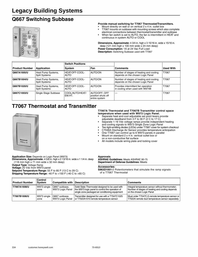
Legacy Building Systems
334 customer.honeywell.com 70-6910
Q667 Switching SubbaseProvide manual switching for T7067 Thermostat/Transmitters.• Mount directly on wall or on vertical 2 x 4 in. outlet box • T7067 mounts on subbase with mounting screws which also complete
electrical connections between thermostat/transmitter and subbase • When fan switch is set to AUTO, the fan is intermittent in HEAT and
continuous in system AUTO or COOL
Dimensions, Approximate: 4 3/4 in. high x 3 15/16 in. wide x 15/16 in. deep (121 mm high x 100 mm wide x 24 mm deep)
Power Consumption: 1A at 24 Vac Full LoadDescription: Switching Subbase used with T7067
T7067 Thermostat and TransmitterT7067A Thermostat and T7067B Transmitter control space temperature when used with W973 Logic Panel.• Separate heat and cool adjustable set point levers provide
adjustable deadband from 3 F to 30 F (2 C to 17 C) • Separate 1-16 Vdc voltage ramps provide independent heating
and cooling signals to W973 Single Zone Logic Panel • Two light-emitting diodes (LEDs) under T7067 cover for system checkout • C7046A Discharge Air Sensor provides temperature anticipation • One T7067 can control up to 6 W973 panels in parallel • Mount on standard 2 x 4 in. vertical outlet box or
on a non-conductive flat surface • All models include wiring plate and locking cover
Application Size: Depends on Logic Panel (W973)Dimensions, Approximate: 4 5/8 in. high x 2 13/16 in. wide x 1 1/4 in. deep
(118 mm high x 71 mm wide x 32 mm deep) Output Type: Voltage RampVoltage: 20 Vdc from W973 panelSetpoint Temperature Range: 55 F to 85 F (13 C to 29 C) Shipping Temperature Range: -40 F to +150 F (-40 C to +65 C)
ApprovalsASHRAE Guidelines: Meets ASHRAE 90-75Department of Defense Guidelines: Meets
Accessories:S963D1001-2 Potentiometers that simulate the ramp signals
of a T7067 Thermostat
Product Number Application
Switch Positions
Comments Used WithSystem Fan
Q667A1005/U Heat Pump Systems, Split Systems
HEAT-OFF-COOL-AUTO
AUTO/ON Number of stages of heating and cooling depends on the chosen Logic Panel
T7067
Q667B1004/U Heat Pump Systems, Split Systems
HEAT-OFF-COOL-AUTO
AUTO/ON Number of stages of heating and cooling depends on the chosen Logic Panel
T7067
Q667B1020/U Heat Pump Systems, Split Systems
HEAT-OFF-COOL-AUTO
AUTO/ON Provides intermittent fan operation in cooling when used with W974B
T7067
Q667C1003/U Single Stage Subbase COOL/AUTO/HEAT/EM.HT.
AUTO/OFF; OFF position shuts off entire system
— T7067
Product NumberControl System Compatible with Description Comments
T7067A1008/U W973 single zone
Q667 subbase, W973 Logic Panel
Solid State Thermostat designed to be used with the W973 logic panel to control the operation of single zone packaged air conditioning equipment
Integral temperature sensor without thermometer; Number of stages of heating and cooling depends on the chosen Logic Panel
T7067B1006/U W973 single zone
Q667 subbase, W973 Logic Panel
Transmitter designed for use with a T7047C1025 or T7022A1010 remote temperature sensor
Must order T7047C,G remote temperature sensor or T7022A remote duct temperature sensor separately

Legacy Building Systems
70-6910 335
B
uilding A
utomation
T7080 Electronic Dual Setpoint ThermostatUsed in W7080 control system to provide modulating space temperature control.• Separate heat and cool adjustable set point levers provide adjustable
deadband from 3 F to 30 F (2 C to 17 C) • Single 2 to 22 Vdc voltage ramp provides heating/cooling signal to
W7080 Load Analyzer • Outputs constant 12 Vdc when sensed temperature is
within deadband range • Ramp output decreases on call for heat: increases on call for cooling • C7100B or C7046B Air Temperature Sensors are used to provide
heating/cooling anticipation (one required for each zone thermostat) and can also be optionally used as remote return air temperature sensors with the T7080B transmitter
• Operates on 24 Vdc supplied by W7080A Load Analyzer • Mounts on standard 2 x 4 in. outlet box or on nonconductive flat surface
Application Size: 3 Heat / 3 CoolDimensions, Approximate: 4 5/8 in. high x 2 13/16 in. wide x 1 1/4 in. deep
(118 mm high x 71 mm wide x 32 mm deep) Voltage: 24 VdcSetpoint Temperature Range: 55 F to 85 F (13 C to 29 C)
Shipping Temperature Range: -40 F to +150 F (-40 C to +65 C) ApprovalsASHRAE Guidelines: Meets ASHRAE 90-75Department of Defense Guidelines: Meets
W7080 Load AnalyzerControls heating, cooling and space demand oriented economizer operation in the Honeywell Electronic Dual Set point Multizone control system.• Controls 3 stages of on/off heating, modulated heating, modulated
economizer, 3 stages of on/off cooling and modulated cooling • Responds to highest heating and cooling demand signal from
up to 12 T7080 Zone Thermostat/Transmitters • Analyzer is short-circuit protected source of 24 Vdc power for zone
thermostat/transmitter, sensor and W7081A Limit Controller Package • Switches all stages off when power is interrupted; switches stages
on when power is restored • Compressor turn-on time delays must be incorporated for each compressor • No adjustment or calibrations required • Night setback and cooling shutdown for individual or all zones
by addition of time-clock • Mounts with 4 No. 8 Screws (not provided) through holes in base
Application Size: 3 Heat / 3 CoolDimensions, Approximate: 6 1/4 in. high x 4 1/8 in. wide x 2 5/16 in. deep
(159 mm high x 105 mm wide x 59 mm deep) Contact Ratings: NO 240 VA inrush @ 24 Vac, 60 VA running @
24 Vac; NC 75 VA inrush @ 24 Vac, 30 VA running @ 24 VacElectrical Connections: 1/4 in. quick-connect male terminalsVoltage: 24 VdcFrequency: 50 Hz; 60 Hz
Operating Temperature Range: -40 F to +150 F (-40 C to +65 C) Shipping Temperature Range: -40 F to +150 F (-40 C to +65 C) ApprovalsASHRAE Guidelines: Meets ASHRAE 90-75Canadian Standards Association: Component RecognizedDepartment of Defense Guidelines: MeetsUnderwriters Laboratories, Inc: Component Recognized
Product Number Application Output Type
T7080A1019/U Split System; Furnace; Packaged RTU Voltage Ramp
T7080B1017/U Split System; Heat Pump Systems; Furnace; Packaged RTU Voltage Ramp
Product Number Application Control SystemCompatible with Description Comments
W7080A1016/U Split System; Furnace; Packaged RTU
W7080 control system
T7080 Thermostat
Load Analyzer, 3 Heat/ 3 Cool
Load analyzer provides control of On/Off and modulated cooling and modulated economizer functions

Legacy Building Systems
336 customer.honeywell.com 70-6910
W7081 Limit ControllerUsed with W7080A Load Analyzer to provide cold deck low limit, hot deck high limit, and economizer/mixed air low limit functions.• Limits the maximum and minimum temperatures of the hot and cold
deck and of the mixed air by supplying modified demand signals to the W7080A Load Analyzer and to the economizer
• The positive limits stabilize deck temperatures under light load conditions providing greater comfort and reducing energy usage
• Has jumper selectable set points for each of its 3 functions • Compact to fit easily in HVAC system control panel • Mounts with 4 No. 8 screws (not provided) through holes in base
Application Size: Small (<20 I/O Points)Dimensions, Approximate: 6 1/4 in. high x 4 1/8 in. wide x 2 5/16 in. deep
(159 mm high x 105 mm wide x 59 mm deep) Electrical Connections: 1/4 in. quick-connect male terminalsPower Consumption: 0.29 VA maximumOperating Temperature Range: -40 F to +150 F (-40 C to +65 C)
Shipping Temperature Range: -40 F to +150 F (-40 C to +65 C) ApprovalsASHRAE Guidelines: Meets ASHRAE 90-75Canadian Standards Association: Component RecognizedDepartment of Defense Guidelines: MeetsUnderwriters Laboratories, Inc: Component Recognized
W7100A,C Discharge Air Temperature Controller
Maintain an average discharge air temperature in variable air volume (VAV) systems, or other systems requiring discharge air control of multistage cooling or heating. Reduce kilowatt demand
and consumption by maintaining the minimum amount of heating or cooling capacity required to hold the discharge air set point. Utilize economizer for free cooling when available.• W7100 Controller maintains an average discharge air temperature
in variable air volume (VAV) cooling systems by modulating an economizer and sequencing stages of mechanical cooling
• The W7100 can be applied to electric makeup air and other systems requiring discharge air control of multistage heating or cooling
• Staging capacity of the W7100A,C can be extended six stages using a W7101A Satellite Sequencer
• When power is interrupted, the system cycles to all stages off • When power is restored, the economizer will first be modulated
open (if enthalpy is suitable), then stages of mechanical cooling will be sequenced on
• If enthalpy is not suitable for economizer operation, the first stage of cooling or heating is energized within five minutes
• Reset signal from either space sensor or outdoor air sensor
Dimensions, Approximate: 8 5/8 in. high x 6 1/2 in. wide x 3 in. deep (219 mm high x 161 mm wide x 76 mm deep)
Contact Ratings: NO 240 VA inrush @ 24 Vac, 60 VA running @ 24 VacNC 75 VA inrush @ 24 Vac, 30 VA running @ 24 VacNO 750 VA inrush @ 120/240 Vac, 75 VA running @ 120/240 VacNC 240 VA inrush @ 40 Vac, 30 VA running @ 24 Vac
Electrical Connections: 1/4 in. quick-connect male terminalsVoltage: 20 to 30 VacFrequency: 50 Hz; 60 Hz
Power Consumption: 12 VA at 24 Vac, 50/60 Hz (max).Operating Temperature Range: 40 F to 90 F (4 C to 32 C) Setpoint Temperature Range: 40 F to 90 F (4 C to 32 C) Shipping Temperature Range: -40 F to +150 F (-40 C to +65 C)
Accessories:S963B1037-Manual Potentiometer (480 ohm)S963B1078-Manual Potentiometer (500 ohm)S963B1128-Manual Potentiometer (135 ohm)
Product Number Application Control System Compatible with: Description
W7081A1015/U Split System; Heat Pump Systems; Furnace; Packaged RTU W7080 control system W7080 Load analyzer Limit Controller
Product Number ApplicationApplication Size
Control System Output Type Description Comments
W7100A1053/U Discharge Air 0 Heat / 6 Cool W7100 family Staged On/Off 20 to 30 Vac Discharge air temperature controller
Additional stages of heating and cooling can be achieved by adding a W7101 Satellite Sequencer
W7100C1018/U Discharge Air 2 Heat / 4 Cool W7100 family Staged On/Off 20 to 30 Vac Discharge air temperature controller
Additional stages of heating and cooling can be achieved by adding a W7101 Satellite Sequencer
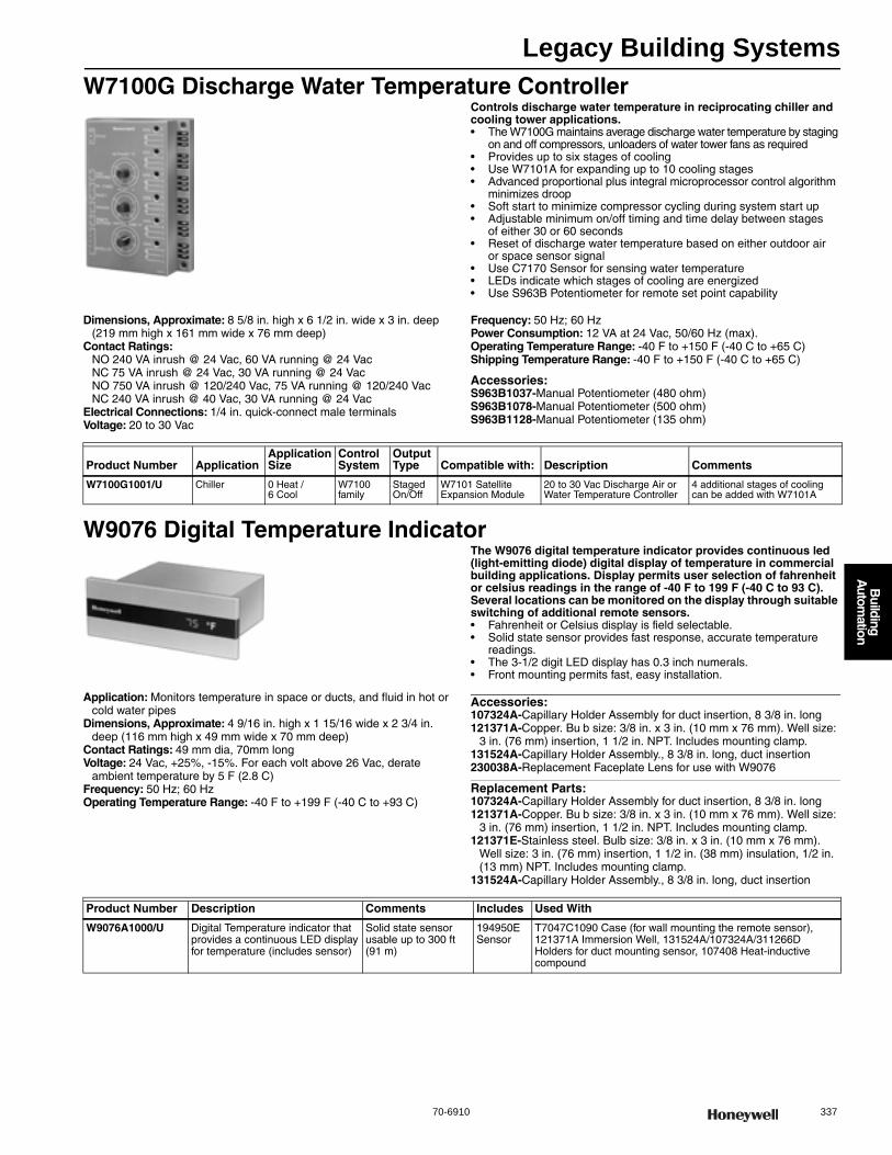
Legacy Building Systems
70-6910 337
B
uilding A
utomation
W7100G Discharge Water Temperature ControllerControls discharge water temperature in reciprocating chiller and cooling tower applications.• The W7100G maintains average discharge water temperature by staging
on and off compressors, unloaders of water tower fans as required • Provides up to six stages of cooling • Use W7101A for expanding up to 10 cooling stages • Advanced proportional plus integral microprocessor control algorithm
minimizes droop • Soft start to minimize compressor cycling during system start up • Adjustable minimum on/off timing and time delay between stages
of either 30 or 60 seconds • Reset of discharge water temperature based on either outdoor air
or space sensor signal • Use C7170 Sensor for sensing water temperature • LEDs indicate which stages of cooling are energized • Use S963B Potentiometer for remote set point capability
Dimensions, Approximate: 8 5/8 in. high x 6 1/2 in. wide x 3 in. deep (219 mm high x 161 mm wide x 76 mm deep)
Contact Ratings: NO 240 VA inrush @ 24 Vac, 60 VA running @ 24 VacNC 75 VA inrush @ 24 Vac, 30 VA running @ 24 VacNO 750 VA inrush @ 120/240 Vac, 75 VA running @ 120/240 VacNC 240 VA inrush @ 40 Vac, 30 VA running @ 24 Vac
Electrical Connections: 1/4 in. quick-connect male terminalsVoltage: 20 to 30 Vac
Frequency: 50 Hz; 60 HzPower Consumption: 12 VA at 24 Vac, 50/60 Hz (max).Operating Temperature Range: -40 F to +150 F (-40 C to +65 C) Shipping Temperature Range: -40 F to +150 F (-40 C to +65 C)
Accessories:S963B1037-Manual Potentiometer (480 ohm)S963B1078-Manual Potentiometer (500 ohm)S963B1128-Manual Potentiometer (135 ohm)
W9076 Digital Temperature IndicatorThe W9076 digital temperature indicator provides continuous led (light-emitting diode) digital display of temperature in commercial building applications. Display permits user selection of fahrenheit or celsius readings in the range of -40 F to 199 F (-40 C to 93 C). Several locations can be monitored on the display through suitable switching of additional remote sensors.• Fahrenheit or Celsius display is field selectable. • Solid state sensor provides fast response, accurate temperature
readings. • The 3-1/2 digit LED display has 0.3 inch numerals. • Front mounting permits fast, easy installation.
Application: Monitors temperature in space or ducts, and fluid in hot or cold water pipes
Dimensions, Approximate: 4 9/16 in. high x 1 15/16 wide x 2 3/4 in. deep (116 mm high x 49 mm wide x 70 mm deep)
Contact Ratings: 49 mm dia, 70mm longVoltage: 24 Vac, +25%, -15%. For each volt above 26 Vac, derate
ambient temperature by 5 F (2.8 C)Frequency: 50 Hz; 60 HzOperating Temperature Range: -40 F to +199 F (-40 C to +93 C)
Accessories:107324A-Capillary Holder Assembly for duct insertion, 8 3/8 in. long121371A-Copper. Bu b size: 3/8 in. x 3 in. (10 mm x 76 mm). Well size:
3 in. (76 mm) insertion, 1 1/2 in. NPT. Includes mounting clamp.131524A-Capillary Holder Assembly., 8 3/8 in. long, duct insertion230038A-Replacement Faceplate Lens for use with W9076
Replacement Parts:107324A-Capillary Holder Assembly for duct insertion, 8 3/8 in. long121371A-Copper. Bu b size: 3/8 in. x 3 in. (10 mm x 76 mm). Well size:
3 in. (76 mm) insertion, 1 1/2 in. NPT. Includes mounting clamp.121371E-Stainless steel. Bulb size: 3/8 in. x 3 in. (10 mm x 76 mm).
Well size: 3 in. (76 mm) insertion, 1 1/2 in. (38 mm) insulation, 1/2 in. (13 mm) NPT. Includes mounting clamp.
131524A-Capillary Holder Assembly., 8 3/8 in. long, duct insertion
Product Number ApplicationApplication Size
Control System
Output Type Compatible with: Description Comments
W7100G1001/U Chiller 0 Heat / 6 Cool
W7100 family
Staged On/Off
W7101 Satellite Expansion Module
20 to 30 Vac Discharge Air or Water Temperature Controller
4 additional stages of cooling can be added with W7101A
Product Number Description Comments Includes Used With
W9076A1000/U Digital Temperature indicator that provides a continuous LED display for temperature (includes sensor)
Solid state sensor usable up to 300 ft (91 m)
194950E Sensor
T7047C1090 Case (for wall mounting the remote sensor), 121371A Immersion Well, 131524A/107324A/311266D Holders for duct mounting sensor, 107408 Heat-inductive compound
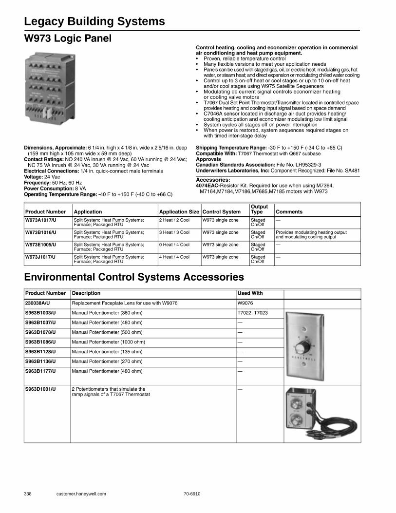
Legacy Building Systems
338 customer.honeywell.com 70-6910
W973 Logic PanelControl heating, cooling and economizer operation in commercial air conditioning and heat pump equipment.• Proven, reliable temperature control • Many flexible versions to meet your application needs • Panels can be used with staged gas, oil, or electric heat; modulating gas, hot
water, or steam heat; and direct expansion or modulating chilled water cooling • Control up to 3 on-off heat or cool stages or up to 10 on-off heat
and/or cool stages using W975 Satellite Sequencers • Modulating dc current signal controls economizer heating
or cooling valve motors • T7067 Dual Set Point Thermostat/Transmitter located in controlled space
provides heating and cooling input signal based on space demand • C7046A sensor located in discharge air duct provides heating/
cooling anticipation and economizer modulating low limit signal • System cycles all stages off on power interruption • When power is restored, system sequences required stages on
with timed inter-stage delay
Dimensions, Approximate: 6 1/4 in. high x 4 1/8 in. wide x 2 5/16 in. deep (159 mm high x 105 mm wide x 59 mm deep)
Contact Ratings: NO 240 VA inrush @ 24 Vac, 60 VA running @ 24 Vac; NC 75 VA inrush @ 24 Vac, 30 VA running @ 24 Vac
Electrical Connections: 1/4 in. quick-connect male terminalsVoltage: 24 VacFrequency: 50 Hz; 60 HzPower Consumption: 8 VAOperating Temperature Range: -40 F to +150 F (-40 C to +66 C)
Shipping Temperature Range: -30 F to +150 F (-34 C to +65 C) Compatible With: T7067 Thermostat with Q667 subbaseApprovalsCanadian Standards Association: File No. LR95329-3Underwriters Laboratories, Inc: Component Recognized: File No. SA481
Accessories:4074EAC-Resistor Kit. Required for use when using M7364,
M7164,M7184,M7186,M7685,M7185 motors with W973
Environmental Control Systems Accessories
Product Number Application Application Size Control SystemOutput Type Comments
W973A1017/U Split System; Heat Pump Systems; Furnace; Packaged RTU
2 Heat / 2 Cool W973 single zone Staged On/Off
—
W973B1016/U Split System; Heat Pump Systems; Furnace; Packaged RTU
3 Heat / 3 Cool W973 single zone Staged On/Off
Provides modulating heating output and modulating cooling output
W973E1005/U Split System; Heat Pump Systems; Furnace; Packaged RTU
0 Heat / 4 Cool W973 single zone Staged On/Off
—
W973J1017/U Split System; Heat Pump Systems; Furnace; Packaged RTU
4 Heat / 4 Cool W973 single zone Staged On/Off
—
Product Number Description Used With
230038A/U Replacement Faceplate Lens for use with W9076 W9076
S963B1003/U Manual Potentiometer (360 ohm) T7022; T7023
S963B1037/U Manual Potentiometer (480 ohm) —
S963B1078/U Manual Potentiometer (500 ohm) —
S963B1086/U Manual Potentiometer (1000 ohm) —
S963B1128/U Manual Potentiometer (135 ohm) —
S963B1136/U Manual Potentiometer (270 ohm) —
S963B1177/U Manual Potentiometer (480 ohm) —
S963D1001/U 2 Potentiometers that simulate the ramp signals of a T7067 Thermostat
—
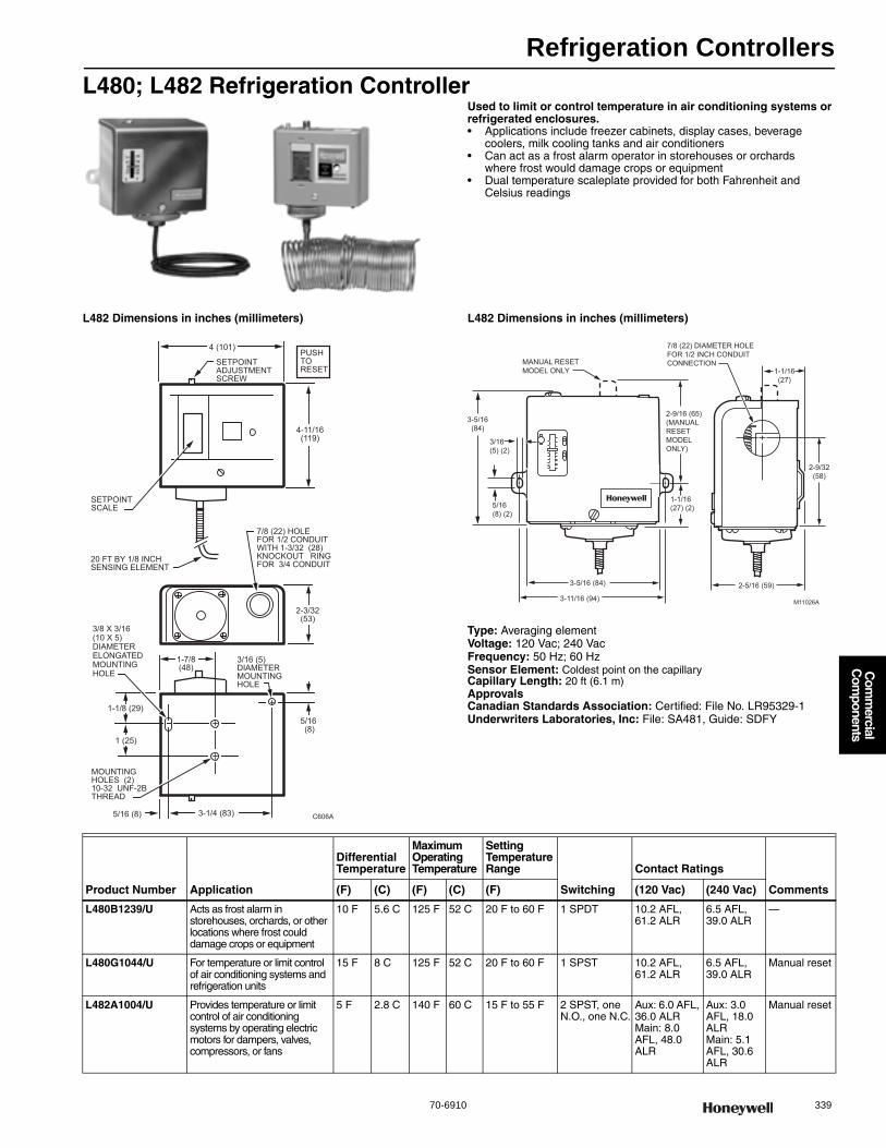
Refrigeration Controllers
70-6910 339
Com
mercial
Com
ponents
L480; L482 Refrigeration ControllerUsed to limit or control temperature in air conditioning systems or refrigerated enclosures.• Applications include freezer cabinets, display cases, beverage
coolers, milk cooling tanks and air conditioners• Can act as a frost alarm operator in storehouses or orchards
where frost would damage crops or equipment• Dual temperature scaleplate provided for both Fahrenheit and
Celsius readings
L482 Dimensions in inches (millimeters) L482 Dimensions in inches (millimeters)
Type: Averaging elementVoltage: 120 Vac; 240 VacFrequency: 50 Hz; 60 HzSensor Element: Coldest point on the capillaryCapillary Length: 20 ft (6.1 m)ApprovalsCanadian Standards Association: Certified: File No. LR95329-1Underwriters Laboratories, Inc: File: SA481, Guide: SDFY
SETPOINT ADJUSTMENT SCREW
4 (101)
2-3/32(53)
7/8 (22) HOLEFOR 1/2 CONDUITWITH 1-3/32 (28) KNOCKOUT RINGFOR 3/4 CONDUIT
1-7/8(48)
5/16 (8)
3/16 (5) DIAMETERMOUNTING HOLE
3-1/4 (83)5/16 (8)
1 (25)
1-1/8 (29)
3/8 X 3/16(10 X 5) DIAMETER ELONGATED MOUNTINGHOLE
C606A
SETPOINTSCALE
4-11/16(119)
MOUNTING HOLES (2)10-32 UNF-2B THREAD
PUSHTORESET
20 FT BY 1/8 INCHSENSING ELEMENT
7/8 (22) DIAMETER HOLEFOR 1/2 INCH CONDUITCONNECTIONMANUAL RESET
MODEL ONLY
2-9/16 (65)(MANUALRESETMODEL ONLY)
1-1/16(27) (2)
1-1/16(27)
3-5/16(84)
3/16(5) (2)
5/16(8) (2)
3-5/16 (84)
3-11/16 (94)
2-5/16 (59)
2-9/32(58)
M11026A
Product Number Application
Differential Temperature
Maximum Operating Temperature
Setting Temperature Range
Switching
Contact Ratings
Comments(F) (C) (F) (C) (F) (120 Vac) (240 Vac)
L480B1239/U Acts as frost alarm in storehouses, orchards, or other locations where frost could damage crops or equipment
10 F 5.6 C 125 F 52 C 20 F to 60 F 1 SPDT 10.2 AFL, 61.2 ALR
6.5 AFL, 39.0 ALR
—
L480G1044/U For temperature or limit control of air conditioning systems and refrigeration units
15 F 8 C 125 F 52 C 20 F to 60 F 1 SPST 10.2 AFL, 61.2 ALR
6.5 AFL, 39.0 ALR
Manual reset
L482A1004/U Provides temperature or limit control of air conditioning systems by operating electric motors for dampers, valves, compressors, or fans
5 F 2.8 C 140 F 60 C 15 F to 55 F 2 SPST, one N.O., one N.C.
Aux: 6.0 AFL, 36.0 ALRMain: 8.0 AFL, 48.0 ALR
Aux: 3.0 AFL, 18.0 ALRMain: 5.1 AFL, 30.6 ALR
Manual reset
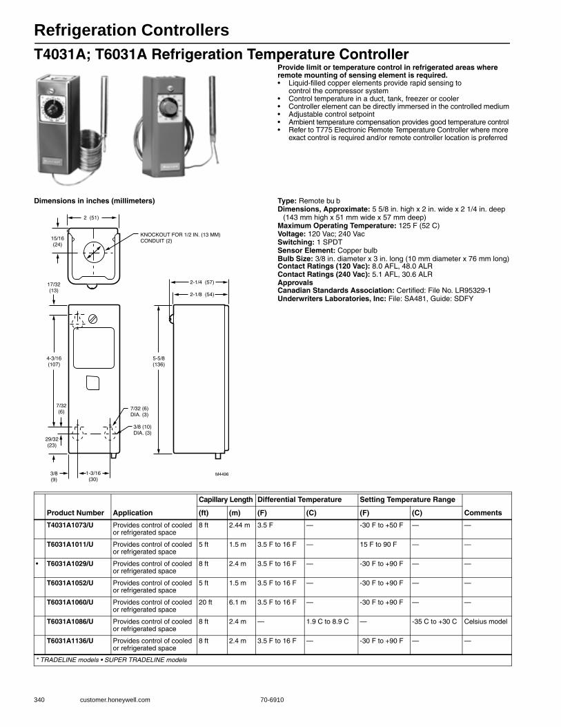
Refrigeration Controllers
340 customer.honeywell.com 70-6910
T4031A; T6031A Refrigeration Temperature ControllerProvide limit or temperature control in refrigerated areas where remote mounting of sensing element is required.• Liquid-filled copper elements provide rapid sensing to
control the compressor system• Control temperature in a duct, tank, freezer or cooler• Controller element can be directly immersed in the controlled medium• Adjustable control setpoint• Ambient temperature compensation provides good temperature control• Refer to T775 Electronic Remote Temperature Controller where more
exact control is required and/or remote controller location is preferred
Dimensions in inches (millimeters) Type: Remote bu bDimensions, Approximate: 5 5/8 in. high x 2 in. wide x 2 1/4 in. deep
(143 mm high x 51 mm wide x 57 mm deep) Maximum Operating Temperature: 125 F (52 C) Voltage: 120 Vac; 240 VacSwitching: 1 SPDTSensor Element: Copper bulbBulb Size: 3/8 in. diameter x 3 in. long (10 mm diameter x 76 mm long)Contact Ratings (120 Vac): 8.0 AFL, 48.0 ALRContact Ratings (240 Vac): 5.1 AFL, 30.6 ALRApprovalsCanadian Standards Association: Certified: File No. LR95329-1Underwriters Laboratories, Inc: File: SA481, Guide: SDFY
Product Number Application
Capillary Length Differential Temperature Setting Temperature Range
Comments(ft) (m) (F) (C) (F) (C)
T4031A1073/U Provides control of cooled or refrigerated space
8 ft 2.44 m 3.5 F — -30 F to +50 F — —
T6031A1011/U Provides control of cooled or refrigerated space
5 ft 1.5 m 3.5 F to 16 F — 15 F to 90 F — —
• T6031A1029/U Provides control of cooled or refrigerated space
8 ft 2.4 m 3.5 F to 16 F — -30 F to +90 F — —
T6031A1052/U Provides control of cooled or refrigerated space
5 ft 1.5 m 3.5 F to 16 F — -30 F to +90 F — —
T6031A1060/U Provides control of cooled or refrigerated space
20 ft 6.1 m 3.5 F to 16 F — -30 F to +90 F — —
T6031A1086/U Provides control of cooled or refrigerated space
8 ft 2.4 m — 1.9 C to 8.9 C — -35 C to +30 C Celsius model
T6031A1136/U Provides control of cooled or refrigerated space
8 ft 2.4 m 3.5 F to 16 F — -30 F to +90 F — —
* TRADELINE models • SUPER TRADELINE models

Sail Switches
70-6910 341
Com
mercial
Com
ponents
S437; S637 Sail SwitchThe S637 Sail Switches respond to the air velocity in heating or warm air ducts, such as used in farm crop dryers. The switch completes a 24V or line voltage burner control circuit only when the blower or fan has produced a predetermined air velocity.• Micro Switch SPDT snap switch is operated by
a metal sail inserted in an air stream• Has a set of normally closed contacts which can be used to
energize a signal or warning circuit when the velocity drops off• Sail can trimmed to one-half the original size to double the
velocity required to close the snap switch contacts• Switch differential can be manually adjusted by
turning a knurled knob on the snap switch• A conduit knockout is located on each end of the case for wiring convenience
Dimensions, Approximate: 2 15/16 in. high x 3 3/4 in. wide x 2 in. deep (59 mm high x 95 mm wide x 51 mm deep)
Contact Ratings (AFL): 7.5 A @ 12 Vdc; 15.0 A @ 6 Vdc; 2.0 A @ 24 Vac; 5.1 A @ 240 Vac; 8.0 A @ 120 Vac
Contact Ratings (ALR): 30.6 A @ 240 Vac; 48.0 A @ 120 Vac
Maximum Ambient Temperature: 150 F (66 C) ApprovalsCanadian Standards Association: CSA: Guide: MFHZUnderwriters Laboratories, Inc: UL: File: MP2618
Manual Switch Accessories
Product Number Switching
Operating Velocity Sail DimensionsInsertion Length
(fpm) (m/s) (inch) (mm) (inch) (mm)
S437A1009/U 1 SPST 1900 fpm-2250 fpm 9.7 m/s-11.4 m/s 1 in. x 3 in. 25 mm x 76 mm 3 1/2 in. 89 mm
S437A1025/U 1 SPST 1900 fpm-2250 fpm 9.7 m/s-11.4 m/s 1 1/2 in. x 4 in. 38 mm x 102 mm 3 1/2 in. 89 mm
S637A1004/U 1 SPDT 1900 fpm-2250 fpm 9.7 m/s-11.4 m/s 1 in. x 3 in. 25 mm x 76 mm 3 1/2 in. 89 mm
Product Number Application Type Description
113578A/U Mounting Strap Mounting Strap with screws for one toggle switch applications
113700/U — Toggle Switch (3 positions) ON-OFF-ON, switches 15 A at 125 Vac
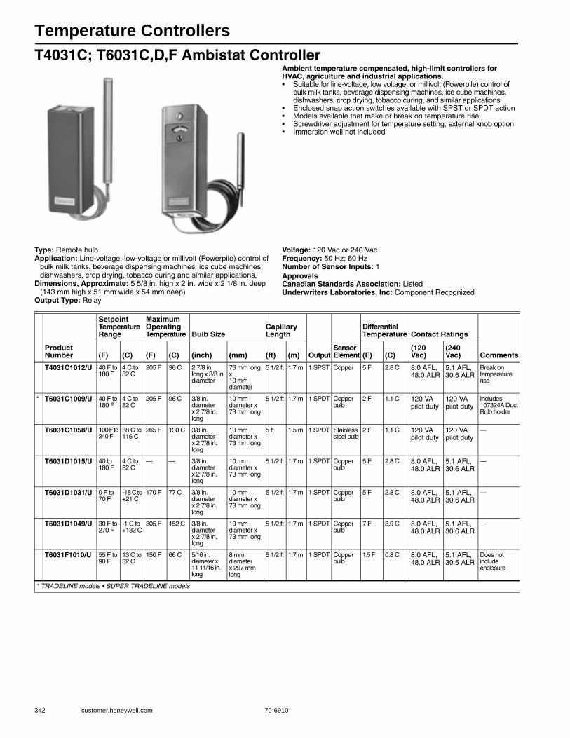
Temperature Controllers
342 customer.honeywell.com 70-6910
T4031C; T6031C,D,F Ambistat ControllerAmbient temperature compensated, high-limit controllers for HVAC, agriculture and industrial applications.• Suitable for line-voltage, low voltage, or millivolt (Powerpile) control of
bulk milk tanks, beverage dispensing machines, ice cube machines, dishwashers, crop drying, tobacco curing, and similar applications
• Enclosed snap action switches available with SPST or SPDT action• Models available that make or break on temperature rise• Screwdriver adjustment for temperature setting; external knob option • Immersion well not included
Type: Remote bulbApplication: Line-voltage, low-voltage or millivolt (Powerpile) control of
bulk milk tanks, beverage dispensing machines, ice cube machines, dishwashers, crop drying, tobacco curing and similar applications.
Dimensions, Approximate: 5 5/8 in. high x 2 in. wide x 2 1/8 in. deep (143 mm high x 51 mm wide x 54 mm deep)
Output Type: Relay
Voltage: 120 Vac or 240 VacFrequency: 50 Hz; 60 HzNumber of Sensor Inputs: 1ApprovalsCanadian Standards Association: ListedUnderwriters Laboratories, Inc: Component Recognized
Product Number
Setpoint Temperature Range
Maximum Operating Temperature Bulb Size
Capillary Length
OutputSensor Element
Differential Temperature Contact Ratings
Comments(F) (C) (F) (C) (inch) (mm) (ft) (m) (F) (C)(120 Vac)
(240 Vac)
T4031C1012/U 40 F to 180 F
4 C to 82 C
205 F 96 C 2 7/8 in. long x 3/8 in. diameter
73 mm long x 10 mm diameter
5 1/2 ft 1.7 m 1 SPST Copper 5 F 2.8 C 8.0 AFL, 48.0 ALR
5.1 AFL, 30.6 ALR
Break on temperature rise
* T6031C1009/U 40 F to 180 F
4 C to 82 C
205 F 96 C 3/8 in. diameter x 2 7/8 in. long
10 mm diameter x 73 mm long
5 1/2 ft 1.7 m 1 SPDT Copper bulb
2 F 1.1 C 120 VA pilot duty
120 VA pilot duty
Includes 107324A Duct Bulb holder
T6031C1058/U 100 F to 240 F
38 C to 116 C
265 F 130 C 3/8 in. diameter x 2 7/8 in. long
10 mm diameter x 73 mm long
5 ft 1.5 m 1 SPDT Stainless steel bulb
2 F 1.1 C 120 VA pilot duty
120 VA pilot duty
—
T6031D1015/U 40 to 180 F
4 C to 82 C
— — 3/8 in. diameter x 2 7/8 in. long
10 mm diameter x 73 mm long
5 1/2 ft 1.7 m 1 SPDT Copper bulb
5 F 2.8 C 8.0 AFL, 48.0 ALR
5.1 AFL, 30.6 ALR
—
T6031D1031/U 0 F to 70 F
-18 C to +21 C
170 F 77 C 3/8 in. diameter x 2 7/8 in. long
10 mm diameter x 73 mm long
5 1/2 ft 1.7 m 1 SPDT Copper bulb
5 F 2.8 C 8.0 AFL, 48.0 ALR
5.1 AFL, 30.6 ALR
—
T6031D1049/U 30 F to 270 F
-1 C to +132 C
305 F 152 C 3/8 in. diameter x 2 7/8 in. long
10 mm diameter x 73 mm long
5 1/2 ft 1.7 m 1 SPDT Copper bulb
7 F 3.9 C 8.0 AFL, 48.0 ALR
5.1 AFL, 30.6 ALR
—
T6031F1010/U 55 F to 90 F
13 C to 32 C
150 F 66 C 5/16 in. diameter x 11 11/16 in. long
8 mm diameter x 297 mm long
5 1/2 ft 1.7 m 1 SPDT Copper bulb
1.5 F 0.8 C 8.0 AFL, 48.0 ALR
5.1 AFL, 30.6 ALR
Does not include enclosure
* TRADELINE models • SUPER TRADELINE models
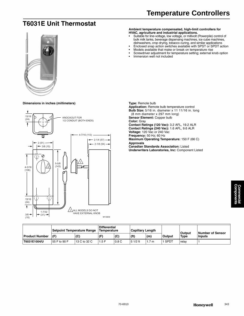
Temperature Controllers
70-6910 343
Com
mercial
Com
ponents
T6031E Unit ThermostatAmbient temperature compensated, high-limit controllers for HVAC, agriculture and industrial applications.• Suitable for line-voltage, low voltage, or millivolt (Powerpile) control of
bulk milk tanks, beverage dispensing machines, ice cube machines, dishwashers, crop drying, tobacco curing, and similar applications
• Enclosed snap action switches available with SPST or SPDT action • Models available that make or break on temperature rise• Screwdriver adjustment for temperature setting; external knob option • Immersion well not included
Dimensions in inches (millimeters) Type: Remote bulbApplication: Remote bulb temperature controlBulb Size: 5/16 in. diameter x 11 11/16 in. long
(8 mm diameter x 297 mm long) Sensor Element: Copper bulbColor: GrayContact Ratings (120 Vac): 3.2 AFL, 19.2 ALRContact Ratings (240 Vac): 1.6 AFL, 9.6 ALRVoltage: 120 Vac or 240 VacFrequency: 50 Hz; 60 HzMaximum Operating Temperature: 150 F (66 C) ApprovalsCanadian Standards Association: ListedUnderwriters Laboratories, Inc: Component Listed
3/8 (10)2 (51)
4-3/16(106)
15/16(24)
5-5/8(143)
4-7/16 (113)
2-1/4 (57)
2-1/8 (54)
15/16(24)
3/8(10)
1-7/32(31)
1
2
ALL MODELS DO NOTHAVE EXTERNAL KNOB
1
M13909
KNOCKOUT FOR1/2 CONDUIT (BOTH ENDS)
Product Number
Setpoint Temperature RangeDifferential Temperature Capillary Length
OutputOutput Type
Number of Sensor Inputs(F) (C) (F) (C) (ft) (m)
T6031E1004/U 55 F to 90 F 13 C to 32 C 1.5 F 0.8 C 5 1/2 ft 1.7 m 1 SPDT relay 1
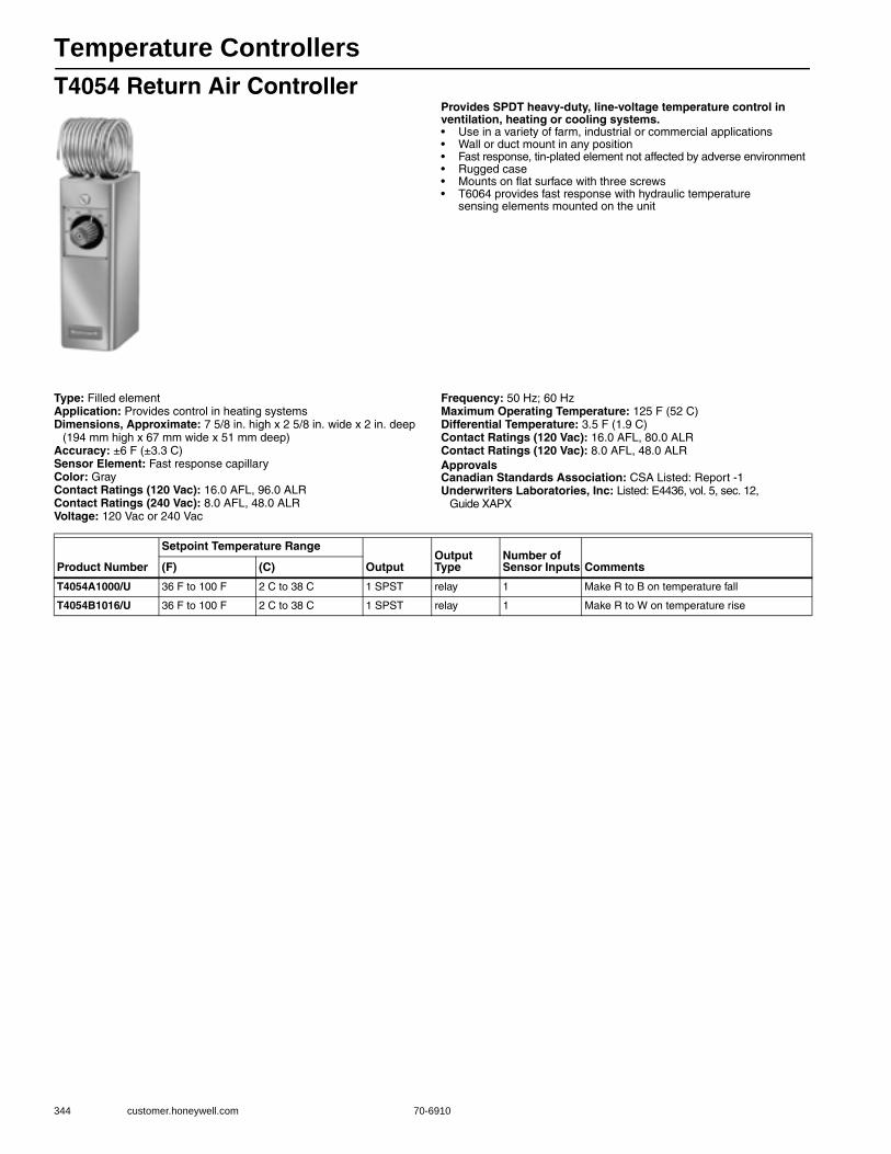
Temperature Controllers
344 customer.honeywell.com 70-6910
T4054 Return Air ControllerProvides SPDT heavy-duty, line-voltage temperature control in ventilation, heating or cooling systems.• Use in a variety of farm, industrial or commercial applications• Wall or duct mount in any position• Fast response, tin-plated element not affected by adverse environment • Rugged case• Mounts on flat surface with three screws• T6064 provides fast response with hydraulic temperature
sensing elements mounted on the unit
Type: Filled elementApplication: Provides control in heating systemsDimensions, Approximate: 7 5/8 in. high x 2 5/8 in. wide x 2 in. deep
(194 mm high x 67 mm wide x 51 mm deep) Accuracy: ±6 F (±3.3 C) Sensor Element: Fast response capillaryColor: GrayContact Ratings (120 Vac): 16.0 AFL, 96.0 ALRContact Ratings (240 Vac): 8.0 AFL, 48.0 ALRVoltage: 120 Vac or 240 Vac
Frequency: 50 Hz; 60 HzMaximum Operating Temperature: 125 F (52 C) Differential Temperature: 3.5 F (1.9 C) Contact Ratings (120 Vac): 16.0 AFL, 80.0 ALRContact Ratings (120 Vac): 8.0 AFL, 48.0 ALRApprovalsCanadian Standards Association: CSA Listed: Report -1Underwriters Laboratories, Inc: Listed: E4436, vol. 5, sec. 12,
Guide XAPX
Product Number
Setpoint Temperature Range
OutputOutput Type
Number of Sensor Inputs Comments(F) (C)
T4054A1000/U 36 F to 100 F 2 C to 38 C 1 SPST relay 1 Make R to B on temperature fall
T4054B1016/U 36 F to 100 F 2 C to 38 C 1 SPST relay 1 Make R to W on temperature rise
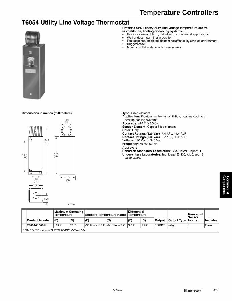
Temperature Controllers
70-6910 345
Com
mercial
Com
ponents
T6054 Utility Line Voltage ThermostatProvides SPDT heavy-duty, line-voltage temperature control in ventilation, heating or cooling systems.• Use in a variety of farm, industrial or commercial applications• Wall or duct mount in any position• Fast response, tin-plated element not affected by adverse environment• Rugged case• Mounts on flat surface with three screws
Dimensions in inches (millimeters) Type: Filled elementApplication: Provides control in ventilation, heating, cooling or
heating-cooling systemsAccuracy: ±10 F (±5.6 C) Sensor Element: Copper filled elementColor: GrayContact Ratings (120 Vac): 7.4 AFL, 44.4 ALRContact Ratings (240 Vac): 3.7 AFL, 22.2 ALRVoltage: 120 Vac or 240 VacFrequency: 50 Hz; 60 HzApprovalsCanadian Standards Association: CSA Listed: Report -1Underwriters Laboratories, Inc: Listed: E4436, vol. 5, sec. 12,
Guide XAPX
M27438
4-3/16(106)
7-1/8(181)
1-1/4(32)
2 (51)
5-5/8(143)
2 -1/8(54)
1-1/2(38)
1 (25)
Product Number
Maximum Operating Temperature Setpoint Temperature Range
Differential Temperature
Output Output Type
Number of Sensor Inputs Includes(F) (C) (F) (C) (F) (C)
* T6054A1005/U 125 F 52 C -30 F to +110 F -34 C to +43 C 3.5 F 1.9 C 1 SPDT relay 1 Case
* TRADELINE models • SUPER TRADELINE models
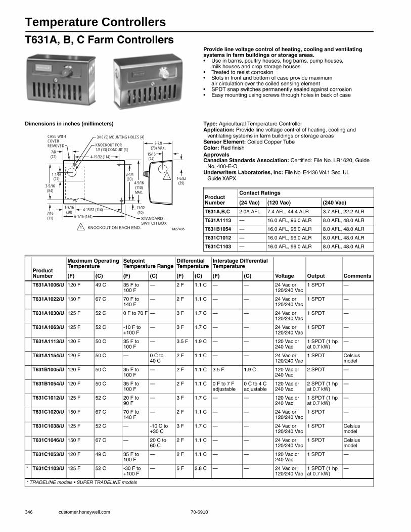
Temperature Controllers
346 customer.honeywell.com 70-6910
T631A, B, C Farm ControllersProvide line voltage control of heating, cooling and ventilating systems in farm buildings or storage areas.• Use in barns, poultry houses, hog barns, pump houses,
milk houses and crop storage houses• Treated to resist corrosion• Slots in front and bottom of case provide maximum
air circulation over the coiled sensing element• SPDT snap switches permanently sealed against corrosion• Easy mounting using screws through holes in back of case
Dimensions in inches (millimeters) Type: Agricultural Temperature ControllerApplication: Provide line voltage control of heating, cooling and
ventilating systems in farm buildings or storage areasSensor Element: Coiled Copper TubeColor: Red finishApprovalsCanadian Standards Association: Certified: File No. LR1620, Guide
No. 400-E-OUnderwriters Laboratories, Inc: File No. E4436 Vol.1 Sec. UL
Guide XAPX
4-15/32 (114)
KNOCKOUT FOR 1/2 (13) CONDUIT [3]
4-5/16(110)MAX.
1-5/32(29)
KNOCKOUT ON EACH END.1
6-1/16 (154)
1-3/16(30)
3-1/4(83)
4-15/32 (114)
1
15/16(24)
2-7/8(73) MAX.
7/8(22)
13/32(10)
CASE WITHCOVERREMOVED
3/16 (5) MOUNTING HOLES [4]
3-5/16(84)
1-1/16(27)
7/16(11)
M27435
STANDARDSWITCH BOX
Product Number
Contact Ratings
(24 Vac) (120 Vac) (240 Vac)
T631A,B,C 2.0A AFL 7.4 AFL, 44.4 ALR 3.7 AFL, 22.2 ALR
T631A1113 — 16.0 AFL, 96.0 ALR 8.0 AFL, 48.0 ALR
T631B1054 — 16.0 AFL, 96.0 ALR 8.0 AFL, 48.0 ALR
T631C1012 — 16.0 AFL, 96.0 ALR 8.0 AFL, 48.0 ALR
T631C1103 — 16.0 AFL, 96.0 ALR 8.0 AFL, 48.0 ALR
Product Number
Maximum Operating Temperature
Setpoint Temperature Range
Differential Temperature
Interstage Differential Temperature
Voltage Output Comments(F) (C) (F) (C) (F) (C) (F) (C)
T631A1006/U 120 F 49 C 35 F to 100 F
— 2 F 1.1 C — — 24 Vac or 120/240 Vac
1 SPDT —
T631A1022/U 150 F 67 C 70 F to 140 F
— 2 F 1.1 C — — 24 Vac or 120/240 Vac
1 SPDT —
T631A1030/U 125 F 52 C 0 F to 70 F — 3 F 1.7 C — — 24 Vac or 120/240 Vac
1 SPDT —
T631A1063/U 125 F 52 C -10 F to +100 F
— 3 F 1.7 C — — 24 Vac or 120/240 Vac
1 SPDT —
T631A1113/U 120 F 50 C 35 F to 100 F
— 3.5 F 1.9 C — — 120 Vac or 240 Vac
1 SPDT (1 hp at 0.7 kW)
—
T631A1154/U 120 F 50 C — 0 C to 40 C
2 F 1.1 C — — 24 Vac or 120/240 Vac
1 SPDT Celsius model
T631B1005/U 120 F 50 C 35 F to 100 F
— 2 F 1.1 C 3.5 F 1.9 C 120 Vac or 240 Vac
2 SPDT —
T631B1054/U 120 F 50 C 35 F to 100 F
— 2 F 1.1 C 0 F to 7 F adjustable
0 C to 4 C adjustable
120 Vac or 240 Vac
2 SPDT (1 hp at 0.7 kW)
—
T631C1012/U 125 F 52 C 20 F to 90 F
— 3 F 1.7 C — — 120 Vac or 240 Vac
1 SPDT (1 hp at 0.7 kW)
—
T631C1020/U 150 F 67 C 70 F to 140 F
— 2 F 1.1 C — — 24 Vac or 120/240 Vac
1 SPDT —
T631C1038/U 125 F 52 C — -10 C to +30 C
3 F 1.7 C — — 24 Vac or 120/240 Vac
1 SPDT Celsius model
T631C1046/U 150 F 67 C — 20 C to 60 C
2 F 1.1 C — — 24 Vac or 120/240 Vac
1 SPDT Celsius model
T631C1053/U 120 F 49 C 35 F to 100 F
— 2 F 1.1 C — — 120 Vac or 240 Vac
1 SPDT —
* T631C1103/U 125 F 52 C -30 F to +100 F
— 5 F 2.8 C — — 24 Vac or 120/240 Vac
1 SPDT (1 hp at 0.7 kW)
—
* TRADELINE models • SUPER TRADELINE models
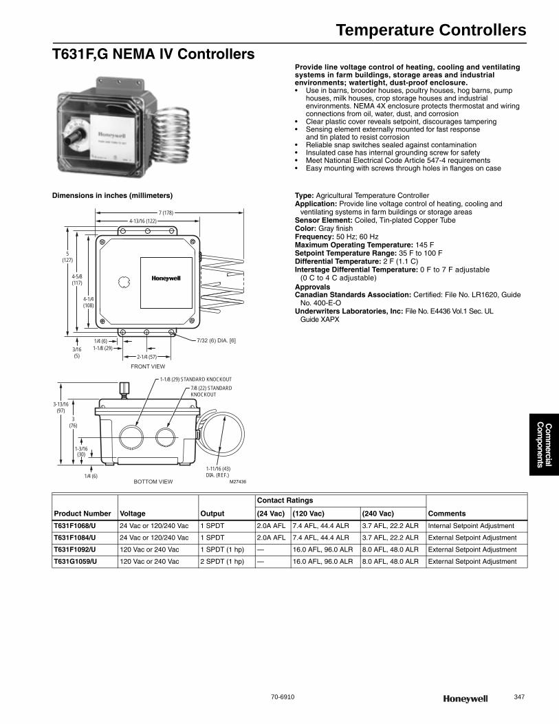
Temperature Controllers
70-6910 347
Com
mercial
Com
ponents
T631F,G NEMA IV ControllersProvide line voltage control of heating, cooling and ventilating systems in farm buildings, storage areas and industrial environments; watertight, dust-proof enclosure.• Use in barns, brooder houses, poultry houses, hog barns, pump
houses, milk houses, crop storage houses and industrial environments. NEMA 4X enclosure protects thermostat and wiring connections from oil, water, dust, and corrosion
• Clear plastic cover reveals setpoint, discourages tampering• Sensing element externally mounted for fast response
and tin plated to resist corrosion• Reliable snap switches sealed against contamination• Insulated case has internal grounding screw for safety• Meet National Electrical Code Article 547-4 requirements• Easy mounting with screws through holes in flanges on case
Dimensions in inches (millimeters) Type: Agricultural Temperature ControllerApplication: Provide line voltage control of heating, cooling and
ventilating systems in farm buildings or storage areasSensor Element: Coiled, Tin-plated Copper TubeColor: Gray finishFrequency: 50 Hz; 60 HzMaximum Operating Temperature: 145 FSetpoint Temperature Range: 35 F to 100 FDifferential Temperature: 2 F (1.1 C) Interstage Differential Temperature: 0 F to 7 F adjustable
(0 C to 4 C adjustable) ApprovalsCanadian Standards Association: Certified: File No. LR1620, Guide
No. 400-E-OUnderwriters Laboratories, Inc: File No. E4436 Vol.1 Sec. UL
Guide XAPX
M27436
FRONT VIEW
BOTTOM VIEW
4-1/4(108)
4-5/8(117)
5(127)
4-13/16 (122)7 (178)
3/16(5)
1-1/8 (29)1/4 (6)
2-1/4 (57)
7/32 (6) DIA. [6]
3-13/16(97)
3(76)
1-3/16(30)
1/4 (6)
1-1/8 (29) STANDARD KNOCKOUT7/8 (22) STANDARDKNOCKOUT
1-11/16 (43)DIA. (REF.)
Product Number Voltage Output
Contact Ratings
Comments(24 Vac) (120 Vac) (240 Vac)
T631F1068/U 24 Vac or 120/240 Vac 1 SPDT 2.0A AFL 7.4 AFL, 44.4 ALR 3.7 AFL, 22.2 ALR Internal Setpoint Adjustment
T631F1084/U 24 Vac or 120/240 Vac 1 SPDT 2.0A AFL 7.4 AFL, 44.4 ALR 3.7 AFL, 22.2 ALR External Setpoint Adjustment
T631F1092/U 120 Vac or 240 Vac 1 SPDT (1 hp) — 16.0 AFL, 96.0 ALR 8.0 AFL, 48.0 ALR External Setpoint Adjustment
T631G1059/U 120 Vac or 240 Vac 2 SPDT (1 hp) — 16.0 AFL, 96.0 ALR 8.0 AFL, 48.0 ALR External Setpoint Adjustment
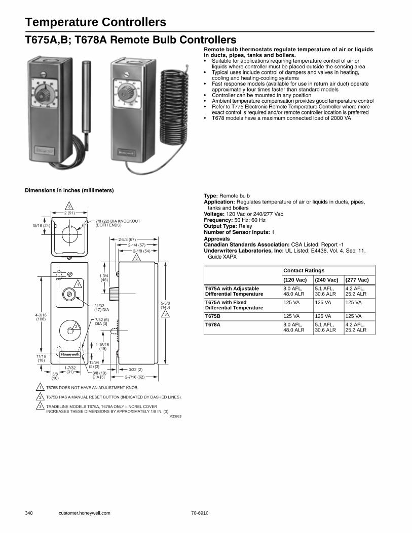
Temperature Controllers
348 customer.honeywell.com 70-6910
T675A,B; T678A Remote Bulb ControllersRemote bulb thermostats regulate temperature of air or liquids in ducts, pipes, tanks and boilers.• Suitable for applications requiring temperature control of air or
liquids where controller must be placed outside the sensing area• Typical uses include control of dampers and valves in heating,
cooling and heating-cooling systems• Fast response models (available for use in return air duct) operate
approximately four times faster than standard models• Controller can be mounted in any position• Ambient temperature compensation provides good temperature control• Refer to T775 Electronic Remote Temperature Controller where more
exact control is required and/or remote controller location is preferred• T678 models have a maximum connected load of 2000 VA
Dimensions in inches (millimeters)Type: Remote bu bApplication: Regulates temperature of air or liquids in ducts, pipes,
tanks and boilersVoltage: 120 Vac or 240/277 VacFrequency: 50 Hz; 60 HzOutput Type: RelayNumber of Sensor Inputs: 1ApprovalsCanadian Standards Association: CSA Listed: Report -1Underwriters Laboratories, Inc: UL Listed: E4436, Vol. 4, Sec. 11,
Guide XAPX
1-7/32(31)
1 T675B DOES NOT HAVE AN ADJUSTMENT KNOB.
T675B HAS A MANUAL RESET BUTTON (INDICATED BY DASHED LINES).
TRADELINE MODELS T675A, T678A ONLY – NOREL COVER INCREASES THESE DIMENSIONS BY APPROXIMATELY 1/8 IN. (3).
2
3
2 (51)
7/8 (22) DIA KNOCKOUT(BOTH ENDS)15/16 (24)
3
1
2
4-3/16(106)
11/16(18)
3/8(10)
13/64(5) [3]
7/32 (6)DIA [3]
21/32 (17) DIA
3/8 (10) DIA [3]
2-1/8 (54)
3
2-1/4 (57)2-5/8 (67)
5-5/8(143)
1-3/4 (45)
3
1-15/16 (49)
2-7/16 (62)
3/32 (2)
M23928
Contact Ratings
(120 Vac) (240 Vac) (277 Vac)T675A with Adjustable Differential Temperature
8.0 AFL, 48.0 ALR
5.1 AFL, 30.6 ALR
4.2 AFL, 25.2 ALR
T675A with Fixed Differential Temperature
125 VA 125 VA 125 VA
T675B 125 VA 125 VA 125 VA
T678A 8.0 AFL, 48.0 ALR
5.1 AFL, 30.6 ALR
4.2 AFL, 25.2 ALR

Temperature Controllers
70-6910 349
Com
mercial
Com
ponents
Product Number
Maximum Operating Temperature
Setpoint Temperature Range
Differential Temperature
Interstage Differential Temperature Bulb Size
Capillary Length
OutputSensor Element Comments(F) (C) (F) (C) (F) (C) (F) (C) (inch) (mm) (ft) (m)
T675A1045/U 125 F 52 C 0 F to 100 F
-18 C to +38 C
3 F to 10 F
1.7 C to 5.6 C
— — 1/2 in. x 4 3/16 in.
13 mm dia. x 106 mm long
20 ft 6.1 m 1 SPDT Stainless steel bulb
Stainless Steel Bulb
T675A1102/U 280 F 138 C 160 F to 260 F
71 C to 127 C
3 F to 10 F
1.7 C to 5.6 C
— — 1/2 in. x 4 3/16 in.
13 mm dia. x 106 mm long
20 ft 6.1 m 1 SPDT Copper bulb
—
T675A1136/U 125 F 52 C 0 F to 100 F
-18 C to +38 C
1 F fixed 0.6 C fixed
— — 1/2 in. x 4 3/16 in.
13 mm dia. x 106 mm long
20 ft 6.1 m 1 SPDT Copper bulb
—
T675A1243/U 125 F 52 C 167 F to 257 F
75 C to 125 C
3 F to 10 F
1.7 C to 5.6 C
— — 1/2 in. x 4 3/16 in.
13 mm dia. x 106 mm long
5 ft 1.5 m 1 SPDT Copper bulb
Celsius model
T675A1425/U 200 F 93 C 55 F to 175 F
13 C to 79 C
3.6 F to 12 F
2 C to 6.7 C
— — 1/2 in. x 3 9/16 in.
13 mm x 90 mm
20 ft 6.1 m 1 SPDT Copper bulb
—
T675A1458/U 200 F 93 C 55 F to 175 F
13 C to 79 C
1 F fixed 0.6 C fixed
— — 1/2 in. x 3 9/16 in.
13 mm x 90 mm
5 ft 1.5 m 1 SPDT Copper bulb
—
* T675A1508/U 125 F 52 C 0 F to 100 F
-18 C to +38 C
3 F to 10 F
1.7 C to 5.6 C
— — 1/2 in. x 4 3/16 in.
13 mm dia. x 106 mm long
5 ft 1.5 m 1 SPDT Copper bulb
Includes 107324A Duct Bulb Holder
* T675A1516/U 125 F 52 C 0 F to 100 F
-18 C to +38 C
1 F fixed 0.6 C fixed
— — 1/2 in. x 4 3/16 in.
13 mm dia. x 106 mm long
5 ft 1.5 m 1 SPDT Copper bulb
Includes 107324A Duct Bulb Holder
T675A1524/U 200 F 93 C 55 F to 175 F
13 C to 79 C
1 F fixed 0.6 C fixed
— — 1/2 in. x 3 9/16 in.
13 mm x 90 mm
20 ft 6.1 m 1 SPDT Copper bulb
—
* T675A1532/U 280 F 138 C 160 F to 260 F
71 C to 127 C
3 F to 10 F
1.7 C to 5.6 C
— — 1/2 in. x 4 3/16 in.
13 mm dia. x 106 mm long
5 ft 1.5 m 1 SPDT Copper bulb
Includes 107324A Duct Bulb Holder
* T675A1540/U 200 F 93 C 55 F to 175 F
13 C to 79 C
3.6 F to 12 F
2 C to 6.7 C
— — 1/2 in. x 3 9/16 in.
13 mm x 90 mm
5 ft 1.5 m 1 SPDT Copper bulb
Includes 107324A Duct Bulb Holder
* T675A1565/U 125 F 52 C 0 F to 100 F
-18 C to +38 C
3 F to 10 F
1.7 C to 5.6 C
— — 1/2 in. x 4 3/16 in.
13 mm x 90 mm
20 ft 6.1 m 1 SPDT Copper bulb
Includes 107324A Duct Bulb Holder
* T675A1706/U 125 F 52 C 0 F to 100 F
-18 C to +38 C
3 F to 10 F
1.7 C to 5.6 C
— — coil 1 1/2 in. diameter x 5 in.
coil 38.1 mm x 127 mm
5 ft 1.5 m 1 SPDT Fast response capillary
Fast response model, includes 131524A Duct Bulb Holder
T675A1771/U 200 F 93 C 55 F to 175 F
13 C to 79 C
1 F fixed 0.6 C fixed
— — coil 1 1/2 in. diameter x 5 in.
coil 38.1 mm x 127 mm
5 ft 1.5 m 1 SPDT Fast response capillary
Fast response model, includes 13154A Duct Bulb Holder
T675B1002/U 125 F 52 C 30 F to 50 F
-1 C to +10 C
Manual Reset
Manual Reset
— — 1/2 in. x 4 3/16 in.
13 mm dia. x 106 mm long
10 ft 3 m 1 SPDT Copper bulb
—
T675B1010/U 125 F 52 C 30 F to 50 F
-1 C to +10 C
Manual Reset
Manual Reset
— — 1/2 in. x 4 3/16 in.
13 mm dia. x 106 mm long
20 ft 6.1 m 1 SPDT Copper bulb
—
T675B1028/U 125 F 52 C -20 F to +50 F
-29 C to +10 C
Manual Reset
Manual Reset
— — 1/2 in. x 4 3/16 in.
13 mm dia. x 106 mm long
10 ft 3 m 1 SPDT Copper bulb
—
T678A1015/U 125 F 52 C 0 F to 100 F
-18 C to +38 C
3 F fixed 1.7 C fixed
3 F to 10 F adjustable
1.7 C to 5.6 C adjustable
1/2 in. x 4 3/16 in.
13 mm dia. x 106 mm long
20 ft 6.1 m 2 SPDT switch contacts
Copper bulb
maximum connected load = 2000VA
T678A1163/U 125 F 52 C 5 F to 95 F
-15 C to +35 C
3 F fixed 1.7 C fixed
3 F to 10 F adjustable
1.7 C to 5.6 C adjustable
1/2 in. x 4 3/16 in.
13 mm dia. x 106 mm long
20 ft 6.1 m 2 SPDT switch contacts
Copper bulb
maximum connected load = 2000VA; Celsius model
T678A1361/U 200 F 93 C 55 F to 175 F
13 C to 79 C
3.6 F fixed
2.0 C fixed
3.6 F to 12 F adjustable
2.0 C to 6.7 C adjustable
1/2 in. x 3 9/16 in.
13 mm x 90 mm
20 ft 6.1 m 2 SPDT switch contacts
Copper bulb
maximum connected load = 2000VA
* T678A1437/U 125 F 52 C 0 F to 100 F
-18 C to +38 C
3 F fixed 1.7 C fixed
3 F to 10 F adjustable
1.7 C to 5.6 C adjustable
1/2 in. x 4 3/16 in.
13 mm dia. x 106 mm long
5 ft 1.5 m 2 SPDT switch contacts
Copper bulb
maximum connected load = 2000VA
* TRADELINE models • SUPER TRADELINE models
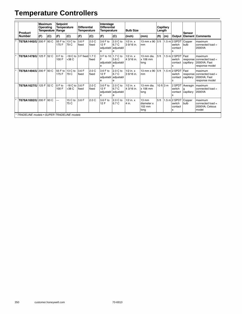
Temperature Controllers
350 customer.honeywell.com 70-6910
* T678A1445/U 200 F 93 C 55 F to 175 F
13 C to 79 C
3.6 F fixed
2.0 C fixed
3.6 F to 12 F adjustable
2.0 C to 6.7 C adjustable
1/2 in. x 3 9/16 in.
13 mm x 90 mm
5 ft 1.5 m 2 SPDT switch contacts
Copper bulb
maximum connected load = 2000VA
* T678A1478/U 125 F 52 C 0 F to 100 F
-18 C to +38 C
3 F fixed 1.7 C fixed
3 F to 10 F adjustable
1.7 C to 5.6 C adjustable
1/2 in. x 4 3/16 in.
13 mm dia. x 106 mm long
5 ft 1.5 m 2 SPDT switch contacts
Fast response capillary
maximum connected load = 2000VA; Fast response model
* T678A1494/U 200 F 93 C 55 F to 175 F
13 C to 79 C
3.6 F fixed
2.0 C fixed
3.6 F to 12 F adjustable
2.0 C to 6.7 C adjustable
1/2 in. x 3 9/16 in.
13 mm x 90 mm
5 ft 1.5 m 2 SPDT switch contacts
Fast response capillary
maximum connected load = 2000VA; Fast response model
T678A1627/U 125 F 52 C 0 F to 100 F
-18 C to +38 C
3.6 F fixed
2.0 C fixed
3.6 F to 12 F adjustable
2.0 C to 6.7 C adjustable
1/2 in. x 4 3/16 in.
13 mm dia. x 106 mm long
10 ft 3 m 2 SPDT switch contacts
Averaging capillary
maximum connected load = 2000VA
* T678A1692/U 200 F 93 C — 15 C to 75 C
3.6 F 2.0 C 3.6 F to 12 F
2.0 C to 6.7 C
1/2 in. x 4 in.
13 mm diameter x 102 mm long
5 ft 1.5 m 2 SPDT switch contacts
Copper bulb
maximum connected load = 2000VA; Celsius model
Product Number
Maximum Operating Temperature
Setpoint Temperature Range
Differential Temperature
Interstage Differential Temperature Bulb Size
Capillary Length
OutputSensor Element Comments(F) (C) (F) (C) (F) (C) (F) (C) (inch) (mm) (ft) (m)
* TRADELINE models • SUPER TRADELINE models

Temperature Controllers
70-6910 351
Com
mercial
Com
ponents
T675F Crop-Trol ControllerUsed to control an oil burning, portable crop dryer.• Suitable for line-voltage, low-voltage or millivolt (Powerpile) switching • Mounts directly on dryer with sensing bulb in discharge air duct • Knob extends through case for manual control point adjustment• Differential setting wheel, located under cover, adjusts difference
between cut-in and cut-out temperatures
Dimensions in inches (millimeters) Type: Remote bulbApplication: Crop-trol, provides control of portable crop drying equipmentBulb Size: 3/8 in. x 3 in. (10 mm x 76 mm) Sensor Element: Copper bulbContact Ratings (120 Vac): 8.0 AFL, 48.0 ALRContact Ratings (240 Vac): 5.1 AFL, 30.6 ALRContact Ratings (277 Vac): 4.2 AFL, 25.2 ALRVoltage: 120 Vac or 240/277 VacFrequency: 50 Hz; 60 HzMaximum Operating Temperature: 245 F (118 C) Setpoint Temperature Range: 80 F to 220 F (27 C to 104 C) Differential Temperature: 5 F to 30 F (2.8 C to 17 C) ApprovalsUnderwriters Laboratories, Inc: Component Listed
M23927
2-1/8(54)
2 (51)
15/16 (24)
2-19/32(66)
7/8 (22) DIA KNOCKOUT(BOTH ENDS)
MOUTING HOLES LOCATED IN BACK OF CASE
4-3/16(106)
5-5/8(143)
1-1/4(32)
11/16 (18)
Product Number Description
Capillary Length
Output Output Type Number of Sensor Inputs(m) (ft)
T675F1032/U Remote bulb Commercial Temperature Controller, 80 F to 220 F, 10 ft. capillary, Copper bulb sensing element
3 m 10 ft 1 SPDT relay 1
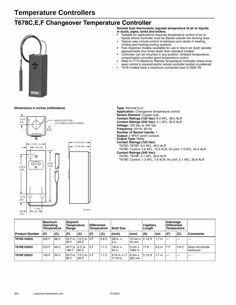
Temperature Controllers
352 customer.honeywell.com 70-6910
T678C,E,F Changeover Temperature ControllerRemote bulb thermostats regulate temperature of air or liquids in ducts, pipes, tanks and boilers.• Suitable for applications requiring temperature control of air or
liquids where controller must be placed outside the sensing area • Typical uses include control of dampers and valves in heating,
cooling and heating-cooling systems • Fast response models (available for use in return air duct) operate
approximately four times faster than standard models • Controller can be mounted in any position. Ambient temperature
compensation provides good temperature control• Refer to T775 Electronic Remote Temperature Controller where more
exact control is required and/or remote controller location is preferred• T678 models have a maximum connected load of 2000 VA
Dimensions in inches (millimeters) Type: Remote bu bApplication: Changeover temperature controlSensor Element: Copper bulbContact Ratings (120 Vac): 8.0 AFL, 48.0 ALRContact Ratings (240 Vac): 5.1 AFL, 30.6 ALRVoltage: 120 Vac or 240 VacFrequency: 50 Hz; 60 HzNumber of Sensor Inputs: 1Output: 2 SPDT switch contactsOutput Type: RelayContact Ratings (120 Vac):
T678C, T678F: 8.0 AFL, 48.0 ALRT678E: Control: 2.6 AFL, 15.6 ALR; Hi Limit: 7.4 AFL, 44.4 ALR
Contact Ratings (240 Vac): T678C, T678F: 5.1 AFL, 30.6 ALRT678E: Control: 1.3 AFL, 7.8 ALR; Hi Limit: 5.1 AFL, 30.6 ALR
3/8 (10)2 (51)
4-3/16(106)
15/16(24)
5-5/8(143)
2-1/4 (57)
2-1/8 (54)
15/16(24)
3/8(10)
1-7/32(31)
1
M13907
KNOCKOUT FOR1/2 CONDUIT (BOTH ENDS)
6070 80
Product Number
Maximum Operating Temperature
Setpoint Temperature Range
Differential Temperature Bulb Size
Capillary Length
Interstage Differential Temperature
Comments(F) (C) (F) (C) (F) (C) (inch) (mm) (ft) (m) (F) (C)
T678C1005/U 205 F 96 C 55 F to 85 F
13 C to 29 C
5 F 2.8 C 3/8 in. x 3 in.
10 mm x 76 mm
5 1/2 ft 1.7 m — — —
T678E1003/U 210 F 99 C 40 F to 180 F
4 C to 82 C
2 F 1.1 C 1/8 in. x 42 in.
3 mm x 1064 m
17 ft 5.2 m 7 F 3.9 C Does not include enclosure
T678F1002/U 130 F 54 C 55 F to 85 F
13 C to 29 C
2 F 1.1 C 5/16 in. x 11 11/16 in.
8 mm x 297 mm
5 1/2 ft 1.7 m — — —
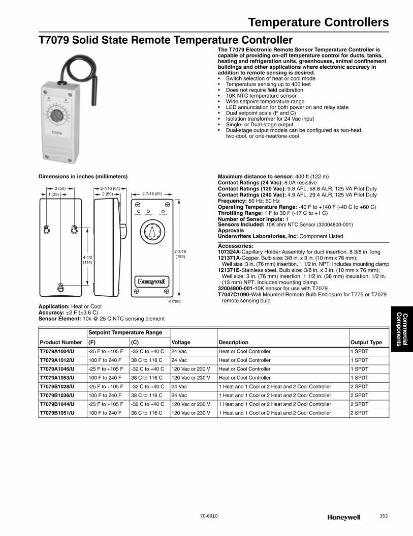
Temperature Controllers
70-6910 353
Com
mercial
Com
ponents
T7079 Solid State Remote Temperature ControllerThe T7079 Electronic Remote Sensor Temperature Controller is capable of providing on-off temperature control for ducts, tanks, heating and refrigeration units, greenhouses, animal confinement buildings and other applications where electronic accuracy in addition to remote sensing is desired.• Switch selection of heat or cool mode• Temperature sensing up to 400 feet• Does not require field calibration • 10K NTC temperature sensor • Wide setpoint temperature range • LED annunciation for both power on and relay state • Dual setpoint scale (F and C) • Isolation transformer for 24 Vac input • Single- or Dual-stage output • Dual-stage output models can be configured as two-heat,
two-cool, or one-heat/one-cool
Dimensions in inches (millimeters)
Application: Heat or CoolAccuracy: ±2 F (±3.6 C) Sensor Element: 10k @ 25 C NTC sensing element
Maximum distance to sensor: 400 ft (122 m) Contact Ratings (24 Vac): 8.0A resistiveContact Ratings (120 Vac): 9.8 AFL, 58.8 ALR, 125 VA Pilot DutyContact Ratings (240 Vac): 4.9 AFL, 29.4 ALR, 125 VA Pilot DutyFrequency: 50 Hz; 60 HzOperating Temperature Range: -40 F to +140 F (-40 C to +60 C) Throttling Range: 1 F to 30 F (-17 C to +1 C) Number of Sensor Inputs: 1Sensors Included: 10K ohm NTC Sensor (32004800-001)ApprovalsUnderwriters Laboratories, Inc: Component Listed
Accessories:107324A-Capillary Holder Assembly for duct insertion, 8 3/8 in. long121371A-Copper. Bulb size: 3/8 in. x 3 in. (10 mm x 76 mm);
Well size: 3 in. (76 mm) insertion, 1 1/2 in. NPT; Includes mounting clamp121371E-Stainless steel. Bulb size: 3/8 in. x 3 in. (10 mm x 76 mm);
Well size: 3 in. (76 mm) insertion, 1 1/2 in. (38 mm) insulation, 1/2 in. (13 mm) NPT; Includes mounting clamp.
32004800-001-10K sensor for use with T7079T7047C1090-Wall Mounted Remote Bulb Enclosure for T775 or T7079
remote sensing bulb.
STAGE1 STAGE2 POWER
2 (50)2-7/16 (61)
1 (25)2 (50)
4-1/2(114)
7-3/16(183)
2-7/16 (61)
M17560
Product Number
Setpoint Temperature Range
Voltage Description Output Type(F) (C)
T7079A1004/U -25 F to +105 F -32 C to +40 C 24 Vac Heat or Cool Controller 1 SPDT
T7079A1012/U 100 F to 240 F 38 C to 116 C 24 Vac Heat or Cool Controller 1 SPDT
T7079A1046/U -25 F to +105 F -32 C to +40 C 120 Vac or 230 V Heat or Cool Controller 1 SPDT
T7079A1053/U 100 F to 240 F 38 C to 116 C 120 Vac or 230 V Heat or Cool Controller 1 SPDT
T7079B1028/U -25 F to +105 F -32 C to +40 C 24 Vac 1 Heat and 1 Cool or 2 Heat and 2 Cool Controller 2 SPDT
T7079B1036/U 100 F to 240 F 38 C to 116 C 24 Vac 1 Heat and 1 Cool or 2 Heat and 2 Cool Controller 2 SPDT
T7079B1044/U -25 F to +105 F -32 C to +40 C 120 Vac or 230 V 1 Heat and 1 Cool or 2 Heat and 2 Cool Controller 2 SPDT
T7079B1051/U 100 F to 240 F 38 C to 116 C 120 Vac or 230 V 1 Heat and 1 Cool or 2 Heat and 2 Cool Controller 2 SPDT
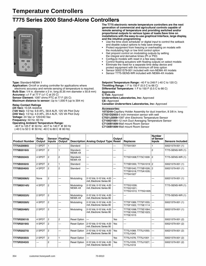
Temperature Controllers
354 customer.honeywell.com 70-6910
T775 Series 2000 Stand-Alone ControllersThe T775 electronic remote temperature controllers are the next generation of commercial and agricultural controls capable of remote sensing of temperature and providing switched and/or proportional outputs to various types of loads.Save time on installations with the easy-to-use graphical Interface, large display, and the intuitive programming• Use the time clock scheduler or digital input to control the setback
and disable output options to help save energy • Protect equipment from freezing or overheating on models with
the modulating high or low limit control option • Get pinpoint control on modulating outputs by setting
the integral and derivative times (PI or PID) • Configure models with reset in a few easy steps • Control floating actuators with floating outputs on select models • Eliminate the need for a separate time delay device and
protect equipment with the minimum off time option • Sensor 50021579-001 included with non-NEMA 4X models• Sensor T775-SENS-WR included with NEMA-4X models
Type: Standard-NEMA 1Application: On/off or analog controller for applications where
electronic accuracy and remote sensing of temperature is required.Bulb Size: 1/4 in. diameter x 2 in. long (6.35 mm diameter x 50.8 mm) Accuracy: ±1 F at 77 F (±1 C at 25 C) Sensor Element: 1097 ohms PTC at 77 F (25 C)Maximum distance to sensor: Up to 1,000 ft (up to 304 m)
Relay Contact Ratings(24 Vac): 10.0A resistive(120 Vac): 1/2 hp; 9.8 AFL, 58.8 ALR, 125 VA Pilot Duty(240 Vac): 1/2 hp; 4.9 AFL, 29.4 ALR, 125 VA Pilot DutyVoltage: 24 Vac or 120/240 VacFrequency: 50 Hz; 60 HzOperating Ambient Temperature Range:
-40 F to 125 F @ 50 Hz; -40 F to 140 F @ 60 Hz (-40 C to 52 C @ 50 Hz; -40 C to 60 C @ 60 Hz)
Setpoint Temperature Range: -40 F to 248 F (-40 C to 120 C) Throttling Range: 1 F to 150 F (0.5 C to 66 C) Differential Temperature: 1 F to 150 F (0.5 C to 66 C) ApprovalsC-Tick: ApprovedUnderwriters Laboratories, Inc: ApprovedCE: ApprovedCanadian Underwriters Laboratories, Inc: Approved
Accessories:107324A-Capillary Holder Assembly for duct insertion, 8 3/8 in. longC7031D2003-5 inch immersion sensor with wellC7031J2009-1097 ohm Electronic Temperature SensorC7100D1001-12 inch Duct Averaging Temperature SensorC7130B1009-Wall mount Room SensorC7130B1009-Wall mount Room Sensor
Product NumberRelay Output
Sensor Inputs
Floating Output Description Analog Output Type
Output Reset Replaces
Number of Sensor Inputs Sensors Included
T775A2009/U 1 SPDT 1 — Standard — — T775A1001 1 50021579-001 (1)
T775B2016/U 2 SPDT 2 1 Standard- NEMA 4X
— — — 2 T775-SENS-WR (1)
T775B2024/U 4 SPDT 2 2 Standard- NEMA 4X
— — T775D1008;T775C1009 2 T775-SENS-WR (1)
T775B2032/U 2 SPDT 2 1 Standard — — T775B1000; T775A1019 2 50021579-001 (1)
T775B2040/U 4 SPDT 2 2 Standard — — T775B1042; T775B1026; T775B1018; T775A1035; T775A1027
2 50021579-001 (1)
T775M2006/U None 2 — Modulating 2-10 Vdc; 0-10 Vdc; 4-20 mA; Electronic Series 90
— — — 50021579-001 (1)
T775M2014/U 4 SPDT 2 — Modulating-NEMA 4X
2-10 Vdc; 0-10 Vdc; 4-20 mA; Electronic Series 90
— T775G1039; T775G1021; T775G1013; T775G1005
— T775-SENS-WR (1)
T775M2022/U 2 SPDT 2 — Modulating-NEMA 4X
2-10 Vdc; 0-10 Vdc; 4-20 mA; Electronic Series 90
— — — T775-SENS-WR (1)
T775M2030/U 4 SPDT 2 — Modulating 2-10 Vdc; 0-10 Vdc; 4-20 mA; Electronic Series 90
— T775F1089; T775F1055; T775F1022; T775E1114
— 50021579-001 (1)
T775M2048/U 2 SPDT 2 — Modulating 2-10 Vdc; 0-10 Vdc; 4-20 mA; Electronic Series 90
— T775E1098; T775E1064; T775E1056; T775E1023; T775E1015
— 50021579-001 (1)
T775R2001/U 4 SPDT 2 2 Reset Option — Yes — — 50021579-001 (2)
T775R2019/U 4 SPDT 2 — Reset Option 2-10 Vdc; 0-10 Vdc; 4-20 mA; Electronic Series 90
Yes — — 50021579-001 (2)
T775R2027/U 2 SPDT 2 — Reset Option 2-10 Vdc; 0-10 Vdc; 4-20 mA; Electronic Series 90
Yes T775J1068; T775J1050; T775J1043
— 50021579-001 (2)
T775R2035/U 2 SPDT 2 1 Reset Option — Yes T775J1076; T775J1001 — 50021579-001 (2)
T775R2043/U — 2 — Reset Option 2-10 Vdc; 0-10 Vdc; 4-20 mA; Electronic Series 90
Yes T775J1035; T775J1027; T775J1019
— 50021579-001 (2)

Temperature Controllers
70-6910 355
Com
mercial
Com
ponents
Dimensions in inches (millimeters)
4 13/32 (112.1) 1/2 (12.4)3 31/32 (101)
7 23/32(196)
8 5/32(207.1)
2 15/16 (74)
7/8 (22.5)
1 (25.5)
4 1/16 (103.4)
4 1/16 (103.4)
1/64 (3.8)
2 11/16 (68.1)
7/8 (22.5)
2 13/16 (71.8)
7/8 (22.5)
1 (25.5)
7/8 (22.5)
M24279
TOPBOTTOM
LEFT RIGHT
FRONT VIEW
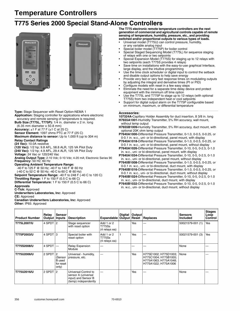
Temperature Controllers
356 customer.honeywell.com 70-6910
T775 Series 2000 Special Stand-Alone ControllersThe T775 electronic remote temperature controllers are the next generation of commercial and agricultural controls capable of remote sensing of temperature, humidity, pressure, etc., and providing switched and/or proportional outputs to various types of loads.• Universal model (T775U) can control pressure, humidity,
or any variable analog input • Special boiler model (T775P) for boiler control • Special Staged Sequencing Model (T775L) for sequence staging
of relays with one or two setpoints • Special Expansion Model (T775S) for staging up to 12 relays with
two setpoints (each T775S provides 4 relays) • Save time on installations with the easy-to-use graphical Interface,
large display, and the intuitive programming • Use the time clock scheduler or digital input to control the setback
and disable output options to help save energy • Provide very fast or very fast response times on modulating outputs
by adjusting the integral and derivative times (PI or PID) • Configure models with reset in a few easy steps • Eliminate the need for a separate time delay device and protect
equipment with the minimum off time option • Use the T775L and T775P to stage up to 12 relays (with optional
T775S) from two independent heat or cool setpoints • Support for digital output alarm on the T775P configurable based
on minimum, maximum, or differential temperature
Type: Stage Sequencer with Reset Option-NEMA 1Application: Staging controller for applications where electronic
accuracy and remote sensing of temperature is required.Bulb Size (T775L, T775P): 1/4 in. diameter x 2 in. long
(6.35 mm diameter x 50.8 mm) Accuracy: ±1 F at 77 F (±1 C at 25 C) Sensor Element: 1097 ohms PTC at 77 F (25 C)Maximum distance to sensor: Up to 1,000 ft (up to 304 m) Relay Contact Ratings(24 Vac): 10.0A resistive(120 Vac): 1/2 hp; 9.8 AFL, 58.8 ALR, 125 VA Pilot Duty(240 Vac): 1/2 hp; 4.9 AFL, 29.4 ALR, 125 VA Pilot DutyVoltage: 24 Vac or 120/240 VacAnalog Output Type: 2-10 Vdc; 0-10 Vdc; 4-20 mA; Electronic Series 90Frequency: 50 Hz; 60 HzOperating Ambient Temperature Range:
-40 F to 125 F @ 50 Hz; -40 F to 140 F @ 60 Hz(-40 C to 52 C @ 50 Hz; -40 C to 60 C @ 60 Hz)
Setpoint Temperature Range: -40 F to 248 F (-40 C to 120 C) Throttling Range: 1 F to 150 F (0.5 C to 66 C) Differential Temperature: 1 F to 150 F (0.5 C to 66 C) ApprovalsC-Tick: ApprovedUnderwriters Laboratories, Inc: ApprovedCE: ApprovedCanadian Underwriters Laboratories, Inc: ApprovedOther: IP65: Approved
Accessories:107324A-Capillary Holder Assembly for duct insertion, 8 3/8 in. longH7655A1001-Humidity Transmitter, 5% RH accuracy, wall mount,
without temp outputH7655B1009-Humidity Transmitter, 5% RH accuracy, duct mount, with
optional 20K ohm temp outputP7640A1000-Differential Pressure Transmitter, 0-1.0, 0-0.5, 0-0.25, or
0-0.1 in. w.c., uni- or bi-directional, panel mount, with displayP7640A1018-Differential Pressure Transmitter, 0-1.0, 0-0.5, 0-0.25, or
0-0.1 in. w.c., uni- or bi-directional, panel mount, without displayP7640A1026-Differential Pressure Transmitter, 0-10, 0-5, 0-2.5, 0-1.0
in. w.c., uni- or bi-directional, panel mount, with displayP7640A1034-Differential Pressure Transmitter, 0-10, 0-5, 0-2.5, 0-1.0
in. w.c., uni- or bi-directional, panel mount, without displayP7640B1008-Differential Pressure Transmitter, 0-1.0, 0-0.5, 0-0.25, or
0-0.1 in. w.c., uni- or bi-directional, duct mount, with displayP7640B1016-Differential Pressure Transmitter, 0-1.0, 0-0.5, 0-0.25, or
0-0.1 in. w.c., uni- or bi-directional, duct mount, without displayP7640B1024-Differential Pressure Transmitter, 0-10, 0-5, 0-2.5, 0-1.0
in. w.c., uni- or bi-directional, duct mount, with displayP7640B1032-Differential Pressure Transmitter, 0-10, 0-5, 0-2.5, 0-1.0
in. w.c., uni- or bi-directional, duct mount, without display
Product NumberRelay Output
Sensor Inputs Description Expandable
Digital Output
Output Reset Replaces
Sensors Included
Stages Loop Control
T775L2007/U 4 SPDT 2 Stage sequencer with reset option
Add 1 or 2 T775Ss (4 relays ea)
Yes — 50021579-001 (1) Yes
T775P2003/U 4 SPDT 3 Special boiler with reset option
Add 1 or 2 T775Ss (4 relays ea)
1 Yes — 50021579-001 (3) Yes
T775S2008/U 4 SPDT — Relay Expansion Module
— — — None —
T775U2006/U 2 SPDT 2 (Sensor B used for reset only)
Universal - humidity, pressure, etc.
— Yes H775E1002; H775D1003; H775C1004; H775B1005; H775A1063; H775A1048; H775A1022; H775A1006
None —
T775U2016/U 2 SPDT 2 Universal-Control to sensor A (universal input) and Sensor B (temp) independently
— Yes — None —
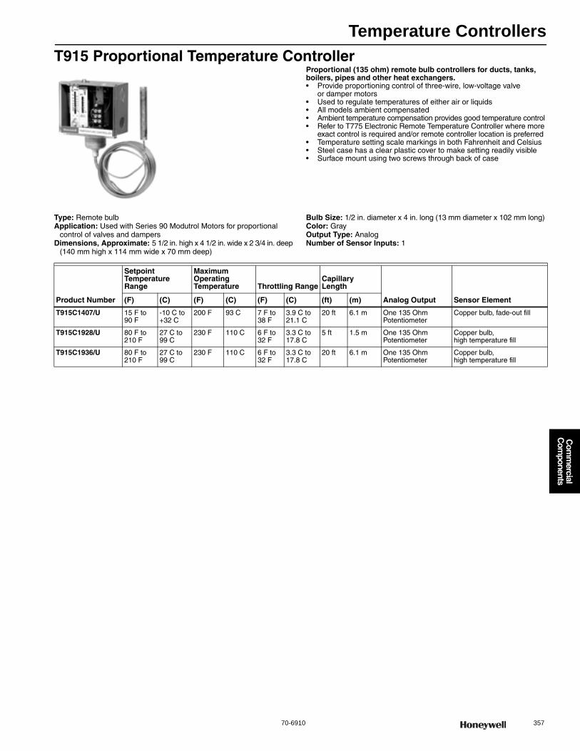
Temperature Controllers
70-6910 357
Com
mercial
Com
ponents
T915 Proportional Temperature ControllerProportional (135 ohm) remote bulb controllers for ducts, tanks, boilers, pipes and other heat exchangers.• Provide proportioning control of three-wire, low-voltage valve
or damper motors• Used to regulate temperatures of either air or liquids • All models ambient compensated • Ambient temperature compensation provides good temperature control• Refer to T775 Electronic Remote Temperature Controller where more
exact control is required and/or remote controller location is preferred • Temperature setting scale markings in both Fahrenheit and Celsius• Steel case has a clear plastic cover to make setting readily visible• Surface mount using two screws through back of case
Type: Remote bulbApplication: Used with Series 90 Modutrol Motors for proportional
control of valves and dampersDimensions, Approximate: 5 1/2 in. high x 4 1/2 in. wide x 2 3/4 in. deep
(140 mm high x 114 mm wide x 70 mm deep)
Bulb Size: 1/2 in. diameter x 4 in. long (13 mm diameter x 102 mm long) Color: GrayOutput Type: AnalogNumber of Sensor Inputs: 1
Product Number
Setpoint Temperature Range
Maximum Operating Temperature Throttling Range
Capillary Length
Analog Output Sensor Element(F) (C) (F) (C) (F) (C) (ft) (m)
T915C1407/U 15 F to 90 F
-10 C to +32 C
200 F 93 C 7 F to 38 F
3.9 C to 21.1 C
20 ft 6.1 m One 135 Ohm Potentiometer
Copper bulb, fade-out fill
T915C1928/U 80 F to 210 F
27 C to 99 C
230 F 110 C 6 F to 32 F
3.3 C to 17.8 C
5 ft 1.5 m One 135 Ohm Potentiometer
Copper bulb, high temperature fill
T915C1936/U 80 F to 210 F
27 C to 99 C
230 F 110 C 6 F to 32 F
3.3 C to 17.8 C
20 ft 6.1 m One 135 Ohm Potentiometer
Copper bulb,high temperature fill

Temperature Controllers
358 customer.honeywell.com 70-6910
T991A Proportional Temperature ControllerProportional (135 ohm) remote bulb controllers for modulating control of water or air temperature in ducts, tanks and similar applications.• Fast response models (for duct mounting) have coiled sensing element
giving at least four times faster response than standard models• Ambient temperature compensated for the case and tubing• Sensing element capillary tubing allows remote mounting of sensing element• Setpoint may be read and adjusted through cover • Throttling dial inside case adjusts proportional throttling range
Dimensions in inches (millimeters) Type: Modulating Remote bulbApplication: Provide modulating control of water or air temperature
in ducts or tanksColor: GrayVoltage: 24 Vac to 30 VacFrequency: 50 Hz; 60 HzOutput Type: AnalogNumber of Sensor Inputs: 1
M23881BULB LENGTH IS 3-9/16 (91).ON 55 TO 175 F AND 15 TO 75 C RANGE.1
1
KNOCKOUT FOR 1/2-INCH CONDUIT (2)
4-3/16(106)
2(51)
1/2(13)
3/8(10)
1-3/16(51)
17/32(13)
4-3/16(106)
5-5/8(143)
2-1/4(57)
2-1/8(54)
15/16 (24)
7/32 DIA. (3)
Product Number
Setpoint Temperature Range
Maximum Operating Temperature
Throttling Range Bulb Size
Capillary Length
Analog Output Sensor Element Includes(F) (C) (F) (C) (F) (C) (inch) (mm) (ft) (m)
T991A1004/U 0 F to 100 F
-18 C to +38 C
125 F 52 C 3 F to 30 F
1.7 C to 16.7 C
1/2 in. diameter x 4 3/16 in. long
13 mm diameter x 107 mm long
5 ft 1.5 m One 135 Ohm Potentiometer
Copper bulb —
T991A1012/U 0 F to 100 F
-18 C to +38 C
125 F 52 C 3 F to 30 F
1.7 C to 16.7 C
1/2 in. diameter x 4 3/16 in. long
13 mm diameter x 107 mm long
20 ft 6.1 m One 135 Ohm Potentiometer
Copper bulb —
T991A1061/U 160 F to 260 F
71 C to 127 C
280 F 138 C 3 F to 30 F
1.7 C to 16.7 C
1/2 in. diameter x 4 3/16 in. long
13 mm diameter x 107 mm long
5 ft 1.5 m One 135 Ohm Potentiometer
Copper bulb —
T991A1079/U 160 F to 260 F
71 C to 127 C
280 F 138 C 3 F to 30 F
1.7 C to 16.7 C
1/2 in. diameter x 4 3/16 in. long
13 mm diameter x 107 mm long
20 ft 6.1 m One 135 Ohm Potentiometer
Copper bulb —
T991A1095/U 5 F to 95 F
-15 C to +35 C
125 F 52 C 3 F to 30 F
1.7 C to 16.7 C
1/2 in. diameter x 4 3/16 in. long
13 mm diameter x 107 mm long
5 ft 1.5 m One 135 Ohm Potentiometer
Copper bulb Celsius scale
T991A1186/U 55 F to 175 F
13 C to 79 C
200 F 93 C 3 F to 30 F
1.7 C to 16.7 C
1/2 in. diameter x 4 3/16 in. long
13 mm diameter x 107 mm long
5 ft 1.5m One 135 Ohm Potentiometer
Copper bulb —
T991A1194/U 55 F to 175 F
13 C to 79 C
200 F 93 C 3 5 F to 36 F
1 9 C to 20 C
1/2 in. diameter x 3 9/16 in. long
13 mm diameter x 90 mm long
20 ft 6.1m One 135 Ohm Potentiometer
Copper bulb —
T991A1210/U 59 F to 167F
15 C to 75 C
200 F 93 C 3 F to 10 F
1.7 C to 16.7 C
1/2 in. diameter x 4 3/16 in. long
13 mm diameter x 107 mm long
5 ft 1.5m One 135 Ohm Potentiometer
Copper bulb Celsius Scale
T991A1244/U 55 F to 175 F
13 C to 79 C
200 F 93 C 3 5 F to 36 F
1 9 C to 20 C
1/2 in. diameter x 3 9/16 in. long
13 mm diameter x 90 mm long
5 ft 1.5m One 135 Ohm Potentiometer
Copper bulb 107324A Duct Bulb holder
T991A1269/U 55 F to 175 F
13 C to 79 C
200 F 93 C 3 5 F to 36 F
1 9 C to 20 C
1/2 in. diameter x 3 9/16 in. long
13 mm diameter x 90 mm long
20 ft 6.1m One 280 Ohm Potentiometer
Copper bulb —
T991A1343/U 55 F to 175 F
13 C to 79 C
200 F 93 C 3 5 F to 36 F
1 9 C to 20 C
1/2 in. diameter x 3 9/16 in. long
13 mm diameter x 90 mm long
5 ft 1.5m One 280 Ohm Potentiometer
Copper bulb 107324A Duct Bulb holder

Temperature Controllers
70-6910 359
Com
mercial
Com
ponents
Remote Bulb Controller Accessories
T991A1350/U 55 F to 175 F
13 C to 79 C
200 F 93 C 3 5 F to 36 F
1 9 C to 20 C
7/64 in. diameter x 24 ft. long
2 8 mm diameter x 7 3 m long
24 ft 7.3 m One 135 Ohm Potentiometer
Copper averaging element
—
T991A1426/U 0 F to 100 F
-18 C to +38 C
125 F 52 C 3 F to 10 F
1.7 C to 16.7 C
1/2 in. diameter x 4 3/16 in. long
13 mm diameter x 107 mm long
5 ft 1.5 m One 135 Ohm Potentiometer
Copper bulb 107324A Duct Bulb holder
T991A1715/U 0 F to 100 F
-18 C to +38 C
125 F 52 C 3 F to 10 F
1.7 C to 16.7 C
1/8 in. diameter x 76 3/8 in. long
3 mm diameter x 1 9 m long
5 ft 1.5 m One 135 Ohm Potentiometer
Copper fast response element
131524A duct coil holder
T991A1756/U 55 F to 175 F
13 C to 79 C
200 F 93 C 3 5 F to 36 F
1 9 C to 20 C
1/8 in. diameter x 76 3/8 in. long
3 mm diameter x 1 9 m long
5 ft 1.5 m One 135 Ohm Potentiometer
Copper fast response element
131524A duct coil holder
T991A1764/U 0 F to 100 F
-18 C to +38 C
125 F 52 C 3 F to 30 F
1.7 C to 16.7 C
7/64 in. diameter x 24 ft. long
2 8 mm diameter x 7 3 m long
24 ft 7.3 m One 135 Ohm Potentiometer
Copper averaging element
—
T991A2069/U 0 F to 100 F
-18 C to +38 C
125 F 52 C 3 F to 30 F
1.7 C to 16.7 C
1/8 in. diameter x 76 3/8 in. long
3 mm diameter x 1 9 m long
20 ft 6.1 m One 135 Ohm Potentiometer
Copper fast response element
131524A duct coil holder
Product Number Description
107323A/U Remote Bu b Shield Assembly, 3/8 in. diameter bulbs, < 5 in. long
107324A/U Capillary Holder Assembly for duct insertion, 8 3/8 in. long
107408/U Heat Conductive Compound, 4 ounces
112620AA/U Well Assembly., 3 3/4 in. (95 mm) insertion, 3/8 in. (10 mm) diameter, copper
112620BB/U Well Assembly., 5 1/2 in. (140 mm) insertion, 3/8 in. (10 mm) diameter, copper
112622AA/U Well Assembly., 4 in. (102 mm) insertion, 1/2 in. (13 mm) diameter, copper
112624AA/U Well Assembly., 4 3/4 in. (121 mm) insertion, 1/2 in. (13 mm) diameter, stainless steel
112628AA/U Well Assembly., 4 3/4 in. (121 mm) insertion, 1/2 in. (13 mm) diameter, stainless steel
112630AA/U Well Assembly., 4 1/4 in. (108 mm) insertion, 1/2 in. (13 mm) diameter, copper
112632AA/U Well Assembly., 4 1/4 in. (108 mm) insertion, 1/2 in. (13 mm) diameter, stainless steel
112634AA/U Well Assembly., 4 1/4 in. (108 mm) insertion, 1/2 in. (13 mm) diameter, copper
131524A/U Capillary Holder Assembly., 8 3/8 in. long, duct insertion
193987GA/U Encapsulated platinum sensing element used with the T7075 and T775. 2 5/8 in long, 3/8 in diameter, 6 in. leads.
Product Number
Setpoint Temperature Range
Maximum Operating Temperature
Throttling Range Bulb Size
Capillary Length
Analog Output Sensor Element Includes(F) (C) (F) (C) (F) (C) (inch) (mm) (ft) (m)
M17284A
107323A
107324AM17275A
M17401A
131524AM17276A
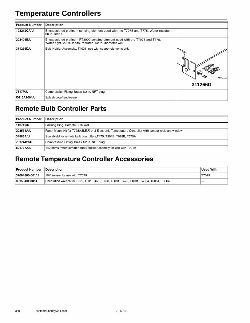
Temperature Controllers
360 customer.honeywell.com 70-6910
Remote Bulb Controller Parts
Remote Temperature Controller Accessories
198212CA/U Encapsulated platinum sensing element used with the T7075 and T775. Water resistant, 60 in. leads.
203401B/U Encapsulated platinum PT3000 sensing element used with the T7075 and T775. Water tight, 20 in. leads, requires 1/2 in. diameter well.
311266D/U Bulb Holder Assembly., T4031, use with copper elements only
7617M/U Compression Fitting, brass 1/2 in. NPT plug
Q615A1004/U Splash proof enclosure
Product Number Description
112719/U Packing Ring, Remote Bulb Well
203531A/U Panel Mount Kit for T775A,B,E,F, or J Electronic Temperature Controller with tamper resistant window
34886A/U Sun shield for remote bulb controllers,T475, T991B, T678B, T675A
7617ABY/U Compression Fitting, brass 1/2 in. NPT plug
801737A/U 140 ohms Potentiometer and Bracket Assembly for use with T991A
Product Number Description Used With
32004800-001/U 10K sensor for use with T7079 T7079
801534/0638/U Calibration wrench for T991, T631, T675, T678, T6031, T475, T4031, T4054, T6054, T6064 —
Product Number Description
M17277A
311266D
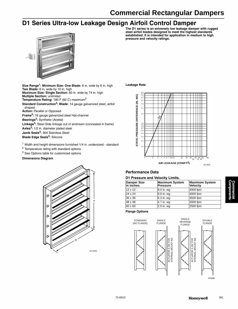
Commercial Rectangular Dampers
70-6910 361
Com
mercial
Com
ponents
D1 Series Ultra-low Leakage Design Airfoil Control Damper The D1 series is an extremely low leakage damper with rugged steel airfoil blades designed to meet the highest standards established. It is intended for application in medium to high pressure and velocity ratings.
Size Range1: Minimum Size: One Blade: 6 in. wide by 6 in. highTwo Blade: 6 in. wide by 10 in. highMaximum Size: Single Section: 60 in. wide by 74 in. highMultiple Section: unlimitedTemperature Rating: 180 F (82 C) maximum2
Standard Construction3: Blade: 14 gauge galvanized steel, airfoil shaped
Action: Parallel or OpposedFrame3: 16 gauge galvanized steel Hat-channelBearings3: Synthetic (Acetal)Linkage3: Steel Side linkage out of airstream (concealed in frame)Axles3: 1/2 in. diameter plated steel Jamb Seals3: 304 Stainless SteelBlade Edge Seals3: Silicone
1 Width and height dimensions furnished 1/4 in. undersized - standard2 Temperature rating with standard options3 See Options table for customized options
Dimensions Diagram
Leakage Rate
Performance DataD1 Pressure and Velocity Limits.
Flange Options
H
W
M13905
Damper Sizein inches.
Maximum System Pressure
Maximum System Velocity
12 x 12 8.0 in. wg 4000 fpm24 x 24 8.0 in. wg 4000 fpm36 x 36 6.3 in. wg 3500 fpm48 x 48 4.7 in. wg 3000 fpm60 x 60 2.0 in. wg 2500 fpm
1 2 3 4 5 6 7 8 9 10 20 30 40 50
60 70
80 90100 150
AIR LEAKAGE (CFM/FT2)
STAT
IC P
RES
SUR
E D
IFFE
REN
CE
(IN. W
G)
0 2
0 3
0 4
0 50 60 70 80 91 0
2 0
3 0
4 0
5 06 07 08 08 5
M13906
D1
M18986
STANDARD(NO FLANGE)
AC
TU
ATO
R S
DE
FO
RN
TE
RN
AL
MO
UN
TN
G
SINGLEFLANGE
SINGLEREVERSEFLANGE
AC
TU
ATO
R S
DE
FO
RN
TE
RN
AL
MO
UN
TN
G
DOUBLEFLANGE
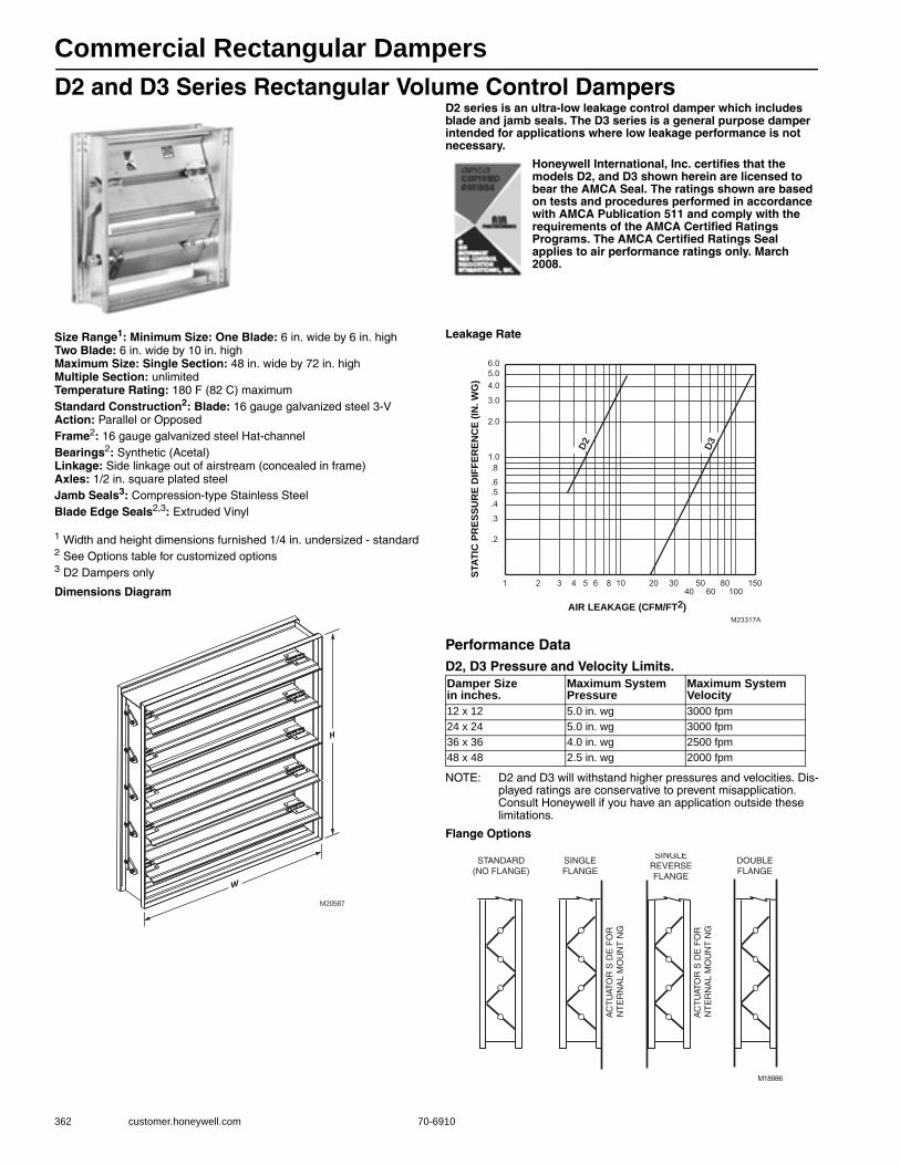
Commercial Rectangular Dampers
362 customer.honeywell.com 70-6910
D2 and D3 Series Rectangular Volume Control DampersD2 series is an ultra-low leakage control damper which includes blade and jamb seals. The D3 series is a general purpose damper intended for applications where low leakage performance is not necessary.
Honeywell International, Inc. certifies that the models D2, and D3 shown herein are licensed to bear the AMCA Seal. The ratings shown are based on tests and procedures performed in accordance with AMCA Publication 511 and comply with the requirements of the AMCA Certified Ratings Programs. The AMCA Certified Ratings Seal applies to air performance ratings only. March 2008.
Size Range1: Minimum Size: One Blade: 6 in. wide by 6 in. highTwo Blade: 6 in. wide by 10 in. highMaximum Size: Single Section: 48 in. wide by 72 in. highMultiple Section: unlimitedTemperature Rating: 180 F (82 C) maximumStandard Construction2: Blade: 16 gauge galvanized steel 3-VAction: Parallel or OpposedFrame2: 16 gauge galvanized steel Hat-channelBearings2: Synthetic (Acetal)Linkage: Side linkage out of airstream (concealed in frame)Axles: 1/2 in. square plated steelJamb Seals3: Compression-type Stainless SteelBlade Edge Seals2,3: Extruded Vinyl
1 Width and height dimensions furnished 1/4 in. undersized - standard2 See Options table for customized options3 D2 Dampers only
Dimensions Diagram
Leakage Rate
Performance DataD2, D3 Pressure and Velocity Limits.
NOTE: D2 and D3 will withstand higher pressures and velocities. Dis-played ratings are conservative to prevent misapplication. Consult Honeywell if you have an application outside these limitations.
Flange Options
H
W
M20587
Damper Sizein inches.
Maximum System Pressure
Maximum System Velocity
12 x 12 5.0 in. wg 3000 fpm24 x 24 5.0 in. wg 3000 fpm36 x 36 4.0 in. wg 2500 fpm48 x 48 2.5 in. wg 2000 fpm
1.0.8
.6
.5
.4
.3
.2
6.05.04.0
3.0
2.0
1
M23317A
2 3 5 6 8 10 20 30 50 60
80 100
AIR LEAKAGE (CFM/FT2)
STAT
IC P
RES
SUR
E D
IFFE
REN
CE
(IN. W
G)
404 150
D3D2
M18986
STANDARD(NO FLANGE)
AC
TU
ATO
R S
DE
FO
RN
TE
RN
AL
MO
UN
TN
G
SINGLEFLANGE
SINGLEREVERSEFLANGE
AC
TU
ATO
R S
DE
FO
RN
TE
RN
AL
MO
UN
TN
G
DOUBLEFLANGE

Commercial Rectangular Dampers
70-6910 363
Com
mercial
Com
ponents
Standard Models
Options
MaterialFrame Gauge Blade Seals
Jamb Seals Bearings Axles
Linkage Materials Flange Sizing
S = StandardO = Optional Galv S/S 16 14 12 Vinyl Silicone S/S Synthetic Bronze S/S Steel S/S Steel S/S None Single Double Reverse Nominal Actual
D1 Ultra-low Leakage Airfoil Volume Control Damper
S O S O O N/A S S S O O S O S O S O O O S O
MaterialFrame Gauge Blade Seals
Jamb Seals Bearings Axles
Linkage Materials Flange Sizing
S = StandardO = Optional Galv S/S Al 16 14 12 Vinyl Silicone S/S Synthetic Bronze S/S Steel S/S Steel S/S None Single Double Reverse Nominal Actual
D2 Ultra-low Leakage Volume Control Damper
S O O S O O S O S S O O S O S O S O O O S O
D3 Standard Volume Control Damper
S O O S O O N/A N/A N/A S O O S O S O S O O O S O
* Contact Customer Care for additional options and models.
D2 Class II Leakage, 3 V blade with sealsProduct Type
D3 Class III Leakage, 3 V blade without sealsP Parallel
Blade ActionO Opposed
A 16 gauge galvanized frame with galvanized linkages and axles FrameA Acetal Bearings /No Seal
Axle Bearings and Seals Materials (When you select D3 you are only selecting the bearing type)
B Acetal Bearings/Vinyl SealC Bronze Bearings/No SealD Bronze Bearings/Vinyl Seal
(006-072)
Standard Rectangular Damper Width Width (in 2 inch increments through 46 in. then 4 in. increments through 72 in.)
(006-072)
Standard Rectangular Damper Height Height (in 2 inch increments through 46 in. then 4 in. increments through 72 in.)
N Nominal Sizing SizingA No flange Flange
A
External LH Standard without jackshaft (may include jackshaft for larger sizes)
Actuator MountingB
Internal LH Standard without jackshaft (may include jackshaft for larger sizes)
C
External RH Standard without jackshaft (may include jackshaft for larger sizes)
D2 P B* A XXX XXX N A A Example
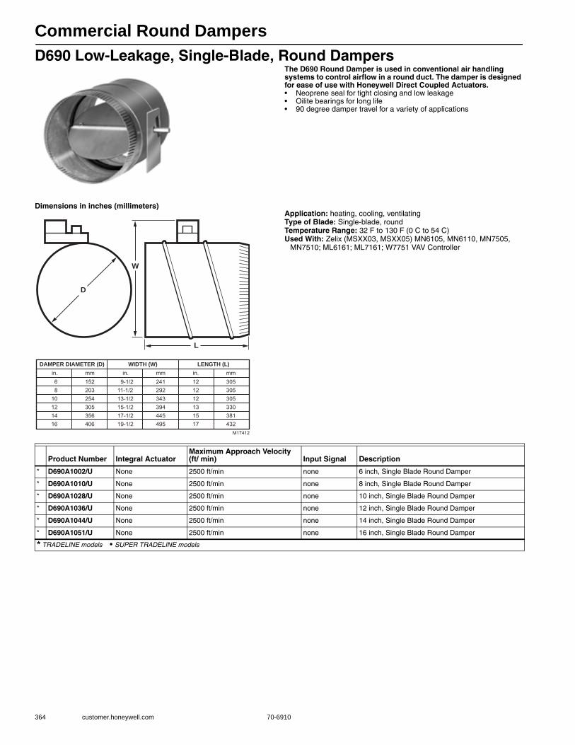
Commercial Round Dampers
364 customer.honeywell.com 70-6910
D690 Low-Leakage, Single-Blade, Round DampersThe D690 Round Damper is used in conventional air handling systems to control airflow in a round duct. The damper is designed for ease of use with Honeywell Direct Coupled Actuators.• Neoprene seal for tight closing and low leakage • Oilite bearings for long life • 90 degree damper travel for a variety of applications
Dimensions in inches (millimeters)Application: heating, cooling, ventilatingType of Blade: Single-blade, roundTemperature Range: 32 F to 130 F (0 C to 54 C) Used With: Zelix (MSXX03, MSXX05) MN6105, MN6110, MN7505,
MN7510; ML6161; ML7161; W7751 VAV Controller
D
W
L
DAMPER DIAMETER (D)
68
10121416
WIDTH (W) LENGTH (L)in.
152203254305356406
mm9-1/2
11-1/213-1/215-1/217-1/219-1/2
in.241292343394445495
mm121212131517
in.305305305330381432
mm
M17412
Product Number Integral ActuatorMaximum Approach Velocity (ft/ min) Input Signal Description
* D690A1002/U None 2500 ft/min none 6 inch, Single Blade Round Damper
* D690A1010/U None 2500 ft/min none 8 inch, Single Blade Round Damper
* D690A1028/U None 2500 ft/min none 10 inch, Single Blade Round Damper
* D690A1036/U None 2500 ft/min none 12 inch, Single Blade Round Damper
* D690A1044/U None 2500 ft/min none 14 inch, Single Blade Round Damper
* D690A1051/U None 2500 ft/min none 16 inch, Single Blade Round Damper
* TRADELINE models • SUPER TRADELINE models
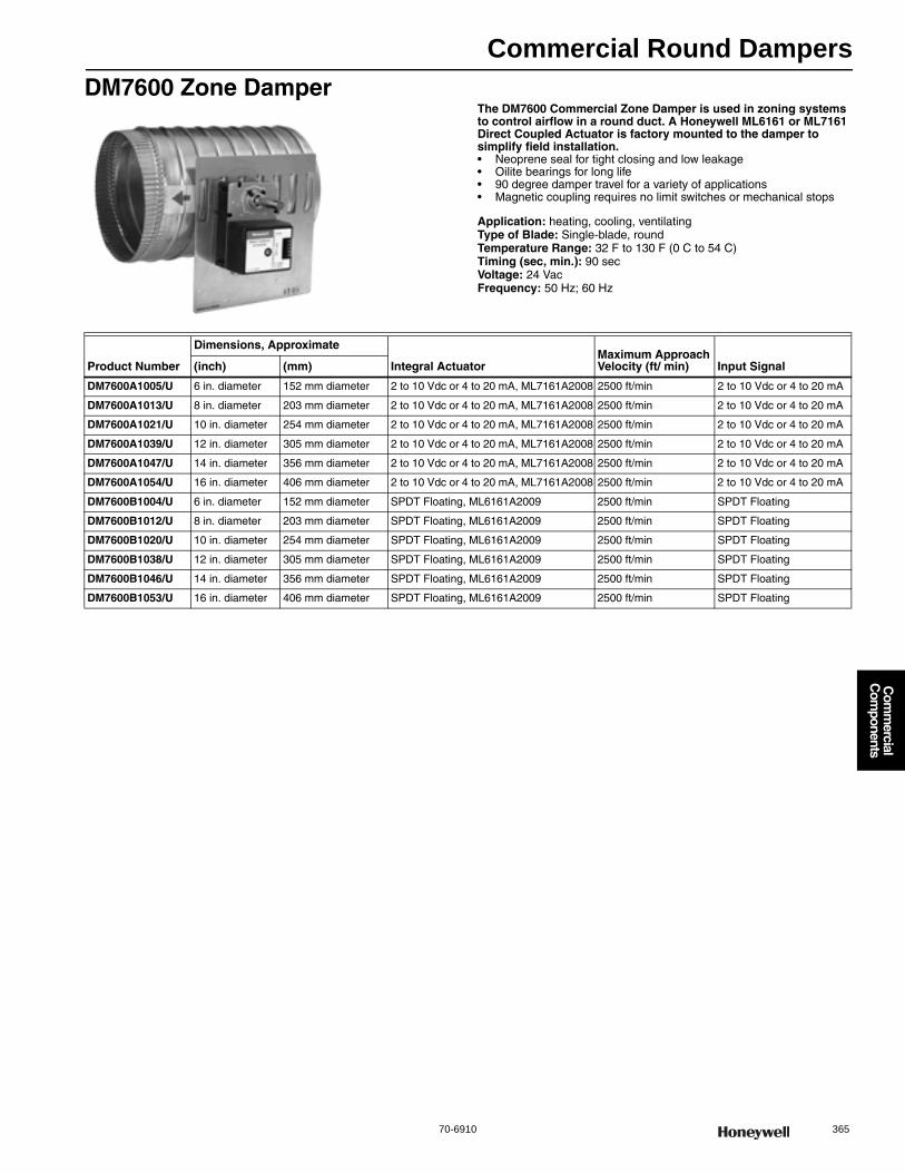
Commercial Round Dampers
70-6910 365
Com
mercial
Com
ponents
DM7600 Zone DamperThe DM7600 Commercial Zone Damper is used in zoning systems to control airflow in a round duct. A Honeywell ML6161 or ML7161 Direct Coupled Actuator is factory mounted to the damper to simplify field installation.• Neoprene seal for tight closing and low leakage • Oilite bearings for long life • 90 degree damper travel for a variety of applications • Magnetic coupling requires no limit switches or mechanical stops
Application: heating, cooling, ventilatingType of Blade: Single-blade, roundTemperature Range: 32 F to 130 F (0 C to 54 C) Timing (sec, min.): 90 secVoltage: 24 VacFrequency: 50 Hz; 60 Hz
Product Number
Dimensions, Approximate
Integral ActuatorMaximum Approach Velocity (ft/ min) Input Signal(inch) (mm)
DM7600A1005/U 6 in. diameter 152 mm diameter 2 to 10 Vdc or 4 to 20 mA, ML7161A2008 2500 ft/min 2 to 10 Vdc or 4 to 20 mA
DM7600A1013/U 8 in. diameter 203 mm diameter 2 to 10 Vdc or 4 to 20 mA, ML7161A2008 2500 ft/min 2 to 10 Vdc or 4 to 20 mA
DM7600A1021/U 10 in. diameter 254 mm diameter 2 to 10 Vdc or 4 to 20 mA, ML7161A2008 2500 ft/min 2 to 10 Vdc or 4 to 20 mA
DM7600A1039/U 12 in. diameter 305 mm diameter 2 to 10 Vdc or 4 to 20 mA, ML7161A2008 2500 ft/min 2 to 10 Vdc or 4 to 20 mA
DM7600A1047/U 14 in. diameter 356 mm diameter 2 to 10 Vdc or 4 to 20 mA, ML7161A2008 2500 ft/min 2 to 10 Vdc or 4 to 20 mA
DM7600A1054/U 16 in. diameter 406 mm diameter 2 to 10 Vdc or 4 to 20 mA, ML7161A2008 2500 ft/min 2 to 10 Vdc or 4 to 20 mA
DM7600B1004/U 6 in. diameter 152 mm diameter SPDT Floating, ML6161A2009 2500 ft/min SPDT Floating
DM7600B1012/U 8 in. diameter 203 mm diameter SPDT Floating, ML6161A2009 2500 ft/min SPDT Floating
DM7600B1020/U 10 in. diameter 254 mm diameter SPDT Floating, ML6161A2009 2500 ft/min SPDT Floating
DM7600B1038/U 12 in. diameter 305 mm diameter SPDT Floating, ML6161A2009 2500 ft/min SPDT Floating
DM7600B1046/U 14 in. diameter 356 mm diameter SPDT Floating, ML6161A2009 2500 ft/min SPDT Floating
DM7600B1053/U 16 in. diameter 406 mm diameter SPDT Floating, ML6161A2009 2500 ft/min SPDT Floating
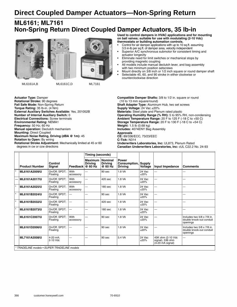
Direct Coupled Damper Actuators—Non-Spring Return
366 customer.honeywell.com 70-6910
ML6161; ML7161 Non-Spring Return Direct Coupled Damper Actuators, 35 lb-in
Used to control dampers in HVAC applications and for mounting on ball valves; suitable for use with modulating (2-10 Vdc) thermostats or building automation controls.• Control for air damper applications with up to 10 sq.ft. assuming
3.5 in-lb per sq.ft. of damper area, velocity independent • Superior A/C synchronous submotor for consistent timing and
actuator longevity • Eliminate need for limit switches or mechanical stops by
providing magnetic coupling • All models include manual declutch lever, and bag assembly
with two minimum position setscrews • Mount directly on 3/8 inch or 1/2 inch square or round damper shaft • Selectable 45, 60, and 90 stroke in either clockwise or
counterclockwise direction
Actuator Type: DamperRotational Stroke: 90 degreesFail Safe Mode: Non-Spring ReturnTorque Rating: 35 lb-in. (4 Nm) External Auxiliary Switches Available: Yes, 201052BNumber of Internal Auxiliary Switch: 0Electrical Connections: Screw terminalsEnvironmental Rating: NEMA1Frequency: 50 Hz; 60 HzManual operation: Declutch mechanismMounting: Direct CoupledMaximum Noise Rating, Driving (dBA @ 1m): 45Rotation to Open: By wiringRotational Stroke Adjustment: Mechanically limited at 45 or 60
degrees in cw or ccw directions
Compatible Damper Shafts: 3/8 to 1/2 in. square or round (10 to 13 mm square/round)
Shaft Adapter Type: Aluminum Hub, two set screwsSupply Voltage: 24 Vac ±20%Materials: Steel plate and Plenum rated plasticOperating Humidity Range (% RH): 5 to 95% RH, non-condensingAmbient Temperature Range: 20 F to 125 F (-18 C to +50 C) Storage Temperature Range: 20 F to 130 F (-18 C to +54 C) Weight: 1.5 lb (0.68 kg) Includes: 4074ENY Bag AssemblyApprovalsCE: 89/336/ECC, 73/23/EECC-Tick: N314Underwriters Laboratories, Inc: UL873, Plenum RatedCanadian Underwriters Laboratories, Inc: cUL C22.2 No. 24-93
ML6161A,B ML6161C,D ML7161
Product NumberControl Signal Feedback
Timing (seconds)
Power Consumption, Driving
Supply Voltage Input Impedance Comments
Maximum Driving @ 60 Hz
Nominal Driving @ 60 Hz
* ML6161A2009/U On/Off; SPDT; Floating
With accessory
— 90 sec 1.8 VA 24 Vac ±20%
— —
— ML6161A2017/U On/Off; SPDT; Floating
With accessory
— 420 sec 1.8 VA 24 Vac ±20%
— —
* ML6161A2025/U On/Off; SPDT; Floating
With accessory
— 180 sec 1.8 VA 24 Vac ±20%
— —
* ML6161B2024/U On/Off; SPDT; Floating
— — 90 sec 1.8 VA 24 Vac ±20%
— —
* ML6161B2032/U On/Off; SPDT; Floating
— — 420 sec 1.8 VA 24 Vac ±20%
— —
* ML6161B2073/U On/Off; SPDT; Floating
— — 180 sec 1.8 VA 24 Vac ±20%
— —
ML6161C2007/U On/Off; SPDT; Floating
With accessory
— 90 sec 1.8 VA 24 Vac ±20%
— Includes two 5/8 x 7/8 in. double knock-out conduit openings
ML6161D2006/U On/Off; SPDT; Floating
— — 90 sec 1.8 VA 24 Vac ±20%
— Includes two 5/8 x 7/8 in. double knock-out conduit openings
ML7161A2008/U 4-20 mA; 2-10 Vdc
— — 90 sec 5.4 VA 24 Vac ±20%
45K ohm (2-10 Vdc signal), 536 ohm (4-20 mA signal)
—
* TRADELINE models • SUPER TRADELINE models
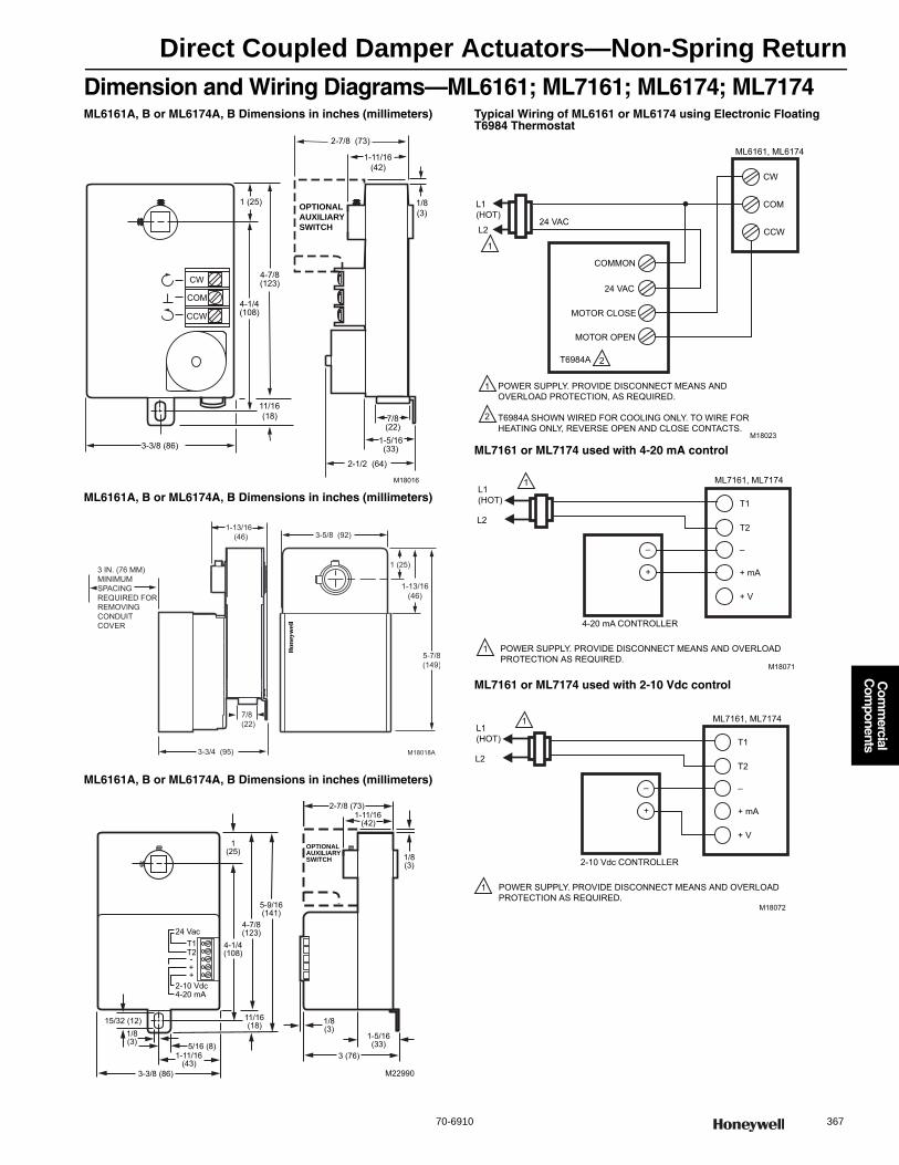
Direct Coupled Damper Actuators—Non-Spring Return
70-6910 367
Com
mercial
Com
ponents
Dimension and Wiring Diagrams—ML6161; ML7161; ML6174; ML7174ML6161A, B or ML6174A, B Dimensions in inches (millimeters)
ML6161A, B or ML6174A, B Dimensions in inches (millimeters)
ML6161A, B or ML6174A, B Dimensions in inches (millimeters)
Typical Wiring of ML6161 or ML6174 using Electronic Floating T6984 Thermostat
ML7161 or ML7174 used with 4-20 mA control
ML7161 or ML7174 used with 2-10 Vdc control
1 (25)
M18016
CW
COM
CCW
OPTIONALAUXILIARYSWITCH
11/16(18)
3-3/8 (86)
4-1/4(108)
4-7/8(123)
2-7/8 (73)
1-11/16(42)
1/8(3)
1-5/16(33)
7/8(22)
2-1/2 (64)
M18018A
5-7/8(149)
1-13/16(46)
1 (25)
3-5/8 (92)1-13/16
(46)
3 IN. (76 MM)MINIMUM SPACINGREQUIRED FOR REMOVING CONDUIT COVER
3-3/4 (95)
7/8(22)
1(25)
M22990
OPTIONALAUXILIARYSWITCH
T1T2-++
24 Vac
2-10 Vdc4-20 mA
4-7/8(123)
4-1/4(108)
5-9/16(141)
11/16(18) 1/8
(3)
5/16 (8)1-11/16
(43)3-3/8 (86)
1/8(3)
15/32 (12)
1-5/16(33)
3 (76)
2-7/8 (73)1-11/16
(42)
1/8(3)
1
1
2
2
L1(HOT)
24 VAC
POWER SUPPLY. PROVIDE DISCONNECT MEANS AND OVERLOAD PROTECTION, AS REQUIRED.
T6984A SHOWN WIRED FOR COOLING ONLY. TO WIRE FORHEATING ONLY, REVERSE OPEN AND CLOSE CONTACTS.
M18023
ML6161, ML6174
CW
COM
CCWL2
COMMON
24 VAC
MOTOR CLOSE
MOTOR OPEN
T6984A
L1 (HOT)
L2
1
1 POWER SUPPLY. PROVIDE DISCONNECT MEANS AND OVERLOAD PROTECTION AS REQUIRED.
4-20 mA CONTROLLER
ML7161, ML7174
T1
T2
––
+ + mA
+ V
M18071
L1 (HOT)
L2
1
1 POWER SUPPLY. PROVIDE DISCONNECT MEANS AND OVERLOAD PROTECTION AS REQUIRED.
2-10 Vdc CONTROLLER
ML7161, ML7174
T1
T2
––
+ + mA
+ V
M18072

Direct Coupled Damper Actuators—Non-Spring Return
368 customer.honeywell.com 70-6910
ML6174; ML7174, Non-Spring Return Direct Coupled Damper Actuators, 70 lb-in
Used to control dampers in HVAC applications and for mounting on ball valves; suitable for use with modulating (2-10 Vdc) thermostats or building automation controls.• Control for air damper applications with up to 20 sq.ft. assuming
3.5 in-lb per sq.ft. of damper area, velocity independent • Magnetic coupling eliminates the need for mechanical stops or limit
switch adjustments by limiting stall torque to 130 lb-in. maximum • Mount directly on 3/8 to 1/2 in. round and square damper shafts• All models include manual declutch lever for ease of mounting, and
bag assembly with two minimum position setscrews• 90 second timing models are suitable for use with
pressure independent VAV systems • Selectable 45, 60, and 90 degree stroke in either
clockwise or counterclockwise direction
Actuator Type: DamperRotational Stroke: 90 degreesFail Safe Mode: Non-Spring ReturnTorque Rating: 70 lb-in. (8 Nm) External Auxiliary Switches Available: Yes, 201052BNumber of Internal Auxiliary Switch: 0Electrical Connections: Screw terminalsEnvironmental Rating: NEMA1Frequency: 50 Hz; 60 HzManual operation: Declutch mechanismMounting: Direct CoupledMaximum Noise Rating, Driving (dBA @ 1m): 45Rotation to Open: By wiringRotational Stroke Adjustment: Mechanically limited at 45 or 60
degrees in cw or ccw directions
Compatible Damper Shafts: 3/8 to 1/2 in. square or round (10 to 13 mm square/round)
Shaft Adapter Type: Aluminum Hub, two set screwsSupply Voltage: 24 Vac ±20%Materials: Steel plate and Plenum rated plasticOperating Humidity Range (% RH): 5 to 95% RH, non-condensingAmbient Temperature Range: 20 F to 125 F (-18 C to +50 C) Storage Temperature Range: 20 F to 130 F (-18 C to +54 C) Weight: 1.5 lb (0.68 kg) Includes: 4074ENY Bag AssemblyApprovalsUnderwriters Laboratories, Inc: UL873, Plenum RatedCanadian Underwriters Laboratories, Inc: cUL C22.2 No. 24-93
ML6161A,B ML6161C,D ML7161
Product NumberControl Signal Feedback
Timing (seconds)Nominal Driving @ 60 Hz
Power Consumption, Driving Input Impedance Comments
* ML6174A2002/U On/Off; SPDT; Floating
With accessory
90 sec 2.4 VA — —
* ML6174A2010/U On/Off; SPDT; Floating
With accessory
180 sec 2.4 VA — —
* ML6174B2019/U On/Off; SPDT; Floating
— 90 sec 2.4 VA — —
ML6174B2035 On/Off; SPDT; Floating
— 420 sec 2.4 VA — —
ML6174D2009/U On/Off; SPDT; Floating
— 90 sec 2.4 VA — Includes two 5/8 x 7/8 in. double knock-out conduit openings
ML7174A2001/U 4-20 mA; 2-10 Vdc
— 90 sec 5.4 VA 45K ohm (2-10 Vdc signal), 536 ohm (4-20 mA signal)
—
* TRADELINE models • SUPER TRADELINE models
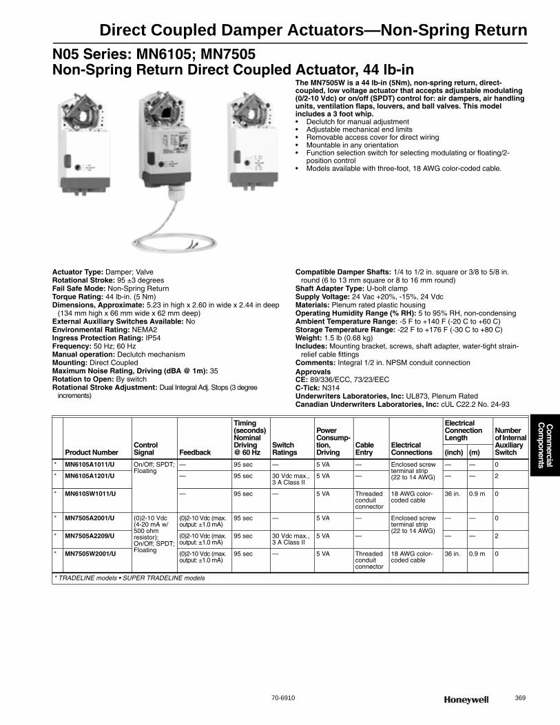
Direct Coupled Damper Actuators—Non-Spring Return
70-6910 369
Com
mercial
Com
ponents
N05 Series: MN6105; MN7505 Non-Spring Return Direct Coupled Actuator, 44 lb-in
The MN7505W is a 44 lb-in (5Nm), non-spring return, direct-coupled, low voltage actuator that accepts adjustable modulating (0/2-10 Vdc) or on/off (SPDT) control for: air dampers, air handling units, ventilation flaps, louvers, and ball valves. This model includes a 3 foot whip.• Declutch for manual adjustment • Adjustable mechanical end limits • Removable access cover for direct wiring • Mountable in any orientation • Function selection switch for selecting modulating or floating/2-
position control• Models available with three-foot, 18 AWG color-coded cable.
Actuator Type: Damper; ValveRotational Stroke: 95 ±3 degreesFail Safe Mode: Non-Spring ReturnTorque Rating: 44 lb-in. (5 Nm) Dimensions, Approximate: 5.23 in high x 2.60 in wide x 2.44 in deep
(134 mm high x 66 mm wide x 62 mm deep) External Auxiliary Switches Available: NoEnvironmental Rating: NEMA2Ingress Protection Rating: IP54Frequency: 50 Hz; 60 HzManual operation: Declutch mechanismMounting: Direct CoupledMaximum Noise Rating, Driving (dBA @ 1m): 35Rotation to Open: By switchRotational Stroke Adjustment: Dual Integral Adj. Stops (3 degree
increments)
Compatible Damper Shafts: 1/4 to 1/2 in. square or 3/8 to 5/8 in. round (6 to 13 mm square or 8 to 16 mm round)
Shaft Adapter Type: U-bolt clampSupply Voltage: 24 Vac +20%, -15%, 24 VdcMaterials: Plenum rated plastic housingOperating Humidity Range (% RH): 5 to 95% RH, non-condensingAmbient Temperature Range: -5 F to +140 F (-20 C to +60 C) Storage Temperature Range: -22 F to +176 F (-30 C to +80 C) Weight: 1.5 lb (0.68 kg) Includes: Mounting bracket, screws, shaft adapter, water-tight strain-
relief cable fittingsComments: Integral 1/2 in. NPSM conduit connectionApprovalsCE: 89/336/ECC, 73/23/EECC-Tick: N314Underwriters Laboratories, Inc: UL873, Plenum RatedCanadian Underwriters Laboratories, Inc: cUL C22.2 No. 24-93
Product NumberControl Signal Feedback
Timing (seconds)Nominal Driving @ 60 Hz
Switch Ratings
Power Consump-tion, Driving
Cable Entry
Electrical Connections
Electrical Connection Length
Number of Internal Auxiliary Switch(inch) (m)
* MN6105A1011/U On/Off; SPDT; Floating
— 95 sec — 5 VA — Enclosed screw terminal strip (22 to 14 AWG)
— — 0
* MN6105A1201/U — 95 sec 30 Vdc max., 3 A Class II
5 VA — — — 2
* MN6105W1011/U — 95 sec — 5 VA Threaded conduit connector
18 AWG color-coded cable
36 in. 0.9 m 0
* MN7505A2001/U (0)2-10 Vdc (4-20 mA w/500 ohm resistor); On/Off; SPDT; Floating
(0)2-10 Vdc (max. output: ±1.0 mA)
95 sec — 5 VA — Enclosed screw terminal strip (22 to 14 AWG)
— — 0
* MN7505A2209/U (0)2-10 Vdc (max. output: ±1.0 mA)
95 sec 30 Vdc max., 3 A Class II
5 VA — — — 2
* MN7505W2001/U (0)2-10 Vdc (max. output: ±1.0 mA)
95 sec — 5 VA Threaded conduit connector
18 AWG color-coded cable
36 in. 0.9 m 0
* TRADELINE models • SUPER TRADELINE models
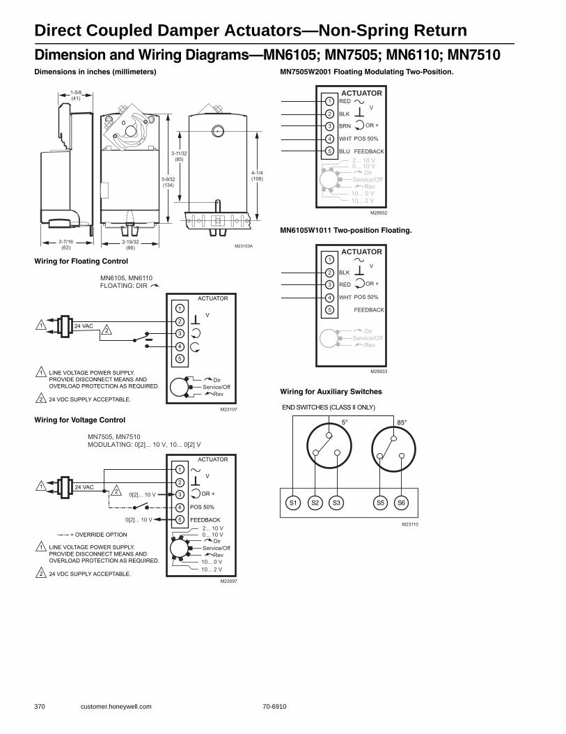
Direct Coupled Damper Actuators—Non-Spring Return
370 customer.honeywell.com 70-6910
Dimension and Wiring Diagrams—MN6105; MN7505; MN6110; MN7510Dimensions in inches (millimeters)
Wiring for Floating Control
Wiring for Voltage Control
MN7505W2001 Floating Modulating Two-Position.
MN6105W1011 Two-position Floating.
Wiring for Auxiliary Switches
M23103A
5-9/32(134)
1-5/8(41)
2-7/16(62)
2-19/32(66)
4-1/4(108)
3-11/32(85)
FLOATING: DIR
24 VAC1
1
2
2
LINE VOLTAGE POWER SUPPLY. PROVIDE DISCONNECT MEANS AND OVERLOAD PROTECTION AS REQUIRED.
24 VDC SUPPLY ACCEPTABLE.
M23107
ACTUATOR
V
5
4
3
1
2
DirService/Off Rev
MN6105, MN6110
MN7505, MN7510MODULATING: 0[2]... 10 V, 10... 0[2] V
24 VAC1
1
2
2
LINE VOLTAGE POWER SUPPLY. PROVIDE DISCONNECT MEANS AND OVERLOAD PROTECTION AS REQUIRED.
24 VDC SUPPLY ACCEPTABLE.M23097
ACTUATOR
V
OR +
FEEDBACK5
4
3
1
2
DirService/Off Rev
2... 10 V0... 10 V
10... 0 V10... 2 V
0[2]... 10 V
= OVERRIDE OPTION
0[2]... 10 V
POS 50%
M28932
ACTUATOR
BLU
WHT
BRN
BLK
RED
5
4
3
1
2
DirService/Off Rev
2... 10 V0... 10 V
10... 0 V10... 2 V
V
OR +
FEEDBACK
POS 50%
M28933
ACTUATOR
WHT
RED
BLK
5
4
3
1
2
DirService/Off Rev
V
OR +
FEEDBACK
POS 50%
5° 85°
S1 S2 S3 S5 S6
M23110
END SWITCHES (CLASS II ONLY)

Direct Coupled Damper Actuators—Non-Spring Return
70-6910 371
Com
mercial
Com
ponents
N10 Series: MN6110; MN7510 Non-Spring Return Direct Coupled Actuator, 88 lb-in
The MN7510 is a 88 lb-in (10Nm), non-spring return, direct-coupled, low voltage actuator that accepts adjustable modulating (0/2-10 Vdc) or on/off (SPDT) control for: air dampers, air handling units, ventilation flaps, louvers, and ball valves.• Declutch for manual adjustment • Adjustable mechanical end limits • Removable access cover for direct wiring • Mountable in any orientation • Function selection switch for selecting modulating or
floating/2-position control
Actuator Type: Damper; ValveRotational Stroke: 95 ±3 degreesFail Safe Mode: Non-Spring ReturnTorque Rating: 88 lb-in. (10 Nm) Dimensions, Approximate: 5.23 in high x 2.60 in wide x 2.44 in deep
(134 mm high x 66 mm wide x 62 mm deep.) External Auxiliary Switches Available: NoElectrical Connections: Enclosed screw terminal strip (22 to 14 AWG)Environmental Rating: NEMA2Ingress Protection Rating: IP54Frequency: 50 Hz; 60 HzManual operation: Declutch mechanismMounting: Direct CoupledMaximum Noise Rating, Driving (dBA @ 1m): 35Rotation to Open: By switchRotational Stroke Adjustment: Dual Integral Adj. Stops (3 degree
increments)
Compatible Damper Shafts: 1/4 to 1/2 in. square or 3/8 to 5/8 in. round (6 to 13 mm square or 8 to 16 mm round)
Shaft Adapter Type: U-bolt clampSupply Voltage: 24 Vac +20%, -15%, 24 VdcMaterials: Plenum rated plastic housingOperating Humidity Range (% RH): 5 to 95% RH, non-condensingAmbient Temperature Range: -5 F to +140 F (-20 C to +60 C) Storage Temperature Range: -22 F to +176 F (-30 C to +80 C) Weight: 1.5 lb (0.68 kg) Includes: Mounting bracket, screws, shaft adapter, water-tight strain-
relief cable fittingsComments: Integral 1/2 in. NPSM conduit connection.ApprovalsCE: 89/336/ECC, 73/23/EECC-Tick: N314Underwriters Laboratories, Inc: UL873, Plenum RatedCanadian Underwriters Laboratories, Inc: cUL C22.2 No. 24-93
Product Number Control Signal Feedback
Timing (seconds)Nominal Driving @ 60 Hz
Switch Ratings
Power Consumption, Driving
Number of Internal Auxiliary Switch
* MN6110A1003/U On/Off; SPDT; Floating — 95 sec — 5 VA 0
* MN6110A1201/U On/Off; SPDT; Floating — 95 sec 30 Vdc max., 3 A Class II
5 VA 2
* MN7510A2001/U (0)2-10 Vdc (4-20 mA w/500 ohm resistor); On/Off; SPDT; Floating
(0)2-10 Vdc (max. output: ±1.0 mA)
95 sec — 5 VA 0
* MN7510A2209/U (0)2-10 Vdc (4-20 mA w/500 ohm resistor); On/Off; SPDT; Floating
(0)2-10 Vdc (max. output: ±1.0 mA)
95 sec 30 Vdc max., 3 A Class II
5 VA 2
* TRADELINE models • SUPER TRADELINE models
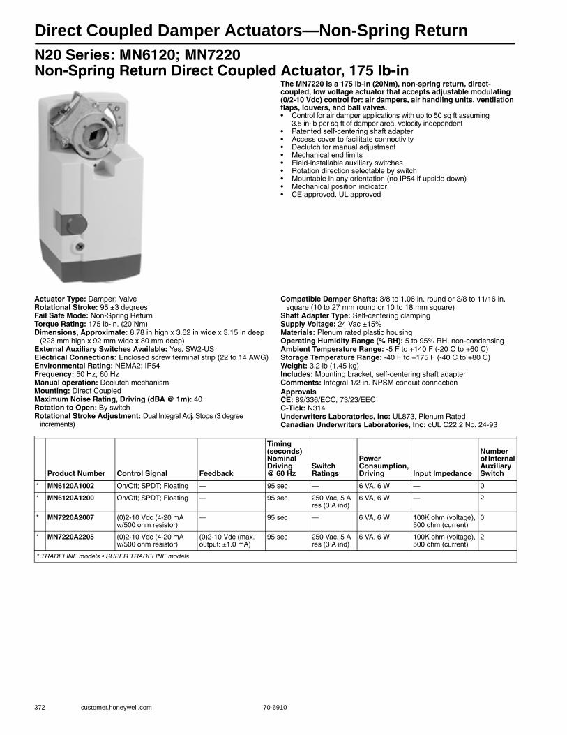
Direct Coupled Damper Actuators—Non-Spring Return
372 customer.honeywell.com 70-6910
N20 Series: MN6120; MN7220 Non-Spring Return Direct Coupled Actuator, 175 lb-in
The MN7220 is a 175 lb-in (20Nm), non-spring return, direct-coupled, low voltage actuator that accepts adjustable modulating (0/2-10 Vdc) control for: air dampers, air handling units, ventilation flaps, louvers, and ball valves.• Control for air damper applications with up to 50 sq ft assuming
3.5 in- b per sq ft of damper area, velocity independent • Patented self-centering shaft adapter • Access cover to facilitate connectivity • Declutch for manual adjustment • Mechanical end limits • Field-installable auxiliary switches • Rotation direction selectable by switch • Mountable in any orientation (no IP54 if upside down) • Mechanical position indicator • CE approved. UL approved
Actuator Type: Damper; ValveRotational Stroke: 95 ±3 degreesFail Safe Mode: Non-Spring ReturnTorque Rating: 175 lb-in. (20 Nm) Dimensions, Approximate: 8.78 in high x 3.62 in wide x 3.15 in deep
(223 mm high x 92 mm wide x 80 mm deep) External Auxiliary Switches Available: Yes, SW2-USElectrical Connections: Enclosed screw terminal strip (22 to 14 AWG)Environmental Rating: NEMA2; IP54Frequency: 50 Hz; 60 HzManual operation: Declutch mechanismMounting: Direct CoupledMaximum Noise Rating, Driving (dBA @ 1m): 40Rotation to Open: By switchRotational Stroke Adjustment: Dual Integral Adj. Stops (3 degree
increments)
Compatible Damper Shafts: 3/8 to 1.06 in. round or 3/8 to 11/16 in. square (10 to 27 mm round or 10 to 18 mm square)
Shaft Adapter Type: Self-centering clampingSupply Voltage: 24 Vac ±15%Materials: Plenum rated plastic housingOperating Humidity Range (% RH): 5 to 95% RH, non-condensingAmbient Temperature Range: -5 F to +140 F (-20 C to +60 C) Storage Temperature Range: -40 F to +175 F (-40 C to +80 C) Weight: 3.2 lb (1.45 kg) Includes: Mounting bracket, self-centering shaft adapterComments: Integral 1/2 in. NPSM conduit connectionApprovalsCE: 89/336/ECC, 73/23/EECC-Tick: N314Underwriters Laboratories, Inc: UL873, Plenum RatedCanadian Underwriters Laboratories, Inc: cUL C22.2 No. 24-93
Product Number Control Signal Feedback
Timing (seconds)Nominal Driving @ 60 Hz
Switch Ratings
Power Consumption, Driving Input Impedance
Number of Internal Auxiliary Switch
* MN6120A1002 On/Off; SPDT; Floating — 95 sec — 6 VA, 6 W — 0
* MN6120A1200 On/Off; SPDT; Floating — 95 sec 250 Vac, 5 A res (3 A ind)
6 VA, 6 W — 2
* MN7220A2007 (0)2-10 Vdc (4-20 mA w/500 ohm resistor)
— 95 sec — 6 VA, 6 W 100K ohm (voltage), 500 ohm (current)
0
* MN7220A2205 (0)2-10 Vdc (4-20 mA w/500 ohm resistor)
(0)2-10 Vdc (max. output: ±1.0 mA)
95 sec 250 Vac, 5 A res (3 A ind)
6 VA, 6 W 100K ohm (voltage), 500 ohm (current)
2
* TRADELINE models • SUPER TRADELINE models
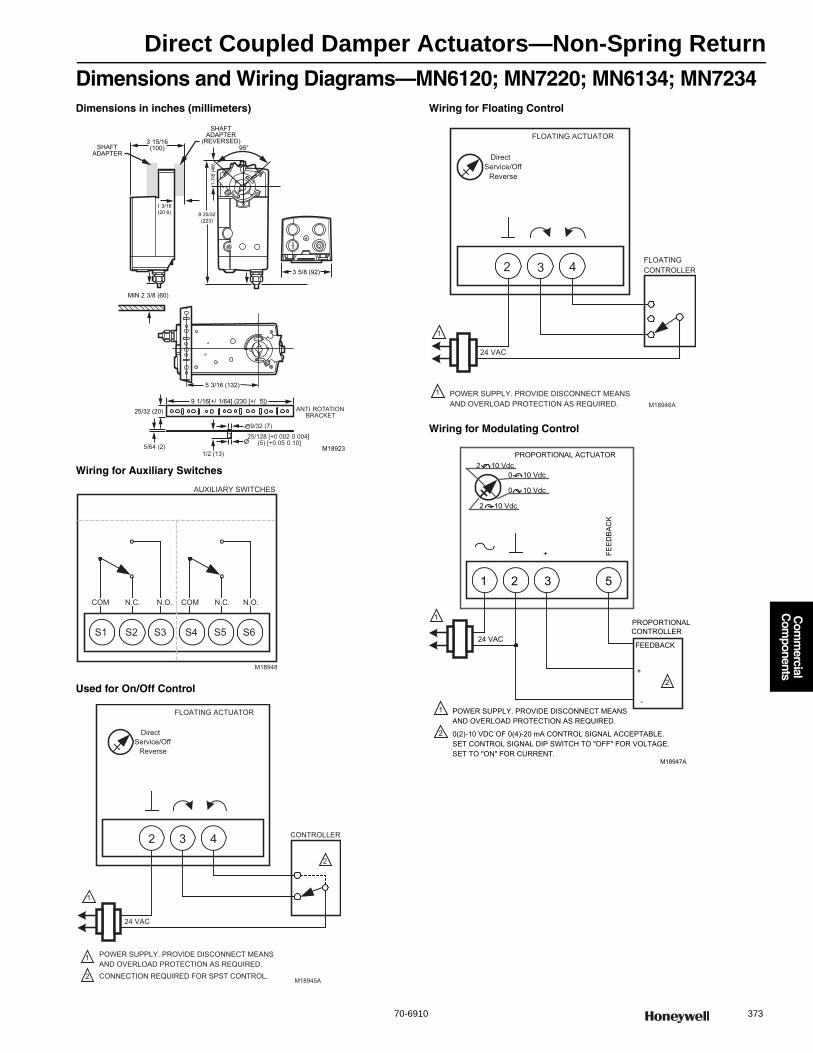
Direct Coupled Damper Actuators—Non-Spring Return
70-6910 373
Com
mercial
Com
ponents
Dimensions and Wiring Diagrams—MN6120; MN7220; MN6134; MN7234Dimensions in inches (millimeters)
Wiring for Auxiliary Switches
Used for On/Off Control
Wiring for Floating Control
Wiring for Modulating Control
M18923
3 15/16(100)SHAFT
ADAPTER
SHAFTADAPTER
(REVERSED)
1 3/16(20 6)
MIN 2 3/8 (60)
ANTI ROTATIONBRACKET
9 1/16[+/ 1/64] (230 [+/ 5])25/32 (20)
9/32 (7)
25/128 [+0 002 0 004] (5) [+0 05 0 10]
1/2 (13)5/64 (2)
95°
1-7/
8 (4
8)8 25/32(223)
5 3/16 (132)
3 5/8 (92)
AUXILIARY SWITCHES
S1 S2 S3 S4 S5 S6
COM N.O.N.C. COM N.O.N.C.
M18948
432
FLOATING ACTUATOR
24 VAC
1
1 POWER SUPPLY. PROVIDE DISCONNECT MEANSAND OVERLOAD PROTECTION AS REQUIRED.CONNECTION REQUIRED FOR SPST CONTROL.2
CONTROLLER
2
Direct
ReverseService/Off
M18945A
432
FLOATING ACTUATOR
24 VAC
Direct
ReverseService/Off
1
1 POWER SUPPLY. PROVIDE DISCONNECT MEANSAND OVERLOAD PROTECTION AS REQUIRED.
FLOATINGCONTROLLER
M18946A
24 VAC
1
1 POWER SUPPLY. PROVIDE DISCONNECT MEANSAND OVERLOAD PROTECTION AS REQUIRED.
PROPORTIONALCONTROLLER
+
-
FEEDBACK
1 32 5
PROPORTIONAL ACTUATOR
FEE
DB
AC
K
+
0(2)-10 VDC OF 0(4)-20 mA CONTROL SIGNAL ACCEPTABLE.SET CONTROL SIGNAL DIP SWITCH TO "OFF" FOR VOLTAGE.SET TO "ON" FOR CURRENT.
2
2
2 -10 Vdc
2 -10 Vdc
0 -10 Vdc
0 10 Vdc
M18947A

Direct Coupled Damper Actuators—Non-Spring Return
374 customer.honeywell.com 70-6910
N34 Series: MN6134; MN7234 Non-Spring Return Direct Coupled Actuator, 300 lb-in
The MN7234 is a 300 lb-in (34Nm), non-spring return, direct-coupled, low voltage actuator that accepts adjustable modulating (0/2-10 Vdc) control for: air dampers, air handling units, ventilation flaps, louvers, and ball valves.• Control for air damper applications with up to 85 sq ft assuming
3.5 in- b per sq ft of damper area, velocity independent • Patented self-centering shaft adapter • Access cover to facilitate connectivity • Declutch for manual adjustment • Mechanical end limits • Field-installable auxiliary switches • Rotation direction selectable by switch • Mountable in any orientation (no IP54 if upside down) • Mechanical position indicator • CE approved. UL approved
Actuator Type: Damper; ValveRotational Stroke: 95 ±3 degreesFail Safe Mode: Non-Spring ReturnTorque Rating: 300 lb-in. (34 Nm) Dimensions, Approximate: 8.78 in high x 3.62 in wide x 3.15 in deep
(223 mm high x 92 mm wide x 80 mm deep) External Auxiliary Switches Available: Yes, SW2-USNumber of Internal Auxiliary Switch: 0Electrical Connections: Enclosed screw terminal strip (22 to 14 AWG)Environmental Rating: NEMA2Frequency: 50 Hz; 60 HzManual operation: Declutch mechanismMounting: Direct CoupledMaximum Noise Rating, Driving (dBA @ 1m): 40Rotation to Open: By switch
Compatible Damper Shafts: 3/8 to 1.06 in. round or 3/8 to 11/16 in. square (10 to 27 mm round or 10 to 18 mm square)
Shaft Adapter Type: Self-centering clampingSupply Voltage: 24 Vac ±15%, 24 VdcMaterials: Plenum rated plastic housingOperating Humidity Range (% RH): 5 to 95% RH, non-condensingAmbient Temperature Range: -5 F to +140 F (-20 C to +60 C) Storage Temperature Range: -40 F to +175 F (-40 C to +80 C) Weight: 3.2 lb (1.45 kg) Includes: Mounting bracket, self-centering shaft adapterComments: Integral 1/2 in. NPSM conduit connectionApprovalsCE89/336/ECC, 73/23/EECC-Tick: N314Underwriters Laboratories, Inc: UL873, Plenum RatedCanadian Underwriters Laboratories, Inc: cUL C22.2 No. 24-93
Product Number Control Signal Feedback
Timing (seconds)Nominal Driving @ 60 Hz
Power Consumption, Driving Input Impedance
* MN6134A1003 On/Off; SPDT; Floating — 95 sec 9 VA, 9 W —
* MN7234A2008 (0)2-10 Vdc (4-20 mA w/500 ohm resistor)
(0)2-10 Vdc (max. output: ±1.0 mA)
95 sec 8 VA, 6 W 100K ohm (voltage), 500 ohm (current)
* TRADELINE models • SUPER TRADELINE models
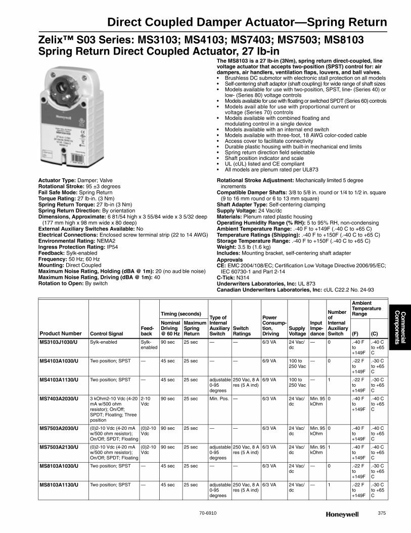
Direct Coupled Damper Actuator—Spring Return
70-6910 375
Com
mercial
Com
ponents
Zelix™ S03 Series: MS3103; MS4103; MS7403; MS7503; MS8103 Spring Return Direct Coupled Actuator, 27 lb-in
The MS8103 is a 27 lb-in (3Nm), spring return direct-coupled, line voltage actuator that accepts two-position (SPST) control for: air dampers, air handlers, ventilation flaps, louvers, and ball valves.• Brushless DC submotor with electronic stall protection on all models • Self-centering shaft adaptor (shaft coupling) for wide range of shaft sizes • Models available for use with two-position, SPST, line- (Series 40) or
low- (Series 80) voltage controls • Models available for use with floating or switched SPDT (Series 60) controls • Models avail able for use with proportional current or
voltage (Series 70) controls • Models available with combined floating and
modulating control in a single device • Models available with an internal end switch • Models available with three-foot, 18 AWG color-coded cable • Access cover to facilitate connectivity • Durable plastic housing with built-in mechanical end limits • Spring return direction field selectable • Shaft position indicator and scale • UL (cUL) listed and CE compliant • All models are plenum rated per UL873
Actuator Type: Damper; ValveRotational Stroke: 95 ±3 degreesFail Safe Mode: Spring ReturnTorque Rating: 27 lb-in. (3 Nm) Spring Return Torque: 27 lb-in (3 Nm) Spring Return Direction: By orientationDimensions, Approximate: 6 81/54 high x 3 55/84 wide x 3 5/32 deep
(177 mm high x 98 mm wide x 80 deep) External Auxiliary Switches Available: NoElectrical Connections: Enclosed screw terminal strip (22 to 14 AWG)Environmental Rating: NEMA2Ingress Protection Rating: IP54Feedback: Sylk-enabledFrequency: 50 Hz; 60 HzMounting: Direct CoupledMaximum Noise Rating, Holding (dBA @ 1m): 20 (no aud ble noise)Maximum Noise Rating, Driving (dBA @ 1m): 40Rotation to Open: By switch
Rotational Stroke Adjustment: Mechanically limited 5 degree increments
Compatible Damper Shafts: 3/8 to 5/8 in. round or 1/4 to 1/2 in. square (9 to 16 mm round or 6 to 13 mm square)
Shaft Adapter Type: Self-centering clampingSupply Voltage: 24 Vac/dcMaterials: Plenum rated plastic housingOperating Humidity Range (% RH): 5 to 95% RH, non-condensingAmbient Temperature Range: .-40 F to +149F (.-40 C to +65 C) Temperature Ratings (Shipping): .-40 F to +150F (.-40 C to +65 C) Storage Temperature Range: .-40 F to +150F (.-40 C to +65 C) Weight: 3.5 lb (1.6 kg) Includes: Mounting bracket, self-centering shaft adapterApprovalsCE: EMC 2004/108/EC; Certification Low Voltage Directive 2006/95/EC;
IEC 60730-1 and Part 2-14C-Tick: N314Underwriters Laboratories, Inc: UL 873Canadian Underwriters Laboratories, Inc: cUL C22.2 No. 24-93
Product Number Control SignalFeed-back
Timing (seconds)Type of Internal Auxiliary Switch
Switch Ratings
Power Consump-tion, Driving
Supply Voltage
Input Impe-dance
Number of Internal Auxiliary Switch
Ambient Temperature Range
Nominal Driving @ 60 Hz
Maximum Spring Return (F) (C)
MS3103J1030/U Sylk-enabled Sylk-enabled
90 sec 25 sec — — 6/3 VA 24 Vac/dc
— 0 .-40 F to +149F
.-40 C to +65 C
MS4103A1030/U Two position; SPST — 45 sec 25 sec — — 6/9 VA 100 to 250 Vac
— 0 .-22 F to +149F
.-30 C to +65 C
MS4103A1130/U Two position; SPST — 45 sec 25 sec adjustable 0-95 degrees
250 Vac, 8 A res (5 A ind)
6/9 VA 100 to 250 Vac
— 1 .-22 F to +149F
.-30 C to +65 C
MS7403A2030/U 3 kOhm2-10 Vdc (4-20 mA w/500 ohm resistor); On/Off; SPDT; Floating; Three position
2-10 Vdc
90 sec 25 sec Min. Pos. — 6/3 VA 24 Vac/dc
Min. 95 kOhm
0 .-40 F to +149F
.-40 C to +65 C
MS7503A2030/U (0)2-10 Vdc (4-20 mA w/500 ohm resistor); On/Off; SPDT; Floating
(0)2-10 Vdc
90 sec 25 sec — — 6/3 VA 24 Vac/dc
Min. 95 kOhm
0 .-40 F to +149F
.-40 C to +65 C
MS7503A2130/U (0)2-10 Vdc (4-20 mA w/500 ohm resistor); On/Off; SPDT; Floating
(0)2-10 Vdc
90 sec 25 sec adjustable 0-95 degrees
250 Vac, 8 A res (5 A ind)
6/3 VA 24 Vac/dc
Min. 95 kOhm
1 .-40 F to +149F
.-40 C to +65 C
MS8103A1030/U Two position; SPST — 45 sec 25 sec — — 6/3 VA 24 Vac/dc
— 0 .-22 F to +149F
.-30 C to +65 C
MS8103A1130/U Two position; SPST — 45 sec 25 sec adjustable 0-95 degrees
250 Vac, 8 A res (5 A ind)
6/3 VA 24 Vac/dc
— 1 .-22 F to +149F
.-30 C to +65 C

Direct Coupled Damper Actuator—Spring Return
376 customer.honeywell.com 70-6910
Dimension and Wiring Diagrams—MS3103; MS3105; MS4103; MS4105; MS7403; MS7405; MS7503; MS7505; MS8103; MS8105Dimensions in inches (millimeters)
Wiring for low-voltage two-position control
Wiring for line-voltage two-position control
Wiring for SPDT on/off Control
Wiring for floating control
Wiring for (0)2-10 Vdc proportioning controllers
M27712A
3-55/64 (98)
6-61/64(177)
1-1/8(29)
5-27/32(148)
1-9/16(40)
3-5/32 (80)
4-9/16(116)
1-15/16(49)
1-1/16(27)
2-1/64(55)
47/64(19)2-27/64 (61)
ACTUATOR
SPST24 VAC1
1
2
2
LINE VOLTAGE POWER SUPPLY. PROVIDE DISCONNECT MEANS AND OVERLOAD PROTECTION AS REQUIRED.
24 VDC SUPPLY ACCEPTABLE.
V1
2
M29512
ACTUATOR
SPST1
1 LINE VOLTAGE POWER SUPPLY. PROVIDE DISCONNECT MEANS AND OVERLOAD PROTECTION AS REQUIRED.
V1
2
M29513
SPDT
24 VAC1
1
2
3
2
LINE VOLTAGE POWER SUPPLY. PROVIDE DISCONNECT MEANS AND OVERLOAD PROTECTION AS REQUIRED.
24 VDC SUPPLY ACCEPTABLE.
SET SWITCH TO FLOATING. M29514
ACTUATOR
V
0°-90°
90°-0°
FEEDBACK5
4
3
1
2
2-10 VDC10-2 VDC0-10 VDC10-0 VDCFltg, fwdFltg, rev
3
24 VAC 1
1
2
3
2
LINE VOLTAGE POWER SUPPLY. PROVIDE DISCONNECT MEANS AND OVERLOAD PROTECTION AS REQUIRED.
24 VDC SUPPLY ACCEPTABLE.
SET SWITCH TO FLOATING.
M29515
ACTUATOR
V
FEEDBACK5
4
3
1
2
2-10 VDC 10-2 VDC 0-10 VDC 10-0 VDC Fltg, fwd Fltg, rev
3
0°-90°
90°-0°
ACTUATOR
0/2 TO 10 VDCPROPORTIONINGCONTROLLER
24 VAC1
1
2
3
2
LINE VOLTAGE POWER SUPPLY. PROVIDE DISCONNECT MEANS AND OVERLOAD PROTECTION AS REQUIRED.
24 VDC SUPPLY ACCEPTABLE.
SET SWITCH TO MODULATING.
V
FEEDBACK–
+
FEEDBACK
5
4
3
1
2
M29516
2-10 VDC10-2 VDC0-10 VDC10-0 VDCFltg, fwdFltg, rev
3
0°-90°
90°-0°
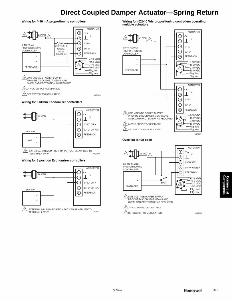
Direct Coupled Damper Actuator—Spring Return
70-6910 377
Com
mercial
Com
ponents
Wiring for 4-10 mA proportioning controllers
Wiring for 3 kOhm Economizer controllers
Wiring for 3 position Economizer controllers
Wiring for (0)2-10 Vdc proportioning controllers operating multiple actuators
Override to full open
ACTUATOR
4 TO 20 mA PROPORTIONING CONTROLLER
24 VAC1
1
2
3
2
490 TO 510 OHMS, 1/2 W
MINIMUM
LINE VOLTAGE POWER SUPPLY. PROVIDE DISCONNECT MEANS AND OVERLOAD PROTECTION AS REQUIRED. 24 VDC SUPPLY ACCEPTABLE. SET SWITCH TO MODULATING.
V
FEEDBACK –
+
FEEDBACK
5
4
3
1
2
M29508
2-10 VDC 10-2 VDC 0-10 VDC 10-0 VDC Fltg, fwd Fltg, rev
3
0°-90°
90°-0°
ACTUATOR
SENSOR
24 VAC V
FEEDBACK–
+
5
4
3
1
2
M29510
3KΩ
0°-90° OR +
90°-0° OR N/A
1 EXTERNAL MINIMUM POSITION POT CAN BE APPLIED TO TERMINAL 4 90°-0°.
ACTUATOR
SENSOR
24 VAC V
FEEDBACK–
+
5
4
3
1
2
M29511
0°-90° OR +
90°-0° OR N/A
1 EXTERNAL MINIMUM POSITION POT CAN BE APPLIED TO TERMINAL 4 90°-0°.
ACTUATOR
0/2 TO 10 VDCPROPORTIONINGCONTROLLER
24 VAC1
1
2
3
2
LINE VOLTAGE POWER SUPPLY. PROVIDE DISCONNECT MEANS AND OVERLOAD PROTECTION AS REQUIRED.
24 VDC SUPPLY ACCEPTABLE.
SET SWITCH TO MODULATING.
V
FEEDBACK–
+
FEEDBACK
5
4
3
1
2
M29509
2-10 VDC10-2 VDC0-10 VDC10-0 VDCFltg, fwdFltg, rev
3
ACTUATOR
V
FEEDBACK5
4
3
1
2
2-10 VDC10-2 VDC0-10 VDC10-0 VDCFltg, fwdFltg, rev
3
0°-90°
90°-0°
0°-90°
90°-0°
ACTUATOR
0/2 TO 10 VDC PROPORTIONING CONTROLLER
24 VAC 1
1
2
3
2
LINE VOLTAGE POWER SUPPLY. PROVIDE DISCONNECT MEANS AND OVERLOAD PROTECTION AS REQUIRED. 24 VDC SUPPLY ACCEPTABLE. SET SWITCH TO MODULATING.
V
FEEDBACK–
+
FEEDBACK
5
4
3
1
2
M27827
2-10 VDC 10-2 VDC 0-10 VDC 10-0 VDC Fltg, fwd Fltg, rev
3 SPDT
0°-90° OR +
90°-0° OR N/A
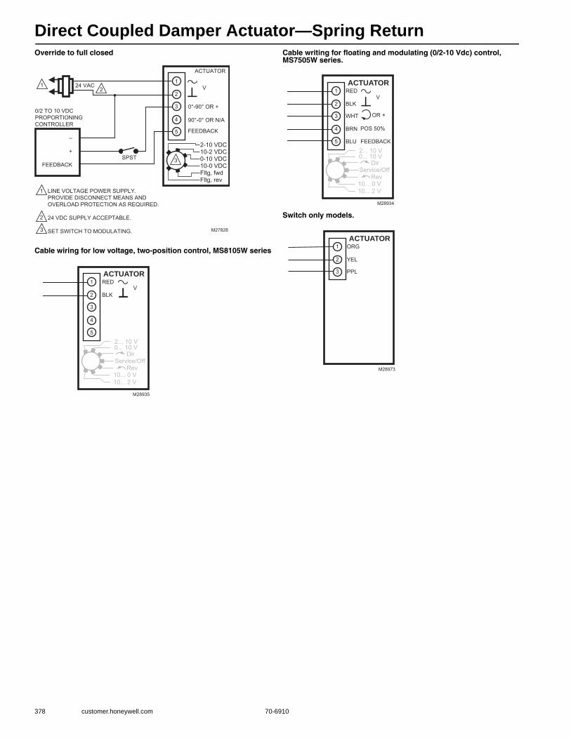
Direct Coupled Damper Actuator—Spring Return
378 customer.honeywell.com 70-6910
Override to full closed
Cable wiring for low voltage, two-position control, MS8105W series
Cable writing for floating and modulating (0/2-10 Vdc) control, MS7505W series.
Switch only models.
ACTUATOR
0/2 TO 10 VDC PROPORTIONING CONTROLLER
24 VAC 1
1
2
3
2
LINE VOLTAGE POWER SUPPLY. PROVIDE DISCONNECT MEANS AND OVERLOAD PROTECTION AS REQUIRED. 24 VDC SUPPLY ACCEPTABLE. SET SWITCH TO MODULATING.
V
FEEDBACK –
+
FEEDBACK
5
4
3
1
2
2-10 VDC 10-2 VDC 0-10 VDC 10-0 VDC Fltg, fwd Fltg, rev
3 SPST
M27828
0°-90° OR +
90°-0° OR N/A
M28935
ACTUATOR
BLK
RED
5
4
3
1
2
DirService/Off Rev
2... 10 V0... 10 V
10... 0 V10... 2 V
V
M28934
ACTUATOR
BLU
BRN
WHT
BLK
RED
5
4
3
1
2
DirService/Off Rev
2... 10 V0... 10 V
10... 0 V10... 2 V
V
OR +
FEEDBACK
POS 50%
M28973
ACTUATOR
PPL
YEL
ORG
3
1
2

Direct Coupled Damper Actuator—Spring Return
70-6910 379
Com
mercial
Com
ponents
Zelix™ S05 Series: MS3105; MS4105; MS7405; MS7505; MS8105 Spring Return Direct Coupled Actuator, 44 lb-in
The MS8105 is a 44 lb-in (5Nm), spring return direct-coupled, line voltage actuator that accepts two-position (SPST) control for: air dampers, air handlers, ventilation flaps, louvers, and ball valves.• Brushless DC submotor with electronic stall protection on all models • Self-centering shaft adaptor (shaft coupling) for wide range of shaft sizes • Models available for use with two-position, SPST, line- (Series 40)
or low- (Series 80) voltage controls • Models available for use with floating or switched SPDT (Series 60) controls • Models avail able for use with proportional current or
voltage (Series 70) controls • Models available with combined floating and
modulating control in a single device • Models available with an internal end switch • Models available with three-foot, 18 AWG color-coded cable • Access cover to facilitate connectivity • Durable plastic housing with built-in mechanical end limits • Spring return direction field selectable • Shaft position indicator and scale • UL (cUL) listed and CE compliant • All models are plenum rated per UL873• Integral 1/2 in. NPSM conduit connection on some models
Actuator Type: Damper; ValveRotational Stroke: 95 ±3 degreesFail Safe Mode: Spring ReturnTorque Rating: 44 lb-in. (5 Nm) Spring Return Torque: 44 lb-in. (5 Nm) Spring Return Direction: By orientationDimensions, Approximate: 6 81/54 high x 3 55/84 wide x 3 5/32 deep
(177 mm high x 98 mm wide x 80 deep) External Auxiliary Switches Available: NoEnvironmental Rating: NEMA2Ingress Protection Rating: IP54Feedback: Sylk-enabledFrequency: 50 Hz; 60 HzMounting: Direct CoupledMaximum Noise Rating, Holding (dBA @ 1m): 20 (no aud ble noise)Maximum Noise Rating, Driving (dBA @ 1m): 40Rotation to Open: By switchRotational Stroke Adjustment: Mechanically limited 5 degree
increments
Compatible Damper Shafts: 3/8 to 5/8 in. round or 1/4 to 1/2 in. square (9 to 16 mm round or 6 to 13 mm square)
Shaft Adapter Type: Self-centering clampingSupply Voltage: 24 Vac/dcMaterials: Plenum rated plastic housingOperating Humidity Range (% RH): 5 to 95% RH, non-condensingTemperature Ratings (Shipping): -40 F to +150F (-40 C to +65 C) Ambient Temperature Range:
MS3105, MS7405, MS7505: -40 F to +149F (-40 C to +65 C)MS4105, MS8105: -22 F to +149F (-30 C to +65 C)
Storage Temperature Range: .-40 F to +150F (.-40 C to +65 C) Weight: 3.5 lb (1.6 kg) Includes: Mounting bracket, self-centering shaft adapterApprovalsCE: EMC 2004/108/EC; Certification Low Voltage Directive 2006/95/EC;
IEC 60730-1 and Part 2-14C-Tick: N314Underwriters Laboratories, Inc: UL 873Canadian Underwriters Laboratories, Inc: cUL C22.2 No. 24-93
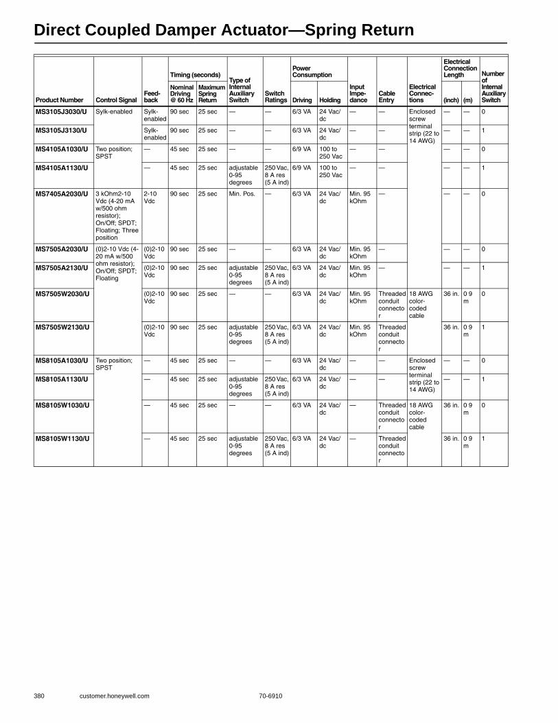
Direct Coupled Damper Actuator—Spring Return
380 customer.honeywell.com 70-6910
Product Number Control SignalFeed-back
Timing (seconds)Type of Internal Auxiliary Switch
Switch Ratings
Power Consumption
Input Impe-dance
Cable Entry
Electrical Connec-tions
Electrical Connection Length Number
of Internal Auxiliary Switch
Nominal Driving @ 60 Hz
Maximum Spring Return Driving Holding (inch) (m)
MS3105J3030/U Sylk-enabled Sylk-enabled
90 sec 25 sec — — 6/3 VA 24 Vac/dc
— — Enclosed screw terminal strip (22 to 14 AWG)
— — 0
MS3105J3130/U Sylk-enabled
90 sec 25 sec — — 6/3 VA 24 Vac/dc
— — — — 1
MS4105A1030/U Two position; SPST
— 45 sec 25 sec — — 6/9 VA 100 to 250 Vac
— — — — 0
MS4105A1130/U — 45 sec 25 sec adjustable 0-95 degrees
250 Vac, 8 A res (5 A ind)
6/9 VA 100 to 250 Vac
— — — — 1
MS7405A2030/U 3 kOhm2-10 Vdc (4-20 mA w/500 ohm resistor); On/Off; SPDT; Floating; Three position
2-10 Vdc
90 sec 25 sec Min. Pos. — 6/3 VA 24 Vac/dc
Min. 95 kOhm
— — — 0
MS7505A2030/U (0)2-10 Vdc (4-20 mA w/500 ohm resistor); On/Off; SPDT; Floating
(0)2-10 Vdc
90 sec 25 sec — — 6/3 VA 24 Vac/dc
Min. 95 kOhm
— — — 0
MS7505A2130/U (0)2-10 Vdc
90 sec 25 sec adjustable 0-95 degrees
250 Vac, 8 A res (5 A ind)
6/3 VA 24 Vac/dc
Min. 95 kOhm
— — — 1
MS7505W2030/U (0)2-10 Vdc
90 sec 25 sec — — 6/3 VA 24 Vac/dc
Min. 95 kOhm
Threaded conduit connector
18 AWG color-coded cable
36 in. 0 9 m
0
MS7505W2130/U (0)2-10 Vdc
90 sec 25 sec adjustable 0-95 degrees
250 Vac, 8 A res (5 A ind)
6/3 VA 24 Vac/dc
Min. 95 kOhm
Threaded conduit connector
36 in. 0 9 m
1
MS8105A1030/U Two position; SPST
— 45 sec 25 sec — — 6/3 VA 24 Vac/dc
— — Enclosed screw terminal strip (22 to 14 AWG)
— — 0
MS8105A1130/U — 45 sec 25 sec adjustable 0-95 degrees
250 Vac, 8 A res (5 A ind)
6/3 VA 24 Vac/dc
— — — — 1
MS8105W1030/U — 45 sec 25 sec — — 6/3 VA 24 Vac/dc
— Threaded conduit connector
18 AWG color-coded cable
36 in. 0 9 m
0
MS8105W1130/U — 45 sec 25 sec adjustable 0-95 degrees
250 Vac, 8 A res (5 A ind)
6/3 VA 24 Vac/dc
— Threaded conduit connector
36 in. 0 9 m
1
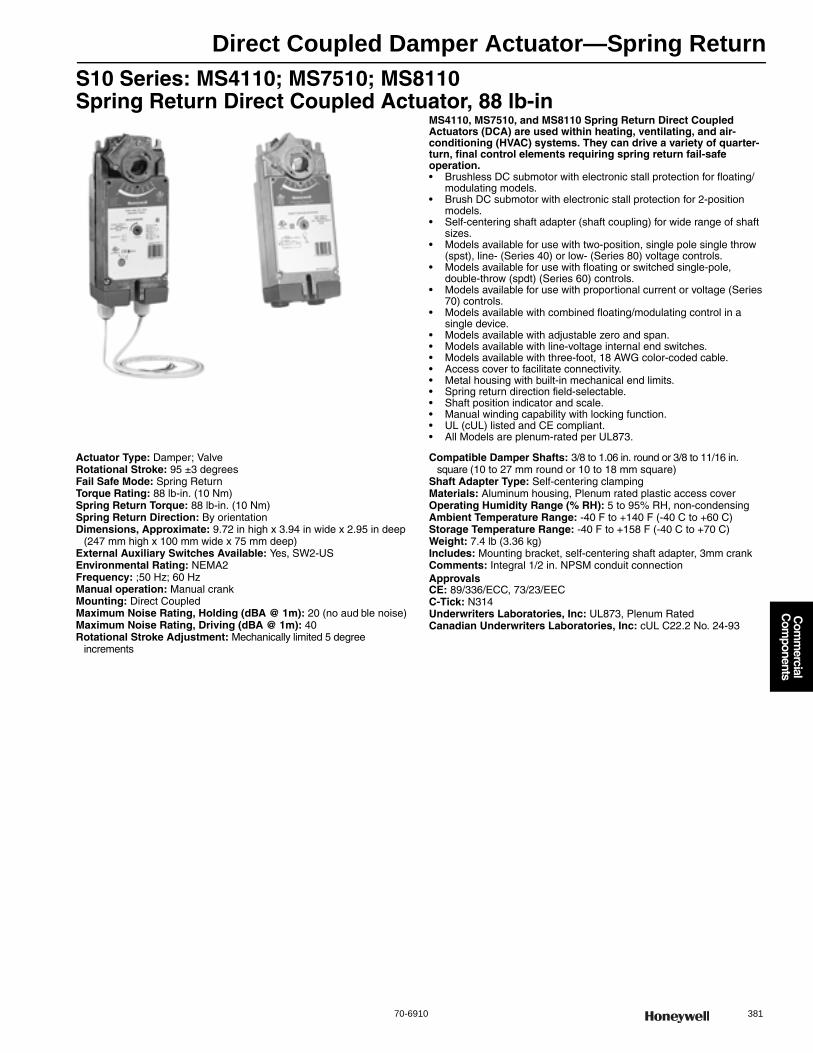
Direct Coupled Damper Actuator—Spring Return
70-6910 381
Com
mercial
Com
ponents
S10 Series: MS4110; MS7510; MS8110 Spring Return Direct Coupled Actuator, 88 lb-in
MS4110, MS7510, and MS8110 Spring Return Direct Coupled Actuators (DCA) are used within heating, ventilating, and air-conditioning (HVAC) systems. They can drive a variety of quarter-turn, final control elements requiring spring return fail-safe operation.• Brushless DC submotor with electronic stall protection for floating/
modulating models. • Brush DC submotor with electronic stall protection for 2-position
models. • Self-centering shaft adapter (shaft coupling) for wide range of shaft
sizes. • Models available for use with two-position, single pole single throw
(spst), line- (Series 40) or low- (Series 80) voltage controls. • Models available for use with floating or switched single-pole,
double-throw (spdt) (Series 60) controls.• Models available for use with proportional current or voltage (Series
70) controls.• Models available with combined floating/modulating control in a
single device.• Models available with adjustable zero and span.• Models available with line-voltage internal end switches. • Models available with three-foot, 18 AWG color-coded cable. • Access cover to facilitate connectivity. • Metal housing with built-in mechanical end limits. • Spring return direction field-selectable. • Shaft position indicator and scale. • Manual winding capability with locking function. • UL (cUL) listed and CE compliant. • All Models are plenum-rated per UL873.
Actuator Type: Damper; ValveRotational Stroke: 95 ±3 degreesFail Safe Mode: Spring ReturnTorque Rating: 88 lb-in. (10 Nm) Spring Return Torque: 88 lb-in. (10 Nm) Spring Return Direction: By orientationDimensions, Approximate: 9.72 in high x 3.94 in wide x 2.95 in deep
(247 mm high x 100 mm wide x 75 mm deep) External Auxiliary Switches Available: Yes, SW2-USEnvironmental Rating: NEMA2Frequency: ;50 Hz; 60 HzManual operation: Manual crankMounting: Direct CoupledMaximum Noise Rating, Holding (dBA @ 1m): 20 (no aud ble noise)Maximum Noise Rating, Driving (dBA @ 1m): 40Rotational Stroke Adjustment: Mechanically limited 5 degree
increments
Compatible Damper Shafts: 3/8 to 1.06 in. round or 3/8 to 11/16 in. square (10 to 27 mm round or 10 to 18 mm square)
Shaft Adapter Type: Self-centering clampingMaterials: Aluminum housing, Plenum rated plastic access coverOperating Humidity Range (% RH): 5 to 95% RH, non-condensingAmbient Temperature Range: -40 F to +140 F (-40 C to +60 C) Storage Temperature Range: -40 F to +158 F (-40 C to +70 C) Weight: 7.4 lb (3.36 kg) Includes: Mounting bracket, self-centering shaft adapter, 3mm crankComments: Integral 1/2 in. NPSM conduit connectionApprovalsCE: 89/336/ECC, 73/23/EECC-Tick: N314Underwriters Laboratories, Inc: UL873, Plenum RatedCanadian Underwriters Laboratories, Inc: cUL C22.2 No. 24-93
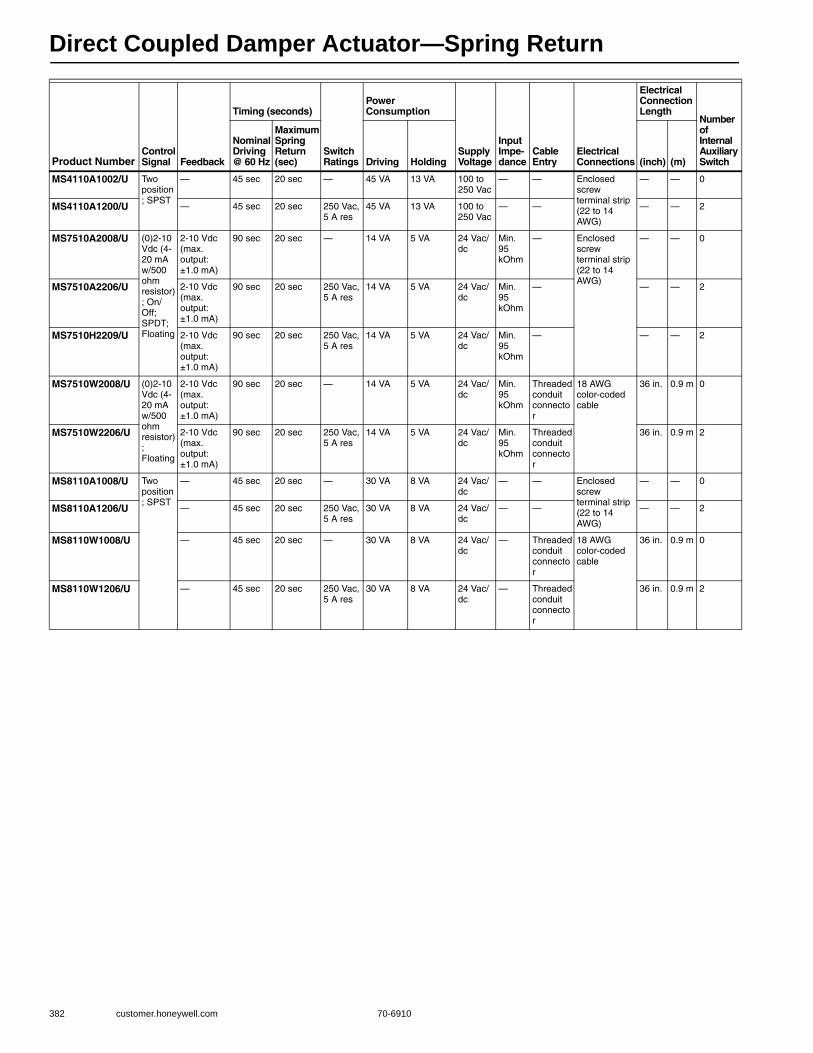
Direct Coupled Damper Actuator—Spring Return
382 customer.honeywell.com 70-6910
Product NumberControl Signal Feedback
Timing (seconds)
Switch Ratings
Power Consumption
Supply Voltage
Input Impe-dance
Cable Entry
Electrical Connections
Electrical Connection Length
Number of Internal Auxiliary Switch
Nominal Driving @ 60 Hz
Maximum Spring Return (sec) Driving Holding (inch) (m)
MS4110A1002/U Two position; SPST
— 45 sec 20 sec — 45 VA 13 VA 100 to 250 Vac
— — Enclosed screw terminal strip (22 to 14 AWG)
— — 0
MS4110A1200/U — 45 sec 20 sec 250 Vac, 5 A res
45 VA 13 VA 100 to 250 Vac
— — — — 2
MS7510A2008/U (0)2-10 Vdc (4-20 mA w/500 ohm resistor); On/Off; SPDT; Floating
2-10 Vdc (max. output: ±1.0 mA)
90 sec 20 sec — 14 VA 5 VA 24 Vac/dc
Min. 95 kOhm
— Enclosed screw terminal strip (22 to 14 AWG)
— — 0
MS7510A2206/U 2-10 Vdc (max. output: ±1.0 mA)
90 sec 20 sec 250 Vac, 5 A res
14 VA 5 VA 24 Vac/dc
Min. 95 kOhm
— — — 2
MS7510H2209/U 2-10 Vdc (max. output: ±1.0 mA)
90 sec 20 sec 250 Vac, 5 A res
14 VA 5 VA 24 Vac/dc
Min. 95 kOhm
— — — 2
MS7510W2008/U (0)2-10 Vdc (4-20 mA w/500 ohm resistor); Floating
2-10 Vdc (max. output: ±1.0 mA)
90 sec 20 sec — 14 VA 5 VA 24 Vac/dc
Min. 95 kOhm
Threaded conduit connector
18 AWG color-coded cable
36 in. 0.9 m 0
MS7510W2206/U 2-10 Vdc (max. output: ±1.0 mA)
90 sec 20 sec 250 Vac, 5 A res
14 VA 5 VA 24 Vac/dc
Min. 95 kOhm
Threaded conduit connector
36 in. 0.9 m 2
MS8110A1008/U Two position; SPST
— 45 sec 20 sec — 30 VA 8 VA 24 Vac/dc
— — Enclosed screw terminal strip (22 to 14 AWG)
— — 0
MS8110A1206/U — 45 sec 20 sec 250 Vac, 5 A res
30 VA 8 VA 24 Vac/dc
— — — — 2
MS8110W1008/U — 45 sec 20 sec — 30 VA 8 VA 24 Vac/dc
— Threaded conduit connector
18 AWG color-coded cable
36 in. 0.9 m 0
MS8110W1206/U — 45 sec 20 sec 250 Vac, 5 A res
30 VA 8 VA 24 Vac/dc
— Threaded conduit connector
36 in. 0.9 m 2

Direct Coupled Damper Actuator—Spring Return
70-6910 383
Com
mercial
Com
ponents
Dimension and Wiring Diagrams—MS4110; MS4120; MS7510; MS7520; MS8110; MS8120Dimensions in inches (millimeters)
Wiring for On/Off Control
Wiring for Floating Control (Floating mode setting)
Wiring for Proportioning Controllers (Modulating mode setting)
Override to full open (Modulating mode setting)
9-3/4(247)
1-9/16(40)
2-1/2(64)MIN.
3 (76)MIN.
3 (76)MIN.
FROMSHAFT
END
6-1/8(156)
1-9/16(40)
1-9/16(40)
3-15/16 (100)
2-15/16 (75)1/4 (6)
M20952
ACTUATOR
SPST24 VAC1
1
2
2
LINE VOLTAGE POWER SUPPLY. PROVIDE DISCONNECT MEANS AND OVERLOAD PROTECTION AS REQUIRED.
24 VDC SUPPLY ACCEPTABLE.
ENSURE PROPER GROUNDING OF ACTUATOR CASE.
V1
2
M19718C3
3
ACTUATOR
SPST1
1 LINE VOLTAGE POWER SUPPLY. PROVIDE DISCONNECT MEANS AND OVERLOAD PROTECTION AS REQUIRED.
ENSURE PROPER GROUNDING OF ACTUATOR CASE.
V1
2
M22289A
2
2
24 VAC 1
1
2
3
2
LINE VOLTAGE POWER SUPPLY. PROVIDE DISCONNECT MEANS AND OVERLOAD PROTECTION AS REQUIRED.
24 VDC SUPPLY ACCEPTABLE.
SET SWITCH TO FLOATING.
M19573B
ACTUATOR
V
OR +
OR N/A
FEEDBACK 5
4
3
1
2
2-10 VDC 10-2 VDC 0-10 VDC 10-0 VDC Fltg, fwd Fltg, rev
3
4
4
ENSURE PROPER GROUNDING OF ACTUATOR CASE.
ACTUATOR
0/2 TO 10 VDCPROPORTIONINGCONTROLLER
24 VAC1
1
2
3
2
LINE VOLTAGE POWER SUPPLY. PROVIDE DISCONNECT MEANS AND OVERLOAD PROTECTION AS REQUIRED.
24 VDC SUPPLY ACCEPTABLE.
SET SWITCH TO MODULATING.
V
OR +
OR N/A
FEEDBACK–
+
FEEDBACK
5
4
3
1
2
M19574B
2-10 VDC10-2 VDC0-10 VDC10-0 VDCFltg, fwdFltg, rev
3
4 ENSURE PROPER GROUNDING OF ACTUATOR CASE.
4
ACTUATOR
0/2 TO 10 VDCPROPORTIONINGCONTROLLER
24 VAC1
1
2
3
2
LINE VOLTAGE POWER SUPPLY. PROVIDE DISCONNECT MEANS AND OVERLOAD PROTECTION AS REQUIRED.
24 VDC SUPPLY ACCEPTABLE.
SET SWITCH TO MODULATING.
V
OR +
OR N/A
FEEDBACK–
+
FEEDBACK
5
4
3
1
2
M19576A
2-10 VDC10-2 VDC0-10 VDC10-0 VDCFltg, fwdFltg, rev
3SPDT

Direct Coupled Damper Actuator—Spring Return
384 customer.honeywell.com 70-6910
MS7510W2008/2206 Floating Modulating.
MS8110W1008/1206 Two Position, Low voltage.
Switch only models.
Override to full closed (Modulating mode setting)
Terminal Block Details
Wiring for Proportioning Controllers (Modulating mode setting)
Wiring for Proportioning Controllers operating multiple actuators (Modulating mode setting)
M28934
ACTUATOR
BLU
BRN
WHT
BLK
RED
5
4
3
1
2
DirService/Off Rev
2... 10 V0... 10 V
10... 0 V10... 2 V
V
OR +
FEEDBACK
POS 50%
M28935
ACTUATOR
BLK
RED
5
4
3
1
2
DirService/Off Rev
2... 10 V0... 10 V
10... 0 V10... 2 V
V
M28936
ACTUATOR
GRY
PPL
YEL
ORG
4
3
1
2
PNK5
TAN6
ACTUATOR
0/2 TO 10 VDCPROPORTIONINGCONTROLLER
24 VAC1
1
2
3
2
LINE VOLTAGE POWER SUPPLY. PROVIDE DISCONNECT MEANS AND OVERLOAD PROTECTION AS REQUIRED.
24 VDC SUPPLY ACCEPTABLE.
SET SWITCH TO MODULATING.
V
OR +
OR N/A
FEEDBACK–
+
FEEDBACK
5
4
3
1
2
M19577A
2-10 VDC10-2 VDC0-10 VDC10-0 VDCFltg, fwdFltg, rev
3SPST
1 POWER SUPPLY. PROVIDE DISCONNECT MEANS AND OVERLOAD PROTECTION AS REQUIRED.
3 ENSURE PROPER GROUNDING OF ACTUATOR CASE.
2 THE INTERNAL AUXILIARY SWITCHES MUST BE CONNECTED TO THE SAME POWER SOURCE; OR THE AUXILIARY SWITCHES SHALL BE CONNECTED TO THE SAME POLE OF THE SAME SUPPLY CIRCUIT, CONNECTED IN A SAME POLARITY MANNER.
V OR+
ORN/A FE
ED
BA
CK
ACTUATOR
12
3
5431
7° 85°
S1 S2 S3 S4 S5 S6 2
M19571B
ACTUATOR
4 TO 20 mA PROPORTIONING CONTROLLER
24 VAC 1
1
2
3
2
490 TO 510 OHMS, 1/2 W
MINIMUM
LINE VOLTAGE POWER SUPPLY. PROVIDE DISCONNECT MEANS AND OVERLOAD PROTECTION AS REQUIRED. 24 VDC SUPPLY ACCEPTABLE. SET SWITCH TO MODULATING.
V
OR +
OR N/A
FEEDBACK –
+
FEEDBACK
5
4
3
1
2
M22282B
2-10 VDC 10-2 VDC 0-10 VDC 10-0 VDC Fltg, fwd Fltg, rev
3
4 ENSURE PROPER GROUNDING OF ACTUATOR CASE.
4
ACTUATOR
0/2 TO 10 VDCPROPORTIONINGCONTROLLER
1
2
3
2
LINE VOLTAGE POWER SUPPLY. PROVIDE DISCONNECT MEANS AND OVERLOAD PROTECTION AS REQUIRED.
24 VDC SUPPLY ACCEPTABLE.
SET SWITCH TO MODULATING.
V
OR +
OR N/A
FEEDBACK5
4
3
1
2
M22288
2-10 VDC10-2 VDC0-10 VDC10-0 VDCFltg, fwdFltg, rev
3
ACTUATOR
V
OR +
OR N/A
FEEDBACK5
4
3
1
2
2-10 VDC10-2 VDC0-10 VDC10-0 VDCFltg, fwdFltg, rev
3
24 VAC1
24 VAC1
224 VAC1
HOT
COM
–
+

Direct Coupled Damper Actuator—Spring Return
70-6910 385
Com
mercial
Com
ponents
S20 Series: MS4120; MS7520; MS8120 Spring Return Direct Coupled Actuator, 175 lb-in
MS4120, MS7520, MS8120 Spring Return Direct Coupled Actuators (DCA) are used within heating, ventilating, and air-conditioning (HVAC) systems. They can drive a variety of quarter-turn, final control elements requiring spring return fail-safe operation.• Brushless DC submotor with electronic stall protection for floating/
modulating models.• Brush DC submotor with electronic stall protection for 2-position
models. • Self-centering shaft adapter (shaft coupling) for wide range of shaft
sizes. • Models available for use with two-position, single pole single throw
(spst), line- (Series 40) or low- (Series 80) voltage controls. • Models available for use with floating or switched single-pole,
double-throw (spdt) (Series 60) controls. • Models available for use with proportional current or voltage (Series
70) controls. • Models available with combined floating/modulating control in a
single device.• Models available with adjustable zero and span.• Models available with line-voltage internal end switches. • Models available with three-foot, 18 AWG color-coded cable. • Access cover to facilitate connectivity. • Metal housing with built-in mechanical end limits. • Spring return direction field-selectable. • Shaft position indicator and scale. • Manual winding capability with locking function. • UL (cUL) listed and CE compliant.• All models are plenum-rated per UL873.
Actuator Type: Damper; ValveRotational Stroke: 95 ±3 degreesFail Safe Mode: Spring ReturnTorque Rating: 175 lb-in. (20 Nm) Spring Return Torque: 175 lb-in. (20 Nm) Spring Return Direction: By orientationDimensions, Approximate: 9.72 in high x 3.94 in wide x 2.95 in deep
(247 mm high x 100 mm wide x 75 mm deep) External Auxiliary Switches Available: Yes, SW2-USElectrical Connections: Enclosed screw terminal strip (22 to 14 AWG)Environmental Rating: NEMA2Frequency: 50 Hz; 60 HzManual operation: Manual crankMounting: Direct CoupledMaximum Noise Rating, Holding (dBA @ 1m): 20 (no aud ble noise)Maximum Noise Rating, Driving (dBA @ 1m): 40Rotational Stroke Adjustment: Mechanically limited 5 degree
increments
Compatible Damper Shafts: 3/8 to 1.06 in. round or 3/8 to 11/16 in. square (10 to 27 mm round or 10 to 18 mm square)
Shaft Adapter Type: Self-centering clampingSupply Voltage: 100 to 250 VacMaterials: Aluminum housing, Plenum rated plastic access coverOperating Humidity Range (% RH): 5 to 95% RH, non-condensingAmbient Temperature Range: -40 F to +140 F (-40 C to +60 C) Storage Temperature Range: -40 F to +158 F (-40 C to +70 C) Weight: 7.4 lb (3.36 kg) Includes: Mounting bracket, self-centering shaft adapter, 3mm crankComments: Integral 1/2 in. NPSM conduit connectionApprovalsCE: 89/336/ECC, 73/23/EECC-Tick: N314Underwriters Laboratories, Inc: UL873, Plenum RatedCanadian Underwriters Laboratories, Inc: cUL C22.2 No. 24-93
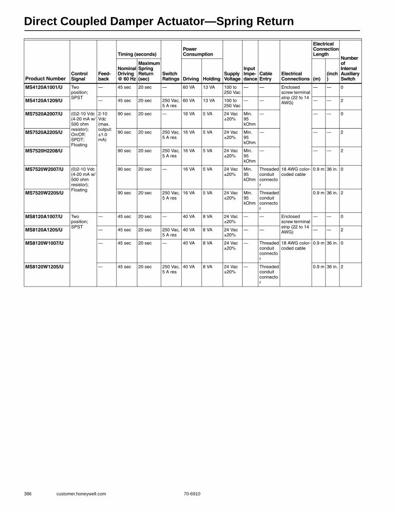
Direct Coupled Damper Actuator—Spring Return
386 customer.honeywell.com 70-6910
Product NumberControl Signal
Feed-back
Timing (seconds)
Switch Ratings
Power Consumption
Supply Voltage
Input Impe-dance
Cable Entry
Electrical Connections
Electrical Connection Length
Number of Internal Auxiliary Switch
Nominal Driving @ 60 Hz
Maximum Spring Return (sec) Driving Holding (m)
(inch)
MS4120A1001/U Two position; SPST
— 45 sec 20 sec — 60 VA 13 VA 100 to 250 Vac
— — Enclosed screw terminal strip (22 to 14 AWG)
— — 0
MS4120A1209/U — 45 sec 20 sec 250 Vac, 5 A res
60 VA 13 VA 100 to 250 Vac
— — — — 2
MS7520A2007/U (0)2-10 Vdc (4-20 mA w/500 ohm resistor); On/Off; SPDT; Floating
2-10 Vdc (max. output: ±1.0 mA)
90 sec 20 sec — 16 VA 5 VA 24 Vac ±20%
Min. 95 kOhm
— — — 0
MS7520A2205/U 90 sec 20 sec 250 Vac, 5 A res
16 VA 5 VA 24 Vac ±20%
Min. 95 kOhm
— — — 2
MS7520H2208/U 90 sec 20 sec 250 Vac, 5 A res
16 VA 5 VA 24 Vac ±20%
Min. 95 kOhm
— — — 2
MS7520W2007/U (0)2-10 Vdc (4-20 mA w/500 ohm resistor); Floating
90 sec 20 sec — 16 VA 5 VA 24 Vac ±20%
Min. 95 kOhm
Threaded conduit connector
18 AWG color-coded cable
0.9 m 36 in. 0
MS7520W2205/U 90 sec 20 sec 250 Vac, 5 A res
16 VA 5 VA 24 Vac ±20%
Min. 95 kOhm
Threaded conduit connector
0.9 m 36 in. 2
MS8120A1007/U Two position; SPST
— 45 sec 20 sec — 40 VA 8 VA 24 Vac ±20%
— — Enclosed screw terminal strip (22 to 14 AWG)
— — 0
MS8120A1205/U — 45 sec 20 sec 250 Vac, 5 A res
40 VA 8 VA 24 Vac ±20%
— — — — 2
MS8120W1007/U — 45 sec 20 sec — 40 VA 8 VA 24 Vac ±20%
— Threaded conduit connector
18 AWG color-coded cable
0.9 m 36 in. 0
MS8120W1205/U — 45 sec 20 sec 250 Vac, 5 A res
40 VA 8 VA 24 Vac ±20%
— Threaded conduit connector
0.9 m 36 in. 2

Direct Coupled Damper Actuator—Spring Return
70-6910 387
Com
mercial
Com
ponents
ML4135; ML8135 HVAC, Fast-Acting, Two-Position Actuators, 40 lb-in
The ML8135 Fast-Acting, Two-Position Actuators are spring return direct coupled actuators (DCA) with an integral junction box for on/off damper control.• Integral spring return • -40 C to 130 F (-40 C to 54 C) operating temperature range • No audible noise during holding • Electronic circuitry provides efficient operation while
eliminating the need for limit switches • Ninety-five degree angle of rotation • Die-cast aluminum housing • Housing design allows flush mounting to damper • Integral junction box with three conduit openings eliminates
need for separate wiring box • Direct mounting to 3/8 or 1/2 in. round or square shaft • Not intended for smoke control systems
Actuator Type: DamperRotational Stroke: 95 ±3 degreesFail Safe Mode: Spring ReturnTorque Rating: 40 lb-in. (4.5 Nm) Spring Return Torque: 40 lb-in. (4.5 Nm) Dimensions, Approximate: 7.5 in high x 5.13 in wide x 3.32 in deep
(192 mm high x 129 mm wide x 84 mm deep) External Auxiliary Switches Available: Yes, 32003532-005Number of Internal Auxiliary Switch: 0Electrical Connections: Two color-coded leadsElectrical Connection Length: 16 in. (406 mm) Environmental Rating: NEMA1Frequency: 60 HzMounting: Direct CoupledMaximum Noise Rating, Holding (dBA @ 1m): 20 (no aud ble noise)
Maximum Noise Rating, Driving (dBA @ 1m): 65Compatible Damper Shafts: 3/8 to 1/2 in. square or round
(10 to 13 mm square/round) Shaft Adapter Type: Aluminum Hub, four set screwsMaterials: Aluminum housingOperating Humidity Range (% RH): 5 to 95% RH, non-condensingAmbient Temperature Range: x-40 F to +130 F (4.5 Nm) Storage Temperature Range: -40 F to +140 F (-18 C to +60 C) Weight: 6 lb (2.72 kg) Comments: Integral junction box with three 7/8 in. conduit openings
(fittings not included)ApprovalsUnderwriters Laboratories, Inc: UL873, Plenum RatedCanadian Underwriters Laboratories, Inc: cUL C22.2 No. 24-93
Product Number Control Signal
Timing (seconds) Power Consumption
Supply Voltage Includes
Spring Return Direction
Maximum Driving @ 60 Hz
Nominal Driving @ 60 Hz
Maximum Spring Return (sec) Driving Holding
ML4135A1007/U Two position; SPST 25 sec 20 sec 15 sec 0.18A, 18W 0.11A, 9W 120 Vac ±10% Mounting bracket, ground screw
CCW
ML4135B1006/U Two position; SPST 25 sec 20 sec 15 sec 0.18A, 18W 0.11A, 9W 120 Vac ±10% Mounting bracket, ground screw
CW
ML8135A1003/U Two position; SPST 25 sec 20 sec 15 sec 18 VA 8.5 VA 24 Vac +20%, -10% Mounting bracket CCW
ML8135B1002/U Two position; SPST 25 sec 20 sec 15 sec 18 VA 8.5 VA 24 Vac +20%, -10% Mounting bracket CW
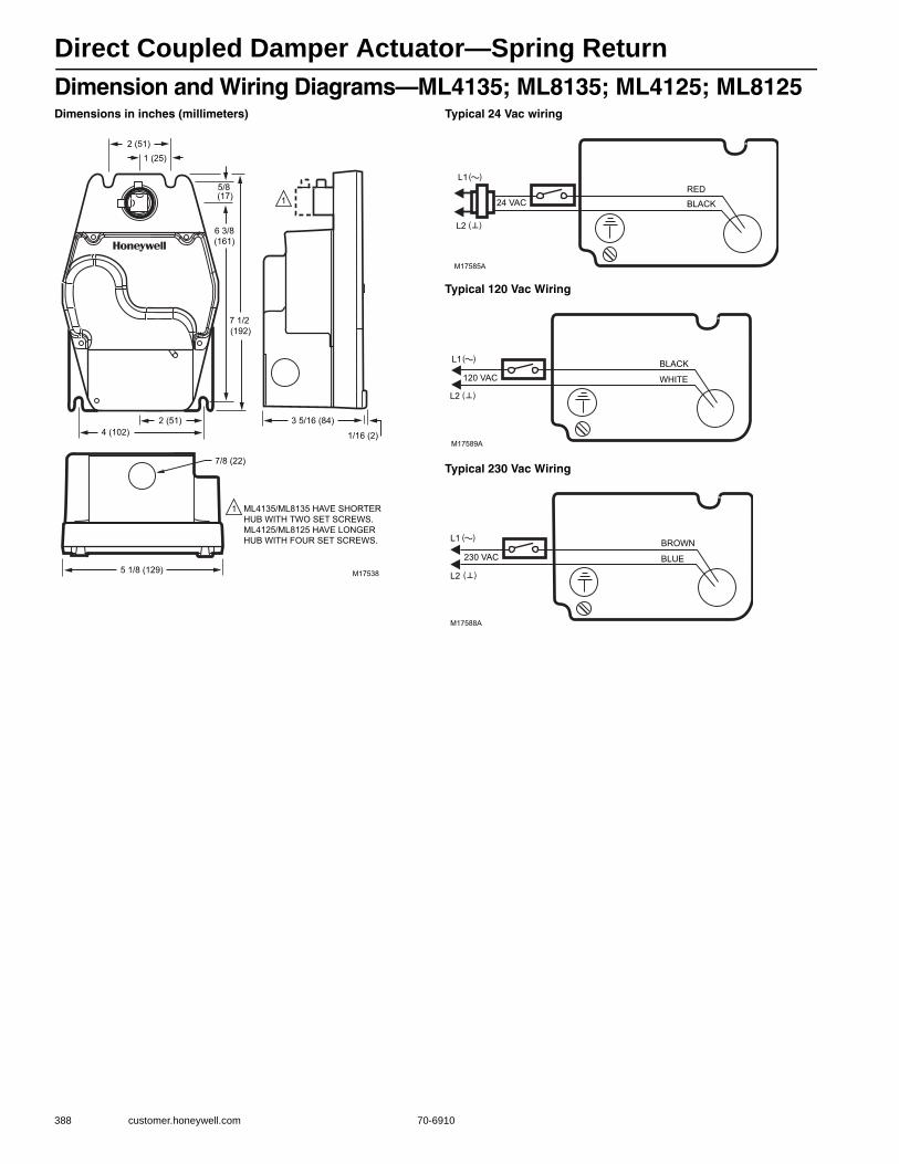
Direct Coupled Damper Actuator—Spring Return
388 customer.honeywell.com 70-6910
Dimension and Wiring Diagrams—ML4135; ML8135; ML4125; ML8125Dimensions in inches (millimeters) Typical 24 Vac wiring
Typical 120 Vac Wiring
Typical 230 Vac Wiring
2 (51)1 (25)
5/8 (17)
6 3/8(161)
7 1/2 (192)
4 (102)
7/8 (22)
5 1/8 (129)
2 (51) 3 5/16 (84)
1/16 (2)
M17538
ML4135/ML8135 HAVE SHORTERHUB WITH TWO SET SCREWS.ML4125/ML8125 HAVE LONGER HUB WITH FOUR SET SCREWS.
1
1
L1
24 VAC
L2
RED
BLACK
M17585A
( )
( )
L1
120 VAC
L2
WHITE
BLACK
M17589A
( )
( )
L1
230 VAC
L2
BLUE
BROWN
M17588A
( )
( )
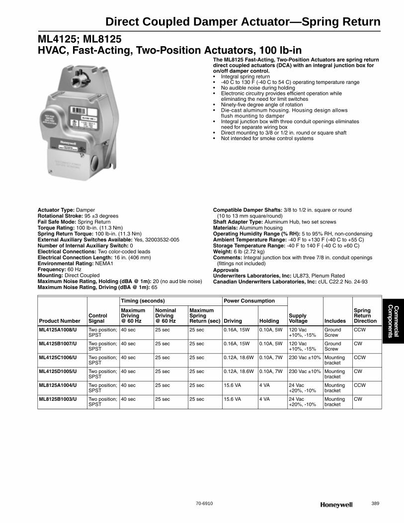
Direct Coupled Damper Actuator—Spring Return
70-6910 389
Com
mercial
Com
ponents
ML4125; ML8125 HVAC, Fast-Acting, Two-Position Actuators, 100 lb-in
The ML8125 Fast-Acting, Two-Position Actuators are spring return direct coupled actuators (DCA) with an integral junction box for on/off damper control.• Integral spring return • -40 C to 130 F (-40 C to 54 C) operating temperature range • No audible noise during holding • Electronic circuitry provides efficient operation while
eliminating the need for limit switches• Ninety-five degree angle of rotation • Die-cast aluminum housing. Housing design allows
flush mounting to damper • Integral junction box with three conduit openings eliminates
need for separate wiring box • Direct mounting to 3/8 or 1/2 in. round or square shaft • Not intended for smoke control systems
Actuator Type: DamperRotational Stroke: 95 ±3 degreesFail Safe Mode: Spring ReturnTorque Rating: 100 lb-in. (11.3 Nm) Spring Return Torque: 100 lb-in. (11.3 Nm) External Auxiliary Switches Available: Yes, 32003532-005Number of Internal Auxiliary Switch: 0Electrical Connections: Two color-coded leadsElectrical Connection Length: 16 in. (406 mm) Environmental Rating: NEMA1Frequency: 60 HzMounting: Direct CoupledMaximum Noise Rating, Holding (dBA @ 1m): 20 (no aud ble noise)Maximum Noise Rating, Driving (dBA @ 1m): 65
Compatible Damper Shafts: 3/8 to 1/2 in. square or round (10 to 13 mm square/round)
Shaft Adapter Type: Aluminum Hub, two set screwsMaterials: Aluminum housingOperating Humidity Range (% RH): 5 to 95% RH, non-condensingAmbient Temperature Range: -40 F to +130 F (-40 C to +55 C) Storage Temperature Range: -40 F to 140 F (-40 C to +60 C) Weight: 6 lb (2.72 kg) Comments: Integral junction box with three 7/8 in. conduit openings
(fittings not included)ApprovalsUnderwriters Laboratories, Inc: UL873, Plenum RatedCanadian Underwriters Laboratories, Inc: cUL C22.2 No. 24-93
Product NumberControl Signal
Timing (seconds) Power Consumption
Supply Voltage Includes
Spring Return Direction
Maximum Driving @ 60 Hz
Nominal Driving @ 60 Hz
Maximum Spring Return (sec) Driving Holding
ML4125A1008/U Two position; SPST
40 sec 25 sec 25 sec 0.16A, 15W 0.10A, 5W 120 Vac +10%, -15%
Ground Screw
CCW
ML4125B1007/U Two position; SPST
40 sec 25 sec 25 sec 0.16A, 15W 0.10A, 5W 120 Vac +10%, -15%
Ground Screw
CW
ML4125C1006/U Two position; SPST
40 sec 25 sec 25 sec 0.12A, 18.6W 0.10A, 7W 230 Vac ±10% Mounting bracket
CCW
ML4125D1005/U Two position; SPST
40 sec 25 sec 25 sec 0.12A, 18.6W 0.10A, 7W 230 Vac ±10% Mounting bracket
CW
ML8125A1004/U Two position; SPST
40 sec 25 sec 25 sec 15.6 VA 4 VA 24 Vac +20%, -10%
Mounting bracket
CCW
ML8125B1003/U Two position; SPST
40 sec 25 sec 25 sec 15.6 VA 4 VA 24 Vac +20%, -10%
Mounting bracket
CW
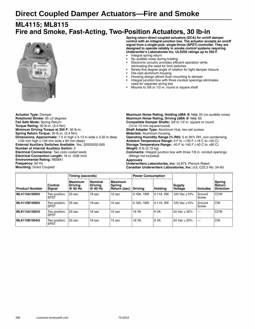
Direct Coupled Damper Actuators—Fire and Smoke
390 customer.honeywell.com 70-6910
ML4115; ML8115 Fire and Smoke, Fast-Acting, Two-Position Actuators, 30 lb-in
Spring return direct coupled actuators (DCA) for on/off damper control with an integral junction box. The actuator accepts an on/off signal from a single-pole, single-throw (SPST) controller. They are designed to operate reliably in smoke control systems requiring Underwriter's Laboratories Inc. UL555S ratings up to 350 F.• Integral spring return • No audible noise during holding • Electronic circuitry provides efficient operation while
eliminating the need for limit switches • Ninety-five degree angle of rotation for tight damper closure• Die-cast aluminum housing • Housing design allows flush mounting to damper • Integral junction box with three conduit openings eliminates
need for separate wiring box• Mounts to 3/8 or 1/2 in. round or square shaft
Actuator Type: DamperRotational Stroke: 95 ±3 degreesFail Safe Mode: Spring ReturnTorque Rating: 30 lb-in. (3.4 Nm) Minimum Driving Torque at 350 F: 30 lb-in.Spring Return Torque: 30 lb-in. (3.4 Nm) Dimensions, Approximate: 7.5 in high x 5.13 in wide x 3.32 in deep
(192 mm high x 129 mm wide x 84 mm deep) External Auxiliary Switches Available: Yes, 32003532-005Number of Internal Auxiliary Switch: 0Electrical Connections: Two color-coded leadsElectrical Connection Length: 16 in. (406 mm) Environmental Rating: NEMA1Frequency: 60 HzMounting: Direct Coupled
Maximum Noise Rating, Holding (dBA @ 1m): 20 (no audible noise)Maximum Noise Rating, Driving (dBA @ 1m): 65Compatible Damper Shafts: 3/8 to 1/2 in. square or round
(10 to 13 mm square/round) Shaft Adapter Type: Aluminum Hub, two set screwsMaterials: Aluminum housingOperating Humidity Range (% RH): 5 to 95% RH, non-condensingAmbient Temperature Range: 0 F to +130 F (-18 C to +55 C) Storage Temperature Range: -40 F to 140 F (-40 C to +60 C) Weight: 6 lb (2.72 kg) Comments: Integral junction box with three 7/8 in. conduit openings
(fittings not included)ApprovalsUnderwriters Laboratories, Inc: UL873, Plenum RatedCanadian Underwriters Laboratories, Inc: cUL C22.2 No. 24-93
Product NumberControl Signal
Timing (seconds) Power Consumption
Supply Voltage Includes
Spring Return Direction
Maximum Driving @ 60 Hz
Nominal Driving @ 60 Hz
Maximum Spring Return (sec) Driving Holding
ML4115A1009/U Two position; SPST
25 sec 18 sec 15 sec 0.18A, 18W 0.11A, 9W 120 Vac ±10% Ground Screw
CCW
ML4115B1008/U Two position; SPST
25 sec 18 sec 15 sec 0.18A, 18W 0.11A, 9W 120 Vac ±10% Ground Screw
CW
ML8115A1005/U Two position; SPST
25 sec 18 sec 15 sec 16 VA 8 VA 24 Vac ± 20% — CCW
ML8115B1004/U Two position; SPST
25 sec 18 sec 15 sec 16 VA 8 VA 24 Vac ± 20% — CW
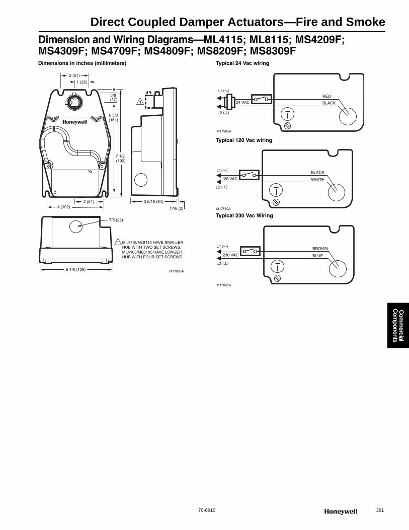
Direct Coupled Damper Actuators—Fire and Smoke
70-6910 391
Com
mercial
Com
ponents
Dimension and Wiring Diagrams—ML4115; ML8115; MS4209F; MS4309F; MS4709F; MS4809F; MS8209F; MS8309FDimensions in inches (millimeters) Typical 24 Vac wiring
Typical 120 Vac wiring
Typical 230 Vac Wiring
2 (51)1 (25)
5/8 (17)
6 3/8(161)
7 1/2 (192)
4 (102)
7/8 (22)
5 1/8 (129)
2 (51) 3 5/16 (84)
1/16 (2)
M13053A
ML4115/ML8115 HAVE SMALLER HUB WITH TWO SET SCREWS.ML4105/ML8105 HAVE LONGER HUB WITH FOUR SET SCREWS.
1
1
L1
24 VAC
L2
RED
BLACK
M17585A
( )
( )
L1
120 VAC
L2
WHITE
BLACK
M17589A
( )
( )
L1
230 VAC
L2
BLUE
BROWN
M17588A
( )
( )
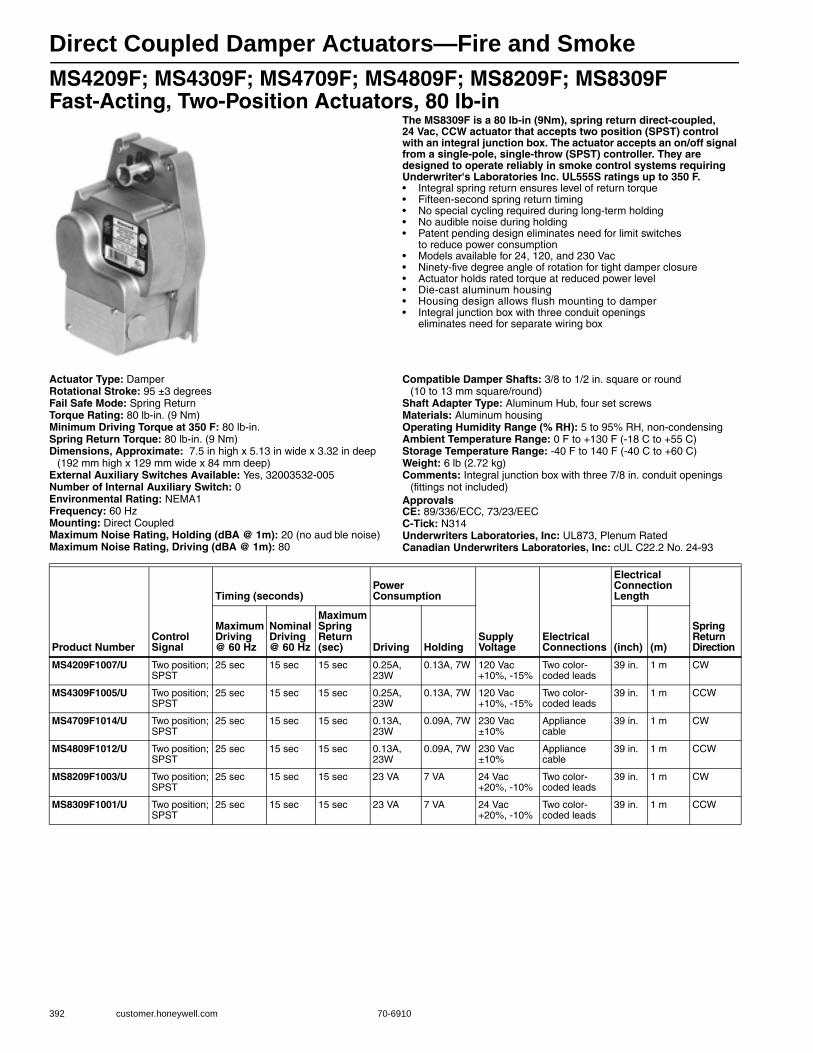
Direct Coupled Damper Actuators—Fire and Smoke
392 customer.honeywell.com 70-6910
MS4209F; MS4309F; MS4709F; MS4809F; MS8209F; MS8309F Fast-Acting, Two-Position Actuators, 80 lb-in
The MS8309F is a 80 lb-in (9Nm), spring return direct-coupled, 24 Vac, CCW actuator that accepts two position (SPST) control with an integral junction box. The actuator accepts an on/off signal from a single-pole, single-throw (SPST) controller. They are designed to operate reliably in smoke control systems requiring Underwriter's Laboratories Inc. UL555S ratings up to 350 F.• Integral spring return ensures level of return torque • Fifteen-second spring return timing • No special cycling required during long-term holding • No audible noise during holding • Patent pending design eliminates need for limit switches
to reduce power consumption • Models available for 24, 120, and 230 Vac • Ninety-five degree angle of rotation for tight damper closure • Actuator holds rated torque at reduced power level • Die-cast aluminum housing• Housing design allows flush mounting to damper • Integral junction box with three conduit openings
eliminates need for separate wiring box
Actuator Type: DamperRotational Stroke: 95 ±3 degreesFail Safe Mode: Spring ReturnTorque Rating: 80 lb-in. (9 Nm) Minimum Driving Torque at 350 F: 80 lb-in.Spring Return Torque: 80 lb-in. (9 Nm) Dimensions, Approximate: 7.5 in high x 5.13 in wide x 3.32 in deep
(192 mm high x 129 mm wide x 84 mm deep) External Auxiliary Switches Available: Yes, 32003532-005Number of Internal Auxiliary Switch: 0Environmental Rating: NEMA1Frequency: 60 HzMounting: Direct CoupledMaximum Noise Rating, Holding (dBA @ 1m): 20 (no aud ble noise)Maximum Noise Rating, Driving (dBA @ 1m): 80
Compatible Damper Shafts: 3/8 to 1/2 in. square or round (10 to 13 mm square/round)
Shaft Adapter Type: Aluminum Hub, four set screwsMaterials: Aluminum housingOperating Humidity Range (% RH): 5 to 95% RH, non-condensingAmbient Temperature Range: 0 F to +130 F (-18 C to +55 C) Storage Temperature Range: -40 F to 140 F (-40 C to +60 C) Weight: 6 lb (2.72 kg) Comments: Integral junction box with three 7/8 in. conduit openings
(fittings not included)ApprovalsCE: 89/336/ECC, 73/23/EECC-Tick: N314Underwriters Laboratories, Inc: UL873, Plenum RatedCanadian Underwriters Laboratories, Inc: cUL C22.2 No. 24-93
Product NumberControl Signal
Timing (seconds)Power Consumption
Supply Voltage
Electrical Connections
Electrical Connection Length
Spring Return Direction
Maximum Driving @ 60 Hz
Nominal Driving @ 60 Hz
Maximum Spring Return (sec) Driving Holding (inch) (m)
MS4209F1007/U Two position; SPST
25 sec 15 sec 15 sec 0.25A, 23W
0.13A, 7W 120 Vac +10%, -15%
Two color-coded leads
39 in. 1 m CW
MS4309F1005/U Two position; SPST
25 sec 15 sec 15 sec 0.25A, 23W
0.13A, 7W 120 Vac +10%, -15%
Two color-coded leads
39 in. 1 m CCW
MS4709F1014/U Two position; SPST
25 sec 15 sec 15 sec 0.13A, 23W
0.09A, 7W 230 Vac ±10%
Appliance cable
39 in. 1 m CW
MS4809F1012/U Two position; SPST
25 sec 15 sec 15 sec 0.13A, 23W
0.09A, 7W 230 Vac ±10%
Appliance cable
39 in. 1 m CCW
MS8209F1003/U Two position; SPST
25 sec 15 sec 15 sec 23 VA 7 VA 24 Vac +20%, -10%
Two color-coded leads
39 in. 1 m CW
MS8309F1001/U Two position; SPST
25 sec 15 sec 15 sec 23 VA 7 VA 24 Vac +20%, -10%
Two color-coded leads
39 in. 1 m CCW

Direct Coupled Damper Actuators—Fire and Smoke
70-6910 393
Com
mercial
Com
ponents
MS4120F; MS4620F; MS8120F Fast-Acting, Two-Position Actuators, 175 lb-in
The MS8120F,S is a 175 lb-in (20Nm), spring return direct-coupled, 24 Vac actuator that accepts two position (SPST) control with an integral junction box. The actuator accepts an on/off signal from a single-pole, single-throw (SPST) controller. They are designed to operate reliably in smoke control systems requiring Underwriter's Laboratories Inc. UL555S ratings up to 350 F.• Brush DC submotor with electronic stall protection for 2-position models • Self-centering shaft adapter (shaft coupling) for wide range of shaft sizes • Models available for use with two-position, single pole single throw
(spst), line- (Series 40) or low- (Series 80) voltage controls • Metal housing with built-in mechanical end limits • Spring return direction field-selectable • Shaft position indicator and scale • Manual winding capability with locking function • UL (cUL) listed and CE compliant • All Models are plenum-rated per UL873
Actuator Type: DamperRotational Stroke: 95 ±3 degreesFail Safe Mode: Spring ReturnTorque Rating: 175 lb-in. (20 Nm) Minimum Driving Torque at 350 F: 175 b-in.Spring Return Torque: 175 lb-in. (20 Nm) External Auxiliary Switches Available: NoElectrical Connections: Teflon-jacketed cableElectrical Connection Length: 40 in. (1 m) Environmental Rating: NEMA2Ingress Protection Rating: IP54Frequency: 60 HzManual operation: Manual crankMounting: Direct CoupledMaximum Noise Rating, Holding (dBA @ 1m): 20 (no aud ble noise)Maximum Noise Rating, Driving (dBA @ 1m): 70
Compatible Damper Shafts: 3/8 to 1.06 in. round or 3/8 to 11/16 in. square (10 to 27 mm round or 10 to 18 mm square)
Shaft Adapter Type: Self-centering clampingMaterials: Aluminum housingOperating Humidity Range (% RH): 5 to 95% RH, non-condensingAmbient Temperature Range: -40 F to +130 F (-40 C to +55 C) Storage Temperature Range: -40 F to +140 F (-40 C to +60 C) Weight: 8 lb (3.63 kg) Includes: Self-centering shaft adapter, 3mm crankComments: Two integral 3/8 in. flexible conduit connectionsApprovalsCE: 89/336/ECC, 73/23/EECC-Tick: N314Underwriters Laboratories, Inc: UL873, Plenum RatedCanadian Underwriters Laboratories, Inc: cUL C22.2 No. 24-93
Product NumberControl Signal
Timing (seconds)
Switch Ratings
Power Consumption
Supply Voltage
Number of Internal Auxiliary Switch
Spring Return Direction
Nominal Driving @ 60 Hz
Maximum Spring Return (sec) Driving Holding
MS4120F1006/U Two position; SPST
15 sec 15 sec — 0.35A, 35W 0.15A, 10W 120 Vac ±10%
0 By orientation
MS4120F1204/U Two position; SPST
15 sec 15 sec 250 Vac, 5 A res 0.35A, 35W 0.15A, 10W 120 Vac ±10%
2 By orientation
MS4620F1005/U Two position; SPST
15 sec 15 sec — 0.20A, 35W 0.14A, 10W 230 Vac ±10%
0 By orientation
MS4620F1203/U Two position; SPST
15 sec 15 sec 250 Vac, 5 A res 0.20A, 35W 0.14A, 10W 230 Vac ±10%
2 By orientation
MS8120F1002/U Two position; SPST
15 sec 15 sec — 45 VA 10 VA 24 Vac +20%, -10%
0 By orientation
MS8120F1200/U Two position; SPST
15 sec 15 sec 250 Vac, 5 A res 45 VA 10 VA 24 Vac +20%, -10%
2 By orientation
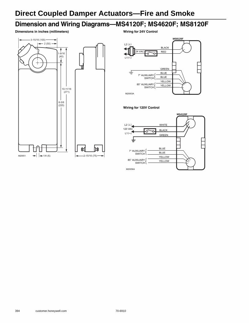
Direct Coupled Damper Actuators—Fire and Smoke
394 customer.honeywell.com 70-6910
Dimension and Wiring Diagrams—MS4120F; MS4620F; MS8120FDimensions in inches (millimeters) Wiring for 24V Control
Wiring for 120V Control
10-11/16(271)
1-9/16(40)
8-5/8(220)
2 (50)3-15/16 (100)
2-15/16 (75)1/4 (6)M20051
M20053A
24 VACBLACK
RED
GREEN
MS8120F
L1 ( )
L2 ( )
YELLOW
YELLOW
BLUE7° AUXILIARY
SWITCH
85° AUXILIARYSWITCH
BLUE
M20056A
WHITE
BLACK
GREEN
MS4120F
L1 ( )
L2 ( )
YELLOW
YELLOW
BLUE
BLUE7° AUXILIARY
SWITCH
85° AUXILIARYSWITCH
120 VAC
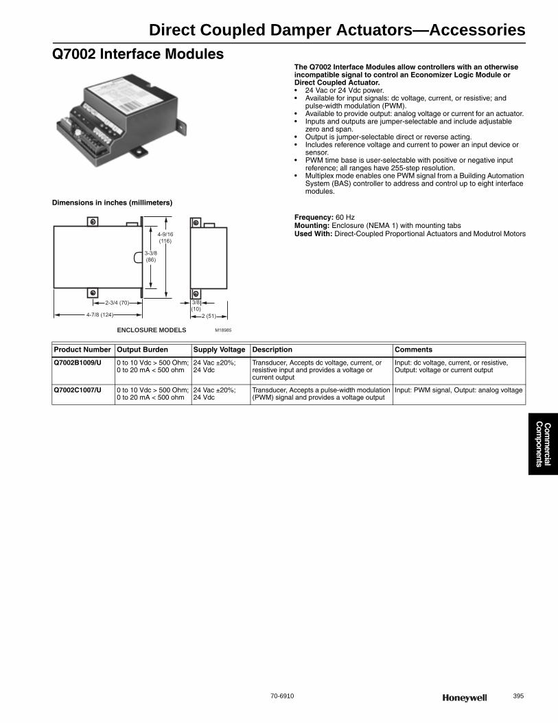
Direct Coupled Damper Actuators—Accessories
70-6910 395
Com
mercial
Com
ponents
Q7002 Interface ModulesThe Q7002 Interface Modules allow controllers with an otherwise incompatible signal to control an Economizer Logic Module or Direct Coupled Actuator.• 24 Vac or 24 Vdc power. • Available for input signals: dc voltage, current, or resistive; and
pulse-width modulation (PWM). • Available to provide output: analog voltage or current for an actuator. • Inputs and outputs are jumper-selectable and include adjustable
zero and span. • Output is jumper-selectable direct or reverse acting. • Includes reference voltage and current to power an input device or
sensor. • PWM time base is user-selectable with positive or negative input
reference; all ranges have 255-step resolution. • Multiplex mode enables one PWM signal from a Building Automation
System (BAS) controller to address and control up to eight interface modules.
Dimensions in inches (millimeters)
Frequency: 60 HzMounting: Enclosure (NEMA 1) with mounting tabsUsed With: Direct-Coupled Proportional Actuators and Modutrol Motors
3-3/8(86)
4-9/16(116)
4-7/8 (124)
2-3/4 (70)
2 (51)
3/8(10)
M18985ENCLOSURE MODELS
Product Number Output Burden Supply Voltage Description Comments
Q7002B1009/U 0 to 10 Vdc > 500 Ohm; 0 to 20 mA < 500 ohm
24 Vac ±20%; 24 Vdc
Transducer, Accepts dc voltage, current, or resistive input and provides a voltage or current output
Input: dc voltage, current, or resistive, Output: voltage or current output
Q7002C1007/U 0 to 10 Vdc > 500 Ohm; 0 to 20 mA < 500 ohm
24 Vac ±20%; 24 Vdc
Transducer, Accepts a pulse-width modulation (PWM) signal and provides a voltage output
Input: PWM signal, Output: analog voltage
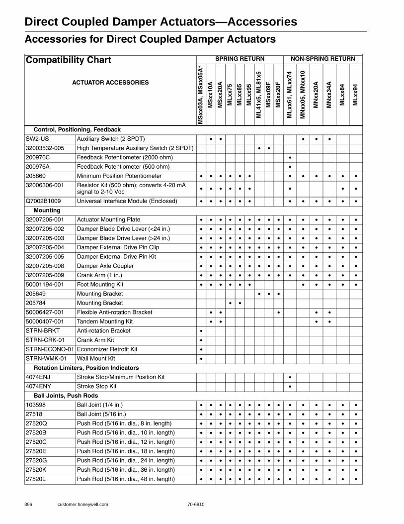
Direct Coupled Damper Actuators—Accessories
396 customer.honeywell.com 70-6910
Accessories for Direct Coupled Damper Actuators
Compatibility Chart
ACTUATOR ACCESSORIES
SPRING RETURN NON-SPRING RETURN
MS
xx03
A, M
Sxx
05A
*
MS
xx10
A
MS
xx20
A
ML
xx75
ML
xx85
ML
xx95
ML
41x5
, ML
81x5
MS
xx09
F
MS
xx20
F
ML
xx61
, ML
xx74
MN
xx05
, MN
xx10
MN
xx20
A
MN
xx34
A
ML
xx84
ML
xx94
Control, Positioning, Feedback
SW2-US Auxiliary Switch (2 SPDT) • • • • •32003532-005 High Temperature Auxiliary Switch (2 SPDT) • •200976C Feedback Potentiometer (2000 ohm) •200976A Feedback Potentiometer (500 ohm) •205860 Minimum Position Potentiometer • • • • • • • • • • • •32006306-001 Resistor Kit (500 ohm); converts 4-20 mA
signal to 2-10 Vdc • • • • • • • • •
Q7002B1009 Universal Interface Module (Enclosed) • • • • • • • • • • • •Mounting
32007205-001 Actuator Mounting Plate • • • • • • • • • • • • • • •32007205-002 Damper Blade Drive Lever (<24 in.) • • • • • • • • • • • • • • •32007205-003 Damper Blade Drive Lever (>24 in.) • • • • • • • • • • • • • • •32007205-004 Damper External Drive Pin Clip • • • • • • • • • • • • • • •32007205-005 Damper External Drive Pin Kit • • • • • • • • • • • • • • •32007205-008 Damper Axle Coupler • • • • • • • • • • • • • • •32007205-009 Crank Arm (1 in.) • • • • • • • • • • • • • • •50001194-001 Foot Mounting Kit • • • • • • • • • • •205649 Mounting Bracket • • •205784 Mounting Bracket • •50006427-001 Flexible Anti-rotation Bracket • • • • •50000407-001 Tandem Mounting Kit • • • •STRN-BRKT Anti-rotation Bracket •STRN-CRK-01 Crank Arm Kit •STRN-ECONO-01 Economizer Retrofit Kit •STRN-WMK-01 Wall Mount Kit •
Rotation Limiters, Position Indicators
4074ENJ Stroke Stop/Minimum Position Kit •4074ENY Stroke Stop Kit •
Ball Joints, Push Rods
103598 Ball Joint (1/4 in.) • • • • • • • • • • • • • • •27518 Ball Joint (5/16 in.) • • • • • • • • • • • • • • •27520Q Push Rod (5/16 in. dia., 8 in. length) • • • • • • • • • • • • • • •27520B Push Rod (5/16 in. dia., 10 in. length) • • • • • • • • • • • • • • •27520C Push Rod (5/16 in. dia., 12 in. length) • • • • • • • • • • • • • • •27520E Push Rod (5/16 in. dia., 18 in. length) • • • • • • • • • • • • • • •27520G Push Rod (5/16 in. dia., 24 in. length) • • • • • • • • • • • • • • •27520K Push Rod (5/16 in. dia., 36 in. length) • • • • • • • • • • • • • • •27520L Push Rod (5/16 in. dia., 48 in. length) • • • • • • • • • • • • • • •
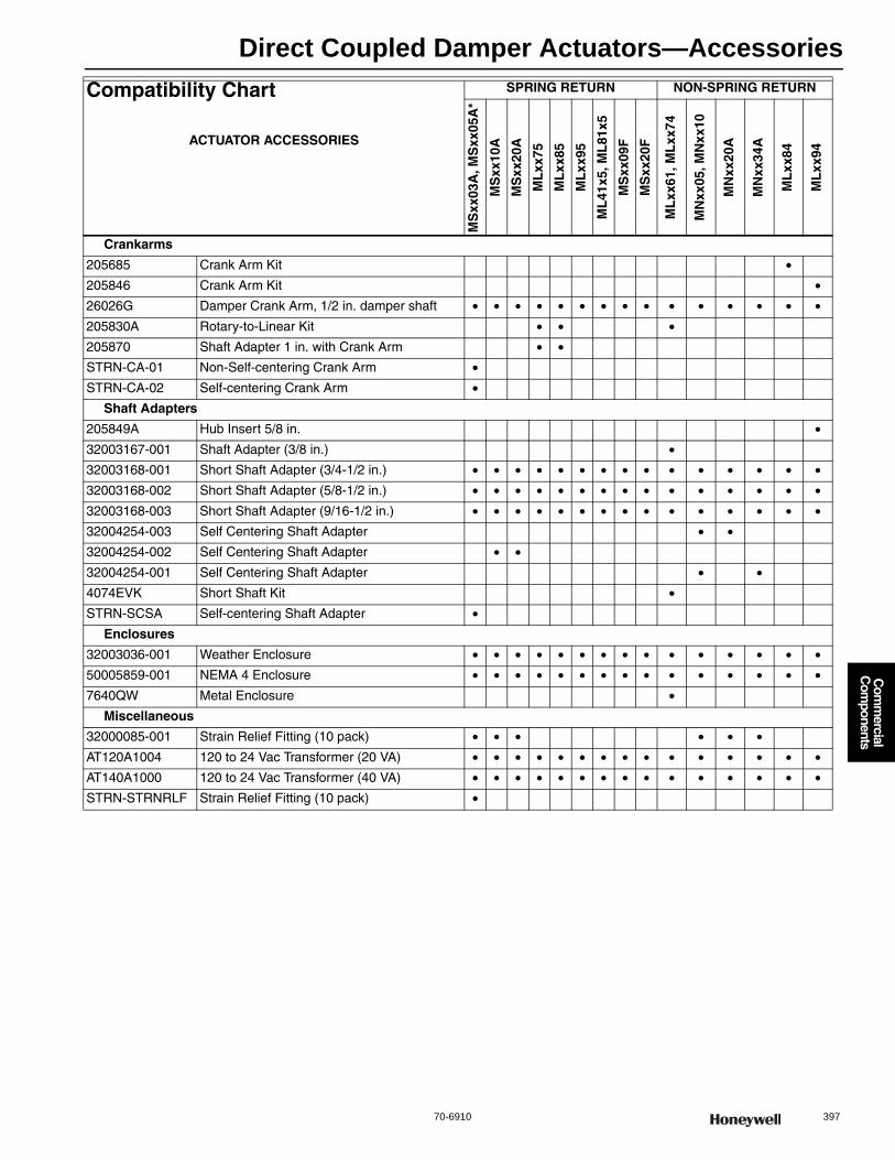
Direct Coupled Damper Actuators—Accessories
70-6910 397
Com
mercial
Com
ponents
Crankarms
205685 Crank Arm Kit •205846 Crank Arm Kit •26026G Damper Crank Arm, 1/2 in. damper shaft • • • • • • • • • • • • • • •205830A Rotary-to-Linear Kit • • •205870 Shaft Adapter 1 in. with Crank Arm • •STRN-CA-01 Non-Self-centering Crank Arm •STRN-CA-02 Self-centering Crank Arm •
Shaft Adapters
205849A Hub Insert 5/8 in. •32003167-001 Shaft Adapter (3/8 in.) •32003168-001 Short Shaft Adapter (3/4-1/2 in.) • • • • • • • • • • • • • • •32003168-002 Short Shaft Adapter (5/8-1/2 in.) • • • • • • • • • • • • • • •32003168-003 Short Shaft Adapter (9/16-1/2 in.) • • • • • • • • • • • • • • •32004254-003 Self Centering Shaft Adapter • •32004254-002 Self Centering Shaft Adapter • •32004254-001 Self Centering Shaft Adapter • •4074EVK Short Shaft Kit •STRN-SCSA Self-centering Shaft Adapter •
Enclosures
32003036-001 Weather Enclosure • • • • • • • • • • • • • • •50005859-001 NEMA 4 Enclosure • • • • • • • • • • • • • • •7640QW Metal Enclosure •
Miscellaneous
32000085-001 Strain Relief Fitting (10 pack) • • • • • •AT120A1004 120 to 24 Vac Transformer (20 VA) • • • • • • • • • • • • • • •AT140A1000 120 to 24 Vac Transformer (40 VA) • • • • • • • • • • • • • • •STRN-STRNRLF Strain Relief Fitting (10 pack) •
Compatibility Chart
ACTUATOR ACCESSORIES
SPRING RETURN NON-SPRING RETURN
MS
xx03
A, M
Sxx
05A
*
MS
xx10
A
MS
xx20
A
ML
xx75
ML
xx85
ML
xx95
ML
41x5
, ML
81x5
MS
xx09
F
MS
xx20
F
ML
xx61
, ML
xx74
MN
xx05
, MN
xx10
MN
xx20
A
MN
xx34
A
ML
xx84
ML
xx94
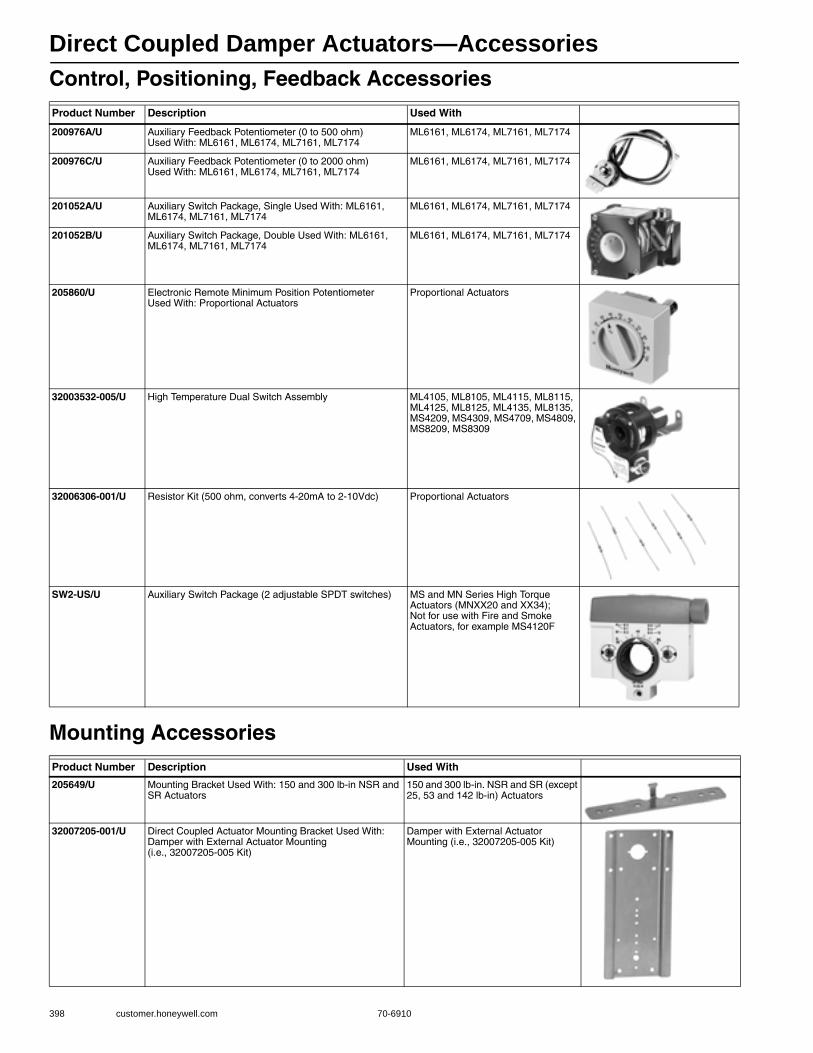
Direct Coupled Damper Actuators—Accessories
398 customer.honeywell.com 70-6910
Control, Positioning, Feedback Accessories
Mounting Accessories
Product Number Description Used With
200976A/U Auxiliary Feedback Potentiometer (0 to 500 ohm) Used With: ML6161, ML6174, ML7161, ML7174
ML6161, ML6174, ML7161, ML7174
200976C/U Auxiliary Feedback Potentiometer (0 to 2000 ohm) Used With: ML6161, ML6174, ML7161, ML7174
ML6161, ML6174, ML7161, ML7174
201052A/U Auxiliary Switch Package, Single Used With: ML6161, ML6174, ML7161, ML7174
ML6161, ML6174, ML7161, ML7174
201052B/U Auxiliary Switch Package, Double Used With: ML6161, ML6174, ML7161, ML7174
ML6161, ML6174, ML7161, ML7174
205860/U Electronic Remote Minimum Position Potentiometer Used With: Proportional Actuators
Proportional Actuators
32003532-005/U High Temperature Dual Switch Assembly ML4105, ML8105, ML4115, ML8115, ML4125, ML8125, ML4135, ML8135, MS4209, MS4309, MS4709, MS4809, MS8209, MS8309
32006306-001/U Resistor Kit (500 ohm, converts 4-20mA to 2-10Vdc) Proportional Actuators
SW2-US/U Auxiliary Switch Package (2 adjustable SPDT switches) MS and MN Series High Torque Actuators (MNXX20 and XX34); Not for use with Fire and Smoke Actuators, for example MS4120F
Product Number Description Used With
205649/U Mounting Bracket Used With: 150 and 300 lb-in NSR and SR Actuators
150 and 300 lb-in. NSR and SR (except 25, 53 and 142 lb-in) Actuators
32007205-001/U Direct Coupled Actuator Mounting Bracket Used With: Damper with External Actuator Mounting (i.e., 32007205-005 Kit)
Damper with External Actuator Mounting (i.e., 32007205-005 Kit)
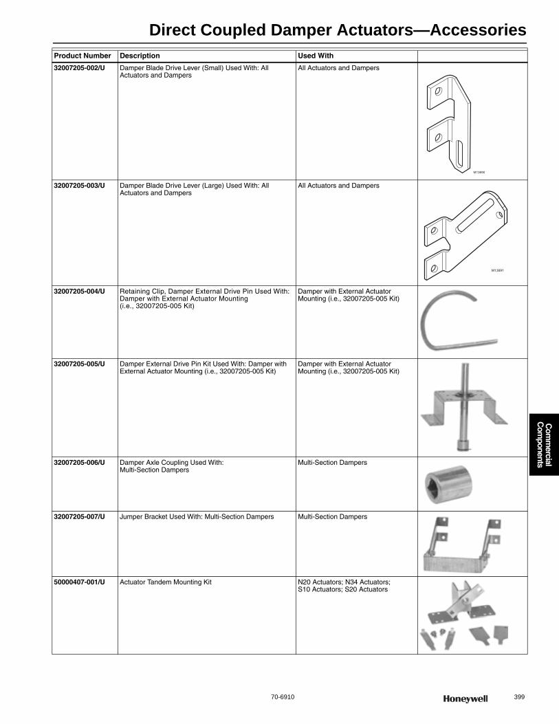
Direct Coupled Damper Actuators—Accessories
70-6910 399
Com
mercial
Com
ponents
32007205-002/U Damper Blade Drive Lever (Small) Used With: All Actuators and Dampers
All Actuators and Dampers
32007205-003/U Damper Blade Drive Lever (Large) Used With: All Actuators and Dampers
All Actuators and Dampers
32007205-004/U Retaining Clip, Damper External Drive Pin Used With: Damper with External Actuator Mounting (i.e., 32007205-005 Kit)
Damper with External Actuator Mounting (i.e., 32007205-005 Kit)
32007205-005/U Damper External Drive Pin Kit Used With: Damper with External Actuator Mounting (i.e., 32007205-005 Kit)
Damper with External Actuator Mounting (i.e., 32007205-005 Kit)
32007205-006/U Damper Axle Coupling Used With: Multi-Section Dampers
Multi-Section Dampers
32007205-007/U Jumper Bracket Used With: Multi-Section Dampers Multi-Section Dampers
50000407-001/U Actuator Tandem Mounting Kit N20 Actuators; N34 Actuators; S10 Actuators; S20 Actuators
Product Number Description Used With
M13690
M13691
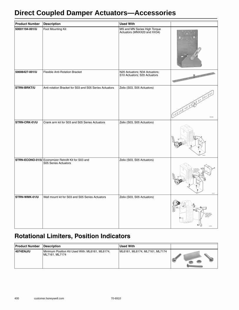
Direct Coupled Damper Actuators—Accessories
400 customer.honeywell.com 70-6910
Rotational Limiters, Position Indicators
50001194-001/U Foot Mounting Kit MS and MN Series High Torque Actuators (MNXX20 and XX34)
50006427-001/U Flexible Anti-Rotation Bracket N20 Actuators; N34 Actuators; S10 Actuators; S20 Actuators
STRN-BRKT/U Anti-rotation Bracket for S03 and S05 Series Actuators Zelix (S03, S05 Actuators)
STRN-CRK-01/U Crank arm kit for S03 and S05 Series Actuators Zelix (S03, S05 Actuators)
STRN-ECONO-01/U Economizer Retrofit Kit for S03 and S05 Series Actuators
Zelix (S03, S05 Actuators)
STRN-WMK-01/U Wall mount kit for S03 and S05 Series Actuators Zelix (S03, S05 Actuators)
Product Number Description Used With
4074ENJ/U Minimum Position Kit Used With: ML6161, ML6174, ML7161, ML7174
ML6161, ML6174, ML7161, ML7174
Product Number Description Used With
M29089
M29085
M29084
CL NCH NUTSPRE ATTACHEDTO BACK OFBRACKET
M29082
CLINCH NUTSPRE ATTACHEDTO BACK OFBRACKET
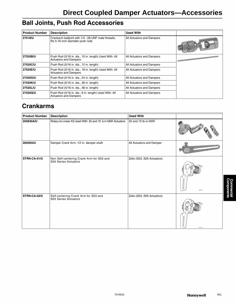
Direct Coupled Damper Actuators—Accessories
70-6910 401
Com
mercial
Com
ponents
Ball Joints, Push Rod Accessories
Crankarms
Product Number Description Used With
27518/U Crankarm balljoint with 1/4 - 28 UNF male threads, fits 5-16 inch diameter push rods
All Actuators and Dampers
27520B/U Push Rod (5/16 in. dia., 10 in. length) Used With: All Actuators and Dampers
All Actuators and Dampers
27520C/U Push Rod (5/16 in. dia., 12 in. length) All Actuators and Dampers
27520E/U Push Rod (5/16 in. dia., 18 in. length) Used With: All Actuators and Dampers
All Actuators and Dampers
27520G/U Push Rod (5/16 in. dia., 24 in. length) All Actuators and Dampers
27520K/U Push Rod (5/16 in. dia., 36 in. length) All Actuators and Dampers
27520L/U Push Rod (5/16 in. dia., 48 in. length) All Actuators and Dampers
27520Q/U Push Rod (5/16 in. dia., 8 in. length) Used With: All Actuators and Dampers
All Actuators and Dampers
Product Number Description Used With
205830A/U Rotary-to-Linear Kit Used With: 35 and 70 b-in NSR Actuators 35 and 70 lb-in.NSR
26026G/U Damper Crank Arm, 1/2 in. damper shaft All Actuators and Damper
STRN-CA-01/U Non Self-centering Crank Arm for S03 and S05 Series Actuators
Zelix (S03, S05 Actuators)
STRN-CA-02/U Self-centering Crank Arm for S03 and S05 Series Actuators
Zelix (S03, S05 Actuators)
M29087
M29086
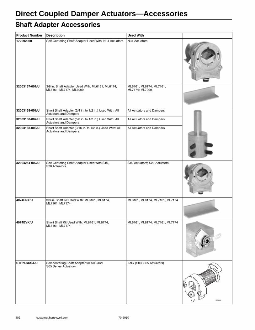
Direct Coupled Damper Actuators—Accessories
402 customer.honeywell.com 70-6910
Shaft Adapter AccessoriesProduct Number Description Used With
172092060 Self-Centering Shaft Adapter Used With: N34 Actuators N34 Actuators
32003167-001/U 3/8 in. Shaft Adapter Used With: ML6161, ML6174, ML7161, ML7174, ML7999
ML6161; ML6174; ML7161; ML7174; ML7999
32003168-001/U Short Shaft Adapter (3/4 in. to 1/2 in.) Used With: All Actuators and Dampers
All Actuators and Dampers
32003168-002/U Short Shaft Adapter (5/8 in. to 1/2 in.) Used With: All Actuators and Dampers
All Actuators and Dampers
32003168-003/U Short Shaft Adapter (9/16 in. to 1/2 in.) Used With: All Actuators and Dampers
All Actuators and Dampers
32004254-002/U Self-Centering Shaft Adapter Used With S10, S20 Actuators
S10 Actuators; S20 Actuators
4074ENY/U 3/8 in. Shaft Kit Used With: ML6161, ML6174, ML7161, ML7174
ML6161, ML6174, ML7161, ML7174
4074EVK/U Short Shaft Kit Used With: ML6161, ML6174, ML7161, ML7174
ML6161, ML6174, ML7161, ML7174
STRN-SCSA/U Self-centering Shaft Adapter for S03 and S05 Series Actuators
Zelix (S03, S05 Actuators)
M29088

Direct Coupled Damper Actuators—Accessories
70-6910 403
Com
mercial
Com
ponents
Enclosure Accessories
Rectangular Damper Accessories
Miscellaneous Accessories
Product Number Description Used With
32003036-001/U Weather Enclosure Used With: All Actuators All Actuators
50005859-001/U NEMA 4 Enclosure for Direct Coupled Actuator ML6161, ML6174, ML7161, ML7174; N20 Actuators; N34 Actuators; 150 b-in. NSR Actuators (ML Series); S03 Actuators; S05 Actuators; S10 Actuators; S20 Actuators
7640QW/U Enclosure for Conduit Connection Used With: ML6161, ML6174, ML7161, ML7174
ML6161, ML6174, ML7161, ML7174
Product Number Description106783A/U Damper Crank Assembly for 1/2 inch diameter axle
14000028-001/U Nylon Bearing
14000644-002/U Drive Bracket for D640 and D641 (included in Q605D1069)
14000644-004/U Drive Bracket for D640 and D641
14004096-001 Drive Bracket Right
27514B/U Damper crank arm for 3/4 in. damper shaft
Product Number Description Used With
32000085-001 Strain Relief Fitting (10 pack) MS and MN Series Actuators
STRN-STRNRLF/U Strain Relief Fitting for S03 and S05 Series Actuators Zelix (S03, S05 Actuators)
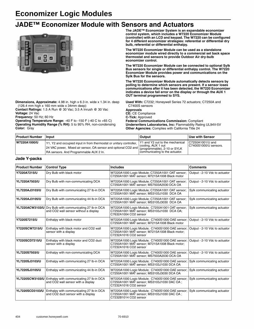
Economizer Logic Modules
404 customer.honeywell.com 70-6910
JADE™ Economizer Module with Sensors and ActuatorsThe JADE™ Economizer System is an expandable economizer control system, which includes a W7220 Economizer Module (controller) with an LCD and keypad. The W7220 can be configured for 4 different economizer strategies: referential or differential dry bulb, referential or differential enthalpy.
The W7220 Economizer Module can be used as a standalone economizer module wired directly to a commercial set back space thermostat and sensors to provide Outdoor Air dry-bulb economizer control.
The W7220 Economizer Module can be connected to optional Sylk Bus sensors for single or differential enthalpy control. The W7220 Economizer Module provides power and communications on the Sylk Bus for the sensors.
The W7220 Economizer Module automatically detects sensors by polling to determine which sensors are present. If a sensor loses communications after it has been detected, the W7220 Economizer indicates a device fail error on the display or through the AUX 1 OUT terminal programmed to SYS.
Dimensions, Approximate: 4.98 in. high x 6.3 in. wide x 1.34 in. deep (126.4 mm high x 160 mm wide x 34mm deep)
Contact Ratings: 1.5 A Run @ 30 Vac; 3.5 A Inrush @ 30 VacVoltage: 24 VacFrequency: 50 Hz; 60 HzOperating Temperature Range: -40 F to -150 F (-40 C to +65 C) Operating Humidity Range (% RH): 5 to 95% RH, non-condensingColor: Gray
Used With: C7232; Honeywell Series 72 actuators; C7250A and C7400S sensors
ApprovalsCE: CE ComplianceC-Tick: ApprovedFederal Communications Commission: CompliantUnderwriters Laboratories, Inc: Flammability Rating UL94V-5VOther Agencies: Complies with California Title 24
Jade Y-packs
Product Number Input Output Use with Sensor
W7220A1000/U Y1, Y2 and occupied input in from thermostat or unitary controller, 24 VAC power, Mixed air sensor, OA sensor and optional CO2 and RA sensors. And Programmable AUX 2 In.
Y1 and Y2 out to the mechanical cooling, AUX 1 out (programmable), 2-10 or SYLK communicating to the actuator.
C7250A1001/U and C7400S1000/U sensors.
Product Number Control Type Includes Comments
Y7220A7215/U Dry Bulb with black motor W7220A1000 Logic Module; C7250A1001 OAT sensor; C7250A1001 MAT sensor; M7215A1008 Black motor
Output - 2-10 Vdc to actuator
YL7220A7503/U Dry Bulb with non-communicating DCA W7220A1000 Logic Module; C7250A1001 OAT sensor; C7250A1001 MAT sensor; MS7503A2030 DCA OA
Output - 2-10 Vdc to actuator
YL7220AJ3103/U Dry Bulb with communicating 27 lb-in DCA W7220A1000 Logic Module; C7250A1001 OAT sensor; C7250A1001 MAT sensor; MS3103J1030 DCA OA
Sylk communicating actuator
YL7220AJ3105/U Dry Bulb with communicating 44 lb-in DCA W7220A1000 Logic Module; C7250A1001 OAT sensor; C7250A1001 MAT sensor; MS3105J3030 DCA OA
Sylk communicating actuator
YL7220ACW3103/U Dry Bulb with communicating 27 lb-in DCA and CO2 wall sensor without a display
W7220A1000 Logic Module; C7250A1001 OAT sensor; C7250A1001 MAT sensor; MS3103J1030 DCA OA; C7632A1004 CO2 sensor
Sylk communicating actuator
Y7220S7215/U Enthalpy with black motor W7220A1000 Logic Module; C7400S1000 OAE sensor; C7250A1001 MAT sensor; M7215A1008 Black motor
Output - 2-10 Vdc to actuator
Y7220SCW7215/U Enthalpy with black motor and CO2 wall sensor with a display
W7220A1000 Logic Module; C7400S1000 OAE sensor; C7250A1001 MAT sensor; M7215A1008 Black motor; C7232A1016 CO2 sensor
Output - 2-10 Vdc to actuator
Y7220SCD7215/U Enthalpy with black motor and CO2 duct sensor with a display
W7220A1000 Logic Module; C7400S1000 OAE sensor; C7250A1001 MAT sensor; M7215A1008 Black motor; C7232A1016 CO2 sensor
Output - 2-10 Vdc to actuator
YL7220S7503/U Enthalpy with non-communicating DCA W7220A1000 Logic Module; C7400S1000 OAE sensor; C7250A1001 MAT sensor; MS7503A2030 DCA OA
Output - 2-10 Vdc to actuator
YL7220SJ3103/U Enthalpy with communicating 27 lb-in DCA W7220A1000 Logic Module; C7400S1000 OAE sensor; C7250A1001 MAT sensor; MS3103J1030 DCA OA
Sylk communicating actuator
YL7220SJ3105/U Enthalpy with communicating 44 lb-in DCA W7220A1000 Logic Module; C7400S1000 OAE sensor; C7250A1001 MAT sensor; MS3105J3030 DCA OA
Sylk communicating actuator
YL7220SCW3103/U Enthalpy with communicating 27 lb-in DCA and CO2 wall sensor with a display
W7220A1000 Logic Module; C7400S1000 OAE sensor; C7250A1001 MAT sensor; MS3103J1030 DAC OA ; C7232A1016 CO2 sensor
Sylk communicating actuator
YL7220SCD3103/U Enthalpy with communicating 27 lb-in DCA and CO2 duct sensor with a display
W7220A1000 Logic Module; C7400S1000 OAE sensor; C7250A1001 MAT sensor; MS3103J1030 DAC OA ; C7232B1014 CO2 sensor
Sylk communicating actuator
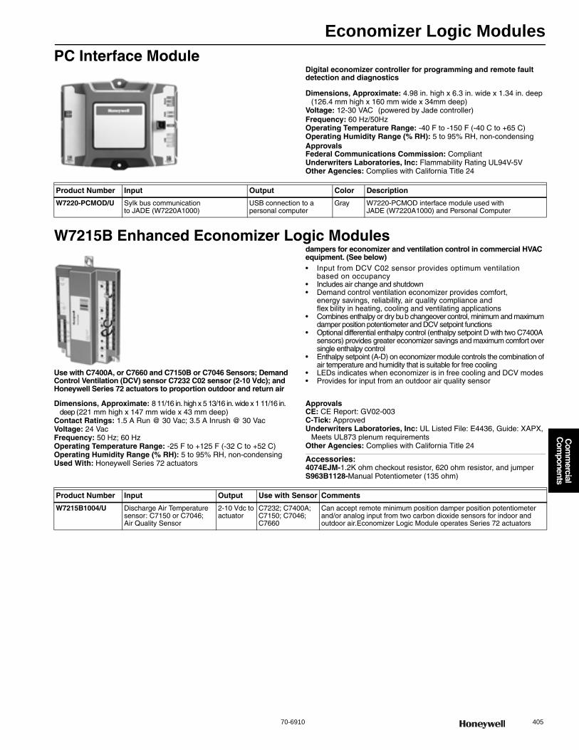
Economizer Logic Modules
70-6910 405
Com
mercial
Com
ponents
PC Interface ModuleDigital economizer controller for programming and remote fault detection and diagnostics
Dimensions, Approximate: 4.98 in. high x 6.3 in. wide x 1.34 in. deep (126.4 mm high x 160 mm wide x 34mm deep)
Voltage: 12-30 VAC (powered by Jade controller)Frequency: 60 Hz/50HzOperating Temperature Range: -40 F to -150 F (-40 C to +65 C) Operating Humidity Range (% RH): 5 to 95% RH, non-condensingApprovalsFederal Communications Commission: CompliantUnderwriters Laboratories, Inc: Flammability Rating UL94V-5VOther Agencies: Complies with California Title 24
W7215B Enhanced Economizer Logic Modules
Use with C7400A, or C7660 and C7150B or C7046 Sensors; Demand Control Ventilation (DCV) sensor C7232 C02 sensor (2-10 Vdc); and Honeywell Series 72 actuators to proportion outdoor and return air
dampers for economizer and ventilation control in commercial HVAC equipment. (See below)• Input from DCV C02 sensor provides optimum ventilation
based on occupancy • Includes air change and shutdown • Demand control ventilation economizer provides comfort,
energy savings, reliability, air quality compliance and flex bility in heating, cooling and ventilating applications
• Combines enthalpy or dry bub changeover control, minimum and maximum damper position potentiometer and DCV setpoint functions
• Optional differential enthalpy control (enthalpy setpoint D with two C7400A sensors) provides greater economizer savings and maximum comfort over single enthalpy control
• Enthalpy setpoint (A-D) on economizer module controls the combination of air temperature and humidity that is suitable for free cooling
• LEDs indicates when economizer is in free cooling and DCV modes • Provides for input from an outdoor air quality sensor
Dimensions, Approximate: 8 11/16 in. high x 5 13/16 in. wide x 1 11/16 in. deep (221 mm high x 147 mm wide x 43 mm deep)
Contact Ratings: 1.5 A Run @ 30 Vac; 3.5 A Inrush @ 30 VacVoltage: 24 VacFrequency: 50 Hz; 60 HzOperating Temperature Range: -25 F to +125 F (-32 C to +52 C) Operating Humidity Range (% RH): 5 to 95% RH, non-condensingUsed With: Honeywell Series 72 actuators
ApprovalsCE: CE Report: GV02-003C-Tick: ApprovedUnderwriters Laboratories, Inc: UL Listed File: E4436, Guide: XAPX,
Meets UL873 plenum requirementsOther Agencies: Complies with California Title 24
Accessories:4074EJM-1.2K ohm checkout resistor, 620 ohm resistor, and jumperS963B1128-Manual Potentiometer (135 ohm)
Product Number Input Output Color Description
W7220-PCMOD/U Sylk bus communication to JADE (W7220A1000)
USB connection to a personal computer
Gray W7220-PCMOD interface module used with JADE (W7220A1000) and Personal Computer
Product Number Input Output Use with Sensor Comments
W7215B1004/U Discharge Air Temperature sensor: C7150 or C7046; Air Quality Sensor
2-10 Vdc to actuator
C7232; C7400A; C7150; C7046; C7660
Can accept remote minimum position damper position potentiometer and/or analog input from two carbon dioxide sensors for indoor and outdoor air.Economizer Logic Module operates Series 72 actuators
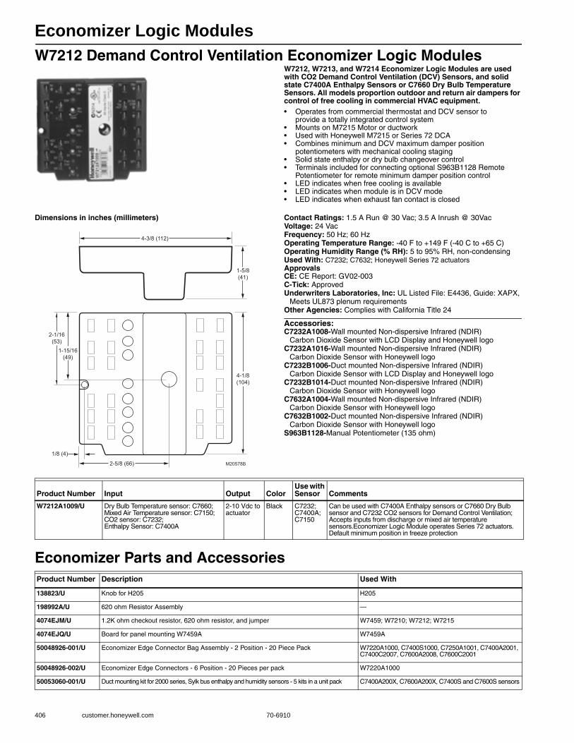
Economizer Logic Modules
406 customer.honeywell.com 70-6910
W7212 Demand Control Ventilation Economizer Logic ModulesW7212, W7213, and W7214 Economizer Logic Modules are used with CO2 Demand Control Ventilation (DCV) Sensors, and solid state C7400A Enthalpy Sensors or C7660 Dry Bulb Temperature Sensors. All models proportion outdoor and return air dampers for control of free cooling in commercial HVAC equipment.• Operates from commercial thermostat and DCV sensor to
provide a totally integrated control system • Mounts on M7215 Motor or ductwork • Used with Honeywell M7215 or Series 72 DCA • Combines minimum and DCV maximum damper position
potentiometers with mechanical cooling staging • Solid state enthalpy or dry bulb changeover control • Terminals included for connecting optional S963B1128 Remote
Potentiometer for remote minimum damper position control • LED indicates when free cooling is available • LED indicates when module is in DCV mode • LED indicates when exhaust fan contact is closed
Dimensions in inches (millimeters) Contact Ratings: 1.5 A Run @ 30 Vac; 3.5 A Inrush @ 30VacVoltage: 24 VacFrequency: 50 Hz; 60 HzOperating Temperature Range: -40 F to +149 F (-40 C to +65 C) Operating Humidity Range (% RH): 5 to 95% RH, non-condensingUsed With: C7232; C7632; Honeywell Series 72 actuatorsApprovalsCE: CE Report: GV02-003C-Tick: ApprovedUnderwriters Laboratories, Inc: UL Listed File: E4436, Guide: XAPX,
Meets UL873 plenum requirementsOther Agencies: Complies with California Title 24
Accessories:C7232A1008-Wall mounted Non-dispersive Infrared (NDIR)
Carbon Dioxide Sensor with LCD Display and Honeywell logoC7232A1016-Wall mounted Non-dispersive Infrared (NDIR)
Carbon Dioxide Sensor with Honeywell logoC7232B1006-Duct mounted Non-dispersive Infrared (NDIR)
Carbon Dioxide Sensor with LCD Display and Honeywell logoC7232B1014-Duct mounted Non-dispersive Infrared (NDIR)
Carbon Dioxide Sensor with Honeywell logoC7632A1004-Wall mounted Non-dispersive Infrared (NDIR)
Carbon Dioxide Sensor with Honeywell logoC7632B1002-Duct mounted Non-dispersive Infrared (NDIR)
Carbon Dioxide Sensor with Honeywell logoS963B1128-Manual Potentiometer (135 ohm)
Economizer Parts and Accessories
4-3/8 (112)
1-5/8(41)
4-1/8(104)
1/8 (4)
2-5/8 (66) M20578B
2-1/16(53)
1-15/16(49)
Product Number Input Output ColorUse with Sensor Comments
W7212A1009/U Dry Bulb Temperature sensor: C7660; Mixed Air Temperature sensor: C7150; CO2 sensor: C7232; Enthalpy Sensor: C7400A
2-10 Vdc to actuator
Black C7232; C7400A; C7150
Can be used with C7400A Enthalpy sensors or C7660 Dry Bulb sensor and C7232 CO2 sensors for Demand Control Ventilation; Accepts inputs from discharge or mixed air temperature sensors.Economizer Logic Module operates Series 72 actuators. Default minimum position in freeze protection
Product Number Description Used With
138823/U Knob for H205 H205
198992A/U 620 ohm Resistor Assembly —
4074EJM/U 1.2K ohm checkout resistor, 620 ohm resistor, and jumper W7459; W7210; W7212; W7215
4074EJQ/U Board for panel mounting W7459A W7459A
50048926-001/U Economizer Edge Connector Bag Assembly - 2 Position - 20 Piece Pack W7220A1000, C7400S1000, C7250A1001, C7400A2001, C7400C2007, C7600A2008, C7600C2001
50048926-002/U Economizer Edge Connectors - 6 Position - 20 Pieces per pack W7220A1000
50053060-001/U Duct mounting kit for 2000 series, Sylk bus enthalpy and humidity sensors - 5 kits in a unit pack C7400A200X, C7600A200X, C7400S and C7600S sensors
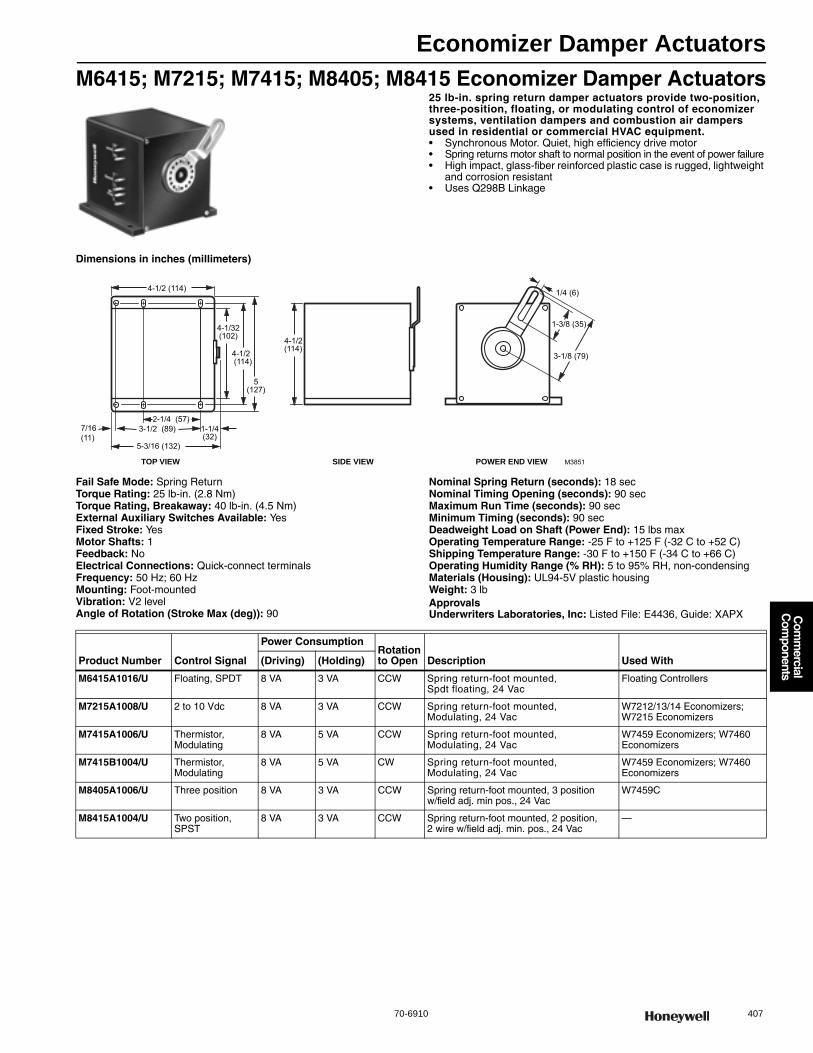
Economizer Damper Actuators
70-6910 407
Com
mercial
Com
ponents
M6415; M7215; M7415; M8405; M8415 Economizer Damper Actuators25 lb-in. spring return damper actuators provide two-position, three-position, floating, or modulating control of economizer systems, ventilation dampers and combustion air dampers used in residential or commercial HVAC equipment.• Synchronous Motor. Quiet, high efficiency drive motor • Spring returns motor shaft to normal position in the event of power failure • High impact, glass-fiber reinforced plastic case is rugged, lightweight
and corrosion resistant • Uses Q298B Linkage
Dimensions in inches (millimeters)
Fail Safe Mode: Spring ReturnTorque Rating: 25 lb-in. (2.8 Nm) Torque Rating, Breakaway: 40 lb-in. (4.5 Nm) External Auxiliary Switches Available: YesFixed Stroke: YesMotor Shafts: 1Feedback: NoElectrical Connections: Quick-connect terminalsFrequency: 50 Hz; 60 HzMounting: Foot-mountedVibration: V2 levelAngle of Rotation (Stroke Max (deg)): 90
Nominal Spring Return (seconds): 18 secNominal Timing Opening (seconds): 90 secMaximum Run Time (seconds): 90 secMinimum Timing (seconds): 90 secDeadweight Load on Shaft (Power End): 15 lbs maxOperating Temperature Range: -25 F to +125 F (-32 C to +52 C) Shipping Temperature Range: -30 F to +150 F (-34 C to +66 C) Operating Humidity Range (% RH): 5 to 95% RH, non-condensingMaterials (Housing): UL94-5V plastic housingWeight: 3 lbApprovalsUnderwriters Laboratories, Inc: Listed File: E4436, Guide: XAPX
7/16(11)
1-1/4(32)
5-3/16 (132)
4-1/2 (114)
3-1/2 (89)2-1/4 (57)
4-1/2 (114)
5(127)
4-1/32(102)
1-3/8 (35)
3-1/8 (79)
M3851TOP VIEW SIDE VIEW POWER END VIEW
1/4 (6)
4-1/2(114)
Product Number Control Signal
Power ConsumptionRotation to Open Description Used With(Driving) (Holding)
M6415A1016/U Floating, SPDT 8 VA 3 VA CCW Spring return-foot mounted, Spdt floating, 24 Vac
Floating Controllers
M7215A1008/U 2 to 10 Vdc 8 VA 3 VA CCW Spring return-foot mounted, Modulating, 24 Vac
W7212/13/14 Economizers; W7215 Economizers
M7415A1006/U Thermistor, Modulating
8 VA 5 VA CCW Spring return-foot mounted, Modulating, 24 Vac
W7459 Economizers; W7460 Economizers
M7415B1004/U Thermistor, Modulating
8 VA 5 VA CW Spring return-foot mounted, Modulating, 24 Vac
W7459 Economizers; W7460 Economizers
M8405A1006/U Three position 8 VA 3 VA CCW Spring return-foot mounted, 3 position w/field adj. min pos., 24 Vac
W7459C
M8415A1004/U Two position, SPST
8 VA 3 VA CCW Spring return-foot mounted, 2 position, 2 wire w/field adj. min. pos., 24 Vac
—
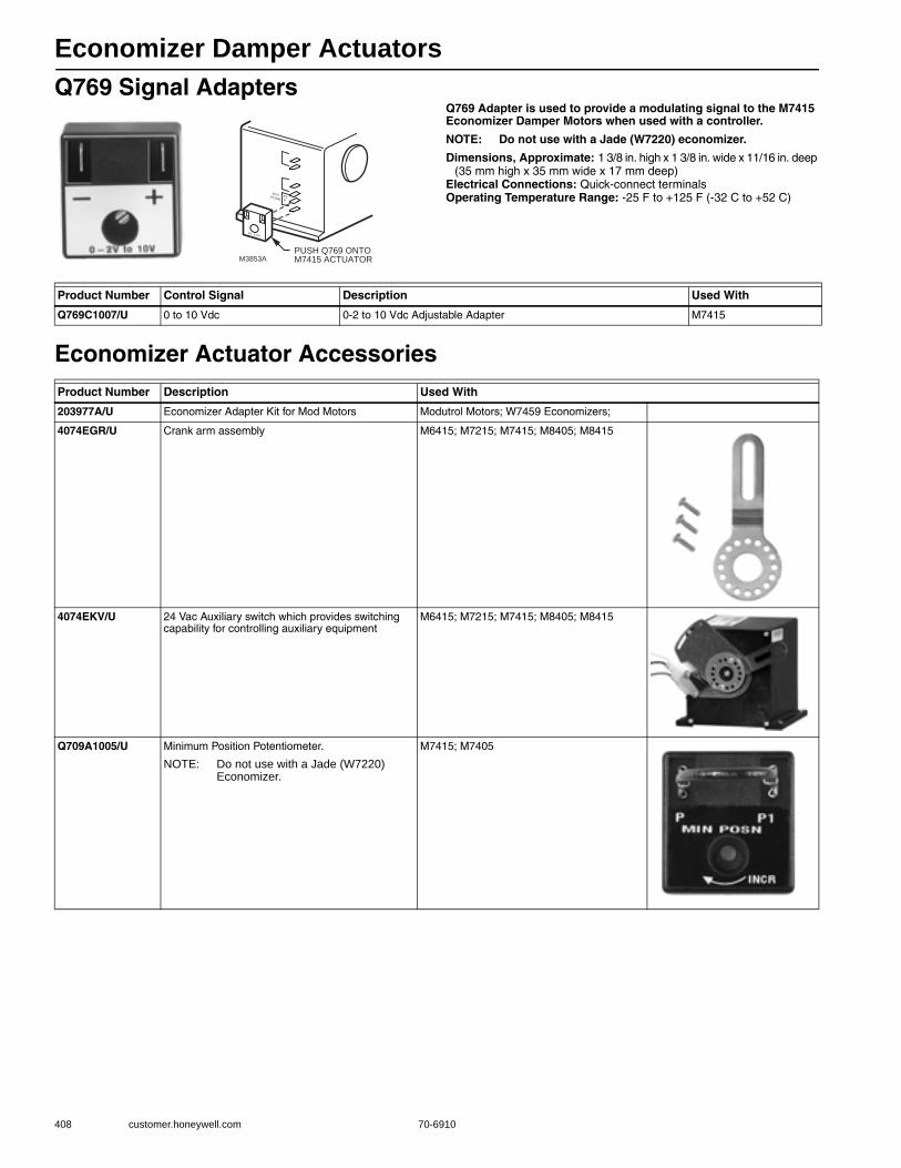
Economizer Damper Actuators
408 customer.honeywell.com 70-6910
Q769 Signal AdaptersQ769 Adapter is used to provide a modulating signal to the M7415 Economizer Damper Motors when used with a controller.
NOTE: Do not use with a Jade (W7220) economizer.
Dimensions, Approximate: 1 3/8 in. high x 1 3/8 in. wide x 11/16 in. deep (35 mm high x 35 mm wide x 17 mm deep)
Electrical Connections: Quick-connect terminalsOperating Temperature Range: -25 F to +125 F (-32 C to +52 C)
Economizer Actuator Accessories
M3853A
6V o 9V
M NPOSN
P1P
PUSH Q769 ONTO M7415 ACTUATOR
Product Number Control Signal Description Used With
Q769C1007/U 0 to 10 Vdc 0-2 to 10 Vdc Adjustable Adapter M7415
Product Number Description Used With
203977A/U Economizer Adapter Kit for Mod Motors Modutrol Motors; W7459 Economizers;
4074EGR/U Crank arm assembly M6415; M7215; M7415; M8405; M8415
4074EKV/U 24 Vac Auxiliary switch which provides switching capability for controlling auxiliary equipment
M6415; M7215; M7415; M8405; M8415
Q709A1005/U Minimum Position Potentiometer.
NOTE: Do not use with a Jade (W7220) Economizer.
M7415; M7405

Economizer Sensors
70-6910 409
Com
mercial
Com
ponents
C7150 Mixed Air SensorC7150 Solid State mixed air sensor is used with Honeywell economizer logic modules and W973 and M7415 to proportion outdoor and return air dampers in economizer systems.• Uses thermistor sensing element in ventilation duct systems • Negative temperature coefficient (NTC) causes resistance
to decrease as sampled air temperature increases • Resistance change used as in input to control W973 and M7415 • Requires no settings or calibration • Mounts on duct surface with four screws (not supplied)
Application: Temperature Mixed AirDimensions, Approximate: 2 in. high, 2 1/2 in. wide, 3/4 in. deep
(51 mm high x 64 mm wide) Sensor Type: 3000 ohms @ 25C NTCColor: Black
Mounting: Mount on a mounting bracket (not included) inside the mixed air or discharge air duct
Operating Temperature Range: 40 F to 110 F (4 C to 43 C) Electrical Connections: 1/4 in. (6 mm) quick-connect terminalsApprovalsCE: Report: GV97-011Underwriters Laboratories, Inc: Component Recognized
C7250 Temperature SensorThe C7250 Mixed Air sensor is designed for use as a 20k input to a controller for mixed air temperature in rooftop packaged air conditioning equipment.
A separate controller such as the JADE™ Economizer System (Model W7220) provides power and communications for the C7250 Mixed Air sensor.
Application: Electronic 20K temperature sensorDimensions, Approximate: 4.25 in high x 2.17 in wide x .81 in deep
(108 mm high by 55 mm wide x 20.5 mm deep) Sensor Type: 20K NTCColor: GrayMounting: Mounted in any position where it is exposed to freely circulating airOperating Temperature Range: -40 F to 150 F (-40 C to 66 C)
Operating Humidity Range (% RH): 11 to 89% RHElectrical Connections: 2-pin header-pin style or 2-pin card edge
removable terminal blocksApprovalsUnderwriters Laboratories, Inc: Component Recognized
Product NumberApplication Type
Maximum Ambient Temperature
Description Used With(F) (C)
C7150B1004/U Duct mixed or discharge air
250 F 121 C Electronic Temperature Sensor W973 and M7415; W7210, W7212, W7213, W7214, W7215, W7459, W7460
Product Number Application Type
Maximum Ambient Temperature Description
Used With
C7250A1001/U A 20k temperature sensor intended for sensing mixed or discharge air in roof top packaged air conditioning equipment. used with a W7220 economizer controller
150 F 66 C Electronic 20k temperature sensor
W7220
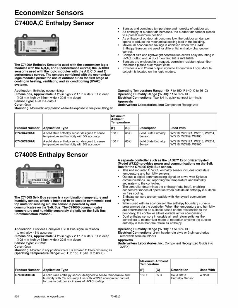
Economizer Sensors
410 customer.honeywell.com 70-6910
C7400A,C Enthalpy Sensor
The C7400A Enthalpy Sensor is used with the economizer logic modules with the A,B,C, and D performance curves; the C7400C sensor is used with the logic modules with the A,B,C,D, and E performance curves. The sensors combined with the economizer logic modules permit the use of outdoor air as the first stage of cooling in heating, ventilating and air conditioning (HVAC) systems.
• Senses and combines temperature and humidity of outdoor air.• As enthalpy of outdoor air increases, the outdoor air damper closes
to a preset minimum position.• As enthalpy of outdoor air becomes low, the outdoor air damper
opens to reduce the mechanical cooling load in the building.• Maximum economizer savings is achieved when two C7400
Enthalpy Sensors are used for differential enthalpy changeover control.
• Compact size and lightweight construction allows easy mounting in HVAC rooftop unit. A duct mounting kit is available.
• Sensors are enclosed in a rugged, corrosion-resistant glass-fiber reinforced plastic duct-mount case.
• Provides a 4 to 20 mA output signal to Economizer Logic Module; setpoint is located on the logic module.
Application: Enthalpy economizingDimensions, Approximate: 4.25 in high x 2.17 in wide x .81 in deep
(108 mm high by 55mm wide x 20.5 mm deep) Sensor Type: 4-20 mA outputColor: GrayMounting: Mounted in any position where it is exposed to freely circulating air.
Operating Temperature Range: -40 F to 150 F (-40 C to 66 C) Operating Humidity Range (% RH): 11 to 89% RHElectrical Connections: Two 1/4 in. quick-connect terminalsApprovalsUnderwriters Laboratories, Inc: Component Recognized
C7400S Enthalpy Sensor
The C7400S Sylk Bus sensor is a combination temperature and humidity sensor, which is intended to be used in commercial roof top units for sensing air. The sensor is powered by and communicates on the Sylk Bus. The C7400S communicates temperature and humidity separately digitally on the Sylk Bus Communication Protocol.
A separate controller such as the JADE™ Economizer System (Model W7220) provides power and communications on the Sylk Bus for the C7400S Sylk Bus sensor.• This unit mounted C7400S enthalpy sensor includes solid state
temperature and humidity sensors.• Outputs a digital communicating signal on a two-wire Sylkbus
communications link, reporting the temperature and humidity separately to the controller.
• The controller determines the enthalpy (total heat), enabling economizer modes of operation when outside air enthalpy is suitable for free cooling.
• Enthalpy sensors are compatible with Honeywell economizer systems.
• When used with an economizer, the enthalpy boundary curve is programmed via the controller. When the temperature and humidity are determined to be suitable based on the relationship to the boundary, the controller allows outside air for economizing.
• Dual enthalpy sensors in outside air and return switches the controllers to economizer mode of operation anytime the outside enthalpy is less than the return air enthalpy.
Application: Provides Honeywell SYLK Bus signal in relation to enthalpy - 5% accuracy
Dimensions, Approximate: 4.25 in high x 2.17 in wide x .81 in deep (108 mm high by 55mm wide x 20.5 mm deep)
Sensor Type: 7-21VdcColor: GrayMounting: Mounted in any position where it is exposed to freely circulating air.Operating Temperature Range: -40 F to 150 F (-40 C to 66 C)
Operating Humidity Range (% RH): 11 to 89% RHElectrical Connections: 2-pin header-pin style or 2-pin card edge
removable terminal blocksApprovalsUnderwriters Laboratories, Inc: Component Recognized Guide info
XAPX)
Product Number Application Type
Maximum Ambient Temperature
Description Used With(F) (C)
C7400A2001/U A solid state enthalpy sensor designed to sense temperature and humidity with 5% accuracy
150 F 66 C Solid State Enthalpy Sensor
W7210, W7212A, W7213, W7214, W7215, W7459, W7460
C7400C2007/U A solid state enthalpy sensor designed to sense temperature and humidity with 5% accuracy
150 F 66 C Solid State Enthalpy Sensor
W7210, W7212A, W7213, W7214, W7215, W7459, W7460
Product Number Application Type
Maximum Ambient Temperature
Description Used With(F) (C)
C7400S1000/U A solid state enthalpy sensor designed to sense temperature and humidity with 5% accuracy. Use with W7220 economizer control, for use in outdoor air intakes of HVAC rooftop
150 F 65 C Solid State Enthalpy Sensor
W7220
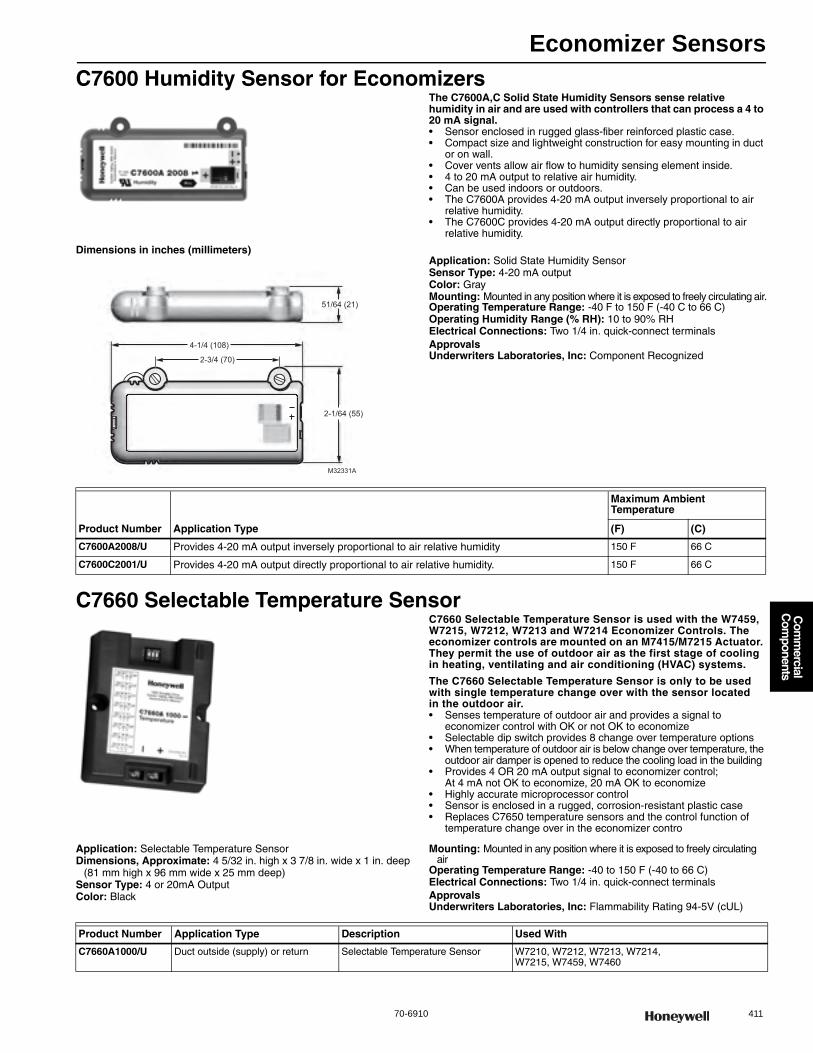
Economizer Sensors
70-6910 411
Com
mercial
Com
ponents
C7600 Humidity Sensor for EconomizersThe C7600A,C Solid State Humidity Sensors sense relative humidity in air and are used with controllers that can process a 4 to 20 mA signal.• Sensor enclosed in rugged glass-fiber reinforced plastic case.• Compact size and lightweight construction for easy mounting in duct
or on wall.• Cover vents allow air flow to humidity sensing element inside.• 4 to 20 mA output to relative air humidity.• Can be used indoors or outdoors.• The C7600A provides 4-20 mA output inversely proportional to air
relative humidity.• The C7600C provides 4-20 mA output directly proportional to air
relative humidity.
Dimensions in inches (millimeters)Application: Solid State Humidity SensorSensor Type: 4-20 mA outputColor: GrayMounting: Mounted in any position where it is exposed to freely circulating air.Operating Temperature Range: -40 F to 150 F (-40 C to 66 C) Operating Humidity Range (% RH): 10 to 90% RHElectrical Connections: Two 1/4 in. quick-connect terminalsApprovalsUnderwriters Laboratories, Inc: Component Recognized
C7660 Selectable Temperature SensorC7660 Selectable Temperature Sensor is used with the W7459, W7215, W7212, W7213 and W7214 Economizer Controls. The economizer controls are mounted on an M7415/M7215 Actuator. They permit the use of outdoor air as the first stage of cooling in heating, ventilating and air conditioning (HVAC) systems.
The C7660 Selectable Temperature Sensor is only to be used with single temperature change over with the sensor located in the outdoor air.• Senses temperature of outdoor air and provides a signal to
economizer control with OK or not OK to economize • Selectable dip switch provides 8 change over temperature options • When temperature of outdoor air is below change over temperature, the
outdoor air damper is opened to reduce the cooling load in the building • Provides 4 OR 20 mA output signal to economizer control;
At 4 mA not OK to economize, 20 mA OK to economize • Highly accurate microprocessor control • Sensor is enclosed in a rugged, corrosion-resistant plastic case • Replaces C7650 temperature sensors and the control function of
temperature change over in the economizer contro
Application: Selectable Temperature SensorDimensions, Approximate: 4 5/32 in. high x 3 7/8 in. wide x 1 in. deep
(81 mm high x 96 mm wide x 25 mm deep) Sensor Type: 4 or 20mA OutputColor: Black
Mounting: Mounted in any position where it is exposed to freely circulating air
Operating Temperature Range: -40 to 150 F (-40 to 66 C) Electrical Connections: Two 1/4 in. quick-connect terminalsApprovalsUnderwriters Laboratories, Inc: Flammability Rating 94-5V (cUL)
M32331A
4-1/4 (108)
2-1/64 (55)
51/64 (21)
2-3/4 (70)
Product Number Application Type
Maximum Ambient Temperature
(F) (C)
C7600A2008/U Provides 4-20 mA output inversely proportional to air relative humidity 150 F 66 C
C7600C2001/U Provides 4-20 mA output directly proportional to air relative humidity. 150 F 66 C
Product Number Application Type Description Used With
C7660A1000/U Duct outside (supply) or return Selectable Temperature Sensor W7210, W7212, W7213, W7214, W7215, W7459, W7460
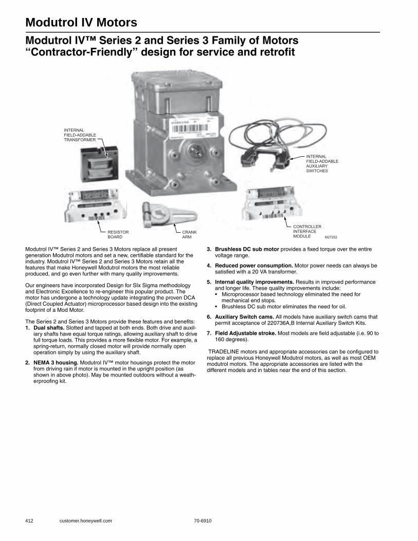
Modutrol IV Motors
412 customer.honeywell.com 70-6910
Modutrol IV™ Series 2 and Series 3 Family of Motors “Contractor-Friendly” design for service and retrofit
Modutrol IV™ Series 2 and Series 3 Motors replace all present generation Modutrol motors and set a new, certifiable standard for the industry. Modutrol IV™ Series 2 and Series 3 Motors retain all the features that make Honeywell Modutrol motors the most reliable produced, and go even further with many quality improvements.
Our engineers have incorporated Design for SIx Sigma methodology and Electronic Excellence to re-engineer this popular product. The motor has undergone a technology update integrating the proven DCA (Direct Coupled Actuator) microprocessor based design into the existing footprint of a Mod Motor.
The Series 2 and Series 3 Motors provide these features and benefits:1. Dual shafts. Slotted and tapped at both ends. Both drive and auxil-
iary shafts have equal torque ratings, allowing auxiliary shaft to drive full torque loads. This provides a more flexible motor. For example, a spring-return, normally closed motor will provide normally open operation simply by using the auxiliary shaft.
2. NEMA 3 housing. Modutrol IV™ motor housings protect the motor from driving rain if motor is mounted in the upright position (as shown in above photo). May be mounted outdoors without a weath-erproofing kit.
3. Brushless DC sub motor provides a fixed torque over the entire voltage range.
4. Reduced power consumption. Motor power needs can always be satisfied with a 20 VA transformer.
5. Internal quality improvements. Results in improved performance and longer life. These quality improvements include:• Microprocessor based technology eliminated the need for
mechanical end stops.• Brushless DC sub motor eliminates the need for oil.
6. Auxiliary Switch cams. All models have auxiliary switch cams that permit acceptance of 220736A,B Internal Auxiliary Switch Kits.
7. Field Adjustable stroke. Most models are field adjustable (i.e. 90 to 160 degrees).
TRADELINE motors and appropriate accessories can be configured to replace all previous Honeywell Modutrol motors, as well as most OEM modutrol motors. The appropriate accessories are listed with the different models and in tables near the end of this section.
M27252
INTERNALFIELD-ADDABLEAUXILIARYSWITCHES
INTERNAL FIELD-ADDABLE TRANSFORMER
CRANKARM
RESISTORBOARD
CONTROLLERINTERFACEMODULE
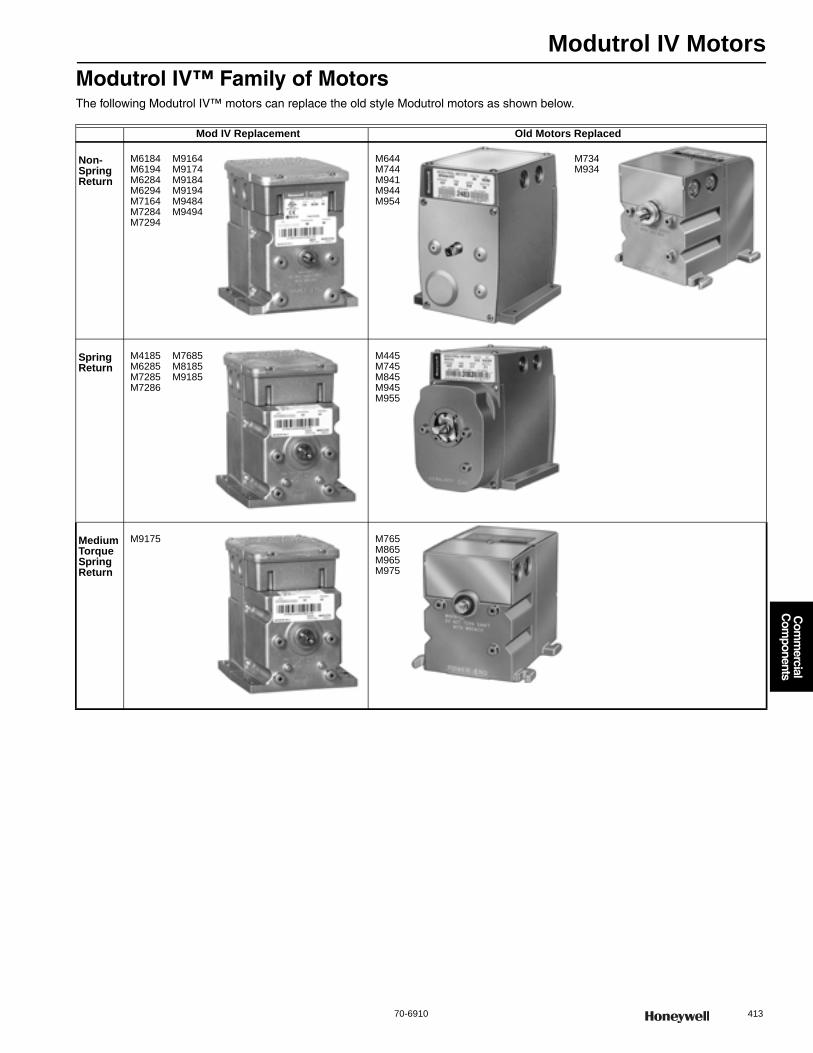
Modutrol IV Motors
70-6910 413
Com
mercial
Com
ponents
Modutrol IV™ Family of MotorsThe following Modutrol IV™ motors can replace the old style Modutrol motors as shown below.
Mod IV Replacement Old Motors Replaced
Non-Spring Return
M6184M6194M6284M6294M7164M7284M7294
M9164M9174M9184M9194M9484M9494
M644M744M941M944M954
M734M934
Spring Return
M4185M6285M7285M7286
M7685M8185M9185
M445M745M845M945M955
MediumTorqueSpringReturn
M9175 M765M865M965M975
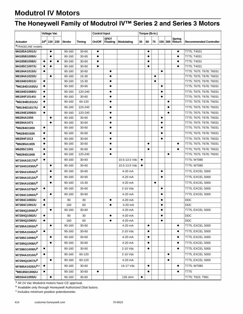
Modutrol IV Motors
414 customer.honeywell.com 70-6910
The Honeywell Family of Modutrol IV™ Series 2 and Series 3 Motors
Actuator
Voltage Vac
Stroke Timing
Control Input Torque (lb-in.)
Spring Return Recommended Controller24a 120 230 On/Off
SPDT Floating Modulating 35 60 75 150 300
*TRADELINE models.
M4185A1001/U 90-160 30-60 T775; T4031
M4185B1009/U 90-160 30-60 T775; T4031
M4185B1058/U 90-160 30-60 T775; T4031
M4185C1007/U 90-160 30-60 T775; T4031
M6184A1015/U 90-160 30-60 T775; T675; T678; T6031
M6184A1023/U 90-160 15-30 T775; T675; T678; T6031
M6184D1001/U 90-160 15-30 T775; T675; T678; T6031
*M6184D1035/U 90-160 30-60 T775; T675; T678; T6031
M6184D1068/U 90-160 120-240 T775; T675; T678; T6031
M6184F1014/U 90-160 30-60 T775; T675; T678; T6031
*M6194B1011/U 90-160 60-120 T775; T675; T678; T6031
*M6194D1017/U 90-160 120-240 T775; T675; T678; T6031
M6194E1006/U 90-160 120-240 T775; T675; T678; T6031
M6284A1055 90-160 30-60 T775; T675; T678; T6031
M6284A1071 90-160 30-60 T775; T675; T678; T6031
*M6284D1000 90-160 30-60 T775; T675; T678; T6031
*M6284D1026 90-160 30-60 T775; T675; T678; T6031
M6284F1013 90-160 30-60 T775; T675; T678; T6031
*M6285A1005 90-160 30-60 T775; T675; T678; T6031
M6285C1001 90-160 30-60 T775; T675; T678; T6031
*M6294D1008 90-160 120-240 T775; T675; T678; T6031
M7164A1017/Ub 90-160 30-60 10.5-13.5 Vdc T775; W7080
M7164G1030/Ub 90-160 30-60 10.5-13.5 Vdc T775; W7080
M7284A1004/Ub 90-160 30-60 4-20 mA T775, EXCEL 5000
M7284A1012/Ub 90-160 30-60 4-20 mA T775, EXCEL 5000
M7284A1038/Ub 90-160 15-30 4-20 mA T775, EXCEL 5000
M7284A1079/Ub 90-160 30-60 2-10 Vdc T775, EXCEL 5000
M7284C1000/Ub 90-160 30-60 4-20 mA T775, EXCEL 5000
M7284C1083/U 90 30 4-20 mA DDC
M7284C1091/U 160 60 4-20 mA DDC
M7284Q1009/Ub 90-160 30-60 4-20 mA T775, EXCEL 5000
M7284Q1082/U 90 30 4-20 mA DDC
M7284Q1090/U 160 60 4-20 mA DDC
M7285A1003/Ub 90-160 30-60 4-20 mA T775, EXCEL 5000
M7285A1045/Ub 90-160 30-60 2-10 Vdc T775, EXCEL 5000
M7285C1009/Ub 90-160 30-60 4-20 mA T775, EXCEL 5000
M7285Q1008/Ub 90-160 30-60 4-20 mA T775, EXCEL 5000
M7286G1009/Ub 90-160 30-60 2-10 Vdc T775, EXCEL 5000
M7294A1010/Ub 90-160 60-120 2-10 Vdc T775, EXCEL 5000
M7294Q1007/Ub 90-160 60-120 4-20 mA T775, EXCEL 5000
M7685A1025/Ub,c 90-160 30-60 14-17 Vdc T775; W7080
*M8185D1006/U 90-160 30-60 T775
M9164A1005/U 90-160 30-60 135 ohm T775; T915; T991a All 24 Vac Modutrol motors have CE approval.b Available only through Honeywell Authorized Distr butors.c Includes minimum position potentiometer.

Modutrol IV Motors
70-6910 415
Com
mercial
Com
ponents
Modutrol IV™ Series 2 and Series 3 Motor Order Number Guide
M9164A1013/U 90-160 30-60 135 ohm T775; T915; T991
M9164A1070/U 90-160 30-60 135 ohm T775; T915; T991
M9164C1001/U 90-160 30-60 135 ohm T775; T915; T991
M9164C1068/U 90-160 30-60 135 ohm T775; T915; T991
*M9164D1009/U 90-160 30-60 135 ohm T775; T915; T991
M9174B1027/U 90-160 30-60 135 ohm T775; T915; T991
M9174C1025/U 90-160 30-60 135 ohm T775; T915; T991
M9174C1033/U 90-160 30-60 135 ohm T775; T915; T991
*M9174D1007/U 90-160 30-60 135 ohm T775; T915; T991
M9184A1019/U 90-160 30-60 135 ohm T775; T915; T991
M9184C1031/U 90-160 30-60 135 ohm T775; T915; T991
M9184D1005/U 90-160 15-30 135 ohm T775; T915; T991
*M9184D1021/U 90-160 30-60 135 ohm T775; T915; T991
M9184F1034/U 90-160 30-60 135 ohm T775; T915; T991
M9185A1018/U 90-160 30-60 135 ohm T775; T915; T991
M9185C1006/U 90-160 30-60 135 ohm T775; T915; T991
*M9185D1004/U 90-160 30-60 135 ohm T775; T915; T991
M9185E1019/U 90-160 30-60 135 ohm T775; T915; T991
*M9194D1003/U 90-160 120-240 135 ohm T775; T915; T991
M9194E1000/U 90-160 120-240 135 ohm T775; T915; T991
Actuator
Voltage Vac
Stroke Timing
Control Input Torque (lb-in.)
Spring Return Recommended Controller24a 120 230 On/Off
SPDT Floating Modulating 35 60 75 150 300
*TRADELINE models.
a All 24 Vac Modutrol motors have CE approval.b Available only through Honeywell Authorized Distributors.c Includes minimum position potentiometer.
SERIES 40, TWO-POSITION, LINE VOLTAGE SERIES 60, FLOATING CONTROL SERIES 60, FLOATING WITH FEEDBACK POTENTIOMETER 4-7, 6-9, 10.5-13.5 VDC CONTROL 4-20 mA OR 2-10 VDC CONTROL 14-17 VDC WITH MINIMUM POSITION SERIES 80, TWO-POSITION, LOW VOLTAGE SERIES 90, PROPORTIONING CONTROL PROPORTIONAL FLAME SAFEGUARD FIRING RATE MOTOR
35 LB-IN.
75 LB-IN.
150 LB-IN.
300 LB-IN. 60 LB-IN.
SPRING RETURN
NON-SPRING RETURN
TORQUE
TORQUE DESIGNATION
6
7
8
9
N.O.
N.O.
N.O.
SPRING RETURN
SPRING RETURN
NON-SPRING RETURN
NON-SPRING RETURN ROTATION ACTION
OUTPUT DRIVE
4
5
6
1
2
41 61 62 71 72 76 81 91 94
CONTROL SERIES (FIRST TWO DIGITS)
SHAFT
DUAL-ENDEDSHAFT
NUMBER OF AUX. SWITCHES
SUFFIX LETTER APPLIES TO ALL MODELS
A
SPECIAL FUNCTION
B C
Q
V W
G
0 1 2 STANDARD
MINIMUM POSITION
STANDARD
ADJ. ZERO AND SPAN
STROKE ELECTRICAL ROTATION
N.O.
N.O.
ADJUSTABLE
ADJUSTABLE F D E STANDARD ADJUSTABLE
SPECIFICATION NUMBER
FURTHER IDENTIFIES MOTOR M9184D1021
M13696A2
2
MODEL NUMBERS IN SHADED AREAS ARE AVAILABLE SPECIAL ORDER ONLY. CONTACT YOUR HONEYWELL SALES REPRESENTATIVE. SUFFIX LETTERS IN BOLD ARE OBSOLETE.
1
1
1
1
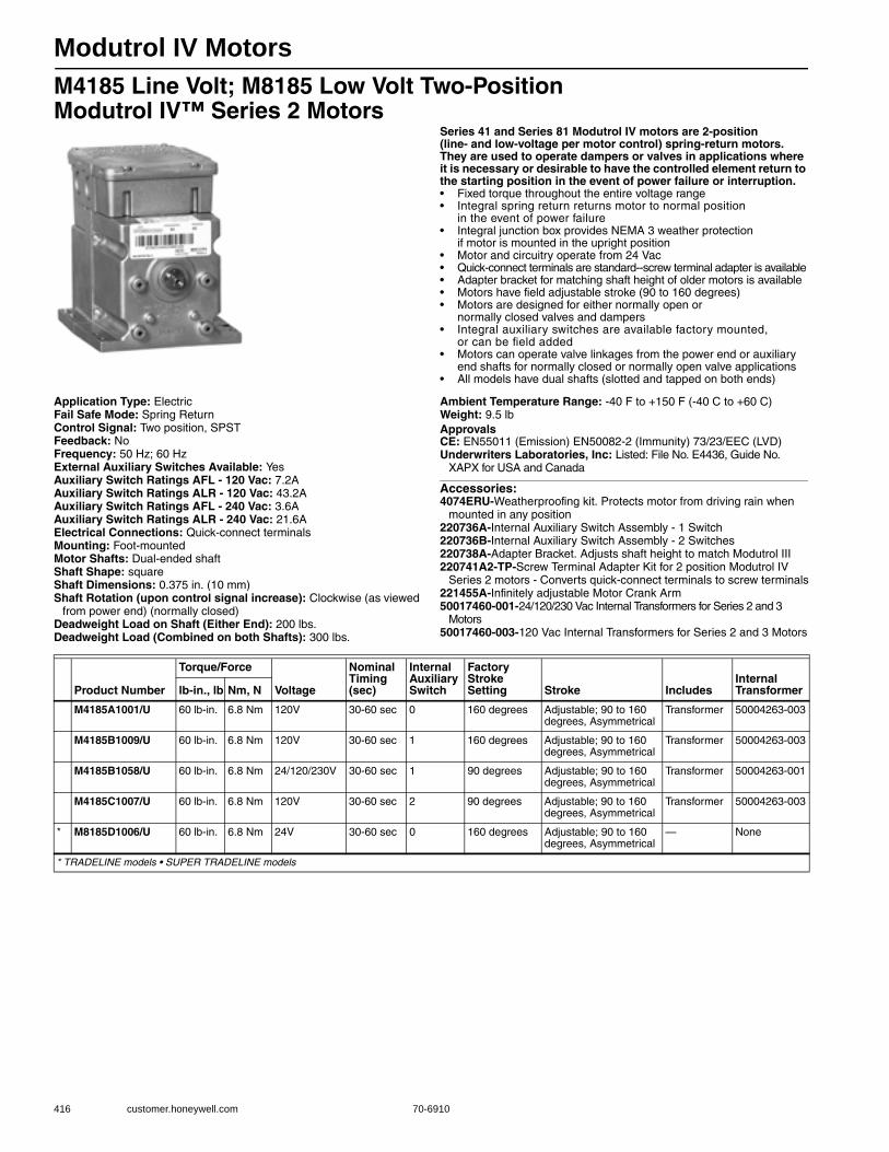
Modutrol IV Motors
416 customer.honeywell.com 70-6910
M4185 Line Volt; M8185 Low Volt Two-Position Modutrol IV™ Series 2 Motors
Series 41 and Series 81 Modutrol IV motors are 2-position (line- and low-voltage per motor control) spring-return motors. They are used to operate dampers or valves in applications where it is necessary or desirable to have the controlled element return to the starting position in the event of power failure or interruption.• Fixed torque throughout the entire voltage range • Integral spring return returns motor to normal position
in the event of power failure • Integral junction box provides NEMA 3 weather protection
if motor is mounted in the upright position • Motor and circuitry operate from 24 Vac • Quick-connect terminals are standard--screw terminal adapter is available • Adapter bracket for matching shaft height of older motors is available • Motors have field adjustable stroke (90 to 160 degrees) • Motors are designed for either normally open or
normally closed valves and dampers • Integral auxiliary switches are available factory mounted,
or can be field added • Motors can operate valve linkages from the power end or auxiliary
end shafts for normally closed or normally open valve applications • All models have dual shafts (slotted and tapped on both ends)
Application Type: ElectricFail Safe Mode: Spring ReturnControl Signal: Two position, SPSTFeedback: NoFrequency: 50 Hz; 60 HzExternal Auxiliary Switches Available: YesAuxiliary Switch Ratings AFL - 120 Vac: 7.2AAuxiliary Switch Ratings ALR - 120 Vac: 43.2AAuxiliary Switch Ratings AFL - 240 Vac: 3.6AAuxiliary Switch Ratings ALR - 240 Vac: 21.6AElectrical Connections: Quick-connect terminalsMounting: Foot-mountedMotor Shafts: Dual-ended shaftShaft Shape: squareShaft Dimensions: 0.375 in. (10 mm) Shaft Rotation (upon control signal increase): Clockwise (as viewed
from power end) (normally closed)Deadweight Load on Shaft (Either End): 200 lbs.Deadweight Load (Combined on both Shafts): 300 lbs.
Ambient Temperature Range: -40 F to +150 F (-40 C to +60 C) Weight: 9.5 lbApprovalsCE: EN55011 (Emission) EN50082-2 (Immunity) 73/23/EEC (LVD)Underwriters Laboratories, Inc: Listed: File No. E4436, Guide No.
XAPX for USA and Canada
Accessories:4074ERU-Weatherproofing kit. Protects motor from driving rain when
mounted in any position220736A-Internal Auxiliary Switch Assembly - 1 Switch220736B-Internal Auxiliary Switch Assembly - 2 Switches220738A-Adapter Bracket. Adjusts shaft height to match Modutrol III 220741A2-TP-Screw Terminal Adapter Kit for 2 position Modutrol IV
Series 2 motors - Converts quick-connect terminals to screw terminals221455A-Infinitely adjustable Motor Crank Arm50017460-001-24/120/230 Vac Internal Transformers for Series 2 and 3
Motors50017460-003-120 Vac Internal Transformers for Series 2 and 3 Motors
Product Number
Torque/Force
Voltage
Nominal Timing (sec)
Internal Auxiliary Switch
Factory Stroke Setting Stroke Includes
Internal Transformerlb-in., lb Nm, N
M4185A1001/U 60 lb-in. 6.8 Nm 120V 30-60 sec 0 160 degrees Adjustable; 90 to 160 degrees, Asymmetrical
Transformer 50004263-003
M4185B1009/U 60 lb-in. 6.8 Nm 120V 30-60 sec 1 160 degrees Adjustable; 90 to 160 degrees, Asymmetrical
Transformer 50004263-003
M4185B1058/U 60 lb-in. 6.8 Nm 24/120/230V 30-60 sec 1 90 degrees Adjustable; 90 to 160 degrees, Asymmetrical
Transformer 50004263-001
M4185C1007/U 60 lb-in. 6.8 Nm 120V 30-60 sec 2 90 degrees Adjustable; 90 to 160 degrees, Asymmetrical
Transformer 50004263-003
* M8185D1006/U 60 lb-in. 6.8 Nm 24V 30-60 sec 0 160 degrees Adjustable; 90 to 160 degrees, Asymmetrical
— None
* TRADELINE models • SUPER TRADELINE models
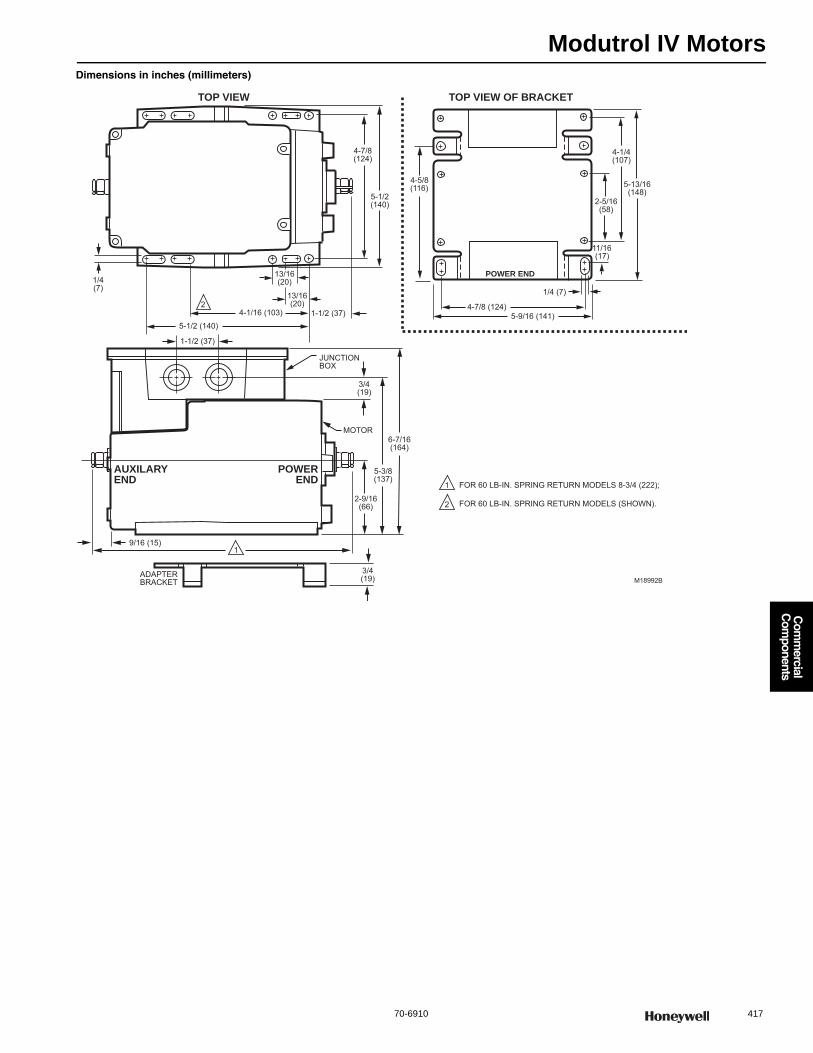
Modutrol IV Motors
70-6910 417
Com
mercial
Com
ponents
Dimensions in inches (millimeters)
4-7/8 (124)
5-1/2 (140)
13/16 (20)
4-1/16 (103)
1/4 (7)
1-1/2 (37) 5-1/2 (140)
JUNCTION BOX
MOTOR
AUXILARY END
POWER END
ADAPTER BRACKET
2-9/16 (66)
5-3/8 (137)
6-7/16 (164)
9/16 (15)
3/4 (19)
TOP VIEW OF BRACKET TOP VIEW
4-5/8 (116)
4-1/4 (107)
2-5/16 (58)
11/16 (17)
4-7/8 (124) 5-9/16 (141)
1/4 (7)
5-13/16 (148)
1
POWER END
2
1-1/2 (37)
3/4 (19)
13/16 (20)
M18992B
FOR 60 LB-IN. SPRING RETURN MODELS 8-3/4 (222); FOR 60 LB-IN. SPRING RETURN MODELS (SHOWN).
1
2

Modutrol IV Motors
418 customer.honeywell.com 70-6910
M6184; M6194 Floating Modutrol IV™ Series 2 MotorsSeries 61 Modutrol IV™ Motors non-spring return floating control motors used with controllers that provide a switched spdt or floating output to operate dampers or valves.• Integral junction box provides NEMA 3 weather protection
if motor is mounted in the upright position • Motor and circuitry operate from 24 Vac • Quick-connect terminals are standard--screw terminal adapter is available • Adapter bracket for matching shaft height of older motors is available • Motors have field adjustable stroke (90 to 160 degrees) • Integral auxiliary switches are available factory mounted,
or can be field added • All models have dual shafts (slotted and tapped on both ends) • All models have auxiliary switch cams • Fixed torque throughout the entire voltage range • Motors are designed for either normally open or
normally closed valves and dampers
Application Type: ElectricFail Safe Mode: Non-Spring ReturnControl Signal: FloatingFeedback: NoFrequency: 50 Hz; 60 HzExternal Auxiliary Switches Available: YesAuxiliary Switch Ratings AFL - 120 Vac: 7.2AAuxiliary Switch Ratings ALR - 120 Vac: 43.2AAuxiliary Switch Ratings AFL - 240 Vac: 3.6AAuxiliary Switch Ratings ALR - 240 Vac: 21.6AElectrical Connections: Quick-connect terminalsInternal Transformer: NoneMounting: Foot-mountedMotor Shafts: Dual-ended shaftShaft Shape: squareShaft Dimensions: 0.375 in. (10 mm) Shaft Rotation (upon control signal increase): Dependent on wiring
(normally closed)Deadweight Load on Shaft (Either End): 200 lbs.
Deadweight Load (Combined on both Shafts): 300 lbs.Ambient Temperature Range: -40 F to +150 F (-40 C to +60 C) Weight: 6.5 lbApprovalsCE: EN55011 (Emission) EN50082-2 (Immunity) 73/23/EEC (LVD)Underwriters Laboratories, Inc: Listed: File No. E4436, Guide No.
XAPX for USA and Canada
Accessories:4074ERU-Weatherproofing kit. Protects motor from driving rain when
mounted in any position220736A-Internal Auxiliary Switch Assembly - 1 Switch220736B-Internal Auxiliary Switch Assembly - 2 Switches220738A-Adapter Bracket. Adjusts shaft height to match Modutrol III motors221455A-Infinitely adjustable Motor Crank Arm50017460-001-24/120/230 Vac Internal Transformers for Series 2 and 3
Motors50017460-003-120 Vac Internal Transformers for Series 2 and 3 Motors
Product Number
Torque/Force
VoltageNominal Timing (sec)
Internal Auxiliary Switch
Factory Stroke Setting Stroke Includes Comments
Internal Transformerlb-in., lb Nm, N
M6184A1015/U 150 b-in. 17 Nm 24V 30-60 sec 0 90 degrees
Adjustable; 90 to 160 degrees, Symmetrical
— — None
M6184A1023/U 75 lb-in. 8.5 Nm 120V 15-30 sec 0 160 degrees
Adjustable; 90 to 160 degrees, Asymmetrical
Transformer — 50004263-003
M6184D1001/U 75 lb-in. 8.5 Nm 24V 15-30 sec 0 90 degrees
Adjustable; 90 to 160 degrees, Symmetrical
— — None
* M6184D1035/U 150 b-in. 17 Nm 24V 30-60 sec 0 160 degrees
Adjustable; 90 to 160 degrees, Symmetrical
— — None
M6184D1068/U 150 b-in. 17 Nm 24V 120-240 sec 0 90 degrees
Adjustable; 90 to 160 degrees, Symmetrical
— Contains on-off pulsing circuitry to achieve timing
None
M6184F1014/U 150 b-in. 17 Nm 24V 30-60 sec 2 90 degrees
Adjustable; 90 to 160 degrees, Symmetrical
— — None
M6194B1011/U 300 b-in. 34 Nm 24V 60-120 sec 1 90 degrees
Adjustable; 90 to 160 degrees, Symmetrical
— — None
* M6194D1017/U 300 b-in. 34 Nm 24V 120-240 sec 0 160 degrees
Adjustable; 90 to 160 degrees, Symmetrical
— — None
M6194E1006/U 300 b-in. 34 Nm 24V 120-240 sec 1 90 degrees
Adjustable; 90 to 160 degrees, Symmetrical
— — None
* TRADELINE models • SUPER TRADELINE models
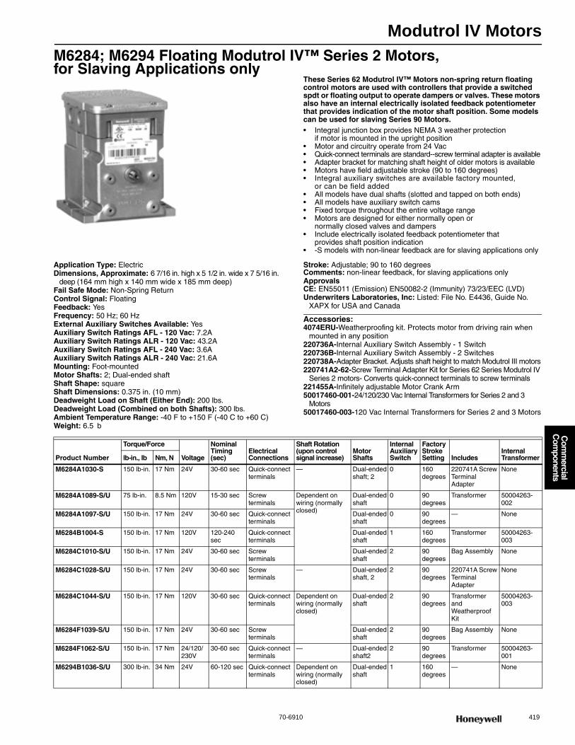
Modutrol IV Motors
70-6910 419
Com
mercial
Com
ponents
M6284; M6294 Floating Modutrol IV™ Series 2 Motors, for Slaving Applications only
These Series 62 Modutrol IV™ Motors non-spring return floating control motors are used with controllers that provide a switched spdt or floating output to operate dampers or valves. These motors also have an internal electrically isolated feedback potentiometer that provides indication of the motor shaft position. Some models can be used for slaving Series 90 Motors.• Integral junction box provides NEMA 3 weather protection
if motor is mounted in the upright position • Motor and circuitry operate from 24 Vac • Quick-connect terminals are standard--screw terminal adapter is available • Adapter bracket for matching shaft height of older motors is available • Motors have field adjustable stroke (90 to 160 degrees) • Integral auxiliary switches are available factory mounted,
or can be field added • All models have dual shafts (slotted and tapped on both ends) • All models have auxiliary switch cams • Fixed torque throughout the entire voltage range • Motors are designed for either normally open or
normally closed valves and dampers • Include electrically isolated feedback potentiometer that
provides shaft position indication • -S models with non-linear feedback are for slaving applications only
Application Type: ElectricDimensions, Approximate: 6 7/16 in. high x 5 1/2 in. wide x 7 5/16 in.
deep (164 mm high x 140 mm wide x 185 mm deep) Fail Safe Mode: Non-Spring ReturnControl Signal: FloatingFeedback: YesFrequency: 50 Hz; 60 HzExternal Auxiliary Switches Available: YesAuxiliary Switch Ratings AFL - 120 Vac: 7.2AAuxiliary Switch Ratings ALR - 120 Vac: 43.2AAuxiliary Switch Ratings AFL - 240 Vac: 3.6AAuxiliary Switch Ratings ALR - 240 Vac: 21.6AMounting: Foot-mountedMotor Shafts: 2; Dual-ended shaftShaft Shape: squareShaft Dimensions: 0.375 in. (10 mm) Deadweight Load on Shaft (Either End): 200 lbs.Deadweight Load (Combined on both Shafts): 300 lbs.Ambient Temperature Range: -40 F to +150 F (-40 C to +60 C) Weight: 6.5 b
Stroke: Adjustable; 90 to 160 degreesComments: non-linear feedback, for slaving applications onlyApprovalsCE: EN55011 (Emission) EN50082-2 (Immunity) 73/23/EEC (LVD)Underwriters Laboratories, Inc: Listed: File No. E4436, Guide No.
XAPX for USA and Canada
Accessories:4074ERU-Weatherproofing kit. Protects motor from driving rain when
mounted in any position220736A-Internal Auxiliary Switch Assembly - 1 Switch220736B-Internal Auxiliary Switch Assembly - 2 Switches220738A-Adapter Bracket. Adjusts shaft height to match Modutrol III motors220741A2-62-Screw Terminal Adapter Kit for Series 62 Series Modutrol IV
Series 2 motors- Converts quick-connect terminals to screw terminals221455A-Infinitely adjustable Motor Crank Arm50017460-001-24/120/230 Vac Internal Transformers for Series 2 and 3
Motors50017460-003-120 Vac Internal Transformers for Series 2 and 3 Motors
Product Number
Torque/Force
Voltage
Nominal Timing (sec)
Electrical Connections
Shaft Rotation (upon control signal increase)
Motor Shafts
Internal Auxiliary Switch
Factory Stroke Setting Includes
Internal Transformerlb-in., lb Nm, N
M6284A1030-S 150 lb-in. 17 Nm 24V 30-60 sec Quick-connect terminals
— Dual-ended shaft; 2
0 160 degrees
220741A Screw Terminal Adapter
None
M6284A1089-S/U 75 lb-in. 8.5 Nm 120V 15-30 sec Screw terminals
Dependent on wiring (normally closed)
Dual-ended shaft
0 90 degrees
Transformer 50004263-002
M6284A1097-S/U 150 lb-in. 17 Nm 24V 30-60 sec Quick-connect terminals
Dual-ended shaft
0 90 degrees
— None
M6284B1004-S 150 lb-in. 17 Nm 120V 120-240 sec
Quick-connect terminals
Dual-ended shaft
1 160 degrees
Transformer 50004263-003
M6284C1010-S/U 150 lb-in. 17 Nm 24V 30-60 sec Screw terminals
Dual-ended shaft
2 90 degrees
Bag Assembly None
M6284C1028-S/U 150 lb-in. 17 Nm 24V 30-60 sec Screw terminals
— Dual-ended shaft, 2
2 90 degrees
220741A Screw Terminal Adapter
None
M6284C1044-S/U 150 lb-in. 17 Nm 120V 30-60 sec Quick-connect terminals
Dependent on wiring (normally closed)
Dual-ended shaft
2 90 degrees
Transformer and Weatherproof Kit
50004263-003
M6284F1039-S/U 150 lb-in. 17 Nm 24V 30-60 sec Screw terminals
Dual-ended shaft
2 90 degrees
Bag Assembly None
M6284F1062-S/U 150 lb-in. 17 Nm 24/120/230V
30-60 sec Quick-connect terminals
— Dual-ended shaft2
2 90 degrees
Transformer 50004263-001
M6294B1036-S/U 300 lb-in. 34 Nm 24V 60-120 sec Quick-connect terminals
Dependent on wiring (normally closed)
Dual-ended shaft
1 160 degrees
— None

Modutrol IV Motors
420 customer.honeywell.com 70-6910
M6284; M6294 Floating Modutrol IV™ Series 2 Motors, for Slaving Applications only
These Series 62 Modutrol IV™ Motors non-spring return floating control motors are used with controllers that provide a switched spdt or floating output to operate dampers or valves. These motors also have an internal electrically isolated feedback potentiometer that provides indication of the motor shaft position. Some models can be used for slaving Series 90 Motors.• Integral junction box provides NEMA 3 weather protection
if motor is mounted in the upright position • Motor and circuitry operate from 24 Vac • Quick-connect terminals are standard--screw terminal adapter is available • Adapter bracket for matching shaft height of older motors is available • Motors have field adjustable stroke (90 to 160 degrees) • Integral auxiliary switches are available factory mounted, or can be field added • All models have dual shafts (slotted and tapped on both ends) • All models have auxiliary switch cams • Fixed torque throughout the entire voltage range • Motors are designed for either normally open or
normally closed valves and dampers • Include electrically isolated feedback potentiometer that
provides shaft position indication • -S models with non-linear feedback are for slaving applications only
Application Type: ElectricDimensions, Approximate: 6 7/16 in. high x 5 1/2 in. wide x 7 5/16 in.
deep (164 mm high x 140 mm wide x 185 mm deep) Fail Safe Mode: Non-Spring ReturnControl Signal: FloatingFeedback: YesFrequency: 50 Hz; 60 HzExternal Auxiliary Switches Available: YesAuxiliary Switch Ratings AFL - 120 Vac: 7.2AAuxiliary Switch Ratings ALR - 120 Vac: 43.2AAuxiliary Switch Ratings AFL - 240 Vac: 3.6AAuxiliary Switch Ratings ALR - 240 Vac: 21.6AMounting: Foot-mounted; Dual-ended shaftMotor Shafts: Dual-ended shaftShaft Shape: squareShaft Dimensions: 0.375 in. (10 mm) Shaft Rotation (upon control signal increase): Dependent on wiring
(normally closed)Deadweight Load on Shaft (Either End): 200 lbs.Deadweight Load (Combined on both Shafts): 300 lbs.
Ambient Temperature Range: -40 F to +150 F (-40 C to +60 C) Weight: 7.5 lbComments: non-linear feedback, for slaving applications onlyApprovalsCE: EN55011 (Emission) EN50082-2 (Immunity) 73/23/EEC (LVD)Underwriters Laboratories, Inc: Listed: File No. E4436, Guide No.
XAPX for USA and Canada
Accessories:4074ERU-Weatherproofing kit. Protects motor from driving rain when
mounted in any position220736A-Internal Auxiliary Switch Assembly - 1 Switch220736B-Internal Auxiliary Switch Assembly - 2 Switches220738A-Adapter Bracket. Adjusts shaft height to match Modutrol III motors220741A2-62-Screw Terminal Adapter Kit for Series 62 Series Modutrol IV
Series 2 motors- Converts quick-connect terminals to screw terminals221455A-Infinitely adjustable Motor Crank Arm50017460-001-24/120/230 Vac Internal Transformers for Series 2 and 3
Motors50017460-003-120 Vac Internal Transformers for Series 2 and 3 Motors
Product Number
Torque/Force
Voltage
Nominal Timing (sec)
Electrical Connections
Internal Auxiliary Switch
Factory Stroke Setting Stroke Includes
Internal Transformerlb-in., lb Nm, N
M6284A1055-S/U 150 lb-in. 17 Nm 120V 30-60 sec Quick-connect terminals
0 90 degrees
Adjustable; 90 to 160 degrees, Symmetrical
Transformer 50004263-003
M6284A1071-S/U 150 lb-in. 17 Nm 120V 30-60 sec Screw terminals 0 90 degrees
Adjustable; 90 to 160 degrees, Symmetrical
Transformer 50004263-002
* M6284D1000-S/U 150 lb-in. 17 Nm 24V 30-60 sec Quick-connect terminals
0 160 degrees
Adjustable; 90 to 160 degrees, Symmetrical
Slave with Series 90 Motors
None
* M6284D1026-S/U 150 lb-in. 17 Nm 24V 30-60 sec Quick-connect terminals
0 90 degrees
Adjustable; 90 to 160 degrees, Symmetrical
220741A2-62 Screw Terminal Adapter Kit
None
* M6284D4004-S/U 150 lb-in. 17 Nm 24V 30-60 sec Quick-connect terminals
0 160 degrees
Adjustable; 90 to 160 degrees, Symmetrical
— None
M6284F1013-S/U 150 lb-in. 17 Nm 24V 30-60 sec Quick-connect terminals
2 160 degrees
Adjustable; 90 to 160 degrees, Symmetrical
— None
* M6294D1008-S/U 300 lb-in. 34 Nm 24V 120-240 sec
Quick-connect terminals
0 160 degrees
Adjustable; 90 to 160 degrees
— None
* TRADELINE models • SUPER TRADELINE models

Modutrol IV Motors
70-6910 421
Com
mercial
Com
ponents
M6285 Floating Modutrol IV™ Series 2 Motors, for Slaving Applications only
Series 62 Modutrol IV™ Motors are spring return floating control motors used with controllers that provide a switched spdt or floating output to operate dampers or valves. These motors also have an internal electrically isolated feedback potentiometer that provides indication of the motor shaft position and can be used for slaving Series 90 motors or rebalancing an external control circuit.• Integral junction box provides NEMA 3 weather protection
if motor is mounted in the upright position • Integral spring return returns motor to normal position
in the event of power failure • Motor and circuitry operate from 24 Vac • Quick-connect terminals are standard--screw terminal adapter is available• Adapter bracket for matching shaft height of older motors is available • Motors have field adjustable stroke (90 to 160 degrees) • Integral auxiliary switches are available factory mounted,
or can be field added • Spring return motors can operate valve linkages from power end or
auxiliary end shafts for normally closed or normally open valve applications • All models have dual shafts (slotted and tapped on both ends) • All models have auxiliary switch cams • Fixed torque throughout the entire voltage range • Motors are designed for either normally open or
normally closed valves and dampers • Include electrically isolated feedback potentiometer that
provides shaft position indication
Application Type: ElectricDimensions, Approximate: 6 7/16 in. high x 5 1/2 in. wide x 8 3/4 in. deep
(164 mm high x 140 mm wide x 222 mm deep) Fail Safe Mode: Spring ReturnControl Signal: FloatingFeedback: YesFrequency: 50 Hz; 60 HzExternal Auxiliary Switches Available: YesAuxiliary Switch Ratings AFL - 120 Vac: 7.2AAuxiliary Switch Ratings ALR - 120 Vac: 43.2AAuxiliary Switch Ratings AFL - 240 Vac: 3.6AAuxiliary Switch Ratings ALR - 240 Vac: 21.6AMounting: Foot-mountedMotor Shafts: Dual-ended shaftShaft Shape: squareShaft Dimensions: 0.375 in. (10 mm) Shaft Rotation (upon control signal increase): Dependent on wiring
(normally closed)Deadweight Load on Shaft (Either End): 200 lbs.
Deadweight Load (Combined on both Shafts): 300 lbs.Ambient Temperature Range: -40 F to +150 F (-40 C to +60 C) Weight: 8.5 lbComments: non-linear feedback, for slaving applications onlyApprovalsCE: EN55011 (Emission) EN50082-2 (Immunity) 73/23/EEC (LVD)Underwriters Laboratories, Inc: Listed: File No. E4436, Guide No.
XAPX for USA and Canada
Accessories:4074ERU-Weatherproofing kit. Protects motor from driving rain when
mounted in any position220736A-Internal Auxiliary Switch Assembly - 1 Switch220736B-Internal Auxiliary Switch Assembly - 2 Switches221455A-Infinitely adjustable Motor Crank Arm50017460-001-24/120/230 Vac Internal Transformers for Series 2 and 3
Motors50017460-003-120 Vac Internal Transformers for Series 2 and 3 Motors
Product Number
Torque/Force
Voltage
Nominal Timing (sec)
Electrical Connections
Internal Auxiliary Switch
Factory Stroke Setting Stroke Includes
Internal Transformerlb-in., lb Nm, N
M6285A1039-S 60 lb-in. 6.8 Nm 24V 60-120 sec Quick-connect terminals
0 90 degrees Adjustable; 90 to 160 degrees
— None
M6285A1047-S/U 60 lb-in. 6.8 Nm 24V 30-60 sec Screw terminals
0 160 degrees Adjustable; 90 to 160 degrees
Bag Assembly
None
M6285A1054-S 60 lb-in. 6.8 Nm 120V 30-60sec Quick-connect terminals
0 160 degrees Adjustable; 90 to 160 degrees
Transformer 50004263-003
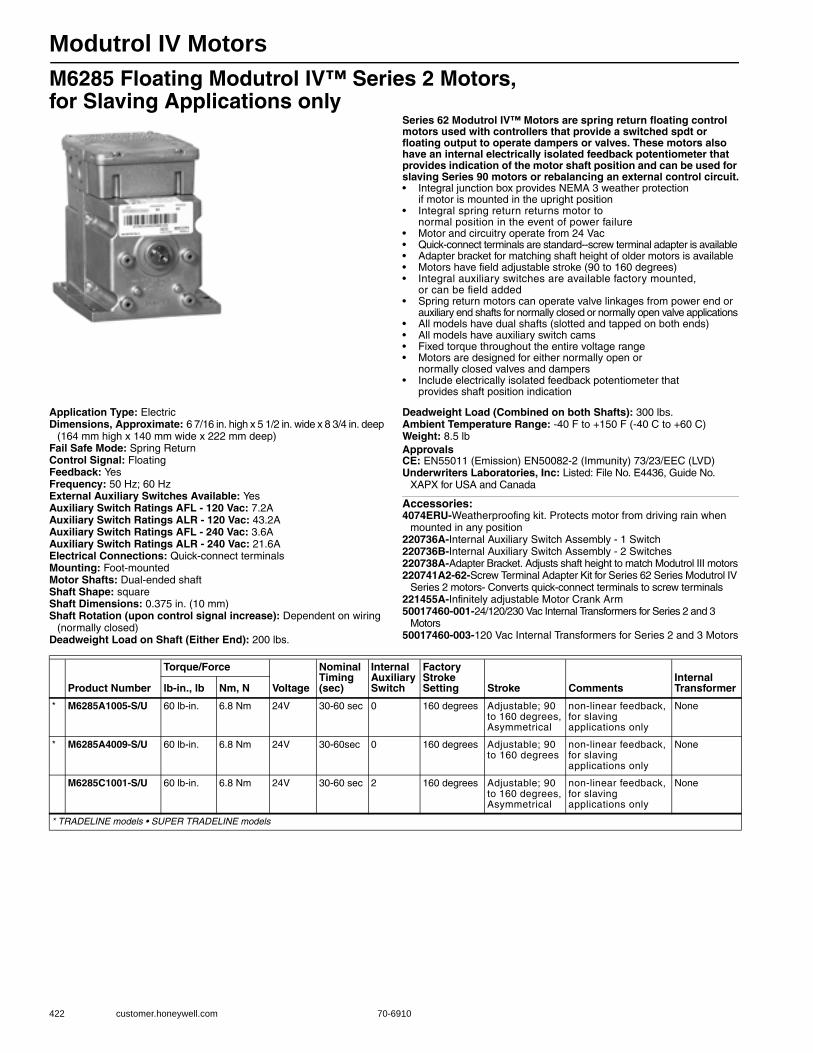
Modutrol IV Motors
422 customer.honeywell.com 70-6910
M6285 Floating Modutrol IV™ Series 2 Motors, for Slaving Applications only
Series 62 Modutrol IV™ Motors are spring return floating control motors used with controllers that provide a switched spdt or floating output to operate dampers or valves. These motors also have an internal electrically isolated feedback potentiometer that provides indication of the motor shaft position and can be used for slaving Series 90 motors or rebalancing an external control circuit.• Integral junction box provides NEMA 3 weather protection
if motor is mounted in the upright position • Integral spring return returns motor to
normal position in the event of power failure • Motor and circuitry operate from 24 Vac • Quick-connect terminals are standard--screw terminal adapter is available • Adapter bracket for matching shaft height of older motors is available • Motors have field adjustable stroke (90 to 160 degrees) • Integral auxiliary switches are available factory mounted,
or can be field added • Spring return motors can operate valve linkages from power end or
auxiliary end shafts for normally closed or normally open valve applications • All models have dual shafts (slotted and tapped on both ends) • All models have auxiliary switch cams • Fixed torque throughout the entire voltage range • Motors are designed for either normally open or
normally closed valves and dampers • Include electrically isolated feedback potentiometer that
provides shaft position indication
Application Type: ElectricDimensions, Approximate: 6 7/16 in. high x 5 1/2 in. wide x 8 3/4 in. deep
(164 mm high x 140 mm wide x 222 mm deep) Fail Safe Mode: Spring ReturnControl Signal: FloatingFeedback: YesFrequency: 50 Hz; 60 HzExternal Auxiliary Switches Available: YesAuxiliary Switch Ratings AFL - 120 Vac: 7.2AAuxiliary Switch Ratings ALR - 120 Vac: 43.2AAuxiliary Switch Ratings AFL - 240 Vac: 3.6AAuxiliary Switch Ratings ALR - 240 Vac: 21.6AElectrical Connections: Quick-connect terminalsMounting: Foot-mountedMotor Shafts: Dual-ended shaftShaft Shape: squareShaft Dimensions: 0.375 in. (10 mm) Shaft Rotation (upon control signal increase): Dependent on wiring
(normally closed)Deadweight Load on Shaft (Either End): 200 lbs.
Deadweight Load (Combined on both Shafts): 300 lbs.Ambient Temperature Range: -40 F to +150 F (-40 C to +60 C) Weight: 8.5 lbApprovalsCE: EN55011 (Emission) EN50082-2 (Immunity) 73/23/EEC (LVD)Underwriters Laboratories, Inc: Listed: File No. E4436, Guide No.
XAPX for USA and Canada
Accessories:4074ERU-Weatherproofing kit. Protects motor from driving rain when
mounted in any position220736A-Internal Auxiliary Switch Assembly - 1 Switch220736B-Internal Auxiliary Switch Assembly - 2 Switches220738A-Adapter Bracket. Adjusts shaft height to match Modutrol III motors220741A2-62-Screw Terminal Adapter Kit for Series 62 Series Modutrol IV
Series 2 motors- Converts quick-connect terminals to screw terminals221455A-Infinitely adjustable Motor Crank Arm50017460-001-24/120/230 Vac Internal Transformers for Series 2 and 3
Motors50017460-003-120 Vac Internal Transformers for Series 2 and 3 Motors
Product Number
Torque/Force
Voltage
Nominal Timing (sec)
Internal Auxiliary Switch
Factory Stroke Setting Stroke Comments
Internal Transformerlb-in., lb Nm, N
* M6285A1005-S/U 60 lb-in. 6.8 Nm 24V 30-60 sec 0 160 degrees Adjustable; 90 to 160 degrees, Asymmetrical
non-linear feedback, for slaving applications only
None
* M6285A4009-S/U 60 lb-in. 6.8 Nm 24V 30-60sec 0 160 degrees Adjustable; 90 to 160 degrees
non-linear feedback, for slaving applications only
None
M6285C1001-S/U 60 lb-in. 6.8 Nm 24V 30-60 sec 2 160 degrees Adjustable; 90 to 160 degrees, Asymmetrical
non-linear feedback, for slaving applications only
None
* TRADELINE models • SUPER TRADELINE models
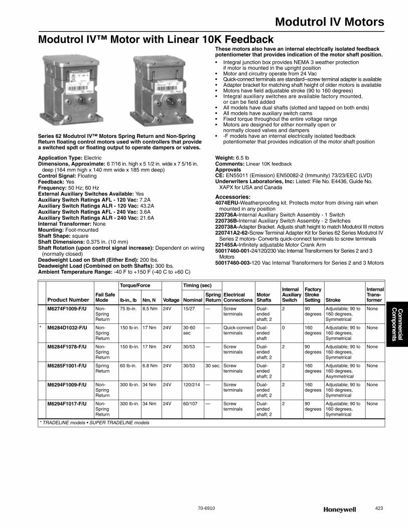
Modutrol IV Motors
70-6910 423
Com
mercial
Com
ponents
Modutrol IV™ Motor with Linear 10K Feedback
Series 62 Modutrol IV™ Motors Spring Return and Non-Spring Return floating control motors used with controllers that provide a switched spdt or floating output to operate dampers or valves.
These motors also have an internal electrically isolated feedback potentiometer that provides indication of the motor shaft position.• Integral junction box provides NEMA 3 weather protection
if motor is mounted in the upright position • Motor and circuitry operate from 24 Vac • Quick-connect terminals are standard--screw terminal adapter is available • Adapter bracket for matching shaft height of older motors is available • Motors have field adjustable stroke (90 to 160 degrees) • Integral auxiliary switches are available factory mounted,
or can be field added • All models have dual shafts (slotted and tapped on both ends) • All models have auxiliary switch cams • Fixed torque throughout the entire voltage range • Motors are designed for either normally open or
normally closed valves and dampers • -F models have an internal electrically isolated feedback
potentiometer that provides indication of the motor shaft position
Application Type: ElectricDimensions, Approximate: 6 7/16 in. high x 5 1/2 in. wide x 7 5/16 in.
deep (164 mm high x 140 mm wide x 185 mm deep) Control Signal: FloatingFeedback: YesFrequency: 50 Hz; 60 HzExternal Auxiliary Switches Available: YesAuxiliary Switch Ratings AFL - 120 Vac: 7.2AAuxiliary Switch Ratings ALR - 120 Vac: 43.2AAuxiliary Switch Ratings AFL - 240 Vac: 3.6AAuxiliary Switch Ratings ALR - 240 Vac: 21.6AInternal Transformer: NoneMounting: Foot-mountedShaft Shape: squareShaft Dimensions: 0.375 in. (10 mm) Shaft Rotation (upon control signal increase): Dependent on wiring
(normally closed)Deadweight Load on Shaft (Either End): 200 lbs.Deadweight Load (Combined on both Shafts): 300 lbs.Ambient Temperature Range: -40 F to +150 F (-40 C to +60 C)
Weight: 6.5 lbComments: Linear 10K feedbackApprovalsCE: EN55011 (Emission) EN50082-2 (Immunity) 73/23/EEC (LVD)Underwriters Laboratories, Inc: Listed: File No. E4436, Guide No.
XAPX for USA and Canada
Accessories:4074ERU-Weatherproofing kit. Protects motor from driving rain when
mounted in any position220736A-Internal Auxiliary Switch Assembly - 1 Switch220736B-Internal Auxiliary Switch Assembly - 2 Switches220738A-Adapter Bracket. Adjusts shaft height to match Modutrol III motors220741A2-62-Screw Terminal Adapter Kit for Series 62 Series Modutrol IV
Series 2 motors- Converts quick-connect terminals to screw terminals221455A-Infinitely adjustable Motor Crank Arm50017460-001-24/120/230 Vac Internal Transformers for Series 2 and 3
Motors50017460-003-120 Vac Internal Transformers for Series 2 and 3 Motors
Product NumberFail Safe Mode
Torque/Force
Voltage
Timing (sec)
Electrical Connections
Motor Shafts
Internal Auxiliary Switch
Factory Stroke Setting Stroke
Internal Trans- formerlb-in., lb Nm, N Nominal
Spring Return
M6274F1009-F/U Non-Spring Return
75 lb-in. 8.5 Nm 24V 15/27 — Screw terminals
Dual-ended shaft; 2
2 90 degrees
Adjustable; 90 to 160 degrees, Symmetrical
None
* M6284D1032-F/U Non-Spring Return
150 lb-in. 17 Nm 24V 30-60 sec
— Quick-connect terminals
Dual-ended shaft
0 160 degrees
Adjustable; 90 to 160 degrees, Symmetrical
None
M6284F1078-F/U Non-Spring Return
150 lb-in. 17 Nm 24V 30/53 — Screw terminals
Dual-ended shaft; 2
2 90 degrees
Adjustable; 90 to 160 degrees, Symmetrical
None
M6285F1001-F/U Spring Return
60 lb-in. 6.8 Nm 24V 30/53 30 sec. Screw terminals
Dual-ended shaft; 2
2 160 degrees
Adjustable; 90 to 160 degrees, Asymmetrical
None
M6294F1009-F/U Non-Spring Return
300 lb-in. 34 Nm 24V 120/214 — Screw terminals
Dual-ended shaft; 2
2 160 degrees
Adjustable; 90 to 160 degrees, Symmetrical
None
M6294F1017-F/U Non-Spring Return
300 lb-in. 34 Nm 24V 60/107 — Screw terminals
Dual-ended shaft; 2
2 90 degrees
Adjustable; 90 to 160 degrees, Symmetrical
None
* TRADELINE models • SUPER TRADELINE models
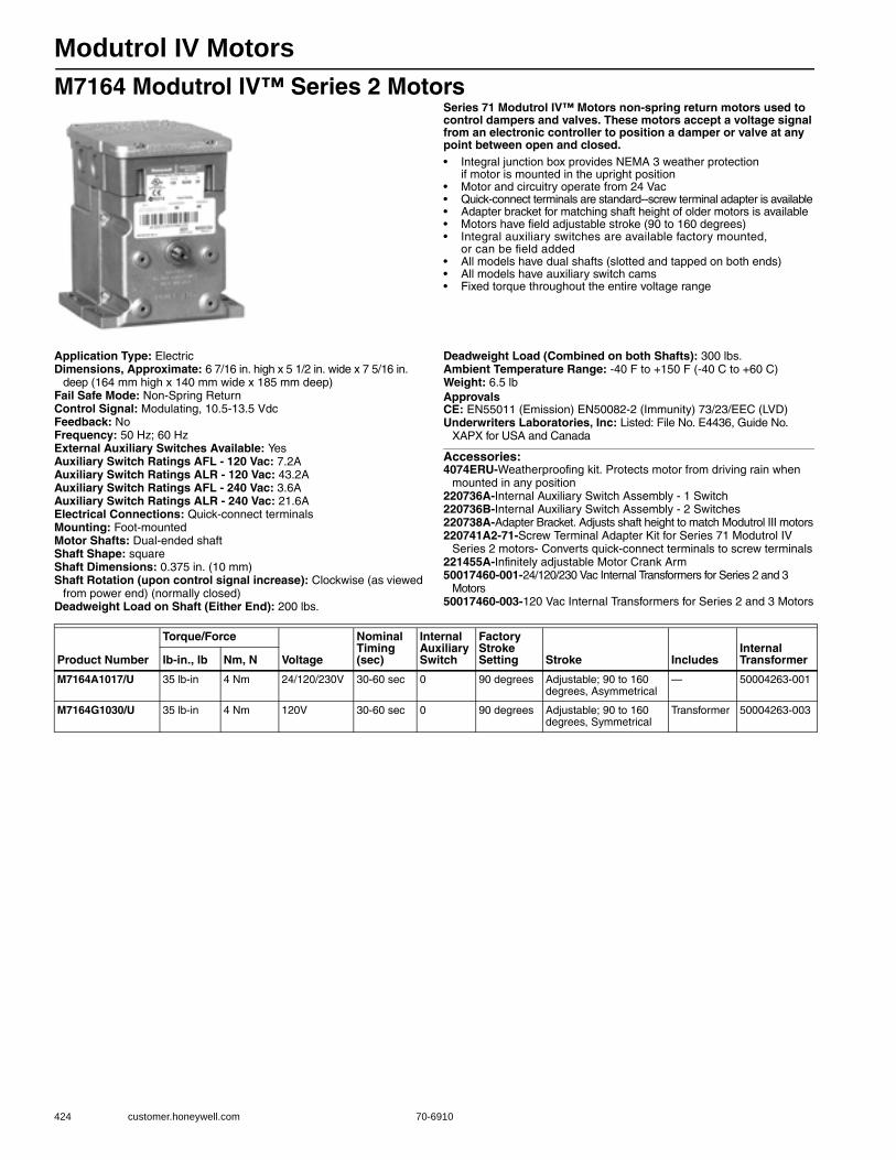
Modutrol IV Motors
424 customer.honeywell.com 70-6910
M7164 Modutrol IV™ Series 2 MotorsSeries 71 Modutrol IV™ Motors non-spring return motors used to control dampers and valves. These motors accept a voltage signal from an electronic controller to position a damper or valve at any point between open and closed.• Integral junction box provides NEMA 3 weather protection
if motor is mounted in the upright position • Motor and circuitry operate from 24 Vac • Quick-connect terminals are standard--screw terminal adapter is available • Adapter bracket for matching shaft height of older motors is available • Motors have field adjustable stroke (90 to 160 degrees) • Integral auxiliary switches are available factory mounted,
or can be field added • All models have dual shafts (slotted and tapped on both ends) • All models have auxiliary switch cams • Fixed torque throughout the entire voltage range
Application Type: ElectricDimensions, Approximate: 6 7/16 in. high x 5 1/2 in. wide x 7 5/16 in.
deep (164 mm high x 140 mm wide x 185 mm deep) Fail Safe Mode: Non-Spring ReturnControl Signal: Modulating, 10.5-13.5 VdcFeedback: NoFrequency: 50 Hz; 60 HzExternal Auxiliary Switches Available: YesAuxiliary Switch Ratings AFL - 120 Vac: 7.2AAuxiliary Switch Ratings ALR - 120 Vac: 43.2AAuxiliary Switch Ratings AFL - 240 Vac: 3.6AAuxiliary Switch Ratings ALR - 240 Vac: 21.6AElectrical Connections: Quick-connect terminalsMounting: Foot-mountedMotor Shafts: Dual-ended shaftShaft Shape: squareShaft Dimensions: 0.375 in. (10 mm) Shaft Rotation (upon control signal increase): Clockwise (as viewed
from power end) (normally closed)Deadweight Load on Shaft (Either End): 200 lbs.
Deadweight Load (Combined on both Shafts): 300 lbs.Ambient Temperature Range: -40 F to +150 F (-40 C to +60 C) Weight: 6.5 lbApprovalsCE: EN55011 (Emission) EN50082-2 (Immunity) 73/23/EEC (LVD)Underwriters Laboratories, Inc: Listed: File No. E4436, Guide No.
XAPX for USA and Canada
Accessories:4074ERU-Weatherproofing kit. Protects motor from driving rain when
mounted in any position220736A-Internal Auxiliary Switch Assembly - 1 Switch220736B-Internal Auxiliary Switch Assembly - 2 Switches220738A-Adapter Bracket. Adjusts shaft height to match Modutrol III motors220741A2-71-Screw Terminal Adapter Kit for Series 71 Modutrol IV
Series 2 motors- Converts quick-connect terminals to screw terminals221455A-Infinitely adjustable Motor Crank Arm50017460-001-24/120/230 Vac Internal Transformers for Series 2 and 3
Motors50017460-003-120 Vac Internal Transformers for Series 2 and 3 Motors
Product Number
Torque/Force
Voltage
Nominal Timing (sec)
Internal Auxiliary Switch
Factory Stroke Setting Stroke Includes
Internal Transformerlb-in., lb Nm, N
M7164A1017/U 35 lb-in 4 Nm 24/120/230V 30-60 sec 0 90 degrees Adjustable; 90 to 160 degrees, Asymmetrical
— 50004263-001
M7164G1030/U 35 lb-in 4 Nm 120V 30-60 sec 0 90 degrees Adjustable; 90 to 160 degrees, Symmetrical
Transformer 50004263-003
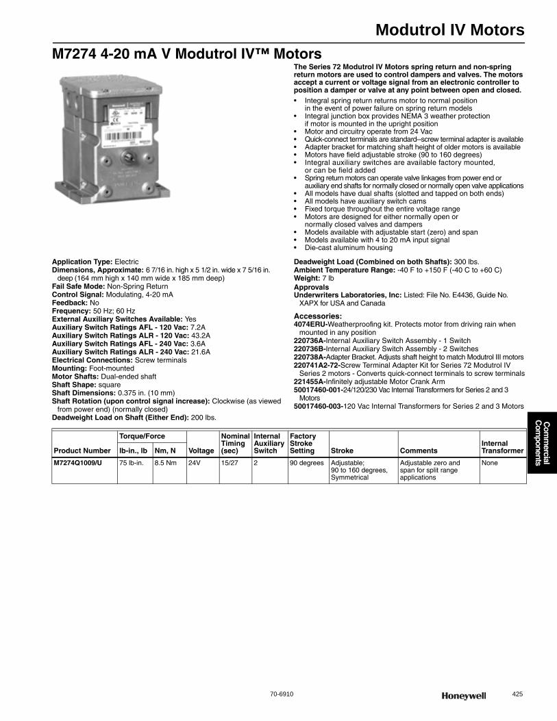
Modutrol IV Motors
70-6910 425
Com
mercial
Com
ponents
M7274 4-20 mA V Modutrol IV™ MotorsThe Series 72 Modutrol IV Motors spring return and non-spring return motors are used to control dampers and valves. The motors accept a current or voltage signal from an electronic controller to position a damper or valve at any point between open and closed.• Integral spring return returns motor to normal position
in the event of power failure on spring return models • Integral junction box provides NEMA 3 weather protection
if motor is mounted in the upright position • Motor and circuitry operate from 24 Vac • Quick-connect terminals are standard--screw terminal adapter is available • Adapter bracket for matching shaft height of older motors is available • Motors have field adjustable stroke (90 to 160 degrees) • Integral auxiliary switches are available factory mounted,
or can be field added • Spring return motors can operate valve linkages from power end or
auxiliary end shafts for normally closed or normally open valve applications • All models have dual shafts (slotted and tapped on both ends) • All models have auxiliary switch cams • Fixed torque throughout the entire voltage range • Motors are designed for either normally open or
normally closed valves and dampers • Models available with adjustable start (zero) and span • Models available with 4 to 20 mA input signal • Die-cast aluminum housing
Application Type: ElectricDimensions, Approximate: 6 7/16 in. high x 5 1/2 in. wide x 7 5/16 in.
deep (164 mm high x 140 mm wide x 185 mm deep) Fail Safe Mode: Non-Spring ReturnControl Signal: Modulating, 4-20 mAFeedback: NoFrequency: 50 Hz; 60 HzExternal Auxiliary Switches Available: YesAuxiliary Switch Ratings AFL - 120 Vac: 7.2AAuxiliary Switch Ratings ALR - 120 Vac: 43.2AAuxiliary Switch Ratings AFL - 240 Vac: 3.6AAuxiliary Switch Ratings ALR - 240 Vac: 21.6AElectrical Connections: Screw terminalsMounting: Foot-mountedMotor Shafts: Dual-ended shaftShaft Shape: squareShaft Dimensions: 0.375 in. (10 mm) Shaft Rotation (upon control signal increase): Clockwise (as viewed
from power end) (normally closed)Deadweight Load on Shaft (Either End): 200 lbs.
Deadweight Load (Combined on both Shafts): 300 lbs.Ambient Temperature Range: -40 F to +150 F (-40 C to +60 C) Weight: 7 lbApprovalsUnderwriters Laboratories, Inc: Listed: File No. E4436, Guide No.
XAPX for USA and Canada
Accessories:4074ERU-Weatherproofing kit. Protects motor from driving rain when
mounted in any position220736A-Internal Auxiliary Switch Assembly - 1 Switch220736B-Internal Auxiliary Switch Assembly - 2 Switches220738A-Adapter Bracket. Adjusts shaft height to match Modutrol III motors220741A2-72-Screw Terminal Adapter Kit for Series 72 Modutrol IV
Series 2 motors - Converts quick-connect terminals to screw terminals221455A-Infinitely adjustable Motor Crank Arm50017460-001-24/120/230 Vac Internal Transformers for Series 2 and 3
Motors50017460-003-120 Vac Internal Transformers for Series 2 and 3 Motors
Product Number
Torque/Force
Voltage
Nominal Timing (sec)
Internal Auxiliary Switch
Factory Stroke Setting Stroke Comments
Internal Transformerlb-in., lb Nm, N
M7274Q1009/U 75 lb-in. 8.5 Nm 24V 15/27 2 90 degrees Adjustable; 90 to 160 degrees, Symmetrical
Adjustable zero and span for split range applications
None

Modutrol IV Motors
426 customer.honeywell.com 70-6910
M7284; M7285; M7286; M7294 Modutrol IV™ Series 2 MotorsSeries 72 Modutrol IV Motors are spring return and non-spring return motors (per motor type) used to control dampers and valves. The motors accept a current or voltage signal from an electronic controller to position a damper or valve at any point between open and closed.• Integral spring return returns motor to normal position
in the event of power failure on spring return models • Integral junction box provides NEMA 3 weather protection
if motor is mounted in the upright position • Motor and circuitry operate from 24 Vac • Quick-connect terminals are standard--screw terminal adapter is available • Adapter bracket for matching shaft height of older motors is available • Motors have field adjustable stroke (90 to 160 degrees) • Integral auxiliary switches are available factory mounted,
or can be field added • Spring return motors can operate valve linkages from power end or
auxiliary end shafts for normally closed or normally open valve applications • All models have dual shafts (slotted and tapped on both ends) • All models have auxiliary switch cams • Fixed torque throughout the entire voltage range • Motors are designed for either normally open or
normally closed valves and dampers • Models available with adjustable start (zero) and span • Models available with 4 to 20 mA input signal • Models available with 2 to 10 Vdc input signal • Die-cast aluminum housing
Application Type: ElectricDimensions, Approximate: 6 7/16 in. high x 5 1/2 in. wide x 7 5/16 in.
deep (164 mm high x 140 mm wide x 185 mm deep) Feedback: NoFrequency: 50 Hz; 60 HzExternal Auxiliary Switches Available: YesAuxiliary Switch Ratings AFL - 120 Vac: 7.2AAuxiliary Switch Ratings ALR - 120 Vac: 43.2AAuxiliary Switch Ratings AFL - 240 Vac: 3.6AAuxiliary Switch Ratings ALR - 240 Vac: 21.6AInternal Transformer: 50004263-002Mounting: Foot-mountedMotor Shafts: Dual-ended shaftShaft Shape: squareShaft Dimensions: 0.375 in. (10 mm) Shaft Rotation (upon control signal increase):
M7284A,C,Q; M7285A,C,Q; M7294A,Q: Clockwise (as viewed from power end) (normally closed)M7286G: Counter-clockwise (as viewed from power end) (normally open)
Deadweight Load on Shaft (Either End): 200 lbs.
Deadweight Load (Combined on both Shafts): 300 lbs.Ambient Temperature Range: -40 F to +150 F (-40 C to +60 C) Weight: 7.5 lbApprovalsCE: EN55011 (Emission) EN50082-2 (Immunity) 73/23/EEC (LVD)Underwriters Laboratories, Inc: Listed: File No. E4436, Guide No.
XAPX for USA and Canada
Accessories:4074ERU-Weatherproofing kit. Protects motor from driving rain when
mounted in any position220736A-Internal Auxiliary Switch Assembly - 1 Switch220736B-Internal Auxiliary Switch Assembly - 2 Switches220738A-Adapter Bracket. Adjusts shaft height to match Modutrol III motors220741A2-72-Screw Terminal Adapter Kit for Series 72 Modutrol IV
Series 2 motors - Converts quick-connect terminals to screw terminals221455A-Infinitely adjustable Motor Crank Arm50017460-001-24/120/230 Vac Internal Transformers for Series 2 and 3
Motors50017460-003-120 Vac Internal Transformers for Series 2 and 3 Motors
Product Number
Fail Safe Mode
Torque/Force
Voltage
Nominal Timing (sec)
Electrical Connec-tions
Control Signal
Internal Auxiliary Switch
Factory Stroke Setting Stroke Includes Comments
Internal Transformerlb-in., lb Nm, N
M7284A1004/U Non-Spring Return
150 lb-in. 17 Nm 120V 30-60 sec
Screw terminals
Modulating, 4-20 mA
0 90 degrees
Adjustable; 90 to 160 degrees, Symmetrical
Transformer and Screw Terminal Adapter
— 50004263-002
M7284A1012/U Non-Spring Return
150 lb-in. 17 Nm 120V 30-60 sec
Screw terminals
Modulating, 4-20 mA
0 160 degrees
Adjustable; 90 to 160 degrees, Asymmetrical
Transformer and Screw Terminal Adapter
— 50004263-002
M7284A1038/U Non-Spring Return
75 lb-in. 8 5 Nm 120V 15-30 sec
Screw terminals
Modulating, 4-20 mA
0 90 degrees
Adjustable; 90 to 160 degrees, Asymmetrical
Transformer and Screw Terminal Adapter
— 50004263-002
M7284A1079/U Non-Spring Return
150 lb-in. 17 Nm 24V 30-60 sec
Quick-connect terminals
Modulating, 2-10 Vdc
0 160 degrees
Adjustable; 90 to 160 degrees, Asymmetrical
— — None
M7284C1000/U Non-Spring Return
150 lb-in. 17 Nm 120V 30-60 sec
Screw terminals
Modulating, 4-20 mA
2 90 degrees
Adjustable; 90 to 160 degrees, Symmetrical
Transformer and Screw Terminal Adapter
— 50004263-002
M7284C1083/U Non-Spring Return
150 lb-in. 17 Nm 24/120/230V
30 sec Screw terminals
Modulating, 4-20 mA
2 90 degrees
Fixed; 90 degrees, Symmetrical
Transformer Enhanced models, additional repositions
50004263-001
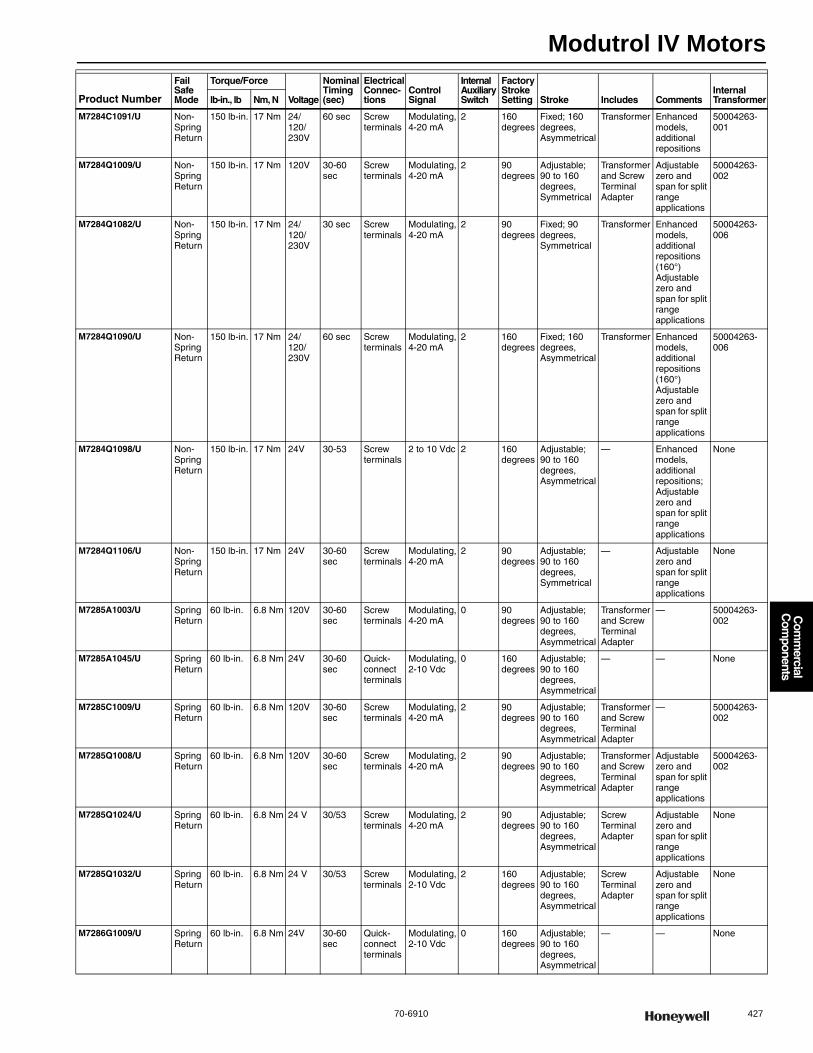
Modutrol IV Motors
70-6910 427
Com
mercial
Com
ponents
M7284C1091/U Non-Spring Return
150 lb-in. 17 Nm 24/120/230V
60 sec Screw terminals
Modulating, 4-20 mA
2 160 degrees
Fixed; 160 degrees, Asymmetrical
Transformer Enhanced models, additional repositions
50004263-001
M7284Q1009/U Non-Spring Return
150 lb-in. 17 Nm 120V 30-60 sec
Screw terminals
Modulating, 4-20 mA
2 90 degrees
Adjustable; 90 to 160 degrees, Symmetrical
Transformer and Screw Terminal Adapter
Adjustable zero and span for split range applications
50004263-002
M7284Q1082/U Non-Spring Return
150 lb-in. 17 Nm 24/120/230V
30 sec Screw terminals
Modulating, 4-20 mA
2 90 degrees
Fixed; 90 degrees, Symmetrical
Transformer Enhanced models, additional repositions (160°) Adjustable zero and span for split range applications
50004263-006
M7284Q1090/U Non-Spring Return
150 lb-in. 17 Nm 24/120/230V
60 sec Screw terminals
Modulating, 4-20 mA
2 160 degrees
Fixed; 160 degrees, Asymmetrical
Transformer Enhanced models, additional repositions (160°) Adjustable zero and span for split range applications
50004263-006
M7284Q1098/U Non-Spring Return
150 lb-in. 17 Nm 24V 30-53 Screw terminals
2 to 10 Vdc 2 160 degrees
Adjustable; 90 to 160 degrees, Asymmetrical
— Enhanced models, additional repositions; Adjustable zero and span for split range applications
None
M7284Q1106/U Non-Spring Return
150 lb-in. 17 Nm 24V 30-60 sec
Screw terminals
Modulating, 4-20 mA
2 90 degrees
Adjustable; 90 to 160 degrees, Symmetrical
— Adjustable zero and span for split range applications
None
M7285A1003/U Spring Return
60 lb-in. 6.8 Nm 120V 30-60 sec
Screw terminals
Modulating, 4-20 mA
0 90 degrees
Adjustable; 90 to 160 degrees, Asymmetrical
Transformer and Screw Terminal Adapter
— 50004263-002
M7285A1045/U Spring Return
60 lb-in. 6.8 Nm 24V 30-60 sec
Quick-connect terminals
Modulating, 2-10 Vdc
0 160 degrees
Adjustable; 90 to 160 degrees, Asymmetrical
— — None
M7285C1009/U Spring Return
60 lb-in. 6.8 Nm 120V 30-60 sec
Screw terminals
Modulating, 4-20 mA
2 90 degrees
Adjustable; 90 to 160 degrees, Asymmetrical
Transformer and Screw Terminal Adapter
— 50004263-002
M7285Q1008/U Spring Return
60 lb-in. 6.8 Nm 120V 30-60 sec
Screw terminals
Modulating, 4-20 mA
2 90 degrees
Adjustable; 90 to 160 degrees, Asymmetrical
Transformer and Screw Terminal Adapter
Adjustable zero and span for split range applications
50004263-002
M7285Q1024/U Spring Return
60 lb-in. 6.8 Nm 24 V 30/53 Screw terminals
Modulating, 4-20 mA
2 90 degrees
Adjustable; 90 to 160 degrees, Asymmetrical
Screw Terminal Adapter
Adjustable zero and span for split range applications
None
M7285Q1032/U Spring Return
60 lb-in. 6.8 Nm 24 V 30/53 Screw terminals
Modulating, 2-10 Vdc
2 160 degrees
Adjustable; 90 to 160 degrees, Asymmetrical
Screw Terminal Adapter
Adjustable zero and span for split range applications
None
M7286G1009/U Spring Return
60 lb-in. 6.8 Nm 24V 30-60 sec
Quick-connect terminals
Modulating, 2-10 Vdc
0 160 degrees
Adjustable; 90 to 160 degrees, Asymmetrical
— — None
Product Number
Fail Safe Mode
Torque/Force
Voltage
Nominal Timing (sec)
Electrical Connec-tions
Control Signal
Internal Auxiliary Switch
Factory Stroke Setting Stroke Includes Comments
Internal Transformerlb-in., lb Nm, N
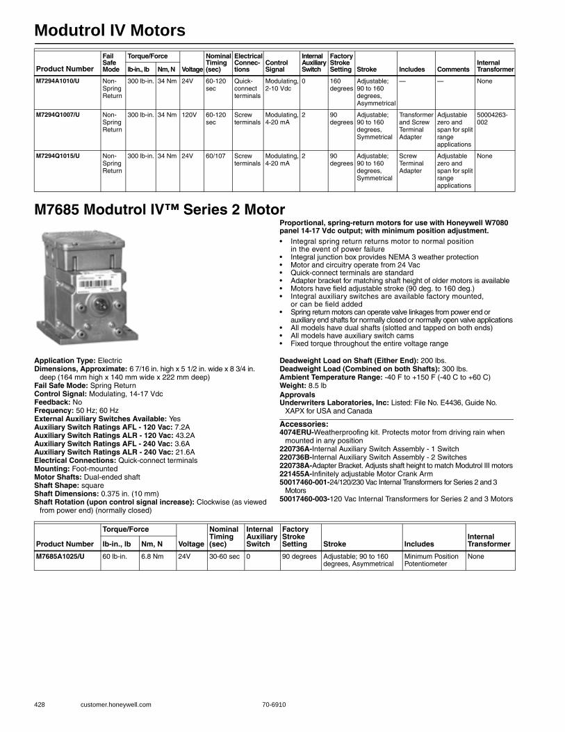
Modutrol IV Motors
428 customer.honeywell.com 70-6910
M7685 Modutrol IV™ Series 2 MotorProportional, spring-return motors for use with Honeywell W7080 panel 14-17 Vdc output; with minimum position adjustment.• Integral spring return returns motor to normal position
in the event of power failure • Integral junction box provides NEMA 3 weather protection • Motor and circuitry operate from 24 Vac• Quick-connect terminals are standard • Adapter bracket for matching shaft height of older motors is available • Motors have field adjustable stroke (90 deg. to 160 deg.) • Integral auxiliary switches are available factory mounted,
or can be field added • Spring return motors can operate valve linkages from power end or
auxiliary end shafts for normally closed or normally open valve applications • All models have dual shafts (slotted and tapped on both ends) • All models have auxiliary switch cams • Fixed torque throughout the entire voltage range
Application Type: ElectricDimensions, Approximate: 6 7/16 in. high x 5 1/2 in. wide x 8 3/4 in.
deep (164 mm high x 140 mm wide x 222 mm deep) Fail Safe Mode: Spring ReturnControl Signal: Modulating, 14-17 VdcFeedback: NoFrequency: 50 Hz; 60 HzExternal Auxiliary Switches Available: YesAuxiliary Switch Ratings AFL - 120 Vac: 7.2AAuxiliary Switch Ratings ALR - 120 Vac: 43.2AAuxiliary Switch Ratings AFL - 240 Vac: 3.6AAuxiliary Switch Ratings ALR - 240 Vac: 21.6AElectrical Connections: Quick-connect terminalsMounting: Foot-mountedMotor Shafts: Dual-ended shaftShaft Shape: squareShaft Dimensions: 0.375 in. (10 mm) Shaft Rotation (upon control signal increase): Clockwise (as viewed
from power end) (normally closed)
Deadweight Load on Shaft (Either End): 200 lbs.Deadweight Load (Combined on both Shafts): 300 lbs.Ambient Temperature Range: -40 F to +150 F (-40 C to +60 C) Weight: 8.5 lbApprovalsUnderwriters Laboratories, Inc: Listed: File No. E4436, Guide No.
XAPX for USA and Canada
Accessories:4074ERU-Weatherproofing kit. Protects motor from driving rain when
mounted in any position220736A-Internal Auxiliary Switch Assembly - 1 Switch220736B-Internal Auxiliary Switch Assembly - 2 Switches220738A-Adapter Bracket. Adjusts shaft height to match Modutrol III motors221455A-Infinitely adjustable Motor Crank Arm50017460-001-24/120/230 Vac Internal Transformers for Series 2 and 3
Motors50017460-003-120 Vac Internal Transformers for Series 2 and 3 Motors
M7294A1010/U Non-Spring Return
300 lb-in. 34 Nm 24V 60-120 sec
Quick-connect terminals
Modulating, 2-10 Vdc
0 160 degrees
Adjustable; 90 to 160 degrees, Asymmetrical
— — None
M7294Q1007/U Non-Spring Return
300 lb-in. 34 Nm 120V 60-120 sec
Screw terminals
Modulating, 4-20 mA
2 90 degrees
Adjustable; 90 to 160 degrees, Symmetrical
Transformer and Screw Terminal Adapter
Adjustable zero and span for split range applications
50004263-002
M7294Q1015/U Non-Spring Return
300 lb-in. 34 Nm 24V 60/107 Screw terminals
Modulating, 4-20 mA
2 90 degrees
Adjustable; 90 to 160 degrees, Symmetrical
Screw Terminal Adapter
Adjustable zero and span for split range applications
None
Product Number
Fail Safe Mode
Torque/Force
Voltage
Nominal Timing (sec)
Electrical Connec-tions
Control Signal
Internal Auxiliary Switch
Factory Stroke Setting Stroke Includes Comments
Internal Transformerlb-in., lb Nm, N
Product Number
Torque/Force
Voltage
Nominal Timing (sec)
Internal Auxiliary Switch
Factory Stroke Setting Stroke Includes
Internal Transformerlb-in., lb Nm, N
M7685A1025/U 60 lb-in. 6.8 Nm 24V 30-60 sec 0 90 degrees Adjustable; 90 to 160 degrees, Asymmetrical
Minimum Position Potentiometer
None

Modutrol IV Motors
70-6910 429
Com
mercial
Com
ponents
M9164; M9174; M9184; M9194 Modutrol IV™ Series 3 MotorsSeries 90 Modutrol™ IV Motors non-spring return modulating proportional control motors used with controllers that provide a Series 90 output to operate dampers or valves.• Integral junction box provides NEMA 3 weather protection
if motor is mounted in the upright position • Motor and circuitry operate from 24 Vac • Quick-connect terminals are standard; screw terminal adapter is available • Adapter bracket for matching shaft height of older motors is available • Motors have field adjustable stroke (90 to 160 degrees) • Integral auxiliary switches are available factory mounted,
or can be field added • All models have dual shafts (slotted and tapped on both ends) • All models have auxiliary switch cams • Fixed torque throughout the entire voltage range
Application Type: ElectricDimensions, Approximate: 6 7/16 in. high x 5 1/2 in. wide x 7 5/16 in.
deep (164 mm high x 140 mm wide x 185 mm deep) Fail Safe Mode: Non-Spring ReturnControl Signal: Proportional, 135 ohmFeedback: NoFrequency: 50 Hz; 60 HzExternal Auxiliary Switches Available: YesAuxiliary Switch Ratings AFL - 120 Vac: 7.2AAuxiliary Switch Ratings ALR - 120 Vac: 43.2AAuxiliary Switch Ratings AFL - 240 Vac: 3.6AAuxiliary Switch Ratings ALR - 240 Vac: 21.6AMounting: Foot-mountedMotor Shafts: Dual-ended shaftShaft Shape: squareShaft Dimensions: 0.375 in. (10 mm) Shaft Rotation (upon control signal increase):
M9164A,C; M9174B,C,D,F; M9184A,C,D,E,F; M9194D,E: Clockwise (as viewed from power end) (normally closed)M9164D: Counter-clockwise (as viewed from power end) (normally open)
Deadweight Load on Shaft (Either End): 200 lbs.Deadweight Load (Combined on both Shafts): 300 lbs.
Ambient Temperature Range: -40 F to +150 F (-40 C to +60 C) Weight: 7.5 lbApprovalsCE: EN55011 (Emission) EN50082-2 (Immunity) 73/23/EEC (LVD)Underwriters Laboratories, Inc: Listed: File No. E4436, Guide No.
XAPX for USA and Canada
Accessories:Q7230A1005-Interface module, provides adjustable zero & span,
voltage or current control4074ERU-Weatherproofing kit. Protects motor from driving rain when
mounted in any position220736A-Internal Auxiliary Switch Assembly - 1 Switch220736B-Internal Auxiliary Switch Assembly - 2 Switches220738A-Adapter Bracket. Adjusts shaft height to match Modutrol III motors220741A2-90-Screw Terminal Adapter Kit for Series 90 Modutrol IV Series
2and Series 3 motors - Converts quick-connect terminals to Accessories:221455A-Infinitely adjustable Motor Crank Arm50017460-001-24/120/230 Vac Internal Transformers for Series 2 and 3
Motors50017460-003-120 Vac Internal Transformers for Series 2 and 3 Motors
Product Number
Torque/Force
Voltage
Nominal Timing (sec)
Electrical Connections
Internal Auxiliary Switch
Factory Stroke Setting Stroke Includes
Internal Transformerlb-in., lb Nm, N
M9164A1005/U 35 lb-in 4 Nm 120V 30-60 sec Quick-connect terminals
0 90 degrees Adjustable; 90 to 160 degrees, Asymmetrical
Transformer 50004263-003
M9164A1013/U 35 lb-in 4 Nm 24/120/230V
30-60 sec Quick-connect terminals
0 160 degrees Adjustable; 90 to 160 degrees, Asymmetrical
Transformer 50004263-001
M9164A1070/U 35 lb-in 4 Nm 24V 30-60 sec Quick-connect terminals
0 160 degrees Adjustable; 90 to 160 degrees, Asymmetrical
— None
M9164C1001/U 35 lb-in 4 Nm 24V 30-60 sec Quick-connect terminals
2 160 degrees Adjustable; 90 to 160 degrees, Asymmetrical
— None
M9164C1068/U 35 lb-in 4 Nm 120V 30-60 sec Quick-connect terminals
2 90 degrees Adjustable; 90 to 160 degrees, Asymmetrical
Transformer 50004263-003
* M9164D1009/U 35 lb-in 4 Nm 24V 30-60 sec Quick-connect terminals
0 160 degrees Adjustable; 90 to 160 degrees, Asymmetrical
— None
M9174B1027/U 75 lb-in. 8.5 Nm 120V 30-60 sec Quick-connect terminals
1 90 degrees Adjustable; 90 to 160 degrees, Asymmetrical
Transformer 50004263-003
M9174C1025/U 75 lb-in. 8.5 Nm 120V 30-60 sec Quick-connect terminals
2 90 degrees Adjustable; 90 to 160 degrees, Asymmetrical
Transformer 50004263-003
M9174C1033/U 75 lb-in. 8.5 Nm 120V 30-60 sec Quick-connect terminals
2 160 degrees Adjustable; 90 to 160 degrees, Asymmetrical
Transformer 50004263-003
* TRADELINE models • SUPER TRADELINE models
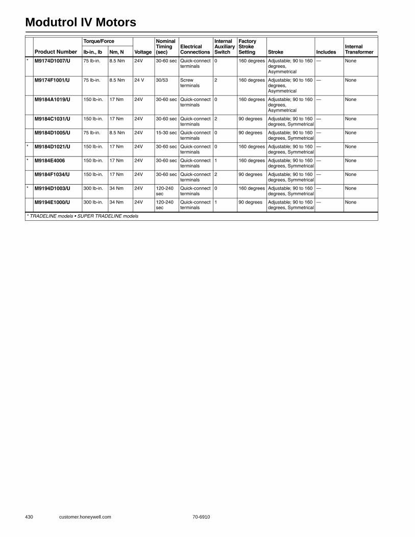
Modutrol IV Motors
430 customer.honeywell.com 70-6910
* M9174D1007/U 75 lb-in. 8.5 Nm 24V 30-60 sec Quick-connect terminals
0 160 degrees Adjustable; 90 to 160 degrees, Asymmetrical
— None
M9174F1001/U 75 lb-in. 8.5 Nm 24 V 30/53 Screw terminals
2 160 degrees Adjustable; 90 to 160 degrees, Asymmetrical
— None
M9184A1019/U 150 lb-in. 17 Nm 24V 30-60 sec Quick-connect terminals
0 160 degrees Adjustable; 90 to 160 degrees, Asymmetrical
— None
M9184C1031/U 150 lb-in. 17 Nm 24V 30-60 sec Quick-connect terminals
2 90 degrees Adjustable; 90 to 160 degrees, Symmetrical
— None
M9184D1005/U 75 lb-in. 8.5 Nm 24V 15-30 sec Quick-connect terminals
0 90 degrees Adjustable; 90 to 160 degrees, Symmetrical
— None
* M9184D1021/U 150 lb-in. 17 Nm 24V 30-60 sec Quick-connect terminals
0 160 degrees Adjustable; 90 to 160 degrees, Symmetrical
— None
* M9184E4006 150 lb-in. 17 Nm 24V 30-60 sec Quick-connect terminals
1 160 degrees Adjustable; 90 to 160 degrees, Symmetrical
— None
M9184F1034/U 150 lb-in. 17 Nm 24V 30-60 sec Quick-connect terminals
2 90 degrees Adjustable; 90 to 160 degrees, Symmetrical
— None
* M9194D1003/U 300 lb-in. 34 Nm 24V 120-240 sec
Quick-connect terminals
0 160 degrees Adjustable; 90 to 160 degrees, Symmetrical
— None
M9194E1000/U 300 lb-in. 34 Nm 24V 120-240 sec
Quick-connect terminals
1 90 degrees Adjustable; 90 to 160 degrees, Symmetrical
— None
Product Number
Torque/Force
Voltage
Nominal Timing (sec)
Electrical Connections
Internal Auxiliary Switch
Factory Stroke Setting Stroke Includes
Internal Transformerlb-in., lb Nm, N
* TRADELINE models • SUPER TRADELINE models
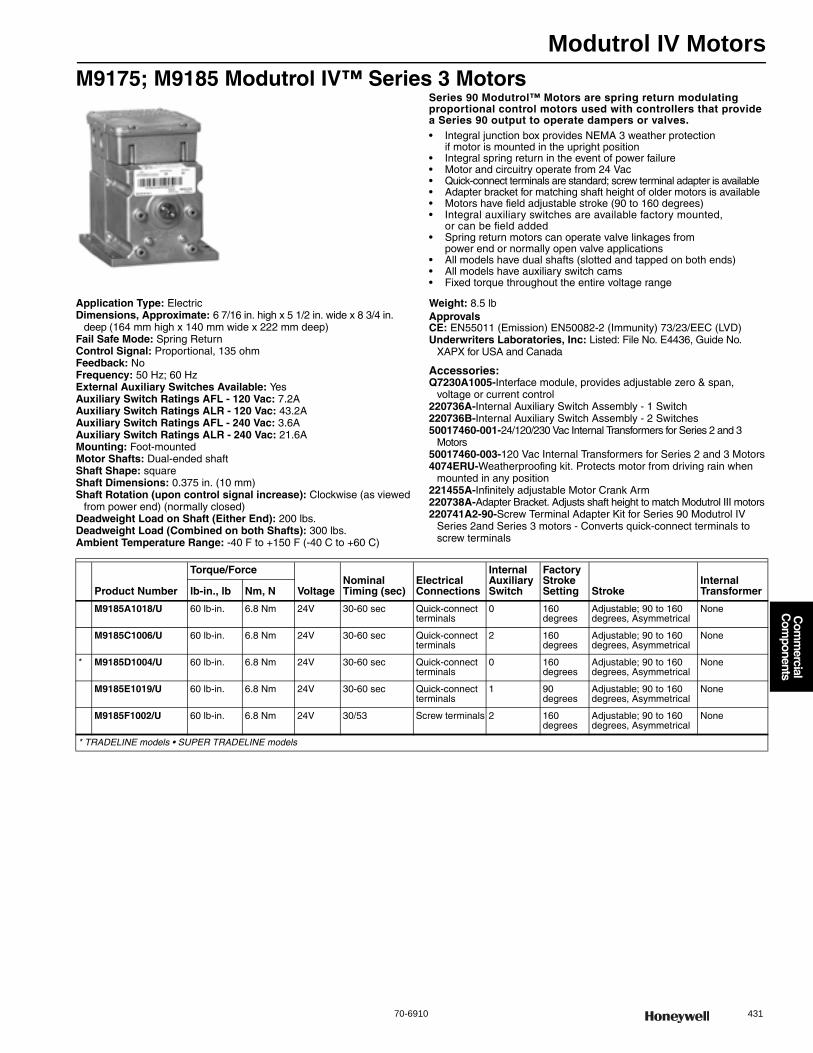
Modutrol IV Motors
70-6910 431
Com
mercial
Com
ponents
M9175; M9185 Modutrol IV™ Series 3 MotorsSeries 90 Modutrol™ Motors are spring return modulating proportional control motors used with controllers that provide a Series 90 output to operate dampers or valves.• Integral junction box provides NEMA 3 weather protection
if motor is mounted in the upright position • Integral spring return in the event of power failure • Motor and circuitry operate from 24 Vac • Quick-connect terminals are standard; screw terminal adapter is available • Adapter bracket for matching shaft height of older motors is available • Motors have field adjustable stroke (90 to 160 degrees) • Integral auxiliary switches are available factory mounted,
or can be field added • Spring return motors can operate valve linkages from
power end or normally open valve applications • All models have dual shafts (slotted and tapped on both ends) • All models have auxiliary switch cams • Fixed torque throughout the entire voltage range
Application Type: ElectricDimensions, Approximate: 6 7/16 in. high x 5 1/2 in. wide x 8 3/4 in.
deep (164 mm high x 140 mm wide x 222 mm deep) Fail Safe Mode: Spring ReturnControl Signal: Proportional, 135 ohmFeedback: NoFrequency: 50 Hz; 60 HzExternal Auxiliary Switches Available: YesAuxiliary Switch Ratings AFL - 120 Vac: 7.2AAuxiliary Switch Ratings ALR - 120 Vac: 43.2AAuxiliary Switch Ratings AFL - 240 Vac: 3.6AAuxiliary Switch Ratings ALR - 240 Vac: 21.6AMounting: Foot-mountedMotor Shafts: Dual-ended shaftShaft Shape: squareShaft Dimensions: 0.375 in. (10 mm) Shaft Rotation (upon control signal increase): Clockwise (as viewed
from power end) (normally closed)Deadweight Load on Shaft (Either End): 200 lbs.Deadweight Load (Combined on both Shafts): 300 lbs.Ambient Temperature Range: -40 F to +150 F (-40 C to +60 C)
Weight: 8.5 lbApprovalsCE: EN55011 (Emission) EN50082-2 (Immunity) 73/23/EEC (LVD)Underwriters Laboratories, Inc: Listed: File No. E4436, Guide No.
XAPX for USA and Canada
Accessories:Q7230A1005-Interface module, provides adjustable zero & span,
voltage or current control220736A-Internal Auxiliary Switch Assembly - 1 Switch220736B-Internal Auxiliary Switch Assembly - 2 Switches50017460-001-24/120/230 Vac Internal Transformers for Series 2 and 3
Motors50017460-003-120 Vac Internal Transformers for Series 2 and 3 Motors4074ERU-Weatherproofing kit. Protects motor from driving rain when
mounted in any position221455A-Infinitely adjustable Motor Crank Arm220738A-Adapter Bracket. Adjusts shaft height to match Modutrol III motors220741A2-90-Screw Terminal Adapter Kit for Series 90 Modutrol IV
Series 2and Series 3 motors - Converts quick-connect terminals to screw terminals
Product Number
Torque/Force
VoltageNominal Timing (sec)
Electrical Connections
Internal Auxiliary Switch
Factory Stroke Setting Stroke
Internal Transformerlb-in., lb Nm, N
M9185A1018/U 60 lb-in. 6.8 Nm 24V 30-60 sec Quick-connect terminals
0 160 degrees
Adjustable; 90 to 160 degrees, Asymmetrical
None
M9185C1006/U 60 lb-in. 6.8 Nm 24V 30-60 sec Quick-connect terminals
2 160 degrees
Adjustable; 90 to 160 degrees, Asymmetrical
None
* M9185D1004/U 60 lb-in. 6.8 Nm 24V 30-60 sec Quick-connect terminals
0 160 degrees
Adjustable; 90 to 160 degrees, Asymmetrical
None
M9185E1019/U 60 lb-in. 6.8 Nm 24V 30-60 sec Quick-connect terminals
1 90 degrees
Adjustable; 90 to 160 degrees, Asymmetrical
None
M9185F1002/U 60 lb-in. 6.8 Nm 24V 30/53 Screw terminals 2 160 degrees
Adjustable; 90 to 160 degrees, Asymmetrical
None
* TRADELINE models • SUPER TRADELINE models
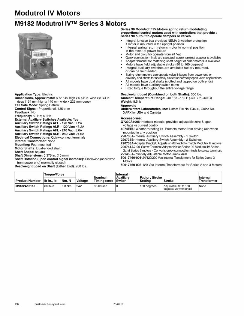
Modutrol IV Motors
432 customer.honeywell.com 70-6910
M9182 Modutrol IV™ Series 3 MotorsSeries 90 Modutrol™ IV Motors spring return modulating proportional control motors used with controllers that provide a Series 90 output to operate dampers or valves.• Integral junction box provides NEMA 3 weather protection
if motor is mounted in the upright position • Integral spring return returns motor to normal position
in the event of power failure • Motor and circuitry operate from 24 Vac • Quick-connect terminals are standard; screw terminal adapter is available• Adapter bracket for matching shaft height of older motors is available • Motors have field adjustable stroke (90 to 160 degrees) • Integral auxiliary switches are available factory mounted,
or can be field added • Spring return motors can operate valve linkages from power end or
auxiliary end shafts for normally closed or normally open valve applications • All models have dual shafts (slotted and tapped on both ends) • All models have auxiliary switch cams • Fixed torque throughout the entire voltage range
Application Type: ElectricDimensions, Approximate: 6 7/16 in. high x 5 1/2 in. wide x 8 3/4 in.
deep (164 mm high x 140 mm wide x 222 mm deep) Fail Safe Mode: Spring ReturnControl Signal: Proportional, 135 ohmFeedback: NoFrequency: 50 Hz; 60 HzExternal Auxiliary Switches Available: YesAuxiliary Switch Ratings AFL - 120 Vac: 7.2AAuxiliary Switch Ratings ALR - 120 Vac: 43.2AAuxiliary Switch Ratings AFL - 240 Vac: 3.6AAuxiliary Switch Ratings ALR - 240 Vac: 21.6AElectrical Connections: Quick-connect terminalsInternal Transformer: NoneMounting: Foot-mountedMotor Shafts: Dual-ended shaftShaft Shape: squareShaft Dimensions: 0.375 in. (10 mm) Shaft Rotation (upon control signal increase): Clockwise (as viewed
from power end) (normally closed)Deadweight Load on Shaft (Either End): 200 lbs.
Deadweight Load (Combined on both Shafts): 300 lbs.Ambient Temperature Range: -40 F to +150 F (-40 C to +60 C) Weight: 8.5 lbApprovalsUnderwriters Laboratories, Inc: Listed: File No. E4436, Guide No.
XAPX for USA and Canada
Accessories:Q7230A1005-Interface module, provides adjustable zero & span,
voltage or current control4074ERU-Weatherproofing kit. Protects motor from driving rain when
mounted in any position220736A-Internal Auxiliary Switch Assembly - 1 Switch220736B-Internal Auxiliary Switch Assembly - 2 Switches220738A-Adapter Bracket. Adjusts shaft height to match Modutrol III motors220741A2-90-Screw Terminal Adapter Kit for Series 90 Modutrol IV Series
2and Series 3 motors - Converts quick-connect terminals to screw terminals221455A-Infinitely adjustable Motor Crank Arm50017460-001-24/120/230 Vac Internal Transformers for Series 2 and 3
Motors50017460-003-120 Vac Internal Transformers for Series 2 and 3 Motors
Product Number
Torque/Force
VoltageNominal Timing (sec)
Internal Auxiliary Switch
Factory Stroke Setting Stroke
Internal Transformerlb-in., lb Nm, N
M9182A1011/U 60 lb-in. 6.8 Nm 24V 30-60 sec 0 160 degrees Adjustable; 90 to 160 degrees, Asymmetrical
None
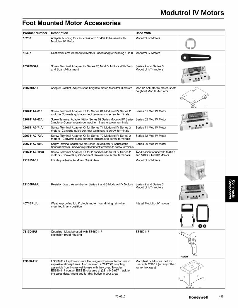
Modutrol IV Motors
70-6910 433
Com
mercial
Com
ponents
Foot Mounted Motor AccessoriesProduct Number Description Used With
16230 Adapter bushing for cast crank arm 18437 to be used with Modutrol IV Motor
Modutrol IV Motors
18437 Cast crank arm for Modutrol Motors - need adapter bushing 16230 Modutrol IV Motors
203709D2/U Screw Terminal Adapter for Series 70 Mod IV Motors With Zero and Span Adjustment
Series 2 and Series 3 Modutrol IV™ motors
220738A/U Adapter Bracket. Adjusts shaft height to match Modutrol III motors Mod IV Actuator to match shaft height of Mod III Actuator
220741A2-61/U Screw Terminal Adapter Kit for Series 61 Modutrol IV Series 2 motors- Converts quick-connect terminals to screw terminals
Series 61 Mod IV Motor
220741A2-62/U Screw Terminal Adapter Kit for Series 62 Series Modutrol IV Series 2 motors- Converts quick-connect terminals to screw terminals
Series 62 Mod IV Motor
220741A2-71/U Screw Terminal Adapter Kit for Series 71 Modutrol IV Series 2 motors- Converts quick-connect terminals to screw terminals
Series 71 Mod IV Motor
220741A2-72/U Screw Terminal Adapter Kit for Series 72 Modutrol IV Series 2 motors - Converts quick-connect terminals to screw terminals
Series 72 Mod IV Motor
220741A2-90/U Screw Terminal Adapter Kit for Series 90 Modutrol IV Series 2and Series 3 motors - Converts quick-connect terminals to screw terminals
Series 90 Mod IV Motor
220741A2-TP/U Screw Terminal Adapter Kit for 2 position Modutrol IV Series 2 motors - Converts quick-connect terminals to screw terminals
Two Position for use with M4XXX and M8XXX Mod IV Motors
221455A/U Infinitely adjustable Motor Crank Arm Modutrol IV Motors
221508A2/U Resistor Board Assembly for Series 2 and 3 Modutrol IV Motors Series 2 and Series 3 Modutrol IV™ motors
4074ERU/U Weatherproofing kit. Protects motor from driving rain when mounted in any position
Fits all Modutrol IV motors
7617DM/U Coupling- Must be used with ES650117 explosion-proof housing
ES650117
ES650-117 ES650-117 Explosion-Proof Housing encloses motor for use in explosive atmospheres. Also required, a 7617DM coupling assembly from Honeywell to use with the cover. To order ES650-117 contact EGS Enclosures at (281) 449-6271, ask for the sales department and for distribution in your area.
Modutrol IV Motors, not for use with Q5001 (or any other valve linkages)
220738 M11550
M115157617DM
ES 650 117 M11534

Modutrol IV Motors
434 customer.honeywell.com 70-6910
198162 Internal Transformer for Series 1 MotorsApplication Type: Internal TransformerAmbient Temperature Range: 0 F to 131 F (-18 C to +55 C)
220736 Internal Auxiliary Switch KitsApplication Type: Internal Auxiliary Switch KitsAuxiliary Switch Ratings AFL - 120 Vac: 7.2AAuxiliary Switch Ratings ALR - 120 Vac: 43.2AAuxiliary Switch Ratings AFL - 240 Vac: 3.6AAuxiliary Switch Ratings ALR - 240 Vac: 21.6AElectrical Connections: 15 in (381 mm) Lead WiresAmbient Temperature Range: 0 F to 131 F (-18 C to +55 C) Weight: 0.3 lb
50017460 Internal Transformers for Series 2 and 3 MotorsApplication Type: Internal TransformerControl Signal: SPST, On/Off switchFrequency: 50 Hz; 60 HzMounting: Internal mount to Modutrol IV MotorsAmbient Temperature Range: 0 F to 131 F (-18 C to +55 C)
Product Number Voltage Control Signal Includes Comments
198162AA/U 120/208/240 Vac at 50 or 60 Hz
SPST, On/Off switch
Transformer, screws, instructions for mounting internally in Modutrol IV Series 1 motors
For Mod IV Series 2 and 3 actuators, use 50017460-001
198162EA/U 120 Vac at 50 or 60 Hz
SPST, On/Off switch
Transformer, screws, instructions for mounting internally in Modutrol IV Series 1 motors
For Mod IV Series 2 and 3 actuators, use 50017460-003
198162GA/U 220 Vac at 50 or 60 Hz
SPST, On/Off switch
Transformer, screws, instructions for mounting internally in Modutrol IV Series 1 motors
For Mod IV Series 2 and 3 actuators, use 50017460-001
198162JA/U 24 Vac (for electrical isolation)
SPST, On/Off switch
Transformer, screws, instructions for mounting internally in Modutrol IV Series 1 motors
For Mod IV Series 2 and 3 actuators, use 50017460-001
Product NumberElectrical Connections Control Signal Includes Used With
220736A/U 15 in (381 mm) Lead Wires
SPDT, On/Off switch One Micro Switch V3 precision switch, which is actuated by adjustable cams inside the motor.
TRADELINE Modutrol IV Motors
220736B/U 15 in (381 mm) Lead Wires
SPDT, On/Off switch Two Micro Switch V3 precision switches, which are actuated by adjustable cams inside the motor.
TRADELINE Modutrol IV Motors
Product Number Voltage Control Signal Includes Used With
50017460-001/U 24/120/230 Vac SPST, On/Off switch Transformer, screws, instructions for mounting internally in Modutrol IV™ Series 2 and 3 motors
Series 2 and Series 3 Modutrol IV™ motors
50017460-003/U 120 Vac SPST, On/Off switch Transformer, screws, instructions for mounting internally in Modutrol IV™ Series 2 and 3 motors
Series 2 and Series 3 Modutrol IV™ motors

Modutrol IV Motors
70-6910 435
Com
mercial
Com
ponents
Q181 Auxiliary Potentiometer for Modutrol MotorsControls from one to four Modutrol (Series 90) motors from one master motor.• Compat ble with Modutrol III and Modutrol IV motors • Mounts on master motor and operates controlled motors
in unison or in sequence • Controls motors with mechanical balance relay and solid state drive circuit • Use with 24V motors
Application Type: Electro-mechanicalDimensions, Approximate: 3 3/16 in. high x 3 1/4 in. wide x 3 3/8 in.
deep (81 mm high x 83 mm wide x 86 mm deep) Mounting: External mount to Modutrol IV MotorsWeight: 1.38 bApprovalsCE: Report: GV97-011
Q209 Manual Potentiometer for Modutrol MotorsUsed to limit minimum position of a proportioning Modutrol motor.• Mount directly in motor • All wiring is accomplished within motor wiring compartment • Color-coded leadwires
Application Type: Electro-mechanicalDimensions, Approximate: 3 1/4 in. high x 3 3/8 in. wide x 3 7/8 in. deep
(83 mm high x 86 mm wide x 98 mm deep) Control Signal: SPST, On/Off switchElectrical Connections: Screw terminalsMounting: Internal mount to Modutrol IV MotorsWeight: 0.2 lbApprovalsCE: Report: GV97-011
Product NumberElectrical Connections Control Signal Includes Comments Used With
Q181A1007/U Screw terminals SPST, On/Off switch Cover For controlling one modutrol motor Series 90
Q181A1015/U Screw terminals SPST, On/Off switch Cover For controlling two modutrol motors Series 90
Q181A1064/U Screw terminals SPST, On/Off switch — For controlling up to three modutrol motors Series 90
Product Number Electrical Connections Control Signal Includes Used With
Q209A1022/U Screw terminals SPST, On/Off switch 150 ohm Potentiometer, leadwires and bracket
M9184; M9185; M6284; M6285
Q209A1030/U Screw terminals SPST, On/Off switch 300 ohm Potentiometer, leadwires and bracket
M9184; M9185; M6284; M6285
Q209E1002/U Quick-connect terminals with lead wires
SPST, On/Off switch 150 ohm Potentiometer, factory mounted on a wring cover box
—
Q209E1010/U Quick-connect terminals with lead wires
SPST, On/Off switch 300 Ohm Potentiometer, Factory Mounted on a wiring cover box
—
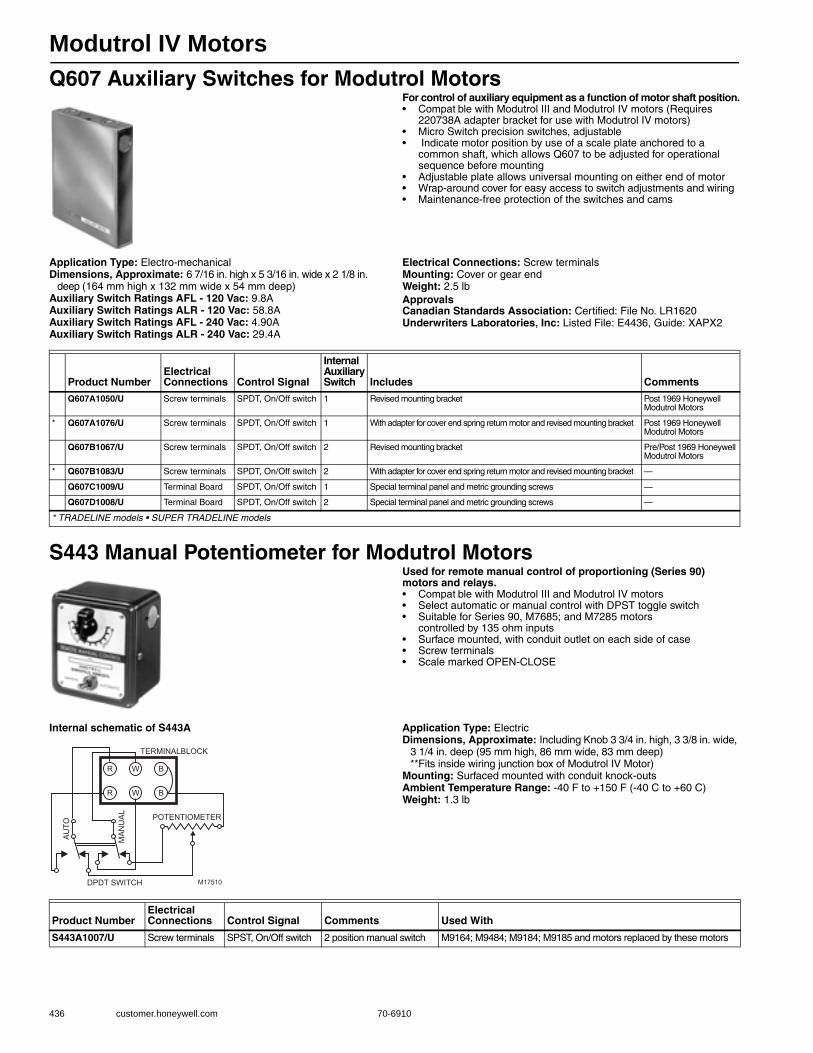
Modutrol IV Motors
436 customer.honeywell.com 70-6910
Q607 Auxiliary Switches for Modutrol MotorsFor control of auxiliary equipment as a function of motor shaft position.• Compat ble with Modutrol III and Modutrol IV motors (Requires
220738A adapter bracket for use with Modutrol IV motors) • Micro Switch precision switches, adjustable • Indicate motor position by use of a scale plate anchored to a
common shaft, which allows Q607 to be adjusted for operational sequence before mounting
• Adjustable plate allows universal mounting on either end of motor • Wrap-around cover for easy access to switch adjustments and wiring • Maintenance-free protection of the switches and cams
Application Type: Electro-mechanicalDimensions, Approximate: 6 7/16 in. high x 5 3/16 in. wide x 2 1/8 in.
deep (164 mm high x 132 mm wide x 54 mm deep) Auxiliary Switch Ratings AFL - 120 Vac: 9.8AAuxiliary Switch Ratings ALR - 120 Vac: 58.8AAuxiliary Switch Ratings AFL - 240 Vac: 4.90AAuxiliary Switch Ratings ALR - 240 Vac: 29.4A
Electrical Connections: Screw terminalsMounting: Cover or gear endWeight: 2.5 lbApprovalsCanadian Standards Association: Certified: File No. LR1620Underwriters Laboratories, Inc: Listed File: E4436, Guide: XAPX2
S443 Manual Potentiometer for Modutrol MotorsUsed for remote manual control of proportioning (Series 90) motors and relays.• Compat ble with Modutrol III and Modutrol IV motors • Select automatic or manual control with DPST toggle switch • Suitable for Series 90, M7685; and M7285 motors
controlled by 135 ohm inputs • Surface mounted, with conduit outlet on each side of case • Screw terminals • Scale marked OPEN-CLOSE
Internal schematic of S443A Application Type: ElectricDimensions, Approximate: Including Knob 3 3/4 in. high, 3 3/8 in. wide,
3 1/4 in. deep (95 mm high, 86 mm wide, 83 mm deep)**Fits inside wiring junction box of Modutrol IV Motor)
Mounting: Surfaced mounted with conduit knock-outsAmbient Temperature Range: -40 F to +150 F (-40 C to +60 C) Weight: 1.3 lb
Product NumberElectrical Connections Control Signal
Internal Auxiliary Switch Includes Comments
Q607A1050/U Screw terminals SPDT, On/Off switch 1 Revised mounting bracket Post 1969 Honeywell Modutrol Motors
* Q607A1076/U Screw terminals SPDT, On/Off switch 1 With adapter for cover end spring return motor and revised mounting bracket Post 1969 Honeywell Modutrol Motors
Q607B1067/U Screw terminals SPDT, On/Off switch 2 Revised mounting bracket Pre/Post 1969 Honeywell Modutrol Motors
* Q607B1083/U Screw terminals SPDT, On/Off switch 2 With adapter for cover end spring return motor and revised mounting bracket —
Q607C1009/U Terminal Board SPDT, On/Off switch 1 Special terminal panel and metric grounding screws —
Q607D1008/U Terminal Board SPDT, On/Off switch 2 Special terminal panel and metric grounding screws —
* TRADELINE models • SUPER TRADELINE models
M17510
BWR
BWR
POTENTIOMETER
AU
TO
MA
NU
AL
DPDT SWITCH
TERMINALBLOCK
Product NumberElectrical Connections Control Signal Comments Used With
S443A1007/U Screw terminals SPST, On/Off switch 2 position manual switch M9164; M9484; M9184; M9185 and motors replaced by these motors
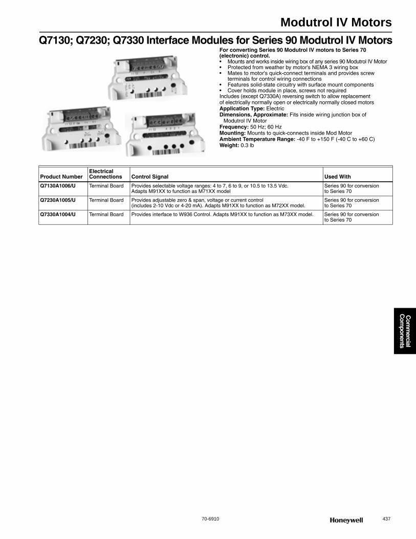
Modutrol IV Motors
70-6910 437
Com
mercial
Com
ponents
Q7130; Q7230; Q7330 Interface Modules for Series 90 Modutrol IV MotorsFor converting Series 90 Modutrol IV motors to Series 70 (electronic) control.• Mounts and works inside wiring box of any series 90 Modutrol IV Motor • Protected from weather by motor's NEMA 3 wiring box • Mates to motor's quick-connect terminals and provides screw
terminals for control wiring connections • Features solid-state circuitry with surface mount components • Cover holds module in place, screws not required Includes (except Q7330A) reversing switch to allow replacement of electrically normally open or electrically normally closed motorsApplication Type: ElectricDimensions, Approximate: Fits inside wiring junction box of
Modutrol IV MotorFrequency: 50 Hz; 60 HzMounting: Mounts to quick-connects inside Mod MotorAmbient Temperature Range: -40 F to +150 F (-40 C to +60 C) Weight: 0.3 lb
Product NumberElectrical Connections Control Signal Used With
Q7130A1006/U Terminal Board Provides selectable voltage ranges: 4 to 7, 6 to 9, or 10.5 to 13.5 Vdc. Adapts M91XX to function as M71XX model
Series 90 for conversion to Series 70
Q7230A1005/U Terminal Board Provides adjustable zero & span, voltage or current control (includes 2-10 Vdc or 4-20 mA). Adapts M91XX to function as M72XX model.
Series 90 for conversion to Series 70
Q7330A1004/U Terminal Board Provides interface to W936 Control. Adapts M91XX to function as M73XX model. Series 90 for conversion to Series 70
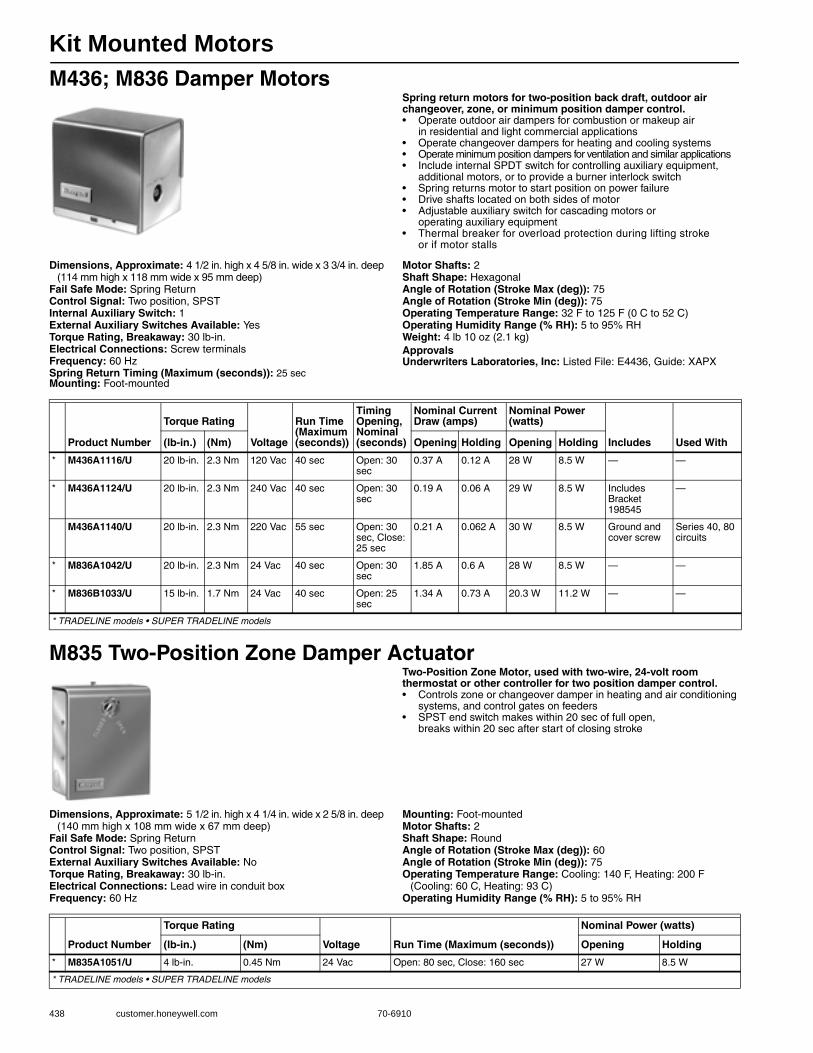
Kit Mounted Motors
438 customer.honeywell.com 70-6910
M436; M836 Damper MotorsSpring return motors for two-position back draft, outdoor air changeover, zone, or minimum position damper control.• Operate outdoor air dampers for combustion or makeup air
in residential and light commercial applications • Operate changeover dampers for heating and cooling systems • Operate minimum position dampers for ventilation and similar applications • Include internal SPDT switch for controlling auxiliary equipment,
additional motors, or to provide a burner interlock switch • Spring returns motor to start position on power failure • Drive shafts located on both sides of motor • Adjustable auxiliary switch for cascading motors or
operating auxiliary equipment • Thermal breaker for overload protection during lifting stroke
or if motor stalls
Dimensions, Approximate: 4 1/2 in. high x 4 5/8 in. wide x 3 3/4 in. deep (114 mm high x 118 mm wide x 95 mm deep)
Fail Safe Mode: Spring ReturnControl Signal: Two position, SPSTInternal Auxiliary Switch: 1External Auxiliary Switches Available: YesTorque Rating, Breakaway: 30 lb-in.Electrical Connections: Screw terminalsFrequency: 60 HzSpring Return Timing (Maximum (seconds)): 25 secMounting: Foot-mounted
Motor Shafts: 2Shaft Shape: HexagonalAngle of Rotation (Stroke Max (deg)): 75Angle of Rotation (Stroke Min (deg)): 75Operating Temperature Range: 32 F to 125 F (0 C to 52 C) Operating Humidity Range (% RH): 5 to 95% RHWeight: 4 lb 10 oz (2.1 kg) ApprovalsUnderwriters Laboratories, Inc: Listed File: E4436, Guide: XAPX
M835 Two-Position Zone Damper ActuatorTwo-Position Zone Motor, used with two-wire, 24-volt room thermostat or other controller for two position damper control.• Controls zone or changeover damper in heating and air conditioning
systems, and control gates on feeders • SPST end switch makes within 20 sec of full open,
breaks within 20 sec after start of closing stroke
Dimensions, Approximate: 5 1/2 in. high x 4 1/4 in. wide x 2 5/8 in. deep (140 mm high x 108 mm wide x 67 mm deep)
Fail Safe Mode: Spring ReturnControl Signal: Two position, SPSTExternal Auxiliary Switches Available: NoTorque Rating, Breakaway: 30 lb-in.Electrical Connections: Lead wire in conduit boxFrequency: 60 Hz
Mounting: Foot-mountedMotor Shafts: 2Shaft Shape: RoundAngle of Rotation (Stroke Max (deg)): 60Angle of Rotation (Stroke Min (deg)): 75Operating Temperature Range: Cooling: 140 F, Heating: 200 F
(Cooling: 60 C, Heating: 93 C) Operating Humidity Range (% RH): 5 to 95% RH
Product Number
Torque Rating
Voltage
Run Time (Maximum (seconds))
Timing Opening, Nominal (seconds)
Nominal Current Draw (amps)
Nominal Power (watts)
Includes Used With(lb-in.) (Nm) Opening Holding Opening Holding
* M436A1116/U 20 lb-in. 2.3 Nm 120 Vac 40 sec Open: 30 sec
0.37 A 0.12 A 28 W 8.5 W — —
* M436A1124/U 20 lb-in. 2.3 Nm 240 Vac 40 sec Open: 30 sec
0.19 A 0.06 A 29 W 8.5 W Includes Bracket 198545
—
M436A1140/U 20 lb-in. 2.3 Nm 220 Vac 55 sec Open: 30 sec, Close: 25 sec
0.21 A 0.062 A 30 W 8.5 W Ground and cover screw
Series 40, 80 circuits
* M836A1042/U 20 lb-in. 2.3 Nm 24 Vac 40 sec Open: 30 sec
1.85 A 0.6 A 28 W 8.5 W — —
* M836B1033/U 15 lb-in. 1.7 Nm 24 Vac 40 sec Open: 25 sec
1.34 A 0.73 A 20.3 W 11.2 W — —
* TRADELINE models • SUPER TRADELINE models
Product Number
Torque Rating
Voltage Run Time (Maximum (seconds))
Nominal Power (watts)
(lb-in.) (Nm) Opening Holding
* M835A1051/U 4 lb-in. 0.45 Nm 24 Vac Open: 80 sec, Close: 160 sec 27 W 8.5 W
* TRADELINE models • SUPER TRADELINE models

Kit Mounted Motors
70-6910 439
Com
mercial
Com
ponents
M847 Two-Position Draft Damper ActuatorTwo-Position Draft Damper Actuators. Use with two-wire 24V room thermostats or other low voltage controllers to operate the draft damper on solid fuel furnaces or boilers and other similar light duty applications.• Low voltage, spring-return damper actuator • Equipped with mounting bracket for wall, duct or direct appliance
mounting to control draft damper through an actuator arm or chain linkage arrangement
• Actuator wheel rotates in a clockwise direction (when facing the wheel) when energized
Dimensions, Approximate: 3 1/2 in. high x 2 5/8 in. wide x 3 5/16 in. deep (89 mm high x 66 mm wide x 84 mm deep)
Fail Safe Mode: Spring ReturnControl Signal: Two position, SPSTExternal Auxiliary Switches Available: NoFrequency: 60 HzMounting: Foot mounted. Direct Coupled
Motor Shafts: 1Shaft Shape: RoundAngle of Rotation (Stroke Max (deg)): 45Operating Temperature Range: 40 F to 125 F (5 C to 50 C) Operating Humidity Range (% RH): 5 to 95% RHWeight: 1.75 bs
Replacement Parts and Accessories for Kit Mounted Motors
Product Number
Torque Rating
Voltage Run Time (Maximum (seconds)) Includes(lb-in.) (Nm)
M847A1072/U 1.9 lb-in. 0.21 Nm 24 Vac 20 sec 3.8 in. linkage arm
M847A1080/U 1.9 lb-in. 0.21 Nm 24 Vac 20 sec 38 in. linkage chain
Product Number Description Used With
121825AA/U Auxiliary crank arm assembly Q298; M835
126809/0021/U M836 Mounting Bracket M836
126816/0021/U Clamp for M436 M436
128336/0021/U Mounting Bracket for M436/M836, Increases motor height 0.5 inches M436, M836
16254AC Motor mounting bracket for M436/M836 M436, M836
198545/U Motor mounting bracket for M436/M836 M436, M836
4074BRU/U Bag Assembly Extension adapter and screws for mounting Q607 Auxiliary switch to M436A Damper Motor
Q607; M436A
4074ELR/U Crank arm, heavy duty —
4074ELY/U Crank arm, infinitely adjustable —
198545 M11526
4074BRUM11524
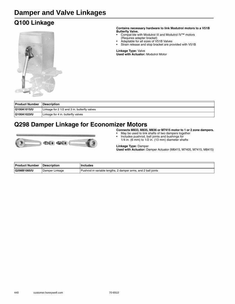
Damper and Valve Linkages
440 customer.honeywell.com 70-6910
Q100 LinkageContains necessary hardware to link Modutrol motors to a V51B Butterfly Valve.• Compat ble with Modutrol III and Modutrol IV™ motors
(Requires adapter bracket) • Adaptable for all sizes of V51B Valves • Strain release and stop bracket are provided with V51B
Linkage Type: ValveUsed with Actuator: Modutrol Motor
Q298 Damper Linkage for Economizer MotorsConnects M833, M835, M836 or M7415 motor to 1 or 2 zone dampers.• May be used to link shafts of two dampers together • Includes pushrod, ball joints and bushings for
1/4 in. (6 mm) to 1/2 in. (13 mm) diameter shafts
Linkage Type: DamperUsed with Actuator: Damper Actuator (M6415, M7405, M7415, M8415)
Product Number Description
Q100A1015/U Linkage for 2 1/2 and 3 in. butterfly valves
Q100A1023/U Linkage for 4 in. butterfly valves
Product Number Description Includes
Q298B1065/U Damper Linkage Pushrod in variable lengths, 2 damper arms, and 2 ball joints
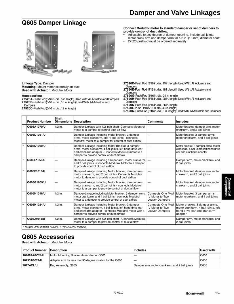
Damper and Valve Linkages
70-6910 441
Com
mercial
Com
ponents
Q605 Damper LinkageConnect Modutrol motor to standard damper or set of dampers to provide control of duct airflow.• Adjustable to any degree of damper opening. Include ball joints,
motor crank arm and damper arm for 1/2 in. (13 mm) diameter shaft • 27520 pushrod must be ordered separately
Linkage Type: DamperMounting: Mount motor externally on ductUsed with Actuator: Modutrol Motor
Accessories:27520A-Push Rod (5/16 in. dia., 5 in. length) Used With: All Actuators and Dampers27520B-Push Rod (5/16 in. dia., 10 in. length) Used With: All Actuators and
Dampers27520C-Push Rod (5/16 in. dia., 12 in. length)
27520D-Push Rod (5/16 in. dia., 15 in. length) Used With: All Actuators and Dampers
27520E-Push Rod (5/16 in. dia., 18 in. length) Used With: All Actuators and Dampers
27520G-Push Rod (5/16 in. dia., 24 in. length)27520H-Push Rod (5/16 in. dia., 28 in. length) Used With: All Actuators and
Dampers27520K-Push Rod (5/16 in. dia., 36 in. length)27520L-Push Rod (5/16 in. dia., 48 in. length)27520Q-Push Rod (5/16 in. dia., 8 in. length) Used With: All Actuators and Dampers
Q605 AccessoriesUsed with Actuator: Modutrol Motor
Product NumberShaft Dimensions Description Comments Includes
* Q605A1070/U 1/2 in. Damper-Linkage with 1/2 inch shaft- Connects Modutrol motor to a damper to control duct air flow
— Motor bracket, damper arm, motor crankarm, and 2 ball joints
* Q605D1051/U — Damper-Linkage including motor bracket, 3 damper arms, motor crankarm, and 4 ball joints - connects Modutrol motor to a damper for control of duct airflow
— Motor bracket, 3 damper arms, motor crankarm, and 4 ball joints
• Q605D1069/U — Damper-Linkage including Motor Bracket, 3 damper arms, motor crankarm, 4 ball joints, left hand drive ear and crankarm adapter - Connects Modutrol motor to a damper to provide control of duct airflow
— Motor bracket, 3 damper arms, motor crankarm, 4 ball joints, left hand drive ear and crankarm adapter
* Q605E1050/U — Damper-Linkage including damper arm, motor crankarm, and 2 ball joints - Connects Modutrol Motor to a damper to provide control of duct airflow
— Damper arm, motor crankarm, and 2 ball joints
* Q605F1018/U — Damper-Linkage including Motor bracket, damper arm, motor crankarm, and 2 ball joints - Connects Modutrol motor to damper to provide control of duct airflow
— Motor bracket, damper arm, motor crankarm, and 2 ball joints
Q605G1009/U — Damper-Linkage including Motor bracket, damper arm, motor crankarm, and 2 ball joints - connects Modutrol motor to a damper to provide control of duct airflow
— Motor bracket, damper arm, motor crankarm, and 2 ball joints
Q605H1016/U 1/2 in. Damper-Linkage including Motor bracket, 3 damper arms, motor crankarm, and 4 ball joints - connects Modutrol motor to a damper to provide control of duct airflow
Connects One Mod IV Motor to Two Louver Dampers
Motor bracket, 3 damper arms, motor crankarm, and 4 ball joints
• Q605H1024/U 1/2 in. Damper-Linkage including Motor bracket, 3 damper arms, motor crankarm, 4 ball joints, left hand drive ear and crankarm adapter - connects Modutrol motor with a damper to provide control of duct airflow
Connects One Mod IV Motor to Two Louver Dampers
Motor bracket, 3 damper arms, motor crankarm, 4 ball joints, left hand drive ear and crankarm adapter
* Q605J1013/U 1/2 in. Damper-Linkage with 1/2 inch shaft - Connects Modutrol motor to a damper to provide control of duct airflow
— Damper arm, motor crankarm, and 2 ball joints
* TRADELINE models • SUPER TRADELINE models
Product Number Description Includes Used With
101662A/0021/U Motor Mounting Bracket Assembly for Q605 — Q605
102931/0021/U Adapter arm for less that 90 degree rotation for the Q605 — Q605
7617ACL/U Bag Assembly, Q605 Damper arm, motor crankarm, and 2 ball joints Q605

Damper and Valve Linkages
442 customer.honeywell.com 70-6910
Q5001 Valve Linkage for Modutrol IV MotorsThe Q5001 Valve Linkage connects a Modutrol Motor to a 2- or 3-way valve. It is used primarily on V5011 or V5013 steam and water valves.• Q5001 Valve Linkage is applicable to 2-Way or 3-Way valves in
modulating or two-position service • Linkage requires no adjustment when used with Honeywell
valves and Modutrol IV™ Motors • Q5001 Valve Linkage replaces Q601 and Q618 Valve Linkages • Linkage mounts directly to the valve bonnet; motor mounts to linkage bracket • Easy-to-read position indicator • Valve stem lift height cam selectable • Overtravel permits tight close-off without excessive motor strain • Available brackets make linkages adaptable to many valve bodies • Models available with 80 lb, 160 lb, and 320 b stem force • Reversible cams on the Q5001 allow field selection of
normally open or normally closed valve operation • All models have anti-spin clips
Linkage Type: ValveMounting: Linkage mounts directly to the valve bonnet; motor mounts
on linkage bracketUsed with Actuator: Modutrol MotorStem Force Rating: 80 or 160 lbf (356 N or 712 N) Ambient Temperature Range: -40 F to +150 F (-40 C to +66 C)
Replacement Parts:220845/0767-Retainer button for Q5001
Q5001 parts
Product NumberBonnet Size (in.) Stroke Description Includes Used With
* Q5001D1000/U 1 3/8 in. 3/4 in. Valve Linkage for Mod III and Mod IV motors with 80 or 160 lb stem force
1 3/8 in. valve bracket and Anti spin clip
V5011/V5013; Modutrol IV Motors
* Q5001D1018/U 1 3/8 in. 3/4 in. Valve Linkage for Mod IV motors with 160 or 320 lb stem force and up to 3 inch valves
1 3/8 in. valve bracket and Anti spin clip
Valve sizes up to 3 inch; V5011/V5013; Modutrol IV Motors
* Q5001D1026/U 1 7/8 in. 1 1/2 in. Valve Linkage for Mod IV motors with 160 or 320 lb stem force and 4, 5 or 6 inch valves
1 7/8 in. valve bracket and Anti spin clip
4, 5 or 6 inch valves; V5011/V5013; Modutrol IV Motors
* TRADELINE models • SUPER TRADELINE models
Product Number Stroke Description Used With
220845/0767/U — Retainer button for Q5001 —
220848A/U 1/2 in. Q5001 Cam Q5001
220852A/U — Stroke Indicator, Q5001 Q5001
220861A/U 3/4 in. 3/4 inch lift Q5001 linkage cam assembly Q5001
220863A/U 1 in. 1 inch lift Q5001 linkage cam assembly Q5001
220864A/U 1 1/8 in. 1 1/8 inch lift Q5001 linkage cam assembly Q5001
220867A/U 1 1/2 in. 1 1/2 inch lift Q5001 linkage cam assembly Q5001
220874/0767/U — 9/16 inch anti spin clip for Q5001 —
4074ETB/U — Antispin Kit, Q5001 Q5001

Damper and Valve Linkages
70-6910 443
Com
mercial
Com
ponents
Q5020 Globe Valve LinkagesThe Q5020 Globe Valve Linkages connect a Honeywell direct coupled actuator (DCA) to a steam or water globe valve. The Q5020 Linkages are compatible with two-way and three-way globe valves up to 3 inch (DN80).• Used with two-way and three-way globe valves in
modulating or two-position service • Used with 25, 50, and 142 b-in. spring return and 35, 70, 150,
and 300 b-in. non-spring return DCA • Quick and simple installation with no disassembly required • Heavy-duty Steel rack and pinion construction and
Aluminum Die-cast housing • Maintenance-free construction • Precision roller-bearing rack construction prevents
premature valve packing wear and leakage • Flexible actuator mounting orientation • Adjustable manual override lever and valve position indicator • Can be mounted on specific non-Honeywell valves using
a 32004629 Bonnet Adapter Kit
Linkage Type: ValveMounting: Linkage mounts directly to the valve bonnet; actuator
mounts on linkage
Used with Actuator: Direct Coupled Actuator
Product NumberBonnet Size (in.)
Shaft Dimensions Stroke Includes Used With
Q5020A1003/U 1 3/8 in. 1/2 in. 3/4 in. 1/2 in. diameter drive shaft V5011G; V5011F; V5013N; V5011N
Q5020B1001/U 1 3/8 in. 1 in. 3/4 in. 1 in. diameter drive shaft V5011G; V5011F; V5013N; V5011N
Q5020C1009/U 1 3/8 in. 1 in. 1 1/2 in. 1 in. diameter drive shaft V5051
Q5020D1007/U 1 3/8 in. 1/2 in. 1/2 in. 1/2 in. diameter drive shaft T.A.C. valves; Johnson valves; Siemens valves
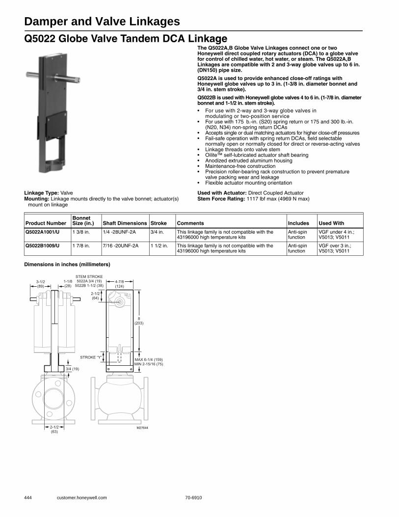
Damper and Valve Linkages
444 customer.honeywell.com 70-6910
Q5022 Globe Valve Tandem DCA LinkageThe Q5022A,B Globe Valve Linkages connect one or two Honeywell direct coupled rotary actuators (DCA) to a globe valve for control of chilled water, hot water, or steam. The Q5022A,B Linkages are compatible with 2 and 3-way globe valves up to 6 in. (DN150) pipe size.
Q5022A is used to provide enhanced close-off ratings with Honeywell globe valves up to 3 in. (1-3/8 in. diameter bonnet and 3/4 in. stem stroke).
Q5022B is used with Honeywell globe valves 4 to 6 in. (1-7/8 in. diameter bonnet and 1-1/2 in. stem stroke).• For use with 2-way and 3-way globe valves in
modulating or two-position service • For use with 175 b.-in. (S20) spring return or 175 and 300 lb.-in.
(N20, N34) non-spring return DCAs • Accepts single or dual matching actuators for higher close-off pressures • Fail-safe operation with spring return DCAs, field selectable
normally open or normally closed for direct or reverse-acting valves • Linkage threads onto valve stem • Oilite™ self-lubricated actuator shaft bearing • Anodized extruded aluminum housing • Maintenance-free construction • Precision roller-bearing rack construction to prevent premature
valve packing wear and leakage • Flexible actuator mounting orientation
Linkage Type: ValveMounting: Linkage mounts directly to the valve bonnet; actuator(s)
mount on linkage
Used with Actuator: Direct Coupled ActuatorStem Force Rating: 1117 lbf max (4969 N max)
Dimensions in inches (millimeters)
Product NumberBonnet Size (in.) Shaft Dimensions Stroke Comments Includes Used With
Q5022A1001/U 1 3/8 in. 1/4 -28UNF-2A 3/4 in. This linkage family is not compatible with the 43196000 high temperature kits
Anti-spin function
VGF under 4 in.; V5013; V5011
Q5022B1009/U 1 7/8 in. 7/16 -20UNF-2A 1 1/2 in. This linkage family is not compatible with the 43196000 high temperature kits
Anti-spin function
VGF over 3 in.; V5013; V5011
M27644
4-7/8(124)
8(203)
3-1/2(89)
STEM STROKE5022A 3/4 (19)
5022B 1-1/2 (38)
2-1/2(64)
1-1/8(28)
3/4 (19)
2-1/2(63)
MAX 6-1/4 (159)MIN 2-15/16 (75)
STROKE “Y”
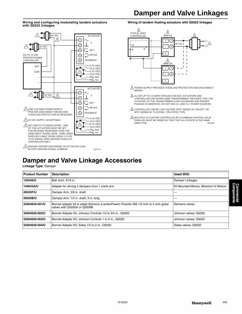
Damper and Valve Linkages
70-6910 445
Com
mercial
Com
ponents
Wiring and configuring modulating tandem actuators with Q5022 linkages
Wiring of tandem floating actuators with Q5022 linkages
Damper and Valve Linkage AccessoriesLinkage Type: Damper
ACTUATOR
0/2 TO 10 VDCPROPORTIONINGCONTROLLER
1
2
3
2
LINE VOLTAGE POWER SUPPLY. PROVIDE DISCONNECT MEANS AND OVERLOAD PROTECTION AS REQUIRED.
24 VDC SUPPLY ACCEPTABLE.
SET SWITCH TO MODULATING. ONE OF THE ACTUATORS MUST BE SET FOR REVERSE RESPONSE OVER THE SAME INPUT SIGNAL SPAN. WIRE USING SHIELDED CABLE WHEN USING 0-10 OR 10-0V SIGNAL SPAN GROUND SHIELD ATCONTROLLER ONLY.
V
OR +
OR N/A
FEEDBACK5
4
3
1
2
M27710
2-10 VDC10-2 VDC0-10 VDC10-0 VDCFltg, fwdFltg, rev
3
ACTUATOR
V
OR +
OR N/A
FEEDBACK5
4
3
1
2
2-10 VDC10-2 VDC0-10 VDC10-0 VDCFltg, fwdFltg, rev
3
24 VAC1
24 VAC1
224 VAC1
HOT
COM
–
+
4 ENSURE PROPER GROUNDING OF ACTUATOR CASE. DO NOT GROUND SIGNAL COMMON.
M27648
W
B R
34
4
2
13
3
1
1
4
4
24 Vac2
2
1
1
L1
L2
MN6134TYPICAL SPDTCONTROLLER
MN6134
POWER SUPPLY PROVIDES OVERLOAD PROTECTION AND DISCONNECT MEANS.
ALLOW UP TO 0.5 AMPS FOR EACH DEVICE. ACTUATORS AND CONTROLLER CAN SHARE SAME TRANSFORMER, PROVIDED THAT THE VA RATING OF THE TRANSFORMER IS NOT EXCEEDED AND PROPER PHASING IS OBSERVED. DO NOT MIX A.C. AND D.C. POWER SOURCES.
CONTROLLER CAN BE LOW VOLTAGE SPDT SERIES 20 “ON-OFF” OR SP3T SERIES 60 “FLOATING” (TRI-STATE) TYPE.
MULTIPLE ACTUATORS CONTROLLED BY A COMMON CONTROLLER IN PARALLEL MUST BE WIRED SO THAT THEY ALL ROTATE IN THE SAME DIRECTION.
1
2
3
4
Product Number Description Used With
102546/U Ball Joint, 5/16 in. Damper Linkages
104643A/U Adapter for driving 2 dampers from 1 crank arm Kit Mounted Motors; Modutrol IV Motors
26025F/U Damper Arm, 3/8 in. shaft —
26026B/U Damper Arm, 1/2 in. shaft, 3 in. long —
32004629-001/U Bonnet adapter kit to adapt Seimens (Landis/Power) Flowrite 599 1/2 inch to 3 inch globe valves with Q5020A or Q5009B
Siemens valves
32004629-002/U Bonnet Adapter Kit, Johnson Controls 1/2 to 3/4 in., Q5020 Johnson valves; Q5020
32004629-003/U Bonnet Adapter Kit, Johnson Controls 1 to 2 in., Q5020 Johnson valves; Q5020
32004629-004/U Bonnet Adapter Kit, Siebe 1/2 to 2 in., Q5020 Siebe valves; Q5020
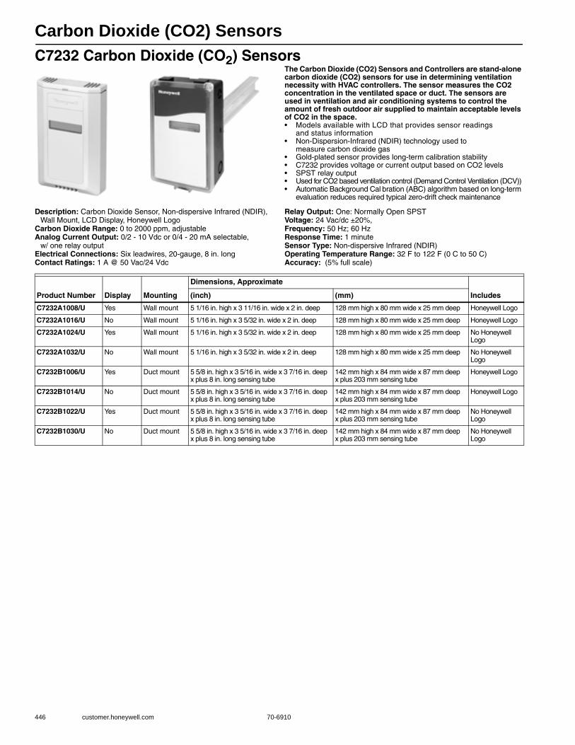
Carbon Dioxide (CO2) Sensors
446 customer.honeywell.com 70-6910
C7232 Carbon Dioxide (CO2) SensorsThe Carbon Dioxide (CO2) Sensors and Controllers are stand-alone carbon dioxide (CO2) sensors for use in determining ventilation necessity with HVAC controllers. The sensor measures the CO2 concentration in the ventilated space or duct. The sensors are used in ventilation and air conditioning systems to control the amount of fresh outdoor air supplied to maintain acceptable levels of CO2 in the space.• Models available with LCD that provides sensor readings
and status information • Non-Dispersion-Infrared (NDIR) technology used to
measure carbon dioxide gas • Gold-plated sensor provides long-term calibration stability • C7232 provides voltage or current output based on CO2 levels • SPST relay output • Used for CO2 based ventilation control (Demand Control Ventilation (DCV)) • Automatic Background Cal bration (ABC) algorithm based on long-term
evaluation reduces required typical zero-drift check maintenance
Description: Carbon Dioxide Sensor, Non-dispersive Infrared (NDIR), Wall Mount, LCD Display, Honeywell Logo
Carbon Dioxide Range: 0 to 2000 ppm, adjustableAnalog Current Output: 0/2 - 10 Vdc or 0/4 - 20 mA selectable,
w/ one relay outputElectrical Connections: Six leadwires, 20-gauge, 8 in. longContact Ratings: 1 A @ 50 Vac/24 Vdc
Relay Output: One: Normally Open SPSTVoltage: 24 Vac/dc ±20%,Frequency: 50 Hz; 60 HzResponse Time: 1 minuteSensor Type: Non-dispersive Infrared (NDIR)Operating Temperature Range: 32 F to 122 F (0 C to 50 C) Accuracy: (5% full scale)
Product Number Display Mounting
Dimensions, Approximate
Includes(inch) (mm)
C7232A1008/U Yes Wall mount 5 1/16 in. high x 3 11/16 in. wide x 2 in. deep 128 mm high x 80 mm wide x 25 mm deep Honeywell Logo
C7232A1016/U No Wall mount 5 1/16 in. high x 3 5/32 in. wide x 2 in. deep 128 mm high x 80 mm wide x 25 mm deep Honeywell Logo
C7232A1024/U Yes Wall mount 5 1/16 in. high x 3 5/32 in. wide x 2 in. deep 128 mm high x 80 mm wide x 25 mm deep No Honeywell Logo
C7232A1032/U No Wall mount 5 1/16 in. high x 3 5/32 in. wide x 2 in. deep 128 mm high x 80 mm wide x 25 mm deep No Honeywell Logo
C7232B1006/U Yes Duct mount 5 5/8 in. high x 3 5/16 in. wide x 3 7/16 in. deep x plus 8 in. long sensing tube
142 mm high x 84 mm wide x 87 mm deep x plus 203 mm sensing tube
Honeywell Logo
C7232B1014/U No Duct mount 5 5/8 in. high x 3 5/16 in. wide x 3 7/16 in. deep x plus 8 in. long sensing tube
142 mm high x 84 mm wide x 87 mm deep x plus 203 mm sensing tube
Honeywell Logo
C7232B1022/U Yes Duct mount 5 5/8 in. high x 3 5/16 in. wide x 3 7/16 in. deep x plus 8 in. long sensing tube
142 mm high x 84 mm wide x 87 mm deep x plus 203 mm sensing tube
No Honeywell Logo
C7232B1030/U No Duct mount 5 5/8 in. high x 3 5/16 in. wide x 3 7/16 in. deep x plus 8 in. long sensing tube
142 mm high x 84 mm wide x 87 mm deep x plus 203 mm sensing tube
No Honeywell Logo

Carbon Dioxide (CO2) Sensors
70-6910 447
Com
mercial
Com
ponents
C7262 Carbon Dioxide (CO2)/Temperature SensorsThe C7262 Sensor is a stand-alone carbon dioxide (CO2) and temperature sensor for use in determining ventilation necessity with HVAC controllers. The C7262 measures the CO2 concentration and temperature to control the amount of fresh outdoor air supplied to maintain acceptable levels of CO2 in the space.• Used for CO2 based ventilation control.• Integral 20K ohm NTC temperature output.• Models available with LCD that provides CO2 ppm level.• Non-Dispersion-Infrared (NDIR) technology used to measure carbon
dioxide gas.• Device provides voltage or current output based on CO2 levels.• Models available with SPST relay output.• Automatic Background Cal bration (ABC) algorithm based on long-
term evaluation reduces required typical zero-drift check maintenance.
Description: Carbon Dioxide and Temperature Sensor, Non-dispersive infrared
Carbon Dioxide Range: 0 to 2000 ppm, adjustableAnalog Current Output: 0/2 - 10 Vdc or 0/4 - 20 mA selectable,
w/ one relay outputContact Ratings: 1 A @ 50 Vac/24 VdcRelay Output: One: Normally Open SPST
Voltage: 24 Vac/dc ±20%,Frequency: 50 Hz; 60 HzResponse Time: 1 minuteSensor Type: Non-dispersive Infrared (NDIR)Temperature Sensor Range: 50 F to 100 FOperating Temperature Range: 32 F to 122 F (0 C to 50 C) Accuracy: (± (30 ppm + 2% of reading))
C7632 Carbon Dioxide (CO2) SensorsThe Carbon Dioxide (CO2) Sensors offer a fixed 0-2000ppm and fixed 0-10Vdc output. No adjustments are necessary. Like the C7232 sensors, these are for use in determining ventilation necessity with HVAC controllers. The sensor measures the CO2 concentration in the ventilated space or duct. The sensors are used in ventilation and air conditioning systems to control the amount of fresh outdoor air supplied to maintain acceptable levels of CO2 in the space.• Non-Dispersion-Infrared (NDIR) technology used to
measure carbon dioxide gas • Gold-plated sensor provides long-term calibration stability • Fixed 0-2000ppm, fixed 0-10Vdc output • Used for CO2 based ventilation control (Demand Control Ventilation (DCV)) • Automatic Background Cal bration (ABC) algorithm based on long-term
evaluation reduces required typical zero-drift check maintenance
Description: Carbon Dioxide Sensor, Non-dispersive Infrared (NDIR), Wall Mount, Honeywell Logo
Carbon Dioxide Range: 0 to 2000 ppm, fixedAnalog Current Output: 0-10Vdc fixedElectrical Connections: Terminal blockRelay Output: None
Voltage: 24 Vac (±20%)Frequency: 50 Hz; 60 HzResponse Time: 1 minuteSensor Type: Non-dispersive Infrared (NDIR)Operating Temperature Range: 32 F to 122 F (0 C to 50 C) Accuracy: (5% full scale)
Product Number Display Mounting
Dimensions, Approximate
Includes(inch) (mm)
C7262A1008/U Yes Wall mount 4 9/16 in. high x 3 in. wide x 7/8 in. deep 116 mm high x 76 mm wide x 22 mm deep Honeywell Logo
C7262A1016/U No Wall mount 4 9/16 in. high x 3 in. wide x 7/8 in. deep 116 mm high x 76 mm wide x 22 mm deep Honeywell Logo
Product Number Display Mounting
Dimensions, Approximate
Includes(inch) (mm)
C7632A1004/U No Wall mount 4 1/8 in high x 3 7/8 in. wide x 1 1/16 in. deep 104 mm high x 99 mm high x 27 mm deep Honeywell Logo
C7632B1002/U No Duct mount 5 5/8 in. high x 3 5/16 in. wide x 1 13/16 in. deep x plus 8 in. long sensing tube
142 mm high x 84 mm wide x 87 mm deep x plus 203 mm sensing tube
Honeywell Logo

Current Switches
448 customer.honeywell.com 70-6910
Solid and Split Core Current SwitchesAll of these sensors have a solid-state output with an adjustable or fixed trip point (setpoint). These current switches should be used in applications in which a “Go/No Go” current switch is required. The current switches can be used to monitor devices with a maximum continuous operating current of up to 250 Amps. These current switches do not need to be externally powered, since the power for the switch is induced from the conductor being monitored. The split core switches are ideal for retrofit or existing installations, since it is not necessary to power down the unit and disconnect any wires during the installation process. Solid core switches are extremely easy to install, they are an excellent choice for new installations.• Solid or split core switches with fixed or adjustable trip points • Very low operating trip points • LED status indication • Integral DIN rail mounting flange • Accepts up to a 350 MCM (17.3 mm) cable • Operates up to 250 continuous amps • RoHS and WEEE Compliant • Limited 5 year warranty
Application: Great for monitoring fans, pumps, motors, compressors, or other electrical equipment
Dimensions, Approximate: 2 45/64 in. high x 3 21/64 in. wide x 1 5/64 in. deep (69 mm high x 85 mm wide x 25 mm deep)
Din Rail Size: 1-3/8 in. (35 mm) Enclosure Rating/Color: UL94-5V/BurgundyIsolation Voltage: 2200 VacSupply Voltage: Induced from monitored conductorFrequency: 40 Hz to 1 kHz
Operating Temperature Range: 5 F to 104 F (-15 C to 40 C) Operating Humidity Range (% RH): 0 to 95% RH, non-condensingWeight: 0.23 b (0.1 kg) ApprovalsCE: ApprovedUnderwriters Laboratories, Inc: ApprovedEnvironmental Compliance: RoHS-Directive 2002/95/EC, WEEE-
Directive 2002/96/EC
Product Number DescriptionCore Type
Normal Position Output Switch Rating
Operating Range Trip Point LEDs
CSP-C-A200-001/U Adjustable Current Switch
Split N.C. 0.15 Amps @ 300 Vac/Vdc 0-250A 2.5-250 Amps Green – Below the trip point; Red – Above the trip point
CSP-O-A200-001/U Adjustable Current Switch
Split N.O. 0.30 Amps @ 200 Vac/Vdc 0-250A 2.0-200 Amps Green – Below the trip point; Red – Above the trip point
CSP-O-A300-001/U Adjustable Current Switch
Split N.O. 0.30 Amps @ 200 Vac/Vdc 0-250A 3.0-200 Amps Green – Below the trip point; Red – Above the trip point
CSP-O-F10-001/U Go/No Go Current Switch
Split N.O. 0.30 Amps @ 200 Vac/Vdc 0-200A 1.50 Amps Red – Above the trip point
CSP-O-F15-001/U Go/No Go Current Switch
Split N.O. 0.30 Amps @ 200 Vac/Vdc 0-200A 2.50 Amps Red – Above the trip point
CSS-C-F1-001/U Go/No Go Current Switch
Solid N.C. 0.15 Amps @ 300 Vac/Vdc 0-250A 0.50 Amps Red – Above the trip point
CSS-C-F5-001/U Go/No Go Current Switch
Solid N.C. 0.15 Amps @ 300 Vac/Vdc 0-250A 1.00 Amps Red – Above the trip point
CSS-O-A200-001/U Adjustable Current Switch
Solid N.O. 0.30 Amps @ 200 Vac/Vdc 0-200A 0.5-250 Amps Green – Below the trip point; Red – Above the trip point
CSS-O-A300-001/U Adjustable Current Switch
Solid N.O. 0.30 Amps @ 200 Vac/Vdc 0-200A 1.0-250 Amps Green – Below the trip point; Red – Above the trip point
CSS-O-F1-001/U Go/No Go Current Switch
Solid N.O. 0.30 Amps @ 200 Vac/Vdc 0-250A 0.20 Amps Red – Above the trip point
CSS-O-F5-001/U Go/No Go Current Switch
Solid N.O. 0.30 Amps @ 200 Vac/Vdc 0-250A 0.50 Amps Red – Above the trip point
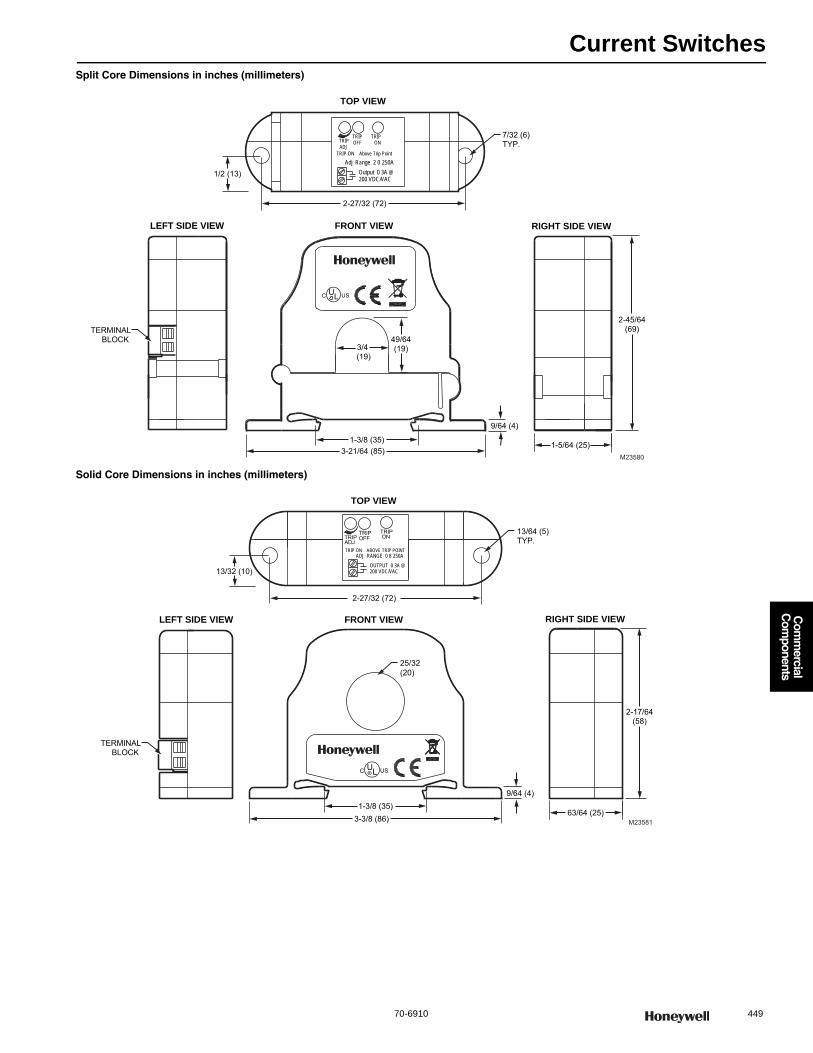
Current Switches
70-6910 449
Com
mercial
Com
ponents
Split Core Dimensions in inches (millimeters)
Solid Core Dimensions in inches (millimeters)
FRONT VIEW RIGHT SIDE VIEWLEFT SIDE VIEW
TOP VIEW
M23580
UC L US
ADJTRIP
Adj Range 2 0 250ATRIP ON Above Trip Point
Output 0 3A @200 VDC/VAC
ONOFFTRIP TRIP
1/2 (13)
2-27/32 (72)
7/32 (6)TYP.
3-21/64 (85)1-3/8 (35)
9/64 (4)
3/4 (19)
49/64(19)
2-45/64(69)
1-5/64 (25)
TERMINALBLOCK
13/32 (10)
25/32(20)
FRONT VIEW RIGHT SIDE VIEWLEFT SIDE VIEW
TOP VIEW
TERMINALBLOCK
13/64 (5)TYP.
C L® USU
ONTRIP
2-27/32 (72)
M235813-3/8 (86)1-3/8 (35)
9/64 (4)
2-17/64(58)
63/64 (25)
OUTPUT 0 3A @200 VDC/VAC
ADJTRIP
TRIP ON ABOVE TRIP POINT
TRIPOFF
ADJ RANGE 0 8 250A
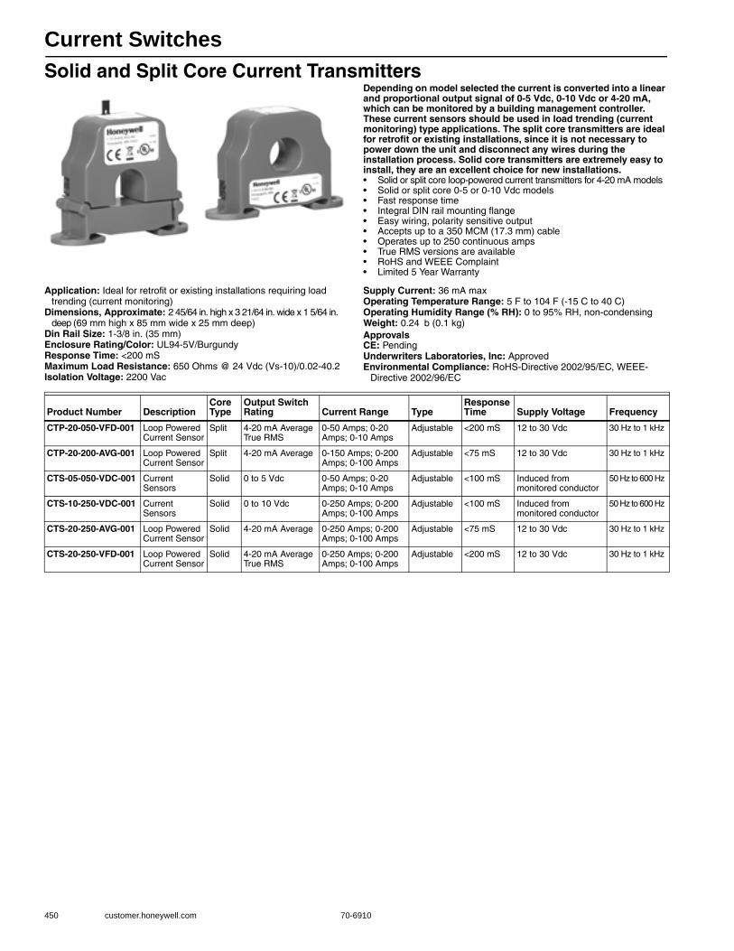
Current Switches
450 customer.honeywell.com 70-6910
Solid and Split Core Current TransmittersDepending on model selected the current is converted into a linear and proportional output signal of 0-5 Vdc, 0-10 Vdc or 4-20 mA, which can be monitored by a building management controller. These current sensors should be used in load trending (current monitoring) type applications. The split core transmitters are ideal for retrofit or existing installations, since it is not necessary to power down the unit and disconnect any wires during the installation process. Solid core transmitters are extremely easy to install, they are an excellent choice for new installations.• Solid or split core loop-powered current transmitters for 4-20 mA models • Solid or split core 0-5 or 0-10 Vdc models • Fast response time • Integral DIN rail mounting flange • Easy wiring, polarity sensitive output • Accepts up to a 350 MCM (17.3 mm) cable • Operates up to 250 continuous amps • True RMS versions are available • RoHS and WEEE Complaint • Limited 5 Year Warranty
Application: Ideal for retrofit or existing installations requiring load trending (current monitoring)
Dimensions, Approximate: 2 45/64 in. high x 3 21/64 in. wide x 1 5/64 in. deep (69 mm high x 85 mm wide x 25 mm deep)
Din Rail Size: 1-3/8 in. (35 mm) Enclosure Rating/Color: UL94-5V/BurgundyResponse Time: <200 mSMaximum Load Resistance: 650 Ohms @ 24 Vdc (Vs-10)/0.02-40.2Isolation Voltage: 2200 Vac
Supply Current: 36 mA maxOperating Temperature Range: 5 F to 104 F (-15 C to 40 C) Operating Humidity Range (% RH): 0 to 95% RH, non-condensingWeight: 0.24 b (0.1 kg) ApprovalsCE: PendingUnderwriters Laboratories, Inc: ApprovedEnvironmental Compliance: RoHS-Directive 2002/95/EC, WEEE-
Directive 2002/96/EC
Product Number DescriptionCore Type
Output Switch Rating Current Range Type
Response Time Supply Voltage Frequency
CTP-20-050-VFD-001 Loop Powered Current Sensor
Split 4-20 mA Average True RMS
0-50 Amps; 0-20 Amps; 0-10 Amps
Adjustable <200 mS 12 to 30 Vdc 30 Hz to 1 kHz
CTP-20-200-AVG-001 Loop Powered Current Sensor
Split 4-20 mA Average 0-150 Amps; 0-200 Amps; 0-100 Amps
Adjustable <75 mS 12 to 30 Vdc 30 Hz to 1 kHz
CTS-05-050-VDC-001 Current Sensors
Solid 0 to 5 Vdc 0-50 Amps; 0-20 Amps; 0-10 Amps
Adjustable <100 mS Induced from monitored conductor
50 Hz to 600 Hz
CTS-10-250-VDC-001 Current Sensors
Solid 0 to 10 Vdc 0-250 Amps; 0-200 Amps; 0-100 Amps
Adjustable <100 mS Induced from monitored conductor
50 Hz to 600 Hz
CTS-20-250-AVG-001 Loop Powered Current Sensor
Solid 4-20 mA Average 0-250 Amps; 0-200 Amps; 0-100 Amps
Adjustable <75 mS 12 to 30 Vdc 30 Hz to 1 kHz
CTS-20-250-VFD-001 Loop Powered Current Sensor
Solid 4-20 mA Average True RMS
0-250 Amps; 0-200 Amps; 0-100 Amps
Adjustable <200 mS 12 to 30 Vdc 30 Hz to 1 kHz
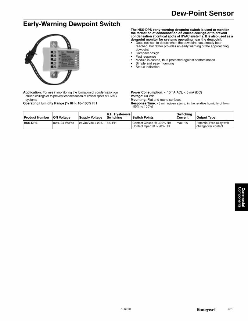
Dew-Point Sensor
70-6910 451
Com
mercial
Com
ponents
Early-Warning Dewpoint SwitchThe HSS-DPS early-warning dewpoint switch is used to monitor the formation of condensation on chilled ceilings or to prevent condensation at critical spots of HVAC systems. It is also used as a dewpoint monitor for systems operating near the dewpoint.• Does not wait to detect when the dewpoint has already been
reached, but rather provides an early warning of the approaching dewpoint
• Compact design• Fast response• Module is coated, thus protected against contamination• Simple and easy mounting• Status indication
Application: For use in monitoring the formation of condensation on chilled ceilings or to prevent condensation at critical spots of HVAC systems
Operating Humidity Range (% RH): 10~100% RH
Power Consumption: < 10mA(AC); < 3 mA (DC)Voltage: 60 VdcMounting: Flat and round surfacesResponse Time: ~3 min (given a jump in the relative humidity of from
55% to 100%)
Product Number ON Voltage Supply VoltageR.H. Hysteresis Switching Switch Points
Switching Current Output Type
HSS-DPS max. 24 Vac/dc 24Vac/Vdc ± 20% 5% RH Contact Closed @ <90% RHContact Open @ > 90% RH
max. 1A Potential-Free relay with changeover contact

Humidity Sensors
452 customer.honeywell.com 70-6910
H7012 Humidity and Temperature Room SensorsWall-mounted, capacitance type relative humidity room sensor.• Capacitance type sensing element • Wide sensing range • Temperature indication sensor, H7012B only
Application: HumidityDimensions, Approximate: 5 1/8 in. high x 3 3/16 in. wide x 1 11/32 in.
deep (130 mm high x 81 mm wide x 34 mm deep) Operating Humidity Range (% RH): 30 to 70% RH
H7015B Humidity TransducersThe H7015B Combined Humidity/Temperature Duct Sensor combines a capacitance-type relative humidity sensor with a PT1000 or BALCO 500 temperature sensor in one housing. These sensors can be used for discharge, outside or return air control or as a high-limit sensor in applications such as steam humidification.• Wide sensing range • Capacitance type sensing element for relative humidity • PT1000 or BALCO 500 temperature sensing element
Dimensions in inches (millimeters)Application: Humidity SensorOperating Temperature Range: -22 F to 158 F (-30 C to 70 C) Operating Humidity Range (% RH): 10 to 90% RH, non-condensing
Product Number Mounting Sensor Type Description Comments
H7012A1009 Wall mount — Humidity Sensor Capacitance type humidity sensor
H7012B1007 Wall mount PT1000 Humidity and Temperature Sensor Capacitance type humidity sensor
H7012B1015 Wall mount Balco 500 Humidity and Temperature Sensor Capacitance type humidity sensor
M4586A
3-1/8 (80)
1/2(12)
12-3/4 (323)2-3/16 (55)
4-3/4(120)
1/4 (7) DIA. CABLE ENTRY
DISTANCE VARIABLE BY CLAMP
CLAMP
GASKET
9/16 (14)
Product Number Mounting Description Comments
H7015B1004 Duct mount Humidity and Temperature Duct Mounted Sensors With PT1000 Temperature Sensor
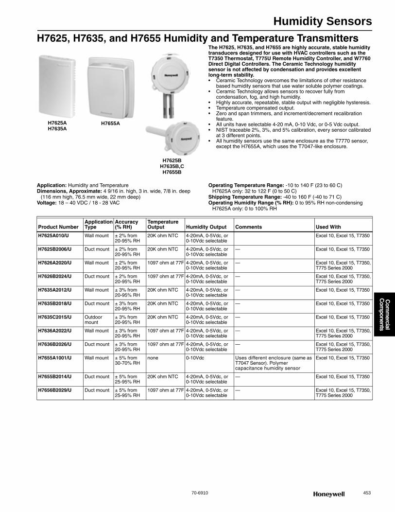
Humidity Sensors
70-6910 453
Com
mercial
Com
ponents
H7625, H7635, and H7655 Humidity and Temperature TransmittersThe H7625, H7635, and H7655 are highly accurate, stable humidity transducers designed for use with HVAC controllers such as the T7350 Thermostat, T775U Remote Humidity Controller, and W7760 Direct Digital Controllers. The Ceramic Technology humidity sensor is not affected by condensation and provides excellent long-term stability.• Ceramic Technology overcomes the limitations of other resistance
based humidity sensors that use water soluble polymer coatings. • Ceramic Technology allows sensors to recover fully from
condensation, fog, and high humidity. • Highly accurate, repeatable, stable output with negligible hysteresis. • Temperature compensated output. • Zero and span trimmers, and increment/decrement recalibration
feature. • All units have selectable 4-20 mA, 0-10 Vdc, or 0-5 Vdc output. • NIST traceable 2%, 3%, and 5% calibration, every sensor calibrated
at 3 different points. • All humidity sensors use the same enclosure as the T7770 sensor,
except the H7655A, which uses the T7047-like enclosure.
Application: Humidity and TemperatureDimensions, Approximate: 4 9/16 in. high, 3 in. wide, 7/8 in. deep
(116 mm high, 76.5 mm wide, 22 mm deep) Voltage: 18 – 40 VDC / 18 - 28 VAC
Operating Temperature Range: -10 to 140 F (23 to 60 C)H7625A only: 32 to 122 F (0 to 50 C)
Shipping Temperature Range: -40 to 160 F (-40 to 71 C) Operating Humidity Range (% RH): 0 to 95% RH non-condensing
H7625A only: 0 to 100% RH
H7625AH7635A
H7655A
H7625BH7635B,CH7655B
Product NumberApplication Type
Accuracy (% RH)
Temperature Output Humidity Output Comments Used With
H7625A010/U Wall mount ± 2% from 20-95% RH
20K ohm NTC 4-20mA, 0-5Vdc, or 0-10Vdc selectable
Excel 10, Excel 15, T7350
H7625B2006/U Duct mount ± 2% from 20-95% RH
20K ohm NTC 4-20mA, 0-5Vdc, or 0-10Vdc selectable
— Excel 10, Excel 15, T7350
H7626A2020/U Wall mount ± 2% from 20-95% RH
1097 ohm at 77F 4-20mA, 0-5Vdc, or 0-10Vdc selectable
— Excel 10, Excel 15, T7350, T775 Series 2000
H7626B2024/U Duct mount ± 2% from 20-95% RH
1097 ohm at 77F 4-20mA, 0-5Vdc, or 0-10Vdc selectable
— Excel 10, Excel 15, T7350, T775 Series 2000
H7635A2012/U Wall mount ± 3% from 20-95% RH
20K ohm NTC 4-20mA, 0-5Vdc, or 0-10Vdc selectable
— Excel 10, Excel 15, T7350
H7635B2018/U Duct mount ± 3% from 20-95% RH
20K ohm NTC 4-20mA, 0-5Vdc, or 0-10Vdc selectable
— Excel 10, Excel 15, T7350
H7635C2015/U Outdoor mount
± 3% from 20-95% RH
20K ohm NTC 4-20mA, 0-5Vdc, or 0-10Vdc selectable
— Excel 10, Excel 15, T7350
H7636A2022/U Wall mount ± 3% from 20-95% RH
1097 ohm at 77F 4-20mA, 0-5Vdc, or 0-10Vdc selectable
— Excel 10, Excel 15, T7350, T775 Series 2000
H7636B2026/U Duct mount ± 3% from 20-95% RH
1097 ohm at 77F 4-20mA, 0-5Vdc, or 0-10Vdc selectable
— Excel 10, Excel 15, T7350, T775 Series 2000
H7655A1001/U Wall mount ± 5% from 30-70% RH
none 0-10Vdc Uses different enclosure (same as T7047 Sensor). Polymer capacitance humidity sensor
Excel 10, Excel 15, T7350
H7655B2014/U Duct mount ± 5% from 25-95% RH
20K ohm NTC 4-20mA, 0-5Vdc, or 0-10Vdc selectable
— Excel 10, Excel 15, T7350
H7656B2029/U Duct mount ± 5% from 25-95% RH
1097 ohm at 77F 4-20mA, 0-5Vdc, or 0-10Vdc selectable
— Excel 10, Excel 15, T7350, T775 Series 2000
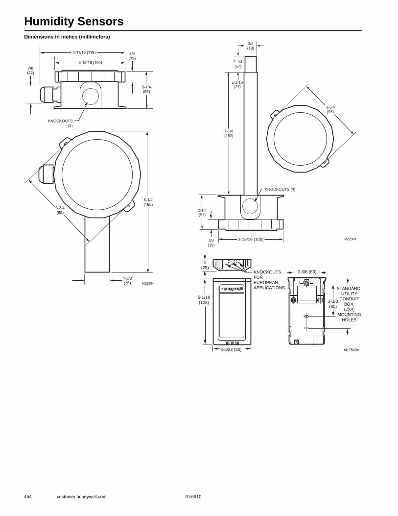
Humidity Sensors
454 customer.honeywell.com 70-6910
Dimensions in inches (millimeters)
3-3/4(95)
M22584
6-1/2(165)
3-15/16 (100)
2-1/4(57)
3/4(19)
4-11/16 (119)
KNOCKOUTS(3)
7/8(22)
1-3/8(36)
3-15/16 (100)
2-1/4(57)
3/4(19)
7-1/8(182)
2-1/4(57)
1-1/16(27)
KNOCKOUTS (4)
3-3/4(95)
M22583
3/4(19)
M17540A
STANDARD
UTILITY
CONDUIT
BOX
(2X4)
MOUNTING
HOLES
KNOCKOUTS
FOR
EUROPEAN
APPLICATIONS
3-5/32 (80)
2-3/8 (60)
1
(25)
5-1/16
(128) 2-3/8
(60)
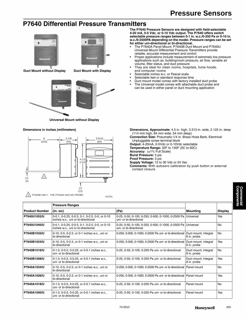
Pressure Sensors
70-6910 455
Com
mercial
Com
ponents
P7640 Differential Pressure TransmittersThe P7640 Pressure Sensors are designed with field-selectable 4-20 mA, 0-5 Vdc, or 0-10 Vdc output. The P7640 offers switch selectable pressure ranges between 0-1 in. w.c./0-250 Pa or 0-10 in. w.c./0-2500PA depending on the model. Pressure ranges can be set for either uni-directional or bi-directional.• The P7640A Panel Mount, P7640B Duct Mount and P7640U
Universal Mount Differential Pressure Transmitters provide reliable, accurate measurement and control
• Proper applications include measurement of extremely low pressure applications such as: building/room pressure, air flow, variable air volume, filter status, and duct pressure
• They are ideal for clean rooms, hospitals, fume hoods, and computer rooms
• Selectable inches w.c. or Pascal scale • Selectable fast or standard response time • Duct mount model comes with factory installed duct probe • The Universal model comes with attachable duct probe and
can be used in either panel or duct mounting application
Dimensions in inches (millimeters) Dimensions, Approximate: 4.5 in. high, 3.313 in. wide, 2.125 in. deep(114 mm high, 84 mm wide, 54 mm deep)
Connection Size: Pneumatic:1/4 in. Brass Hose Barb, Electrical: Unpluggable screw terminal block
Output: 4-20mA, 0-5Vdc or 0-10Vdc selectableTemperature Range: 32F to 140F (0C to 60C) Accuracy: (±1% Full Scale) Burst Pressure: 5 psiProof Pressure: 3 psiSupply Voltage: 12 to 30 Vdc or 24 VacComments: With autozero calibration by push button or external
contact closure
Duct Mount without Display Duct Mount with Display
Universal Mount without Display
M22581
4-1/2(114)
1/4 (6)
2-1/8(54)
P7640B ONLY. THE P7640A HAS NO PROBE.1
1
8(203)
3-5/16(84)
1/2(13)
Product Number
Pressure Ranges
Mounting Display(in. wc) (Pa)
P7640U1052/U 0-0.1, 0-0.25, 0-0.5, 0-1, 0-2.5, 0-5, or 0-10 inches w.c., uni or bi-directional
0-25, 0-50, 0-100, 0-250, 0-500, 0-1000, 0-2500 Pa uni- or bi-directional
Universal Yes
P7640U1040/U 0-0.1, 0-0.25, 0-0.5, 0-1, 0-2.5, 0-5, or 0-10 inches w.c., uni or bi-directional
0-25, 0-50, 0-100, 0-250, 0-500, 0-1000, 0-2500 Pa uni- or bi-directional
Universal No
P7640B1032/U 0-10, 0-5, 0-2.5, or 0-1 inches w.c., uni or bi-directional
0-250, 0-500, 0-1000, 0-2500 Pa uni- or bi-directional Duct mount, integral 8 in. probe
No
P7640B1024/U 0-10, 0-5, 0-2.5, or 0-1 inches w.c., uni or bi-directional
0-250, 0-500, 0-1000, 0-2500 Pa uni- or bi-directional Duct mount, integral 8 in. probe
Yes
P7640B1016/U 0-1.0, 0-0.5, 0-0.25, or 0-0.1 inches w.c., uni- or bi-directional
0-25, 0-50, 0-100, 0-250 Pa uni- or bi-directional Duct mount, integral 8 in. probe
No
P7640B1008/U 0-1.0, 0-0.5, 0-0.25, or 0-0.1 inches w.c., uni- or bi-directional
0-25, 0-50, 0-100, 0-250 Pa uni- or bi-directional Duct mount, integral 8 in. probe
Yes
P7640A1034/U 0-10, 0-5, 0-2.5, or 0-1 inches w.c., uni or bi-directional
0-250, 0-500, 0-1000, 0-2500 Pa uni- or bi-directional Panel mount No
P7640A1026/U 0-10, 0-5, 0-2.5, or 0-1 inches w.c., uni or bi-directional
0-250, 0-500, 0-1000, 0-2500 Pa uni- or bi-directional Panel mount Yes
P7640A1018/U 0-1.0, 0-0.5, 0-0.25, or 0-0.1 inches w.c., uni- or bi-directional
0-25, 0-50, 0-100, 0-250 Pa uni- or bi-directional Panel mount No
P7640A1000/U 0-1.0, 0-0.5, 0-0.25, or 0-0.1 inches w.c., uni- or bi-directional
0-25, 0-50, 0-100, 0-250 Pa uni- or bi-directional Panel mount Yes
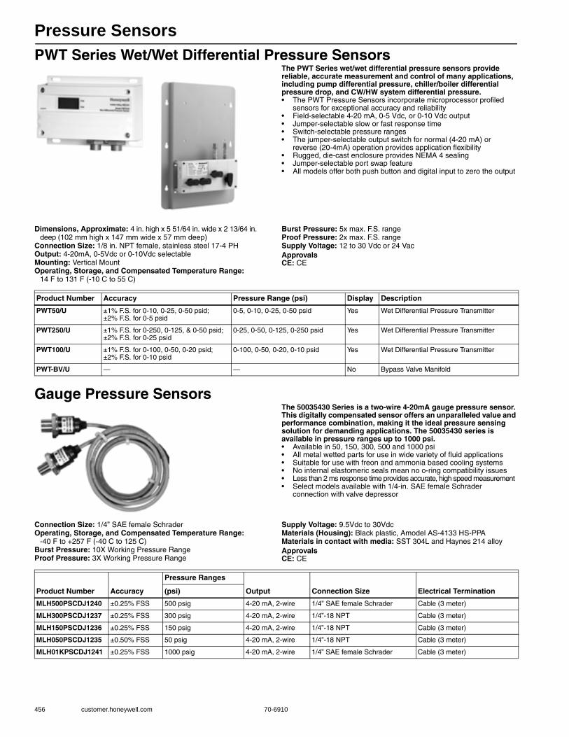
Pressure Sensors
456 customer.honeywell.com 70-6910
PWT Series Wet/Wet Differential Pressure SensorsThe PWT Series wet/wet differential pressure sensors provide reliable, accurate measurement and control of many applications, including pump differential pressure, chiller/boiler differential pressure drop, and CW/HW system differential pressure.• The PWT Pressure Sensors incorporate microprocessor profiled
sensors for exceptional accuracy and reliability• Field-selectable 4-20 mA, 0-5 Vdc, or 0-10 Vdc output • Jumper-selectable slow or fast response time • Switch-selectable pressure ranges • The jumper-selectable output switch for normal (4-20 mA) or
reverse (20-4mA) operation provides application flexibility • Rugged, die-cast enclosure provides NEMA 4 sealing • Jumper-selectable port swap feature • All models offer both push button and digital input to zero the output
Dimensions, Approximate: 4 in. high x 5 51/64 in. wide x 2 13/64 in. deep (102 mm high x 147 mm wide x 57 mm deep)
Connection Size: 1/8 in. NPT female, stainless steel 17-4 PHOutput: 4-20mA, 0-5Vdc or 0-10Vdc selectableMounting: Vertical MountOperating, Storage, and Compensated Temperature Range:
14 F to 131 F (-10 C to 55 C)
Burst Pressure: 5x max. F.S. rangeProof Pressure: 2x max. F.S. rangeSupply Voltage: 12 to 30 Vdc or 24 VacApprovalsCE: CE
Gauge Pressure SensorsThe 50035430 Series is a two-wire 4-20mA gauge pressure sensor. This digitally compensated sensor offers an unparalleled value and performance combination, making it the ideal pressure sensing solution for demanding applications. The 50035430 series is available in pressure ranges up to 1000 psi.• Available in 50, 150, 300, 500 and 1000 psi• All metal wetted parts for use in wide variety of fluid applications• Suitable for use with freon and ammonia based cooling systems• No internal elastomeric seals mean no o-ring compatibility issues• Less than 2 ms response time provides accurate, high speed measurement• Select models available with 1/4-in. SAE female Schrader
connection with valve depressor
Connection Size: 1/4” SAE female SchraderOperating, Storage, and Compensated Temperature Range:
-40 F to +257 F (-40 C to 125 C) Burst Pressure: 10X Working Pressure RangeProof Pressure: 3X Working Pressure Range
Supply Voltage: 9.5Vdc to 30VdcMaterials (Housing): Black plastic, Amodel AS-4133 HS-PPAMaterials in contact with media: SST 304L and Haynes 214 alloyApprovalsCE: CE
Product Number Accuracy Pressure Range (psi) Display Description
PWT50/U ±1% F.S. for 0-10, 0-25, 0-50 psid; ±2% F.S. for 0-5 psid
0-5, 0-10, 0-25, 0-50 psid Yes Wet Differential Pressure Transmitter
PWT250/U ±1% F.S. for 0-250, 0-125, & 0-50 psid; ±2% F.S. for 0-25 psid
0-25, 0-50, 0-125, 0-250 psid Yes Wet Differential Pressure Transmitter
PWT100/U ±1% F.S. for 0-100, 0-50, 0-20 psid; ±2% F.S. for 0-10 psid
0-100, 0-50, 0-20, 0-10 psid Yes Wet Differential Pressure Transmitter
PWT-BV/U — — No Bypass Valve Manifold
Product Number Accuracy
Pressure Ranges
Output Connection Size Electrical Termination(psi)
MLH500PSCDJ1240 ±0.25% FSS 500 psig 4-20 mA, 2-wire 1/4” SAE female Schrader Cable (3 meter)
MLH300PSCDJ1237 ±0.25% FSS 300 psig 4-20 mA, 2-wire 1/4”-18 NPT Cable (3 meter)
MLH150PSCDJ1236 ±0.25% FSS 150 psig 4-20 mA, 2-wire 1/4”-18 NPT Cable (3 meter)
MLH050PSCDJ1235 ±0.50% FSS 50 psig 4-20 mA, 2-wire 1/4”-18 NPT Cable (3 meter)
MLH01KPSCDJ1241 ±0.25% FSS 1000 psig 4-20 mA, 2-wire 1/4” SAE female Schrader Cable (3 meter)
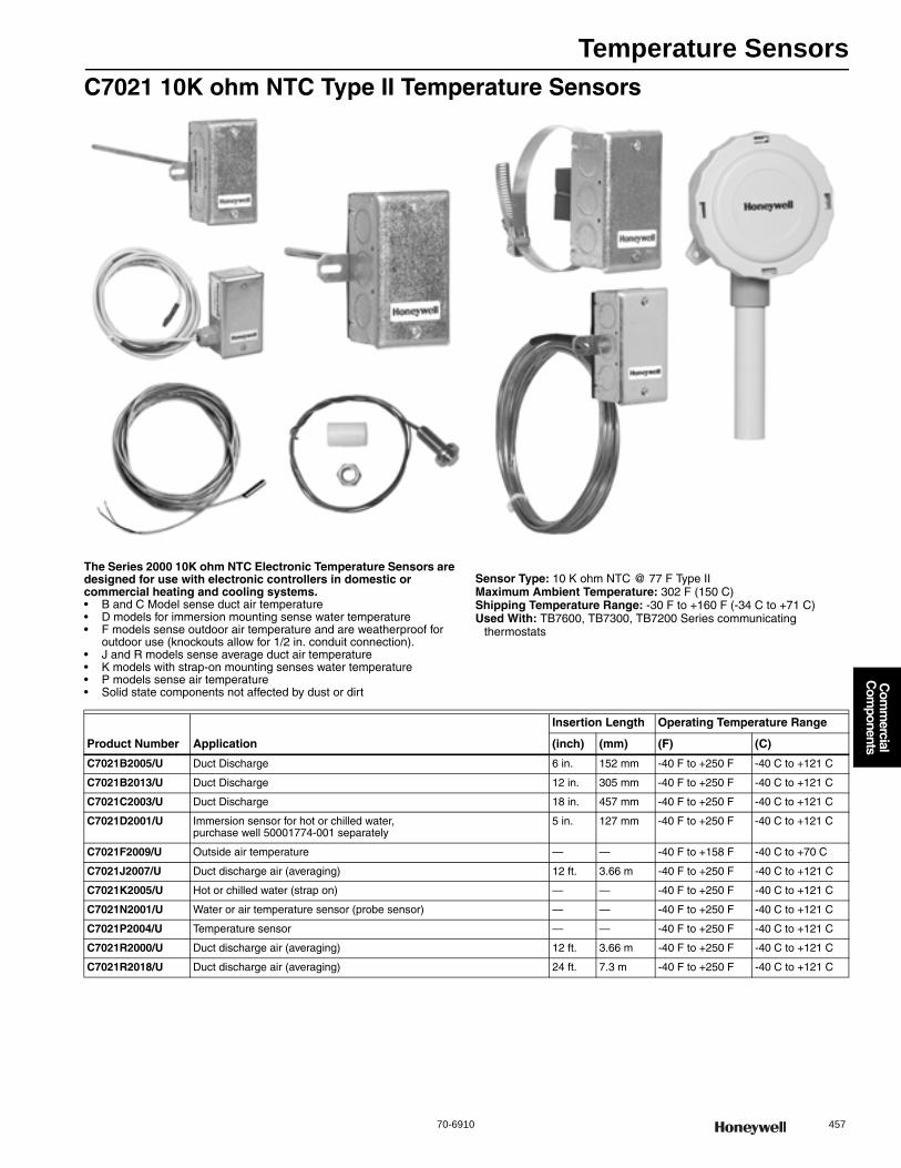
Temperature Sensors
70-6910 457
Com
mercial
Com
ponents
C7021 10K ohm NTC Type II Temperature Sensors
The Series 2000 10K ohm NTC Electronic Temperature Sensors are designed for use with electronic controllers in domestic or commercial heating and cooling systems.• B and C Model sense duct air temperature • D models for immersion mounting sense water temperature • F models sense outdoor air temperature and are weatherproof for
outdoor use (knockouts allow for 1/2 in. conduit connection). • J and R models sense average duct air temperature • K models with strap-on mounting senses water temperature • P models sense air temperature • Solid state components not affected by dust or dirt
Sensor Type: 10 K ohm NTC @ 77 F Type IIMaximum Ambient Temperature: 302 F (150 C) Shipping Temperature Range: -30 F to +160 F (-34 C to +71 C) Used With: TB7600, TB7300, TB7200 Series communicating
thermostats
Product Number Application
Insertion Length Operating Temperature Range
(inch) (mm) (F) (C)
C7021B2005/U Duct Discharge 6 in. 152 mm -40 F to +250 F -40 C to +121 C
C7021B2013/U Duct Discharge 12 in. 305 mm -40 F to +250 F -40 C to +121 C
C7021C2003/U Duct Discharge 18 in. 457 mm -40 F to +250 F -40 C to +121 C
C7021D2001/U Immersion sensor for hot or chilled water, purchase well 50001774-001 separately
5 in. 127 mm -40 F to +250 F -40 C to +121 C
C7021F2009/U Outside air temperature — — -40 F to +158 F -40 C to +70 C
C7021J2007/U Duct discharge air (averaging) 12 ft. 3.66 m -40 F to +250 F -40 C to +121 C
C7021K2005/U Hot or chilled water (strap on) — — -40 F to +250 F -40 C to +121 C
C7021N2001/U Water or air temperature sensor (probe sensor) — — -40 F to +250 F -40 C to +121 C
C7021P2004/U Temperature sensor — — -40 F to +250 F -40 C to +121 C
C7021R2000/U Duct discharge air (averaging) 12 ft. 3.66 m -40 F to +250 F -40 C to +121 C
C7021R2018/U Duct discharge air (averaging) 24 ft. 7.3 m -40 F to +250 F -40 C to +121 C

Temperature Sensors
458 customer.honeywell.com 70-6910
Diagrams for C7031, C7032, C7041 and T775 Series 2000 SensorC7021B/C, C7023B/C, C7041B/C Dimensions
C7021D, C7023D, C7031D, C7041D Dimensions in inches (millimeters)
C7021R, C7023R, C7041R Dimensions
2-5/16(59)
15/16(23)
1-11/16(43)
4-3/16(107)
3/4(19)
4(70)
1-11/16(43)
C7031B: 5-11/16 (145)C7021B, C7023B,C7041B: 11-5/8 (295)C7021C, C7023C,C7041C: 17-5/8 (448)
M22131A
1-13/16(46)
7/16 (12)
1/8 NPSM (3)
3-7/8 (99)
2-5/16(59)
1-11/16(43)
4-3/16(107)
1/4(6)
4(70)
1-11/16(43)
6-11/16 (170)
M22596
5 (127)
1/2 NPSM (13)
2-5/16(59)
15/16(23)
1-11/16(43)
4-3/16(107)
3/4(19)
4(70)
1-11/16(43)
M22818
1-13/16(46)
7/16 (12)
1/8 NPSM (3)
3-7/8 (99)
DEPENDING ON THE MODEL, THE ELEMENT LENGTH IS EITHER 12 FT (366 CM) OR 24 FT (732 CM).
1
1

Temperature Sensors
70-6910 459
Com
mercial
Com
ponents
C7021F, C7023F, C7031G, C7041F, C7021F, C7023F, C7031G, C7041F, T775-SENS-OAT Dimensions
C7021J, C7023J, C7031J, C7041J Dimensions
C7021P, C7023P, C7041P Dimensions
Dimensions in inches (millimeters)
C7021K, C7023K, C7021K, C7023KC7041K, T775-SENS-STRAP Dimensions
2-1/4 (57)
3/4(19)
1 (25)
5(127)
7/8(22)
8-5/16(211)
M22132
3-5/8 (91)
2-5/16(59)
1(25)
1-11/16(43)
4-3/16(107)
4 THERMISTORS PLACED ON A 12 FOOT (3.7M) WIRE.
4(70)
1-11/16(43)
M22133
1 (26)
11/16(18)
5/8 (16)
M22821
5/16(8)
SPACER SENSOR
1 (26)
7/8 (22)
3/16 (4)
3/8 IN.-16 THREAD
2 3/32 (53)
4 3/16 (106)
1 5/32
(29)
2 19/64
(58)
1/8 INCH NPSM
STRAIGHT
THREADS
SINGLE GANG
RACO COVER
FOAM PAD
5 75 ± 0 25
(146)
[8] 1/2 INCH
CONDUIT
KNOCKOUTS 1 59/64
(49)
M27006
[2] 1/64 (5) X 5/8 (16)
MOUNTING HOLES 3 57/64
(99)
2 5/16(59)
4 3/16(107)
4(70)
1 11/16(43)
7 1/8 (182)
9/16 (14)1 1/2(38)
1 1/2(38)
2 5/16(59)
M22134
1 1/4(32)
5 (127)
MAXIMUM PIPE DIAMETER SHOWN.
MINIMUM PIPE DIAMETER: 1-5/8 (41)
1
1
4 3/16 (107)
COPPER PLATE
FOAM PAD

Temperature Sensors
460 customer.honeywell.com 70-6910
C7023 10K ohm NTC Type III Temperature Sensors
The Series C7023 2000 10 K ohm Type III Electronic Temperature Sensors are designed for use with electronic controllers in domestic or commercial heating and cooling systems.• B and C Model sense duct air temperature • D models for immersion mounting sense water temperature • F models sense outdoor air temperature and are weatherproof for
outdoor use (knockouts allow for 1/2 in. conduit connection). • J and R models sense average duct air temperature • K models with strap-on mounting senses water temperature • P models sense air temperature • Solid state components not affected by dust or dirt
Sensor Type: 10 K ohm NTC @ 77 F Type IIIMaximum Ambient Temperature: 302 F (150 C) Shipping Temperature Range: -30 F to +160 F (-34 C to +71 C) Used With: WEBs-AX I/O Modules
Product Number Application
Insertion Length Operating Temperature Range
(inch) (mm) (F) (C)
C7023B2005/U Duct 6 in. 152 mm -40 F to +250 F -40 C to +121 C
C7023B2013/U Duct 12 in. 305 mm -40 F to +250 F -40 C to +121 C
C7023C2003/U Duct 18 in. 457 mm -40 F to +250 F -40 C to +121 C
C7023D2001/U Immersion sensor for hot or chilled water, purchase well 50001774-001 separately
5 in. 127 mm -40 F to +250 F -40 C to +121 C
C7023F2009/U Outside air temperature — — -40 F to +158 F -40 C to +70 C
C7023J2007/U Duct (averaging) 12 ft. 3.66 m -40 F to +250 F -40 C to +121 C
C7023K2005/U Hot or chilled water (strap on) — — -40 F to +250 F -40 C to +121 C
C7023N2001/U Water or air temperature sensor (probe sensor) — — -40 F to +250 F -40 C to +121 C
C7023P2004/U Temperature sensor — — -40 F to +250 F -40 C to +121 C
C7023R2000/U Duct (averaging) 12 ft. 3.66 m -40 F to +250 F -40 C to +121 C
C7023R2018/U Duct (averaging) 24 ft. 7.3 m -40 F to +250 F -40 C to +121 C
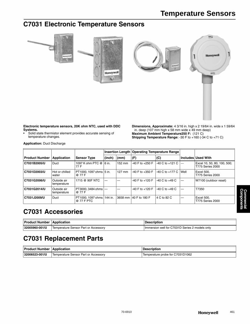
Temperature Sensors
70-6910 461
Com
mercial
Com
ponents
C7031 Electronic Temperature Sensors
Electronic temperature sensors, 20K ohm NTC, used with DDC Systems.• Solid state thermistor element provides accurate sensing of
temperature changes.
Application: Duct Discharge
Dimensions, Approximate: 4 3/16 in. high x 2 19/64 in. wide x 1 59/64 in. deep (107 mm high x 58 mm wide x 49 mm deep)
Maximum Ambient Temperature250 F: (121 C) Shipping Temperature Range: -30 F to +160 (-34 C to +71 C)
C7031 Accessories
C7031 Replacement Parts
Product Number Application Sensor Type
Insertion Length Operating Temperature Range
Includes Used With(inch) (mm) (F) (C)
C7031B2005/U Duct 1097 K ohm PTC @ 77 F
6 in. 152 mm -40 F to +250 F -40 C to +121 C — Excel 10, 50, 80, 100, 500; T775 Series 2000
C7031D2003/U Hot or chilled water
PT1000, 1097 ohms @ 77 F
5 in. 127 mm -40 F to +350 F -40 C to +177 C Well Excel 500, T775 Series 2000
C7031G2006/U Outside air temperature
1715 @ 90F NTC — — -40 F to +120 F -40 C to +49 C — W7100 (outdoor reset)
C7031G2014/U Outside air temperature
PT3000, 3484 ohms @ 77 F
— — -40 F to +120 F -40 C to +49 C — T7350
C7031J2009/U Duct PT1000, 1097 ohms @ 77 F PTC
144 in. 3658 mm 40 F to 180 F 4 C to 82 C — Excel 500, T775 Series 2000
Product Number Application Description
32005960-001/U Temperature Sensor Part or Accessory Immersion well for C7031D Series 2 models only
Product Number Application Description
32006523-001/U Temperature Sensor Part or Accessory Temperature probe for C7031D1062

Temperature Sensors
462 customer.honeywell.com 70-6910
C7041 20K ohm NTC Temperature Sensors
The C7041 Electronic Temperature Sensors are 20K ohm NTC sensors designed to be used with electronic controllers in domestic or commercial heating and cooling systems.• The C7041 series of electronic temperature sensors are designed
for use with the Excel 10, Excel 15, or any controller requiring a 20K ohm NTC non-linearized sensor input.
• Various models are available for sensing duct air temperature, averaging air temperature, water temperature, outdoor air temperature, or water pipe temperature.
• All devices consist of a temperature sensitive element and leadwires enclosed for protection from physical damage.
• Sensor element enclosures are made of various lengths and configurations for the specific applications.
• All devices have a wiring box housing to enclose the field wiring connections. C7041F outdoor sensor design, made of aluminum and stainless steel, is waterproof, and includes a sunshield.
Sensor Type: 20 K ohm NTC @ 77 FMaximum Ambient Temperature: 302 F (150 C) Operating Temperature Range: -40 F to +250 F (-40 C to +121 C) Shipping Temperature Range: -30 F to +160 F (-34 C to +71 C) Used With: Excel 10, 50, 80, 100, 500
Accessories:50001774-001-5 inch Stainless Steel Immersion Well for Use with
C7041D200150001775-001-Immersion well adaptor, to adapt new C7041D2001 to fit
into old brass 32005960-001 well used with old C7031D1062 and C7041D1003
Product Number Application
Insertion Length Operating Temperature Range
(inch) (mm) (F) (C)
C7041B2005/U Duct 6 in. 152 mm -40 F to +250 F -40 C to +121 C
C7041B2013/U Duct 12 in. 305 mm -40 F to +250 F -40 C to +121 C
C7041C2003/U Duct 18 in. 457 mm -40 F to +250 F -40 C to +121 C
C7041D2001/U Immersion sensor for hot or chilled water, purchase well 50001774-001 separately
5 in. 127 mm -40 F to +250 F -40 C to +121 C
C7041F2006/U Outside air temperature — — -40 F to +158 F -40 C to +70 C
C7041J2007/U Duct (averaging) 12 ft. 3.66 m -40 F to +250 F -40 C to +121 C
C7041K2005/U Hot or chilled water (strap on) — — -40 F to +250 F -40 C to +121 C
C7041N2020/U Water or air temperature sensor (probe sensor) — — -40 F to +250 F -40 C to +121 C
C7041P2004/U Temperature sensor — — -40 F to +250 F -40 C to +121 C
C7041R2000/U Duct (averaging) 12 ft. 3.66 m -40 F to +250 F -40 C to +121 C
C7041R2018/U Duct (averaging) 24 ft. 7.3 m -40 F to +250 F -40 C to +121 C
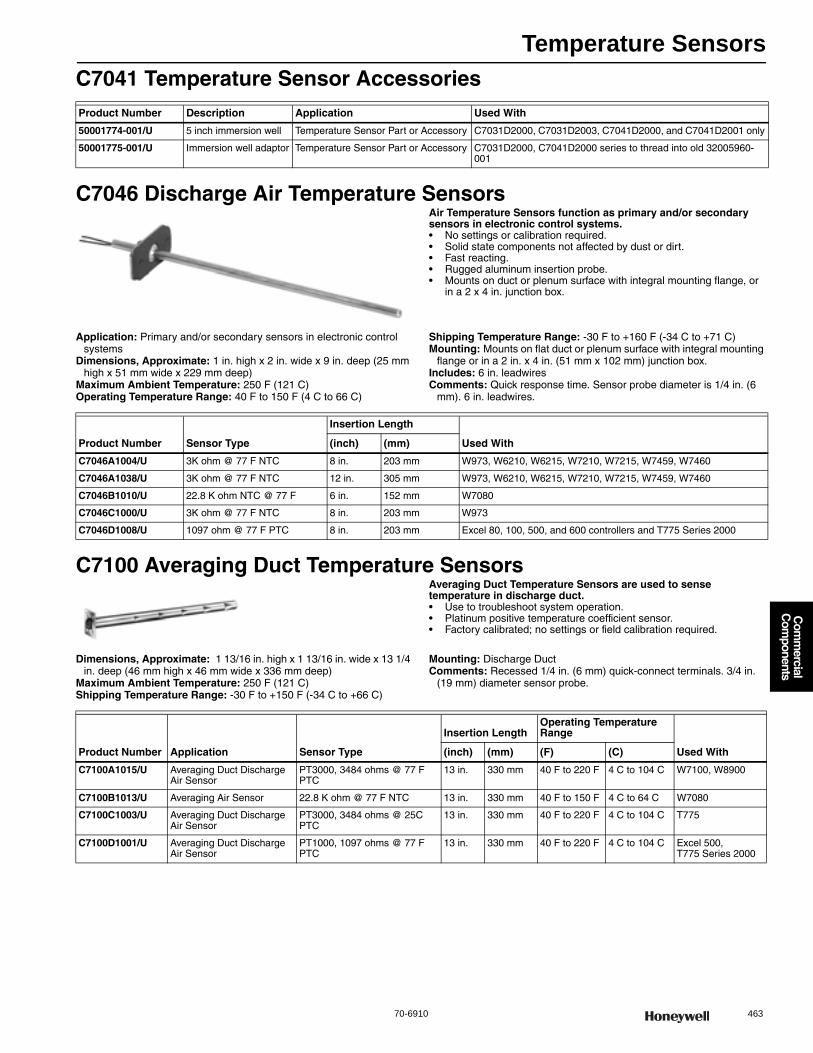
Temperature Sensors
70-6910 463
Com
mercial
Com
ponents
C7041 Temperature Sensor Accessories
C7046 Discharge Air Temperature SensorsAir Temperature Sensors function as primary and/or secondary sensors in electronic control systems.• No settings or calibration required. • Solid state components not affected by dust or dirt. • Fast reacting. • Rugged aluminum insertion probe. • Mounts on duct or plenum surface with integral mounting flange, or
in a 2 x 4 in. junction box.
Application: Primary and/or secondary sensors in electronic control systems
Dimensions, Approximate: 1 in. high x 2 in. wide x 9 in. deep (25 mm high x 51 mm wide x 229 mm deep)
Maximum Ambient Temperature: 250 F (121 C) Operating Temperature Range: 40 F to 150 F (4 C to 66 C)
Shipping Temperature Range: -30 F to +160 F (-34 C to +71 C) Mounting: Mounts on flat duct or plenum surface with integral mounting
flange or in a 2 in. x 4 in. (51 mm x 102 mm) junction box.Includes: 6 in. leadwiresComments: Quick response time. Sensor probe diameter is 1/4 in. (6
mm). 6 in. leadwires.
C7100 Averaging Duct Temperature SensorsAveraging Duct Temperature Sensors are used to sense temperature in discharge duct.• Use to troubleshoot system operation. • Platinum positive temperature coefficient sensor. • Factory calibrated; no settings or field calibration required.
Dimensions, Approximate: 1 13/16 in. high x 1 13/16 in. wide x 13 1/4 in. deep (46 mm high x 46 mm wide x 336 mm deep)
Maximum Ambient Temperature: 250 F (121 C) Shipping Temperature Range: -30 F to +150 F (-34 C to +66 C)
Mounting: Discharge Duct Comments: Recessed 1/4 in. (6 mm) quick-connect terminals. 3/4 in.
(19 mm) diameter sensor probe.
Product Number Description Application Used With
50001774-001/U 5 inch immersion well Temperature Sensor Part or Accessory C7031D2000, C7031D2003, C7041D2000, and C7041D2001 only
50001775-001/U Immersion well adaptor Temperature Sensor Part or Accessory C7031D2000, C7041D2000 series to thread into old 32005960-001
Product Number Sensor Type
Insertion Length
Used With(inch) (mm)
C7046A1004/U 3K ohm @ 77 F NTC 8 in. 203 mm W973, W6210, W6215, W7210, W7215, W7459, W7460
C7046A1038/U 3K ohm @ 77 F NTC 12 in. 305 mm W973, W6210, W6215, W7210, W7215, W7459, W7460
C7046B1010/U 22.8 K ohm NTC @ 77 F 6 in. 152 mm W7080
C7046C1000/U 3K ohm @ 77 F NTC 8 in. 203 mm W973
C7046D1008/U 1097 ohm @ 77 F PTC 8 in. 203 mm Excel 80, 100, 500, and 600 controllers and T775 Series 2000
Product Number Application Sensor Type
Insertion LengthOperating Temperature Range
Used With(inch) (mm) (F) (C)
C7100A1015/U Averaging Duct Discharge Air Sensor
PT3000, 3484 ohms @ 77 F PTC
13 in. 330 mm 40 F to 220 F 4 C to 104 C W7100, W8900
C7100B1013/U Averaging Air Sensor 22.8 K ohm @ 77 F NTC 13 in. 330 mm 40 F to 150 F 4 C to 64 C W7080
C7100C1003/U Averaging Duct Discharge Air Sensor
PT3000, 3484 ohms @ 25C PTC
13 in. 330 mm 40 F to 220 F 4 C to 104 C T775
C7100D1001/U Averaging Duct Discharge Air Sensor
PT1000, 1097 ohms @ 77 F PTC
13 in. 330 mm 40 F to 220 F 4 C to 104 C Excel 500, T775 Series 2000
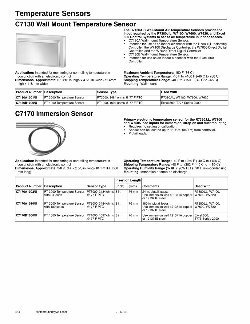
Temperature Sensors
464 customer.honeywell.com 70-6910
C7130 Wall Mount Temperature SensorThe C7130A,B Wall-Mount Air Temperature Sensors provide the input required by the R7380J,L, W7100, W7600, W7620, and Excel 500 Control Systems to sense air temperature in indoor spaces.• C7130A Wall-mount Temperature Sensor: • Intended for use as an indoor air sensor with the R7380J,L Indicating
Controller, the W7100 Discharge Controller, the W7600 Direct Digital Controller, and the W7620 Direct Digital Controller.
• C7130B Wall-mount Temperature Sensor: • Intended for use as an indoor air sensor with the Excel 500
Controller.
Application: Intended for monitoring or controlling temperature in conjunction with an electronic control
Dimensions, Approximate: 2 13/16 in. high x 4 5/8 in. wide (71.4mm high x 118 mm wide)
Maximum Ambient Temperature: 150 F (66 C) Operating Temperature Range: -40 F to +100 F (-40 C to +38 C) Shipping Temperature Range: -40 F to +150 F (-40 C to +65 C) Mounting: Wall mount
C7170 Immersion SensorPrimary electronic temperature sensor for the R7380J,L, W7100 and W7505 load inputs for immersion, strap-on and duct mounting.• Requires no setting or calibration. • Sensor can be located up to 1195 ft. (340 m) from controller. • Pigtail leads.
Application: Intended for monitoring or controlling temperature in conjunction with an electronic control
Dimensions, Approximate: 3/8 in. dia. x 2 5/8 in. long (10 mm dia. x 66 mm long)
Operating Temperature Range: -40 F to +250 F (-40 C to +125 C) Shipping Temperature Range: -40 F to +302 F (-40 C to +150 C) Operating Humidity Range (% RH): 90% RH at 90 F, non-condensingMounting: Immersion or strap-on discharge
Product Number Description Sensor Type Used With
C7130A1001/U PT 3000 Temperature Sensor PT3000, 3484 ohms @ 77 F PTC R7380J,L, W7100, W7600, W7620
C7130B1009/U PT 1000 Temperature Sensor PT1000, 1097 ohms @ 77 F PTC Excel 500, T775 Series 2000
Product Number Description Sensor Type
Insertion Length
Comments Used With(inch) (mm)
C7170A1002/U PT 3000 Temperature Sensor with 24 leads
PT3000, 3484 ohms @ 77 F PTC
3 in. 76 mm 24 in. pigtail leads; Use immersion well 121371A copper or 121371E steel.
R7380J,L, W7100, W7600, W7620
C7170A1010/U PT 3000 Temperature Sensor with 180 leads
PT3000, 3484 ohms @ 77 F PTC
3 in. 76 mm 180 in. pigtail leads; Use immersion well 121371A copper or 121371E steel.
R7380J,L, W7100, W7600, W7620
C7170B1000/U PT 1000 Temperature Sensor PT1000, 1097 ohms @ 77 F PTC
3 in. 76 mm Use immersion well 121371A copper or 121371E steel.
Excel 500, T775 Series 2000
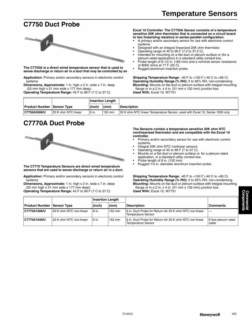
Temperature Sensors
70-6910 465
Com
mercial
Com
ponents
C7750 Duct Probe
The C7750A is a direct wired temperature sensor that is used to sense discharge or return air in a duct that may be controlled by an
Excel 10 Controller. The C7750A Sensor consists of a temperature sensitive 20K ohm thermistor that is connected on a circuit board to two linearizing resistors in series-parallel configuration.• A primary and/or secondary sensor for use with electronic control
systems. • Designed with an integral linearized 20K ohm thermistor. • Operating range of 45 to 99 F (7.2 to 37.2 C). • Intended for mounting on a flat duct or plenum surface or (for a
plenum-rated application) in a standard utility conduit box. • Probe length of 6-1/2 in. (165 mm) and a nominal sensor resistance
of 8000 ohms at 77 F (25 C). • Rugged aluminum insertion probe.
Application: Primary and/or secondary sensors in electronic control systems
Dimensions, Approximate: 1 in. high x 2 in. wide x 7 in. deep (25 mm high x 51 mm wide x 177 mm deep)
Operating Temperature Range: 45 F to 99 F (7 C to 37 C)
Shipping Temperature Range: -40 F to +150 F (-40 C to +65 C) Operating Humidity Range (% RH): 5 to 95% RH, non-condensingMounting: Mounts on flat duct or plenum surface with integral mounting
flange or in a 2 in. x 4 in. (51 mm x 102 mm) junction box.Used With: Excel 10, W7751
C7770A Duct Probe
The C7770 Temperature Sensors are direct wired temperature sensors that are used to sense discharge or return air in a duct.
The Sensors contain a temperature sensitive 20K ohm NTC nonlinearized thermistor and are compatible with the Excel 10 controller.• Primary and/or secondary sensor for use with electronic control
systems. • Integral 20K ohm NTC nonlinear sensors • Operating range of 45 to 99 F (7 to 37 C). • Mounts on a flat duct or plenum surface or, for a plenum-rated
application, in a standard utility conduit box. • Probe length of 6 in. (152 mm) • Rugged 1/4 in. diameter aluminum insertion probe.
Application: Primary and/or secondary sensors in electronic control systems
Dimensions, Approximate: 1 in. high x 2 in. wide x 7 in. deep (25 mm high x 51 mm wide x 177 mm deep)
Operating Temperature Range: 45 F to 99 F (7 C to 37 C)
Shipping Temperature Range: -40 F to +150 F (-40 C to +65 C) Operating Humidity Range (% RH): 5 to 95% RH, non-condensingMounting: Mounts on flat duct or plenum surface with integral mounting
flange or in a 2 in. x 4 in. (51 mm x 102 mm) junction box.Used With: Excel 10, W7751
Product Number Sensor Type
Insertion Length
Description(inch) (mm)
C7750A3006/U 20 K ohm NTC linear 6 in. 152 mm 20 K ohm NTC linear Temperature Sensor, used with Excel 10, Series 1000 only
Product Number Sensor Type
Insertion Length
Description Comments(inch) (mm)
C7770A1006/U 20 K ohm NTC non-linear 6 in. 152 mm 6 in. Duct Probe for Return Air 20 K ohm NTC non-linear Temperature Sensor
—
C7770A1040/U 20 K ohm NTC non-linear 6 in. 152 mm 6 in. Duct Probe for Return Air 20 K ohm NTC non-linear Temperature Sensor
6 foot plenum rated cable
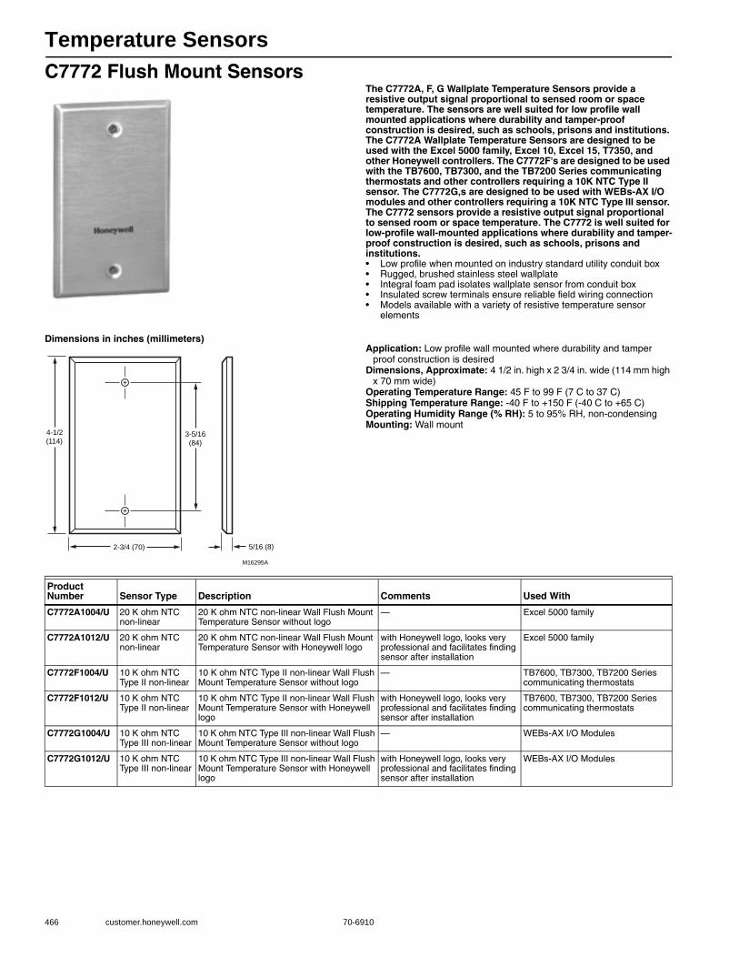
Temperature Sensors
466 customer.honeywell.com 70-6910
C7772 Flush Mount SensorsThe C7772A, F, G Wallplate Temperature Sensors provide a resistive output signal proportional to sensed room or space temperature. The sensors are well suited for low profile wall mounted applications where durability and tamper-proof construction is desired, such as schools, prisons and institutions. The C7772A Wallplate Temperature Sensors are designed to be used with the Excel 5000 family, Excel 10, Excel 15, T7350, and other Honeywell controllers. The C7772F's are designed to be used with the TB7600, TB7300, and the TB7200 Series communicating thermostats and other controllers requiring a 10K NTC Type II sensor. The C7772G,s are designed to be used with WEBs-AX I/O modules and other controllers requiring a 10K NTC Type III sensor. The C7772 sensors provide a resistive output signal proportional to sensed room or space temperature. The C7772 is well suited for low-profile wall-mounted applications where durability and tamper-proof construction is desired, such as schools, prisons and institutions.• Low profile when mounted on industry standard utility conduit box • Rugged, brushed stainless steel wallplate • Integral foam pad isolates wallplate sensor from conduit box • Insulated screw terminals ensure reliable field wiring connection • Models available with a variety of resistive temperature sensor
elements
Dimensions in inches (millimeters)Application: Low profile wall mounted where durability and tamper
proof construction is desiredDimensions, Approximate: 4 1/2 in. high x 2 3/4 in. wide (114 mm high
x 70 mm wide) Operating Temperature Range: 45 F to 99 F (7 C to 37 C) Shipping Temperature Range: -40 F to +150 F (-40 C to +65 C) Operating Humidity Range (% RH): 5 to 95% RH, non-condensingMounting: Wall mount
4-1/2
(114)3-5/16
(84)
2-3/4 (70) 5/16 (8)
M16295A
Product Number Sensor Type Description Comments Used With
C7772A1004/U 20 K ohm NTC non-linear
20 K ohm NTC non-linear Wall Flush Mount Temperature Sensor without logo
— Excel 5000 family
C7772A1012/U 20 K ohm NTC non-linear
20 K ohm NTC non-linear Wall Flush Mount Temperature Sensor with Honeywell logo
with Honeywell logo, looks very professional and facilitates finding sensor after installation
Excel 5000 family
C7772F1004/U 10 K ohm NTC Type II non-linear
10 K ohm NTC Type II non-linear Wall Flush Mount Temperature Sensor without logo
— TB7600, TB7300, TB7200 Series communicating thermostats
C7772F1012/U 10 K ohm NTC Type II non-linear
10 K ohm NTC Type II non-linear Wall Flush Mount Temperature Sensor with Honeywell logo
with Honeywell logo, looks very professional and facilitates finding sensor after installation
TB7600, TB7300, TB7200 Series communicating thermostats
C7772G1004/U 10 K ohm NTC Type III non-linear
10 K ohm NTC Type III non-linear Wall Flush Mount Temperature Sensor without logo
— WEBs-AX I/O Modules
C7772G1012/U 10 K ohm NTC Type III non-linear
10 K ohm NTC Type III non-linear Wall Flush Mount Temperature Sensor with Honeywell logo
with Honeywell logo, looks very professional and facilitates finding sensor after installation
WEBs-AX I/O Modules
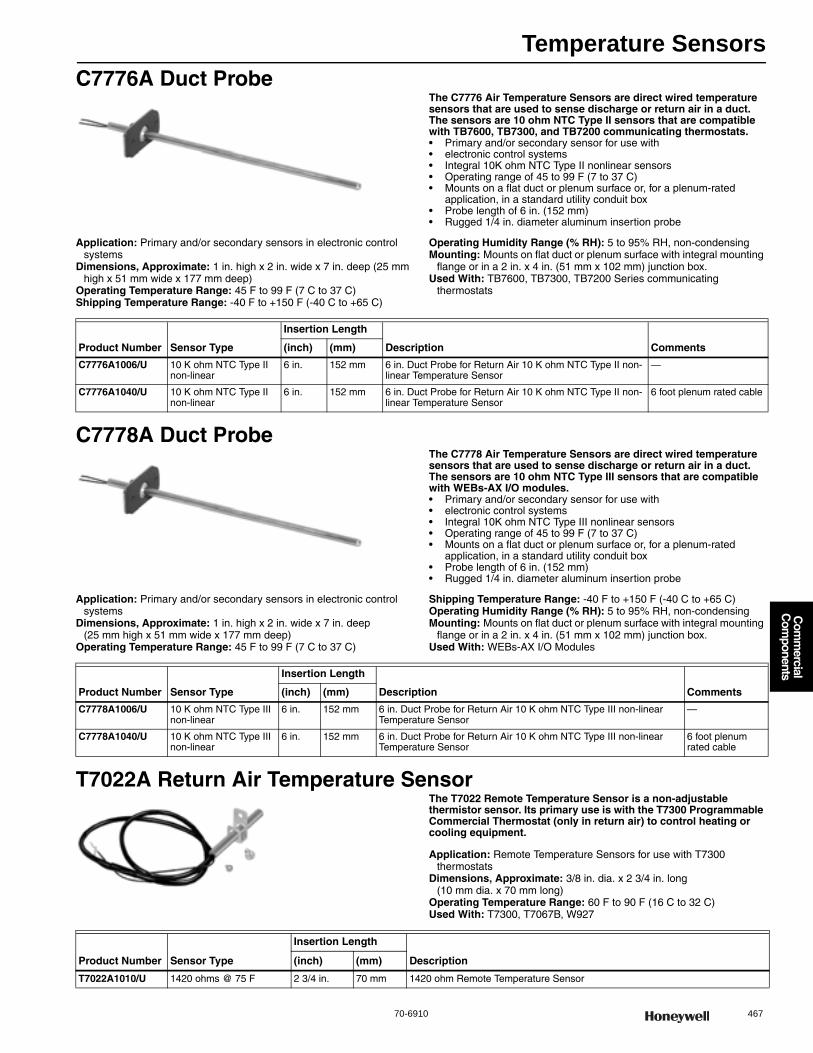
Temperature Sensors
70-6910 467
Com
mercial
Com
ponents
C7776A Duct ProbeThe C7776 Air Temperature Sensors are direct wired temperature sensors that are used to sense discharge or return air in a duct. The sensors are 10 ohm NTC Type II sensors that are compatible with TB7600, TB7300, and TB7200 communicating thermostats.• Primary and/or secondary sensor for use with• electronic control systems • Integral 10K ohm NTC Type II nonlinear sensors • Operating range of 45 to 99 F (7 to 37 C) • Mounts on a flat duct or plenum surface or, for a plenum-rated
application, in a standard utility conduit box • Probe length of 6 in. (152 mm) • Rugged 1/4 in. diameter aluminum insertion probe
Application: Primary and/or secondary sensors in electronic control systems
Dimensions, Approximate: 1 in. high x 2 in. wide x 7 in. deep (25 mm high x 51 mm wide x 177 mm deep)
Operating Temperature Range: 45 F to 99 F (7 C to 37 C) Shipping Temperature Range: -40 F to +150 F (-40 C to +65 C)
Operating Humidity Range (% RH): 5 to 95% RH, non-condensingMounting: Mounts on flat duct or plenum surface with integral mounting
flange or in a 2 in. x 4 in. (51 mm x 102 mm) junction box.Used With: TB7600, TB7300, TB7200 Series communicating
thermostats
C7778A Duct ProbeThe C7778 Air Temperature Sensors are direct wired temperature sensors that are used to sense discharge or return air in a duct. The sensors are 10 ohm NTC Type III sensors that are compatible with WEBs-AX I/O modules.• Primary and/or secondary sensor for use with• electronic control systems • Integral 10K ohm NTC Type III nonlinear sensors • Operating range of 45 to 99 F (7 to 37 C) • Mounts on a flat duct or plenum surface or, for a plenum-rated
application, in a standard utility conduit box • Probe length of 6 in. (152 mm) • Rugged 1/4 in. diameter aluminum insertion probe
Application: Primary and/or secondary sensors in electronic control systems
Dimensions, Approximate: 1 in. high x 2 in. wide x 7 in. deep(25 mm high x 51 mm wide x 177 mm deep)
Operating Temperature Range: 45 F to 99 F (7 C to 37 C)
Shipping Temperature Range: -40 F to +150 F (-40 C to +65 C) Operating Humidity Range (% RH): 5 to 95% RH, non-condensingMounting: Mounts on flat duct or plenum surface with integral mounting
flange or in a 2 in. x 4 in. (51 mm x 102 mm) junction box.Used With: WEBs-AX I/O Modules
T7022A Return Air Temperature SensorThe T7022 Remote Temperature Sensor is a non-adjustable thermistor sensor. Its primary use is with the T7300 Programmable Commercial Thermostat (only in return air) to control heating or cooling equipment.
Application: Remote Temperature Sensors for use with T7300 thermostats
Dimensions, Approximate: 3/8 in. dia. x 2 3/4 in. long (10 mm dia. x 70 mm long)
Operating Temperature Range: 60 F to 90 F (16 C to 32 C) Used With: T7300, T7067B, W927
Product Number Sensor Type
Insertion Length
Description Comments(inch) (mm)
C7776A1006/U 10 K ohm NTC Type II non-linear
6 in. 152 mm 6 in. Duct Probe for Return Air 10 K ohm NTC Type II non-linear Temperature Sensor
—
C7776A1040/U 10 K ohm NTC Type II non-linear
6 in. 152 mm 6 in. Duct Probe for Return Air 10 K ohm NTC Type II non-linear Temperature Sensor
6 foot plenum rated cable
Product Number Sensor Type
Insertion Length
Description Comments(inch) (mm)
C7778A1006/U 10 K ohm NTC Type III non-linear
6 in. 152 mm 6 in. Duct Probe for Return Air 10 K ohm NTC Type III non-linear Temperature Sensor
—
C7778A1040/U 10 K ohm NTC Type III non-linear
6 in. 152 mm 6 in. Duct Probe for Return Air 10 K ohm NTC Type III non-linear Temperature Sensor
6 foot plenum rated cable
Product Number Sensor Type
Insertion Length
Description(inch) (mm)
T7022A1010/U 1420 ohms @ 75 F 2 3/4 in. 70 mm 1420 ohm Remote Temperature Sensor
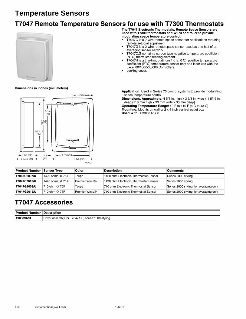
Temperature Sensors
468 customer.honeywell.com 70-6910
T7047 Remote Temperature Sensors for use with T7300 ThermostatsThe T7047 Electronic Thermostats, Remote Space Sensors are used with T7300 thermostats and W973 controller to provide modulating space temperature control.• T7047C is a 2-wire remote space sensor for applications requiring
remote setpoint adjustment.• T7047G is a 2-wire remote space sensor used as one half of an
averaging sensor network. • T7047C,G contain a carbon type negative temperature coefficient
(NTC) thermistor sensing element. • T7047H is a thin-film, platinum 1K (at 0 C), positive temperature
coefficient (PTC) temperature sensor only and is for use with the Excel 80/100/500/600 Controllers.
• Locking cover.
Dimensions in inches (millimeters)Application: Used in Series 70 control systems to provide modulating
space temperature controlDimensions, Approximate: 4 5/8 in. high x 3 5/8 in. wide x 1 5/16 in.
deep (118 mm high x 93 mm wide x 33 mm deep) Operating Temperature Range: 40 F to 110 F (4 C to 43 C) Mounting: Mounts on wall or 2 x 4 inch vertical outlet boxUsed With: T7300/Q7300
T7047 Accessories
3-1/4(83)
3-13/16(97)
4-5/8(117)
1-13/16 (46)
3-5/8 (92)
7/8 (22)
1-1/16 (27)
2-7/8 (73)3/8
(10)
M17720
Product Number Sensor Type Color Description Comments
T7047C2007/U 1420 ohms @ 75 F Taupe 1420 ohm Electronic Thermostat Sensor Series 2000 styling
T7047C2015/U 1420 ohms @ 75 F Premier White® 1420 ohm Electronic Thermostat Sensor Series 2000 styling
T7047G2008/U 710 ohm @ 75F Taupe 710 ohm Electronic Thermostat Sensor Series 2000 styling, for averaging only.
T7047G2016/U 710 ohm @ 75F Premier White® 710 ohm Electronic Thermostat Sensor Series 2000 styling, for averaging only.
Product Number Description
190389A/U Cover assembly for T7047A,B, series 1000 styling
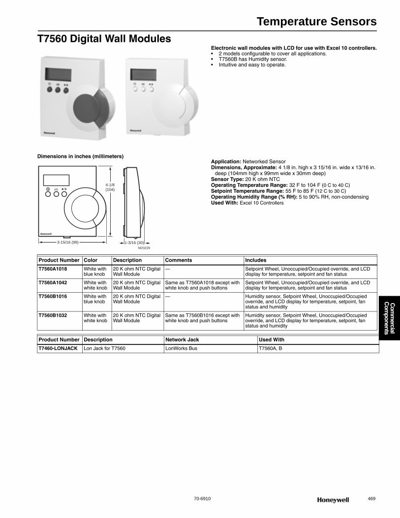
Temperature Sensors
70-6910 469
Com
mercial
Com
ponents
T7560 Digital Wall ModulesElectronic wall modules with LCD for use with Excel 10 controllers.• 2 models configurable to cover all applications. • T7560B has Humidity sensor. • Intuitive and easy to operate.
Dimensions in inches (millimeters)Application: Networked SensorDimensions, Approximate: 4 1/8 in. high x 3 15/16 in. wide x 13/16 in.
deep (104mm high x 99mm wide x 30mm deep) Sensor Type: 20 K ohm NTCOperating Temperature Range: 32 F to 104 F (0 C to 40 C) Setpoint Temperature Range: 55 F to 85 F (12 C to 30 C) Operating Humidity Range (% RH): 5 to 90% RH, non-condensingUsed With: Excel 10 Controllers
3-15/16 (99) 1-3/16 (30)
4-1/8
(104)
M23229
Product Number Color Description Comments Includes
T7560A1018 White with blue knob
20 K ohm NTC Digital Wall Module
— Setpoint Wheel, Unoccupied/Occupied override, and LCD display for temperature, setpoint and fan status
T7560A1042 White with white knob
20 K ohm NTC Digital Wall Module
Same as T7560A1018 except with white knob and push buttons
Setpoint Wheel, Unoccupied/Occupied override, and LCD display for temperature, setpoint and fan status
T7560B1016 White with blue knob
20 K ohm NTC Digital Wall Module
— Humidity sensor, Setpoint Wheel, Unoccupied/Occupied override, and LCD display for temperature, setpoint, fan status and humidity
T7560B1032 White with white knob
20 K ohm NTC Digital Wall Module
Same as T7560B1016 except with white knob and push buttons
Humidity sensor, Setpoint Wheel, Unoccupied/Occupied override, and LCD display for temperature, setpoint, fan status and humidity
Product Number Description Network Jack Used With
T7460-LONJACK Lon Jack for T7560 LonWorks Bus T7560A, B
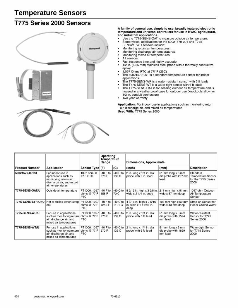
Temperature Sensors
470 customer.honeywell.com 70-6910
T775 Series 2000 SensorsA family of general use, simple to use, broadly featured electronic temperature and universal controllers for use in HVAC, agricultural, and industrial applications.• Use the T775-SENS-OAT to measure outside air temperature. • Some typical applications for the 50021579-001 and T775-
SENSWT/WR sensors include: • Monitoring return air temperatures • Monitoring discharge air temperatures • Monitoring mixed air temperatures• All sensors:• Fast response time and highly accurate • 1/2 in. (6.35 mm) stainless steel probe with a thermally conductive
epoxy• 1,097 Ohms PTC at 77ÞF (25C) • The 50021579-001 is a standard temperature sensor for indoor
applications • The T775-SENS-WR is a water resistant sensor with 5 ft leads • The T775-SENS-WT is a water tight sensor with 6 ft leads • The T775-SENS-OAT is for sensing outdoor air temperature and is
housed in a weatherproof case for outdoor use (knockouts allow for 1/2 in. conduit connection)
• Two year warranty
Application: For indoor use in applications such as monitoring return air, discharge air, and mixed air temperatures
Used With: T775 Series 2000
Product Number Application Sensor Type
Operating Temperature Range Dimensions, Approximate
Description(F) (C) (inch) (mm)
50021579-001/U For indoor use in applications such as monitoring return air, discharge air, and mixed air temperatures
1097 ohm @ 77 F PTC
-40 F to 270 F
-40 C to 132 C
2 in. long x 1/4 in. dia probe with 9 in. lead
51 mm long x 6 mm dia probe with 227 mm lead
Standard Temperature Sensor for the T775 Series 2000
T775-SENS-OAT/U Outside air temperature PT1000, 1097 ohms @ 77 F PTC
-40 F to 158 F
-40 C to 70 C
8 5/16 in. high x 3 5/8 in. wide x 2 1/4 in. deep
211 mm high x 91 mm wide x 57 mm deep
1097 ohm Outdoor Air Temperature Sensor
T775-SENS-STRAP/U Hot or chilled water (strap on)
PT1000, 1097 ohms @ 77 F PTC
-40 F to +250 F
-40 C to +121 C
4 3/16 in. high x 2 5/16 in. wide x 1 11/16 in. deep
107 mm high x 59 mm wide x 43 mm deep
Strap-on Sensor for Hot or Chilled Water
T775-SENS-WR/U For use in applications such as monitoring return air, discharge air, and mixed air temperatures
PT1000, 1097 ohms @ 77 F PTC
-40 F to 270 F
-40 C to 132 C
2 in. long x 1/4 in. dia probe with 5 ft. lead
51 mm long x 6 mm dia probe with 1524 mm lead
Water-resistant Sensor for T775 Series 2000.
T775-SENS-WT/U For use in applications such as monitoring return air, discharge air, and mixed air temperatures
PT1000, 1097 ohms @ 77 F PTC
-40 F to 270 F
-40 C to 132 C
2 in. long x 1/4 in. dia probe with 6 ft. lead
51 mm long x 6 mm dia probe with 1829 mm lead
Water-tight Sensor for T775 Series 2000
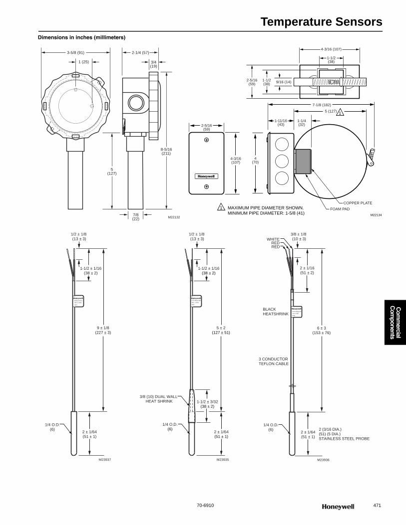
Temperature Sensors
70-6910 471
Com
mercial
Com
ponents
Dimensions in inches (millimeters)
2-1/4 (57)
3/4(19)
1 (25)
5(127)
7/8(22)
8-5/16(211)
M22132
3-5/8 (91)
2-5/16(59)
4-3/16(107)
4(70)
1-11/16(43)
7-1/8 (182)
9/16 (14)1-1/2(38)
1-1/2(38)
2-5/16(59)
M22134
1-1/4(32)
5 (127)
MAXIMUM PIPE DIAMETER SHOWN.
MINIMUM PIPE DIAMETER: 1-5/8 (41)
1
1
4-3/16 (107)
COPPER PLATE
FOAM PAD
50021579-001
80C to 200C
0641
1/4 O.D.(6)
2 ± 1/64(51 ± 1)
9 ± 1/8(227 ± 3)
1/2 ± 1/8 (13 ± 3)
1-1/2 ± 1/16(38 ± 2)
M23937
1/4 O.D.(6)
2 ± 1/64(51 ± 1)
5 ± 2(127 ± 51)
1/2 ± 1/8 (13 ± 3)
1-1/2 ± 1/16(38 ± 2)
M23935
T775-SENS-WR
-80C o 200C
0641
1-1/2 ± 3/32(38 ± 2)
3/8 (10) DUAL WALL HEAT SHRINK
1/4 O.D.(6)
2 ± 1/64(51 ± 1)
6 ± 3(153 ± 76)
3/8 ± 1/8 (10 ± 3)
2 ± 1/16(51 ± 2)
M23936
2 (3/16 DIA.) (51) (5 DIA.) STAINLESS STEEL PROBE
3 CONDUCTORTEFLON CABLE
0708
40 to 270F
T775-SENS-WT
RED
BLACKHEATSHRINK
WHITE
RED

Temperature Sensors
472 customer.honeywell.com 70-6910
T7750 Wall ModulesTemperature sensors for use with Excel 10 Series 1000 Controllers. The T7750 Wall Modules provide the following additional combination of options to the customer: analog setpoint input and for models used with Excel 10 Controllers, override (bypass) digital input contact, LED status indicator and network access jack.• Integral linearized 20K ohm NTC thermistor. • Vertical Mounting. • Models available with setpoint adjustment. • Models available with occupied/unoccupied override. • For use only as replacement of existing T7750's. • Not for new installations. • All new Honeywell controllers now use TR20 Series Wall Modules.
Application: Wall ModulesDimensions, Approximate: 5 1/32 in. high x 3 5/32 in. wide x 1 19/32
in. deep (128 mm high x 80 mm wide x 41 mm deep) Operating Temperature Range: 45 F to 99 F (7 C to 37 C) Setpoint Temperature Range: 55 F to 85 F (12 C to 30 C)
T7771 Wall ModuleThe T7771A Remote Temperature Sensors are direct wired wall modules for use with the Honeywell T7350 Commercial Programmable Thermostat. The T7771A has a space temperature sensor, LED push button setpoint adjustment, and override with LED.• Push button setpoint adjustment with LED indicators. • Occupied/unoccupied override (bypass) with LED. • LONWORKS® bus jack. • Operating range 45 to 99 F (7 to 37 C).
Application: Remote Room Temperature Sensor for use with T7350 thermostat
Dimensions, Approximate: 5 1/32 in. high x 3 5/32 in. wide x 1 in. deep (128 mm high x 80 mm wide x 25 mm deep)
Color: WhiteOperating Temperature Range: 45 F to 99 F (7 C to 37 C) Setpoint Temperature Range: offset +/- 3F (offset +/- 1.67 C)
Shipping Temperature Range: -40 F to +150 F (-40 C to +65 C) Operating Humidity Range (% RH): 5 to 95% RH, non-condensingComments: Can be configured to output 10K ohms for use in multiple
sensor averaging with T7770A.Used With: T7350ApprovalsN.E.C. Class II
Product Number Sensor Type Mounting Comments Used With
T7750A1000/U 20 K ohm NTC linear Wall mount — W7751
T7750B1008/U 20 K ohm NTC linear Wall mount Has optional setpoint W7751; Excel 20, 80, 100, 500, or 600
T7750C1006/U 20 K ohm NTC linear Wall mount Has optional setpoint, override, and override LED W7751
T7750D1004/U 20 K ohm NTC linear Wall mount Has override, and override LED W7751
Product Number Sensor Type Network Jack Mounting Comments
T7771A1005/U 20 K ohm NTC non-linear
LonWorks Bus Mounted on a standard 2 x 4 inch junction box or on a 60 mm diameter junction box.
Can be configured to output 10K ohms for use in multiple sensor averaging with T7770A.
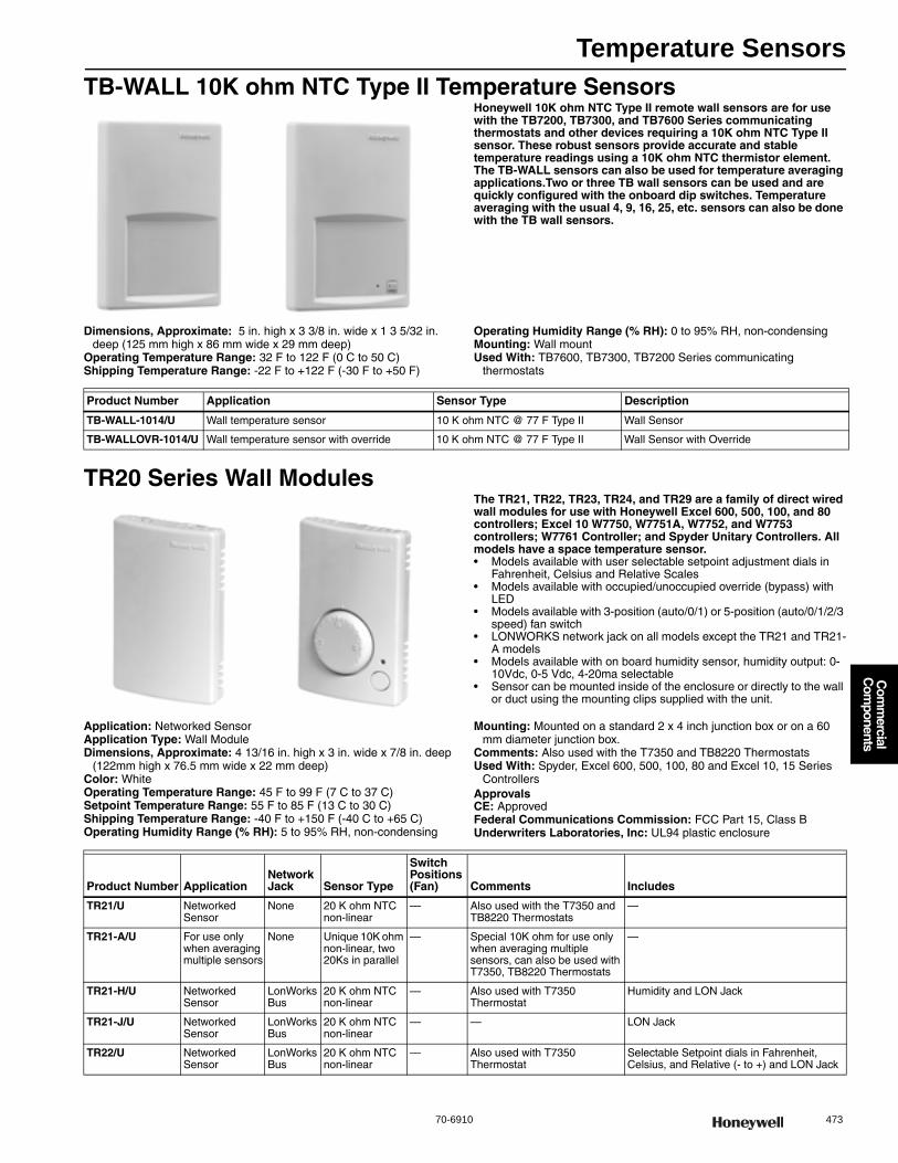
Temperature Sensors
70-6910 473
Com
mercial
Com
ponents
TB-WALL 10K ohm NTC Type II Temperature SensorsHoneywell 10K ohm NTC Type II remote wall sensors are for use with the TB7200, TB7300, and TB7600 Series communicating thermostats and other devices requiring a 10K ohm NTC Type II sensor. These robust sensors provide accurate and stable temperature readings using a 10K ohm NTC thermistor element. The TB-WALL sensors can also be used for temperature averaging applications.Two or three TB wall sensors can be used and are quickly configured with the onboard dip switches. Temperature averaging with the usual 4, 9, 16, 25, etc. sensors can also be done with the TB wall sensors.
Dimensions, Approximate: 5 in. high x 3 3/8 in. wide x 1 3 5/32 in. deep (125 mm high x 86 mm wide x 29 mm deep)
Operating Temperature Range: 32 F to 122 F (0 C to 50 C) Shipping Temperature Range: -22 F to +122 F (-30 F to +50 F)
Operating Humidity Range (% RH): 0 to 95% RH, non-condensingMounting: Wall mountUsed With: TB7600, TB7300, TB7200 Series communicating
thermostats
TR20 Series Wall ModulesThe TR21, TR22, TR23, TR24, and TR29 are a family of direct wired wall modules for use with Honeywell Excel 600, 500, 100, and 80 controllers; Excel 10 W7750, W7751A, W7752, and W7753 controllers; W7761 Controller; and Spyder Unitary Controllers. All models have a space temperature sensor.• Models available with user selectable setpoint adjustment dials in
Fahrenheit, Celsius and Relative Scales • Models available with occupied/unoccupied override (bypass) with
LED • Models available with 3-position (auto/0/1) or 5-position (auto/0/1/2/3
speed) fan switch • LONWORKS network jack on all models except the TR21 and TR21-
A models • Models available with on board humidity sensor, humidity output: 0-
10Vdc, 0-5 Vdc, 4-20ma selectable• Sensor can be mounted inside of the enclosure or directly to the wall
or duct using the mounting clips supplied with the unit.
Application: Networked SensorApplication Type: Wall ModuleDimensions, Approximate: 4 13/16 in. high x 3 in. wide x 7/8 in. deep
(122mm high x 76.5 mm wide x 22 mm deep) Color: WhiteOperating Temperature Range: 45 F to 99 F (7 C to 37 C) Setpoint Temperature Range: 55 F to 85 F (13 C to 30 C)Shipping Temperature Range: -40 F to +150 F (-40 C to +65 C) Operating Humidity Range (% RH): 5 to 95% RH, non-condensing
Mounting: Mounted on a standard 2 x 4 inch junction box or on a 60 mm diameter junction box.
Comments: Also used with the T7350 and TB8220 ThermostatsUsed With: Spyder, Excel 600, 500, 100, 80 and Excel 10, 15 Series
ControllersApprovalsCE: ApprovedFederal Communications Commission: FCC Part 15, Class BUnderwriters Laboratories, Inc: UL94 plastic enclosure
Product Number Application Sensor Type Description
TB-WALL-1014/U Wall temperature sensor 10 K ohm NTC @ 77 F Type II Wall Sensor
TB-WALLOVR-1014/U Wall temperature sensor with override 10 K ohm NTC @ 77 F Type II Wall Sensor with Override
Product Number ApplicationNetwork Jack Sensor Type
Switch Positions (Fan) Comments Includes
TR21/U Networked Sensor
None 20 K ohm NTC non-linear
— Also used with the T7350 and TB8220 Thermostats
—
TR21-A/U For use only when averaging multiple sensors
None Unique 10K ohm non-linear, two 20Ks in parallel
— Special 10K ohm for use only when averaging multiple sensors, can also be used with T7350, TB8220 Thermostats
—
TR21-H/U Networked Sensor
LonWorks Bus
20 K ohm NTC non-linear
— Also used with T7350 Thermostat
Humidity and LON Jack
TR21-J/U Networked Sensor
LonWorks Bus
20 K ohm NTC non-linear
— — LON Jack
TR22/U Networked Sensor
LonWorks Bus
20 K ohm NTC non-linear
— Also used with T7350 Thermostat
Selectable Setpoint dials in Fahrenheit, Celsius, and Relative (- to +) and LON Jack
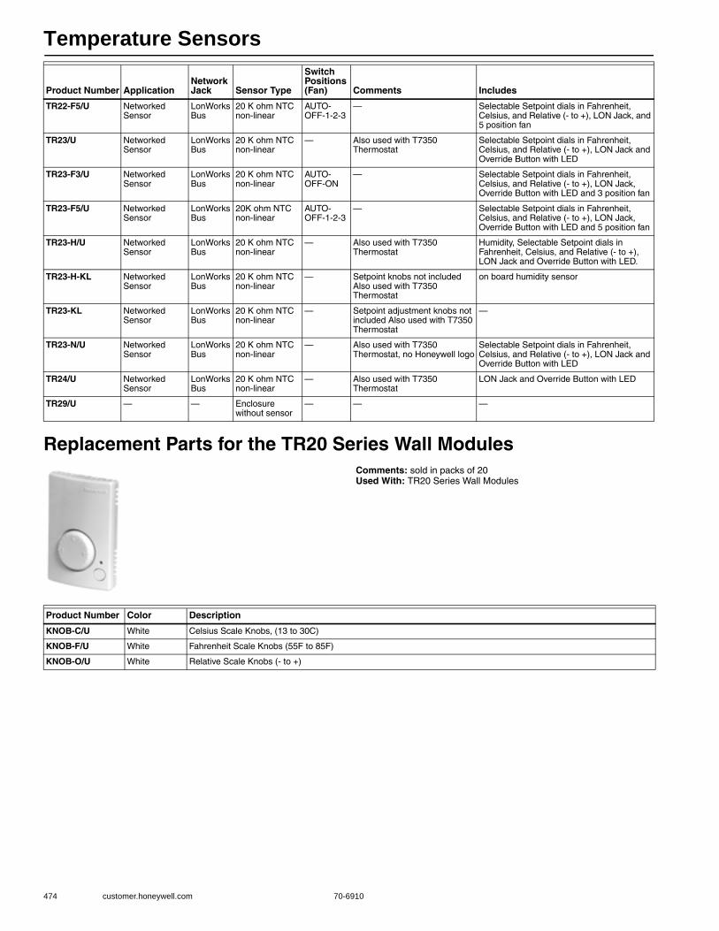
Temperature Sensors
474 customer.honeywell.com 70-6910
Replacement Parts for the TR20 Series Wall ModulesComments: sold in packs of 20Used With: TR20 Series Wall Modules
TR22-F5/U Networked Sensor
LonWorks Bus
20 K ohm NTC non-linear
AUTO-OFF-1-2-3
— Selectable Setpoint dials in Fahrenheit, Celsius, and Relative (- to +), LON Jack, and 5 position fan
TR23/U Networked Sensor
LonWorks Bus
20 K ohm NTC non-linear
— Also used with T7350 Thermostat
Selectable Setpoint dials in Fahrenheit, Celsius, and Relative (- to +), LON Jack and Override Button with LED
TR23-F3/U Networked Sensor
LonWorks Bus
20 K ohm NTC non-linear
AUTO-OFF-ON
— Selectable Setpoint dials in Fahrenheit, Celsius, and Relative (- to +), LON Jack, Override Button with LED and 3 position fan
TR23-F5/U Networked Sensor
LonWorks Bus
20K ohm NTC non-linear
AUTO-OFF-1-2-3
— Selectable Setpoint dials in Fahrenheit, Celsius, and Relative (- to +), LON Jack, Override Button with LED and 5 position fan
TR23-H/U Networked Sensor
LonWorks Bus
20 K ohm NTC non-linear
— Also used with T7350 Thermostat
Humidity, Selectable Setpoint dials in Fahrenheit, Celsius, and Relative (- to +), LON Jack and Override Button with LED.
TR23-H-KL Networked Sensor
LonWorks Bus
20 K ohm NTC non-linear
— Setpoint knobs not included Also used with T7350 Thermostat
on board humidity sensor
TR23-KL Networked Sensor
LonWorks Bus
20 K ohm NTC non-linear
— Setpoint adjustment knobs not included Also used with T7350 Thermostat
—
TR23-N/U Networked Sensor
LonWorks Bus
20 K ohm NTC non-linear
— Also used with T7350 Thermostat, no Honeywell logo
Selectable Setpoint dials in Fahrenheit, Celsius, and Relative (- to +), LON Jack and Override Button with LED
TR24/U Networked Sensor
LonWorks Bus
20 K ohm NTC non-linear
— Also used with T7350 Thermostat
LON Jack and Override Button with LED
TR29/U — — Enclosure without sensor
— — —
Product Number ApplicationNetwork Jack Sensor Type
Switch Positions (Fan) Comments Includes
Product Number Color Description
KNOB-C/U White Celsius Scale Knobs, (13 to 30C)
KNOB-F/U White Fahrenheit Scale Knobs (55F to 85F)
KNOB-O/U White Relative Scale Knobs (- to +)
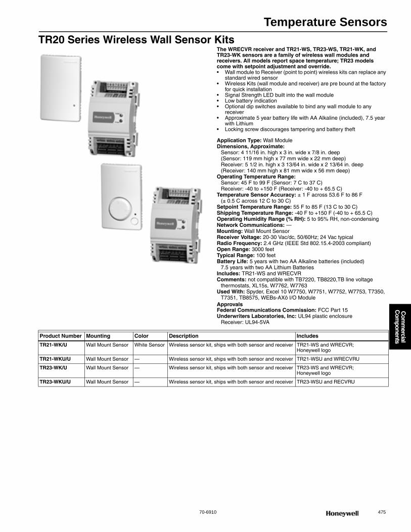
Temperature Sensors
70-6910 475
Com
mercial
Com
ponents
TR20 Series Wireless Wall Sensor KitsThe WRECVR receiver and TR21-WS, TR23-WS, TR21-WK, and TR23-WK sensors are a family of wireless wall modules and receivers. All models report space temperature; TR23 models come with setpoint adjustment and override.• Wall module to Receiver (point to point) wireless kits can replace any
standard wired sensor • Wireless Kits (wall module and receiver) are pre bound at the factory
for quick installation • Signal Strength LED built into the wall module • Low battery indication • Optional dip switches available to bind any wall module to any
receiver • Approximate 5 year battery life with AA Alkaline (included), 7.5 year
with Lithium • Locking screw discourages tampering and battery theft
Application Type: Wall ModuleDimensions, Approximate:
Sensor: 4 11/16 in. high x 3 in. wide x 7/8 in. deep (Sensor: 119 mm high x 77 mm wide x 22 mm deep) Receiver: 5 1/2 in. high x 3 13/64 in. wide x 2 13/64 in. deep(Receiver: 140 mm high x 81 mm wide x 56 mm deep)
Operating Temperature Range: Sensor: 45 F to 99 F (Sensor: 7 C to 37 C) Receiver: -40 to +150 F (Receiver: -40 to + 65.5 C)
Temperature Sensor Accuracy: ± 1 F across 53.6 F to 86 F (± 0.5 C across 12 C to 30 C)
Setpoint Temperature Range: 55 F to 85 F (13 C to 30 C)Shipping Temperature Range: -40 F to +150 F (-40 to + 65.5 C) Operating Humidity Range (% RH): 5 to 95% RH, non-condensingNetwork Communications: —Mounting: Wall Mount SensorReceiver Voltage: 20-30 Vac/dc, 50/60Hz; 24 Vac typicalRadio Frequency: 2.4 GHz (IEEE Std 802.15.4-2003 compliant)Open Range: 3000 feetTypical Range: 100 feetBattery Life: 5 years with two AA Alkaline batteries (included)
7.5 years with two AA Lithium Batteries Includes: TR21-WS and WRECVRComments: not compatible with TB7220, TB8220,TB line voltage
thermostats, XL15s, W7762, W7763Used With: Spyder, Excel 10 W7750, W7751, W7752, W7753, T7350,
T7351, TB8575, WEBs-AXô I/O ModuleApprovalsFederal Communications Commission: FCC Part 15Underwriters Laboratories, Inc: UL94 plastic enclosure
Receiver: UL94-5VA
Product Number Mounting Color Description Includes
TR21-WK/U Wall Mount Sensor White Sensor Wireless sensor kit, ships with both sensor and receiver TR21-WS and WRECVR; Honeywell logo
TR21-WKU/U Wall Mount Sensor — Wireless sensor kit, ships with both sensor and receiver TR21-WSU and WRECVRU
TR23-WK/U Wall Mount Sensor — Wireless sensor kit, ships with both sensor and receiver TR23-WS and WRECVR; Honeywell logo
TR23-WKU/U Wall Mount Sensor — Wireless sensor kit, ships with both sensor and receiver TR23-WSU and RECVRU

Temperature Sensors
476 customer.honeywell.com 70-6910
TR20 Series Wireless Wall SensorsTR21-WS and TR23-WS sensors are a family of wireless wall modules. All models report space temperature; TR23 models come with setpoint adjustment and override.• Wall module to Receiver (point to point) wireless kits can replace any
standard wired sensor • Wireless Kits (wall module and receiver) are pre bound at the factory
for quick installation • Signal Strength LED built into the wall module • Low battery indication • Optional dip switches available to bind any wall module to any
receiver • Approximate 5 year battery life with AA Alkaline (included), 7.5 year
with Lithium • Locking screw discourages tampering and battery theft
Application Type: Wall ModuleColor: WhiteDimensions, Approximate: 4 11/16 in. high x 3 in. wide x 7/8 in. deep
(119 mm high x 77 mm wide x 22 mm deep) Operating Temperature Range: 45 F to 99 F (7 C to 37 C) Setpoint Temperature Range: 55 F to 85 F (13 C to 30 C)Temperature Sensor Accuracy: ± 1 F across 53.6 F to 86 F
(± 0.5 C across 12 C to 30 C)Shipping Temperature Range: -40 F to +150 F (-40 to + 65.5 C) Operating Humidity Range (% RH): 5 to 95% RH, non-condensingMounting: Wall mount
Battery Life: 5 years with two AA Alkaline batteries (included)7.5 years with two AA Lithium Batteries
Radio Frequency: 2.4 GHz (IEEE Std 802.15.4-2003 compliant)Open Range: 3000 feetTypical Range: 100 feetComments: not compatible with TB7220, TB8220,TB line voltage
thermostats, XL15s, W7762, W7763Used With: Spyder, Excel 10 W7750, W7751, W7752, W7753, T7350,
T7351, TB8575, WEBs-AXô I/O ModuleApprovalsFederal Communications Commission: FCC Part 15Underwriters Laboratories, Inc: UL94 plastic enclosure
TR20 Series Wireless Wall ModulesThe WRECVR receiver and TR21-WS, TR23-WS, TR21-WK, and TR23-WK sensors are a family of wireless wall modules and receivers.• Wall module to Receiver (point to point) wireless kits can replace any
standard wired sensor • Wireless Kits (wall module and receiver) are pre bound at the factory
for quick installation • Signal Strength LED built into the wall module • Low battery indication • Optional dip switches available to bind any wall module to any
receiver
Application: ReceiverApplication Type: Wireless ReceiverDimensions, Approximate:
5 1/2 in. high x 3 13/64 in. wide x 2 13/64 in. deep (140 mm high x 81 mm wide x 56 mm deep)
Operating Temperature Range: -40 to +150 F (-40 to + 65.5 C) Shipping Temperature Range: -40 F to +150 F (-40 to + 65.5 C) Operating Humidity Range (% RH): 5 to 95% RH, non-condensing
Receiver Voltage: 20-30 Vac/dc, 50/60Hz; 24 Vac typicalRadio Frequency: 2.4 GHz (IEEE Std 802.15.4-2003 compliant)Open Range: 3000 feetTypical Range: 100 feetApprovalsFederal Communications Commission: FCC Part 15Underwriters Laboratories, Inc: UL94-5VA
Product Number Description Includes
TR21-WS/U TR21 wireless temperature sensor Honeywell logo
TR21-WSU/U TR21 Wireless Temp Sensor without Honeywell logo —
TR23-WS/U TR23 Wireless temperature sensor with Setpoint (F/C/Relative) and override button
Selectable Setpoint dials in Fahrenheit, Celsius, and Relative (- to +), and Override Button; Honeywell logo
TR23-WSU/U TR23 Wireless temperature sensor, with Setpoint (F/C/Relative) and override button, no Honeywell logo
Selectable Setpoint dials in Fahrenheit, Celsius, and Relative (- to +), and Override Button
Product Number Comments Includes Used With Description
WRECVR/U — Honeywell Logo TR21-WS, TR23-WS Receiver used with wireless temperature sensors
WRECVRU/U no Honeywell logo — TR21-WSU, TR23-WSU Receiver used with wireless temperature sensors
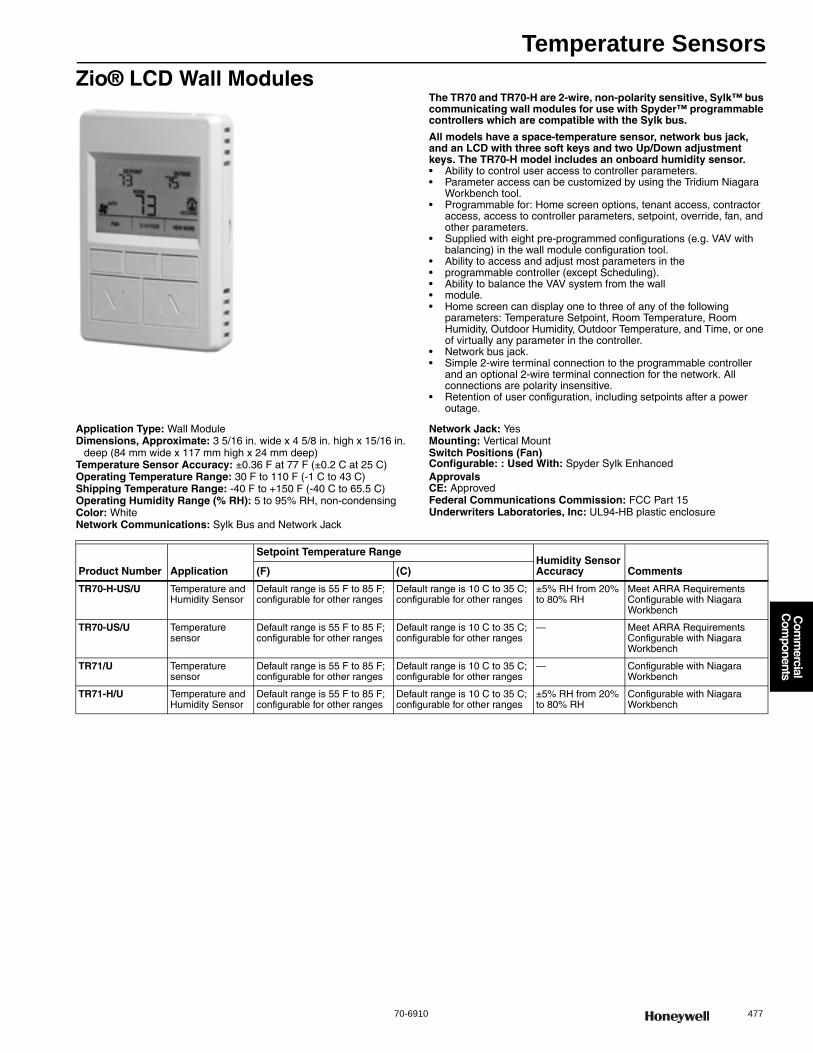
Temperature Sensors
70-6910 477
Com
mercial
Com
ponents
Zio® LCD Wall ModulesThe TR70 and TR70-H are 2-wire, non-polarity sensitive, Sylk™ bus communicating wall modules for use with Spyder™ programmable controllers which are compatible with the Sylk bus.
All models have a space-temperature sensor, network bus jack, and an LCD with three soft keys and two Up/Down adjustment keys. The TR70-H model includes an onboard humidity sensor.• Ability to control user access to controller parameters. • Parameter access can be customized by using the Tridium Niagara
Workbench tool. • Programmable for: Home screen options, tenant access, contractor
access, access to controller parameters, setpoint, override, fan, and other parameters.
• Supplied with eight pre-programmed configurations (e.g. VAV with balancing) in the wall module configuration tool.
• Ability to access and adjust most parameters in the• programmable controller (except Scheduling). • Ability to balance the VAV system from the wall• module. • Home screen can display one to three of any of the following
parameters: Temperature Setpoint, Room Temperature, Room Humidity, Outdoor Humidity, Outdoor Temperature, and Time, or one of virtually any parameter in the controller.
• Network bus jack. • Simple 2-wire terminal connection to the programmable controller
and an optional 2-wire terminal connection for the network. All connections are polarity insensitive.
• Retention of user configuration, including setpoints after a power outage.
Application Type: Wall ModuleDimensions, Approximate: 3 5/16 in. wide x 4 5/8 in. high x 15/16 in.
deep (84 mm wide x 117 mm high x 24 mm deep) Temperature Sensor Accuracy: ±0.36 F at 77 F (±0.2 C at 25 C)Operating Temperature Range: 30 F to 110 F (-1 C to 43 C) Shipping Temperature Range: -40 F to +150 F (-40 C to 65.5 C) Operating Humidity Range (% RH): 5 to 95% RH, non-condensingColor: WhiteNetwork Communications: Sylk Bus and Network Jack
Network Jack: YesMounting: Vertical MountSwitch Positions (Fan)Configurable: : Used With: Spyder Sylk EnhancedApprovalsCE: ApprovedFederal Communications Commission: FCC Part 15Underwriters Laboratories, Inc: UL94-HB plastic enclosure
Product Number Application
Setpoint Temperature RangeHumidity Sensor Accuracy Comments(F) (C)
TR70-H-US/U Temperature and Humidity Sensor
Default range is 55 F to 85 F; configurable for other ranges
Default range is 10 C to 35 C; configurable for other ranges
±5% RH from 20% to 80% RH
Meet ARRA Requirements Configurable with Niagara Workbench
TR70-US/U Temperature sensor
Default range is 55 F to 85 F; configurable for other ranges
Default range is 10 C to 35 C; configurable for other ranges
— Meet ARRA Requirements Configurable with Niagara Workbench
TR71/U Temperature sensor
Default range is 55 F to 85 F; configurable for other ranges
Default range is 10 C to 35 C; configurable for other ranges
— Configurable with Niagara Workbench
TR71-H/U Temperature and Humidity Sensor
Default range is 55 F to 85 F; configurable for other ranges
Default range is 10 C to 35 C; configurable for other ranges
±5% RH from 20% to 80% RH
Configurable with Niagara Workbench
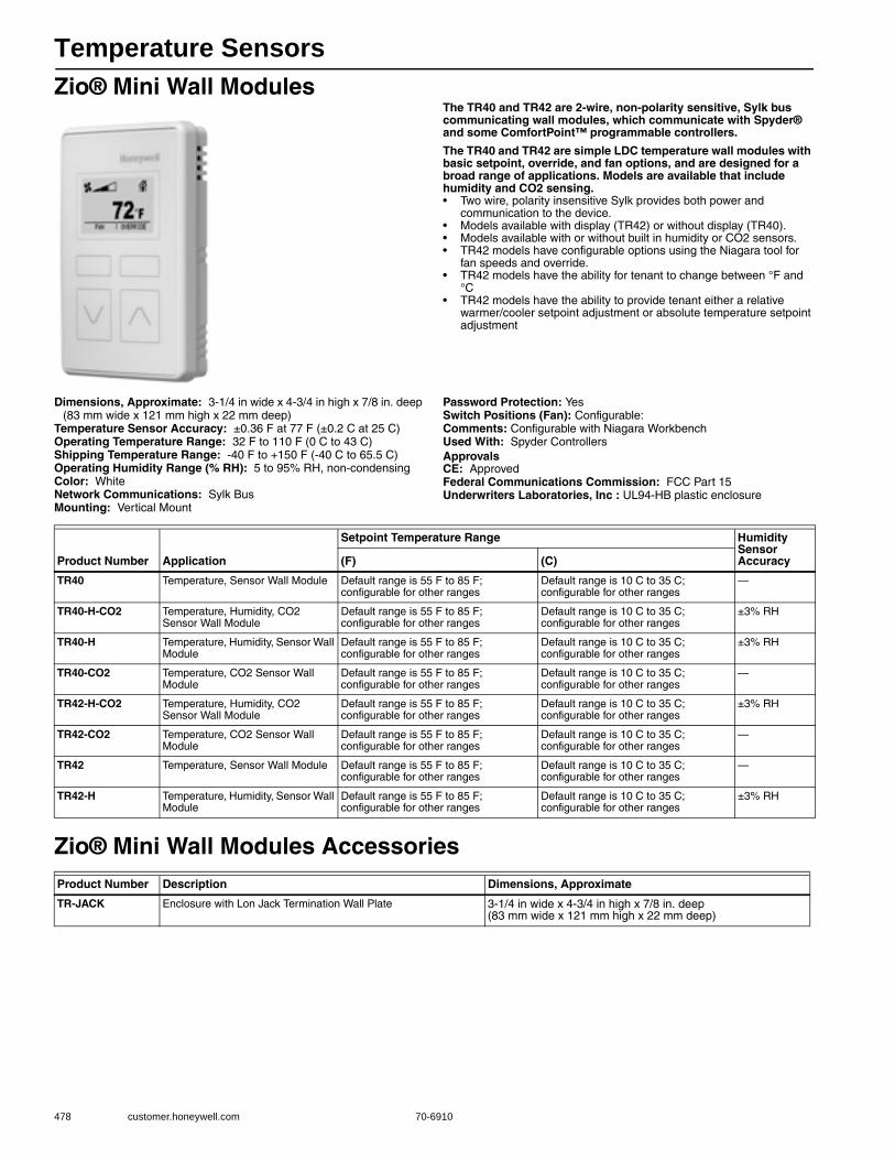
Temperature Sensors
478 customer.honeywell.com 70-6910
Zio® Mini Wall ModulesThe TR40 and TR42 are 2-wire, non-polarity sensitive, Sylk bus communicating wall modules, which communicate with Spyder® and some ComfortPoint™ programmable controllers.
The TR40 and TR42 are simple LDC temperature wall modules with basic setpoint, override, and fan options, and are designed for a broad range of applications. Models are available that include humidity and CO2 sensing.• Two wire, polarity insensitive Sylk provides both power and
communication to the device.• Models available with display (TR42) or without display (TR40).• Models available with or without built in humidity or CO2 sensors.• TR42 models have configurable options using the Niagara tool for
fan speeds and override.• TR42 models have the ability for tenant to change between °F and
°C• TR42 models have the ability to provide tenant either a relative
warmer/cooler setpoint adjustment or absolute temperature setpoint adjustment
Dimensions, Approximate: 3-1/4 in wide x 4-3/4 in high x 7/8 in. deep (83 mm wide x 121 mm high x 22 mm deep)
Temperature Sensor Accuracy: ±0.36 F at 77 F (±0.2 C at 25 C)Operating Temperature Range: 32 F to 110 F (0 C to 43 C)Shipping Temperature Range: -40 F to +150 F (-40 C to 65.5 C)Operating Humidity Range (% RH): 5 to 95% RH, non-condensingColor: WhiteNetwork Communications: Sylk BusMounting: Vertical Mount
Password Protection: YesSwitch Positions (Fan): Configurable:Comments: Configurable with Niagara WorkbenchUsed With: Spyder ControllersApprovalsCE: ApprovedFederal Communications Commission: FCC Part 15Underwriters Laboratories, Inc : UL94-HB plastic enclosure
Zio® Mini Wall Modules Accessories
Product Number Application
Setpoint Temperature Range Humidity Sensor Accuracy(F) (C)
TR40 Temperature, Sensor Wall Module Default range is 55 F to 85 F; configurable for other ranges
Default range is 10 C to 35 C; configurable for other ranges
—
TR40-H-CO2 Temperature, Humidity, CO2 Sensor Wall Module
Default range is 55 F to 85 F; configurable for other ranges
Default range is 10 C to 35 C; configurable for other ranges
±3% RH
TR40-H Temperature, Humidity, Sensor Wall Module
Default range is 55 F to 85 F; configurable for other ranges
Default range is 10 C to 35 C; configurable for other ranges
±3% RH
TR40-CO2 Temperature, CO2 Sensor Wall Module
Default range is 55 F to 85 F; configurable for other ranges
Default range is 10 C to 35 C; configurable for other ranges
—
TR42-H-CO2 Temperature, Humidity, CO2 Sensor Wall Module
Default range is 55 F to 85 F; configurable for other ranges
Default range is 10 C to 35 C; configurable for other ranges
±3% RH
TR42-CO2 Temperature, CO2 Sensor Wall Module
Default range is 55 F to 85 F; configurable for other ranges
Default range is 10 C to 35 C; configurable for other ranges
—
TR42 Temperature, Sensor Wall Module Default range is 55 F to 85 F; configurable for other ranges
Default range is 10 C to 35 C; configurable for other ranges
—
TR42-H Temperature, Humidity, Sensor Wall Module
Default range is 55 F to 85 F; configurable for other ranges
Default range is 10 C to 35 C; configurable for other ranges
±3% RH
Product Number Description Dimensions, Approximate
TR-JACK Enclosure with Lon Jack Termination Wall Plate 3-1/4 in wide x 4-3/4 in high x 7/8 in. deep (83 mm wide x 121 mm high x 22 mm deep)
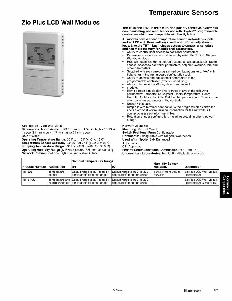
Temperature Sensors
70-6910 479
Com
mercial
Com
ponents
Zio Plus LCD Wall ModulesThe TR70 and TR70-H are 2-wire, non-polarity sensitive, Sylk™ bus communicating wall modules for use with Spyder™ programmable controllers which are compatible with the Sylk bus.
All models have a space-temperature sensor, network bus jack, and an LCD with three soft keys and two Up/Down adjustment keys. Like the TR71, but includes access to controller schedule and has more memory for additional parameters.• Ability to control user access to controller parameters. • Parameter access can be customized by using the Tridium Niagara
Workbench tool. • Programmable for: Home screen options, tenant access, contractor
access, access to controller parameters, setpoint, override, fan, and other parameters.
• Supplied with eight pre-programmed configurations (e.g. VAV with balancing) in the wall module configuration tool.
• Ability to access and adjust most parameters in the• programmable controller (except Scheduling). • Ability to balance the VAV system from the wall• module. • Home screen can display one to three of any of the following
parameters: Temperature Setpoint, Room Temperature, Room Humidity, Outdoor Humidity, Outdoor Temperature, and Time, or one of virtually any parameter in the controller.
• Network bus jack. • Simple 2-wire terminal connection to the programmable controller
and an optional 2-wire terminal connection for the network. All connections are polarity insensitive.
• Retention of user configuration, including setpoints after a power outage.
Application Type: Wall ModuleDimensions, Approximate: 3 5/16 in. wide x 4 5/8 in. high x 15/16 in.
deep (84 mm wide x 117 mm high x 24 mm deep) Color: WhiteOperating Temperature Range: 30 F to 110 F (-1 C to 43 C) Temperature Sensor Accuracy: ±0.36 F at 77 F (±0.2 C at 25 C)Shipping Temperature Range: -40 F to +150 F (-40 C to 65.5 C) Operating Humidity Range (% RH): 5 to 95% RH, non-condensingNetwork Communications: Sylk Bus and Network Jack
Network Jack: YesMounting: Vertical MountSwitch Positions (Fan): ConfigurableComments: Configurable with Niagara WorkbenchUsed With: Spyder Sylk EnhancedApprovalsCE: ApprovedFederal Communications Commission: FCC Part 15Underwriters Laboratories, Inc: UL94-HB plastic enclosure
Product Number Application
Setpoint Temperature RangeHumidity Sensor Accuracy Description(F) (C)
TR75/U Temperature sensor
Default range is 55 F to 85 F; configurable for other ranges
Default range is 10 C to 35 C; configurable for other ranges
±5% RH from 20% to 80% RH
Zio Plus LCD Wall Module (Temperature)
TR75-H/U Temperature and Humidity Sensor
Default range is 55 F to 85 F; configurable for other ranges
Default range is 10 C to 35 C; configurable for other ranges
— Zio Plus LCD Wall Module (Temperature & Humidity)
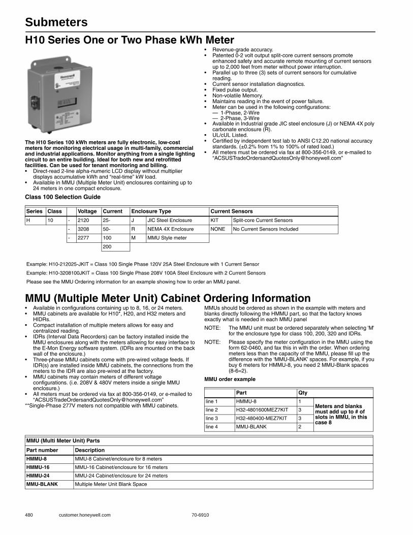
Submeters
480 customer.honeywell.com 70-6910
H10 Series One or Two Phase kWh Meter
The H10 Series 100 kWh meters are fully electronic, low-cost meters for monitoring electrical usage in multi-family, commercial and industrial applications. Monitor anything from a single lighting circuit to an entire building. Ideal for both new and retrofitted facilities. Can be used for tenant monitoring and billing.• Direct-read 2-line alpha-numeric LCD display without multiplier
displays accumulative kWh and “real-time” kW load.• Available in MMU (Multiple Meter Unit) enclosures containing up to
24 meters in one compact enclosure.
• Revenue-grade accuracy.• Patented 0-2 volt output split-core current sensors promote
enhanced safety and accurate remote mounting of current sensors up to 2,000 feet from meter without power interruption.
• Parallel up to three (3) sets of current sensors for cumulative reading.
• Current sensor installation diagnostics.• Fixed pulse output.• Non-volatile Memory.• Maintains reading in the event of power failure.• Meter can be used in the following configurations:
— 1-Phase, 2-Wire— 2-Phase, 3-Wire
• Available in Industrial grade JIC steel enclosure (J) or NEMA 4X poly carbonate enclosure (R).
• UL/cUL Listed.• Certified by independent test lab to ANSI C12.20 national accuracy
standards. (±0.2% from 1% to 100% of rated load.)• All meters must be ordered via fax at 800-356-0149, or e-mailed to
Class 100 Selection Guide
MMU (Multiple Meter Unit) Cabinet Ordering Information• Available in configurations containing up to 8, 16, or 24 meters.• MMU cabinets are available for H10*, H20, and H32 meters and
HIDRs.• Compact installation of multiple meters allows for easy and
centralized reading.• IDRs (Interval Data Recorders) can be factory installed inside the
MMU enclosures along with the meters allowing for easy interface to the E-Mon Energy software system. (IDRs are mounted on the back wall of the enclosure.)
• Three-phase MMU cabinets come with pre-wired voltage feeds. If IDR(s) are installed inside MMU cabinets, the connections from the meters to the IDR are also pre-wired at the factory.
• MMU cabinets may contain meters of different voltage configurations. (i.e. 208V & 480V meters inside a single MMU enclosure.)
• All meters must be ordered via fax at 800-356-0149, or e-mailed to “[email protected]”
**Single-Phase 277V meters not compatible with MMU cabinets.
MMUs should be ordered as shown in the example with meters and blanks directly following the HMMU part, so that the factory knows exactly what is needed in each MMU panel
NOTE: The MMU unit must be ordered separately when selecting 'M' for the enclosure type for class 100, 200, 320 and IDRs.
NOTE: Please specify the meter configuration in the MMU using the form 62-0460, and fax this in with the order. When ordering meters less than the capacity of the MMU, please fill up the difference with the ‘MMU-BLANK’ spaces. For example, if you buy 6 meters for HMMU-8, you need 2 MMU-Blank spaces (8-6=2).
MMU order example
Series Class Voltage Current Enclosure Type Current Sensors
H 10 - 2120 25- J JIC Steel Enclosure KIT Split-core Current Sensors
- 3208 50- R NEMA 4X Enclosure NONE No Current Sensors Included
- 2277 100 M MMU Style meter
200
Example: H10-212025-JKIT = Class 100 Single Phase 120V 25A Steel Enclosure with 1 Current Sensor
Example: H10-3208100JKIT = Class 100 Single Phase 208V 100A Steel Enclosure with 2 Current Sensors
Please see the MMU Ordering information for an example showing how to order an MMU panel.
Part Qty
line 1 HMMU-8 1Meters and blanks must add up to # of slots in MMU, in this case 8
line 2 H32-4801600MEZ7KIT 3
line 3 H32-480400-MEZ7KIT 3
line 4 MMU-BLANK 2
MMU (Multi Meter Unit) Parts
Part number Description
HMMU-8 MMU-8 Cabinet/enclosure for 8 meters
HMMU-16 MMU-16 Cabinet/enclosure for 16 meters
HMMU-24 MMU-24 Cabinet/enclosure for 24 meters
MMU-BLANK Multiple Meter Unit Blank Space

Submeters
70-6910 481
Com
mercial
Com
ponents
H20 Series Three Phase kWh demand meterThe H20 Series 200 kWh meters are fully electronic, low cost meters for monitoring electrical usage in multifamily, commercial and industrial applications.• Direct-read 2-line alpha-numeric LCD display without multiplier
displays cumulative kWh & “real-time” kW load.• Demand option displays kW/Demand and kW Peak date and time
(15 minute interval standard, 30 and 60 minute intervals available.)• Patented 0-2 volt output split-core current sensors promote
enhanced safety and accurate remote mounting of current sensors up to 2000 feet from meter without power interruption.
• Onboard installation diagnostics & verification system.• Parallel up to three (3) sets of current sensors for cumulative
reading.• Meter can be used on the following configurations:
3-Phase, 4-Wire3-Phase, 3-Wire2-Phase, 3-Wire
• Fixed-value pulse output.• Available in both industrial grade JIC steel enclosure and NEMA 4X
polycarbonate enclosure.• Non-volatile Memory.• UL/CUL Listed.• Revenue Grade Accuracy. Certified by independent test lab to ANSI
C12.20 national accuracy standards. (±0.2% from 1% to 100% of rated load.)
• All meters must be ordered via fax at 800-356-0149, or e-mailed to “[email protected]”
Class 200 and Green Net Meter Selection Guide
Series Class Voltage Current Enclosure Type Green or Demand Option Current Sensors
H 20 - 120 100- J JIC Steel Enclosure -G- Green Class Meter KIT Split-core Current Sensors
- 208 200- R NEMA 4X Enclosure KIT No Options, Split Core Sensors NONE No Current Sensors Included
- 480 400- M MMU Style Meter SCS Solid-core Current Sensors
600 800- XXX No Options. No Sensors
1600
3200
Example: H20-208100-RKIT = Class 200 Three Phase 208/240V 100A NEMA 4X Enclosure with 3 Current Sensors.
Example: H20-2081600R-D-KIT = Class 200 Three Phase 208/240V 1600A NEMA 4X Enclosure, Demand Option, with Three Current Sensors
Please see the MMU Ordering information for an example showing how to order an MMU panel.
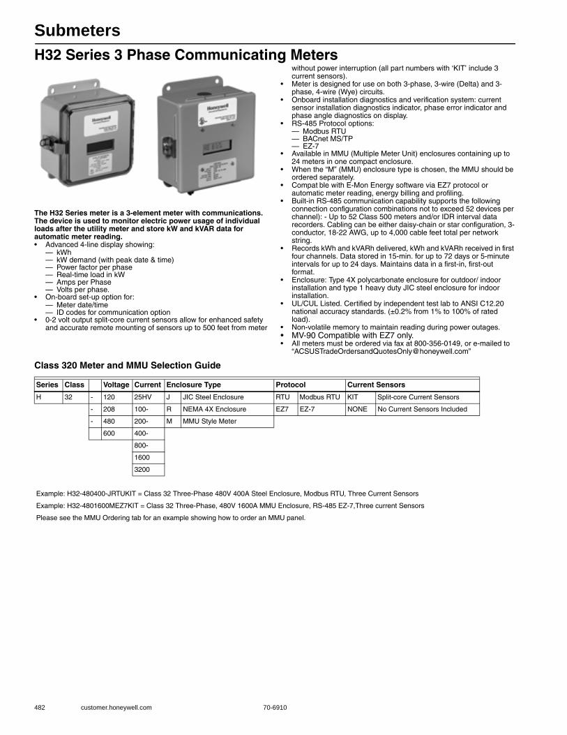
Submeters
482 customer.honeywell.com 70-6910
H32 Series 3 Phase Communicating Meters
The H32 Series meter is a 3-element meter with communications. The device is used to monitor electric power usage of individual loads after the utility meter and store kW and kVAR data for automatic meter reading.• Advanced 4-line display showing:
— kWh— kW demand (with peak date & time)— Power factor per phase— Real-time load in kW— Amps per Phase— Volts per phase.
• On-board set-up option for:— Meter date/time— ID codes for communication option
• 0-2 volt output split-core current sensors allow for enhanced safety and accurate remote mounting of sensors up to 500 feet from meter
without power interruption (all part numbers with ‘KIT’ include 3 current sensors).
• Meter is designed for use on both 3-phase, 3-wire (Delta) and 3-phase, 4-wire (Wye) circuits.
• Onboard installation diagnostics and verification system: current sensor installation diagnostics indicator, phase error indicator and phase angle diagnostics on display.
• RS-485 Protocol options:— Modbus RTU— BACnet MS/TP— EZ-7
• Available in MMU (Multiple Meter Unit) enclosures containing up to 24 meters in one compact enclosure.
• When the “M” (MMU) enclosure type is chosen, the MMU should be ordered separately.
• Compat ble with E-Mon Energy software via EZ7 protocol or automatic meter reading, energy billing and profiling.
• Built-in RS-485 communication capability supports the following connection configuration combinations not to exceed 52 devices per channel): - Up to 52 Class 500 meters and/or IDR interval data recorders. Cabling can be either daisy-chain or star configuration, 3-conductor, 18-22 AWG, up to 4,000 cable feet total per network string.
• Records kWh and kVARh delivered, kWh and kVARh received in first four channels. Data stored in 15-min. for up to 72 days or 5-minute intervals for up to 24 days. Maintains data in a first-in, first-out format.
• Enclosure: Type 4X polycarbonate enclosure for outdoor/ indoor installation and type 1 heavy duty JIC steel enclosure for indoor installation.
• UL/CUL Listed. Certified by independent test lab to ANSI C12.20 national accuracy standards. (±0.2% from 1% to 100% of rated load).
• Non-volatile memory to maintain reading during power outages.• MV-90 Compatible with EZ7 only.• All meters must be ordered via fax at 800-356-0149, or e-mailed to
Class 320 Meter and MMU Selection Guide
Series Class Voltage Current Enclosure Type Protocol Current Sensors
H 32 - 120 25HV J JIC Steel Enclosure RTU Modbus RTU KIT Split-core Current Sensors
- 208 100- R NEMA 4X Enclosure EZ7 EZ-7 NONE No Current Sensors Included
- 480 200- M MMU Style Meter
600 400-
800-
1600
3200
Example: H32-480400-JRTUKIT = Class 32 Three-Phase 480V 400A Steel Enclosure, Modbus RTU, Three Current Sensors
Example: H32-4801600MEZ7KIT = Class 32 Three-Phase, 480V 1600A MMU Enclosure, RS-485 EZ-7,Three current Sensors
Please see the MMU Ordering tab for an example showing how to order an MMU panel.
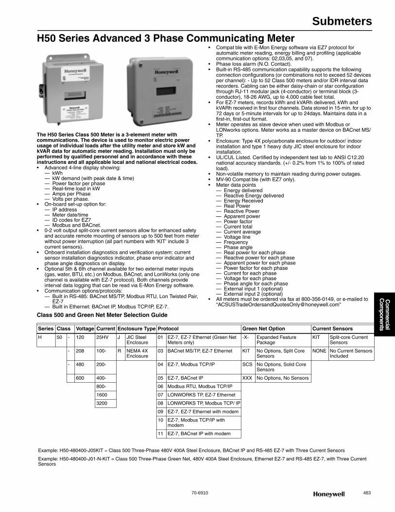
Submeters
70-6910 483
Com
mercial
Com
ponents
H50 Series Advanced 3 Phase Communicating Meter
The H50 Series Class 500 Meter is a 3-element meter with communications. The device is used to monitor electric power usage of individual loads after the utility meter and store kW and kVAR data for automatic meter reading. Installation must only be performed by qualified personnel and in accordance with these instructions and all applicable local and national electrical codes.• Advanced 4-line display showing:
— kWh— kW demand (with peak date & time)— Power factor per phase— Real-time load in kW— Amps per Phase— Volts per phase.
• On-board set-up option for:— IP address— Meter date/time— ID codes for EZ7— Modbus and BACnet.
• 0-2 volt output split-core current sensors allow for enhanced safety and accurate remote mounting of sensors up to 500 feet from meter without power interruption (all part numbers with ‘KIT’ include 3 current sensors).
• Onboard installation diagnostics and verification system: current sensor installation diagnostics indicator, phase error indicator and phase angle diagnostics on display.
• Optional 5th & 6th channel available for two external meter inputs (gas, water, BTU, etc.) on Modbus, BACnet, and LonWorks (only one channel is available with EZ-7 protocol). Both channels provide interval data logging that can be read via E-Mon Energy software.
• Communication options/protocols:— Built in RS-485: BACnet MS/TP, Modbus RTU, Lon Twisted Pair,
EZ-7— Built in Ethernet: BACnet IP, Modbus TCP/IP, EZ-7.
• Compat ble with E-Mon Energy software via EZ7 protocol for automatic meter reading, energy billing and profiling (applicable communication options: 02,03,05, and 07).
• Phase loss alarm (N.O. Contact).• Built-in RS-485 communication capability supports the following
connection configurations (or combinations not to exceed 52 devices per channel): - Up to 52 Class 500 meters and/or IDR interval data recorders. Cabling can be either daisy-chain or star configuration through RJ-11 modular jack (4-conductor) or terminal block (3-conductor), 18-26 AWG, up to 4,000 cable feet total.
• For EZ-7 meters, records kWh and kVARh delivered, kWh and kVARh received in first four channels. Data stored in 15-min. for up to 72 days or 5-minute intervals for up to 24days. Maintains data in a first-in, first-out format.
• Meter operates as slave device when used with Modbus or LONworks options. Meter works as a master device on BACnet MS/TP.
• Enclosure: Type 4X polycarbonate enclosure for outdoor/ indoor installation and type 1 heavy duty JIC steel enclosure for indoor installation.
• UL/CUL Listed. Certified by independent test lab to ANSI C12.20 national accuracy standards. (+/- 0.2% from 1% to 100% of rated load).
• Non-volatile memory to maintain reading during power outages.• MV-90 Compat ble (with EZ7 only).• Meter data points
— Energy delivered— Reactive Energy delivered— Energy Received— Real Power— Reactive Power— Apparent power— Power factor— Current total— Current average— Voltage line— Frequency— Phase angle— Real power for each phase— Reactive power for each phase— Apparent power for each phase— Power factor for each phase— Current for each phase— Voltage for each phase— Phase angle for each phase— External input 1 (optional)— External input 2 (optional)
• All meters must be ordered via fax at 800-356-0149, or e-mailed to “[email protected]”
Class 500 and Green Net Meter Selection Guide
Series Class Voltage Current Enclosure Type Protocol Green Net Option Current Sensors
H 50 - 120 25HV J JIC Steel Enclosure
01 EZ-7, EZ-7 Ethernet (Green Net Meters only)
-X- Expanded Feature Package
KIT Split-core Current Sensors
- 208 100- R NEMA 4X Enclosure
03 BACnet MS/TP, EZ-7 Ethernet KIT No Options, Split Core Sensors
NONE No Current Sensors Included
- 480 200- 04 EZ-7, Modbus TCP/IP SCS No Options, Solid Core Sensors
600 400- 05 EZ-7, BACnet IP XXX No Options, No Sensors
800- 06 Modbus RTU, Modbus TCP/IP
1600 07 LONWORKS TP, EZ-7 Ethernet
3200 08 LONWORKS TP, Modbus TCP/ IP
09 EZ-7, EZ-7 Ethernet with modem
10 EZ-7, Modbus TCP/IP with modem
11 EZ-7, BACnet IP with modem
Example: H50-480400-J05KIT = Class 500 Three-Phase 480V 400A Steel Enclosure, BACnet IP and RS-485 EZ-7 with Three Current Sensors
Example: H50-480400-J01-N-KIT = Class 500 Three-Phase Green Net, 480V 400A Steel Enclosure, Ethernet EZ-7 and RS-485 EZ-7, with Three Current Sensors
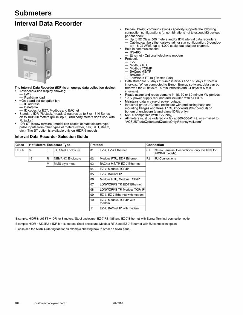
Submeters
484 customer.honeywell.com 70-6910
Interval Data Recorder
The Interval Data Recorder (IDR) is an energy data collection device.• Advanced 4-line display showing:
— kWh— Real-time load
• • On-board set-up option for:— IP address— Date/time— ID codes for EZ7, Modbus and BACnet
• Standard IDR (RJ Jacks) reads & records up to 8 or 16 H-Series class 100/200 meters (pulse input). (3rd party meters don’t work with RJ jacks.)
• IDR-ST (screw terminal) model can accept contact closure type pulse inputs from other types of meters (water, gas, BTU, steam, etc.). The ST option is available only on HIDR-8 models.
• Built-in RS-485 communications capability supports the following connection configurations (or combinations not to exceed 52 devices per channel):— Up to 52 Class 500 meters and/or IDR interval data recorders— Cabling can be either daisy-chain or star configuration, 3-conduc-
tor, 18-22 AWG, up to 4,000 cable feet total per channel.• Built-in communications
— RS-485— Ethernet - Optional telephone modem
• Protocols— EZ7— Modbus RTU— Modbus TCP/IP— BACnet MS/TP— BACnet IP— LonWorks FT-10 (Twisted Pair)
• Data stored for 55 days at 5-min intervals and 165 days at 15-min intervals. (When connected to E-mon Energy software, data can be retrieved for 72 days at 15-min intervals and 24 days at 5-min intervals).
• Reads usage and reads demand in 15, 30 or 60-minute kW periods.• 120V power supply required and included with all IDR's.• Maintains data in case of power outage.• Industrial-grade JIC steel enclosure with padlocking hasp and
mounting flanges and three 1 1/16 knockouts (3/4” conduit) on bottom of enclosure (stand-alone IDR’s only).
• MV-90 compatible (with EZ7 only).• All meters must be ordered via fax at 800-356-0149, or e-mailed to
Interval Data Recorder Selection Guide
Class # of Meters Enclosure Type Protocol Connection
HIDR- 8- J JIC Steel Enclosure 01 EZ-7, EZ-7 Ethernet ST Screw Terminal Connections (only available for HIDR-8 models)
16 R NEMA 4X Enclosure 02 Modbus RTU, EZ-7 Ethernet RJ RJ Connections
M MMU style meter 03 BACnet MS/TP, EZ-7 Ethernet
04 EZ-7, Modbus TCP/IP
05 EZ-7, BACnet IP
06 Modbus RTU, Modbus TCP/IP
07 LONWORKS TP, EZ-7 Ethernet
08 LONWORKS TP, Modbus TCP/ IP
09 EZ-7, EZ-7 Ethernet with modem
10 EZ-7, Modbus TCP/IP with modem
11 EZ-7, BACnet IP with modem
Example: HIDR-8-J05ST = IDR for 8 meters, Steel enclosure, EZ-7 RS-485 and EZ-7 Ethernet with Screw Terminal connection option
Example: HIDR-16J02RJ = IDR for 16 meters, Steel enclosure, Modbus RTU and EZ-7 Ethernet with RJ connection option
Please see the MMU Ordering tab for an example showing how to order an MMU panel.
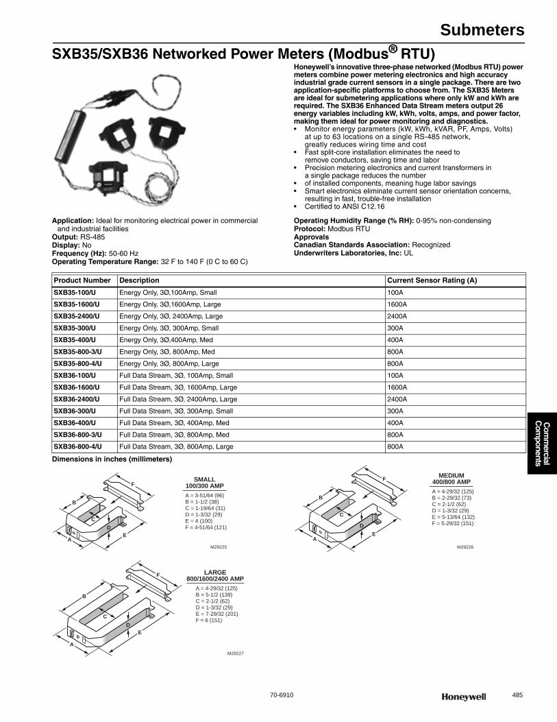
Submeters
70-6910 485
Com
mercial
Com
ponents
SXB35/SXB36 Networked Power Meters (Modbus® RTU)Honeywell’s innovative three-phase networked (Modbus RTU) power meters combine power metering electronics and high accuracy industrial grade current sensors in a single package. There are two application-specific platforms to choose from. The SXB35 Meters are ideal for submetering applications where only kW and kWh are required. The SXB36 Enhanced Data Stream meters output 26 energy variables including kW, kWh, volts, amps, and power factor, making them ideal for power monitoring and diagnostics.• Monitor energy parameters (kW, kWh, kVAR, PF, Amps, Volts)
at up to 63 locations on a single RS-485 network, greatly reduces wiring time and cost
• Fast split-core installation eliminates the need to remove conductors, saving time and labor
• Precision metering electronics and current transformers in a single package reduces the number
• of installed components, meaning huge labor savings • Smart electronics eliminate current sensor orientation concerns,
resulting in fast, trouble-free installation • Certified to ANSI C12.16
Application: Ideal for monitoring electrical power in commercial and industrial facilities
Output: RS-485Display: NoFrequency (Hz): 50-60 HzOperating Temperature Range: 32 F to 140 F (0 C to 60 C)
Operating Humidity Range (% RH): 0-95% non-condensingProtocol: Modbus RTUApprovalsCanadian Standards Association: RecognizedUnderwriters Laboratories, Inc: UL
Dimensions in inches (millimeters)
Product Number Description Current Sensor Rating (A)
SXB35-100/U Energy Only, 3Ø,100Amp, Small 100A
SXB35-1600/U Energy Only, 3Ø,1600Amp, Large 1600A
SXB35-2400/U Energy Only, 3Ø, 2400Amp, Large 2400A
SXB35-300/U Energy Only, 3Ø, 300Amp, Small 300A
SXB35-400/U Energy Only, 3Ø,400Amp, Med 400A
SXB35-800-3/U Energy Only, 3Ø, 800Amp, Med 800A
SXB35-800-4/U Energy Only, 3Ø, 800Amp, Large 800A
SXB36-100/U Full Data Stream, 3Ø, 100Amp, Small 100A
SXB36-1600/U Full Data Stream, 3Ø, 1600Amp, Large 1600A
SXB36-2400/U Full Data Stream, 3Ø, 2400Amp, Large 2400A
SXB36-300/U Full Data Stream, 3Ø, 300Amp, Small 300A
SXB36-400/U Full Data Stream, 3Ø, 400Amp, Med 400A
SXB36-800-3/U Full Data Stream, 3Ø, 800Amp, Med 800A
SXB36-800-4/U Full Data Stream, 3Ø, 800Amp, Large 800A
B
E
CD
SMALL100/300 AMPA = 3-51/64 (96)B = 1-1/2 (38)C = 1-19/64 (31)D = 1-3/32 (29)E = 4 (100) F = 4-51/64 (121)
A
F
M29225
B
E
LARGE800/1600/2400 AMP
A = 4-29/32 (125)B = 5-1/2 (139)C = 2-1/2 (62)D = 1-3/32 (29)E = 7-29/32 (201) F = 6 (151)
F
A
CD
M29227
MEDIUM400/800 AMPA = 4-29/32 (125)B = 2-29/32 (73)C = 2-1/2 (62)D = 1-3/32 (29)E = 5-13/64 (132) F = 5-29/32 (151)
F
B
E
C
A
D
M29226
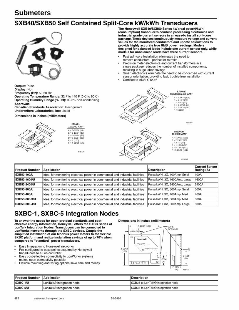
Submeters
486 customer.honeywell.com 70-6910
SXB40/SXB50 Self Contained Split-Core kW/kWh TransducersThe Honeywell SXB40/SXB50 Series kW (real power)/kWh (consumption) transducers combine processing electronics and industrial grade current sensors in an easy-to install split-core package. These devices continuously measure voltage and current values for the monitored conductors and update calculations to provide highly accurate true RMS power readings. Models designed for balanced loads include one current sensor only, while models for unbalanced loads have three current sensors.• Fast split-core installation eliminates the need to
remove conductors - perfect for retrofits • Precision meter electronics and current transformers in a
single package reduces the number of installed components, resulting in huge labor savings
• Smart electronics eliminate the need to be concerned with current sensor orientation, providing fast, trouble-free installation
• Certified to ANSI C12.16
Output: PulseDisplay: NoFrequency (Hz): 50-60 HzOperating Temperature Range: 32 F to 140 F (0 C to 60 C) Operating Humidity Range (% RH): 0-95% non-condensingApprovalsCanadian Standards Association: RecognizedUnderwriters Laboratories, Inc: Listed
Dimensions in inches (millimeters)
SXBC-1, SXBC-5 Integration NodesTo answer the needs for open-protocol standards and cost-effective energy information, Honeywell offers the SXBC Series of LonTalk Integration Nodes. Transducers can be connected to LonWorks networks through the SXBC devices. Couple the simplified installation of our Modbus power meters to the flexible SXBC platform and realize installation savings of up to 70% when compared to “standard” power transducers.
• Easy Integration to Honeywell networks • Pre-configured to pass points acquired by Honeywell
transducers to a Lon controller • Easy cost-effective connectivity to LonWorks systems
makes open connectivity possible • Flexible mounting and wiring options save time and money
Dimensions in inches (millimeters)
B
E
CD
SMALL100/300 AMPA = 3-51/64 (96)B = 1-13/64 (30)C = 1-19/64 (31)D = 1-13/64 (30)E = 4 (100) F = 4-51/64 (121)
A
F
M29198
B
E
LARGE800/1600/2400 AMP
A = 4-29/32 (125)B = 5-1/2 (139)C = 2-1/2 (62)D = 1-13/64 (30)E = 7-29/32 (201) F = 6 (151)
F
A
CD
M29200
MEDIUM400/800 AMPA = 4-29/32 (125)B = 2-29/32 (73)C = 2-1/2 (62)D = 1-13/64 (30)E = 5-13/64 (132) F = 5-29/32 (151)
F
B
E
C
A
D
M29199
Product Number Application DescriptionCurrent Sensor Rating (A)
SXB53-100/U Ideal for monitoring electrical power in commercial and industrial facilities Pulse/kWH, 3Ø, 100Amp, Small 100A
SXB53-1600/U Ideal for monitoring electrical power in commercial and industrial facilities Pulse/kWH, 3Ø, 1600Amp, Large 1600A
SXB53-2400/U Ideal for monitoring electrical power in commercial and industrial facilities Pulse/kWH, 3Ø, 2400Amp, Large 2400A
SXB53-300/U Ideal for monitoring electrical power in commercial and industrial facilities Pulse/kWH, 3Ø, 300Amp, Small 300A
SXB53-400/U Ideal for monitoring electrical power in commercial and industrial facilities Pulse/kWH, 3Ø, 400Amp, Med 400A
SXB53-800-3/U Ideal for monitoring electrical power in commercial and industrial facilities Pulse/kWH, 3Ø, 800Amp, Med 800A
SXB53-800-4/U Ideal for monitoring electrical power in commercial and industrial facilities Pulse/kWH, 3Ø, 800Amp, Large 800A
CL
1-13/64(30)
4-19/64(108)
SXBC Series LonTalk® Integrat on Node
4-19/64 (108) WIREOPENING
M29415
1-13/64 (30)
2-13/64(54)
1-19/32(39)
CL
CL
Product Number Application Description
SXBC-1/U LonTalk® integration node SXB36 to LonTalk® integration node
SXBC-5/U LonTalk® integration node SXB35 to LonTalk® integration node
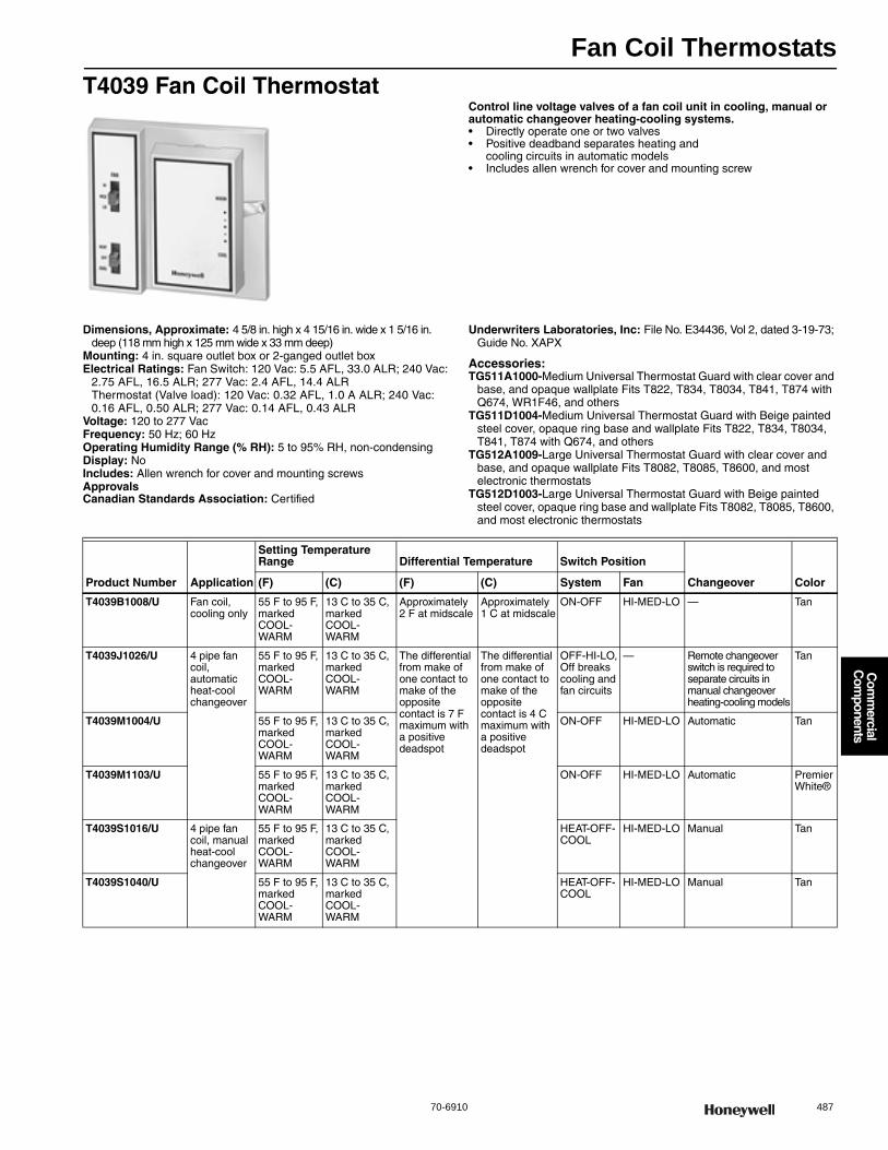
Fan Coil Thermostats
70-6910 487
Com
mercial
Com
ponents
T4039 Fan Coil ThermostatControl line voltage valves of a fan coil unit in cooling, manual or automatic changeover heating-cooling systems.• Directly operate one or two valves • Positive deadband separates heating and
cooling circuits in automatic models • Includes allen wrench for cover and mounting screw
Dimensions, Approximate: 4 5/8 in. high x 4 15/16 in. wide x 1 5/16 in. deep (118 mm high x 125 mm wide x 33 mm deep)
Mounting: 4 in. square outlet box or 2-ganged outlet boxElectrical Ratings: Fan Switch: 120 Vac: 5.5 AFL, 33.0 ALR; 240 Vac:
2.75 AFL, 16.5 ALR; 277 Vac: 2.4 AFL, 14.4 ALRThermostat (Valve load): 120 Vac: 0.32 AFL, 1.0 A ALR; 240 Vac: 0.16 AFL, 0.50 ALR; 277 Vac: 0.14 AFL, 0.43 ALR
Voltage: 120 to 277 VacFrequency: 50 Hz; 60 HzOperating Humidity Range (% RH): 5 to 95% RH, non-condensingDisplay: NoIncludes: Allen wrench for cover and mounting screwsApprovalsCanadian Standards Association: Certified
Underwriters Laboratories, Inc: File No. E34436, Vol 2, dated 3-19-73; Guide No. XAPX
Accessories:TG511A1000-Medium Universal Thermostat Guard with clear cover and
base, and opaque wallplate Fits T822, T834, T8034, T841, T874 with Q674, WR1F46, and others
TG511D1004-Medium Universal Thermostat Guard with Beige painted steel cover, opaque ring base and wallplate Fits T822, T834, T8034, T841, T874 with Q674, and others
TG512A1009-Large Universal Thermostat Guard with clear cover and base, and opaque wallplate Fits T8082, T8085, T8600, and most electronic thermostats
TG512D1003-Large Universal Thermostat Guard with Beige painted steel cover, opaque ring base and wallplate Fits T8082, T8085, T8600, and most electronic thermostats
Product Number Application
Setting Temperature Range Differential Temperature Switch Position
Changeover Color(F) (C) (F) (C) System Fan
T4039B1008/U Fan coil, cooling only
55 F to 95 F, marked COOL-WARM
13 C to 35 C, marked COOL-WARM
Approximately 2 F at midscale
Approximately 1 C at midscale
ON-OFF HI-MED-LO — Tan
T4039J1026/U 4 pipe fan coil, automatic heat-cool changeover
55 F to 95 F, marked COOL-WARM
13 C to 35 C, marked COOL-WARM
The differential from make of one contact to make of the opposite contact is 7 F maximum with a positive deadspot
The differential from make of one contact to make of the opposite contact is 4 C maximum with a positive deadspot
OFF-HI-LO, Off breaks cooling and fan circuits
— Remote changeover switch is required to separate circuits in manual changeover heating-cooling models
Tan
T4039M1004/U 55 F to 95 F, marked COOL-WARM
13 C to 35 C, marked COOL-WARM
ON-OFF HI-MED-LO Automatic Tan
T4039M1103/U 55 F to 95 F, marked COOL-WARM
13 C to 35 C, marked COOL-WARM
ON-OFF HI-MED-LO Automatic Premier White®
T4039S1016/U 4 pipe fan coil, manual heat-cool changeover
55 F to 95 F, marked COOL-WARM
13 C to 35 C, marked COOL-WARM
HEAT-OFF-COOL
HI-MED-LO Manual Tan
T4039S1040/U 55 F to 95 F, marked COOL-WARM
13 C to 35 C, marked COOL-WARM
HEAT-OFF-COOL
HI-MED-LO Manual Tan
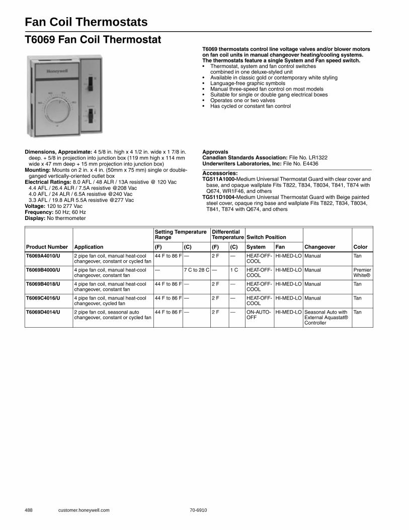
Fan Coil Thermostats
488 customer.honeywell.com 70-6910
T6069 Fan Coil ThermostatT6069 thermostats control line voltage valves and/or blower motors on fan coil units in manual changeover heating/cooling systems. The thermostats feature a single System and Fan speed switch.• Thermostat, system and fan control switches
combined in one deluxe-styled unit • Available in classic gold or contemporary white styling • Language-free graphic symbols • Manual three-speed fan control on most models • Suitable for single or double gang electrical boxes • Operates one or two valves • Has cycled or constant fan control
Dimensions, Approximate: 4 5/8 in. high x 4 1/2 in. wide x 1 7/8 in. deep. + 5/8 in projection into junction box (119 mm high x 114 mm wide x 47 mm deep + 15 mm projection into junction box)
Mounting: Mounts on 2 in. x 4 in. (50mm x 75 mm) single or double-ganged vertically-oriented outlet box
Electrical Ratings: 8.0 AFL / 48 ALR / 13A resistive @ 120 Vac4.4 AFL / 26.4 ALR / 7.5A resistive @208 Vac4.0 AFL / 24 ALR / 6.5A resistive @240 Vac3.3 AFL / 19.8 ALR 5.5A resistive @277 Vac
Voltage: 120 to 277 VacFrequency: 50 Hz; 60 HzDisplay: No thermometer
ApprovalsCanadian Standards Association: File No. LR1322Underwriters Laboratories, Inc: File No. E4436
Accessories:TG511A1000-Medium Universal Thermostat Guard with clear cover and
base, and opaque wallplate Fits T822, T834, T8034, T841, T874 with Q674, WR1F46, and others
TG511D1004-Medium Universal Thermostat Guard with Beige painted steel cover, opaque ring base and wallplate Fits T822, T834, T8034, T841, T874 with Q674, and others
Product Number Application
Setting Temperature Range
Differential Temperature Switch Position
Changeover Color(F) (C) (F) (C) System Fan
T6069A4010/U 2 pipe fan coil, manual heat-cool changeover, constant or cycled fan
44 F to 86 F — 2 F — HEAT-OFF-COOL
HI-MED-LO Manual Tan
T6069B4000/U 4 pipe fan coil, manual heat-cool changeover, constant fan
— 7 C to 28 C — 1 C HEAT-OFF-COOL
HI-MED-LO Manual Premier White®
T6069B4018/U 4 pipe fan coil, manual heat-cool changeover, constant fan
44 F to 86 F — 2 F — HEAT-OFF-COOL
HI-MED-LO Manual Tan
T6069C4016/U 4 pipe fan coil, manual heat-cool changeover, cycled fan
44 F to 86 F — 2 F — HEAT-OFF-COOL
HI-MED-LO Manual Tan
T6069D4014/U 2 pipe fan coil, seasonal auto changeover, constant or cycled fan
44 F to 86 F — 2 F — ON-AUTO-OFF
HI-MED-LO Seasonal Auto with External Aquastat® Controller
Tan
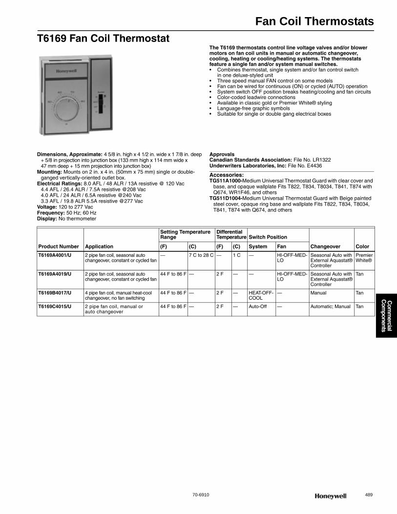
Fan Coil Thermostats
70-6910 489
Com
mercial
Com
ponents
T6169 Fan Coil ThermostatThe T6169 thermostats control line voltage valves and/or blower motors on fan coil units in manual or automatic changeover, cooling, heating or cooling/heating systems. The thermostats feature a single fan and/or system manual switches.• Combines thermostat, single system and/or fan control switch
in one deluxe-styled unit • Three speed manual FAN control on some models • Fan can be wired for continuous (ON) or cycled (AUTO) operation • System switch OFF position breaks heating/cooling and fan circuits • Color-coded leadwire connections • Available in classic gold or Premier White® styling• Language-free graphic symbols • Suitable for single or double gang electrical boxes
Dimensions, Approximate: 4 5/8 in. high x 4 1/2 in. wide x 1 7/8 in. deep+ 5/8 in projection into junction box (133 mm high x 114 mm wide x 47 mm deep + 15 mm projection into junction box)
Mounting: Mounts on 2 in. x 4 in. (50mm x 75 mm) single or double-ganged vertically-oriented outlet box.
Electrical Ratings: 8.0 AFL / 48 ALR / 13A resistive @ 120 Vac4.4 AFL / 26.4 ALR / 7.5A resistive @208 Vac4.0 AFL / 24 ALR / 6.5A resistive @240 Vac3.3 AFL / 19.8 ALR 5.5A resistive @277 Vac
Voltage: 120 to 277 VacFrequency: 50 Hz; 60 HzDisplay: No thermometer
ApprovalsCanadian Standards Association: File No. LR1322Underwriters Laboratories, Inc: File No. E4436
Accessories:TG511A1000-Medium Universal Thermostat Guard with clear cover and
base, and opaque wallplate Fits T822, T834, T8034, T841, T874 with Q674, WR1F46, and others
TG511D1004-Medium Universal Thermostat Guard with Beige painted steel cover, opaque ring base and wallplate Fits T822, T834, T8034, T841, T874 with Q674, and others
Product Number Application
Setting Temperature Range
Differential Temperature Switch Position
Changeover Color(F) (C) (F) (C) System Fan
T6169A4001/U 2 pipe fan coil, seasonal auto changeover, constant or cycled fan
— 7 C to 28 C — 1 C — HI-OFF-MED-LO
Seasonal Auto with External Aquastat® Controller
Premier White®
T6169A4019/U 2 pipe fan coil, seasonal auto changeover, constant or cycled fan
44 F to 86 F — 2 F — — HI-OFF-MED-LO
Seasonal Auto with External Aquastat® Controller
Tan
T6169B4017/U 4 pipe fan coil, manual heat-cool changeover, no fan switching
44 F to 86 F — 2 F — HEAT-OFF-COOL
— Manual Tan
T6169C4015/U 2 pipe fan coil, manual or auto changeover
44 F to 86 F — 2 F — Auto-Off — Automatic; Manual Tan

Fan Coil Thermostats
490 customer.honeywell.com 70-6910
TB6575; TB8575 Digital Fan-Coil Thermostat
The TB6575A, TB6575B, and TB8575A are a family of Digital Fan-Coil thermostats for residential and commercial applications. They are great for use in hotels, condos, and school classrooms. They provide line voltage and low voltage on/off control for various fan-coil units. The three models provide control of 2 or 4 pipe fan-coil units, 120, 240, or 24 Vac, and manual or automatic heat/cool changeover. The fan can also be controlled from the thermostat, which offers three fan speeds (Low, Med, High) and Auto. Valves and auxiliary electric heaters can be controlled using a relay or contactor system switch controlled by the thermostat.
• Simple, intuitive user interface and ease of installation • Attractive modern styling ideal for hotels and condos • Digital display of ambient temperature, setpoint, mode icons
when cooling or heating relays operate, when energy savings mode is active, and fan status
• Four buttons allow manual control of system operation, fan speed, and temperature setpoint adjustment
• VersaSpeed™ Fan Ramp Algorithm automatically adjusts Low, Medium, High fan speed
• Optional freeze protection feature that turns on heat, if necessary • Activity sensing algorithm sets back thermostat to economy mode • Auto fan rest option sets back fan to auto mode • Energy savings mode -- external energy savings input from dry contact
such as time switch, occupancy sensor, or hotel cardkey overrides comfort setpoint with selectable setback heating or cooling setpoints
• Energy savings input configurable as a normally open or normally closed dry contact
• Proportional plus integral (P+I) control algorithm for precision temperature regulation
• Selectable C or F• Adjustable deadband, in auto changeover mode, for heat and cool control• Adjustable maximum heating and minimum cooling setpoint limits • Installer setup mode allows changes of operating parameters • EEPROM permanently retains user settings, including setpoints,
during power loss (no batteries required)• Capability to display temperature sensor failure for easier troubleshooting • Optional remote temperature sensor and remote pipe sensor
Dimensions, Approximate: 3 13/16 in. high x 5 13/16 in. wide x 1 1/8 in. deep (97 mm high x 148 mm wide x 29 mm deep)
Mounting: Direct mounting on horizontal 2 x 4 in. (50mm x 75 mm) junction box. Mounts on vertical 2 x 4 in. or 4 x 4 in junction box with optional wall plate (50033847-001)
Electrical Ratings: 120 Vac, Fan Rating: 6.0 A, Relay Rating: 1.0 A; 240 Vac, Fan Rating: 3.0 A, Relay Rating: 1.0 A
Frequency: 50 Hz; 60 HzOperating Humidity Range (% RH): 5 to 95% RH, non-condensingDisplay: LCDColor: Premier White®ApprovalsCanadian Standards Association: CertifiedUnderwriters Laboratories, Inc: Meets the same requirements as UL-
873
Accessories:50033847-001-Adapter plate for mounting TB6575/TB8575 series fan
coil thermostats to vertical, single or double-gang junction boxC7041B2005-20K ohm NTC Temperature Sensor with 6 in. insertionC7041B2013-20K ohm NTC Temperature Sensor with 12 in. insertionC7041C2003-20K ohm NTC Temperature Sensor with 18 in. insertionC7041P2004-20K ohm NTC Stainless Steel Button Sensor, 11/16 in. dia.C7770A1006-6 in. Duct Probe for Return Air 20 K ohm NTC non-linear
Temperature SensorC7772A1004-20 K ohm NTC non-linear Wall Flush Mount Temperature
Sensor without logoC7772A1012-20 K ohm NTC non-linear Wall Flush Mount Temperature
Sensor with Honeywell logoTR21-20 K ohm NTC non-linear Temperature Wall ModuleTR21-A-10 K ohm NTC non-linear Temperature Wall Module
(for averaging only)PS20-20 K ohm Pipe sensor
Product Number Application
Setting Temperature Range Switch Position
Changeover Description Voltage(C) (F) System Fan
TB6575A1000/U 2 or 4 pipe fan coil, Heat/Cool manual/auto changeover, 3-speed fan, 120 - 240 Vac
10 C to 30 C
50 F to 90 F
OFF-HEAT-COOL-AUTO
HI-MED-LOW-AUTO-OFF
Manual/Auto 3-Speed Fan Coil Thermostat; 2 or 4 pipe Manual/Auto Heat/Cool changeover, 3 speed fan, Supply voltage: 120/240 Vac 50/60 Hz
120 Vac (+/- 10%) or 240 Vac (+/- 10%)
TB6575B1000/U 2 pipe fan coil, Heat/Cool manual/auto changeover, 3-speed fan, 120 - 240 Vac
10 C to 30 C
50 F to 90 F
OFF-HEAT-COOL-AUTO
HI-MED-LOW-AUTO-OFF
Manual/Auto 3-Speed Fan Coil Thermostat; 2 pipe Manual/Auto Heat/Cool changeover, 3 speed fan, Supply voltage: 120/240 Vac 50/60 Hz
120 Vac (+/- 10%) or 240 Vac (+/- 10%)
TB6575C1000/U 2 or 4 pipe fan coil, Heat/Cool manual/auto changeover, 3-speed fan, 120 - 240 Vac
10 C to 30 C
50 F to 90 F
OFF-HEAT-COOL-AUTO
HI-MED-LOW-AUTO-OFF
Manual/Auto 3-Speed Fan Coil Thermostat; 2 or 4 pipe Manual/Auto Heat/Cool changeover, 3 speed fan, Supply voltage: 120/240 Vac 50/60 Hz
120 Vac(+/-10%), 240 Vac(-15% to 10%) or 277 Vac(+/- 10%)
TB8575A1000/U 2 or 4 pipe fan coil, Heat/Cool manual/auto changeover, 3-speed fan, 24 Vac
10 C to 30 C
50 F to 90 F
OFF-HEAT-COOL-AUTO
HI-MED-LOW-AUTO-OFF
Manual/Auto 3-Speed Fan Coil Thermostat; 2 or 4 pipe Manual/Auto Heat or Cool changeover, 3 speed fan, Supply voltage: 24 Vac 50/60 Hz
20 to 30 Vac
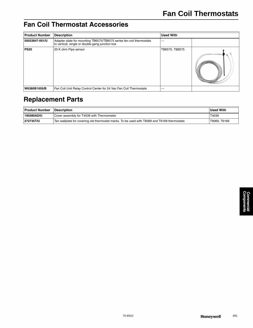
Fan Coil Thermostats
70-6910 491
Com
mercial
Com
ponents
Fan Coil Thermostat Accessories
Replacement Parts
Product Number Description Used With
50033847-001/U Adapter plate for mounting TB6575/TB8575 series fan coil thermostats to vertical, single or double-gang junction box
—
PS20 20 K ohm Pipe sensor TB6575, TB8575
W6380B1005/B Fan Coil Unit Relay Control Center for 24 Vac Fan Coil Thermostats —
Product Number Description Used With
190389AD/U Cover assembly for T4039 with Thermometer T4039
272735T/U Tan wallplate for covering old thermostat marks. To be used with T6069 and T6169 thermostats T6069, T6169
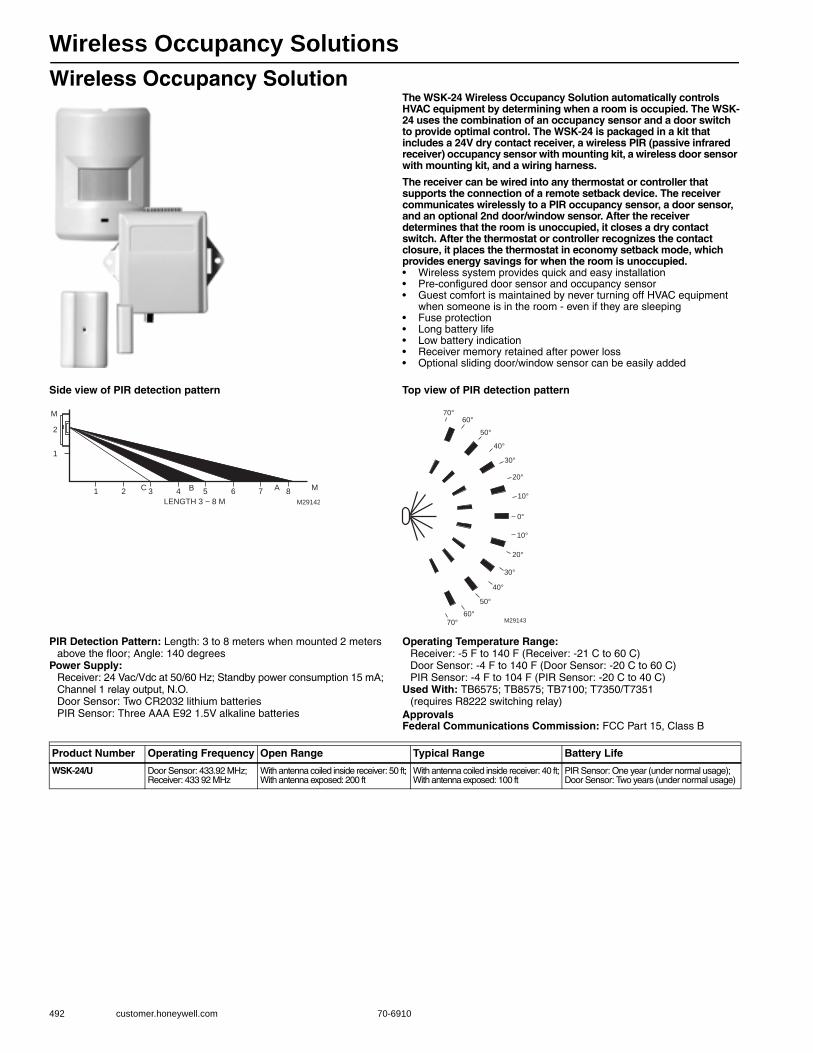
Wireless Occupancy Solutions
492 customer.honeywell.com 70-6910
Wireless Occupancy SolutionThe WSK-24 Wireless Occupancy Solution automatically controls HVAC equipment by determining when a room is occupied. The WSK-24 uses the combination of an occupancy sensor and a door switch to provide optimal control. The WSK-24 is packaged in a kit that includes a 24V dry contact receiver, a wireless PIR (passive infrared receiver) occupancy sensor with mounting kit, a wireless door sensor with mounting kit, and a wiring harness.
The receiver can be wired into any thermostat or controller that supports the connection of a remote setback device. The receiver communicates wirelessly to a PIR occupancy sensor, a door sensor, and an optional 2nd door/window sensor. After the receiver determines that the room is unoccupied, it closes a dry contact switch. After the thermostat or controller recognizes the contact closure, it places the thermostat in economy setback mode, which provides energy savings for when the room is unoccupied.• Wireless system provides quick and easy installation • Pre-configured door sensor and occupancy sensor • Guest comfort is maintained by never turning off HVAC equipment
when someone is in the room - even if they are sleeping • Fuse protection • Long battery life • Low battery indication • Receiver memory retained after power loss • Optional sliding door/window sensor can be easily added
Side view of PIR detection pattern Top view of PIR detection pattern
PIR Detection Pattern: Length: 3 to 8 meters when mounted 2 meters above the floor; Angle: 140 degrees
Power Supply: Receiver: 24 Vac/Vdc at 50/60 Hz; Standby power consumption 15 mA; Channel 1 relay output, N.O.Door Sensor: Two CR2032 lithium batteriesPIR Sensor: Three AAA E92 1.5V alkaline batteries
Operating Temperature Range: Receiver: -5 F to 140 F (Receiver: -21 C to 60 C)Door Sensor: -4 F to 140 F (Door Sensor: -20 C to 60 C)PIR Sensor: -4 F to 104 F (PIR Sensor: -20 C to 40 C)
Used With: TB6575; TB8575; TB7100; T7350/T7351 (requires R8222 switching relay)
ApprovalsFederal Communications Commission: FCC Part 15, Class B
M29142
1 2 3 4 5 6 7 8
LENGTH 3 ~ 8 M
M
2
1
BC A M
M29143
70°60°
50°
40°
30°
20°
10°
0°
10°
20°
30°
40°
50°
60°70°
Product Number Operating Frequency Open Range Typical Range Battery Life
WSK-24/U Door Sensor: 433.92 MHz; Receiver: 433 92 MHz
With antenna coiled inside receiver: 50 ft; With antenna exposed: 200 ft
With antenna coiled inside receiver: 40 ft; With antenna exposed: 100 ft
PIR Sensor: One year (under normal usage); Door Sensor: Two years (under normal usage)
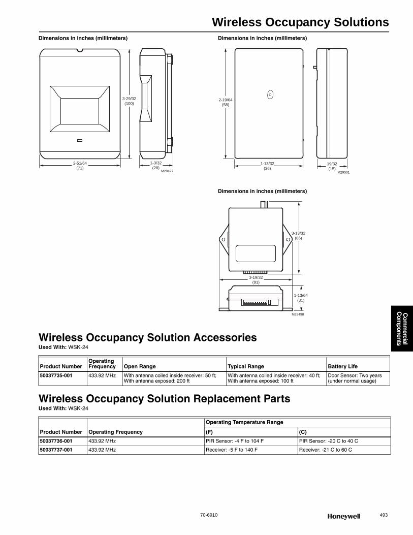
Wireless Occupancy Solutions
70-6910 493
Com
mercial
Com
ponents
Dimensions in inches (millimeters) Dimensions in inches (millimeters)
Dimensions in inches (millimeters)
Wireless Occupancy Solution AccessoriesUsed With: WSK-24
Wireless Occupancy Solution Replacement PartsUsed With: WSK-24
3-29/32
(100)
2-51/64
(71)
1-3/32
(28)M29497
19/32
(15)
1-13/32
(36)
2-19/64
(58)
M29501
M29498
3-19/32
(91)
3-13/32
(86)
1-13/64
(31)
Product NumberOperating Frequency Open Range Typical Range Battery Life
50037735-001 433.92 MHz With antenna coiled inside receiver: 50 ft; With antenna exposed: 200 ft
With antenna coiled inside receiver: 40 ft; With antenna exposed: 100 ft
Door Sensor: Two years (under normal usage)
Product Number Operating Frequency
Operating Temperature Range
(F) (C)
50037736-001 433.92 MHz PIR Sensor: -4 F to 104 F PIR Sensor: -20 C to 40 C
50037737-001 433.92 MHz Receiver: -5 F to 140 F Receiver: -21 C to 60 C
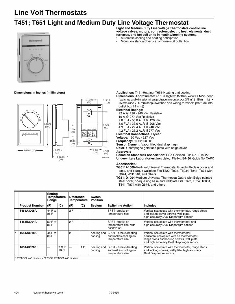
Line Volt Thermostats
494 customer.honeywell.com 70-6910
T451; T651 Light and Medium Duty Line Voltage ThermostatLight and Medium Duty Line Voltage Thermostats control line voltage valves, motors, contractors, electric heat, elements, duct furnaces, and fan coil units in heating/cooling systems.• Automatic cooling and heating anticipation • Mount on standard vertical or horizontal outlet box
Dimensions in inches (millimeters) Application: T451-Heating; T651-Heating and coolingDimensions, Approximate: 4 1/2 in. high x 2 15/16 in. wide x 1 1/2 in. deep
(switches and wiring terminals protrude into outlet box 3/4 in.) (115 mm high x 75 mm wide x 39 mm deep (switches and wiring terminals protrude into outlet box 19 mm))
Electrical Ratings: 22 A @ 120 - 240 Vac Resistive19 A @ 277 Vac Resistive9.8 FLA / 58.8 ALR @ 120 Vac5.6 FLA / 33.6 ALR @ 208 Vac4.9 FLA / 29.4 ALR @240 Vac4.2 FLA / 25.2 ALR @277 Vac
Electrical Connections: FlyleadVoltage: 120 Vac - 227 VacFrequency: 50 Hz; 60 HzSensor Element: Vapor filled dual diaphragmColor: Champagne gold face-plate with beige coverApprovalsCanadian Standards Association: CSA Certified, File No. LR1322Underwriters Laboratories, Inc: Listed: File No. E4436, Guide No. XAPX
Accessories:TG511A1000-Medium Universal Thermostat Guard with clear cover and
base, and opaque wallplate Fits T822, T834, T8034, T841, T874 with Q674, WR1F46, and others
TG511D1004-Medium Universal Thermostat Guard with Beige painted steel cover, opaque ring base and wallplate Fits T822, T834, T8034, T841, T874 with Q674, and others
40
50
60 70
80
90
40 50 60 70 80 90
COOL HEAT COMF
M6130A
2-13/16 (70)
4-17/32(114)
1-1/8(22)
1-13/16(48)
15/16(24)
1-3/4(45)
1-1/8(37)
17/32(14)
3-9/32(83)
1-15/32(35)
9/16(14)
Product Number
Setting Temperature Range
Differential Temperature
Switch Position
Switching Action Includes(F) (C) (F) (C) System
T451A3005/U 44 F to 86 F
— 2 F — — SPST- breaks on temperature rise
Vertical scaleplate with thermometer, range stops and locking cover screws, wall plate, high accuracy Dual Diaphragm sensor
T451B3004/U 50 F to 86 F
— 2 F — — SPST- breaks on temperature rise; with positive off
Vertical scaleplate with thermometer and high accuracy Dual Diaphragm sensor
• T651A3018/U 44 F to 86 F
— 2 F — heating and cooling
SPDT - breaks heating and makes cooling on temperature rise
Vertical scaleplate with thermometer, horizontal scaleplate with no thermometer, range stops and locking screws, wall plate, and high accuracy Dual Diaphragm sensor
T651A3026/U — 7 C to 28 C
— 1 C heating and cooling
SPDT - breaks heating and makes cooling on temperature rise
Vertical scaleplate with thermometer, range stops and locking screws, wall plate, high accuracy Dual Diaphragm sensor
* TRADELINE models • SUPER TRADELINE models
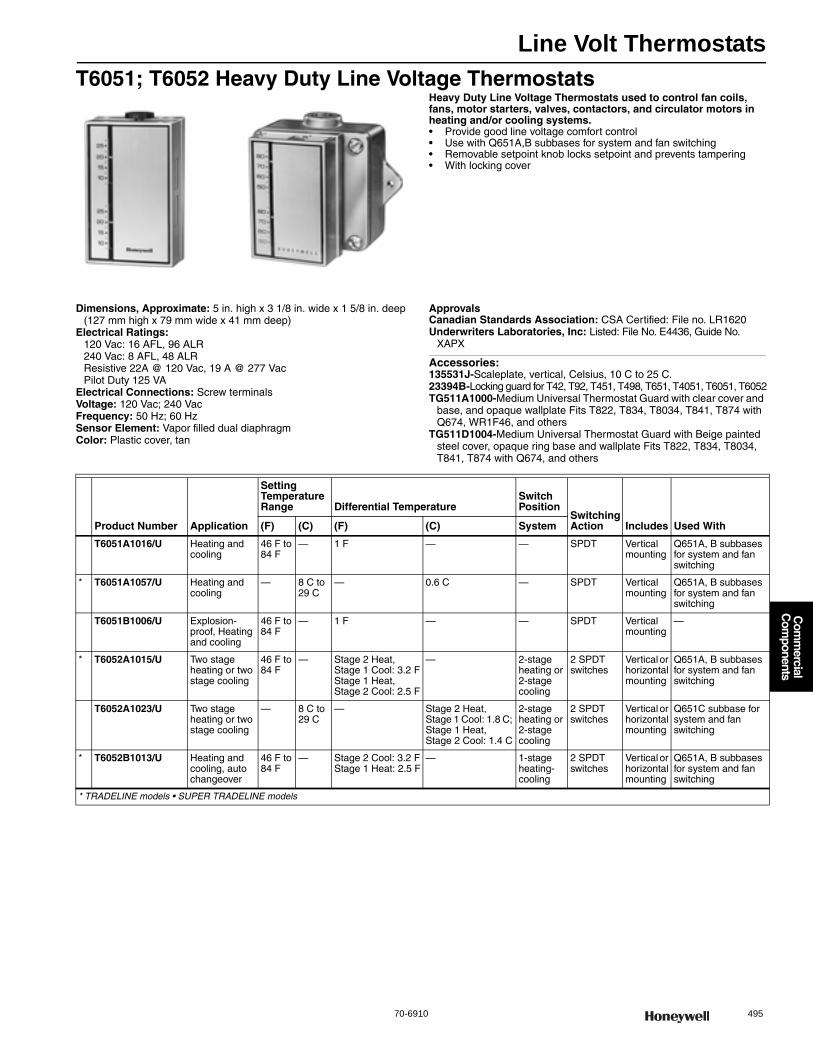
Line Volt Thermostats
70-6910 495
Com
mercial
Com
ponents
T6051; T6052 Heavy Duty Line Voltage ThermostatsHeavy Duty Line Voltage Thermostats used to control fan coils, fans, motor starters, valves, contactors, and circulator motors in heating and/or cooling systems.• Provide good line voltage comfort control • Use with Q651A,B subbases for system and fan switching • Removable setpoint knob locks setpoint and prevents tampering • With locking cover
Dimensions, Approximate: 5 in. high x 3 1/8 in. wide x 1 5/8 in. deep (127 mm high x 79 mm wide x 41 mm deep)
Electrical Ratings: 120 Vac: 16 AFL, 96 ALR240 Vac: 8 AFL, 48 ALRResistive 22A @ 120 Vac, 19 A @ 277 VacPilot Duty 125 VA
Electrical Connections: Screw terminalsVoltage: 120 Vac; 240 VacFrequency: 50 Hz; 60 HzSensor Element: Vapor filled dual diaphragmColor: Plastic cover, tan
ApprovalsCanadian Standards Association: CSA Certified: File no. LR1620Underwriters Laboratories, Inc: Listed: File No. E4436, Guide No.
XAPX
Accessories:135531J-Scaleplate, vertical, Celsius, 10 C to 25 C.23394B-Locking guard for T42, T92, T451, T498, T651, T4051, T6051, T6052TG511A1000-Medium Universal Thermostat Guard with clear cover and
base, and opaque wallplate Fits T822, T834, T8034, T841, T874 with Q674, WR1F46, and others
TG511D1004-Medium Universal Thermostat Guard with Beige painted steel cover, opaque ring base and wallplate Fits T822, T834, T8034, T841, T874 with Q674, and others
Product Number Application
Setting Temperature Range Differential Temperature
Switch Position
Switching Action Includes Used With(F) (C) (F) (C) System
T6051A1016/U Heating and cooling
46 F to 84 F
— 1 F — — SPDT Vertical mounting
Q651A, B subbases for system and fan switching
* T6051A1057/U Heating and cooling
— 8 C to 29 C
— 0.6 C — SPDT Vertical mounting
Q651A, B subbases for system and fan switching
T6051B1006/U Explosion-proof, Heating and cooling
46 F to 84 F
— 1 F — — SPDT Vertical mounting
—
* T6052A1015/U Two stage heating or two stage cooling
46 F to 84 F
— Stage 2 Heat, Stage 1 Cool: 3.2 FStage 1 Heat, Stage 2 Cool: 2.5 F
— 2-stage heating or 2-stage cooling
2 SPDT switches
Vertical or horizontal mounting
Q651A, B subbases for system and fan switching
T6052A1023/U Two stage heating or two stage cooling
— 8 C to 29 C
— Stage 2 Heat, Stage 1 Cool: 1.8 C; Stage 1 Heat, Stage 2 Cool: 1.4 C
2-stage heating or 2-stage cooling
2 SPDT switches
Vertical or horizontal mounting
Q651C subbase for system and fan switching
* T6052B1013/U Heating and cooling, auto changeover
46 F to 84 F
— Stage 2 Cool: 3.2 FStage 1 Heat: 2.5 F
— 1-stage heating-cooling
2 SPDT switches
Vertical or horizontal mounting
Q651A, B subbases for system and fan switching
* TRADELINE models • SUPER TRADELINE models
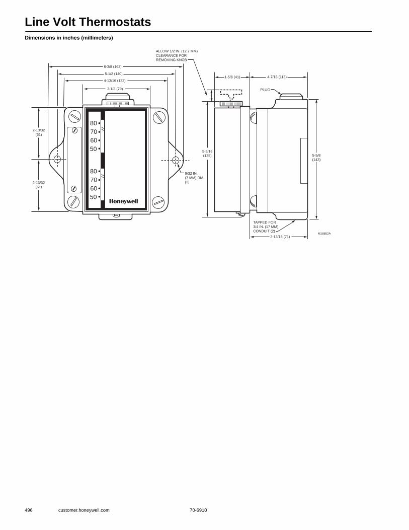
Line Volt Thermostats
496 customer.honeywell.com 70-6910
Dimensions in inches (millimeters)
80
70
60
50
••••
80
70
60
50
••••
6-3/8 (162)
5-1/2 (140)
4-13/16 (122)
3-1/8 (79)
2-13/32
(61)
2-13/32
(61)
9/32 IN.
(7 MM) DIA.
(2)
5-5/16
(135)
1-5/8 (41) 4-7/16 (113)
PLUG
ALLOW 1/2 IN. (12.7 MM)
CLEARANCE FOR
REMOVING KNOB
5-5/8
(143)
TAPPED FOR
3/4 IN. (17 MM)
CONDUIT (2)
2-13/16 (71)M18852A
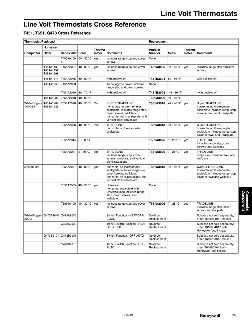
Line Volt Thermostats
70-6910 497
Com
mercial
Com
ponents
Line Volt Thermostats Cross ReferenceT451, T651, Q473 Cross Reference
Thermostat Replaced Replacement
Competitor
Honeywell
ScaleThermometer Comments
Product Number Scale
Thermometer CommentsOlder Series 2000
T4059A1005
10 - 30 °C yes Includes range stop and cover screws
None
T451A1132T451A1157T451A1298
T451A2007 40 - 90 °F yes Includes range stop and cover screws
T451A3005 44 - 86 °F yes Includes range stop and cover screws
T451A1173 T451A2015 40 - 90 °F with positive off T451B3004 50 - 86 °F with positive off
T451A1256 T451A2023 Trane logo on cover; Includes range stop and cover screws
None
T451A2049 40 - 70 °F with positive off T451B3004 46 - 86 °F with positive off
T651A1202 T651A2010 40 - 90 °F T651A3000 44 - 86 °F
White Rogers1A10-651
T651A1269T651A1236
T651A2028 40 - 90 °F Yes SUPER TRADELINEhorizontal; no thermometer scaleplate; includes range stop, cover screws, wallplate, horizontal blank scaleplate, and vertical blank scaleplate
T651A3018 44 - 86 °F yes Super TRADELINEhorizontal no thermometer scaleplate Includes range stop, cover screws, and wallplate
T651A2036 40 - 90 °F Yes TRADELINEhorizontal no thermometer scaleplate
T651A3018 44 - 86 °F yes Super TRADELINEhorizontal no thermometer scaleplate Includes range stop, cover screws, and wallplate
T651A2044 5 - 30 °C T651A3026 7 - 28 °C yes TRADELINEIncludes range stop, cover screws, and wallplate
T651A2051 5 - 30 °C yes TRADELINEIncludes range stop, cover screws, wallplate, and vertical blank scaleplate
T651A3026 7 - 28 °C yes TRADELINErange stop, cover screws, and wallplate
Jonson T26 T651A2077 40 - 90 °F yes horizontal no thermometer scaleplate Includes range stop, cover screws, wallplate, horizontal blank scaleplate, and vertical blank scaleplate
T651A3018 44 - 86 °F yes SUPER TRADELINEhorizontal no thermometer scaleplate Includes range stop, cover screws and wallplate
T651A2085 40 - 90 °F yes Universalhorizontal scaleplate with Universal logo Includes range stop, cover screws, and wallplate
None
T6059A1000
10 - 30 °C yes Includes range stop and cover screws
T651A3026 7 - 28 °C yes TRADELINEIncludes range stop, cover screws and wallplate
White Rogers S29-21
Q473A1040 Q473A2006 Switch Function - HEAT-OFF-COOL
No direct Replacement
Subbase not sold separately; order T6169B4017 instead
Q473A2022 Trane; Switch Function - HEAT-OFF-COOL
No direct Replacement
Subbase not sold separately; order T6169B4017 with Honeywell logo instead
Q473B21015
Q473B2005 Switch Function - OFF-AUTO No direct Replacement
Subbase not sold separately; order T6169C4015 instead
Q473B2013 Trane; Switch Function - OFF-AUTO
No direct Replacement
Subbase not sold separately; order T6169C4015 with Honeywell logo instead
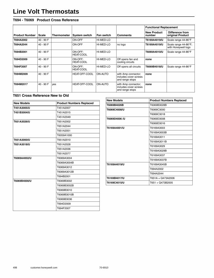
Line Volt Thermostats
498 customer.honeywell.com 70-6910
T694 - T6069 Product Cross Reference
T651 Cross Reference New to Old
Product Number Scale Thermometer System switch Fan switch Comments
Functional Replacement
New Product number
Difference from original Product
T694A2002 40 - 90 F ON-OFF HI-MED-LO T6169A4019/U Scale range 44-86°F
T694A2044 40 - 90 F ON-OFF HI-MED-LO no logo T6169A4019/U Scale range 44-86°F; with Honeywell logo
T694B2001 40 - 90 F ON-OFF; HEAT-COOL
HI-MED-LO T6069A4010/U Scale range 44-86°F
T694D2009 40 - 90 F ON-OFF; HEAT-COOL
HI-MED-LO Off opens fan and cooling circuits
none
T694F2007 40 - 90 F ON-OFF; HEAT-COOL
HI-MED-LO Off opens all circuits T6069B4018/U Scale range 44-86°F
T694M2009 40 - 90 F HEAT-OFF-COOL ON-AUTO with Amp connector; includes cover screws and range stops
none
T694M2017 40 - 90 F yes HEAT-OFF-COOL ON-AUTO with Amp connector; includes cover screws and range stops
none
New Models Product Numbers Replaced
T451A3005/U T451A2007
T451B3004/U T451A2015
T451A2049
T651A3026/U T651A2002
T651A2044
T651A2051
T6059A1000
T651A3000/U T651A2010
T651A3018/U T651A2028
T651A2036
T651A2077
T6069A4002/U T6069A3004
T6069A3004B
T6069A3012
T6069A3012B
T694B2001
T6069B4000/U T6069B3002
T6069B3002B
T6069B3010
T6069B3010B
T6069B3036
T694D2009
T694F2007
T6069B4026B T6069B3028B
T6069C4008/U T6069C3000
T6069C3018
T6069D4006 /U T6069D3008
T6069D3016
T6169A4001/U T6169A3003
T6169A3003B
T6169A3011
T6169A3011B
T6169A3029
T6169A3029B
T6169A3037
T6169A3037B
T6169A4019/U T6169A3045B
T694A2002
T694A2044
T6169B4017/U T651A + Q473A2006
T6169C4015/U T651 + Q473B2005
New Models Product Numbers Replaced
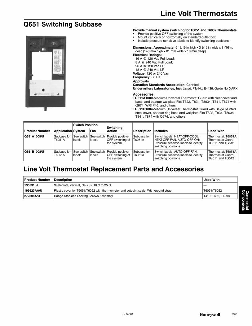
Line Volt Thermostats
70-6910 499
Com
mercial
Com
ponents
Q651 Switching SubbaseProvide manual system switching for T6051 and T6052 Thermostats.• Provide positive OFF switching of the system • Mount vertically or horizontally on standard outlet box • Include pressure sensitive labels to identify switching positions
Dimensions, Approximate: 5 13/16 in. high x 3 3/16 in. wide x 11/16 in. deep (148 mm high x 81 mm wide x 18 mm deep)
Electrical Ratings: 16 A @ 120 Vac Full Load; 8 A @ 240 Vac Full Load; 96 A @ 120 Vac LR; 48 A @ 240 Vac LR
Voltage: 120 or 240 VacFrequency: 60 HzApprovalsCanadian Standards Association: CertifiedUnderwriters Laboratories, Inc: Listed: File No. E4436, Guide No. XAPX
Accessories:TG511A1000-Medium Universal Thermostat Guard with clear cover and
base, and opaque wallplate Fits T822, T834, T8034, T841, T874 with Q674, WR1F46, and others
TG511D1004-Medium Universal Thermostat Guard with Beige painted steel cover, opaque ring base and wallplate Fits T822, T834, T8034, T841, T874 with Q674, and others
Line Volt Thermostat Replacement Parts and Accessories
Product Number Application
Switch PositionSwitching Action Description Includes Used WithSystem Fan
Q651A1009/U Subbase for T6051A
See switch labels
See switch labels
Provide positive OFF switching of the system
Subbase for T6051A
Switch labels: HEAT-OFF-COOL, HEAT-OFF-FAN, AUTO-OFF-ON; Pressure sensitive labels to identify switching positions
Thermostat: T6051A, Thermostat Guard: TG511 and TG512
Q651B1008/U Subbase for T6051A
See switch labels
See switch labels
Provide positive OFF switching of the system
Subbase for T6051A
Switch labels: AUTO-OFF-FAN; Pressure sensitive labels to identify switching positions
Thermostat: T6051A, Thermostat Guard: TG511 and TG512
Product Number Description Used With
135531J/U Scaleplate, vertical, Celsius, 10 C to 25 C —
199923AA/U Plastic cover for T6051/T6052 with thermometer and setpoint scale. With ground strap T6051/T6052
272804A/U Range Stop and Locking Screws Assembly T410, T498, T4398
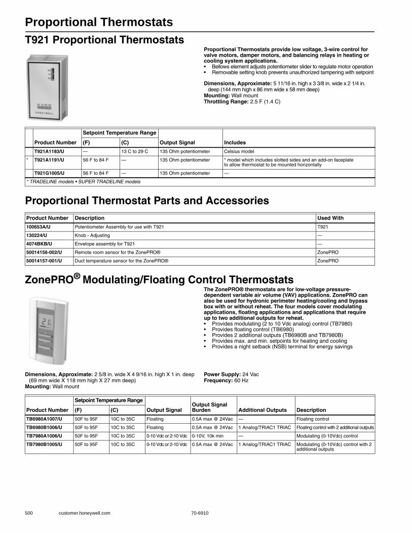
Proportional Thermostats
500 customer.honeywell.com 70-6910
T921 Proportional ThermostatsProportional Thermostats provide low voltage, 3-wire control for valve motors, damper motors, and balancing relays in heating or cooling system applications.• Bellows element adjusts potentiometer slider to regulate motor operation • Removable setting knob prevents unauthorized tampering with setpoint
Dimensions, Approximate: 5 11/16 in. high x 3 3/8 in. wide x 2 1/4 in. deep (144 mm high x 86 mm wide x 58 mm deep)
Mounting: Wall mountThrottling Range: 2.5 F (1.4 C)
Proportional Thermostat Parts and Accessories
ZonePRO® Modulating/Floating Control ThermostatsThe ZonePRO® thermostats are for low-voltage pressure-dependent variable air volume (VAV) applications. ZonePRO can also be used for hydronic perimeter heating/cooling and bypass box with or without reheat. The four models cover modulating applications, floating applications and applications that require up to two additional outputs for reheat.• Provides modulating (2 to 10 Vdc analog) control (TB7980) • Provides floating control (TB6980) • Provides 2 additional outputs (TB6980B and TB7980B) • Provides max. and min. setpoints for heating and cooling • Provides a night setback (NSB) terminal for energy savings
Dimensions, Approximate: 2 5/8 in. wide X 4 9/16 in. high X 1 in. deep (69 mm wide X 118 mm high X 27 mm deep)
Mounting: Wall mount
Power Supply: 24 VacFrequency: 60 Hz
Product Number
Setpoint Temperature Range
Output Signal Includes(F) (C)
T921A1183/U — 13 C to 29 C 135 Ohm potentiometer Celsius model
* T921A1191/U 56 F to 84 F — 135 Ohm potentiometer * model which includes slotted sides and an add-on faceplate to allow thermostat to be mounted horizontally
T921G1005/U 56 F to 84 F — 135 Ohm potentiometer —
* TRADELINE models • SUPER TRADELINE models
Product Number Description Used With
100653A/U Potentiometer Assembly for use with T921 T921
130224/U Knob - Adjusting —
4074BKB/U Envelope assembly for T921 —
50014156-002/U Remote room sensor for the ZonePRO® ZonePRO
50014157-001/U Duct temperature sensor for the ZonePRO® ZonePRO
Product Number
Setpoint Temperature Range
Output SignalOutput Signal Burden Additional Outputs Description(F) (C)
TB6980A1007/U 50F to 95F 10C to 35C Floating 0.5A max @ 24Vac — Floating control
TB6980B1006/U 50F to 95F 10C to 35C Floating 0.5A max @ 24Vac 1 Analog/TRIAC1 TRIAC Floating control with 2 additional outputs
TB7980A1006/U 50F to 95F 10C to 35C 0-10 Vdc or 2-10 Vdc 0-10V, 10k min — Modulating (0-10Vdc) control
TB7980B1005/U 50F to 95F 10C to 35C 0-10 Vdc or 2-10 Vdc 0.5A max @ 24Vac 1 Analog/TRIAC1 TRIAC Modulating (0-10Vdc) control with 2 additional outputs
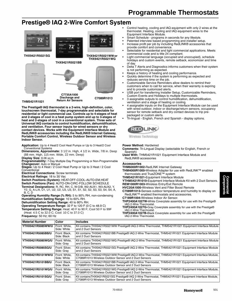
Programmable Thermostats
70-6910 501
Com
mercial
Com
ponents
Prestige® IAQ 2-Wire Comfort System
The Prestige® IAQ thermostat is a 2-wire, high-definition, color, touchscreen thermostat, 7-day programmable and selectable for residential or light commercial use. Controls up to 4-stages of heat and 2-stages of cool in a heat pump system and up to 3-stages of heat and 2-stages of cool in a conventional system. Three sets of Universal IAQ contacts to control humidification, dehumidification, and ventilation. Four sensor inputs for wired sensors or dry contact devices. Works with the Equipment Interface Module and RedLINK® accessories including the RedLINK® Internet Gateway, Portable Comfort Control, Wireless Outdoor Sensor and Wireless Indoor Sensor.
• Control heating, cooling and IAQ equipment with only 2 wires at the thermostat. Heating, cooling and IAQ equipment wires to the Equipment Interface Module.
• Smart Schedule - programs in seconds for any lifestyle.• Patented interview based programming and installer setup.• Increase profit per job by including RedLINK® accessories that
provide comfort and convenience.• Selectable for residential and light commercial applications. Meets
commercial code and is title 24 compliant.• Light commercial language (occupied and unoccupied), schedule
holidays and custom events, remote setback, economizer and time of day.
• Delta T Alerts and Diagnostics informs customers when their system is not performing as expected.
• Keeps a history of heating and cooling performance. • Quickly determine if the system is performing as expected and
reduces service time on the job.• Customizable Service Reminders allow dealers to remind their
customers when to call for service, when their warranty is expiring and to provide customized alerts.
• USB port for transferring Installer Setup, Customizable Reminders, Custom Events and Holidays to multiple thermostats.
• 3 assignable outputs to control humidification, dehumidification, ventilation and a stage of heating or cooling.
• 4 assignable inputs on the Equipment Interface Module can be used with wired outdoor, indoor or discharge/return sensors, occupancy sensor for remote setback and dry contact devices to trip pre-packaged or custom alerts.
• Tri-lingual - English, French and Spanish - display options.
Application: Up to 4 Heat/2 Cool Heat Pumps or Up to 3 Heat/2 Cool Conventional Systems
Dimensions, Approximate: 3 1/2 in. High, 4 1/2 in. Wide, 7/8 in. Deep (88 mm. High, 115 mm. Wide, 22 mm. Deep)
Display Size: 8.06 sq in.Programmability: 7-Day Multiple Day Programming or Non-ProgrammableChangeover: Auto or ManualStages: Up to 4 Heat / 2 Cool Heat Pump or Up to 3 Heat / 2 Cool ConventionalElectrical Connections: Screw terminalsElectrical Ratings: 18 to 30 VacSwitch Positions (System): HEAT-OFF-COOL-AUTO-EM.HEATSwitch Positions (Fan): AUTO-ON-CIRC-FOLLOW SCHEDULETerminal Designations: R, RC, RH, C, W-O/B, W2-AUX1, W3-AUX2, Y,
Y2, G, A-L/A, U1, U1, U2, U2, U3, U3, S1, S1, S2, S2, S3, S3, S4, S4, A, B, C, D
Operating Humidity Range (% RH): 5 to 90% RH, non-condensingHumidification Setting Range: 10 to 60% RH.Dehumidification Setting Range: 40 to 80% RH.Operating Temperature Range: 32 F to 120 F (0 C to 48.9 C) Temperature Setting Range: Heat: 40 F to 90 F; Cool 50 F to 99F
(Heat: 4.5 C to 32.0 C; Cool: 10 C to 37.0 C) Frequency: 50 Hz; 60 Hz
Power Method: HardwiredComments: Tri-Lingual Display (selectable for English, French or
Spanish)Used With: THM5421R1021 Equipment Interface Module and
RedLINK® accessories
AccessoriesTHM6000R1002-RedLINK Internet GatewayTHM4000R1000-Wireless Adapter for use with RedLINK™ enabled
thermostats and TrueZONE™ systemTHM5421R1021-Equipment Interface ModuleYTHM5421R1010-Equipment Interface Module Kit with 2 Duct Sensors. REM1000R1003-Wireless Entry/Exit RemoteHVC20A1000-Wireless Vent and Filter Boost RemoteC7089R1013-Senses outdoor temperature and humidity to display on
RedLINK™ enabled thermostats and accessories.C7189R1004-Wireless Indoor Air Sensor.THP2400A1027W-White Coverplate assembly for use with the Prestige®
IAQ 2-Wire Thermostat. THP2400A1027G-Gray Coverplate assembly for use with the Prestige®
IAQ 2-Wire Thermostat. THP2400A1027B-Black Coverplate assembly for use with the Prestige®
IAQ 2-Wire Thermostat.
THX9421R5021SG THX9421R5021WW or THX9421R5021WG
THX9421R5021BB
THM5421R1021C7089R1013
C7735A1000Discharge and
Return Air Sensors
Material Number Color IncludesYTHX9421R5085WW/U Front: White,
Side: WhiteKit contains THX9421R5021WW Prestige® IAQ 2-Wire Thermostat, THM5421R1021 Equipment Interface Module and 2 Duct Sensors
YTHX9421R5085BB/U Front: Black, Side: Black
Kit contains THX9421R5021BB Prestige® IAQ 2-Wire Thermostat, THM5421R1021 Equipment Interface Module and 2 Duct Sensors
YTHX9421R5085WG/U Front: White, Side: Gray
Kit contains THX9421R5021WG Prestige® IAQ 2-Wire Thermostat, THM5421R1021 Equipment Interface Module and 2 Duct Sensors
YTHX9421R5085SG/U Front: Silver, Side: Gray
Kit contains THX9421R5021SG Prestige® IAQ 2-Wire Thermostat, THM5421R1021 Equipment Interface Module and 2 Duct Sensors
YTHX9421R5101WW/U Front: White, Side: White
Kit contains THX9421R5021WW Prestige® IAQ 2-Wire Thermostat, THM5421R1021 Equipment Interface Module, C7089R1013 Wireless Outdoor Sensor and 2 Duct Sensors
YTHX9421R5101BB/U Front: Black, Side: Black
Kit contains THX9421R5021BB Prestige® IAQ 2-Wire Thermostat, THM5421R1021 Equipment Interface Module, C7089R1013 Wireless Outdoor Sensor and 2 Duct Sensors
YTHX9421R5101WG/U Front: White, Side: Gray
Kit contains THX9421R5021WG Prestige® IAQ 2-Wire Thermostat, THM5421R1021 Equipment Interface Module, C7089R1013 Wireless Outdoor Sensor and 2 Duct Sensors
YTHX9421R5101SG/U Front: Silver, Side: Gray
Kit containsTHX9421R5021SG Prestige® IAQ 2-Wire Thermostat, THM5421R1021 Equipment Interface Module, C7089R1013 Wireless Outdoor Sensor and 2 Duct Sensors
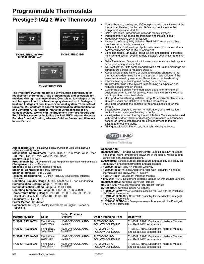
Programmable Thermostats
502 customer.honeywell.com 70-6910
Prestige® IAQ 2-Wire Thermostat
The Prestige® IAQ thermostat is a 2-wire, high-definition, color, touchscreen thermostat, 7-day programmable and selectable for residential or light commercial use. Controls up to 4-stages of heat and 2-stages of cool in a heat pump system and up to 3-stages of heat and 2-stages of cool in a conventional system. Three sets of Universal IAQ contacts to control humidification, dehumidification, and ventilation. Four sensor inputs for wired sensors or dry contact devices. Works with the Equipment Interface Module and RedLINK® accessories including the RedLINK® Internet Gateway, Portable Comfort Control, Wireless Outdoor Sensor and Wireless Indoor Sensor.
• Control heating, cooling and IAQ equipment with only 2 wires at the thermostat. Heating, cooling and IAQ equipment wires to the Equipment Interface Module.
• Smart Schedule - programs in seconds for any lifestyle.• Patented interview based programming and installer setup.• RedLINK® wireless communication.• Increase profit per job by including RedLINK® accessories that
provide comfort and convenience.• Selectable for residential and light commercial applications. Meets
commercial code and is title 24 compliant• Light commercial language (occupied and unoccupied), schedule
holidays and custom events, remote setback, economizer and time of day.
• Delta T Alerts and Diagnostics informs customers when their system is not performing as expected.
• All Prestige® IAQ kits come standard with a return and discharge air temperature sensor to measure Delta T.
• Keeps a searchable history of alerts and setting changes to the thermostat to determine if there is a system malfunction or if the issue was caused by user error. Saves time in troubleshooting.
• Keeps a history of heating and cooling performance. • Quickly determine if the system is performing as expected and
reduces service time on the job.• Customizable Service Reminders allow dealers to remind their
customers when to call for service, when their warranty is expiring and to provide customized alerts.
• USB port for transferring Installer Setup, Customizable Reminders, Custom Events and Holidays to multiple thermostats.
• USB port for adding the dealer's full color business logo on the screen.
• 3 assignable outputs to control humidification, dehumidification, ventilation and a stage of heating or cooling.
• 4 assignable inputs on the Equipment Interface Module can be used with wired outdoor, indoor or discharge/return sensors, occupancy sensor for remote setback and dry contact devices to trip pre-packaged or custom alerts.
• Tri-lingual - English, French and Spanish - display options.
Application: Up to 4 Heat/2 Cool Heat Pumps or Up to 3 Heat/2 Cool Conventional Systems
Dimensions, Approximate: 3 1/2 in. High, 4 1/2 in. Wide, 7/8 in. Deep (88 mm. High, 115 mm. Wide, 22 mm. Deep)
Display Size: 8.06 sq in.Programmability: 7-Day Multiple Day Programming or Non-ProgrammableChangeover: Auto or ManualStages: See Equipment Interface ModuleElectrical Connections: Screw terminalsElectrical Ratings: 18 to 30 VacTerminal Designations: R, C then RedLINK to Equipment Interface
ModuleOperating Humidity Range (% RH): 5 to 90% RH, non-condensingHumidification Setting Range: 10 to 60% RH.Dehumidification Setting Range: 40 to 80% RH.Operating Temperature Range: 32 F to 120 F (0 C to 48.9 C) Temperature Setting Range: Heat: 40 F to 90 F; Cool 50 F to 99F
(Heat: 4.5 C to 32.0 C; Cool: 10 C to 37.0 C) Frequency: 50 Hz; 60 HzPower Method: HardwiredComments: Tri-Lingual Display (selectable for English, French or
Spanish)
Accessories:REM5000R1001-Portable Comfort Control uses RedLINK™ to sense
and control room temperature anywhere in the home. Works in both zoned and non-zoned applications.
C7089R1013-Senses outdoor temperature and humidity to display on RedLINK™ enabled thermostats and accessories.
THM6000R1002-RedLINK Internet GatewayTHM4000R1000-Wireless Adapter for use with RedLINK™ enabled
thermostats and TrueZONE™ systemTHM5421R1021-Equipment Interface ModuleYTHM5421R1010-Equipment Interface Module Kit with 2 Duct Sensors. REM1000R1003-Wireless Entry/Exit RemoteHVC20A1000-Wireless Vent and Filter Boost RemoteC7189R1004-Wireless Indoor Air Sensor.THP2400A1027W-White Coverplate assembly for use with the Prestige®
IAQ 2-Wire Thermostat. THP2400A1027G-Gray Coverplate assembly for use with the Prestige®
IAQ 2-Wire Thermostat. THP2400A1027B-Black Coverplate assembly for use with the Prestige®
IAQ 2-Wire Thermostat.
THX9421R5021SG
THX9421R5021WW or THX9421R5021WG
THX9421R5021BB
Material Number ColorSwitch Positions (System) Switch Positions (Fan) Used With
THX9421R5021WW/U Front: White, Side: White
HEAT-OFF-COOL-AUTO-EM.HEAT
AUTO-ON-CIRC-FOLLOW SCHEDULE
THM5421R1021 Equipment Interface Module and RedLINK® accessories
THX9421R5021BB/U Front: Black, Side: Black
HEAT-OFF-COOL-AUTO-EM.HEAT
AUTO-ON-CIRC-FOLLOW SCHEDULE
THM5421R1021 Equipment Interface Module and RedLINK® accessories
THX9421R5021WG/U Front: White, Side: Gray
HEAT-OFF-COOL-AUTO-EM.HEAT
AUTO-ON-CIRC-FOLLOW SCHEDULE
THM5421R1021 Equipment Interface Module and RedLINK® accessories
THX9421R5021SG/U Front: Silver, Side: Gray
HEAT-OFF-COOL-AUTO-EM.HEAT
AUTO-ON-CIRC-FOLLOW SCHEDULE
THM5421R1021 Equipment Interface Module and RedLINK® accessories

Programmable Thermostats
70-6910 503
Com
mercial
Com
ponents
Prestige® 2.0 Comfort System
The Prestige® 2.0 thermostat is a high-definition, color, touchscreen thermostat, 7-day programmable, selectable for residential and light commercial, up to 3 heat/2 cool heat pump and up to 2 heat / 2 cool conventional, controls humidification, dehumidification, or ventilation. Works with RedLINK™ accessories including the RedLINK™ Internet Gateway, Portable Comfort Control, Wireless Outdoor Sensor and Wireless Indoor Sensor.
• Patented interview based programming and installer setup.• RedLINK™ wireless communication.• Increase profit per job by including RedLINK™ accessories that
provide comfort and convenience.• Selectable for residential and light commercial applications.• Meets commercial code and is title 24 compliant.• Light commercial language (occupied and unoccupied), schedule
holidays and custom events, remote setback, economizer and time of day.
• Keeps a searchable history of alerts and setting changes to the thermostat to determine if there is a system malfunction or if the issue was caused by user error.
• Customizable Service Reminders allow dealers to remind customers when to call for service, when warranty is expiring and to provide customized alerts.
• USB port for transferring Installer Setup, Customizable Reminders, Custom Events and Holidays to multiple thermostats.
• USB port for adding the dealer's full color business logo on the screen.
• 2 assignable outputs to control humidification, dehumidification, ventilation and a stage of heating or cooling.
• Tri-lingual - English, French and Spanish - display options.
Application: Up to 3 Heat/2 Cool Heat Pumps; Up to 2 Heat/2 Cool Conventional Systems
Dimensions, Approximate: 3 15/16 in. High, 6 7/8 in. Wide, 1 1/2 in. Deep (100 mm. High, 175 mm. Wide, 38 mm. Deep)
Display Size: 8.06 sq in.Color: Arctic WhiteProgrammability: 7-Day Multiple Day Programming or Non-
ProgrammableChangeover: Auto or ManualElectrical Connections: Screw terminalsElectrical Ratings: 18 to 30 VacOperating Humidity Range (% RH): 0 to 90% RH, non-condensingHumidity Setting Range: 10 to 60% RH.Dehumidification Setting Range: 40 to 80% RH.Operating Temperature Range: 32 F to 120 F (0 C to 48.9 C) Stages:
Up to 3 Heat / 2 Cool Heat Pump orUp to 2 Heat / 2 Cool Conventional
Frequency: 50 Hz; 60 Hz
Power Method: HardwiredUsed With: RedLINK™ accessories
Accessories:C7089R1013-Senses outdoor temperature and humidity to display on
RedLINK™ enabled thermostats and accessories.C7189R1004-Wireless Indoor Air Sensor.HVC20A1000-Wireless Vent and Filter Boost RemoteREM1000R1003-Wireless Entry/Exit RemoteREM5000R1001-Portable Comfort Control uses RedLINK™ to sense
and control room temperature anywhere in the home. Works in both zoned and non-zoned applications.
THM4000R1000-Wireless Adapter for use with RedLINK™ enabled thermostats and TrueZONE™ system
THP9045A1023-WireSaverTHM6000R1002-RedLINK Internet Gateway50028399-001-Cover plate for Prestige Thermostats 7 7/8 in. (200 mm)
x 5 1/2 in. (140 mm)
Product Number
Switch PositionsTerminal Designations
Temperature Setting Range
IncludesSystem Fan (F) (C)
THX9321R5030/U HEAT-OFF-COOL-AUTO-EM.HEAT
AUTO-ON-CIRC-FOLLOW SCHEDULE
R, RC, C, W-O/B, W2-AUX/E, Y, Y2, G, A-L/A, K, U1 U1, U2 U2
Heat: 40 F to 90 F; Cool 60 F to 99F
Heat: 4.5 C to 32.0 C; Cool: 10.0 C to 37.0 C
Prestige 2.0 High Definition Color Touchscreen Thermostat
YTHX9321R5061/U HEAT-OFF-COOL-AUTO-EM.HEAT
AUTO-ON-CIRC-FOLLOW SCHEDULE
R, RC, C, W-O/B, W2-AUX/E, Y, Y2, G, A-L/A, K, U1 U1, U2 U2
Heat: 40 F to 90 F; Cool 50 F to 99F
Heat: 4.5 C to 32.0 C; Cool: 10 C to 37.0 C
THX9321R5030 Prestige 2.0 HD Thermostat, REM5000R1001 Portable Comfort Control and C7089R1013 Wireless Outdoor Air Sensor
YTHX9321R5079/U HEAT-OFF-COOL-AUTO-EM.HEAT
AUTO-ON-CIRC-FOLLOW SCHEDULE
R, RC, C, W-O/B, W2-AUX/E, Y, Y2, G, A-L/A, K, U1 U1, U2 U2
Heat: 40 F to 90 F; Cool 50 F to 99F
Heat: 4.5 C to 32.0 C; Cool: 10 C to 37.0 C
THX9321R5030 Prestige 2.0 HD Thermostat and C7089R1013 Wireless Outdoor Air Sensor
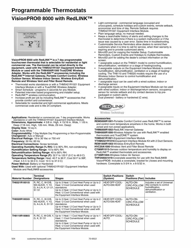
Programmable Thermostats
504 customer.honeywell.com 70-6910
VisionPRO® 8000 with RedLINK™
VisionPRO® 8000 with RedLINK™ is a 7 day programmable touchscreen thermostat that is selectable for residential or light commercial use. The thermostat can be wired directly to the equipment, used with the THM5421R1021 Equipment Interface Module or used with the THM4000R1000 TrueZONE Wireless Adapter. Works with the RedLINK™ accessories including the RedLINK™ Internet Gateway, Portable Comfort Control, Wireless Outdoor Sensor, Wireless Indoor Sensor, Wireless Entry/Exit Remote and Wireless Vent and Filter Boost Remote.• Thermostat works standalone or with a THM5421R1021 Equipment
Interface Module or with a TrueZONE Wireless Adapter.• Smart Schedule - programs in seconds for any lifestyle.• Patented interview based programming and installer setup.• RedLINK™ wireless communication.• Increase profit per job by including RedLINK™ accessories that
provide comfort and convenience.• Selectable for residential and light commercial applications. Meets
commercial code and is title 24 compliant.
• Light commercial - commercial language (occupied and unoccupied), schedule holidays and custom events, remote setback, economizer and time of day. Remote Setback requires THM5421R1021 Equipment Interface Module.
• Plain language setup, no manual needed.• Keeps a searchable history of alerts and setting changes to the
thermostat to determine if there is a system malfunction or if the issue was caused by a user error. Saves time in troubleshooting.
• Customizable Service Reminders allow dealers to remind their customers when it is time to call for service, when their warranty is expiring and to provide customized alerts.
• MicroSD port for copying the Installer Setup, Customizable Reminders, Custom Events and Holidays to multiple thermostats.
• MicroSD port for adding the dealer's contact information on the screen.
• 1 assignable output on the TH8321 model to control humidification, dehumidification, ventilation or a stage of heating/cooling.
• 3 assignable outputs on the Equipment Interface Module to control humidification, dehumidification, ventilation or a stage of heating/cooling. The TH8110 and TH8320 models require the use of a Wireless Indoor Sensor to control humidification and dehumidification.
• 1 assignable input can be used with a wired outdoor, indoor or discharge sensor.
• 4 assignable inputs on the Equipment Interface Module can be used with wired outdoor, indoor or discharge/return sensors, occupancy sensor for remote setback and dry contact devices to trip pre-packaged or custom alerts.
• Dual powered - battery or hardwired (C wire).
Applications: Residential or commercial use. 7 day programmable. Works standalone or with the THM5421R1021 Equipment Interface Module.
Dimensions, Approximate: 4 5/8 in. High, 4 15/16 in. Wide, 1 1/8 in. Deep (118 mm. High, 126 mm. Wide, 29 mm. Deep)
Display Size: 10 sq in.Color: Arctic WhiteProgrammability: 7-Day Multiple Day Programming or Non-ProgrammableChangeover: Auto or ManualElectrical Ratings: 18 to 30 Vac or 750 mVFrequency: 50 Hz; 60 HzElectrical Connections: Screw terminalsOperating Humidity Range (% RH): 5 to 90% RH, non-condensingHumidification Setting Range: 10 to 60% RH.Dehumidification Setting Range: 40 to 80% RH.Operating Temperature Range (F): 32 F to 120 F (0 C to 48.9 C)Temperature Setting Range: Heat: 40 F to 90 F; Cool 50 F to 99F,
(Heat: 4.5 C to 32.0 C; Cool: 10 C to 37.0 C)Power Method: Battery or HardwiredUsed With: Used with optional THM5421R1021 Equipment Interface
Module and RedLINK® accessories
Accessories:REM5000R1001-Portable Comfort Control uses RedLINK™ to sense
and control room temperature anywhere in the home. Works in both zoned and non-zoned applications.
THM6000R1002-RedLINK Internet GatewayTHM4000R1000-Wireless Adapter for use with RedLINK™ enabled
thermostats and TrueZONE™ systemTHM5421R1021-Equipment Interface ModuleYTHM5421R1010-Equipment Interface Module Kit with 2 Duct Sensors. REM1000R1003-Wireless Entry/Exit RemoteHVC20A1000-Wireless Vent and Filter Boost RemoteC7089R1013-Senses outdoor temperature and humidity to display on
RedLINK™ enabled thermostats and accessories.C7189R1004-Wireless Indoor Air Sensor. THP2400A1019-Coverplate assembly for use with the RedLINK®
VisionPRO®. Includes a coverplate, bracket for j-boxes and mounting hardware. Coverplate is 5-3/4 in. x 6-5/32 in.
Material NumberTerminal Designations Stages
Switch Positions (System)
Switch Positions (Fan) Includes
TH8321R1001/U R, RC, C, W-O/B, W2-AUX/E, Y, Y2, G, A-L/A, K, U1 U1, S1 S1
Up to 3 Heat / 2 Cool Heat Pump or Up to 2 Heat / 2 Cool Conventional when used standalone. Up to 4 Heat / 2 Cool Heat Pump or Up to 3 Heat / 2 Cool Conventional when used with the Equipment Interface Module.
HEAT-OFF-COOL-AUTO-EM.HEAT
AUTO-ON-CIRC-FOLLOW SCHEDULE
Includes a set of Universal IAQ contacts to control humidification, dehumidification or ventilation.
TH8320R1003/U R, RC, C, W-O/B, W2-AUX/E, Y, Y2, G, A-L/A, K, S1 S1
Up to 3 Heat / 2 Cool Heat Pump or Up to 2 Heat / 2 Cool Conventional when used standalone. Up to 4 Heat / 2 Cool Heat Pump or Up to 3 Heat / 2 Cool Conventional when used with the Equipment Interface Module.
HEAT-OFF-COOL-AUTO-EM.HEAT
AUTO-ON-CIRC-FOLLOW SCHEDULE
—
TH8110R1008/U R, RC, C, W-O/B, Y, G, K, S1 S1
Up to 1 Heat / 1 Cool Heat Pump or Up to 1 Heat / 1 Cool Conventional when used standalone. Up to 4 Heat / 2 Cool Heat Pump or Up to 3 Heat / 2 Cool Conventional when used with the Equipment Interface Module.
HEAT-OFF-COOL-AUTO
AUTO-ON-CIRC-FOLLOW SCHEDULE
—
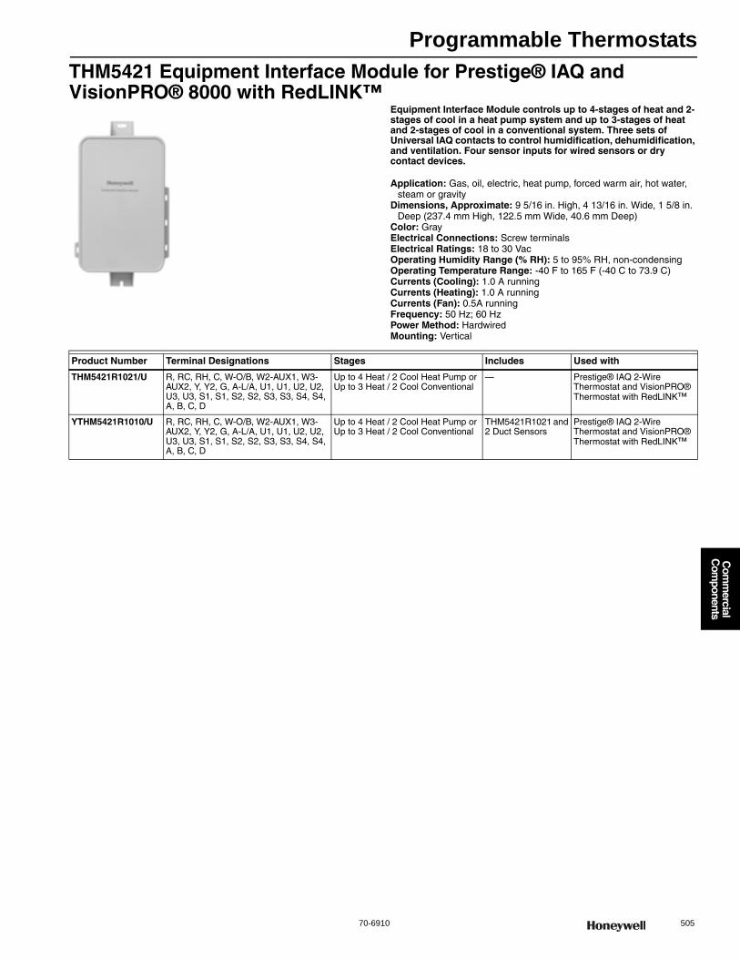
Programmable Thermostats
70-6910 505
Com
mercial
Com
ponents
THM5421 Equipment Interface Module for Prestige® IAQ and VisionPRO® 8000 with RedLINK™
Equipment Interface Module controls up to 4-stages of heat and 2-stages of cool in a heat pump system and up to 3-stages of heat and 2-stages of cool in a conventional system. Three sets of Universal IAQ contacts to control humidification, dehumidification, and ventilation. Four sensor inputs for wired sensors or dry contact devices.
Application: Gas, oil, electric, heat pump, forced warm air, hot water, steam or gravity
Dimensions, Approximate: 9 5/16 in. High, 4 13/16 in. Wide, 1 5/8 in. Deep (237.4 mm High, 122.5 mm Wide, 40.6 mm Deep)
Color: GrayElectrical Connections: Screw terminalsElectrical Ratings: 18 to 30 VacOperating Humidity Range (% RH): 5 to 95% RH, non-condensingOperating Temperature Range: -40 F to 165 F (-40 C to 73.9 C) Currents (Cooling): 1.0 A runningCurrents (Heating): 1.0 A runningCurrents (Fan): 0.5A runningFrequency: 50 Hz; 60 HzPower Method: HardwiredMounting: Vertical
Product Number Terminal Designations Stages Includes Used with
THM5421R1021/U R, RC, RH, C, W-O/B, W2-AUX1, W3-AUX2, Y, Y2, G, A-L/A, U1, U1, U2, U2, U3, U3, S1, S1, S2, S2, S3, S3, S4, S4, A, B, C, D
Up to 4 Heat / 2 Cool Heat Pump or Up to 3 Heat / 2 Cool Conventional
— Prestige® IAQ 2-Wire Thermostat and VisionPRO® Thermostat with RedLINK™
YTHM5421R1010/U R, RC, RH, C, W-O/B, W2-AUX1, W3-AUX2, Y, Y2, G, A-L/A, U1, U1, U2, U2, U3, U3, S1, S1, S2, S2, S3, S3, S4, S4, A, B, C, D
Up to 4 Heat / 2 Cool Heat Pump or Up to 3 Heat / 2 Cool Conventional
THM5421R1021 and 2 Duct Sensors
Prestige® IAQ 2-Wire Thermostat and VisionPRO® Thermostat with RedLINK™

Programmable Commercial Thermostats
506 customer.honeywell.com 70-6910
Commercial VisionPRO® 8000
The TB8220 Commercial VisionPRO 8000 Touchscreen Programmable Thermostat is an effortless, seven day programmable thermostat that provides universal system compatibility, precise comfort control and is easy to program.
The TB8220 provides temperature control for gas, oil, electric and heat pumps for up to 2 heat, 2 cool systems.
• Large, clear display with backlight shows the current and set temperature and time even in the dark
• Menu-driven programming make setup effortless • Beautiful ergonomic design is smart and sophisticated to
match your customers' lifestyle • Touchscreen interaction Real-time clock keeps time during
power failures and automatically updates to daylight savings • Saving Changes notification lets you know when the
schedule changes have been saved • Change reminders let you know when to replace the batteries • Holiday Override options allow you to override the
program schedule, as desired • Speedy same--schedule programming--no need to copy multiple days • Armchair programming allows you to remove the
thermostat from the wall for programming
Dimensions in inches (millimeters) Application: 24 Vac heating and cooling systems; Heat Pump Systems; Conventional systems; Packaged RTU
Color: Premier White®Network Communications: NoneComments: The L-terminal is an input only Selectable programmable or
non-programmable.Includes A terminal to enable an economizer or control a lighting panel when used as a time of day relay
Accessories:C7041B2005-20K ohm NTC Temperature Sensor with 6 in. insertionC7041B2013-20K ohm NTC Temperature Sensor with 12 in. insertionC7041C2003-20K ohm NTC Temperature Sensor with 18 in. insertionC7041P2004-20K ohm NTC Stainless Steel Button Sensor, 11/16 in. dia.C7089U1006-Remote Outdoor SensorC7189U1005-Remote Indoor SensorC7770A1006-6 in. Duct Probe for Return Air 20 K ohm NTC
non-linear Temperature SensorC7772A1004-20 K ohm NTC non-linear Wall Flush Mount
Temperature Sensor without logoC7772A1012-20 K ohm NTC non-linear Wall Flush Mount
Temperature Sensor with Honeywell logoTR21-20 K ohm NTC non-linear Temperature Wall ModuleTR21-A-10 K ohm NTC non-linear Temperature Wall Module
(for averaging only)W7212A1009-Series 72 Economizer Logic Module with
Demand Control Ventilation32003796-001-Premier White® cover plate 7 7/8 in. x 5 1/2 in.
(200 mm x 140 mm)
M22421
6 (152)
THERMOSTAT
4-9/16(116)
3-3/8 (86)WALLPLATE
3-3/8 (86)
THERMOSTATAND WALLPLATE
1-3/8 (35)
Product Number
Switch PositionTerminal Designations Stages
Setting Temperature Range
System Fan (F) (C)
TB8220U1003/U HEAT-OFF-COOL-AUTO-EM.HEAT
AUTO-ON R, Rc, W (O/B), W2 (W1), Y, Y2, L, A, G, C, S1, S2
Up to 2 Heat/2 Cool Conventional; Up to 3 Heat/2 Cool Heat Pump
Heat: 40 F to 90 F; Cool: 50 F to 99 F
Heat: 4.5 C to 32 C; Cool: 10 C to 37 C
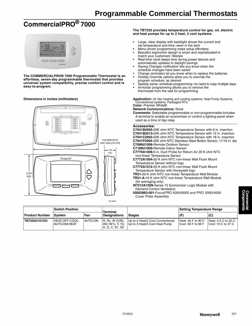
Programmable Commercial Thermostats
70-6910 507
Com
mercial
Com
ponents
CommercialPRO® 7000
The COMMERCIALPRO® 7000 Programmable Thermostat is an effortless, seven-day programmable thermostat that provides universal system compatibility, precise comfort control and is easy-to-program.
The TB7220 provides temperature control for gas, oil, electric and heat pumps for up to 2 heat, 2 cool systems.
• Large, clear display with backlight shows the current and set temperature and time--even in the dark
• Menu-driven programming make setup effortless • Beautiful ergonomic design is smart and sophisticated to
match your customers’ lifestyle • Real-time clock keeps time during power failures and
automatically updates to daylight savings • Saving Changes notification lets you know when the
schedule changes have been saved • Change reminders let you know when to replace the batteries • Holiday Override options allow you to override the
program schedule, as desired • Speedy same--schedule programming--no need to copy multiple days • Armchair programming allows you to remove the
thermostat from the wall for programming
Dimensions in inches (millimeters) Application: 24 Vac heating and cooling systems; Heat Pump Systems; Conventional systems; Packaged RTU
Color: Premier White®Network Communications: NoneComments: Selectable programmable or non-programmable.Includes
A terminal to enable an economizer or control a lighting panel when used as a time of day relay
Accessories:C7041B2005-20K ohm NTC Temperature Sensor with 6 in. insertionC7041B2013-20K ohm NTC Temperature Sensor with 12 in. insertionC7041C2003-20K ohm NTC Temperature Sensor with 18 in. insertionC7041P2004-20K ohm NTC Stainless Steel Button Sensor, 11/16 in. dia.C7089U1006-Remote Outdoor SensorC7189U1005-Remote Indoor SensorC7770A1006-6 in. Duct Probe for Return Air 20 K ohm NTC
non-linear Temperature SensorC7772A1004-20 K ohm NTC non-linear Wall Flush Mount
Temperature Sensor without logoC7772A1012-20 K ohm NTC non-linear Wall Flush Mount
Temperature Sensor with Honeywell logoTR21-20 K ohm NTC non-linear Temperature Wall ModuleTR21-A-10 K ohm NTC non-linear Temperature Wall Module
(for averaging only)W7212A1009-Series 72 Economizer Logic Module with
Demand Control Ventilation50002883-001-FocusPRO 5000/6000 and PRO 3000/4000
Cover Plate AssemblyM13668
3-3/4
(95)
THERMOSTAT
AND WALLPLATE
1-3/8
(35)
6 (152)
Product Number
Switch PositionTerminal Designations Stages
Setting Temperature Range
System Fan (F) (C)
TB7220U1012/U HEAT-OFF-COOL-AUTO-EM.HEAT
AUTO-ON R, Rc, W (O/B), W2 (W1), Y, Y2, A, G, C, S1, S2
Up to 2 Heat/2 Cool Conventional; Up to 3 Heat/2 Cool Heat Pump
Heat: 40 F to 90 F; Cool: 50 F to 99 F
Heat: 4.5 C to 32 C; Cool: 10 C to 37 C
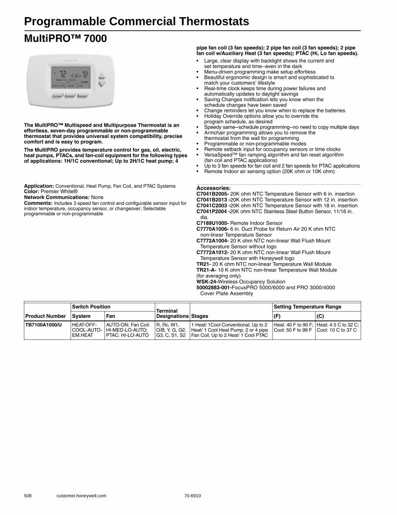
Programmable Commercial Thermostats
508 customer.honeywell.com 70-6910
MultiPRO™ 7000
The MultiPRO™ Multispeed and Multipurpose Thermostat is an effortless, seven-day programmable or non-programmable thermostat that provides universal system compatibility, precise comfort and is easy to program.
The MultiPRO provides temperature control for gas, oil, electric, heat pumps, PTACs, and fan-coil equipment for the following types of applications: 1H/1C conventional; Up to 2H/1C heat pump; 4
pipe fan coil (3 fan speeds); 2 pipe fan coil (3 fan speeds); 2 pipe fan coil w/Auxiliary Heat (3 fan speeds); PTAC (Hi, Lo fan speeds).• Large, clear display with backlight shows the current and
set temperature and time--even in the dark • Menu-driven programming make setup effortless • Beautiful ergonomic design is smart and sophisticated to
match your customers’ lifestyle • Real-time clock keeps time during power failures and
automatically updates to daylight savings • Saving Changes notification lets you know when the
schedule changes have been saved • Change reminders let you know when to replace the batteries • Holiday Override options allow you to override the
program schedule, as desired • Speedy same--schedule programming--no need to copy multiple days • Armchair programming allows you to remove the
thermostat from the wall for programming • Programmable or non-programmable modes • Remote setback input for occupancy sensors or time clocks • VersaSpeed™ fan ramping algorithm and fan reset algorithm
(fan coil and PTAC applications) • Up to 3 fan speeds for fan coil and 2 fan speeds for PTAC applications • Remote Indoor air sensing option (20K ohm or 10K ohm)
Application: Conventional, Heat Pump, Fan Coil, and PTAC SystemsColor: Premier White®Network Communications: NoneComments: Includes 3 speed fan control and configurable sensor input for indoor temperature, occupancy sensor, or changeover; Selectable programmable or non-programmable
Accessories:C7041B2005- 20K ohm NTC Temperature Sensor with 6 in. insertionC7041B2013 -20K ohm NTC Temperature Sensor with 12 in. insertionC7041C2003 -20K ohm NTC Temperature Sensor with 18 in. insertionC7041P2004 -20K ohm NTC Stainless Steel Button Sensor, 11/16 in.
dia.C7189U1005- Remote Indoor SensorC7770A1006- 6 in. Duct Probe for Return Air 20 K ohm NTC
non-linear Temperature SensorC7772A1004- 20 K ohm NTC non-linear Wall Flush Mount
Temperature Sensor without logoC7772A1012- 20 K ohm NTC non-linear Wall Flush Mount
Temperature Sensor with Honeywell logoTR21- 20 K ohm NTC non-linear Temperature Wall ModuleTR21-A- 10 K ohm NTC non-linear Temperature Wall Module (for averaging only)WSK-24-Wireless Occupancy Solution50002883-001-FocusPRO 5000/6000 and PRO 3000/4000
Cover Plate Assembly
Product Number
Switch PositionTerminal Designations Stages
Setting Temperature Range
System Fan (F) (C)
TB7100A1000/U HEAT-OFF-COOL-AUTO-EM.HEAT
AUTO-ON; Fan Coil: HI-MED-LO-AUTO; PTAC: HI-LO-AUTO
R, Rc, W1, O/B, Y, G, G2, G3, C, S1, S2
1 Heat/ 1Cool Conventional; Up to 2 Heat/ 1 Cool Heat Pump; 2 or 4 pipe Fan Coil; Up to 2 Heat/ 1 Cool PTAC
Heat: 40 F to 90 F; Cool: 50 F to 99 F
Heat: 4.5 C to 32 C; Cool: 10 C to 37 C
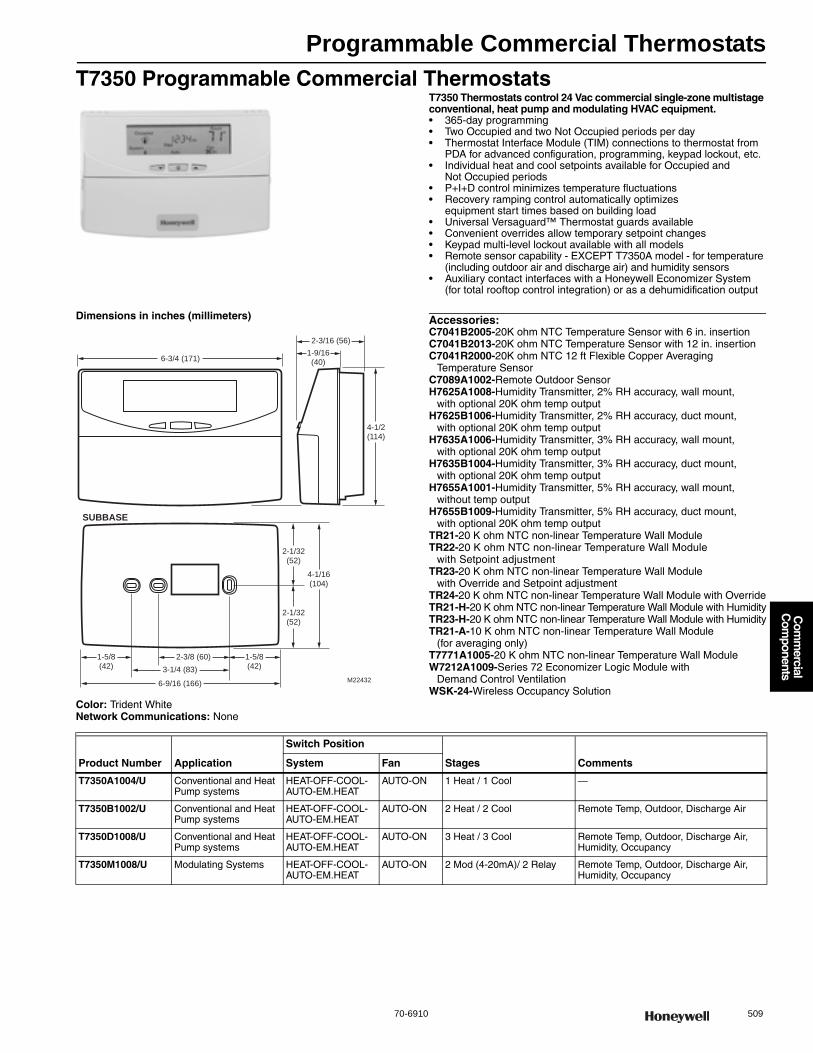
Programmable Commercial Thermostats
70-6910 509
Com
mercial
Com
ponents
T7350 Programmable Commercial ThermostatsT7350 Thermostats control 24 Vac commercial single-zone multistage conventional, heat pump and modulating HVAC equipment.• 365-day programming • Two Occupied and two Not Occupied periods per day • Thermostat Interface Module (TIM) connections to thermostat from
PDA for advanced configuration, programming, keypad lockout, etc. • Individual heat and cool setpoints available for Occupied and
Not Occupied periods • P+I+D control minimizes temperature fluctuations • Recovery ramping control automatically optimizes
equipment start times based on building load • Universal Versaguard™ Thermostat guards available • Convenient overrides allow temporary setpoint changes • Keypad multi-level lockout available with all models • Remote sensor capability - EXCEPT T7350A model - for temperature
(including outdoor air and discharge air) and humidity sensors • Auxiliary contact interfaces with a Honeywell Economizer System
(for total rooftop control integration) or as a dehumidification output
Dimensions in inches (millimeters)
Color: Trident WhiteNetwork Communications: None
Accessories:C7041B2005-20K ohm NTC Temperature Sensor with 6 in. insertionC7041B2013-20K ohm NTC Temperature Sensor with 12 in. insertionC7041R2000-20K ohm NTC 12 ft Flexible Copper Averaging
Temperature SensorC7089A1002-Remote Outdoor SensorH7625A1008-Humidity Transmitter, 2% RH accuracy, wall mount,
with optional 20K ohm temp outputH7625B1006-Humidity Transmitter, 2% RH accuracy, duct mount,
with optional 20K ohm temp outputH7635A1006-Humidity Transmitter, 3% RH accuracy, wall mount,
with optional 20K ohm temp outputH7635B1004-Humidity Transmitter, 3% RH accuracy, duct mount,
with optional 20K ohm temp outputH7655A1001-Humidity Transmitter, 5% RH accuracy, wall mount,
without temp outputH7655B1009-Humidity Transmitter, 5% RH accuracy, duct mount,
with optional 20K ohm temp outputTR21-20 K ohm NTC non-linear Temperature Wall ModuleTR22-20 K ohm NTC non-linear Temperature Wall Module
with Setpoint adjustmentTR23-20 K ohm NTC non-linear Temperature Wall Module
with Override and Setpoint adjustmentTR24-20 K ohm NTC non-linear Temperature Wall Module with OverrideTR21-H-20 K ohm NTC non-linear Temperature Wall Module with HumidityTR23-H-20 K ohm NTC non-linear Temperature Wall Module with HumidityTR21-A-10 K ohm NTC non-linear Temperature Wall Module
(for averaging only)T7771A1005-20 K ohm NTC non-linear Temperature Wall ModuleW7212A1009-Series 72 Economizer Logic Module with
Demand Control VentilationWSK-24-Wireless Occupancy Solution
6-3/4 (171)
2-3/16 (56)
1-9/16(40)
4-1/2(114)
2-1/32(52)
2-1/32(52)
4-1/16(104)
1-5/8(42)
2-3/8 (60)
3-1/4 (83)
6-9/16 (166)M22432
1-5/8(42)
SUBBASE
Product Number Application
Switch Position
Stages CommentsSystem Fan
T7350A1004/U Conventional and Heat Pump systems
HEAT-OFF-COOL-AUTO-EM.HEAT
AUTO-ON 1 Heat / 1 Cool —
T7350B1002/U Conventional and Heat Pump systems
HEAT-OFF-COOL-AUTO-EM.HEAT
AUTO-ON 2 Heat / 2 Cool Remote Temp, Outdoor, Discharge Air
T7350D1008/U Conventional and Heat Pump systems
HEAT-OFF-COOL-AUTO-EM.HEAT
AUTO-ON 3 Heat / 3 Cool Remote Temp, Outdoor, Discharge Air, Humidity, Occupancy
T7350M1008/U Modulating Systems HEAT-OFF-COOL-AUTO-EM.HEAT
AUTO-ON 2 Mod (4-20mA)/ 2 Relay Remote Temp, Outdoor, Discharge Air, Humidity, Occupancy
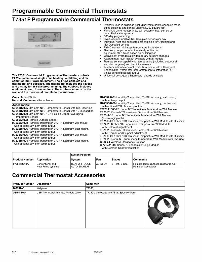
Programmable Commercial Thermostats
510 customer.honeywell.com 70-6910
T7351F Programmable Commercial Thermostats
The T7351 Commercial Programmable Thermostat controls 24 Vac commercial single zone heating, ventilating and air conditioning (HVAC) equipment. The T7351 consists of a thermostat and subbase. The thermostat includes the keypad and display for 365-day programming. The subbase includes equipment control connections. The subbase mounts on the wall and the thermostat mounts to the subbase.
• Typically used in buildings (including: restaurants, shopping malls, office buildings and banks) under 55,000 square feet
• For single zone rooftop units, split systems, heat pumps or hot/chilled water systems
• 365-day programming • Two Occupied and two Not Occupied periods per day • Individual heat and cool setpoints available for Occupied and
Not Occupied periods• P+I+D control minimizes temperature fluctuations • Recovery ramp control automatically optimizes
equipment start times based on building load • Convenient overrides allow temporary setpoint changes • Keypad multi-level lockout available with all models • Remote sensor capability for temperature (including outdoor air
and discharge air) and humidity sensors • Auxiliary subbase contact typically interface with a Honeywell
Economizer System (for total rooftop control integration) or act as dehumidification output
• Universal Versaguard Thermostat guards available
Color: Trident WhiteNetwork Communications: None
Accessories:C7041B2005-20K ohm NTC Temperature Sensor with 6 in. insertionC7041B2013-20K ohm NTC Temperature Sensor with 12 in. insertionC7041R2000-20K ohm NTC 12 ft Flexible Copper Averaging
Temperature SensorC7089A1002-Remote Outdoor SensorH7625A1008-Humidity Transmitter, 2% RH accuracy, wall mount,
with optional 20K ohm temp outputH7625B1006-Humidity Transmitter, 2% RH accuracy, duct mount,
with optional 20K ohm temp outputH7635A1006-Humidity Transmitter, 3% RH accuracy, wall mount,
with optional 20K ohm temp outputH7635B1004-Humidity Transmitter, 3% RH accuracy, duct mount,
with optional 20K ohm temp output
H7655A1001-Humidity Transmitter, 5% RH accuracy, wall mount, without temp output
H7655B1009-Humidity Transmitter, 5% RH accuracy, duct mount, with optional 20K ohm temp output
T7771A1005-20 K ohm NTC non-linear Temperature Wall ModuleTR21-20 K ohm NTC non-linear Temperature Wall ModuleTR21-A-10 K ohm NTC non-linear Temperature Wall Module
(for averaging only)TR21-H-20 K ohm NTC non-linear Temperature Wall Module with HumidityTR22-20 K ohm NTC non-linear Temperature Wall Module
with Setpoint adjustmentTR23-20 K ohm NTC non-linear Temperature Wall Module
with Override and Setpoint adjustmentTR23-H-20 K ohm NTC non-linear Temperature Wall Module with HumidityTR24-20 K ohm NTC non-linear Temperature Wall Module with OverrideWSK-24-Wireless Occupancy SolutionW7212A1009-Series 72 Economizer Logic Module
with Demand Control Ventilation
Commercial Thermostat Accessories
Product Number Application
Switch Position
Stages CommentsSystem Fan
T7351F2010/U Conventional and Heat Pump systems
HEAT-OFF-COOL-AUTO-EM.HEAT
AUTO-ON 3 Heat / 3 Cool Remote Temp, Outdoor, Discharge Air, Humidity, Occupancy
Product Number Description Used With
209651A/U Wallplate T7350;
USB-TIM/U USB Thermostat Interface Module cable T7350 thermostats and TStat; Spec software

Communicating Thermostats
70-6910 511
Com
mercial
Com
ponents
T7350 Communicating Programmable Commercial ThermostatsT7350H Communicating Thermostats control 24 Vac commercial single-zone multistage conventional, heat pump and modulating HVAC equipment. T7350H allows remote access and the sharing of system parameters with other devices in a LONWORKS® network• 365-day programming. • Two Occupied and two Not Occupied periods per day. • Thermostat Interface Module (TIM) connections to thermostat from
PDA for advanced configuration, programming, keypad lockout, etc. • Individual heat and cool setpoints available for Occupied and Not
Occupied periods. • P+I+D control minimizes temperature fluctuations. • Recovery ramping control automatically optimizes equipment start
times based on building load. • Universal Versaguard™ Thermostat guards available. • Convenient overrides allow temporary setpoint changes. • Keypad multi-level lockout available with all models. • Remote sensor capability for temperature (including outdoor air and
discharge air) and humidity sensors. • Auxiliary contact interfaces with a Honeywell Economizer System
(for total rooftop control integration) or as a dehumidification output LONWORKS® network communication.
Color: Trident WhiteStages: 3 Heat / 3 CoolNetwork Communications: LonWorks Bus and PDA Serial Port
Accessories:C7041B2005-20K ohm NTC Temperature Sensor with 6 in. insertionC7041R2000-20K ohm NTC 12 ft Flexible Copper Averaging
Temperature SensorH7625A1008-Humidity Transmitter, 2% RH accuracy, wall mount, with
optional 20K ohm temp outputH7625B1006-Humidity Transmitter, 2% RH accuracy, duct mount, with
optional 20K ohm temp outputH7635A1006-Humidity Transmitter, 3% RH accuracy, wall mount, with
optional 20K ohm temp outputH7635B1004-Humidity Transmitter, 3% RH accuracy, duct mount, with
optional 20K ohm temp outputH7635C1002-Humidity Transmitter, 3% RH accuracy, outdoor mount,
with optional 20K ohm temp output
H7655A1001-Humidity Transmitter, 5% RH accuracy, wall mount, without temp output
H7655B1009-Humidity Transmitter, 5% RH accuracy, duct mount, with optional 20K ohm temp output
W7212A1009-Series 72 Economizer Logic Module with Demand Control Ventilation
T7771A1005-20 K ohm NTC non-linear Temperature Wall ModuleTR21-20 K ohm NTC non-linear Temperature Wall ModuleTR21-H-20 K ohm NTC non-linear Temperature Wall Module with
HumidityTR22-20 K ohm NTC non-linear Temperature Wall Module with Setpoint
adjustmentTR23-20 K ohm NTC non-linear Temperature Wall Module with Override
and Setpoint adjustmentTR23-H-20 K ohm NTC non-linear Temperature Wall Module with
HumidityTR24-20 K ohm NTC non-linear Temperature Wall Module with OverrideTR21-A-10 K ohm NTC non-linear Temperature Wall Module (for
averaging only)
Product Number Application
Switch Position
Comments IncludesSystem Fan
T7350H1009/U Conventional and Heat Pump systems
HEAT-OFF-COOL-AUTO-EM.HEAT
AUTO-ON Remote Temp, Outdoor, Discharge Air, Humidity
—
T7350H1017/U Modulating Systems HEAT-OFF-COOL-AUTO-EM.HEAT
AUTO-ON Remote Temp, Outdoor, Discharge Air, Humidity and Occupancy
—
Y7355H1009/U Conventional and Heat Pump systems
HEAT-OFF-COOL-AUTO-EM.HEAT
AUTO-ON Remote Temp, Outdoor, Discharge Air, Humidity, Occupancy
T7350H1009, C7041B2005, T7771A1005
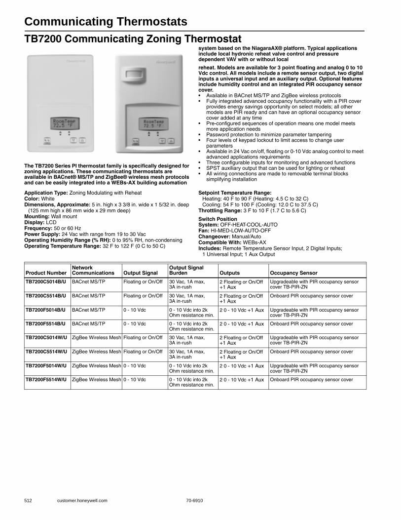
Communicating Thermostats
512 customer.honeywell.com 70-6910
TB7200 Communicating Zoning Thermostat
The TB7200 Series PI thermostat family is specifically designed for zoning applications. These communicating thermostats are available in BACnet® MS/TP and ZigBee® wireless mesh protocols and can be easily integrated into a WEBs-AX building automation
system based on the NiagaraAX® platform. Typical applications include local hydronic reheat valve control and pressure dependent VAV with or without local
reheat. Models are available for 3 point floating and analog 0 to 10 Vdc control. All models include a remote sensor output, two digital inputs a universal input and an auxiliary output. Optional features include humidity control and an integrated PIR occupancy sensor cover.• Available in BACnet MS/TP and ZigBee wireless protocols • Fully integrated advanced occupancy functionality with a PIR cover
provides energy savings opportunity on select models; all other models are PIR ready and can have an optional occupancy sensor cover added at any time
• Pre-configured sequences of operation means one model meets more application needs
• Password protection to minimize parameter tampering • Four levels of keypad lockout to limit access to change user
parameters • Available in 24 Vac on/off, floating or 0-10 Vdc analog control to meet
advanced applications requirements • Three configurable inputs for monitoring and advanced functions • SPST auxiliary output that can be used for lighting or reheat • All wiring connections are made to removable terminal blocks
simplifying installation
Application Type: Zoning Modulating with ReheatColor: WhiteDimensions, Approximate: 5 in. high x 3 3/8 in. wide x 1 5/32 in. deep
(125 mm high x 86 mm wide x 29 mm deep) Mounting: Wall mountDisplay: LCDFrequency: 50 or 60 HzPower Supply: 24 Vac with range from 19 to 30 VacOperating Humidity Range (% RH): 0 to 95% RH, non-condensingOperating Temperature Range: 32 F to 122 F (0 C to 50 C)
Setpoint Temperature Range: Heating: 40 F to 90 F (Heating: 4.5 C to 32 C) Cooling: 54 F to 100 F (Cooling: 12.0 C to 37.5 C)
Throttling Range: 3 F to 10 F (1.7 C to 5.6 C)
Switch PositionSystem: OFF-HEAT-COOL-AUTOFan: HI-MED-LOW-AUTO-OFFChangeover: Manual/AutoCompatible With: WEBs-AXIncludes: Remote Temperature Sensor Input, 2 Digital Inputs;
1 Universal Input; 1 Aux Output
Product NumberNetwork Communications Output Signal
Output Signal Burden Outputs Occupancy Sensor
TB7200C5014B/U BACnet MS/TP Floating or On/Off 30 Vac, 1A max, 3A in-rush
2 Floating or On/Off +1 Aux
Upgradeable with PIR occupancy sensor cover TB-PIR-ZN
TB7200C5514B/U BACnet MS/TP Floating or On/Off 30 Vac, 1A max, 3A in-rush
2 Floating or On/Off +1 Aux
Onboard PIR occupancy sensor cover
TB7200F5014B/U BACnet MS/TP 0 - 10 Vdc 0 - 10 Vdc into 2k Ohm resistance min.
2 0 - 10 Vdc +1 Aux Upgradeable with PIR occupancy sensor cover TB-PIR-ZN
TB7200F5514B/U BACnet MS/TP 0 - 10 Vdc 0 - 10 Vdc into 2k Ohm resistance min.
2 0 - 10 Vdc +1 Aux Onboard PIR occupancy sensor cover
TB7200C5014W/U ZigBee Wireless Mesh Floating or On/Off 30 Vac, 1A max, 3A in-rush
2 Floating or On/Off +1 Aux
Upgradeable with PIR occupancy sensor cover TB-PIR-ZN
TB7200C5514W/U ZigBee Wireless Mesh Floating or On/Off 30 Vac, 1A max, 3A in-rush
2 Floating or On/Off +1 Aux
Onboard PIR occupancy sensor cover
TB7200F5014W/U ZigBee Wireless Mesh 0 - 10 Vdc 0 - 10 Vdc into 2k Ohm resistance min.
2 0 - 10 Vdc +1 Aux Upgradeable with PIR occupancy sensor cover TB-PIR-ZN
TB7200F5514W/U ZigBee Wireless Mesh 0 - 10 Vdc 0 - 10 Vdc into 2k Ohm resistance min.
2 0 - 10 Vdc +1 Aux Onboard PIR occupancy sensor cover
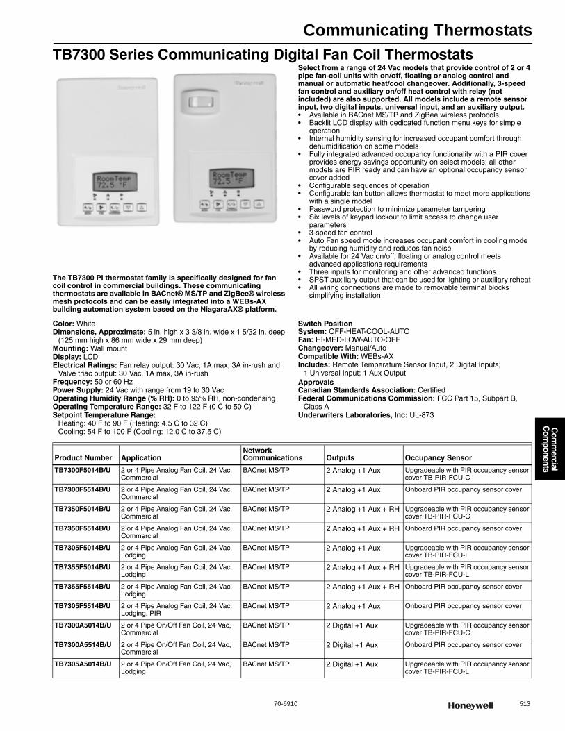
Communicating Thermostats
70-6910 513
Com
mercial
Com
ponents
TB7300 Series Communicating Digital Fan Coil Thermostats
The TB7300 PI thermostat family is specifically designed for fan coil control in commercial buildings. These communicating thermostats are available in BACnet® MS/TP and ZigBee® wireless mesh protocols and can be easily integrated into a WEBs-AX building automation system based on the NiagaraAX® platform.
Select from a range of 24 Vac models that provide control of 2 or 4 pipe fan-coil units with on/off, floating or analog control and manual or automatic heat/cool changeover. Additionally, 3-speed fan control and auxiliary on/off heat control with relay (not included) are also supported. All models include a remote sensor input, two digital inputs, universal input, and an auxiliary output.• Available in BACnet MS/TP and ZigBee wireless protocols • Backlit LCD display with dedicated function menu keys for simple
operation • Internal humidity sensing for increased occupant comfort through
dehumidification on some models • Fully integrated advanced occupancy functionality with a PIR cover
provides energy savings opportunity on select models; all other models are PIR ready and can have an optional occupancy sensor cover added
• Configurable sequences of operation • Configurable fan button allows thermostat to meet more applications
with a single model • Password protection to minimize parameter tampering • Six levels of keypad lockout to limit access to change user
parameters• 3-speed fan control • Auto Fan speed mode increases occupant comfort in cooling mode
by reducing humidity and reduces fan noise • Available for 24 Vac on/off, floating or analog control meets
advanced applications requirements • Three inputs for monitoring and other advanced functions • SPST auxiliary output that can be used for lighting or auxiliary reheat • All wiring connections are made to removable terminal blocks
simplifying installation
Color: WhiteDimensions, Approximate: 5 in. high x 3 3/8 in. wide x 1 5/32 in. deep
(125 mm high x 86 mm wide x 29 mm deep) Mounting: Wall mountDisplay: LCDElectrical Ratings: Fan relay output: 30 Vac, 1A max, 3A in-rush and
Valve triac output: 30 Vac, 1A max, 3A in-rushFrequency: 50 or 60 HzPower Supply: 24 Vac with range from 19 to 30 VacOperating Humidity Range (% RH): 0 to 95% RH, non-condensingOperating Temperature Range: 32 F to 122 F (0 C to 50 C) Setpoint Temperature Range:
Heating: 40 F to 90 F (Heating: 4.5 C to 32 C) Cooling: 54 F to 100 F (Cooling: 12.0 C to 37.5 C)
Switch PositionSystem: OFF-HEAT-COOL-AUTOFan: HI-MED-LOW-AUTO-OFFChangeover: Manual/AutoCompatible With: WEBs-AXIncludes: Remote Temperature Sensor Input, 2 Digital Inputs;
1 Universal Input; 1 Aux OutputApprovalsCanadian Standards Association: CertifiedFederal Communications Commission: FCC Part 15, Subpart B,
Class AUnderwriters Laboratories, Inc: UL-873
Product Number ApplicationNetwork Communications Outputs Occupancy Sensor
TB7300F5014B/U 2 or 4 Pipe Analog Fan Coil, 24 Vac, Commercial
BACnet MS/TP 2 Analog +1 Aux Upgradeable with PIR occupancy sensor cover TB-PIR-FCU-C
TB7300F5514B/U 2 or 4 Pipe Analog Fan Coil, 24 Vac, Commercial
BACnet MS/TP 2 Analog +1 Aux Onboard PIR occupancy sensor cover
TB7350F5014B/U 2 or 4 Pipe Analog Fan Coil, 24 Vac, Commercial
BACnet MS/TP 2 Analog +1 Aux + RH Upgradeable with PIR occupancy sensor cover TB-PIR-FCU-C
TB7350F5514B/U 2 or 4 Pipe Analog Fan Coil, 24 Vac, Commercial
BACnet MS/TP 2 Analog +1 Aux + RH Onboard PIR occupancy sensor cover
TB7305F5014B/U 2 or 4 Pipe Analog Fan Coil, 24 Vac, Lodging
BACnet MS/TP 2 Analog +1 Aux Upgradeable with PIR occupancy sensor cover TB-PIR-FCU-L
TB7355F5014B/U 2 or 4 Pipe Analog Fan Coil, 24 Vac, Lodging
BACnet MS/TP 2 Analog +1 Aux + RH Upgradeable with PIR occupancy sensor cover TB-PIR-FCU-L
TB7355F5514B/U 2 or 4 Pipe Analog Fan Coil, 24 Vac, Lodging
BACnet MS/TP 2 Analog +1 Aux + RH Onboard PIR occupancy sensor cover
TB7305F5514B/U 2 or 4 Pipe Analog Fan Coil, 24 Vac, Lodging, PIR
BACnet MS/TP 2 Analog +1 Aux Onboard PIR occupancy sensor cover
TB7300A5014B/U 2 or 4 Pipe On/Off Fan Coil, 24 Vac, Commercial
BACnet MS/TP 2 Digital +1 Aux Upgradeable with PIR occupancy sensor cover TB-PIR-FCU-C
TB7300A5514B/U 2 or 4 Pipe On/Off Fan Coil, 24 Vac, Commercial
BACnet MS/TP 2 Digital +1 Aux Onboard PIR occupancy sensor cover
TB7305A5014B/U 2 or 4 Pipe On/Off Fan Coil, 24 Vac, Lodging
BACnet MS/TP 2 Digital +1 Aux Upgradeable with PIR occupancy sensor cover TB-PIR-FCU-L

Communicating Thermostats
514 customer.honeywell.com 70-6910
TB7305A5514B/U 2 or 4 Pipe On/Off Fan Coil, 24 Vac, Lodging
BACnet MS/TP 2 Digital +1 Aux Onboard PIR occupancy sensor cover
TB7300C5014B/U 2 or 4 Pipe On/Off or Floating Fan Coil, 24 Vac, Commercial
BACnet MS/TP 2 Floating +1 Aux Upgradeable with PIR occupancy sensor cover TB-PIR-RTU
TB7300C5514B/U 2 or 4 Pipe On/Off or Floating Fan Coil, 24 Vac, Commercial
BACnet MS/TP 2 Floating +1 Aux Onboard PIR occupancy sensor cover
TB7350C5014B/U 2 or 4 Pipe On/Off or Floating Fan Coil, 24 Vac, Commercial
BACnet MS/TP 2 Floating +1 Aux +RH Upgradeable with PIR occupancy sensor cover TB-PIR-RTU
TB7350C5514B/U 2 or 4 Pipe On/Off or Floating Fan Coil, 24 Vac, Commercial
BACnet MS/TP 2 Floating +1 Aux +RH Onboard PIR occupancy sensor cover
TB7305C5014B/U 2 or 4 Pipe On/Off or Floating Fan Coil, 24 Vac, Lodging
BACnet MS/TP 2 Floating +1 Aux Upgradeable with PIR occupancy sensor cover TB-PIR-RTU
TB7305C5514B/U 2 or 4 Pipe On/Off or Floating Fan Coil, 24 Vac, Lodging
BACnet MS/TP 2 Digital +1 Aux Onboard PIR occupancy sensor cover
TB7355C5014B/U 2 or 4 Pipe On/Off or Floating Fan Coil, 24 Vac, Lodging
BACnet MS/TP 2 Floating +1 Aux +RH Upgradeable with PIR occupancy sensor cover TB-PIR-RTU
TB7355C5514B/U 2 or 4 Pipe On/Off or Floating Fan Coil, 24 Vac, Lodging
BACnet MS/TP 2 Floating +1 Aux +RH Onboard PIR occupancy sensor cover
TB7300A5014W/U 2 or 4 Pipe On/Off Fan Coil, 24 Vac, Commercial
ZigBee Wireless Mesh 2 Digital +1 Aux Upgradeable with PIR occupancy sensor cover TB-PIR-FCU-C
TB7300A5514W/U 2 or 4 Pipe On/Off Fan Coil, 24 Vac, Commercial
ZigBee Wireless Mesh 2 Digital +1 Aux Onboard PIR occupancy sensor cover
TB7300C5014W/U 2 or 4 Pipe On/Off or Floating Fan Coil, 24 Vac, Commercial
ZigBee Wireless Mesh 2 Floating +1 Aux Upgradeable with PIR occupancy sensor cover TB-PIR-RTU
TB7300C5514W/U 2 or 4 Pipe On/Off or Floating Fan Coil, 24 Vac, Commercial
ZigBee Wireless Mesh 2 Floating +1 Aux Onboard PIR occupancy sensor cover
TB7300F5014W/U 2 or 4 Pipe Analog Fan Coil, 24 Vac, Commercial
ZigBee Wireless Mesh 2 Analog +1 Aux Upgradeable with PIR occupancy sensor cover TB-PIR-FCU-C
TB7300F5514W/U 2 or 4 Pipe Analog Fan Coil, 24 Vac, Commercial
ZigBee Wireless Mesh 2 Analog +1 Aux Onboard PIR occupancy sensor cover
TB7305A5014W/U 2 or 4 Pipe On/Off Fan Coil, 24 Vac, Lodging
ZigBee Wireless Mesh 2 Digital +1 Aux Upgradeable with PIR occupancy sensor cover TB-PIR-FCU-L
TB7305A5514W/U 2 or 4 Pipe On/Off Fan Coil, 24 Vac, Lodging
ZigBee Wireless Mesh 2 Digital +1 Aux Onboard PIR occupancy sensor cover
TB7305C5014W/U 2 or 4 Pipe On/Off or Floating Fan Coil, 24 Vac, Lodging
ZigBee Wireless Mesh 2 Floating +1 Aux Upgradeable with PIR occupancy sensor cover TB-PIR-RTU
TB7305C5514W/U 2 or 4 Pipe On/Off or Floating Fan Coil, 24 Vac, Lodging
ZigBee Wireless Mesh 2 Floating +1 Aux Onboard PIR occupancy sensor cover
TB7305F5014W/U 2 or 4 Pipe Analog Fan Coil, 24 Vac, Lodging
ZigBee Wireless Mesh 2 Analog +1 Aux Upgradeable with PIR occupancy sensor cover TB-PIR-FCU-L
TB7305F5514W/U 2 or 4 Pipe Analog Fan Coil, 24 Vac, Lodging, PIR
ZigBee Wireless Mesh 2 Analog +1 Aux Onboard PIR occupancy sensor cover
TB7350C5014W/U 2 or 4 Pipe On/Off or Floating Fan Coil, 24 Vac, Commercial
ZigBee Wireless Mesh 2 Floating +1 Aux + RH Upgradeable with PIR occupancy sensor cover TB-PIR-RTU
TB7350C5514W/U 2 or 4 Pipe On/Off or Floating Fan Coil, 24 Vac, Commercial
ZigBee Wireless Mesh 2 Floating +1 Aux + RH Onboard PIR occupancy sensor cover
TB7350F5014W/U 2 or 4 Pipe Analog Fan Coil, 24 Vac, Commercial
ZigBee Wireless Mesh 2 Analog +1 Aux Upgradeable with PIR occupancy sensor cover TB-PIR-FCU-C
TB7350F5514W/U 2 or 4 Pipe Analog Fan Coil, 24 Vac, Commercial
ZigBee Wireless Mesh 2 Analog +1 Aux Onboard PIR occupancy sensor cover
TB7355C5014W/U 2 or 4 Pipe On/Off or Floating Fan Coil, 24 Vac, Lodging
ZigBee Wireless Mesh 2 Floating +1 Aux +RH Upgradeable with PIR occupancy sensor cover TB-PIR-RTU
TB7355C5514W/U 2 or 4 Pipe On/Off or Floating Fan Coil, 24 Vac, Lodging
ZigBee Wireless Mesh 2 Floating +1 Aux +RH Onboard PIR occupancy sensor cover
TB7355F5014W/U 2 or 4 Pipe Analog Fan Coil, 24 Vac, Lodging
ZigBee Wireless Mesh 2 Analog +1 Aux +RH Upgradeable with PIR occupancy sensor cover TB-PIR-FCU-L
TB7355F5514W/U 2 or 4 Pipe Analog Fan Coil, 24 Vac, Lodging
ZigBee Wireless Mesh 2 Analog +1 Aux +RH Onboard PIR occupancy sensor cover
Product Number ApplicationNetwork Communications Outputs Occupancy Sensor

Communicating Thermostats
70-6910 515
Com
mercial
Com
ponents
TB7600 Communicating Commercial Thermostats
The TB7600 Series PI thermostat family is designed for single stage and multi-stage control of heating/cooling equipment such as rooftop and heat pump. These communicating thermostats have models available in BACnet® MS/TP and ZigBee® wireless mesh protocols and can be easily integrated into a WEBs-AX building automation system based on the NiagaraAX® platform. The product features an intuitive, menu-driven, back-lit LCD display, which walks users through the programming steps, making the process extremely simple. Depending on the model, up to three
remote sensor inputs are available and all models include an auxiliary output, and one or two digital inputs. Optional features include humidity control, an integrated economizer control logic and integrated PIR occupancy sensor cover.• Available in BACnet MS/TP and ZigBee wireless protocols • Built in default profile set-up for easier start up and commissioning • Fully integrated advanced occupancy functionality with a PIR
accessory cover on some models • Programmable smart fan operation • Password protection to minimize parameter tampering • Three levels of keypad lockout • Gas/oil or electric system compatibility for all type of applications • SPST auxiliary output can be used for lighting and/or economizer
override • 0 to 10 Vdc economizer output for more retrofit opportunities • Automatic frost protection to prevents costly freeze damage • Anti short cycle and minimum on/off run time protection to reduce
wear and maximizes life span of mechanical equipment • One or two programmable digital inputs for added flexibility can be
use to monitor filter status, activate a remote temporary occupancy switch, and/or used as a general purpose service indicator
• Heat Pump models support single and two stages heat pump with one auxiliary heat stage, selectable single or dual stage compressor stages, and comfort/economy mode maximizes heat pump use before turning on auxiliary heating, compressor/auxiliary interlock adds flexibility by locking out heat pump operation during auxiliary heating to prevent high pressure trip when the coil is downstream of the auxiliary heat source
• 7 day programmable models, 2 or 4 events for use in non-networked applications
Application : Conventional systemsColor: WhiteDimensions, Approximate: 5 in. high x 3 3/8 in. wide x 1 5/32 in. deep
(125 mm high x 86 mm wide x 29 mm deep) Mounting: Wall mountDisplay: LCDElectrical Ratings: —Frequency: 50 or 60 HzPower Supply: 24 Vac with range from 19 to 30 VacOperating Humidity Range (% RH): 0 to 95% RH, non-condensingOperating Temperature Range: 32 F to 122 F (0 C to 50 C)
Switch PositionSystem: OFF-HEAT-COOL-AUTOFan: HI-MED-LOW-AUTO-OFFChangeover: Manual/AutoSetpoint Temperature Range:
Heating: 40 F to 90 F (Heating: 4.5 C to 32 C) Cooling: 54 F to 100 F (Cooling: 12.0 C to 37.5 C)
Compatible With: WEBs-AXApprovalsCanadian Standards Association: CertifiedFederal Communications Commission: FCC Part 15, Subpart B,
Class AUnderwriters Laboratories, Inc: UL-873
Product Number Stages
Network Communi-cations Occupancy Sensor Scheduling
Humidity Control Includes
TB7600A5014B/U 1 Heat / 1 Cool
BACnet MS/TP
Upgradeable with PIR occupancy sensor cover TB-PIR-RTU
— —
Remote Temperature Sensor, Outdoor Air Sensor & Mixed Air Sensor Inputs; 2 Digital Inputs; 1 Aux Output
TB7600A5014W/U 1 Heat / 1 Cool
ZigBee Wireless
Upgradeable with PIR occupancy sensor cover TB-PIR-RTU
— —
TB7600A5514B/U 1 Heat / 1 Cool
BACnet MS/TP
Onboard PIR occupancy sensor cover
— —
TB7600A5514W/U 1 Heat / 1 Cool
ZigBee Wireless
Onboard PIR occupancy sensor cover
— —
TB7600B5014B/U 2 Heat / 2 Cool
BACnet MS/TP
Upgradeable with PIR occupancy sensor cover TB-PIR-RTU
— —
TB7600B5014W/U 2 Heat / 2 Cool
ZigBee Wireless
Upgradeable with PIR occupancy sensor cover TB-PIR-RTU
— —
TB7600B5514B/U 2 Heat / 2 Cool
BACnet MS/TP
Onboard PIR occupancy sensor cover
— —
TB7600B5514W/U 2 Heat / 2 Cool
ZigBee Wireless
Onboard PIR occupancy sensor cover
— —
TB7600H5014B/U 3 Heat / 2 Cool
BACnet MS/TP
Upgradeable with PIR occupancy sensor cover TB-PIR-RTU
— —
TB7600H5014W/U 3 Heat / 2 Cool
ZigBee Wireless
Upgradeable with PIR occupancy sensor cover TB-PIR-RTU
— —
TB7600H5514B/U 3 Heat / 2 Cool
BACnet MS/TP
Onboard PIR occupancy sensor cover
— —
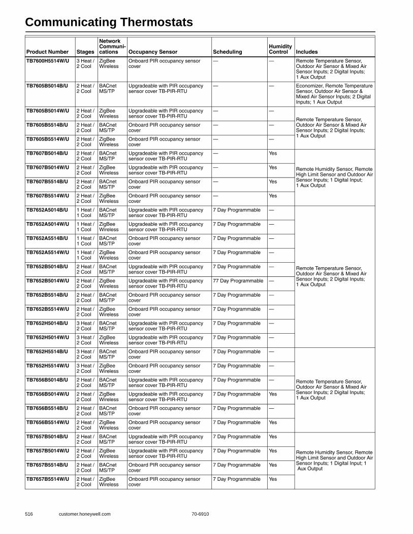
Communicating Thermostats
516 customer.honeywell.com 70-6910
TB7600H5514W/U 3 Heat / 2 Cool
ZigBee Wireless
Onboard PIR occupancy sensor cover
— — Remote Temperature Sensor, Outdoor Air Sensor & Mixed Air Sensor Inputs; 2 Digital Inputs; 1 Aux Output
TB7605B5014B/U 2 Heat / 2 Cool
BACnet MS/TP
Upgradeable with PIR occupancy sensor cover TB-PIR-RTU
— — Economizer, Remote Temperature Sensor, Outdoor Air Sensor & Mixed Air Sensor Inputs; 2 Digital Inputs; 1 Aux Output
TB7605B5014W/U 2 Heat / 2 Cool
ZigBee Wireless
Upgradeable with PIR occupancy sensor cover TB-PIR-RTU
— —
Remote Temperature Sensor, Outdoor Air Sensor & Mixed Air Sensor Inputs; 2 Digital Inputs; 1 Aux Output
TB7605B5514B/U 2 Heat / 2 Cool
BACnet MS/TP
Onboard PIR occupancy sensor cover
— —
TB7605B5514W/U 2 Heat / 2 Cool
ZigBee Wireless
Onboard PIR occupancy sensor cover
— —
TB7607B5014B/U 2 Heat / 2 Cool
BACnet MS/TP
Upgradeable with PIR occupancy sensor cover TB-PIR-RTU
— Yes
Remote Humidity Sensor, Remote High Limit Sensor and Outdoor Air Sensor Inputs; 1 Digital Input; 1 Aux Output
TB7607B5014W/U 2 Heat / 2 Cool
ZigBee Wireless
Upgradeable with PIR occupancy sensor cover TB-PIR-RTU
— Yes
TB7607B5514B/U 2 Heat / 2 Cool
BACnet MS/TP
Onboard PIR occupancy sensor cover
— Yes
TB7607B5514W/U 2 Heat / 2 Cool
ZigBee Wireless
Onboard PIR occupancy sensor cover
— Yes
TB7652A5014B/U 1 Heat / 1 Cool
BACnet MS/TP
Upgradeable with PIR occupancy sensor cover TB-PIR-RTU
7 Day Programmable —
Remote Temperature Sensor, Outdoor Air Sensor & Mixed Air Sensor Inputs; 2 Digital Inputs; 1 Aux Output
TB7652A5014W/U 1 Heat / 1 Cool
ZigBee Wireless
Upgradeable with PIR occupancy sensor cover TB-PIR-RTU
7 Day Programmable —
TB7652A5514B/U 1 Heat / 1 Cool
BACnet MS/TP
Onboard PIR occupancy sensor cover
7 Day Programmable —
TB7652A5514W/U 1 Heat / 1 Cool
ZigBee Wireless
Onboard PIR occupancy sensor cover
7 Day Programmable —
TB7652B5014B/U 2 Heat / 2 Cool
BACnet MS/TP
Upgradeable with PIR occupancy sensor cover TB-PIR-RTU
7 Day Programmable —
TB7652B5014W/U 2 Heat / 2 Cool
ZigBee Wireless
Upgradeable with PIR occupancy sensor cover TB-PIR-RTU
77 Day Programmable —
TB7652B5514B/U 2 Heat / 2 Cool
BACnet MS/TP
Onboard PIR occupancy sensor cover
7 Day Programmable —
TB7652B5514W/U 2 Heat / 2 Cool
ZigBee Wireless
Onboard PIR occupancy sensor cover
7 Day Programmable —
TB7652H5014B/U 3 Heat / 2 Cool
BACnet MS/TP
Upgradeable with PIR occupancy sensor cover TB-PIR-RTU
7 Day Programmable —
TB7652H5014W/U 3 Heat / 2 Cool
ZigBee Wireless
Upgradeable with PIR occupancy sensor cover TB-PIR-RTU
7 Day Programmable —
TB7652H5514B/U 3 Heat / 2 Cool
BACnet MS/TP
Onboard PIR occupancy sensor cover
7 Day Programmable —
Remote Temperature Sensor, Outdoor Air Sensor & Mixed Air Sensor Inputs; 2 Digital Inputs; 1 Aux Output
TB7652H5514W/U 3 Heat / 2 Cool
ZigBee Wireless
Onboard PIR occupancy sensor cover
7 Day Programmable —
TB7656B5014B/U 2 Heat / 2 Cool
BACnet MS/TP
Upgradeable with PIR occupancy sensor cover TB-PIR-RTU
7 Day Programmable —
TB7656B5014W/U 2 Heat / 2 Cool
ZigBee Wireless
Upgradeable with PIR occupancy sensor cover TB-PIR-RTU
7 Day Programmable Yes
TB7656B5514B/U 2 Heat / 2 Cool
BACnet MS/TP
Onboard PIR occupancy sensor cover
7 Day Programmable —
TB7656B5514W/U 2 Heat / 2 Cool
ZigBee Wireless
Onboard PIR occupancy sensor cover
7 Day Programmable Yes
TB7657B5014B/U 2 Heat / 2 Cool
BACnet MS/TP
Upgradeable with PIR occupancy sensor cover TB-PIR-RTU
7 Day Programmable Yes
Remote Humidity Sensor, Remote High Limit Sensor and Outdoor Air Sensor Inputs; 1 Digital Input; 1 Aux Output
TB7657B5014W/U 2 Heat / 2 Cool
ZigBee Wireless
Upgradeable with PIR occupancy sensor cover TB-PIR-RTU
7 Day Programmable Yes
TB7657B5514B/U 2 Heat / 2 Cool
BACnet MS/TP
Onboard PIR occupancy sensor cover
7 Day Programmable Yes
TB7657B5514W/U 2 Heat / 2 Cool
ZigBee Wireless
Onboard PIR occupancy sensor cover
7 Day Programmable Yes
Product Number Stages
Network Communi-cations Occupancy Sensor Scheduling
Humidity Control Includes

Communicating Thermostats
70-6910 517
Com
mercial
Com
ponents
Commercial Communicating Thermostats Accessories
TB7200 Communicating Zoning Thermostat Accessories
Product Number Description
TB-RA-1014/U WEBs-AX ZigBee Wireless Communication Card Remote Antenna
TB-RP5000W/U ZigBee Wireless Repeater for TB7200, TB7300, TB7600 Series Wireless Communicating Thermostat Networks
TB-VWG-APP-1014/U WEBs-AX ZigBee Wireless Communication Card for TB7200 / TB7300 / TB7600 Series Wireless Thermostats
Product Number Description
TB-PIR-ZN/U TB7200 Communicating Zoning Thermostat PIR Occupancy Sensor Cover

Communicating Thermostats
518 customer.honeywell.com 70-6910
TB7300 Series Communicating Digital Fan Coil Thermostat Accessories
TB7600 Communicating RTU/Heat Pump Thermostat Accessories
Product Number Description
TB-PIR-FCU-C/U TB7300 Fan Coil Thermostat PIR Occupancy Sensor Cover for Commercial Models
TB-PIR-FCU-L/U TB7300 Fan Coil Thermostat PIR Occupancy Sensor Cover for Lodging Models
Product Number Description Used With
TB-PIR-RTU/U TB7600 Series RTU/Heat Pump Thermostat PIR Occupancy Sensor Cover
TBST-5014W/U ZigBee Wireless Survey Toolkit for TB7200, TB7300, TB7600 Series Wireless Communicating Thermostat Networks
TB7200, TB7300, TB7600 Series Wireless Communicating Thermostats;

Timers
70-6910 519
Com
mercial
Com
ponents
ST6008 Energy Management TimersProvide 24-hour or 7-day time-based switching.• Universal application with 24-hour or 7-day programming • Battery backup (quartz drive) • Screw wiring terminals • Three-way override • Captive trippers
Dimensions, Approximate: 4 1/4 in. high x 2 15/16 in. wide x 2 1/4 in. deep (108 mm high x 75 mm wide x 57 mm deep)
Electrical Connections (in.): Screw terminalsMounting: Surface or on DIN railFrequency: 60 Hz
Ambient Temperature Range: -40 F to +180 F (-40 C to +82 C) Operating Humidity Range (% RH): 0 to 95% RHApprovalsCanadian Standards Association: Certified: File No. LR52379Underwriters Laboratories, Inc: Listed File: E83486
Product Number Clock Type VoltageMinimum Timing Switching Switch Ratings
ST6008A1006/U 24-hours synchronous 120 Vac 15 min 1 SPDT 1350 W tungsten; 21 A resistive @ 250 V
ST6008B1005/U 7-day synchronous 120 Vac 2 hrs 1 SPDT 22 A resistive @ 250 V; 1350 W tungsten
ST6008C1004/U 7-day quartz (7 day battery reserve) 120 Vac 2 hrs 1 SPDT 23 A resistive @ 250 V; 1350 W tungsten
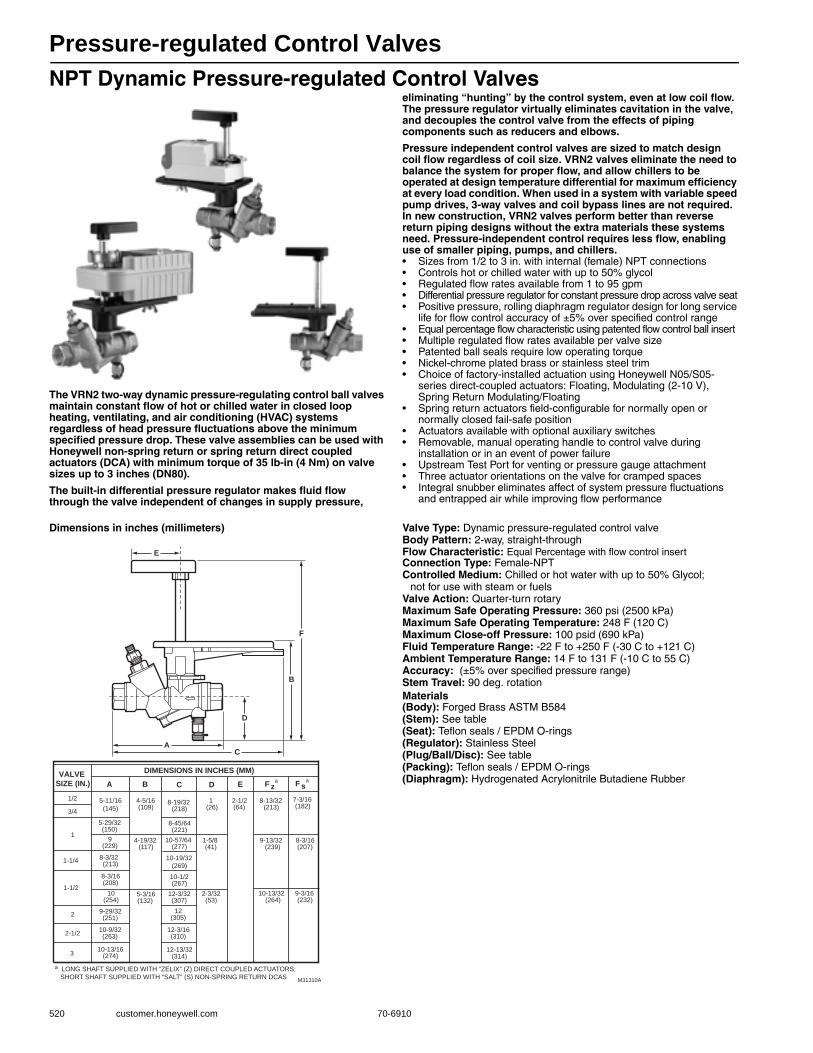
Pressure-regulated Control Valves
520 customer.honeywell.com 70-6910
NPT Dynamic Pressure-regulated Control Valves
The VRN2 two-way dynamic pressure-regulating control ball valves maintain constant flow of hot or chilled water in closed loop heating, ventilating, and air conditioning (HVAC) systems regardless of head pressure fluctuations above the minimum specified pressure drop. These valve assemblies can be used with Honeywell non-spring return or spring return direct coupled actuators (DCA) with minimum torque of 35 lb-in (4 Nm) on valve sizes up to 3 inches (DN80).
The built-in differential pressure regulator makes fluid flow through the valve independent of changes in supply pressure,
eliminating “hunting” by the control system, even at low coil flow. The pressure regulator virtually eliminates cavitation in the valve, and decouples the control valve from the effects of piping components such as reducers and elbows.
Pressure independent control valves are sized to match design coil flow regardless of coil size. VRN2 valves eliminate the need to balance the system for proper flow, and allow chillers to be operated at design temperature differential for maximum efficiency at every load condition. When used in a system with variable speed pump drives, 3-way valves and coil bypass lines are not required. In new construction, VRN2 valves perform better than reverse return piping designs without the extra materials these systems need. Pressure-independent control requires less flow, enabling use of smaller piping, pumps, and chillers.• Sizes from 1/2 to 3 in. with internal (female) NPT connections • Controls hot or chilled water with up to 50% glycol • Regulated flow rates available from 1 to 95 gpm • Differential pressure regulator for constant pressure drop across valve seat • Positive pressure, rolling diaphragm regulator design for long service
life for flow control accuracy of ±5% over specified control range • Equal percentage flow characteristic using patented flow control ball insert• Multiple regulated flow rates available per valve size • Patented ball seals require low operating torque • Nickel-chrome plated brass or stainless steel trim • Choice of factory-installed actuation using Honeywell N05/S05-
series direct-coupled actuators: Floating, Modulating (2-10 V), Spring Return Modulating/Floating
• Spring return actuators field-configurable for normally open or normally closed fail-safe position
• Actuators available with optional auxiliary switches • Removable, manual operating handle to control valve during
installation or in an event of power failure • Upstream Test Port for venting or pressure gauge attachment • Three actuator orientations on the valve for cramped spaces• Integral snubber eliminates affect of system pressure fluctuations
and entrapped air while improving flow performance
Dimensions in inches (millimeters) Valve Type: Dynamic pressure-regulated control valveBody Pattern: 2-way, straight-throughFlow Characteristic: Equal Percentage with flow control insertConnection Type: Female-NPTControlled Medium: Chilled or hot water with up to 50% Glycol;
not for use with steam or fuelsValve Action: Quarter-turn rotaryMaximum Safe Operating Pressure: 360 psi (2500 kPa) Maximum Safe Operating Temperature: 248 F (120 C) Maximum Close-off Pressure: 100 psid (690 kPa) Fluid Temperature Range: -22 F to +250 F (-30 C to +121 C) Ambient Temperature Range: 14 F to 131 F (-10 C to 55 C) Accuracy: (±5% over specified pressure range) Stem Travel: 90 deg. rotationMaterials(Body): Forged Brass ASTM B584(Stem): See table(Seat): Teflon seals / EPDM O-rings(Regulator): Stainless Steel(Plug/Ball/Disc): See table(Packing): Teflon seals / EPDM O-rings(Diaphragm): Hydrogenated Acrylonitrile Butadiene Rubber
M31310A
AC
F
B
E
D
a LONG SHAFT SUPPLIED WITH “ZELIX” (Z) DIRECT COUPLED ACTUATORS;
SHORT SHAFT SUPPLIED WITH “SALT” (S) NON-SPRING RETURN DCAS
VALVE SIZE (IN.)
DIMENSIONS IN INCHES (MM)
F za F s
a
1/2 5-11/16
(145)
4-5/16(109)
8-19/32 (218)
1 (26)
2-1/2 (64)
8-13/32 (213)
7-3/16 (182)
3/4
1
5-29/32(150)
8-45/64 (221)
9(229)
4-19/32(117)
10-57/64(277)
1-5/8 (41)
9-13/32 (239)
8-3/16 (207)
1-1/48-3/32(213)
10-19/32(269)
1-1/2
8-3/16(208)
10-1/2(267)
10(254)
5-3/16(132)
12-3/32(307)
2-3/32 (53)
10-13/32 (264)
9-3/16 (232)
29-29/32(251)
12(305)
2-1/210-9/32(263)
12-3/16(310)
10-13/163 (274)
12-13/32(314)
A B C D E

Pressure-regulated Control Valves
70-6910 521
Com
mercial
Com
ponents
.V
alve
,R
egu
late
d
Pip
e f
itti
ng
Bo
dy
Pat
tern
Val
ve S
ize
Flo
w
Rat
ing
Pre
ssu
reR
atin
g
Val
ve T
rim
Act
uat
or
Sec
on
dar
y S
pec
Act
uat
or
Co
ntr
ol
Fo
rm
Description
VR Dynamic pressure regulated control valveN
OT
E:“F.P.” in
dicates fu
ll po
rt ball (n
o flow
characterizatio
n in
sert).N Female NPT fitting
2 2-way
A Valve size, 1/2 in. (DN15)
B Valve size, 3/4 in. (DN20)
C Valve size, 1 in. (DN25)
D Valve size, 1-1/4 in. (DN32)
E Valve size, 1-1/2 in. (DN40)
F Valve size, 2 in. (DN50)
G Valve size, 2-1/2 in. (DN65)
H Valve size, 3 in. (DN80)
B 1 0 gpm
1/2
in.
3/4
in.
1 in
.
D 2 0 gpm
E 3 0 gpm
F 4 0 gpm
G 5 0 gpm
H 6 0 gpm
J 7 0 gpm
K 8 0 gpm
L 9 0 gpm
M 10 gpm1-
1/4
in.
1-1/
2 in
.
F.P.
N 15 gpm
P 20 gpm
Q 25 gpm
2 in
.
2-1/
2 in
.
3 in
.
R 30 gpm
S 35 gpm F.P.
T 40 gpm
U 45 gpm
1 50 gpm
2 55 gpm
3 60 gpm
4 65 gpm
5 70 gpm
6 75 gpm
7 80 gpm
8 85 gpm
9 95 gpm F.P. F.P.
3 360 psig body static pressure rating
D Brass trim, dual Test Ports
S Stainless steel trim, dual Test Ports
2 NEMA-2 actuator housing
F Flanged valve bonnet (no actuator)
A Floating actuator
B Modulating actuator
D Modulating spring return actuator
X Valve body only
VR N 2 B F 3 S 2 D = 2-way, 3/4-in. NPT dynamic pressure-regulated valve, SS trim, max. 4 gpm, modulating spring return.
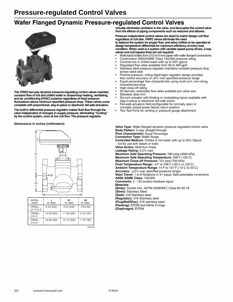
Pressure-regulated Control Valves
522 customer.honeywell.com 70-6910
Wafer Flanged Dynamic Pressure-regulated Control Valves
The VRW2 two-way dynamic pressure-regulating control valves maintain constant flow of hot and chilled water in closed-loop heating, ventilating, and air conditioning (HVAC) systems regardless of head pressure fluctuations above minimum specified pressure drop. These valves come complete with proportional, stay-in-place or electronic fail-safe actuators.
The built-in differential pressure regulator makes fluid flow through the valve independent of changes in supply pressure, eliminating “hunting” by the control system, even at low coil flow. The pressure regulator
virtually eliminates cavitation in the valve, and decouples the control valve from the effects of piping components such as reducers and elbows.
Pressure independent control valves are sized to match design coil flow regardless of coil size. VRW2 valves eliminate the need to balance the system for proper flow, and allow chillers to be operated at design temperature differential for maximum efficiency at every load condition. When used in a system with variable speed pump drives, 3-way valves and coil bypass lines are not required.• Multi-sized bodies from 21/2 to 6 inch pipes with wafer flanged connections • Combination ANSI/ASME Class 150/300 pressure rating • Controls hot or chilled water with up to 50% glycol • Regulated flow rates available from 39 to 469 gpm • Stainless steel pressure regulator maintains constant pressure drop
across valve seat • Positive pressure, rolling diaphragm regulator design provides
flow control accuracy of ±5% over specified pressure range • Equal percentage flow characteristic using multi turn, non-rising,
characterized plug • High close-off rating • 50 discrete, selectable flow rates available per valve size • Stainless steel trim • Six-turn actuator with floating or modulating inputs available with
stay-in-place or electronic fail-safe action • Fail-safe actuators field-configurable for normally open or
normally closed power failure return position • Two Test Ports for venting or pressure gauge attachment
Dimensions in inches (millimeters)Valve Type: Wafer flanged dynamic pressure-regulated control valveBody Pattern: 2-way, straight-throughFlow Characteristic: Equal PercentageConnection Type: Wafer flangeControlled Medium: Chilled or hot water with up to 50% Glycol;
not for use with steam or fuelsValve Action: Multi-turn linearLeakage Rating: 0.2% maxMaximum Safe Operating Pressure: 580 psig (4000 kPa) Maximum Safe Operating Temperature: 248 F (120 C) Maximum Close-off Pressure: 101 psid (700 kPa) Fluid Temperature Range: -4 F to 248 F (-20 C to 120 C) Ambient Temperature Range: 14 F to 131 F (-10 C to 55 C) Accuracy: (±5% over specified pressure range) Stem Travel: 1 to 6 Rotations in 51 equal, field-selectable incrementsANSI/ ASME Class: 150/300Comments: 2 - 10V position feedback signalMaterials(Body): Ductile Iron, ASTM A536ñ65T, Class 60-45-18(Stem): Stainless Steel(Seat): 316 Stainless steel(Regulator): 316 Stainless steel(Plug/Ball/Disc): 316 stainless steel(Packing): EPDM and Nitrile O-rings(Diaphragm): EPDM
M34706
L
H2
H1
MODEL L H1 H2 (SIZE) IN. (MM) IN. (MM) IN. (MM)
VRW2J… 8 3/4 (224) 9 3/4 (246) 3 3/4 (95)(2-1/2 & 3)
VRW2K… 12 5/8 (320) 11 3/8 (290) 5 1/4 (135)(3 & 4)
VRW2L… 16 5/8 (422) 13 1/4 (338) 7 1/8 (180)(5 & 6)
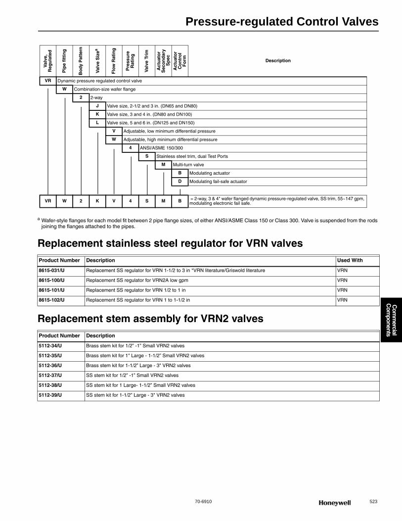
Pressure-regulated Control Valves
70-6910 523
Com
mercial
Com
ponents
a Wafer-style flanges for each model fit between 2 pipe flange sizes, of either ANSI/ASME Class 150 or Class 300. Valve is suspended from the rods joining the flanges attached to the pipes.
Replacement stainless steel regulator for VRN valves
Replacement stem assembly for VRN2 valves
Product Number Description Used With
8615-031/U Replacement SS regulator for VRN 1-1/2 to 3 in *VRN literature/Griswold literature VRN
8615-100/U Replacement SS regulator for VRN2A low gpm VRN
8615-101/U Replacement SS regulator for VRN 1/2 to 1 in VRN
8615-102/U Replacement SS regulator for VRN 1 to 1-1/2 in VRN
Product Number Description
5112-34/U Brass stem kit for 1/2” -1” Small VRN2 valves
5112-35/U Brass stem kit for 1" Large - 1-1/2” Small VRN2 valves
5112-36/U Brass stem kit for 1-1/2” Large - 3" VRN2 valves
5112-37/U SS stem kit for 1/2” -1” Small VRN2 valves
5112-38/U SS stem kit for 1 Large- 1-1/2” Small VRN2 valves
5112-39/U SS stem kit for 1-1/2” Large - 3" VRN2 valves
Val
ve,
Reg
ula
ted
Pip
e fi
ttin
g
Bo
dy P
atte
rn
Val
ve S
izea
Flo
w R
atin
g
Pre
ssu
reR
atin
g
Val
ve T
rim
Act
uat
or
Sec
on
dar
y S
pec
Act
uat
or
Co
ntr
ol
Fo
rm Description
VR Dynamic pressure regulated control valve
W Combination-size wafer flange
2 2-way
J Valve size, 2-1/2 and 3 in. (DN65 and DN80)
K Valve size, 3 and 4 in. (DN80 and DN100)
L Valve size, 5 and 6 in. (DN125 and DN150)
V Adjustable, low minimum differential pressure
W Adjustable, high minimum differential pressure
4 ANSI/ASME 150/300
S Stainless steel trim, dual Test Ports
M Multi-turn valve
B Modulating actuator
D Modulating fail-safe actuator
VR W 2 K V 4 S M B = 2-way, 3 & 4" wafer flanged dynamic pressure-regulated valve, SS trim, 55~147 gpm, modulating electronic fail safe.
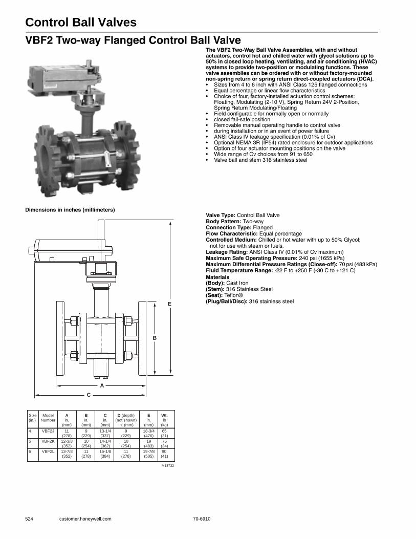
Control Ball Valves
524 customer.honeywell.com 70-6910
VBF2 Two-way Flanged Control Ball ValveThe VBF2 Two-Way Ball Valve Assemblies, with and without actuators, control hot and chilled water with glycol solutions up to 50% in closed loop heating, ventilating, and air conditioning (HVAC) systems to provide two-position or modulating functions. These valve assemblies can be ordered with or without factory-mounted non-spring return or spring return direct-coupled actuators (DCA).• Sizes from 4 to 6 inch with ANSI Class 125 flanged connections • Equal percentage or linear flow characteristics • Choice of four, factory-installed actuation control schemes:
Floating, Modulating (2-10 V), Spring Return 24V 2-Position, Spring Return Modulating/Floating
• Field configurable for normally open or normally• closed fail-safe position• Removable manual operating handle to control valve• during installation or in an event of power failure • ANSI Class IV leakage specification (0.01% of Cv) • Optional NEMA 3R (IP54) rated enclosure for outdoor applications • Option of four actuator mounting positions on the valve • Wide range of Cv choices from 91 to 650 • Valve ball and stem 316 stainless steel
Dimensions in inches (millimeters)Valve Type: Control Ball ValveBody Pattern: Two-wayConnection Type: FlangedFlow Characteristic: Equal percentageControlled Medium: Chilled or hot water with up to 50% Glycol;
not for use with steam or fuels.Leakage Rating: ANSI Class IV (0.01% of Cv maximum)Maximum Safe Operating Pressure: 240 psi (1655 kPa) Maximum Differential Pressure Ratings (Close-off): 70 psi (483 kPa) Fluid Temperature Range: -22 F to +250 F (-30 C to +121 C) Materials(Body): Cast Iron(Stem): 316 Stainless Steel(Seat): Teflon®(Plug/Ball/Disc): 316 stainless steel
A
B
C
E
Size Model A B C D (depth) E Wt.(in.) Number in. in. in. (not shown) in. lb (mm) (mm) (mm) in. (mm) (mm) (kg)
4 VBF2J 11 9 13-1/4 9 18-3/4 65 (278) (229) (337) (229) (476) (31)
5 VBF2K 12-3/8 10 14-1/4 10 19 75 (352) (254) (362) (254) (483) (34)
6 VBF2L 13-7/8 11 15-1/8 11 19-7/8 90 (352) (278) (384) (278) (505) (41)
M13732

Control Ball Valves
70-6910 525
Com
mercial
Com
ponents
Valve Fitting Body/Flow Size CV T/P Trim Enclosure Actuator
VB = valve, ball
F = Flanged
N = Female NPT threaded
2 = 2 way
3 = 3 way
inch S.I. metric
A 1/2 DN15
B 3/4 DN20
C 1 DN25
D 1-1/4 DN32
E 1-1/2 DN40
F 2 DN50
G 2-1/2 DN65
H 3 DN80
J 4 DN100
K 5 DN125
L 6 DN150
B CV Designator (specific values vary by valve size)
C
D
E
F
….
S
T
U
1
2
3
4
5
6
7
1 = ANSI Valve construction
3 = ANSI 300 Valve construction
P = Plated (chrome or nickel)
S = Stainless Steel
0 = no enclosure
R = NEMA 3R enclosure
X = no actuator
A = NSR, Floating, conduit
B = NSR, Modulating
C = SR, 2-Position, 24 Vac
D = SR, Floating/Modulating
F = NSR, Floating, open terminal strip, 1/2 and 3/4 inch only
VB F 2 A B 1 S 0 A
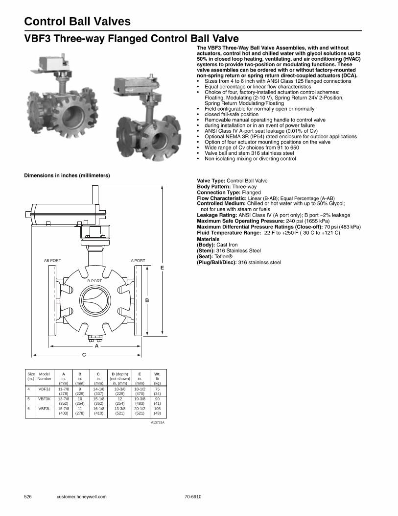
Control Ball Valves
526 customer.honeywell.com 70-6910
VBF3 Three-way Flanged Control Ball ValveThe VBF3 Three-Way Ball Valve Assemblies, with and without actuators, control hot and chilled water with glycol solutions up to 50% in closed loop heating, ventilating, and air conditioning (HVAC) systems to provide two-position or modulating functions. These valve assemblies can be ordered with or without factory-mounted non-spring return or spring return direct-coupled actuators (DCA).• Sizes from 4 to 6 inch with ANSI Class 125 flanged connections • Equal percentage or linear flow characteristics • Choice of four, factory-installed actuation control schemes:
Floating, Modulating (2-10 V), Spring Return 24V 2-Position, Spring Return Modulating/Floating
• Field configurable for normally open or normally• closed fail-safe position• Removable manual operating handle to control valve• during installation or in an event of power failure • ANSI Class IV A-port seat leakage (0.01% of Cv) • Optional NEMA 3R (IP54) rated enclosure for outdoor applications • Option of four actuator mounting positions on the valve • Wide range of Cv choices from 91 to 650 • Valve ball and stem 316 stainless steel • Non-isolating mixing or diverting control
Dimensions in inches (millimeters)Valve Type: Control Ball ValveBody Pattern: Three-wayConnection Type: FlangedFlow Characteristic: Linear (B-AB); Equal Percentage (A-AB)Controlled Medium: Chilled or hot water with up to 50% Glycol;
not for use with steam or fuelsLeakage Rating: ANSI Class IV (A port only); B port ~2% leakageMaximum Safe Operating Pressure: 240 psi (1655 kPa) Maximum Differential Pressure Ratings (Close-off): 70 psi (483 kPa) Fluid Temperature Range: -22 F to +250 F (-30 C to +121 C) Materials(Body): Cast Iron(Stem): 316 Stainless Steel(Seat): Teflon®(Plug/Ball/Disc): 316 stainless steel
A
B
C
E
Size Model A B C D (depth) E Wt.(in.) Number in. in. in. (not shown) in. lb (mm) (mm) (mm) in. (mm) (mm) (kg)
4 VBF3J 11-7/8 9 14-1/8 10-3/8 18-1/2 75 (278) (229) (337) (229) (470) (34)
5 VBF3K 13-7/8 10 15-1/8 12 19-3/8 90 (352) (254) (362) (254) (483) (41)
6 VBF3L 15-7/8 11 16-1/8 13-3/8 20-1/2 105 (403) (278) (410) (521) (521) (48)
M13733A
AB PORT
B PORT
A PORT
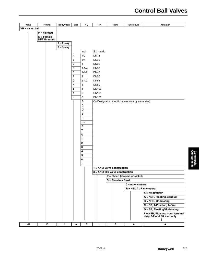
Control Ball Valves
70-6910 527
Com
mercial
Com
ponents
Valve Fitting Body/Flow Size CV T/P Trim Enclosure Actuator
VB = valve, ball
F = Flanged
N = Female NPT threaded
2 = 2 way
3 = 3 way
inch S.I. metric
A 1/2 DN15
B 3/4 DN20
C 1 DN25
D 1-1/4 DN32
E 1-1/2 DN40
F 2 DN50
G 2-1/2 DN65
H 3 DN80
J 4 DN100
K 5 DN125
L 6 DN150
B CV Designator (specific values vary by valve size)
C
D
E
F
….
S
T
U
1
2
3
4
5
6
7
1 = ANSI Valve construction
3 = ANSI 300 Valve construction
P = Plated (chrome or nickel)
S = Stainless Steel
0 = no enclosure
R = NEMA 3R enclosure
X = no actuator
A = NSR, Floating, conduit
B = NSR, Modulating
C = SR, 2-Position, 24 Vac
D = SR, Floating/Modulating
F = NSR, Floating, open terminal strip, 1/2 and 3/4 inch only
VB F 2 A B 1 S 0 A
Control Ball Valves
528 customer.honeywell.com 70-6910
Replacement bottom stem for VBF2 and VBF3 valves
Replacement seal for VBF valves
Replacement seal O-ring for VBF valves
Replacement flange O-ring for VBF valves
Product Number Description Used With
7981-701/U Replacement bottom stem for VBF2 AND VBF3 ball valves VBF2 and VBF3 Ball Valves
Product Number Description Used With
7981-910/U Replacement seal for VBF2 4 in. ball valves 4 in. VBF2 Ball Valves
7981-911/U Replacement seal for VBF2 5 in. and VBF3 4 in. ball valves 5 in. VBF2 and 4 in. VBF3 Ball Valves
7981-912/U Replacement seal for VBF2 6 in. and VBF3 5 in. ball valves 6 in. VBF2 and 5 in. VBF3 Ball Valves
7981-913/U Replacement seal for VBF3 6 in. ball valves 6 in. VBF3 Ball Valves
Product Number Description Used With
7981-914/U O-Ring Replacement seal for VBF2 4 in. ball valves 4 in. VBF2 Ball Valves
7981-915/U Replacement seal O-Ring for VBF2 5 in. and VBF3 4 in. ball valves 5 in. VBF2 and 4 in. VBF3 Ball Valves
7981-916/U Replacement seal O-Ring for VBF2 6 in. and VBF3 5 in. ball valves 6 in. VBF2 and 5 in. VBF3 Ball Valves
7981-917/U Replacement seal O-Ring for VBF3 6 in. ball valves 6 in. VBF3 Ball Valves
Product Number Description Used With
7978-65/U Replacement flange O-Ring for VBF2 4 in. ball valves 4 in. VBF2 Ball Valves
7978-66/U Replacement flange O-Ring for VBF2 5 in. and VBF3 4 in. ball valves 5 in. VBF2 and 4 in. VBF3 Ball Valves
7978-67/U Replacement flange O-Ring for VBF3 5 in. ball valves 5 in. VBF3 Ball Valves
7978-68/U Replacement flange O-Ring for VBF2 6 in. ball valves 6 in. VBF2 Ball Valves
7978-69/U Replacement flange O-Ring for VBF3 6 in. ball valves 6 in. VBF3 Ball Valves
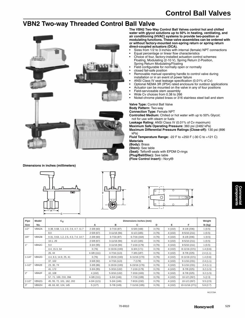
Control Ball Valves
70-6910 529
Com
mercial
Com
ponents
VBN2 Two-way Threaded Control Ball ValveThe VBN2 Two-Way Control Ball Valves control hot and chilled water with glycol solutions up to 50% in heating, ventilating, and air conditioning (HVAC) systems to provide two-position or modulating functions. These valve assemblies can be ordered with or without factory-mounted non-spring return or spring return direct-coupled actuators (DCA).• Sizes from 1/2 to 3 inches with internal (female) NPT connections • Equal percentage or linear flow characteristics • Choice of four, factory-installed actuation control schemes:
Floating, Modulating (2-10 V), Spring Return 2-Position, Spring Return Modulating/Floating
• Field configurable for normally open or normally• closed fail-safe position• Removable manual operating handle to control valve during
installation or in an event of power failure• ANSI Class IV seat leakage specification (0.01% of Cv)• Optional NEMA 3R (IP54) rated enclosure for outdoor applications• Actuator can be mounted on the valve in any of four positions • Field-serviceable stem assembly• Wide Cv choices from 0.38 to 266• Nickel-chrome plated brass or 316 stainless steel ball and stem
Valve Type: Control Ball ValveBody Pattern: Two-wayConnection Type: Female NPTControlled Medium: Chilled or hot water with up to 50% Glycol;
not for use with steam or fuelsLeakage Rating: ANSI Class IV (0.01% of Cv maximum)Maximum Safe Operating Pressure: 360 psi (2482 kPa) Maximum Differential Pressure Ratings (Close-off): 130 psi (896
kPa) Fluid Temperature Range: -22 F to +250 F (-30 C to +121 C) Materials(Body): Brass(Stem): See table(Seat): Teflon® seals with EPDM O-rings(Plug/Ball/Disc): See table(Flow Control Insert) : Noryl®
Dimensions in inches (millimeters)
A C
M13729A
F E D
B
Pipe Model CV Dimensions inches (mm) Weight Size No. A B C D E F lb (kg) 1/2" VBN2A 0.38, 0.68, 1.3, 2.0, 2.6, 4.7, 11.7 2-3/8 (60) 3-7/16 (87) 6-5/8 (168) 3 (76) 4 (102) 8-1/8 (206) 1 (0.5)
8.0 2-5/8 (67) 3-11/16 (94) 6-1/2 (165) 3 (76) 4 (102) 8-5/16 (211) 1 (0.5)
3/4" VBN2B 0.31, 0.63, 1.2, 2.5, 4.3, 7.4, 14.7 2-3/8 (60) 3-7/16 (87) 6-7/16 (164) 3 (76) 4 (102) 8-1/8 (206) 1 (0.5)
10.1, 29 2-5/8 (67) 3-11/16 (94) 6-1/2 (165) 3 (76) 4 (102) 8-5/16 (211) 1 (0.5)
1" VBN2C 9.0 3-3/4 (95) 3-11/16 (94) 7-1/16 (179) 3 (76) 4 (102) 8-5/16 (211) 1 (0.5)
4.4, 15.3, 54 3 (76) 3-15/16 (100) 6-3/4 (171) 3 (76) 4 (102) 8-11/16 (221) 1.4 (0.6)
26, 44 4-3/8 (111) 4-7/16 (113) 7-3/8 (187) 3 (76) 4 (102) 8-7/8 (225) 2.4 (1.1)
1-1/4" VBN2D 4.4, 8.3, 14.9, 25, 41 3 (76) 3-15/16 (100) 6-11/16 (170) 3 (76) 4 (102) 8-11/16 (221) 1.4 (0.6)
37, 102 3-5/8 (92) 4-7/16 (113) 7 (178) 3 (76) 4 (102) 9-1/16 (231) 2.4 (1.1)
1-1/2" VBN2E 23, 30, 74 3-3/8 (86) 3-15/16 (100) 6-15/16 (176) 3 (76) 4 (102) 9-1/16 (231) 2.4 (1.1)
41, 172 3-3/4 (95) 5-3/16 (132) 7-1/16 (179) 3 (76) 4 (102) 8-7/8 (225) 3.2 (1.5)
2" VBN2F 42, 108 4 (102) 5-3/16 (132) 7-3/16 (183) 3 (76) 4 (102) 8-7/8 (225) 3.2 (1.5)
57, 71, 100, 210, 266 4-3/8 (111) 5-3/4 (146) 7-7/16 (189) 3 (76) 4 (102) 10-1/2 (267) 5 (2.3)
2-1/2" VBN2G 45, 55, 72, 101, 162, 202 4-3/4 (121) 5-3/4 (146) 7-9/16 (192) 3 (76) 4 (102) 10-1/2 (267) 5.5 (2.5)
3" VBN2H 49, 63, 82, 124, 145 5 (127) 5-7/8 (149) 7-11/16 (195) 3 (76) 4 (102) 10-11/16 (271) 5.9 (2.7)
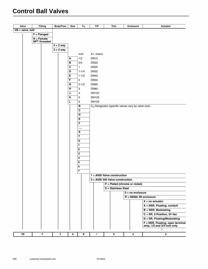
Control Ball Valves
530 customer.honeywell.com 70-6910
Valve Fitting Body/Flow Size CV T/P Trim Enclosure Actuator
VB = valve, ball
F = Flanged
N = Female NPT threaded
2 = 2 way
3 = 3 way
inch S.I. metric
A 1/2 DN15
B 3/4 DN20
C 1 DN25
D 1-1/4 DN32
E 1-1/2 DN40
F 2 DN50
G 2-1/2 DN65
H 3 DN80
J 4 DN100
K 5 DN125
L 6 DN150
B CV Designator (specific values vary by valve size)
C
D
E
F
….
S
T
U
1
2
3
4
5
6
7
1 = ANSI Valve construction
3 = ANSI 300 Valve construction
P = Plated (chrome or nickel)
S = Stainless Steel
0 = no enclosure
R = NEMA 3R enclosure
X = no actuator
A = NSR, Floating, conduit
B = NSR, Modulating
C = SR, 2-Position, 24 Vac
D = SR, Floating/Modulating
F = NSR, Floating, open terminal strip, 1/2 and 3/4 inch only
VB F 2 A B 1 S 0 A
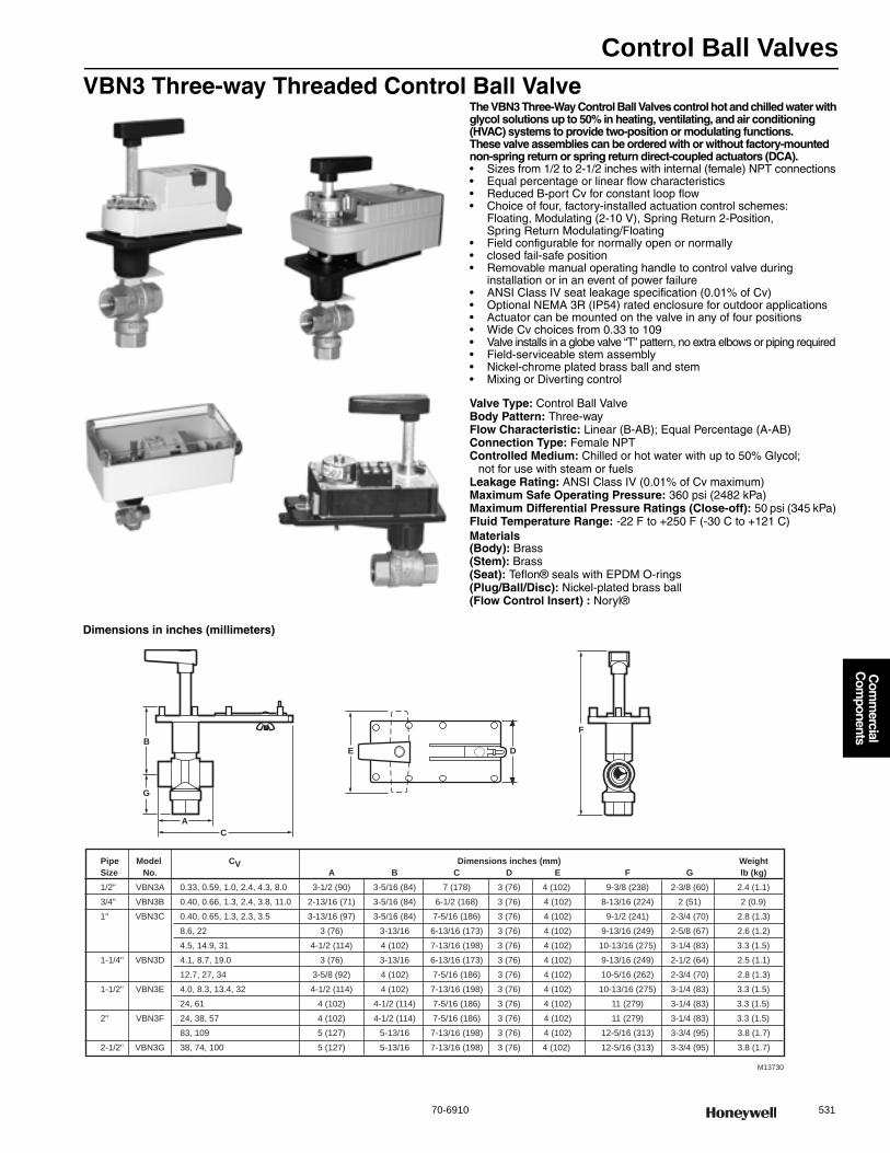
Control Ball Valves
70-6910 531
Com
mercial
Com
ponents
VBN3 Three-way Threaded Control Ball ValveThe VBN3 Three-Way Control Ball Valves control hot and chilled water with glycol solutions up to 50% in heating, ventilating, and air conditioning (HVAC) systems to provide two-position or modulating functions. These valve assemblies can be ordered with or without factory-mounted non-spring return or spring return direct-coupled actuators (DCA).• Sizes from 1/2 to 2-1/2 inches with internal (female) NPT connections • Equal percentage or linear flow characteristics • Reduced B-port Cv for constant loop flow • Choice of four, factory-installed actuation control schemes:
Floating, Modulating (2-10 V), Spring Return 2-Position, Spring Return Modulating/Floating
• Field configurable for normally open or normally• closed fail-safe position• Removable manual operating handle to control valve during
installation or in an event of power failure• ANSI Class IV seat leakage specification (0.01% of Cv)• Optional NEMA 3R (IP54) rated enclosure for outdoor applications• Actuator can be mounted on the valve in any of four positions • Wide Cv choices from 0.33 to 109• Valve installs in a globe valve “T” pattern, no extra elbows or piping required • Field-serviceable stem assembly • Nickel-chrome plated brass ball and stem • Mixing or Diverting control
Valve Type: Control Ball ValveBody Pattern: Three-wayFlow Characteristic: Linear (B-AB); Equal Percentage (A-AB)Connection Type: Female NPTControlled Medium: Chilled or hot water with up to 50% Glycol;
not for use with steam or fuelsLeakage Rating: ANSI Class IV (0.01% of Cv maximum)Maximum Safe Operating Pressure: 360 psi (2482 kPa) Maximum Differential Pressure Ratings (Close-off): 50 psi (345 kPa) Fluid Temperature Range: -22 F to +250 F (-30 C to +121 C) Materials(Body): Brass(Stem): Brass(Seat): Teflon® seals with EPDM O-rings(Plug/Ball/Disc): Nickel-plated brass ball(Flow Control Insert) : Noryl®
Dimensions in inches (millimeters)
M13730
E DB
G
AC
F
Pipe Model CV Dimensions inches (mm) WeightSize No. A B C D E F G lb (kg)1/2" VBN3A 0.33, 0.59, 1.0, 2.4, 4.3, 8.0 3-1/2 (90) 3-5/16 (84) 7 (178) 3 (76) 4 (102) 9-3/8 (238) 2-3/8 (60) 2.4 (1.1)
3/4" VBN3B 0.40, 0.66, 1.3, 2.4, 3.8, 11.0 2-13/16 (71) 3-5/16 (84) 6-1/2 (168) 3 (76) 4 (102) 8-13/16 (224) 2 (51) 2 (0.9)
1" VBN3C 0.40, 0.65, 1.3, 2.3, 3.5 3-13/16 (97) 3-5/16 (84) 7-5/16 (186) 3 (76) 4 (102) 9-1/2 (241) 2-3/4 (70) 2.8 (1.3)
8.6, 22 3 (76) 3-13/16 6-13/16 (173) 3 (76) 4 (102) 9-13/16 (249) 2-5/8 (67) 2.6 (1.2)
4.5, 14.9, 31 4-1/2 (114) 4 (102) 7-13/16 (198) 3 (76) 4 (102) 10-13/16 (275) 3-1/4 (83) 3.3 (1.5)
1-1/4" VBN3D 4.1, 8.7, 19.0 3 (76) 3-13/16 6-13/16 (173) 3 (76) 4 (102) 9-13/16 (249) 2-1/2 (64) 2.5 (1.1)
12.7, 27, 34 3-5/8 (92) 4 (102) 7-5/16 (186) 3 (76) 4 (102) 10-5/16 (262) 2-3/4 (70) 2.8 (1.3)
1-1/2" VBN3E 4.0, 8.3, 13.4, 32 4-1/2 (114) 4 (102) 7-13/16 (198) 3 (76) 4 (102) 10-13/16 (275) 3-1/4 (83) 3.3 (1.5)
24, 61 4 (102) 4-1/2 (114) 7-5/16 (186) 3 (76) 4 (102) 11 (279) 3-1/4 (83) 3.3 (1.5)
2" VBN3F 24, 38, 57 4 (102) 4-1/2 (114) 7-5/16 (186) 3 (76) 4 (102) 11 (279) 3-1/4 (83) 3.3 (1.5)
83, 109 5 (127) 5-13/16 7-13/16 (198) 3 (76) 4 (102) 12-5/16 (313) 3-3/4 (95) 3.8 (1.7)
2-1/2" VBN3G 38, 74, 100 5 (127) 5-13/16 7-13/16 (198) 3 (76) 4 (102) 12-5/16 (313) 3-3/4 (95) 3.8 (1.7)

Control Ball Valves
532 customer.honeywell.com 70-6910
Valve Fitting Body/Flow Size CV T/P Trim Enclosure Actuator
VB = valve, ball
F = Flanged
N = Female NPT threaded
2 = 2 way
3 = 3 way
inch S.I. metric
A 1/2 DN15
B 3/4 DN20
C 1 DN25
D 1-1/4 DN32
E 1-1/2 DN40
F 2 DN50
G 2-1/2 DN65
H 3 DN80
J 4 DN100
K 5 DN125
L 6 DN150
B CV Designator (specific values vary by valve size)
C
D
E
F
….
S
T
U
1
2
3
4
5
6
7
1 = ANSI Valve construction
3 = ANSI 300 Valve construction
P = Plated (chrome or nickel)
S = Stainless Steel
0 = no enclosure
R = NEMA 3R enclosure
X = no actuator
A = NSR, Floating, conduit
B = NSR, Modulating
C = SR, 2-Position, 24 Vac
D = SR, Floating/Modulating
F = NSR, Floating, open terminal strip, 1/2 and 3/4 inch only
VB F 2 A B 1 S 0 A

Control Ball Valves
70-6910 533
Com
mercial
Com
ponents
Replacement stem assembly for VBN valves
Control Ball Valves Accessories
Product Number Description
5112-11/U Stem replacement kit
5112-19/U Brass stem kit for 1/2”-1” Small VBN valves
5112-20/U Brass stem kit for 1" Large-1-1/2” Small VBN valves
5112-21/U Brass stem kit for 1-1/2” Large-3” VBN valves
5112-22/U Stainless Steel stem kit for 1/2” - 1" Small VBN2 valves
5112-23/U Stainless Steel stem kit for 1" Large-1-1/2” Small VBN2 valves
5112-24/U Stainless Steel stem kit for 1-1/2” Large to 3" VBN2 valves
Product Number Description
5112-3R NEMA 3R Enclosure

Butterfly Control Valves
534 customer.honeywell.com 70-6910
VFF1 Two-way Normally-Open Butterfly Control ValvesResilient seat in two-way valves, provide control for HVAC system applications including chilled water, hot water, cooling tower water, and thermal storage systems.
Body Pattern: 2 way (S/R NO)Valve Action: Normally OpenConnection Type: LuggedControlled Medium: Chilled or hot water with up to 50% Glycol;
not for use with steam or fuels.Actuator Control Type: PneumaticFlow Characteristic: Modified Equal PercentMounting: ANSI FlangedStatic Pressure Rating (max): 250 psi (1724 kPa) Actuator Ambient Temperature Ratings: -20 F to 150 F (-29 C to 66
C) Temperature Range: -40 F to 250 F (-40 C to 121 C) Number of Flange BoltsFor 2 in., 2-1/2 in., 3 in. valves: 4For 4 in., 5 in., 6 in., 8 in., valves: 8For 10 in., 12 in., 14 in. valves: 12For 16 in., 18 in. valves: 16For 20 in. valves: 20Flange Bolt ThreadFor 2 in., 2-1/2 in., 3 in., 4 in. valves: 5/8 in. -11 pitchFor 5 in., 6 in., 8 in., valves: 3/4 in. -10 pitchFor 10 in., 12 in. valves: 7/8 in. -9 pitchFor 14 in., 16 in., 18 in., 20 in. valves: 1-1/8 in. -7 pitchMaterials(Body): Polyester-coated cast iron ASTM A126 Class B(Stem): 416 Stainless Steel(Seat): Peroxide-cured EPDM resilient seat(Plug/Ball/Disc): Nylon 11-coated ductile iron (optional: aluminum,
bronze, and stainless steel)

Butterfly Control Valves
70-6910 535
Com
mercial
Com
ponents
Bu
tter
fly
Val
ves
Fit
tin
g
Bo
dy
Pat
tern
Siz
e
Dis
k si
ze (
clo
se-o
ff)
Pre
ssu
re
Rat
ing
Val
ve t
rim
Act
uat
or
seco
nd
ary
Sp
ecif
icat
ion
Act
uat
or
pri
mar
yS
pec
ific
atio
n
Description Act
uat
or
Typ
e
VF Butterfly Valve, resilient seat
F Flanged fitting
1 2-way (spring return normally open)
2 2-way (non-spring return: Spring return normally closed or field-convertible)
3 3-way A-B-AB (mixing/diverting)
6 3-way A-AB-B (diverting/mixing)
F 2 inch (DN50)
G 2-1/2 inch (DN65)
H 3 inch (DN80)
J 4 inch (DN100)
K 5 inch (DN125)
L 6 inch (DN150)
M 8 inch (DN200)
N 10 inch (DN250)
P 12 inch (DN300)
R 14 inch (DN350)
S 16 inch (DN400)
T 18 inch (DN450)
U 20 inch (DN500)
V Undercut disk (lower actuator torque; 50 psid close-off)
W Full diameter disk (high close-off)
1 ANSI 150 psig body pressure rating
2 ANSI 250 psig body pressure rating
Y Nylon-coated disk, EPDM seat
2 NEMA 2 actuator housing (Honeywell DCA)
Ele
ctri
c
6 NEMA 6 actuator housing with manual operator and heater
X NEMA 4X actuator housing with manual operator and heater
8 Spring Range 8-13 psi for 20 psi pneumatic actuator
Pne
umat
ic
C 24 Vac solenoid for 80 psi pneumatic actuator
D Electro-pneumatic positioner for 80 psi actuator
E 120 Vac solenoid for 80 psi pneumatic actuator
P Pneumatic positioner for modulating applications
X Standard, two-position control only
L Lever operator for dead end service
Man
ual
G Geared operator for dead end service
A Floating actuator
Ele
ctri
c
B Modulating actuator
C Two-position 24 Vac spring return actuator
D Modulating spring return actuator
E Two-position 120 Vac spring return actuator
P Pneumatic actuator, spring return 20 psi
Pne
umat
icR Pneumatic actuator, push-pull 80 psi
S Pneumatic actuator, spring return 80 psi
X Valve body only, for dead end service Man
VF F 2 J V 1 Y 2 D 2-way, 4 inch flanged resilient-sear butterfly valve, undercut disk (50 psid close-off) modulating/floating control, spring return normally closed.
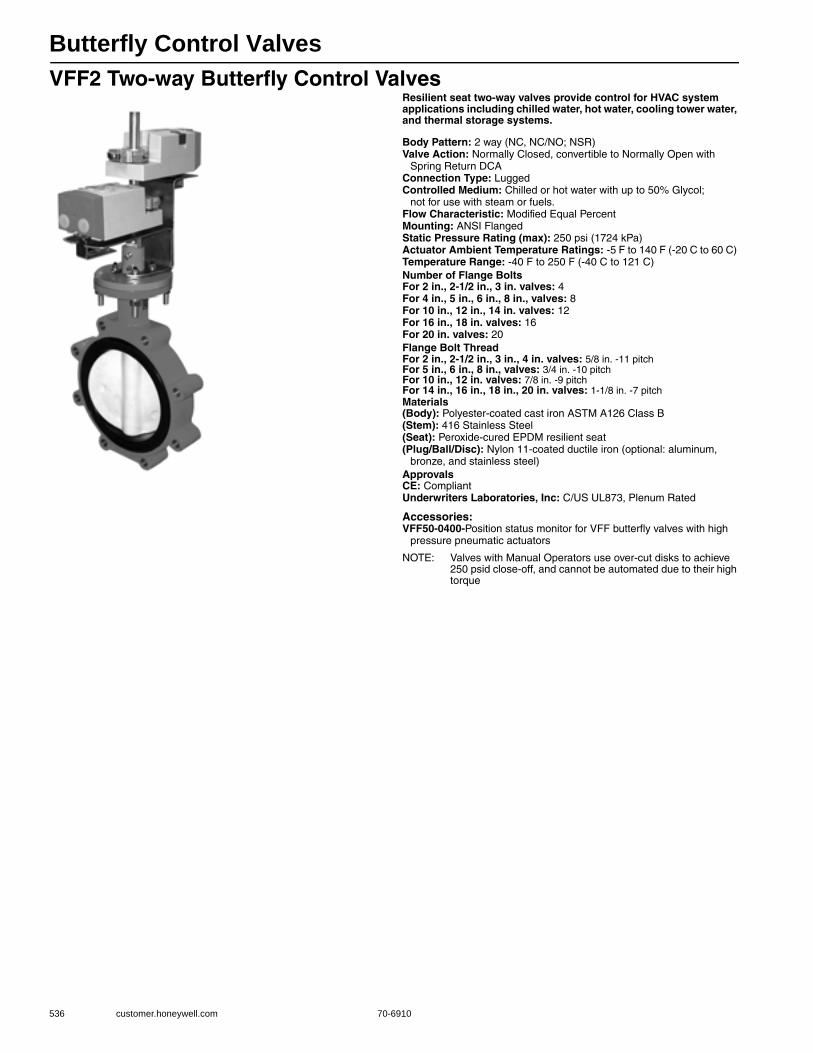
Butterfly Control Valves
536 customer.honeywell.com 70-6910
VFF2 Two-way Butterfly Control ValvesResilient seat two-way valves provide control for HVAC system applications including chilled water, hot water, cooling tower water, and thermal storage systems.
Body Pattern: 2 way (NC, NC/NO; NSR)Valve Action: Normally Closed, convertible to Normally Open with
Spring Return DCAConnection Type: LuggedControlled Medium: Chilled or hot water with up to 50% Glycol;
not for use with steam or fuels.Flow Characteristic: Modified Equal PercentMounting: ANSI FlangedStatic Pressure Rating (max): 250 psi (1724 kPa) Actuator Ambient Temperature Ratings: -5 F to 140 F (-20 C to 60 C) Temperature Range: -40 F to 250 F (-40 C to 121 C) Number of Flange BoltsFor 2 in., 2-1/2 in., 3 in. valves: 4For 4 in., 5 in., 6 in., 8 in., valves: 8For 10 in., 12 in., 14 in. valves: 12For 16 in., 18 in. valves: 16For 20 in. valves: 20Flange Bolt ThreadFor 2 in., 2-1/2 in., 3 in., 4 in. valves: 5/8 in. -11 pitchFor 5 in., 6 in., 8 in., valves: 3/4 in. -10 pitchFor 10 in., 12 in. valves: 7/8 in. -9 pitchFor 14 in., 16 in., 18 in., 20 in. valves: 1-1/8 in. -7 pitchMaterials(Body): Polyester-coated cast iron ASTM A126 Class B(Stem): 416 Stainless Steel(Seat): Peroxide-cured EPDM resilient seat(Plug/Ball/Disc): Nylon 11-coated ductile iron (optional: aluminum,
bronze, and stainless steel)ApprovalsCE: CompliantUnderwriters Laboratories, Inc: C/US UL873, Plenum Rated
Accessories:VFF50-0400-Position status monitor for VFF butterfly valves with high
pressure pneumatic actuators
NOTE: Valves with Manual Operators use over-cut disks to achieve 250 psid close-off, and cannot be automated due to their high torque
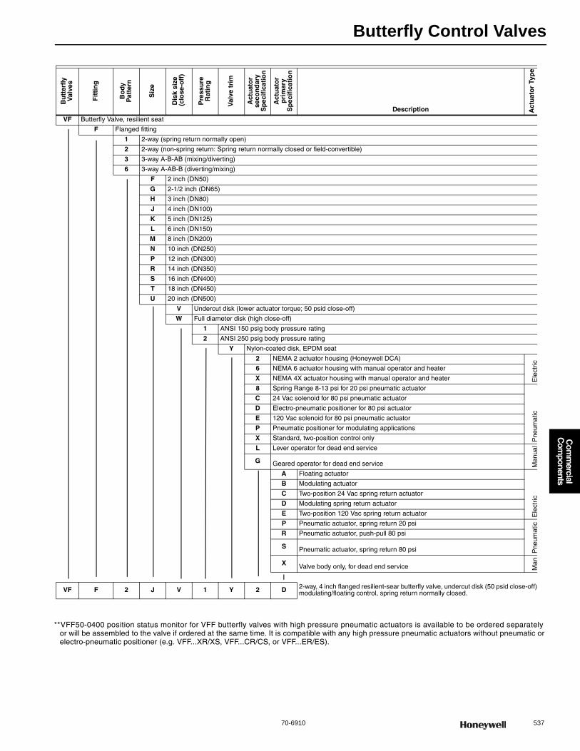
Butterfly Control Valves
70-6910 537
Com
mercial
Com
ponents
**VFF50-0400 position status monitor for VFF butterfly valves with high pressure pneumatic actuators is available to be ordered separately or will be assembled to the valve if ordered at the same time. It is compatible with any high pressure pneumatic actuators without pneumatic or electro-pneumatic positioner (e.g. VFF...XR/XS, VFF...CR/CS, or VFF...ER/ES).
Bu
tter
fly
Val
ves
Fit
tin
g
Bo
dy
Pat
tern
Siz
e
Dis
k si
ze (
clo
se-o
ff)
Pre
ssu
re
Rat
ing
Val
ve t
rim
Act
uat
or
seco
nd
ary
Sp
ecif
icat
ion
Act
uat
or
pri
mar
yS
pec
ific
atio
n
Description Act
uat
or
Typ
e
VF Butterfly Valve, resilient seat
F Flanged fitting
1 2-way (spring return normally open)
2 2-way (non-spring return: Spring return normally closed or field-convertible)
3 3-way A-B-AB (mixing/diverting)
6 3-way A-AB-B (diverting/mixing)
F 2 inch (DN50)
G 2-1/2 inch (DN65)
H 3 inch (DN80)
J 4 inch (DN100)
K 5 inch (DN125)
L 6 inch (DN150)
M 8 inch (DN200)
N 10 inch (DN250)
P 12 inch (DN300)
R 14 inch (DN350)
S 16 inch (DN400)
T 18 inch (DN450)
U 20 inch (DN500)
V Undercut disk (lower actuator torque; 50 psid close-off)
W Full diameter disk (high close-off)
1 ANSI 150 psig body pressure rating
2 ANSI 250 psig body pressure rating
Y Nylon-coated disk, EPDM seat
2 NEMA 2 actuator housing (Honeywell DCA)
Ele
ctri
c
6 NEMA 6 actuator housing with manual operator and heater
X NEMA 4X actuator housing with manual operator and heater
8 Spring Range 8-13 psi for 20 psi pneumatic actuator
Pne
umat
ic
C 24 Vac solenoid for 80 psi pneumatic actuator
D Electro-pneumatic positioner for 80 psi actuator
E 120 Vac solenoid for 80 psi pneumatic actuator
P Pneumatic positioner for modulating applications
X Standard, two-position control only
L Lever operator for dead end service
Man
ual
G Geared operator for dead end service
A Floating actuator
Ele
ctri
c
B Modulating actuator
C Two-position 24 Vac spring return actuator
D Modulating spring return actuator
E Two-position 120 Vac spring return actuator
P Pneumatic actuator, spring return 20 psi
Pne
umat
icR Pneumatic actuator, push-pull 80 psi
S Pneumatic actuator, spring return 80 psi
X Valve body only, for dead end service Man
VF F 2 J V 1 Y 2 D 2-way, 4 inch flanged resilient-sear butterfly valve, undercut disk (50 psid close-off) modulating/floating control, spring return normally closed.

Butterfly Control Valves
538 customer.honeywell.com 70-6910
VFF3 Three-way (A-B-AB) Butterfly Control ValvesResilient seat three-way valves provide control for HVAC system applications including chilled water, hot water, cooling tower water, and thermal storage systems.
Body Pattern: 3 way (A-B-AB porting)Valve Action: Normally ClosedConnection Type: LuggedControlled Medium: Chilled or hot water with up to 50% Glycol;
not for use with steam or fuels.Flow Characteristic: Modified Equal PercentMounting: ANSI FlangedStatic Pressure Rating (max): 250 psi (1724 kPa) Actuator Ambient Temperature Ratings: -5 F to 140 F (-20 C to 60 C) Temperature Range: -40 F to 250 F (-40 C to 121 C) Number of Flange BoltsFor 2 in., 2-1/2 in., 3 in. valves: 4For 4 in., 5 in., 6 in., 8 in., valves: 8For 10 in., 12 in., 14 in. valves: 12For 16 in., 18 in. valves: 16For 20 in. valves: 20Flange Bolt ThreadFor 2 in., 2-1/2 in., 3 in., 4 in. valves: 5/8 in. -11 pitchFor 5 in., 6 in., 8 in., valves: 3/4 in. -10 pitchFor 10 in., 12 in. valves: 7/8 in. -9 pitchFor 14 in., 16 in., 18 in., 20 in. valves: 1-1/8 in. -7 pitchMaterials(Body): Polyester-coated cast iron ASTM A126 Class B(Stem): 416 Stainless Steel(Seat): Peroxide-cured EPDM resilient seat(Plug/Ball/Disc): Nylon 11-coated ductile iron (optional: aluminum,
bronze, and stainless steel)ApprovalsCE: CompliantUnderwriters Laboratories, Inc: C/US UL873, Plenum Rated
Accessories:VFF50-0400-Position status monitor for VFF butterfly valves with high
pressure pneumatic actuators
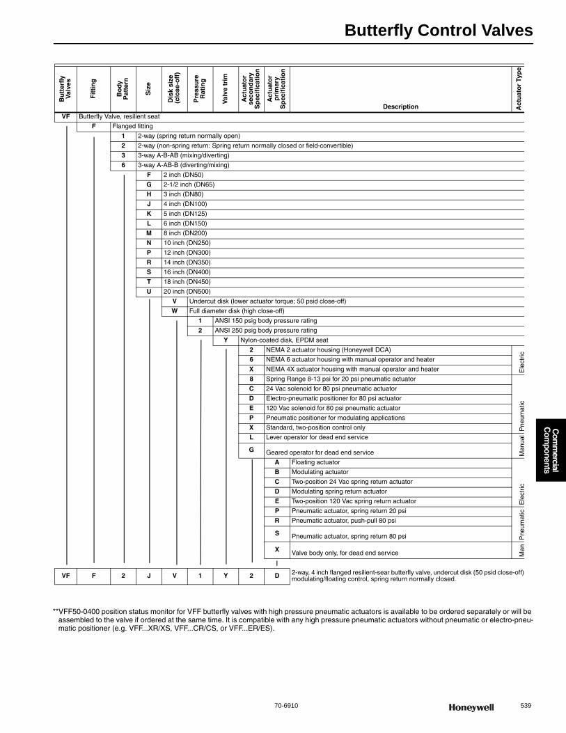
Butterfly Control Valves
70-6910 539
Com
mercial
Com
ponents
**VFF50-0400 position status monitor for VFF butterfly valves with high pressure pneumatic actuators is available to be ordered separately or will be assembled to the valve if ordered at the same time. It is compatible with any high pressure pneumatic actuators without pneumatic or electro-pneu-matic positioner (e.g. VFF...XR/XS, VFF...CR/CS, or VFF...ER/ES).
Bu
tter
fly
Val
ves
Fit
tin
g
Bo
dy
Pat
tern
Siz
e
Dis
k si
ze (
clo
se-o
ff)
Pre
ssu
re
Rat
ing
Val
ve t
rim
Act
uat
or
seco
nd
ary
Sp
ecif
icat
ion
Act
uat
or
pri
mar
yS
pec
ific
atio
n
Description Act
uat
or
Typ
e
VF Butterfly Valve, resilient seat
F Flanged fitting
1 2-way (spring return normally open)
2 2-way (non-spring return: Spring return normally closed or field-convertible)
3 3-way A-B-AB (mixing/diverting)
6 3-way A-AB-B (diverting/mixing)
F 2 inch (DN50)
G 2-1/2 inch (DN65)
H 3 inch (DN80)
J 4 inch (DN100)
K 5 inch (DN125)
L 6 inch (DN150)
M 8 inch (DN200)
N 10 inch (DN250)
P 12 inch (DN300)
R 14 inch (DN350)
S 16 inch (DN400)
T 18 inch (DN450)
U 20 inch (DN500)
V Undercut disk (lower actuator torque; 50 psid close-off)
W Full diameter disk (high close-off)
1 ANSI 150 psig body pressure rating
2 ANSI 250 psig body pressure rating
Y Nylon-coated disk, EPDM seat
2 NEMA 2 actuator housing (Honeywell DCA)
Ele
ctri
c
6 NEMA 6 actuator housing with manual operator and heater
X NEMA 4X actuator housing with manual operator and heater
8 Spring Range 8-13 psi for 20 psi pneumatic actuator
Pne
umat
ic
C 24 Vac solenoid for 80 psi pneumatic actuator
D Electro-pneumatic positioner for 80 psi actuator
E 120 Vac solenoid for 80 psi pneumatic actuator
P Pneumatic positioner for modulating applications
X Standard, two-position control only
L Lever operator for dead end service
Man
ual
G Geared operator for dead end service
A Floating actuator
Ele
ctri
c
B Modulating actuator
C Two-position 24 Vac spring return actuator
D Modulating spring return actuator
E Two-position 120 Vac spring return actuator
P Pneumatic actuator, spring return 20 psi
Pne
umat
icR Pneumatic actuator, push-pull 80 psi
S Pneumatic actuator, spring return 80 psi
X Valve body only, for dead end service Man
VF F 2 J V 1 Y 2 D 2-way, 4 inch flanged resilient-sear butterfly valve, undercut disk (50 psid close-off) modulating/floating control, spring return normally closed.
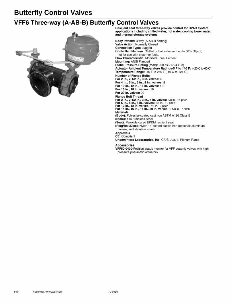
Butterfly Control Valves
540 customer.honeywell.com 70-6910
VFF6 Three-way (A-AB-B) Butterfly Control ValvesResilient seat three-way valves provide control for HVAC system applications including chilled water, hot water, cooling tower water, and thermal storage systems.
Body Pattern: 3 way (A-AB-B porting)Valve Action: Normally ClosedConnection Type: LuggedControlled Medium: Chilled or hot water with up to 50% Glycol;
not for use with steam or fuels.Flow Characteristic: Modified Equal PercentMounting: ANSI FlangedStatic Pressure Rating (max): 250 psi (1724 kPa) Actuator Ambient Temperature Ratings-5 F to 140 F: (-20 C to 60 C) Temperature Range: -40 F to 250 F (-40 C to 121 C) Number of Flange BoltsFor 2 in., 2-1/2 in., 3 in. valves: 4For 4 in., 5 in., 6 in., 8 in., valves: 8For 10 in., 12 in., 14 in. valves: 12For 16 in., 18 in. valves: 16For 20 in. valves: 20Flange Bolt ThreadFor 2 in., 2-1/2 in., 3 in., 4 in. valves: 5/8 in. -11 pitchFor 5 in., 6 in., 8 in., valves: 3/4 in. -10 pitchFor 10 in., 12 in. valves: 7/8 in. -9 pitchFor 14 in., 16 in., 18 in., 20 in. valves: 1-1/8 in. -7 pitchMaterials(Body): Polyester-coated cast iron ASTM A126 Class B(Stem): 416 Stainless Steel(Seat): Peroxide-cured EPDM resilient seat(Plug/Ball/Disc): Nylon 11-coated ductile iron (optional: aluminum,
bronze, and stainless steel)ApprovalsCE: CompliantUnderwriters Laboratories, Inc: C/US UL873, Plenum Rated
Accessories:VFF50-0400-Position status monitor for VFF butterfly valves with high
pressure pneumatic actuators

Butterfly Control Valves
70-6910 541
Com
mercial
Com
ponents
**VFF50-0400 position status monitor for VFF butterfly valves with high pressure pneumatic actuators is available to be ordered separately or will be assembled to the valve if ordered at the same time. It is compatible with any high pressure pneumatic actuators without pneumatic or electro-pneu-matic positioner (e.g. VFF...XR/XS, VFF...CR/CS, or VFF...ER/ES).
Bu
tter
fly
Val
ves
Fit
tin
g
Bo
dy
Pat
tern
Siz
e
Dis
k si
ze (
clo
se-o
ff)
Pre
ssu
re
Rat
ing
Val
ve t
rim
Act
uat
or
seco
nd
ary
Sp
ecif
icat
ion
Act
uat
or
pri
mar
yS
pec
ific
atio
n
Description Act
uat
or
Typ
e
VF Butterfly Valve, resilient seat
F Flanged fitting
1 2-way (spring return normally open)
2 2-way (non-spring return: Spring return normally closed or field-convertible)
3 3-way A-B-AB (mixing/diverting)
6 3-way A-AB-B (diverting/mixing)
F 2 inch (DN50)
G 2-1/2 inch (DN65)
H 3 inch (DN80)
J 4 inch (DN100)
K 5 inch (DN125)
L 6 inch (DN150)
M 8 inch (DN200)
N 10 inch (DN250)
P 12 inch (DN300)
R 14 inch (DN350)
S 16 inch (DN400)
T 18 inch (DN450)
U 20 inch (DN500)
V Undercut disk (lower actuator torque; 50 psid close-off)
W Full diameter disk (high close-off)
1 ANSI 150 psig body pressure rating
2 ANSI 250 psig body pressure rating
Y Nylon-coated disk, EPDM seat
2 NEMA 2 actuator housing (Honeywell DCA)
Ele
ctri
c
6 NEMA 6 actuator housing with manual operator and heater
X NEMA 4X actuator housing with manual operator and heater
8 Spring Range 8-13 psi for 20 psi pneumatic actuator
Pne
umat
ic
C 24 Vac solenoid for 80 psi pneumatic actuator
D Electro-pneumatic positioner for 80 psi actuator
E 120 Vac solenoid for 80 psi pneumatic actuator
P Pneumatic positioner for modulating applications
X Standard, two-position control only
L Lever operator for dead end service
Man
ual
G Geared operator for dead end service
A Floating actuator
Ele
ctri
c
B Modulating actuator
C Two-position 24 Vac spring return actuator
D Modulating spring return actuator
E Two-position 120 Vac spring return actuator
P Pneumatic actuator, spring return 20 psi
Pne
umat
icR Pneumatic actuator, push-pull 80 psi
S Pneumatic actuator, spring return 80 psi
X Valve body only, for dead end service Man
VF F 2 J V 1 Y 2 D 2-way, 4 inch flanged resilient-sear butterfly valve, undercut disk (50 psid close-off) modulating/floating control, spring return normally closed.
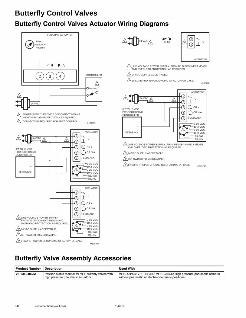
Butterfly Control Valves
542 customer.honeywell.com 70-6910
Butterfly Control Valves Actuator Wiring Diagrams
Butterfly Valve Assembly Accessories
432
FLOATING ACTUATOR
24 VAC
1
1POWER SUPPLY. PROVIDE DISCONNECT MEANS
AND OVERLOAD PROTECTION AS REQUIRED.
CONNECTION REQUIRED FOR SPST CONTROL.2
CONTROLLER
2
Direct
Reverse
Service/Off
M18945A
ACTUATOR
0/2 TO 10 VDC
PROPORTIONING
CONTROLLER
24 VAC1
1
2
3
2
LINE VOLTAGE POWER SUPPLY.
PROVIDE DISCONNECT MEANS AND
OVERLOAD PROTECTION AS REQUIRED.
24 VDC SUPPLY ACCEPTABLE.
SET SWITCH TO MODULATING.
V
OR +
OR N/A
FEEDBACK
–
+
FEEDBACK
5
4
3
1
2
M19575B
2-10 VDC10-2 VDC0-10 VDC10-0 VDCFltg, fwdFltg, rev
3
ACTUATOR
V
OR +
OR N/A
FEEDBACK5
4
3
1
2
2-10 VDC10-2 VDC0-10 VDC10-0 VDCFltg, fwdFltg, rev
3
4
4 ENSURE PROPER GROUNDING OF ACTUATOR CASE.
ACTUATOR
SPST24 VAC1
1
2
2
LINE VOLTAGE POWER SUPPLY. PROVIDE DISCONNECT MEANS
AND OVERLOAD PROTECTION AS REQUIRED.
24 VDC SUPPLY ACCEPTABLE.
ENSURE PROPER GROUNDING OF ACTUATOR CASE.
V1
2
M19718C
3
3
ACTUATOR
0/2 TO 10 VDC
PROPORTIONING
CONTROLLER
24 VAC1
1
2
3
2
LINE VOLTAGE POWER SUPPLY. PROVIDE DISCONNECT MEANS
AND OVERLOAD PROTECTION AS REQUIRED.
24 VDC SUPPLY ACCEPTABLE.
SET SWITCH TO MODULATING.
V
OR +
OR N/A
FEEDBACK
–
+
FEEDBACK
5
4
3
1
2
M19574B
2-10 VDC10-2 VDC0-10 VDC10-0 VDCFltg, fwdFltg, rev
3
4 ENSURE PROPER GROUNDING OF ACTUATOR CASE.
4
Product Number Description Used With
VFF50-0400/M Position status monitor for VFF butterfly valves with high pressure pneumatic actuators
VFF...XR/XS; VFF...ER/ES; VFF...CR/CS; High pressure pneumatic actuator without pneumatic or electro-pneumatic positioner

Flanged Globe Valves
70-6910 543
Com
mercial
Com
ponents
V5011A,B Two-Way Flanged Globe ValvesUsed for proportional control of hot or chilled water and glycol solutions (to 50 percent concentration) and for two-position control of low pressure steam in closed loop HVAC systems.• Sizes range from 2-1/2 to 6 inches • Stainless steel stem with serviceable Teflon packing • Valves utilize direct mounting valve actuators, Q5020/Q5022
linkages with Direct Coupled Actuators, or Pneumatic Valve Actuators to operate the valve
• Equal Percentage flow characteristic
Dimensions in inches (millimeters)Valve Type: Globe ValveBody Pattern: Two-wayConnection Type: FlangedControlled Medium: Chilled or hot water with up to 50% Glycol;
not for use with fuels; Low pressure steamMaximum Safe Operating Pressure: 15 psi steam (100 kPa steam)
150 psi at 240 F water (1034 kPa at 115 C water) Maximum Differential for Quiet Water Service: 20 psid (138 kPa) Ambient Temperature Range: 40 F to 250 F (4 C to 121 C) ANSI/ASME Rating: 125Actuation: Must be purchased separatelyMaterials(Body): Cast Iron(Stem): 316 Stainless Steel(Seat): Bronze(Packing): Teflon Cone
A
C
D
F
GH
EB
I
M27256
J
3-1/2(89)3-1/2(89)5-1/4(133)6-3/4(171)
2-1/2(64)
Aa B C D E FVALVESIZE
3 (76)
4(102)
4-13/16(122)3-1/2(89)5-1/4(133)6-3/4(171)
4(102)4-5/8(117)
5-3/16(132)8-1/16(205)
9-1/2(241)
11(279)
13(330)
13(330)
7(178)7-1/2(191)
9(229)
9(229)
2-1/2(64)
3(76)
4(102)
4(102)
G
3/4(19)3/4(19)3/4(19)3/4(19)
H
5-1/2(140)
6(152)7-1/2(191)7-1/2(191)
I(TRAVEL)
3/4(19)3/4(19)1-1/2(38)1-1/2(38)
J(DIAMETER)
1-3/8(35)1-3/8(35)1-7/8(48)1-7/8(48)
MODEL
V5011B
V5011A
4(102)
Product Number
Valve Size Flow Capacity Stem Travel Bonnet SizeValve Action Used With(inch) DN (Cv) (Kv) (inch) (mm) (inch) (mm)
V5011A1734/U 2 1/2 in. DN65 63 Cv 54 kvs 3/4 in. 20 mm 1-3/8 in. 35 mm Stem down to close
Q5001/Modutrol IV Motor; MP953; ML6420,21A,25; ML7420/ML7421A/ML7425; ML6984/ML7984
V5011A1767/U 3 in. DN80 100 Cv 85 kvs 3/4 in. 20 mm 1-3/8 in. 35 mm Stem down to close
ML6984/ML7984; ML7420/ML7421A/ML7425; ML6420,21A,25; Q5001/Modutrol IV Motor; MP953
V5011A1858/U 4 in. DN100 160 Cv 137 kvs 1 1/2 in. 38 mm 1-7/8 in. 47.6 mm Stem down to close
Q5001/Modutrol IV Motor; MP953; ML7421B; ML6421B
V5011A1882/U 5 in. DN125 250 Cv 214 kvs 1 1/2 in. 38 mm 1-7/8 in. 47.6 mm Stem down to close
ML6421B; ML7421B; Q5001/Modutrol IV Motor; MP953
V5011A1916/U 6 in. DN150 360 Cv 308 kvs 1 1/2 in. 38 mm 1-7/8 in. 47.6 mm Stem down to close
ML6421B; Q5001/Modutrol IV Motor; MP953; ML7421B
V5011B1013/U 4 in. DN100 160 Cv 137 kvs 1 1/2 in. 38 mm 1-7/8 in. 47.6 mm Stem up to close
ML7421B; Q5001/Modutrol IV Motor; MP953; ML6421B
V5011B1047/U 5 in. DN125 250 Cv 214 kvs 1 1/2 in. 38 mm 1-7/8 in. 47.6 mm Stem up to close
ML6421B; ML7421B; Q5001/Modutrol IV Motor; MP953
V5011B1070/U 6 in. DN150 360 Cv 308 kvs 1 1/2 in. 38 mm 1-7/8 in. 47.6 mm Stem up to close
ML6421B; Q5001/Modutrol IV Motor; MP953; ML7421B
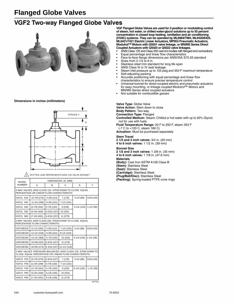
Flanged Globe Valves
544 customer.honeywell.com 70-6910
VGF2 Two-way Flanged Globe ValvesVGF Flanged Globe Valves are used for 2-position or modulating control of steam, hot water, or chilled water-glycol solutions up to 50 percent concentration in closed loop heating, ventilation and air conditioning (HVAC) systems. They can be operated by ML6984/7984, ML6420/6425, ML6421/7421 Electric Linear Actuators, MP953 Pneumatic Actuators, Modutrol™ Motors with Q5001 valve linkage, or MN/MS Series Direct Coupled Actuators with Q5020 or Q5022 valve linkages.• ANSI Class 125 and Class 250 cast iron bodies with flanged end connections • Equal percentage and linear flow characteristics • Face-to-face flange dimensions per ANSI/ISA S75.03 standard • Sizes from 2-1/2 to 6 in. • Stainless steel trim standard for long life span • ANSI Class III or IV seat leakage • Steam inlet pressure up to 125 psig and 353 F maximum temperature • Self-adjusting packing • Accurate positioning with equal percentage and linear flow
characteristics to ensure precise temperature control • Universal bonnet for direct-coupled electric and pneumatic actuators
for easy mounting, or linkage coupled Modutrol™ Motors and MN/MS Series direct coupled actuators
• Not suitable for combustible gasses
Dimensions in inches (millimeters)Valve Type: Globe ValveValve Action: Stem down to closeBody Pattern: Two-wayConnection Type: FlangedControlled Medium: Steam; Chilled or hot water with up to 50% Glycol;
not for use with fuelsFluid Temperature Range: 20 F to 250 F, steam 353 F
(-7 C to +120 C, steam 180 C) Actuation: Must be purchased separately
Stem Travel2 1/2 and 3 inch valves: 3/4 in. (20 mm)4 to 6 inch valves: 1 1/2 in. (39 mm)
Bonnet Size2 1/2 and 3 inch valves: 1 3/8 in. (35 mm)4 to 6 inch valves: 1 7/8 in. (47.6 mm)Materials(Body): Cast Iron ASTM A126 Class B(Stem): Stainless Steel(Seat): Stainless Steel(Cartridge): Stainless Steel(Plug/Ball/Disc): Stainless Steel(Packing): Spring-loaded PTFE cone rings
M27603
C
A
B
D
STROKE Y
1 DOTTED LINE REPRESENTS ANSI 125 VALVE BONNET.
MODEL
NUMBER
DIMENSIONS, IN. (MM)
A B C E Y
2-WAY VALVES, ANSI CLASS 125. STEM DOWN TO CLOSE. EQUAL
PERCENTAGE OR LINEAR FLOW CHARACTERISTIC
VGF21 S25 10-7/8 (276) 4-3/8 (112) 7 (178) 3-1/2 (89) 13/16 (20)
VGF21 S30 11-3/4 (298) 6-3/8 (161) 7-1/2 (191)
VGF21 S40 13-7/8 (352) 5-7/8 (150) 9 (229) 5-1/4 (133) 1-1/2 (38)
VGF21 S50 15-3/4 (400) 6-3/16 (157) 10 (254)
VGF21 S60 17-3/4 (451) 6-3/16 (157) 11 (279)
2-WAY VALVES, ANSI CLASS 250. STEM DOWN TO CLOSE. EQUAL
PERCENTAGE FLOW CHARACTERISTIC
VGF22ES25 11-1/2 (292) 4-3/8 (112) 7-1/2 (191) 3-1/2 (89) 13/16 (20)
VGF22ES30 12-1/2 (318) 6-3/8 (161) 8-1/4 (210)
VGF22ES40 14-1/2 (368) 5-7/8 (150) 10 (254) 5-1/4 (133) 1-1/2 (38)
VGF22ES50 16-5/8 (422) 6-3/16 (157) 11 (279)
VGF22ES60 18-5/8 (473) 6-3/16 (157) 12-1/2 (318)
2-WAY VALVES, PRESSURE-BALANCED, ANSI CLASS 125. STEM DOWN TO
CLOSE. EQUAL PERCENTAGE OR LINEAR FLOW CHARACTERISTIC
VGF21 P25 10-7/8 (276) 4-3/16 (107) 7 (178) 3-1/2 (89) 13/16 (20)
VGF21 P30 11-3/4 (298) 5-7/8 (150) 7-1/2 (191)
VGF21 P40 13-7/8 (352) 5-7/8 (150) 9 (229) 5-1/4 (133) 1-1/2 (38)
VGF21 P50 15-3/4 (400) 6-1/8 (156) 10 (254)
VGF21 P60 17-3/4 (451) 6-1/8 (156) 11 (279)
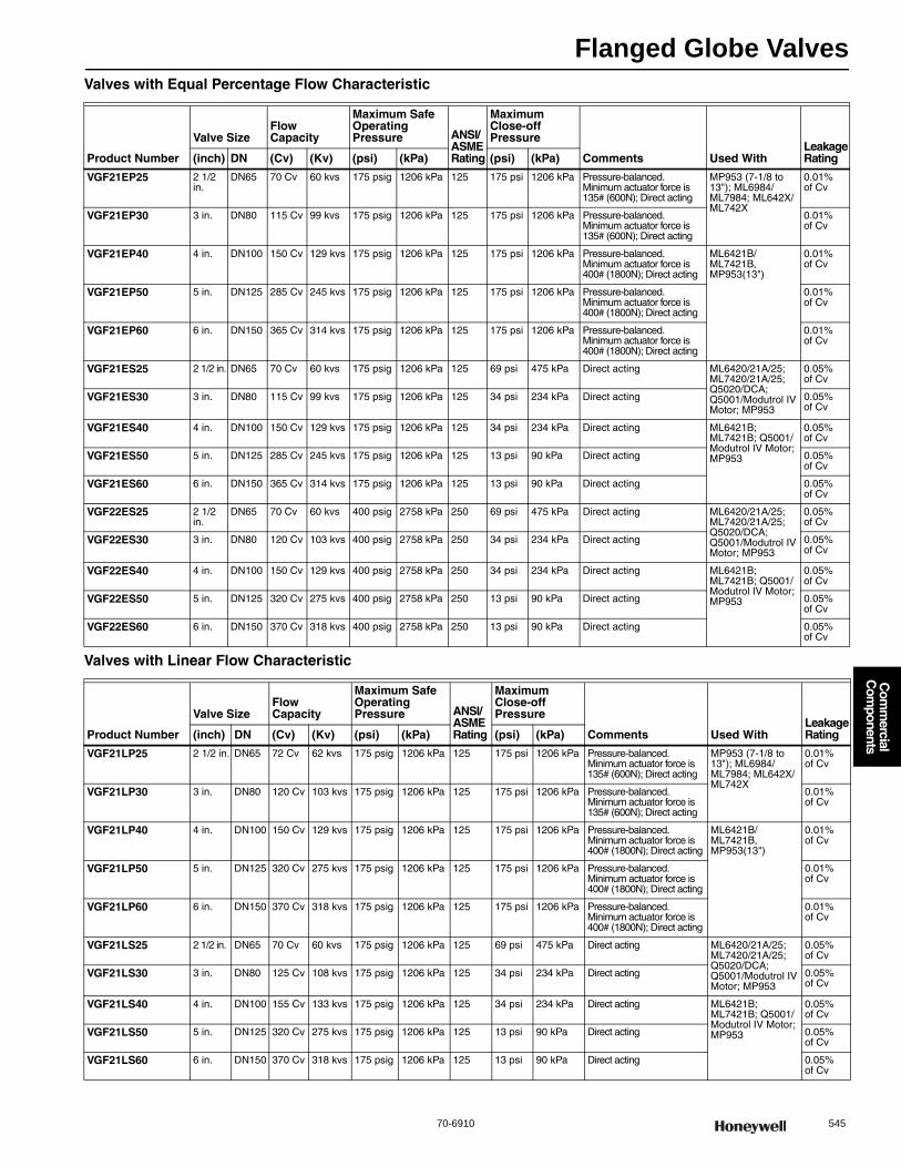
Flanged Globe Valves
70-6910 545
Com
mercial
Com
ponents
Valves with Equal Percentage Flow Characteristic
Valves with Linear Flow Characteristic
Product Number
Valve SizeFlow Capacity
Maximum Safe Operating Pressure ANSI/
ASME Rating
Maximum Close-off Pressure
Comments Used WithLeakage Rating(inch) DN (Cv) (Kv) (psi) (kPa) (psi) (kPa)
VGF21EP25 2 1/2 in.
DN65 70 Cv 60 kvs 175 psig 1206 kPa 125 175 psi 1206 kPa Pressure-balanced. Minimum actuator force is 135# (600N); Direct acting
MP953 (7-1/8 to 13"); ML6984/ML7984; ML642X/ML742X
0.01% of Cv
VGF21EP30 3 in. DN80 115 Cv 99 kvs 175 psig 1206 kPa 125 175 psi 1206 kPa Pressure-balanced. Minimum actuator force is 135# (600N); Direct acting
0.01% of Cv
VGF21EP40 4 in. DN100 150 Cv 129 kvs 175 psig 1206 kPa 125 175 psi 1206 kPa Pressure-balanced. Minimum actuator force is 400# (1800N); Direct acting
ML6421B/ML7421B, MP953(13")
0.01% of Cv
VGF21EP50 5 in. DN125 285 Cv 245 kvs 175 psig 1206 kPa 125 175 psi 1206 kPa Pressure-balanced. Minimum actuator force is 400# (1800N); Direct acting
0.01% of Cv
VGF21EP60 6 in. DN150 365 Cv 314 kvs 175 psig 1206 kPa 125 175 psi 1206 kPa Pressure-balanced. Minimum actuator force is 400# (1800N); Direct acting
0.01% of Cv
VGF21ES25 2 1/2 in. DN65 70 Cv 60 kvs 175 psig 1206 kPa 125 69 psi 475 kPa Direct acting ML6420/21A/25; ML7420/21A/25; Q5020/DCA; Q5001/Modutrol IV Motor; MP953
0.05% of Cv
VGF21ES30 3 in. DN80 115 Cv 99 kvs 175 psig 1206 kPa 125 34 psi 234 kPa Direct acting 0.05% of Cv
VGF21ES40 4 in. DN100 150 Cv 129 kvs 175 psig 1206 kPa 125 34 psi 234 kPa Direct acting ML6421B; ML7421B; Q5001/Modutrol IV Motor; MP953
0.05% of Cv
VGF21ES50 5 in. DN125 285 Cv 245 kvs 175 psig 1206 kPa 125 13 psi 90 kPa Direct acting 0.05% of Cv
VGF21ES60 6 in. DN150 365 Cv 314 kvs 175 psig 1206 kPa 125 13 psi 90 kPa Direct acting 0.05% of Cv
VGF22ES25 2 1/2 in.
DN65 70 Cv 60 kvs 400 psig 2758 kPa 250 69 psi 475 kPa Direct acting ML6420/21A/25; ML7420/21A/25; Q5020/DCA; Q5001/Modutrol IV Motor; MP953
0.05% of Cv
VGF22ES30 3 in. DN80 120 Cv 103 kvs 400 psig 2758 kPa 250 34 psi 234 kPa Direct acting 0.05% of Cv
VGF22ES40 4 in. DN100 150 Cv 129 kvs 400 psig 2758 kPa 250 34 psi 234 kPa Direct acting ML6421B; ML7421B; Q5001/Modutrol IV Motor; MP953
0.05% of Cv
VGF22ES50 5 in. DN125 320 Cv 275 kvs 400 psig 2758 kPa 250 13 psi 90 kPa Direct acting 0.05% of Cv
VGF22ES60 6 in. DN150 370 Cv 318 kvs 400 psig 2758 kPa 250 13 psi 90 kPa Direct acting 0.05% of Cv
Product Number
Valve SizeFlow Capacity
Maximum Safe Operating Pressure ANSI/
ASME Rating
Maximum Close-off Pressure
Comments Used WithLeakage Rating(inch) DN (Cv) (Kv) (psi) (kPa) (psi) (kPa)
VGF21LP25 2 1/2 in. DN65 72 Cv 62 kvs 175 psig 1206 kPa 125 175 psi 1206 kPa Pressure-balanced. Minimum actuator force is 135# (600N); Direct acting
MP953 (7-1/8 to 13"); ML6984/ML7984; ML642X/ML742X
0.01% of Cv
VGF21LP30 3 in. DN80 120 Cv 103 kvs 175 psig 1206 kPa 125 175 psi 1206 kPa Pressure-balanced. Minimum actuator force is 135# (600N); Direct acting
0.01% of Cv
VGF21LP40 4 in. DN100 150 Cv 129 kvs 175 psig 1206 kPa 125 175 psi 1206 kPa Pressure-balanced. Minimum actuator force is 400# (1800N); Direct acting
ML6421B/ML7421B, MP953(13")
0.01% of Cv
VGF21LP50 5 in. DN125 320 Cv 275 kvs 175 psig 1206 kPa 125 175 psi 1206 kPa Pressure-balanced. Minimum actuator force is 400# (1800N); Direct acting
0.01% of Cv
VGF21LP60 6 in. DN150 370 Cv 318 kvs 175 psig 1206 kPa 125 175 psi 1206 kPa Pressure-balanced. Minimum actuator force is 400# (1800N); Direct acting
0.01% of Cv
VGF21LS25 2 1/2 in. DN65 70 Cv 60 kvs 175 psig 1206 kPa 125 69 psi 475 kPa Direct acting ML6420/21A/25; ML7420/21A/25; Q5020/DCA; Q5001/Modutrol IV Motor; MP953
0.05% of Cv
VGF21LS30 3 in. DN80 125 Cv 108 kvs 175 psig 1206 kPa 125 34 psi 234 kPa Direct acting 0.05% of Cv
VGF21LS40 4 in. DN100 155 Cv 133 kvs 175 psig 1206 kPa 125 34 psi 234 kPa Direct acting ML6421B; ML7421B; Q5001/Modutrol IV Motor; MP953
0.05% of Cv
VGF21LS50 5 in. DN125 320 Cv 275 kvs 175 psig 1206 kPa 125 13 psi 90 kPa Direct acting 0.05% of Cv
VGF21LS60 6 in. DN150 370 Cv 318 kvs 175 psig 1206 kPa 125 13 psi 90 kPa Direct acting 0.05% of Cv
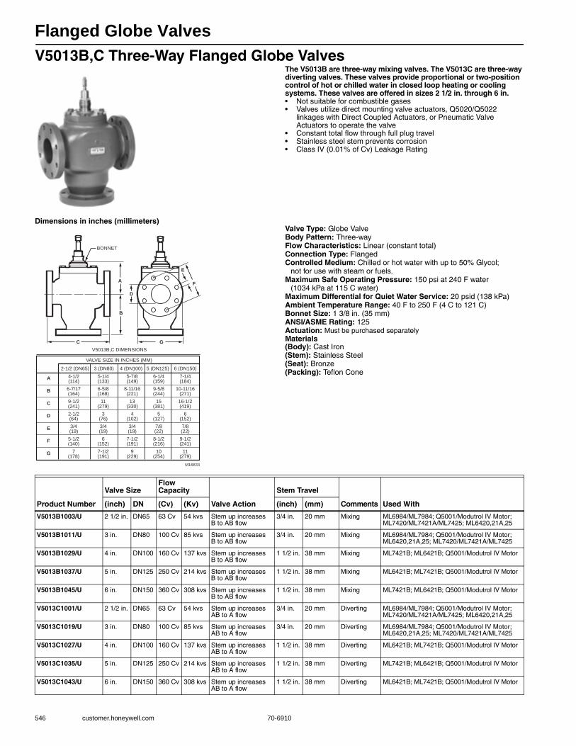
Flanged Globe Valves
546 customer.honeywell.com 70-6910
V5013B,C Three-Way Flanged Globe ValvesThe V5013B are three-way mixing valves. The V5013C are three-way diverting valves. These valves provide proportional or two-position control of hot or chilled water in closed loop heating or cooling systems. These valves are offered in sizes 2 1/2 in. through 6 in.• Not suitable for combustible gases • Valves utilize direct mounting valve actuators, Q5020/Q5022
linkages with Direct Coupled Actuators, or Pneumatic Valve Actuators to operate the valve
• Constant total flow through full plug travel • Stainless steel stem prevents corrosion • Class IV (0.01% of Cv) Leakage Rating
Dimensions in inches (millimeters)Valve Type: Globe ValveBody Pattern: Three-wayFlow Characteristics: Linear (constant total)Connection Type: FlangedControlled Medium: Chilled or hot water with up to 50% Glycol;
not for use with steam or fuels.Maximum Safe Operating Pressure: 150 psi at 240 F water
(1034 kPa at 115 C water) Maximum Differential for Quiet Water Service: 20 psid (138 kPa) Ambient Temperature Range: 40 F to 250 F (4 C to 121 C) Bonnet Size: 1 3/8 in. (35 mm)ANSI/ASME Rating: 125 Actuation: Must be purchased separatelyMaterials(Body): Cast Iron(Stem): Stainless Steel(Seat): Bronze(Packing): Teflon Cone
G
E
F
D
A
C
B
M16833
VALVE SIZE IN INCHES (MM)
V5013B,C DIMENSIONS
A 4-1/2(114)
5-1/4(133)
5-7/8(149)
6-1/4(159)
7-1/4(184)
BONNET
B 6-7/17(164)
6-5/8(168)
8-11/16(221)
9-5/8(244)
10-11/16(271)
C 9-1/2(241)
11(279)
13(330)
15(381)
16-1/2(419)
D 2-1/2(64)
3(76)
4(102)
5(127)
6(152)
E 3/4(19)
3/4(19)
3/4(19)
7/8(22)
7/8(22)
F 5-1/2(140)
6(152)
7-1/2(191)
8-1/2(216)
9-1/2(241)
G 7(178)
7-1/2(191)
9(229)
10(254)
11(279)
2-1/2 (DN65) 3 (DN80) 4 (DN100) 5 (DN125) 6 (DN150)
Product Number
Valve SizeFlow Capacity
Valve Action
Stem Travel
Comments Used With(inch) DN (Cv) (Kv) (inch) (mm)
V5013B1003/U 2 1/2 in. DN65 63 Cv 54 kvs Stem up increases B to AB flow
3/4 in. 20 mm Mixing ML6984/ML7984; Q5001/Modutrol IV Motor; ML7420/ML7421A/ML7425; ML6420,21A,25
V5013B1011/U 3 in. DN80 100 Cv 85 kvs Stem up increases B to AB flow
3/4 in. 20 mm Mixing ML6984/ML7984; Q5001/Modutrol IV Motor; ML6420,21A,25; ML7420/ML7421A/ML7425
V5013B1029/U 4 in. DN100 160 Cv 137 kvs Stem up increases B to AB flow
1 1/2 in. 38 mm Mixing ML7421B; ML6421B; Q5001/Modutrol IV Motor
V5013B1037/U 5 in. DN125 250 Cv 214 kvs Stem up increases B to AB flow
1 1/2 in. 38 mm Mixing ML6421B; ML7421B; Q5001/Modutrol IV Motor
V5013B1045/U 6 in. DN150 360 Cv 308 kvs Stem up increases B to AB flow
1 1/2 in. 38 mm Mixing ML7421B; ML6421B; Q5001/Modutrol IV Motor
V5013C1001/U 2 1/2 in. DN65 63 Cv 54 kvs Stem up increases AB to A flow
3/4 in. 20 mm Diverting ML6984/ML7984; Q5001/Modutrol IV Motor; ML7420/ML7421A/ML7425; ML6420,21A,25
V5013C1019/U 3 in. DN80 100 Cv 85 kvs Stem up increases AB to A flow
3/4 in. 20 mm Diverting ML6984/ML7984; Q5001/Modutrol IV Motor; ML6420,21A,25; ML7420/ML7421A/ML7425
V5013C1027/U 4 in. DN100 160 Cv 137 kvs Stem up increases AB to A flow
1 1/2 in. 38 mm Diverting ML6421B; ML7421B; Q5001/Modutrol IV Motor
V5013C1035/U 5 in. DN125 250 Cv 214 kvs Stem up increases AB to A flow
1 1/2 in. 38 mm Diverting ML7421B; ML6421B; Q5001/Modutrol IV Motor
V5013C1043/U 6 in. DN150 360 Cv 308 kvs Stem up increases AB to A flow
1 1/2 in. 38 mm Diverting ML6421B; ML7421B; Q5001/Modutrol IV Motor
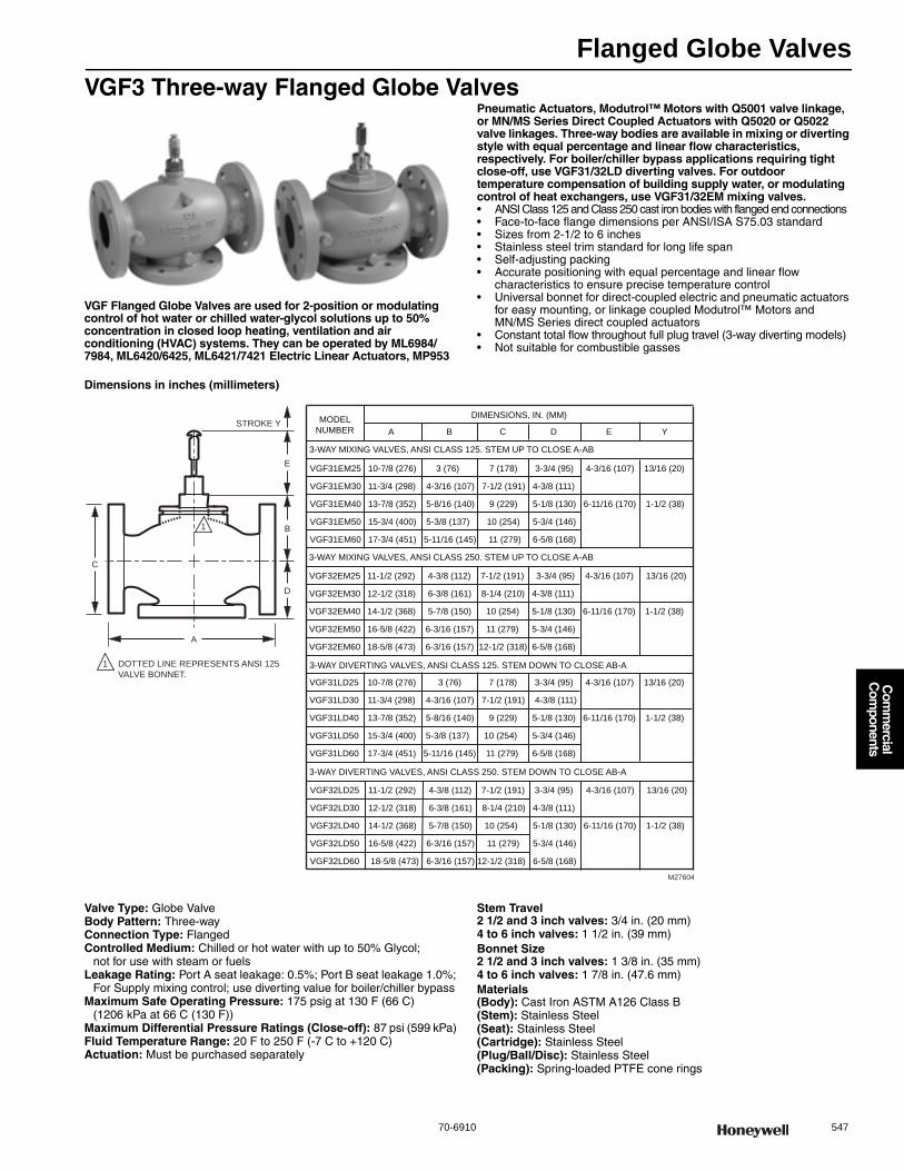
Flanged Globe Valves
70-6910 547
Com
mercial
Com
ponents
VGF3 Three-way Flanged Globe Valves
VGF Flanged Globe Valves are used for 2-position or modulating control of hot water or chilled water-glycol solutions up to 50% concentration in closed loop heating, ventilation and air conditioning (HVAC) systems. They can be operated by ML6984/7984, ML6420/6425, ML6421/7421 Electric Linear Actuators, MP953
Pneumatic Actuators, Modutrol™ Motors with Q5001 valve linkage, or MN/MS Series Direct Coupled Actuators with Q5020 or Q5022 valve linkages. Three-way bodies are available in mixing or diverting style with equal percentage and linear flow characteristics, respectively. For boiler/chiller bypass applications requiring tight close-off, use VGF31/32LD diverting valves. For outdoor temperature compensation of building supply water, or modulating control of heat exchangers, use VGF31/32EM mixing valves.• ANSI Class 125 and Class 250 cast iron bodies with flanged end connections • Face-to-face flange dimensions per ANSI/ISA S75.03 standard • Sizes from 2-1/2 to 6 inches • Stainless steel trim standard for long life span • Self-adjusting packing • Accurate positioning with equal percentage and linear flow
characteristics to ensure precise temperature control • Universal bonnet for direct-coupled electric and pneumatic actuators
for easy mounting, or linkage coupled Modutrol™ Motors and MN/MS Series direct coupled actuators
• Constant total flow throughout full plug travel (3-way diverting models) • Not suitable for combustible gasses
Dimensions in inches (millimeters)
Valve Type: Globe ValveBody Pattern: Three-wayConnection Type: FlangedControlled Medium: Chilled or hot water with up to 50% Glycol;
not for use with steam or fuelsLeakage Rating: Port A seat leakage: 0.5%; Port B seat leakage 1.0%;
For Supply mixing control; use diverting value for boiler/chiller bypassMaximum Safe Operating Pressure: 175 psig at 130 F (66 C)
(1206 kPa at 66 C (130 F)) Maximum Differential Pressure Ratings (Close-off): 87 psi (599 kPa) Fluid Temperature Range: 20 F to 250 F (-7 C to +120 C) Actuation: Must be purchased separately
Stem Travel2 1/2 and 3 inch valves: 3/4 in. (20 mm)4 to 6 inch valves: 1 1/2 in. (39 mm)Bonnet Size2 1/2 and 3 inch valves: 1 3/8 in. (35 mm)4 to 6 inch valves: 1 7/8 in. (47.6 mm)Materials(Body): Cast Iron ASTM A126 Class B(Stem): Stainless Steel(Seat): Stainless Steel(Cartridge): Stainless Steel(Plug/Ball/Disc): Stainless Steel(Packing): Spring-loaded PTFE cone rings
D
A
C
B
1 DOTTED LINE REPRESENTS ANSI 125
VALVE BONNET.
1
E
STROKE Y MODEL
NUMBER
DIMENSIONS, IN. (MM)
A B C D E Y
3-WAY MIXING VALVES, ANSI CLASS 125. STEM UP TO CLOSE A-AB
VGF31EM25 10-7/8 (276) 3 (76) 7 (178) 3-3/4 (95) 4-3/16 (107) 13/16 (20)
VGF31EM30 11-3/4 (298) 4-3/16 (107) 7-1/2 (191) 4-3/8 (111)
VGF31EM40 13-7/8 (352) 5-8/16 (140) 9 (229) 5-1/8 (130) 6-11/16 (170) 1-1/2 (38)
VGF31EM50 15-3/4 (400) 5-3/8 (137) 10 (254) 5-3/4 (146)
VGF31EM60 17-3/4 (451) 5-11/16 (145) 11 (279) 6-5/8 (168)
3-WAY MIXING VALVES, ANSI CLASS 250. STEM UP TO CLOSE A-AB
VGF32EM25 11-1/2 (292) 4-3/8 (112) 7-1/2 (191) 3-3/4 (95) 4-3/16 (107) 13/16 (20)
VGF32EM30 12-1/2 (318) 6-3/8 (161) 8-1/4 (210) 4-3/8 (111)
VGF32EM40 14-1/2 (368) 5-7/8 (150) 10 (254) 5-1/8 (130) 6-11/16 (170) 1-1/2 (38)
VGF32EM50 16-5/8 (422) 6-3/16 (157) 11 (279) 5-3/4 (146)
VGF32EM60 18-5/8 (473) 6-3/16 (157) 12-1/2 (318) 6-5/8 (168)
3-WAY DIVERTING VALVES, ANSI CLASS 125. STEM DOWN TO CLOSE AB-A
VGF31LD25 10-7/8 (276) 3 (76) 7 (178) 3-3/4 (95) 4-3/16 (107) 13/16 (20)
VGF31LD30 11-3/4 (298) 4-3/16 (107) 7-1/2 (191) 4-3/8 (111)
VGF31LD40 13-7/8 (352) 5-8/16 (140) 9 (229) 5-1/8 (130) 6-11/16 (170) 1-1/2 (38)
VGF31LD50 15-3/4 (400) 5-3/8 (137) 10 (254) 5-3/4 (146)
VGF31LD60 17-3/4 (451) 5-11/16 (145) 11 (279) 6-5/8 (168)
M27604
3-WAY DIVERTING VALVES, ANSI CLASS 250. STEM DOWN TO CLOSE AB-A
VGF32LD25 11-1/2 (292) 4-3/8 (112) 7-1/2 (191) 3-3/4 (95) 4-3/16 (107) 13/16 (20)
VGF32LD30 12-1/2 (318) 6-3/8 (161) 8-1/4 (210) 4-3/8 (111)
VGF32LD40 14-1/2 (368) 5-7/8 (150) 10 (254) 5-1/8 (130) 6-11/16 (170) 1-1/2 (38)
VGF32LD50 16-5/8 (422) 6-3/16 (157) 11 (279) 5-3/4 (146)
VGF32LD60 18-5/8 (473) 6-3/16 (157) 12-1/2 (318) 6-5/8 (168)
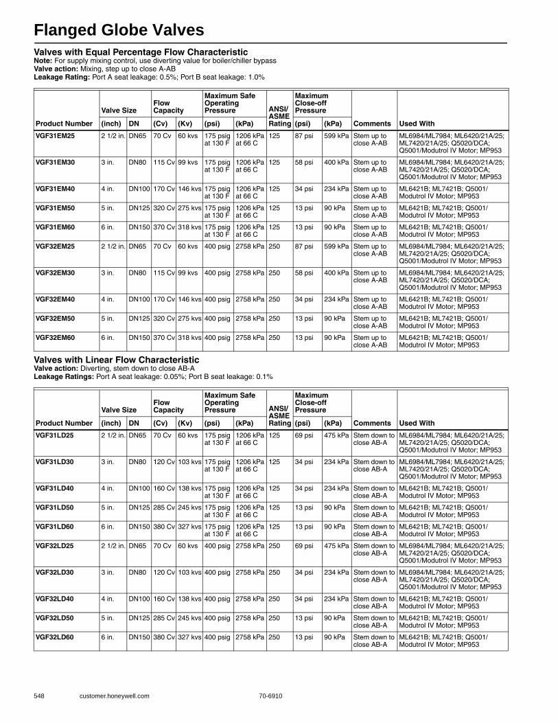
Flanged Globe Valves
548 customer.honeywell.com 70-6910
Valves with Equal Percentage Flow CharacteristicNote: For supply mixing control, use diverting value for boiler/chiller bypassValve action: Mixing, step up to close A-ABLeakage Rating: Port A seat leakage: 0.5%; Port B seat leakage: 1.0%
Valves with Linear Flow CharacteristicValve action: Diverting, stem down to close AB-ALeakage Ratings: Port A seat leakage: 0.05%; Port B seat leakage: 0.1%
Product Number
Valve SizeFlow Capacity
Maximum Safe Operating Pressure ANSI/
ASME Rating
Maximum Close-off Pressure
Comments Used With(inch) DN (Cv) (Kv) (psi) (kPa) (psi) (kPa)
VGF31EM25 2 1/2 in. DN65 70 Cv 60 kvs 175 psig at 130 F
1206 kPa at 66 C
125 87 psi 599 kPa Stem up to close A-AB
ML6984/ML7984; ML6420/21A/25; ML7420/21A/25; Q5020/DCA; Q5001/Modutrol IV Motor; MP953
VGF31EM30 3 in. DN80 115 Cv 99 kvs 175 psig at 130 F
1206 kPa at 66 C
125 58 psi 400 kPa Stem up to close A-AB
ML6984/ML7984; ML6420/21A/25; ML7420/21A/25; Q5020/DCA; Q5001/Modutrol IV Motor; MP953
VGF31EM40 4 in. DN100 170 Cv 146 kvs 175 psig at 130 F
1206 kPa at 66 C
125 34 psi 234 kPa Stem up to close A-AB
ML6421B; ML7421B; Q5001/Modutrol IV Motor; MP953
VGF31EM50 5 in. DN125 320 Cv 275 kvs 175 psig at 130 F
1206 kPa at 66 C
125 13 psi 90 kPa Stem up to close A-AB
ML6421B; ML7421B; Q5001/Modutrol IV Motor; MP953
VGF31EM60 6 in. DN150 370 Cv 318 kvs 175 psig at 130 F
1206 kPa at 66 C
125 13 psi 90 kPa Stem up to close A-AB
ML6421B; ML7421B; Q5001/Modutrol IV Motor; MP953
VGF32EM25 2 1/2 in. DN65 70 Cv 60 kvs 400 psig 2758 kPa 250 87 psi 599 kPa Stem up to close A-AB
ML6984/ML7984; ML6420/21A/25; ML7420/21A/25; Q5020/DCA; Q5001/Modutrol IV Motor; MP953
VGF32EM30 3 in. DN80 115 Cv 99 kvs 400 psig 2758 kPa 250 58 psi 400 kPa Stem up to close A-AB
ML6984/ML7984; ML6420/21A/25; ML7420/21A/25; Q5020/DCA; Q5001/Modutrol IV Motor; MP953
VGF32EM40 4 in. DN100 170 Cv 146 kvs 400 psig 2758 kPa 250 34 psi 234 kPa Stem up to close A-AB
ML6421B; ML7421B; Q5001/Modutrol IV Motor; MP953
VGF32EM50 5 in. DN125 320 Cv 275 kvs 400 psig 2758 kPa 250 13 psi 90 kPa Stem up to close A-AB
ML6421B; ML7421B; Q5001/Modutrol IV Motor; MP953
VGF32EM60 6 in. DN150 370 Cv 318 kvs 400 psig 2758 kPa 250 13 psi 90 kPa Stem up to close A-AB
ML6421B; ML7421B; Q5001/Modutrol IV Motor; MP953
Product Number
Valve SizeFlow Capacity
Maximum Safe Operating Pressure ANSI/
ASME Rating
Maximum Close-off Pressure
Comments Used With(inch) DN (Cv) (Kv) (psi) (kPa) (psi) (kPa)
VGF31LD25 2 1/2 in. DN65 70 Cv 60 kvs 175 psig at 130 F
1206 kPa at 66 C
125 69 psi 475 kPa Stem down to close AB-A
ML6984/ML7984; ML6420/21A/25; ML7420/21A/25; Q5020/DCA; Q5001/Modutrol IV Motor; MP953
VGF31LD30 3 in. DN80 120 Cv 103 kvs 175 psig at 130 F
1206 kPa at 66 C
125 34 psi 234 kPa Stem down to close AB-A
ML6984/ML7984; ML6420/21A/25; ML7420/21A/25; Q5020/DCA; Q5001/Modutrol IV Motor; MP953
VGF31LD40 4 in. DN100 160 Cv 138 kvs 175 psig at 130 F
1206 kPa at 66 C
125 34 psi 234 kPa Stem down to close AB-A
ML6421B; ML7421B; Q5001/Modutrol IV Motor; MP953
VGF31LD50 5 in. DN125 285 Cv 245 kvs 175 psig at 130 F
1206 kPa at 66 C
125 13 psi 90 kPa Stem down to close AB-A
ML6421B; ML7421B; Q5001/Modutrol IV Motor; MP953
VGF31LD60 6 in. DN150 380 Cv 327 kvs 175 psig at 130 F
1206 kPa at 66 C
125 13 psi 90 kPa Stem down to close AB-A
ML6421B; ML7421B; Q5001/Modutrol IV Motor; MP953
VGF32LD25 2 1/2 in. DN65 70 Cv 60 kvs 400 psig 2758 kPa 250 69 psi 475 kPa Stem down to close AB-A
ML6984/ML7984; ML6420/21A/25; ML7420/21A/25; Q5020/DCA; Q5001/Modutrol IV Motor; MP953
VGF32LD30 3 in. DN80 120 Cv 103 kvs 400 psig 2758 kPa 250 34 psi 234 kPa Stem down to close AB-A
ML6984/ML7984; ML6420/21A/25; ML7420/21A/25; Q5020/DCA; Q5001/Modutrol IV Motor; MP953
VGF32LD40 4 in. DN100 160 Cv 138 kvs 400 psig 2758 kPa 250 34 psi 234 kPa Stem down to close AB-A
ML6421B; ML7421B; Q5001/Modutrol IV Motor; MP953
VGF32LD50 5 in. DN125 285 Cv 245 kvs 400 psig 2758 kPa 250 13 psi 90 kPa Stem down to close AB-A
ML6421B; ML7421B; Q5001/Modutrol IV Motor; MP953
VGF32LD60 6 in. DN150 380 Cv 327 kvs 400 psig 2758 kPa 250 13 psi 90 kPa Stem down to close AB-A
ML6421B; ML7421B; Q5001/Modutrol IV Motor; MP953
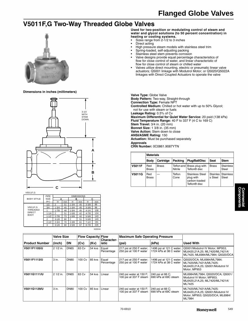
Flanged Globe Valves
70-6910 549
Com
mercial
Com
ponents
V5011F,G Two-Way Threaded Globe ValvesUsed for two-position or modulating control of steam and water and glycol solutions (to 50 percent concentration) in heating or cooling systems.• Sizes range from 2-1/2 to 3 inches • Direct acting • High pressure steam models with stainless steel trim • Spring-loaded, self-adjusting packing • Stainless steel stem prevents corrosion • Valve designs provide equal percentage characteristics of
flow for close control of water, and linear characteristic of flow for close control of steam or chilled water
• Valves utilize direct mounting, electric or pneumatic linear valve actuators; Q5001 linkage with Modutrol Motor; or Q5020/Q5022A linkages with Direct Coupled Actuators to operate the valve
Dimensions in inches (millimeters)Valve Type: Globe ValveBody Pattern: Two-way, Straight-throughConnection Type: Female NPTControlled Medium: Chilled or hot water with up to 50% Glycol;
not for use with steam or fuelsLeakage Rating: 0.5% of CvMaximum Differential for Quiet Water Service: 20 psid (138 kPa) Fluid Temperature Range: 40 F to 337 F (4 C to 169 C) Stem Travel: 3/4 in. (20 mm) Bonnet Size: 1 3/8 in. (35 mm) Valve Action: Stem down to close ANSI/ASME Rating: 150 Actuation: Must be purchased separately ApprovalsCRN Number: 0C0861.9087YTN
A
B
C
3-1/2WITH STEM DOWN
DIMENSIONS
1/23/411-1/41-1/222-1/23
21-3/41-7/822-7/83-1/82-3/43-1/8
5145485173807080
1-3/41-3/41-3/41-5/81-5/822-3/82-5/8
4545454242516167
3-3/83-3/84-1/44-7/85-5/85-5/87-1/28-7/8
8686108124143143191226
A B Cmmin
V5011F,GTHREADEDDIRECTBODY
inin mmmmBODY STYLE
PIPESIZE(in.)
M2804A
V5011F,G
Materials
Body Cartridge Packing Plug/Ball/Disc Seat Stem
V5011F Red Brass
Brass Teflon and Nitrile
Brass plug with Teflon® disc
Brass Stainless Steel
V5011G Red Brass
— Teflon Cone
Stainless Steel plug with carbon-loaded Teflon® disc
Stainless Steel
Stainless Steel
Product Number
Valve Size Flow Capacity Flow Character-istic
Maximum Safe Operating Pressure
Used With(inch) DN (Cv) (Kv) (psi) (kPa)
V5011F1105/U 2 1/2 in. DN65 63 Cv 54 kvs Equal Percentage
217 psi at 250 F water; 250 psi at 100 F water
1496 psi at 121 C water; 1724 kPa at 38 C water
Q5001/Modutrol IV Motor; MP953; ML6420,21A,25; ML7420/ML7421A/ML7425; ML6984/ML7984; Q5020/DCA
V5011F1113/U 3 in. DN80 100 Cv 85 kvs Equal Percentage
217 psi at 250 F water; 250 psi at 100 F water
1496 psi at 121 C water; 1724 kPa at 38 C water
Q5020/DCA; ML6984/ML7984; ML7420/ML7421A/ML7425; ML6420,21A,25; Q5001/Modutrol IV Motor; MP953
V5011G1111/U 2 1/2 in. DN65 63 Cv 54 kvs Linear 240 psi water at 150 F; 100 psi at 337 F steam
240 psi at 66 C; 690 kPa at 69C steam
ML6984/ML7984; Q5020/DCA; Q5001/Modutrol IV Motor; MP953; ML6420,21A,25; ML7420/ML7421A/ML7425
V5011G1129/U 3 in. DN80 100 Cv 85 kvs Linear 240 psi water at 150 F; 100 psi at 337 F steam
240 psi at 66 C; 690 kPa at 69C steam
ML7420/ML7421A/ML7425; ML6420,21A,25; Q5001/Modutrol IV Motor; MP953; Q5020/DCA; ML6984/ML7984
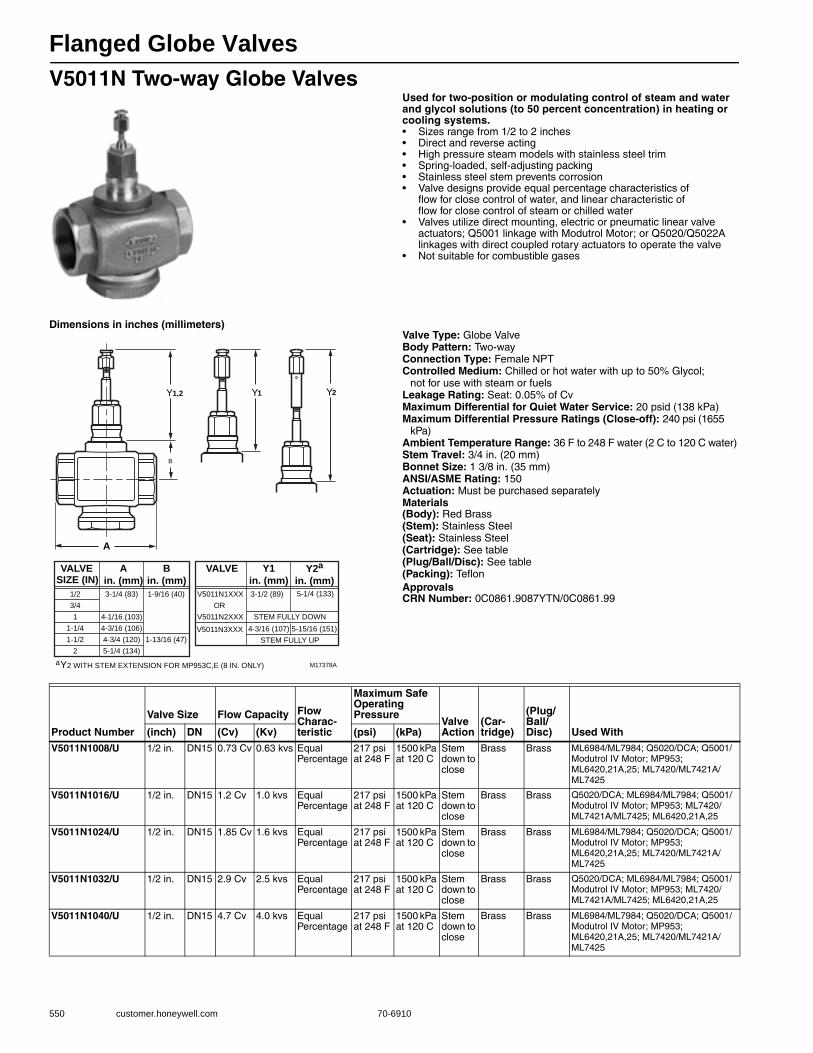
Flanged Globe Valves
550 customer.honeywell.com 70-6910
V5011N Two-way Globe ValvesUsed for two-position or modulating control of steam and water and glycol solutions (to 50 percent concentration) in heating or cooling systems.• Sizes range from 1/2 to 2 inches • Direct and reverse acting • High pressure steam models with stainless steel trim • Spring-loaded, self-adjusting packing • Stainless steel stem prevents corrosion • Valve designs provide equal percentage characteristics of
flow for close control of water, and linear characteristic of flow for close control of steam or chilled water
• Valves utilize direct mounting, electric or pneumatic linear valve actuators; Q5001 linkage with Modutrol Motor; or Q5020/Q5022A linkages with direct coupled rotary actuators to operate the valve
• Not suitable for combustible gases
Dimensions in inches (millimeters)Valve Type: Globe ValveBody Pattern: Two-wayConnection Type: Female NPTControlled Medium: Chilled or hot water with up to 50% Glycol;
not for use with steam or fuelsLeakage Rating: Seat: 0.05% of CvMaximum Differential for Quiet Water Service: 20 psid (138 kPa) Maximum Differential Pressure Ratings (Close-off): 240 psi (1655
kPa) Ambient Temperature Range: 36 F to 248 F water (2 C to 120 C water) Stem Travel: 3/4 in. (20 mm) Bonnet Size: 1 3/8 in. (35 mm) ANSI/ASME Rating: 150 Actuation: Must be purchased separatelyMaterials(Body): Red Brass(Stem): Stainless Steel(Seat): Stainless Steel(Cartridge): See table(Plug/Ball/Disc): See table(Packing): TeflonApprovalsCRN Number: 0C0861.9087YTN/0C0861.99
A
B
Y1,2
M17378A
Ain. (mm)
Bin. (mm)
1/2
3/4
1
1-1/4
1-1/2
2
3-1/4 (83)
4-1/16 (103)
4-3/16 (106)
4-3/4 (120)
5-1/4 (134)
1-9/16 (40)
1-13/16 (47)
VALVESIZE (IN)
Y1in. (mm)
Y2a
in. (mm)V5011N1XXX
OR
V5011N2XXX
3-1/2 (89) 5-1/4 (133)
VALVE
aY2 WITH STEM EXTENSION FOR MP953C,E (8 IN. ONLY)
Y1 Y2
STEM FULLY DOWN
STEM FULLY UP
5-15/16 (151)4-3/16 (107)V5011N3XXX
Product Number
Valve Size Flow Capacity Flow Charac-teristic
Maximum Safe Operating Pressure
Valve Action
(Car-tridge)
(Plug/Ball/Disc) Used With(inch) DN (Cv) (Kv) (psi) (kPa)
V5011N1008/U 1/2 in. DN15 0.73 Cv 0.63 kvs Equal Percentage
217 psi at 248 F
1500 kPa at 120 C
Stem down to close
Brass Brass ML6984/ML7984; Q5020/DCA; Q5001/Modutrol IV Motor; MP953; ML6420,21A,25; ML7420/ML7421A/ML7425
V5011N1016/U 1/2 in. DN15 1.2 Cv 1.0 kvs Equal Percentage
217 psi at 248 F
1500 kPa at 120 C
Stem down to close
Brass Brass Q5020/DCA; ML6984/ML7984; Q5001/Modutrol IV Motor; MP953; ML7420/ML7421A/ML7425; ML6420,21A,25
V5011N1024/U 1/2 in. DN15 1.85 Cv 1.6 kvs Equal Percentage
217 psi at 248 F
1500 kPa at 120 C
Stem down to close
Brass Brass ML6984/ML7984; Q5020/DCA; Q5001/Modutrol IV Motor; MP953; ML6420,21A,25; ML7420/ML7421A/ML7425
V5011N1032/U 1/2 in. DN15 2.9 Cv 2.5 kvs Equal Percentage
217 psi at 248 F
1500 kPa at 120 C
Stem down to close
Brass Brass Q5020/DCA; ML6984/ML7984; Q5001/Modutrol IV Motor; MP953; ML7420/ML7421A/ML7425; ML6420,21A,25
V5011N1040/U 1/2 in. DN15 4.7 Cv 4.0 kvs Equal Percentage
217 psi at 248 F
1500 kPa at 120 C
Stem down to close
Brass Brass ML6984/ML7984; Q5020/DCA; Q5001/Modutrol IV Motor; MP953; ML6420,21A,25; ML7420/ML7421A/ML7425
Flanged Globe Valves
70-6910 551
Com
mercial
Com
ponents
V5011N1057/U 3/4 in. DN20 7.3 Cv 6.3 kvs Equal Percentage
217 psi at 248 F
1500 kPa at 120 C
Stem down to close
Brass Brass Q5020/DCA; ML6984/ML7984; Q5001/Modutrol IV Motor; MP953; ML7420/ML7421A/ML7425; ML6420,21A,25
V5011N1065/U 1 in. DN25 11.7 Cv 10 kvs Equal Percentage
217 psi at 248 F
1500 kPa at 120 C
Stem down to close
Brass Brass ML6984/ML7984; Q5020/DCA; Q5001/Modutrol IV Motor; MP953; ML6420,21A,25; ML7420/ML7421A/ML7425
V5011N1073/U 1 1/4 in. DN32 18.7 Cv 16 kvs Equal Percentage
217 psi at 248 F
1500 kPa at 120 C
Stem down to close
Brass Brass Q5020/DCA; ML6984/ML7984; Q5001/Modutrol IV Motor; MP953; ML7420/ML7421A/ML7425; ML6420,21A,25
V5011N1081/U 1 1/2 in. DN40 29 Cv 25 kvs Equal Percentage
217 psi at 248 F
1500 kPa at 120 C
Stem down to close
Brass Brass ML6984/ML7984; Q5020/DCA; Q5001/Modutrol IV Motor; MP953; ML6420,21A,25; ML7420/ML7421A/ML7425
V5011N1099/U 2 in. DN50 46.8 Cv 40 kvs Equal Percentage
217 psi at 248 F
1500 kPa at 120 C
Stem down to close
Brass Brass Q5020/DCA; ML6984/ML7984; Q5001/Modutrol IV Motor; MP953; ML7420/ML7421A/ML7425; ML6420,21A,25
V5011N2006/U 1/2 in. DN15 0.73 Cv 0.63 kvs Linear 100 psi/337 F steam
690 kPa/169C steam
Stem down to close
Stainless Steel
Stainless Steel
ML6984/ML7984; Q5020/DCA; Q5001/Modutrol IV Motor; MP953; ML6420,21A,25; ML7420/ML7421A/ML7425
V5011N2014/U 1/2 in. DN15 1.2 Cv 1.0 kvs Linear 100 psi/337 F steam
690 kPa/169C steam
Stem down to close
Stainless Steel
Stainless Steel
Q5020/DCA; ML6984/ML7984; Q5001/Modutrol IV Motor; MP953; ML7420/ML7421A/ML7425; ML6420,21A,25
V5011N2022/U 1/2 in. DN15 1.85 Cv 1.6 kvs Linear 100 psi/337 F steam
690 kPa/169C steam
Stem down to close
Stainless Steel
Stainless Steel
ML6984/ML7984; Q5020/DCA; Q5001/Modutrol IV Motor; MP953; ML6420,21A,25; ML7420/ML7421A/ML7425
V5011N2030/U 1/2 in. DN15 2.9 Cv 2.5 kvs Linear 100 psi/337 F steam
690 kPa/169C steam
Stem down to close
Stainless Steel
Stainless Steel
Q5020/DCA; ML6984/ML7984; Q5001/Modutrol IV Motor; MP953; ML7420/ML7421A/ML7425; ML6420,21A,25
V5011N2048/U 1/2 in. DN15 4.7 Cv 4.0 kvs Linear 100 psi/337 F steam
690 kPa/169C steam
Stem down to close
Stainless Steel
Stainless Steel
ML6984/ML7984; Q5020/DCA; Q5001/Modutrol IV Motor; MP953; ML6420,21A,25; ML7420/ML7421A/ML7425
V5011N2055/U 3/4 in. DN20 7.3 Cv 6.3 kvs Linear 100 psi/337 F steam
690 kPa/169C steam
Stem down to close
Stainless Steel
Stainless Steel
Q5020/DCA; ML6984/ML7984; Q5001/Modutrol IV Motor; MP953; ML7420/ML7421A/ML7425; ML6420,21A,25
V5011N2063/U 1 in. DN25 11.7 Cv 10 kvs Linear 100 psi/337 F steam
690 kPa/169C steam
Stem down to close
Stainless Steel
Stainless Steel
ML6984/ML7984; Q5020/DCA; Q5001/Modutrol IV Motor; MP953; ML6420,21A,25; ML7420/ML7421A/ML7425
V5011N2071/U 1 1/4 in. DN32 18.7 Cv 16 kvs Linear 100 psi/337 F steam
690 kPa/169C steam
Stem down to close
Stainless Steel
Stainless Steel
Q5020/DCA; ML6984/ML7984; Q5001/Modutrol IV Motor; MP953; ML7420/ML7421A/ML7425; ML6420,21A,25
V5011N2089/U 1 1/2 in. DN40 29 Cv 25 kvs Linear 100 psi/337 F steam
690 kPa/169C steam
Stem down to close
Stainless Steel
Stainless Steel
ML6984/ML7984; Q5020/DCA; Q5001/Modutrol IV Motor; MP953; ML6420,21A,25; ML7420/ML7421A/ML7425
V5011N2097/U 2 in. DN50 46.8 Cv 40 kvs Linear 100 psi/337 F steam
690 kPa/169C steam
Stem down to close
Stainless Steel
Stainless Steel
Q5020/DCA; ML6984/ML7984; Q5001/Modutrol IV Motor; MP953; ML7420/ML7421A/ML7425; ML6420,21A,25
V5011N3004/U 1/2 in. DN15 2.9 Cv 2.5 kvs Equal Percentage
217 psi at 248 F
1500 kPa at 120 C
Stem up to close
Brass Brass MP953; ML6984/ML7984; Q5020/DCA; Q5001/Modutrol IV Motor; ML6420,21A,25; ML7420/ML7421A/ML7425
V5011N3012/U 1/2 in. DN15 4.7 Cv 4.0 kvs Equal Percentage
217 psi at 248 F
1500 kPa at 120 C
Stem up to close
Brass Brass MP953; ML6984/ML7984; Q5020/DCA; Q5001/Modutrol IV Motor; ML6420,21A,25; ML7420/ML7421A/ML7426
V5011N3020/U 3/4 in. DN20 7.3 Cv 6.3 kvs Equal Percentage
217 psi at 248 F
1500 kPa at 120 C
Stem up to close
Brass Brass MP953; ML6984/ML7984; Q5020/DCA; Q5001/Modutrol IV Motor; ML6420,21A,25; ML7420/ML7421A/ML7427
V5011N3038/U 1 in. DN25 11.7 Cv 10 kvs Equal Percentage
217 psi at 248 F
1500 kPa at 120 C
Stem up to close
Brass Brass MP953; ML6984/ML7984; Q5020/DCA; Q5001/Modutrol IV Motor; ML6420,21A,25; ML7420/ML7421A/ML7428
V5011N3046/U 1 1/4 in. DN32 18.7 Cv 16 kvs Equal Percentage
217 psi at 248 F
1500 kPa at 120 C
Stem up to close
Brass Brass MP953; ML6984/ML7984; Q5020/DCA; Q5001/Modutrol IV Motor; ML6420,21A,25; ML7420/ML7421A/ML7429
Product Number
Valve Size Flow Capacity Flow Charac-teristic
Maximum Safe Operating Pressure
Valve Action
(Car-tridge)
(Plug/Ball/Disc) Used With(inch) DN (Cv) (Kv) (psi) (kPa)
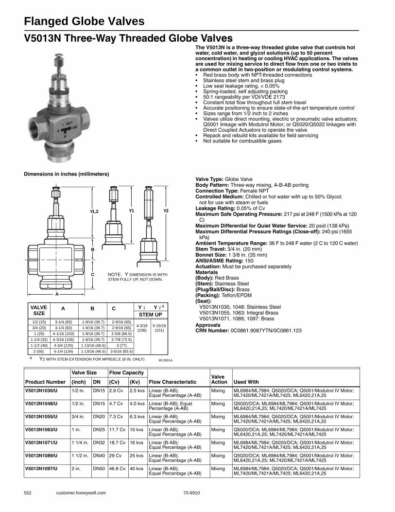
Flanged Globe Valves
552 customer.honeywell.com 70-6910
V5013N Three-Way Threaded Globe ValvesThe V5013N is a three-way threaded globe valve that controls hot water, cold water, and glycol solutions (up to 50 percent concentration) in heating or cooling HVAC applications. The valves are used for mixing service to direct flow from one or two inlets to a common outlet in two-position or modulating control systems.• Red brass body with NPT-threaded connections • Stainless steel stem and brass plug • Low seat leakage rating, < 0.05% • Spring-loaded, self adjusting packing • 50:1 rangeability per VDI/VDE 2173 • Constant total flow throughout full stem travel • Accurate positioning to ensure state-of-the-art temperature control • Sizes range from 1/2 inch to 2 inches • Valves utilize direct mounting, electric or pneumatic valve actuators;
Q5001 linkage with Modutrol Motor; or Q5020/Q5022 linkages with Direct Coupled Actuators to operate the valve
• Repack and rebuild kits available for field servicing • Not suitable for combustible gases
Dimensions in inches (millimeters)Valve Type: Globe ValveBody Pattern: Three-way mixing, A-B-AB portingConnection Type: Female NPTControlled Medium: Chilled or hot water with up to 50% Glycol;
not for use with steam or fuelsLeakage Rating: 0.05% of CvMaximum Safe Operating Pressure: 217 psi at 248 F (1500 kPa at 120
C) Maximum Differential for Quiet Water Service: 20 psid (138 kPa) Maximum Differential Pressure Ratings (Close-off): 240 psi (1655
kPa) Ambient Temperature Range: 36 F to 248 F water (2 C to 120 C water) Stem Travel: 3/4 in. (20 mm) Bonnet Size: 1 3/8 in. (35 mm) ANSI/ASME Rating: 150 Actuation: Must be purchased separatelyMaterials(Body): Red Brass(Stem): Stainless Steel(Plug/Ball/Disc): Brass(Packing): Teflon/EPDM(Seat):
V5013N1030, 1048: Stainless SteelV5013N1055, 1063: Integral BrassV5013N1071, 1089, 1097: Brass
ApprovalsCRN Number: 0C0861.9087YTN/0C0861.123
A
A
B
C
B C
Y1,2 Y1
Y 1
Y2
Y 2
1/2 (15)
3/4 (20)
1 (25)
1-1/4 (32)
1-1/2 (40)
2 (50)
3-1/4 (83)
3-1/4 (83)
4-1/16 (103)
4-3/16 (106)
4-3/4 (120)
5-1/4 (134)
1-9/16 (39.7)
1-9/16 (39.7)
1-9/16 (39.7)
1-9/16 (39.7)
1-13/16 (46.5)
1-13/16 (46.5)
2-9/16 (65)
2-9/16 (65)
2-5/8 (66.5)
2-7/8 (72.5)
3 (77)
3-5/16 (83.5)
VALVESIZE STEM UP
4-3/16(106)
5-15/16(151)
M12901A
a
a Y2 WITH STEM EXTENSION FOR MP953C,E (8 IN. ONLY)
NOTE: Y DIMENSION IS WITH
STEM FULLY UP, NOT DOWN.
Product Number
Valve Size Flow Capacity
Flow CharacteristicValve Action Used With(inch) DN (Cv) (Kv)
V5013N1030/U 1/2 in. DN15 2.9 Cv 2.5 kvs Linear (B-AB); Equal Percentage (A-AB)
Mixing ML6984/ML7984; Q5020/DCA; Q5001/Modutrol IV Motor; ML7420/ML7421A/ML7425; ML6420,21A,25
V5013N1048/U 1/2 in. DN15 4.7 Cv 4.0 kvs Linear (B-AB); Equal Percentage (A-AB)
Mixing Q5020/DCA; ML6984/ML7984; Q5001/Modutrol IV Motor; ML6420,21A,25; ML7420/ML7421A/ML7425
V5013N1055/U 3/4 in. DN20 7.3 Cv 6.3 kvs Linear (B-AB); Equal Percentage (A-AB)
Mixing ML6984/ML7984; Q5020/DCA; Q5001/Modutrol IV Motor; ML7420/ML7421A/ML7425; ML6420,21A,25
V5013N1063/U 1 in. DN25 11.7 Cv 10 kvs Linear (B-AB); Equal Percentage (A-AB)
Mixing Q5020/DCA; ML6984/ML7984; Q5001/Modutrol IV Motor; ML6420,21A,25; ML7420/ML7421A/ML7425
V5013N1071/U 1 1/4 in. DN32 18.7 Cv 16 kvs Linear (B-AB); Equal Percentage (A-AB)
Mixing ML6984/ML7984; Q5020/DCA; Q5001/Modutrol IV Motor; ML7420/ML7421A/ML7425; ML6420,21A,25
V5013N1089/U 1 1/2 in. DN40 29 Cv 25 kvs Linear (B-AB); Equal Percentage (A-AB)
Mixing Q5020/DCA; ML6984/ML7984; Q5001/Modutrol IV Motor; ML6420,21A,25; ML7420/ML7421A/ML7425
V5013N1097/U 2 in. DN50 46.8 Cv 40 kvs Linear (B-AB); Equal Percentage (A-AB)
Mixing ML6984/ML7984; Q5020/DCA; Q5001/Modutrol IV Motor; ML7420/ML7421A/ML7425; ML6420,21A,25

Globe Valve Accessories and Replacement Parts
70-6910 553
Com
mercial
Com
ponents
Globe Valve AccessoriesProduct Number Description Used With
0901787A/U Rebuild kit for V5011N and V5013N 1 1/2 to 3 inch valves V5011N; V5011n and V5013N
14002734-001/U Grease Tube —
14002734-002/U Lubricant, packing, AMOCO H-100 —
14004552-001/U Packing Nut for V5011F, G V5011F,G
14004623-001/U Stem button for V5011F/G V5011F,G
205699A/U Stem/Bonnet Adapter for 2 1/2 in. and 3 in. V33xx and V34xx Flanged Valves
2 1/2 inch and 3 inch V33xx and V34xx Flanged Valves
209116/U Stem Button for 4 inch to 6 inch V5011 and V3350 valves V3350; V5011
209117/U Stem Button for 2 1/2 inch to 3 inch V5011 and V3350 valves V5011; V3350
310498/U Packing Spring, V5011A, C, J V5011A,C,J
310506/U Packing Follower —
310509/U Packing Gland, V5011 1/2 in. to 1 1/4 in. V5011
310537/U Valve Seat, V5011A, C, F, G, Cv 4 V5011A, C,F,G
310538/U Valve Seat, V5011A, C, F, G, Cv 6.3 V5011A, C,F,G
310623/U Packing, Teflon Cone, V5011, Steam V5011
310890/U Valve Seat, V5011A, C, F, G, Cv 6.3 V5011A, C,F,G
311057/U Lubricant, Tube —
311077/U Valve Seat, V5011A, C, F, G, Cv 10 V5011A, C,F,G
311078/U Valve Seat, V5011A, C, F, G, Cv V5011A, C,F,G
311095A/U Stem and Disc holder, V5011A, C, F, Cv V5011A
311619A/U Stem Assembly, V5011 A, C, F, G, 3/4 in. travel, 1 1/2 in. to 3 in. NPT V5011A
311731/U Seat, V5011A, C, F, G, 2 1/2 in., Cv 63 V5011A, C,F,G
311734/U Seat, V5011A, C, F, G, 3 in., Cv 100 V5011A, C,F,G
311860/U Plug, V5011A, F, 2 1/2 in., Cv 63 V5011A
311861/U Plug, V5011A, F, 3 in., Cv 100 V5011A
312495/U Large stem button provides anti-spin for globe valves up to 3 in. (1/4-28UNF stem) with ML6420, ML7420, ML6421A, ML7421A, ML6425, and ML7425 actuators. Not required with ML6984/7984 actuators or Q5022A linkage; not compatible with Q5020 linkage.
—
312498/U Packing, V5013A, 4 in. to 6 in. V5013A
313104/U Disc, V5011, 1 in. NPT V5011
313338/U Valve Stem, 1/2 in. to 1 1/4 in. NPT for V5013 V5013
314539/U Plug, V5011C, G, 3 in. NPT, Cv 100 V5011C
32003941-001/U Seat Removal Tool —
32003941-002/U Seat Removal Tool —
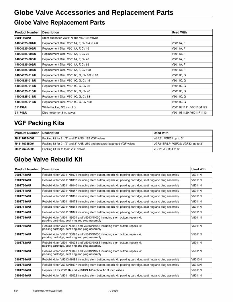
Globe Valve Accessories and Replacement Parts
554 customer.honeywell.com 70-6910
Globe Valve Replacement Parts
VGF Packing Kits
Globe Valve Rebuild Kit
Product Number Description Used With
0901116A/U Stem button for V5011N and V5013N valves —
14004625-001/U Replacement Disc, V5011A, F, Cv 0.4 to 4.0 V5011A, F
14004625-003/U Replacement Disc, V5011A, F, Cv 16 V5011A, F
14004625-004/U Replacement Disc, V5011A, F, Cv 25 V5011A, F
14004625-005/U Replacement Disc, V5011A, F, Cv 40 V5011A, F
14004625-006/U Replacement Disc, V5011A, F, Cv 63 V5011A, F
14004625-007/U Replacement Disc, V5011A, F, Cv 100 V5011A, F
14004625-012/U Replacement Disc, V5011C, G, Cv 6.3 to 10 V5011C, G
14004625-013/U Replacement Disc, V5011C, G, Cv 16 V5011C, G
14004625-014/U Replacement Disc, V5011C, G, Cv 25 V5011C, G
14004625-015/U Replacement Disc, V5011C, G, Cv 40 V5011C, G
14004625-016/U Replacement Disc, V5011C, G, Cv 63 V5011C, G
14004625-017/U Replacement Disc, V5011C, G, Cv 100 V5011C, G
311432/U White Packing 3/8 inch I.D. V5011G1111; V5011G1129
311746/U Disc holder for 3 in. valves V5011G1129; V5011F1113
Product Number Description Used With
R43176754002 Packing kit for 2 1/2” and 3" ANSI 125 VGF valves VGF21, VGF31 up to 3"
R43176755004 Packing kit for 2 1/2” and 3" ANSI 250 and pressure-balanced VGF valves VGF21EP/LP; VGF22; VGF32; up to 3"
R43176755005 Packing kit for 4" to 6" VGF valves VGF2; VGF3; 4 to 6"
Product Number Description Used With
0901748A/U Rebuild kit for V5011N1024 including stem button, repack kit, packing cartridge, seat ring and plug assembly V5011N
0901749A/U Rebuild kit for V5011N1032 including stem button, repack kit, packing cartridge, seat ring and plug assembly V5011N
0901750A/U Rebuild kit for V5011N1040 including stem button, repack kit, packing cartridge, seat ring and plug assembly V5011N
0901751A/U Rebuild kit for V5011N1057 including stem button, repack kit, packing cartridge, seat ring and plug assembly V5011N
0901752A/U Rebuild kit for V5011N1065 including stem button, repack kit, packing cartridge, seat ring and plug assembly V5011N
0901753A/U Rebuild kit for V5011N1073 including stem button, repack kit, packing cartridge, seat ring and plug assembly V5011N
0901754A/U Rebuild kit for V5011N1081 including stem button, repack kit, packing cartridge, seat ring and plug assembly V5011N
0901755A/U Rebuild kit for V5011N1099 including stem button, repack kit, packing cartridge, seat ring and plug assembly V5011N
0901759A/U Rebuild kit for V5011N3004 and V5013N1030 including stem button, repack kit, packing cartridge, seat ring and plug assembly
V5011N
0901760A/U Rebuild kit for V5011N3012 and V5013N1048 including stem button, repack kit, packing cartridge, seat ring and plug assembly
V5011N
0901761A/U Rebuild kit for V5011N3020 and V5013N1055 including stem button, repack kit, packing cartridge, seat ring and plug assembly
V5011N
0901762A/U Rebuild kit for V5011N3038 and V5013N1063 including stem button, repack kit, packing cartridge, seat ring and plug assembly
V5011N
0901763A/U Rebuild kit for V5011N3046 and V5013N1071 including stem button, repack kit, packing cartridge, seat ring and plug assembly
V5011N
0901764A/U Rebuild kit for V5013N1089 including stem button, repack kit, packing cartridge, seat ring and plug assembly V5013N
0901765A/U Rebuild kit for V5013N1097 including stem button, repack kit, packing cartridge, seat ring and plug assembly V5013N
0901786A/U Repack Kit for V5011N and V5013N 1/2 inch to 1-1/4 inch valves V5011N
0903424A/U Rebuild kit for V5011N2022 including stem button, repack kit, packing cartridge, seat ring and plug assembly V5011N
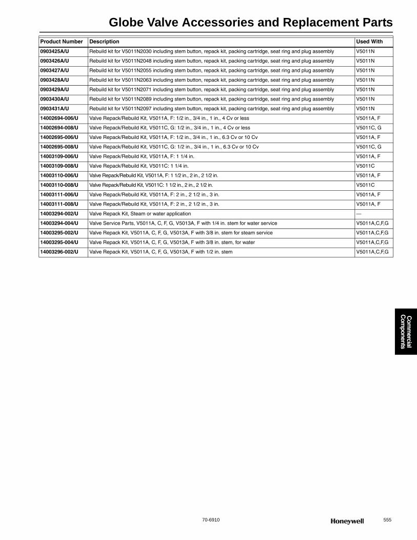
Globe Valve Accessories and Replacement Parts
70-6910 555
Com
mercial
Com
ponents
0903425A/U Rebuild kit for V5011N2030 including stem button, repack kit, packing cartridge, seat ring and plug assembly V5011N
0903426A/U Rebuild kit for V5011N2048 including stem button, repack kit, packing cartridge, seat ring and plug assembly V5011N
0903427A/U Rebuild kit for V5011N2055 including stem button, repack kit, packing cartridge, seat ring and plug assembly V5011N
0903428A/U Rebuild kit for V5011N2063 including stem button, repack kit, packing cartridge, seat ring and plug assembly V5011N
0903429A/U Rebuild kit for V5011N2071 including stem button, repack kit, packing cartridge, seat ring and plug assembly V5011N
0903430A/U Rebuild kit for V5011N2089 including stem button, repack kit, packing cartridge, seat ring and plug assembly V5011N
0903431A/U Rebuild kit for V5011N2097 including stem button, repack kit, packing cartridge, seat ring and plug assembly V5011N
14002694-006/U Valve Repack/Rebuild Kit, V5011A, F: 1/2 in., 3/4 in., 1 in., 4 Cv or less V5011A, F
14002694-008/U Valve Repack/Rebuild Kit, V5011C, G: 1/2 in., 3/4 in., 1 in., 4 Cv or less V5011C, G
14002695-006/U Valve Repack/Rebuild Kit, V5011A, F: 1/2 in., 3/4 in., 1 in., 6.3 Cv or 10 Cv V5011A, F
14002695-008/U Valve Repack/Rebuild Kit, V5011C, G: 1/2 in., 3/4 in., 1 in., 6.3 Cv or 10 Cv V5011C, G
14003109-006/U Valve Repack/Rebuild Kit, V5011A, F: 1 1/4 in. V5011A, F
14003109-008/U Valve Repack/Rebuild Kit, V5011C: 1 1/4 in. V5011C
14003110-006/U Valve Repack/Rebuild Kit, V5011A, F: 1 1/2 in., 2 in., 2 1/2 in. V5011A, F
14003110-008/U Valve Repack/Rebuild Kit, V5011C: 1 1/2 in., 2 in., 2 1/2 in. V5011C
14003111-006/U Valve Repack/Rebuild Kit, V5011A, F: 2 in., 2 1/2 in., 3 in. V5011A, F
14003111-008/U Valve Repack/Rebuild Kit, V5011A, F: 2 in., 2 1/2 in., 3 in. V5011A, F
14003294-002/U Valve Repack Kit, Steam or water application —
14003294-004/U Valve Service Parts, V5011A, C, F, G, V5013A, F with 1/4 in. stem for water service V5011A,C,F,G
14003295-002/U Valve Repack Kit, V5011A, C, F, G, V5013A, F with 3/8 in. stem for steam service V5011A,C,F,G
14003295-004/U Valve Repack Kit, V5011A, C, F, G, V5013A, F with 3/8 in. stem, for water V5011A,C,F,G
14003296-002/U Valve Repack Kit, V5011A, C, F, G, V5013A, F with 1/2 in. stem V5011A,C,F,G
Product Number Description Used With
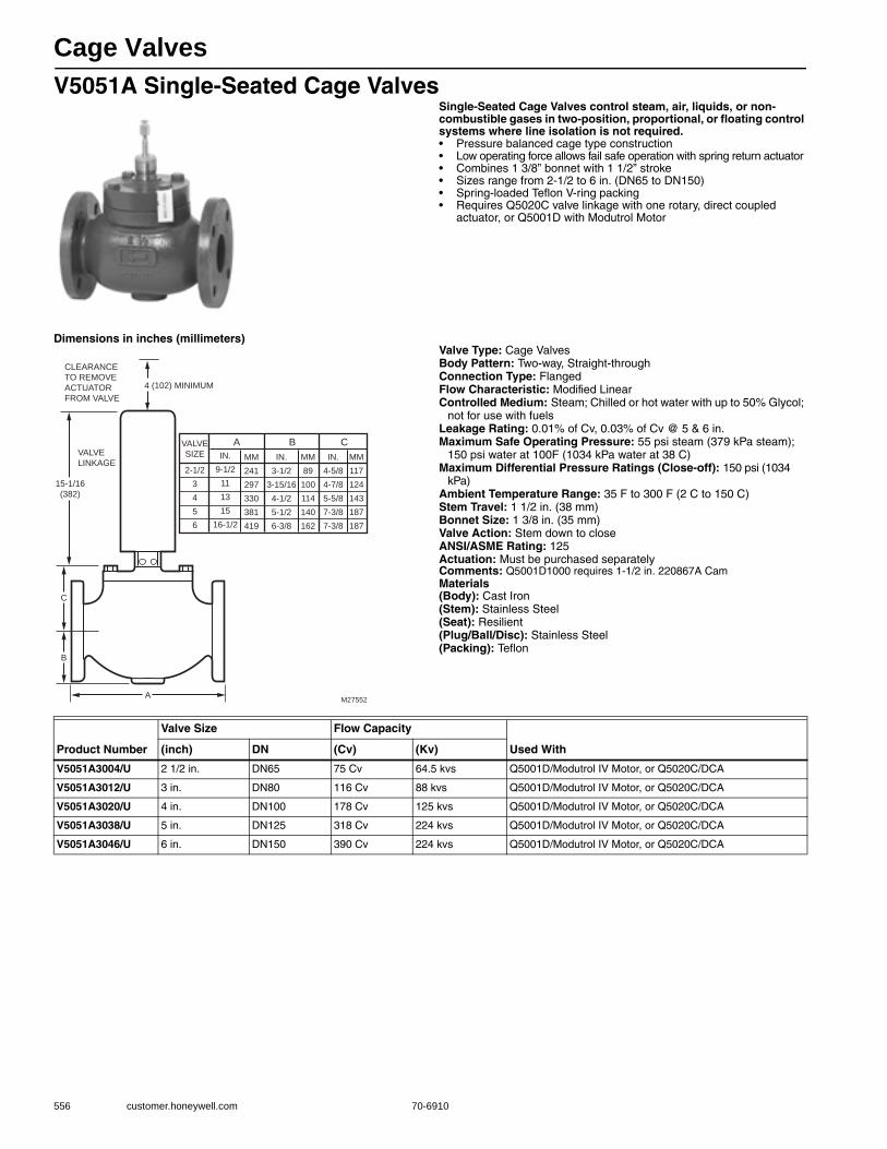
Cage Valves
556 customer.honeywell.com 70-6910
V5051A Single-Seated Cage ValvesSingle-Seated Cage Valves control steam, air, liquids, or non-combustible gases in two-position, proportional, or floating control systems where line isolation is not required.• Pressure balanced cage type construction • Low operating force allows fail safe operation with spring return actuator • Combines 1 3/8” bonnet with 1 1/2” stroke • Sizes range from 2-1/2 to 6 in. (DN65 to DN150) • Spring-loaded Teflon V-ring packing • Requires Q5020C valve linkage with one rotary, direct coupled
actuator, or Q5001D with Modutrol Motor
Dimensions in inches (millimeters)Valve Type: Cage ValvesBody Pattern: Two-way, Straight-throughConnection Type: FlangedFlow Characteristic: Modified LinearControlled Medium: Steam; Chilled or hot water with up to 50% Glycol;
not for use with fuelsLeakage Rating: 0.01% of Cv, 0.03% of Cv @ 5 & 6 in.Maximum Safe Operating Pressure: 55 psi steam (379 kPa steam);
150 psi water at 100F (1034 kPa water at 38 C) Maximum Differential Pressure Ratings (Close-off): 150 psi (1034
kPa) Ambient Temperature Range: 35 F to 300 F (2 C to 150 C) Stem Travel: 1 1/2 in. (38 mm) Bonnet Size: 1 3/8 in. (35 mm) Valve Action: Stem down to closeANSI/ASME Rating: 125Actuation: Must be purchased separatelyComments: Q5001D1000 requires 1-1/2 in. 220867A CamMaterials(Body): Cast Iron(Stem): Stainless Steel(Seat): Resilient(Plug/Ball/Disc): Stainless Steel(Packing): Teflon
CLEARANCE
TO REMOVE
ACTUATOR
FROM VALVE
4 (102) MINIMUM
VALVE
LINKAGE
15-1/16
(382)
C
B
AM27552
VALVE
SIZE
A B C
IN.
9-1/2
11
13
15
16-1/2
MM
241
297
330
381
419
IN.
3-1/2
3-15/16
4-1/2
5-1/2
6-3/8
MM
89
100
114
140
162
IN.
4-5/8
4-7/8
5-5/8
7-3/8
7-3/8
MM
117
124
143
187
187
2-1/2
3
4
5
6
Product Number
Valve Size Flow Capacity
Used With(inch) DN (Cv) (Kv)
V5051A3004/U 2 1/2 in. DN65 75 Cv 64.5 kvs Q5001D/Modutrol IV Motor, or Q5020C/DCA
V5051A3012/U 3 in. DN80 116 Cv 88 kvs Q5001D/Modutrol IV Motor, or Q5020C/DCA
V5051A3020/U 4 in. DN100 178 Cv 125 kvs Q5001D/Modutrol IV Motor, or Q5020C/DCA
V5051A3038/U 5 in. DN125 318 Cv 224 kvs Q5001D/Modutrol IV Motor, or Q5020C/DCA
V5051A3046/U 6 in. DN150 390 Cv 224 kvs Q5001D/Modutrol IV Motor, or Q5020C/DCA

Cartridge Globe Valves
70-6910 557
Com
mercial
Com
ponents
V5852; V5862 Two-way Cartridge Globe ValvesTwo-way Cartridge Globe Valves control hot and/or chilled water for VAV terminal units, fan coil units, small reheaters and recoolers in electric/electronic temperature control systems. Used with the M6410 3-position floating Non-Spring Return Valve Actuator and the M7410 selectable 0 to 10 Vdc or 2 to 10 Vdc Non-Spring Return Actuator. The 1/2” and 3/4” valves are compatible with the M6435 floating Spring Return Actuator, the M7435 selectable 0 to 10 Vdc or 2 to 10 Vdc Spring Return Actuator, and the MP958 Pneumatic Actuator. Larger valves (1" through 1-1/2”) are pressure balanced, which results in higher close-off pressures.• Long stroke allows wider range of control • Soft valve seat provides low leakage rate • Inserts for 1/2 in. and 3/4 in. valves are changeable without
draining valve when used with an insert replacement tool • Brass body and Stainless Steel stem • Threaded plastic cover/manual handle allows manual operation • Easily installed in areas where space is limited
Valve Type: Cartridge Globe ValveBody Pattern: Two-wayControlled Medium: Chilled or hot water with up to 50% Glycol;
not for use with steam or fuelsLeakage Rating:
1/2 in. and 3/4 in. valves: ANSI Class IV (0.01% of Cv maximum)1 in., 1 1/4 in., 1 1/2 in. valves: ANSI Class III (less than 0.02% of Cv)
Maximum Safe Operating Pressure: 235 psi (1620 kPa) Ambient Temperature Range: 36 F to 230 F (2 C to 110 C) Stem Travel: 1/4 in. (6.4 mm) Actuation: Must be purchased separatelyMaterials(Body): Brass(Stem): Stainless Steel(Seat): Brass(Cartridge): Brass(Plug/Ball/Disc): Brass
Replacement Parts:0902812-Replacement Insert for 1/2” V5852/V5862, 0.19 Cv
Interchangeable with 0902809 or 0902100902814-Replacement Insert for 3/4” V5852/V5862, 2.9 Cv
Interchangeable with 09028150902815-Replacement Insert for 3/4” V5852/V5862, 4.9 Cv
Interchangeable with 09028140903827-Replacement Packing for 1" V5862/630903828-Replacement Packing for 1-1/4” V5862/630903829-Replacement Packing for 1-1/2” V5862/63
Accessories:0902807-Replacement Insert for 1/2” V5852/V5862, 1.9Cv
Interchangeable with 09028080902808-Replacement Insert for 1/2” V5852/V5862, 1.2 Cv
Interchangeable with 09028070902809-Replacement Insert for 1/2” V5852/V5862, 0.74 Cv
Interchangeable with 0902810 or 0902120902810-Replacement Insert for 1/2” V5852/V5862, 0.47 Cv
Interchangeable with 0902809 or 0902120903827-Replacement Packing for 1" V5862/63
Product Number
Valve Size Flow CapacityFlow Characteristic
Connec-tion Type
Valve Action
Maximum Close-off Pressure
Used With(inch) DN (Cv) (Kv) (psi) (kPa)
V5852A2007 1/2 in. DN15 0.19 Cv 0.16 kvs Equal Percentage
Sweat (Female)
Stem down to close
232 psi 1600 kPa M6410A1029; M7410F1000; M6435A1004; M7435F1001; MP958
V5852A2015 1/2 in. DN15 0.29 Cv 0.25 kvs Equal Percentage
Sweat (Female)
Stem down to close
232 psi 1600 kPa M6410A1029; M6435A1004; M7410F1000; M7435F1001; MP958
V5852A2023 1/2 in. DN15 0.47 Cv 0.41 kvs Equal Percentage
Sweat (Female)
Stem down to close
232 psi 1600 kPa M6410A1029; M7410F1000; M6435A1004; M7435F1001; MP958
V5852A2031 1/2 in. DN15 0.7 Cv 0.6 kvs Equal Percentage
Sweat (Female)
Stem down to close
232 psi 1600 kPa M6410A1029; M6435A1004; M7410F1000; M7435F1001; MP958
V5852A2049 1/2 in. DN15 1.2 Cv 1.0 kvs Equal Percentage
Sweat (Female)
Stem down to close
174 psi 1200 kPa M6410A1029; M7410F1000; M6435A1004; M7435F1001; MP958
V5852A2056 1/2 in. DN15 1.9 Cv 1.6 kvs Equal Percentage
Sweat (Female)
Stem down to close
174 psi 1200 kPa M6410A1029; M6435A1004; M7410F1000; M7435F1001; MP958
V5852A2064 3/4 in. DN20 2.9 Cv 2.5 kvs Equal Percentage
Sweat (Female)
Stem down to close
58 psi 400 kPa M6410A1029; M7410F1000; M6435A1004; M7435F1001; MP958
V5852A2072 3/4 in. DN20 4.9 Cv 4.2 kvs Equal Percentage
Sweat (Female)
Stem down to close
58 psi 400 kPa M6410A1029; M6435A1004; M7410F1000; M7435F1001; MP958
V5862A2005 1/2 in. DN15 0.19 Cv 0.16 kvs Equal Percentage
Female NPT
Stem down to close
232 psi 1600 kPa M6410A1029; M6435A1004; M7410F1000; M7435F1001; MP958
V5862A2013 1/2 in. DN15 0.29 Cv 0.25 kvs Equal Percentage
Female NPT
Stem down to close
232 psi 1600 kPa M6410A1029; M7410F1000; M6435A1004; M7435F1001; MP958
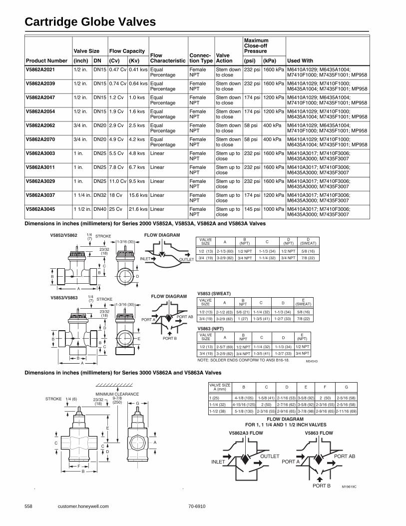
Cartridge Globe Valves
558 customer.honeywell.com 70-6910
Dimensions in inches (millimeters) for Series 2000 V5852A, V5853A, V5862A and V5863A Valves
Dimensions in inches (millimeters) for Series 3000 V5862A and V5863A Valves
V5862A2021 1/2 in. DN15 0.47 Cv 0.41 kvs Equal Percentage
Female NPT
Stem down to close
232 psi 1600 kPa M6410A1029; M6435A1004; M7410F1000; M7435F1001; MP958
V5862A2039 1/2 in. DN15 0.74 Cv 0.64 kvs Equal Percentage
Female NPT
Stem down to close
232 psi 1600 kPa M6410A1029; M7410F1000; M6435A1004; M7435F1001; MP958
V5862A2047 1/2 in. DN15 1.2 Cv 1.0 kvs Equal Percentage
Female NPT
Stem down to close
174 psi 1200 kPa M6410A1029; M6435A1004; M7410F1000; M7435F1001; MP958
V5862A2054 1/2 in. DN15 1.9 Cv 1.6 kvs Equal Percentage
Female NPT
Stem down to close
174 psi 1200 kPa M6410A1029; M7410F1000; M6435A1004; M7435F1001; MP958
V5862A2062 3/4 in. DN20 2.9 Cv 2.5 kvs Equal Percentage
Female NPT
Stem down to close
58 psi 400 kPa M6410A1029; M6435A1004; M7410F1000; M7435F1001; MP958
V5862A2070 3/4 in. DN20 4.9 Cv 4.2 kvs Equal Percentage
Female NPT
Stem down to close
58 psi 400 kPa M6410A1029; M7410F1000; M6435A1004; M7435F1001; MP958
V5862A3003 1 in. DN25 5.5 Cv 4.8 kvs Linear Female NPT
Stem up to close
232 psi 1600 kPa M6410A3017; M7410F3006; M6435A3000; M7435F3007
V5862A3011 1 in. DN25 7.8 Cv 6.7 kvs Linear Female NPT
Stem up to close
232 psi 1600 kPa M6410A3017; M7410F3006; M6435A3000; M7435F3007
V5862A3029 1 in. DN25 11.0 Cv 9.5 kvs Linear Female NPT
Stem up to close
232 psi 1600 kPa M6410A3017; M7410F3006; M6435A3000; M7435F3007
V5862A3037 1 1/4 in. DN32 18 Cv 15.6 kvs Linear Female NPT
Stem up to close
174 psi 1200 kPa M6410A3017; M7410F3006; M6435A3000; M7435F3007
V5862A3045 1 1/2 in. DN40 25 Cv 21.6 kvs Linear Female NPT
Stem up to close
145 psi 1000 kPa M6410A3017; M7410F3006; M6435A3000; M7435F3007
Product Number
Valve Size Flow CapacityFlow Characteristic
Connec-tion Type
Valve Action
Maximum Close-off Pressure
Used With(inch) DN (Cv) (Kv) (psi) (kPa)
M34543
INLET OUTLET
PORT APORT AB
PORT B
A
B
C
STROKEV5852/V5862
V5853/V5863
2-1/2 (63)
3-2/9 (82)
5/6 (21)
1 (27)
1-1/4 (32)
1-3/5 (41)
1-1/3 (34)
1-2/7 (33)
1/2 (13)
3/4 (19)
D
E
D
B
STROKE
B
BA
C
1/2 (13)
3/4 (19)
2-1/3 (60)
3-2/9 (82)
1/2 NPT
3/4 NPT
1-1/3 (34)
1-1/4 (32)
B
FLOW DIAGRAM
AB
(NPT) C
1/2 NPT
3/4 NPT
5/8 (16)
7/8 (22)
D(NPT)
AB
NPT C D
FLOW DIAGRAM
1/4 (7)
1/4 (7)
23/32(18)
23/32(18)
1-3/16 (30)
1-3/16 (30)
NOTE: SOLDER ENDS CONFORM TO ANSI B16-18.
D(SWEAT)
5/8 (16)
7/8 (22)
E(SWEAT)
VALVESIZE
VALVESIZE
V5853 (SWEAT)
2-5/7 (69)
3-2/9 (82)
1/2 NPT
3/4 NPT
1-1/4 (32)
1-3/5 (41)
1-1/3 (34)
1-2/7 (33)
1/2 (13)
3/4 (19)
AB
NPT C D
1/2 NPT
3/4 NPT
E(NPT)
VALVESIZE
V5863 (NPT)
E
ACC
FB
D
23/32(18) G
1/4 (6)STROKEMINIMUM CLEARANCE
9-7/8(250)
M19619C
INLETOUTLET
PORT APORT AB
PORT B
V5863 FLOWV5862A3 FLOW
1 (25)
1-1/4 (32)
1-1/2 (38)
4-1/8 (105)
4-15/16 (125)
5-1/8 (130)
1-5/8 (41)
2 (50)
2-3/16 (55)
2-1/16 (53)
2-7/16 (62)
2-9/16 (65)
3-5/8 (92)
3-5/8 (92)
3-7/8 (98)
B C D E
2-5/16 (58)
2-5/16 (58)
2-11/16 (69)
G
2 (50)
2-3/16 (55)
2-9/16 (65)
FVALVE SIZEA (mm)
FLOW DIAGRAM FOR 1, 1 1/4 AND 1 1/2 INCH VALVES
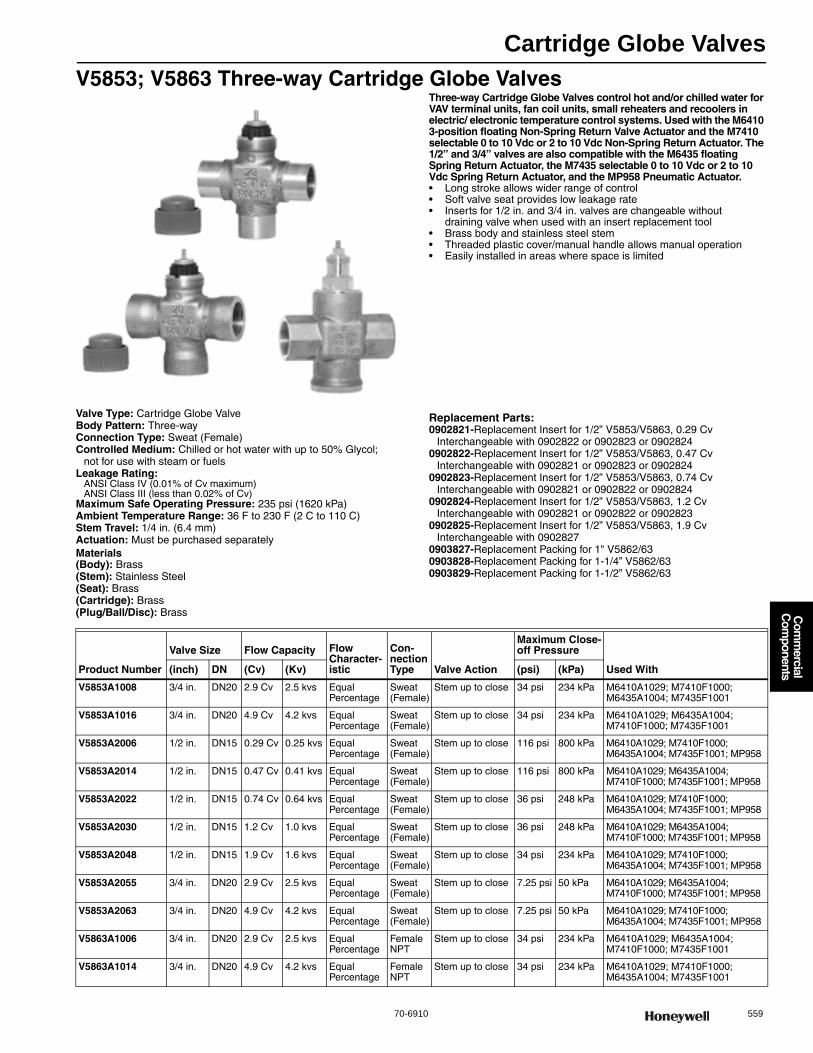
Cartridge Globe Valves
70-6910 559
Com
mercial
Com
ponents
V5853; V5863 Three-way Cartridge Globe ValvesThree-way Cartridge Globe Valves control hot and/or chilled water for VAV terminal units, fan coil units, small reheaters and recoolers in electric/ electronic temperature control systems. Used with the M6410 3-position floating Non-Spring Return Valve Actuator and the M7410 selectable 0 to 10 Vdc or 2 to 10 Vdc Non-Spring Return Actuator. The 1/2” and 3/4” valves are also compatible with the M6435 floating Spring Return Actuator, the M7435 selectable 0 to 10 Vdc or 2 to 10 Vdc Spring Return Actuator, and the MP958 Pneumatic Actuator.• Long stroke allows wider range of control • Soft valve seat provides low leakage rate • Inserts for 1/2 in. and 3/4 in. valves are changeable without
draining valve when used with an insert replacement tool • Brass body and stainless steel stem • Threaded plastic cover/manual handle allows manual operation • Easily installed in areas where space is limited
Valve Type: Cartridge Globe ValveBody Pattern: Three-wayConnection Type: Sweat (Female)Controlled Medium: Chilled or hot water with up to 50% Glycol;
not for use with steam or fuelsLeakage Rating:
ANSI Class IV (0.01% of Cv maximum)ANSI Class III (less than 0.02% of Cv)
Maximum Safe Operating Pressure: 235 psi (1620 kPa) Ambient Temperature Range: 36 F to 230 F (2 C to 110 C) Stem Travel: 1/4 in. (6.4 mm) Actuation: Must be purchased separatelyMaterials(Body): Brass(Stem): Stainless Steel(Seat): Brass(Cartridge): Brass(Plug/Ball/Disc): Brass
Replacement Parts:0902821-Replacement Insert for 1/2” V5853/V5863, 0.29 Cv
Interchangeable with 0902822 or 0902823 or 09028240902822-Replacement Insert for 1/2” V5853/V5863, 0.47 Cv
Interchangeable with 0902821 or 0902823 or 09028240902823-Replacement Insert for 1/2” V5853/V5863, 0.74 Cv
Interchangeable with 0902821 or 0902822 or 09028240902824-Replacement Insert for 1/2” V5853/V5863, 1.2 Cv
Interchangeable with 0902821 or 0902822 or 09028230902825-Replacement Insert for 1/2” V5853/V5863, 1.9 Cv
Interchangeable with 09028270903827-Replacement Packing for 1" V5862/630903828-Replacement Packing for 1-1/4” V5862/630903829-Replacement Packing for 1-1/2” V5862/63
Product Number
Valve Size Flow Capacity Flow Character-istic
Con-nection Type Valve Action
Maximum Close-off Pressure
Used With(inch) DN (Cv) (Kv) (psi) (kPa)
V5853A1008 3/4 in. DN20 2.9 Cv 2.5 kvs Equal Percentage
Sweat (Female)
Stem up to close 34 psi 234 kPa M6410A1029; M7410F1000; M6435A1004; M7435F1001
V5853A1016 3/4 in. DN20 4.9 Cv 4.2 kvs Equal Percentage
Sweat (Female)
Stem up to close 34 psi 234 kPa M6410A1029; M6435A1004; M7410F1000; M7435F1001
V5853A2006 1/2 in. DN15 0.29 Cv 0.25 kvs Equal Percentage
Sweat (Female)
Stem up to close 116 psi 800 kPa M6410A1029; M7410F1000; M6435A1004; M7435F1001; MP958
V5853A2014 1/2 in. DN15 0.47 Cv 0.41 kvs Equal Percentage
Sweat (Female)
Stem up to close 116 psi 800 kPa M6410A1029; M6435A1004; M7410F1000; M7435F1001; MP958
V5853A2022 1/2 in. DN15 0.74 Cv 0.64 kvs Equal Percentage
Sweat (Female)
Stem up to close 36 psi 248 kPa M6410A1029; M7410F1000; M6435A1004; M7435F1001; MP958
V5853A2030 1/2 in. DN15 1.2 Cv 1.0 kvs Equal Percentage
Sweat (Female)
Stem up to close 36 psi 248 kPa M6410A1029; M6435A1004; M7410F1000; M7435F1001; MP958
V5853A2048 1/2 in. DN15 1.9 Cv 1.6 kvs Equal Percentage
Sweat (Female)
Stem up to close 34 psi 234 kPa M6410A1029; M7410F1000; M6435A1004; M7435F1001; MP958
V5853A2055 3/4 in. DN20 2.9 Cv 2.5 kvs Equal Percentage
Sweat (Female)
Stem up to close 7.25 psi 50 kPa M6410A1029; M6435A1004; M7410F1000; M7435F1001; MP958
V5853A2063 3/4 in. DN20 4.9 Cv 4.2 kvs Equal Percentage
Sweat (Female)
Stem up to close 7.25 psi 50 kPa M6410A1029; M7410F1000; M6435A1004; M7435F1001; MP958
V5863A1006 3/4 in. DN20 2.9 Cv 2.5 kvs Equal Percentage
Female NPT
Stem up to close 34 psi 234 kPa M6410A1029; M6435A1004; M7410F1000; M7435F1001
V5863A1014 3/4 in. DN20 4.9 Cv 4.2 kvs Equal Percentage
Female NPT
Stem up to close 34 psi 234 kPa M6410A1029; M7410F1000; M6435A1004; M7435F1001
Cartridge Globe Valves
560 customer.honeywell.com 70-6910
Cartridge Globe Valve Accessories
V5863A2004 1/2 in. DN15 0.29 Cv 0.25 kvs Equal Percentage
Female NPT
Stem up to close 116 psi 800 kPa M6410A1029; M6435A1004; M7410F1000; M7435F1001; MP958
V5863A2012 1/2 in. DN15 0.47 Cv 0.41 kvs Equal Percentage
Female NPT
Stem up to close 116 psi 800 kPa M6410A1029; M7410F1000; M6435A1004; M7435F1001; MP958
V5863A2020 1/2 in. DN15 0.74 Cv 0.64 kvs Equal Percentage
Female NPT
Stem up to close 36 psi 248 kPa M6410A1029; M6435A1004; M7410F1000; M7435F1001; MP958
V5863A2038 1/2 in. DN15 1.2 Cv 1.0 kvs Equal Percentage
Female NPT
Stem up to close 36 psi 248 kPa M6410A1029; M7410F1000; M6435A1004; M7435F1001; MP958
V5863A2046 1/2 in. DN15 1.9 Cv 1.6 kvs Equal Percentage
Female NPT
Stem up to close 34 psi 234 kPa M6410A1029; M6435A1004; M7410F1000; M7435F1001; MP958
V5863A2053 3/4 in. DN20 2.9 Cv 2.5 kvs Equal Percentage
Female NPT
Stem up to close 7.25 psi 50 kPa M6410A1029; M7410F1000; M6435A1004; M7435F1001; MP958
V5863A2061 3/4 in. DN20 4.9 Cv 4.2 kvs Equal Percentage
Female NPT
Stem up to close 7.25 psi 50 kPa M6410A1029; M6435A1004; M7410F1000; M7435F1001; MP958
V5863A3002 1 in. DN25 5.5 Cv 4.8 kvs Linear Female NPT
Stem up to close port A to AB
232 psi 1600 kPa M6410A3017; M7410F3006; M6435A3000; M7435F3007
V5863A3010 1 in. DN25 7.8 Cv 6.7 kvs Linear Female NPT
Stem up to close port A to AB
232 psi 1600 kPa M6410A3017; M7410F3006; M6435A3000; M7435F3007
V5863A3028 1 in. DN25 11.0 Cv 9.5 kvs Linear Female NPT
Stem up to close port A to AB
232 psi 1600 kPa M6410A3017; M7410F3006; M6435A3000; M7435F3007
V5863A3036 1 1/4 in. DN32 18 Cv 15.6 kvs Linear Female NPT
Stem up to close port A to AB
174 psi 1200 kPa M6410A3017; M7410F3006; M6435A3000; M7435F3007
V5863A3044 1 1/2 in. DN40 25 Cv 21.6 kvs Linear Female NPT
Stem up to close port A to AB
145 psi 1000 kPa M6410A3017; M7410F3006; M6435A3000; M7435F3007
Product Number Description Used With
WV108B Brush Tool for Valve Cleaning 1/2” and 3/4” V5852/V5853/V5862/V5863 V5862; V5853; V5852; V5863
WV108M Insert Replacement Tool for 1/2” and 3/4” V5852/V5853/V5862/V5863 V5853; V5862; V5852; V5863
Product Number
Valve Size Flow Capacity Flow Character-istic
Con-nection Type Valve Action
Maximum Close-off Pressure
Used With(inch) DN (Cv) (Kv) (psi) (kPa)
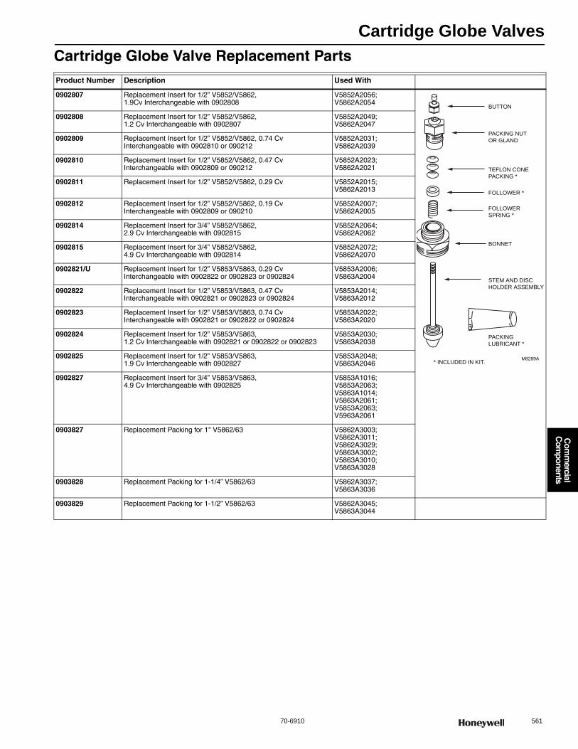
Cartridge Globe Valves
70-6910 561
Com
mercial
Com
ponents
Cartridge Globe Valve Replacement PartsProduct Number Description Used With
0902807 Replacement Insert for 1/2” V5852/V5862, 1.9Cv Interchangeable with 0902808
V5852A2056; V5862A2054
0902808 Replacement Insert for 1/2” V5852/V5862, 1.2 Cv Interchangeable with 0902807
V5852A2049; V5862A2047
0902809 Replacement Insert for 1/2” V5852/V5862, 0.74 Cv Interchangeable with 0902810 or 090212
V5852A2031; V5862A2039
0902810 Replacement Insert for 1/2” V5852/V5862, 0.47 Cv Interchangeable with 0902809 or 090212
V5852A2023; V5862A2021
0902811 Replacement Insert for 1/2” V5852/V5862, 0.29 Cv V5852A2015; V5862A2013
0902812 Replacement Insert for 1/2” V5852/V5862, 0.19 Cv Interchangeable with 0902809 or 090210
V5852A2007; V5862A2005
0902814 Replacement Insert for 3/4” V5852/V5862, 2.9 Cv Interchangeable with 0902815
V5852A2064; V5862A2062
0902815 Replacement Insert for 3/4” V5852/V5862, 4.9 Cv Interchangeable with 0902814
V5852A2072; V5862A2070
0902821/U Replacement Insert for 1/2” V5853/V5863, 0.29 Cv Interchangeable with 0902822 or 0902823 or 0902824
V5853A2006; V5863A2004
0902822 Replacement Insert for 1/2” V5853/V5863, 0.47 Cv Interchangeable with 0902821 or 0902823 or 0902824
V5853A2014; V5863A2012
0902823 Replacement Insert for 1/2” V5853/V5863, 0.74 Cv Interchangeable with 0902821 or 0902822 or 0902824
V5853A2022; V5863A2020
0902824 Replacement Insert for 1/2” V5853/V5863, 1.2 Cv Interchangeable with 0902821 or 0902822 or 0902823
V5853A2030; V5863A2038
0902825 Replacement Insert for 1/2” V5853/V5863, 1.9 Cv Interchangeable with 0902827
V5853A2048; V5863A2046
0902827 Replacement Insert for 3/4” V5853/V5863, 4.9 Cv Interchangeable with 0902825
V5853A1016; V5853A2063; V5863A1014; V5863A2061; V5853A2063; V5963A2061
0903827 Replacement Packing for 1" V5862/63 V5862A3003; V5862A3011; V5862A3029; V5863A3002; V5863A3010; V5863A3028
0903828 Replacement Packing for 1-1/4” V5862/63 V5862A3037; V5863A3036
0903829 Replacement Packing for 1-1/2” V5862/63 V5862A3045; V5863A3044
BUTTON
PACKING NUT
OR GLAND
TEFLON CONE
PACKING *
FOLLOWER *
FOLLOWER
SPRING *
BONNET
STEM AND DISC
HOLDER ASSEMBLY
PACKING
LUBRICANT *
* INCLUDED IN KIT.M8289A

Cartridge Cage Valves
562 customer.honeywell.com 70-6910
VCZA; VCZB Two-way Cartridge Cage Valves
Two-way Cartridge Cage Valves are intended for hydronic applications in a normal indoor environment to control the flow of hot water or chilled water glycol solution to 60% concentration. These valves are designed for zone control of heating/cooling systems, or to control individual fan coil, baseboard radiator or convector applications. Depending on the model selected they can be controlled by SPST or SPDT two position controller, tristate (floating), or modulating proportional controller. For best control, outdoor temperature compensation of supply water temperature is recommended. For trouble-free operation of the product, good installation practice must include initial system flushing, chemical water treatment, and the use of a 50 micron (or finer) system side stream filter(s). Remove all filters before flushing.• Quick open, linear, and equal percentage flow characteristics available • Bi-directional installation • 3000-series valves for floating and modulating non-fail safe applications • 1000-series valves for two-position control • High close-off rating independent of Cv • Available with a variety of North American and international pipe fittings • No tools required for actuator installation or removal • Actuator removal does not require draining system • Service is by replacement of cartridge, not valve body • Cartridge replacement rebuilds valve to factory-new condition
Dimensions in inches (millimeters)
Sweat Connection Sweat Connection Sweat Connection
NPT Connection NPT Connection NPT Connection
A B
3-3/4 (94)
D
3-9/16
(90)
C
2-3/4 (68)
C D
PIPE FITTING SIZES IN. MM IN. MM3/8" FLARE 3-7/8 98 4-3/8 111
1/2" SWEAT 3-1/2 89
1/2" FLARE 3-7/8 98
1/2" INVERTED FLARE
1/2" NPT (int.)
3/4" NPT (int.) 3-11/16 94 4-7/16 113
3/4" SWEAT
1" NPT (int.)
1" SWEAT
1-1/4" SWEAT 4-5/16 110 4-5/8 118
1-1/4" NPT (int.)
1
1
NO ADAPTERS M16839
1
1
Cartridge Cage Valves
70-6910 563
Com
mercial
Com
ponents
Valve Type: Cartridge Cage ValveValve Action: Stem up to close A portBody Pattern: Two-way, Straight-throughControlled Medium: Chilled or hot water with up to 60% GlycolMaximum Safe Operating Pressure: 300 psi (2068 kPa (20 Bar)) Maximum Differential Pressure Ratings (Close-off): (414 kPa; 60 psi
(4 bar))Fluid Temperature Range: 34 F to 203 F (1 C to 95 C) Ambient Temperature Range: 32 F to 150 F (0 C to 65 C) Stem Travel: 0.4 in. (10 mm)
Materials(Body): Bronze(Stem): Stainless Steel(Seat): EPDM O-ring seals on Noryl piston(Cartridge): Ryton™, Noryl™ engineering plastic(Packing): EPDM rubberIncludes: Cartridge installation wrenchApprovalsCanadian Standards Association: CSA Certified
Accessories:40007029-002-Wrench for cartridge (included with sweat valves
and all replacement cartridges)
Valves with Linear Flow CharacteristicComments: Characterized cartridge; Can be controlled by either a low or a line voltage SPDT or SPST or floating controller
Valves with Linear Flow CharacteristicComments: Characterized cartridge for use with non-fail safe floating and modulating actuators
Product Number
Valve Size Flow Capacity Timing (sec, min.) when used with VC series Actuator
Connection Type Actuation Used With(inch) DN (Cv) (Kv)
VCZAA1100/U 1/2 in. DN15 3.5 Cv 3.03 kvs On/Off models with 6 seconds Sweat Must be purchased separately
VC actuators, On-Off Type
VCZAE1100/U 1/2 in. DN15 3.2 Cv 2.74 kvs On/Off models with 6 seconds Inverted Flare
Must be purchased separately
VC actuators, On-Off Type
VCZAL1100/U 3/4 in. DN20 4.7 Cv 4.0 kvs On/Off models with 6 seconds Female NPT Must be purchased separately
VC actuators, On-Off Type
VCZAM1100/U 3/4 in. DN20 4.6 Cv 3.9 kvs On/Off models with 6 seconds Sweat Must be purchased separately
VC actuators, On-Off Type
VCZAR1100/U 1 in. DN25 6.6 Cv 5.7 kvs On/Off models with 6 seconds Female NPT Must be purchased separately
VC actuators, On-Off Type
VCZAS1100/U 1 in. DN25 6.6 Cv 5.7 kvs On/Off models with 6 seconds Sweat Must be purchased separately
VC actuators, On-Off Type
VCZBB1100/U 1/2 in. DN15 3.5 Cv 3.03 kvs On/Off models with 6 seconds Female NPT Must be purchased separately
VC actuators, On-Off Type
VCZBD1100/U 1 1/4 in. DN32 7.0 Cv 6.5 kvs On/Off models with 6 seconds Female NPT Must be purchased separately
VC actuators, On-Off Type
VCZBE1100/U 1 1/4 in. DN32 7.0 Cv 6.5 kvs On/Off models with 6 seconds Sweat Must be purchased separately
VC actuators, On-Off Type
Product Number
Valve Size Flow Capacity Timing (sec, min.) when used with VC series Actuator
Connec-tion Type Actuation Used With(inch) DN (Cv) (Kv)
VCZAA3100/U 1/2 in. DN15 3.5 Cv 3.03 kvs 2 minutes Sweat Proportional non-fail safe, purchase separately
VC6830/VC6831/VC6834; VC6930/VC6931/VC6934; VC7930/VC7931/VC7934
VCZAL3100/U 3/4 in. DN20 4.7 Cv 4.0 kvs 2 minutes Female NPT
Proportional non-fail safe, purchase separately
VC6830/VC6831/VC6834; VC6930/VC6931/VC6934; VC7930/VC7931/VC7934
VCZAM3100/U 3/4 in. DN20 4.7 Cv 4.0 kvs 2 minutes Sweat Proportional non-fail safe, purchase separately
VC6830/VC6831/VC6834; VC6930/VC6931/VC6934; VC7930/VC7931/VC7934
VCZAR3100/U 1 in. DN20 6.6 Cv 5.7 kvs 2 minutes Female NPT
Proportional non-fail safe, purchase separately
VC6830/VC6831/VC6834; VC6930/VC6931/VC6934; VC7930/VC7931/VC7934
VCZAS3100/U 1 in. DN20 6.6 Cv 5.7 kvs 2 minutes Sweat Proportional non-fail safe, purchase separately
VC6830/VC6831/VC6834; VC6930/VC6931/VC6934; VC7930/VC7931/VC7934
VCZBB3100/U 1/2 in. DN15 3.5 Cv 3.03 kvs 2 minutes Female NPT
Proportional non-fail safe, purchase separately
VC6830/VC6831/VC6834; VC6930/VC6931/VC6934; VC7930/VC7931/VC7934
VCZBD3100/U 1 1/4 in. DN32 7.0 Cv 6.5 kvs 2 minutes Female NPT
Proportional non-fail safe, purchase separately
VC6830/VC6831/VC6834; VC6930/VC6931/VC6934; VC7930/VC7931/VC7934
VCZBE3100/U 1 1/4 in. DN32 7.0 Cv 6.5 kvs 2 minutes Sweat Proportional non-fail safe, purchase separately
VC6830/VC6831/VC6834; VC6930/VC6931/VC6934; VC7930/VC7931/VC7934
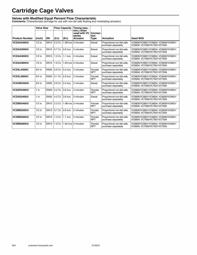
Cartridge Cage Valves
564 customer.honeywell.com 70-6910
Valves with Modified Equal Percent Flow CharacteristicComments: Characterized cartridge for use with non-fail safe floating and modulating actuators
Product Number
Valve Size Flow Capacity Timing (sec, min.) when used with VC series Actuator
Connec-tion Type Actuation Used With(inch) DN (Cv) (Kv)
VCZAA3400/U 1/2 in. DN15 2.3 Cv 1.98 kvs 2 minutes Sweat Proportional non-fail safe, purchase separately
VC6830/VC6831/VC6834; VC6930/VC6931/VC6934; VC7930/VC7931/VC7934
VCZAA3500/U 1/2 in. DN15 0.7 Cv 0.6 kvs 2 minutes Sweat Proportional non-fail safe, purchase separately
VC6830/VC6831/VC6834; VC6930/VC6931/VC6934; VC7930/VC7931/VC7934
VCZAA3600/U 1/2 in. DN15 1.3 Cv 1.1 kvs 2 minutes Sweat Proportional non-fail safe, purchase separately
VC6830/VC6831/VC6834; VC6930/VC6931/VC6934; VC7930/VC7931/VC7934
VCZAA3800/U 1/2 in. DN15 1.9 Cv 1.64 kvs 2 minutes Sweat Proportional non-fail safe, purchase separately
VC6830/VC6831/VC6834; VC6930/VC6931/VC6934; VC7930/VC7931/VC7934
VCZAL3400/U 3/4 in. DN20 3.9 Cv 3.4 kvs 2 minutes Female NPT
Proportional non-fail safe, purchase separately
VC6830/VC6831/VC6834; VC6930/VC6931/VC6934; VC7930/VC7931/VC7934
VCZAL3800/U 3/4 in. DN20 3.1 Cv 2.6 kvs 2 minutes Female NPT
Proportional non-fail safe, purchase separately
VC6830/VC6831/VC6834; VC6930/VC6931/VC6934; VC7930/VC7931/VC7934
VCZAM3400/U 3/4 in. DN20 3.9 Cv 3.4 kvs 2 minutes Sweat Proportional non-fail safe, purchase separately
VC6830/VC6831/VC6834; VC6930/VC6931/VC6934; VC7930/VC7931/VC7934
VCZAR3400/U 1 in. DN20 4.2 Cv 3.6 kvs 2 minutes Female NPT
Proportional non-fail safe, purchase separately
VC6830/VC6831/VC6834; VC6930/VC6931/VC6934; VC7930/VC7931/VC7934
VCZAS3400/U 1 in. DN20 4.2 Cv 3.6 kvs 2 minutes Sweat Proportional non-fail safe, purchase separately
VC6830/VC6831/VC6834; VC6930/VC6931/VC6934; VC7930/VC7931/VC7934
VCZBB3400/U 1/2 in. DN15 2.3 Cv 1.98 kvs 2 minutes Female NPT
Proportional non-fail safe, purchase separately
VC6830/VC6831/VC6834; VC6930/VC6931/VC6934; VC7930/VC7931/VC7934
VCZBB3500/U 1/2 in. DN15 0.7 Cv 0.6 kvs 2 minutes Female NPT
Proportional non-fail safe, purchase separately
VC6830/VC6831/VC6834; VC6930/VC6931/VC6934; VC7930/VC7931/VC7934
VCZBB3600/U 1/2 in. DN15 1.3 Cv 1.1 kvs 2 minutes Female NPT
Proportional non-fail safe, purchase separately
VC6830/VC6831/VC6834; VC6930/VC6931/VC6934; VC7930/VC7931/VC7934
VCZBB3800/U 1/2 in. DN15 1.9 Cv 1.64 kvs 2 minutes Female NPT
Proportional non-fail safe, purchase separately
VC6830/VC6831/VC6834; VC6930/VC6931/VC6934; VC7930/VC7931/VC7934
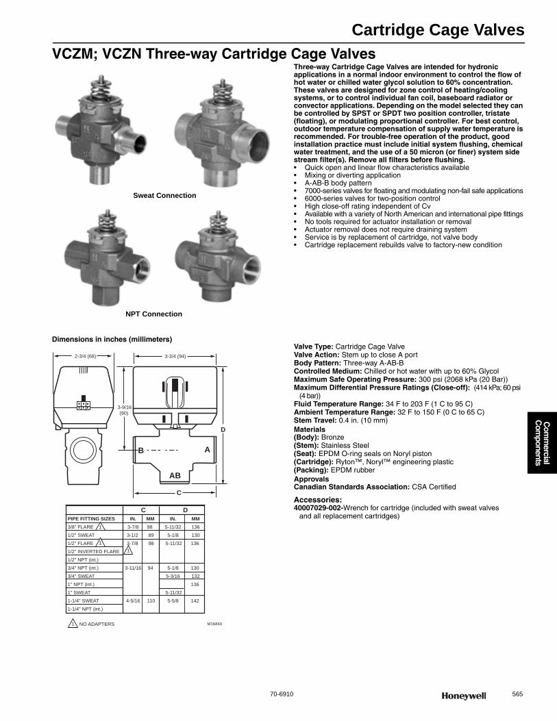
Cartridge Cage Valves
70-6910 565
Com
mercial
Com
ponents
VCZM; VCZN Three-way Cartridge Cage ValvesThree-way Cartridge Cage Valves are intended for hydronic applications in a normal indoor environment to control the flow of hot water or chilled water glycol solution to 60% concentration. These valves are designed for zone control of heating/cooling systems, or to control individual fan coil, baseboard radiator or convector applications. Depending on the model selected they can be controlled by SPST or SPDT two position controller, tristate (floating), or modulating proportional controller. For best control, outdoor temperature compensation of supply water temperature is recommended. For trouble-free operation of the product, good installation practice must include initial system flushing, chemical water treatment, and the use of a 50 micron (or finer) system side stream filter(s). Remove all filters before flushing.• Quick open and linear flow characteristics available • Mixing or diverting application • A-AB-B body pattern • 7000-series valves for floating and modulating non-fail safe applications • 6000-series valves for two-position control • High close-off rating independent of Cv • Available with a variety of North American and international pipe fittings • No tools required for actuator installation or removal • Actuator removal does not require draining system • Service is by replacement of cartridge, not valve body • Cartridge replacement rebuilds valve to factory-new condition
Dimensions in inches (millimeters)Valve Type: Cartridge Cage ValveValve Action: Stem up to close A portBody Pattern: Three-way A-AB-BControlled Medium: Chilled or hot water with up to 60% GlycolMaximum Safe Operating Pressure: 300 psi (2068 kPa (20 Bar)) Maximum Differential Pressure Ratings (Close-off): (414 kPa; 60 psi
(4 bar)) Fluid Temperature Range: 34 F to 203 F (1 C to 95 C) Ambient Temperature Range: 32 F to 150 F (0 C to 65 C) Stem Travel: 0.4 in. (10 mm) Materials(Body): Bronze(Stem): Stainless Steel(Seat): EPDM O-ring seals on Noryl piston(Cartridge): Ryton™, Noryl™ engineering plastic(Packing): EPDM rubberApprovalsCanadian Standards Association: CSA Certified
Accessories:40007029-002-Wrench for cartridge (included with sweat valves
and all replacement cartridges)
Sweat Connection
NPT Connection
B
AB
A
3-9/16
(90)
3-3/4 (94)
C
2-3/4 (68)
D
C D PIPE FITTING SIZES IN. MM IN. MM3/8" FLARE 3-7/8 98 5-11/32 136
1/2" SWEAT 3-1/2 89 5-1/8 130
1/2" FLARE 3-7/8 98 5-11/32 136
1/2" INVERTED FLARE
1/2" NPT (int.)
3/4" NPT (int.) 3-11/16 94 5-1/8 130
3/4" SWEAT 5-3/16 132
1" NPT (int.) 136
1" SWEAT 5-11/32
1-1/4" SWEAT 4-5/16 110 5-5/8 142
1-1/4" NPT (int.)
1
1
1
NO ADAPTERS M16840
1

Cartridge Cage Valves
566 customer.honeywell.com 70-6910
Valves with Linear Flow CharacteristicsComments: Characterized cartridge; Can be controlled by either a low or a line voltage SPDT or SPST or floating controller
Valves with Linear Flow CharacteristicsComments: Characterized cartridge for use with non-fail safe floating and modulating actuators
Valves with Linear Flow CharacteristicsComments: Can be controlled by either a low voltage or a line voltage SPDT or SPST or floating controller;
characterized cartridge for use with floating and modulating actuators
Product Number
Valve Size Flow Capacity Timing (sec, min.) when used with VC series Actuator
Connec-tion Type Actuation Used With Includes(inch) DN (Cv) (Kv)
VCZMA6100/U 1/2 in. DN15 3.7 Cv 3.2 kvs On/Off models with 6 seconds
Sweat Must be purchased separately
VC actuators, 2-position, On-Off Type
Cartridge changing tool
VCZMC6100/U 1/2 in. DN15 3.8 Cv 3.3 kvs On/Off models with 6 seconds
Flare Must be purchased separately
VC actuators, 2-position, On-Off Type
—
VCZMD6100/U 1/2 in. DN15 3.2 Cv 2.74 kvs
On/Off models with 6 seconds
Inverted Flare
Must be purchased separately
VC actuators, 2-position, On-Off Type
—
VCZMK6100/U 3/4 in. DN20 6.6 Cv 5.7 kvs On/Off models with 6 seconds
Female NPT
Must be purchased separately
VC actuators, 2-position, On-Off Type
—
VCZML6100/U 3/4 in. DN20 6.6 Cv 5.7 kvs On/Off models with 6 seconds
Sweat Must be purchased separately
VC actuators, 2-position, On-Off Type
Cartridge changing tool
VCZMR6100/U 1 in. DN25 8.3 Cv 7.1 kvs On/Off models with 6 seconds
Female NPT
Must be purchased separately
VC actuators, 2-position, On-Off Type
—
VCZMS6100/U 1 in. DN25 8.3 Cv 7.1 kvs On/Off models with 6 seconds
Sweat Must be purchased separately
VC actuators, 2-position, On-Off Type
Cartridge changing tool
VCZNB6100/U 1/2 in. DN15 3.7 Cv 3.2 kvs On/Off models with 6 seconds
Female NPT
Must be purchased separately
VC actuators, 2-position, On-Off Type
—
VCZND6100/U 1 1/4 in. DN32 9.0 Cv 7.7 kvs On/Off models with 6 seconds
Female NPT
Must be purchased separately
VC actuators, 2-position, On-Off Type
—
VCZNE6100/U 1 1/4 in. DN32 9.0 Cv 7.7 kvs On/Off models with 6 seconds
Sweat Must be purchased separately
VC actuators, 2-position, On-Off Type
Cartridge changing tool
Product Number
Valve Size Flow Capacity Timing (sec, min.) when used with VC series Actuator
Connec-tion Type Actuation Used With Includes(inch) DN (Cv) (Kv)
VCZMA7100/U 1/2 in. DN15 3.7 Cv 3.2 kvs 2 minutes Sweat Proportional non-fail safe, purchase separately
VC6830/VC6831/VC6834; VC6930/VC6931/VC6934; VC7930/VC7931/VC7934
Cartridge changing tool
VCZMK7100/U 3/4 in. DN20 6.6 Cv 5.7 kvs 2 minutes Female NPT
Proportional non-fail safe, purchase separately
VC6830/VC6831/VC6834; VC6930/VC6931/VC6934; VC7930/VC7931/VC7934
—
VCZML7100/U 3/4 in. DN20 6.6 Cv 5.7 kvs 2 minutes Sweat Proportional non-fail safe, purchase separately
VC6830/VC6831/VC6834; VC6930/VC6931/VC6934; VC7930/VC7931/VC7934
Cartridge changing tool
VCZNB7100/U 1/2 in. DN15 3.7 Cv 3.2 kvs 2 minutes Female NPT
Proportional non-fail safe, purchase separately
VC6830/VC6831/VC6834; VC6930/VC6931/VC6934; VC7930/VC7931/VC7934
—
VCZND7100/U 1 1/4 in. DN32 9.0 Cv 7.7 kvs 2 minutes Female NPT
Proportional non-fail safe, purchase separately
VC6830/VC6831/VC6834; VC6930/VC6931/VC6934; VC7930/VC7931/VC7934
—
VCZNE7100/U 1 1/4 in. DN32 9.0 Cv 7.7 kvs 2 minutes Sweat Proportional non-fail safe, purchase separately
VC6830/VC6831/VC6834; VC6930/VC6931/VC6934; VC7930/VC7931/VC7934
Cartridge changing tool
Product Number
Valve Size Flow Capacity Timing (sec, min.) when used with VC series Actuator
Connec-tion Type Actuation Used With Includes(inch) DN (Cv) (Kv)
VCZMR7100/U 1 in. DN25 8.3 Cv 7.1 kvs 2 minutes Female NPT
Proportional non-fail safe, purchase separately
VC6830/VC6831/VC6834; VC6930/VC6931/VC6934; VC7930/VC7931/VC7934
—
VCZMS7100/U 1 in. DN25 8.3 Cv 7.1 kvs 2 minutes Sweat Proportional non-fail safe, purchase separately
VC6830/VC6831/VC6834; VC6930/VC6931/VC6934; VC7930/VC7931/VC7934
Cartridge changing tool
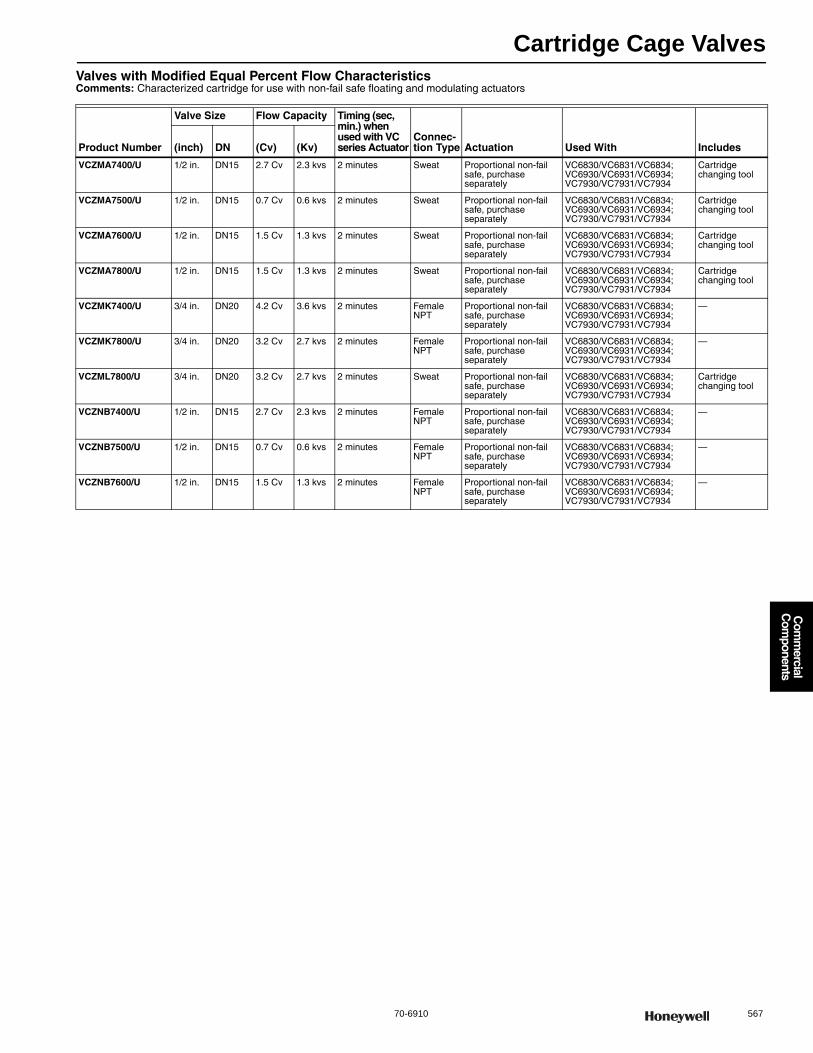
Cartridge Cage Valves
70-6910 567
Com
mercial
Com
ponents
Valves with Modified Equal Percent Flow CharacteristicsComments: Characterized cartridge for use with non-fail safe floating and modulating actuators
Product Number
Valve Size Flow Capacity Timing (sec, min.) when used with VC series Actuator
Connec-tion Type Actuation Used With Includes(inch) DN (Cv) (Kv)
VCZMA7400/U 1/2 in. DN15 2.7 Cv 2.3 kvs 2 minutes Sweat Proportional non-fail safe, purchase separately
VC6830/VC6831/VC6834; VC6930/VC6931/VC6934; VC7930/VC7931/VC7934
Cartridge changing tool
VCZMA7500/U 1/2 in. DN15 0.7 Cv 0.6 kvs 2 minutes Sweat Proportional non-fail safe, purchase separately
VC6830/VC6831/VC6834; VC6930/VC6931/VC6934; VC7930/VC7931/VC7934
Cartridge changing tool
VCZMA7600/U 1/2 in. DN15 1.5 Cv 1.3 kvs 2 minutes Sweat Proportional non-fail safe, purchase separately
VC6830/VC6831/VC6834; VC6930/VC6931/VC6934; VC7930/VC7931/VC7934
Cartridge changing tool
VCZMA7800/U 1/2 in. DN15 1.5 Cv 1.3 kvs 2 minutes Sweat Proportional non-fail safe, purchase separately
VC6830/VC6831/VC6834; VC6930/VC6931/VC6934; VC7930/VC7931/VC7934
Cartridge changing tool
VCZMK7400/U 3/4 in. DN20 4.2 Cv 3.6 kvs 2 minutes Female NPT
Proportional non-fail safe, purchase separately
VC6830/VC6831/VC6834; VC6930/VC6931/VC6934; VC7930/VC7931/VC7934
—
VCZMK7800/U 3/4 in. DN20 3.2 Cv 2.7 kvs 2 minutes Female NPT
Proportional non-fail safe, purchase separately
VC6830/VC6831/VC6834; VC6930/VC6931/VC6934; VC7930/VC7931/VC7934
—
VCZML7800/U 3/4 in. DN20 3.2 Cv 2.7 kvs 2 minutes Sweat Proportional non-fail safe, purchase separately
VC6830/VC6831/VC6834; VC6930/VC6931/VC6934; VC7930/VC7931/VC7934
Cartridge changing tool
VCZNB7400/U 1/2 in. DN15 2.7 Cv 2.3 kvs 2 minutes Female NPT
Proportional non-fail safe, purchase separately
VC6830/VC6831/VC6834; VC6930/VC6931/VC6934; VC7930/VC7931/VC7934
—
VCZNB7500/U 1/2 in. DN15 0.7 Cv 0.6 kvs 2 minutes Female NPT
Proportional non-fail safe, purchase separately
VC6830/VC6831/VC6834; VC6930/VC6931/VC6934; VC7930/VC7931/VC7934
—
VCZNB7600/U 1/2 in. DN15 1.5 Cv 1.3 kvs 2 minutes Female NPT
Proportional non-fail safe, purchase separately
VC6830/VC6831/VC6834; VC6930/VC6931/VC6934; VC7930/VC7931/VC7934
—

Cartridge Cage Valves
568 customer.honeywell.com 70-6910
VC Series Valve and Fail-Safe Actuator AssembliesThe Fail Safe VC6936 Floating and VC7936 Modulating Control valves provides proportional control of hot or chilled water in commercial heating and cooling applications, such as unit ventilators. On a power failure, this patented actuator design drives the valve to the fail safe position, either fully open or closed according to the installer’s wiring connections. These actuators use a microprocessor-controlled, low voltage stepper motor with a super capacitor-based power supply capable of storing enough power to drive the valve to its when 24V power is removed from the actuator.A VC hydronic valve consists of a valve body, a replaceable characterized cartridge assembly and a Honeywell VC6900 or VC7900-series actuator, providing proportional flow control. Three-way bodies may be used in either diverting or mixing applications. VC valves use cam-operated cartridge travel to resist water hammer. Limit switches prevent motor overrun. For best control, outdoor temperature compensation of supply water temperature is recommended.
Valve Type: Cartridge Cage ValveValve Action: Stem up to close A portControlled Medium: Chilled or hot water with up to 60% GlycolMaximum Safe Operating Pressure: 300 psi (2068 kPa (20 Bar)) Maximum Differential Pressure Ratings (Close-off): (414 kPa; 60 psi
(4 bar)) Fluid Temperature Range: 34 F to 203 F (1 C to 95 C) Ambient Temperature Range: 32 F to 150 F (0 C to 65 C) Stem Travel: 0.4 in. (10 mm)
Timing (sec, min.): For VC6936: 2 minutes; For VC7936: installer-selectable 60 or 120 seconds
Materials(Body): Bronze(Stem): Stainless Steel(Seat): EPDM O-ring seals on Noryl piston(Cartridge): Ryton®, Noryl™ engineering plastic(Packing): EPDM rubberApprovalsCanadian Standards Association: CSA Certified
Two-way, Straight-through ValvesComments: Characterized cartridge for use with non-fail safe floating and modulating actuators
Product Number
Valve Size Flow CapacityConnec-tion Type Flow Characteristic Actuation Includes(inch) DN (Cv) (Kv)
VC6936AA1100/U 1/2 in. DN15 3.5 Cv 3.1 kvs Sweat Linear Floating (24V SP3T) fail-safe Cartridge changing tool
VC6936AA1400/U 1/2 in. DN15 2.3 Cv 1.98 kvs Sweat Modified Equal Percent Floating (24V SP3T) fail-safe Cartridge changing tool
VC6936AA1500/U 1/2 in. DN15 0.7 Cv 0.6 kvs Sweat Modified Equal Percent Floating (24V SP3T) fail-safe Cartridge changing tool
VC6936AA1600/U 1/2 in. DN15 1.3 Cv 1.1 kvs Sweat Modified Equal Percent Floating (24V SP3T) fail-safe Cartridge changing tool
VC6936AA1800/U 1/2 in. DN15 1.9 Cv 1.6 kvs Sweat Modified Equal Percent Floating (24V SP3T) fail-safe Cartridge changing tool
VC6936AL1100/U 3/4 in. DN20 4.7 Cv 4.1 kvs Female NPT Linear Floating (24V SP3T) fail-safe —
VC6936AL1400/U 3/4 in. DN20 3.9 Cv 3.4 kvs Female NPT Modified Equal Percent Floating (24V SP3T) fail-safe —
VC6936AL1800/U 3/4 in. DN20 3.1 Cv 2.6 kvs Female NPT Modified Equal Percent Floating (24V SP3T) fail-safe —
VC6936AM1100/U 3/4 in. DN20 4.7 Cv 4.1 kvs Sweat Linear Floating (24V SP3T) fail-safe Cartridge changing tool
VC6936AM1400/U 3/4 in. DN20 3.9 Cv 3.4 kvs Sweat Modified Equal Percent Floating (24V SP3T) fail-safe Cartridge changing tool
VC6936AM1800/U 3/4 in. DN20 3.1 Cv 2.6 kvs Sweat Modified Equal Percent Floating (24V SP3T) fail-safe Cartridge changing tool
VC6936AR1100/U 1 in. DN20 6.6 Cv 5.7 kvs Female NPT Linear Floating (24V SP3T) fail-safe —
VC6936AR1400/U 1 in. DN20 4.2 Cv 3.6 kvs Female NPT Modified Equal Percent Floating (24V SP3T) fail-safe —
VC6936AS1100/U 1 in. DN20 6.6 Cv 5.7 kvs Sweat Linear Floating (24V SP3T) fail-safe Cartridge changing tool
VC6936AS1400/U 1 in. DN20 4.2 Cv 3.6 kvs Sweat Modified Equal Percent Floating (24V SP3T) fail-safe Cartridge changing tool
VC6936BB1100/U 1/2 in. DN15 3.5 Cv 3.1 kvs Female NPT Linear Floating (24V SP3T) fail-safe —
VC6936BB1400/U 1/2 in. DN15 2.3 Cv 1.98 kvs Female NPT Modified Equal Percent Floating (24V SP3T) fail-safe —
VC6936BB1500/U 1/2 in. DN15 0.7 Cv 0.6 kvs Female NPT Modified Equal Percent Floating (24V SP3T) fail-safe —
VC6936BB1600/U 1/2 in. DN15 1.3 Cv 1.1 kvs Female NPT Modified Equal Percent Floating (24V SP3T) fail-safe —
VC6936BB1800/U 1/2 in. DN15 1.9 Cv 1.6 kvs Female NPT Modified Equal Percent Floating (24V SP3T) fail-safe —
VC6936BD1100/U 1 1/4 in. DN32 7 Cv 6.0 kvs Female NPT Linear Floating (24V SP3T) fail-safe —
VC6936BE1100/U 1 1/4 in. DN32 7 Cv 6.0 kvs Sweat Linear Floating (24V SP3T) fail-safe Cartridge changing tool
VC7936AA1100/U 1/2 in. DN15 3.5 Cv 3.1 kvs Sweat Linear Modulating/Floating/PWM fail-safe Cartridge changing tool
VC7936AA1400/U 1/2 in. DN15 2.3 Cv 1.98 kvs Sweat Modified Equal Percent Modulating/Floating/PWM fail-safe Cartridge changing tool
VC7936AA1500/U 1/2 in. DN15 0.7 Cv 0.6 kvs Sweat Modified Equal Percent Modulating/Floating/PWM fail-safe Cartridge changing tool
VC7936AA1600/U 1/2 in. DN15 1.3 Cv 1.1 kvs Sweat Modified Equal Percent Modulating/Floating/PWM fail-safe Cartridge changing tool
VC7936AA1800/U 1/2 in. DN15 1 9 Cv 1.6 kvs Sweat Modified Equal Percent Modulating/Floating/PWM fail-safe Cartridge changing tool
VC7936AL1100/U 3/4 in. DN20 4.7 Cv 4.1 kvs Female NPT Linear Modulating/Floating/PWM fail-safe —
VC7936AL1400/U 3/4 in. DN20 3 9 Cv 3.4 kvs Female NPT Modified Equal Percent Modulating/Floating/PWM fail-safe —
VC7936AL1800/U 3/4 in. DN20 3.1 Cv 2.6 kvs Female NPT Modified Equal Percent Modulating/Floating/PWM fail-safe —
VC7936AM1100/U 3/4 in. DN20 4.7 Cv 4.1 kvs Sweat Linear Modulating/Floating/PWM fail-safe Cartridge changing tool
VC7936AM1400/U 3/4 in. DN20 3 9 Cv 3.4 kvs Sweat Modified Equal Percent Modulating/Floating/PWM fail-safe Cartridge changing tool
VC7936AM1800/U 3/4 in. DN20 3.1 Cv 2.6 kvs Sweat Modified Equal Percent Modulating/Floating/PWM fail-safe Cartridge changing tool
VC7936AR1100/U 1 in. DN20 6 6 Cv 5.7 kvs Female NPT Linear Modulating/Floating/PWM fail-safe —
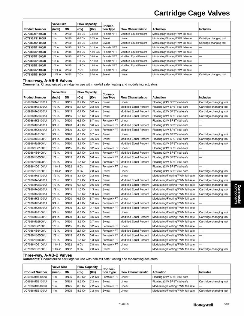
Cartridge Cage Valves
70-6910 569
Com
mercial
Com
ponents
Three-way, A-AB-B ValvesComments: Characterized cartridge for use with non-fail safe floating and modulating actuators
Three-way, A-AB-B ValvesComments: Characterized cartridge for use with non-fail safe floating and modulating actuators
VC7936AR1400/U 1 in. DN20 4 2 Cv 3.6 kvs Female NPT Modified Equal Percent Modulating/Floating/PWM fail-safe —
VC7936AS1100/U 1 in. DN20 6 6 Cv 5.7 kvs Sweat Linear Modulating/Floating/PWM fail-safe Cartridge changing tool
VC7936AS1400/U 1 in. DN20 4 2 Cv 3.6 kvs Sweat Modified Equal Percent Modulating/Floating/PWM fail-safe Cartridge changing tool
VC7936BB1100/U 1/2 in. DN15 3 5 Cv 3.1 kvs Female NPT Linear Modulating/Floating/PWM fail-safe —
VC7936BB1400/U 1/2 in. DN15 2 3 Cv 1.98 kvs Female NPT Modified Equal Percent Modulating/Floating/PWM fail-safe —
VC7936BB1500/U 1/2 in. DN15 0.7 Cv 0.6 kvs Female NPT Modified Equal Percent Modulating/Floating/PWM fail-safe —
VC7936BB1600/U 1/2 in. DN15 1 3 Cv 1.1 kvs Female NPT Modified Equal Percent Modulating/Floating/PWM fail-safe —
VC7936BB1800/U 1/2 in. DN15 1 9 Cv 1.6 kvs Female NPT Modified Equal Percent Modulating/Floating/PWM fail-safe —
VC7936BD1100/U 1 1/4 in. DN32 7 Cv 6.0 kvs Female NPT Linear Modulating/Floating/PWM fail-safe —
VC7936BE1100/U 1 1/4 in. DN32 7 Cv 6.0 kvs Sweat Linear Modulating/Floating/PWM fail-safe Cartridge changing tool
Product Number
Valve Size Flow CapacityConnec-tion Type Flow Characteristic Actuation Includes(inch) DN (Cv) (Kv)
VC6936MA6100/U 1/2 in. DN15 3.7 Cv 3.2 kvs Sweat Linear Floating (24V SP3T) fail-safe Cartridge changing tool
VC6936MA6400/U 1/2 in. DN15 2.7 Cv 2.3 kvs Sweat Modified Equal Percent Floating (24V SP3T) fail-safe Cartridge changing tool
VC6936MA6500/U 1/2 in. DN15 0.7 Cv 0.6 kvs Sweat Modified Equal Percent Floating (24V SP3T) fail-safe Cartridge changing tool
VC6936MA6600/U 1/2 in. DN15 1.5 Cv 1.3 kvs Sweat Modified Equal Percent Floating (24V SP3T) fail-safe Cartridge changing tool
VC6936MK6100/U 3/4 in. DN20 6.6 Cv 5.7 kvs Female NPT Linear Floating (24V SP3T) fail-safe —
VC6936MK6400/U 3/4 in. DN20 4.2 Cv 3.6 kvs Female NPT Modified Equal Percent Floating (24V SP3T) fail-safe —
VC6936MK6800/U 3/4 in. DN20 3.2 Cv 2.7 kvs Female NPT Modified Equal Percent Floating (24V SP3T) fail-safe —
VC6936ML6100/U 3/4 in. DN20 6.6 Cv 5.7 kvs Sweat Linear Floating (24V SP3T) fail-safe Cartridge changing tool
VC6936ML6400/U 3/4 in. DN20 4.2 Cv 3.6 kvs Sweat Modified Equal Percent Floating (24V SP3T) fail-safe Cartridge changing tool
VC6936ML6800/U 3/4 in. DN20 3.2 Cv 2.7 kvs Sweat Modified Equal Percent Floating (24V SP3T) fail-safe Cartridge changing tool
VC6936NB6100/U 1/2 in. DN15 3.7 Cv 3.2 kvs Female NPT Linear Floating (24V SP3T) fail-safe —
VC6936NB6400/U 1/2 in. DN15 2.7 Cv 2.3 kvs Female NPT Modified Equal Percent Floating (24V SP3T) fail-safe —
VC6936NB6500/U 1/2 in. DN15 0.7 Cv 0.6 kvs Female NPT Modified Equal Percent Floating (24V SP3T) fail-safe —
VC6936NB6600/U 1/2 in. DN15 1.5 Cv 1.3 kvs Female NPT Modified Equal Percent Floating (24V SP3T) fail-safe —
VC6936ND6100/U 1 1/4 in. DN32 9 Cv 7.8 kvs Female NPT Linear Floating (24V SP3T) fail-safe —
VC6936NE6100/U 1 1/4 in. DN32 9 Cv 7.8 kvs Sweat Linear Floating (24V SP3T) fail-safe Cartridge changing tool
VC7936MA6100/U 1/2 in. DN15 3.7 Cv 3.2 kvs Sweat Linear Modulating/Floating/PWM fail-safe Cartridge changing tool
VC7936MA6400/U 1/2 in. DN15 2.7 Cv 2.3 kvs Sweat Modified Equal Percent Modulating/Floating/PWM fail-safe Cartridge changing tool
VC7936MA6500/U 1/2 in. DN15 0.7 Cv 0.6 kvs Sweat Modified Equal Percent Modulating/Floating/PWM fail-safe Cartridge changing tool
VC7936MA6600/U 1/2 in. DN15 1.5 Cv 1.3 kvs Sweat Modified Equal Percent Modulating/Floating/PWM fail-safe Cartridge changing tool
VC7936MA6800/U 1/2 in. DN15 1.5 Cv 1.3 kvs Sweat Modified Equal Percent Modulating/Floating/PWM fail-safe Cartridge changing tool
VC7936MK6100/U 3/4 in. DN20 6.6 Cv 5.7 kvs Female NPT Linear Modulating/Floating/PWM fail-safe —
VC7936MK6400/U 3/4 in. DN20 4.2 Cv 3.6 kvs Female NPT Modified Equal Percent Modulating/Floating/PWM fail-safe —
VC7936MK6800/U 3/4 in. DN20 3.2 Cv 2.7 kvs Female NPT Modified Equal Percent Modulating/Floating/PWM fail-safe —
VC7936ML6100/U 3/4 in. DN20 6.6 Cv 5.7 kvs Sweat Linear Modulating/Floating/PWM fail-safe Cartridge changing tool
VC7936ML6400/U 3/4 in. DN20 4.2 Cv 3.6 kvs Sweat Modified Equal Percent Modulating/Floating/PWM fail-safe Cartridge changing tool
VC7936ML6800/U 3/4 in. DN20 3.2 Cv 2.7 kvs Sweat Modified Equal Percent Modulating/Floating/PWM fail-safe Cartridge changing tool
VC7936NB6100/U 1/2 in. DN15 3.7 Cv 3.2 kvs Female NPT Linear Modulating/Floating/PWM fail-safe —
VC7936NB6400/U 1/2 in. DN15 2.7 Cv 2.3 kvs Female NPT Modified Equal Percent Modulating/Floating/PWM fail-safe —
VC7936NB6500/U 1/2 in. DN15 0.7 Cv 0.6 kvs Female NPT Modified Equal Percent Modulating/Floating/PWM fail-safe —
VC7936NB6600/U 1/2 in. DN15 1.5 Cv 1.3 kvs Female NPT Modified Equal Percent Modulating/Floating/PWM fail-safe —
VC7936ND6100/U 1 1/4 in. DN32 9 Cv 7.8 kvs Female NPT Linear Modulating/Floating/PWM fail-safe —
VC7936NE6100/U 1 1/4 in. DN32 9 Cv 7.8 kvs Sweat Linear Modulating/Floating/PWM fail-safe Cartridge changing tool
Product Number
Valve Size Flow CapacityConnec-tion Type Flow Characteristic Actuation Includes(inch) DN (Cv) (Kv)
VC6936MR6100/U 1 in. DN25 8.3 Cv 7.2 kvs Female NPT Linear Floating (24V SP3T) fail-safe —
VC6936MS6100/U 1 in. DN25 8.3 Cv 7.2 kvs Sweat Linear Floating (24V SP3T) fail-safe Cartridge changing tool
VC7936MR6100/U 1 in. DN25 8.3 Cv 7.2 kvs Female NPT Linear Modulating/Floating/PWM fail-safe —
VC7936MS6100/U 1 in. DN25 8.3 Cv 7.2 kvs Sweat Linear Modulating/Floating/PWM fail-safe Cartridge changing tool
Product Number
Valve Size Flow CapacityConnec-tion Type Flow Characteristic Actuation Includes(inch) DN (Cv) (Kv)
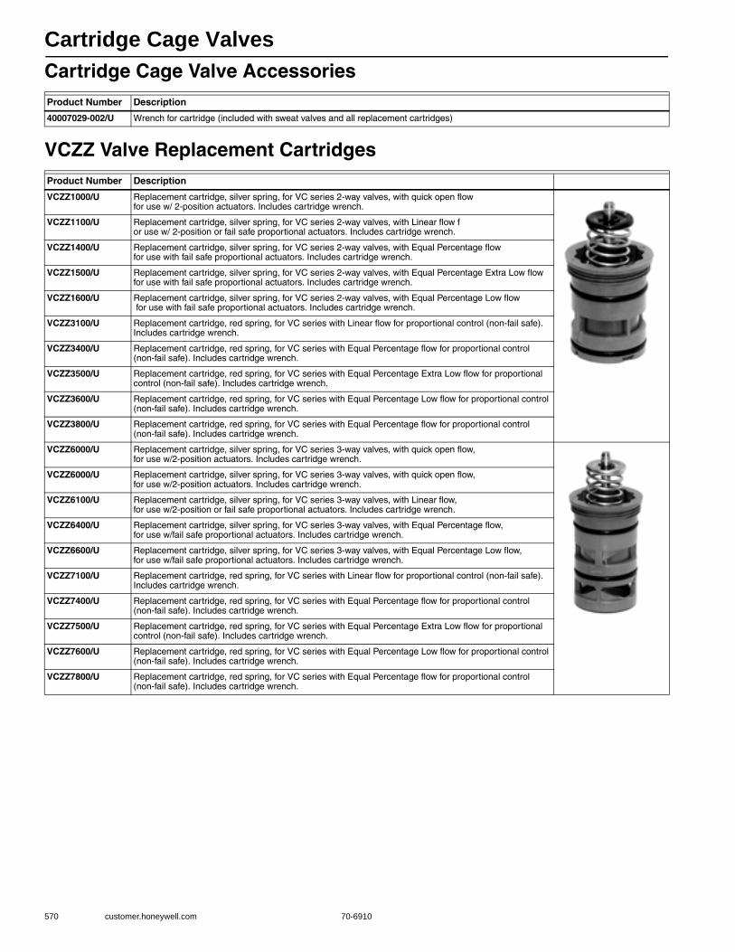
Cartridge Cage Valves
570 customer.honeywell.com 70-6910
Cartridge Cage Valve Accessories
VCZZ Valve Replacement Cartridges
Product Number Description
40007029-002/U Wrench for cartridge (included with sweat valves and all replacement cartridges)
Product Number Description
VCZZ1000/U Replacement cartridge, silver spring, for VC series 2-way valves, with quick open flow for use w/ 2-position actuators. Includes cartridge wrench.
VCZZ1100/U Replacement cartridge, silver spring, for VC series 2-way valves, with Linear flow for use w/ 2-position or fail safe proportional actuators. Includes cartridge wrench.
VCZZ1400/U Replacement cartridge, silver spring, for VC series 2-way valves, with Equal Percentage flow for use with fail safe proportional actuators. Includes cartridge wrench.
VCZZ1500/U Replacement cartridge, silver spring, for VC series 2-way valves, with Equal Percentage Extra Low flow for use with fail safe proportional actuators. Includes cartridge wrench.
VCZZ1600/U Replacement cartridge, silver spring, for VC series 2-way valves, with Equal Percentage Low flow for use with fail safe proportional actuators. Includes cartridge wrench.
VCZZ3100/U Replacement cartridge, red spring, for VC series with Linear flow for proportional control (non-fail safe). Includes cartridge wrench.
VCZZ3400/U Replacement cartridge, red spring, for VC series with Equal Percentage flow for proportional control (non-fail safe). Includes cartridge wrench.
VCZZ3500/U Replacement cartridge, red spring, for VC series with Equal Percentage Extra Low flow for proportional control (non-fail safe). Includes cartridge wrench.
VCZZ3600/U Replacement cartridge, red spring, for VC series with Equal Percentage Low flow for proportional control (non-fail safe). Includes cartridge wrench.
VCZZ3800/U Replacement cartridge, red spring, for VC series with Equal Percentage flow for proportional control (non-fail safe). Includes cartridge wrench.
VCZZ6000/U Replacement cartridge, silver spring, for VC series 3-way valves, with quick open flow, for use w/2-position actuators. Includes cartridge wrench.
VCZZ6000/U Replacement cartridge, silver spring, for VC series 3-way valves, with quick open flow, for use w/2-position actuators. Includes cartridge wrench.
VCZZ6100/U Replacement cartridge, silver spring, for VC series 3-way valves, with Linear flow, for use w/2-position or fail safe proportional actuators. Includes cartridge wrench.
VCZZ6400/U Replacement cartridge, silver spring, for VC series 3-way valves, with Equal Percentage flow, for use w/fail safe proportional actuators. Includes cartridge wrench.
VCZZ6600/U Replacement cartridge, silver spring, for VC series 3-way valves, with Equal Percentage Low flow, for use w/fail safe proportional actuators. Includes cartridge wrench.
VCZZ7100/U Replacement cartridge, red spring, for VC series with Linear flow for proportional control (non-fail safe). Includes cartridge wrench.
VCZZ7400/U Replacement cartridge, red spring, for VC series with Equal Percentage flow for proportional control (non-fail safe). Includes cartridge wrench.
VCZZ7500/U Replacement cartridge, red spring, for VC series with Equal Percentage Extra Low flow for proportional control (non-fail safe). Includes cartridge wrench.
VCZZ7600/U Replacement cartridge, red spring, for VC series with Equal Percentage Low flow for proportional control (non-fail safe). Includes cartridge wrench.
VCZZ7800/U Replacement cartridge, red spring, for VC series with Equal Percentage flow for proportional control (non-fail safe). Includes cartridge wrench.
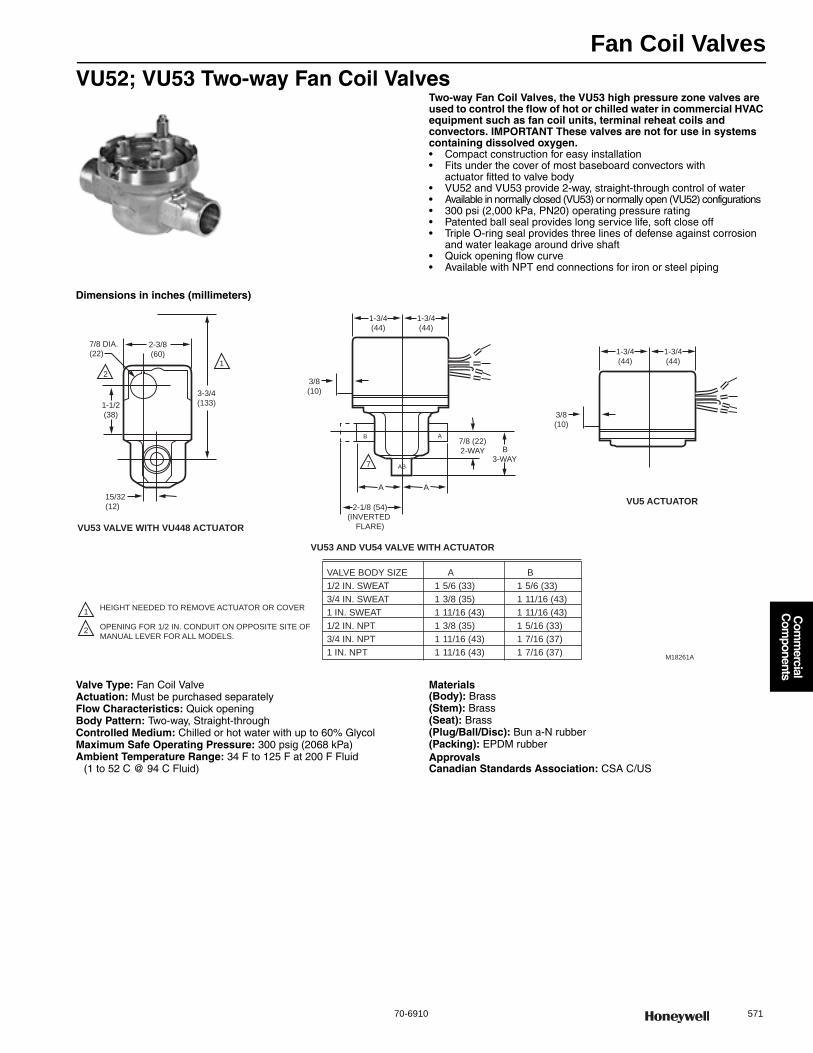
Fan Coil Valves
70-6910 571
Com
mercial
Com
ponents
VU52; VU53 Two-way Fan Coil ValvesTwo-way Fan Coil Valves, the VU53 high pressure zone valves are used to control the flow of hot or chilled water in commercial HVAC equipment such as fan coil units, terminal reheat coils and convectors. IMPORTANT These valves are not for use in systems containing dissolved oxygen.• Compact construction for easy installation • Fits under the cover of most baseboard convectors with
actuator fitted to valve body • VU52 and VU53 provide 2-way, straight-through control of water • Available in normally closed (VU53) or normally open (VU52) configurations • 300 psi (2,000 kPa, PN20) operating pressure rating • Patented ball seal provides long service life, soft close off • Triple O-ring seal provides three lines of defense against corrosion
and water leakage around drive shaft • Quick opening flow curve • Available with NPT end connections for iron or steel piping
Dimensions in inches (millimeters)
Valve Type: Fan Coil ValveActuation: Must be purchased separatelyFlow Characteristics: Quick openingBody Pattern: Two-way, Straight-throughControlled Medium: Chilled or hot water with up to 60% GlycolMaximum Safe Operating Pressure: 300 psig (2068 kPa) Ambient Temperature Range: 34 F to 125 F at 200 F Fluid
(1 to 52 C @ 94 C Fluid)
Materials(Body): Brass(Stem): Brass(Seat): Brass(Plug/Ball/Disc): Bun a-N rubber(Packing): EPDM rubberApprovalsCanadian Standards Association: CSA C/US
2
2
1
1
VU53 VALVE WITH VU448 ACTUATOR
VU53 AND VU54 VALVE WITH ACTUATOR
VU5 ACTUATOR
2-3/8
(60)
7/8 DIA.
(22)
1-1/2
(38)
3-3/4
(133)
15/32
(12)
3/8
(10)
1-3/4
(44)
1-3/4
(44)
A
A
B
AB 7
3/8
(10)
A
2-1/8 (54)
(INVERTED
FLARE)
1-3/4
(44)
1-3/4
(44)
B
3-WAY
7/8 (22)
2-WAY
VALVE BODY SIZE A B
1/2 IN. SWEAT 1 5/6 (33) 1 5/6 (33)
3/4 IN. SWEAT 1 3/8 (35) 1 11/16 (43)
1 IN. SWEAT 1 11/16 (43) 1 11/16 (43)
1/2 IN. NPT 1 3/8 (35) 1 5/16 (33)
3/4 IN. NPT 1 11/16 (43) 1 7/16 (37)
1 IN. NPT 1 11/16 (43) 1 7/16 (37)
HEIGHT NEEDED TO REMOVE ACTUATOR OR COVER
OPENING FOR 1/2 IN. CONDUIT ON OPPOSITE SITE OF
MANUAL LEVER FOR ALL MODELS.
M18261A
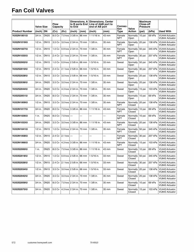
Fan Coil Valves
572 customer.honeywell.com 70-6910
Product Number
Valve SizeFlow Capacity
Dimensions, A to B ports End to End
Dimensions, Center Line of A&B port to end of AB port Connec-
tion Type
Valve Action
Maximum Close-off Pressure
Used With(inch) DN (Cv) (Kv) (inch) (mm) (inch) (mm) (psi) (kPa)
VU52N1001/U 3/4 in. DN20 8.0 Cv 7.0 kvs 3 3/8 in. 86 mm 1 11/16 in. 43 mm Female NPT
Normally Open
10 psi 69 kPa VU444 Actuator, VU844 Actuator
VU52N1019/U 1/2 in. DN15 3.5 Cv 3.0 kvs 2 3/4 in. 70 mm 1 3/8 in. 35 mm Female NPT
Normally Open
20 psi 138 kPa VU444 Actuator, VU844 Actuator
VU52N1027/U 1/2 in. DN15 1.0 Cv 0.9 kvs 2 3/4 in. 70 mm 1 3/8 in. 35 mm Female NPT
Normally Open
50 psi 345 kPa VU444 Actuator, VU844 Actuator
VU52N1035/U 1/2 in. DN15 2.4 Cv 2.1 kvs 2 3/4 in. 70 mm 1 3/8 in. 35 mm Female NPT
Normally Open
30 psi 207 kPa VU444 Actuator, VU844 Actuator
VU52S2002/U 1/2 in. DN15 1.0 Cv 0.9 kvs 2 5/8 in. 66 mm 1 5/16 in. 33 mm Sweat Normally Open
50 psi 345 kPa VU444 Actuator, VU844 Actuator
VU52S2010/U 1/2 in. DN15 2.4 Cv 2.1 kvs 2 5/8 in. 66 mm 1 5/16 in. 33 mm Sweat Normally Open
30 psi 207 kPa VU444 Actuator, VU844 Actuator
VU52S2028/U 1/2 in. DN15 3.5 Cv 3.0 kvs 2 5/8 in. 66 mm 1 5/16 in. 33 mm Sweat Normally Open
20 psi 138 kPa VU444 Actuator, VU844 Actuator
VU52S2036/U 3/4 in. DN20 3.5 Cv 3.0 kvs 2 3/4 in. 70 mm 1 3/8 in. 35 mm Sweat Normally Open
20 psi 138 kPa VU444 Actuator, VU844 Actuator
VU52S2044/U 3/4 in. DN20 5.0 Cv 4.3 kvs 2 3/4 in. 70 mm 1 3/8 in. 35 mm Sweat Normally Open
15 psi 103 kPa VU444 Actuator, VU844 Actuator
VU52S2051/U 3/4 in. DN20 8.0 Cv 7.0 kvs 2 3/4 in. 70 mm 1 3/8 in. 35 mm Sweat Normally Open
10 psi 69 kPa VU444 Actuator, VU844 Actuator
VU53N1009/U 1/2 in. DN15 3.5 Cv 3.0 kvs 2 3/4 in. 70 mm 1 3/8 in. 35 mm Female NPT
Normally Closed
20 psi 138 kPa VU443 Actuator, VU843 Actuator
VU53N1017/U 3/4 in. DN20 8.0 Cv 7.0 kvs 3 3/8 in. 86 mm 1 11/16 in. 43 mm Female NPT
Normally Closed
10 psi 69 kPa VU443 Actuator, VU843 Actuator
VU53N1026/U 1 in. DN25 8.0 Cv 7.0 kvs — — — — Female NPT
Normally Closed
10 psi 69 kPa VU443 Actuator, VU843 Actuator
VU53N1033/U 3/4 in. DN20 3.5 Cv 3.0 kvs 3 3/8 in. 86 mm 1 11/16 in. 43 mm Female NPT
Normally Closed
20 psi 138 kPa VU443 Actuator, VU843 Actuator
VU53N1041/U 1/2 in. DN15 1.0 Cv 0.9 kvs 2 3/4 in. 70 mm 1 3/8 in. 35 mm Female NPT
Normally Closed
50 psi 345 kPa VU443 Actuator, VU843 Actuator
VU53N1058/U 1/2 in. DN15 2.4 Cv 2.1 kvs — — — — Female NPT
Normally Closed
30 psi 207 kPa VU443 Actuator, VU843 Actuator
VU53N1066/U 3/4 in. DN20 5.0 Cv 4.3 kvs 3 3/8 in. 86 mm 1 11/16 in. 43 mm Female NPT
Normally Closed
15 psi 103 kPa VU443 Actuator, VU843 Actuator
VU53S2000/U 1 in. DN25 8.0 Cv 7.0 kvs 3 3/8 in. 86 mm 1 11/16 in. 43 mm Sweat Normally Closed
10 psi 69 kPa VU443 Actuator, VU843 Actuator
VU53S2018/U 1/2 in. DN15 1.0 Cv 0.9 kvs 2 5/8 in. 66 mm 1 5/16 in. 33 mm Sweat Normally Closed
50 psi 345 kPa VU443 Actuator, VU843 Actuator
VU53S2026/U 1/2 in. DN15 2.4 Cv 2.1 kvs 2 5/8 in. 66 mm 1 5/16 in. 33 mm Sweat Normally Closed
30 psi 207 kPa VU443 Actuator, VU843 Actuator
VU53S2034/U 1/2 in. DN15 3.5 Cv 3.0 kvs 2 5/8 in. 66 mm 1 5/16 in. 33 mm Sweat Normally Closed
20 psi 138 kPa VU443 Actuator, VU843 Actuator
VU53S2042/U 3/4 in. DN20 3.5 Cv 3.0 kvs 2 3/4 in. 70 mm 1 3/8 in. 35 mm Sweat Normally Closed
20 psi 138 kPa VU443 Actuator, VU843 Actuator
VU53S2059/U 3/4 in. DN20 8.0 Cv 7.0 kvs 2 3/4 in. 70 mm 1 3/8 in. 35 mm Sweat Normally Closed
10 psi 69 kPa VU443 Actuator, VU843 Actuator
VU53S2075/U 3/4 in. DN20 5.0 Cv 4.3 kvs 2 3/4 in. 70 mm 1 3/8 in. 35 mm Sweat Normally Closed
15 psi 103 kPa VU443 Actuator, VU843 Actuator

Fan Coil Valves
70-6910 573
Com
mercial
Com
ponents
VU54 Three-way Fan Coil ValvesThree-way Fan Coil Valve, the VU54 high pressure zone valves are used to control the flow of hot or chilled water in commercial HVAC equipment such as fan coil units, terminal reheat coils and convectors. IMPORTANT These valves are not for use in systems containing dissolved oxygen.• Compact construction for easy installation • Fits under the cover of most baseboard convectors with
actuator fitted to valve body • VU54 provides three-way diverting control of water • 300 psi (2,000 kPa, PN20) operating pressure rating • Patented ball seal provides long service life, soft close off • Triple O-ring seal provides three lines of defense against corrosion
and water leakage around drive shaft • Quick opening flow curve • Choice of NPT end connections for iron or steel piping
Valve Type: Fan Coil ValveValve Action: MixingBody Pattern: Three-way A-AB-BFlow Characteristic: Quick openingControlled Medium: Chilled or hot water with up to 60% GlycolMaximum Safe Operating Pressure: 300 psig (2068 kPa) Ambient Temperature Range: 34 F to 125 F at 200 F Fluid
(1 to 52 C @ 94 C Fluid) Actuation: Must be purchased separately
Materials(Body): Brass(Stem): Brass(Seat): Brass(Plug/Ball/Disc): Buna-N rubber(Packing): EPDM rubberUsed WIth: VU444 Actuator; VU844 ActuatorApprovalsCanadian Standards Association: CSA C/US
Product Number
Valve Size Flow CapacityDimensions, A to B ports End to End
Dimensions, Center Line of A&B port to end of AB port
Connection Type
Maximum Close-off Pressure
(inch) DN (Cv) (Kv) (inch) (mm) (inch) (mm) (psi) (kPa)
VU54N1007/U 1/2 in. DN15 4.0 Cv 3.4 kvs 2 3/4 in. 70 mm 1 3/8 in. 35 mm Female NPT 20 psi 138 kPa
VU54N1015/U 3/4 in. DN20 7.0 Cv 6.5 kvs 3 3/8 in. 86 mm 1 11/16 in. 43 mm Female NPT 10 psi 69 kPa
VU54N1023/U 1 in. DN25 7.0 Cv 6.5 kvs — — — — Female NPT 10 psi 69 kPa
VU54N1031/U 3/4 in. DN20 4.0 Cv 3.4 kvs 3 3/8 in. 86 mm 1 11/16 in. 43 mm Female NPT 20 psi 138 kPa
VU54N1049/U 3/4 in. DN20 5.0 Cv 4.3 kvs 3 3/8 in. 86 mm 1 11/16 in. 43 mm Female NPT 15 psi 103 kPa
VU54S2008/U 1/2 in. DN15 4.0 Cv 3.4 kvs 2 5/8 in. 66 mm 1 5/16 in. 33 mm Sweat 20 psi 138 kPa
VU54S2016/U 3/4 in. DN20 7.0 Cv 6.5 kvs 2 3/4 in. 70 mm 1 3/8 in. 35 mm Sweat 10 psi 69 kPa
VU54S2024/U 1 in. DN25 7.0 Cv 6.5 kvs 3 3/8 in. 86 mm 1 11/16 in. 43 mm Sweat 10 psi 69 kPa
VU54S2040/U 1/2 in. DN15 3.0 Cv 2.6 kvs 2 5/8 in. 66 mm 1 5/16 in. 33 mm Sweat 25 psi 172 kPa
VU54S2057/U 3/4 in. DN20 5.0 Cv 4.3 kvs 2 3/4 in. 70 mm 1 3/8 in. 35 mm Sweat 15 psi 103 kPa
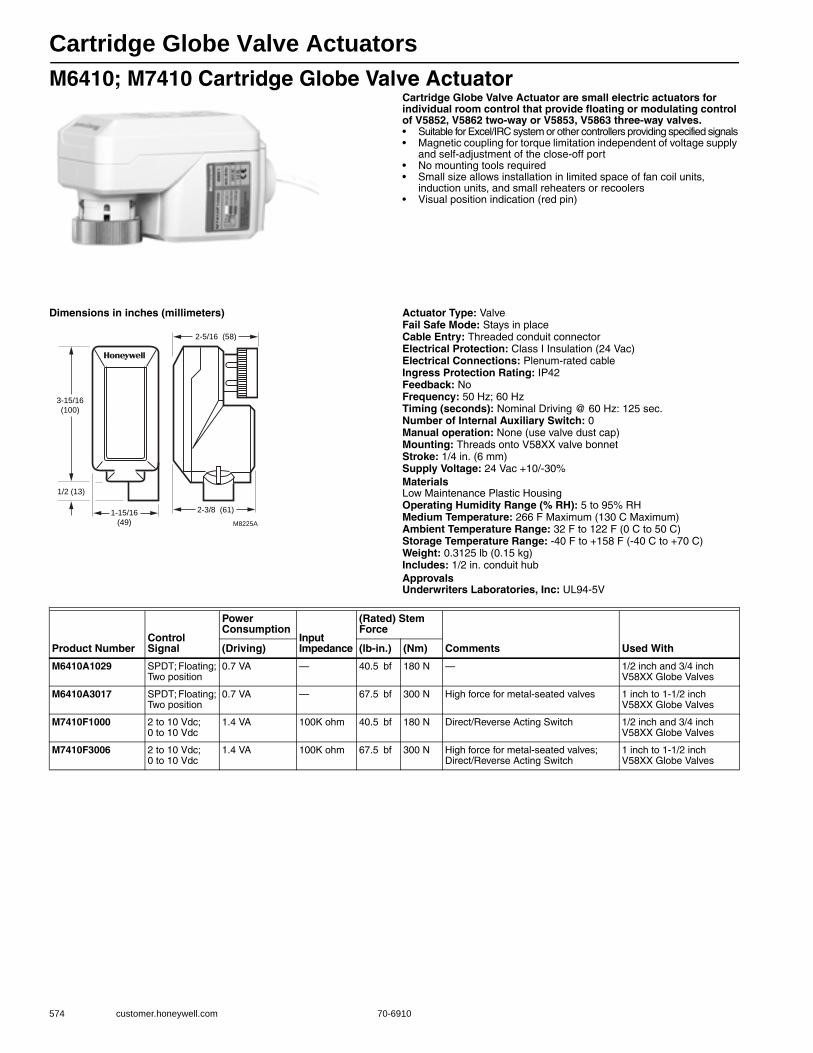
Cartridge Globe Valve Actuators
574 customer.honeywell.com 70-6910
M6410; M7410 Cartridge Globe Valve ActuatorCartridge Globe Valve Actuator are small electric actuators for individual room control that provide floating or modulating control of V5852, V5862 two-way or V5853, V5863 three-way valves.• Suitable for Excel/IRC system or other controllers providing specified signals • Magnetic coupling for torque limitation independent of voltage supply
and self-adjustment of the close-off port • No mounting tools required • Small size allows installation in limited space of fan coil units,
induction units, and small reheaters or recoolers • Visual position indication (red pin)
Dimensions in inches (millimeters) Actuator Type: ValveFail Safe Mode: Stays in placeCable Entry: Threaded conduit connectorElectrical Protection: Class I Insulation (24 Vac)Electrical Connections: Plenum-rated cableIngress Protection Rating: IP42Feedback: NoFrequency: 50 Hz; 60 HzTiming (seconds): Nominal Driving @ 60 Hz: 125 sec.Number of Internal Auxiliary Switch: 0Manual operation: None (use valve dust cap)Mounting: Threads onto V58XX valve bonnetStroke: 1/4 in. (6 mm) Supply Voltage: 24 Vac +10/-30%MaterialsLow Maintenance Plastic HousingOperating Humidity Range (% RH): 5 to 95% RHMedium Temperature: 266 F Maximum (130 C Maximum) Ambient Temperature Range: 32 F to 122 F (0 C to 50 C) Storage Temperature Range: -40 F to +158 F (-40 C to +70 C) Weight: 0.3125 lb (0.15 kg) Includes: 1/2 in. conduit hubApprovalsUnderwriters Laboratories, Inc: UL94-5V
M8225A
3-15/16
(100)
1/2 (13)
1-15/16
(49)
2-3/8 (61)
2-5/16 (58)
Product NumberControl Signal
Power Consumption
Input Impedance
(Rated) Stem Force
Comments Used With(Driving) (lb-in.) (Nm)
M6410A1029 SPDT; Floating; Two position
0.7 VA — 40.5 bf 180 N — 1/2 inch and 3/4 inch V58XX Globe Valves
M6410A3017 SPDT; Floating; Two position
0.7 VA — 67.5 bf 300 N High force for metal-seated valves 1 inch to 1-1/2 inch V58XX Globe Valves
M7410F1000 2 to 10 Vdc; 0 to 10 Vdc
1.4 VA 100K ohm 40.5 bf 180 N Direct/Reverse Acting Switch 1/2 inch and 3/4 inch V58XX Globe Valves
M7410F3006 2 to 10 Vdc; 0 to 10 Vdc
1.4 VA 100K ohm 67.5 bf 300 N High force for metal-seated valves; Direct/Reverse Acting Switch
1 inch to 1-1/2 inch V58XX Globe Valves
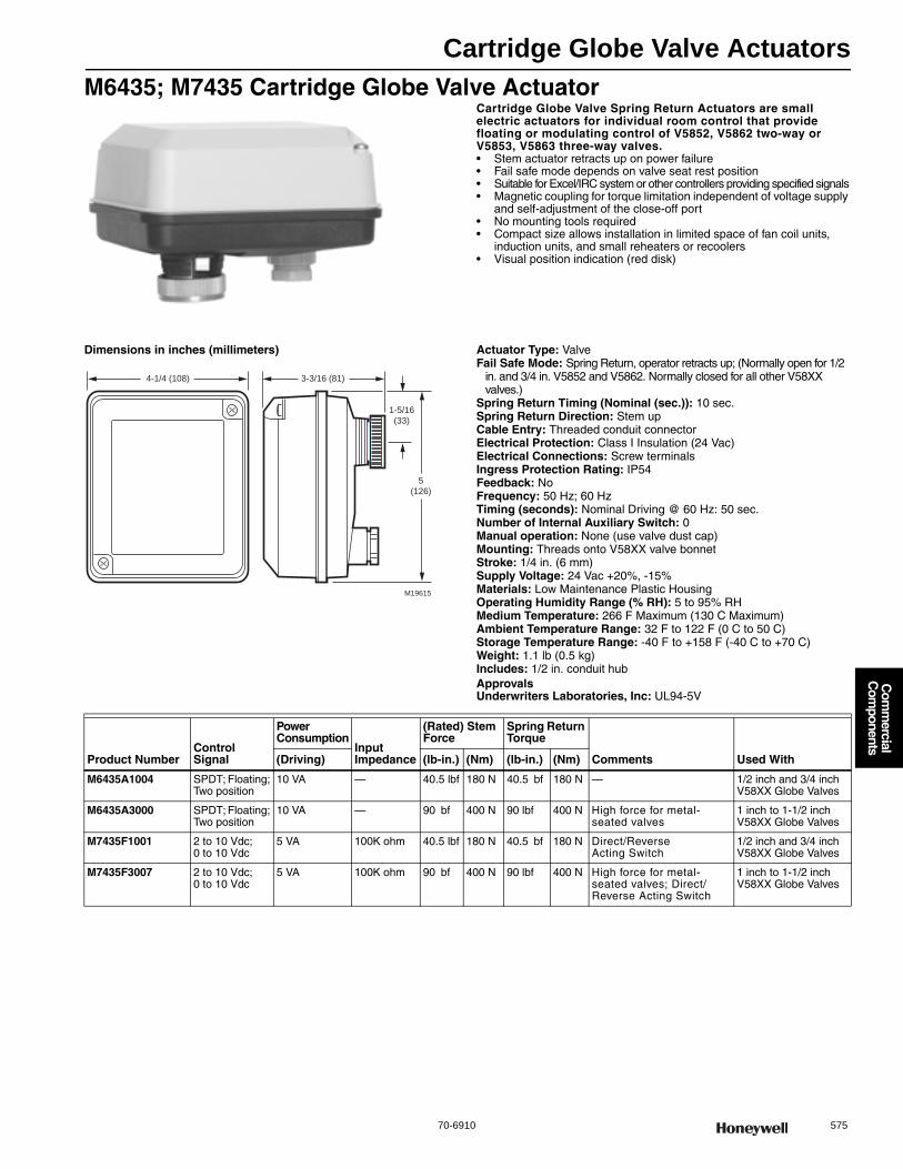
Cartridge Globe Valve Actuators
70-6910 575
Com
mercial
Com
ponents
M6435; M7435 Cartridge Globe Valve ActuatorCartridge Globe Valve Spring Return Actuators are small electric actuators for individual room control that provide floating or modulating control of V5852, V5862 two-way or V5853, V5863 three-way valves.• Stem actuator retracts up on power failure• Fail safe mode depends on valve seat rest position • Suitable for Excel/IRC system or other controllers providing specified signals • Magnetic coupling for torque limitation independent of voltage supply
and self-adjustment of the close-off port • No mounting tools required • Compact size allows installation in limited space of fan coil units,
induction units, and small reheaters or recoolers • Visual position indication (red disk)
Dimensions in inches (millimeters) Actuator Type: ValveFail Safe Mode: Spring Return, operator retracts up; (Normally open for 1/2
in. and 3/4 in. V5852 and V5862. Normally closed for all other V58XX valves.)
Spring Return Timing (Nominal (sec.)): 10 sec. Spring Return Direction: Stem up Cable Entry: Threaded conduit connectorElectrical Protection: Class I Insulation (24 Vac)Electrical Connections: Screw terminalsIngress Protection Rating: IP54Feedback: NoFrequency: 50 Hz; 60 HzTiming (seconds): Nominal Driving @ 60 Hz: 50 sec.Number of Internal Auxiliary Switch: 0Manual operation: None (use valve dust cap)Mounting: Threads onto V58XX valve bonnetStroke: 1/4 in. (6 mm) Supply Voltage: 24 Vac +20%, -15%Materials: Low Maintenance Plastic HousingOperating Humidity Range (% RH): 5 to 95% RHMedium Temperature: 266 F Maximum (130 C Maximum) Ambient Temperature Range: 32 F to 122 F (0 C to 50 C) Storage Temperature Range: -40 F to +158 F (-40 C to +70 C) Weight: 1.1 lb (0.5 kg) Includes: 1/2 in. conduit hubApprovalsUnderwriters Laboratories, Inc: UL94-5V
5
(126)
1-5/16
(33)
3-3/16 (81)
M19615
4-1/4 (108)
Product NumberControl Signal
Power Consumption
Input Impedance
(Rated) Stem Force
Spring Return Torque
Comments Used With(Driving) (lb-in.) (Nm) (lb-in.) (Nm)
M6435A1004 SPDT; Floating; Two position
10 VA — 40.5 lbf 180 N 40.5 bf 180 N — 1/2 inch and 3/4 inch V58XX Globe Valves
M6435A3000 SPDT; Floating; Two position
10 VA — 90 bf 400 N 90 lbf 400 N High force for metal-seated valves
1 inch to 1-1/2 inch V58XX Globe Valves
M7435F1001 2 to 10 Vdc;0 to 10 Vdc
5 VA 100K ohm 40.5 lbf 180 N 40.5 bf 180 N Direct/Reverse Acting Switch
1/2 inch and 3/4 inch V58XX Globe Valves
M7435F3007 2 to 10 Vdc;0 to 10 Vdc
5 VA 100K ohm 90 bf 400 N 90 lbf 400 N High force for metal-seated valves; Direct/Reverse Acting Switch
1 inch to 1-1/2 inch V58XX Globe Valves

VC Valve Actuators
576 customer.honeywell.com 70-6910
VC Series Two-position ActuatorsControl central heating and/or cooling systems, fan coil systems, radiators and convectors. Depending on the model selected, it can be controlled by either a low or line voltage SPST or SPDT controller such as a room thermostat.• Use with two-way or three-way valves • Minimal actuator power consumption • Quick-connect or one meter cable electrical connections available • Quick and easy replacement of moving parts • Actuator head installation does not require draining the system • On/Off models with six second nominal timing • Use two-position actuators with 1000 Series 2 way and
6000 Series 3-way VC valve bodies only • All VC Series actuator-valve combinations provide 60 psi close-off
Actuator Type: ValveFail Safe Mode: Stays in placeCable Entry: Molded strain relief, conduit clampDimensions, Approximate: 2.8 in. high x 3.7 in. wide x 2.7 in. deep
(70 mm high x 94 mm wide x 68 mm deep) External Auxiliary Switches Available: —Electrical Protection: Double InsulatedIngress Protection Rating: IP40Frequency: 60 HzTiming (seconds): Nominal Driving @ 60 Hz: 6 sec.Manual operation: LeverMounting: Direct CoupledShaft Adapter Type: Self-alignment
Stroke: 0.4 in. (10 mm) Maximum Differential Pressure Ratings (Close-off): 60 psidMaterials: Plastic housingOperating Humidity Range (% RH): 5 to 95% RH, non-condensingMedium Temperature: 203 F (95 C) Ambient Temperature Range: 32 F to 150 F (0 C to 65 C) Temperature Ratings (Shipping): -40 F to +150 F (-40 C to +65 C) Storage Temperature Range: -40 F to +150 F (-40 C to +65 C) Weight: 0.75 b (0.34 kg) ApprovalsCanadian Standards Association: CSA Certified: LR1322-367CE: 89/336/ECC, 73/23/EECUnderwriters Laboratories, Inc: UL Recognized, File# MH11826
Product Number
Control Signal
Type of Internal Auxiliary Switch
Switch Ratings
Power Con-sump-tion(Driving)
Supply Voltage
Cable Entry
Electrical ConnectionsType of Internal Auxiliary Switch
Number of Internal Auxiliary Switch Comments
Used With IncludesType
Length
(inch) (m)
VC2114ZZ11/U SPDT; Two position
— — 6 VA 24 Vac Molded strain relief, conduit clamp
Plenum-rated cable
5 ft. 1 5 m — 0 — VC Series Valves, 1000 Series 2-way and 6000 Series 3-way
Flexible conduit adapter
VC2714ZZ11/U On/Off switch; SPDT
SPDT 2.2A (5 to 110 Vac)/1.0A (110 to 277Vac) Inductive; Min. DC switching capability: 5 mA @ 24 Vac.
6 VA 24 Vac Plenum-rated cable
5 ft. 1 5 m SPDT 1 — 3/8 in. flex conduit adapter
VC4011ZZ11/U Two position; SPST
— — 6 VA 100 to 130V
Molded strain relief
Cable 39 in. 1 m — 0 — VC Series Valve
—
VC4013ZZ11/U Two position; SPST
— — 6 VA 200 to 240V
Cable 39 in. 1 m — 0 — VC Series Valves, 1000 Series 2-way and 6000 Series 3-way
—
VC8111ZZ11/U Two position; SPST
— — 6 VA 24 Vac Cable 39 in. 1 m — 0 — —
VC8114ZZ11/U Two position; SPST
— — 6 VA 24 Vac Molded strain relief, conduit clamp
Plenum-rated cable
5 ft. 1.5 m — 0 — Flexible conduit adapter

VC Valve Actuators
70-6910 577
Com
mercial
Com
ponents
VC8711ZZ11/U Two position; SPST
SPDT 2.2A (5 to 110 Vac)/1.0A (110 to 277Vac) Inductive; Min. DC switching capability: 5 mA @ 24 Vac.
6 VA 24 Vac Molded strain relief
Cable 39 in. 1 m SPDT 1 — VC Series Valves, 1000 Series 2-way and 6000 Series 3-way
—
VC8714ZZ11/U Two position; SPST
SPDT 6 VA 24 Vac Molded strain relief, conduit clamp
Plenum-rated cable
5 ft. 1 5 m SPDT 1 — Flexible conduit adapter
VC8715ZZ11/U Two position; SPST
SPST 6 VA, 3W standby for thermostat anticipator
24 Vac Molded strain relief
Cable 39 in. 1 m SPST 1 With additional current draw for compatibility with Honeywell power stealing thermostats
—
Product Number
Control Signal
Type of Internal Auxiliary Switch
Switch Ratings
Power Con-sump-tion(Driving)
Supply Voltage
Cable Entry
Electrical ConnectionsType of Internal Auxiliary Switch
Number of Internal Auxiliary Switch Comments
Used With IncludesType
Length
(inch) (m)

VC Valve Actuators
578 customer.honeywell.com 70-6910
VC Series Proportional ActuatorsControl central heating and/or cooling systems, fan coil systems, radiators and convectors. Depending on the model selected, it can be controlled by a low voltage SPST or SPDT switch, pulse-width modulated 24 Vac signal, or floating input, modulating controller such as a room thermostat, Aquastat control, flow switch or a 0/2 to 10 Vdc controller.• Use with two-way or three-way valves • Double insulated actuator • Five foot plenum-rated cable • Quick and easy replacement of moving parts • Actuator head installation does not require draining the system • Selectable/switchable electronic fail safe normally open or normally closed • Available with valve bodies with 1000-series 2-way and
6000-series 3-way cartridges for new construction • All VC Series actuator-valve combinations provide 60 psi close-off
Actuator Type: ValveFail Safe Mode: Stays in placeCable Entry: Molded strain relief, conduit clampDimensions, Approximate: 2.8 in. high x 3.7 in. wide x 2.7 in. deep
(70 mm high x 94 mm wide x 68 mm deep) Electrical Protection: Double InsulatedIngress Protection Rating: IP40Frequency: 50 Hz; 60 HzTiming (seconds): Nominal Driving @ 60 Hz: 120 sec.Manual operation: LeverMounting: Direct CoupledShaft Adapter Type: Self-alignmentStroke: 0.4 in. (10 mm) Close-off: 60 psid
Power Consumption (driving): 6 VASupply Voltage: 24 VacMaterials: Plastic housingOperating Humidity Range (% RH): 5 to 95% RH, non-condensingMedium Temperature: 203 F (95 C) Ambient Temperature Range: 32 F to 150 F (0 C to 65 C) Temperature Ratings (Shipping): -40 F to +150 F (-40 C to +65 C) Storage Temperature Range: -40 F to +150 F (-40 C to +65 C) Weight: 0.84 b (0.38 kg) Used With: 3000 Series 2-way and 7000 Series VC valve bodies onlyApprovalsCanadian Standards Association: CSA Certified: LR1322-367Underwriters Laboratories, Inc: Listed 94-5V
Product NumberControl Signal
Type of Internal Auxiliary Switch Switch Ratings Cable Entry
Electrical Connections Number of Internal Auxiliary Switch IncludesType
Length
(inch) (m)
VC6834ZZ11/U 24 Vac; SP3T (tri-state) Floating
SPDT 2.2A (5 to 110 Vac)/1.0A (110 to 277 Vac) Inductive; Min. DC switching capability: 5 mA @ 24 Vac
Molded strain relief, conduit clamp
Plenum-rated cable
1.5 m 5 ft. 1 Flexible conduit adapter
VC6931ZZ11/U 24 Vac; SP3T (tri-state) Floating
— — Molded strain relief
Cable 1 m 39 in. 0 Flexible conduit adapter
VC6934ZZ11/U 24 Vac; SP3T (tri-state) Floating
— — Molded strain relief, conduit clamp
Plenum-rated cable
1.5 m 5 ft. 0 Flexible conduit adapter
VC7931ZZ11/U 2 to 10 Vdc — — Molded strain relief
Cable 1 m 39 in. 0 —
VC7934ZZ11/U 2 to 10 Vdc — — Molded strain relief, conduit clamp
Plenum-rated cable
1.5 m 5 ft. 0 Flexible conduit adapter
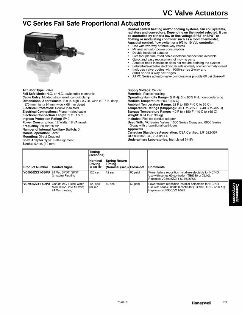
VC Valve Actuators
70-6910 579
Com
mercial
Com
ponents
VC Series Fail Safe Proportional ActuatorsControl central heating and/or cooling systems, fan coil systems, radiators and convectors. Depending on the model selected, it can be controlled by either a low or line voltage SPST or SPDT or floating or modulating controller such as a room thermostat, Aquastat control, flow switch or a 0/2 to 10 Vdc controller.• Use with two-way or three-way valves • Minimal actuator power consumption • Double insulated actuator • Five foot plenum-rated cable electrical connections available • Quick and easy replacement of moving parts • Actuator head installation does not require draining the system • Selectable/switchable electronic fail safe normally open or normally closed• Includes valve bodies with 1000-series 2-way and
3000-series 3-way cartridges • All VC Series actuator-valve combinations provide 60 psi close-off
Actuator Type: ValveFail Safe Mode: N.O. or N.C., switchable electronicCable Entry: Molded strain relief, conduit clampDimensions, Approximate: 2.8 in. high x 3.7 in. wide x 2.7 in. deep
(70 mm high x 94 mm wide x 68 mm deep) Electrical Protection: Double InsulatedElectrical Connections: Plenum-rated cableElectrical Connection Length: 5 ft. (1.5 m) Ingress Protection Rating: IP40Power Consumption: 12 Watts, 18 VA inrushFrequency: 50 Hz; 60 HzNumber of Internal Auxiliary Switch: 0Manual operation: LeverMounting: Direct CoupledShaft Adapter Type: Self-alignmentStroke: 0.4 in. (10 mm)
Supply Voltage: 24 VacMaterials: Plastic housingOperating Humidity Range (% RH): 5 to 95% RH, non-condensingMedium Temperature: 203 F (95 C) Ambient Temperature Range: 32 F to 150 F (0 C to 65 C) Temperature Ratings (Shipping): -40 F to +150 F (-40 C to +65 C) Storage Temperature Range: -40 F to +150 F (-40 C to +65 C) Weight: 0.84 lb (0.38 kg) Includes: Flex ble conduit adapterUsed With: VC Series Valves, 1000 Series 2-way and 6000 Series
3-way with proportional cartridgesApprovalsCanadian Standards Association: CSA Certified: LR1322-367CE: 89/336/ECC, 73/23/EECUnderwriters Laboratories, Inc: Listed 94-5V
Product Number Control Signal
Timing (seconds)
Spring Return Timing (Nominal (sec)) Close-off Comments
Nominal Driving @ 60 Hz
VC6936ZZ11-530/U 24 Vac SPDT; SP3T (tri-state) Floating
120 sec 12 sec. 60 psid Power failure reposition installer-selectable for NC/NO. Use with series 60 controller (TB6980 or XL10). Replaces VC6936ZZ11-524/526/527
VC7936ZZ11-529/U On/Off; 24V Pulse Width Modulation; 2 to 10 Vdc; 24 Vac Floating
120 sec; 60 sec
12 sec. 60 psid Power failure reposition installer-selectable for NC/NO. Use with series 60/70/80 controller (TB6980, XL15, or XL10). Replaces VC7936ZZ11-523
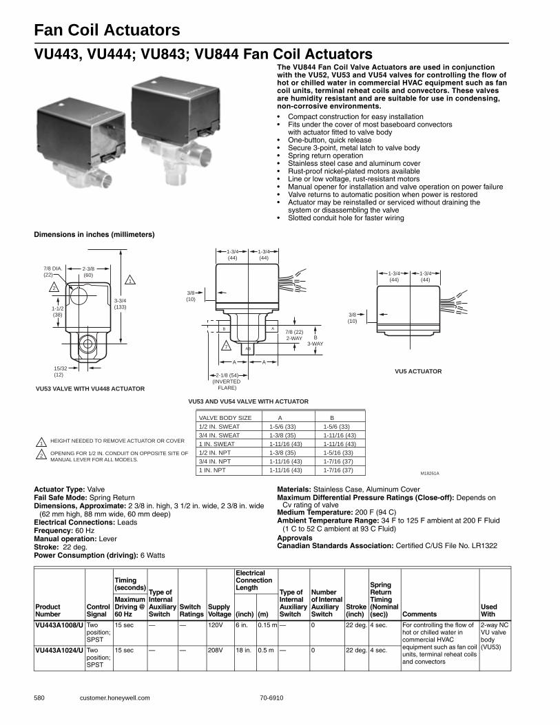
Fan Coil Actuators
580 customer.honeywell.com 70-6910
VU443, VU444; VU843; VU844 Fan Coil ActuatorsThe VU844 Fan Coil Valve Actuators are used in conjunction with the VU52, VU53 and VU54 valves for controlling the flow of hot or chilled water in commercial HVAC equipment such as fan coil units, terminal reheat coils and convectors. These valves are humidity resistant and are suitable for use in condensing, non-corrosive environments.• Compact construction for easy installation • Fits under the cover of most baseboard convectors
with actuator fitted to valve body • One-button, quick release• Secure 3-point, metal latch to valve body • Spring return operation • Stainless steel case and aluminum cover• Rust-proof nickel-plated motors available • Line or low voltage, rust-resistant motors • Manual opener for installation and valve operation on power failure • Valve returns to automatic position when power is restored • Actuator may be reinstalled or serviced without draining the
system or disassembling the valve • Slotted conduit hole for faster wiring
Dimensions in inches (millimeters)
Actuator Type: ValveFail Safe Mode: Spring ReturnDimensions, Approximate: 2 3/8 in. high, 3 1/2 in. wide, 2 3/8 in. wide
(62 mm high, 88 mm wide, 60 mm deep) Electrical Connections: LeadsFrequency: 60 HzManual operation: LeverStroke: 22 deg.Power Consumption (driving): 6 Watts
Materials: Stainless Case, Aluminum CoverMaximum Differential Pressure Ratings (Close-off): Depends on
Cv rating of valveMedium Temperature: 200 F (94 C) Ambient Temperature Range: 34 F to 125 F ambient at 200 F Fluid
(1 C to 52 C ambient at 93 C Fluid) ApprovalsCanadian Standards Association: Certified C/US File No. LR1322
2
2
1
1
VU53 VALVE WITH VU448 ACTUATOR
VU53 AND VU54 VALVE WITH ACTUATOR
VU5 ACTUATOR
2-3/8
(60)
7/8 DIA.
(22)
1-1/2
(38)
3-3/4
(133)
15/32
(12)
3/8
(10)
1-3/4
(44)
1-3/4
(44)
A
A
B
AB 7
3/8
(10)
A
2-1/8 (54)
(INVERTED
FLARE)
1-3/4
(44)
1-3/4
(44)
B
3-WAY
7/8 (22)
2-WAY
VALVE BODY SIZE A B
1/2 IN. SWEAT 1-5/6 (33) 1-5/6 (33)
3/4 IN. SWEAT 1-3/8 (35) 1-11/16 (43)
1 IN. SWEAT 1-11/16 (43) 1-11/16 (43)
1/2 IN. NPT 1-3/8 (35) 1-5/16 (33)
3/4 IN. NPT 1-11/16 (43) 1-7/16 (37)
1 IN. NPT 1-11/16 (43) 1-7/16 (37)
HEIGHT NEEDED TO REMOVE ACTUATOR OR COVER
OPENING FOR 1/2 IN. CONDUIT ON OPPOSITE SITE OF
MANUAL LEVER FOR ALL MODELS.
M18261A
Product Number
Control Signal
Timing (seconds)
Type of Internal Auxiliary Switch
Switch Ratings
Supply Voltage
Electrical Connection Length
Type of Internal Auxiliary Switch
Number of Internal Auxiliary Switch
Stroke(inch)
Spring Return Timing (Nominal (sec)) Comments
Used With
Maximum Driving @ 60 Hz (inch) (m)
VU443A1008/U Two position; SPST
15 sec — — 120V 6 in. 0.15 m — 0 22 deg. 4 sec. For controlling the flow of hot or chilled water in commercial HVAC equipment such as fan coil units, terminal reheat coils and convectors
2-way NC VU valve body (VU53)VU443A1024/U Two
position; SPST
15 sec — — 208V 18 in. 0.5 m — 0 22 deg. 4 sec.

Fan Coil Actuators
70-6910 581
Com
mercial
Com
ponents
VU443A1057/U Two position; SPST
15 sec — — 277V 18 in. 0.5 m — 0 22 deg. 4 sec. For controlling the flow of hot or chilled water in commercial HVAC equipment such as fan coil units, terminal reheat coils andconvectors
2-way NC VU valve body (VU53)VU443A1115/U Two
position; SPST
15 sec — — 230V 6 in. 0.15 m — 0 22 deg. 4 sec.
VU443A1180/U Two position; SPST
15 sec — — 120V 6 in. 0.15 m — 0 22 deg. 4 sec. Nickel plated motor for added humidity resistance; For controlling the flow of hot or chilled water in commercial HVAC equipment such as fan coil units, terminal reheat coils and convectors
VU443E1009/U Two position; SPST
15 sec SPST, N.O.
1 A Pilot Duty
120V 18 in. 0.5 m SPST, N.O.
1 22 deg. 4 sec. For controlling the flow of hot or chilled water in commercial HVAC equipment such as fan coil units, terminal reheat coils and convectors; Aux Switch Rating - Inductive: 2.2 A from 5 to 110 Vac, 1.0 A from 110 to 277 Vac
VU444A1007/U Two position; SPST
15 sec — — 120V 6 in. 0.15 m — 0 45 deg. 6 sec. For controlling the flow of hot or chilled water in commercial HVAC equipment such as fan coil units, terminal reheat coils and convectors
2-way NO (VU52) or 3-way VU valve body (VU54)
VU444A1098/U Two position; SPST
15 sec — — 227V 18 in. 0.5 m — 0 45 deg. 6 sec.
VU444A1106/U Two position; SPST
15 sec — — 230V 6 in. 0.15 m — 0 45 deg. 6 sec.
VU444A1155/U Two position; SPST
15 sec — — 120V 6 in. 0.15 m — 0 45 deg. 6 sec. Nickel plated motor for added humidity resistance; For controlling the flow of hot or chilled water in commercial HVAC equipment such as fan coil units, terminal reheat coils and convectors
VU843A1004/U Two position; SPST
15 sec — — 24V 6 in. 0.15 m — 0 22 deg. 4 sec. For controlling the flow of hot or chilled water in commercial HVAC equipment such as fan coil units, terminal reheat coils and convectors
2-way NC VU valve body (VU53)
VU843A1087/U Two position; SPST
15 sec — — 24V 6 in. 0.15 m — 0 22 deg. 4 sec. Nickel plated motor for added humidity resistance; For controlling the flow of hot or chilled water in commercial HVAC equipment such as fan coil units, terminal reheat coils and convectors
VU844A1003/U Two position; SPST
15 sec — — 24V 6 in. 0.15 m — 0 45 deg. 6 sec. For controlling the flow of hot or chilled water in commercial HVAC equipment such as fan coil units, terminal reheat coils and convectors
2-way NO (VU52) or 3-way VU valve body (VU54)
VU844A1060/U Two position; SPST
15 sec — — 24V 6 in. 0.15 m — 0 45 deg. 6 sec. Nickel plated motor for added humidity resistance; For controlling the flow of hot or chilled water in commercial HVAC equipment such as fan coil units, terminal reheat coils and convectors
Product Number
Control Signal
Timing (seconds)
Type of Internal Auxiliary Switch
Switch Ratings
Supply Voltage
Electrical Connection Length
Type of Internal Auxiliary Switch
Number of Internal Auxiliary Switch
Stroke(inch)
Spring Return Timing (Nominal (sec)) Comments
Used With
Maximum Driving @ 60 Hz (inch) (m)
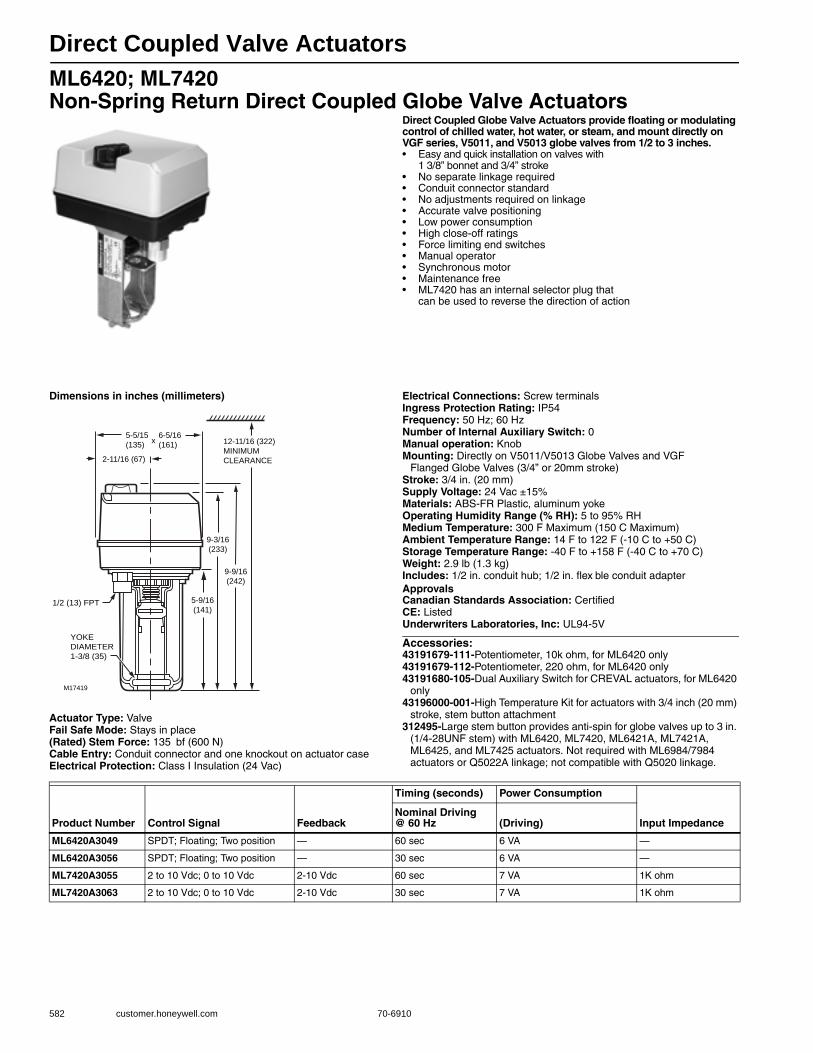
Direct Coupled Valve Actuators
582 customer.honeywell.com 70-6910
ML6420; ML7420 Non-Spring Return Direct Coupled Globe Valve Actuators
Direct Coupled Globe Valve Actuators provide floating or modulating control of chilled water, hot water, or steam, and mount directly on VGF series, V5011, and V5013 globe valves from 1/2 to 3 inches.• Easy and quick installation on valves with
1 3/8” bonnet and 3/4” stroke • No separate linkage required • Conduit connector standard • No adjustments required on linkage • Accurate valve positioning • Low power consumption • High close-off ratings • Force limiting end switches • Manual operator • Synchronous motor• Maintenance free • ML7420 has an internal selector plug that
can be used to reverse the direction of action
Dimensions in inches (millimeters)
Actuator Type: ValveFail Safe Mode: Stays in place(Rated) Stem Force: 135 bf (600 N) Cable Entry: Conduit connector and one knockout on actuator caseElectrical Protection: Class I Insulation (24 Vac)
Electrical Connections: Screw terminalsIngress Protection Rating: IP54Frequency: 50 Hz; 60 HzNumber of Internal Auxiliary Switch: 0Manual operation: KnobMounting: Directly on V5011/V5013 Globe Valves and VGF
Flanged Globe Valves (3/4” or 20mm stroke)Stroke: 3/4 in. (20 mm) Supply Voltage: 24 Vac ±15%Materials: ABS-FR Plastic, aluminum yokeOperating Humidity Range (% RH): 5 to 95% RHMedium Temperature: 300 F Maximum (150 C Maximum) Ambient Temperature Range: 14 F to 122 F (-10 C to +50 C) Storage Temperature Range: -40 F to +158 F (-40 C to +70 C) Weight: 2.9 lb (1.3 kg) Includes: 1/2 in. conduit hub; 1/2 in. flex ble conduit adapterApprovalsCanadian Standards Association: CertifiedCE: ListedUnderwriters Laboratories, Inc: UL94-5V
Accessories:43191679-111-Potentiometer, 10k ohm, for ML6420 only43191679-112-Potentiometer, 220 ohm, for ML6420 only43191680-105-Dual Auxiliary Switch for CREVAL actuators, for ML6420
only43196000-001-High Temperature Kit for actuators with 3/4 inch (20 mm)
stroke, stem button attachment312495-Large stem button provides anti-spin for globe valves up to 3 in.
(1/4-28UNF stem) with ML6420, ML7420, ML6421A, ML7421A, ML6425, and ML7425 actuators. Not required with ML6984/7984 actuators or Q5022A linkage; not compatible with Q5020 linkage.
5-5/15
(135)
6-5/16
(161)x
2-11/16 (67)
12-11/16 (322)
MINIMUM
CLEARANCE
9-3/16
(233)
9-9/16
(242)
5-9/16
(141)
M17419
1/2 (13) FPT
YOKE
DIAMETER
1-3/8 (35)
Product Number Control Signal Feedback
Timing (seconds) Power Consumption
Input ImpedanceNominal Driving @ 60 Hz (Driving)
ML6420A3049 SPDT; Floating; Two position — 60 sec 6 VA —
ML6420A3056 SPDT; Floating; Two position — 30 sec 6 VA —
ML7420A3055 2 to 10 Vdc; 0 to 10 Vdc 2-10 Vdc 60 sec 7 VA 1K ohm
ML7420A3063 2 to 10 Vdc; 0 to 10 Vdc 2-10 Vdc 30 sec 7 VA 1K ohm

Direct Coupled Valve Actuators
70-6910 583
Com
mercial
Com
ponents
ML6421; ML7421 Non-Spring Return Direct Coupled Globe Valve Actuators
Direct Coupled Globe Valve Actuators provide floating or modulating control of chilled water, hot water, or steam, and mount directly on VGF series, V5011, and V5013 valves. These Non-Spring Return High Force Actuators will operate 1-1/2 to 6 inch valves.• Easy and quick installation on valves with 1 3/8” bonnet and 3/4” stroke,
or with 1 7/8” bonnet and 1 1/2” stroke • High force for VGF Pressure-balanced valves • No separate linkage required • Conduit connector standard • No adjustments required on linkage • Accurate valve positioning • Low power consumption • High close-off ratings • Force limiting end switches • Manual operator • Synchronous motor • Maintenance free
Dimensions in inches (millimeters)
Actuator Type: ValveFail Safe Mode: Stays in place(Rated) Stem Force: 405 bf (1800 N)
Cable Entry: Two knockout holes for 1/2 in. conduit standard on actuator case
Electrical Protection: Class I Insulation (24 Vac)Electrical Connections: Screw terminalsIngress Protection Rating: IP54Frequency: 50 Hz; 60 HzNumber of Internal Auxiliary Switch: 0Manual operation: KnobMounting: Directly on V5011/V5013 Globe Valves and
VGF Flanged Globe ValvesSupply Voltage: 24 Vac +10%,-15%Materials: ABS PlasticOperating Humidity Range (% RH): 5 to 95% RHMedium Temperature: 300 F Maximum (150 C Maximum) Ambient Temperature Range: 14 F to 122 F (-10 C to +50 C) Storage Temperature Range: -40 F to +158 F (-40 C to +70 C) Weight: 5.1 lb (2.3 kg) Includes: 1/2 in. conduit hub; 1/2 in. flex ble conduit adapterApprovalsCanadian Standards Association: CertifiedCE: RecognizedUnderwriters Laboratories, Inc: UL94-5V
Accessories:43191679-101-Auxiliary Potentiometer for ML6421A43191679-102-220 ohm Auxiliary Potentiometer for ML6421B43191680-102-Dual Auxiliary Switch for CREVAL actuators43196000-001-High Temperature Kit for actuators with 3/4 inch (20 mm)
stroke, stem button attachment43196000-038-High Temperature Kit for actuators with 1-1/2 inch (38
mm) stroke, stem button attachment312495-Large stem button provides anti-spin for globe valves up to 3 in.
(1/4-28UNF stem) with ML6420, ML7420, ML6421A, ML7421A, ML6425, and ML7425 actuators. Not required with ML6984/7984 actuators or Q5022A linkage; not compatible with Q5020 linkage.
2-1/2(64)
7 (178 ) X 7 (178)
A
A
B
C
D
E
5-5/8 (142)
9-3/8 (239)
10-3/8 (264)
14-1/4 (360)
1-3/8 (35)
8 (204)
11-7/8 (301)
12-3/4 (326)
16-7/8 (430)
1-7/8 (48)
KNOCKOUTS (2) 7/8 (22)
B
C
D
MINIMUM
CLEARANCE
ML6421A, ML7421A ML6421B, ML7421B
E (YOKE DIAMETER)
M16827
Product Number Control Signal Feedback
StrokeTiming (seconds)
Power Consumption
(inch) (mm)Nominal Driving @ 60 Hz (Driving)
ML6421A1017 SPDT; Floating; Two position — 3/4 in. 20 mm 95 sec 11 VA
ML6421B1040 SPDT; Floating; Two position — 1 1/2 in. 38 mm 175 sec 11 VA
ML7421A1032 2 to 10 Vdc; 0 to 10 Vdc 2-10 Vdc 3/4 in. 20 mm 95 sec 12 VA
ML7421B1023 2 to 10 Vdc; 0 to 10 Vdc 2-10 Vdc 1 1/2 in. 38 mm 175 sec 12 VA
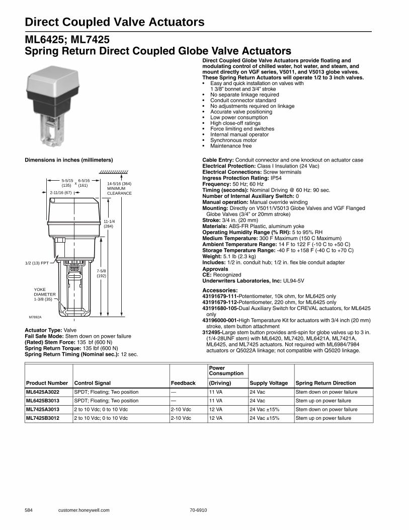
Direct Coupled Valve Actuators
584 customer.honeywell.com 70-6910
ML6425; ML7425 Spring Return Direct Coupled Globe Valve Actuators
Direct Coupled Globe Valve Actuators provide floating and modulating control of chilled water, hot water, and steam, and mount directly on VGF series, V5011, and V5013 globe valves. These Spring Return Actuators will operate 1/2 to 3 inch valves.• Easy and quick installation on valves with
1 3/8” bonnet and 3/4” stroke • No separate linkage required • Conduit connector standard • No adjustments required on linkage • Accurate valve positioning • Low power consumption • High close-off ratings • Force limiting end switches • Internal manual operator • Synchronous motor • Maintenance free
Dimensions in inches (millimeters)
Actuator Type: ValveFail Safe Mode: Stem down on power failure(Rated) Stem Force: 135 bf (600 N) Spring Return Torque: 135 lbf (600 N) Spring Return Timing (Nominal sec.): 12 sec.
Cable Entry: Conduit connector and one knockout on actuator caseElectrical Protection: Class I Insulation (24 Vac)Electrical Connections: Screw terminalsIngress Protection Rating: IP54Frequency: 50 Hz; 60 HzTiming (seconds): Nominal Driving @ 60 Hz: 90 sec.Number of Internal Auxiliary Switch: 0Manual operation: Manual override windingMounting: Directly on V5011/V5013 Globe Valves and VGF Flanged
Globe Valves (3/4” or 20mm stroke)Stroke: 3/4 in. (20 mm) Materials: ABS-FR Plastic, aluminum yokeOperating Humidity Range (% RH): 5 to 95% RHMedium Temperature: 300 F Maximum (150 C Maximum) Ambient Temperature Range: 14 F to 122 F (-10 C to +50 C) Storage Temperature Range: -40 F to +158 F (-40 C to +70 C) Weight: 5.1 lb (2.3 kg) Includes: 1/2 in. conduit hub; 1/2 in. flex ble conduit adapterApprovalsCE: RecognizedUnderwriters Laboratories, Inc: UL94-5V
Accessories:43191679-111-Potentiometer, 10k ohm, for ML6425 only43191679-112-Potentiometer, 220 ohm, for ML6425 only43191680-105-Dual Auxiliary Switch for CREVAL actuators, for ML6425
only43196000-001-High Temperature Kit for actuators with 3/4 inch (20 mm)
stroke, stem button attachment312495-Large stem button provides anti-spin for globe valves up to 3 in.
(1/4-28UNF stem) with ML6420, ML7420, ML6421A, ML7421A, ML6425, and ML7425 actuators. Not required with ML6984/7984 actuators or Q5022A linkage; not compatible with Q5020 linkage.
5-5/15
(135)
6-5/16
(161)x
2-11/16 (67)
14-5/16 (364)
MINIMUM
CLEARANCE
11-1/4
(284)
7-5/8
(192)
M7892A
1/2 (13) FPT
YOKE
DIAMETER
1-3/8 (35)
Product Number Control Signal Feedback
Power Consumption
Supply Voltage Spring Return Direction(Driving)
ML6425A3022 SPDT; Floating; Two position — 11 VA 24 Vac Stem down on power failure
ML6425B3013 SPDT; Floating; Two position — 11 VA 24 Vac Stem up on power failure
ML7425A3013 2 to 10 Vdc; 0 to 10 Vdc 2-10 Vdc 12 VA 24 Vac ±15% Stem down on power failure
ML7425B3012 2 to 10 Vdc; 0 to 10 Vdc 2-10 Vdc 12 VA 24 Vac ±15% Stem up on power failure

Direct Coupled Valve Actuators
70-6910 585
Com
mercial
Com
ponents
ML6984 Direct Coupled Linear Valve ActuatorsThe ML6984 is a self-contained, self-adjusting, motorized linkage that mounts directly onto V5011 two-way or V5013 three-way valves and provides up to 25 mm (1") of linear travel (stem lift). For use with low voltage 3-wire SPDT Series 20 (on-off); Series 60 (floating) electromechanical (dry) contacts; or electronic (triac output) controllers (3-wire installation).• Allows the use of one common transformer power supply for
multiple actuators and controllers • Self-contained, motorized valve linkage • Linkage self-adjusts to valve stroke of 12 to 25 mm (1/2 to 1") • Multi-pose mounting • Strong valve seat closing force 160 lbf (710 N) • Compact size for easy installation in confined area • One device for either 24 Vac or 28 Vdc power supply application • Electronic current sensing provides internal protection and
positive full closing force • Field-addable position feedback/auxiliary switch module available
(5-wire control wiring only) • Compat ble with 3-wire control systems
Dimensions in inches (millimeters)
Actuator Type: ValveFail Safe Mode: Stays in place(Rated) Stem Force: 160 bf (710 N) Cable Entry: 7/8 in. hole for 1/2 in. conduitExternal Auxiliary Switches Available: 272630DElectrical Protection: NEMA 3RElectrical Connections: Screw terminalsIngress Protection Rating: NEMA 3R, IP54 (mounted in vertical
position)Feedback: Position feedback available w/ 272630D; 2-10 VdcFrequency: 50 Hz; 60 HzNumber of Internal Auxiliary Switch: 0Manual operation: NoneMounting: Screws onto 1/4-28 UNF threaded valve stemStroke: 1/2 to 1 in. (13 to 25 mm)
Supply Voltage: 24 Vac; 28 VdcMaterials: UV-stabilized plastic cover, aluminum base & yokeOperating Humidity Range (% RH): 15 to 95% RH at 104 F (40 C)Medium Temperature: 300 F Maximum (150 C Maximum) Ambient Temperature Range: 32 F to 130 F (0 C to 50 C) Temperature Ratings (Shipping): -40 F to +150 F (-40 C to + 65 C) Storage Temperature Range: -40 F to +150 F (-40 C to +65 C) Weight: 2.2 lb (1 kg) Includes: Screw terminalsComments: 3 or 5-wire operation.(3-wire required for XL10 controllers)
Accessories:272629A-Adapter Kit for mounting ML6984/ML7984 to V5045 and
VGF non-pressure balanced 2-way valves272630D-Position feedback and SPDT pilot duty auxiliary switch
YELLOW2-45/64 (69)
4-1/16(103)
7/8 (22)KNOCKOUT
25/32(20)
4(102)
M27550
1-17/32(39)
3-1/16(78)
3-13/64(82)
4 (102)2 (51) 1/4 (6) – 28UNF
1-23/64 (35)MOUNTING DIA.
1/4 (6) –20 NUT [2]
2-3/32(53)
17/64(7)
51/64(21)
7/32(6)
7-3/64(179)
3-3/32(78)
1-21/32 (42)
2-13/64 (56)3-7/32 (82)
4-9/16(116)
25/64 (10)
3/16 (5) DIA.
SILVER2-53/64 (72)
3/4 (19)NOMINALSTROKE
Product Number Control Signal
Timing (seconds)
Switch Ratings
Power Consumption
Used WithNominal Driving @ 60 Hz (Driving) (Holding)
ML6984A4000/U SPDT; Floating; Two position 63 at 3/4 in stroke 24 Vac 6 VA 12 VA V5011/13, VGF21, and VGF22 up to 3 in.; V5045 w/ 272629A

Direct Coupled Valve Actuators
586 customer.honeywell.com 70-6910
ML7984 Direct Coupled Linear Valve ActuatorsThe ML7984 is a self-contained, self-adjusting, motorized linkage that mounts directly onto V5011 two-way or V5013 three-way valves and provides up to 25 mm (1") of linear stem travel. For use with Series 70 2-10Vdc, 4-20mA; Series 90 135 ohm; and Electronic (Super Mod) modulating signals controllers.• Allows the use of one common transformer power supply
for multiple actuators and controllers • Self-contained, motorized valve linkage • Linkage self-adjusts to valve stroke from 12 to 25 mm (1/2 - 1") • Multi-pose mounting • Strong valve seat closing force 160 bf (710 N) • Compact size for easy installation in confined area • One device for either Vac or Vdc power supply application • Electronic current sensing provides internal protection and
positive full closing force • Field-addable position feedback/auxiliary switch module available
Actuator Type: ValveFail Safe Mode: Stays in place(Rated) Stem Force: 160 bf (710 N) Cable Entry: 7/8 in. hole for 1/2 in. conduitDimensions, Approximate: 6 13/16 in. high x 4 in. wide x 3 3/16 in.
deep (173 mm high x 102 mm wide x 82 mm deep) External Auxiliary Switches Available: 272630DElectrical Protection: NEMA 3RElectrical Connections: Screw terminalsIngress Protection Rating: NEMA 3R, IP54 (mounted in vertical
position)Feedback: Position feedback available w/ 272630D; 2-10 VdcFrequency: 50 Hz; 60 HzNumber of Internal Auxiliary Switch: 0Manual operation: NoneMounting: Screws onto 1/4-28 UNF threaded valve stem
Stroke: 1/2 to 1 in. (13 to 25 mm) Supply Voltage: 24 Vac; 28 VdcMaterials: UV-stabilized plastic cover, aluminum base & yokeOperating Humidity Range (% RH): 15 to 95% RH at 104 F (40 C)Ambient Temperature Range: 32 F to 130 F (0 C to 55 C) Temperature Ratings (Shipping): -40 F to +150 F (-40 C to + 65 C) Storage Temperature Range: -40 F to +150 F (-40 C to +65 C) Weight: 2.2 lb (1 kg) Includes: Screw terminalsComments: Direct/Reverse Acting Switch
Accessories:272629A-Adapter Kit for mounting ML6984/ML7984 to V5045 and
VGF non-pressure balanced 2-way valves272630D-Position feedback and SPDT pilot duty auxiliary switch
Product Number Control Signal
Timing (seconds)
Switch Ratings
Power Consumption
Input Impedance Used With
Nominal Driving @ 60 Hz (Driving) (Holding)
ML7984A4009/U SuperMod; 2 to 10 Vdc; 4 to 20 mA; 135 ohm potentiometer
63 at 3/4 in stroke
24 Vac 6 VA 12 VA Voltage - 20 Kohm, Current - 237ohm
V5011/13, VGF21, and VGF22 up to 3 in.; V5045 w/ 272629A
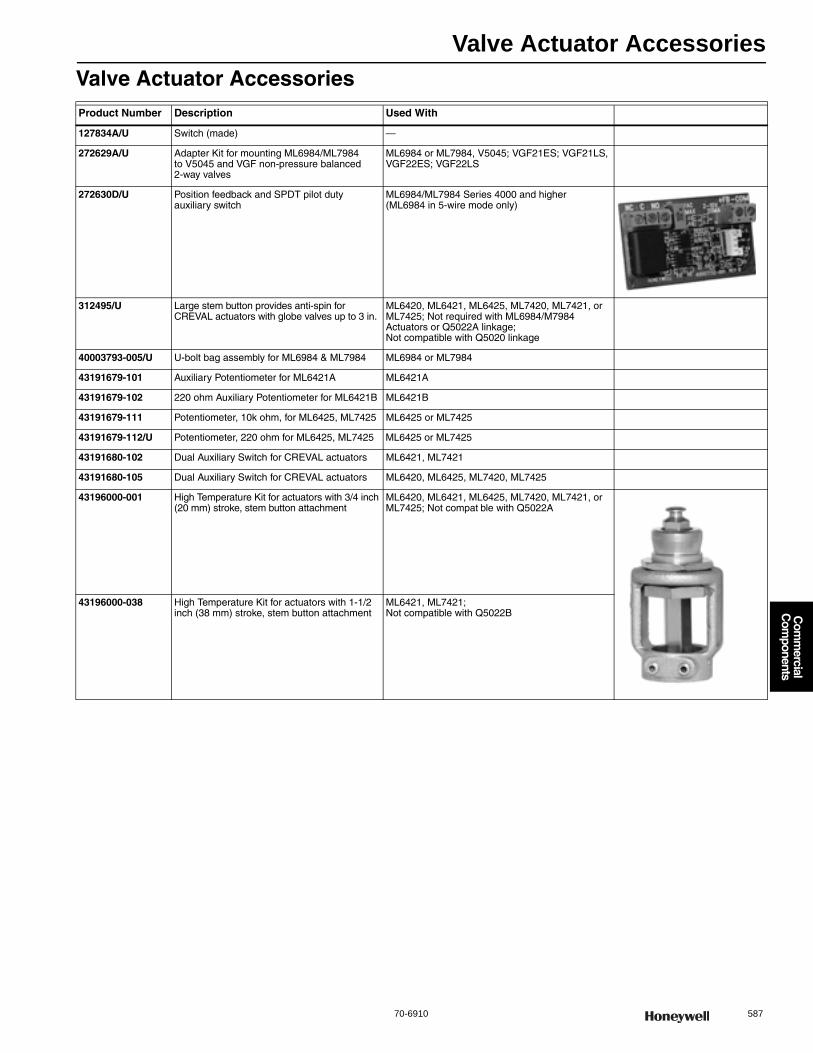
Valve Actuator Accessories
70-6910 587
Com
mercial
Com
ponents
Valve Actuator AccessoriesProduct Number Description Used With
127834A/U Switch (made) —
272629A/U Adapter Kit for mounting ML6984/ML7984 to V5045 and VGF non-pressure balanced 2-way valves
ML6984 or ML7984, V5045; VGF21ES; VGF21LS, VGF22ES; VGF22LS
272630D/U Position feedback and SPDT pilot dutyauxiliary switch
ML6984/ML7984 Series 4000 and higher (ML6984 in 5-wire mode only)
312495/U Large stem button provides anti-spin for CREVAL actuators with globe valves up to 3 in.
ML6420, ML6421, ML6425, ML7420, ML7421, or ML7425; Not required with ML6984/M7984 Actuators or Q5022A linkage; Not compatible with Q5020 linkage
40003793-005/U U-bolt bag assembly for ML6984 & ML7984 ML6984 or ML7984
43191679-101 Auxiliary Potentiometer for ML6421A ML6421A
43191679-102 220 ohm Auxiliary Potentiometer for ML6421B ML6421B
43191679-111 Potentiometer, 10k ohm, for ML6425, ML7425 ML6425 or ML7425
43191679-112/U Potentiometer, 220 ohm for ML6425, ML7425 ML6425 or ML7425
43191680-102 Dual Auxiliary Switch for CREVAL actuators ML6421, ML7421
43191680-105 Dual Auxiliary Switch for CREVAL actuators ML6420, ML6425, ML7420, ML7425
43196000-001 High Temperature Kit for actuators with 3/4 inch (20 mm) stroke, stem button attachment
ML6420, ML6421, ML6425, ML7420, ML7421, or ML7425; Not compat ble with Q5022A
43196000-038 High Temperature Kit for actuators with 1-1/2 inch (38 mm) stroke, stem button attachment
ML6421, ML7421; Not compatible with Q5022B
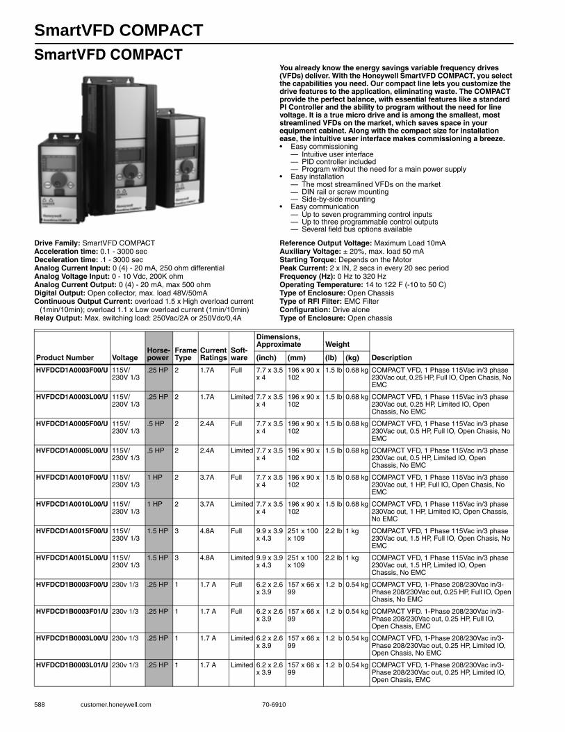
SmartVFD COMPACT
588 customer.honeywell.com 70-6910
SmartVFD COMPACTYou already know the energy savings variable frequency drives (VFDs) deliver. With the Honeywell SmartVFD COMPACT, you select the capabilities you need. Our compact line lets you customize the drive features to the application, eliminating waste. The COMPACT provide the perfect balance, with essential features like a standard PI Controller and the ability to program without the need for line voltage. It is a true micro drive and is among the smallest, most streamlined VFDs on the market, which saves space in your equipment cabinet. Along with the compact size for installation ease, the intuitive user interface makes commissioning a breeze.• Easy commissioning
— Intuitive user interface — PID controller included — Program without the need for a main power supply
• Easy installation — The most streamlined VFDs on the market — DIN rail or screw mounting — Side-by-side mounting
• Easy communication — Up to seven programming control inputs — Up to three programmable control outputs — Several field bus options available
Drive Family: SmartVFD COMPACTAcceleration time: 0.1 - 3000 secDeceleration time: .1 - 3000 secAnalog Current Input: 0 (4) - 20 mA, 250 ohm differentialAnalog Voltage Input: 0 - 10 Vdc, 200K ohmAnalog Current Output: 0 (4) - 20 mA, max 500 ohmDigital Output: Open collector, max. load 48V/50mAContinuous Output Current: overload 1.5 x High overload current
(1min/10min); overload 1.1 x Low overload current (1min/10min)Relay Output: Max. switching load: 250Vac/2A or 250Vdc/0,4A
Reference Output Voltage: Maximum Load 10mAAuxiliary Voltage: ± 20%, max. load 50 mAStarting Torque: Depends on the MotorPeak Current: 2 x IN, 2 secs in every 20 sec periodFrequency (Hz): 0 Hz to 320 HzOperating Temperature: 14 to 122 F (-10 to 50 C) Type of Enclosure: Open ChassisType of RFI Filter: EMC FilterConfiguration: Drive aloneType of Enclosure: Open chassis
Product Number VoltageHorse-power
Frame Type
Current Ratings
Soft-ware
Dimensions, Approximate Weight
Description(inch) (mm) (lb) (kg)
HVFDCD1A0003F00/U 115V/230V 1/3
.25 HP 2 1.7A Full 7.7 x 3.5 x 4
196 x 90 x 102
1.5 lb 0.68 kg COMPACT VFD, 1 Phase 115Vac in/3 phase 230Vac out, 0.25 HP, Full IO, Open Chasis, No EMC
HVFDCD1A0003L00/U 115V/230V 1/3
.25 HP 2 1.7A Limited 7.7 x 3.5 x 4
196 x 90 x 102
1.5 lb 0.68 kg COMPACT VFD, 1 Phase 115Vac in/3 phase 230Vac out, 0.25 HP, Limited IO, Open Chassis, No EMC
HVFDCD1A0005F00/U 115V/230V 1/3
.5 HP 2 2.4A Full 7.7 x 3.5 x 4
196 x 90 x 102
1.5 lb 0.68 kg COMPACT VFD, 1 Phase 115Vac in/3 phase 230Vac out, 0.5 HP, Full IO, Open Chasis, No EMC
HVFDCD1A0005L00/U 115V/230V 1/3
.5 HP 2 2.4A Limited 7.7 x 3.5 x 4
196 x 90 x 102
1.5 lb 0.68 kg COMPACT VFD, 1 Phase 115Vac in/3 phase 230Vac out, 0.5 HP, Limited IO, Open Chassis, No EMC
HVFDCD1A0010F00/U 115V/230V 1/3
1 HP 2 3.7A Full 7.7 x 3.5 x 4
196 x 90 x 102
1.5 lb 0.68 kg COMPACT VFD, 1 Phase 115Vac in/3 phase 230Vac out, 1 HP, Full IO, Open Chasis, No EMC
HVFDCD1A0010L00/U 115V/230V 1/3
1 HP 2 3.7A Limited 7.7 x 3.5 x 4
196 x 90 x 102
1.5 lb 0.68 kg COMPACT VFD, 1 Phase 115Vac in/3 phase 230Vac out, 1 HP, Limited IO, Open Chassis, No EMC
HVFDCD1A0015F00/U 115V/230V 1/3
1.5 HP 3 4.8A Full 9.9 x 3.9 x 4.3
251 x 100 x 109
2.2 lb 1 kg COMPACT VFD, 1 Phase 115Vac in/3 phase 230Vac out, 1.5 HP, Full IO, Open Chasis, No EMC
HVFDCD1A0015L00/U 115V/230V 1/3
1.5 HP 3 4.8A Limited 9.9 x 3.9 x 4.3
251 x 100 x 109
2.2 lb 1 kg COMPACT VFD, 1 Phase 115Vac in/3 phase 230Vac out, 1.5 HP, Limited IO, Open Chassis, No EMC
HVFDCD1B0003F00/U 230v 1/3 .25 HP 1 1.7 A Full 6.2 x 2.6 x 3.9
157 x 66 x 99
1.2 b 0.54 kg COMPACT VFD, 1-Phase 208/230Vac in/3-Phase 208/230Vac out, 0.25 HP, Full IO, Open Chasis, No EMC
HVFDCD1B0003F01/U 230v 1/3 .25 HP 1 1.7 A Full 6.2 x 2.6 x 3.9
157 x 66 x 99
1.2 b 0.54 kg COMPACT VFD. 1-Phase 208/230Vac in/3-Phase 208/230Vac out, 0.25 HP, Full IO, Open Chasis, EMC
HVFDCD1B0003L00/U 230v 1/3 .25 HP 1 1.7 A Limited 6.2 x 2.6 x 3.9
157 x 66 x 99
1.2 b 0.54 kg COMPACT VFD, 1-Phase 208/230Vac in/3-Phase 208/230Vac out, 0.25 HP, Limited IO, Open Chasis, No EMC
HVFDCD1B0003L01/U 230v 1/3 .25 HP 1 1.7 A Limited 6.2 x 2.6 x 3.9
157 x 66 x 99
1.2 b 0.54 kg COMPACT VFD, 1-Phase 208/230Vac in/3-Phase 208/230Vac out, 0.25 HP, Limited IO, Open Chasis, EMC

SmartVFD COMPACT
70-6910 589
Com
mercial
Com
ponents
HVFDCD1B0005F00/U 230v 1/3 0.5 HP 1 2.4 A Full 6.2 x 2.6 x 3.9
157 x 66 x 99
1.2 lb 0.54 kg COMPACT VFD, 1-Phase 208/230Vac in/3-Phase 208/230Vac out, 0.5HP, Full IO, Open Chasis, No EMC
HVFDCD1B0005F01/U 230v 1/3 0.5 HP 1 2.4 A Full 6.2 x 2.6 x 3.9
157 x 66 x 99
1.2 lb 0.54 kg COMPACT VFD, 1-Phase 208/230Vac0.5HP, Full IO, Open Chasis, EMC
HVFDCD1B0005L00/U 230v 1/3 0.5 HP 1 2.4 A Limited 6.2 x 2.6 x 3.9
157 x 66 x 99
1.2 lb 0.54 kg COMPACT VFD, 1-Phase 208/230Vac, 0.5HP, Limited IO, Open Chasis, No EMC
HVFDCD1B0005L01/U 230v 1/3 0.5 HP 1 2.4 A Limited 6.2 x 2.6 x 3.9
157 x 66 x 99
1.2 lb 0.54 kg COMPACT VFD, 1-Phase 208/230Vac in/3-Phase 208/230Vac out, 0.5HP, Limited IO, Open Chasis, EMC
HVFDCD1B0007F00/U 230v 1/3 0.75 HP 1 2.8 A Full 6.2 x 2.6 x 3.9
157 x 66 x 99
1.2 lb 0.54 kg COMPACT VFD, 1-Phase 208/230Vac in/3-Phase 208/230Vac out, 0.75HP, Full IO, Open Chasis, No EMC
HVFDCD1B0007F01/U 230v 1/3 0.75 HP 1 2.8 A Full 6.2 x 2.6 x 3.9
157 x 66 x 99
1.2 lb 0.54 kg COMPACT VFD, 1-Phase 208/230Vac in/3-Phase 208/230Vac out, 0.75HP, Full IO, Open Chasis, EMC
HVFDCD1B0007L00/U 230v 1/3 0.75 HP 1 2.8 A Limited 6.2 x 2.6 x 3.9
157 x 66 x 99
1.2 lb 0.54 kg COMPACT VFD, 1-Phase 208/230Vac in/3-Phase 208/230Vac out, 0.75HP, Limited IO, Open Chasis, No EMC
HVFDCD1B0007L01/U 230v 1/3 0.75 HP 1 2.8 A Limited 6.2 x 2.6 x 3.9
157 x 66 x 99
1.2 lb 0.54 kg COMPACT VFD, 1-Phase 208/230Vac in/3-Phase 208/230Vac out, 0.75HP, Limited IO, Open Chasis, EMC
HVFDCD1B0010F00/U 230v 1/3 1 HP 1 3.7 A Full 6.2 x 2.6 x 3.9
157 x 66 x 99
1.2 lb 0.54 kg COMPACT VFD, 1-Phase 208/230Vac in/3-Phase 208/230Vac out, 1HP, Full IO, Open Chasis, No EMC
HVFDCD1B0010F01/U 230v 1/3 1 HP 1 3.7 A Full 6.2 x 2.6 x 3.9
157 x 66 x 99
1.2 lb 0.54 kg COMPACT VFD, 1-Phase 208/230Vac in/3-Phase 208/230Vac out, 1HP, Full IO, Open Chasis, EMC
HVFDCD1B0010L00/U 230v 1/3 1 HP 1 3.7 A Limited 6.2 x 2.6 x 3.9
157 x 66 x 99
1.2 lb 0.54 kg COMPACT VFD, 1-Phase 208/230Vac in/3-Phase 208/230Vac out, 1HP, Limited IO, Open Chasis, No EMC
HVFDCD1B0010L01/U 230v 1/3 1 HP 1 3.7 A Limited 6.2 x 2.6 x 3.9
157 x 66 x 99
1.2 lb 0.54 kg COMPACT VFD, 1-Phase 208/230Vac in/3-Phase 208/230Vac out, 1HP, Limited IO, Open Chasis, EMC
HVFDCD1B0015F00/U 230v 1/3 1.5 HP 2 4.8 A Full 7.7 x 3.5 x 4
196 x 90 x 102
1.5 lb 0.68 kg COMPACT VFD, 1-Phase 208/230Vac in/3-Phase 208/230Vac out, 1.5HP, Full IO, Open Chasis, No EMC
HVFDCD1B0015F01/U 230v 1/3 1.5 HP 2 4.8 A Full 7.7 x 3.5 x 4
196 x 90 x 102
1.5 lb 0.68 kg COMPACT VFD, 1-Phase 208/230Vac in/3-Phase 208/230Vac out, 1.5HP, Full IO, Open Chasis, EMC
HVFDCD1B0015L00/U 230v 1/3 1.5 HP 2 4.8 A Limited 7.7 x 3.5 x 4
196 x 90 x 102
1.5 lb 0.68 kg COMPACT VFD, 1-Phase 208/230Vac in/3-Phase 208/230Vac out, 1.5HP, Limited IO, Open Chasis, No EMC
HVFDCD1B0015L01/U 230v 1/3 1.5 HP 2 4.8 A Limited 7.7 x 3.5 x 4
196 x 90 x 102
1.5 lb 0.68 kg COMPACT VFD, 1-Phase 208/230Vac in/3-Phase 208/230Vac out, 1.5HP, Limited IO, Open Chasis, EMC
HVFDCD1B0020F00/U 230v 1/3 2 HP 2 7.0 A Full 7.7 x 3.5 x 4
196 x 90 x 102
1.5 lb 0.68 kg COMPACT VFD, 1-Phase 208/230Vac in/3-Phase 208/230Vac out, 2HP, Full IO, Open Chasis, No EMC
HVFDCD1B0020F01/U 230v 1/3 2 HP 2 7.0 A Full 7.7 x 3.5 x 4
196 x 90 x 102
1.5 lb 0.68 kg COMPACT VFD, 1-Phase 208/230Vac in/3-Phase 208/230Vac out, 2HP, Full IO, Open Chasis, EMC
HVFDCD1B0020L00/U 230v 1/3 2 HP 2 7.0 A Limited 7.7 x 3.5 x 4
196 x 90 x 102
1.5 lb 0.68 kg COMPACT VFD, 1-Phase 208/230Vac in/3-Phase 208/230Vac out, 2HP, Limited IO, Open Chasis, No EMC
HVFDCD1B0020L01/U 230v 1/3 2 HP 2 7.0 A Limited 7.7 x 3.5 x 4
196 x 90 x 102
1.5 lb 0.68 kg COMPACT VFD, 1-Phase 208/230Vac2HP, Limited IO, Open Chasis, EMC
HVFDCD1B0030F00/U 230v 1/3 3 HP 3 11.0 A Full 9.9 x 3.9 x 4.3
251 x 100 x 109
2.2 lb 1 kg COMPACT VFD, 1-Phase 208/230Vac in/3-Phase 208/230Vac out, 3HP, Full IO, Open Chasis, No EMC
HVFDCD1B0030F01/U 230v 1/3 3 HP 3 11.0 A Full 9.9 x 3.9 x 4.3
251 x 100 x 109
2.2 lb 1 kg COMPACT VFD, 1-Phase 208/230Vac in/3-Phase 208/230Vac out, 3HP, Full IO, Open Chasis, EMC
HVFDCD1B0030L00/U 230v 1/3 3 HP 3 11.0 A Limited 9.9 x 3.9 x 4.3
251 x 100 x 109
2.2 lb 1 kg COMPACT VFD, 1-Phase 208/230Vac in/3-Phase 208/230Vac out, 3HP, Limited IO, Open Chasis, No EMC
Product Number VoltageHorse-power
Frame Type
Current Ratings
Soft-ware
Dimensions, Approximate Weight
Description(inch) (mm) (lb) (kg)
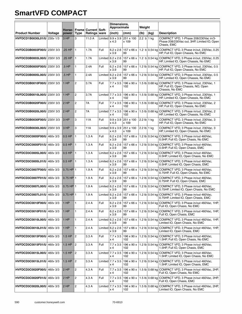
SmartVFD COMPACT
590 customer.honeywell.com 70-6910
HVFDCD1B0030L01/U 230v 1/3 3 HP 3 11.0 A Limited 9.9 x 3.9 x 4.3
251 x 100 x 109
2.2 b 1 kg COMPACT VFD, 1-Phase 208/230Vac in/3-Phase 208/230Vac out, 3HP, Limited IO, Open Chasis, EMC
HVFDCD3B0003F00/U 230V 3/3 .25 HP 1 1.7A Full 6.2 x 2.6 x 3.9
157 x 66 x 99
1.2 b 0.54 kg COMPACT VFD, 3 Phase in/out, 230Vac, 0.25 HP, Full IO, Open Chassis, No EMC
HVFDCD3B0003L00/U 230V 3/3 .25 HP 1 1.7A Limited 6.2 x 2.6 x 3.9
157 x 66 x 99
1.2 b 0.54 kg COMPACT VFD, 3 Phase in/out, 230Vac, 0.25 HP, Limited IO, Open Chassis, No EMC
HVFDCD3B0005F00/U 230V 3/3 .5 HP 1 2.4A Full 6.2 x 2.6 x 3.9
157 x 66 x 99
1.2 lb 0.54 kg COMPACT VFD, 3 Phase in/out, 230Vac, 0.5 HP, Full IO, Open Chassis, No EMC
HVFDCD3B0005L00/U 230V 3/3 .5 HP 1 2.4A Limited 6.2 x 2.6 x 3.9
157 x 66 x 99
1.2 lb 0.54 kg COMPACT VFD, 3 Phase in/out, 230Vac, 0.5 HP, Limited IO, Open Chassis, No EMC
HVFDCD3B0010F00/U 230V 3/3 1 HP 2 3.7A Full 7.7 x 3.5 x 4
196 x 90 x 102
1.5 lb 0.68 kg COMPACT VFD, 3 Phase in/out, 230Vac, 1 HP, Full IO, Open Chassis, NO, Open Chassis, No EMC
HVFDCD3B0010L00/U 230V 3/3 1 HP 2 3.7A Limited 7.7 x 3.5 x 4
196 x 90 x 102
1.5 lb 0.68 kg COMPACT VFD, 3 Phase in/out, 230Vac, 1 HP, Limited IO, Open Chassis, No EMC
HVFDCD3B0020F00/U 230V 3/3 2 HP 2 7A Full 7.7 x 3.5 x 4
196 x 90 x 102
1.5 lb 0.68 kg COMPACT VFD, 3 Phase in/out, 230Vac, 2 HP, Full IO, Open Chassis, No EMC
HVFDCD3B0020L00/U 230V 3/3 2 HP 2 7A Limited 7.7 x 3.5 x 4
196 x 90 x 102
1.5 lb 0.68 kg COMPACT VFD, 3 Phase in/out, 230Vac, 2 HP, Limited IO, Open Chassis, No EMC
HVFDCD3B0030F00/U 230V 3/3 3 HP 3 11A Full 9.9 x 3.9 x 4.3
251 x 100 x 109
2.2 lb 1 kg COMPACT VFD, 3 Phase in/out, 230Vac, 3 HP, Full IO, Open Chassis, No EMC
HVFDCD3B0030L00/U 230V 3/3 3 HP 3 11A Limited 9.9 x 3.9 x 4.3
251 x 100 x 109
2.2 lb 1 kg COMPACT VFD, 3 Phase in/out, 230Vac, 3 HP, Limited IO, Open Chassis, No EMC
HVFDCD3C0005F00/U 460v 3/3 0.5 HP 1 1.3 A Full 6.2 x 2.6 x 3.9
157 x 66 x 99
1.2 lb 0.54 kg COMPACT VFD, 3 Phase in/out 460Vac, 0.5HP, Full IO, Open Chasis, No EMC
HVFDCD3C0005F01/U 460v 3/3 0.5 HP 1 1.3 A Full 6.2 x 2.6 x 3.9
157 x 66 x 99
1.2 lb 0.54 kg COMPACT VFD, 3 Phase in/out 460Vac, 0.5HP, Full IO, Open Chasis, EMC
HVFDCD3C0005L00/U 460v 3/3 0.5 HP 1 1.3 A Limited 6.2 x 2.6 x 3.9
157 x 66 x 99
1.2 lb 0.54 kg COMPACT VFD, 3 Phase in/out 460Vac, 0.5HP, Limited IO, Open Chasis, No EMC
HVFDCD3C0005L01/U 460v 3/3 0.5 HP 1 1.3 A Limited 6.2 x 2.6 x 3.9
157 x 66 x 99
1.2 lb 0.54 kg COMPACT VFD, 3 Phase in/out 460Vac, 0.5HP, Limited IO, Open Chasis, EMC
HVFDCD3C0007F00/U 460v 3/3 0.75 HP 1 1.9 A Full 6.2 x 2.6 x 3.9
157 x 66 x 99
1.2 lb 0.54 kg COMPACT VFD, 3 Phase in/out 460Vac, 0.75HP, Full IO, Open Chasis, No EMC
HVFDCD3C0007F01/U 460v 3/3 0.75 HP 1 1.9 A Full 6.2 x 2.6 x 3.9
157 x 66 x 99
1.2 lb 0.54 kg COMPACT VFD, 3 Phase in/out 460Vac, 0.75HP, Full IO, Open Chasis, EMC
HVFDCD3C0007L00/U 460v 3/3 0.75 HP 1 1.9 A Limited 6.2 x 2.6 x 3.9
157 x 66 x 99
1.2 lb 0.54 kg COMPACT VFD, 3 Phase in/out 460Vac, 0.75HP, Limited IO, Open Chasis, No EMC
HVFDCD3C0007L01/U 460v 3/3 0.75 HP 1 1.9 A Limited 6.2 x 2.6 x 3.9
157 x 66 x 99
1.2 lb 0.54 kg COMPACT VFD, 3 Phase in/out 460Vac, 0.75HP, Limited IO, Open Chasis, EMC
HVFDCD3C0010F00/U 460v 3/3 1 HP 1 2.4 A Full 6.2 x 2.6 x 3.9
157 x 66 x 99
1.2 lb 0.54 kg COMPACT VFD, 3 Phase in/out 460Vac, 1HP, Full IO, Open Chasis, No EMC
HVFDCD3C0010F01/U 460v 3/3 1 HP 1 2.4 A Full 6.2 x 2.6 x 3.9
157 x 66 x 99
1.2 lb 0.54 kg COMPACT VFD, 3 Phase in/out 460Vac, 1HP, Full IO, Open Chasis, EMC
HVFDCD3C0010L00/U 460v 3/3 1 HP 1 2.4 A Limited 6.2 x 2.6 x 3.9
157 x 66 x 99
1.2 lb 0.54 kg COMPACT VFD, 3 Phase in/out 460Vac, 1HP, Limited IO, Open Chasis, No EMC
HVFDCD3C0010L01/U 460v 3/3 1 HP 1 2.4 A Limited 6.2 x 2.6 x 3.9
157 x 66 x 99
1.2 lb 0.54 kg COMPACT VFD, 3 Phase in/out 460Vac, 1HP, Limited IO, Open Chasis, EMC
HVFDCD3C0015F00/U 460v 3/3 1.5 HP 2 3.3 A Full 7.7 x 3.5 x 4
196 x 90 x 102
1.2 lb 0.54 kg COMPACT VFD, 3 Phase in/out 460Vac, 1.5HP, Full IO, Open Chasis, No EMC
HVFDCD3C0015F01/U 460v 3/3 1.5 HP 2 3.3 A Full 7.7 x 3.5 x 4
196 x 90 x 102
1.2 lb 0.54 kg COMPACT VFD, 3 Phase in/out 460Vac, 1.5HP, Full IO, Open Chasis, EMC
HVFDCD3C0015L00/U 460v 3/3 1.5 HP 2 3.3 A Limited 7.7 x 3.5 x 4
196 x 90 x 102
1.2 lb 0.54 kg COMPACT VFD, 3 Phase in/out 460Vac, 1.5HP, Limited IO, Open Chasis, No EMC
HVFDCD3C0015L01/U 460v 3/3 1.5 HP 2 3.3 A Limited 7.7 x 3.5 x 4
196 x 90 x 102
1.2 lb 0.54 kg COMPACT VFD, 3 Phase in/out 460Vac, 1.5HP, Limited IO, Open Chasis, EMC
HVFDCD3C0020F00/U 460v 3/3 2 HP 2 4.3 A Full 7.7 x 3.5 x 4
196 x 90 x 102
1.5 lb 0.68 kg COMPACT VFD, 3 Phase in/out 460Vac, 2HP, Full IO, Open Chasis, No EMC
HVFDCD3C0020F01/U 460v 3/3 2 HP 2 4.3 A Full 7.7 x 3.5 x 4
196 x 90 x 102
1.5 lb 0.68 kg COMPACT VFD, 3 Phase in/out 460Vac, 2HP, Full IO, Open Chasis, EMC
HVFDCD3C0020L00/U 460v 3/3 2 HP 2 4.3 A Limited 7.7 x 3.5 x 4
196 x 90 x 102
1.5 lb 0.68 kg COMPACT VFD, 3 Phase in/out 460Vac, 2HP, Limited IO, Open Chasis, No EMC
Product Number VoltageHorse-power
Frame Type
Current Ratings
Soft-ware
Dimensions, Approximate Weight
Description(inch) (mm) (lb) (kg)
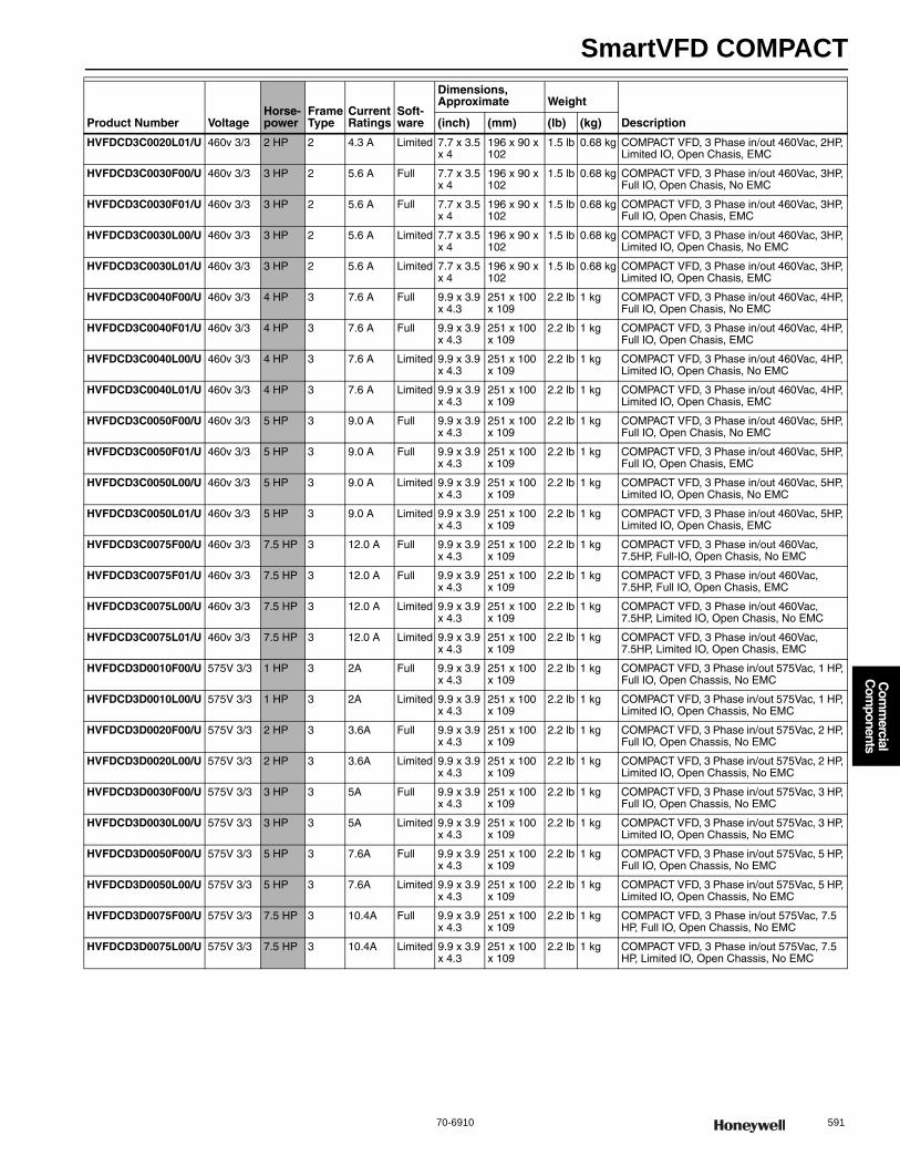
SmartVFD COMPACT
70-6910 591
Com
mercial
Com
ponents
HVFDCD3C0020L01/U 460v 3/3 2 HP 2 4.3 A Limited 7.7 x 3.5 x 4
196 x 90 x 102
1.5 lb 0.68 kg COMPACT VFD, 3 Phase in/out 460Vac, 2HP, Limited IO, Open Chasis, EMC
HVFDCD3C0030F00/U 460v 3/3 3 HP 2 5.6 A Full 7.7 x 3.5 x 4
196 x 90 x 102
1.5 lb 0.68 kg COMPACT VFD, 3 Phase in/out 460Vac, 3HP, Full IO, Open Chasis, No EMC
HVFDCD3C0030F01/U 460v 3/3 3 HP 2 5.6 A Full 7.7 x 3.5 x 4
196 x 90 x 102
1.5 lb 0.68 kg COMPACT VFD, 3 Phase in/out 460Vac, 3HP, Full IO, Open Chasis, EMC
HVFDCD3C0030L00/U 460v 3/3 3 HP 2 5.6 A Limited 7.7 x 3.5 x 4
196 x 90 x 102
1.5 lb 0.68 kg COMPACT VFD, 3 Phase in/out 460Vac, 3HP, Limited IO, Open Chasis, No EMC
HVFDCD3C0030L01/U 460v 3/3 3 HP 2 5.6 A Limited 7.7 x 3.5 x 4
196 x 90 x 102
1.5 lb 0.68 kg COMPACT VFD, 3 Phase in/out 460Vac, 3HP, Limited IO, Open Chasis, EMC
HVFDCD3C0040F00/U 460v 3/3 4 HP 3 7.6 A Full 9.9 x 3.9 x 4.3
251 x 100 x 109
2.2 lb 1 kg COMPACT VFD, 3 Phase in/out 460Vac, 4HP, Full IO, Open Chasis, No EMC
HVFDCD3C0040F01/U 460v 3/3 4 HP 3 7.6 A Full 9.9 x 3.9 x 4.3
251 x 100 x 109
2.2 lb 1 kg COMPACT VFD, 3 Phase in/out 460Vac, 4HP, Full IO, Open Chasis, EMC
HVFDCD3C0040L00/U 460v 3/3 4 HP 3 7.6 A Limited 9.9 x 3.9 x 4.3
251 x 100 x 109
2.2 lb 1 kg COMPACT VFD, 3 Phase in/out 460Vac, 4HP, Limited IO, Open Chasis, No EMC
HVFDCD3C0040L01/U 460v 3/3 4 HP 3 7.6 A Limited 9.9 x 3.9 x 4.3
251 x 100 x 109
2.2 lb 1 kg COMPACT VFD, 3 Phase in/out 460Vac, 4HP, Limited IO, Open Chasis, EMC
HVFDCD3C0050F00/U 460v 3/3 5 HP 3 9.0 A Full 9.9 x 3.9 x 4.3
251 x 100 x 109
2.2 lb 1 kg COMPACT VFD, 3 Phase in/out 460Vac, 5HP, Full IO, Open Chasis, No EMC
HVFDCD3C0050F01/U 460v 3/3 5 HP 3 9.0 A Full 9.9 x 3.9 x 4.3
251 x 100 x 109
2.2 lb 1 kg COMPACT VFD, 3 Phase in/out 460Vac, 5HP, Full IO, Open Chasis, EMC
HVFDCD3C0050L00/U 460v 3/3 5 HP 3 9.0 A Limited 9.9 x 3.9 x 4.3
251 x 100 x 109
2.2 lb 1 kg COMPACT VFD, 3 Phase in/out 460Vac, 5HP, Limited IO, Open Chasis, No EMC
HVFDCD3C0050L01/U 460v 3/3 5 HP 3 9.0 A Limited 9.9 x 3.9 x 4.3
251 x 100 x 109
2.2 lb 1 kg COMPACT VFD, 3 Phase in/out 460Vac, 5HP, Limited IO, Open Chasis, EMC
HVFDCD3C0075F00/U 460v 3/3 7.5 HP 3 12.0 A Full 9.9 x 3.9 x 4.3
251 x 100 x 109
2.2 lb 1 kg COMPACT VFD, 3 Phase in/out 460Vac, 7.5HP, Full-IO, Open Chasis, No EMC
HVFDCD3C0075F01/U 460v 3/3 7.5 HP 3 12.0 A Full 9.9 x 3.9 x 4.3
251 x 100 x 109
2.2 lb 1 kg COMPACT VFD, 3 Phase in/out 460Vac, 7.5HP, Full IO, Open Chasis, EMC
HVFDCD3C0075L00/U 460v 3/3 7.5 HP 3 12.0 A Limited 9.9 x 3.9 x 4.3
251 x 100 x 109
2.2 lb 1 kg COMPACT VFD, 3 Phase in/out 460Vac, 7.5HP, Limited IO, Open Chasis, No EMC
HVFDCD3C0075L01/U 460v 3/3 7.5 HP 3 12.0 A Limited 9.9 x 3.9 x 4.3
251 x 100 x 109
2.2 lb 1 kg COMPACT VFD, 3 Phase in/out 460Vac, 7.5HP, Limited IO, Open Chasis, EMC
HVFDCD3D0010F00/U 575V 3/3 1 HP 3 2A Full 9.9 x 3.9 x 4.3
251 x 100 x 109
2.2 lb 1 kg COMPACT VFD, 3 Phase in/out 575Vac, 1 HP, Full IO, Open Chassis, No EMC
HVFDCD3D0010L00/U 575V 3/3 1 HP 3 2A Limited 9.9 x 3.9 x 4.3
251 x 100 x 109
2.2 lb 1 kg COMPACT VFD, 3 Phase in/out 575Vac, 1 HP, Limited IO, Open Chassis, No EMC
HVFDCD3D0020F00/U 575V 3/3 2 HP 3 3.6A Full 9.9 x 3.9 x 4.3
251 x 100 x 109
2.2 lb 1 kg COMPACT VFD, 3 Phase in/out 575Vac, 2 HP, Full IO, Open Chassis, No EMC
HVFDCD3D0020L00/U 575V 3/3 2 HP 3 3.6A Limited 9.9 x 3.9 x 4.3
251 x 100 x 109
2.2 lb 1 kg COMPACT VFD, 3 Phase in/out 575Vac, 2 HP, Limited IO, Open Chassis, No EMC
HVFDCD3D0030F00/U 575V 3/3 3 HP 3 5A Full 9.9 x 3.9 x 4.3
251 x 100 x 109
2.2 lb 1 kg COMPACT VFD, 3 Phase in/out 575Vac, 3 HP, Full IO, Open Chassis, No EMC
HVFDCD3D0030L00/U 575V 3/3 3 HP 3 5A Limited 9.9 x 3.9 x 4.3
251 x 100 x 109
2.2 lb 1 kg COMPACT VFD, 3 Phase in/out 575Vac, 3 HP, Limited IO, Open Chassis, No EMC
HVFDCD3D0050F00/U 575V 3/3 5 HP 3 7.6A Full 9.9 x 3.9 x 4.3
251 x 100 x 109
2.2 lb 1 kg COMPACT VFD, 3 Phase in/out 575Vac, 5 HP, Full IO, Open Chassis, No EMC
HVFDCD3D0050L00/U 575V 3/3 5 HP 3 7.6A Limited 9.9 x 3.9 x 4.3
251 x 100 x 109
2.2 lb 1 kg COMPACT VFD, 3 Phase in/out 575Vac, 5 HP, Limited IO, Open Chassis, No EMC
HVFDCD3D0075F00/U 575V 3/3 7.5 HP 3 10.4A Full 9.9 x 3.9 x 4.3
251 x 100 x 109
2.2 lb 1 kg COMPACT VFD, 3 Phase in/out 575Vac, 7.5 HP, Full IO, Open Chassis, No EMC
HVFDCD3D0075L00/U 575V 3/3 7.5 HP 3 10.4A Limited 9.9 x 3.9 x 4.3
251 x 100 x 109
2.2 lb 1 kg COMPACT VFD, 3 Phase in/out 575Vac, 7.5 HP, Limited IO, Open Chassis, No EMC
Product Number VoltageHorse-power
Frame Type
Current Ratings
Soft-ware
Dimensions, Approximate Weight
Description(inch) (mm) (lb) (kg)
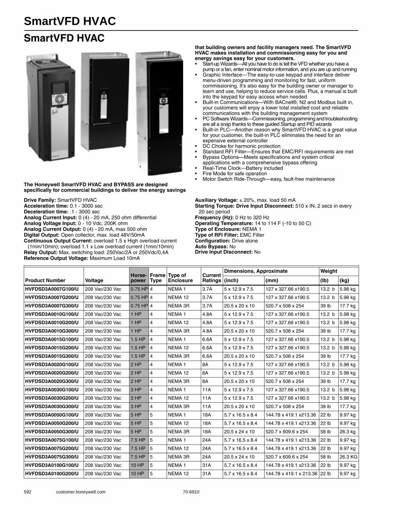
SmartVFD HVAC
592 customer.honeywell.com 70-6910
SmartVFD HVAC
The Honeywell SmartVFD HVAC and BYPASS are designed specifically for commercial buildings to deliver the energy savings
that building owners and facility managers need. The SmartVFD HVAC makes installation and commissioning easy for you and energy savings easy for your customers.• Start-up Wizards—All you have to do is tell the VFD whether you have a
pump or a fan, enter nominal motor information, and you are up and running • Graphic Interface—The easy-to-use keypad and interface deliver
menu-driven programming and monitoring for fast, uniform commissioning. It's also easy for the building owner or manager to learn and use, helping to reduce service calls. Plus, a manual is built into the keypad for easy access when needed
• Built-in Communications—With BACnet®, N2 and Modbus built in, your customers will enjoy a lower total installed cost and reliable communications with the building management system
• PC Software Wizards—Commissioning, programming and troubleshooting are all a snap thanks to these guided Startup and PID wizards
• Built-in PLC—Another reason why SmartVFD HVAC is a great value for your customer, the built-in PLC eliminates the need for an expensive external controller
• DC Choke for harmonic protection • Standard RFI Filter—Ensures that EMC/RFI requirements are met • Bypass Options—Meets specifications and system critical
applications with a comprehensive bypass offering • Real-Time Clock—Battery included • Fire Mode for safe operation • Motor Switch Ride-Through—easy, fault-free maintenance
Drive Family: SmartVFD HVACAcceleration time: 0.1 - 3000 secDeceleration time: .1 - 3000 secAnalog Current Input: 0 (4) - 20 mA, 250 ohm differentialAnalog Voltage Input: 0 - 10 Vdc, 200K ohmAnalog Current Output: 0 (4) - 20 mA, max 500 ohmDigital Output: Open collector, max. load 48V/50mAContinuous Output Current: overload 1.5 x High overload current
(1min/10min); overload 1.1 x Low overload current (1min/10min)Relay Output: Max. switching load: 250Vac/2A or 250Vdc/0,4AReference Output Voltage: Maximum Load 10mA
Auxiliary Voltage: ± 20%, max. load 50 mAStarting Torque: Drive Input Disconnect: 510 x IN, 2 secs in every
20 sec periodFrequency (Hz): 0 Hz to 320 HzOperating Temperature: 14 to 114 F (-10 to 50 C) Type of Enclosure: NEMA 1Type of RFI Filter: EMC FilterConfiguration: Drive aloneAuto Bypass: NoDrive Input Disconnect: No
Product Number VoltageHorse-power
Frame Type
Type of Enclosure
Current Ratings
Dimensions, Approximate Weight
(inch) (mm) (lb) (kg)
HVFDSD3A0007G100/U 208 Vac/230 Vac 0.75 HP 4 NEMA 1 3.7A 5 x 12.9 x 7.5 127 x 327.66 x190.5 13.2 b 5.98 kg
HVFDSD3A0007G200/U 208 Vac/230 Vac 0.75 HP 4 NEMA 12 3.7A 5 x 12.9 x 7.5 127 x 327.66 x190.5 13.2 b 5.98 kg
HVFDSD3A0007G300/U 208 Vac/230 Vac 0.75 HP 4 NEMA 3R 3.7A 20.5 x 20 x 10 520.7 x 508 x 254 39 lb 17.7 kg
HVFDSD3A0010G100/U 208 Vac/230 Vac 1 HP 4 NEMA 1 4.8A 5 x 12.9 x 7.5 127 x 327.66 x190.5 13.2 b 5.98 kg
HVFDSD3A0010G200/U 208 Vac/230 Vac 1 HP 4 NEMA 12 4.8A 5 x 12.9 x 7.5 127 x 327.66 x190.5 13.2 b 5.98 kg
HVFDSD3A0010G300/U 208 Vac/230 Vac 1 HP 4 NEMA 3R 4.8A 20.5 x 20 x 10 520.7 x 508 x 254 39 lb 17.7 kg
HVFDSD3A0015G100/U 208 Vac/230 Vac 1.5 HP 4 NEMA 1 6.6A 5 x 12.9 x 7.5 127 x 327.66 x190.5 13.2 b 5.98 kg
HVFDSD3A0015G200/U 208 Vac/230 Vac 1.5 HP 4 NEMA 12 6.6A 5 x 12.9 x 7.5 127 x 327.66 x190.5 13.2 b 5.98 kg
HVFDSD3A0015G300/U 208 Vac/230 Vac 1.5 HP 4 NEMA 3R 6.6A 20.5 x 20 x 10 520.7 x 508 x 254 39 lb 17.7 kg
HVFDSD3A0020G100/U 208 Vac/230 Vac 2 HP 4 NEMA 1 8A 5 x 12.9 x 7.5 127 x 327.66 x190.5 13.2 b 5.98 kg
HVFDSD3A0020G200/U 208 Vac/230 Vac 2 HP 4 NEMA 12 8A 5 x 12.9 x 7.5 127 x 327.66 x190.5 13.2 b 5.98 kg
HVFDSD3A0020G300/U 208 Vac/230 Vac 2 HP 4 NEMA 3R 8A 20.5 x 20 x 10 520.7 x 508 x 254 39 lb 17.7 kg
HVFDSD3A0030G100/U 208 Vac/230 Vac 3 HP 4 NEMA 1 11A 5 x 12.9 x 7.5 127 x 327.66 x190.5 13.2 b 5.98 kg
HVFDSD3A0030G200/U 208 Vac/230 Vac 3 HP 4 NEMA 12 11A 5 x 12.9 x 7.5 127 x 327.66 x190.5 13.2 b 5.98 kg
HVFDSD3A0030G300/U 208 Vac/230 Vac 3 HP 4 NEMA 3R 11A 20.5 x 20 x 10 520.7 x 508 x 254 39 lb 17.7 kg
HVFDSD3A0050G100/U 208 Vac/230 Vac 5 HP 5 NEMA 1 18A 5.7 x 16.5 x 8.4 144.78 x 419.1 x213.36 22 lb 9.97 kg
HVFDSD3A0050G200/U 208 Vac/230 Vac 5 HP 5 NEMA 12 18A 5.7 x 16.5 x 8.4 144.78 x 419.1 x213.36 22 lb 9.97 kg
HVFDSD3A0050G300/U 208 Vac/230 Vac 5 HP 5 NEMA 3R 18A 20.5 x 24 x 10 520.7 x 609.6 x 254 58 lb 26.3 kg
HVFDSD3A0075G100/U 208 Vac/230 Vac 7.5 HP 5 NEMA 1 24A 5.7 x 16.5 x 8.4 144.78 x 419.1 x213.36 22 lb 9.97 kg
HVFDSD3A0075G200/U 208 Vac/230 Vac 7.5 HP 5 NEMA 12 24A 5.7 x 16.5 x 8.4 144.78 x 419.1 x213.36 22 lb 9.97 kg
HVFDSD3A0075G300/U 208 Vac/230 Vac 7.5 HP 5 NEMA 3R 24A 20.5 x 24 x 10 520.7 x 609.6 x 254 58 lb 26.3 KG
HVFDSD3A0100G100/U 208 Vac/230 Vac 10 HP 5 NEMA 1 31A 5.7 x 16.5 x 8.4 144.78 x 419.1 x213.36 22 lb 9.97 kg
HVFDSD3A0100G200/U 208 Vac/230 Vac 10 HP 5 NEMA 12 31A 5.7 x 16.5 x 8.4 144.78 x 419.1 x 213.36 22 lb 9.97 kg
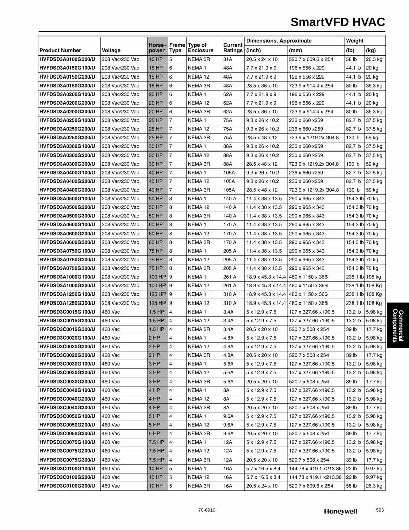
SmartVFD HVAC
70-6910 593
Com
mercial
Com
ponents
HVFDSD3A0100G300/U 208 Vac/230 Vac 10 HP 5 NEMA 3R 31A 20.5 x 24 x 10 520.7 x 609.6 x 254 58 lb 26.3 kg
HVFDSD3A0150G100/U 208 Vac/230 Vac 15 HP 6 NEMA 1 48A 7.7 x 21.9 x 9 196 x 556 x 229 44.1 b 20 kg
HVFDSD3A0150G200/U 208 Vac/230 Vac 15 HP 6 NEMA 12 48A 7.7 x 21.9 x 9 196 x 556 x 229 44.1 b 20 kg
HVFDSD3A0150G300/U 208 Vac/230 Vac 15 HP 6 NEMA 3R 48A 28.5 x 36 x 10 723.9 x 914.4 x 254 80 lb 36.3 kg
HVFDSD3A0200G100/U 208 Vac/230 Vac 20 HP 6 NEMA 1 62A 7.7 x 21.9 x 9 196 x 556 x 229 44.1 b 20 kg
HVFDSD3A0200G200/U 208 Vac/230 Vac 20 HP 6 NEMA 12 62A 7.7 x 21.9 x 9 196 x 556 x 229 44.1 b 20 kg
HVFDSD3A0200G300/U 208 Vac/230 Vac 20 HP 6 NEMA 3R 62A 28.5 x 36 x 10 723.9 x 914.4 x 254 80 lb 36.3 kg
HVFDSD3A0250G100/U 208 Vac/230 Vac 25 HP 7 NEMA 1 75A 9.3 x 26 x 10.2 236 x 660 x259 82.7 b 37.5 kg
HVFDSD3A0250G200/U 208 Vac/230 Vac 25 HP 7 NEMA 12 75A 9.3 x 26 x 10.2 236 x 660 x259 82.7 b 37.5 kg
HVFDSD3A0250G300/U 208 Vac/230 Vac 25 HP 7 NEMA 3R 75A 28.5 x 48 x 12 723.9 x 1219.2x 304.8 130 b 59 kg
HVFDSD3A0300G100/U 208 Vac/230 Vac 30 HP 7 NEMA 1 88A 9.3 x 26 x 10.2 236 x 660 x259 82.7 b 37.5 kg
HVFDSD3A0300G200/U 208 Vac/230 Vac 30 HP 7 NEMA 12 88A 9.3 x 26 x 10.2 236 x 660 x259 82.7 b 37.5 kg
HVFDSD3A0300G300/U 208 Vac/230 Vac 30 HP 7 NEMA 3R 88A 28.5 x 48 x 12 723.9 x 1219.2x 304.8 130 b 59 kg
HVFDSD3A0400G100/U 208 Vac/230 Vac 40 HP 7 NEMA 1 105A 9.3 x 26 x 10.2 236 x 660 x259 82.7 b 37.5 kg
HVFDSD3A0400G200/U 208 Vac/230 Vac 40 HP 7 NEMA 12 105A 9.3 x 26 x 10.2 236 x 660 x259 82.7 b 37.5 kg
HVFDSD3A0400G300/U 208 Vac/230 Vac 40 HP 7 NEMA 3R 105A 28.5 x 48 x 12 723.9 x 1219.2x 304.8 130 b 59 kg
HVFDSD3A0500G100/U 208 Vac/230 Vac 50 HP 8 NEMA 1 140 A 11.4 x 38 x 13.5 290 x 965 x 343 154.3 lb 70 kg
HVFDSD3A0500G200/U 208 Vac/230 Vac 50 HP 8 NEMA 12 140 A 11.4 x 38 x 13.5 290 x 965 x 343 154.3 lb 70 kg
HVFDSD3A0500G300/U 208 Vac/230 Vac 50 HP 8 NEMA 3R 140 A 11.4 x 38 x 13.5 290 x 965 x 343 154.3 lb 70 kg
HVFDSD3A0600G100/U 208 Vac/230 Vac 60 HP 8 NEMA 1 170 A 11.4 x 38 x 13.5 290 x 965 x 343 154.3 lb 70 kg
HVFDSD3A0600G200/U 208 Vac/230 Vac 60 HP 8 NEMA 12 170 A 11.4 x 38 x 13.5 290 x 965 x 343 154.3 lb 70 kg
HVFDSD3A0600G300/U 208 Vac/230 Vac 60 HP 8 NEMA 3R 170 A 11.4 x 38 x 13.5 290 x 965 x 343 154.3 lb 70 kg
HVFDSD3A0750G100/U 208 Vac/230 Vac 75 HP 8 NEMA 1 205 A 11.4 x 38 x 13.5 290 x 965 x 343 154.3 lb 70 kg
HVFDSD3A0750G200/U 208 Vac/230 Vac 75 HP 8 NEMA 12 205 A 11.4 x 38 x 13.5 290 x 965 x 343 154.3 lb 70 kg
HVFDSD3A0750G300/U 208 Vac/230 Vac 75 HP 8 NEMA 3R 205 A 11.4 x 38 x 13.5 290 x 965 x 343 154.3 lb 70 kg
HVFDSD3A1000G100/U 208 Vac/230 Vac 100 HP 9 NEMA 1 261 A 18.9 x 45.3 x 14.4 480 x 1150 x 366 238.1 lb 108 kg
HVFDSD3A1000G200/U 208 Vac/230 Vac 100 HP 9 NEMA 12 261 A 18.9 x 45.3 x 14.4 480 x 1150 x 366 238.1 lb 108 Kg
HVFDSD3A1250G100/U 208 Vac/230 Vac 125 HP 9 NEMA 1 310 A 18.9 x 45.3 x 14.4 480 x 1150 x 366 238.1 lb 108 Kg
HVFDSD3A1250G200/U 208 Vac/230 Vac 125 HP 9 NEMA 12 310 A 18.9 x 45.3 x 14.4 480 x 1150 x 366 238.1 lb 108 Kg
HVFDSD3C0015G100/U 460 Vac 1.5 HP 4 NEMA 1 3.4A 5 x 12.9 x 7.5 127 x 327.66 x190.5 13.2 b 5.98 kg
HVFDSD3C0015G200/U 460 Vac 1.5 HP 4 NEMA 12 3.4A 5 x 12.9 x 7.5 127 x 327.66 x190.5 13.2 b 5.98 kg
HVFDSD3C0015G300/U 460 Vac 1.5 HP 4 NEMA 3R 3.4A 20.5 x 20 x 10 520.7 x 508 x 254 39 lb 17.7 kg
HVFDSD3C0020G100/U 460 Vac 2 HP 4 NEMA 1 4.8A 5 x 12.9 x 7.5 127 x 327.66 x190.5 13.2 b 5.98 kg
HVFDSD3C0020G200/U 460 Vac 2 HP 4 NEMA 12 4.8A 5 x 12.9 x 7.5 127 x 327.66 x190.5 13.2 b 5.98 kg
HVFDSD3C0020G300/U 460 Vac 2 HP 4 NEMA 3R 4.8A 20.5 x 20 x 10 520.7 x 508 x 254 39 lb 17.7 kg
HVFDSD3C0030G100/U 460 Vac 3 HP 4 NEMA 1 5.6A 5 x 12.9 x 7.5 127 x 327.66 x190.5 13.2 b 5.98 kg
HVFDSD3C0030G200/U 460 Vac 3 HP 4 NEMA 12 5.6A 5 x 12.9 x 7.5 127 x 327.66 x190.5 13.2 b 5.98 kg
HVFDSD3C0030G300/U 460 Vac 3 HP 4 NEMA 3R 5.6A 20.5 x 20 x 10 520.7 x 508 x 254 39 lb 17.7 kg
HVFDSD3C0040G100/U 460 Vac 4 HP 4 NEMA 1 8A 5 x 12.9 x 7.5 127 x 327.66 x190.5 13.2 b 5.98 kg
HVFDSD3C0040G200/U 460 Vac 4 HP 4 NEMA 12 8A 5 x 12.9 x 7.5 127 x 327.66 x190.5 13.2 b 5.98 kg
HVFDSD3C0040G300/U 460 Vac 4 HP 4 NEMA 3R 8A 20.5 x 20 x 10 520.7 x 508 x 254 39 lb 17.7 kg
HVFDSD3C0050G100/U 460 Vac 5 HP 4 NEMA 1 9.6A 5 x 12.9 x 7.5 127 x 327.66 x190.5 13.2 b 5.98 kg
HVFDSD3C0050G200/U 460 Vac 5 HP 4 NEMA 12 9.6A 5 x 12.9 x 7.5 127 x 327.66 x190.5 13.2 b 5.98 kg
HVFDSD3C0050G300/U 460 Vac 5 HP 4 NEMA 3R 9.6A 20.5 x 20 x 10 520.7 x 508 x 254 39 lb 17.7 kg
HVFDSD3C0075G100/U 460 Vac 7.5 HP 4 NEMA 1 12A 5 x 12.9 x 7.5 127 x 327.66 x190.5 13.2 b 5.98 kg
HVFDSD3C0075G200/U 460 Vac 7.5 HP 4 NEMA 12 12A 5 x 12.9 x 7.5 127 x 327.66 x190.5 13.2 b 5.98 kg
HVFDSD3C0075G300/U 460 Vac 7.5 HP 4 NEMA 3R 12A 20.5 x 20 x 10 520.7 x 508 x 254 39 lb 17.7 kg
HVFDSD3C0100G100/U 460 Vac 10 HP 5 NEMA 1 16A 5.7 x 16.5 x 8.4 144.78 x 419.1 x213.36 22 lb 9.97 kg
HVFDSD3C0100G200/U 460 Vac 10 HP 5 NEMA 12 16A 5.7 x 16.5 x 8.4 144.78 x 419.1 x213.36 22 lb 9.97 kg
HVFDSD3C0100G300/U 460 Vac 10 HP 5 NEMA 3R 16A 20.5 x 24 x 10 520.7 x 609.6 x 254 58 lb 26.3 kg
Product Number VoltageHorse-power
Frame Type
Type of Enclosure
Current Ratings
Dimensions, Approximate Weight
(inch) (mm) (lb) (kg)
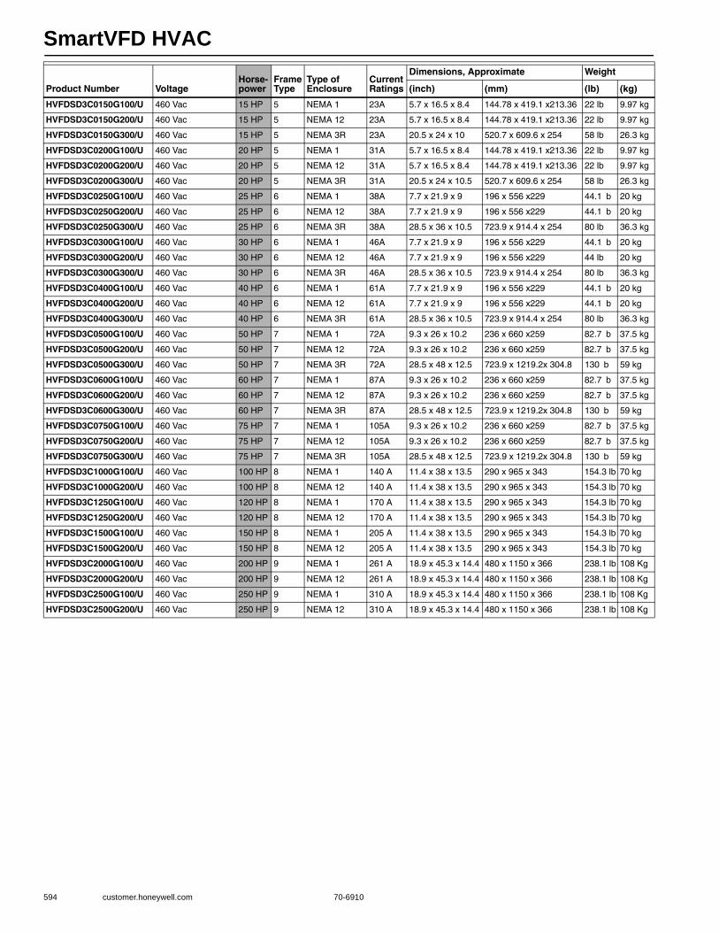
SmartVFD HVAC
594 customer.honeywell.com 70-6910
HVFDSD3C0150G100/U 460 Vac 15 HP 5 NEMA 1 23A 5.7 x 16.5 x 8.4 144.78 x 419.1 x213.36 22 lb 9.97 kg
HVFDSD3C0150G200/U 460 Vac 15 HP 5 NEMA 12 23A 5.7 x 16.5 x 8.4 144.78 x 419.1 x213.36 22 lb 9.97 kg
HVFDSD3C0150G300/U 460 Vac 15 HP 5 NEMA 3R 23A 20.5 x 24 x 10 520.7 x 609.6 x 254 58 lb 26.3 kg
HVFDSD3C0200G100/U 460 Vac 20 HP 5 NEMA 1 31A 5.7 x 16.5 x 8.4 144.78 x 419.1 x213.36 22 lb 9.97 kg
HVFDSD3C0200G200/U 460 Vac 20 HP 5 NEMA 12 31A 5.7 x 16.5 x 8.4 144.78 x 419.1 x213.36 22 lb 9.97 kg
HVFDSD3C0200G300/U 460 Vac 20 HP 5 NEMA 3R 31A 20.5 x 24 x 10.5 520.7 x 609.6 x 254 58 lb 26.3 kg
HVFDSD3C0250G100/U 460 Vac 25 HP 6 NEMA 1 38A 7.7 x 21.9 x 9 196 x 556 x229 44.1 b 20 kg
HVFDSD3C0250G200/U 460 Vac 25 HP 6 NEMA 12 38A 7.7 x 21.9 x 9 196 x 556 x229 44.1 b 20 kg
HVFDSD3C0250G300/U 460 Vac 25 HP 6 NEMA 3R 38A 28.5 x 36 x 10.5 723.9 x 914.4 x 254 80 lb 36.3 kg
HVFDSD3C0300G100/U 460 Vac 30 HP 6 NEMA 1 46A 7.7 x 21.9 x 9 196 x 556 x229 44.1 b 20 kg
HVFDSD3C0300G200/U 460 Vac 30 HP 6 NEMA 12 46A 7.7 x 21.9 x 9 196 x 556 x229 44 lb 20 kg
HVFDSD3C0300G300/U 460 Vac 30 HP 6 NEMA 3R 46A 28.5 x 36 x 10.5 723.9 x 914.4 x 254 80 lb 36.3 kg
HVFDSD3C0400G100/U 460 Vac 40 HP 6 NEMA 1 61A 7.7 x 21.9 x 9 196 x 556 x229 44.1 b 20 kg
HVFDSD3C0400G200/U 460 Vac 40 HP 6 NEMA 12 61A 7.7 x 21.9 x 9 196 x 556 x229 44.1 b 20 kg
HVFDSD3C0400G300/U 460 Vac 40 HP 6 NEMA 3R 61A 28.5 x 36 x 10.5 723.9 x 914.4 x 254 80 lb 36.3 kg
HVFDSD3C0500G100/U 460 Vac 50 HP 7 NEMA 1 72A 9.3 x 26 x 10.2 236 x 660 x259 82.7 b 37.5 kg
HVFDSD3C0500G200/U 460 Vac 50 HP 7 NEMA 12 72A 9.3 x 26 x 10.2 236 x 660 x259 82.7 b 37.5 kg
HVFDSD3C0500G300/U 460 Vac 50 HP 7 NEMA 3R 72A 28.5 x 48 x 12.5 723.9 x 1219.2x 304.8 130 b 59 kg
HVFDSD3C0600G100/U 460 Vac 60 HP 7 NEMA 1 87A 9.3 x 26 x 10.2 236 x 660 x259 82.7 b 37.5 kg
HVFDSD3C0600G200/U 460 Vac 60 HP 7 NEMA 12 87A 9.3 x 26 x 10.2 236 x 660 x259 82.7 b 37.5 kg
HVFDSD3C0600G300/U 460 Vac 60 HP 7 NEMA 3R 87A 28.5 x 48 x 12.5 723.9 x 1219.2x 304.8 130 b 59 kg
HVFDSD3C0750G100/U 460 Vac 75 HP 7 NEMA 1 105A 9.3 x 26 x 10.2 236 x 660 x259 82.7 b 37.5 kg
HVFDSD3C0750G200/U 460 Vac 75 HP 7 NEMA 12 105A 9.3 x 26 x 10.2 236 x 660 x259 82.7 b 37.5 kg
HVFDSD3C0750G300/U 460 Vac 75 HP 7 NEMA 3R 105A 28.5 x 48 x 12.5 723.9 x 1219.2x 304.8 130 b 59 kg
HVFDSD3C1000G100/U 460 Vac 100 HP 8 NEMA 1 140 A 11.4 x 38 x 13.5 290 x 965 x 343 154.3 lb 70 kg
HVFDSD3C1000G200/U 460 Vac 100 HP 8 NEMA 12 140 A 11.4 x 38 x 13.5 290 x 965 x 343 154.3 lb 70 kg
HVFDSD3C1250G100/U 460 Vac 120 HP 8 NEMA 1 170 A 11.4 x 38 x 13.5 290 x 965 x 343 154.3 lb 70 kg
HVFDSD3C1250G200/U 460 Vac 120 HP 8 NEMA 12 170 A 11.4 x 38 x 13.5 290 x 965 x 343 154.3 lb 70 kg
HVFDSD3C1500G100/U 460 Vac 150 HP 8 NEMA 1 205 A 11.4 x 38 x 13.5 290 x 965 x 343 154.3 lb 70 kg
HVFDSD3C1500G200/U 460 Vac 150 HP 8 NEMA 12 205 A 11.4 x 38 x 13.5 290 x 965 x 343 154.3 lb 70 kg
HVFDSD3C2000G100/U 460 Vac 200 HP 9 NEMA 1 261 A 18.9 x 45.3 x 14.4 480 x 1150 x 366 238.1 lb 108 Kg
HVFDSD3C2000G200/U 460 Vac 200 HP 9 NEMA 12 261 A 18.9 x 45.3 x 14.4 480 x 1150 x 366 238.1 lb 108 Kg
HVFDSD3C2500G100/U 460 Vac 250 HP 9 NEMA 1 310 A 18.9 x 45.3 x 14.4 480 x 1150 x 366 238.1 lb 108 Kg
HVFDSD3C2500G200/U 460 Vac 250 HP 9 NEMA 12 310 A 18.9 x 45.3 x 14.4 480 x 1150 x 366 238.1 lb 108 Kg
Product Number VoltageHorse-power
Frame Type
Type of Enclosure
Current Ratings
Dimensions, Approximate Weight
(inch) (mm) (lb) (kg)
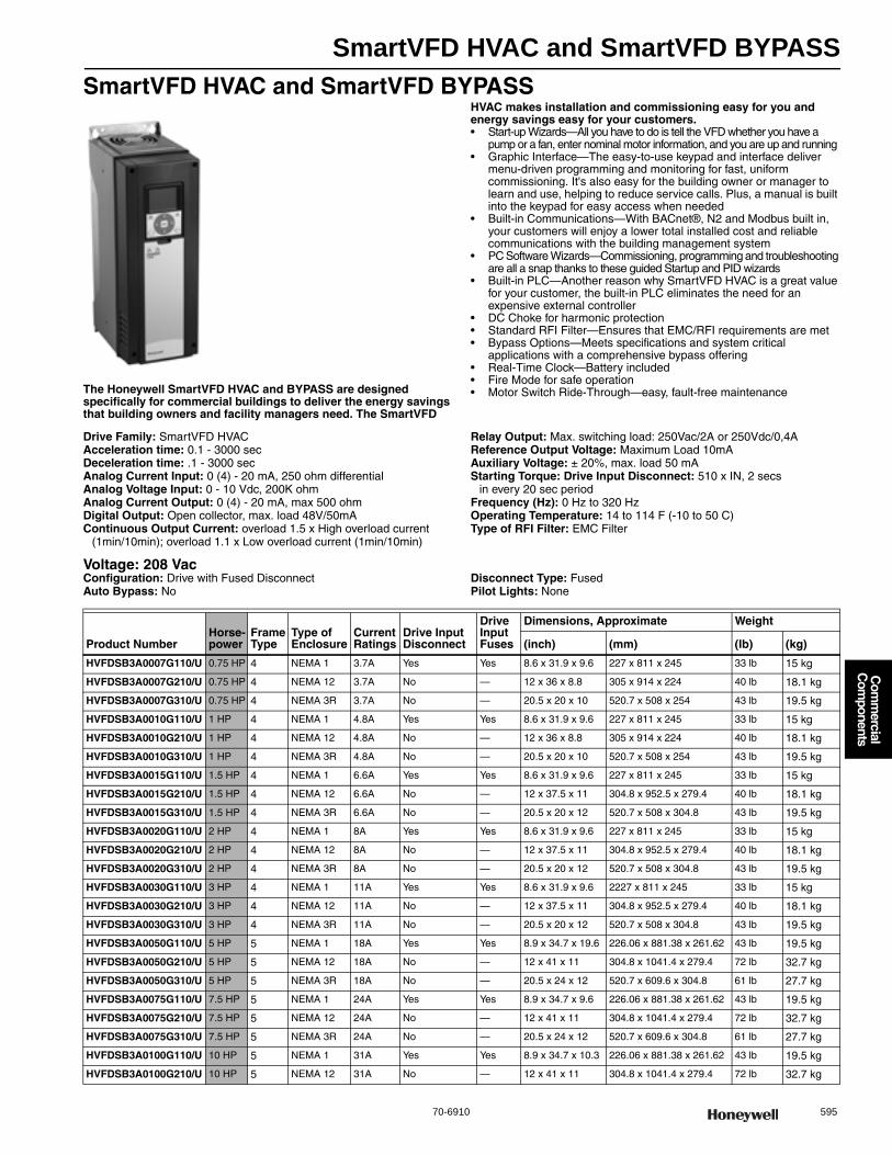
SmartVFD HVAC and SmartVFD BYPASS
70-6910 595
Com
mercial
Com
ponents
SmartVFD HVAC and SmartVFD BYPASS
The Honeywell SmartVFD HVAC and BYPASS are designed specifically for commercial buildings to deliver the energy savings that building owners and facility managers need. The SmartVFD
HVAC makes installation and commissioning easy for you and energy savings easy for your customers.• Start-up Wizards—All you have to do is tell the VFD whether you have a
pump or a fan, enter nominal motor information, and you are up and running • Graphic Interface—The easy-to-use keypad and interface deliver
menu-driven programming and monitoring for fast, uniform commissioning. It's also easy for the building owner or manager to learn and use, helping to reduce service calls. Plus, a manual is built into the keypad for easy access when needed
• Built-in Communications—With BACnet®, N2 and Modbus built in, your customers will enjoy a lower total installed cost and reliable communications with the building management system
• PC Software Wizards—Commissioning, programming and troubleshooting are all a snap thanks to these guided Startup and PID wizards
• Built-in PLC—Another reason why SmartVFD HVAC is a great value for your customer, the built-in PLC eliminates the need for an expensive external controller
• DC Choke for harmonic protection • Standard RFI Filter—Ensures that EMC/RFI requirements are met • Bypass Options—Meets specifications and system critical
applications with a comprehensive bypass offering • Real-Time Clock—Battery included • Fire Mode for safe operation • Motor Switch Ride-Through—easy, fault-free maintenance
Drive Family: SmartVFD HVACAcceleration time: 0.1 - 3000 secDeceleration time: .1 - 3000 secAnalog Current Input: 0 (4) - 20 mA, 250 ohm differentialAnalog Voltage Input: 0 - 10 Vdc, 200K ohmAnalog Current Output: 0 (4) - 20 mA, max 500 ohmDigital Output: Open collector, max. load 48V/50mAContinuous Output Current: overload 1.5 x High overload current
(1min/10min); overload 1.1 x Low overload current (1min/10min)
Relay Output: Max. switching load: 250Vac/2A or 250Vdc/0,4AReference Output Voltage: Maximum Load 10mAAuxiliary Voltage: ± 20%, max. load 50 mAStarting Torque: Drive Input Disconnect: 510 x IN, 2 secs
in every 20 sec periodFrequency (Hz): 0 Hz to 320 HzOperating Temperature: 14 to 114 F (-10 to 50 C)Type of RFI Filter: EMC Filter
Voltage: 208 VacConfiguration: Drive with Fused DisconnectAuto Bypass: No
Disconnect Type: FusedPilot Lights: None
Product NumberHorse-power
Frame Type
Type of Enclosure
Current Ratings
Drive Input Disconnect
Drive Input Fuses
Dimensions, Approximate Weight
(inch) (mm) (lb) (kg)
HVFDSB3A0007G110/U 0.75 HP 4 NEMA 1 3.7A Yes Yes 8.6 x 31.9 x 9.6 227 x 811 x 245 33 lb 15 kg
HVFDSB3A0007G210/U 0.75 HP 4 NEMA 12 3.7A No — 12 x 36 x 8.8 305 x 914 x 224 40 lb 18.1 kg
HVFDSB3A0007G310/U 0.75 HP 4 NEMA 3R 3.7A No — 20.5 x 20 x 10 520.7 x 508 x 254 43 lb 19.5 kg
HVFDSB3A0010G110/U 1 HP 4 NEMA 1 4.8A Yes Yes 8.6 x 31.9 x 9.6 227 x 811 x 245 33 lb 15 kg
HVFDSB3A0010G210/U 1 HP 4 NEMA 12 4.8A No — 12 x 36 x 8.8 305 x 914 x 224 40 lb 18.1 kg
HVFDSB3A0010G310/U 1 HP 4 NEMA 3R 4.8A No — 20.5 x 20 x 10 520.7 x 508 x 254 43 lb 19.5 kg
HVFDSB3A0015G110/U 1.5 HP 4 NEMA 1 6.6A Yes Yes 8.6 x 31.9 x 9.6 227 x 811 x 245 33 lb 15 kg
HVFDSB3A0015G210/U 1.5 HP 4 NEMA 12 6.6A No — 12 x 37.5 x 11 304.8 x 952.5 x 279.4 40 lb 18.1 kg
HVFDSB3A0015G310/U 1.5 HP 4 NEMA 3R 6.6A No — 20.5 x 20 x 12 520.7 x 508 x 304.8 43 lb 19.5 kg
HVFDSB3A0020G110/U 2 HP 4 NEMA 1 8A Yes Yes 8.6 x 31.9 x 9.6 227 x 811 x 245 33 lb 15 kg
HVFDSB3A0020G210/U 2 HP 4 NEMA 12 8A No — 12 x 37.5 x 11 304.8 x 952.5 x 279.4 40 lb 18.1 kg
HVFDSB3A0020G310/U 2 HP 4 NEMA 3R 8A No — 20.5 x 20 x 12 520.7 x 508 x 304.8 43 lb 19.5 kg
HVFDSB3A0030G110/U 3 HP 4 NEMA 1 11A Yes Yes 8.6 x 31.9 x 9.6 2227 x 811 x 245 33 lb 15 kg
HVFDSB3A0030G210/U 3 HP 4 NEMA 12 11A No — 12 x 37.5 x 11 304.8 x 952.5 x 279.4 40 lb 18.1 kg
HVFDSB3A0030G310/U 3 HP 4 NEMA 3R 11A No — 20.5 x 20 x 12 520.7 x 508 x 304.8 43 lb 19.5 kg
HVFDSB3A0050G110/U 5 HP 5 NEMA 1 18A Yes Yes 8.9 x 34.7 x 19.6 226.06 x 881.38 x 261.62 43 lb 19.5 kg
HVFDSB3A0050G210/U 5 HP 5 NEMA 12 18A No — 12 x 41 x 11 304.8 x 1041.4 x 279.4 72 lb 32.7 kg
HVFDSB3A0050G310/U 5 HP 5 NEMA 3R 18A No — 20.5 x 24 x 12 520.7 x 609.6 x 304.8 61 lb 27.7 kg
HVFDSB3A0075G110/U 7.5 HP 5 NEMA 1 24A Yes Yes 8.9 x 34.7 x 9.6 226.06 x 881.38 x 261.62 43 lb 19.5 kg
HVFDSB3A0075G210/U 7.5 HP 5 NEMA 12 24A No — 12 x 41 x 11 304.8 x 1041.4 x 279.4 72 lb 32.7 kg
HVFDSB3A0075G310/U 7.5 HP 5 NEMA 3R 24A No — 20.5 x 24 x 12 520.7 x 609.6 x 304.8 61 lb 27.7 kg
HVFDSB3A0100G110/U 10 HP 5 NEMA 1 31A Yes Yes 8.9 x 34.7 x 10.3 226.06 x 881.38 x 261.62 43 lb 19.5 kg
HVFDSB3A0100G210/U 10 HP 5 NEMA 12 31A No — 12 x 41 x 11 304.8 x 1041.4 x 279.4 72 lb 32.7 kg
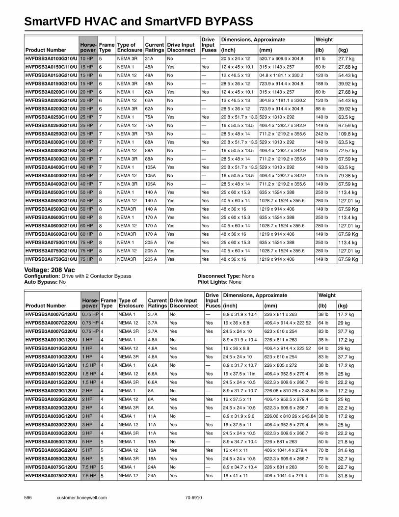
SmartVFD HVAC and SmartVFD BYPASS
596 customer.honeywell.com 70-6910
Voltage: 208 VacConfiguration: Drive with 2 Contactor BypassAuto Bypass: No
Disconnect Type: NonePilot Lights: None
HVFDSB3A0100G310/U 10 HP 5 NEMA 3R 31A No — 20.5 x 24 x 12 520.7 x 609.6 x 304.8 61 lb 27.7 kg
HVFDSB3A0150G110/U 15 HP 6 NEMA 1 48A Yes Yes 12.4 x 45 x 10.1 315 x 1143 x 257 60 lb 27.68 kg
HVFDSB3A0150G210/U 15 HP 6 NEMA 12 48A No — 12 x 46.5 x 13 04.8 x 1181.1 x 330.2 120 lb 54.43 kg
HVFDSB3A0150G310/U 15 HP 6 NEMA 3R 48A No — 28.5 x 36 x 12 723.9 x 914.4 x 304.8 188 lb 39.92 kg
HVFDSB3A0200G110/U 20 HP 6 NEMA 1 62A Yes Yes 12.4 x 45 x 10.1 315 x 1143 x 257 60 lb 27.68 kg
HVFDSB3A0200G210/U 20 HP 6 NEMA 12 62A No — 12 x 46.5 x 13 304.8 x 1181.1 x 330.2 120 lb 54.43 kg
HVFDSB3A0200G310/U 20 HP 6 NEMA 3R 62A No — 28.5 x 36 x 12 723.9 x 914.4 x 304.8 88 ib 39.92 kg
HVFDSB3A0250G110/U 25 HP 7 NEMA 1 75A Yes Yes 20 8 x 51.7 x 13.3 529 x 1313 x 292 140 lb 63.5 kg
HVFDSB3A0250G210/U 25 HP 7 NEMA 12 75A No — 16 x 50.5 x 13.5 406.4 x 1282.7 x 342.9 149 lb 67.59 kg
HVFDSB3A0250G310/U 25 HP 7 NEMA 3R 75A No — 28.5 x 48 x 14 711.2 x 1219.2 x 355.6 242 lb 109.8 kg
HVFDSB3A0300G110/U 30 HP 7 NEMA 1 88A Yes Yes 20 8 x 51.7 x 13.3 529 x 1313 x 292 140 lb 63.5 kg
HVFDSB3A0300G210/U 30 HP 7 NEMA 12 88A No — 16 x 50.5 x 13.5 406.4 x 1282.7 x 342.9 160 lb 72.57 kg
HVFDSB3A0300G310/U 30 HP 7 NEMA 3R 88A No — 28.5 x 48 x 14 711.2 x 1219.2 x 355.6 149 lb 67.59 kg
HVFDSB3A0400G110/U 40 HP 7 NEMA 1 105A Yes Yes 20 8 x 51.7 x 13.3 529 x 1313 x 292 140 lb 63.5 kg
HVFDSB3A0400G210/U 40 HP 7 NEMA 12 105A No — 16 x 50.5 x 13.5 406.4 x 1282.7 x 342.9 175 lb 79.38 kg
HVFDSB3A0400G310/U 40 HP 7 NEMA 3R 105A No — 28.5 x 48 x 14 711.2 x 1219.2 x 355.6 149 lb 67.59 kg
HVFDSB3A0500G110/U 50 HP 8 NEMA 1 140 A Yes Yes 25 x 60 x 15.3 635 x 1524 x 388 250 lb 113.4 kg
HVFDSB3A0500G210/U 50 HP 8 NEMA 12 140 A Yes Yes 40.5 x 60 x 14 1028.7 x 1524 x 355.6 280 lb 127.01 kg
HVFDSB3A0500G310/U 50 HP 8 NEMA3R 140 A Yes Yes 48 x 36 x 16 1219 x 914 x 406 149 lb 67.59 Kg
HVFDSB3A0600G110/U 60 HP 8 NEMA 1 170 A Yes Yes 25 x 60 x 15.3 635 x 1524 x 388 250 lb 113.4 kg
HVFDSB3A0600G210/U 60 HP 8 NEMA 12 170 A Yes Yes 40.5 x 60 x 14 1028.7 x 1524 x 355.6 280 lb 127.01 kg
HVFDSB3A0600G310/U 60 HP 8 NEMA3R 170 A Yes Yes 48 x 36 x 16 1219 x 914 x 406 149 lb 67.59 Kg
HVFDSB3A0750G110/U 75 HP 8 NEMA 1 205 A Yes Yes 25 x 60 x 15.3 635 x 1524 x 388 250 lb 113.4 kg
HVFDSB3A0750G210/U 75 HP 8 NEMA 12 205 A Yes Yes 40.5 x 60 x 14 1028.7 x 1524 x 355.6 280 lb 127.01 kg
HVFDSB3A0750G310/U 75 HP 8 NEMA3R 205 A Yes Yes 48 x 36 x 16 1219 x 914 x 406 149 lb 67.59 Kg
Product NumberHorse-power
Frame Type
Type of Enclosure
Current Ratings
Drive Input Disconnect
Drive Input Fuses
Dimensions, Approximate Weight
(inch) (mm) (lb) (kg)
Product NumberHorse-power
Frame Type
Type of Enclosure
Current Ratings
Drive Input Disconnect
Drive Input Fuses
Dimensions, Approximate Weight
(inch) (mm) (lb) (kg)
HVFDSB3A0007G120/U 0.75 HP 4 NEMA 1 3.7A No — 8.9 x 31.9 x 10.4 226 x 811 x 263 38 lb 17.2 kg
HVFDSB3A0007G220/U 0.75 HP 4 NEMA 12 3.7A Yes Yes 16 x 36 x 8.8 406.4 x 914.4 x 223 52 64 lb 29 kg
HVFDSB3A0007G320/U 0.75 HP 4 NEMA 3R 3.7A Yes Yes 24.5 x 24 x 10 623 x 610 x 254 83 lb 37.7 kg
HVFDSB3A0010G120/U 1 HP 4 NEMA 1 4.8A No — 8.9 x 31.9 x 10.4 226 x 811 x 263 38 lb 17.2 kg
HVFDSB3A0010G220/U 1 HP 4 NEMA 12 4.8A Yes Yes 16 x 36 x 8.8 406.4 x 914.4 x 223 52 64 lb 29 kg
HVFDSB3A0010G320/U 1 HP 4 NEMA 3R 4.8A Yes Yes 24.5 x 24 x 10 623 x 610 x 254 83 lb 37.7 kg
HVFDSB3A0015G120/U 1.5 HP 4 NEMA 1 6.6A No — 8.9 x 31.7 x 10.7 226 x 805 x 272 38 lb 17.2 kg
HVFDSB3A0015G220/U 1.5 HP 4 NEMA 12 6.6A Yes Yes 16 x 37.5 x 11in. 406.4 x 952.5 x 279.4 55 lb 25 kg
HVFDSB3A0015G320/U 1.5 HP 4 NEMA 3R 6.6A Yes Yes 24.5 x 24 x 10.5 622.3 x 609.6 x 266.7 49 lb 22.2 kg
HVFDSB3A0020G120/U 2 HP 4 NEMA 1 8A No — 8.9 x 31.7 x 10.7 226.06 x 810 26 x 243.84 38 lb 17.2 kg
HVFDSB3A0020G220/U 2 HP 4 NEMA 12 8A Yes Yes 16 x 37.5 x 11 406.4 x 952.5 x 279.4 55 lb 25 kg
HVFDSB3A0020G320/U 2 HP 4 NEMA 3R 8A Yes Yes 24.5 x 24 x 10.5 622.3 x 609.6 x 266.7 49 lb 22.2 kg
HVFDSB3A0030G120/U 3 HP 4 NEMA 1 11A No — 8.9 x 31.9 x 9.6 226.06 x 810 26 x 243.84 38 lb 17.2 kg
HVFDSB3A0030G220/U 3 HP 4 NEMA 12 11A Yes Yes 16 x 37.5 x 11 406.4 x 952.5 x 279.4 55 lb 25 kg
HVFDSB3A0030G320/U 3 HP 4 NEMA 3R 11A Yes Yes 24.5 x 24 x 10.5 622.3 x 609.6 x 266.7 49 lb 22.2 kg
HVFDSB3A0050G120/U 5 HP 5 NEMA 1 18A No — 8.9 x 34.7 x 10.4 226 x 881 x 263 50 lb 21.8 kg
HVFDSB3A0050G220/U 5 HP 5 NEMA 12 18A Yes Yes 16 x 41 x 11 406 x 1041.4 x 279.4 70 lb 31.6 kg
HVFDSB3A0050G320/U 5 HP 5 NEMA 3R 18A Yes Yes 24.5 x 24 x 10.5 622.3 x 609.6 x 266.7 72 lb 32.7 kg
HVFDSB3A0075G120/U 7.5 HP 5 NEMA 1 24A No — 8.9 x 34.7 x 10.4 226 x 881 x 263 50 lb 22.7 kg
HVFDSB3A0075G220/U 7.5 HP 5 NEMA 12 24A Yes Yes 16 x 41 x 11 406 x 1041.4 x 279.4 70 lb 31.8 kg
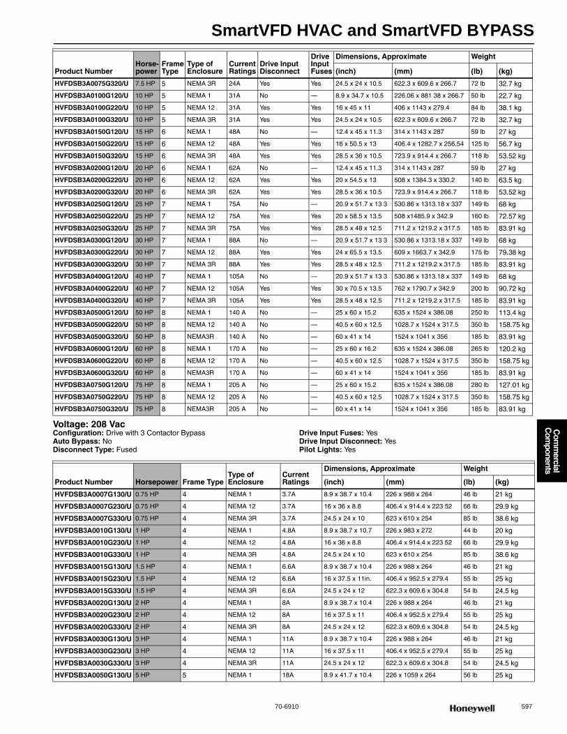
SmartVFD HVAC and SmartVFD BYPASS
70-6910 597
Com
mercial
Com
ponents
Voltage: 208 VacConfiguration: Drive with 3 Contactor BypassAuto Bypass: NoDisconnect Type: Fused
Drive Input Fuses: YesDrive Input Disconnect: YesPilot Lights: Yes
HVFDSB3A0075G320/U 7.5 HP 5 NEMA 3R 24A Yes Yes 24.5 x 24 x 10.5 622.3 x 609.6 x 266.7 72 lb 32.7 kg
HVFDSB3A0100G120/U 10 HP 5 NEMA 1 31A No — 8.9 x 34.7 x 10.5 226.06 x 881 38 x 266.7 50 lb 22.7 kg
HVFDSB3A0100G220/U 10 HP 5 NEMA 12 31A Yes Yes 16 x 45 x 11 406 x 1143 x 279.4 84 lb 38.1 kg
HVFDSB3A0100G320/U 10 HP 5 NEMA 3R 31A Yes Yes 24.5 x 24 x 10.5 622.3 x 609.6 x 266.7 72 lb 32.7 kg
HVFDSB3A0150G120/U 15 HP 6 NEMA 1 48A No — 12.4 x 45 x 11.3 314 x 1143 x 287 59 lb 27 kg
HVFDSB3A0150G220/U 15 HP 6 NEMA 12 48A Yes Yes 16 x 50.5 x 13 406.4 x 1282.7 x 256.54 125 lb 56.7 kg
HVFDSB3A0150G320/U 15 HP 6 NEMA 3R 48A Yes Yes 28.5 x 36 x 10.5 723.9 x 914.4 x 266.7 118 lb 53.52 kg
HVFDSB3A0200G120/U 20 HP 6 NEMA 1 62A No — 12.4 x 45 x 11.3 314 x 1143 x 287 59 lb 27 kg
HVFDSB3A0200G220/U 20 HP 6 NEMA 12 62A Yes Yes 20 x 54.5 x 13 508 x 1384.3 x 330.2 140 lb 63.5 kg
HVFDSB3A0200G320/U 20 HP 6 NEMA 3R 62A Yes Yes 28.5 x 36 x 10.5 723.9 x 914.4 x 266.7 118 lb 53.52 kg
HVFDSB3A0250G120/U 25 HP 7 NEMA 1 75A No — 20.9 x 51.7 x 13 3 530.86 x 1313.18 x 337 149 lb 68 kg
HVFDSB3A0250G220/U 25 HP 7 NEMA 12 75A Yes Yes 20 x 58.5 x 13.5 508 x1485.9 x 342.9 160 lb 72.57 kg
HVFDSB3A0250G320/U 25 HP 7 NEMA 3R 75A Yes Yes 28.5 x 48 x 12.5 711.2 x 1219.2 x 317.5 185 lb 83.91 kg
HVFDSB3A0300G120/U 30 HP 7 NEMA 1 88A No — 20.9 x 51.7 x 13 3 530.86 x 1313.18 x 337 149 lb 68 kg
HVFDSB3A0300G220/U 30 HP 7 NEMA 12 88A Yes Yes 24 x 65.5 x 13.5 609 x 1663.7 x 342.9 175 lb 79.38 kg
HVFDSB3A0300G320/U 30 HP 7 NEMA 3R 88A Yes Yes 28.5 x 48 x 12.5 711.2 x 1219.2 x 317.5 185 lb 83.91 kg
HVFDSB3A0400G120/U 40 HP 7 NEMA 1 105A No — 20.9 x 51.7 x 13 3 530.86 x 1313.18 x 337 149 lb 68 kg
HVFDSB3A0400G220/U 40 HP 7 NEMA 12 105A Yes Yes 30 x 70.5 x 13.5 762 x 1790.7 x 342.9 200 lb 90.72 kg
HVFDSB3A0400G320/U 40 HP 7 NEMA 3R 105A Yes Yes 28.5 x 48 x 12.5 711.2 x 1219.2 x 317.5 185 lb 83.91 kg
HVFDSB3A0500G120/U 50 HP 8 NEMA 1 140 A No — 25 x 60 x 15.2 635 x 1524 x 386.08 250 lb 113.4 kg
HVFDSB3A0500G220/U 50 HP 8 NEMA 12 140 A No — 40.5 x 60 x 12.5 1028.7 x 1524 x 317.5 350 lb 158.75 kg
HVFDSB3A0500G320/U 50 HP 8 NEMA3R 140 A No — 60 x 41 x 14 1524 x 1041 x 356 185 lb 83.91 kg
HVFDSB3A0600G120/U 60 HP 8 NEMA 1 170 A No — 25 x 60 x 16.2 635 x 1524 x 386.08 265 lb 120.2 kg
HVFDSB3A0600G220/U 60 HP 8 NEMA 12 170 A No — 40.5 x 60 x 12.5 1028.7 x 1524 x 317.5 350 lb 158.75 kg
HVFDSB3A0600G320/U 60 HP 8 NEMA3R 170 A No — 60 x 41 x 14 1524 x 1041 x 356 185 lb 83.91 kg
HVFDSB3A0750G120/U 75 HP 8 NEMA 1 205 A No — 25 x 60 x 15.2 635 x 1524 x 386.08 280 lb 127.01 kg
HVFDSB3A0750G220/U 75 HP 8 NEMA 12 205 A No — 40.5 x 60 x 12.5 1028.7 x 1524 x 317.5 350 lb 158.75 kg
HVFDSB3A0750G320/U 75 HP 8 NEMA3R 205 A No — 60 x 41 x 14 1524 x 1041 x 356 185 lb 83.91 kg
Product NumberHorse-power
Frame Type
Type of Enclosure
Current Ratings
Drive Input Disconnect
Drive Input Fuses
Dimensions, Approximate Weight
(inch) (mm) (lb) (kg)
Product Number Horsepower Frame TypeType of Enclosure
Current Ratings
Dimensions, Approximate Weight
(inch) (mm) (lb) (kg)
HVFDSB3A0007G130/U 0.75 HP 4 NEMA 1 3.7A 8.9 x 38.7 x 10.4 226 x 988 x 264 46 lb 21 kg
HVFDSB3A0007G230/U 0.75 HP 4 NEMA 12 3.7A 16 x 36 x 8.8 406.4 x 914.4 x 223 52 66 lb 29.9 kg
HVFDSB3A0007G330/U 0.75 HP 4 NEMA 3R 3.7A 24.5 x 24 x 10 623 x 610 x 254 85 lb 38.6 kg
HVFDSB3A0010G130/U 1 HP 4 NEMA 1 4.8A 8.9 x 38.7 x 10.7 226 x 983 x 272 44 lb 20 kg
HVFDSB3A0010G230/U 1 HP 4 NEMA 12 4.8A 16 x 36 x 8.8 406.4 x 914.4 x 223 52 66 lb 29.9 kg
HVFDSB3A0010G330/U 1 HP 4 NEMA 3R 4.8A 24.5 x 24 x 10 623 x 610 x 254 85 lb 38.6 kg
HVFDSB3A0015G130/U 1.5 HP 4 NEMA 1 6.6A 8.9 x 38.7 x 10.4 226 x 988 x 264 46 lb 21 kg
HVFDSB3A0015G230/U 1.5 HP 4 NEMA 12 6.6A 16 x 37.5 x 11in. 406.4 x 952.5 x 279.4 55 lb 25 kg
HVFDSB3A0015G330/U 1.5 HP 4 NEMA 3R 6.6A 24.5 x 24 x 12 622.3 x 609.6 x 304.8 54 lb 24.5 kg
HVFDSB3A0020G130/U 2 HP 4 NEMA 1 8A 8.9 x 38.7 x 10.4 226 x 988 x 264 46 lb 21 kg
HVFDSB3A0020G230/U 2 HP 4 NEMA 12 8A 16 x 37.5 x 11 406.4 x 952.5 x 279.4 55 lb 25 kg
HVFDSB3A0020G330/U 2 HP 4 NEMA 3R 8A 24.5 x 24 x 12 622.3 x 609.6 x 304.8 54 lb 24.5 kg
HVFDSB3A0030G130/U 3 HP 4 NEMA 1 11A 8.9 x 38.7 x 10.4 226 x 988 x 264 46 lb 21 kg
HVFDSB3A0030G230/U 3 HP 4 NEMA 12 11A 16 x 37.5 x 11 406.4 x 952.5 x 279.4 55 lb 25 kg
HVFDSB3A0030G330/U 3 HP 4 NEMA 3R 11A 24.5 x 24 x 12 622.3 x 609.6 x 304.8 54 lb 24.5 kg
HVFDSB3A0050G130/U 5 HP 5 NEMA 1 18A 8.9 x 41.7 x 10.4 226 x 1059 x 264 56 lb 25 kg
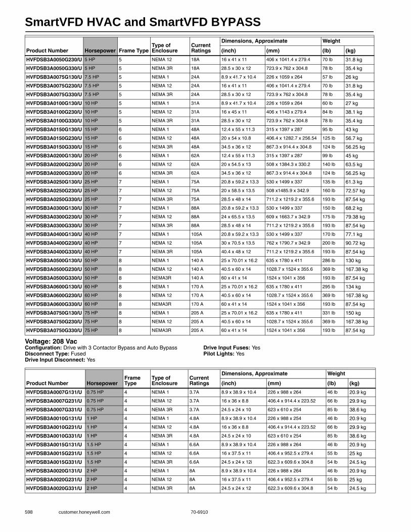
SmartVFD HVAC and SmartVFD BYPASS
598 customer.honeywell.com 70-6910
Voltage: 208 VacConfiguration: Drive with 3 Contactor Bypass and Auto BypassDisconnect Type: FusedDrive Input Disconnect: Yes
Drive Input Fuses: YesPilot Lights: Yes
HVFDSB3A0050G230/U 5 HP 5 NEMA 12 18A 16 x 41 x 11 406 x 1041.4 x 279.4 70 lb 31.8 kg
HVFDSB3A0050G330/U 5 HP 5 NEMA 3R 18A 28.5 x 30 x 12 723.9 x 762 x 304.8 78 lb 35.4 kg
HVFDSB3A0075G130/U 7.5 HP 5 NEMA 1 24A 8.9 x 41.7 x 10.4 226 x 1059 x 264 57 lb 26 kg
HVFDSB3A0075G230/U 7.5 HP 5 NEMA 12 24A 16 x 41 x 11 406 x 1041.4 x 279.4 70 lb 31.8 kg
HVFDSB3A0075G330/U 7.5 HP 5 NEMA 3R 24A 28.5 x 30 x 12 723.9 x 762 x 304.8 78 lb 35.4 kg
HVFDSB3A0100G130/U 10 HP 5 NEMA 1 31A 8.9 x 41.7 x 10.4 226 x 1059 x 264 60 lb 27 kg
HVFDSB3A0100G230/U 10 HP 5 NEMA 12 31A 16 x 45 x 11 406 x 1143 x 279.4 84 lb 38.1 kg
HVFDSB3A0100G330/U 10 HP 5 NEMA 3R 31A 28.5 x 30 x 12 723.9 x 762 x 304.8 78 lb 35.4 kg
HVFDSB3A0150G130/U 15 HP 6 NEMA 1 48A 12.4 x 55 x 11.3 315 x 1397 x 287 95 lb 43 kg
HVFDSB3A0150G230/U 15 HP 6 NEMA 12 48A 20 x 54 x 10.8 406.4 x 1282.7 x 256.54 125 lb 56.7 kg
HVFDSB3A0150G330/U 15 HP 6 NEMA 3R 48A 34.5 x 36 x 12 867.3 x 914.4 x 304.8 124 lb 56.25 kg
HVFDSB3A0200G130/U 20 HP 6 NEMA 1 62A 12.4 x 55 x 11.3 315 x 1397 x 287 99 lb 45 kg
HVFDSB3A0200G230/U 20 HP 6 NEMA 12 62A 20 x 54.5 x 13 508 x 1384.3 x 330.2 140 lb 63.5 kg
HVFDSB3A0200G330/U 20 HP 6 NEMA 3R 62A 34.5 x 36 x 12 867.3 x 914.4 x 304.8 124 lb 56.25 kg
HVFDSB3A0250G130/U 25 HP 7 NEMA 1 75A 20.8 x 59.2 x 13.3 530 x 1499 x 337 135 lb 61.3 kg
HVFDSB3A0250G230/U 25 HP 7 NEMA 12 75A 20 x 58.5 x 13.5 508 x1485.9 x 342.9 160 lb 72.57 kg
HVFDSB3A0250G330/U 25 HP 7 NEMA 3R 75A 28.5 x 48 x 14 711.2 x 1219.2 x 355.6 193 lb 87.54 kg
HVFDSB3A0300G130/U 30 HP 7 NEMA 1 88A 20.8 x 59.2 x 13.3 530 x 1499 x 337 150 lb 68.2 kg
HVFDSB3A0300G230/U 30 HP 7 NEMA 12 88A 24 x 65.5 x 13.5 609 x 1663.7 x 342.9 175 lb 79.38 kg
HVFDSB3A0300G330/U 30 HP 7 NEMA 3R 88A 28.5 x 48 x 14 711.2 x 1219.2 x 355.6 193 lb 87.54 kg
HVFDSB3A0400G130/U 40 HP 7 NEMA 1 105A 20.8 x 59.2 x 13.3 530 x 1499 x 337 170 lb 77.1 kg
HVFDSB3A0400G230/U 40 HP 7 NEMA 12 105A 30 x 70.5 x 13.5 762 x 1790.7 x 342.9 200 lb 90.72 kg
HVFDSB3A0400G330/U 40 HP 7 NEMA 3R 105A 40.4 x 48 x 12 711.2 x 1219.2 x 355.6 193 lb 87.54 kg
HVFDSB3A0500G130/U 50 HP 8 NEMA 1 140 A 25 x 70.01 x 16.2 635 x 1780 x 411 286 lb 130 kg
HVFDSB3A0500G230/U 50 HP 8 NEMA 12 140 A 40.5 x 60 x 14 1028.7 x 1524 x 355.6 369 lb 167.38 kg
HVFDSB3A0500G330/U 50 HP 8 NEMA3R 140 A 60 x 41 x 14 1524 x 1041 x 356 193 lb 87.54 kg
HVFDSB3A0600G130/U 60 HP 8 NEMA 1 170 A 25 x 70.01 x 16.2 635 x 1780 x 411 295 lb 134 kg
HVFDSB3A0600G230/U 60 HP 8 NEMA 12 170 A 40.5 x 60 x 14 1028.7 x 1524 x 355.6 369 lb 167.38 kg
HVFDSB3A0600G330/U 60 HP 8 NEMA3R 170 A 60 x 41 x 14 1524 x 1041 x 356 193 lb 87.54 kg
HVFDSB3A0750G130/U 75 HP 8 NEMA 1 205 A 25 x 70.01 x 16.2 635 x 1780 x 411 331 lb 150 kg
HVFDSB3A0750G230/U 75 HP 8 NEMA 12 205 A 40.5 x 60 x 14 1028.7 x 1524 x 355.6 369 lb 167.38 kg
HVFDSB3A0750G330/U 75 HP 8 NEMA3R 205 A 60 x 41 x 14 1524 x 1041 x 356 193 lb 87.54 kg
Product Number Horsepower Frame TypeType of Enclosure
Current Ratings
Dimensions, Approximate Weight
(inch) (mm) (lb) (kg)
Product Number HorsepowerFrame Type
Type of Enclosure
Current Ratings
Dimensions, Approximate Weight
(inch) (mm) (lb) (kg)
HVFDSB3A0007G131/U 0.75 HP 4 NEMA 1 3.7A 8.9 x 38.9 x 10.4 226 x 988 x 264 46 lb 20.9 kg
HVFDSB3A0007G231/U 0.75 HP 4 NEMA 12 3.7A 16 x 36 x 8.8 406.4 x 914.4 x 223.52 66 lb 29.9 kg
HVFDSB3A0007G331/U 0.75 HP 4 NEMA 3R 3.7A 24.5 x 24 x 10 623 x 610 x 254 85 lb 38.6 kg
HVFDSB3A0010G131/U 1 HP 4 NEMA 1 4.8A 8.9 x 38.9 x 10.4 226 x 988 x 254 46 lb 20.9 kg
HVFDSB3A0010G231/U 1 HP 4 NEMA 12 4.8A 16 x 36 x 8.8 406.4 x 914.4 x 223.52 66 lb 29.9 kg
HVFDSB3A0010G331/U 1 HP 4 NEMA 3R 4.8A 24.5 x 24 x 10 623 x 610 x 254 85 lb 38.6 kg
HVFDSB3A0015G131/U 1.5 HP 4 NEMA 1 6.6A 8.9 x 38.9 x 10.4 226 x 988 x 264 46 lb 20.9 kg
HVFDSB3A0015G231/U 1.5 HP 4 NEMA 12 6.6A 16 x 37.5 x 11 406.4 x 952.5 x 279.4 55 lb 25 kg
HVFDSB3A0015G331/U 1.5 HP 4 NEMA 3R 6.6A 24.5 x 24 x 12i 622.3 x 609.6 x 304.8 54 lb 24.5 kg
HVFDSB3A0020G131/U 2 HP 4 NEMA 1 8A 8.9 x 38.9 x 10.4 226 x 988 x 264 46 lb 20.9 kg
HVFDSB3A0020G231/U 2 HP 4 NEMA 12 8A 16 x 37.5 x 11 406.4 x 952.5 x 279.4 55 lb 25 kg
HVFDSB3A0020G331/U 2 HP 4 NEMA 3R 8A 24.5 x 24 x 12 622.3 x 609.6 x 304.8 54 lb 24.5 kg
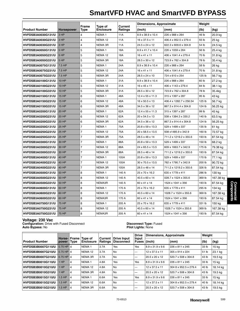
SmartVFD HVAC and SmartVFD BYPASS
70-6910 599
Com
mercial
Com
ponents
Voltage: 230 VacConfiguration: Drive with Fused DisconnectAuto Bypass: No
Disconnect Type: FusedPilot Lights: None
HVFDSB3A0030G131/U 3 HP 4 NEMA 1 11A 8.9 x 38.9 x 10.4 226 x 988 x 264 46 lb 20.9 kg
HVFDSB3A0030G231/U 3 HP 4 NEMA 12 11A 16 x 37.5 x 11 406.4 x 952.5 x 279.4 55 lb 25 kg
HVFDSB3A0030G331/U 3 HP 4 NEMA 3R 11A 24.5 x 24 x 12 622.3 x 609.6 x 304.8 54 lb 24.5 kg
HVFDSB3A0050G131/U 5 HP 5 NEMA 1 18A 8.9 x 41.7 x 10.4 226 x 1059 x 264 56 lb 25.4 kg
HVFDSB3A0050G231/U 5 HP 5 NEMA 12 18A 16 x 41 x 11 406 x 1041.4 x 279.4 70 lb 31.8 kg
HVFDSB3A0050G331/U 5 HP 5 NEMA 3R 18A 28.5 x 30 x 12 723.9 x 762 x 304.8 78 lb 35.4 kg
HVFDSB3A0075G131/U 7.5 HP 5 NEMA 1 24A 8.9 x 38.9 x 10.4 226 x 988 x 264 58 lb 26 kg
HVFDSB3A0075G231/U 7.5 HP 5 NEMA 12 24A 16 x 41 x 11 406 x 1041.4 x 279.4 70 lb 31.8 kg
HVFDSB3A0075G331/U 7.5 HP 5 NEMA 3R 24A 28.5 x 24 x 10 724 x 610 x 254 125 lb 56.7 kg
HVFDSB3A0100G131/U 10 HP 5 NEMA 1 31A 8.9 x 38.9 x 10.4 226 x 988 x 264 60 lb 27.2 kg
HVFDSB3A0100G231/U 10 HP 5 NEMA 12 31A 16 x 45 x 11 406 x 1143 x 279.4 84 lb 38.1 kg
HVFDSB3A0100G331/U 10 HP 5 NEMA 3R 31A 28.5 x 30 x 12 723.9 x 762 x 304.8 78 lb 35.4kg
HVFDSB3A0150G131/U 15 HP 6 NEMA 1 48A 12.4 x 55 x 11.3 315 x 1397 x 287 95 lb 43 kg
HVFDSB3A0150G231/U 15 HP 6 NEMA 12 48A 16 x 50.5 x 13 406.4 x 1282.7 x 256.54 125 lb 56.7 kg
HVFDSB3A0150G331/U 15 HP 6 NEMA 3R 48A 34.5 x 36 x 12 867.3 x 914.4 x 304.8 124 lb 56.25 kg
HVFDSB3A0200G131/U 20 HP 6 NEMA 1 62A 12.4 x 55 x 11.3 315 x 1397 x 287 99 lb 45 kg
HVFDSB3A0200G231/U 20 HP 6 NEMA 12 62A 20 x 54.5 x 13 508 x 1384.3 x 330.2 140 lb 63.5 kg
HVFDSB3A0200G331/U 20 HP 6 NEMA 3R 62A 34.5 x 36 x 12 867.3 x 914.4 x 304.8 124 lb 56.25 kg
HVFDSB3A0250G131/U 25 HP 7 NEMA 1 75A 20.8 x 59 x 13.3 529 x 1499 x 337 135 lb 61 kg
HVFDSB3A0250G231/U 25 HP 7 NEMA 12 75A 20 x 58.5 x 13.5 508 x1485.9 x 342.9 160 lb 72.57 kg
HVFDSB3A0250G331/U 25 HP 7 NEMA 3R 75A 28.5 x 48 x 14 711.2 x 1219.2 x 355.6 193 lb 87.54 kg
HVFDSB3A0300G131/U 30 HP 7 NEMA 1 88A 20.8 x 59 x 13.3 529 x 1499 x 337 150 lb 68.2 kg
HVFDSB3A0300G231/U 30 HP 7 NEMA 12 88A 24 x 65.5 x 13.5 609 x 1663.7 x 342.9 175 lb 79.38 kg
HVFDSB3A0300G331/U 30 HP 7 NEMA 3R 88A 28.5 x 48 x 14 711.2 x 1219.2 x 355.6 193 lb 87.54 kg
HVFDSB3A0400G131/U 40 HP 7 NEMA 1 105A 20.8 x 59 x 13.3 529 x 1499 x 337 170 lb 77.1 kg
HVFDSB3A0400G231/U 40 HP 7 NEMA 12 105A 30 x 70.5 x 13.5 762 x 1790.7 x 342.9 200 lb 90.72 kg
HVFDSB3A0400G331/U 40 HP 7 NEMA 3R 105A 28.5 x 48 x 14 711.2 x 1219.2 x 355.6 326 lb 87.54 kg
HVFDSB3A0500G131/U 50 HP 8 NEMA 1 140 A 25 x 70 x 16.2 635 x 1778 x 411 286 lb 130 kg
HVFDSB3A0500G231/U 50 HP 8 NEMA 12 140 A 40.5 x 60 x 14 028.7 x 1524 x 355.6 369 lb 167.38 kg
HVFDSB3A0500G331/U 50 HP 8 NEMA3R 140 A 60 x 41 x 14 1524 x 1041 x 356 193 lb 87.54 kg
HVFDSB3A0600G131/U 60 HP 8 NEMA 1 170 A 25 x 70 x 16.2 635 x 1778 x 411 295 lb 134 kg
HVFDSB3A0600G231/U 60 HP 8 NEMA 12 170 A 40.5 x 60 x 14 1028.7 x 1524 x 355.6 369 lb 167.38 kg
HVFDSB3A0600G331/U 60 HP 8 NEMA3R 170 A 60 x 41 x 14 1524 x 1041 x 356 193 lb 87.54 kg
HVFDSB3A0750G131/U 75 HP 8 NEMA 1 205 A 25 x 70 x 16.2 635 x 1778 x 411 331 lb 150 kg
HVFDSB3A0750G231/U 75 HP 8 NEMA 12 205 A 40.5 x 60 x 14 1028.7 x 1524 x 355.6 369 lb 167.38 kg
HVFDSB3A0750G331/U 75 HP 8 NEMA3R 205 A 60 x 41 x 14 1524 x 1041 x 356 193 lb 87.54 kg
Product Number HorsepowerFrame Type
Type of Enclosure
Current Ratings
Dimensions, Approximate Weight
(inch) (mm) (lb) (kg)
Product NumberHorse-power
Frame Type
Type of Enclosure
Current Ratings
Drive Input Disconnect
Drive Input Fuses
Dimensions, Approximate Weight
(inch) (mm) (lb) (kg)
HVFDSB3B0007G110/U 0.75 HP 4 NEMA 1 3.7A Yes Yes 8.9 x 31.9 x 9.6 226 x 811 x 245 33 lb 15 kg
HVFDSB3B0007G210/U 0.75 HP 4 NEMA 12 3.7A No — 12 x 37.5 x 11 305 x 914 x 224 51 lb 23.1 kg
HVFDSB3B0007G310/U 0.75 HP 4 NEMA 3R 3.7A No — 20.5 x 20 x 12 520.7 x 508 x 304.8 43 lb 19.5 kg
HVFDSB3B0010G110/U 1 HP 4 NEMA 1 4.8A Yes Yes 8.9 x 31.9 x 9.6 226 x 811 x 245 33 lb 15 kg
HVFDSB3B0010G210/U 1 HP 4 NEMA 12 4.8A No — 12 x 37.5 x 11 304 8 x 952.5 x 279.4 40 lb 18.14 kg
HVFDSB3B0010G310/U 1 HP 4 NEMA 3R 4.8A No — 20.5 x 20 x 12 520.7 x 508 x 304.8 43 lb 19.5 kg
HVFDSB3B0015G110/U 1.5 HP 4 NEMA 1 6.6A Yes Yes 8.9 x 31.9 x 9.6 226 x 811 x 245 33 lb 15 kg
HVFDSB3B0015G210/U 1.5 HP 4 NEMA 12 6.6A No — 12 x 37.5 x 11 304 8 x 952.5 x 279.4 40 lb 18.14 kg
HVFDSB3B0015G310/U 1.5 HP 4 NEMA 3R 6.6A No — 20.5 x 20 x 12 520.7 x 508 x 304.8 43 lb 19.5 kg
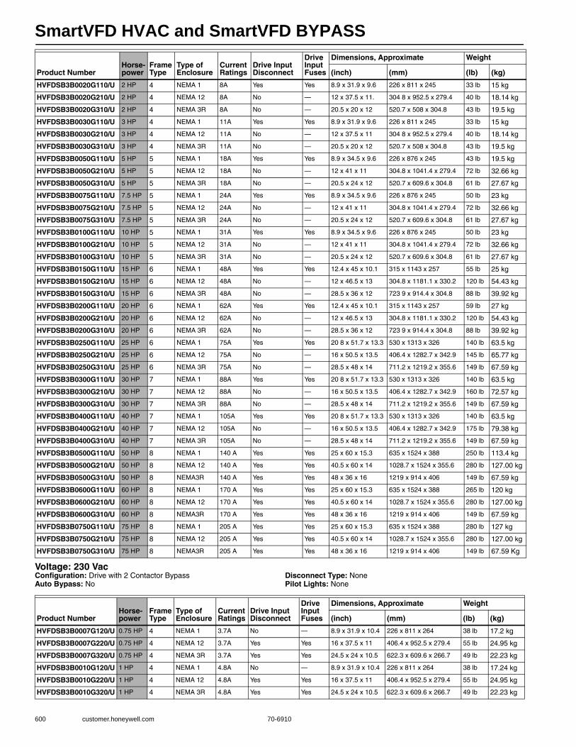
SmartVFD HVAC and SmartVFD BYPASS
600 customer.honeywell.com 70-6910
Voltage: 230 VacConfiguration: Drive with 2 Contactor BypassAuto Bypass: No
Disconnect Type: NonePilot Lights: None
HVFDSB3B0020G110/U 2 HP 4 NEMA 1 8A Yes Yes 8.9 x 31.9 x 9.6 226 x 811 x 245 33 lb 15 kg
HVFDSB3B0020G210/U 2 HP 4 NEMA 12 8A No — 12 x 37.5 x 11. 304 8 x 952.5 x 279.4 40 lb 18.14 kg
HVFDSB3B0020G310/U 2 HP 4 NEMA 3R 8A No — 20.5 x 20 x 12 520.7 x 508 x 304.8 43 lb 19.5 kg
HVFDSB3B0030G110/U 3 HP 4 NEMA 1 11A Yes Yes 8.9 x 31.9 x 9.6 226 x 811 x 245 33 lb 15 kg
HVFDSB3B0030G210/U 3 HP 4 NEMA 12 11A No — 12 x 37.5 x 11 304 8 x 952.5 x 279.4 40 lb 18.14 kg
HVFDSB3B0030G310/U 3 HP 4 NEMA 3R 11A No — 20.5 x 20 x 12 520.7 x 508 x 304.8 43 lb 19.5 kg
HVFDSB3B0050G110/U 5 HP 5 NEMA 1 18A Yes Yes 8.9 x 34.5 x 9.6 226 x 876 x 245 43 lb 19.5 kg
HVFDSB3B0050G210/U 5 HP 5 NEMA 12 18A No — 12 x 41 x 11 304.8 x 1041.4 x 279.4 72 lb 32.66 kg
HVFDSB3B0050G310/U 5 HP 5 NEMA 3R 18A No — 20.5 x 24 x 12 520.7 x 609.6 x 304.8 61 lb 27.67 kg
HVFDSB3B0075G110/U 7.5 HP 5 NEMA 1 24A Yes Yes 8.9 x 34.5 x 9.6 226 x 876 x 245 50 lb 23 kg
HVFDSB3B0075G210/U 7.5 HP 5 NEMA 12 24A No — 12 x 41 x 11 304.8 x 1041.4 x 279.4 72 lb 32.66 kg
HVFDSB3B0075G310/U 7.5 HP 5 NEMA 3R 24A No — 20.5 x 24 x 12 520.7 x 609.6 x 304.8 61 lb 27.67 kg
HVFDSB3B0100G110/U 10 HP 5 NEMA 1 31A Yes Yes 8.9 x 34.5 x 9.6 226 x 876 x 245 50 lb 23 kg
HVFDSB3B0100G210/U 10 HP 5 NEMA 12 31A No — 12 x 41 x 11 304.8 x 1041.4 x 279.4 72 lb 32.66 kg
HVFDSB3B0100G310/U 10 HP 5 NEMA 3R 31A No — 20.5 x 24 x 12 520.7 x 609.6 x 304.8 61 lb 27.67 kg
HVFDSB3B0150G110/U 15 HP 6 NEMA 1 48A Yes Yes 12.4 x 45 x 10.1 315 x 1143 x 257 55 lb 25 kg
HVFDSB3B0150G210/U 15 HP 6 NEMA 12 48A No — 12 x 46.5 x 13 304.8 x 1181.1 x 330.2 120 lb 54.43 kg
HVFDSB3B0150G310/U 15 HP 6 NEMA 3R 48A No — 28.5 x 36 x 12 723 9 x 914.4 x 304.8 88 lb 39.92 kg
HVFDSB3B0200G110/U 20 HP 6 NEMA 1 62A Yes Yes 12.4 x 45 x 10.1 315 x 1143 x 257 59 lb 27 kg
HVFDSB3B0200G210/U 20 HP 6 NEMA 12 62A No — 12 x 46.5 x 13 304.8 x 1181.1 x 330.2 120 lb 54.43 kg
HVFDSB3B0200G310/U 20 HP 6 NEMA 3R 62A No — 28.5 x 36 x 12 723 9 x 914.4 x 304.8 88 lb 39.92 kg
HVFDSB3B0250G110/U 25 HP 6 NEMA 1 75A Yes Yes 20 8 x 51.7 x 13.3 530 x 1313 x 326 140 lb 63.5 kg
HVFDSB3B0250G210/U 25 HP 6 NEMA 12 75A No — 16 x 50.5 x 13.5 406.4 x 1282.7 x 342.9 145 lb 65.77 kg
HVFDSB3B0250G310/U 25 HP 6 NEMA 3R 75A No — 28.5 x 48 x 14 711.2 x 1219.2 x 355.6 149 lb 67.59 kg
HVFDSB3B0300G110/U 30 HP 7 NEMA 1 88A Yes Yes 20 8 x 51.7 x 13.3 530 x 1313 x 326 140 lb 63.5 kg
HVFDSB3B0300G210/U 30 HP 7 NEMA 12 88A No — 16 x 50.5 x 13.5 406.4 x 1282.7 x 342.9 160 lb 72.57 kg
HVFDSB3B0300G310/U 30 HP 7 NEMA 3R 88A No — 28.5 x 48 x 14 711.2 x 1219.2 x 355.6 149 lb 67.59 kg
HVFDSB3B0400G110/U 40 HP 7 NEMA 1 105A Yes Yes 20 8 x 51.7 x 13.3 530 x 1313 x 326 140 lb 63.5 kg
HVFDSB3B0400G210/U 40 HP 7 NEMA 12 105A No — 16 x 50.5 x 13.5 406.4 x 1282.7 x 342.9 175 lb 79.38 kg
HVFDSB3B0400G310/U 40 HP 7 NEMA 3R 105A No — 28.5 x 48 x 14 711.2 x 1219.2 x 355.6 149 lb 67.59 kg
HVFDSB3B0500G110/U 50 HP 8 NEMA 1 140 A Yes Yes 25 x 60 x 15.3 635 x 1524 x 388 250 lb 113.4 kg
HVFDSB3B0500G210/U 50 HP 8 NEMA 12 140 A Yes Yes 40.5 x 60 x 14 1028.7 x 1524 x 355.6 280 lb 127.00 kg
HVFDSB3B0500G310/U 50 HP 8 NEMA3R 140 A Yes Yes 48 x 36 x 16 1219 x 914 x 406 149 lb 67.59 kg
HVFDSB3B0600G110/U 60 HP 8 NEMA 1 170 A Yes Yes 25 x 60 x 15.3 635 x 1524 x 388 265 lb 120 kg
HVFDSB3B0600G210/U 60 HP 8 NEMA 12 170 A Yes Yes 40.5 x 60 x 14 1028.7 x 1524 x 355.6 280 lb 127.00 kg
HVFDSB3B0600G310/U 60 HP 8 NEMA3R 170 A Yes Yes 48 x 36 x 16 1219 x 914 x 406 149 lb 67.59 kg
HVFDSB3B0750G110/U 75 HP 8 NEMA 1 205 A Yes Yes 25 x 60 x 15.3 635 x 1524 x 388 280 lb 127 kg
HVFDSB3B0750G210/U 75 HP 8 NEMA 12 205 A Yes Yes 40.5 x 60 x 14 1028.7 x 1524 x 355.6 280 lb 127.00 kg
HVFDSB3B0750G310/U 75 HP 8 NEMA3R 205 A Yes Yes 48 x 36 x 16 1219 x 914 x 406 149 lb 67.59 Kg
Product NumberHorse-power
Frame Type
Type of Enclosure
Current Ratings
Drive Input Disconnect
Drive Input Fuses
Dimensions, Approximate Weight
(inch) (mm) (lb) (kg)
Product NumberHorse-power
Frame Type
Type of Enclosure
Current Ratings
Drive Input Disconnect
Drive Input Fuses
Dimensions, Approximate Weight
(inch) (mm) (lb) (kg)
HVFDSB3B0007G120/U 0.75 HP 4 NEMA 1 3.7A No — 8.9 x 31.9 x 10.4 226 x 811 x 264 38 lb 17.2 kg
HVFDSB3B0007G220/U 0.75 HP 4 NEMA 12 3.7A Yes Yes 16 x 37.5 x 11 406.4 x 952.5 x 279.4 55 lb 24.95 kg
HVFDSB3B0007G320/U 0.75 HP 4 NEMA 3R 3.7A Yes Yes 24.5 x 24 x 10.5 622.3 x 609.6 x 266.7 49 lb 22.23 kg
HVFDSB3B0010G120/U 1 HP 4 NEMA 1 4.8A No — 8.9 x 31.9 x 10.4 226 x 811 x 264 38 lb 17.24 kg
HVFDSB3B0010G220/U 1 HP 4 NEMA 12 4.8A Yes Yes 16 x 37.5 x 11 406.4 x 952.5 x 279.4 55 lb 24.95 kg
HVFDSB3B0010G320/U 1 HP 4 NEMA 3R 4.8A Yes Yes 24.5 x 24 x 10.5 622.3 x 609.6 x 266.7 49 lb 22.23 kg
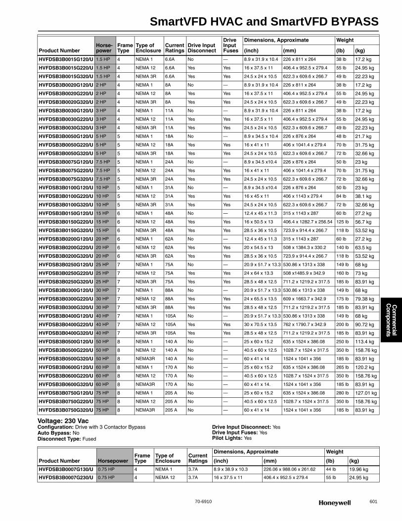
SmartVFD HVAC and SmartVFD BYPASS
70-6910 601
Com
mercial
Com
ponents
Voltage: 230 VacConfiguration: Drive with 3 Contactor BypassAuto Bypass: NoDisconnect Type: Fused
Drive Input Disconnect: YesDrive Input Fuses: YesPilot Lights: Yes
HVFDSB3B0015G120/U 1.5 HP 4 NEMA 1 6.6A No — 8.9 x 31.9 x 10.4 226 x 811 x 264 38 lb 17.2 kg
HVFDSB3B0015G220/U 1.5 HP 4 NEMA 12 6.6A Yes Yes 16 x 37.5 x 11 406.4 x 952.5 x 279.4 55 lb 24.95 kg
HVFDSB3B0015G320/U 1.5 HP 4 NEMA 3R 6.6A Yes Yes 24.5 x 24 x 10.5 622.3 x 609.6 x 266.7 49 lb 22.23 kg
HVFDSB3B0020G120/U 2 HP 4 NEMA 1 8A No — 8.9 x 31.9 x 10.4 226 x 811 x 264 38 lb 17.2 kg
HVFDSB3B0020G220/U 2 HP 4 NEMA 12 8A Yes Yes 16 x 37.5 x 11 406.4 x 952.5 x 279.4 55 lb 24.95 kg
HVFDSB3B0020G320/U 2 HP 4 NEMA 3R 8A Yes Yes 24.5 x 24 x 10.5 622.3 x 609.6 x 266.7 49 lb 22.23 kg
HVFDSB3B0030G120/U 3 HP 4 NEMA 1 11A No — 8.9 x 31.9 x 10.4 226 x 811 x 264 38 lb 17.2 kg
HVFDSB3B0030G220/U 3 HP 4 NEMA 12 11A Yes Yes 16 x 37.5 x 11 406.4 x 952.5 x 279.4 55 lb 24.95 kg
HVFDSB3B0030G320/U 3 HP 4 NEMA 3R 11A Yes Yes 24.5 x 24 x 10.5 622.3 x 609.6 x 266.7 49 lb 22.23 kg
HVFDSB3B0050G120/U 5 HP 5 NEMA 1 18A No — 8.9 x 34.5 x 10.4 226 x 876 x 264 48 lb 21.7 kg
HVFDSB3B0050G220/U 5 HP 5 NEMA 12 18A Yes Yes 16 x 41 x 11 406 x 1041.4 x 279.4 70 lb 31.75 kg
HVFDSB3B0050G320/U 5 HP 5 NEMA 3R 18A Yes Yes 24.5 x 24 x 10.5 622.3 x 609.6 x 266.7 72 lb 32.66 kg
HVFDSB3B0075G120/U 7.5 HP 5 NEMA 1 24A No — 8.9 x 34.5 x10.4 226 x 876 x 264 50 lb 23 kg
HVFDSB3B0075G220/U 7.5 HP 5 NEMA 12 24A Yes Yes 16 x 41 x 11 406 x 1041.4 x 279.4 70 lb 31.75 kg
HVFDSB3B0075G320/U 7.5 HP 5 NEMA 3R 24A Yes Yes 24.5 x 24 x 10.5 622.3 x 609.6 x 266.7 72 lb 32.66 kg
HVFDSB3B0100G120/U 10 HP 5 NEMA 1 31A No — 8.9 x 34.5 x10.4 226 x 876 x 264 50 lb 23 kg
HVFDSB3B0100G220/U 10 HP 5 NEMA 12 31A Yes Yes 16 x 45 x 11 406 x 1143 x 279.4 84 lb 38.1 kg
HVFDSB3B0100G320/U 10 HP 5 NEMA 3R 31A Yes Yes 24.5 x 24 x 10.5 622.3 x 609.6 x 266.7 72 lb 32.66 kg
HVFDSB3B0150G120/U 15 HP 6 NEMA 1 48A No — 12.4 x 45 x 11.3 315 x 1143 x 287 60 lb 27.2 kg
HVFDSB3B0150G220/U 15 HP 6 NEMA 12 48A Yes Yes 16 x 50.5 x 13 406.4 x 1282.7 x 256.54 125 lb 56.7 kg
HVFDSB3B0150G320/U 15 HP 6 NEMA 3R 48A Yes Yes 28.5 x 36 x 10.5 723.9 x 914.4 x 266.7 118 lb 53.52 kg
HVFDSB3B0200G120/U 20 HP 6 NEMA 1 62A No — 12.4 x 45 x 11.3 315 x 1143 x 287 60 lb 27.2 kg
HVFDSB3B0200G220/U 20 HP 6 NEMA 12 62A Yes Yes 20 x 54.5 x 13 508 x 1384.3 x 330.2 140 lb 63.5 kg
HVFDSB3B0200G320/U 20 HP 6 NEMA 3R 62A Yes Yes 28.5 x 36 x 10.5 723.9 x 914.4 x 266.7 118 lb 53.52 kg
HVFDSB3B0250G120/U 25 HP 7 NEMA 1 75A No — 20.9 x 51.7 x 13.3 530.86 x 1313 x 338 149 lb 68 kg
HVFDSB3B0250G220/U 25 HP 7 NEMA 12 75A Yes Yes 24 x 64 x 13.3 508 x1485.9 x 342.9 160 lb 73 kg
HVFDSB3B0250G320/U 25 HP 7 NEMA 3R 75A Yes Yes 28.5 x 48 x 12.5 711.2 x 1219.2 x 317.5 185 lb 83.91 kg
HVFDSB3B0300G120/U 30 HP 7 NEMA 1 88A No — 20.9 x 51.7 x 13.3 530.86 x 1313 x 338 149 lb 68 kg
HVFDSB3B0300G220/U 30 HP 7 NEMA 12 88A Yes Yes 24 x 65.5 x 13.5 609 x 1663.7 x 342.9 175 lb 79.38 kg
HVFDSB3B0300G320/U 30 HP 7 NEMA 3R 88A Yes Yes 28.5 x 48 x 12.5 711.2 x 1219.2 x 317.5 185 lb 83.91 kg
HVFDSB3B0400G120/U 40 HP 7 NEMA 1 105A No — 20.9 x 51.7 x 13.3 530.86 x 1313 x 338 149 lb 68 kg
HVFDSB3B0400G220/U 40 HP 7 NEMA 12 105A Yes Yes 30 x 70.5 x 13.5 762 x 1790.7 x 342.9 200 lb 90.72 kg
HVFDSB3B0400G320/U 40 HP 7 NEMA 3R 105A Yes Yes 28.5 x 48 x 12.5 711.2 x 1219.2 x 317.5 185 lb 83.91 kg
HVFDSB3B0500G120/U 50 HP 8 NEMA 1 140 A No — 25 x 60 x 15.2 635 x 1524 x 386.08 250 lb 113.4 kg
HVFDSB3B0500G220/U 50 HP 8 NEMA 12 140 A No — 40.5 x 60 x 12.5 1028.7 x 1524 x 317.5 350 lb 158.76 kg
HVFDSB3B0500G320/U 50 HP 8 NEMA3R 140 A No — 60 x 41 x 14 1524 x 1041 x 356 185 lb 83.91 kg
HVFDSB3B0600G120/U 60 HP 8 NEMA 1 170 A No — 25 x 60 x 15.2 635 x 1524 x 386.08 265 lb 120.2 kg
HVFDSB3B0600G220/U 60 HP 8 NEMA 12 170 A No — 40.5 x 60 x 12.5 1028.7 x 1524 x 317.5 350 lb 158.76 kg
HVFDSB3B0600G320/U 60 HP 8 NEMA3R 170 A No — 60 x 41 x 14. 1524 x 1041 x 356 185 lb 83.91 kg
HVFDSB3B0750G120/U 75 HP 8 NEMA 1 205 A No — 25 x 60 x 15.2 635 x 1524 x 386.08 280 lb 127.01 kg
HVFDSB3B0750G220/U 75 HP 8 NEMA 12 205 A No — 40.5 x 60 x 12.5 1028.7 x 1524 x 317.5 350 lb 158.76 kg
HVFDSB3B0750G320/U 75 HP 8 NEMA3R 205 A No — 60 x 41 x 14 1524 x 1041 x 356 185 lb 83.91 kg
Product NumberHorse-power
Frame Type
Type of Enclosure
Current Ratings
Drive Input Disconnect
Drive Input Fuses
Dimensions, Approximate Weight
(inch) (mm) (lb) (kg)
Product Number HorsepowerFrame Type
Type of Enclosure
Current Ratings
Dimensions, Approximate Weight
(inch) (mm) (lb) (kg)
HVFDSB3B0007G130/U 0.75 HP 4 NEMA 1 3.7A 8.9 x 38.9 x 10.3 226.06 x 988.06 x 261.62 44 lb 19.96 kg
HVFDSB3B0007G230/U 0.75 HP 4 NEMA 12 3.7A 16 x 37.5 x 11 406.4 x 952.5 x 279.4 55 lb 24.95 kg
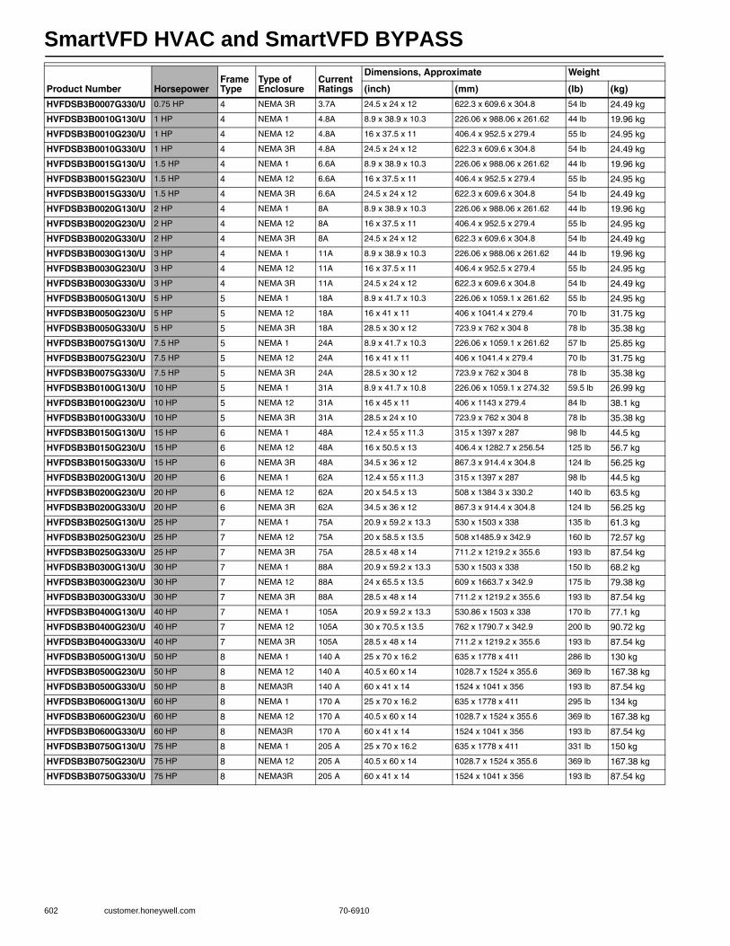
SmartVFD HVAC and SmartVFD BYPASS
602 customer.honeywell.com 70-6910
HVFDSB3B0007G330/U 0.75 HP 4 NEMA 3R 3.7A 24.5 x 24 x 12 622.3 x 609.6 x 304.8 54 lb 24.49 kg
HVFDSB3B0010G130/U 1 HP 4 NEMA 1 4.8A 8.9 x 38.9 x 10.3 226.06 x 988.06 x 261.62 44 lb 19.96 kg
HVFDSB3B0010G230/U 1 HP 4 NEMA 12 4.8A 16 x 37.5 x 11 406.4 x 952.5 x 279.4 55 lb 24.95 kg
HVFDSB3B0010G330/U 1 HP 4 NEMA 3R 4.8A 24.5 x 24 x 12 622.3 x 609.6 x 304.8 54 lb 24.49 kg
HVFDSB3B0015G130/U 1.5 HP 4 NEMA 1 6.6A 8.9 x 38.9 x 10.3 226.06 x 988.06 x 261.62 44 lb 19.96 kg
HVFDSB3B0015G230/U 1.5 HP 4 NEMA 12 6.6A 16 x 37.5 x 11 406.4 x 952.5 x 279.4 55 lb 24.95 kg
HVFDSB3B0015G330/U 1.5 HP 4 NEMA 3R 6.6A 24.5 x 24 x 12 622.3 x 609.6 x 304.8 54 lb 24.49 kg
HVFDSB3B0020G130/U 2 HP 4 NEMA 1 8A 8.9 x 38.9 x 10.3 226.06 x 988.06 x 261.62 44 lb 19.96 kg
HVFDSB3B0020G230/U 2 HP 4 NEMA 12 8A 16 x 37.5 x 11 406.4 x 952.5 x 279.4 55 lb 24.95 kg
HVFDSB3B0020G330/U 2 HP 4 NEMA 3R 8A 24.5 x 24 x 12 622.3 x 609.6 x 304.8 54 lb 24.49 kg
HVFDSB3B0030G130/U 3 HP 4 NEMA 1 11A 8.9 x 38.9 x 10.3 226.06 x 988.06 x 261.62 44 lb 19.96 kg
HVFDSB3B0030G230/U 3 HP 4 NEMA 12 11A 16 x 37.5 x 11 406.4 x 952.5 x 279.4 55 lb 24.95 kg
HVFDSB3B0030G330/U 3 HP 4 NEMA 3R 11A 24.5 x 24 x 12 622.3 x 609.6 x 304.8 54 lb 24.49 kg
HVFDSB3B0050G130/U 5 HP 5 NEMA 1 18A 8.9 x 41.7 x 10.3 226.06 x 1059.1 x 261.62 55 lb 24.95 kg
HVFDSB3B0050G230/U 5 HP 5 NEMA 12 18A 16 x 41 x 11 406 x 1041.4 x 279.4 70 lb 31.75 kg
HVFDSB3B0050G330/U 5 HP 5 NEMA 3R 18A 28.5 x 30 x 12 723.9 x 762 x 304 8 78 lb 35.38 kg
HVFDSB3B0075G130/U 7.5 HP 5 NEMA 1 24A 8.9 x 41.7 x 10.3 226.06 x 1059.1 x 261.62 57 lb 25.85 kg
HVFDSB3B0075G230/U 7.5 HP 5 NEMA 12 24A 16 x 41 x 11 406 x 1041.4 x 279.4 70 lb 31.75 kg
HVFDSB3B0075G330/U 7.5 HP 5 NEMA 3R 24A 28.5 x 30 x 12 723.9 x 762 x 304 8 78 lb 35.38 kg
HVFDSB3B0100G130/U 10 HP 5 NEMA 1 31A 8.9 x 41.7 x 10.8 226.06 x 1059.1 x 274.32 59.5 lb 26.99 kg
HVFDSB3B0100G230/U 10 HP 5 NEMA 12 31A 16 x 45 x 11 406 x 1143 x 279.4 84 lb 38.1 kg
HVFDSB3B0100G330/U 10 HP 5 NEMA 3R 31A 28.5 x 24 x 10 723.9 x 762 x 304 8 78 lb 35.38 kg
HVFDSB3B0150G130/U 15 HP 6 NEMA 1 48A 12.4 x 55 x 11.3 315 x 1397 x 287 98 lb 44.5 kg
HVFDSB3B0150G230/U 15 HP 6 NEMA 12 48A 16 x 50.5 x 13 406.4 x 1282.7 x 256.54 125 lb 56.7 kg
HVFDSB3B0150G330/U 15 HP 6 NEMA 3R 48A 34.5 x 36 x 12 867.3 x 914.4 x 304.8 124 lb 56.25 kg
HVFDSB3B0200G130/U 20 HP 6 NEMA 1 62A 12.4 x 55 x 11.3 315 x 1397 x 287 98 lb 44.5 kg
HVFDSB3B0200G230/U 20 HP 6 NEMA 12 62A 20 x 54.5 x 13 508 x 1384 3 x 330.2 140 lb 63.5 kg
HVFDSB3B0200G330/U 20 HP 6 NEMA 3R 62A 34.5 x 36 x 12 867.3 x 914.4 x 304.8 124 lb 56.25 kg
HVFDSB3B0250G130/U 25 HP 7 NEMA 1 75A 20.9 x 59.2 x 13.3 530 x 1503 x 338 135 lb 61.3 kg
HVFDSB3B0250G230/U 25 HP 7 NEMA 12 75A 20 x 58.5 x 13.5 508 x1485.9 x 342.9 160 lb 72.57 kg
HVFDSB3B0250G330/U 25 HP 7 NEMA 3R 75A 28.5 x 48 x 14 711.2 x 1219.2 x 355.6 193 lb 87.54 kg
HVFDSB3B0300G130/U 30 HP 7 NEMA 1 88A 20.9 x 59.2 x 13.3 530 x 1503 x 338 150 lb 68.2 kg
HVFDSB3B0300G230/U 30 HP 7 NEMA 12 88A 24 x 65.5 x 13.5 609 x 1663.7 x 342.9 175 lb 79.38 kg
HVFDSB3B0300G330/U 30 HP 7 NEMA 3R 88A 28.5 x 48 x 14 711.2 x 1219.2 x 355.6 193 lb 87.54 kg
HVFDSB3B0400G130/U 40 HP 7 NEMA 1 105A 20.9 x 59.2 x 13.3 530.86 x 1503 x 338 170 lb 77.1 kg
HVFDSB3B0400G230/U 40 HP 7 NEMA 12 105A 30 x 70.5 x 13.5 762 x 1790.7 x 342.9 200 lb 90.72 kg
HVFDSB3B0400G330/U 40 HP 7 NEMA 3R 105A 28.5 x 48 x 14 711.2 x 1219.2 x 355.6 193 lb 87.54 kg
HVFDSB3B0500G130/U 50 HP 8 NEMA 1 140 A 25 x 70 x 16.2 635 x 1778 x 411 286 lb 130 kg
HVFDSB3B0500G230/U 50 HP 8 NEMA 12 140 A 40.5 x 60 x 14 1028.7 x 1524 x 355.6 369 lb 167.38 kg
HVFDSB3B0500G330/U 50 HP 8 NEMA3R 140 A 60 x 41 x 14 1524 x 1041 x 356 193 lb 87.54 kg
HVFDSB3B0600G130/U 60 HP 8 NEMA 1 170 A 25 x 70 x 16.2 635 x 1778 x 411 295 lb 134 kg
HVFDSB3B0600G230/U 60 HP 8 NEMA 12 170 A 40.5 x 60 x 14 1028.7 x 1524 x 355.6 369 lb 167.38 kg
HVFDSB3B0600G330/U 60 HP 8 NEMA3R 170 A 60 x 41 x 14 1524 x 1041 x 356 193 lb 87.54 kg
HVFDSB3B0750G130/U 75 HP 8 NEMA 1 205 A 25 x 70 x 16.2 635 x 1778 x 411 331 lb 150 kg
HVFDSB3B0750G230/U 75 HP 8 NEMA 12 205 A 40.5 x 60 x 14 1028.7 x 1524 x 355.6 369 lb 167.38 kg
HVFDSB3B0750G330/U 75 HP 8 NEMA3R 205 A 60 x 41 x 14 1524 x 1041 x 356 193 lb 87.54 kg
Product Number HorsepowerFrame Type
Type of Enclosure
Current Ratings
Dimensions, Approximate Weight
(inch) (mm) (lb) (kg)
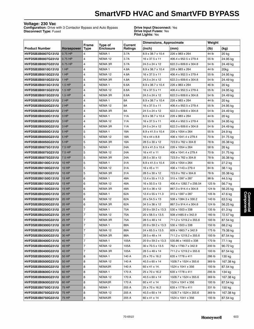
SmartVFD HVAC and SmartVFD BYPASS
70-6910 603
Com
mercial
Com
ponents
Voltage: 230 VacConfiguration: Drive with 3 Contactor Bypass and Auto BypassDisconnect Type: Fused
Drive Input Disconnect: YesDrive Input Fuses: YesPilot Lights: Yes
Product Number HorsepowerFrame Type
Type of Enclosure
Current Ratings
Dimensions, Approximate Weight
(inch) (mm) (lb) (kg)
HVFDSB3B0007G131/U 0.75 HP 4 NEMA 1 3.7A 8.9 x 38.7 x 10.4 226 x 983 x 264 44 lb 20 kg
HVFDSB3B0007G231/U 0.75 HP 4 NEMA 12 3.7A 16 x 37.5 x 11 406.4 x 952.5 x 279.4 55 lb 24.95 kg
HVFDSB3B0007G331/U 0.75 HP 4 NEMA 3R 3.7A 24.5 x 24 x 12 622.3 x 609.6 x 304.8 54 lb 24.49 kg
HVFDSB3B0010G131/U 1 HP 4 NEMA 1 4.8A 8.9 x 38.7 x 10.4 226 x 983 x 264 44 lb 20kg
HVFDSB3B0010G231/U 1 HP 4 NEMA 12 4.8A 16 x 37.5 x 11 406.4 x 952.5 x 279.4 55 lb 24.95 kg
HVFDSB3B0010G331/U 1 HP 4 NEMA 3R 4.8A 24.5 x 24 x 12 622.3 x 609.6 x 304.8 54 lb 24.49 kg
HVFDSB3B0015G131/U 1.5 HP 4 NEMA 1 6.6A 8.9 x 38.7 x 10.4 226 x 983 x 264 46 lb 20 kg
HVFDSB3B0015G231/U 1.5 HP 4 NEMA 12 6.6A 16 x 37.5 x 11 406.4 x 952.5 x 279.4 55 lb 24.95 kg
HVFDSB3B0015G331/U 1.5 HP 4 NEMA 3R 6.6A 24.5 x 24 x 12 622.3 x 609.6 x 304.8 54 lb 24.49 kg
HVFDSB3B0020G131/U 2 HP 4 NEMA 1 8A 8.9 x 38.7 x 10.4 226 x 983 x 264 44 lb 20 kg
HVFDSB3B0020G231/U 2 HP 4 NEMA 12 8A 16 x 37.5 x 11 406.4 x 952.5 x 279.4 55 lb 24.95 kg
HVFDSB3B0020G331/U 2 HP 4 NEMA 3R 8A 24 5 x 24 x 12 622.3 x 609.6 x 304.8 54 lb 24.49 kg
HVFDSB3B0030G131/U 3 HP 4 NEMA 1 11A 8.9 x 38.7 x 10.4 226 x 983 x 264 44 lb 20 kg
HVFDSB3B0030G231/U 3 HP 4 NEMA 12 11A 16 x 37.5 x 11 406.4 x 952.5 x 279.4 55 lb 24.95 kg
HVFDSB3B0030G331/U 3 HP 4 NEMA 3R 11A 24 5 x 24 x 12 622.3 x 609.6 x 304.8 54 lb 24.49 kg
HVFDSB3B0050G131/U 5 HP 5 NEMA 1 18A 8.9 x 41.5 x 10.4 226 x 1054 x 264 55 lb 24.9 kg
HVFDSB3B0050G231/U 5 HP 5 NEMA 12 18A 16 x 44 x 8.8 406 x 1041.4 x 279.4 70 lb 31.75 kg
HVFDSB3B0050G331/U 5 HP 5 NEMA 3R 18A 28 5 x 30 x 12 723.9 x 762 x 304.8 78 lb 35.38 kg
HVFDSB3B0075G131/U 7.5 HP 5 NEMA 1 24A 8.9 x 41.5 x 10.4 226 x 1054 x 264 58 lb 26 kg
HVFDSB3B0075G231/U 7.5 HP 5 NEMA 12 24A 16 x 41 x 11 406 x 1041.4 x 279.4 70 lb 31.75 kg
HVFDSB3B0075G331/U 7.5 HP 5 NEMA 3R 24A 28 5 x 30 x 12 723.9 x 762 x 304.8 78 lb 35.38 kg
HVFDSB3B0100G131/U 10 HP 5 NEMA 1 31A 8.9 x 41.5 x 10.4 226 x 1054 x 264 60 lb 27.2 kg
HVFDSB3B0100G231/U 10 HP 5 NEMA 12 31A 16 x 45 x 11 406 x 1143 x 279.4 84 lb 38.1 kg
HVFDSB3B0100G331/U 10 HP 5 NEMA 3R 31A 28 5 x 30 x 12 723.9 x 762 x 304.8 78 lb 35.38 kg
HVFDSB3B0150G131/U 15 HP 6 NEMA 1 48A 12.4 x 55 x 11.3 315 x 1397 x 287 98 lb 44.5 kg
HVFDSB3B0150G231/U 15 HP 6 NEMA 12 48A 16 x 50.5 x 13 406.4 x 1282.7 x 256.54 125 lb 56.7 kg
HVFDSB3B0150G331/U 15 HP 6 NEMA 3R 48A 34 5 x 36 x 12 867.3 x 914.4 x 304.8 124 lb 56.25 kg
HVFDSB3B0200G131/U 20 HP 6 NEMA 1 62A 12.4 x 55 x 11.3 315 x 1397 x 287 105 lb 47.6 kg
HVFDSB3B0200G231/U 20 HP 6 NEMA 12 62A 20 x 54.5 x 13 508 x 1384.3 x 330.2 140 lb 63.5 kg
HVFDSB3B0200G331/U 20 HP 6 NEMA 3R 62A 34 5 x 36 x 12 867.3 x 914.4 x 304.8 124 lb 56.25 kg
HVFDSB3B0250G131/U 25 HP 7 NEMA 1 75A 20 9 x 59 2 x 13.3 530 x 1503 x 338 135 lb 61.3 kg
HVFDSB3B0250G231/U 25 HP 7 NEMA 12 75A 20 x 58.5 x 13.5 508 x1485.9 x 342.9 160 lb 72.57 kg
HVFDSB3B0250G331/U 25 HP 7 NEMA 3R 75A 28 5 x 48 x 14 711.2 x 1219.2 x 355.6 193 lb 87.54 kg
HVFDSB3B0300G131/U 30 HP 7 NEMA 1 88A 20 9 x 59 2 x 13.3 530 x 1503 x 338 150 lb 68.2 kg
HVFDSB3B0300G231/U 30 HP 7 NEMA 12 88A 24 x 65.5 x 13.5 609 x 1663.7 x 342.9 175 lb 79.38 kg
HVFDSB3B0300G331/U 30 HP 7 NEMA 3R 88A 28 5 x 48 x 14 711.2 x 1219.2 x 355.6 193 lb 87.54 kg
HVFDSB3B0400G131/U 40 HP 7 NEMA 1 105A 20 9 x 59 2 x 13.3 530.86 x 14503 x 338 170 lb 77.1 kg
HVFDSB3B0400G231/U 40 HP 7 NEMA 12 105A 30 x 70.5 x 13.5 762 x 1790.7 x 342.9 200 lb 90.72 kg
HVFDSB3B0400G331/U 40 HP 7 NEMA 3R 105A 28 5 x 48 x 14 711.2 x 1219.2 x 355.6 193 lb 87.54 kg
HVFDSB3B0500G131/U 50 HP 8 NEMA 1 140 A 25 x 70 x 16.2 635 x 1778 x 411 286 lb 130 kg
HVFDSB3B0500G231/U 50 HP 8 NEMA 12 140 A 40.5 x 60 x 14 1028.7 x 1524 x 355.6 369 lb 167.38 kg
HVFDSB3B0500G331/U 50 HP 8 NEMA3R 140 A 60 x 41 x 14. 1524 x 1041 x 356 193 lb 87.54 kg
HVFDSB3B0600G131/U 60 HP 8 NEMA 1 170 A 25 x 70 x 16.2 635 x 1778 x 411 295 lb 134 kg
HVFDSB3B0600G231/U 60 HP 8 NEMA 12 170 A 40.5 x 60 x 14 1028.7 x 1524 x 355.6 369 lb 167.38 kg
HVFDSB3B0600G331/U 60 HP 8 NEMA3R 170 A 60 x 41 x 14 1524 x 1041 x 356 193 lb 87.54 kg
HVFDSB3B0750G131/U 75 HP 8 NEMA 1 205 A 25 x 70 x 16.2 635 x 1778 x 411 331 lb 150 kg
HVFDSB3B0750G231/U 75 HP 8 NEMA 12 205 A 40.5 x 60 x 14 1028.7 x 1524 x 355.6 369 lb 167.38 kg
HVFDSB3B0750G331/U 75 HP 8 NEMA3R 205 A 60 x 41 x 14 1524 x 1041 x 356 193 lb 87.54 kg
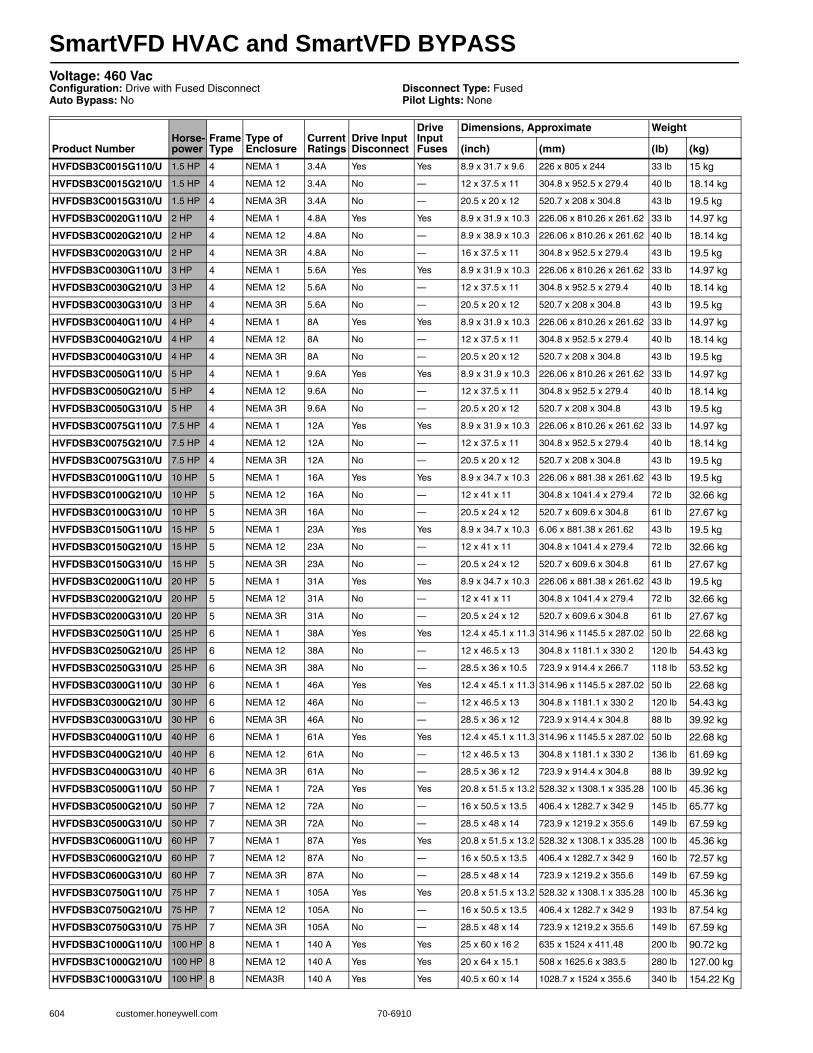
SmartVFD HVAC and SmartVFD BYPASS
604 customer.honeywell.com 70-6910
Voltage: 460 VacConfiguration: Drive with Fused Disconnect Auto Bypass: No
Disconnect Type: FusedPilot Lights: None
Product NumberHorse-power
Frame Type
Type of Enclosure
Current Ratings
Drive Input Disconnect
Drive Input Fuses
Dimensions, Approximate Weight
(inch) (mm) (lb) (kg)
HVFDSB3C0015G110/U 1.5 HP 4 NEMA 1 3.4A Yes Yes 8.9 x 31.7 x 9.6 226 x 805 x 244 33 lb 15 kg
HVFDSB3C0015G210/U 1.5 HP 4 NEMA 12 3.4A No — 12 x 37.5 x 11 304.8 x 952.5 x 279.4 40 lb 18.14 kg
HVFDSB3C0015G310/U 1.5 HP 4 NEMA 3R 3.4A No — 20.5 x 20 x 12 520.7 x 208 x 304.8 43 lb 19.5 kg
HVFDSB3C0020G110/U 2 HP 4 NEMA 1 4.8A Yes Yes 8.9 x 31.9 x 10.3 226.06 x 810.26 x 261.62 33 lb 14.97 kg
HVFDSB3C0020G210/U 2 HP 4 NEMA 12 4.8A No — 8.9 x 38.9 x 10.3 226.06 x 810.26 x 261.62 40 lb 18.14 kg
HVFDSB3C0020G310/U 2 HP 4 NEMA 3R 4.8A No — 16 x 37.5 x 11 304.8 x 952.5 x 279.4 43 lb 19.5 kg
HVFDSB3C0030G110/U 3 HP 4 NEMA 1 5.6A Yes Yes 8.9 x 31.9 x 10.3 226.06 x 810.26 x 261.62 33 lb 14.97 kg
HVFDSB3C0030G210/U 3 HP 4 NEMA 12 5.6A No — 12 x 37.5 x 11 304.8 x 952.5 x 279.4 40 lb 18.14 kg
HVFDSB3C0030G310/U 3 HP 4 NEMA 3R 5.6A No — 20.5 x 20 x 12 520.7 x 208 x 304.8 43 lb 19.5 kg
HVFDSB3C0040G110/U 4 HP 4 NEMA 1 8A Yes Yes 8.9 x 31.9 x 10.3 226.06 x 810.26 x 261.62 33 lb 14.97 kg
HVFDSB3C0040G210/U 4 HP 4 NEMA 12 8A No — 12 x 37.5 x 11 304.8 x 952.5 x 279.4 40 lb 18.14 kg
HVFDSB3C0040G310/U 4 HP 4 NEMA 3R 8A No — 20.5 x 20 x 12 520.7 x 208 x 304.8 43 lb 19.5 kg
HVFDSB3C0050G110/U 5 HP 4 NEMA 1 9.6A Yes Yes 8.9 x 31.9 x 10.3 226.06 x 810.26 x 261.62 33 lb 14.97 kg
HVFDSB3C0050G210/U 5 HP 4 NEMA 12 9.6A No — 12 x 37.5 x 11 304.8 x 952.5 x 279.4 40 lb 18.14 kg
HVFDSB3C0050G310/U 5 HP 4 NEMA 3R 9.6A No — 20.5 x 20 x 12 520.7 x 208 x 304.8 43 lb 19.5 kg
HVFDSB3C0075G110/U 7.5 HP 4 NEMA 1 12A Yes Yes 8.9 x 31.9 x 10.3 226.06 x 810.26 x 261.62 33 lb 14.97 kg
HVFDSB3C0075G210/U 7.5 HP 4 NEMA 12 12A No — 12 x 37.5 x 11 304.8 x 952.5 x 279.4 40 lb 18.14 kg
HVFDSB3C0075G310/U 7.5 HP 4 NEMA 3R 12A No — 20.5 x 20 x 12 520.7 x 208 x 304.8 43 lb 19.5 kg
HVFDSB3C0100G110/U 10 HP 5 NEMA 1 16A Yes Yes 8.9 x 34.7 x 10.3 226.06 x 881.38 x 261.62 43 lb 19.5 kg
HVFDSB3C0100G210/U 10 HP 5 NEMA 12 16A No — 12 x 41 x 11 304.8 x 1041.4 x 279.4 72 lb 32.66 kg
HVFDSB3C0100G310/U 10 HP 5 NEMA 3R 16A No — 20.5 x 24 x 12 520.7 x 609.6 x 304.8 61 lb 27.67 kg
HVFDSB3C0150G110/U 15 HP 5 NEMA 1 23A Yes Yes 8.9 x 34.7 x 10.3 6.06 x 881.38 x 261.62 43 lb 19.5 kg
HVFDSB3C0150G210/U 15 HP 5 NEMA 12 23A No — 12 x 41 x 11 304.8 x 1041.4 x 279.4 72 lb 32.66 kg
HVFDSB3C0150G310/U 15 HP 5 NEMA 3R 23A No — 20.5 x 24 x 12 520.7 x 609.6 x 304.8 61 lb 27.67 kg
HVFDSB3C0200G110/U 20 HP 5 NEMA 1 31A Yes Yes 8.9 x 34.7 x 10.3 226.06 x 881.38 x 261.62 43 lb 19.5 kg
HVFDSB3C0200G210/U 20 HP 5 NEMA 12 31A No — 12 x 41 x 11 304.8 x 1041.4 x 279.4 72 lb 32.66 kg
HVFDSB3C0200G310/U 20 HP 5 NEMA 3R 31A No — 20.5 x 24 x 12 520.7 x 609.6 x 304.8 61 lb 27.67 kg
HVFDSB3C0250G110/U 25 HP 6 NEMA 1 38A Yes Yes 12.4 x 45.1 x 11.3 314.96 x 1145.5 x 287.02 50 lb 22.68 kg
HVFDSB3C0250G210/U 25 HP 6 NEMA 12 38A No — 12 x 46.5 x 13 304.8 x 1181.1 x 330 2 120 lb 54.43 kg
HVFDSB3C0250G310/U 25 HP 6 NEMA 3R 38A No — 28.5 x 36 x 10.5 723.9 x 914.4 x 266.7 118 lb 53.52 kg
HVFDSB3C0300G110/U 30 HP 6 NEMA 1 46A Yes Yes 12.4 x 45.1 x 11.3 314.96 x 1145.5 x 287.02 50 lb 22.68 kg
HVFDSB3C0300G210/U 30 HP 6 NEMA 12 46A No — 12 x 46.5 x 13 304.8 x 1181.1 x 330 2 120 lb 54.43 kg
HVFDSB3C0300G310/U 30 HP 6 NEMA 3R 46A No — 28.5 x 36 x 12 723.9 x 914.4 x 304.8 88 lb 39.92 kg
HVFDSB3C0400G110/U 40 HP 6 NEMA 1 61A Yes Yes 12.4 x 45.1 x 11.3 314.96 x 1145.5 x 287.02 50 lb 22.68 kg
HVFDSB3C0400G210/U 40 HP 6 NEMA 12 61A No — 12 x 46.5 x 13 304.8 x 1181.1 x 330 2 136 lb 61.69 kg
HVFDSB3C0400G310/U 40 HP 6 NEMA 3R 61A No — 28.5 x 36 x 12 723.9 x 914.4 x 304.8 88 lb 39.92 kg
HVFDSB3C0500G110/U 50 HP 7 NEMA 1 72A Yes Yes 20.8 x 51.5 x 13.2 528.32 x 1308.1 x 335.28 100 lb 45.36 kg
HVFDSB3C0500G210/U 50 HP 7 NEMA 12 72A No — 16 x 50.5 x 13.5 406.4 x 1282.7 x 342 9 145 lb 65.77 kg
HVFDSB3C0500G310/U 50 HP 7 NEMA 3R 72A No — 28.5 x 48 x 14 723.9 x 1219.2 x 355.6 149 lb 67.59 kg
HVFDSB3C0600G110/U 60 HP 7 NEMA 1 87A Yes Yes 20.8 x 51.5 x 13.2 528.32 x 1308.1 x 335.28 100 lb 45.36 kg
HVFDSB3C0600G210/U 60 HP 7 NEMA 12 87A No — 16 x 50.5 x 13.5 406.4 x 1282.7 x 342 9 160 lb 72.57 kg
HVFDSB3C0600G310/U 60 HP 7 NEMA 3R 87A No — 28.5 x 48 x 14 723.9 x 1219.2 x 355.6 149 lb 67.59 kg
HVFDSB3C0750G110/U 75 HP 7 NEMA 1 105A Yes Yes 20.8 x 51.5 x 13.2 528.32 x 1308.1 x 335.28 100 lb 45.36 kg
HVFDSB3C0750G210/U 75 HP 7 NEMA 12 105A No — 16 x 50.5 x 13.5 406.4 x 1282.7 x 342 9 193 lb 87.54 kg
HVFDSB3C0750G310/U 75 HP 7 NEMA 3R 105A No — 28.5 x 48 x 14 723.9 x 1219.2 x 355.6 149 lb 67.59 kg
HVFDSB3C1000G110/U 100 HP 8 NEMA 1 140 A Yes Yes 25 x 60 x 16 2 635 x 1524 x 411.48 200 lb 90.72 kg
HVFDSB3C1000G210/U 100 HP 8 NEMA 12 140 A Yes Yes 20 x 64 x 15.1 508 x 1625.6 x 383.5 280 lb 127.00 kg
HVFDSB3C1000G310/U 100 HP 8 NEMA3R 140 A Yes Yes 40.5 x 60 x 14 1028.7 x 1524 x 355.6 340 lb 154.22 Kg
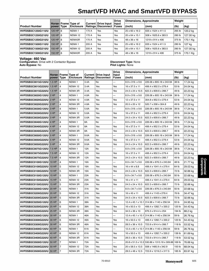
SmartVFD HVAC and SmartVFD BYPASS
70-6910 605
Com
mercial
Com
ponents
Voltage: 460 VacConfiguration: Drive with 2 Contactor BypassAuto Bypass: No
Disconnect Type: NonePilot Lights: None
HVFDSB3C1250G110/U 120 HP 8 NEMA 1 170 A Yes Yes 25 x 60 x 16 2 635 x 1524 x 411.5 265 lb 120.2 kg
HVFDSB3C1250G210/U 120 HP 8 NEMA 12 170 A Yes Yes 20 x 64 x 15.1 508 x 1625.6 x 383.5 280 lb 127.00 kg
HVFDSB3C1250G310/U 120 HP 8 NEMA3R 170 A Yes Yes 48 x 36 x 16 1219 x 914 x 406 375 lb 170.1 Kg
HVFDSB3C1500G110/U 150 HP 8 NEMA 1 205 A Yes Yes 25 x 60 x 16 2 635 x 1524 x 411.5 280 lb 127 kg
HVFDSB3C1500G210/U 150 HP 8 NEMA 12 205 A Yes Yes 20 x 64 x 15.1 508 x 1625.6 x 383.5 280 lb 127.00 kg
HVFDSB3C1500G310/U 150 HP 8 NEMA3R 205 A Yes Yes 48 x 36 x 16 1219 x 914 x 406 375 lb 170.1 Kg
Product NumberHorse-power
Frame Type
Type of Enclosure
Current Ratings
Drive Input Disconnect
Drive Input Fuses
Dimensions, Approximate Weight
(inch) (mm) (lb) (kg)
Product NumberHorse-power
Frame Type
Type of Enclosure
Current Ratings
Drive Input Disconnect
Drive Input Fuses
Dimensions, Approximate Weight
(inch) (mm) (lb) (kg)
HVFDSB3C0015G120/U 1.5 HP 4 NEMA 1 3.4A No — 8.9 x 319. x 9.6 226.06 x 805.18 x 243 84 38 lb 17.24 kg
HVFDSB3C0015G220/U 1.5 HP 4 NEMA 12 3.4A Yes Yes 16 x 37.5 x 11 406.4 x 952.5 x 279.4 53 lb 24.04 kg
HVFDSB3C0015G320/U 1.5 HP 4 NEMA 3R 3.4A Yes Yes 24.5 x 24 x 10.5 622.3 x 609.6 x 266.7 49 lb 22.23 kg
HVFDSB3C0020G120/U 2 HP 4 NEMA 1 4.8A No — 8.9 x 319. x 9.6 226.06 x 805.18 x 243 84 38 lb 17.24 kg
HVFDSB3C0020G220/U 2 HP 4 NEMA 12 4.8A Yes Yes 12 x 37.5 x 11 304.8 x 952.5 x 279.4 53 lb 24.04 kg
HVFDSB3C0020G320/U 2 HP 4 NEMA 3R 4.8A Yes Yes 20.5 x 20 x 12 520.7 x 208 x 304.8 49 lb 22.23 kg
HVFDSB3C0030G120/U 3 HP 4 NEMA 1 5.6A No — 8.9 x 319. x 9.6 226.06 x 805.18 x 243 84 38 lb 17.24 kg
HVFDSB3C0030G220/U 3 HP 4 NEMA 12 5.6A Yes Yes 16 x 37.5 x 11 406.4 x 952.5 x 279.4 53 lb 24.04 kg
HVFDSB3C0030G320/U 3 HP 4 NEMA 3R 5.6A Yes Yes 24.5 x 24 x 10.5 622.3 x 609.6 x 266.7 49 lb 22.23 kg
HVFDSB3C0040G120/U 4 HP 4 NEMA 1 8A No — 8.9 x 319. x 9.6 226.06 x 805.18 x 243 84 38 lb 17.24 kg
HVFDSB3C0040G220/U 4 HP 4 NEMA 12 8A Yes Yes 16 x 37.5 x 11 406.4 x 952.5 x 279.4 53 lb 24.04 kg
HVFDSB3C0040G320/U 4 HP 4 NEMA 3R 8A Yes Yes 24.5 x 24 x 10.5 622.3 x 609.6 x 266.7 49 lb 22.23 kg
HVFDSB3C0050G120/U 5 HP 4 NEMA 1 9.6A No — 8.9 x 319. x 9.6 226.06 x 805.18 x 243 84 38 lb 17.24 kg
HVFDSB3C0050G220/U 5 HP 4 NEMA 12 9.6A Yes Yes 16 x 37.5 x 11 406.4 x 952.5 x 279.4 53 lb 24.04 kg
HVFDSB3C0050G320/U 5 HP 4 NEMA 3R 9.6A Yes Yes 24.5 x 24 x 10.5 622.3 x 609.6 x 266.7 49 lb 22.23 kg
HVFDSB3C0075G120/U 7.5 HP 4 NEMA 1 12A No — 8.9 x 319. x 9.6 226.06 x 805.18 x 243 84 38 lb 17.24 kg
HVFDSB3C0075G220/U 7.5 HP 4 NEMA 12 12A Yes Yes 16 x 37.5 x 11 406.4 x 952.5 x 279.4 53 lb 24.04 kg
HVFDSB3C0075G320/U 7.5 HP 4 NEMA 3R 12A Yes Yes 24.5 x 24 x 10.5 622.3 x 609.6 x 266.7 49 lb 22.23 kg
HVFDSB3C0100G120/U 10 HP 4 NEMA 1 16A No — 8.9 x 34.7 x 9.6 226.06 x 876.3 x 243.84 48 lb 21.77 kg
HVFDSB3C0100G220/U 10 HP 5 NEMA 12 16A Yes Yes 16 x 44 x 8.8 406.4 x 1041.4 x 279.4 64 lb 29.03 kg
HVFDSB3C0100G320/U 10 HP 5 NEMA 3R 16A Yes Yes 24.5 x 24 x 10.5 622.3 x 609.6 x 266.7 72 lb 32.66 kg
HVFDSB3C0150G120/U 15 HP 5 NEMA 1 23A No — 8.9 x 34.7 x 9.6 226.06 x 876.3 x 243.84 50 lb 22.68 kg
HVFDSB3C0150G220/U 15 HP 5 NEMA 12 23A Yes Yes 16 x 41 x 11 406.4 x 1041.4 x 279.4 64 lb 29.03 kg
HVFDSB3C0150G320/U 15 HP 5 NEMA 3R 23A Yes Yes 24.5 x 24 x 10.5 622.3 x 609.6 x 266.7 72 lb 32.66 kg
HVFDSB3C0200G120/U 20 HP 5 NEMA 1 31A No — 8.9 x 34.7 x 9.6 226.06 x 876.3 x 243.84 50 lb 22.68 kg
HVFDSB3C0200G220/U 20 HP 5 NEMA 12 31A Yes Yes 16 x 45 x 11 406.4 x 1143 x 279.4 76 lb 34.47 kg
HVFDSB3C0200G320/U 20 HP 5 NEMA 3R 31A Yes Yes 24.5 x 24 x 10.5 622.3 x 609.6 x 266.7 72 lb 32.66 kg
HVFDSB3C0250G120/U 25 HP 6 NEMA 1 38A No — 12.4 x 45.1 x 10.1 314.96 x 1143 x 256.54 55 lb 24.95 kg
HVFDSB3C0250G220/U 25 HP 6 NEMA 12 38A Yes Yes 16 x 50.5 x 13 406.4 x 1282.7 x 330.2 120 lb 54.43 kg
HVFDSB3C0250G320/U 25 HP 6 NEMA 3R 38A Yes Yes 34.5 x 36 x 10 876.3 x 914.4 x 254 194 lb 88.2 kg
HVFDSB3C0300G120/U 30 HP 6 NEMA 1 46A No — 12.4 x 45.1 x 10.1 314.96 x 1143 x 256.54 59 lb 26.76 kg
HVFDSB3C0300G220/U 30 HP 6 NEMA 12 46A Yes Yes 16 x 50.5 x 13 406.4 x 1282.7 x 330.2 120 lb 54.43 kg
HVFDSB3C0300G320/U 30 HP 6 NEMA 3R 46A Yes Yes 28.5 x 36 x 10.5 723.9 x 914.4 x 266.7 118 lb 53.52 kg
HVFDSB3C0400G120/U 40 HP 6 NEMA 1 61A No — 12.4 x 45.1 x 10.1 314.96 x 1143 x 256.54 59 lb 26.76 kg
HVFDSB3C0400G220/U 40 HP 6 NEMA 12 61A Yes Yes 16 x 50.5 x 13 406.4 x 1282.7 x 330.2 136 lb 61.69 kg
HVFDSB3C0400G320/U 40 HP 6 NEMA 3R 61A Yes Yes 28.5 x 36 x 10.5 723.9 x 914.4 x 266.7 118 lb 53.52 kg
HVFDSB3C0500G120/U 50 HP 7 NEMA 1 72A No — 20.8 x 51.5 x 12.2 530.86 x 1313.18 x 309.88 169 lb 76.66 kg
HVFDSB3C0500G220/U 50 HP 7 NEMA 12 72A Yes Yes 20 x 58.5 x 13.5 508 x 1485.9 x 342.9 150 lb 68.04 kg
HVFDSB3C0500G320/U 50 HP 7 NEMA 3R 72A Yes Yes 28.5 x 48 x 12.5 723.9 x 1219.2 x 317.5 185 lb 83.91 kg

SmartVFD HVAC and SmartVFD BYPASS
606 customer.honeywell.com 70-6910
Voltage: 460 VacConfiguration: Drive with 3 Contactor BypassAuto Bypass: NoDisconnect Type: Fused
Drive Input Disconnect: YesDrive Input Fuses: YesPilot Lights: Yes
HVFDSB3C0600G120/U 60 HP 7 NEMA 1 87A No — 20.8 x 51.5 x 12.2 530.86 x 1313.18 x 309.88 179 lb 81.19 kg
HVFDSB3C0600G220/U 60 HP 7 NEMA 12 87A Yes Yes 20 x 58.5 x 13.5 508 x 1485.9 x 342.9 165 lb 74.84 kg
HVFDSB3C0600G320/U 60 HP 7 NEMA 3R 87A Yes Yes 28.5 x 48 x 12.5 723.9 x 1219.2 x 317.5 185 lb 83.91 kg
HVFDSB3C0750G120/U 75 HP 7 NEMA 1 105A No — 20.8 x 51.5 x 12.2 530.86 x 1313.18 x 309.88 189 lb 85.73 kg
HVFDSB3C0750G220/U 75 HP 7 NEMA 12 105A Yes Yes 20 x 58.5 x 13.5 508 x 1485.9 x 342.9 193 lb 87.54 kg
HVFDSB3C0750G320/U 75 HP 7 NEMA 3R 105A Yes Yes 28.5 x 48 x 12.5 723.9 x 1219.2 x 317.5 185 lb 83.91 kg
HVFDSB3C1000G120/U 100 HP 8 NEMA 1 140 A No — 25 x 60 x 15.2 635 x 1524 x 386.08 250 lb 113.4 kg
HVFDSB3C1000G220/U 100 HP 8 NEMA 12 140 A No — 56 x 48 x 15.1 1422 x 1219 x 384 350 lb 158.76 kg
HVFDSB3C1000G320/U 100 HP 8 NEMA3R 140 A No — 40.5 x 60 x 12.5 1028.7 x 1524 x 317.5 430 lb 195.04 kg
HVFDSB3C1250G120/U 120 HP 8 NEMA 1 170 A No — 25 x 60 x 16.2 635 x 1524 x 411.5 265 lb 120.2 kg
HVFDSB3C1250G220/U 120 HP 8 NEMA 12 170 A No — 56 x 48 x 15.1 1422 x 1219 x 384 350 lb 158.76 kg
HVFDSB3C1250G320/U 120 HP 8 NEMA3R 170 A No — 60 x 41 x 14 1524 x 1041 x 356 451 lb 204.6 kg
HVFDSB3C1500G120/U 150 HP 8 NEMA 1 205 A No — 25 x 60 x 16.2 635 x 1524 x 411.5 280 lb 127 kg
HVFDSB3C1500G220/U 150 HP 8 NEMA 12 205 A No — 56 x 48 x 15.1 1422 x 1219 x 384 350 lb 158.76 kg
HVFDSB3C1500G320/U 150 HP 8 NEMA3R 205 A No — 60 x 41 x 14 1524 x 1041 x 356 451 lb 204.6 kg
Product NumberHorse-power
Frame Type
Type of Enclosure
Current Ratings
Drive Input Disconnect
Drive Input Fuses
Dimensions, Approximate Weight
(inch) (mm) (lb) (kg)
Product Number HorsepowerFrame Type
Type of Enclosure
Current Ratings
Dimensions, Approximate Weight
(inch) (mm) (lb) (kg)
HVFDSB3C0015G130/U 1.5 HP 4 NEMA 1 3.4A 8.9 x 38.9 x 10.3 226.06 x 810.26 x 261.62 44 lb 19.96 kg
HVFDSB3C0015G230/U 1.5 HP 4 NEMA 12 3.4A 16 x 37.5 x 11 304.8 x 952.5 x 279.4 53 lb 24.04 kg
HVFDSB3C0015G330/U 1.5 HP 4 NEMA 3R 3.4A 24 5 x 24 x 12 622.3 x 609.6 x 304.8 54 lb 24.49 kg
HVFDSB3C0020G130/U 2 HP 4 NEMA 1 4.8A 8.9 x 38.9 x 10.3 226.06 x 810.26 x 261.62 44 lb 19.96 kg
HVFDSB3C0020G230/U 2 HP 4 NEMA 12 4.8A 16 x 37.5 x 11 406.4 x 952.5 x 279.4 53 lb 24.04 kg
HVFDSB3C0020G330/U 2 HP 4 NEMA 3R 4.8A 24 5 x 24 x 10.5 622.3 x 609.6 x 266.7 54 lb 24.49 kg
HVFDSB3C0030G130/U 3 HP 4 NEMA 1 5.6A 8.9 x 38.9 x 10.3 226.06 x 810.26 x 261.62 44 lb 19.96 kg
HVFDSB3C0030G230/U 3 HP 4 NEMA 12 5.6A 16 x 37.5 x 11 304.8 x 952.5 x 279.4 53 lb 24.04 kg
HVFDSB3C0030G330/U 3 HP 4 NEMA 3R 5.6A 24 5 x 24 x 12 622.3 x 609.6 x 304.8 54 lb 24.49 kg
HVFDSB3C0040G130/U 4 HP 4 NEMA 1 8A 8.9 x 38.9 x 10.3 226.06 x 810.26 x 261.62 44 lb 19.96 kg
HVFDSB3C0040G230/U 4 HP 4 NEMA 12 8A 16 x 37.5 x 11 304.8 x 952.5 x 279.4 53 lb 24.04 kg
HVFDSB3C0040G330/U 4 HP 4 NEMA 3R 8A 24.5 x 24 x 12 622.3 x 609.6 x 304.8 54 lb 24.49 kg
HVFDSB3C0050G130/U 5 HP 4 NEMA 1 9.6A 8.9 x 38.9 x 10.3 226.06 x 810.26 x 261.62 44 lb 19.96 kg
HVFDSB3C0050G230/U 5 HP 4 NEMA 12 9.6A 16 x 37.5 x 11 304.8 x 952.5 x 279.4 53 lb 24.04 kg
HVFDSB3C0050G330/U 5 HP 4 NEMA 3R 9.6A 24 5 x 24 x 12 622.3 x 609.6 x 304.8 54 lb 24.49 kg
HVFDSB3C0075G130/U 7.5 HP 4 NEMA 1 12A 8.9 x 38.9 x 10.3 226.06 x 810.26 x 261.62 44 lb 19.96 kg
HVFDSB3C0075G230/U 7.5 HP 4 NEMA 12 12A 16 x 37.5 x 11 406.4 x 952.5 x 279.4 53 lb 24.04 kg
HVFDSB3C0075G330/U 7.5 HP 4 NEMA 3R 12A 24.5 x 24 x 12 622.3 x 609.6 x 304.8 54 lb 24.49 kg
HVFDSB3C0100G130/U 10 HP 5 NEMA 1 16A 8.9 x 41.7 x 10.3 226.06 x 881.38 x 261.62 55 lb 24.95 kg
HVFDSB3C0100G230/U 10 HP 5 NEMA 12 16A 16 x 41 x 11 406.4 x 1041.4 x 279.4 64 lb 29.03 kg
HVFDSB3C0100G330/U 10 HP 5 NEMA 3R 16A 28 5 x 30 x 12 723.9 x 762 x 304.8 78 lb 35.38 kg
HVFDSB3C0150G130/U 15 HP 5 NEMA 1 23A 8.9 x 41.7 x 10.3 226.06 x 881.38 x 261.62 57 lb 25.85 kg
HVFDSB3C0150G230/U 15 HP 5 NEMA 12 23A 16 x 41 x 11 406.4 x 1041.4 x 279.4 64 lb 29.03 kg
HVFDSB3C0150G330/U 15 HP 5 NEMA 3R 23A 28 5 x 30 x 12 723.9 x 762 x 304.8 78 lb 35.38 kg
HVFDSB3C0200G130/U 20 HP 5 NEMA 1 31A 8.9 x 41.7 x 10.8 226.06 x 881.38 x 274.32 59 lb 26.76 kg
HVFDSB3C0200G230/U 20 HP 5 NEMA 12 31A 16 x 45 x 11 406.4 x 1143 x 279.4 76 lb 34.47 kg
HVFDSB3C0200G330/U 20 HP 5 NEMA 3R 31A 28 5 x 30 x 12 723.9 x 762 x 304.8 78 lb 35.38 kg
HVFDSB3C0250G130/U 25 HP 6 NEMA 1 38A 12.4 x 55.2 x 11 3 314.96 x 1145.5 x 287.02 94.5 lb 42.86 kg
HVFDSB3C0250G230/U 25 HP 6 NEMA 12 38A 16 x 50.5 x 13 406.4 x 1282.7 x 330.2 120 lb 54.43 kg

SmartVFD HVAC and SmartVFD BYPASS
70-6910 607
Com
mercial
Com
ponents
Voltage: 460 VacConfiguration: Drive with 3 Contactor Bypass and Auto BypassDisconnect Type: FusedDrive Input Disconnect: Yes
Drive Input Fuses: YesPilot Lights: Yes
HVFDSB3C0250G330/U 25 HP 6 NEMA 3R 38A 34.5 x 36 x 12 723.9 x 914.4 x 304.8 124 lb 56.25 kg
HVFDSB3C0300G130/U 30 HP 6 NEMA 1 46A 12.4 x 55 2 x 11 3 314.96 x 1145.5 x 287.02 98.5 lb 44.68 kg
HVFDSB3C0300G230/U 30 HP 6 NEMA 12 46A 16 x 50.5 x 13 406.4 x 1282.7 x 330 2 120 lb 54.43 kg
HVFDSB3C0300G330/U 30 HP 6 NEMA 3R 46A 34.5 x 36 x 12 723.9 x 914.4 x 304.8 124 lb 56.25 kg
HVFDSB3C0400G130/U 40 HP 6 NEMA 1 61A 12.4 x 55.2 x 11.3 314.96 x 1145.5 x 287.02 105.5 lb 47.85 kg
HVFDSB3C0400G230/U 40 HP 6 NEMA 12 61A 16 x 50.5 x 13 406.4 x 1282.7 x 330 2 136 lb 61.69 kg
HVFDSB3C0400G330/U 40 HP 6 NEMA 3R 61A 34.5 x 36 x 12 723.9 x 914.4 x 304.8 124 lb 56.25 kg
HVFDSB3C0500G130/U 50 HP 7 NEMA 1 72A 20.8 x 59 x 13.2 528.32 x 1308.1 x 335.28 175 lb 79.38 kg
HVFDSB3C0500G230/U 50 HP 7 NEMA 12 72A 20 x 58.5 x 13.5 508 x 1485.9 x 342.9 150 lb 68.04 kg
HVFDSB3C0500G330/U 50 HP 7 NEMA 3R 72A 40.5 x 48 x 14 1028.7 x 1219.2 x 355.6 193 lb 87.54 kg
HVFDSB3C0600G130/U 60 HP 7 NEMA 1 87A 20.8 x 59 x 13.2 528.32 x 1308.1 x 335.28 184 lb 83.46 kg
HVFDSB3C0600G230/U 60 HP 7 NEMA 12 87A 20 x 58.5 x 13.5 508 x 1485.9 x 342.9 165 lb 74.84 kg
HVFDSB3C0600G330/U 60 HP 7 NEMA 3R 87A 40.5 x 48 x 14 1028.7 x 1219.2 x 355.6 193 lb 87.54 kg
HVFDSB3C0750G130/U 75 HP 7 NEMA 1 105A 20.8 x 59 x 13.2 528.32 x 1308.1 x 335.28 195 lb 88.45 kg
HVFDSB3C0750G230/U 75 HP 7 NEMA 12 105A 20 x 58.5 x 13.5 508 x 1485.9 x 342.9 193 lb 87.54 kg
HVFDSB3C0750G330/U 75 HP 7 NEMA 3R 105A 40.5 x 48 x 14 1028.7 x 1219.2 x 355.6 193 lb 87.54 kg
HVFDSB3C1000G130/U 100 HP 8 NEMA 1 140 A 25 x 70 x 16.2 635 x 1524 x 411.48 285 lb 129.27 kg
HVFDSB3C1000G230/U 100 HP 8 NEMA 12 140 A 56 x 48 x 15.1 1422 x 1219 x 384 369 lb 158.76 kg
HVFDSB3C1000G330/U 100 HP 8 NEMA3R 140 A 40.4 x 60 x 12 1026 x 1524 x 304.8 470 lb 213.2 kg
HVFDSB3C1250G130/U 120 HP 8 NEMA 1 170 A 56 x 48 x 15.1 1422 x 1219 x 384 369 lb 167.4 kg
HVFDSB3C1250G230/U 120 HP 8 NEMA 12 170 A 56 x 48 x 15.1 1422 x 1219 x 384 369 lb 158.76 kg
HVFDSB3C1250G330/U 120 HP 8 NEMA3R 170 A 40.4 x 60 x 12 1026 x 1524 x 304.8 470 lb 213.2 kg
HVFDSB3C1500G130/U 150 HP 8 NEMA 1 205 A 56 x 48 x 15.1 1422 x 1219 x 384 369 lb 167.4 kg
HVFDSB3C1500G230/U 150 HP 8 NEMA 12 205 A 56 x 48 x 15.1 1422 x 1219 x 384 369 lb 158.76 kg
HVFDSB3C1500G330/U 150 HP 8 NEMA3R 205 A 40.4 x 60 x 12 1026 x 1524 x 304.8 470 lb 213.2 kg
Product Number HorsepowerFrame Type
Type of Enclosure
Current Ratings
Dimensions, Approximate Weight
(inch) (mm) (lb) (kg)
Product Number HorsepowerFrame Type
Type of Enclosure
Current Ratings
Dimensions, Approximate Weight
(inch) (mm) (lb) (kg)
HVFDSB3C0015G131/U 1.5 HP 4 NEMA 1 3.4A 8.9 x 38.9 x 10.3 226.06 x 810.26 x 261.62 46 lb 20.87 kg
HVFDSB3C0015G231/U 1.5 HP 4 NEMA 12 3.4A 16 x 37.5 x 11 304.8 x 952.5 x 279.4 53 lb 24.04 kg
HVFDSB3C0015G331/U 1.5 HP 4 NEMA 3R 3.4A 24.5 x 24 x 12 622.3 x 609.6 x 304.8 54 lb 24.49 kg
HVFDSB3C0020G131/U 2 HP 4 NEMA 1 8A 8.9 x 38.7 x 10.7 226.06 x 982.98 x 271.78 Contact Customer Care
HVFDSB3C0020G231/U 2 HP 4 NEMA 12 4.8A 16 x 37.5 x 11 304.8 x 952.5 x 279.4 53 lb 24.04 kg
HVFDSB3C0020G331/U 2 HP 4 NEMA 3R 4.8A 24.5 x 24 x 12 622.3 x 609.6 x 304.8 54 lb 24.49 kg
HVFDSB3C0030G131/U 3 HP 4 NEMA 1 5.6A 8.9 x 38.9 x 10.3 226.06 x 810.26 x 261.62 46 lb 20.87 kg
HVFDSB3C0030G231/U 3 HP 4 NEMA 12 5.6A 16 x 37.5 x 11 304.8 x 952.5 x 279.4 53 lb 24.04 kg
HVFDSB3C0030G331/U 3 HP 4 NEMA 3R 5.6A 24.5 x 24 x 12 622.3 x 609.6 x 304.8 54 lb 24.49 kg
HVFDSB3C0040G131/U 4 HP 4 NEMA 1 8A 8.9 x 38.9 x 10.3 226.06 x 810.26 x 261.62 46 lb 20.87 kg
HVFDSB3C0040G231/U 4 HP 4 NEMA 12 8A 16 x 37.5 x 11 304.8 x 952.5 x 279.4 53 lb 24.04 kg
HVFDSB3C0040G331/U 4 HP 4 NEMA 3R 8A 24.5 x 24 x 12 622.3 x 609.6 x 304.8 54 lb 24.49 kg
HVFDSB3C0050G131/U 5 HP 4 NEMA 1 9.6A 8.9 x 38.9 x 10.3 226.06 x 810.26 x 261.62 46 lb 20.87 kg
HVFDSB3C0050G231/U 5 HP 4 NEMA 12 9.6A 16 x 37.5 x 11 304.8 x 952.5 x 279.4 53 lb 24.04 kg
HVFDSB3C0050G331/U 5 HP 4 NEMA 3R 9.6A 24.5 x 24 x 12 622.3 x 609.6 x 304.8 54 lb 24.49 kg
HVFDSB3C0075G131/U 7.5 HP 4 NEMA 1 12A 8.9 x 38.9 x 10.3 226.06 x 810.26 x 261.62 46 lb 20.87 kg
HVFDSB3C0075G231/U 7.5 HP 4 NEMA 12 12A 16 x 37.5 x 11 406.4 x 952.5 x 279.4 53 lb 24.04 kg
HVFDSB3C0075G331/U 7.5 HP 4 NEMA 3R 12A 24.5 x 24 x 12 622.3 x 609.6 x 304.8 54 lb 24.49kg
HVFDSB3C0100G131/U 10 HP 5 NEMA 1 16A 8.9 x 41.7 x 10.3 226.06 x 881.38 x 261.62 55 lb 25.4 kg
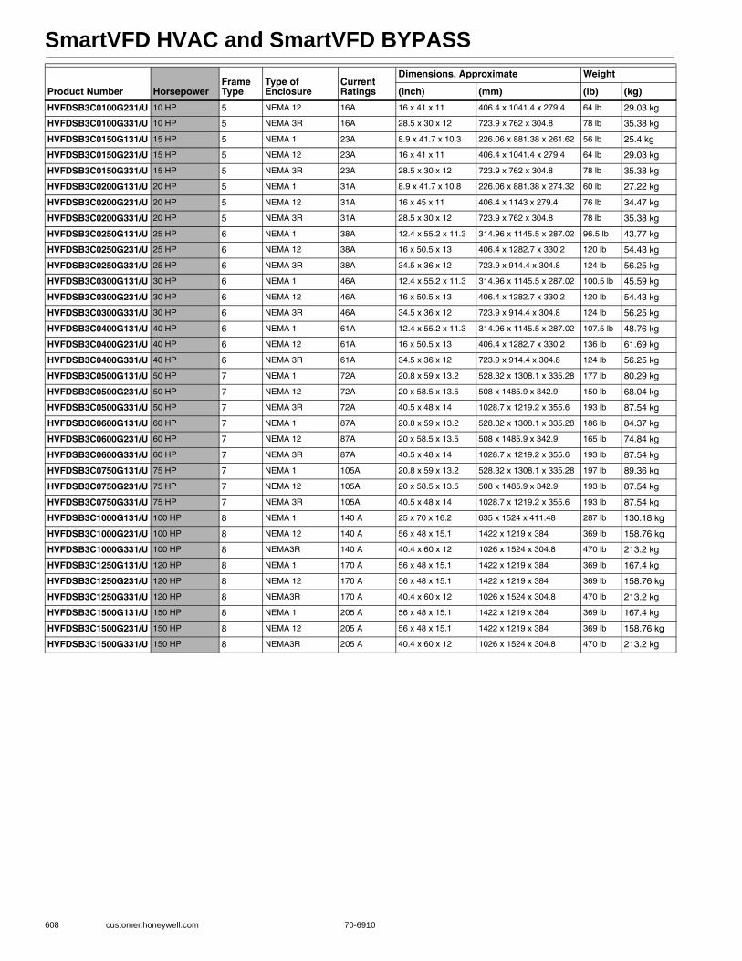
SmartVFD HVAC and SmartVFD BYPASS
608 customer.honeywell.com 70-6910
HVFDSB3C0100G231/U 10 HP 5 NEMA 12 16A 16 x 41 x 11 406.4 x 1041.4 x 279.4 64 lb 29.03 kg
HVFDSB3C0100G331/U 10 HP 5 NEMA 3R 16A 28.5 x 30 x 12 723.9 x 762 x 304.8 78 lb 35.38 kg
HVFDSB3C0150G131/U 15 HP 5 NEMA 1 23A 8.9 x 41.7 x 10.3 226.06 x 881.38 x 261.62 56 lb 25.4 kg
HVFDSB3C0150G231/U 15 HP 5 NEMA 12 23A 16 x 41 x 11 406.4 x 1041.4 x 279.4 64 lb 29.03 kg
HVFDSB3C0150G331/U 15 HP 5 NEMA 3R 23A 28.5 x 30 x 12 723.9 x 762 x 304.8 78 lb 35.38 kg
HVFDSB3C0200G131/U 20 HP 5 NEMA 1 31A 8.9 x 41.7 x 10.8 226.06 x 881.38 x 274.32 60 lb 27.22 kg
HVFDSB3C0200G231/U 20 HP 5 NEMA 12 31A 16 x 45 x 11 406.4 x 1143 x 279.4 76 lb 34.47 kg
HVFDSB3C0200G331/U 20 HP 5 NEMA 3R 31A 28.5 x 30 x 12 723.9 x 762 x 304.8 78 lb 35.38 kg
HVFDSB3C0250G131/U 25 HP 6 NEMA 1 38A 12.4 x 55.2 x 11.3 314.96 x 1145.5 x 287.02 96.5 lb 43.77 kg
HVFDSB3C0250G231/U 25 HP 6 NEMA 12 38A 16 x 50.5 x 13 406.4 x 1282.7 x 330 2 120 lb 54.43 kg
HVFDSB3C0250G331/U 25 HP 6 NEMA 3R 38A 34.5 x 36 x 12 723.9 x 914.4 x 304.8 124 lb 56.25 kg
HVFDSB3C0300G131/U 30 HP 6 NEMA 1 46A 12.4 x 55.2 x 11.3 314.96 x 1145.5 x 287.02 100.5 lb 45.59 kg
HVFDSB3C0300G231/U 30 HP 6 NEMA 12 46A 16 x 50.5 x 13 406.4 x 1282.7 x 330 2 120 lb 54.43 kg
HVFDSB3C0300G331/U 30 HP 6 NEMA 3R 46A 34.5 x 36 x 12 723.9 x 914.4 x 304.8 124 lb 56.25 kg
HVFDSB3C0400G131/U 40 HP 6 NEMA 1 61A 12.4 x 55.2 x 11.3 314.96 x 1145.5 x 287.02 107.5 lb 48.76 kg
HVFDSB3C0400G231/U 40 HP 6 NEMA 12 61A 16 x 50.5 x 13 406.4 x 1282.7 x 330 2 136 lb 61.69 kg
HVFDSB3C0400G331/U 40 HP 6 NEMA 3R 61A 34.5 x 36 x 12 723.9 x 914.4 x 304.8 124 lb 56.25 kg
HVFDSB3C0500G131/U 50 HP 7 NEMA 1 72A 20.8 x 59 x 13.2 528.32 x 1308.1 x 335.28 177 lb 80.29 kg
HVFDSB3C0500G231/U 50 HP 7 NEMA 12 72A 20 x 58.5 x 13.5 508 x 1485.9 x 342.9 150 lb 68.04 kg
HVFDSB3C0500G331/U 50 HP 7 NEMA 3R 72A 40.5 x 48 x 14 1028.7 x 1219.2 x 355.6 193 lb 87.54 kg
HVFDSB3C0600G131/U 60 HP 7 NEMA 1 87A 20.8 x 59 x 13.2 528.32 x 1308.1 x 335.28 186 lb 84.37 kg
HVFDSB3C0600G231/U 60 HP 7 NEMA 12 87A 20 x 58.5 x 13.5 508 x 1485.9 x 342.9 165 lb 74.84 kg
HVFDSB3C0600G331/U 60 HP 7 NEMA 3R 87A 40.5 x 48 x 14 1028.7 x 1219.2 x 355.6 193 lb 87.54 kg
HVFDSB3C0750G131/U 75 HP 7 NEMA 1 105A 20.8 x 59 x 13.2 528.32 x 1308.1 x 335.28 197 lb 89.36 kg
HVFDSB3C0750G231/U 75 HP 7 NEMA 12 105A 20 x 58.5 x 13.5 508 x 1485.9 x 342.9 193 lb 87.54 kg
HVFDSB3C0750G331/U 75 HP 7 NEMA 3R 105A 40.5 x 48 x 14 1028.7 x 1219.2 x 355.6 193 lb 87.54 kg
HVFDSB3C1000G131/U 100 HP 8 NEMA 1 140 A 25 x 70 x 16.2 635 x 1524 x 411.48 287 lb 130.18 kg
HVFDSB3C1000G231/U 100 HP 8 NEMA 12 140 A 56 x 48 x 15.1 1422 x 1219 x 384 369 lb 158.76 kg
HVFDSB3C1000G331/U 100 HP 8 NEMA3R 140 A 40.4 x 60 x 12 1026 x 1524 x 304.8 470 lb 213.2 kg
HVFDSB3C1250G131/U 120 HP 8 NEMA 1 170 A 56 x 48 x 15.1 1422 x 1219 x 384 369 lb 167.4 kg
HVFDSB3C1250G231/U 120 HP 8 NEMA 12 170 A 56 x 48 x 15.1 1422 x 1219 x 384 369 lb 158.76 kg
HVFDSB3C1250G331/U 120 HP 8 NEMA3R 170 A 40.4 x 60 x 12 1026 x 1524 x 304.8 470 lb 213.2 kg
HVFDSB3C1500G131/U 150 HP 8 NEMA 1 205 A 56 x 48 x 15.1 1422 x 1219 x 384 369 lb 167.4 kg
HVFDSB3C1500G231/U 150 HP 8 NEMA 12 205 A 56 x 48 x 15.1 1422 x 1219 x 384 369 lb 158.76 kg
HVFDSB3C1500G331/U 150 HP 8 NEMA3R 205 A 40.4 x 60 x 12 1026 x 1524 x 304.8 470 lb 213.2 kg
Product Number HorsepowerFrame Type
Type of Enclosure
Current Ratings
Dimensions, Approximate Weight
(inch) (mm) (lb) (kg)
SmartVFD HVAC and SmartVFD BYPASS
70-6910 609
Com
mercial
Com
ponents
SmartVFD COMPACT Accessories
SmartVFD HVAC Accessories
Product Number Description Used With
HVFDCABLE/U SmartVFD HVAC and COMPACT USB Commissioning Cable SmartVFD COMPACT
HVFDCDMCA/U COMPACT VFD Commissioning device SmartVFD COMPACT
HVFDCDMCAKIT/U COMPACT VFD Commissioning kit SmartVFD COMPACT
HVFDCDNEMA1FR1/U COMPACT VFD NEMA 1 kit - Frame size 1 SmartVFD COMPACT
HVFDCDNEMA1FR2/U COMPACT VFD NEMA 1 kit - Frame Size 2 SmartVFD COMPACT
HVFDCDNEMA1FR3/U COMPACT VFD NEMA 1 kit - Frame size 3 SmartVFD COMPACT
HVFDCDTRAINER/U COMPACT VFD Training Demonstration kit SmartVFD COMPACT
Product Number Description Used With
32006630-001/U Lon Communication Card (NXOPTC4) SmartVFD HVAC
HFVDSDMOUNTKIT/U SmartVFD HVAC panel mount kit for NEMA 12 Install, 3 meter cable SmartVFD HVAC
HVFDSDBATTERY/U Battery Package, 5 pcs, for Real Time Clock SmartVFD HVAC
HVFDSDFANFR4/U SmartVFD HVAC Frame 4 Replacement Fan SmartVFD HVAC
HVFDSDFANFR5/U SmartVFD HVAC Frame 5 Replacement Fan SmartVFD HVAC
HVFDSDFANFR6/U SmartVFD HVAC Frame 6 Replacement Fan SmartVFD HVAC
HVFDSDFANFR7/U SmartVFD HVAC Frame 7 Replacement Fan SmartVFD HVAC
HVFDSDFLANGEFR4/U SmartVFD HVAC Flange Mounting Kit for Frame 4 SmartVFD HVAC
HVFDSDFLANGEFR5/U SmartVFD HVAC Flange Mounting Kit for Frame 5 SmartVFD HVAC
HVFDSDFLANGEFR6/U SmartVFD HVAC Flange Mounting Kit for Frame 6 SmartVFD HVAC
HVFDSDFLANGEFR7/U SmartVFD HVAC Flange Mounting Kit for Frame 7 SmartVFD HVAC
HVFDSDGRAPHICKP/U SmartVFD HVAC Replacement Graphical Keypad SmartVFD HVAC
HVFDSDINSTALLFR4/U SmartVFD HVAC Replacement Installation Accessories Frame 4 SmartVFD HVAC
HVFDSDINSTALLFR5/U SmartVFD HVAC Replacement Installation Accessories Frame 5 SmartVFD HVAC
HVFDSDINSTALLFR6/U SmartVFD HVAC Replacement Installation Accessories Frame 6 SmartVFD HVAC
32006630-001/U LON Communication Card (NXOPTC4) SmartVFD HVAC
HVFSDMOUNTKIT/U SmartVFD HVAC Panel Mount Kit for NEMA 12 Install; 3-meter cable SmartVFD HVAC
HVFDSDNEMA12FR4/U SmartVFD HVAC NEMA12 Kit Frame 4 SmartVFD HVAC
HVFDSDNEMA12FR5/U SmartVFD HVAC NEMA12 Kit Frame 5 SmartVFD HVAC
HVFDSDNEMA12FR6/U SmartVFD HVAC NEMA12 Kit Frame 6 SmartVFD HVAC
HVFDSDOPT1AI2AO/U 1 x AI, 2 x AO (isolated, D- and E-slot compatible) SmartVFD HVAC
HVFDSDOPT1RO5DI/U 1 x RO, 5 x DI (42-240VAC, D- and E-slot compatible) SmartVFD HVAC
HVFDSDOPT2RO1T/U 2 x RO + Thermistor (D- and E-slot compatible) SmartVFD HVAC
HVFDSDOPT3RO/U 3 x RO (D- and E-slot compatible) SmartVFD HVAC
HVFDSDOPT6DI/U 6 x DI / DO Programmable (D- and E-slot compatible) SmartVFD HVAC
HVFDSDREP2RO1T/U 2 x RO + Thermistor (B-slot compatible) SmartVFD HVAC
HVFDSDREP3RO/U 3 x RO (B-slot compatible) SmartVFD HVAC
HVFDSDTRAINER/U SmartVFD HVAC Training Demonstration Kit with 115V Transformer to 230V SmartVFD HVAC
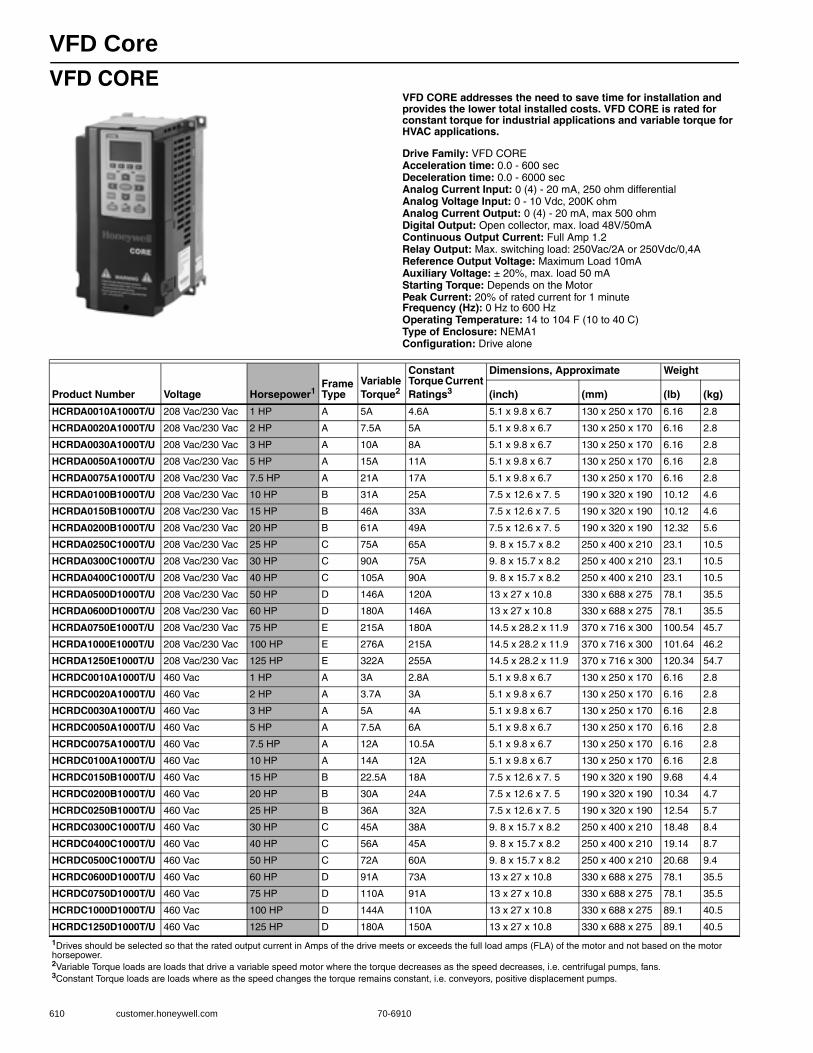
VFD Core
610 customer.honeywell.com 70-6910
VFD COREVFD CORE addresses the need to save time for installation and provides the lower total installed costs. VFD CORE is rated for constant torque for industrial applications and variable torque for HVAC applications.
Drive Family: VFD COREAcceleration time: 0.0 - 600 secDeceleration time: 0.0 - 6000 secAnalog Current Input: 0 (4) - 20 mA, 250 ohm differentialAnalog Voltage Input: 0 - 10 Vdc, 200K ohmAnalog Current Output: 0 (4) - 20 mA, max 500 ohmDigital Output: Open collector, max. load 48V/50mAContinuous Output Current: Full Amp 1.2Relay Output: Max. switching load: 250Vac/2A or 250Vdc/0,4AReference Output Voltage: Maximum Load 10mAAuxiliary Voltage: ± 20%, max. load 50 mAStarting Torque: Depends on the MotorPeak Current: 20% of rated current for 1 minuteFrequency (Hz): 0 Hz to 600 HzOperating Temperature: 14 to 104 F (10 to 40 C) Type of Enclosure: NEMA1Configuration: Drive alone
Product Number Voltage Horsepower1Frame Type
Variable Torque2
Constant Torque Current Ratings3
Dimensions, Approximate Weight
(inch) (mm) (lb) (kg)
HCRDA0010A1000T/U 208 Vac/230 Vac 1 HP A 5A 4.6A 5.1 x 9.8 x 6.7 130 x 250 x 170 6.16 2.8
HCRDA0020A1000T/U 208 Vac/230 Vac 2 HP A 7.5A 5A 5.1 x 9.8 x 6.7 130 x 250 x 170 6.16 2.8
HCRDA0030A1000T/U 208 Vac/230 Vac 3 HP A 10A 8A 5.1 x 9.8 x 6.7 130 x 250 x 170 6.16 2.8
HCRDA0050A1000T/U 208 Vac/230 Vac 5 HP A 15A 11A 5.1 x 9.8 x 6.7 130 x 250 x 170 6.16 2.8
HCRDA0075A1000T/U 208 Vac/230 Vac 7.5 HP A 21A 17A 5.1 x 9.8 x 6.7 130 x 250 x 170 6.16 2.8
HCRDA0100B1000T/U 208 Vac/230 Vac 10 HP B 31A 25A 7.5 x 12.6 x 7. 5 190 x 320 x 190 10.12 4.6
HCRDA0150B1000T/U 208 Vac/230 Vac 15 HP B 46A 33A 7.5 x 12.6 x 7. 5 190 x 320 x 190 10.12 4.6
HCRDA0200B1000T/U 208 Vac/230 Vac 20 HP B 61A 49A 7.5 x 12.6 x 7. 5 190 x 320 x 190 12.32 5.6
HCRDA0250C1000T/U 208 Vac/230 Vac 25 HP C 75A 65A 9. 8 x 15.7 x 8.2 250 x 400 x 210 23.1 10.5
HCRDA0300C1000T/U 208 Vac/230 Vac 30 HP C 90A 75A 9. 8 x 15.7 x 8.2 250 x 400 x 210 23.1 10.5
HCRDA0400C1000T/U 208 Vac/230 Vac 40 HP C 105A 90A 9. 8 x 15.7 x 8.2 250 x 400 x 210 23.1 10.5
HCRDA0500D1000T/U 208 Vac/230 Vac 50 HP D 146A 120A 13 x 27 x 10.8 330 x 688 x 275 78.1 35.5
HCRDA0600D1000T/U 208 Vac/230 Vac 60 HP D 180A 146A 13 x 27 x 10.8 330 x 688 x 275 78.1 35.5
HCRDA0750E1000T/U 208 Vac/230 Vac 75 HP E 215A 180A 14.5 x 28.2 x 11.9 370 x 716 x 300 100.54 45.7
HCRDA1000E1000T/U 208 Vac/230 Vac 100 HP E 276A 215A 14.5 x 28.2 x 11.9 370 x 716 x 300 101.64 46.2
HCRDA1250E1000T/U 208 Vac/230 Vac 125 HP E 322A 255A 14.5 x 28.2 x 11.9 370 x 716 x 300 120.34 54.7
HCRDC0010A1000T/U 460 Vac 1 HP A 3A 2.8A 5.1 x 9.8 x 6.7 130 x 250 x 170 6.16 2.8
HCRDC0020A1000T/U 460 Vac 2 HP A 3.7A 3A 5.1 x 9.8 x 6.7 130 x 250 x 170 6.16 2.8
HCRDC0030A1000T/U 460 Vac 3 HP A 5A 4A 5.1 x 9.8 x 6.7 130 x 250 x 170 6.16 2.8
HCRDC0050A1000T/U 460 Vac 5 HP A 7.5A 6A 5.1 x 9.8 x 6.7 130 x 250 x 170 6.16 2.8
HCRDC0075A1000T/U 460 Vac 7.5 HP A 12A 10.5A 5.1 x 9.8 x 6.7 130 x 250 x 170 6.16 2.8
HCRDC0100A1000T/U 460 Vac 10 HP A 14A 12A 5.1 x 9.8 x 6.7 130 x 250 x 170 6.16 2.8
HCRDC0150B1000T/U 460 Vac 15 HP B 22.5A 18A 7.5 x 12.6 x 7. 5 190 x 320 x 190 9.68 4.4
HCRDC0200B1000T/U 460 Vac 20 HP B 30A 24A 7.5 x 12.6 x 7. 5 190 x 320 x 190 10.34 4.7
HCRDC0250B1000T/U 460 Vac 25 HP B 36A 32A 7.5 x 12.6 x 7. 5 190 x 320 x 190 12.54 5.7
HCRDC0300C1000T/U 460 Vac 30 HP C 45A 38A 9. 8 x 15.7 x 8.2 250 x 400 x 210 18.48 8.4
HCRDC0400C1000T/U 460 Vac 40 HP C 56A 45A 9. 8 x 15.7 x 8.2 250 x 400 x 210 19.14 8.7
HCRDC0500C1000T/U 460 Vac 50 HP C 72A 60A 9. 8 x 15.7 x 8.2 250 x 400 x 210 20.68 9.4
HCRDC0600D1000T/U 460 Vac 60 HP D 91A 73A 13 x 27 x 10.8 330 x 688 x 275 78.1 35.5
HCRDC0750D1000T/U 460 Vac 75 HP D 110A 91A 13 x 27 x 10.8 330 x 688 x 275 78.1 35.5
HCRDC1000D1000T/U 460 Vac 100 HP D 144A 110A 13 x 27 x 10.8 330 x 688 x 275 89.1 40.5
HCRDC1250D1000T/U 460 Vac 125 HP D 180A 150A 13 x 27 x 10.8 330 x 688 x 275 89.1 40.5
1Drives should be selected so that the rated output current in Amps of the drive meets or exceeds the full load amps (FLA) of the motor and not based on the motor horsepower.2Variable Torque loads are loads that drive a variable speed motor where the torque decreases as the speed decreases, i.e. centrifugal pumps, fans.3Constant Torque loads are loads where as the speed changes the torque remains constant, i.e. conveyors, positive displacement pumps.
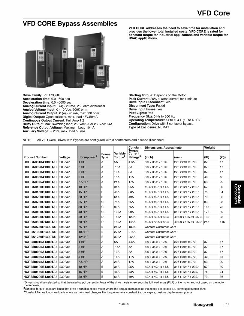
VFD Core
70-6910 611
Com
mercial
Com
ponents
VFD CORE Bypass AssembliesVFD CORE addresses the need to save time for installation and provides the lower total installed costs. VFD CORE is rated for constant torque for industrial applications and variable torque for HVAC applications.
Drive Family: VFD COREAcceleration time: 0.0 - 600 secDeceleration time: 0.0 - 6000 secAnalog Current Input: 0 (4) - 20 mA, 250 ohm differentialAnalog Voltage Input: 0 - 10 Vdc, 200K ohmAnalog Current Output: 0 (4) - 20 mA, max 500 ohmDigital Output: Open collector, max. load 48V/50mAContinuous Output Current: Full Amp 1.2Relay Output: Max. switching load: 250Vac/2A or 250Vdc/0,4AReference Output Voltage: Maximum Load 10mAAuxiliary Voltage: ± 20%, max. load 50 mA
Starting Torque: Depends on the MotorPeak Current: 20% of rated current for 1 minuteDrive Input Disconnect: YesDisconnect Type: FusedDrive Input Fuses: YesPilot Lights: YesFrequency (Hz): 0 Hz to 600 HzOperating Temperature: 14 to 104 F (10 to 40 C) Configuration: Drive with 3 contactor bypassType of Enclosure: NEMA1
NOTE: All VFD Core Drives with Bypass are configured with 3 contractors and a fused disconnect.
Product Number Voltage Horsepower1Frame Type
Variable Torque2
Constant Torque Current Ratings3
Dimensions, Approximate Weight
(inch) (mm) (lb) (kg)
HCRBA0010A1300T/U 208 Vac 1 HP A 5A 4.6A 8.9 x 35.2 x 10.6 226 x 894 x 270 37 17
HCRBA0020A1300T/U 208 Vac 2 HP A 7.5A 5A 8.9 x 35.2 x 10.6 226 x 894 x 270 37 17
HCRBA0030A1300T/U 208 Vac 3 HP A 10A 8A 8.9 x 35.2 x 10.6 226 x 894 x 270 37 17
HCRBA0050A1300T/U 208 Vac 5 HP A 15A 11A 8.9 x 35.2 x 10.6 226 x 894 x 270 40 18
HCRBA0075A1300T/U 208 Vac 7.5 HP A 21A 17A 8.9 x 35.2 x 10.6 226 x 894 x 270 63 29
HCRBA0100B1300T/U 208 Vac 10 HP B 31A 25A 12.4 x 49.1 x 11.5 315 x 1247 x 292.1 67 30
HCRBA0150B1300T/U 208 Vac 15 HP B 46A 33A 12.4 x 49.1 x 11.5 315 x 1247 x 292.1 75 34
HCRBA0200B1300T/U 208 Vac 20 HP B 61A 49A 12.4 x 49.1 x 11.5 315 x 1247 x 292.1 79 36
HCRBA0250C1300T/U 208 Vac 25 HP C 75A 65A 12.4 x 49.1 x 11.5 315 x 1247 x 292.1 83 38
HCRBA0300C1300T/U 208 Vac 30 HP C 90A 75A 12.4 x 49.1 x 11.5 315 x 1247 x 292.1 166 75
HCRBA0400C1300T/U 208 Vac 40 HP C 105A 90A 12.4 x 49.1 x 11.5 315 x 1247 x 292.1 176 80
HCRBA0500D1300T/U 208 Vac 50 HP D 146A 120A 19.6 x 53.5 x 13.3 497.8 x 1359 x 337.8 193 88
HCRBA0600D1300T/U 208 Vac 60 HP D 180A 146A 19.6 x 53.5 x 13.3 497.8 x 1359 x 337.8 255 116
HCRBA0750E1300T/U 208 Vac 75 HP E 215A 180A Contact Customer Care
HCRBA1000E1300T/U 208 Vac 100 HP E 276A 215A Contact Customer Care
HCRBA1250E1300T/U 208 Vac 125 HP E 322A 255A Contact Customer Care
HCRBB0010A1300T/U 230 Vac 1 HP A 5A 4.6A 8.9 x 35.2 x 10.6 226 x 894 x 270 37 17
HCRBB0020A1300T/U 230 Vac 2 HP A 7.5A 5A 8.9 x 35.2 x 10.6 226 x 894 x 270 37 17
HCRBB0030A1300T/U 230 Vac 3 HP A 10A 8A 8.9 x 35.2 x 10.6 226 x 894 x 270 37 17
HCRBB0050A1300T/U 230 Vac 5 HP A 15A 11A 8.9 x 35.2 x 10.6 226 x 894 x 270 40 18
HCRBB0075A1300T/U 230 Vac 7.5 HP A 21A 17A 8.9 x 35.2 x 10.6 226 x 894 x 270 63 29
HCRBB0100B1300T/U 230 Vac 10 HP B 31A 25A 12.4 x 49.1 x 11.5 315 x 1247 x 292.1 67 30
HCRBB0150B1300T/U 230 Vac 15 HP B 46A 33A 12.4 x 49.1 x 11.5 315 x 1247 x 292.1 75 34
HCRBB0200B1300T/U 230 Vac 20 HP B 61A 49A 12.4 x 49.1 x 11.5 315 x 1247 x 292.1 79 36
1Drives should be selected so that the rated output current in Amps of the drive meets or exceeds the full load amps (FLA) of the motor and not based on the motor horsepower.
2Variable Torque loads are loads that drive a variable speed motor where the torque decreases as the speed decreases, i.e. centrifugal pumps, fans.3Constant Torque loads are loads where as the speed changes the torque remains constant, i.e. conveyors, positive displacement pumps.
VFD Core
612 customer.honeywell.com 70-6910
VFD Core Accessories
HCRBB0250C1300T/U 230 Vac 25 HP C 75A 65A 12.4 x 49.1 x 11.5 315 x 1247 x 292.1 83 38
HCRBB0300C1300T/U 230 Vac 30 HP C 90A 75A 12.4 x 49.1 x 11.5 315 x 1247 x 292.1 166 75
HCRBB0400C1300T/U 230 Vac 40 HP C 105A 90A 12.4 x 49.1 x 11.5 315 x 1247 x 292.1 176 80
HCRBB0500D1300T/U 230 Vac 50 HP D 146A 120A 19.6 x 53.5 x 13.3 497.8 x 1359 x 337.8 193 88
HCRBB0600D1300T/U 230 Vac 60 HP D 180A 146A 19.6 x 53.5 x 13.3 497.8 x 1359 x 337.8 255 116
HCRBB0750E1300T/U 230 Vac 75 HP E 215A 180A Contact Customer Care
HCRBB1000E1300T/U 230 Vac 100 HP E 276A 215A Contact Customer Care
HCRBB1250E1300T/U 230 Vac 125 HP E 322A 255A Contact Customer Care
HCRBC0010A1300T/U 460 Vac 1 HP A 3A 2.8A 8.9 x 35.2 x 10.6 226 x 894 x 270 37 17
HCRBC0020A1300T/U 460 Vac 2 HP A 3.7A 3A 8.9 x 35.2 x 10.6 226 x 894 x 270 37 17
HCRBC0030A1300T/U 460 Vac 3 HP A 5A 4A 8.9 x 35.2 x 10.6 226 x 894 x 270 37 17
HCRBC0050A1300T/U 460 Vac 5 HP A 7.5A 6A 8.9 x 35.2 x 10.6 226 x 894 x 270 37 17
HCRBC0075A1300T/U 460 Vac 7.5 HP A 12A 10A 8.9 x 35.2 x 10.6 226 x 894 x 270 37 17
HCRBC0100A1300T/U 460 Vac 10 HP A 14A 12A 8.9 x 35.2 x 10.6 226 x 894 x 270 40 18
HCRBC0150B1300T/U 460 Vac 15 HP B 22.5A 18A 12.4 x 49.1 x 11.5 315 x 1247 x 292.1 63 29
HCRBC0200B1300T/U 460 Vac 20 HP B 30A 24A 12.4 x 49.1 x 11.5 315 x 1247 x 292.1 67 30
HCRBC0250B1300T/U 460 Vac 25 HP B 36A 32A 12.4 x 49.1 x 11.5 315 x 1247 x 292.1 71 32
HCRBC0300C1300T/U 460 Vac 30 HP C 45A 38A 12.4 x 49.1 x 11.5 315 x 1247 x 292.1 75 34
HCRBC0400C1300T/U 460 Vac 40 HP C 56A 45A 12.4 x 49.1 x 11.5 315 x 1247 x 292.1 79 36
HCRBC0500C1300T/U 460 Vac 50 HP C 72A 60A 12.4 x 49.1 x 11.5 315 x 1247 x 292.1 83 38
HCRBC0600D1300T/U 460 Vac 60 HP D 91A 73A 19.6 x 53.5 x 13.3 497.8 x 1359 x 337.8 166 75
HCRBC0750D1300T/U 460 Vac 75 HP D 110A 91A 19.6 x 53.5 x 13.3 497.8 x 1359 x 337.8 176 80
HCRBC1000D1300T/U 460 Vac 100 HP D 144A 110A 19.6 x 53.5 x 13.3 497.8 x 1359 x 337.8 193 88
HCRBC1250D1300T/U 460 Vac 125 HP D 180A 150A 19.6 x 53.5 x 13.3 497.8 x 1359 x 337.8 255 116
Product Number Drive Family Description
HCRDFANFRA1H/U VFD CORE VFD CORE Replacement Fan Frame A (Heat Sink Cooling Fan for 3-7.5HP 208/ 230 V and 5-10 HP 460 V)
HCRDFANFRB1B/U VFD CORE VFD CORE Replacement Fan Frame B (Board Cooling Fan for 10-20 HP 208/230 V and 15-25 HP 460 V)
HCRDFANFRB1H/U VFD CORE VFD CORE Replacement Fan Frame B (Heat Sink Cooling Fan for 10 HP 208/230 V and 15 HP 460 V)
HCRDFANFRB2H/U VFD CORE VFD CORE Replacement Fan Frame B (Heat Sink Cooling Fan for 15-20 HP 208/230 V and 20-25 HP 460V)
HCRDFANFRC1B/U VFD CORE VFD CORE Replacement Fan Frame C (Board Cooling Fan for 25-40 HP 208/230 V)
HCRDFANFRC2B/U VFD CORE VFD CORE Replacement Fan Frame C (Board Cooling Fan for 30-50 HP 460 V)
HCRDFANFRD1B/U VFD CORE VFD CORE Replacement Fan Frame D (Board Cooling Fan for 50-60 HP 208/230 V and 60-125 HP 460V)
HCRDFANFRD1H/U VFD CORE VFD CORE Replacement Fan Frame D (Heat Sink Cooling Fan for 50-60 HP 208/230 V and 60-125 HP 460V)
HCRDFANFRE1B/U VFD CORE VFD CORE Replacement Fan Frame E (Board Cooling Fan for 75- 125 HP 208/230V)
HCRDFANFRE1H/U VFD CORE VFD CORE Replacement Fan Frame E (Heat Sink Cooling Fan for 75- 100 HP 208/230 V)
HCRDFANFRE2H/U VFD CORE VFD CORE Replacement Fan Frame E (Heat Sink Cooling Fan for 125 HP 208/230 V)
HCRDKEYPAD/U VFD CORE VFD CORE Replacement Keypad
HCRDMOUNTKIT/U VFD CORE VFD CORE Keypad Mounting Kit
HCRDTRAINER/U VFD CORE VFD CORE Training Demonstration Kit
Product Number Voltage Horsepower1Frame Type
Variable Torque2
Constant Torque Current Ratings3
Dimensions, Approximate Weight
(inch) (mm) (lb) (kg)
1Drives should be selected so that the rated output current in Amps of the drive meets or exceeds the full load amps (FLA) of the motor and not based on the motor horsepower.
2Variable Torque loads are loads that drive a variable speed motor where the torque decreases as the speed decreases, i.e. centrifugal pumps, fans.3Constant Torque loads are loads where as the speed changes the torque remains constant, i.e. conveyors, positive displacement pumps.

Variable Frequency Drives
70-6910 613
Com
mercial
Com
ponents
NXP Variable Frequency DrivesVariable Frequency Drives (VFD) accept a control input and then output tailored PWM control signal to operate (motors, fans, pumps, etc.) with maximum efficiency. The VFD can be field-programmed without any extra devices or computer connections• Seven configurable applications built in • Easy commissioning through software or control panel • Devices are free-standing to ensure secure installation• Insulated gate bi-polar transistor (IGBT) technology
Drive Family: NXPAcceleration time: 0 - 3000 secDeceleration time: 0 - 3000 secAnalog Current Input: 0 (4) - 20 mA, 250 ohm differentialAnalog Voltage Input: 0 - 10 Vdc, 200K ohmAnalog Current Output: 0 (4) - 20 mA, max 500 ohmDigital Output: 50 mA/48v open collectorContinuous Output Current: overload 1.5 x High overload current
(1min/10min); overload 1.1 x Low overload current (1min/10min)Relay Output: 24 Vdc/8A; 125 Vdc/0.4A; 250 Vac/8AReference Output Voltage: +10V, +3%, max 10mAAuxiliary Voltage: 24V, +/- 15%, max 250 mAStarting Torque: 200% High; 150% LowPeak Current: 2 x high overload current, 2 seconds every 20 secondsVoltage: 460 VacFrequency (Hz): 0 Hz to 320 HzOperating Temperature: High Overload 14 to 122; Low Overload 14 to
104 (High Overload -10 to 50; Low Overload -10 to 40) Type of Enclosure: NEMA 1Type of RFI Filter: Industrial filterLayout: Stand-alone driveConfiguration: Drive alone
Dimensions in inches (millimeters)
H
W D
M23816
Product Number HorsepowerFrame Type
Current Ratings
Dimensions, Approximate Weight
(inch) (mm) (lb) (kg)
NXP3000A1003/U 300 HP FR10 385A 23.4 x 79.5 x 23.7 595 x 2018 x 602 595 b 270 kg
NXP3500A1008/U 350 HP FR10 460A 23.4 x 79.5 x 23.7 595 x 2018 x 602 595 b 270 kg
NXP4500A1006/U 450 HP FR10 520A 23.4 x 79.5 x 23.7 595 x 2018 x 602 595 b 270 kg

Variable Frequency Drives
614 customer.honeywell.com 70-6910
NXS Variable Frequency DrivesVariable Frequency Drives (VFD) accept a control input and then output tailored PWM control signal to operate (fans, pumps, etc.) with maximum efficiency. The VFD can be field-programmed without any extra devices or computer connections.• Seven configurable applications built in • Easy commissioning through software or control panel • Devices can be wall-mounted or panel-mounted • Eleven protective functions (see Form 63-2600, Users Manual,
Technical Data sections) • Compact Size• Insulated gate bi-polar transistor (IGBT) technology • Modbus, BACnet, Device Net, Prof bus, LobBus,
NS available as options cards
Drive Family: NXSAcceleration time: 0 - 3000 secDeceleration time: 0 - 3000 secAnalog Current Input: 0 (4) - 20 mA, 250 ohm differentialAnalog Voltage Input: 0 - 10 Vdc, 200K ohmAnalog Current Output: 0 (4) - 20 mA, max 500 ohmDigital Output: 50 mA/48v open collectorContinuous Output Current: overload 1.5 x High overload current
(1min/10min); overload 1.1 x Low overload current (1min/10min)Relay Output: 24 Vdc/8A; 125 Vdc/0.4A; 250 Vac/8A
Reference Output Voltage: +10V, +3%, max 10mAAuxiliary Voltage: 24V, +/- 15%, max 250 mAStarting Torque: 200% High; 150% LowPeak Current: 2 x high overload current, 2 seconds every 20 secondsFrequency (Hz): 0 Hz to 320 HzOperating Temperature: High Overload 14 to 122; Low Overload 14 to
104 (High Overload -10 to 50; Low Overload -10 to 40) Type of RFI Filter: Industrial filterConfiguration: Drive alone
Voltage: 208 Vac; 230 Vac
Product NumberHorse-power
Frame Type Layout
Type of Enclosure
Current Ratings
Dimensions, Approximate Weight
(inch) (mm) (lb) (kg)
NXS0010B1000/U 1 HP FR4 Stand-alone drive NEMA 1 4.8A 5.4 x 11.5 x 7.5 137 x 292 x 191 11 lb 5.0 kg
NXS0010B1208/U 1 HP FR4 Stand-alone drive NEMA 12 4.8A 5.4 x 11.5 x 7.5 137 x 292 x 191 11 lb 5.0 kg
NXS0015B1005/U 1.5 HP FR4 Stand-alone drive NEMA 1 6.6A 5.4 x 11.5 x 7.5 137 x 292 x 191 11 lb 5.0 kg
NXS0015B1203/U 1.5 HP FR4 Stand-alone drive NEMA 12 6.6A 5.4 x 11.5 x 7.5 137 x 292 x 191 11 lb 5.0 kg
NXS0020B1008/U 2 HP FR4 Stand-alone drive NEMA 1 7.8A 5.4 x 11.5 x 7.5 137 x 292 x 191 11 lb 5.0 kg
NXS0020B1206/U 2 HP FR4 Stand-alone drive NEMA 12 7.8A 5.4 x 11.5 x 7.5 137 x 292 x 191 11 lb 5.0 kg
NXS0030B1006/U 3 HP FR4 Stand-alone drive NEMA 1 11A 5.4 x 11.5 x 7.5 137 x 292 x 191 11 lb 5.0 kg
NXS0030B1204/U 3 HP FR4 Stand-alone drive NEMA 12 11A 5.4 x 11.5 x 7.5 137 x 292 x 191 11 lb 5.0 kg
NXS0040B1004/U 4 HP FR4 Stand-alone drive NEMA 1 12.5A 5.4 x 11.5 x 7.5 137 x 292 x 191 17.9 lb 8.1 kg
NXS0040B1202/U 4 HP FR4 Stand-alone drive NEMA 12 12.5A 5.4 x 11.5 x 7.5 137 x 292 x 191 17.9 lb 8.1 kg
NXS0050B1001/U 5 HP FR5 Stand-alone drive NEMA 1 17.5A 5.7 x 15.4 x 8.4 144.8 x 391.2 x 213.4 17.9 lb 8.1 kg
NXS0050B1209/U 5 HP FR5 Stand-alone drive NEMA 12 17.5A 5.7 x 15.4 x 8.4 144.8 x 391.2 x 213.4 17.9 lb 8.1 kg
NXS0075B1002/U 7.5 HP FR5 Stand-alone drive NEMA 1 25A 5.7 x 15.4 x 8.4 144.8 x 391.2 x 213.4 17.9 lb 8.1 kg
NXS0075B1200/U 7.5 HP FR5 Stand-alone drive NEMA 12 25A 5.7 x 15.4 x 8.4 144.8 x 391.2 x 213.4 17.9 lb 8.1 kg
NXS0100B1001/U 10 HP FR5 Stand-alone drive NEMA 1 31A 5.7 x 15.4 x 8.4 144.8 x 391.2 x 213.4 40.8 lb 18.5 kg
NXS0100B1209/U 10 HP FR5 Stand-alone drive NEMA 12 31A 5.7 x 15.4 x 8.4 144.8 x 391.2 x 213.4 40.8 lb 18.5 kg
NXS0150B1000/U 15 HP FR6 Stand-alone drive NEMA 1 48A 7.7 x 20.4 x 9.3 196 x 518 x 236 40.8 lb 18.5 kg
NXS0150B1208/U 15 HP FR6 Stand-alone drive NEMA 12 48A 7.7 x 20.4 x 9.3 196 x 518 x 236 40.8 lb 18.5 kg
NXS0200B1000/U 20 HP FR6 Stand-alone drive NEMA 1 61A 7.7 x 20.4 x 9.3 196 x 518 x 236 77.2 lb 35 kg
NXS0200B1208/U 20 HP FR6 Stand-alone drive NEMA 12 61A 7.7 x 20.4 x 9.3 196 x 518 x 236 77.2 lb 35 kg
NXS0250B1009/U 25 HP FR7 Stand-alone drive NEMA 1 75A 9.3 x 23.3 x 10.1 236 x 520 x 257 77.2 lb 35 kg
NXS0250B1207/U 25 HP FR7 Stand-alone drive NEMA 12 75A 9.3 x 23.3 x 10.1 236 x 520 x 257 77.2 lb 35 kg
NXS0300B1009/U 30 HP FR7 Stand-alone drive NEMA 1 88A 9.3 x 23.3 x 10.1 236 x 520 x 257 77.2 lb 35 kg
NXS0300B1207/U 30 HP FR7 Stand-alone drive NEMA 12 88A 9.3 x 23.3 x 10.1 236 x 520 x 257 77.2 lb 35 kg
NXS0400B1008/U 40 HP FR8 Stand-alone drive NEMA 1 114A 9.3 x 23.3 x 10.1 236 x 520 x 257 127.9 lb 58.0 kg
NXS0400B1206/U 40 HP FR8 Stand-alone drive NEMA 12 114A 11.2 x 28.4 x 12.3 285 x 721 x 312 127.9 lb 58.0 kg
NXS0500B1007/U 50 HP FR8 Stand-alone drive NEMA 1 140A 11.2 x 28.4 x 12.3 285 x 721 x 312 127.9 lb 58.0 kg
NXS0500B1205/U 50 HP FR8 Stand-alone drive NEMA 12 140A 11.2 x 28.4 x 12.3 285 x 721 x 312 127.9 lb 58.0 kg
NXS0600B1006/U 60 HP FR8 Stand-alone drive NEMA 1 169A 11.2 x 28.4 x 12.3 285 x 721 x 312 127.9 lb 58.0 kg
NXS0600B1204/U 60 HP FR8 Stand-alone drive NEMA 12 169A 11.2 x 28.4 x 12.3 285 x 721 x 312 127.9 lb 58.0 kg
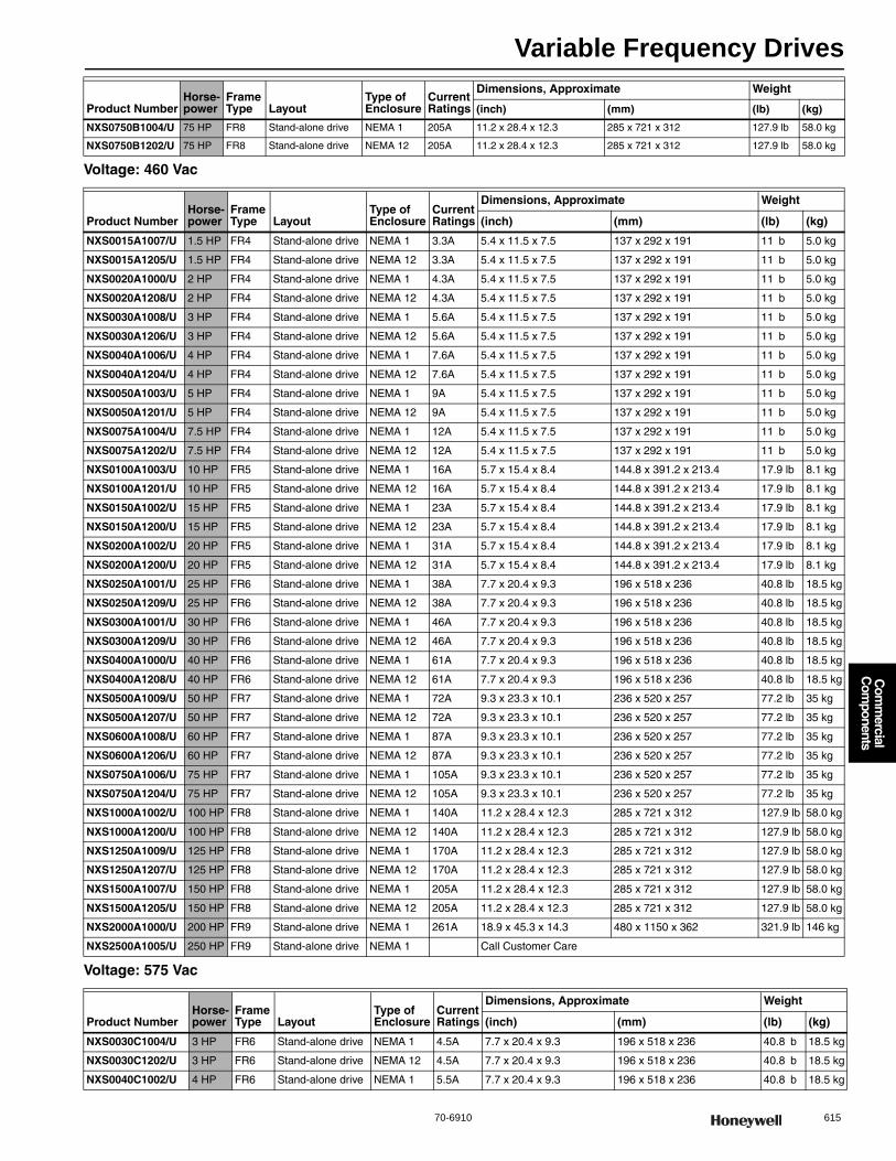
Variable Frequency Drives
70-6910 615
Com
mercial
Com
ponents
Voltage: 460 Vac
Voltage: 575 Vac
NXS0750B1004/U 75 HP FR8 Stand-alone drive NEMA 1 205A 11.2 x 28.4 x 12.3 285 x 721 x 312 127.9 lb 58.0 kg
NXS0750B1202/U 75 HP FR8 Stand-alone drive NEMA 12 205A 11.2 x 28.4 x 12.3 285 x 721 x 312 127.9 lb 58.0 kg
Product NumberHorse-power
Frame Type Layout
Type of Enclosure
Current Ratings
Dimensions, Approximate Weight
(inch) (mm) (lb) (kg)
NXS0015A1007/U 1.5 HP FR4 Stand-alone drive NEMA 1 3.3A 5.4 x 11.5 x 7.5 137 x 292 x 191 11 b 5.0 kg
NXS0015A1205/U 1.5 HP FR4 Stand-alone drive NEMA 12 3.3A 5.4 x 11.5 x 7.5 137 x 292 x 191 11 b 5.0 kg
NXS0020A1000/U 2 HP FR4 Stand-alone drive NEMA 1 4.3A 5.4 x 11.5 x 7.5 137 x 292 x 191 11 b 5.0 kg
NXS0020A1208/U 2 HP FR4 Stand-alone drive NEMA 12 4.3A 5.4 x 11.5 x 7.5 137 x 292 x 191 11 b 5.0 kg
NXS0030A1008/U 3 HP FR4 Stand-alone drive NEMA 1 5.6A 5.4 x 11.5 x 7.5 137 x 292 x 191 11 b 5.0 kg
NXS0030A1206/U 3 HP FR4 Stand-alone drive NEMA 12 5.6A 5.4 x 11.5 x 7.5 137 x 292 x 191 11 b 5.0 kg
NXS0040A1006/U 4 HP FR4 Stand-alone drive NEMA 1 7.6A 5.4 x 11.5 x 7.5 137 x 292 x 191 11 b 5.0 kg
NXS0040A1204/U 4 HP FR4 Stand-alone drive NEMA 12 7.6A 5.4 x 11.5 x 7.5 137 x 292 x 191 11 b 5.0 kg
NXS0050A1003/U 5 HP FR4 Stand-alone drive NEMA 1 9A 5.4 x 11.5 x 7.5 137 x 292 x 191 11 b 5.0 kg
NXS0050A1201/U 5 HP FR4 Stand-alone drive NEMA 12 9A 5.4 x 11.5 x 7.5 137 x 292 x 191 11 b 5.0 kg
NXS0075A1004/U 7.5 HP FR4 Stand-alone drive NEMA 1 12A 5.4 x 11.5 x 7.5 137 x 292 x 191 11 b 5.0 kg
NXS0075A1202/U 7.5 HP FR4 Stand-alone drive NEMA 12 12A 5.4 x 11.5 x 7.5 137 x 292 x 191 11 b 5.0 kg
NXS0100A1003/U 10 HP FR5 Stand-alone drive NEMA 1 16A 5.7 x 15.4 x 8.4 144.8 x 391.2 x 213.4 17.9 lb 8.1 kg
NXS0100A1201/U 10 HP FR5 Stand-alone drive NEMA 12 16A 5.7 x 15.4 x 8.4 144.8 x 391.2 x 213.4 17.9 lb 8.1 kg
NXS0150A1002/U 15 HP FR5 Stand-alone drive NEMA 1 23A 5.7 x 15.4 x 8.4 144.8 x 391.2 x 213.4 17.9 lb 8.1 kg
NXS0150A1200/U 15 HP FR5 Stand-alone drive NEMA 12 23A 5.7 x 15.4 x 8.4 144.8 x 391.2 x 213.4 17.9 lb 8.1 kg
NXS0200A1002/U 20 HP FR5 Stand-alone drive NEMA 1 31A 5.7 x 15.4 x 8.4 144.8 x 391.2 x 213.4 17.9 lb 8.1 kg
NXS0200A1200/U 20 HP FR5 Stand-alone drive NEMA 12 31A 5.7 x 15.4 x 8.4 144.8 x 391.2 x 213.4 17.9 lb 8.1 kg
NXS0250A1001/U 25 HP FR6 Stand-alone drive NEMA 1 38A 7.7 x 20.4 x 9.3 196 x 518 x 236 40.8 lb 18.5 kg
NXS0250A1209/U 25 HP FR6 Stand-alone drive NEMA 12 38A 7.7 x 20.4 x 9.3 196 x 518 x 236 40.8 lb 18.5 kg
NXS0300A1001/U 30 HP FR6 Stand-alone drive NEMA 1 46A 7.7 x 20.4 x 9.3 196 x 518 x 236 40.8 lb 18.5 kg
NXS0300A1209/U 30 HP FR6 Stand-alone drive NEMA 12 46A 7.7 x 20.4 x 9.3 196 x 518 x 236 40.8 lb 18.5 kg
NXS0400A1000/U 40 HP FR6 Stand-alone drive NEMA 1 61A 7.7 x 20.4 x 9.3 196 x 518 x 236 40.8 lb 18.5 kg
NXS0400A1208/U 40 HP FR6 Stand-alone drive NEMA 12 61A 7.7 x 20.4 x 9.3 196 x 518 x 236 40.8 lb 18.5 kg
NXS0500A1009/U 50 HP FR7 Stand-alone drive NEMA 1 72A 9.3 x 23.3 x 10.1 236 x 520 x 257 77.2 lb 35 kg
NXS0500A1207/U 50 HP FR7 Stand-alone drive NEMA 12 72A 9.3 x 23.3 x 10.1 236 x 520 x 257 77.2 lb 35 kg
NXS0600A1008/U 60 HP FR7 Stand-alone drive NEMA 1 87A 9.3 x 23.3 x 10.1 236 x 520 x 257 77.2 lb 35 kg
NXS0600A1206/U 60 HP FR7 Stand-alone drive NEMA 12 87A 9.3 x 23.3 x 10.1 236 x 520 x 257 77.2 lb 35 kg
NXS0750A1006/U 75 HP FR7 Stand-alone drive NEMA 1 105A 9.3 x 23.3 x 10.1 236 x 520 x 257 77.2 lb 35 kg
NXS0750A1204/U 75 HP FR7 Stand-alone drive NEMA 12 105A 9.3 x 23.3 x 10.1 236 x 520 x 257 77.2 lb 35 kg
NXS1000A1002/U 100 HP FR8 Stand-alone drive NEMA 1 140A 11.2 x 28.4 x 12.3 285 x 721 x 312 127.9 lb 58.0 kg
NXS1000A1200/U 100 HP FR8 Stand-alone drive NEMA 12 140A 11.2 x 28.4 x 12.3 285 x 721 x 312 127.9 lb 58.0 kg
NXS1250A1009/U 125 HP FR8 Stand-alone drive NEMA 1 170A 11.2 x 28.4 x 12.3 285 x 721 x 312 127.9 lb 58.0 kg
NXS1250A1207/U 125 HP FR8 Stand-alone drive NEMA 12 170A 11.2 x 28.4 x 12.3 285 x 721 x 312 127.9 lb 58.0 kg
NXS1500A1007/U 150 HP FR8 Stand-alone drive NEMA 1 205A 11.2 x 28.4 x 12.3 285 x 721 x 312 127.9 lb 58.0 kg
NXS1500A1205/U 150 HP FR8 Stand-alone drive NEMA 12 205A 11.2 x 28.4 x 12.3 285 x 721 x 312 127.9 lb 58.0 kg
NXS2000A1000/U 200 HP FR9 Stand-alone drive NEMA 1 261A 18.9 x 45.3 x 14.3 480 x 1150 x 362 321.9 lb 146 kg
NXS2500A1005/U 250 HP FR9 Stand-alone drive NEMA 1 Call Customer Care
Product NumberHorse-power
Frame Type Layout
Type of Enclosure
Current Ratings
Dimensions, Approximate Weight
(inch) (mm) (lb) (kg)
NXS0030C1004/U 3 HP FR6 Stand-alone drive NEMA 1 4.5A 7.7 x 20.4 x 9.3 196 x 518 x 236 40.8 b 18.5 kg
NXS0030C1202/U 3 HP FR6 Stand-alone drive NEMA 12 4.5A 7.7 x 20.4 x 9.3 196 x 518 x 236 40.8 b 18.5 kg
NXS0040C1002/U 4 HP FR6 Stand-alone drive NEMA 1 5.5A 7.7 x 20.4 x 9.3 196 x 518 x 236 40.8 b 18.5 kg
Product NumberHorse-power
Frame Type Layout
Type of Enclosure
Current Ratings
Dimensions, Approximate Weight
(inch) (mm) (lb) (kg)
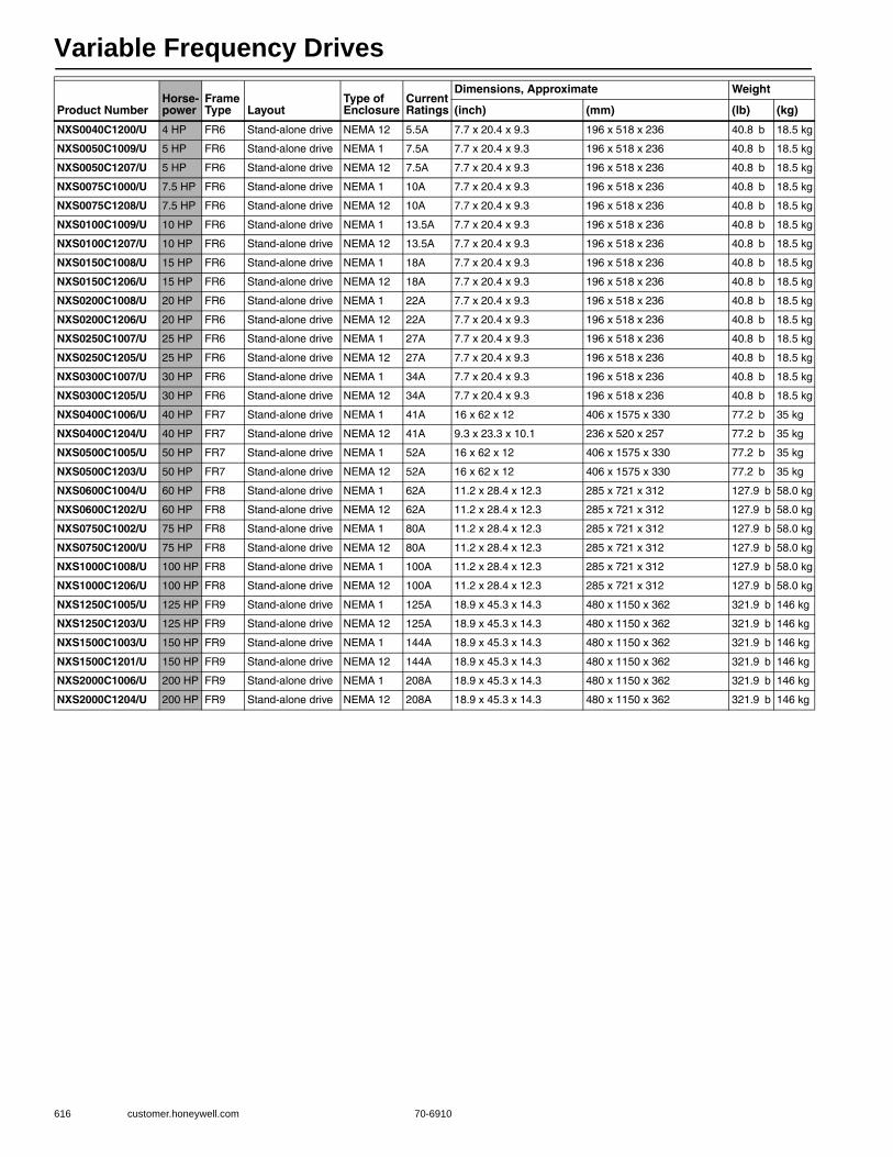
Variable Frequency Drives
616 customer.honeywell.com 70-6910
NXS0040C1200/U 4 HP FR6 Stand-alone drive NEMA 12 5.5A 7.7 x 20.4 x 9.3 196 x 518 x 236 40.8 b 18.5 kg
NXS0050C1009/U 5 HP FR6 Stand-alone drive NEMA 1 7.5A 7.7 x 20.4 x 9.3 196 x 518 x 236 40.8 b 18.5 kg
NXS0050C1207/U 5 HP FR6 Stand-alone drive NEMA 12 7.5A 7.7 x 20.4 x 9.3 196 x 518 x 236 40.8 b 18.5 kg
NXS0075C1000/U 7.5 HP FR6 Stand-alone drive NEMA 1 10A 7.7 x 20.4 x 9.3 196 x 518 x 236 40.8 b 18.5 kg
NXS0075C1208/U 7.5 HP FR6 Stand-alone drive NEMA 12 10A 7.7 x 20.4 x 9.3 196 x 518 x 236 40.8 b 18.5 kg
NXS0100C1009/U 10 HP FR6 Stand-alone drive NEMA 1 13.5A 7.7 x 20.4 x 9.3 196 x 518 x 236 40.8 b 18.5 kg
NXS0100C1207/U 10 HP FR6 Stand-alone drive NEMA 12 13.5A 7.7 x 20.4 x 9.3 196 x 518 x 236 40.8 b 18.5 kg
NXS0150C1008/U 15 HP FR6 Stand-alone drive NEMA 1 18A 7.7 x 20.4 x 9.3 196 x 518 x 236 40.8 b 18.5 kg
NXS0150C1206/U 15 HP FR6 Stand-alone drive NEMA 12 18A 7.7 x 20.4 x 9.3 196 x 518 x 236 40.8 b 18.5 kg
NXS0200C1008/U 20 HP FR6 Stand-alone drive NEMA 1 22A 7.7 x 20.4 x 9.3 196 x 518 x 236 40.8 b 18.5 kg
NXS0200C1206/U 20 HP FR6 Stand-alone drive NEMA 12 22A 7.7 x 20.4 x 9.3 196 x 518 x 236 40.8 b 18.5 kg
NXS0250C1007/U 25 HP FR6 Stand-alone drive NEMA 1 27A 7.7 x 20.4 x 9.3 196 x 518 x 236 40.8 b 18.5 kg
NXS0250C1205/U 25 HP FR6 Stand-alone drive NEMA 12 27A 7.7 x 20.4 x 9.3 196 x 518 x 236 40.8 b 18.5 kg
NXS0300C1007/U 30 HP FR6 Stand-alone drive NEMA 1 34A 7.7 x 20.4 x 9.3 196 x 518 x 236 40.8 b 18.5 kg
NXS0300C1205/U 30 HP FR6 Stand-alone drive NEMA 12 34A 7.7 x 20.4 x 9.3 196 x 518 x 236 40.8 b 18.5 kg
NXS0400C1006/U 40 HP FR7 Stand-alone drive NEMA 1 41A 16 x 62 x 12 406 x 1575 x 330 77.2 b 35 kg
NXS0400C1204/U 40 HP FR7 Stand-alone drive NEMA 12 41A 9.3 x 23.3 x 10.1 236 x 520 x 257 77.2 b 35 kg
NXS0500C1005/U 50 HP FR7 Stand-alone drive NEMA 1 52A 16 x 62 x 12 406 x 1575 x 330 77.2 b 35 kg
NXS0500C1203/U 50 HP FR7 Stand-alone drive NEMA 12 52A 16 x 62 x 12 406 x 1575 x 330 77.2 b 35 kg
NXS0600C1004/U 60 HP FR8 Stand-alone drive NEMA 1 62A 11.2 x 28.4 x 12.3 285 x 721 x 312 127.9 b 58.0 kg
NXS0600C1202/U 60 HP FR8 Stand-alone drive NEMA 12 62A 11.2 x 28.4 x 12.3 285 x 721 x 312 127.9 b 58.0 kg
NXS0750C1002/U 75 HP FR8 Stand-alone drive NEMA 1 80A 11.2 x 28.4 x 12.3 285 x 721 x 312 127.9 b 58.0 kg
NXS0750C1200/U 75 HP FR8 Stand-alone drive NEMA 12 80A 11.2 x 28.4 x 12.3 285 x 721 x 312 127.9 b 58.0 kg
NXS1000C1008/U 100 HP FR8 Stand-alone drive NEMA 1 100A 11.2 x 28.4 x 12.3 285 x 721 x 312 127.9 b 58.0 kg
NXS1000C1206/U 100 HP FR8 Stand-alone drive NEMA 12 100A 11.2 x 28.4 x 12.3 285 x 721 x 312 127.9 b 58.0 kg
NXS1250C1005/U 125 HP FR9 Stand-alone drive NEMA 1 125A 18.9 x 45.3 x 14.3 480 x 1150 x 362 321.9 b 146 kg
NXS1250C1203/U 125 HP FR9 Stand-alone drive NEMA 12 125A 18.9 x 45.3 x 14.3 480 x 1150 x 362 321.9 b 146 kg
NXS1500C1003/U 150 HP FR9 Stand-alone drive NEMA 1 144A 18.9 x 45.3 x 14.3 480 x 1150 x 362 321.9 b 146 kg
NXS1500C1201/U 150 HP FR9 Stand-alone drive NEMA 12 144A 18.9 x 45.3 x 14.3 480 x 1150 x 362 321.9 b 146 kg
NXS2000C1006/U 200 HP FR9 Stand-alone drive NEMA 1 208A 18.9 x 45.3 x 14.3 480 x 1150 x 362 321.9 b 146 kg
NXS2000C1204/U 200 HP FR9 Stand-alone drive NEMA 12 208A 18.9 x 45.3 x 14.3 480 x 1150 x 362 321.9 b 146 kg
Product NumberHorse-power
Frame Type Layout
Type of Enclosure
Current Ratings
Dimensions, Approximate Weight
(inch) (mm) (lb) (kg)
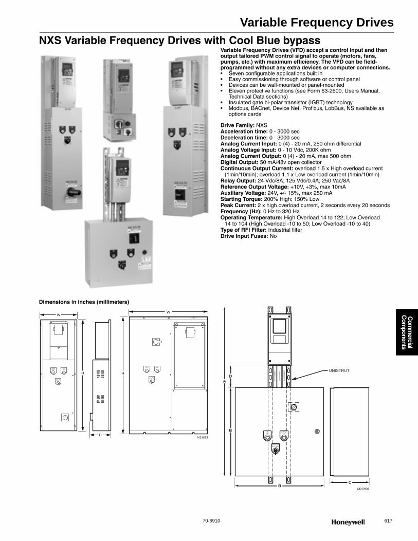
Variable Frequency Drives
70-6910 617
Com
mercial
Com
ponents
NXS Variable Frequency Drives with Cool Blue bypassVariable Frequency Drives (VFD) accept a control input and then output tailored PWM control signal to operate (motors, fans, pumps, etc.) with maximum efficiency. The VFD can be field-programmed without any extra devices or computer connections.• Seven configurable applications built in • Easy commissioning through software or control panel • Devices can be wall-mounted or panel-mounted • Eleven protective functions (see Form 63-2600, Users Manual,
Technical Data sections) • Insulated gate bi-polar transistor (IGBT) technology • Modbus, BACnet, Device Net, Prof bus, LobBus, NS available as
options cards
Drive Family: NXSAcceleration time: 0 - 3000 secDeceleration time: 0 - 3000 secAnalog Current Input: 0 (4) - 20 mA, 250 ohm differentialAnalog Voltage Input: 0 - 10 Vdc, 200K ohmAnalog Current Output: 0 (4) - 20 mA, max 500 ohmDigital Output: 50 mA/48v open collectorContinuous Output Current: overload 1.5 x High overload current
(1min/10min); overload 1.1 x Low overload current (1min/10min)Relay Output: 24 Vdc/8A; 125 Vdc/0.4A; 250 Vac/8AReference Output Voltage: +10V, +3%, max 10mAAuxiliary Voltage: 24V, +/- 15%, max 250 mAStarting Torque: 200% High; 150% LowPeak Current: 2 x high overload current, 2 seconds every 20 secondsFrequency (Hz): 0 Hz to 320 HzOperating Temperature: High Overload 14 to 122; Low Overload
14 to 104 (High Overload -10 to 50; Low Overload -10 to 40) Type of RFI Filter: Industrial filterDrive Input Fuses: No
Dimensions in inches (millimeters)
M23813
A
BYPASSRUN
VFDRUN
G
OFF
FDYP SS
EST
ON
A
BYP SSRUN
FDRUN
G
O F
VFBY ASS
TES
ON
OF
F
H
W
H
W
D
D
B
UNISTRUT
BC
M20991
A
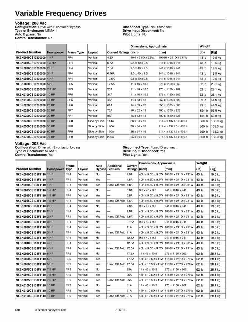
Variable Frequency Drives
618 customer.honeywell.com 70-6910
Voltage: 208 VacConfiguration: Drive with 2 contactor bypassType of Enclosure: NEMA 1Auto Bypass: NoControl Transformer: No
Disconnect Type: No DisconnectDrive Input Disconnect: NoPilot Lights: No
Voltage: 208 VacConfiguration: Drive with 3 contactor bypassType of Enclosure: NEMA 1Control Transformer: Yes
Disconnect Type: Fused DisconnectDrive Input Disconnect: YesPilot Lights: Yes
Product Number Horsepower Frame Type Layout Current Ratings
Dimensions, Approximate Weight
(inch) (mm) (lb) (kg)
NXBK0010CS10200000 1 HP FR4 Vertical 4.8A 40H x 9.5D x 9.5W 1016H x 241D x 231W 43 lb 19.5 kg
NXBK0015CS10200000 1.5 HP FR4 Vertical 6.6A 9.5 x 40 x 9.5 241 x 1016 x 241 43 lb 19.5 kg
NXBK0020CS10200000 2 HP FR4 Vertical 7.8A 9.5 x 40 x 9.5 241 x 1016 x 241 43 lb 19.5 kg
NXBK0030CS10200000 3 HP FR4 Vertical 0.46A 9.5 x 40 x 9.5 241 x 1016 x 241 43 lb 19.5 kg
NXBK0040CS10200000 4 HP FR4 Vertical 12.5A 9.5 x 40 x 9.5 241 x 1016 x 241 43 lb 19.5 kg
NXBK0050CS10200000 5 HP FR5 Vertical 17.5A 11 x 46 x 10.5 275 x 1150 x 262 62 lb 28.1 kg
NXBK0075CS10200000 7.5 HP FR5 Vertical 25A 11 x 46 x 10.5 275 x 1150 x 262 62 lb 28.1 kg
NXBK0100CS10200000 10 HP FR5 Vertical 31A 11 x 46 x 10.5 275 x 1150 x 262 62 lb 28.1 kg
NXBK0150CS10200000 15 HP FR6 Vertical 48A 14 x 53 x 12 350 x 1325 x 300 99 lb 44.9 kg
NXBK0200CS10200000 20 HP FR6 Vertical 61A 14 x 53 x 12 350 x 1325 x 300 99 lb 44.9 kg
NXBK0250CS10200000 25 HP FR7 Vertical 75A 16 x 62 x 13 400 x 1550 x 325 154 b 69.8 kg
NXBK0300CS10200000 30 HP FR7 Vertical 88A 16 x 62 x 13 400 x 1550 x 325 154 b 69.8 kg
NXBK0400CS10200000 40 HP FR8 Side by Side 114A 36 x 54 x 16 914.4 x 1371.6 x 406.4 360 b 163.3 kg
NXBK0500CS10200000 50 HP FR8 Side by Side 140A 36 x 54 x 16 914.4 x 1371.6 x 406.4 360 b 163.3 kg
NXBK0600CS10200000 60 HP FR8 Side by Side 170A 36 x 54 x 16 914.4 x 1371.6 x 406.4 360 b 163.3 kg
NXBK0750CS10200000 75 HP FR8 Side by Side 205A 36 x 54 x 16 914.4 x 1371.6 x 406.4 360 b 163.3 kg
Product Number HorsepowerFrame Type Layout
Auto Bypass
Additional Features
Current Ratings
Dimensions, Approximate Weight
(inch) (mm) (lb) (kg)
NXBK0010CS103F1110 1 HP FR4 Vertical No — 4.8A 40H x 9.5D x 9.5W 1016H x 241D x 231W 43 lb 19.5 kg
NXBK0010CS113F1110 1 HP FR4 Vertical Yes — 4.8A 40H x 9.5D x 9.5W 1016H x 241D x 231W 43 lb 19.5 kg
NXBK0010CS133F1110 1 HP FR4 Vertical Yes Hand Off Auto 4.8A 40H x 9.5D x 9.5W 1016H x 241D x 231W 43 lb 19.5 kg
NXBK0015CS103F1110 1.5 HP FR4 Vertical No — 6.6A 9.5 x 40 x 9.5 241 x 1016 x 241 43 lb 19.5 kg
NXBK0015CS113F1110 1.5 HP FR4 Vertical Yes — 6.6A 40H x 9.5D x 9.5W 1016H x 241D x 231W 43 lb 19.5 kg
NXBK0015CS133F1110 1.5 HP FR4 Vertical Yes Hand Off Auto 6.6A 40H x 9.5D x 9.5W 1016H x 241D x 231W 43 lb 19.5 kg
NXBK0020CS103F1110 2 HP FR4 Vertical No — 7.8A 9.5 x 40 x 9.5 241 x 1016 x 241 43 lb 19.5 kg
NXBK0020CS113F1110 2 HP FR4 Vertical Yes — 7.8A 40H x 9.5D x 9.5W 1016H x 241D x 231W 43 lb 19.5 kg
NXBK0020CS133F1110 2 HP FR4 Vertical Yes Hand Off Auto 7.8A 40H x 9.5D x 9.5W 1016H x 241D x 231W 43 lb 19.5 kg
NXBK0030CS103F1110 3 HP FR4 Vertical No — 0.46A 9.5 x 40 x 9.5 241 x 1016 x 241 43 lb 19.5 kg
NXBK0030CS113F1110 3 HP FR4 Vertical Yes — 11A 40H x 9.5D x 9.5W 1016H x 241D x 231W 43 lb 19.5 kg
NXBK0030CS133F1110 3 HP FR4 Vertical Yes Hand Off Auto 11A 40H x 9.5D x 9.5W 1016H x 241D x 231W 43 lb 19.5 kg
NXBK0040CS103F1110 4 HP FR4 Vertical No — 12.5A 9.5 x 40 x 9.5 241 x 1016 x 241 43 lb 19.5 kg
NXBK0040CS113F1110 4 HP FR4 Vertical Yes — 12.5A 40H x 9.5D x 9.5W 1016H x 241D x 231W 43 lb 19.5 kg
NXBK0040CS133F1110 4 HP FR4 Vertical Yes Hand Off Auto 12.5A 40H x 9.5D x 9.5W 1016H x 241D x 231W 43 lb 19.5 kg
NXBK0050CS103F1110 5 HP FR5 Vertical No — 17.5A 11 x 46 x 10.5 275 x 1150 x 262 62 lb 28.1 kg
NXBK0050CS113F1110 5 HP FR5 Vertical Yes — 17.5A 46H x 10.5D x 11W 1168H x 257D x 279W 62 lb 28.1 kg
NXBK0050CS133F1110 5 HP FR5 Vertical Yes Hand Off Auto 17.5A 46H x 10.5D x 11W 1168H x 257D x 279W 62 lb 28.1 kg
NXBK0075CS103F1110 7.5 HP FR5 Vertical No — 25A 11 x 46 x 10.5 275 x 1150 x 262 62 lb 28.1 kg
NXBK0075CS113F1110 7.5 HP FR5 Vertical Yes — 25A 46H x 10.5D x 11W 1168H x 257D x 279W 62 lb 28.1 kg
NXBK0075CS133F1110 7.5 HP FR5 Vertical Yes Hand Off Auto 25A 46H x 10.5D x 11W 1168H x 257D x 279W 62 lb 28.1 kg
NXBK0100CS103F1110 10 HP FR5 Vertical No — 31A 11 x 46 x 10.5 275 x 1150 x 262 62 lb 28.1 kg
NXBK0100CS113F1110 10 HP FR5 Vertical Yes — 31A 46H x 10.5D x 11W 1168H x 257D x 279W 62 lb 28.1 kg
NXBK0100CS133F1110 10 HP FR5 Vertical Yes Hand Off Auto 31A 46H x 10.5D x 11W 1168H x 257D x 279W 62 lb 28.1 kg

Variable Frequency Drives
70-6910 619
Com
mercial
Com
ponents
Voltage: 208 VacConfiguration: Drive with fused disconnectType of Enclosure: NEMA 1Auto Bypass: NoControl Transformer: No
Disconnect Type: Fused DisconnectDrive Input Disconnect: NoPilot Lights: No
NXBK0150CS103F1110 15 HP FR6 Vertical No — 48A 14 x 53 x 12 350 x 1325 x 300 99 lb 44.9 kg
NXBK0150CS113F1110 15 HP FR6 Vertical Yes — 48A 53H x 12D x 14W 1298H x 294D x 343W 99 lb 44.9 kg
NXBK0150CS133F1110 15 HP FR6 Vertical Yes Hand Off Auto 48A 53H x 12D x 14W 1298H x 294D x 343W 99 lb 44.9 kg
NXBK0200CS103F1110 20 HP FR6 Vertical No — 61A 14 x 53 x 12 350 x 1325 x 300 99 lb 44.9 kg
NXBK0200CS113F1110 20 HP FR6 Vertical Yes — 61A 53H x 12D x 14W 1298H x 294D x 343W 99 lb 44.9 kg
NXBK0200CS133F1110 20 HP FR6 Vertical Yes Hand Off Auto 61A 53H x 12D x 14W 1298H x 294D x 343W 99 lb 44.9 kg
NXBK0250CS103F1110 25 HP FR7 Vertical No — 75A 16 x 62 x 12 400 x 1550 x 300 154 b 69.8 kg
NXBK0250CS113F1110 25 HP FR7 Vertical Yes — 75A 62 x 13 x 16 1574 x 339 x 406 154 b 69.8 kg
NXBK0250CS133F1110 25 HP FR7 Vertical Yes Hand Off Auto 75A 62 x 13 x 16 1574 x 339 x 406 154 b 69.8 kg
NXBK0300CS103F1110 30 HP FR7 Vertical No — 88A 16 x 62 x 12 400 x 1550 x 300 154 b 69.8 kg
NXBK0300CS113F1110 30 HP FR7 Vertical Yes — 88A 62 x 13 x 16 1574 x 339 x 406 154 b 69.8 kg
NXBK0300CS133F1110 30 HP FR7 Vertical Yes Hand Off Auto 88A 62 x 13 x 16 1574 x 339 x 406 154 b 69.8 kg
NXBK0400CS103F1110 40 HP FR8 Side by Side No — 114A 36 x 54 x 16 914.4 x 1371.6 x 406.4 360 b 163.3 kg
NXBK0400CS113F1110 40 HP FR7 Vertical Yes — 114A 62 x 13 x 16 1574 x 339 x 406 154 b 69.8 kg
NXBK0400CS133F1110 40 HP FR7 Vertical Yes Hand Off Auto 114A 62 x 13 x 16 1574 x 339 x 406 154 b 69.8 kg
NXBK0500CS103F1110 50 HP FR8 Side by Side No — 140A 36 x 54 x 16 914.4 x 1371.6 x 406.4 360 b 163.3 kg
NXBK0500CS113F1110 50 HP FR8 Side by Side Yes — 140A 54H x 16D x 36W 1350H x 400D x 900W 360 b 163.3 kg
NXBK0500CS133F1110 50 HP FR8 Side by Side Yes Hand Off Auto 140A 54H x 16D x 36W 1350H x 400D x 900W 360 b 163.3 kg
NXBK0600CS103F1110 60 HP FR8 Side by Side No — 170A 36 x 54 x 16 914.4 x 1371.6 x 406.4 360 b 163.3 kg
NXBK0600CS113F1110 60 HP FR8 Side by Side Yes — 170A 54H x 16D x 36W 1350H x 400D x 900W 360 b 163.3 kg
NXBK0600CS133F1110 60 HP FR8 Side by Side Yes Hand Off Auto 170A 54H x 16D x 36W 1350H x 400D x 900W 360 b 163.3 kg
NXBK0750CS103F1110 75 HP FR8 Side by Side No — 205A 36 x 54 x 16 914.4 x 1371.6 x 406.4 360 b 163.3 kg
NXBK0750CS113F1110 75 HP FR8 Side by Side Yes — 205A 54H x 16D x 36W 1350H x 400D x 900W 360 b 163.3 kg
NXBK0750CS133F1110 75 HP FR8 Side by Side Yes Hand Off Auto 205A 54H x 16D x 36W 1350H x 400D x 900W 360 b 163.3 kg
Product Number HorsepowerFrame Type Layout
Auto Bypass
Additional Features
Current Ratings
Dimensions, Approximate Weight
(inch) (mm) (lb) (kg)
Product Number Horsepower Frame Type LayoutCurrent Ratings
Dimensions, Approximate Weight
(inch) (mm) (lb) (kg)
NXBK0010DS100F0000 1 HP FR4 Vertical 4.8A 40H x 9.5D x 9.5W 1016H x 241D x 231W 43 lb 19.5 kg
NXBK0015DS100F0000 1.5 HP Call Customer Care Vertical 6.6A Call Customer Care
NXBK0020DS100F0000 2 HP Vertical 7.8A Call Customer Care
NXBK0030DS100F0000 3 HP Vertical 0.46A Call Customer Care
NXBK0040DS100F0000 4 HP Vertical 12.5A Call Customer Care
NXBK0050DS100F0000 5 HP Vertical 17.5A Call Customer Care
NXBK0075DS100F0000 7.5 HP FR5 Vertical 25A 11 in. x 46 in. x 10.5 in. 275 x 1150 x 262 62 lb 28.1 kg
NXBK0100DS100F0000 10 HP Call Customer Care Vertical 31A Call Customer Care
NXBK0150DS100F0000 15 HP Vertical 48A Call Customer Care
NXBK0200DS100F0000 20 HP Vertical 61A Call Customer Care
NXBK0250DS100F0000 25 HP Vertical 75A Call Customer Care
NXBK0300DS100F0000 30 HP Vertical 88A Call Customer Care
NXBK0400DS100F0000 40 HP Side by Side 114A Call Customer Care
NXBK0500DS100F0000 50 HP Side by Side 140A Call Customer Care
NXBK0600DS100F0000 60 HP Side by Side 170A Call Customer Care
NXBK0750DS100F0000 75 HP Side by Side 205A Call Customer Care

Variable Frequency Drives
620 customer.honeywell.com 70-6910
Voltage: 208 VacConfiguration: Drive aloneType of Enclosure: NEMA 3RAuto Bypass: NoControl Transformer: No
Disconnect Type: No DisconnectDrive Input Disconnect: NoPilot Lights: No
Voltage: 208 VacConfiguration: Drive with 2 contactor bypassType of Enclosure: NEMA 3RAuto Bypass: NoControl Transformer: No
Disconnect Type: No DisconnectDrive Input Disconnect: NoPilot Lights: No
Voltage: 208 VacConfiguration: Drive with 3 contactor bypassType of Enclosure: NEMA 3RDisconnect Type: Fused Disconnect
Product Number Horsepower Frame Type Layout Current Ratings
Dimensions, Approximate Weight
(inch) (mm) (lb) (kg)
NXBK0010CS30000000 1 HP FR4 Vertical 4.8A 24H x 10D x 20W 588H x 245D x 490W 54 lb 118.8 kg
NXBK0015CS30000000 1.5 HP FR4 Vertical 6.6A 24H x 10D x 20W 588H x 245D x 490W 54 lb 118.8 kg
NXBK0020CS30000000 2 HP FR4 Vertical 7.8A 24H x 10D x 20W 588H x 245D x 490W 54 lb 118.8 kg
NXBK0030CS30000000 3 HP FR4 Vertical 11A 24H x 10D x 20W 588H x 245D x 490W 54 lb 118.8 kg
NXBK0040CS30000000 4 HP FR4 Vertical 12.5A 24H x 10D x 20W 588H x 245D x 490W 54 lb 118.8 kg
NXBK0050CS30000000 5 HP FR5 Vertical 17.5A 30H x 10D x 24W 735H x 245D x 588W 78 lb 171.6 kg
NXBK0075CS30000000 7.5 HP FR5 Vertical 25A 30H x 10D x 24W 735H x 245D x 588W 78 lb 171.6 kg
NXBK0100CS30000000 10 HP FR5 Vertical 31A 30H x 10D x 24W 735H x 245D x 588W 78 lb 171.6 kg
NXBK0150CS30000000 15 HP FR6 Vertical 48A 36H x 12D x 30W 882H x 294D x 735W 124 lb 272.8 kg
NXBK0200CS30000000 20 HP FR6 Vertical 61A 36H x 12D x 30W 882H x 294D x 735W 124 lb 272.8 kg
NXBK0250CS30000000 25 HP FR7 Vertical 75A 48H x 12D x 36W 1176H x 294D x 882W 193 lb 424.6 kg
NXBK0300CS30000000 30 HP FR7 Vertical 88A 48H x 12D x 36W 1176H x 294D x 882W 193 lb 424.6 kg
NXBK0400CS30000000 40 HP FR7 Vertical 114A 48H x 12D x 36W 1176H x 294D x 882W 193 lb 424.6 kg
NXBS0150CS30000000 15 HP FR6 Vertical 48A 36H x 12D x 30W 882H x 294D x 735W 124 lb 272.8 kg
Product Number Horsepower Frame Type LayoutCurrent Ratings
Dimensions, Approximate Weight
(inch) (mm) (lb) (kg)
NXBK0010CS30200000 1 HP FR4 Vertical 4.8A 24H x 10D x 20W 588H x 245D x 490W 54 lb 118.8 kg
NXBK0020CS30200000 2 HP FR4 Vertical 7.8A 24H x 10D x 20W 588H x 245D x 490W 54 lb 118.8 kg
NXBK0075CS30200000 7.5 HP FR5 Vertical 25A 30H x 10D x 24W 735H x 245D x 588W 78 lb 171.6 kg
NXBK0250CS30200000 25 HP FR7 Vertical 75A 48H x 12D x 36W 1176H x 294D x 882W 193 lb 424.6 kg
NXBK0600CS30200000 60 HP FR8 Side by Side 170A 60H x 14D x 36W 1470H x 343D x 882W 440 lb 968 kg
Product NumberHorse-power
Frame Type Layout
Auto Bypass
Additional Features
Current Ratings
Control Trans-former
Drive Input Disconnect
Pilot Lights
Dimensions, Approximate Weight
(inch) (mm) (lb) (kg)
NXBK0010CS303F1110 1 HP FR4 Vertical No — 4.8A Yes Yes Yes 24 x 10 x 20 588 x 245 x 490 54 lb 118.8 kg
NXBK0010CS313F1110 1 HP FR4 Vertical Yes — 4.8A Yes Yes Yes 24 x 10 x 20 588 x 245 x 490 54 lb 118.8 kg
NXBK0010CS333F1110 1 HP FR4 Vertical Yes Hand Off Auto
4.8A Yes Yes Yes 24 x 10 x 20 588 x 245 x 490 54 lb 118.8 kg
NXBK0015CS303F1110 1.5 HP FR4 Vertical No — 6.6A Yes Yes Yes 24 x 10 x 20 588 x 245 x 490 54 lb 118.8 kg
NXBK0015CS313F1110 1.5 HP FR4 Vertical Yes — 6.6A Yes Yes Yes 24 x 10 x 20 588 x 245 x 490 54 lb 118.8 kg
NXBK0015CS333F1110 1.5 HP FR4 Vertical Yes Hand Off Auto
6.6A Yes Yes Yes 24 x 10 x 20 588 x 245 x 490 54 lb 118.8 kg
NXBK0020CS303F1110 2 HP FR4 Vertical No — 7.8A Yes Yes Yes 24 x 10 x 20 588 x 245 x 490 54 lb 118.8 kg
NXBK0020CS313F1110 2 HP FR4 Vertical Yes — 7.8A Yes Yes Yes 24 x 10 x 20 588 x 245 x 490 54 lb 118.8 kg
NXBK0020CS333F1110 2 HP FR4 Vertical Yes Hand Off Auto
7.8A Yes Yes Yes 24 x 10 x 20 588 x 245 x 490 54 lb 118.8 kg
NXBK0030CS303F1110 3 HP FR4 Vertical No — 11A Yes Yes Yes 24 x 10 x 20 588 x 245 x 490 54 lb 118.8 kg
NXBK0030CS313F1110 3 HP FR4 Vertical Yes — 11A Yes Yes Yes 24 x 10 x 20 588 x 245 x 490 54 lb 118.8 kg
NXBK0030CS333F1110 3 HP FR4 Vertical Yes Hand Off Auto
11A Yes Yes Yes 24 x 10 x 20 588 x 245 x 490 54 lb 118.8 kg
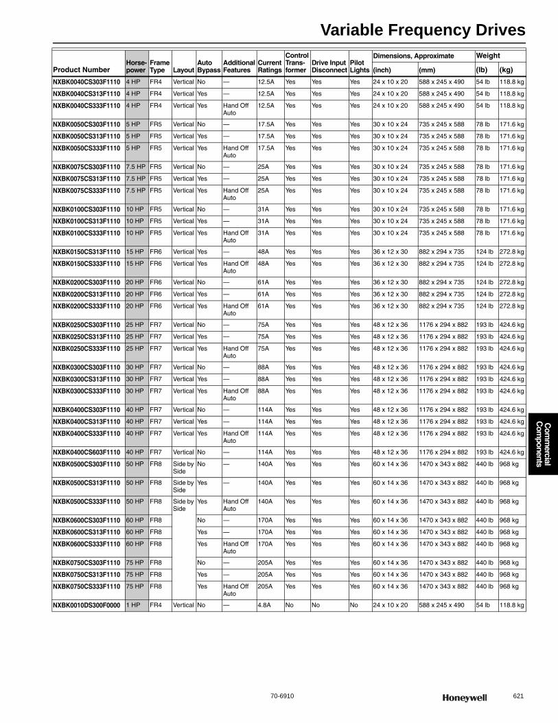
Variable Frequency Drives
70-6910 621
Com
mercial
Com
ponents
NXBK0040CS303F1110 4 HP FR4 Vertical No — 12.5A Yes Yes Yes 24 x 10 x 20 588 x 245 x 490 54 lb 118.8 kg
NXBK0040CS313F1110 4 HP FR4 Vertical Yes — 12.5A Yes Yes Yes 24 x 10 x 20 588 x 245 x 490 54 lb 118.8 kg
NXBK0040CS333F1110 4 HP FR4 Vertical Yes Hand Off Auto
12.5A Yes Yes Yes 24 x 10 x 20 588 x 245 x 490 54 lb 118.8 kg
NXBK0050CS303F1110 5 HP FR5 Vertical No — 17.5A Yes Yes Yes 30 x 10 x 24 735 x 245 x 588 78 lb 171.6 kg
NXBK0050CS313F1110 5 HP FR5 Vertical Yes — 17.5A Yes Yes Yes 30 x 10 x 24 735 x 245 x 588 78 lb 171.6 kg
NXBK0050CS333F1110 5 HP FR5 Vertical Yes Hand Off Auto
17.5A Yes Yes Yes 30 x 10 x 24 735 x 245 x 588 78 lb 171.6 kg
NXBK0075CS303F1110 7.5 HP FR5 Vertical No — 25A Yes Yes Yes 30 x 10 x 24 735 x 245 x 588 78 lb 171.6 kg
NXBK0075CS313F1110 7.5 HP FR5 Vertical Yes — 25A Yes Yes Yes 30 x 10 x 24 735 x 245 x 588 78 lb 171.6 kg
NXBK0075CS333F1110 7.5 HP FR5 Vertical Yes Hand Off Auto
25A Yes Yes Yes 30 x 10 x 24 735 x 245 x 588 78 lb 171.6 kg
NXBK0100CS303F1110 10 HP FR5 Vertical No — 31A Yes Yes Yes 30 x 10 x 24 735 x 245 x 588 78 lb 171.6 kg
NXBK0100CS313F1110 10 HP FR5 Vertical Yes — 31A Yes Yes Yes 30 x 10 x 24 735 x 245 x 588 78 lb 171.6 kg
NXBK0100CS333F1110 10 HP FR5 Vertical Yes Hand Off Auto
31A Yes Yes Yes 30 x 10 x 24 735 x 245 x 588 78 lb 171.6 kg
NXBK0150CS313F1110 15 HP FR6 Vertical Yes — 48A Yes Yes Yes 36 x 12 x 30 882 x 294 x 735 124 lb 272.8 kg
NXBK0150CS333F1110 15 HP FR6 Vertical Yes Hand Off Auto
48A Yes Yes Yes 36 x 12 x 30 882 x 294 x 735 124 lb 272.8 kg
NXBK0200CS303F1110 20 HP FR6 Vertical No — 61A Yes Yes Yes 36 x 12 x 30 882 x 294 x 735 124 lb 272.8 kg
NXBK0200CS313F1110 20 HP FR6 Vertical Yes — 61A Yes Yes Yes 36 x 12 x 30 882 x 294 x 735 124 lb 272.8 kg
NXBK0200CS333F1110 20 HP FR6 Vertical Yes Hand Off Auto
61A Yes Yes Yes 36 x 12 x 30 882 x 294 x 735 124 lb 272.8 kg
NXBK0250CS303F1110 25 HP FR7 Vertical No — 75A Yes Yes Yes 48 x 12 x 36 1176 x 294 x 882 193 lb 424.6 kg
NXBK0250CS313F1110 25 HP FR7 Vertical Yes — 75A Yes Yes Yes 48 x 12 x 36 1176 x 294 x 882 193 lb 424.6 kg
NXBK0250CS333F1110 25 HP FR7 Vertical Yes Hand Off Auto
75A Yes Yes Yes 48 x 12 x 36 1176 x 294 x 882 193 lb 424.6 kg
NXBK0300CS303F1110 30 HP FR7 Vertical No — 88A Yes Yes Yes 48 x 12 x 36 1176 x 294 x 882 193 lb 424.6 kg
NXBK0300CS313F1110 30 HP FR7 Vertical Yes — 88A Yes Yes Yes 48 x 12 x 36 1176 x 294 x 882 193 lb 424.6 kg
NXBK0300CS333F1110 30 HP FR7 Vertical Yes Hand Off Auto
88A Yes Yes Yes 48 x 12 x 36 1176 x 294 x 882 193 lb 424.6 kg
NXBK0400CS303F1110 40 HP FR7 Vertical No — 114A Yes Yes Yes 48 x 12 x 36 1176 x 294 x 882 193 lb 424.6 kg
NXBK0400CS313F1110 40 HP FR7 Vertical Yes — 114A Yes Yes Yes 48 x 12 x 36 1176 x 294 x 882 193 lb 424.6 kg
NXBK0400CS333F1110 40 HP FR7 Vertical Yes Hand Off Auto
114A Yes Yes Yes 48 x 12 x 36 1176 x 294 x 882 193 lb 424.6 kg
NXBK0400CS603F1110 40 HP FR7 Vertical No — 114A Yes Yes Yes 48 x 12 x 36 1176 x 294 x 882 193 lb 424.6 kg
NXBK0500CS303F1110 50 HP FR8 Side by Side
No — 140A Yes Yes Yes 60 x 14 x 36 1470 x 343 x 882 440 lb 968 kg
NXBK0500CS313F1110 50 HP FR8 Side by Side
Yes — 140A Yes Yes Yes 60 x 14 x 36 1470 x 343 x 882 440 lb 968 kg
NXBK0500CS333F1110 50 HP FR8 Side by Side
Yes Hand Off Auto
140A Yes Yes Yes 60 x 14 x 36 1470 x 343 x 882 440 lb 968 kg
NXBK0600CS303F1110 60 HP FR8 No — 170A Yes Yes Yes 60 x 14 x 36 1470 x 343 x 882 440 lb 968 kg
NXBK0600CS313F1110 60 HP FR8 Yes — 170A Yes Yes Yes 60 x 14 x 36 1470 x 343 x 882 440 lb 968 kg
NXBK0600CS333F1110 60 HP FR8 Yes Hand Off Auto
170A Yes Yes Yes 60 x 14 x 36 1470 x 343 x 882 440 lb 968 kg
NXBK0750CS303F1110 75 HP FR8 No — 205A Yes Yes Yes 60 x 14 x 36 1470 x 343 x 882 440 lb 968 kg
NXBK0750CS313F1110 75 HP FR8 Yes — 205A Yes Yes Yes 60 x 14 x 36 1470 x 343 x 882 440 lb 968 kg
NXBK0750CS333F1110 75 HP FR8 Yes Hand Off Auto
205A Yes Yes Yes 60 x 14 x 36 1470 x 343 x 882 440 lb 968 kg
NXBK0010DS300F0000 1 HP FR4 Vertical No — 4.8A No No No 24 x 10 x 20 588 x 245 x 490 54 lb 118.8 kg
Product NumberHorse-power
Frame Type Layout
Auto Bypass
Additional Features
Current Ratings
Control Trans-former
Drive Input Disconnect
Pilot Lights
Dimensions, Approximate Weight
(inch) (mm) (lb) (kg)
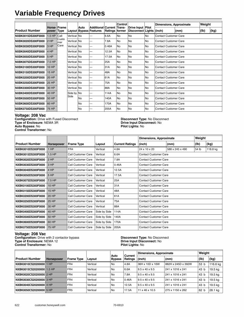
Variable Frequency Drives
622 customer.honeywell.com 70-6910
Voltage: 208 VacConfiguration: Drive with Fused DisconnectType of Enclosure: NEMA 3RAuto Bypass: NoControl Transformer: No
Disconnect Type: No DisconnectDrive Input Disconnect: NoPilot Lights: No
Voltage: 208 VacConfiguration: Drive with 2 contactor bypassType of Enclosure: NEMA 12Control Transformer: No
Disconnect Type: No DisconnectDrive Input Disconnect: NoPilot Lights: No
NXBK0015DS300F0000 1.5 HP Call Customer Care
Vertical No — 6.6A No No No Contact Customer Care
NXBK0020DS300F0000 2 HP Vertical No — 7.8A No No No Contact Customer Care
NXBK0030DS300F0000 3 HP Vertical No — 0.46A No No No Contact Customer Care
NXBK0040DS300F0000 4 HP Vertical No — 12.5A No No No Contact Customer Care
NXBK0050DS300F0000 5 HP Vertical No — 17.5A No No No Contact Customer Care
NXBK0075DS300F0000 7.5 HP Vertical No — 25A No No No Contact Customer Care
NXBK0100DS300F0000 10 HP Vertical No — 31A No No No Contact Customer Care
NXBK0150DS300F0000 15 HP Vertical No — 48A No No No Contact Customer Care
NXBK0200DS300F0000 20 HP Vertical No — 61A No No No Contact Customer Care
NXBK0250DS300F0000 25 HP Vertical No — 75A No No No Contact Customer Care
NXBK0300DS300F0000 30 HP Vertical No — 88A No No No Contact Customer Care
NXBK0400DS300F0000 40 HP Side by Side
No — 114A No No No Contact Customer Care
NXBK0500DS300F0000 50 HP No — 140A No No No Contact Customer Care
NXBK0600DS300F0000 60 HP No — 170A No No No Contact Customer Care
NXBK0750DS300F0000 75 HP No — 205A No No No Contact Customer Care
Product NumberHorse-power
Frame Type Layout
Auto Bypass
Additional Features
Current Ratings
Control Trans-former
Drive Input Disconnect
Pilot Lights
Dimensions, Approximate Weight
(inch) (mm) (lb) (kg)
Product Number Horsepower Frame Type Layout Current Ratings
Dimensions, Approximate Weight
(inch) (mm) (lb) (kg)
NXBK0010DS300F0000 1 HP FR4 Vertical 4.8A 24 x 10 x 20 588 x 245 x 490 54 lb 118.8 kg
NXBK0015DS300F0000 1.5 HP Call Customer Care Vertical 6.6A Contact Customer Care
NXBK0020DS300F0000 2 HP Call Customer Care Vertical 7.8A Contact Customer Care
NXBK0030DS300F0000 3 HP Call Customer Care Vertical 0.46A Contact Customer Care
NXBK0040DS300F0000 4 HP Call Customer Care Vertical 12.5A Contact Customer Care
NXBK0050DS300F0000 5 HP Call Customer Care Vertical 17.5A Contact Customer Care
NXBK0075DS300F0000 7.5 HP Call Customer Care Vertical 25A Contact Customer Care
NXBK0100DS300F0000 10 HP Call Customer Care Vertical 31A Contact Customer Care
NXBK0150DS300F0000 15 HP Call Customer Care Vertical 48A Contact Customer Care
NXBK0200DS300F0000 20 HP Call Customer Care Vertical 61A Contact Customer Care
NXBK0250DS300F0000 25 HP Call Customer Care Vertical 75A Contact Customer Care
NXBK0300DS300F0000 30 HP Call Customer Care Vertical 88A Contact Customer Care
NXBK0400DS300F0000 40 HP Call Customer Care Side by Side 114A Contact Customer Care
NXBK0500DS300F0000 50 HP Call Customer Care Side by Side 140A Contact Customer Care
NXBK0600DS300F0000 60 HP Call Customer Care Side by Side 170A Contact Customer Care
NXBK0750DS300F0000 75 HP Call Customer Care Side by Side 205A Contact Customer Care
Product Number Horsepower Frame Type LayoutAuto Bypass
Current Ratings
Dimensions, Approximate Weight
(inch) (mm) (lb) (kg)
NXBK0010CS20200000 1 HP FR4 Vertical No 4.8A 36H x 10D x 16W 882H x 245D x 392W 53 b 116.6 kg
NXBK0015CS20200000 1.5 HP FR4 Vertical No 6.6A 9.5 x 40 x 9.5 241 x 1016 x 241 43 b 19.5 kg
NXBK0020CS20200000 2 HP FR4 Vertical No 7.8A 9.5 x 40 x 9.5 241 x 1016 x 241 43 b 19.5 kg
NXBK0030CS20200000 3 HP FR4 Vertical No 0.46A 9.5 x 40 x 9.5 241 x 1016 x 241 43 b 19.5 kg
NXBK0040CS20200000 4 HP FR4 Vertical No 12.5A 9.5 x 40 x 9.5 241 x 1016 x 241 43 b 19.5 kg
NXBK0050CS20200000 5 HP FR5 Vertical No 17.5A 11 x 46 x 10.5 275 x 1150 x 262 62 b 28.1 kg
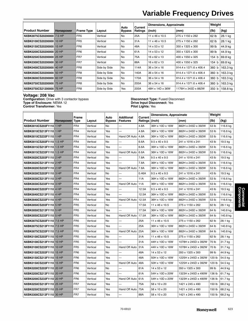
Variable Frequency Drives
70-6910 623
Com
mercial
Com
ponents
Voltage: 208 VacConfiguration: Drive with 3 contactor bypassType of Enclosure: NEMA 12Control Transformer: Yes
Disconnect Type: Fused DisconnectDrive Input Disconnect: YesPilot Lights: Yes
NXBK0075CS20200000 7.5 HP FR5 Vertical No 25A 11 x 46 x 10.5 275 x 1150 x 262 62 lb 28.1 kg
NXBK0100CS20200000 10 HP FR5 Vertical No 31A 11 x 46 x 10.5 275 x 1150 x 262 62 lb 28.1 kg
NXBK0150CS20200000 15 HP FR6 Vertical No 48A 14 x 53 x 12 350 x 1325 x 300 99 lb 44.9 kg
NXBK0200CS20200000 20 HP FR6 Vertical No 61A 14 x 53 x 12 350 x 1325 x 300 99 lb 44.9 kg
NXBK0250CS20200000 25 HP FR7 Vertical No 75A 16 x 62 x 13 400 x 1550 x 325 154 b 69.8 kg
NXBK0300CS20200000 30 HP FR7 Vertical No 88A 16 x 62 x 13 400 x 1550 x 325 154 b 69.8 kg
NXBK0400CS20200000 40 HP FR8 Side by Side No 114A 36 x 54 x 16 914.4 x 1371.6 x 406.4 360 b 163.3 kg
NXBK0500CS20200000 50 HP FR8 Side by Side No 140A 36 x 54 x 16 914.4 x 1371.6 x 406.4 360 b 163.3 kg
NXBK0600CS20200000 60 HP FR8 Side by Side No 170A 36 x 54 x 16 914.4 x 1371.6 x 406.4 360 b 163.3 kg
NXBK0750CS20200000 75 HP FR8 Side by Side No 205A 36 x 54 x 16 914.4 x 1371.6 x 406.4 360 b 163.3 kg
NXBK0750CS21200000 75 HP FR8 Side by Side Yes 205A 48H x 14D x 36W 1176H x 343D x 882W 350 b 158.8 kg
Product Number Horsepower Frame Type LayoutAuto Bypass
Current Ratings
Dimensions, Approximate Weight
(inch) (mm) (lb) (kg)
Product Number HorsepowerFrame Type Layout
Auto Bypass
Additional Features
Current Ratings
Dimensions, Approximate Weight
(inch) (mm) (lb) (kg)
NXBK0010CS203F1110 1 HP FR4 Vertical No — 4.8A 36H x 10D x 16W 882H x 245D x 392W 53 lb 116.6 kg
NXBK0010CS213F1110 1 HP FR4 Vertical Yes — 4.8A 36H x 10D x 16W 882H x 245D x 392W 53 lb 116.6 kg
NXBK0010CS233F1110 1 HP FR4 Vertical Yes Hand Off Auto 4.8A 36H x 10D x 16W 882H x 245D x 392W 53 lb 116.6 kg
NXBK0015CS203F1110 1.5 HP FR4 Vertical No — 6.6A 9.5 x 40 x 9.5 241 x 1016 x 241 43 lb 19.5 kg
NXBK0015CS213F1110 1.5 HP FR4 Vertical Yes — 6.6A 36H x 10D x 16W 882H x 245D x 392W 53 lb 116.6 kg
NXBK0015CS233F1110 1.5 HP FR4 Vertical Yes Hand Off Auto 6.6A 36H x 10D x 16W 882H x 245D x 392W 53 lb 116.6 kg
NXBK0020CS203F1110 2 HP FR4 Vertical No — 7.8A 9.5 x 40 x 9.5 241 x 1016 x 241 43 lb 19.5 kg
NXBK0020CS213F1110 2 HP FR4 Vertical Yes — 7.8A 36H x 10D x 16W 882H x 245D x 392W 53 lb 116.6 kg
NXBK0020CS233F1110 2 HP FR4 Vertical Yes Hand Off Auto 7.8A 36H x 10D x 16W 882H x 245D x 392W 53 lb 116.6 kg
NXBK0030CS203F1110 3 HP FR4 Vertical No — 0.46A 9.5 x 40 x 9.5 241 x 1016 x 241 43 lb 19.5 kg
NXBK0030CS213F1110 3 HP FR4 Vertical Yes — 11A 36H x 10D x 16W 882H x 245D x 392W 53 lb 116.6 kg
NXBK0030CS233F1110 3 HP FR4 Vertical Yes Hand Off Auto 11A 36H x 10D x 16W 882H x 245D x 392W 53 lb 116.6 kg
NXBK0040CS203F1110 4 HP FR4 Vertical No — 12.5A 9.5 x 40 x 9.5 241 x 1016 x 241 43 lb 19.5 kg
NXBK0040CS213F1110 4 HP FR4 Vertical Yes — 12.5A 36H x 10D x 16W 882H x 245D x 392W 53 lb 116.6 kg
NXBK0040CS233F1110 4 HP FR4 Vertical Yes Hand Off Auto 12.5A 36H x 10D x 16W 882H x 245D x 392W 53 lb 116.6 kg
NXBK0050CS203F1110 5 HP FR5 Vertical No — 17.5A 11 x 46 x 10.5 275 x 1150 x 262 62 lb 28.1 kg
NXBK0050CS213F1110 5 HP FR5 Vertical Yes — 17.5A 36H x 10D x 16W 882H x 245D x 392W 64 lb 140.8 kg
NXBK0050CS233F1110 5 HP FR5 Vertical Yes Hand Off Auto 17.5A 36H x 10D x 16W 882H x 245D x 392W 64 lb 140.8 kg
NXBK0075CS203F1110 7.5 HP FR5 Vertical No — 25A 11 x 46 x 10.5 275 x 1150 x 262 62 lb 28.1 kg
NXBK0075CS213F1110 7.5 HP FR5 Vertical Yes — 25A 36H x 10D x 16W 882H x 245D x 392W 64 lb 140.8 kg
NXBK0075CS233F1110 7.5 HP FR5 Vertical Yes Hand Off Auto 25A 36H x 10D x 16W 882H x 245D x 392W 64 lb 140.8 kg
NXBK0100CS203F1110 10 HP FR5 Vertical No — 31A 11 x 46 x 10.5 275 x 1150 x 262 62 lb 28.1 kg
NXBK0100CS213F1110 10 HP FR5 Vertical Yes — 31A 44H x 10D x 16W 1078H x 245D x 392W 70 lb 31.7 kg
NXBK0100CS233F1110 10 HP FR5 Vertical Yes Hand Off Auto 31A 44H x 10D x 16W 1078H x 245D x 392W 70 lb 31.7 kg
NXBK0150CS203F1110 15 HP FR6 Vertical No — 48A 14 x 53 x 12 350 x 1325 x 300 99 lb 44.9 kg
NXBK0150CS213F1110 15 HP FR6 Vertical Yes — 48A 50H x 10D x 16W 1225H x 245D x 392W 120 lb 54.5 kg
NXBK0150CS233F1110 15 HP FR6 Vertical Yes Hand Off Auto 48A 50H x 10D x 16W 1225H x 245D x 392W 120 lb 54.5 kg
NXBK0200CS203F1110 20 HP FR6 Vertical No — 61A 14 x 53 x 12 350 x 1325 x 300 99 lb 44.9 kg
NXBK0200CS213F1110 20 HP FR6 Vertical Yes — 61A 54H x 10D x 20W 1323H x 245D x 490W 136 lb 61.7 kg
NXBK0200CS233F1110 20 HP FR6 Vertical Yes Hand Off Auto 61A 54H x 10D x 20W 1323H x 245D x 490W 136 lb 61.7 kg
NXBK0250CS213F1110 25 HP FR7 Vertical Yes — 75A 58 x 10 x 20 1421 x 245 x 490 150 lb 68.2 kg
NXBK0250CS233F1110 25 HP FR7 Vertical Yes Hand Off Auto 75A 58 x 10 x 20 1421 x 245 x 490 150 lb 68.2 kg
NXBK0300CS213F1110 30 HP FR7 Vertical Yes — 88A 58 x 10 x 20 1421 x 245 x 490 150 lb 68.2 kg

Variable Frequency Drives
624 customer.honeywell.com 70-6910
Voltage: 208 VacConfiguration: Drive with Fused DisconnectType of Enclosure: NEMA 12Auto Bypass: NoControl Transformer: No
Disconnect Type: Fused DisconnectDrive Input Disconnect: NoPilot Lights: No
Voltage: 230 VacConfiguration: Drive with 2 contactor bypassType of Enclosure: NEMA 1Auto Bypass: NoControl Transformer: No
Disconnect Type: No DisconnectDrive Input Disconnect: NoPilot Lights: No
NXBK0300CS233F1110 30 HP FR7 Vertical Yes Hand Off Auto 88A 58 x 10 x 20 1421 x 245 x 490 150 lb 68.2 kg
NXBK0400CS213F1110 40 HP FR7 Vertical Yes — 114A 64 x 12 x 24 1568 x 294 x 588mm 200 lb 90.7 kg
NXBK0400CS233F1110 40 HP FR7 Vertical Yes Hand Off Auto 114A 64 x 12 x 24 1568 x 294 x 588mm 200 lb 90.7 kg
NXBK0500CS213F1110 50 HP FR8 Side by Side Yes — 140A 48H x 14D x 36W 1176H x 343D x 882W 350 lb 158.8 kg
NXBK0500CS233F1110 50 HP FR8 Side by Side Yes Hand Off Auto 140A 48H x 14D x 36W 1176H x 343D x 882W 350 lb 158.8 kg
NXBK0600CS213F1110 60 HP FR8 Side by Side Yes — 170A 48H x 14D x 36W 1176H x 343D x 882W 350 lb 158.8 kg
NXBK0600CS233F1110 60 HP FR8 Side by Side Yes Hand Off Auto 170A 48H x 14D x 36W 1176H x 343D x 882W 350 lb 158.8 kg
NXBK0750CS213F1110 75 HP FR8 Side by Side Yes — 205A 48H x 14D x 36W 1176H x 343D x 882W 350 lb 158.8 kg
NXBK0750CS233F1110 75 HP FR8 Side by Side Yes Hand Off Auto 205A 48H x 14D x 36W 1176H x 343D x 882W 350 lb 158.8 kg
Product Number HorsepowerFrame Type Layout
Auto Bypass
Additional Features
Current Ratings
Dimensions, Approximate Weight
(inch) (mm) (lb) (kg)
Product Number Horsepower Frame Type LayoutCurrent Ratings Contactor
Dimensions, Approximate Weight
(inch) (mm) (lb) (kg)
NXBK0010DS200F0000 1 HP FR4 Vertical 4.8A — 36H x 10D x 16W 882H x 245D x 392W 53 lb 116.6 kg
NXBK0015DS200F0000 1.5 HP Call Customer Care Vertical 6.6A — Call Customer Care
NXBK0020DS200F0000 2 HP Call Customer Care Vertical 7.8A — Call Customer Care
NXBK0030DS200F0000 3 HP Call Customer Care Vertical 0.46A — Call Customer Care
NXBK0040DS200F0000 4 HP Call Customer Care Vertical 12.5A — Call Customer Care
NXBK0050DS200F0000 5 HP Call Customer Care Vertical 17.5A — Call Customer Care
NXBK0075DS200F0000 7.5 HP Call Customer Care Vertical 25A — Call Customer Care
NXBK0100DS200F0000 10 HP Call Customer Care Vertical 31A — Call Customer Care
NXBK0150DS200F0000 15 HP Call Customer Care Vertical 48A — Call Customer Care
NXBK0200DS200F0000 20 HP Call Customer Care Vertical 61A — Call Customer Care
NXBK0250DS200F0000 25 HP Call Customer Care Vertical 75A — Call Customer Care
NXBK0300DS200F0000 30 HP Call Customer Care Vertical 88A — Call Customer Care
NXBK0400DS200F0000 40 HP Call Customer Care Side by Side 114A — Call Customer Care
NXBK0500DS200F0000 50 HP Call Customer Care Side by Side 140A — Call Customer Care
NXBK0600DS200F0000 60 HP Call Customer Care Side by Side 170A — Call Customer Care
NXBK0750DS200F0000 75 HP Call Customer Care Side by Side 205A — Call Customer Care
Product Number HorsepowerFrame Type Layout
Current Ratings
Dimensions, Approximate Weight
(inch) (mm) (lb) (kg)
NXBS0010CS10200000 1 HP FR4 Vertical 4.8A 40H x 9.5D x 9.5W 1016H x 241D x 231W 43 lb 19.5 kg
NXBS0015CS10200000 1.5 HP FR4 Vertical 6.6A 9.5 x 40 x 9.5 241 x 1016 x 241 43 lb 19.5 kg
NXBS0020CS10200000 2 HP FR4 Vertical 7.8A 9.5 x 40 x 9.5 241 x 1016 x 241 43 lb 19.5 kg
NXBS0030CS10200000 3 HP FR4 Vertical 11A 9.5 x 40 x 9.5 241 x 1016 x 241 43 lb 19.5 kg
NXBS0040CS10200000 4 HP FR4 Vertical 12.5A 9.5 x 40 x 9.5 241 x 1016 x 241 43 lb 19.5 kg
NXBS0050CS10200000 5 HP FR5 Vertical 17.5A 11 x 46 x 10.5 275 x 1150 x 262 62 lb 28.1 kg
NXBS0075CS10200000 7.5 HP FR5 Vertical 25A 11 x 46 x 10.5 275 x 1150 x 262 62 lb 28.1 kg
NXBS0100CS10200000 10 HP FR5 Vertical 31A 11 x 46 x 10.5 275 x 1150 x 262 62 lb 28.1 kg
NXBS0150CS10200000 15 HP FR6 Vertical 48A 14 x 53 x 12 350 x 1325 x 300 99 lb 44.9 kg
NXBS0200CS10200000 20 HP FR6 Vertical 61A 14 x 53 x 12 350 x 1325 x 300 99 lb 44.9 kg
NXBS0250CS10200000 25 HP FR7 Vertical 75A 16 x 62 x 13 400 x 1550 x 325 154 b 69.8 kg
NXBS0300CS10200000 30 HP FR7 Vertical 88A 16 x 62 x 13 400 x 1550 x 325 154 b 69.8 kg
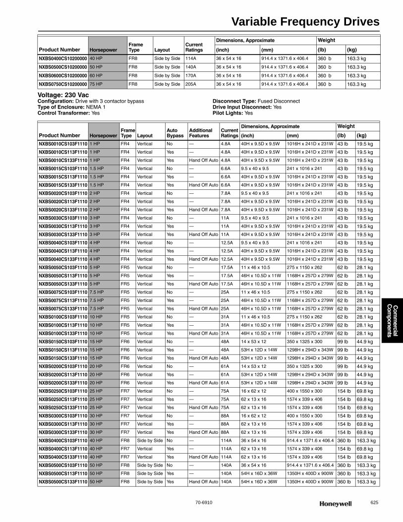
Variable Frequency Drives
70-6910 625
Com
mercial
Com
ponents
Voltage: 230 VacConfiguration: Drive with 3 contactor bypassType of Enclosure: NEMA 1Control Transformer: Yes
Disconnect Type: Fused DisconnectDrive Input Disconnect: YesPilot Lights: Yes
NXBS0400CS10200000 40 HP FR8 Side by Side 114A 36 x 54 x 16 914.4 x 1371.6 x 406.4 360 b 163.3 kg
NXBS0500CS10200000 50 HP FR8 Side by Side 140A 36 x 54 x 16 914.4 x 1371.6 x 406.4 360 b 163.3 kg
NXBS0600CS10200000 60 HP FR8 Side by Side 170A 36 x 54 x 16 914.4 x 1371.6 x 406.4 360 b 163.3 kg
NXBS0750CS10200000 75 HP FR8 Side by Side 205A 36 x 54 x 16 914.4 x 1371.6 x 406.4 360 b 163.3 kg
Product Number HorsepowerFrame Type Layout
Current Ratings
Dimensions, Approximate Weight
(inch) (mm) (lb) (kg)
Product Number HorsepowerFrame Type Layout
Auto Bypass
Additional Features
Current Ratings
Dimensions, Approximate Weight
(inch) (mm) (lb) (kg)
NXBS0010CS103F1110 1 HP FR4 Vertical No — 4.8A 40H x 9.5D x 9.5W 1016H x 241D x 231W 43 lb 19.5 kg
NXBS0010CS113F1110 1 HP FR4 Vertical Yes — 4.8A 40H x 9.5D x 9.5W 1016H x 241D x 231W 43 lb 19.5 kg
NXBS0010CS133F1110 1 HP FR4 Vertical Yes Hand Off Auto 4.8A 40H x 9.5D x 9.5W 1016H x 241D x 231W 43 lb 19.5 kg
NXBS0015CS103F1110 1.5 HP FR4 Vertical No — 6.6A 9.5 x 40 x 9.5 241 x 1016 x 241 43 lb 19.5 kg
NXBS0015CS113F1110 1.5 HP FR4 Vertical Yes — 6.6A 40H x 9.5D x 9.5W 1016H x 241D x 231W 43 lb 19.5 kg
NXBS0015CS133F1110 1.5 HP FR4 Vertical Yes Hand Off Auto 6.6A 40H x 9.5D x 9.5W 1016H x 241D x 231W 43 lb 19.5 kg
NXBS0020CS103F1110 2 HP FR4 Vertical No — 7.8A 9.5 x 40 x 9.5 241 x 1016 x 241 43 lb 19.5 kg
NXBS0020CS113F1110 2 HP FR4 Vertical Yes — 7.8A 40H x 9.5D x 9.5W 1016H x 241D x 231W 43 lb 19.5 kg
NXBS0020CS133F1110 2 HP FR4 Vertical Yes Hand Off Auto 7.8A 40H x 9.5D x 9.5W 1016H x 241D x 231W 43 lb 19.5 kg
NXBS0030CS103F1110 3 HP FR4 Vertical No — 11A 9.5 x 40 x 9.5 241 x 1016 x 241 43 lb 19.5 kg
NXBS0030CS113F1110 3 HP FR4 Vertical Yes — 11A 40H x 9.5D x 9.5W 1016H x 241D x 231W 43 lb 19.5 kg
NXBS0030CS133F1110 3 HP FR4 Vertical Yes Hand Off Auto 11A 40H x 9.5D x 9.5W 1016H x 241D x 231W 43 lb 19.5 kg
NXBS0040CS103F1110 4 HP FR4 Vertical No — 12.5A 9.5 x 40 x 9.5 241 x 1016 x 241 43 lb 19.5 kg
NXBS0040CS113F1110 4 HP FR4 Vertical Yes — 12.5A 40H x 9.5D x 9.5W 1016H x 241D x 231W 43 lb 19.5 kg
NXBS0040CS133F1110 4 HP FR4 Vertical Yes Hand Off Auto 12.5A 40H x 9.5D x 9.5W 1016H x 241D x 231W 43 lb 19.5 kg
NXBS0050CS103F1110 5 HP FR5 Vertical No — 17.5A 11 x 46 x 10.5 275 x 1150 x 262 62 lb 28.1 kg
NXBS0050CS113F1110 5 HP FR5 Vertical Yes — 17.5A 46H x 10.5D x 11W 1168H x 257D x 279W 62 lb 28.1 kg
NXBS0050CS133F1110 5 HP FR5 Vertical Yes Hand Off Auto 17.5A 46H x 10.5D x 11W 1168H x 257D x 279W 62 lb 28.1 kg
NXBS0075CS103F1110 7.5 HP FR5 Vertical No — 25A 11 x 46 x 10.5 275 x 1150 x 262 62 lb 28.1 kg
NXBS0075CS113F1110 7.5 HP FR5 Vertical Yes — 25A 46H x 10.5D x 11W 1168H x 257D x 279W 62 lb 28.1 kg
NXBS0075CS133F1110 7.5 HP FR5 Vertical Yes Hand Off Auto 25A 46H x 10.5D x 11W 1168H x 257D x 279W 62 lb 28.1 kg
NXBS0100CS103F1110 10 HP FR5 Vertical No — 31A 11 x 46 x 10.5 275 x 1150 x 262 62 lb 28.1 kg
NXBS0100CS113F1110 10 HP FR5 Vertical Yes — 31A 46H x 10.5D x 11W 1168H x 257D x 279W 62 lb 28.1 kg
NXBS0100CS133F1110 10 HP FR5 Vertical Yes Hand Off Auto 31A 46H x 10.5D x 11W 1168H x 257D x 279W 62 lb 28.1 kg
NXBS0150CS103F1110 15 HP FR6 Vertical No — 48A 14 x 53 x 12 350 x 1325 x 300 99 lb 44.9 kg
NXBS0150CS113F1110 15 HP FR6 Vertical Yes — 48A 53H x 12D x 14W 1298H x 294D x 343W 99 lb 44.9 kg
NXBS0150CS133F1110 15 HP FR6 Vertical Yes Hand Off Auto 48A 53H x 12D x 14W 1298H x 294D x 343W 99 lb 44.9 kg
NXBS0200CS103F1110 20 HP FR6 Vertical No — 61A 14 x 53 x 12 350 x 1325 x 300 99 lb 44.9 kg
NXBS0200CS113F1110 20 HP FR6 Vertical Yes — 61A 53H x 12D x 14W 1298H x 294D x 343W 99 lb 44.9 kg
NXBS0200CS133F1110 20 HP FR6 Vertical Yes Hand Off Auto 61A 53H x 12D x 14W 1298H x 294D x 343W 99 lb 44.9 kg
NXBS0250CS103F1110 25 HP FR7 Vertical No — 75A 16 x 62 x 12 400 x 1550 x 300 154 lb 69.8 kg
NXBS0250CS113F1110 25 HP FR7 Vertical Yes — 75A 62 x 13 x 16 1574 x 339 x 406 154 lb 69.8 kg
NXBS0250CS133F1110 25 HP FR7 Vertical Yes Hand Off Auto 75A 62 x 13 x 16 1574 x 339 x 406 154 lb 69.8 kg
NXBS0300CS103F1110 30 HP FR7 Vertical No — 88A 16 x 62 x 12 400 x 1550 x 300 154 lb 69.8 kg
NXBS0300CS113F1110 30 HP FR7 Vertical Yes — 88A 62 x 13 x 16 1574 x 339 x 406 154 lb 69.8 kg
NXBS0300CS133F1110 30 HP FR7 Vertical Yes Hand Off Auto 88A 62 x 13 x 16 1574 x 339 x 406 154 lb 69.8 kg
NXBS0400CS103F1110 40 HP FR8 Side by Side No — 114A 36 x 54 x 16 914.4 x 1371.6 x 406.4 360 lb 163.3 kg
NXBS0400CS113F1110 40 HP FR7 Vertical Yes — 114A 62 x 13 x 16 1574 x 339 x 406 154 lb 69.8 kg
NXBS0400CS133F1110 40 HP FR7 Vertical Yes Hand Off Auto 114A 62 x 13 x 16 1574 x 339 x 406 154 lb 69.8 kg
NXBS0500CS103F1110 50 HP FR8 Side by Side No — 140A 36 x 54 x 16 914.4 x 1371.6 x 406.4 360 lb 163.3 kg
NXBS0500CS113F1110 50 HP FR8 Side by Side Yes — 140A 54H x 16D x 36W 1350H x 400D x 900W 360 lb 163.3 kg
NXBS0500CS133F1110 50 HP FR8 Side by Side Yes Hand Off Auto 140A 54H x 16D x 36W 1350H x 400D x 900W 360 lb 163.3 kg
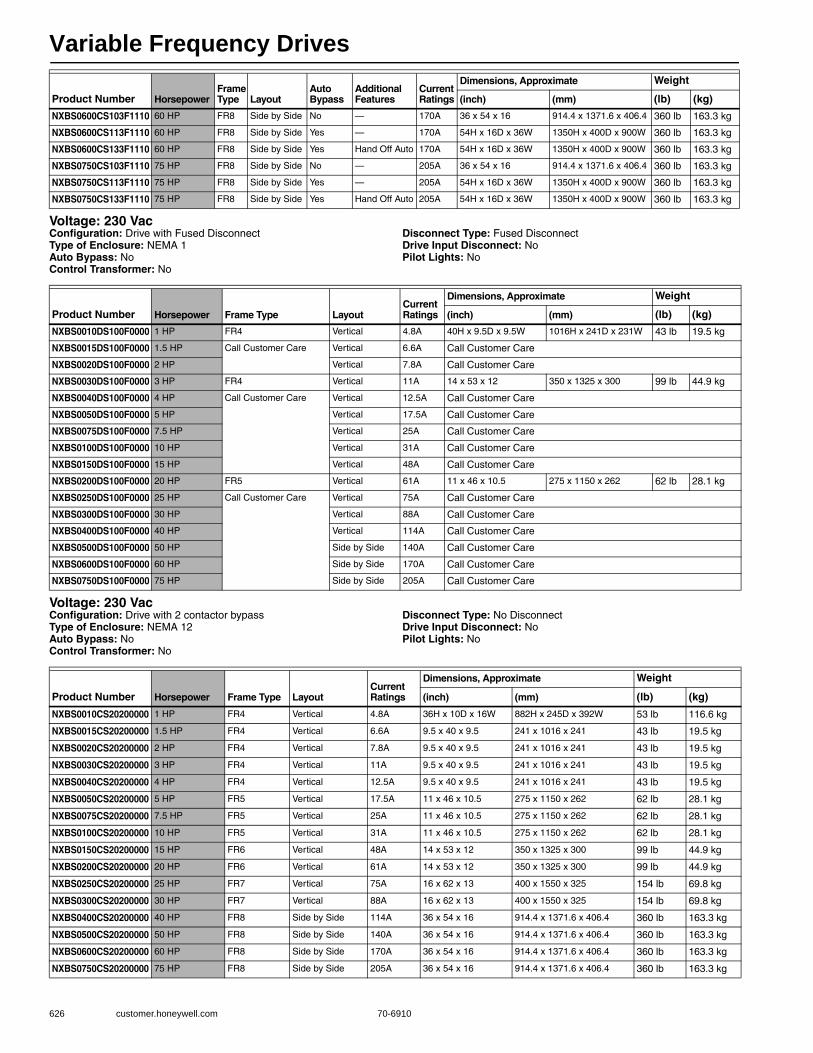
Variable Frequency Drives
626 customer.honeywell.com 70-6910
Voltage: 230 VacConfiguration: Drive with Fused DisconnectType of Enclosure: NEMA 1Auto Bypass: NoControl Transformer: No
Disconnect Type: Fused DisconnectDrive Input Disconnect: NoPilot Lights: No
Voltage: 230 VacConfiguration: Drive with 2 contactor bypassType of Enclosure: NEMA 12Auto Bypass: NoControl Transformer: No
Disconnect Type: No DisconnectDrive Input Disconnect: NoPilot Lights: No
NXBS0600CS103F1110 60 HP FR8 Side by Side No — 170A 36 x 54 x 16 914.4 x 1371.6 x 406.4 360 lb 163.3 kg
NXBS0600CS113F1110 60 HP FR8 Side by Side Yes — 170A 54H x 16D x 36W 1350H x 400D x 900W 360 lb 163.3 kg
NXBS0600CS133F1110 60 HP FR8 Side by Side Yes Hand Off Auto 170A 54H x 16D x 36W 1350H x 400D x 900W 360 lb 163.3 kg
NXBS0750CS103F1110 75 HP FR8 Side by Side No — 205A 36 x 54 x 16 914.4 x 1371.6 x 406.4 360 lb 163.3 kg
NXBS0750CS113F1110 75 HP FR8 Side by Side Yes — 205A 54H x 16D x 36W 1350H x 400D x 900W 360 lb 163.3 kg
NXBS0750CS133F1110 75 HP FR8 Side by Side Yes Hand Off Auto 205A 54H x 16D x 36W 1350H x 400D x 900W 360 lb 163.3 kg
Product Number HorsepowerFrame Type Layout
Auto Bypass
Additional Features
Current Ratings
Dimensions, Approximate Weight
(inch) (mm) (lb) (kg)
Product Number Horsepower Frame Type LayoutCurrent Ratings
Dimensions, Approximate Weight
(inch) (mm) (lb) (kg)
NXBS0010DS100F0000 1 HP FR4 Vertical 4.8A 40H x 9.5D x 9.5W 1016H x 241D x 231W 43 lb 19.5 kg
NXBS0015DS100F0000 1.5 HP Call Customer Care Vertical 6.6A Call Customer Care
NXBS0020DS100F0000 2 HP Vertical 7.8A Call Customer Care
NXBS0030DS100F0000 3 HP FR4 Vertical 11A 14 x 53 x 12 350 x 1325 x 300 99 lb 44.9 kg
NXBS0040DS100F0000 4 HP Call Customer Care Vertical 12.5A Call Customer Care
NXBS0050DS100F0000 5 HP Vertical 17.5A Call Customer Care
NXBS0075DS100F0000 7.5 HP Vertical 25A Call Customer Care
NXBS0100DS100F0000 10 HP Vertical 31A Call Customer Care
NXBS0150DS100F0000 15 HP Vertical 48A Call Customer Care
NXBS0200DS100F0000 20 HP FR5 Vertical 61A 11 x 46 x 10.5 275 x 1150 x 262 62 lb 28.1 kg
NXBS0250DS100F0000 25 HP Call Customer Care Vertical 75A Call Customer Care
NXBS0300DS100F0000 30 HP Vertical 88A Call Customer Care
NXBS0400DS100F0000 40 HP Vertical 114A Call Customer Care
NXBS0500DS100F0000 50 HP Side by Side 140A Call Customer Care
NXBS0600DS100F0000 60 HP Side by Side 170A Call Customer Care
NXBS0750DS100F0000 75 HP Side by Side 205A Call Customer Care
Product Number Horsepower Frame Type LayoutCurrent Ratings
Dimensions, Approximate Weight
(inch) (mm) (lb) (kg)
NXBS0010CS20200000 1 HP FR4 Vertical 4.8A 36H x 10D x 16W 882H x 245D x 392W 53 lb 116.6 kg
NXBS0015CS20200000 1.5 HP FR4 Vertical 6.6A 9.5 x 40 x 9.5 241 x 1016 x 241 43 lb 19.5 kg
NXBS0020CS20200000 2 HP FR4 Vertical 7.8A 9.5 x 40 x 9.5 241 x 1016 x 241 43 lb 19.5 kg
NXBS0030CS20200000 3 HP FR4 Vertical 11A 9.5 x 40 x 9.5 241 x 1016 x 241 43 lb 19.5 kg
NXBS0040CS20200000 4 HP FR4 Vertical 12.5A 9.5 x 40 x 9.5 241 x 1016 x 241 43 lb 19.5 kg
NXBS0050CS20200000 5 HP FR5 Vertical 17.5A 11 x 46 x 10.5 275 x 1150 x 262 62 lb 28.1 kg
NXBS0075CS20200000 7.5 HP FR5 Vertical 25A 11 x 46 x 10.5 275 x 1150 x 262 62 lb 28.1 kg
NXBS0100CS20200000 10 HP FR5 Vertical 31A 11 x 46 x 10.5 275 x 1150 x 262 62 lb 28.1 kg
NXBS0150CS20200000 15 HP FR6 Vertical 48A 14 x 53 x 12 350 x 1325 x 300 99 lb 44.9 kg
NXBS0200CS20200000 20 HP FR6 Vertical 61A 14 x 53 x 12 350 x 1325 x 300 99 lb 44.9 kg
NXBS0250CS20200000 25 HP FR7 Vertical 75A 16 x 62 x 13 400 x 1550 x 325 154 lb 69.8 kg
NXBS0300CS20200000 30 HP FR7 Vertical 88A 16 x 62 x 13 400 x 1550 x 325 154 lb 69.8 kg
NXBS0400CS20200000 40 HP FR8 Side by Side 114A 36 x 54 x 16 914.4 x 1371.6 x 406.4 360 lb 163.3 kg
NXBS0500CS20200000 50 HP FR8 Side by Side 140A 36 x 54 x 16 914.4 x 1371.6 x 406.4 360 lb 163.3 kg
NXBS0600CS20200000 60 HP FR8 Side by Side 170A 36 x 54 x 16 914.4 x 1371.6 x 406.4 360 lb 163.3 kg
NXBS0750CS20200000 75 HP FR8 Side by Side 205A 36 x 54 x 16 914.4 x 1371.6 x 406.4 360 lb 163.3 kg

Variable Frequency Drives
70-6910 627
Com
mercial
Com
ponents
Voltage: 230 VacConfiguration: Drive with 3 contactor bypassType of Enclosure: NEMA 12Control Transformer: Yes
Disconnect Type: Fused DisconnectDrive Input Disconnect: YesPilot Lights: Yes
Product Number HorsepowerFrame Type Layout
Auto Bypass
Additional Features
Current Ratings
Dimensions, Approximate Weight
(inch) (mm) (lb) (kg)
NXBS0010CS203F1110 1 HP FR4 Vertical No — 4.8A 36H x 10D x 16W 882H x 245D x 392W 53 lb 116.6 kg
NXBS0010CS213F1110 1 HP FR4 Vertical Yes — 4.8A 36H x 10D x 16W 882H x 245D x 392W 53 lb 116.6 kg
NXBS0010CS233F1110 1 HP FR4 Vertical Yes Hand Off Auto 4.8A 36H x 10D x 16W 882H x 245D x 392W 53 lb 116.6 kg
NXBS0015CS203F1110 1.5 HP FR4 Vertical No — 6.6A 9.5 x 40 x 9.5 241 x 1016 x 241 43 lb 19.5 kg
NXBS0015CS213F1110 1.5 HP FR4 Vertical Yes — 6.6A 36H x 10D x 16W 882H x 245D x 392W 53 lb 116.6 kg
NXBS0015CS233F1110 1.5 HP FR4 Vertical Yes Hand Off Auto 6.6A 36H x 10D x 16W 882H x 245D x 392W 53 lb 116.6 kg
NXBS0020CS203F1110 2 HP FR4 Vertical No — 7.8A 9.5 x 40 x 9.5 241 x 1016 x 241 43 lb 19.5 kg
NXBS0020CS213F1110 2 HP FR4 Vertical Yes — 7.8A 36H x 10D x 16W 882H x 245D x 392W 53 lb 116.6 kg
NXBS0020CS233F1110 2 HP FR4 Vertical Yes Hand Off Auto 7.8A 36H x 10D x 16W 882H x 245D x 392W 53 lb 116.6 kg
NXBS0030CS203F1110 3 HP FR4 Vertical No — 11A 9.5 x 40 x 9.5 241 x 1016 x 241 43 lb 19.5 kg
NXBS0030CS213F1110 3 HP FR4 Vertical Yes — 11A 36H x 10D x 16W 882H x 245D x 392W 53 lb 116.6 kg
NXBS0030CS233F1110 3 HP FR4 Vertical Yes Hand Off Auto 11A 36H x 10D x 16W 882H x 245D x 392W 53 lb 116.6 kg
NXBS0040CS203F1110 4 HP FR4 Vertical No — 12.5A 9.5 x 40 x 9.5 241 x 1016 x 241 43 lb 19.5 kg
NXBS0040CS213F1110 4 HP FR4 Vertical Yes — 12.5A 36H x 10D x 16W 882H x 245D x 392W 53 lb 116.6 kg
NXBS0040CS233F1110 4 HP FR4 Vertical Yes Hand Off Auto 12.5A 36H x 10D x 16W 882H x 245D x 392W 53 lb 116.6 kg
NXBS0050CS203F1110 5 HP FR5 Vertical No — 17.5A 11 x 46 x 10.5 275 x 1150 x 262 62 lb 28.1 kg
NXBS0050CS213F1110 5 HP FR5 Vertical Yes — 17.5A 36H x 10D x 16W 882H x 245D x 392W 64 lb 29 kg
NXBS0050CS233F1110 5 HP FR5 Vertical Yes Hand Off Auto 17.5A 36H x 10D x 16W 882H x 245D x 392W 64 lb 29 kg
NXBS0075CS203F1110 7.5 HP FR5 Vertical No — 25A 11 x 46 x 10.5 275 x 1150 x 262 62 lb 28.1 kg
NXBS0075CS213F1110 7.5 HP FR5 Vertical Yes — 25A 36H x 10D x 16W 882H x 245D x 392W 64 lb 29 kg
NXBS0075CS233F1110 7.5 HP FR5 Vertical Yes Hand Off Auto 25A 36H x 10D x 16W 882H x 245D x 392W 64 lb 29 kg
NXBS0100CS203F1110 10 HP FR5 Vertical No — 31A 11 x 46 x 10.5 275 x 1150 x 262 62 lb 28.1 kg
NXBS0100CS213F1110 10 HP FR5 Vertical Yes — 31A 44H x 10D x 16W 1078H x 245D x 392W 70 lb 31.7 kg
NXBS0100CS233F1110 10 HP FR5 Vertical Yes Hand Off Auto 31A 44H x 10D x 16W 1078H x 245D x 392W 70 lb 31.7 kg
NXBS0150CS203F1110 15 HP FR6 Vertical No — 48A 14 x 53 x 12 350 x 1325 x 300 99 lb 44.9 kg
NXBS0150CS213F1110 15 HP FR6 Vertical Yes — 48A 50H x 10D x 16W 1225H x 245D x 392W 120 lb 54.5 kg
NXBS0150CS233F1110 15 HP FR6 Vertical Yes Hand Off Auto 48A 50H x 10D x 16W 1225H x 245D x 392W 120 lb 54.5 kg
NXBS0200CS203F1110 20 HP FR6 Vertical No — 61A 14 x 53 x 12 350 x 1325 x 300 99 lb 44.9 kg
NXBS0200CS213F1110 20 HP FR6 Vertical Yes — 61A 54H x 10D x 20W 1323H x 245D x 490W 136 lb 61.7 kg
NXBS0200CS233F1110 20 HP FR6 Vertical Yes Hand Off Auto 61A 54H x 10D x 20W 1323H x 245D x 490W 136 lb 61.7 kg
NXBS0250CS213F1110 25 HP FR7 Vertical Yes — 75A 58 x 10 x 20 1421 x 245 x 490 150 lb 68.2 kg
NXBS0250CS233F1110 25 HP FR7 Vertical Yes Hand Off Auto 75A 58 x 10 x 20 1421 x 245 x 490 150 lb 68.2 kg
NXBS0300CS213F1110 30 HP FR7 Vertical Yes — 88A 58 x 10 x 20 1421 x 245 x 490 150 lb 68.2 kg
NXBS0300CS233F1110 30 HP FR7 Vertical Yes Hand Off Auto 88A 58 x 10 x 20 1421 x 245 x 490 150 lb 68.2 kg
NXBS0400CS213F1110 40 HP FR7 Vertical Yes — 114A 64 x 12 x 24 1568 x 294 x 588mm 200 lb 90.7 kg
NXBS0400CS233F1110 40 HP FR7 Vertical Yes Hand Off Auto 114A 64 x 12 x 24 1568 x 294 x 588mm 200 lb 90.7 kg
NXBS0500CS213F1110 50 HP FR8 Side by Side Yes — 140A 48H x 14D x 36W 1176H x 343D x 882W 350 lb 158.8 kg
NXBS0500CS233F1110 50 HP FR8 Side by Side Yes Hand Off Auto 140A 48H x 14D x 36W 1176H x 343D x 882W 350 lb 158.8 kg
NXBS0600CS213F1110 60 HP FR8 Side by Side Yes — 170A 48H x 14D x 36W 1176H x 343D x 882W 350 lb 158.8 kg
NXBS0600CS233F1110 60 HP FR8 Side by Side Yes Hand Off Auto 170A 48H x 14D x 36W 1176H x 343D x 882W 350 lb 158.8 kg
NXBS0750CS213F1110 75 HP FR8 Side by Side Yes — 205A 48H x 14D x 36W 1176H x 343D x 882W 350 lb 158.8 kg
NXBS0750CS233F1110 75 HP FR8 Side by Side Yes Hand Off Auto 205A 48H x 14D x 36W 1176H x 343D x 882W 350 lb 158.8 kg
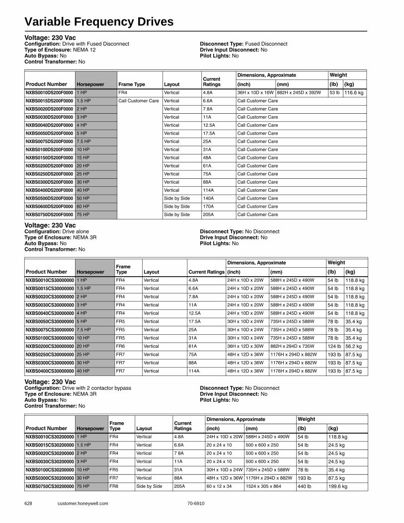
Variable Frequency Drives
628 customer.honeywell.com 70-6910
Voltage: 230 VacConfiguration: Drive with Fused DisconnectType of Enclosure: NEMA 12Auto Bypass: NoControl Transformer: No
Disconnect Type: Fused DisconnectDrive Input Disconnect: NoPilot Lights: No
Voltage: 230 VacConfiguration: Drive aloneType of Enclosure: NEMA 3RAuto Bypass: NoControl Transformer: No
Disconnect Type: No DisconnectDrive Input Disconnect: NoPilot Lights: No
Voltage: 230 VacConfiguration: Drive with 2 contactor bypassType of Enclosure: NEMA 3RAuto Bypass: NoControl Transformer: No
Disconnect Type: No DisconnectDrive Input Disconnect: NoPilot Lights: No
Product Number Horsepower Frame Type LayoutCurrent Ratings
Dimensions, Approximate Weight
(inch) (mm) (lb) (kg)
NXBS0010DS200F0000 1 HP FR4 Vertical 4.8A 36H x 10D x 16W 882H x 245D x 392W 53 lb 116.6 kg
NXBS0015DS200F0000 1.5 HP Call Customer Care Vertical 6.6A Call Customer Care
NXBS0020DS200F0000 2 HP Vertical 7.8A Call Customer Care
NXBS0030DS200F0000 3 HP Vertical 11A Call Customer Care
NXBS0040DS200F0000 4 HP Vertical 12.5A Call Customer Care
NXBS0050DS200F0000 5 HP Vertical 17.5A Call Customer Care
NXBS0075DS200F0000 7.5 HP Vertical 25A Call Customer Care
NXBS0100DS200F0000 10 HP Vertical 31A Call Customer Care
NXBS0150DS200F0000 15 HP Vertical 48A Call Customer Care
NXBS0200DS200F0000 20 HP Vertical 61A Call Customer Care
NXBS0250DS200F0000 25 HP Vertical 75A Call Customer Care
NXBS0300DS200F0000 30 HP Vertical 88A Call Customer Care
NXBS0400DS200F0000 40 HP Vertical 114A Call Customer Care
NXBS0500DS200F0000 50 HP Side by Side 140A Call Customer Care
NXBS0600DS200F0000 60 HP Side by Side 170A Call Customer Care
NXBS0750DS200F0000 75 HP Side by Side 205A Call Customer Care
Product Number HorsepowerFrame Type Layout Current Ratings
Dimensions, Approximate Weight
(inch) (mm) (lb) (kg)
NXBS0010CS30000000 1 HP FR4 Vertical 4.8A 24H x 10D x 20W 588H x 245D x 490W 54 lb 118.8 kg
NXBS0015CS30000000 1.5 HP FR4 Vertical 6.6A 24H x 10D x 20W 588H x 245D x 490W 54 lb 118.8 kg
NXBS0020CS30000000 2 HP FR4 Vertical 7.8A 24H x 10D x 20W 588H x 245D x 490W 54 lb 118.8 kg
NXBS0030CS30000000 3 HP FR4 Vertical 11A 24H x 10D x 20W 588H x 245D x 490W 54 lb 118.8 kg
NXBS0040CS30000000 4 HP FR4 Vertical 12.5A 24H x 10D x 20W 588H x 245D x 490W 54 lb 118.8 kg
NXBS0050CS30000000 5 HP FR5 Vertical 17.5A 30H x 10D x 24W 735H x 245D x 588W 78 lb 35.4 kg
NXBS0075CS30000000 7.5 HP FR5 Vertical 25A 30H x 10D x 24W 735H x 245D x 588W 78 lb 35.4 kg
NXBS0100CS30000000 10 HP FR5 Vertical 31A 30H x 10D x 24W 735H x 245D x 588W 78 lb 35.4 kg
NXBS0200CS30000000 20 HP FR6 Vertical 61A 36H x 12D x 30W 882H x 294D x 735W 124 lb 56.2 kg
NXBS0250CS30000000 25 HP FR7 Vertical 75A 48H x 12D x 36W 1176H x 294D x 882W 193 lb 87.5 kg
NXBS0300CS30000000 30 HP FR7 Vertical 88A 48H x 12D x 36W 1176H x 294D x 882W 193 lb 87.5 kg
NXBS0400CS30000000 40 HP FR7 Vertical 114A 48H x 12D x 36W 1176H x 294D x 882W 193 lb 87.5 kg
Product Number HorsepowerFrame Type Layout
Current Ratings
Dimensions, Approximate Weight
(inch) (mm) (lb) (kg)
NXBS0010CS30200000 1 HP FR4 Vertical 4.8A 24H x 10D x 20W 588H x 245D x 490W 54 lb 118.8 kg
NXBS0015CS30200000 1.5 HP FR4 Vertical 6.6A 20 x 24 x 10 500 x 600 x 250 54 lb 24.5 kg
NXBS0020CS30200000 2 HP FR4 Vertical 7 8A 20 x 24 x 10 500 x 600 x 250 54 lb 24.5 kg
NXBS0030CS30200000 3 HP FR4 Vertical 11A 20 x 24 x 10 500 x 600 x 250 54 lb 24.5 kg
NXBS0100CS30200000 10 HP FR5 Vertical 31A 30H x 10D x 24W 735H x 245D x 588W 78 lb 35.4 kg
NXBS0300CS30200000 30 HP FR7 Vertical 88A 48H x 12D x 36W 1176H x 294D x 882W 193 lb 87.5 kg
NXBS0750CS30200000 75 HP FR8 Side by Side 205A 60 x 12 x 34 1524 x 305 x 864 440 lb 199.6 kg
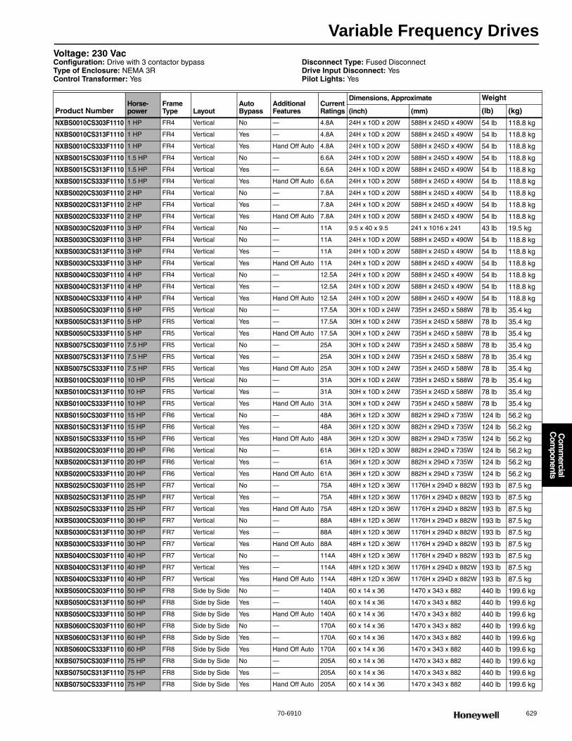
Variable Frequency Drives
70-6910 629
Com
mercial
Com
ponents
Voltage: 230 VacConfiguration: Drive with 3 contactor bypassType of Enclosure: NEMA 3RControl Transformer: Yes
Disconnect Type: Fused DisconnectDrive Input Disconnect: YesPilot Lights: Yes
Product NumberHorse-power
Frame Type Layout
Auto Bypass
Additional Features
Current Ratings
Dimensions, Approximate Weight
(inch) (mm) (lb) (kg)
NXBS0010CS303F1110 1 HP FR4 Vertical No — 4.8A 24H x 10D x 20W 588H x 245D x 490W 54 lb 118.8 kg
NXBS0010CS313F1110 1 HP FR4 Vertical Yes — 4.8A 24H x 10D x 20W 588H x 245D x 490W 54 lb 118.8 kg
NXBS0010CS333F1110 1 HP FR4 Vertical Yes Hand Off Auto 4.8A 24H x 10D x 20W 588H x 245D x 490W 54 lb 118.8 kg
NXBS0015CS303F1110 1.5 HP FR4 Vertical No — 6.6A 24H x 10D x 20W 588H x 245D x 490W 54 lb 118.8 kg
NXBS0015CS313F1110 1.5 HP FR4 Vertical Yes — 6.6A 24H x 10D x 20W 588H x 245D x 490W 54 lb 118.8 kg
NXBS0015CS333F1110 1.5 HP FR4 Vertical Yes Hand Off Auto 6.6A 24H x 10D x 20W 588H x 245D x 490W 54 lb 118.8 kg
NXBS0020CS303F1110 2 HP FR4 Vertical No — 7.8A 24H x 10D x 20W 588H x 245D x 490W 54 lb 118.8 kg
NXBS0020CS313F1110 2 HP FR4 Vertical Yes — 7.8A 24H x 10D x 20W 588H x 245D x 490W 54 lb 118.8 kg
NXBS0020CS333F1110 2 HP FR4 Vertical Yes Hand Off Auto 7.8A 24H x 10D x 20W 588H x 245D x 490W 54 lb 118.8 kg
NXBS0030CS203F1110 3 HP FR4 Vertical No — 11A 9.5 x 40 x 9.5 241 x 1016 x 241 43 lb 19.5 kg
NXBS0030CS303F1110 3 HP FR4 Vertical No — 11A 24H x 10D x 20W 588H x 245D x 490W 54 lb 118.8 kg
NXBS0030CS313F1110 3 HP FR4 Vertical Yes — 11A 24H x 10D x 20W 588H x 245D x 490W 54 lb 118.8 kg
NXBS0030CS333F1110 3 HP FR4 Vertical Yes Hand Off Auto 11A 24H x 10D x 20W 588H x 245D x 490W 54 lb 118.8 kg
NXBS0040CS303F1110 4 HP FR4 Vertical No — 12.5A 24H x 10D x 20W 588H x 245D x 490W 54 lb 118.8 kg
NXBS0040CS313F1110 4 HP FR4 Vertical Yes — 12.5A 24H x 10D x 20W 588H x 245D x 490W 54 lb 118.8 kg
NXBS0040CS333F1110 4 HP FR4 Vertical Yes Hand Off Auto 12.5A 24H x 10D x 20W 588H x 245D x 490W 54 lb 118.8 kg
NXBS0050CS303F1110 5 HP FR5 Vertical No — 17.5A 30H x 10D x 24W 735H x 245D x 588W 78 lb 35.4 kg
NXBS0050CS313F1110 5 HP FR5 Vertical Yes — 17.5A 30H x 10D x 24W 735H x 245D x 588W 78 lb 35.4 kg
NXBS0050CS333F1110 5 HP FR5 Vertical Yes Hand Off Auto 17.5A 30H x 10D x 24W 735H x 245D x 588W 78 lb 35.4 kg
NXBS0075CS303F1110 7.5 HP FR5 Vertical No — 25A 30H x 10D x 24W 735H x 245D x 588W 78 lb 35.4 kg
NXBS0075CS313F1110 7.5 HP FR5 Vertical Yes — 25A 30H x 10D x 24W 735H x 245D x 588W 78 lb 35.4 kg
NXBS0075CS333F1110 7.5 HP FR5 Vertical Yes Hand Off Auto 25A 30H x 10D x 24W 735H x 245D x 588W 78 lb 35.4 kg
NXBS0100CS303F1110 10 HP FR5 Vertical No — 31A 30H x 10D x 24W 735H x 245D x 588W 78 lb 35.4 kg
NXBS0100CS313F1110 10 HP FR5 Vertical Yes — 31A 30H x 10D x 24W 735H x 245D x 588W 78 lb 35.4 kg
NXBS0100CS333F1110 10 HP FR5 Vertical Yes Hand Off Auto 31A 30H x 10D x 24W 735H x 245D x 588W 78 lb 35.4 kg
NXBS0150CS303F1110 15 HP FR6 Vertical No — 48A 36H x 12D x 30W 882H x 294D x 735W 124 lb 56.2 kg
NXBS0150CS313F1110 15 HP FR6 Vertical Yes — 48A 36H x 12D x 30W 882H x 294D x 735W 124 lb 56.2 kg
NXBS0150CS333F1110 15 HP FR6 Vertical Yes Hand Off Auto 48A 36H x 12D x 30W 882H x 294D x 735W 124 lb 56.2 kg
NXBS0200CS303F1110 20 HP FR6 Vertical No — 61A 36H x 12D x 30W 882H x 294D x 735W 124 lb 56.2 kg
NXBS0200CS313F1110 20 HP FR6 Vertical Yes — 61A 36H x 12D x 30W 882H x 294D x 735W 124 lb 56.2 kg
NXBS0200CS333F1110 20 HP FR6 Vertical Yes Hand Off Auto 61A 36H x 12D x 30W 882H x 294D x 735W 124 lb 56.2 kg
NXBS0250CS303F1110 25 HP FR7 Vertical No — 75A 48H x 12D x 36W 1176H x 294D x 882W 193 lb 87.5 kg
NXBS0250CS313F1110 25 HP FR7 Vertical Yes — 75A 48H x 12D x 36W 1176H x 294D x 882W 193 lb 87.5 kg
NXBS0250CS333F1110 25 HP FR7 Vertical Yes Hand Off Auto 75A 48H x 12D x 36W 1176H x 294D x 882W 193 lb 87.5 kg
NXBS0300CS303F1110 30 HP FR7 Vertical No — 88A 48H x 12D x 36W 1176H x 294D x 882W 193 lb 87.5 kg
NXBS0300CS313F1110 30 HP FR7 Vertical Yes — 88A 48H x 12D x 36W 1176H x 294D x 882W 193 lb 87.5 kg
NXBS0300CS333F1110 30 HP FR7 Vertical Yes Hand Off Auto 88A 48H x 12D x 36W 1176H x 294D x 882W 193 lb 87.5 kg
NXBS0400CS303F1110 40 HP FR7 Vertical No — 114A 48H x 12D x 36W 1176H x 294D x 882W 193 lb 87.5 kg
NXBS0400CS313F1110 40 HP FR7 Vertical Yes — 114A 48H x 12D x 36W 1176H x 294D x 882W 193 lb 87.5 kg
NXBS0400CS333F1110 40 HP FR7 Vertical Yes Hand Off Auto 114A 48H x 12D x 36W 1176H x 294D x 882W 193 lb 87.5 kg
NXBS0500CS303F1110 50 HP FR8 Side by Side No — 140A 60 x 14 x 36 1470 x 343 x 882 440 lb 199.6 kg
NXBS0500CS313F1110 50 HP FR8 Side by Side Yes — 140A 60 x 14 x 36 1470 x 343 x 882 440 lb 199.6 kg
NXBS0500CS333F1110 50 HP FR8 Side by Side Yes Hand Off Auto 140A 60 x 14 x 36 1470 x 343 x 882 440 lb 199.6 kg
NXBS0600CS303F1110 60 HP FR8 Side by Side No — 170A 60 x 14 x 36 1470 x 343 x 882 440 lb 199.6 kg
NXBS0600CS313F1110 60 HP FR8 Side by Side Yes — 170A 60 x 14 x 36 1470 x 343 x 882 440 lb 199.6 kg
NXBS0600CS333F1110 60 HP FR8 Side by Side Yes Hand Off Auto 170A 60 x 14 x 36 1470 x 343 x 882 440 lb 199.6 kg
NXBS0750CS303F1110 75 HP FR8 Side by Side No — 205A 60 x 14 x 36 1470 x 343 x 882 440 lb 199.6 kg
NXBS0750CS313F1110 75 HP FR8 Side by Side Yes — 205A 60 x 14 x 36 1470 x 343 x 882 440 lb 199.6 kg
NXBS0750CS333F1110 75 HP FR8 Side by Side Yes Hand Off Auto 205A 60 x 14 x 36 1470 x 343 x 882 440 lb 199.6 kg
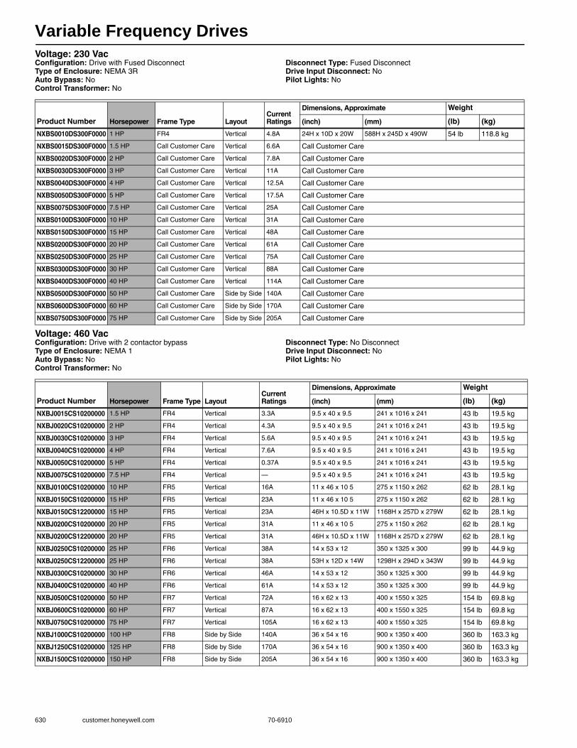
Variable Frequency Drives
630 customer.honeywell.com 70-6910
Voltage: 230 VacConfiguration: Drive with Fused DisconnectType of Enclosure: NEMA 3RAuto Bypass: NoControl Transformer: No
Disconnect Type: Fused DisconnectDrive Input Disconnect: NoPilot Lights: No
Voltage: 460 VacConfiguration: Drive with 2 contactor bypassType of Enclosure: NEMA 1Auto Bypass: NoControl Transformer: No
Disconnect Type: No DisconnectDrive Input Disconnect: NoPilot Lights: No
Product Number Horsepower Frame Type LayoutCurrent Ratings
Dimensions, Approximate Weight
(inch) (mm) (lb) (kg)
NXBS0010DS300F0000 1 HP FR4 Vertical 4.8A 24H x 10D x 20W 588H x 245D x 490W 54 lb 118.8 kg
NXBS0015DS300F0000 1.5 HP Call Customer Care Vertical 6.6A Call Customer Care
NXBS0020DS300F0000 2 HP Call Customer Care Vertical 7.8A Call Customer Care
NXBS0030DS300F0000 3 HP Call Customer Care Vertical 11A Call Customer Care
NXBS0040DS300F0000 4 HP Call Customer Care Vertical 12.5A Call Customer Care
NXBS0050DS300F0000 5 HP Call Customer Care Vertical 17.5A Call Customer Care
NXBS0075DS300F0000 7.5 HP Call Customer Care Vertical 25A Call Customer Care
NXBS0100DS300F0000 10 HP Call Customer Care Vertical 31A Call Customer Care
NXBS0150DS300F0000 15 HP Call Customer Care Vertical 48A Call Customer Care
NXBS0200DS300F0000 20 HP Call Customer Care Vertical 61A Call Customer Care
NXBS0250DS300F0000 25 HP Call Customer Care Vertical 75A Call Customer Care
NXBS0300DS300F0000 30 HP Call Customer Care Vertical 88A Call Customer Care
NXBS0400DS300F0000 40 HP Call Customer Care Vertical 114A Call Customer Care
NXBS0500DS300F0000 50 HP Call Customer Care Side by Side 140A Call Customer Care
NXBS0600DS300F0000 60 HP Call Customer Care Side by Side 170A Call Customer Care
NXBS0750DS300F0000 75 HP Call Customer Care Side by Side 205A Call Customer Care
Product Number Horsepower Frame Type LayoutCurrent Ratings
Dimensions, Approximate Weight
(inch) (mm) (lb) (kg)
NXBJ0015CS10200000 1.5 HP FR4 Vertical 3.3A 9.5 x 40 x 9.5 241 x 1016 x 241 43 lb 19.5 kg
NXBJ0020CS10200000 2 HP FR4 Vertical 4.3A 9.5 x 40 x 9.5 241 x 1016 x 241 43 lb 19.5 kg
NXBJ0030CS10200000 3 HP FR4 Vertical 5.6A 9.5 x 40 x 9.5 241 x 1016 x 241 43 lb 19.5 kg
NXBJ0040CS10200000 4 HP FR4 Vertical 7.6A 9.5 x 40 x 9.5 241 x 1016 x 241 43 lb 19.5 kg
NXBJ0050CS10200000 5 HP FR4 Vertical 0.37A 9.5 x 40 x 9.5 241 x 1016 x 241 43 lb 19.5 kg
NXBJ0075CS10200000 7.5 HP FR4 Vertical — 9.5 x 40 x 9.5 241 x 1016 x 241 43 lb 19.5 kg
NXBJ0100CS10200000 10 HP FR5 Vertical 16A 11 x 46 x 10 5 275 x 1150 x 262 62 lb 28.1 kg
NXBJ0150CS10200000 15 HP FR5 Vertical 23A 11 x 46 x 10 5 275 x 1150 x 262 62 lb 28.1 kg
NXBJ0150CS12200000 15 HP FR5 Vertical 23A 46H x 10.5D x 11W 1168H x 257D x 279W 62 lb 28.1 kg
NXBJ0200CS10200000 20 HP FR5 Vertical 31A 11 x 46 x 10 5 275 x 1150 x 262 62 lb 28.1 kg
NXBJ0200CS12200000 20 HP FR5 Vertical 31A 46H x 10.5D x 11W 1168H x 257D x 279W 62 lb 28.1 kg
NXBJ0250CS10200000 25 HP FR6 Vertical 38A 14 x 53 x 12 350 x 1325 x 300 99 lb 44.9 kg
NXBJ0250CS12200000 25 HP FR6 Vertical 38A 53H x 12D x 14W 1298H x 294D x 343W 99 lb 44.9 kg
NXBJ0300CS10200000 30 HP FR6 Vertical 46A 14 x 53 x 12 350 x 1325 x 300 99 lb 44.9 kg
NXBJ0400CS10200000 40 HP FR6 Vertical 61A 14 x 53 x 12 350 x 1325 x 300 99 lb 44.9 kg
NXBJ0500CS10200000 50 HP FR7 Vertical 72A 16 x 62 x 13 400 x 1550 x 325 154 lb 69.8 kg
NXBJ0600CS10200000 60 HP FR7 Vertical 87A 16 x 62 x 13 400 x 1550 x 325 154 lb 69.8 kg
NXBJ0750CS10200000 75 HP FR7 Vertical 105A 16 x 62 x 13 400 x 1550 x 325 154 lb 69.8 kg
NXBJ1000CS10200000 100 HP FR8 Side by Side 140A 36 x 54 x 16 900 x 1350 x 400 360 lb 163.3 kg
NXBJ1250CS10200000 125 HP FR8 Side by Side 170A 36 x 54 x 16 900 x 1350 x 400 360 lb 163.3 kg
NXBJ1500CS10200000 150 HP FR8 Side by Side 205A 36 x 54 x 16 900 x 1350 x 400 360 lb 163.3 kg
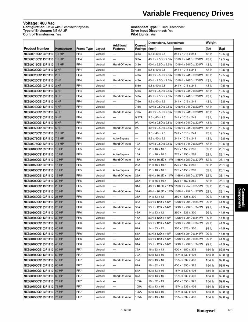
Variable Frequency Drives
70-6910 631
Com
mercial
Com
ponents
Voltage: 460 VacConfiguration: Drive with 3 contactor bypassType of Enclosure: NEMA 3RControl Transformer: Yes
Disconnect Type: Fused DisconnectDrive Input Disconnect: YesPilot Lights: Yes
Product Number Horsepower Frame Type LayoutAdditional Features
Current Ratings
Dimensions, Approximate Weight
(inch) (mm) (lb) (kg)
NXBJ0015CS103F1110 1.5 HP FR4 Vertical — 3.3A 9.5 x 40 x 9.5 241 x 1016 x 241 43 lb 19.5 kg
NXBJ0015CS113F1110 1.5 HP FR4 Vertical — 3.3A 40H x 9.5D x 9.5W 1016H x 241D x 231W 43 lb 19.5 kg
NXBJ0015CS133F1110 1.5 HP FR4 Vertical Hand Off Auto 3.3A 40H x 9.5D x 9.5W 1016H x 241D x 231W 43 lb 19.5 kg
NXBJ0020CS103F1110 2 HP FR4 Vertical — 4.3A 9.5 x 40 x 9.5 241 x 1016 x 241 43 lb 19.5 kg
NXBJ0020CS113F1110 2 HP FR4 Vertical — 4.3A 40H x 9.5D x 9.5W 1016H x 241D x 231W 43 lb 19.5 kg
NXBJ0020CS133F1110 2 HP FR4 Vertical Hand Off Auto 4.3A 40H x 9.5D x 9.5W 1016H x 241D x 231W 43 lb 19.5 kg
NXBJ0030CS103F1110 3 HP FR4 Vertical — 5.6A 9.5 x 40 x 9.5 241 x 1016 x 241 43 lb 19.5 kg
NXBJ0030CS113F1110 3 HP FR4 Vertical — 5.6A 40H x 9.5D x 9.5W 1016H x 241D x 231W 43 lb 19.5 kg
NXBJ0030CS133F1110 3 HP FR4 Vertical Hand Off Auto 5.6A 40H x 9.5D x 9.5W 1016H x 241D x 231W 43 lb 19.5 kg
NXBJ0040CS103F1110 4 HP FR4 Vertical — 7.6A 9.5 x 40 x 9.5 241 x 1016 x 241 43 lb 19.5 kg
NXBJ0040CS113F1110 4 HP FR4 Vertical — 7.6A 40H x 9.5D x 9.5W 1016H x 241D x 231W 43 lb 19.5 kg
NXBJ0040CS133F1110 4 HP FR4 Vertical Hand Off Auto 7.6A 40H x 9.5D x 9.5W 1016H x 241D x 231W 43 lb 19.5 kg
NXBJ0050CS103F1110 5 HP FR4 Vertical — 0.37A 9.5 x 40 x 9.5 241 x 1016 x 241 43 lb 19.5 kg
NXBJ0050CS113F1110 5 HP FR4 Vertical — 9A 40H x 9.5D x 9.5W 1016H x 241D x 231W 43 lb 19.5 kg
NXBJ0050CS133F1110 5 HP FR4 Vertical Hand Off Auto 9A 40H x 9.5D x 9.5W 1016H x 241D x 231W 43 lb 19.5 kg
NXBJ0075CS103F1110 7.5 HP FR4 Vertical — — 9.5 x 40 x 9.5 241 x 1016 x 241 43 lb 19.5 kg
NXBJ0075CS113F1110 7.5 HP FR4 Vertical Auto-Bypass — 9.5 x 40 x 9.5 241 x 1016 x 241 43 lb 19.5 kg
NXBJ0075CS133F1110 7.5 HP FR4 Vertical Hand Off Auto 12A 40H x 9.5D x 9.5W 1016H x 241D x 231W 43 lb 19.5 kg
NXBJ0100CS103F1110 10 HP FR5 Vertical — 16A 11 x 46 x 10.5 275 x 1150 x 262 62 lb 28.1 kg
NXBJ0100CS113F1110 10 HP FR5 Vertical Auto-Bypass 16A 11 x 46 x 10.5 275 x 1150 x 262 62 lb 28.1 kg
NXBJ0100CS133F1110 10 HP FR5 Vertical Hand Off Auto 16A 46H x 10.5D x 11W 1168H x 257D x 279W 62 lb 28.1 kg
NXBJ0150CS103F1110 15 HP FR5 Vertical — 23A 11 x 46 x 10.5 275 x 1150 x 262 62 lb 28.1 kg
NXBJ0150CS113F1110 15 HP FR5 Vertical Auto-Bypass 23A 11 x 46 x 10.5 275 x 1150 x 262 62 lb 28.1 kg
NXBJ0150CS133F1110 15 HP FR5 Vertical Hand Off Auto 23A 46H x 10.5D x 11W 1168H x 257D x 279W 62 lb 28.1 kg
NXBJ0200CS103F1110 20 HP FR5 Vertical — 31A 11 x 46 x 10.5 275 x 1150 x 262 62 lb 28.1 kg
NXBJ0200CS113F1110 20 HP FR5 Vertical — 31A 46H x 10.5D x 11W 1168H x 257D x 279W 62 lb 28.1 kg
NXBJ0200CS133F1110 20 HP FR5 Vertical Hand Off Auto 31A 46H x 10.5D x 11W 1168H x 257D x 279W 62 lb 28.1 kg
NXBJ0250CS103F1110 25 HP FR6 Vertical — 38A 14 x 53 x 12 350 x 1325 x 300 99 lb 44.9 kg
NXBJ0250CS113F1110 25 HP FR6 Vertical — 38A 53H x 12D x 14W 1298H x 294D x 343W 99 lb 44.9 kg
NXBJ0250CS133F1110 25 HP FR6 Vertical Hand Off Auto 38A 53H x 12D x 14W 1298H x 294D x 343W 99 lb 44.9 kg
NXBJ0300CS103F1110 30 HP FR6 Vertical — 46A 14 x 53 x 12 350 x 1325 x 300 99 lb 44.9 kg
NXBJ0300CS113F1110 30 HP FR6 Vertical — 46A 53H x 12D x 14W 1298H x 294D x 343W 99 lb 44.9 kg
NXBJ0300CS133F1110 30 HP FR6 Vertical Hand Off Auto 46A 53H x 12D x 14W 1298H x 294D x 343W 99 lb 44.9 kg
NXBJ0400CS103F1110 40 HP FR6 Vertical — 61A 14 x 53 x 12 350 x 1325 x 300 99 lb 44.9 kg
NXBJ0400CS113F1110 40 HP FR6 Vertical — 61A 53H x 12D x 14W 1298H x 294D x 343W 99 lb 44.9 kg
NXBJ0400CS123F1110 40 HP FR6 Vertical — 61A 53H x 12D x 14W 1298H x 294D x 343W 99 lb 44.9 kg
NXBJ0400CS133F1110 40 HP FR6 Vertical Hand Off Auto 61A 53H x 12D x 14W 1298H x 294D x 343W 99 lb 44.9 kg
NXBJ0500CS103F1110 50 HP FR7 Vertical — 72A 16 x 62 x 13 400 x 1550 x 325 154 b 69.8 kg
NXBJ0500CS113F1110 50 HP FR7 Vertical — 72A 62 x 13 x 16 1574 x 339 x 406 154 b 69.8 kg
NXBJ0500CS133F1110 50 HP FR7 Vertical Hand Off Auto 72A 62 x 13 x 16 1574 x 339 x 406 154 b 69.8 kg
NXBJ0600CS103F1110 60 HP FR7 Vertical — 87A 16 x 62 x 13 400 x 1550 x 325 154 b 69.8 kg
NXBJ0600CS113F1110 60 HP FR7 Vertical — 87A 62 x 13 x 16 1574 x 339 x 406 154 b 69.8 kg
NXBJ0600CS133F1110 60 HP FR7 Vertical Hand Off Auto 87A 62 x 13 x 16 1574 x 339 x 406 154 b 69.8 kg
NXBJ0750CS103F1110 75 HP FR7 Vertical — 105A 16 x 62 x 13 400 x 1550 x 325 154 b 69.8 kg
NXBJ0750CS113F1110 75 HP FR7 Vertical — 105A 62 x 13 x 16 1574 x 339 x 406 154 b 69.8 kg
NXBJ0750CS123F1110 75 HP FR7 Vertical — 105A 62 x 13 x 16 1574 x 339 x 406 154 b 69.8 kg
NXBJ0750CS133F1110 75 HP FR7 Vertical Hand Off Auto 105A 62 x 13 x 16 1574 x 339 x 406 154 b 69.8 kg
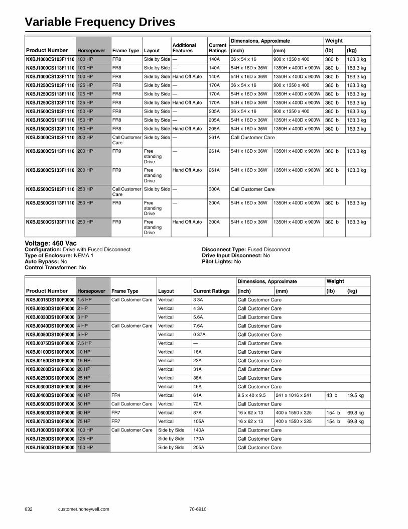
Variable Frequency Drives
632 customer.honeywell.com 70-6910
Voltage: 460 VacConfiguration: Drive with Fused DisconnectType of Enclosure: NEMA 1Auto Bypass: NoControl Transformer: No
Disconnect Type: Fused DisconnectDrive Input Disconnect: NoPilot Lights: No
NXBJ1000CS103F1110 100 HP FR8 Side by Side — 140A 36 x 54 x 16 900 x 1350 x 400 360 b 163.3 kg
NXBJ1000CS113F1110 100 HP FR8 Side by Side — 140A 54H x 16D x 36W 1350H x 400D x 900W 360 b 163.3 kg
NXBJ1000CS133F1110 100 HP FR8 Side by Side Hand Off Auto 140A 54H x 16D x 36W 1350H x 400D x 900W 360 b 163.3 kg
NXBJ1250CS103F1110 125 HP FR8 Side by Side — 170A 36 x 54 x 16 900 x 1350 x 400 360 b 163.3 kg
NXBJ1250CS113F1110 125 HP FR8 Side by Side — 170A 54H x 16D x 36W 1350H x 400D x 900W 360 b 163.3 kg
NXBJ1250CS133F1110 125 HP FR8 Side by Side Hand Off Auto 170A 54H x 16D x 36W 1350H x 400D x 900W 360 b 163.3 kg
NXBJ1500CS103F1110 150 HP FR8 Side by Side — 205A 36 x 54 x 16 900 x 1350 x 400 360 b 163.3 kg
NXBJ1500CS113F1110 150 HP FR8 Side by Side — 205A 54H x 16D x 36W 1350H x 400D x 900W 360 b 163.3 kg
NXBJ1500CS133F1110 150 HP FR8 Side by Side Hand Off Auto 205A 54H x 16D x 36W 1350H x 400D x 900W 360 b 163.3 kg
NXBJ2000CS103F1110 200 HP Call Customer Care
Side by Side — 261A Call Customer Care
NXBJ2000CS113F1110 200 HP FR9 Free standing Drive
— 261A 54H x 16D x 36W 1350H x 400D x 900W 360 b 163.3 kg
NXBJ2000CS133F1110 200 HP FR9 Free standing Drive
Hand Off Auto 261A 54H x 16D x 36W 1350H x 400D x 900W 360 b 163.3 kg
NXBJ2500CS103F1110 250 HP Call Customer Care
Side by Side — 300A Call Customer Care
NXBJ2500CS113F1110 250 HP FR9 Free standing Drive
— 300A 54H x 16D x 36W 1350H x 400D x 900W 360 b 163.3 kg
NXBJ2500CS133F1110 250 HP FR9 Free standing Drive
Hand Off Auto 300A 54H x 16D x 36W 1350H x 400D x 900W 360 b 163.3 kg
Product Number Horsepower Frame Type LayoutAdditional Features
Current Ratings
Dimensions, Approximate Weight
(inch) (mm) (lb) (kg)
Product Number Horsepower Frame Type Layout Current Ratings
Dimensions, Approximate Weight
(inch) (mm) (lb) (kg)
NXBJ0015DS100F0000 1.5 HP Call Customer Care Vertical 3 3A Call Customer Care
NXBJ0020DS100F0000 2 HP Vertical 4 3A Call Customer Care
NXBJ0030DS100F0000 3 HP Vertical 5.6A Call Customer Care
NXBJ0040DS100F0000 4 HP Call Customer Care Vertical 7.6A Call Customer Care
NXBJ0050DS100F0000 5 HP Vertical 0 37A Call Customer Care
NXBJ0075DS100F0000 7.5 HP Vertical — Call Customer Care
NXBJ0100DS100F0000 10 HP Vertical 16A Call Customer Care
NXBJ0150DS100F0000 15 HP Vertical 23A Call Customer Care
NXBJ0200DS100F0000 20 HP Vertical 31A Call Customer Care
NXBJ0250DS100F0000 25 HP Vertical 38A Call Customer Care
NXBJ0300DS100F0000 30 HP Vertical 46A Call Customer Care
NXBJ0400DS100F0000 40 HP FR4 Vertical 61A 9.5 x 40 x 9.5 241 x 1016 x 241 43 b 19.5 kg
NXBJ0500DS100F0000 50 HP Call Customer Care Vertical 72A Call Customer Care
NXBJ0600DS100F0000 60 HP FR7 Vertical 87A 16 x 62 x 13 400 x 1550 x 325 154 b 69.8 kg
NXBJ0750DS100F0000 75 HP FR7 Vertical 105A 16 x 62 x 13 400 x 1550 x 325 154 b 69.8 kg
NXBJ1000DS100F0000 100 HP Call Customer Care Side by Side 140A Call Customer Care
NXBJ1250DS100F0000 125 HP Side by Side 170A Call Customer Care
NXBJ1500DS100F0000 150 HP Side by Side 205A Call Customer Care
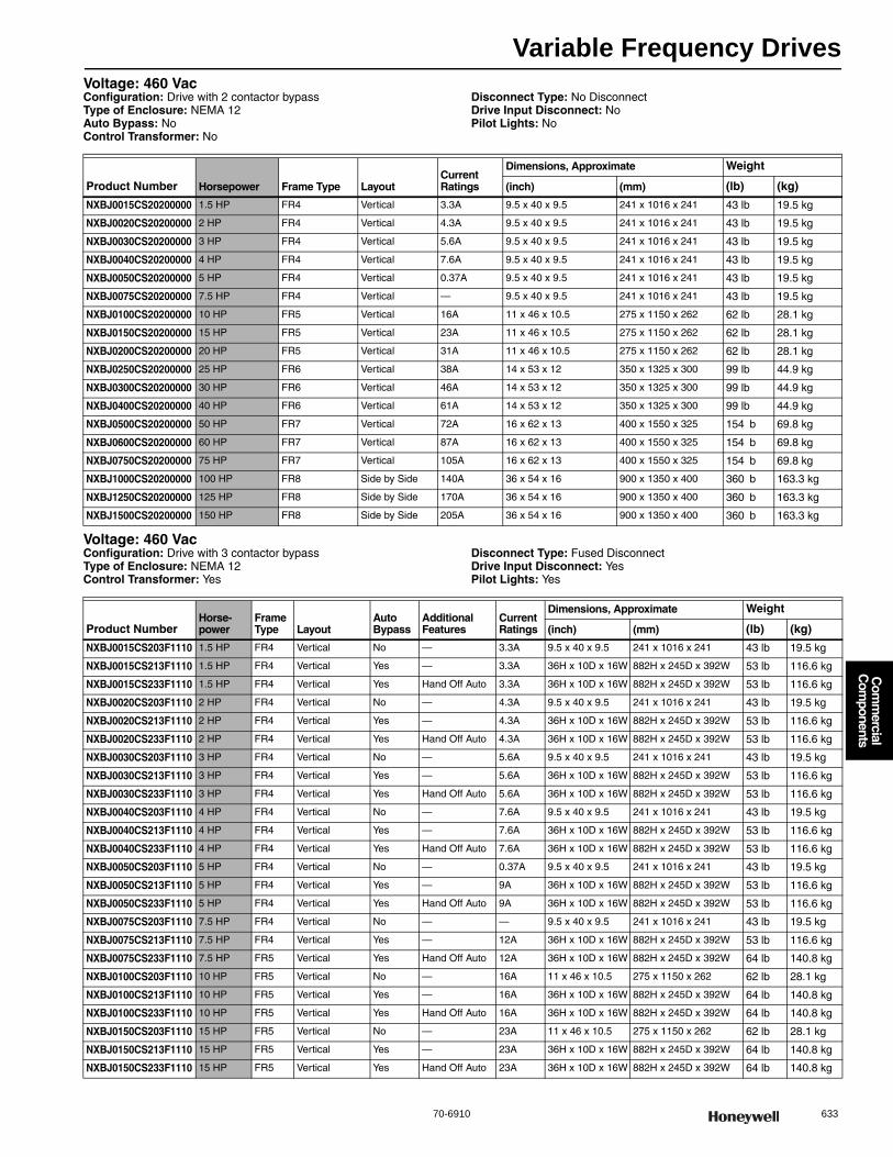
Variable Frequency Drives
70-6910 633
Com
mercial
Com
ponents
Voltage: 460 VacConfiguration: Drive with 2 contactor bypassType of Enclosure: NEMA 12Auto Bypass: NoControl Transformer: No
Disconnect Type: No DisconnectDrive Input Disconnect: NoPilot Lights: No
Voltage: 460 VacConfiguration: Drive with 3 contactor bypassType of Enclosure: NEMA 12Control Transformer: Yes
Disconnect Type: Fused DisconnectDrive Input Disconnect: YesPilot Lights: Yes
Product Number Horsepower Frame Type LayoutCurrent Ratings
Dimensions, Approximate Weight
(inch) (mm) (lb) (kg)
NXBJ0015CS20200000 1.5 HP FR4 Vertical 3.3A 9.5 x 40 x 9.5 241 x 1016 x 241 43 lb 19.5 kg
NXBJ0020CS20200000 2 HP FR4 Vertical 4.3A 9.5 x 40 x 9.5 241 x 1016 x 241 43 lb 19.5 kg
NXBJ0030CS20200000 3 HP FR4 Vertical 5.6A 9.5 x 40 x 9.5 241 x 1016 x 241 43 lb 19.5 kg
NXBJ0040CS20200000 4 HP FR4 Vertical 7.6A 9.5 x 40 x 9.5 241 x 1016 x 241 43 lb 19.5 kg
NXBJ0050CS20200000 5 HP FR4 Vertical 0.37A 9.5 x 40 x 9.5 241 x 1016 x 241 43 lb 19.5 kg
NXBJ0075CS20200000 7.5 HP FR4 Vertical — 9.5 x 40 x 9.5 241 x 1016 x 241 43 lb 19.5 kg
NXBJ0100CS20200000 10 HP FR5 Vertical 16A 11 x 46 x 10.5 275 x 1150 x 262 62 lb 28.1 kg
NXBJ0150CS20200000 15 HP FR5 Vertical 23A 11 x 46 x 10.5 275 x 1150 x 262 62 lb 28.1 kg
NXBJ0200CS20200000 20 HP FR5 Vertical 31A 11 x 46 x 10.5 275 x 1150 x 262 62 lb 28.1 kg
NXBJ0250CS20200000 25 HP FR6 Vertical 38A 14 x 53 x 12 350 x 1325 x 300 99 lb 44.9 kg
NXBJ0300CS20200000 30 HP FR6 Vertical 46A 14 x 53 x 12 350 x 1325 x 300 99 lb 44.9 kg
NXBJ0400CS20200000 40 HP FR6 Vertical 61A 14 x 53 x 12 350 x 1325 x 300 99 lb 44.9 kg
NXBJ0500CS20200000 50 HP FR7 Vertical 72A 16 x 62 x 13 400 x 1550 x 325 154 b 69.8 kg
NXBJ0600CS20200000 60 HP FR7 Vertical 87A 16 x 62 x 13 400 x 1550 x 325 154 b 69.8 kg
NXBJ0750CS20200000 75 HP FR7 Vertical 105A 16 x 62 x 13 400 x 1550 x 325 154 b 69.8 kg
NXBJ1000CS20200000 100 HP FR8 Side by Side 140A 36 x 54 x 16 900 x 1350 x 400 360 b 163.3 kg
NXBJ1250CS20200000 125 HP FR8 Side by Side 170A 36 x 54 x 16 900 x 1350 x 400 360 b 163.3 kg
NXBJ1500CS20200000 150 HP FR8 Side by Side 205A 36 x 54 x 16 900 x 1350 x 400 360 b 163.3 kg
Product NumberHorse-power
Frame Type Layout
Auto Bypass
Additional Features
Current Ratings
Dimensions, Approximate Weight
(inch) (mm) (lb) (kg)
NXBJ0015CS203F1110 1.5 HP FR4 Vertical No — 3.3A 9.5 x 40 x 9.5 241 x 1016 x 241 43 lb 19.5 kg
NXBJ0015CS213F1110 1.5 HP FR4 Vertical Yes — 3.3A 36H x 10D x 16W 882H x 245D x 392W 53 lb 116.6 kg
NXBJ0015CS233F1110 1.5 HP FR4 Vertical Yes Hand Off Auto 3.3A 36H x 10D x 16W 882H x 245D x 392W 53 lb 116.6 kg
NXBJ0020CS203F1110 2 HP FR4 Vertical No — 4.3A 9.5 x 40 x 9.5 241 x 1016 x 241 43 lb 19.5 kg
NXBJ0020CS213F1110 2 HP FR4 Vertical Yes — 4.3A 36H x 10D x 16W 882H x 245D x 392W 53 lb 116.6 kg
NXBJ0020CS233F1110 2 HP FR4 Vertical Yes Hand Off Auto 4.3A 36H x 10D x 16W 882H x 245D x 392W 53 lb 116.6 kg
NXBJ0030CS203F1110 3 HP FR4 Vertical No — 5.6A 9.5 x 40 x 9.5 241 x 1016 x 241 43 lb 19.5 kg
NXBJ0030CS213F1110 3 HP FR4 Vertical Yes — 5.6A 36H x 10D x 16W 882H x 245D x 392W 53 lb 116.6 kg
NXBJ0030CS233F1110 3 HP FR4 Vertical Yes Hand Off Auto 5.6A 36H x 10D x 16W 882H x 245D x 392W 53 lb 116.6 kg
NXBJ0040CS203F1110 4 HP FR4 Vertical No — 7.6A 9.5 x 40 x 9.5 241 x 1016 x 241 43 lb 19.5 kg
NXBJ0040CS213F1110 4 HP FR4 Vertical Yes — 7.6A 36H x 10D x 16W 882H x 245D x 392W 53 lb 116.6 kg
NXBJ0040CS233F1110 4 HP FR4 Vertical Yes Hand Off Auto 7.6A 36H x 10D x 16W 882H x 245D x 392W 53 lb 116.6 kg
NXBJ0050CS203F1110 5 HP FR4 Vertical No — 0.37A 9.5 x 40 x 9.5 241 x 1016 x 241 43 lb 19.5 kg
NXBJ0050CS213F1110 5 HP FR4 Vertical Yes — 9A 36H x 10D x 16W 882H x 245D x 392W 53 lb 116.6 kg
NXBJ0050CS233F1110 5 HP FR4 Vertical Yes Hand Off Auto 9A 36H x 10D x 16W 882H x 245D x 392W 53 lb 116.6 kg
NXBJ0075CS203F1110 7.5 HP FR4 Vertical No — — 9.5 x 40 x 9.5 241 x 1016 x 241 43 lb 19.5 kg
NXBJ0075CS213F1110 7.5 HP FR4 Vertical Yes — 12A 36H x 10D x 16W 882H x 245D x 392W 53 lb 116.6 kg
NXBJ0075CS233F1110 7.5 HP FR5 Vertical Yes Hand Off Auto 12A 36H x 10D x 16W 882H x 245D x 392W 64 lb 140.8 kg
NXBJ0100CS203F1110 10 HP FR5 Vertical No — 16A 11 x 46 x 10.5 275 x 1150 x 262 62 lb 28.1 kg
NXBJ0100CS213F1110 10 HP FR5 Vertical Yes — 16A 36H x 10D x 16W 882H x 245D x 392W 64 lb 140.8 kg
NXBJ0100CS233F1110 10 HP FR5 Vertical Yes Hand Off Auto 16A 36H x 10D x 16W 882H x 245D x 392W 64 lb 140.8 kg
NXBJ0150CS203F1110 15 HP FR5 Vertical No — 23A 11 x 46 x 10.5 275 x 1150 x 262 62 lb 28.1 kg
NXBJ0150CS213F1110 15 HP FR5 Vertical Yes — 23A 36H x 10D x 16W 882H x 245D x 392W 64 lb 140.8 kg
NXBJ0150CS233F1110 15 HP FR5 Vertical Yes Hand Off Auto 23A 36H x 10D x 16W 882H x 245D x 392W 64 lb 140.8 kg
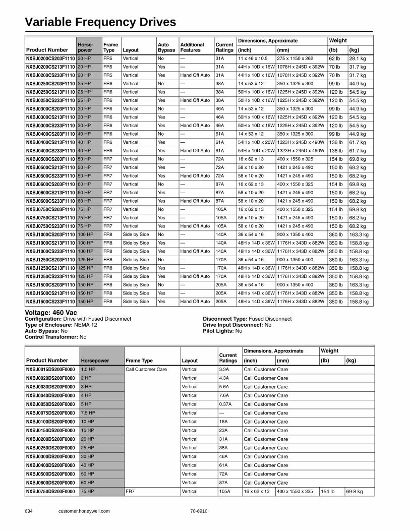
Variable Frequency Drives
634 customer.honeywell.com 70-6910
Voltage: 460 VacConfiguration: Drive with Fused DisconnectType of Enclosure: NEMA 12Auto Bypass: NoControl Transformer: No
Disconnect Type: Fused DisconnectDrive Input Disconnect: NoPilot Lights: No
NXBJ0200CS203F1110 20 HP FR5 Vertical No — 31A 11 x 46 x 10.5 275 x 1150 x 262 62 lb 28.1 kg
NXBJ0200CS213F1110 20 HP FR5 Vertical Yes — 31A 44H x 10D x 16W 1078H x 245D x 392W 70 lb 31.7 kg
NXBJ0200CS233F1110 20 HP FR5 Vertical Yes Hand Off Auto 31A 44H x 10D x 16W 1078H x 245D x 392W 70 lb 31.7 kg
NXBJ0250CS203F1110 25 HP FR6 Vertical No — 38A 14 x 53 x 12 350 x 1325 x 300 99 lb 44.9 kg
NXBJ0250CS213F1110 25 HP FR6 Vertical Yes — 38A 50H x 10D x 16W 1225H x 245D x 392W 120 lb 54.5 kg
NXBJ0250CS233F1110 25 HP FR6 Vertical Yes Hand Off Auto 38A 50H x 10D x 16W 1225H x 245D x 392W 120 lb 54.5 kg
NXBJ0300CS203F1110 30 HP FR6 Vertical No — 46A 14 x 53 x 12 350 x 1325 x 300 99 lb 44.9 kg
NXBJ0300CS213F1110 30 HP FR6 Vertical Yes — 46A 50H x 10D x 16W 1225H x 245D x 392W 120 lb 54.5 kg
NXBJ0300CS233F1110 30 HP FR6 Vertical Yes Hand Off Auto 46A 50H x 10D x 16W 1225H x 245D x 392W 120 lb 54.5 kg
NXBJ0400CS203F1110 40 HP FR6 Vertical No — 61A 14 x 53 x 12 350 x 1325 x 300 99 lb 44.9 kg
NXBJ0400CS213F1110 40 HP FR6 Vertical Yes — 61A 54H x 10D x 20W 1323H x 245D x 490W 136 lb 61.7 kg
NXBJ0400CS233F1110 40 HP FR6 Vertical Yes Hand Off Auto 61A 54H x 10D x 20W 1323H x 245D x 490W 136 lb 61.7 kg
NXBJ0500CS203F1110 50 HP FR7 Vertical No — 72A 16 x 62 x 13 400 x 1550 x 325 154 lb 69.8 kg
NXBJ0500CS213F1110 50 HP FR7 Vertical Yes — 72A 58 x 10 x 20 1421 x 245 x 490 150 lb 68.2 kg
NXBJ0500CS233F1110 50 HP FR7 Vertical Yes Hand Off Auto 72A 58 x 10 x 20 1421 x 245 x 490 150 lb 68.2 kg
NXBJ0600CS203F1110 60 HP FR7 Vertical No — 87A 16 x 62 x 13 400 x 1550 x 325 154 lb 69.8 kg
NXBJ0600CS213F1110 60 HP FR7 Vertical Yes — 87A 58 x 10 x 20 1421 x 245 x 490 150 lb 68.2 kg
NXBJ0600CS233F1110 60 HP FR7 Vertical Yes Hand Off Auto 87A 58 x 10 x 20 1421 x 245 x 490 150 lb 68.2 kg
NXBJ0750CS203F1110 75 HP FR7 Vertical No — 105A 16 x 62 x 13 400 x 1550 x 325 154 lb 69.8 kg
NXBJ0750CS213F1110 75 HP FR7 Vertical Yes — 105A 58 x 10 x 20 1421 x 245 x 490 150 lb 68.2 kg
NXBJ0750CS233F1110 75 HP FR7 Vertical Yes Hand Off Auto 105A 58 x 10 x 20 1421 x 245 x 490 150 lb 68.2 kg
NXBJ1000CS203F1110 100 HP FR8 Side by Side No — 140A 36 x 54 x 16 900 x 1350 x 400 360 lb 163.3 kg
NXBJ1000CS213F1110 100 HP FR8 Side by Side Yes — 140A 48H x 14D x 36W 1176H x 343D x 882W 350 lb 158.8 kg
NXBJ1000CS233F1110 100 HP FR8 Side by Side Yes Hand Off Auto 140A 48H x 14D x 36W 1176H x 343D x 882W 350 lb 158.8 kg
NXBJ1250CS203F1110 125 HP FR8 Side by Side No — 170A 36 x 54 x 16 900 x 1350 x 400 360 lb 163.3 kg
NXBJ1250CS213F1110 125 HP FR8 Side by Side Yes — 170A 48H x 14D x 36W 1176H x 343D x 882W 350 lb 158.8 kg
NXBJ1250CS233F1110 125 HP FR8 Side by Side Yes Hand Off Auto 170A 48H x 14D x 36W 1176H x 343D x 882W 350 lb 158.8 kg
NXBJ1500CS203F1110 150 HP FR8 Side by Side No — 205A 36 x 54 x 16 900 x 1350 x 400 360 lb 163.3 kg
NXBJ1500CS213F1110 150 HP FR8 Side by Side Yes — 205A 48H x 14D x 36W 1176H x 343D x 882W 350 lb 158.8 kg
NXBJ1500CS233F1110 150 HP FR8 Side by Side Yes Hand Off Auto 205A 48H x 14D x 36W 1176H x 343D x 882W 350 lb 158.8 kg
Product NumberHorse-power
Frame Type Layout
Auto Bypass
Additional Features
Current Ratings
Dimensions, Approximate Weight
(inch) (mm) (lb) (kg)
Product Number Horsepower Frame Type LayoutCurrent Ratings
Dimensions, Approximate Weight
(inch) (mm) (lb) (kg)
NXBJ0015DS200F0000 1.5 HP Call Customer Care Vertical 3.3A Call Customer Care
NXBJ0020DS200F0000 2 HP Vertical 4.3A Call Customer Care
NXBJ0030DS200F0000 3 HP Vertical 5.6A Call Customer Care
NXBJ0040DS200F0000 4 HP Vertical 7.6A Call Customer Care
NXBJ0050DS200F0000 5 HP Vertical 0.37A Call Customer Care
NXBJ0075DS200F0000 7.5 HP Vertical — Call Customer Care
NXBJ0100DS200F0000 10 HP Vertical 16A Call Customer Care
NXBJ0150DS200F0000 15 HP Vertical 23A Call Customer Care
NXBJ0200DS200F0000 20 HP Vertical 31A Call Customer Care
NXBJ0250DS200F0000 25 HP Vertical 38A Call Customer Care
NXBJ0300DS200F0000 30 HP Vertical 46A Call Customer Care
NXBJ0400DS200F0000 40 HP Vertical 61A Call Customer Care
NXBJ0500DS200F0000 50 HP Vertical 72A Call Customer Care
NXBJ0600DS200F0000 60 HP Vertical 87A Call Customer Care
NXBJ0750DS200F0000 75 HP FR7 Vertical 105A 16 x 62 x 13 400 x 1550 x 325 154 lb 69.8 kg

Variable Frequency Drives
70-6910 635
Com
mercial
Com
ponents
Voltage: 460 VacConfiguration: Drive aloneType of Enclosure: NEMA 3RAuto Bypass: NoControl Transformer: No
Disconnect Type: No DisconnectDrive Input Disconnect: NoPilot Lights: No
Voltage: 460 VacConfiguration: Drive with 2 contactor bypassType of Enclosure: NEMA 3RAuto Bypass: NoControl Transformer: No
Disconnect Type: No DisconnectDrive Input Disconnect: NoPilot Lights: No
Voltage: 460 VacConfiguration: Drive with 3 contactor bypassType of Enclosure: NEMA 3RControl Transformer: Yes
Disconnect Type: Fused DisconnectDrive Input Disconnect: YesPilot Lights: Yes
NXBJ1000DS200F0000 100 HP Call Customer Care Side by Side 140A Call Customer Care
NXBJ1250DS200F0000 125 HP Side by Side 170A Call Customer Care
NXBJ1500DS200F0000 150 HP Side by Side 205A Call Customer Care
Product Number Horsepower Frame Type LayoutCurrent Ratings
Dimensions, Approximate Weight
(inch) (mm) (lb) (kg)
Product Number Horsepower Frame Type LayoutCurrent Ratings
Dimensions, Approximate Weight
(inch) (mm) (lb) (kg)
NXBJ0015CS30000000 1.5 HP FR4 Vertical 3.3A 24H x 10D x 20W 588H x 245D x 490W 54 lb 118.8 kg
NXBJ0015CS60000000 1.5 HP FR4 Vertical 3.3A 24H x 10D x 20W 588H x 245D x 490W 54 lb 118.8 kg
NXBJ0020CS30000000 2 HP FR4 Vertical 4.3A 24H x 10D x 20W 588H x 245D x 490W 54 lb 118.8 kg
NXBJ0030CS30000000 3 HP FR4 Vertical 5.6A 24H x 10D x 20W 588H x 245D x 490W 54 lb 118.8 kg
NXBJ0040CS30000000 4 HP FR4 Vertical 7.6A 24H x 10D x 20W 588H x 245D x 490W 54 lb 118.8 kg
NXBJ0050CS30000000 5 HP FR4 Vertical 9A 24H x 10D x 20W 588H x 245D x 490W 54 lb 118.8 kg
NXBJ0075CS30000000 7.5 HP FR4 Vertical 12A 24H x 10D x 20W 588H x 245D x 490W 54 lb 118.8 kg
NXBJ0100CS30000000 10 HP FR5 Vertical 16A 30H x 10D x 24W 735H x 245D x 588W 78 lb 35.4 kg
NXBJ0150CS30000000 15 HP FR5 Vertical 23A 30H x 10D x 24W 735H x 245D x 588W 78 lb 35.4 kg
NXBJ0200CS30000000 20 HP FR5 Vertical 31A 30H x 10D x 24W 735H x 245D x 588W 78 lb 35.4 kg
NXBJ0250CS30000000 25 HP FR6 Vertical 38A 36H x 12D x 30W 882H x 294D x 735W 124 lb 56.2 kg
NXBJ0300CS30000000 30 HP FR6 Vertical 46A 36H x 12D x 30W 882H x 294D x 735W 124 lb 56.2 kg
NXBJ0400CS30000000 40 HP FR6 Vertical 61A 36H x 12D x 30W 882H x 294D x 735W 124 lb 56.2 kg
NXBJ0500CS30000000 50 HP FR7 Vertical 72A 48H x 12D x 36W 1176H x 294D x 882W 193 lb 87.5 kg
NXBJ0600CS30000000 60 HP FR7 Vertical 87A 48H x 12D x 36W 1176H x 294D x 882W 193 lb 87.5 kg
NXBJ0750CS30000000 75 HP FR7 Vertical 105A 48H x 12D x 36W 1176H x 294D x 882W 193 lb 87.5 kg
Product Number HorsepowerFrame Type Layout
Additional Features
Current Ratings
Dimensions, Approximate Weight
(inch) (mm) (lb) (kg)
NXBJ0050CS30200000 5 HP FR4 Vertical — 0.37A 20 x 24 x 10 500 x 600 x 250 54 lb 24.5 kg
NXBJ0150CS30200000 15 HP FR5 Vertical — 23A 24 x30 x 10 610 x 762 x 254 78 lb 35.4 kg
NXBJ0200CS60200000 20 HP FR5 Vertical with Cooling Fan and Heat Strip
31A 24 x30 x 10 610 x 762 x 254 78 lb 35.4 kg
NXBJ0300CS30200000 30 HP FR6 Vertical — 46A 36H x 12D x 30W 882H x 294D x 735W 124 lb 56.2 kg
NXBJ0600CS30200000 60 HP FR7 Vertical — 87A 48H x 12D x 36W 1176H x 294D x 882W 193 lb 87.5 kg
NXBJ0750CS602F0000 75 HP FR7 Vertical — 105A 48H x 12D x 36W 1176H x 294D x 882W 193 lb 87.5 kg
NXBJ1500CS30200000 150 HP FR8 Side by Side — 205A 60 x 14 x 36 1470 x 343 x 882 440 lb 199.6 kg
Product Number HorsepowerFrame Type Layout
Auto Bypass
Additional Features
Current Ratings
Dimensions, Approximate Weight
(inch) (mm) (lb) (kg)
NXBJ0015CS303F1110 1.5 HP FR4 Vertical No — 3.3A 24H x 10D x 20W 588H x 245D x 490W 54 lb 118.8 kg
NXBJ0015CS313F1110 1.5 HP FR4 Vertical Yes — 3.3A 24H x 10D x 20W 588H x 245D x 490W 54 lb 118.8 kg
NXBJ0015CS333F1110 1.5 HP FR4 Vertical Yes Hand Off Auto 3.3A 24H x 10D x 20W 588H x 245D x 490W 54 lb 118.8 kg
NXBJ0020CS303F1110 2 HP FR4 Vertical No — 4.3A 24H x 10D x 20W 588H x 245D x 490W 54 lb 118.8 kg

Variable Frequency Drives
636 customer.honeywell.com 70-6910
NXBJ0020CS313F1110 2 HP FR4 Vertical Yes — 4.3A 24H x 10D x 20W 588H x 245D x 490W 54 lb 118.8 kg
NXBJ0020CS333F1110 2 HP FR4 Vertical Yes Hand Off Auto 4.3A 24H x 10D x 20W 588H x 245D x 490W 54 lb 118.8 kg
NXBJ0030CS303F1110 3 HP FR4 Vertical No — 5.6A 24H x 10D x 20W 588H x 245D x 490W 54 lb 118.8 kg
NXBJ0030CS313F1110 3 HP FR4 Vertical Yes — 5.6A 24H x 10D x 20W 588H x 245D x 490W 54 lb 118.8 kg
NXBJ0030CS333F1110 3 HP FR4 Vertical Yes Hand Off Auto 5.6A 24H x 10D x 20W 588H x 245D x 490W 54 lb 118.8 kg
NXBJ0040CS303F1110 4 HP FR4 Vertical No — 7.6A 24H x 10D x 20W 588H x 245D x 490W 54 lb 118.8 kg
NXBJ0040CS313F1110 4 HP FR4 Vertical Yes — 7.6A 24H x 10D x 20W 588H x 245D x 490W 54 lb 118.8 kg
NXBJ0040CS333F1110 4 HP FR4 Vertical Yes Hand Off Auto 7.6A 24H x 10D x 20W 588H x 245D x 490W 54 lb 118.8 kg
NXBJ0050CS303F1110 5 HP FR4 Vertical No — 9A 24H x 10D x 20W 588H x 245D x 490W 54 lb 118.8 kg
NXBJ0050CS313F1110 5 HP FR4 Vertical Yes — 9A 24H x 10D x 20W 588H x 245D x 490W 54 lb 118.8 kg
NXBJ0050CS333F1110 5 HP FR4 Vertical Yes Hand Off Auto 9A 24H x 10D x 20W 588H x 245D x 490W 54 lb 118.8 kg
NXBJ0075CS303F1110 7.5 HP FR4 Vertical No — 12A 24H x 10D x 20W 588H x 245D x 490W 54 lb 118.8 kg
NXBJ0075CS313F1110 7.5 HP FR4 Vertical Yes — 12A 24H x 10D x 20W 588H x 245D x 490W 54 lb 118.8 kg
NXBJ0075CS333F1110 7.5 HP FR4 Vertical Yes Hand Off Auto 12A 24H x 10D x 20W 588H x 245D x 490W 54 lb 118.8 kg
NXBJ0100CS303F1110 10 HP FR5 Vertical No — 16A 30H x 10D x 24W 735H x 245D x 588W 78 lb 35.4 kg
NXBJ0100CS313F1110 10 HP FR5 Vertical Yes — 16A 30H x 10D x 24W 735H x 245D x 588W 78 lb 35.4 kg
NXBJ0100CS333F1110 10 HP FR5 Vertical Yes Hand Off Auto 16A 30H x 10D x 24W 735H x 245D x 588W 78 lb 35.4 kg
NXBJ0100CS603F1110 10 HP FR5 Vertical No — 16A 30H x 10D x 24W 735H x 245D x 588W 78 lb 35.4 kg
NXBJ0150CS313F1110 15 HP FR5 Vertical Yes — 23A 30H x 10D x 24W 735H x 245D x 588W 78 lb 35.4 kg
NXBJ0150CS333F1110 15 HP FR5 Vertical Yes Hand Off Auto 23A 30H x 10D x 24W 735H x 245D x 588W 78 lb 35.4 kg
NXBJ0150CS603F1110 15 HP FR5 Vertical No — 23A 30H x 10D x 24W 735H x 245D x 588W 78 lb 35.4 kg
NXBJ0200CS303F1110 20 HP FR5 Vertical No — 31A 30H x 10D x 24W 735H x 245D x 588W 78 lb 35.4 kg
NXBJ0200CS313F1110 20 HP FR5 Vertical Yes — 31A 30H x 10D x 24W 735H x 245D x 588W 78 lb 35.4 kg
NXBJ0200CS333F1110 20 HP FR5 Vertical Yes Hand Off Auto 31A 30H x 10D x 24W 735H x 245D x 588W 78 lb 35.4 kg
NXBJ0250CS303F1110 25 HP FR6 Vertical No — 38A 36H x 12D x 30W 882H x 294D x 735W 124 lb 56 2 kg
NXBJ0250CS313F1110 25 HP FR6 Vertical Yes — 38A 36H x 12D x 30W 882H x 294D x 735W 124 lb 56 2 kg
NXBJ0250CS333F1110 25 HP FR6 Vertical Yes Hand Off Auto 38A 36H x 12D x 30W 882H x 294D x 735W 124 lb 56 2 kg
NXBJ0300CS303F1110 30 HP FR6 Vertical No — 46A 36H x 12D x 30W 882H x 294D x 735W 124 lb 56 2 kg
NXBJ0300CS313F1110 30 HP FR6 Vertical Yes — 46A 36H x 12D x 30W 882H x 294D x 735W 124 lb 56 2 kg
NXBJ0300CS333F1110 30 HP FR6 Vertical Yes Hand Off Auto 46A 36H x 12D x 30W 882H x 294D x 735W 124 lb 56 2 kg
NXBJ0400CS303F1110 40 HP FR6 Vertical No — 61A 36H x 12D x 30W 882H x 294D x 735W 124 lb 56 2 kg
NXBJ0400CS313F1110 40 HP FR6 Vertical Yes — 61A 36H x 12D x 30W 882H x 294D x 735W 124 lb 56 2 kg
NXBJ0400CS333F1110 40 HP FR6 Vertical Yes Hand Off Auto 61A 36H x 12D x 30W 882H x 294D x 735W 124 lb 56 2 kg
NXBJ0400CS623F1100 40 HP FR6 Vertical No — 61A 36H x 12D x 30W 882H x 294D x 735W 124 lb 56 2 kg
NXBJ0500CS303F1110 50 HP FR7 Vertical No — 72A 48H x 12D x 36W 1176H x 294D x 882W 193 lb 87 5 kg
NXBJ0500CS313F1110 50 HP FR7 Vertical Yes — 72A 48H x 12D x 36W 1176H x 294D x 882W 193 lb 87 5 kg
NXBJ0500CS333F1110 50 HP FR7 Vertical Yes Hand Off Auto 72A 48H x 12D x 36W 1176H x 294D x 882W 193 lb 87.5 kg
NXBJ0600CS303F1110 60 HP FR7 Vertical No — 87A 48H x 12D x 36W 1176H x 294D x 882W 193 lb 87 5 kg
NXBJ0600CS313F1110 60 HP FR7 Vertical Yes — 87A 48H x 12D x 36W 1176H x 294D x 882W 193 lb 87 5 kg
NXBJ0600CS333F1110 60 HP FR7 Vertical Yes Hand Off Auto 87A 48H x 12D x 36W 1176H x 294D x 882W 193 lb 87.5 kg
NXBJ0750CS303F1110 75 HP FR7 Vertical No — 105A 48H x 12D x 36W 1176H x 294D x 882W 193 lb 87 5 kg
NXBJ0750CS313F1110 75 HP FR7 Vertical Yes — 105A 48H x 12D x 36W 1176H x 294D x 882W 193 lb 87.5 kg
NXBJ0750CS333F1110 75 HP FR7 Vertical Yes Hand Off Auto 105A 48H x 12D x 36W 1176H x 294D x 882W 193 lb 87.5 kg
NXBJ1000CS303F1110 100 HP FR8 Side by Side No — 140A 60 x 14 x 36 1470 x 343 x 882 440 lb 199.6 kg
NXBJ1000CS313F1110 100 HP FR8 Side by Side Yes — 140A 60 x 14 x 36 1470 x 343 x 882 440 lb 199.6 kg
NXBJ1000CS333F1110 100 HP FR8 Side by Side Yes Hand Off Auto 140A 60 x 14 x 36 1470 x 343 x 882 440 lb 199.6 kg
NXBJ1250CS303F1110 125 HP FR8 Side by Side No — 140A 60 x 14 x 36 1470 x 343 x 882 440 lb 199.6 kg
NXBJ1250CS313F1110 125 HP FR8 Side by Side Yes — 140A 60 x 14 x 36 1470 x 343 x 882 440 lb 199.6 kg
NXBJ1250CS333F1110 125 HP FR8 Side by Side Yes Hand Off Auto 140A 60 x 14 x 36 1470 x 343 x 882 440 lb 199.6 kg
NXBJ1500CS303F1110 150 HP FR8 Side by Side No — 205A 60 x 14 x 36 1470 x 343 x 882 440 lb 199.6 kg
NXBJ1500CS313F1110 150 HP FR8 Side by Side Yes — 205A 60 x 14 x 36 1470 x 343 x 882 440 lb 199.6 kg
NXBJ1500CS333F1110 150 HP FR8 Side by Side Yes Hand Off Auto 205A 60 x 14 x 36 1470 x 343 x 882 440 lb 199.6 kg
Product Number HorsepowerFrame Type Layout
Auto Bypass
Additional Features
Current Ratings
Dimensions, Approximate Weight
(inch) (mm) (lb) (kg)
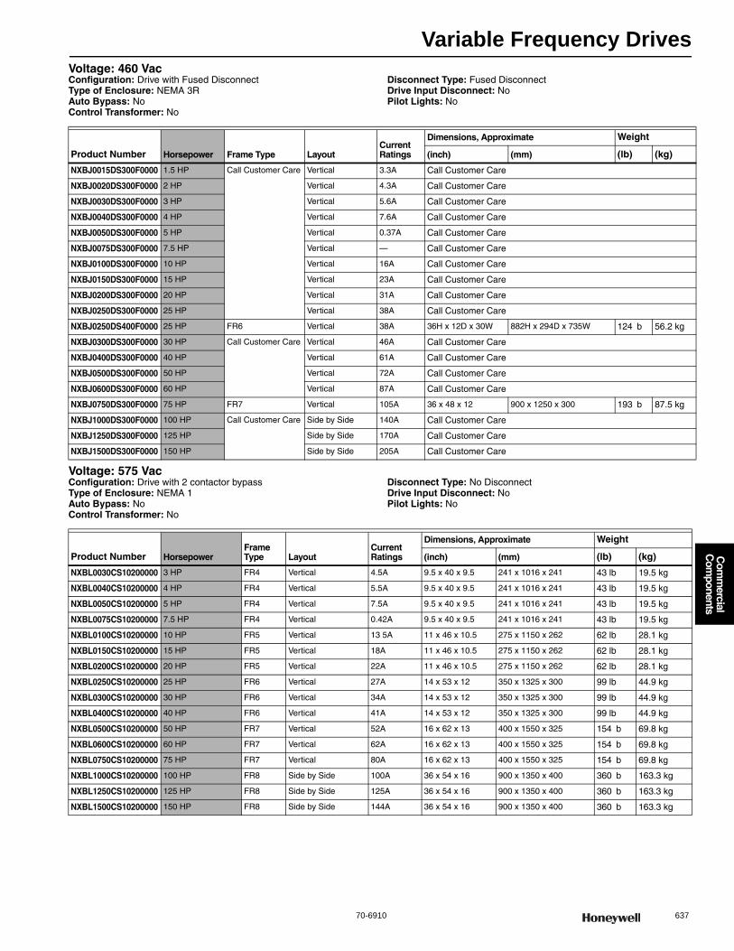
Variable Frequency Drives
70-6910 637
Com
mercial
Com
ponents
Voltage: 460 VacConfiguration: Drive with Fused DisconnectType of Enclosure: NEMA 3RAuto Bypass: NoControl Transformer: No
Disconnect Type: Fused DisconnectDrive Input Disconnect: NoPilot Lights: No
Voltage: 575 VacConfiguration: Drive with 2 contactor bypassType of Enclosure: NEMA 1Auto Bypass: NoControl Transformer: No
Disconnect Type: No DisconnectDrive Input Disconnect: NoPilot Lights: No
Product Number Horsepower Frame Type LayoutCurrent Ratings
Dimensions, Approximate Weight
(inch) (mm) (lb) (kg)
NXBJ0015DS300F0000 1.5 HP Call Customer Care Vertical 3.3A Call Customer Care
NXBJ0020DS300F0000 2 HP Vertical 4.3A Call Customer Care
NXBJ0030DS300F0000 3 HP Vertical 5.6A Call Customer Care
NXBJ0040DS300F0000 4 HP Vertical 7.6A Call Customer Care
NXBJ0050DS300F0000 5 HP Vertical 0.37A Call Customer Care
NXBJ0075DS300F0000 7.5 HP Vertical — Call Customer Care
NXBJ0100DS300F0000 10 HP Vertical 16A Call Customer Care
NXBJ0150DS300F0000 15 HP Vertical 23A Call Customer Care
NXBJ0200DS300F0000 20 HP Vertical 31A Call Customer Care
NXBJ0250DS300F0000 25 HP Vertical 38A Call Customer Care
NXBJ0250DS400F0000 25 HP FR6 Vertical 38A 36H x 12D x 30W 882H x 294D x 735W 124 b 56.2 kg
NXBJ0300DS300F0000 30 HP Call Customer Care Vertical 46A Call Customer Care
NXBJ0400DS300F0000 40 HP Vertical 61A Call Customer Care
NXBJ0500DS300F0000 50 HP Vertical 72A Call Customer Care
NXBJ0600DS300F0000 60 HP Vertical 87A Call Customer Care
NXBJ0750DS300F0000 75 HP FR7 Vertical 105A 36 x 48 x 12 900 x 1250 x 300 193 b 87.5 kg
NXBJ1000DS300F0000 100 HP Call Customer Care Side by Side 140A Call Customer Care
NXBJ1250DS300F0000 125 HP Side by Side 170A Call Customer Care
NXBJ1500DS300F0000 150 HP Side by Side 205A Call Customer Care
Product Number HorsepowerFrame Type Layout
Current Ratings
Dimensions, Approximate Weight
(inch) (mm) (lb) (kg)
NXBL0030CS10200000 3 HP FR4 Vertical 4.5A 9.5 x 40 x 9.5 241 x 1016 x 241 43 lb 19.5 kg
NXBL0040CS10200000 4 HP FR4 Vertical 5.5A 9.5 x 40 x 9.5 241 x 1016 x 241 43 lb 19.5 kg
NXBL0050CS10200000 5 HP FR4 Vertical 7.5A 9.5 x 40 x 9.5 241 x 1016 x 241 43 lb 19.5 kg
NXBL0075CS10200000 7.5 HP FR4 Vertical 0.42A 9.5 x 40 x 9.5 241 x 1016 x 241 43 lb 19.5 kg
NXBL0100CS10200000 10 HP FR5 Vertical 13 5A 11 x 46 x 10.5 275 x 1150 x 262 62 lb 28.1 kg
NXBL0150CS10200000 15 HP FR5 Vertical 18A 11 x 46 x 10.5 275 x 1150 x 262 62 lb 28.1 kg
NXBL0200CS10200000 20 HP FR5 Vertical 22A 11 x 46 x 10.5 275 x 1150 x 262 62 lb 28.1 kg
NXBL0250CS10200000 25 HP FR6 Vertical 27A 14 x 53 x 12 350 x 1325 x 300 99 lb 44.9 kg
NXBL0300CS10200000 30 HP FR6 Vertical 34A 14 x 53 x 12 350 x 1325 x 300 99 lb 44.9 kg
NXBL0400CS10200000 40 HP FR6 Vertical 41A 14 x 53 x 12 350 x 1325 x 300 99 lb 44.9 kg
NXBL0500CS10200000 50 HP FR7 Vertical 52A 16 x 62 x 13 400 x 1550 x 325 154 b 69.8 kg
NXBL0600CS10200000 60 HP FR7 Vertical 62A 16 x 62 x 13 400 x 1550 x 325 154 b 69.8 kg
NXBL0750CS10200000 75 HP FR7 Vertical 80A 16 x 62 x 13 400 x 1550 x 325 154 b 69.8 kg
NXBL1000CS10200000 100 HP FR8 Side by Side 100A 36 x 54 x 16 900 x 1350 x 400 360 b 163.3 kg
NXBL1250CS10200000 125 HP FR8 Side by Side 125A 36 x 54 x 16 900 x 1350 x 400 360 b 163.3 kg
NXBL1500CS10200000 150 HP FR8 Side by Side 144A 36 x 54 x 16 900 x 1350 x 400 360 b 163.3 kg
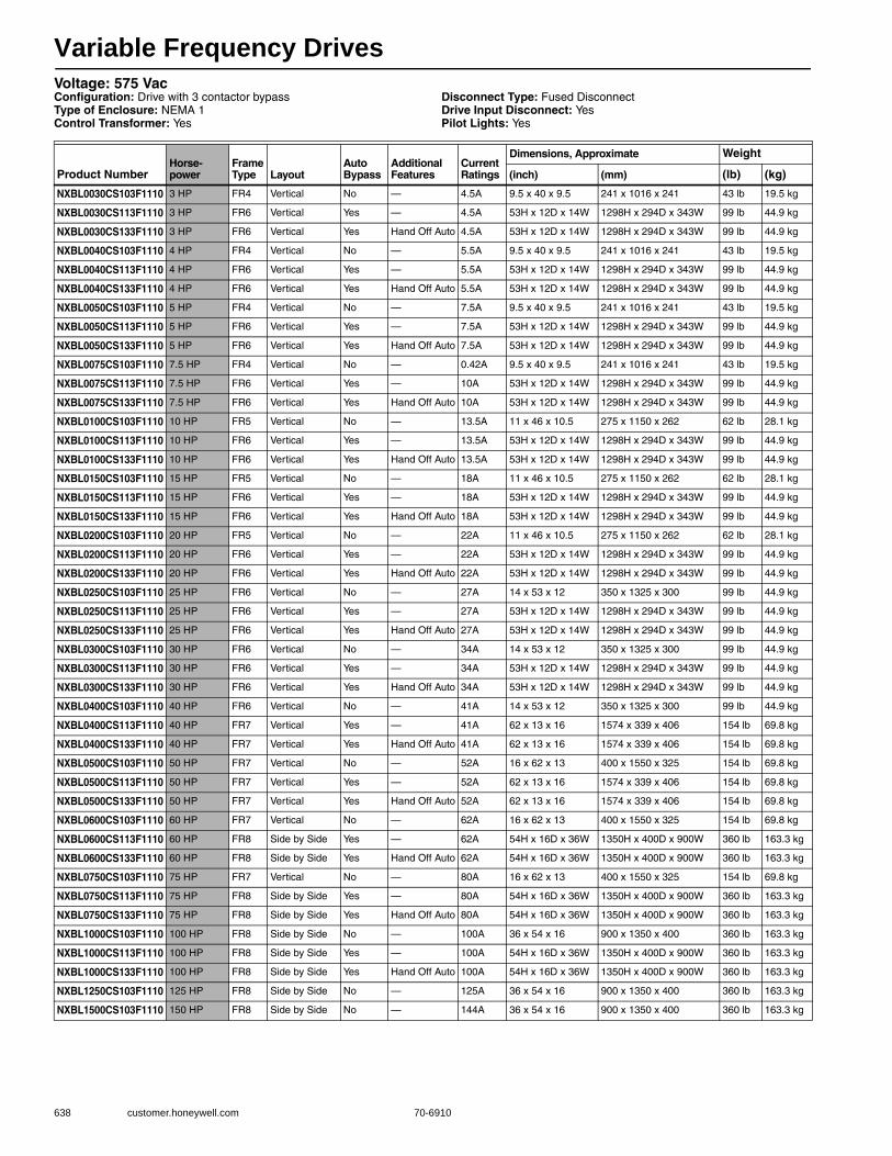
Variable Frequency Drives
638 customer.honeywell.com 70-6910
Voltage: 575 VacConfiguration: Drive with 3 contactor bypassType of Enclosure: NEMA 1Control Transformer: Yes
Disconnect Type: Fused DisconnectDrive Input Disconnect: YesPilot Lights: Yes
Product NumberHorse-power
Frame Type Layout
Auto Bypass
Additional Features
Current Ratings
Dimensions, Approximate Weight
(inch) (mm) (lb) (kg)
NXBL0030CS103F1110 3 HP FR4 Vertical No — 4.5A 9.5 x 40 x 9.5 241 x 1016 x 241 43 lb 19.5 kg
NXBL0030CS113F1110 3 HP FR6 Vertical Yes — 4.5A 53H x 12D x 14W 1298H x 294D x 343W 99 lb 44.9 kg
NXBL0030CS133F1110 3 HP FR6 Vertical Yes Hand Off Auto 4.5A 53H x 12D x 14W 1298H x 294D x 343W 99 lb 44.9 kg
NXBL0040CS103F1110 4 HP FR4 Vertical No — 5.5A 9.5 x 40 x 9.5 241 x 1016 x 241 43 lb 19.5 kg
NXBL0040CS113F1110 4 HP FR6 Vertical Yes — 5.5A 53H x 12D x 14W 1298H x 294D x 343W 99 lb 44.9 kg
NXBL0040CS133F1110 4 HP FR6 Vertical Yes Hand Off Auto 5.5A 53H x 12D x 14W 1298H x 294D x 343W 99 lb 44.9 kg
NXBL0050CS103F1110 5 HP FR4 Vertical No — 7.5A 9.5 x 40 x 9.5 241 x 1016 x 241 43 lb 19.5 kg
NXBL0050CS113F1110 5 HP FR6 Vertical Yes — 7.5A 53H x 12D x 14W 1298H x 294D x 343W 99 lb 44.9 kg
NXBL0050CS133F1110 5 HP FR6 Vertical Yes Hand Off Auto 7.5A 53H x 12D x 14W 1298H x 294D x 343W 99 lb 44.9 kg
NXBL0075CS103F1110 7.5 HP FR4 Vertical No — 0.42A 9.5 x 40 x 9.5 241 x 1016 x 241 43 lb 19.5 kg
NXBL0075CS113F1110 7.5 HP FR6 Vertical Yes — 10A 53H x 12D x 14W 1298H x 294D x 343W 99 lb 44.9 kg
NXBL0075CS133F1110 7.5 HP FR6 Vertical Yes Hand Off Auto 10A 53H x 12D x 14W 1298H x 294D x 343W 99 lb 44.9 kg
NXBL0100CS103F1110 10 HP FR5 Vertical No — 13.5A 11 x 46 x 10.5 275 x 1150 x 262 62 lb 28.1 kg
NXBL0100CS113F1110 10 HP FR6 Vertical Yes — 13.5A 53H x 12D x 14W 1298H x 294D x 343W 99 lb 44.9 kg
NXBL0100CS133F1110 10 HP FR6 Vertical Yes Hand Off Auto 13.5A 53H x 12D x 14W 1298H x 294D x 343W 99 lb 44.9 kg
NXBL0150CS103F1110 15 HP FR5 Vertical No — 18A 11 x 46 x 10.5 275 x 1150 x 262 62 lb 28.1 kg
NXBL0150CS113F1110 15 HP FR6 Vertical Yes — 18A 53H x 12D x 14W 1298H x 294D x 343W 99 lb 44.9 kg
NXBL0150CS133F1110 15 HP FR6 Vertical Yes Hand Off Auto 18A 53H x 12D x 14W 1298H x 294D x 343W 99 lb 44.9 kg
NXBL0200CS103F1110 20 HP FR5 Vertical No — 22A 11 x 46 x 10.5 275 x 1150 x 262 62 lb 28.1 kg
NXBL0200CS113F1110 20 HP FR6 Vertical Yes — 22A 53H x 12D x 14W 1298H x 294D x 343W 99 lb 44.9 kg
NXBL0200CS133F1110 20 HP FR6 Vertical Yes Hand Off Auto 22A 53H x 12D x 14W 1298H x 294D x 343W 99 lb 44.9 kg
NXBL0250CS103F1110 25 HP FR6 Vertical No — 27A 14 x 53 x 12 350 x 1325 x 300 99 lb 44.9 kg
NXBL0250CS113F1110 25 HP FR6 Vertical Yes — 27A 53H x 12D x 14W 1298H x 294D x 343W 99 lb 44.9 kg
NXBL0250CS133F1110 25 HP FR6 Vertical Yes Hand Off Auto 27A 53H x 12D x 14W 1298H x 294D x 343W 99 lb 44.9 kg
NXBL0300CS103F1110 30 HP FR6 Vertical No — 34A 14 x 53 x 12 350 x 1325 x 300 99 lb 44.9 kg
NXBL0300CS113F1110 30 HP FR6 Vertical Yes — 34A 53H x 12D x 14W 1298H x 294D x 343W 99 lb 44.9 kg
NXBL0300CS133F1110 30 HP FR6 Vertical Yes Hand Off Auto 34A 53H x 12D x 14W 1298H x 294D x 343W 99 lb 44.9 kg
NXBL0400CS103F1110 40 HP FR6 Vertical No — 41A 14 x 53 x 12 350 x 1325 x 300 99 lb 44.9 kg
NXBL0400CS113F1110 40 HP FR7 Vertical Yes — 41A 62 x 13 x 16 1574 x 339 x 406 154 lb 69.8 kg
NXBL0400CS133F1110 40 HP FR7 Vertical Yes Hand Off Auto 41A 62 x 13 x 16 1574 x 339 x 406 154 lb 69.8 kg
NXBL0500CS103F1110 50 HP FR7 Vertical No — 52A 16 x 62 x 13 400 x 1550 x 325 154 lb 69.8 kg
NXBL0500CS113F1110 50 HP FR7 Vertical Yes — 52A 62 x 13 x 16 1574 x 339 x 406 154 lb 69.8 kg
NXBL0500CS133F1110 50 HP FR7 Vertical Yes Hand Off Auto 52A 62 x 13 x 16 1574 x 339 x 406 154 lb 69.8 kg
NXBL0600CS103F1110 60 HP FR7 Vertical No — 62A 16 x 62 x 13 400 x 1550 x 325 154 lb 69.8 kg
NXBL0600CS113F1110 60 HP FR8 Side by Side Yes — 62A 54H x 16D x 36W 1350H x 400D x 900W 360 lb 163.3 kg
NXBL0600CS133F1110 60 HP FR8 Side by Side Yes Hand Off Auto 62A 54H x 16D x 36W 1350H x 400D x 900W 360 lb 163.3 kg
NXBL0750CS103F1110 75 HP FR7 Vertical No — 80A 16 x 62 x 13 400 x 1550 x 325 154 lb 69.8 kg
NXBL0750CS113F1110 75 HP FR8 Side by Side Yes — 80A 54H x 16D x 36W 1350H x 400D x 900W 360 lb 163.3 kg
NXBL0750CS133F1110 75 HP FR8 Side by Side Yes Hand Off Auto 80A 54H x 16D x 36W 1350H x 400D x 900W 360 lb 163.3 kg
NXBL1000CS103F1110 100 HP FR8 Side by Side No — 100A 36 x 54 x 16 900 x 1350 x 400 360 lb 163.3 kg
NXBL1000CS113F1110 100 HP FR8 Side by Side Yes — 100A 54H x 16D x 36W 1350H x 400D x 900W 360 lb 163.3 kg
NXBL1000CS133F1110 100 HP FR8 Side by Side Yes Hand Off Auto 100A 54H x 16D x 36W 1350H x 400D x 900W 360 lb 163.3 kg
NXBL1250CS103F1110 125 HP FR8 Side by Side No — 125A 36 x 54 x 16 900 x 1350 x 400 360 lb 163.3 kg
NXBL1500CS103F1110 150 HP FR8 Side by Side No — 144A 36 x 54 x 16 900 x 1350 x 400 360 lb 163.3 kg
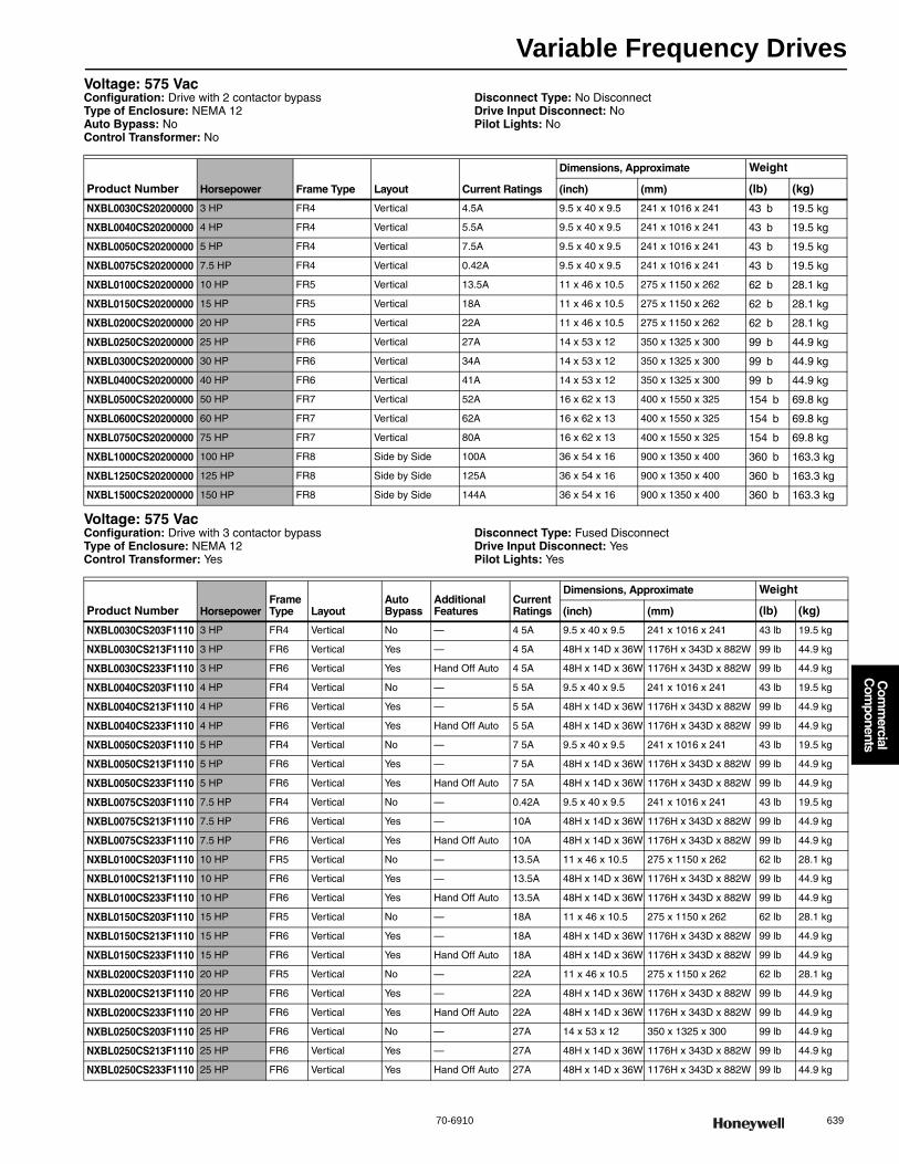
Variable Frequency Drives
70-6910 639
Com
mercial
Com
ponents
Voltage: 575 VacConfiguration: Drive with 2 contactor bypassType of Enclosure: NEMA 12Auto Bypass: NoControl Transformer: No
Disconnect Type: No DisconnectDrive Input Disconnect: NoPilot Lights: No
Voltage: 575 VacConfiguration: Drive with 3 contactor bypassType of Enclosure: NEMA 12Control Transformer: Yes
Disconnect Type: Fused DisconnectDrive Input Disconnect: YesPilot Lights: Yes
Product Number Horsepower Frame Type Layout Current Ratings
Dimensions, Approximate Weight
(inch) (mm) (lb) (kg)
NXBL0030CS20200000 3 HP FR4 Vertical 4.5A 9.5 x 40 x 9.5 241 x 1016 x 241 43 b 19.5 kg
NXBL0040CS20200000 4 HP FR4 Vertical 5.5A 9.5 x 40 x 9.5 241 x 1016 x 241 43 b 19.5 kg
NXBL0050CS20200000 5 HP FR4 Vertical 7.5A 9.5 x 40 x 9.5 241 x 1016 x 241 43 b 19.5 kg
NXBL0075CS20200000 7.5 HP FR4 Vertical 0.42A 9.5 x 40 x 9.5 241 x 1016 x 241 43 b 19.5 kg
NXBL0100CS20200000 10 HP FR5 Vertical 13.5A 11 x 46 x 10.5 275 x 1150 x 262 62 b 28.1 kg
NXBL0150CS20200000 15 HP FR5 Vertical 18A 11 x 46 x 10.5 275 x 1150 x 262 62 b 28.1 kg
NXBL0200CS20200000 20 HP FR5 Vertical 22A 11 x 46 x 10.5 275 x 1150 x 262 62 b 28.1 kg
NXBL0250CS20200000 25 HP FR6 Vertical 27A 14 x 53 x 12 350 x 1325 x 300 99 b 44.9 kg
NXBL0300CS20200000 30 HP FR6 Vertical 34A 14 x 53 x 12 350 x 1325 x 300 99 b 44.9 kg
NXBL0400CS20200000 40 HP FR6 Vertical 41A 14 x 53 x 12 350 x 1325 x 300 99 b 44.9 kg
NXBL0500CS20200000 50 HP FR7 Vertical 52A 16 x 62 x 13 400 x 1550 x 325 154 b 69.8 kg
NXBL0600CS20200000 60 HP FR7 Vertical 62A 16 x 62 x 13 400 x 1550 x 325 154 b 69.8 kg
NXBL0750CS20200000 75 HP FR7 Vertical 80A 16 x 62 x 13 400 x 1550 x 325 154 b 69.8 kg
NXBL1000CS20200000 100 HP FR8 Side by Side 100A 36 x 54 x 16 900 x 1350 x 400 360 b 163.3 kg
NXBL1250CS20200000 125 HP FR8 Side by Side 125A 36 x 54 x 16 900 x 1350 x 400 360 b 163.3 kg
NXBL1500CS20200000 150 HP FR8 Side by Side 144A 36 x 54 x 16 900 x 1350 x 400 360 b 163.3 kg
Product Number HorsepowerFrame Type Layout
Auto Bypass
Additional Features
Current Ratings
Dimensions, Approximate Weight
(inch) (mm) (lb) (kg)
NXBL0030CS203F1110 3 HP FR4 Vertical No — 4 5A 9.5 x 40 x 9.5 241 x 1016 x 241 43 lb 19.5 kg
NXBL0030CS213F1110 3 HP FR6 Vertical Yes — 4 5A 48H x 14D x 36W 1176H x 343D x 882W 99 lb 44.9 kg
NXBL0030CS233F1110 3 HP FR6 Vertical Yes Hand Off Auto 4 5A 48H x 14D x 36W 1176H x 343D x 882W 99 lb 44.9 kg
NXBL0040CS203F1110 4 HP FR4 Vertical No — 5 5A 9.5 x 40 x 9.5 241 x 1016 x 241 43 lb 19.5 kg
NXBL0040CS213F1110 4 HP FR6 Vertical Yes — 5 5A 48H x 14D x 36W 1176H x 343D x 882W 99 lb 44.9 kg
NXBL0040CS233F1110 4 HP FR6 Vertical Yes Hand Off Auto 5 5A 48H x 14D x 36W 1176H x 343D x 882W 99 lb 44.9 kg
NXBL0050CS203F1110 5 HP FR4 Vertical No — 7 5A 9.5 x 40 x 9.5 241 x 1016 x 241 43 lb 19.5 kg
NXBL0050CS213F1110 5 HP FR6 Vertical Yes — 7 5A 48H x 14D x 36W 1176H x 343D x 882W 99 lb 44.9 kg
NXBL0050CS233F1110 5 HP FR6 Vertical Yes Hand Off Auto 7 5A 48H x 14D x 36W 1176H x 343D x 882W 99 lb 44.9 kg
NXBL0075CS203F1110 7.5 HP FR4 Vertical No — 0.42A 9.5 x 40 x 9.5 241 x 1016 x 241 43 lb 19.5 kg
NXBL0075CS213F1110 7.5 HP FR6 Vertical Yes — 10A 48H x 14D x 36W 1176H x 343D x 882W 99 lb 44.9 kg
NXBL0075CS233F1110 7.5 HP FR6 Vertical Yes Hand Off Auto 10A 48H x 14D x 36W 1176H x 343D x 882W 99 lb 44.9 kg
NXBL0100CS203F1110 10 HP FR5 Vertical No — 13.5A 11 x 46 x 10.5 275 x 1150 x 262 62 lb 28.1 kg
NXBL0100CS213F1110 10 HP FR6 Vertical Yes — 13.5A 48H x 14D x 36W 1176H x 343D x 882W 99 lb 44.9 kg
NXBL0100CS233F1110 10 HP FR6 Vertical Yes Hand Off Auto 13.5A 48H x 14D x 36W 1176H x 343D x 882W 99 lb 44.9 kg
NXBL0150CS203F1110 15 HP FR5 Vertical No — 18A 11 x 46 x 10.5 275 x 1150 x 262 62 lb 28.1 kg
NXBL0150CS213F1110 15 HP FR6 Vertical Yes — 18A 48H x 14D x 36W 1176H x 343D x 882W 99 lb 44.9 kg
NXBL0150CS233F1110 15 HP FR6 Vertical Yes Hand Off Auto 18A 48H x 14D x 36W 1176H x 343D x 882W 99 lb 44.9 kg
NXBL0200CS203F1110 20 HP FR5 Vertical No — 22A 11 x 46 x 10.5 275 x 1150 x 262 62 lb 28.1 kg
NXBL0200CS213F1110 20 HP FR6 Vertical Yes — 22A 48H x 14D x 36W 1176H x 343D x 882W 99 lb 44.9 kg
NXBL0200CS233F1110 20 HP FR6 Vertical Yes Hand Off Auto 22A 48H x 14D x 36W 1176H x 343D x 882W 99 lb 44.9 kg
NXBL0250CS203F1110 25 HP FR6 Vertical No — 27A 14 x 53 x 12 350 x 1325 x 300 99 lb 44.9 kg
NXBL0250CS213F1110 25 HP FR6 Vertical Yes — 27A 48H x 14D x 36W 1176H x 343D x 882W 99 lb 44.9 kg
NXBL0250CS233F1110 25 HP FR6 Vertical Yes Hand Off Auto 27A 48H x 14D x 36W 1176H x 343D x 882W 99 lb 44.9 kg

Variable Frequency Drives
640 customer.honeywell.com 70-6910
Voltage: 575 VacConfiguration: Drive with 3 contactor bypassType of Enclosure: NEMA 3RControl Transformer: Yes
Disconnect Type: Fused DisconnectDrive Input Disconnect: YesPilot Lights: Yes
NXBL0300CS203F1110 30 HP FR6 Vertical No — 34A 14 x 53 x 12 350 x 1325 x 300 99 lb 44.9 kg
NXBL0300CS213F1110 30 HP FR6 Vertical Yes — 34A 48H x 14D x 36W 1176H x 343D x 882W 99 lb 44.9 kg
NXBL0300CS233F1110 30 HP FR6 Vertical Yes Hand Off Auto 34A 48H x 14D x 36W 1176H x 343D x 882W 99 lb 44.9 kg
NXBL0400CS203F1110 40 HP FR6 Vertical No — 41A 14 x 53 x 12 350 x 1325 x 300 99 lb 44.9 kg
NXBL0400CS213F1110 40 HP FR7 Vertical Yes — 41A 48H x 14D x 36W 1176H x 343D x 882W 154 lb 69.8 kg
NXBL0400CS233F1110 40 HP FR7 Vertical Yes Hand Off Auto 41A 48H x 14D x 36W 1176H x 343D x 882W 154 lb 69.8 kg
NXBL0500CS203F1110 50 HP FR7 Vertical No — 52A 16 x 62 x 13 400 x 1550 x 325 154 lb 69.8 kg
NXBL0500CS213F1110 50 HP FR7 Vertical Yes — 52A 48H x 14D x 36W 1176H x 343D x 882W 154 lb 69.8 kg
NXBL0500CS233F1110 50 HP FR7 Vertical Yes Hand Off Auto 52A 48H x 14D x 36W 1176H x 343D x 882W 154 lb 69.8 kg
NXBL0600CS203F1110 60 HP FR7 Vertical No — 62A 16 x 62 x 13 400 x 1550 x 325 154 lb 69.8 kg
NXBL0600CS213F1110 60 HP FR8 Side by Side Yes — 62A 48H x 14D x 36W 1176H x 343D x 882W 360 lb 163 3 kg
NXBL0600CS233F1110 60 HP FR8 Side by Side Yes Hand Off Auto 62A 48H x 14D x 36W 1176H x 343D x 882W 360 lb 163 3 kg
NXBL0750CS203F1110 75 HP FR7 Vertical No — 80A 16 x 62 x 13 400 x 1550 x 325 154 lb 69.8 kg
NXBL0750CS213F1110 75 HP FR8 Side by Side Yes — 80A 48H x 14D x 36W 1176H x 343D x 882W 360 lb 163 3 kg
NXBL0750CS233F1110 75 HP FR8 Side by Side Yes Hand Off Auto 80A 48H x 14D x 36W 1176H x 343D x 882W 360 lb 163 3 kg
NXBL1000CS203F1110 100 HP FR8 Side by Side No — 100A 36 x 54 x 16 900 x 1350 x 400 360 lb 163 3 kg
NXBL1000CS213F1110 100 HP FR8 Side by Side Yes — 100A 48H x 14D x 36W 1176H x 343D x 882W 360 lb 163 3 kg
NXBL1000CS233F1110 100 HP FR8 Side by Side Yes Hand Off Auto 100A 48H x 14D x 36W 1176H x 343D x 882W 360 lb 163 3 kg
NXBL1250CS203F1110 125 HP FR8 Side by Side No — 125A 36 x 54 x 16 900 x 1350 x 400 360 lb 163 3 kg
NXBL1500CS203F1110 150 HP FR8 Side by Side No — 144A 36 x 54 x 16 900 x 1350 x 400 360 lb 163 3 kg
Product Number HorsepowerFrame Type Layout
Auto Bypass
Additional Features
Current Ratings
Dimensions, Approximate Weight
(inch) (mm) (lb) (kg)
Product Number HorsepowerFrame Type Layout
Auto Bypass
Additional Features
Current Ratings
Dimensions, Approximate Weight
(inch) (mm) (lb) (kg)
NXBL0030CS303F1110 3 HP FR6 Vertical No — 4.5A 36H x 12D x 30W 882H x 294D x 735W 124 lb 56.2 kg
NXBL0030CS313F1110 3 HP FR6 Vertical Yes — 4.5A 36H x 12D x 30W 882H x 294D x 735W 124 lb 56.2 kg
NXBL0030CS333F1110 3 HP FR6 Vertical Yes Hand Off Auto 4.5A 36H x 12D x 30W 882H x 294D x 735W 124 lb 56.2 kg
NXBL0040CS303F1110 4 HP FR6 Vertical No — 5.5A 36H x 12D x 30W 882H x 294D x 735W 124 lb 56.2 kg
NXBL0040CS313F1110 4 HP FR6 Vertical Yes — 5.5A 36H x 12D x 30W 882H x 294D x 735W 124 lb 56.2 kg
NXBL0040CS333F1110 4 HP FR6 Vertical Yes Hand Off Auto 5.5A 36H x 12D x 30W 882H x 294D x 735W 124 lb 56.2 kg
NXBL0050CS303F1110 5 HP FR6 Vertical No — 7.5A 36H x 12D x 30W 882H x 294D x 735W 124 lb 56.2 kg
NXBL0050CS313F1110 5 HP FR6 Vertical Yes — 7.5A 36H x 12D x 30W 882H x 294D x 735W 124 lb 56.2 kg
NXBL0050CS333F1110 5 HP FR6 Vertical Yes Hand Off Auto 7.5A 36H x 12D x 30W 882H x 294D x 735W 124 lb 56.2 kg
NXBL0075CS303F1110 7.5 HP FR6 Vertical No — 10A 36H x 12D x 30W 882H x 294D x 735W 124 lb 56.2 kg
NXBL0075CS313F1110 7.5 HP FR6 Vertical Yes — 10A 36H x 12D x 30W 882H x 294D x 735W 124 lb 56.2 kg
NXBL0075CS333F1110 7.5 HP FR6 Vertical Yes Hand Off Auto 10A 36H x 12D x 30W 882H x 294D x 735W 124 lb 56.2 kg
NXBL0100CS303F1110 10 HP FR6 Vertical No — 13.5A 36H x 12D x 30W 882H x 294D x 735W 124 lb 56.2 kg
NXBL0100CS313F1110 10 HP FR6 Vertical Yes — 13.5A 36H x 12D x 30W 882H x 294D x 735W 124 lb 56.2 kg
NXBL0100CS333F1110 10 HP FR6 Vertical Yes Hand Off Auto 13.5A 36H x 12D x 30W 882H x 294D x 735W 124 lb 56.2 kg
NXBL0150CS303F1110 15 HP FR6 Vertical No — 18A 36H x 12D x 30W 882H x 294D x 735W 124 lb 56.2 kg
NXBL0150CS313F1110 15 HP FR6 Vertical Yes — 18A 36H x 12D x 30W 882H x 294D x 735W 124 lb 56.2 kg
NXBL0150CS333F1110 15 HP FR6 Vertical Yes Hand Off Auto 18A 36H x 12D x 30W 882H x 294D x 735W 124 lb 56.2 kg
NXBL0200CS303F1110 20 HP FR6 Vertical No — 22A 36H x 12D x 30W 882H x 294D x 735W 124 lb 56.2 kg
NXBL0200CS313F1110 20 HP FR6 Vertical Yes — 22A 36H x 12D x 30W 882H x 294D x 735W 124 lb 56.2 kg
NXBL0200CS333F1110 20 HP FR6 Vertical Yes Hand Off Auto 22A 36H x 12D x 30W 882H x 294D x 735W 124 lb 56.2 kg
NXBL0250CS303F1110 25 HP FR6 Vertical No — 27A 36H x 12D x 30W 882H x 294D x 735W 124 lb 56.2 kg
NXBL0250CS313F1110 25 HP FR6 Vertical Yes — 27A 36H x 12D x 30W 882H x 294D x 735W 124 lb 56.2 kg
NXBL0250CS333F1110 25 HP FR6 Vertical Yes Hand Off Auto 27A 36H x 12D x 30W 882H x 294D x 735W 124 lb 56.2 kg

Variable Frequency Drives
70-6910 641
Com
mercial
Com
ponents
Variable Frequency Drive Accessories
Variable Frequency Drive Replacement Parts
NXBL0300CS303F1110 30 HP FR6 Vertical No — 34A 36H x 12D x 30W 882H x 294D x 735W 124 lb 56.2 kg
NXBL0300CS313F1110 30 HP FR6 Vertical Yes — 34A 36H x 12D x 30W 882H x 294D x 735W 124 lb 56.2 kg
NXBL0300CS333F1110 30 HP FR6 Vertical Yes Hand Off Auto 34A 36H x 12D x 30W 882H x 294D x 735W 124 lb 56.2 kg
NXBL0400CS303F1110 40 HP FR7 Vertical No — 41A 48H x 12D x 36W 1176H x 294D x 882W 193 lb 87.5 kg
NXBL0400CS313F1110 40 HP FR7 Vertical Yes — 41A 48H x 12D x 36W 1176H x 294D x 882W 193 lb 87.5 kg
NXBL0400CS333F1110 40 HP FR7 Vertical Yes Hand Off Auto 41A 48H x 12D x 36W 1176H x 294D x 882W 193 lb 87.5 kg
NXBL0500CS303F1110 50 HP FR7 Vertical No — 52A 48H x 12D x 36W 1176H x 294D x 882W 193 lb 87.5 kg
NXBL0500CS313F1110 50 HP FR7 Vertical Yes — 52A 48H x 12D x 36W 1176H x 294D x 882W 193 lb 87.5 kg
NXBL0500CS333F1110 50 HP FR7 Vertical Yes Hand Off Auto 52A 48H x 12D x 36W 1176H x 294D x 882W 193 lb 87.5 kg
NXBL0600CS303F1110 60 HP FR8 Side by Side No — 62A 60 x 14 x 36 1470 x 343 x 882 440 lb 199.6 kg
NXBL0600CS313F1110 60 HP FR8 Side by Side Yes — 62A 60 x 14 x 36 1470 x 343 x 882 440 lb 199.6 kg
NXBL0600CS333F1110 60 HP FR8 Side by Side Yes Hand Off Auto 62A 60 x 14 x 36 1470 x 343 x 882 440 lb 199.6 kg
Product Number Description Used With
32004193-002 CX Series Keypad Display, Alphanumeric Display CX Series VFD
32006628-001 Panel mount kit, NEMA 12, 6 ft NXS
32006629-001 Blank display NXS
32006629-002 Alphanumeric Display NXS
32006629-003 7 segment display for NXL NXL
32006629-004 Variable Frequency Drive RS232 Adapter —
32006629-010 2m RS232 Serial Link Cable NXS/NXL
32006629-011 1,5M RS232 PC-Cable for NXS/NXL Models NXS/NXL
32006630-001 Lonbus Card NXS/NXL
32006630-002 Modbus Card NXS/NXL
32006630-003 2 RO (NO/NC) NXS/NXL
32006630-004 6DI/DO Programmable NXS/NXL
32006630-005 6DI, 1DO, 2AI, 1AO NXS/NXL
32006630-006 1RO (NO/NC), 1RO (NO) NXS/NXL
32006630-007 3RO (NO) NXS/NXL
32006630-008 1AI (mA), 2AO (mA) NXS/NXL
32006630-013 BACnet card NXS/NXL
32006662-002 NXS demo NXS
HVFDSDMOUNTKIT SmartVFD HVAC Panel mount kit, NEMA 12, 6 ft SmartVFD HVAC
Product Number Description Horsepower Used With
32006803-001 Control Module NXS — NXS
32006803-002 Fan assembly up to 7.5HP up to 7.5 HP NXS
32006803-003 Fan assembly 10 - 20 HP 10 - 20 HP NXS
32006803-004 Fan assembly 25 - 40 HP 25 - 40 HP NXS
32006803-005 Fan assembly 50 - 75HP 50 - 75 HP NXS
32006803-006 Fan assembly 100 - 150HP 100 - 150 HP NXS
32006803-005 Fan assembly 175 - 250HP FR9 175 - 250 HP NXS
Product Number HorsepowerFrame Type Layout
Auto Bypass
Additional Features
Current Ratings
Dimensions, Approximate Weight
(inch) (mm) (lb) (kg)

642 customer.honeywell.com 70-6910
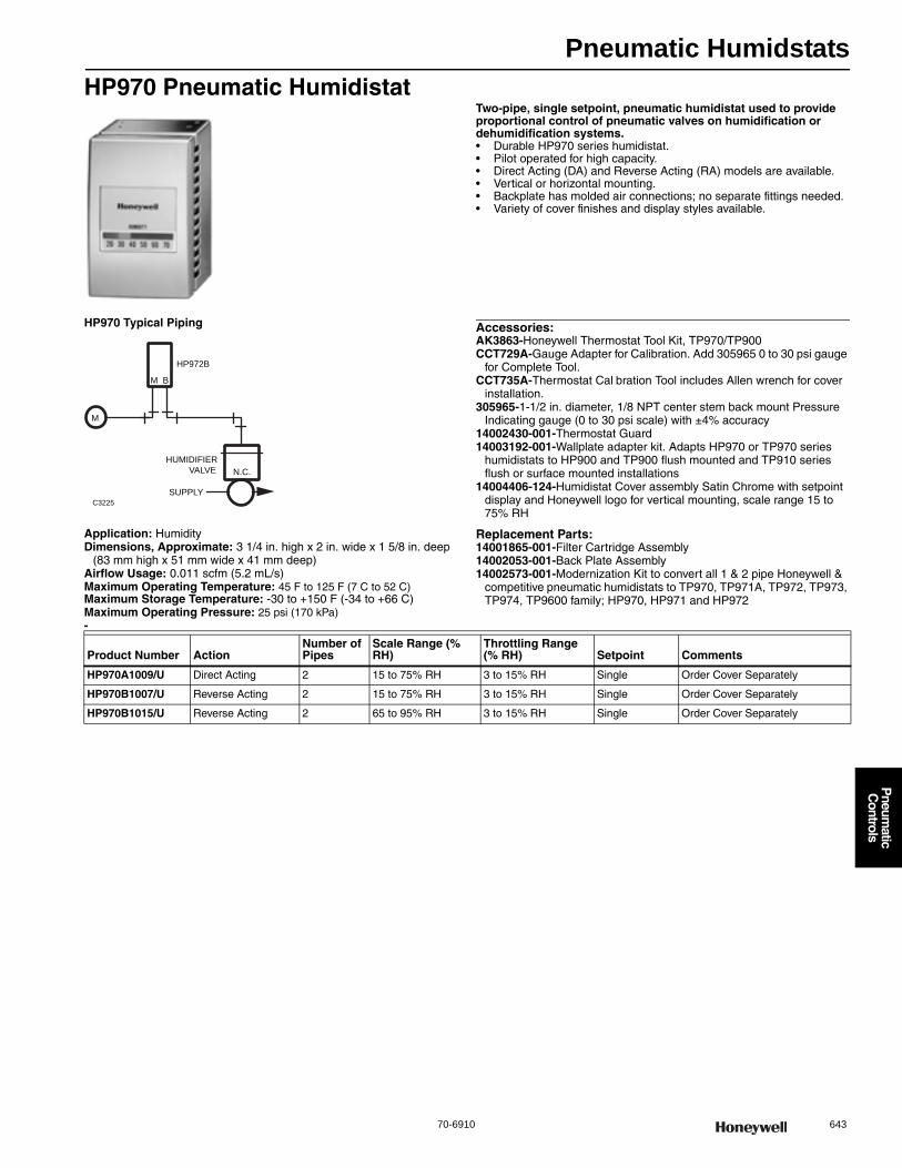
Pneumatic Humidstats
70-6910 643
P
neumatic
Controls
HP970 Pneumatic HumidistatTwo-pipe, single setpoint, pneumatic humidistat used to provide proportional control of pneumatic valves on humidification or dehumidification systems.• Durable HP970 series humidistat. • Pilot operated for high capacity. • Direct Acting (DA) and Reverse Acting (RA) models are available. • Vertical or horizontal mounting. • Backplate has molded air connections; no separate fittings needed. • Variety of cover finishes and display styles available.
HP970 Typical Piping
Application: HumidityDimensions, Approximate: 3 1/4 in. high x 2 in. wide x 1 5/8 in. deep
(83 mm high x 51 mm wide x 41 mm deep) Airflow Usage: 0.011 scfm (5.2 mL/s)Maximum Operating Temperature: 45 F to 125 F (7 C to 52 C) Maximum Storage Temperature: -30 to +150 F (-34 to +66 C) Maximum Operating Pressure: 25 psi (170 kPa)
Accessories:AK3863-Honeywell Thermostat Tool Kit, TP970/TP900CCT729A-Gauge Adapter for Calibration. Add 305965 0 to 30 psi gauge
for Complete Tool.CCT735A-Thermostat Cal bration Tool includes Allen wrench for cover
installation.305965-1-1/2 in. diameter, 1/8 NPT center stem back mount Pressure
Indicating gauge (0 to 30 psi scale) with ±4% accuracy14002430-001-Thermostat Guard14003192-001-Wallplate adapter kit. Adapts HP970 or TP970 series
humidistats to HP900 and TP900 flush mounted and TP910 series flush or surface mounted installations
14004406-124-Humidistat Cover assembly Satin Chrome with setpoint display and Honeywell logo for vertical mounting, scale range 15 to 75% RH
Replacement Parts:14001865-001-Filter Cartridge Assembly14002053-001-Back Plate Assembly14002573-001-Modernization Kit to convert all 1 & 2 pipe Honeywell &
competitive pneumatic humidistats to TP970, TP971A, TP972, TP973, TP974, TP9600 family; HP970, HP971 and HP972
-
C3225
N.C.
M
M B
HUMIDIFIER
VALVE
SUPPLY
HP972B
Product Number ActionNumber of Pipes
Scale Range (% RH)
Throttling Range (% RH) Setpoint Comments
HP970A1009/U Direct Acting 2 15 to 75% RH 3 to 15% RH Single Order Cover Separately
HP970B1007/U Reverse Acting 2 15 to 75% RH 3 to 15% RH Single Order Cover Separately
HP970B1015/U Reverse Acting 2 65 to 95% RH 3 to 15% RH Single Order Cover Separately
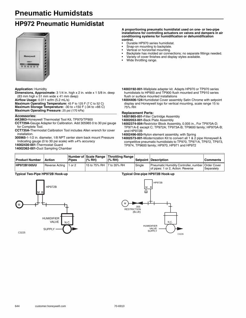
Pneumatic Humidstats
644 customer.honeywell.com 70-6910
HP972 Pneumatic HumidistatA proportioning pneumatic humidistat used on one- or two-pipe installations for controlling actuators on valves and dampers in air conditioning systems for humidification or dehumidification control.• Durable HP970 series humidistat. • Snap-on mounting to backplate. • Vertical or horizontal mounting. • Backplate has molded air connections; no separate fittings needed. • Variety of cover finishes and display styles available. • Wide throttling range.
Application: HumidityDimensions, Approximate: 3 1/4 in. high x 2 in. wide x 1 5/8 in. deep
(83 mm high x 51 mm wide x 41 mm deep) Airflow Usage: 0.011 scfm (5.2 mL/s)Maximum Operating Temperature: 45 F to 125 F (7 C to 52 C) Maximum Storage Temperature: -30 to +150 F (-34 to +66 C) Maximum Operating Pressure: 25 psi (170 kPa)
Accessories:AK3863-Honeywell Thermostat Tool Kit, TP970/TP900CCT729A-Gauge Adapter for Calibration. Add 305965 0 to 30 psi gauge
for Complete Tool.CCT735A-Thermostat Calibration Tool includes Allen wrench for cover
installation.305965-1-1/2 in. diameter, 1/8 NPT center stem back mount Pressure
Indicating gauge (0 to 30 psi scale) with ±4% accuracy14002430-001-Thermostat Guard14002362-001-Duct Sampling Chamber
14003192-001-Wallplate adapter kit. Adapts HP970 or TP970 series humidistats to HP900 and TP900 flush mounted and TP910 series flush or surface mounted installations
14004406-124-Humidistat Cover assembly Satin Chrome with setpoint display and Honeywell logo for vertical mounting, scale range 15 to 75% RH
Replacement Parts:14001865-001-Filter Cartridge Assembly14002053-001-Back Plate Assembly14002374-004-Restrictor Block Assembly, 0.005 in., For TP970A-D;
TP971A-E except C; TP972A; TP973A-B; TP9600 family; HP970A-B; and HP972B
14002496-003-Nylon element assembly, with Spring14002573-001-Modernization Kit to convert all 1 & 2 pipe Honeywell &
competitive pneumatic humidistats to TP970, TP971A, TP972, TP973, TP974, TP9600 family; HP970, HP971 and HP972
Typical Two-Pipe HP972B Hook-up Typical One-pipe HP972B Hook-up
Product Number ActionNumber of Pipes
Scale Range (% RH)
Throttling Range (% RH) Setpoint Description Comments
HP972B1005/U Reverse Acting 1 or 2 15 to 75% RH 7 to 35% RH Single Pneumatic Humidity Controller, number of pipes: 1 or 2, Action: Reverse
Order Cover Separately
C3225
N.C.
M
M B
HUMIDIFIER
VALVE
SUPPLY
HP972B
C3226
N.C.
M
M B
HUMIDIFIER VALVE
SUPPLY
HP972B
.005RESTRICTION
(BLUE)

Pneumatic Humidstats
70-6910 645
P
neumatic
Controls
Humidistat Accessories
Humidistat Cover AssembliesApplication: Accessory or Replacement Part
Replacement Parts
Product Number Description Used With
CCT729A/U Gauge Adapter for Cal bration. Add 305965 0 to 30 psi gauge for Complete Tool.
HP970, HP972;
CCT735A/U Thermostat Calibration Tool includes Allen wrench for cover installation. HP970, HP972;
Product Number Scale Range (% RH) Description Used With
14004406-910H/U 15 to 75% RH Humidistat Satin Chrome Cover Kit with setpoint display and Honeywell logo for vertical and horizontal mounting, scale range 15 to 75% RH. Includes the Setpoint Knob Insert
HP970; HP972
Product Number Description Used With
14002496-003/U Nylon element assembly, with Spring HP970B1015; HP972B
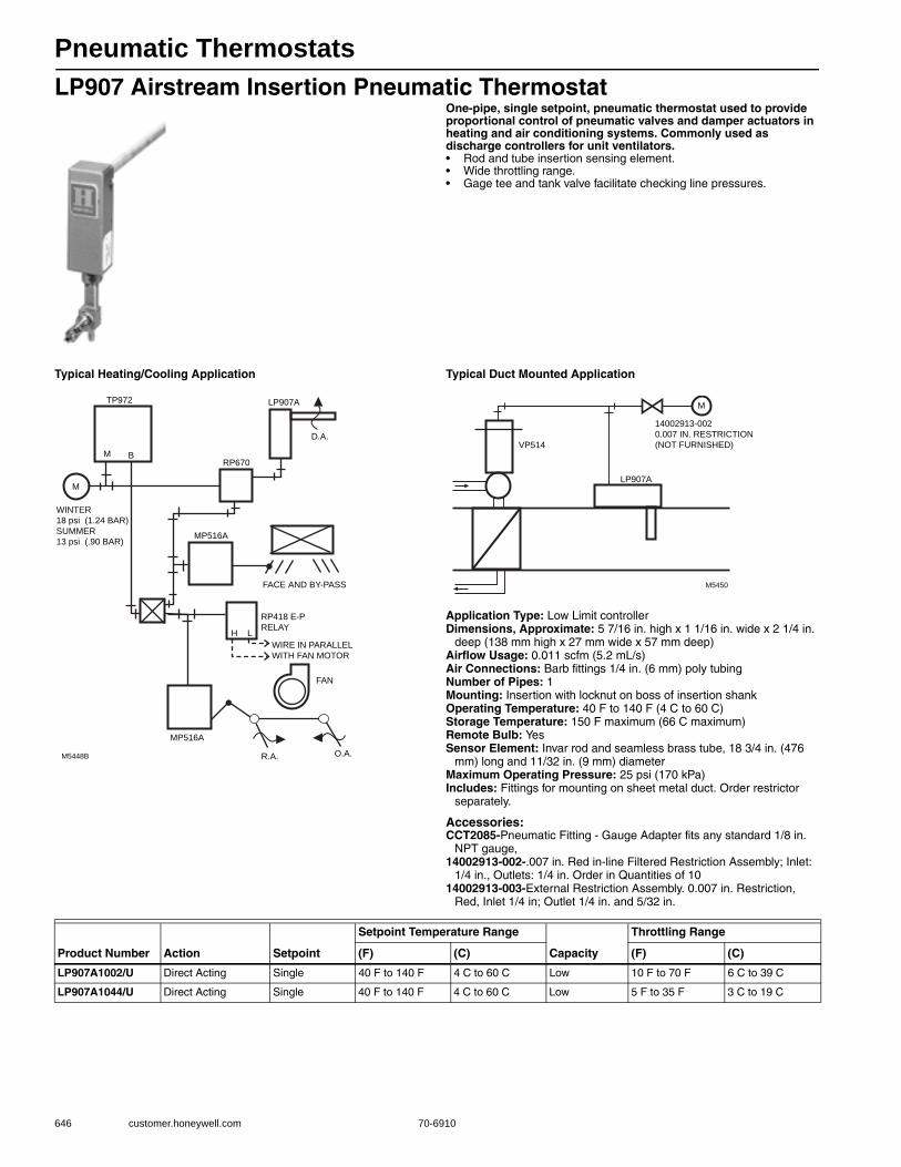
Pneumatic Thermostats
646 customer.honeywell.com 70-6910
LP907 Airstream Insertion Pneumatic ThermostatOne-pipe, single setpoint, pneumatic thermostat used to provide proportional control of pneumatic valves and damper actuators in heating and air conditioning systems. Commonly used as discharge controllers for unit ventilators.• Rod and tube insertion sensing element. • Wide throttling range. • Gage tee and tank valve facilitate checking line pressures.
Typical Heating/Cooling Application Typical Duct Mounted Application
Application Type: Low Limit controllerDimensions, Approximate: 5 7/16 in. high x 1 1/16 in. wide x 2 1/4 in.
deep (138 mm high x 27 mm wide x 57 mm deep) Airflow Usage: 0.011 scfm (5.2 mL/s)Air Connections: Barb fittings 1/4 in. (6 mm) poly tubingNumber of Pipes: 1Mounting: Insertion with locknut on boss of insertion shankOperating Temperature: 40 F to 140 F (4 C to 60 C) Storage Temperature: 150 F maximum (66 C maximum) Remote Bulb: YesSensor Element: Invar rod and seamless brass tube, 18 3/4 in. (476
mm) long and 11/32 in. (9 mm) diameterMaximum Operating Pressure: 25 psi (170 kPa) Includes: Fittings for mounting on sheet metal duct. Order restrictor
separately.
Accessories:CCT2085-Pneumatic Fitting - Gauge Adapter fits any standard 1/8 in.
NPT gauge,14002913-002-.007 in. Red in-line Filtered Restriction Assembly; Inlet:
1/4 in., Outlets: 1/4 in. Order in Quantities of 1014002913-003-External Restriction Assembly. 0.007 in. Restriction,
Red, Inlet 1/4 in; Outlet 1/4 in. and 5/32 in.
M5448B R.A. O.A.
MP516A
LP907A
D.A.
M B
M
FAN
TP972
RP670
WINTER
18 psi (1.24 BAR)
SUMMER
13 psi (.90 BAR)
FACE AND BY-PASS
MP516A
H L
RP418 E-P
RELAY
WIRE IN PARALLEL
WITH FAN MOTOR
M
M5450
LP907A
VP514
14002913-002
0.007 IN. RESTRICTION
(NOT FURNISHED)
Product Number Action Setpoint
Setpoint Temperature Range
Capacity
Throttling Range
(F) (C) (F) (C)
LP907A1002/U Direct Acting Single 40 F to 140 F 4 C to 60 C Low 10 F to 70 F 6 C to 39 C
LP907A1044/U Direct Acting Single 40 F to 140 F 4 C to 60 C Low 5 F to 35 F 3 C to 19 C
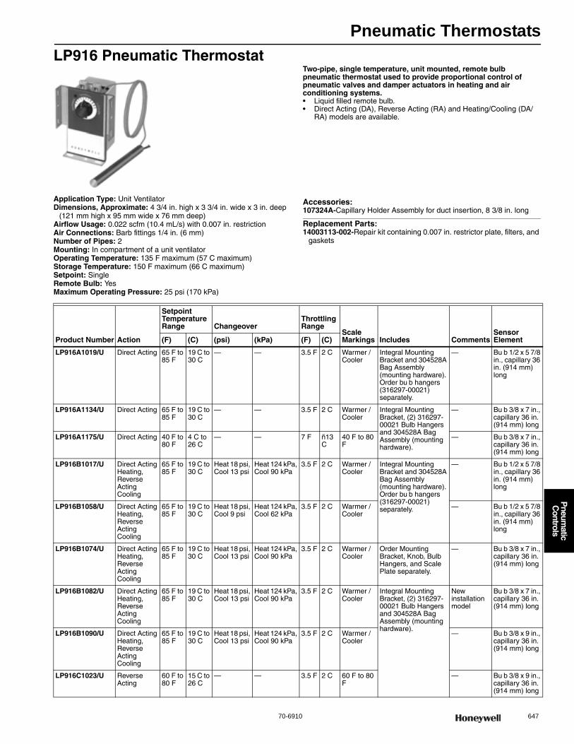
Pneumatic Thermostats
70-6910 647
P
neumatic
Controls
LP916 Pneumatic ThermostatTwo-pipe, single temperature, unit mounted, remote bulb pneumatic thermostat used to provide proportional control of pneumatic valves and damper actuators in heating and air conditioning systems.• Liquid filled remote bulb. • Direct Acting (DA), Reverse Acting (RA) and Heating/Cooling (DA/
RA) models are available.
Application Type: Unit VentilatorDimensions, Approximate: 4 3/4 in. high x 3 3/4 in. wide x 3 in. deep
(121 mm high x 95 mm wide x 76 mm deep) Airflow Usage: 0.022 scfm (10.4 mL/s) with 0.007 in. restrictionAir Connections: Barb fittings 1/4 in. (6 mm)Number of Pipes: 2Mounting: In compartment of a unit ventilatorOperating Temperature: 135 F maximum (57 C maximum) Storage Temperature: 150 F maximum (66 C maximum) Setpoint: SingleRemote Bulb: YesMaximum Operating Pressure: 25 psi (170 kPa)
Accessories:107324A-Capillary Holder Assembly for duct insertion, 8 3/8 in. long
Replacement Parts:14003113-002-Repair kit containing 0.007 in. restrictor plate, filters, and
gaskets
Product Number Action
Setpoint Temperature Range Changeover
Throttling Range
Scale Markings Includes Comments
Sensor Element(F) (C) (psi) (kPa) (F) (C)
LP916A1019/U Direct Acting 65 F to 85 F
19 C to 30 C
— — 3.5 F 2 C Warmer / Cooler
Integral Mounting Bracket and 304528A Bag Assembly (mounting hardware). Order bu b hangers (316297-00021) separately.
— Bu b 1/2 x 5 7/8 in., capillary 36 in. (914 mm) long
LP916A1134/U Direct Acting 65 F to 85 F
19 C to 30 C
— — 3.5 F 2 C Warmer / Cooler
Integral Mounting Bracket, (2) 316297-00021 Bulb Hangers and 304528A Bag Assembly (mounting hardware).
— Bu b 3/8 x 7 in., capillary 36 in. (914 mm) long
LP916A1175/U Direct Acting 40 F to 80 F
4 C to 26 C
— — 7 F ñ13 C
40 F to 80 F
— Bu b 3/8 x 7 in., capillary 36 in. (914 mm) long
LP916B1017/U Direct Acting Heating, Reverse Acting Cooling
65 F to 85 F
19 C to 30 C
Heat 18 psi, Cool 13 psi
Heat 124 kPa, Cool 90 kPa
3.5 F 2 C Warmer / Cooler
Integral Mounting Bracket and 304528A Bag Assembly (mounting hardware). Order bu b hangers (316297-00021) separately.
— Bu b 1/2 x 5 7/8 in., capillary 36 in. (914 mm) long
LP916B1058/U Direct Acting Heating, Reverse Acting Cooling
65 F to 85 F
19 C to 30 C
Heat 18 psi, Cool 9 psi
Heat 124 kPa, Cool 62 kPa
3.5 F 2 C Warmer / Cooler
— Bu b 1/2 x 5 7/8 in., capillary 36 in. (914 mm) long
LP916B1074/U Direct Acting Heating, Reverse Acting Cooling
65 F to 85 F
19 C to 30 C
Heat 18 psi, Cool 13 psi
Heat 124 kPa, Cool 90 kPa
3.5 F 2 C Warmer / Cooler
Order Mounting Bracket, Knob, Bulb Hangers, and Scale Plate separately.
— Bu b 3/8 x 7 in., capillary 36 in. (914 mm) long
LP916B1082/U Direct Acting Heating, Reverse Acting Cooling
65 F to 85 F
19 C to 30 C
Heat 18 psi, Cool 13 psi
Heat 124 kPa, Cool 90 kPa
3.5 F 2 C Warmer / Cooler
Integral Mounting Bracket, (2) 316297-00021 Bulb Hangers and 304528A Bag Assembly (mounting hardware).
New installation model
Bu b 3/8 x 7 in., capillary 36 in. (914 mm) long
LP916B1090/U Direct Acting Heating, Reverse Acting Cooling
65 F to 85 F
19 C to 30 C
Heat 18 psi, Cool 13 psi
Heat 124 kPa, Cool 90 kPa
3.5 F 2 C Warmer / Cooler
— Bu b 3/8 x 9 in., capillary 36 in. (914 mm) long
LP916C1023/U Reverse Acting
60 F to 80 F
15 C to 26 C
— — 3.5 F 2 C 60 F to 80 F
— Bu b 3/8 x 9 in., capillary 36 in. (914 mm) long
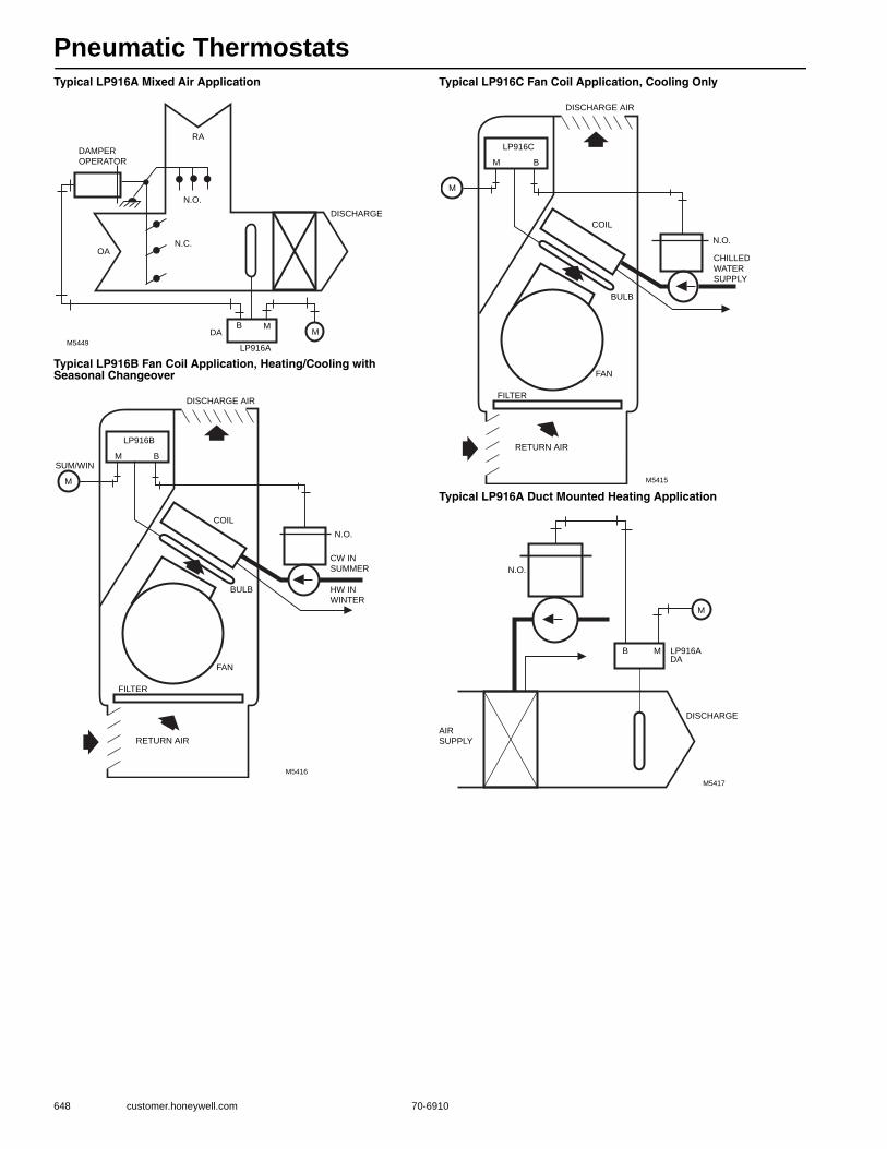
Pneumatic Thermostats
648 customer.honeywell.com 70-6910
Typical LP916A Mixed Air Application
Typical LP916B Fan Coil Application, Heating/Cooling with Seasonal Changeover
Typical LP916C Fan Coil Application, Cooling Only
Typical LP916A Duct Mounted Heating Application
DAMPER
OPERATOR
RA
N.O.
N.C.OA
DA
LP916A
B MM
M5449
DISCHARGE
M5416
DISCHARGE AIR
CW IN
SUMMER
HW IN
WINTER
N.O.
COIL
BULB
FAN
FILTER
RETURN AIR
LP916B
M B
M
SUM/WIN
M5415
DISCHARGE AIR
CHILLED
WATER
SUPPLY
N.O.
COIL
BULB
FAN
FILTER
RETURN AIR
LP916C
M B
M
N.O.
B M LP916ADA
DISCHARGE
AIR
SUPPLY
M5417
M
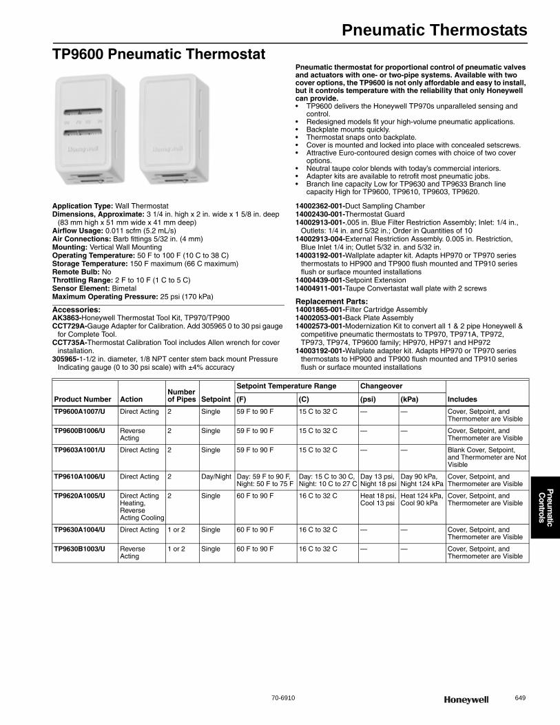
Pneumatic Thermostats
70-6910 649
P
neumatic
Controls
TP9600 Pneumatic ThermostatPneumatic thermostat for proportional control of pneumatic valves and actuators with one- or two-pipe systems. Available with two cover options, the TP9600 is not only affordable and easy to install, but it controls temperature with the reliability that only Honeywell can provide.• TP9600 delivers the Honeywell TP970s unparalleled sensing and
control. • Redesigned models fit your high-volume pneumatic applications. • Backplate mounts quickly. • Thermostat snaps onto backplate. • Cover is mounted and locked into place with concealed setscrews. • Attractive Euro-contoured design comes with choice of two cover
options. • Neutral taupe color blends with today’s commercial interiors. • Adapter kits are available to retrofit most pneumatic jobs. • Branch line capacity Low for TP9630 and TP9633 Branch line
capacity High for TP9600, TP9610, TP9603, TP9620.
Application Type: Wall ThermostatDimensions, Approximate: 3 1/4 in. high x 2 in. wide x 1 5/8 in. deep
(83 mm high x 51 mm wide x 41 mm deep) Airflow Usage: 0.011 scfm (5.2 mL/s)Air Connections: Barb fittings 5/32 in. (4 mm)Mounting: Vertical Wall MountingOperating Temperature: 50 F to 100 F (10 C to 38 C) Storage Temperature: 150 F maximum (66 C maximum) Remote Bulb: NoThrottling Range: 2 F to 10 F (1 C to 5 C)Sensor Element: BimetalMaximum Operating Pressure: 25 psi (170 kPa)
Accessories:AK3863-Honeywell Thermostat Tool Kit, TP970/TP900CCT729A-Gauge Adapter for Calibration. Add 305965 0 to 30 psi gauge
for Complete Tool.CCT735A-Thermostat Calibration Tool includes Allen wrench for cover
installation.305965-1-1/2 in. diameter, 1/8 NPT center stem back mount Pressure
Indicating gauge (0 to 30 psi scale) with ±4% accuracy
14002362-001-Duct Sampling Chamber14002430-001-Thermostat Guard14002913-001-.005 in. Blue Filter Restriction Assembly; Inlet: 1/4 in.,
Outlets: 1/4 in. and 5/32 in.; Order in Quantities of 1014002913-004-External Restriction Assembly. 0.005 in. Restriction,
Blue Inlet 1/4 in; Outlet 5/32 in. and 5/32 in.14003192-001-Wallplate adapter kit. Adapts HP970 or TP970 series
thermostats to HP900 and TP900 flush mounted and TP910 series flush or surface mounted installations
14004439-001-Setpoint Extension14004911-001-Taupe Convertastat wall plate with 2 screws
Replacement Parts:14001865-001-Filter Cartridge Assembly14002053-001-Back Plate Assembly14002573-001-Modernization Kit to convert all 1 & 2 pipe Honeywell &
competitive pneumatic thermostats to TP970, TP971A, TP972, TP973, TP974, TP9600 family; HP970, HP971 and HP972
14003192-001-Wallplate adapter kit. Adapts HP970 or TP970 series thermostats to HP900 and TP900 flush mounted and TP910 series flush or surface mounted installations
Product Number ActionNumber of Pipes Setpoint
Setpoint Temperature Range Changeover
Includes(F) (C) (psi) (kPa)
TP9600A1007/U Direct Acting 2 Single 59 F to 90 F 15 C to 32 C — — Cover, Setpoint, and Thermometer are Visible
TP9600B1006/U Reverse Acting
2 Single 59 F to 90 F 15 C to 32 C — — Cover, Setpoint, and Thermometer are Visible
TP9603A1001/U Direct Acting 2 Single 59 F to 90 F 15 C to 32 C — — Blank Cover, Setpoint, and Thermometer are Not Visible
TP9610A1006/U Direct Acting 2 Day/Night Day: 59 F to 90 F, Night: 50 F to 75 F
Day: 15 C to 30 C, Night: 10 C to 27 C
Day 13 psi, Night 18 psi
Day 90 kPa, Night 124 kPa
Cover, Setpoint, and Thermometer are Visible
TP9620A1005/U Direct Acting Heating, Reverse Acting Cooling
2 Single 60 F to 90 F 16 C to 32 C Heat 18 psi, Cool 13 psi
Heat 124 kPa, Cool 90 kPa
Cover, Setpoint, and Thermometer are Visible
TP9630A1004/U Direct Acting 1 or 2 Single 60 F to 90 F 16 C to 32 C — — Cover, Setpoint, and Thermometer are Visible
TP9630B1003/U Reverse Acting
1 or 2 Single 60 F to 90 F 16 C to 32 C — — Cover, Setpoint, and Thermometer are Visible

Pneumatic Thermostats
650 customer.honeywell.com 70-6910
TP970 Pneumatic ThermostatTwo-pipe, single setpoint, pneumatic thermostat used to provide proportional control of pneumatic valves and damper actuators in heating and air conditioning systems. Replacement kits are available for Johnson, Powers, Robertshaw, Barber-Colman, and older Honeywell two-pipe pneumatic thermostats.
• Honeywell's best pneumatic thermostat-TP970 series.• Shock-resistant, suspension-mounted thermostats provide
dependable performance and responsiveness year in and year out. • Pilot operated for high capacity. • Direct Acting (DA) and Reverse Acting (RA) models are available. • Wide throttling range models for Zero Energy Band (ZEB) operation
are available. • Adapter plate in Convertastat and Modernization kits covers existing
thermostat wall mark. • Backplate has molded air connections-no separate fittings needed. • Universal locking cover with satin chrome finish and horizontal,
vertical, or blank window options. • Typical Wide Throttling Range Application.
Typical Standard Throttling Range Piping
Typical Wide Throttling Range Piping
Application Type: HeatingDimensions, Approximate: 3 1/4 in. high x 2 in. wide x 1 5/8 in. deep
(83 mm high x 51 mm wide x 41 mm deep) Airflow Usage: 0.011 scfm (5.2 mL/s)Number of Pipes: 2Mounting: Wall mountOperating Temperature: 100 F maximumStorage Temperature: 150 F maximum (66 C maximum) Remote Bulb: NoSetpoint: SingleSensor Element: BimetalMaximum Operating Pressure: 25 psi (170 kPa)
Accessories:AK3863-Honeywell Thermostat Tool Kit, TP970/TP900CCT729A-Gauge Adapter for Calibration. Add 305965 0 to 30 psi gauge
for Complete Tool.CCT735A-Thermostat Cal bration Tool includes Allen wrench for cover
installation.305965-1-1/2 in. diameter, 1/8 NPT center stem back mount Pressure
Indicating gauge (0 to 30 psi scale) with ±4% accuracy14002362-001-Duct Sampling Chamber14002430-001-Thermostat Guard14004439-001-Setpoint Extension14004447-001-Setpoint Cam Assembly for TP970A1004, A1012,
A1020, A1038, A1046, A1053, A1095, A2004, A2012, A2020, A2038AK3863-Honeywell Thermostat Tool Kit, TP970/TP900CCT729A-Gauge Adapter for Calibration. Add 305965 0 to 30 psi gauge
for Complete Tool.CCT735A-Thermostat Cal bration Tool includes Allen wrench for cover
installation.305965-1-1/2 in. diameter, 1/8 NPT center stem back mount Pressure
Indicating gauge (0 to 30 psi scale) with ±4% accuracy14002362-001-Duct Sampling Chamber14002430-001-Thermostat Guard14004439-001-Setpoint Extension14004447-001-Setpoint Cam Assembly for TP970A1004, A1012,
A1020, A1038, A1046, A1053, A1095, A2004, A2012, A2020, A2038, A2053, A2095; TP970C; TP972A1143, A2143; TP973A1001, A1019, A1127
14004447-002-Setpoint Cam Assembly for TP970B1002, B1010, B1028, B1036, B2002, B2010, B2028, B2036; TP970D; TP972A1002, A1010, A1028, A1044, A2002, A2010, A2028, A2044; TP973B1009, B1017, B1025, B1108
14004447-005-Setpoint Cam Assembly for TP970B1044; TP972A1051, A1101
14004459-001-Repair kit consisting of a thermometer assembly, a thermometer post and a 60 to 90F aluminum scaleplate
Replacement Parts:14001865-001-Filter Cartridge Assembly14002053-001-Back Plate Assembly14002573-001-Modernization Kit to convert all 1 & 2 pipe Honeywell &
competitive pneumatic thermostats to TP970, TP971A, TP972, TP973, TP974, TP9600 family; HP970, HP971 and HP972
14004459-001-Repair kit consisting of a thermometer assembly, a thermometer post and a 60 to 90F aluminum scaleplate
SUPPLY
TP970A,B OR
TP9600A,B
N.O.
M B
M
C3535-1
VALVE
OPEN
VALVE
CLOSED
4 DEGREES F
(2.2 DEGREES C)
ZERO
ENERGY
BAND
THERMOSTAT SETTING
TR=10 DEGREES F
(5.6 DEGREES C)
20C 22C 24C
66F 68F 70F 72F 74F 76F 78F
TP970C
DIRECT
ACTING
COOLING
VALVE
9 TO 13 PSI
(62 TO 90 kPa)
SPRING
HEATING
VALVE
2 TO 5 PSI
(14 TO 34 kPa)
SPRING N.C.N.O.
M B
M
C3538
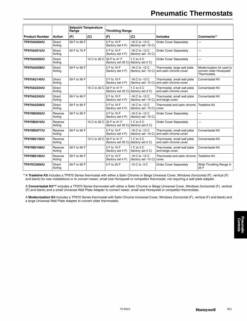
Pneumatic Thermostats
70-6910 651
P
neumatic
Controls
**A Tradeline Kit includes a TP970 Series thermostat with either a Satin Chrome or Beige Universal Cover, Windows (horizontal (F), vertical (F) and blank) for new installations or to convert newer, small size Honeywell or competitor thermostat, not requiring a wall plate adapter.
A Convertastat Kit™ includes a TP970 Series thermostat with either a Satin Chrome or Beige Universal Cover, Windows (horizontal (F), vertical (F) and blank) and a small Universal Wall Plate Adapter to convert newer, small size Honeywell or competitor thermostats.
A Modernization Kit includes a TP970 Series thermostat with Satin Chrome Universal Cover, Windows (horizontal (F), vertical (F) and blank) and a large Universal Wall Plate Adapter to convert older thermostats.
Product Number Action
Setpoint Temperature Range Throttling Range
Includes Comments**(F) (C) (F) (C)
TP970A2004/U Direct Acting
59 F to 90 F 2 F to 10 F (factory set 4 F)
-16 C to -12 C (factory set -15 C)
Order Cover Separately —
TP970A2012/U Direct Acting
40 F to 70 F 2 F to 10 F (factory set 4 F)
-16 C to -12 C (factory set -15 C)
Order Cover Separately —
TP970A2020/U Direct Acting
15 C to 30 C 33 F to 41 F (factory set 35 C)
1 C to 5 C (factory set 2 C)
Order Cover Separately —
TP970A2038/U Direct Acting
59 F to 90 F 2 F to 10 F (factory set 4 F)
-16 C to -12 C (factory set -15 C)
Thermostat, large wall plate and satin chrome cover.
Modernization kit used to convert older Honeywell Thermostats.
TP970A2145/U Direct Acting
59 F to 90 F 2 F to 10 F (factory set 4 F)
-16 C to -12 C (factory set -15 C)
Thermostat, small wall plate and satin chrome cover.
Convertastat Kit
TP970A2234/U Direct Acting
15 C to 30 C 33 F to 41 F (factory set 35 C)
1 C to 5 C (factory set 2 C)
Thermostat, small wall plate and satin chrome cover.
Convertastat Kit
TP970A2242/U Direct Acting
59 F to 90 F 2 F to 10 F (factory set 4 F)
-16 C to -12 C (factory set -15 C)
Thermostat, small wall plate and beige cover.
Convertastat Kit
TP970A2259/U Direct Acting
59 F to 90 F 2 F to 10 F (factory set 4 F)
-16 C to -12 C (factory set -15 C)
Thermostat and satin chrome cover.
Tradeline Kit
TP970B2002/U Reverse Acting
59 F to 90 F 2 F to 10 F (factory set 4 F)
-16 C to -12 C (factory set -15 C)
Order Cover Separately —
TP970B2010/U Reverse Acting
15 C to 30 C 33 F to 41 F (factory set 35 C)
1 C to 5 C (factory set 2 C)
Order Cover Separately —
TP970B2077/U Reverse Acting
59 F to 90 F 2 F to 10 F (factory set 4 F)
-16 C to -12 C (factory set -15 C)
Thermostat, small wall plate and satin chrome cover.
Convertastat Kit
TP970B2150/U Reverse Acting
15 C to 30 C 33 F to 41 F (factory set 35 C)
1 C to 5 C (factory set 2 C)
Thermostat, small wall plate and satin chrome cover.
Convertastat Kit
TP970B2166/U Reverse Acting
59 F to 90 F 2 F to 10 F (factory set 4 F)
1 C to 5 C (factory set 2 C)
Thermostat, small wall plate and beige cover.
Convertastat Kit
TP970B2182/U Reverse Acting
59 F to 90 F 2 F to 10 F (factory set 4 F)
-16 C to -12 C (factory set -15 C)
Thermostat and satin chrome cover.
Tradeline Kit
TP970C2000/U Direct Acting
59 F to 90 F 5 F to 25 F -15 C to -3 C Order Cover Separately Wide Throttling Range 5-25 F
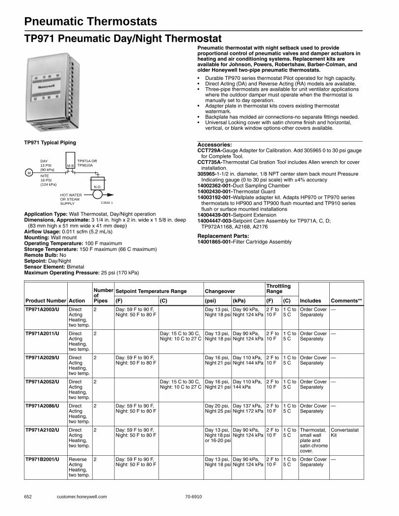
Pneumatic Thermostats
652 customer.honeywell.com 70-6910
TP971 Pneumatic Day/Night ThermostatPneumatic thermostat with night setback used to provide proportional control of pneumatic valves and damper actuators in heating and air conditioning systems. Replacement kits are available for Johnson, Powers, Robertshaw, Barber-Colman, and older Honeywell two-pipe pneumatic thermostats.
• Durable TP970 series thermostat Pilot operated for high capacity. • Direct Acting (DA) and Reverse Acting (RA) models are available. • Three-pipe thermostats are available for unit ventilator applications
where the outdoor damper must operate when the thermostat is manually set to day operation.
• Adapter plate in thermostat kits covers existing thermostat watermark.
• Backplate has molded air connections-no separate fittings needed. • Universal Locking cover with satin chrome finish and horizontal,
vertical, or blank window options-other covers available.
TP971 Typical Piping
Application Type: Wall Thermostat, Day/Night operationDimensions, Approximate: 3 1/4 in. high x 2 in. wide x 1 5/8 in. deep
(83 mm high x 51 mm wide x 41 mm deep) Airflow Usage: 0.011 scfm (5.2 mL/s)Mounting: Wall mountOperating Temperature: 100 F maximumStorage Temperature: 150 F maximum (66 C maximum) Remote Bulb: NoSetpoint: Day/NightSensor Element: BimetalMaximum Operating Pressure: 25 psi (170 kPa)
Accessories:CCT729A-Gauge Adapter for Calibration. Add 305965 0 to 30 psi gauge
for Complete Tool.CCT735A-Thermostat Cal bration Tool includes Allen wrench for cover
installation.305965-1-1/2 in. diameter, 1/8 NPT center stem back mount Pressure
Indicating gauge (0 to 30 psi scale) with ±4% accuracy14002362-001-Duct Sampling Chamber14002430-001-Thermostat Guard14003192-001-Wallplate adapter kit. Adapts HP970 or TP970 series
thermostats to HP900 and TP900 flush mounted and TP910 series flush or surface mounted installations
14004439-001-Setpoint Extension14004447-003-Setpoint Cam Assembly for TP971A, C, D;
TP972A1168, A2168, A2176
Replacement Parts:14001865-001-Filter Cartridge Assembly
TP971A OR
TP9610ADAY
13 PSI
(90 kPa)
NITE
18 PSI
(124 kPa)
M B
N.O.
M
HOT WATER
OR STEAM
SUPPLY C3540 1
Product Number Action
Number of Pipes
Setpoint Temperature Range ChangeoverThrottling Range
Includes Comments**(F) (C) (psi) (kPa) (F) (C)
TP971A2003/U Direct Acting Heating, two temp.
2 Day: 59 F to 90 F, Night: 50 F to 80 F
Day 13 psi, Night 18 psi
Day 90 kPa, Night 124 kPa
2 F to 10 F
1 C to 5 C
Order Cover Separately
—
TP971A2011/U Direct Acting Heating, two temp.
2 Day: 15 C to 30 C, Night: 10 C to 27 C
Day 13 psi, Night 18 psi
Day 90 kPa, Night 124 kPa
2 F to 10 F
1 C to 5 C
Order Cover Separately
—
TP971A2029/U Direct Acting Heating, two temp.
2 Day: 59 F to 90 F, Night: 50 F to 80 F
Day 16 psi, Night 21 psi
Day 110 kPa, Night 144 kPa
2 F to 10 F
1 C to 5 C
Order Cover Separately
—
TP971A2052/U Direct Acting Heating, two temp.
2 Day: 15 C to 30 C, Night: 10 C to 27 C
Day 16 psi, Night 21 psi
Day 110 kPa, 144 kPa
2 F to 10 F
1 C to 5 C
Order Cover Separately
—
TP971A2086/U Direct Acting Heating, two temp.
2 Day: 59 F to 90 F, Night: 50 F to 80 F
Day 20 psi, Night 25 psi
Day 137 kPa, Night 172 kPa
2 F to 10 F
1 C to 5 C
Order Cover Separately
—
TP971A2102/U Direct Acting Heating, two temp.
2 Day: 59 F to 90 F, Night: 50 F to 80 F
Day 13 psi, Night 18 psi or 16-20 psi
Day 90 kPa, Night 124 kPa
2 F to 10 F
1 C to 5 C
Thermostat, small wall plate and satin chrome cover.
Convertastat Kit
TP971B2001/U Reverse Acting Heating, two temp.
2 Day: 59 F to 90 F, Night: 50 F to 80 F
Day 13 psi, Night 18 psi
Day 90 kPa, Night 124 kPa
2 F to 10 F
1 C to 5 C
Order Cover Separately
—
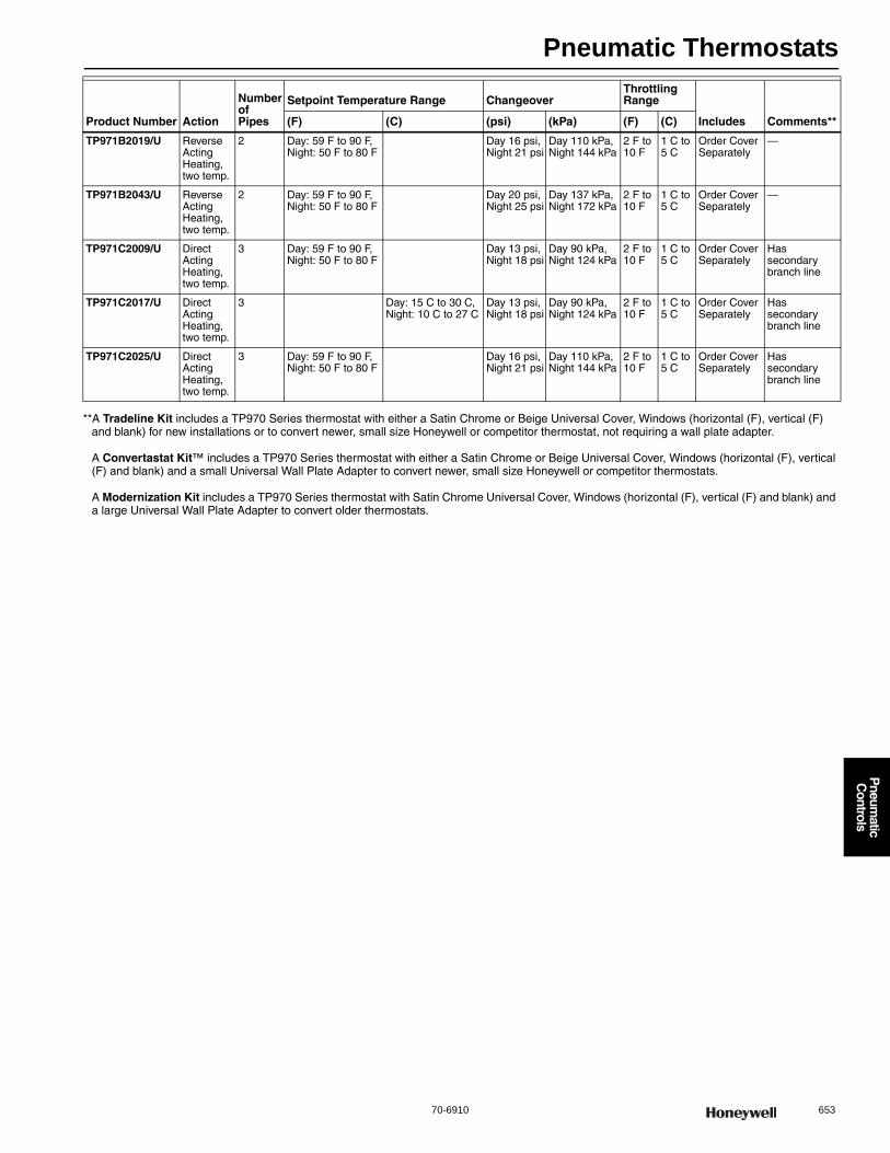
Pneumatic Thermostats
70-6910 653
P
neumatic
Controls
**A Tradeline Kit includes a TP970 Series thermostat with either a Satin Chrome or Beige Universal Cover, Windows (horizontal (F), vertical (F) and blank) for new installations or to convert newer, small size Honeywell or competitor thermostat, not requiring a wall plate adapter.
A Convertastat Kit™ includes a TP970 Series thermostat with either a Satin Chrome or Beige Universal Cover, Windows (horizontal (F), vertical (F) and blank) and a small Universal Wall Plate Adapter to convert newer, small size Honeywell or competitor thermostats.
A Modernization Kit includes a TP970 Series thermostat with Satin Chrome Universal Cover, Windows (horizontal (F), vertical (F) and blank) and a large Universal Wall Plate Adapter to convert older thermostats.
TP971B2019/U Reverse Acting Heating, two temp.
2 Day: 59 F to 90 F, Night: 50 F to 80 F
Day 16 psi, Night 21 psi
Day 110 kPa, Night 144 kPa
2 F to 10 F
1 C to 5 C
Order Cover Separately
—
TP971B2043/U Reverse Acting Heating, two temp.
2 Day: 59 F to 90 F, Night: 50 F to 80 F
Day 20 psi, Night 25 psi
Day 137 kPa, Night 172 kPa
2 F to 10 F
1 C to 5 C
Order Cover Separately
—
TP971C2009/U Direct Acting Heating, two temp.
3 Day: 59 F to 90 F, Night: 50 F to 80 F
Day 13 psi, Night 18 psi
Day 90 kPa, Night 124 kPa
2 F to 10 F
1 C to 5 C
Order Cover Separately
Has secondary branch line
TP971C2017/U Direct Acting Heating, two temp.
3 Day: 15 C to 30 C, Night: 10 C to 27 C
Day 13 psi, Night 18 psi
Day 90 kPa, Night 124 kPa
2 F to 10 F
1 C to 5 C
Order Cover Separately
Has secondary branch line
TP971C2025/U Direct Acting Heating, two temp.
3 Day: 59 F to 90 F, Night: 50 F to 80 F
Day 16 psi, Night 21 psi
Day 110 kPa, Night 144 kPa
2 F to 10 F
1 C to 5 C
Order Cover Separately
Has secondary branch line
Product Number Action
Number of Pipes
Setpoint Temperature Range ChangeoverThrottling Range
Includes Comments**(F) (C) (psi) (kPa) (F) (C)
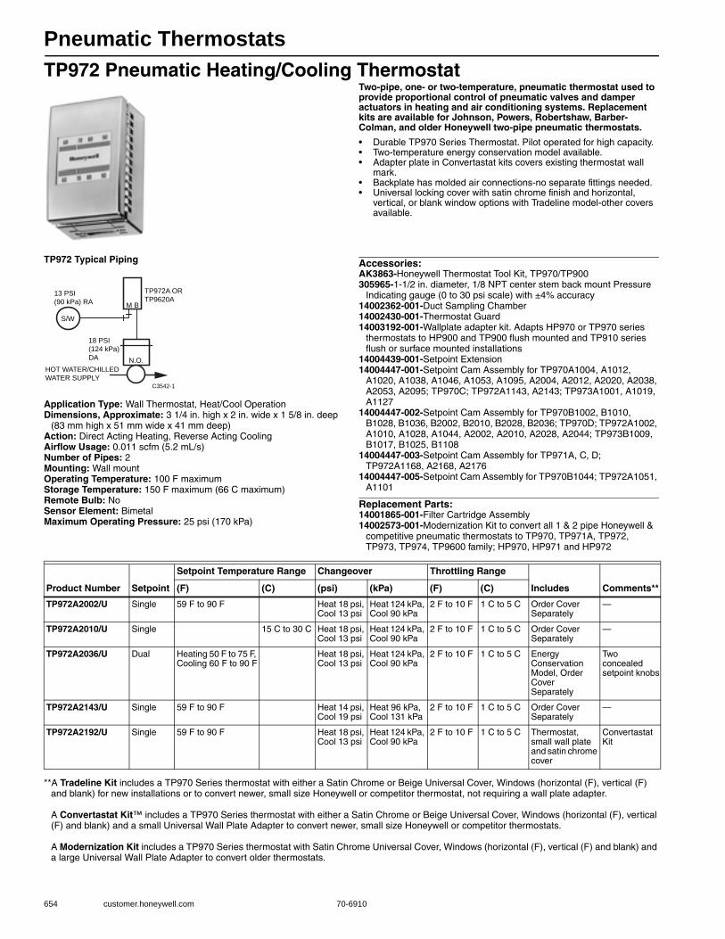
Pneumatic Thermostats
654 customer.honeywell.com 70-6910
TP972 Pneumatic Heating/Cooling ThermostatTwo-pipe, one- or two-temperature, pneumatic thermostat used to provide proportional control of pneumatic valves and damper actuators in heating and air conditioning systems. Replacement kits are available for Johnson, Powers, Robertshaw, Barber-Colman, and older Honeywell two-pipe pneumatic thermostats.
• Durable TP970 Series Thermostat. Pilot operated for high capacity. • Two-temperature energy conservation model available. • Adapter plate in Convertastat kits covers existing thermostat wall
mark. • Backplate has molded air connections-no separate fittings needed. • Universal locking cover with satin chrome finish and horizontal,
vertical, or blank window options with Tradeline model-other covers available.
TP972 Typical Piping
Application Type: Wall Thermostat, Heat/Cool OperationDimensions, Approximate: 3 1/4 in. high x 2 in. wide x 1 5/8 in. deep
(83 mm high x 51 mm wide x 41 mm deep) Action: Direct Acting Heating, Reverse Acting CoolingAirflow Usage: 0.011 scfm (5.2 mL/s)Number of Pipes: 2Mounting: Wall mountOperating Temperature: 100 F maximumStorage Temperature: 150 F maximum (66 C maximum) Remote Bulb: NoSensor Element: BimetalMaximum Operating Pressure: 25 psi (170 kPa)
Accessories:AK3863-Honeywell Thermostat Tool Kit, TP970/TP900305965-1-1/2 in. diameter, 1/8 NPT center stem back mount Pressure
Indicating gauge (0 to 30 psi scale) with ±4% accuracy14002362-001-Duct Sampling Chamber14002430-001-Thermostat Guard14003192-001-Wallplate adapter kit. Adapts HP970 or TP970 series
thermostats to HP900 and TP900 flush mounted and TP910 series flush or surface mounted installations
14004439-001-Setpoint Extension14004447-001-Setpoint Cam Assembly for TP970A1004, A1012,
A1020, A1038, A1046, A1053, A1095, A2004, A2012, A2020, A2038, A2053, A2095; TP970C; TP972A1143, A2143; TP973A1001, A1019, A1127
14004447-002-Setpoint Cam Assembly for TP970B1002, B1010, B1028, B1036, B2002, B2010, B2028, B2036; TP970D; TP972A1002, A1010, A1028, A1044, A2002, A2010, A2028, A2044; TP973B1009, B1017, B1025, B1108
14004447-003-Setpoint Cam Assembly for TP971A, C, D; TP972A1168, A2168, A2176
14004447-005-Setpoint Cam Assembly for TP970B1044; TP972A1051, A1101
Replacement Parts:14001865-001-Filter Cartridge Assembly14002573-001-Modernization Kit to convert all 1 & 2 pipe Honeywell &
competitive pneumatic thermostats to TP970, TP971A, TP972, TP973, TP974, TP9600 family; HP970, HP971 and HP972
**A Tradeline Kit includes a TP970 Series thermostat with either a Satin Chrome or Beige Universal Cover, Windows (horizontal (F), vertical (F) and blank) for new installations or to convert newer, small size Honeywell or competitor thermostat, not requiring a wall plate adapter.
A Convertastat Kit™ includes a TP970 Series thermostat with either a Satin Chrome or Beige Universal Cover, Windows (horizontal (F), vertical (F) and blank) and a small Universal Wall Plate Adapter to convert newer, small size Honeywell or competitor thermostats.
A Modernization Kit includes a TP970 Series thermostat with Satin Chrome Universal Cover, Windows (horizontal (F), vertical (F) and blank) and a large Universal Wall Plate Adapter to convert older thermostats.
TP972A OR
TP9620A13 PSI
(90 kPa) RA
18 PSI
(124 kPa)
DA N.O.
M B
S/W
HOT WATER/CHILLED
WATER SUPPLY C3542-1
Product Number Setpoint
Setpoint Temperature Range Changeover Throttling Range
Includes Comments**(F) (C) (psi) (kPa) (F) (C)
TP972A2002/U Single 59 F to 90 F Heat 18 psi, Cool 13 psi
Heat 124 kPa, Cool 90 kPa
2 F to 10 F 1 C to 5 C Order Cover Separately
—
TP972A2010/U Single 15 C to 30 C Heat 18 psi, Cool 13 psi
Heat 124 kPa, Cool 90 kPa
2 F to 10 F 1 C to 5 C Order Cover Separately
—
TP972A2036/U Dual Heating 50 F to 75 F, Cooling 60 F to 90 F
Heat 18 psi, Cool 13 psi
Heat 124 kPa, Cool 90 kPa
2 F to 10 F 1 C to 5 C Energy Conservation Model, Order Cover Separately
Two concealed setpoint knobs
TP972A2143/U Single 59 F to 90 F Heat 14 psi, Cool 19 psi
Heat 96 kPa, Cool 131 kPa
2 F to 10 F 1 C to 5 C Order Cover Separately
—
TP972A2192/U Single 59 F to 90 F Heat 18 psi, Cool 13 psi
Heat 124 kPa, Cool 90 kPa
2 F to 10 F 1 C to 5 C Thermostat, small wall plate and satin chrome cover
Convertastat Kit
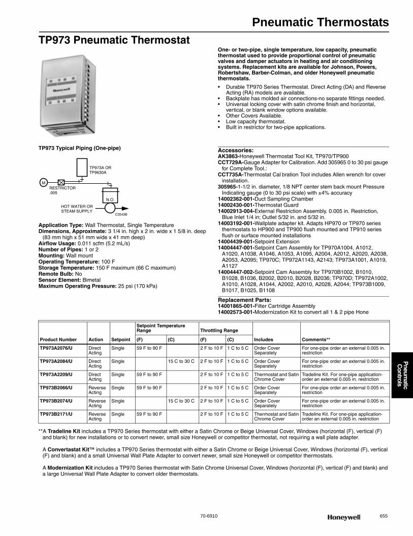
Pneumatic Thermostats
70-6910 655
P
neumatic
Controls
TP973 Pneumatic ThermostatOne- or two-pipe, single temperature, low capacity, pneumatic thermostat used to provide proportional control of pneumatic valves and damper actuators in heating and air conditioning systems. Replacement kits are available for Johnson, Powers, Robertshaw, Barber-Colman, and older Honeywell pneumatic thermostats.
• Durable TP970 Series Thermostat. Direct Acting (DA) and Reverse Acting (RA) models are available.
• Backplate has molded air connections-no separate fittings needed. • Universal locking cover with satin chrome finish and horizontal,
vertical, or blank window options available. • Other Covers Available. • Low capacity thermostat. • Built in restrictor for two-pipe applications.
TP973 Typical Piping (One-pipe)
Application Type: Wall Thermostat, Single TemperatureDimensions, Approximate: 3 1/4 in. high x 2 in. wide x 1 5/8 in. deep
(83 mm high x 51 mm wide x 41 mm deep) Airflow Usage: 0.011 scfm (5.2 mL/s)Number of Pipes: 1 or 2Mounting: Wall mountOperating Temperature: 100 FStorage Temperature: 150 F maximum (66 C maximum) Remote Bulb: NoSensor Element: BimetalMaximum Operating Pressure: 25 psi (170 kPa)
Accessories:AK3863-Honeywell Thermostat Tool Kit, TP970/TP900CCT729A-Gauge Adapter for Calibration. Add 305965 0 to 30 psi gauge
for Complete Tool.:CCT735A-Thermostat Cal bration Tool includes Allen wrench for cover
installation.305965-1-1/2 in. diameter, 1/8 NPT center stem back mount Pressure
Indicating gauge (0 to 30 psi scale) with ±4% accuracy14002362-001-Duct Sampling Chamber14002430-001-Thermostat Guard14002913-004-External Restriction Assembly. 0.005 in. Restriction,
Blue Inlet 1/4 in; Outlet 5/32 in. and 5/32 in.14003192-001-Wallplate adapter kit. Adapts HP970 or TP970 series
thermostats to HP900 and TP900 flush mounted and TP910 series flush or surface mounted installations
14004439-001-Setpoint Extension14004447-001-Setpoint Cam Assembly for TP970A1004, A1012,
A1020, A1038, A1046, A1053, A1095, A2004, A2012, A2020, A2038, A2053, A2095; TP970C; TP972A1143, A2143; TP973A1001, A1019, A1127
14004447-002-Setpoint Cam Assembly for TP970B1002, B1010, B1028, B1036, B2002, B2010, B2028, B2036; TP970D; TP972A1002, A1010, A1028, A1044, A2002, A2010, A2028, A2044; TP973B1009, B1017, B1025, B1108
Replacement Parts:14001865-001-Filter Cartridge Assembly14002573-001-Modernization Kit to convert all 1 & 2 pipe Hone
**A Tradeline Kit includes a TP970 Series thermostat with either a Satin Chrome or Beige Universal Cover, Windows (horizontal (F), vertical (F) and blank) for new installations or to convert newer, small size Honeywell or competitor thermostat, not requiring a wall plate adapter.
A Convertastat Kit™ includes a TP970 Series thermostat with either a Satin Chrome or Beige Universal Cover, Windows (horizontal (F), vertical (F) and blank) and a small Universal Wall Plate Adapter to convert newer, small size Honeywell or competitor thermostats.
A Modernization Kit includes a TP970 Series thermostat with Satin Chrome Universal Cover, Windows (horizontal (F), vertical (F) and blank) and a large Universal Wall Plate Adapter to convert older thermostats.
Product Number Action Setpoint
Setpoint Temperature Range Throttling Range
Includes Comments**(F) (C) (F) (C)
TP973A2076/U Direct Acting
Single 59 F to 90 F 2 F to 10 F 1 C to 5 C Order Cover Separately
For one-pipe order an external 0.005 in. restriction
TP973A2084/U Direct Acting
Single 15 C to 30 C 2 F to 10 F 1 C to 5 C Order Cover Separately
For one-pipe order an external 0.005 in. restriction
TP973A2209/U Direct Acting
Single 59 F to 90 F 2 F to 10 F 1 C to 5 C Thermostat and Satin Chrome Cover
Tradeline Kit. For one-pipe application- order an external 0.005 in. restriction
TP973B2066/U Reverse Acting
Single 59 F to 90 F 2 F to 10 F 1 C to 5 C Order Cover Separately
For one-pipe order an external 0.005 in. restriction
TP973B2074/U Reverse Acting
Single 15 C to 30 C 2 F to 10 F 1 C to 5 C Order Cover Separately
For one-pipe order an external 0.005 in. restriction
TP973B2171/U Reverse Acting
Single 59 F to 90 F 2 F to 10 F 1 C to 5 C Thermostat and Satin Chrome Cover
Tradeline Kit. For one-pipe application- order an external 0.005 in. restriction
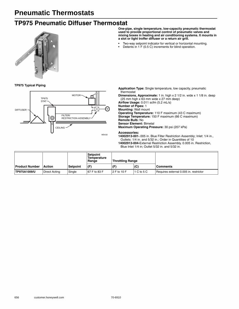
Pneumatic Thermostats
656 customer.honeywell.com 70-6910
TP975 Pneumatic Diffuser ThermostatOne-pipe, single temperature, low-capacity pneumatic thermostat used to provide proportional control of pneumatic valves and mixing boxes in heating and air conditioning systems. It mounts in a slot or light troffer diffuser or a return air grill.
• Two-way setpoint indicator for vertical or horizontal mounting. • Detents in 1 F (0.5 C) increments for blind operation.
TP975 Typical PipingApplication Type: Single temperature, low capacity, pneumatic
thermostatDimensions, Approximate: 1 in. high x 2 1/2 in. wide x 1 1/8 in. deep
(25 mm high x 63 mm wide x 27 mm deep) Airflow Usage: 0.011 scfm (5.2 mL/s)Number of Pipes: 1Mounting: Wall mountOperating Temperature: 110 F maximum (43 C maximum) Storage Temperature: 150 F maximum (66 C maximum) Remote Bulb: NoSensor Element: BimetalMaximum Operating Pressure: 30 psi (207 kPa)
Accessories:14002913-001-.005 in. Blue Filter Restriction Assembly; Inlet: 1/4 in.,
Outlets: 1/4 in. and 5/32 in.; Order in Quantities of 1014002913-004-External Restriction Assembly. 0.005 in. Restriction,
Blue Inlet 1/4 in; Outlet 5/32 in. and 5/32 in.
M5418
MOTOR
DIFFUSER
CEILING
FILTER/
RESTRICTION ASSEMBLY
TP975
STAT
M
Product Number Action Setpoint
Setpoint Temperature Range Throttling Range
Comments(F) (F) (C)
TP975A1009/U Direct Acting Single 67 F to 83 F 2 F to 10 F 1 C to 5 C Requires external 0.005 in. restrictor
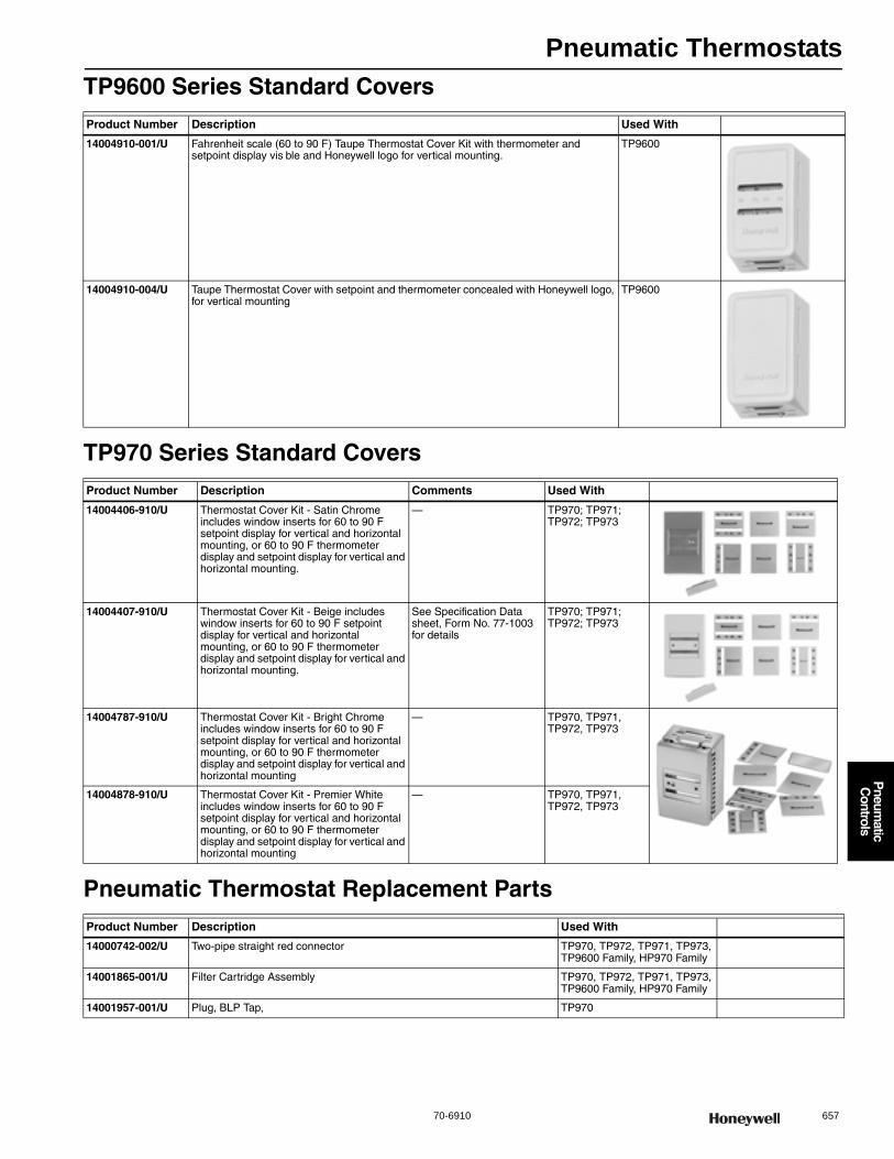
Pneumatic Thermostats
70-6910 657
P
neumatic
Controls
TP9600 Series Standard Covers
TP970 Series Standard Covers
Pneumatic Thermostat Replacement Parts
Product Number Description Used With
14004910-001/U Fahrenheit scale (60 to 90 F) Taupe Thermostat Cover Kit with thermometer and setpoint display vis ble and Honeywell logo for vertical mounting.
TP9600
14004910-004/U Taupe Thermostat Cover with setpoint and thermometer concealed with Honeywell logo, for vertical mounting
TP9600
Product Number Description Comments Used With
14004406-910/U Thermostat Cover Kit - Satin Chrome includes window inserts for 60 to 90 F setpoint display for vertical and horizontal mounting, or 60 to 90 F thermometer display and setpoint display for vertical and horizontal mounting.
— TP970; TP971; TP972; TP973
14004407-910/U Thermostat Cover Kit - Beige includes window inserts for 60 to 90 F setpoint display for vertical and horizontal mounting, or 60 to 90 F thermometer display and setpoint display for vertical and horizontal mounting.
See Specification Data sheet, Form No. 77-1003 for details
TP970; TP971; TP972; TP973
14004787-910/U Thermostat Cover Kit - Bright Chrome includes window inserts for 60 to 90 F setpoint display for vertical and horizontal mounting, or 60 to 90 F thermometer display and setpoint display for vertical and horizontal mounting
— TP970, TP971, TP972, TP973
14004878-910/U Thermostat Cover Kit - Premier White includes window inserts for 60 to 90 F setpoint display for vertical and horizontal mounting, or 60 to 90 F thermometer display and setpoint display for vertical and horizontal mounting
— TP970, TP971, TP972, TP973
Product Number Description Used With
14000742-002/U Two-pipe straight red connector TP970, TP972, TP971, TP973, TP9600 Family, HP970 Family
14001865-001/U Filter Cartridge Assembly TP970, TP972, TP971, TP973, TP9600 Family, HP970 Family
14001957-001/U Plug, BLP Tap, TP970
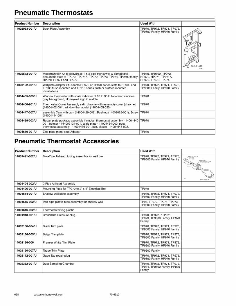
Pneumatic Thermostats
658 customer.honeywell.com 70-6910
Pneumatic Thermostat Accessories
14002053-001/U Back Plate Assembly TP970, TP972, TP971, TP973, TP9600 Family, HP970 Family
14002573-001/U Modernization Kit to convert all 1 & 2 pipe Honeywell & competitive pneumatic stats to TP970, TP971A, TP972, TP973, TP974, TP9600 family; HP970, HP971 and HP972
TP970, TP9600, TP972, HP970, HP971, TP971A, HP972, TP973, TP974
14003192-001/U Wallplate adapter kit. Adapts HP970 or TP970 series stats to HP900 and TP900 flush mounted and TP910 series flush or surface mounted installations
TP970, TP972, TP971, TP973, TP9600 Family, HP970 Family
14004405-005/U Window thermostat with scale indicator of 60 to 90 F, two clear windows, gray background, Honeywell logo in middle.
TP970
14004406-901/U Thermostat Cover Assembly satin chrome with assembly-cover [chrome] (14004402-001), window thermostat (14004405-020)
TP970
14004447-007/U assembly Cam with cam (14004429-002), Bushing (14002025-001), Screw (14004444-001)
TP970
14004459-003/U Repair plate package assembly includes: thermostat assembly - 14004440-001, pointer - 144002124-001, scale plate - 14004434-003, post, thermostat assembly - 14004436-001, box, plastic - 14004645-002.
TP970
14004610-001/U Zinc plate metal stud Adapter TP970
Product Number Description Used With
14001491-002/U Two-Pipe Airhead, tubing assembly for wall box TP970, TP972, TP971, TP973, TP9600 Family, HP970 Family
14001494-002/U 2 Pipe Airhead Assembly —
14001496-001/U Mounting Plate for TP970 to 2" x 4" Electrical Box TP970
14001614-001/U Shallow wall plate assembly TP970, TP972, TP971, TP973, TP9600 Family, HP970 Family
14001615-002/U Two-pipe plastic tube assembly for shallow wall TP97, TP972, TP971, TP973, TP9600 Family, HP970 Family
14001616-002/U Thermostat fitting plastic —
14001918-001/U Branchline Pressure plug TP970, TP972, nTP971, TP973, TP9600 Family, HP970 Family
14002136-004/U Black Trim plate TP970, TP972, TP971, TP973, TP9600 Family, HP970 Family
14002136-005/U Beige Trim plate TP970, TP972, TP971, TP973, TP9600 Family, HP970 Family
14002136-006 Premier White Trim Plate TP970, TP972, TP971, TP973, TP9600 Family, HP970 Family
14002136-007/U Taupe Trim Plate TP9600 Family
14002172-001/U Gage Tap repair plug TP970, TP972, TP971, TP973, TP9600 Family, HP970 Family
14002362-001/U Duct Sampling Chamber TP970, TP972, TP971, TP973, TP974, TP9600 Family, HP970 Family
Product Number Description Used With
BACKPLATEM5479
UP
B
M
PROTECT VE CAP
OR CAPS
PROVIDED
SNAP R NG
(FITS KNOCKOUT FOR
1/2 INCH CONDUIT)
8 FEET
[2 5 M]
BRASS ELBOWM5477
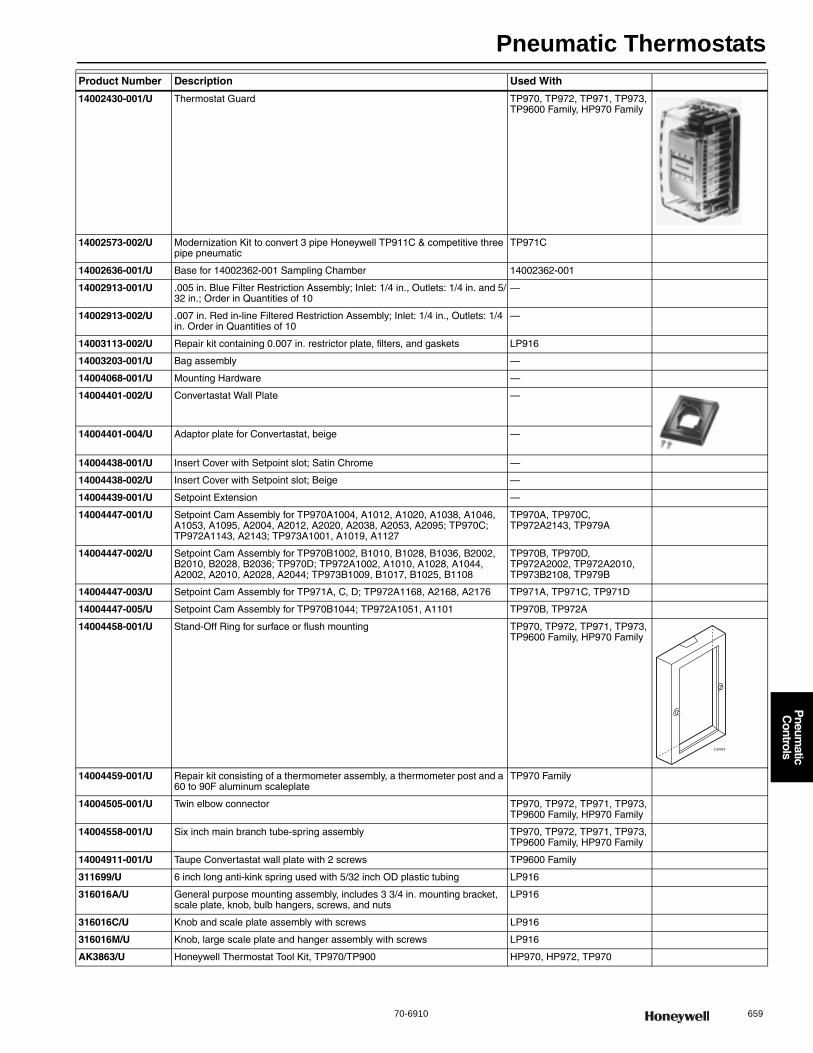
Pneumatic Thermostats
70-6910 659
P
neumatic
Controls
14002430-001/U Thermostat Guard TP970, TP972, TP971, TP973, TP9600 Family, HP970 Family
14002573-002/U Modernization Kit to convert 3 pipe Honeywell TP911C & competitive three pipe pneumatic
TP971C
14002636-001/U Base for 14002362-001 Sampling Chamber 14002362-001
14002913-001/U .005 in. Blue Filter Restriction Assembly; Inlet: 1/4 in., Outlets: 1/4 in. and 5/32 in.; Order in Quantities of 10
—
14002913-002/U .007 in. Red in-line Filtered Restriction Assembly; Inlet: 1/4 in., Outlets: 1/4 in. Order in Quantities of 10
—
14003113-002/U Repair kit containing 0.007 in. restrictor plate, filters, and gaskets LP916
14003203-001/U Bag assembly —
14004068-001/U Mounting Hardware —
14004401-002/U Convertastat Wall Plate —
14004401-004/U Adaptor plate for Convertastat, beige —
14004438-001/U Insert Cover with Setpoint slot; Satin Chrome —
14004438-002/U Insert Cover with Setpoint slot; Beige —
14004439-001/U Setpoint Extension —
14004447-001/U Setpoint Cam Assembly for TP970A1004, A1012, A1020, A1038, A1046, A1053, A1095, A2004, A2012, A2020, A2038, A2053, A2095; TP970C; TP972A1143, A2143; TP973A1001, A1019, A1127
TP970A, TP970C, TP972A2143, TP979A
14004447-002/U Setpoint Cam Assembly for TP970B1002, B1010, B1028, B1036, B2002, B2010, B2028, B2036; TP970D; TP972A1002, A1010, A1028, A1044, A2002, A2010, A2028, A2044; TP973B1009, B1017, B1025, B1108
TP970B, TP970D, TP972A2002, TP972A2010, TP973B2108, TP979B
14004447-003/U Setpoint Cam Assembly for TP971A, C, D; TP972A1168, A2168, A2176 TP971A, TP971C, TP971D
14004447-005/U Setpoint Cam Assembly for TP970B1044; TP972A1051, A1101 TP970B, TP972A
14004458-001/U Stand-Off Ring for surface or flush mounting TP970, TP972, TP971, TP973, TP9600 Family, HP970 Family
14004459-001/U Repair kit consisting of a thermometer assembly, a thermometer post and a 60 to 90F aluminum scaleplate
TP970 Family
14004505-001/U Twin elbow connector TP970, TP972, TP971, TP973, TP9600 Family, HP970 Family
14004558-001/U Six inch main branch tube-spring assembly TP970, TP972, TP971, TP973, TP9600 Family, HP970 Family
14004911-001/U Taupe Convertastat wall plate with 2 screws TP9600 Family
311699/U 6 inch long anti-kink spring used with 5/32 inch OD plastic tubing LP916
316016A/U General purpose mounting assembly, includes 3 3/4 in. mounting bracket, scale plate, knob, bulb hangers, screws, and nuts
LP916
316016C/U Knob and scale plate assembly with screws LP916
316016M/U Knob, large scale plate and hanger assembly with screws LP916
AK3863/U Honeywell Thermostat Tool Kit, TP970/TP900 HP970, HP972, TP970
Product Number Description Used With
C8404
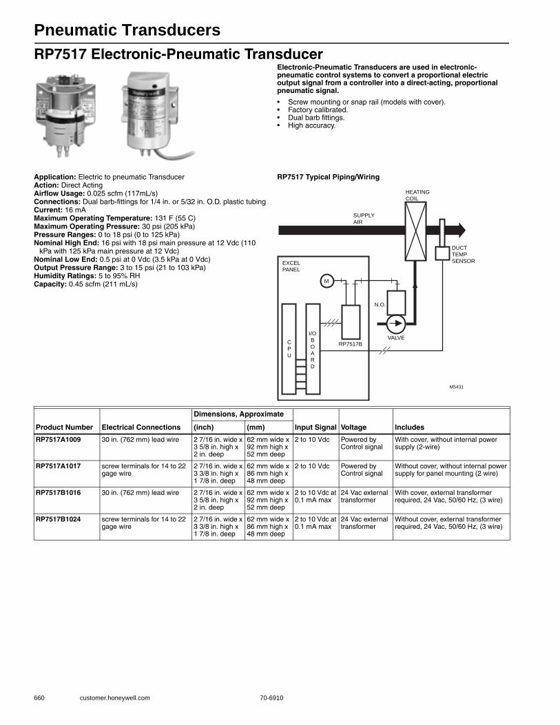
Pneumatic Transducers
660 customer.honeywell.com 70-6910
RP7517 Electronic-Pneumatic TransducerElectronic-Pneumatic Transducers are used in electronic-pneumatic control systems to convert a proportional electric output signal from a controller into a direct-acting, proportional pneumatic signal.
• Screw mounting or snap rail (models with cover). • Factory calibrated. • Dual barb fittings. • High accuracy.
Application: Electric to pneumatic TransducerAction: Direct ActingAirflow Usage: 0.025 scfm (117mL/s)Connections: Dual barb-fittings for 1/4 in. or 5/32 in. O.D. plastic tubingCurrent: 16 mAMaximum Operating Temperature: 131 F (55 C) Maximum Operating Pressure: 30 psi (205 kPa) Pressure Ranges: 0 to 18 psi (0 to 125 kPa) Nominal High End: 16 psi with 18 psi main pressure at 12 Vdc (110
kPa with 125 kPa main pressure at 12 Vdc) Nominal Low End: 0.5 psi at 0 Vdc (3.5 kPa at 0 Vdc) Output Pressure Range: 3 to 15 psi (21 to 103 kPa) Humidity Ratings: 5 to 95% RHCapacity: 0.45 scfm (211 mL/s)
RP7517 Typical Piping/Wiring
M
M5431
VALVE
DUCT
TEMP
SENSOR
SUPPLY
AIR
HEATING
COIL
N.O.
C
P
U
I/O
B
O
A
R
D
RP7517B
EXCEL
PANEL
Product Number Electrical Connections
Dimensions, Approximate
Input Signal Voltage Includes(inch) (mm)
RP7517A1009 30 in. (762 mm) lead wire 2 7/16 in. wide x 3 5/8 in. high x 2 in. deep
62 mm wide x 92 mm high x 52 mm deep
2 to 10 Vdc Powered by Control signal
With cover, without internal power supply (2-wire)
RP7517A1017 screw terminals for 14 to 22 gage wire
2 7/16 in. wide x 3 3/8 in. high x 1 7/8 in. deep
62 mm wide x 86 mm high x 48 mm deep
2 to 10 Vdc Powered by Control signal
Without cover, without internal power supply for panel mounting (2 wire)
RP7517B1016 30 in. (762 mm) lead wire 2 7/16 in. wide x 3 5/8 in. high x 2 in. deep
62 mm wide x 92 mm high x 52 mm deep
2 to 10 Vdc at 0.1 mA max
24 Vac external transformer
With cover, external transformer required, 24 Vac, 50/60 Hz, (3 wire)
RP7517B1024 screw terminals for 14 to 22 gage wire
2 7/16 in. wide x 3 3/8 in. high x 1 7/8 in. deep
62 mm wide x 86 mm high x 48 mm deep
2 to 10 Vdc at 0.1 mA max
24 Vac external transformer
Without cover, external transformer required, 24 Vac, 50/60 Hz, (3 wire)
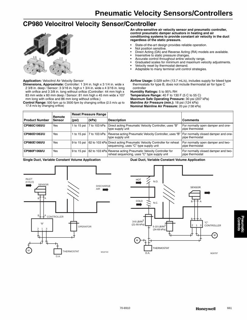
Pneumatic Velocity Sensors/Controllers
70-6910 661
P
neumatic
Controls
CP980 Velocitrol Velocity Sensor/ControllerAn ultra-sensitive air velocity sensor and pneumatic controller, control pneumatic damper actuators in heating and air conditioning systems to provide constant air velocity in the duct regardless of the static pressure.
• State-of-the-art design provides reliable operation. • Not position sensitive.• Direct Acting (DA) and Reverse Acting (RA) models are available. • Insensitive to static pressure changes.• Accurate control throughout entire velocity range.• Graduated scales for minimum and maximum velocity adjustments.• Velocity reset by thermostat demand.• Adaptable to many terminal unit control strategies.
Application: Velocitrol Air Velocity SensorDimensions, Approximate: Controller: 1 3/4 in. high x 3 1/4 in. wide x
2 3/8 in. deep / Sensor: 3 3/16 in. high x 1 3/4 in. wide x 4 3/16 in. long with orifice and 3 3/8 in. long without orifice (Controller: 44 mm high x 83 mm wide x 60 mm deep / Sensor: 81 mm high x 45 mm wide x 107 mm long with orifice and 86 mm long without orifice.)
Control Range: 500 fpm up to 3500 fpm by changing orifice (2.5 m/s up to 17.8 m/s by changing orifice)
Airflow Usage: 0.029 scfm (13.7 mL/s), includes supply for bleed type thermostats for type B, does not include thermostat air for type C controller
Humidity Ratings: 5 to 95% RHTemperature Range: 40 F to 130 F (5 C to 55 C) Maximum Safe Operating Pressure: 30 psi (207 kPa) Mainline Air Pressure (min.): 18 psi (124 kPa) Nominal Mainline Air Pressure: 20 psi (138 kPa)
Single Duct, Variable Constant Volume Application Dual Duct, Variable Constant Volume Application
Product NumberRemote Sensor
Reset Pressure Range
Description Comments(psi) (kPa)
CP980C1065/U Yes 1 to 15 psi 7 to 103 kPa Direct acting Pneumatic Velocity Controller, uses “B” type supply unit
For normally open damper and one-pipe thermostat
CP980D1063/U Yes 1 to 15 psi 7 to 103 kPa Reverse acting Pneumatic Velocity Controller, uses “B” type supply unit
For normally closed damper and one-pipe thermostat
CP980E1060/U Yes 9 to 15 psi 62 to 103 kPa Direct acting Pneumatic Velocity Controller for reheat sequencing, uses “C” type supply unit
For normally open damper and two-pipe thermostat
CP980F1068/U Yes 9 to 15 psi 62 to 103 kPa Reverse acting Pneumatic Velocity Controller for reheat sequencing, uses “C” type supply unit
For normally closed damper and two-pipe thermostat
M16743
INLET
(COLD)
CONTROLLER
SENSORDISCHARGE
AIR
M
B A
B A
2 1 3
THERMOSTAT
D.A.
“B”
OPERATOR
M16707
HOT
COLD
N.O.
N.C.
3-8 LB/IN2
(21-55 kPa)5-10 LB/IN
2
(34-69 kPa)
"C"
CONTROLLER
SENSOR
M
M
B A
B A
2 1 3
THERMOSTAT
D.A.
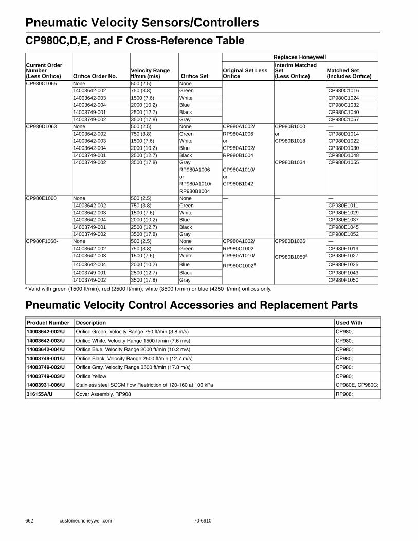
Pneumatic Velocity Sensors/Controllers
662 customer.honeywell.com 70-6910
CP980C,D,E, and F Cross-Reference Table.
a Valid with green (1500 ft/min), red (2500 ft/min), white (3500 ft/min) or blue (4250 ft/min) orifices only.
Pneumatic Velocity Control Accessories and Replacement Parts
Current Order Number (Less Orifice) Orifice Order No.
Velocity Range ft/min (m/s) Orifice Set
Replaces Honeywell
Original Set Less Orifice
Interim Matched Set (Less Orifice)
Matched Set (Includes Orifice)
CP980C1065 None 500 (2.5) None — — —14003642-002 750 (3.8) Green CP980C101614003642-003 1500 (7.6) White CP980C102414003642-004 2000 (10.2) Blue CP980C103214003749-001 2500 (12.7) Black CP980C104014003749-002 3500 (17.8) Gray CP980C1057
CP980D1063 None 500 (2.5) None CP980A1002/ CP980B1000 —14003642-002 750 (3.8) Green RP980A1006 or CP980D101414003642-003 1500 (7.6) White or CP980B1018 CP980D102214003642-004 2000 (10.2) Blue CP980A1002/ CP980D103014003749-001 2500 (12.7) Black RP980B1004 CP980D104814003749-002 3500 (17.8) Gray CP980B1034 CP980D1055
RP980A1006 CP980A1010/or orRP980A1010/ CP980B1042RP980B1004
CP980E1060 None 500 (2.5) None — — —14003642-002 750 (3.8) Green CP980E101114003642-003 1500 (7.6) White CP980E102914003642-004 2000 (10.2) Blue CP980E103714003749-001 2500 (12.7) Black CP980E104514003749-002 3500 (17.8) Gray CP980E1052
CP980F1068- None 500 (2.5) None CP980A1002/ CP980B1026 —14003642-002 750 (3.8) Green RP980C1002 CP980F101914003642-003 1500 (7.6) White CP980A1010/ CP980B1059a CP980F1027
14003642-004 2000 (10.2) Blue RP980C1002a CP980F1035
14003749-001 2500 (12.7) Black CP980F104314003749-002 3500 (17.8) Gray CP980F1050
Product Number Description Used With
14003642-002/U Orifice Green, Velocity Range 750 ft/min (3.8 m/s) CP980;
14003642-003/U Orifice White, Velocity Range 1500 ft/min (7.6 m/s) CP980;
14003642-004/U Orifice Blue, Velocity Range 2000 ft/min (10.2 m/s) CP980;
14003749-001/U Orifice Black, Velocity Range 2500 ft/min (12.7 m/s) CP980;
14003749-002/U Orifice Gray, Velocity Range 3500 ft/min (17.8 m/s) CP980;
14003749-003/U Orifice Yellow CP980;
14003931-006/U Stainless steel SCCM flow Restriction of 120-160 at 100 kPa CP980E, CP980C;
316155A/U Cover Assembly, RP908 RP908;
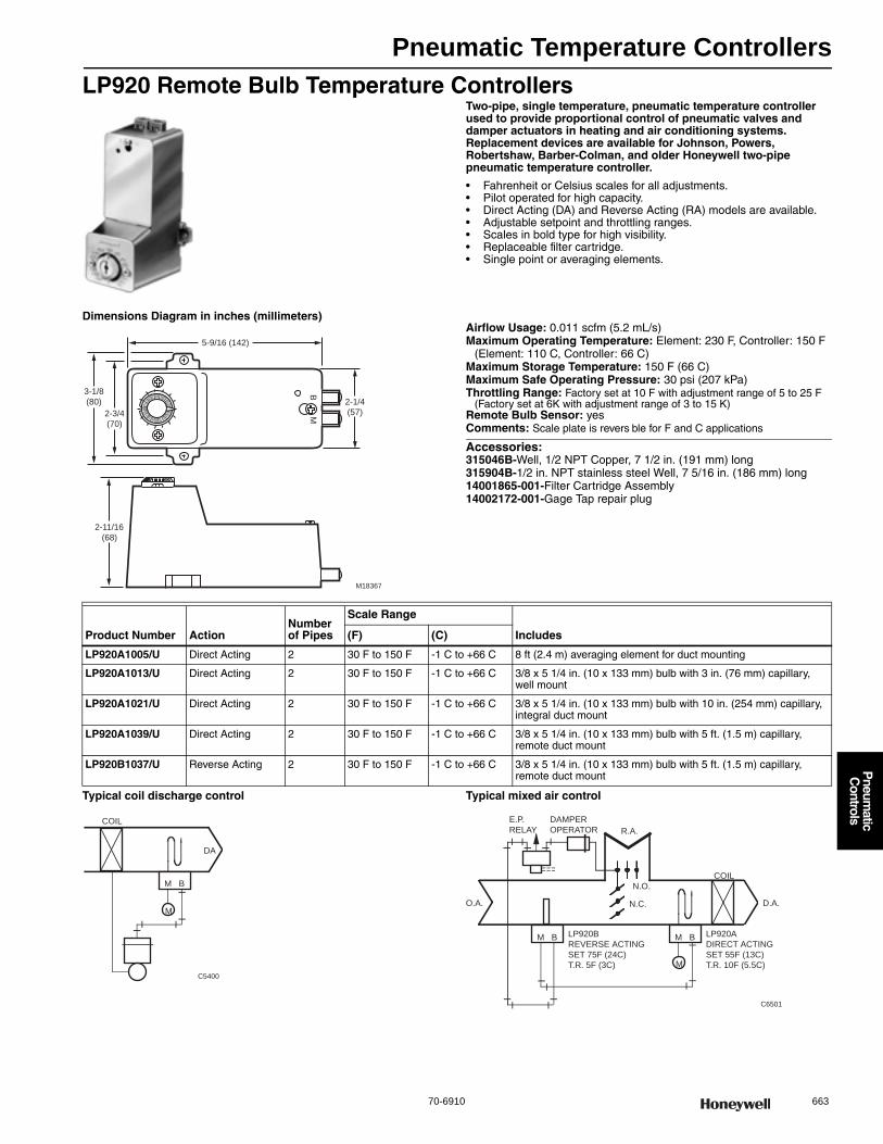
Pneumatic Temperature Controllers
70-6910 663
P
neumatic
Controls
LP920 Remote Bulb Temperature ControllersTwo-pipe, single temperature, pneumatic temperature controller used to provide proportional control of pneumatic valves and damper actuators in heating and air conditioning systems. Replacement devices are available for Johnson, Powers, Robertshaw, Barber-Colman, and older Honeywell two-pipe pneumatic temperature controller.
• Fahrenheit or Celsius scales for all adjustments. • Pilot operated for high capacity. • Direct Acting (DA) and Reverse Acting (RA) models are available. • Adjustable setpoint and throttling ranges. • Scales in bold type for high visibility. • Replaceable filter cartridge. • Single point or averaging elements.
Dimensions Diagram in inches (millimeters)Airflow Usage: 0.011 scfm (5.2 mL/s)Maximum Operating Temperature: Element: 230 F, Controller: 150 F
(Element: 110 C, Controller: 66 C) Maximum Storage Temperature: 150 F (66 C) Maximum Safe Operating Pressure: 30 psi (207 kPa) Throttling Range: Factory set at 10 F with adjustment range of 5 to 25 F
(Factory set at 6K with adjustment range of 3 to 15 K)Remote Bulb Sensor: yesComments: Scale plate is revers ble for F and C applications
Accessories:315046B-Well, 1/2 NPT Copper, 7 1/2 in. (191 mm) long315904B-1/2 in. NPT stainless steel Well, 7 5/16 in. (186 mm) long14001865-001-Filter Cartridge Assembly14002172-001-Gage Tap repair plug
Typical coil discharge control Typical mixed air control
BM
3-1/8
(80)
2-11/16
(68)
2-3/4
(70)
5-9/16 (142)
2-1/4
(57)
M18367
Product Number ActionNumber of Pipes
Scale Range
Includes(F) (C)
LP920A1005/U Direct Acting 2 30 F to 150 F -1 C to +66 C 8 ft (2.4 m) averaging element for duct mounting
LP920A1013/U Direct Acting 2 30 F to 150 F -1 C to +66 C 3/8 x 5 1/4 in. (10 x 133 mm) bulb with 3 in. (76 mm) capillary, well mount
LP920A1021/U Direct Acting 2 30 F to 150 F -1 C to +66 C 3/8 x 5 1/4 in. (10 x 133 mm) bulb with 10 in. (254 mm) capillary, integral duct mount
LP920A1039/U Direct Acting 2 30 F to 150 F -1 C to +66 C 3/8 x 5 1/4 in. (10 x 133 mm) bulb with 5 ft. (1.5 m) capillary, remote duct mount
LP920B1037/U Reverse Acting 2 30 F to 150 F -1 C to +66 C 3/8 x 5 1/4 in. (10 x 133 mm) bulb with 5 ft. (1.5 m) capillary, remote duct mount
M
M B
COIL
DA
C5400
C6501
M
M B
COIL
N.O.
N.C.O.A. D.A.
DAMPER
OPERATOR R.A.
LP920B
REVERSE ACTING
SET 75F (24C)
T.R. 5F (3C)
M B LP920A
DIRECT ACTING
SET 55F (13C)
T.R. 10F (5.5C)
E.P.
RELAY
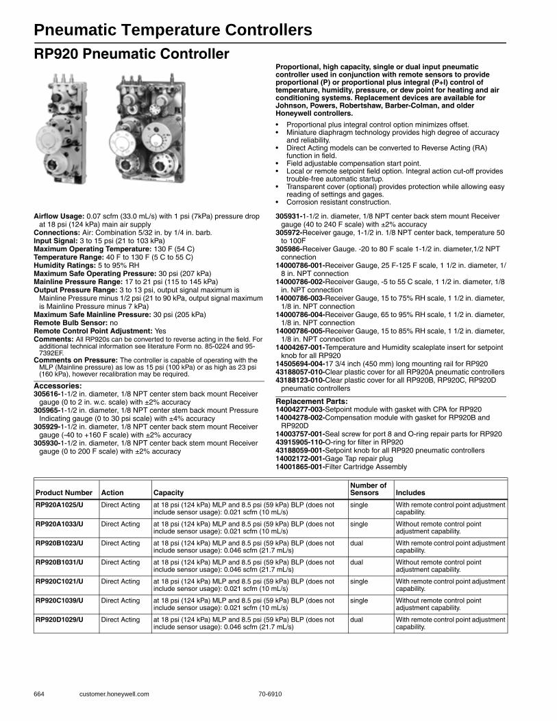
Pneumatic Temperature Controllers
664 customer.honeywell.com 70-6910
RP920 Pneumatic ControllerProportional, high capacity, single or dual input pneumatic controller used in conjunction with remote sensors to provide proportional (P) or proportional plus integral (P+I) control of temperature, humidity, pressure, or dew point for heating and air conditioning systems. Replacement devices are available for Johnson, Powers, Robertshaw, Barber-Colman, and older Honeywell controllers.
• Proportional plus integral control option minimizes offset. • Miniature diaphragm technology provides high degree of accuracy
and reliability. • Direct Acting models can be converted to Reverse Acting (RA)
function in field. • Field adjustable compensation start point. • Local or remote setpoint field option. Integral action cut-off provides
trouble-free automatic startup. • Transparent cover (optional) provides protection while allowing easy
reading of settings and gages. • Corrosion resistant construction.
Airflow Usage: 0.07 scfm (33.0 mL/s) with 1 psi (7kPa) pressure drop at 18 psi (124 kPa) main air supply
Connections: Air: Combination 5/32 in. by 1/4 in. barb.Input Signal: 3 to 15 psi (21 to 103 kPa) Maximum Operating Temperature: 130 F (54 C) Temperature Range: 40 F to 130 F (5 C to 55 C) Humidity Ratings: 5 to 95% RHMaximum Safe Operating Pressure: 30 psi (207 kPa) Mainline Pressure Range: 17 to 21 psi (115 to 145 kPa) Output Pressure Range: 3 to 13 psi, output signal maximum is
Mainline Pressure minus 1/2 psi (21 to 90 kPa, output signal maximum is Mainline Pressure minus 7 kPa)
Maximum Safe Mainline Pressure: 30 psi (205 kPa)Remote Bulb Sensor: noRemote Control Point Adjustment: YesComments: All RP920s can be converted to reverse acting in the field. For
additional technical information see literature Form no. 85-0224 and 95-7392EF.
Comments on Pressure: The controller is capable of operating with the MLP (Mainline pressure) as low as 15 psi (100 kPa) or as high as 23 psi (160 kPa), however recalibration may be required.
Accessories:305616-1-1/2 in. diameter, 1/8 NPT center stem back mount Receiver
gauge (0 to 2 in. w.c. scale) with ±2% accuracy305965-1-1/2 in. diameter, 1/8 NPT center stem back mount Pressure
Indicating gauge (0 to 30 psi scale) with ±4% accuracy305929-1-1/2 in. diameter, 1/8 NPT center back stem mount Receiver
gauge (-40 to +160 F scale) with ±2% accuracy305930-1-1/2 in. diameter, 1/8 NPT center back stem mount Receiver
gauge (0 to 200 F scale) with ±2% accuracy
305931-1-1/2 in. diameter, 1/8 NPT center back stem mount Receiver gauge (40 to 240 F scale) with ±2% accuracy
305972-Receiver gauge, 1-1/2 in. 1/8 NPT center back, temperature 50 to 100F
305986-Receiver Gauge. -20 to 80 F scale 1-1/2 in. diameter,1/2 NPT connection
14000786-001-Receiver Gauge, 25 F-125 F scale, 1 1/2 in. diameter, 1/8 in. NPT connection
14000786-002-Receiver Gauge, -5 to 55 C scale, 1 1/2 in. diameter, 1/8 in. NPT connection
14000786-003-Receiver Gauge, 15 to 75% RH scale, 1 1/2 in. diameter, 1/8 in. NPT connection
14000786-004-Receiver Gauge, 65 to 95% RH scale, 1 1/2 in. diameter, 1/8 in. NPT connection
14000786-005-Receiver Gauge, 15 to 85% RH scale, 1 1/2 in. diameter, 1/8 in. NPT connection
14004267-001-Temperature and Humidity scaleplate insert for setpoint knob for all RP920
14505694-004-17 3/4 inch (450 mm) long mounting rail for RP92043188057-010-Clear plastic cover for all RP920A pneumatic controllers43188123-010-Clear plastic cover for all RP920B, RP920C, RP920D
pneumatic controllers
Replacement Parts:14004277-003-Setpoint module with gasket with CPA for RP92014004278-002-Compensation module with gasket for RP920B and
RP920D14003757-001-Seal screw for port 8 and O-ring repair parts for RP92043915905-110-O-ring for filter in RP92043188059-001-Setpoint knob for all RP920 pneumatic controllers14002172-001-Gage Tap repair plug14001865-001-Filter Cartridge Assembly
Product Number Action CapacityNumber of Sensors Includes
RP920A1025/U Direct Acting at 18 psi (124 kPa) MLP and 8.5 psi (59 kPa) BLP (does not include sensor usage): 0.021 scfm (10 mL/s)
single With remote control point adjustment capability.
RP920A1033/U Direct Acting at 18 psi (124 kPa) MLP and 8.5 psi (59 kPa) BLP (does not include sensor usage): 0.021 scfm (10 mL/s)
single Without remote control point adjustment capability.
RP920B1023/U Direct Acting at 18 psi (124 kPa) MLP and 8.5 psi (59 kPa) BLP (does not include sensor usage): 0.046 scfm (21.7 mL/s)
dual With remote control point adjustment capability.
RP920B1031/U Direct Acting at 18 psi (124 kPa) MLP and 8.5 psi (59 kPa) BLP (does not include sensor usage): 0.046 scfm (21.7 mL/s)
dual Without remote control point adjustment capability.
RP920C1021/U Direct Acting at 18 psi (124 kPa) MLP and 8.5 psi (59 kPa) BLP (does not include sensor usage): 0.021 scfm (10 mL/s)
single With remote control point adjustment capability.
RP920C1039/U Direct Acting at 18 psi (124 kPa) MLP and 8.5 psi (59 kPa) BLP (does not include sensor usage): 0.021 scfm (10 mL/s)
single Without remote control point adjustment capability.
RP920D1029/U Direct Acting at 18 psi (124 kPa) MLP and 8.5 psi (59 kPa) BLP (does not include sensor usage): 0.046 scfm (21.7 mL/s)
dual With remote control point adjustment capability.

Pneumatic Temperature Controllers
70-6910 665
P
neumatic
Controls
Dimensions Diagram in inches (millimeters) Typical Dual-Input Control System
Typical Single-Input Control System
M17581RP90A: 1-7/8 (48)
RP920B-D: 3-13/16 (96)
1/8 (3)
MINIMUM
SPACING
BETWEEN
MODULES
3 (75) MINIMUM CLEARANCE
4
(102)
5-7/8
(148)
3-3/8 (86)9/32
(7)
RP920A: 1-1/2 (36)RP920B-D: 3-1/4 (83)
4 8 9
2 3 1
7
56
M
M
(COIL DISCHARGE)
(TEMPERATURE)
PRIMARY
SENSOR
VALVE
N.O.
COMPENSATION
SENSOR (OUTDOOR AIR)
RP920B OR D
C3361-1
0.007 IN.
RESTRICTION
HOT WATER CONVERTERCONTROL SYSTEM
C87-2
M
2 4
1
M
CPA
OPTIONAL CPA
MODELS ONLY
RP920A OR C
DA
PRIMARY
SENSOR IN HW
SUPPLY LINE
N.O.
TO CONVERTERSTEAM
SUPPLY
4 8 9
2 3 1
M
2
1
4
3
12
3
RP970A
PRIMARY
CONTROLLER
RP920C
4 8 9
2 3 1
7IM 5
6D.A.
1
2 4
M
4 8 9
2 3 1
M
LIMIT
CONTROLLER
RP920A
R.A.
FROM
FAN
INTERLOCK
VENT
E-P
RELAY
DAMPER
ACTUATOR
SP970
MINIMUM
POSITION
REGULATOR
OUTDOOR
AIR
RETURN
AIR
PRIMARY
SENSOR
SUPPLY
AIR
MIXED AIR CONTROL SYSTEM
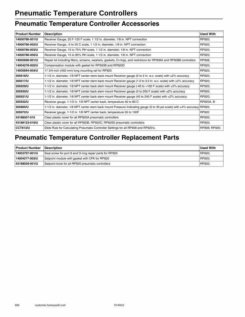
Pneumatic Temperature Controllers
666 customer.honeywell.com 70-6910
Pneumatic Temperature Controller Accessories
Pneumatic Temperature Controller Replacement Parts
Product Number Description Used With
14000786-001/U Receiver Gauge, 25 F-125 F scale, 1 1/2 in. diameter, 1/8 in. NPT connection RP920;
14000786-002/U Receiver Gauge, -5 to 55 C scale, 1 1/2 in. diameter, 1/8 in. NPT connection RP920;
14000786-003/U Receiver Gauge, 15 to 75% RH scale, 1 1/2 in. diameter, 1/8 in. NPT connection RP920;
14000786-005/U Receiver Gauge, 15 to 85% RH scale, 1 1/2 in. diameter, 1/8 in. NPT connection RP920;
14002696-001/U Repair kit including filters, screens, washers, gaskets, O-rings, and restrictors for RP908A and RP908B controllers RP908;
14004278-002/U Compensation module with gasket for RP920B and RP920D RP920;
14505694-004/U 17 3/4 inch (450 mm) long mounting rail for RP920 RP920;
305616/U 1-1/2 in. diameter, 1/8 NPT center stem back mount Receiver gauge (0 to 2 in. w.c. scale) with ±2% accuracy RP920;
305617/U 1-1/2 in. diameter, 1/8 NPT center stem back mount Receiver gauge (1.0 to 3.0 in. w.c. scale) with ±2% accuracy RP920;
305929/U 1-1/2 in. diameter, 1/8 NPT center back stem mount Receiver gauge (-40 to +160 F scale) with ±2% accuracy RP920;
305930/U 1-1/2 in. diameter, 1/8 NPT center back stem mount Receiver gauge (0 to 200 F scale) with ±2% accuracy RP920;
305931/U 1-1/2 in. diameter, 1/8 NPT center back stem mount Receiver gauge (40 to 240 F scale) with ±2% accuracy RP920;
305932/U Receiver gauge, 1-1/2 in. 1/8 NPT center back, temperature 40 to 60 C RP920A, B
305965/U 1-1/2 in. diameter, 1/8 NPT center stem back mount Pressure Indicating gauge (0 to 30 psi scale) with ±4% accuracy RP920;
305972/U Receiver gauge, 1-1/2 in. 1/8 NPT center back, temperature 50 to 100F RP920
43188057-010 Clear plastic cover for all RP920A pneumatic controllers RP920;
43188123-010/U Clear plastic cover for all RP920B, RP920C, RP920D pneumatic controllers RP920;
CCT813/U Slide Rule for Calculating Pneumatic Controller Settings for all RP908 and RP920's. RP908; RP920;
Product Number Description Used With
14003757-001/U Seal screw for port 8 and O-ring repair parts for RP920 RP920;
14004277-003/U Setpoint module with gasket with CPA for RP920 RP920;
43188059-001/U Setpoint knob for all RP920 pneumatic controllers RP920;
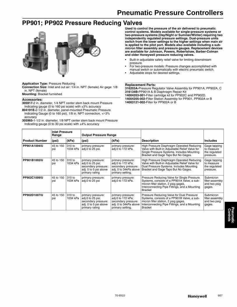
Pneumatic Pressure Controllers
70-6910 667
P
neumatic
Controls
PP901; PP902 Pressure Reducing ValvesUsed to control the pressure of the air delivered to pneumatic control systems. Models available for single-pressure systems or two-pressure systems (Day/Night or Summer/Winter) requiring two independently regulated pressure settings. Dual-pressure units switch from the lower settings to the higher settings when main air is applied to the pilot port. Models also available including a sub-micron filter assembly and pressure gauges. Replacement devices are available for Johnson, Powers, Robertshaw, Barber-Colman and older Honeywell pressure reducing valves.
• Built-in adjustable safety relief valve for limiting downstream pressure.
• For two-pressure models: Pressure changes accomplished with manual switch or automatically with electric pneumatic switch.
• Adjustable stops for desired settings.
Application Type: Pressure ReducingConnection Size: Inlet and out air: 1/4 in. NPT (female) Air gage: 1/8
in. NPT (female)Mounting: Bracket furnished
Accessories:305917-2 in. diameter, 1/4 NPT center stem back mount Pressure
Indicating gauge (0 to 160 psi scale) with ±3% accuracy804191E-2-1/2 in. diameter, panel-mounted Pneumatic Pressure
Indicating Gauge (0 to 160 psi), 1/8 in. NPT connection, +/-3% accuracy
305965-1-1/2 in. diameter, 1/8 NPT center stem back mount Pressure Indicating gauge (0 to 30 psi scale) with ±4% accuracy
Replacement Parts:316203A-Pressure Regulator Valve Assembly for PP901A; PP902A, C316134B-PP901A & B Diaphragm Repair Kit14004203-001-Filter cartridge kit for PP902C and PP902D.14004205-002-Filter Station Assembly for PP901, PP902A or B14003121-002-Filter for PP902A or B
Product Number
Inlet Pressure Range Output Pressure Range
Description Includes(psi) (kPa) (psi) (kPa)
PP901A1004/U 45 to 150 psi
310 to 1034 kPa
primary pressure: adj.0 to 25 psi.
primary pressure: adj.0 to 172 kPa.
High Pressure Diaphragm Operated Reducing Valve with Built-in Adjustable Relief Valve for Single Pressure Systems. Includes Mounting Bracket and Gage Taps But No Gages.
Gage tapping to measure the regulated pressure.
PP901B1002/U 45 to 150 psi
310 to 1034 kPa
primary pressure: adj.0 to 25 psi; secondary pressure: adj. 0 to 5 psi above primary rating
primary pressure: adj.0 to 172 kPa; secondary pressure: adj. 0 to 34kPa above primary setting.
High Pressure Diaphragm Operated Reducing Valve with Built-in Adjustable Relief Valve for Dual Pressure Systems. Includes Mounting Bracket and Gage Taps But No Gages.
Gage tapping to measure the regulated pressure.
PP902C1009/U 45 to 150 psi
310 to 1034 kPa
primary pressure: adj.0 to 25 psi
primary pressure: adj.0 to 172 kPa.
Pressure Reducing Valve for Single Pressure Systems, consists of a PP901A Valve, a sub-micron filter station, 2 psig gages, Interconnecting Pipe Fittings, and a Mounting Bracket
Submicron filter assembly and two psig gages.
PP902D1007/U 45 to 150 psi
310 to 1034 kPa
primary pressure: adj.0 to 25 psi; secondary pressure: adj. 0 to 5 psi above primary rating
primary pressure: adj.0 to 172 kPa; secondary pressure: adj. 0 to 34kPa above primary setting.
Pressure Reducing Valve for Dual Pressure Systems, consists of a PP901B Valve, a sub-micron filter station, 2 psig gages, Interconnecting Pipe Fittings, and a Mounting Bracket
Submicron filter assembly and two psig gages.

Pneumatic Pressure Controllers
668 customer.honeywell.com 70-6910
PP901 Dimensions in inches (millimeters) PP902 Dimensions in inches (millimeters)
PP902D Typical Operation PP902C Typical Operation
1- 1/ 2
(38)
1/4 NPTOUTLE T
1/4 NPTINLET
C5146
GAGE
CONNECTION
1/8 NPT
SWITCHOVER
INLET PORT
(PP901B ONLY)
2-1/4
(57)
3-1/4 (83)
4-7/8
(124)
5-3/8(135)
C5325
8-5/8(219)
3-7/8(100)
9-5/8(244)
5-3/4(146)
15
20
25
300
5
10
psig
80100
120
1600
20
40
psig
140
60
IN
2
3
1E X
FROM
COMPRESSOR
FILTER
OUT
PRV
REDUCED
PRESSURE
TO SYSTEM
C5544
TO AUTOMATIC OR
MANUAL SWITCHOVER
CONTROLEP RELAY
IN
FROM
COMPRESSOR
FILTER
REDUCED
PRESSURE
TO SYSTEM
C5543
PRV
OUT

Pneumatic Pressure Controllers
70-6910 669
P
neumatic
Controls
PP903 Pneumatic Differential PressuretrolOne-pipe, pressure operated device used to provide proportional control of pneumatic valve or damper actuators by varying the pressure to the actuators in relation to the pressure difference between two separate water pressures. Replacement devices are available for Johnson, Powers, Robertshaw, and older Honeywell pneumatic pressure controllers.
• Easily accessible adjustments.• Direct Acting (DA) or Reverse Acting (RA) setting.• Mounting lugs for quick mounting.
Dimensions Diagram PP903A Typical Piping
Application Type: Differential PressureAction: Reverse Acting, Direct ActingConnection Size: Input: 1/4 in. NPT; Branch Line: 1/8 in. NPTPressure Range: 0 to 300 psi (0 to 2068 kPa) Approximate Throttling Range, Midscale (max.): 25 psi (172 kPa) Mounting: Lugs for 3-point surface mounting
9-11/16 (246)
8-5/8(219)
3-5/16 (84)
M27078
M5423
RETURN
MAIN
PP903A
SUPPLY
MAIN
HAND
VALVE GAGE
TEE
HAND
VALVE GAGE
TEE
RESTRICTION
HEAT
EXCHANGER
PUMP
N.O.
M
Product Number
Actuator Force Maximum Operating Pressure Differential Pressure Range
(psi) (kPa) (psi) (kPa) (psi) (kPa)
PP903A1036/U 7.5 psi 52 kPa 18 psi 124 kPa 5 to 65 psi 34 to 448 kPa
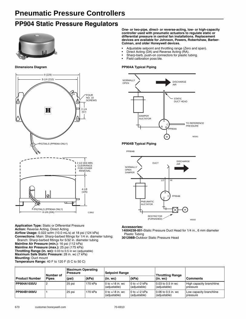
Pneumatic Pressure Controllers
670 customer.honeywell.com 70-6910
PP904 Static Pressure RegulatorsOne- or two-pipe, direct- or reverse-acting, low- or high-capacity controller used with pneumatic actuators to regulate static or differential pressure in central fan installations. Replacement devices are available for Johnson, Powers, Robertshaw, Barber-Colman, and older Honeywell devices.
• Adjustable setpoint and throttling range (Zero and span). • Direct Acting (DA) and Reverse Acting (RA). • Sharp-barb, push-on connectors for plastic tubing. • Field calibration poss ble.
Dimensions Diagram PP904A Typical Piping
PP904B Typical Piping
Application Type: Static or Differential PressureAction: Reverse Acting, Direct ActingAirflow Usage: 0.022 scfm (10.0 mL/s) at 18 psi (124 kPa)Connections: Main: Sharp-barbed fittings for 1/4 in. diameter tubing;
Branch: Sharp-barbed fittings for 5/32 in. diameter tubingMainline Air Pressure (min.): 16 psi (112 kPa) Mainline Air Pressure (max.): 25 psi (175 kPa) Throttling Range (in. wc): 0.03 to 0.5 in wc (adjustable)Maximum Safe Static Pressure: 28 in. wc (7 kPa) Mounting: Duct mountTemperature Range: 40 F to 120 F (5 C to 50 C)
Accessories:14004238-001-Static Pressure Duct Head for 1/4 in., 6 mm diameter
Plastic Tubing301298B-Outdoor Static Pressure Head
A
8-1/4 (210)
2-1/4(57)
FOURNO. 10SCREWS
9 (229)
2-1/2 (63) MIN.CLEARANCEFOR COVERREMOVAL
4-1/8(105)
PIGTAILS (PP904A ONLY)
8-1/8 (206) C3952
PIGTAILS (PP904A ONLY)
DAMPER
AUCTATOR
PP904A
M M5561
DISCHARGE
AIR
STATIC
DUCT HEAD
TO REFERENCE
PRESSURE
NORMALLY
OPEN
A
CMB
PNEUMATIC
AUCTATOR
PP904B
M
M5562
DISCHARGE
AIR
RESTRICTOR
(FURNISHED)
NORMALLY
OPEN
DAMPER
A
C
DUCT
PP904B
HILO
Product NumberNumber of Pipes
Maximum Operating Pressure Setpoint Range
Throttling Range (in. wc) Comments(psi) (kPa) (in. wc) (kPa)
PP904A1035/U 2 25 psi 170 kPa 0 to +/-8 in. wc (adjustable)
0 to +/-2 kPa (adjustable)
0.03 to 0.5 in wc (adjustable)
High capacity branchline pressure
PP904B1009/U 1 25 psi 170 kPa 0 to +/-8 in. wc (adjustable)
0 to +/-2 kPa (adjustable)
0.06 to 0.5 in. wc (adjustable)
Low capacity branchline pressure

Pneumatic Pressure Controllers
70-6910 671
P
neumatic
Controls
PP905 Static Pressure SensorOne-pipe, direct-or reverse-acting pressure sensor used with RP908/RP920 Controllers to provide control of duct static, velocity, or differential pressure in airflow applications. Replacement devices available for Johnson, Powers, Robertshaw, Barber-Colman, and older Honeywell devices.• Three-diaphragm design minimizes cal bration shift with static
pressure changes in velocity pressure applications. • Not sensitive to normal supply air variations. • Continuous static, total, velocity, or differential pressure indication
available by using differential pressure gage.
Dimensions Diagram PP905 in Pneumatic Static Pressure Application
Application Type: Static PressureAction: Can be set for Direct Acting or Reverse ActingAirflow Usage: 0.021 cfm (9.9 ml/s)Connections: Push-on barb for 1/4 in (6 mm) Diameter tubingMainline Air Pressure (min.): 16 psi (112 kPa) Mainline Air Pressure (max.): 25 psi (175 kPa) Pressure Range: 2 in. wc (0.5 kPa) Maximum Safe Static Pressure: 28 in. wc (7 kPa) Mounting: Duct mountTemperature Range: 40 F to 120 F (4 C to 50 C)
Accessories:14004238-001-Static Pressure Duct Head for 1/4 in., 6 mm diameter
Plastic Tubing
2-1/4(57)
KEYHOLE SLOTS
FOR FOUR (4) NO.
10 SCREWS
8-3/8 (212)
1 (25)
4-3/16
(107)
9 (229)
M27075
X
7-7/8 (200)
4-1/8(105)
3/64(1)
5/8(16)
ALLOW 2-1/2 (63)
MINIMUM CLEARANCE
FOR COVER REMOVAL
2-1/2
(63)
PNEUMATIC
AUCTATOR
PP905BSENSOR
M M5570A
DISCHARGE
AIR
RP920CCONTROLLER
NORMALLY
OPEN
DAMPER
A
C
DUCT
1
2 3 9
REFERENCE STATIC
Product Number
Maximum Operating Pressure
Output Pressure Range Setpoint Range
Span (Non-Adjustable)
Comments(psi) (kPa) (psi) (kPa) (in. wc) (kPa) (in. wc) (kPa)
PP905B1008/U 25 psi 172 kPa 3 psi to 15 psi
21 kPa to 103 kPa
0 in. wc. to 7 in. wc. (Adjustable)
0 kPa to 1.7 kPa (Adjustable)
2 in. wc. 0.5 kPa The setpoint determines the midpoint of the span.
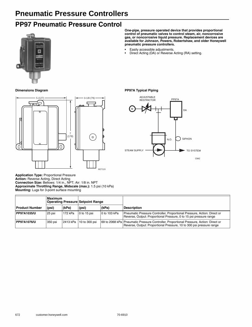
Pneumatic Pressure Controllers
672 customer.honeywell.com 70-6910
PP97 Pneumatic Pressure ControlOne-pipe, pressure operated device that provides proportional control of pneumatic valves to control steam, air, noncorrosive gas, or noncorrosive liquid pressure. Replacement devices are available for Johnson, Powers, Robertshaw, and older Honeywell pneumatic pressure controllers.
• Easily accessible adjustments. • Direct Acting (DA) or Reverse Acting (RA) setting.
Dimensions Diagram PP97A Typical Piping
Application Type: Proportional PressureAction: Reverse Acting, Direct ActingConnection Size: Bellows: 1/4 in., NPT; Air: 1/8 in. NPTApproximate Throttling Range, Midscale (max.): 1.5 psi (10 kPa) Mounting: Lugs for 3-point surface mounting
M27119
5 (127)
7(178)
3-1/8 (79)
TO SYSTEM
N.O. SIPHON
DA
PP97A
M
ADJUSTABLE
RESTRICTOR
STEAM SUPPLY
C842
Product Number
Maximum Operating Pressure Setpoint Range
Description(psi) (kPa) (psi) (kPa)
PP97A1035/U 25 psi 172 kPa 0 to 15 psi 0 to 103 kPa Pneumatic Pressure Controller, Proportional Pressure, Action: Direct or Reverse, Output: Proportional Pressure, 0 to 15 psi pressure range
PP97A1076/U 350 psi 2413 kPa 10 to 300 psi 69 to 2068 kPa Pneumatic Pressure Controller, Proportional Pressure, Action: Direct or Reverse, Output: Proportional Pressure, 10 to 300 psi pressure range
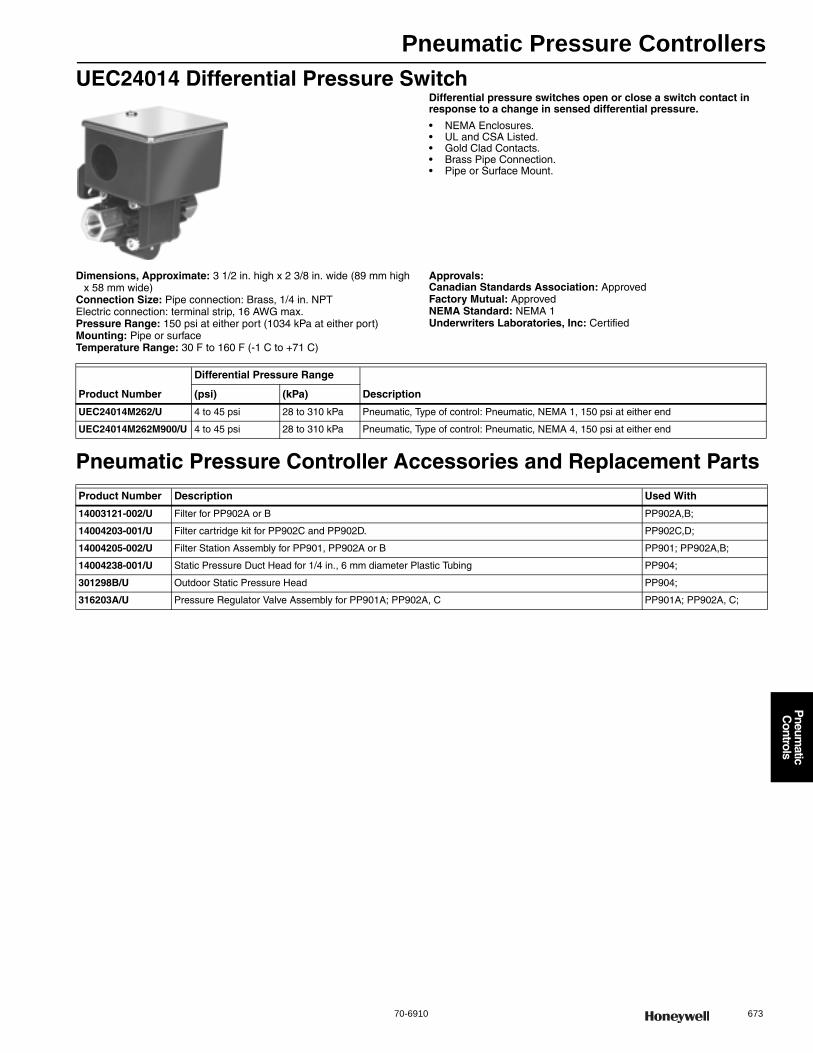
Pneumatic Pressure Controllers
70-6910 673
P
neumatic
Controls
UEC24014 Differential Pressure SwitchDifferential pressure switches open or close a switch contact in response to a change in sensed differential pressure.
• NEMA Enclosures. • UL and CSA Listed. • Gold Clad Contacts. • Brass Pipe Connection. • Pipe or Surface Mount.
Dimensions, Approximate: 3 1/2 in. high x 2 3/8 in. wide (89 mm high x 58 mm wide)
Connection Size: Pipe connection: Brass, 1/4 in. NPTElectric connection: terminal strip, 16 AWG max.Pressure Range: 150 psi at either port (1034 kPa at either port) Mounting: Pipe or surfaceTemperature Range: 30 F to 160 F (-1 C to +71 C)
Approvals:Canadian Standards Association: ApprovedFactory Mutual: ApprovedNEMA Standard: NEMA 1Underwriters Laboratories, Inc: Certified
Pneumatic Pressure Controller Accessories and Replacement Parts
Product Number
Differential Pressure Range
Description(psi) (kPa)
UEC24014M262/U 4 to 45 psi 28 to 310 kPa Pneumatic, Type of control: Pneumatic, NEMA 1, 150 psi at either end
UEC24014M262M900/U 4 to 45 psi 28 to 310 kPa Pneumatic, Type of control: Pneumatic, NEMA 4, 150 psi at either end
Product Number Description Used With
14003121-002/U Filter for PP902A or B PP902A,B;
14004203-001/U Filter cartridge kit for PP902C and PP902D. PP902C,D;
14004205-002/U Filter Station Assembly for PP901, PP902A or B PP901; PP902A,B;
14004238-001/U Static Pressure Duct Head for 1/4 in., 6 mm diameter Plastic Tubing PP904;
301298B/U Outdoor Static Pressure Head PP904;
316203A/U Pressure Regulator Valve Assembly for PP901A; PP902A, C PP901A; PP902A, C;
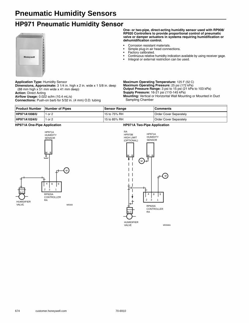
Pneumatic Humidity Sensors
674 customer.honeywell.com 70-6910
HP971 Pneumatic Humidity SensorOne- or two-pipe, direct-acting humidity sensor used with RP908/RP920 Controllers to provide proportional control of pneumatic valve or damper actuators in systems requiring humidification or dehumidification control.
• Corrosion resistant materials. • Simple plug-in air head connections. • Factory calibrated. • Continuous relative humidity indication available by using receiver gage. • Integral or external restriction can be used.
Application Type: Humidity SensorDimensions, Approximate: 3 1/4 in. high x 2 in. wide x 1 5/8 in. deep
(88 mm high x 51 mm wide x 41 mm deep) Action: Direct ActingAirflow Usage: 0.022 scfm (10.4 mL/s)Connections: Push-on barb for 5/32 in. (4 mm) O.D. tubing
Maximum Operating Temperature: 125 F (52 C) Maximum Operating Pressure: 25 psi (172 kPa) Output Pressure Range: 3 psi to 15 psi (21 kPa to 103 kPa) Supply Pressure: 16-21 psi (110-145 kPa) Mounting: Vertical or Horizontal Wall Mounting or Mounted in Duct
Sampling Chamber
HP971A One-Pipe Application HP971A Two-Pipe Application
Product Number Number of Pipes Sensor Range Comments
HP971A1008/U 1 or 2 15 to 75% RH Order Cover Separately
HP971A1024/U 1 or 2 15 to 85% RH Order Cover Separately
M
2 3 1
4 8 9
N.C.RP920A
CONTROLLER
RA
M5569
HUMIDIFIER
VALVE
M B
HP971A
HUMIDITY
SENSOR
M
2 3 1
4 8 9
N.C.
RP920A
CONTROLLER
RA
M5568A
HUMIDIFIER
VALVE
M B
HP971A
HUMIDITY
SENSOR
RA
HP970B
HIGH LIMIT
(OPTIONAL)
M B
M
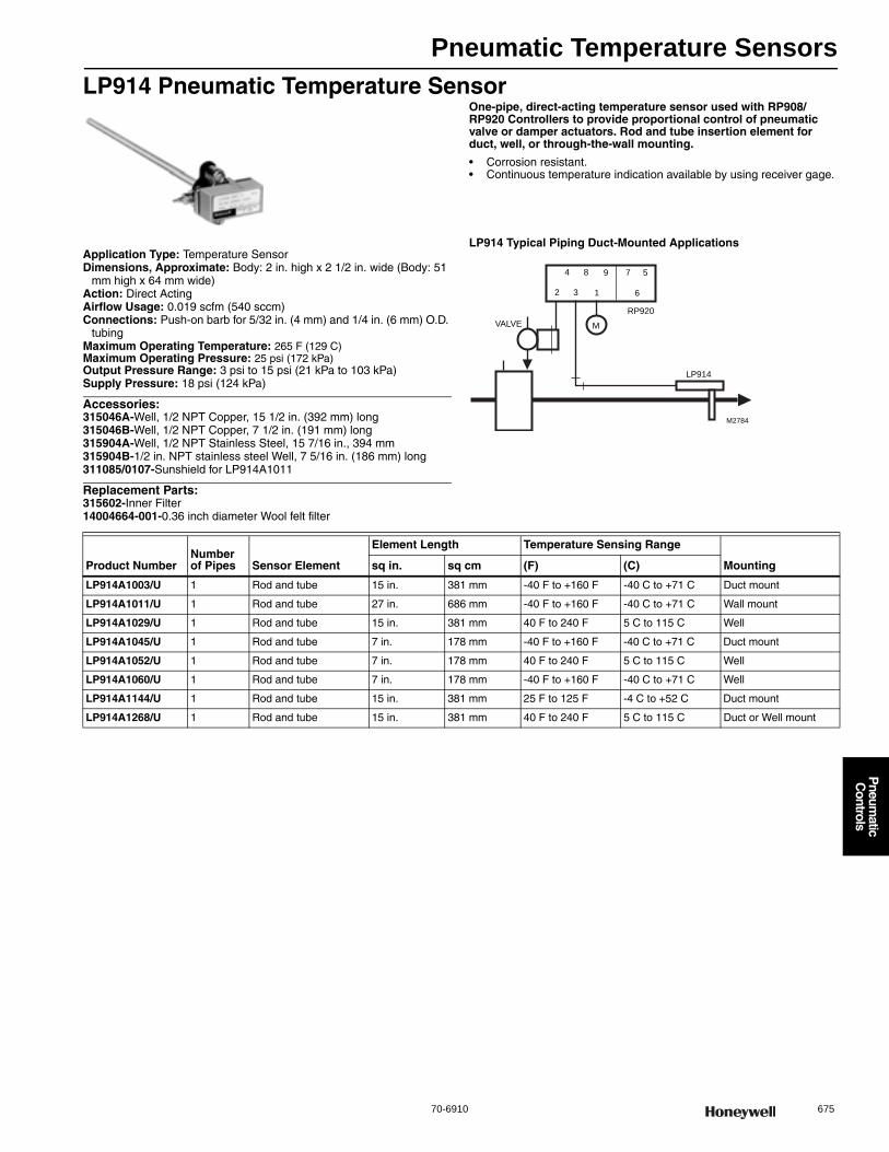
Pneumatic Temperature Sensors
70-6910 675
P
neumatic
Controls
LP914 Pneumatic Temperature SensorOne-pipe, direct-acting temperature sensor used with RP908/RP920 Controllers to provide proportional control of pneumatic valve or damper actuators. Rod and tube insertion element for duct, well, or through-the-wall mounting.
• Corrosion resistant. • Continuous temperature indication available by using receiver gage.
Application Type: Temperature SensorDimensions, Approximate: Body: 2 in. high x 2 1/2 in. wide (Body: 51
mm high x 64 mm wide) Action: Direct ActingAirflow Usage: 0.019 scfm (540 sccm)Connections: Push-on barb for 5/32 in. (4 mm) and 1/4 in. (6 mm) O.D.
tubingMaximum Operating Temperature: 265 F (129 C) Maximum Operating Pressure: 25 psi (172 kPa) Output Pressure Range: 3 psi to 15 psi (21 kPa to 103 kPa) Supply Pressure: 18 psi (124 kPa)
Accessories:315046A-Well, 1/2 NPT Copper, 15 1/2 in. (392 mm) long315046B-Well, 1/2 NPT Copper, 7 1/2 in. (191 mm) long315904A-Well, 1/2 NPT Stainless Steel, 15 7/16 in., 394 mm315904B-1/2 in. NPT stainless steel Well, 7 5/16 in. (186 mm) long311085/0107-Sunshield for LP914A1011
Replacement Parts:315602-Inner Filter14004664-001-0.36 inch diameter Wool felt filter
LP914 Typical Piping Duct-Mounted Applications
M
7 5
62 3 1
4 8 9
VALVE
LP914
RP920
M2784
Product NumberNumber of Pipes Sensor Element
Element Length Temperature Sensing Range
Mountingsq in. sq cm (F) (C)
LP914A1003/U 1 Rod and tube 15 in. 381 mm -40 F to +160 F -40 C to +71 C Duct mount
LP914A1011/U 1 Rod and tube 27 in. 686 mm -40 F to +160 F -40 C to +71 C Wall mount
LP914A1029/U 1 Rod and tube 15 in. 381 mm 40 F to 240 F 5 C to 115 C Well
LP914A1045/U 1 Rod and tube 7 in. 178 mm -40 F to +160 F -40 C to +71 C Duct mount
LP914A1052/U 1 Rod and tube 7 in. 178 mm 40 F to 240 F 5 C to 115 C Well
LP914A1060/U 1 Rod and tube 7 in. 178 mm -40 F to +160 F -40 C to +71 C Well
LP914A1144/U 1 Rod and tube 15 in. 381 mm 25 F to 125 F -4 C to +52 C Duct mount
LP914A1268/U 1 Rod and tube 15 in. 381 mm 40 F to 240 F 5 C to 115 C Duct or Well mount
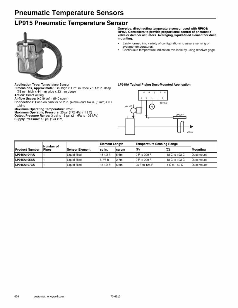
Pneumatic Temperature Sensors
676 customer.honeywell.com 70-6910
LP915 Pneumatic Temperature SensorOne-pipe, direct-acting temperature sensor used with RP908/RP920 Controllers to provide proportional control of pneumatic valve or damper actuators. Averaging, liquid-filled element for duct mounting.
• Easily formed into variety of configurations to assure sensing of average temperatures.
• Continuous temperature indication available by using receiver gage.
Application Type: Temperature SensorDimensions, Approximate: 3 in. high x 1 7/8 in. wide x 1 1/2 in. deep
(76 mm high x 44 mm wide x 33 mm deep) Action: Direct ActingAirflow Usage: 0.019 scfm (540 sccm)Connections: Push-on barb for 5/32 in. (4 mm) and 1/4 in. (6 mm) O.D.
tubingMaximum Operating Temperature: 225 FMaximum Operating Pressure: 25 psi (172 kPa) (118 C) Output Pressure Range: 3 psi to 15 psi (21 kPa to 103 kPa) Supply Pressure: 18 psi (124 kPa)
LP915A Typical Piping Duct-Mounted Application
M
7 5
62 3 1
4 8 9
VALVE
LP915A
RP920
M5566
Product NumberNumber of Pipes Sensor Element
Element Length Temperature Sensing Range
Mountingsq in. sq cm (F) (C)
LP915A1044/U 1 Liquid-filled 18 1/2 ft 5.6m 0 F to 200 F -18 C to +93 C Duct mount
LP915A1051/U 1 Liquid-filled 8 7/8 ft 2.7m 0 F to 200 F -18 C to +93 C Duct mount
LP915A1077/U 1 Liquid-filled 18 1/2 ft 5.6m 25 F to 125 F -4 C to +52 C Duct mount
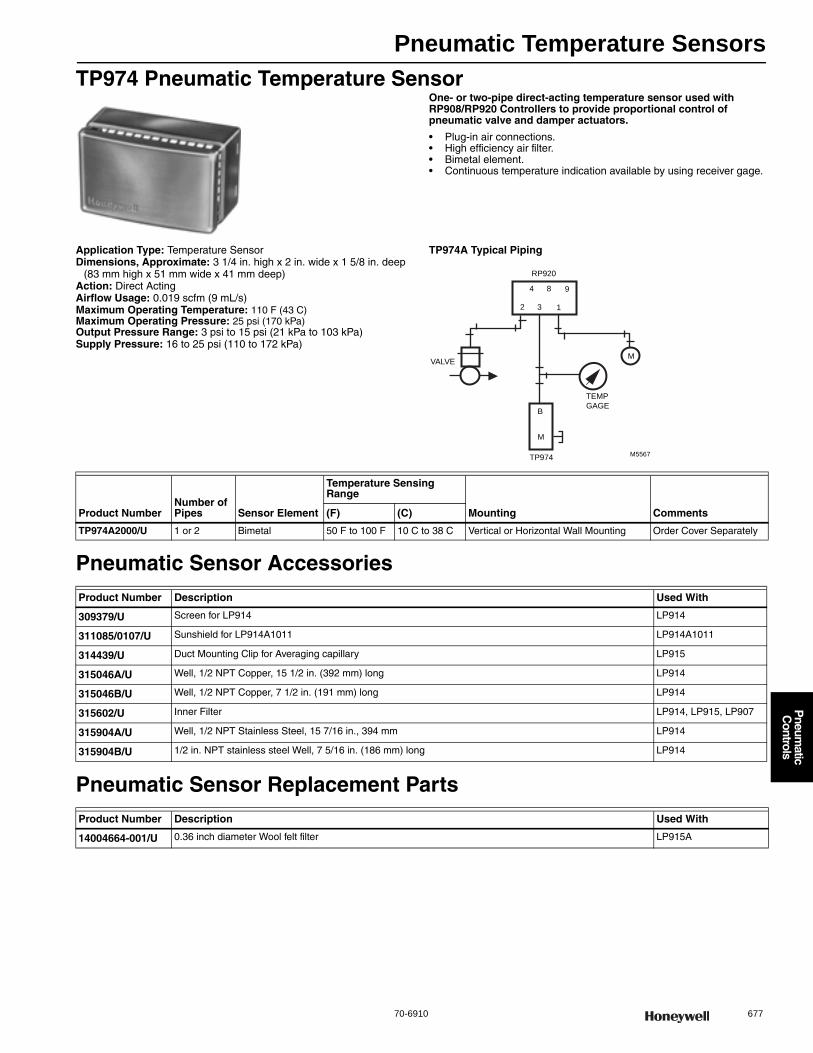
Pneumatic Temperature Sensors
70-6910 677
P
neumatic
Controls
TP974 Pneumatic Temperature SensorOne- or two-pipe direct-acting temperature sensor used with RP908/RP920 Controllers to provide proportional control of pneumatic valve and damper actuators.
• Plug-in air connections. • High efficiency air filter. • Bimetal element. • Continuous temperature indication available by using receiver gage.
Application Type: Temperature SensorDimensions, Approximate: 3 1/4 in. high x 2 in. wide x 1 5/8 in. deep
(83 mm high x 51 mm wide x 41 mm deep) Action: Direct ActingAirflow Usage: 0.019 scfm (9 mL/s)Maximum Operating Temperature: 110 F (43 C) Maximum Operating Pressure: 25 psi (170 kPa) Output Pressure Range: 3 psi to 15 psi (21 kPa to 103 kPa) Supply Pressure: 16 to 25 psi (110 to 172 kPa)
TP974A Typical Piping
Pneumatic Sensor Accessories
Pneumatic Sensor Replacement Parts
M
2 3 1
4 8 9
VALVE
RP920
M5567
TEMP
GAGE
TP974
M
B
Product NumberNumber of Pipes Sensor Element
Temperature Sensing Range
Mounting Comments(F) (C)
TP974A2000/U 1 or 2 Bimetal 50 F to 100 F 10 C to 38 C Vertical or Horizontal Wall Mounting Order Cover Separately
Product Number Description Used With
309379/U Screen for LP914 LP914
311085/0107/U Sunshield for LP914A1011 LP914A1011
314439/U Duct Mounting Clip for Averaging capillary LP915
315046A/U Well, 1/2 NPT Copper, 15 1/2 in. (392 mm) long LP914
315046B/U Well, 1/2 NPT Copper, 7 1/2 in. (191 mm) long LP914
315602/U Inner Filter LP914, LP915, LP907
315904A/U Well, 1/2 NPT Stainless Steel, 15 7/16 in., 394 mm LP914
315904B/U 1/2 in. NPT stainless steel Well, 7 5/16 in. (186 mm) long LP914
Product Number Description Used With
14004664-001/U 0.36 inch diameter Wool felt filter LP915A
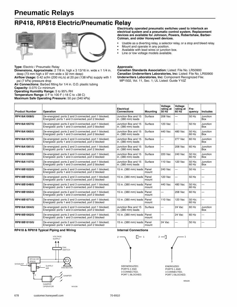
Pneumatic Relays
678 customer.honeywell.com 70-6910
RP418, RP818 Electric/Pneumatic RelayElectrically operated pneumatic switches used to interlock an electrical system and a pneumatic control system. Replacement devices are available for Johnson, Powers, Robertshaw, Barber-Colman, and older Honeywell devices.
• Usable as a diverting relay, a selector relay, or a stop and bleed relay. • Mount and operate in any position. • Available with lead wires or junction box. • Line or low voltage models available.
Type: Electric / Pneumatic RelayDimensions, Approximate: 2 7/8 in. high x 3 13/16 in. wide x 1 1/4 in.
deep (73 mm high x 97 mm wide x 32 mm deep) Airflow Usage: 0.42 scfm (200 mL/s) at 20 psi (138 kPa) supply with 1
psi (7 kPa) pressure dropAir Connections: Barbed fitting for 1/4 in. O.D. plastic tubingCapacity: 0.075 Cv minimumOperating Humidity Range: 5 to 95% RHTemperature Range: 0 F to 100 F (-18 C to +38 C) Maximum Safe Operating Pressure: 50 psi (340 kPa)
Approvals:Canadian Standards Association: Listed: File No. LR50900Canadian Underwriters Laboratories, Inc: Listed: File No. LR50900Underwriters Laboratories, Inc: Component Recognized File:
MP1502, Vol. 11, Sec. 1; UL Listed: Guide Y10Z
RP418 & RP818 Typical Piping and Wiring Internal Connections
Product Number OperationElectrical Connections Mounting
Voltage rating at 50 Hz
Voltage rating at 60 Hz
Fre-quency Includes
RP418A1008/U De-energized: ports 2 and 3 connected, port 1 blocked; Energized: ports 1 and 3 connected, port 2 blocked
Junction Box and 15 in. (380 mm) leads
Surface 208 Vac — 50 Hz Junction Box
RP418A1057/U De-energized: ports 2 and 3 connected, port 1 blocked; Energized: ports 1 and 3 connected, port 2 blocked
Junction Box and 15 in. (380 mm) leads
Surface 120 Vac — 50 Hz Junction Box
RP418A1065/U De-energized: ports 2 and 3 connected, port 1 blocked; Energized: ports 1 and 3 connected, port 2 blocked
Junction Box and 15 in. (380 mm) leads
Surface 440 Vac 480 Vac 50 Hz; 60 Hz
Junction Box
RP418A1073/U De-energized: ports 2 and 3 connected, port 1 blocked; Energized: ports 1 and 3 connected, port 2 blocked
Junction Box and 15 in. (380 mm) leads
Surface — 277 Vac 60 Hz Junction Box
RP418A1081/U De-energized: ports 2 and 3 connected, port 1 blocked; Energized: ports 1 and 3 connected, port 2 blocked
Junction Box and 15 in. (380 mm) leads
Surface — 208 Vac 60 Hz Junction Box
RP418A1099/U De-energized: ports 2 and 3 connected, port 1 blocked; Energized: ports 1 and 3 connected, port 2 blocked
Junction Box and 15 in. (380 mm) leads
Surface 220 Vac 240 Vac 50 Hz; 60 Hz
Junction Box
RP418A1107/U De-energized: ports 2 and 3 connected, port 1 blocked; Energized: ports 1 and 3 connected, port 2 blocked
Junction Box and 15 in. (380 mm) leads
Surface 110 Vac 120 Vac 50 Hz; 60 Hz
Junction Box
RP418B1022/U De-energized: ports 2 and 3 connected, port 1 blocked; Energized: ports 1 and 3 connected, port 2 blocked
15 in. (380 mm) leads Panel mount
240 Vac — 50 Hz —
RP418B1030/U De-energized: ports 2 and 3 connected, port 1 blocked; Energized: ports 1 and 3 connected, port 2 blocked
15 in. (380 mm) leads Panel mount
120 Vac — 50 Hz —
RP418B1048/U De-energized: ports 2 and 3 connected, port 1 blocked; Energized: ports 1 and 3 connected, port 2 blocked
15 in. (380 mm) leads Panel mount
440 Vac 480 Vac 50 Hz; 60 Hz
—
RP418B1055/U De-energized: ports 2 and 3 connected, port 1 blocked; Energized: ports 1 and 3 connected, port 2 blocked
15 in. (380 mm) leads Panel mount
— 208 Vac 60 Hz —
RP418B1071/U De-energized: ports 2 and 3 connected, port 1 blocked; Energized: ports 1 and 3 connected, port 2 blocked
15 in. (380 mm) leads Panel mount
110 Vac 120 Vac 50 Hz; 60 Hz
—
RP818A1004/U De-energized: ports 2 and 3 connected, port 1 blocked; Energized: ports 1 and 3 connected, port 2 blocked
Junction Box and 15 in. (380 mm) leads
Surface — 24 Vac 60 Hz Junction Box
RP818B1002/U De-energized: ports 2 and 3 connected, port 1 blocked; Energized: ports 1 and 3 connected, port 2 blocked
15 in. (380 mm) leads Panel mount
— 24 Vac 60 Hz —
RP818B1010/U De-energized: ports 2 and 3 connected, port 1 blocked; Energized: ports 1 and 3 connected, port 2 blocked
15 in. (380 mm) leads Panel mount
24 Vac — 50 Hz —
FAN
SWITCH
FAN MOTOR
DAMPER
EXHAUST
DAMPER
OPERATOR
RP418 OR
RP818
SUPPLY
AIR
VOLTAGE
SUPPLY
M5429B
12
3
M5428
DEENERGIZED:
PORTS 2 AND
3 CONNECTED,
PORT 1 BLOCKED.
ENERGIZED:
PORTS 1 AND
3 CONNECTED,
PORT 2 BLOCKED.
3
12 2
3
1
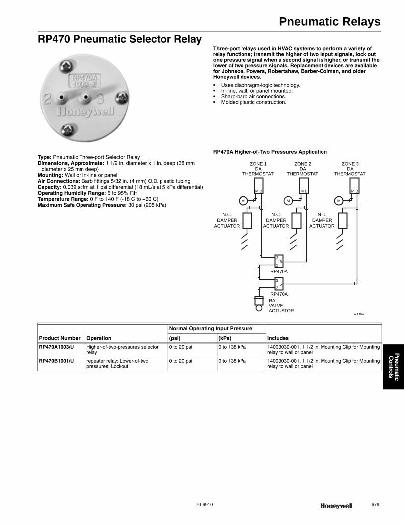
Pneumatic Relays
70-6910 679
P
neumatic
Controls
RP470 Pneumatic Selector RelayThree-port relays used in HVAC systems to perform a variety of relay functions; transmit the higher of two input signals, lock out one pressure signal when a second signal is higher, or transmit the lower of two pressure signals. Replacement devices are available for Johnson, Powers, Robertshaw, Barber-Colman, and older Honeywell devices.
• Uses diaphragm-logic technology. • In-line, wall, or panel mounted. • Sharp-barb air connections. • Molded plastic construction.
Type: Pneumatic Three-port Selector RelayDimensions, Approximate: 1 1/2 in. diameter x 1 in. deep (38 mm
diameter x 25 mm deep) Mounting: Wall or In-line or panelAir Connections: Barb fittings 5/32 in. (4 mm) O.D. plastic tubingCapacity: 0.039 scfm at 1 psi differential (18 mL/s at 5 kPa differential)Operating Humidity Range: 5 to 95% RHTemperature Range: 0 F to 140 F (-18 C to +60 C) Maximum Safe Operating Pressure: 30 psi (205 kPa)
RP470A Higher-of-Two Pressures Application
RP470A
C4492
RAVALVEACTUATOR
ZONE 1DA
THERMOSTAT
ZONE 2DA
THERMOSTAT
ZONE 3DA
THERMOSTAT
N.C.
DAMPER
ACTUATOR
N.C.
DAMPER
ACTUATOR
N.C.
DAMPER
ACTUATOR
35
2
RP470A
35
2
M B
M
M B
M
M B
M
Product Number Operation
Normal Operating Input Pressure
Includes(psi) (kPa)
RP470A1003/U Higher-of-two-pressures selector relay
0 to 20 psi 0 to 138 kPa 14003030-001, 1 1/2 in. Mounting Clip for Mounting relay to wall or panel
RP470B1001/U repeater relay; Lower-of-two pressures; Lockout
0 to 20 psi 0 to 138 kPa 14003030-001, 1 1/2 in. Mounting Clip for Mounting relay to wall or panel
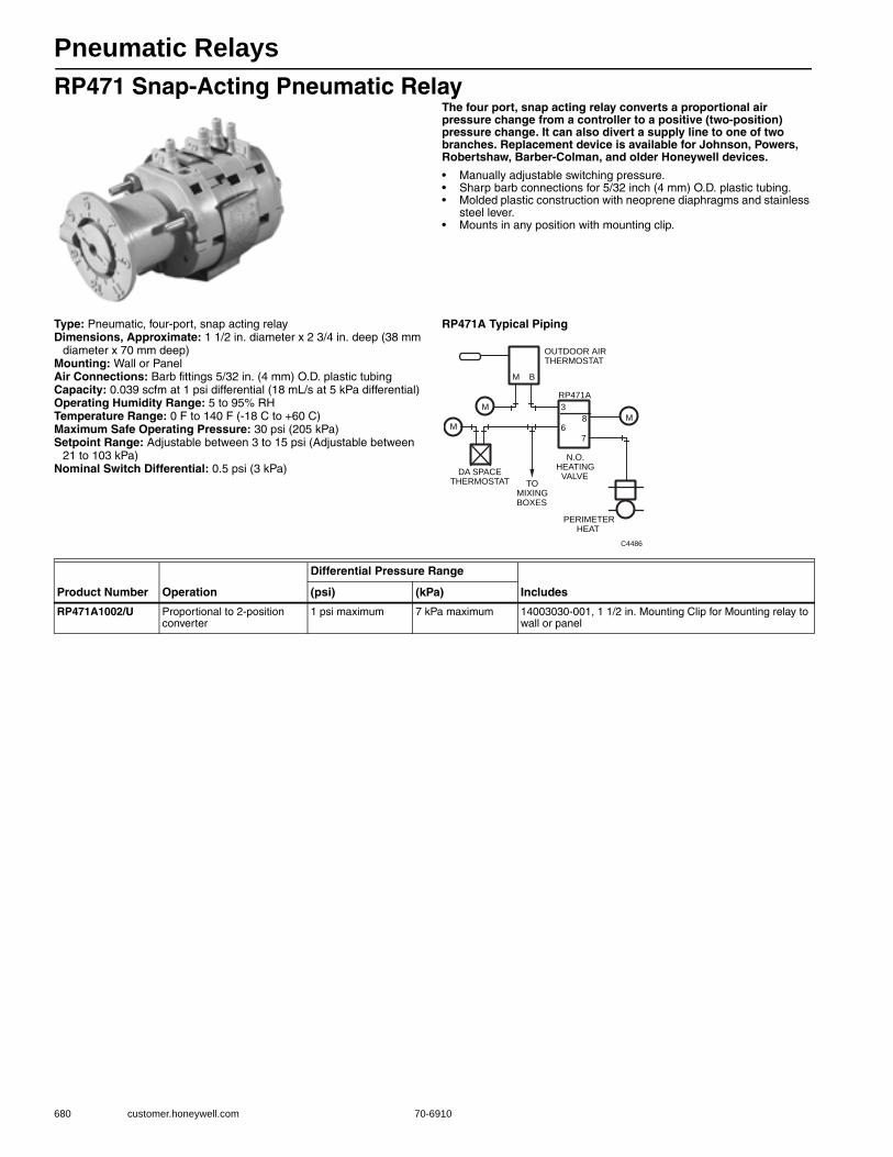
Pneumatic Relays
680 customer.honeywell.com 70-6910
RP471 Snap-Acting Pneumatic RelayThe four port, snap acting relay converts a proportional air pressure change from a controller to a positive (two-position) pressure change. It can also divert a supply line to one of two branches. Replacement device is available for Johnson, Powers, Robertshaw, Barber-Colman, and older Honeywell devices.
• Manually adjustable switching pressure. • Sharp barb connections for 5/32 inch (4 mm) O.D. plastic tubing. • Molded plastic construction with neoprene diaphragms and stainless
steel lever. • Mounts in any position with mounting clip.
Type: Pneumatic, four-port, snap acting relayDimensions, Approximate: 1 1/2 in. diameter x 2 3/4 in. deep (38 mm
diameter x 70 mm deep) Mounting: Wall or PanelAir Connections: Barb fittings 5/32 in. (4 mm) O.D. plastic tubingCapacity: 0.039 scfm at 1 psi differential (18 mL/s at 5 kPa differential)Operating Humidity Range: 5 to 95% RHTemperature Range: 0 F to 140 F (-18 C to +60 C) Maximum Safe Operating Pressure: 30 psi (205 kPa) Setpoint Range: Adjustable between 3 to 15 psi (Adjustable between
21 to 103 kPa) Nominal Switch Differential: 0.5 psi (3 kPa)
RP471A Typical Piping
M
M B
OUTDOOR AIRTHERMOSTAT
3
68
7
M
RP471A
N.O.HEATING
VALVE
PERIMETERHEAT
TOMIXINGBOXES
M
DA SPACETHERMOSTAT
C4486
Product Number Operation
Differential Pressure Range
Includes(psi) (kPa)
RP471A1002/U Proportional to 2-position converter
1 psi maximum 7 kPa maximum 14003030-001, 1 1/2 in. Mounting Clip for Mounting relay to wall or panel
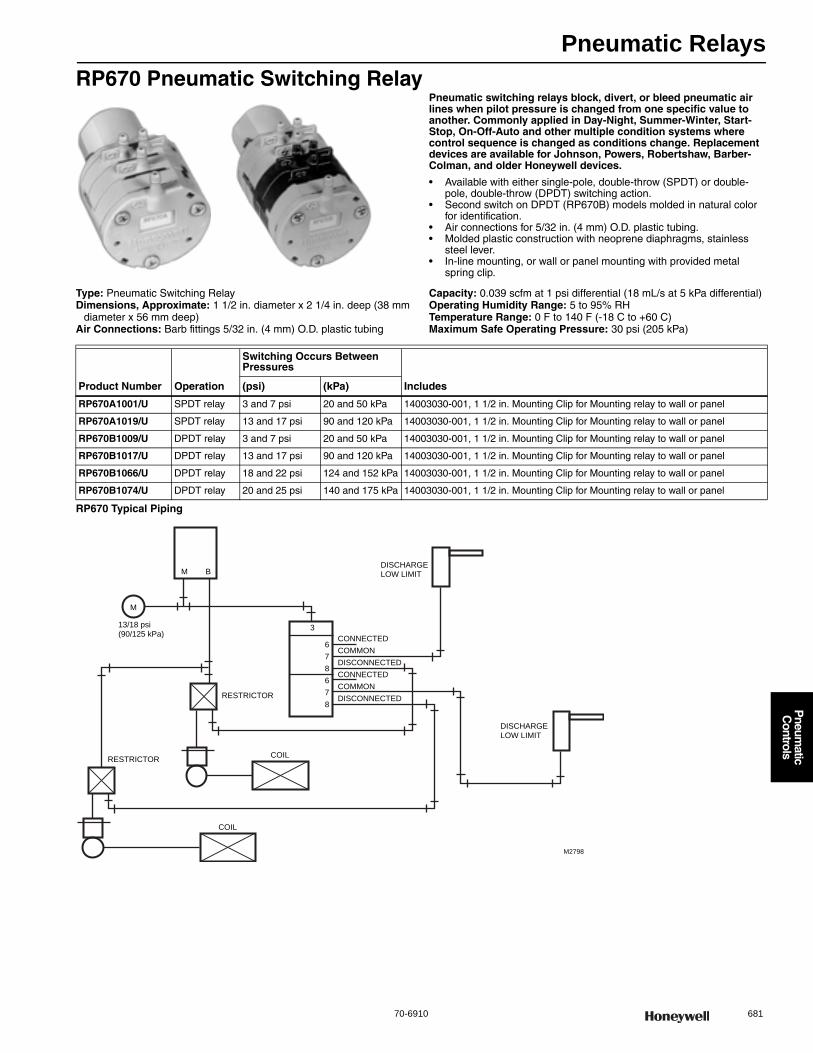
Pneumatic Relays
70-6910 681
P
neumatic
Controls
RP670 Pneumatic Switching RelayPneumatic switching relays block, divert, or bleed pneumatic air lines when pilot pressure is changed from one specific value to another. Commonly applied in Day-Night, Summer-Winter, Start-Stop, On-Off-Auto and other multiple condition systems where control sequence is changed as conditions change. Replacement devices are available for Johnson, Powers, Robertshaw, Barber-Colman, and older Honeywell devices.
• Available with either single-pole, double-throw (SPDT) or double-pole, double-throw (DPDT) switching action.
• Second switch on DPDT (RP670B) models molded in natural color for identification.
• Air connections for 5/32 in. (4 mm) O.D. plastic tubing. • Molded plastic construction with neoprene diaphragms, stainless
steel lever. • In-line mounting, or wall or panel mounting with provided metal
spring clip.
Type: Pneumatic Switching RelayDimensions, Approximate: 1 1/2 in. diameter x 2 1/4 in. deep (38 mm
diameter x 56 mm deep) Air Connections: Barb fittings 5/32 in. (4 mm) O.D. plastic tubing
Capacity: 0.039 scfm at 1 psi differential (18 mL/s at 5 kPa differential)Operating Humidity Range: 5 to 95% RHTemperature Range: 0 F to 140 F (-18 C to +60 C) Maximum Safe Operating Pressure: 30 psi (205 kPa)
RP670 Typical Piping
Product Number Operation
Switching Occurs Between Pressures
Includes(psi) (kPa)
RP670A1001/U SPDT relay 3 and 7 psi 20 and 50 kPa 14003030-001, 1 1/2 in. Mounting Clip for Mounting relay to wall or panel
RP670A1019/U SPDT relay 13 and 17 psi 90 and 120 kPa 14003030-001, 1 1/2 in. Mounting Clip for Mounting relay to wall or panel
RP670B1009/U DPDT relay 3 and 7 psi 20 and 50 kPa 14003030-001, 1 1/2 in. Mounting Clip for Mounting relay to wall or panel
RP670B1017/U DPDT relay 13 and 17 psi 90 and 120 kPa 14003030-001, 1 1/2 in. Mounting Clip for Mounting relay to wall or panel
RP670B1066/U DPDT relay 18 and 22 psi 124 and 152 kPa 14003030-001, 1 1/2 in. Mounting Clip for Mounting relay to wall or panel
RP670B1074/U DPDT relay 20 and 25 psi 140 and 175 kPa 14003030-001, 1 1/2 in. Mounting Clip for Mounting relay to wall or panel
M
M B
RESTRICTOR
RESTRICTORCOIL
COIL
3
6
7
8
6
7
8
CONNECTED
COMMON
DISCONNECTED
CONNECTED
COMMON
DISCONNECTED
DISCHARGELOW LIMIT
DISCHARGELOW LIMIT
M2798
13/18 psi(90/125 kPa)
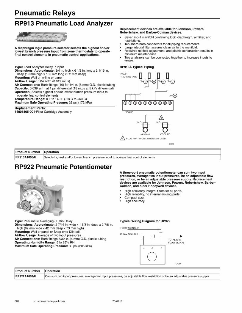
Pneumatic Relays
682 customer.honeywell.com 70-6910
RP913 Pneumatic Load Analyzer
A diaphragm logic pressure selector selects the highest and/or lowest branch pressure input from zone thermostats to operate final control elements in pneumatic control applications.
Replacement devices are available for Johnson, Powers, Robertshaw, and Barber-Colman devices.
• Seven input manifold containing logic diaphragm, air filter, and restrictions.
• Ten sharp barb connectors for all piping requirements. • Large integral filter assures clean air to the manifold. • Requires no field adjustment, and plastic construction results in
minimum maintenance. • Two analyzers can be connected together to increase inputs to
twelve.
Type: Load Analyzer Relay, 7 inputDimensions, Approximate: 3/4 in. high x 6 1/2 in. long x 2 1/16 in.
deep (19 mm high x 165 mm long x 52 mm deep) Mounting: Wall or In-line or panelAirflow Usage: 0.04 scfm (0.019 mL/s)Air Connections: Barb fittings (10) for 1/4 in. (6 mm) O.D. plastic tubingCapacity: 0.039 scfm at 1 psi differential (18 mL/s at 5 kPa differential)Operation: Selects highest and/or lowest branch pressure input to
operate final control elementsTemperature Range: 0 F to 140 F (-18 C to +60 C) Maximum Safe Operating Pressure: 25 psi (172 kPa)
Replacement Parts:14001865-001-Filter Cartridge Assembly
RP913A Typical Piping
RP922 Pneumatic PotentiometerA three-port pneumatic potentiometer can sum two input pressures, average two input pressures, be an adjustable flow restriction, or be an adjustable pressure supply. Replacement devices are available for Johnson, Powers, Robertshaw, Barber-Colman, and older Honeywell devices.
• High efficiency integral filters for all ports. • High reliability, no internal moving parts. • Compact size. • High accuracy.
Type: Pneumatic Averaging / Ratio RelayDimensions, Approximate: 2 7/16 in. wide x 1 5/8 in. deep x 2 7/8 in.
high (62 mm wide x 42 mm deep x 73 mm high) Mounting: Wall or panel or Snap onto DIN railAirflow Usage: Average of two input pressuresAir Connections: Barb fittings 5/32 in. (4 mm) O.D. plastic tubingOperating Humidity Range: 5 to 95% RHMaximum Safe Operating Pressure: 30 psi (205 kPa)
Typical Wiring Diagram for RP922
PLUG PORT H OR L WHEN NOT USED.
C4483
1
MHL1234567
COOLINGHEATING
ZONETHERMOSTATS
1
MMMM
M
N.C.N.O.
RP913A
Product Number Operation
RP913A1008/U Selects highest and/or lowest branch pressure input to operate final control elements
1 2 3
FLOW SIGNAL 2
FLOW SIGNAL 1
TOTAL CFM
FLOW SIGNAL
C4289
Product Number Operation
RP922A1007/U Can sum two input pressures, average two input pressures, be adjustable flow restriction or be an adjustable pressure supply.
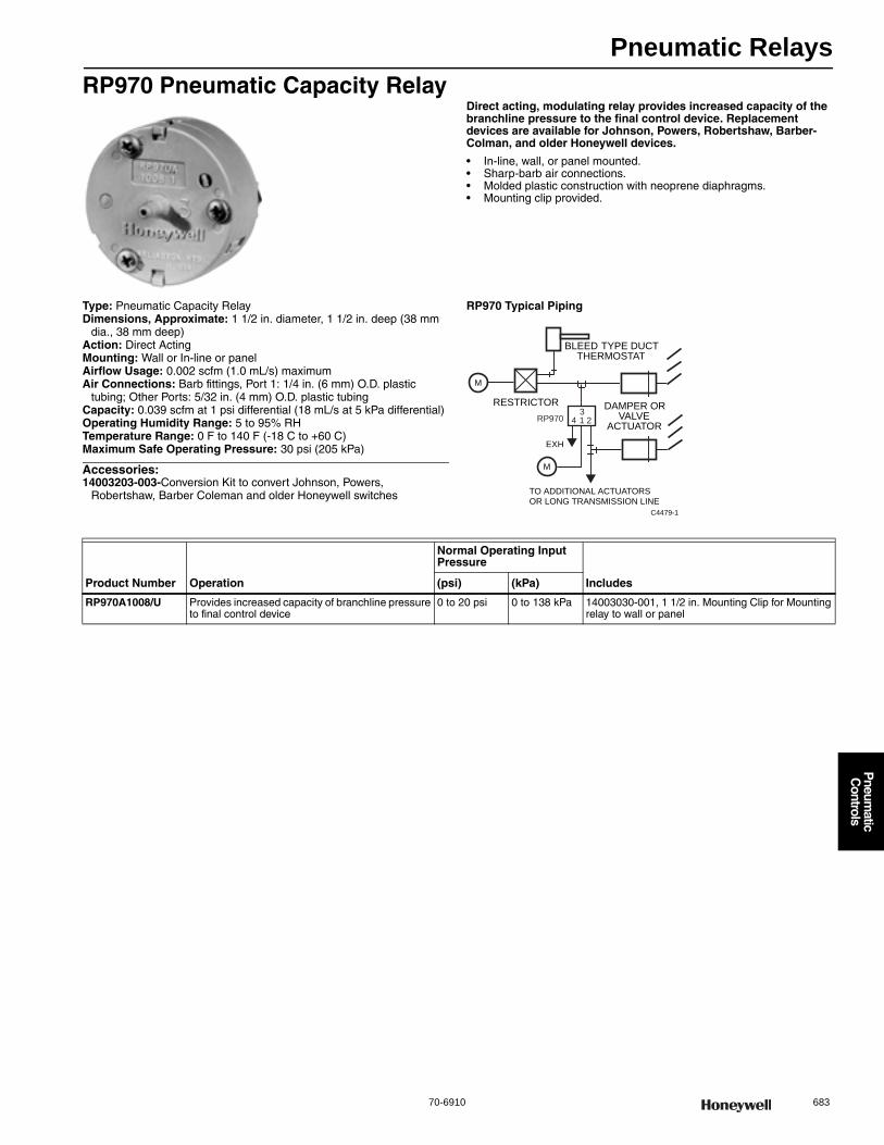
Pneumatic Relays
70-6910 683
P
neumatic
Controls
RP970 Pneumatic Capacity RelayDirect acting, modulating relay provides increased capacity of the branchline pressure to the final control device. Replacement devices are available for Johnson, Powers, Robertshaw, Barber-Colman, and older Honeywell devices.
• In-line, wall, or panel mounted. • Sharp-barb air connections. • Molded plastic construction with neoprene diaphragms. • Mounting clip provided.
Type: Pneumatic Capacity RelayDimensions, Approximate: 1 1/2 in. diameter, 1 1/2 in. deep (38 mm
dia., 38 mm deep) Action: Direct ActingMounting: Wall or In-line or panelAirflow Usage: 0.002 scfm (1.0 mL/s) maximumAir Connections: Barb fittings, Port 1: 1/4 in. (6 mm) O.D. plastic
tubing; Other Ports: 5/32 in. (4 mm) O.D. plastic tubingCapacity: 0.039 scfm at 1 psi differential (18 mL/s at 5 kPa differential)Operating Humidity Range: 5 to 95% RHTemperature Range: 0 F to 140 F (-18 C to +60 C) Maximum Safe Operating Pressure: 30 psi (205 kPa)
Accessories:14003203-003-Conversion Kit to convert Johnson, Powers,
Robertshaw, Barber Coleman and older Honeywell switches
RP970 Typical Piping
M
DAMPER ORVALVE
ACTUATOR
RESTRICTOR
BLEED TYPE DUCTTHERMOSTAT
C4479-1
RP970 4 13
2
EXH
TO ADDITIONAL ACTUATORSOR LONG TRANSMISSION LINE
M
Product Number Operation
Normal Operating Input Pressure
Includes(psi) (kPa)
RP970A1008/U Provides increased capacity of branchline pressure to final control device
0 to 20 psi 0 to 138 kPa 14003030-001, 1 1/2 in. Mounting Clip for Mounting relay to wall or panel
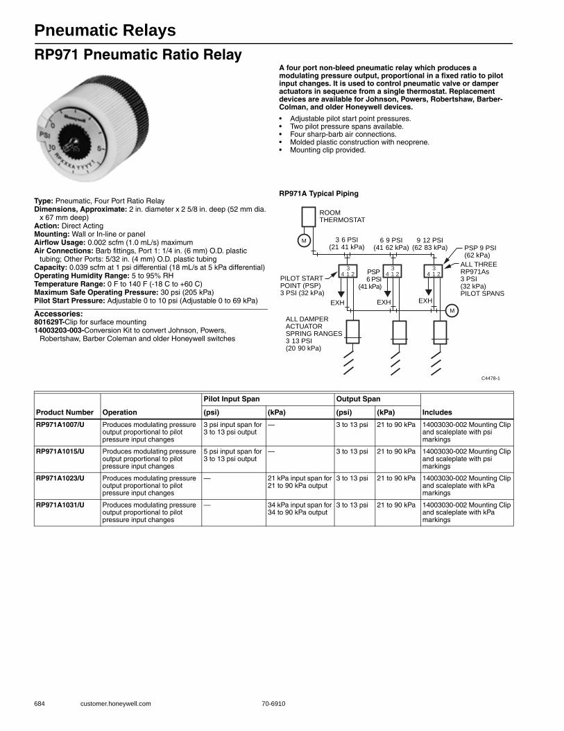
Pneumatic Relays
684 customer.honeywell.com 70-6910
RP971 Pneumatic Ratio RelayA four port non-bleed pneumatic relay which produces a modulating pressure output, proportional in a fixed ratio to pilot input changes. It is used to control pneumatic valve or damper actuators in sequence from a single thermostat. Replacement devices are available for Johnson, Powers, Robertshaw, Barber-Colman, and older Honeywell devices.
• Adjustable pilot start point pressures. • Two pilot pressure spans available. • Four sharp-barb air connections. • Molded plastic construction with neoprene. • Mounting clip provided.
Type: Pneumatic, Four Port Ratio RelayDimensions, Approximate: 2 in. diameter x 2 5/8 in. deep (52 mm dia.
x 67 mm deep) Action: Direct ActingMounting: Wall or In-line or panelAirflow Usage: 0.002 scfm (1.0 mL/s) maximumAir Connections: Barb fittings, Port 1: 1/4 in. (6 mm) O.D. plastic
tubing; Other Ports: 5/32 in. (4 mm) O.D. plastic tubingCapacity: 0.039 scfm at 1 psi differential (18 mL/s at 5 kPa differential)Operating Humidity Range: 5 to 95% RHTemperature Range: 0 F to 140 F (-18 C to +60 C) Maximum Safe Operating Pressure: 30 psi (205 kPa) Pilot Start Pressure: Adjustable 0 to 10 psi (Adjustable 0 to 69 kPa)
Accessories:801629T-Clip for surface mounting14003203-003-Conversion Kit to convert Johnson, Powers,
Robertshaw, Barber Coleman and older Honeywell switches
RP971A Typical Piping
EXHEXH
3 6 PSI(21 41 kPa)
6 9 PSI(41 62 kPa)
9 12 PSI(62 83 kPa)
ROOMTHERMOSTAT
ALL DAMPER ACTUATORSPRING RANGES 3 13 PSI(20 90 kPa)
C4478-1
EXH
PILOT START POINT (PSP) 3 PSI (32 kPa)
PSP 6 PSI
(41 kPa)
PSP 9 PSI(62 kPa)
ALL THREE RP971As3 PSI (32 kPa)PILOT SPANS
M
M
4 13
2 4 13
2 4 13
2
Product Number Operation
Pilot Input Span Output Span
Includes(psi) (kPa) (psi) (kPa)
RP971A1007/U Produces modulating pressure output proportional to pilot pressure input changes
3 psi input span for 3 to 13 psi output
— 3 to 13 psi 21 to 90 kPa 14003030-002 Mounting Clip and scaleplate with psi markings
RP971A1015/U Produces modulating pressure output proportional to pilot pressure input changes
5 psi input span for 3 to 13 psi output
— 3 to 13 psi 21 to 90 kPa 14003030-002 Mounting Clip and scaleplate with psi markings
RP971A1023/U Produces modulating pressure output proportional to pilot pressure input changes
— 21 kPa input span for 21 to 90 kPa output
3 to 13 psi 21 to 90 kPa 14003030-002 Mounting Clip and scaleplate with kPa markings
RP971A1031/U Produces modulating pressure output proportional to pilot pressure input changes
— 34 kPa input span for 34 to 90 kPa output
3 to 13 psi 21 to 90 kPa 14003030-002 Mounting Clip and scaleplate with kPa markings
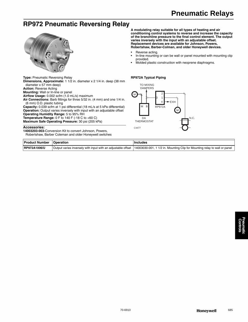
Pneumatic Relays
70-6910 685
P
neumatic
Controls
RP972 Pneumatic Reversing RelayA modulating relay suitable for all types of heating and air conditioning control systems to reverse and increase the capacity of the branchline pressure to the final control element. The output varies inversely with the input with an adjustable offset. Replacement devices are available for Johnson, Powers, Robertshaw, Barber-Colman, and older Honeywell devices.
• Reverse acting. • In-line mounting or can be wall or panel mounted with mounting clip
provided. • Molded plastic construction with neoprene diaphragms.
Type: Pneumatic Reversing RelayDimensions, Approximate: 1 1/2 in. diameter x 2 1/4 in. deep (38 mm
diameter x 57 mm deep) Action: Reverse ActingMounting: Wall or In-line or panelAirflow Usage: 0.002 scfm (1.0 mL/s) maximumAir Connections: Barb fittings for three 5/32 in. (4 mm) and one 1/4 in.
(6 mm) O.D. plastic tubingCapacity: 0.039 scfm at 1 psi differential (18 mL/s at 5 kPa differential)Operation: Output varies inversely with input with an adjustable offsetOperating Humidity Range: 5 to 95% RHTemperature Range: 0 F to 140 F (-18 C to +60 C) Maximum Safe Operating Pressure: 30 psi (205 kPa)
Accessories:14003203-003-Conversion Kit to convert Johnson, Powers,
Robertshaw, Barber Coleman and older Honeywell switches
RP972A Typical Piping
M
M B
THERMOSTATDA
3
2
1
4
M
TO MIXINGDAMPERS
RP972A
C4477
N.C.
EXH
Product Number Operation Includes
RP972A1006/U Output varies inversely with input with an adjustable offset 14003030-001, 1 1/2 in. Mounting Clip for Mounting relay to wall or panel
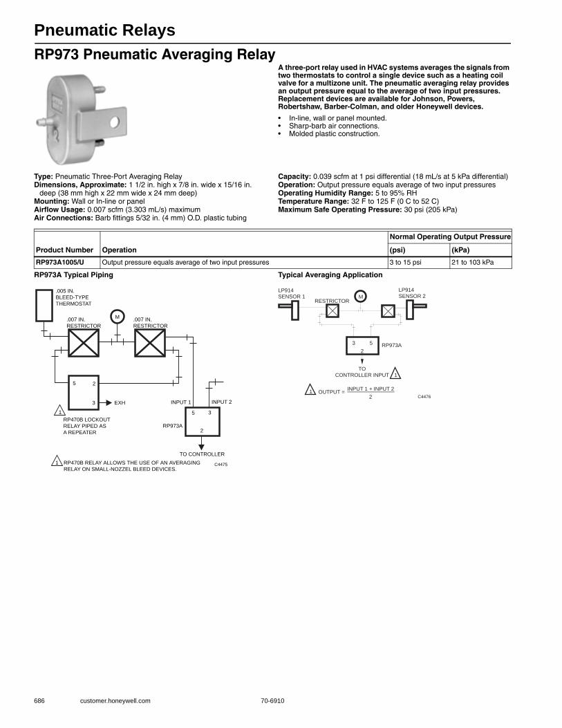
Pneumatic Relays
686 customer.honeywell.com 70-6910
RP973 Pneumatic Averaging RelayA three-port relay used in HVAC systems averages the signals from two thermostats to control a single device such as a heating coil valve for a multizone unit. The pneumatic averaging relay provides an output pressure equal to the average of two input pressures. Replacement devices are available for Johnson, Powers, Robertshaw, Barber-Colman, and older Honeywell devices.
• In-line, wall or panel mounted. • Sharp-barb air connections. • Molded plastic construction.
Type: Pneumatic Three-Port Averaging RelayDimensions, Approximate: 1 1/2 in. high x 7/8 in. wide x 15/16 in.
deep (38 mm high x 22 mm wide x 24 mm deep) Mounting: Wall or In-line or panelAirflow Usage: 0.007 scfm (3.303 mL/s) maximumAir Connections: Barb fittings 5/32 in. (4 mm) O.D. plastic tubing
Capacity: 0.039 scfm at 1 psi differential (18 mL/s at 5 kPa differential)Operation: Output pressure equals average of two input pressuresOperating Humidity Range: 5 to 95% RHTemperature Range: 32 F to 125 F (0 C to 52 C) Maximum Safe Operating Pressure: 30 psi (205 kPa)
RP973A Typical Piping Typical Averaging Application
Product Number Operation
Normal Operating Output Pressure
(psi) (kPa)
RP973A1005/U Output pressure equals average of two input pressures 3 to 15 psi 21 to 103 kPa
M.007 IN.
RESTRICTOR
.005 IN.
BLEED-TYPE
THERMOSTAT
EXH
5
5
2
2
3
3
INPUT 1 INPUT 2
RP973A
RP470B LOCKOUT
RELAY PIPED AS
A REPEATER
TO CONTROLLER
RP470B RELAY ALLOWS THE USE OF AN AVERAGING
RELAY ON SMALL-NOZZEL BLEED DEVICES.
1
1
C4475
.007 IN.
RESTRICTOR
M
2
3 5
TOCONTROLLER INPUT
RP973A
LP914SENSOR 1
LP914SENSOR 2
INPUT 1 + INPUT 2
2OUTPUT =
C44761
1
RESTRICTOR
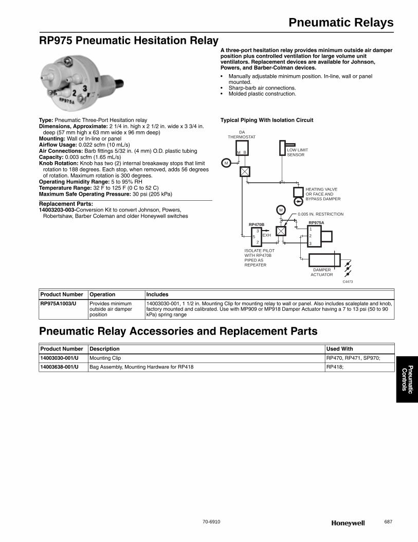
Pneumatic Relays
70-6910 687
P
neumatic
Controls
RP975 Pneumatic Hesitation RelayA three-port hesitation relay provides minimum outside air damper position plus controlled ventilation for large volume unit ventilators. Replacement devices are available for Johnson, Powers, and Barber-Colman devices.
• Manually adjustable minimum position. In-line, wall or panel mounted.
• Sharp-barb air connections. • Molded plastic construction.
Type: Pneumatic Three-Port Hesitation relayDimensions, Approximate: 2 1/4 in. high x 2 1/2 in. wide x 3 3/4 in.
deep (57 mm high x 63 mm wide x 96 mm deep) Mounting: Wall or In-line or panelAirflow Usage: 0.022 scfm (10 mL/s)Air Connections: Barb fittings 5/32 in. (4 mm) O.D. plastic tubingCapacity: 0.003 scfm (1.65 mL/s)Knob Rotation: Knob has two (2) internal breakaway stops that limit
rotation to 188 degrees. Each stop, when removed, adds 56 degrees of rotation. Maximum rotation is 300 degrees.
Operating Humidity Range: 5 to 95% RHTemperature Range: 32 F to 125 F (0 C to 52 C) Maximum Safe Operating Pressure: 30 psi (205 kPa)
Replacement Parts:14003203-003-Conversion Kit to convert Johnson, Powers,
Robertshaw, Barber Coleman and older Honeywell switches
Typical Piping With Isolation Circuit
Pneumatic Relay Accessories and Replacement Parts
M
B M
2
1
3
RP975A
M
DA THERMOSTAT
LOW LIMIT SENSOR
5
3
2
RP470B
ISOLATE PILOT WITH RP470B PIPED AS REPEATER
C4473
HEATING VALVE OR FACE AND BYPASS DAMPER
0.005 IN. RESTRICTION
EXH
DAMPER ACTUATOR
Product Number Operation Includes
RP975A1003/U Provides minimum outside air damper position
14003030-001, 1 1/2 in. Mounting Clip for mounting relay to wall or panel. Also includes scaleplate and knob, factory mounted and calibrated. Use with MP909 or MP918 Damper Actuator having a 7 to 13 psi (50 to 90 kPa) spring range
Product Number Description Used With
14003030-001/U Mounting Clip RP470, RP471, SP970;
14003638-001/U Bag Assembly, Mounting Hardware for RP418 RP418;
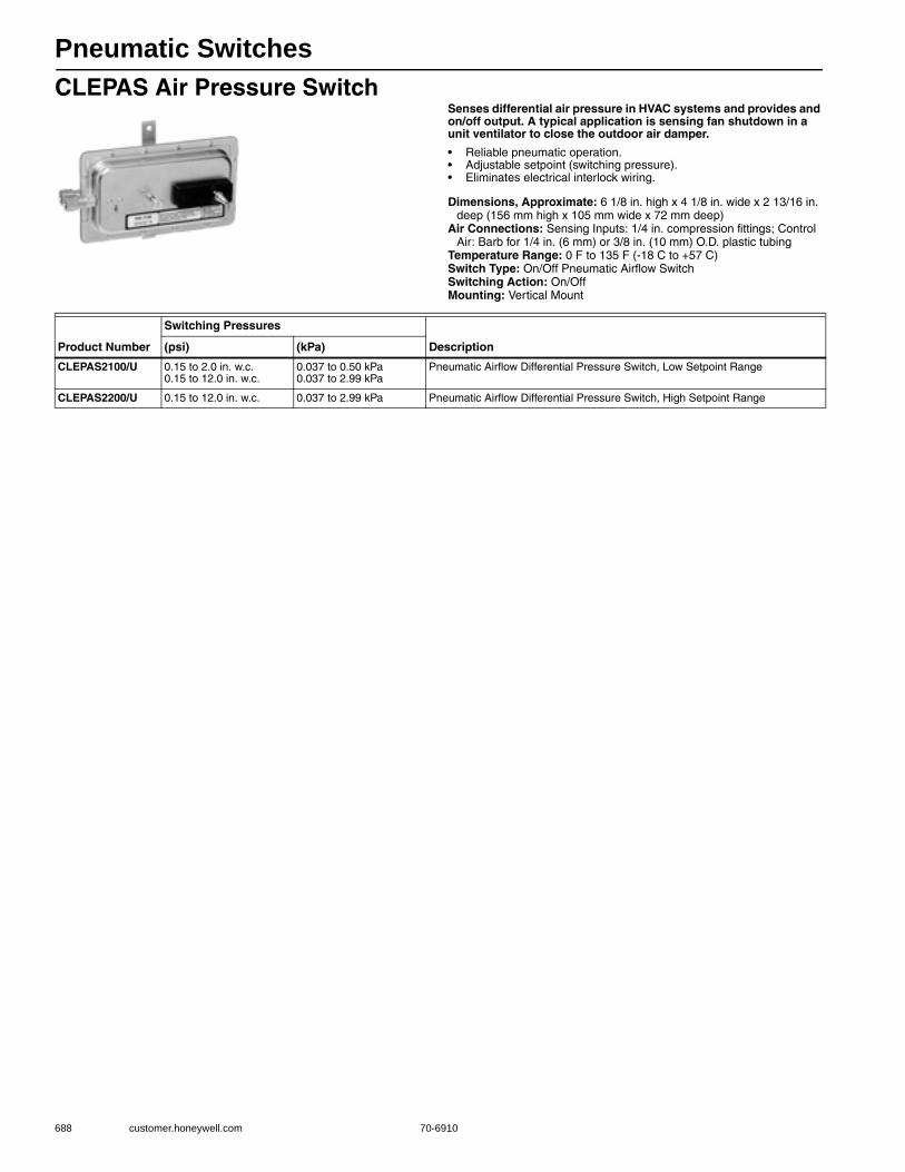
Pneumatic Switches
688 customer.honeywell.com 70-6910
CLEPAS Air Pressure SwitchSenses differential air pressure in HVAC systems and provides and on/off output. A typical application is sensing fan shutdown in a unit ventilator to close the outdoor air damper.
• Reliable pneumatic operation. • Adjustable setpoint (switching pressure). • Eliminates electrical interlock wiring.
Dimensions, Approximate: 6 1/8 in. high x 4 1/8 in. wide x 2 13/16 in. deep (156 mm high x 105 mm wide x 72 mm deep)
Air Connections: Sensing Inputs: 1/4 in. compression fittings; Control Air: Barb for 1/4 in. (6 mm) or 3/8 in. (10 mm) O.D. plastic tubing
Temperature Range: 0 F to 135 F (-18 C to +57 C) Switch Type: On/Off Pneumatic Airflow SwitchSwitching Action: On/OffMounting: Vertical Mount
Product Number
Switching Pressures
Description(psi) (kPa)
CLEPAS2100/U 0.15 to 2.0 in. w.c.0.15 to 12.0 in. w.c.
0.037 to 0.50 kPa0.037 to 2.99 kPa
Pneumatic Airflow Differential Pressure Switch, Low Setpoint Range
CLEPAS2200/U 0.15 to 12.0 in. w.c. 0.037 to 2.99 kPa Pneumatic Airflow Differential Pressure Switch, High Setpoint Range
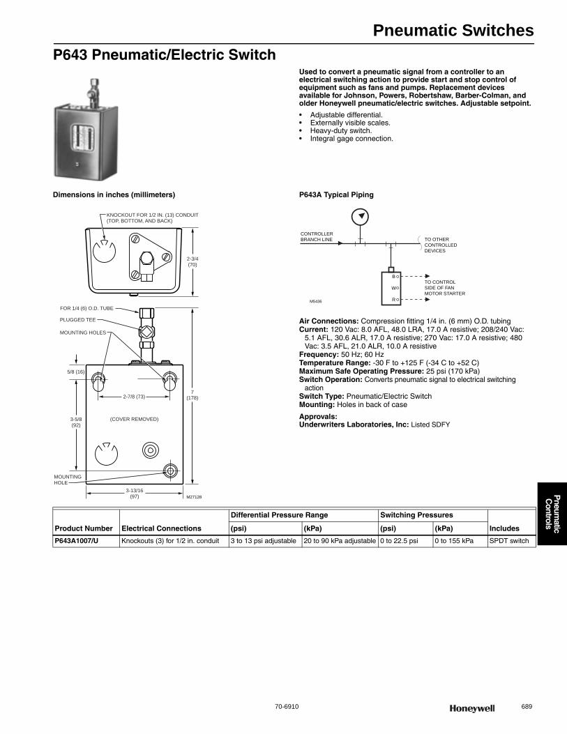
Pneumatic Switches
70-6910 689
P
neumatic
Controls
P643 Pneumatic/Electric SwitchUsed to convert a pneumatic signal from a controller to an electrical switching action to provide start and stop control of equipment such as fans and pumps. Replacement devices available for Johnson, Powers, Robertshaw, Barber-Colman, and older Honeywell pneumatic/electric switches. Adjustable setpoint.
• Adjustable differential. • Externally visible scales. • Heavy-duty switch. • Integral gage connection.
Dimensions in inches (millimeters) P643A Typical Piping
Air Connections: Compression fitting 1/4 in. (6 mm) O.D. tubingCurrent: 120 Vac: 8.0 AFL, 48.0 LRA, 17.0 A resistive; 208/240 Vac:
5.1 AFL, 30.6 ALR, 17.0 A resistive; 270 Vac: 17.0 A resistive; 480 Vac: 3.5 AFL, 21.0 ALR, 10.0 A resistive
Frequency: 50 Hz; 60 HzTemperature Range: -30 F to +125 F (-34 C to +52 C) Maximum Safe Operating Pressure: 25 psi (170 kPa) Switch Operation: Converts pneumatic signal to electrical switching
actionSwitch Type: Pneumatic/Electric SwitchMounting: Holes in back of case
Approvals:Underwriters Laboratories, Inc: Listed SDFY
M27128
KNOCKOUT FOR 1/2 IN. (13) CONDUIT(TOP, BOTTOM, AND BACK)
(COVER REMOVED)
2-7/8 (73)
2-3/4(70)
7(178)
3-5/8(92)
5/8 (16)
FOR 1/4 (6) O.D. TUBE
3-13/16(97)
PLUGGED TEE
MOUNTING HOLES
MOUNTINGHOLE
M5436
TO CONTROL
SIDE OF FAN
MOTOR STARTER
B
W
R
TO OTHER
CONTROLLED
DEVICES
CONTROLLER
BRANCH LINE
Product Number Electrical Connections
Differential Pressure Range Switching Pressures
Includes(psi) (kPa) (psi) (kPa)
P643A1007/U Knockouts (3) for 1/2 in. conduit 3 to 13 psi adjustable 20 to 90 kPa adjustable 0 to 22.5 psi 0 to 155 kPa SPDT switch
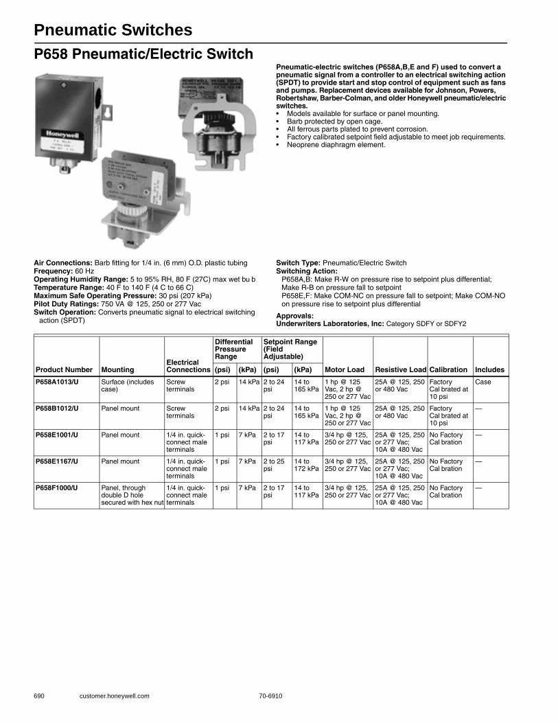
Pneumatic Switches
690 customer.honeywell.com 70-6910
P658 Pneumatic/Electric SwitchPneumatic-electric switches (P658A,B,E and F) used to convert a pneumatic signal from a controller to an electrical switching action (SPDT) to provide start and stop control of equipment such as fans and pumps. Replacement devices available for Johnson, Powers, Robertshaw, Barber-Colman, and older Honeywell pneumatic/electric switches.• Models available for surface or panel mounting. • Barb protected by open cage. • All ferrous parts plated to prevent corrosion. • Factory calibrated setpoint field adjustable to meet job requirements. • Neoprene diaphragm element.
Air Connections: Barb fitting for 1/4 in. (6 mm) O.D. plastic tubingFrequency: 60 HzOperating Humidity Range: 5 to 95% RH, 80 F (27C) max wet bu bTemperature Range: 40 F to 140 F (4 C to 66 C) Maximum Safe Operating Pressure: 30 psi (207 kPa) Pilot Duty Ratings: 750 VA @ 125, 250 or 277 VacSwitch Operation: Converts pneumatic signal to electrical switching
action (SPDT)
Switch Type: Pneumatic/Electric SwitchSwitching Action:
P658A,B: Make R-W on pressure rise to setpoint plus differential; Make R-B on pressure fall to setpointP658E,F: Make COM-NC on pressure fall to setpoint; Make COM-NO on pressure rise to setpoint plus differential
Approvals:Underwriters Laboratories, Inc: Category SDFY or SDFY2
Product Number MountingElectrical Connections
Differential Pressure Range
Setpoint Range (Field Adjustable)
Motor Load Resistive Load Calibration Includes(psi) (kPa) (psi) (kPa)
P658A1013/U Surface (includes case)
Screw terminals
2 psi 14 kPa 2 to 24 psi
14 to 165 kPa
1 hp @ 125 Vac, 2 hp @ 250 or 277 Vac
25A @ 125, 250 or 480 Vac
Factory Cal brated at 10 psi
Case
P658B1012/U Panel mount Screw terminals
2 psi 14 kPa 2 to 24 psi
14 to 165 kPa
1 hp @ 125 Vac, 2 hp @ 250 or 277 Vac
25A @ 125, 250 or 480 Vac
Factory Cal brated at 10 psi
—
P658E1001/U Panel mount 1/4 in. quick-connect male terminals
1 psi 7 kPa 2 to 17 psi
14 to 117 kPa
3/4 hp @ 125, 250 or 277 Vac
25A @ 125, 250 or 277 Vac; 10A @ 480 Vac
No Factory Cal bration
—
P658E1167/U Panel mount 1/4 in. quick-connect male terminals
1 psi 7 kPa 2 to 25 psi
14 to 172 kPa
3/4 hp @ 125, 250 or 277 Vac
25A @ 125, 250 or 277 Vac; 10A @ 480 Vac
No Factory Cal bration
—
P658F1000/U Panel, through double D hole secured with hex nut
1/4 in. quick-connect male terminals
1 psi 7 kPa 2 to 17 psi
14 to 117 kPa
3/4 hp @ 125, 250 or 277 Vac
25A @ 125, 250 or 277 Vac; 10A @ 480 Vac
No Factory Cal bration
—
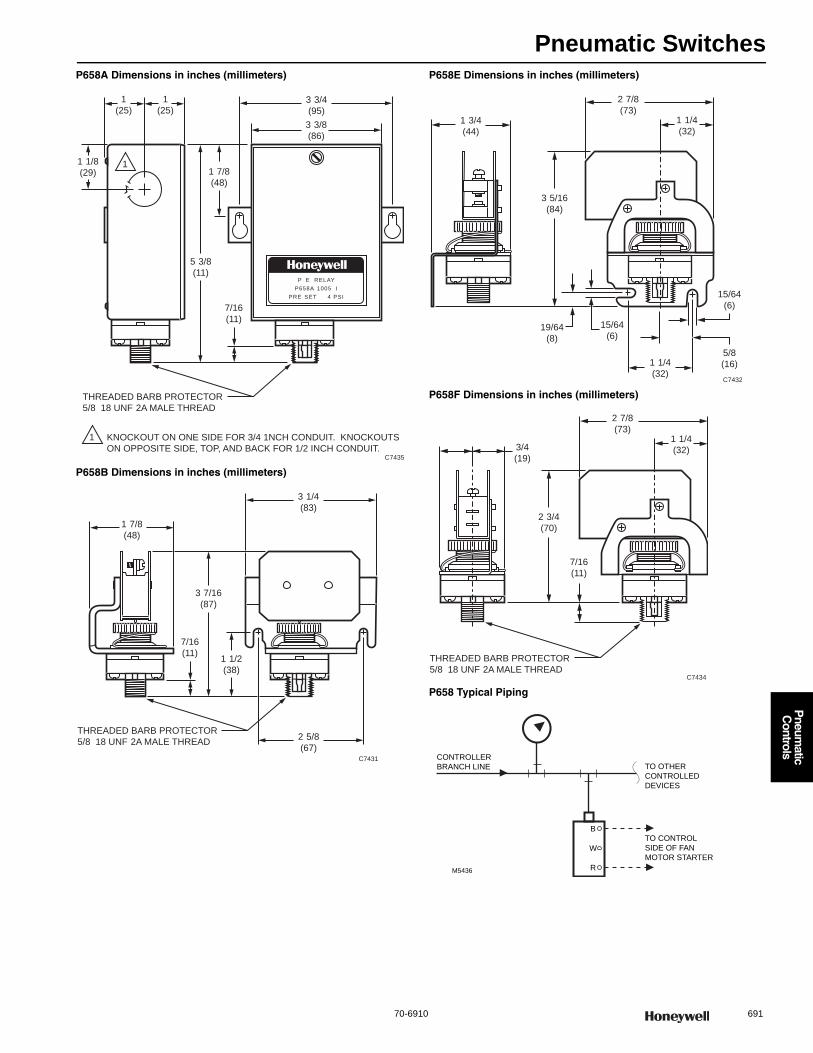
Pneumatic Switches
70-6910 691
P
neumatic
Controls
P658A Dimensions in inches (millimeters)
P658B Dimensions in inches (millimeters)
P658E Dimensions in inches (millimeters)
P658F Dimensions in inches (millimeters)
P658 Typical Piping
P E RELAY
P658A 1005 I
PRE SET 4 PSI
1
1
(25)
1 1/8
(29) 1 7/8
(48)
5 3/8
(11)
7/16
(11)
3 3/4
(95)
3 3/8
(86)
1
(25)
THREADED BARB PROTECTOR
5/8 18 UNF 2A MALE THREAD
KNOCKOUT ON ONE SIDE FOR 3/4 1NCH CONDUIT. KNOCKOUTS
ON OPPOSITE SIDE, TOP, AND BACK FOR 1/2 INCH CONDUIT.C7435
1
C7431
3 7/16
(87)
7/16
(11)
THREADED BARB PROTECTOR
5/8 18 UNF 2A MALE THREAD
3 1/4
(83)
1 7/8
(48)
1 1/2
(38)
2 5/8
(67)
C7432
3 5/16
(84)
19/64
(8)
15/64
(6)
15/64
(6)
5/8
(16)
2 7/8
(73)1 3/4
(44)
1 1/4
(32)
1 1/4
(32)
C7434
2 3/4
(70)
7/16
(11)
2 7/8
(73)
3/4
(19)
1 1/4
(32)
THREADED BARB PROTECTOR
5/8 18 UNF 2A MALE THREAD
M5436
TO CONTROL
SIDE OF FAN
MOTOR STARTER
B
W
R
TO OTHER
CONTROLLED
DEVICES
CONTROLLER
BRANCH LINE

Pneumatic Switches
692 customer.honeywell.com 70-6910
SP470 Pneumatic Diverting SwitchesPneumatic diverting switch used to manually divert, block, or bleed air in pneumatic air lines to revise control sequence with a change in conditions. Commonly applied on Day-Night, Summer-Winter, On-Off-Auto, or Start-Stop functions. Replacement kits are available for Johnson, Powers, Robertshaw, Barber-Colman, and older Honeywell switches.
• Available in two-position or three-position devices. • Mountable on a panel up to 7/16 in. (11 mm) thick. • Complete with knob and scaleplate.
Dimensions in inches (millimeters)
Air Connections: Barb fitting for 5/32 in. (4 mm) O.D. plastic tubingAirflow Usage: 0.175 scfm (82.6 mL/s) minimum at 1 psi pressure dropOperating Humidity Range: 5 to 95% RHTemperature Range: 20 F to 140 F (-7 C to +60 C) Maximum Safe Operating Pressure: 30 psi (207 kPa)
Switch Operation: Used to manually divert, block or bleed pneumatic air lines
Switch Type: Two or Three Position Pneumatic Diverting SwitchMounting: Panel mount
SP470A Typical three-position application SP470A Switches
1-3/16
(30)
1-1/2
(38)
1
(25)
1-1/2
(38)1-1/2
(38)
C8142
1-1/2
(38)
3/8 FLAT
(10)
1-1/8
(29)
13/16
(21)
19/32
(15)
3
(76)
1-3/16
(30)
Product Number Description Includes
SP470A1000/U Pneumatic Manual Switch, 4 port, 2-position interchange Mounting nuts, knob, and two-position scaleplate
SP470A1018/U Pneumatic Manual Switch, 4 port, 3-position, Port 7 is common Mounting nuts, knob, and three-position scaleplate
M
M
B M
N.O. VALVE
7
9 8
6
EXH
DA
CONTROLLER
SP470
POSITION 1, VALVES OPEN: PORTS 7 AND 9 CONNECTED,
PORTS 6 AND 8 BLOCKED
POSITION 2, VALVE AUTO: PORTS 7 AND 8 CONNECTED,
PORTS 6 AND 9 BLOCKED
POSITION 3, VALVE CLOSED: PORTS 7 AND 6 CONNECTED,
PORTS 8 AND 9 BLOCKED C4290
NOTES:
7
9
6
8
7
9
6
8
7
9
6
8
THREE-POSITION SWITCH
TWO-POSITION SWITCH
C1887
7
9
6
8
7
9
6
8

Pneumatic Switches
70-6910 693
P
neumatic
Controls
SP970 Pneumatic Manual or Minimum Position SwitchesUsed to manually position a remote damper actuator or to reset the setpoint of a pneumatic controller. They can also provide minimum damper position by setting a minimum pressure limit in the branch line to the damper actuator. Replacement kits are available for Johnson, Powers, Robertshaw, Barber-Colman, and older Honeywell switches.
• Two spans available as shipped. Six spans with breakaway stops on knob.
• Pilot bleed and isolated pilot models available. • Wall or panel mounting.
Dimensions in inches (millimeters)
Air Connections: Barb fitting for 5/32 in. (4 mm) O.D. plastic tubingAirflow Usage: 0.022 scfm (9.8 mL/s)Capacity: 0.021 scfm (9.4 mL/s) below minimum position. Above
minimum position, device feeding pilot determines capacityOperating Humidity Range: 5 to 95% RHTemperature Range: 0 F to 140 F (-18 C to +60 C) Maximum Safe Operating Pressure: 30 psi (207 kPa)
Switch Operation: Used to manually position a remote damper actuator or reset setpoint of pneumatic controller
Switch Type: Three-port pneumatic manual or minimum position switchMounting: Panel or WallComments: The setpoint knob normally rotates 188 degrees. Two
breakaway stops on the knob allow rotation of 244 degrees and 300 degrees.
Pneumatic Switch Replacement Parts
C4857FRONT VIEWSP970A 3-1/2 (89)
SP970C 3-7/8 (98)
SIDE VIEW
0
80
6040
20
100
2-1/2(63)
1-1/2(38)
7/8(22)
2-1/4(57)
1-7/8(48)
Product Number
Output Span
Includes(psi) (kPa)
SP970A1005/U 10 psi (with 188 degree knob rotation)16 psi (with 300 degree knob rotation)13 psi (with 244 degree knob rotation)
69 kPa (with 188 degree knob rotation)110 kPa (with 300 degree knob rotation)90 kPa (with 244 degree knob rotation)
Knob, 0 to 100% scale plate and locknuts
SP970A1013/U 5 psi (with 188 degree knob rotation)8 psi (with 300 degree knob rotation)6.5 psi (with 244 degree knob rotation)
34 kPa (with 188 degree knob rotation)56 kPa (with 300 degree knob rotation)45 kPa (with 244 degree knob rotation)
Knob, 0 to 100% scale plate and locknuts
SP970C1001/U 10 psi (with 188 degree knob rotation)16 psi (with 300 degree knob rotation)13 psi (with 244 degree knob rotation)
69 kPa (with 188 degree knob rotation)110 kPa (with 300 degree knob rotation)90 kPa (with 244 degree knob rotation)
Knob, 0 to 100% scale plate and locknuts
SP970C1043/U 5 psi (with 188 degree knob rotation)8 psi (with 300 degree knob rotation)6.5 psi (with 244 degree knob rotation)
34 kPa (with 188 degree knob rotation)56 kPa (with 300 degree knob rotation)45 kPa (with 244 degree knob rotation)
Knob, 0 to 100% scale plate and locknuts
Product Number Description Used With
14003022-003/U Final Assembly, manual and minimum position switch, 10 psi span SP970A
14003199-002/U Bag assembly with two scale plates, knob assembly and nuts for SP470A SP470A
176112023 Pneumatic 2-Position Switch SP470A
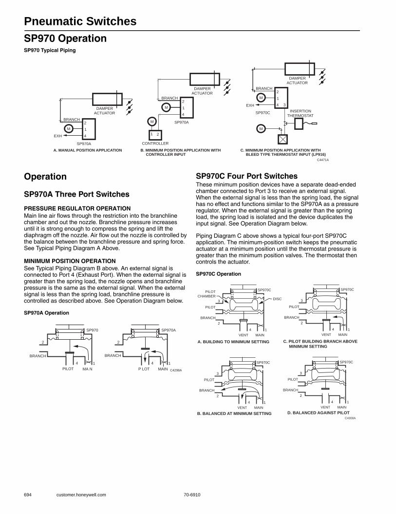
Pneumatic Switches
694 customer.honeywell.com 70-6910
SP970 OperationSP970 Typical Piping
Operation
SP970A Three Port Switches
PRESSURE REGULATOR OPERATION Main line air flows through the restriction into the branchline chamber and out the nozzle. Branchline pressure increases until it is strong enough to compress the spring and lift the diaphragm off the nozzle. Air flow out the nozzle is controlled by the balance between the branchline pressure and spring force. See Typical Piping Diagram A Above.
MINIMUM POSITION OPERATION See Typical Piping Diagram B above. An external signal is connected to Port 4 (Exhaust Port). When the external signal is greater than the spring load, the nozzle opens and branchline pressure is the same as the external signal. When the external signal is less than the spring load, branchline pressure is controlled as described above. See Operation Diagram below.
SP970A Operation
SP970C Four Port SwitchesThese minimum position devices have a separate dead-ended chamber connected to Port 3 to receive an external signal. When the external signal is less than the spring load, the signal has no effect and functions similar to the SP970A as a pressure regulator. When the external signal is greater than the spring load, the spring load is isolated and the device duplicates the input signal. See Operation Diagram below.
Piping Diagram C above shows a typical four-port SP970C application. The minimum-position switch keeps the pneumatic actuator at a minimum position until the thermostat pressure is greater than the minimum position valves. The thermostat then controls the actuator.
SP970C Operation
C4471A
C. MINIMUM POSITION APPLICATION WITH BLEED TYPE THERMOSTAT INPUT (LP916)
A. MANUAL POSITION APPLICATION
2
1
4
BRANCH
M
SP970A
EXH
DAMPER ACTUATOR
2
1
4
BRANCH
M
SP970C
3 EXH
INSERTION THERMOSTAT
M
DAMPER ACTUATOR
1 2
M
CONTROLLER
DAMPER ACTUATOR
2
1
4
BRANCH
SP970A
B. MINIMUM POSITION APPLICATION WITH CONTROLLER INPUT
M
2
PILOT
SP970 SP970A
1
BRANCH
MA N4
C4298A
2
P LOT1
BRANCH
MAIN4
3
2
PILOT
SP970C
A. BUILDING TO MINIMUM SETTING
B. BALANCED AT MINIMUM SETTING D. BALANCED AGAINST PILOT
1
BRANCH
MAIN
DISC
VENT
4
C4300A
PILOT
CHAMBER
3
2
PILOT
SP970C
1
BRANCH
MAINVENT
4
3
2
PILOT
SP970C
1
BRANCH
MAINVENT
4
3
2
PILOT
SP970C
C. PILOT BUILDING BRANCH ABOVE MINIMUM SETTING
1
BRANCH
MAINVENT
4
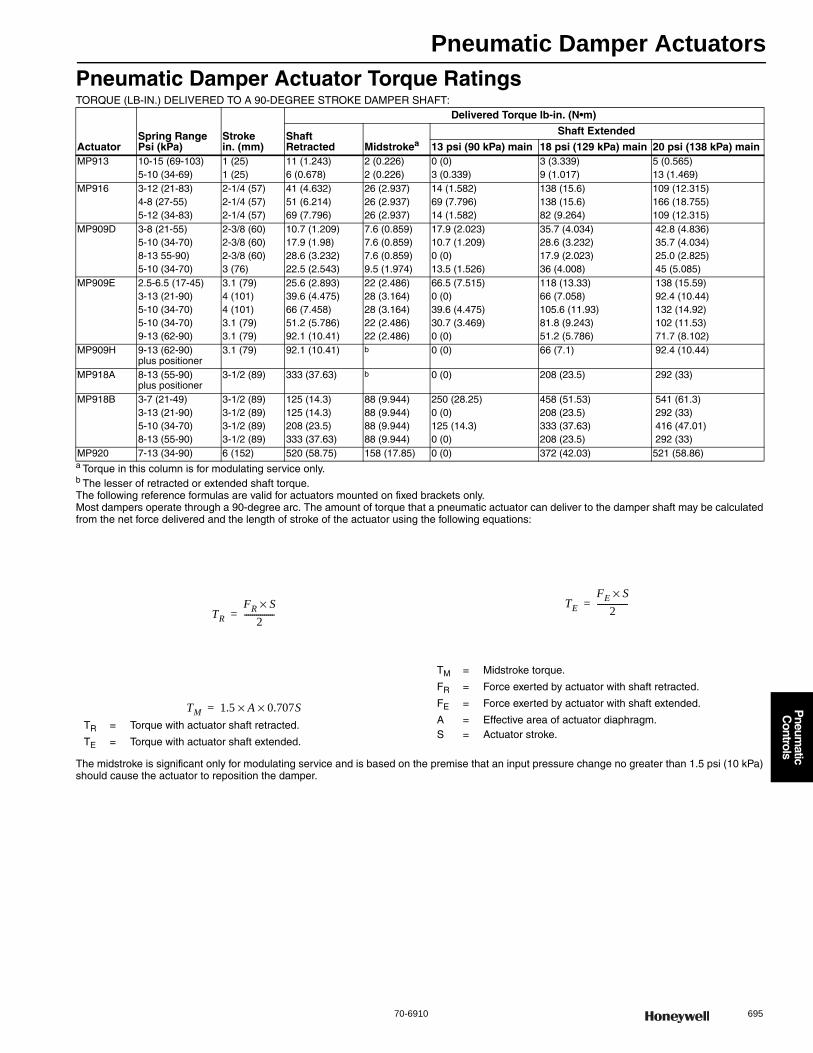
Pneumatic Damper Actuators
70-6910 695
P
neumatic
Controls
Pneumatic Damper Actuator Torque RatingsTORQUE (LB-IN.) DELIVERED TO A 90-DEGREE STROKE DAMPER SHAFT:
a Torque in this column is for modulating service only.b The lesser of retracted or extended shaft torque.The following reference formulas are valid for actuators mounted on fixed brackets only.Most dampers operate through a 90-degree arc. The amount of torque that a pneumatic actuator can deliver to the damper shaft may be calculated from the net force delivered and the length of stroke of the actuator using the following equations:
TR = Torque with actuator shaft retracted.
TE = Torque with actuator shaft extended.
TM = Midstroke torque.
FR = Force exerted by actuator with shaft retracted.
FE = Force exerted by actuator with shaft extended.
A = Effective area of actuator diaphragm.S = Actuator stroke.
The midstroke is significant only for modulating service and is based on the premise that an input pressure change no greater than 1.5 psi (10 kPa) should cause the actuator to reposition the damper.
ActuatorSpring Range Psi (kPa)
Stroke in. (mm)
Delivered Torque lb-in. (N•m)
Shaft Retracted Midstrokea
Shaft Extended
13 psi (90 kPa) main 18 psi (129 kPa) main 20 psi (138 kPa) mainMP913 10-15 (69-103)
5-10 (34-69)1 (25)1 (25)
11 (1.243)6 (0.678)
2 (0.226)2 (0.226)
0 (0)3 (0.339)
3 (3.339)9 (1.017)
5 (0.565)13 (1.469)
MP916 3-12 (21-83)4-8 (27-55)5-12 (34-83)
2-1/4 (57)2-1/4 (57)2-1/4 (57)
41 (4.632)51 (6.214)69 (7.796)
26 (2.937)26 (2.937)26 (2.937)
14 (1.582)69 (7.796)14 (1.582)
138 (15.6)138 (15.6)82 (9.264)
109 (12.315)166 (18.755)109 (12.315)
MP909D 3-8 (21-55)5-10 (34-70)8-13 55-90)5-10 (34-70)
2-3/8 (60)2-3/8 (60)2-3/8 (60)3 (76)
10.7 (1.209)17.9 (1.98)28.6 (3.232)22.5 (2.543)
7.6 (0.859)7.6 (0.859)7.6 (0.859)9.5 (1.974)
17.9 (2.023)10.7 (1.209)0 (0)13.5 (1.526)
35.7 (4.034)28.6 (3.232)17.9 (2.023)36 (4.008)
42.8 (4.836) 35.7 (4.034) 25.0 (2.825) 45 (5.085)
MP909E 2.5-6.5 (17-45)3-13 (21-90)5-10 (34-70)5-10 (34-70)9-13 (62-90)
3.1 (79)4 (101)4 (101)3.1 (79)3.1 (79)
25.6 (2.893)39.6 (4.475)66 (7.458)51.2 (5.786)92.1 (10.41)
22 (2.486)28 (3.164)28 (3.164)22 (2.486)22 (2.486)
66.5 (7.515)0 (0)39.6 (4.475)30.7 (3.469)0 (0)
118 (13.33)66 (7.058)105.6 (11.93)81.8 (9.243)51.2 (5.786)
138 (15.59) 92.4 (10.44) 132 (14.92) 102 (11.53) 71.7 (8.102)
MP909H 9-13 (62-90)plus positioner
3.1 (79) 92.1 (10.41) b 0 (0) 66 (7.1) 92.4 (10.44)
MP918A 8-13 (55-90)plus positioner
3-1/2 (89) 333 (37.63) b 0 (0) 208 (23.5) 292 (33)
MP918B 3-7 (21-49)3-13 (21-90)5-10 (34-70)8-13 (55-90)
3-1/2 (89)3-1/2 (89)3-1/2 (89)3-1/2 (89)
125 (14.3)125 (14.3)208 (23.5)333 (37.63)
88 (9.944)88 (9.944)88 (9.944)88 (9.944)
250 (28.25)0 (0)125 (14.3)0 (0)
458 (51.53)208 (23.5)333 (37.63)208 (23.5)
541 (61.3) 292 (33) 416 (47.01) 292 (33)
MP920 7-13 (34-90) 6 (152) 520 (58.75) 158 (17.85) 0 (0) 372 (42.03) 521 (58.86)
TRFR S×
2---------------=
TM 1.5 A 0.707S××=
TEFE S×
2---------------=
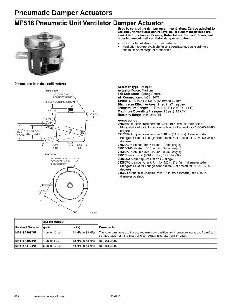
Pneumatic Damper Actuators
696 customer.honeywell.com 70-6910
MP516 Pneumatic Unit Ventilator Damper ActuatorUsed to control the damper on unit ventilators. Can be adapted to various unit ventilator control cycles. Replacement devices are available for Johnson, Powers, Robertshaw, Barber-Colman, and older Honeywell unit ventilator damper actuators.
• Constructed of strong zinc die castings. • Hesitation feature available for unit ventilator cycles requiring a
minimum percentage of outdoor air.
Dimensions in inches (millimeters)Actuator Type: DamperActuator Force: MediumFail Safe Mode: Spring ReturnAir Connections: 1/8 in. NPTStroke: 2-1/8 in. to 2-1/2 in. (54 mm to 63 mm) Diaphragm Effective Area: 11 sq in. (71 sq cm) Temperature Range: -20 F to +160 F (-29 C to +71 C) Maximum Operating Pressure: 25 psi (172 kPa) Humidity Range: 5 to 95% RH
Accessories:26025B-Damper crank arm for 3/8 in. (9.5 mm) diameter axle.
Elongated slot for linkage connection. Slot scaled for 40-50-60-75-90 degrees.
27174B-Damper crank arm for 7/16 in. (11.1 mm) diameter axle. Elongated slot for linkage connection. Slot scaled for 40-50-60-75-90 degrees.
27520C-Push Rod (5/16 in. dia., 12 in. length)27520G-Push Rod (5/16 in. dia., 24 in. length)27520K-Push Rod (5/16 in. dia., 36 in. length)27520L-Push Rod (5/16 in. dia., 48 in. length)309389J-Mounting Bracket and Linkage312867C-Damper Crank Arm for 1/2 in. (12.7mm) diameter axle.
Elongated slot for linkage connection. Slot scaled for 45-60-75-90 degrees
315321-Crankarm Balljoint (with 1/4 in male threads), fits 5/16 in. diameter pushrod
ALTERNATE POSITIONFOR SUPPLY AIR CONNECTION
TOP VIEW
5 (27)
2-13/16(71)
SIDE VIEW1/8 (3) NPT AIR CONNECTION (2)
3/4-16 MOUNTING STUD
5/8 (16)
9/32 (7)
7/16 (11)
4-3/8(111)
2-1/2(64)
2-1/2 (64)MAX.
TRAVEL
2-1/16 (52)MIN. TRAVEL
M27104
Product Number
Spring Range
Comments(psi) (kPa)
MP516A1087/U 3 psi to 12 psi 21 kPa to 83 kPa The lever arm moves to the desired minimum position as air pressure increases from 0 to 3 psi, hesitates from 3 to 8 psi, and completes its stroke from 8-12 psi.
MP516A1095/U 4 psi to 8 psi 28 kPa to 55 kPa No hesitation.
MP516A1103/U 5 psi to 12 psi 34 kPa to 83 kPa No hesitation.
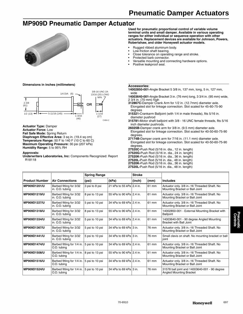
Pneumatic Damper Actuators
70-6910 697
P
neumatic
Controls
MP909D Pneumatic Damper ActuatorUsed for pneumatic proportional control of variable volume terminal units and small damper. Available in various operating ranges for either individual or sequence operation with other actuators. Replacement devices are available for Johnson, Powers, Robertshaw, and older Honeywell actuator models.
• Rugged ribbed aluminum body. • Low-friction shaft bearing. • Close tolerance on operating range and stroke. • Protected barb connector. • Versatile mounting and connecting hardware options. • Positive leakproof seal.
Dimensions in inches (millimeters)
Actuator Type: DamperActuator Force: LowFail Safe Mode: Spring ReturnDiaphragm Effective Area: 3 sq in. (19.4 sq cm) Temperature Range: 50 F to 140 F (10 C to 60 C) Maximum Operating Pressure: 30 psi (207 kPa) Humidity Range: 5 to 95% RH
Approvals:Underwriters Laboratories, Inc: Components Recognized: Report
R18118
Accessories:14002850-001-Angle Bracket 5 3/8 in, 137 mm, long, 5 in, 127 mm,
wide14003640-001-Angle Bracket 3 in. (76 mm) long, 3 3/4 in. (95 mm) wide, 2 3/4 in. (70 mm) high312867C-Damper Crank Arm for 1/2 in. (12.7mm) diameter axle.
Elongated slot for linkage connection. Slot scaled for 45-60-75-90 degrees
315321-Crankarm Balljoint (with 1/4 in male threads), fits 5/16 in. diameter pushrod
315781-Motor shaft balljoint with 3/8 - 16 UNC female threads, fits 5/16 inch diameter pushrods.
26025B-Damper crank arm for 3/8 in. (9.5 mm) diameter axle. Elongated slot for linkage connection. Slot scaled for 40-50-60-75-90 degrees.
27174B-Damper crank arm for 7/16 in. (11.1 mm) diameter axle. Elongated slot for linkage connection. Slot scaled for 40-50-60-75-90 degrees.
27520C-Push Rod (5/16 in. dia., 12 in. length)27520G-Push Rod (5/16 in. dia., 24 in. length)27520K-Push Rod (5/16 in. dia., 36 in. length)27520L-Push Rod (5/16 in. dia., 48 in. length)27520K-Push Rod (5/16 in. dia., 36 in. length)27520L-Push Rod (5/16 in. dia., 48 in. length)
1/4 DIA (6)
1/2 (13)1-3/16(46)
5-11/16 (145)
2-3/8(61) OR
1-1/16(27)
3/8-16 UNC-2A
13/16 (20) LONG
MIN.
C484-2
Product Number Air Connections
Spring Range Stroke
Includes(psi) (kPa) (inch) (mm)
MP909D1201/U Barbed fitting for 3/32 in. O.D. tubing
3 psi to 8 psi 21 kPa to 55 kPa 2.4 in. 61 mm Actuator only. 3/8 in.-16 Threaded Shaft. No Mounting Bracket or Ball Joint
MP909D1219/U Barbed fitting for 3/32 in. O.D. tubing
8 psi to 13 psi 55 kPa to 90 kPa 2.4 in. 61 mm Actuator only. 3/8 in.-16 Threaded Shaft. No Mounting Bracket or Ball Joint
MP909D1227/U Barbed fitting for 3/32 in. O.D. tubing
5 psi to 10 psi 34 kPa to 69 kPa 2.4 in. 61 mm Actuator only. 3/8 in.-16 Threaded Shaft. No Mounting Bracket or Ball Joint
MP909D1318/U Barbed fitting for 3/32 in. O.D. tubing
8 psi to 13 psi 55 kPa to 90 kPa 2.4 in. 61 mm 14002850-001 - External Mounting Bracket with Balljoint
MP909D1334/U Barbed fitting for 3/32 in. O.D. tubing
5 psi to 10 psi 34 kPa to 69 kPa 2.4 in. 61 mm 14003640-001 - 90 degree Angled Mounting Bracket with Ball Joint
MP909D1367/U Barbed fitting for 3/32 in. O.D. tubing
5 psi to 10 psi 34 kPa to 69 kPa 3 in. 76 mm Actuator only. 3/8 in.-16 Threaded Shaft. No Mounting Bracket or Ball Joint
MP909D1441/U Barbed fitting for 3/32 in. O.D. tubing
5 psi to 10 psi 34 kPa to 69 kPa 3 in. 76 mm Small clevis on shaft. No mounting bracket or ball joint
MP909D1474/U Barbed fitting for 1/4 in. O.D. tubing
5 psi to 10 psi 34 kPa to 69 kPa 2.4 in. 61 mm Actuator only. 3/8 in.-16 Threaded Shaft. No Mounting Bracket or Ball Joint
MP909D1508/U Barbed fitting for 1/4 in. O.D. tubing
8 psi to 13 psi 55 kPa to 90 kPa 2.4 in. 61 mm Actuator only. 3/8 in.-16 Threaded Shaft. No Mounting Bracket or Ball Joint
MP909D1516/U Barbed fitting for 1/4 in. O.D. tubing
5 psi to 10 psi 34 kPa to 69 kPa 2.4 in. 61 mm Actuator only. 3/8 in.-16 Threaded Shaft. No Mounting Bracket or Ball Joint
MP909D1524/U Barbed fitting for 1/4 in. O.D. tubing
5 psi to 10 psi 34 kPa to 69 kPa 3 in. 76 mm 31578 ball joint and 14003640-001 - 90 degree Angled Mounting Bracket

Pneumatic Damper Actuators
698 customer.honeywell.com 70-6910
MP909E,H Pneumatic Damper ActuatorsThese actuators are used for proportional control of variable volume terminal units, mixing boxes, and small to medium sized dampers. They are available in various operating ranges for either independent operation or sequence operation with other actuators. The MP909E has an optional adjustable stroke feature. The MP909H includes a positive positioner. Replacement devices are available for Johnson, Powers, Robertshaw, Barber-Colman, and older Honeywell actuator models.
• Rolling diaphragm operated. • Low friction shaft bearing. • Close tolerance on operating range and stroke. • Non-overlapping spring ranges for sequencing. • Corrosion resistant materials. • Reliable long life.
Dimensions in inches (millimeters)Actuator with Fixed External Mounting Bracket
Actuator with Internal N.C. Trunnion Mounting Bracket
Actuator with External Trunnion Mounting Bracket
Actuator with Internal N.O. Trunnion Mounting Bracket
Actuator Type: DamperActuator Force: MediumFail Safe Mode: Spring ReturnAir Connections: Dual Barbed fitting for 5/32 in. or 1/4 in. O.D. tubingDiaphragm Effective Area: 6.6 sq in. (43 sq cm) Temperature Range: -28 F to +160 F (-33 C to +71 C) Humidity Range: 5 to 95% RH
Approvals:Underwriters Laboratories, Inc: Components Recognized: Report
R18118
Accessories:27518-Crankarm balljoint with 1/4 - 28 UNF male threads, fits 5-16 inch
diameter push rods26025B-Damper crank arm for 3/8 in. (9.5 mm) diameter axle.
Elongated slot for linkage connection. Slot scaled for 40-50-60-75-90 degrees.
27520C-Push Rod (5/16 in. dia., 12 in. length)27520G-Push Rod (5/16 in. dia., 24 in. length)27520K-Push Rod (5/16 in. dia., 36 in. length)27520L-Push Rod (5/16 in. dia., 48 in. length)312867C-Damper Crank Arm for 1/2 in. (12.7mm) diameter axle.
Elongated slot for linkage connection. Slot scaled for 45-60-75-90 degrees
312867H-Externally mounted Linkage Kit314440A-MP909 - Clevis, Clevis Pin and Cotter Pin Assembly315321-Crankarm Balljoint (with 1/4 in male threads), fits 5/16 in.
diameter pushrod315781-Motor shaft balljoint with 3/8 - 16 UNC female threads, fits 5/16
inch diameter pushrods.14002850-001-Angle Bracket 5 3/8 in, 137 mm, long, 5 in, 127 mm,
wide14003640-001-Angle Bracket 3 in. (76 mm) long, 3 3/4 in. (95 mm) wide,
2 3/4 in. (70 mm) high14004062-001-External Trunnion Mounting Bracket14004062-002-Internal N.C. Trunnion Mounting Bracket14004062-003-Internal N.O. Trunnion Mounting Bracket14004106-001-Actuator pushrod for conversion of internal N.C. to
external14004107-001-Crankarm Assembly for conversion from internal N.C. to
external Trunnion mounting14004210-001-Feedback Spring Kit includes orange spring (3 psi
[21kPa]), yellow spring (5 psi [34 kPa]), and blue spring (10 psi [69 kPa]).
14004236-001-Coupler, actuator shaft to 5/16 in, 8 mm, pushrod14004241-002-Hitch Pin (Six Sets)14004242-001-MP918 Top Mount Operator Assembly14004667-001-Offset Crank arm assembly with 2 screws (304725-062),
nuts (14004102-001), crank arm (14004655-001) for 1/2 in. Drive Axle
Replacement Parts:14004137-001-Retrofit Kit for adding positive positioner to MP909E or
repair of MP909H
13-3/4 (350) MP909H
5 (127)
9-1/4 (235) MP909E
4-1/2(114)
MP909H6-1/4(159)
M27095
1 ANGLE BRACKET IS 14002851-001 FOR MP909E1067 AND IS 14002850-001 FOR OTHERS.
17 (430) MP909E
19-3/4 (500) MP909H
MP909E N.C.
7 (180)
MP909HN.C.
9-1/2 (240)
EDGE OFDAMPER
6-7/8 (175) WIDE
M27097
7-1/4(185)
M27096
17 (430) MP909E22 (560) MP909H
17 (430) MP909E19-3/4 (500) MP909H
6-1/2(169)
MP909E
9 (230)MP909H
EDGE OFDAMPER
6-7/8 (175) WIDE
M27098

Pneumatic Damper Actuators
70-6910 699
P
neumatic
Controls
Product Number Air Connections
Maximum Operating Pressure Spring Range Stroke
Includes(psi) (kPa) (psi) (kPa) (inch) (mm)
MP909E1018/U Dual Barbed fitting for 5/32 in. or 1/4 in. O.D. tubing
29 psi 200 kPa 3 psi to 13 psi
21 kPa to 90 kPa
4 in. 102 mm 315781 Balljoint, Linkage Kit 14002061-006 and 14002850-001 Fixed External Mounting Bracket with Balljoint
MP909E1034/U Dual Barbed fitting for 5/32 in. or 1/4 in. O.D. tubing
29 psi 200 kPa 5 psi to 10 psi
34 kPa to 69 kPa
4 in. 102 mm 315781 Balljoint, Linkage Kit 14002061-006 and 14002850-001 Fixed External Mounting Bracket with Balljoint
MP909E1059/U Dual Barbed fitting for 5/32 in. or 1/4 in. O.D. tubing
29 psi 200 kPa 5 psi to 10 psi
34 kPa to 69 kPa
2 3/4 in. 70 mm Actuator only. 3/8 in.-16 Threaded Shaft with stroke stops. No Mounting Bracket
MP909E1067/U Dual Barbed fitting for 5/32 in. or 1/4 in. O.D. tubing
29 psi 200 kPa 5 psi to 10 psi
34 kPa to 69 kPa
3 in. 79 mm Fixed external unitary mounting bracket and clevis shaft with stroke stops
MP909E1083/U Dual Barbed fitting for 5/32 in. or 1/4 in. O.D. tubing
29 psi 200 kPa 2.5 psi to 6.5 psi
17 kPa to 45 kPa
3 in. 79 mm 315781 Balljoint, Linkage Kit 14002061-006 and 14002850-001 Fixed External Mounting Bracket with Balljoint
MP909E1109/U Dual Barbed fitting for 5/32 in. or 1/4 in. O.D. tubing
29 psi 200 kPa 2.5 psi to 6.5 psi
17 kPa to 45 kPa
2 3/4 in. 70 mm Actuator only. 3/8 in.-16 Threaded Shaft with stroke stops. No Mounting Bracket
MP909E1158/U Dual Barbed fitting for 5/32 in. or 1/4 in. O.D. tubing
29 psi 200 kPa 9 psi to 13 psi
62 kPa to 90 kPa
3 in. 79 mm Actuator only. 3/8 in.-16 Threaded Shaft. No Mounting Bracket
MP909E1174/U Dual Barbed fitting for 5/32 in. or 1/4 in. O.D. tubing
29 psi 200 kPa 9 psi to 13 psi
62 kPa to 90 kPa
3 in. 70 mm 14002850-001 - Fixed External Mounting Bracket with 315781 Balljoint
MP909E1240/U Dual Barbed fitting for 5/32 in. or 1/4 in. O.D. tubing
29 psi 200 kPa 5 psi to 10 psi
34 kPa to 69 kPa
3 in. 79 mm Actuator only. 3/8 in.-16 Threaded Shaft. No Mounting Bracket
MP909E1349/U Dual Barbed fitting for 5/32 in. or 1/4 in. O.D. tubing
29 psi 200 kPa 3 psi to 13 psi
21 kPa to 90 kPa
4 in. 102 mm Internal N.C. trunnion mounting bracket
MP909E1356/U Dual Barbed fitting for 5/32 in. or 1/4 in. O.D. tubing
29 psi 200 kPa 3 psi to 13 psi
21 kPa to 90 kPa
4 in. 102 mm External trunnion mounting bracket
MP909E1364/U Dual Barbed fitting for 5/32 in. or 1/4 in. O.D. tubing
29 psi 200 kPa 5 psi to 10 psi
34 kPa to 69 kPa
4 in. 102 mm External trunnion mounting bracket
MP909E1372/U Dual Barbed fitting for 5/32 in. or 1/4 in. O.D. tubing
29 psi 200 kPa 2.5 psi to 6.5 psi
17 kPa to 45 kPa
3 in. 70 mm External trunnion mounting bracket
MP909E1380/U Dual Barbed fitting for 5/32 in. or 1/4 in. O.D. tubing
29 psi 200 kPa 9 psi to 13 psi
62 kPa to 90 kPa
3 in. 79 mm External trunnion mounting bracket
MP909E1398/U Dual Barbed fitting for 5/32 in. or 1/4 in. O.D. tubing
29 psi 200 kPa 9 psi to 13 psi
62 kPa to 90 kPa
3 in. 79 mm Internal N.C. trunnion mounting bracket
MP909E1422/U Dual Barbed fitting for 5/32 in. or 1/4 in. O.D. tubing
29 psi 200 kPa 5 psi to 10 psi
34 kPa to 69 kPa
4 in. 102 mm 14004062-003 Internal N.O. Mounting Bracket with crankarm and pushrod assembly
MP909E1463/U Dual Barbed fitting for 5/32 in. or 1/4 in. O.D. tubing
29 psi 200 kPa 5 psi to 10 psi
34 kPa to 69 kPa
4 in. 102 mm 14002850-001 - Fixed External Mounting Bracket
MP909H1331/U Positioner: Pilot 5/32 in. barb, Main 1/4 in. barb, Branch 1/4 in. barb. Actuator: combination 5/32 in. and 1/4 in. barb
25 psi 172 kPa Positive positioner 10 psi span (5 psi spring included)
Positive positioner 69 kPa span (34 kPa spring included)
4 in. 102 mm 315781 Balljoint, Positive Positioner, and 14002850-001 - Fixed External Mounting Bracket with Balljoint
MP909H1368/U Positioner: Pilot 5/32 in. barb, Main 1/4 in. barb, Branch 1/4 in. barb. Actuator: combination 5/32 in. and 1/4 in. barb
25 psi 172 kPa Positive positioner 10 psi span (5 psi spring included)
Positive positioner 69 kPa span (34 kPa spring included)
4 in. 102 mm External Trunnion Bracket, Positive Positioner
MP909H1392/U Positioner: Pilot 5/32 in. barb, Main 1/4 in. barb, Branch 1/4 in. barb. Actuator: combination 5/32 in. and 1/4 in. barb
25 psi 172 kPa Positive positioner 10 psi span (5 psi spring included)
Positive positioner 69 kPa span (34 kPa spring included)
4 in. 102 mm Mounting bracket for internal N.C. Trunnion mounting, positive positioner
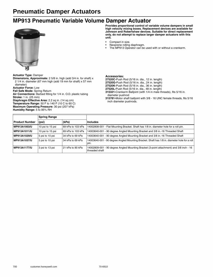
Pneumatic Damper Actuators
700 customer.honeywell.com 70-6910
MP913 Pneumatic Variable Volume Damper ActuatorProvides proportional control of variable volume dampers in small high velocity mixing boxes. Replacement devices are available for Johnson and Robertshaw devices. Suitable for direct replacement only, do not attempt to replace larger damper actuators with this unit.
• Compact in size. • Neoprene rolling diaphragm. • The MP913 Operator can be used with or without a crankarm.
Actuator Type: DamperDimensions, Approximate: 2 5/8 in. high (add 3/4 in. for shaft) x
2 1/4 in. diameter (67 mm high (add 19 mm for shaft) x 57 mm diameter)
Actuator Force: LowFail Safe Mode: Spring ReturnAir Connections: Barbed fitting for 1/4 in. O.D. plastic tubingStroke: 1 in. (25 mm) Diaphragm Effective Area: 2.2 sq in. (14 sq cm) Temperature Range: 50 F to 140 F (10 C to 60 C) Maximum Operating Pressure: 30 psi (207 kPa) Humidity Range: 5 to 95% RH
Accessories:27520C-Push Rod (5/16 in. dia., 12 in. length)27520G-Push Rod (5/16 in. dia., 24 in. length)27520K-Push Rod (5/16 in. dia., 36 in. length)27520L-Push Rod (5/16 in. dia., 48 in. length)315321-Crankarm Balljoint (with 1/4 in male threads), fits 5/16 in.
diameter pushrod315781-Motor shaft balljoint with 3/8 - 16 UNC female threads, fits 5/16
inch diameter pushrods.
Product Number
Spring Range
Includes(psi) (kPa)
MP913A1003/U 10 psi to 15 psi 69 kPa to 103 kPa 14002808-001 - Flat Mounting Bracket. Shaft has 1/8 in. diameter hole for a roll pin.
MP913A1011/U 10 psi to 15 psi 69 kPa to 103 kPa 14003640-001 - 90 degree Angled Mounting Bracket and 3/8 in.-16 Threaded Shaft
MP913A1029/U 5 psi to 10 psi 34 kPa to 69 kPa 14003640-001 - 90 degree Angled Mounting Bracket and 3/8 in.-16 Threaded Shaft
MP913A1037/U 5 psi to 10 psi 34 kPa to 69 kPa 14003640-001 - 90 degree Angled Mounting Bracket. Shaft has 1/8 in. diameter hole for a roll pin.
MP913A1177/U 3 psi to 13 psi 21 kPa to 90 kPa 14002809-001 - 90 degree Angled Mounting Bracket (3-point attachment) and 3/8 inch - 16 threaded shaft
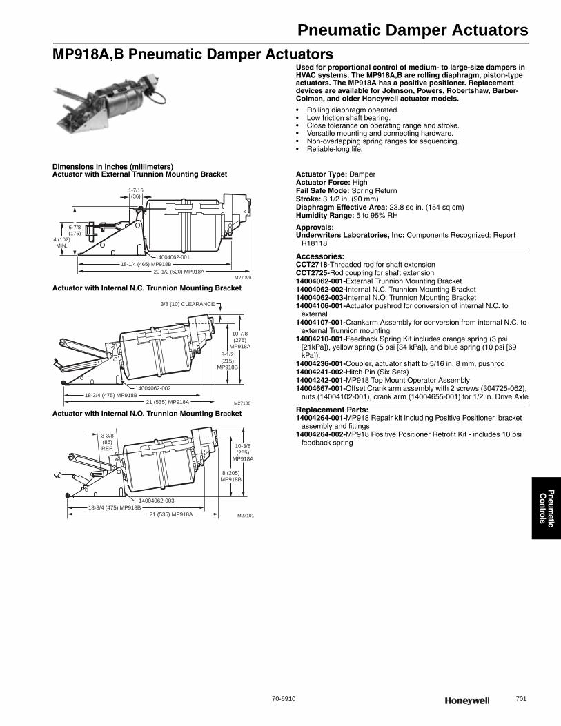
Pneumatic Damper Actuators
70-6910 701
P
neumatic
Controls
MP918A,B Pneumatic Damper ActuatorsUsed for proportional control of medium- to large-size dampers in HVAC systems. The MP918A,B are rolling diaphragm, piston-type actuators. The MP918A has a positive positioner. Replacement devices are available for Johnson, Powers, Robertshaw, Barber-Colman, and older Honeywell actuator models.
• Rolling diaphragm operated. • Low friction shaft bearing. • Close tolerance on operating range and stroke. • Versatile mounting and connecting hardware. • Non-overlapping spring ranges for sequencing. • Reliable-long life.
Dimensions in inches (millimeters)Actuator with External Trunnion Mounting Bracket
Actuator with Internal N.C. Trunnion Mounting Bracket
Actuator with Internal N.O. Trunnion Mounting Bracket
Actuator Type: DamperActuator Force: HighFail Safe Mode: Spring ReturnStroke: 3 1/2 in. (90 mm) Diaphragm Effective Area: 23.8 sq in. (154 sq cm) Humidity Range: 5 to 95% RH
Approvals:Underwriters Laboratories, Inc: Components Recognized: Report
R18118
Accessories:CCT2718-Threaded rod for shaft extensionCCT2725-Rod coupling for shaft extension14004062-001-External Trunnion Mounting Bracket14004062-002-Internal N.C. Trunnion Mounting Bracket14004062-003-Internal N.O. Trunnion Mounting Bracket14004106-001-Actuator pushrod for conversion of internal N.C. to
external14004107-001-Crankarm Assembly for conversion from internal N.C. to
external Trunnion mounting14004210-001-Feedback Spring Kit includes orange spring (3 psi
[21kPa]), yellow spring (5 psi [34 kPa]), and blue spring (10 psi [69 kPa]).
14004236-001-Coupler, actuator shaft to 5/16 in, 8 mm, pushrod14004241-002-Hitch Pin (Six Sets)14004242-001-MP918 Top Mount Operator Assembly14004667-001-Offset Crank arm assembly with 2 screws (304725-062),
nuts (14004102-001), crank arm (14004655-001) for 1/2 in. Drive Axle
Replacement Parts:14004264-001-MP918 Repair kit including Positive Positioner, bracket
assembly and fittings14004264-002-MP918 Positive Positioner Retrofit Kit - includes 10 psi
feedback spring
18-1/4 (465) MP918B
6-7/8(175)
4 (102)MIN.
M27099
20-1/2 (520) MP918A
14004062-001
1-7/16(36)
M27100
8-1/2(215)
MP918B
10-7/8(275)
MP918A
3/8 (10) CLEARANCE
18-3/4 (475) MP918B
21 (535) MP918A
14004062-002
M27101
8 (205)MP918B
10-3/8(265)
MP918A
18-3/4 (475) MP918B
21 (535) MP918A
14004062-003
3-3/8(86)REF.
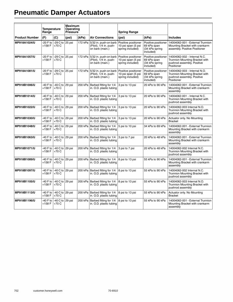
Pneumatic Damper Actuators
702 customer.honeywell.com 70-6910
Product Number
Temperature Range
Maximum Operating Pressure
Air Connections
Spring Range
Includes(F) (C) (psi) (kPa) (psi) (kPa)
MP918A1024/U -20 F to +158 F
-29 C to +70 C
25 psi 172 kPa 5/32 in. push-on barb (Pilot), 1/4 in. push-on barb (main.)
Positive positioner 10 psi span (5 psi spring included)
Positive positioner 69 kPa span (34 kPa spring included)
14004062-001 - External Trunnion Mounting Bracket with crankarm assembly. Positive Positioner
MP918A1057/U -20 F to +158 F
-29 C to +70 C
25 psi 172 kPa 5/32 in. push-on barb (Pilot), 1/4 in. push-on barb (main.)
Positive positioner 10 psi span (5 psi spring included)
Positive positioner 69 kPa span (34 kPa spring included)
14004062-002 - Internal N.C. Trunnion Mounting Bracket with pushrod assembly. Positive Positioner
MP918A1081/U -20 F to +158 F
-29 C to +70 C
25 psi 172 kPa 5/32 in. push-on barb (Pilot), 1/4 in. push-on barb (main.)
Positive positioner 10 psi span (5 psi spring included)
Positive positioner 69 kPa span (34 kPa spring included)
14004062-003 - Internal N.O. Trunnion Mounting Bracket with pushrod assembly. Positive Positioner
MP918B1006/U -40 F to +158 F
-40 C to +70 C
29 psi 200 kPa Barbed fitting for 1/4 in. O.D. plastic tubing
3 psi to 13 psi 20 kPa to 90 kPa 14004062-001 - External Trunnion Mounting Bracket with crankarm assembly
MP918B1014/U -40 F to +158 F
-40 C to +70 C
29 psi 200 kPa Barbed fitting for 1/4 in. O.D. plastic tubing
3 psi to 13 psi 20 kPa to 90 kPa 14004062-001 - Internal N.C. Trunnion Mounting Bracket with pushrod assembly
MP918B1022/U -40 F to +158 F
-40 C to +70 C
29 psi 200 kPa Barbed fitting for 1/4 in. O.D. plastic tubing
3 psi to 13 psi 20 kPa to 90 kPa 14004062-003 Internal N.O. Trunnion Mounting Bracket with pushrod assembly
MP918B1030/U -40 F to +158 F
-40 C to +70 C
29 psi 200 kPa Barbed fitting for 1/4 in. O.D. plastic tubing
3 psi to 13 psi 20 kPa to 90 kPa Actuator only. No Mounting Bracket
MP918B1048/U -40 F to +158 F
-40 C to +70 C
29 psi 200 kPa Barbed fitting for 1/4 in. O.D. plastic tubing
5 psi to 10 psi 34 kPa to 69 kPa 14004062-001 - External Trunnion Mounting Bracket with crankarm assembly
MP918B1063/U -40 F to +158 F
-40 C to +70 C
29 psi 200 kPa Barbed fitting for 1/4 in. O.D. plastic tubing
3 psi to 7 psi 20 kPa to 48 kPa 14004062-001 - External Trunnion Mounting Bracket with crankarm assembly
MP918B1071/U -40 F to +158 F
-40 C to +70 C
29 psi 200 kPa Barbed fitting for 1/4 in. O.D. plastic tubing
3 psi to 7 psi 20 kPa to 48 kPa 14004062-002 Internal N.C. Trunnion Mounting Bracket with pushrod assembly
MP918B1089/U -40 F to +158 F
-40 C to +70 C
29 psi 200 kPa Barbed fitting for 1/4 in. O.D. plastic tubing
8 psi to 13 psi 55 kPa to 90 kPa 14004062-001 - External Trunnion Mounting Bracket with crankarm assembly
MP918B1097/U -40 F to +158 F
-40 C to +70 C
29 psi 200 kPa Barbed fitting for 1/4 in. O.D. plastic tubing
8 psi to 13 psi 55 kPa to 90 kPa 14004062-002 Internal N.C. Trunnion Mounting Bracket with pushrod assembly
MP918B1105/U -40 F to +158 F
-40 C to +70 C
29 psi 200 kPa Barbed fitting for 1/4 in. O.D. plastic tubing
8 psi to 13 psi 55 kPa to 90 kPa 14004062-003 Internal N.O. Trunnion Mounting Bracket with pushrod assembly
MP918B1113/U -40 F to +158 F
-40 C to +70 C
29 psi 200 kPa Barbed fitting for 1/4 in. O.D. plastic tubing
8 psi to 13 psi 55 kPa to 90 kPa Actuator only. No Mounting Bracket
MP918B1196/U -40 F to +158 F
-40 C to +70 C
29 psi 200 kPa Barbed fitting for 1/4 in. O.D. plastic tubing
8 psi to 13 psi 55 kPa to 90 kPa 14004062-001 - External Trunnion Mounting Bracket with crankarm assembly
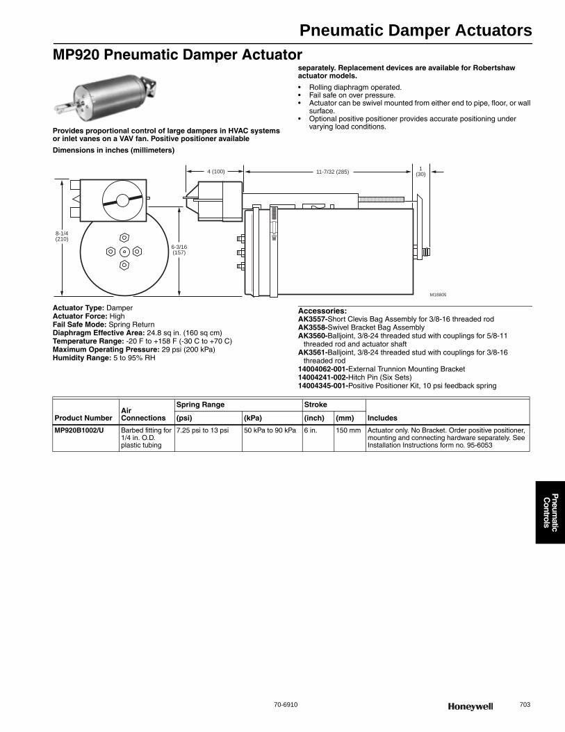
Pneumatic Damper Actuators
70-6910 703
P
neumatic
Controls
MP920 Pneumatic Damper Actuator
Provides proportional control of large dampers in HVAC systems or inlet vanes on a VAV fan. Positive positioner available
separately. Replacement devices are available for Robertshaw actuator models.
• Rolling diaphragm operated. • Fail safe on over pressure. • Actuator can be swivel mounted from either end to pipe, floor, or wall
surface. • Optional positive positioner provides accurate positioning under
varying load conditions.
Dimensions in inches (millimeters)
Actuator Type: DamperActuator Force: HighFail Safe Mode: Spring ReturnDiaphragm Effective Area: 24.8 sq in. (160 sq cm) Temperature Range: -20 F to +158 F (-30 C to +70 C) Maximum Operating Pressure: 29 psi (200 kPa) Humidity Range: 5 to 95% RH
Accessories:AK3557-Short Clevis Bag Assembly for 3/8-16 threaded rodAK3558-Swivel Bracket Bag AssemblyAK3560-Balljoint, 3/8-24 threaded stud with couplings for 5/8-11
threaded rod and actuator shaftAK3561-Balljoint, 3/8-24 threaded stud with couplings for 3/8-16
threaded rod14004062-001-External Trunnion Mounting Bracket14004241-002-Hitch Pin (Six Sets)14004345-001-Positive Positioner Kit, 10 psi feedback spring
1(30)11-7/32 (285)
M18809
4 (100)
6-3/16(157)
8-1/4(210)
Product NumberAir Connections
Spring Range Stroke
Includes(psi) (kPa) (inch) (mm)
MP920B1002/U Barbed fitting for 1/4 in. O.D. plastic tubing
7.25 psi to 13 psi 50 kPa to 90 kPa 6 in. 150 mm Actuator only. No Bracket. Order positive positioner, mounting and connecting hardware separately. See Installation Instructions form no. 95-6053

Pneumatic Damper Actuators
704 customer.honeywell.com 70-6910
Pneumatic Damper Actuator Piping DiagramsMP516A Typical Piping
MP909D Piping Diagram
MP909D Ball Joint Linkage
MP920B Typical Piping
MP909E,H Piping Diagram
MP918A and B Typical Piping
MP913A Typical Piping
M5440A
MAY BE SURFACE MOUNTED OR ATTACHED TO MP516A.
1
1
M
RESTRICTION
THERMOSTAT
AIRSTREAM
THERMOSTAT
TO FAN
INTERLOCK E/P RELAY
ATM
MP516A
VALVE
1 2 3
M B
MP909D
M M5577
DISCHARGE
AIR PRIMARY AIR
ROOM THERMOSTAT
VARIABLE VOLUME
AIR TERMINAL UNIT
DAMPER AXLE
SETSCREW
CRANKARM BALLJOINT
5/16 in. PUSHROD
MOUNTINGBRACKET
LOCKNUT
OPERATOR SHAFT
M16438
MOTOR SHAFT BALLJOINT
INLET PORT
CRANKARM
MP920B
M5578
VAV FAN
FROM
CONTROLLER
B M P
M
MP909E
MP909H
FROM
CONTROLLER
M5575
SECTIONS OF LARGE DAMPER REQUIRING
MORE THAN ONE OPERATOR MUST BE LINKED
1
1
B M P
M
MP918B
MP918A
FROM
CONTROLLER
M5576
SECTIONS OF LARGE DAMPER REQUIRING
MORE THAN ONE OPERATOR MUST BE LINKED
1
1
M5438
PRIMARY
AIR
MP913A
CEILING
DIFFUSER
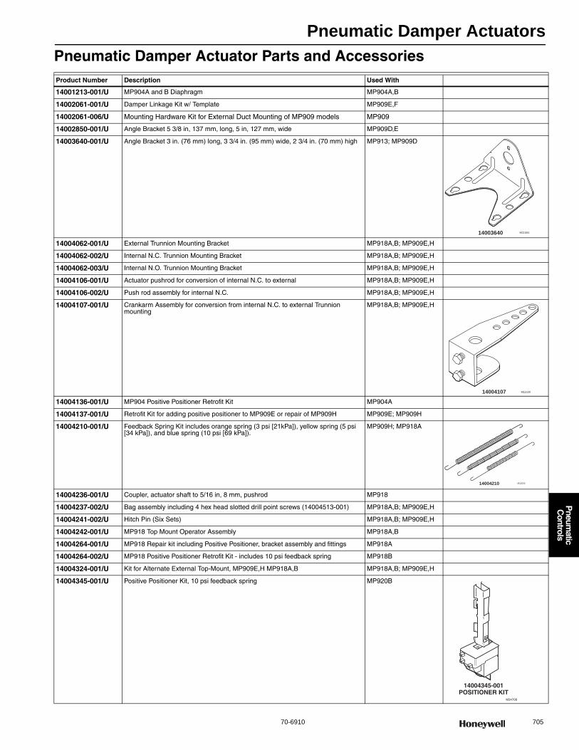
Pneumatic Damper Actuators
70-6910 705
P
neumatic
Controls
Pneumatic Damper Actuator Parts and AccessoriesProduct Number Description Used With
14001213-001/U MP904A and B Diaphragm MP904A,B
14002061-001/U Damper Linkage Kit w/ Template MP909E,F
14002061-006/U Mounting Hardware Kit for External Duct Mounting of MP909 models MP909
14002850-001/U Angle Bracket 5 3/8 in, 137 mm, long, 5 in, 127 mm, wide MP909D,E
14003640-001/U Angle Bracket 3 in. (76 mm) long, 3 3/4 in. (95 mm) wide, 2 3/4 in. (70 mm) high MP913; MP909D
14004062-001/U External Trunnion Mounting Bracket MP918A,B; MP909E,H
14004062-002/U Internal N.C. Trunnion Mounting Bracket MP918A,B; MP909E,H
14004062-003/U Internal N.O. Trunnion Mounting Bracket MP918A,B; MP909E,H
14004106-001/U Actuator pushrod for conversion of internal N.C. to external MP918A,B; MP909E,H
14004106-002/U Push rod assembly for internal N.C. MP918A,B; MP909E,H
14004107-001/U Crankarm Assembly for conversion from internal N.C. to external Trunnion mounting
MP918A,B; MP909E,H
14004136-001/U MP904 Positive Positioner Retrofit Kit MP904A
14004137-001/U Retrofit Kit for adding positive positioner to MP909E or repair of MP909H MP909E; MP909H
14004210-001/U Feedback Spring Kit includes orange spring (3 psi [21kPa]), yellow spring (5 psi [34 kPa]), and blue spring (10 psi [69 kPa]).
MP909H; MP918A
14004236-001/U Coupler, actuator shaft to 5/16 in, 8 mm, pushrod MP918
14004237-002/U Bag assembly including 4 hex head slotted drill point screws (14004513-001) MP918A,B; MP909E,H
14004241-002/U Hitch Pin (Six Sets) MP918A,B; MP909E,H
14004242-001/U MP918 Top Mount Operator Assembly MP918A,B
14004264-001/U MP918 Repair kit including Positive Positioner, bracket assembly and fittings MP918A
14004264-002/U MP918 Positive Positioner Retrofit Kit - includes 10 psi feedback spring MP918B
14004324-001/U Kit for Alternate External Top-Mount, MP909E,H MP918A,B MP918A,B; MP909E,H
14004345-001/U Positive Positioner Kit, 10 psi feedback spring MP920B
14003640 M11504
14004107 M11530
M1153214004210
M34708
14004345-001POSITIONER KIT

Pneumatic Damper Actuators
706 customer.honeywell.com 70-6910
14004350-001/U Steel Clevis Pin (1/4 x 7/8) MP918
14004577-001/U MP953 A, C, and E (Direct Acting, 5 in. diameter) Yoke/Base Assembly MP953A,C,E
26025B/U Damper crank arm for 3/8 in. (9.5 mm) diameter axle. Elongated slot for linkage connection. Slot scaled for 40-50-60-75-90 degrees.
MP516; MP909D; MP909E, H
27174B/U Damper crank arm for 7/16 in. (11.1 mm) diameter axle. Elongated slot for linkage connection. Slot scaled for 40-50-60-75-90 degrees.
MP516; MP513
309292/U MP516A Diaphragm MP516
309389J/U Mounting Bracket and Linkage MP516
312809C/U MP904A and B Tube and Diaphragm Assembly MP904A,B
312817/U MP953C (5 in. diameter) Cover MP953C (5 in.)
312867C/U Damper Crank Arm for 1/2 in. (12.7mm) diameter axle. Elongated slot for linkage connection. Slot scaled for 45-60-75-90 degrees
MP516; MP909D; MP909E; MP909H
312867H/U Externally mounted Linkage Kit MP516; MP909D,E,H
314100/U MP909A Replacement Diaphragm MP909A
314316A/U Crank Arm Assembly MP516
314440A/U MP909 - Clevis, Clevis Pin and Cotter Pin Assembly MP909
315321/U Crankarm Balljoint (with 1/4 in male threads), fits 5/16 in. diameter pushrod MP516; MP909D,E,H; MP913
315321G/U Crankarm and Linkage MP909A,D
315439/0062/U Clevis MP909D
315781/U Motor shaft balljoint with 3/8 - 16 UNC female threads, fits 5/16 inch diameter pushrods.
MP909D,E,H; MP913
315782/U Balljoint (9/16 in.-18 UNC) accepts 5/16 in. Pushrod MP920B
AK3557/U Short Clevis Bag Assembly for 3/8-16 threaded rod MP920B
AK3558/U Swivel Bracket Bag Assembly MP920B
AK3560/U Balljoint, 3/8-24 threaded stud with couplings for 5/8-11 threaded rod and actuator shaft
MP920B
AK3561/U Balljoint, 3/8-24 threaded stud with couplings for 3/8-16 threaded rod MP920B
CCT2718/U Threaded rod for shaft extension MP918
CCT2725/U Rod coupling for shaft extension MP918
Product Number Description Used With
315781 M11503
AK3557 M11509
AK3560 M11507
AK3561 M11506
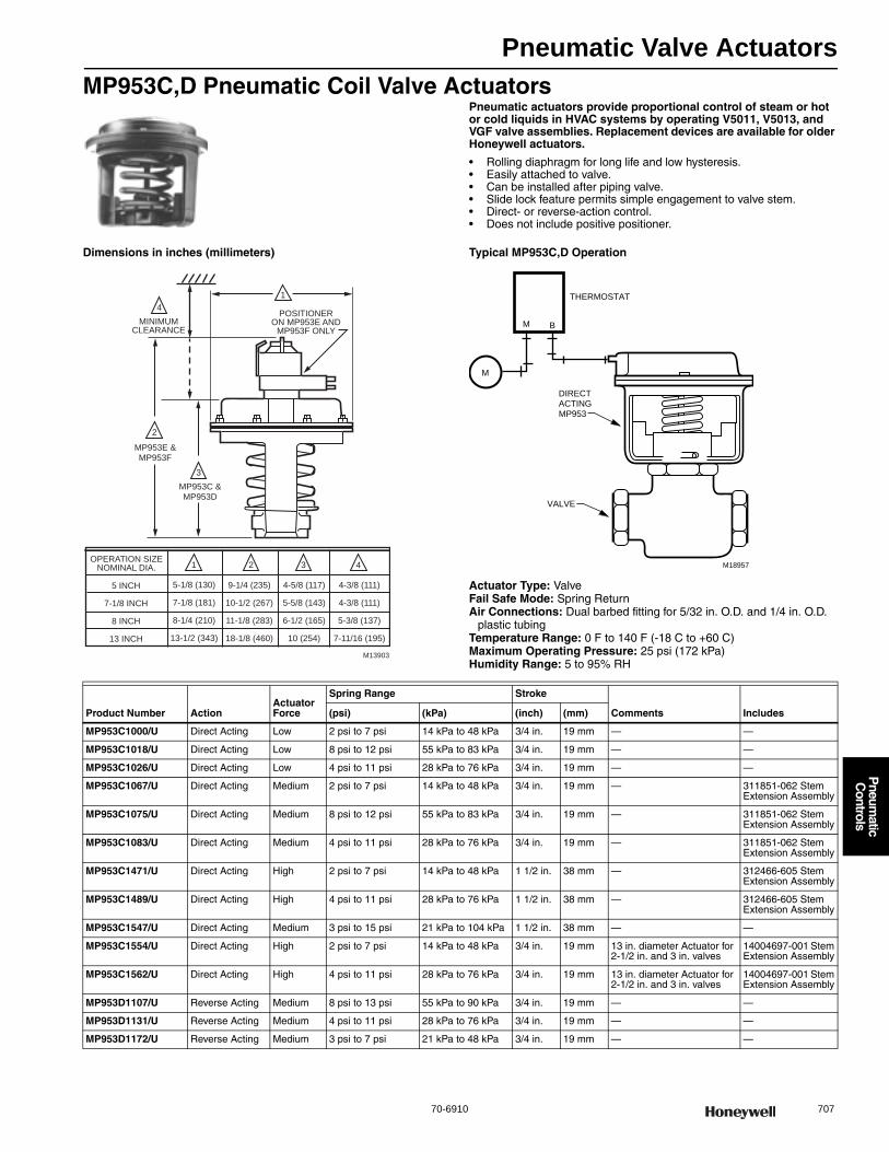
Pneumatic Valve Actuators
70-6910 707
P
neumatic
Controls
MP953C,D Pneumatic Coil Valve ActuatorsPneumatic actuators provide proportional control of steam or hot or cold liquids in HVAC systems by operating V5011, V5013, and VGF valve assemblies. Replacement devices are available for older Honeywell actuators.
• Rolling diaphragm for long life and low hysteresis. • Easily attached to valve. • Can be installed after piping valve. • Slide lock feature permits simple engagement to valve stem. • Direct- or reverse-action control. • Does not include positive positioner.
Dimensions in inches (millimeters) Typical MP953C,D Operation
Actuator Type: ValveFail Safe Mode: Spring ReturnAir Connections: Dual barbed fitting for 5/32 in. O.D. and 1/4 in. O.D.
plastic tubingTemperature Range: 0 F to 140 F (-18 C to +60 C) Maximum Operating Pressure: 25 psi (172 kPa) Humidity Range: 5 to 95% RH
2
4
3
MP953E &MP953F
MP953C &MP953D
POSITIONERON MP953E AND
MP953F ONLYMINIMUM
CLEARANCE
1 2 3 4OPERATION SIZE
NOMINAL DIA.
5 INCH
7-1/8 INCH
8 INCH
13 INCH
5-1/8 (130)
7-1/8 (181)
8-1/4 (210)
13-1/2 (343)
9-1/4 (235)
10-1/2 (267)
11-1/8 (283)
18-1/8 (460)
4-5/8 (117)
5-5/8 (143)
6-1/2 (165)
10 (254)
4-3/8 (111)
4-3/8 (111)
5-3/8 (137)
7-11/16 (195)
1
M13903
M B
M
M18957
DIRECTACTINGMP953
VALVE
THERMOSTAT
Product Number ActionActuator Force
Spring Range Stroke
Comments Includes(psi) (kPa) (inch) (mm)
MP953C1000/U Direct Acting Low 2 psi to 7 psi 14 kPa to 48 kPa 3/4 in. 19 mm — —
MP953C1018/U Direct Acting Low 8 psi to 12 psi 55 kPa to 83 kPa 3/4 in. 19 mm — —
MP953C1026/U Direct Acting Low 4 psi to 11 psi 28 kPa to 76 kPa 3/4 in. 19 mm — —
MP953C1067/U Direct Acting Medium 2 psi to 7 psi 14 kPa to 48 kPa 3/4 in. 19 mm — 311851-062 Stem Extension Assembly
MP953C1075/U Direct Acting Medium 8 psi to 12 psi 55 kPa to 83 kPa 3/4 in. 19 mm — 311851-062 Stem Extension Assembly
MP953C1083/U Direct Acting Medium 4 psi to 11 psi 28 kPa to 76 kPa 3/4 in. 19 mm — 311851-062 Stem Extension Assembly
MP953C1471/U Direct Acting High 2 psi to 7 psi 14 kPa to 48 kPa 1 1/2 in. 38 mm — 312466-605 Stem Extension Assembly
MP953C1489/U Direct Acting High 4 psi to 11 psi 28 kPa to 76 kPa 1 1/2 in. 38 mm — 312466-605 Stem Extension Assembly
MP953C1547/U Direct Acting Medium 3 psi to 15 psi 21 kPa to 104 kPa 1 1/2 in. 38 mm — —
MP953C1554/U Direct Acting High 2 psi to 7 psi 14 kPa to 48 kPa 3/4 in. 19 mm 13 in. diameter Actuator for 2-1/2 in. and 3 in. valves
14004697-001 Stem Extension Assembly
MP953C1562/U Direct Acting High 4 psi to 11 psi 28 kPa to 76 kPa 3/4 in. 19 mm 13 in. diameter Actuator for 2-1/2 in. and 3 in. valves
14004697-001 Stem Extension Assembly
MP953D1107/U Reverse Acting Medium 8 psi to 13 psi 55 kPa to 90 kPa 3/4 in. 19 mm — —
MP953D1131/U Reverse Acting Medium 4 psi to 11 psi 28 kPa to 76 kPa 3/4 in. 19 mm — —
MP953D1172/U Reverse Acting Medium 3 psi to 7 psi 21 kPa to 48 kPa 3/4 in. 19 mm — —

Pneumatic Valve Actuators
708 customer.honeywell.com 70-6910
MP953E,F Pneumatic Coil Valve ActuatorsPneumatic actuators provide proportional control of steam or hot or cold liquids in HVAC systems by operating V5011, V5013, and VGF valve assemblies. Replacement devices are available for older Honeywell actuators.
• Rolling diaphragm for long life and low hysteresis. • Easily attached to valve. • Can be installed after piping valve. • Slide lock feature permits simple engagement to valve stem. • Direct- or reverse-action control. • Integral positive positioner relay provides positive positioning under
varying load conditions.
Dimensions in inches (millimeters) Typical Piping for MP953E,F Pneumatic Valve Actuator Wiring
Actuator Type: ValveTemperature Range: 0 F to 140 F (-18 C to +60 C)Maximum Operating Pressure: 25 psi (172 kPa)Humidity Range: 5 to 95% RH
2
4
3
MP953E &MP953F
MP953C &MP953D
POSITIONERON MP953E AND
MP953F ONLYMINIMUM
CLEARANCE
1 2 3 4OPERATION SIZE
NOMINAL DIA
5 INCH
7 1/8 INCH
8 INCH
13 INCH
5 1/8 (130)
7 1/8 (181)
8 1/4 (210)
13 1/2 (343)
9 1/4 (235)
10 1/2 (267)
11 1/8 (283)
18 1/8 (460)
4 5/8 (117)
5 5/8 (143)
6 1/2 (165)
10 (254)
4 3/8 (111)
4 3/8 (111)
5 3/8 (137)
7 11/16 (195)
1
M13903
M B
M
M5445A
PILOT
MP953DA
VALVE
THERMOSTAT
POSITIONER
Product Number ActionActuator Force
Spring Range Stroke
Includes(psi) (kPa) (inch) (mm)
MP953E1285/U Direct Acting Medium 4 psi to 11 psi 28 kPa to 76 kPa 1 1/2 in. 38 mm Positive Positioner with 5 psi (35 kPa) range
MP953E1301/U Direct Acting Low 4 psi to 11 psi 28 kPa to 76 kPa 3/4 in. 19 mm Positive Positioner with 3 psi range (21kPa)
MP953E1319/U Direct Acting Low 4 psi to 11 psi 28 kPa to 76 kPa 3/4 in. 19 mm Positive Positioner with 5 psi range (35 kPa)
MP953E1327/U Direct Acting Low 4 psi to 11 psi 28 kPa to 76 kPa 3/4 in. 19 mm Positive Positioner with 10 psi range (70 kPa)
MP953E1368/U Direct Acting Medium 4 psi to 11 psi 28 kPa to 76 kPa 3/4 in. 19 mm 311851-062 Stem Extension Assembly and Positive Positioner with 3 psi range
MP953E1376/U Direct Acting Medium 4 psi to 11 psi 28 kPa to 76 kPa 3/4 in. 19 mm 311851-062 Stem Extension Assembly and Positive Positioner with 5 psi range
MP953E1384/U Direct Acting Medium 4 psi to 11 psi 28 kPa to 76 kPa 3/4 in. 19 mm 311851-062 Stem Extension Assembly and Positive Positioner with 10 psi range
MP953E1400/U Direct Acting High 4 psi to 11 psi 28 kPa to 76 kPa 1 1/2 in. 38 mm 312466-605 Stem Extension Assembly and Positive Positioner with 5 psi range
MP953E1418/U Direct Acting High 4 psi to 11 psi 28 kPa to 76 kPa 1 1/2 in. 38 mm 312466-605 Stem Extension Assembly and Positive Positioner with 10 psi range
MP953E1435/U Direct Acting High 4 psi to 11 psi 28 kPa to 76 kPa 3/4 in. 19 mm 14004697-001 Stem Extension Assembly and Positive Positioner with 5 psi range (35 kPa)
MP953E1443/U Direct Acting High 4 psi to 11 psi 28 kPa to 76 kPa 3/4 in. 19 mm Positive Positioner with 10 psi range and 14004697-001 Stem Extension Assembly
MP953F1093/U Reverse Acting Medium 8 psi to 13 psi 55 kPa to 90 kPa 3/4 in. 19 mm Positive Positioner with 3 psi range and EPDM diaphragm
MP953F1101/U Reverse Acting Medium 8 psi to 13 psi 55 kPa to 90 kPa 3/4 in. 19 mm Positive Positioner with 5 psi range and EPDM diaphragm
MP953F1119/U Reverse Acting Medium 8 psi to 13 psi 55 kPa to 90 kPa 3/4 in. 19 mm Positive Positioner with 10 psi range and EPDM diaphragm

Pneumatic Valve Actuators
70-6910 709
P
neumatic
Controls
MP958 Pneumatic Valve ActuatorsThe MP958 Pneumatic Valve Actuator is direct-acting and used only with Honeywell V5852A2xx, V5862A2xx, V5853A2xx, and V5863A2xx Terminal Unit Valves to control hot and/or chilled water.
Actuator Type: ValveAction: Direct ActingActuator Force: LowFail Safe Mode: Spring ReturnAir Connections: Barbed fitting for 1/4 in. O.D. plastic tubingMaximum Operating Pressure: 30 psi
Dimensions in inches (millimeters)
Close-off ratings
Product Number
Spring Range
Comments(psi) (kPa)
MP958A1009/U 2 psi to 5 psi 14 kPa to 35 kPa Only works with V5852A2xx, V5862A2xx, V5853A2xx, V5863A2xx
MP958A1017/U 3 psi to 10 psi 21 kPa to 69 kPa Only works with V5852A2xx, V5862A2xx, V5853A2xx, V5863A2xx
MP958A1025/U 8 psi to 11 psi 55 kPa to 76 kPa Only works with V5852A2xx, V5862A2xx, V5853A2xx, V5863A2xx
1 1/4(32)
2 1/4 DIA
1
VALVE SIZE A IN. (MM)1/2 in. NPT
3/4 in. NPT
3 3/16 (81)
3 1/8 (79)
A
M34709
1 1/4 IN. (32 MM) MINIMUM CLEARANCE TO REMOVE ACTUATOR. 2 1/4 IN. (57 MM) MINIMUM CLEARANCE TO FACILITATE STRAIGHT ON TUBING CONNECTION. IF CLEARANCE IS LESS THAN 2 1/4 IN. (57 MM), USE AN ELBOW.
1
CLOSEOFF RATING IN PSI (kPa)C8105
6 (41)
7 (48)
8 (55)
9 (62)
10 (69)
11 (76)
12 (83)
13 (90)
14 (97)
15 (103)
16 (110)
17 (117)
18 (124)
19 (131)
20 (138)20
(138)40
(276)60
(414)80
(512)100
(689)120
(827)140
(965)160
(1103)180
(1241)200
(1379)220
(1517)240
(1655)0
2 - 5
(14 - 35)
3 - 10
(21 - 69)
SPRING RANGE IN PSI (kPa)
11 (76)
12 (83)
13 (90)
14 (97)
15 (103)
16 (110)
17 (117)
18 (124)
19 (131)
20 (138)
8 - 11
(55 - 76)
12 (83)
13 (90)
14 (97)
15 (103)
16 (110)
17 (117)
18 (124)
19 (131)
20 (138)
Cv = 0 19 – 0 74
Cv = 1 2, 1 9
Cv = 2.9, 4.9
CO
NT
RO
L A
R P
RE
SS
UR
E N
PS
(kP
a)
CLOSEOFF RATINGS FOR MP958A ACTUATOR AND IRC VALVES
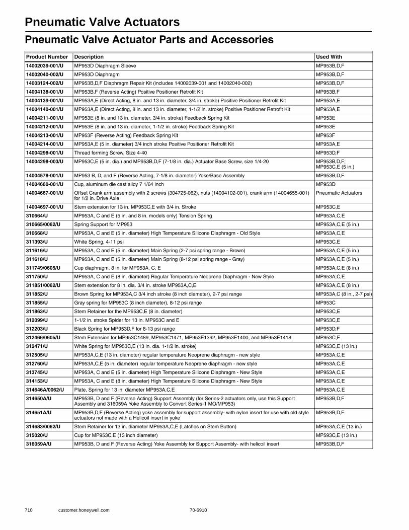
Pneumatic Valve Actuators
710 customer.honeywell.com 70-6910
Pneumatic Valve Actuator Parts and AccessoriesProduct Number Description Used With
14002039-001/U MP953D Diaphragm Sleeve MP953B,D,F
14002040-002/U MP953D Diaphragm MP953B,D,F
14003124-002/U MP953B,D,F Diaphragm Repair Kit (includes 14002039-001 and 14002040-002) MP953B,D,F
14004138-001/U MP953B,F (Reverse Acting) Positive Positioner Retrofit Kit MP953B,F
14004139-001/U MP953A,E (Direct Acting, 8 in. and 13 in. diameter, 3/4 in. stroke) Positive Positioner Retrofit Kit MP953A,E
14004140-001/U MP953A,E (Direct Acting, 8 in. and 13 in. diameter, 1-1/2 in. stroke) Positive Positioner Retrofit Kit MP953A,E
14004211-001/U MP953E (8 in. and 13 in. diameter, 3/4 in. stroke) Feedback Spring Kit MP953E
14004212-001/U MP953E (8 in. and 13 in. diameter, 1-1/2 in. stroke) Feedback Spring Kit MP953E
14004213-001/U MP953F (Reverse Acting) Feedback Spring Kit MP953F
14004214-001/U MP953A,E (5 in. diameter) 3/4 inch stroke Positive Positioner Retrofit Kit MP953A,E
14004298-001/U Thread forming Screw, Size 4-40 MP953D,F
14004298-003/U MP953C,E (5 in. dia.) and MP953B,D,F (7-1/8 in. dia.) Actuator Base Screw, size 1/4-20 MP953B,D,F;MP953C,E (5 in.)
14004578-001/U MP953 B, D, and F (Reverse Acting, 7-1/8 in. diameter) Yoke/Base Assembly MP953B,D,F
14004660-001/U Cup, aluminum die cast alloy 7 1/64 inch MP953D
14004667-001/U Offset Crank arm assembly with 2 screws (304725-062), nuts (14004102-001), crank arm (14004655-001) for 1/2 in. Drive Axle
Pneumatic Actuators
14004697-001/U Stem extension for 13 in. MP953C,E with 3/4 in. Stroke MP953C,E
310664/U MP953A, C and E (5 in. and 8 in. models only) Tension Spring MP953A,C,E
310665/0062/U Spring Support for MP953 MP953A,C,E (5 in.)
310668/U MP953A, C and E (5 in. diameter) High Temperature Silicone Diaphragm - Old Style MP953A,C,E
311393/U White Spring, 4-11 psi MP953C,E
311616/U MP953A, C and E (5 in. diameter) Main Spring (2-7 psi spring range - Brown) MP953A,C,E (5 in.)
311618/U MP953A, C and E (5 in. diameter) Main Spring (8-12 psi spring range - Gray) MP953A,C,E (5 in.)
311749/0605/U Cup diaphragm, 8 in. for MP953A, C, E MP953A,C,E (8 in.)
311750/U MP953A, C and E (8 in. diameter) Regular Temperature Neoprene Diaphragm - New Style MP953A,C,E
311851/0062/U Stem extension for 8 in. dia. 3/4 in. stroke MP953A,C,E MP953A,C,E (8 in.)
311852/U Brown Spring for MP953A,C 3/4 inch stroke (8 inch diameter), 2-7 psi range MP953A,C (8 in., 2-7 psi)
311855/U Gray spring for MP953C (8 inch diameter), 8-12 psi range MP953C
311863/U Stem Retainer for the MP953C,E (8 in. diameter) MP953C,E
312099/U 1-1/2 in. stroke Spider for 13 in. MP953C and E MP953C,E
312203/U Black Spring for MP953D,F for 8-13 psi range MP953D,F
312466/0605/U Stem Extension for MP953C1489, MP953C1471, MP953E1392, MP953E1400, and MP953E1418 MP953C,E
312471/U White Spring for MP953C,E (13 in. dia. 1-1/2 in. stroke) MP953C,E (13 in.)
312505/U MP953A,C,E (13 in. diameter) regular temperature Neoprene diaphragm - new style MP953A,C,E
312760/U MP953A,C,E (5 in. diameter) regular temperature Neoprene diaphragm - new style MP953A,C,E
313745/U MP953A, C and E (5 in. diameter) High Temperature Silicone Diaphragm - New Style MP953A,C,E
314153/U MP953A, C and E (8 in. diameter) High Temperature Silicone Diaphragm - New Style MP953A,C,E
314646A/0062/U Plate, Spring for 13 in. diameter MP953A,C,E MP953A,C,E
314650A/U MP953B, D and F (Reverse Acting) Support Assembly (for Series-2 actuators only, use this Support Assembly and 316059A Yoke Assembly to Convert Series-1 MO/MP953)
MP953B,D,F
314651A/U MP953B,D,F (Reverse Acting) yoke assembly for support assembly- with nylon insert for use with old style actuators not made with a Helicoil insert in yoke
MP953B,D,F
314683/0062/U Stem Retainer for 13 in. diameter MP953A,C,E (Latches on Stem Button) MP953A,C,E (13 in.)
315020/U Cup for MP953C,E (13 inch diameter) MP593C,E (13 in.)
316059A/U MP953B, D and F (Reverse Acting) Yoke Assembly for Support Assembly- with helicoil insert MP953B,D,F
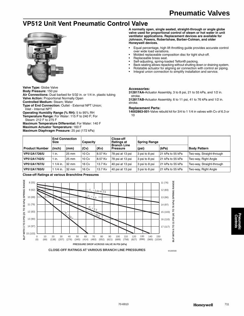
Pneumatic Valves
70-6910 711
P
neumatic
Controls
VP512 Unit Vent Pneumatic Control ValveA normally open, single seated, straight-through or angle globe valve used for proportional control of steam or hot water in unit ventilator applications. Replacement devices are available for Johnson, Powers, Robertshaw, Barber-Colman, and older Honeywell devices.
• Equal percentage, high lift throttling guide provides accurate control over wide load variations.
• Molded replaceable composition disc for tight shut-off. • Replaceable brass seat. • Self-adjusting, spring-loaded Teflon® packing. • Back-seating allows repacking without shutting down or draining system. • Rotatable actuator for aligning air connection with control air piping. • Integral union connection to simplify installation and service.
Valve Type: Globe ValveBody Pressure: 150 psiAir Connections: Dual barbed for 5/32 in. or 1/4 in. plastic tubingValve Action: Proportional Normally OpenControlled Medium: Steam; WaterType of End Connection: Outlet - External NPT Union;
Inlet - Internal NPTOperating Humidity Range (% RH): 5 to 95% RHTemperature Range: For Water: 115 F to 240 F; For
Steam: 212 F to 275 FMaximum Temperature Differential: For Water: 140 FMaximum Actuator Temperature: 160 FMaximum Diaphragm Pressure: 25 psi (172 kPa)
Accessories:312817AA-Actuator Assembly, 3 to 8 psi, 21 to 55 kPa, and 1/2 in.
stroke.312817AB-Actuator Assembly, 6 to 11 psi, 41 to 76 kPa and 1/2 in. stroke.
Replacement Parts:14002863-001-Valve rebuild kit for 3/4 to 1 1/4 in valves with Cv of 6.3 or
10
Close-off Ratings at various Branchline Pressures
Product Number
End Connection Size Capacity
Close-off Ratings at Branch Line Pressure
Spring Range
Body Pattern(inch) (mm) (Cv) (Kv) (psi) (kPa)
VP512A1726/U 1 in. 25 mm 10 Cv 8.57 Kv 78 psi at 13 psi 3 psi to 8 psi 21 kPa to 55 kPa Two-way, Straight-through
VP512A1742/U 1 in. 25 mm 10 Cv 8.57 Kv 78 psi at 13 psi 3 psi to 8 psi 21 kPa to 55 kPa Two-way, Right Angle
VP512A1767/U 1 1/4 in. 32 mm 16 Cv 13.7 Kv 40 psi at 13 psi 3 psi to 8 psi 21 kPa to 55 kPa Two-way, Straight-through
VP512A1783/U 1 1/4 in. 32 mm 16 Cv 13.7 Kv 40 psi at 13 psi 3 psi to 8 psi 21 kPa to 55 kPa Two-way, Right Angle
M18956B
BLP
WIT
H 3
TO
8 P
SI (2
1 TO
55
kPa)
SPR
ING
RA
NG
E
BLP
WIT
H 6
TO
11
PSI (
41 T
O 7
6 kP
a) S
PRIN
G R
AN
GE
PRESSURE DROP ACROSS VALVE IN PSI (kPa)
8 (55)
9 (62)
10 (69)
12 (83)
11 (76)
13 (90)
0
(0)
10
(69)
30
(207)
50
(345)
70
(483)
150
(1034)
110
(758)
15 (103)
14 (97)
12 (83)
11 (76)
13 (90)
15 (103)
16 (110)
17 (117)
14 (97)
140
(965)
20
(138)
40
(276)
60
(414)
90
(621)
80
(552)
100
(689)
120
(827)
130
(896)
CLOSE-OFF RATINGS AT VARIOUS BRANCH LINE PRESSURES
CV = 16.0
CV = 0.63 to 2.5
CV = 10.0
CV = 6 3
CV = 4 0
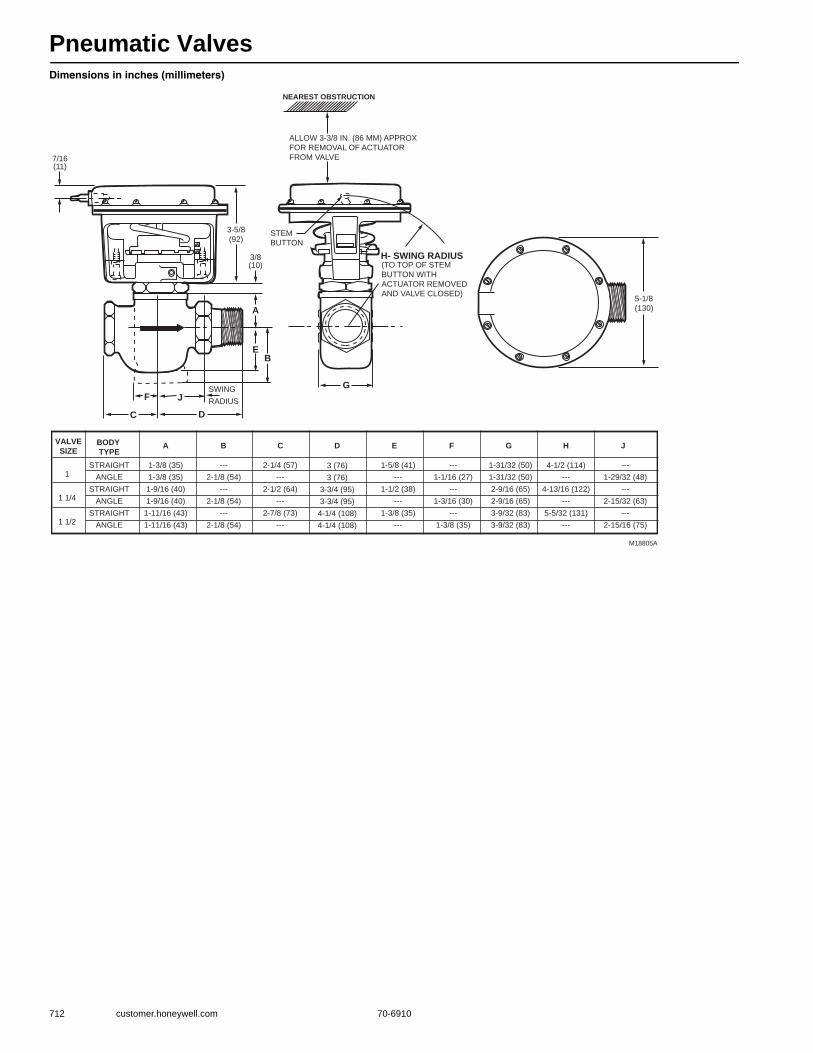
Pneumatic Valves
712 customer.honeywell.com 70-6910
Dimensions in inches (millimeters)
M18805A
NEAREST OBSTRUCTION
ALLOW 3-3/8 IN. (86 MM) APPROX
FOR REMOVAL OF ACTUATOR
FROM VALVE
H- SWING RADIUS(TO TOP OF STEM
BUTTON WITH
ACTUATOR REMOVED
AND VALVE CLOSED)
STEM
BUTTON
GSWING
RADIUS
A
B
C D
E
3/8(10)
3-5/8
(92)
7/16(11)
5-1/8
(130)
F J
VALVESIZE
BODY TYPE
A B C D E F G H J
1
1 1/4
1 1/2
STRAIGHT
ANGLE
STRAIGHT
ANGLE
STRAIGHT
ANGLE
1-3/8 (35)
1-3/8 (35)
1-9/16 (40)
1-9/16 (40)
1-11/16 (43)
1-11/16 (43)
---
2-1/8 (54)
---
2-1/8 (54)
---
2-1/8 (54)
3 (76)
3 (76)
3-3/4 (95)
3-3/4 (95)
4-1/4 (108)
4-1/4 (108)
2-1/4 (57)
---
2-1/2 (64)
---
2-7/8 (73)
---
1-5/8 (41)
---
1-1/2 (38)
---
1-3/8 (35)
---
---
1-1/16 (27)
---
1-3/16 (30)
---
1-3/8 (35)
1-31/32 (50)
1-31/32 (50)
2-9/16 (65)
2-9/16 (65)
3-9/32 (83)
3-9/32 (83)
4-1/2 (114)
---
4-13/16 (122)
---
5-5/32 (131)
---
---
1-29/32 (48)
---
2-15/32 (63)
---
2-15/16 (75)
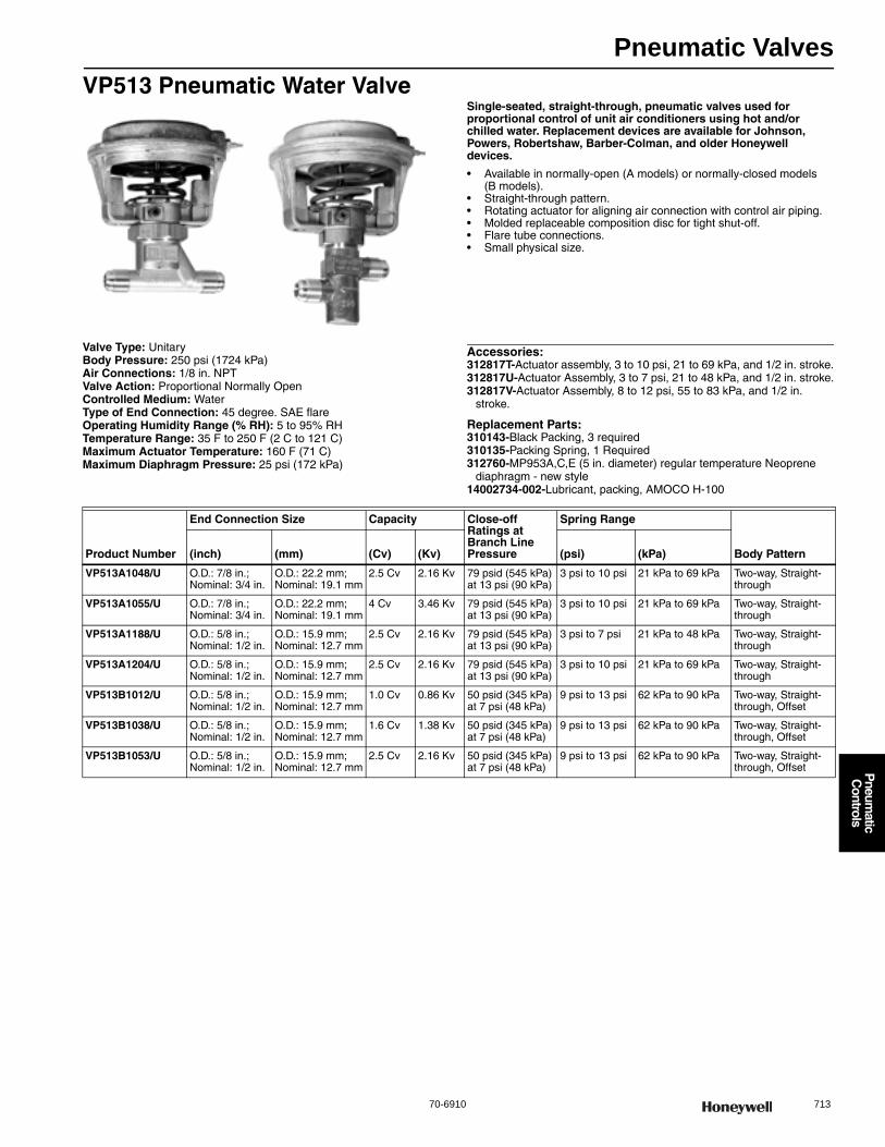
Pneumatic Valves
70-6910 713
P
neumatic
Controls
VP513 Pneumatic Water ValveSingle-seated, straight-through, pneumatic valves used for proportional control of unit air conditioners using hot and/or chilled water. Replacement devices are available for Johnson, Powers, Robertshaw, Barber-Colman, and older Honeywell devices.
• Available in normally-open (A models) or normally-closed models (B models).
• Straight-through pattern. • Rotating actuator for aligning air connection with control air piping. • Molded replaceable composition disc for tight shut-off. • Flare tube connections. • Small physical size.
Valve Type: UnitaryBody Pressure: 250 psi (1724 kPa) Air Connections: 1/8 in. NPTValve Action: Proportional Normally OpenControlled Medium: WaterType of End Connection: 45 degree. SAE flareOperating Humidity Range (% RH): 5 to 95% RHTemperature Range: 35 F to 250 F (2 C to 121 C) Maximum Actuator Temperature: 160 F (71 C) Maximum Diaphragm Pressure: 25 psi (172 kPa)
Accessories:312817T-Actuator assembly, 3 to 10 psi, 21 to 69 kPa, and 1/2 in. stroke.312817U-Actuator Assembly, 3 to 7 psi, 21 to 48 kPa, and 1/2 in. stroke.312817V-Actuator Assembly, 8 to 12 psi, 55 to 83 kPa, and 1/2 in.
stroke.
Replacement Parts:310143-Black Packing, 3 required310135-Packing Spring, 1 Required312760-MP953A,C,E (5 in. diameter) regular temperature Neoprene
diaphragm - new style14002734-002-Lubricant, packing, AMOCO H-100
Product Number
End Connection Size Capacity Close-off Ratings at Branch Line Pressure
Spring Range
Body Pattern(inch) (mm) (Cv) (Kv) (psi) (kPa)
VP513A1048/U O.D.: 7/8 in.; Nominal: 3/4 in.
O.D.: 22.2 mm; Nominal: 19.1 mm
2.5 Cv 2.16 Kv 79 psid (545 kPa) at 13 psi (90 kPa)
3 psi to 10 psi 21 kPa to 69 kPa Two-way, Straight-through
VP513A1055/U O.D.: 7/8 in.; Nominal: 3/4 in.
O.D.: 22.2 mm; Nominal: 19.1 mm
4 Cv 3.46 Kv 79 psid (545 kPa) at 13 psi (90 kPa)
3 psi to 10 psi 21 kPa to 69 kPa Two-way, Straight-through
VP513A1188/U O.D.: 5/8 in.; Nominal: 1/2 in.
O.D.: 15.9 mm; Nominal: 12.7 mm
2.5 Cv 2.16 Kv 79 psid (545 kPa) at 13 psi (90 kPa)
3 psi to 7 psi 21 kPa to 48 kPa Two-way, Straight-through
VP513A1204/U O.D.: 5/8 in.; Nominal: 1/2 in.
O.D.: 15.9 mm; Nominal: 12.7 mm
2.5 Cv 2.16 Kv 79 psid (545 kPa) at 13 psi (90 kPa)
3 psi to 10 psi 21 kPa to 69 kPa Two-way, Straight-through
VP513B1012/U O.D.: 5/8 in.; Nominal: 1/2 in.
O.D.: 15.9 mm; Nominal: 12.7 mm
1.0 Cv 0.86 Kv 50 psid (345 kPa) at 7 psi (48 kPa)
9 psi to 13 psi 62 kPa to 90 kPa Two-way, Straight-through, Offset
VP513B1038/U O.D.: 5/8 in.; Nominal: 1/2 in.
O.D.: 15.9 mm; Nominal: 12.7 mm
1.6 Cv 1.38 Kv 50 psid (345 kPa) at 7 psi (48 kPa)
9 psi to 13 psi 62 kPa to 90 kPa Two-way, Straight-through, Offset
VP513B1053/U O.D.: 5/8 in.; Nominal: 1/2 in.
O.D.: 15.9 mm; Nominal: 12.7 mm
2.5 Cv 2.16 Kv 50 psid (345 kPa) at 7 psi (48 kPa)
9 psi to 13 psi 62 kPa to 90 kPa Two-way, Straight-through, Offset

Pneumatic Valves
714 customer.honeywell.com 70-6910
Straight-through valve dimensions in inches (millimeters) Offset valve dimensions in inches (millimeters)
VP513 Typical Piping Diagram
5-11/16(144)
5-1/8(130)
M271104-1/2(114)
4 (102) CLEARANCE REQUIRED TO REMOVE ACTUATOR
5-3/4(146)
5-1/8(130)
M27111
3-1/2(89)
3-3/8 (86) MINIMUM APPROXIMATE CLEARANCE REQUIRED TO REMOVE ACTUATOR
IN
OUT
1-1/8(29)
2(51)
M5443
VP513A
HOT
WATER
CONTROL
AIR
N.O.COIL
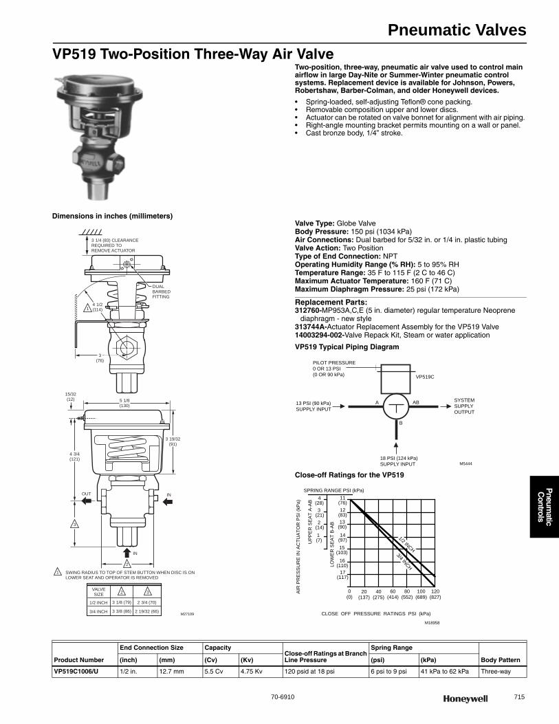
Pneumatic Valves
70-6910 715
P
neumatic
Controls
VP519 Two-Position Three-Way Air ValveTwo-position, three-way, pneumatic air valve used to control main airflow in large Day-Nite or Summer-Winter pneumatic control systems. Replacement device is available for Johnson, Powers, Robertshaw, Barber-Colman, and older Honeywell devices.
• Spring-loaded, self-adjusting Teflon® cone packing. • Removable composition upper and lower discs. • Actuator can be rotated on valve bonnet for alignment with air piping. • Right-angle mounting bracket permits mounting on a wall or panel. • Cast bronze body, 1/4” stroke.
Dimensions in inches (millimeters)Valve Type: Globe ValveBody Pressure: 150 psi (1034 kPa) Air Connections: Dual barbed for 5/32 in. or 1/4 in. plastic tubingValve Action: Two PositionType of End Connection: NPTOperating Humidity Range (% RH): 5 to 95% RHTemperature Range: 35 F to 115 F (2 C to 46 C) Maximum Actuator Temperature: 160 F (71 C) Maximum Diaphragm Pressure: 25 psi (172 kPa)
Replacement Parts:312760-MP953A,C,E (5 in. diameter) regular temperature Neoprene
diaphragm - new style313744A-Actuator Replacement Assembly for the VP519 Valve14003294-002-Valve Repack Kit, Steam or water application
VP519 Typical Piping Diagram
Close-off Ratings for the VP519
3 19/32(91)
3 1/4 (83) CLEARANCE REQUIRED TO REMOVE ACTUATOR
M27109
5 1/8(130)
15/32(12)
4 3/4(121)
3
2
SWING RADIUS TO TOP OF STEM BUTTON WHEN DISC IS ON LOWER SEAT AND OPERATOR IS REMOVED
INOUT
IN
3(76)
DUALBARBEDFITTING
14 1/2(114)
1
2 3VALVESIZE
1/2 INCH
3/4 INCH
3 1/8 (79)
3 3/8 (86)
2 3/4 (70)
2 19/32 (66)
M5444
VP519C
13 PSI (90 kPa)
SUPPLY INPUT
PILOT PRESSURE
0 OR 13 PSI
(0 OR 90 kPa)
18 PSI (124 kPa)
SUPPLY INPUT
A
B
AB SYSTEM
SUPPLY
OUTPUT
UP
PE
R S
EA
T A
-AB
14(97)15
(103)16
(110)
11(76)12
(83)13
(90)
AIR
PR
ES
SU
RE
IN A
CTU
ATO
R P
SI (
kPa)
1 (7)
2 (14)
3 (21)
4(28)
17(117)
0(0)
20(137)
40(275)
60(414)
80(552)
100(689)
CLOSE OFF PRESSURE RATINGS PSI (kPa)
SPRING RANGE PSI (kPa)
120(827)
M18958
LOW
ER
SE
AT
B-A
B
1/2 INCH
3/4 INCH
Product Number
End Connection Size CapacityClose-off Ratings at Branch Line Pressure
Spring Range
Body Pattern(inch) (mm) (Cv) (Kv) (psi) (kPa)
VP519C1006/U 1/2 in. 12.7 mm 5.5 Cv 4.75 Kv 120 psid at 18 psi 6 psi to 9 psi 41 kPa to 62 kPa Three-way
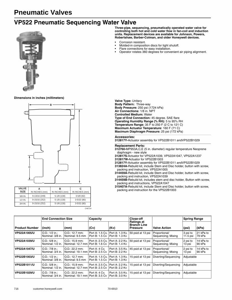
Pneumatic Valves
716 customer.honeywell.com 70-6910
VP522 Pneumatic Sequencing Water ValveThree-pipe, sequencing, pneumatically operated water valve for controlling both hot and cold water flow in fan-coil and induction units. Replacement devices are available for Johnson, Powers, Robertshaw, Barber-Colman, and older Honeywell devices.
• Corrosion resistant. • Molded-in composition discs for tight shutoff. • Flare connections for easy installation. • Operator rotates 360 degrees for convenient air piping alignment.
Dimensions in inches (millimeters)Valve Type: UnitaryBody Pattern: Three-wayBody Pressure: 250 psi (1724 kPa) Air Connections: 1/8 in. NPTControlled Medium: WaterType of End Connection: 45 degree. SAE flareOperating Humidity Range (% RH): 5 to 95% RHTemperature Range: 35 F to 250 F (2 C to 121 C) Maximum Actuator Temperature: 160 F (71 C) Maximum Diaphragm Pressure: 25 psi (172 kPa)
Accessories:312817Y-Actuator assembly for VP522B1011 andVP522B1029
Replacement Parts:312760-MP953A,C,E (5 in. diameter) regular temperature Neoprene
diaphragm - new style312817S-Actuator for VP522A1039, VP522A1047, VP522A1237312817W-Actuator for VP522B1003312817Y-Actuator assembly for VP522B1011 andVP522B1029313824A-Rebuild kit, include Stem and Disc holder, button with screw,
packing and instruction, VP522A1005314459A-Rebuild kit, include Stem and Disc holder, button with screw,
packing and instruction, VP522A1039314459B-Rebuild kit, includes stem and disc holder, Button with screw,
packing and instructions, VP522A1047315407A-Rebuild kit, include Stem and Disc holder, button with screw,
packing and instruction for the VP522B1003
B
C4671A
A
C
VALVE SIZE3/8 IN.
1/2 IN.
3/4 IN.
AIN INCHES (mm)
BIN INCHES (mm)
CIN INCHES (mm)
9-13/16 (249)
9-15/16 (252)
9-15/16 (252)
5-1/8 (130)
5-1/8 (130)
5-1/8 (130)
3-5/8 (92)
3-5/32 (80)
3-5/32 (80)
Product Number
End Connection Size Capacity Close-off Ratings at Branch Line Pressure Valve Action
Spring Range
(inch) (mm) (Cv) (Kv) (psi) (kPa)
VP522A1005/U O.D.: 1/2 in.; Nominal: 3/8 in.
O.D.: 12.7 mm; Nominal: 9.5 mm
Port A: 1.5 Cv, Port B: 1.5 Cv
Port A: 1.3 Kv, Port B: 1.3 Kv
50 psid at 13 psi Proportional/Sequencing; Mixing
3 psi to 11.5 psi
21 kPa to 79 kPa
VP522A1039/U O.D.: 5/8 in.; Nominal: 1/2 in.
O.D.: 15.9 mm; Nominal: 12.7 mm
Port A: 2.5 Cv, Port B: 1.6 Cv
Port A: 2.2 Kv, Port B: 1.4 Kv
50 psid at 13 psi Proportional/Sequencing; Mixing
2 psi to 13 psi
14 kPa to 90 kPa
VP522A1047/U O.D.: 7/8 in.; Nominal: 3/4 in.
O.D.: 22.2 mm; Nominal: 19.1 mm
Port A: 4 Cv, Port B: 2.5 Cv
Port A: 3.5 Kv, Port B: 2.2 Kv
45 psid at 13 psi Proportional/Sequencing; Mixing
2 psi to 13 psi
14 kPa to 90 kPa
VP522B1003/U O.D.: 1/2 in.; Nominal: 3/8 in.
O.D.: 12.7 mm; Nominal: 9.5 mm
Port A: 1.5 Cv, Port B: 1.5 Cv
Port A: 1.3 Kv, Port B: 1.3 Kv
15 psid at 13 psi Diverting/Sequencing Adjustable
VP522B1011/U O.D.: 5/8 in.; Nominal: 1/2 in.
O.D.: 15.9 mm; Nominal: 12.7 mm
Port A: 2.5 Cv, Port B: 2.5 Cv
Port A: 2.2 Kv, Port B: 2.2 Kv
15 psid at 13 psi Diverting/Sequencing Adjustable
VP522B1029/U O.D.: 7/8 in.; Nominal: 3/4 in.
O.D.: 22.2 mm; Nominal: 19.1 mm
Port A: 4 Cv, Port B: 3.5 Cv
Port A: 3.5 Kv, Port B: 3.0 Kv
15 psid at 13 psi Diverting/Sequencing Adjustable
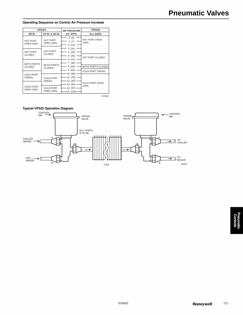
Pneumatic Valves
70-6910 717
P
neumatic
Controls
Operating Sequence on Control Air Pressure Increase
Typical VP522 Operation Diagram
VP522A AIR PRESSUREpsi (kPa)
VP522B3/8 IN. 1/2 IN. & 3/4 IN. ALL SIZES
HOT PORT
OPEN 100%
HOT PORT
CLOSES
BOTH PORTS
CLOSED
COLD PORT
OPENS
COLD PORT
OPEN 100%
0 (0)
1 (7)
2 (14)
3 (21)
4 (28)
5 (34)
6 (41)
7 (48)
8 (55)
9 (62)
10 (69)
11 (76)
12 (83)
13 (90)
14 (97)
15 (103)
HOT PORT
OPEN 100%
HOT PORT
CLOSES
BOTH PORTS
CLOSED
COLD PORT
OPENS
HOT PORT OPEN
100%
COLD PORT
OPEN 100%
HOT PORT CLOSES
BOTH PORTS CLOSED
COLD PORT OPENS
COLD PORT OPEN
100%
M13864
M5447
A
B
N.O. PORTS
B TO AB
VP522A
VALVE
CONTROL
AIR
AB
CHILLED
WATER
HOT
WATER
VP522B
VALVE
TO
CHILLER
TO
BOILER
CONTROL
AIR
A
B
AB
COIL
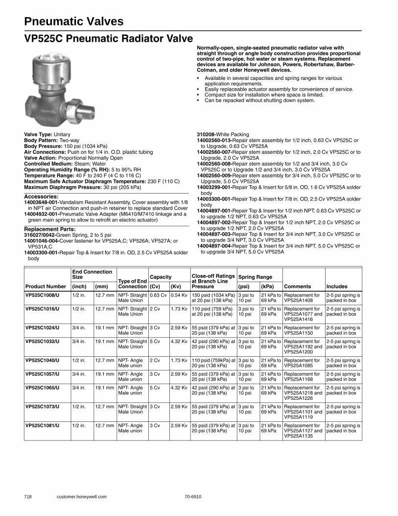
Pneumatic Valves
718 customer.honeywell.com 70-6910
VP525C Pneumatic Radiator ValveNormally-open, single-seated pneumatic radiator valve with straight through or angle body construction provides proportional control of two-pipe, hot water or steam systems. Replacement devices are available for Johnson, Powers, Robertshaw, Barber-Colman, and older Honeywell devices.
• Available in several capacities and spring ranges for various application requirements.
• Easily replaceable actuator assembly for convenience of service. • Compact size for installation where space is limited. • Can be repacked without shutting down system.
Valve Type: UnitaryBody Pattern: Two-wayBody Pressure: 150 psi (1034 kPa) Air Connections: Push on for 1/4 in. O.D. plastic tubingValve Action: Proportional Normally OpenControlled Medium: Steam; WaterOperating Humidity Range (% RH): 5 to 95% RHTemperature Range: 40 F to 240 F (4 C to 116 C) Maximum Safe Actuator Diaphragm Temperature: 230 F (110 C) Maximum Diaphragm Pressure: 30 psi (205 kPa)
Accessories:14003648-001-Vandalism Resistant Assembly, Cover assembly with 1/8
in NPT air Connection and push-in retainer to replace standard Cover14004932-001-Pneumatic Valve Adapter (M6410/M7410 linkage and a
green main spring to allow to retrofit an electric actuator)
Replacement Parts:316027/0042-Green Spring, 2 to 5 psi14001046-004-Cover fastener for VP525A,C; VP526A; VP527A; or
VP531A,C14003300-001-Repair Top & Insert for 7/8 in. OD, 2.5 Cv VP525A solder
body
310208-White Packing14002560-013-Repair stem assembly for 1/2 inch, 0.63 Cv VP525C or
to Upgrade, 0.63 Cv VP525A14002560-007-Repair stem assembly for 1/2 inch, 2.0 Cv VP525C or to
Upgrade, 2.0 Cv VP525A14002560-008-Repair stem assembly for 1/2 and 3/4 inch, 3.0 Cv
VP525C or to Upgrade 1/2 and 3/4 inch, 3.0 Cv VP525A14002560-009-Repair stem assembly for 3/4 inch, 5.0 Cv VP525C or to
Upgrade, 5.0 Cv VP525A14003299-001-Repair Top & Insert for 5/8 in. OD, 1.6 Cv VP525A solder
body14003300-001-Repair Top & Insert for 7/8 in. OD, 2.5 Cv VP525A solder
body14004897-001-Repair Top & Insert for 1/2 inch NPT, 0.63 Cv VP525C or
to upgrade 1/2 NPT, 0.63 Cv VP525A14004897-002-Repair Top & Insert for 1/2 inch NPT, 2.0 Cv VP525C or
to upgrade 1/2 NPT, 2.0 Cv VP525A14004897-003-Repair Top & Insert for 3/4 inch NPT, 3.0 Cv VP525C or
to upgrade 3/4 NPT, 3.0 Cv VP525A14004897-004-Repair Top & Insert for 3/4 inch NPT, 5.0 Cv VP525C or
to upgrade 3/4 NPT, 5.0 Cv VP525A
Product Number
End Connection Size
Type of End Connection
Capacity Close-off Ratings at Branch Line Pressure
Spring Range
Comments Includes(inch) (mm) (Cv) (Kv) (psi) (kPa)
VP525C1008/U 1/2 in. 12.7 mm NPT- Straight Male Union
0.63 Cv 0.54 Kv 150 psid (1034 kPa) at 20 psi (138 kPa)
3 psi to 10 psi
21 kPa to 69 kPa
Replacement for VP525A1408
2-5 psi spring is packed in box
VP525C1016/U 1/2 in. 12.7 mm NPT- Straight Male Union
2 Cv 1.73 Kv 110 psid (759 kPa) at 20 psi (138 kPa)
3 psi to 10 psi
21 kPa to 69 kPa
Replacement for VP525A1077 and VP525A1416
2-5 psi spring is packed in box
VP525C1024/U 3/4 in. 19.1 mm NPT- Straight Male Union
3 Cv 2.59 Kv 55 psid (379 kPa) at 20 psi (138 kPa)
3 psi to 10 psi
21 kPa to 69 kPa
Replacement for VP525A1150
2-5 psi spring is packed in box
VP525C1032/U 3/4 in. 19.1 mm NPT- Straight Male Union
5 Cv 4.32 Kv 42 psid (290 kPa) at 20 psi (138 kPa)
3 psi to 10 psi
21 kPa to 69 kPa
Replacement for VP525A1192 and VP525A1200
2-5 psi spring is packed in box
VP525C1040/U 1/2 in. 12.7 mm NPT- Angle Male union
2 Cv 1.73 Kv 110 psid (759kPa) at 20 psi (138 kPa)
3 psi to 10 psi
21 kPa to 69 kPa
Replacement for VP525A1085
2-5 psi spring is packed in box
VP525C1057/U 3/4 in. 19.1 mm NPT- Angle Male union
3 Cv 2.59 Kv 55 psid (379 kPa) at 20 psi (138 kPa)
3 psi to 10 psi
21 kPa to 69 kPa
Replacement for VP525A1168
2-5 psi spring is packed in box
VP525C1065/U 3/4 in. 19.1 mm NPT- Angle Male union
5 Cv 4.32 Kv 42 psid (290 kPa) at 20 psi (138 kPa)
3 psi to 10 psi
21 kPa to 69 kPa
Replacement for VP525A1218 and VP525A1226
2-5 psi spring is packed in box
VP525C1073/U 1/2 in. 12.7 mm NPT- Straight Male Union
3 Cv 2.59 Kv 55 psid (379 kPa) at 20 psi (138 kPa)
3 psi to 10 psi
21 kPa to 69 kPa
Replacement for VP525A1101 and VP525A1119
2-5 psi spring is packed in box
VP525C1081/U 1/2 in. 12.7 mm NPT- Angle Male union
3 Cv 2.59 Kv 55 psid (379 kPa) at 20 psi (138 kPa)
3 psi to 10 psi
21 kPa to 69 kPa
Replacement for VP525A1127 and VP525A1135
2-5 psi spring is packed in box
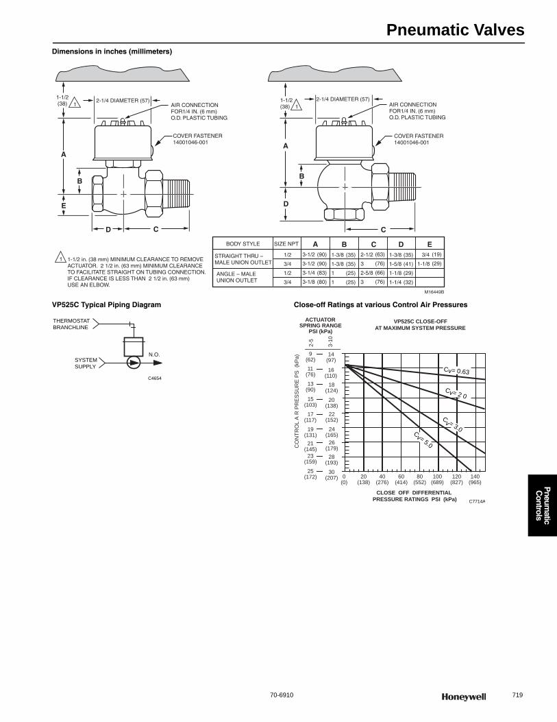
Pneumatic Valves
70-6910 719
P
neumatic
Controls
Dimensions in inches (millimeters)
VP525C Typical Piping Diagram Close-off Ratings at various Control Air Pressures
AA
E
BB
CC
D
D
1-1/2(38)
1-1/2(38)
2-1/4 DIAMETER (57) 2-1/4 DIAMETER (57)
BODY STYLE SIZE NPT A B C D E
STRAIGHT THRU –MALE UNION OUTLET
1/2
3/4
1/2
3/4
3-1/2
3-1/2
3-1/4
3-1/8
(90)
(90)
(83)
(80)
1-3/8
1-3/8
1
1
(35)
(35)
(25)
(25)
1-3/8
1-5/8
1-1/8
1-1/4
(35)
(41)
(29)
(32)
2-1/2
3
2-5/8
3
(63)
(76)
(66)
(76)
3/4
1-1/8
(19)
(29)
ANGLE – MALE UNION OUTLET
M16449B
1-1/2 in. (38 mm) MINIMUM CLEARANCE TO REMOVE ACTUATOR. 2 1/2 in. (63 mm) MINIMUM CLEARANCE TO FACILITATE STRAIGHT ON TUBING CONNECTION. IF CLEARANCE IS LESS THAN 2 1/2 in. (63 mm) USE AN ELBOW.
1
1 1AIR CONNECTION FOR1/4 IN. (6 mm) O.D. PLASTIC TUBING
AIR CONNECTION FOR1/4 IN. (6 mm) O.D. PLASTIC TUBING
COVER FASTENER14001046-001
COVER FASTENER14001046-001
THERMOSTAT
BRANCHLINE
N.O.
C4654
SYSTEM
SUPPLY
VP525C CLOSE-OFFAT MAXIMUM SYSTEM PRESSURE3
-10
2-5
19(131)
21(145)
CO
NT
RO
L A
R P
RE
SS
UR
E P
S (
kP
a)
20(138)
15(103)
17(117)
18(124)
13(90)
16(110)
11(76)
9(62)
14(97)
ACTUATORSPRING RANGE
PSI (kPa)
0(0)
20(138)
40(276)
60(414)
80(552)
100(689)
CLOSE OFF DIFFERENTIAL PRESSURE RATINGS PSI (kPa)
120(827)
140(965)
C7714A
30(207)
25(172)
28(193)
23(159)
Cv= 2 0
Cv= 0.63
Cv = 3.0
Cv= 5.026
(179)
24(165)
22(152)
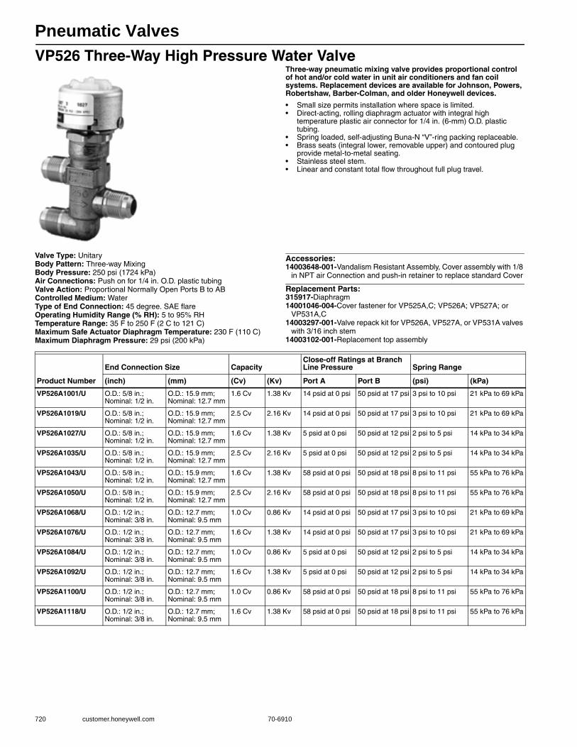
Pneumatic Valves
720 customer.honeywell.com 70-6910
VP526 Three-Way High Pressure Water ValveThree-way pneumatic mixing valve provides proportional control of hot and/or cold water in unit air conditioners and fan coil systems. Replacement devices are available for Johnson, Powers, Robertshaw, Barber-Colman, and older Honeywell devices.
• Small size permits installation where space is limited. • Direct-acting, rolling diaphragm actuator with integral high
temperature plastic air connector for 1/4 in. (6-mm) O.D. plastic tubing.
• Spring loaded, self-adjusting Buna-N “V”-ring packing replaceable. • Brass seats (integral lower, removable upper) and contoured plug
provide metal-to-metal seating. • Stainless steel stem. • Linear and constant total flow throughout full plug travel.
Valve Type: UnitaryBody Pattern: Three-way MixingBody Pressure: 250 psi (1724 kPa) Air Connections: Push on for 1/4 in. O.D. plastic tubingValve Action: Proportional Normally Open Ports B to ABControlled Medium: WaterType of End Connection: 45 degree. SAE flareOperating Humidity Range (% RH): 5 to 95% RHTemperature Range: 35 F to 250 F (2 C to 121 C) Maximum Safe Actuator Diaphragm Temperature: 230 F (110 C) Maximum Diaphragm Pressure: 29 psi (200 kPa)
Accessories:14003648-001-Vandalism Resistant Assembly, Cover assembly with 1/8
in NPT air Connection and push-in retainer to replace standard Cover
Replacement Parts:315917-Diaphragm14001046-004-Cover fastener for VP525A,C; VP526A; VP527A; or
VP531A,C14003297-001-Valve repack kit for VP526A, VP527A, or VP531A valves
with 3/16 inch stem14003102-001-Replacement top assembly
Product Number
End Connection Size CapacityClose-off Ratings at Branch Line Pressure Spring Range
(inch) (mm) (Cv) (Kv) Port A Port B (psi) (kPa)
VP526A1001/U O.D.: 5/8 in.; Nominal: 1/2 in.
O.D.: 15.9 mm; Nominal: 12.7 mm
1.6 Cv 1.38 Kv 14 psid at 0 psi 50 psid at 17 psi 3 psi to 10 psi 21 kPa to 69 kPa
VP526A1019/U O.D.: 5/8 in.; Nominal: 1/2 in.
O.D.: 15.9 mm; Nominal: 12.7 mm
2.5 Cv 2.16 Kv 14 psid at 0 psi 50 psid at 17 psi 3 psi to 10 psi 21 kPa to 69 kPa
VP526A1027/U O.D.: 5/8 in.; Nominal: 1/2 in.
O.D.: 15.9 mm; Nominal: 12.7 mm
1.6 Cv 1.38 Kv 5 psid at 0 psi 50 psid at 12 psi 2 psi to 5 psi 14 kPa to 34 kPa
VP526A1035/U O.D.: 5/8 in.; Nominal: 1/2 in.
O.D.: 15.9 mm; Nominal: 12.7 mm
2.5 Cv 2.16 Kv 5 psid at 0 psi 50 psid at 12 psi 2 psi to 5 psi 14 kPa to 34 kPa
VP526A1043/U O.D.: 5/8 in.; Nominal: 1/2 in.
O.D.: 15.9 mm; Nominal: 12.7 mm
1.6 Cv 1.38 Kv 58 psid at 0 psi 50 psid at 18 psi 8 psi to 11 psi 55 kPa to 76 kPa
VP526A1050/U O.D.: 5/8 in.; Nominal: 1/2 in.
O.D.: 15.9 mm; Nominal: 12.7 mm
2.5 Cv 2.16 Kv 58 psid at 0 psi 50 psid at 18 psi 8 psi to 11 psi 55 kPa to 76 kPa
VP526A1068/U O.D.: 1/2 in.; Nominal: 3/8 in.
O.D.: 12.7 mm; Nominal: 9.5 mm
1.0 Cv 0.86 Kv 14 psid at 0 psi 50 psid at 17 psi 3 psi to 10 psi 21 kPa to 69 kPa
VP526A1076/U O.D.: 1/2 in.; Nominal: 3/8 in.
O.D.: 12.7 mm; Nominal: 9.5 mm
1.6 Cv 1.38 Kv 14 psid at 0 psi 50 psid at 17 psi 3 psi to 10 psi 21 kPa to 69 kPa
VP526A1084/U O.D.: 1/2 in.; Nominal: 3/8 in.
O.D.: 12.7 mm; Nominal: 9.5 mm
1.0 Cv 0.86 Kv 5 psid at 0 psi 50 psid at 12 psi 2 psi to 5 psi 14 kPa to 34 kPa
VP526A1092/U O.D.: 1/2 in.; Nominal: 3/8 in.
O.D.: 12.7 mm; Nominal: 9.5 mm
1.6 Cv 1.38 Kv 5 psid at 0 psi 50 psid at 12 psi 2 psi to 5 psi 14 kPa to 34 kPa
VP526A1100/U O.D.: 1/2 in.; Nominal: 3/8 in.
O.D.: 12.7 mm; Nominal: 9.5 mm
1.0 Cv 0.86 Kv 58 psid at 0 psi 50 psid at 18 psi 8 psi to 11 psi 55 kPa to 76 kPa
VP526A1118/U O.D.: 1/2 in.; Nominal: 3/8 in.
O.D.: 12.7 mm; Nominal: 9.5 mm
1.6 Cv 1.38 Kv 58 psid at 0 psi 50 psid at 18 psi 8 psi to 11 psi 55 kPa to 76 kPa
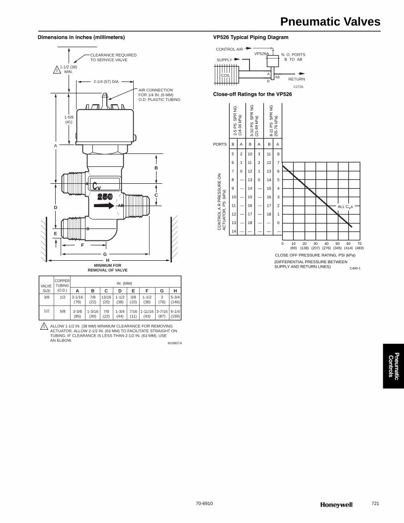
Pneumatic Valves
70-6910 721
P
neumatic
Controls
Dimensions in inches (millimeters) VP526 Typical Piping Diagram
Close-off Ratings for the VP526
CLEARANCE REQUIRED
TO SERVICE VALVE
1-1/2 (38)
MIN.
2-1/4 (57) DIA.
AIR CONNECTION
FOR 1/4 IN. (6 MM)
O.D. PLASTIC TUBING
MINIMUM FORREMOVAL OF VALVE
1-5/8
(41)
A
D
E
B
C
F
GH
A D EB C F G H
1
1
VALVE
SIZE
COPPER
TUBING
(O.D.)
IN. (MM)
3/8
1/2
1/2
5/8
3-1/16
(78)
3-3/8
(85)
7/8
(22)
1-3/16
(30)
13/16
(20)
7/8
(22)
1-1/2
(38)
1-3/4
(44)
3/8
(10)
7/16
(11)
1-1/2
(38)
1-11/16
(43)
3
(76)
3-7/16
(87)
5-3/4
(146)
6-1/4
(159)
ALLOW 1-1/2 IN. (38 MM) MINIMUM CLEARANCE FOR REMOVING
ACTUATOR. ALLOW 2-1/2 IN. (63 MM) TO FACILITATE STRAIGHT ON
TUBING. IF CLEARANCE IS LESS THAN 2-1/2 IN. (63 MM), USE
AN ELBOW.M18807A
AAB
B
SUPPLY
RETURN
CONTROL AIRVP526A N. O. PORTS
B TO AB
C2726
COIL
C493-1
CLOSE OFF PRESSURE RATING, PSI (kPa)
(DIFFERENTIAL PRESSURE BETWEEN
SUPPLY AND RETURN LINES)
0 10
(69)
20
(138)
30
(207)
40
(276)
50
(345)
60
(414)
70
(483)
ALL CVs
5
6
7
8
9
10
11
12
13
14
10
11
12
13
14
15
16
17
18
—
2
1
0
—
—
—
—
—
—
—
3
2
1
0
—
—
—
—
—
—
11
12
13
14
15
16
17
18
—
—
8
7
6
5
4
3
2
1
0
—
B A B A B A
CO
NT
RO
L A
R P
RE
SS
UR
E O
N
AC
TU
AT
OR
, P
S (
kP
a)
PORTS
2-5
PS
SP
RN
G
(14
-34
kP
a)
3-1
0 P
S S
PR
NG
(21
-69
kP
a)
8-1
1 P
S S
PR
NG
(55
-76
kP
a)

Pneumatic Valves
722 customer.honeywell.com 70-6910
VP527 Pneumatic Water ValveNormally open, single-seated, high pressure valve provides proportional control of hot and/or cold water in unit air conditioners and fan coil units. Replacement devices are available for Johnson, Powers, Robertshaw, Barber-Colman, and older Honeywell devices.
• Small size permits installation where space is limited. • Forged brass, straight-through body with end connections threaded
for 45 degrees SAE flare fitting nuts. • Spring-loaded, self-adjusting, Buna-N “V”-ring packing is
replaceable without shutting system down. • High-temperature rolling diaphragm actuator (aluminum cover) and
high-temperature plastic diaphragm retaining cup with integral air connection for 1/4 in. (6 mm) O.D. plastic tubing.
• Integral seat and brass plug with removable composition disc provides equal percentage flow.
• Stainless steel stem, 3/16 in. (5 mm) diameter.
Dimensions in inches (millimeters)Valve Type: UnitaryBody Pattern: Two-wayBody Pressure: 250 psi (1724 kPa) Air Connections: Push on for 1/4 in. O.D. plastic tubingValve Action: Proportional Normally OpenControlled Medium: WaterType of End Connection: 45 degree. SAE flareOperating Humidity Range (% RH): 5 to 95% RHTemperature Range: 35 F to 250 F (2 C to 121 C) Maximum Safe Actuator Diaphragm Temperature: 230 F (110 C) Maximum Diaphragm Pressure: 30 psi (205 kPa)
Accessories:14003648-001-Vandalism Resistant Assembly, Cover assembly with 1/8
in NPT air Connection and push-in retainer to replace standard Cover14004932-001-Pneumatic Valve Adapter (M6410/M7410 linkage and a
green main spring to allow to retrofit an electric actuator)
Replacement Parts:14001046-004-Cover fastener for VP525A,C; VP526A; VP527A; or
VP531A,C14003102-001-Replacement top assembly14003297-001-Valve repack kit for VP526A, VP527A, or VP531A valves
with 3/16 inch stem14003475-001-Valve Rebuild Kit for 1/2 in. valve with 0.4 or 0.63 Cv14003476-001-Valve Rebuild Kit for 1/2 in. valve with 1 or 1.6 Cv315917-Diaphragm
1
22
1 ALLOW 1-1/2 IN. (38 MM) MINIMUM CLEARANCE TO SERVICE VALVE,
2-1/2 IN. (63 MM) CLEARANCE TO CONNECT TUBING STRAIGHT TO
CONNECTOR. IF CLEARANCE IS LESS THAN 2-1/2 IN. (63 MM),
USE AN ELBOW CONNECTOR.
2 ALLOW 1-3/8 IN. (35 MM) MINIMUM CLEARANCE TO REMOVE VALVE.
M18348A
2-1/4 (57) DIA.
AIR CONNECTION
FOR 1/4 IN. (6 MM)
O.D. PLASTIC TUBING
1-1/2
(38)
3-13/16
(97)
1-5/8
(41)
3-1/8 (79)
1-3/8
(35)
1/2 IN. (12MM) X 45 SAE FLARED TUBE
CONNECTION - 2 (NOT FURNISHED)
Product Number
End Connection Size Capacity Close-off Ratings at Branch Line Pressure
Spring Range
(inch) (mm) (Cv) (Kv) (psi) (kPa)
VP527A1018/U O.D.: 1/2 in.; Nominal: 3/8 in.
O.D.: 12.7 mm; Nominal: 9.5 mm
0.63 Cv 0.54 Kv 130 psid at 13 psi 3 psi to 10 psi 21 kPa to 69 kPa
VP527A1026/U O.D.: 1/2 in.; Nominal: 3/8 in.
O.D.: 12.7 mm; Nominal: 9.5 mm
1.0 Cv 0.86 Kv 45 psid at 13 psi 3 psi to 10 psi 21 kPa to 69 kPa
VP527A1034/U O.D.: 1/2 in.; Nominal: 3/8 in.
O.D.: 12.7 mm; Nominal: 9.5 mm
1.6 Cv 1.38 Kv 45 psid at 13 psi 3 psi to 10 psi 21 kPa to 69 kPa
VP527A1059/U O.D.: 1/2 in.; Nominal: 3/8 in.
O.D.: 12.7 mm; Nominal: 9.5 mm
0.63 Cv 0.54 Kv 130 psid at 8 psi 2 psi to 5 psi 14 kPa to 34 kPa
VP527A1067/U O.D.: 1/2 in.; Nominal: 3/8 in.
O.D.: 12.7 mm; Nominal: 9.5 mm
1.0 Cv 0.86 Kv 45 psid at 8 psi 2 psi to 5 psi 14 kPa to 34 kPa
VP527A1075/U O.D.: 1/2 in.; Nominal: 3/8 in.
O.D.: 12.7 mm; Nominal: 9.5 mm
1.6 Cv 1.38 Kv 45 psid at 8 psi 2 psi to 5 psi 14 kPa to 34 kPa
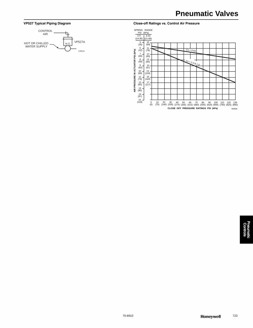
Pneumatic Valves
70-6910 723
P
neumatic
Controls
VP527 Typical Piping Diagram Close-off Ratings vs. Control Air Pressure
CONTROLAIR
HOT OR CHILLED WATER SUPPLY
VP527AN.O.
C5514
2-5
(14-35)
14(97)
15(103)
16(110)
11(76)
12(83)
13(90)
AIR
PR
ESSU
RE
IN A
CTU
ATO
R P
SI (k
Pa)
11(76)
10 (69)
9 (62)
8 (55)
7(49)
17(117)
0(0)
30(205)
50(345)
70(480)
90(620)
20(140)
40(275)
60(415)
80(550)
100(690)
CLOSE OFF PRESSURE RATINGS PSI (kPa)
12(83)
3-10
(21-69)
10(70)
SPRING RANGE
PSI (kPa)
110(760)
120(825)
130(895)
13(90)
14(97)
15(103)
M3636
10 (69)
6 (42)
5(35)
Cv = 0 63
Cv = 1 0 & 1 6
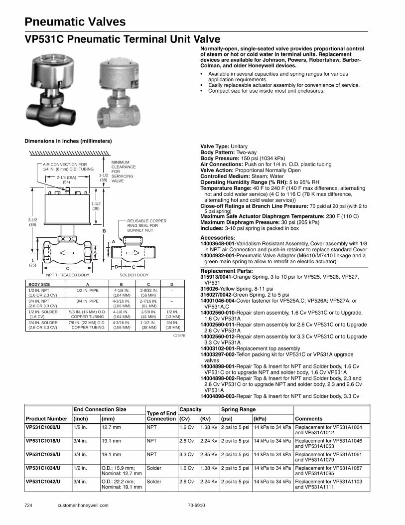
Pneumatic Valves
724 customer.honeywell.com 70-6910
VP531C Pneumatic Terminal Unit ValveNormally-open, single-seated valve provides proportional control of steam or hot or cold water in terminal units. Replacement devices are available for Johnson, Powers, Robertshaw, Barber-Colman, and older Honeywell devices.
• Available in several capacities and spring ranges for various application requirements.
• Easily replaceable actuator assembly for convenience of service. • Compact size for use inside most unit enclosures.
Dimensions in inches (millimeters)Valve Type: UnitaryBody Pattern: Two-wayBody Pressure: 150 psi (1034 kPa) Air Connections: Push on for 1/4 in. O.D. plastic tubingValve Action: Proportional Normally OpenControlled Medium: Steam; WaterOperating Humidity Range (% RH): 5 to 95% RHTemperature Range: 40 F to 240 F (140 F max difference, alternating
hot and cold water service) (4 C to 116 C (78 K max difference, alternating hot and cold water service))
Close-off Ratings at Branch Line Pressure: 70 psid at 20 psi (with 2 to 5 psi spring)
Maximum Safe Actuator Diaphragm Temperature: 230 F (110 C) Maximum Diaphragm Pressure: 30 psi (205 kPa)Includes: 3-10 psi spring is packed in box
Accessories:14003648-001-Vandalism Resistant Assembly, Cover assembly with 1/8
in NPT air Connection and push-in retainer to replace standard Cover14004932-001-Pneumatic Valve Adapter (M6410/M7410 linkage and a
green main spring to allow to retrofit an electric actuator)
Replacement Parts:315913/0041-Orange Spring, 3 to 10 psi for VP525, VP526, VP527,
VP531316026-Yellow Spring, 8-11 psi316027/0042-Green Spring, 2 to 5 psi14001046-004-Cover fastener for VP525A,C; VP526A; VP527A; or
VP531A,C14002560-010-Repair stem assembly, 1.6 Cv VP531C or to Upgrade,
1.6 Cv VP531A14002560-011-Repair stem assembly for 2.6 Cv VP531C or to Upgrade
2.6 Cv VP531A14002560-012-Repair stem assembly for 3.3 Cv VP531C or to Upgrade
3.3 Cv VP531A14003102-001-Replacement top assembly14003297-002-Teflon packing kit for VP531C or VP531A upgrade
valves14004898-001-Repair Top & Insert for NPT and Solder body, 1.6 Cv
VP531C or to upgrade NPT and solder body, 1.6 Cv VP531A14004898-002-Repair Top & Insert for NPT and Solder body, 2.3 and
2.6 Cv VP531C or to upgrade NPT and solder body, 2.3 and 2.6 Cv VP531A
14004898-003-Repair Top & Insert for NPT and Solder body, 3.3 Cv
A
D CC
2-1/4 (DIA)(54)
AIR CONNECTION FOR1/4 IN. (6 mm) O.D. TUBING
1-1/2(38)
B
A
1(25)
3-1/2(89)
NPT THREADED BODY SOLDER BODY
1-1/2(38)
MINIMUMCLEARANCEFORSERVICINGVALVE
REUSABLE COPPER RING SEAL FOR BONNET NUT
C7987B
BODY SIZE A B C D 1/2 IN. NPT 1/2 IN. PIPE 4-1/8 IN. 2-9/32 IN. –
(1.6 OR 2.3 CV) (104 MM) (58 MM)
3/4 IN. NPT 3/4 IN. PIPE 4-3/16 IN. 2-7/16 IN. –
(2.6 OR 3.3 CV) (106 MM) (61 MM)
1/2 IN. SOLDER 5/8 IN. (16 MM) O.D. 4-1/8 IN. 1-5/8 IN. 1/2 IN.
(1.6 CV) COPPER TUBING (104 MM) (41 MM) (13 MM)
3/4 IN. SOLDER 7/8 IN. (22 MM) O.D. 4-3/16 IN. 1-1/2 IN. 3/4 IN.
(2.6 OR 3.3 CV) COPPER TUBING (106 MM) (38 MM) (19 MM)
Product Number
End Connection SizeType of End Connection
Capacity Spring Range
Comments(inch) (mm) (Cv) (Kv) (psi) (kPa)
VP531C1000/U 1/2 in. 12.7 mm NPT 1.6 Cv 1.38 Kv 2 psi to 5 psi 14 kPa to 34 kPa Replacement for VP531A1004 and VP531A1012
VP531C1018/U 3/4 in. 19.1 mm NPT 2.6 Cv 2.24 Kv 2 psi to 5 psi 14 kPa to 34 kPa Replacement for VP531A1046 and VP531A1053
VP531C1026/U 3/4 in. 19.1 mm NPT 3.3 Cv 2.85 Kv 2 psi to 5 psi 14 kPa to 34 kPa Replacement for VP531A1061 and VP531A1079
VP531C1034/U 1/2 in. O.D.: 15.9 mm; Nominal: 12.7 mm
Solder 1.6 Cv 1.38 Kv 2 psi to 5 psi 14 kPa to 34 kPa Replacement for VP531A1087 and VP531A1095
VP531C1042/U 3/4 in. O.D.: 22.2 mm; Nominal: 19.1 mm
Solder 2.6 Cv 2.24 Kv 2 psi to 5 psi 14 kPa to 34 kPa Replacement for VP531A1103 and VP531A1111
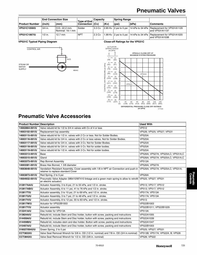
Pneumatic Valves
70-6910 725
P
neumatic
Controls
VP531C Typical Piping Diagram Close-off Ratings for the VP531C
Pneumatic Valve Accessories
VP531C1059/U 3/4 in. O.D.: 22.2 mm; Nominal: 19.1 mm
Solder 3.3 Cv 2.85 Kv 2 psi to 5 psi 14 kPa to 34 kPa Replacement for VP531A1129 and VP531A1137
VP531C1067/U 1/2 in. 12.7 mm NPT 2.3 Cv 1.99 Kv 2 psi to 5 psi 14 kPa to 34 kPa Replacement for VP531A1020 and VP531A1038
Product Number
End Connection SizeType of End Connection
Capacity Spring Range
Comments(inch) (mm) (Cv) (Kv) (psi) (kPa)
M5441
N.O.
STEAM OR
WATER
SUPPLY
CONTROL AIR
VP531A,C CLOSE-OFF ATMAXIMUM SYSTEM PRESSURE3
-10
2-5
CO
NT
RO
L A
IR P
RE
SS
UR
E p
si (k
Pa)
20(138)
15(103)
18(124)
13(90)
11(76)
9(62)
7(48)
16(110)
14(97)
12(83)
ACTUATORSPRING RANGE
psi (kPa)
0(0)
20(138)
40(276)
60(414)
80(552)
100(689)
DIFFERENTIAL PRESSURE CLOSE OFF RATINGS psi (kPa)
120(827)
140(965)
C7715A
28(193)
23(159)
26(179)
21(145)
19(131)
17(117)
24(165)
22(152)
30(207)
25(172)
VP531A
VP531C
Product Number Description Used With14002864-001/U Valve rebuild kit for 1/2 to 3/4 in valves with Cv of 4 or less VP512
14003102-001/U Replacement top assembly VP526; VP525; VP527; VP531
14003115-001/U Valve rebuild kit for 1/2 in. valves with 2 Cv or less. Not for Solder Bodies. VP525A
14003116-001/U Valve rebuild kit for 3/4 in. valves with 2 Cv or less valves. Not for Solder Bodies. VP525A
14003117-001/U Valve rebuild kit for 3/4 in. valves with 3 Cv. Not for Solder Bodies. VP525A
14003118-001/U Valve rebuild kit for 3/4 in. valves with 5 Cv. Not for solder bodies. VP525A
14003119-001/U Valve rebuild kit for 1/2 in. valves with 3 Cv. Not for solder bodies. VP525A
14003313-001/U Base VP526A; VP527A; VP525A,C; VP531A,C
14003315-001/U Gland VP526A; VP527A; VP525A,C; VP531A,C
14003373-001/U Rep Bonnet Assembly VP513A
14003381-001/U Brass Hex Bonnet, 1 3/8 diameter VP526A; VP527A
14003648-001/U Vandalism Resistant Assembly, Cover assembly with 1/8 in NPT air Connection and push-in retainer to replace standard Cover
VP526A; VP527A; VP525A,C; VP531A,
14003873-001/U Red Spring, 2 to 5 psi VP526A
14004932-001/U Pneumatic Valve Adapter (M6410/M7410 linkage and a green main spring to allow to retrofit an electric actuator)
VP525; VP527; VP531
312817AA/U Actuator Assembly, 3 to 8 psi, 21 to 55 kPa, and 1/2 in. stroke. VP513; VP517; VP512
312817AB/U Actuator Assembly, 6 to 11 psi, 41 to 76 kPa and 1/2 in. stroke. VP513; VP517; VP512
312817T/U Actuator assembly, 3 to 10 psi, 21 to 69 kPa, and 1/2 in. stroke. VP517A; VP513A
312817U/U Actuator Assembly, 3 to 7 psi, 21 to 48 kPa, and 1/2 in. stroke. VP517A; VP513A
312817V/U Actuator Assembly, 8 to 12 psi, 55 to 83 kPa, and 1/2 in. stroke. VP513
312817W/U Actuator for VP522B1003 VP522B1003
312817Y/U Actuator assembly VP522B1011; VP522B1029
313241A/U Disc holder for VP513A VP513A
313824A/U Rebuild kit, include Stem and Disc holder, button with screw, packing and instructions VP522A1005
314459A/U Rebuild kit, include Stem and Disc holder, button with screw, packing and instructions VP522A1039
314459B/U Rebuild kit, includes stem and disc holder, Button with screw, packing and instructions VP522A1047
315407A/U Rebuild kit, include Stem and Disc holder, button with screw, packing and instructions VP522B1003
316027/0042/U Green Spring, 2 to 5 psi VP525; VP527; VP531
CCT3833/U Valve Seat Removal Wrench for 5/8 in. OD (1/2 in. nominal) and 7/8 in. OD (3/4 in.nominal) VP513B; VP517A; VP522A, B; VP526
CCT3843/U Valve Seat Removal Wrench for 1/2 in. OD (3/8 in. nominal) VP526; VP522
Pneumatic Valves
726 customer.honeywell.com 70-6910
Pneumatic Valve Replacement PartsProduct Number Description Used With
14000639-001/U Washer VP526
14001046-004/U Fastener VP526A; VP527A; VP525A,C; VP531A,C
14002560-002/U Stem and Disk Assembly VP527A1018; VP527A1059
14002560-004/U Stem and Disk Assembly VP527A1034; VP527A1075
14002560-006/U Stem and Disk Holder Assembly. For 0.63 Cv VP525 Valve VP525;
14002560-007/U Repair stem assembly for 1/2 inch, 2.0 Cv VP525C or to Upgrade, 2.0 Cv VP525A VP525A; VP525C
14002560-008/U Repair stem assembly for 1/2 and 3/4 inch, 3.0 Cv VP525C or to Upgrade 1/2 and 3/4 inch, 3.0 Cv VP525A
VP525A; VP525C
14002560-009/U Repair stem assembly for 3/4 inch, 5.0 Cv VP525C or to Upgrade, 5.0 Cv VP525A VP525A; VP525C
14002560-010/U Repair stem assembly, 1.6 Cv VP531C or to Upgrade, 1.6 Cv VP531A VP531A; VP531C
14002560-011/U Repair stem assembly for 2.6 Cv VP531C or to Upgrade 2.6 Cv VP531A VP531A; VP531C
14002560-012/U Repair stem assembly for 3.3 Cv VP531C or to Upgrade 3.3 Cv VP531A VP531A; VP531C
14002560-013/U Repair stem assembly for 1/2 inch, 0.63 Cv VP525C or to Upgrade, 0.63 Cv VP525A VP525A; VP525C
14002863-001/U Valve rebuild kit for 3/4 to 1 1/4 in valves with Cv of 6.3 or 10 VP512
14003297-001/U Valve repack kit for VP526A, VP527A, or VP531A valves with 3/16 inch stem VP526A; VP527A; VP531A
14003297-002/U Teflon packing kit for VP531C or VP531A upgrade valves VP531A; VP531C
14003299-001/U Repair Top & Insert for 5/8 in. OD, 1.6 Cv VP525A solder body VP525A
14003300-001/U Repair Top & Insert for 7/8 in. OD, 2.5 Cv VP525A solder body VP525A
14003308-001/U Valve Bonnet VP531A; VP531C
14003314-001/U 1 1/4 inch hex stainless steel Bonnet nut, Finish zinc plate with Dichromate treatment. VP531A; VP531C
14003352-001/U Seal washer, 1 1/64 outside diameter X 7/8 inside diameter VP531A; VP531C
14003382-001/U Brass Hex Bonnet 1-1/2 in. diameter VP526A; VP525C
14003475-001/U Valve Rebuild Kit for 1/2 in. valve with 0.4 or 0.63 Cv VP527A
14003476-001/U Valve Rebuild Kit for 1/2 in. valve with 1 or 1.6 Cv VP527A
14004897-001/U Repair Top & Insert for 1/2 inch NPT, 0.63 Cv VP525C or to upgrade 1/2 NPT, 0.63 Cv VP525A
VP525A; VP525C
14004897-002/U Repair Top & Insert for 1/2 inch NPT, 2.0 Cv VP525C or to upgrade 1/2 NPT, 2.0 Cv VP525A VP525A; VP525C
14004897-003/U Repair Top & Insert for 3/4 inch NPT, 3.0 Cv VP525C or to upgrade 3/4 NPT, 3.0 Cv VP525A VP525A; VP525C
14004897-004/U Repair Top & Insert for 3/4 inch NPT, 5.0 Cv VP525C or to upgrade 3/4 NPT, 5.0 Cv VP525A VP525A; VP525C
14004898-001/U Repair Top & Insert for NPT and Solder body, 1.6 Cv VP531C or to upgrade NPT and solder body, 1.6 Cv VP531A
VP531A; VP531C
14004898-002/U Repair Top & Insert for NPT and Solder body, 2.3 and 2.6 Cv VP531C or to upgrade NPT and solder body, 2.3 and 2.6 Cv VP531A
VP531A; VP531C
14004898-003/U Repair Top & Insert for NPT and Solder body, 3.3 Cv VP531C or to upgrade NPT and solder body, 3.3 Cv VP531A
VP531A; VP531C
310135/U Packing Spring, 1 Required VP513A,B; VP522A,B
310137/U Spacer for VP513 or VP517 Valves VP513A,B; VP522A,B
310143/U Black Packing, 3 required VP513A,B; VP522A,B
310208/U White Packing, 3 required per valve VP525C; VP531C
312826/U O-Ring —
313102/U Disc for VP513A Valves VP513A
313744A/U Actuator Replacement Assembly for the VP519 Valve VP519C
314526/U Orange Spring with Blue stripe, 3 to 10 psi, 1/2 in. stroke VP517A; VP513A; 312817T
315911/0021/2 Cup with keyhole for VP525, VP526, VP527, VP531 VP526A; VP527A; VP525A,C; VP531A,C
315913/0041/U Orange Spring, 3 to 10 psi for VP525, VP526, VP527, VP531 VP526A; VP527A; VP525A,C; VP531A,C
315917/U Diaphragm VP526A; VP527A; VP525A,C; VP531A,C
315939/U Spring VP513B
316026/U Yellow Spring, 8-11 psi VP526A
316207/U Stem for VP526A VP526A
316208/U Valve Seat VP526A
316209/U Plug 1.0 Cv VP526A
316210/U Plug for VP526 VP526A1118, VP526A1076, VP526A1092
316336/U Disc VP527A1026; VP527A1067
320047/U Retaining Ring VP526A

Pneumatic Gauges
70-6910 727
P
neumatic
Controls
Gauges for PneumaticsProduct Number Description
14004904-001/U 2-1/2 in. diameter, typical panel mount Pneumatic Receiver gauge (-40 to 160 F), ±2% accuracy. Replaces 14506495-001(gauge) + 14505846-001
14004904-002/U 2-1/2 in. diameter, typical panel mount Pneumatic Receiver gauge (0 to 200 F), ±2% accuracy. Replaces 4506495-001(gauge) + 14505846-002
14004904-003/U 2-1/2 in. diameter, typical panel mount Pneumatic Receiver gauge (40 to 240 F), ±2% accuracy, Replaces 14506495-001(gauge) + 14505846-003
14004904-005/U 2-1/2 in. diameter, typical panel mount Pneumatic Receiver gauge (0 to 20 psi), ±2% accuracy, Replaces 14506495-001(gauge) + 14505846-023
14004904-006/U 2-1/2 in. diameter, typical panel mount Pneumatic Receiver gauge (25 to 125 F), ±2% accuracy, Replaces 14506495-001(gauge) + 14505846-004
14004904-007/U 2-1/2 in. diameter, typical panel mount Pneumatic Receiver gauge (50 to 100 F), ±2% accuracy, Replaces 14506495-001(gauge) + 14505846-005
14004904-008/U 2-1/2 in. diameter, Pneumatic Receiver gauge (-20 to 80 F), ±2% accuracy
14004904-011/U 2-1/2 in. diameter, Pneumatic Receiver gauge (15 to 75% RH), ±2% accuracy
14004904-101/U 2-1/2 in. diameter, Pneumatic Receiver gauge (-40 to 160 F), ±1% accuracy. Replaces 14506495-101(gauge) + 14505846-001
14004904-102/U 2-1/2 in. diameter, Pneumatic Receiver gauge (0 to 200 F), ±1% accuracy. Replaces 14506495-101(gauge) + 14505846-002
14004904-103/U 2-1/2 in. diameter, Pneumatic Receiver gauge (40 to 240 F), ±1% accuracy. Replaces 14506495-101(gauge) + 14505846-003
14004904-104/U 2-1/2 in. diameter, Pneumatic Receiver gauge (3 to 15 psi), ±1% accuracy. Replaces 14506495-101(gauge) + 14505846-022
14004904-105/U 2-1/2 in. diameter, Pneumatic Receiver gauge (0 to 20 psi), ±1% accuracy. Replaces 14506495-101(gauge) + 14505846-023
14004905-001/U 3-1/2 in. diameter, Pneumatic Receiver gauge (-40 to 160 F), ±2% accuracy
14004905-002/U 3-1/2 in. diameter, Pneumatic Receiver gauge (0 to 200 F), ±2% accuracy. Replaces 14506496-001(gauge) + 14505846-102
14004905-003/U 3-1/2 in. diameter, Pneumatic Receiver gauge (40 to 240 F), ±2% accuracy. Replaces 14506496-001(gauge) + 14505846-103
14004905-006/U 3-1/2 in. diameter, Pneumatic Receiver gauge (25 to 125 F), ±2% accuracy. Replaces 14506496-001(gauge) + 14505846-104
14004905-009/U 3-1/2 in. diameter, Pneumatic Receiver gauge (0 to 2 in. wc), ±2% accuracy
14004905-010/U 3-1/2 in. diameter, Pneumatic Receiver gauge (15 to 85% RH), ±2% accuracy
14004905-011/U 3-1/2 in. diameter, Pneumatic Receiver gauge (15 to 75% RH), ±2% accuracy
14004905-101/U 3-1/2 in. diameter, Pneumatic Receiver gauge (-40 to 160 F), ±1% accuracy. Replaces 14506496-101(gauge) + 14505846-101
14004905-102/U 3-1/2 in. diameter, Pneumatic Receiver gauge (0 to 200 F), ±1% accuracy. Replaces 14506496-101(gauge) + 14505846-102
14004905-103/U 3-1/2 in. diameter, Pneumatic Receiver gauge (40 to 240 F), ±1% accuracy. Replaces 14506496-101(gauge) + 14505846-103
14004905-105/U 3-1/2 in. diameter, Pneumatic Receiver gauge (0 to 20 psi), ±1% accuracy. Replaces 14506496-101(gauge) + 14505846-123
14004905-106/U 3-1/2 in. diameter, Pneumatic Receiver gauge (25 to 125 F), ±1% accuracy. Replaces 14506496-101(gauge) + 14505846-104
14004905-107/U 3-1/2 in. diameter, Pneumatic Receiver gauge (50 to 100 F), ±1% accuracy. Replaces 14506496-101(gauge) + 14505846-105
305911/U Gauge, 2 in., 0-160PSI, 1/8 in. NPT
305912/U Gauge, 0-100PSI, 2 in., 1/8 in. NPT
305914/U 2 in. diameter, 1/8 NPT center stem back mount Pressure Indicating gauge (0 to 30 psi scale) with ±3% accuracy
305917/U 2 in. diameter, 1/4 NPT center stem back mount Pressure Indicating gauge (0 to 160 psi scale) with ±3% accuracy
305923/U 1-1/2 in. diameter, 1/8 NPT stem on bottom mount Pressure Indicating gauge (0 to 30 psi scale) with ±4% accuracy
305925/U Gauge, 0-30 PSI, 2 in., 1/8 in. NPT
305935/U 3-1/2 in. diameter, surface mounted 1/8 NPT stem on bottom Receiver gauge (-40 to +160 F scale) with ±2% accuracy
305986/U Receiver Gauge. -20 to 80 F scale 1-1/2 in. diameter,1/2 NPT connection
804191B/U 2-1/2 in. diameter, panel-mounted Pneumatic Pressure Indicating Gauge (0 to 30 psi), 1/4 in. barbed connection, +/-3% accuracy
804191C/U 2-1/2 in. diameter, panel-mounted Pneumatic Pressure Indicating Gauge (0 to 60 psi), 1/8 in. NPT connection, +/-3% accuracy
804191E/U 2-1/2 in. diameter, panel-mounted Pneumatic Pressure Indicating Gauge (0 to 160 psi), 1/8 in. NPT connection, +/-3% accuracy
Pneumatic Accessories
728 customer.honeywell.com 70-6910
Pneumatic AccessoriesProduct Number Description Used With
14002913-003/U External Restriction Assembly. 0.007 in. Restriction, Red, Inlet 1/4 in; Outlet 1/4 in. and 5/32 in. LP907
14002913-004/U External Restriction Assembly. 0.005 in. Restriction, Blue Inlet 1/4 in; Outlet 5/32 in. and 5/32 in. —
14002913-005/U External Restriction Assembly. 0.007 in. Restriction, Red Inlet 1/4 in; Outlet 5/32 in. and 5/32 in. —
14002913-007 External Restriction Assembly. 0.013 in. Restriction, Gray and Red, Inlet 1/4 in; Outlet 1/4 in. and 1/4 in. —
14002914-001 Internal Restriction Assembly, 0.005 in. Restriction, Blue RP975, SP970
14003428-001/U Amber tint filter bowl 4 1/64 inch long x 2 59/64 inch diameter including Bushing (313003) WP251A
14003519-001/U 0-30 psi Gauge Kit with Fittings for Copper or Poly Tubing —
14004239-001/U Total air flow pick-up Tube assembly PP904A
14004441-003/U Bag assembly, with Spring [silver] (14001992-001) window [vertical. Logo] (14004405-001), window [horizontal. Logo] (14004405-002), window [vertical. 60-90] (14004405-005),1 window [horizontal. 60-90] (14004405-014)
—
14004559-001 Adaptor assemblies consisting of 5/32 in. tube and 5/32 to 1/4 barb fitting for TP970 connections Pneumatic Fittings
14501547-001/U ISD Central relay panel —
14501600-001/U Resistor Assembly PPK, End of Line Resistor, 1.91K Ohms Single Zone Fire Alarm Panels —
14501600-003/U Resistor Assembly PPK, End of Line Resistor, 1.91K Ohms Single Zone Fire Alarm Panels —
14502412-005/U Lightning Suppressor for Lighting Products —
14502412-006/U Lightning Suppressor for Lighting Products —
14502412-009/U Lightning Suppressor for Lighting Products —
14502412-010/U Lightning Suppressor for Lighting Products —
14502412-011/U Lightning Suppressor for Lighting Products —
14502412-012/U Lightning Suppressor for Lighting Products —
14502412-014/U Lightning Suppressor for Lighting Products —
14505159-001/U Tamper Switch for Cabinet —
14505393-001/U Isolation Transformer, 24V / 50-60 Hz —
14505928-001/U Lock & Key for Cabinet —
14506587-004/U Base for TC804, TC805 Smoke Detector —
14506635-001/U Rough-in Ring, for Half-sized (18 in. x 18 in.) Standard Cabinet (19 in. x 24 in. x 9 in.). —
14506635-002/U Rough-in Ring for Full-sized (36 in. x 36 in.) Standard Cabinet (38 in. x 24 in. x 9 in.). —
14506636-001/U Door with Lock for Half-sized (18 in. x 18 in.) Standard Cabinet. —
14506636-002/U Door with Lock for Full-sized (36 in. x 36 in.) Standard Cabinet. —
15753207-004/U Back Coverplate for Half-sized (18 in. x 18 in.) Standard Cabinet. —
176112024 Three position switch, same as SP470A1018 without the scaleplate SP470A1018
186115138 Internal Restriction Assembly, 0.013 in. Restriction, Gray —
301572A/0767/U Thermostat Key —
310418A/U Pneumatic External Adjustable Restrictor —
310543/U Seat, Valve, Removable, V5005 —
314316A/U Crank Arm Assembly, MP516 —
315559E/U Pneumatic “Tee” Restrictor —
316134B/U PP901A & B Diaphragm Repair Kit PP901A,B
802550/U Toggle Switch —
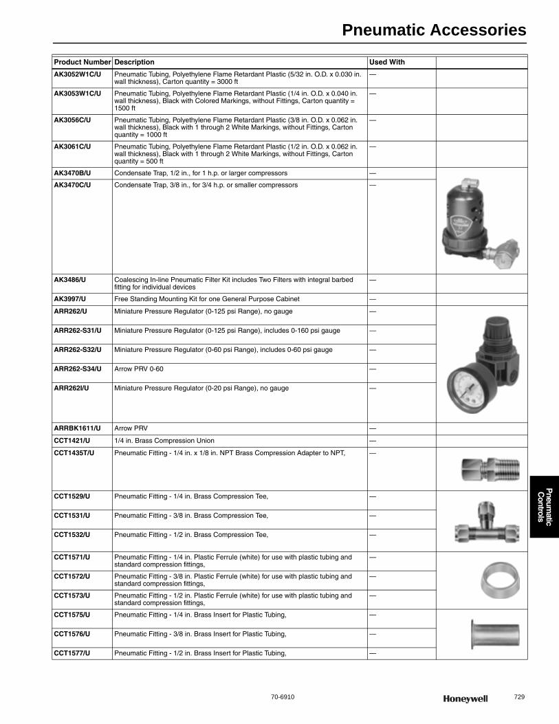
Pneumatic Accessories
70-6910 729
P
neumatic
Controls
Product Number Description Used With
AK3052W1C/U Pneumatic Tubing, Polyethylene Flame Retardant Plastic (5/32 in. O.D. x 0.030 in. wall thickness), Carton quantity = 3000 ft
—
AK3053W1C/U Pneumatic Tubing, Polyethylene Flame Retardant Plastic (1/4 in. O.D. x 0.040 in. wall thickness), Black with Colored Markings, without Fittings, Carton quantity = 1500 ft
—
AK3056C/U Pneumatic Tubing, Polyethylene Flame Retardant Plastic (3/8 in. O.D. x 0.062 in. wall thickness), Black with 1 through 2 White Markings, without Fittings, Carton quantity = 1000 ft
—
AK3061C/U Pneumatic Tubing, Polyethylene Flame Retardant Plastic (1/2 in. O.D. x 0.062 in. wall thickness), Black with 1 through 2 White Markings, without Fittings, Carton quantity = 500 ft
—
AK3470B/U Condensate Trap, 1/2 in., for 1 h.p. or larger compressors —
AK3470C/U Condensate Trap, 3/8 in., for 3/4 h.p. or smaller compressors —
AK3486/U Coalescing In-line Pneumatic Filter Kit includes Two Filters with integral barbed fitting for individual devices
—
AK3997/U Free Standing Mounting Kit for one General Purpose Cabinet —
ARR262/U Miniature Pressure Regulator (0-125 psi Range), no gauge —
ARR262-S31/U Miniature Pressure Regulator (0-125 psi Range), includes 0-160 psi gauge —
ARR262-S32/U Miniature Pressure Regulator (0-60 psi Range), includes 0-60 psi gauge —
ARR262-S34/U Arrow PRV 0-60 —
ARR262I/U Miniature Pressure Regulator (0-20 psi Range), no gauge —
ARRBK1611/U Arrow PRV —
CCT1421/U 1/4 in. Brass Compression Union —
CCT1435T/U Pneumatic Fitting - 1/4 in. x 1/8 in. NPT Brass Compression Adapter to NPT, —
CCT1529/U Pneumatic Fitting - 1/4 in. Brass Compression Tee, —
CCT1531/U Pneumatic Fitting - 3/8 in. Brass Compression Tee, —
CCT1532/U Pneumatic Fitting - 1/2 in. Brass Compression Tee, —
CCT1571/U Pneumatic Fitting - 1/4 in. Plastic Ferrule (white) for use with plastic tubing and standard compression fittings,
—
CCT1572/U Pneumatic Fitting - 3/8 in. Plastic Ferrule (white) for use with plastic tubing and standard compression fittings,
—
CCT1573/U Pneumatic Fitting - 1/2 in. Plastic Ferrule (white) for use with plastic tubing and standard compression fittings,
—
CCT1575/U Pneumatic Fitting - 1/4 in. Brass Insert for Plastic Tubing, —
CCT1576/U Pneumatic Fitting - 3/8 in. Brass Insert for Plastic Tubing, —
CCT1577/U Pneumatic Fitting - 1/2 in. Brass Insert for Plastic Tubing, —

Pneumatic Accessories
730 customer.honeywell.com 70-6910
CCT1589B/U Pneumatic Fitting - 1/4 in.x1/8 in. FPT 90 Barbed Female Street Ells, —
CCT1590BT/U Pneumatic Fitting - 1/4 in. Barbed x 1/8 in. NPT Male Adapter, Taped, —
CCT1594B/U Pneumatic Fitting - 1/4 in. Barbed x 1/8 in. FPT Female Adapter, —
CCT1595BT/U Pneumatic Fitting - 1/4 in. barbed x 1/8 in. NPT 90 Barbed Male Street Ells, —
CCT1598B/U Pneumatic Fitting - 3/8 in. barbed x 3/8 in. barbed 90 E bow —
CCT1599BT/U Pneumatic Fitting - combination 5/32 in. and 1/4 in. Barbed x 1/8 in. NPT Male Adapter,
—
CCT1602/U Pneumatic Fitting - In-line gauge Tee (5/32 in. barbed x 5/32 in. barbed x 1/8 in. FPT),
—
CCT1606B/U Pneumatic Fitting - 5/32 in. barbed x 1/4 in. barbed (brass) plastic tubing coupling, reducing,
—
CCT1607B/U Pneumatic Fitting - 1/4 in. barbed x 1/4 in. barbed (brass) plastic tubing coupling, —
CCT1608B/U Pneumatic Fitting - 3/8 in. barbed x 3/8 in. barbed (brass) plastic tubing coupling, —
CCT1610B/U Pneumatic Fitting - 3/8 in. barbed x 1/4 in. barbed (brass) plastic tubing coupling, —
CCT1611B/U Pneumatic Fitting - 1/2 in. barbed x 3/8 in. barbed (brass) plastic tubing coupling, —
CCT1612B/U Pneumatic Fitting - 1/4 in. barbed x 1/4 in. barbed x 1/4 in. barbed (brass) Straight Tee,
—
CCT1613B/U Pneumatic Fitting - 3/8 in. barbed x 3/8 in. barbed x 3/8 in. barbed (brass) Straight Tee,
—
CCT1614B/U Pneumatic Fitting - 1/4 in. barbed x 1/4 in. barbed x 1/8 in. FPT In-line gauge Tee, —
CCT1615B/U Pneumatic Fitting - 3/8 in. barbed x 3/8 in. barbed x 1/4 in. barbed Reducing Tee, —
CCT1616B/U Pneumatic Fitting - 1/2 in. barbed x 1/2 in. barbed x 1/4 in. barbed Reducing Tee, —
Product Number Description Used With

Pneumatic Accessories
70-6910 731
P
neumatic
Controls
CCT1617B/U Pneumatic Fitting - 1/2 in. barbed x 1/2 in. barbed (brass) plastic tubing coupling, —
CCT1618B/U Pneumatic Fitting - 1/2 in. barbed x 1/2 in. barbed x 3/8 in. barbed Reducing Tee, —
CCT1619B/U Pneumatic Fitting - Bulkhead Barb, 1/4 in. barbed x 1/4 in. Compression Nuts (for panels 5/16 in. thick),
—
CCT1620B/U Pneumatic Fitting - 1/2 in. barbed x 1/2 in. barbed x 1/2 in. barbed (brass) Straight Tee,
—
CCT1622/U Pneumatic Fitting - 1/4 in. barbed x 1/4 in. barbed x 1/8 in. FPT In-line gauge Tee with mounting tabs,
—
CCT1623/U Pneumatic Fitting - 1/4 in. Spring Clamp for Pneumatic Tubing, —
CCT1628B/U Pneumatic Fitting - 5/32 in. barbed x 5/32 in. barbed (brass) plastic tubing coupling, —
CCT1629B/U Pneumatic Fitting - 1/2 in. barbed x 1/4 in. barbed (brass) plastic tubing coupling, —
CCT1630B/U Pneumatic Fitting - 1/4 in. barbed x 1/4 in. barbed x 5/32 in. barbed Reducing Tee, —
CCT1631B/U Pneumatic Fitting - 3/8 in. barbed x 3/8 in. barbed x 5/32 in. barbed Reducing Tee, —
CCT1633BT/U Pneumatic Fitting - 1/4 in. Barbed x 1/4 in. NPT Male Adapter, —
CCT1635B/U Pneumatic Fitting - 1/4 in. barbed x 1/4 in. Compression Adapter, —
CCT1637B/U Pneumatic Fitting - 5/32 in. barbed x 5/32 in. barbed x 5/32 in. barbed (brass) Straight Tee,
—
CCT1640/U Pneumatic Fitting - 1/4 in. Tubing Plug, —
Product Number Description Used With
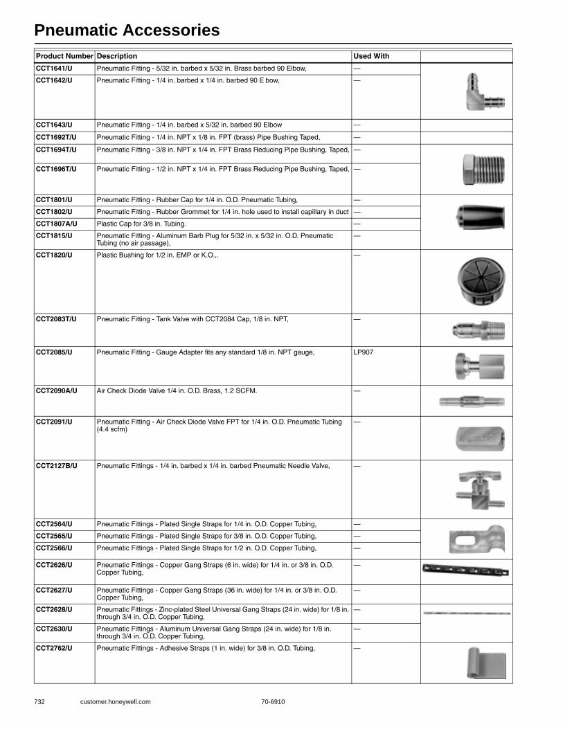
Pneumatic Accessories
732 customer.honeywell.com 70-6910
CCT1641/U Pneumatic Fitting - 5/32 in. barbed x 5/32 in. Brass barbed 90 Elbow, —
CCT1642/U Pneumatic Fitting - 1/4 in. barbed x 1/4 in. barbed 90 E bow, —
CCT1643/U Pneumatic Fitting - 1/4 in. barbed x 5/32 in. barbed 90 Elbow —
CCT1692T/U Pneumatic Fitting - 1/4 in. NPT x 1/8 in. FPT (brass) Pipe Bushing Taped, —
CCT1694T/U Pneumatic Fitting - 3/8 in. NPT x 1/4 in. FPT Brass Reducing Pipe Bushing, Taped, —
CCT1696T/U Pneumatic Fitting - 1/2 in. NPT x 1/4 in. FPT Brass Reducing Pipe Bushing, Taped, —
CCT1801/U Pneumatic Fitting - Rubber Cap for 1/4 in. O.D. Pneumatic Tubing, —
CCT1802/U Pneumatic Fitting - Rubber Grommet for 1/4 in. hole used to install capillary in duct —
CCT1807A/U Plastic Cap for 3/8 in. Tubing. —
CCT1815/U Pneumatic Fitting - Aluminum Barb Plug for 5/32 in. x 5/32 in. O.D. Pneumatic Tubing (no air passage),
—
CCT1820/U Plastic Bushing for 1/2 in. EMP or K.O.,. —
CCT2083T/U Pneumatic Fitting - Tank Valve with CCT2084 Cap, 1/8 in. NPT, —
CCT2085/U Pneumatic Fitting - Gauge Adapter fits any standard 1/8 in. NPT gauge, LP907
CCT2090A/U Air Check Diode Valve 1/4 in. O.D. Brass, 1.2 SCFM. —
CCT2091/U Pneumatic Fitting - Air Check Diode Valve FPT for 1/4 in. O.D. Pneumatic Tubing (4.4 scfm)
—
CCT2127B/U Pneumatic Fittings - 1/4 in. barbed x 1/4 in. barbed Pneumatic Needle Valve, —
CCT2564/U Pneumatic Fittings - Plated Single Straps for 1/4 in. O.D. Copper Tubing, —
CCT2565/U Pneumatic Fittings - Plated Single Straps for 3/8 in. O.D. Copper Tubing, —
CCT2566/U Pneumatic Fittings - Plated Single Straps for 1/2 in. O.D. Copper Tubing, —
CCT2626/U Pneumatic Fittings - Copper Gang Straps (6 in. wide) for 1/4 in. or 3/8 in. O.D. Copper Tubing,
—
CCT2627/U Pneumatic Fittings - Copper Gang Straps (36 in. wide) for 1/4 in. or 3/8 in. O.D. Copper Tubing,
—
CCT2628/U Pneumatic Fittings - Zinc-plated Steel Universal Gang Straps (24 in. wide) for 1/8 in. through 3/4 in. O.D. Copper Tubing,
—
CCT2630/U Pneumatic Fittings - Aluminum Universal Gang Straps (24 in. wide) for 1/8 in. through 3/4 in. O.D. Copper Tubing,
—
CCT2762/U Pneumatic Fittings - Adhesive Straps (1 in. wide) for 3/8 in. O.D. Tubing, —
Product Number Description Used With
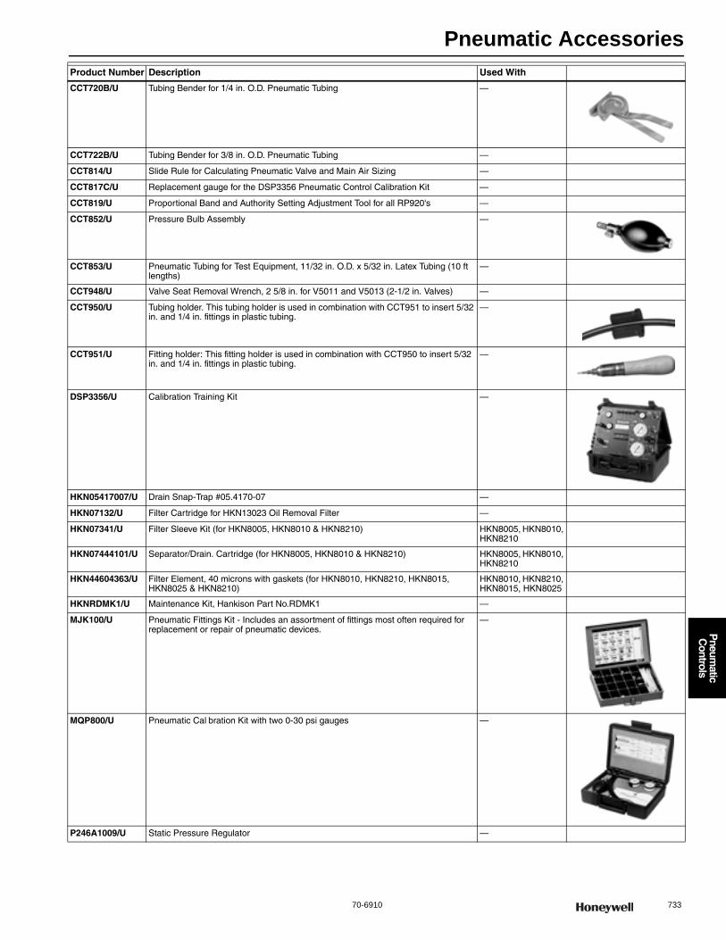
Pneumatic Accessories
70-6910 733
P
neumatic
Controls
CCT720B/U Tubing Bender for 1/4 in. O.D. Pneumatic Tubing —
CCT722B/U Tubing Bender for 3/8 in. O.D. Pneumatic Tubing —
CCT814/U Slide Rule for Calculating Pneumatic Valve and Main Air Sizing —
CCT817C/U Replacement gauge for the DSP3356 Pneumatic Control Calibration Kit —
CCT819/U Proportional Band and Authority Setting Adjustment Tool for all RP920's —
CCT852/U Pressure Bulb Assembly —
CCT853/U Pneumatic Tubing for Test Equipment, 11/32 in. O.D. x 5/32 in. Latex Tubing (10 ft lengths)
—
CCT948/U Valve Seat Removal Wrench, 2 5/8 in. for V5011 and V5013 (2-1/2 in. Valves) —
CCT950/U Tubing holder. This tubing holder is used in combination with CCT951 to insert 5/32 in. and 1/4 in. fittings in plastic tubing.
—
CCT951/U Fitting holder: This fitting holder is used in combination with CCT950 to insert 5/32 in. and 1/4 in. fittings in plastic tubing.
—
DSP3356/U Calibration Training Kit —
HKN05417007/U Drain Snap-Trap #05.4170-07 —
HKN07132/U Filter Cartridge for HKN13023 Oil Removal Filter —
HKN07341/U Filter Sleeve Kit (for HKN8005, HKN8010 & HKN8210) HKN8005, HKN8010, HKN8210
HKN07444101/U Separator/Drain. Cartridge (for HKN8005, HKN8010 & HKN8210) HKN8005, HKN8010, HKN8210
HKN44604363/U Filter Element, 40 microns with gaskets (for HKN8010, HKN8210, HKN8015, HKN8025 & HKN8210)
HKN8010, HKN8210, HKN8015, HKN8025
HKNRDMK1/U Maintenance Kit, Hankison Part No.RDMK1 —
MJK100/U Pneumatic Fittings Kit - Includes an assortment of fittings most often required for replacement or repair of pneumatic devices.
—
MQP800/U Pneumatic Cal bration Kit with two 0-30 psi gauges —
P246A1009/U Static Pressure Regulator —
Product Number Description Used With

Pneumatic Definitions and Abbreviations
734 customer.honeywell.com 70-6910
Definitions and AbbreviationsActuator (Damper)— A mechanical device that operates a final control
element (e.g., valve, damper). Actuator (Valve)—The part of an automatic control valve that moves the stem up and down based on an electric, electronic, or pneumatic signal from a controller. For butterfly or other rotary valves, the actuator rotates the stem. The actuator and valve can be two separate devices or together they can be one device.
BLP—See Branchline pressure.
Body rating (actual)—The correlation between safe, permissible flowing fluid pressure and flowing fluid temperature of the valve body (exclusive of the packing, disc, etc.). The nominal valve body rating is the permiss ble pressure at a specific temperature.
EXAMPLE:A cast iron, screwed-end valve has a 125 psi nominal body rat-ing. The actual valve body ratings may be 125 psi at 380 F and 175 psi at 175 F.
Body rating (nominal)—The theoretical pressure rating, expressed in psi, of the valve body exclusive of packing, disc, etc. The nominal rating is often cast on the valve body and provides a way to classify the valve by pressure. A valve of specified body material and nominal body rating often has characteristics such as pressure-temperature ratings, wall thickness, and end connections which are determined by a society such as ANSI (American National Standards Institute). Figure 2 shows typical ANSI pressure-temperature ratings for valves. Note that the nominal body rating is not the same as the actual body rating.
Body—The valve casting through which the controlled fluid flows.
Bonnet—The part that screws to the top of the valve body and contains the packing that seals and guides the valve stem.
Branch line—The air line from a controller to the controlled device.
Branchline pressure (BLP)—A varying air pressure signal from a controller to an actuator, carried by the branch line. Can go from zero to full main line pressure.
British thermal unit (Btu)—The amount of heat required to raise one pound of water one degree Fahrenheit.
Btu—See British thermal unit.
Close-off rating of three-way valves—The maximum pressure difference between either of the two inlet ports and the outlet port for mixing valves, or the pressure difference between the inlet port and either of the two outlet ports for diverting valves.
Close-off rating—The maximum pressure drop that a valve can withstand without leakage while in the full closed position. The close-off rating is a function of actuator power to hold the valve closed against pressure drop, but structural parts such as the stem can be the limiting factor.
EXAMPLE:A valve with a close-off rating of 10 psi could have 40 psi upstream pressure and 30 psi downstream pressure. Note that in applications where failure of the valve to close is hazardous, the maximum upstream pressure must not exceed the valve close-off rating, regardless of the downstream pressure.
The valve close-off rating is independent of the actual valve body rating. See definition of BODY RATING (ACTUAL) in this section.
Control point—The actual value of the controlled variable (setpoint plus or minus offset).
Control valve—A device used to control the flow of fluids such as steam, water, or air.
Controlled variable—The quantity or condition that is measured and controlled (e.g., temperature, relative humidity, pressure).
Controller—A device that senses the controlled variable (or receives an input signal from a remote sensing element), compares the signal with the setpoint, and outputs a control signal (branchline pressure) to an actuator.
Cv—See Flow coefficient.
DA—See Direct acting or Discharge air.
Damper—A device used to control the flow of air in a duct or through a wall louver.
Dew-point temperature—The temperature at which water vapor from the air begins to form droplets and settles or condenses on surfaces that are colder than the air. The more moisture the air contains, the higher its dew point temperature. When dry-bu b and wet-bulb temperatures of the air are known, the dew-point temperature can be plotted on the psychrometric chart.
Differential—A term that applies to two-position devices. The range through which the controlled variable must pass in order to move the final control element from one to the other of its two possible positions. The difference between cut-in and cut-out temperatures, pressures, etc.
Direct acting (DA)—A direct-acting thermostat or controller increases the branchline pressure on an increase in the measured variable and decreases the branchline pressure on a decrease in the variable. A direct-acting actuator extends on an increase in branchline pressure and retracts on a decrease in pressure.
Direction of flow—The correct flow of the controlled fluid through the valve is usually indicated on the valve body. If the flow of the fluid goes against the indicated direction, the disc can slam into the seat as it approaches the closed position. The result is excessive valve wear, hammering, and oscillations. In addition, the actuator must work harder to reopen the closed valve since it must overcome the pressure exerted by the fluid on top of the disc rather than have the fluid assist in opening the valve by exerting pressure under the disc.
Discharge air (DA)—Conditioned air that has passed through a coil. Also, air discharged from a supply duct outlet into a space.
Disc—The part of the plug assembly that contacts the valve seat to close off flow of the controlled fluid. Certain valve plug assemblies are built so the part of the assembly contacting the seat is replaceable. This type of plug is called a renewable disc plug assembly. Renewable discs are usually made of a composition material softer than metal. Valves with all metal or nonrenewable discs may have to be “ground in” to restore a damaged seating surface. Note that the term disc can mean both the plug and disc together.
Dry-bulb temperature—The temperature read directly on an ordinary thermometer as degrees Fahrenheit (F) or degrees Celsius (C).
Equal percentage—A valve which changes the existing flow an equal percentage (regardless of flow rate) for similar movements in stem travel (at any point in the flow range).
Final control element—A device such as a valve or damper that acts to change the value of the manipulated variable. Positioned by an actuator.
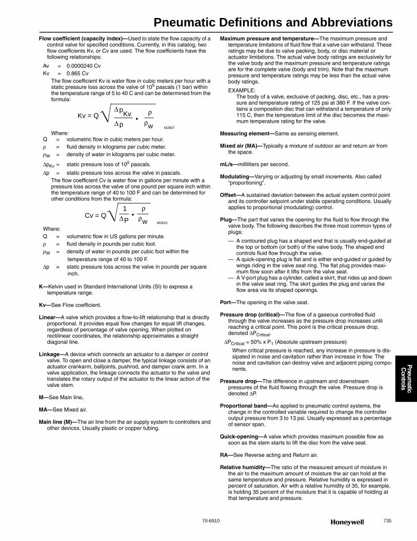
Pneumatic Definitions and Abbreviations
70-6910 735
P
neumatic
Controls
Flow coefficient (capacity index)—Used to state the flow capacity of a control valve for specified conditions. Currently, in this catalog, two flow coefficients Kv, or Cv are used. The flow coefficients have the following relationships:
Av = 0.0000240 CvKv = 0.865 Cv
The flow coefficient Kv is water flow in cubic meters per hour with a static pressure loss across the valve of 105 pascals (1 bar) within the temperature range of 5 to 40 C and can be determined from the formula:
Where:Q = volumetric flow in cubic meters per hour.ρ = fluid density in kilograms per cubic meter.ρW = density of water in kilograms per cubic meter.
ΔpKv = static pressure loss of 105 pascals.
Δp = static pressure loss across the valve in pascals.The flow coefficient Cv is water flow in gallons per minute with a pressure loss across the valve of one pound per square inch within the temperature range of 40 to 100 F and can be determined for other conditions from the formula:
Where:Q = volumetric flow in US gallons per minute.ρ = fluid density in pounds per cubic foot.ρW = density of water in pounds per cubic foot within the
temperature range of 40 to 100 F.Δp = static pressure loss across the valve in pounds per square
inch.
K—Kelvin used in Standard International Units (SI) to express a temperature range.
Kv—See Flow coefficient.
Linear—A valve which provides a flow-to-lift relationship that is directly proportional. It provides equal flow changes for equal lift changes, regardless of percentage of valve opening. When plotted on rectilinear coordinates, the relationship approximates a straight diagonal line.
Linkage—A device which connects an actuator to a damper or control valve. To open and close a damper, the typical linkage consists of an actuator crankarm, balljoints, pushrod, and damper crank arm. In a valve application, the linkage connects the actuator to the valve and translates the rotary output of the actuator to the linear action of the valve stem.
M—See Main line.
MA—See Mixed air.
Main line (M)—The air line from the air supply system to controllers and other devices. Usually plastic or copper tubing.
Maximum pressure and temperature—The maximum pressure and temperature limitations of fluid flow that a valve can withstand. These ratings may be due to valve packing, body, or disc material or actuator limitations. The actual valve body ratings are exclusively for the valve body and the maximum pressure and temperature ratings are for the complete valve (body and trim). Note that the maximum pressure and temperature ratings may be less than the actual valve body ratings.
EXAMPLE:The body of a valve, exclusive of packing, disc, etc., has a pres-sure and temperature rating of 125 psi at 380 F. If the valve con-tains a composition disc that can withstand a temperature of only 115 C, then the temperature limit of the disc becomes the maxi-mum temperature rating for the valve.
Measuring element—Same as sensing element.
Mixed air (MA)—Typically a mixture of outdoor air and return air from the space.
mL/s—milliliters per second.
Modulating—Varying or adjusting by small increments. Also called “proportioning”.
Offset—A sustained deviation between the actual system control point and its controller setpoint under stable operating conditions. Usually applies to proportional (modulating) control.
Plug—The part that varies the opening for the fluid to flow through the valve body. The following describes the three most common types of plugs:
— A contoured plug has a shaped end that is usually end-guided at the top or bottom (or both) of the valve body. The shaped end controls fluid flow through the valve.
— A quick-opening plug is flat and is either end-guided or guided by wings riding in the valve seat ring. The flat plug provides maxi-mum flow soon after it lifts from the valve seat.
— A V-port plug has a cylinder, called a skirt, that rides up and down in the valve seat ring. The skirt guides the plug and varies the flow area via its shaped openings.
Port—The opening in the valve seat.
Pressure drop (critical)—The flow of a gaseous controlled fluid through the valve increases as the pressure drop increases until reaching a critical point. This point is the critical pressure drop, denoted ΔPCritical.
ΔPCritical = 50% x P1 (Absolute upstream pressure)
When critical pressure is reached, any increase in pressure is dis-sipated in noise and cavitation rather than increase in flow. The noise and cavitation can destroy valve and adjacent piping compo-nents.
Pressure drop—The difference in upstream and downstream pressures of the fluid flowing through the valve. Pressure drop is denoted ΔP.
Proportional band—As applied to pneumatic control systems, the change in the controlled variable required to change the controller output pressure from 3 to 13 psi. Usually expressed as a percentage of sensor span.
Quick-opening—A valve which provides maximum possible flow as soon as the stem starts to lift the disc from the valve seat.
RA—See Reverse acting and Return air.
Relative humidity—The ratio of the measured amount of moisture in the air to the maximum amount of moisture the air can hold at the same temperature and pressure. Relative humidity is expressed in percent of saturation. Air with a relative humidity of 35, for example, is holding 35 percent of the moisture that it is capable of holding at that temperature and pressure.
pKv
p•
ρρw
Kv = Q
M2807
Δ
Δ
P•
ρρ
wCv = Q
M2810
1
Δ

Pneumatic Definitions and Abbreviations
736 customer.honeywell.com 70-6910
Restrictor—A device in an air line that limits the flow of air.
Return air (RA)—Air from the conditioned space which is passed through the air handling unit and returned to the conditioned space.
Reverse acting (RA)—A reverse-acting thermostat or controller decreases the branchline pressure on an increase in the measured variable and increases the branchline pressure on a decrease in the variable. A reverse-acting valve actuator retracts on an increase in branchline pressure and extends on a decrease in pressure.
scfm—standard cubic feet per minute.
Seat—The stationary part of the valve body that has a raised lip to contact the valve disc when closing off flow of the controlled fluid.
Sensing element—A device that detects and measures the controlled variable (e.g., temperature, humidity).
Setpoint—The value on the controller scale at which the controller is set (e.g., the desired room temperature set on a thermostat). The desired control point.
Sling psychrometer—A device commonly used to measure the wet-bulb temperature. It consists of two identical thermometers mounted on a common base. The base is pivoted on a handle so it can be whirled through the air. One thermometer measures dry-bulb temperature. The bulb of the other thermometer is encased in a water-soaked wick. This thermometer measures wet-bulb temperature. Some models provide slide rule construction which allows converting the dry-bulb and wet-bulb readings to relative humidity.
Although commonly used, sling psychrometers can cause inaccurate readings, especially at low relative humidities, because of factors such as inadequate air flow past the wet-bulb wick, too much wick wetting from a continuous water feed, thermometer calibration error, and human error. To take more accurate readings, especially in low relative humidity conditions, motorized psychrometers are recommended.
Stem—The shaft that runs through the valve bonnet and connects an actuator to the valve plug.
Thermostat—A device that responds to changes in temperature and outputs a control signal (branchline pressure). Usually mounted on a wall in the controlled space.
Throttling range—Same as proportional band, except expressed in values of the controlled variable (e.g., degrees, percent relative humidity, pounds per square inch) rather than in percent.
Tight shut-off/close-off—A valve condition in which virtually no leakage of the controlled fluid occurs in the closed position. Generally, only single-seated valves provide tight shut-off. Double-seated valves typically have a one to three percent leakage in the closed position.
Trim—All parts of the valve that contact the controlled fluid. Trim includes the stem, packing, plug, disc, and seat; it does not include the valve body.
Wet-bulb temperature—The temperature read on a thermometer with the mercury bulb encased in a wet wick (stocking or sock) and with an air flow of 900 feet per minute across the wick. Water evaporation causes the temperature reading to be lower than the ambient dry-bulb temperature by an amount proportional to the moisture content of the air. The temperature reduction is sometimes called the evaporative effect. When the reading stops falling, the value read is the wet-bu b temperature.
The wet-bulb and dry-bulb temperatures are the easiest air properties to measure. When they are known, they can be used to determine other air properties on a psychrometric chart.
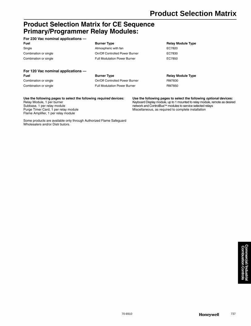
Product Selection Matrix
70-6910 737
Com
mercial / Industrial
Com
bustion Controls
Product Selection Matrix for CE SequencePrimary/Programmer Relay Modules:For 230 Vac nominal applications —
For 120 Vac nominal applications —
Use the following pages to select the following required devices:Relay Module, 1 per burnerSubbase, 1 per relay module Purge Timer Card, 1 per relay moduleFlame Amplifier, 1 per relay module
Some products are available only through Authorized Flame Safeguard Wholesalers and/or Distr butors.
Use the following pages to select the following optional devices:Keyboard Display module, up to 1 mounted to relay module, remote as desirednetwork and ControlBus™ modules to service selected relaysMiscellaneous, as required to complete installation
Fuel Burner Type Relay Module TypeSingle Atmospheric with fan EC7820
Combination or single On/Off Controlled Power Burner EC7830
Combination or single Full Modulation Power Burner EC7850
Fuel Burner Type Relay Module TypeCombination or single On/Off Controlled Power Burner RM7830
Combination or single Full Modulation Power Burner RM7850
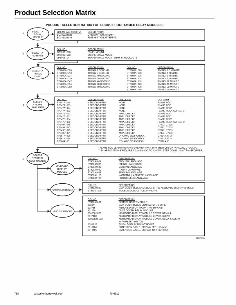
Product Selection Matrix
738 customer.honeywell.com 70-6910
PRODUCT SELECTION MATRIX FOR EC7820 PROGRAMMER RELAY MODULES:
M15516G
SELECT A SUBBASE
SELECT A PURGECARD
SELECTOPTIONAL
COMPONENTS
KEYBOARDDISPLAYMODULE
COMMUNICATIONS
MISCELLANEOUS
SELECT A RELAY
MODULE
220-240 VAC 50/60 HZEC7820A1026EC7820A1034
DESCRIPTIONONE IGNITION ATTEMPTFIVE IGNITION ATTEMPTS
O.S. NO.Q7800A1005Q7800B1003Q7800B1011
DESCRIPTIONPANEL MOUNTBURNER/WALL MOUNTBURNER/WALL MOUNT WITH 3 KNOCKOUTS
O.S. NO.ST7800A1005ST7800A1013ST7800A1021ST7800A1039ST7800A1047ST7800A1054ST7800A1062
DESCRIPTIONTIMING: 2 SECONDTIMING: 7 SECONDTIMING: 10 SECONDTIMING: 30 SECONDTIMING: 40 SECONDTIMING: 60 SECONDTIMING: 90 SECOND
O.S. NO.ST7800A1070ST7800A1088ST7800A1096ST7800A1104ST7800A1112ST7800A1120ST7800A1138ST7800A1146
DESCRIPTIONTIMING: 2.5 MINUTETIMING: 4 MINUTETIMING: 6 MINUTETIMING: 9 MINUTETIMING: 12 MINUTETIMING: 15 MINUTETIMING: 22 MINUTETIMING: 30 MINUTE
O.S. NO.R7847A1025R7847A1033R7847A1074R7847A1082R7847B1023R7847B1031R7847B1064R7847B1072R7849A1015R7849A1023R7849B1013R7849B1021R7861A1026R7861A1034R7886A1001
DESCRIPTION1 SECOND FFRT2 SECOND FFRT1 SECOND FFRT2 SECOND FFRT1 SECOND FFRT2 SECOND FFRT1 SECOND FFRT2 SECOND FFRT1 SECOND FFRT2 SECOND FFRT1 SECOND FFRT2 SECOND FFRT2 SECOND FFRT1 SECOND FFRT2 SECOND FFRT
CHECKINGNONENONENONENONEAMPLICHECK®
AMPLICHECK®
AMPLICHECK®
AMPLICHECK®
AMPLICHECK®
AMPLICHECK®
AMPLICHECK®
AMPLICHECK®
DYNAMIC SELF-CHECKDYNAMIC SELF-CHECKDYNAMIC SELF-CHECK
O.S. NO.S7800A1001S7800A1035S7800A1043S7800A1050S7800A1068S7800A1118S7800A1126
DESCRIPTIONENGLISH LANGUAGEFRENCH LANGUAGEGERMAN LANGUAGEITALIAN LANGUAGESPANISH LANGUAGEKATAKANA (JAPANESE) LANGUAGEPORTUGUESE LANGUAGE
O.S. NO.S7810A1009S7810M1029
DESCRIPTIONDATA CONTROLBUS® MODULE (IF NO KEYBOARD DISPLAY IS USED)MODBUS MODULE - CE APPROVAL
O.S. NO.S7820A100720354120376522172950023821-001204718B50023821-002
205321B221818A221818C
DESCRIPTIONREMOTE RESET MODULEDATA CONTROLBUS CONNECTOR, 5-WIREREMOTE DISPLAY MOUNTING BRACKETDUST COVER, RELAY MODULEKEYBOARD DISPLAY MODULE COVER, NEMA 4, KEYBOARD DISPLAY MODULE COVER, CLEARKEYBOARD DISPLAY MODULE COVER, NEMA 4, CLEAR WITH RESET BUTTONFLUSH DISPLAY MOUNTING KITEXTENSION CABLE, DISPLAY 5FT (1524MM)EXTENSION CABLE, DISPLAY 10FT (3048MM)
USE WITHFLAME RODFLAME RODFLAME ROD*FLAME ROD*, C7012A, CFLAME RODFLAME RODFLAME ROD*FLAME ROD*, C7012A, CC7027, C7035C7027, C7035C7027, C7035C7027, C7035C7061A, F, M**C7061A, F, M**C7076A, F
SELECT A FLAME
AMPLIFIER
* FLAME ROD LEADWIRE RUNS GREATER THAN 50FT (1524 CM) OR PARALLEL C7012 A,C.** EC APPLICATIONS REQUIRE A 220-240 VAC TO 120 VAC, STEP DOWN, 10VA TRANSFORMER.
1.)
2.)
3.)
4.)
5.)

Product Selection Matrix
70-6910 739
Com
mercial / Industrial
Com
bustion Controls
PRODUCT SELECTION MATRIX FOR EC/RM7830 PROGRAMMER RELAY MODULES:
M15517H
SELECT A SUBBASE
SELECT A PURGECARD
SELECTOPTIONAL
COMPONENTS
KEYBOARDDISPLAYMODULE
COMMUNICATIONS
MISCELLANEOUS
SELECT A RELAY
MODULE
220-240 VAC 50/60 HZEC7830A1033EC7830A1041EC7830A1066
120VAC 50/60 HZRM7830A1003RM7830A1029RM7830A1011
O.S. NO.Q7800A1005Q7800B1003Q7800B1011
DESCRIPTIONPANEL MOUNTBURNER/WALL MOUNTBURNER/WALL MOUNT WITH 3 KNOCKOUTS
O.S. NO.ST7800A1005ST7800A1013ST7800A1021ST7800A1039ST7800A1047ST7800A1054ST7800A1062
DESCRIPTIONTIMING: 2 SECONDTIMING: 7 SECONDTIMING: 10 SECONDTIMING: 30 SECONDTIMING: 40 SECONDTIMING: 60 SECONDTIMING: 90 SECOND
O.S. NO.ST7800A1070ST7800A1088ST7800A1096ST7800A1104ST7800A1112ST7800A1120ST7800A1138ST7800A1146
DESCRIPTIONTIMING: 2.5 MINUTETIMING: 4 MINUTETIMING: 6 MINUTETIMING: 9 MINUTETIMING: 12 MINUTETIMING: 15 MINUTETIMING: 22 MINUTETIMING: 30 MINUTE
O.S. NO.R7847A1025R7847A1033R7847A1074R7847A1082R7847B1023R7847B1031R7847B1064R7847B1072R7849A1015R7849A1023R7849B1013R7849B1021R7861A1026R7861A1034R7886A1001
DESCRIPTION1 SECOND FFRT2 SECOND FFRT1 SECOND FFRT2 SECOND FFRT1 SECOND FFRT2 SECOND FFRT1 SECOND FFRT2 SECOND FFRT1 SECOND FFRT2 SECOND FFRT1 SECOND FFRT2 SECOND FFRT2 SECOND FFRT1 SECOND FFRT2 SECOND FFRT
CHECKINGNONENONENONENONEAMPLICHECK®AMPLICHECK®AMPLICHECK®AMPLICHECK®AMPLICHECK®AMPLICHECK®AMPLICHECK®AMPLICHECK®DYNAMIC SELF-CHECKDYNAMIC SELF-CHECKDYNAMIC SELF-CHECK
DESCRIPTIONPOST-PURGE 2 SECONDSPOST-PURGE 30 SECONDSPOST-PURGE 15 SECONDS
O.S. NO.S7800A1001S7800A1035S7800A1043S7800A1050S7800A1068S7800A1118S7800A1126
DESCRIPTIONENGLISH LANGUAGEFRENCH LANGUAGEGERMAN LANGUAGEITALIAN LANGUAGESPANISH LANGUAGEKATAKANA (JAPANESE) LANGUAGEPORTUGUESE LANGUAGE
O.S. NO.S7810A1009S7810M1029
DESCRIPTIONDATA CONTROLBUS® MODULE (IF NO KEYBOARD DISPLAY IS USED)MODBUS MODULE - CE APPROVAL
O.S. NO.S7820A100720354120376522172950023821-001204718B50023821-002
205321B221818A221818C
DESCRIPTIONREMOTE RESET MODULEDATA CONTROLBUS CONNECTOR, 5-WIREREMOTE DISPLAY MOUNTING BRACKETDUST COVER, RELAY MODULEKEYBOARD DISPLAY MODULE COVER, NEMA 4KEYBOARD DISPLAY MODULE COVER, CLEARKEYBOARD DISPLAY MODULE COVER, NEMA 4, CLEAR WITH RESET BUTTONFLUSH DISPLAY MOUNTING KITEXTENSION CABLE, DISPLAY 5FT (1524MM)EXTENSION CABLE, DISPLAY 10FT (3048MM)
USE WITHFLAME RODFLAME RODFLAME ROD*FLAME ROD*, C7012A, CFLAME RODFLAME RODFLAME ROD*FLAME ROD*, C7012A, CC7027, C7035C7027, C7035C7027, C7035C7027, C7035C7061A, F, M**C7061A, F, M**C7076A, F
SELECT A FLAME
AMPLIFIER
* FLAME ROD LEADWIRE RUNS GREATER THAN 50FT (1524 CM) OR PARALLEL C7012 A,C.** EC APPLICATIONS REQUIRE A 220-240 VAC TO 120 VAC, STEP DOWN, 10VA TRANSFORMER.
1.)
2.)
3.)
4.)
5.)

Product Selection Matrix
740 customer.honeywell.com 70-6910
PRODUCT SELECTION MATRIX FOR EC/RM7850 PROGRAMMER RELAY MODULES:
M15519G
SELECT A SUBBASE
SELECT A PURGECARD
SELECTOPTIONAL
COMPONENTS
KEYBOARDDISPLAYMODULE
COMMUNICATIONS
MISCELLANEOUS
SELECT A RELAY
MODULE
220-240 VAC 50/60 HZEC7850A1064EC7850A1072EC7850A1080EC7850A1122
120VAC 50/60 HZ
RM7850A1001RM7850A1027RM7850A1019
O.S. NO.Q7800A1005Q7800B1003Q7800B1011
DESCRIPTIONPANEL MOUNTBURNER/WALL MOUNTBURNER/WALL MOUNT WITH 3 KNOCKOUTS
O.S. NO.ST7800A1005ST7800A1013ST7800A1021ST7800A1039ST7800A1047ST7800A1054ST7800A1062
DESCRIPTIONTIMING: 2 SECONDTIMING: 7 SECONDTIMING: 10 SECONDTIMING: 30 SECONDTIMING: 40 SECONDTIMING: 60 SECONDTIMING: 90 SECOND
O.S. NO.ST7800A1070ST7800A1088ST7800A1096ST7800A1104ST7800A1112ST7800A1120ST7800A1138ST7800A1146
DESCRIPTIONTIMING: 2.5 MINUTETIMING: 4 MINUTETIMING: 6 MINUTETIMING: 9 MINUTETIMING: 12 MINUTETIMING: 15 MINUTETIMING: 22 MINUTETIMING: 30 MINUTE
O.S. NO.R7847A1025R7847A1033R7847A1074R7847A1082R7847B1023R7847B1031R7847B1064R7847B1072R7849A1015R7849A1023R7849B1013R7849B1021R7861A1026R7861A1034R7886A1001
DESCRIPTION1 SECOND FFRT2 SECOND FFRT1 SECOND FFRT2 SECOND FFRT1 SECOND FFRT2 SECOND FFRT1 SECOND FFRT2 SECOND FFRT1 SECOND FFRT2 SECOND FFRT1 SECOND FFRT2 SECOND FFRT2 SECOND FFRT1 SECOND FFRT2 SECOND FFRT
CHECKINGNONENONENONENONEAMPLICHECK®AMPLICHECK®AMPLICHECK®AMPLICHECK®AMPLICHECK®AMPLICHECK®AMPLICHECK®AMPLICHECK®DYNAMIC SELF-CHECKDYNAMIC SELF-CHECKDYNAMIC SELF-CHECK
DESCRIPTIONDYNAMIC AIR DAMPER CHECKPOST-PURGE 2 SECONDSPOST-PURGE 30 SECONDSPOST-PURGE 15 SECONDS
O.S. NO.S7800A1001S7800A1035S7800A1043S7800A1050S7800A1068S7800A1118S7800A1126
DESCRIPTIONENGLISH LANGUAGEFRENCH LANGUAGEGERMAN LANGUAGEITALIAN LANGUAGESPANISH LANGUAGEKATAKANA (JAPANESE) LANGUAGEPORTUGUESE LANGUAGE
O.S. NO.S7810A1009S7810M1029
DESCRIPTIONDATA CONTROLBUS® MODULE (IF NO KEYBOARD DISPLAY IS USED)MODBUS MODULE - CE APPROVAL
O.S. NO.S7820A100720354120376522172950023821-001204718B50023821-002
205321B221818A221818C
DESCRIPTIONREMOTE RESET MODULEDATA CONTROLBUS CONNECTOR, 5-WIREREMOTE DISPLAY MOUNTING BRACKETDUST COVER, RELAY MODULEKEYBOARD DISPLAY MODULE COVER, NEMA 4KEYBOARD DISPLAY MODULE COVER, CLEARKEYBOARD DISPLAY MODULE COVER, NEMA 4, CLEAR WITH RESET BUTTONFLUSH DISPLAY MOUNTING KITEXTENSION CABLE, DISPLAY 5FT (1524MM)EXTENSION CABLE, DISPLAY 10FT (3048MM)
USE WITHFLAME RODFLAME RODFLAME ROD*FLAME ROD*, C7012A, CFLAME RODFLAME RODFLAME ROD*FLAME ROD*, C7012A, CC7027, C7035C7027, C7035C7027, C7035C7027, C7035C7061A, F, M**C7061A, F, M**C7076A, F
SELECT A FLAME
AMPLIFIER
* FLAME ROD LEADWIRE RUNS GREATER THAN 50FT (1524 CM) OR PARALLEL C7012A,C.** EC APPLICATIONS REQUIRE A 220-240 VAC TO 120 VAC, STEP DOWN, 10VA TRANSFORMER.
1.)
2.)
3.)
4.)
5.)
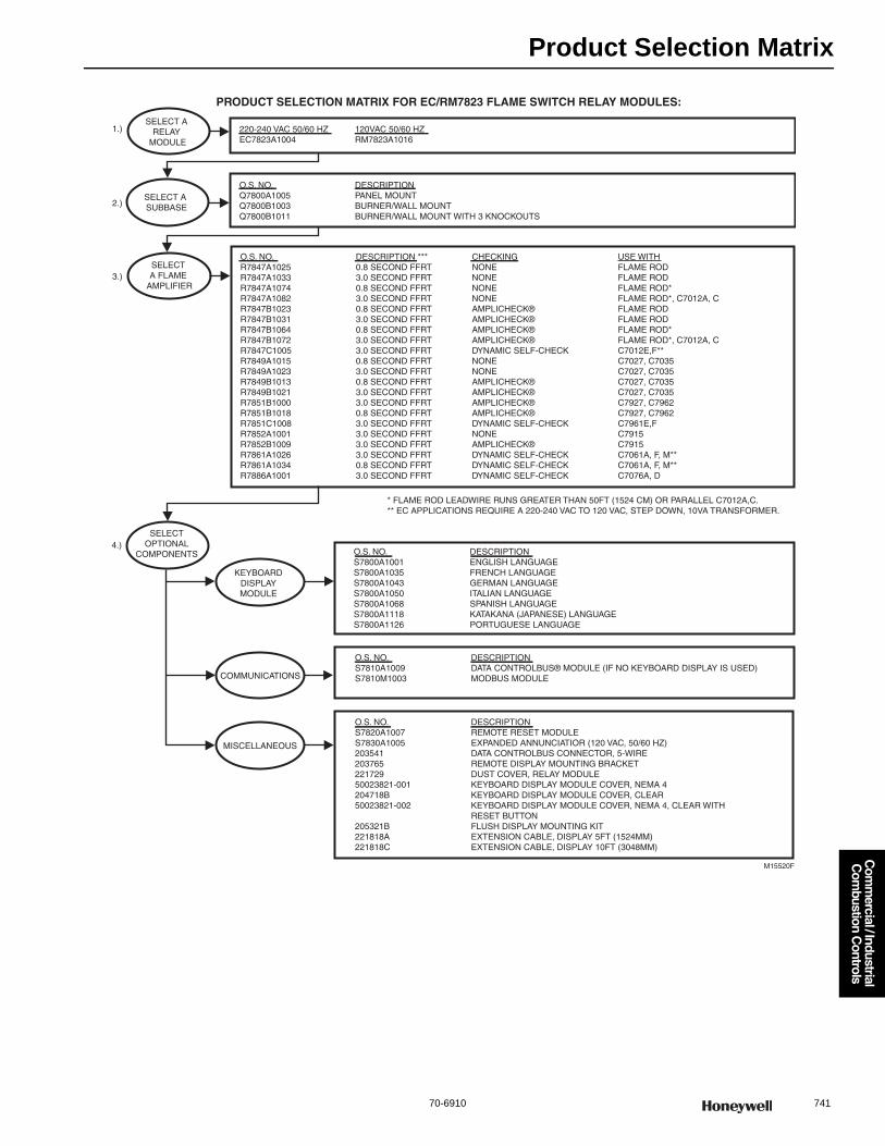
Product Selection Matrix
70-6910 741
Com
mercial / Industrial
Com
bustion Controls
PRODUCT SELECTION MATRIX FOR EC/RM7823 FLAME SWITCH RELAY MODULES:
M15520F
SELECT A SUBBASE
SELECTOPTIONAL
COMPONENTS
KEYBOARDDISPLAYMODULE
COMMUNICATIONS
MISCELLANEOUS
SELECT A RELAY
MODULE
220-240 VAC 50/60 HZEC7823A1004
120VAC 50/60 HZRM7823A1016
O.S. NO.Q7800A1005Q7800B1003Q7800B1011
DESCRIPTIONPANEL MOUNTBURNER/WALL MOUNTBURNER/WALL MOUNT WITH 3 KNOCKOUTS
O.S. NO.S7800A1001S7800A1035S7800A1043S7800A1050S7800A1068S7800A1118S7800A1126
DESCRIPTIONENGLISH LANGUAGEFRENCH LANGUAGEGERMAN LANGUAGEITALIAN LANGUAGESPANISH LANGUAGEKATAKANA (JAPANESE) LANGUAGEPORTUGUESE LANGUAGE
O.S. NO.S7810A1009S7810M1003
DESCRIPTIONDATA CONTROLBUS® MODULE (IF NO KEYBOARD DISPLAY IS USED)MODBUS MODULE
O.S. NO.S7820A1007S7830A100520354120376522172950023821-001204718B50023821-002
205321B221818A221818C
DESCRIPTIONREMOTE RESET MODULEEXPANDED ANNUNCIATIOR (120 VAC, 50/60 HZ)DATA CONTROLBUS CONNECTOR, 5-WIREREMOTE DISPLAY MOUNTING BRACKETDUST COVER, RELAY MODULEKEYBOARD DISPLAY MODULE COVER, NEMA 4KEYBOARD DISPLAY MODULE COVER, CLEARKEYBOARD DISPLAY MODULE COVER, NEMA 4, CLEAR WITH RESET BUTTONFLUSH DISPLAY MOUNTING KITEXTENSION CABLE, DISPLAY 5FT (1524MM)EXTENSION CABLE, DISPLAY 10FT (3048MM)
O.S. NO.R7847A1025R7847A1033R7847A1074R7847A1082R7847B1023R7847B1031R7847B1064R7847B1072R7847C1005R7849A1015R7849A1023R7849B1013R7849B1021R7851B1000R7851B1018R7851C1008R7852A1001R7852B1009R7861A1026R7861A1034R7886A1001
DESCRIPTION ***0.8 SECOND FFRT3.0 SECOND FFRT0.8 SECOND FFRT3.0 SECOND FFRT0.8 SECOND FFRT3.0 SECOND FFRT0.8 SECOND FFRT3.0 SECOND FFRT3.0 SECOND FFRT0.8 SECOND FFRT3.0 SECOND FFRT0.8 SECOND FFRT3.0 SECOND FFRT3.0 SECOND FFRT0.8 SECOND FFRT3.0 SECOND FFRT3.0 SECOND FFRT3.0 SECOND FFRT3.0 SECOND FFRT0.8 SECOND FFRT3.0 SECOND FFRT
CHECKINGNONENONENONENONEAMPLICHECK®AMPLICHECK®AMPLICHECK®AMPLICHECK®DYNAMIC SELF-CHECKNONENONEAMPLICHECK®AMPLICHECK®AMPLICHECK®AMPLICHECK®DYNAMIC SELF-CHECKNONEAMPLICHECK®DYNAMIC SELF-CHECKDYNAMIC SELF-CHECKDYNAMIC SELF-CHECK
USE WITHFLAME RODFLAME RODFLAME ROD*FLAME ROD*, C7012A, CFLAME RODFLAME RODFLAME ROD*FLAME ROD*, C7012A, CC7012E,F**C7027, C7035C7027, C7035C7027, C7035C7027, C7035C7927, C7962C7927, C7962C7961E,FC7915C7915C7061A, F, M**C7061A, F, M**C7076A, D
SELECT A FLAME
AMPLIFIER
1.)
2.)
3.)
4.)
* FLAME ROD LEADWIRE RUNS GREATER THAN 50FT (1524 CM) OR PARALLEL C7012A,C.** EC APPLICATIONS REQUIRE A 220-240 VAC TO 120 VAC, STEP DOWN, 10VA TRANSFORMER.
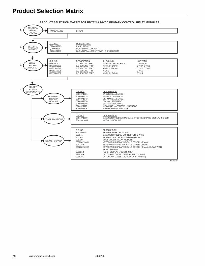
Product Selection Matrix
742 customer.honeywell.com 70-6910
PRODUCT SELECTION MATRIX FOR RM7824A 24VDC PRIMARY CONTROL RELAY MODULES:
M15521D
SELECT A
SUBBASE
SELECT
A FLAME
AMPLIFIER
SELECT
OPTIONAL
COMPONENTS
KEYBOARD
DISPLAY
MODULE
COMMUNICATIONS
MISCELLANEOUS
SELECT A
RELAY
MODULERM7824A1006 24VDC
O.S. NO.
Q7800A1005
Q7800B1003
Q7800B1011
DESCRIPTION
PANEL MOUNT
BURNER/WALL MOUNT
BURNER/WALL MOUNT WITH 3 KNOCKOUTS
O.S. NO.
R7824C1002
R7851B1000
R7851B1018
R7852A1001
R7852B1009
DESCRIPTION
3.0 SECOND FFRT
3.0 SECOND FFRT
0.8 SECOND FFRT
3.0 SECOND FFRT
0.8 SECOND FFRT
CHECKING
DYNAMIC SELF-CHECK
AMPLICHECK®
AMPLICHECK®
NONE
AMPLICHECK®
O.S. NO.
S7800A1001
S7800A1035
S7800A1043
S7800A1050
S7800A1068
S7800A1118
S7800A1126
DESCRIPTION
ENGLISH LANGUAGE
FRENCH LANGUAGE
GERMAN LANGUAGE
ITALIAN LANGUAGE
SPANISH LANGUAGE
KATAKANA (JAPANESE) LANGUAGE
PORTUGUESE LANGUAGE
O.S. NO.
S7810A1009
S7810M1003
DESCRIPTION
DATA CONTROLBUS® MODULE (IF NO KEYBOARD DISPLAY IS USED)
MODBUS MODULE
O.S. NO.
S7820A1007
203541
203765
221729
50023821-001
204718B
50023821-002
205321B
221818A
221818C
DESCRIPTION
REMOTE RESET MODULE
DATA CONTROLBUS CONNECTOR, 5-WIRE
REMOTE DISPLAY MOUNTING BRACKET
DUST COVER, RELAY MODULE
KEYBOARD DISPLAY MODULE COVER, NEMA 4
KEYBOARD DISPLAY MODULE COVER, CLEAR
KEYBOARD DISPLAY MODULE COVER, NEMA 4, CLEAR WITH
RESET BUTTON
FLUSH DISPLAY MOUNTING KIT
EXTENSION CABLE, DISPLAY 5FT (1524MM)
EXTENSION CABLE, DISPLAY 10FT (3048MM)
USE WITH
C7024E, F
C7927, C7962
C7927, C7962
C7915
C7915
1.)
2.)
3.)
4.)

Product Selection Matrix
70-6910 743
Com
mercial / Industrial
Com
bustion Controls
PRODUCT SELECTION MATRIX FOR RM7885 MANUAL START PRIMARY RELAY MODULES:
M15522F
SELECT A SUBBASE
SELECTOPTIONAL
COMPONENTS
KEYBOARDDISPLAYMODULE
COMMUNICATIONS
MISCELLANEOUS
SELECT A RELAY
MODULE
120VAC 50/60 HZRM7885A1015
DESCRIPTIONSEMI AUTOMATIC PRIMARY
O.S. NO.Q7800A1005Q7800B1003Q7800B1011
DESCRIPTIONPANEL MOUNTBURNER/WALL MOUNTBURNER/WALL MOUNT WITH 3 KNOCKOUTS
O.S. NO.S7800A1001S7800A1035S7800A1043S7800A1050S7800A1068S7800A1118S7800A1126
DESCRIPTIONENGLISH LANGUAGEFRENCH LANGUAGEGERMAN LANGUAGEITALIAN LANGUAGESPANISH LANGUAGEKATAKANA (JAPANESE) LANGUAGEPORTUGUESE LANGUAGE
O.S. NO.S7810A1009S7810M1003
DESCRIPTIONDATA CONTROLBUS® MODULE (IF NO KEYBOARD DISPLAY IS USED)MODBUS MODULE
O.S. NO.S7820A100720354120376522172950023821-001204718B50023821-002
205321B221818A221818C
DESCRIPTIONREMOTE RESET MODULEDATA CONTROLBUS CONNECTOR, 5-WIREREMOTE DISPLAY MOUNTING BRACKETDUST COVER, RELAY MODULEKEYBOARD DISPLAY MODULE COVER, NEMA 4KEYBOARD DISPLAY MODULE COVER, CLEARKEYBOARD DISPLAY MODULE COVER, NEMA 4, CLEAR WITHRESET BUTTONFLUSH DISPLAY MOUNTING KITEXTENSION CABLE, DISPLAY 5FT (1524MM)EXTENSION CABLE, DISPLAY 10FT (3048MM)
O.S. NO.R7847A1025R7847A1033R7847A1074R7847A1082R7847B1023R7847B1031R7847B1064R7847B1072R7847C1005R7849A1015R7849A1023R7849B1013R7849B1021R7851B1000R7851B1018R7851C1008R7852A1001R7852B1009R7861A1026R7861A1034R7886A1001
DESCRIPTION***0.8 SECOND FFRT3.0 SECOND FFRT0.8 SECOND FFRT3.0 SECOND FFRT0.8 SECOND FFRT3.0 SECOND FFRT0.8 SECOND FFRT3.0 SECOND FFRT3.0 SECOND FFRT0.8 SECOND FFRT3.0 SECOND FFRT0.8 SECOND FFRT3.0 SECOND FFRT3.0 SECOND FFRT0.8 SECOND FFRT3.0 SECOND FFRT3.0 SECOND FFRT3.0 SECOND FFRT3.0 SECOND FFRT0.8 SECOND FFRT3.0 SECOND FFRT
CHECKINGNONENONENONENONEAMPLICHECK®AMPLICHECK®AMPLICHECK®AMPLICHECK®DYNAMIC SELF-CHECKNONENONEAMPLICHECK®AMPLICHECK®AMPLICHECK®AMPLICHECK®DYNAMIC SELF-CHECKNONEAMPLICHECK®DYNAMIC SELF-CHECKDYNAMIC SELF-CHECKDYNAMIC SELF-CHECK
USE WITHFLAME RODFLAME RODFLAME ROD*FLAME ROD*, C7012A, CFLAME RODFLAME RODFLAME ROD*FLAME ROD*, C7012A, CC7012E, FC7027, C7035C7027, C7035C7027, C7035C7027, C7035C7927, C7962C7927, C7962C7961E,FC7915C7915C7061A, F, MC7061A, F, MC7076A, D
SELECT A FLAME
AMPLIFIER
1.)
2.)
3.)
4.)
* FLAME ROD LEADWIRE RUNS GREATER THAN 50FT (1524 CM) OR PARALLEL C7012A,C.
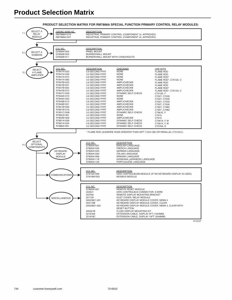
Product Selection Matrix
744 customer.honeywell.com 70-6910
PRODUCT SELECTION MATRIX FOR RM7888A SPECIAL FUNCTION PRIMARY CONTROL RELAY MODULES:
M15523F
SELECT A SUBBASE
SELECTOPTIONAL
COMPONENTS
KEYBOARDDISPLAYMODULE
COMMUNICATIONS
MISCELLANEOUS
SELECT A RELAY
MODULE
120VAC 50/60 HZRM7888A1019RM7888A1027
DESCRIPTIONINDUSTRIAL PRIMARY CONTROL (COMPONENT UL APPROVED)INDUSTRIAL PRIMARY CONTROL (COMPONENT UL APPROVED)
O.S. NO.Q7800A1005Q7800B1003Q7800B1011
DESCRIPTIONPANEL MOUNTBURNER/WALL MOUNTBURNER/WALL MOUNT WITH 3 KNOCKOUTS
O.S. NO.S7800A1001S7800A1035S7800A1043S7800A1050S7800A1068S7800A1118S7800A1126
DESCRIPTIONENGLISH LANGUAGEFRENCH LANGUAGEGERMAN LANGUAGEITALIAN LANGUAGESPANISH LANGUAGEKATAKANA (JAPANESE) LANGUAGEPORTUGUESE LANGUAGE
O.S. NO.S7810A1009S7810M1003
DESCRIPTIONDATA CONTROLBUS® MODULE (IF NO KEYBOARD DISPLAY IS USED)MODBUS MODULE
O.S. NO.S7820A100720354120376522172950023821-001204718B50023821-002
205321B221818A221818C
DESCRIPTIONREMOTE RESET MODULEDATA CONTROLBUS CONNECTOR, 5-WIREREMOTE DISPLAY MOUNTING BRACKETDUST COVER, RELAY MODULEKEYBOARD DISPLAY MODULE COVER, NEMA 4KEYBOARD DISPLAY MODULE COVER, CLEARKEYBOARD DISPLAY MODULE COVER, NEMA 4, CLEAR WITHRESET BUTTONFLUSH DISPLAY MOUNTING KITEXTENSION CABLE, DISPLAY 5FT (1524MM)EXTENSION CABLE, DISPLAY 10FT (3048MM)
O.S. NO.R7847A1025R7847A1033R7847A1074R7847A1082R7847B1023R7847B1031R7847B1064R7847B1072R7847C1005R7849A1015R7849A1023R7849B1013R7849B1021R7851B1000R7851B1018R7851C1008R7852A1001R7852B1009R7861A1026R7861A1034R7886A1001
DESCRIPTION0.8 SECOND FFRT3.0 SECOND FFRT0.8 SECOND FFRT3.0 SECOND FFRT0.8 SECOND FFRT3.0 SECOND FFRT0.8 SECOND FFRT3.0 SECOND FFRT3.0 SECOND FFRT0.8 SECOND FFRT3.0 SECOND FFRT0.8 SECOND FFRT3.0 SECOND FFRT3.0 SECOND FFRT0.8 SECOND FFRT3.0 SECOND FFRT3.0 SECOND FFRT3.0 SECOND FFRT3.0 SECOND FFRT0.8 SECOND FFRT3.0 SECOND FFRT
CHECKINGNONENONENONENONEAMPLICHECK®AMPLICHECK®AMPLICHECK®AMPLICHECK®DYNAMIC SELF-CHECKNONENONEAMPLICHECK®AMPLICHECK®AMPLICHECK®AMPLICHECK®DYNAMIC SELF-CHECKNONEAMPLICHECK®DYNAMIC SELF-CHECKDYNAMIC SELF-CHECKDYNAMIC SELF-CHECK
USE WITHFLAME RODFLAME RODFLAME ROD*FLAME ROD*, C7012A, CFLAME RODFLAME RODFLAME ROD*FLAME ROD*, C7012A, CC7012E, FC7027, C7035C7027, C7035C7027, C7035C7027, C7035C7927, C7962C7927, C7962C7961E, FC7915C7915C7061A, F, MC7061A, F, MC7076A, D
SELECT A FLAME
AMPLIFIER
1.)
2.)
3.)
4.)
* FLAME ROD LEADWIRE RUNS GREATER THAN 50FT (1524 CM) OR PARALLEL C7012A,C.
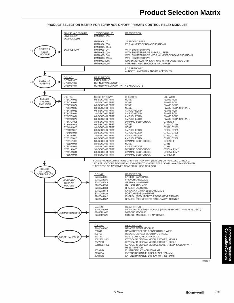
Product Selection Matrix
70-6910 745
Com
mercial / Industrial
Com
bustion Controls
PRODUCT SELECTION MATRIX FOR EC/RM7890 ON/OFF PRIMARY CONTROL RELAY MODULES:
M15524F
SELECT A SUBBASE
SELECTOPTIONAL
COMPONENTS
KEYBOARDDISPLAYMODULE
COMMUNICATIONS
MISCELLANEOUS
SELECT A RELAY
MODULE
220-240 VAC 50/60 HZEC7890A1011EC7890A1029‡
EC7890B1010
120VAC 50/60 HZRM7890A1015
RM7890A1031RM7890A1056RM7890A1064‡RM7890B1014RM7890B1030RM7890B1048RM7890B1055++RM7890C1005RM7890D1004
DESCRIPTION
30 SECOND PFEPFOR VALVE PROVING APPLICATIONS
WITH SHUTTER DRIVEWITH SHUTTER DRIVE AND FULL PFEPWITH SHUTTER DRIVE - FOR VALVE PROVING APPLICATIONSWITH SHUTTER DRIVESTANDING PILOT APPLICATIONS WITH FLAME RODS ONLYINFRARED HEATER ONLY 15 OR 30 PREF
O.S. NO.Q7800A1005Q7800B1003Q7800B1011
DESCRIPTIONPANEL MOUNTBURNER/WALL MOUNTBURNER/WALL MOUNT WITH 3 KNOCKOUTS
O.S. NO.S7800A1001S7800A1035S7800A1043S7800A1050S7800A1068S7800A1118S7800A1126S7800A1142S7800A1167
DESCRIPTIONENGLISH LANGUAGEFRENCH LANGUAGEGERMAN LANGUAGEITALIAN LANGUAGESPANISH LANGUAGEKATAKANA (JAPANESE) LANGUAGEPORTUGUESE LANGUAGEENGLISH (REQUIRED TO PROGRAM VP TIMINGS)SPANISH (REQUIRED TO PROGRAM VP TIMINGS)
O.S. NO.S7810A1009S7810M1003S7810M1029
DESCRIPTIONDATA CONTROLBUS® MODULE (IF NO KEYBOARD DISPLAY IS USED)MODBUS MODULEMODBUS MODULE - CE APPROVED
O.S. NO.S7820A100720354120376522172950023821-001204718B50023821-002
205321B221818A221818C
DESCRIPTIONREMOTE RESET MODULEDATA CONTROLBUS CONNECTOR, 5-WIREREMOTE DISPLAY MOUNTING BRACKETDUST COVER, RELAY MODULEKEYBOARD DISPLAY MODULE COVER, NEMA 4KEYBOARD DISPLAY MODULE COVER, CLEARKEYBOARD DISPLAY MODULE COVER, NEMA 4, CLEAR WITHRESET BUTTONFLUSH DISPLAY MOUNTING KITEXTENSION CABLE, DISPLAY 5FT (1524MM)EXTENSION CABLE, DISPLAY 10FT (3048MM)
O.S. NO.R7847A1025R7847A1033R7847A1074R7847A1082R7847B1023R7847B1031R7847B1064R7847B1072R7847C1005R7849A1015R7849A1023R7849B1013R7849B1021R7851B1000R7851B1018R7851C1008R7852A1001R7852B1009R7861A1026R7861A1034R7886A1001
DESCRIPTION***0.8 SECOND FFRT3.0 SECOND FFRT0.8 SECOND FFRT3.0 SECOND FFRT0.8 SECOND FFRT3.0 SECOND FFRT0.8 SECOND FFRT3.0 SECOND FFRT3.0 SECOND FFRT0.8 SECOND FFRT3.0 SECOND FFRT0.8 SECOND FFRT3.0 SECOND FFRT3.0 SECOND FFRT0.8 SECOND FFRT3.0 SECOND FFRT3.0 SECOND FFRT3.0 SECOND FFRT3.0 SECOND FFRT0.8 SECOND FFRT3.0 SECOND FFRT
CHECKINGNONENONENONENONEAMPLICHECK®AMPLICHECK®AMPLICHECK®AMPLICHECK®DYNAMIC SELF-CHECKNONENONEAMPLICHECK®AMPLICHECK®AMPLICHECK®AMPLICHECK®DYNAMIC SELF-CHECKNONEAMPLICHECK®DYNAMIC SELF-CHECKDYNAMIC SELF-CHECKDYNAMIC SELF-CHECK
USE WITHFLAME RODFLAME RODFLAME ROD*FLAME ROD*, C7012A, CFLAME RODFLAME RODFLAME ROD*FLAME ROD*, C7012A, CC7012E, F**C7027, C7035C7027, C7035C7027, C7035C7027, C7035C7927, C7962C7927, C7962C7961E, FC7915C7915C7061A, F, M**C7061A, F, M**C7076A, D
SELECT A FLAME
AMPLIFIER
1.)
2.)
3.)
4.)
* FLAME ROD LEADWIRE RUNS GREATER THAN 50FT (1524 CM) OR PARALLEL C7012A,C.** EC APPLICATIONS REQUIRE A 220-240 VAC TO 120 VAC, STEP DOWN, 10VA TRANSFORMER.*** FFRT FOR CE APPROVED CONTROLS 1 SEC. OR 2 SEC.
‡ CE APPROVED++ NORTH AMERICAN AND CE APPROVED
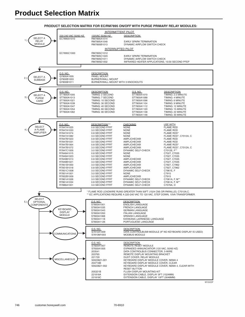
Product Selection Matrix
746 customer.honeywell.com 70-6910
PRODUCT SELECTION MATRIX FOR EC/RM7895 ON/OFF WITH PURGE PRIMARY RELAY MODULES:
M15525F
SELECT A SUBBASE
SELECTOPTIONAL
COMPONENTS
KEYBOARDDISPLAYMODULE
COMMUNICATIONS
MISCELLANEOUS
SELECT A RELAY
MODULE
220-240 VAC 50/60 HZEC7895A1010
EC7895C1000
120VAC 50/60 HZRM7895A1014RM7895A1048RM7895B1013
RM7895C1012RM7895C1020RM7895D1011RM7895E1002
DESCRIPTION
EARLY SPARK TERMINATIONDYNAMIC AIRFLOW SWITCH CHECK
EARLY SPARK TERMINATIONDYNAMIC AIRFLOW SWITCH CHECKINFRARED HEATER APPLICATIONS, 15/30 SECOND PFEP
O.S. NO.Q7800A1005Q7800B1003Q7800B1011
DESCRIPTIONPANEL MOUNTBURNER/WALL MOUNTBURNER/WALL MOUNT WITH 3 KNOCKOUTS
O.S. NO.S7800A1001S7800A1035S7800A1043S7800A1050S7800A1068S7800A1118S7800A1126
DESCRIPTIONENGLISH LANGUAGEFRENCH LANGUAGEGERMAN LANGUAGEITALIAN LANGUAGESPANISH LANGUAGEKATAKANA (JAPANESE) LANGUAGEPORTUGUESE LANGUAGE
O.S. NO.S7810A1009S7810M1003
DESCRIPTIONDATA CONTROLBUS® MODULE (IF NO KEYBOARD DISPLAY IS USED)MODBUS MODULE
O.S. NO.S7820A1007S7830A100520354120376522172950023821-001204718B50023821-002
205321B221818A221818C
DESCRIPTIONREMOTE RESET MODULEEXPANDED ANNUNCIATIOR (120 VAC, 50/60 HZ)DATA CONTROLBUS CONNECTOR, 5-WIREREMOTE DISPLAY MOUNTING BRACKETDUST COVER, RELAY MODULEKEYBOARD DISPLAY MODULE COVER, NEMA 4KEYBOARD DISPLAY MODULE COVER, CLEARKEYBOARD DISPLAY MODULE COVER, NEMA 4, CLEAR WITH RESET BUTTONFLUSH DISPLAY MOUNTING KITEXTENSION CABLE, DISPLAY 5FT (1524MM)EXTENSION CABLE, DISPLAY 10FT (3048MM)
INTERRUPTED PILOT
INTERMITTENT PILOT
SELECT A PURGECARD
O.S. NO.ST7800A1005ST7800A1013ST7800A1021ST7800A1039ST7800A1047ST7800A1054ST7800A1062
DESCRIPTIONTIMING: 2 SECONDTIMING: 7 SECONDTIMING: 10 SECONDTIMING: 30 SECONDTIMING: 40 SECONDTIMING: 60 SECONDTIMING: 90 SECOND
O.S. NO.ST7800A1070ST7800A1088ST7800A1096ST7800A1104ST7800A1112ST7800A1120ST7800A1138ST7800A1146
DESCRIPTIONTIMING: 2.5 MINUTETIMING: 4 MINUTETIMING: 6 MINUTETIMING: 9 MINUTETIMING: 12 MINUTETIMING: 15 MINUTETIMING: 22 MINUTETIMING: 30 MINUTE
O.S. NO.R7847A1025R7847A1033R7847A1074R7847A1082R7847B1023R7847B1031R7847B1064R7847B1072R7847C1005R7849A1015R7849A1023R7849B1013R7849B1021R7851B1000R7851B1018R7851C1008R7851A1001R7852B1009R7861A1026R7861A1034R7886A1001
DESCRIPTION***0.8 SECOND FFRT3.0 SECOND FFRT0.8 SECOND FFRT3.0 SECOND FFRT0.8 SECOND FFRT3.0 SECOND FFRT0.8 SECOND FFRT3.0 SECOND FFRT3.0 SECOND FFRT0.8 SECOND FFRT3.0 SECOND FFRT0.8 SECOND FFRT3.0 SECOND FFRT3.0 SECOND FFRT0.8 SECOND FFRT3.0 SECOND FFRT3.0 SECOND FFRT3.0 SECOND FFRT3.0 SECOND FFRT0.8 SECOND FFRT3.0 SECOND FFRT
CHECKINGNONENONENONENONEAMPLICHECK®AMPLICHECK®AMPLICHECK®AMPLICHECK®DYNAMIC SELF-CHECKNONENONEAMPLICHECK®AMPLICHECK®AMPLICHECK®AMPLICHECK®DYNAMIC SELF-CHECKNONEAMPLICHECK®DYNAMIC SELF-CHECKDYNAMIC SELF-CHECKDYNAMIC SELF-CHECK
USE WITHFLAME RODFLAME RODFLAME ROD*FLAME ROD*, C7012A, CFLAME RODFLAME RODFLAME ROD*FLAME ROD*, C7012A, CC7012E, F**C7027, C7035C7027, C7035C7027, C7035C7027, C7035C7927, C7962C7927, C7962C7961E, FC7915C7915C7061A, F, M**C7061A, F, M**C7076A, D
SELECT A FLAME
AMPLIFIER
1.)
2.)
3.)
4.)
5.)
* FLAME ROD LEADWIRE RUNS GREATER THAN 50FT (1524 CM) OR PARALLEL C7012A,C.** EC APPLICATIONS REQUIRE A 220-240 VAC TO 120 VAC, STEP DOWN, 10VA TRANSFORMER.
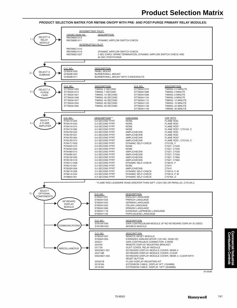
Product Selection Matrix
70-6910 747
Com
mercial / Industrial
Com
bustion Controls
PRODUCT SELECTION MATRIX FOR RM7896 ON/OFF WITH PRE- AND POST-PURGE PRIMARY RELAY MODULES:
M13908B
SELECT A SUBBASE
SELECTOPTIONAL
COMPONENTS
KEYBOARDDISPLAYMODULE
COMMUNICATIONS
MISCELLANEOUS
SELECT A RELAY
MODULE
120VAC 50/60 HZRM7896A1012RM7896B1011
RM7896C1010RM7896D1019RM7896D1027
DESCRIPTION
DYNAMIC AIRFLOW SWITCH CHECK
DYNAMIC AIRFLOW SWITCH CHECK5 SEC EARLY SPARK TERMINATION, DYNAMIC AIRFLOW SWITCH CHECK AND60 SEC POST-PURGE
O.S. NO.Q7800A1005Q7800B1003Q7800B1011
DESCRIPTIONPANEL MOUNTBURNER/WALL MOUNTBURNER/WALL MOUNT WITH 3 KNOCKOUTS
O.S. NO.S7800A1001S7800A1035S7800A1043S7800A1050S7800A1068S7800A1118S7800A1126
DESCRIPTIONENGLISH LANGUAGEFRENCH LANGUAGEGERMAN LANGUAGEITALIAN LANGUAGESPANISH LANGUAGEKATAKANA (JAPANESE) LANGUAGEPORTUGUESE LANGUAGE
O.S. NO.S7810A1009S7810M1003
DESCRIPTIONDATA CONTROLBUS® MODULE (IF NO KEYBOARD DISPLAY IS USED)MODBUS MODULE
O.S. NO.S7820A1007S7830A100520354120376522172950023821-001204718B50023821-002
205321B221818A221818C
DESCRIPTIONREMOTE RESET MODULEEXPANDED ANNUNCIATIOR (120 VAC, 50/60 HZ)DATA CONTROLBUS CONNECTOR, 5-WIREREMOTE DISPLAY MOUNTING BRACKETDUST COVER, RELAY MODULEKEYBOARD DISPLAY MODULE COVER, NEMA 4KEYBOARD DISPLAY MODULE COVER, CLEARKEYBOARD DISPLAY MODULE COVER, NEMA 4, CLEAR WITH RESET BUTTONFLUSH DISPLAY MOUNTING KITEXTENSION CABLE, DISPLAY 5FT (1524MM)EXTENSION CABLE, DISPLAY 10FT (3048MM)
INTERRUPTED PILOT
INTERMITTENT PILOT
SELECT A PURGECARD
O.S. NO.ST7800A1005ST7800A1013ST7800A1021ST7800A1039ST7800A1047ST7800A1054ST7800A1062
DESCRIPTIONTIMING: 2 SECONDTIMING: 7 SECONDTIMING: 10 SECONDTIMING: 30 SECONDTIMING: 40 SECONDTIMING: 60 SECONDTIMING: 90 SECOND
O.S. NO.ST7800A1070ST7800A1088ST7800A1096ST7800A1104ST7800A1112ST7800A1120ST7800A1138ST7800A1146
DESCRIPTIONTIMING: 2.5 MINUTETIMING: 4 MINUTETIMING: 6 MINUTETIMING: 9 MINUTETIMING: 12 MINUTETIMING: 15 MINUTETIMING: 22 MINUTETIMING: 30 MINUTE
O.S. NO.R7847A1025R7847A1033R7847A1074R7847A1082R7847B1023R7847B1031R7847B1064R7847B1072R7847C1005R7849A1015R7849A1023R7849B1013R7849B1021R7851B1000R7851B1018R7851C1008R7851A1001R7852B1009R7861A1026R7861A1034R7886A1001
DESCRIPTION***0.8 SECOND FFRT3.0 SECOND FFRT0.8 SECOND FFRT3.0 SECOND FFRT0.8 SECOND FFRT3.0 SECOND FFRT0.8 SECOND FFRT3.0 SECOND FFRT3.0 SECOND FFRT0.8 SECOND FFRT3.0 SECOND FFRT0.8 SECOND FFRT3.0 SECOND FFRT3.0 SECOND FFRT0.8 SECOND FFRT3.0 SECOND FFRT3.0 SECOND FFRT3.0 SECOND FFRT3.0 SECOND FFRT0.8 SECOND FFRT3.0 SECOND FFRT
CHECKINGNONENONENONENONEAMPLICHECK®AMPLICHECK®AMPLICHECK®AMPLICHECK®DYNAMIC SELF-CHECKNONENONEAMPLICHECK®AMPLICHECK®AMPLICHECK®AMPLICHECK®DYNAMIC SELF-CHECKNONEAMPLICHECK®DYNAMIC SELF-CHECKDYNAMIC SELF-CHECKDYNAMIC SELF-CHECK
USE WITHFLAME RODFLAME RODFLAME ROD*FLAME ROD*, C7012A, CFLAME RODFLAME RODFLAME ROD*FLAME ROD*, C7012A, CC7012E, FC7027, C7035C7027, C7035C7027, C7035C7027, C7035C7927, C7962C7927, C7962C7961E, FC7915C7915C7061A, F, MC7061A, F, MC7076A, D
SELECT A FLAME
AMPLIFIER
1.)
2.)
3.)
4.)
5.)
* FLAME ROD LEADWIRE RUNS GREATER THAN 50FT (1524 CM) OR PARALLEL C7012A,C.
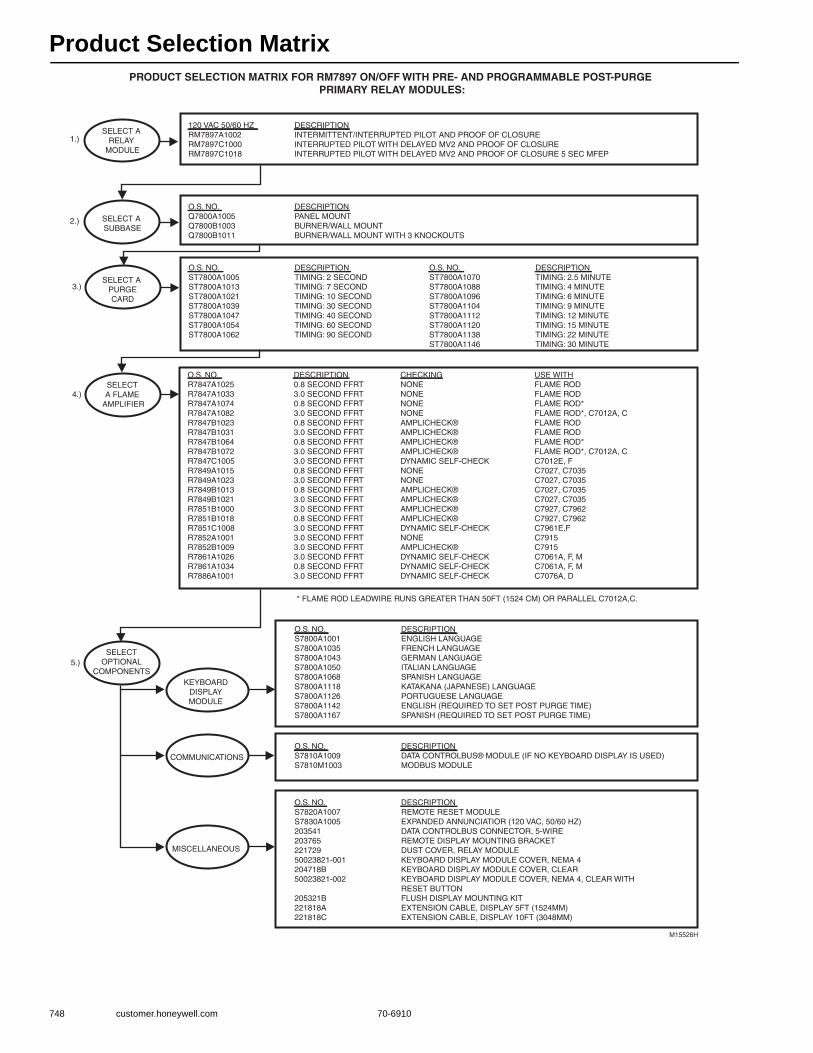
Product Selection Matrix
748 customer.honeywell.com 70-6910
PRODUCT SELECTION MATRIX FOR RM7897 ON/OFF WITH PRE- AND PROGRAMMABLE POST-PURGE PRIMARY RELAY MODULES:
M15526H
SELECT A SUBBASE
SELECTOPTIONAL
COMPONENTSKEYBOARD
DISPLAYMODULE
COMMUNICATIONS
MISCELLANEOUS
SELECT A RELAY
MODULE
O.S. NO.Q7800A1005Q7800B1003Q7800B1011
DESCRIPTIONPANEL MOUNTBURNER/WALL MOUNTBURNER/WALL MOUNT WITH 3 KNOCKOUTS
DESCRIPTIONINTERMITTENT/INTERRUPTED PILOT AND PROOF OF CLOSUREINTERRUPTED PILOT WITH DELAYED MV2 AND PROOF OF CLOSUREINTERRUPTED PILOT WITH DELAYED MV2 AND PROOF OF CLOSURE 5 SEC MFEP
O.S. NO.S7800A1001S7800A1035S7800A1043S7800A1050S7800A1068S7800A1118S7800A1126S7800A1142S7800A1167
DESCRIPTIONENGLISH LANGUAGEFRENCH LANGUAGEGERMAN LANGUAGEITALIAN LANGUAGESPANISH LANGUAGEKATAKANA (JAPANESE) LANGUAGEPORTUGUESE LANGUAGEENGLISH (REQUIRED TO SET POST PURGE TIME)SPANISH (REQUIRED TO SET POST PURGE TIME)
O.S. NO.S7810A1009S7810M1003
DESCRIPTIONDATA CONTROLBUS® MODULE (IF NO KEYBOARD DISPLAY IS USED)MODBUS MODULE
O.S. NO.S7820A1007S7830A100520354120376522172950023821-001204718B50023821-002
205321B221818A221818C
DESCRIPTIONREMOTE RESET MODULEEXPANDED ANNUNCIATIOR (120 VAC, 50/60 HZ)DATA CONTROLBUS CONNECTOR, 5-WIREREMOTE DISPLAY MOUNTING BRACKETDUST COVER, RELAY MODULEKEYBOARD DISPLAY MODULE COVER, NEMA 4KEYBOARD DISPLAY MODULE COVER, CLEARKEYBOARD DISPLAY MODULE COVER, NEMA 4, CLEAR WITHRESET BUTTONFLUSH DISPLAY MOUNTING KITEXTENSION CABLE, DISPLAY 5FT (1524MM)EXTENSION CABLE, DISPLAY 10FT (3048MM)
SELECT A PURGECARD
O.S. NO.ST7800A1005ST7800A1013ST7800A1021ST7800A1039ST7800A1047ST7800A1054ST7800A1062
DESCRIPTIONTIMING: 2 SECONDTIMING: 7 SECONDTIMING: 10 SECONDTIMING: 30 SECONDTIMING: 40 SECONDTIMING: 60 SECONDTIMING: 90 SECOND
O.S. NO.ST7800A1070ST7800A1088ST7800A1096ST7800A1104ST7800A1112ST7800A1120ST7800A1138ST7800A1146
DESCRIPTIONTIMING: 2.5 MINUTETIMING: 4 MINUTETIMING: 6 MINUTETIMING: 9 MINUTETIMING: 12 MINUTETIMING: 15 MINUTETIMING: 22 MINUTETIMING: 30 MINUTE
120 VAC 50/60 HZRM7897A1002RM7897C1000RM7897C1018
O.S. NO.R7847A1025R7847A1033R7847A1074R7847A1082R7847B1023R7847B1031R7847B1064R7847B1072R7847C1005R7849A1015R7849A1023R7849B1013R7849B1021R7851B1000R7851B1018R7851C1008R7852A1001R7852B1009R7861A1026R7861A1034R7886A1001
DESCRIPTION0.8 SECOND FFRT3.0 SECOND FFRT0.8 SECOND FFRT3.0 SECOND FFRT0.8 SECOND FFRT3.0 SECOND FFRT0.8 SECOND FFRT3.0 SECOND FFRT3.0 SECOND FFRT0.8 SECOND FFRT3.0 SECOND FFRT0.8 SECOND FFRT3.0 SECOND FFRT3.0 SECOND FFRT0.8 SECOND FFRT3.0 SECOND FFRT3.0 SECOND FFRT3.0 SECOND FFRT3.0 SECOND FFRT0.8 SECOND FFRT3.0 SECOND FFRT
CHECKINGNONENONENONENONEAMPLICHECK®AMPLICHECK®AMPLICHECK®AMPLICHECK®DYNAMIC SELF-CHECKNONENONEAMPLICHECK®AMPLICHECK®AMPLICHECK®AMPLICHECK®DYNAMIC SELF-CHECKNONEAMPLICHECK®DYNAMIC SELF-CHECKDYNAMIC SELF-CHECKDYNAMIC SELF-CHECK
USE WITHFLAME RODFLAME RODFLAME ROD*FLAME ROD*, C7012A, CFLAME RODFLAME RODFLAME ROD*FLAME ROD*, C7012A, CC7012E, FC7027, C7035C7027, C7035C7027, C7035C7027, C7035C7927, C7962C7927, C7962C7961E,FC7915C7915C7061A, F, MC7061A, F, MC7076A, D
SELECT A FLAME
AMPLIFIER
1.)
2.)
3.)
4.)
5.)
* FLAME ROD LEADWIRE RUNS GREATER THAN 50FT (1524 CM) OR PARALLEL C7012A,C.

Product Selection Matrix
70-6910 749
Com
mercial / Industrial
Com
bustion Controls
PRODUCT SELECTION MATRIX FOR RM7898 ON/OFF WITH PRE- AND PROGRAMMABLE POST-PURGE PRIMARY RELAY MODULES FOR VALVE PROVING APPLICATIONS:
M23254C
SELECT A SUBBASE
SELECTOPTIONAL
COMPONENTS
KEYBOARDDISPLAYMODULE
COMMUNICATIONS
MISCELLANEOUS
SELECT A RELAY
MODULE
O.S. NO.Q7800A1005Q7800B1003Q7800B1011
DESCRIPTIONPANEL MOUNTBURNER/WALL MOUNTBURNER/WALL MOUNT WITH 3 KNOCKOUTS
DESCRIPTIONINTERMITTENT/INTERRUPTED PILOT AND PROOF OF CLOSUREINTERMITTENT/INTERRUPTED PILOT WITH EARLY SPARK TERMINATION AND PROOF OF CLOSURE
O.S. NO.S7800A1001S7800A1035S7800A1043S7800A1050S7800A1068S7800A1118S7800A1126S7800A1142S7800A1167
DESCRIPTIONENGLISH LANGUAGEFRENCH LANGUAGEGERMAN LANGUAGEITALIAN LANGUAGESPANISH LANGUAGEKATAKANA (JAPANESE) LANGUAGEPORTUGUESE LANGUAGEENGLISH (REQUIRED TO PROGRAM POST PURGE AND VP TIMINGS)SPANISH (REQUIRED TO PROGRAM POST PURGE AND VP TIMINGS)
O.S. NO.S7810A1009S7810M1003
DESCRIPTIONDATA CONTROLBUS® MODULE (IF NO KEYBOARD DISPLAY IS USED)MODBUS MODULE
O.S. NO.S7820A1007S7830A100520354120376522172950023821-001204718B50023821-002
205321B221818A221818C
DESCRIPTIONREMOTE RESET MODULEEXPANDED ANNUNCIATIOR (120 VAC, 50/60 HZ)DATA CONTROLBUS CONNECTOR, 5-WIREREMOTE DISPLAY MOUNTING BRACKETDUST COVER, RELAY MODULEKEYBOARD DISPLAY MODULE COVER, NEMA 4KEYBOARD DISPLAY MODULE COVER, CLEARKEYBOARD DISPLAY MODULE COVER, NEMA 4, CLEAR WITHRESET BUTTONFLUSH DISPLAY MOUNTING KITEXTENSION CABLE, DISPLAY 5FT (1524MM)EXTENSION CABLE, DISPLAY 10FT (3048MM)
SELECT A PURGECARD
O.S. NO.ST7800A1005ST7800A1013ST7800A1021ST7800A1039ST7800A1047ST7800A1054ST7800A1062
DESCRIPTIONTIMING: 2 SECONDTIMING: 7 SECONDTIMING: 10 SECONDTIMING: 30 SECONDTIMING: 40 SECONDTIMING: 60 SECONDTIMING: 90 SECOND
O.S. NO.ST7800A1070ST7800A1088ST7800A1096ST7800A1104ST7800A1112ST7800A1120ST7800A1138ST7800A1146
DESCRIPTIONTIMING: 2.5 MINUTETIMING: 4 MINUTETIMING: 6 MINUTETIMING: 9 MINUTETIMING: 12 MINUTETIMING: 15 MINUTETIMING: 22 MINUTETIMING: 30 MINUTE
120 VAC 50/60 HZRM7898A1000RM7898A1018
O.S. NO.R7847A1025R7847A1033R7847A1074R7847A1082R7847B1023R7847B1031R7847B1064R7847B1072R7847C1005R7849A1015R7849A1023R7849B1013R7849B1021R7851B1000R7851B1018R7851C1008R7852A1001R7852B1009R7861A1026R7861A1034R7886A1001
DESCRIPTION0.8 SECOND FFRT3.0 SECOND FFRT0.8 SECOND FFRT3.0 SECOND FFRT0.8 SECOND FFRT3.0 SECOND FFRT0.8 SECOND FFRT3.0 SECOND FFRT3.0 SECOND FFRT0.8 SECOND FFRT3.0 SECOND FFRT0.8 SECOND FFRT3.0 SECOND FFRT3.0 SECOND FFRT0.8 SECOND FFRT3.0 SECOND FFRT3.0 SECOND FFRT3.0 SECOND FFRT3.0 SECOND FFRT0.8 SECOND FFRT3.0 SECOND FFRT
CHECKINGNONENONENONENONEAMPLICHECK®AMPLICHECK®AMPLICHECK®AMPLICHECK®DYNAMIC SELF-CHECKNONENONEAMPLICHECK®AMPLICHECK®AMPLICHECK®AMPLICHECK®DYNAMIC SELF-CHECKNONEAMPLICHECK®DYNAMIC SELF-CHECKDYNAMIC SELF-CHECKDYNAMIC SELF-CHECK
USE WITHFLAME RODFLAME RODFLAME ROD*FLAME ROD*, C7012A, CFLAME RODFLAME RODFLAME ROD*FLAME ROD*, C7012A, CC7012E, FC7027, C7035C7027, C7035C7027, C7035C7027, C7035C7927, C7962C7927, C7962C7961E,FC7915C7915C7061A, F, MC7061A, F, MC7076A, D
SELECT A FLAME
AMPLIFIER
1.)
2.)
3.)
4.)
5.)
* FLAME ROD LEADWIRE RUNS GREATER THAN 50FT (1524 CM) OR PARALLEL C7012A,C.
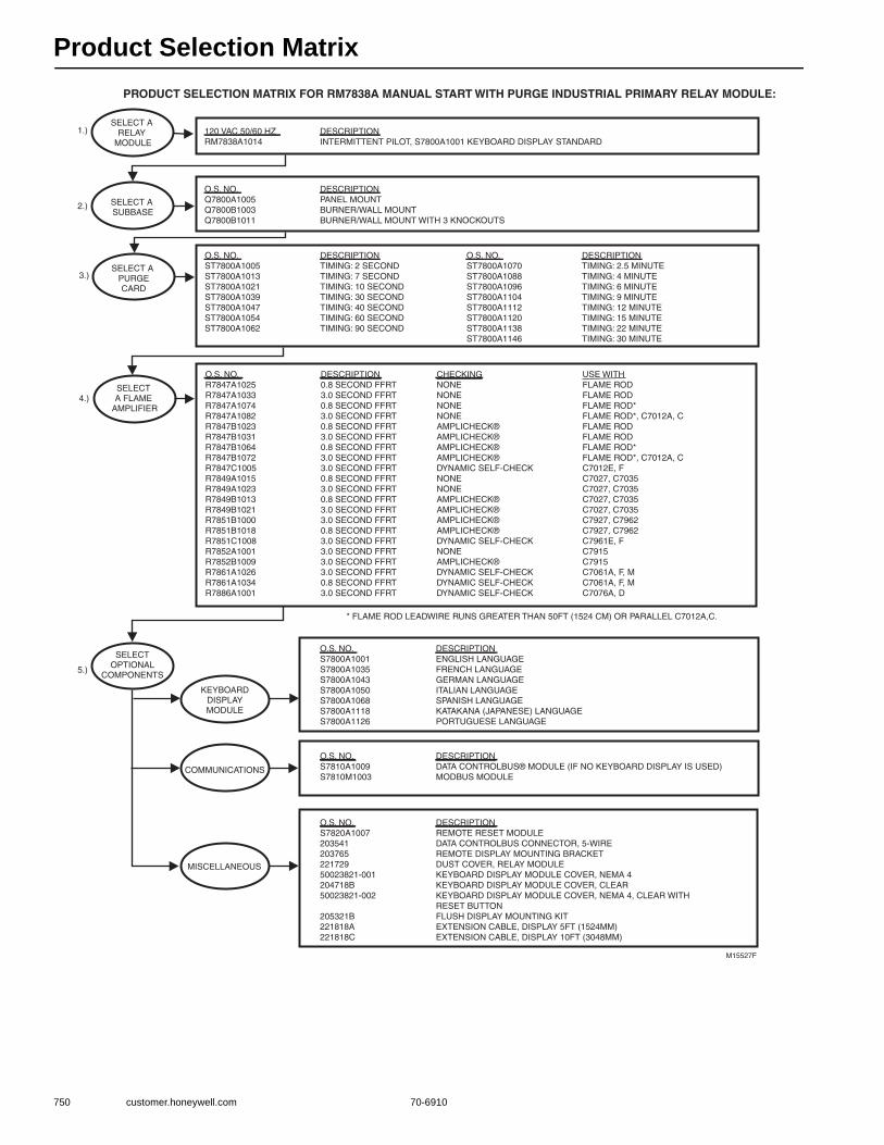
Product Selection Matrix
750 customer.honeywell.com 70-6910
PRODUCT SELECTION MATRIX FOR RM7838A MANUAL START WITH PURGE INDUSTRIAL PRIMARY RELAY MODULE:
M15527F
SELECT A SUBBASE
SELECTOPTIONAL
COMPONENTS
KEYBOARDDISPLAYMODULE
COMMUNICATIONS
MISCELLANEOUS
SELECT A RELAY
MODULE
O.S. NO.Q7800A1005Q7800B1003Q7800B1011
DESCRIPTIONPANEL MOUNTBURNER/WALL MOUNTBURNER/WALL MOUNT WITH 3 KNOCKOUTS
DESCRIPTIONINTERMITTENT PILOT, S7800A1001 KEYBOARD DISPLAY STANDARD
O.S. NO.S7800A1001S7800A1035S7800A1043S7800A1050S7800A1068S7800A1118S7800A1126
DESCRIPTIONENGLISH LANGUAGEFRENCH LANGUAGEGERMAN LANGUAGEITALIAN LANGUAGESPANISH LANGUAGEKATAKANA (JAPANESE) LANGUAGEPORTUGUESE LANGUAGE
O.S. NO.S7810A1009S7810M1003
DESCRIPTIONDATA CONTROLBUS® MODULE (IF NO KEYBOARD DISPLAY IS USED)MODBUS MODULE
O.S. NO.S7820A100720354120376522172950023821-001204718B50023821-002
205321B221818A221818C
DESCRIPTIONREMOTE RESET MODULEDATA CONTROLBUS CONNECTOR, 5-WIREREMOTE DISPLAY MOUNTING BRACKETDUST COVER, RELAY MODULEKEYBOARD DISPLAY MODULE COVER, NEMA 4KEYBOARD DISPLAY MODULE COVER, CLEARKEYBOARD DISPLAY MODULE COVER, NEMA 4, CLEAR WITHRESET BUTTONFLUSH DISPLAY MOUNTING KITEXTENSION CABLE, DISPLAY 5FT (1524MM)EXTENSION CABLE, DISPLAY 10FT (3048MM)
SELECT A PURGECARD
O.S. NO.ST7800A1005ST7800A1013ST7800A1021ST7800A1039ST7800A1047ST7800A1054ST7800A1062
DESCRIPTIONTIMING: 2 SECONDTIMING: 7 SECONDTIMING: 10 SECONDTIMING: 30 SECONDTIMING: 40 SECONDTIMING: 60 SECONDTIMING: 90 SECOND
O.S. NO.ST7800A1070ST7800A1088ST7800A1096ST7800A1104ST7800A1112ST7800A1120ST7800A1138ST7800A1146
DESCRIPTIONTIMING: 2.5 MINUTETIMING: 4 MINUTETIMING: 6 MINUTETIMING: 9 MINUTETIMING: 12 MINUTETIMING: 15 MINUTETIMING: 22 MINUTETIMING: 30 MINUTE
120 VAC 50/60 HZRM7838A1014
O.S. NO.R7847A1025R7847A1033R7847A1074R7847A1082R7847B1023R7847B1031R7847B1064R7847B1072R7847C1005R7849A1015R7849A1023R7849B1013R7849B1021R7851B1000R7851B1018R7851C1008R7852A1001R7852B1009R7861A1026R7861A1034R7886A1001
DESCRIPTION0.8 SECOND FFRT3.0 SECOND FFRT0.8 SECOND FFRT3.0 SECOND FFRT0.8 SECOND FFRT3.0 SECOND FFRT0.8 SECOND FFRT3.0 SECOND FFRT3.0 SECOND FFRT0.8 SECOND FFRT3.0 SECOND FFRT0.8 SECOND FFRT3.0 SECOND FFRT3.0 SECOND FFRT0.8 SECOND FFRT3.0 SECOND FFRT3.0 SECOND FFRT3.0 SECOND FFRT3.0 SECOND FFRT0.8 SECOND FFRT3.0 SECOND FFRT
CHECKINGNONENONENONENONEAMPLICHECK®AMPLICHECK®AMPLICHECK®AMPLICHECK®DYNAMIC SELF-CHECKNONENONEAMPLICHECK®AMPLICHECK®AMPLICHECK®AMPLICHECK®DYNAMIC SELF-CHECKNONEAMPLICHECK®DYNAMIC SELF-CHECKDYNAMIC SELF-CHECKDYNAMIC SELF-CHECK
USE WITHFLAME RODFLAME RODFLAME ROD*FLAME ROD*, C7012A, CFLAME RODFLAME RODFLAME ROD*FLAME ROD*, C7012A, CC7012E, FC7027, C7035C7027, C7035C7027, C7035C7027, C7035C7927, C7962C7927, C7962C7961E, FC7915C7915C7061A, F, MC7061A, F, MC7076A, D
SELECT A FLAME
AMPLIFIER
1.)
2.)
3.)
4.)
5.)
* FLAME ROD LEADWIRE RUNS GREATER THAN 50FT (1524 CM) OR PARALLEL C7012A,C.

Product Selection Matrix
70-6910 751
Com
mercial / Industrial
Com
bustion Controls
PRODUCT SELECTION MATRIX FOR RM7838B MANUAL START INDUSTRIAL PROGRAMMER RELAY MODULE:
SELECT A SUBBASE
SELECTOPTIONAL
COMPONENTSKEYBOARD
DISPLAYMODULE
COMMUNICATIONS
MISCELLANEOUS
SELECT A RELAY
MODULE
O.S. NO.Q7800A1005Q7800B1003Q7800B1011
DESCRIPTIONPANEL MOUNTBURNER/WALL MOUNTBURNER/WALL MOUNT WITH 3 KNOCKOUTS
DESCRIPTIONSEMI-AUTOMATIC PROGRAMMER WITH: S7800A1001 KEYBOARD DISPLAY STANDARD S7800A1142 KEYBOARD DISPLAY STANDARD - HAS VALVE PROVING FEATURE
O.S. NO.R7847A1025R7847A1033R7847A1074R7847A1082R7847B1023R7847B1031R7847B1064R7847B1072R7847C1005R7849A1015R7849A1023R7849B1013R7849B1021R7851B1000R7851B1018R7851C1008R7852A1001R7852B1009R7861A1026R7861A1034R7886A1001
DESCRIPTION0.8 SECOND FFRT3.0 SECOND FFRT0.8 SECOND FFRT3.0 SECOND FFRT0.8 SECOND FFRT3.0 SECOND FFRT0.8 SECOND FFRT3.0 SECOND FFRT3.0 SECOND FFRT0.8 SECOND FFRT3.0 SECOND FFRT0.8 SECOND FFRT3.0 SECOND FFRT3.0 SECOND FFRT0.8 SECOND FFRT3.0 SECOND FFRT3.0 SECOND FFRT3.0 SECOND FFRT3.0 SECOND FFRT0.8 SECOND FFRT3.0 SECOND FFRT
CHECKINGNONENONENONENONEAMPLICHECK®AMPLICHECK®AMPLICHECK®AMPLICHECK®DYNAMIC SELF-CHECKNONENONEAMPLICHECK®AMPLICHECK®AMPLICHECK®AMPLICHECK®DYNAMIC SELF-CHECKNONEAMPLICHECK®DYNAMIC SELF-CHECKDYNAMIC SELF-CHECKDYNAMIC SELF-CHECK
M15528F
O.S. NO.S7800A1001S7800A1035S7800A1043S7800A1050S7800A1068S7800A1118S7800A1126
DESCRIPTIONENGLISH LANGUAGEFRENCH LANGUAGEGERMAN LANGUAGEITALIAN LANGUAGESPANISH LANGUAGEKATAKANA (JAPANESE) LANGUAGEPORTUGUESE LANGUAGE
O.S. NO.S7810A1009S7810M1003
DESCRIPTIONDATA CONTROLBUS® MODULE (IF NO KEYBOARD DISPLAY IS USED)MODBUS MODULE
O.S. NO.S7820A1007S7830A100520354120376522172950023821-001204718B50023821-002
205321B221818A221818C
DESCRIPTIONREMOTE RESET MODULEEXPANDED ANNUNCIATIOR (120 VAC, 50/60 HZ)DATA CONTROLBUS CONNECTOR, 5-WIREREMOTE DISPLAY MOUNTING BRACKETDUST COVER, RELAY MODULEKEYBOARD DISPLAY MODULE COVER, NEMA 4KEYBOARD DISPLAY MODULE COVER, CLEARKEYBOARD DISPLAY MODULE COVER, NEMA 4, CLEAR WITHRESET BUTTONFLUSH DISPLAY MOUNTING KITEXTENSION CABLE, DISPLAY 5FT (1524MM)EXTENSION CABLE, DISPLAY 10FT (3048MM)
USE WITHFLAME RODFLAME RODFLAME ROD*FLAME ROD*, C7012A, CFLAME RODFLAME RODFLAME ROD*FLAME ROD*, C7012A, CC7012E, FC7027, C7035C7027, C7035C7027, C7035C7027, C7035C7927, C7962C7927, C7962C7961E,FC7915C7915C7061A, F, MC7061A, F, MC7076A, D
SELECT A PURGECARD
O.S. NO.ST7800A1005ST7800A1013ST7800A1021ST7800A1039ST7800A1047ST7800A1054ST7800A1062
DESCRIPTIONTIMING: 2 SECONDTIMING: 7 SECONDTIMING: 10 SECONDTIMING: 30 SECONDTIMING: 40 SECONDTIMING: 60 SECONDTIMING: 90 SECOND
O.S. NO.ST7800A1070ST7800A1088ST7800A1096ST7800A1104ST7800A1112ST7800A1120ST7800A1138ST7800A1146
DESCRIPTIONTIMING: 2.5 MINUTETIMING: 4 MINUTETIMING: 6 MINUTETIMING: 9 MINUTETIMING: 12 MINUTETIMING: 15 MINUTETIMING: 22 MINUTETIMING: 30 MINUTE
120 VAC 50/60 HZ
RM7838B1013*RM7838B1021*
SELECT A FLAME
AMPLIFIER
1.)
2.)
3.)
4.)
5.)
* ALARM SOUNDS UNTIL FLAME SENSED
* FLAME ROD LEADWIRE RUNS GREATER THAN 50FT (1524 CM) OR PARALLEL C7012A,C.
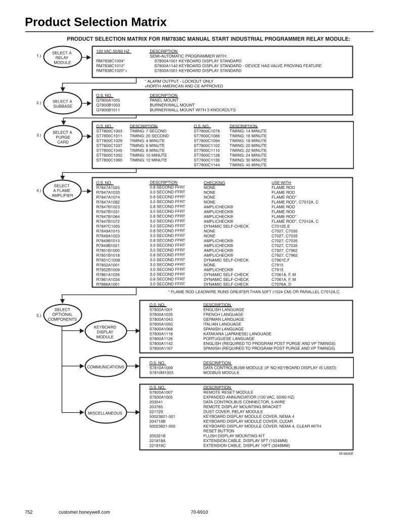
Product Selection Matrix
752 customer.honeywell.com 70-6910
PRODUCT SELECTION MATRIX FOR RM7838C MANUAL START INDUSTRIAL PROGRAMMER RELAY MODULE:
SELECT A SUBBASE
SELECTOPTIONAL
COMPONENTS
KEYBOARDDISPLAYMODULE
COMMUNICATIONS
MISCELLANEOUS
SELECT A RELAY
MODULE
O.S. NO.Q7800A1005Q7800B1003Q7800B1011
DESCRIPTIONPANEL MOUNTBURNER/WALL MOUNTBURNER/WALL MOUNT WITH 3 KNOCKOUTS
DESCRIPTIONSEMI-AUTOMATIC PROGRAMMER WITH: S7800A1001 KEYBOARD DISPLAY STANDARD S7800A1142 KEYBOARD DISPLAY STANDARD - DEVICE HAS VALVE PROVING FEATURE S7800A1001 KEYBOARD DISPLAY STANDARD
O.S. NO.R7847A1025R7847A1033R7847A1074R7847A1082R7847B1023R7847B1031R7847B1064R7847B1072R7847C1005R7849A1015R7849A1023R7849B1013R7849B1021R7851B1000R7851B1018R7851C1008R7852A1001R7852B1009R7861A1026R7861A1034R7886A1001
DESCRIPTION0.8 SECOND FFRT3.0 SECOND FFRT0.8 SECOND FFRT3.0 SECOND FFRT0.8 SECOND FFRT3.0 SECOND FFRT0.8 SECOND FFRT3.0 SECOND FFRT3.0 SECOND FFRT0.8 SECOND FFRT3.0 SECOND FFRT0.8 SECOND FFRT3.0 SECOND FFRT3.0 SECOND FFRT0.8 SECOND FFRT3.0 SECOND FFRT3.0 SECOND FFRT3.0 SECOND FFRT3.0 SECOND FFRT0.8 SECOND FFRT3.0 SECOND FFRT
CHECKINGNONENONENONENONEAMPLICHECK®AMPLICHECK®AMPLICHECK®AMPLICHECK®DYNAMIC SELF-CHECKNONENONEAMPLICHECK®AMPLICHECK®AMPLICHECK®AMPLICHECK®DYNAMIC SELF-CHECKNONEAMPLICHECK®DYNAMIC SELF-CHECKDYNAMIC SELF-CHECKDYNAMIC SELF-CHECK
M18830E
O.S. NO.S7800A1001S7800A1035S7800A1043S7800A1050S7800A1068S7800A1118S7800A1126S7800A1142S7800A1167
DESCRIPTIONENGLISH LANGUAGEFRENCH LANGUAGEGERMAN LANGUAGEITALIAN LANGUAGESPANISH LANGUAGEKATAKANA (JAPANESE) LANGUAGEPORTUGUESE LANGUAGEENGLISH (REQUIRED TO PROGRAM POST PURGE AND VP TIMINGS)SPANISH (REQUIRED TO PROGRAM POST PURGE AND VP TIMINGS)
O.S. NO.S7810A1009S7810M1003
DESCRIPTIONDATA CONTROLBUS® MODULE (IF NO KEYBOARD DISPLAY IS USED)MODBUS MODULE
O.S. NO.S7820A1007S7830A100520354120376522172950023821-001204718B50023821-002
205321B221818A221818C
DESCRIPTIONREMOTE RESET MODULEEXPANDED ANNUNCIATIOR (120 VAC, 50/60 HZ)DATA CONTROLBUS CONNECTOR, 5-WIREREMOTE DISPLAY MOUNTING BRACKETDUST COVER, RELAY MODULEKEYBOARD DISPLAY MODULE COVER, NEMA 4KEYBOARD DISPLAY MODULE COVER, CLEARKEYBOARD DISPLAY MODULE COVER, NEMA 4, CLEAR WITHRESET BUTTONFLUSH DISPLAY MOUNTING KITEXTENSION CABLE, DISPLAY 5FT (1524MM)EXTENSION CABLE, DISPLAY 10FT (3048MM)
USE WITHFLAME RODFLAME RODFLAME ROD*FLAME ROD*, C7012A, CFLAME RODFLAME RODFLAME ROD*FLAME ROD*, C7012A, CC7012E,E C7027, C7035C7027, C7035C7027, C7035C7027, C7035C7927, C7962C7927, C7962C7961E,FC7915C7915C7061A, F, MC7061A, F, MC7076A, D
SELECT A PURGECARD
O.S. NO.ST7800C1003ST7800C1011ST7800C1029ST7800C1037ST7800C1045ST7800C1052ST7800C1060
DESCRIPTIONTIMING: 7 SECONDTIMING: 20 SECONDTIMING: 4 MINUTETIMING: 6 MINUTETIMING: 8 MINUTETIMING: 10 MINUTETIMING: 12 MINUTE
O.S. NO.ST7800C1078ST7800C1086ST7800C1094ST7800C1102ST7800C1110ST7800C1128ST7800C1136ST7800C1144
DESCRIPTIONTIMING: 14 MINUTETIMING: 16 MINUTETIMING: 18 MINUTETIMING: 20 MINUTETIMING: 22 MINUTETIMING: 24 MINUTETIMING: 30 MINUTETIMING: 45 MINUTE
120 VAC 50/60 HZ
RM7838C1004*RM7838C1012*RM7838C1020*+
SELECT A FLAME
AMPLIFIER
1.)
2.)
3.)
4.)
5.)
* ALARM OUTPUT - LOCKOUT ONLY+NORTH AMERICAN AND CE APPROVED
* FLAME ROD LEADWIRE RUNS GREATER THAN 50FT (1524 CM) OR PARALLEL C7012A,C.
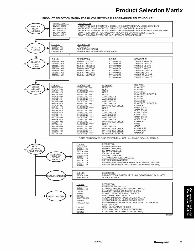
Product Selection Matrix
70-6910 753
Com
mercial / Industrial
Com
bustion Controls
PRODUCT SELECTION MATRIX FOR UL/CSA RM78XXG,M PROGRAMMER RELAY MODULE:
M15529F
SELECT A SUBBASE
SELECTOPTIONAL
COMPONENTS
KEYBOARDDISPLAYMODULE
COMMUNICATIONS
MISCELLANEOUS
SELECT A RELAY
MODULE
O.S. NO.Q7800A1005Q7800B1003Q7800B1011
DESCRIPTIONPANEL MOUNTBURNER/WALL MOUNTBURNER/WALL MOUNT WITH 3 KNOCKOUTS
O.S. NO.R7847A1025R7847A1033R7847A1074R7847A1082R7847B1023R7847B1031R7847B1064R7847B1072R7847C1005R7849A1015R7849A1023R7849B1013R7849B1021R7851B1000R7851B1018R7851C1008R7852A1001R7852B1009R7861A1026R7861A1034R7886A1001
DESCRIPTION0.8 SECOND FFRT3.0 SECOND FFRT0.8 SECOND FFRT3.0 SECOND FFRT0.8 SECOND FFRT3.0 SECOND FFRT0.8 SECOND FFRT3.0 SECOND FFRT3.0 SECOND FFRT0.8 SECOND FFRT3.0 SECOND FFRT0.8 SECOND FFRT3.0 SECOND FFRT3.0 SECOND FFRT0.8 SECOND FFRT3.0 SECOND FFRT3.0 SECOND FFRT3.0 SECOND FFRT3.0 SECOND FFRT0.8 SECOND FFRT3.0 SECOND FFRT
CHECKINGNONENONENONENONEAMPLICHECK®AMPLICHECK®AMPLICHECK®AMPLICHECK®DYNAMIC SELF-CHECKNONENONEAMPLICHECK®AMPLICHECK®AMPLICHECK®AMPLICHECK®DYNAMIC SELF-CHECKNONEAMPLICHECK®DYNAMIC SELF-CHECKDYNAMIC SELF-CHECKDYNAMIC SELF-CHECK
O.S. NO.S7800A1001S7800A1035S7800A1043S7800A1050S7800A1068S7800A1118S7800A1126S7800A1142S7800A1167
DESCRIPTIONENGLISH LANGUAGEFRENCH LANGUAGEGERMAN LANGUAGEITALIAN LANGUAGESPANISH LANGUAGEKATAKANA (JAPANESE) LANGUAGEPORTUGEUESE LANGUAGEENGLISH (REQUIRED TO PROGRAM VALVE PROVING FEATURE)SPANISH (REQUIRED TO PROGRAM VALVE PROVING FEATURE)
O.S. NO.S7810A1009S7810M1003
DESCRIPTIONDATA CONTROLBUS® MODULE (IF NO KEYBOARD DISPLAY IS USED)MODBUS MODULE
O.S. NO.S7820A1007S7830A100520354120376522172950023821-001204718B50023821-002
205321B221818A221818C
DESCRIPTIONREMOTE RESET MODULEEXPANDED ANNUNCIATIOR (120 VAC, 50/60 HZ)DATA CONTROLBUS CONNECTOR, 5-WIREREMOTE DISPLAY MOUNTING BRACKETDUST COVER, RELAY MODULEKEYBOARD DISPLAY MODULE COVER, NEMA 4KEYBOARD DISPLAY MODULE COVER, CLEARKEYBOARD DISPLAY MODULE COVER, NEMA 4, CLEAR WITH RESET BUTTONFLUSH DISPLAY MOUNTING KITEXTENSION CABLE, DISPLAY 5FT (1524MM)EXTENSION CABLE, DISPLAY 10FT (3048MM)
USE WITHFLAME RODFLAME RODFLAME ROD*FLAME ROD*, C7012A, CFLAME RODFLAME RODFLAME ROD*FLAME ROD*, C7012A, CC7012E, FC7027, C7035C7027, C7035C7027, C7035C7027, C7035C7927, C7962C7927, C7962C7961E, FC7915C7915C7061A, F, MC7061A, F, MC7076A, D
SELECT A PURGECARD
O.S. NO.ST7800A1005ST7800A1013ST7800A1021ST7800A1039ST7800A1047ST7800A1054ST7800A1062
DESCRIPTIONTIMING: 2 SECONDTIMING: 7 SECONDTIMING: 10 SECONDTIMING: 30 SECONDTIMING: 40 SECONDTIMING: 60 SECONDTIMING: 90 SECOND
O.S. NO.ST7800A1070ST7800A1088ST7800A1096ST7800A1104ST7800A1112ST7800A1120ST7800A1138ST7800A1146
DESCRIPTIONTIMING: 2.5 MINUTETIMING: 4 MINUTETIMING: 6 MINUTETIMING: 9 MINUTETIMING: 12 MINUTETIMING: 15 MINUTETIMING: 22 MINUTETIMING: 30 MINUTE
120VAC 50/60 HZRM7800G1018RM7840G1014RM7840G1022RM7800M1011RM7840M1017
DESCRIPTIONMODULATING BURNER CONTROL, S7800A1001 KEYBOARD DISPLAY MODULE STANDARDMODULATING BURNER CONTROL, WITHOUT KEYBOARD DISPLAY MODULEMODULATING BURNER CONTROL, WITHOUT KEYBOARD DISPLAY MODULE - FOR VALVE PROVINGON-OFF BURNER CONTROL, S7800A1001 KEYBOARD DISPLAY MODULE STANDARDON-OFF BURNER CONTROL, WITHOUT KEYBOARD DISPLAY MODULE
SELECT A FLAME
AMPLIFIER
1.)
2.)
3.)
4.)
5.)
* FLAME ROD LEADWIRE RUNS GREATER THAN 50FT (1524 CM) OR PARALLEL C7012A,C.
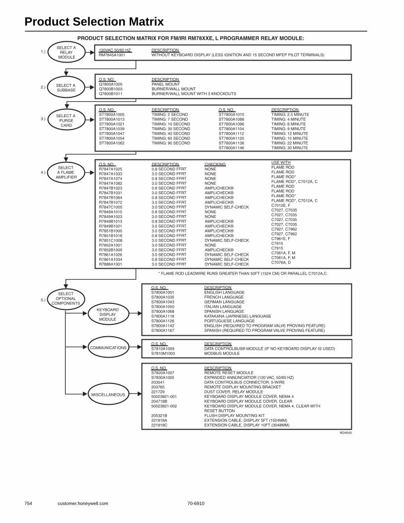
Product Selection Matrix
754 customer.honeywell.com 70-6910
PRODUCT SELECTION MATRIX FOR FM/IRI RM78XXE, L PROGRAMMER RELAY MODULE:
M34645
SELECT A SUBBASE
SELECTOPTIONAL
COMPONENTS
KEYBOARDDISPLAYMODULE
COMMUNICATIONS
MISCELLANEOUS
SELECT A RELAY
MODULE
O.S. NO.Q7800A1005Q7800B1003Q7800B1011
DESCRIPTIONPANEL MOUNTBURNER/WALL MOUNTBURNER/WALL MOUNT WITH 3 KNOCKOUTS
O.S. NO.R7847A1025R7847A1033R7847A1074R7847A1082R7847B1023R7847B1031R7847B1064R7847B1072R7847C1005R7849A1015R7849A1023R7849B1013R7849B1021R7851B1000R7851B1018R7851C1008R7852A1001R7852B1009R7861A1026R7861A1034R7886A1001
DESCRIPTION0.8 SECOND FFRT3.0 SECOND FFRT0.8 SECOND FFRT3.0 SECOND FFRT0.8 SECOND FFRT3.0 SECOND FFRT0.8 SECOND FFRT3.0 SECOND FFRT3.0 SECOND FFRT0.8 SECOND FFRT3.0 SECOND FFRT0.8 SECOND FFRT3.0 SECOND FFRT3.0 SECOND FFRT0.8 SECOND FFRT3.0 SECOND FFRT3.0 SECOND FFRT3.0 SECOND FFRT3.0 SECOND FFRT0.8 SECOND FFRT3.0 SECOND FFRT
CHECKINGNONENONENONENONEAMPLICHECK®AMPLICHECK®AMPLICHECK®AMPLICHECK®DYNAMIC SELF-CHECKNONENONEAMPLICHECK®AMPLICHECK®AMPLICHECK®AMPLICHECK®DYNAMIC SELF-CHECKNONEAMPLICHECK®DYNAMIC SELF-CHECKDYNAMIC SELF-CHECKDYNAMIC SELF-CHECK
O.S. NO.S7800A1001S7800A1035S7800A1043S7800A1050S7800A1068S7800A1118S7800A1126S7800A1142S7800A1167
DESCRIPTIONENGLISH LANGUAGEFRENCH LANGUAGEGERMAN LANGUAGEITALIAN LANGUAGESPANISH LANGUAGEKATAKANA (JAPANESE) LANGUAGEPORTUGUESE LANGUAGEENGLISH (REQUIRED TO PROGRAM VALVE PROVING FEATURE)SPANISH (REQUIRED TO PROGRAM VALVE PROVING FEATURE)
O.S. NO.S7810A1009S7810M1003
DESCRIPTIONDATA CONTROLBUS® MODULE (IF NO KEYBOARD DISPLAY IS USED)MODBUS MODULE
O.S. NO.S7820A1007S7830A100520354120376522172950023821-001204718B50023821-002
205321B221818A221818C
DESCRIPTIONREMOTE RESET MODULEEXPANDED ANNUNCIATIOR (120 VAC, 50/60 HZ)DATA CONTROLBUS CONNECTOR, 5-WIREREMOTE DISPLAY MOUNTING BRACKETDUST COVER, RELAY MODULEKEYBOARD DISPLAY MODULE COVER, NEMA 4KEYBOARD DISPLAY MODULE COVER, CLEARKEYBOARD DISPLAY MODULE COVER, NEMA 4, CLEAR WITHRESET BUTTONFLUSH DISPLAY MOUNTING KITEXTENSION CABLE, DISPLAY 5FT (1524MM)EXTENSION CABLE, DISPLAY 10FT (3048MM)
USE WITHFLAME ROD FLAME RODFLAME ROD*FLAME ROD*, C7012A, CFLAME RODFLAME RODFLAME ROD*FLAME ROD*, C7012A, CC7012E, FC7027, C7035C7027, C7035C7027, C7035C7027, C7035C7927, C7962C7927, C7962C7961E, FC7915C7915C7061A, F, MC7061A, F, MC7076A, D
SELECT A PURGECARD
O.S. NO.ST7800A1005ST7800A1013ST7800A1021ST7800A1039ST7800A1047ST7800A1054ST7800A1062
DESCRIPTIONTIMING: 2 SECONDTIMING: 7 SECONDTIMING: 10 SECONDTIMING: 30 SECONDTIMING: 40 SECONDTIMING: 60 SECONDTIMING: 90 SECOND
O.S. NO.ST7800A1070ST7800A1088ST7800A1096ST7800A1104ST7800A1112ST7800A1120ST7800A1138ST7800A1146
DESCRIPTIONTIMING: 2.5 MINUTETIMING: 4 MINUTETIMING: 6 MINUTETIMING: 9 MINUTETIMING: 12 MINUTETIMING: 15 MINUTETIMING: 22 MINUTETIMING: 30 MINUTE
120VAC 50/60 HZRM7845A1001
DESCRIPTIONWITHOUT KEYBOARD DISPLAY (LESS IGNITION AND 15 SECOND MFEP PILOT TERMINALS)
SELECT A FLAME
AMPLIFIER
1.)
2.)
3.)
4.)
5.)
* FLAME ROD LEADWIRE RUNS GREATER THAN 50FT (1524 CM) OR PARALLEL C7012A,C.
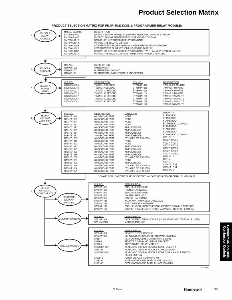
Product Selection Matrix
70-6910 755
Com
mercial / Industrial
Com
bustion Controls
PRODUCT SELECTION MATRIX FOR FM/IRI RM78XXE, L PROGRAMMER RELAY MODULE:
M15530G
SELECT A SUBBASE
SELECTOPTIONAL
COMPONENTS
KEYBOARDDISPLAYMODULE
COMMUNICATIONS
MISCELLANEOUS
SELECT A RELAY
MODULE
O.S. NO.Q7800A1005Q7800B1003Q7800B1011
DESCRIPTIONPANEL MOUNTBURNER/WALL MOUNTBURNER/WALL MOUNT WITH 3 KNOCKOUTS
O.S. NO.R7847A1025R7847A1033R7847A1074R7847A1082R7847B1023R7847B1031R7847B1064R7847B1072R7847C1005R7849A1015R7849A1023R7849B1013R7849B1021R7851B1000R7851B1018R7851C1008R7852A1001R7852B1009R7861A1026R7861A1034R7886A1001
DESCRIPTION0.8 SECOND FFRT3.0 SECOND FFRT0.8 SECOND FFRT3.0 SECOND FFRT0.8 SECOND FFRT3.0 SECOND FFRT0.8 SECOND FFRT3.0 SECOND FFRT3.0 SECOND FFRT0.8 SECOND FFRT3.0 SECOND FFRT0.8 SECOND FFRT3.0 SECOND FFRT3.0 SECOND FFRT0.8 SECOND FFRT3.0 SECOND FFRT3.0 SECOND FFRT3.0 SECOND FFRT3.0 SECOND FFRT0.8 SECOND FFRT3.0 SECOND FFRT
CHECKINGNONENONENONENONEAMPLICHECK®AMPLICHECK®AMPLICHECK®AMPLICHECK®DYNAMIC SELF-CHECKNONENONEAMPLICHECK®AMPLICHECK®AMPLICHECK®AMPLICHECK®DYNAMIC SELF-CHECKNONEAMPLICHECK®DYNAMIC SELF-CHECKDYNAMIC SELF-CHECKDYNAMIC SELF-CHECK
O.S. NO.S7800A1001S7800A1035S7800A1043S7800A1050S7800A1068S7800A1118S7800A1126S7800A1142S7800A1167
DESCRIPTIONENGLISH LANGUAGEFRENCH LANGUAGEGERMAN LANGUAGEITALIAN LANGUAGESPANISH LANGUAGEKATAKANA (JAPANESE) LANGUAGEPORTUGUESE LANGUAGEENGLISH (REQUIRED TO PROGRAM VALVE PROVING FEATURE)SPANISH (REQUIRED TO PROGRAM VALVE PROVING FEATURE)
O.S. NO.S7810A1009S7810M1003
DESCRIPTIONDATA CONTROLBUS® MODULE (IF NO KEYBOARD DISPLAY IS USED)MODBUS MODULE
O.S. NO.S7820A1007S7830A100520354120376522172950023821-001204718B50023821-002
205321B221818A221818C
DESCRIPTIONREMOTE RESET MODULEEXPANDED ANNUNCIATIOR (120 VAC, 50/60 HZ)DATA CONTROLBUS CONNECTOR, 5-WIREREMOTE DISPLAY MOUNTING BRACKETDUST COVER, RELAY MODULEKEYBOARD DISPLAY MODULE COVER, NEMA 4KEYBOARD DISPLAY MODULE COVER, CLEARKEYBOARD DISPLAY MODULE COVER, NEMA 4, CLEAR WITHRESET BUTTONFLUSH DISPLAY MOUNTING KITEXTENSION CABLE, DISPLAY 5FT (1524MM)EXTENSION CABLE, DISPLAY 10FT (3048MM)
USE WITHFLAME ROD FLAME RODFLAME ROD*FLAME ROD*, C7012A, CFLAME RODFLAME RODFLAME ROD*FLAME ROD*, C7012A, CC7012E, FC7027, C7035C7027, C7035C7027, C7035C7027, C7035C7927, C7962C7927, C7962C7961E, FC7915C7915C7061A, F, MC7061A, F, MC7076A, D
SELECT A PURGECARD
O.S. NO.ST7800A1005ST7800A1013ST7800A1021ST7800A1039ST7800A1047ST7800A1054ST7800A1062
DESCRIPTIONTIMING: 2 SECONDTIMING: 7 SECONDTIMING: 10 SECONDTIMING: 30 SECONDTIMING: 40 SECONDTIMING: 60 SECONDTIMING: 90 SECOND
O.S. NO.ST7800A1070ST7800A1088ST7800A1096ST7800A1104ST7800A1112ST7800A1120ST7800A1138ST7800A1146
DESCRIPTIONTIMING: 2.5 MINUTETIMING: 4 MINUTETIMING: 6 MINUTETIMING: 9 MINUTETIMING: 12 MINUTETIMING: 15 MINUTETIMING: 22 MINUTETIMING: 30 MINUTE
120VAC 50/60 HZRM7800E1010RM7840E1016RM7800L1012RM7840L1018RM7800L1053RM7840L1026RM7800L1087RM7840L1075
DESCRIPTIONENERGY SAVING PURGE, S7800A1001 KEYBOARD DISPLAY STANDARDENERGY SAVING PURGE WITHOUT KEYBOARD DISPLAYS7800A1001 KEYBOARD DISPLAY STANDARDWITHOUT KEYBOARD DISPLAYINTERMITTENT PILOT, S7800A1001 KEYBOARD DISPLAY STANDARDINTERMITTENT PILOT WITHOUT KEYBOARD DISPLAYS7800A1142 KEYBOARD DISPLAY STANDARD - WITH VALVE PROVING FEATUREWITHOUT KEYBOARD DISPLAY - WITH VALVE PROVING FEATURE
SELECT A FLAME
AMPLIFIER
1.)
2.)
3.)
4.)
5.)
* FLAME ROD LEADWIRE RUNS GREATER THAN 50FT (1524 CM) OR PARALLEL C7012A,C.
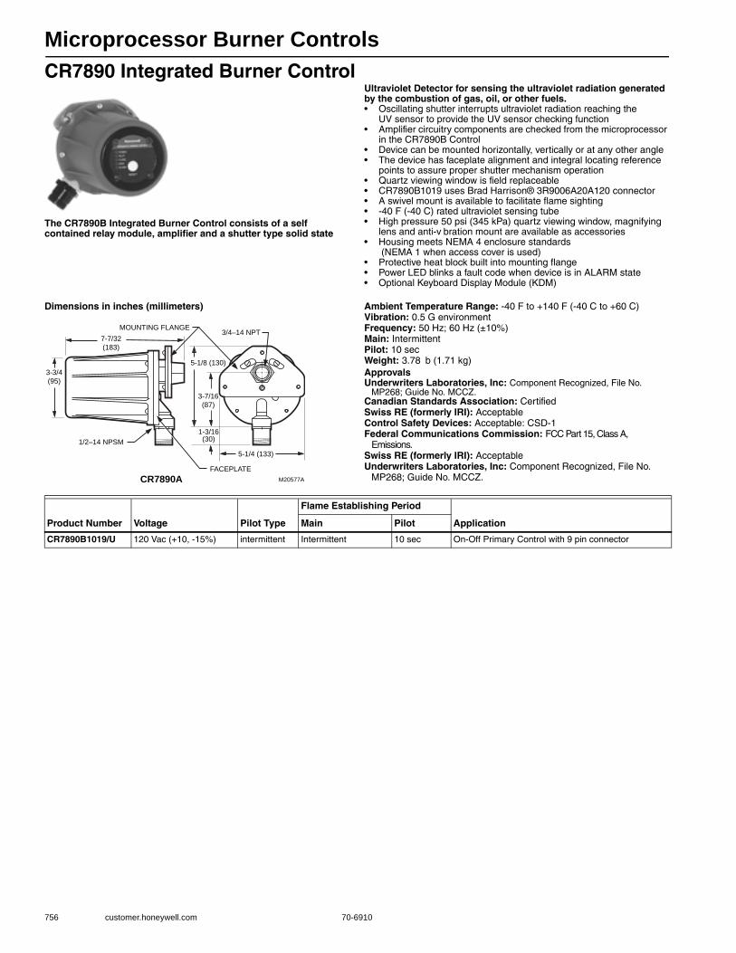
Microprocessor Burner Controls
756 customer.honeywell.com 70-6910
CR7890 Integrated Burner Control
The CR7890B Integrated Burner Control consists of a self contained relay module, amplifier and a shutter type solid state
Ultraviolet Detector for sensing the ultraviolet radiation generated by the combustion of gas, oil, or other fuels.• Oscillating shutter interrupts ultraviolet radiation reaching the
UV sensor to provide the UV sensor checking function • Amplifier circuitry components are checked from the microprocessor
in the CR7890B Control • Device can be mounted horizontally, vertically or at any other angle • The device has faceplate alignment and integral locating reference
points to assure proper shutter mechanism operation • Quartz viewing window is field replaceable • CR7890B1019 uses Brad Harrison® 3R9006A20A120 connector • A swivel mount is available to facilitate flame sighting • -40 F (-40 C) rated ultraviolet sensing tube • High pressure 50 psi (345 kPa) quartz viewing window, magnifying
lens and anti-v bration mount are available as accessories • Housing meets NEMA 4 enclosure standards
(NEMA 1 when access cover is used) • Protective heat block built into mounting flange • Power LED blinks a fault code when device is in ALARM state • Optional Keyboard Display Module (KDM)
Dimensions in inches (millimeters) Ambient Temperature Range: -40 F to +140 F (-40 C to +60 C) Vibration: 0.5 G environmentFrequency: 50 Hz; 60 Hz (±10%)Main: IntermittentPilot: 10 secWeight: 3.78 b (1.71 kg) ApprovalsUnderwriters Laboratories, Inc: Component Recognized, File No.
MP268; Guide No. MCCZ.Canadian Standards Association: CertifiedSwiss RE (formerly IRI): AcceptableControl Safety Devices: Acceptable: CSD-1Federal Communications Commission: FCC Part 15, Class A,
Emissions.Swiss RE (formerly IRI): AcceptableUnderwriters Laboratories, Inc: Component Recognized, File No.
MP268; Guide No. MCCZ.
MOUNTING FLANGE
1/2–14 NPSM
FACEPLATE
3/4–14 NPT
M20577A
3-3/4
(95)
7-7/32
(183)
5-1/8 (130)
3-7/16
(87)
1-3/16(30)
5-1/4 (133)
CR7890A
Product Number Voltage Pilot Type
Flame Establishing Period
ApplicationMain Pilot
CR7890B1019/U 120 Vac (+10, -15%) intermittent Intermittent 10 sec On-Off Primary Control with 9 pin connector
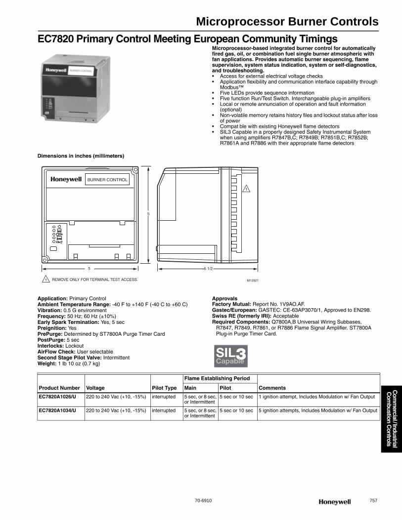
Microprocessor Burner Controls
70-6910 757
Com
mercial / Industrial
Com
bustion Controls
EC7820 Primary Control Meeting European Community TimingsMicroprocessor-based integrated burner control for automatically fired gas, oil, or combination fuel single burner atmospheric with fan applications. Provides automatic burner sequencing, flame supervision, system status indication, system or self-diagnostics, and troubleshooting.• Access for external electrical voltage checks • Application flexibility and communication interface capability through
Modbus™• Five LEDs provide sequence information • Five function Run/Test Switch. Interchangeable plug-in amplifiers • Local or remote annunciation of operation and fault information
(optional) • Non-volatile memory retains history files and lockout status after loss
of power • Compat ble with existing Honeywell flame detectors• SIL3 Capable in a properly designed Safety Instrumental System
when using amplifiers R7847B,C; R7849B; R7851B,C; R7852B; R7861A and R7886 with their appropriate flame detectors
Dimensions in inches (millimeters)
Application: Primary ControlAmbient Temperature Range: -40 F to +140 F (-40 C to +60 C) Vibration: 0.5 G environmentFrequency: 50 Hz; 60 Hz (±10%)Early Spark Termination: Yes, 5 secPreignition: YesPrePurge: Determined by ST7800A Purge Timer CardPostPurge: 5 secInterlocks: LockoutAirFlow Check: User selectableSecond Stage Pilot Valve: IntermittentWeight: 1 lb 10 oz (0.7 kg)
ApprovalsFactory Mutual: Report No. 1V9AO.AF.Gastec/European: GASTEC: CE-63AP3070/1, Approved to EN298.Swiss RE (formerly IRI): AcceptableRequired Components: Q7800A,B Universal Wiring Subbases,
R7847, R7849, R7861, or R7886 Flame Signal Amplifier. ST7800A Plug-in Purge Timer Card.
5
5
BURNER CONTROL
5 1/2
M12821
1
REMOVE ONLY FOR TERMINAL TEST ACCESS.1
SIL3Capable
Product Number Voltage Pilot Type
Flame Establishing Period
CommentsMain Pilot
EC7820A1026/U 220 to 240 Vac (+10, -15%) interrupted 5 sec, or 8 sec, or Intermittent
5 sec or 10 sec 1 ignition attempt, Includes Modulation w/ Fan Output
EC7820A1034/U 220 to 240 Vac (+10, -15%) interrupted 5 sec, or 8 sec, or Intermittent
5 sec or 10 sec 5 ignition attempts, Includes Modulation w/ Fan Output
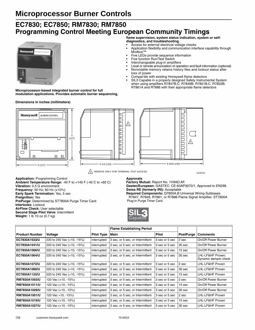
Microprocessor Burner Controls
758 customer.honeywell.com 70-6910
EC7830; EC7850; RM7830; RM7850 Programming Control Meeting European Community Timings
Microprocessor-based integrated burner control for full modulation applications. Provides automatic burner sequencing,
flame supervision, system status indication, system or self-diagnostics, and troubleshooting.• Access for external electrical voltage checks • Application flexibility and communication interface capability through
Modbus™• Five LEDs provide sequence information • Five function Run/Test Switch • Interchangeable plug-in amplifiers • Local or remote annunciation of operation and fault information (optional) • Nonvolatile memory retains history files and lockout status after
loss of power • Compat ble with existing Honeywell flame detectors• SIL3 Capable in a properly designed Safety Instrumental System
when using amplifiers R7847B,C; R7849B; R7851B,C; R7852B; R7861A and R7886 with their appropriate flame detectors
Dimensions in inches (millimeters)
Application: Programming ControlAmbient Temperature Range: -40 F to +140 F (-40 C to +60 C) Vibration: 0.5 G environmentFrequency: 50 Hz; 60 Hz (±10%)Early Spark Termination: Yes, 5 secPreignition: YesPrePurge: Determined by ST7800A Purge Timer CardInterlocks: LockoutAirFlow Check: User selectableSecond Stage Pilot Valve: IntermittentWeight: 1 lb 10 oz (0.7 kg)
ApprovalsFactory Mutual: Report No. 1V9AO.AF.Gastec/European: GASTEC: CE-63AP3070/1, Approved to EN298.Swiss RE (formerly IRI): AcceptableRequired Components: Q7800A,B Universal Wiring Subbases.
R7847, R7849, R7861, or R7886 Flame Signal Amplifier. ST7800A Plug-in Purge Timer Card.
5(127)
5 (127)
BURNER CONTROL
1
5-1/4 (133)
M15532AREMOVE ONLY FOR TERMINAL TEST ACCESS.1
6-3/32 (155)
1
SIL3Capable
Product Number Voltage Pilot Type
Flame Establishing Period
PostPurge CommentsMain Pilot
EC7830A1033/U 220 to 240 Vac (+10, -15%) interrupted 3 sec, or 5 sec, or Intermittent 3 sec or 5 sec 2 sec On/Off Power Burner
EC7830A1041/U 220 to 240 Vac (+10, -15%) interrupted 3 sec, or 5 sec, or Intermittent 3 sec or 5 sec 30 sec On/Off Power Burner
EC7830A1066/U 220 to 240 Vac (+10, -15%) interrupted 3 sec, or 5 sec, or Intermittent 3 sec or 5 sec 15 sec On/Off Power Burner
EC7850A1064/U 220 to 240 Vac (+10, -15%) interrupted 3 sec, or 5 sec, or Intermittent 3 sec or 5 sec 30 sec LHL-LF&HF Proven; Dynamic damper check
EC7850A1072/U 220 to 240 Vac (+10, -15%) interrupted 3 sec, or 5 sec, or Intermittent 3 sec or 5 sec 2 sec LHL-LF&HF Proven
EC7850A1080/U 220 to 240 Vac (+10, -15%) interrupted 3 sec, or 5 sec, or Intermittent 3 sec or 5 sec 30 sec LHL-LF&HF Proven
EC7850A1122/U 220 to 240 Vac (+10, -15%) interrupted 3 sec, or 5 sec, or Intermittent 3 sec or 5 sec 15 sec LHL-LF&HF Proven
RM7830A1003/U 120 Vac (+10, -15%) interrupted 3 sec, or 5 sec, or Intermittent 3 sec or 5 sec 2 sec On/Off Power Burner
RM7830A1011/U 120 Vac (+10, -15%) interrupted 3 sec, or 5 sec, or Intermittent 3 sec or 5 sec 15 sec On/Off Power Burner
RM7830A1029/U 120 Vac (+10, -15%) interrupted 3 sec, or 5 sec, or Intermittent 3 sec or 5 sec 30 sec On/Off Power Burner
RM7850A1001/U 120 Vac +10, -15%) interrupted 3 sec, or 5 sec, or Intermittent 3 sec or 5 sec 2 sec LHL-LF&HF Proven
RM7850A1019/U 120 Vac (+10, -15%) interrupted 3 sec, or 5 sec, or Intermittent 3 sec or 5 sec 15 sec LHL-LF&HF Proven
RM7850A1027/U 120 Vac (+10, -15%) interrupted 3 sec, or 5 sec, or Intermittent 3 sec or 5 sec 30 sec LHL-LF&HF Proven
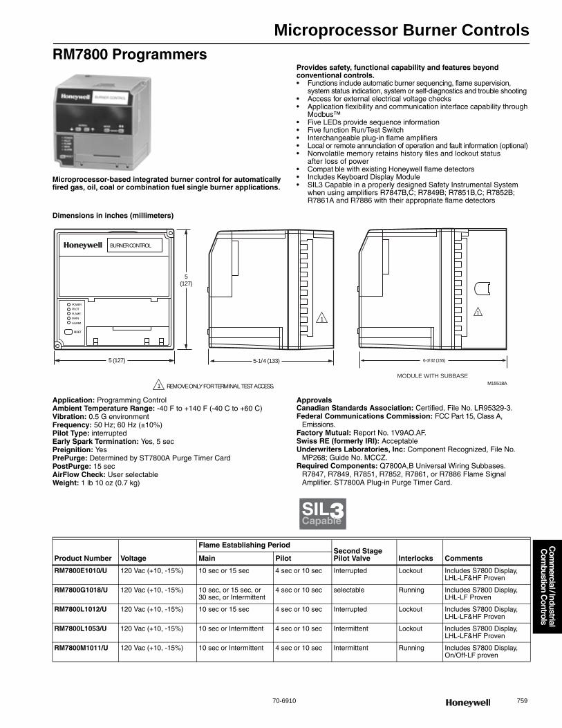
Microprocessor Burner Controls
70-6910 759
Com
mercial / Industrial
Com
bustion Controls
RM7800 Programmers
Microprocessor-based integrated burner control for automatically fired gas, oil, coal or combination fuel single burner applications.
Provides safety, functional capability and features beyond conventional controls.• Functions include automatic burner sequencing, flame supervision,
system status indication, system or self-diagnostics and trouble shooting • Access for external electrical voltage checks • Application flexibility and communication interface capability through
Modbus™• Five LEDs provide sequence information • Five function Run/Test Switch • Interchangeable plug-in flame amplifiers • Local or remote annunciation of operation and fault information (optional) • Nonvolatile memory retains history files and lockout status
after loss of power • Compat ble with existing Honeywell flame detectors • Includes Keyboard Display Module• SIL3 Capable in a properly designed Safety Instrumental System
when using amplifiers R7847B,C; R7849B; R7851B,C; R7852B; R7861A and R7886 with their appropriate flame detectors
Dimensions in inches (millimeters)
Application: Programming ControlAmbient Temperature Range: -40 F to +140 F (-40 C to +60 C) Vibration: 0.5 G environmentFrequency: 50 Hz; 60 Hz (±10%)Pilot Type: interruptedEarly Spark Termination: Yes, 5 secPreignition: YesPrePurge: Determined by ST7800A Purge Timer CardPostPurge: 15 secAirFlow Check: User selectableWeight: 1 lb 10 oz (0.7 kg)
ApprovalsCanadian Standards Association: Certified, File No. LR95329-3.Federal Communications Commission: FCC Part 15, Class A,
Emissions.Factory Mutual: Report No. 1V9AO.AF.Swiss RE (formerly IRI): AcceptableUnderwriters Laboratories, Inc: Component Recognized, File No.
MP268; Guide No. MCCZ.Required Components: Q7800A,B Universal Wiring Subbases.
R7847, R7849, R7851, R7852, R7861, or R7886 Flame Signal Amplifier. ST7800A Plug-in Purge Timer Card.
M15518A
BURNER CONTROL
POWER
PILOT
FLAME
MAIN
ALARM
RESET
5(127)
5 (127)
REMOVE ONLY FOR TERMINAL TEST ACCESS.1
1
5-1/4 (133)
1
6-3/32 (155)
MODULE WITH SUBBASE
SIL3Capable
Product Number Voltage
Flame Establishing PeriodSecond Stage Pilot Valve Interlocks CommentsMain Pilot
RM7800E1010/U 120 Vac (+10, -15%) 10 sec or 15 sec 4 sec or 10 sec Interrupted Lockout Includes S7800 Display, LHL-LF&HF Proven
RM7800G1018/U 120 Vac (+10, -15%) 10 sec, or 15 sec, or 30 sec, or Intermittent
4 sec or 10 sec selectable Running Includes S7800 Display, LHL-LF Proven
RM7800L1012/U 120 Vac (+10, -15%) 10 sec or 15 sec 4 sec or 10 sec Interrupted Lockout Includes S7800 Display, LHL-LF&HF Proven
RM7800L1053/U 120 Vac (+10, -15%) 10 sec or Intermittent 4 sec or 10 sec Intermittent Lockout Includes S7800 Display, LHL-LF&HF Proven
RM7800M1011/U 120 Vac (+10, -15%) 10 sec or Intermittent 4 sec or 10 sec Intermittent Running Includes S7800 Display, On/Off-LF proven
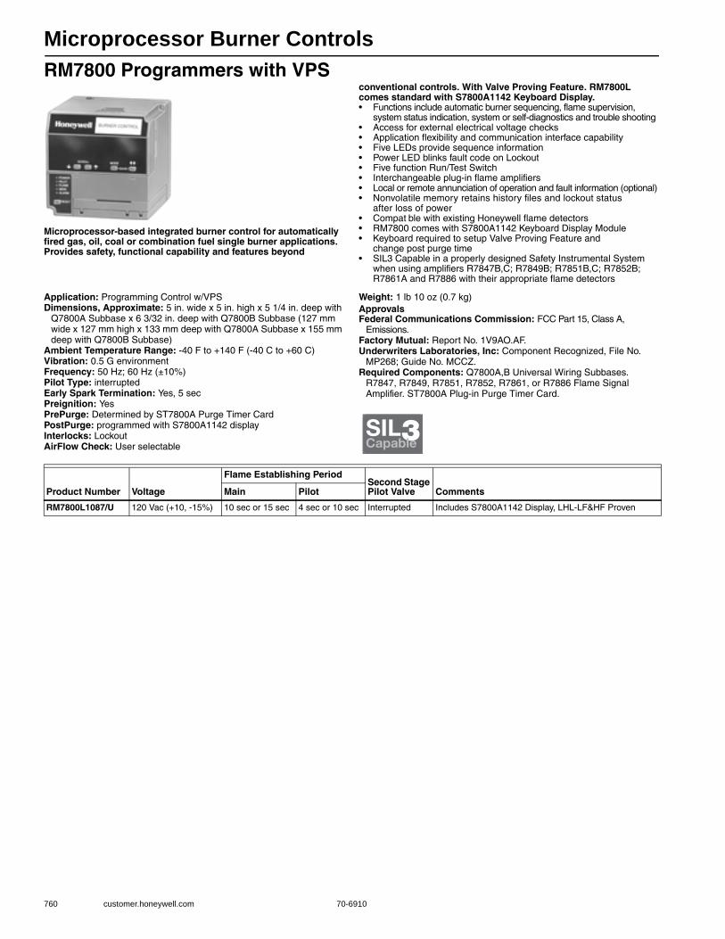
Microprocessor Burner Controls
760 customer.honeywell.com 70-6910
RM7800 Programmers with VPS
Microprocessor-based integrated burner control for automatically fired gas, oil, coal or combination fuel single burner applications. Provides safety, functional capability and features beyond
conventional controls. With Valve Proving Feature. RM7800L comes standard with S7800A1142 Keyboard Display.• Functions include automatic burner sequencing, flame supervision,
system status indication, system or self-diagnostics and trouble shooting • Access for external electrical voltage checks • Application flexibility and communication interface capability • Five LEDs provide sequence information • Power LED blinks fault code on Lockout• Five function Run/Test Switch • Interchangeable plug-in flame amplifiers • Local or remote annunciation of operation and fault information (optional) • Nonvolatile memory retains history files and lockout status
after loss of power • Compat ble with existing Honeywell flame detectors • RM7800 comes with S7800A1142 Keyboard Display Module• Keyboard required to setup Valve Proving Feature and
change post purge time• SIL3 Capable in a properly designed Safety Instrumental System
when using amplifiers R7847B,C; R7849B; R7851B,C; R7852B; R7861A and R7886 with their appropriate flame detectors
Application: Programming Control w/VPSDimensions, Approximate: 5 in. wide x 5 in. high x 5 1/4 in. deep with
Q7800A Subbase x 6 3/32 in. deep with Q7800B Subbase (127 mm wide x 127 mm high x 133 mm deep with Q7800A Subbase x 155 mm deep with Q7800B Subbase)
Ambient Temperature Range: -40 F to +140 F (-40 C to +60 C) Vibration: 0.5 G environmentFrequency: 50 Hz; 60 Hz (±10%)Pilot Type: interruptedEarly Spark Termination: Yes, 5 secPreignition: YesPrePurge: Determined by ST7800A Purge Timer CardPostPurge: programmed with S7800A1142 displayInterlocks: LockoutAirFlow Check: User selectable
Weight: 1 lb 10 oz (0.7 kg) ApprovalsFederal Communications Commission: FCC Part 15, Class A,
Emissions.Factory Mutual: Report No. 1V9AO.AF.Underwriters Laboratories, Inc: Component Recognized, File No.
MP268; Guide No. MCCZ.Required Components: Q7800A,B Universal Wiring Subbases.
R7847, R7849, R7851, R7852, R7861, or R7886 Flame Signal Amplifier. ST7800A Plug-in Purge Timer Card.
SIL3Capable
Product Number Voltage
Flame Establishing PeriodSecond Stage Pilot Valve CommentsMain Pilot
RM7800L1087/U 120 Vac (+10, -15%) 10 sec or 15 sec 4 sec or 10 sec Interrupted Includes S7800A1142 Display, LHL-LF&HF Proven
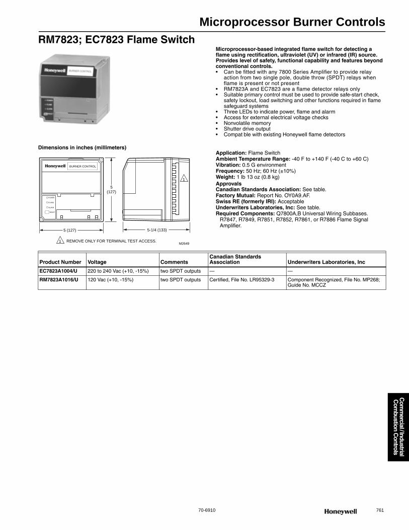
Microprocessor Burner Controls
70-6910 761
Com
mercial / Industrial
Com
bustion Controls
RM7823; EC7823 Flame SwitchMicroprocessor-based integrated flame switch for detecting a flame using rectification, ultraviolet (UV) or infrared (IR) source. Provides level of safety, functional capability and features beyond conventional controls.• Can be fitted with any 7800 Series Amplifier to provide relay
action from two single pole, double throw (SPDT) relays when flame is present or not present
• RM7823A and EC7823 are a flame detector relays only • Suitable primary control must be used to provide safe-start check,
safety lockout, load switching and other functions required in flame safeguard systems
• Three LEDs to indicate power, flame and alarm • Access for external electrical voltage checks • Nonvolatile memory • Shutter drive output • Compat ble with existing Honeywell flame detectors
Dimensions in inches (millimeters)Application: Flame SwitchAmbient Temperature Range: -40 F to +140 F (-40 C to +60 C) Vibration: 0.5 G environmentFrequency: 50 Hz; 60 Hz (±10%)Weight: 1 lb 13 oz (0.8 kg) ApprovalsCanadian Standards Association: See table.Factory Mutual: Report No. OY0A9.AF.Swiss RE (formerly IRI): AcceptableUnderwriters Laboratories, Inc: See table.Required Components: Q7800A,B Universal Wiring Subbases.
R7847, R7849, R7851, R7852, R7861, or R7886 Flame Signal Amplifier.
POWER
FLAME
ALARM
RESET
5(127)
5 (127)
M2649
BURNER CONTROL
REMOVE ONLY FOR TERMINAL TEST ACCESS.1
1
5-1/4 (133)
Product Number Voltage CommentsCanadian Standards Association Underwriters Laboratories, Inc
EC7823A1004/U 220 to 240 Vac (+10, -15%) two SPDT outputs — —
RM7823A1016/U 120 Vac (+10, -15%) two SPDT outputs Certified, File No. LR95329-3 Component Recognized, File No. MP268; Guide No. MCCZ
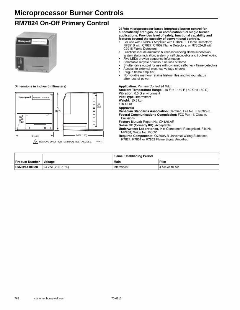
Microprocessor Burner Controls
762 customer.honeywell.com 70-6910
RM7824 On-Off Primary Control24 Vdc microprocessor-based integrated burner control for automatically fired gas, oil or combination fuel single burner applications. Provides level of safety, functional capability and features beyond the capacity of conventional controls.• For use with R7824C Amplifier with C7024E,F Flame Detectors;
R7851B with C7927, C7962 Flame Detectors; or R7852A,B with C7915 Flame Detectors
• Functions include automatic burner sequencing, flame supervision, system status indication, system or self diagnostics and troubleshooting
• Five LEDs provide sequence information • Selectable recycle or lockout on loss of flame • Shutter drive output for use with dynamic self-check flame detectors • Access for external electrical voltage checks • Plug-in flame amplifier • Nonvolatile memory retains history files and lockout status
after loss of power
Dimensions in inches (millimeters) Application: Primary Control 24 VdcAmbient Temperature Range: -40 F to +140 F (-40 C to +60 C) Vibration: 0.5 G environmentPilot Type: intermittentWeight: (0.8 kg) 1 lb 13 ozApprovalsCanadian Standards Association: Certified, File No. LR95329-3.Federal Communications Commission: FCC Part 15, Class A,
Emissions.Factory Mutual: Report No. OX4A5.AF.Swiss RE (formerly IRI): AcceptableUnderwriters Laboratories, Inc: Component Recognized, File No.
MP268; Guide No. MCCZ.Required Components: Q7800A,B Universal Wiring Subbases.
R7824, R7851 or R7852 Flame Signal Amplifier.
5(127)
5 (127)
M5872
BURNER CONTROL
REMOVE ONLY FOR TERMINAL TEST ACCESS.1
1
5-1/4 (133)
Product Number Voltage
Flame Establishing Period
Main Pilot
RM7824A1006/U 24 Vdc (+10, -15%) Intermittent 4 sec or 10 sec
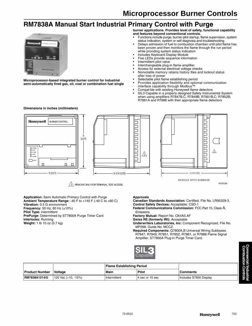
Microprocessor Burner Controls
70-6910 763
Com
mercial / Industrial
Com
bustion Controls
RM7838A Manual Start Industrial Primary Control with Purge
Microprocessor-based integrated burner control for industrial semi-automatically fired gas, oil, coal or combination fuel single
burner applications. Provides level of safety, functional capability and features beyond conventional controls.• Functions include purge, burner pilot startup, flame supervision, system
status indication, system or self diagnosis and troubleshooting • Delays admission of fuel to combustion chamber until pilot flame has
been proven and then monitors the flame through the run period while providing system status indication
• Includes Keyboard Display Module • Five LEDs provide sequence information • Intermittent pilot valve • Interchangeable plug-in flame amplifier • Access for external electrical voltage checks • Nonvolatile memory retains history files and lockout status
after loss of power • Selectable pilot flame establishing period • Provides application flexibility and optional communication
interface capability through Modbus™ • Compat ble with existing Honeywell flame detectors• SIL3 Capable in a properly designed Safety Instrumental System
when using amplifiers R7847B,C; R7849B; R7851B,C; R7852B; R7861A and R7886 with their appropriate flame detectors
Dimensions in inches (millimeters)
Application: Semi Automatic Primary Control with PurgeAmbient Temperature Range: -40 F to +140 F (-40 C to +60 C) Vibration: 0.5 G environmentFrequency: 50 Hz; 60 Hz (±10%)Pilot Type: intermittentPrePurge: Determined by ST7800A Purge Timer CardInterlocks: RunningWeight: 1 lb 10 oz (0.7 kg)
ApprovalsCanadian Standards Association: Certified, File No. LR95329-3.Control Safety Devices: Acceptable: CSD-1Federal Communications Commission: FCC Part 15, Class A,
EmissionsFactory Mutual: Report No. OX4A5.AFSwiss RE (formerly IRI): AcceptableUnderwriters Laboratories, Inc: Component Recognized, File No.
MP268; Guide No. MCCZ.Required Components: Q7800A,B Universal Wiring Subbases.
R7847, R7849, R7851, R7852, R7861, or R7886 Flame Signal Amplifier. ST7800A Plug-in Purge Timer Card.
M15518A
BURNER CONTROL
POWER
PILOT
FLAME
MAIN
ALARM
RESET
5(127)
5 (127)
REMOVE ONLY FOR TERMINAL TEST ACCESS.1
1
5-1/4 (133)
1
6-3/32 (155)
MODULE WITH SUBBASE
SIL3Capable
Product Number Voltage
Flame Establishing Period
CommentsMain Pilot
RM7838A1014/U 120 Vac (+10, -15%) Intermittent 4 sec or 10 sec Includes S7800 Display

Microprocessor Burner Controls
764 customer.honeywell.com 70-6910
RM7838B,C Manual Start Industrial Programmers
Microprocessor-based integrated burner control for industrial semi-automatically fired gas, oil, coal or combination fuel single
burner applications. Provides level of safety, functional capability and features beyond conventional controls.• Functions include purge, burner pilot startup, flame supervision, system
status indication, system or self diagnosis and troubleshooting • Delays admission of fuel to combustion chamber until pilot flame has
been proven and then monitors the flame through the run period while providing system status indication
• Includes Keyboard Display Module • Five LEDs provide sequence information • Intermittent pilot valve • Interchangeable plug-in flame amplifier • Access for external electrical voltage checks • Nonvolatile memory retains history files and lockout status
after loss of power • Selectable pilot flame establishing period • Provides application flexibility and optional communication
interface capability through Modbus™• Compat ble with existing Honeywell flame detectors• SIL3 Capable in a properly designed Safety Instrumental System
when using amplifiers R7847B,C; R7849B; R7851B,C; R7852B; R7861A and R7886 with their appropriate flame detectors
Application: Semi Automatic Programming ControlDimensions, Approximate: 5 in. wide x 5 in. high x 5 1/4 in. deep
with Q7800A Subbase x 6 3/32 in. deep with Q7800B Subbase (127 mm wide x 127 mm high x 133 mm deep with Q7800A Subbase x 155 mm deep with Q7800B Subbase)
Ambient Temperature Range: -40 F to +140 F (-40 C to +60 C) Vibration: 0.5 G environmentFrequency: 50 Hz; 60 Hz (±10%)Pilot Type: interruptedEarly Spark Termination: Yes, 5 secPreignition: YesPrePurge: Determined by ST7800A Purge Timer Card; RM7838C
requires ST7800C Purge Timer CardInterlocks: LockoutWeight: 1 lb 10 oz (0.7 kg)
ApprovalsCanadian Standards Association: Certified, File No. LR95329-3Control Safety Devices: Acceptable: CSD-1Federal Communications Commission: FCC Part 15, Class A,
EmissionsFactory Mutual: Report No. OX4A5.AFGastec/European: See tableSwiss RE (formerly IRI): AcceptableUnderwriters Laboratories, Inc: Component Recognized, File No.
MP268; Guide No. MCCZ.Required Components: Q7800A,B Universal Wiring Subbases.
R7847, R7849, R7851, R7852, R7861, or R7886 Flame Signal Amplifier. ST7800A (ST7800C for RM7838C) Plug-in Purge Timer Card.
SIL3Capable
Product Number Voltage
Flame Establishing Period
Comments Gastec/EuropeanMain Pilot
RM7838B1013/U 120 Vac (+10, -15%) 10 sec or Intermittent 4 sec or 10 sec Includes S7800 Display —
RM7838C1004/U 120 Vac (+10, -15%) 10 sec or Intermittent 4 sec or 10 sec Includes S7800 Display —
RM7838C1020/U 120 Vac (+10, -15%) 10 sec or Intermittent 4 sec or 10 sec Includes S7800 Display Gastec EN268 Report 1156791

Microprocessor Burner Controls
70-6910 765
Com
mercial / Industrial
Com
bustion Controls
RM7838B,C Manual Start Industrial Programmers with VPSMicroprocessor-based integrated burner control for industrial semi-automatically fired gas, oil, coal or combination fuel single burner applications. Provides level of safety, functional capability and features beyond conventional controls. Includes Valve Proving Feature.• Functions include purge, burner pilot startup, flame supervision,
system status indication, system or self diagnosis and troubleshooting
• Delays admission of fuel to combustion chamber until pilot flame has been proven and then monitors the flame through the run period while providing system status indication
• Includes S7800A1142 Keyboard Display Module • Five LEDs provide sequence information • Intermittent pilot valve • Interchangeable plug-in flame amplifier • Access for external electrical voltage checks • Nonvolatile memory retains history files and lockout status
after loss of power • Selectable pilot flame establishing period • Provides application flexibility and optional communication interface
capability through Modbus™ • Compat ble with existing Honeywell flame detectors• With Valve Proving Feature and Programmable Post Purge Time• Power LED blinks a fault code on system lockout• SIL3 Capable in a properly designed Safety Instrumental System
when using amplifiers R7847B,C; R7849B; R7851B,C; R7852B; R7861A and R7886 with their appropriate flame detectors
Application: Semi Automatic Programming Control w/VPSDimensions, Approximate: 5 in. wide x 5 in. high x 5 1/4 in. deep
with Q7800A Subbase x 6 3/32 in. deep with Q7800B Subbase (127 mm wide x 127 mm high x 133 mm deep with Q7800A Subbase x 155 mm deep with Q7800B Subbase)
Ambient Temperature Range: -40 F to +140 F (-40 C to +60 C) Vibration: 0.5 G environmentFrequency: 50 Hz; 60 Hz (±10%)Pilot Type: interruptedEarly Spark Termination: Yes, 5 secPreignition: YesPrePurge: Determined by ST7800A (ST7800C for RM7838C) Purge
Timer Card; RM7838C requires ST7800C Purge Timer CardPostPurge: programmed with S7800A1142 displayInterlocks: LockoutWeight: 1 lb 10 oz (0.7 kg)
ApprovalsControl Safety Devices: Acceptable: CSD-1Federal Communications Commission: FCC Part 15, Class A,
EmissionsFactory Mutual: Report No. OX4A5.AFSwiss RE (formerly IRI): AcceptableUnderwriters Laboratories, Inc: Component Recognized, File No.
MP268; Guide No. MCCZ.Required Components: Q7800A,B Universal Wiring Subbases.
R7847, R7849, R7851, R7852, R7861, or R7886 Flame Signal Amplifier. ST7800A (ST7800C for RM7838C) Plug-in Purge Timer Card.
SIL3Capable
Product Number Voltage
Flame Establishing Period
CommentsMain Pilot
RM7838B1021/U 120 Vac (+10, -15%) 10 sec or Intermittent 4 sec or 10 sec Includes programmable VPS (Valve Proving Switch) check feature and blinking LED fault annunciation
RM7838C1012/U 120 Vac (+10, -15%) 10 sec or Intermittent 4 sec or 10 sec Includes programmable VPS (Valve Proving Switch) check feature and blinking LED fault annunciation

Microprocessor Burner Controls
766 customer.honeywell.com 70-6910
RM7840 Programmers
Microprocessor-based integrated burner control for automatically fired gas, oil, coal or combination fuel single burner applications.
Provides safety, functional capability and features beyond conventional controls.• Functions include automatic burner sequencing, flame supervision,
system status indication, system or self-diagnostics and troubleshooting • Access for external electrical voltage checks • Application flexibility and communication interface capability through
Modbus™• Five LEDs provide sequence information • Five function Run/Test Switch • Interchangeable plug-in flame amplifiers • Local or remote annunciation of RM7840 operation and fault information
using the S7800 Keyboard Display Module (not included) • Nonvolatile memory retains history files and lockout status
after loss of power • Compat ble with existing Honeywell flame detectors• SIL3 Capable in a properly designed Safety Instrumental System
when using amplifiers R7847B,C; R7849B; R7851B,C; R7852B; R7861A and R7886 with their appropriate flame detectors
Dimensions in inches (millimeters)
Application: Programming ControlAmbient Temperature Range: -40 F to +140 F (-40 C to +60 C) Vibration: 0.5 G environmentFrequency: 50 Hz; 60 Hz (±10%)Pilot Type: interrupted
Early Spark Termination: Yes, 5 secPreignition: YesPrePurge: Determined by ST7800A Purge Timer CardPostPurge: 15 secAirFlow Check: User selectableWeight: 1 lb 13 oz (0.8 kg) ApprovalsCanadian Standards Association: Certified, File No. LR95329-3Control Safety Devices: Acceptable: CSD-1Federal Communications Commission: FCC Part 15, Class A,
EmissionsFactory Mutual: Report No. OX4A5.AFSwiss RE (formerly IRI): AcceptableUnderwriters Laboratories, Inc: Component Recognized, File No.
MP268; Guide No. MCCZ.Required Components: Q7800A,B Universal Wiring Subbases.
R7847, RR7849, 7851, R7852, R7861, or R7886 Flame Signal Amplifier. ST7800A Plug-in Purge Timer Card.
POWER
PILOT
FLAME
MAIN
ALARM
RESET
5(127)
5 (127)
M5003B
(133)
BURNER CONTROL
REMOVE ONLY FOR TERMINAL TEST ACCESS.
1
5-1/4
1
SIL3Capable
Product Number Voltage
Flame Establishing PeriodSecond Stage Pilot Valve Interlocks CommentsMain Pilot
RM7840E1016/U 120 Vac (+10, -15%) 10 sec or 15 sec 4 sec or 10 sec Interrupted Lockout LHL-LF&HF Proven
RM7840G1014/U 120 Vac (+10, -15%) 10 sec, or 15 sec, or 30 sec, or Intermittent
4 sec or 10 sec selectable Running LHL-LF Proven
RM7840L1018/U 120 Vac (+10, -15%) 10 sec or 15 sec 4 sec or 10 sec Interrupted Lockout LHL-LF&HF Proven
RM7840L1026/U 120 Vac (+10, -15%) 10 sec or Intermittent 4 sec or 10 sec Intermittent Lockout LHL-LF&HF Proven
RM7840M1017/U 120 Vac (+10, -15%) 10 sec or Intermittent 4 sec or 10 sec Intermittent Running On/Off-LF Proven
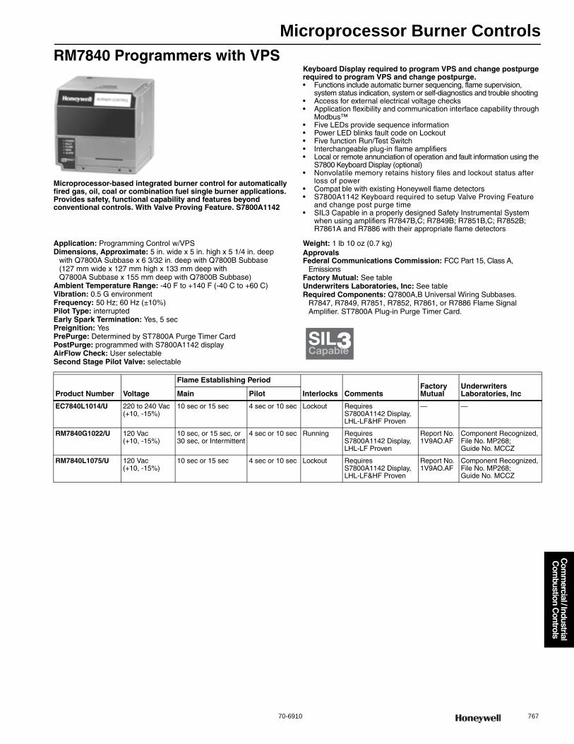
Microprocessor Burner Controls
70-6910 767
Com
mercial / Industrial
Com
bustion Controls
RM7840 Programmers with VPS
Microprocessor-based integrated burner control for automatically fired gas, oil, coal or combination fuel single burner applications. Provides safety, functional capability and features beyond conventional controls. With Valve Proving Feature. S7800A1142
Keyboard Display required to program VPS and change postpurge required to program VPS and change postpurge.• Functions include automatic burner sequencing, flame supervision,
system status indication, system or self-diagnostics and trouble shooting • Access for external electrical voltage checks • Application flexibility and communication interface capability through
Modbus™• Five LEDs provide sequence information• Power LED blinks fault code on Lockout• Five function Run/Test Switch • Interchangeable plug-in flame amplifiers • Local or remote annunciation of operation and fault information using the
S7800 Keyboard Display (optional) • Nonvolatile memory retains history files and lockout status after
loss of power • Compat ble with existing Honeywell flame detectors • S7800A1142 Keyboard required to setup Valve Proving Feature
and change post purge time• SIL3 Capable in a properly designed Safety Instrumental System
when using amplifiers R7847B,C; R7849B; R7851B,C; R7852B; R7861A and R7886 with their appropriate flame detectors
Application: Programming Control w/VPSDimensions, Approximate: 5 in. wide x 5 in. high x 5 1/4 in. deep
with Q7800A Subbase x 6 3/32 in. deep with Q7800B Subbase (127 mm wide x 127 mm high x 133 mm deep with Q7800A Subbase x 155 mm deep with Q7800B Subbase)
Ambient Temperature Range: -40 F to +140 F (-40 C to +60 C) Vibration: 0.5 G environmentFrequency: 50 Hz; 60 Hz (±10%)Pilot Type: interruptedEarly Spark Termination: Yes, 5 secPreignition: YesPrePurge: Determined by ST7800A Purge Timer CardPostPurge: programmed with S7800A1142 displayAirFlow Check: User selectableSecond Stage Pilot Valve: selectable
Weight: 1 lb 10 oz (0.7 kg) ApprovalsFederal Communications Commission: FCC Part 15, Class A,
EmissionsFactory Mutual: See tableUnderwriters Laboratories, Inc: See tableRequired Components: Q7800A,B Universal Wiring Subbases.
R7847, R7849, R7851, R7852, R7861, or R7886 Flame Signal Amplifier. ST7800A Plug-in Purge Timer Card.
SIL3Capable
Product Number Voltage
Flame Establishing Period
Interlocks CommentsFactory Mutual
Underwriters Laboratories, IncMain Pilot
EC7840L1014/U 220 to 240 Vac (+10, -15%)
10 sec or 15 sec 4 sec or 10 sec Lockout Requires S7800A1142 Display, LHL-LF&HF Proven
— —
RM7840G1022/U 120 Vac (+10, -15%)
10 sec, or 15 sec, or 30 sec, or Intermittent
4 sec or 10 sec Running Requires S7800A1142 Display, LHL-LF Proven
Report No. 1V9AO.AF
Component Recognized, File No. MP268; Guide No. MCCZ
RM7840L1075/U 120 Vac (+10, -15%)
10 sec or 15 sec 4 sec or 10 sec Lockout Requires S7800A1142 Display, LHL-LF&HF Proven
Report No. 1V9AO.AF
Component Recognized, File No. MP268; Guide No. MCCZ
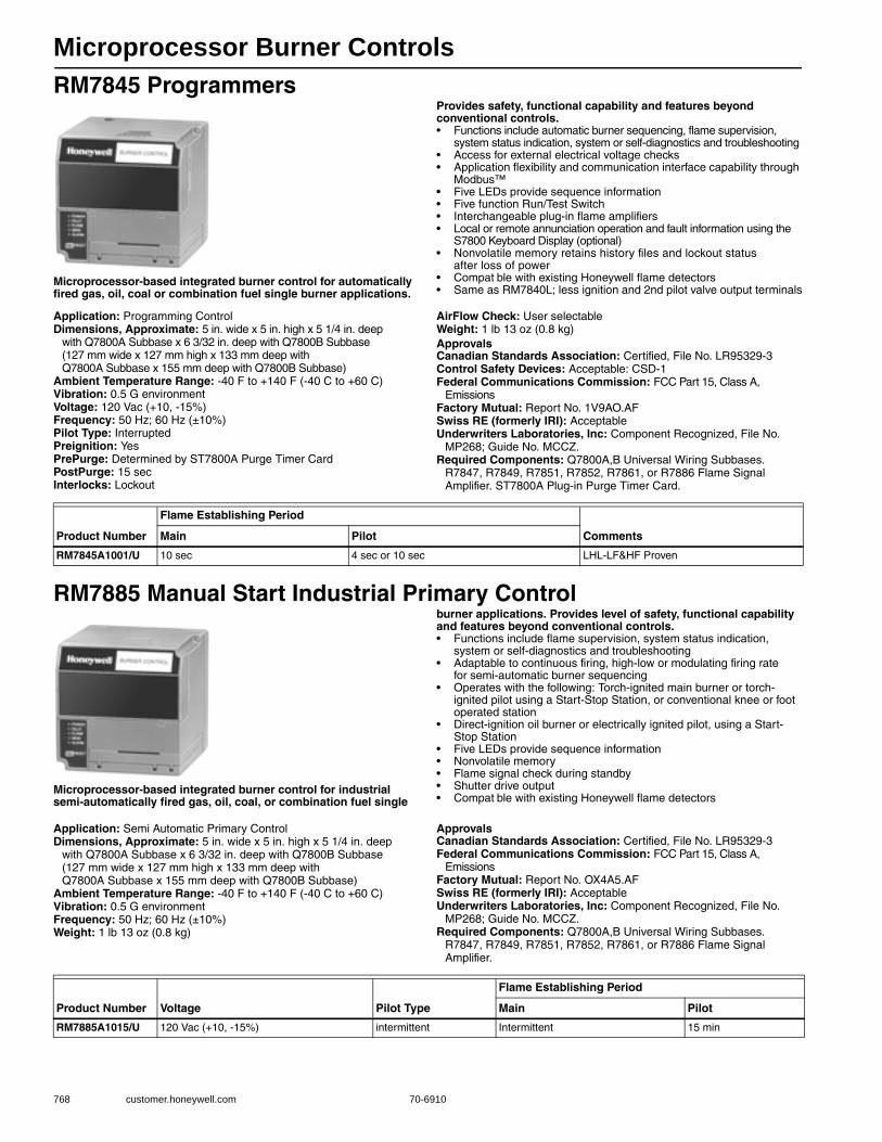
Microprocessor Burner Controls
768 customer.honeywell.com 70-6910
RM7845 Programmers
Microprocessor-based integrated burner control for automatically fired gas, oil, coal or combination fuel single burner applications.
Provides safety, functional capability and features beyond conventional controls.• Functions include automatic burner sequencing, flame supervision,
system status indication, system or self-diagnostics and troubleshooting • Access for external electrical voltage checks • Application flexibility and communication interface capability through
Modbus™• Five LEDs provide sequence information • Five function Run/Test Switch • Interchangeable plug-in flame amplifiers • Local or remote annunciation operation and fault information using the
S7800 Keyboard Display (optional)• Nonvolatile memory retains history files and lockout status
after loss of power • Compat ble with existing Honeywell flame detectors• Same as RM7840L; less ignition and 2nd pilot valve output terminals
Application: Programming ControlDimensions, Approximate: 5 in. wide x 5 in. high x 5 1/4 in. deep
with Q7800A Subbase x 6 3/32 in. deep with Q7800B Subbase (127 mm wide x 127 mm high x 133 mm deep with Q7800A Subbase x 155 mm deep with Q7800B Subbase)
Ambient Temperature Range: -40 F to +140 F (-40 C to +60 C) Vibration: 0.5 G environmentVoltage: 120 Vac (+10, -15%)Frequency: 50 Hz; 60 Hz (±10%)Pilot Type: InterruptedPreignition: YesPrePurge: Determined by ST7800A Purge Timer CardPostPurge: 15 secInterlocks: Lockout
AirFlow Check: User selectableWeight: 1 lb 13 oz (0.8 kg) ApprovalsCanadian Standards Association: Certified, File No. LR95329-3Control Safety Devices: Acceptable: CSD-1Federal Communications Commission: FCC Part 15, Class A,
EmissionsFactory Mutual: Report No. 1V9AO.AFSwiss RE (formerly IRI): AcceptableUnderwriters Laboratories, Inc: Component Recognized, File No.
MP268; Guide No. MCCZ.Required Components: Q7800A,B Universal Wiring Subbases.
R7847, R7849, R7851, R7852, R7861, or R7886 Flame Signal Amplifier. ST7800A Plug-in Purge Timer Card.
RM7885 Manual Start Industrial Primary Control
Microprocessor-based integrated burner control for industrial semi-automatically fired gas, oil, coal, or combination fuel single
burner applications. Provides level of safety, functional capability and features beyond conventional controls.• Functions include flame supervision, system status indication,
system or self-diagnostics and troubleshooting • Adaptable to continuous firing, high-low or modulating firing rate
for semi-automatic burner sequencing • Operates with the following: Torch-ignited main burner or torch-
ignited pilot using a Start-Stop Station, or conventional knee or foot operated station
• Direct-ignition oil burner or electrically ignited pilot, using a Start-Stop Station
• Five LEDs provide sequence information • Nonvolatile memory • Flame signal check during standby • Shutter drive output • Compat ble with existing Honeywell flame detectors
Application: Semi Automatic Primary ControlDimensions, Approximate: 5 in. wide x 5 in. high x 5 1/4 in. deep
with Q7800A Subbase x 6 3/32 in. deep with Q7800B Subbase (127 mm wide x 127 mm high x 133 mm deep with Q7800A Subbase x 155 mm deep with Q7800B Subbase)
Ambient Temperature Range: -40 F to +140 F (-40 C to +60 C) Vibration: 0.5 G environmentFrequency: 50 Hz; 60 Hz (±10%)Weight: 1 lb 13 oz (0.8 kg)
ApprovalsCanadian Standards Association: Certified, File No. LR95329-3Federal Communications Commission: FCC Part 15, Class A,
EmissionsFactory Mutual: Report No. OX4A5.AFSwiss RE (formerly IRI): AcceptableUnderwriters Laboratories, Inc: Component Recognized, File No.
MP268; Guide No. MCCZ.Required Components: Q7800A,B Universal Wiring Subbases.
R7847, R7849, R7851, R7852, R7861, or R7886 Flame Signal Amplifier.
Product Number
Flame Establishing Period
CommentsMain Pilot
RM7845A1001/U 10 sec 4 sec or 10 sec LHL-LF&HF Proven
Product Number Voltage Pilot Type
Flame Establishing Period
Main Pilot
RM7885A1015/U 120 Vac (+10, -15%) intermittent Intermittent 15 min
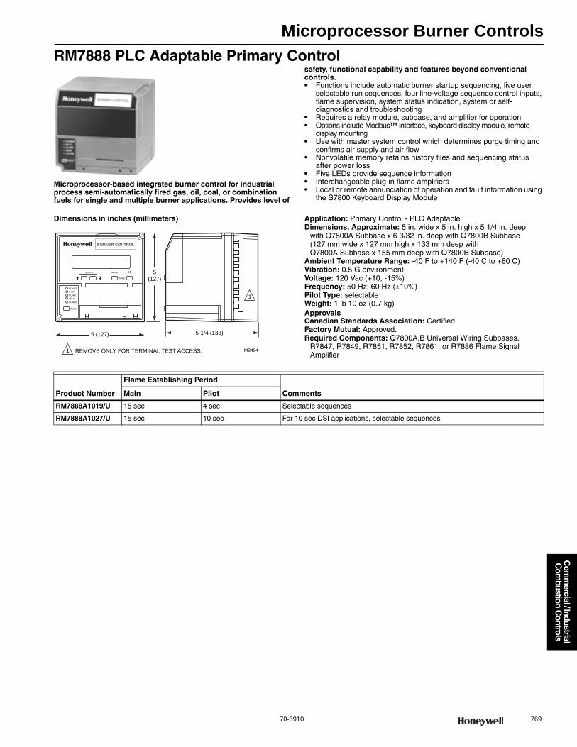
Microprocessor Burner Controls
70-6910 769
Com
mercial / Industrial
Com
bustion Controls
RM7888 PLC Adaptable Primary Control
Microprocessor-based integrated burner control for industrial process semi-automatically fired gas, oil, coal, or combination fuels for single and multiple burner applications. Provides level of
safety, functional capability and features beyond conventional controls.• Functions include automatic burner startup sequencing, five user
selectable run sequences, four line-voltage sequence control inputs, flame supervision, system status indication, system or self-diagnostics and troubleshooting
• Requires a relay module, subbase, and amplifier for operation • Options include Modbus™ interface, keyboard display module, remote
display mounting• Use with master system control which determines purge timing and
confirms air supply and air flow • Nonvolatile memory retains history files and sequencing status
after power loss • Five LEDs provide sequence information • Interchangeable plug-in flame amplifiers • Local or remote annunciation of operation and fault information using
the S7800 Keyboard Display Module
Dimensions in inches (millimeters) Application: Primary Control - PLC AdaptableDimensions, Approximate: 5 in. wide x 5 in. high x 5 1/4 in. deep
with Q7800A Subbase x 6 3/32 in. deep with Q7800B Subbase (127 mm wide x 127 mm high x 133 mm deep with Q7800A Subbase x 155 mm deep with Q7800B Subbase)
Ambient Temperature Range: -40 F to +140 F (-40 C to +60 C) Vibration: 0.5 G environmentVoltage: 120 Vac (+10, -15%)Frequency: 50 Hz; 60 Hz (±10%)Pilot Type: selectableWeight: 1 lb 10 oz (0.7 kg) ApprovalsCanadian Standards Association: CertifiedFactory Mutual: Approved.Required Components: Q7800A,B Universal Wiring Subbases.
R7847, R7849, R7851, R7852, R7861, or R7886 Flame Signal Amplifier
BURNER CONTROL
POWER
P LOT
FLAME
MA N
ALARM
RESET
SCROLL MODE
SAVE
5(127)
5 (127)
M9494
5-1/4 (133)
REMOVE ONLY FOR TERMINAL TEST ACCESS.1
1
Product Number
Flame Establishing Period
CommentsMain Pilot
RM7888A1019/U 15 sec 4 sec Selectable sequences
RM7888A1027/U 15 sec 10 sec For 10 sec DSI applications, selectable sequences

Microprocessor Burner Controls
770 customer.honeywell.com 70-6910
RM7890 On-Off Primary Control with VPS
Microprocessor-based integrated primary burner control for automatically fired gas, oil or combination fuel single burner
applications. Provides level of safety, functional capability and features beyond conventional controls.• Functions include automatic burner sequencing, flame supervision,
system status indication, system or self diagnostics and troubleshooting • Subbase and amplifier are required for operation • Power LED blinks Fault Code on lockout• Options include Modbus™ interface, keyboard display module, remote
display module • Five LEDs provide sequence information • Interchangeable plug-in flame amplifiers • Optional local or remote annunciation of operation and fault information
using the S7800 Keyboard Display Module• Nonvolatile memory retains history files and sequencing status
after power loss • Selectable relight or lockout on loss of flame• Contains Valve Proving Feature - require S7800A1142 Keyboard
Display (not provided) to set up• SIL3 Capable in a properly designed Safety Instrumental System
when using amplifiers R7847B,C; R7849B; R7851B,C; R7852B; R7861A and R7886 with their appropriate flame detectors
Dimensions in inches (millimeters) Application: On-Off Primary Control w/VPSDimensions, Approximate: 5 in. wide x 5 in. high x 5 1/4 in. deep
with Q7800A Subbase x 6 3/32 in. deep with Q7800B Subbase (127 mm wide x 127 mm high x 133 mm deep with Q7800A Subbase x 155 mm deep with Q7800B Subbase)
Ambient Temperature Range: -40 F to +140 F (-40 C to +60 C) Vibration: 0.5 G environmentFrequency: 50 Hz; 60 Hz (±10%)Preignition: YesWeight: 1 lb 13 oz (0.8 kg) ApprovalsCanadian Standards Association: Certified, File No. LR95329-3Federal Communications Commission: FCC Part 15, Class A,
EmissionsFactory Mutual: Report No. OX4A5.AFSwiss RE (formerly IRI): AcceptableUnderwriters Laboratories, Inc: Component Recognized, File No.
MP268; Guide No. MCCZ.Required Components: Q7800A,B Universal Wiring Subbases.
R7847, R7849, R7851, R7852, R7861, or R7886 Flame Signal Amplifier.
POWER
PILOT
FLAME
MAIN
ALARM
RESET
5(127)
5 (127)
M5003B
(133)
BURNER CONTROL
REMOVE ONLY FOR TERMINAL TEST ACCESS.
1
5-1/4
1
SIL3Capable
Product Number
Flame Establishing Period
CommentsMain Pilot
RM7890A1056/U Intermittent 4 sec or 10 sec Includes programmable VPS (Valve Proving Switch) check feature and blinking LED fault annunciation
RM7890B1048/U Intermittent 4 sec or 10 sec Includes Shutter Drive Capability, VPS (Valve Proving Switch) check and blinking LED fault annunciation
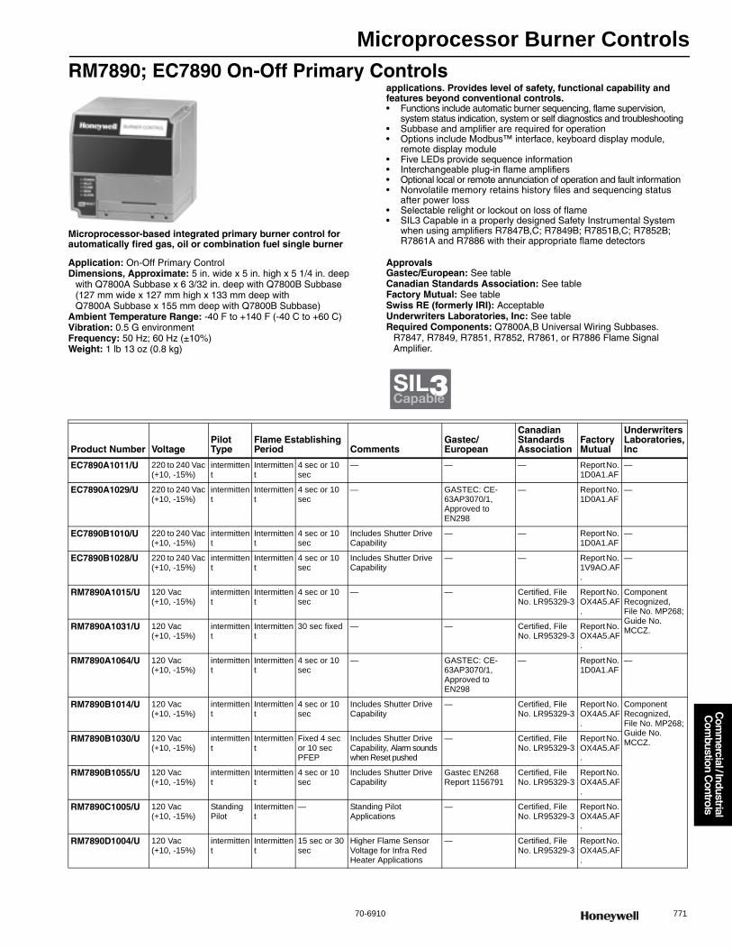
Microprocessor Burner Controls
70-6910 771
Com
mercial / Industrial
Com
bustion Controls
RM7890; EC7890 On-Off Primary Controls
Microprocessor-based integrated primary burner control for automatically fired gas, oil or combination fuel single burner
applications. Provides level of safety, functional capability and features beyond conventional controls.• Functions include automatic burner sequencing, flame supervision,
system status indication, system or self diagnostics and troubleshooting • Subbase and amplifier are required for operation • Options include Modbus™ interface, keyboard display module,
remote display module• Five LEDs provide sequence information • Interchangeable plug-in flame amplifiers • Optional local or remote annunciation of operation and fault information • Nonvolatile memory retains history files and sequencing status
after power loss • Selectable relight or lockout on loss of flame• SIL3 Capable in a properly designed Safety Instrumental System
when using amplifiers R7847B,C; R7849B; R7851B,C; R7852B; R7861A and R7886 with their appropriate flame detectors
Application: On-Off Primary ControlDimensions, Approximate: 5 in. wide x 5 in. high x 5 1/4 in. deep
with Q7800A Subbase x 6 3/32 in. deep with Q7800B Subbase (127 mm wide x 127 mm high x 133 mm deep with Q7800A Subbase x 155 mm deep with Q7800B Subbase)
Ambient Temperature Range: -40 F to +140 F (-40 C to +60 C) Vibration: 0.5 G environmentFrequency: 50 Hz; 60 Hz (±10%)Weight: 1 lb 13 oz (0.8 kg)
ApprovalsGastec/European: See tableCanadian Standards Association: See tableFactory Mutual: See tableSwiss RE (formerly IRI): AcceptableUnderwriters Laboratories, Inc: See tableRequired Components: Q7800A,B Universal Wiring Subbases.
R7847, R7849, R7851, R7852, R7861, or R7886 Flame Signal Amplifier.
SIL3Capable
Product Number VoltagePilot Type
Flame Establishing Period Comments
Gastec/European
Canadian Standards Association
Factory Mutual
Underwriters Laboratories, Inc
EC7890A1011/U 220 to 240 Vac (+10, -15%)
intermittent
Intermittent
4 sec or 10 sec
— — — Report No. 1D0A1.AF
—
EC7890A1029/U 220 to 240 Vac (+10, -15%)
intermittent
Intermittent
4 sec or 10 sec
— GASTEC: CE-63AP3070/1, Approved to EN298
— Report No. 1D0A1.AF
—
EC7890B1010/U 220 to 240 Vac (+10, -15%)
intermittent
Intermittent
4 sec or 10 sec
Includes Shutter Drive Capability
— — Report No. 1D0A1.AF
—
EC7890B1028/U 220 to 240 Vac (+10, -15%)
intermittent
Intermittent
4 sec or 10 sec
Includes Shutter Drive Capability
— — Report No. 1V9AO.AF.
—
RM7890A1015/U 120 Vac (+10, -15%)
intermittent
Intermittent
4 sec or 10 sec
— — Certified, File No. LR95329-3
Report No. OX4A5.AF.
Component Recognized, File No. MP268; Guide No. MCCZ.RM7890A1031/U 120 Vac
(+10, -15%)intermittent
Intermittent
30 sec fixed — — Certified, File No. LR95329-3
Report No. OX4A5.AF.
RM7890A1064/U 120 Vac(+10, -15%)
intermittent
Intermittent
4 sec or 10 sec
— GASTEC: CE-63AP3070/1, Approved to EN298
— Report No. 1D0A1.AF
—
RM7890B1014/U 120 Vac(+10, -15%)
intermittent
Intermittent
4 sec or 10 sec
Includes Shutter Drive Capability
— Certified, File No. LR95329-3
Report No. OX4A5.AF.
Component Recognized, File No. MP268; Guide No. MCCZ.RM7890B1030/U 120 Vac
(+10, -15%)intermittent
Intermittent
Fixed 4 sec or 10 sec PFEP
Includes Shutter Drive Capability, Alarm sounds when Reset pushed
— Certified, File No. LR95329-3
Report No. OX4A5.AF.
RM7890B1055/U 120 Vac (+10, -15%)
intermittent
Intermittent
4 sec or 10 sec
Includes Shutter Drive Capability
Gastec EN268 Report 1156791
Certified, File No. LR95329-3
Report No. OX4A5.AF.
RM7890C1005/U 120 Vac (+10, -15%)
Standing Pilot
Intermittent
— Standing Pilot Applications
— Certified, File No. LR95329-3
Report No. OX4A5.AF.
RM7890D1004/U 120 Vac (+10, -15%)
intermittent
Intermittent
15 sec or 30 sec
Higher Flame Sensor Voltage for Infra Red Heater Applications
— Certified, File No. LR95329-3
Report No. OX4A5.AF.

Microprocessor Burner Controls
772 customer.honeywell.com 70-6910
RM7895; EC7895 On-Off Primary Control with Prepurge
Microprocessor-based integrated primary burner control for automatically fired gas, oil, or combination fuel single burner
applications. Provides level of safety, functional capability and features beyond conventional controls.• Functions include automatic burner sequencing, flame supervision,
system status indication, system or self-diagnostics and troubleshooting • Subbase, amplifier, and prepurge timer are required for operation • Options include Modbus™ interface, keyboard display module, remote
display module and first-out expanded annunciator• Five LEDs provide sequence information • Interchangeable plug-in flame amplifiers • Optional local or remote annunciation of operation and fault information
using the S7800 Keyboard Display Module• Nonvolatile memory retains history files and sequencing status
after power loss • Selectable relight or lockout on loss of flame • Dynamic airflow switch check
Application: On-Off Primary Control with PrepurgeDimensions, Approximate: 5 in. wide x 5 in. high x 5 1/4 in. deep
with Q7800A Subbase x 6 3/32 in. deep with Q7800B Subbase (127 mm wide x 127 mm high x 133 mm deep with Q7800A Subbase x 155 mm deep with Q7800B Subbase)
Ambient Temperature Range: -40 F to +140 F (-40 C to +60 C) Vibration: 0.5 G environmentFrequency: 50 Hz; 60 Hz (±10%)PrePurge: Determined by ST7800A Purge Timer CardInterlocks: Selectable
Weight: 1 lb 15 oz (0.9 kg) ApprovalsCanadian Standards Association: See tableFactory Mutual: See tableSwiss RE (formerly IRI): AcceptableControl Safety Devices: See tableUnderwriters Laboratories, Inc: See tableRequired Components: Q7800A,B Universal Wiring Subbases.
R7847, R7849, R7851, R7852, R7861, or R7886 Flame Signal Amplifier. ST7800A Plug-in Purge Timer Card.
Product Number VoltagePilot Type
AirFlow Check
Flame Establishing Period Delaye
d Main Valve Comments Used With
Canadian Standards Association
Factory Mutual
Control Safety Devices
Underwriters Laborato-ries, Inc.Main Pilot
EC7895A1010/U 220 to 240 Vac (+10, -15%)
intermittent
— Intermittent
4 sec or 10 sec
No — 7800 Series Amplifiers
— Report No. 1D0A1.AF
— —
EC7895C1000/U interrupted
— 10 sec 4 sec or 10 sec
Yes — 7800 Series Amplifiers
— — —
RM7895A1014/U 120 Vac (+10, -15%)
intermittent
— Intermittent
4 sec or 10 sec
No — 7800 Series Amplifiers
Certified, File No. LR95329-3
Report No. OX4A5.AF
Acceptable: CSD-1
Component Recognized, File No. MP268; Guide No. MCCZ.
RM7895A1048/U intermittent
— Intermittent
4 sec or 10 sec
No Includes ignition cut-out during PFEP
7800 Series Amplifiers
RM7895B1013/U intermittent
Dynamic
Intermittent
4 sec to 10 sec
No — 7800 Series Amplifiers
RM7895C1012/U interrupted
— 10 sec 4 sec or 10 sec
Yes — 7800 Series Amplifiers
RM7895C1020/U interrupted
— 10 sec 10 sec Yes Includes ignition cut-out during PFEP
7800 Series Amplifiers
RM7895D1011/U interrupted
Dynamic
10 sec 4 sec or 10 sec
Yes — 7800 Series Amplifiers
RM7895E1002/U intermittent
— Intermittent
15 sec or 30 sec
No Higher Flame Sensor Voltage for Infra Red Heater Applications
R7847 only
RM7895E1010/U intermittent
— Intermittent
15 sec or 30 sec
No R7847 only
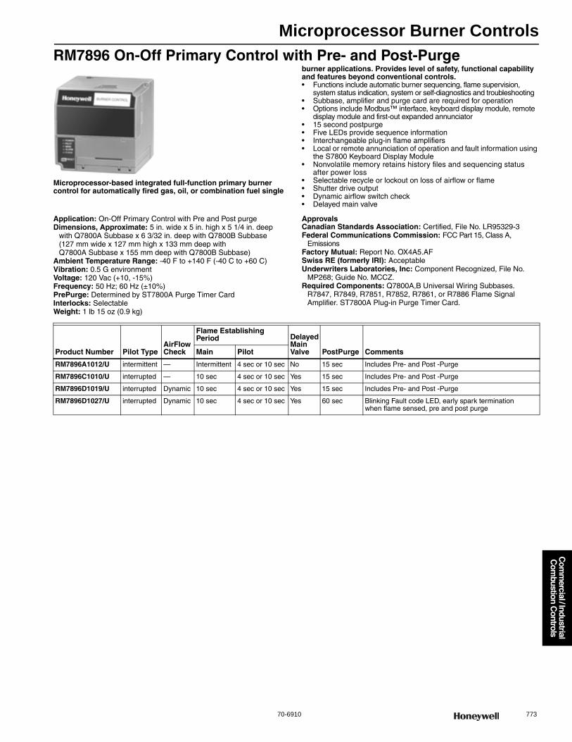
Microprocessor Burner Controls
70-6910 773
Com
mercial / Industrial
Com
bustion Controls
RM7896 On-Off Primary Control with Pre- and Post-Purge
Microprocessor-based integrated full-function primary burner control for automatically fired gas, oil, or combination fuel single
burner applications. Provides level of safety, functional capability and features beyond conventional controls.• Functions include automatic burner sequencing, flame supervision,
system status indication, system or self-diagnostics and troubleshooting • Subbase, amplifier and purge card are required for operation • Options include Modbus™ interface, keyboard display module, remote
display module and first-out expanded annunciator• 15 second postpurge • Five LEDs provide sequence information • Interchangeable plug-in flame amplifiers • Local or remote annunciation of operation and fault information using
the S7800 Keyboard Display Module• Nonvolatile memory retains history files and sequencing status
after power loss • Selectable recycle or lockout on loss of airflow or flame • Shutter drive output • Dynamic airflow switch check • Delayed main valve
Application: On-Off Primary Control with Pre and Post purgeDimensions, Approximate: 5 in. wide x 5 in. high x 5 1/4 in. deep
with Q7800A Subbase x 6 3/32 in. deep with Q7800B Subbase (127 mm wide x 127 mm high x 133 mm deep with Q7800A Subbase x 155 mm deep with Q7800B Subbase)
Ambient Temperature Range: -40 F to +140 F (-40 C to +60 C) Vibration: 0.5 G environmentVoltage: 120 Vac (+10, -15%)Frequency: 50 Hz; 60 Hz (±10%)PrePurge: Determined by ST7800A Purge Timer CardInterlocks: SelectableWeight: 1 lb 15 oz (0.9 kg)
ApprovalsCanadian Standards Association: Certified, File No. LR95329-3Federal Communications Commission: FCC Part 15, Class A,
EmissionsFactory Mutual: Report No. OX4A5.AFSwiss RE (formerly IRI): AcceptableUnderwriters Laboratories, Inc: Component Recognized, File No.
MP268; Guide No. MCCZ.Required Components: Q7800A,B Universal Wiring Subbases.
R7847, R7849, R7851, R7852, R7861, or R7886 Flame Signal Amplifier. ST7800A Plug-in Purge Timer Card.
Product Number Pilot TypeAirFlow Check
Flame Establishing Period Delayed
Main Valve PostPurge CommentsMain Pilot
RM7896A1012/U intermittent — Intermittent 4 sec or 10 sec No 15 sec Includes Pre- and Post -Purge
RM7896C1010/U interrupted — 10 sec 4 sec or 10 sec Yes 15 sec Includes Pre- and Post -Purge
RM7896D1019/U interrupted Dynamic 10 sec 4 sec or 10 sec Yes 15 sec Includes Pre- and Post -Purge
RM7896D1027/U interrupted Dynamic 10 sec 4 sec or 10 sec Yes 60 sec Blinking Fault code LED, early spark termination when flame sensed, pre and post purge
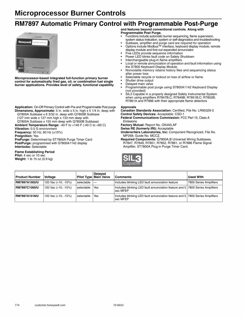
Microprocessor Burner Controls
774 customer.honeywell.com 70-6910
RM7897 Automatic Primary Control with Programmable Post-Purge
Microprocessor-based integrated full-function primary burner control for automatically fired gas, oil, or combination fuel single burner applications. Provides level of safety, functional capability
and features beyond conventional controls. Along with Programmable Post Purge.• Functions include automatic burner sequencing, flame supervision,
system status indication, system or self-diagnostics and troubleshooting • Subbase, amplifier and purge card are required for operation • Options include Modbus™ interface, keyboard display module, remote
display module and first-out expanded annunciator• Five LEDs provide sequence information• Power LED blinks fault code on Safety Shutdown• Interchangeable plug-in flame amplifiers • Local or remote annunciation of operation and fault information using
the S7800 Keyboard Display Module.• Nonvolatile memory retains history files and sequencing status
after power loss • Selectable recycle or lockout on loss of airflow or flame • Shutter drive output • Delayed main valve• Programmable post purge using S7800A1142 Keyboard Display
(not provided)• SIL3 Capable in a properly designed Safety Instrumental System
when using amplifiers R7847B,C; R7849B; R7851B,C; R7852B; R7861A and R7886 with their appropriate flame detectors
Application: On-Off Primary Control with Pre and Programmable Post purgeDimensions, Approximate: 5 in. wide x 5 in. high x 5 1/4 in. deep with
Q7800A Subbase x 6 3/32 in. deep with Q7800B Subbase (127 mm wide x 127 mm high x 133 mm deep with Q7800A Subbase x 155 mm deep with Q7800B Subbase)
Ambient Temperature Range: -40 F to +140 F (-40 C to +60 C) Vibration: 0.5 G environmentFrequency: 50 Hz; 60 Hz (±10%)Preignition: YesPrePurge: Determined by ST7800A Purge Timer CardPostPurge: programmed with S7800A1142 displayInterlocks: Selectable
Flame Establishing PeriodPilot: 4 sec or 10 secWeight: 1 lb 15 oz (0.9 kg)
ApprovalsCanadian Standards Association: Certified, File No. LR95329-3Control Safety Devices: Acceptable: CSD-1Federal Communications Commission: FCC Part 15, Class A
EmissionsFactory Mutual: Report No. OX4A5.AFSwiss RE (formerly IRI): AcceptableUnderwriters Laboratories, Inc: Component Recognized, File No.
MP268; Guide No. MCCZ.Required Components: Q7800A,B Universal Wiring Subbases.
R7847, R7849, R7851, R7852, R7861, or R7886 Flame Signal Amplifier. ST7800A Plug-in Purge Timer Card.
SIL3Capable
Product Number Voltage Pilot TypeDelayed Main Valve Comments Used With
RM7897A1002/U 120 Vac (+10, -15%) selectable — Includes blinking LED fault annunciation feature 7800 Series Amplifiers
RM7897C1000/U 120 Vac (+10, -15%) selectable Yes Includes blinking LED fault annunciation feature and 5 sec MFEP
7800 Series Amplifiers
RM7897A1018/U 120 Vac (+10, -15%) selectable Yes Includes blinking LED fault annunciation feature and 5 sec MFEP
7800 Series Amplifiers
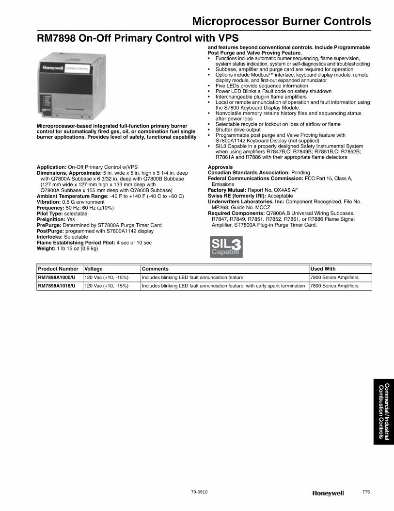
Microprocessor Burner Controls
70-6910 775
Com
mercial / Industrial
Com
bustion Controls
RM7898 On-Off Primary Control with VPS
Microprocessor-based integrated full-function primary burner control for automatically fired gas, oil, or combination fuel single burner applications. Provides level of safety, functional capability
and features beyond conventional controls. Include Programmable Post Purge and Valve Proving Feature.• Functions include automatic burner sequencing, flame supervision,
system status indication, system or self-diagnostics and troubleshooting • Subbase, amplifier and purge card are required for operation • Options include Modbus™ interface, keyboard display module, remote
display module, and first-out expanded annunciator• Five LEDs provide sequence information• Power LED Blinks a Fault code on safety shutdown• Interchangeable plug-in flame amplifiers • Local or remote annunciation of operation and fault information using
the S7800 Keyboard Display Module.• Nonvolatile memory retains history files and sequencing status
after power loss • Selectable recycle or lockout on loss of airflow or flame • Shutter drive output • Programmable post purge and Valve Proving feature with
S7800A1142 Keyboard Display (not supplied)• SIL3 Capable in a properly designed Safety Instrumental System
when using amplifiers R7847B,C; R7849B; R7851B,C; R7852B; R7861A and R7886 with their appropriate flame detectors
Application: On-Off Primary Control w/VPSDimensions, Approximate: 5 in. wide x 5 in. high x 5 1/4 in. deep
with Q7800A Subbase x 6 3/32 in. deep with Q7800B Subbase (127 mm wide x 127 mm high x 133 mm deep with Q7800A Subbase x 155 mm deep with Q7800B Subbase)
Ambient Temperature Range: -40 F to +140 F (-40 C to +60 C) Vibration: 0.5 G environmentFrequency: 50 Hz; 60 Hz (±10%)Pilot Type: selectablePreignition: YesPrePurge: Determined by ST7800A Purge Timer CardPostPurge: programmed with S7800A1142 displayInterlocks: SelectableFlame Establishing Period Pilot: 4 sec or 10 secWeight: 1 lb 15 oz (0.9 kg)
ApprovalsCanadian Standards Association: PendingFederal Communications Commission: FCC Part 15, Class A,
EmissionsFactory Mutual: Report No. OX4A5.AFSwiss RE (formerly IRI): AcceptableUnderwriters Laboratories, Inc: Component Recognized, File No.
MP268; Guide No. MCCZRequired Components: Q7800A,B Universal Wiring Subbases.
R7847, R7849, R7851, R7852, R7861, or R7886 Flame Signal Amplifier. ST7800A Plug-in Purge Timer Card.
SIL3Capable
Product Number Voltage Comments Used With
RM7898A1000/U 120 Vac (+10, -15%) Includes blinking LED fault annunciation feature 7800 Series Amplifiers
RM7898A1018/U 120 Vac (+10, -15%) Includes blinking LED fault annunciation feature, with early spark termination 7800 Series Amplifiers
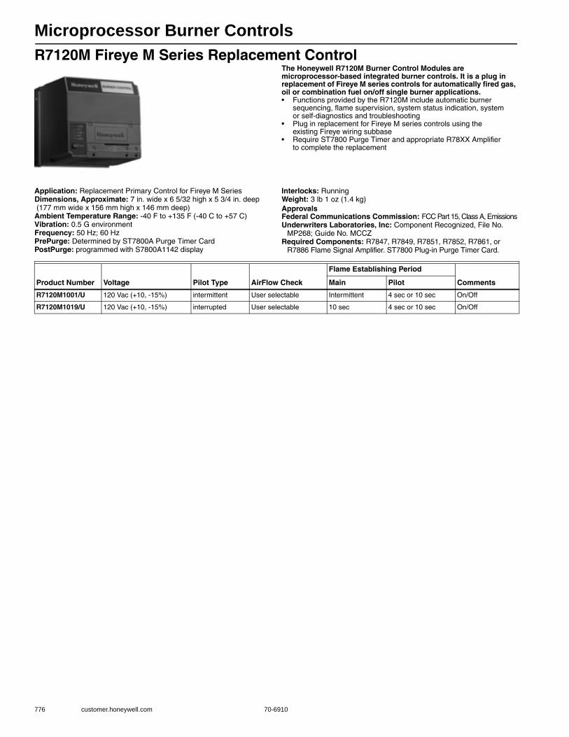
Microprocessor Burner Controls
776 customer.honeywell.com 70-6910
R7120M Fireye M Series Replacement ControlThe Honeywell R7120M Burner Control Modules are microprocessor-based integrated burner controls. It is a plug in replacement of Fireye M series controls for automatically fired gas, oil or combination fuel on/off single burner applications.• Functions provided by the R7120M include automatic burner
sequencing, flame supervision, system status indication, system or self-diagnostics and troubleshooting
• Plug in replacement for Fireye M series controls using the existing Fireye wiring subbase
• Require ST7800 Purge Timer and appropriate R78XX Amplifier to complete the replacement
Application: Replacement Primary Control for Fireye M SeriesDimensions, Approximate: 7 in. wide x 6 5/32 high x 5 3/4 in. deep (177 mm wide x 156 mm high x 146 mm deep) Ambient Temperature Range: -40 F to +135 F (-40 C to +57 C) Vibration: 0.5 G environmentFrequency: 50 Hz; 60 HzPrePurge: Determined by ST7800A Purge Timer CardPostPurge: programmed with S7800A1142 display
Interlocks: RunningWeight: 3 lb 1 oz (1.4 kg) ApprovalsFederal Communications Commission: FCC Part 15, Class A, EmissionsUnderwriters Laboratories, Inc: Component Recognized, File No.
MP268; Guide No. MCCZRequired Components: R7847, R7849, R7851, R7852, R7861, or
R7886 Flame Signal Amplifier. ST7800 Plug-in Purge Timer Card.
Product Number Voltage Pilot Type AirFlow Check
Flame Establishing Period
CommentsMain Pilot
R7120M1001/U 120 Vac (+10, -15%) intermittent User selectable Intermittent 4 sec or 10 sec On/Off
R7120M1019/U 120 Vac (+10, -15%) interrupted User selectable 10 sec 4 sec or 10 sec On/Off
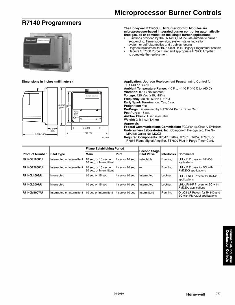
Microprocessor Burner Controls
70-6910 777
Com
mercial / Industrial
Com
bustion Controls
R7140 ProgrammersThe Honeywell R7140G, L, M Burner Control Modules are microprocessor-based integrated burner control for automatically fired gas, oil or combination fuel single burner applications.• Functions provided by the R7140G,L,M include automatic burner
sequencing, flame supervision, system status indication, system or self-diagnostics and troubleshooting
• Upgrade replacement for BC7000 or R4140 legacy Programmer controls• Require ST7800 Purge Timer and appropriate R78XX Amplifier
to complete the replacement
Dimensions in inches (millimeters) Application: Upgrade Replacement Programming Control for R4140 or BC7000
Ambient Temperature Range: -40 F to +140 F (-40 C to +60 C) Vibration: 0.5 G environmentVoltage: 120 Vac (+10, -15%)Frequency: 50 Hz, 60 Hz (±10%)Early Spark Termination: Yes, 5 secPreignition: YesPrePurge: Determined by ST7800A Purge Timer CardPostPurge: 15 secAirFlow Check: User selectableWeight: 3 lb 1 oz (1.4 kg) ApprovalsFederal Communications Commission: FCC Part 15, Class A, EmissionsUnderwriters Laboratories, Inc: Component Recognized, File No.
MP268; Guide No. MCCZRequired Components: R7847, R7849, R7851, R7852, R7861, or
R7886 Flame Signal Amplifier. ST7800 Plug-in Purge Timer Card.
5-3/4 (146)
1-1/4 (32)
RESET
POWER
PILOT
FLAME
MAIN
ALARM
5(127)
5 (127)
7 (177)
6-5/32(156)
BURNER CONTROL
M22604
Product Number Pilot Type
Flame Establishing PeriodSecond Stage Pilot Valve Interlocks CommentsMain Pilot
R7140G1000/U Interrupted or Intermittent 10 sec, or 15 sec, or 30 sec, or Intermittent
4 sec or 10 sec selectable Running LHL-LF Proven for R4140G applications
R7140G2008/U Interrupted or Intermittent 10 sec, or 15 sec, or 30 sec, or Intermittent
4 sec or 10 sec — Running LHL-LF Proven for BC with PM720G applications
R7140L1009/U interrupted 10 sec or 15 sec 4 sec or 10 sec Interrupted Lockout LHL-LF&HF Proven for R4140L applications
R7140L2007/U interrupted 10 sec or 15 sec 4 sec or 10 sec Interrupted Lockout LHL-LF&HF Proven for BC with PM720L applications
R7140M1007/U Interrupted or Intermittent 10 sec or Intermittent 4 sec or 10 sec Intermittent Running On/Off-LF Proven for R4140 and BC with PM720M applications
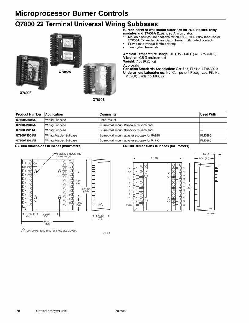
Microprocessor Burner Controls
778 customer.honeywell.com 70-6910
Q7800 22 Terminal Universal Wiring SubbasesBurner, panel or wall mount subbases for 7800 SERIES relay modules and S7830A Expanded Annunciator.• Makes electrical connections for 7800 SERIES relay modules or
S7830A Expanded Annunciator through bifurcated contacts • Provides terminals for field wiring • Twenty-two terminals
Ambient Temperature Range: -40 F to +140 F (-40 C to +60 C) Vibration: 0.5 G environmentWeight: 7 oz (0.20 kg) ApprovalsCanadian Standards Association: Certified, File No. LR95329-3Underwriters Laboratories, Inc: Component Recognized, File No.
MP268; Guide No. MCCZ2
Q7800A dimensions in inches (millimeters) Q7800F dimensions in inches (millimeters)
Q7800B
Q7800A
Q7800F
Product Number Application Comments Used With
Q7800A1005/U Wiring Subbase Panel mount —
Q7800B1003/U Wiring Subbase Burner/wall mount 2 knockouts each end —
Q7800B1011/U Wiring Subbase Burner/wall mount 3 knockouts each end —
Q7800F1004/U Wiring Adapter Subbase Burner/wall mount adapter subbase for RA890 RM7890
Q7800F1012/U Wiring Adapter Subbase Burner/wall mount adapter subbase for R4795 RM7895
12
13
14
15
16
17
18
19
20
21
22
G
L2(N)
3
4
5
6
7
8
9
10
F
USE NO. 6 MOUNTING SCREWS (4)
M1968DOPTIONAL TERMINAL TEST ACCESS COVER.1
4-31/32(126)
2-1/2(64)
1-11/32(34)
1-11/32(34)
2-9/32(58)
4-31/32(126)
1-13/32(36)
1
12
13
14
15
16
17
18
19
20
21
22
G
L2(N)
3
4
5
6
7
8
9
10
F (11)
5 (127)
5(127)
M5648A
1-3/4 (44)
1/4 (6)
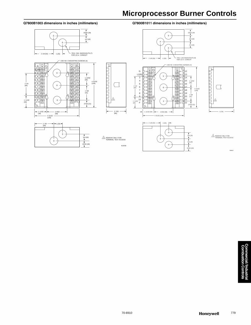
Microprocessor Burner Controls
70-6910 779
Com
mercial / Industrial
Com
bustion Controls
Q7800B1003 dimensions in inches (millimeters) Q7800B1011 dimensions in inches (millimeters)
12
13
14
15
16
17
18
19
20
21
22
G
L2(N)3
4
5
6
7
8
9
10
F
7/8 in DIA KNOCKOUTS (7)FOR 1/2 in CONDUIT
USE NO 6 MOUNTING SCREWS (4)
1 (25)
1 (25)
M1966B
REMOVE ONLY FOR TERMINAL TEST ACCESS
1
1
2 1/8 (54)
2 1/4(64)
1 11/32(34)
1 11/32(34)
1 13/32(36)
4 31/32(126)
4 31/32(126)
1 5/8(41)
27/32 (21)
2 9/32(58)
23/32 (18)
3/4 (19)
2 1/8(54)
2 7/32(56)
23/32 (18)
1/2 (19)
12
13
14
15
16
17
18
19
20
21
22
G
L2(N)
3
4
5
6
7
8
9
10
F
7/8 in (22) KNOCKOUTS (9)FOR 1/2 in CONDUIT
USE NO 6 MOUNTING SCREWS (4)
1 (25)
1 (25)
M9883
REMOVE ONLY FOR TERMINAL TEST ACCESS
1
1
2 1/8 (54)
2 1/4(64)
1 11/32(34)
1 11/32 (34)
1 13/32(36)
4 31/32(126)
4 31/32 (126)
1 5/8(41)
27/32 (21)
2 9/32 (58)
23/32 (18)
3/4 (19)
3/4 (19)
2 1/8 (54)
3 (76)
23/32 (18)
3/4 (19)
3/4 (19)
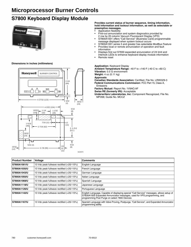
Microprocessor Burner Controls
780 customer.honeywell.com 70-6910
S7800 Keyboard Display ModuleProvides current status of burner sequence, timing information, hold information and lockout information, as well as selectable or preemptive messages.• Application flexibility • First-out annunciation and system diagnostics provided by
2 row by 20 column Vacuum Fluorescent Display (VFD) • S7800A1001 offers “Call Service” (Business Card) programmable
message displayed when system lockout occurs• S7800A1001 series 5 and greater has selectable ModBus Feature • Provides local or remote annunciation of operation and fault
information • Displays first out S7830 expanded annunciation of 24 limit and
interlock LEDs to enhance keyboard display module information • Remote reset
Dimensions in inches (millimeters)Application: Keyboard DisplayAmbient Temperature Range: -40 F to +140 F (-40 C to +60 C) Vibration: 0.5 G environmentWeight: 4 oz (0.11 kg) ApprovalsCanadian Standards Association: Certified, File No. LR95329-3Federal Communications Commission: FCC Part 15, Class A,
EmissionsFactory Mutual: Report No. 1V9AO.AFSwiss RE (formerly IRI): AcceptableUnderwriters Laboratories, Inc: Component Recognized, File No.
MP268; Guide No. MCCZ
2 -1 /3 2(5 2 )
BURNER CONTROL
29/32
(23)
19/32
(15)1-1/4
(32)1-1/32
(26)
5/32
(4)
5/16
(8)
M22870
1/2
(13)
7/16 (11)1-5/16
(49) 2-7/16 (62)
29/32
(23)
5/32 (4)15/32
(12)3-7/8 (99)
5/16
(8)13/
32
(11)
BACKENTEREdit - +
4-27/32 (123)
4-3/32 (104)
2-3/4
(69)
Product Number Voltage Comments
S7800A1001/U 13 Vdc peak fullwave rectified (+20/-15%) English Language
S7800A1035/U 13 Vdc peak fullwave rectified (+20/-15%) French Language
S7800A1043/U 13 Vdc peak fullwave rectified (+20/-15%) German Language
S7800A1050/U 13 Vdc peak fullwave rectified (+20/-15%) Italian Language
S7800A1068/U 13 Vdc peak fullwave rectified (+20/-15%) Spanish Language
S7800A1118/U 13 Vdc peak fullwave rectified (+20/-15%) Japanese Language
S7800A1126/U 13 Vdc peak fullwave rectified (+20/-15%) Portuguese Language
S7800A1142/U 13 Vdc peak fullwave rectified (+20/-15%) English Language, Capable of displaying special “Call Service” messages, allows setup of S7830A1005 Expanded Annunciator messages, used for VPS programming, and programming Post Purge on select 7800 Devices
S7800A1167/U 13 Vdc peak fullwave rectified (+20/-15%) Spanish Language with Valve Proving, Postpurge, “Call Service”, and Expanded Annunciator programming ability
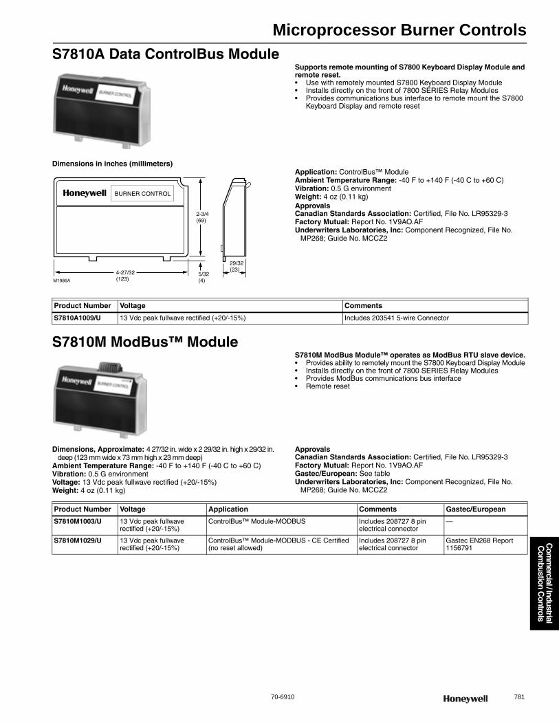
Microprocessor Burner Controls
70-6910 781
Com
mercial / Industrial
Com
bustion Controls
S7810A Data ControlBus ModuleSupports remote mounting of S7800 Keyboard Display Module and remote reset.• Use with remotely mounted S7800 Keyboard Display Module • Installs directly on the front of 7800 SERIES Relay Modules • Provides communications bus interface to remote mount the S7800
Keyboard Display and remote reset
Dimensions in inches (millimeters)Application: ControlBus™ ModuleAmbient Temperature Range: -40 F to +140 F (-40 C to +60 C) Vibration: 0.5 G environmentWeight: 4 oz (0.11 kg) ApprovalsCanadian Standards Association: Certified, File No. LR95329-3Factory Mutual: Report No. 1V9AO.AFUnderwriters Laboratories, Inc: Component Recognized, File No.
MP268; Guide No. MCCZ2
S7810M ModBus™ ModuleS7810M ModBus Module™ operates as ModBus RTU slave device.• Provides ability to remotely mount the S7800 Keyboard Display Module • Installs directly on the front of 7800 SERIES Relay Modules • Provides ModBus communications bus interface • Remote reset
Dimensions, Approximate: 4 27/32 in. wide x 2 29/32 in. high x 29/32 in. deep (123 mm wide x 73 mm high x 23 mm deep)
Ambient Temperature Range: -40 F to +140 F (-40 C to +60 C) Vibration: 0.5 G environmentVoltage: 13 Vdc peak fullwave rectified (+20/-15%)Weight: 4 oz (0.11 kg)
ApprovalsCanadian Standards Association: Certified, File No. LR95329-3Factory Mutual: Report No. 1V9AO.AFGastec/European: See tableUnderwriters Laboratories, Inc: Component Recognized, File No.
MP268; Guide No. MCCZ2
Product Number Voltage Comments
S7810A1009/U 13 Vdc peak fullwave rectified (+20/-15%) Includes 203541 5-wire Connector
Product Number Voltage Application Comments Gastec/European
S7810M1003/U 13 Vdc peak fullwave rectified (+20/-15%)
ControlBus™ Module-MODBUS Includes 208727 8 pin electrical connector
—
S7810M1029/U 13 Vdc peak fullwave rectified (+20/-15%)
ControlBus™ Module-MODBUS - CE Certified (no reset allowed)
Includes 208727 8 pin electrical connector
Gastec EN268 Report 1156791
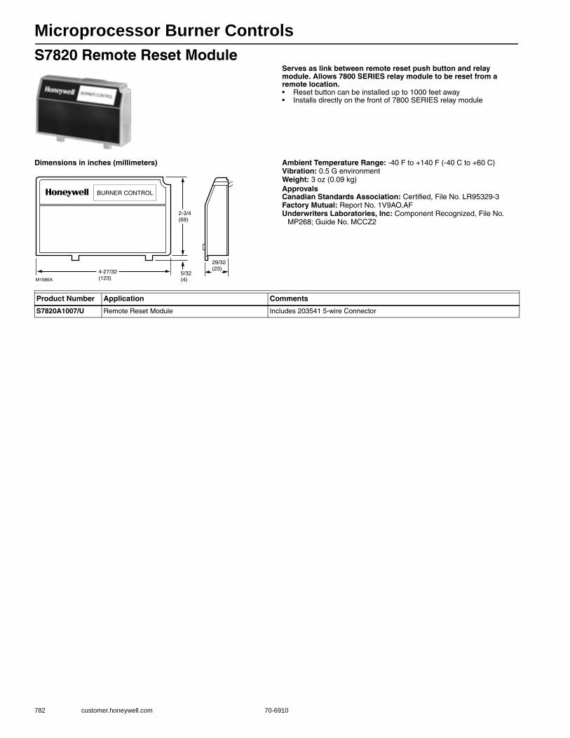
Microprocessor Burner Controls
782 customer.honeywell.com 70-6910
S7820 Remote Reset ModuleServes as link between remote reset push button and relay module. Allows 7800 SERIES relay module to be reset from a remote location.• Reset button can be installed up to 1000 feet away • Installs directly on the front of 7800 SERIES relay module
Dimensions in inches (millimeters) Ambient Temperature Range: -40 F to +140 F (-40 C to +60 C) Vibration: 0.5 G environmentWeight: 3 oz (0.09 kg) ApprovalsCanadian Standards Association: Certified, File No. LR95329-3Factory Mutual: Report No. 1V9AO.AFUnderwriters Laboratories, Inc: Component Recognized, File No.
MP268; Guide No. MCCZ2
Product Number Application Comments
S7820A1007/U Remote Reset Module Includes 203541 5-wire Connector
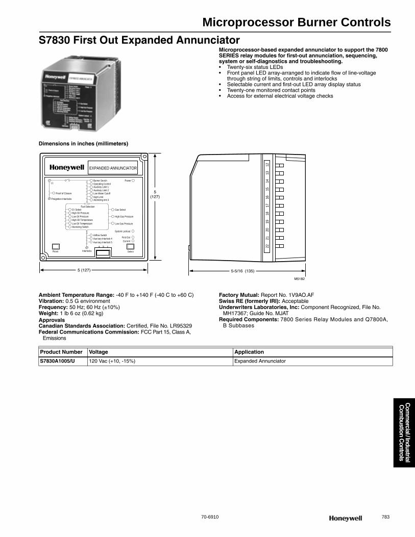
Microprocessor Burner Controls
70-6910 783
Com
mercial / Industrial
Com
bustion Controls
S7830 First Out Expanded AnnunciatorMicroprocessor-based expanded annunciator to support the 7800 SERIES relay modules for first-out annunciation, sequencing, system or self-diagnostics and troubleshooting.• Twenty-six status LEDs • Front panel LED array-arranged to indicate flow of line-voltage
through string of limits, controls and interlocks • Selectable current and first-out LED array display status • Twenty-one monitored contact points • Access for external electrical voltage checks
Dimensions in inches (millimeters)
Ambient Temperature Range: -40 F to +140 F (-40 C to +60 C) Vibration: 0.5 G environmentFrequency: 50 Hz; 60 Hz (±10%)Weight: 1 lb 6 oz (0.62 kg) ApprovalsCanadian Standards Association: Certified, File No. LR95329Federal Communications Commission: FCC Part 15, Class A,
Emissions
Factory Mutual: Report No. 1V9AO.AFSwiss RE (formerly IRI): AcceptableUnderwriters Laboratories, Inc: Component Recognized, File No.
MH17367; Guide No. MJATRequired Components: 7800 Series Relay Modules and Q7800A,
B Subbases
O l SelectHigh Oil PressureLow Oil PressureHigh Oil TemperatureLow Oil Temperature
Reset
EXPANDED ANNUNCIATOR
Select
Atomizing Switch
Fuel SelectionGas Select
High Gas Pressure
Low Gas Pressure
Airflow SwitchAuxi iary Interlock 4Auxi iary Interlock 5
Interlocks
a b c
First OutCurrent
System Lockout
Operating ControlAuxiliary Limit 1Auxiliary Limit 2Low Water CutoffHigh LimitAtomizing imit 3
Burner Sw tch
Proof of Closure
Preignition Interlocks
L1Power
2221
2019
1817
1615
1413
12
Product Number Voltage Application
S7830A1005/U 120 Vac (+10, -15%) Expanded Annunciator
Microprocessor Burner Controls
784 customer.honeywell.com 70-6910
ST7800 Plug In Purge TimerProvides the prepurge timing for select 7800 SERIES relay modules. ST7800C used with the RM7838C only.
ApprovalsCanadian Standards Association: Certified, File No. LR95329-3Factory Mutual: Approved: Report No. 2X0A1.AF
Underwriters Laboratories, Inc: Component Recognized, File No. MP268; Guide No. MCCZ2
Product Number PrePurge Application
ST7800A1005/U 2 seconds Purge Timer
ST7800A1013/U 7 seconds Purge Timer
ST7800A1021/U 10 seconds Purge Timer
ST7800A1039/U 30 seconds Purge Timer
ST7800A1047/U 40 seconds Purge Timer
ST7800A1054/U 60 seconds Purge Timer
ST7800A1062/U 90 seconds Purge Timer
ST7800A1070/U 2.5 minutes Purge Timer
ST7800A1088/U 4.0 minutes Purge Timer
ST7800A1096/U 6.0 minutes Purge Timer
ST7800A1104/U 9.0 minutes Purge Timer
ST7800A1112/U 12.0 minutes Purge Timer
ST7800A1120/U 15.0 minutes Purge Timer
ST7800A1138/U 22.0 minutes Purge Timer
ST7800A1146/U 30.0 minutes Purge Timer
ST7800C1003/U 7 seconds Purge Timer for RM7838C Only
ST7800C1011/U 20 seconds Purge Timer for RM7838C Only
ST7800C1029/U 4.0 minutes Purge Timer for RM7838C Only
ST7800C1037/U 6.0 minutes Purge Timer for RM7838C Only
ST7800C1045/U 8.0 minutes Purge Timer for RM7838C Only
ST7800C1052/U 10.0 minutes Purge Timer for RM7838C Only
ST7800C1060/U 12.0 minutes Purge Timer for RM7838C Only
ST7800C1078/U 14.0 minutes Purge Timer for RM7838C Only
ST7800C1086/U 16.0 minutes Purge Timer for RM7838C Only
ST7800C1094/U 18.0 minutes Purge Timer for RM7838C Only
ST7800C1102/U 20.0 minutes Purge Timer for RM7838C Only
ST7800C1110/U 22.0 minutes Purge Timer for RM7838C Only
ST7800C1128/U 24.0 minutes Purge Timer for RM7838C Only
ST7800C1136/U 30.0 minutes Purge Timer for RM7838C Only
ST7800C1144/U 45.0 minutes Purge Timer for RM7838C Only
Microprocessor Burner Controls
70-6910 785
Com
mercial / Industrial
Com
bustion Controls
7800 Series Accessories or PartsApplication: Accessory or Replacement Part
Product Number Comments Used With
203541/U 5 wire Connector for S7800 Display S7800 Display
203765/U Remote Mounting Bracket for S7800 Display (wall mounting).Includes 203541 5-wire Connector S7800 Display
204718B/U Nema I Cover Assembly for Panel Mounting S7800 (series 1-4) displays. Includes 203541 5-wire Connector S7800 Display
205321B/U Mounting Bracket - Flush mounting the S7800 Display for panel mounting. Includes 203541 5-wire Connector
S7800 Display
206311/U Carrying Case for S7800 Display S7800 Display
208727/U Connector, 8 pin for S7810B or M S7810B, S7810M
221729A/U Dust Cover for 7800 Relay Modules - Honeywell Logo 7800 Relay Modules
221818A/U Display Extension Cable - 60 inch for S7800 Display S7800 Display
221818C/U Display Extension Cable - 120 inch for S7800 Display S7800 Display
32005580-001/U Cable for connecting the S7800 Keyboard Display to the CR7890 CR7890
32007181-001/U Wiring Harness with 9 pin connector for wiring CR7890, length 6 fee CR7890
50023821-001/U Nema 4 Cover Assembly for Panel Mounting the S7800 Display. Includes 203541 5-wire Connector S7800 Display
50023821-002/U Nema 4 Cover Assembly with Reset Button for Panel Mounting the S7800 Display. Includes 203541 5-wire Connector
S7800 Display

SOLA Controllers
786 customer.honeywell.com 70-6910
R7910 SOLA Hydronic Control
The R7910A SOLA HC is a hydronic boiler control system that provides heat control, flame supervision, circulation pump control,
fan control, boiler control, and electric ignition function. It will also provide boiler status and error reporting.• Frost Protection, Slow Start, Anti-condensate, Boiler Delta-T,
Stack Limit, Boiler Limit, DHW Limit, Outlet T-Rise Limit • Primary Flame Safeguard Control • Internal or external spark generator• Analog NTC Sensor Inputs (10kohm or 12kohm)• Other Analog Inputs • PID Load Control • Digital Inputs • Digital Outputs • Analog Outputs • Algorithm Prioritization • Two Temperature Loops of Control (CH and DHW)• High Limit Control-CH, DHW, & Stack (Meets UL 353) using dual
10kohm NTC sensors • Fifteen Item Fault Code History including equipment status
at time of lockout • Fifteen Item Alert Code Status including equipment status
at time of internal alerts • 24Vac Device Power • 24 or 120Vac Digital I/O models available • Flame Signal test jacks (Vdc) • Three Status LEDs • UV or Flame rod Flame Sensing
Dimensions in inches (millimeters) Application: HydronicComments: Includes Programmable featuresFrequency (Hz): 60 Hz ± 5%ApprovalsControl Safety Devices: AcceptableFederal Communications Commission: Part 15, Class B EmissionsUnderwriters Laboratories, Inc: UL, cUL Component File No.
MH20613 (MCCZ)
M27583
9-21/64(237) MAX
[2] 8-21/32(220)
6-21/64 (161)
[2] 5-19/64 (135)
[4] Ø 3/16 (5) MAX
2-19/32 (66)
Product NumberEnclosure Rating Firing Rate Switch
Flame Sensor Type
Modulation Output
Load Voltage
Operating Voltage
(0-10 Vdc)
(4-20 mA) (PWM)
R7910A1001/U NEMA I/IP 40 — FR/UV Yes Yes Yes 24 Vac 24 Vac
R7910A1019/U NEMA I/IP 40 Low Fire Switch; High Fire Switch FR/UV Yes Yes Yes 120 Vac 24 Vac
R7910A1027/U NEMA I/IP 40 — FR/UV Yes Yes Yes 120 Vac 24 Vac
R7910A1084/U NEMA I/IP 40 — FR; Stat Yes Yes Yes 24 Vac 24 Vac
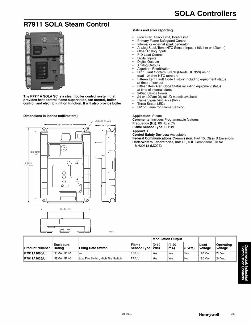
SOLA Controllers
70-6910 787
Com
mercial / Industrial
Com
bustion Controls
R7911 SOLA Steam Control
The R7911A SOLA SC is a steam boiler control system that provides heat control, flame supervision, fan control, boiler control, and electric ignition function. It will also provide boiler
status and error reporting.
• Slow Start, Stack Limit, Boiler Limit • Primary Flame Safeguard Control • Internal or external spark generator• Analog Stack Temp NTC Sensor Inputs (10kohm or 12kohm)• Other Analog Inputs • PID Load Control • Digital Inputs • Digital Outputs • Analog Outputs • Algorithm Prioritization • High Limit Control- Stack (Meets UL 353) using
dual 10kohm NTC sensors • Fifteen Item Fault Code History including equipment status
at time of lockout • Fifteen Item Alert Code Status including equipment status
at time of internal alerts • 24Vac Device Power • 24 or 120Vac Digital I/O models available • Flame Signal test jacks (Vdc) • Three Status LEDs • UV or Flame rod Flame Sensing
Dimensions in inches (millimeters) Application: SteamComments: Includes Programmable featuresFrequency (Hz): 60 Hz ± 5%Flame Sensor Type: FR/UVApprovalsControl Safety Devices: AcceptableFederal Communications Commission: Part 15, Class B EmissionsUnderwriters Laboratories, Inc: UL, cUL Component File No.
MH20613 (MCCZ)
[2] 5 19/64 (135)
9 21/64(237) MAX
[4] Ø 3/16 (5) MAX
2 19/32 (66)
6 21/64 (161)
[2] 8 21/32
(220)
M27063
Product NumberEnclosure Rating Firing Rate Switch
Flame Sensor Type
Modulation Output
Load Voltage
Operating Voltage
(0-10 Vdc)
(4-20 mA) (PWM)
R7911A1000/U NEMA I/IP 40 — FR/UV Yes Yes Yes 120 Vac 24 Vac
R7911A1026/U NEMA I/IP 40 Low Fire Switch; High Fire Switch FR/UV Yes Yes No 120 Vac 24 Vac
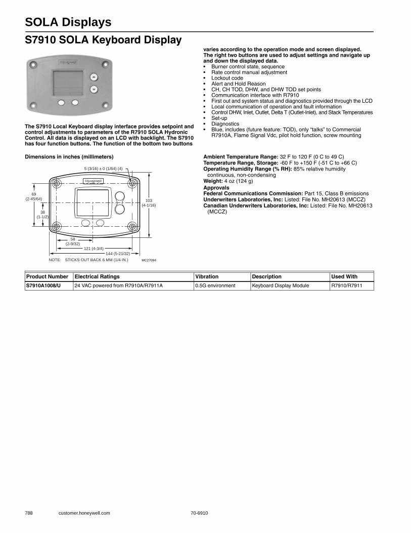
SOLA Displays
788 customer.honeywell.com 70-6910
S7910 SOLA Keyboard Display
The S7910 Local Keyboard display interface provides setpoint and control adjustments to parameters of the R7910 SOLA Hydronic Control. All data is displayed on an LCD with backlight. The S7910 has four function buttons. The function of the bottom two buttons
varies according to the operation mode and screen displayed. The right two buttons are used to adjust settings and navigate up and down the displayed data.• Burner control state, sequence • Rate control manual adjustment • Lockout code • Alert and Hold Reason • CH, CH TOD, DHW, and DHW TOD set points• Communication interface with R7910 • First out and system status and diagnostics provided through the LCD • Local communication of operation and fault information • Control DHW, Inlet, Outlet, Delta T (Outlet-Inlet), and Stack Temperatures • Set-up • Diagnostics • Blue, includes (future feature: TOD), only “talks” to Commercial
R7910A, Flame Signal Vdc, pilot hold function, screw mounting
Dimensions in inches (millimeters) Ambient Temperature Range: 32 F to 120 F (0 C to 49 C) Temperature Range, Storage: -60 F to +150 F (-51 C to +66 C) Operating Humidity Range (% RH): 85% relative humidity
continuous, non-condensingWeight: 4 oz (124 g) ApprovalsFederal Communications Commission: Part 15, Class B emissionsUnderwriters Laboratories, Inc: Listed: File No. MH20613 (MCCZ)Canadian Underwriters Laboratories, Inc: Listed: File No. MH20613
(MCCZ)
NOTE: STICKS OUT BACK 6 MM (1/4 IN.) MC27094
69(2-45/64)
38(1-1/2)
58(2-9/32)
121 (4-3/4)
144 (5-21/32)
103(4-1/16)
5 (3/16) ± 0 (1/64) (4)
Product Number Electrical Ratings Vibration Description Used With
S7910A1008/U 24 VAC powered from R7910A/R7911A 0.5G environment Keyboard Display Module R7910/R7911
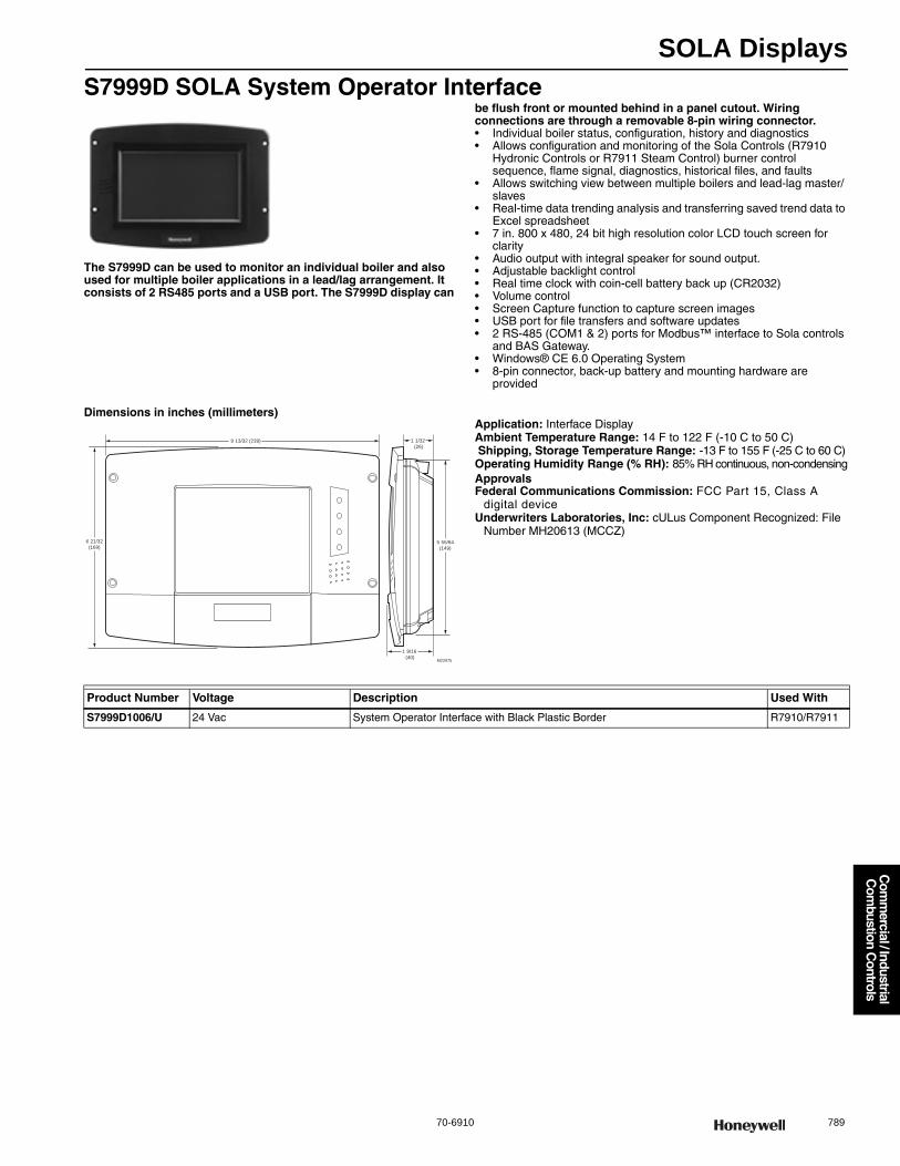
SOLA Displays
70-6910 789
Com
mercial / Industrial
Com
bustion Controls
S7999D SOLA System Operator Interface
The S7999D can be used to monitor an individual boiler and also used for multiple boiler applications in a lead/lag arrangement. It consists of 2 RS485 ports and a USB port. The S7999D display can
be flush front or mounted behind in a panel cutout. Wiring connections are through a removable 8-pin wiring connector.• Individual boiler status, configuration, history and diagnostics • Allows configuration and monitoring of the Sola Controls (R7910
Hydronic Controls or R7911 Steam Control) burner control sequence, flame signal, diagnostics, historical files, and faults
• Allows switching view between multiple boilers and lead-lag master/slaves
• Real-time data trending analysis and transferring saved trend data to Excel spreadsheet
• 7 in. 800 x 480, 24 bit high resolution color LCD touch screen for clarity
• Audio output with integral speaker for sound output. • Adjustable backlight control • Real time clock with coin-cell battery back up (CR2032) • Volume control • Screen Capture function to capture screen images • USB port for file transfers and software updates • 2 RS-485 (COM1 & 2) ports for Modbus™ interface to Sola controls
and BAS Gateway. • Windows® CE 6.0 Operating System • 8-pin connector, back-up battery and mounting hardware are
provided
Dimensions in inches (millimeters)Application: Interface DisplayAmbient Temperature Range: 14 F to 122 F (-10 C to 50 C) Shipping, Storage Temperature Range: -13 F to 155 F (-25 C to 60 C) Operating Humidity Range (% RH): 85% RH continuous, non-condensingApprovalsFederal Communications Commission: FCC Part 15, Class A
digital deviceUnderwriters Laboratories, Inc: cULus Component Recognized: File
Number MH20613 (MCCZ)6 21/32
(169)
9 13/32 (239)
5 55/64
(149)
1 9/16
(40)
1 1/32
(26)
M22975
Product Number Voltage Description Used With
S7999D1006/U 24 Vac System Operator Interface with Black Plastic Border R7910/R7911

SOLA Program Module
790 customer.honeywell.com 70-6910
PM7910 Program ModuleThe PM7910 Program Module is an optional plug-in device for the R7910 SOLA HC (Hydronic Control) and R7911 Sola SC (Steam Control). From the system level the S7999 System Operator Interface can direct the R7910/R7911 to transfer or retrieve parameter information with the Program Module.• Can be removed or installed while the R7910 or R7911 is powered • Facilitate multiple controller setups • Backup and restore the R7910 programmable data including:
— Non-safety parameter values— Parameter Control Blocks (information on how the parameter
values may be modified7
SOLA Accessories or PartsApplication: Single element sensor with 6" leadwire with Socket
Product Number Application Comments
PM7910A1013/U Support backup and restore Indicator LEDs - One (Status LED) Blinking LED indicated the Program Module is properly seated and powered from the R7910/R7911
Product Number Application
32003971-002/U Single element sensor with 6 in. leadwire with Socket
32003971-003/U Single element sensor with 42 in. leadwire, includes wire nuts (2), #8 mounting screws (3), anchors (2), sensor clip (1), tie strap (2)
50001464-006/U Dual Element Sensor with 6 in. leadwire with Female Socket
50001464-007/U Dual Element Sensor with 42 in. leadwire without connector
50032893-001/U Bag of connectors for R7910 and R7911 Controllers
121371B/U Water Temperature Immersion Well 3 in. insertions, 3/4 in. spud
50044082-001 12 vdc (Meanwell brand) for S7999B and C
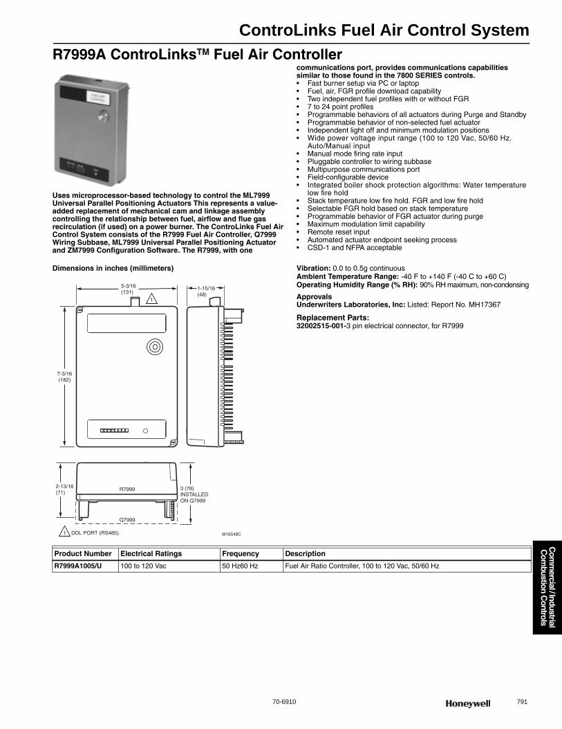
ControLinks Fuel Air Control System
70-6910 791
Com
mercial / Industrial
Com
bustion Controls
R7999A ControLinksTM Fuel Air Controller
Uses microprocessor-based technology to control the ML7999 Universal Parallel Positioning Actuators This represents a value-added replacement of mechanical cam and linkage assembly controlling the relationship between fuel, airflow and flue gas recirculation (if used) on a power burner. The ControLinks Fuel Air Control System consists of the R7999 Fuel Air Controller, Q7999 Wiring Subbase, ML7999 Universal Parallel Positioning Actuator and ZM7999 Configuration Software. The R7999, with one
communications port, provides communications capabilities similar to those found in the 7800 SERIES controls.• Fast burner setup via PC or laptop • Fuel, air, FGR profile download capability • Two independent fuel profiles with or without FGR • 7 to 24 point profiles • Programmable behaviors of all actuators during Purge and Standby • Programmable behavior of non-selected fuel actuator • Independent light off and minimum modulation positions • Wide power voltage input range (100 to 120 Vac, 50/60 Hz.
Auto/Manual input • Manual mode firing rate input • Pluggable controller to wiring subbase • Multipurpose communications port • Field-configurable device • Integrated boiler shock protection algorithms: Water temperature
low fire hold • Stack temperature low fire hold. FGR and low fire hold • Selectable FGR hold based on stack temperature • Programmable behavior of FGR actuator during purge • Maximum modulation limit capability • Remote reset input • Automated actuator endpoint seeking process • CSD-1 and NFPA acceptable
Dimensions in inches (millimeters) Vibration: 0.0 to 0.5g continuousAmbient Temperature Range: -40 F to +140 F (-40 C to +60 C) Operating Humidity Range (% RH): 90% RH maximum, non-condensing
ApprovalsUnderwriters Laboratories, Inc: Listed: Report No. MH17367
Replacement Parts:32002515-001-3 pin electrical connector, for R7999
1-15/16(48)
5-3/16(131)
7-3/16(182)
2-13/16(71)
3 (76)INSTALLEDON Q7999
M16548C
R7999
Q7999
DDL PORT (RS485).1
1
Product Number Electrical Ratings Frequency Description
R7999A1005/U 100 to 120 Vac 50 Hz60 Hz Fuel Air Ratio Controller, 100 to 120 Vac, 50/60 Hz
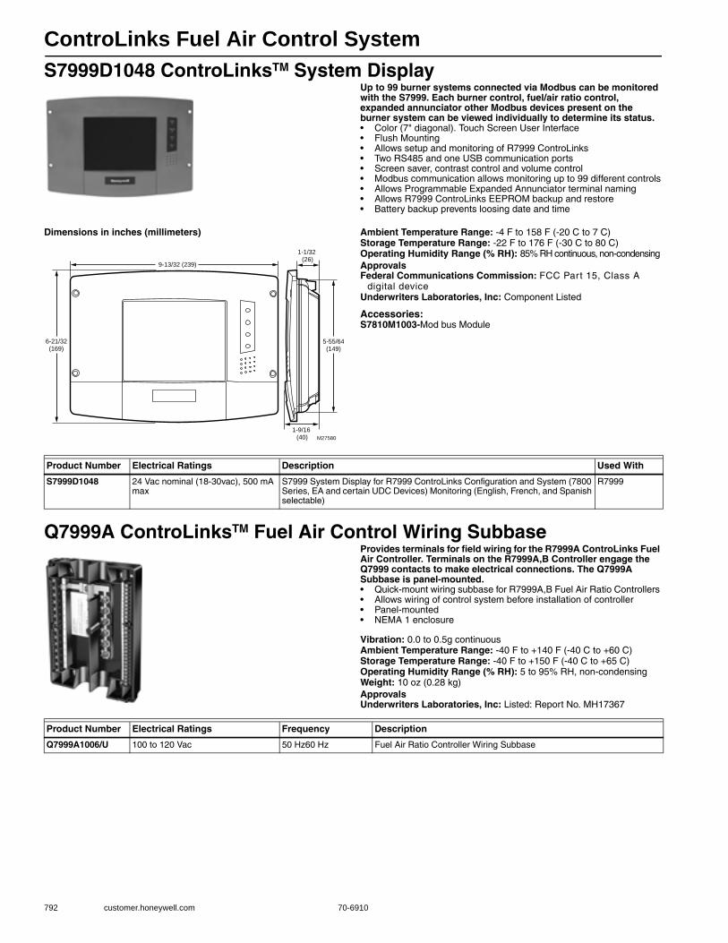
ControLinks Fuel Air Control System
792 customer.honeywell.com 70-6910
S7999D1048 ControLinksTM System DisplayUp to 99 burner systems connected via Modbus can be monitored with the S7999. Each burner control, fuel/air ratio control, expanded annunciator other Modbus devices present on the burner system can be viewed individually to determine its status.• Color (7" diagonal). Touch Screen User Interface• Flush Mounting• Allows setup and monitoring of R7999 ControLinks• Two RS485 and one USB communication ports• Screen saver, contrast control and volume control• Modbus communication allows monitoring up to 99 different controls• Allows Programmable Expanded Annunciator terminal naming• Allows R7999 ControLinks EEPROM backup and restore• Battery backup prevents loosing date and time
Dimensions in inches (millimeters) Ambient Temperature Range: -4 F to 158 F (-20 C to 7 C) Storage Temperature Range: -22 F to 176 F (-30 C to 80 C) Operating Humidity Range (% RH): 85% RH continuous, non-condensingApprovalsFederal Communications Commission: FCC Part 15, Class A
digital deviceUnderwriters Laboratories, Inc: Component Listed
Accessories:S7810M1003-Mod bus Module
Q7999A ControLinksTM Fuel Air Control Wiring SubbaseProvides terminals for field wiring for the R7999A ControLinks Fuel Air Controller. Terminals on the R7999A,B Controller engage the Q7999 contacts to make electrical connections. The Q7999A Subbase is panel-mounted.• Quick-mount wiring subbase for R7999A,B Fuel Air Ratio Controllers • Allows wiring of control system before installation of controller • Panel-mounted • NEMA 1 enclosure
Vibration: 0.0 to 0.5g continuousAmbient Temperature Range: -40 F to +140 F (-40 C to +60 C) Storage Temperature Range: -40 F to +150 F (-40 C to +65 C) Operating Humidity Range (% RH): 5 to 95% RH, non-condensingWeight: 10 oz (0.28 kg) ApprovalsUnderwriters Laboratories, Inc: Listed: Report No. MH17367
6-21/32(169)
9-13/32 (239)
5-55/64(149)
1-9/16 (40)
1-1/32 (26)
M27580
Product Number Electrical Ratings Description Used With
S7999D1048 24 Vac nominal (18-30vac), 500 mA max
S7999 System Display for R7999 ControLinks Configuration and System (7800 Series, EA and certain UDC Devices) Monitoring (English, French, and Spanish selectable)
R7999
Product Number Electrical Ratings Frequency Description
Q7999A1006/U 100 to 120 Vac 50 Hz60 Hz Fuel Air Ratio Controller Wiring Subbase
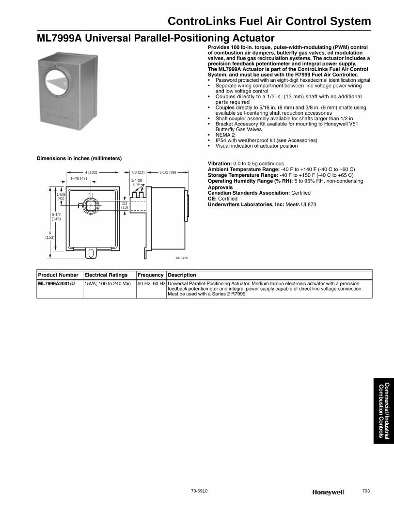
ControLinks Fuel Air Control System
70-6910 793
Com
mercial / Industrial
Com
bustion Controls
ML7999A Universal Parallel-Positioning ActuatorProvides 100 lb-in. torque, pulse-width-modulating (PWM) control of combustion air dampers, butterfly gas valves, oil modulation valves, and flue gas recirculation systems. The actuator includes a precision feedback potentiometer and integral power supply. The ML7999A Actuator is part of the ControLinks Fuel Air Control System, and must be used with the R7999 Fuel Air Controller.• Password protected with an eight-digit hexadecimal identification signal• Separate wiring compartment between line voltage power wiring
and low voltage control • Couples directly to a 1/2 in. (13 mm) shaft with no additional
parts required • Couples directly to 5/16 in. (8 mm) and 3/8 in. (9 mm) shafts using
available self-centering shaft reduction accessories • Shaft coupler assembly available for shafts larger than 1/2 in • Bracket Accessory Kit available for mounting to Honeywell V51
Butterfly Gas Valves • NEMA 2 • IP54 with weatherproof kit (see Accessories) • Visual indication of actuator position
Dimensions in inches (millimeters)Vibration: 0.0 to 0.5g continuousAmbient Temperature Range: -40 F to +140 F (-40 C to +60 C) Storage Temperature Range: -40 F to +150 F (-40 C to +65 C) Operating Humidity Range (% RH): 5 to 95% RH, non-condensingApprovalsCanadian Standards Association: CertifiedCE: CertifiedUnderwriters Laboratories, Inc: Meets UL873
4 (102) 7/8 (22)
1-7/8 (47)
1/2(13)
3-1/2 (89)
1-5/8(41)
5-1/2(140)
6(153)
M16466
1/4-28unF
Product Number Electrical Ratings Frequency Description
ML7999A2001/U 15VA; 100 to 240 Vac 50 Hz; 60 Hz Universal Parallel-Positioning Actuator. Medium torque electronic actuator with a precision feedback potentiometer and integral power supply capable of direct line voltage connection. Must be used with a Series 2 R7999
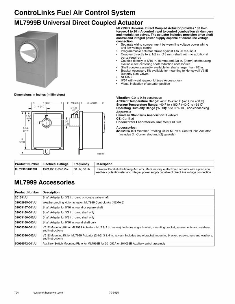
ControLinks Fuel Air Control System
794 customer.honeywell.com 70-6910
ML7999B Universal Direct Coupled ActuatorML7999B Universal Direct Coupled Actuator provides 100 lb-in. torque, 4 to 20 mA control input to control combustion air dampers and modulation valves. The actuator includes precision drive shaft control and integral power supply capable of direct line voltage connection.• Separate wiring compartment between line voltage power wiring
and low voltage control • Programmable actuator stroke against 4 to 20 mA input• Couples directly to a 1/2 in. (13 mm) shaft with no additional
parts required • Couples directly to 5/16 in. (8 mm) and 3/8 in. (9 mm) shafts using
available self-centering shaft reduction accessories • Shaft coupler assembly available for shafts larger than 1/2 in. • Bracket Accessory Kit available for mounting to Honeywell V51E
Butterfly Gas Valves • NEMA 2 • IP54 with weatherproof kit (see Accessories)• Visual indication of actuator position
Dimensions in inches (millimeters)Vibration: 0.0 to 0.5g continuousAmbient Temperature Range: -40 F to +140 F (-40 C to +60 C) Storage Temperature Range: -40 F to +150 F (-40 C to +65 C) Operating Humidity Range (% RH): 5 to 95% RH, non-condensingApprovalsCanadian Standards Association: CertifiedCE: CertifiedUnderwriters Laboratories, Inc: Meets UL873
Accessories:32002935-001-Weather Proofing kit for ML7999 ControLinks Actuator
(includes (1) Corner stop and (2) gaskets)
ML7999 Accessories
4 (102) 7/8 (22)
1-7/8 (47)
1/2(13)
3-1/2 (89)
1-5/8(41)
5-1/2(140)
6(153)
M16466
1/4-28unF
Product Number Electrical Ratings Frequency Description
ML7999B1002/U 15VA100 to 240 Vac 50 Hz; 60 Hz Universal Parallel-Positioning Actuator. Medium torque electronic actuator with a precision feedback potentiometer and integral power supply capable of direct line voltage connection
Product Number Description
201391/U Shaft Adapter for 3/8 in. round or square valve shaft
32002935-001/U Weatherproofing kit for actuator, ML7999 ControLinks (NEMA 3)
32003167-001/U Shaft Adapter for 5/16 in. round or square shaft
32003168-001/U Shaft Adapter for 3/4 in. round shaft only
32003168-002/U Shaft Adapter for 5/8 in. round shaft only
32003168-003/U Shaft Adapter for 9/16 in. round shaft only
32003396-001/U V51E Mounting Kit for ML7999 Actuator (1-1/2 & 2 in. valves). Includes angle bracket, mounting bracket, screws, nuts and washers, and instructions
32003396-002/U V51E Mounting Kit for ML7999 Actuator (2-1/2, 3 & 4 in. valves). Includes angle bracket, mounting bracket, screws, nuts and washers, and instructions
50036542-001/U Auxiliary Switch Mounting Plate for ML7999B for 201052A or 201052B Auxiliary switch assembly
ControLinks Fuel Air Control System
70-6910 795
Com
mercial / Industrial
Com
bustion Controls
ZM7999A ControLinksTM Fuel Air Control System Configuration SoftwareThe ZM7999 Software Configuration Tool reduces burner setup time by letting you create a burner modulation curve (profile) for the burner that allows for safe and efficient operation at all points along the modulation curve. The software uses a wizard-like process to assist you through the commissioning process. It also lets you save curves in standard PC files so that you can commission similar systems rapidly and safely. Once the burner is
commissioned, real-time monitoring of the system can be done via the monitoring tool.• Minimum Hardware Requirements: PC or laptop with a Pentium© processor • Windows® 95 or Windows® 98 • 16 MB of RAM • 1G hard drive with 100 MB of free memory • 4X (or higher) CD-ROM drive • Mouse • Super VGA color monitor (800 x 600 resolution suggested)
Accessories:QM4520A1004-Isolated RS-232 to RS-485 Converter Module
ControLinksTM Accessories
Product Number Description Used With
ZM7999A1006/U Configuration Software R7999
Product Number Frequency Description Used With
32002515-001/U — 3 pin electrical connector, for R7999 R7999
50020034-001/U — 9 pin electrical connector, for S7999B S7999B
50044082-001/U 50 Hz; 60 Hz Power Supply, 120vac to 12vdc, for S7999B/C S7999B/C
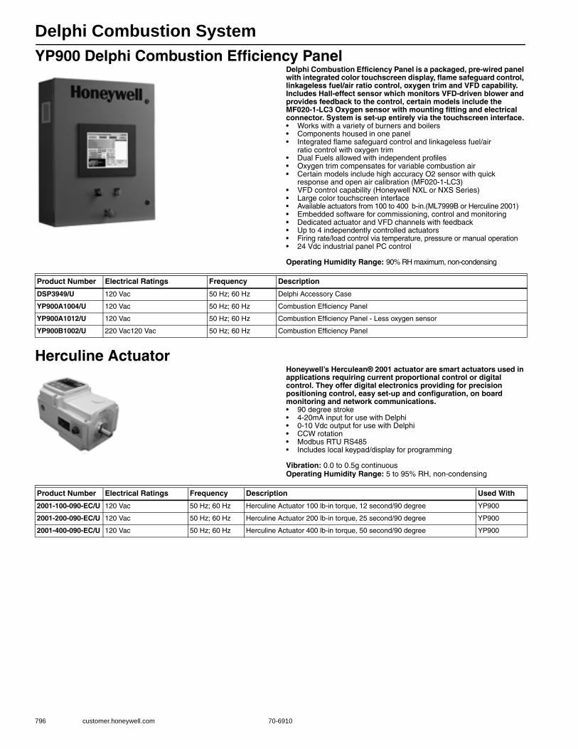
Delphi Combustion System
796 customer.honeywell.com 70-6910
YP900 Delphi Combustion Efficiency PanelDelphi Combustion Efficiency Panel is a packaged, pre-wired panel with integrated color touchscreen display, flame safeguard control, linkageless fuel/air ratio control, oxygen trim and VFD capability. Includes Hall-effect sensor which monitors VFD-driven blower and provides feedback to the control, certain models include the MF020-1-LC3 Oxygen sensor with mounting fitting and electrical connector. System is set-up entirely via the touchscreen interface.• Works with a variety of burners and boilers• Components housed in one panel• Integrated flame safeguard control and linkageless fuel/air
ratio control with oxygen trim• Dual Fuels allowed with independent profiles• Oxygen trim compensates for variable combustion air• Certain models include high accuracy O2 sensor with quick
response and open air calibration (MF020-1-LC3)• VFD control capability (Honeywell NXL or NXS Series)• Large color touchscreen interface• Available actuators from 100 to 400 b-in.(ML7999B or Herculine 2001)• Embedded software for commissioning, control and monitoring• Dedicated actuator and VFD channels with feedback• Up to 4 independently controlled actuators• Firing rate/load control via temperature, pressure or manual operation• 24 Vdc industrial panel PC control
Operating Humidity Range: 90% RH maximum, non-condensing
Herculine ActuatorHoneywell’s Herculean® 2001 actuator are smart actuators used in applications requiring current proportional control or digital control. They offer digital electronics providing for precision positioning control, easy set-up and configuration, on board monitoring and network communications.• 90 degree stroke• 4-20mA input for use with Delphi• 0-10 Vdc output for use with Delphi• CCW rotation• Modbus RTU RS485• Includes local keypad/display for programming
Vibration: 0.0 to 0.5g continuousOperating Humidity Range: 5 to 95% RH, non-condensing
Product Number Electrical Ratings Frequency Description
DSP3949/U 120 Vac 50 Hz; 60 Hz Delphi Accessory Case
YP900A1004/U 120 Vac 50 Hz; 60 Hz Combustion Efficiency Panel
YP900A1012/U 120 Vac 50 Hz; 60 Hz Combustion Efficiency Panel - Less oxygen sensor
YP900B1002/U 220 Vac120 Vac 50 Hz; 60 Hz Combustion Efficiency Panel
Product Number Electrical Ratings Frequency Description Used With
2001-100-090-EC/U 120 Vac 50 Hz; 60 Hz Herculine Actuator 100 lb-in torque, 12 second/90 degree YP900
2001-200-090-EC/U 120 Vac 50 Hz; 60 Hz Herculine Actuator 200 lb-in torque, 25 second/90 degree YP900
2001-400-090-EC/U 120 Vac 50 Hz; 60 Hz Herculine Actuator 400 lb-in torque, 50 second/90 degree YP900
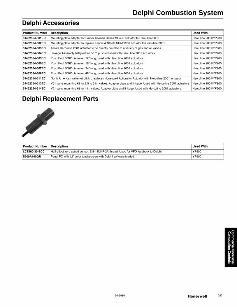
Delphi Combustion System
70-6910 797
Com
mercial / Industrial
Com
bustion Controls
Delphi Accessories
Delphi Replacement Parts
Product Number Description Used With
51452354-501EC Mounting plate adapter for Barber Colman Series MP495 actuator to Herculine 2001 Herculine 2001/YP900
51452354-502EC Mounting plate adapter to replace Landis & Staefa SQM53/56 actuator to Herculine 2001 Herculine 2001/YP900
51452354-503EC Allows Herculine 2001 actuator to be directly coupled to a variety of gas and oil valves Herculine 2001/YP900
51452354-504EC Linkage Assembly ball joint for 5/16” pushrod used with Herculine 2001 actuators Herculine 2001/YP900
51452354-505EC Push Rod, 5/16” diameter, 12" long, used with Herculine 2001 actuators Herculine 2001/YP900
51452354-506EC Push Rod, 5/16” diameter, 18" long, used with Herculine 2001 actuators Herculine 2001/YP900
51452354-507EC Push Rod, 5/16” diameter, 24" long, used with Herculine 2001 actuators Herculine 2001/YP900
51452354-508EC Push Rod, 5/16” diameter, 48" long, used with Herculine 2001 actuators Herculine 2001/YP900
51452354-511EC North American valve retrofit kit, replaces Honeywell Actionator Actuator with Herculine 2001 actuator Herculine 2001/YP900
51452354-513EC V51 valve mounting kit for 2.5 to 3 in. valves. Adapter plate and linkage. Used with Herculine 2001 actuators Herculine 2001/YP900
51452354-514EC V51 valve mounting kit for 4 in. valves. Adapter plate and linkage. Used with Herculine 2001 actuators Herculine 2001/YP900
Product Number Description Used With
LCZ460-30-ECC Hall-effect zero speed sensor, 5/8-18UNF-2A thread. Used for VFD feedback to Delphi. YP900
S900A1000/U Panel PC with 12" color touchscreen with Delphi software loaded YP900
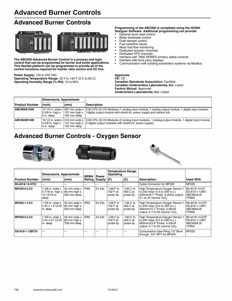
Advanced Burner Controls
798 customer.honeywell.com 70-6910
Advanced Burner Controls
The ABC900 Advanced Burner Control is a process and logic control that can be programmed for burner and boiler applications. This flexible platform can be programmed to provide all of the control functions required for fuel/air ratio control and O2 trim.
Programming of the ABC900 is completed using the HC900 Designer Software. Additional programming can provide:• Optional drum level control• Boiler feedwater control • Draft damper control • Fuel selection inputs• Mass fuel flow monitoring• Dedicated actuator channels• Dedicated VFD channels• Interface with 7800 SERIES primary safety controls• Interface with third party displays• Communication with building automation systems via Modbus
Power Supply: 120 to 240 VACOperating Temperature Range: 32 F to 140 F (0 C to 60 C) Operating Humidity Range (% RH): 10 to 90%
ApprovalsCE: CECanadian Standards Association: CertifiedCanadian Underwriters Laboratories, Inc: ListedFactory Mutual: ApprovedUnderwriters Laboratories, Inc: Listed
Advanced Burner Controls - Oxygen Sensor
Product Number
Dimensions, Approximate
Description(inch) (mm)
ABC900A1000 10-1/2 in. wide x 5-3/8 in. high x 6 in. deep
267 mm wide x 137 mm high x 152 mm deep
C30 CPU (4) I/O Modules (1 analog input module, 1 analog output module, 1 digital input module, 1digital output module with shield kit, power supply and resistor kit)
ABC900B1009 16-1/2 in. wide x 5-3/8 in. high x 6 in. deep
419 mm wide x 137 mm high x 152 mm deep
C30 CPU (8) I/O Modules (2 analog input modules, 1 analog output module, 1 digital input module, 2 digital output modules with shield kit, power supply)
Product Number
Dimensions, ApproximateNEMA Rating
Power Supply
Temperature Range, Operating
Description Used With(inch) (mm) (F) (C)
99-4218-14-07/U — — — — — — Cable Connector for MF020 MF020
MF020-0-LC3 1 5/8 in. wide x 2 7/16 in. high x 12 13/16 in. deep
42 mm wide x 60 mm high x 325 mm deep
IP65 24 Vdc -148 F to 752 F at probe tip
-100 C to 400 C at probe tip
High Temperature Oxygen Sensor 1 to 250 mbar (0.4 to 200"w.c.) 220mm/8.7” Probe, 4-20ma output, 0.1 to 25 volume %O2
99-4218-14-07; SS-810-1-12BT; ABC900A,B; YP900
MF020-1-LC3 1 5/8 in. wide x 2.4h x 1 9 13/16 in. deep
42 mm wide x 60 mm high x 503 mm deep
IP65 24 Vdc -148 F to 752 F at probe tip
-100 C to 400 C at probe tip
High Temperature Oxygen Sensor 1 to 250 mbar (0.4 to 200"w.c.) 400mm/15.7” Probe, 4-20mA output, 0.1 to 25 volume %O2
99-4218-14-07P SS-810-1-12BT; ABC900A,B; YP900
MF020-2-LC3 1 5/8 in. wide x 2.4h x 27 13/16 in. deep
42 mm wide x 60 mm high x 706 mm deep
IP65 24 Vdc -148 F to 752 F at probe tip
-100 C to 400 C at probe tip
High Temperature Oxygen Sensor 1 to 250 mbar (0.4 to 200"w.c.) 600mm/23.6” Probe, 4-20mA output, 0.1 to 25 volume %O2
99-4218-14-07P SS-810-1-12BT; ABC900A,B; YP900
SS-810-1-12BT/U — — — — — — Compression tube fitting 1/2” Bore through, 3/4” NPT for MF020
MF020
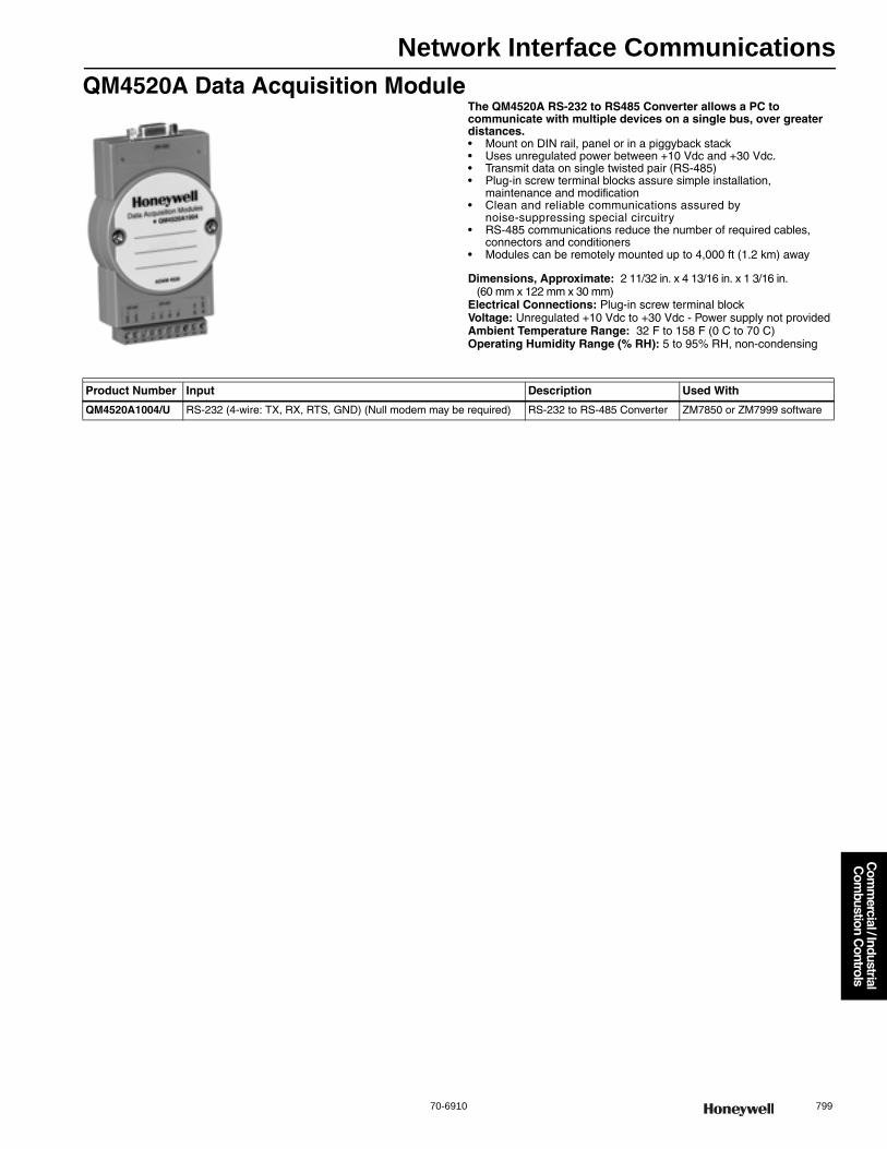
Network Interface Communications
70-6910 799
Com
mercial / Industrial
Com
bustion Controls
QM4520A Data Acquisition ModuleThe QM4520A RS-232 to RS485 Converter allows a PC to communicate with multiple devices on a single bus, over greater distances.• Mount on DIN rail, panel or in a piggyback stack• Uses unregulated power between +10 Vdc and +30 Vdc. • Transmit data on single twisted pair (RS-485) • Plug-in screw terminal blocks assure simple installation,
maintenance and modification • Clean and reliable communications assured by
noise-suppressing special circuitry • RS-485 communications reduce the number of required cables,
connectors and conditioners • Modules can be remotely mounted up to 4,000 ft (1.2 km) away
Dimensions, Approximate: 2 11/32 in. x 4 13/16 in. x 1 3/16 in. (60 mm x 122 mm x 30 mm)
Electrical Connections: Plug-in screw terminal blockVoltage: Unregulated +10 Vdc to +30 Vdc - Power supply not providedAmbient Temperature Range: 32 F to 158 F (0 C to 70 C)Operating Humidity Range (% RH): 5 to 95% RH, non-condensing
Product Number Input Description Used With
QM4520A1004/U RS-232 (4-wire: TX, RX, RTS, GND) (Null modem may be required) RS-232 to RS-485 Converter ZM7850 or ZM7999 software
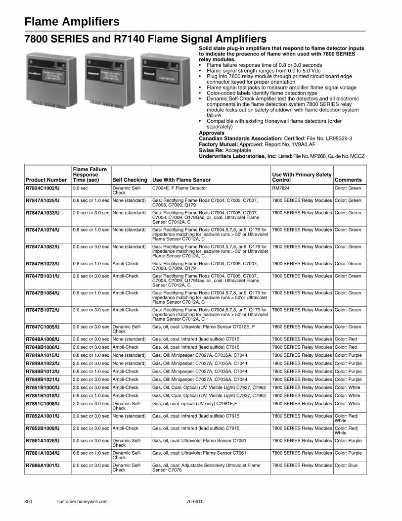
Flame Amplifiers
800 customer.honeywell.com 70-6910
7800 SERIES and R7140 Flame Signal AmplifiersSolid state plug-in amplifiers that respond to flame detector inputs to indicate the presence of flame when used with 7800 SERIES relay modules.• Flame failure response time of 0.8 or 3.0 seconds • Flame signal strength ranges from 0.0 to 5.0 Vdc • Plug into 7800 relay module through printed circuit board edge
connector keyed for proper orientation • Flame signal test jacks to measure amplifier flame signal voltage • Color-coded labels identify flame detection type• Dynamic Self-Check Amplifier test the detectors and all electronic
components in the flame detection system 7800 SERIES relay module locks out on safety shutdown with flame detection system failure
• Compat ble with existing Honeywell flame detectors (order separately)
ApprovalsCanadian Standards Association: Certified: File No. LR95329-3Factory Mutual: Approved: Report No. 1V9A0.AFSwiss Re: AcceptableUnderwriters Laboratories, Inc: Listed: File No. MP268, Guide No. MCCZ
Product Number
Flame Failure Response Time (sec) Self Checking Use With Flame Sensor
Use With Primary Safety Control Comments
R7824C1002/U 3.0 sec Dynamic Self-Check
C7024E, F Flame Detector RM7824 Color: Green
R7847A1025/U 0.8 sec or 1.0 sec None (standard) Gas: Rectifying Flame Rods C7004, C7005, C7007, C7008, C7009, Q179
7800 SERIES Relay Modules Color: Green
R7847A1033/U 2.0 sec or 3.0 sec None (standard) Gas: Rectifying Flame Rods C7004, C7005, C7007, C7008, C7009, Q179Gas, oil, coal: Ultraviolet Flame Sensor C7012A, C
7800 SERIES Relay Modules Color: Green
R7847A1074/U 0.8 sec or 1.0 sec None (standard) Gas: Rectifying Flame Rods C7004,5,7,8, or 9, Q179 for impedance matching for leadwire runs > 50' or Ultraviolet Flame Sensor C7012A, C
7800 SERIES Relay Modules Color: Green
R7847A1082/U 2.0 sec or 3.0 sec None (standard) Gas: Rectifying Flame Rods C7004,5,7,8, or 9, Q179 for impedance matching for leadwire runs > 50' or Ultraviolet Flame Sensor C7012A, C
7800 SERIES Relay Modules Color: Green
R7847B1023/U 0.8 sec or 1.0 sec Ampli-Check Gas: Rectifying Flame Rods C7004, C7005, C7007, C7008, C7009, Q179
7800 SERIES Relay Modules Color: Green
R7847B1031/U 2.0 sec or 3.0 sec Ampli-Check Gas: Rectifying Flame Rods C7004, C7005, C7007, C7008, C7009, Q179Gas, oil, coal: Ultraviolet Flame Sensor C7012A, C
7800 SERIES Relay Modules Color: Green
R7847B1064/U 0.8 sec or 1.0 sec Ampli-Check Gas: Rectifying Flame Rods C7004,5,7,8, or 9, Q179 for impedance matching for leadwire runs > 50'or Ultraviolet Flame Sensor C7012A, C
7800 SERIES Relay Modules Color: Green
R7847B1072/U 2.0 sec or 3.0 sec Ampli-Check Gas: Rectifying Flame Rods C7004,5,7,8, or 9, Q179 for impedance matching for leadwire runs > 50' or Ultraviolet Flame Sensor C7012A, C
7800 SERIES Relay Modules Color: Green
R7847C1005/U 2.0 sec or 3.0 sec Dynamic Self-Check
Gas, oil, coal: Ultraviolet Flame Sensor C7012E, F 7800 SERIES Relay Modules Color: Green
R7848A1008/U 2.0 sec or 3.0 sec None (standard) Gas, oil, coal: Infrared (lead sulfide) C7015 7800 SERIES Relay Modules Color: Red
R7848B1006/U 2.0 sec or 3.0 sec Ampli-Check Gas, oil, coal: Infrared (lead sulfide) C7015 7800 SERIES Relay Modules Color: Red
R7849A1015/U 0.8 sec or 1.0 sec None (standard) Gas, Oil: Minipeeper C7027A, C7035A, C7044 7800 SERIES Relay Modules Color: Purple
R7849A1023/U 2.0 sec or 3.0 sec None (standard) Gas, Oil: Minipeeper C7027A, C7035A, C7044 7800 SERIES Relay Modules Color: Purple
R7849B1013/U 0.8 sec or 1.0 sec Ampli-Check Gas, Oil: Minipeeper C7027A, C7035A, C7044 7800 SERIES Relay Modules Color: Purple
R7849B1021/U 2.0 sec or 3.0 sec Ampli-Check Gas, Oil: Minipeeper C7027A, C7035A, C7044 7800 SERIES Relay Modules Color: Purple
R7851B1000/U 2.0 sec or 3.0 sec Ampli-Check Gas, Oil, Coal: Optical (UV, Visible Light) C7927, C7962 7800 SERIES Relay Modules Color: White
R7851B1018/U 0.8 sec or 1.0 sec Ampli-Check Gas, Oil, Coal: Optical (UV, Visible Light) C7927, C7962 7800 SERIES Relay Modules Color: White
R7851C1008/U 2.0 sec or 3.0 sec Dynamic Self-Check
Gas, oil, coal: optical (UV only) C7961E,F 7800 SERIES Relay Modules Color: White
R7852A1001/U 2.0 sec or 3.0 sec None (standard) Gas, oil, coal: Infrared (lead sulfide) C7915 7800 SERIES Relay Modules Color: Red/White
R7852B1009/U 2.0 sec or 3.0 sec Ampli-Check Gas, oil, coal: Infrared (lead sulfide) C7915 7800 SERIES Relay Modules Color: Red/White
R7861A1026/U 2.0 sec or 3.0 sec Dynamic Self-Check
Gas, oil, coal: Ultraviolet Flame Sensor C7061 7800 SERIES Relay Modules Color: Purple
R7861A1034/U 0.8 sec or 1.0 sec Dynamic Self-Check
Gas, oil, coal: Ultraviolet Flame Sensor C7061 7800 SERIES Relay Modules Color: Purple
R7886A1001/U 2.0 sec or 3.0 sec Dynamic Self-Check
Gas, oil, coal: Adjustable Sensitivity Ultraviolet Flame Sensor C7076
7800 SERIES Relay Modules Color: Blue

Flame Amplifiers
70-6910 801
Com
mercial / Industrial
Com
bustion Controls
R7247; R7248; R7249; R7476 Flame AmplifiersSolid state plug-in units respond to flame detector signal and indicate presence of flame.• Use with BC7000; R4140; R4075C,D,E; R4138C,D Flame
Safeguard controls and appropriate flame detector and FSP5075A1, FSP5075A3 Flame Amplifier Modules
ApprovalsCanadian Standards Association: Certified: File No. LR1620, Guide
No. 140-A-2Control Safety Devices: Acceptable (CSD-1)Factory Mutual: Approved: Report No. 24181.01Swiss Re: AcceptableUnderwriters Laboratories, Inc: Listed: File No. MP268, Guide No. MCCZ2
R7259 Flame Safeguard AmplifiersSolid state, plug-in units allow use of rectification, infrared and ultraviolet flame detections.• Use with Q518, Q519 and W688A Flame Safeguard multi-burner
modules and appropriate flame detector
ApprovalsCanadian Standards Association: Certified: File No. LR95329-3Underwriters Laboratories, Inc: Listed: File No. MP268, Guide No. MCCZ2
Product Number
Flame Failure Response Time (sec) Self Checking Use With Flame Sensor
Use With Primary Safety Control Comments
R7247B1003/U 2 to 4 sec Ampli-Check Gas: Rectifying Flame Rods C7004, C7005, C7007, C7008, C7009, Q179Gas, oil, coal: Ultraviolet Flame Sensor C7012A, C
R4140; BC7000; R4075C,D,E; R4138C,D; FSP5075
Color: Green
R7247C1001/U 2 to 4 sec Dynamic Self-Check
Gas, oil, coal: Ultraviolet Flame Sensor C7012E, F R4140, BC7000, R4075C,D,E, R4138C,D; FSP5075
Color: Green
R7247C1019/U 2 sec max. Dynamic Self-Check
Gas, oil, coal: Ultraviolet Flame Sensor C7012E, F R4140; BC7000; R4075C,D,E; R4138C,D; FSP5075
Color: Green
R7248A1004/U 2 to 4 sec None (standard) Gas, oil, coal: Infrared (lead sulfide) C7015 R4140; BC7000; R4075C,D,E; R4138C,D; FSP5075
Color: Red
R7249A1003/U 2 to 4 sec None (standard) Gas, oil, coal: Ultraviolet (Minipeeper) C7027, C7035 R4140; BC7000; R4075C,D,E; R4138C,D; FSP5075
Color: Purple
R7476A1007/U 2 to 4 sec Dynamic Self-Check
Gas, oil, coal: Adjustable Sensitivity Ultraviolet Flame Sensor C7076
R4140; BC7000; R4075C,D,E; R4138C,D; FSP5075
Color: Blue
R7476A1015/U 2 sec max. Dynamic Self-Check
Gas, oil, coal: Adjustable Sensitivity Ultraviolet Flame Sensor C7076
R4140, BC7000, R4075C,D,E, R4138C,D; FSP5075
Color: Blue
Product Number
Flame Failure Response Time (sec) Self Checking Use With Flame Sensor
Use With Primary Safety Control Comments
R7259A1000/U 2 to 4 sec None (standard) Gas, oil, coal: Ultraviolet (Minipeeper) C7027, C7035 Q518, Q519, W688A Color: Purple
Flame Amplifiers
802 customer.honeywell.com 70-6910
R7289; R7290 Flame Safeguard Amplifiers (for R4795)Solid state, plug-in units allow use of rectification or ultraviolet flame detection.• Use with R4795A,D Flame Safeguard primary controls and
appropriate flame detector
ApprovalsCanadian Standards Association: Certified: File No. 158158-1120040Factory Mutual: Approved: Report No. 19608.1Underwriters Laboratories, Inc: Listed: File No. MP268, Vol 7, Sec. 2
Flame Amplifier Accessories
Product Number
Flame Failure Response Time (sec) Self Checking Use With Flame Sensor
Use With Primary Safety Control Comments
R7289A1004/U 2 to 4 sec None (standard) Gas: Rectifying Flame Rods C7004, C7005, C7007, C7008, C7009, Q179Gas, oil, coal: Ultraviolet Flame Sensor C7012A, C
R4795A,D Color: Green
R7290A1001/U 2 to 4 sec None (standard) Gas, oil, coal: Ultraviolet (Minipeeper) C7027, C7035 R4795A,D Color: Purple
Product Number Description Used With
32005301-001/U T Filter for Rectification Amplifiers R7847, R7247
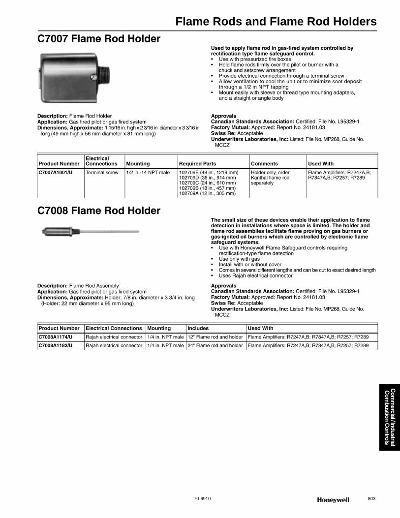
Flame Rods and Flame Rod Holders
70-6910 803
Com
mercial / Industrial
Com
bustion Controls
C7007 Flame Rod HolderUsed to apply flame rod in gas-fired system controlled by rectification type flame safeguard control.• Use with pressurized fire boxes • Hold flame rods firmly over the pilot or burner with a
chuck and setscrew arrangement • Provide electrical connection through a terminal screw • Allow ventilation to cool the unit or to minimize soot deposit
through a 1/2 in NPT tapping • Mount easily with sleeve or thread type mounting adapters,
and a straight or angle body
Description: Flame Rod HolderApplication: Gas fired pilot or gas fired systemDimensions, Approximate: 1 15/16 in. high x 2 3/16 in. diameter x 3 3/16 in.
long (49 mm high x 56 mm diameter x 81 mm long)
ApprovalsCanadian Standards Association: Certified: File No. L95329-1Factory Mutual: Approved: Report No. 24181.03Swiss Re: AcceptableUnderwriters Laboratories, Inc: Listed: File No. MP268, Guide No.
MCCZ
C7008 Flame Rod HolderThe small size of these devices enable their application to flame detection in installations where space is limited. The holder and flame rod assemblies facilitate flame proving on gas burners or gas-ignited oil burners which are controlled by electronic flame safeguard systems.• Use with Honeywell Flame Safeguard controls requiring
rectification-type flame detection • Use only with gas • Install with or without cover • Comes in several different lengths and can be cut to exact desired length • Uses Rajah electrical connector
Description: Flame Rod AssemblyApplication: Gas fired pilot or gas fired systemDimensions, Approximate: Holder: 7/8 in. diameter x 3 3/4 in. long
(Holder: 22 mm diameter x 95 mm long)
ApprovalsCanadian Standards Association: Certified: File No. L95329-1Factory Mutual: Approved: Report No. 24181.03Swiss Re: AcceptableUnderwriters Laboratories, Inc: Listed: File No. MP268, Guide No.
MCCZ
Product NumberElectrical Connections Mounting Required Parts Comments Used With
C7007A1001/U Terminal screw 1/2 in.-14 NPT male 102709E (48 in., 1219 mm)102709D (36 in., 914 mm)102709C (24 in., 610 mm)102709B (18 in., 457 mm)102709A (12 in., 305 mm)
Holder only, order Kanthal flame rod separately
Flame Amplifiers: R7247A,B; R7847A,B; R7257; R7289
Product Number Electrical Connections Mounting Includes Used With
C7008A1174/U Rajah electrical connector 1/4 in. NPT male 12" Flame rod and holder Flame Amplifiers: R7247A,B; R7847A,B; R7257; R7289
C7008A1182/U Rajah electrical connector 1/4 in. NPT male 24" Flame rod and holder Flame Amplifiers: R7247A,B; R7847A,B; R7257; R7289
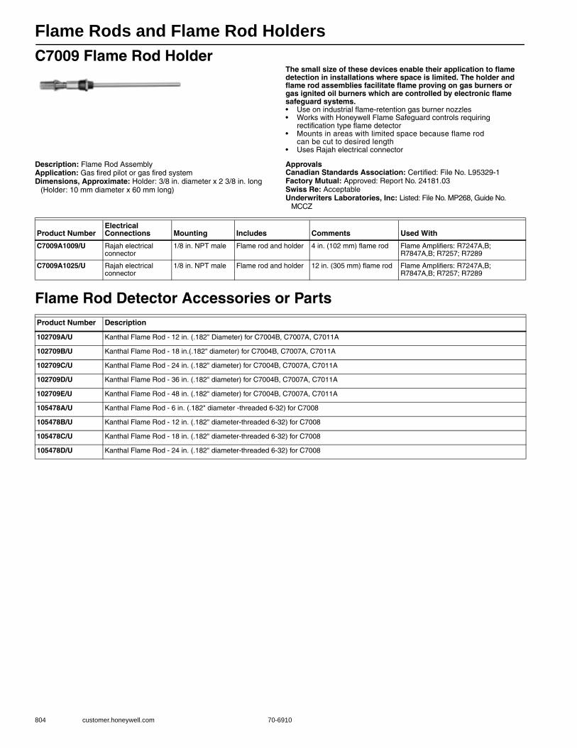
Flame Rods and Flame Rod Holders
804 customer.honeywell.com 70-6910
C7009 Flame Rod HolderThe small size of these devices enable their application to flame detection in installations where space is limited. The holder and flame rod assemblies facilitate flame proving on gas burners or gas ignited oil burners which are controlled by electronic flame safeguard systems.• Use on industrial flame-retention gas burner nozzles • Works with Honeywell Flame Safeguard controls requiring
rectification type flame detector • Mounts in areas with limited space because flame rod
can be cut to desired length • Uses Rajah electrical connector
Description: Flame Rod AssemblyApplication: Gas fired pilot or gas fired systemDimensions, Approximate: Holder: 3/8 in. diameter x 2 3/8 in. long
(Holder: 10 mm diameter x 60 mm long)
ApprovalsCanadian Standards Association: Certified: File No. L95329-1Factory Mutual: Approved: Report No. 24181.03Swiss Re: AcceptableUnderwriters Laboratories, Inc: Listed: File No. MP268, Guide No.
MCCZ
Flame Rod Detector Accessories or Parts
Product NumberElectrical Connections Mounting Includes Comments Used With
C7009A1009/U Rajah electrical connector
1/8 in. NPT male Flame rod and holder 4 in. (102 mm) flame rod Flame Amplifiers: R7247A,B; R7847A,B; R7257; R7289
C7009A1025/U Rajah electrical connector
1/8 in. NPT male Flame rod and holder 12 in. (305 mm) flame rod Flame Amplifiers: R7247A,B; R7847A,B; R7257; R7289
Product Number Description
102709A/U Kanthal Flame Rod - 12 in. (.182" Diameter) for C7004B, C7007A, C7011A
102709B/U Kanthal Flame Rod - 18 in.(.182" diameter) for C7004B, C7007A, C7011A
102709C/U Kanthal Flame Rod - 24 in. (.182" diameter) for C7004B, C7007A, C7011A
102709D/U Kanthal Flame Rod - 36 in. (.182" diameter) for C7004B, C7007A, C7011A
102709E/U Kanthal Flame Rod - 48 in. (.182" diameter) for C7004B, C7007A, C7011A
105478A/U Kanthal Flame Rod - 6 in. (.182" diameter -threaded 6-32) for C7008
105478B/U Kanthal Flame Rod - 12 in. (.182" diameter-threaded 6-32) for C7008
105478C/U Kanthal Flame Rod - 18 in. (.182" diameter-threaded 6-32) for C7008
105478D/U Kanthal Flame Rod - 24 in. (.182" diameter-threaded 6-32) for C7008
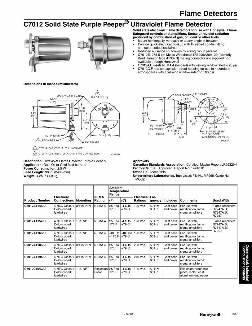
Flame Detectors
70-6910 805
Com
mercial / Industrial
Com
bustion Controls
C7012 Solid State Purple Peeper® Ultraviolet Flame DetectorSolid state electronic flame detectors for use with Honeywell Flame Safeguard controls and amplifiers. Sense ultraviolet radiation produced by combustion of gas, oil, coal or other fuels.• Mount horizontally, vertically or at any angle in between • Provide quick electrical hookup with threaded conduit fitting
and color-coded leadwires • Reduced nuisance shutdowns by wiring two in parallel• C7012E1278 5 pin Molex Woodhead 1R5006A20A120 (formerly
Brad Harrison type 41307N) mating connector not supplied nor available through Honeywell
• C7012A,E meets NEMA 4 standards with viewing window rated to 20 psi• C7012C,F has an explosion-proof housing for use in hazardous
atmospheres with a viewing window rated to 100 psi
Dimensions in inches (millimeters)
Description: Ultraviolet Flame Detector (Purple Peeper)Application: Gas, Oil or Coal fired burnersPower Consumption: 2.5 WLead Length: 96 in. (2438 mm)Weight: 4.25 lb (1.9 kg)
ApprovalsCanadian Standards Association: Certified: Master Report LR95329-1Factory Mutual: Approved: Report No. 14740.01Swiss Re: AcceptableUnderwriters Laboratories, Inc: Listed: File No. MP268, Guide No.
MCCZ
MOUNTING FLANGE
1/2–14 NPSM
LEADWIRESFACEPLATE
3/4–14 NPT
M10167D
3-3/4(95)
7-7/32(183)
5-1/8(130)
3-7/16(87)
5-1/4 (133)
1
1
2
2
C7061A1046, C7061A1053: INCH NPT
C7061A1038 AND C7061A1046: TYPE CONNECTOR.
M1963A
FACEPLATE
PIPEUNION
8(203) DIA.
1/2-14 NPT
LEADWIRES
9 (229)
2(51)
5(127)
1-11 1/2 NPT
2-1/16 (52)1-1/2
(38)5/16-18 UNC-2B BY7/16 (11) DEEPMOUNTING HOLES (2)
2 (51)
1 (25)
3(76)
Product NumberElectrical Connections Mounting
NEMA Rating
Ambient Temperature Range
Electrical Ratings
Fre-quency Includes Comments Used With(F) (C)
C7012A1145/U 4 NEC Class 1 Color-coded leadwires
3/4 in. NPT NEMA 4 25 F to 175 F
-4 C to +79 C
120 Vac 50 Hz; 60 Hz
Cast case and cover
For use with rectification flame signal amplifiers
Flame Amplifiers: R7247A,B; R7847A,B; R7257
C7012A1152/U 4 NEC Class 1 Color-coded leadwires
1 in. NPT NEMA 4 25 F to 175 F
-4 C to +79 C
120 Vac 50 Hz; 60 Hz
Cast case and cover
For use with rectification flame signal amplifiers
Flame Amplifiers: R7247A,B; R7847A,B; R7257
C7012A1160/U 4 NEC Class 1 Color-coded leadwires
1 in. NPT NEMA 4 -40 F to +175 F
-40 C to +79 C
120 Vac 50 Hz; 60 Hz
Cast case and cover
For use with rectification flame signal amplifiers
C7012A1186/U 4 NEC Class 1 Color-coded leadwires
3/4 in. NPT NEMA 4 25 F to 175 F
-4 C to +79 C
208 Vac 50 Hz; 60 Hz
Cast case and cover
For use with rectification flame signal amplifiers
C7012A1194/U 4 NEC Class 1 Color-coded leadwires
3/4 in. NPT NEMA 4 25 F to 175 F
-4 C to +79 C
240 Vac 50 Hz; 60 Hz
Cast case and cover
For use with rectification flame signal amplifiers
C7012C1042/U 4 NEC Class 1 Color-coded leadwires
1 in. NPT Explosion Proof
25 F to 175 F
-4 C to +79 C
120 Vac 50 Hz; 60 Hz
— Explosion-proof, two piece, violet, cast aluminum enclosure
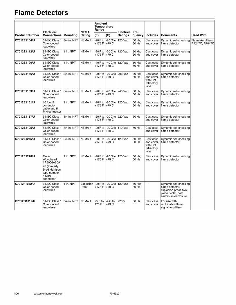
Flame Detectors
806 customer.honeywell.com 70-6910
C7012E1104/U 6 NEC Class 1 Color-coded leadwires
3/4 in. NPT NEMA 4 -20 F to +175 F
-20 C to +79 C
120 Vac 50 Hz; 60 Hz
Cast case and cover
Dynamic self-checking flame detector
Flame Amplifiers: R7247C, R7847C
C7012E1112/U 6 NEC Class 1 Color-coded leadwires
1 in. NPT NEMA 4 -20 F to +175 F
-20 C to +79 C
120 Vac 50 Hz; 60 Hz
Cast case and cover
Dynamic self-checking flame detector
C7012E1120/U 6 NEC Class 1 Color-coded leadwires
1 in. NPT NEMA 4 -40 F to +175 F
-40 C to +79 C
120 Vac 50 Hz; 60 Hz
Cast case and cover
Dynamic self-checking flame detector
C7012E1146/U 6 NEC Class 1 Color-coded leadwires
3/4 in. NPT NEMA 4 -20 F to +175 F
-20 C to +79 C
208 Vac 50 Hz; 60 Hz
Cast case and cover, with Hot refractory tube
Dynamic self-checking flame detector
C7012E1153/U 6 NEC Class 1 Color-coded leadwires
3/4 in. NPT NEMA 4 -20 F to +175 F
-20 C to +79 C
240 Vac 50 Hz; 60 Hz
Cast case and cover
Dynamic self-checking flame detector
C7012E1161/U 10 foot 5 conductor cable and 5 PIN connector
1 in. NPT NEMA 4 -20 F to +175 F
-20 C to +79 C
120 Vac 50 Hz; 60 Hz
Cast case and cover
Dynamic self-checking flame detector
C7012E1187/U 6 NEC Class 1 Color-coded leadwires
3/4 in. NPT NEMA 4 -20 F to +175 F
-20 C to +79 C
220 Vac 50 Hz Cast case and cover
Dynamic self-checking flame detector
C7012E1195/U 6 NEC Class 1 Color-coded leadwires
3/4 in. NPT NEMA 4 -20 F to +175 F
-20 C to +79 C
110 Vac 50 Hz Cast case and cover
Dynamic self-checking flame detector
C7012E1245/U 6 NEC Class 1 Color-coded leadwires
3/4 in. NPT NEMA 4 -20 F to +175 F
-20 C to +79 C
120 Vac 50 Hz; 60 Hz
Cast case and cover, with Hot refractory tube
Dynamic self-checking flame detector
C7012E1278/U Molex Woodhead 1R5006A20A120 (formerly Brad Harrison type number 41310 connector)
1 in. NPT NEMA 4 -20 F to +175 F
-20 C to +79 C
120 Vac 50 Hz; 60 Hz
Cast case and cover
Dynamic self-checking flame detector
C7012F1052/U 6 NEC Class 1 Color-coded leadwires
1 in. NPT Explosion Proof
-20 F to +175 F
-20 C to +79 C
120 Vac 50 Hz; 60 Hz
— Dynamic self-checking flame detector, explosion-proof, two piece, violet, cast aluminum enclosure
C7012G1019/U 5 NEC Class 1 Color-coded leadwires
3/4 in. NPT NEMA 4 25 F to 175 F
-4 C to +79 C
220 V 50 Hz Cast case and cover
For use with rectification flame signal amplifiers
Product NumberElectrical Connections Mounting
NEMA Rating
Ambient Temperature Range
Electrical Ratings
Fre-quency Includes Comments Used With(F) (C)
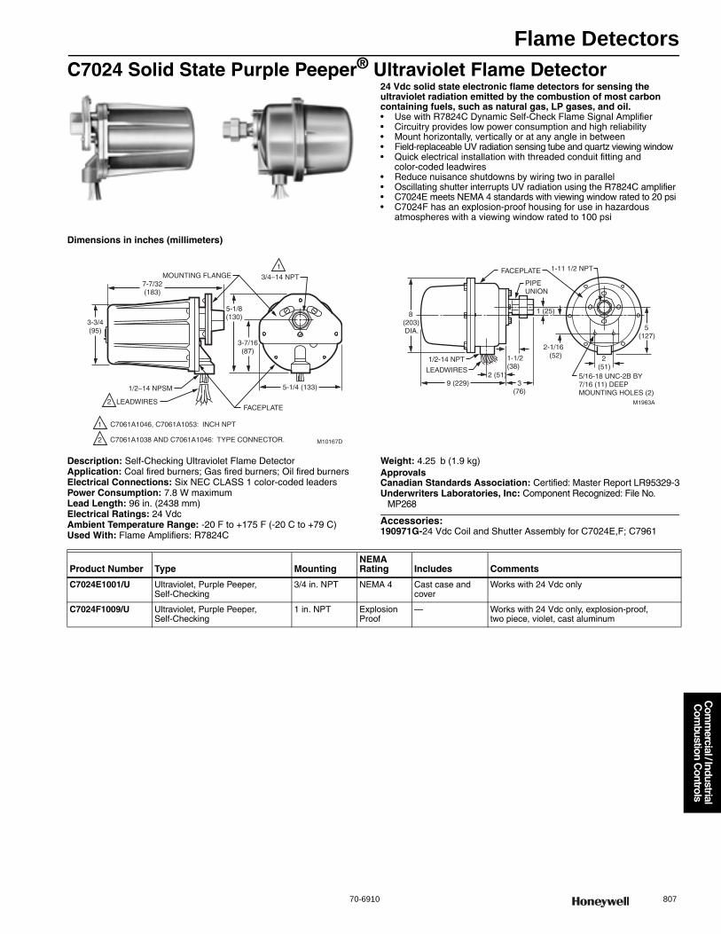
Flame Detectors
70-6910 807
Com
mercial / Industrial
Com
bustion Controls
C7024 Solid State Purple Peeper® Ultraviolet Flame Detector24 Vdc solid state electronic flame detectors for sensing the ultraviolet radiation emitted by the combustion of most carbon containing fuels, such as natural gas, LP gases, and oil.• Use with R7824C Dynamic Self-Check Flame Signal Amplifier • Circuitry provides low power consumption and high reliability • Mount horizontally, vertically or at any angle in between • Field-replaceable UV radiation sensing tube and quartz viewing window • Quick electrical installation with threaded conduit fitting and
color-coded leadwires• Reduce nuisance shutdowns by wiring two in parallel • Oscillating shutter interrupts UV radiation using the R7824C amplifier• C7024E meets NEMA 4 standards with viewing window rated to 20 psi• C7024F has an explosion-proof housing for use in hazardous
atmospheres with a viewing window rated to 100 psi
Dimensions in inches (millimeters)
Description: Self-Checking Ultraviolet Flame DetectorApplication: Coal fired burners; Gas fired burners; Oil fired burnersElectrical Connections: Six NEC CLASS 1 color-coded leadersPower Consumption: 7.8 W maximumLead Length: 96 in. (2438 mm)Electrical Ratings: 24 VdcAmbient Temperature Range: -20 F to +175 F (-20 C to +79 C) Used With: Flame Amplifiers: R7824C
Weight: 4.25 b (1.9 kg) ApprovalsCanadian Standards Association: Certified: Master Report LR95329-3Underwriters Laboratories, Inc: Component Recognized: File No.
MP268
Accessories:190971G-24 Vdc Coil and Shutter Assembly for C7024E,F; C7961
MOUNTING FLANGE
1/2–14 NPSM
LEADWIRESFACEPLATE
3/4–14 NPT
M10167D
3-3/4(95)
7-7/32(183)
5-1/8(130)
3-7/16(87)
5-1/4 (133)
1
1
2
2
C7061A1046, C7061A1053: INCH NPT
C7061A1038 AND C7061A1046: TYPE CONNECTOR.
M1963A
FACEPLATE
PIPEUNION
8(203) DIA.
1/2-14 NPT
LEADWIRES
9 (229)
2(51)
5(127)
1-11 1/2 NPT
2-1/16 (52)1-1/2
(38)5/16-18 UNC-2B BY7/16 (11) DEEPMOUNTING HOLES (2)
2 (51)
1 (25)
3(76)
Product Number Type MountingNEMA Rating Includes Comments
C7024E1001/U Ultraviolet, Purple Peeper, Self-Checking
3/4 in. NPT NEMA 4 Cast case and cover
Works with 24 Vdc only
C7024F1009/U Ultraviolet, Purple Peeper, Self-Checking
1 in. NPT Explosion Proof
— Works with 24 Vdc only, explosion-proof, two piece, violet, cast aluminum
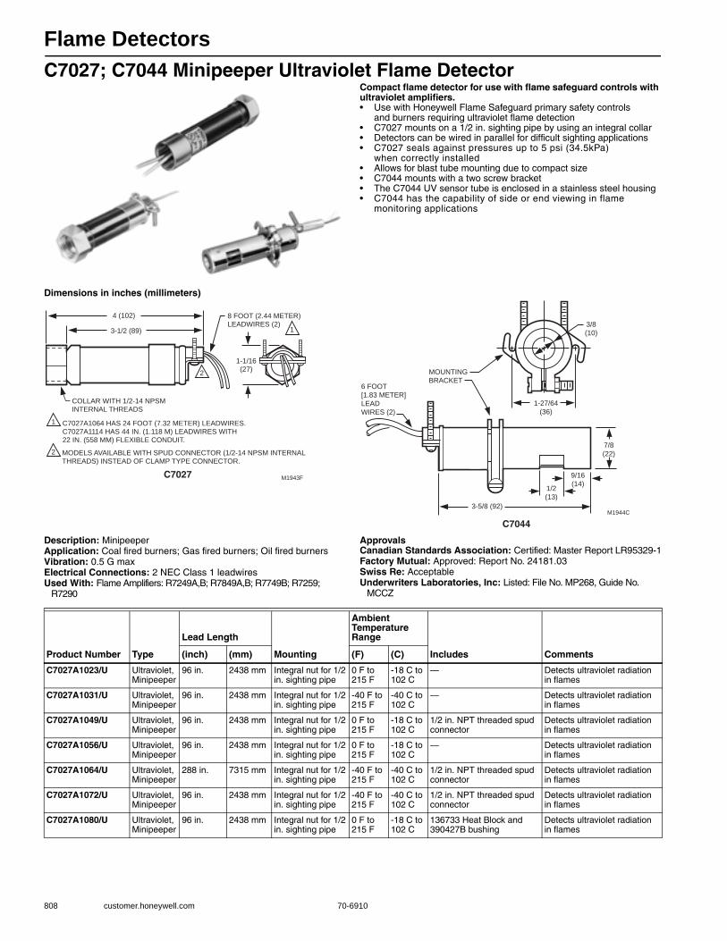
Flame Detectors
808 customer.honeywell.com 70-6910
C7027; C7044 Minipeeper Ultraviolet Flame DetectorCompact flame detector for use with flame safeguard controls with ultraviolet amplifiers.• Use with Honeywell Flame Safeguard primary safety controls
and burners requiring ultraviolet flame detection • C7027 mounts on a 1/2 in. sighting pipe by using an integral collar • Detectors can be wired in parallel for difficult sighting applications • C7027 seals against pressures up to 5 psi (34.5kPa)
when correctly installed • Allows for blast tube mounting due to compact size• C7044 mounts with a two screw bracket • The C7044 UV sensor tube is enclosed in a stainless steel housing • C7044 has the capability of side or end viewing in flame
monitoring applications
Dimensions in inches (millimeters)
Description: MinipeeperApplication: Coal fired burners; Gas fired burners; Oil fired burnersVibration: 0.5 G maxElectrical Connections: 2 NEC Class 1 leadwiresUsed With: Flame Amplifiers: R7249A,B; R7849A,B; R7749B; R7259;
R7290
ApprovalsCanadian Standards Association: Certified: Master Report LR95329-1Factory Mutual: Approved: Report No. 24181.03Swiss Re: AcceptableUnderwriters Laboratories, Inc: Listed: File No. MP268, Guide No.
MCCZ
COLLAR WITH 1/2-14 NPSM INTERNAL THREADS
4 (102) 8 FOOT (2.44 METER) LEADWIRES (2)
M1943F
C7027A1064 HAS 24 FOOT (7.32 METER) LEADWIRES. C7027A1114 HAS 44 IN. (1.118 M) LEADWIRES WITH 22 IN. (558 MM) FLEXIBLE CONDUIT.
1
2
2
3-1/2 (89)
1-1/16 (27)
1
MODELS AVAILABLE WITH SPUD CONNECTOR (1/2-14 NPSM INTERNAL THREADS) INSTEAD OF CLAMP TYPE CONNECTOR.
6 FOOT
[1.83 METER]
LEAD
WIRES (2)
3-5/8 (92)
1/2
(13)
1-27/64
(36)
3/8
(10)
7/8
(22)
9/16
(14)
M1944C
MOUNTING
BRACKET
Product Number Type
Lead Length
Mounting
Ambient Temperature Range
Includes Comments(inch) (mm) (F) (C)
C7027A1023/U Ultraviolet, Minipeeper
96 in. 2438 mm Integral nut for 1/2 in. sighting pipe
0 F to 215 F
-18 C to 102 C
— Detects ultraviolet radiation in flames
C7027A1031/U Ultraviolet, Minipeeper
96 in. 2438 mm Integral nut for 1/2 in. sighting pipe
-40 F to 215 F
-40 C to 102 C
— Detects ultraviolet radiation in flames
C7027A1049/U Ultraviolet, Minipeeper
96 in. 2438 mm Integral nut for 1/2 in. sighting pipe
0 F to 215 F
-18 C to 102 C
1/2 in. NPT threaded spud connector
Detects ultraviolet radiation in flames
C7027A1056/U Ultraviolet, Minipeeper
96 in. 2438 mm Integral nut for 1/2 in. sighting pipe
0 F to 215 F
-18 C to 102 C
— Detects ultraviolet radiation in flames
C7027A1064/U Ultraviolet, Minipeeper
288 in. 7315 mm Integral nut for 1/2 in. sighting pipe
-40 F to 215 F
-40 C to 102 C
1/2 in. NPT threaded spud connector
Detects ultraviolet radiation in flames
C7027A1072/U Ultraviolet, Minipeeper
96 in. 2438 mm Integral nut for 1/2 in. sighting pipe
-40 F to 215 F
-40 C to 102 C
1/2 in. NPT threaded spud connector
Detects ultraviolet radiation in flames
C7027A1080/U Ultraviolet, Minipeeper
96 in. 2438 mm Integral nut for 1/2 in. sighting pipe
0 F to 215 F
-18 C to 102 C
136733 Heat Block and 390427B bushing
Detects ultraviolet radiation in flames
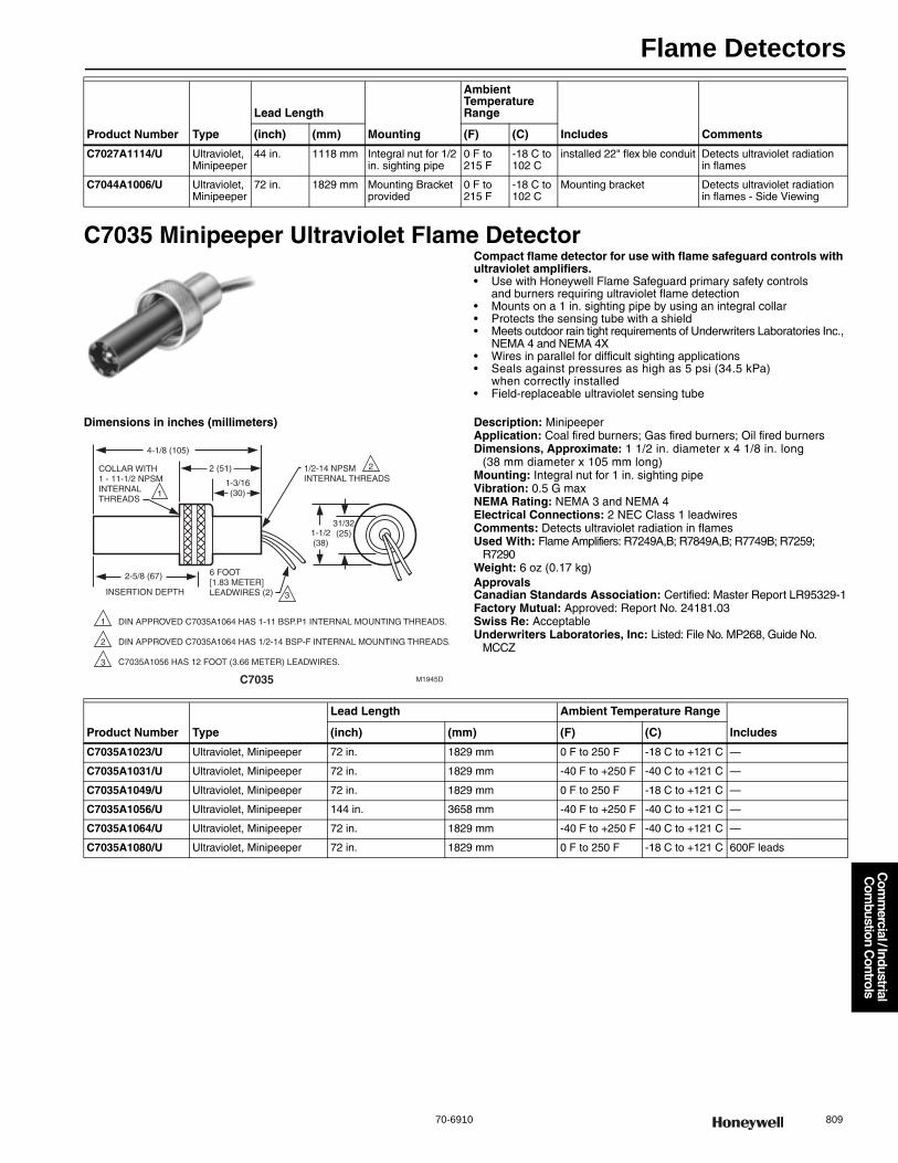
Flame Detectors
70-6910 809
Com
mercial / Industrial
Com
bustion Controls
C7035 Minipeeper Ultraviolet Flame DetectorCompact flame detector for use with flame safeguard controls with ultraviolet amplifiers.• Use with Honeywell Flame Safeguard primary safety controls
and burners requiring ultraviolet flame detection • Mounts on a 1 in. sighting pipe by using an integral collar • Protects the sensing tube with a shield • Meets outdoor rain tight requirements of Underwriters Laboratories Inc.,
NEMA 4 and NEMA 4X • Wires in parallel for difficult sighting applications • Seals against pressures as high as 5 psi (34.5 kPa)
when correctly installed • Field-replaceable ultraviolet sensing tube
Dimensions in inches (millimeters) Description: MinipeeperApplication: Coal fired burners; Gas fired burners; Oil fired burnersDimensions, Approximate: 1 1/2 in. diameter x 4 1/8 in. long
(38 mm diameter x 105 mm long) Mounting: Integral nut for 1 in. sighting pipeVibration: 0.5 G maxNEMA Rating: NEMA 3 and NEMA 4Electrical Connections: 2 NEC Class 1 leadwiresComments: Detects ultraviolet radiation in flamesUsed With: Flame Amplifiers: R7249A,B; R7849A,B; R7749B; R7259;
R7290Weight: 6 oz (0.17 kg) ApprovalsCanadian Standards Association: Certified: Master Report LR95329-1Factory Mutual: Approved: Report No. 24181.03Swiss Re: AcceptableUnderwriters Laboratories, Inc: Listed: File No. MP268, Guide No.
MCCZ
C7027A1114/U Ultraviolet, Minipeeper
44 in. 1118 mm Integral nut for 1/2 in. sighting pipe
0 F to 215 F
-18 C to 102 C
installed 22" flex ble conduit Detects ultraviolet radiation in flames
C7044A1006/U Ultraviolet, Minipeeper
72 in. 1829 mm Mounting Bracket provided
0 F to 215 F
-18 C to 102 C
Mounting bracket Detects ultraviolet radiation in flames - Side Viewing
Product Number Type
Lead Length
Mounting
Ambient Temperature Range
Includes Comments(inch) (mm) (F) (C)
1/2-14 NPSMINTERNAL THREADS
22 (51)COLLAR WITH1 - 11-1/2 NPSMINTERNALTHREADS
1
1 DIN APPROVED C7035A1064 HAS 1-11 BSP.P1 INTERNAL MOUNTING THREADS.
DIN APPROVED C7035A1064 HAS 1/2-14 BSP-F INTERNAL MOUNTING THREADS.
C7035A1056 HAS 12 FOOT (3.66 METER) LEADWIRES.
2
3
INSERTION DEPTH
6 FOOT [1.83 METER]LEADWIRES (2) 3
M1945D
2-5/8 (67)
1-1/2(38)
31/32(25)
4-1/8 (105)
1-3/16(30)
Product Number Type
Lead Length Ambient Temperature Range
Includes(inch) (mm) (F) (C)
C7035A1023/U Ultraviolet, Minipeeper 72 in. 1829 mm 0 F to 250 F -18 C to +121 C —
C7035A1031/U Ultraviolet, Minipeeper 72 in. 1829 mm -40 F to +250 F -40 C to +121 C —
C7035A1049/U Ultraviolet, Minipeeper 72 in. 1829 mm 0 F to 250 F -18 C to +121 C —
C7035A1056/U Ultraviolet, Minipeeper 144 in. 3658 mm -40 F to +250 F -40 C to +121 C —
C7035A1064/U Ultraviolet, Minipeeper 72 in. 1829 mm -40 F to +250 F -40 C to +121 C —
C7035A1080/U Ultraviolet, Minipeeper 72 in. 1829 mm 0 F to 250 F -18 C to +121 C 600F leads

Flame Detectors
810 customer.honeywell.com 70-6910
C7061 Dynamic Self-Check Ultraviolet Flame DetectorDynamic self-checking flame detector used with R7861 Dynamic Self-check Amplifiers for sensing the ultraviolet radiation generated by the combustion of gas, oil, or other fuels.• Oscillating shutter interrupts ultraviolet radiation reaching the
UV sensor to provide the UV sensor tube checking function • Can be mounted horizontally, vertically or at any angle in between • The detector requires faceplate alignment and has integral locating
reference points to assure proper operation of the shutter mechanism • Field replaceable ultraviolet sensing tube and quartz viewing window • Models with threaded conduit fitting and color-coded leadwires allow
rapid electrical installation• C7061A1038, A1046 and C7061M1016 5 pin Molex Woodhead
1R5006A20A120 (formerly Brad Harrison type mating connector not supplied nor available through Honeywell
• Two detectors can be wired in parallel to reduce nuisance shutdowns in difficult flame sighting applications
• Protective heat block built into mounting flange • -40 F (-40 C) rated ultraviolet sensing tube is supplied• Meets IP66 (similar to NEMA 4)standards with
viewing window rated to 20 psi
Description: Ultraviolet Flame Detector with shutterType: Ultraviolet, Purple Peeper, Self-CheckingApplication: Gas fired burners; Oil fired burnersFrequency: 50 Hz; 60 HzComments: Dynamic self-checking flame detectorUsed With: Flame Amplifiers: R7861
ApprovalsCanadian Standards Association: Certified: Master Report LR95329-1Factory Mutual: Approved: Report No. 14740.01Swiss Re: AcceptableUnderwriters Laboratories, Inc: Listed: File No. MP268, Guide No.
MCCZ
C7061A C7061F
C7061M
Product Number Electrical Connections
Lead Length
Mounting NEMA Rating
Ambient Temperature RangeElectrical Ratings(inch) (mm) (F) (C)
C7061A1004/U PVC jacketed cable 77 in. 1981 mm 3/4 in. NPT NEMA 4 -40 F to +175 F -40 C to +79 C 120 Vac
C7061A1012/U Color-coded lead wires 96 in. 2438 mm 3/4 in. NPT NEMA 4 -40 F to +175 F -40 C to +79 C 120 Vac
C7061A1020/U Terminal block — — 3/4 in. NPT NEMA 4 -40 F to +175 F -40 C to +79 C 120 or 230 Vac
C7061A1038/U Molex Woodhead 1R5006A20A120 (formerly Brad Harrison type number 41310 connector)
— — 3/4 in. NPT NEMA 4 -40 F to +175 F -40 C to +79 C 120 Vac
C7061A1046/U Molex Woodhead 1R5006A20A120 (formerly Brad Harrison type number 41310 connector)
— — 1 in. NPT NEMA 4 -40 F to +175 F -40 C to +79 C 120 Vac
C7061A1053/U Color-coded lead wires 96 in. 2438 mm 1 in. NPT NEMA 4 -40 F to +175 F -40 C to +79 C 120 Vac
C7061F1003 Terminal block — — 1 in. NPT Explosion Proof -40 F to +175 F -40 C to +79 C 120 or 230 Vac
C7061F2001/U Color-coded lead wires 96 in. 2438 mm 1 in. NPT Explosion Proof -40 F to +175 F -40 C to +79 C 120 Vac
C7061M1008/U Color-coded lead wires 96 in. 2438 mm 1 in. NPT NEMA 4 -4 F to +175 F -20 C to +79 C 120 Vac
C7061M1016/U Molex Woodhead 1R5006A20A120 (formerly Brad Harrison type number 41310 connector)
— — 1 in. NPT NEMA 4 -4 F to +175 F -20 C to +79 C 120 Vac
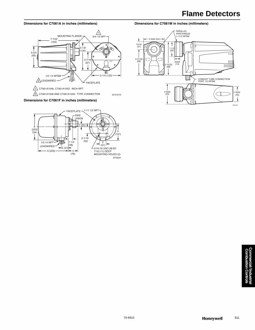
Flame Detectors
70-6910 811
Com
mercial / Industrial
Com
bustion Controls
Dimensions for C7061A in inches (millimeters)
Dimensions for C7061F in inches (millimeters)
Dimensions for C7061M in inches (millimeters)
MOUNTING FLANGE
1/2–14 NPSM
LEADWIRESFACEPLATE
3/4–14 NPT
M10167D
3-3/4(95)
7-7/32(183)
5-1/8(130)
3-7/16(87)
5-1/4 (133)
1
1
2
2
C7061A1046, C7061A1053: INCH NPT
C7061A1038 AND C7061A1046: TYPE CONNECTOR.
M1963A
FACEPLATE
PIPEUNION
8(203) DIA.
1/2-14 NPT
LEADWIRES
9 (229)
2(51)
5(127)
1-11 1/2 NPT
2-1/16 (52)1-1/2
(38)5/16-18 UNC-2B BY7/16 (11) DEEPMOUNTING HOLES (2)
2 (51)
1 (25)
3(76)
M34706
2-9/64 (55)
13/16 (21)
2-21/32(68)
3-15/32(88)
1-1/2(39)
PARALLELPIPETHREAD 1-11/2 NPSM
33/64(13)
2-9/64(55)
1-35/64(40)
CONDUIT TUBE CONNECTIONPORT 1/2 NPSM
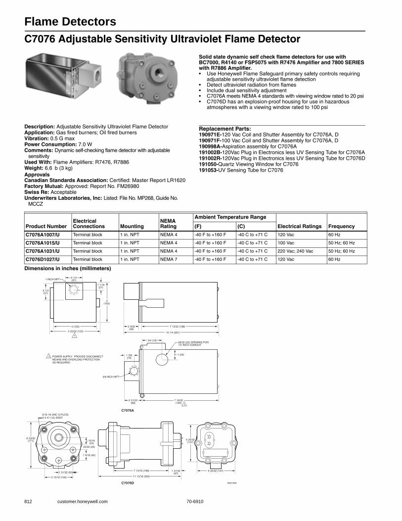
Flame Detectors
812 customer.honeywell.com 70-6910
C7076 Adjustable Sensitivity Ultraviolet Flame Detector
Solid state dynamic self check flame detectors for use with BC7000, R4140 or FSP5075 with R7476 Amplifier and 7800 SERIES with R7886 Amplifier.• Use Honeywell Flame Safeguard primary safety controls requiring
adjustable sensitivity ultraviolet flame detection • Detect ultraviolet radiation from flames • Include dual sensitivity adjustment• C7076A meets NEMA 4 standards with viewing window rated to 20 psi• C7076D has an explosion-proof housing for use in hazardous
atmospheres with a viewing window rated to 100 psi
Description: Adjustable Sensitivity Ultraviolet Flame DetectorApplication: Gas fired burners; Oil fired burnersVibration: 0.5 G maxPower Consumption: 7.0 WComments: Dynamic self-checking flame detector with adjustable
sensitivityUsed With: Flame Amplifiers: R7476, R7886Weight: 6.6 b (3 kg) ApprovalsCanadian Standards Association: Certified: Master Report LR1620Factory Mutual: Approved: Report No. FM26980Swiss Re: AcceptableUnderwriters Laboratories, Inc: Listed: File No. MP268, Guide No.
MCCZ
Replacement Parts:190971E-120 Vac Coil and Shutter Assembly for C7076A, D190971F-100 Vac Coil and Shutter Assembly for C7076A, D190998A-Aspiration assembly for C7076A191002B-120Vac Plug in Electronics less UV Sensing Tube for C7076A191002R-120Vac Plug in Electronics less UV Sensing Tube for C7076D191050-Quartz Viewing Window for C7076191053-UV Sensing Tube for C7076
Dimensions in inches (millimeters)
Product NumberElectrical Connections Mounting
NEMA Rating
Ambient Temperature Range
Electrical Ratings Frequency(F) (C)
C7076A1007/U Terminal block 1 in. NPT NEMA 4 -40 F to +160 F -40 C to +71 C 120 Vac 60 Hz
C7076A1015/U Terminal block 1 in. NPT NEMA 4 -40 F to +160 F -40 C to +71 C 100 Vac 50 Hz; 60 Hz
C7076A1031/U Terminal block 1 in. NPT NEMA 4 -40 F to +160 F -40 C to +71 C 220 Vac; 240 Vac 50 Hz; 60 Hz
C7076D1027/U Terminal block 1 in. NPT NEMA 7 -40 F to +160 F -40 C to +71 C 120 Vac 60 Hz
C7076A
C7076D M20749A
2 1/4(57)
2 1/4(57)
2 9/32(58)
5 25/32 (147)
5 25/32(147)
1 27/32(47)
7 13/16 (198)
15/16(24)
25/32 (20)
1 9/16 (40)
11 13/16 (300)
3/4 (19)
1 5/8(19)
2 21/32(68)
7 19/32(194)
3/8 INCH NPT
1 (25)
29/32 (22) OPENING FOR1/2 INCH CONDUIT
7 13/32 (188)
10 1/4 (261)
1 1/16(27)
4(102)
4 (102)
4 25/32 (122)
1 INCH NPT
POWER SUPPLY PROVIDE DISCONNECTMEANS AND OVERLOAD PROTECTION AS REQUIRED
1
1
1
6 23/32(171)
1 31/32 (50)
3 15/16 (100)
5/16 18 UNC (3 PLCS)X 0 47 (12) DEEP
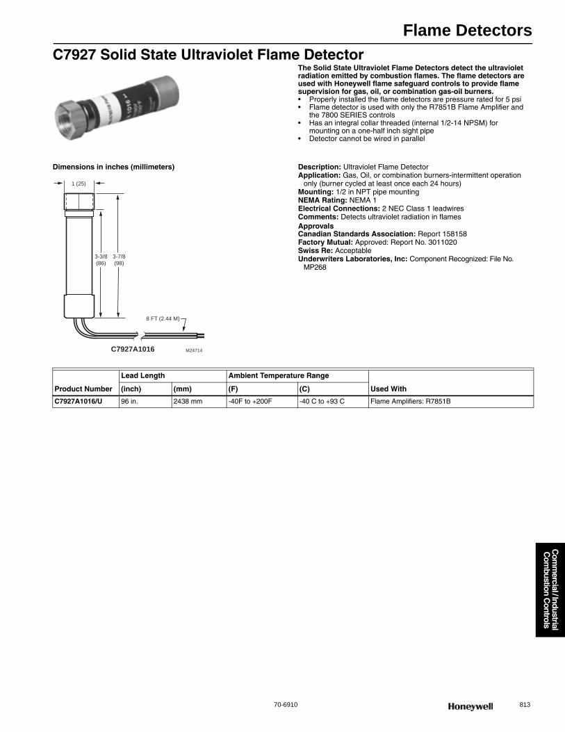
Flame Detectors
70-6910 813
Com
mercial / Industrial
Com
bustion Controls
C7927 Solid State Ultraviolet Flame DetectorThe Solid State Ultraviolet Flame Detectors detect the ultraviolet radiation emitted by combustion flames. The flame detectors are used with Honeywell flame safeguard controls to provide flame supervision for gas, oil, or combination gas-oil burners.• Properly installed the flame detectors are pressure rated for 5 psi • Flame detector is used with only the R7851B Flame Amplifier and
the 7800 SERIES controls • Has an integral collar threaded (internal 1/2-14 NPSM) for
mounting on a one-half inch sight pipe• Detector cannot be wired in parallel
Dimensions in inches (millimeters) Description: Ultraviolet Flame DetectorApplication: Gas, Oil, or combination burners-intermittent operation
only (burner cycled at least once each 24 hours)Mounting: 1/2 in NPT pipe mountingNEMA Rating: NEMA 1Electrical Connections: 2 NEC Class 1 leadwiresComments: Detects ultraviolet radiation in flamesApprovalsCanadian Standards Association: Report 158158Factory Mutual: Approved: Report No. 3011020Swiss Re: AcceptableUnderwriters Laboratories, Inc: Component Recognized: File No.
MP268
8 FT (2.44 M)
1 (25)
C7927A1016 M24714
3-7/8
(98)
3-3/8
(86)
Product Number
Lead Length Ambient Temperature Range
Used With(inch) (mm) (F) (C)
C7927A1016/U 96 in. 2438 mm -40F to +200F -40 C to +93 C Flame Amplifiers: R7851B
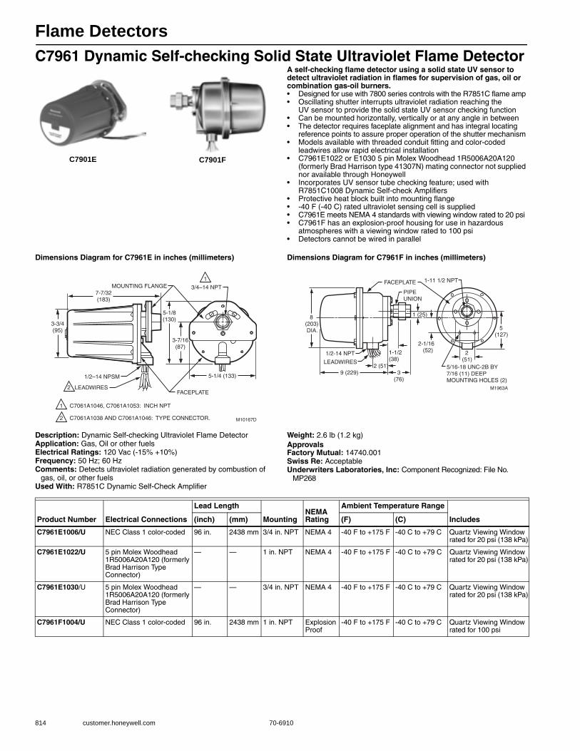
Flame Detectors
814 customer.honeywell.com 70-6910
C7961 Dynamic Self-checking Solid State Ultraviolet Flame DetectorA self-checking flame detector using a solid state UV sensor to detect ultraviolet radiation in flames for supervision of gas, oil or combination gas-oil burners.• Designed for use with 7800 series controls with the R7851C flame amp • Oscillating shutter interrupts ultraviolet radiation reaching the
UV sensor to provide the solid state UV sensor checking function • Can be mounted horizontally, vertically or at any angle in between • The detector requires faceplate alignment and has integral locating
reference points to assure proper operation of the shutter mechanism• Models available with threaded conduit fitting and color-coded
leadwires allow rapid electrical installation• C7961E1022 or E1030 5 pin Molex Woodhead 1R5006A20A120
(formerly Brad Harrison type 41307N) mating connector not supplied nor available through Honeywell
• Incorporates UV sensor tube checking feature; used with R7851C1008 Dynamic Self-check Amplifiers
• Protective heat block built into mounting flange • -40 F (-40 C) rated ultraviolet sensing cell is supplied• C7961E meets NEMA 4 standards with viewing window rated to 20 psi• C7961F has an explosion-proof housing for use in hazardous
atmospheres with a viewing window rated to 100 psi• Detectors cannot be wired in parallel
Dimensions Diagram for C7961E in inches (millimeters) Dimensions Diagram for C7961F in inches (millimeters)
Description: Dynamic Self-checking Ultraviolet Flame DetectorApplication: Gas, Oil or other fuelsElectrical Ratings: 120 Vac (-15% +10%)Frequency: 50 Hz; 60 HzComments: Detects ultraviolet radiation generated by combustion of
gas, oil, or other fuelsUsed With: R7851C Dynamic Self-Check Amplifier
Weight: 2.6 lb (1.2 kg) ApprovalsFactory Mutual: 14740.001Swiss Re: AcceptableUnderwriters Laboratories, Inc: Component Recognized: File No.
MP268
C7901E C7901F
MOUNTING FLANGE
1/2–14 NPSM
LEADWIRESFACEPLATE
3/4–14 NPT
M10167D
3-3/4(95)
7-7/32(183)
5-1/8(130)
3-7/16(87)
5-1/4 (133)
1
1
2
2
C7061A1046, C7061A1053: INCH NPT
C7061A1038 AND C7061A1046: TYPE CONNECTOR.
M1963A
FACEPLATE
PIPEUNION
8(203) DIA.
1/2-14 NPT
LEADWIRES
9 (229)
2(51)
5(127)
1-11 1/2 NPT
2-1/16 (52)1-1/2
(38)5/16-18 UNC-2B BY7/16 (11) DEEPMOUNTING HOLES (2)
2 (51)
1 (25)
3(76)
Product Number Electrical Connections
Lead Length
MountingNEMA Rating
Ambient Temperature Range
Includes(inch) (mm) (F) (C)
C7961E1006/U NEC Class 1 color-coded 96 in. 2438 mm 3/4 in. NPT NEMA 4 -40 F to +175 F -40 C to +79 C Quartz Viewing Window rated for 20 psi (138 kPa)
C7961E1022/U 5 pin Molex Woodhead 1R5006A20A120 (formerly Brad Harrison Type Connector)
— — 1 in. NPT NEMA 4 -40 F to +175 F -40 C to +79 C Quartz Viewing Window rated for 20 psi (138 kPa)
C7961E1030/U 5 pin Molex Woodhead 1R5006A20A120 (formerly Brad Harrison Type Connector)
— — 3/4 in. NPT NEMA 4 -40 F to +175 F -40 C to +79 C Quartz Viewing Window rated for 20 psi (138 kPa)
C7961F1004/U NEC Class 1 color-coded 96 in. 2438 mm 1 in. NPT Explosion Proof
-40 F to +175 F -40 C to +79 C Quartz Viewing Window rated for 100 psi
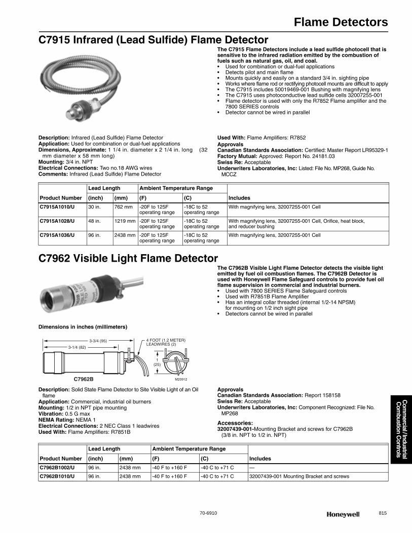
Flame Detectors
70-6910 815
Com
mercial / Industrial
Com
bustion Controls
C7915 Infrared (Lead Sulfide) Flame DetectorThe C7915 Flame Detectors include a lead sulfide photocell that is sensitive to the infrared radiation emitted by the combustion of fuels such as natural gas, oil, and coal.• Used for combination or dual-fuel applications • Detects pilot and main flame • Mounts quickly and easily on a standard 3/4 in. sighting pipe • Works where flame rod or rectifying photocell mounts are difficult to apply• The C7915 includes 50019469-001 Bushing with magnifying lens • The C7915 uses photoconductive lead sulfide cells 32007255-001• Flame detector is used with only the R7852 Flame amplifier and the
7800 SERIES controls• Detector cannot be wired in parallel
Description: Infrared (Lead Sulfide) Flame DetectorApplication: Used for combination or dual-fuel applicationsDimensions, Approximate: 1 1/4 in. diameter x 2 1/4 in. long (32
mm diameter x 58 mm long) Mounting: 3/4 in. NPTElectrical Connections: Two no.18 AWG wiresComments: Infrared (Lead Sulfide) Flame Detector
Used With: Flame Amplifiers: R7852ApprovalsCanadian Standards Association: Certified: Master Report LR95329-1Factory Mutual: Approved: Report No. 24181.03Swiss Re: AcceptableUnderwriters Laboratories, Inc: Listed: File No. MP268, Guide No.
MCCZ
C7962 Visible Light Flame DetectorThe C7962B Visible Light Flame Detector detects the visible light emitted by fuel oil combustion flames. The C7962B Detector is used with Honeywell Flame Safeguard controls to provide fuel oil flame supervision in commercial and industrial burners.• Used with 7800 SERIES Flame Safeguard controls • Used with R7851B Flame Amplifier • Has an integral collar threaded (internal 1/2-14 NPSM)
for mounting on 1/2 inch sight pipe• Detectors cannot be wired in parallel
Dimensions in inches (millimeters)
Description: Solid State Flame Detector to Site Visible Light of an Oil flame
Application: Commercial, industrial oil burnersMounting: 1/2 in NPT pipe mountingVibration: 0.5 G maxNEMA Rating: NEMA 1Electrical Connections: 2 NEC Class 1 leadwiresUsed With: Flame Amplifiers: R7851B
ApprovalsCanadian Standards Association: Report 158158Swiss Re: AcceptableUnderwriters Laboratories, Inc: Component Recognized: File No.
MP268
Accessories:32007439-001-Mounting Bracket and screws for C7962B
(3/8 in. NPT to 1/2 in. NPT)
Product Number
Lead Length Ambient Temperature Range
Includes(inch) (mm) (F) (C)
C7915A1010/U 30 in. 762 mm -20F to 125F operating range
-18C to 52 operating range
With magnifying lens, 32007255-001 Cell
C7915A1028/U 48 in. 1219 mm -20F to 125F operating range
-18C to 52 operating range
With magnifying lens, 32007255-001 Cell, Orifice, heat block, and reducer bushing
C7915A1036/U 96 in. 2438 mm -20F to 125F operating range
-18C to 52 operating range
With magnifying lens, 32007255-001 Cell
4 FOOT (1.2 METER)LEADWIRES (2)
M20912
3-1/4 (82)
3-3/4 (95)
1(25)
C7962B
Product Number
Lead Length Ambient Temperature Range
Includes(inch) (mm) (F) (C)
C7962B1002/U 96 in. 2438 mm -40 F to +160 F -40 C to +71 C —
C7962B1010/U 96 in. 2438 mm -40 F to +160 F -40 C to +71 C 32007439-001 Mounting Bracket and screws

Flame Detectors
816 customer.honeywell.com 70-6910
Optical Flame Detector Accessories or PartsProduct Number Description Used With
105061/U 3/4 in. Heat Block for C7015, C7915 C7015, C7915
105172A/U Pressure Seal-off Adapter (3/4 NPT) for C7015, C7915 C7015, C7915
105172C/U Pressure Seal-off Adapter (3/4 NPT) w/UV Quartz window for C7012, C7024, C7027, C7061 C7024; C7012; C7061; C7012, C7024, C7027, C7061
113228/U UV Sensing Tube (-20 F to 175 F) for C7012; C7024 C7012; C7024
114372/U 20 PSI window for C7012E,F; C7024; C7061 C7024; C7012; C7061
114465/U Window Gasket for C7012A, E; C7024A; C7061A C7024; C7012; C7061
114638/U Rubber Washer (Red) for C7012A, E; C7024A; C7061A; C7961A C7012; C7061; C7024
117181/U Cork Gasket for C7012A, E;C7024A; C7061A C7024; C7012; C7061
118367A/U Swivel Mount with 3/4 in. coupling for C7012, C7015, C7024, C7027, C7035, C7061, C7076 C7024; C7012; C7061
120739/U Flange Gasket for C7012, C7024, C7061 C7024; C7012; C7061
120934/520/U Mounting Flange (3/4” NPT) for C7012A,E; C7024A; C7061A; C7961E C7012A,G, C7024E, C7061A, C7961E
122037/U 100 PSI Quartz Window for C7012C, F; C7061F C7012C, F; C7061F
122748/U 50 PSI Quartz Window for C7012, C7061 C7012; C7061; C7024
123539/U Anti-Vibration Mount for C7012, C7024 or C7061 C7012; C7061; C7024
124198/U Mounting Flange (1") for C7012A,E; C7024A; C7061A; C7961E C7012A,G, C7024E, C7061A, C7961E
124204/U Quartz Magnifying Lens for C7012, C7024 or C7061 C7024; C7012; C7061
129464M/U UV Power Tube (0 to 250F) for C7035 C7035
129464N/U UV Power Tube (-40 to 250F) for C7035, C7061 C7061; C7035
129811B/U Socket Assembly w/NPT threads C7035
136733/U Heat Block for C7027, C7015, C7915 (laminated plastic) C7027; C7027, C7015, C7915
190971B/U 120 Vac 50/60 Hz Coil and Shutter Assembly for C7012E, F, C7061A, F C7012E,F; C7061A,F
190971D/U 110 Vac 50 Hz Coil and Shutter Assembly for C7012E1187, 1195 C7012E
190971E/U 120 Vac Coil and Shutter Assembly for C7076A, D C7076; C7076A,D; C7076A,D
190971F/U 100 Vac Coil and Shutter Assembly for C7076A, D C7076A,D
190971G/U 24 Vdc Coil and Shutter Assembly for C7024E, F; C7961 C7024;C7961
190998A/U Aspiration assembly for C7076A C7076A
190999/U Grommet for C7076 Sensors C7076
191002A/U 100Vac Plug in Electronics less UV Sensing Tube for C7076A C7076A
191002B/U 120Vac Plug in Electronics less UV Sensing Tube for C7076A C7076A
191002D/U 220/240Vac Plug in Electronics less UV Sensing Tube for C7076A C7076A
191002R/U 120Vac Plug in Electronics less UV Sensing Tube for C7076D C7076D
191050/U Quartz Viewing Window for C7076 C7076
191053/U UV Sensing Tube for C7076 C7076
191054/U Housing Gasket for C7076 C7076
191284/U Aluminum Shield for C7035 C7035
191286/U UV Sensing Tube (-40F to 175F) for C7012, C7024 C7024; C7012
191702/U Electronics less UV sensing tube for C7012F (120Vac) C7012F
24400152-001/U Quartz lens replacement kit for C7076D consists of quartz lens, gasket, gasket seal C7076
32007255-001/U Lead Sulfide Cell for C7915 C7915
32007439-001/U Mounting Bracket and screws for C7962B (3/8 in. NPT to 1/2 in. NPT) C7962B
390427B/U Reducer Bushing (1/2” NPT to 3/8” NPT) C7027; C7015
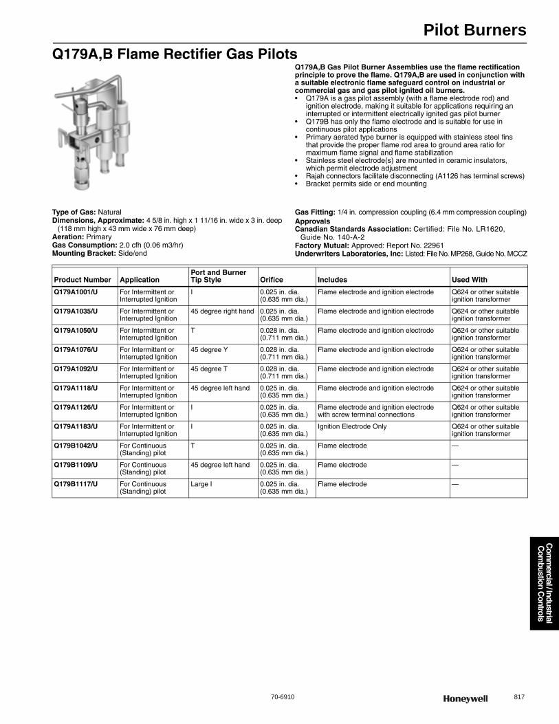
Pilot Burners
70-6910 817
Com
mercial / Industrial
Com
bustion Controls
Q179A,B Flame Rectifier Gas PilotsQ179A,B Gas Pilot Burner Assemblies use the flame rectification principle to prove the flame. Q179A,B are used in conjunction with a suitable electronic flame safeguard control on industrial or commercial gas and gas pilot ignited oil burners.• Q179A is a gas pilot assembly (with a flame electrode rod) and
ignition electrode, making it suitable for applications requiring an interrupted or intermittent electrically ignited gas pilot burner
• Q179B has only the flame electrode and is suitable for use in continuous pilot applications
• Primary aerated type burner is equipped with stainless steel fins that provide the proper flame rod area to ground area ratio for maximum flame signal and flame stabilization
• Stainless steel electrode(s) are mounted in ceramic insulators, which permit electrode adjustment
• Rajah connectors facilitate disconnecting (A1126 has terminal screws) • Bracket permits side or end mounting
Type of Gas: NaturalDimensions, Approximate: 4 5/8 in. high x 1 11/16 in. wide x 3 in. deep
(118 mm high x 43 mm wide x 76 mm deep) Aeration: PrimaryGas Consumption: 2.0 cfh (0.06 m3/hr)Mounting Bracket: Side/end
Gas Fitting: 1/4 in. compression coupling (6.4 mm compression coupling)ApprovalsCanadian Standards Association: Certified: File No. LR1620,
Guide No. 140-A-2Factory Mutual: Approved: Report No. 22961Underwriters Laboratories, Inc: Listed: File No. MP268, Guide No. MCCZ
Product Number ApplicationPort and Burner Tip Style Orifice Includes Used With
Q179A1001/U For Intermittent or Interrupted Ignition
I 0.025 in. dia. (0.635 mm dia.)
Flame electrode and ignition electrode Q624 or other suitable ignition transformer
Q179A1035/U For Intermittent or Interrupted Ignition
45 degree right hand 0.025 in. dia. (0.635 mm dia.)
Flame electrode and ignition electrode Q624 or other suitable ignition transformer
Q179A1050/U For Intermittent or Interrupted Ignition
T 0.028 in. dia. (0.711 mm dia.)
Flame electrode and ignition electrode Q624 or other suitable ignition transformer
Q179A1076/U For Intermittent or Interrupted Ignition
45 degree Y 0.028 in. dia. (0.711 mm dia.)
Flame electrode and ignition electrode Q624 or other suitable ignition transformer
Q179A1092/U For Intermittent or Interrupted Ignition
45 degree T 0.028 in. dia. (0.711 mm dia.)
Flame electrode and ignition electrode Q624 or other suitable ignition transformer
Q179A1118/U For Intermittent or Interrupted Ignition
45 degree left hand 0.025 in. dia. (0.635 mm dia.)
Flame electrode and ignition electrode Q624 or other suitable ignition transformer
Q179A1126/U For Intermittent or Interrupted Ignition
I 0.025 in. dia. (0.635 mm dia.)
Flame electrode and ignition electrode with screw terminal connections
Q624 or other suitable ignition transformer
Q179A1183/U For Intermittent or Interrupted Ignition
I 0.025 in. dia. (0.635 mm dia.)
Ignition Electrode Only Q624 or other suitable ignition transformer
Q179B1042/U For Continuous (Standing) pilot
T 0.025 in. dia. (0.635 mm dia.)
Flame electrode —
Q179B1109/U For Continuous (Standing) pilot
45 degree left hand 0.025 in. dia. (0.635 mm dia.)
Flame electrode —
Q179B1117/U For Continuous (Standing) pilot
Large I 0.025 in. dia. (0.635 mm dia.)
Flame electrode —
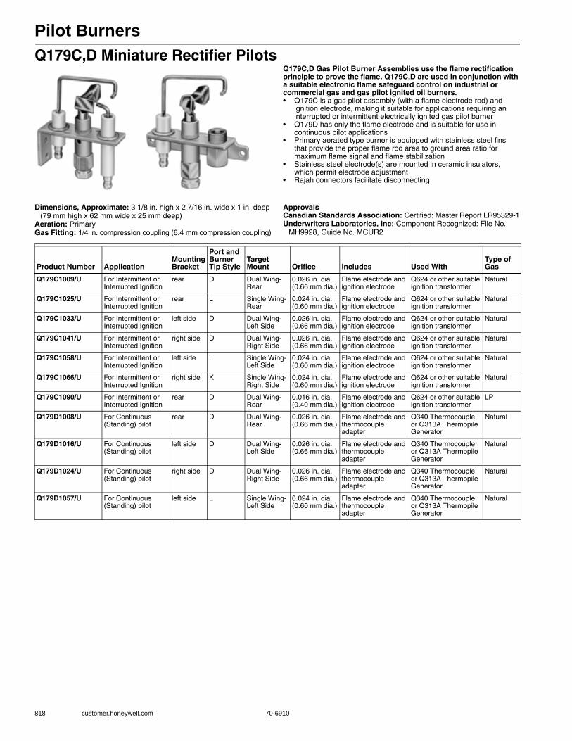
Pilot Burners
818 customer.honeywell.com 70-6910
Q179C,D Miniature Rectifier PilotsQ179C,D Gas Pilot Burner Assemblies use the flame rectification principle to prove the flame. Q179C,D are used in conjunction with a suitable electronic flame safeguard control on industrial or commercial gas and gas pilot ignited oil burners.• Q179C is a gas pilot assembly (with a flame electrode rod) and
ignition electrode, making it suitable for applications requiring an interrupted or intermittent electrically ignited gas pilot burner
• Q179D has only the flame electrode and is suitable for use in continuous pilot applications
• Primary aerated type burner is equipped with stainless steel fins that provide the proper flame rod area to ground area ratio for maximum flame signal and flame stabilization
• Stainless steel electrode(s) are mounted in ceramic insulators, which permit electrode adjustment
• Rajah connectors facilitate disconnecting
Dimensions, Approximate: 3 1/8 in. high x 2 7/16 in. wide x 1 in. deep (79 mm high x 62 mm wide x 25 mm deep)
Aeration: PrimaryGas Fitting: 1/4 in. compression coupling (6.4 mm compression coupling)
ApprovalsCanadian Standards Association: Certified: Master Report LR95329-1Underwriters Laboratories, Inc: Component Recognized: File No.
MH9928, Guide No. MCUR2
Product Number ApplicationMounting Bracket
Port and Burner Tip Style
Target Mount Orifice Includes Used With
Type of Gas
Q179C1009/U For Intermittent or Interrupted Ignition
rear D Dual Wing- Rear
0.026 in. dia. (0.66 mm dia.)
Flame electrode and ignition electrode
Q624 or other suitable ignition transformer
Natural
Q179C1025/U For Intermittent or Interrupted Ignition
rear L Single Wing- Rear
0.024 in. dia. (0.60 mm dia.)
Flame electrode and ignition electrode
Q624 or other suitable ignition transformer
Natural
Q179C1033/U For Intermittent or Interrupted Ignition
left side D Dual Wing- Left Side
0.026 in. dia. (0.66 mm dia.)
Flame electrode and ignition electrode
Q624 or other suitable ignition transformer
Natural
Q179C1041/U For Intermittent or Interrupted Ignition
right side D Dual Wing- Right Side
0.026 in. dia. (0.66 mm dia.)
Flame electrode and ignition electrode
Q624 or other suitable ignition transformer
Natural
Q179C1058/U For Intermittent or Interrupted Ignition
left side L Single Wing- Left Side
0.024 in. dia. (0.60 mm dia.)
Flame electrode and ignition electrode
Q624 or other suitable ignition transformer
Natural
Q179C1066/U For Intermittent or Interrupted Ignition
right side K Single Wing- Right Side
0.024 in. dia. (0.60 mm dia.)
Flame electrode and ignition electrode
Q624 or other suitable ignition transformer
Natural
Q179C1090/U For Intermittent or Interrupted Ignition
rear D Dual Wing- Rear
0.016 in. dia. (0.40 mm dia.)
Flame electrode and ignition electrode
Q624 or other suitable ignition transformer
LP
Q179D1008/U For Continuous (Standing) pilot
rear D Dual Wing- Rear
0.026 in. dia. (0.66 mm dia.)
Flame electrode and thermocouple adapter
Q340 Thermocouple or Q313A Thermopile Generator
Natural
Q179D1016/U For Continuous (Standing) pilot
left side D Dual Wing- Left Side
0.026 in. dia. (0.66 mm dia.)
Flame electrode and thermocouple adapter
Q340 Thermocouple or Q313A Thermopile Generator
Natural
Q179D1024/U For Continuous (Standing) pilot
right side D Dual Wing- Right Side
0.026 in. dia. (0.66 mm dia.)
Flame electrode and thermocouple adapter
Q340 Thermocouple or Q313A Thermopile Generator
Natural
Q179D1057/U For Continuous (Standing) pilot
left side L Single Wing- Left Side
0.024 in. dia. (0.60 mm dia.)
Flame electrode and thermocouple adapter
Q340 Thermocouple or Q313A Thermopile Generator
Natural
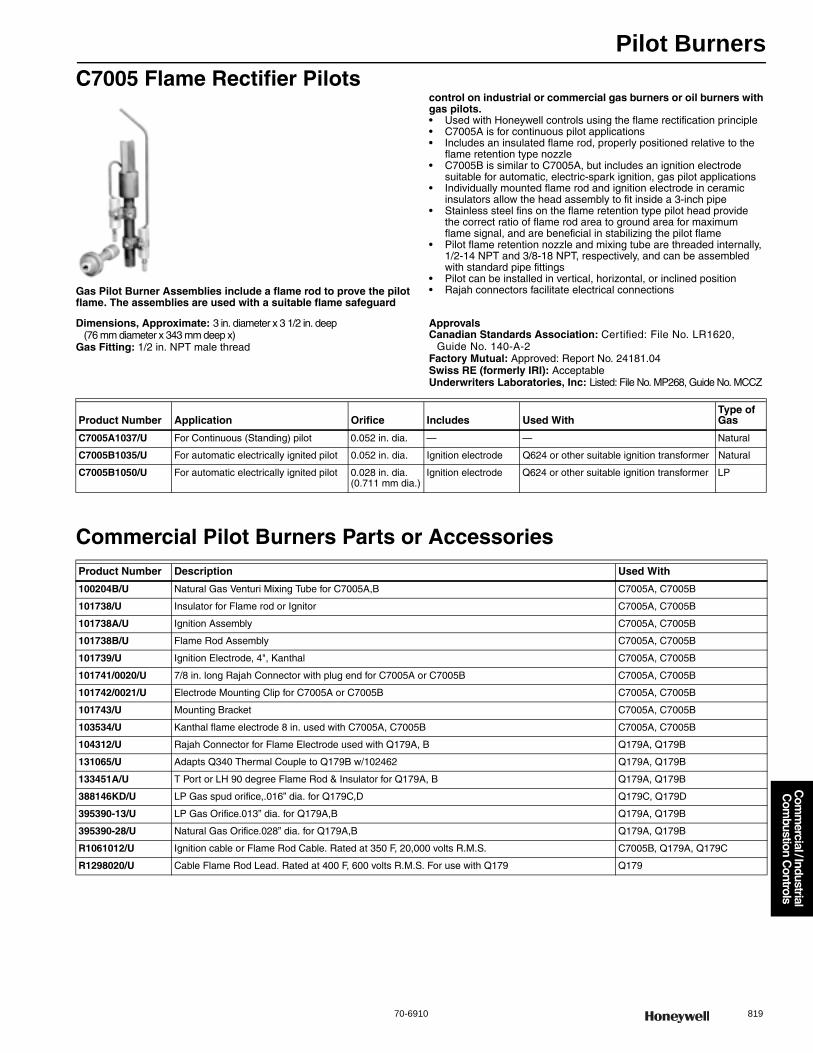
Pilot Burners
70-6910 819
Com
mercial / Industrial
Com
bustion Controls
C7005 Flame Rectifier Pilots
Gas Pilot Burner Assemblies include a flame rod to prove the pilot flame. The assemblies are used with a suitable flame safeguard
control on industrial or commercial gas burners or oil burners with gas pilots.• Used with Honeywell controls using the flame rectification principle • C7005A is for continuous pilot applications • Includes an insulated flame rod, properly positioned relative to the
flame retention type nozzle• C7005B is similar to C7005A, but includes an ignition electrode
suitable for automatic, electric-spark ignition, gas pilot applications • Individually mounted flame rod and ignition electrode in ceramic
insulators allow the head assembly to fit inside a 3-inch pipe • Stainless steel fins on the flame retention type pilot head provide
the correct ratio of flame rod area to ground area for maximum flame signal, and are beneficial in stabilizing the pilot flame
• Pilot flame retention nozzle and mixing tube are threaded internally, 1/2-14 NPT and 3/8-18 NPT, respectively, and can be assembled with standard pipe fittings
• Pilot can be installed in vertical, horizontal, or inclined position • Rajah connectors facilitate electrical connections
Dimensions, Approximate: 3 in. diameter x 3 1/2 in. deep (76 mm diameter x 343 mm deep x)
Gas Fitting: 1/2 in. NPT male thread
ApprovalsCanadian Standards Association: Certified: File No. LR1620,
Guide No. 140-A-2Factory Mutual: Approved: Report No. 24181.04Swiss RE (formerly IRI): AcceptableUnderwriters Laboratories, Inc: Listed: File No. MP268, Guide No. MCCZ
Commercial Pilot Burners Parts or Accessories
Product Number Application Orifice Includes Used WithType of Gas
C7005A1037/U For Continuous (Standing) pilot 0.052 in. dia. — — Natural
C7005B1035/U For automatic electrically ignited pilot 0.052 in. dia. Ignition electrode Q624 or other suitable ignition transformer Natural
C7005B1050/U For automatic electrically ignited pilot 0.028 in. dia. (0.711 mm dia.)
Ignition electrode Q624 or other suitable ignition transformer LP
Product Number Description Used With
100204B/U Natural Gas Venturi Mixing Tube for C7005A,B C7005A, C7005B
101738/U Insulator for Flame rod or Ignitor C7005A, C7005B
101738A/U Ignition Assembly C7005A, C7005B
101738B/U Flame Rod Assembly C7005A, C7005B
101739/U Ignition Electrode, 4", Kanthal C7005A, C7005B
101741/0020/U 7/8 in. long Rajah Connector with plug end for C7005A or C7005B C7005A, C7005B
101742/0021/U Electrode Mounting Clip for C7005A or C7005B C7005A, C7005B
101743/U Mounting Bracket C7005A, C7005B
103534/U Kanthal flame electrode 8 in. used with C7005A, C7005B C7005A, C7005B
104312/U Rajah Connector for Flame Electrode used with Q179A, B Q179A, Q179B
131065/U Adapts Q340 Thermal Couple to Q179B w/102462 Q179A, Q179B
133451A/U T Port or LH 90 degree Flame Rod & Insulator for Q179A, B Q179A, Q179B
388146KD/U LP Gas spud orifice,.016” dia. for Q179C,D Q179C, Q179D
395390-13/U LP Gas Orifice.013” dia. for Q179A,B Q179A, Q179B
395390-28/U Natural Gas Orifice.028” dia. for Q179A,B Q179A, Q179B
R1061012/U Ignition cable or Flame Rod Cable. Rated at 350 F, 20,000 volts R.M.S. C7005B, Q179A, Q179C
R1298020/U Cable Flame Rod Lead. Rated at 400 F, 600 volts R.M.S. For use with Q179 Q179
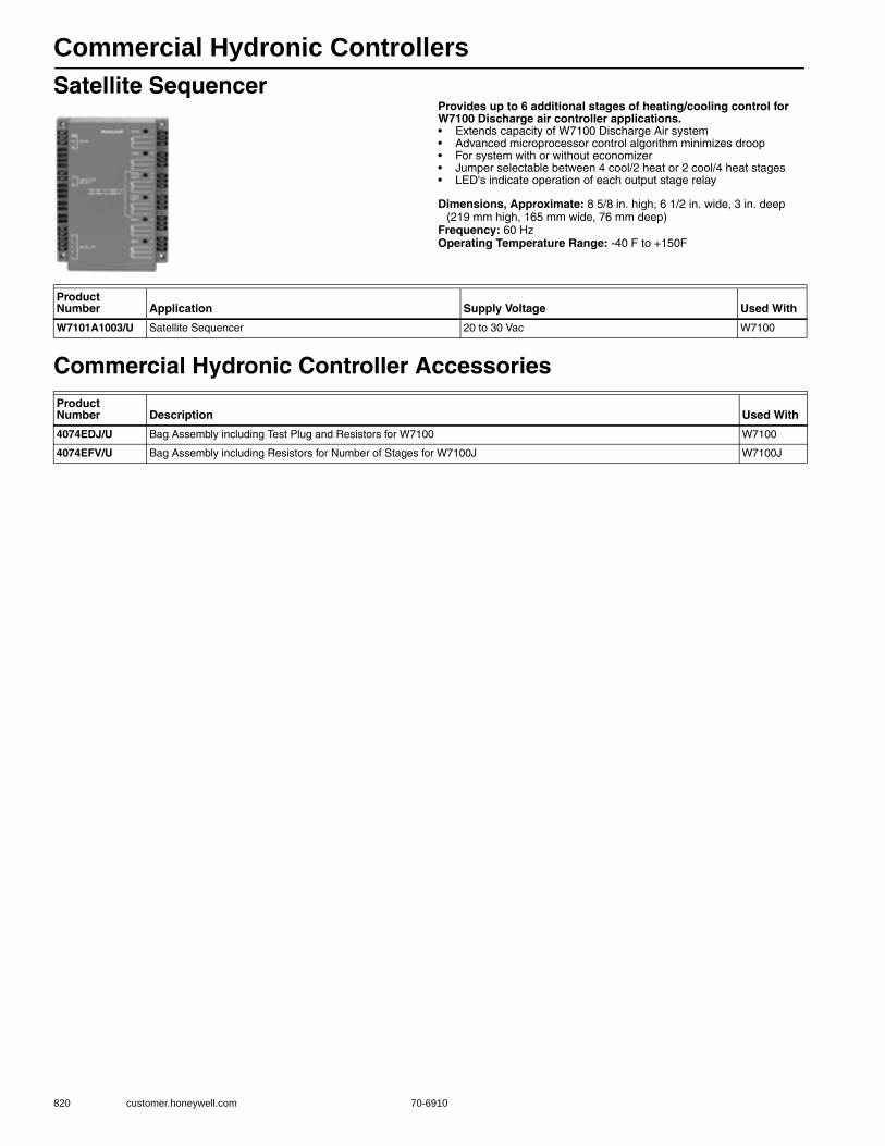
Commercial Hydronic Controllers
820 customer.honeywell.com 70-6910
Satellite SequencerProvides up to 6 additional stages of heating/cooling control for W7100 Discharge air controller applications.• Extends capacity of W7100 Discharge Air system • Advanced microprocessor control algorithm minimizes droop • For system with or without economizer • Jumper selectable between 4 cool/2 heat or 2 cool/4 heat stages• LED's indicate operation of each output stage relay
Dimensions, Approximate: 8 5/8 in. high, 6 1/2 in. wide, 3 in. deep (219 mm high, 165 mm wide, 76 mm deep)
Frequency: 60 HzOperating Temperature Range: -40 F to +150F
Commercial Hydronic Controller Accessories
Product Number Application Supply Voltage Used With
W7101A1003/U Satellite Sequencer 20 to 30 Vac W7100
Product Number Description Used With
4074EDJ/U Bag Assembly including Test Plug and Resistors for W7100 W7100
4074EFV/U Bag Assembly including Resistors for Number of Stages for W7100J W7100J

Ignition Transformers
70-6910 821
Com
mercial / Industrial
Com
bustion Controls
Q624 Solid State Ignition TransformerUsed to ignite pilots on commercial or industrial gas burners.• Ignite gas pilots with spark gaps up to 1/4 in. (6.5 mm) • Reliable light off with 15,000 peak voltage • Prevent detection of the ignition spark when properly applied
in a flame detection system with the C7027, C7035 or C7044 Minipeeper Ultraviolet Flame Detector or C7061 Dynamic Self Check Ultraviolet Flame Detector
• For use only in interrupted ignition applications • Mount in same space used by conventional ignition transformer • Light weight, 3 lbs. (1.4 kg) versus 8-1/2 lbs. (3.9 kg)
for standard transformers
Dimensions in inches (millimeters)
Ambient Temperature Range: -40 F to +125 F (-40 C to +52 C)Operating Humidity Range (% RH): 95% RHWeight: 3 lb
ApprovalsCanadian Standards Association: Certified: File No. LR95329Underwriters Laboratories, Inc: Component Recognized
TERM NALBOARD
MOUNTINGPLATE
HIGH VOLTAGEELECTRODE
COVER SCREW
KNOCKOUT FOR 1/2 INCH CONDUIT
32(1-1/4)
20.5(13/16)
133.5 (5-1/4)
7(19/64)
108(4-1/4)
32(1-1/4)
76 (3)
MC20858
151 (5-15/16)171 5 (6-3/4 )
Product Number Application Electrical Ratings Frequency
Q624A1014/U Gas Ignition Transformer 120 Vac 50 Hz; 60 Hz
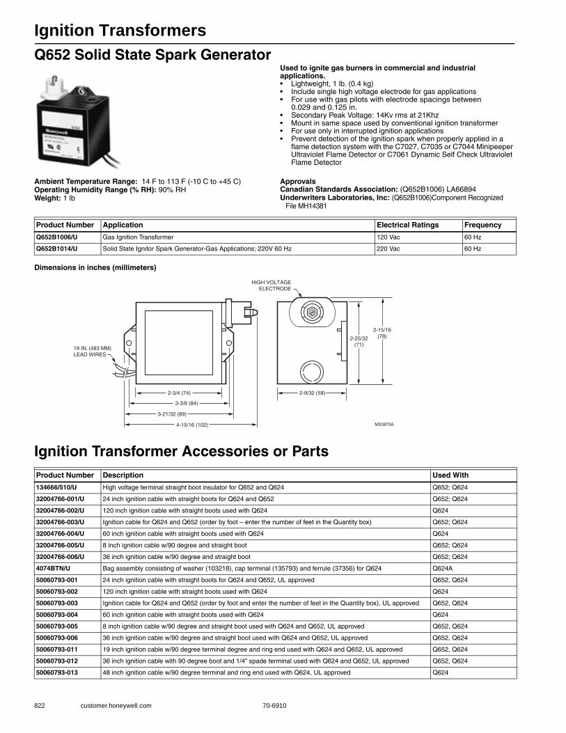
Ignition Transformers
822 customer.honeywell.com 70-6910
Q652 Solid State Spark GeneratorUsed to ignite gas burners in commercial and industrial applications.• Lightweight, 1 lb. (0.4 kg) • Include single high voltage electrode for gas applications • For use with gas pilots with electrode spacings between
0.029 and 0.125 in. • Secondary Peak Voltage: 14Kv rms at 21Khz• Mount in same space used by conventional ignition transformer• For use only in interrupted ignition applications • Prevent detection of the ignition spark when properly applied in a
flame detection system with the C7027, C7035 or C7044 Minipeeper Ultraviolet Flame Detector or C7061 Dynamic Self Check Ultraviolet Flame Detector
Ambient Temperature Range: 14 F to 113 F (-10 C to +45 C)Operating Humidity Range (% RH): 90% RHWeight: 1 lb
ApprovalsCanadian Standards Association: (Q652B1006) LA66894Underwriters Laboratories, Inc: (Q652B1006)Component Recognized
File MH14381
Dimensions in inches (millimeters)
Ignition Transformer Accessories or Parts
Product Number Application Electrical Ratings Frequency
Q652B1006/U Gas Ignition Transformer 120 Vac 60 Hz
Q652B1014/U Solid State Ignitor Spark Generator-Gas Applications; 220V 60 Hz 220 Vac 60 Hz
Product Number Description Used With
134666/510/U High voltage terminal straight boot insulator for Q652 and Q624 Q652; Q624
32004766-001/U 24 inch ignition cable with straight boots for Q624 and Q652 Q652; Q624
32004766-002/U 120 inch ignition cable with straight boots used with Q624 Q624
32004766-003/U Ignition cable for Q624 and Q652 (order by foot – enter the number of feet in the Quantity box) Q652; Q624
32004766-004/U 60 inch ignition cable with straight boots used with Q624 Q624
32004766-005/U 8 inch ignition cable w/90 degree and straight boot Q652; Q624
32004766-006/U 36 inch ignition cable w/90 degree and straight boot Q652; Q624
4074BTN/U Bag assembly consisting of washer (103218), cap terminal (135793) and ferrule (37356) for Q624 Q624A
50060793-001 24 inch ignition cable with straight boots for Q624 and Q652, UL approved Q652, Q624
50060793-002 120 inch ignition cable with straight boots used with Q624 Q624
50060793-003 Ignition cable for Q624 and Q652 (order by foot and enter the number of feet in the Quantity box), UL approved Q652, Q624
50060793-004 60 inch ignition cable with straight boots used with Q624 Q624
50060793-005 8 inch ignition cable w/90 degree and straight boot used with Q624 and Q652, UL approved Q652, Q624
50060793-006 36 inch ignition cable w/90 degree and straight boot used with Q624 and Q652, UL approved Q652, Q624
50060793-011 19 inch ignition cable w/90 degree terminal degree and ring end used with Q624 and Q652, UL approved Q652, Q624
50060793-012 36 inch ignition cable with 90 degree boot and 1/4” spade terminal used with Q624 and Q652, UL approved Q652, Q624
50060793-013 48 inch ignition cable w/90 degree terminal and ring end used with Q624, UL approved Q624
M20870A
2-25/32(71)
2-9/32 (58)2-3/4 (74)
19 IN. (483 MM)LEAD WIRES
HIGH VOLTAGEELECTRODE
3-3/8 (84)
3-21/32 (89)
4-15/16 (102)
2-15/16(78)
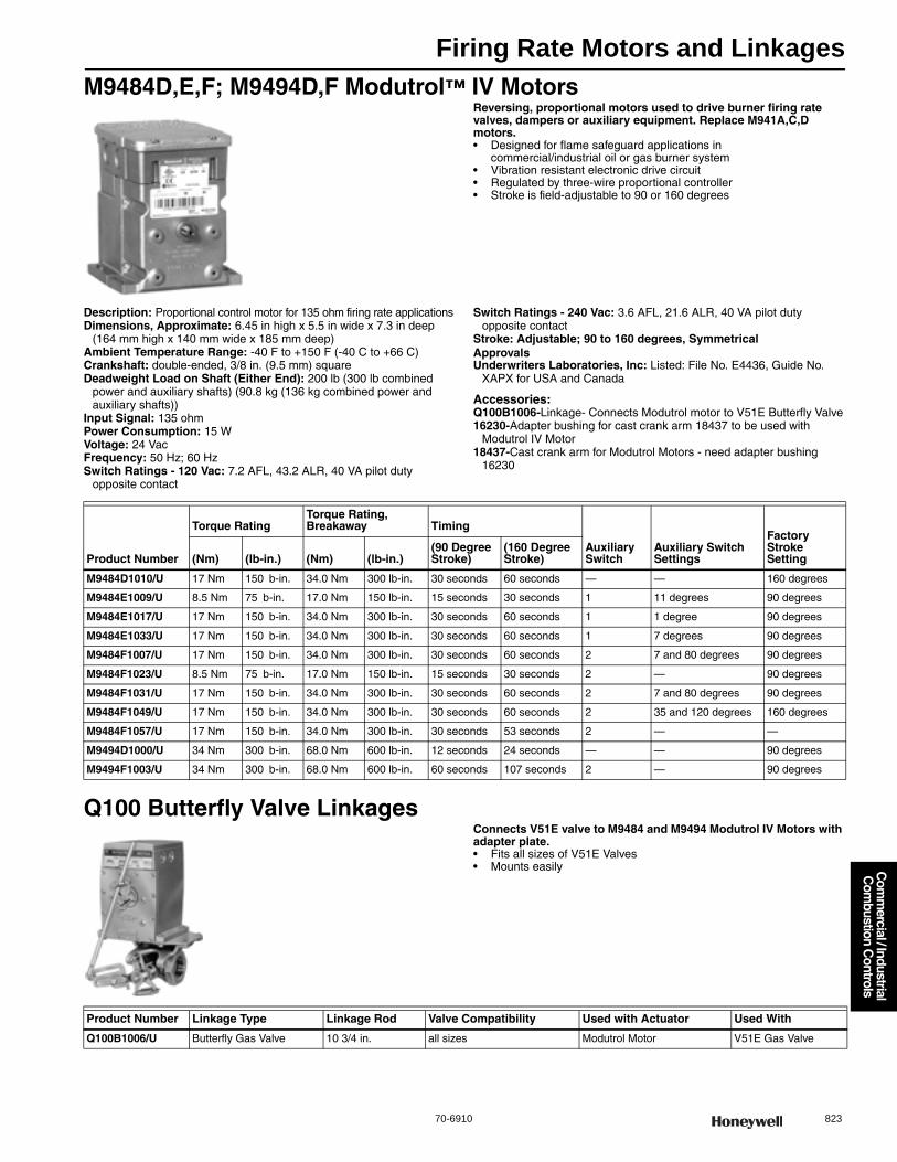
Firing Rate Motors and Linkages
70-6910 823
Com
mercial / Industrial
Com
bustion Controls
M9484D,E,F; M9494D,F Modutrol™ IV MotorsReversing, proportional motors used to drive burner firing rate valves, dampers or auxiliary equipment. Replace M941A,C,D motors.• Designed for flame safeguard applications in
commercial/industrial oil or gas burner system • Vibration resistant electronic drive circuit • Regulated by three-wire proportional controller • Stroke is field-adjustable to 90 or 160 degrees
Description: Proportional control motor for 135 ohm firing rate applicationsDimensions, Approximate: 6.45 in high x 5.5 in wide x 7.3 in deep
(164 mm high x 140 mm wide x 185 mm deep) Ambient Temperature Range: -40 F to +150 F (-40 C to +66 C) Crankshaft: double-ended, 3/8 in. (9.5 mm) squareDeadweight Load on Shaft (Either End): 200 lb (300 lb combined
power and auxiliary shafts) (90.8 kg (136 kg combined power and auxiliary shafts))
Input Signal: 135 ohmPower Consumption: 15 WVoltage: 24 VacFrequency: 50 Hz; 60 HzSwitch Ratings - 120 Vac: 7.2 AFL, 43.2 ALR, 40 VA pilot duty
opposite contact
Switch Ratings - 240 Vac: 3.6 AFL, 21.6 ALR, 40 VA pilot duty opposite contact
Stroke: Adjustable; 90 to 160 degrees, SymmetricalApprovalsUnderwriters Laboratories, Inc: Listed: File No. E4436, Guide No.
XAPX for USA and Canada
Accessories:Q100B1006-Linkage- Connects Modutrol motor to V51E Butterfly Valve16230-Adapter bushing for cast crank arm 18437 to be used with
Modutrol IV Motor18437-Cast crank arm for Modutrol Motors - need adapter bushing
16230
Q100 Butterfly Valve LinkagesConnects V51E valve to M9484 and M9494 Modutrol IV Motors with adapter plate.• Fits all sizes of V51E Valves • Mounts easily
Product Number
Torque RatingTorque Rating, Breakaway Timing
Auxiliary Switch
Auxiliary Switch Settings
Factory Stroke Setting(Nm) (lb-in.) (Nm) (lb-in.)
(90 Degree Stroke)
(160 Degree Stroke)
M9484D1010/U 17 Nm 150 b-in. 34.0 Nm 300 lb-in. 30 seconds 60 seconds — — 160 degrees
M9484E1009/U 8.5 Nm 75 b-in. 17.0 Nm 150 lb-in. 15 seconds 30 seconds 1 11 degrees 90 degrees
M9484E1017/U 17 Nm 150 b-in. 34.0 Nm 300 lb-in. 30 seconds 60 seconds 1 1 degree 90 degrees
M9484E1033/U 17 Nm 150 b-in. 34.0 Nm 300 lb-in. 30 seconds 60 seconds 1 7 degrees 90 degrees
M9484F1007/U 17 Nm 150 b-in. 34.0 Nm 300 lb-in. 30 seconds 60 seconds 2 7 and 80 degrees 90 degrees
M9484F1023/U 8.5 Nm 75 b-in. 17.0 Nm 150 lb-in. 15 seconds 30 seconds 2 — 90 degrees
M9484F1031/U 17 Nm 150 b-in. 34.0 Nm 300 lb-in. 30 seconds 60 seconds 2 7 and 80 degrees 90 degrees
M9484F1049/U 17 Nm 150 b-in. 34.0 Nm 300 lb-in. 30 seconds 60 seconds 2 35 and 120 degrees 160 degrees
M9484F1057/U 17 Nm 150 b-in. 34.0 Nm 300 lb-in. 30 seconds 53 seconds 2 — —
M9494D1000/U 34 Nm 300 b-in. 68.0 Nm 600 lb-in. 12 seconds 24 seconds — — 90 degrees
M9494F1003/U 34 Nm 300 b-in. 68.0 Nm 600 lb-in. 60 seconds 107 seconds 2 — 90 degrees
Product Number Linkage Type Linkage Rod Valve Compatibility Used with Actuator Used With
Q100B1006/U Butterfly Gas Valve 10 3/4 in. all sizes Modutrol Motor V51E Gas Valve

Diaphragm Gas Valves
824 customer.honeywell.com 70-6910
V48A; V88A Diaphragm Gas ValvesSolenoid-operated diaphragm valves provide slow opening and fast closing suitable for controlling natural, LP or manufactured gases. They are normally used on atmospheric boilers, commercial water heaters, and rooftop heaters.• V48 for line voltage service; V88 for 24Vac service• Close firmly with diaphragm that is both weight and spring loaded • Two second maximum closing time• Valve closes on power failure; recommended for final shutoff service • Set opening time with various sized bleed orifices or
adjustable bleed valve • Use with LP, natural or manufactured gases • Made with cast aluminum in straight-through valve pattern • Valve position indicator available for 1-1/4 in. V48A2227
Dimensions in inches (millimeters) Body Pattern: Straight-throughElectrical Connections: 6 in. LeadwiresGround Terminal: YesPilot Tapping: 1/8-27 NPT Frequency: 60 HzMounting: Upright (horizontal)Bleed Tapping: 1/8-27 NPTValve Opening Time: 5 sec maxValve Closing Time: 2 sec maxOperating Temperature Range: 32 F to 125 F (0 C to 52 C)
Materials(Body): AluminumType of Gas: Natural, LP, ManufacturedApprovalsCanadian Standards Association: Certificate No. 158158-
2500005576 (Z21.21-CSA 6.5)Underwriters Laboratories, Inc: File No. MH1639, Guide No. YIOZ
1
2
1
2
BLEED TAPPING: 1/8-27 NPT, OR 1/8-28 BSP. PL.
PILOT TAPING (2): 1/8-27 NPT FOR 3/4 THROUGH 1-1/2 IN. SIZES,
1/4-18 NPT FOR 2 THROUGH 3 IN. SIZES; OR 1/8-28 BSP.
PL FOR 1 THROUGH 1-1/2 IN. SIZES, 1/4-19 BSP.PL FOR 2 THROUGH
3 IN SIZES.M8487
E
C
A
BD
F
APPROXIMATE DIMENSIONSVALVE
SIZE
(IN.)A B C D E F
IN. MM IN. MM IN. MM IN. MM IN. MM IN. MM
3/4
1
1-1/4
1-1/2
2
2-1/2
3
4-11/16
5-1/16
5-9/16
5-9/16
6-15/16
6-15/16
6-15/16
119.1
128.6
141.3
141.3
176.2
176.2
176.2
3/4
1
1-1/4
1-1/4
2-1/4
2-1/4
2-1/4
19.1
25.4
31.8
31.8
57.2
57.2
57.2
4-5/8
5
5-7/8
5-7/8
9-1/2
9-1/2
9-1/2
117.5
127.0
149.2
149.2
241.3
241.3
241.3
3-1/2
3-11/16
5-5/16
5-5/16
8-3/8
8-3/8
8-3/8
88.9
93.7
134.9
134.9
212.7
212.7
212.7
1-5/8
2-1/16
2-3/8
2-3/8
3-9/16
3-9/16
3-9/16
41.3
52.4
60.3
60.3
90.5
90.5
90.5
3-13/16
4-5/16
5-5/16
5-5/16
5-5/16
9-5/16
9-5/16
96.8
109.5
134.9
134.9
236.5
236.5
236.5
1-13/16
(46)
3-11/16
(94)
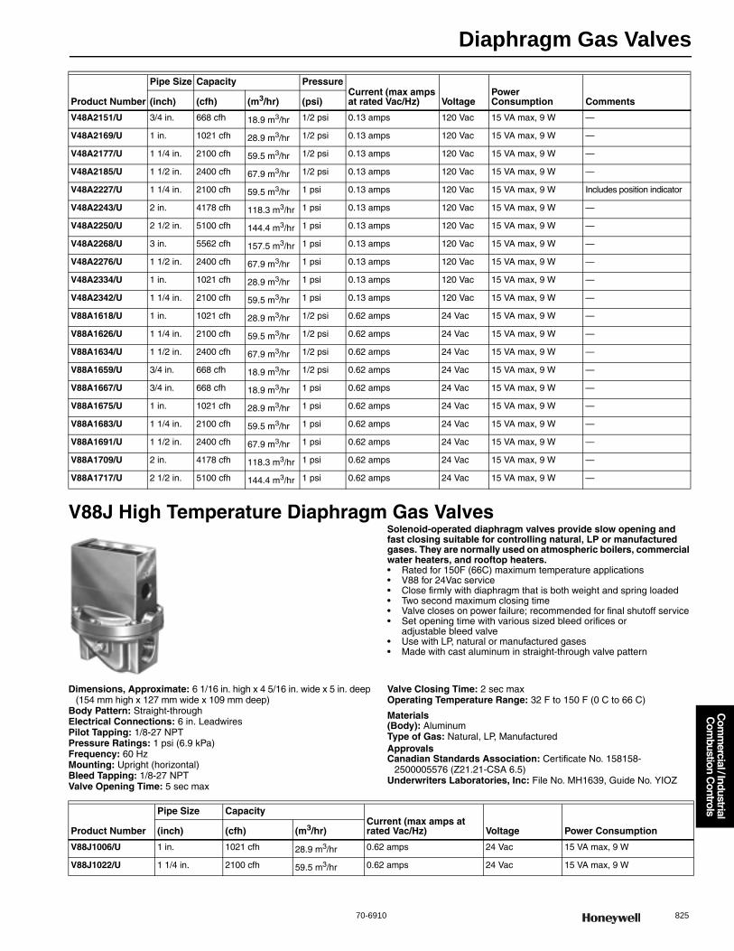
Diaphragm Gas Valves
70-6910 825
Com
mercial / Industrial
Com
bustion Controls
V88J High Temperature Diaphragm Gas ValvesSolenoid-operated diaphragm valves provide slow opening and fast closing suitable for controlling natural, LP or manufactured gases. They are normally used on atmospheric boilers, commercial water heaters, and rooftop heaters.• Rated for 150F (66C) maximum temperature applications• V88 for 24Vac service• Close firmly with diaphragm that is both weight and spring loaded • Two second maximum closing time• Valve closes on power failure; recommended for final shutoff service • Set opening time with various sized bleed orifices or
adjustable bleed valve • Use with LP, natural or manufactured gases • Made with cast aluminum in straight-through valve pattern
Dimensions, Approximate: 6 1/16 in. high x 4 5/16 in. wide x 5 in. deep (154 mm high x 127 mm wide x 109 mm deep)
Body Pattern: Straight-throughElectrical Connections: 6 in. LeadwiresPilot Tapping: 1/8-27 NPTPressure Ratings: 1 psi (6.9 kPa) Frequency: 60 HzMounting: Upright (horizontal)Bleed Tapping: 1/8-27 NPTValve Opening Time: 5 sec max
Valve Closing Time: 2 sec maxOperating Temperature Range: 32 F to 150 F (0 C to 66 C)
Materials(Body): AluminumType of Gas: Natural, LP, ManufacturedApprovalsCanadian Standards Association: Certificate No. 158158-
2500005576 (Z21.21-CSA 6.5)Underwriters Laboratories, Inc: File No. MH1639, Guide No. YIOZ
Product Number
Pipe Size Capacity PressureCurrent (max amps at rated Vac/Hz) Voltage
Power Consumption Comments(inch) (cfh) (m3/hr) (psi)
V48A2151/U 3/4 in. 668 cfh 18.9 m3/hr 1/2 psi 0.13 amps 120 Vac 15 VA max, 9 W —
V48A2169/U 1 in. 1021 cfh 28.9 m3/hr 1/2 psi 0.13 amps 120 Vac 15 VA max, 9 W —
V48A2177/U 1 1/4 in. 2100 cfh 59.5 m3/hr 1/2 psi 0.13 amps 120 Vac 15 VA max, 9 W —
V48A2185/U 1 1/2 in. 2400 cfh 67.9 m3/hr 1/2 psi 0.13 amps 120 Vac 15 VA max, 9 W —
V48A2227/U 1 1/4 in. 2100 cfh 59.5 m3/hr 1 psi 0.13 amps 120 Vac 15 VA max, 9 W Includes position indicator
V48A2243/U 2 in. 4178 cfh 118.3 m3/hr 1 psi 0.13 amps 120 Vac 15 VA max, 9 W —
V48A2250/U 2 1/2 in. 5100 cfh 144.4 m3/hr 1 psi 0.13 amps 120 Vac 15 VA max, 9 W —
V48A2268/U 3 in. 5562 cfh 157.5 m3/hr 1 psi 0.13 amps 120 Vac 15 VA max, 9 W —
V48A2276/U 1 1/2 in. 2400 cfh 67.9 m3/hr 1 psi 0.13 amps 120 Vac 15 VA max, 9 W —
V48A2334/U 1 in. 1021 cfh 28.9 m3/hr 1 psi 0.13 amps 120 Vac 15 VA max, 9 W —
V48A2342/U 1 1/4 in. 2100 cfh 59.5 m3/hr 1 psi 0.13 amps 120 Vac 15 VA max, 9 W —
V88A1618/U 1 in. 1021 cfh 28.9 m3/hr 1/2 psi 0.62 amps 24 Vac 15 VA max, 9 W —
V88A1626/U 1 1/4 in. 2100 cfh 59.5 m3/hr 1/2 psi 0.62 amps 24 Vac 15 VA max, 9 W —
V88A1634/U 1 1/2 in. 2400 cfh 67.9 m3/hr 1/2 psi 0.62 amps 24 Vac 15 VA max, 9 W —
V88A1659/U 3/4 in. 668 cfh 18.9 m3/hr 1/2 psi 0.62 amps 24 Vac 15 VA max, 9 W —
V88A1667/U 3/4 in. 668 cfh 18.9 m3/hr 1 psi 0.62 amps 24 Vac 15 VA max, 9 W —
V88A1675/U 1 in. 1021 cfh 28.9 m3/hr 1 psi 0.62 amps 24 Vac 15 VA max, 9 W —
V88A1683/U 1 1/4 in. 2100 cfh 59.5 m3/hr 1 psi 0.62 amps 24 Vac 15 VA max, 9 W —
V88A1691/U 1 1/2 in. 2400 cfh 67.9 m3/hr 1 psi 0.62 amps 24 Vac 15 VA max, 9 W —
V88A1709/U 2 in. 4178 cfh 118.3 m3/hr 1 psi 0.62 amps 24 Vac 15 VA max, 9 W —
V88A1717/U 2 1/2 in. 5100 cfh 144.4 m3/hr 1 psi 0.62 amps 24 Vac 15 VA max, 9 W —
Product Number
Pipe Size CapacityCurrent (max amps at rated Vac/Hz) Voltage Power Consumption(inch) (cfh) (m3/hr)
V88J1006/U 1 in. 1021 cfh 28.9 m3/hr 0.62 amps 24 Vac 15 VA max, 9 W
V88J1022/U 1 1/4 in. 2100 cfh 59.5 m3/hr 0.62 amps 24 Vac 15 VA max, 9 W
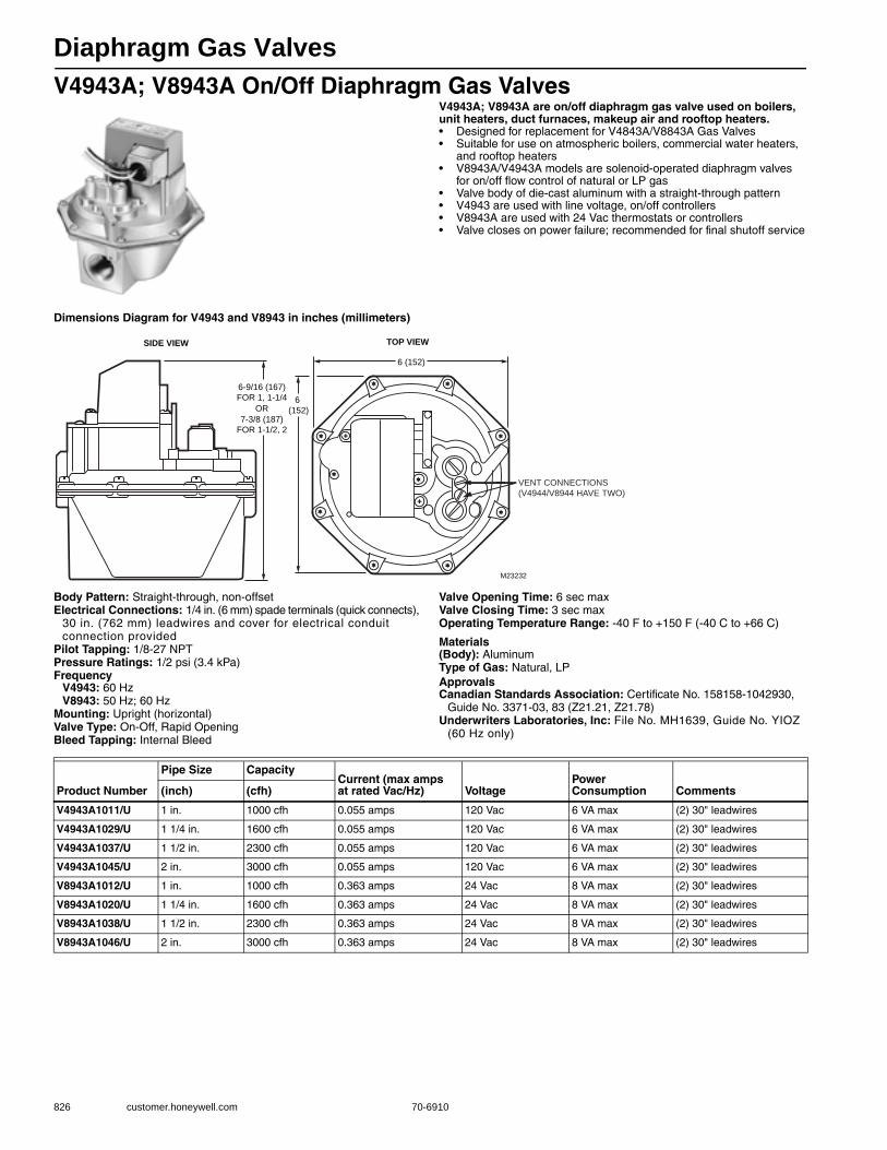
Diaphragm Gas Valves
826 customer.honeywell.com 70-6910
V4943A; V8943A On/Off Diaphragm Gas ValvesV4943A; V8943A are on/off diaphragm gas valve used on boilers, unit heaters, duct furnaces, makeup air and rooftop heaters.• Designed for replacement for V4843A/V8843A Gas Valves• Suitable for use on atmospheric boilers, commercial water heaters,
and rooftop heaters• V8943A/V4943A models are solenoid-operated diaphragm valves
for on/off flow control of natural or LP gas • Valve body of die-cast aluminum with a straight-through pattern • V4943 are used with line voltage, on/off controllers• V8943A are used with 24 Vac thermostats or controllers • Valve closes on power failure; recommended for final shutoff service
Dimensions Diagram for V4943 and V8943 in inches (millimeters)
Body Pattern: Straight-through, non-offsetElectrical Connections: 1/4 in. (6 mm) spade terminals (quick connects),
30 in. (762 mm) leadwires and cover for electrical conduit connection provided
Pilot Tapping: 1/8-27 NPTPressure Ratings: 1/2 psi (3.4 kPa) Frequency
V4943: 60 HzV8943: 50 Hz; 60 Hz
Mounting: Upright (horizontal)Valve Type: On-Off, Rapid OpeningBleed Tapping: Internal Bleed
Valve Opening Time: 6 sec maxValve Closing Time: 3 sec maxOperating Temperature Range: -40 F to +150 F (-40 C to +66 C)
Materials(Body): AluminumType of Gas: Natural, LPApprovalsCanadian Standards Association: Certificate No. 158158-1042930,
Guide No. 3371-03, 83 (Z21.21, Z21.78)Underwriters Laboratories, Inc: File No. MH1639, Guide No. YIOZ
(60 Hz only)
6-9/16 (167)
FOR 1, 1-1/4
OR
7-3/8 (187)
FOR 1-1/2, 2
SIDE VIEW
6 (152)
6
(152)
TOP VIEW
M23232
VENT CONNECTIONS
(V4944/V8944 HAVE TWO)
Product Number
Pipe Size CapacityCurrent (max ampsat rated Vac/Hz) Voltage
Power Consumption Comments(inch) (cfh)
V4943A1011/U 1 in. 1000 cfh 0.055 amps 120 Vac 6 VA max (2) 30" leadwires
V4943A1029/U 1 1/4 in. 1600 cfh 0.055 amps 120 Vac 6 VA max (2) 30" leadwires
V4943A1037/U 1 1/2 in. 2300 cfh 0.055 amps 120 Vac 6 VA max (2) 30" leadwires
V4943A1045/U 2 in. 3000 cfh 0.055 amps 120 Vac 6 VA max (2) 30" leadwires
V8943A1012/U 1 in. 1000 cfh 0.363 amps 24 Vac 8 VA max (2) 30" leadwires
V8943A1020/U 1 1/4 in. 1600 cfh 0.363 amps 24 Vac 8 VA max (2) 30" leadwires
V8943A1038/U 1 1/2 in. 2300 cfh 0.363 amps 24 Vac 8 VA max (2) 30" leadwires
V8943A1046/U 2 in. 3000 cfh 0.363 amps 24 Vac 8 VA max (2) 30" leadwires
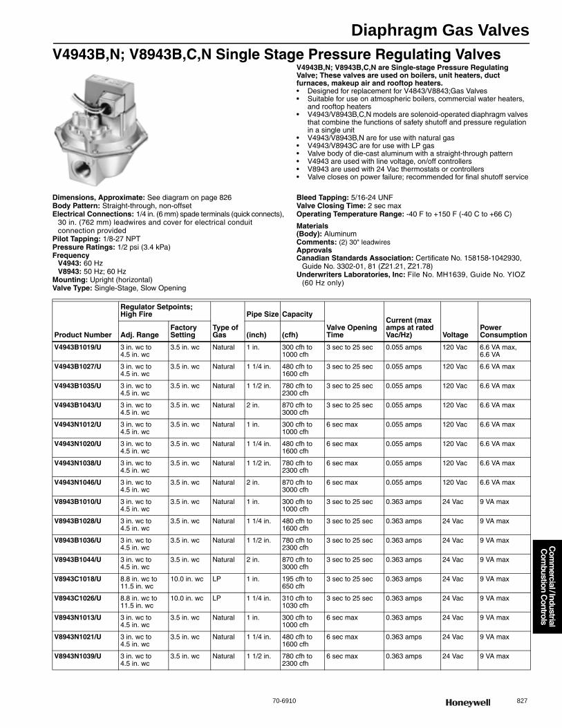
Diaphragm Gas Valves
70-6910 827
Com
mercial / Industrial
Com
bustion Controls
V4943B,N; V8943B,C,N Single Stage Pressure Regulating ValvesV4943B,N; V8943B,C,N are Single-stage Pressure Regulating Valve; These valves are used on boilers, unit heaters, duct furnaces, makeup air and rooftop heaters.• Designed for replacement for V4843/V8843;Gas Valves• Suitable for use on atmospheric boilers, commercial water heaters,
and rooftop heaters• V4943/V8943B,C,N models are solenoid-operated diaphragm valves
that combine the functions of safety shutoff and pressure regulation in a single unit
• V4943/V8943B,N are for use with natural gas • V4943/V8943C are for use with LP gas • Valve body of die-cast aluminum with a straight-through pattern • V4943 are used with line voltage, on/off controllers• V8943 are used with 24 Vac thermostats or controllers• Valve closes on power failure; recommended for final shutoff service
Dimensions, Approximate: See diagram on page 826Body Pattern: Straight-through, non-offsetElectrical Connections: 1/4 in. (6 mm) spade terminals (quick connects),
30 in. (762 mm) leadwires and cover for electrical conduit connection provided
Pilot Tapping: 1/8-27 NPTPressure Ratings: 1/2 psi (3.4 kPa) Frequency
V4943: 60 HzV8943: 50 Hz; 60 Hz
Mounting: Upright (horizontal)Valve Type: Single-Stage, Slow Opening
Bleed Tapping: 5/16-24 UNFValve Closing Time: 2 sec maxOperating Temperature Range: -40 F to +150 F (-40 C to +66 C)
Materials(Body): AluminumComments: (2) 30" leadwiresApprovalsCanadian Standards Association: Certificate No. 158158-1042930,
Guide No. 3302-01, 81 (Z21.21, Z21.78)Underwriters Laboratories, Inc: File No. MH1639, Guide No. YIOZ
(60 Hz only)
Product Number
Regulator Setpoints; High Fire
Type of Gas
Pipe Size Capacity
Valve Opening Time
Current (max amps at rated Vac/Hz) Voltage
Power ConsumptionAdj. Range
Factory Setting (inch) (cfh)
V4943B1019/U 3 in. wc to 4.5 in. wc
3.5 in. wc Natural 1 in. 300 cfh to 1000 cfh
3 sec to 25 sec 0.055 amps 120 Vac 6.6 VA max, 6.6 VA
V4943B1027/U 3 in. wc to 4.5 in. wc
3.5 in. wc Natural 1 1/4 in. 480 cfh to 1600 cfh
3 sec to 25 sec 0.055 amps 120 Vac 6.6 VA max
V4943B1035/U 3 in. wc to 4.5 in. wc
3.5 in. wc Natural 1 1/2 in. 780 cfh to 2300 cfh
3 sec to 25 sec 0.055 amps 120 Vac 6.6 VA max
V4943B1043/U 3 in. wc to 4.5 in. wc
3.5 in. wc Natural 2 in. 870 cfh to 3000 cfh
3 sec to 25 sec 0.055 amps 120 Vac 6.6 VA max
V4943N1012/U 3 in. wc to 4.5 in. wc
3.5 in. wc Natural 1 in. 300 cfh to 1000 cfh
6 sec max 0.055 amps 120 Vac 6.6 VA max
V4943N1020/U 3 in. wc to 4.5 in. wc
3.5 in. wc Natural 1 1/4 in. 480 cfh to 1600 cfh
6 sec max 0.055 amps 120 Vac 6.6 VA max
V4943N1038/U 3 in. wc to 4.5 in. wc
3.5 in. wc Natural 1 1/2 in. 780 cfh to 2300 cfh
6 sec max 0.055 amps 120 Vac 6.6 VA max
V4943N1046/U 3 in. wc to 4.5 in. wc
3.5 in. wc Natural 2 in. 870 cfh to 3000 cfh
6 sec max 0.055 amps 120 Vac 6.6 VA max
V8943B1010/U 3 in. wc to 4.5 in. wc
3.5 in. wc Natural 1 in. 300 cfh to 1000 cfh
3 sec to 25 sec 0.363 amps 24 Vac 9 VA max
V8943B1028/U 3 in. wc to 4.5 in. wc
3.5 in. wc Natural 1 1/4 in. 480 cfh to 1600 cfh
3 sec to 25 sec 0.363 amps 24 Vac 9 VA max
V8943B1036/U 3 in. wc to 4.5 in. wc
3.5 in. wc Natural 1 1/2 in. 780 cfh to 2300 cfh
3 sec to 25 sec 0.363 amps 24 Vac 9 VA max
V8943B1044/U 3 in. wc to 4.5 in. wc
3.5 in. wc Natural 2 in. 870 cfh to 3000 cfh
3 sec to 25 sec 0.363 amps 24 Vac 9 VA max
V8943C1018/U 8.8 in. wc to 11.5 in. wc
10.0 in. wc LP 1 in. 195 cfh to 650 cfh
3 sec to 25 sec 0.363 amps 24 Vac 9 VA max
V8943C1026/U 8.8 in. wc to 11.5 in. wc
10.0 in. wc LP 1 1/4 in. 310 cfh to 1030 cfh
3 sec to 25 sec 0.363 amps 24 Vac 9 VA max
V8943N1013/U 3 in. wc to 4.5 in. wc
3.5 in. wc Natural 1 in. 300 cfh to 1000 cfh
6 sec max 0.363 amps 24 Vac 9 VA max
V8943N1021/U 3 in. wc to 4.5 in. wc
3.5 in. wc Natural 1 1/4 in. 480 cfh to 1600 cfh
6 sec max 0.363 amps 24 Vac 9 VA max
V8943N1039/U 3 in. wc to 4.5 in. wc
3.5 in. wc Natural 1 1/2 in. 780 cfh to 2300 cfh
6 sec max 0.363 amps 24 Vac 9 VA max
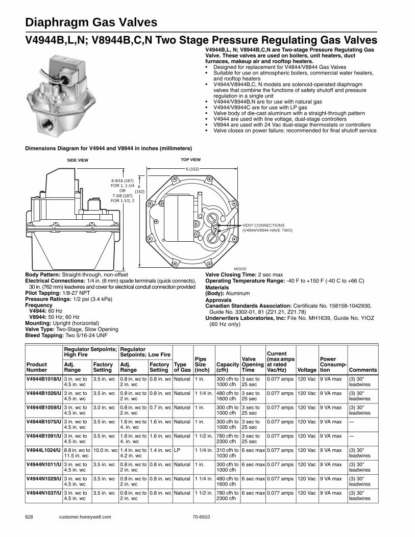
Diaphragm Gas Valves
828 customer.honeywell.com 70-6910
V4944B,L,N; V8944B,C,N Two Stage Pressure Regulating Gas ValvesV4944B,L, N; V8944B,C,N are Two-stage Pressure Regulating Gas Valve. These valves are used on boilers, unit heaters, duct furnaces, makeup air and rooftop heaters.• Designed for replacement for V4844/V8844 Gas Valves• Suitable for use on atmospheric boilers, commercial water heaters,
and rooftop heaters• V4944/V8944B,C, N models are solenoid-operated diaphragm
valves that combine the functions of safety shutoff and pressure regulation in a single unit
• V4944/V8944B,N are for use with natural gas • V4944/V8944C are for use with LP gas • Valve body of die-cast aluminum with a straight-through pattern • V4944 are used with line voltage, dual-stage controllers• V8944 are used with 24 Vac dual-stage thermostats or controllers • Valve closes on power failure; recommended for final shutoff service
Dimensions Diagram for V4944 and V8944 in inches (millimeters)
Body Pattern: Straight-through, non-offsetElectrical Connections: 1/4 in. (6 mm) spade terminals (quick connects),
30 in. (762 mm) leadwires and cover for electrical conduit connection providedPilot Tapping: 1/8-27 NPTPressure Ratings: 1/2 psi (3.4 kPa) Frequency
V4944: 60 HzV8944: 50 Hz; 60 Hz
Mounting: Upright (horizontal)Valve Type: Two-Stage, Slow OpeningBleed Tapping: Two 5/16-24 UNF
Valve Closing Time: 2 sec maxOperating Temperature Range: -40 F to +150 F (-40 C to +66 C) Materials(Body): AluminumApprovalsCanadian Standards Association: Certificate No. 158158-1042930,
Guide No. 3302-01, 81 (Z21.21, Z21.78)Underwriters Laboratories, Inc: File No. MH1639, Guide No. YIOZ
(60 Hz only)
6-9/16 (167)
FOR 1, 1-1/4
OR
7-3/8 (187)
FOR 1-1/2, 2
SIDE VIEW
6 (152)
6
(152)
TOP VIEW
M23232
VENT CONNECTIONS
(V4944/V8944 HAVE TWO)
Product Number
Regulator Setpoints; High Fire
Regulator Setpoints; Low Fire
Type of Gas
Pipe Size(inch)
Capacity(cfh)
Valve Opening Time
Current (max amps at rated Vac/Hz) Voltage
Power Consump-tion Comments
Adj. Range
Factory Setting
Adj. Range
Factory Setting
V4944B1018/U 3 in. wc to 4.5 in. wc
3.5 in. wc 0.8 in. wc to 2 in. wc
0.8 in. wc Natural 1 in. 300 cfh to 1000 cfh
3 sec to 25 sec
0.077 amps 120 Vac 9 VA max (3) 30" leadwires
V4944B1026/U 3 in. wc to 4.5 in. wc
3.5 in. wc 0.8 in. wc to 2 in. wc
0.8 in. wc Natural 1 1/4 in. 480 cfh to 1600 cfh
3 sec to 25 sec
0.077 amps 120 Vac 9 VA max (3) 30" leadwires
V4944B1059/U 3 in. wc to 4.5 in. wc
3.0 in. wc 0.8 in. wc to 2 in. wc
0.7 in. wc Natural 1 in. 300 cfh to 1000 cfh
3 sec to 25 sec
0.077 amps 120 Vac 9 VA max (3) 30" leadwires
V4944B1075/U 3 in. wc to 4.5 in. wc
3.5 in. wc 1.6 in. wc to 4. in. wc
1.6 in. wc Natural 1 in. 300 cfh to 1000 cfh
3 sec to 25 sec
0.077 amps 120 Vac 9 VA max —
V4944B1091/U 3 in. wc to 4.5 in. wc
3.5 in. wc 1.6 in. wc to 4. in. wc
1.6 in. wc Natural 1 1/2 in. 780 cfh to 2300 cfh
3 sec to 25 sec
0.077 amps 120 Vac 9 VA max —
V4944L1024/U 8.8 in. wc to 11.5 in. wc
10.0 in. wc 1.4 in. wc to 4.2 in. wc
1.4 in. wc LP 1 1/4 in. 310 cfh to 1030 cfh
6 sec max 0.077 amps 120 Vac 9 VA max (3) 30" leadwires
V4944N1011/U 3 in. wc to 4.5 in. wc
3.5 in. wc 0.8 in. wc to 2 in. wc
0.8 in. wc Natural 1 in. 300 cfh to 1000 cfh
6 sec max 0.077 amps 120 Vac 9 VA max (3) 30" leadwires
V4944N1029/U 3 in. wc to 4.5 in. wc
3.5 in. wc 0.8 in. wc to 2 in. wc
0.8 in. wc Natural 1 1/4 in. 480 cfh to 1600 cfh
6 sec max 0.077 amps 120 Vac 9 VA max (3) 30" leadwires
V4944N1037/U 3 in. wc to 4.5 in. wc
3.5 in. wc 0.8 in. wc to 2 in. wc
0.8 in. wc Natural 1 1/2 in. 780 cfh to 2300 cfh
6 sec max 0.077 amps 120 Vac 9 VA max (3) 30" leadwires
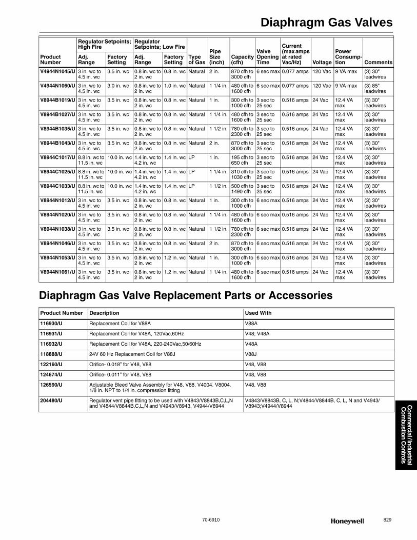
Diaphragm Gas Valves
70-6910 829
Com
mercial / Industrial
Com
bustion Controls
Diaphragm Gas Valve Replacement Parts or Accessories
V4944N1045/U 3 in. wc to 4.5 in. wc
3.5 in. wc 0.8 in. wc to 2 in. wc
0.8 in. wc Natural 2 in. 870 cfh to 3000 cfh
6 sec max 0.077 amps 120 Vac 9 VA max (3) 30" leadwires
V4944N1060/U 3 in. wc to 4.5 in. wc
3.0 in. wc 0.8 in. wc to 2 in. wc
1.0 in. wc Natural 1 1/4 in. 480 cfh to 1600 cfh
6 sec max 0.077 amps 120 Vac 9 VA max (3) 85" leadwires
V8944B1019/U 3 in. wc to 4.5 in. wc
3.5 in. wc 0.8 in. wc to 2 in. wc
0.8 in. wc Natural 1 in. 300 cfh to 1000 cfh
3 sec to 25 sec
0.516 amps 24 Vac 12.4 VA max
(3) 30" leadwires
V8944B1027/U 3 in. wc to 4.5 in. wc
3.5 in. wc 0.8 in. wc to 2 in. wc
0.8 in. wc Natural 1 1/4 in. 480 cfh to 1600 cfh
3 sec to 25 sec
0.516 amps 24 Vac 12.4 VA max
(3) 30" leadwires
V8944B1035/U 3 in. wc to 4.5 in. wc
3.5 in. wc 0.8 in. wc to 2 in. wc
0.8 in. wc Natural 1 1/2 in. 780 cfh to 2300 cfh
3 sec to 25 sec
0.516 amps 24 Vac 12.4 VA max
(3) 30" leadwires
V8944B1043/U 3 in. wc to 4.5 in. wc
3.5 in. wc 0.8 in. wc to 2 in. wc
0.8 in. wc Natural 2 in. 870 cfh to 3000 cfh
3 sec to 25 sec
0.516 amps 24 Vac 12.4 VA max
(3) 30" leadwires
V8944C1017/U 8.8 in. wc to 11.5 in. wc
10.0 in. wc 1.4 in. wc to 4.2 in. wc
1.4 in. wc LP 1 in. 195 cfh to 650 cfh
3 sec to 25 sec
0.516 amps 24 Vac 12.4 VA max
(3) 30" leadwires
V8944C1025/U 8.8 in. wc to 11.5 in. wc
10.0 in. wc 1.4 in. wc to 4.2 in. wc
1.4 in. wc LP 1 1/4 in. 310 cfh to 1030 cfh
3 sec to 25 sec
0.516 amps 24 Vac 12.4 VA max
(3) 30" leadwires
V8944C1033/U 8.8 in. wc to 11.5 in. wc
10.0 in. wc 1.4 in. wc to 4.2 in. wc
1.4 in. wc LP 1 1/2 in. 500 cfh to 1490 cfh
3 sec to 25 sec
0.516 amps 24 Vac 12.4 VA max
(3) 30" leadwires
V8944N1012/U 3 in. wc to 4.5 in. wc
3.5 in. wc 0.8 in. wc to 2 in. wc
0.8 in. wc Natural 1 in. 300 cfh to 1000 cfh
6 sec max 0.516 amps 24 Vac 12.4 VA max
(3) 30" leadwires
V8944N1020/U 3 in. wc to 4.5 in. wc
3.5 in. wc 0.8 in. wc to 2 in. wc
0.8 in. wc Natural 1 1/4 in. 480 cfh to 1600 cfh
6 sec max 0.516 amps 24 Vac 12.4 VA max
(3) 30" leadwires
V8944N1038/U 3 in. wc to 4.5 in. wc
3.5 in. wc 0.8 in. wc to 2 in. wc
0.8 in. wc Natural 1 1/2 in. 780 cfh to 2300 cfh
6 sec max 0.516 amps 24 Vac 12.4 VA max
(3) 30" leadwires
V8944N1046/U 3 in. wc to 4.5 in. wc
3.5 in. wc 0.8 in. wc to 2 in. wc
0.8 in. wc Natural 2 in. 870 cfh to 3000 cfh
6 sec max 0.516 amps 24 Vac 12.4 VA max
(3) 30" leadwires
V8944N1053/U 3 in. wc to 4.5 in. wc
3.5 in. wc 0.8 in. wc to 2 in. wc
1.2 in. wc Natural 1 in. 300 cfh to 1000 cfh
6 sec max 0.516 amps 24 Vac 12.4 VA max
(3) 30" leadwires
V8944N1061/U 3 in. wc to 4.5 in. wc
3.5 in. wc 0.8 in. wc to 2 in. wc
1.2 in. wc Natural 1 1/4 in. 480 cfh to 1600 cfh
6 sec max 0.516 amps 24 Vac 12.4 VA max
(3) 30" leadwires
Product Number Description Used With
116930/U Replacement Coil for V88A V88A
116931/U Replacement Coil for V48A, 120Vac,60Hz V48; V48A
116932/U Replacement Coil for V48A, 220-240Vac,50/60Hz V48A
118888/U 24V 60 Hz Replacement Coil for V88J V88J
122160/U Orifice- 0.018” for V48, V88 V48, V88
124674/U Orifice- 0.011” for V48, V88 V48, V88
126590/U Adjustable Bleed Valve Assembly for V48, V88, V4004. V8004. 1/8 in. NPT to 1/4 in. compression fitting
V48, V88
204480/U Regulator vent pipe fitting to be used with V4843/V8843B,C,L,N and V4844/V8844B,C,L,N and V4943/V8943, V4944/V8944
V4843/V8843B, C, L, N;V4844/V8844B, C, L, N and V4943/V8943;V4944/V8944
Product Number
Regulator Setpoints; High Fire
Regulator Setpoints; Low Fire
Type of Gas
Pipe Size(inch)
Capacity(cfh)
Valve Opening Time
Current (max amps at rated Vac/Hz) Voltage
Power Consump-tion Comments
Adj. Range
Factory Setting
Adj. Range
Factory Setting

Butterfly Gas Valves
830 customer.honeywell.com 70-6910
V51 Butterfly Gas/Air ValveProvides modulating control of natural, manufactured, LP gases or air.• Use in commercial and industrial installations where large
amounts of gas must be closely controlled • NOT for use as safety shutoff valve • Adaptable to most modulating jobs • Modutrol motor, such as the M9484 or M9494, may be
mounted directly on valve or close to it • Valve mechanism has strain release • Adjustable stroke over low fire-high fire range • Straight-through valve pattern • Rugged cast aluminum body provides durability and
maintenance-free operation
Dimensions in inches (millimeters)
Type of Gas: Air, natural, manufactured, and LPBody Pattern: Straight-throughPressure Ratings: 5 psi (34.5 kPa) Mounting: Motor shaft horizontalOperating Temperature Range: 32 F to 140 F (0 C to 60 C)Used With: Mod Motor with Q100 Linkage
Materials(Body): Aluminum
ApprovalsUnderwriters Laboratories, Inc: File No. MH5968 Vol. 1 Sec. 1,
Guide no. MHKZ
Accessories:Q100B1006-Linkage- Connects Modutrol motor to V51E Butterfly Valve32003396-001-V51E Mounting Kit for ML7999 Actuator (1-1/2 & 2 in.
valves). Includes angle bracket, mounting bracket, screws, nuts and washers, and instructions.
32003396-002- V51E Mounting Kit for ML7999 Actuator (2-1/2,3 & 4 in. valves). Includes angle bracket, mounting bracket, screws, nuts and washers, and instructions.
Firing Rate Gas Valve Parts
VALVE
SIZE (in.)
1 1/2
2
2 1/2
3
4
2 21/32
3 5/32
3 27/32
4 1/32
5 21/64
67.5
80.2
97.6
102.4
135.3
A
A
1
in. mm
1 9/16
1 13/16
2 5/16
2 25/64
3 5/32
39.7
46.0
58.7
60.7
80.2
B
B
in. mm
4 1/4
4 1/4
4 13/16
5
5 3/8
108.0
108.0
122.2
127.0
136.5
C
C
in. mm
3 1/32
3 17/32
4 23/32
4 23/32
5 17/64
77.0
89.7
119.9
119.9
133.8
D
D
in. mm
M9532
1 2 1
1 MAXIMUM DIMENSIONS.
NOMINAL DIMENSIONS.2
V51E DIMENSIONS
Product Number
Pipe Size Capacity
Inlet/Outlet Pressure Tapping(inch) DN (cfh) (m3/hr)
V51E1000/U 1 1/2 in. DN40 4200 cfh 118.9 m3/hr Two downstream 1/4 in. NPT taps
V51E1018/U 2 in. DN50 9210 cfh 260.7 m3/hr —
V51E1034/U 2 1/2 in. DN65 8390 cfh 199.8 m3/hr —
V51E1059/U 3 in. DN80 14640 cfh 414.5 m3/hr —
V51E1075/U 4 in. DN100 33000 cfh 934.2 m3/hr —
Product Number Description Used With
49084/0021/U Adjusting arm for V51E V51E
49085B/U Strain Release Assembly for V51E V51E

Butterfly Gas Valves
70-6910 831
Com
mercial / Industrial
Com
bustion Controls
V5197 Integrated Valve Train Butterfly Gas Valve
The V5197A is a firing rate valve used to provide variable flow control of air, natural gas, liquefied petroleum (LP), and manufactured gases. The V5197A is actuated by a ML7999A or B firing rate motor that can be mounted directly on the valve. The V5197A is not applicable as a safety shutoff valve. The V5197A is specially designed to provide fine control of gas flow in
applications where a high turn down ratio is required. The maximum flow adjustment screw on the bottom of the valve allows adjusting the maximum flow of gas through the V5197 while maintaining the linear modulating characteristics and stroke. The V5197A is part of the Honeywell Integrated Valve Train System that allows gas train components to be directly bolted together.• Used with air, natural, manufactured or liquefied petroleum (LP) gases • For modulating applications that do not require final shutoff service
of firing rate valve • Two valve body types (small and large) applicable to seven pipe
sizes: Small body type for 3/4 in. (19 mm), 1 in. (25 mm), 1-1/4 in. (32 mm), 1-1/2 in. (38 mm) and 2 in. (51 mm) pipes, NPT or ISO 7 threads. Large body type for 2 in. (51 mm), 2-1/2 in. (64 mm) and 3 in. (76 mm) pipes, NPT or ISO 7 threads
• Two downstream 1/4 in. NPT threaded pressure taps available • Accepts C6097 Pressure Switch mounted directly to flange
(downstream pressure tap only) • Unpainted cast aluminum body • Suitable for electric or pneumatic operators with the appropriate linkage • May be used with manufacturers own linkage and drive motor • Flow adjustment screw on bottom of valve controls maximum flow • Visual position indicator
Type of Gas: Air, natural, manufactured, and LPPressure Ratings: 15 psi max (1 Bar) Mounting: Directly bolted to Integrated Valve Train (IVT) components
or IVT adaptersOperating Temperature Range: -40 F to +150 F (-40 C to +66 C)
Materials(Body): Die-cast aluminumApprovalsCanadian Standards Association: Design CertifiedSwiss Re: AcceptableUnderwriters Laboratories, Inc: Component Listed
Dimensions in inches (millimeters) for V5197A1003 Dimensions in inches (millimeters) for V5197A1011
Product Number
Pipe Size Capacity
Inlet/Outlet Pressure Tapping(inch) DN (cfh) (m3/hr)
V5197A1003 2 in.1 1/2 in. 1 1/4 in. 1 in. 3/4 in.
DN50 DN40 DN32 DN25 DN20
5480 cfh for 2 in. 5010 cfh for 1 1/2 in. 4430 cfh for 1 1/4 in. 3080 cfh for 1 in. 2450 cfh for 3/4 in.
51 mm =15538 mm =14232 mm = 12525 mm =8719 mm =69
Two downstream 1/4 in. NPT taps
V5197A1011 3 in. 2 1/2 in. 2 in.
DN80 DN65 DN50
16,900 cfh for 3 in. 14,800 cfh for 2 1/2 in. 12,600 cfh for 2 in.
76 mm=47864 mm=41951 mm=356
Two downstream 1/4 in. NPT taps
10-5/16(277)
4-27/32 (123)
6-7/16 (165)
2-1/2 (64)
7-1/8(181)
3-25/32(96)
M17528
12-11/16(322)
4-13/16 (122)
9-1/4 (235)
4 (102)
7-15/16(202)
4-3/4(121)
M17898
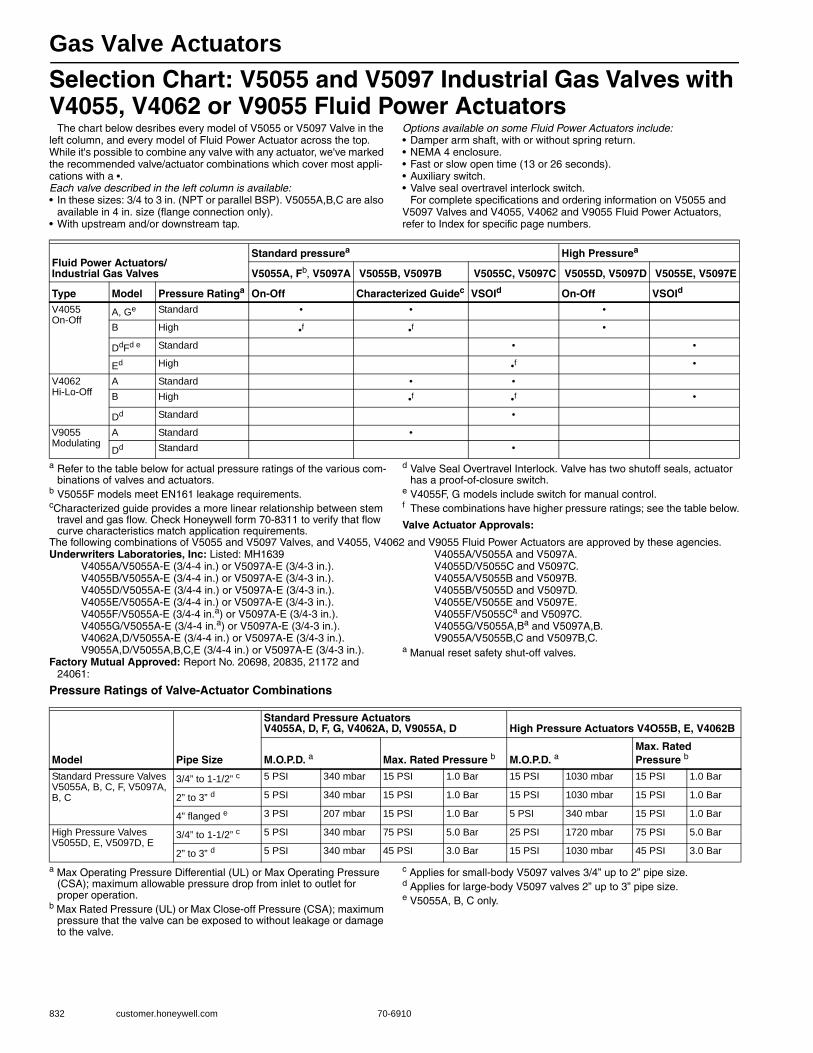
Gas Valve Actuators
832 customer.honeywell.com 70-6910
Selection Chart: V5055 and V5097 Industrial Gas Valves with V4055, V4062 or V9055 Fluid Power Actuators
The chart below desribes every model of V5055 or V5097 Valve in the left column, and every model of Fluid Power Actuator across the top. While it's possible to combine any valve with any actuator, we've marked the recommended valve/actuator combinations which cover most appli-cations with a •.Each valve described in the left column is available: • In these sizes: 3/4 to 3 in. (NPT or parallel BSP). V5055A,B,C are also
available in 4 in. size (flange connection only).• With upstream and/or downstream tap.
Options available on some Fluid Power Actuators include: • Damper arm shaft, with or without spring return.• NEMA 4 enclosure.• Fast or slow open time (13 or 26 seconds).• Auxiliary switch.• Valve seal overtravel interlock switch.
For complete specifications and ordering information on V5055 and V5097 Valves and V4055, V4062 and V9055 Fluid Power Actuators, refer to Index for specific page numbers.
a Refer to the table below for actual pressure ratings of the various com-binations of valves and actuators.
b V5055F models meet EN161 leakage requirements.cCharacterized guide provides a more linear relationship between stem
travel and gas flow. Check Honeywell form 70-8311 to verify that flow curve characteristics match application requirements.
d Valve Seal Overtravel Interlock. Valve has two shutoff seals, actuator has a proof-of-closure switch.
e V4055F, G models include switch for manual control.f These combinations have higher pressure ratings; see the table below.
Valve Actuator Approvals:
The following combinations of V5055 and V5097 Valves, and V4055, V4062 and V9055 Fluid Power Actuators are approved by these agencies.Underwriters Laboratories, Inc: Listed: MH1639
V4055A/V5055A-E (3/4-4 in.) or V5097A-E (3/4-3 in.).V4055B/V5055A-E (3/4-4 in.) or V5097A-E (3/4-3 in.).V4055D/V5055A-E (3/4-4 in.) or V5097A-E (3/4-3 in.).V4055E/V5055A-E (3/4-4 in.) or V5097A-E (3/4-3 in.).V4055F/V5055A-E (3/4-4 in.a) or V5097A-E (3/4-3 in.).V4055G/V5055A-E (3/4-4 in.a) or V5097A-E (3/4-3 in.).V4062A,D/V5055A-E (3/4-4 in.) or V5097A-E (3/4-3 in.).V9055A,D/V5055A,B,C,E (3/4-4 in.) or V5097A-E (3/4-3 in.).
Factory Mutual Approved: Report No. 20698, 20835, 21172 and 24061:
V4055A/V5055A and V5097A.V4055D/V5055C and V5097C.V4055A/V5055B and V5097B.V4055B/V5055D and V5097D.V4055E/V5055E and V5097E.V4055F/V5055Ca and V5097C.V4055G/V5055A,Ba and V5097A,B.V9055A/V5055B,C and V5097B,C.
a Manual reset safety shut-off valves.
Pressure Ratings of Valve-Actuator Combinations
a Max Operating Pressure Differential (UL) or Max Operating Pressure (CSA); maximum allowable pressure drop from inlet to outlet for proper operation.
b Max Rated Pressure (UL) or Max Close-off Pressure (CSA); maximum pressure that the valve can be exposed to without leakage or damage to the valve.
c Applies for small-body V5097 valves 3/4” up to 2” pipe size.d Applies for large-body V5097 valves 2” up to 3” pipe size.e V5055A, B, C only.
Fluid Power Actuators/Industrial Gas Valves
Standard pressurea High Pressurea
V5055A, Fb, V5097A V5055B, V5097B V5055C, V5097C V5055D, V5097D V5055E, V5097E
Type Model Pressure Ratinga On-Off Characterized Guidec VSOId On-Off VSOId
V4055On-Off
A, Ge Standard • • •
B High •f •f •
DdFd e Standard • •
Ed High •f •
V4062Hi-Lo-Off
A Standard • •B High •f •f •
Dd Standard •
V9055Modulating
A Standard •
Dd Standard •
Model Pipe Size
Standard Pressure Actuators V4055A, D, F, G, V4062A, D, V9055A, D High Pressure Actuators V4O55B, E, V4062B
M.O.P.D. a Max. Rated Pressure b M.O.P.D. a Max. Rated Pressure b
Standard Pressure Valves V5055A, B, C, F, V5097A, B, C
3/4” to 1-1/2” c 5 PSI 340 mbar 15 PSI 1.0 Bar 15 PSI 1030 mbar 15 PSI 1.0 Bar
2” to 3” d 5 PSI 340 mbar 15 PSI 1.0 Bar 15 PSI 1030 mbar 15 PSI 1.0 Bar
4” flanged e 3 PSI 207 mbar 15 PSI 1.0 Bar 5 PSI 340 mbar 15 PSI 1.0 Bar
High Pressure Valves V5055D, E, V5097D, E
3/4” to 1-1/2” c 5 PSI 340 mbar 75 PSI 5.0 Bar 25 PSI 1720 mbar 75 PSI 5.0 Bar
2” to 3” d 5 PSI 340 mbar 45 PSI 3.0 Bar 15 PSI 1030 mbar 45 PSI 3.0 Bar
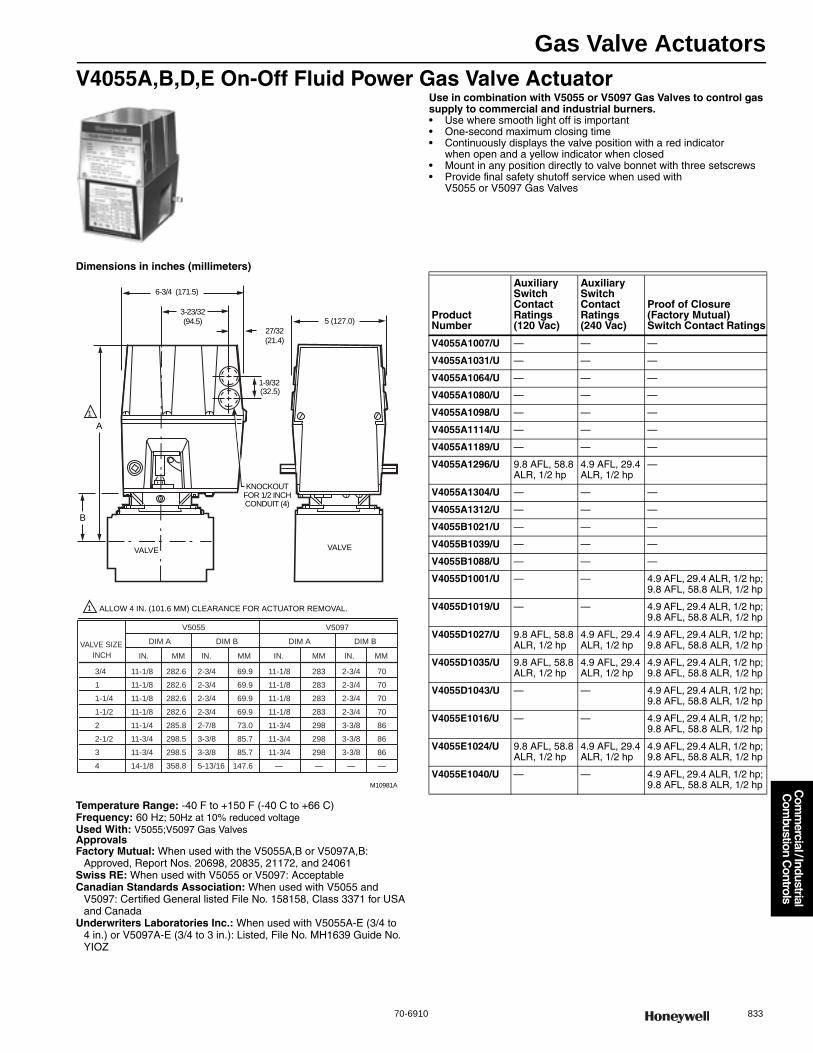
Gas Valve Actuators
70-6910 833
Com
mercial / Industrial
Com
bustion Controls
V4055A,B,D,E On-Off Fluid Power Gas Valve ActuatorUse in combination with V5055 or V5097 Gas Valves to control gas supply to commercial and industrial burners.• Use where smooth light off is important • One-second maximum closing time • Continuously displays the valve position with a red indicator
when open and a yellow indicator when closed • Mount in any position directly to valve bonnet with three setscrews • Provide final safety shutoff service when used with
V5055 or V5097 Gas Valves
Dimensions in inches (millimeters)
Temperature Range: -40 F to +150 F (-40 C to +66 C) Frequency: 60 Hz; 50Hz at 10% reduced voltageUsed With: V5055;V5097 Gas ValvesApprovalsFactory Mutual: When used with the V5055A,B or V5097A,B:
Approved, Report Nos. 20698, 20835, 21172, and 24061Swiss RE: When used with V5055 or V5097: AcceptableCanadian Standards Association: When used with V5055 and
V5097: Certified General listed File No. 158158, Class 3371 for USA and Canada
Underwriters Laboratories Inc.: When used with V5055A-E (3/4 to 4 in.) or V5097A-E (3/4 to 3 in.): Listed, File No. MH1639 Guide No. YIOZ
B
A
1
1
(32.5)
KNOCKOUTFOR 1/2 INCHCONDUIT (4)
5 (127.0)
1-9/32
27/32
(21.4)
3-23/32
(94.5)
6-3/4 (171.5)
ALLOW 4 IN. (101.6 MM) CLEARANCE FOR ACTUATOR REMOVAL.
M10981A
3/4
1
1-1/4
1-1/2
2
2-1/2
3
4
VALVE SIZE
INCH
11-1/8
11-1/8
11-1/8
11-1/8
11-1/4
11-3/4
11-3/4
14-1/8
282.6
282.6
282.6
282.6
285.8
298.5
298.5
358.8
2-3/4
2-3/4
2-3/4
2-3/4
2-7/8
3-3/8
3-3/8
5-13/16
69.9
69.9
69.9
69.9
73.0
85.7
85.7
147.6
11-1/8
11-1/8
11-1/8
11-1/8
11-3/4
11-3/4
11-3/4
—
283
283
283
283
298
298
298
—
2-3/4
2-3/4
2-3/4
2-3/4
3-3/8
3-3/8
3-3/8
—
70
70
70
70
86
86
86
—
DIM A
V5055 V5097
IN. MM
DIM B
IN. MM
DIM A
IN. MM
DIM B
IN. MM
VALVE VALVE
Product Number
Auxiliary Switch Contact Ratings (120 Vac)
Auxiliary Switch Contact Ratings (240 Vac)
Proof of Closure (Factory Mutual) Switch Contact Ratings
V4055A1007/U — — —
V4055A1031/U — — —
V4055A1064/U — — —
V4055A1080/U — — —
V4055A1098/U — — —
V4055A1114/U — — —
V4055A1189/U — — —
V4055A1296/U 9.8 AFL, 58.8 ALR, 1/2 hp
4.9 AFL, 29.4 ALR, 1/2 hp
—
V4055A1304/U — — —
V4055A1312/U — — —
V4055B1021/U — — —
V4055B1039/U — — —
V4055B1088/U — — —
V4055D1001/U — — 4.9 AFL, 29.4 ALR, 1/2 hp; 9.8 AFL, 58.8 ALR, 1/2 hp
V4055D1019/U — — 4.9 AFL, 29.4 ALR, 1/2 hp; 9.8 AFL, 58.8 ALR, 1/2 hp
V4055D1027/U 9.8 AFL, 58.8 ALR, 1/2 hp
4.9 AFL, 29.4 ALR, 1/2 hp
4.9 AFL, 29.4 ALR, 1/2 hp; 9.8 AFL, 58.8 ALR, 1/2 hp
V4055D1035/U 9.8 AFL, 58.8 ALR, 1/2 hp
4.9 AFL, 29.4 ALR, 1/2 hp
4.9 AFL, 29.4 ALR, 1/2 hp; 9.8 AFL, 58.8 ALR, 1/2 hp
V4055D1043/U — — 4.9 AFL, 29.4 ALR, 1/2 hp; 9.8 AFL, 58.8 ALR, 1/2 hp
V4055E1016/U — — 4.9 AFL, 29.4 ALR, 1/2 hp; 9.8 AFL, 58.8 ALR, 1/2 hp
V4055E1024/U 9.8 AFL, 58.8 ALR, 1/2 hp
4.9 AFL, 29.4 ALR, 1/2 hp
4.9 AFL, 29.4 ALR, 1/2 hp; 9.8 AFL, 58.8 ALR, 1/2 hp
V4055E1040/U — — 4.9 AFL, 29.4 ALR, 1/2 hp; 9.8 AFL, 58.8 ALR, 1/2 hp
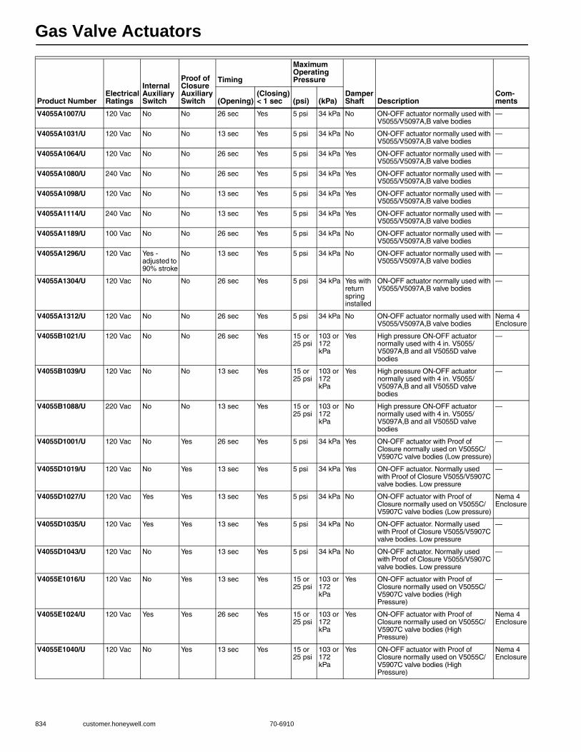
Gas Valve Actuators
834 customer.honeywell.com 70-6910
Product NumberElectrical Ratings
Internal Auxiliary Switch
Proof of Closure Auxiliary Switch
Timing
Maximum Operating Pressure
Damper Shaft Description
Com-ments(Opening)
(Closing) < 1 sec (psi) (kPa)
V4055A1007/U 120 Vac No No 26 sec Yes 5 psi 34 kPa No ON-OFF actuator normally used with V5055/V5097A,B valve bodies
—
V4055A1031/U 120 Vac No No 13 sec Yes 5 psi 34 kPa No ON-OFF actuator normally used with V5055/V5097A,B valve bodies
—
V4055A1064/U 120 Vac No No 26 sec Yes 5 psi 34 kPa Yes ON-OFF actuator normally used with V5055/V5097A,B valve bodies
—
V4055A1080/U 240 Vac No No 26 sec Yes 5 psi 34 kPa Yes ON-OFF actuator normally used with V5055/V5097A,B valve bodies
—
V4055A1098/U 120 Vac No No 13 sec Yes 5 psi 34 kPa Yes ON-OFF actuator normally used with V5055/V5097A,B valve bodies
—
V4055A1114/U 240 Vac No No 13 sec Yes 5 psi 34 kPa Yes ON-OFF actuator normally used with V5055/V5097A,B valve bodies
—
V4055A1189/U 100 Vac No No 26 sec Yes 5 psi 34 kPa No ON-OFF actuator normally used with V5055/V5097A,B valve bodies
—
V4055A1296/U 120 Vac Yes - adjusted to 90% stroke
No 13 sec Yes 5 psi 34 kPa No ON-OFF actuator normally used with V5055/V5097A,B valve bodies
—
V4055A1304/U 120 Vac No No 26 sec Yes 5 psi 34 kPa Yes with return spring installed
ON-OFF actuator normally used with V5055/V5097A,B valve bodies
—
V4055A1312/U 120 Vac No No 26 sec Yes 5 psi 34 kPa No ON-OFF actuator normally used with V5055/V5097A,B valve bodies
Nema 4 Enclosure
V4055B1021/U 120 Vac No No 26 sec Yes 15 or 25 psi
103 or 172 kPa
Yes High pressure ON-OFF actuator normally used with 4 in. V5055/V5097A,B and all V5055D valve bodies
—
V4055B1039/U 120 Vac No No 13 sec Yes 15 or 25 psi
103 or 172 kPa
Yes High pressure ON-OFF actuator normally used with 4 in. V5055/V5097A,B and all V5055D valve bodies
—
V4055B1088/U 220 Vac No No 13 sec Yes 15 or 25 psi
103 or 172 kPa
No High pressure ON-OFF actuator normally used with 4 in. V5055/V5097A,B and all V5055D valve bodies
—
V4055D1001/U 120 Vac No Yes 26 sec Yes 5 psi 34 kPa Yes ON-OFF actuator with Proof of Closure normally used on V5055C/V5907C valve bodies (Low pressure)
—
V4055D1019/U 120 Vac No Yes 13 sec Yes 5 psi 34 kPa Yes ON-OFF actuator. Normally used with Proof of Closure V5055/V5907C valve bodies. Low pressure
—
V4055D1027/U 120 Vac Yes Yes 13 sec Yes 5 psi 34 kPa No ON-OFF actuator with Proof of Closure normally used on V5055C/V5907C valve bodies (Low pressure)
Nema 4 Enclosure
V4055D1035/U 120 Vac Yes Yes 13 sec Yes 5 psi 34 kPa No ON-OFF actuator. Normally used with Proof of Closure V5055/V5907C valve bodies. Low pressure
—
V4055D1043/U 120 Vac No Yes 13 sec Yes 5 psi 34 kPa No ON-OFF actuator. Normally used with Proof of Closure V5055/V5907C valve bodies. Low pressure
—
V4055E1016/U 120 Vac No Yes 13 sec Yes 15 or 25 psi
103 or 172 kPa
Yes ON-OFF actuator with Proof of Closure normally used on V5055C/V5907C valve bodies (High Pressure)
—
V4055E1024/U 120 Vac Yes Yes 26 sec Yes 15 or 25 psi
103 or 172 kPa
Yes ON-OFF actuator with Proof of Closure normally used on V5055C/V5907C valve bodies (High Pressure)
Nema 4 Enclosure
V4055E1040/U 120 Vac No Yes 13 sec Yes 15 or 25 psi
103 or 172 kPa
Yes ON-OFF actuator with Proof of Closure normally used on V5055C/V5907C valve bodies (High Pressure)
Nema 4 Enclosure
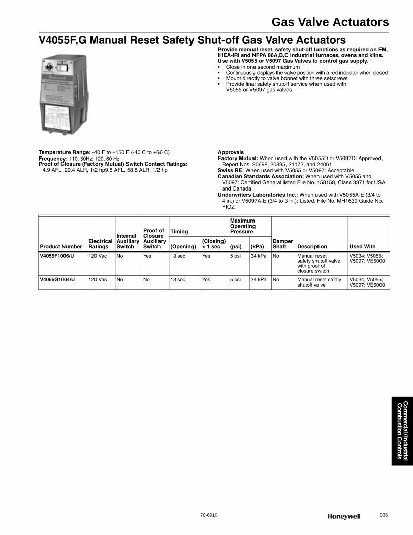
Gas Valve Actuators
70-6910 835
Com
mercial / Industrial
Com
bustion Controls
V4055F,G Manual Reset Safety Shut-off Gas Valve ActuatorsProvide manual reset, safety shut-off functions as required on FM, IHEA-IRI and NFPA 86A,B,C industrial furnaces, ovens and kilns. Use with V5055 or V5097 Gas Valves to control gas supply.• Close in one second maximum • Continuously displays the valve position with a red indicator when closed • Mount directly to valve bonnet with three setscrews• Provide final safety shutoff service when used with
V5055 or V5097 gas valves
Temperature Range: -40 F to +150 F (-40 C to +66 C) Frequency: 110, 50Hz; 120, 60 HzProof of Closure (Factory Mutual) Switch Contact Ratings:
4.9 AFL, 29.4 ALR, 1/2 hp9.8 AFL, 58.8 ALR, 1/2 hp
ApprovalsFactory Mutual: When used with the V5055D or V5097D: Approved,
Report Nos. 20698, 20835, 21172, and 24061Swiss RE: When used with V5055 or V5097: AcceptableCanadian Standards Association: When used with V5055 and
V5097: Certified General listed File No. 158158, Class 3371 for USA and Canada
Underwriters Laboratories Inc.: When used with V5055A-E (3/4 to 4 in.) or V5097A-E (3/4 to 3 in.): Listed, File No. MH1639 Guide No. YIOZ
Product NumberElectrical Ratings
Internal Auxiliary Switch
Proof of Closure Auxiliary Switch
Timing
Maximum Operating Pressure
Damper Shaft Description Used With(Opening)
(Closing) < 1 sec (psi) (kPa)
V4055F1006/U 120 Vac No Yes 13 sec Yes 5 psi 34 kPa No Manual reset safety shutoff valve with proof of closure switch
V5034; V5055; V5097; VE5000
V4055G1004/U 120 Vac No No 13 sec Yes 5 psi 34 kPa No Manual reset safety shutoff valve
V5034; V5055; V5097; VE5000

Gas Valve Actuators
836 customer.honeywell.com 70-6910
V4062 Off-Lo-Hi Fluid Power Gas Valve ActuatorsUse with V5055 or V5097 Gas Valves to control gas supply for commercial and industrial burners. Valve opens to low fire position when power is applied; valve opens all the way on demand.• Provide final safety shutoff service when used with
V5055 or V5097 gas valves• One-second maximum closing time • Continuously displays the valve position with a red indicator
when open and a yellow indicator when closed • Mount in any position directly to valve bonnet with three setscrews• Provide final safety shutoff service when used with
V5055 or V5097 gas valves
Temperature Range: -40 F to +150 F (-40 C to +66 C) Used With: V5055; V5097; VE5000Frequency: 110, 50 Hz; 120, 60 Hz
ApprovalsSwiss RE: When used with V5055 or V5097: AcceptableCanadian Standards Association: When used with V5055 and
V5097: Certified General listed File No. 158158, Class 3371 for USA and Canada
Underwriters Laboratories Inc.: When used with V5055A-E (3/4 to 4 in.) or V5097A-E (3/4 to 3 in.): Listed, File No. MH1639 Guide No. YIOZ
Product Number
Electrical Ratings
Internal Auxiliary Switch
Proof of Closure Auxiliary Switch
Timing
Maximum Operating Pressure
Damper Shaft Description
Auxiliary Switch Contact Ratings (120 Vac)
Auxiliary Switch Contact Ratings (240 Vac)
Proof of Closure (Factory Mutual) Switch Contact Ratings
Comments
(Opening)
(Closing) < 1 sec (psi) (kPa)
V4062A1008/U 120 Vac No No 26 sec Yes 5 psi 34 kPa Yes HI-LO-OFF actuator for use with V5055B and V5097B valve bodies. Low pressure
— — — —
V4062A1123/U 120 Vac Yes No 26 sec Yes 5 psi 34 kPa Yes with return spring installed
HI-LO-OFF actuator for use with V5055B and V5097B valve bodies. Low pressure
9.8 AFL, 58.8 ALR, 1/2 hp
4.9 AFL, 29.4 ALR, 1/2 hp
— —
V4062A1131/U 120 Vac No No 13 sec Yes 5 psi 34 kPa Yes HI-LO-OFF actuator for use with V5055B and V5097B valve bodies. Low pressure
— — — —
V4062A1156/U 120 Vac No No 26 sec Yes 5 psi 34 kPa No HI-LO-OFF actuator for use with V5055B and V5097B valve bodies. Low pressure
— — — For Series 60 Floating Control
V4062A1198/U 120 Vac Yes - adjusted to 90 degree stroke
No 13 sec Yes 5 psi 34 kPa Yes with return spring installed
HI-LO-OFF actuator for use with V5055B and V5097B valve bodies. Low pressure
9.8 AFL, 58.8 ALR, 1/2 hp
4.9 AFL, 29.4 ALR, 1/2 hp
— —
V4062D1002/U 120 Vac No Yes 26 sec Yes 5 psi 34 kPa Yes HI-LO-OFF actuator with Proof of Closure normally used on V5055C,E/V5907C,E valve bodies (Low Pressure)
— — 4 9 AFL, 29.4 ALR, 1/2 hp; 9.8 AFL, 58.8 ALR, 1/2 hp
—
V4062D1010/U 120 Vac No Yes 13 sec Yes 5 psi 34 kPa Yes HI-LO-OFF actuator with Proof of Closure normally used on V5055C,E/V5907C,E valve bodies (Low Pressure)
— — 4 9 AFL, 29.4 ALR, 1/2 hp; 9.8 AFL, 58.8 ALR, 1/2 hp
—
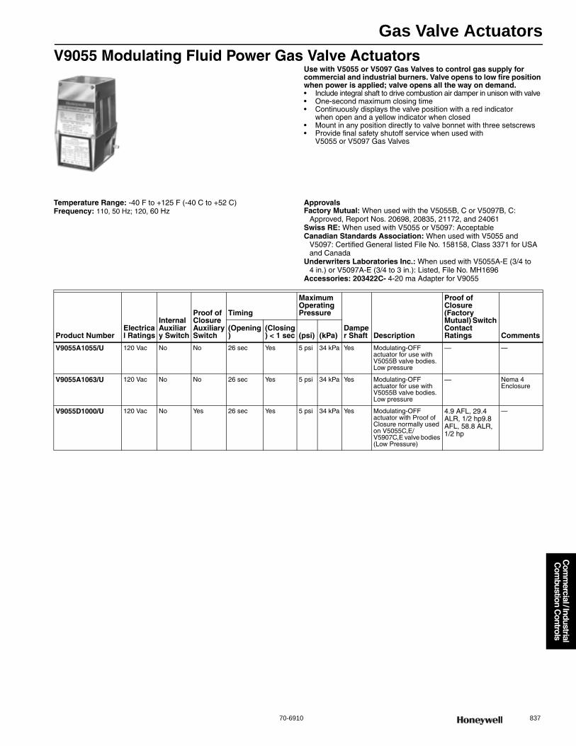
Gas Valve Actuators
70-6910 837
Com
mercial / Industrial
Com
bustion Controls
V9055 Modulating Fluid Power Gas Valve ActuatorsUse with V5055 or V5097 Gas Valves to control gas supply for commercial and industrial burners. Valve opens to low fire position when power is applied; valve opens all the way on demand.• Include integral shaft to drive combustion air damper in unison with valve • One-second maximum closing time • Continuously displays the valve position with a red indicator
when open and a yellow indicator when closed • Mount in any position directly to valve bonnet with three setscrews• Provide final safety shutoff service when used with
V5055 or V5097 Gas Valves
Temperature Range: -40 F to +125 F (-40 C to +52 C) Frequency: 110, 50 Hz; 120, 60 Hz
ApprovalsFactory Mutual: When used with the V5055B, C or V5097B, C:
Approved, Report Nos. 20698, 20835, 21172, and 24061Swiss RE: When used with V5055 or V5097: AcceptableCanadian Standards Association: When used with V5055 and
V5097: Certified General listed File No. 158158, Class 3371 for USA and Canada
Underwriters Laboratories Inc.: When used with V5055A-E (3/4 to 4 in.) or V5097A-E (3/4 to 3 in.): Listed, File No. MH1696
Accessories: 203422C- 4-20 ma Adapter for V9055
Product NumberElectrical Ratings
Internal Auxiliary Switch
Proof of Closure Auxiliary Switch
Timing
Maximum Operating Pressure
Damper Shaft Description
Proof of Closure (Factory Mutual) Switch Contact Ratings Comments
(Opening)
(Closing) < 1 sec (psi) (kPa)
V9055A1055/U 120 Vac No No 26 sec Yes 5 psi 34 kPa Yes Modulating-OFF actuator for use with V5055B valve bodies. Low pressure
— —
V9055A1063/U 120 Vac No No 26 sec Yes 5 psi 34 kPa Yes Modulating-OFF actuator for use with V5055B valve bodies. Low pressure
— Nema 4 Enclosure
V9055D1000/U 120 Vac No Yes 26 sec Yes 5 psi 34 kPa Yes Modulating-OFF actuator with Proof of Closure normally used on V5055C,E/V5907C,E valve bodies (Low Pressure)
4.9 AFL, 29.4 ALR, 1/2 hp9.8 AFL, 58.8 ALR, 1/2 hp
—
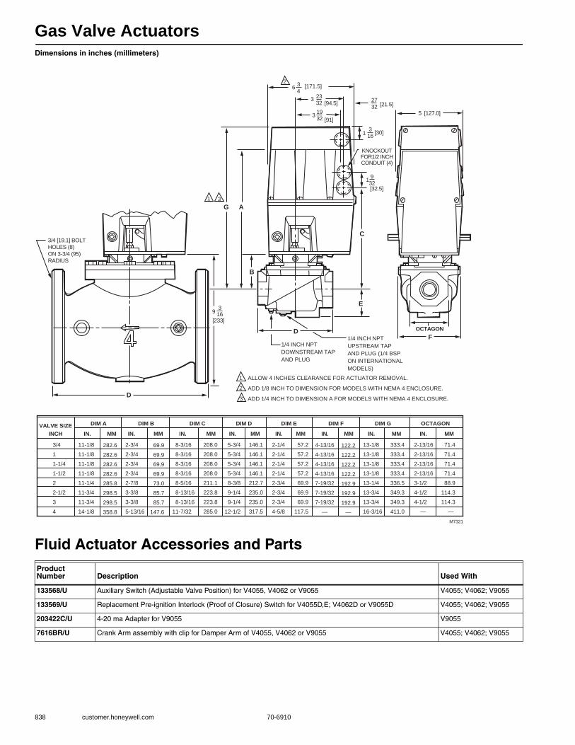
Gas Valve Actuators
838 customer.honeywell.com 70-6910
Dimensions in inches (millimeters)
Fluid Actuator Accessories and PartsProduct Number Description Used With
133568/U Auxiliary Switch (Adjustable Valve Position) for V4055, V4062 or V9055 V4055; V4062; V9055
133569/U Replacement Pre-ignition Interlock (Proof of Closure) Switch for V4055D,E; V4062D or V9055D V4055; V4062; V9055
203422C/U 4-20 ma Adapter for V9055 V9055
7616BR/U Crank Arm assembly with clip for Damper Arm of V4055, V4062 or V9055 V4055; V4062; V9055
B
E
F
C
D
AG31
D
1/4 INCH NPT
DOWNSTREAM TAP
AND PLUG
1/4 INCH NPT
UPSTREAM TAP
AND PLUG (1/4 BSP
ON INTERNATIONAL
MODELS)
2
1
2
3
[32.5]
KNOCKOUTFOR1/2 INCHCONDUIT (4)
OCTAGON
3/4 [19.1] BOLT
HOLES (8)
ON 3-3/4 (95)
RADIUS
1932
1316
[30]
9316
[233]
2732 [21.5]
32332
5
[94.5]
[127.0]31932 [91]
63
4[171.5]
3/4
1
1-1/4
1-1/2
2
2-1/2
3
4
VALVE SIZEINCH
11-1/8
11-1/8
11-1/8
11-1/8
11-1/4
11-3/4
11-3/4
14-1/8
2-3/4
2-3/4
2-3/4
2-3/4
2-7/8
3-3/8
3-3/8
5-13/16
8-3/16
8-3/16
8-3/16
8-3/16
8-5/16
8-13/16
8-13/16
11-7/32
5-3/4
5-3/4
5-3/4
5-3/4
8-3/8
9-1/4
9-1/4
12-1/2
13-1/8
13-1/8
13-1/8
13-1/8
13-1/4
13-3/4
13-3/4
16-3/16
2-13/16
2-13/16
2-13/16
2-13/16
3-1/2
4-1/2
4-1/2
—
333.4
333.4
333.4
333.4
336.5
349.3
349.3
411.0
DIM A
IN. MM
DIM B
IN. MM
DIM C
IN. MM
DIM D
IN. MM
DIM E
IN. MM
DIM F
IN. MM
DIM G OCTAGON
IN. IN.MM MM
ALLOW 4 INCHES CLEARANCE FOR ACTUATOR REMOVAL.
ADD 1/8 INCH TO DIMENSION FOR MODELS WITH NEMA 4 ENCLOSURE.
ADD 1/4 INCH TO DIMENSION A FOR MODELS WITH NEMA 4 ENCLOSURE.
M7321
282.6
282.6
282.6
282.6
285.8
298.5
298.5
358.8
69.9
69.9
69.9
69.9
73.0
85.7
85.7
147.6
208.0
208.0
208.0
208.0
211.1
223.8
223.8
285.0
146.1
146.1
146.1
146.1
212.7
235.0
235.0
317.5
2-1/4
2-1/4
2-1/4
2-1/4
2-3/4
2-3/4
2-3/4
4-5/8
57.2
57.2
57.2
57.2
69.9
69.9
69.9
117.5
4-13/16
4-13/16
4-13/16
4-13/16
7-19/32
7-19/32
7-19/32
—
122.2
122.2
122.2
122.2
192.9
192.9
192.9
—
71.4
71.4
71.4
71.4
88.9
114.3
114.3
—
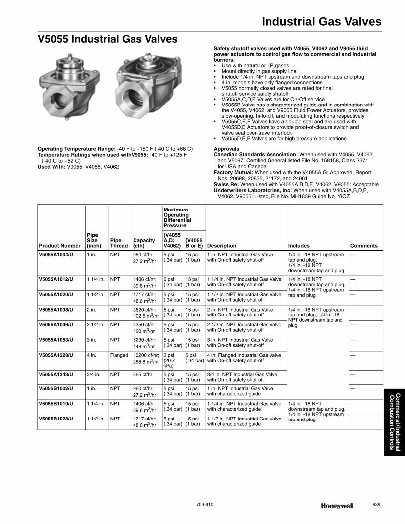
Industrial Gas Valves
70-6910 839
Com
mercial / Industrial
Com
bustion Controls
V5055 Industrial Gas ValvesSafety shutoff valves used with V4055, V4062 and V9055 fluid power actuators to control gas flow to commercial and industrial burners.• Use with natural or LP gases • Mount directly in gas supply line • Include 1/4 in. NPT upstream and downstream taps and plug • 4 in. models have only flanged connections • V5055 normally closed valves are rated for final
shutoff service safety shutoff • V5055A,C,D,E Valves are for On-Off service • V5055B Valve has a characterized guide and in combination with
the V4055, V4062, and V9055 Fluid Power Actuators, provides slow-opening, hi-lo-off, and modulating functions respectively
• V5055C,E,F Valves have a double seal and are used with V4055D,E Actuators to provide proof-of-closure switch and valve seal over-travel interlock
• V5055D,E,F Valves are for high pressure applications
Operating Temperature Range: -40 F to +150 F (-40 C to +66 C) Temperature Ratings when used withV9055: -40 F to +125 F
(-40 C to +52 C) Used With: V9055, V4055, V4062
ApprovalsCanadian Standards Association: When used with V4055, V4062,
and V5097: Certified General listed File No. 158158, Class 3371 for USA and Canada
Factory Mutual: When used with the V4055A,G: Approved, Report Nos. 20698, 20835, 21172, and 24061
Swiss Re: When used with V4055A,B,D,E, V4062, V9055: AcceptableUnderwriters Laboratories, Inc: When used with V4055A,B,D,E,
V4062, V9055: Listed, File No. MH1639 Guide No. YIOZ
Product Number
Pipe Size(inch)
Pipe Thread
Capacity (cfh)
Maximum Operating Differential Pressure
Description Includes Comments
(V4055A,D; V4062)
(V4055B or E)
V5055A1004/U 1 in. NPT 960 cf/hr; 27.2 m3/hr
5 psi (.34 bar)
15 psi (1 bar)
1 in. NPT Industrial Gas Valve with On-off safety shut-off
1/4 in. -18 NPT upstream tap and plug, 1/4 in. -18 NPT downstream tap and plug
—
V5055A1012/U 1 1/4 in. NPT 1406 cf/hr; 39.8 m3/hr
5 psi (.34 bar)
15 psi (1 bar)
1 1/4 in. NPT Industrial Gas Valve with On-off safety shut-off
1/4 in. -18 NPT downstream tap and plug, 1/4 in. -18 NPT upstream tap and plug
—
V5055A1020/U 1 1/2 in. NPT 1717 cf/hr; 48.6 m3/hr
5 psi (.34 bar)
15 psi (1 bar)
1 1/2 in. NPT Industrial Gas Valve with On-off safety shut-off
—
V5055A1038/U 2 in. NPT 3620 cf/hr; 102.5 m3/hr
5 psi (.34 bar)
15 psi (1 bar)
2 in. NPT Industrial Gas Valve with On-off safety shut-off
1/4 in. -18 NPT upstream tap and plug, 1/4 in. -18 NPT downstream tap and plug
—
V5055A1046/U 2 1/2 in. NPT 4250 cf/hr; 120 m3/hr
5 psi (.34 bar)
15 psi (1 bar)
2 1/2 in. NPT Industrial Gas Valve with On-off safety shut-off
—
V5055A1053/U 3 in. NPT 5230 cf/hr; 148 m3/hr
5 psi (.34 bar)
15 psi (1 bar)
3 in. NPT Industrial Gas Valve with On-off safety shut-off
—
V5055A1228/U 4 in. Flanged 10200 cf/hr; 288.8 m3/hr
3 psi (20.7 kPa)
5 psi (.34 bar)
4 in. Flanged Industrial Gas Valve with On-off safety shut-off
—
V5055A1343/U 3/4 in. NPT 665 cf/hr 5 psi (.34 bar)
15 psi (1 bar)
3/4 in. NPT Industrial Gas Valve with On-off safety shut-off
—
V5055B1002/U 1 in. NPT 960 cf/hr; 27.2 m3/hr
5 psi (.34 bar)
15 psi (1 bar)
1 in. NPT Industrial Gas Valve with characterized guide
—
V5055B1010/U 1 1/4 in. NPT 1406 cf/hr; 39.8 m3/hr
5 psi (.34 bar)
15 psi (1 bar)
1 1/4 in. NPT Industrial Gas Valve with characterized guide
1/4 in. -18 NPT downstream tap and plug, 1/4 in. -18 NPT upstream tap and plug
—
V5055B1028/U 1 1/2 in. NPT 1717 cf/hr; 48.6 m3/hr
5 psi (.34 bar)
15 psi (1 bar)
1 1/2 in. NPT Industrial Gas Valve with characterized guide
—

Industrial Gas Valves
840 customer.honeywell.com 70-6910
V5055B1069/U 2 in. NPT 3620 cf/hr; 102.5 m3/hr
5 psi (.34 bar)
15 psi (1 bar)
2 in. NPT Industrial Gas Valve with characterized guide
1/4 in. -18 NPT upstream tap and plug, 1/4 in. -18 NPT downstream tap and plug
—
V5055B1077/U 2 1/2 in. NPT 4250 cf/hr; 120 m3/hr
5 psi (.34 bar)
15 psi (1 bar)
2 1/2 in. NPT Industrial Gas Valve with characterized guide
—
V5055B1085/U 3 in. NPT 5230 cf/hr; 148 m3/hr
5 psi (.34 bar)
15 psi (1 bar)
3 in. NPT Industrial Gas Valve with characterized guide
—
V5055B1150/U 4 in. Flanged 9180 cf/hr; 259.9 m3/hr
3 psi (20.7 kPa)
5 psi (.34 bar)
4 in. Flanged Industrial Gas Valve with characterized guide
—
V5055C1000/U 2 in. NPT 3620 cf/hr; 102.5 m3/hr
5 psi (.34 bar)
15 psi (1 bar)
2 in. NPT Industrial Gas Valve with On-off safety shut-off with double seal
—
V5055C1018/U 2 1/2 in. NPT 4250 cf/hr; 120 m3/hr
5 psi (.34 bar)
15 psi (1 bar)
2 1/2 in. NPT Industrial Gas Valve with On-off safety shut-off with double seal
—
V5055C1026/U 3 in. NPT 5230 cf/hr; 148 m3/hr
5 psi (.34 bar)
15 psi (1 bar)
3 in. NPT Industrial Gas Valve with On-off safety shut-off with double seal
1/4 in. -18 NPT downstream tap and plug, 1/4 in. -18 NPT upstream tap and plug
—
V5055C1034/U 1 in. NPT 960 cf/hr; 27.2 m3/hr
5 psi (.34 bar)
15 psi (1 bar)
1 in. NPT Industrial Gas Valve with On-off safety shut-off with double seal
1/4 in. -18 NPT upstream tap and plug, 1/4 in. -18 NPT downstream tap and plug
—
V5055C1042/U 1 1/4 in. NPT 1406 cf/hr; 39.8 m3/hr
5 psi (.34 bar)
15 psi (1 bar)
1 1/4 in. NPT Industrial Gas Valve with On-off safety shut-off with double seal
1/4 in. -18 NPT downstream tap and plug, 1/4 in. -18 NPT upstream tap and plug
—
V5055C1059/U 1 1/2 in. NPT 1717 cf/hr; 48.6 m3/hr
5 psi (.34 bar)
15 psi (1 bar)
1 1/2 in. NPT Industrial Gas Valve with On-off safety shut-off with double seal
1/4 in. -18 NPT upstream tap and plug, 1/4 in. -18 NPT downstream tap and plug
—
V5055C1109/U 4 in. Flanged 9180 cf/hr; 259.9 m3/hr
3 psi (20.7 kPa)
5 psi (.34 bar)
4 in. Flanged Industrial Gas Valve with On-off safety shut-off with double seal
—
V5055C1182/U 3/4 in. NPT 665 cf/hr 5 psi (.34 bar)
15 psi (1 bar)
3/4 in. NPT Industrial Gas Valve with On-off safety shut-off with double seal
1/4 in. -18 NPT downstream tap and plug, 1/4 in. -18 NPT upstream tap and plug
—
V5055D1008/U 1 in. NPT 960 cf/hr; 27.2 m3/hr
5 psi (.34 bar)
25 psi (1.6 bar)
1 in. NPT High Pressure Industrial Gas Valve with On-off safety shut-off
1/4 in. -18 NPT upstream tap and plug, 1/4 in. -18 NPT downstream tap and plug
—
V5055D1016/U 1 1/4 in. NPT 1406 cf/hr; 39.8 m3/hr
5 psi (.34 bar)
25 psi (1.6 bar)
1 1/4 in. NPT High Pressure Industrial Gas Valve with On-off safety shut-off
—
V5055D1024/U 1 1/2 in. NPT 1717 cf/hr; 48.6 m3/hr
5 psi (.34 bar)
25 psi (1.6 bar)
1 1/2 in. NPT High Pressure Industrial Gas Valve with On-off safety shut-off
—
V5055D1032/U 2 in. NPT 3620 cf/hr; 102.5 m3/hr
5 psi (.34 bar)
15 psi (1 bar)
2 in. NPT High Pressure Industrial Gas Valve with On-off safety shut-off
—
V5055D1040/U 2 1/2 in. NPT 4250 cf/hr; 120 m3/hr
5 psi (.34 bar)
15 psi (1 bar)
2 1/2 in. NPT High Pressure Industrial Gas Valve with On-off safety shut-off
—
V5055D1057/U 3 in. NPT 5230 cf/hr 5 psi (.34 bar)
15 psi (1 bar)
3 in. NPT High Pressure Industrial Gas Valve with On-off safety shut-off
—
V5055D1065/U 3/4 in. NPT 665 cf/hr 5 psi (.34 bar)
25 psi (1.6 bar)
3/4 in. NPT High Pressure Industrial Gas Valve with On-off safety shut-off
—
V5055E1005/U 2 in. NPT 3620 cf/hr; 102.5 m3/hr
5 psi (.34 bar)
15 psi (1 bar)
2 in. NPT High Pressure Industrial Gas Valve with On-off safety shut-off with double seal
—
Product Number
Pipe Size(inch)
Pipe Thread
Capacity (cfh)
Maximum Operating Differential Pressure
Description Includes Comments
(V4055A,D; V4062)
(V4055B or E)
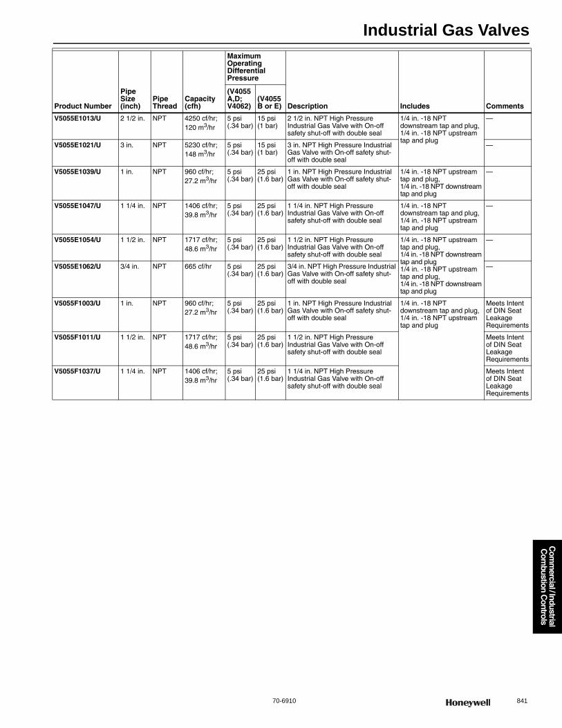
Industrial Gas Valves
70-6910 841
Com
mercial / Industrial
Com
bustion Controls
V5055E1013/U 2 1/2 in. NPT 4250 cf/hr; 120 m3/hr
5 psi (.34 bar)
15 psi (1 bar)
2 1/2 in. NPT High Pressure Industrial Gas Valve with On-off safety shut-off with double seal
1/4 in. -18 NPT downstream tap and plug, 1/4 in. -18 NPT upstream tap and plug
—
V5055E1021/U 3 in. NPT 5230 cf/hr; 148 m3/hr
5 psi (.34 bar)
15 psi (1 bar)
3 in. NPT High Pressure Industrial Gas Valve with On-off safety shut-off with double seal
—
V5055E1039/U 1 in. NPT 960 cf/hr; 27.2 m3/hr
5 psi (.34 bar)
25 psi (1.6 bar)
1 in. NPT High Pressure Industrial Gas Valve with On-off safety shut-off with double seal
1/4 in. -18 NPT upstream tap and plug, 1/4 in. -18 NPT downstream tap and plug
—
V5055E1047/U 1 1/4 in. NPT 1406 cf/hr; 39.8 m3/hr
5 psi (.34 bar)
25 psi (1.6 bar)
1 1/4 in. NPT High Pressure Industrial Gas Valve with On-off safety shut-off with double seal
1/4 in. -18 NPT downstream tap and plug, 1/4 in. -18 NPT upstream tap and plug
—
V5055E1054/U 1 1/2 in. NPT 1717 cf/hr; 48.6 m3/hr
5 psi (.34 bar)
25 psi (1.6 bar)
1 1/2 in. NPT High Pressure Industrial Gas Valve with On-off safety shut-off with double seal
1/4 in. -18 NPT upstream tap and plug, 1/4 in. -18 NPT downstream tap and plug1/4 in. -18 NPT upstream tap and plug, 1/4 in. -18 NPT downstream tap and plug
—
V5055E1062/U 3/4 in. NPT 665 cf/hr 5 psi (.34 bar)
25 psi (1.6 bar)
3/4 in. NPT High Pressure Industrial Gas Valve with On-off safety shut-off with double seal
—
V5055F1003/U 1 in. NPT 960 cf/hr; 27.2 m3/hr
5 psi (.34 bar)
25 psi (1.6 bar)
1 in. NPT High Pressure Industrial Gas Valve with On-off safety shut-off with double seal
1/4 in. -18 NPT downstream tap and plug, 1/4 in. -18 NPT upstream tap and plug
Meets Intent of DIN Seat Leakage Requirements
V5055F1011/U 1 1/2 in. NPT 1717 cf/hr; 48.6 m3/hr
5 psi (.34 bar)
25 psi (1.6 bar)
1 1/2 in. NPT High Pressure Industrial Gas Valve with On-off safety shut-off with double seal
Meets Intent of DIN Seat Leakage Requirements
V5055F1037/U 1 1/4 in. NPT 1406 cf/hr; 39.8 m3/hr
5 psi (.34 bar)
25 psi (1.6 bar)
1 1/4 in. NPT High Pressure Industrial Gas Valve with On-off safety shut-off with double seal
Meets Intent of DIN Seat Leakage Requirements
Product Number
Pipe Size(inch)
Pipe Thread
Capacity (cfh)
Maximum Operating Differential Pressure
Description Includes Comments
(V4055A,D; V4062)
(V4055B or E)

Industrial Gas Valves
842 customer.honeywell.com 70-6910
Dimensions in inches (millimeters)
B
E
F
C
D
A1
1/4 INCH NPT
DOWNSTREAM
TAP AND PLUG
1
KNOCKOUT
FOR1/2 INCH
CONDUIT (4)
OCTAGON
5 (127) 27/32 (21)
3-23/32 (95)
6-3/4 (172)
ALLOW 2 IN. (51 mm) CLEARANCE FOR ACTUATOR REMOVAL.
M27268
3/4
1
1-1/4
1-1/2
2
2-1/2
3
VALVE SIZEINCH
11-1/8
11-1/8
11-1/8
11-1/8
11-1/4
11-3/4
11-3/4
283
283
283
283
286
299
299
2-3/4
2-3/4
2-3/4
2-3/4
2-7/8
3-3/8
3-3/8
70
70
70
70
73
86
86
8-3/16
8-3/16
8-3/16
8-3/16
8-5/16
8-13/16
8-13/16
208
208
208
208
211
224
224
5-3/4
5-3/4
5-3/4
5-3/4
8-3/8
9-1/4
9-1/4
146
146
146
146
213
235
235
2-1/4
2-1/4
2-1/4
2-1/4
2-3/4
2-3/4
2-3/4
57
57
57
57
70
70
70
4-7/8
4-7/8
4-7/8
4-7/8
7-19/32
7-19/32
7-19/32
124
124
124
124
193
193
193
2-13/16
2-13/16
2-13/16
2-13/16
3-1/2
4-1/2
4-1/2
71
71
71
71
89
114
114
DIM A
IN. MM
DIM B
IN. MM
DIM C
IN. MM
DIM D
IN. MM
DIM E
IN. MM
DIM F
IN. MM
OCTAGON
IN. MM
1-9/32
(33)
1/4 INCH NPT UPSTREAM
TAP AND PLUG
OCTAGON
H
6-3/4 (171)
1-9/32 (33)
A
B
C
D
DIM. A DIM. B DIM. C DIM. D DIM. E DIM. F DIM. G DIM. H DIM. J
EG
FJ
OCTAGON
5 (127)
VALVE
SIZE
(IN.) IN. MM IN. MM IN. MM IN. MM IN. MM IN. MM IN. MM
11-1/8
11-1/8
11-1/8
11-1/8
11-3/4
11-3/4
11-3/4
283
283
283
283
298
298
298
2-3/4
2-3/4
2-3/4
2-3/4
3-3/8
3-3/8
3-3/8
70
70
70
70
86
86
86
8-3/16
8-3/16
8-3/16
8-3/16
8-5/16
8-5/16
8-5/16
208
208
208
208
211
211
211
8-1/4
8-1/4
8-1/4
8-1/4
11-3/4
11-3/4
11-3/4
210
210
210
210
298
298
298
IN. MM IN. MM IN. MM
62
62
62
62
91
91
91
5
5
5
5
8
8
8
127
127
127
127
203
203
203
58
58
58
58
113
113
113
23
23
23
23
38
38
38
100
100
100
100
165
165
165
71
71
71
71
114
114
114
3/4
1
1-1/4
1-1/2
2
2-1/2
3
M27581
ALLOW 2 IN. (51 MM) CLEARANCE FOR ACTUATOR REMOVAL.1
1
2-7/16
2-7/16
2-7/16
2-7/16
3-5/8
3-5/8
3-5/8
2-5/16
2-5/16
2-5/16
2-5/16
4-7/16
4-7/16
4-7/16
7/8
7/8
7/8
7/8
1-1/2
1-1/2
1-1/2
3-15/16
3-15/16
3-15/16
3-15/16
6-1/2
6-1/2
6-1/2
2-13/16
2-13/16
2-13/16
2-13/16
4-1/2
4-1/2
4-1/2

Industrial Gas Valves
70-6910 843
Com
mercial / Industrial
Com
bustion Controls
V5097 Integrated Valve Train
Safety shutoff valves used with V4055, V4062 and V9055 fluid power actuators to control gas flow to commercial and industrial burners.
• Use with natural or LP gases • Mount directly in gas supply line • Two Valve body types. Small body type for 3/4 in., 1 in., 1-1/4 in., 1-1/2 in.,
2 in. pipes. Large body types for 2 in., 2-1/2 in. and 3 in. pipes • Seven pipe adapter sizes from 3/4 in. to 3 in. have NPT or BSP
threaded connections • Provides three 1/4 in. upstream and two 1/4 in. downstream tap and plug • CE version provides an additional downstream tap and plug • Yellow SHUT indicator attached to the valve stem provides an
indication of the valve closed position • V5097A,C,D,E Valves are for on-off service • V5097B Valve has a characterized guide and in combination with
the V4055, V4062 and V9055 Fluid Power Actuators, provides slow-opening, HI-LO-OFF, and modulating functions, respectively
• V5097C,E Valves have a double seal and are used with V4055D,E Actuators to provide proof-of-closure switch and valve seal over-travel interlock
• V5097D,E Valves are for high pressure applications • Two valve body types (small and large) applicable to server pipe size
Operating Temperature Range: -40 F to +150 F (-40 C to +66 C) Temperature Ratings when used withV9055: -40 F to +125 F
(-40 C to +52 C) Includes: Three 1/4 in. -18 NPT upstream and two 1/4 in. -18 NPT
downstream tapsComments: Select Proper Pipe AdapterUsed With: V9055, V4055, V4062
ApprovalsCanadian Standards Association: : When used with V4055, V4062, and
V5097: Certified General listed File No. 158158, Class 3371 for USA and Canada
CE: CE #E3070 (Gastec)Factory Mutual: When used with the V4055A,G: Approved, Report
Nos. 20698, 20835, 21172, and 24061Swiss Re: When used with V4055A,B,D,E, V4062, V9055: AcceptableUnderwriters Laboratories, Inc: When used with V4055A,B,D,E,
V4062, V9055: Listed, File No. MH1639 Guide No. YIOZ
Product Number
Pipe Size
Capacity (cfh)
Maximum Operating Differential Pressure
Integrated Valve Train Body Size Description Includes(inch)
(V4055A,D; V4062)
(V4055B or E)
V5097A1004/U 3/4 in. or 1 in. or 1 1/4 in. or 2 in.
665 cf/hr to 3620 cf/hr; 18.8 to 102.5 m3/hr
5 psi (340 mbar) 15 psi (1 bar) Small body Small Body Low Pressure Integrated Valve with On-off safety shut-off
Three 1/4 in. -18 NPT upstream and two 1/4 in. -18 NPT downstream taps
V5097A1012/U 2 in. or 2 1/2 in. or 3 in.
3620 cf/hr to 5230 cf/hr; 102.5 to 148.0 m3/hr
5 psi (340 mbar) 15 psi (1 bar) Large body Large Body Low Pressure Integrated Valve with On-off safety shut-off
Three 1/4 in. -18 NPT upstream and two 1/4 in. -18 NPT downstream taps
V5097B1002/U 3/4 in. or 1 in. or 1 1/4 in. or 2 in.
665 cf/hr to 3620 cf/hr 5 psi (340 mbar) 15 psi (1 bar) Small body Small Body Low Pressure Integrated Valve with characterized guide safety shut-off
Three 1/4 in. -18 NPT upstream and two 1/4 in. -18 NPT downstream taps
V5097B1010/U 2 in. or 2 1/2 in. or 3 in.
3620 cf/hr to 5230 cf/hr; 102.5 to 148.0 m3/hr
5 psi (340 mbar) 15 psi (1 bar) Large body Large Body Low Pressure Integrated Valve with characterized guide safety shut-off
Three 1/4 in. -18 NPT upstream and two 1/4 in. -18 NPT downstream taps
V5097C1000/U 3/4 in. or 1 in. or 1 1/4 in. or 2 in.
665 cf/hr to 3620 cf/hr; 18.8 to 102.5 m3/hr
5 psi (340 mbar) 15 psi (1 bar) Small body Small Body Low Pressure Integrated Valve with On-off safety shut-off with double seal
Three 1/4 in. -18 NPT upstream and two 1/4 in. -18 NPT downstream taps
V5097C1018/U 2 in. or 2 1/2 in. or 3 in.
3620 cf/hr to 5230 cf/hr; 102.5 to 148.0 m3/hr
5 psi (340 mbar) 15 psi (1 bar) Large body Large Body Low Pressure Integrated Valve with On-off safety shut-off with double seal
Three 1/4 in. -18 NPT upstream and two 1/4 in. -18 NPT downstream taps
V5097D1008/U 3/4 in. or 1 in. or 1 1/4 in. or 2 in.
665 cf/hr to 3620 cf/hr; 18.8 to 102.5 m3/hr
5 psi (340 mbar) 25 psi (1.6 bar)
Small body Small Body High Pressure Integrated Valve with On-off safety shut-off
Three 1/4 in. -18 NPT upstream and two 1/4 in. -18 NPT downstream taps
V5097D1016/U 2 in. or 2 1/2 in. or 3 in.
3620 cf/hr to 5230 cf/hr; 102.5 to 148.0 m3/hr
5 psi (340 mbar) 15 psi (1 bar) Large body Large Body High Pressure Integrated Valve with On-off safety shut-off
Three 1/4 in. -18 NPT upstream and two 1/4 in. -18 NPT downstream taps
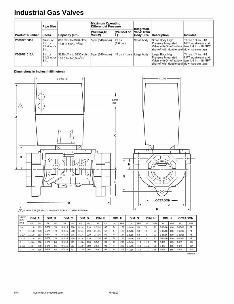
Industrial Gas Valves
844 customer.honeywell.com 70-6910
Dimensions in inches (millimeters)
V5097E1005/U 3/4 in. or 1 in. or 1 1/4 in. or 2 in.
665 cf/hr to 3620 cf/hr;18.8 to 102.5 m3/hr
5 psi (340 mbar) 25 psi (1.6 bar)
Small body Small Body High Pressure Integrated Valve with On-off safety shut-off with double seal
Three 1/4 in. -18 NPT upstream and two 1/4 in. -18 NPT downstream taps
V5097E1013/U 2 in. or 2 1/2 in. or 3 in.
3620 cf/hr to 5230 cf/hr;102.5 to 148.0 m3/hr
5 psi (340 mbar) 15 psi (1 bar) Large body Large Body High Pressure Integrated Valve with On-off safety shut-off with double seal
Three 1/4 in. -18 NPT upstream and two 1/4 in. -18 NPT downstream taps
Product Number
Pipe Size
Capacity (cfh)
Maximum Operating Differential Pressure
Integrated Valve Train Body Size Description Includes(inch)
(V4055A,D; V4062)
(V4055B or E)
6-3/4 (171)
1-9/32
(33)
A
B
C
D
DIM. A DIM. B DIM. C DIM. D DIM. E DIM. F DIM. G DIM. H DIM. J
E
G
H
FJ
OCTAGON
OCTAGON
5 (127)
VALVE
SIZE
(IN.) IN. MM IN. MM IN. MM IN. MM IN. MM IN. MM IN. MM
11-1/8
11-1/8
11-1/8
11-1/8
11-3/4
11-3/4
11-3/4
283
283
283
283
298
298
298
2-3/4
2-3/4
2-3/4
2-3/4
3-3/8
3-3/8
3-3/8
70
70
70
70
86
86
86
8-3/16
8-3/16
8-3/16
8-3/16
8-5/16
8-5/16
8-5/16
208
208
208
208
211
211
211
8-1/4
8-1/4
8-1/4
8-1/4
11-3/4
11-3/4
11-3/4
210
210
210
210
298
298
298
IN. MM IN. MM IN. MM
62
62
62
62
91
91
91
5
5
5
5
8
8
8
127
127
127
127
203
203
203
58
58
58
58
113
113
113
23
23
23
23
38
38
38
100
100
100
100
165
165
165
71
71
71
71
114
114
114
3/4
1
1-1/4
1-1/2
2
2-1/2
3
M11682A
ALLOW 2 IN. (51 MM) CLEARANCE FOR ACTUATOR REMOVAL.1
1
2-7/16
2-7/16
2-7/16
2-7/16
3-5/8
3-5/8
3-5/8
2-5/16
2-5/16
2-5/16
2-5/16
4-7/16
4-7/16
4-7/16
7/8
7/8
7/8
7/8
1-1/2
1-1/2
1-1/2
3-15/16
3-15/16
3-15/16
3-15/16
6-1/2
6-1/2
6-1/2
2-13/16
2-13/16
2-13/16
2-13/16
4-1/2
4-1/2
4-1/2
Industrial Gas Valves
70-6910 845
Com
mercial / Industrial
Com
bustion Controls
Integrated Valve Train Pipe Adapters
V5055/5097 Replacement Parts or Accessories
Product Number
Pipe SizePipe Thread
Integrated Valve Train Body Size Description Used With(inch)
32000109-001/U 3/4 in. NPT Small body 3/4 in. NPT Pipe Adapter Small Body Integrated Valve Train. Required for Valve Train Assembly.
V5097; V4297; V5197
32000109-002/U 1 in. NPT Small body 1 in. NPT Pipe Adapter Small Body Integrated Valve Train. Required for Valve Train Assembly.
V5097; V4297; V5197
32000109-003/U 1 1/4 in. NPT Small body 1 1/4 in. NPT Pipe Adapter Small Body Integrated Valve Train. Required for Valve Train Assembly.
V5097; V4297; V5197
32000109-004/U 1 1/2 in. NPT Small body 1 1/2 in. NPT Pipe Adapter Small Body Integrated Valve Train. Required for Valve Train Assembly.
V5097; V4297; V5197
32000109-005/U 2 in. NPT Small body 2 in. NPT Pipe Adapter Small Body Integrated Valve Train. Required for Valve Train Assembly.
V5097; V4297; V5197
32000109-006/U 3/4 in. BSP Small body 3/4 in. BSP Pipe Adapter Small Body Integrated Valve Train. Required for Valve Train Assembly.
V5097; V4297; V5197
32000109-007/U 1 in. BSP Small body 1 in. BSP Pipe Adapter Small Body Integrated Valve Train. Required for Valve Train Assembly.
V5097; V4297; V5197
32000109-008/U 1 1/4 in. BSP Small body 1 1/4 in. BSP Pipe Adapter Small Body Integrated Valve Train. Required for Valve Train Assembly.
V5097; V4297; V5197
32000109-009/U 1 1/2 in. BSP Small body 1 1/2 in. BSP Pipe Adapter Small Body Integrated Valve Train. Required for Valve Train Assembly.
V5097; V4297; V5197
32000109-010/U 2 in. BSP Small body 2 in. BSP Pipe Adapter Small Body Integrated Valve Train. Required for Valve Train Assembly.
V5097; V4297; V5197
32001605-001/U 2 in. NPT Large body 2 in. NPT Pipe Adapter Large Body Integrated Valve Train. Required for Valve Train Assembly.
V5097; V4297; V5197
32001605-002/U 2 1/2 in. NPT Large body 2 1/2 in. NPT Pipe Adapter Large Body Integrated Valve Train. Required for Valve Train Assembly.
V5097; V4297; V5197
32001605-003/U 3 in. NPT Large body 3 in. NPT Pipe Adapter Large Body Integrated Valve Train. Required for Valve Train Assembly.
V5097; V4297; V5197
32001605-004/U 2 in. BSP Large body 2 in. BSP Pipe Adapter Large Body Integrated Valve Train. Required for Valve Train Assembly.
V5097; V4297; V5197
32001605-005/U 2 1/2 in. BSP Large body 2 1/2 in. BSP Pipe Adapter Large Body Integrated Valve Train. Required for Valve Train Assembly.
V5097; V4297; V5197
32001605-006/U 3 in. BSP Large body 3 in. BSP Pipe Adapter Large Body Integrated Valve Train. Required for Valve Train Assembly.
V5097; V4297; V5197
Product Number Description Used With
133392A/U O-Ring Assembly for 2 in., 2 1/2 in., and 3 in. V5055 valves V5055/V5097 valves
133393A/U O-Ring Assembly for 1 in., 1 1/4 in., and 1 1/2 in. V5055 valves V5055/V5097 valves
133398AA/U Replacement Bonnet Assembly with 133393A Seal Assembly for 3/4, 1, 1-1/4, 1-1/2 in. V5055A valves V5055/V5097 valves
133398BA/U Replacement Bonnet Assembly with 133393A Seal Assembly for 3/4, 1, 1-1/4, 1-1/2 in. V5055B valves V5055/V5097 valves
133398CA/U Replacement Bonnet Assembly, with 137253A replacement Seal Assembly for small body (3/4,1, 1/1/2 in.) V5055/V5097C
V5055/V5097 valves
133417AA/U Replacement Bonnet Assembly with 133392A Seal Assembly for 2, 2 1/2, and 3 in. V5055A valves V5055/V5097 valves
133417BA/U Replacement Bonnet Assembly with 133392A Seal Assembly for 2, 2 1/2, and 3 in. V5055B valves V5055/V5097 valves
133417CA/U Bonnet Assembly for 2, 2 1/2, or 3 in. V5055C or V5097C valves V5055C/V5097C valves
137253A/U Replacement seal assembly. For 4 inch V5055 V5055
32002512-001/U Large bodies 2 in.-3 in. normally open vent valve adapter. Use with V5097 V5097
32002513-001/U Small bodies 3/4 in.-2 in. normally open vent valve adapter. Use with V5097|Small bodies 3/4 in.-2 in. normally open vent valve adapter. Use with V5097
V5097
32004771-001 Small Body Multi-tap Adapter Assembly, Integrated Valve Train V5097
4074EYE/U Bag assembly for V5097 (large body) includes 6 ea bolts, nuts and washers Large Body V5097
4074EYF/U Bag assembly for V5097 (small body) includes 6 ea bolts, nuts and washers Small Body V5097
4074EYK/U Bag assembly for V5097 (small body) includes (2) O-rings, (1) grease capsule Small Body V5097
4074EYL/U Bag assembly for V5097 (large body) includes (2) O-rings, (1) grease capsule Large Body V5097
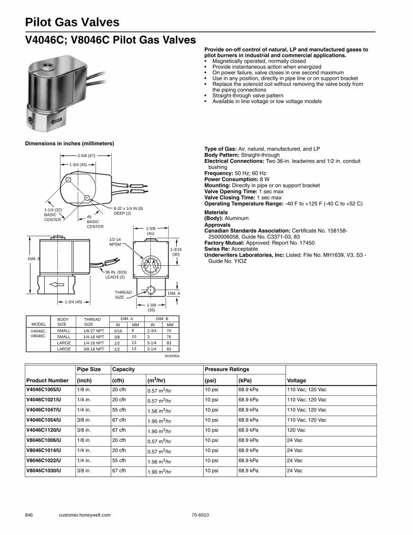
Pilot Gas Valves
846 customer.honeywell.com 70-6910
V4046C; V8046C Pilot Gas ValvesProvide on-off control of natural, LP and manufactured gases to pilot burners in industrial and commercial applications.• Magnetically operated, normally closed • Provide instantaneous action when energized • On power failure, valve closes in one second maximum • Use in any position, directly in pipe line or on support bracket • Replace the solenoid coil without removing the valve body from
the piping connections • Straight-through valve pattern • Available in line voltage or low voltage models
Dimensions in inches (millimeters)Type of Gas: Air, natural, manufactured, and LPBody Pattern: Straight-throughElectrical Connections: Two 36-in. leadwires and 1/2 in. conduit
bushingFrequency: 50 Hz; 60 HzPower Consumption: 8 WMounting: Directly in pipe or on support bracketValve Opening Time: 1 sec maxValve Closing Time: 1 sec maxOperating Temperature Range: -40 F to +125 F (-40 C to +52 C)
Materials(Body): AluminumApprovalsCanadian Standards Association: Certificate No. 158158-
2500006058, Guide No. C3371-03, 83Factory Mutual: Approved: Report No. 17450Swiss Re: AcceptableUnderwriters Laboratories, Inc: Listed: File No. MH1639, V3, S3 -
Guide No. YIOZ
1-3/16
(30)
DIM. A
1-3/8
(35)
1-5/8
(41)
1-3/4 (45)
2-5/8 (67)
1-3/4 (45)
DIM. B
1-1/4 (32)
BASIC
CENTER45
BASIC
CENTER
8-32 x 1/4 IN.(6)
DEEP (2)
1/2-14
NPSM
36 IN. (915)
LEADS (2)
THREAD
SIZE
MODEL
V4046C,V8046C
BODY
SIZE
THREAD
SIZE
SMALL
SMALL
LARGE
LARGE
1/8-27 NPT
1/4-18 NPT
1/4-18 NPT
3/8-18 NPT
5/16
3/8
1/2
1/2
8
10
13
13
2-3/4
3
3-1/4
3-1/4
70
76
83
83
DIM. A DIM. B
IN MM IN MM
M16595A
Product Number
Pipe Size Capacity Pressure Ratings
Voltage(inch) (cfh) (m3/hr) (psi) (kPa)
V4046C1005/U 1/8 in. 20 cfh 0.57 m3/hr 10 psi 68.9 kPa 110 Vac; 120 Vac
V4046C1021/U 1/4 in. 20 cfh 0.57 m3/hr 10 psi 68.9 kPa 110 Vac; 120 Vac
V4046C1047/U 1/4 in. 55 cfh 1.56 m3/hr 10 psi 68.9 kPa 110 Vac; 120 Vac
V4046C1054/U 3/8 in. 67 cfh 1.90 m3/hr 10 psi 68.9 kPa 110 Vac; 120 Vac
V4046C1120/U 3/8 in. 67 cfh 1.90 m3/hr 10 psi 68.9 kPa 120 Vac
V8046C1006/U 1/8 in. 20 cfh 0.57 m3/hr 10 psi 68.9 kPa 24 Vac
V8046C1014/U 1/4 in. 20 cfh 0.57 m3/hr 10 psi 68.9 kPa 24 Vac
V8046C1022/U 1/4 in. 55 cfh 1.56 m3/hr 10 psi 68.9 kPa 24 Vac
V8046C1030/U 3/8 in. 67 cfh 1.90 m3/hr 10 psi 68.9 kPa 24 Vac
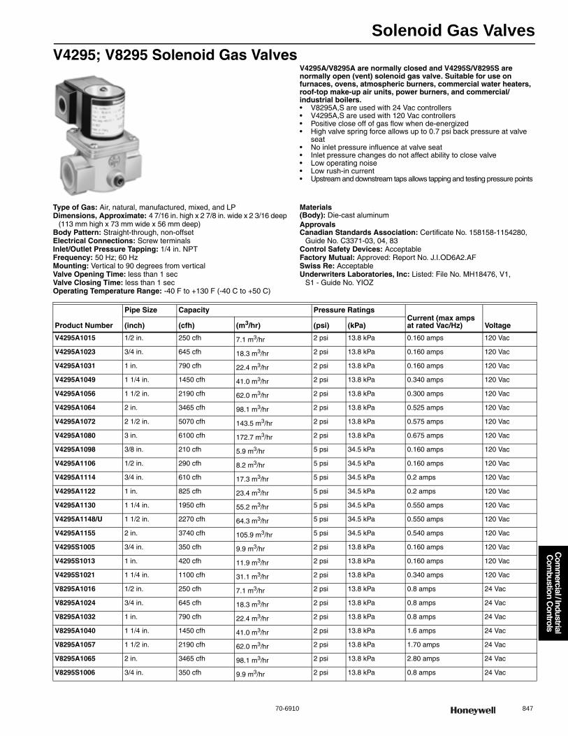
Solenoid Gas Valves
70-6910 847
Com
mercial / Industrial
Com
bustion Controls
V4295; V8295 Solenoid Gas ValvesV4295A/V8295A are normally closed and V4295S/V8295S are normally open (vent) solenoid gas valve. Suitable for use on furnaces, ovens, atmospheric burners, commercial water heaters, roof-top make-up air units, power burners, and commercial/industrial boilers.• V8295A,S are used with 24 Vac controllers• V4295A,S are used with 120 Vac controllers • Positive close off of gas flow when de-energized • High valve spring force allows up to 0.7 psi back pressure at valve
seat • No inlet pressure influence at valve seat • Inlet pressure changes do not affect ability to close valve • Low operating noise • Low rush-in current • Upstream and downstream taps allows tapping and testing pressure points
Type of Gas: Air, natural, manufactured, mixed, and LPDimensions, Approximate: 4 7/16 in. high x 2 7/8 in. wide x 2 3/16 deep
(113 mm high x 73 mm wide x 56 mm deep) Body Pattern: Straight-through, non-offsetElectrical Connections: Screw terminalsInlet/Outlet Pressure Tapping: 1/4 in. NPTFrequency: 50 Hz; 60 HzMounting: Vertical to 90 degrees from verticalValve Opening Time: less than 1 secValve Closing Time: less than 1 secOperating Temperature Range: -40 F to +130 F (-40 C to +50 C)
Materials(Body): Die-cast aluminumApprovalsCanadian Standards Association: Certificate No. 158158-1154280,
Guide No. C3371-03, 04, 83Control Safety Devices: AcceptableFactory Mutual: Approved: Report No. J.I.OD6A2.AFSwiss Re: AcceptableUnderwriters Laboratories, Inc: Listed: File No. MH18476, V1,
S1 - Guide No. YIOZ
Product Number
Pipe Size Capacity Pressure RatingsCurrent (max amps at rated Vac/Hz) Voltage(inch) (cfh) (m3/hr) (psi) (kPa)
V4295A1015 1/2 in. 250 cfh 7.1 m3/hr 2 psi 13.8 kPa 0.160 amps 120 Vac
V4295A1023 3/4 in. 645 cfh 18.3 m3/hr 2 psi 13.8 kPa 0.160 amps 120 Vac
V4295A1031 1 in. 790 cfh 22.4 m3/hr 2 psi 13.8 kPa 0.160 amps 120 Vac
V4295A1049 1 1/4 in. 1450 cfh 41.0 m3/hr 2 psi 13.8 kPa 0.340 amps 120 Vac
V4295A1056 1 1/2 in. 2190 cfh 62.0 m3/hr 2 psi 13.8 kPa 0.300 amps 120 Vac
V4295A1064 2 in. 3465 cfh 98.1 m3/hr 2 psi 13.8 kPa 0.525 amps 120 Vac
V4295A1072 2 1/2 in. 5070 cfh 143.5 m3/hr 2 psi 13.8 kPa 0.575 amps 120 Vac
V4295A1080 3 in. 6100 cfh 172.7 m3/hr 2 psi 13.8 kPa 0.675 amps 120 Vac
V4295A1098 3/8 in. 210 cfh 5.9 m3/hr 5 psi 34.5 kPa 0.160 amps 120 Vac
V4295A1106 1/2 in. 290 cfh 8.2 m3/hr 5 psi 34.5 kPa 0.160 amps 120 Vac
V4295A1114 3/4 in. 610 cfh 17.3 m3/hr 5 psi 34.5 kPa 0.2 amps 120 Vac
V4295A1122 1 in. 825 cfh 23.4 m3/hr 5 psi 34.5 kPa 0.2 amps 120 Vac
V4295A1130 1 1/4 in. 1950 cfh 55.2 m3/hr 5 psi 34.5 kPa 0.550 amps 120 Vac
V4295A1148/U 1 1/2 in. 2270 cfh 64.3 m3/hr 5 psi 34.5 kPa 0.550 amps 120 Vac
V4295A1155 2 in. 3740 cfh 105.9 m3/hr 5 psi 34.5 kPa 0.540 amps 120 Vac
V4295S1005 3/4 in. 350 cfh 9.9 m3/hr 2 psi 13.8 kPa 0.160 amps 120 Vac
V4295S1013 1 in. 420 cfh 11.9 m3/hr 2 psi 13.8 kPa 0.160 amps 120 Vac
V4295S1021 1 1/4 in. 1100 cfh 31.1 m3/hr 2 psi 13.8 kPa 0.340 amps 120 Vac
V8295A1016 1/2 in. 250 cfh 7.1 m3/hr 2 psi 13.8 kPa 0.8 amps 24 Vac
V8295A1024 3/4 in. 645 cfh 18.3 m3/hr 2 psi 13.8 kPa 0.8 amps 24 Vac
V8295A1032 1 in. 790 cfh 22.4 m3/hr 2 psi 13.8 kPa 0.8 amps 24 Vac
V8295A1040 1 1/4 in. 1450 cfh 41.0 m3/hr 2 psi 13.8 kPa 1.6 amps 24 Vac
V8295A1057 1 1/2 in. 2190 cfh 62.0 m3/hr 2 psi 13.8 kPa 1.70 amps 24 Vac
V8295A1065 2 in. 3465 cfh 98.1 m3/hr 2 psi 13.8 kPa 2.80 amps 24 Vac
V8295S1006 3/4 in. 350 cfh 9.9 m3/hr 2 psi 13.8 kPa 0.8 amps 24 Vac

Solenoid Gas Valves
848 customer.honeywell.com 70-6910
V4297A Solenoid Safety Shut-off Valve for IVTV4297A are normally closed solenoid gas valve. Suitable for use on furnaces, ovens, atmospheric burners, commercial water heaters, roof-top make-up air units, power burners, and commercial/industrial boilers.• V4297A are used with 120 Vac controllers • Positive close off of gas flow when de-energized • High valve spring force allows up to 0.7 psi back pressure at valve
seat • No inlet pressure influence at valve seat • Inlet pressure changes do not affect ability to close valve • Low operating noise • Low rush-in current • Upstream and downstream taps allows tapping and
testing pressure points • For use with the Integrated Valve Train• Accepts C6097 Pressure Switch mounted directly to flange
(upstream pressure tap only)
Dimensions in inches (millimeters)
Type of Gas: Air, natural, manufactured, mixed, and LPBody Pattern: Straight-through, non-offsetElectrical Connections: Screw terminalsInlet/Outlet Pressure Tapping: 1/4 in. NPTPressure Ratings: 5 psi (34.5 kPa) Frequency: 50 Hz; 60 HzMounting: Directly bolted to Integrated Valve Train ComponentsValve Opening Time: less than 1 secValve Closing Time: less than 1 secFlanges: Required, Order SeparatelyOperating Temperature Range: -40 F to +130 F (-40 C to +50 C)
Materials(Body): Die-cast aluminum
ApprovalsCanadian Standards Association: Certificate No. 158158-1154280,
Guide No. C3371-03, 04, 83Swiss Re: AcceptableUnderwriters Laboratories, Inc: Listed: File No. MH18476, V1, S1 -
Guide No. YIOZ
Replacement Parts:4074EYF-Bag assembly for V5097 (small body) includes 6 ea bolts,
nuts and washers4074EYK-Bag assembly for V5097 (small body) includes (2) O-rings,
(1) grease capsule
2 (51)
5 (127)
5-1/2 (140)
5-5/8 (143)
3-3/4 (95)1-1/2 (38)
2-3/4(70)
1/2 (13)
5-3/4 (147)
6-1/4
(159)
10-1/4
(260)
M23226
TOP VIEW
Product Number
Pipe Size Capacity
Integrated Valve Train Body Size
Current (max amps at rated Vac/Hz) Voltage(inch) (cfh) (m3/hr)
V4297A1005 3/4 in. to 1 1/4 in. 780 cfh; 700 cfh; 650 cfh 19.8 m3/hr Small body, small flow 0.2 amps 110/120 Vac; 110 Vac; 120 Vac
V4297A1013 3/4 in. to 2 in. 3060 cfh; 2735 cfh; 2260 cfh;1460 cfh; 1190 cfh
— Small body, large flow 0.5 amps 110/120 Vac

Solenoid Gas Valves
70-6910 849
Com
mercial / Industrial
Com
bustion Controls
V4297S Normally Open Vent Valve for IVTV4297S are normally open (vent) solenoid gas valves. Suitable for use on furnaces, ovens, atmospheric burners, commercial water heaters, roof-top make-up air units, power burners, and commercial/industrial boilers.• V4297S is used with 120 Vac controllers • Low operating noise • Low rush-in current • Upstream and downstream taps allows tapping and
testing pressure points • For use with the Integrated Valve Train
Dimensions in inches (millimeters)
Type of Gas: Air, natural, manufactured, mixed, and LPBody Pattern: Straight-through, non-offsetElectrical Connections: Screw terminalsInlet/Outlet Pressure Tapping: 1/4 in. NPTPressure Ratings: 5 psi (34.5 kPa) Frequency: 50 Hz; 60 HzMounting: Directly bolted to Integrated Valve Train ComponentsValve Opening Time: less than 1 secValve Closing Time: less than 1 secFlanges: Required for Stand AloneOperating Temperature Range: -40 F to +145 F (-40 C to +63 C)
Materials(Body): Die-cast aluminum
ApprovalsCanadian Standards Association: Certificate No. 158158-1154280,
Guide No. C3371-03, 04, 83Swiss Re: AcceptableUnderwriters Laboratories, Inc: Listed: File No. MH18476, V1, S1 -
Guide No. YIOZ
Replacement Parts:4074EYF-Bag assembly for V5097 (small body)
includes 6 ea bolts, nuts and washers4074EYK-Bag assembly for V5097 (small body)
includes (2) O-rings, (1) grease capsule4074EYL-Bag assembly for V5097 (large body)
includes (2) O-rings, (1) grease capsule
Solenoid Gas Valve Replacement Parts or Accessories
2-5/8(69)3
(76)
1-1/2(38)
5/16(8)
3/4 (18)
3/4 (18)
2 (51)
5 (127) 8 (203)
1-1/2(32)
3/16 (5)
M23252
2(51)
12-3/8(314)
3-1/8(79)
1/2 (13) 4-1/2 (114)
5/8(16)
1 (25)
1/2(13)
1-1/4 IN. NPT
1/2 (13)(3 HOLES)
3/8 (10)(3 HOLES)
2 5/8
(69)
9 1/2(241)
3 1/8(79)
3/8(10)
1/2(13)
1/2 (13)
7/8(22)
4 1/8(105)
3 1/8 (79) 5 (127)
3/8(10)
1/2(13)
1 1/4(32)
2 (51)
1 1/2(32)
3/16 (5)
1 15/16(49)
2 3/8(60)
M23251
2 (51)
1 IN NPT
Product Number
CapacityIntegrated Valve Train Body Size
Current (max amps at rated Vac/Hz) Voltage(cfh) (m3/hr)
V4297S1003 714 cfh 20.2 m3/hr Small body 0.2 amps 110/120 Vac
V4297S1011 1115 cfh 31.6 m3/hr Large body 0.34 amps 110/120 Vac
Product Number Description Used With
116668A/U Replacement Coil Assembly for 24V, 60 Hz V8046 V8046
32004925-001 Closed Position Indicator (COPY) switch. Used with V4297A V4295/V4297
KTCPI001 Visual indication for V4297A V4295/V4297
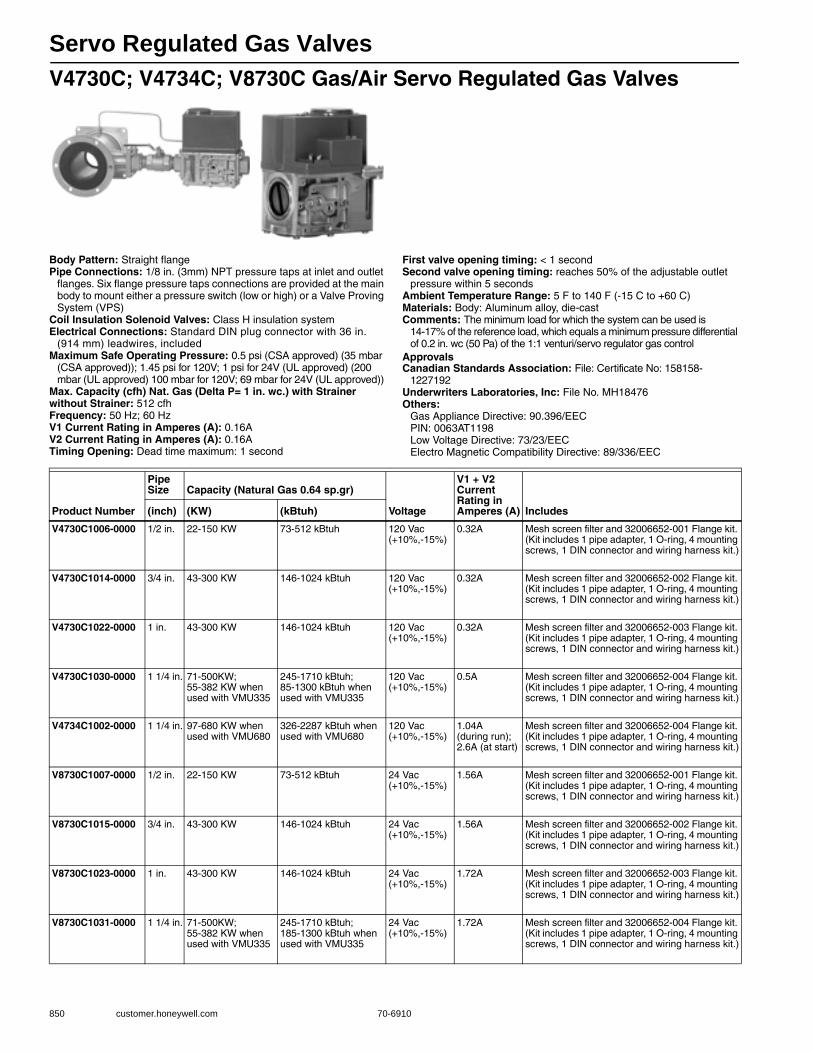
Servo Regulated Gas Valves
850 customer.honeywell.com 70-6910
V4730C; V4734C; V8730C Gas/Air Servo Regulated Gas Valves
Body Pattern: Straight flangePipe Connections: 1/8 in. (3mm) NPT pressure taps at inlet and outlet
flanges. Six flange pressure taps connections are provided at the main body to mount either a pressure switch (low or high) or a Valve Proving System (VPS)
Coil Insulation Solenoid Valves: Class H insulation systemElectrical Connections: Standard DIN plug connector with 36 in.
(914 mm) leadwires, includedMaximum Safe Operating Pressure: 0.5 psi (CSA approved) (35 mbar
(CSA approved)); 1.45 psi for 120V; 1 psi for 24V (UL approved) (200 mbar (UL approved) 100 mbar for 120V; 69 mbar for 24V (UL approved))
Max. Capacity (cfh) Nat. Gas (Delta P= 1 in. wc.) with Strainer without Strainer: 512 cfhFrequency: 50 Hz; 60 HzV1 Current Rating in Amperes (A): 0.16AV2 Current Rating in Amperes (A): 0.16ATiming Opening: Dead time maximum: 1 second
First valve opening timing: < 1 secondSecond valve opening timing: reaches 50% of the adjustable outlet
pressure within 5 secondsAmbient Temperature Range: 5 F to 140 F (-15 C to +60 C) Materials: Body: Aluminum alloy, die-castComments: The minimum load for which the system can be used is
14-17% of the reference load, which equals a minimum pressure differential of 0.2 in. wc (50 Pa) of the 1:1 venturi/servo regulator gas control
ApprovalsCanadian Standards Association: File: Certificate No: 158158-
1227192Underwriters Laboratories, Inc: File No. MH18476Others:
Gas Appliance Directive: 90.396/EECPIN: 0063AT1198Low Voltage Directive: 73/23/EECElectro Magnetic Compatibility Directive: 89/336/EEC
Product Number
Pipe Size Capacity (Natural Gas 0.64 sp.gr)
Voltage
V1 + V2 Current Rating in Amperes (A) Includes(inch) (KW) (kBtuh)
V4730C1006-0000 1/2 in. 22-150 KW 73-512 kBtuh 120 Vac (+10%,-15%)
0.32A Mesh screen filter and 32006652-001 Flange kit. (Kit includes 1 pipe adapter, 1 O-ring, 4 mounting screws, 1 DIN connector and wiring harness kit.)
V4730C1014-0000 3/4 in. 43-300 KW 146-1024 kBtuh 120 Vac (+10%,-15%)
0.32A Mesh screen filter and 32006652-002 Flange kit. (Kit includes 1 pipe adapter, 1 O-ring, 4 mounting screws, 1 DIN connector and wiring harness kit.)
V4730C1022-0000 1 in. 43-300 KW 146-1024 kBtuh 120 Vac (+10%,-15%)
0.32A Mesh screen filter and 32006652-003 Flange kit. (Kit includes 1 pipe adapter, 1 O-ring, 4 mounting screws, 1 DIN connector and wiring harness kit.)
V4730C1030-0000 1 1/4 in. 71-500KW; 55-382 KW when used with VMU335
245-1710 kBtuh; 85-1300 kBtuh when used with VMU335
120 Vac (+10%,-15%)
0.5A Mesh screen filter and 32006652-004 Flange kit. (Kit includes 1 pipe adapter, 1 O-ring, 4 mounting screws, 1 DIN connector and wiring harness kit.)
V4734C1002-0000 1 1/4 in. 97-680 KW when used with VMU680
326-2287 kBtuh when used with VMU680
120 Vac (+10%,-15%)
1.04A (during run); 2.6A (at start)
Mesh screen filter and 32006652-004 Flange kit. (Kit includes 1 pipe adapter, 1 O-ring, 4 mounting screws, 1 DIN connector and wiring harness kit.)
V8730C1007-0000 1/2 in. 22-150 KW 73-512 kBtuh 24 Vac (+10%,-15%)
1.56A Mesh screen filter and 32006652-001 Flange kit. (Kit includes 1 pipe adapter, 1 O-ring, 4 mounting screws, 1 DIN connector and wiring harness kit.)
V8730C1015-0000 3/4 in. 43-300 KW 146-1024 kBtuh 24 Vac (+10%,-15%)
1.56A Mesh screen filter and 32006652-002 Flange kit. (Kit includes 1 pipe adapter, 1 O-ring, 4 mounting screws, 1 DIN connector and wiring harness kit.)
V8730C1023-0000 1 in. 43-300 KW 146-1024 kBtuh 24 Vac (+10%,-15%)
1.72A Mesh screen filter and 32006652-003 Flange kit. (Kit includes 1 pipe adapter, 1 O-ring, 4 mounting screws, 1 DIN connector and wiring harness kit.)
V8730C1031-0000 1 1/4 in. 71-500KW; 55-382 KW when used with VMU335
245-1710 kBtuh; 185-1300 kBtuh when used with VMU335
24 Vac (+10%,-15%)
1.72A Mesh screen filter and 32006652-004 Flange kit. (Kit includes 1 pipe adapter, 1 O-ring, 4 mounting screws, 1 DIN connector and wiring harness kit.)
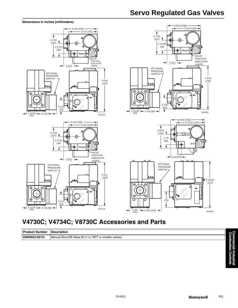
Servo Regulated Gas Valves
70-6910 851
Com
mercial / Industrial
Com
bustion Controls
Dimensions in inches (millimeters)
V4730C; V4734C; V8730C Accessories and Parts
M22414
6-1/8 (156)
1-27/32
(48)
4-7/32
(107)
5-1/4 (133)
7-5/16
(240)
2 (51)
2-1/32
(52)
3-7/8 (98)1-11/16(43)
PRESSURE
SWITCH
OPTIONAL
VALVE
POSITION
INDICATOR
LAMPS
M22415
6-1/8 (156)
1-27/32
(48)
4-7/32
(107)
5-1/4 (133)
6-1/2
(166)
2 (51)
2-1/32
(52)
3-7/8 (98)1-11/16(43)
OPTIONAL
PRESSURE
SWITCH
VALVE
POSITION
INDICATOR
LAMPS
M16865
6-9/16 (166)
1-27/32
(48)
4-7/32
(107)
5-1/4 (133)
7-5/16
(190)
2 (51)
2-1/32
(52)
3-7/8 (98)1-11/16(43)
OPTIONAL
PRESSURE
SWITCH
VALVE
POSITION
INDICATOR
LAMPS
M16864
6-9/16 (166)
1-7/8
(48)
4-5/16
(109)
5-11/32 (136)
8-15/32
(215)
2-1/4 (57)
3(76)
4-1/32 (102)1-3/4(44)
OPTIONAL
PRESSURE
SWITCH
Product Number Description
50002653-001/U Manual Shut-Off Valve Kit (1 in. NPT or smaller valves)
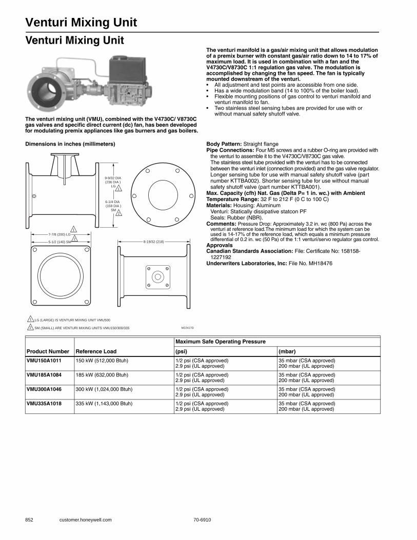
Venturi Mixing Unit
852 customer.honeywell.com 70-6910
Venturi Mixing Unit
The venturi mixing unit (VMU), combined with the V4730C/ V8730C gas valves and specific direct current (dc) fan, has been developed for modulating premix appliances like gas burners and gas boilers.
The venturi manifold is a gas/air mixing unit that allows modulation of a premix burner with constant gas/air ratio down to 14 to 17% of maximum load. It is used in combination with a fan and the V4730C/V8730C 1:1 regulation gas valve. The modulation is accomplished by changing the fan speed. The fan is typically mounted downstream of the venturi.• All adjustment and test points are accessible from one side.• Has a wide modulation band (14 to 100% of the boiler load).• Flexible mounting positions of gas control to venturi manifold and
venturi manifold to fan.• Two stainless steel sensing tubes are provided for use with or
without manual safety shutoff valve.
Dimensions in inches (millimeters) Body Pattern: Straight flangePipe Connections: Four M5 screws and a rubber O-ring are provided with
the venturi to assemble it to the V4730C/V8730C gas valve.The stainless steel tube provided with the venturi has to be connected between the venturi inlet (connection provided) and the gas valve regulator.Longer sensing tube for use with manual safety shutoff valve (part number KTTBA002). Shorter sensing tube for use without manual safety shutoff valve (part number KTTBA001).
Max. Capacity (cfh) Nat. Gas (Delta P= 1 in. wc.) with Ambient Temperature Range: 32 F to 212 F (0 C to 100 C) Materials: Housing: Aluminum
Venturi: Statically dissipative statcon PFSeals: Rubber (NBR).
Comments: Pressure Drop: Approximately 3.2 in. wc (800 Pa) across the venturi at reference load.The minimum load for which the system can be used is 14-17% of the reference load, which equals a minimum pressure differential of 0.2 in. wc (50 Pa) of the 1:1 venturi/servo regulator gas control.
ApprovalsCanadian Standards Association: File: Certificate No: 158158-
1227192Underwriters Laboratories, Inc: File No. MH18476
M22417D
8-19/32 (218)
7-7/8 (200) LG
5-1/2 (140) SM
9-9/32 DIA
(236 DIA )
LG
6-1/4 DIA
(159 DIA )
SM
1
2
1
2
1 LG (LARGE) IS VENTURI MIXING UNIT VMU500
2 SM (SMALL) ARE VENTURI MIXING UNITS VMU150/300/335
Product Number Reference Load
Maximum Safe Operating Pressure
(psi) (mbar)
VMU150A1011 150 kW (512,000 Btuh) 1/2 psi (CSA approved)2.9 psi (UL approved)
35 mbar (CSA approved)200 mbar (UL approved)
VMU185A1084 185 kW (632,000 Btuh) 1/2 psi (CSA approved)2.9 psi (UL approved)
35 mbar (CSA approved)200 mbar (UL approved)
VMU300A1046 300 kW (1,024,000 Btuh) 1/2 psi (CSA approved)2.9 psi (UL approved)
35 mbar (CSA approved)200 mbar (UL approved)
VMU335A1018 335 kW (1,143,000 Btuh) 1/2 psi (CSA approved)2.9 psi (UL approved)
35 mbar (CSA approved)200 mbar (UL approved)
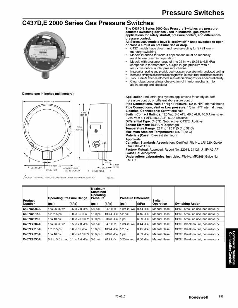
Pressure Switches
70-6910 853
Com
mercial / Industrial
Com
bustion Controls
C437D,E 2000 Series Gas Pressure SwitchesThe C437D,E Series 2000 Gas Pressure Switches are pressure-actuated switching devices used in industrial gas system applications for safety shutoff, pressure control, and differential-pressure control.All Series 2000 models have MicroSwitch™ snap switches to open or close a circuit on pressure rise or drop.• C437 models have direct- and reverse-acting for SPST (non-
mercury) switching • Models intended for lockout applications must be manually
reset before resuming operation• Models with pressure range of 1 to 26 in. wc (0.25 to 6.5 kPa)
compensate for momentary surges in gas pressure with a restrictive orifice in inlet pressure channel
• Impede tampering and provide dust-resistant operation with enclosed setting • Increase strength of control diaphragm with Buna N fber-reinforced material • Two Buna-N fiber-reinforced seal-off diaphragms for added reliability • Clear glass cover allows observation of interior mechanism to
aid in setting and checkout
Dimensions in inches (millimeters)Application: Industrial gas system applications for safety shutoff,
pressure control, or differential-pressure controlPipe Connections, Main or High Pressure: 1/2 in. NPT internal threadPipe Connections, Vent or Low pressure: 1/8 in. NPT internal threadElectrical Connections: Screw terminalsSwitch Contact Ratings: 120 Vac: 8.0 AFL, 48.0 ALR, 10.0 A resistive;
240 Vac: 5.1 AFL, 30.6 ALR, 5.0 A resistiveDifferential Type: C437D: Subtractive; C437E: AdditiveSensor Element: BUNA N DiaphragmTemperature Range: 32 F to 125 F (0 C to 52 C) Maximum Ambient Temperature: 125 F (52 C) Materials (Case): Die-cast aluminumApprovalsCanadian Standards Association: Certified: File No. LR1620, Guide
No. 380-W-1.16Factory Mutual: Approved: Report No. 22018, 24127, J.I.IF4A3.AFSwiss Re: AcceptableUnderwriters Laboratories, Inc: Listed: File No. MP2168, Guide No.
MFHX1-5/16(33.3)
1(25.4)
6-1/2(165.1)
7-3/4(196.9)
2 (50.8)
4545
7-3/8 (187.3)1/8–27 NPT
1/2–14 NPTTAPPED FOR 1/2 IN. CONDUIT
1 VENT TAPPING. REMOVE DUST-SEAL LABEL BEFORE MOUNTING. M34705
6-1/4 (159)
3-7/16 (87.3)
1
Product Number
Operating Pressure Range
Maximum Sustained Operating Pressure Pressure Differential
Switch Operation Switching Action(psi) (kPa) (psi) (kPa) (psi) (kPa)
C437D2003/U 1 to 26 in. wc 0.5 to 7.0 kPa 5.0 psi 34.5 kPa 1 3/4 in. wc 0.44 kPa Manual Reset SPST, break on rise, non-mercury
C437D2011/U 1/2 to 5 psi 3.0 to 35 kPa 15.0 psi 103.4 kPa 1/2 psi 3.45 kPa Manual Reset SPST, break on rise, non-mercury
C437D2029/U 1 to 10 psi 5.0 to 70.0 kPa 30.0 psi 206.8 kPa 1 psi 6.89 kPa Manual Reset SPST, break on rise, non-mercury
C437E2002/U 1 to 26 in. wc 0.5 to 7.0 kPa 5.0 psi 34.5 kPa 1 3/4 in. wc 0.44 kPa Manual Reset SPST, Break on Fall, non mercury
C437E2010/U 1/2 to 5 psi 3.0 to 35 kPa 15.0 psi 103.4 kPa 1/2 psi 3.45 kPa Manual Reset SPST, Break on Fall, non mercury
C437E2028/U 1 to 10 psi 5.0 to 70.0 kPa 30.0 psi 206.8 kPa 1 psi 6.89 kPa Manual Reset SPST, Break on Fall, non mercury
C437E2036/U 0.5 to 5.5 in. wc 0.1 to 1.4 kPa 3.0 psi 20.7 kPa 0.25 in. wc 0.06 kPa Manual Reset SPST, Break on Fall, non mercury
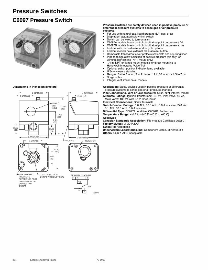
Pressure Switches
854 customer.honeywell.com 70-6910
C6097 Pressure SwitchPressure Switches are safety devices used in positive-pressure or differential-pressure systems to sense gas or air pressure systems.• For use with natural gas, liquid propane (LP) gas, or air • Diaphragm-actuated safety-limit switch • Switch can be wired to turn on alarm • C6097A models break control circuit at setpoint on pressure fall • C6097B models break control circuit at setpoint on pressure rise • Lockout with manual reset and recycle options • Lockout models have external manual reset button • Removable transparent cover protects scaleplate and adjusting knob • Pipe tappings allow selection of positive pressure (air only) or
venting connections (NPT mount only)• 1/4 in. NPT or flange mount models for direct mounting to
Honeywell Integrated Valve Train • Optional switch position indicator lamp available • IP54 enclosure standard • Ranges: 0.4 to 5 in.wc, 3 to 21 in.wc, 12 to 60 in.wc or 1.5 to 7 psi • Surge orifice• Integral vent limiter on all models
Dimensions in inches (millimeters) Application: Safety devices used in positive-pressure or differential-pressure systems to sense gas or air pressure changes
Pipe Connections, Vent or Low pressure: 1/8 in. NPT internal threadAlternate Ratings: Ignition Transformer: 540 VA, Pilot Valve: 50 VA.
Main Valve: 400 VA with 2-1/2 times inrushElectrical Connections: Screw terminalsSwitch Contact Ratings: 3.0 AFL, 18.0 ALR, 5.0 A resistive; 240 Vac:
5.1 AFL, 30.6 ALR, 5.0 A resistiveDifferential Type: C6097A: Additive; C6097B: SubtractiveTemperature Range: -40 F to +140 F (-40 C to +60 C) ApprovalsCanadian Standards Association: File # 95329 Certificate 2632-01Factory Mutual: JI 2D4A1.AFSwiss Re: AcceptableUnderwriters Laboratories, Inc: Component Listed, MP 2168-8-1Others: CSD-1 AFB: Acceptable
27/32 (22) HOLE
HOUSING
GAS CONNECTION 1/4 NPT WITH DUST SEAL
2-1/4(57)
3-3/16(81)
1-17/32(90)
2-21/32 (68)2-21/32 (68)
31/32(25)
25/32
(21)
15/32 (12)1-3/32 (28)
13/32 (11)
2-23/32 (69)2-23/32 (69)
1-3/4 (45)
2-13/32(61)
ATMOSPHERIC PRESSURE REFERENCE PORT OR DIFFERENTIALCONNECTION 1/8 NPT
INDICATOR
M29773
1 2 3
P
NO
NC
COM
TERMINAL DIAGRAM

Pressure Switches
70-6910 855
Com
mercial / Industrial
Com
bustion Controls
Product Number
Operating Pressure Range Pressure Differential
Nominal Pressure Differential
Maximum Pressure Differential
Switch Operation
Switching Action Mounting(psi) (kPa) (psi) (kPa) (psi) (kPa) (psi) (kPa)
C6097A1004/U 0.4 to 5 in. wc
0.10 to 1.25 kPa
— — 0.04 kPa 0.16 in. wc 0.24 in. wc 0.06 kPa Auto recycle Break on pressure fall
1/4 in. NPT internal thread
C6097A1012/U 3 to 21 in. wc
0.7 to 5.2 kPa
max. 2.4 in. wc @ min. setpoint; max. 4.2 in. wc @ max. setpoint
max. 0.60 kPa @ min. setpoint; max. 1.05 kPa @ max. setpoint
— — — — Manual Reset
Break on pressure fall
1/4 in. NPT internal thread
C6097A1020/U 3 to 21 in. wc
0.7 to 5.2 kPa
— — — — Manual Reset
Break on pressure fall
Flange Mount
C6097A1038/U 12 to 60 in. wc
3.0 to 15 kPa
max. 10 in. wc @ min. setpoint; max. 12 in. wc @ max. setpoint
max. 2.5 kPa @ min. setpoint; max. 3.0 kPa @ max. setpoint
— — — — Manual Reset
Break on pressure fall
1/4 in. NPT internal thread
C6097A1046/U 12 to 60 in. wc
3.0 to 15 kPa
— — — — Manual Reset
Break on pressure fall
Flange Mount
C6097A1053/U 3 to 21 in. wc
0.7 to 5.2 kPa
— — 0.06 kPa 0.24 in. wc 0.48 in. wc 0.12 kPa Auto recycle Break on pressure fall
1/4 in. NPT internal thread
C6097A1061/U 3 to 21 in. wc
0.7 to 5.2 kPa
— — 0.06 kPa 0.24 in. wc 0.48 in. wc 0.12 kPa Auto recycle Break on pressure fall
Flange Mount
C6097A1079/U 12 to 60 in. wc
3.0 to 15 kPa
— — 0.27 kPa 1.1 in. wc 2.4 in. wc 0.60 kPa Auto recycle Break on pressure fall
1/4 in. NPT internal thread
C6097A1087/U 12 to 60 in. wc
3.0 to 15 kPa
— — 0.27 kPa 1.1 in. wc 2.4 in. wc 0.60 kPa Auto recycle Break on pressure fall
Flange Mount
C6097A1095/U 0.4 to 5 in. wc
0.10 to 1.25 kPa
max. 0.6 in. wc @ min. setpoint; max. 0.25 in. wc @ max. setpoint
max. 0.15 kPa @ min. setpoint; max. 0.25 kPa @ max. setpoint
— — — — Manual Reset
Break on pressure fall
1/4 in. NPT internal thread
C6097A1103/U 1.5 to 7 psi
10 3 to 48 kPa
max. 1.1 psi @ min. setpoint; max. 1.4 psi @ max. setpoint
max. 7.6 kPa @ min. setpoint; max. 9.6 kPa @ max. setpoint
— — — — Manual Reset
Break on pressure fall
Flange Mount
C6097A1111/U 1.5 to 7 psi
10 3 to 48 kPa
— — — — Manual Reset
Break on pressure fall
1/4 in. NPT internal thread
C6097A1129/U 1.5 to 7 psi
10 3 to 48 kPa
— — 0.69 kPa 0.1 psi 0.3 psi 2.07 kPa Auto recycle Break on pressure fall
Flange Mount
C6097A1137/U 1.5 to 7 psi
10 3 to 48 kPa
— — 0.69 kPa 0.1 psi 0.3 psi 2.07 kPa Auto recycle Break on pressure fall
1/4 in. NPT internal thread
C6097A1210/U 0.4 to 5 in. wc
0.10 to 1.25 kPa
— — 0.04 kPa 0.16 in. wc 0.24 in. wc 0.06 kPa Auto recycle Break on pressure fall
Flange Mount
C6097A1228/U 0.4 to 5 in. wc
0.10 to 1.25 kPa
max. 0.6 in. wc @ min. setpoint; max. 0.25 in. wc @ max. setpoint
max. 0.15 kPa @ min. setpoint; max. 0.25 kPa @ max. setpoint
— — — — Manual Reset
Break on pressure fall
Flange Mount
C6097B1002/U 12 to 60 in. wc
3.0 to 15 kPa
max. 10 in. wc @ min. setpoint; max. 12 in. wc @ max. setpoint
max. 2.5 kPa @ min. setpoint; max. 3.0 kPa @ max. setpoint
— — — — Manual Reset
Break on pressure rise
1/4 in. NPT internal thread
C6097B1010/U 12 to 60 in. wc
3.0 to 15 kPa
— — — — Manual Reset
Break on pressure rise
Flange Mount
C6097B1028/U 3 to 21 in. wc
0.7 to 5.2 kPa
max. 2.4 in. wc @ min. setpoint; max. 4.2 in. wc @ max. setpoint
max. 0.60 kPa @ min. setpoint; max. 1.05 kPa @ max. setpoint
— — — — Manual Reset
Break on pressure rise
1/4 in. NPT internal thread
C6097B1036/U 3 to 21 in. wc
0.7 to 5.2 kPa
— — — — Manual Reset
Break on pressure rise
Flange Mount
C6097B1044/U 1.5 to 7 psi
10 3 to 48 kPa
max. 1.1 psi @ min. setpoint; max. 1.4 psi @ max. setpoint
max. 7.6 kPa @ min. setpoint; max. 9.6 kPa @ max. setpoint
— — — — Manual Reset
Break on pressure rise
Flange Mount
C6097B1051/U 1.5 to 7 psi
10 3 to 48 kPa
— — — — Manual Reset
Break on pressure rise
1/4 in. NPT internal thread
C6097B1069/U 3 to 21 in. wc
0.7 to 5.2 kPa
— — 0.06 kPa 0.24 in. wc 0.48 in. wc 0.12 kPa Auto recycle Break on pressure rise
Flange Mount
C6097B1077/U 12 to 60 in. wc
3.0 to 15 kPa
— — 0.27 kPa 1.1 in. wc 2.4 in. wc 0.60 kPa Auto recycle Break on pressure rise
Flange Mount
C6097B1085/U 12 to 60 in. wc
3.0 to 15 kPa
— — 0.27 kPa 1.1 in. wc 2.4 in. wc 0.60 kPa Auto recycle Break on pressure rise
1/4 in. NPT internal thread
C6097B1093/U 1.5 to 7 psi
10 3 to 48 kPa
— — 0.69 kPa 0.1 psi 0.3 psi 2.07 kPa Auto recycle Break on pressure rise
Flange Mount
C6097B1101/U 1.5 to 7 psi
10 3 to 48 kPa
— — 0.69 kPa 0.1 psi 0.3 psi 2.07 kPa Auto recycle Break on pressure rise
1/4 in. NPT internal thread
C6097B1119/U 3 to 21 in. wc
0.7 to 5.2 kPa
— — 0.06 kPa 0.24 in. wc 0.48 in. wc 0.12 kPa Auto recycle Break on pressure rise
1/4 in. NPT internal thread

Pressure and Limit Controllers
856 customer.honeywell.com 70-6910
L404F Pressuretrol® ControllersProvide operating control with automatic limit protection for pressure systems up to 300 psi (2068 kPa).• Use with steam, air, noncombustible gases, or fluids non-corrosive
to pressure sensing element • Models have snap-acting switching to open or close a circuit
on pressure rise • Have adjustable differentials • Adjustments are made by screws on top of case • Mount using 1/4 inch -18 NPT internal pipe threads or
surface mount through base of case• Ground screw terminal
Dimensions in inches (millimeters) for L404
Application: Provide control of steam, air, non-combustible gases or non-corrosive fluids
Pipe Connections, Main or High Pressure: 1/4 in. NPT internal threadElectrical Connections: Screw terminalsSwitch Contact Ratings: 120 Vac: 8.0 AFL, 48.0 ALR, 10.0 A resistive;
240 Vac: 5.1 AFL, 30.6 ALR, 5.0 A resistiveDifferential Type: SubtractiveSensor Element: Stainless Steel diaphragm
Differential Type: SubtractiveTemperature Range: -35 F to +150 F (-37 C to +66 C) ApprovalsCanadian Standards Association: Certified: File No. LR1620, Guide
No. 400-E-OSwiss Re: AcceptableUnderwriters Laboratories, Inc: Listed: File No. MP466, Guide No.
MBPR
3-3/4
(95)
1-1/16 (27)
13/16 (21)
1-3/16
(30)
HOLE FOR
1/2 INCH
CONDUIT
DIFFERENIAL
ADJUSTMENT
SCREW
1-1/2 (38)
2-1/8 (54)
M19635B
1-13/16
(46)
4-1/2 (115)
4-11/32 (111)
1-61/64 (50) 1-15/16 (49)
3/16 X 11/32
(5 X 9)
KNOCKOUT
MAIN SCALE
ADJUSTMENT
SCREW
1/4 –18 NPT
CLEAR
PLASTIC
COVER
3-7/8
(99)
2-3/4 (70)
3-1/4 (83)
DIMENSION
"A"
(SEE TAB)
1
1
1 15 TO 100 kPa (2 TO 15 PSI) SCALE MODELS ONLY.
PSI RANGE
2 TO 15
5 TO 50
10 TO 150
20 TO 300
DIMENSION "A"
123
126
126
146
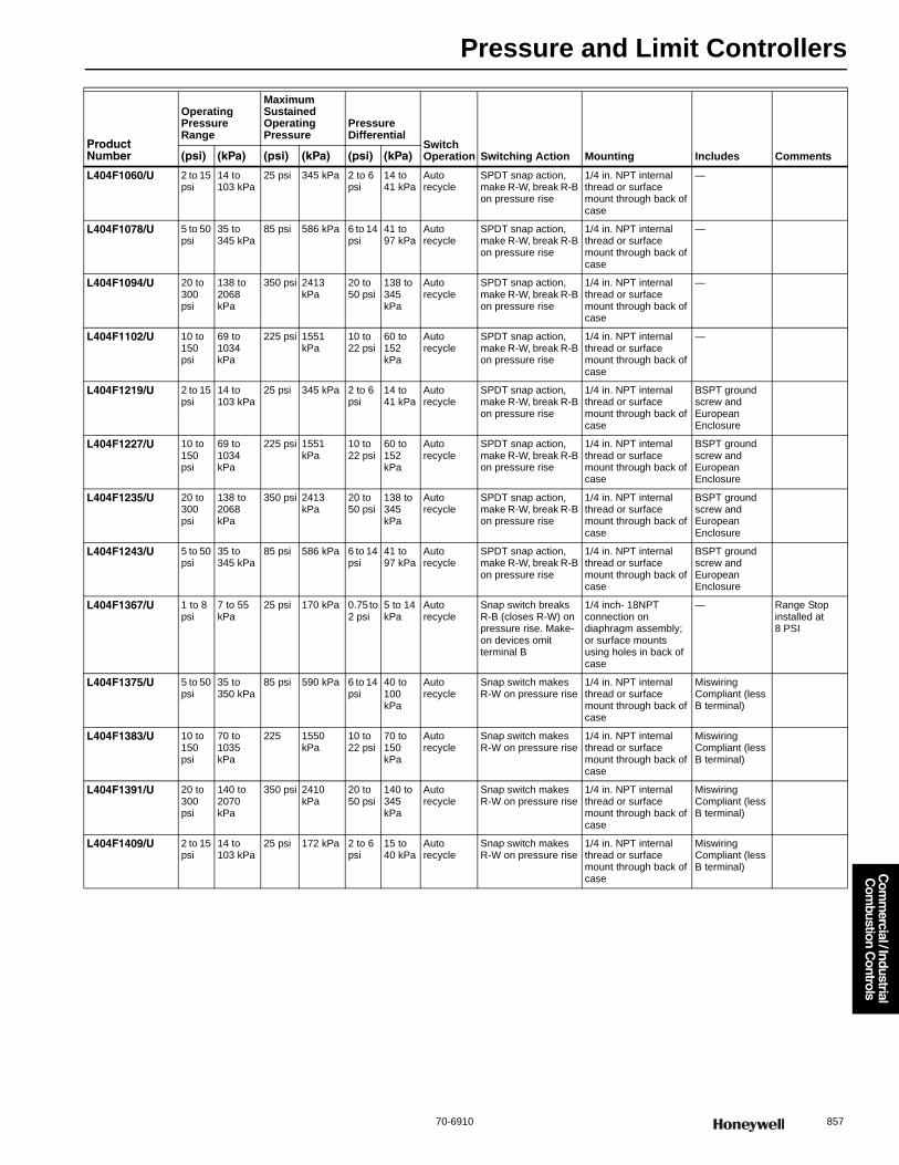
Pressure and Limit Controllers
70-6910 857
Com
mercial / Industrial
Com
bustion Controls
Product Number
Operating Pressure Range
Maximum Sustained Operating Pressure
Pressure Differential
Switch Operation Switching Action Mounting Includes Comments(psi) (kPa) (psi) (kPa) (psi) (kPa)
L404F1060/U 2 to 15 psi
14 to 103 kPa
25 psi 345 kPa 2 to 6 psi
14 to 41 kPa
Auto recycle
SPDT snap action, make R-W, break R-B on pressure rise
1/4 in. NPT internal thread or surface mount through back of case
—
L404F1078/U 5 to 50 psi
35 to 345 kPa
85 psi 586 kPa 6 to 14 psi
41 to 97 kPa
Auto recycle
SPDT snap action, make R-W, break R-B on pressure rise
1/4 in. NPT internal thread or surface mount through back of case
—
L404F1094/U 20 to 300 psi
138 to 2068 kPa
350 psi 2413 kPa
20 to 50 psi
138 to 345 kPa
Auto recycle
SPDT snap action, make R-W, break R-B on pressure rise
1/4 in. NPT internal thread or surface mount through back of case
—
L404F1102/U 10 to 150 psi
69 to 1034 kPa
225 psi 1551 kPa
10 to 22 psi
60 to 152 kPa
Auto recycle
SPDT snap action, make R-W, break R-B on pressure rise
1/4 in. NPT internal thread or surface mount through back of case
—
L404F1219/U 2 to 15 psi
14 to 103 kPa
25 psi 345 kPa 2 to 6 psi
14 to 41 kPa
Auto recycle
SPDT snap action, make R-W, break R-B on pressure rise
1/4 in. NPT internal thread or surface mount through back of case
BSPT ground screw and European Enclosure
L404F1227/U 10 to 150 psi
69 to 1034 kPa
225 psi 1551 kPa
10 to 22 psi
60 to 152 kPa
Auto recycle
SPDT snap action, make R-W, break R-B on pressure rise
1/4 in. NPT internal thread or surface mount through back of case
BSPT ground screw and European Enclosure
L404F1235/U 20 to 300 psi
138 to 2068 kPa
350 psi 2413 kPa
20 to 50 psi
138 to 345 kPa
Auto recycle
SPDT snap action, make R-W, break R-B on pressure rise
1/4 in. NPT internal thread or surface mount through back of case
BSPT ground screw and European Enclosure
L404F1243/U 5 to 50 psi
35 to 345 kPa
85 psi 586 kPa 6 to 14 psi
41 to 97 kPa
Auto recycle
SPDT snap action, make R-W, break R-B on pressure rise
1/4 in. NPT internal thread or surface mount through back of case
BSPT ground screw and European Enclosure
L404F1367/U 1 to 8 psi
7 to 55 kPa
25 psi 170 kPa 0.75 to 2 psi
5 to 14 kPa
Auto recycle
Snap switch breaks R-B (closes R-W) on pressure rise. Make-on devices omit terminal B
1/4 inch- 18NPT connection on diaphragm assembly; or surface mounts using holes in back of case
— Range Stop installed at8 PSI
L404F1375/U 5 to 50 psi
35 to 350 kPa
85 psi 590 kPa 6 to 14 psi
40 to 100 kPa
Auto recycle
Snap switch makes R-W on pressure rise
1/4 in. NPT internal thread or surface mount through back of case
Miswiring Compliant (less B terminal)
L404F1383/U 10 to 150 psi
70 to 1035 kPa
225 1550 kPa
10 to 22 psi
70 to 150 kPa
Auto recycle
Snap switch makes R-W on pressure rise
1/4 in. NPT internal thread or surface mount through back of case
Miswiring Compliant (less B terminal)
L404F1391/U 20 to 300 psi
140 to 2070 kPa
350 psi 2410 kPa
20 to 50 psi
140 to 345 kPa
Auto recycle
Snap switch makes R-W on pressure rise
1/4 in. NPT internal thread or surface mount through back of case
Miswiring Compliant (less B terminal)
L404F1409/U 2 to 15 psi
14 to 103 kPa
25 psi 172 kPa 2 to 6 psi
15 to 40 kPa
Auto recycle
Snap switch makes R-W on pressure rise
1/4 in. NPT internal thread or surface mount through back of case
Miswiring Compliant (less B terminal)
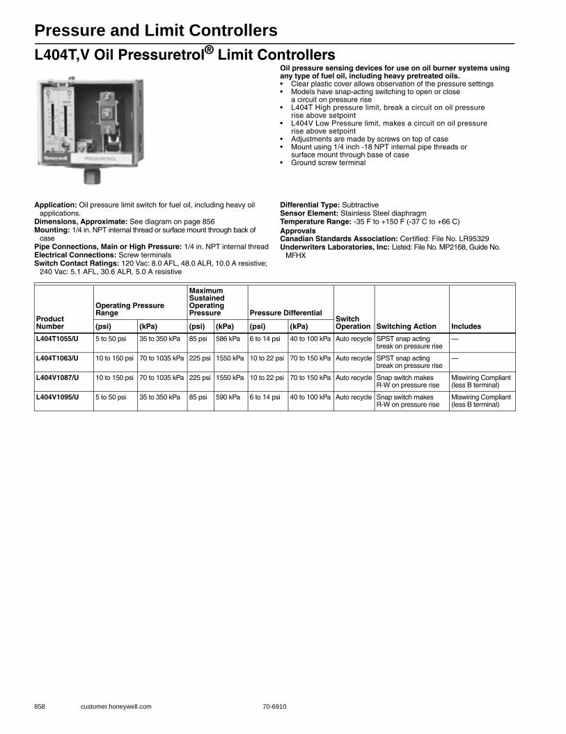
Pressure and Limit Controllers
858 customer.honeywell.com 70-6910
L404T,V Oil Pressuretrol® Limit ControllersOil pressure sensing devices for use on oil burner systems using any type of fuel oil, including heavy pretreated oils.• Clear plastic cover allows observation of the pressure settings • Models have snap-acting switching to open or close
a circuit on pressure rise • L404T High pressure limit, break a circuit on oil pressure
rise above setpoint• L404V Low Pressure limit, makes a circuit on oil pressure
rise above setpoint• Adjustments are made by screws on top of case • Mount using 1/4 inch -18 NPT internal pipe threads or
surface mount through base of case• Ground screw terminal
Application: Oil pressure limit switch for fuel oil, including heavy oil applications.
Dimensions, Approximate: See diagram on page 856Mounting: 1/4 in. NPT internal thread or surface mount through back of
casePipe Connections, Main or High Pressure: 1/4 in. NPT internal threadElectrical Connections: Screw terminalsSwitch Contact Ratings: 120 Vac: 8.0 AFL, 48.0 ALR, 10.0 A resistive;
240 Vac: 5.1 AFL, 30.6 ALR, 5.0 A resistive
Differential Type: SubtractiveSensor Element: Stainless Steel diaphragmTemperature Range: -35 F to +150 F (-37 C to +66 C) ApprovalsCanadian Standards Association: Certified: File No. LR95329Underwriters Laboratories, Inc: Listed: File No. MP2168, Guide No.
MFHX
Product Number
Operating Pressure Range
Maximum Sustained Operating Pressure Pressure Differential
Switch Operation Switching Action Includes(psi) (kPa) (psi) (kPa) (psi) (kPa)
L404T1055/U 5 to 50 psi 35 to 350 kPa 85 psi 586 kPa 6 to 14 psi 40 to 100 kPa Auto recycle SPST snap acting break on pressure rise
—
L404T1063/U 10 to 150 psi 70 to 1035 kPa 225 psi 1550 kPa 10 to 22 psi 70 to 150 kPa Auto recycle SPST snap acting break on pressure rise
—
L404V1087/U 10 to 150 psi 70 to 1035 kPa 225 psi 1550 kPa 10 to 22 psi 70 to 150 kPa Auto recycle Snap switch makes R-W on pressure rise
Miswiring Compliant (less B terminal)
L404V1095/U 5 to 50 psi 35 to 350 kPa 85 psi 590 kPa 6 to 14 psi 40 to 100 kPa Auto recycle Snap switch makes R-W on pressure rise
Miswiring Compliant (less B terminal)

Pressure and Limit Controllers
70-6910 859
Com
mercial / Industrial
Com
bustion Controls
L4079 Pressuretrol® Limit ControllersHigh pressure limit switches.• Stainless steel diaphragm for use with steam, air, noncombustible
gases and fluids non-corrosive to stainless steel • L4079W is for Oil Applications• MicroSwitch™ snap-acting switches open automatically on
pressure rise; must be manually reset• Mount using 1/4 in. NPT female fitting on diaphragm assembly
or surface mount through back of case
Dimensions in inches (millimeters) Application: Provide limit control of steam, air, non-combustible gases or non-corrosive fluids
Mounting: 1/4 in. NPT internal thread or surface mount through back of case
Pipe Connections, Main or High Pressure: 1/4 in. NPT internal threadElectrical Connections: Screw terminalsSwitch Contact Ratings: 120 Vac: 9.8 AFL, 58.8 ALR; 240 Vac:
4.9 AFL, 29.4 ALRSensor Element: Stainless Steel diaphragmMaximum Ambient Temperature: 150 F (66 C) ApprovalsSwiss Re: AcceptableUnderwriters Laboratories, Inc: Listed: File No. MP466, Guide No.
MBPR
3-7/8(98)
1/4(6)
(2-15 PSI ONLY)
KNOCKOUT
FOR 1/2 INCH
CONDUIT (2)
6(1/4)
4-15/16(125)
KNOCKOUT
(2) FOR NO.
10 SCREW
1/4 - 18 NPT
1-1/16 (27)
M22435
2-1/8(54)
1-13/16(46)
1-13/16
(46)
13/16(21)
13/16
(21)
3-1/2 (89)
1-1/2 (38)
3/16 (5)
1-13/16(46)
4-1/2 (114) (COVER)
4-3/8 (111) (CASE)
1-15/16 (49)
1-15/16 (49)
Product Number
Operating Pressure RangeMaximum Sustained Operating Pressure
Switch Operation Switching Action(psi) (kPa) (psi) (kPa)
L4079A1035/U 2 to 15 psi 14 to 103 kPa 25 psi 172 kPa Manual Reset SPST (two) break simultaneously on pressure rise
L4079A1050/U 10 to 150 psi 69 to 1034 kPa 225 psi 1551 kPa Manual Reset SPST (two) break simultaneously on pressure rise
L4079B1033/U 2 to 15 psi 14 to 103 kPa 25 psi 172 kPa Manual Reset SPST break on pressure rise
L4079B1041/U 10 to 150 psi 70 to 1035 kPa 225 psi 1550 kPa Manual Reset SPST break on pressure rise
L4079B1058/U 5 to 50 psi 35 to 350 kPa 85 psi 590 kPa Manual Reset SPST break on pressure rise
L4079B1066/U 20 to 300 psi 140 to 2070 kPa 350 psi 2410 kPa Manual Reset SPST break on pressure rise
L4079W1000/U 10 to 150 psi 35 to 350 kPa 225 psi 590 kPa Manual Reset SPST break on pressure rise - Oil Applications
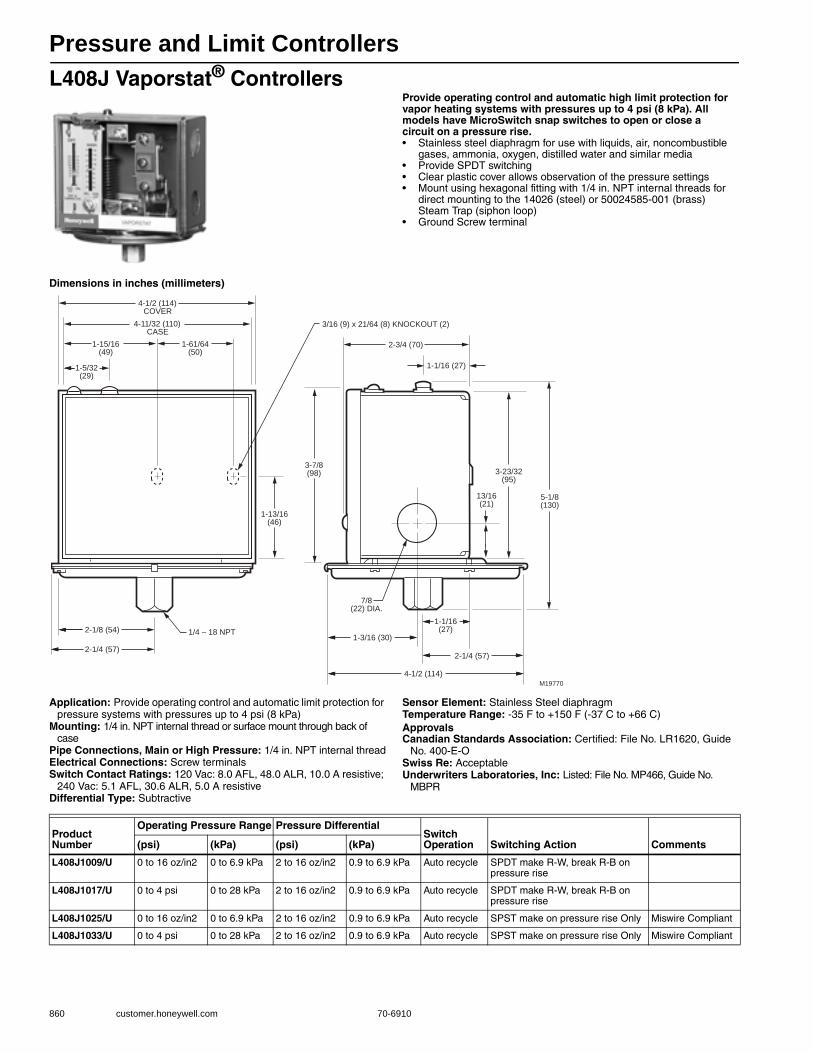
Pressure and Limit Controllers
860 customer.honeywell.com 70-6910
L408J Vaporstat® ControllersProvide operating control and automatic high limit protection for vapor heating systems with pressures up to 4 psi (8 kPa). All models have MicroSwitch snap switches to open or close a circuit on a pressure rise.• Stainless steel diaphragm for use with liquids, air, noncombustible
gases, ammonia, oxygen, distilled water and similar media • Provide SPDT switching • Clear plastic cover allows observation of the pressure settings • Mount using hexagonal fitting with 1/4 in. NPT internal threads for
direct mounting to the 14026 (steel) or 50024585-001 (brass) Steam Trap (siphon loop)
• Ground Screw terminal
Dimensions in inches (millimeters)
Application: Provide operating control and automatic limit protection for pressure systems with pressures up to 4 psi (8 kPa)
Mounting: 1/4 in. NPT internal thread or surface mount through back of case
Pipe Connections, Main or High Pressure: 1/4 in. NPT internal threadElectrical Connections: Screw terminalsSwitch Contact Ratings: 120 Vac: 8.0 AFL, 48.0 ALR, 10.0 A resistive;
240 Vac: 5.1 AFL, 30.6 ALR, 5.0 A resistiveDifferential Type: Subtractive
Sensor Element: Stainless Steel diaphragmTemperature Range: -35 F to +150 F (-37 C to +66 C) ApprovalsCanadian Standards Association: Certified: File No. LR1620, Guide
No. 400-E-OSwiss Re: AcceptableUnderwriters Laboratories, Inc: Listed: File No. MP466, Guide No.
MBPR
1-5/32(29)
2-1/8 (54) 1/4 – 18 NPT
2-1/4 (57)
1-13/16(46)
1-15/16(49)
1-61/64(50)
4-11/32 (110)CASE
4-1/2 (114)COVER
3-7/8(98)
2-3/4 (70)
1-1/16 (27)
13/16(21)
5-1/8(130)
3-23/32(95)
1-1/16(27)
7/8(22) DIA.
1-3/16 (30)
2-1/4 (57)
4-1/2 (114)M19770
3/16 (9) x 21/64 (8) KNOCKOUT (2)
Product Number
Operating Pressure Range Pressure DifferentialSwitch Operation Switching Action Comments(psi) (kPa) (psi) (kPa)
L408J1009/U 0 to 16 oz/in2 0 to 6.9 kPa 2 to 16 oz/in2 0.9 to 6.9 kPa Auto recycle SPDT make R-W, break R-B on pressure rise
L408J1017/U 0 to 4 psi 0 to 28 kPa 2 to 16 oz/in2 0.9 to 6.9 kPa Auto recycle SPDT make R-W, break R-B on pressure rise
L408J1025/U 0 to 16 oz/in2 0 to 6.9 kPa 2 to 16 oz/in2 0.9 to 6.9 kPa Auto recycle SPST make on pressure rise Only Miswire Compliant
L408J1033/U 0 to 4 psi 0 to 28 kPa 2 to 16 oz/in2 0.9 to 6.9 kPa Auto recycle SPST make on pressure rise Only Miswire Compliant

Pressure and Limit Controllers
70-6910 861
Com
mercial / Industrial
Com
bustion Controls
L91 Proportional Pressuretrol® ControllersModulating pressure operating control for regulation of liquid or air and other non-corrosive gases.• Use with steam, air, noncombustible gases, or other fluids non-
corrosive to the brass or phos-bronze (300 psi models) bellows • Do NOT use with combustible mediums or any medium chemically
harmful to phos-bronze bellows (10-300 psi models) or brass bellows (all other pressure range models)
Application: Modulating pressure control for regulation of liquid, air, or other non-corrosive gases.
Pipe Connections, Main or High Pressure: 1/4 in. NPT external thread
Electrical Connections: Screw terminalsSensor Element: Brass bellowsSwitch Operation: ModulatingTemperature Range: 32 F to 150 F (0 C to 66 C)
W R B W R B W R B
PRESSURE RISE PRESSURE RISE
L91A,B L91D M16597
Product Number
Operating Pressure Range
Maximum Sustained Operating Pressure Pressure Differential
Modulating Output Mounting(psi) (kPa) (psi) (kPa) (psi) (kPa)
L91A1037/U 0 to 15 psi 0 to 103 kPa 25 psi 172 kPa 0.5 psi 3.4 kPa Single potentiometer, 140 ohms
optional surface mount through back of case
L91A1052/U 5 to 150 psi 34 to 1034 kPa 225 psi 1551 kPa 5 psi 34 kPa Single potentiometer, 140 ohms
optional surface mount through back of case
L91A1078/U 10 to 300 psi 69 to 2068 kPa 325 psi 2241 kPa 12 psi 83 kPa Single potentiometer, 140 ohms
optional surface mount through back of case
L91A1136/U 10 to 300 psi 69 to 2068 kPa 325 psi 2241 kPa 12 psi 83 kPa Single potentiometer, 140 ohms
optional surface mount through back of case
L91B1035/U 0 to 15 psi 0 to 103 kPa 25 psi 172 kPa 1.5 to 12 psi 10 to 83 kPa Single potentiometer, 140 ohms
optional surface mount through back of case
L91B1050/U 5 to 150 psi 34 to 1034 kPa 225 psi 1551 kPa 5 to 23 psi 35 to 160 kPa Single potentiometer, 140 ohms
optional surface mount through back of case
L91B1068/U 10 to 300 psi 69 to 2068 kPa 325 psi 2241 kPa 28 to 110 psi 193 to 758 kPa Single potentiometer, 140 ohms
optional surface mount through back of case
L91B1100/U 5 to 150 psi 0 - 1 MPa 225 psi 1551 kPa 5 to 23 psi 35 to 160 kPa Single potentiometer, 135 ohms
1/4 in BSP-TR thread Mounting
L91B1118/U 10 to 300 psi 0 - 2 MPa 325 psi 2241 kPa 28 to 110 psi 193 to 758 kPa Single potentiometer, 140 ohms
1/4 in BSP-TR thread Mounting
L91B1241/U 10 to 300 psi 69 to 2068 kPa 325 psi 2241 kPa 12 to 48 psi 85 to 330 kPa Single potentiometer, 140 ohms
optional surface mount through back of case
L91D1015/U 0 to 15 psi 0 to 103 kPa 25 psi 172 kPa 1.5 to 12 psi 10 to 83 kPa Dual potentiometer, 140 ohms
optional surface mount through back of case
L91D1031/U 5 to 150 psi 34 to 1034 kPa 225 psi 1551 kPa 11 to 52 psi 76 to 359 kPa Dual potentiometer, 140 ohms
optional surface mount through back of case
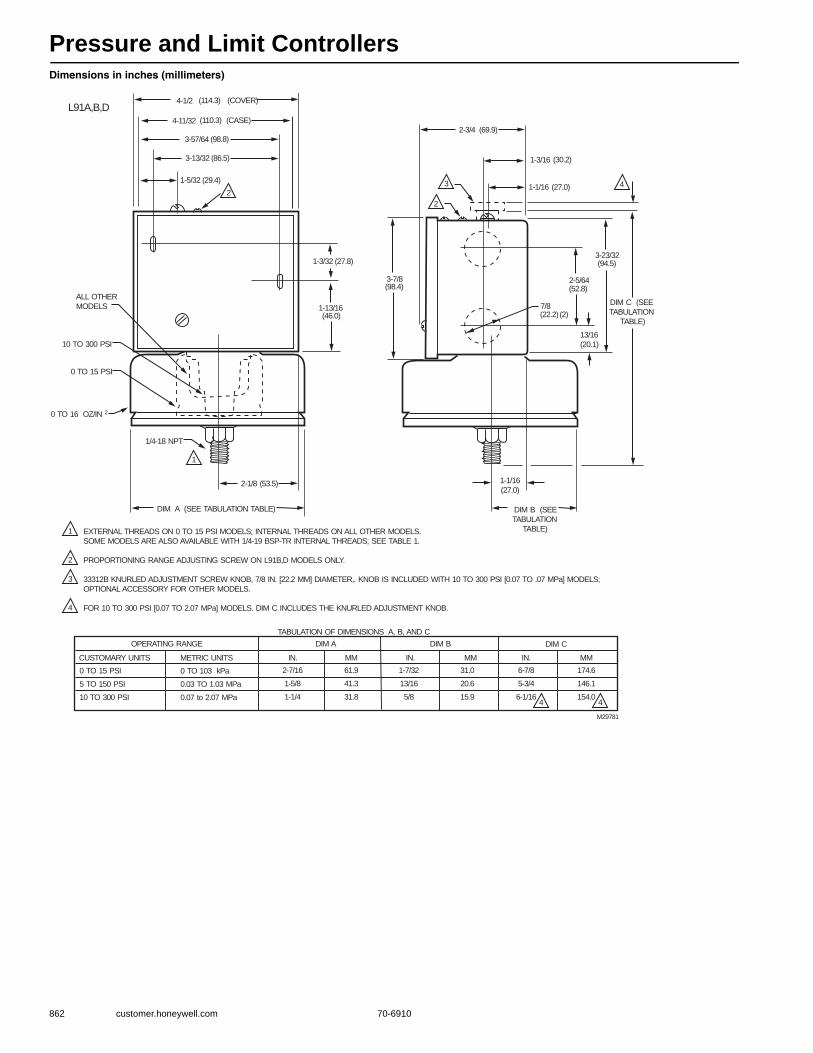
Pressure and Limit Controllers
862 customer.honeywell.com 70-6910
Dimensions in inches (millimeters)
M29781
L91A,B,D
ALL OTHER
MODELS
10 TO 300 PSI
0 TO 15 PSI
0 TO 16 OZ/IN 2
1/4-18 NPT
DIM A (SEE TABULATION TABLE) DIM B (SEE
TABULATION
TABLE)
DIM C (SEE
TABULATION
TABLE)
1
2
2
3 4
1
2
3
4
4-1/2 (114.3) (COVER)
(110.3) (CASE)
(98.8) 3-57/64
3-13/32 (86.5)
(29.4)
(27.8)
(46.0)
(53.5)
(69.9)
(30.2)
1-1/16
1-3/16
(27.0)
(98.4)
(22.2)
4-11/32
(52.8)
(94.5)
(2)
EXTERNAL THREADS ON 0 TO 15 PSI MODELS; INTERNAL THREADS ON ALL OTHER MODELS.
SOME MODELS ARE ALSO AVAILABLE WITH 1/4-19 BSP-TR INTERNAL THREADS; SEE TABLE 1.
PROPORTIONING RANGE ADJUSTING SCREW ON L91B,D MODELS ONLY.
33312B KNURLED ADJUSTMENT SCREW KNOB, 7/8 IN. [22.2 MM] DIAMETER,. KNOB IS INCLUDED WITH 10 TO 300 PSI [0.07 TO .07 MPa] MODELS;
OPTIONAL ACCESSORY FOR OTHER MODELS.
FOR 10 TO 300 PSI [0.07 TO 2.07 MPa] MODELS. DIM C INCLUDES THE KNURLED ADJUSTMENT KNOB.
TABULATION OF DIMENSIONS A, B, AND C
OPERATING RANGE DIM A DIM B DIM C
CUSTOMARY UNITS METRIC UNITS IN. MM IN. MM IN. MM
0 TO 15 PSI
5 TO 150 PSI
10 TO 300 PSI
0 TO 103 kPa
0.03 TO 1.03 MPa
0.07 to 2.07 MPa
2-7/16
1-5/8
1-1/4
61.9
41.3
31.8
1-7/32
13/16
5/8
31.0
20.6
15.9
6-7/8
5-3/4
6-1/16
174.6
146.1
154.0
1-5/32
1-3/32
1-13/16
2-1/8
3-7/8
2-3/4
7/8
2-5/64
3-23/32
13/16
(20.1)
1-1/16
(27.0)
44
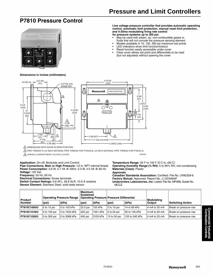
Pressure and Limit Controllers
70-6910 863
Com
mercial / Industrial
Com
bustion Controls
P7810 Pressure ControlLine voltage pressure controller that provides automatic operating control, automatic limit protection, manual reset limit protection, and 4-20ma modulating firing rate control for pressure systems up to 300 psi.• May be used with steam, air, non-combustible gases or
fluids that will not corrode the pressure sensing element • Models available in 15, 150, 300 psi maximum set points • LED indicators show limit function/lockout • Reset function easily accessible under cover • Clear cover allows set point and differentials to be read
(but not adjusted) without opening the cover
Dimensions in inches (millimeters)
Application: On-off, Modulate and Limit ControlPipe Connections, Main or High Pressure: 1/2 in. NPT internal threadPower Consumption: 3.6 W, 4.7 VA @ 50Hz; 3.3 W, 4.0 VA @ 60 HzVoltage: 120 VacFrequency: 50 Hz; 60 HzElectrical Connections: Screw terminalsSwitch Contact Ratings: 9.8 AFL, 58.8 ALR, 10.0 A resistiveSensor Element: Stainless Steel, solid state sensor
Temperature Range: 32 F to 140 F (0 C to +60 C) Operating Humidity Range (% RH): 5 to 95% RH, non-condensingMaterials (Case): PlasticApprovalsCanadian Standards Association: Certified: File No. LR95329-6Factory Mutual: Approved: Report No. J.I.2D3A6AFUnderwriters Laboratories, Inc: Listed: File No. MP268, Guide No.
MCCZ
RESET
PRESSURETROL¨
1/4 (6)2x1-5/8
(41)
1-5/8(41) 2-5/8 (67)
2x5-1/4 (133)3-7/32(82)
2-17/32(82)
3-3/8 (86)
5-1/4
(133)
2x
3-3/16
(81)
2-1/8(55)
4-23/32(120)
2x27/32 (22)DIAMETER
5-29/32 (150)
4-21/32 (119)
2-5/8(67)
4(102)
4-3/4(120)
3/8(10) 7/8
(22)
1
1
1
DIMENSIONS WITH DOOR IN OPEN POSITION.
M23225
2
2
PIPE THREAD IS 1/4 INCH NATIONAL PIPE THREAD FOR P7810A,B; 1/2 INCH NATIONAL PIPE THREAD FOR P7810C,D.
3
3?
3 WIRING COMPARTMENT ACCESS COVER.
Product Number
Operating Pressure Range
Maximum Sustained Operating Pressure Pressure Differential
Modulating Output Switching Action(psi) (kPa) (psi) (kPa) (psi) (kPa)
P7810C1000/U 0 to 15 psi 0 to 103 kPa 22.5 psi 155 kPa 2 to 10 psi 14 to 69 kPa 4 mA to 20 mA Break on pressure rise
P7810C1018/U 0 to 150 psi 0 to 1034 kPa 225 psi 1551 kPa 5 to 20 psi 35 to 135 kPa 4 mA to 20 mA Break on pressure rise
P7810C1026/U 0 to 300 psi 0 to 2068 kPa 450 psi 3103 kPa 15 to 50 psi 103 to 340 kPa 4 mA to 20 mA Break on pressure rise
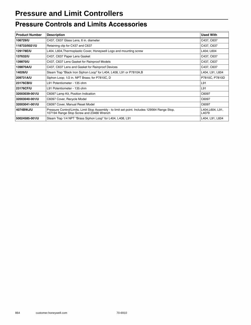
Pressure and Limit Controllers
864 customer.honeywell.com 70-6910
Pressure Controls and Limits AccessoriesProduct Number Description Used With
106729/U C437, C637 Glass Lens, 6 in. diameter C437, C637
118733/0021/U Retaining clip for C437 and C637 C437, C637
129178E/U L404, L604,Thermoplastic Cover, Honeywell Logo and mounting screw L404; L604
137632/U C437, C637 Paper Lens Gasket C437, C637
139870/U C437, C637 Lens Gasket for Rainproof Models C437, C637
139870A/U C437, C637 Lens and Gasket for Rainproof Devices C437, C637
14026/U Steam Trap “Black Iron Siphon Loop” for L404, L408, L91 or P7810A,B L404, L91, L604
209731A/U Siphon Loop; 1/2 in. NPT Brass; for P7810C, D P7810C, P7810D
23176CB/U L91 Potentiometer - 135 ohm L91
23176CF/U L91 Potentiometer - 135 ohm L91
32003039-001/U C6097 Lamp Kit, Position Indication C6097
32003040-001/U C6097 Cover, Recycle Model C6097
32003041-001/U C6097 Cover, Manual Reset Model C6097
4074BWJ/U Pressure Control/Limits, Limit Stop Assembly - to limit set point. Includes 129564 Range Stop, 107194 Range Stop Screw and 23466 Wrench
L404,L604, L91, L4079
50024585-001/U Steam Trap 1/4 NPT “Brass Siphon Loop” for L404, L408, L91 L404, L91, L604
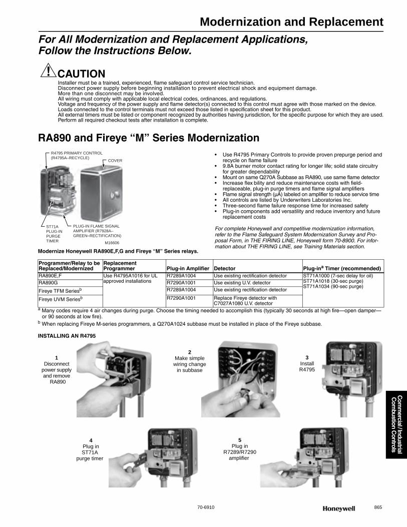
Modernization and Replacement
70-6910 865
Com
mercial / Industrial
Com
bustion Controls
For All Modernization and Replacement Applications, Follow the Instructions Below.
CAUTIONInstaller must be a trained, experienced, flame safeguard control service technician. Disconnect power supply before beginning installation to prevent electrical shock and equipment damage. More than one disconnect may be involved. All wiring must comply with applicable local electrical codes, ordinances, and regulations. Voltage and frequency of the power supply and flame detector(s) connected to this control must agree with those marked on the device.Loads connected to the control terminals must not exceed those listed in specification sheet for this product.All external timers must be listed or component recognized by authorities having jurisdiction, for the specific purpose for which they are used.Perform all required checkout tests after installation is complete.
RA890 and Fireye “M” Series Modernization
Modernize Honeywell RA890E,F,G and Fireye “M” Series relays.
• Use R4795 Primary Controls to provide proven prepurge period and recycle on flame failure
• 9.8A burner motor contact rating for longer life; solid state circuitry for greater dependability
• Mount on same Q270A Subbase as RA890, use same flame detector• Increase flex bility and reduce maintenance costs with field-
replaceable, plug-in purge timers and flame signal amplifiers• Flame signal strength (μA) labeled on amplifier to reduce service time• All controls are listed by Underwriters Laboratories Inc.• Three-second flame failure response time for increased safety• Plug-in components add versatility and reduce inventory and future
replacement costs
For complete Honeywell and competitive modernization information, refer to the Flame Safeguard System Modernization Survey and Pro-posal Form, in THE FIRING LINE, Honeywell form 70-8900. For infor-mation about THE FIRING LINE, see Training Materials section.
a Many codes require 4 air changes during purge. Choose the timing needed to accomplish this (typically 30 seconds at high fire—open damper—or 90 seconds at low fire).
b When replacing Fireye M-series programmers, a Q270A1024 subbase must be installed in place of the Fireye subbase.
INSTALLING AN R4795
R4795 PRIMARY CONTROL
(R4795A–RECYCLE)COVER
ST71A
PLUG-IN
PURGE
TIMER
PLUG-IN FLAME SIGNAL
AMPLIFIER (R7928A–
GREEN–RECTIFICATION)
M16606
Programmer/Relay to be Replaced/Modernized
Replacement Programmer Plug-in Amplifier Detector Plug-ina Timer (recommended)
RA890E,F Use R4795A1016 for UL approved installations
R7289A1004 Use existing rectification detector ST71A1000 (7-sec delay for oil) ST71A1018 (30-sec purge) ST71A1034 (90-sec purge)
RA890G R7290A1001 Use existing U.V. detector
Fireye TFM Seriesb R7289A1004 Use existing rectification detector
Fireye UVM Seriesb R7290A1001 Replace Fireye detector with C7027A1080 U.V. detector
1Disconnect
power supply and remove
RA890
2Make simple wiring change
in subbase
3Install R4795
4Plug in ST71A
purge timer
5Plug in
R7289/R7290 amplifier
Modernization and Replacement
866 customer.honeywell.com 70-6910
R7795 Primary Control
Provide flameout protection plus automatic control of commercial and industrial gas and oil burners.• Meet requirements for gas burners with 400,000 to 2-1/2 million Btuh
(117.2 to 732.8 kW) input. R7795C,D meet requirements to over12-1/2 million Btuh
• R7795A,B provide ignition cutoff and intermittent pilot• R7795C,D have interrupted pilot with delayed main valve• Includes terminals for connection of a line voltage airflow switch to
prove airflow from the start of prepurge through the run period• Mount on Q795A Subbase with two captive screws• Provides all electrical connections between the device and subbase• Access to wiring terminals for testing• Integral solid state color-coded flame amplifiers• Field-selectable ten or four second trial for pilot flame ignition• Field-selectable recycle or lockout on flame failure
Conversion Wiring Chart for R7795A-DYou can easily convert the following model primaries and programmers to the R7795A,B,C or D by following the step-by-step instructions listed below.
IMPORTANT: For on-off, gas-fired systems, some authorities having jurisdiction prohibit the wiring of any limit or operating contacts in
series with the main fuel valve(s).DIRECTIONS:1. Disconnect all power to programmer.2. Remove old programmer from subbase (trade-in to Honeywell
Authorized Flame Safeguard Distr butor).3. Mark all wires on subbase; i.e., wires connected to terminal “1”
should be marked “1.” Disconnect wires as they are marked.4. Remove old subbase.5. Mount Q795A Subbase.6. Connect wires to subbase per attached cross reference. Pay close
attention to footnotes. For example: to convert a Fireye UVM-2 to a R7795, the wire marked “A” would connect to terminal #9 on the Q795. The wire marked “8” would connect to Q795 terminal #8.
7. A superscript letter, such as “a” designates a footnote. Study these footnotes carefully.
8. Plug in the R7795. Make sure you select the proper ST795A Purge Timer and Detector for the application.
9. There are 2 wires on the amplifier section of the R7795, which are used to select the desired trial for ignition timing and mode (lock-out or recycle). Refer to the R7795 instruction sheet (form 66-2001) for assistance with proper selection.
10. If a low voltage controller is used on the RA890 or UVM-1, remove it and replace it with a line voltage controller. The line voltage control-ler should be connected in series with the limits.
11. If a low voltage airflow switch is used on the R7795, it must be replaced with a line voltage airflow switch, such as the Honeywell C645.
12.The following models are recommended for replacements:
CONVERSION CHART FOR R7795 120 VOLT ONLY
a Connect power to terminal L1.b If no airflow switch is used, jumper Q795 terminal 3 to 8.c Replace low voltage alarm (if used) with line voltage alarm. Connect alarm directly to Q795 terminal 9.d On power burners, identify burner motor wire on terminal 3 and connect it to Q795 terminal 8.e R7795 uses only rectification or U.V. detectors. All other detectors must be converted to these types.f On UVM models, the detector must be changed to a Honeywell C7027 or C7035.
Honeywell RA890, R4795 All 120 V models.Fireye M-Series
Honeywell Device to be Replaced
Replace With
Fireye Device to be Replaced
Replace With
RA890E,F R7795B TFM1,2,3H R7795B
RA890G R7795A UVM1,2,3,3H R7795A
R4795A,D/W-R7290 AMP UVM5 R7795C
R4795A,D/W-R7289 AMP R7795B
R4140P R7795C,D
R4140Y R7795A,B
Q795 TERMINAL L1 L2 3 5 6 7 8 9 16 18 F GProgrammer to be ConvertedRA890 (All) 1a 2 b 3d 5 — d,b c 6 4 F G
R4795 (All) a 2 6b 3 5 — 8, 7 c 1 4 F G
R4140P L1 L2 P 5 7 6 M A 3 — S1 S2R4140Y L1 L2 3 6 7 — 8 9 4 5 Fe G
Fireye: UVM/TFM (All models)/MII 1 1 6 3 5 — 8 A 7 4 S2f S1
UVM-1 (Prior to 1968) a 2 b 3 5 — d,b A 1 4 Sf S
UVM-2 (Prior to 1968), All others a 2 6 3 5 — 8 A 1 4 Sf S
Modernization and Replacement
70-6910 867
Com
mercial / Industrial
Com
bustion Controls
RM7895 On-Off Primary Control with Prepurge
Microprocessor-based integrated primary burner control for automatically fired gas, oil, or combination fuel single burner applications. Provides level of safety, functional capability and features beyond conventional controls.• Functions include automatic burner sequencing, flame supervision,
system status indication, system or self-diagnostics and troubleshooting• Subbase, amplifier, and prepurge timer are required for operation• Options include PC interface using ModBus™, keyboard display
module, Data ControlBus™ Module, remote display module and first-out expanded annunciator
• Five LEDs provide sequence information• Interchangeable plug-in flame amplifiers• Optional local or remote annunciation of operation and fault information• Nonvolatile memory retains history files and sequencing status
after power loss• Optional remote reset capability• Optional report generation using modbus™• Selectable relight or lockout on loss of flame• Airflow switch check
IMPORTANT: For on-off, gas-fired systems, some authorities having jurisdiction prohibit the wiring of any limit or operating contacts in series with the main fuel valve(s).
DIRECTIONS:1. Disconnect all power to programmer.2. Remove old programmer from subbase (trade-in to Honeywell
Authorized Flame Safeguard Distr butor).3. Mark all wires on subbase; i.e., wires connected to terminal “1”
should be marked “1.” Disconnect wires as they are marked.4. Remove old subbase.5. Mount Q7800A Subbase.6. Connect wires to subbase per attached cross reference. Pay close
attention to footnotes. For example: to convert a Fireye UVM-2 to a RM7895, the wire marked “A” would connect to terminal #9 on the Q7800. The wire marked “8” would connect to Q7800 terminal #8.
7. A superscript letter, such as “a” designates a footnote. Study these footnotes carefully.
8. Plug in the RM7895. Make sure you select the proper ST7800A Purge Timer and Detector for the application.
9. There are 2 wires on the amplifier section of the RM7895, which are used to select the desired trial for ignition timing and mode (lock-out or recycle). Refer to the RM7895 instruction sheet (form 66-1090) for assistance with proper selection.
10. If a low voltage controller is used on the RA890 or UVM-1, remove it and replace it with a line voltage controller. The line voltage control-ler should be connected in series with the limits.
11. If a low voltage airflow switch is used on the RM7895, it must be replaced with a line voltage airflow switch
12.The following models are recommended for replacements:
CONVERSION CHART FOR RM7895 120 VOLT ONLY
a Connect power to terminal L1.b If no airflow switch is used, jumper Q7800 terminal 6 to 7.c Replace low voltage alarm (if used) with line voltage alarm. Connect alarm directly to Q7800 terminal 3.d On power burners, identify burner motor wire on terminal 3 and connect it to Q7800 terminal 4.e Select amplifier to match detector being used.f On UVM models, the detector must be changed to a Honeywell C7027 or C7035.
Honeywell RA890, R4795, R7795 All 120 V models.Fireye M-Series
Honeywell Device to be Replaced Replace With AmplifierRA890E,F RM7895A R7847A
RA890G RM7895A R7849A
R4795A,D/W-R7290 AMP RM7895A
R4795A,D/W-R7289 AMP RM7895B R7847A
R7795A RM7895A R7849
R7795B RM7895A R7847
R7795C RM7895C R7849
R7796D RM7895C R7847
R4140P RM7895C R7847A or R7849A
R4140Y RM7895A
Fireye Device to be Replaced Replace With AmplifierTFM1,2,3H RM7895A R7847A
UVM1,2,3,3H R7849A
UVM5 RM7895C R7849A
Q7800 TERMINAL L1 L2 3 4 6 7 8 9 10 21 F GProgrammer to be ConvertedRA890 (All) 1a 2 c b,d 6 b 3d 5 4 — F G
R4795 (All) a 2 c 8, 7 1 6b 3 5 4 — F G
R7795A,B L1 L2 9 8 16 3 5 6 18 — F GR7795C,D L1 L2 9 8 16 3 5 6 18 7 F GR4140P L1 L2 A M 3 P 5 7 — 6 S1 S2R4140Y L1 L2 9 8 4 3 6 7 5 — Fe G
Fireye: UVM/TFM (All models)/MII 1 1 A 8 7 6 3 5 4 — S2f S1
UVM-1 (Prior to 1968) a 2 A b,d 1 b 3 5 4 — Sf S
UVM-2 (Prior to 1968), All others a 2 A 8 1 6 3 5 4 — Sf S

Electromechanical Burner Controls
868 customer.honeywell.com 70-6910
R4795 Primary Control with PurgeProvide solid state, electronic flame safeguard protection for commercial and industrial single or dual fuel burners.• Use with rectification or ultraviolet type flame detectors depending
on the interchangeable, plug-in amplifier being used • Recycle after flame failure in attempt to re-establish pilot before lockout • Include manual push-to-reset safety switch in a dust-resistant enclosure • Includes SPDT alarm contacts
Application: Primary ControlDimensions, Approximate: 5 in. high x 5 in. wide x 4 3/4 in. deep
(including subbase) (127 mm high x 127 mm wide x 121 mm deep) Electrical Connections: Alarm contacts: male quick connect terminalsFrequency: 50 Hz; 60 HzTemperature Range: -20 F to +105 F @50 Hz; -20 F to +115 F @ 60 Hz
(-29 C to +40 C @ 50 Hz); (-29 C to +46 C @ 60 Hz)Purging Time: Determined by Plug-in Purge Timer
ApprovalsCanadian Standards Association: CSA Certified: 120V models only,
includes -40 F models-File No. LR1620Factory Mutual: Approved: Report No. 18774SwissRe: AcceptableUnderwriters Laboratories, Inc: UL Listed:120V with 30, 60, 90 sec
prepurge timers, includes -40 F models-File No.MP268, Guide No. MCCZ; UL Comp. Recg.:120V with 7, 10 sec prepurge timers, includes -40 F models-File No.MP268, Guide No.MCCZ2
Required Components: Mounting Base: Q270A1024; Plug-in Amplifier: R7289A1004, R7289A1012, R7290A1001, R7290A1019; Plug-in Purge Timer: ST71A1000 (7 sec), ST71A1018 (30 sec), ST71A1034 (90 sec)
Product Number VoltageAlarm Relay Switching
Safety Switch Timing Description Includes
R4795A1016/U 120 Vac SPDT 15 sec nominal 120V 50/60 HZ less Amplifier and Prepurge Timer Female quick-connects
R4795A1040/U 220 Vac SPDT 15 sec nominal 220V 50/60 HZ less Amplifier and Prepurge Timer Female quick-connects
Electromechanical Burner Controls
70-6910 869
Com
mercial / Industrial
Com
bustion Controls
R7795 Primary ControlsProvide solid state, electronic flame safeguard protection for commercial and industrial single or dual fuel burners.• Include flame signal amplifiers that are color-coded: purple for
ultraviolet and green for rectification • Require a plug-in prepurge timer of 1.5, 7, 10, 30, 60, or 90 seconds • Mount on a Q795A Wiring subbase with two captive screws • Include line voltage airflow switch to prove airflow from the start
of prepurge through the run period • Prevent start-up with lockout if flame or a flame simulating failure exists
Application: Provides Flameout Protection plus Automatic control of Commercial and Industrial Gas and Oil Burners
Dimensions, Approximate: 5 in. high x 5 in wide x 5 1/4 in. deep (127 mm high x 127 mm wide x 133.5 mm deep)
Electrical Connections: Terminals in Q795 Wiring SubbaseFrequency: 50 Hz; 60 HzTemperature Range: -40 F to +135 F (-40 C to +57 C) Purging Time: Determined by Plug-in Purge Timer
ApprovalsCanadian Standards Association: Certified: File No. LR1620-681Factory Mutual: Approved: Report No. J.I.OK389.AFSwissRe: AcceptableUnderwriters Laboratories, Inc: Component Recognized: File No.
MP268, Guide No. MCCZRequired Components: ST795 Prepurge Timer and Q795 Wiring Subbase
RA890F Protectorelay™ Primary ControlPrimary control provides solid state, electronic flame safeguard protection for industrial and commercial single or dual fuel burners for rectification type flame detection.• Uses rectification principle of electronic flame detection • Replaces RA890E in most applications and mounts on
same Q270A1024 Subbase • Recycles if flame signal lost while in Run. Failure to establish
pilot results in a lockout • Safe-start check prevents start-up if flame-simulating failure
occurs in flame detector circuit • Includes built-in protection against ignition crossover in
flame rod systems • Includes SPDT alarm contacts • Solid state circuitry • Mounts and removes easily through use of captive mounting screws • Mounting base is made of strong thermoplastic
Application: Primary control for rectification application (Flame Rod for example)
Dimensions, Approximate: 5 in. high x 5 in. wide x 4 3/4 in. deep (including subbase) (127 mm high x 127 mm wide x 121 mm deep (including subbase))
Frequency: 50 Hz; 60 HzTemperature Range: 50 Hz models -20 F to +105 F; 60 Hz models -20 F
to +115 F (50 Hz Models -29 C to +41 C); (60 Hz Models -29 C to +46 C)
ApprovalsCanadian Standards Association: CSA Certified: 120V models only;
File No. LR1620Factory Mutual: Approved: Report No. 17678,19417,19784Underwriters Laboratories, Inc: UL Listed: 120V models only; File No.
MP268, Guide No. MCCZ
Product Number VoltageFlame Failure Response Time (sec) Alarm Relay Switching Safety Switch Timing Description
R7795A1001/U 120 Vac 3 sec nominal 120Vac Output for Alarm Electronic - 10 seconds, Mechanical - 15 seconds
Full Function Primary Safety Control, Intermittent Pilot, Ultraviolet
R7795B1009/U 120 Vac 3 sec nominal 120Vac Output for Alarm Electronic - 10 seconds, Mechanical - 15 seconds
Full Function Primary Safety Control, Intermittent Pilot, Rectification
R7795C1007/U 120 Vac 3 sec nominal 120Vac Output for Alarm Electronic - 10 seconds, Mechanical - 15 seconds
Full Function Primary Safety Control, Interrupted Pilot, Ultraviolet
R7795D1005/U 120 Vac 3 sec nominal 120Vac Output for Alarm Electronic - 10 seconds, Mechanical - 15 seconds
Full Function Primary Safety Control, Interrupted Pilot, Rectification
Product Number VoltageFlame Failure Response Time (sec)
Alarm Relay Switching
Safety Switch Timing Description
RA890F1270/U 120 Vac 0.8 sec SPDT 15 seconds Rectification, with alarm contacts
RA890F1288/U 120 Vac 3.0 sec SPDT 15 seconds Rectification, with alarm contacts
RA890F1296/U 208 Vac 3.0 sec SPDT 15 seconds Rectification, with alarm contacts
RA890F1304/U 220 Vac 0.8 sec SPDT 15 seconds Rectification, with alarm contacts
RA890F1338/U 120 Vac 0.8 sec SPDT 30 seconds Rectification, with alarm contacts
RA890F1346/U 120 Vac 3.0 sec SPDT 30 seconds Rectification, with alarm contacts
RA890F1387/U 240 Vac 3.0 sec SPDT 15 seconds Rectification, with alarm contacts
RA890F1478/U 120 Vac 0.8 sec SPDT 15 seconds Rectification, with alarm contacts, fast safe start check
Electromechanical Burner Controls
870 customer.honeywell.com 70-6910
RA890G Protectorelay™ Primary ControlPrimary control provides solid state, electronic flame safeguard protection for industrial and commercial single or dual fuel burners applications using Ultraviolet flame detectors.• Design for interrupted ignition with intermittent pilot on gas burners,
and interrupted or intermittent ignition on oil burners • Use with a C7027, C7035 or C7044 Minipeeper Ultraviolet Flame
Detector for flame sensing • Recycles if flame signal lost while in Run • Failure to establish pilot results in a lockout • Safe-start check prevents start-up if flame-simulating failure
occurs in flame detector circuit • Includes SPDT alarm contacts • Solid state circuitry, eliminates warm-up and
increases resistance to v bration • Mounts and removes easily through use of captive mounting screws • Mounting base is made of strong thermoplastic
Application: Either a line or low voltage controller can be usedDimensions, Approximate: 5 in. high x 5 in. wide x 4 3/4 in. deep
(including subbase) (127 mm high x 127 mm wide x 121 mm deep (including subbase))
Frequency: 50 Hz; 60 HzTemperature Range: 50 Hz models -20 F to +105 F; 60 Hz models -20 F
to +115 F (50 Hz Models -29 C to +41 C); (60 Hz Models -29 C to +46 C)
ApprovalsCanadian Standards Association: CSA Certified: 120V models only;
File No. LR9S329Factory Mutual: Approved: Report No. 22013Underwriters Laboratories, Inc: UL Listed: 120V models only; File No.
MP268, Guide No. MCCZ
ST71 Prepurge Timer (for R4795)Application: Prepurge Timer for R4795 Control Systems
ST795 Purge Timer (for R7795)Application: Plug in Purge Timer for use with R7795 Full Function
Primary Safety Control
Primary Control Accessories
Product Number Voltage
Flame Failure Response Time (sec) Alarm Relay Switching Safety Switch Timing Description
RA890G1229/U 120 Vac 0.8 sec SPDT 15 seconds Ultraviolet, with alarm contacts
RA890G1245/U 220 Vac 0.8 sec SPDT 15 seconds Ultraviolet, with alarm contacts
RA890G1260/U 120 Vac 3.0 sec SPDT 15 seconds Ultraviolet, with alarm contacts
RA890G1286/U 240 Vac 3.0 sec SPDT 15 seconds Ultraviolet, with alarm contacts
Product Number Purging Time Description
ST71A1000/U 7 sec Prepurge Timer for R4795 Control Systems
ST71A1018/U 30 sec Prepurge Timer for R4795 Control Systems
ST71A1034/U 90 sec Prepurge Timer for R4795 Control Systems
Product Number Purging Time Description
ST795A1007/U 1.5 sec Prepurge Timer for R7795 Control Systems
ST795A1015/U 7 sec Prepurge Timer for R7795 Control Systems
ST795A1023/U 10 sec Prepurge Timer for R7795 Control Systems
ST795A1031/U 30 sec Prepurge Timer for R7795 Control Systems
ST795A1049/U 60 sec Prepurge Timer for R7795 Control Systems
ST795A1056/U 90 sec Prepurge Timer for R7795 Control Systems
Product Number Description Used With
118702E/U Remote Reset Cover for RA890F, G and R4795, 120V, 50-60 Hz —
202980/U Flame Relay for FSP5075A1 FSP5075A1
202981/U Load Relay for FSP5075A1 FSP5075A1
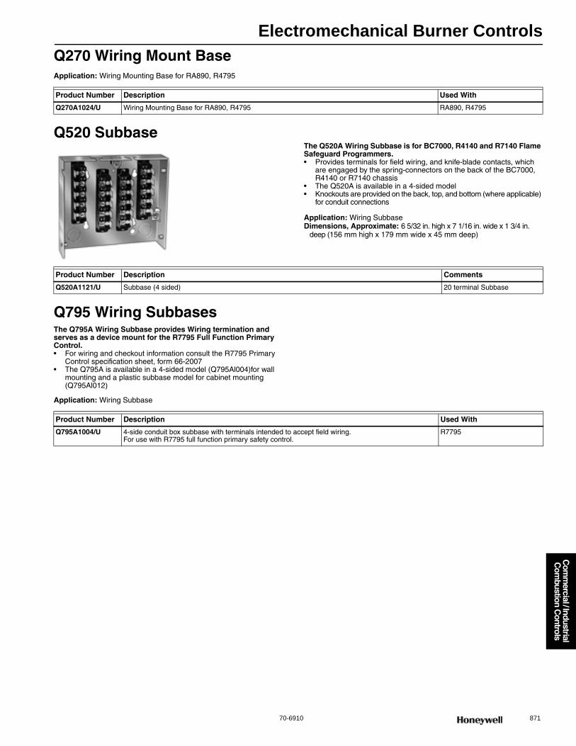
Electromechanical Burner Controls
70-6910 871
Com
mercial / Industrial
Com
bustion Controls
Q270 Wiring Mount BaseApplication: Wiring Mounting Base for RA890, R4795
Q520 SubbaseThe Q520A Wiring Subbase is for BC7000, R4140 and R7140 Flame Safeguard Programmers.• Provides terminals for field wiring, and knife-blade contacts, which
are engaged by the spring-connectors on the back of the BC7000, R4140 or R7140 chassis
• The Q520A is available in a 4-sided model • Knockouts are provided on the back, top, and bottom (where applicable)
for conduit connections
Application: Wiring SubbaseDimensions, Approximate: 6 5/32 in. high x 7 1/16 in. wide x 1 3/4 in.
deep (156 mm high x 179 mm wide x 45 mm deep)
Q795 Wiring SubbasesThe Q795A Wiring Subbase provides Wiring termination and serves as a device mount for the R7795 Full Function Primary Control.• For wiring and checkout information consult the R7795 Primary
Control specification sheet, form 66-2007 • The Q795A is available in a 4-sided model (Q795Al004)for wall
mounting and a plastic subbase model for cabinet mounting (Q795Al012)
Application: Wiring Subbase
Product Number Description Used With
Q270A1024/U Wiring Mounting Base for RA890, R4795 RA890, R4795
Product Number Description Comments
Q520A1121/U Subbase (4 sided) 20 terminal Subbase
Product Number Description Used With
Q795A1004/U 4-side conduit box subbase with terminals intended to accept field wiring. For use with R7795 full function primary safety control.
R7795

Electromechanical Burner Controls
872 customer.honeywell.com 70-6910
FSP5075A1; FSP5075A3 Flame Amplifier Modules
The FSP5075A Flame Amplifier Module is designed to accept a variety of Honeywell plug-in flame signal amplifiers. Depending on the plug-in amplifier model installed, the flame amplifier module can be used with ultraviolet flame detectors, infrared flame detectors, rectifying flame rods or rectifying photocells to provide
continuous flame supervision from lightoff to shutdown. Certain flame amplifier models feature Dynamic Self-Check or Dynamic Ampli-Check™ capability. The flame amplifier module also features plug-in load and flame relays as well as an integral terminal strip mounted on its chassis.• The flame amplifier and relay circuitry combine to provide such
safety features as safe-start check, safety shutdown and rapid flame failure response time
• Approval body certifications include Underwriters Laboratories Inc. component recognized, Factory Mutual approved and Swiss RE approvable
• Zinc dichromate finish resists corrosive effects of most industrial atmospheres • A hermetically sealed relay model is also available • The FSP5075A Flame Amplifier Module is a standard
building block in a burner management system • It allows the system to meet flame safeguard requirements
while adding versatility to the flame detection system
Application: Flame AmplifierDimensions, Approximate: 4 7/8 in. high x 8 1/2 in. wide x 4 in. deep
(124 mm high x 216 mm wide x 102 mm deep) Frequency: 60 HzTemperature Range: -40 F to +140 F (-40 C to +60 C) Used With: R7247, R7248, R7249, or R7476 Flame Amplifier
ApprovalsFactory Mutual: Approved: Report No. 26098SwissRe: AcceptableUnderwriters Laboratories, Inc: Component Recognized: File No.
MP268, Guide No. MCCZ
Product Number Voltage Power Consumption Flame Failure Response Time (sec) Comments
FSP5075A1/U 120 Vac 5.0 W running (max); 2.4 W standby Reference flame signal amplifier Relays Plastic Encapsulated
FSP5075A3/U 120 Vac 5.0 W running (max); 2.4 W standby Reference flame signal amplifier Relays Hermetically Sealed

Reset Temperature Controls
70-6910 873
Com
mercial / Industrial
Com
bustion Controls
T475 Outdoor Reset ControllerOperating controller for a hot water or warm air heating system.• Used for line voltage, low voltage or millivolt (Powerpile) switching. • Maintains proper balance between heating medium temperature and
outdoor temperature. • Raises heating medium control point automatically as outdoor
temperature falls. • Does not replace safety high limit control and is not for use in system
requiring resetting above 71 F (21 C) outdoor temperature.
Type: Remote bulbApplication: Automatically raises heating control setpoint as outdoor
temperature fallsDimensions, Approximate: 5 5/8 in. high x 2 in. wide x 2 1/8 in. deep
(143 mm high x 51 mm wide x 57 mm deep) Sensor Element: Indoor and outdoor copper bulbColor: GrayContact Ratings (120 Vac): 8.0 AFL, 48.0 ALRContact Ratings (240 Vac): 5.1 AFL, 30.6 ALRVoltage: 120 Vac or 240 VacFrequency: 50 Hz; 60 Hz
Reset Ratio: 1:1 reset ratioSetpoint Temperature Range: 70 F to 140 F (21 C to 60 C) Differential Temperature: 6 F to 20 F (3 C to 11 C) Output: 1 SPSTOutput Type: relayNumber of Sensor Inputs: 2Includes: 34886A Outdoor Bulb Guard, 121371P Immersion Well
AssemblyApprovalsUnderwriters Laboratories, Inc: Listed: E4436, vol. 4, Guide XAPX
Product Number
Bulb Size Capillary Length
Comments(inch) (mm) (ft) (m)
* T475A1032/U indoor: 3/8 in. diameter x 3 9/16 long; outdoor: 3/8 in. diameter x 3 9/16 long
indoor: 9.5 mm diameter x 90 mm long; outdoor: 9.5 mm diameter x 90 mm long
Indoor: 10 ft., Outdoor: 30 ft.
Indoor: 3 m, Outdoor: 9.1 m
1:1 reset ratio
* T475A1057/U indoor: 3/8 in. diameter x 3 9/16 long; outdoor: 3/8 in. diameter x 5 5/16 in. long
indoor: 9.5 mm diameter x 90 mm long; outdoor: 9.5 mm diameter x 135 mm long
Indoor: 10 ft., Outdoor: 30 ft.
Indoor: 3 m, Outdoor: 9.1 m
1:1.5 reset ratio
* TRADELINE models • SUPER TRADELINE models
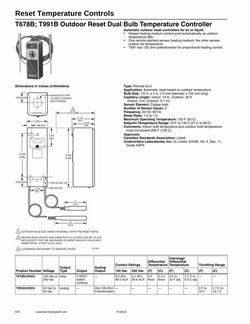
Reset Temperature Controls
874 customer.honeywell.com 70-6910
T678B; T991B Outdoor Reset Dual Bulb Temperature ControllerAutomatic outdoor reset controllers for air or liquid.• Raises heating medium control point automatically as outdoor
temperature falls. • One remote element senses heating medium, the other senses
outdoor air temperature. • T991 has 135 ohm potentiometer for proportional heating control.
Dimensions in inches (millimeters) Type: Remote bu bApplication: Automatic reset based on outdoor temperatureBulb Size: 1/2 in. x 4 in. (13 mm diameter x 102 mm long) Capillary Length: Indoor: 10 ft., Outdoor: 30 ft.
(Indoor: 3 m, Outdoor: 9.1 m)Sensor Element: Copper bulbNumber of Sensor Inputs: 2Frequency: 50 Hz; 60 HzReset Ratio: 1.0 to 1.0Maximum Operating Temperature: 125 F (52 C) Setpoint Temperature Range: 70 F to 140 F (21 C to 60 C)Comments: Indoor bulb temperature plus outdoor bulb temperature
must not exceed 265 F (129 C).ApprovalsCanadian Standards Association: ListedUnderwriters Laboratories, Inc: UL Listed: E4436, Vol. 4, Sec. 11,
Guide XAPX
M23882
OUTDOOR BULB SIZE VARIES INVERSELY WITH THE RESET RATIO.
INDOOR BULB LENGTH AND DIAMETER IS 4-1/2 INCH (114) BY 1/2 (13)
INCH EXCEPT FOR THE AVERAGING ELEMENT WHICH IS 1/8 (3) INCH
DIAMETER BY 12 FEET (3 M) LONG.
CLEARANCE NECESSARY TO REMOVE COVER.
1
1
KNOCKOUT FOR
1/2 INCH CONDUIT
(BOTH ENDS)
4-3/16
(106)
1-1/4(32)
1-3/4
(45)
5-5/8
(143)
2-1/4(57)
2-1/8(54)
15/16 (24)
7/32 (6) DIA. (3)
2
3
2 (51)
3/8 (10)
4-1/4 (108)
3
3/8 (10) DIA.
15/16 (24)
2
Product Number VoltageOutput Type Output
Analog Output
Contact RatingsDifferential Temperature
Interstage Differential Temperature Throttling Range
120 Vac 240 Vac (F) (C) (F) (C) (F) (C)
T678B1006/U 120 Vac or 240 Vac
relay 2 SPDT switch contacts
— 8.0 AFL, 48.0 ALR
5.1 AFL, 30.6 ALR
6 F fixed
3.3 C fixed
3 F to 10 F adj.
1.7 C to 5.5 C adj.
— —
T991B1003/U 24 Vac to 30 Vac
analog — One 135 Ohm Potentiometer
— — — — — — 3 F to 10 F
1.7 C to 16.7 C

Reset Temperature Controls
70-6910 875
Com
mercial / Industrial
Com
bustion Controls
T991E,F Proportional Temperature ControllerProvide both on-off and modulating control of water or air temperatures in ducts, tanks and similar applications.• Micro Switch® end switch cycles burner on and off at low fire; T991
then modulates burner as required. • Designed for use with V9055; can be used with any series 90 motor. • Ambient compensated. • Setpoint adjustment on front of case. • Switch makes 1 F (0.6 C) above end of throttling range. • Mount using three holes in the back of the case.
Dimensions in inches (millimeters) Type: Remote bulbApplication: Provides on/off and modulating control of water or air
temperature in ducts or tanksBulb Size: 1/2 in. diameter x 4 3/16 in. long (13 mm diameter x 107 mm
long) Sensor Element: Copper bulbColor: GrayVoltage: 24 Vac to 30 VacFrequency: 50 Hz; 60 HzOutput Type: analog and relayAnalog Output: One 135 Ohm PotentiometerOutput: 1 SPSTThrottling Range: 11 F (6 C) Differential Temperature: 4 F additive (2.2 C additive)
1-15/16(49)
1-1/16(27)
2-3/16
(56)
15/16 (24)
7/8 (22) DIAM.
KNOCKOUT FOR
1/2 INCH CONDUIT (4)
T991F (WITH AUTOMATIC RESET) HAS 2 REMOTE SENSING BULBS.1
1
5-7/8
(149)
11/16(18)
4-1/2
(114)
11/16(18)
3/8 (10) DIAM. (3)
3/8 (10)
3-3/8(86)
4-1/8(105)
7/32 (6) [3]
M23887
Product Number
Setpoint Temperature Range
Maximum Operating Temperature Capillary Length Number
of Sensor Inputs Comments(F) (C) (F) (C) (ft) (m)
T991E1018/U 160 F to 260 F 71 C to 127 C 280 F 138 C 5 ft 1.5 m 1 —
T991E1034/U 55 F to 175 F 13 C to 79 C 200 F 93 C 5 ft 1.5 m 1 —
T991F1009/U 70 F to 140 F 21 C to 60 C 265 F 129 C Indoor: 10 ft., Outdoor: 30 ft.
Indoor: 3 m, Outdoor: 9.1 m
2 Indoor bulb temperature plus outdoor bulb temperature must not exceed 265 F (129 C).

Testers and Demonstrators
876 customer.honeywell.com 70-6910
A7800 TesterProvides quick operational check of the 7800 SERIES System components.• Allows testing different 7800 SERIES devices using configuration plugs
and functional switches to simulate interlocks and control functions • Indicator lamps represent outputs as activated
Temperature Range: -30F to +150F (-34.5C to +65C) Voltage: 120 VacFrequency: 50 Hz; 60 Hz
A7800 and DSP2672 Replacement Parts
Product Number Required Components Includes Used With
A7800A1010/U Configuration Plugs, Included Configuration Plugs 7800 SERIES Relay Modules with Valve Proving System or New Optical Detector Amplifiers
Product Number Application Comments Used With
203579A/U Tester; DSP2672 RM7800/40/45 (non VPS side) Configuration Plug Configures A7800 and DSP2672 RM7800; RM7840
203579B/U Tester; DSP2672 RM7838A Configuration Plug Configures A7800 and DSP2672 —
203579C/U Tester; DSP2672 RM7838B, C Configuration Plug Configures A7800 and DSP2672 —
203579D/U Tester; DSP2672 RM7885A Configuration Plug Configures A7800 and DSP2672 —
203579E/U Tester; DSP2672 RM7890 (non VPS models) Configuration Plug Configures A7800 and DSP2672 —
203579F/U Tester; DSP2672 RM7823 Configuration Plug Configures A7800 and DSP2672 —
203579G/U Tester; DSP2672 RM7823 Configuration Plug Configures A7800 and DSP2672 —
203579J/U RM7838B, C (VPS) Configuration Plug Configures A7800 and DSP2672 —
203579K/U RM7890 (VPS) Configuration Plug Configures A7800 and DSP2672 —
203579L/U RM7800/40G,L (VPS side) Configuration Plug Configures A7800 and DSP2672 —
203579M/U RM7898 (VPS SIde) Configuration Plug Configures A7800 and DSP2672 —
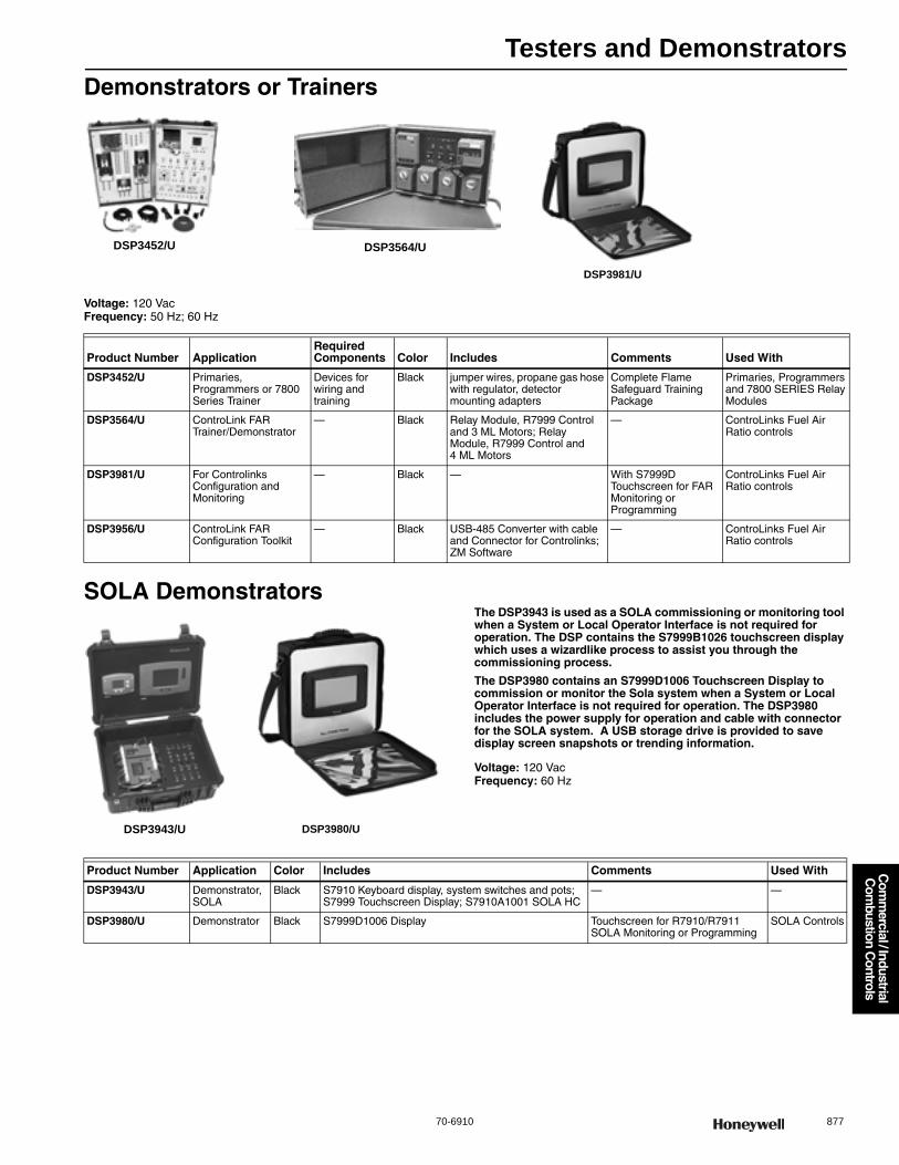
Testers and Demonstrators
70-6910 877
Com
mercial / Industrial
Com
bustion Controls
Demonstrators or Trainers
Voltage: 120 VacFrequency: 50 Hz; 60 Hz
SOLA DemonstratorsThe DSP3943 is used as a SOLA commissioning or monitoring tool when a System or Local Operator Interface is not required for operation. The DSP contains the S7999B1026 touchscreen display which uses a wizardlike process to assist you through the commissioning process.
The DSP3980 contains an S7999D1006 Touchscreen Display to commission or monitor the Sola system when a System or Local Operator Interface is not required for operation. The DSP3980 includes the power supply for operation and cable with connector for the SOLA system. A USB storage drive is provided to save display screen snapshots or trending information.
Voltage: 120 VacFrequency: 60 Hz
DSP3452/U DSP3564/U
DSP3981/U
Product Number ApplicationRequired Components Color Includes Comments Used With
DSP3452/U Primaries, Programmers or 7800 Series Trainer
Devices for wiring and training
Black jumper wires, propane gas hose with regulator, detector mounting adapters
Complete Flame Safeguard Training Package
Primaries, Programmers and 7800 SERIES Relay Modules
DSP3564/U ControLink FAR Trainer/Demonstrator
— Black Relay Module, R7999 Control and 3 ML Motors; Relay Module, R7999 Control and 4 ML Motors
— ControLinks Fuel Air Ratio controls
DSP3981/U For Controlinks Configuration and Monitoring
— Black — With S7999D Touchscreen for FAR Monitoring or Programming
ControLinks Fuel Air Ratio controls
DSP3956/U ControLink FAR Configuration Toolkit
— Black USB-485 Converter with cable and Connector for Controlinks; ZM Software
— ControLinks Fuel Air Ratio controls
DSP3943/U DSP3980/U
Product Number Application Color Includes Comments Used With
DSP3943/U Demonstrator, SOLA
Black S7910 Keyboard display, system switches and pots; S7999 Touchscreen Display; S7910A1001 SOLA HC
— —
DSP3980/U Demonstrator Black S7999D1006 Display Touchscreen for R7910/R7911 SOLA Monitoring or Programming
SOLA Controls
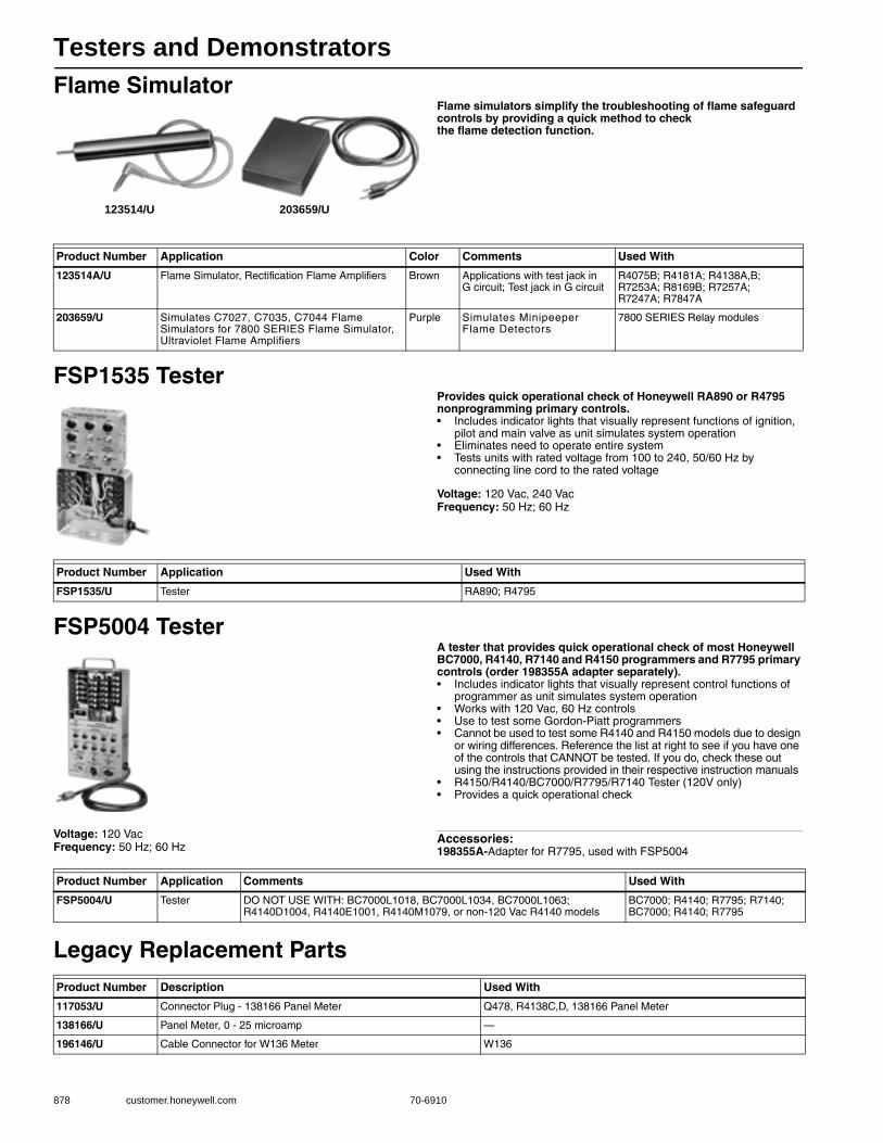
Testers and Demonstrators
878 customer.honeywell.com 70-6910
Flame SimulatorFlame simulators simplify the troubleshooting of flame safeguard controls by providing a quick method to check the flame detection function.
FSP1535 TesterProvides quick operational check of Honeywell RA890 or R4795 nonprogramming primary controls.• Includes indicator lights that visually represent functions of ignition,
pilot and main valve as unit simulates system operation • Eliminates need to operate entire system • Tests units with rated voltage from 100 to 240, 50/60 Hz by
connecting line cord to the rated voltage
Voltage: 120 Vac, 240 VacFrequency: 50 Hz; 60 Hz
FSP5004 TesterA tester that provides quick operational check of most Honeywell BC7000, R4140, R7140 and R4150 programmers and R7795 primary controls (order 198355A adapter separately).• Includes indicator lights that visually represent control functions of
programmer as unit simulates system operation • Works with 120 Vac, 60 Hz controls • Use to test some Gordon-Piatt programmers • Cannot be used to test some R4140 and R4150 models due to design
or wiring differences. Reference the list at right to see if you have one of the controls that CANNOT be tested. If you do, check these out using the instructions provided in their respective instruction manuals
• R4150/R4140/BC7000/R7795/R7140 Tester (120V only)• Provides a quick operational check
Voltage: 120 VacFrequency: 50 Hz; 60 Hz
Accessories:198355A-Adapter for R7795, used with FSP5004
Legacy Replacement Parts
123514/U 203659/U
Product Number Application Color Comments Used With
123514A/U Flame Simulator, Rectification Flame Amplifiers Brown Applications with test jack in G circuit; Test jack in G circuit
R4075B; R4181A; R4138A,B; R7253A; R8169B; R7257A; R7247A; R7847A
203659/U Simulates C7027, C7035, C7044 Flame Simulators for 7800 SERIES Flame Simulator, Ultraviolet Flame Amplifiers
Purple Simulates Minipeeper Flame Detectors
7800 SERIES Relay modules
Product Number Application Used With
FSP1535/U Tester RA890; R4795
Product Number Application Comments Used With
FSP5004/U Tester DO NOT USE WITH: BC7000L1018, BC7000L1034, BC7000L1063; R4140D1004, R4140E1001, R4140M1079, or non-120 Vac R4140 models
BC7000; R4140; R7795; R7140; BC7000; R4140; R7795
Product Number Description Used With
117053/U Connector Plug - 138166 Panel Meter Q478, R4138C,D, 138166 Panel Meter
138166/U Panel Meter, 0 - 25 microamp —
196146/U Cable Connector for W136 Meter W136

Signal Processors
70-6910 879
Industrial Flame
Monitoring
P531; P532 3-channel, Signal ProcessorsThe P531/P532 are 3-channel signal processors which amplify and condition the viewing head signal, for use with a burner management system. Provide proportional 0/4-20mA output signal, 2 SPDT flame relay and 1 SPDT self-check relay outputs.• 3 channels• Two SPDT flame relay outputs, one SPDT self-check relay output
and one N.O. alarm relay output per channel.• FM and CSA approved.• Monitor the UV and IR flame component simultaneously or
separately when using the S550B/BE.• Monitor 3 viewing heads simultaneously.• Independent configuration for each viewing head.• 2 sets of configuration data per viewing head.• Viewing head temperature indication.• Automatic set-up functionality.• Automatic viewing head detection.• Modbus and RS422 protocol compatible.• NEMA 1 Enclosure Rated.
Dimensions, Approximate: 4.3 in. wide x 5.8 in. deep x 5.5 in. high (109 mm wide x 147 mm deep x 117 mm high)
Mounting: Cabinet mounting tabsConnection Type: Removable terminalsCommunications: ModBus and RS422 CompatibleOutput: 0/4-20mA
Used With: S550B/BE, S552B/BE, S556B/BE, S70X, S80X viewing heads
ApprovalsCanadian Standards Association: Approved Factory Mutual: Approved
600U Flame Rod Signal ProcessorDimensions, Approximate: 2-63/64 in. wide x 3-1/4 in. deep x
5-31/64 in. high (76 mm wide x 83 mm deep x 139 mm high)Mounting: DIN rail, 35mmConnection Type: Removable terminalsOutput: 4-175 Vac for flame rodUsed With: Flame Rod
P531 P532
Product Number Description Application KeypadStatus Monitoring
Electrical Ratings Frequency
Required Components
P531AC AC Signal Processor
Signal Processor with 3 channels without keypad
Use P532UI keypad
LEDs 85-264 Vac 50 Hz; 60 Hz Appropriate Flame Detector
P531DC DC Signal Processor
Signal Processor with 3 channels without keypad
Use P532UI keypad
LEDs 22-26 Vdc — Appropriate Flame Detector
P532AC AC Signal Processor
Signal Processor with 3 channels and keypad
Integrated tri-color display
85-264 Vac 50 Hz; 60 Hz Appropriate Flame Detector
P532DC DC Signal Processor
Signal Processor with 3 channels and keypad
Integrated tri-color display
22-26 Vdc — Appropriate Flame Detector
Product Number Description Application KeypadStatus Monitoring
Electrical Ratings Frequency
600U Flame rod signal processor with DPDT flame relay contacts, DPST ignition transformer relay or ignition coil drive
Flame rod signal processor
Integrated LEDs 85 to 132Vac or 170 to 264Vac
50 Hz; 60 Hz
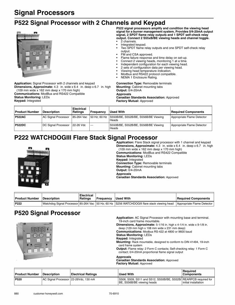
Signal Processors
880 customer honeywell.com 70-6910
P522 Signal Processor with 2 Channels and KeypadP522 signal processors amplify and condition the viewing head signal for a burner management system. Provides 0/4-20mA output signal, 2 SPDT flame relay outputs and 1 SPDT self-check relay output. Connect 2 S55xB/BE viewing heads and channel toggle.• 2 channels.• Integrated keypad.• Two SPDT flame relay outputs and one SPDT self-check relay
output.• FM and CSA approved.• Flame failure response and time delay on set-up.• Connect 2 viewing heads, monitoring 1 at a time.• Independent configuration for each viewing head.• 2 sets of configuration data per viewing head.• Viewing head temperature indication.• Modbus and RS422 protocol compatible.• NEMA 1 Enclosure Rating.
Application: Signal Processor with 2 channels and keypadDimensions, Approximate: 4.3 in. wide x 6.4 in. deep x 6.7 in. high
(109 mm wide x 162 mm deep x 170 mm high)Communications: ModBus and RS422 CompatibleStatus Monitoring: LEDsKeypad: Integrated
Connection Type: Removable terminalsMounting: Cabinet mounting tabsOutput: 0/4-20mAApprovalsCanadian Standards Association: ApprovedFactory Mutual: Approved
P222 WATCHDOGIII Flare Stack Signal ProcessorApplication: Flare Stack signal processor with 1 channel and keypadDimensions, Approximate: 4.3 in. wide x 6.4 in. deep x 6.7 in. high
(109 mm wide x 162 mm deep x 170 mm high)Communications: ModBus and RS422 CompatibleStatus Monitoring: LEDsKeypad: IntegratedConnection Type: Removable terminalsMounting: Cabinet mounting tabsOutput: 0/4-20mAApprovalsCanadian Standards Association: Approved
P520 Signal ProcessorApplication: AC Signal Processor with mounting base and terminal.
19-inch card frame mountable.Dimensions, Approximate: 5-1/16 in. high x 4-1/4 in. wide x 9-1/8 in.
deep (129 mm high x 108 mm wide x 231 mm deep)Communications: Modbus RS-422 at 4800 or 9600 baudStatus Monitoring: LEDsKeypad: IntegratedMounting: Rack mountable, designed to conform to DIN 41494, 19-inch
card frame systemOutput: Flame relay: 2 Form C contacts; Self-checking relay: 1 Form C
contact; 0/4-20mA proportional flame signal output
ApprovalsCanadian Standards Association: ApprovedFactory Mutual: Approved
Product Number DescriptionElectrical Ratings Frequency Used With Required Components
P522AC AC Signal Processor 85-264 Vac 50 Hz; 60 Hz S550B/BE, S552B/BE, S556B/BE Viewing Heads
Appropriate Flame Detector
P522DC DC Signal Processor 22-26 Vdc — S550B/BE, S552B/BE, S556B/BE Viewing Heads
Appropriate Flame Detector
Product Number DescriptionElectrical Ratings Frequency Used With Required Components
P222 Watchdog Signal Processor 85-264 Vac 50 Hz; 60 Hz S256 WATCHDOGIII flare stack viewing head Appropriate Flame Detector
Product Number Description Electrical Ratings Used WithRequired Components
P520 AC Signal Processor 22-26Vdc, 130 mA S506, S509, S511 and S512, S550B/BE, S552B/BE, S556B/BE viewing heads
REARPCB required for initial installation

Signal Processors
70-6910 881
Industrial Flame
Monitoring
700 Signal Processor with 1 ChannelThe 700 is a signal processor which amplifies and conditions the viewing head signal for use with a burner management system. It provides a 0/4-20mA output signal, two SPDT flame relay outputs and one SPDT self-check relay output.• 1 channel.• Two SPDT flame relay outputs and one SPDT self-check relay
output.• FM and CSA approved.• Status LEDs.• DIN rail mounting.• Modbus and RS422 protocol compatible.• NEMA 1 Enclosure Rating.
Dimensions, Approximate: 5-1/2 in. high x 2-29/32 in. wide x 3-1/4 in. deep (139 mm high x 74 mm wide x 83 mm deep)
Application: Signal processor with 1 channelStatus Monitoring: LEDsOutput: 0/4-20mAMounting: DIN rail, 35 mm
Communications: ModBus and RS422 CompatibleConnection Type: Removable terminalsApprovalsCanadian Standards Association: ApprovedFactory Mutual: Approved
Combination DC Signal Processor and Dual UV/IR Viewing HeadApplication: Combination DC signal processor and dual UV/IR Viewing
headDimensions, Approximate: 4.3 in. wide x 5.8 in. deep x 5.5 in. high
(109 mm wide x 147 mm deep x 117 mm high)Status Monitoring: Display and LEDsOutput: 0/4-20mAKeypad: IntegratedCommunications: ModBus and RS422 CompatibleApprovalsCanadian Standards Association: Approved Factory Mutual: Approved IEC: ApprovedATEX: Approved
Product Number Description KeypadElectrical Ratings Frequency Used With Required Components
700ACSP AC Signal Processor Integrated 85-264 Vac 50 Hz; 60 Hz All models of S702, S706, S802, S806 Viewing Heads
Appropriate Flame Detector
700DCSP DC Signal Processor Integrated 22-26 Vdc — All models of S702, S706, S802, S806 Viewing Heads
Appropriate Flame Detector
Product Number Description Electrical Ratings Required Components
U2-1010 Combination DC signal processor and dual UV/IR Viewing head.
22-26 Vdc Cable and connector, PT adapter and purge air coupler sold separately.
U2-1010-PF Combination DC signal processor and dual UV/IR Viewing head with 10-ft (3 m) pigtail
22-26 Vdc PT adapter and purge air coupler sold separately.
U2-1010-PF-050 Combination DC signal processor and dual UV/IR Viewing head with 50-ft (15 m) pigtail
22-26 Vdc PT adapter and purge air coupler sold separately.
U2-1010-PF-100 Combination DC signal processor and dual UV/IR Viewing head with 100-ft (30 m) pigtail
22-26 Vdc PT adapter and purge air coupler sold separately.

Industrial Flame Monitoring Accessories
882 customer honeywell.com 70-6910
Industrial Flame Monitoring - AccessoriesProduct Number Application Description Used With
ISO-UNIT Burner isolation mount 1 in. NPTF sealing union with quartz window and 1/2 in. NPTF purge port. Order the ISO-WRENCH separately, if required.
S702, S706, S802, S806, S5XX, S550B/BE, S552B/BE, S556B/BE, U2 all models
ISO-UNITHPGT Burner isolation mount 1 in. NPTF sealing union with quartz window and 1/2 in. NPTF purge port. High pressure version with 1/2 thick high pressure quartz window. Order the ISO-WRENCH separately, if required.
S702, S706, S802, S806, S5XX, S550B/BE, S552B/BE, S556B/BE, U2 all models
ISO-UNITSS Burner isolation mount 1 in. NPTF stainless steel sealing union with quartz window and 1/2 in. NPTF purge port. Order the ISO-WRENCH separately, if required.
S702, S706, S802, S806, S5XX, S550B/BE, S552B/BE, S556B/BE, U2 all models
700-1 Burner swivel mount Swivel mount for S700 and S800 series viewing heads. 1 in. NPT female to 1/2 in. NPT male connection.
S702, S706, S802, S806 all models
700-2 Burner swivel mount Swivel mount for S700 and S800 series viewing heads. Flanged 1/2 in. connection to 1/2 in. NPTM connection.
S702, S706, S802, S806 all models
700-3 Burner swivel mount Swivel mount for S700 and S800 series viewing heads. 1/2 in. NPTF to 1/2 in. NPTM connection.
S702, S706, S802, S806 all models
M-701-1 Burner swivel mount Swivel mount, 2 in. pipe slip-on to 1 in. NPT connection.
All viewing heads
M-701-2 Burner swivel mount Swivel mount, 2 in. NPT female to 1 in. NPT female.
All viewing heads
M-701-2-FLG Burner swivel mount Flanged swivel mount, 2 in. flanged to 1 in. NPTF.
All viewing heads
M-701-2-SS Burner swivel mount Swivel mount, 2 in. NPT female to 1 in. NPT female, Stainless steel construction.
All viewing heads
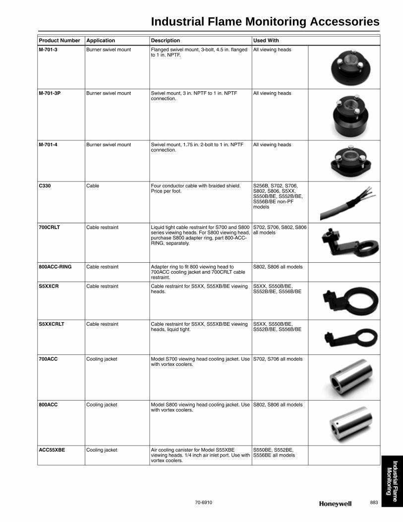
Industrial Flame Monitoring Accessories
70-6910 883
Industrial Flame
Monitoring
M-701-3 Burner swivel mount Flanged swivel mount, 3-bolt, 4.5 in. flanged to 1 in. NPTF.
All viewing heads
M-701-3P Burner swivel mount Swivel mount, 3 in. NPTF to 1 in. NPTF connection.
All viewing heads
M-701-4 Burner swivel mount Swivel mount, 1.75 in. 2-bolt to 1 in. NPTF connection.
All viewing heads
C330 Cable Four conductor cable with braided shield. Price per foot.
S256B, S702, S706, S802, S806, S5XX, S550B/BE, S552B/BE, S556B/BE non-PF models
700CRLT Cable restraint Liquid tight cable restraint for S700 and S800 series viewing heads. For S800 viewing head, purchase S800 adapter ring, part 800-ACC-RING, separately.
S702, S706, S802, S806 all models
800ACC-RING Cable restraint Adapter ring to fit 800 viewing head to 700ACC cooling jacket and 700CRLT cable restraint.
S802, S806 all models
S5XXCR Cable restraint Cable restraint for S5XX, S55XB/BE viewing heads.
S5XX, S550B/BE, S552B/BE, S556B/BE
S5XXCRLT Cable restraint Cable restraint for S5XX, S55XB/BE viewing heads, liquid tight.
S5XX, S550B/BE, S552B/BE, S556B/BE
700ACC Cooling jacket Model S700 viewing head cooling jacket. Use with vortex coolers.
S702, S706 all models
800ACC Cooling jacket Model S800 viewing head cooling jacket. Use with vortex coolers.
S802, S806 all models
ACC55XBE Cooling jacket Air cooling canister for Model S55XBE viewing heads. 1/4 inch air inlet port. Use with vortex coolers.
S550BE, S552BE, S556BE all models
Product Number Application Description Used With
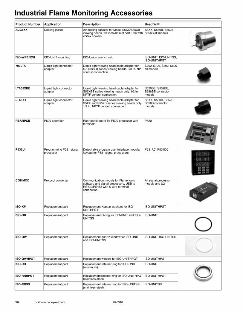
Industrial Flame Monitoring Accessories
884 customer honeywell.com 70-6910
ACC5XX Cooling jacket Air cooling canister for Model S5XX/S55XB viewing heads. 1/4 inch air inlet port. Use with vortex coolers.
S5XX, S550B, S552B, S556B all models
ISO-WRENCH ISO-UNIT mounting ISO-Union wrench set. ISO-UNIT, ISO-UNITSS, ISO-UNITHPGT
700LTA Liquid tight connector adapter
Liquid tight viewing head cable adapter for S700/S800 series viewing heads. 3/8 in. NPT conduit connection.
S702, S706, S802, S806 all models
LTA55XBE Liquid tight connector adapter
Liquid tight viewing head cable adapter for S55XBE series viewing heads only. 1/2 in. NPTF conduit connection.
S550BE, S552BE, S556BE connector models
LTA5XX Liquid tight connector adapter
Liquid tight viewing head cable adapter for S5XX and S55XB series viewing heads only. 1/2 in. NPTF conduit connection.
S5XX, S550B, S552B, S556B connector models
REARPCB P520 operation Rear panel board for P520 processor with terminals.
P520
P532UI Programming P531 signal processor
Detachable program user interface module/keypad for P531 signal processors.
P531AC, P531DC
COMMOD Protocol converter Communication module for Flame tools software and signal processors, USB to RS422/RS485 with 5-wire terminal connection.
All signal processor models and U2
ISO-KP Replacement part Replacement Kapton washers for ISO-UNITHPGT
ISO-UNITHPGT
ISO-OR Replacement part Replacement O-ring for ISO-UNIT and ISO-UNITSS
ISO-UNIT
ISO-QW Replacement part Replacement quartz window for ISO-UNIT and ISO-UNITSS
ISO-UNIT, ISO-UNITSS
ISO-QWHPGT Replacement part Replacement window for ISO-UNITHPGT ISO-UNITHPG
ISO-RR Replacement part Replacement retainer ring for ISO-UNIT (aluminum).
ISO-UNIT
ISO-RRHPGT Replacement part Replacement retainer ring for ISO-UNITHPGT (stainless steel).
ISO-UNITHPGT
ISO-RRSS Replacement part Replacement retainer ring for ISO-UNITSS (stainless steel).
ISO-UNITSS
Product Number Application Description Used With
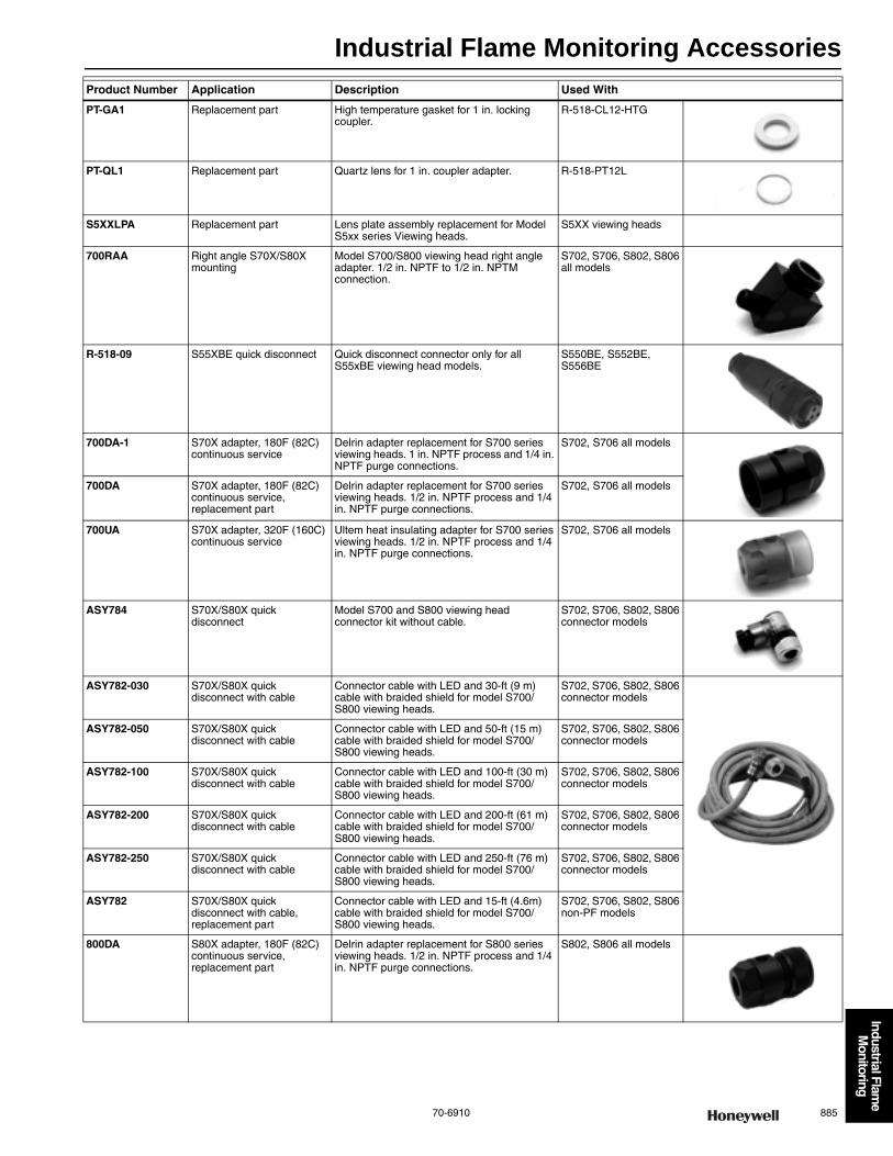
Industrial Flame Monitoring Accessories
70-6910 885
Industrial Flame
Monitoring
PT-GA1 Replacement part High temperature gasket for 1 in. locking coupler.
R-518-CL12-HTG
PT-QL1 Replacement part Quartz lens for 1 in. coupler adapter. R-518-PT12L
S5XXLPA Replacement part Lens plate assembly replacement for Model S5xx series Viewing heads.
S5XX viewing heads
700RAA Right angle S70X/S80X mounting
Model S700/S800 viewing head right angle adapter. 1/2 in. NPTF to 1/2 in. NPTM connection.
S702, S706, S802, S806 all models
R-518-09 S55XBE quick disconnect Quick disconnect connector only for all S55xBE viewing head models.
S550BE, S552BE, S556BE
700DA-1 S70X adapter, 180F (82C) continuous service
Delrin adapter replacement for S700 series viewing heads. 1 in. NPTF process and 1/4 in. NPTF purge connections.
S702, S706 all models
700DA S70X adapter, 180F (82C) continuous service, replacement part
Delrin adapter replacement for S700 series viewing heads. 1/2 in. NPTF process and 1/4 in. NPTF purge connections.
S702, S706 all models
700UA S70X adapter, 320F (160C) continuous service
Ultem heat insulating adapter for S700 series viewing heads. 1/2 in. NPTF process and 1/4 in. NPTF purge connections.
S702, S706 all models
ASY784 S70X/S80X quick disconnect
Model S700 and S800 viewing head connector kit without cable.
S702, S706, S802, S806 connector models
ASY782-030 S70X/S80X quick disconnect with cable
Connector cable with LED and 30-ft (9 m) cable with braided shield for model S700/S800 viewing heads.
S702, S706, S802, S806 connector models
ASY782-050 S70X/S80X quick disconnect with cable
Connector cable with LED and 50-ft (15 m) cable with braided shield for model S700/S800 viewing heads.
S702, S706, S802, S806 connector models
ASY782-100 S70X/S80X quick disconnect with cable
Connector cable with LED and 100-ft (30 m) cable with braided shield for model S700/S800 viewing heads.
S702, S706, S802, S806 connector models
ASY782-200 S70X/S80X quick disconnect with cable
Connector cable with LED and 200-ft (61 m) cable with braided shield for model S700/S800 viewing heads.
S702, S706, S802, S806 connector models
ASY782-250 S70X/S80X quick disconnect with cable
Connector cable with LED and 250-ft (76 m) cable with braided shield for model S700/S800 viewing heads.
S702, S706, S802, S806 connector models
ASY782 S70X/S80X quick disconnect with cable, replacement part
Connector cable with LED and 15-ft (4.6m) cable with braided shield for model S700/S800 viewing heads.
S702, S706, S802, S806 non-PF models
800DA S80X adapter, 180F (82C) continuous service, replacement part
Delrin adapter replacement for S800 series viewing heads. 1/2 in. NPTF process and 1/4 in. NPTF purge connections.
S802, S806 all models
Product Number Application Description Used With
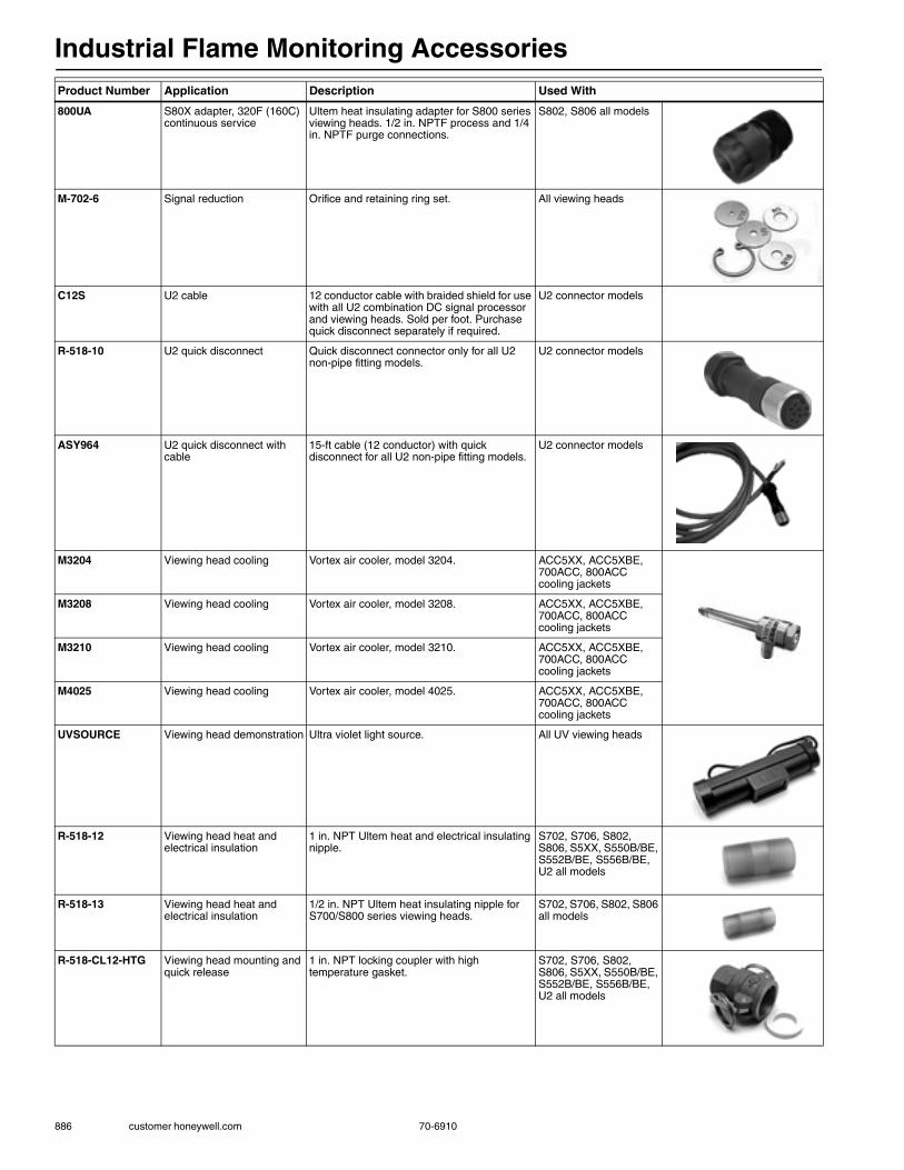
Industrial Flame Monitoring Accessories
886 customer honeywell.com 70-6910
800UA S80X adapter, 320F (160C) continuous service
Ultem heat insulating adapter for S800 series viewing heads. 1/2 in. NPTF process and 1/4 in. NPTF purge connections.
S802, S806 all models
M-702-6 Signal reduction Orifice and retaining ring set. All viewing heads
C12S U2 cable 12 conductor cable with braided shield for use with all U2 combination DC signal processor and viewing heads. Sold per foot. Purchase quick disconnect separately if required.
U2 connector models
R-518-10 U2 quick disconnect Quick disconnect connector only for all U2 non-pipe fitting models.
U2 connector models
ASY964 U2 quick disconnect with cable
15-ft cable (12 conductor) with quick disconnect for all U2 non-pipe fitting models.
U2 connector models
M3204 Viewing head cooling Vortex air cooler, model 3204. ACC5XX, ACC5XBE, 700ACC, 800ACC cooling jackets
M3208 Viewing head cooling Vortex air cooler, model 3208. ACC5XX, ACC5XBE, 700ACC, 800ACC cooling jackets
M3210 Viewing head cooling Vortex air cooler, model 3210. ACC5XX, ACC5XBE, 700ACC, 800ACC cooling jackets
M4025 Viewing head cooling Vortex air cooler, model 4025. ACC5XX, ACC5XBE, 700ACC, 800ACC cooling jackets
UVSOURCE Viewing head demonstration Ultra violet light source. All UV viewing heads
R-518-12 Viewing head heat and electrical insulation
1 in. NPT Ultem heat and electrical insulating nipple.
S702, S706, S802, S806, S5XX, S550B/BE, S552B/BE, S556B/BE, U2 all models
R-518-13 Viewing head heat and electrical insulation
1/2 in. NPT Ultem heat insulating nipple for S700/S800 series viewing heads.
S702, S706, S802, S806 all models
R-518-CL12-HTG Viewing head mounting and quick release
1 in. NPT locking coupler with high temperature gasket.
S702, S706, S802, S806, S5XX, S550B/BE, S552B/BE, S556B/BE, U2 all models
Product Number Application Description Used With

Industrial Flame Monitoring Accessories
70-6910 887
Industrial Flame
Monitoring
R-518-CL12-PG Viewing head mounting and quick release
1 in. NPT aluminum locking quick disconnect/cam and groove coupler adapter with 1/2 in. NPT purge port. Used with U2 processor/viewing heads.
S702, S706, S802, S806, S5XX, S550B/BE, S552B/BE, S556B/BE, U2 all models
R-518-CL13-HTG Viewing head mounting and quick release
1/2 in. NPT locking coupler with high temperature gasket.
S702, S706, S802, S806 all models
R-518-PT12 Viewing head mounting and quick release
1 in. NPT Ultem insulating locking coupler adapter.
S702, S706, S802, S806, S5XX, S550B/BE, S552B/BE, S556B/BE, U2 all models
R-518-PT12L Viewing head mounting and quick release
1 in. NPT Ultem locking coupler adapter with quartz lens.
S702, S706, S802, S806, S5XX, S550B/BE, S552B/BE, S556B/BE, U2 all models
R-518-PT13 Viewing head mounting and quick release
1/2 in. NPT Ultem locking coupler adapter only.
S702, S706, S802, S806 all models
R-518-PT13L Viewing head mounting and quick release
1/2 in. NPT Ultem locking coupler adapter with quartz lens.
S702, S706, S802, S806 all models
Product Number Application Description Used With
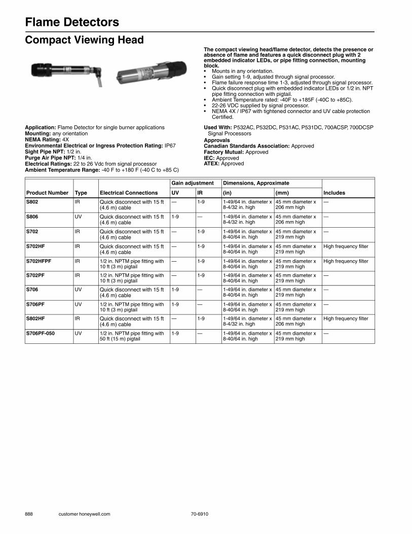
Flame Detectors
888 customer honeywell.com 70-6910
Compact Viewing HeadThe compact viewing head/flame detector, detects the presence or absence of flame and features a quick disconnect plug with 2 embedded indicator LEDs, or pipe fitting connection, mounting block.• Mounts in any orientation.• Gain setting 1-9, adjusted through signal processor.• Flame failure response time 1-3, adjusted through signal processor.• Quick disconnect plug with embedded indicator LEDs or 1/2 in. NPT
pipe fitting connection with pigtail.• Ambient Temperature rated: -40F to +185F (-40C to +85C).• 22-26 VDC supplied by signal processor.• NEMA 4X / IP67 with tightened connector and UV cable protection
Certified.
Application: Flame Detector for single burner applicationsMounting: any orientationNEMA Rating: 4XEnvironmental Electrical or Ingress Protection Rating: IP67Sight Pipe NPT: 1/2 in.Purge Air Pipe NPT: 1/4 in.Electrical Ratings: 22 to 26 Vdc from signal processorAmbient Temperature Range: -40 F to +180 F (-40 C to +85 C)
Used With: P532AC, P532DC, P531AC, P531DC, 700ACSP, 700DCSP Signal Processors
ApprovalsCanadian Standards Association: ApprovedFactory Mutual: ApprovedIEC: ApprovedATEX: Approved
Product Number Type Electrical Connections
Gain adjustment Dimensions, Approximate
IncludesUV IR (in) (mm)
S802 IR Quick disconnect with 15 ft (4.6 m) cable
— 1-9 1-49/64 in. diameter x 8-4/32 in. high
45 mm diameter x 206 mm high
—
S806 UV Quick disconnect with 15 ft (4.6 m) cable
1-9 — 1-49/64 in. diameter x 8-4/32 in. high
45 mm diameter x 206 mm high
—
S702 IR Quick disconnect with 15 ft (4.6 m) cable
— 1-9 1-49/64 in. diameter x 8-40/64 in. high
45 mm diameter x 219 mm high
—
S702HF IR Quick disconnect with 15 ft (4.6 m) cable
— 1-9 1-49/64 in. diameter x 8-40/64 in. high
45 mm diameter x 219 mm high
High frequency filter
S702HFPF IR 1/2 in. NPTM pipe fitting with 10 ft (3 m) pigtail
— 1-9 1-49/64 in. diameter x 8-40/64 in. high
45 mm diameter x 219 mm high
High frequency filter
S702PF IR 1/2 in. NPTM pipe fitting with 10 ft (3 m) pigtail
— 1-9 1-49/64 in. diameter x 8-40/64 in. high
45 mm diameter x 219 mm high
—
S706 UV Quick disconnect with 15 ft (4.6 m) cable
1-9 — 1-49/64 in. diameter x 8-40/64 in. high
45 mm diameter x 219 mm high
—
S706PF UV 1/2 in. NPTM pipe fitting with 10 ft (3 m) pigtail
1-9 — 1-49/64 in. diameter x 8-40/64 in. high
45 mm diameter x 219 mm high
—
S802HF IR Quick disconnect with 15 ft (4.6 m) cable
— 1-9 1-49/64 in. diameter x 8-4/32 in. high
45 mm diameter x 206 mm high
High frequency filter
S706PF-050 UV 1/2 in. NPTM pipe fitting with 50 ft (15 m) pigtail
1-9 — 1-49/64 in. diameter x 8-40/64 in. high
45 mm diameter x 219 mm high
—

Flame Detectors
70-6910 889
Industrial Flame
Monitoring
Viewing Head with Digital DisplayThe S552/556 viewing head/flame detectors feature a digital display, quick disconnect plug, or pipe fitting connection, gain setting, flame on/off settings for added discrimination and NEMA 4X/IP67 enclosure rating. Perfect for difficult sighting and multiple burners.• Immune of X-Rays and Gamma Rays. • Mount in any orientation. • With Digital display. • Quick disconnect plug or 1/2 in. NPT pipe fitting connection with
pigtail. • Ambient Temperature: -40F to +158F(-40C to +70C). • 22-26 VDC supplied by signal processor. • Enclosure NEMA 4X / IP67 Certified.
Application: Flame Detector for single or multiple burner applicationsDimensions in: 4.1 in. wide x 8.1 in. deep x 5.4 in. high (104 mm wide x
206 mm deep x 137 mm high)Electrical Ratings: 22 to 26Vdc from signal processorNEMA Rating: 4XEnvironmental Electrical or Ingress Protection Rating: IP67Sight Pipe NPT: 1 in.
Purge Air Pipe NPT: 1/2 in.Ambient Temperature Range: -40 to 158 F (-40 C to +70 C)ApprovalsCanadian Standards Association: ApprovedFactory Mutual: ApprovedIEC: Approved
Product Number TypeElectrical Connections
Gain adjustment
Digital Displays Comments Used WithUV IR
S552BE IR Quick disconnect plug — 0-699 Yes (1) — P532AC, P532DC, P531AC, P531DC, P522AC, P522DC Signal Processors
S556BE UV Quick disconnect plug 0-99 — Yes (1) — P532AC, P532DC, P531AC, P531DC, P522AC, P522DC Signal Processors
S552B IR Quick disconnect plug — 0-699 Yes (1) For new jobs, use S552BE P532AC, P532DC, P531AC, P531DC, P522AC, P522DC Signal Processors
S552BE-PF IR 1/2 in. NPTM pipe fitting with 10 ft (3 m) pigtail
— 0-699 Yes (1) Replaces S552B-PF P532AC, P532DC, P531AC, P531DC, P522AC, P522DC Signal Processors
S556B UV Quick disconnect plug 0-99 — Yes (1) For new Jobs, use S556BE P532AC, P532DC, P531AC, P531DC, P522AC, P522DC Signal Processors
S556BE-PF UV 1/2 in. NPTM pipe fitting with 10 ft (3 m) pigtail
0-99 — Yes (1) Replaces S556B-PF P532AC, P532DC, P531AC, P531DC, P522AC, P522DC Signal Processors
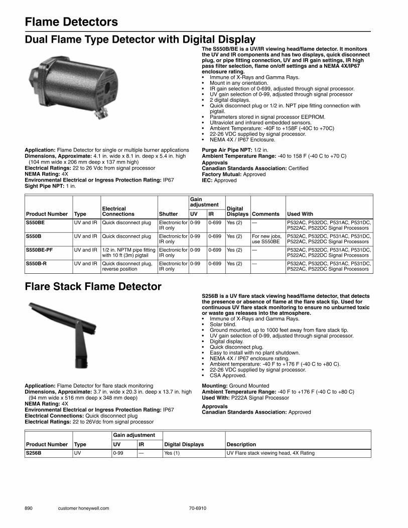
Flame Detectors
890 customer honeywell.com 70-6910
Dual Flame Type Detector with Digital DisplayThe S550B/BE is a UV/IR viewing head/flame detector. It monitors the UV and IR components and has two displays, quick disconnect plug, or pipe fitting connection, UV and IR gain settings, IR high pass filter selection, flame on/off settings and a NEMA 4X/IP67 enclosure rating.• Immune of X-Rays and Gamma Rays. • Mount in any orientation. • IR gain selection of 0-699, adjusted through signal processor.• UV gain selection of 0-99, adjusted through signal processor• 2 digital displays. • Quick disconnect plug or 1/2 in. NPT pipe fitting connection with
pigtail.• Parameters stored in signal processor EEPROM. • Ultraviolet and infrared embedded sensors. • Ambient Temperature: -40F to +158F (-40C to +70C) • 22-26 VDC supplied by signal processor. • NEMA 4X / IP67 Enclosure.
Application: Flame Detector for single or multiple burner applicationsDimensions, Approximate: 4.1 in. wide x 8.1 in. deep x 5.4 in. high
(104 mm wide x 206 mm deep x 137 mm high)Electrical Ratings: 22 to 26 Vdc from signal processorNEMA Rating: 4XEnvironmental Electrical or Ingress Protection Rating: IP67Sight Pipe NPT: 1 in.
Purge Air Pipe NPT: 1/2 in.Ambient Temperature Range: -40 to 158 F (-40 C to +70 C)ApprovalsCanadian Standards Association: CertifiedFactory Mutual: ApprovedIEC: Approved
Flare Stack Flame DetectorS256B is a UV flare stack viewing head/flame detector, that detects the presence or absence of flame at the flare stack tip. Used for continuous UV flare stack monitoring to ensure no unburned toxic or waste gas releases into the atmosphere.• Immune of X-Rays and Gamma Rays. • Solar blind. • Ground mounted, up to 1000 feet away from flare stack tip. • UV gain selection of 0-99, adjusted through signal processor. • Digital display. • Quick disconnect plug. • Easy to install with no plant shutdown. • NEMA 4X / IP67 enclosure rating. • Ambient temperature: -40 F to +176 F (-40 C to +80 C). • 22-26 VDC supplied by signal processor. • CSA Approved.
Application: Flame Detector for flare stack monitoringDimensions, Approximate: 3.7 in. wide x 20.3 in. deep x 13.7 in. high
(94 mm wide x 516 mm deep x 348 mm deep)NEMA Rating: 4XEnvironmental Electrical or Ingress Protection Rating: IP67Electrical Connections: Quick disconnect plugElectrical Ratings: 22 to 26Vdc from signal processor
Mounting: Ground MountedAmbient Temperature Range: -40 F to +176 F (-40 C to +80 C)Used With: P222A Signal Processor
ApprovalsCanadian Standards Association: Approved
Product Number TypeElectrical Connections Shutter
Gain adjustment
Digital Displays Comments Used WithUV IR
S550BE UV and IR Quick disconnect plug Electronic for IR only
0-99 0-699 Yes (2) — P532AC, P532DC, P531AC, P531DC, P522AC, P522DC Signal Processors
S550B UV and IR Quick disconnect plug Electronic for IR only
0-99 0-699 Yes (2) For new jobs, use S550BE
P532AC, P532DC, P531AC, P531DC, P522AC, P522DC Signal Processors
S550BE-PF UV and IR 1/2 in. NPTM pipe fitting with 10 ft (3m) pigtail
Electronic for IR only
0-99 0-699 Yes (2) — P532AC, P532DC, P531AC, P531DC, P522AC, P522DC Signal Processors
S550B-R UV and IR Quick disconnect plug, reverse position
Electronic for IR only
0-99 0-699 Yes (2) — P532AC, P532DC, P531AC, P531DC, P522AC, P522DC Signal Processors
Product Number Type
Gain adjustment
Digital Displays DescriptionUV IR
S256B UV 0-99 — Yes (1) UV Flare stack viewing head, 4X Rating

DVD/Videotapes
70-6910 891
Video is a very effective medium to use for both technical training and product familiarization. Many of the programs described here are relatively short and make a nice addition to a service meeting or formal class on HVAC controls. These tapes have been widely used in a number of applications such as:•At the distributor’s counter – to help answer questions and show technicians how to use new products•At service meetings – to review new service procedures at the beginning of a season•In the classroom – to provide students with authoritative information direct from the manufacturer
Commercial HVAC ControlsIn Control With Solid StateThis three-part DVD covers solid state economizer control systems, and features the H705A Enthalpy Controller, the M7415A Actuator, W7459 Economizer Logic Module, C7400 Air Sensor and C7150 Discharge Air Sensor. Separate parts cover Operation (12:00), Installation (15:00), and Checkout and Troubleshooting (8:00). 35:00
VT34/U $15.00
Heating ControlsTraining on Demand Heating Controls DVDContains the following modules: Basic Hydronic Control 14:33, Hydronic Heating Distribution 12:39, Outdoor Temperature Compensation 16:22, Oil Burner Controls 14:37, Flame Detection 13:14, Standing Pilot 12:33, Intermittent Pilot 14:16, SmartValve System 10:57, Direct Burner Ignition 12:05, SmartValve Direct Burner Ignition 9:44, Advanced SmartValve 11:27, SmartValve Water Heater Control 11:26 (2004), and Universal Integrated Furnace Control 11:07 (2007)
63-9357/U $9.00
Training Booklets
892 customer.honeywell.com 70-6910
Training Booklets
Electronic Air Cleaner Application and InstallationIncludes selection, application and installation information for residential and light commercial type electronic air cleaners. 31 pages
70-9723/U $1.10
Electronic Air Cleaner Service DataIncludes replacement parts, model number identification, service tools and equipment, plus description, checkout and troubleshooting guide and parts list for Honeywell electronic air cleaners. 107 pages
70-9724/U $4.35
Gas Control Reference Manual & Student Reference – Theory and FundamentalsBasic information and technical data on gas heating controls: gas properties, combustion, pilot burner systems, warm air heating systems, hydronic heating appliances, power sources, safety shutoff circuit and combination gas valves. Extensive glossary and technical charts. 48 pages, 1988
71-97473 $10.00
Principles of Millivoltage ControlTheory, controls and control circuits for millivoltage for heating systems with performance specifications on thermopiles. 22 pages, 1989
71-97280 $2.75
Burners and BoilersDescriptions of various types of commercial and industrial gas, oil, and coal burners and their operation. Also boilers classified by construction and size. A comprehensive and understandable introduction to the subject. 65 pages (Order in multiples of 20)
70-8107 $1.57
Quick and Basic ElectricityA contractor’s beginning guide to HVAC circuits, controls and wiring diagrams. 80 pages 71-97431/U $20.00
Really Basic ElectricityWritten for the person with no background in electricity. Introduces basic concepts of a.c. and d.c. electricity. Includes pictures and diagrams. 96 pages
71-97004/U $7.00

Programmed Instruction Books
70-6910 893
Quick and Basic Hydronic ControlsAnother in the “Practical is Good” (P.I.G.) Technical Training Series. A contractor’s easy guide to hydronic controls, wiring, and wiring diagrams. How figuring circuits is like watching a bug on a rope; why thinking in circles is good; how every hydronic control is a power supply, a switch, or a load; how limit controls are like a safety committee; how to see the friendly side of control panels. 87 pages, 2000
71-97160/U $20.00
Quick and Basic Troubleshooting BookThis book tells you how to troubleshoot controls and control circuits using a meter, a “hopscotch,” “Leapfrog,” “daisy chain,” and “homerun” methods, a trouble shooting chart, a wiring diagram and your common sense. 80 pages
71-97931/U $20.00
Quick and Basic House WiringThis book is an HVAC contractor’s guide to what the electrician does. Ever wonder what’s going on inside the walls? This book explains it, both modern and “the old stuff.” It also explains such electricity puzzles as how to wire 3-way and 4-way switches, why 2-wire cable has 3 wires and why 3-wire cable has four.
71-97966/U $20.00
ControlPro Pneumatic Control Training ManualThis manual is for a two-day in-house course on Honeywell pneumatic controls. It is available separately for use in your own training. 150 pages
71-97070 $20.00
Programmed Instruction BooksFundamentals of Residential ControlA step-by-step, self-instruction workbook in a question and answer format. Students learn the necessary foundation for advanced study in controls while working at their own speed. Ideal for individual student use in preparation for other courses. Topics include: nature of electricity, rules governing electricity, inductive and capacitive circuits, principles of motor operation, power, transformer principles, relay principles, analyzing control circuits. 250 pages
71-97083 $10.00
The Psychrometric ChartA valuable tool for everyone in the HVAC industry. Knowledge of the complex relationship between the various characteristics of the air (temperature, humidity, moisture content, etc.) can be the key to solving a number of air conditioning problems. Text illustrates with examples of how to use psychrometric charts. Use it as a self-instruction text or a class exercise. 100 pages
71-97444 $10.00
Training Booklets
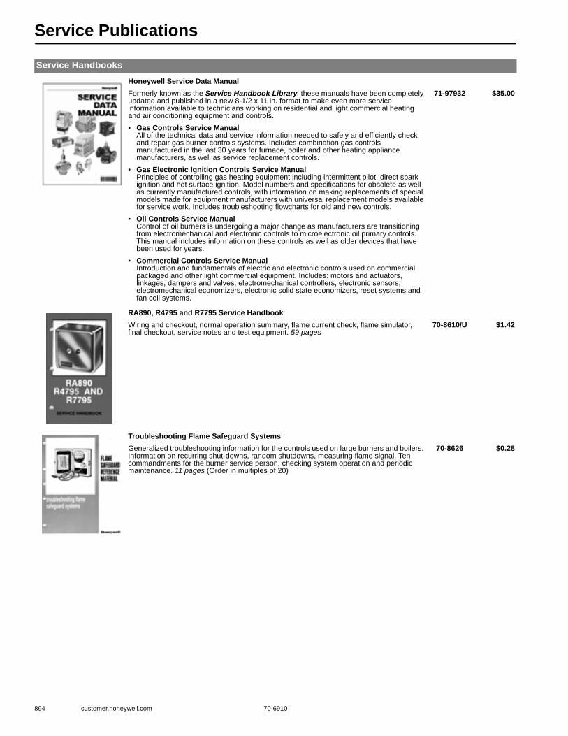
Service Publications
894 customer.honeywell.com 70-6910
Service HandbooksHoneywell Service Data ManualFormerly known as the Service Handbook Library, these manuals have been completely updated and published in a new 8-1/2 x 11 in. format to make even more service information available to technicians working on residential and light commercial heating and air conditioning equipment and controls.
71-97932 $35.00
• Gas Controls Service ManualAll of the technical data and service information needed to safely and efficiently check and repair gas burner controls systems. Includes combination gas controls manufactured in the last 30 years for furnace, boiler and other heating appliance manufacturers, as well as service replacement controls.
• Gas Electronic Ignition Controls Service ManualPrinciples of controlling gas heating equipment including intermittent pilot, direct spark ignition and hot surface ignition. Model numbers and specifications for obsolete as well as currently manufactured controls, with information on making replacements of special models made for equipment manufacturers with universal replacement models available for service work. Includes troubleshooting flowcharts for old and new controls.
• Oil Controls Service ManualControl of oil burners is undergoing a major change as manufacturers are transitioning from electromechanical and electronic controls to microelectronic oil primary controls. This manual includes information on these controls as well as older devices that have been used for years.
• Commercial Controls Service ManualIntroduction and fundamentals of electric and electronic controls used on commercial packaged and other light commercial equipment. Includes: motors and actuators, linkages, dampers and valves, electromechanical controllers, electronic sensors, electromechanical economizers, electronic solid state economizers, reset systems and fan coil systems.
RA890, R4795 and R7795 Service HandbookWiring and checkout, normal operation summary, flame current check, flame simulator, final checkout, service notes and test equipment. 59 pages
70-8610/U $1.42
Troubleshooting Flame Safeguard SystemsGeneralized troubleshooting information for the controls used on large burners and boilers. Information on recurring shut-downs, random shutdowns, measuring flame signal. Ten commandments for the burner service person, checking system operation and periodic maintenance. 11 pages (Order in multiples of 20)
70-8626 $0.28

Classroom Training
70-6910 895
These manuals and notebooks provide instructional support on the fundamentals of controls for residential and some light com-mercial heating and cooling applications.• A Reference Manual, or mini-text, is a clearly written text with easy-to-follow diagrams that detail the fundamentals
of controls and control systems. Designed for use by the student as well as the instructor and organized so that the instructor can vary the outline to fit specific teaching goals. Includes reproductions of the program’s overhead slides.
• A Student Notebook reinforces instruction and offers a check on student understanding through the use of exercises and review questions.
Oil Control and Electric Heating
Oil Heating ControlsOil burner ignition and safety control systems for residential heating. Includes: fuel oil characteristics, oil burner primary controls, stack relay and cad cell flame detection systems, servicing oil burner control systems and general troubleshooting.
Student Notebook 71-97090 $3.00
Electric Heat ControlsThe basics of residential electric heating control starting with a brief review of electrical principles and going through to service procedures. Information on influence of humidity, air circulation and radiant temperature on comfort; heating system performance in terms of response time, cycling rate, heat anticipation and timed sequencing; central and decentralized electric heating systems; servicing electric heat systems and troubleshooting.
Reference Manual 71-97306 $5.00Student Notebook 71-97308 $3.00
ControlPro Reference MaterialThese publications are part of the ControlPro one-day class for heating and air conditioning technicians, and are good references for anyone needing information on Oil or Hydronic Heating Controls.
Oil Heating Controls Technical ReferenceA compilation of all the specification data, installation and service publications on Honeywell’s oil heating controls, such as cad cell oil primaries, stack relays and ignition transformers. 204 pages, 2005
71-97479/U $18.00
Controls for Oil-Fired HeatingThe “textbook” for the ControlPro Oil class. Includes: fuel oil and oil burning equipment, ignition requirements, oil burner control requirements, stack relays, cad cell primary controls, oil primary controls, oil control service and troubleshooting, glossary. 61 pages, 2005
71-97406 $5.50
Hydronic Heating Controls Technical ReferenceA compilation of all the specification data, installation and service publications on Honeywell’s hydronic heating controls, including Aquastat® controllers, Aquastat® relays, zone controls, outdoor temperature compensation controls, thermostats and hydronic heating controls accessories. 415 pages, 2005
71-97480/U $24.00

FSG Textbook
896 customer.honeywell.com 70-6910
FSG Textbook, “Flame Safeguard Controls: A Honeywell Textbook” 2nd editionThe most comprehensive and popular Flame Safeguard textbook available in our industry. It’s where the beginners begin and where the “Old Pros” return year after year and problem after problem.
TextbookFSG Textbook, “Flame Safeguard Controls: A Honeywell Textbook”, 362 pagesContents:• Introduction to Flame Safeguard – Flame Safeguard functions and controls.• Combustion – explanation of fuel types and flame characteristics.• Burners and Boilers – description of representative burners and boilers.• Flame Rod Application – design and installation of flame rods and rectification systems.• Optical Detector Applications – description, operation, application and checkout of
detectors; covering rectifying photocells, infrared, and ultraviolet detectors.• Primary Controls – capabilities and operation of primary controls (RA890, R4795 and
R7795) used on smaller burners• Programming Controls – capabilities and operation of programming controls (R4140 and
BC7000 Microcomputer Programmable Controls.• Troubleshooting FSG Systems – outlines systematic procedures for isolating common
Flame Safeguard problems.• Service Equipment – description and operation of testers, simulators and meters.• Auxiliary Equipment – description, operation, application and checkout of pressure and
temperature controllers.• Valves and Valve Trains – description and application of typical Flame Safeguard valves
and valve trains.• Sizing and Application of Large Gas Valves – principles and procedures for selecting
gas valves (includes selection nomographs).• Firing Rate Controls – covers methods for controlling firing rate, firing rate sequences,
programmer switching, motors and valves.• Glossary – Flame Safeguard terminology.
71-97558/U $22.50

Reference Manuals
70-6910 897
These reference manuals are collations of Honeywell publications used to apply, install and service various categories of control products. Combined they represent virtually all of the technical information Honeywell publishes on its residential and light commer-cial electric and electronic controls.
Reference ManualsTHE SOURCE Reference Material for Gas IgnitionThese are the publications used with The Source gas ignition technical training program. • THE SOURCE Technical Reference
A compilation of all the specification data, installation and service publications on Honeywell’s residential gas ignition controls such as gas valves, ignition modules and electronic fan timers. 634 pages, 2004
71-97414 $4.50
• THE SOURCE Class Notes and Lab ExercisesReproductions of the visuals used in The Source classroom training program along with the lab exercises that make up Honeywell’s popular training program on gas ignition controls. 114 pages, 2003
71-97162 $4.50
The Firing LineA comprehensive manual designed to facilitate the upgrading and replacement of burner and boiler controls in commercial and industrial applications. Extensive information on approval bodies to explain what type of controls are required to meet various codes. Subjects include how to sell control modernization, how to sell replacement, conversion wiring, handy survey guides and worksheets.
70-8900/U $125.00
The Firing Line CD-ROM VersionThe CD-ROM version of The Firing Line is a comprehensive reference media designed to facilitate the upgrade/replacement of burner and boiler controls in commercial and industrial applications. 1996
66-1081/U $25.00
Flame Safeguard Reference ManualSpecification sheet collation on: primary controls, programming controls, gas valves, flame sensors, FSG motors, ignition transformers, pressure controls/limits, reset controls, multiple boiler controls, low water cutoff, and feed water valve.
66-1004/U $135.00
2006 Commercial/Industrial Combustion Controls CatalogThis catalog covers the complete line of Honeywell Burner and Boiler controls. In addition to our premier 7800 SERIES Burner Control Systems, BCS 7700 Boiler Control Systems and Communication Interface, the catalog covers flame amplifiers, firing rate motors, pressure/temperature sensors, amplifiers, auxiliary equipment, Flame Safeguard Modutrol IV motors, flame sensors, gas valves ignition transformers, modernization and replacement equipment, pressure controls/limits, primary and relay controls, programmers, test equipment, and commercial hydronic controls. Contains information on Flame Safeguard training materials, reference manuals and demonstrators and lab trainers.
70-8911/U $2.00
7800 Series Burner Control ManualThis manual contains promotional literature, features/functions/benefits, product selection submittal information, programmers, semi-automatic programmers, primaries, semiautomatic primaries, subbases, amplifiers, purge cards, optional components, expanded annunciator, communications, tester, accessories, conversion wiring diagrams, diagnostics, and troubleshooting, and cross references. In 3-ring poly binder.
66-1065/U $55.00

Reference Manuals
898 customer.honeywell.com 70-6910
Engineering Manual of Automatic Control for Commercial Buildings - Soft cover
The 21st edition of this widely used and extremely valuable manual. Now includes direct digital control and operator workstations, as well as other current control technology and strategies. The 500+ pages guide the reader through the fundamentals of control system theory, direct digital control, building management systems and a dozen other disciplines essential to proper environmental control in buildings. In this edition, microprocessor controls are shown in most of the control applications, rather than pneumatic, electric or electronic controls, to reflect the trends in today’s industry. Also included is new information on indoor air quality and district heating. Often referred to as the “Gray Manual,” this technical resource has been a standard among engineering design professionals since it was first published in 1934. Revised 1997
77-1100/U $24.00
Zoning Systems Reference ManualA comprehensive reference on the Honeywell residential zoning capability. Includes Consumer Literature, System Design, Zone and Bypass Dampers, Networked Zoning, TotalZone, EMM Series, MM-2 and MM-3, Thermostats, Control Accessories and Fresh Air.
63-7067/U $10.00
Water Control Product Catalog
Honeywell Catalogue - Full Line of Quality Products for Water Management Solutions: Water Controls Products, Hydronic Heating, Plumbing and Energy Products.
- Honeywell Water Products: MIxing Valves, Air Vents, Boiler feed Valves/Back Flow Preventer, Expansion Tanks/Combo Kits, Honeywell Thermometers and Tridicators, DS05, DS06 DialSet Pressure Regulation Valves, T104/V110 High Capacity Thermostatic Radiator Valves, MT100/MT110 Service Tools, F74 Water Sediment Filters, D05/D06 Universal Pressure Regulating Valves, T100/V100 Standard capacity TRV, V135/T100 Loop Controls fro radiant floor applications
63-8702/U $1.70
Honeywell TRADELINE CatalogRecently updated, this product catalog is an education in itself—over 1,000 pages of specifications and application information on Honeywell’s residential, light commercial and burner and boiler controls. Included are Home Control products, Water Control products, Building Control products, Indoor Air Quality Products, Pneumatic Controls and Flame Safeguard Products.
70-6910/U $7.00
Reference Manuals
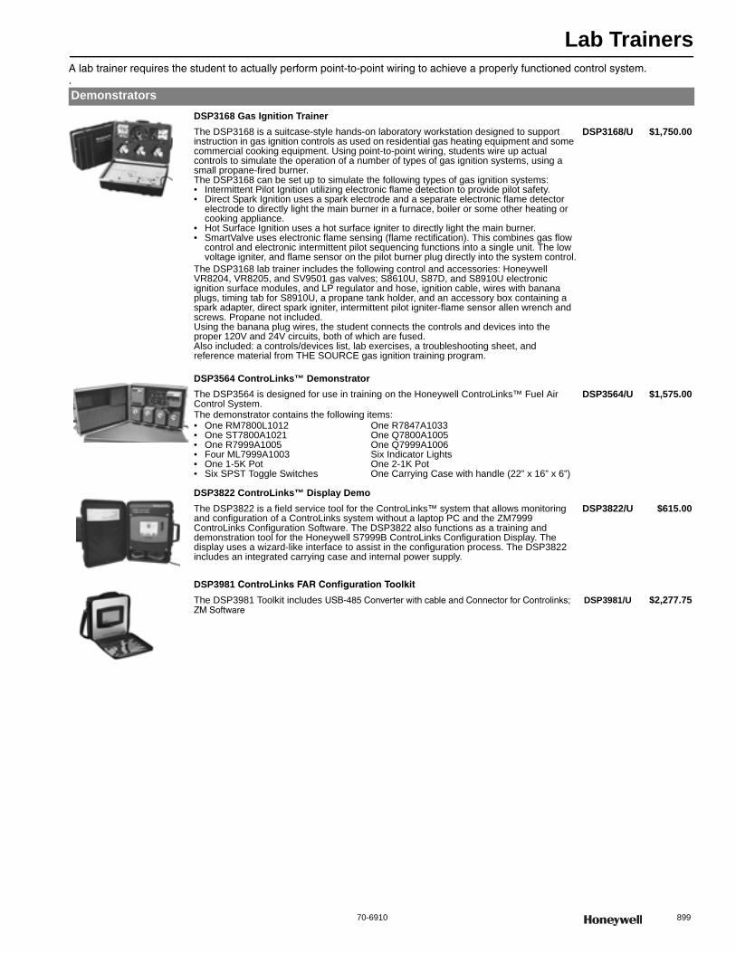
Lab Trainers
70-6910 899
A lab trainer requires the student to actually perform point-to-point wiring to achieve a properly functioned control system..Demonstrators
DSP3168 Gas Ignition TrainerThe DSP3168 is a suitcase-style hands-on laboratory workstation designed to support instruction in gas ignition controls as used on residential gas heating equipment and some commercial cooking equipment. Using point-to-point wiring, students wire up actual controls to simulate the operation of a number of types of gas ignition systems, using a small propane-fired burner.The DSP3168 can be set up to simulate the following types of gas ignition systems:• Intermittent Pilot Ignition utilizing electronic flame detection to provide pilot safety.• Direct Spark Ignition uses a spark electrode and a separate electronic flame detector
electrode to directly light the main burner in a furnace, boiler or some other heating or cooking appliance.
• Hot Surface Ignition uses a hot surface igniter to directly light the main burner.• SmartValve uses electronic flame sensing (flame rectification). This combines gas flow
control and electronic intermittent pilot sequencing functions into a single unit. The low voltage igniter, and flame sensor on the pilot burner plug directly into the system control.
The DSP3168 lab trainer includes the following control and accessories: Honeywell VR8204, VR8205, and SV9501 gas valves; S8610U, S87D, and S8910U electronic ignition surface modules, and LP regulator and hose, ignition cable, wires with banana plugs, timing tab for S8910U, a propane tank holder, and an accessory box containing a spark adapter, direct spark igniter, intermittent pilot igniter-flame sensor allen wrench and screws. Propane not included.Using the banana plug wires, the student connects the controls and devices into the proper 120V and 24V circuits, both of which are fused.Also included: a controls/devices list, lab exercises, a troubleshooting sheet, and reference material from THE SOURCE gas ignition training program.
DSP3168/U $1,750.00
DSP3564 ControLinks™ DemonstratorThe DSP3564 is designed for use in training on the Honeywell ControLinks™ Fuel Air Control System.The demonstrator contains the following items:• One RM7800L1012 One R7847A1033• One ST7800A1021 One Q7800A1005• One R7999A1005 One Q7999A1006• Four ML7999A1003 Six Indicator Lights• One 1-5K Pot One 2-1K Pot• Six SPST Toggle Switches One Carrying Case with handle (22” x 16” x 6”)
DSP3564/U $1,575.00
DSP3822 ControLinks™ Display DemoThe DSP3822 is a field service tool for the ControLinks™ system that allows monitoring and configuration of a ControLinks system without a laptop PC and the ZM7999 ControLinks Configuration Software. The DSP3822 also functions as a training and demonstration tool for the Honeywell S7999B ControLinks Configuration Display. The display uses a wizard-like interface to assist in the configuration process. The DSP3822 includes an integrated carrying case and internal power supply.
DSP3822/U $615.00
DSP3981 ControLinks FAR Configuration Toolkit
The DSP3981 Toolkit includes USB-485 Converter with cable and Connector for Controlinks; ZM Software
DSP3981/U $2,277.75
Lab Trainers
900 customer.honeywell.com 70-6910
DSP3943 SOLA DemonstratorThe DSP3943 is used as a SOLA commissioning or monitoring tool when a System or Local Operator Interface is not required for operation. The DSP contains the S7999B1026 touchscreen display which uses a wizard like process to assist you through the commissioning process.
DSP3944/U $4,791.03
DSP3980 SOLA DemonstratorThe DSP3980 contains an S7999D1006 Touchscreen Display to commission or monitor the Sola system when a System or Local Operator Interface is not required for operation. The DSP3980 includes the power supply for operation and cable with connector for the SOLA system. A USB storage drive is provided to save display screen snapshots or trending information.
DSP3980/U
Burner and Boiler Controls Demonstrator Instructors ManualThis Manual is the Instructor’s version of the Operating Training Board Exercises for the DSP3472
71-97117 $3.25
Burner and Boiler Controls Demonstrator Student WorkbookThis Manual contains the Operating Training Board Exercises for the student for the DSP3472
71-97116 $3.25
Demonstrators
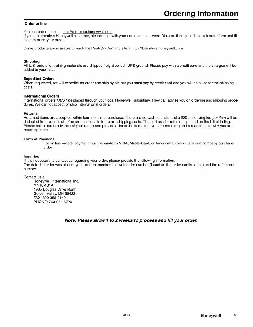
Ordering Information
70-6910 901
Order online
You can order online at http://customer.honeywell.comIf you are already a Honeywell customer, please login with your name and password. You can then go to the quick order form and fill it out to place your order.
Some products are available through the Print-On-Demand site at http://Literature.honeywell.com
ShippingAll U.S. orders for training materials are shipped freight collect, UPS ground. Please pay with a credit card and the charges will be added to your total.
Expedited OrdersWhen requested, we will expedite an order and ship by air, but you must pay by credit card and you will be billed for the shipping costs.
International OrdersInternational orders MUST be placed through your local Honeywell subsidiary. They can advise you on ordering and shipping proce-dures. We cannot accept or ship international orders.
ReturnsReturned items are accepted within four months of purchase. There are no cash refunds, and a $30 restocking fee per item will be deducted from your credit. You are responsible for return shipping costs. The address for returns is printed on the bill of lading. Please call or fax in advance of your return and provide a list of the items that you are returning and a reason as to why you are returning them.
Form of PaymentFor on line orders, payment must be made by VISA, MasterCard, or American Express card or a company purchase order
InquiriesIf it is necessary to contact us regarding your order, please provide the following information:The data the order was places, your account number, the web order number (found on the order confirmation) and the reference number.
Contact us at:Honeywell International Inc.MN10-131A1985 Douglas Drive NorthGolden Valley, MN 55422FAX: 800-356-0149PHONE: 763-954-5720
Note: Please allow 1 to 2 weeks to process and fill your order.

Notes
902 customer.honeywell.com 70-6910

Notes
70-6910 903

Notes
904 customer.honeywell.com 70-6910
70-0568Rev. 5-13
ENVIRONMENTAL AND COMBUSTION CONTROLWARRANTY POLICY
Honeywell warrants the products in this catalog (except those parts designated on Honeywell's price lists as not covered by this warranty) to be free from defects due to workmanship or materials, under normal use and service, for the following warranty periods. Sixty (60) months from date of installation
• Prestige®, Prestige® IAQ, VisionPRO®, Commercial VisionPRO®, FocusPRO®, Wireless FocusPRO®, PRO 4000, PRO 3000, LineVoltPRO™, Digital Round™, and Modern Round ™ (T87K, N) Series Thermostats with a date code of 0501 or later
• Air Cleaners, Humidifiers, Ventilators, Ultraviolet Treatment and Zoning products with a date code of 0501 or later, excluding replacement maintenance parts
• Indoor air quality products F50, F52, F300, F200, F150, UV100E, HE225, HE265, HE365, with date codes of 0452 or earlier, excluding replacement maintenance parts
• MS, MN and fast acting 2-position Direct Coupled Actuators
• JADE economizer when used with Honeywell sensors and actuators
• AquaPUMP circulating pump• C7189 wireless indoor sensor
Sixty (60) months from date of manufacture• Access and Video Systems power supplies
Thirty-six (36) months from date of shipment• Variable frequency drive devices (VFD) and
accessories
Thirty-six (36) months from date of installation• AUBE branded thermostats, timers, and switches
Twenty-four (24) months from date of installation• CommercialPRO, PRO 2000 and PRO 1000
thermostats• Other Honeywell indoor air quality and zoning products
with a date code of 0452 or earlier, unless otherwise specified
• AQ2000 Aquatrol panels and AQ1000 thermostats
Twenty-four (24) months from date of manufacture• Pan-Tilt-Zoom Domes for Access and Video Systems
Eighteen (18) months from date of shipment,• All WEBs building automation and security parts,
unless specified otherwise
Twelve (12) months from date of installation• Water Solutions products• Other Honeywell thermostats and thermostats with a
date code of 0452 or earlier, unless specified otherwise
Twelve (12) months from date of shipment• Building automation security accessories
Twelve (12) months from date of manufacture• Keyboards, Controllers and other Access and Video
System accessories.
Ninety (90) days from date of manufacture• IR Halogen bulbs for Access and Video Systems
The warranty period for all other products is twelve (12) months from date of installation.
If a product is defective due to workmanship or materials, is removed within the applicable warranty period, and is returned to Honeywell in accordance with the procedure described below, Honeywell will, at its option, either repair, replace or credit the customer for the purchase price of the product, in accordance with the procedure described below. This warranty extends only to persons or organizations who purchase products in this catalog for resale.The expressed warranty above constitutes the entire warranty of Honeywell with respect to the products in this catalog and IS IN LIEU OF ALL OTHER WARRANTIES, EXPRESS OR IMPLIED, INCLUDING ANY WARRANTY OF MERCHANTABILITY OR WARRANTY OF FITNESS FOR A PARTICULAR PURPOSE. IN NO EVENT SHALL HONEYWELL BE RESPONSIBLE FOR ANY CONSEQUENTIAL DAMAGES OF ANY NATURE WHATSOEVER.
INSTRUCTIONS—INSTALLING OR SERVICING CONTRACTOR OR DEALER When replacing a Honeywell product under warranty, including those products furnished on original heating and/or cooling equipment, you should rely on your local Honeywell Wholesaler or Distributor for prompt and efficient product replacement service. A Honeywell Returned Goods Identification Tag (form 87-0030) or an electronic data notification system must be completed and approved by the servicing dealer/contractor prior to submitting the product to the Honeywell Wholesaler or Distributor. (Tags may be obtained from the Wholesaler or Distributor in advance.) No warranty claim for product replacement or credit will be honored by the Wholesaler/Distributor without a completed warranty tag attached or electronic notification.
INSTRUCTIONS—WHOLESALER OR DISTRIBUTOR The following will apply to the return of any product to Honeywell under this warranty, except any products which are not variable frequency drives or WEBS and are:
(i) identified with a Honeywell Return Goods Authorization Form (obtained from the B2B website at Customer.Honeywell com)
(ii) (display the RMA number and return address label on the outside of the return carton. Make sure a copy of the RMA is enclosed in the return carton
(iii) packed separately from other returns and protected from shipping damage;
(iv) have certification by the installer or servicing dealer that the product was removed, due to failure, within the applicable warranty period;
(v) are received transportation pre-paid at the facility listed on the shipping and/or packing slip.
(vi) and are found by Honeywell’s inspection to be defective in workmanship or materials under normal use and service
will be handled in accordance with one of the two following procedures, as specified by the customer making the return.
1. CREDIT PROCEDURE. Honeywell will issue credit, at Honeywell’s lowest wholesaler net price in effect at the time of the return (as set forth on Honeywell’s then current price sheet) or at the actual invoice amount if a copy of that invoice is attached to the packing list. (TRADELINE Replacement Exchange Products will be at Honeywell’s lowest replacement exchange net price in effect at the time of such return, as shown on Honeywell’s then current price sheet.) Honeywell reserves the right to disallow this credit option in cases of warranty abuse.
2. REPLACEMENT PROCEDURE. Warranty replacement procedure must be used for in-warranty emergency replacement orders. Customer will not be credited for items not meeting warranty criteria as outlined by policy. Please return the defective item to the address listed on the return authorization form.
List Water Solutions products on a separate Return Goods Order form, marked “Water Solutions”.
All new and unused VBN control ball valves MUST be approved by your Honeywell sales representative before returned.WEBs return products must be processed through WEBs Customer Care. Defective hardware products under warranty have to be returned to Tridium in Richmond, VA. Security Access and Video products must have prior authorization (From No. 87-0288).All VFD warranty return products must be coordinated through the Commercial Components Hotline staff and VFD Warranty and Repair Program Coordinator, (ECC-VFD Coordinator). All VFD warranty returns must have prior authorization and must be returned to the specified Honeywell VFD Service Center. The warranty will not be honored if:
(i) product is damaged or missing parts or accessory items including batteries.
(ii) product exhibits evidence of field misapplications.
Final disposition of any warranty claim will be determined solely by Honeywell. If inspection by Honeywell does not disclose any defect covered by the warranty, the product will be returned or scrapped as instructed by the customer and Honeywell’s regular service charges will apply. Products returned to the customer may be sent shipping charges collect.f you have any questions relative to product returns to Honeywell, contact your Customer Care Representative:
Honeywell International Inc.Customer Care MN10-131A1985 Douglas DriveGolden Valley, MN 554221-888-793-8193
SPECIAL MESSAGE TO INDUSTRIAL USERS AND BUILDING OWNERSThank you for using Honeywell products.As a user, when you purchase a Honeywell product from this catalog you should expect performance from the product and, if it fails, replacement of the product by the installing dealer.Typically, you will have purchased a Honeywell product under the following circumstances:
1. To modernize or refurbish your existing commercial and/or process control system.
2. You have purchased new commercial and/or process heating, cooling, air cleaning or
humidification equipment that is furnished with Honeywell controls or components (refer to your owner’s manual furnished with the equipment).
3. A control has failed on your existing commercial and/or process heating and/or cooling equipment and is replaced by a Honeywell TRADELINE product.
With few exceptions, you utilize the services of a competent plumbing, heating and/or cooling dealer/contractor for new or replacement work performed.Although our warranty does not extend to you, Honeywell does extend a warranty to your supplier.
Your supplier can rely on its local Honeywell Wholesaler/Distributor or Honeywell for prompt replacement.f you have any questions, need additional information or would like to comment on Honeywell’s products or services, please write or phone:
Honeywell International Inc.Customer Care MN10-131A1985 Douglas Drive NorthGolden Valley, MN 55422-43861-888-793-8193
or check your telephone directory (white pages) for one of many Honeywell field sales offices.

Environmental and Combustion Controls24th Edition Product Catalog
TRADELINE Catalog
® U.S. Registered Trademark© 2013 Honeywell International Inc.70-6910 Rev. 05-13
Automation and Control SolutionsHoneywell International Inc. 1985 Douglas Drive North Golden Valley, MN 55422 customer.honeywell.com
spine
spine
Environmental and Combustion Controls
Product Catalog24th Edition