TR532 (lots of missing schematics).pdf
195
1. CONTENTS 2. SPECIFICATIONS 2.1 Technical Specifications 2.2 Dimensions 2.3 Accessories 3. GENERAL DESCRIPTION 3.1 Service Manual 3.2 Tape Deck 3.3 Record/playback Amplifiers AM77 3.4 VU-meter Panel 3.5 Console 3.6 Remote Control Unit 4. INSTALLATION 4.1 Unpacking 4.2 Interconnection 4.3 Connector Table 4.4 Connector Drawings 4.5 Transportation 5. OPERATION 5.1 Switching On 5.2 Loading 5.3 Play Mode 5.4 Record Mode 5.5 Fast Wind Mode 5.6 Edit Mode 5.7 Stop Mode 5.8 Tape Deck Logic 5.9 Ready 5.10 Drop In/Out 5.11 Safe 5.12 Line/Sync/Repro 5.13 Solo/Defeat 5.14 Tape Timer 5.15 Search Function 5.16 Varispeed 5.17 Sync Output 5.18 Special Features 5.19 Tape Position Controller TPC 1977-05-01 TR532 CONTENTS
-
Upload
khangminh22 -
Category
Documents
-
view
0 -
download
0
Transcript of TR532 (lots of missing schematics).pdf
1. CONTENTS 2. SPECIFICATIONS
2.1 Technical Specifications 2.2 Dimensions 2.3 Accessories
3. GENERAL DESCRIPTION
3.1 Service Manual 3.2 Tape Deck 3.3 Record/playback Amplifiers AM77 3.4 VU-meter Panel 3.5 Console 3.6 Remote Control Unit
4. INSTALLATION
4.1 Unpacking 4.2 Interconnection 4.3 Connector Table 4.4 Connector Drawings 4.5 Transportation
5. OPERATION
5.1 Switching On 5.2 Loading 5.3 Play Mode 5.4 Record Mode 5.5 Fast Wind Mode 5.6 Edit Mode 5.7 Stop Mode 5.8 Tape Deck Logic 5.9 Ready 5.10 Drop In/Out 5.11 Safe 5.12 Line/Sync/Repro 5.13 Solo/Defeat 5.14 Tape Timer 5.15 Search Function 5.16 Varispeed 5.17 Sync Output 5.18 Special Features 5.19 Tape Position Controller TPC
1977-05-01 TR532 CONTENTS

6. OPTIONS
6.1 Remote Timer Display 6.2 XLR-panel 6.3 VU-meter Panel 6.4 Mounting Facilities for External Equipment 6.5 External Motor Control 6.6 Free Space on 8 and 16 Track Model 6.7 Transport Frame 6.8 Tape Position Controller 6.9 Tape Speed 7 1/2 - 15 ips 6.10 NAB - CCIR Switchable
7. ADJUSTMENTS
7.1 Reel Platform Height 7.2 Supply Tension Arm Pressure 7.3 Take-up Tension Arm Pressure 7.4 Capstan Pinch Roller Pressure 7.5 Guide Roller Pressure 7.6 Roller Perpendicularity 7.7 Upper Capstan Bearing Point 7.8 Mechanical Brakes 7.9 Tape End Microswitch 7.10 Tension Arm Potentiometer 7.11 Edit Mechanism Microswitch 7.12 Pinch Roller Solenoid Microswitch 7.13 Tension Arm, Guide Roller and Pinch Roller Air Cylinder 7.14 Power Supply 7.15 Lamp and Phototransistor Positioning 7.16 Capstan Speed 7.17 Maximum Capstan Speed 7.18 Maximum Varispeed 7.19 Hall Generator Balance Potentiometer 7.20 Tension Arm Servo System 7.21 Wind Speed Limit 7.22 Start Power 7.23 Start Power Time 7.24 Tape Motion Sensor 7.25 Relay 5 7.26 Search Logic 7.27 Coarse Head 7.28 Fine Azimuth 7.29 AM77 Adjustment Procedure 7.30 Playback/Sync 7.31 Bias 7.32 Record Level 7.33 Erase 7.34 VU-meter Panel 7.35 Bias Filter and DC-current
1977-05-01 TR532 CONTENTS
8. SERVICE
8.1 Capstan Motor System 8.2 Capstan Speed Preamplifier 8.3 Frequency Detector 8.4 Motor Control Commutator 8.5 Reel Motor Servo System 8.6 Wind Speed Limit Circuit 8.7 Dynamic Brake System 8.8 Capstan and Guide Roller Solenoids 8.9 Remote Control Unit Muting System 8.10 Demagnetization 8.11 Ventilation 8.12 Lubrication 8.13 Removing Head Block 8.14 Tension Arm Potentiometer Replacement 8.15 Performance Check
9. SPARE PARTS
9.1 Special Tools
9.2 Spare Parts 10. APPLICATION NOTES 11. SERVICE BULLETINS 12. DIAGRAMS 1977-05-01 TR532 CONTENTS
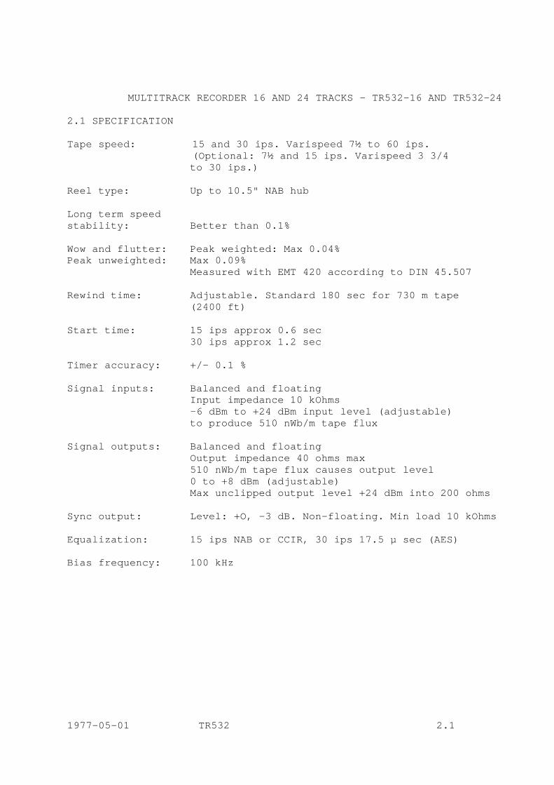
MULTITRACK RECORDER 16 AND 24 TRACKS - TR532-16 AND TR532-24 2.1 SPECIFICATION Tape speed: 15 and 30 ips. Varispeed 7½ to 60 ips. (Optional: 7½ and 15 ips. Varispeed 3 3/4 to 30 ips.) Reel type: Up to 10.5" NAB hub Long term speed stability: Better than 0.1% Wow and flutter: Peak weighted: Max 0.04% Peak unweighted: Max 0.09% Measured with EMT 420 according to DIN 45.507 Rewind time: Adjustable. Standard 180 sec for 730 m tape (2400 ft) Start time: 15 ips approx 0.6 sec 30 ips approx 1.2 sec Timer accuracy: +/- 0.1 % Signal inputs: Balanced and floating Input impedance 10 kOhms -6 dBm to +24 dBm input level (adjustable) to produce 510 nWb/m tape flux Signal outputs: Balanced and floating Output impedance 40 ohms max 510 nWb/m tape flux causes output level 0 to +8 dBm (adjustable) Max unclipped output level +24 dBm into 200 ohms Sync output: Level: +O, -3 dB. Non-floating. Min load 10 kOhms Equalization: 15 ips NAB or CCIR, 30 ips 17.5 µ sec (AES) Bias frequency: 100 kHz 1977-05-01 TR532 2.1
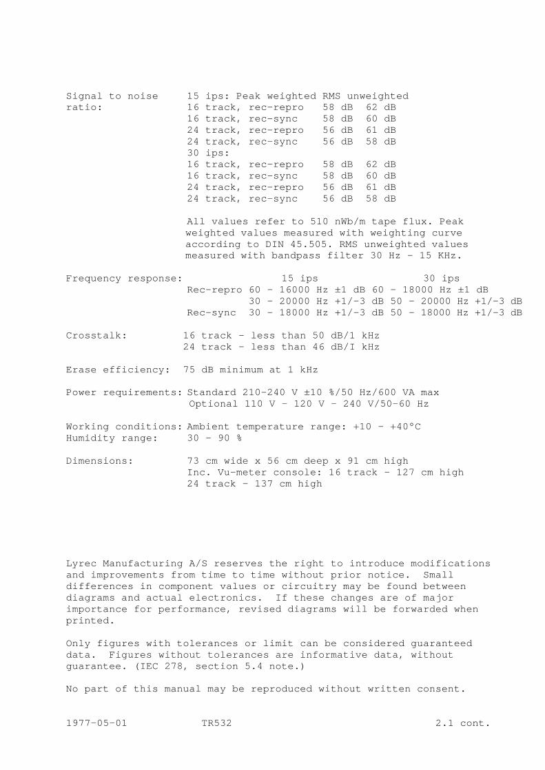
Signal to noise 15 ips: Peak weighted RMS unweighted ratio: 16 track, rec-repro 58 dB 62 dB 16 track, rec-sync 58 dB 60 dB 24 track, rec-repro 56 dB 61 dB 24 track, rec-sync 56 dB 58 dB 30 ips: 16 track, rec-repro 58 dB 62 dB 16 track, rec-sync 58 dB 60 dB 24 track, rec-repro 56 dB 61 dB 24 track, rec-sync 56 dB 58 dB
All values refer to 510 nWb/m tape flux. Peak weighted values measured with weighting curve according to DIN 45.505. RMS unweighted values measured with bandpass filter 30 Hz - 15 KHz.
Frequency response: 15 ips 30 ips Rec-repro 60 - 16000 Hz ±1 dB 60 - 18000 Hz ±1 dB 30 – 20000 Hz +1/-3 dB 50 – 20000 Hz +1/-3 dB Rec-sync 30 – 18000 Hz +1/-3 dB 50 - 18000 Hz +1/-3 dB Crosstalk: 16 track - less than 50 dB/1 kHz 24 track - less than 46 dB/I kHz Erase efficiency: 75 dB minimum at 1 kHz Power requirements: Standard 210-240 V ±10 %/50 Hz/600 VA max Optional 110 V - 120 V - 240 V/50-60 Hz Working conditions: Ambient temperature range: +10 - +40°C Humidity range: 30 – 90 % Dimensions: 73 cm wide x 56 cm deep x 91 cm high Inc. Vu-meter console: 16 track - 127 cm high 24 track - 137 cm high Lyrec Manufacturing A/S reserves the right to introduce modifications and improvements from time to time without prior notice. Small differences in component values or circuitry may be found between diagrams and actual electronics. If these changes are of major importance for performance, revised diagrams will be forwarded when printed. Only figures with tolerances or limit can be considered guaranteed data. Figures without tolerances are informative data, without guarantee. (IEC 278, section 5.4 note.) No part of this manual may be reproduced without written consent. 1977-05-01 TR532 2.1 cont.

2.2 DIMENSIONS
Remote control type RCU Remote control type TPC
1977-05-01 TR532
1977-05-02 2.2
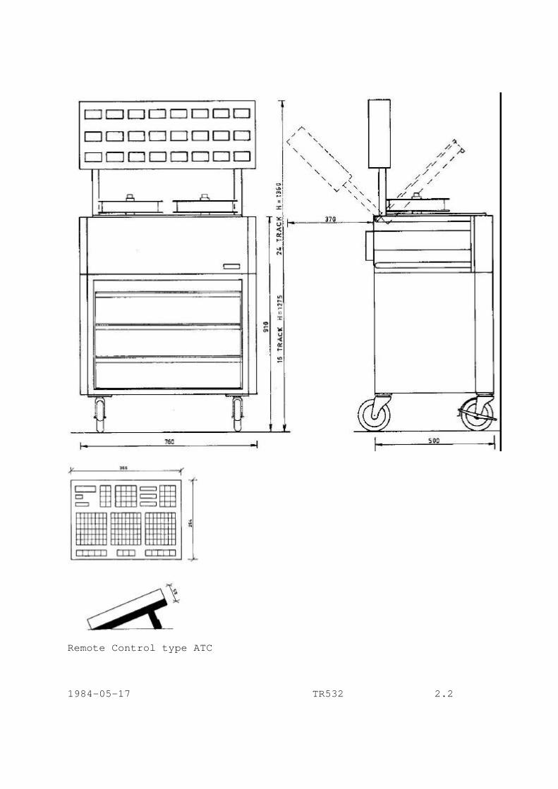
Remote Control type ATC
1984-05-17 TR532 2.2
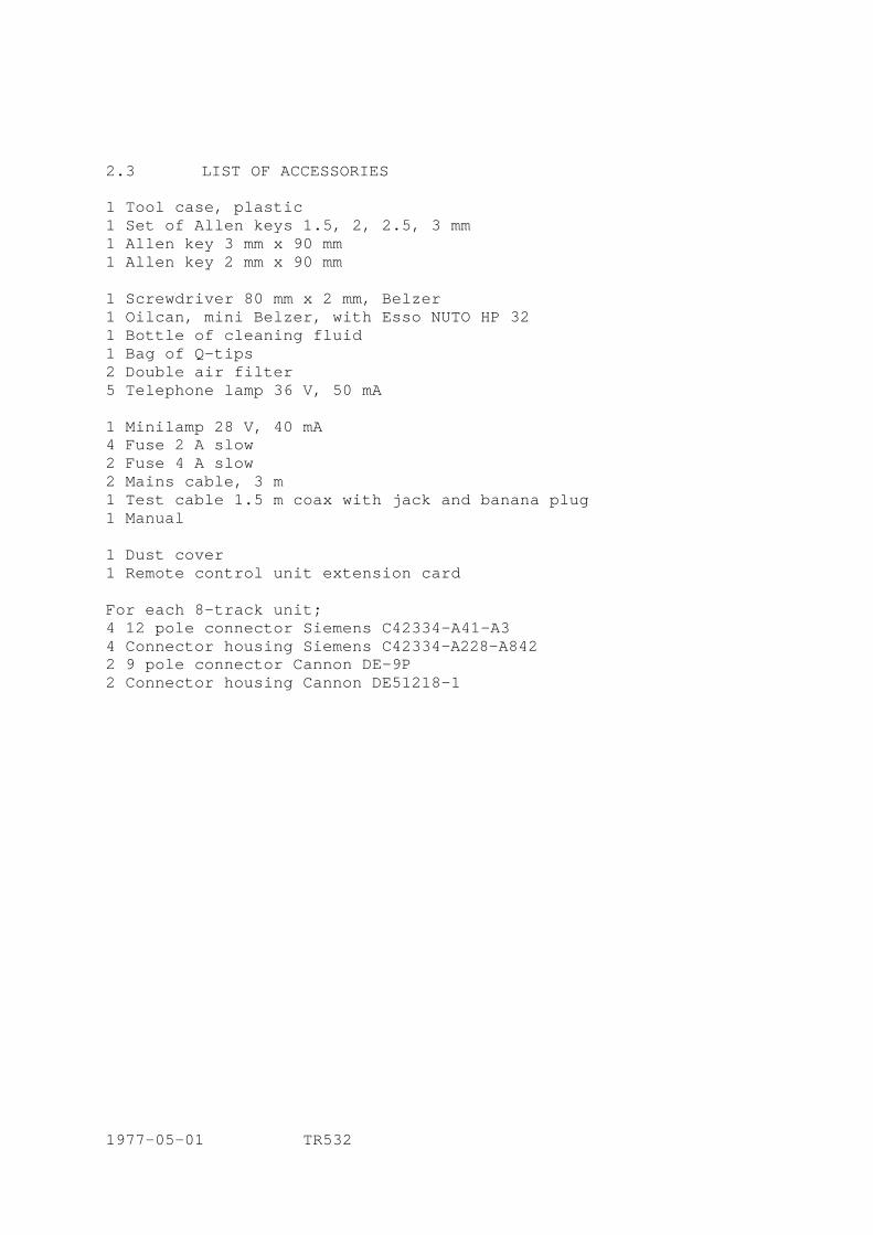
2.3 LIST OF ACCESSORIES 1 Tool case, plastic 1 Set of Allen keys 1.5, 2, 2.5, 3 mm 1 Allen key 3 mm x 90 mm 1 Allen key 2 mm x 90 mm 1 Screwdriver 80 mm x 2 mm, Belzer 1 Oilcan, mini Belzer, with Esso NUTO HP 32 1 Bottle of cleaning fluid 1 Bag of Q-tips 2 Double air filter 5 Telephone lamp 36 V, 50 mA 1 Minilamp 28 V, 40 mA 4 Fuse 2 A slow 2 Fuse 4 A slow 2 Mains cable, 3 m 1 Test cable 1.5 m coax with jack and banana plug 1 Manual 1 Dust cover 1 Remote control unit extension card For each 8-track unit; 4 12 pole connector Siemens C42334-A41-A3 4 Connector housing Siemens C42334-A228-A842 2 9 pole connector Cannon DE-9P 2 Connector housing Cannon DE51218-1 1977-05-01 TR532

2.3 LIST OF ACCESSORIES 969002 1 Tool case, plastic 969011 1 Set of Allen keys 1.5, 2, 2.5, 3 mm 969016 1 Allen key 3 mm x 90 mm 969017 1 Allen key 2 mm x 90 mm 969020 1 Screwdriver 80 mm x 2 mm, Belzer 969036 1 Oilcan with Esso NUTO HP 32 501009 2 Double air filter 961701 5 Telephone lamp 36V, 5OmA 922134 2 Lamp EAO 11.903.0 for ATC 961711 1 Minilamp 28V, 4OmA 961920 4 Fuse 2A slow 961941 2 Fuse 4A slow 961910 2 Fuse 1A slow 999999 1 Mains cable 3 m 501027 1 Test cable 1.5 coax with jack and banana plug 969044 1 Manual 969046 1 Manual for ATC 501028 1 Extender print for AM77 953701 1 25 pole connector Cannon DB25P - male 953702 1 Connector housing Cannon DB115339-2 999999 4 Allen screw M3 x 8 ULS 999999 4 Allen screw M4 x 10 ULS 999999 24 Screw M3 x 10 869583 1 Brake band For each 8 track unit; 954409 4 12 pole connector Siemens C42334-A41-A3 954408 4 Connector housing Siemens C42334-A228-A842 953743 1 9 pole connector Cannon DE-9P 953746 1 Connector housing Cannon DE51218-1 1984-06-12 TR532 2.3
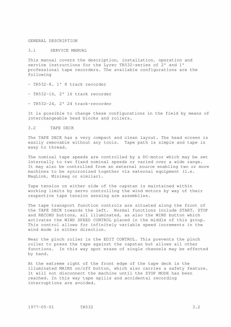
GENERAL DESCRIPTION 3.1 SERVICE MANUAL This manual covers the description, installation, operation and service instructions for the Lyrec TR532-series of 2" and 1" professional tape recorders. The available configurations are the following - TR532-8. 1" 8 track recorder - TR532-16, 2" 16 track recorder - TR532-24, 2" 24 track-recorder It is possible to change these configurations in the field by means of interchangeable head blocks and rollers. 3.2 TAPE DECK The TAPE DECK has a very compact and clean layout. The head screen is easily removable without any tools. Tape path is simple and tape is easy to thread. The nominal tape speeds are controlled by a DC-motor which may be set internally to two fixed nominal speeds or varied over a wide range. It may also be controlled from an external source enabling two or more machines to be syncronized together via external equipment (i.e. MagLink, Minimag or similar). Tape tension on either side of the capstan is maintained within working limits by servo controlling the wind motors by way of their respective tape tension sensing arm assemblies. The tape transport function controls are situated along the front of the TAPE DECK towards the left. Normal functions include START, STOP and RECORD buttons, all illuminated, as also the WIND button which activates the WIND SPEED CONTROL placed in the middle of this group. This control allows for infinitely variable speed increments in the wind mode in either direction. Near the pinch roller is the EDIT CONTROL. This prevents the pinch roller to press the tape against the capstan but allows all other functions. In this way spot erase of single channels may be effected by hand. At the extreme right of the front edge of the tape deck is the illuminated MAINS on/off button, which also carries a safety feature. It will not disconnect the machine until the STOP MODE has been reached. In this way tape spills and accidental recording interruptions are avoided. 1977-05-01 TR532 3.2
Close to the MAINS button are the two speed selection buttons, 15 and 30 ips. When power has been switched off the tape recorder will always come back to the previously selected speed. The power supplies for the machine are housed below the tape deck, together with the servo electronics. 3.3 RECORD/PLAYBACK AMPLIFIERS AM 77 The RECORD/PLAYBACK AMPLIFIERS are housed in 8-track units below the mechanical section of the machine. One complete RECORD/PLAYBACK AMPLIFIER AM 77 is contained on a single printed board. All necessary adjustments are made from the front and each amplifier is an easily replaceable plug-in unit. Equalization amplifiers, level control and bias level control are contained on plug-in boards on the AM 77. This allows easy changing from standard version to any other version by plugging in the correct equalization boards. Furthermore there is a possibility of letting the tape speed pushbuttons control the amplifiers only. In this way a 15 ips CCIR - 15 ips NAB recorder is obtained. For purposes where it is necessary to change bias level on a few tracks on a prerecorded tape, a switch is installed on each amplifier. An arbitrary bias value may then be set without disturbing the two normal bias settings. 3.4 VU-METER PANEL The VU-METER PANEL is mounted at the rear top of the TAPE DECK. It may be mounted at any remote location if the user so desires. Each VU-METER may be calibrated over a wide range of levels to suit individual studio requirements. 3.5 CONSOLE The TAPE DECK, RECORD/PLAYBACK AMPLIFIERS and VU-METER PANEL are mounted in a solid framework on large casters which aid moving the machine around. The three sections are electrically interconnected with cable harnesses which are long enough to allow good service but which are placed at the rear of the machine where they are out of the way in normal use. 1977-05-01 TR532 3.5

All heat producing elements are located at the rear of the machine so that the sides may be placed in direct contact with other equipment, thereby taking up a minimum of control room space. Low-noise fans further enhance the temperature safety margin. 3.6 REMOTE CONTROL UNIT A normal feature of the machine is a very complete REMOTE CONTROL UNIT; facilities include the possibility of switching the output signal of each channel between the LINE input, the SYNC output and the PLAYBACK output. It is possible to drop in or out of record on any individual channel. A SOLO button is also provided for each channel. The switching logic for these functions is so designed as to simplify the operators requirements in so far as routing systems and working requirements are concerned. This allows the use of simpler desks or less tiring work routines. Further features of the REMOTE CONTROL UNIT include VARISPEED continuously covering the range 7.5 to 60 ips. Actual tape speed can be monitored by the TAPE TIMER DISPLAY enabling any VARISPEED setting to be repeated accurately. A SEARCH FUNCTION is provided whereby the machine can rewind to any pre-selected position of the tape, with no overshoot. The normal tape transport functions START, STOP, RECORD and FAST WIND modes are also present in the REMOTE CONTROL UNIT. There is a socket on the rear of the box enabling a REMOTE TIMER DISPLAY to be installed up to 10 meters away from the box, in any convenient control room location. 1977-05-01 TR532 3.6

4. INSTALLATION 4.1 UNPACKING The machine has been packed in a container specially designed for air freight. Inspect it visually and if any damage is observed notify your carrying agent immediately. If all is normal unpack the machine carefully and retain the packing material for possible future use. Remove the front and side covers of TAPE DECK and inspect the SERVO CONTROL print boards; they should be firmly seated in their positions, and all connectors should be likewise. Inspect the TAPE DECK and check that none of the metal parts that come in contact with the tape are damaged in any way. Check the HEAD BLOCK and particularly the front of the head stacks. Rubber rollers should be smooth and all metal rollers should move freely; tension arms should feel slightly hard because of the damping cylinders but movement should be smooth, with no indication of friction or roughness. Check the seating of the individual RECORD/PLAYBACK AMPLIFIERS modules. Refer to the CONNECTOR TABLE below and check that all factory wired plugs and connectors are properly in place. Proceed likewise with the REMOTE CONTROL UNIT and the VU-METER PANEL. Place the VU-METER PANEL in position and secure it with the four screws provided. 4.2 INTERCONNECTION After checking the above refer to the CONNECTOR TABLE again and the CONNECTOR DIAGRAMS and wire up the mains connectors. BE SURE YOUR LOCAL MAINS VOLTAGE IS COMPATIBLE WITH THE MACHINE. BE SURE THAT YOU COMPLY WITH YOUR LOCAL REGULATIONS AND PAY PARTICULAR ATTENTION TO THE EARTHING CONNECTIONS. Then wire up all the LINE IN and LINE OUT connectors the RECORD INDICATION connectors, where applicable, and the SYNC OUTPUT connectors. Connect the REMOTE CONTROL UNIT umbilical to the connector on the rear of the tape deck. CAUTION: THIS CONNECTION SHOULD NOT BE MADE OR BROKEN WITH EITHER
MACHINE OR THE REMOTE CONTROL UNIT OR BOTH SWITCHED ON. DAMAGE TO THE DIGITAL CIRCUITRY WILL ENSUE.
This completes the installation procedure. 1977-05-01 TR532 4.2
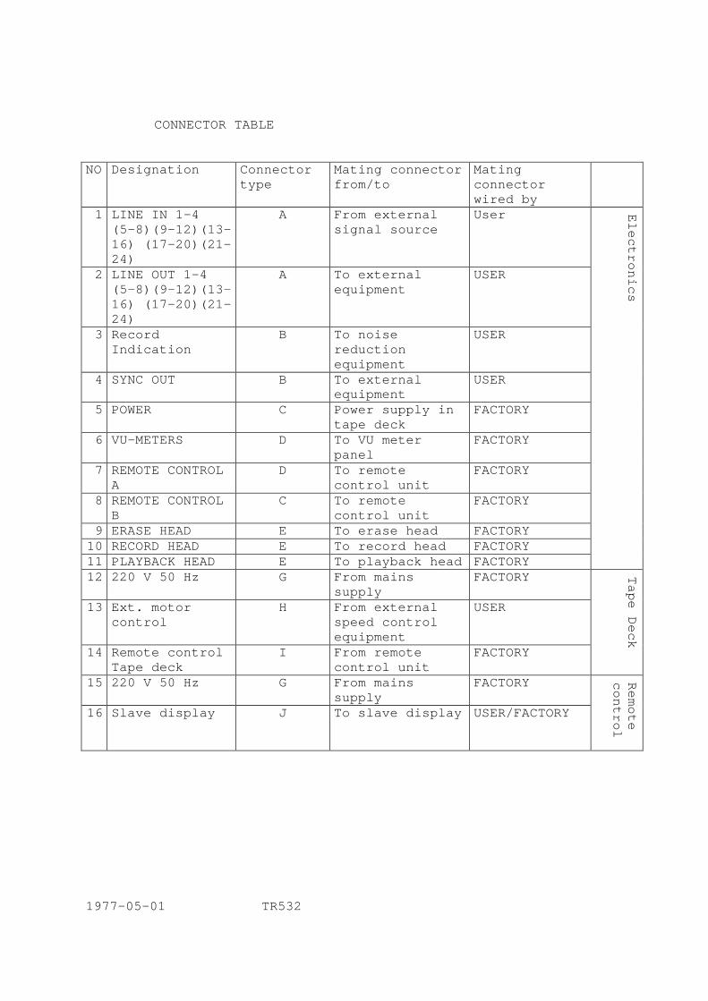
CONNECTOR TABLE NO Designation Connector
type Mating connector from/to
Mating connector wired by
1 LINE IN 1-4 (5-8)(9-12)(13-16) (17-20)(21-24)
A From external signal source
User
2 LINE OUT 1-4 (5-8)(9-12)(13-16) (17-20)(21-24)
A To external equipment
USER
3 Record Indication
B To noise reduction equipment
USER
4 SYNC OUT B To external equipment
USER
5 POWER C Power supply in tape deck
FACTORY
6 VU-METERS D To VU meter panel
FACTORY
7 REMOTE CONTROL A
D To remote control unit
FACTORY
8 REMOTE CONTROL B
C To remote control unit
FACTORY
9 ERASE HEAD E To erase head FACTORY 10 RECORD HEAD E To record head FACTORY 11 PLAYBACK HEAD E To playback head FACTORY
Electronics
12 220 V 50 Hz G From mains supply
FACTORY
13 Ext. motor control
H From external speed control equipment
USER
14 Remote control Tape deck
I From remote control unit
FACTORY
Tape Deck
15 220 V 50 Hz G From mains supply
FACTORY
16 Slave display J To slave display
USER/FACTORY
Remote
control
1977-05-01 TR532
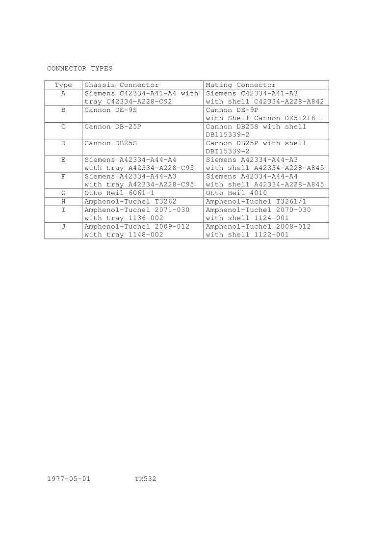
CONNECTOR TYPES Type Chassis Connector Mating Connector A Siemens C42334-A41-A4 with
tray C42334-A228-C92 Siemens C42334-A41-A3 with shell C42334-A228-A842
B Cannon DE-9S Cannon DE-9P with Shell Cannon DE51218-1
C Cannon DB-25P Cannon DB25S with shell DB115339-2
D Cannon DB25S Cannon DB25P with shell DBI15339-2
E Siemens A42334-A44-A4 with tray A42334-A228-C95
Siemens A42334-A44-A3 with shell A42334-A228-A845
F Siemens A42334-A44-A3 with tray A42334-A228-C95
Siemens A42334-A44-A4 with shell A42334-A228-A845
G Otto Heil 6061-1 Otto Heil 4010 H Amphenol-Tuchel T3262 Amphenol-Tuchel T3261/1 I Amphenol-Tuchel 2071-030
with tray 1136-002 Amphenol-Tuchel 2070-030 with shell 1124-001
J Amphenol-Tuchel 2009-012 with tray 1148-002
Amphenol-Tuchel 2008-012 with shell 1122-001
1977-05-01 TR532
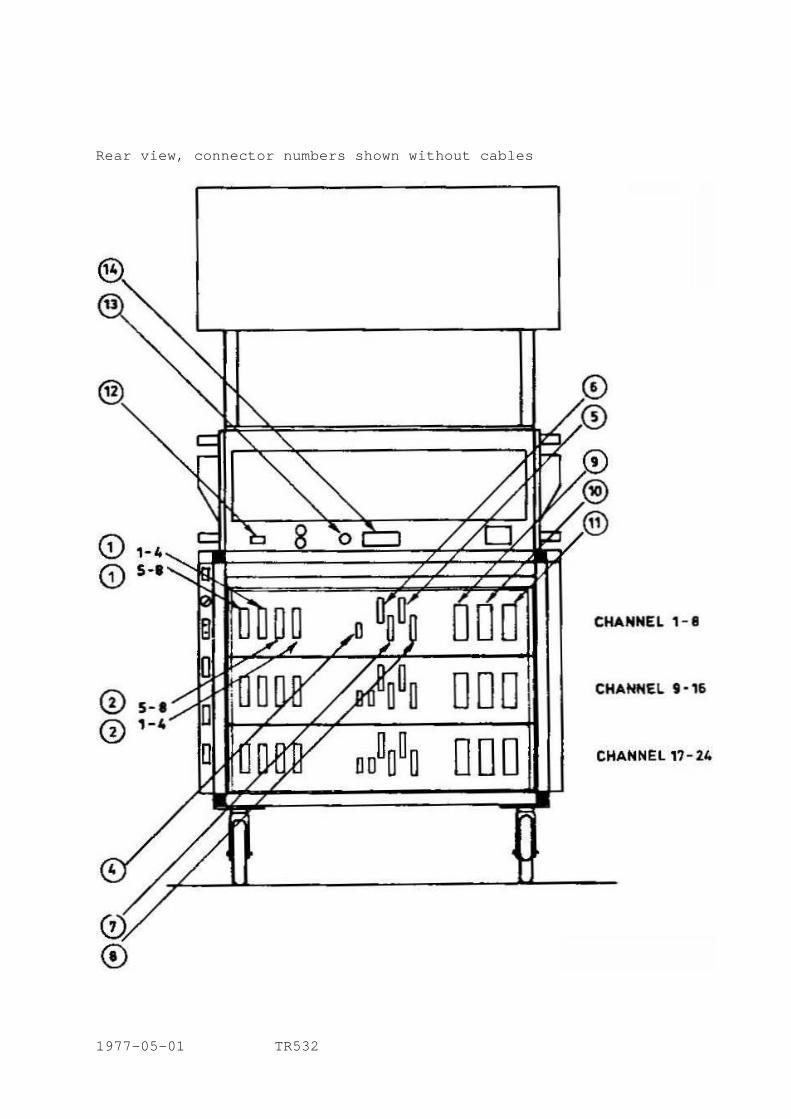
Rear view, connector numbers shown without cables
1977-05-01 TR532

CONNECTOR DRAWINGS No. I LINE IN 1-4 (5-8, 9-12, 13-16, 17-20, 21-24) (all grounds internally connected) No. 2 LINE OUT 1-4 (5-8, 9-12, 13-16, 17-20, 21-24) (pins 2a, 2b, 5a, 5b not connected) No. 3 RECORD INDICATION 1-8 (9-16)(17-24) When a channel is in RECORD, output will be +24 V, other wise a high impedance to ground. Ext. load min 3 Kohms. No. 4 SYNC OUT 1-8 (9-16, 17-24) Ext. load min 10 kOhms No. 13 Ext. Motor Control Note: Do not use this circuit simultaneously with Varispeed from Remote Control Unit. No. 12, 15 All connectors are cablepart seen from solderside.
1977-05-01 TR532
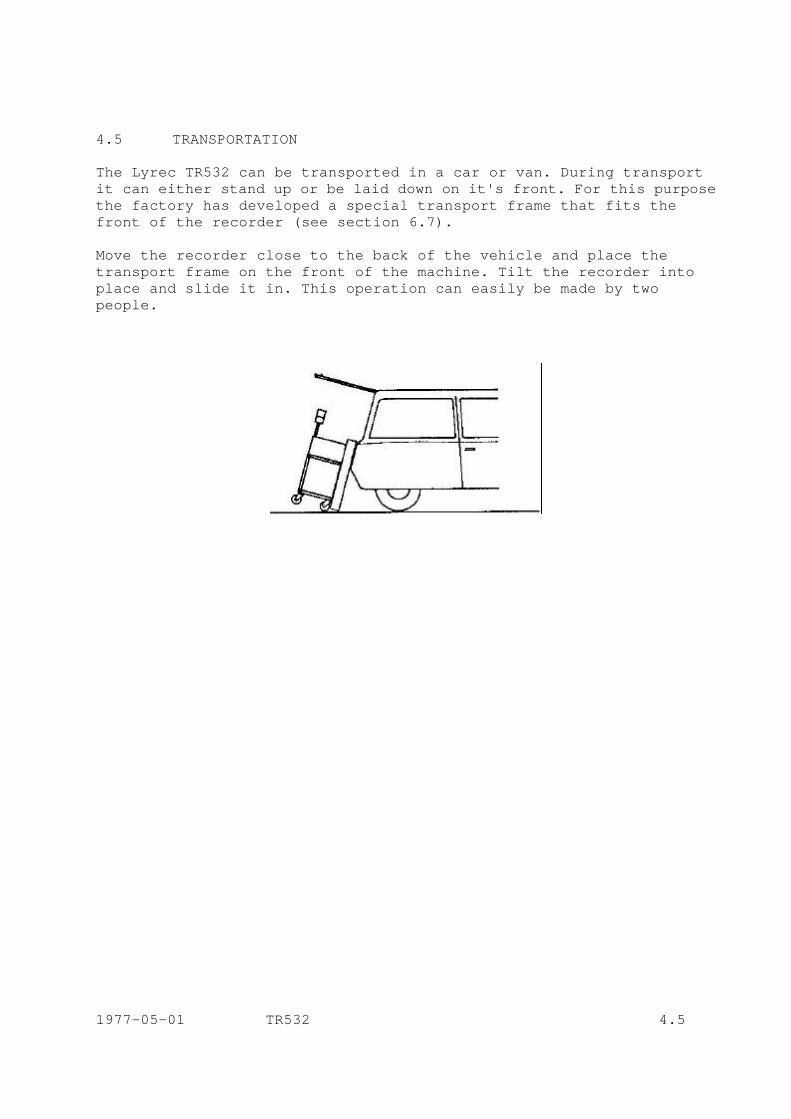
4.5 TRANSPORTATION The Lyrec TR532 can be transported in a car or van. During transport it can either stand up or be laid down on it's front. For this purpose the factory has developed a special transport frame that fits the front of the recorder (see section 6.7). Move the recorder close to the back of the vehicle and place the transport frame on the front of the machine. Tilt the recorder into place and slide it in. This operation can easily be made by two people.
1977-05-01 TR532 4.5
5. OPERATION 5.1 SWITCHING ON Connect both line cords to the appropriate voltage and press the MAINS button on the tape deck. Select the desired tape speed. The MAINS, the STOP and one of the speed buttons on the TAPE DECK and the STOP button on the REMOTE CONTROL UNIT should light up. The ventilation fans should start running and the VU-meters should light up (if of illuminated type). Switch on the REMOTE CONTROL UNIT; the power switch is on the rear panel. All channels should illuminate their SAFE and SYNC LED'S. The TAPE TIMER should indicate 00.00 and the speed should be set at nominal speed, whichever has been selected. TAPE DECK 5.2 LOADING Place an empty reel and a full reel on the appropriate hubs. The knurled knob on the top of the hub should be turned clockwise to lock the reels in place. Refer to drawing No. 5.02 and thread the tape through the tape path. Check the height of the tape, and if necessary adjust it. See section 7.1 for this adjustment. 5.3 PLAY MODE Press START button on the TAPE DECK or on the REMOTE CONTROL UNIT. Both buttons should illuminate; the PINCH ROLLER and GUIDE ROLLER should pull in, placing the tape in contact with the heads and the capstan, which will cause the tape to move forward at its nominal speed. On the REMOTE CONTROL UNIT the timer will begin to show seconds and then minutes of elapsed time. Select REPRO on the REMOTE CONTROL UNIT on those channels from which the tape playback signal is to be monitored. 5.4 RECORD MODE Select the channels to be recorded on the REMOTE CONTROL UNIT by pressing the READY buttons on the appropriate channels; the red LED's will immediately begin flashing to indicate that these channels are ready to record. On the same channels the green SAFE LED will go off. Press RECORD and START buttons simultaneously either on the TAPE DECK or on the REMOTE CONTROL UNIT; the same mechanical functions as in the play mode will occur. On the REMOTE CONTROL UNIT the red flashing LED's will illuminate steadily indicating RECORD MODE on those channels. 1977-05-01 TR532 5.4
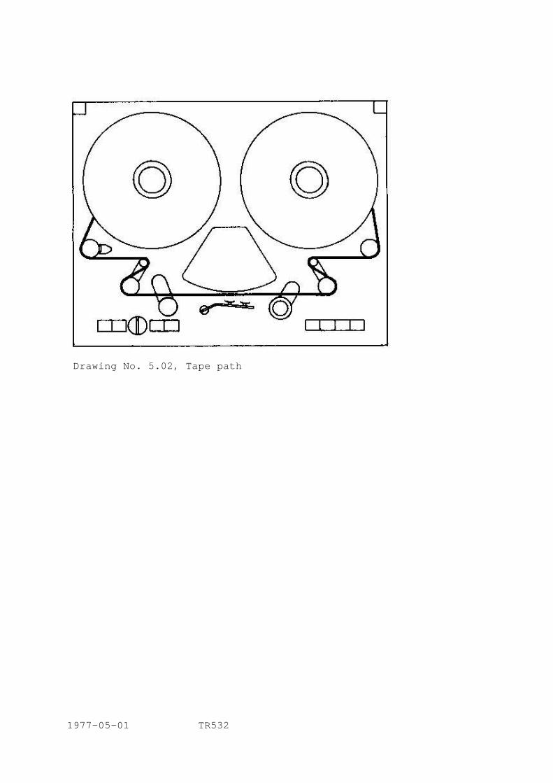
Drawing No. 5.02, Tape path 1977-05-01 TR532
5.5 FAST WIND MODE A. From the TAPE DECK Press the WIND button and select the direction and speed of wind by setting the WIND SPEED CONTROL. B. From REMOTE CONTROL UNIT Press the appropriate button to select wind direction and alternate with the other to control speed. 5.6 EDIT MODE Turn the EDIT CONTROL in anti-clockwise direction, thereby causing the tape to come into contact with the PLAYBACK head but not with the capstan. The SERVO TENSION ARMS are locked and the tape path is now rigid. For convenience the head shields may be removed by simply pulling up, when commencing the operation. Any of the previous modes may be used simultaneously with the EDIT MODE allowing editing in the PLAY MODE, searching in the WIND MODE or hand controlled spot-erasing in the RECORD MODE. It is also possible to enter the EDIT MODE from any of the previous modes. 5.7 STOP MODE Pressing the STOP button immediately interrupts the PLAY or RECORD modes. In both cases the tape motion is immediately halted and the tape is lifted from the heads. Coming from the RECORD MODE the electronics are also switched to a stand-by condition, see below. When coming from the FAST WIND mode dynamic brakes are first applied to slow the reels and when the tape motion sensor indicates that the tape is halted then mechanical brakes are applied, simply to hold the reels in place. 5.8 TAPE DECK LOGIC The TAPE DECK SERVOSYSTEM and LOGIC is so designed as to avoid throwing tape loops or causing spills, jerks or other situations dangerous to the tape. It is possible to go from any mechanical mode to any other with no problems. For description of the circuits, see section 8. REMOTE CONTROL UNIT Channel function selectors. 5.9 READY As previously indicated these buttons select a given channel and place it in READY MODE so that when the START and RECORD buttons are pressed the channel goes into RECORD MODE. In the READY MODE 1977-05-01 TR532 5.9
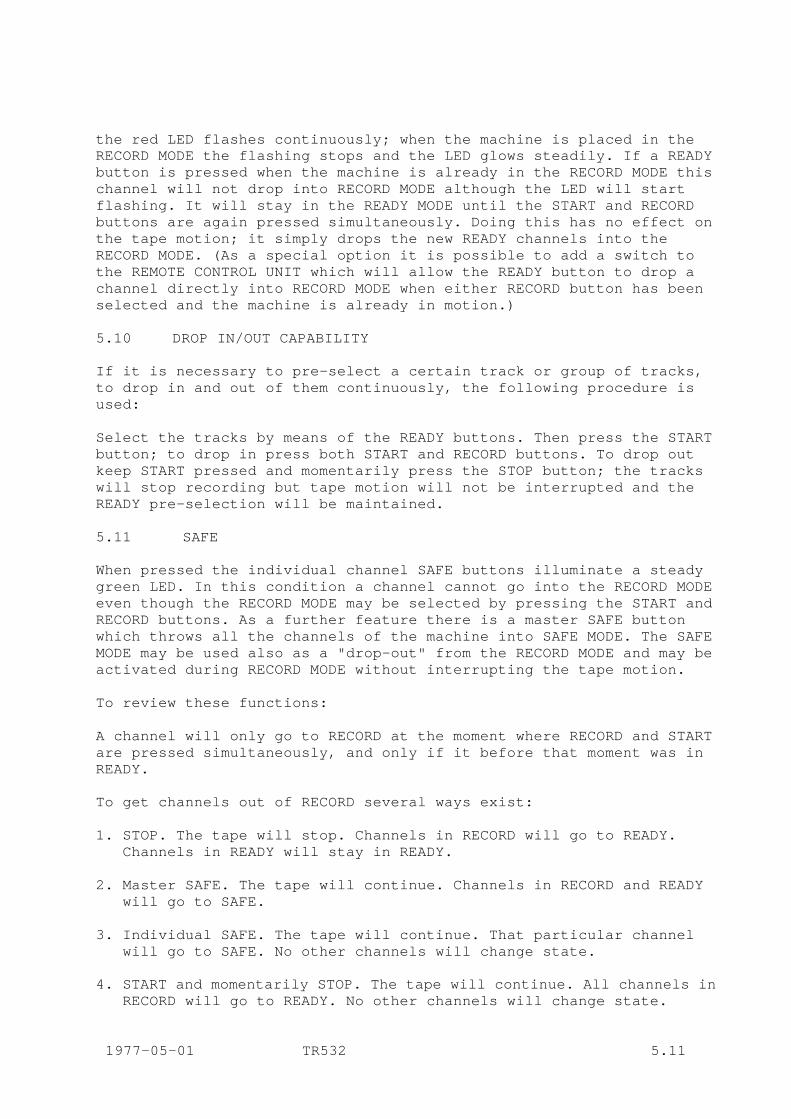
the red LED flashes continuously; when the machine is placed in the RECORD MODE the flashing stops and the LED glows steadily. If a READY button is pressed when the machine is already in the RECORD MODE this channel will not drop into RECORD MODE although the LED will start flashing. It will stay in the READY MODE until the START and RECORD buttons are again pressed simultaneously. Doing this has no effect on the tape motion; it simply drops the new READY channels into the RECORD MODE. (As a special option it is possible to add a switch to the REMOTE CONTROL UNIT which will allow the READY button to drop a channel directly into RECORD MODE when either RECORD button has been selected and the machine is already in motion.) 5.10 DROP IN/OUT CAPABILITY If it is necessary to pre-select a certain track or group of tracks, to drop in and out of them continuously, the following procedure is used: Select the tracks by means of the READY buttons. Then press the START button; to drop in press both START and RECORD buttons. To drop out keep START pressed and momentarily press the STOP button; the tracks will stop recording but tape motion will not be interrupted and the READY pre-selection will be maintained. 5.11 SAFE When pressed the individual channel SAFE buttons illuminate a steady green LED. In this condition a channel cannot go into the RECORD MODE even though the RECORD MODE may be selected by pressing the START and RECORD buttons. As a further feature there is a master SAFE button which throws all the channels of the machine into SAFE MODE. The SAFE MODE may be used also as a "drop-out" from the RECORD MODE and may be activated during RECORD MODE without interrupting the tape motion. To review these functions: A channel will only go to RECORD at the moment where RECORD and START are pressed simultaneously, and only if it before that moment was in READY. To get channels out of RECORD several ways exist: 1. STOP. The tape will stop. Channels in RECORD will go to READY.
Channels in READY will stay in READY. 2. Master SAFE. The tape will continue. Channels in RECORD and READY
will go to SAFE. 3. Individual SAFE. The tape will continue. That particular channel
will go to SAFE. No other channels will change state. 4. START and momentarily STOP. The tape will continue. All channels in
RECORD will go to READY. No other channels will change state. 1977-05-01 TR532 5.11
5.12 LINE/SYNC/REPRO The LINE OUT signal from each PLAYBACK AMPLIFIER may be selected by one of the three following controls: LINE, SYNC and REPRO. This does not affect the recording on this track. Pressing the LINE button selects the LINE INPUT signal of that channel and routes it to the output. Pressing the SYNC button selects the signal from the record head of that channel, used as a playback head. Pressing the REPRO button for that channel selects the signal from the normal playback head. There are also three master buttons for LINE, SYNC and REPRO which will throw all the channels to that particular function. The only exception to these selections occurs when a given channel is selected to SYNC and it is also placed in the RECORD MODE. In this situation the channel is automatically switched to LINE, returning to SYNC when the RECORD MODE is cancelled. 5.13 SOLO/DEFEAT When the SOLO button of a channel is pressed it causes all the other channels to switch to LINE. (This can be changed on special order so that the other channels mute instead of switching to LINE.) Any amount of channels may be soloed simultaneously. In order to return them to their normal situation the DEFEAT button is pressed. 5.14 TAPE TIMER The TAPE TIMER receives information from the tape motion sensor on the tape deck, and shows elapsed time in minutes and seconds relative to 15 ips. By means of the RESET button on the left, it may be reset to 00.00 at any point desired by the operator. In order to avoid accidental resets this button has a protective cover. 5.15 SEARCH FUNCTION The SEARCH FUNCTION comprises two controls, an illuminated SEARCH button and a PRESET DIAL. When the SEARCH button is pressed the TAPE DECK goes into the WIND MODE and automatically winds the tape in such a way as to make the timer display equal to the display on the PRESET DIAL. A built-in feature of this function ensures that the tape will not overshoot since the wind speed is progressively lowered as soon as the difference between the two displays drops below a preset amount. 1977-05-01 TR532 5.15
5.16 NOMINAL/VARISPEED When the NOMINAL button is pressed the LED lights up and the machine will transport the tape at fixed nominal speed of 15 or 30 ips, whichever has been selected. When the VARISPEED button is pressed the LED flashes continuously to warn of a non-normal condition; the speed of the tape now depends on the setting of the two potentiometers below the VARISPEED button. As indicated they allow COURSE and FINE adjustments of the tape speed from slightly below 7 1/2 ips to slightly above 60 ips. A further feature of both buttons, in combination with the TAPE TIMER display allows for checking the actual tape speed. This is operated as follows: Select either the NOMINAL speed or VARISPEED. Do not release the selector button but hold it down. In this position the TAPE TIMER display will change over to 4 digits which express the actual tape speed according to the following formula: 1000
speed ips = 15 x ���������������� 2.000 - DISPLAY Table 1 and 2 shows the full range of the displays with their equivalents in speed deviation in ips, in percentage or in musical values. This speed checking function may be used to reset any VARISPEED setting at any time within close tolerances. An important feature of this function is that it does not disturb the TAPE TIMER counting. When the button is released the timer will go back to its normal timing function without having lost count in the interval. Note: No reading will result if the tape is not in motion,
since the information is taken from the TAPE MOTION SENSOR, therefore reflecting the actual tape motion, not the capstan motor speed.
1977-05-01 TR532 5.16

TABLE 1; nominal speed 15 ips. Applicable for standard REMOTE CONTROL UNIT, RCU
Display Speed (ips) Deviation % 0000 7.50 - 50.00 0100 7.89 - 47.37 0200 8.33 - 44.44 0300 8.82 - 41.18 0400 9.38 - 37.50 0500 10.00 - 33.33 0550 10.34 - 31.03 0600 10.71 - 28.57 0650 11.11 - 25.93 0700 11.54 - 23.08 0750 12.00 - 20.00 0800 12.50 - 16.67 0850 13.04 - 13.04 0865 13.22 - 11.89 - 1 tone 0900 13.64 - 9.09 0902 13.66 - 8.93 - 3/4 tone 0920 13.89 - 7.41 0937 14.11 - 5.93 - 1/2 tone 0940 14.15 - 5.66 0953 14.33 - 4.49 0960 14.42 - 3.85 0969 14.55 - 3.01 - 1/4 tone 0980 14.71 - 1.96 0985 14.78 - 1.48 1000 15.00 0 1015 15.23 1.52 1020 15.31 2.04 1029 15.45 2.99 + 1/4 tone 1040 15.63 4.17 1043 15.67 4.49 1056 15.89 5.93 + 1/2 tone 1060 15.96 6.38 1080 16.30 8.70 1082 16.34 8.93 + 3/4 tone 1100 16.67 11.11 1106 16.78 11.86 + 1 tone 1150 17.65 17.65 1200 18.75 25.00 1250 20.00 33.33 1300 21.43 42.86 1350 23.08 53.85 1400 25.00 66.67 1450 27.27 81.82 1500 30.00 100.00 1977-05-01 TR532 5.16 cont.

TABLE 2; nominal speed 30 ips. Applicable for standard REMOTE REMOTE CONTROL UNIT, RCU Display Speed (ips) Deviation % 1000 15.00 - 50.00 1050 15.79 - 47.37 1100 16.67 - 44.44 1150 17.65 - 41.18 1200 18.75 - 37.50 1250 20.00 - 33.33 1275 20.69 - 31.03 1300 21.43 - 28.57 1325 22.22 - 25.93 1350 23.08 - 23.08 1375 24.00 - 20.00 1400 25.00 - 16.67 1425 26.09 - 13.04 1432 26.43 - 11.89 - 1 tone 1450 27.27 - 9.09 1451 27.32 - 8.93 - ¾ tone 1460 27.78 - 7.41 1468 28.22 - 5.93 - ½ tone 1470 28.30 - 5.66 1476 28.65 - 4.49 1480 28.85 - 3.85 1484 29.10 - 3.01 - ¼ tone 1490 29.41 - 1.96 1492 29.56 - 1.48 1500 30.00 0 1507 30.46 1.52 1510 30.61 2.04 1514 30.90 2.99 + ¼ tone 1520 31.25 4.17 1521 31.35 4.49 1528 31.78 5.93 + ½ tone 1530 31.91 6.38 1540 32.61 8.70 1541 32.68 8.93 + ¾ tone 1550 33.33 11.11 1553 33.56 11.86 + 1 tone 1575 35.29 17.65 1600 37.50 25.00 1625 40.00 33.33 1650 42.86 42.86 1675 46.15 53.85 1700 50.00 66.67 1725 54.55 81.82 1750 60.00 100.00 1977-05-01 TR532 5.16 cont.

RECORD/PLAYBACK AMPLIFIERS 5.17 SYNC OUTPUT Apart from the normal sync signal which is routed to the LINE OUTPUT each AM 77 RECORD/PLAYBACK AMPLIFIER incorporates a separate sync amplifier. The signal from this extra sync output is available independently for each channel at a separate plug. This output is unbalanced and should not be terminated with less than 10 kOhms. The SYNC OUTPUT does not in any way affect or interfere with the ordinary sync signals available at the line output, nor can it be controlled by the SYNC button on the REMOTE CONTROL UNIT. 1977-05-01 TR532 5.17
5.18 SPECIAL FEATURES The machine has been designed for maximum ease of operation. In this context several facilities have been included which are not normally found as standard items. HEADBLOCK To ease maintenance and format changes the HEADBLOCK uses a plug and socket interconnection with a precision mechanical seating arrangement that allows fast changeover operations. EDITING FACILITIES As described (5.6) the EDIT CONTROL not only permits splice editing but also provides for very precise spot erasing with the RECORD MODE activated and the tape moved by hand. Holding the EDIT CONTROL half way in during FAST WIND permits listening to the tape without close contact to the playback head. SWITCH-OFF SAFE-GUARD As mentioned (3.2) the MAINS SWITCH will not switch off the machine unless it is in STOP MODE. This avoids accidental tape spills or interruptions. SPEED MEMORY When mains is switched on and off the taperecorder always comes back to the same speed. Change between the two nominal speeds can only be done in STOP MODE. TRANSIENT PROTECTION To avoid strong switch-on and switch-off transients in the outputs, which might damage monitor speakers, a relay has been included which short-circuits the output of the playback amplifiers for a few seconds after power is applied, until DC conditions are stabilized, and also immediately after it has been removed, before DC working conditions can change. RECORD INDICATION OUTPUT A socket is provided on the back of each eight-channel unit, which delivers +24 V from each individual channel when it goes into the RECORD MODE, enabling external equipment-functions to be controlled (i.e. noise reduction). In other modes the RECORD INDICATION OUTPUT has a high impedance to ground external load: min 3000 ohms. SEARCH FUNCTION As described (5.15) the SEARCH FUNCTION is a useful aid in speeding up working routines; it is built into the machine and requires no extra hardware or powering. 1977-05-01 TR532 5.18
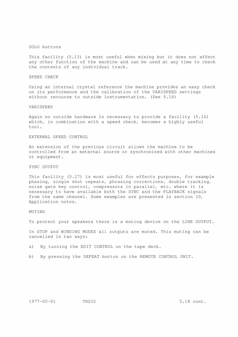
SOLO buttons This facility (5.13) is most useful when mixing but it does not affect any other function of the machine and can be used at any time to check the contents of any individual track. SPEED CHECK Using an internal crystal reference the machine provides an easy check on its performance and the calibration of the VARISPEED settings without recourse to outside instrumentation. (See 5.16) VARISPEED Again no outside hardware is necessary to provide a facility (5.16) which, in combination with a speed check, becomes a highly useful tool. EXTERNAL SPEED CONTROL An extension of the previous circuit allows the machine to be controlled from an external source or synchronized with other machines or equipment. SYNC OUTPUT This facility (5.17) is most useful for effects purposes, for example phasing, single shot repeats, phrasing corrections, double tracking, noise gate key control, compressors in parallel, etc. where it is necessary to have available both the SYNC and the PLAYBACK signals from the same channel. Some examples are presented in section 10, Application notes. MUTING To protect your speakers there is a muting device on the LINE OUTPUT. In STOP and WINDING MODES all outputs are muted. This muting can be cancelled in two ways: a) By turning the EDIT CONTROL on the tape deck. b) By pressing the DEFEAT button on the REMOTE CONTROL UNIT. 1977-05-01 TRS32 5.18 cont.
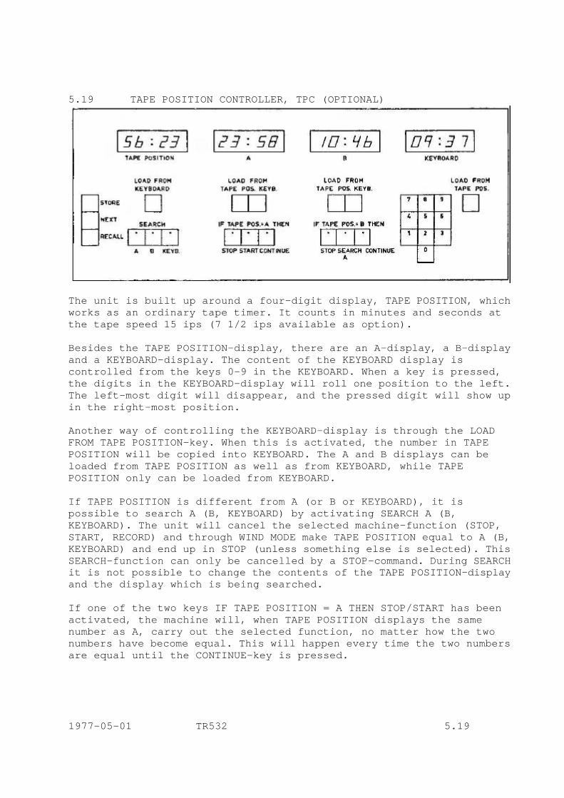
5.19 TAPE POSITION CONTROLLER, TPC (OPTIONAL)
The unit is built up around a four-digit display, TAPE POSITION, which works as an ordinary tape timer. It counts in minutes and seconds at the tape speed 15 ips (7 1/2 ips available as option). Besides the TAPE POSITION-display, there are an A-display, a B-display and a KEYBOARD-display. The content of the KEYBOARD display is controlled from the keys 0-9 in the KEYBOARD. When a key is pressed, the digits in the KEYBOARD-display will roll one position to the left. The left-most digit will disappear, and the pressed digit will show up in the right-most position. Another way of controlling the KEYBOARD-display is through the LOAD FROM TAPE POSITION-key. When this is activated, the number in TAPE POSITION will be copied into KEYBOARD. The A and B displays can be loaded from TAPE POSITION as well as from KEYBOARD, while TAPE POSITION only can be loaded from KEYBOARD. If TAPE POSITION is different from A (or B or KEYBOARD), it is possible to search A (B, KEYBOARD) by activating SEARCH A (B, KEYBOARD). The unit will cancel the selected machine-function (STOP, START, RECORD) and through WIND MODE make TAPE POSITION equal to A (B, KEYBOARD) and end up in STOP (unless something else is selected). This SEARCH-function can only be cancelled by a STOP-command. During SEARCH it is not possible to change the contents of the TAPE POSITION-display and the display which is being searched. If one of the two keys IF TAPE POSITION = A THEN STOP/START has been activated, the machine will, when TAPE POSITION displays the same number as A, carry out the selected function, no matter how the two numbers have become equal. This will happen every time the two numbers are equal until the CONTINUE-key is pressed. 1977-05-01 TR532 5.19
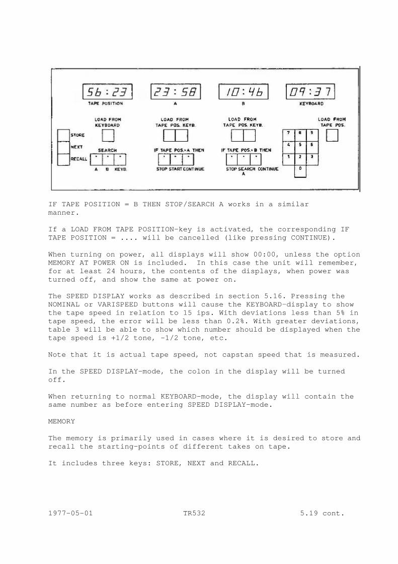
IF TAPE POSITION = B THEN STOP/SEARCH A works in a similar manner. If a LOAD FROM TAPE POSITION-key is activated, the corresponding IF TAPE POSITION = .... will be cancelled (like pressing CONTINUE). When turning on power, all displays will show 00:00, unless the option MEMORY AT POWER ON is included. In this case the unit will remember, for at least 24 hours, the contents of the displays, when power was turned off, and show the same at power on. The SPEED DISPLAY works as described in section 5.16. Pressing the NOMINAL or VARISPEED buttons will cause the KEYBOARD-display to show the tape speed in relation to 15 ips. With deviations less than 5% in tape speed, the error will be less than 0.2%. With greater deviations, table 3 will be able to show which number should be displayed when the tape speed is +1/2 tone, -1/2 tone, etc. Note that it is actual tape speed, not capstan speed that is measured. In the SPEED DISPLAY-mode, the colon in the display will be turned off. When returning to normal KEYBOARD-mode, the display will contain the same number as before entering SPEED DISPLAY-mode. MEMORY The memory is primarily used in cases where it is desired to store and recall the starting-points of different takes on tape. It includes three keys: STORE, NEXT and RECALL. 1977-05-01 TR532 5.19 cont.
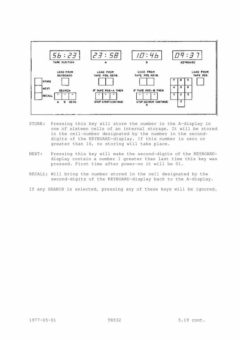
STORE: Pressing this key will store the number in the A-display in
one of sixteen cells of an internal storage. It will be stored in the cell-number designated by the number in the second-digits of the KEYBOARD-display. If this number is zero or greater than 16, no storing will take place.
NEXT: Pressing this key will make the second-digits of the KEYBOARD-
display contain a number 1 greater than last time this key was pressed. First time after power-on it will be 01.
RECALL: Will bring the number stored in the cell designated by the
second-digits of the KEYBOARD-display back to the A-display. If any SEARCH is selected, pressing any of these keys will be ignored. 1977-05-01 TR532 5.19 cont.
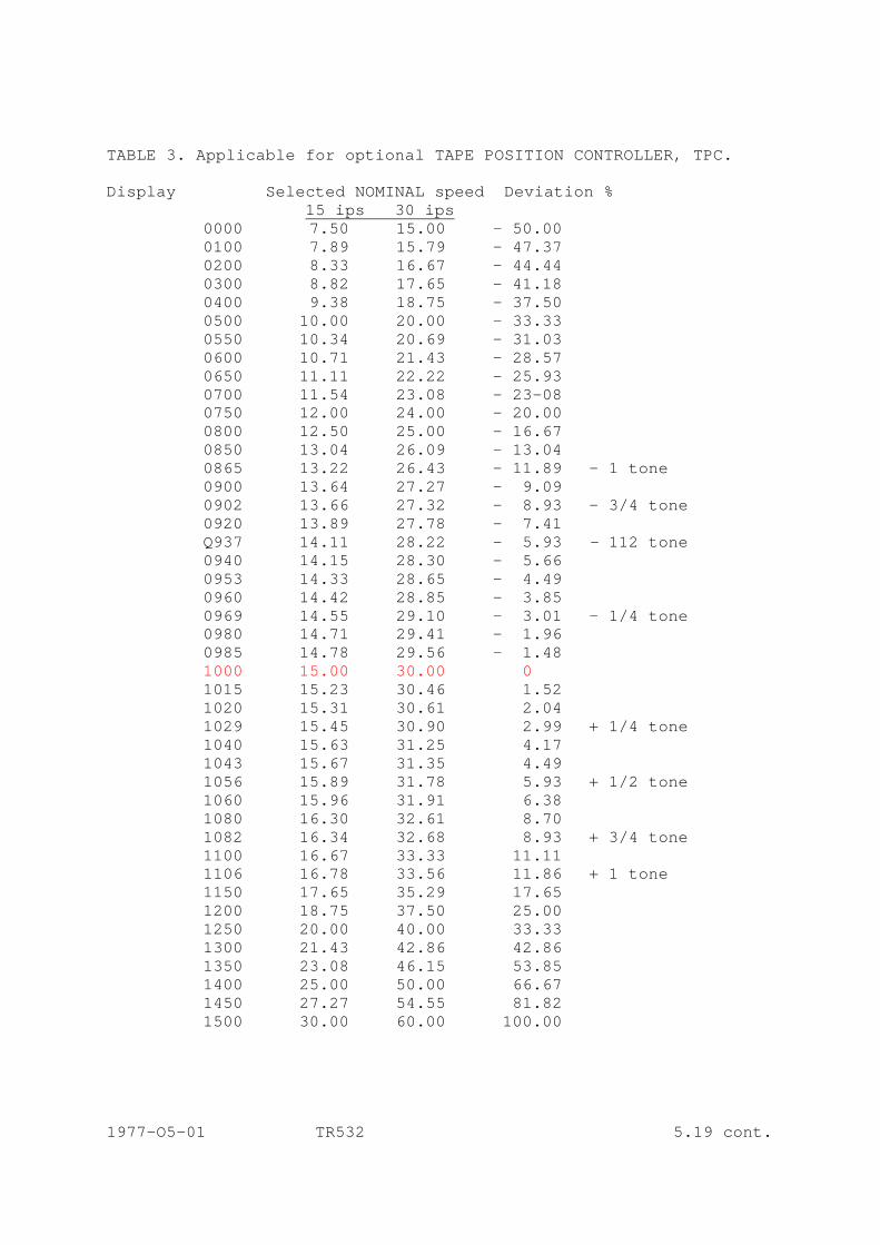
TABLE 3. Applicable for optional TAPE POSITION CONTROLLER, TPC. Display Selected NOMINAL speed Deviation % 15 ips 30 ips 0000 7.50 15.00 - 50.00 0100 7.89 15.79 - 47.37 0200 8.33 16.67 - 44.44 0300 8.82 17.65 - 41.18 0400 9.38 18.75 - 37.50 0500 10.00 20.00 - 33.33 0550 10.34 20.69 - 31.03 0600 10.71 21.43 - 28.57 0650 11.11 22.22 - 25.93 0700 11.54 23.08 - 23-08 0750 12.00 24.00 - 20.00 0800 12.50 25.00 - 16.67 0850 13.04 26.09 - 13.04 0865 13.22 26.43 - 11.89 - 1 tone 0900 13.64 27.27 - 9.09 0902 13.66 27.32 - 8.93 - 3/4 tone 0920 13.89 27.78 - 7.41 Q937 14.11 28.22 - 5.93 - 112 tone 0940 14.15 28.30 - 5.66 0953 14.33 28.65 - 4.49 0960 14.42 28.85 - 3.85 0969 14.55 29.10 - 3.01 - 1/4 tone 0980 14.71 29.41 - 1.96 0985 14.78 29.56 - 1.48 1000 15.00 30.00 0 1015 15.23 30.46 1.52 1020 15.31 30.61 2.04 1029 15.45 30.90 2.99 + 1/4 tone 1040 15.63 31.25 4.17 1043 15.67 31.35 4.49 1056 15.89 31.78 5.93 + 1/2 tone 1060 15.96 31.91 6.38 1080 16.30 32.61 8.70 1082 16.34 32.68 8.93 + 3/4 tone 1100 16.67 33.33 11.11 1106 16.78 33.56 11.86 + 1 tone 1150 17.65 35.29 17.65 1200 18.75 37.50 25.00 1250 20.00 40.00 33.33 1300 21.43 42.86 42.86 1350 23.08 46.15 53.85 1400 25.00 50.00 66.67 1450 27.27 54.55 81.82 1500 30.00 60.00 100.00 1977-O5-01 TR532 5.19 cont.
6A TAPE POSITION CONTROLLER, TPC 6A.1 The Tape Position Controller, TPC, is a microcomputer
controlled unit consisting of 7 printed circuit boards; - Central Processor - Display - LED-module - Keyboard - Interface - Speed Counter - Motherboard It is build into the remote control and connected to this via 3 dual-in-line plugs; DIP-plug # 1 supplies power to the TPC # 2 receives information from the tape deck and transmits
commands to the tape deck # 3 transmits TAPE POSITION number and tape deck status for
use in a slave display and in sync systems. In short the function is that the central processor senses the state of various input (i.e. keys in the keyboard, machine status) and transmits various commands. The following pages will give a more detailed description of the function of each pcb. 1978-07-01 TR532 6A.1
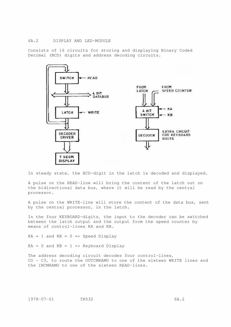
6A.2 DISPLAY AND LED-MODULE Consists of 16 circuits for storing and displaying Binary Coded Decimal (BCD) digits and address decoding circuits.
In steady state, the BCD-digit in the latch is decoded and displayed. A pulse on the READ-line will bring the content of the latch out on the bidirectional data bus, where it will be read by the central processor. A pulse on the WRITE-line will store the content of the data bus, sent by the central processor, in the latch. In the four KEYBOARD-digits, the input to the decoder can be switched between the latch output and the output from the speed counter by means of control-lines KA and KB. KA = 1 and KB = 0 => Speed Display KA = 0 and KB = 1 => Keyboard Display The address decoding circuit decodes four control-lines, CO - C3, to route the OUTCMRAMO to one of the sixteen WRITE lines and the INCMRAMO to one of the sixteen READ-lines. 1978-07-01 TR532 6A.2
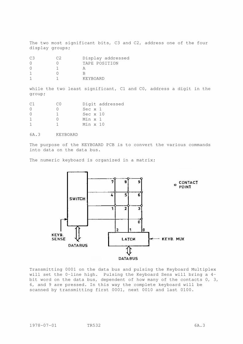
The two most significant bits, C3 and C2, address one of the four display groups; C3 C2 Display addressed 0 0 TAPE POSITION 0 1 A 1 0 B 1 1 KEYBOARD while the two least significant, C1 and C0, address a digit in the group; C1 C0 Digit addressed 0 0 Sec x 1 0 1 Sec x 10 1 0 Min x 1 1 1 Min x 10 6A.3 KEYBOARD The purpose of the KEYBOARD PCB is to convert the various commands into data on the data bus. The numeric keyboard is organized in a matrix;
Transmitting 0001 on the data bus and pulsing the Keyboard Multiplex will set the 0-line high. Pulsing the Keyboard Sens will bring a 4-bit word on the data bus, dependent of how many of the contacts 0, 3, 6, and 9 are pressed. In this way the complete keyboard will be scanned by transmitting first 0001, next 0010 and last 0100. 1978-07-01 TR532 6A.3
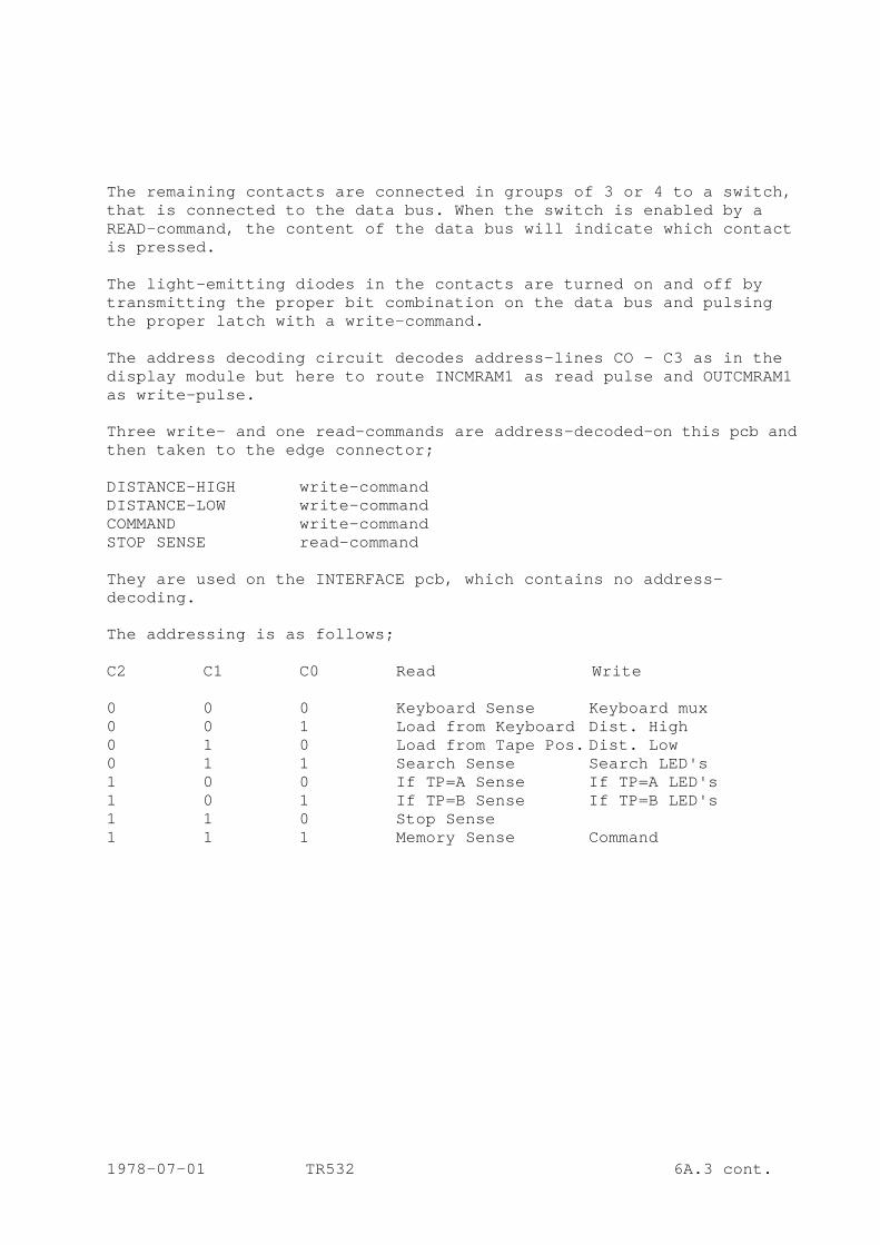
The remaining contacts are connected in groups of 3 or 4 to a switch, that is connected to the data bus. When the switch is enabled by a READ-command, the content of the data bus will indicate which contact is pressed. The light-emitting diodes in the contacts are turned on and off by transmitting the proper bit combination on the data bus and pulsing the proper latch with a write-command. The address decoding circuit decodes address-lines CO - C3 as in the display module but here to route INCMRAM1 as read pulse and OUTCMRAM1 as write-pulse. Three write- and one read-commands are address-decoded-on this pcb and then taken to the edge connector; DISTANCE-HIGH write-command DISTANCE-LOW write-command COMMAND write-command STOP SENSE read-command They are used on the INTERFACE pcb, which contains no address- decoding. The addressing is as follows; C2 C1 C0 Read Write 0 0 0 Keyboard Sense Keyboard mux 0 0 1 Load from Keyboard Dist. High 0 1 0 Load from Tape Pos. Dist. Low 0 1 1 Search Sense Search LED's 1 0 0 If TP=A Sense If TP=A LED's 1 0 1 If TP=B Sense If TP=B LED's 1 1 0 Stop Sense 1 1 1 Memory Sense Command 1978-07-01 TR532 6A.3 cont.

6A.4 SPEED COUNTER MODULE Consists of a crystal oscillator, a counter chain, latches and preset and load oneshots.
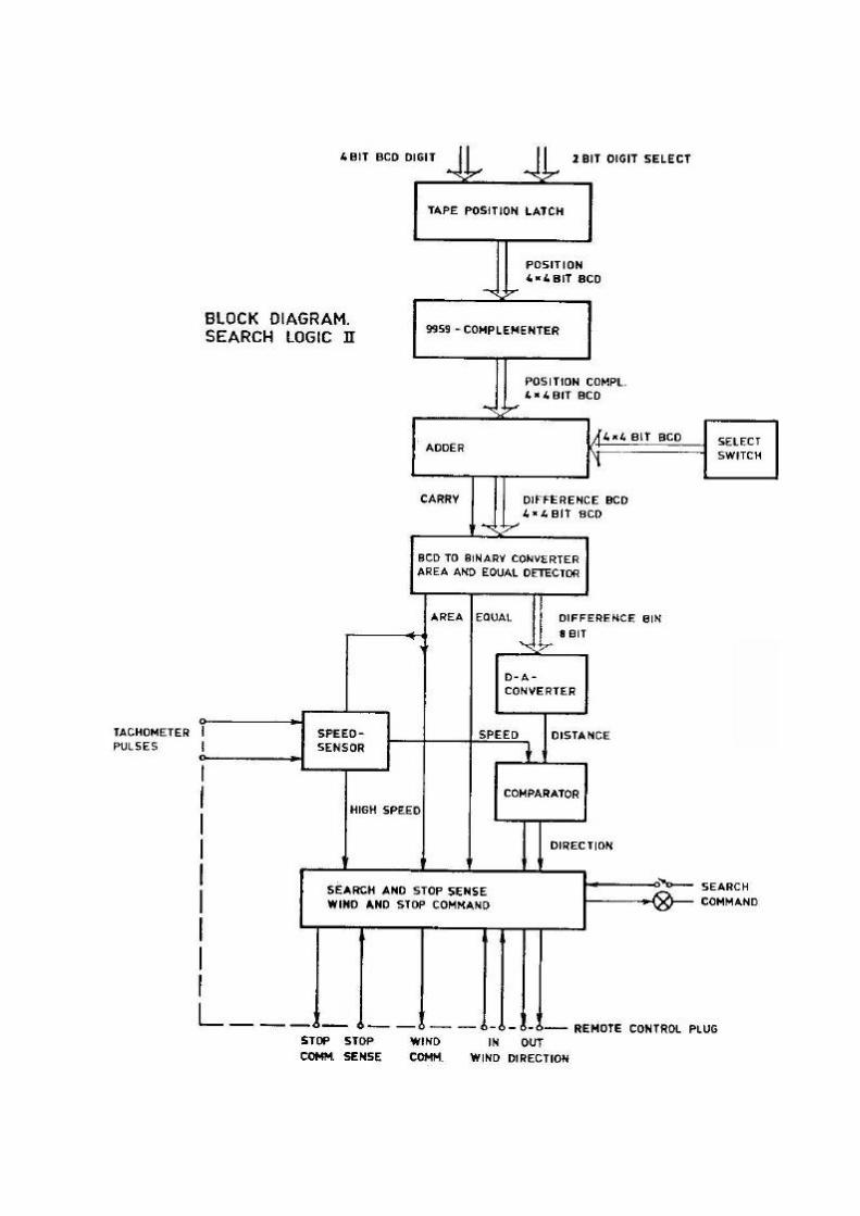
The crystal oscillator runs at 2048 kHz and is prescaled down to 2 kHz, which is fed to the 4 decade down-counter. When a speed pulse arrives (from INTERFACE) the number in the counter is stored in the latch. Next, the prescaler is reset and the counter is preset to 2000. Since the speed pulse arrives every ½ second at nominal tape speed, the counter will count down to 1000. At higher tape speeds, the number will be higher, at lower tape speed the number will be lower. The output of the latch is fed to the DISPLAY-module, 16 bit in parallel. 6A.5 INTERFACE MODULE The interface has several functions; 1) Transmitting commands to the tape deck 2) Receiving tape deck status information 3) Transmitting interrupt to the central processor to count 1 up or down in Tape Position 4) Transmitting speed pulse to speed counter 5) Controlling wind direction in search-mode 1978-07-01 TR532 6A.5

1) Pulsing the COMMAND-line will store the content of the data bus in the command-latch. The output of the latch is then levelconverted from +15 V (CMOS) to +24 V, the tape deck control voltage.
The four outputs correspond to following commands; Databus = 1 => STOP-command = 2 => START-command = 4 => WIND-command = 8 => Activating the relay 1978-07-01 TR532 6A.5 cont.
The relay is activated while searching, thereby letting the TPC control the wind-direction. In normal mode, wind-direction is controlled by the push-buttons. 2) Tape deck status information is received by pulsing the STOP SENSE. The information consists of one bit indicating whether the tape speed is higher or lower than a fixed threshold. The latter is created by letting as well up as down tachometer pulses trigger a retriggerable oneshot. If tape speed is high, the oneshot will be retriggered to give a constant high output, whereas a low tape speed will give a low output between pulses. Both speed and stop-information are used during search mode. 3-4) The UP and DOWN TACHOMETER PULSES coming from the tape deck are used for several purposes; a) counting up or down in tape position b) giving speed information to status switch c) giving speed pulses to speed counter d) giving speed information to the velocity controlled search function First, the tachometer pulses are shaped in Schmitt-trigger NAND-gates. The shaped pulses are AND-ed to give a pulse out independent of direction. This pulse is used to trigger the retriggerable oneshot connected to the status switch. The shaped pulses are also fed to a NAND-gate flip-flop which then indicates the tape direction. One output of this flip-flop is connected to the TEST input on the CENTRAL PROCESSOR, indicating whether a count should be up or down. The count pulse is also extracted from the shaped tachometer pulses via a presettable up-down counter. At 30 ips the counter is used at its full length, dividing by 16. The carry and borrow outputs from the counter are AND-ed and setting a flip-flop, whose output is connected to the INTERRUPT input of the CENTRAL PROCESSOR. The flipflop is reset by the INTERRUPT ACKNOWLEDGE output when the CENTRAL PROCESSOR has entered the interrupt program. At 15 ips the counter only divides by 8. This is established by letting the interrupt signal also preset the counter but the preset is disabled at high speed. When counting up, the counter is preset to 8, whereas it is preset to 7 when counting down. 1978-07-01 TR532 6A.5 cont.

The INTERRUPT signal will occur two times per second at nominal speed, 15 ips as well as 30 ips, since the tachometer roller rotates 4/15 revolution per inch of tape, and the roller has 4 windows. Therefore, the INTERRUPT signal is also used as SPEED-PULSE for the SPEED-COUNTER. Last, the shaped tachometer pulses are fed to two oneshots. The true output of one oneshot and the inverted output of the other are fed via resistors to a capacitor. When neither oneshot is triggered, the capacitor voltage will be half the power supply voltage, indicating zero speed. When the tape starts moving, the voltage will change, in positive direction at reverse movement, and in negative direction at forward movement. Therefore, the voltage across the capacitor can be taken as a measure of tape speed with sign. 5) When SEARCH-mode is entered, the CENTRAL PROCESSOR will transmit the difference in seconds with sign between the TAPE POSITION and the position being searched. This 8-bit difference is latched in the distance latch. At zero difference, the latch will hold 10000000, therefore the maximum distance to be transmitted is +/- 127 seconds. At greater distances, the central process-or automatically transmits either 00000000 or 11111111. The 8-bit distance is fed to a digital to analog converter, AD7520, with a buffer amplifier, 1/4 LM324. The analog distance voltage is offset adjusted in another 1/4 LM324. The output of this is fed to one input of a third 1/4 LM324, while the analog tape speed voltage is fed to the other input. The lack of feedback on this amplifier makes it work as comparator. The output is via a resistor used as a wind direction control to the tape deck. Also it is inverted in a fourth 1/4 LM324, whose output is used as the other wind direction control. The polarity of the voltages is such that if distance is greater than speed, the wind direction will be towards the searched point, if speed is greater than distance the wind direction will be away from the point. In this way a velocity-controlled wind will take place, reducing-the speed as the point is approached. If, for instance, distance is great, the direction will be towards the point even though a tape speed is maximum. As the distance is reduced, it will suddenly be smaller than speed, and wind direction is changed, thereby reducing tape speed but as tape speed is reduced, distance again becomes greater than speed and so on. Due to the inertia of the reels, the result will be that as the point is approached, the speed will be reduced correspondingly. 1978-07-01 TR532 6A.5 cont.
The offset adjustment of the distance voltage is adjusted so that at zero tape speed and zero distance, the distance voltage is equal to the speed voltage, indicated by that the comparator cannot find a stable state but picks up hum and switches continuously on the output. The weight between speed and distance is also adjustable (at both 15 and 30 ips). It should be adjusted so that even in worst case (one full and one empty reel) the reversing will take place early enough to brake the heavy reel but it should not take place so early that the time to complete a search is unnecessary increased. 6A.6 CENTRAL PROCESSOR MODULE The CENTRAL PROCESSOR module is the heart of the TPC. It consists of a 4-bit microprocessor, Intel 4040, a clock generator, 4201, a standard memory interface, 4289 and 4-chips of program memory, 4702, plus some address decoding circuits. The connections to the rest of the systems are; IN/OUT 0 - 3 serves as data bus C0 - C3 serves as address bus INCNRAM0-1 are read-pulses OUTCMRAM0-1 are write-pulses INT is the interrupt-line INTA is the interrupt acknowledge-line TEST is an input, which can be tested by the processor On the following page a short flow diagram will show how the processor reads input and writes output. 1978-07-01 TR532 6A.6

1978-07-01 TR532 6A.6cont.
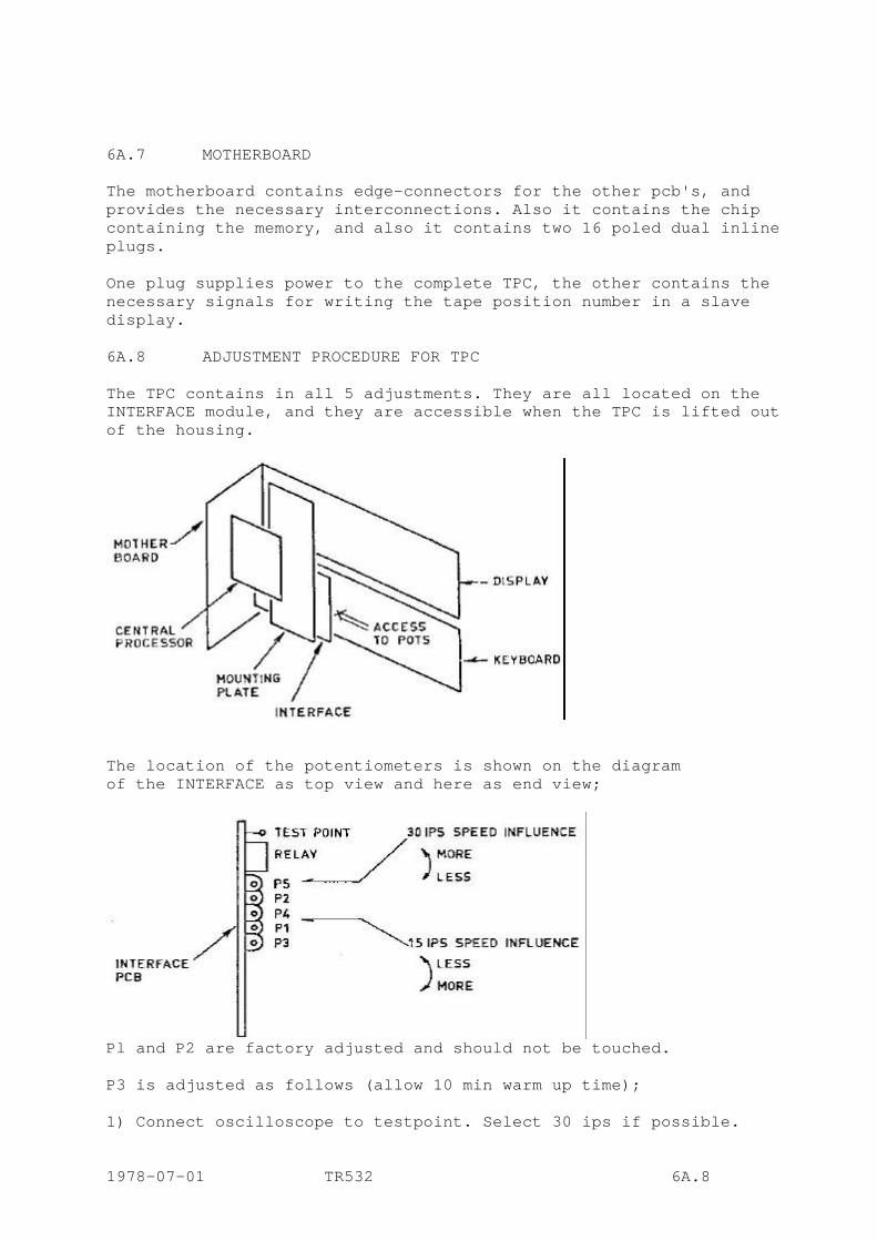
6A.7 MOTHERBOARD The motherboard contains edge-connectors for the other pcb's, and provides the necessary interconnections. Also it contains the chip containing the memory, and also it contains two 16 poled dual inline plugs. One plug supplies power to the complete TPC, the other contains the necessary signals for writing the tape position number in a slave display. 6A.8 ADJUSTMENT PROCEDURE FOR TPC The TPC contains in all 5 adjustments. They are all located on the INTERFACE module, and they are accessible when the TPC is lifted out of the housing.
The location of the potentiometers is shown on the diagram of the INTERFACE as top view and here as end view;
Pl and P2 are factory adjusted and should not be touched. P3 is adjusted as follows (allow 10 min warm up time); 1) Connect oscilloscope to testpoint. Select 30 ips if possible. 1978-07-01 TR532 6A.8
2) Press Load Keyboard from Tape Position 3) Press momentarily SEARCH KEYBOARD. This will load the distance latch with zero distance. Since the two numbers are equal, and the tape is not moving, the search will be terminated immediately. 4) P3 should now be adjusted so that the picture on the oscilloscope tends to oscillate between ground and a positive voltage. If it will not show this oscillation, it should be adjusted to show a positive voltage but as close as possible to the point where it switches to ground. P4 and P5 are the speed influence adjustments, P4 operating at 15 ips and P5 at 30 ips. P4 should always be adjusted before P5, otherwise the procedure is the same. They are adjusted as a compromise between overshoot when searching and the time to complete a search. Normally they are set to zero overshoot. The procedure for adjusting is; With the supply reel almost full, search 2 min forward (1 min at 30 ips). If an overshoot occurs, speed influence should be turned to more, and a new search (from the same beginning) should be tried, If no overshoot occurs, speed influence should be turned to less, to obtain a faster search, and a new search tried (from the same beginning). Continue this procedure till the best compromise is reached. 1978-07-01 TR532 6A.8 cont.

6. OPTIONS 6.1 REMOTE TIMER DISPLAY A REMOTE TIMER DISPLAY can be located, for example, in a mixing console. For this purpose the REMOTE CONTROL UNIT has a connector labeled TO SLAVE DISPLAY on the back. This connector supplies the timer signal in multiplexed BCD-code and +5 V (max 1 A) for powering of the remote display; (max cable length: 10 m) An external display can be built by the user according to drawing or ordered ready made from the factory. Consult your dealer. 6.2 XLR-panel A panel with XLR-connectors for LINE-IN and LINE-OUT signals can be mounted on the back of the machine. The panel is mounted on a hinged door and allows free access to all other connectors. The pin-connections to the XLR-connectors are as follows. Pin one is earth. Pins two and three are the balanced floating winding of the INPUT or OUTPUT transformer. Pin three is the high connection. 6.3 VU-meter panel The VU-meter panel is made as a separate independent unit mounted on two columns at the rear of the machine. If desired the VU-meter panel can be removed and placed anywhere convenient (max cable length: 10 m). 6.4 MOUNTING FACILITIES FOR EXTERNAL EQUIPMENT The two columns at the rear of the TAPE DECK which normally support the VU-METER PANEL can also be used for mounting external rack mounted equipment such as Dolby, dbx, etc. When this is done the VU-METER PANEL must be removed, see 6.3, and a special rack-mount installed. Consult your dealer for further details. 6.5 EXTERNAL MOTOR CONTROL Apart from the VARISPEED function built into the REMOTE CONTROL UNIT the nominal tape speed can be offset by connecting an external potentiometer to socket EXTERNAL MOTOR CONTROL at the rear of tape deck. Diagram 16 in the connector table shows the exact wiring for this. With simple modification the speed can also be changed with an external DC-voltage. This is necessary for some syncronizing equipment such as MagLink and Minimag. WARNING: When the speed is controlled through this socket VARISPEED
should not be selected, since it would be in parallel with the external control equipment.
1977-05-01 TR532 6.5
6.6 FREE SPACE ON 8 AND 16 TRACK MODELS On models having only 8 or 16 tracks, free space is available at the bottom of the machine. This space can be used at the users discretion for mounting external equipment, provided excessive heat is not produced an no large magnetic fields are present. The available space is 19" wide and 265 mm high (8 track), or 130 mm (16 track), max depth 460 mm.
Side brackets for rack-mounting are available. Consult your dealer.
6.7 TRANSPORT FRAME
For transportation in car or van the factory has developed a special transport frame (see section 4.5).
Consult your dealer for further information of this accessory.
6.8 TAPE POSITION CONTROLLER, TPC
The TPC is a more sophisticated search unit than the standard search function. With TPC three preset tape positions can be searched and also automatic recycling can be done between two tape positions.
The TPC also features a memory where 16 different tape positions can be stored, recalled and searched at the operators convenience.
The TPC is built into the REMOTE CONTROL UNIT. A more detailed description of the TPC is found in section 5.19.
6.9 TAPE SPEED 7 1/2 - 15 IPS
To special order the TR532 series tape recorders can be delivered with the tape speeds 7 1/2 and 15 ips. The VARISPEED range will then be 3 3/4 to 30 ips.
6.10
The modular design of the AM 77 amplifier with its plug-in equalizer prints makes some modifications possible. NAB - CCIR SWITCHABLE For customer using only one tape speed the AM 77 amplifier can be equipped with both NAB and CCIR equalizers. Switching between the two is done with the pushbuttons normally used to select tape speed. 1977-05-01 TR532 6.10
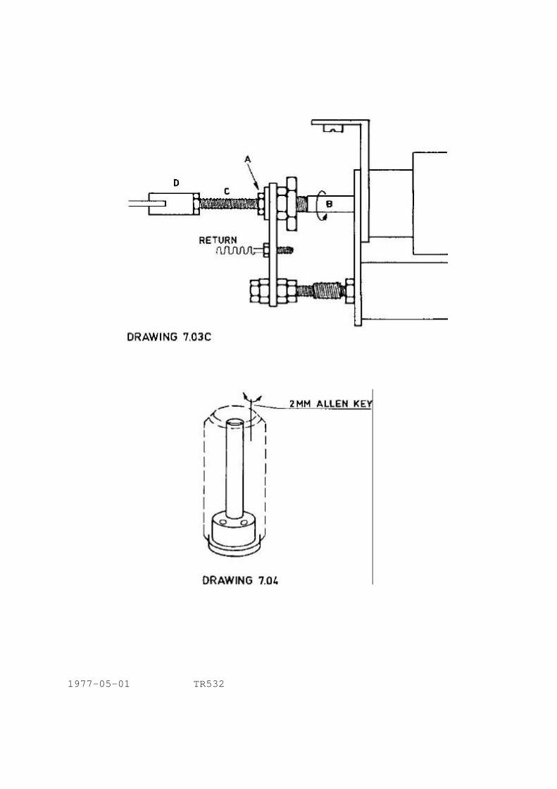
7. ADJUSTMENTS TAPE DECK MECHANICAL ADJUSTMENTS 7.1 REEL PLATFORM HEIGHT, drawing No. 7.01 Insert a long 3 mm Allen key in the hole at the top of the hub and turn clockwise to lower the platform, and anti-clockwise to raise it. For lubrication, see section 8.12. 7.2 SUPPLY TENSION ARM PRESSURE, drawing No. 7.02A Disconnect the damping cylinder from the tension arm by pressing down slightly on the end of the damping cylinder piston arm so that it comes free from the pin which drives it. Adjust the set screw at the end of the long spring, so that the tape tension measured in front of the playback head, when running in the normal PLAY MODE, is 225 p +/- 10 %. Check the servo arm tension as follows: Remove the screw and the cover of the tension arm roller, replace the screw and tie a spring balance to it with a short length of string. With the damping system disconnected measure the tension in the direction indicated in the drawing and check that it falls between 275 and 325 p. 7.3 TAKE-UP TENSION ARM PRESSURE, drawing No. 7.02B Disconnect the damping system. Adjust the set screw at the end of the long spring with the tape moving in PLAY MODE so that the tape tension measured after the CAPSTAN PINCH ROLLER is 225 p +/- 10 %. Check the tension arm pressure as follows: Remove the screw and cover of the tension arm roller. Replace the screw and tie a spring balance to it with a short length of string. With the damping system disconnected, check that the tension in the direction indicated in the drawing lies between 275 and 325 p. 7.4 CAPSTAN PINCH ROLLER PRESSURE ADJUSTMENT, drawings No. 7.03A and 7.03C Remove the screw and the cover of the CAPSTAN PINCH ROLLER. Replace the screw and tie a spring balance to the screw with a length of string. With no tape loaded, press the start button. Pull back on the spring balance in the direction indicated in the drawing till the CAPSTAN PINCH ROLLER begins to lose contact with the capstan. At this point read the tension on the spring balance scale. See drawing No. 7.03C. Loosen lock-nut (A) and screw the shaft (B) in the direction indicated by the arrow to decrease the CAPSTAN PINCH ROLLER pressure or in the opposite direction in order to increase it. When a pressure of 2 kp +/- 20 % is obtained tighten lock-nut (A) Be careful not to misalign the link-system at(D) which should-be horizontal and parallel to the TAPE DECK. 1978-07-01 TR532 7.4

REEL PLATFORM HEIGHT ADJUSTMENT
DRAWING 7.01
1977-05-01 TR532

7.5 GUIDE ROLLER PRESSURE Use the same procedure to adjust the guide roller pressure to 1.2 kp +/- 20 %. Drawings 7.03B and 7.03C. 7.6 ROLLER PERPENDICULARITY, drawing No. 7.04 The two large rollers related to each tension arm, the GUIDE ROLLER and the CAPSTAN PINCH ROLLER, are adjusted to be perpendicular to the TAPE DECK by means of three set screws in their bases. To reach them their covers are removed and a 2 mm Allen key inserted in the hole seen within the top of the roller. Rotating the roller it is possible to find the head of the screw with the Allen key. At each of the three positions place the ALIGNMENT TEMPLATE against the side of the roller and check for perpendicularity and height. Adjusting each screw in turn will tilt the roller accordingly. It will also affect the height so that the three screws must be properly related to each other in order to obtain both perpendicularity and correct height with regard to the TAPE DECK. In some cases it may be necessary to loosen or tighten the center screw which holds the roller assembly in place. The final adjustments of the TAPE PINCH ROLLER must be made after the HEAD BLOCK adjustments are made (section 7.7), with the tape running. CAUTION: When making these adjustments be very careful to remove the
adjustment key from the roller before pressing the START button, otherwise the pinch roller will be jammed against the capstan.
7.7 UPPER CAPSTAN BEARING POINT Place a 20.000 ohms/V DC voltmeter across the test point in code 3 card and chassis ground. Loosen the upper capstan bearing point and set the tape in motion. Watch the voltmeter reading, which should stabilise around 2.7 V, and gently press the upper capstan bearing against the capstan. If the pressure is too high the current through the motor will increase, showing a higher reading on the voltmeter. Adjust the position of the bearing point so that it is in contact with the capstan but the voltmeter reading does not increase. At this point tighten the locking screw. CAUTION: Make sure the bearing is properly lubricated.
See section 8.12. 7.8 MECHANLCAL BRAKES, drawing no. 7.05B Mechanical brake tension should be set to a minimum. This is obtained when brake tension is just sufficient to keep the servo-arms from reaching their rest position, with full reel at either take-up or supply reel. If necessary, loosen locknut B and adjust screw A to obtain a correct tension. Then tighten locknut B. 1977-05-01 TR532 7.8
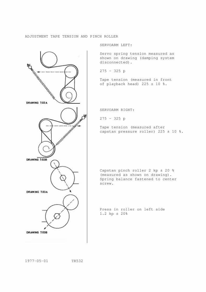
ADJUSTMENT TAPE TENSION AND PINCH ROLLER
SERVOARM LEFT: Servo spring tension measured as shown on drawing (damping system disconnected). 275 - 325 p Tape tension (measured in front of playback head) 225 ± 10 %. SERVOARM RIGHT: 275 - 325 p Tape tension (measured after capstan pressure roller) 225 ± 10 %. Capstan pinch roller 2 kp ± 20 % (measured as shown on drawing). Spring balance fastened to center screw. Press in roller on left side 1.2 kp ± 20%
1977-05-01 TR532 1977-05-01 TR532
1977-05-01 TR532

BRAKE BAND
1978-08-01 TR532

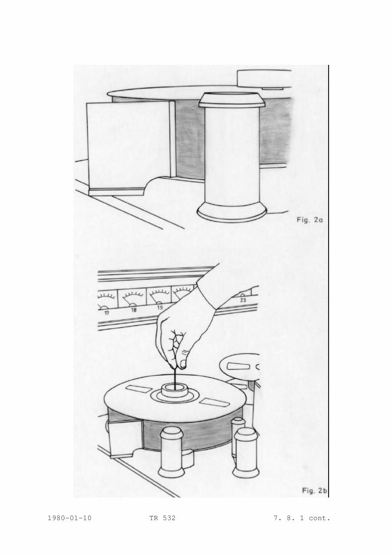
7.8.1 TAPE PATH ALIGNMENT Tools needed: 2” Alignment template Allen keys 3, 2 and 4 mm The following adjustments are critical and require some experience. It is important that the adjustments are done in the order described. A. ALL MODE ADJUSTMENT Before any adjustments are made, it is VERY IMPORTANT that the reel platform height is correct at both supply and take-up side. As there exist reels with flanges of various thickness, this adjustment must be done whenever changing to a new type of reel. The adjustment procedure is simple. Insert a long 3 mm Allen key as described in section 7.1. Place the alignment template, using the tape deck as reference surface, as shown in figure 2, 2a and 2b. Adjust the platform height for minimum space between the template and the bottom flange without the template touching the flange, see figure 2. If this cannot be done, the reel is not flat and cannot be used.
1980-01-10 TR532 7.8.1
1980-01-10 TR 532 7. 8. 1 cont.
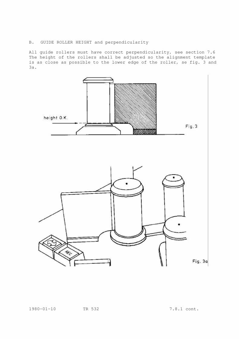
B. GUIDE ROLLER HEIGHT and perpendicularity All guide rollers must have correct perpendicularity, see section 7.6 The height of the rollers shall be adjusted so the alignment template is as close as possible to the lower edge of the roller, se fig. 3 and 3a.
1980-01-10 TR 532 7.8.1 cont.

C. GUIDE ROLLER INFLUENCE The perpendicularity and height of the guide rollers have different influence on the tape travel in different modes. The table below shows the significance of different rollers in different modes. The roller numbers refer to fig l.
Mode Most significant Less significant Not significant Rewind 1 2 3 Fast forward 8 7 6 Play 4-5-6 2-3-7 1-8 D. PINCH ROLLER The pinch roller shall not be fully perpendicular. In rest position it shall lean SLIGHTLY towards the top of the capstan shaft. When the pinch roller is manually pressed against the capstan shaft, the top of the pinch roller shall first come into contact with the capstan shaft, while there is still a small gap at the bottom. This gap is about 0.05 mm and adjustment is made by using a lamp on the opposite side. When the pinch roller is making contact at the top, light shall just be barely seen at the bottom. When the pinch roller is activated with full solenoid pressure, the light will disappear. 1980-01-10 TR532 7.8.1 cont.

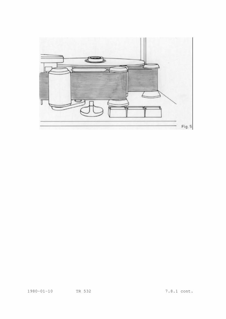
E. TEST OF ADJUSTMENT With tape running at 15 ips, simulate minimum supply tape tension. This is obtained by manually forcing the left servoarm (fig. 1, item 2) to its utmost left position, see fig. 4.
Fig. 4
In this condition, with minimum back tension, observe the tape travel and make sure the tape is within the three guides in the headblock. If not; 1) If the tape tries to travel upwards, adjust roller no. 6. The top
of this roller shall be adjusted TOWARDS the capstan shaft as illustrated in fig. 5.
2) If the tape tries to travel downwards, adjust roller no. 6. The top
of this roller shall be adjusted AWAY from the capstan shaft as illustrated in fig. 5.
1980-01-10 TR532 7.8.1 cont.
1980-01-10 TR 532 7.8.1 cont.
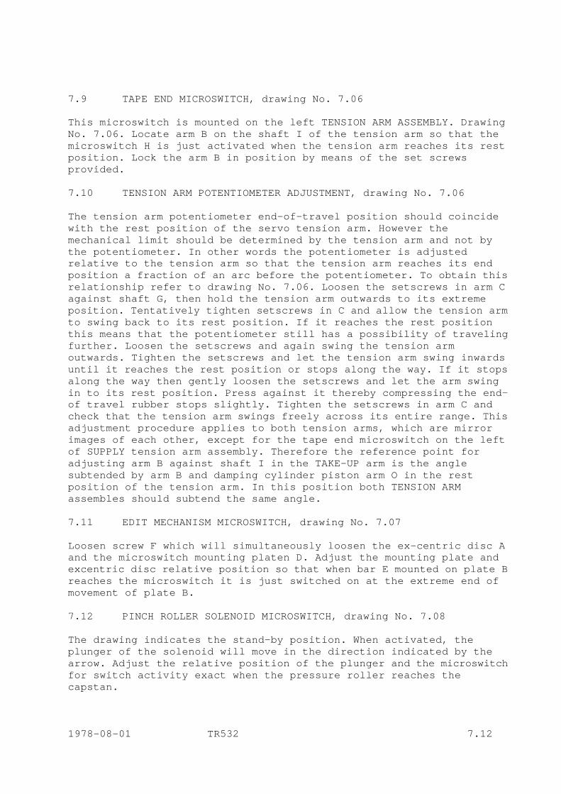
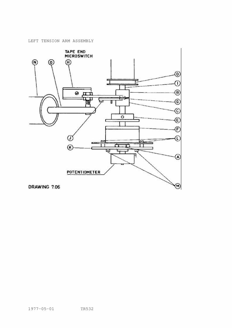
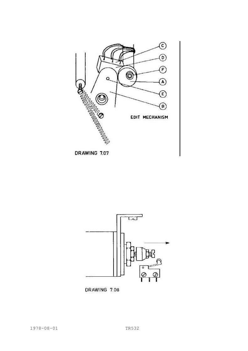
7.9 TAPE END MICROSWITCH, drawing No. 7.06 This microswitch is mounted on the left TENSION ARM ASSEMBLY. Drawing No. 7.06. Locate arm B on the shaft I of the tension arm so that the microswitch H is just activated when the tension arm reaches its rest position. Lock the arm B in position by means of the set screws provided. 7.10 TENSION ARM POTENTIOMETER ADJUSTMENT, drawing No. 7.06 The tension arm potentiometer end-of-travel position should coincide with the rest position of the servo tension arm. However the mechanical limit should be determined by the tension arm and not by the potentiometer. In other words the potentiometer is adjusted relative to the tension arm so that the tension arm reaches its end position a fraction of an arc before the potentiometer. To obtain this relationship refer to drawing No. 7.06. Loosen the setscrews in arm C against shaft G, then hold the tension arm outwards to its extreme position. Tentatively tighten setscrews in C and allow the tension arm to swing back to its rest position. If it reaches the rest position this means that the potentiometer still has a possibility of traveling further. Loosen the setscrews and again swing the tension arm outwards. Tighten the setscrews and let the tension arm swing inwards until it reaches the rest position or stops along the way. If it stops along the way then gently loosen the setscrews and let the arm swing in to its rest position. Press against it thereby compressing the end-of travel rubber stops slightly. Tighten the setscrews in arm C and check that the tension arm swings freely across its entire range. This adjustment procedure applies to both tension arms, which are mirror images of each other, except for the tape end microswitch on the left of SUPPLY tension arm assembly. Therefore the reference point for adjusting arm B against shaft I in the TAKE-UP arm is the angle subtended by arm B and damping cylinder piston arm O in the rest position of the tension arm. In this position both TENSION ARM assembles should subtend the same angle. 7.11 EDIT MECHANISM MICROSWITCH, drawing No. 7.07 Loosen screw F which will simultaneously loosen the ex-centric disc A and the microswitch mounting platen D. Adjust the mounting plate and excentric disc relative position so that when bar E mounted on plate B reaches the microswitch it is just switched on at the extreme end of movement of plate B. 7.12 PINCH ROLLER SOLENOID MICROSWITCH, drawing No. 7.08 The drawing indicates the stand-by position. When activated, the plunger of the solenoid will move in the direction indicated by the arrow. Adjust the relative position of the plunger and the microswitch for switch activity exact when the pressure roller reaches the capstan. 1978-08-01 TR532 7.12
LEFT TENSION ARM ASSEMBLY
1977-05-01 TR532
1978-08-01 TR532
7.13 TENSION ARM, GUIDE ROLLER AND PINCH ROLLER AIR CYLINDER ADJUSTMENT
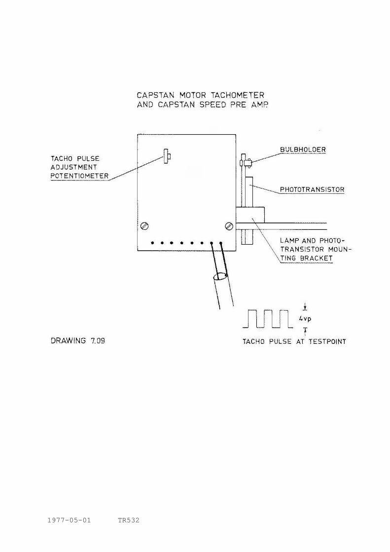
The damping cylinders in these mechanism all have an adjustment screw with a lock-nut at the rear end to adjust the air flow in and out of the cylinder. With a stop watch measure the time between pressing the START button and contact between the PINCH ROLLER and the CAPSTAN. This should be approx between 0.3 and 0.5 sec. Each TENSION ARM should then be held outward to its extreme position and released. The time it takes to reach the inside rest position should be approx 0.3 to 0.5 sec. 7.14 POWER SUPPLY ADJUSTMENTS, code 4 diagram 8497 Code 4 POWER STABILIZER houses three +24 V power stabilizers feeding respectively capstan motor, tape deck logic, record relays and VU-meter lamps. +/-12 V feeding capstan servo system and +5 V feeding digital systems. Measure the voltage to ground from pins 25, 16, 15, 10, 6 and 7 and adjust their respectively potentiometers to give the correct voltages as indicated on the diagram. CAPSTAN MOTOR SERVO CONTROL 7.15 LAMP AND PHOTOTRANSISTOR POSITIONING, drawing No. 7.09 The lamp should be placed 2 mm above the tacho disc and the phototransistor tube about half a mm below. Connect an oscilloscope across the output from the preamplifier (live: orange, ground: brown), and check the shape of the resulting square wave. The phototransistor tube should be turned to obtain at least 4 V peak-to-peak, with the best possible wave shape. To check the correct positioning of the lamp observe the wave shape and see that it is possible to obtain both traces in drawing No. 7.09 SOLELY by adjusting the potentiometer. Then adjust to give a 1:1 mark/space ratio. 7.16 CAPSTAN SPEED ADJUSTMENT code 2 card, diagram 8605/3 Select 15 ips and hold the NOM speed button on the REMOTE CONTROL UNIT down and adjust the CAPSTAN LOW SPEED potentiometer to obtain 10.00 on the REMOTE CONTROL UNIT display. Alternatively connect a frequency counter across the output of the TACHO PREAMPLIFIER (orange: live, brown: 0 V), and adjust CAPSTAN LOW SPEED potentiometer to obtain 13.5 kHz. Select 30 ips and hold the NOM speed button on the REMOTE CONTROL UNIT down and adjust the CAPSTAN HIGH SPEED potentiometer to obtain 15.00 on the REMOTE CONTROL UNIT display. Alternatively connect a frequency counter across the output of the TACHO PREAMPLIFIER (orange: live, brown: 0 V) and adjust CAPSTAN HIGH SPEED potentiometer to obtain 27 kHz. 1977-05-01 TR532 7.16
1977-05-01 TR532
7.17 MAXIMUM CAPSTAN SPEED ADJUSTMENT Potentiometer Pl on code 3 card. The maximum capstan speed is factory adjusted to approx 70 ips. If capstan speed increases above 70 ips (i.e. by tacho lamp failure) the built in electronic overspeed fuse will automatically give the tape deck a STOP command (See section 8.4.). 7.18 MAXIMUM VARISPEED ADJUSTMENT code 2 diagram 8605/3 Select VARISPEED in the REMOTE CONTROL UNIT and with potentiometers COARSE and FINE max clockwise. Adjust the MAXIMUM VARISPEED potentiometer P2 in code 2 card so that the reading on the display is slightly above 17.50. Alternatively a frequency counter can be used (as in 7.16) giving a reading slightly above 54 KHz. 7.19 HALL GENERATOR BALANCE POTENTIOMETER, P2 This potentiometer is factory adjusted for min. wow and flutter. 7.20 TENSION ARM SERVO SYSTEM ADJUSTMENT WIND POWER adjustment code 1 diagram 9870 Wind power potentiometer, P7, on code 1 SERVO SYSTEM card (below the tape deck) controls the maximum power to the reel motors and the crossover point for the WIND SPEED CONTROL on the tape deck. Put the machine in WIND with the WIND SPEED CONTROL in its extreme rewind position. Using the same setup as for measuring the mechanical brakes, see drawing 7.05, read the motor torque. Turn the WIND POWER potentiometer fully clockwise. Turn the potentiometer slowly anti-clockwise. The torque will rise to a maximum, beyond which the potentiometer has no effect. Turning the WIND POWER potentiometer beyond this maximum will only cause increased power to both reel motors in the crossover point of the WIND SPEED CONTROL (i.e. too high tape tension at stand still and very low winding speeds). Finally check that enough wind power is aligned. With equal amount of tape on both reels, select WIND and turn WIND SPEED CONTROL so the tape comes to stand still. Check that tape tension is normal and that the servo arms have no tendency to swing outwards. Also check that the left servo arm does not swing in simulating "tape end" which will give a STOP command. 1977-05-01 TR532 7.20
7.21 WIND SPEED LIMIT adjustment Load a full reel and wind it approx to the middle so that the same amount of tape is on each reel. Press the WIND button and set the tape winding at full speed one way or the other. Hold down the NOM. speed button on the REMOTE CONTROL UNIT to obtain a speed reading on the TIMER display and adjust the WIND SPEED LIMIT potentiometer on CODE 7, TACHO LOGIC card so as to obtain a reading of 19.20 on the display. This corresponds to a tape speed of approx 190"/sec. 7.22 START POWER adjustment potentiometer The potentiometer, placed on the CODE 1, SERVO SYSTEM card, normally require no adjustment. It is set for max power on the TAKE-UP motor. Max power is fully clockwise and min power fully anti-clockwise, as seen from the front of the card. 7.23 START POWER TIME potentiometer This potentiometer, P8, also on CODE 1 SERVO SYSTEM card, is adjusted to add extra start power to the take up reel motor during the acceleration period of the capstan motor. Adjust P8 so that no loops occur when starting the tape with empty supply reel and full take up reel. 7.24 TAPE MOTION SENSOR potentiometer code 7 card Tacho Logic This potentiometer, P1, adjusts the speed of the tape below which the TACHO LOGIC circuit determines that the tape has stopped, when the machine goes from the WIND function into START or RECORD. This is done in order to protect the tape, so that it may not be set in motion in START or RECORD mode without having passed through the STOP mode first. Load a reel of tape and wind it so that most of the tape is on the TAKE-UP reel and very little is left on the SUPPLY reel. With the TAPE MOTION SENSOR potentiometer turned fully anticlockwise press the WIND button and set the tape winding full speed forward. When top speed has been reached press the START button. The tape will slow down due to the action of the dynamic brakes, and eventually stop and go into the START function with normal tape transport speed. However, you will notice that at the last moment, before relay 5 is activated, the tape will tend to move backwards for a moment. This occurs because the STOP function is released too late at the end of the dynamic braking process. Turn the TAPE MOTION SENSOR potentiometer clockwise and repeat the mechanical sequence. A point should be reached where relay 5 is activated just before the end of the dynamic braking process, canceling the slight backward pull. CAUTION: Do not go beyond this point or the START function will be
initiated before the tape comes to rest and damage to the tape may ensue.
1977-05-01 TR532 7.24
7.25 RELAY 5 adjustment potentiometer In case of tacho lamp failure relay 5 is controlled by a time delay circuit adjusted by the potentiometer alongside the relay. Remove the small 5 pin connector at the top of the TACHO LOGIC, code 7 card, and place the machine in WIND. Using a stop watch measure the interval between the moment the STOP button is pressed and the moment relay 5 is activated. Adjust the potentiometer to a minimum of 5 sec. REMOTE CONTROL UNIT 7.26 SEARCH LOGIC ADJUSTMENT diagram 8926 Switch on the machine and the REMOTE CONTROL UNIT and allow at least 5 minutes warm-up time. Load a reel of tape and wind it forward approx 1 minute (display reading). Then reset the TIMER to 00.00. Continue winding a minute or so; stop the machine at an odd number and set the preselected thumb-switch to the same figure as that which appears on the TIMER display. a) Connect an oscilloscope to pin 7 on IC 30 and adjust the DC OFFSET
potentiometer so that the trace on the oscilloscope screen tends to oscillate, at a rate of approx 100 Hz, between 0 V and +24 V. Set the thumb-switch to one more digit than the tape timer display and check that the voltage is fixed at +24 V; Set the thumb-switch to two digits less than the tape timer display and check that the voltage is fixed at 0 V.
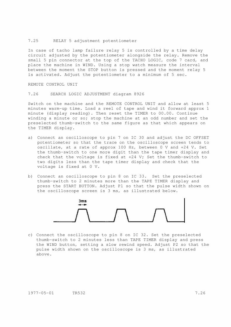
b) Connect an oscilloscope to pin 8 on IC 33. Set the preselected
thumb-switch to 2 minutes more than the TAPE TIMER display and press the START BUTTON. Adjust Pl so that the pulse width shown on the oscilloscope screen is 3 ms, as illustrated below.
c) Connect the oscilloscope to pin 8 on IC 32. Set the preselected
thumb-switch to 2 minutes less than TAPE TIMER display and press the WIND button, setting a slow rewind speed. Adjust P2 so that the pulse width shown on the oscilloscope is 3 ms, as illustrated above.
1977-05-01 TR532 7.26
d) Connect the oscilloscope to pin 8 on IC 34. Set the preselected thumb-switch to 2 minutes more than the TAPE TIMER display. Press the START button (15 ips). Adjust HIGH SPEED potentiometer so that the duration of the pulses shown on the oscilloscope is 30 ms (a mark/space ratio approx equal to 1/1). NOTE: The pulses mentioned in b), c) and d) are only present when the
TAPE TIMER is within 2 minutes of the preselected thumb-switch figures.
e) SPEED INFLUENCE is adjusted as a compromise between overshoot when
searching, and the time to complete a search. Normally it is set to zero overshoot. Set preselected thumbswitch to 02.01 and start a search from tape timer 00.00 (beginning of tape). If an overshoot occurs SPEED INFLUENCE should be returned to more and a new search from 00.00 should be tried. If no overshoot occurs SPEED INFLUENCE should be turned to less to obtain a faster search and a new search from 00.00 should be tried. Continue this procedure till the best compromise adjustment is reached.
7.27 COARSE HEAD adjustment NOTE: This adjustment is only necessary when a head stack has been
replaced. HEAD BLOCK adjustment drawing No. 7.010 Each head is mounted on its individual mounting plate with 3 setscrew calibration points, 1, 3 and 5 and two locking screws 2 and 4. To begin a coarse head adjustment, loosen screw No. 4 half a turn and use the adjustment template to correct the head for tilt with screw 3 and azimuth with screw 5. Screws 1, 3 and 5 together will adjust the height of the head. Check the height adjustment using the position of the tape against each individual head as a guide. On the PLAYBACK and RECORD heads the tape should be exactly centered between the outside shields of the edge tracks. The erase head height adjustment uses as a reference the outer edges of the edge tracks, which should be very slightly wider than the tape width. Keep a constant check on tilt and azimuth by placing the adjustment template head-on to the head (BUT WITHOUT TOUCHING IT) for tilt or flat against it for a rough check of azimuth. 1977-05-01 TR532 7.27
Tighten screw 4 and loosen screw 2. Using a grease pencil smear across the front of each head, check the tape wrap, which should be centered on the tape gap of the PLAYBACK and RECORD heads. In the case of the ERASE head the tape must cover a wider area due to the staggered arrangement used. In this case it may be necessary to adjust the plastic cap which serves as a stop for the GUIDE ROLLER. This may be loosened from below the TAPE DECK and adjusted in position so that the GUIDE ROLLER keeps the tape properly wrapped around the ERASE head. After the best visual adjustment of tilt, height and azimuth has been obtained at the head stacks, check the flutter roller. This can be adjusted for tilt by means of two small screws. 7.28 FINE AZIMUTH adjustment Demagnetize the heads, rollers and tools (section 8.10). With large distances between the tracks the azimuth adjustment become highly critical. We recommend the following procedure: Place a test tape with a 1 kHz signal on the recorder and place it in PLAY mode. Connect the output of track 1 to the horizontal input of an oscilloscope and the output of track 2 to the vertical input and adjust the input levels to give the same length of trace for each input, when the test tape is played back. When both inputs are connected the trace should be a single line at 45° inclination with respect to the baseline. Any deviation from the correct azimuth alignment will cause the trace on the oscilloscope to open out into an ellipse. Adjust the azimuth of the head accordingly, using screw 5. Then disconnect the output of track 2 and substitute with track 3. Again adjust azimuth to obtain the correct image. Continue comparing track 1 against the following tracks until the opposite edge-track is reached. When the adjustment is correct for the two edge-tracks, then play back the different frequency sections of the test tape, going up the frequency scale till the highest frequency on the test tape is reached. At the higher frequencies be very careful not to overdo the adjustment of the screw since it is easy to screw right through a complete cycle on the tape and have the adjustment apparently correct but displaced one or more cycles at high frequencies. (See drawing No. 7.011.) Line A represents the correct azimuth adjustment position for an 8-track head stack. As can be seen the phase shift between track 1 and track 8 is zero at both frequencies represented. However if the head is misaligned as in line B, phase shift varies according to the frequency and the distance between the tracks. Between track 1 and track 8 there is a phase shift of approx 45° for Fl and 90° for F2. If F2 were increased the case might easily be reached where the phase shift will pass through the 360° point several times, representing several cycles of time difference between one track and the other. As can easily be deduced from the drawing, the higher the frequency and the greater the distance between tracks, the more critical the adjustment becomes. 1977-11-05 TR532 7.28
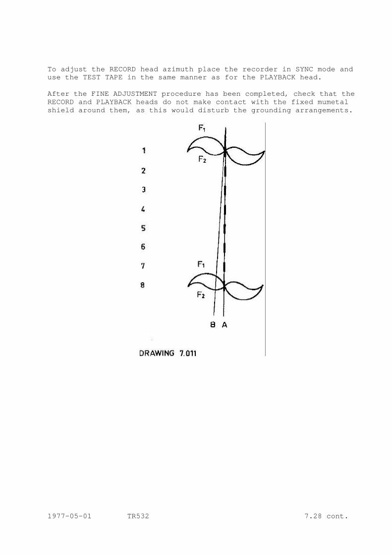
To adjust the RECORD head azimuth place the recorder in SYNC mode and use the TEST TAPE in the same manner as for the PLAYBACK head. After the FINE ADJUSTMENT procedure has been completed, check that the RECORD and PLAYBACK heads do not make contact with the fixed mumetal shield around them, as this would disturb the grounding arrangements.
1977-05-01 TR532 7.28 cont.
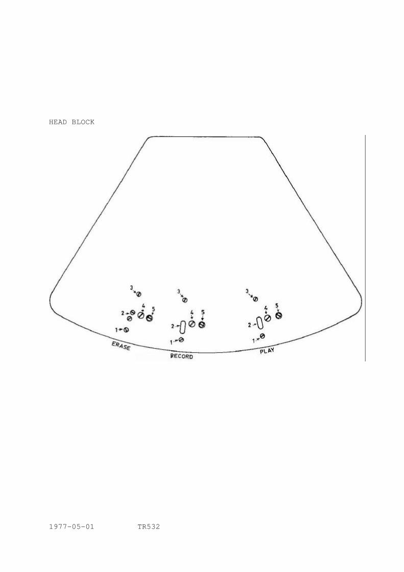
HEAD BLOCK
1977-05-01 TR532
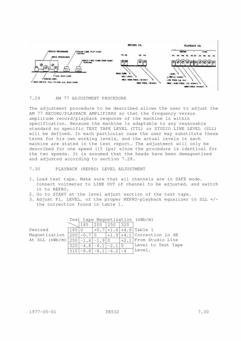
7.29 AM 77 ADJUSTMENT PROCEDURE The adjustment procedure to be described allows the user to adjust the AM 77 RECORD/PLAYBACK AMPLIFIERS so that the frequency versus amplitude record/playback response of the machine is within specification. Because the machine is adaptable to any reasonable standard no specific TEST TAPE LEVEL (TTL) or STUDIO LINE LEVEL (SLL) will be defined. In each particular case the user may substitute these terms for his own working levels, and the actual levels in each machine are stated in the test report. The adjustment will only be described for one speed (15 ips) since the procedure is identical for the two speeds. It is assumed that the heads have been demagnetized and adjusted according to section 7.28. 7.30 PLAYBACK (REPRO) LEVEL ADJUSTMENT 1. Load test tape. Make sure that all channels are in SAFE mode.
Connect voltmeter to LINE OUT of channel to be adjusted, and switch it to REPRO.
2. Go to START at the level adjust section of the test tape. 3. Adjust Pl, LEVEL, of the proper REPRO-playback equalizer to SLL +/-
the correction found in table 1. Test tape Magnetization (nWb/m)
185 200 250 320 185 0 +0.7 +1.4 +4.8 200 -0.7 0 +1.9 +4.1 250 -1.4 -1.9 0 +2.1 320 -4.8 -4.1 -2.1 0
Desired Magnetization At SLL (nWb/m)
510 -8.8 -8.1 -6.2 -4
Table 1 Correction in dB From Studio Line Level to Test Tape Level.
1977-05-01 TR532 7.30
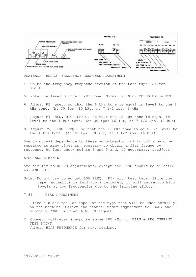
PLAYBACK (REPRO) FREQUENCY RESPONSE ADJUSTMENT 4. Go to the frequency response section of the test tape. Select
START. 5. Note the level of the 1 kHz tone. Normally 10 or 20 dB below TTL. 6. Adjust P2, µsec, so that the 6 kHz tone is equal in level to the 1
kHz tone. (At 30 ips: 10 kHz, at 7 1/2 ips: 6 kHz) 7. Adjust P4, MED.-HIGH FREQ., so that the 12 kHz tone is equal in
level to the 1 kHz tone. (At 30 ips: 16 kHz, at 7 1/2 ips: 12 kHz) 8. Adjust P5, HIGH FREQ., so that the 18 kHz tone is equal in level to
the 1 kHz tone. (At 30 ips: 18 kHz, at 7 1/2 ips: 16 kHz) Due to mutual dependence to these adjustments, points 5-8 should be repeated as many times as necessary to obtain a flat frequency response. At last check points 2 and 3 and, if necessary, readjust. SYNC ADJUSTMENTS are similar to REPRO adjustments, except the SYNC should be selected as LINE OUT. Note: Do not try to adjust LOW FREQ. (P3) with test tape. Since the
tape (normally) is full-track recorded, it will cause too high levels at low frequencies due to the fringing effect.
7.31 BIAS ADJUSTMENT 1. Place a blank reel of tape (of the type that will be used normally)
on the machine. Select the channel under adjustment to READY and select RECORD, without LINE IN signal.
2. Connect voltmeter (response above 100 kHz) to BIAS + REC CURRENT
TEST POINT. Adjust BIAS RESONANCE for max. reading. 1977-05-01 TR532 7.31

3. Turn the proper BIAS CURRENT potentiometer fully anticlockwise. 4. Connect the voltmeter to LINE OUT and select REPRO.
Feed a 10 kHz signal approx 20 dB below SLL to LINE IN, if tape speed is 15 ips. (At 30 ips: 20 kHz, and at 7 ½ ips: 5 kHz)
5. Slowly turn the BIAS CURRENT potentiometer clockwise and watch the
LINE OUT level rise to a max. value, after which it will drop with increasing bias current. Continue until this drop (due to self erasing) is approx 3 dB in relation to the max. value.
Normally bias current is 4-6 mA, corresponding to 40-60 mV across the internal 10 Ohm resistor at test jack. Note: This “3 dB overbias” may vary according to the type of tape
used, for optimum results. If in doubt, refer to the tape manufacturers specifications.
7.32 RECORD LEVEL ADJUSTMENT 1. Still with the blank tape and recording on the channel under
adjustment, feed 1 kHz at SLL to LINE IN. 2. With voltmeter at LINE OUT, and REPRO selected, adjust P2, RECORD LEVEL, on RECORD EQ. to read SLL on the voltmeter. RECORD - PLAYBACK FREQUENCY RESPONSE 3. Feed 1 kHz, SLL - 20 dB (approx), to LINE IN. Note the LINE OUT
level. 4. Feed 12 kHz, same level, to LINE IN. Adjust P3, MED. - HIGH FREQ.,
on RECORD EQ. to obtain the same level at LINE OUT as at 1 kHz. 5. Feed 18 kHz, same level, to LINE IN. Adjust P4, HIGH FREQ., to
obtain the same level - 1 dB at LINE OUT as at 1 kHz. Repeat 4 and 5 due to mutual dependence until a flat frequency response is obtained. 1977-05-01 TR532 7.32
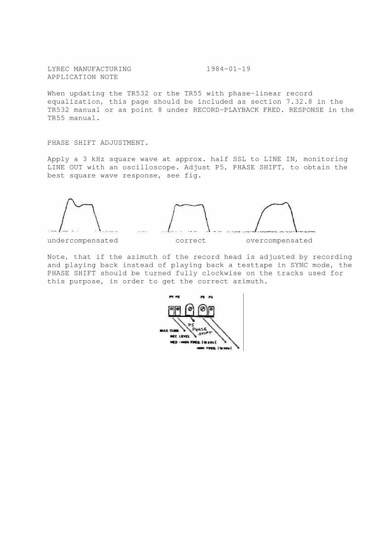
LYREC MANUFACTURING 1984-01-19 APPLICATION NOTE When updating the TR532 or the TR55 with phase-linear record equalization, this page should be included as section 7.32.8 in the TR532 manual or as point 8 under RECORD-PLAYBACK FRED. RESPONSE in the TR55 manual. PHASE SHIFT ADJUSTMENT. Apply a 3 kHz square wave at approx. half SSL to LINE IN, monitoring LINE OUT with an oscilloscope. Adjust P5, PHASE SHIFT, to obtain the best square wave response, see fig.
undercompensated correct overcompensated Note, that if the azimuth of the record head is adjusted by recording and playing back instead of playing back a testtape in SYNC mode, the PHASE SHIFT should be turned fully clockwise on the tracks used for this purpose, in order to get the correct azimuth.
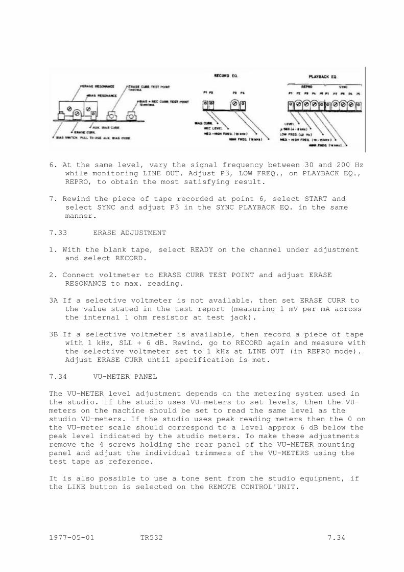
6. At the same level, vary the signal frequency between 30 and 200 Hz
while monitoring LINE OUT. Adjust P3, LOW FREQ., on PLAYBACK EQ., REPRO, to obtain the most satisfying result.
7. Rewind the piece of tape recorded at point 6, select START and
select SYNC and adjust P3 in the SYNC PLAYBACK EQ. in the same manner.
7.33 ERASE ADJUSTMENT 1. With the blank tape, select READY on the channel under adjustment
and select RECORD. 2. Connect voltmeter to ERASE CURR TEST POINT and adjust ERASE
RESONANCE to max. reading. 3A If a selective voltmeter is not available, then set ERASE CURR to
the value stated in the test report (measuring 1 mV per mA across the internal 1 ohm resistor at test jack).
3B If a selective voltmeter is available, then record a piece of tape
with 1 kHz, SLL + 6 dB. Rewind, go to RECORD again and measure with the selective voltmeter set to 1 kHz at LINE OUT (in REPRO mode). Adjust ERASE CURR until specification is met.
7.34 VU-METER PANEL The VU-METER level adjustment depends on the metering system used in the studio. If the studio uses VU-meters to set levels, then the VU-meters on the machine should be set to read the same level as the studio VU-meters. If the studio uses peak reading meters then the 0 on the VU-meter scale should correspond to a level approx 6 dB below the peak level indicated by the studio meters. To make these adjustments remove the 4 screws holding the rear panel of the VU-METER mounting panel and adjust the individual trimmers of the VU-METERS using the test tape as reference. It is also possible to use a tone sent from the studio equipment, if the LINE button is selected on the REMOTE CONTROL'UNIT. 1977-05-01 TR532 7.34

7.35 BIAS FILTER AND DC-CURRENT ADJUSTMENTS These adjustments are not accessible from front and the AM 77 therefore must be connected via the extension cable when adjustment is carried out. On the other hand, they are not part of any routine check, and readjustment is only necessary when components close related to the adjustable components have been substituted. 1. OUTPUT AMPLIFIER DC-CURRENT a) Select STOP, LINE IN, no LINE IN-signal. b) Connect voltmeter across resistor 15e in series with the output
transistors. c) Adjust PDC to read 250 mV, corresponding to 17 mA idle current. 2. OUTPUT AMPLIFIER BIAS TRAP a) Select REC on channel under adjustment, LINE IN, no LINE-signal. b) Connect oscilloscope to output of output amplifier (pin A14). c) Adjust L7 for min. bias leakage. 3. REPRO PREAMP BIAS FILTER a) Select RECORD on channel under adjustment, REPRO, no LINE IN-signal. b) Connect oscilloscope to pin 4 on one of the REPRO EQ.amplifier
connectors. c) Adjust L6 for min. bias leakage. 4. SYNC PREAMP BIAS FILTER a) Select RECORD on neighbouring channel, and SYNC on channel under
adjustment. b) Connect oscilloscope to pin 4 on one of the SYNC EQ. amplifier
connectors. c) Adjust L5 for min. bias leakage. 5. RECORD AMP BIAS FILTER a) Select RECORD on channel under adjustment, no LINE IN signal. b) Connect oscilloscope to one end of one of the two 220 µF capacitors
in the RECORD AMP. c) Adjust L2 for min. bias leakage. 1977-05-01 TR532 7.35
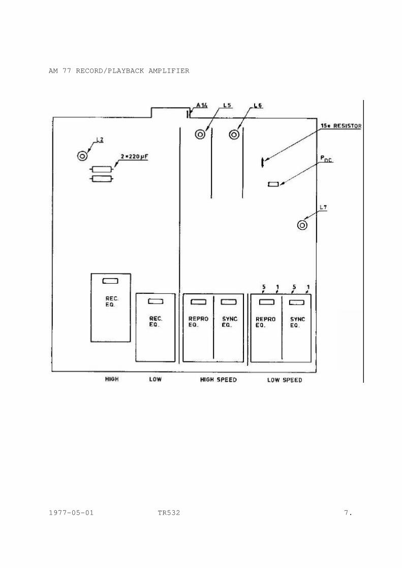
AM 77 RECORD/PLAYBACK AMPLIFIER
1977-05-01 TR532 7.
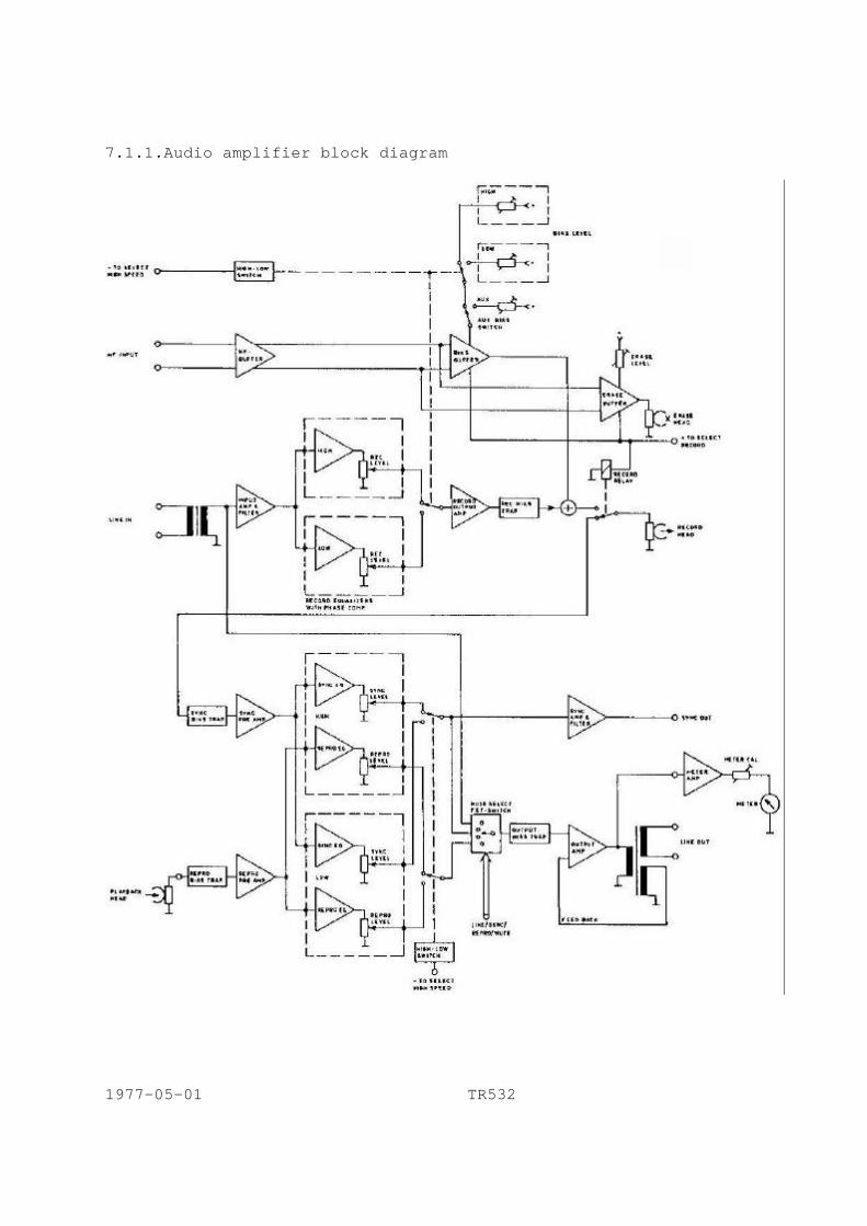
7.1.1.Audio amplifier block diagram
1977-05-01 TR532
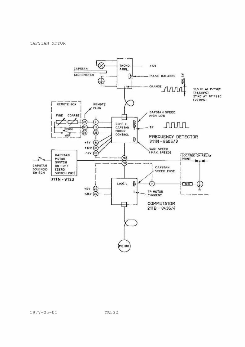
CAPSTAN MOTOR
1977-05-01 TR532
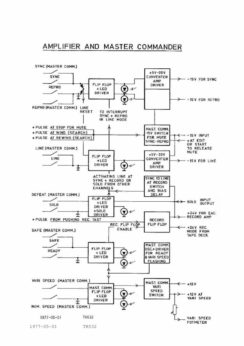
1977-05-01 TR532
8. SERVICE
THEORY OF OPERATION 8.1 CAPSTAN MOTOR SYSTEM The capstan motor is a brushless DC-motor with 4 windings displaced 900 with respect to each other, placed in the air gap between the two pole permanent magnet rotor and the groove free stator. Two Hall generators measure the rotor position. The speed of the motor is controlled by a highly stable one-shot compared with the signals from the 1.000 division stroboscopic system. A 5 V lamp is placed above the tachometer disc and is fed from the capstan speed preamplifier (connection L-L). The distance between the lamp and the tachometer disc should be approx 2 mm; under the disc is the phototransistor detector. This should be placed at a distance of approx 0.5 mm. It is connected to the capstan speed preamplifier by connection CE. 8.2 CAPSTAN SPEED PREAMPLIFIER diagram 9119 The CAPSTAN SPEED PREAMPLIFIER is placed on the motor mounting and serves to amplify the signals from the phototransistor. The output from the capstan speed preamplifier (orange wire) should look like the curve in drawing 7.09. When no light passes the output is low. The times T1 for no light and T2 for light should be equal and can be adjusted with a potentiometer in the CAPSTAN PREMAPLIFIER. The preamplifier is connected to code 2 card with a 4-pin connector for both signal and power. 8.3 FREQUENCY DETECTOR (code 2 card) diagram 8605/3 The capstan motor control FREQUENCY DETECTOR consists of two one-shots (74121) with variable output width, one for pre-set speed and one for variable speed, a low pass filter and an amplifier. The output from the capstan speed preamplifier fires the one-shot. In order to produce a reference voltage for the control system the output from the one-shot is high when no pulse occurs. The pulse from the one-shot is fed to a pulse shaper circuit (2xBC184 and 2xBC214) in order to get a square wave with constant amplitude of approx 12 volts peak-to-peak as seen on an oscilloscope connected to the test point (TP). 15 ips is equal to 13.5 revolutions/sec of the capstan, and with 1.000 lines on the tachometer disc this gives a frequency of 13.500 Hz at the test point. The square wave is fed to a low pass filter (2xLM301) with a corner-frequency of 1.5 kHz and above this frequency an attenuation of 24 dB/octave. After the low pass filter the signal is fed to an amplifier section (2xLM301) with a gain of 100. The output from the frequency detector card is connected to point 16 and under normal conditions the voltage at this point should be above 1 V. 1977-05-01 TR532 8.3
8.3.1 CAPSTAN BRAKING To prevent tape loops at early play start after play stop, the capstan motor is braked by 5V from code 3 capstan motor control (drw. 8436/5). Transistors T3 and T2 control the braking power through point 23 connected from point 23 code 2 (drw. 8605/3), print board 73-093. One shot, 74121, 1 and 2 supplies pulses through diodes to be charged in 2µ2 capacitor as a 5V DC at running motor, the following BC184 as emitter follower puts the control voltage to point 23 or to zero by a transistor connected to base from point 31. Point 31 gets information +24V at start from micro switch on pinch roller solenoid to enable the control output for braking in start mode and only to take place at stop and fade out after final braking. 8.4.1 ACCELERATION CONTROL IN CAPSTAN MOTOR Code 3, print board 72-143, capstan motor control (drw. 8436/5), consists of two adjust potentiometers to control the acceleration time as well as the run quality in nominal speed. TS 14-15-16-17 work as switch for the two potentiometers P3 and P4. P3 is connected in acceleration period and P4 after. The control input for this switching, comes from point 37 code 1 and goes to point 1 code 3. Adjust P3 for min. moving of take-up servo arm in acceleration period. Adjust P4 for min. wow and flutter. Without flutter meter, an oscilloscope connected to the test point motor current can be used to do a fairly good adjustment. Turn P4 clockwise until the picture tend to oscillate and then back a little to safe distance from oscillation risk. 1980-05-01 TR532 8.3.1
8.4 MOTOR CONTROL COMMUTATOR (code 3 card) diagram 8436/5 The four motor windings are current fed from the capstan motor control commutator according to the signals from the two Hall generators in the motor. The signal from the frequency detector (point 16) is connected to the control commutator (point 16) and determines, via transistors T4 and T5 the input from the Hall generators to the four driver transistors. These transistors (4xMJE2955) are connected to the four windings, and each one feeds current to one winding for half a rotation. The balance between the Hall generators can be set with P2 (100 ohms) in order to make the current in the four windings equal. The total motor current can be seen on an oscilloscope connected to test point (TP) and there the normal conditions should be approx constant at a value close to 2.7 V across the test point resistor, which represents 1 A total current in the windings. The total current is limited to approx 2.5 A. To save the capstan motor and tachometer from damage by failures in the motor control circuits an overspeed trigger circuit has been built in, made up of transistors T1, T2 and T3. They derive their information from the induced voltage in the windings. When the induced voltage exceeds the admissible value, point 7 goes high; the exact limit is determined by the potentiometer P1. Point 7 is connected to print 69-025 in the tape deck at point 51, where it causes transistor No. 11 to short-circuit the input to transistor 12 which in turn will activate relay 5 and interrupt the tape deck mode. P1 is factory adjusted to allow tape speed up to about 70 ips. The amplification of the capstan servo system is controlled by P3 on code 3 card. P3 is factory adjusted for the best startup characteristics and minimum wow and flutter and does normally not require adjustment. 8.5 REEL MOTOR SERVO SYSTEM (code 1 card) diagram 9870 The servo system for controlling the SUPPLY and TAKE-UP motors consists of a series connected transformer for each motor, in order to obtain a low secondary control voltage, for safe servo-controlling through power transistors 2N3055 at about 30 V. These transistors are mounted on the rear of the tape deck, and immediately above them, on the inside, is a small printed circuit with the BC310 darlington driver transistors. These in turn are driven from four darlington gates for each motor, which get their logic information in the form of +24 V from the relay to a) connect servo potentiometer in START or RECORD modes, b) winding potentiometer and servo potentiometer in LOCAL WIND MODE or c) wind tension and servo potentiometer in REMOTE WIND MODE. 1977-05-01 TR532 8.5

When the START button is pressed +24 V will appear at point 10 and will activate the STARTING POWER circuit which may be adjusted by means of the START POWER TIME potentiometer and the START POWER potentiometer. The normal factory adjustments for these points are max START POWER on the TAKE-UP motor. START POWER is adjusted to give max take-up motor power during the acceleration period of the capstan motor. The START POWER function is momentary addition to the normal functioning of the servo potentiometers on the tension arms. The start up sensing is obtained from code 2 capstan motor amplifier through pin 1 being +12 V until correct speed is obtained. When the WIND button is pressed on the tape deck +24 V appears at point 23 and will open the darlington gate to connect the local wind potentiometer in circuit. This potentiometer is supplied from an emitter follower (adjusted by a potentiometer labeled WIND POWER) via a 2200 ohm resistor. At the factory the WIND POWER is adjusted to give the best crossover power for both reel motors, with the WIND SPEED CONTROL in center position. When the STOP button is pressed and after the mechanical brakes have taken over the servo tension fades out according to the zener diode ZF4.3 and the 220 µF condenser in parallel with it. 8.6 WIND SPEED LIMIT CIRCUIT An addition to the tachometer logic card, code 7, drawing No. 8520/4, is the wind speed limit circuit. The SN74121 No. 9 will give square wave pulses to charge condenser C10. By way of two steps of amplification the DC-signal is fed through two emitter followers to point 10 for control of the supply motor and point 8 for control of the take-up motor (point 31 and 33 respectively on the servo card, code 1). At a winding speed of between 170 and 190"/sec the WIND SPEED LIMIT potentiometer P2 should be adjusted to give a control voltage through point 8 and 10 so that the supply motor increases the tape tension and does not allow the winding speed to rise any further (read 1925 on speed display). 8.7 DYNAMIC BRAKE SYSTEM diagram 9119 The mechanical brakes on the reel motors are in action only in the stand-by position. During all other brake processes for any tape speed above approx 20 ips braking is effected by introducing an opposite direction wind function, which ends when the tape comes to rest and the mechanical brakes take over. The logic information for the dynamic braking process comes from the tachometer logic card, code 7, diagram 8520/4 1977-05-01 TR532 8.7
When the STOP button is pressed, relay 7 will send +24 V to point 14 and then through point 44-A to transistor latch 1 and 2. This will activate transistor 3 which gives collector voltage to transistors 4 and 5 and drive to transistors 6 and 7 which are outputs for the zero switch drivers on zeros witch print (placed behind the electrolytic capacitors). The zero switch for the supply motor is energized by transistor 7 and the take-up motor by transistor 6. Both situations keep the mechanical motor brakes free while dynamic braking is going on (+24 V at point 18). As long as the tape moves forward point D will be at 0.2 V instead of approx 12 V. When the STOP button is pressed transistors 4 and 5 get collector voltage but point D will keep transistor 5 cut off. Therefore only transistor 7 functions and connects the mains to the SUPPLY motor. As long as the tape moves backwards point C will be 0.2 V instead of approx 12 V. When the STOP button is pressed transistors 4 and 5 get collector voltage but point C will keep transistor 4 cut off. Only transistor 6 will switch on and connect the mains to the TAKE-UP motor. When the tape stops, or is moving very slowly, point V will drop to 0.2 V from approx 12 V so that relay 5 will be activated. Relay 5 driver transistor will at the same time switch transistor latch 1 and 2 and through this the drive for transistors 3, 4, 5, 6 and 7 is cut off. The DYNAMIC BRAKE process then comes to an end. 8.8 CAPSTAN AND GUIDE ROLLER SOLENOIDS When either the START, or START and RECORD buttons are pressed relay 6 is energized. This will connect +24 V through point 11 and point 3B to the solenoids. The solenoids return circuit passes through point 4B to G which connects to 0 V through the diode 1N5404. The pull voltage and the hold-on voltage for these solenoids are respectively 36 V and 24 V. For approx 1 sec after the START or RECORD buttons have been pressed -12 V is added at the 0-end of the solenoids by transistors 9 and 10. During the stop mode the 22 µF electrolytic condenser charges up to 24 V and when start is pressed it will keep transistors 9 and 10 temporarily open and connect -12 V from point E to point G. 1977-05-01 TR532 8.9
8.9 REMOTE CONTROL UNIT MUTING SYSTEM diagram 8905 When the STOP button is pressed 24 V goes to point 18 on the MASTER COMMAND print. Through transistors 5, 6 and 7, transistor 8 disconnects the -15 V supply from point 16 in all amplifier COMMAND PRINTS, thereby muting all tracks in SYNC or REPRO MODE. When the START button is pressed, either alone or with the RECORD button, 29 V is sent from the capstan solenoid via the remote plug point 7B to the MASTER COMMAND PRINT point 17 but short-circuited by a transistor (in the zeroswitchprint placed behind the electrolytic capacitors) until correct capstan speed is obtained. Transistors 5 and 6 are reversed and transistor 8 connects -15 V to point 16 on all the AMPLIFIER COMMAND PRINTS and no muting occurs. A similar situation occurs when the EDIT CONTROL on the TAPE DECK is activated, -12 V from the solenoid power supply. When the MAINS button is pressed the muting system is preselected to stay in mute. 1977-05-01 TR532 8.9 cont.

PREVENTIVE MAINTENANCE 8.10 DEMAGNETIZATION Tape heads and other metal parts in the tape path can become permanently magnetized if mains drops during record mode. This causes noise and distortion and can in bad cases partially erase high frequencies on prerecorded tapes. In order to avoid this, daily demagnetizing is recommended. To demagnetize proceed as follows. Slowly move the switched on demagnetizer towards the heads and parts to be demagnetized. Move the tip of the demagnetizer slowly and with an even motion up and down the magnetic head without switching off the demagnetizer. Slowly withdraw the demagnetizer until 1 m away from the recorder and switch off the demagnetizer. Be sure not to scratch the heads with the tip of the demagnetizer. CLEANING 8.11 VENTILATION The two ventilation fans are equipped with airfilters which are located under the TAPE DECK and can be slid out from the rear. The filters are a double type, of which only one half is used at a time. After both ends have been used, dirty filters are either exchanged or vacuum-cleaned. The filters should be checked at least once every two months, or more frequently if air pollution is high. Depending on tape type it might be necessary from time to time to clean the surface of the two phototransistors located inside the counter roller. Daily cleaning of all parts in the tape path is recommended. For cleaning metal parts, head stacks and the rubber pinch roller the supplied cleaning fluid is recommended. 8.12 LUBRICATION A few parts in the Lyrec TR532 require periodic lubrication. The capstan top bearing should be lubricated with two drops of oil every month. Use Esso Nuto HP 32 oil as supplied with the recorder. Apply a drop of oil on the tip of a piece of wire and lubricate as indicated in drawing 8.0.1, points 7 and 8. If the glass air cylinders connected to the servo arms show any tendency to grip, lubricate them with Rocol molybdenum oil. Once a year put a drop of light oil on the solenoid plungers. 1978-07-01 TR532 8.12
NAB reel hub From time to time it might be necessary to lubricate the rubber expander locking ring if the reels are difficult to put on to the hub. Use a few drops of Esso NUTO HP32 (as supplied with the machine) and spread it with your finger around the ring. Operate the LOCK/ UNLOCK mechanism a few times so that the oil will spread evenly around the rubber ring. No other parts require periodic lubrication. 8.13 REMOVING HEAD BLOCK, see drawing No. 8.0.2 Remove the top cover of the HEAD BLOCK by removing the two screws, then release the rear cover by removing screw 10. Unscrew the locking screw of each head connector and pull back the connector for each head stack. Remove the single locking screw 9 which holds the head block to the tape deck; gently pull up and the complete HEAD BLOCK will come away from the TAPE DECK.
DISMANTLING PARTS
8.14 TENSION ARM POTENTIOMETER REPLACEMENT drawing No. 7.06 Unlock arm C and remove mounting screw M. Unsolder the two leads to the potentiometer and pull down gently on the pot, its mounting plate K and the clutch assembly. This allows access to the three mounting screws L which hold the clutch assembly to the potentiometer mounting plate. Unscrew them, then unlock the upper clutch section E, first noting its relative position to the lower clutch section F and remove the potentiometer. It may now be replaced, after which the process is reversed to reassemble. Keep in mind the separation between the two clutch sections. 8.15 PERFORMANCE CHECK A monthly performance check is recommended. This includes visual inspection of tape chassis. Tape transport is visually checked by running through all modes observing that nothing unusual occurs, e.g. tape loops or similar, start and braking performance. Play test tape and check azimuth adjustment, playback and sync amplifiers, if necessary adjust as described in section 7. 1978-07-01 TR532 8.15

REC-START-WIND-STOP Relay System Diagram 9119 Print 69-025 RELAY # 1 2 3 4 5 6 7 8 11 12 Stand by ¡ ¡ ¡ ¡ ⌧ ¡ ¡ u ¡ ¡ Braking ¡ ¡ ¡ � ¡ ¡ ¡ ⌧ ¡ ¡ Start ⌧ ¡ ¡ ¡ z ⌧ ⌧ ⌧ ¡ ¡ Record ¡ ⌧ ¡ ¡ z ⌧ ⌧ ⌧ ¡ ¡ Wind ¡ ¡ ⌧ ¡ z ¡ ⌧ ⌧ ¡ ¡ Remote wind ¡ ¡ ⌧ ¡ z ¡ ⌧ ⌧ ¡ ⌧ Remote rewind ¡ ¡ ⌧ ¡ z ¡ ⌧ ⌧ ⌧ ¡ ⌧ = Active ¡ = Neutral � = Activated short time z = Active until 1-2 sec after start and then neutral u = Mains switch: with light relay active without light relay active Relay 1 start Relay 2 record Relay 3 wind Relay 4 stop Relay 5 Relay 6 solenoid + servo Relay 7 brake delay Relay 8 mains Relay 11 remote rewind Relay 12 remote wind Relay 10 polarised two stages relay, high and low speed memory. 1977-05-01 TR532
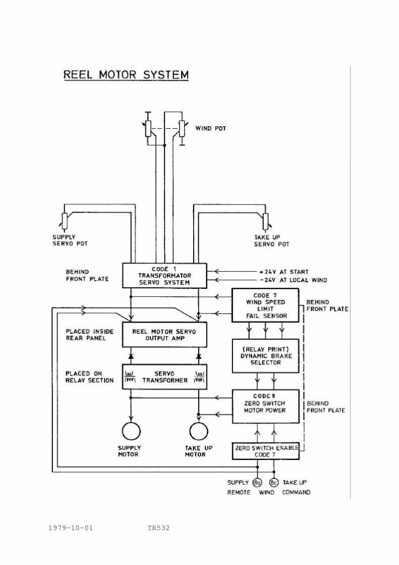
1979-10-01 TR532
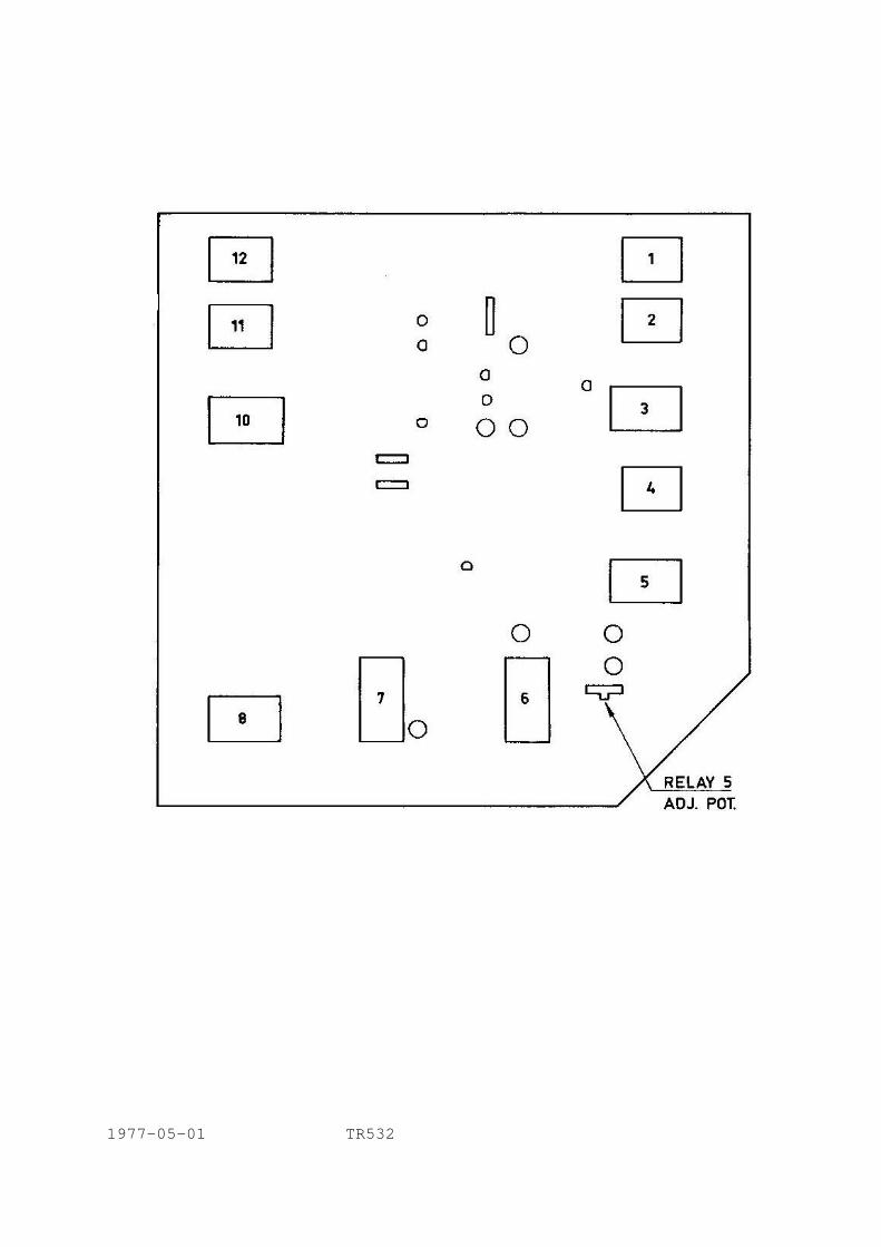
1977-05-01 TR532
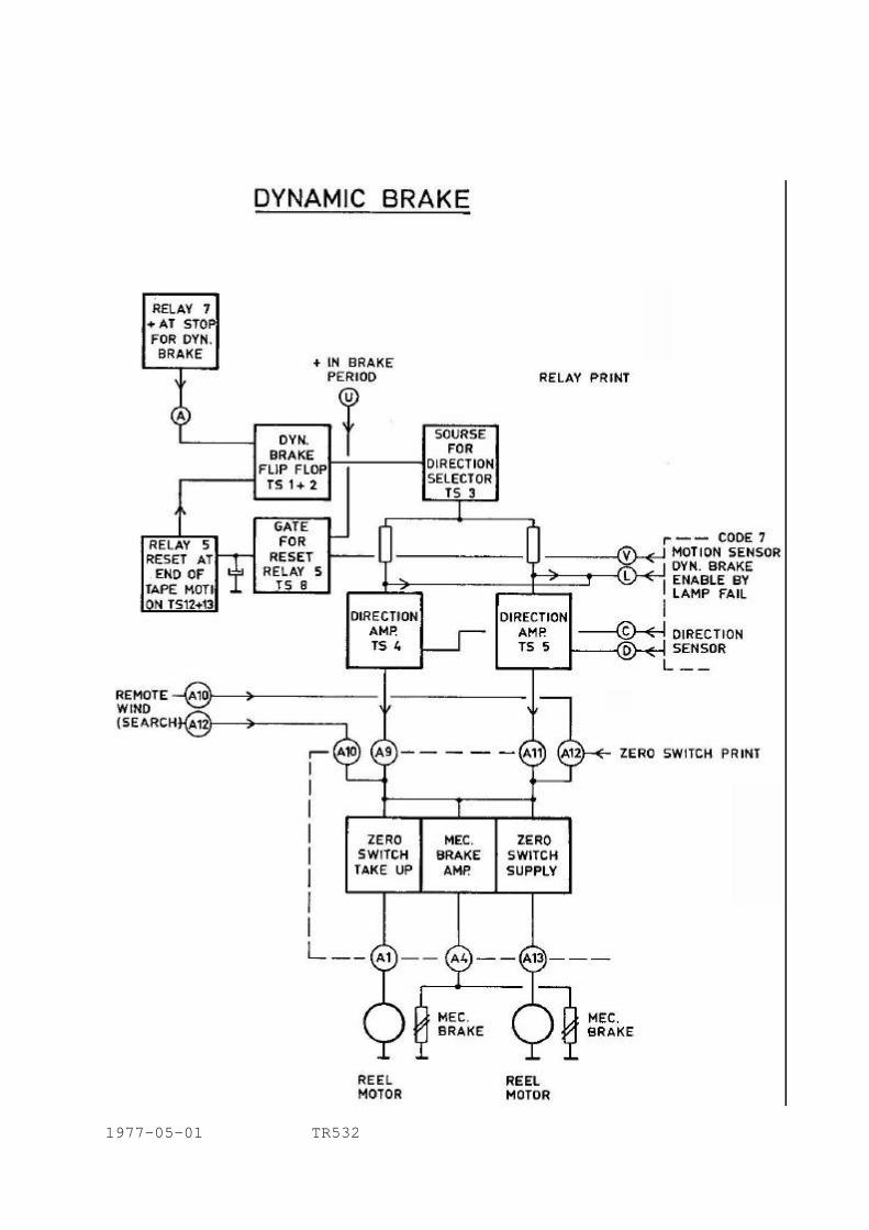
1977-05-01 TR532
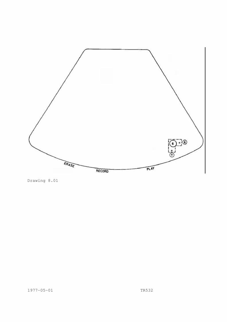
Drawing 8.01 1977-05-01 TR532
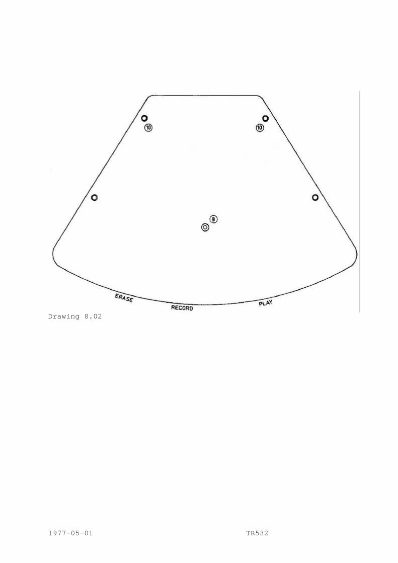
Drawing 8.02 1977-05-01 TR532
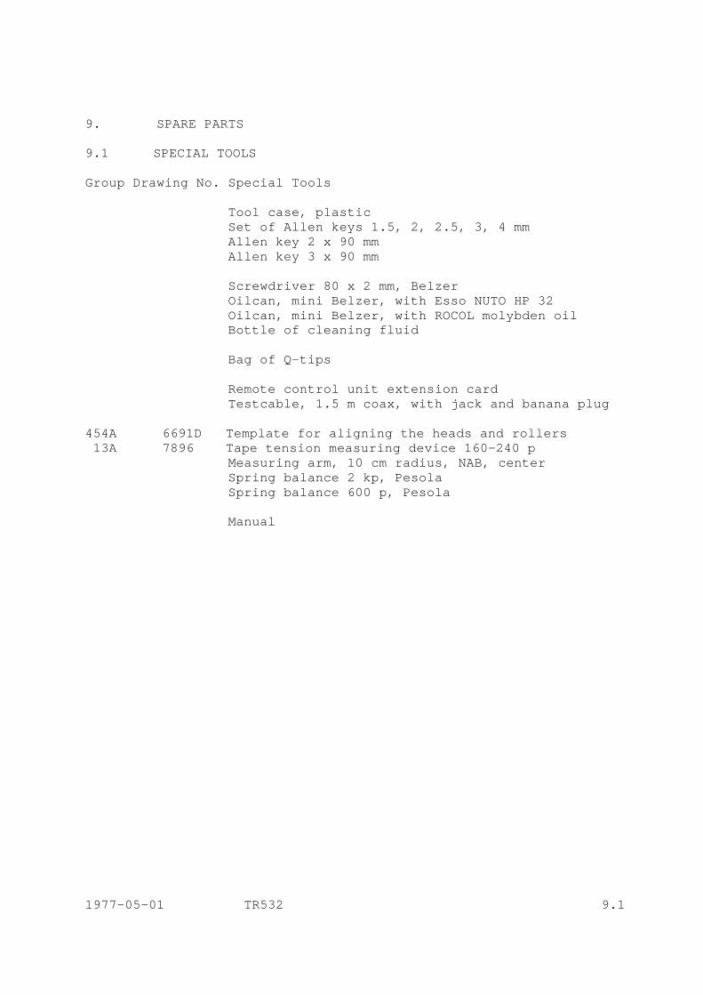
9. SPARE PARTS 9.1 SPECIAL TOOLS Group Drawing No. Special Tools Tool case, plastic Set of Allen keys 1.5, 2, 2.5, 3, 4 mm Allen key 2 x 90 mm Allen key 3 x 90 mm Screwdriver 80 x 2 mm, Belzer Oilcan, mini Belzer, with Esso NUTO HP 32 Oilcan, mini Belzer, with ROCOL molybden oil Bottle of cleaning fluid Bag of Q-tips Remote control unit extension card Testcable, 1.5 m coax, with jack and banana plug 454A 6691D Template for aligning the heads and rollers 13A 7896 Tape tension measuring device 160-240 p Measuring arm, 10 cm radius, NAB, center Spring balance 2 kp, Pesola Spring balance 600 p, Pesola Manual 1977-05-01 TR532 9.1
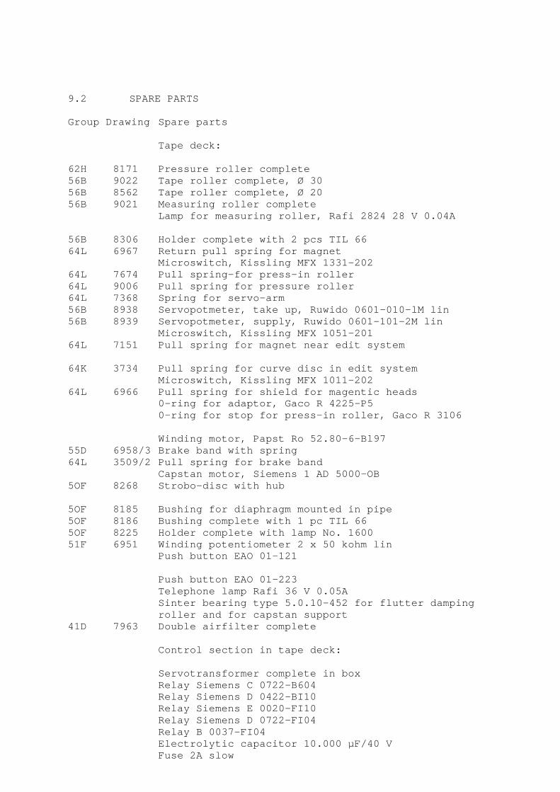
9.2 SPARE PARTS Group Drawing Spare parts Tape deck: 62H 8171 Pressure roller complete 56B 9022 Tape roller complete, Ø 30 56B 8562 Tape roller complete, Ø 20 56B 9021 Measuring roller complete Lamp for measuring roller, Rafi 2824 28 V 0.04A 56B 8306 Holder complete with 2 pcs TIL 66 64L 6967 Return pull spring for magnet Microswitch, Kissling MFX 1331-202 64L 7674 Pull spring-for press-in roller 64L 9006 Pull spring for pressure roller 64L 7368 Spring for servo-arm 56B 8938 Servopotmeter, take up, Ruwido 0601-010-lM lin 56B 8939 Servopotmeter, supply, Ruwido 0601-101-2M lin Microswitch, Kissling MFX 1051-201 64L 7151 Pull spring for magnet near edit system 64K 3734 Pull spring for curve disc in edit system Microswitch, Kissling MFX 1011-202 64L 6966 Pull spring for shield for magentic heads 0-ring for adaptor, Gaco R 4225-P5 0-ring for stop for press-in roller, Gaco R 3106 Winding motor, Papst Ro 52.80-6-Bl97 55D 6958/3 Brake band with spring 64L 3509/2 Pull spring for brake band Capstan motor, Siemens 1 AD 5000-OB 5OF 8268 Strobo-disc with hub 5OF 8185 Bushing for diaphragm mounted in pipe 5OF 8186 Bushing complete with 1 pc TIL 66 5OF 8225 Holder complete with lamp No. 1600 51F 6951 Winding potentiometer 2 x 50 kohm lin Push button EAO 01-121 Push button EAO 01-223 Telephone lamp Rafi 36 V 0.05A
Sinter bearing type 5.0.10-452 for flutter damping roller and for capstan support
41D 7963 Double airfilter complete Control section in tape deck: Servotransformer complete in box Relay Siemens C 0722-B604 Relay Siemens D 0422-BI10 Relay Siemens E 0020-FI10 Relay Siemens D 0722-FI04 Relay B 0037-FI04 Electrolytic capacitor 10.000 µF/40 V Fuse 2A slow
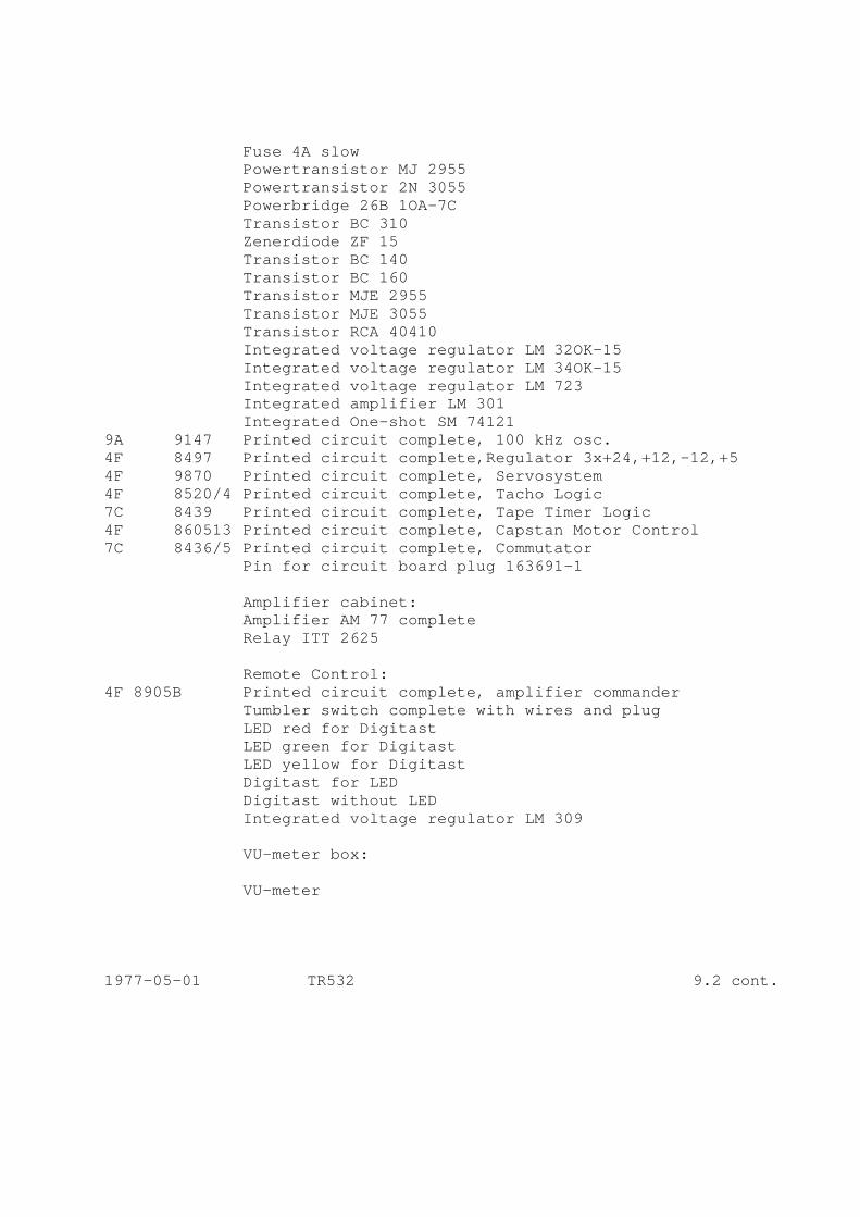
Fuse 4A slow Powertransistor MJ 2955 Powertransistor 2N 3055 Powerbridge 26B 1OA-7C Transistor BC 310 Zenerdiode ZF 15 Transistor BC 140 Transistor BC 160 Transistor MJE 2955 Transistor MJE 3055 Transistor RCA 40410 Integrated voltage regulator LM 32OK-15 Integrated voltage regulator LM 34OK-15 Integrated voltage regulator LM 723 Integrated amplifier LM 301 Integrated One-shot SM 74121 9A 9147 Printed circuit complete, 100 kHz osc. 4F 8497 Printed circuit complete,Regulator 3x+24,+12,-12,+5 4F 9870 Printed circuit complete, Servosystem 4F 8520/4 Printed circuit complete, Tacho Logic 7C 8439 Printed circuit complete, Tape Timer Logic 4F 860513 Printed circuit complete, Capstan Motor Control 7C 8436/5 Printed circuit complete, Commutator Pin for circuit board plug 163691-1 Amplifier cabinet: Amplifier AM 77 complete Relay ITT 2625 Remote Control: 4F 8905B Printed circuit complete, amplifier commander Tumbler switch complete with wires and plug LED red for Digitast LED green for Digitast LED yellow for Digitast Digitast for LED Digitast without LED Integrated voltage regulator LM 309 VU-meter box: VU-meter 1977-05-01 TR532 9.2 cont.
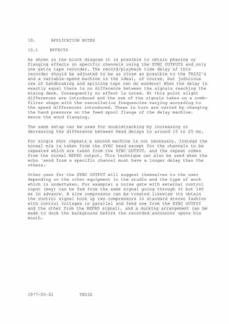
10. APPLICATION NOTES 10.1 EFFECTS As shown in the block diagram it is possible to obtain phasing or flanging effects on specific channels using the SYNC OUTPUTS and only one extra tape recorder. The record/playback time delay of this recorder should be adjusted to be as close as possible to the TR532's and a variable-speed machine is the ideal, of course, but judicious use of handbraking and splicing tape can do wonders! When the delay is exactly equal there is no difference between the signals reaching the mixing desk. Consequently no effect is noted. At this point slight differences are introduced and the sum of the signals takes on a comb-filter shape with the cancellation frequencies varying according to the speed differences introduced. These in turn are varied by changing the hand pressure on the feed spool flange of the delay machine. Hence the word flanging. The same setup can be used for doubletracking by increasing or decreasing the difference between head delays to around 15 to 25 ms. For single shot repeats a second machine is not necessary. Instead the normal mix is taken from the SYNC head except for the channels to be repeated which are taken from the SYNC OUTPUT, and the repeat comes from the normal REPRO output. This technique can also be used when the echo 'send from a specific channel must have a longer delay than the others. Other uses for the SYNC OUTPUT will suggest themselves to the user depending on the other equipment in the studio and the type of work which is undertaken. For example: a noise gate with external control input (key) can be fed from the same signal going through it but 140 ms in advance. A slow compressor can be treated likewise (to obtain the control signal hook up two compressors in standard stereo fashion with control voltages in parallel and feed one from the SYNC OUTPUT and the other from the REPRO signal), and a ducking arrangement can be made to duck the background before the recorded announcer opens his mouth. 1977-05-01 TR532

Drawing 10.01 1977-05-01 TR532
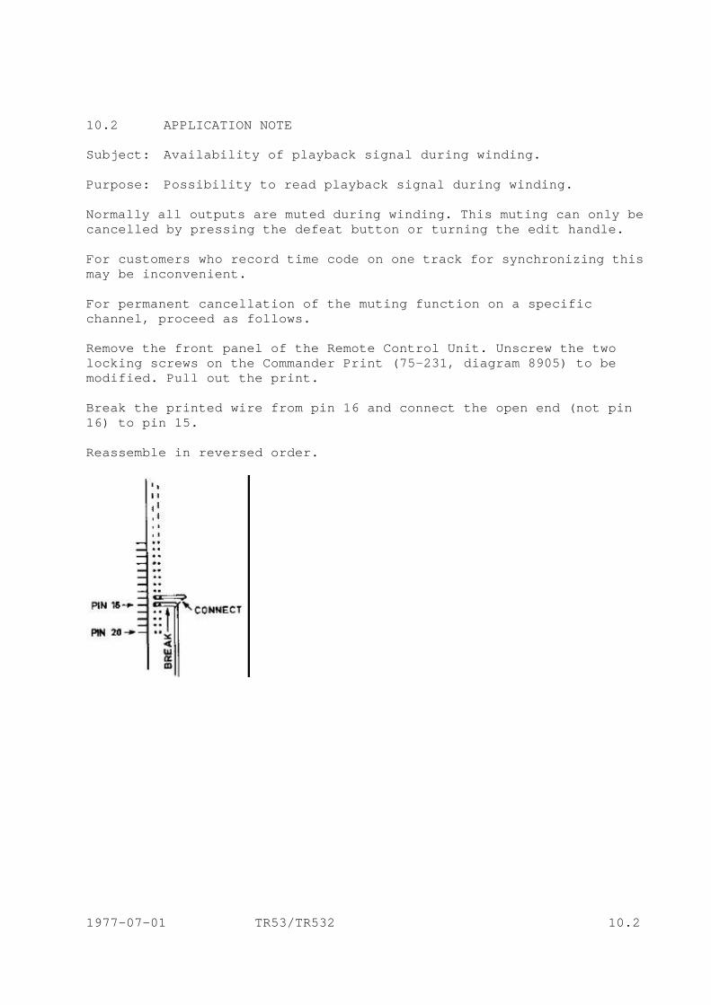
10.2 APPLICATION NOTE Subject: Availability of playback signal during winding. Purpose: Possibility to read playback signal during winding. Normally all outputs are muted during winding. This muting can only be cancelled by pressing the defeat button or turning the edit handle. For customers who record time code on one track for synchronizing this may be inconvenient. For permanent cancellation of the muting function on a specific channel, proceed as follows. Remove the front panel of the Remote Control Unit. Unscrew the two locking screws on the Commander Print (75-231, diagram 8905) to be modified. Pull out the print. Break the printed wire from pin 16 and connect the open end (not pin 16) to pin 15. Reassemble in reversed order.
1977-07-01 TR53/TR532 10.2

APPLICATION NOTE 10.3 SOLO function Normally when using the SOLO function all other channels switch to LINE IN. This can be changed so that all other channels are muted. The modification is simple and requires one 10 kOhm resistor for each channel. Remove the front panel of the REMOTE CONTROL UNIT. Unscrew the two locking screws on the Commander Print (75-231, diagram 8905) to be modified. Pull out the print. Unsolder or cut out diode D4 and leave the circuit open at D4. Install a 10 kOhm resistor between the collector of transistor TS20 and the base of transistor TS10. Proceed likewise for all tracks to be modified. Reassemble in reversed order. After this modification the SOLO button will mute all other tracks although the LINE IN LED indicator will light up. 1977-07-08 TR53/TR532 10.3
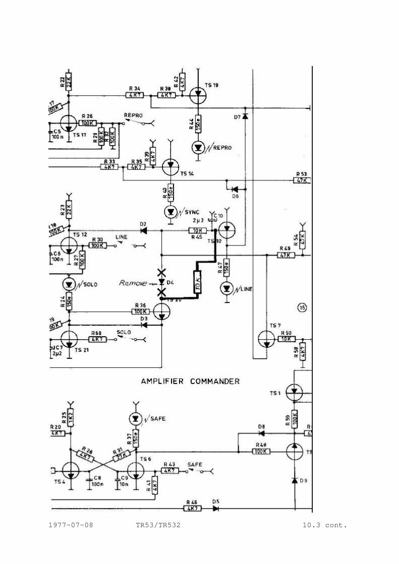
1977-07-08 TR53/TR532 10.3 cont.
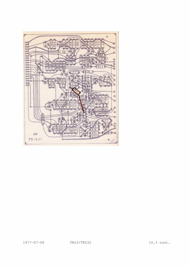
1977-07-08 TR53/TR532 10.3 cont.
10.4 APPLICATION NOTE START after SEARCH in RCU's Normally a search is terminated with a STOP command. With this modification, it is possible to select with a switch, whether the machine will go to STOP or START after SEARCH. In the remote control unit, insert a diode in the wire from STOP-LAMP (pin 5a) to pin 16 on the SEARCH LOGIC. Connect the START-LAMP (pin 1c) via a diode also to pin 16 on SEARCH LOGIC. Terminate the two diodes to ground through a 2K2 resistor. Install a switch and connect the arm to pin 13 on SEARCH LOGIC (disconnect the wire already on pin 13). Connect one side of the switch to STOP COMM (pin 7a) and the other side to START COMM (pin 2c). The position of the switch will now decide whether the machine will go to STOP or START after SEARCH. 1978-09-01 TR532 10.4
APPLICATION NOTE 10.5
Applicable for remote control units type RCU and TPC
GROUP BUILDING WITH THE REMOTE CONTROL By programming the audio commanders in a special sequence, the tracks can be split up into three groups for remix. Each group can be recalled with one button. The three groups can only be recalled in sequence and the process is not reversible. Programming; Group 1. Select tracks for group 1 to SOLO and REPRO. Group 2. Select tracks for group 2 to SOLO and LINE. Group 3. Remaining tracks now automatically belong to group 3. RECALLING GROUPS After programming, only group 1 is active. Provided no signals are routed to the recorder, group 2 and 3 will be silent as they are switched to LINE. To recall group 2, simply press the MASTER REPRO button. This will switch group 2 from SOLO - LINE into SOLO - REPRO, and these tracks are added to group 1. To recall group 3, simply press the DEFEAT button, which will cancel the SOLO function and thus all tracks will be active. TR53/TR532 RCU/TPC

APPLICATION NOTE 10.6
Applicable for remote control type ATC
GROUP BUILDING WITH THE REMOTE CONTROL
By programming the audio commanders in a special sequence, the tracks can be split up in 3 or 4 groups for remix. Each group can be recalled with one button. The groups can only be recalled in sequence and the process is not reversible.
Programming 3 groups;
Before selecting tracks, press MASTER REPRO.
Group 1. Select tracks for group 1 to SOLO. Group 2. Select tracks for group 2 to SOLO and LINE. Group 3. Remaining tracks now automatically belong to group 3. RECALLING GROUPS After programming only group 1 is active. Provided no signals are routed to the recorder, group 2 will be silent as it is switched to LINE. Group 3 is electronically muted. To recall group 2, simply press the MASTER REPRO button. This will switch group 2 from SOLO - LINE into SOLO - REPRO and these tracks are added to group 1. To recall group 3, simply press the DEFEAT button, which will cancel the SOLO function and thus all tracks will be active.
Programming 4 groups;
Before selecting tracks press MASTER REPRO. To obtain a 4th group, this has to be selected first. Group 4. Select tracks for group 4 to LINE. Group 1. Select tracks fro group 1 to SOLO. Group 2. Select tracks for group 2 to SOLO and LINE. Group 3. Remaining tracks automatically belong to group 3.
TR532 ATC

RECALLING GROUPS After programming only group 1 is active. Provided no signals are routed to the recorder, group 2 will be silent as it is switched to LINE. Group 3 and 4 are electronically muted. To recall group 2, simply press the MASTER REPRO button This will switch group 2 from SOLO - LINE into SOLO - REPRO and these tracks are added to group 1. To recall group 3, press the DEFEAT button, which will cancel the SOLO function and group 3 will be added. Simultaneously the remaining group 4 will switch to LINE. To recall group 4, again press the MASTER REPRO button, which will add group 4 and thus all tracks are active. TR532 ATC cont.
11 SERVICE BULLETINS 11.1 EQUALISATION For customers having NAB test tape and aligning for CCIR or vice versa, the table below might be useful. Response from amplifier adjusted for 15 ips NAB when using a 15 ips CCIR test tape, Ereq. Relative output in dB 1 kHz 0.20 2 kHz 0.68 4 kHz 1.63 6.3 kHz 2.26 8 kHz 2.52 10 kHz 2.70 12.5 kHz 2.83 14 kHz 2.88 16 kHz 2.93 18 kHz 2.96 When using a 15 ips NAB test tape with a 15 ips CCIR amplifier, the relative output should be the same number but negative. 1977-09-01 TR53/532 11.1
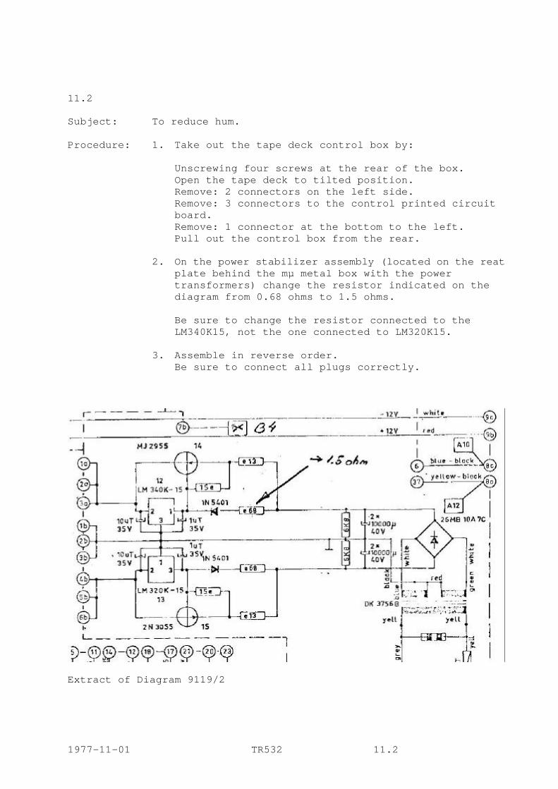
11.2 Subject: To reduce hum. Procedure: 1. Take out the tape deck control box by: Unscrewing four screws at the rear of the box. Open the tape deck to tilted position. Remove: 2 connectors on the left side.
Remove: 3 connectors to the control printed circuit board.
Remove: 1 connector at the bottom to the left. Pull out the control box from the rear.
2. On the power stabilizer assembly (located on the reat plate behind the mµ metal box with the power transformers) change the resistor indicated on the diagram from 0.68 ohms to 1.5 ohms.
Be sure to change the resistor connected to the LM340K15, not the one connected to LM320K15.
3. Assemble in reverse order. Be sure to connect all plugs correctly.
Extract of Diagram 9119/2 1977-11-01 TR532 11.2
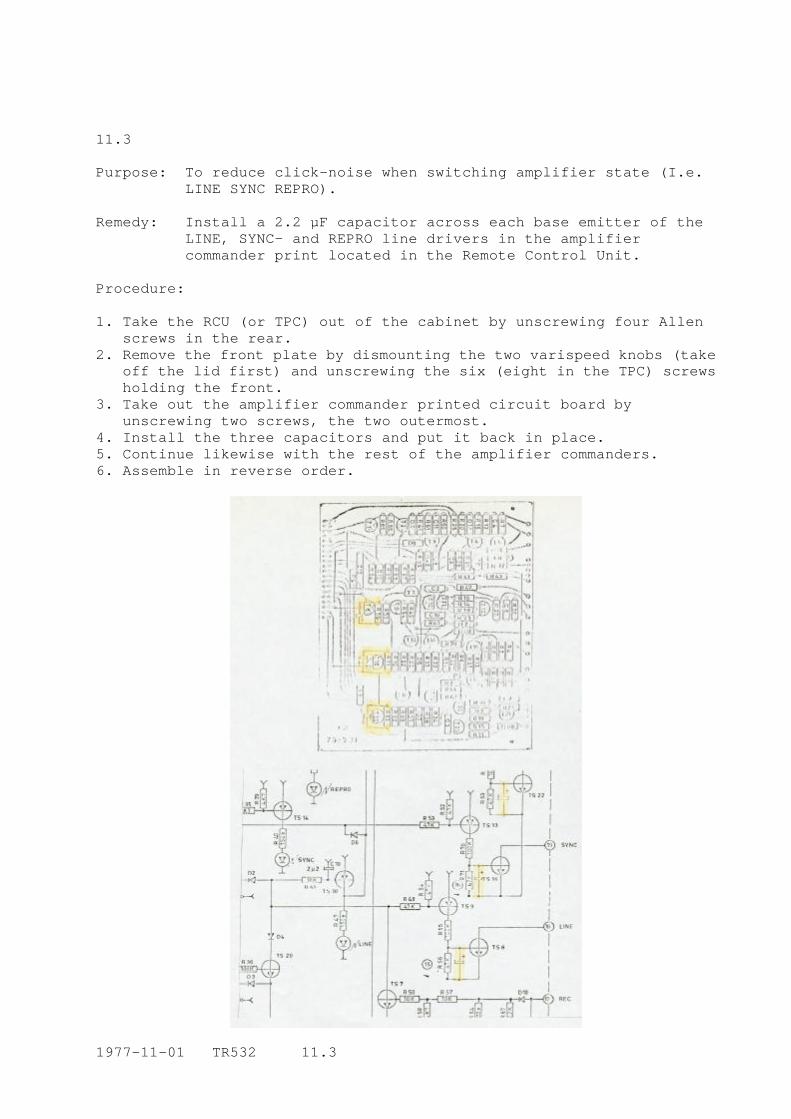
11.3 Purpose: To reduce click-noise when switching amplifier state (I.e. LINE SYNC REPRO). Remedy: Install a 2.2 µF capacitor across each base emitter of the LINE, SYNC- and REPRO line drivers in the amplifier commander print located in the Remote Control Unit. Procedure: 1. Take the RCU (or TPC) out of the cabinet by unscrewing four Allen
screws in the rear. 2. Remove the front plate by dismounting the two varispeed knobs (take
off the lid first) and unscrewing the six (eight in the TPC) screws holding the front.
3. Take out the amplifier commander printed circuit board by unscrewing two screws, the two outermost.
4. Install the three capacitors and put it back in place. 5. Continue likewise with the rest of the amplifier commanders. 6. Assemble in reverse order.
1977-11-01 TR532 11.3
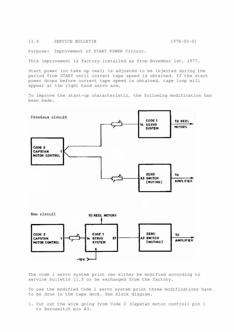
11.4 SERVICE BULLETIN 1978-05-01 Purpose: Improvement of START POWER Circuit. This improvement is factory installed as from November lst, 1977. Start power (on take up reel) is adjusted to be injected during the period from START until correct tape speed is obtained. If the start power drops before correct tape speed is obtained, tape loop will appear at the right hand servo arm. To improve the start-up characteristic, the following modification has been made.
The code 1 servo system print can either be modified according to service bulletin 11.5 or be exchanged from the factory. To use the modified Code 1 servo system print three modifications have to be done in the tape deck. See block diagram. 1. Cut out the wire going from Code 2 (Capstan motor control) pin 1 to Zeroswitch pin A3.

2. Install a wire from Code 4 (power stabilizer) pin 6 to Code 1 pin 6 (-12 V). (If a wire is already soldered to Code 1 pin 6, remove this and re-solder to a not used neighbor pin.) 3. Install a wire from Code 1 pin 37 to Zeroswitch pin A3. After this modification it is possible to adjust the start power to be injected through the whole acceleration period. The muting function is not affected and will work as before. Muting will now be controlled by the start power switch in Code 1 servo system and routed through pin 37 to input A3 on Zeroswitch print. The potentiometer an zeroswitch print will add a fixed time to the acceleration time in which muting will continue until correct tape speed is obtained and the amplifiers will open. Adjustments: Install the modified Code 1 print with the following rough settings: A) Turn potentiometer Pl. start power, to its maximum clockwise position. No further adjustment is necessary for Pl. B) Turn potentiometer P7, wind power, to its middle position. C) Turn potentiometer P8, start power time, clockwise to about ¾ of maximum. D) Thread tape in the normal tape path with the exception that the tape should be thread outside the pinchroller. E) With your hands hold both reels firmly so they can't move. Press the START button. Adjust P8, start power time, anticlockwise until the take up reel pulls with force. Then slowly clockwise until the extra power releases. F) Still hold both reels firmly and with your hand brake the capstan motor. The logic will sense this as start up mode and will add extra power to the tape up reel. Repeat this several times until you are sure the start power is correct. If not, repeat adjustment of P8. G) Thread the tape in the normal tape path. Select 30 ips and press START. If adjustments are correct the right servo arm will go once to its maximum outward position, then once to its maximum inward position and then settle down in normal middle position. If the right servo arm heavily hits its end position several times, adjust P8 slightly clockwise. 1978-05-01 TR532 11.4

WIND POWER ADJUSTMENT With equal amount of tape on both reels, select WIND on the tape deck. Set the WIND control to its exact middle position. Hold the left reel with your hand and adjust P7, wind power, so both servo arms rest in their middle positions. Check the adjustment by running the tape back and forth. The sensor arms should tend to stay in their middle positions. Be especially observant on the point where the tape changes direction. A bad adjustment might cause the tape end stop to be activated. 1978-05-01 TR532 11.4
11.5 SERVICE BULLETIN Modification of: Code 1 servo system print Purpose: Improvement of start up characteristic Parts needed: 1 Transistor BC214 1 Resistor 10 kOhm Modification: 1. The input pin 14 should be connected directly to resistor R34. Move the existing wire from one leg of P8 to resistor R34. Use existing hole close to R34. 2. Change value of resistor R34 to 10 kOhm. 3. Drill 2 holes and install a wire between collector of transistor T18 and pin 37. 4. The grounded end of the three resistors R28 (47 Ohm), R30 (22 kOhm) and R32 (100 kOhm) should be disconnected from 0 V and soldered together and with a wire be connected to the emitter of the new transistor (BC214). 5. To install the new transistor drill a hole for the emitter. Base and collector can be mounted in existing holes. 6. Collector of BC214 should be connected to pin 6. Drill a hole close to the collector and install a wire. The other end of the wire is mounted in existing hole. 7. Cut the printed circuit at 7. 8. The base of BC214 will now be connected to the moving arm of P8. 9. Cut the printed circuit at 9. 10. One and of P8 is connected to 0 V as before. No change required. 11. The other end of P8 should be connected to pin 6. Use the existing hole now made free (see paragraph 1) and connect the other end of the wire to existing hole. To install modified print, see Service Bulletin 11.4. 1978-05-01 TR532 11.5
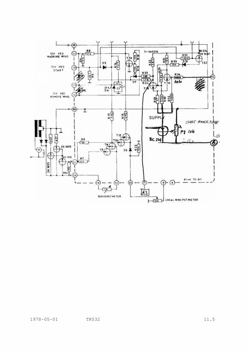
1978-05-01 TR532 11.5
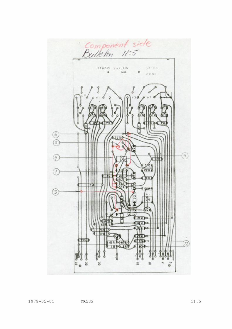
1978-05-01 TR532 11.5
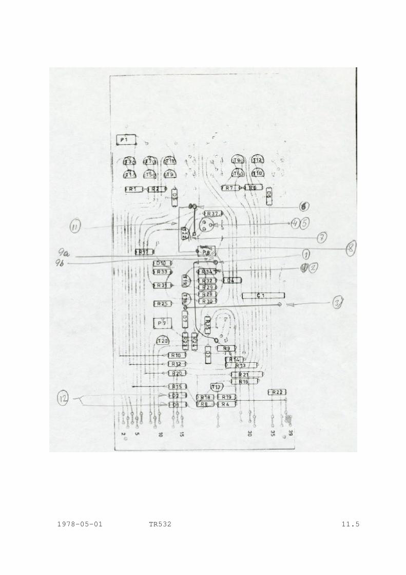
1978-05-01 TR532 11.5
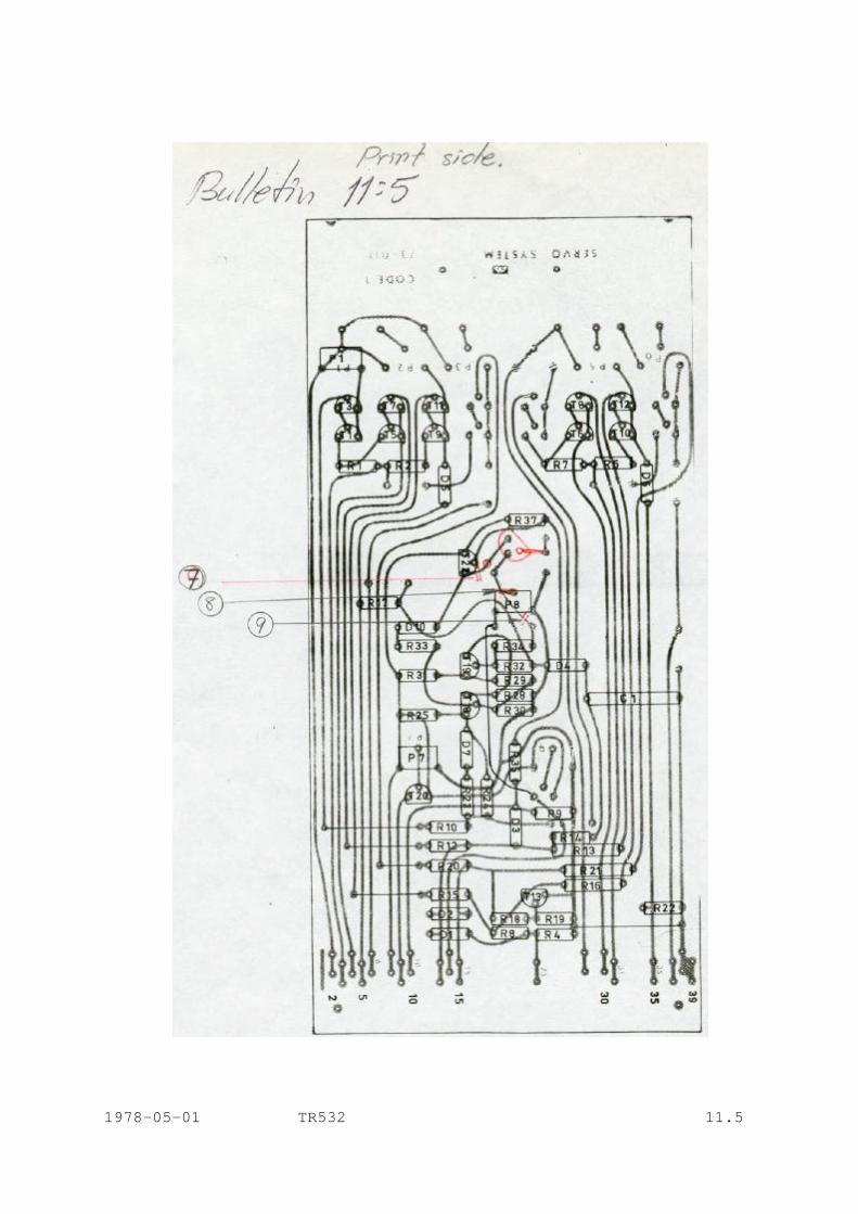
1978-05-01 TR532 11.5
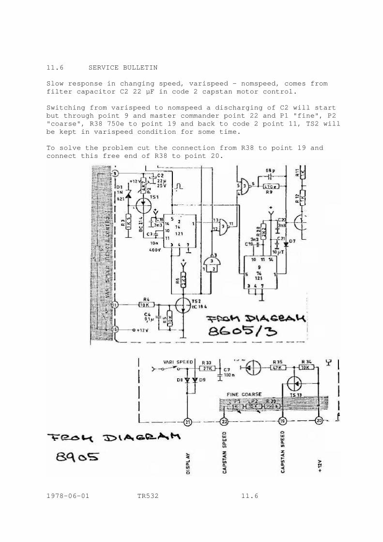
11.6 SERVICE BULLETIN Slow response in changing speed, varispeed - nomspeed, comes from filter capacitor C2 22 µF in code 2 capstan motor control. Switching from varispeed to nomspeed a discharging of C2 will start but through point 9 and master commander point 22 and P1 "fine", P2 "coarse", R38 750e to point 19 and back to code 2 point 11, TS2 will be kept in varispeed condition for some time. To solve the problem cut the connection from R38 to point 19 and connect this free end of R38 to point 20.
1978-06-01 TR532 11.6
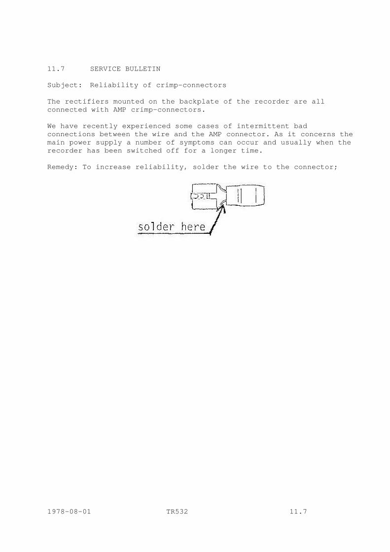
11.7 SERVICE BULLETIN Subject: Reliability of crimp-connectors The rectifiers mounted on the backplate of the recorder are all connected with AMP crimp-connectors. We have recently experienced some cases of intermittent bad connections between the wire and the AMP connector. As it concerns the main power supply a number of symptoms can occur and usually when the recorder has been switched off for a longer time. Remedy: To increase reliability, solder the wire to the connector;
1978-08-01 TR532 11.7

11.8 SERVICE BULLETIN Lifetime of tape timer lamp - This improvement is factory installed as from December 1977. - To increase the lifetime of the lamp driving the tape timer logic, the circuit controlling the lamp needs the following change on code 7 tachometer logic print; 1) Remove resistor R3 (33 Ohm) 2) Remove jumper connecting lamp connector pin 3 with TS4. 3) Install two new resistors R3, 220 Ohm 1/3 W, and R34, 22 kOhm, as shown in the enclosed diagram. 1978-01-01 TR532 11.8

11.9 SERVICE BULLETIN Reducing SYNC to REPRO crosstalk The crosstalk is induced to the repro preamp from the SYNC OUT output wire on the amplifier PCB. To reduce it, cut the PCB-wire connected to pin B13 as close to the connector finger as possible and in the other end as close to the 33e resistor as possible, and substitute the PCB-wire with a short piece of shielded cable. The shield should only be connected to ground in the resistor end. Connect the shield to the metal screen between the repro preamp and the output amp. 1978-09-01 TR532 11.9
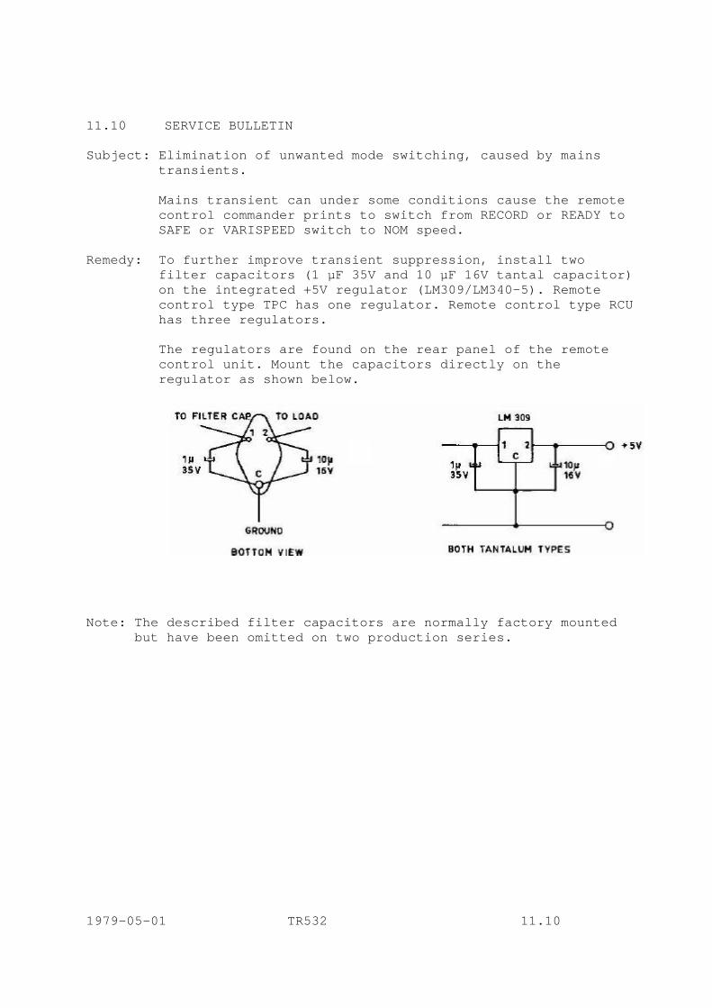
11.10 SERVICE BULLETIN Subject: Elimination of unwanted mode switching, caused by mains transients. Mains transient can under some conditions cause the remote control commander prints to switch from RECORD or READY to SAFE or VARISPEED switch to NOM speed. Remedy: To further improve transient suppression, install two filter capacitors (1 µF 35V and 10 µF 16V tantal capacitor) on the integrated +5V regulator (LM309/LM340-5). Remote control type TPC has one regulator. Remote control type RCU has three regulators. The regulators are found on the rear panel of the remote control unit. Mount the capacitors directly on the regulator as shown below.
Note: The described filter capacitors are normally factory mounted but have been omitted on two production series. 1979-05-01 TR532 11.10
11.11 SERVICE BULLETIN NEW IMPROVED BRAKE BAND, FELT-COATED, has been introduced. The new type gives a smoother operation and increased lifetime. When switching to the new type both brake bands must be changed as well as the servo spring. - Before mounting the new brake band, carefully clean the brakedrum from any grease. Mount the brake band and do NOT apply any lubrication or grease. - When brake band is mounted it needs a short "running in" to achieve the proper brake effect. Use the following procedure; a) Put on a reel of tape and wind until approx equal amount of tape on both reels. b) Disconnect the cable going from the sensor/counter roller to code 7 print (this will simulate lamp failure and activate the mechanical brakes). c) Press forward wind. When tape reaches full wind speed, press stop. Repeat this in rewind. Alternatively wind and rewind about 5 to 10 times in each direction. d) The felt brake bands are now run-in and will have the proper braking effect. e) Adjust brakes as normal (Manual section 7.8). f) Connect cable to code 7 print. As the parking brakes have to be in balance with the servo arm tension, the servo springs shall be changed when installing the new brake bands. - Change the servo spring in supply and take-up side to new short type, 64K-3511. - Check the tension with a spring balance. Pos. 1; 50 - 75 g just to lift the servo arm from bottom. Make sure the tension is enough to activate tape end stop microswitch. Pos. 2; 220 - 250 g just go to balance the servo arm around parallel to the side of the tape deck. Pos. 3; 400 - 450 g just to reach the end of travel. 1979-08-01 TR532 11.11

- Note that changing servo springs demands a careful check or adjustment of the damping system connected to each servo arm. - Watch left hand servo arm when left hand reel is full of tape and right hand servo arm when right hand reel is full of tape. - If any tape loop appears during the servo arm traveling in acceleration period, damping is too high. - If any tape loop appears after the servo arm traveling to rest position, the damping is too low.
Remove the damping system During measuring. Pos. 1 The same procedure for Take up side but reflected to the right. Pos. 2 Pos. 3
1979-08-01 TR532 11.11

1979-05-31 HB TIMING CONSIDERATIONS IN THE LYREC AM77 RECORD/PLAYBACK AMPLIFIER All components referring to drawing 9171 1 Record Timing (see fig. 1) 1a. Drop in When recording starts, pin B11 on the amplifier immediately rises to +24V, "a" on fig. 1. Due to the delay components C50-R95-R96, the collector of TS26 ("b") rises to +15V after a delay of 20-25 msec. This delay ensures that if the track was in SYNC-mode, there is time enough for the automatic switching to LINE-mode to softly turn off the SYNC-signal before the sync-pre-amp input is short-circuited by the relay. If this delay is too small, the SYNC-signal will be turned off abruptly by the relay instead of softly by the FET- switch. As the collector of TS26 goes high, the relay will be activated ("c" in fig. 1) with a delay of 5-10 msec, mainly due to the operate time of the relay. When the relay is activated, the junction of the N.O.contact, R122 and R144 goes high ("d"). Immediately the bases of TS35 ("e") and TS46 start going low as C64 and C82 are charged through R114 and R142. As TS35 and TS46 are coupled as constant-current generators, the bias and erase -current ("f") will be proportional to the voltage between the positive supply rail and the base. That means that the bias rise time is controlled by C64 and R114 and the erase rise time is controlled by C82 and R142.
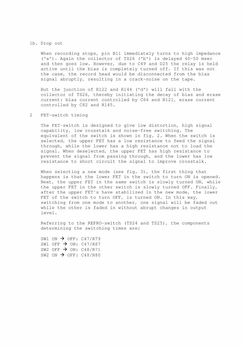
1b. Drop out When recording stops, pin B11 immediately turns to high impedance ("a"). Again the collector of TS26 ("b") is delayed 40-50 msec and then goes low. However, due to C49 and D25 the relay is held active until the bias is completely turned off. If this was not the case, the record head would be disconnected from the bias signal abruptly, resulting in a crack-noise on the tape. But the junction of R122 and R144 ("d") will fall with the collector of TS26, thereby initiating the decay of bias and erase current: bias current controlled by C64 and R121, erase current controlled by C82 and R145. 2 FET-switch timing The FET-switch is designed to give low distortion, high signal capability, low crosstalk and noise-free switching. The equivalent of the switch is shown in fig. 2. When the switch is selected, the upper FET has a low resistance to feed the signal through, while the lower has a high resistance not to load the signal. When deselected, the upper FET has high resistance to prevent the signal from passing through, and the lower has low resistance to short circuit the signal to improve crosstalk. When selecting a new mode (see fig. 3), the first thing that happens is that the lower FET in the switch to turn ON is opened. Next, the upper FET in the same switch is slowly turned ON, while the upper FET in the other switch is slowly turned OFF. Finally, after the upper FET's have stabilized in the new mode, the lower FET of the switch to turn OFF, is turned ON. In this way, switching from one mode to another, one signal will be faded out while the other is faded in without abrupt changes in output level. Referring to the REPRO-switch (TS24 and TS25), the components determining the switching times are; SW1 ON à OFF: C47/R79 SWl OFF à ON: C47/R87 SW2 OFF à ON: C48/R71 SW2 ON à OFF: C48/R80
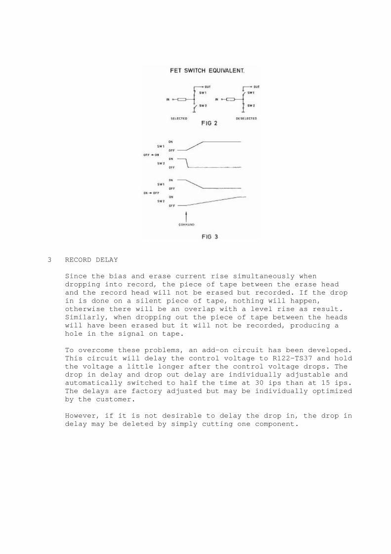
3 RECORD DELAY Since the bias and erase current rise simultaneously when dropping into record, the piece of tape between the erase head and the record head will not be erased but recorded. If the drop in is done on a silent piece of tape, nothing will happen, otherwise there will be an overlap with a level rise as result. Similarly, when dropping out the piece of tape between the heads will have been erased but it will not be recorded, producing a hole in the signal on tape. To overcome these problems, an add-on circuit has been developed. This circuit will delay the control voltage to R122-TS37 and hold the voltage a little longer after the control voltage drops. The drop in delay and drop out delay are individually adjustable and automatically switched to half the time at 30 ips than at 15 ips. The delays are factory adjusted but may be individually optimized by the customer. However, if it is not desirable to delay the drop in, the drop in delay may be deleted by simply cutting one component.

INSTALLATION PROCEDURE FOR RECORD DROP-IN / DROP-OUT DELAY - DIAGRAM 9582 Application: The delay circuit is designed for 15 and 30 ips tape speeds. Other tape speeds made to order. The delay circuit can be applied to all Lyrec recorders of series TR532. It must however be emphasized that this timing circuit do not compensate for the noise reduction switching. It is therefore NOT recommended to use switched noise reduction (i.e. Dolby) in combination with this delay circuit. The timing of the noise reduction switching can only be matched to the delay circuit if the new computer controlled remote control unit type ATC is used. 1. Mark the position of the mounting hole on the AM77 amplifier board by using the supplied drilling template (9583). Drill a hole of 3,2 mm.
2. Insert the nylon screw, from the bottom of the AM77, and use enough washers to lift the delay print free from the AM77 board. 3. Remove the 10K resistor (R122) and connect the 5 wires according to the drawings enclosed. 4. Adjust the delay times to optimum performance at the tape speed mainly used. 5. If drop-in delay is not desired, remove transistor BC184 on the delay circuit board.
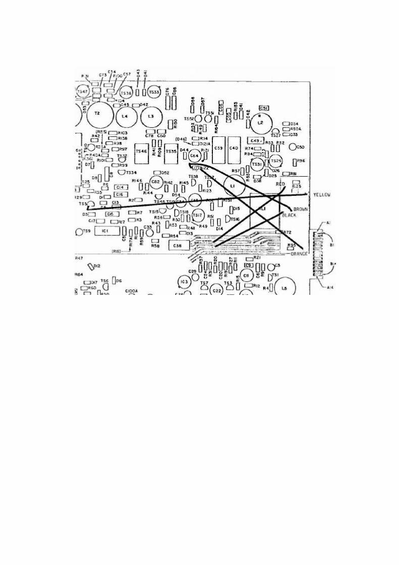
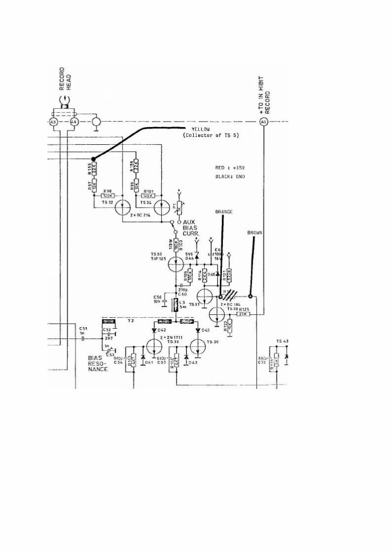
1980-12-17 HB SERVICE BULLETIN AM77-amplifier improvements 1. Erase current symmetry It has proved necessary to block the possibility of dc-current flow in the erase-head. Especially on recorders with a no longer quite new record-head, this will eliminate excessive low-frequency noise being recorded on tape (sometimes referred to as "Rocks"). At point A in the figure, break the pcb-wire running on the component side and install a film capacitor of 470 nF. 2. An increase of C59 from 470 nF to 2.2 µF (point B) will extend the low-frequency range of the amplifier. However, do not make it even greater for two reasons: It will not improve bass-response any further, and low-frequency switching noise will be more audible on the output. If a polarized capacitor is used, connect the positive side as shown. 3. The output-amplifier may in some cases pick up radio-transmitter. To prevent this, install a 220 pF capacitor between base and emitter of TS 39, at point C.
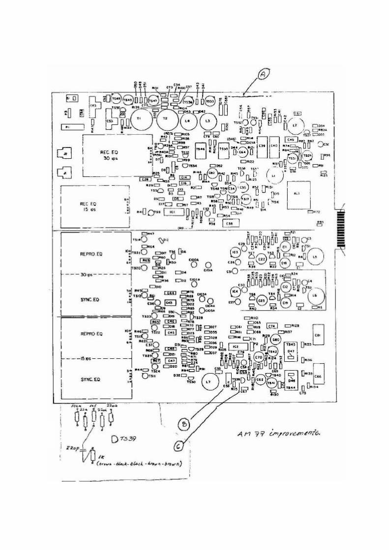
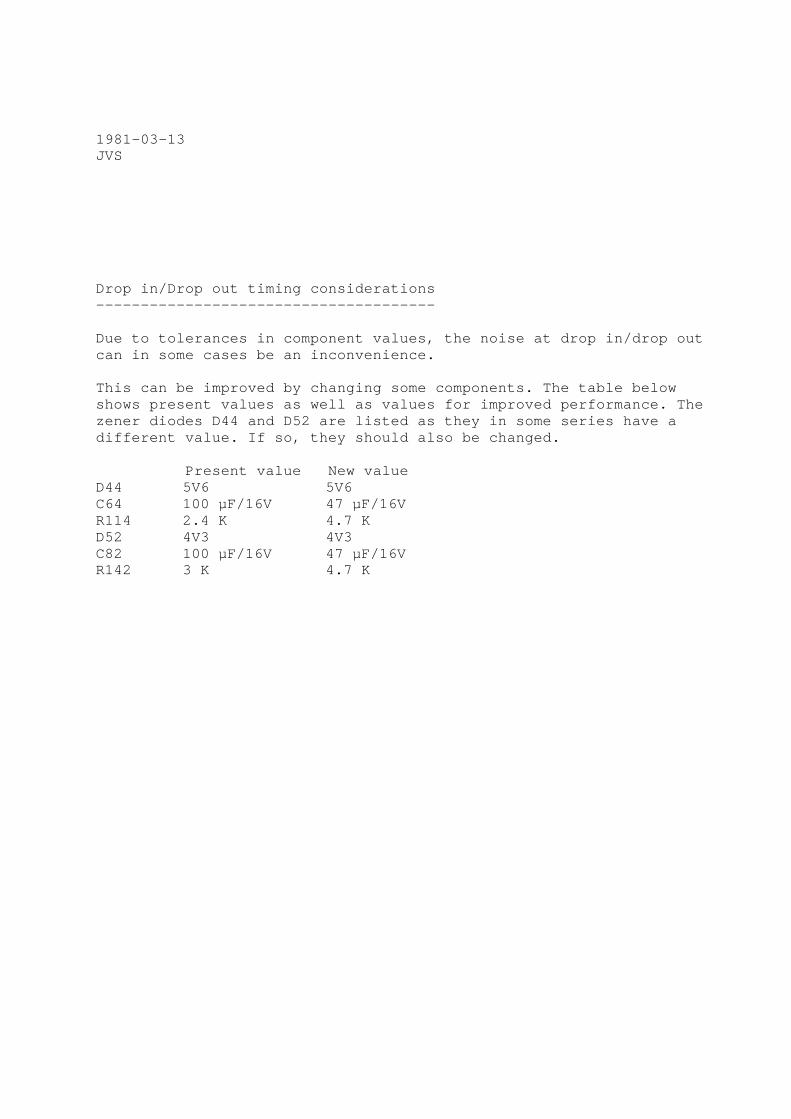
1981-03-13 JVS Drop in/Drop out timing considerations -------------------------------------- Due to tolerances in component values, the noise at drop in/drop out can in some cases be an inconvenience. This can be improved by changing some components. The table below shows present values as well as values for improved performance. The zener diodes D44 and D52 are listed as they in some series have a different value. If so, they should also be changed. Present value New value D44 5V6 5V6 C64 100 µF/16V 47 µF/16V R114 2.4 K 4.7 K D52 4V3 4V3 C82 100 µF/16V 47 µF/16V R142 3 K 4.7 K

1984-08-20 Subject: RECORD RELAY, AM77 RECORD – PLAYBACK AMPLIFIER The record relay, ITT PZ4 A2625/PZ4 A2629, 36 V used on the record-playback amplifier AM77 is no longer available. It may be substituted by type PZ4 A2615 or A2626, which is a 24 V version of the same relay, if a 6.2 V zener diode is installed in series with the relay coil. Drill two holes and install the zener diode with the catode mark facing the relay as shown. Do not forget to break the PCB copper track between the pins of the new zener diode.
Part of AM77 layout seen from soldering side.
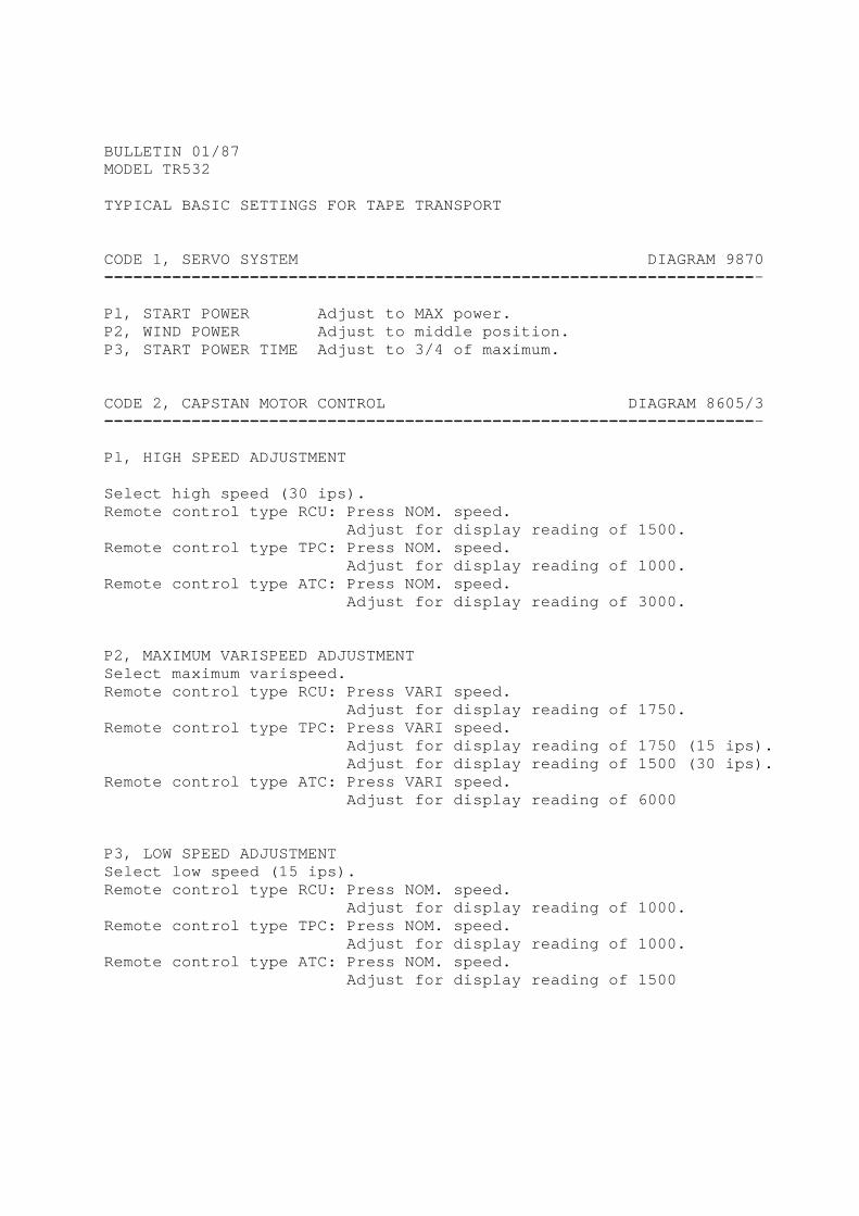
BULLETIN 01/87 MODEL TR532 TYPICAL BASIC SETTINGS FOR TAPE TRANSPORT CODE 1, SERVO SYSTEM DIAGRAM 9870 -------------------------------------------------------------------- Pl, START POWER Adjust to MAX power. P2, WIND POWER Adjust to middle position. P3, START POWER TIME Adjust to 3/4 of maximum. CODE 2, CAPSTAN MOTOR CONTROL DIAGRAM 8605/3 -------------------------------------------------------------------- Pl, HIGH SPEED ADJUSTMENT Select high speed (30 ips). Remote control type RCU: Press NOM. speed. Adjust for display reading of 1500. Remote control type TPC: Press NOM. speed. Adjust for display reading of 1000. Remote control type ATC: Press NOM. speed. Adjust for display reading of 3000. P2, MAXIMUM VARISPEED ADJUSTMENT Select maximum varispeed. Remote control type RCU: Press VARI speed. Adjust for display reading of 1750. Remote control type TPC: Press VARI speed. Adjust for display reading of 1750 (15 ips). Adjust for display reading of 1500 (30 ips). Remote control type ATC: Press VARI speed. Adjust for display reading of 6000 P3, LOW SPEED ADJUSTMENT Select low speed (15 ips). Remote control type RCU: Press NOM. speed. Adjust for display reading of 1000. Remote control type TPC: Press NOM. speed. Adjust for display reading of 1000. Remote control type ATC: Press NOM. speed. Adjust for display reading of 1500
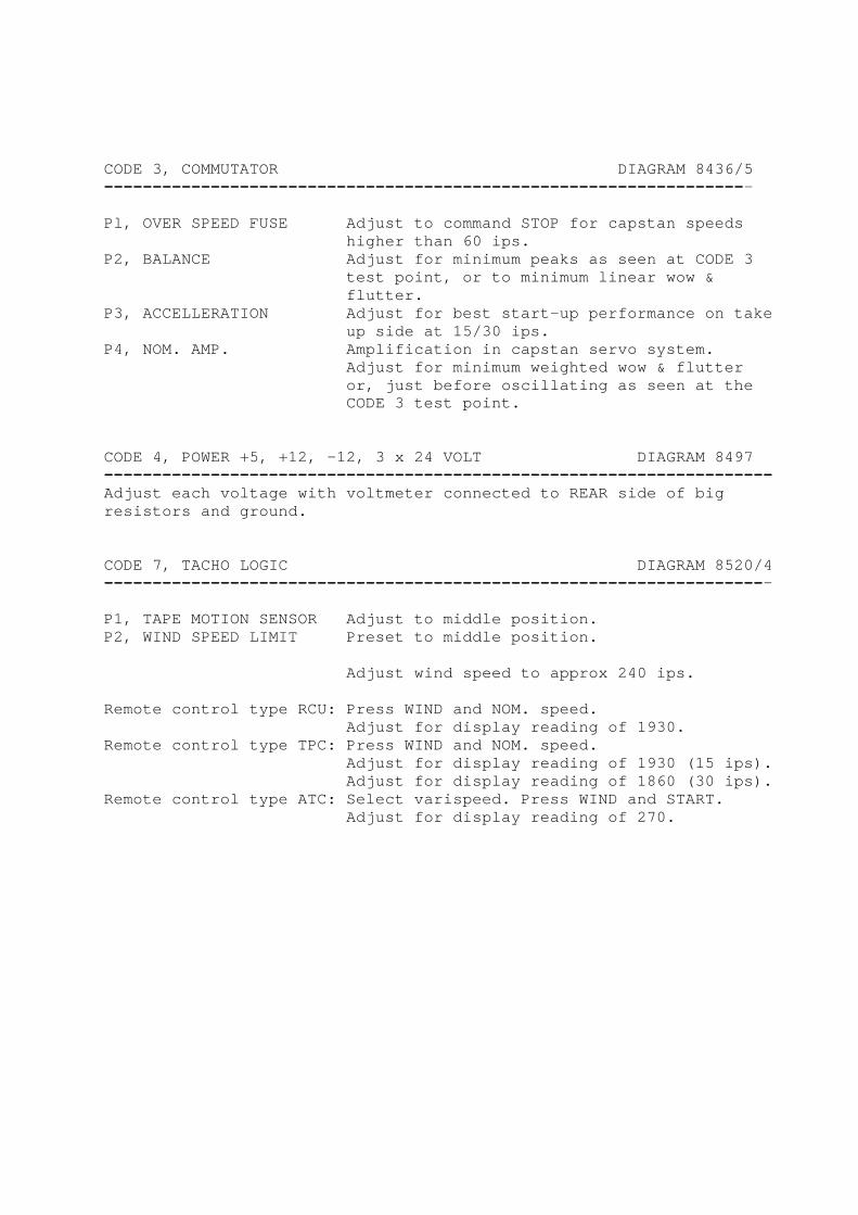
CODE 3, COMMUTATOR DIAGRAM 8436/5 ------------------------------------------------------------------- Pl, OVER SPEED FUSE Adjust to command STOP for capstan speeds higher than 60 ips. P2, BALANCE Adjust for minimum peaks as seen at CODE 3 test point, or to minimum linear wow & flutter. P3, ACCELLERATION Adjust for best start-up performance on take up side at 15/30 ips. P4, NOM. AMP. Amplification in capstan servo system. Adjust for minimum weighted wow & flutter or, just before oscillating as seen at the CODE 3 test point. CODE 4, POWER +5, +12, -12, 3 x 24 VOLT DIAGRAM 8497 ---------------------------------------------------------------------Adjust each voltage with voltmeter connected to REAR side of big resistors and ground. CODE 7, TACHO LOGIC DIAGRAM 8520/4 --------------------------------------------------------------------- P1, TAPE MOTION SENSOR Adjust to middle position. P2, WIND SPEED LIMIT Preset to middle position. Adjust wind speed to approx 240 ips. Remote control type RCU: Press WIND and NOM. speed. Adjust for display reading of 1930. Remote control type TPC: Press WIND and NOM. speed. Adjust for display reading of 1930 (15 ips). Adjust for display reading of 1860 (30 ips). Remote control type ATC: Select varispeed. Press WIND and START. Adjust for display reading of 270.
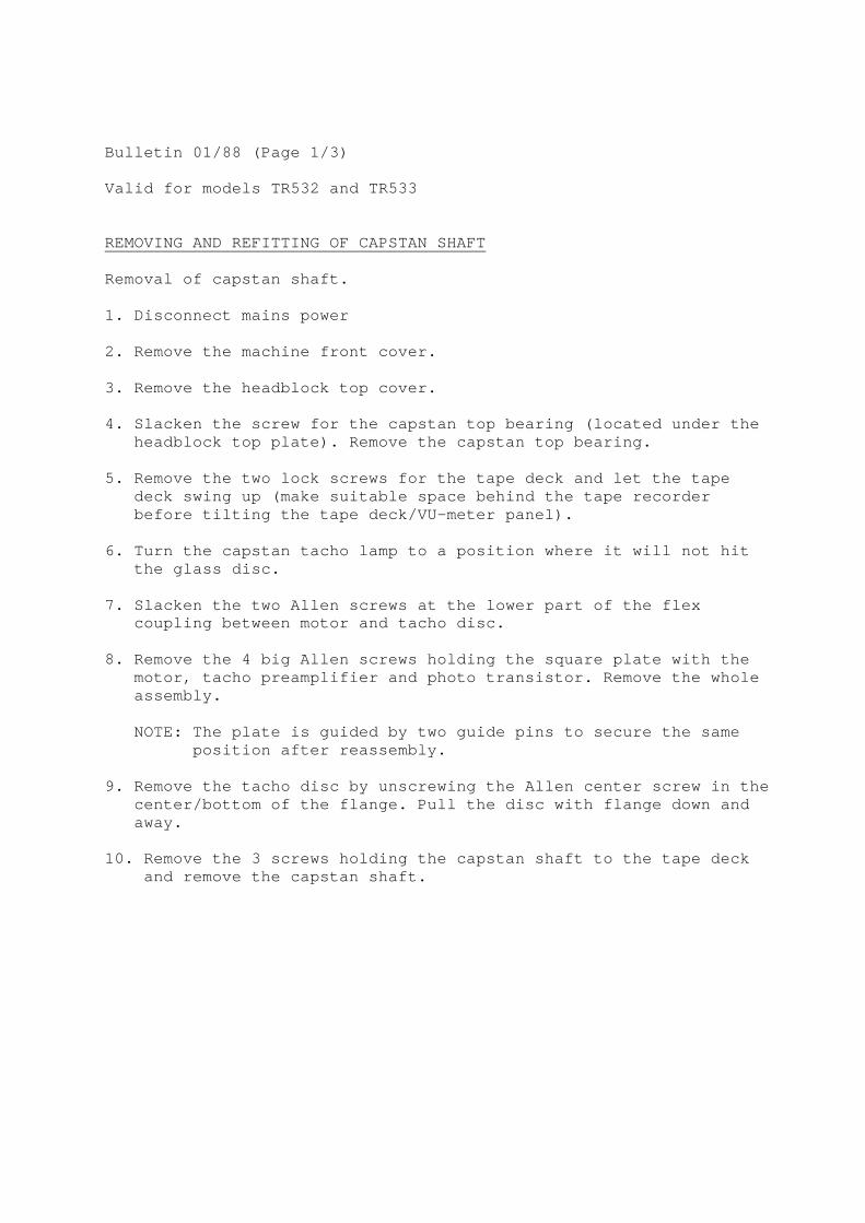
Bulletin 01/88 (Page 1/3) Valid for models TR532 and TR533 REMOVING AND REFITTING OF CAPSTAN SHAFT Removal of capstan shaft. 1. Disconnect mains power 2. Remove the machine front cover. 3. Remove the headblock top cover. 4. Slacken the screw for the capstan top bearing (located under the headblock top plate). Remove the capstan top bearing. 5. Remove the two lock screws for the tape deck and let the tape deck swing up (make suitable space behind the tape recorder before tilting the tape deck/VU-meter panel). 6. Turn the capstan tacho lamp to a position where it will not hit the glass disc. 7. Slacken the two Allen screws at the lower part of the flex coupling between motor and tacho disc. 8. Remove the 4 big Allen screws holding the square plate with the motor, tacho preamplifier and photo transistor. Remove the whole assembly. NOTE: The plate is guided by two guide pins to secure the same position after reassembly. 9. Remove the tacho disc by unscrewing the Allen center screw in the center/bottom of the flange. Pull the disc with flange down and away. 10. Remove the 3 screws holding the capstan shaft to the tape deck and remove the capstan shaft.

INSTALLATION OF NEW CAPSTAN SHAFT Re-assemble in reverse order but note the following points; NOTE: Model TR532 only. Capstan shafts supplied as from 85-01-01 has a new type of bearings and a diameter 10 mm. The new type has part no 440027 and is supplied together with a new capstan top bearing (part no 501008). Previous type with part no 311303 had a diameter of 9 mm. 11. The phototransistor tube must be released and withdrawn to a lower position before re-assembly to secure the glass disc during mounting. 12. The capstan shaft has a small axial play and must always rest in it's lower position. When locking the 2 screws between motor and flex coupling, make sure to press down the flex coupling 0.5 – 1 mm before tightening the two Allen screws. This will secure the correct rest position.
IMPORTANT!
PRESS DOWN 0.5 - 1.0 MM
BEFORE TIGHTENING THE TWO ALLEN SCREWS

13. LAMP AND PHOTOTRANSISTOR POSITIONING The lamp should be placed 5-8 mm above the tacho disc and the phototransistor tube as close as possible without touching the glass disc. Connect an oscilloscope across the output of the preamplifier and check the shape of the resulting square wave. The phototransistor tube should be turned to obtain at least 4 V peak-to-peak, with best possible wave shape. P1; Adjust P1 for a 1:1 mark/space ratio. (The distance between lamp and glass disc also affects the mark/space ratio). P2; Set to middel position.
14. ADJUSTMENT OF CAPSTAN TOP BEARING CAUTION. Make sure the capstan top bearing is properly lubricated before mounting. Connect a DC voltmeter or oscilloscope between ground and motor current test point. Model TR532; PCB Code 3, test point close to motor plug. Model TR533; PCB Capstan Driver, test point 2. Select PLAY with tape loaded. Press the capstan top bearing gently against the capstan shaft while monitoring the motor current. Tighten the screw when the top bearing is in a position giving minimum motor current. Typical motor current for machines equipped with disc motor is 1 A corresponding to a reading of 0.5 V at test point 2 (R22 0.47e). 15. Check and eventually readjust nominal tape speeds.
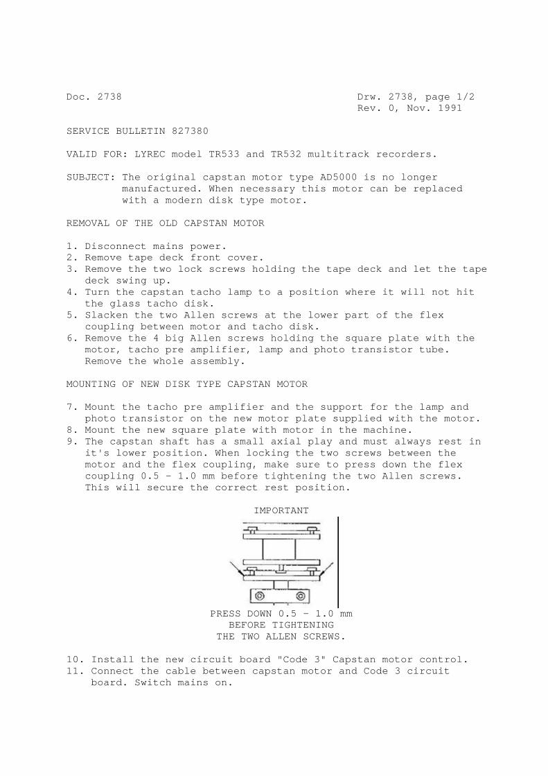
Doc. 2738 Drw. 2738, page 1/2 Rev. 0, Nov. 1991 SERVICE BULLETIN 827380 VALID FOR: LYREC model TR533 and TR532 multitrack recorders. SUBJECT: The original capstan motor type AD5000 is no longer manufactured. When necessary this motor can be replaced with a modern disk type motor. REMOVAL OF THE OLD CAPSTAN MOTOR 1. Disconnect mains power. 2. Remove tape deck front cover. 3. Remove the two lock screws holding the tape deck and let the tape deck swing up. 4. Turn the capstan tacho lamp to a position where it will not hit the glass tacho disk. 5. Slacken the two Allen screws at the lower part of the flex coupling between motor and tacho disk. 6. Remove the 4 big Allen screws holding the square plate with the motor, tacho pre amplifier, lamp and photo transistor tube. Remove the whole assembly. MOUNTING OF NEW DISK TYPE CAPSTAN MOTOR 7. Mount the tacho pre amplifier and the support for the lamp and photo transistor on the new motor plate supplied with the motor. 8. Mount the new square plate with motor in the machine. 9. The capstan shaft has a small axial play and must always rest in it's lower position. When locking the two screws between the motor and the flex coupling, make sure to press down the flex coupling 0.5 - 1.0 mm before tightening the two Allen screws. This will secure the correct rest position.
IMPORTANT
PRESS DOWN 0.5 - 1.0 mm
BEFORE TIGHTENING THE TWO ALLEN SCREWS.
10. Install the new circuit board "Code 3" Capstan motor control. 11. Connect the cable between capstan motor and Code 3 circuit board. Switch mains on.
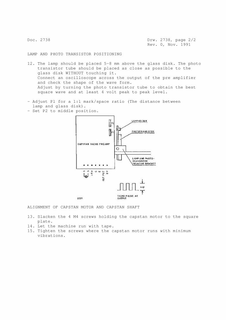
Doc. 2738 Drw. 2738, page 2/2 Rev. 0, Nov. 1991 LAMP AND PHOTO TRANSISTOR POSITIONING 12. The lamp should be placed 5-8 mm above the glass disk. The photo transistor tube should be placed as close as possible to the glass disk WITHOUT touching it. Connect an oscilloscope across the output of the pre amplifier and check the shape of the wave form. Adjust by turning the photo transistor tube to obtain the best square wave and at least 4 volt peak to peak level. - Adjust Pl for a 1:1 mark/space ratio (The distance between lamp and glass disk). - Set P2 to middle position.
ALIGNMENT OF CAPSTAN MOTOR AND CAPSTAN SHAFT 13. Slacken the 4 M4 screws holding the capstan motor to the square plate. 14. Let the machine run with tape. 15. Tighten the screws where the capstan motor runs with minimum vibrations.

SUBSTITUTION OF TRANSISTOR The transistor MJE 2955, Lyrec part no. 912230, is no longer available. It is being substituted by MJE 2955T, which has the same specifications except for power dissipation. In all Lyrec applications, the MJE 2955T may be used directly without exceeding the maximum ratings, but it should be noted that: - pins are reversed. - tab is connected to collector, it may have to be isolated. - tab must have good thermal contact with cooling fin. 1993-06-07 HB.
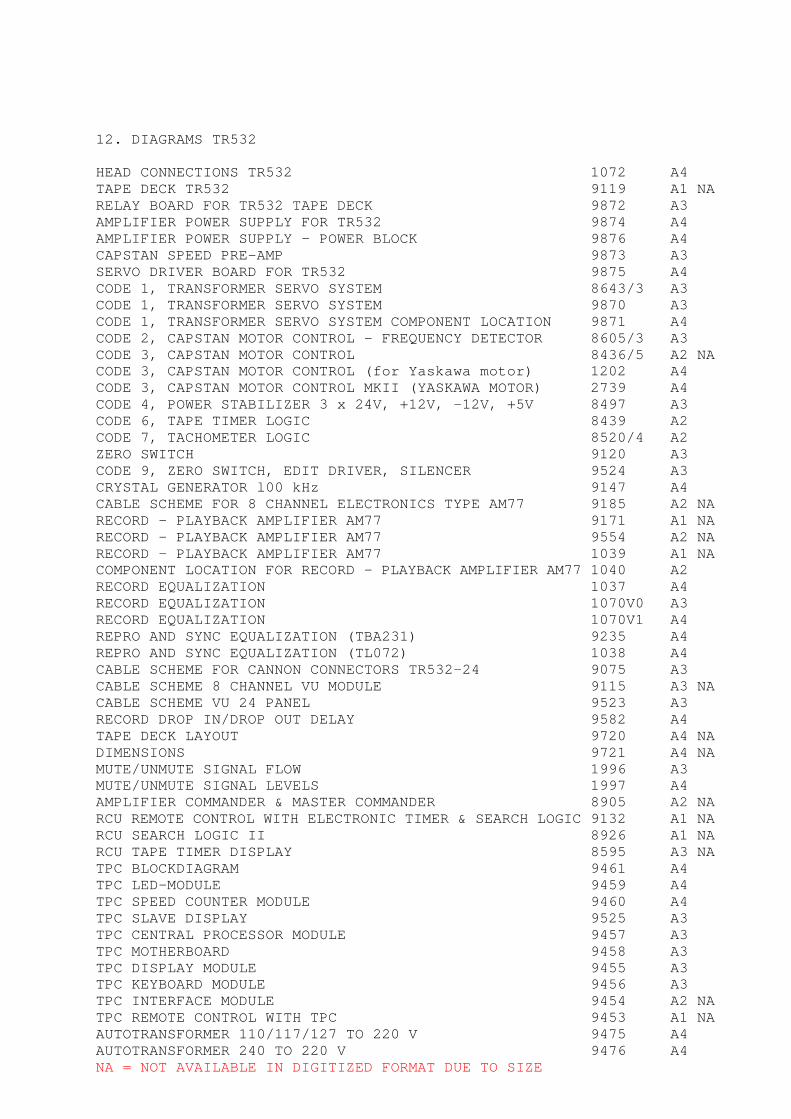
12. DIAGRAMS TR532 HEAD CONNECTIONS TR532 1072 A4 TAPE DECK TR532 9119 A1 NA RELAY BOARD FOR TR532 TAPE DECK 9872 A3 AMPLIFIER POWER SUPPLY FOR TR532 9874 A4 AMPLIFIER POWER SUPPLY - POWER BLOCK 9876 A4 CAPSTAN SPEED PRE-AMP 9873 A3 SERVO DRIVER BOARD FOR TR532 9875 A4 CODE 1, TRANSFORMER SERVO SYSTEM 8643/3 A3 CODE 1, TRANSFORMER SERVO SYSTEM 9870 A3 CODE 1, TRANSFORMER SERVO SYSTEM COMPONENT LOCATION 9871 A4 CODE 2, CAPSTAN MOTOR CONTROL - FREQUENCY DETECTOR 8605/3 A3 CODE 3, CAPSTAN MOTOR CONTROL 8436/5 A2 NA CODE 3, CAPSTAN MOTOR CONTROL (for Yaskawa motor) 1202 A4 CODE 3, CAPSTAN MOTOR CONTROL MKII (YASKAWA MOTOR) 2739 A4 CODE 4, POWER STABILIZER 3 x 24V, +12V, -12V, +5V 8497 A3 CODE 6, TAPE TIMER LOGIC 8439 A2 CODE 7, TACHOMETER LOGIC 8520/4 A2 ZERO SWITCH 9120 A3 CODE 9, ZERO SWITCH, EDIT DRIVER, SILENCER 9524 A3 CRYSTAL GENERATOR l00 kHz 9147 A4 CABLE SCHEME FOR 8 CHANNEL ELECTRONICS TYPE AM77 9185 A2 NA RECORD - PLAYBACK AMPLIFIER AM77 9171 A1 NA RECORD - PLAYBACK AMPLIFIER AM77 9554 A2 NA RECORD - PLAYBACK AMPLIFIER AM77 1039 A1 NA COMPONENT LOCATION FOR RECORD - PLAYBACK AMPLIFIER AM77 1040 A2 RECORD EQUALIZATION 1037 A4 RECORD EQUALIZATION 1070V0 A3 RECORD EQUALIZATION 1070V1 A4 REPRO AND SYNC EQUALIZATION (TBA231) 9235 A4 REPRO AND SYNC EQUALIZATION (TL072) 1038 A4 CABLE SCHEME FOR CANNON CONNECTORS TR532-24 9075 A3 CABLE SCHEME 8 CHANNEL VU MODULE 9115 A3 NA CABLE SCHEME VU 24 PANEL 9523 A3 RECORD DROP IN/DROP OUT DELAY 9582 A4 TAPE DECK LAYOUT 9720 A4 NA DIMENSIONS 9721 A4 NA MUTE/UNMUTE SIGNAL FLOW 1996 A3 MUTE/UNMUTE SIGNAL LEVELS 1997 A4 AMPLIFIER COMMANDER & MASTER COMMANDER 8905 A2 NA RCU REMOTE CONTROL WITH ELECTRONIC TIMER & SEARCH LOGIC 9132 A1 NA RCU SEARCH LOGIC II 8926 A1 NA RCU TAPE TIMER DISPLAY 8595 A3 NA TPC BLOCKDIAGRAM 9461 A4 TPC LED-MODULE 9459 A4 TPC SPEED COUNTER MODULE 9460 A4 TPC SLAVE DISPLAY 9525 A3 TPC CENTRAL PROCESSOR MODULE 9457 A3 TPC MOTHERBOARD 9458 A3 TPC DISPLAY MODULE 9455 A3 TPC KEYBOARD MODULE 9456 A3 TPC INTERFACE MODULE 9454 A2 NA TPC REMOTE CONTROL WITH TPC 9453 A1 NA AUTOTRANSFORMER 110/117/127 TO 220 V 9475 A4 AUTOTRANSFORMER 240 TO 220 V 9476 A4 NA = NOT AVAILABLE IN DIGITIZED FORMAT DUE TO SIZE
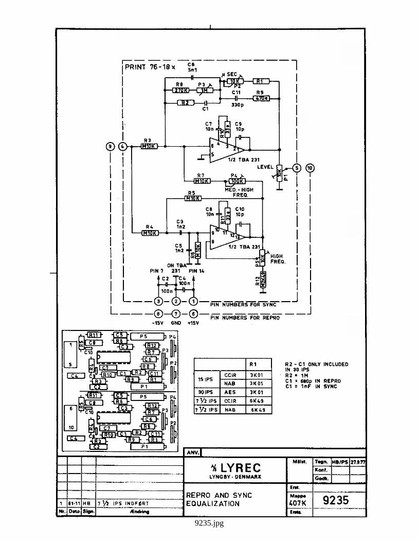
9235.jpg
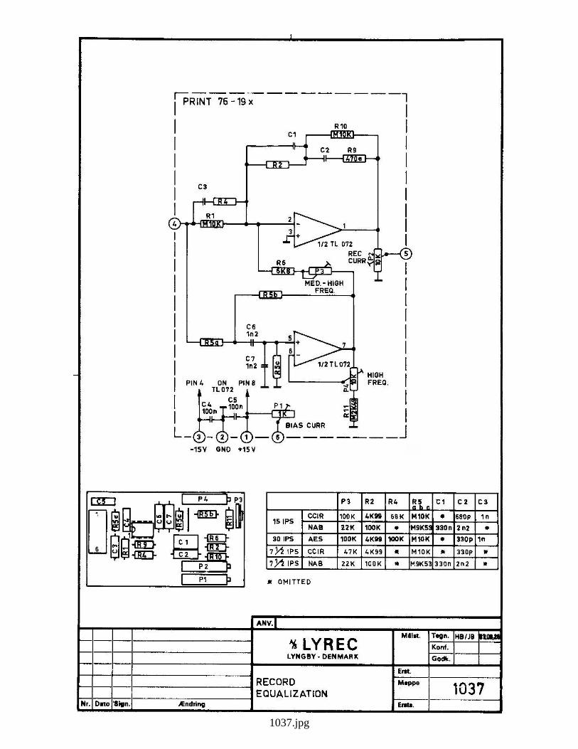
1037.jpg

1038.jpg
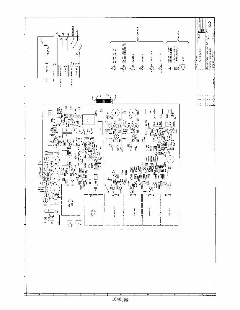
1040.jpg
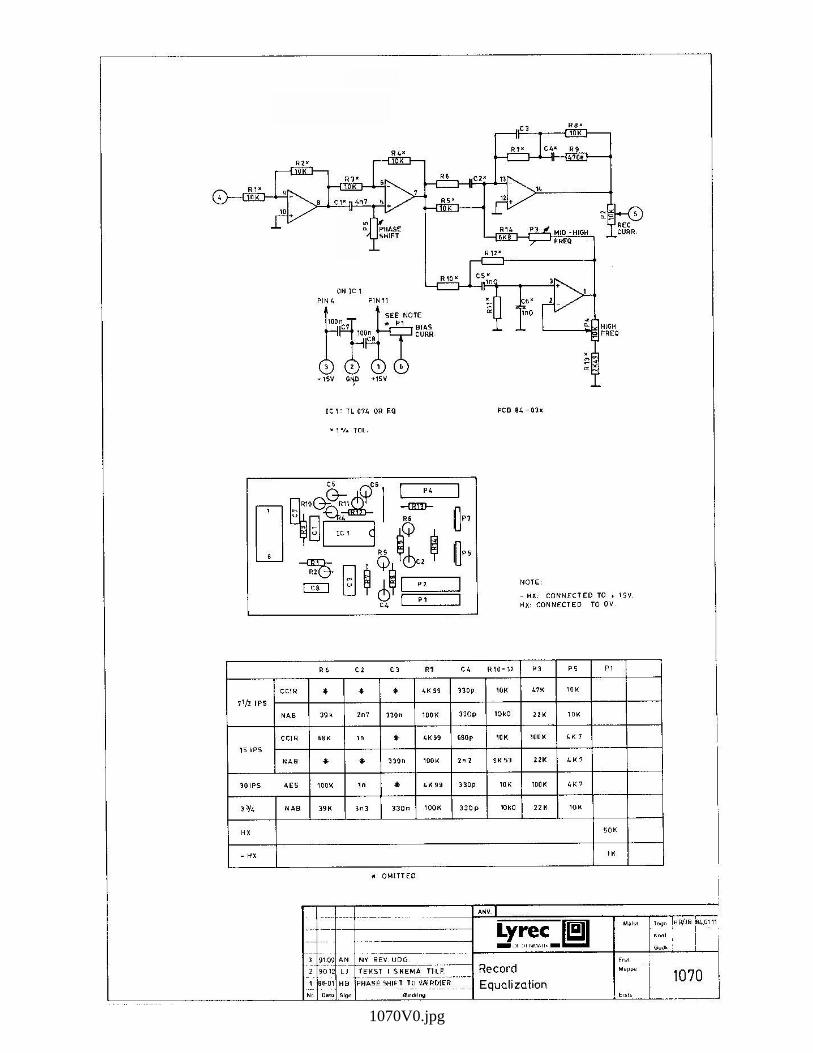
1070V0.jpg

1072.jpg
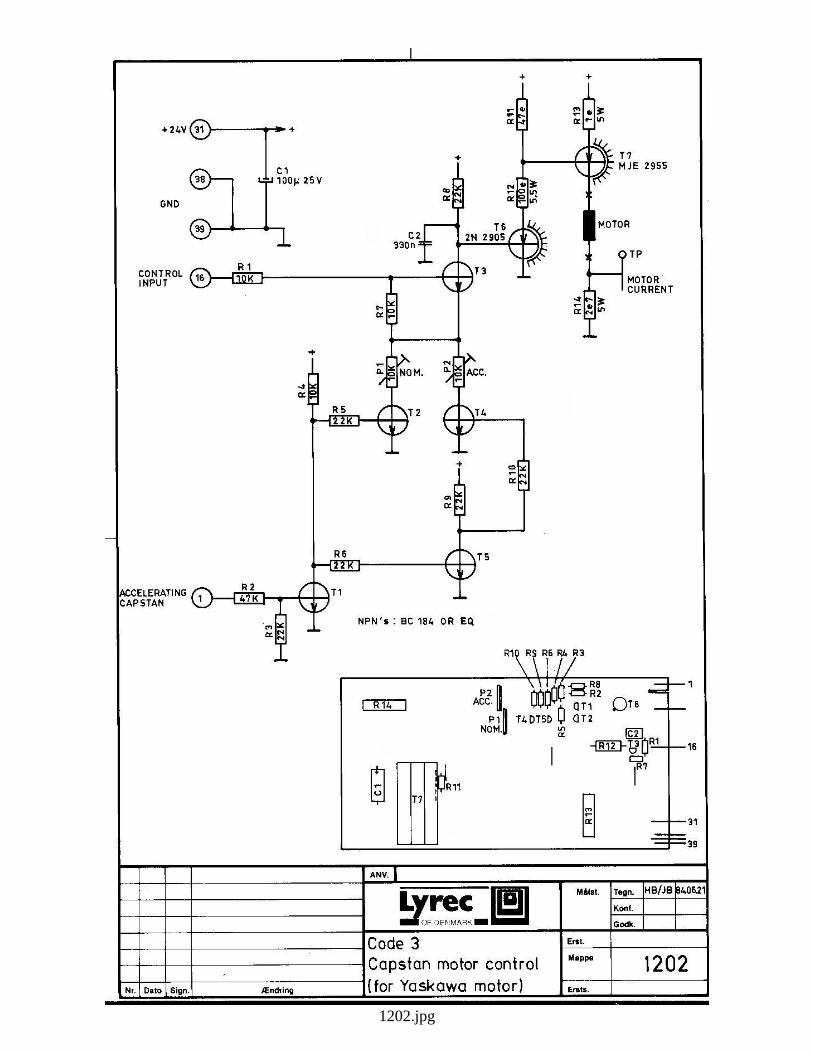
1202.jpg
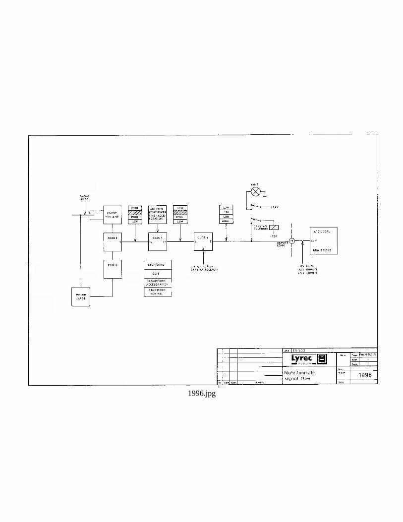
1996.jpg
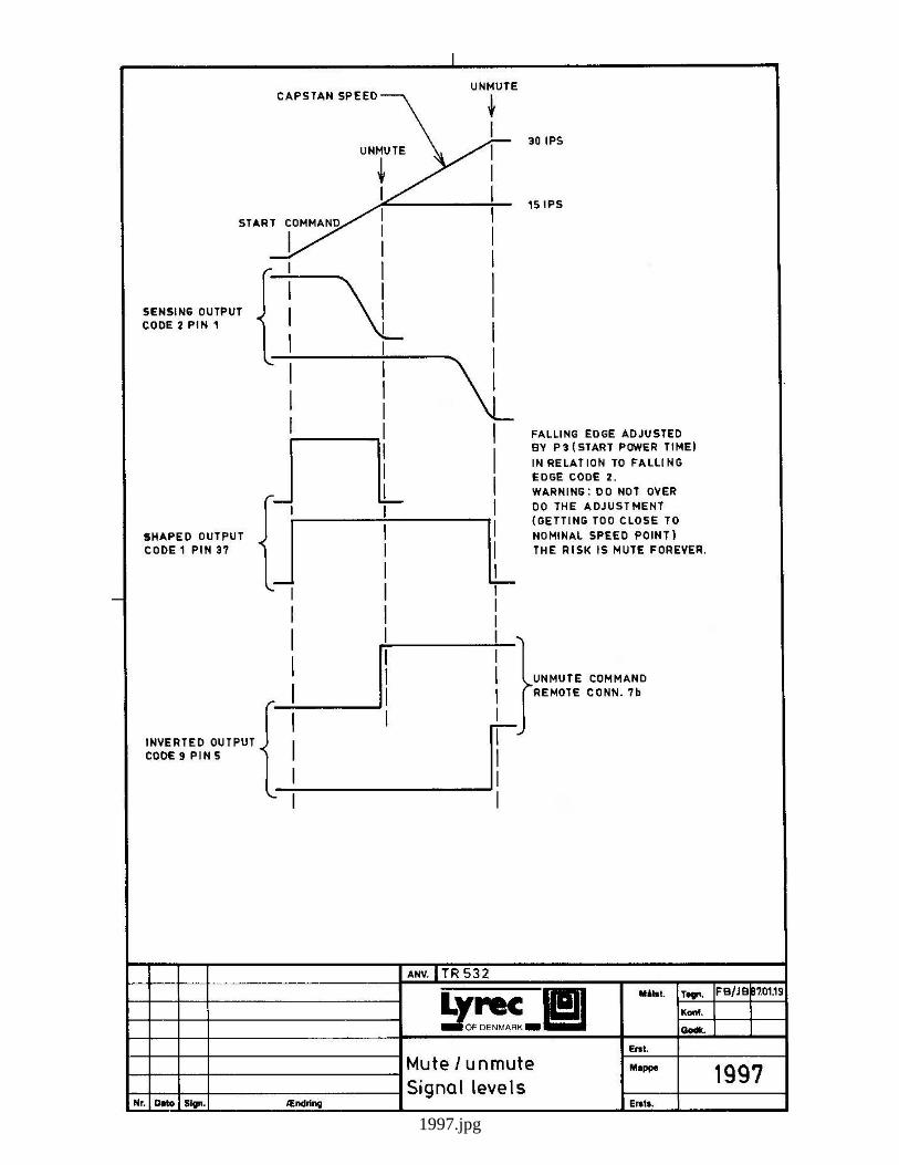
1997.jpg

2739.jpg
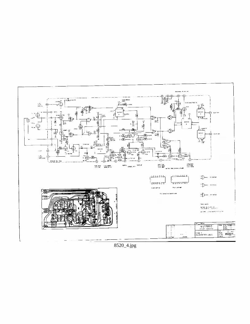
8520_4.jpg
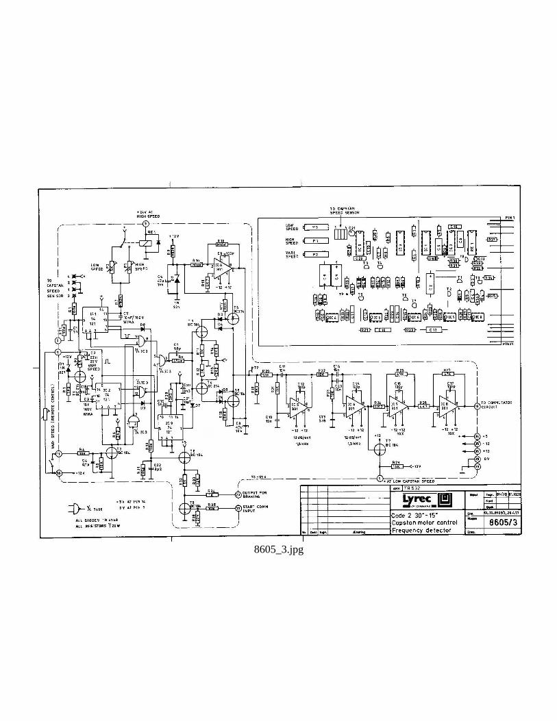
8605_3.jpg

8646_3.jpg
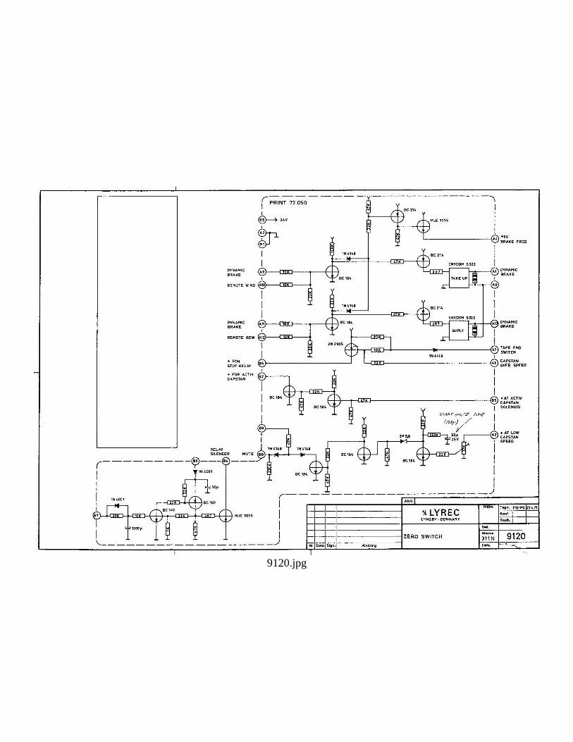
9120.jpg
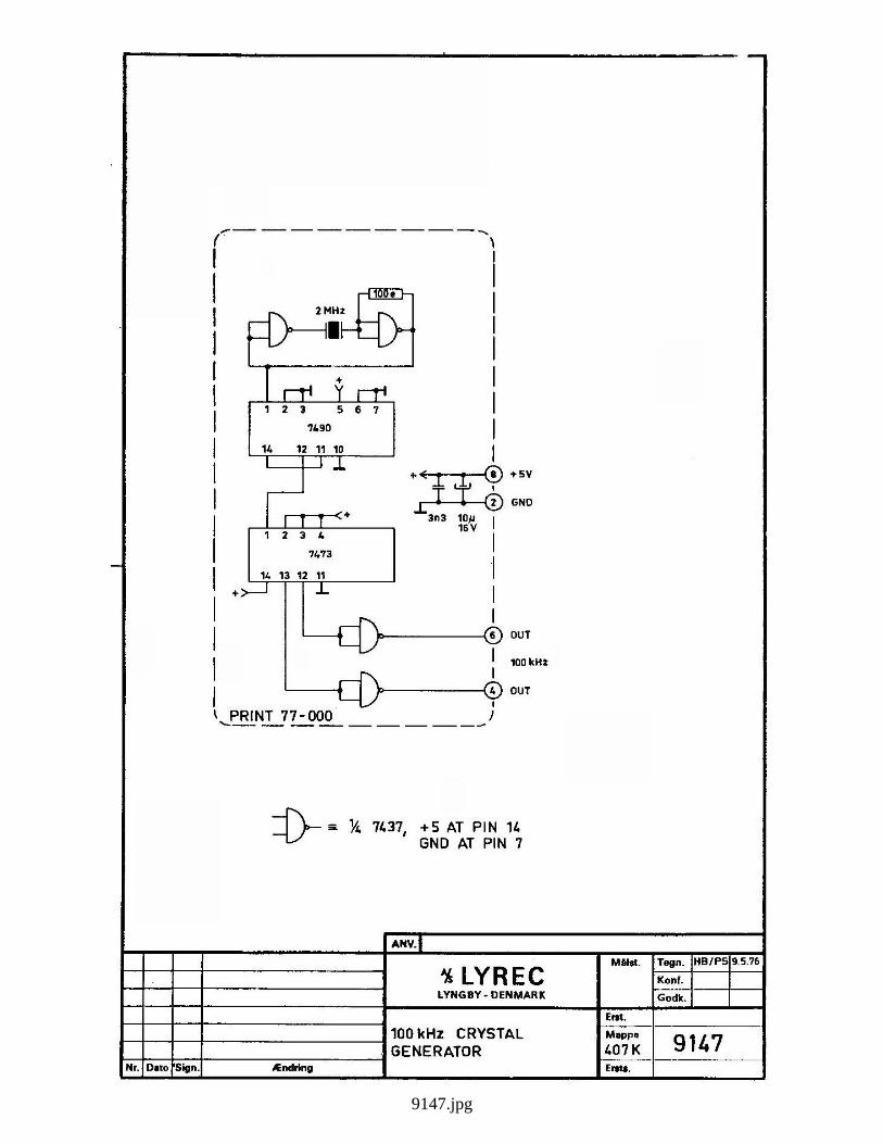
9147.jpg
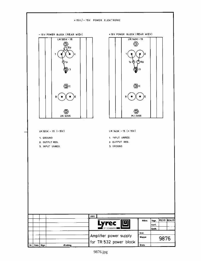
9876.jpg
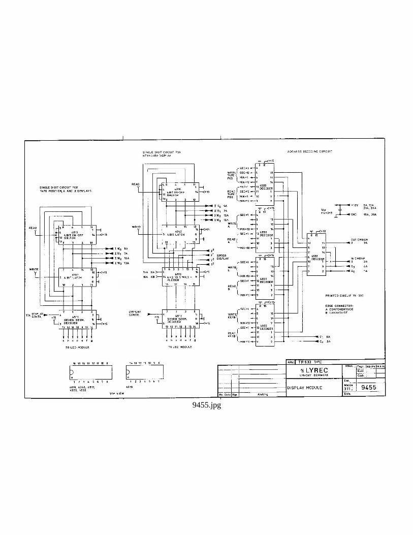
9455.jpg

9456.jpg

9457.jpg
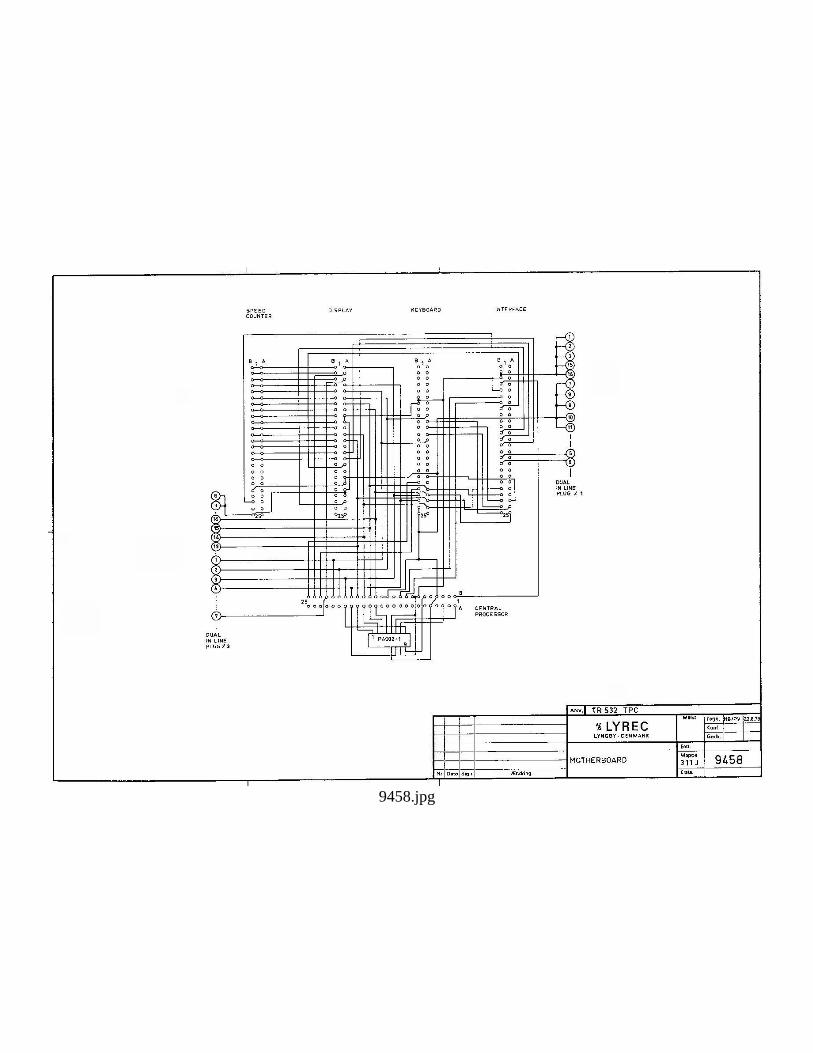
9458.jpg
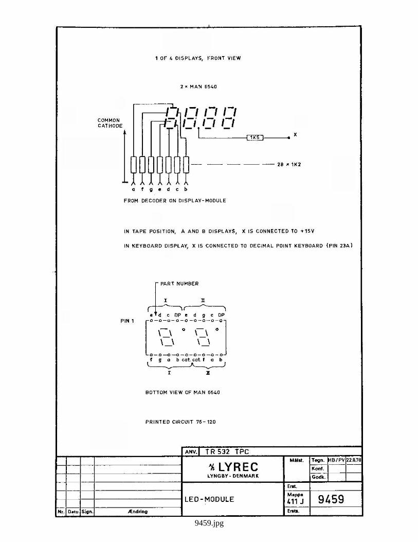
9459.jpg

9460.jpg
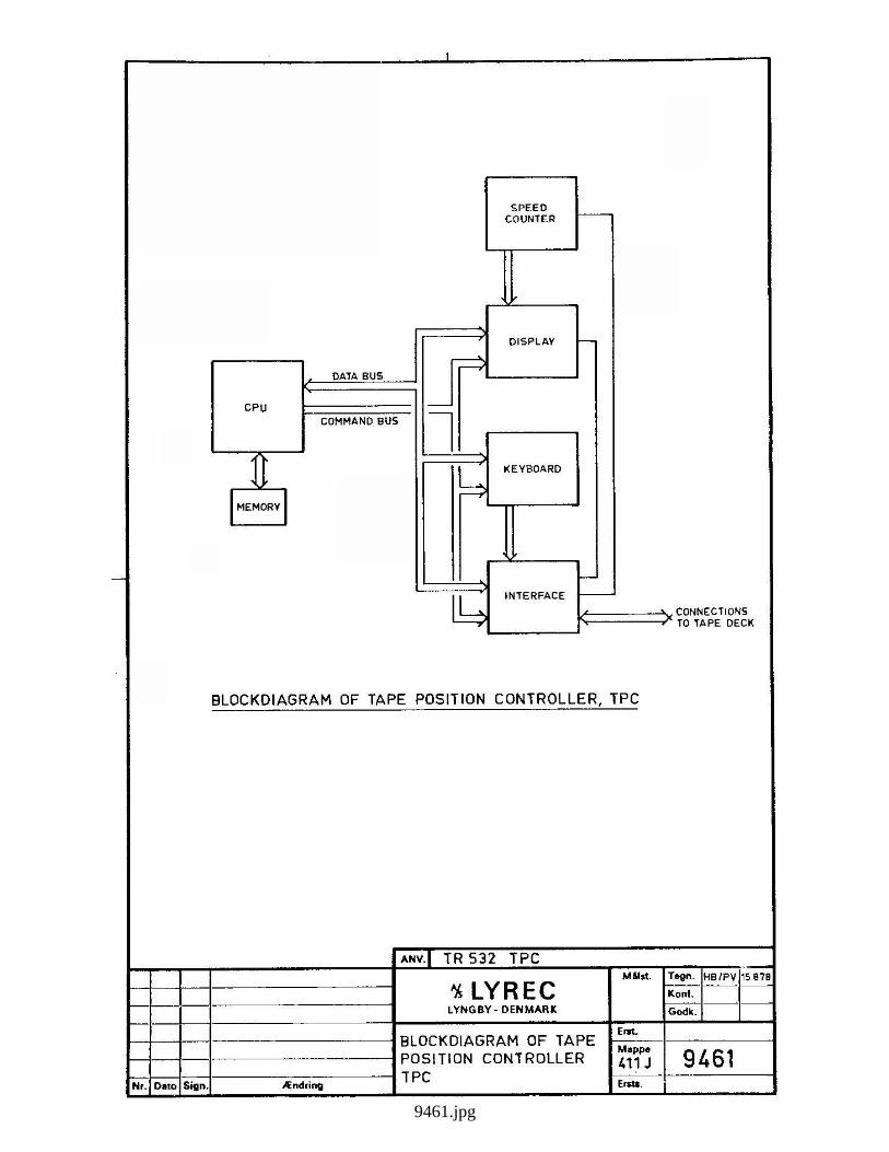
9461.jpg
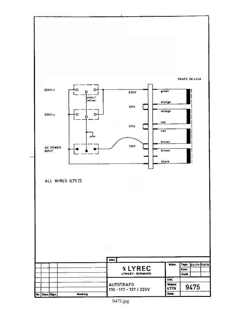
9475.jpg

9476.jpg

9524.jpg
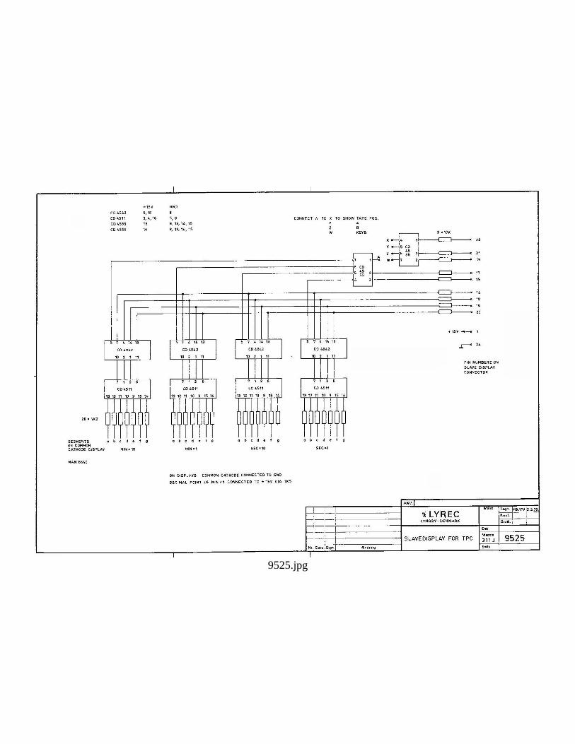
9525.jpg
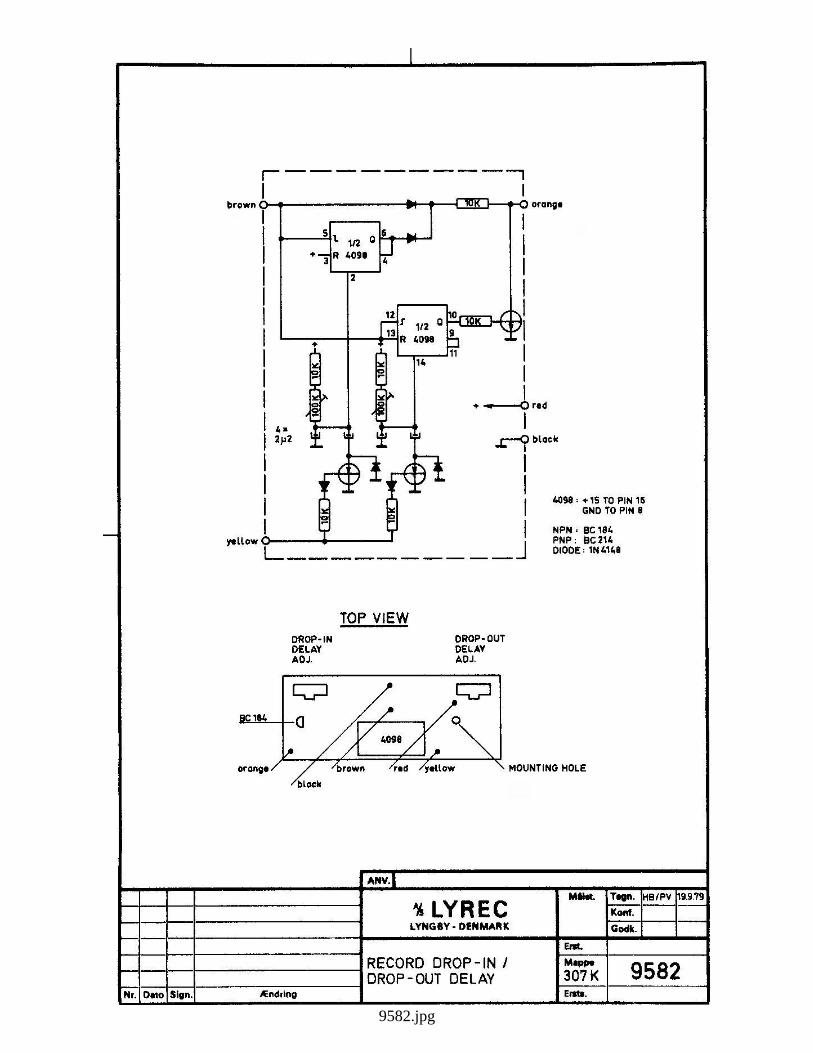
9582.jpg
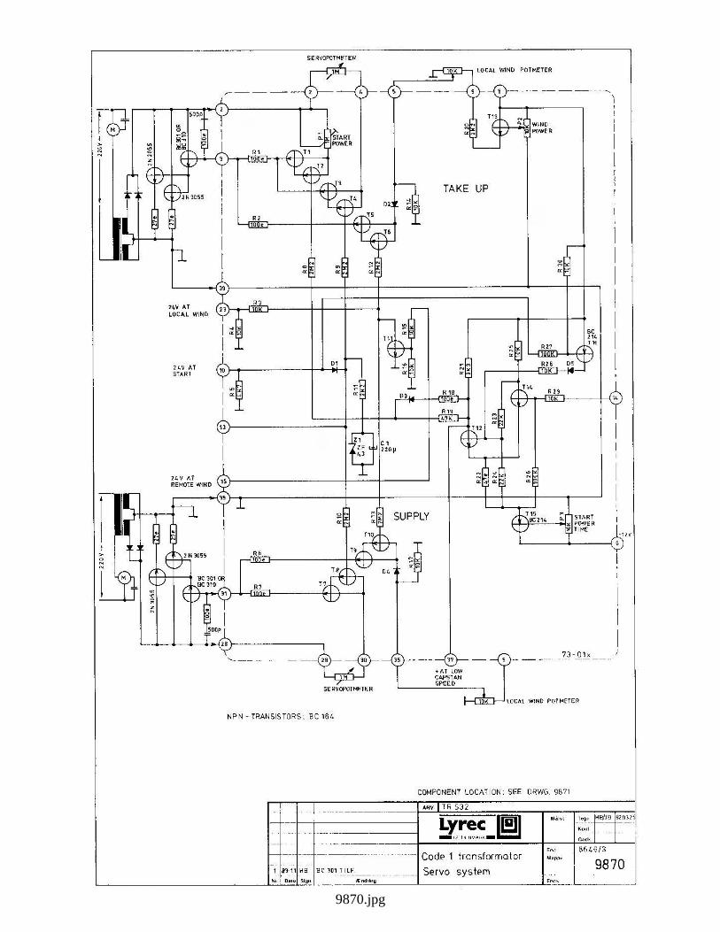
9870.jpg

9871.jpg
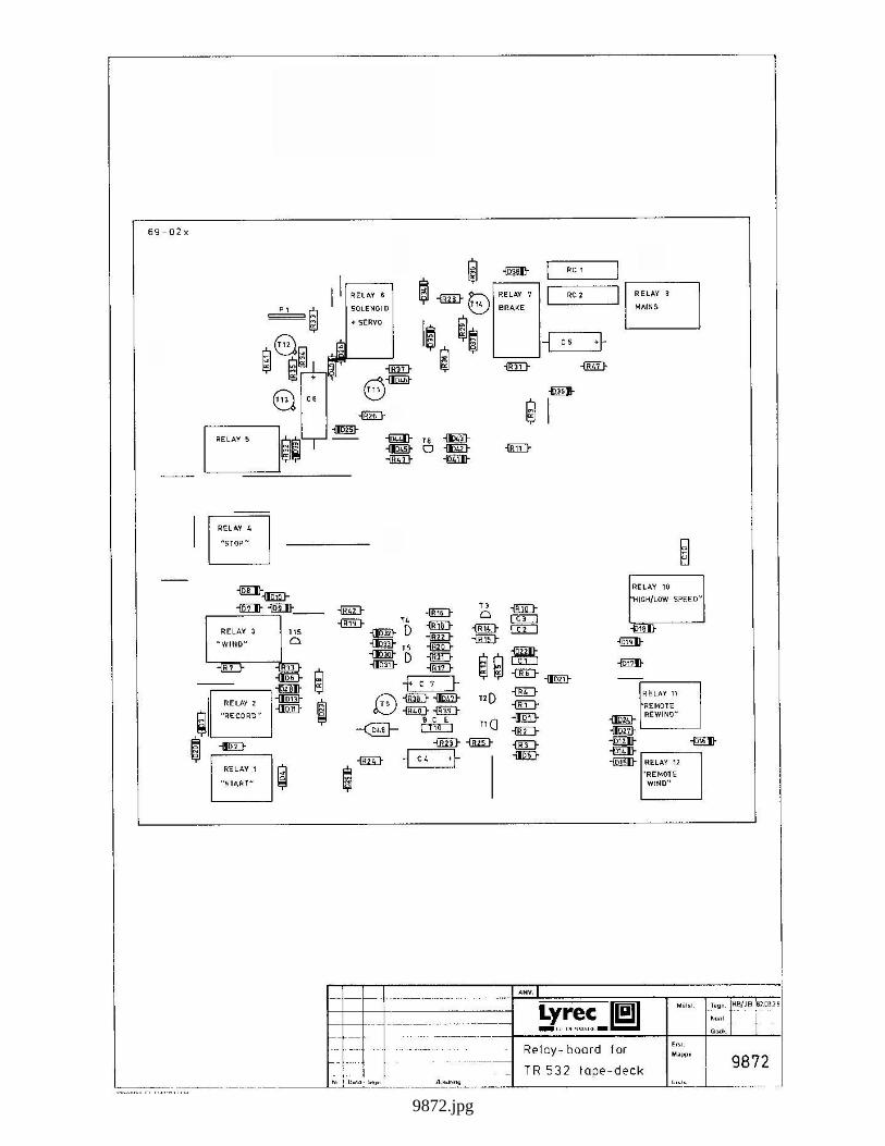
9872.jpg
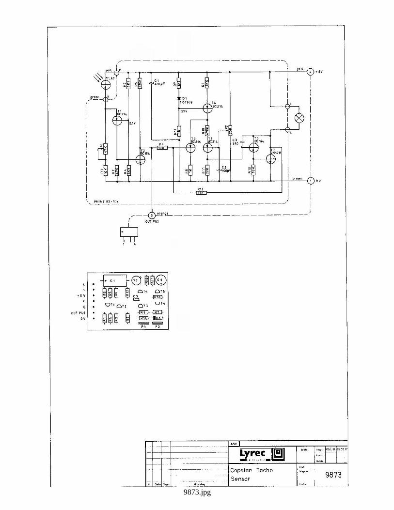
9873.jpg

9874.jpg
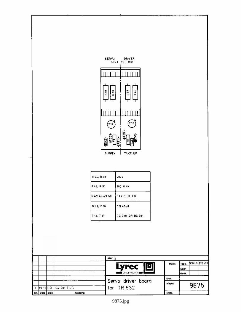
9875.jpg
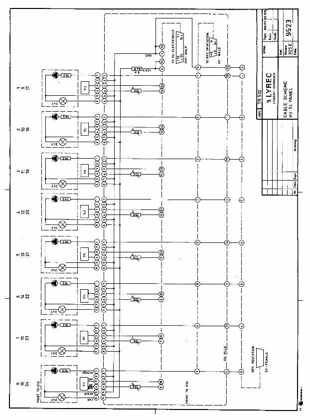
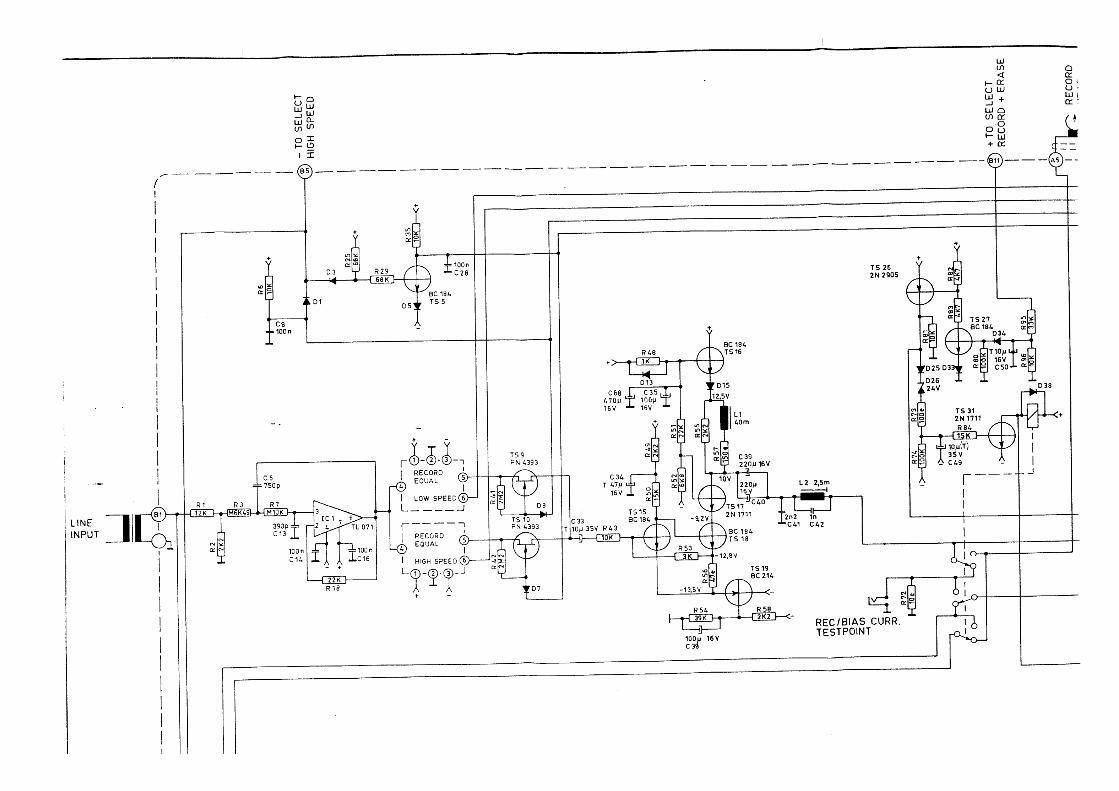
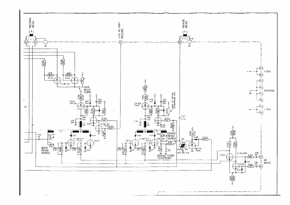


PCB 84-03xIC1: TL 074 OR EQUIVALENT*: 1% TOL.
NOTE:WITH HX PRO: CONNECTED TO 0V, P1 = 50KWITHOUT HX PRO: CONNECTED TO +15V, P1 = 1K
EQUALISERRECORD
10K0
10K0
9K53
10K
10K
10K
10K0
10K0
R10-12
1OKR4*
R6
ÆndringPHASE SHIFT TO VÆRDIER
TEKST TILF.
TEKST TILF.NY REV. UDG.
COMPONENT VALUES CORRECTED
1 7/81 7/83 3/47 1/27 1/2
5
Nr.
3
1
2
496.03 LP
AN
Dato Sign 86.01 HB
90.12 LJ
95.11 JS
91.09
151530
6
IPS
Anv.
39K
*=OMITTED
100K
100K
68K
39K
39K
R6
C4
120/3180 µS
NABCCIRNABCCIRNABAES
70/3180 µS
*
*
C1
IC1
R1
EQ
C8
R2
R3
C3
100K 15K
22K 470e4K99100K4K99100K4K99
470e470e470e470e470e
100K 470e
P2
P1
C2R9
R9R7
R8
R7
R5 R
14
9
10
1
R1*4 10K
IC 1PIN 4
IC 1PIN 11
R12
2
GND
C8
R4
C7
R10
C5R11
100n
-15V
C7
3
P4R13
C6
SEE NOTE
BIASP1
1 6
+15V
1K100n
C1*8
+
-
10KR2*
R3* 6
PHASESHIFT
5n1 5
P5
10K
+
-
Erst.
Mappe
Ersts.
AM77
3n3
330p330p
680p
330p2n2
330p
330p
C4330n2K4 *
330n
330n
330n
*
*
330n6K8 3n36K86K86K86K86K8 1n
1n*
*
2K4 3n3
2n7
*
C3R14 C2
P5
5K 22K 10K
22K
100K
100K
47K22K
22K
SE
E N
OTE
5K 22K10K10K10K4K74K74K7
10K
P1 P3 P5
1070
HB/JB
Godk.
TegnMålst. 84.01
P3
C4*
P3
R10*
R11
*
1n0C5*
C6*
1n0
R6
R5*10K
7
C2* 13
R12*
6K8
+12
-
C3
R7*
HIGHFREQ
R13
*2K
49P
4
+
-2
3
1
10K
RECORDLEVEL
10K
P2
MED-HIGHFREQ
14
10KR8*
470eR9
5
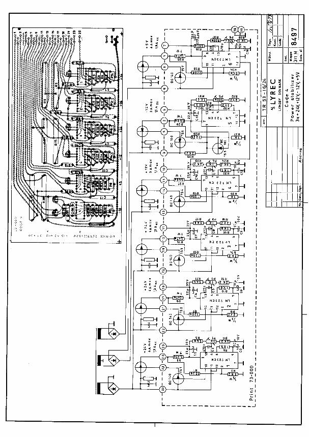
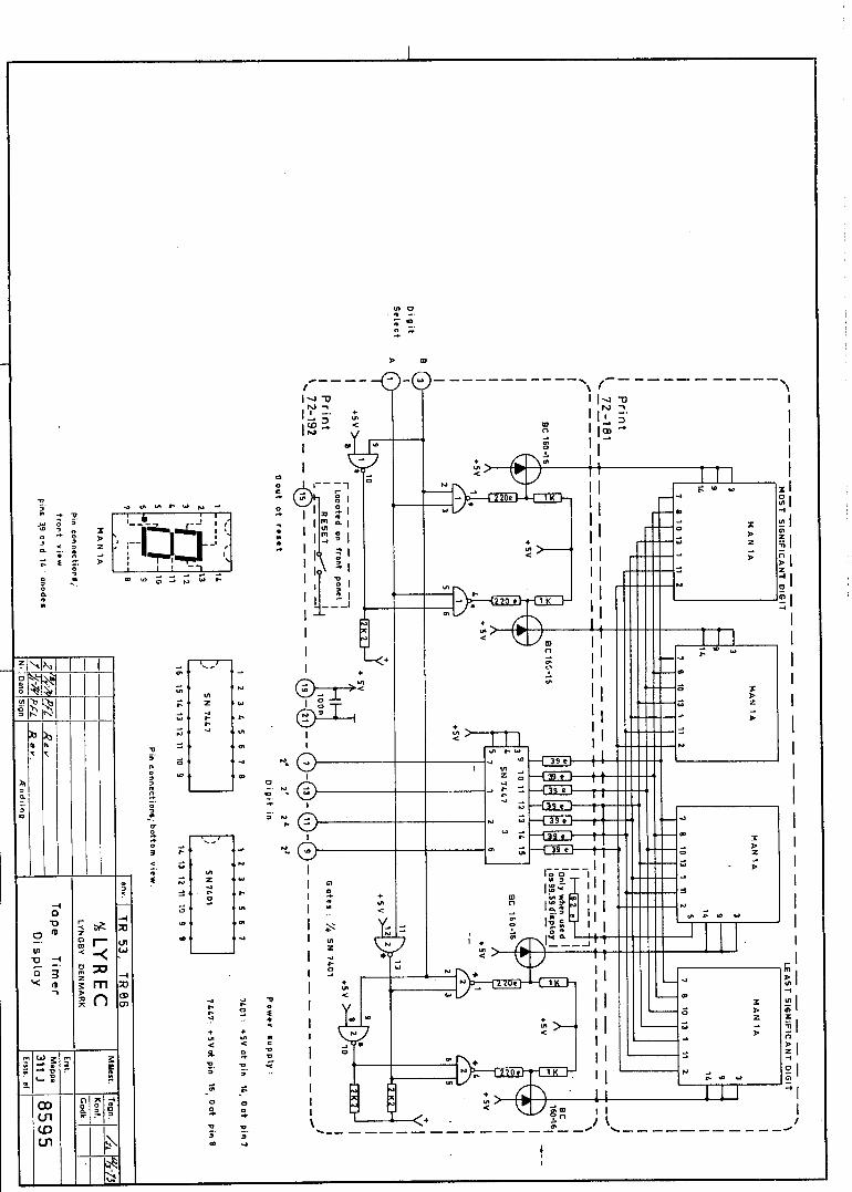
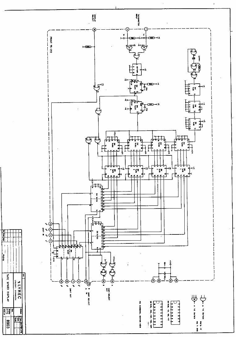
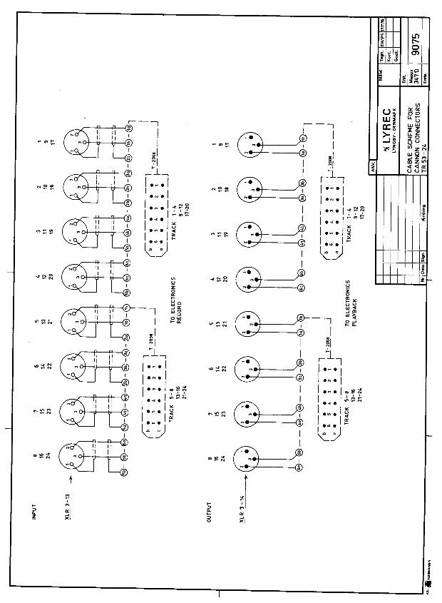
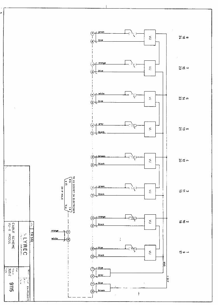
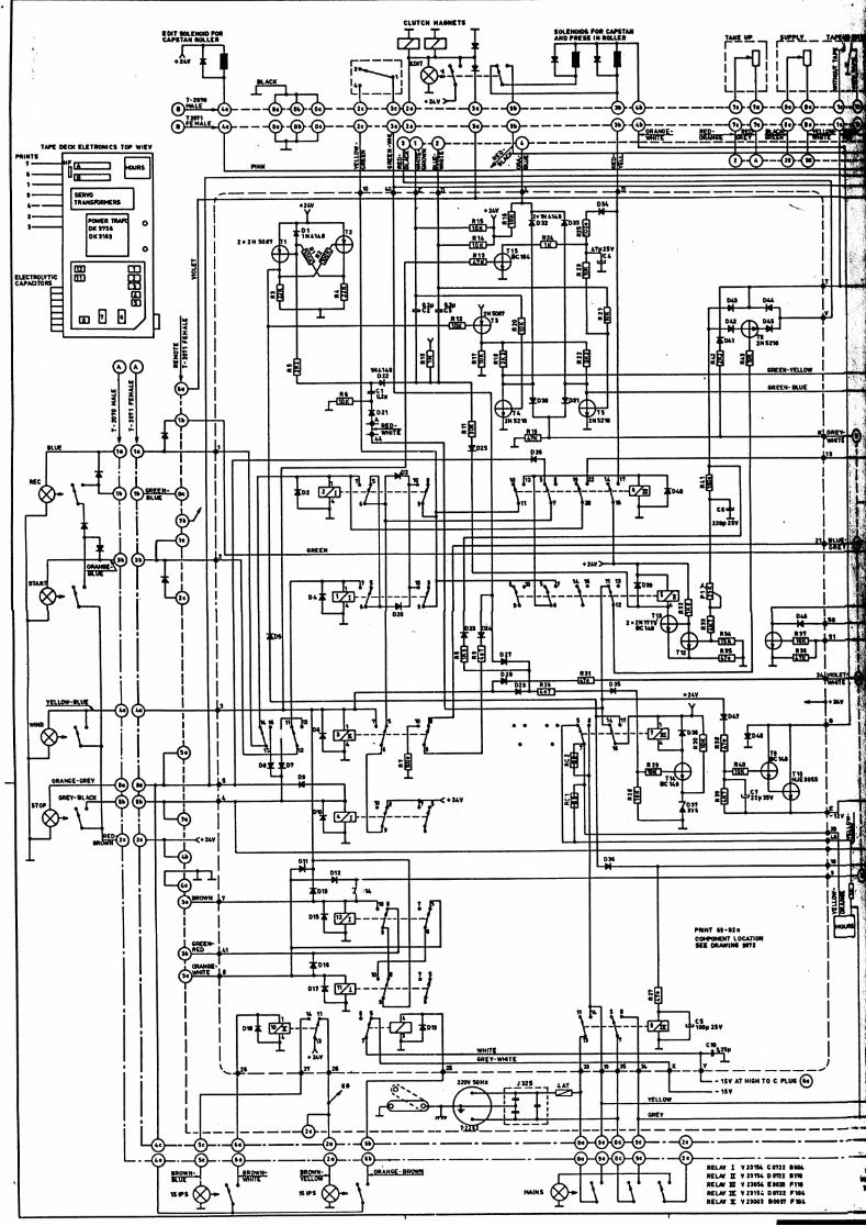
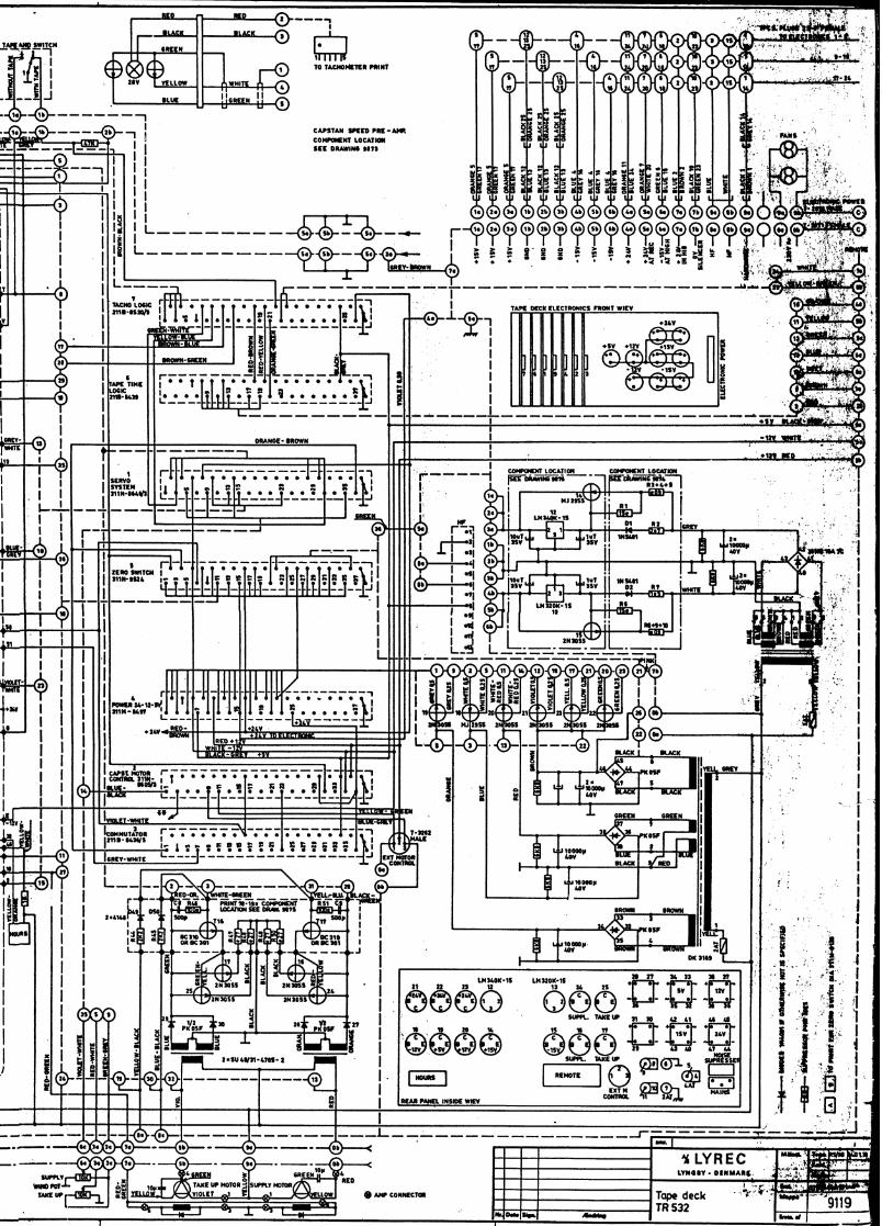
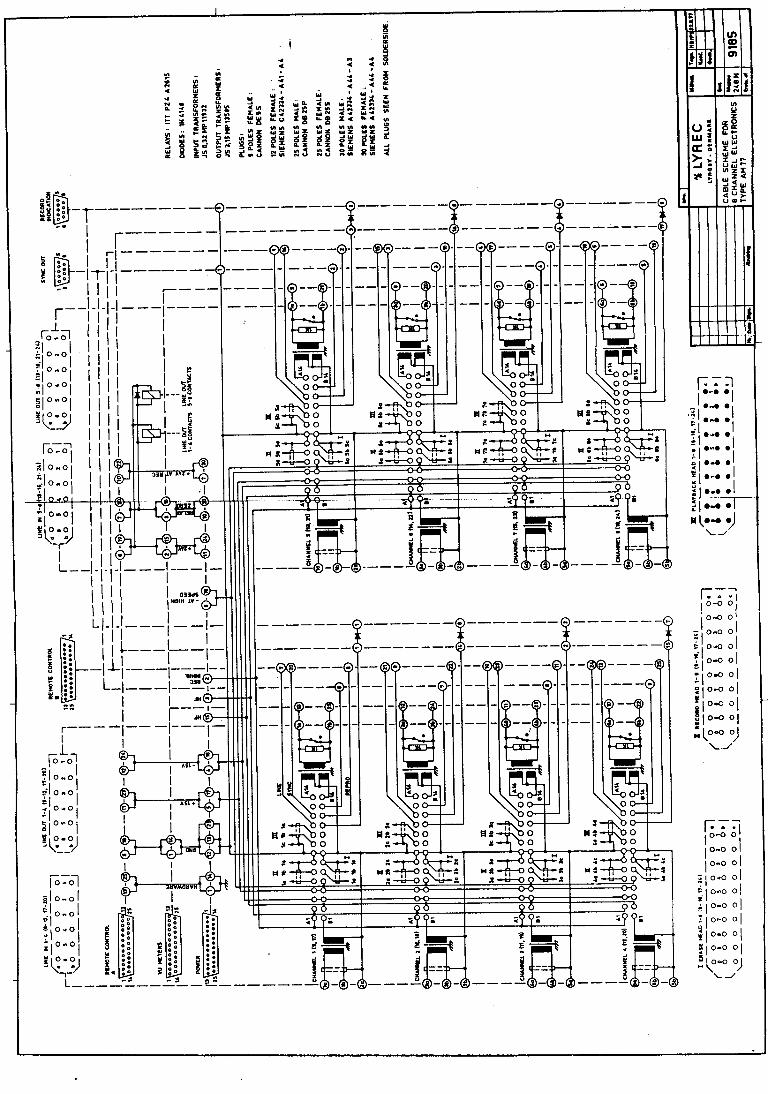

This Manual or Schematic is a
FREE DOWNLOAD
For everyone…
From the archives of
Analogrules.com
and
AudioSchematics.com
If you have paid anything for this
Manual or Schematic
You have been
RIPPED OFF
Demand your money back
And let us know who is stealing
our files and charging for
our free downloads