Mitigating Collisions through Power-Hopping to Improve 802.11 Performance
Upload
independentCategory
view
0download
0
A Unified NET-MAC-PHY Cross-layer Framework forPerformance Evaluation of Multi-hop Ad hoc WLANsH
Rachid El-Azouzi1, Essaid Sabir2,∗, Mohammed Raiss-El-Fenni1and Sujit Kumar Samanta1
1LIA-CERI, University of Avignon, 339 chemin des Meinajaries, Agroparc BP 1228, Avignon cedex 9, France.2RTSE team., GREENTIC/ENSEM, Hassan II University, Route d’El Jadida BP 8118 Oasis, Casablanca, Morocco.
Abstract
Most of the existing works have been evaluated the performance of 802.11 multihop networks by consideringthe MAC layer or network layer separately. Knowing the nature of the multi-hop ad hoc networks, manyfactors in different layers are crucial for study the performance of MANET. In this paper we present a newanalytic model for evaluating average end-to-end throughput in IEEE 802.11e multihop wireless networks.In particular, we investigate an intricate interaction among PHY, MAC and Network layers. For instance, weincorporate carrier sense threshold, transmission power, contention window size, retransmissions retry limit,multi rates, routing protocols and network topology together. We build a general cross-layered frameworkto represent multi-hop ad hoc networks with asymmetric topology and asymmetric traffic. We develop ananalytical model to predict throughput of each connection as well as stability of forwarding queues atintermediate nodes in saturated networks. To the best of our knowledge, it seems that our work is the firstwherein general topology and asymmetric parameters setup are considered in PHY/MAC/Network layers.Performance of such a system is also evaluated through simulation. We show that performance measures ofthe MAC layer are affected by the traffic intensity of flows to be forwarded. More precisely, attempt rate andcollision probability are dependent on traffic flows, topology and routing.
1. IntroductionIn next-generation wireless networks, it is expected thatthe IEEE 802.11 wireless LAN (WLAN) will play animportant role and affect the style of people’s daily life.Further, many factors and applications have made the802.11 wireless LAN networks an attractive commercialfield. The low cost of wireless-network interface wasthe first encouragement to make the network feasiblefor civilian applications. The distributed nature of thenetwork and the flexibility that provides were the basisof many interesting applications that do not really needmaintenance and reconfiguration.
There are lot of interests in modeling the behaviorof the IEEE 802.11 DCF (Distributed CoordinationFunction) and studying its performances for botharchitectures: the WLAN networks and multi-hopwireless networks. A medium access control protocolhas a large impact on the achievable networkthroughput and stability for wireless ad hoc networks.So far, the ad hoc mode of the IEEE 802.11 standard
∗Corresponding author. [email protected]
has been used as the MAC protocols for MANETs. Thisprotocol is based on the CSMA/CA mechanism in DCF.
Over the last decade, there has been a tremendouswave of interest in the study of cooperation in wirelessnetworks, more precisely in wireless ad hoc networks.For instance, the interest has been growing since thepublication of famous article of Bianchi [5]. In ad hocnetworking context, each neighbor node could assist inthe ongoing transmission by exploiting the broadcastnature of the wireless medium. Unfortunately, almostall these studies have been focused on MAC layerwithout taking into account routing and cooperationlevel of nodes in ad-hoc networks, see e.g. [1–4, 10, 14–16]. In multi-hop ad hoc networks, the majority ofefforts are concentrated on extending Bianchi’s model insaturated networks. Now, problem of hidden terminalsand channel asymmetry are still real issues for multi-hop ad-hoc networks. Yang et al. [16] proposed anextension of Bianchi’s model [5] and Kumar et al. [8]for multi-hop context under symmetric scenario. Theystudied the impact of carrier sensing range and thetransmission power on the sender throughput. ThePHY/MAC impact is clearly presented. Basel et al. [1]
1
Research ArticleEAI Endorsed Transactionson Mobile Communications and Applications
Received on 29 March 2014; accepted on 14 May 2014; published on 24 September 2014
Keywords: Ad hoc network, Performance Evaluation, Cross-layer architecture, Fixed point, Coupled systems.
Copyright © 2014 R. El-Azouzi et al., licensed to ICST. This is an open access article distributed under the terms of the Creative Commons Attribution license (http://creativecommons.org/licenses/by/3.0/), which permits unlimited use, distribution and reproduction in any medium so long as the original work is properly cited.
doi:10.4108/mca.1.4.e6
EAI for InnovationEuropean Alliance EAI Endorsed Transactions
on Mobile Communications and Applications 01 - 09 2014 | Volume 01 | Issue 4 | e6

R. El-Azouzi et al.
have also interested in tuning the transmission powerrelatively to the carrier sense threshold. They offereda detailed comparison performance between the two-way handshake and the four-way handshake. A threedimensional Markov chain is proposed in [12] to derivethe saturation throughput of the IEEE 802.11 DCF. Thecollision probability is now a function of the distancebetween the sender and its receiver. The unsaturatednode state and the channel state are introduced in [2]. Aperformance analysis is performed for a single-hop caseand a multi-hop case considering that a node can carrydifferent traffic loads. Medepalli et al. [10] proposed aninteresting framework model for analyzing throughput,delay and fairness characteristics of IEEE 802.11 DCFmulti-hop networks. The applicability of the model interms of network design is also presented.
Recently, Zhu et al. [17] proposed two cooperativeenergy efficient algorithms to control the networktopology. The authors addressed the problem ofinefficient routes that occurs when maintaining thenetwork connectivity, minimizing the transmissionpower of each node but ignoring the energy-efficiencyof paths in constructed topologies. An ordinal potentialgame formulation is proposed by Chu et al. [19].They proposed a cooperative approach to determinethe transmission power for each node so that it canperiodically adapt to the remaining energy on the nodeswithin its neighborhood. Existence of Nash equilibriumfor the game is shown and an algorithm which achievessuch equilibrium is proposed. The authors also shown,by simulation, that their algorithm is able to improvethe lifetime of a wireless sensor network by morethan 50% compared to the best previously-knownalgorithm. Li et al. [18] studied the throughput of atype of heterogeneous networks consisting of a primarynetwork of size n and a cognitive radio ad hoc networkof size m. The authors shown that the individualthroughput of a primary user scales is Θ
(1/√n)
withno performance loss due to scaling law. The same resultapply for cognitive/secondary users, i.e., the individualthroughput scales is Θ
(1/√m).
Our major goal in this paper, is to build a completeframework to analyze multi-hop ad hoc networksunder general and realistic considerations. We presenta probabilistic but rigorous model incorporating jointlyNetwork, MAC and PHY layers in a simple cross-layered architecture in a saturated network. Thiscross-layered architecture has a potential synergy ofinformation exchange among different layers, instead ofthe standard OSI non-communicating layers. Withoutany restriction on the network topology, our modelis built and valid for any ad hoc network topologyunder saturation condition. Note that under asymmetry
scenario, nodes do not have the same channelperception. Thus, the attempt rate may not alwaysdescribe the real channel access activity. Moreover,our model is extended to the IEEE 802.11e1 whichprovides differentiated channel access (differentiatedpriority/QoS) to packets by allowing different rates anddifferent back-off parameters. In order to handle QoS,several traffic classes are also supported. We also allowthat each traffic/stream may have different retry limitsafter which the packet is dropped. By analyzing themodel, we find that the performance measures of MAClayer may be drastically affected by the routing policyand the traffic intensity of crossing flows. Henceforth,the attempt rate and collision probability are dependenton the traffic flows, topology and routing. Fromanalytical result and as confirmed by simulation, theend-to-end throughput is independent of cooperationlevel when all forwarding queues are stabled. Hencethere is no throughput-delay tradeoff that can beobtained by changing the forwarding probabilities. Areal tradeoff is caused by the maximum number ofattempts or power control. Indeed, the throughput isameliorated when reattempting many times on a path,while the service rate on a forwarding queue is sloweddown causing low stability region and delay will beincreased. A direct application of our work is to findnew distributed schemes for channel access and routingthat work near optimal stability region of the network.The structure of the paper is as follows : We formulatethe problem in Section 2. Then we derive the expressionof end-to-end throughput and stability that determinestraffic intensities in the whole network in Section 3. Weillustrate our results by some numerical examples inSection 4 and conclude the paper in Section 5.
2. Problem formulation
2.1. Overview on IEEE 802.11 DCF/EDCFThe distributed coordination function (DCF) of theIEEE 802.11 is based on the CSMA/CA protocol inwhich a node starts by sensing the channel beforeattempting any packet. Then, if the channel is idle itwaits for an interval of time, called the DistributedInter-Frame Space (DIFS), before transmission. But,if the channel is sensed busy the node defers itstransmission and waits for an idle channel. In addition,to reduce collisions of simultaneous transmissions, theIEEE 802.11 employs a slotted binary exponential back-off where each packet in a given node has to wait for arandom number of time slots, called the back-off time,
1We believe that our model could apply for the recent IEEE 802.11nand the future standard IEEE 802.11ac by integrating the adaptivecoding and modulation scheme and the Multiple Input MultipleOutput technique as well.
2EAI for InnovationEuropean Alliance EAI Endorsed Transactions
on Mobile Communications and Applications 01 - 09 2014 | Volume 01 | Issue 4 | e6
A Unified NET-MAC-PHY Cross-layer Framework for Performance Evaluation of Multi-hop Ad hoc WLANs
before attempting the channel. The back-off time isuniformly chosen from the interval [0,W − 1], whereW is the contention window that mainly depends onthe number of experienced collisions. The contentionwindow W is dynamic and given by Wi = 2iW0, wherei represents the stage number (usually, it is consideredas the current retransmission attempt number) of thepacket, and W0 is the initial contention window. Theback-off time is decremented by one slot each timewhen the channel is sensed idle, whereas freezes if it issensed busy. Finally, when the data is transmitted, thesender has to wait for an acknowledgement (ACK) thatwould arrive after an interval of time, called the ShortInter-Frame Space (SIFS). If an ACK is not received,the packet is considered lost and a retransmission hasto be scheduled. When the number of retransmissionsexpires, the packet is definitively dropped. To considermultimedia applications, the IEEE 802.11e uses anenhanced mode of the DCF called the Enhanced DCF(EDCF) which provides differentiated channel accessfor different flow priorities. The main idea of EDCFis based on differentiating the back-off parameters ofdifferent flows. Thus, priorities can be distinguisheddifferent initial contention window, different back-offmultiplier or different inter-frame space. An ArbitrationIFS (AIFS) is used instead of DIFS. The AIFS can take atleast a value of DIFS, and, a high priority flow needs towait only for DIFS before transmission to the channel.Whereas a low priority flow waits for an AIFS greaterthan DIFS. In the next paragraph, we used a generalizedmodel of the back-off mechanism.
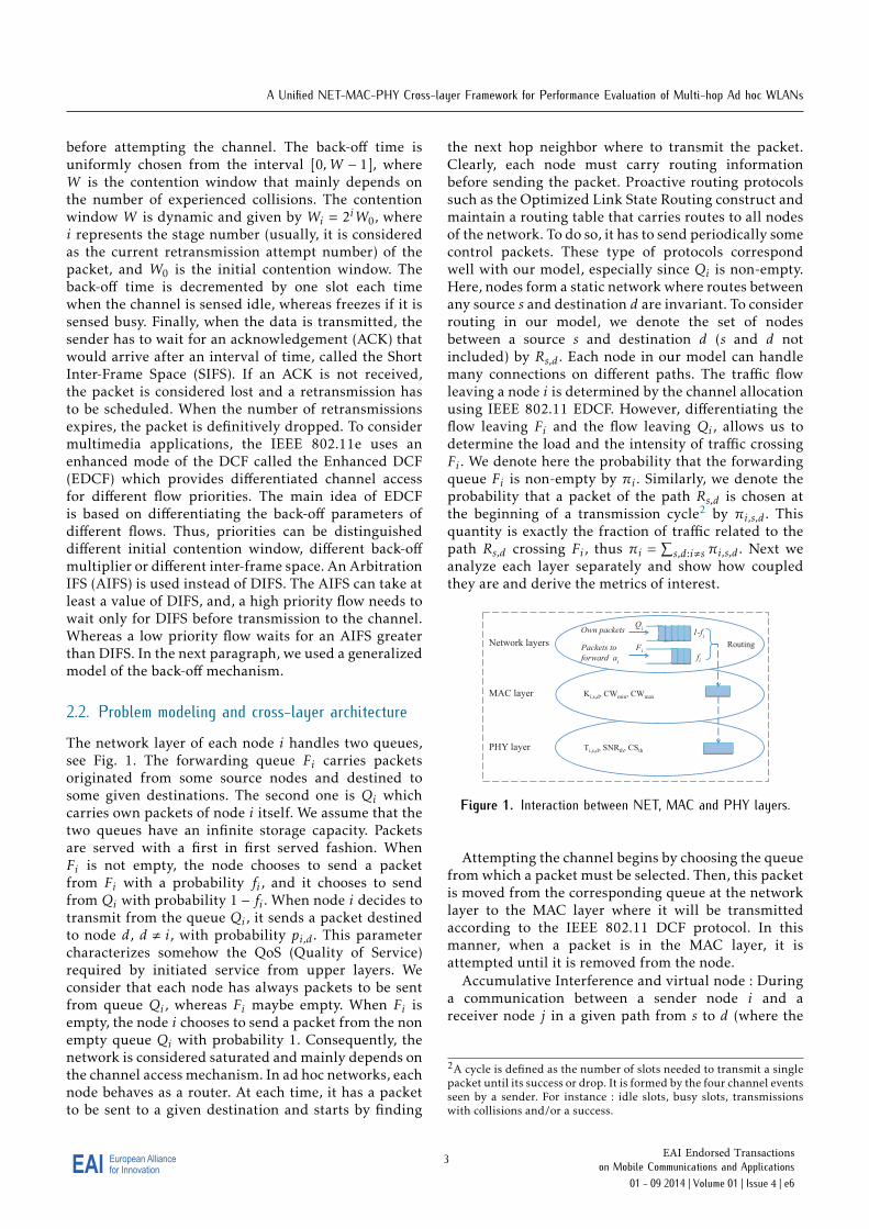
2.2. Problem modeling and cross-layer architectureThe network layer of each node i handles two queues,see Fig. 1. The forwarding queue Fi carries packetsoriginated from some source nodes and destined tosome given destinations. The second one is Qi whichcarries own packets of node i itself. We assume that thetwo queues have an infinite storage capacity. Packetsare served with a first in first served fashion. WhenFi is not empty, the node chooses to send a packetfrom Fi with a probability fi , and it chooses to sendfrom Qi with probability 1 − fi . When node i decides totransmit from the queue Qi , it sends a packet destinedto node d, d , i, with probability pi,d . This parametercharacterizes somehow the QoS (Quality of Service)required by initiated service from upper layers. Weconsider that each node has always packets to be sentfrom queue Qi , whereas Fi maybe empty. When Fi isempty, the node i chooses to send a packet from the nonempty queue Qi with probability 1. Consequently, thenetwork is considered saturated and mainly depends onthe channel access mechanism. In ad hoc networks, eachnode behaves as a router. At each time, it has a packetto be sent to a given destination and starts by finding
the next hop neighbor where to transmit the packet.Clearly, each node must carry routing informationbefore sending the packet. Proactive routing protocolssuch as the Optimized Link State Routing construct andmaintain a routing table that carries routes to all nodesof the network. To do so, it has to send periodically somecontrol packets. These type of protocols correspondwell with our model, especially since Qi is non-empty.Here, nodes form a static network where routes betweenany source s and destination d are invariant. To considerrouting in our model, we denote the set of nodesbetween a source s and destination d (s and d notincluded) by Rs,d . Each node in our model can handlemany connections on different paths. The traffic flowleaving a node i is determined by the channel allocationusing IEEE 802.11 EDCF. However, differentiating theflow leaving Fi and the flow leaving Qi , allows us todetermine the load and the intensity of traffic crossingFi . We denote here the probability that the forwardingqueue Fi is non-empty by πi . Similarly, we denote theprobability that a packet of the path Rs,d is chosen atthe beginning of a transmission cycle2 by πi,s,d . Thisquantity is exactly the fraction of traffic related to thepath Rs,d crossing Fi , thus πi =
∑s,d:i,s πi,s,d . Next we
analyze each layer separately and show how coupledthey are and derive the metrics of interest.
Network layers
MAC layer
PHY layer
Own packets 1-fi
fi
Ki,s,d, CWmin, CWmax
Qi
Fi Packets to
forward ai
Ti,s,d, SNRth, CSth
Routing
Figure 1. Interaction between NET, MAC and PHY layers.
Attempting the channel begins by choosing the queuefrom which a packet must be selected. Then, this packetis moved from the corresponding queue at the networklayer to the MAC layer where it will be transmittedaccording to the IEEE 802.11 DCF protocol. In thismanner, when a packet is in the MAC layer, it isattempted until it is removed from the node.
Accumulative Interference and virtual node : Duringa communication between a sender node i and areceiver node j in a given path from s to d (where the
2A cycle is defined as the number of slots needed to transmit a singlepacket until its success or drop. It is formed by the four channel eventsseen by a sender. For instance : idle slots, busy slots, transmissionswith collisions and/or a success.
3EAI for InnovationEuropean Alliance EAI Endorsed Transactions
on Mobile Communications and Applications 01 - 09 2014 | Volume 01 | Issue 4 | e6
R. El-Azouzi et al.
source node of a connection is s and the destinationnode is d), the node i transmits to j with a powerTi,s,d . The received power on j can be related to thetransmitted one by the propagation relation Ti,s,d ·hi,j , where hi,j is the channel gain experienced byj on the link (i, j). In order to decode the receivedsignal correctly, Ti,s,d · hi,j should exceeds the receiversensitivity denoted by RXth, i.e., Ti,s,d · hi,j ≥ RXth.Under symmetry assumption and no accumulativeeffect of concurrent transmissions, the carrier senserange forms a perfect circle with radius r1. Even whenconsidering accumulative interference, the carrier sensecan be reasonably approached by a circle with radiusr2 ≥ r1.
Definition 1. The group Z, composed of nodes that cannotbe heard individually by a sender i but their accumulativesignal may jam the signal of interest, is called a virtualnode. This way, the virtual nodeZ is equivalent to a fictivenode being in the carrier sense range of sender i.
We can then formulate the carrier sense set of a node iby the following expression
CSi =
Z : ∀s, d, k′ ∈ Z,
∑k∈Z
Tk,s,d · hk,i ≥ CSth
∑k∈Z\k′
Tk,s,d · hk,i < CSth
, (1)
where CSth is the carrier sense threshold. One can seeCSi as the set of virtual nodes that may be heard bysender i when it is sensing the channel in order totransmit on the path Rs,d . In other words, CSi is theset of all real nodes (if they are neighbors of i) andvirtual nodes (due to accumulative interferences) thatmay interfere with node i. Now, we define Hi,s,d as theset of nodes that may sense the channel busy when nodei is transmitting on the path Rs,d . Then
Hi,s,d = {k : Ti,s,d · hi,k ≥ CSth,∀s, d}. (2)
For sake of clarity, we are restricted in our formulationto the case of single transmission power. However,our model can be straightforward used for studyingpower control from nodes individual point of views.An interesting feature is that when the transmissionpower level is the same for all nodes and accumulativeinterferences are neglected, CSi = Hi,s,d . The receiverji,s,d can correctly decode the signal from sender nodei if the Signal to Interference Ratio (SIR) exceeds acertain threshold SIRth. Let the thermal noise variance,experienced on the path Rs,d , be denoted by Ni,s,d , then
SIRji,s,d =Ti,s,d · hi,j∑
k,iTk,s′ ,d′ · hk,j +Ni,s,d
≥ SIRth, ∀s, d, s′ , d′ .
(3)We define now the interference set of a receiver ji,s,don a path Rs,d , denoted by Tji,s,d , as the collection of
its virtual nodes, i.e., all combination of nodes whoseaccumulative signal may cause collisions at ji,s,d . Forinstance, the virtual node Z is in the interference setof node ji,s,d iff the received signal from node i iscompletely jammed when nodes in Z are transmittingall together. The interference set of node j is thenwritten as
Tji,s,d =
Z :
Ti,s,d ·hi,j∑z∈Z
Tz,s′ ,d′ ·hz,j+Ni,s,d< SIRth,
Ti,s,d ·hi,j∑z∈Z\z′
Tz,s′ ,d′ ·hz,j+Ni,s,d≥ SIRth,
∀z′ , s′ , d′ , z′ , i, s′ , s, d′ , d.
(4)
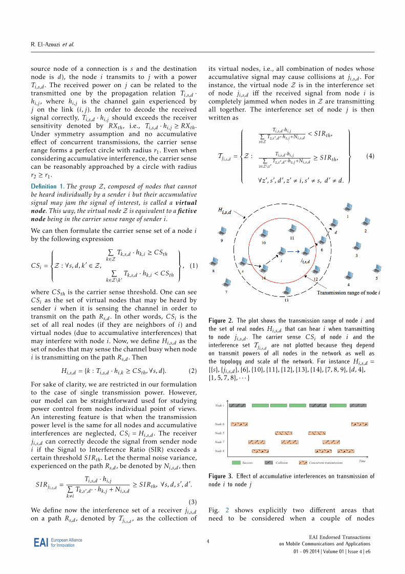
Figure 2. The plot shows the transmission range of node i andthe set of real nodes Hi,s,d that can hear i when transmittingto node ji,s,d . The carrier sense CSi of node i and theinterference set Tji,s,d are not plotted because they dependon transmit powers of all nodes in the network as well asthe topology and scale of the network. For instance Hi,s,d ={{s}, {ji,s,d}, {6}, {10}, {11}, {12}, {13}, {14}, {7, 8, 9}, {d, 4},{1, 5, 7, 8}, · · · }
Node i
Time
Node 8
Node 7
Node 5
Node 6
Success Collision Concurrent transmissions
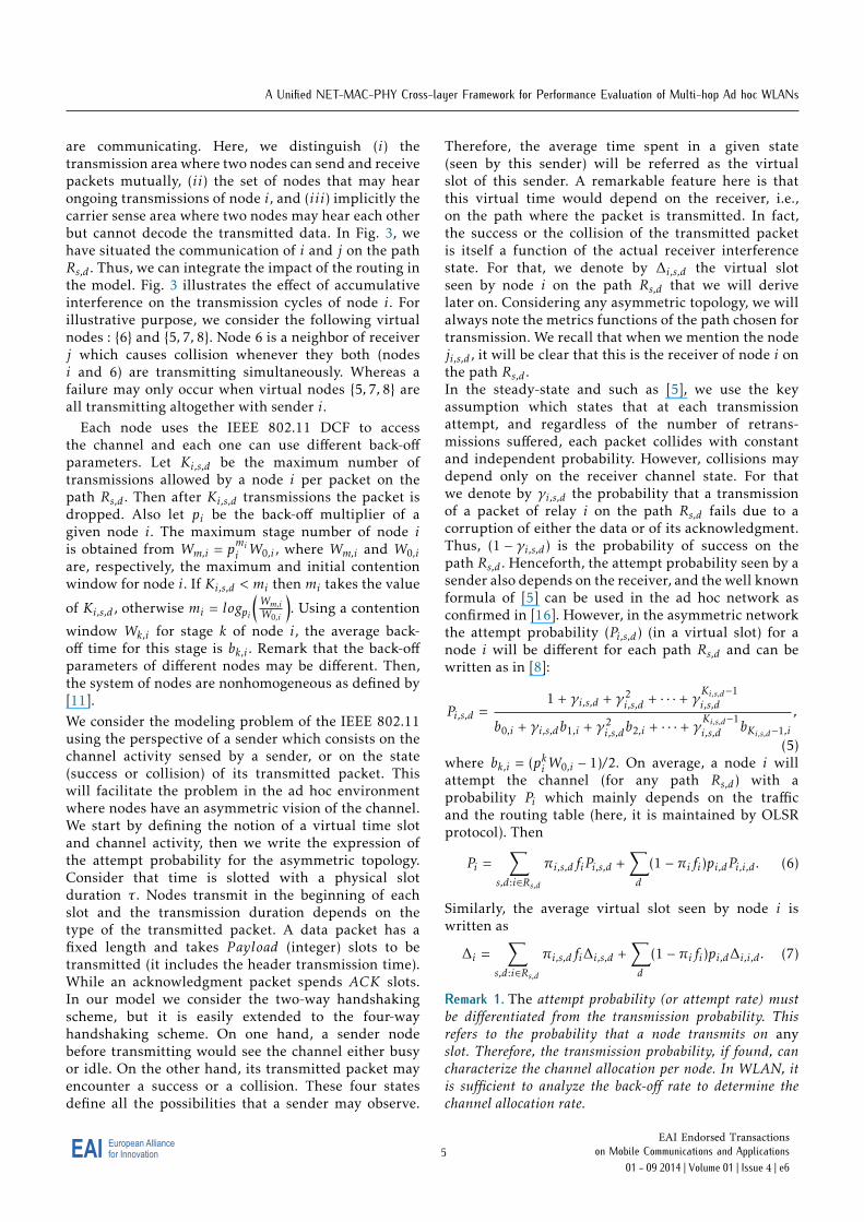
Figure 3. Effect of accumulative interferences on transmission ofnode i to node j
Fig. 2 shows explicitly two different areas thatneed to be considered when a couple of nodes
4EAI for InnovationEuropean Alliance EAI Endorsed Transactions
on Mobile Communications and Applications 01 - 09 2014 | Volume 01 | Issue 4 | e6
A Unified NET-MAC-PHY Cross-layer Framework for Performance Evaluation of Multi-hop Ad hoc WLANs
are communicating. Here, we distinguish (i) thetransmission area where two nodes can send and receivepackets mutually, (ii) the set of nodes that may hearongoing transmissions of node i, and (iii) implicitly thecarrier sense area where two nodes may hear each otherbut cannot decode the transmitted data. In Fig. 3, wehave situated the communication of i and j on the pathRs,d . Thus, we can integrate the impact of the routing inthe model. Fig. 3 illustrates the effect of accumulativeinterference on the transmission cycles of node i. Forillustrative purpose, we consider the following virtualnodes : {6} and {5, 7, 8}. Node 6 is a neighbor of receiverj which causes collision whenever they both (nodesi and 6) are transmitting simultaneously. Whereas afailure may only occur when virtual nodes {5, 7, 8} areall transmitting altogether with sender i.
Each node uses the IEEE 802.11 DCF to accessthe channel and each one can use different back-offparameters. Let Ki,s,d be the maximum number oftransmissions allowed by a node i per packet on thepath Rs,d . Then after Ki,s,d transmissions the packet isdropped. Also let pi be the back-off multiplier of agiven node i. The maximum stage number of node iis obtained from Wm,i = pmii W0,i , where Wm,i and W0,iare, respectively, the maximum and initial contentionwindow for node i. If Ki,s,d < mi then mi takes the value
of Ki,s,d , otherwise mi = logpi
(Wm,iW0,i
). Using a contention
window Wk,i for stage k of node i, the average back-off time for this stage is bk,i . Remark that the back-offparameters of different nodes may be different. Then,the system of nodes are nonhomogeneous as defined by[11].We consider the modeling problem of the IEEE 802.11using the perspective of a sender which consists on thechannel activity sensed by a sender, or on the state(success or collision) of its transmitted packet. Thiswill facilitate the problem in the ad hoc environmentwhere nodes have an asymmetric vision of the channel.We start by defining the notion of a virtual time slotand channel activity, then we write the expression ofthe attempt probability for the asymmetric topology.Consider that time is slotted with a physical slotduration τ . Nodes transmit in the beginning of eachslot and the transmission duration depends on thetype of the transmitted packet. A data packet has afixed length and takes P ayload (integer) slots to betransmitted (it includes the header transmission time).While an acknowledgment packet spends ACK slots.In our model we consider the two-way handshakingscheme, but it is easily extended to the four-wayhandshaking scheme. On one hand, a sender nodebefore transmitting would see the channel either busyor idle. On the other hand, its transmitted packet mayencounter a success or a collision. These four statesdefine all the possibilities that a sender may observe.
Therefore, the average time spent in a given state(seen by this sender) will be referred as the virtualslot of this sender. A remarkable feature here is thatthis virtual time would depend on the receiver, i.e.,on the path where the packet is transmitted. In fact,the success or the collision of the transmitted packetis itself a function of the actual receiver interferencestate. For that, we denote by ∆i,s,d the virtual slotseen by node i on the path Rs,d that we will derivelater on. Considering any asymmetric topology, we willalways note the metrics functions of the path chosen fortransmission. We recall that when we mention the nodeji,s,d , it will be clear that this is the receiver of node i onthe path Rs,d .In the steady-state and such as [5], we use the keyassumption which states that at each transmissionattempt, and regardless of the number of retrans-missions suffered, each packet collides with constantand independent probability. However, collisions maydepend only on the receiver channel state. For thatwe denote by γi,s,d the probability that a transmissionof a packet of relay i on the path Rs,d fails due to acorruption of either the data or of its acknowledgment.Thus, (1 − γi,s,d) is the probability of success on thepath Rs,d . Henceforth, the attempt probability seen by asender also depends on the receiver, and the well knownformula of [5] can be used in the ad hoc network asconfirmed in [16]. However, in the asymmetric networkthe attempt probability (Pi,s,d) (in a virtual slot) for anode i will be different for each path Rs,d and can bewritten as in [8]:
Pi,s,d =1 + γi,s,d + γ2
i,s,d + · · · + γKi,s,d−1i,s,d
b0,i + γi,s,db1,i + γ2i,s,db2,i + · · · + γKi,s,d−1
i,s,d bKi,s,d−1,i
,
(5)where bk,i = (pkiW0,i − 1)/2. On average, a node i willattempt the channel (for any path Rs,d) with aprobability Pi which mainly depends on the trafficand the routing table (here, it is maintained by OLSRprotocol). Then
Pi =∑
s,d:i∈Rs,d
πi,s,dfiPi,s,d +∑d
(1 − πifi)pi,dPi,i,d . (6)
Similarly, the average virtual slot seen by node i iswritten as
∆i =∑
s,d:i∈Rs,d
πi,s,dfi∆i,s,d +∑d
(1 − πifi)pi,d∆i,i,d . (7)
Remark 1. The attempt probability (or attempt rate) mustbe differentiated from the transmission probability. Thisrefers to the probability that a node transmits on anyslot. Therefore, the transmission probability, if found, cancharacterize the channel allocation per node. In WLAN, itis sufficient to analyze the back-off rate to determine thechannel allocation rate.
5EAI for InnovationEuropean Alliance EAI Endorsed Transactions
on Mobile Communications and Applications 01 - 09 2014 | Volume 01 | Issue 4 | e6

R. El-Azouzi et al.
Note that 1 − πifi is the probability to find a packetfrom Qi in the MAC layer. It seems important to notethat the attempt probability represents the back-offexpiration rate. It is the transmission probability in anidle slot (only when the channel is sensed idle). Forthat, it is convenient to work with MAC protocols thatare defined by only an attempt probability, this kind ofdefinition may englobe both slotted Aloha and CSMAtype protocols including IEEE 802.11. The problem inad hoc is that nodes have not the same channel vision(or different back-off parameters) and then the attemptprobability may not always describe the real channelaccess. In [11], the problem of short term unfairness wasstudied in the context of a WLAN.
Collision probability and virtual slot expressions:The collision probability of a packet occurs wheneither the data or the acknowledgment experiences acollision. If we denote by γDi,s,d and γAji,s,d ,s,d , respectively,the collision probability of a data packet and itsacknowledgement, then we have
γi,s,d = 1 −(1 − γDi,s,d
) (1 − γAji,s,d ,s,d
), (8)
The attempt probability of a virtual node Z is definedby PZ =
∏z∈Z Pz. Therefore, the virtual slot of a virtual
node ∆Z can be reasonably estimated using theminimum virtual slot among all nodes in Z, i.e., ∆Z =minj∈Z ∆j . Thus the probability that transmitted datacollides with other concurrent transmissions can bewritten as
γDi,s,d = 1 −∏
k∈Hi,s,d∩Tji,s,d
(1 − Pk)
1 −∑
Z∈Tji,s,d \Hi,s,d
PP ayload
∆ZZ
.(9)
Indeed, nodes in area Hi,s,d ∩ Tji,s,d must be silent atthe beginning of node i transmission. While nodesin Tji,s,d \Hi,s,d are hidden to i (they constitute thevirtual nodes of i) and needs to be silent during allthe data transmission time which is a vulnerable time.The P ayload
∆jis the normalized vulnerable time. After
the beginning of data transmission, nodes in Hi,s,d willdefer their transmission to EIFS (Extended Inter-FrameSpace) duration, which would insure the good receptionof the acknowledgment. In practice, acknowledgementare small packets and less vulnerable to collision, forthat it is plausible to consider γAji,s,d ,s,d ' 0. Then, we can
write γi,s,d = γDi,s,d .Considering the previously defined four states and fromthe view of node i, the network stays in a single state aduration equal to ∆i,s,d . It is given by
∆i,s,d = P succi,s,d .Tsucc + P coli,s,d .Tcol + P idlei .Tidle + P busyi .Tbusy , (10)
where Tsucc = P ayload + ACK + SIFS +DIFS,Tcol = P ayload + ACK +DIFS, Tidle = τ , Tbusy =
P ayload +DIFS, P succi,s,d = Pi,s,d(1 − γi,s,d), P coli,s,d =
Pi,s,dγi,s,d , P idlei =∏Z∈CSi∪{i}(1 − PZ), and P
busyi =
(1 − Pi)∑Z∈CSi PZ .
Finally, let us denote the equations (5), (6), (8) and (10)by system I. Normally, it is sufficient to solve the systemI to derive the fixed points of each node. However, byintroducing the traffic metric in equations (6) and (7),these equations cannot be solved without knowing theπi,s,d which is defined as the traffic intensity for eachpath Rs,d crossing node i. Therefore, in Section 3, weproceed in writing the rate balance equations at eachnode, from which πi,s,d can be derived as a function of Pjand γj,s,d , for all j. These rate balance equations give thetraffic intensity. The problem resides in the complexityof the systems and in the computational issue.
3. End-to-end throughput and traffic intensitysystem
We are interested in this section to derive theend-to-end throughput per connection, function ofdifferent layer parameters, including the IEEE 802.11parameters. It is clear that the average performanceof the system is hardly related to the interactionPHY/MAC/NETWORK. We focus on the traffic crossingthe forwarding queues, which may be an issue on thebuffers’ stability. Now, if the arrival and the servicerates of a queue are stationary then, from Loynes’ĂŹstheorem, the queue is stable if the arrival rate is lessthen the service rate. Usually, the stability region isdefined to be the closure of the set of all arrival ratesvectors such that the network can be stabilized. Hence ifthe queue Fi is stable, then the departure rate of packetsfrom Fi is equal to the arrival rate into it. This is a simpledefinition of balance rate in the stability region. We aregoing to derive this equation for each node i and eachconnection Rs,d . The system of these equations, for all iand Rs,d , will form the traffic intensity system, it will bereferred as system II. In sum, we are writing a systemthat determines πi,s,d for all i and Rs,d . For that, wefirst derive the average length of a transmission cycleper packet Ci at node i. A cycle length on the pathRs,d is formed by the attempt slots that do not lead toa channel access, to a transmission and retransmissionsof the same packet until a success or a drop. A cycle maycontain idle periods, busy periods, collision periodsor/and at most one successful transmission period. Letthe random variable (r.v.) Xi (resp. Yi , Zi and Vi) bethe number of idle period (resp. the number of busyperiod, the number of collision period and the numbersuccessful period) in a cycle on the path Rs,d . Hence the
6EAI for InnovationEuropean Alliance EAI Endorsed Transactions
on Mobile Communications and Applications 01 - 09 2014 | Volume 01 | Issue 4 | e6
A Unified NET-MAC-PHY Cross-layer Framework for Performance Evaluation of Multi-hop Ad hoc WLANs
average length in slots of this cycle is given by
Ci,s,d =Ki,s,d−1∑k=1
∞∑l=0
∞∑h=0
(l + h + k
l
) (h + kh
)× (l.Tidle + h.Tbusy + k.Tcol + Tsucc).P rl,h,k,1
+(l + h + Ki,s,d − 1
l
) (h + Ki,s,d − 1
h
)× (l.Tidle + h.Tbusy + Ki,s,d .Tcol).P rl,h,K,0, (11)
where P rl,h,k,j = (P idlei )l(P busyi )h(P coli,s,d)k(P succi,s,d )j . When anode transmits to several paths, we need to know theaverage cycle length. Hence, the average cycle of a nodeis given by
Ci =∑
s,d:i∈Rs,d
πi,s,dfiCi,s,d +∑d
(1 − πifi)pi,dCi,i,d .(12)
To write the departure rate from Fi as well as the arrivalrate into the queue, let us first consider the followingcounters :
• Ct,i is the number of cycle of the node i till thetth slot, where t slots means t physical slots andit is equivalent to t.δ seconds with δ = 20µs in theIEEE 802.11.
• CFt,i (resp. CQt,i) is the number of all forwardingcycles (resp. source cycles) of the node i till the tth
slot.
• CFt,i,s,d (resp. CQt,i,s,d) is the number of forwardingcycles (resp. source cycles) corresponding to thepath Rs,d of the node i till the tth slot.
• Tt,i,s,d is the number of times we found at the firstslot of a cycle and at the first position in the queueFi a packet for the path Rs,d of the node i till thetth slot.
• It,i,s,d is the number of cycles corresponding to thepath Rs,d of the node i, where a cycle is ended bya success of the transmitted packet till the tth slot.
• At,i,s,d is the number of arrival packets to node ion the path Rs,d .
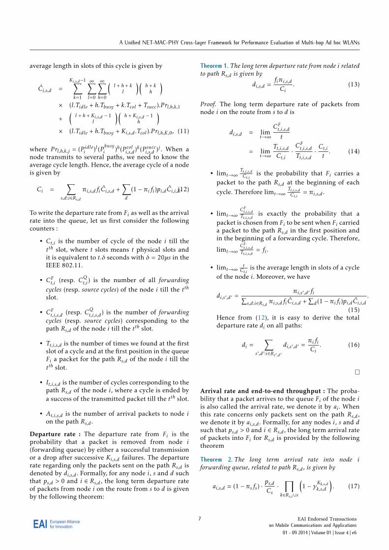
Departure rate : The departure rate from Fi is theprobability that a packet is removed from node i(forwarding queue) by either a successful transmissionor a drop after successive Ki,s,d failures. The departurerate regarding only the packets sent on the path Rs,d isdenoted by di,s,d . Formally, for any node i, s and d suchthat ps,d > 0 and i ∈ Rs,d , the long term departure rateof packets from node i on the route from s to d is givenby the following theorem:
Theorem 1. The long term departure rate from node i relatedto path Rs,d is given by
di,s,d =fiπi,s,dCi
. (13)
Proof. The long term departure rate of packets fromnode i on the route from s to d is
di,s,d = limt→∞
CFt,i,s,dt
= limt→∞
Tt,i,s,dCt,i
·CFt,i,s,dTt,i,s,d
·Ct,it. (14)
• limt→∞Tt,i,s,dCt,i
is the probability that Fi carries apacket to the path Rs,d at the beginning of eachcycle. Therefore limt→∞
Tt,i,s,dCt,i
= πi,s,d .
• limt→∞CFt,i,s,dTt,i,s,d
is exactly the probability that apacket is chosen from Fi to be sent when Fi carrieda packet to the path Rs,d in the first position andin the beginning of a forwarding cycle. Therefore,
limt→∞CFt,i,s,dTt,i,s,d
= fi .
• limt→∞tCt,i
is the average length in slots of a cycleof the node i. Moreover, we have
di,s′ ,d′ =πi,s′ ,d′ fi∑
s,d:i∈Rs,d πi,s,dfiCi,s,d +∑d(1 − πifi)pi,dCi,i,d
.
(15)Hence from (12), it is easy to derive the totaldeparture rate di on all paths:
di =∑
s′ ,d′ :i∈Rs′ ,d′di,s′ ,d′ =
πifiCi
. (16)
Arrival rate and end-to-end throughput : The proba-bility that a packet arrives to the queue Fi of the node iis also called the arrival rate, we denote it by ai . Whenthis rate concerns only packets sent on the path Rs,d ,we denote it by ai,s,d . Formally, for any nodes i, s and dsuch that ps,d > 0 and i ∈ Rs,d , the long term arrival rateof packets into Fi for Rs,d is provided by the followingtheorem
Theorem 2. The long term arrival rate into node iforwarding queue, related to path Rs,d , is given by
ai,s,d = (1 − πsfs) ·ps,dCs·
∏k∈Rs,i∪s
(1 − γKk,s,dk,s,d
). (17)
7EAI for InnovationEuropean Alliance EAI Endorsed Transactions
on Mobile Communications and Applications 01 - 09 2014 | Volume 01 | Issue 4 | e6
R. El-Azouzi et al.
Proof. The long term arrival rate of packets into Fi forRs,d is
ai,s,d = limt→∞
At,i,s,dt
= limt→∞
CQt,sCt,s·CQt,s,s,d
CQt,s·Ct,st·It,s,s,d
CQt,s,s,d·At,i,s,dIt,s,s,d
. (18)
• limt→∞CQt,sCt,s
= 1 − CFt,sCt,s
= 1 − πsfs is exactly theprobability to get a source cycle, i.e., to send apacket from the queue Qs.
• limt→∞CQt,s,s,d
CQt,sis the probability to choose the
path Rs,d to send a packet from Qs. Therefore,
limt→∞CQt,s,s,d
CQt,s= ps,d .
• limt→∞Ct,st = 1
Cs.
• limt→∞It,s,s,d
CQt,s,s,dis the probability that a source cycle
on the path Rs,d ends with a success, i.e., thepacket sent fromQs is received on the queue Fjs,s,d .
Therefore, limt→∞It,s,s,d
CQt,s,s,d= 1 − γKs,s,ds,s,d .
• limt→∞At,i,s,dIt,s,s,d
is the probability that a packetreceived on the node js,s,d is also received on thequeue Fi of the node i. For that, this packet needsto be received by all the nodes in the set Rs,i ∪ s.Therefore, lim
t→∞At,i,s,dIt,s,s,d
=∏
k∈Rs,i∪s
(1 − γKk,s,dk,s,d
).
Consequently, the result of the theorem holds.
End-to-end throughput : The global arrival rate atFi is ai =
∑s,d:i∈Rs,d ai,s,d . Remark that when the node
i is the final destination of a path Rs,d , then ad,s,drepresents the end-to-end average throughput of aconnection from s to d. Practically, ad,s,d is the numberof delivered (to destination) packet per slot. Let ρ be thebit rate in bits/s of the wireless network. Therefore, thethroughput in bits/s can be written as follows:
thps,d = ad,s,d · P ayload · ρ. (19)
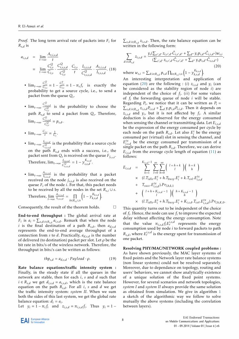
Rate balance equations/traffic intensity system :Finally, in the steady state if all the queues in thenetwork are stable, then for each i, s and d such thati ∈ Rs,d we get di,s,d = ai,s,d , which is the rate balanceequation on the path Rs,d . For all i, s and d we getthe traffic intensity system: system II. When we sumboth the sides of this last system, we get the global ratebalance equation: di = ai .Let yi = 1 − πifi and zi,s,d = πi,s,dfi . Thus yi = 1 −
∑s,d:i∈Rs,d zi,s,d . Then, the rate balance equation can be
written in the following form:∑d:i∈Rs,d
zi,s,d =ys(
∑s′ ,d′ zi,s′ ,d′ Ci,s′ ,d′ +
∑d” yipi,d”Ci,i,d”)ws,i
(∑s′ ,d′ zs,s′ ,d′ Cs,s′ ,d′ +
∑d” ysps,d”Cs,s,d”)
,
(20)
where ws,i =∑d:i∈Rs,d ps,d
∏k∈Rs,i∪s
(1 − γKk,s,dk,s,d
).
An interesting interpretation and application ofequation (20) are the following : (i) zi,s,d and yi (canbe considered as the stability region of node i) areindependent of the choice of fi . (ii) For some valuesof fi the forwarding queue of node i will be stable.Regarding Pi , we notice that it can be written as Pi =∑s,d:i∈Rs,d zi,s,dPi,s,d +
∑d yipi,dPi,i,d . Then it depends on
zi,s,d and yi , but it is not affected by fi . A similardeduction is also observed for the energy consumedwhen sensing the channel or transmitting data. Let Ei,s,dbe the expression of the energy consumed per cycle byeach node on the path Rs,d . Let also Esi be the energyconsumed per (virtual) slot in sensing the channel, andEtxi,s,d be the energy consumed per transmission of asingle packet on the path Rs,d . Therefore, we can deriveEi,s,d from the average cycle length of equation (11) asfollows:
Ei,s,d =Ki,s,d−1∑k=1
∞∑l=0
∞∑h=0
(l + h + k
l
) (h + kh
)× (l.Tidle.E
si + h.Tbusy .E
si + k.Tcol .E
txi,s,d
+ Tsucc.Etxi,s,d).P rl,h,k,1
+(l + h + Ki,s,d − 1
l
) (h + Ki,s,d − 1
h
)× (l.Tidle.E
si + h.Tbusy .E
si + Ki,s,d .Tcol .E
txi,s,d).P rl,h,K,0.
This quantity turns out to be independent of the choiceof fi . Hence, the node can use fi to improve the expecteddelay without affecting the energy consumption. Notethat the value πi,s,dfiE
i,s,dr represents the energy
consumption used by node i to forward packets to pathRs,d , where Ei,s,dr is the energy spent for transmission ofone packet.
Resolving PHY/MAC/NETWORK coupled problems :As have shown previously, the MAC layer systems offixed points and the Network layer rate balance systems(non linear systems) could not be resolved separately.Moreover, due to dependance on topology, routing andusers’ behaviors, we cannot show analytically existenceof a unique solution of the fixed point systems.However, for several scenarios and network topologies,system I and system II always provide the same solutionas obtained from simulation. We give in algorithm 1a sketch of the algorithmic way we follow to solvemutually the above systems (including the correlationbetween layers).
8EAI for InnovationEuropean Alliance EAI Endorsed Transactions
on Mobile Communications and Applications 01 - 09 2014 | Volume 01 | Issue 4 | e6
A Unified NET-MAC-PHY Cross-layer Framework for Performance Evaluation of Multi-hop Ad hoc WLANs
Algorithm 1 : Joint fixed point and rate balanceresolution
Require: π0i,s,d = εi,s,d , δi,s,d : convergence indicator of
path Rs,d1: for each source s, relay i and destination d do
2: while∣∣∣∣∣πt+1
i,s,d−πti,s,d
πti,s,d
∣∣∣∣∣ ≥ δi,s,d do
3: Compute Pi,s,d using fixed point such as [8]4: Update γi,s,d using equation (9)5: Estimate cycles size using equation (12)6: Update πt+1
i,s,d by solving the rate balancesystem (20) using for example the Gaussianelimination method
7: end while8: end for
Special Cases : For sure the system I and system II arecomplicated to solve and computational expensive. Forthat, special cases are important and would facilitatethe analysis of the systems and can be useful and easyto use in numerical results. As we have mentionedpreviously, Pi,s,d and γi,s,d need to be found jointly withπi,s,d . This is due to the traffic asymmetry. Furthermore,the average cycle length Ci is a function of πi,s,d . Thisalso complicate the calculation of πi,s,d , when Pi,s,d andγi,s,d are given. Therefore, two special cases can bedistinguished as follows:
• Uniform traffic distribution and symmetric topol-ogy: γi,s,d ≡ γi and Pi,s,d ≡ Pi . Also, Ci ≡ Ci,s,d .
• Uniform traffic distribution and asymmetrictopology: γi,s,d , γi and Pi,s,d , Pi . Also,Ci , Ci,s,d ,except the case where the routing at each nodechooses the same next hop to route packets for allpaths Rs,d .
In these two cases, the System I is independent of πi,s,d ,i.e., System I and system II are decoupled. Therefore,we can find the attempt and collision probabilities inSystem I, and then calculate the traffic intensity. Inaddition, the system II becomes a linear system that canbe solved easily. Therefore, the system II can be writtenas:
1 − yi =∑s
ysws,i , (21)
where
ws,i =∑
d:i∈Rs,d
Psps,dCi,s,d∏k∈Rs,i
(1 − γKk,s,dk,s,d
). (22)
Therefore, we can write it in a matrix form:
y(I + W ) = 1, (23)
where W is an N ×N matrix whose (s, i)th entry is ws,i(independent on yi) and y is a N−dimensional row
vector. In addition, system I will be simplified whenno hidden nodes are found in the network. This casecan happen when the interference area of receivers j isincluded in the carrier sense area of each sender i, i.e.,Ij \ CSi = ∅. This imply that γi,s,d is independent of thevirtual slot ∆i,s,d .
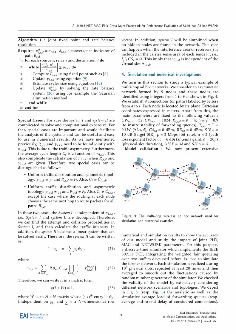
4. Simulation and numerical investigationsWe turn in this section to study a typical example ofmulti-hop ad hoc networks. We consider an asymmetricnetwork formed by 9 nodes and these nodes areidentified using integers from 1 to 9 as shown in Fig. 4.We establish 9 connections (or paths) labeled by lettersfrom a to i. Each node is located by its plane Cartesiancoordinates expressed in meters. Apart from this, themain parameters are fixed to the following values :CWmin = 32, CWmax = 1024, Ki,s,d ≡ K = 4, fi ≡ f = 0.9(to insure stability of forwarding queues), Ti,s,d ≡ T =0.1W (∀i, s, d), CSth = 0 dBm, RXth = 0 dBm, SIRth =10 dB (target SIR), ρ = 2 Mbps (bit rate), α = 2 (pathloss exponent factor), c = 6 dBi (antenna gain), δ = 20µs(physical slot duration), DISF = 3δ and SIFS = δ.
Model validation : We now present extensive
Figure 4. The multi-hop wireless ad hoc network used forsimulation and numerical examples.
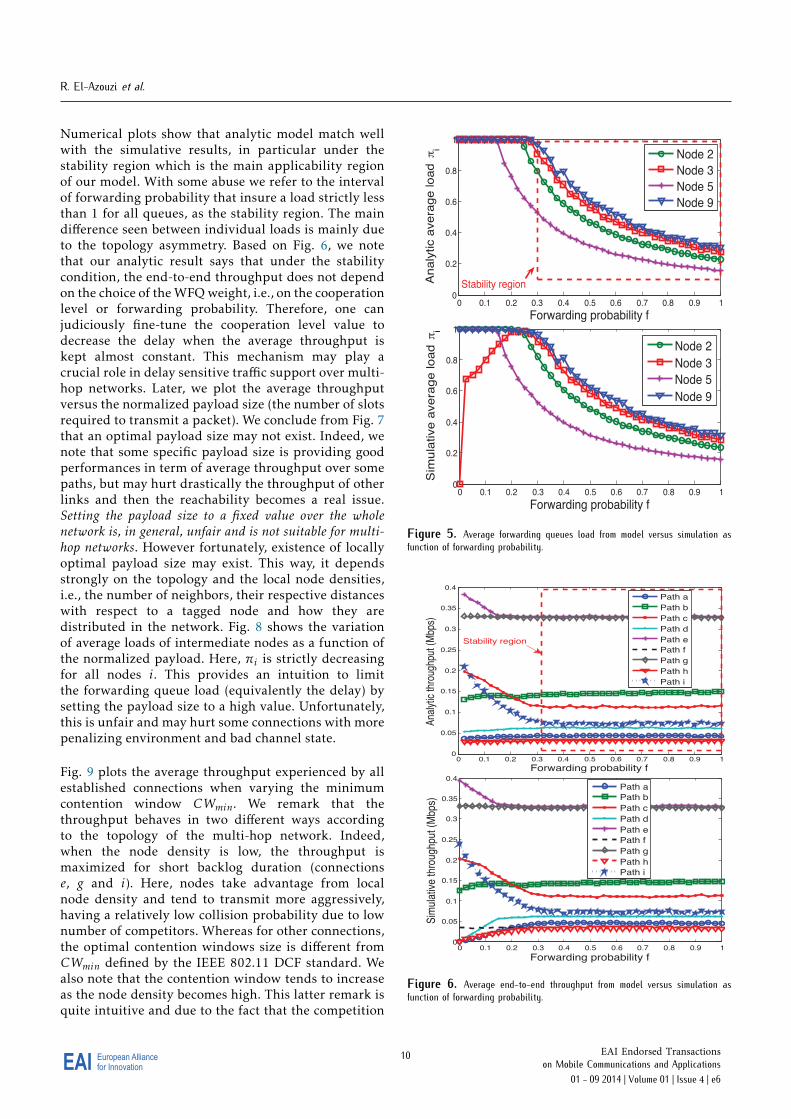
numerical and simulation results to show the accuracyof our model and study the impact of joint PHY,MAC and NETWORK parameters. For this purpose,a discrete time simulator which implements the IEEE802.11 DCF, integrating the weighted fair queueingover two buffers discussed before, is used to simulatethe former network. Each simulation is realized during106 physical slots, repeated at least 20 times and thenaveraged to smooth out the fluctuations caused byrandom number generator of the simulator. We checkedthe validity of the model by extensively consideringdifferent network scenarios and topologies. We depictin Fig. 5 (resp. Fig. 6) the analytic as well as thesimulative average load of forwarding queues (resp.average end-to-end delay of considered connections).
9EAI for InnovationEuropean Alliance EAI Endorsed Transactions
on Mobile Communications and Applications 01 - 09 2014 | Volume 01 | Issue 4 | e6
R. El-Azouzi et al.
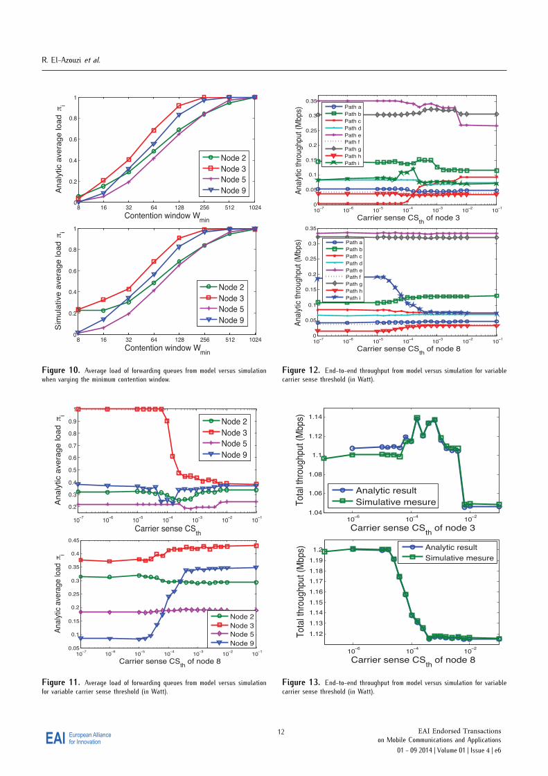
Numerical plots show that analytic model match wellwith the simulative results, in particular under thestability region which is the main applicability regionof our model. With some abuse we refer to the intervalof forwarding probability that insure a load strictly lessthan 1 for all queues, as the stability region. The maindifference seen between individual loads is mainly dueto the topology asymmetry. Based on Fig. 6, we notethat our analytic result says that under the stabilitycondition, the end-to-end throughput does not dependon the choice of the WFQ weight, i.e., on the cooperationlevel or forwarding probability. Therefore, one canjudiciously fine-tune the cooperation level value todecrease the delay when the average throughput iskept almost constant. This mechanism may play acrucial role in delay sensitive traffic support over multi-hop networks. Later, we plot the average throughputversus the normalized payload size (the number of slotsrequired to transmit a packet). We conclude from Fig. 7that an optimal payload size may not exist. Indeed, wenote that some specific payload size is providing goodperformances in term of average throughput over somepaths, but may hurt drastically the throughput of otherlinks and then the reachability becomes a real issue.Setting the payload size to a fixed value over the wholenetwork is, in general, unfair and is not suitable for multi-hop networks. However fortunately, existence of locallyoptimal payload size may exist. This way, it dependsstrongly on the topology and the local node densities,i.e., the number of neighbors, their respective distanceswith respect to a tagged node and how they aredistributed in the network. Fig. 8 shows the variationof average loads of intermediate nodes as a function ofthe normalized payload. Here, πi is strictly decreasingfor all nodes i. This provides an intuition to limitthe forwarding queue load (equivalently the delay) bysetting the payload size to a high value. Unfortunately,this is unfair and may hurt some connections with morepenalizing environment and bad channel state.
Fig. 9 plots the average throughput experienced by allestablished connections when varying the minimumcontention window CWmin. We remark that thethroughput behaves in two different ways accordingto the topology of the multi-hop network. Indeed,when the node density is low, the throughput ismaximized for short backlog duration (connectionse, g and i). Here, nodes take advantage from localnode density and tend to transmit more aggressively,having a relatively low collision probability due to lownumber of competitors. Whereas for other connections,the optimal contention windows size is different fromCWmin defined by the IEEE 802.11 DCF standard. Wealso note that the contention window tends to increaseas the node density becomes high. This latter remark isquite intuitive and due to the fact that the competition
0 0.1 0.2 0.3 0.4 0.5 0.6 0.7 0.8 0.9 10
0.2
0.4
0.6
0.8
1
Analy
tic a
vera
ge load π
i
Forwarding probability f
Node 2
Node 3
Node 5
Node 9
Stability region
0 0.1 0.2 0.3 0.4 0.5 0.6 0.7 0.8 0.9 10
0.2
0.4
0.6
0.8
1
Sim
ula
tive a
vera
ge load π
i
Forwarding probability f
Node 2
Node 3
Node 5
Node 9
Figure 5. Average forwarding queues load from model versus simulation asfunction of forwarding probability.
0 0.1 0.2 0.3 0.4 0.5 0.6 0.7 0.8 0.9 10
0.05
0.1
0.15
0.2
0.25
0.3
0.35
0.4
Ana
lytic
thro
ughp
ut (
Mbp
s)
Forwarding probability f
Path a
Path b
Path c
Path d
Path e
Path f
Path g
Path h
Path i
Stability region
0 0.1 0.2 0.3 0.4 0.5 0.6 0.7 0.8 0.9 10
0.05
0.1
0.15
0.2
0.25
0.3
0.35
0.4
Sim
ulat
ive
thro
ughp
ut (
Mbp
s)
Forwarding probability f
Path a
Path b
Path c
Path d
Path e
Path f
Path g
Path h
Path i
Figure 6. Average end-to-end throughput from model versus simulation asfunction of forwarding probability.
10EAI for InnovationEuropean Alliance EAI Endorsed Transactions
on Mobile Communications and Applications 01 - 09 2014 | Volume 01 | Issue 4 | e6

A Unified NET-MAC-PHY Cross-layer Framework for Performance Evaluation of Multi-hop Ad hoc WLANs
becomes colossal. In terms of queue load (equivalentlydelay), it is clear that when the contention windowincreases it implies the increase of queue load andhenceforth tagged node may suffer from huge delay.
100
101
102
0
0.5
1
1.5
Ana
lytic
thro
ughp
ut (
Mbp
s)
Payload size (in slots)
Path a
Path b
Path c
Path d
Path e
Path f
Path g
Path h
Path i
100
101
102
0
0.5
1
1.5
Sim
ulat
ive
thro
ughp
ut (
Mbp
s)
Payload size (in slots)
Path a
Path b
Path c
Path d
Path e
Path f
Path g
Path h
Path i
Figure 7. Average end-to-end throughput from model versus simulation whenvarying the payload size.
Per path power and carrier sense control : Wereconsider here the Spanning tree-based algorithmproposed in [9]. Each node sets its transmission powerto a level that allows reaching the farthest neighbor, i.e.,the received power is at least equal to the receiversensitivity. Consequently, this per path power controlmay improve the spatial reuse. In order to analyzethe impact of carrier sense threshold on networkperformances, we will vary CSth for some tagged nodeand fix it to the default value, i.e., CSth = 0 dBm. Weplot in Fig. 12 the average throughput of all pathswhen varying the carrier sense threshold of node 3which is located in a relatively dense subnetwork. Wenote that the throughput of all connections continuesto decrease (in particular connections crossing node3 or its immediate neighbors) with CSth exceptconnections originated from node 3. Now we analyzethe interplay of node 8 (in a low dense subnetwork)carrier sense on network performances. We note thatthe only negatively impacted connection is connection ioriginated from node 9 (immediate neighbor of node 8).When carrier sense of node 8 is increasing, it becomesmore nose-tolerable which implies a more transmission
100
101
102
103
10−20
10−15
10−10
10−5
100
An
aly
tic a
ve
rag
e lo
ad
πi
Payload size (in slots)
Node 2
Node 3
Node 5
Node 9
100
101
102
103
10−5
10−4
10−3
10−2
10−1
100
Sim
ula
tive a
vera
ge load π
i
Payload size (in slots)
Node 2
Node 3
Node 5
Node 9
Figure 8. Average load of forwarding queues from model versus simulationwhen varying the payload size.
101
102
103
10−4
10−3
10−2
10−1
100
Ana
lytic
thro
ughp
ut (
Mbp
s)
Contention window Wmin
Path a
Path b
Path c
Path d
Path e
Path f
Path g
Path h
Path i
101
102
103
10−3
10−2
10−1
100
Sim
ulat
ive
thro
ughp
ut (
Mbp
s)
Contention window Wmin
Path a
Path b
Path c
Path d
Path e
Path f
Path g
Path h
Path i
Figure 9. Average end-to-end throughput from model versus simulation whenvarying the minimum contention window.
11EAI for InnovationEuropean Alliance EAI Endorsed Transactions
on Mobile Communications and Applications 01 - 09 2014 | Volume 01 | Issue 4 | e6
R. El-Azouzi et al.
8 16 32 64 128 256 512 10240
0.2
0.4
0.6
0.8
1
An
aly
tic a
ve
rag
e lo
ad
π
i
Contention window Wmin
Node 2
Node 3
Node 5
Node 9
8 16 32 64 128 256 512 10240
0.2
0.4
0.6
0.8
1
Sim
ula
tive
ave
rage
lo
ad
πi
Contention window Wmin
Node 2
Node 3
Node 5
Node 9
Figure 10. Average load of forwarding queues from model versus simulationwhen varying the minimum contention window.
10−7
10−6
10−5
10−4
10−3
10−2
10−1
0.2
0.3
0.4
0.5
0.6
0.7
0.8
0.9
1
Analy
tic a
vera
ge load π
i
Carrier sense CSth
Node 2
Node 3
Node 5
Node 9
10−7
10−6
10−5
10−4
10−3
10−2
10−1
0.05
0.1
0.15
0.2
0.25
0.3
0.35
0.4
0.45
An
aly
tic a
vera
ge
loa
d π
i
Carrier sense CSth
of node 8
Node 2
Node 3
Node 5
Node 9
Figure 11. Average load of forwarding queues from model versus simulationfor variable carrier sense threshold (in Watt).
10−7
10−6
10−5
10−4
10−3
10−2
10−1
0
0.05
0.1
0.15
0.2
0.25
0.3
0.35
Analy
tic thro
ughput (M
bps)
Carrier sense CSth
of node 3
Path a
Path b
Path c
Path d
Path e
Path f
Path g
Path h
Path i
10−7
10−6
10−5
10−4
10−3
10−2
10−1
0
0.05
0.1
0.15
0.2
0.25
0.3
0.35
An
aly
tic t
hro
ug
hp
ut (M
bp
s)
Carrier sense CSth
of node 8
Path a
Path b
Path c
Path d
Path e
Path f
Path g
Path h
Path i
Figure 12. End-to-end throughput from model versus simulation for variablecarrier sense threshold (in Watt).
10−6
10−4
10−2
1.04
1.06
1.08
1.1
1.12
1.14
To
tal t
hro
ug
hp
ut
(Mb
ps)
Carrier sense CSth
of node 3
Analytic result
Simulative mesure
10−6
10−4
10−2
1.12
1.13
1.14
1.15
1.16
1.17
1.18
1.19
1.2
To
tal t
hro
ug
hp
ut
(Mb
ps)
Carrier sense CSth
of node 8
Analytic result
Simulative mesure
Figure 13. End-to-end throughput from model versus simulation for variablecarrier sense threshold (in Watt).
12EAI for InnovationEuropean Alliance EAI Endorsed Transactions
on Mobile Communications and Applications 01 - 09 2014 | Volume 01 | Issue 4 | e6
A Unified NET-MAC-PHY Cross-layer Framework for Performance Evaluation of Multi-hop Ad hoc WLANs
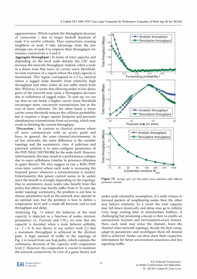
aggressiveness. Which explain the throughput decreaseof connection i due to larger backoff duration ofnode 9 to resolve collision. Thus connections crossingneighbors of node 9 take advantage from the lowattempt rate of node 9 to improve their throughput, forinstance connections a, b and h.Aggregate throughput : In terms of total capacity anddepending on the local node density, the CSC mayincrease the network throughput. Indeed, when a nodein a dense zone fine-tunes its carrier sense threshold,we note existence of a region where the total capacity ismaximized. This region correspond to a CSth intervalwhere a tagged node benefits from relatively highthroughput and other nodes do not suffer much fromthis. Whereas, it seems that allowing nodes in low denseparts of the network may cause a throughput decreasedue to selfishness of tagged nodes. To sum up, we cansay that on one hand, a higher carrier sense thresholdencourages more concurrent transmissions but at thecost of more collisions. On the other hand, a lowercarrier sense threshold reduces the collision probabilitybut it requires a larger spatial footprint and preventssimultaneous transmissions from occurring, which mayresult in limiting the system throughput.Discussion : In contrast to classical systems where
all users communicate with an access point andhave, in general, the same channel/environment, inad hoc networks, the main difference is the variabletopology and the asymmetric view. A judicious andpunctual solution is to auto-configure parameters ofthe PHY/MAC/NETWORK by the node itself. Howeverunfortunately, this may result in a performance collapsedue to users selfishness (similar to prisoners dilemmain game theory). We also suggest to run a MAC/PHYcross-layer control where each node is increasing thetransmit power whenever a retransmission is needed.Unfortunately, this power control seems to be unfairsince the benefit is strongly depending on the topology.Due to asymmetry, many nodes take benefit from thispolicy but others may hardly suffer from it. To sum up,under topology asymmetry, the problem is not how tochoose parameters such as the network may operate inan optimal way; but the problem is how to define acooperation level and a trade-off between end-to-endthroughput and delay.Analyzing Fig. 14 where the behavior of the totalcapacity is depicted as a function of nodes intrinsicparameters (fi , P ayloadi and CWi), we note that thecapacity is maximal when a node behaves selfishly,i.e., f = 0. It was shown in our earlier work [7] thata maximum throughput is achieved in the shortestpath. A high amount of traffic in the topology ofFig. 4 is issued from one hop paths, which explains thecontinuous decrease of the capacity with cooperationlevel f . However, the cooperation is crucial to maintainthe network connectivity. In view of a game theory and
0 0.2 0.4 0.6 0.8 11.15
1.2
1.25
1.3
1.35
1.4
Tota
l thro
ughput (M
bps)
Forwarding probability f
Analytic throughput
Simulative throughput
100
101
102
103
0.5
1
1.5
2
2.5
Tota
l thro
ughput (M
bps)
Payload size (in slots)
Analytic throughput
Simulative throughput
8 16 32 64 128 256 512 10240
0.5
1
1.5
2
2.5
3
Tota
l th
roughput (M
bps)
Contention window Wmin
Analytic throughput
Simulative throughput
Figure 14. Average cycle size from model versus simulation under differentparameters variation.
under node rationality assumption, if a node refuses toforward packets of neighboring nodes then the othermay behave similarly. As a result the total capacitymay fall down drastically and delay may go to infinity(very large waiting time in intermediate buffers). Achallenging but promising concept is then to enable anautonomous location and environment-aware feature.Here, each node may sense the channel, learn thechannel state/network topology, decide the best setup,adapt its parameters and reconfigure them till desiredQoS is achieved. Nodes can then share their respectiveinformation for better environment awareness and lesssignaling traffic.
13EAI for InnovationEuropean Alliance EAI Endorsed Transactions
on Mobile Communications and Applications 01 - 09 2014 | Volume 01 | Issue 4 | e6
R. El-Azouzi et al.
5. ConclusionIn multi-hop ad hoc network, a stack of protocols wouldinteract with each other to accomplish a successfulpacket transfer. In this context, we have developed across-layered model built on the IEEE 802.11e EDCFstandard. We studied the effect of forwarding onend-to-end performances for saturated networks. Wehave discovered that the modeling of the IEEE 802.11in this context is not yet mature in the literature andto the best of our knowledge, there is no study donewhich considers jointly the PHY/MAC/NETWORKinteraction in a non-uniform traffic and a generalnetwork topology. This has led us to build a generalframework using the perspective of individual senders.The attempt and collision probabilities are nowfunctions of the traffic intensity, on topology and onrouting decision. The fixed point system I is indeedrelated to the traffic intensity system II.
This paper opens many interesting directions tostudy in future such as power control and delay-based admission control with guaranteed throughput.Moreover, we will deal with the issue of cooperationbetween nodes in a game theoretical perspective. Inaddition, our proposal could be easily extended for veryhigh data rate IEEE 802.11n or the future standard IEEE802.11ac.
References[1] B. Alawieh, C. Assi, H.T. and Mouftah. Investigation of
power-aware IEEE 802.11 performance in multi-hop adhoc networks. In Proceedings of International Conferenceon Mobile Ad-hoc and Sensor Networks (MSN), pages409-420, 2007.
[2] Alizadeh-Shabdiz, F., and Subramaniam, S.: Analyticalmodels for single-hop and multi-hop ad hoc networks.Mob. Netw. Appl., 11(1):75-90, 2006.
[3] Baras, J. S., Tabatabaee, V., Papageorgiou, G., and Rentz,N.: Modelling and optimization for multi-hop wirelessnetworks using fixed point and automatic differentiation.In WiOpt 2008, 6th IEEE International Symposium onModeling and Optimization in Mobile, Ad Hoc, andWireless Networks, March 31 - April 4 2008.
[4] Y. Barowski S. Biaz and P. Agrawal. Towards theperformance analysis of IEEE 802.11 in multi-hopad-hoc networks. In Proceedings of IEEE WirelessCommunications and Networking Conference (WCNC),pages 100-106, March 2005.
[5] G. Bianchi. Performance analysis of the IEEE 802.11distributed coordination function. IEEE Journal onSelected Areas in Communications, Volume 18(3), pages535-547, 2000.
[6] J. Camp, E. Aryafar and E. Knightly. Coupled 802.11Flows in Urban Channels: Model and ExperimentalEvaluation. In INFOCOM, San Diego, CA, March 2010.
[7] A. Kherani, R. El-Khoury, R. El-Azouzi and E. Altman.Stability-throughput tradeoff and routing in multi-hopwireless ad-hoc networks. Computer Networks, volume52(7), pages 1365-1389, 2008.
[8] A. Kumar, E. Altman, D. Miorandi and M. Goyal. Newinsights from a fixed point analysis of single cell IEEE802.11WLANs. In INFOCOM, pages 1550-1561, 2005.
[9] N. Li, J. C. Hou and L. Sha. Design and analysis ofa MST-based distributed topology control algorithm forwireless ad-hoc networks. IEEE Transactions on WirelessCommunications, volume 4(3), pages 1195-1207, 2005.
[10] K. Medepalli and F.A.Tobagi. Towards performancemodeling of IEEE 802.11 based wireless networks: Aunified framework and its applications. In Proceedings ofIEEE INFOCOM, 2006.
[11] V. Ramaiyan, A. Kumar and E. Altman. Fixed point anal-ysis of single cell IEEE 802.11e WLANs: uniqueness, mul-tistability and throughput differentiation. SIGMETRICSPerformance Evaluation Review, Volume 33(1), pages 109-120, 2005.
[12] He, J., and Pung H.K.: Performance modelling andevaluation of IEEE 802.11 distributed coordinationfunction in multihop wireless networks. ComputerCommunications, 29(9):1300-1308, 2006.
[13] T. Sakurai and H.L. Vu. Mac access delay of IEEE 802.11DCF. IEEE Transactions on Wireless Communications,volume 6(5), pages 1702-1710, 2007.
[14] Vassis, D., and Kormentzas, G.: Performance analysis ofIEEE 802.11 ad hoc networks in the presence of hiddenterminals. Computer Networks, 51(9):2345-2352, 2007.
[15] Vassis, D., and Kormentzas, G.: Performance analysis ofIEEE 802.11 ad hoc networks in the presence of exposedterminals. Ad Hoc Networks, Volume 6(3), pages 474-482,2008.
[16] Yang, Y., Hou, V., and Kung, L.C.: Modeling the effect oftransmit power and physical carrier sense in multi-hopwireless networks. In Proceedings of IEEE INFOCOM,2007.
[17] Zhu, Y., Huang, M., Chen, S. Wang, Y.: Cooperativeenergy spanners: Energy-efficient topology control incooperative ad hoc networks. In Proceedings IEEE of IEEEINFOCOM, Pages 231-235, Shanghai, China, 10-15 April2011.
[18] Li, C., and Dai, H.: On the Throughput Scaling ofCognitive Radio Ad Hoc Networks. In proceeding ofINFOCOM, , Pages 241-245, Shanghai, China, 10-15 April2011.
[19] Chu X., and Sethu, H.: Cooperative Topology Controlwith Adaptation for Improved Lifetime in Wireless AdHoc Networks. In Proceedings IEEE of IEEE INFOCOM,Pages 262-270, Orlando, Florida, USA, 25-30 March 2012.
14EAI for InnovationEuropean Alliance EAI Endorsed Transactions
on Mobile Communications and Applications 01 - 09 2014 | Volume 01 | Issue 4 | e6
Copyright © 2022 FDOKUMEN