Improving the MAC Layer of Multi-Hop Networks
34
Improving the MAC Layer of Multi-Hop Networks Marceau Coupechoux Alcatel Research & Innovation and Institut Eurecom, France ([email protected]) Bruno Baynat Universit´ e de Paris Pierre et Marie Curie, France Thierry Lestable Alcatel Research & Innovation and Sup´ elec, France Vinod Kumar Alcatel Research & Innovation, France Christian Bonnet Institut Eurecom, France November 3. 2003 Abstract. Ad hoc and multi-hop networks will probably be part of the fourth gener- ation of wireless networks, which will integrate networks of several size and capacities with heterogeneous coverage: cellular networks (3G), WLAN hot spots, Wireless Personal Area Networks (WPAN) and Wireless Body Area Networks (WBAN). In this context, MAC protocols play a deciding role for a high utilization of the wireless channel. In this paper, several issues of the MAC layer and concepts for the definition of a new MAC protocol are presented. These concepts include synchronization, multi-user diversity, and multi-packet reception. It is shown that all these techniques can drastically increase the capacity of the MAC layer for multi-hop networks. Keywords: Ad hoc networks, multi-hop networks, MAC protocols, synchronization, multi-user diversity, multi-user detection, multi-packet reception, slotted protocols, TDMA, mobility. 1. Introduction In recent years a lot of effort has been spent in the design of protocols for mobile ad hoc networks. Such packet networks are mobile, multi- hop and operate without any fixed infrastructure. This represents a low cost and easily deployable technology to provide high speed Internet access in a wireless environment, to organize networks of sensors, or even to complement the coverage of future cellular networks. In this paper, a special attention is paid to the Medium Access Con- trol (MAC) sub-layer. It has a lot of impact on the system performance and its design is a very challenging issue. MAC should control access to the medium and share the channel between source-destination pairs and/or flows of data in a dynamic and distributed way. Some desir- c 2004 Kluwer Academic Publishers. Printed in the Netherlands. wirelesscom.tex; 30/09/2004; 11:32; p.1
Transcript of Improving the MAC Layer of Multi-Hop Networks

Improving the MAC Layer of Multi-Hop Networks
Marceau CoupechouxAlcatel Research & Innovation and Institut Eurecom, France([email protected])
Bruno BaynatUniversite de Paris Pierre et Marie Curie, France
Thierry LestableAlcatel Research & Innovation and Supelec, France
Vinod KumarAlcatel Research & Innovation, France
Christian BonnetInstitut Eurecom, France
November 3. 2003
Abstract. Ad hoc and multi-hop networks will probably be part of the fourth gener-ation of wireless networks, which will integrate networks of several size and capacitieswith heterogeneous coverage: cellular networks (3G), WLAN hot spots, WirelessPersonal Area Networks (WPAN) and Wireless Body Area Networks (WBAN). Inthis context, MAC protocols play a deciding role for a high utilization of the wirelesschannel. In this paper, several issues of the MAC layer and concepts for the definitionof a new MAC protocol are presented. These concepts include synchronization,multi-user diversity, and multi-packet reception. It is shown that all these techniquescan drastically increase the capacity of the MAC layer for multi-hop networks.
Keywords: Ad hoc networks, multi-hop networks, MAC protocols, synchronization,multi-user diversity, multi-user detection, multi-packet reception, slotted protocols,TDMA, mobility.
1. Introduction
In recent years a lot of effort has been spent in the design of protocolsfor mobile ad hoc networks. Such packet networks are mobile, multi-hop and operate without any fixed infrastructure. This represents a lowcost and easily deployable technology to provide high speed Internetaccess in a wireless environment, to organize networks of sensors, oreven to complement the coverage of future cellular networks.
In this paper, a special attention is paid to the Medium Access Con-trol (MAC) sub-layer. It has a lot of impact on the system performanceand its design is a very challenging issue. MAC should control accessto the medium and share the channel between source-destination pairsand/or flows of data in a dynamic and distributed way. Some desir-
c© 2004 Kluwer Academic Publishers. Printed in the Netherlands.
wirelesscom.tex; 30/09/2004; 11:32; p.1

2 M. Coupechoux et al.
able features of the access protocol are: to be able to reuse the radioresources as efficiently as possible, to avoid congestion and collisions,to be fair, reliable, and energy efficient.
Many MAC protocols try to address these issues. In the literature,two categories of schemes have been proposed:
1. the contention based schemes
2. the conflict-free schemes
In the contention based protocols, the channel has to be acquired bythe nodes for each packet to be transmitted. Examples of contentionbased schemes are CSMA/CA [32], MACA [29], MACAW [5], FAMA[16], and IEEE 802.11 [1]. The latter seems to be very popular in mostof the testbeds because IEEE 802.11 family products are available offthe shelf. Although IEEE 802.11 is flexible, robust and simple, a recentpaper [41] claims that it may not do very well in a multi-hop envi-ronment. According to [41], 802.11 is impacted by the hidden terminalproblem, does not handle the exposed terminal problem at all and itsbackoff strategy leads to severe unfairness in a multi-hop environment.
On the other hand, conflict-free protocols allow the reservation ofthe channel for a certain amount of time or data, and transmissionsare thus conflict-free. TDMA deterministic scheduling may be pre-ferred for networks with heavy load, carrying mixed traffic and realizingsophisticated functions at higher layers. That is the reason why aslot allocation protocol for mobile ad hoc networks, called CROMA(Collision-free Receiver Oriented MAC), is presented in section 2. Thisprotocol illustrates the capacity increase that can be obtained thanksto synchronization.
Two other concepts are presented for the definition of new MACprotocols for multi-hop networks and illustrate the need for a cross-layer interaction. The first one described in section 3 is the multi-userdiversity, which is illustrated firstly by the evaluation of the capacity ofthe channel aware slotted ALOHA and secondly by the use of mobilityas a source of diversity.
The third and last concept of this paper is the multi-packet re-ception. Section 4 shows that the throughput of the multi-hop slot-ted ALOHA protocol can be greatly increased thanks to multi-packetreception, and in particularly thanks to the multi-user detection.
wirelesscom.tex; 30/09/2004; 11:32; p.2

Improving the MAC Layer of Multi-Hop Networks 3
2. Synchronization
Since the early times of research on ad hoc networks, the node synchro-nization has been seen as a means to reduce or eliminate the numberof collisions and thus to increase the capacity of wireless multi-hopnetworks. A better spatial reuse of the resource is indeed expectedfrom a smart scheduling of the transmissions.
Unfortunately, most of the scheduling problems are NP-complete.For example, Arikan [3] has shown that constructing an optimal re-source assignment in term of throughput is NP-complete for the point-to-point scheduling problem. And this is the same for the broadcastscheduling problem based on throughput optimization, as proved byEphremides and Truong [14]. Consequently, MAC designers have fo-cussed on sub-optimal, dynamic and decentralized solutions for theslot assignment issue.
A first class of scheduling protocols relies on the allocation of prior-ities to nodes. A given slot is assigned preferably to the node with thehighest priority according to its offered traffic. Slots can be allocatedby using a control channel, e.g. in [7]. Priorities of the neighbors areassumed to be known at each node and are allocated in a pseudo-random way as in [4]. Then different strategies can be applied for theallocation of the priorities in order to have a fair and efficient shareof the channel (see e.g. in [31]). However, these protocols suffer from ahigh overhead due to the control channel. Moreover, in some cases, theydo not address the problem of the distributed and dynamic assignmentof priorities.
On the other hand, time-spread protocols seem to be very attractivebecause they are topology-independent (see e.g. in [6] or [22]). However,the frame length makes them less scalable and this class of protocolsalso faces the problem of distributed and dynamic code assignment.
At last, the necessity to address the problem of mobility, topologychanges, and scalability, gives rise to a family of protocols where thereservation of the slots is done via a random access, most of the time ahandshaking, combined with a carrier sensing mechanism. FPRP [42]proposes a five-phase handshaking supported by a pseudo-Bayesian al-gorithm to enable a faster convergence of the reservation procedure.CATA [37] uses four mini-slots in each time-slot to enable unicastand multicast transmissions. The protocol presented in this paper, theCollision-free Receiver Oriented MAC (CROMA), comes within thisfamily of protocols. It tries to make use of the advantages of the mostpopular contention based protocols to a slotted environment in order toincrease their efficiency. In particular, the aim of CROMA is to achieve
wirelesscom.tex; 30/09/2004; 11:32; p.3

4 M. Coupechoux et al.
a high slot utilization, i.e., a high capacity, at high input load thanksto an original reservation and polling scheme.
2.1. Protocol Description
CROMA is a medium access protocol for MANET-like networks thatdynamically schedules transmissions in a slotted environment. It oper-ates on a single-frequency channel with omni-directional antennas. Allnodes are assumed to be synchronized. CROMA is receiver orientedbecause a slot in the frame is associated to a single receiver. More-over, any communication between two nodes must be preceded by apreliminary reservation phase.
In CROMA, time is divided into frames, that are in turn divided intoa fixed number (L) of slots (see Figure 1). Each slot is further dividedin two signaling mini-slots, for request (REQ) and ready-to-receive(RTR), and a information transmission phase (DATA). The REQ-mini-slot is used by requesting nodes during the random access phase toreserve the slot. The RTR-mini-slot is used by their intended receiversto acknowledge requests. After the reservation of the slot, RTR packetsare also used in successive frames to acknowledge data packets and topoll different senders. During the data phase, the sender transmits adata packet of fixed length, eventually obtained after segmentation.
... L-1210
Frame
L slots
REQ RTR DATA
Slot
Figure 1. Frame structure of CROMA
The reservation of a free slot is done via a REQ/RTR dialogue sim-ilar to the traditional RTS/CTS handshake. Then, the transmissionof a data burst is done on the same slot in successive frames. Oncethe connection is established, the sender is no longer required to sendrequests. On the other hand, the receiver sends a RTR at each secondmini-slot to reserve the channel and to prevent the hidden terminaleffect (see [10]). The receiver is said to have got the floor on the slot.The slot is no longer free until the release of the connection.
Now, CROMA allows multiple reservations on the same slot. Thereceiver indeed maintains a list of senders that managed a successfulreservation and will poll them in the successive frames. This feature is
wirelesscom.tex; 30/09/2004; 11:32; p.4

Improving the MAC Layer of Multi-Hop Networks 5
illustrated on Figure 2 that shows two successive reservations on thesame slot i. In frame j, the REQ/RTR dialogue starts the connectionbetween nodes A and B: A sends a REQ with its address. B sends back aRTR, that contains a field to acknowledge the reservation (ackreq), anda field to poll node A (pol). The RTR is also received by node C that isnow aware of a communication on slot i with B as receiver. During thedata phase, A, that has just been polled by B, is allowed to transmit apacket with its address A and a sequence number (sn) 0. B is said tohave got the floor on slot i. In frame j+1, C establishes a connectionwith B. With the RTR, node B acknowledges the reservation with thefield ackreq, acknowledges the packet transmitted by node A in framej, and polls node C. In frame j+2, B now polls A. With the RTR, it alsoacknowledges the data packet of C with sequence number 0. In framej+3, node B polls node C and acknowledges the data packet of A withsequence number 1.
REQ(A to B)
RTR(ackreq A, pol A) RTR(ackreq A, pol A)
REQ(C to B)
BA
Frame j+3, slot i
Frame j+2, slot i
B
A B C
C
C
Fram
e in
dex
DATA(C to B,sn=1)
RTR(ack(A,sn=1), pol C)RTR(ack(A,sn=1), pol C)
RTR(ack(C,sn=0), pol A)
DATA(A to B,sn=1)
RTR(ack(C,sn=0), pol A)
DATA(C to B,sn=0)
RTR(ackreq C, ack(A,sn=0), pol C)RTR(ackreq C, ack(A,sn=0), pol C)
DATA(A to B,sn=0)
A
B C
Frame j+1, slot i
Frame j, slot i
A
Figure 2. Example of two parallel connections on a slot with CROMA
So, RTRs are used by receivers to acknowledge requests, as well asprevious data transmissions, and to poll the senders that managed asuccessful reservation. It is clear that slots are associated to receivers.In that sense, CROMA is receiver-oriented. This feature favores thespatial reuse of resources since only the zone around the receiver has
wirelesscom.tex; 30/09/2004; 11:32; p.5

6 M. Coupechoux et al.
to be secured with respect to collisions [10]. Moreover, the parallelismof connections reduce the number of collisions of control packets andallows finer flow controls and QoS negociations.
These are the basic principles of CROMA; a precise descriptionof the protocol including packet formats, MAC header, reservation,transmission, and release phases, as well as the correctness analysis areavailable in [10].
2.2. Performance
In this section, the performance of CROMA is analyzed. In the case of afully connected network, an analytical model is proposed for the proto-col behavior. Then, throughput and delay characteristics are simulatedin a challenging multi-hop environment.
2.2.1. Analysis in a fully connected network
For the sake of simplicity a simple version of the protocol is analyzed:a receiver can only be associated with a single slot. From this modelwill be derived the slot utilization of CROMA as a function of theprobability p to send a REQ for a given source-destination pair. Let’senumerate the hypothesis of our model (proposed in [9]) for a fullyconnected network of N synchronized nodes and L slots per frame:
1. The maximum number of connections on a slot is K, i.e., when areceiver is already polling K different senders on a slot, no newREQ is allowed.
2. A receiver can only be associated with a single slot.
3. The traffic between any two communicating nodes s and d is aON/OFF traffic.
4. The ON periods are modeled by bursts of packets (also calledmessages) following a geometrical distribution with parameter q.
5. The OFF periods are modeled by a geometrical distribution. Ifa source s doesn’t communicate with a destination d, there is aprobability p that s wants to communicate with d at the next frame.
The system is described by the number of parallel connections on theslots at the end of the frame, (a0, a1, ..., aL−1). This is an aggregateddescription of the system, which is however sufficient to obtain theslot utilization. Let’s consider a slot i occupied by the receiver d. Thenumber of nodes that are likely to send a REQ to d are nodes that arecurrently not in communication with d, their number is N −1−ai. The
wirelesscom.tex; 30/09/2004; 11:32; p.6

Improving the MAC Layer of Multi-Hop Networks 7
probability for such a node s to send a REQ on slot i is p. Thus, theprobability of a successful reservation is: The probability of a successfulreservation is:
θi =
(
N − 1 − ai
1
)
p (1 − p)(N−1−ai)−1 . (1)
Now the probability that a message is ending is 1 − q. The transitionprobabilities for slot i can now be derived:
P (ai → ai + 1) = θiq (2)
P (ai → ai) = θi(1 − q) + q(1 − θi) (3)
P (ai → ai − 1) = (1 − θi)(1 − q). (4)
Let’s now consider a free slot i. There are S =∑L−1
i=0 1{ai>0} occupiedslots in the frame. The probability that a sender s has n REQ for theN − S possible receivers is
p1(n) =
(
N − Sn
)
pn(1 − p)N−S−n (5)
if s also belongs to the S receivers, and
p2(n) =
(
N − S − 1n
)
pn(1 − p)N−S−n−1 (6)
otherwise. Thus, the probability that s has n requests is:
p(n) = p1(n)S
N+ p2(n)
N − S
N. (7)
Now, the probability that s sends a REQ on the free slot i is:
β =N−S∑
n=1
min
(
n
L − S, 1
)
p(n) . (8)
At last, there are N possible senders like s, so the transitions prob-abilities for i are:
P (0 → 1) = Nβ(1 − β)N−1 (9)
P (0 → 0) = 1 − P (0 → 1). (10)
A full slot is now considered. The transition probabilities are:
P (K → K) = θi(1 − q) + q(1 − θi) (11)
P (K → K − 1) = 1 − P (K → K). (12)
(13)
wirelesscom.tex; 30/09/2004; 11:32; p.7

8 M. Coupechoux et al.
0 0.1 0.2 0.3 0.4 0.5 0.6 0.7 0.8 0.9 10
0.1
0.2
0.3
0.4
0.5
0.6
0.7
0.8
0.9
1
p
Slo
t util
izat
ion
Simulation AML=2Analysis AML=2Simulation AML=10Analysis AML=10Simulation AML=100Analysis AML=100
Figure 3. CROMA slot utilization vs. input load, L = 3, N = 5, K = 3
The steady state equations ~π = ~πP , where P is the probabilitytransition matrix, are solved using any numerical method, e.g., theiterative method of Gauss-Seidel [36]. Figure 3 shows the slot utilizationof CROMA as a function of p for different Average Message Lengths(AML). Analysis (solid lines) and simulations (dotted lines) are com-pared and the figure shows a good matching between the two methods.It is also clear that CROMA can achieve a very good channel utilizationprovided that AML is sufficiently high.
2.2.2. Simulation Results
In this section, simulation results are provided and the performance ofCROMA and of the standard IEEE 802.11 (DCF mode) are compared.
As a reference, a challenging topology (see Figure 4), used in theliterature [16], is considered. Four end-to-end communications are run-ning in parallel:0-1-2-3, 0-5-2-7, 7-6-5-4, and 3-6-1-4. Simulations havebeen carried out using the ns2 tool [27] with an ON/OFF traffic (Tab.I).In Figure 5, the throughput of CROMA as a function of the input load
0 3
7654
1 2
Figure 4. A multihop topology, the “squares topology”
for different values of L is shown. CROMA clearly outperforms IEEE802.11 in all cases. However, CROMA suffers from higher delays at low
wirelesscom.tex; 30/09/2004; 11:32; p.8

Improving the MAC Layer of Multi-Hop Networks 9
Table I. Simulation parameter values
Parameter Value
DATA Packet size 512 bytes
K 3
PHY Data Rate 2 Mbps
ON distribution Exponential
OFF distribution Exponential
Peak Rate 256 Kbps
Mean OFF time 0.5 s
input load, as shown on Figure 6. This is mainly due to the minimumdelay of one frame between two successive packet transmissions andto the reservation phase. Let’s now define the fairness index f , as
0 100 200 300 400 500 600 700 800 9000
50
100
150
200
250
300
350
400
450
500
550
Input load [Kbps]
Thr
ough
put [
Kbp
s]
IEEE 802.11Croma L=3Croma L=4Croma L=6Croma L=8
Figure 5. Throughput vs. input load, squares topology
proposed in [21]. If a system allocates resources to n contending entities,
such that the ith entity receives an allocation xi, then:
f(x) =
(
n∑
i=1
xi
)2
nn∑
i=1
x2i
. (14)
wirelesscom.tex; 30/09/2004; 11:32; p.9

10 M. Coupechoux et al.
50 100 150 200 250 300 350 400 450 5000
0.2
0.4
0.6
0.8
1
Input load [Kbps]
Pac
ket d
elay
[s]
40 60 80 100 120 140 160 180 200 2200
0.05
0.1
0.15
0.2
0.25
Input load [Kbps]
Pac
ket d
elay
[s]
IEEE 802.11Croma L=3Croma L=4Croma L=6Croma L=8
Figure 6. Packet Delay vs. input load, squares topology
If all entities get the same amount, i.e., xi’s are all equal, then thefairness index is 1 and the system is 100% fair. The choice of themetric depends upon the application. In our case, entities are the flowsof data between source-destination pairs (i, j) and the metric is theirthroughput, Ti,j. On Figure 7, the fairness index of CROMA and IEEE802.11 are compared. While the index of the standard decreases at thesaturation point, CROMA fairness is always above 0.98. An optional
0 100 200 300 400 500 600 700 800 9000.84
0.86
0.88
0.9
0.92
0.94
0.96
0.98
1
1.02
Input Load [kbps]
Fai
rnes
s In
dex
IEEE 802.11Croma L=3Croma L=4Croma L=6Croma L=8
Figure 7. Fairness index vs. input load, squares topology
multi-slot communication feature can be added to CROMA in order toreduce the dependence of the performance on the frame length. Whenit is activated, a communication can be split over several slots. Thisallows a better utilization of all the slots of the frame.
wirelesscom.tex; 30/09/2004; 11:32; p.10

Improving the MAC Layer of Multi-Hop Networks 11
Each data packet includes a buffer status field that indicates whetherthe sender’s buffer exceeds a pre-defined threshold value, MS THRE-SH. In this case, the receiver is requested for finding a free slot in theframe in order to split the communication. Thus, two or several slotsin the frame can be attributed to a single sender-receiver pair.
For a new slot, the receiver has not priority. Indeed, if it has chosena free slot and receives or senses a packet during the REQ phase ofthis slot, it refrains from sending a RTR. With this algorithm, newcommunications that are initiated by REQ have priority on alreadyrunning communications that request a new slot.
Figure 8 shows an example of splitting. On the left hand side, areservation is done by the sender on slot i, the buffer status field is setto 0. On the right hand side, the buffer exceeds the threshold, “bufferstatus” is set to 1. Slot j is attributed to the receiver until the end ofthe communication on this slot.
Fram
e n+
1 Fram
e n+
2Fr
ame
n+3
Fram
e n
DATA(0)
RTR
Slot iDATA(0)
Sender Receiver
RTR
Slot i
RTR
Slot j
Slot j
Buffer >
RTR
Slot i
DATA(1)
DATA(0)
DATA(0)
DATA(0)
MS_THRESH
RTR
Sender Receiver
RTR
REQ
Slot i
Figure 8. Example of multi-slot communication with CROMA.
Figure 9 shows that allowing multi-slot communications reduces theinfluence of the frame length. Performance is similar for L = 3, 4, 6 and8.
3. Multi-User Diversity
Multi-user diversity is a method firstly introduced by Knopp and Hum-blet in [23] that aims at improving the capacity of multi-user communi-cations over fading channels. They considered uplink communicationsin a single cell and showed that the policy that schedules at any giventime the user with the best channel conditions maximizes the capacity.The probability to find a user with very good channel quality, and thecapacity of the system, increases with the number of users. Hence, thisnumber appears to be a source of diversity.
Multi-user diversity is used in the High Data Rate (HDR) systemof Qualcomm [28]. The principle of favouring the user with the best
wirelesscom.tex; 30/09/2004; 11:32; p.11

12 M. Coupechoux et al.
0 100 200 300 400 500 600 700 800 9000
50
100
150
200
250
300
350
400
450
500
550
Input load [Kbps]
Thr
ough
put [
Kbp
s]
IEEE 802.11Croma L=3 MS_THRESH=15Croma L=4 MS_THRESH=15Croma L=6 MS_THRESH=15Croma L=8 MS_THRESH=15
Figure 9. Throughput vs. input load, influence of L, squares topology,MS THRESH = 15
“channel” quality has been also adapted in the context of ad hocnetworks [19] and in multi-antenna systems [40].
3.1. Channel Aware Slotted ALOHA
In this section, we focus on a new application of the notion of multi-user diversity for random access. Qin and Berry have proposed in [30]a new medium access control protocol based on slotted ALOHA andcalled channel aware slotted ALOHA.
In the considered topology, there is a central station, e.g., a receivernode in CROMA terminology, and users attempting to send informa-tion to this central point, e.g., REQ packets for a slot reservation. Thus,only uplink distributed and random access is considered. This protocolis based on the traditional slotted ALOHA: time is divided in equaltime-slots, where terminals are allowed to transmit with a probabilityp. If several users take the same decision of transmitting during a giventime-slot, a collision occurs at the central station and all packets arelost. In our study, the possibility of capture is excluded. Now, let Tbe the event of a successfull transmission on a time-slot. All users areassumed to be backlogged. If there are n users:
P [T ] = np(1 − p)n−1 . (15)
In the slotted ALOHA protocol, the decision of transmission is notcorrelated to the channel conditions experienced by the user. In thechannel aware slotted ALOHA protocol, users are allowed to transmitonly if their channel quality is good enough, i.e., if their Signal-to-Noise Ratio (SNR), γ, is above a given threshold, γ0. γ0 is chosen inorder to match with the probability p of transmission. Let F (γ) be the
wirelesscom.tex; 30/09/2004; 11:32; p.12

Improving the MAC Layer of Multi-Hop Networks 13
complementary distribution function (cdf) and pγ(γ) the probabilitydistribution function (pdf) of the SNR. F (γ) and γ0 are given by:
F (γ) =
∫ +∞
γpγ(γ)dγ (16)
γ0 = F−1(p) . (17)
The channel aware slotted ALOHA protocol assumes that each useris aware of its own channel conditions and that all users experience thesame SNR distribution. The former assumption can be achieved if weconsider that the central station periodically sends a beacon frame onthe same channel, e.g., a RTR control packet. The latter assumptionis realistic if users are in the same environment and have short rangecommunications, so that they have approximatly the same mean SNR.Otherwise, the system is expected to be unfair.
The channel is now assumed to change at a rate much slower thanthe data rate, so the uplink is a block fading channel. The generaltheory for the capacity of such fading channels has been developed in[17]. It has been shown that the fading channel capacity with chan-nel side information at both the transmitter and receiver is achievedwhen the transmitter adapts its power, data rate, and coding schemeto the channel variations. In our case, the normalized capacity is inbits/Hz/second:
Copra =
∫
γ≥γ0
log2(1 + γ)pγ(γ)dγ . (18)
If users are further assumed to transmit with power S(γ) subject toan average power constraint S
∫
γ≥γ0
S(γ)pγ(γ)dγ ≤ S , (19)
the Lagrange multipliers provide:
Copra =
∫ +∞
max(γ0,λ)log2
(
γ
λ
)
pγ(γ)dγ , (20)
where λ must satisfy:∫ +∞
max(γ0,λ)
(
1
γ− 1
λ
)
pγ(γ)dγ = 1 . (21)
Now, the capacity of the protocol is given by:
C = E [log2(γ/λ)] (22)
= P [T ]E [log2(γ/λ)|T ]
= np(1 − p)n−1E [log2(γ/λ)|γ ≥ max(λ, γ0)] .
wirelesscom.tex; 30/09/2004; 11:32; p.13

14 M. Coupechoux et al.
From this expression, the spectral efficiency of the channel awareslotted ALOHA protocol in case of optimal power and rate adaptationwith average transmit power constraint is deduced in bits/Hz/second:
C = np(1 − p)n−1
∫+∞max(γ0,λ) log2
( γλ
)
pγ(γ)dγ∫ +∞max(γ0,λ) pγ(γ)dγ
. (23)
Note that if γ0 ≥ λ,∫+∞max(γ0,λ) pγ(γ)dγ = p and C can be written:
C = n(1 − p)n−1∫ +∞
γ0
log2
(
γ
λ
)
pγ(γ)dγ . (24)
In this paper, the uplink is assumed to be a Rayleigh fading channel.So the pdf of the SNR is given by the exponential distribution:
pγ(γ) =e−γ/γ
γ, (25)
where γ is the average received SNR.From Equation 16, the SNR threshold is given by:
γ0 = −γ ln(p). (26)
Let assume that λ ≤ γ0 and so max(λ, γ0) = γ0. By substitutingEquation 25 in Equation 21, the power constraint is:
∫ +∞
γ0
(
1
λ− 1
γ
)
e−γ/γ
γdγ = 1 . (27)
After some manipulations λ can be written:
λ =γ0E0(γ0/γ)
γ + E1(γ0/γ), (28)
where En(x) is the exponential integral of order n defined by:
En(x) =
∫ +∞
1t−ne−xtdt , x ≥ 0 . (29)
If γ0 ≤ λ, the power constraint is:
∫ +∞
λ
(
1
λ− 1
γ
)
e−γ/γ
γdγ = 1 , (30)
and λ is the solution of the following equation:
E0
(
λ
γ
)
− E1
(
λ
γ
)
= γ . (31)
wirelesscom.tex; 30/09/2004; 11:32; p.14

Improving the MAC Layer of Multi-Hop Networks 15
It is straightforward to show by derivation that this equation has aunique solution (see [2] for a similar demonstration).
This paper focuses on the dependency of the capacity on p. So,let g(p) be the expression of λ when λ ≤ γ0, i.e., g(p) = γp
γ+E1(− ln p) .
Equation 28 is valid only for g ≤ γ0. Hence, the sign of f(p) = p +ln p(γ + E1(− ln p)), which has the same sign than g(p) − γ0(p) has tobe studied. The derivative of f ,
f ′(p) =γ + E1(− ln p)
p, (32)
is clearly positive for p between 0 and 1. Moreover, limp→0 f(p) = −∞.On the other hand, when p tends towards 1, x = − ln(p) tends
toward 0. Moreover, an asymptotic expression of E1 (see p. 927 of [18],E1(x) = −E1(−x)) provides:
E1(x) = −C − ln(x) −∞∑
k=1
(−1)kxk
k.k!(33)
xE1(x) = −xC − x ln(x) −∞∑
k=1
(−1)kxk+1
k.k!(34)
limx→0
xE1(x) = 0, (35)
where C is the Euler constant.Now, it is straightforward that limp→1 f(p) = 1Hence, let p∗ be the unique solution of f(p) = 0. For p ≤ p∗, λ is
given by Equation 28 and for p ≥ p∗, λ verifies Equation 31.However, the case p ≥ p∗ is not the most interesting one. Indeed,
Figure 10 shows p∗ as a function of γ and Figure 11 shows the capacityof the protocol for a small number of users, n = 5, as a function of p.It is clear that for p ≥ p∗, the capacity is very low and the protocolparameter is not well dimensionned. It is also expected that the mostinteresting part for p is where the capacity reaches its maximum, i.e.,in the neighborhood of 1/n. In the following steps, this case will beneglected and next steps will focus on situations where λ ≤ γ0.
Equation 25 can now be substituted in Equation 24:
C = n(1 − p)n−1∫ +∞
γ0
log2
(
γ
λ
)
e−γ/γ
γdγ , (36)
that can be reduced to:
C = n(1 − p)n−1 log2(e)× (37)(
ln(γ0
λ
)
e−γ0/γ + γ0
γ J1(γ0/γ))
,
wirelesscom.tex; 30/09/2004; 11:32; p.15

16 M. Coupechoux et al.
0 5 10 15 20 25 300.65
0.7
0.75
0.8
0.85
0.9
0.95
1
Mean SNR E[γ]
p*
Figure 10. p∗ as a function of the mean SNR γ = E[γ].
0 0.1 0.2 0.3 0.4 0.5 0.6 0.7 0.8 0.9 10
1
2
3
4
5
6
Probability of transmission p
Cap
acity
[bits
/s/H
z]
E[γ]=0 dBE[γ]=5 dBE[γ]=10 dBE[γ]=15 dBE[γ]=20 dBE[γ]=25 dBE[γ]=30 dB
λ ≥ γ0
for E[γ] = 0 dB
Figure 11. Capacity as a function of the mean SNR γ = E[γ] for n=5 users.
where the integral Jn(µ) are defined by:
Jn(µ) =∫+∞1 tn−1 ln(t)e−µtdt, (38)
µ > 0; n = 1, 2, ... .
wirelesscom.tex; 30/09/2004; 11:32; p.16
Improving the MAC Layer of Multi-Hop Networks 17
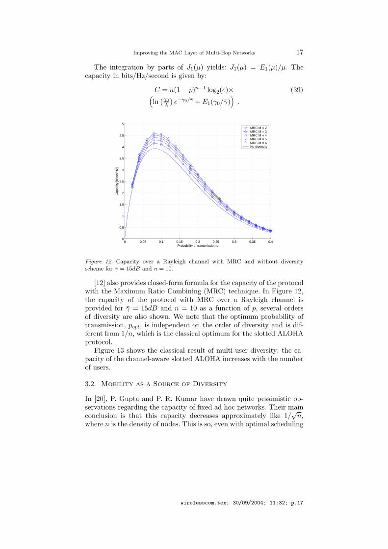
The integration by parts of J1(µ) yields: J1(µ) = E1(µ)/µ. Thecapacity in bits/Hz/second is given by:
C = n(1 − p)n−1 log2(e)× (39)(
ln(γ0
λ
)
e−γ0/γ + E1(γ0/γ))
.
0 0.05 0.1 0.15 0.2 0.25 0.3 0.35 0.40
0.5
1
1.5
2
2.5
3
3.5
4
4.5
5
Probability of transmission p
Cap
acity
[bits
/s/H
z]
MRC M = 2MRC M = 3MRC M = 4MRC M = 5MRC M = 6No diversity
Figure 12. Capacity over a Rayleigh channel with MRC and without diversityscheme for γ = 15dB and n = 10.
[12] also provides closed-form formula for the capacity of the protocolwith the Maximum Ratio Combining (MRC) technique. In Figure 12,the capacity of the protocol with MRC over a Rayleigh channel isprovided for γ = 15dB and n = 10 as a function of p, several ordersof diversity are also shown. We note that the optimum probability oftransmission, popt, is independent on the order of diversity and is dif-ferent from 1/n, which is the classical optimum for the slotted ALOHAprotocol.
Figure 13 shows the classical result of multi-user diversity: the ca-pacity of the channel-aware slotted ALOHA increases with the numberof users.
3.2. Mobility as a Source of Diversity
In [20], P. Gupta and P. R. Kumar have drawn quite pessimistic ob-servations regarding the capacity of fixed ad hoc networks. Their mainconclusion is that this capacity decreases approximately like 1/
√n,
where n is the density of nodes. This is so, even with optimal scheduling
wirelesscom.tex; 30/09/2004; 11:32; p.17

18 M. Coupechoux et al.
0 20 40 60 80 100 120 140 160 180 2003.5
4
4.5
5
5.5
6
6.5
Number of users n
Cap
acity
[bits
/Hz/
s]
MRC M = 2MRC M = 3MRC M = 4MRC M = 5MRC M = 6No diversity
Figure 13. Influence of the number of users on the capacity at p = 1/n for γ = 15dB,with MRC and without diversity scheme.
and routing schemes. For a given node density, the system throughputis limited, on the one hand, by interference when the number of hopsis small, and on the other hand, by the amount of relaying traffic if thenumber of hops is high.
However, M. Grossglauser and D. Tse proved in [19] that this lim-itation can be overcome through node mobility. For that they use ananalogy of multi-user diversity in mobile ad hoc networks: at each time-slot the only packets allowed to be sent are those that are one hop awayfrom their final destination, i.e., with the best “route conditions”. Thisanalogy leads to one hop transmissions, i.e., when destination is in thecommunication range of the source. In fact it is claimed that mobilitybrings a substantial increase in system capacity of ad hoc networks,especially if no more than one relay node between each active sourceand destination pair is considered. In a dense network, the probabilityof finding adequatly matched source and destination nodes as well asthe same for finding relay nodes as and when required, increases withnode mobility.
A centrally controlled scheduling policy described in [19] is basedon a two phase transmission method, i.e., from source to a waitingqueue in a relay node and then from the relay node to destination.Since distributed scheduling policies are known to be more suitable forimplementation in ad hoc networking applications, this section demon-
wirelesscom.tex; 30/09/2004; 11:32; p.18

Improving the MAC Layer of Multi-Hop Networks 19
strates the usefulness of such a scheme that shows the benefit of nodemobility on the network throughput.
In the proposed scheduling policy [11], the network is assumed to beperfectly synchronized and the channel is supposed to be slotted. TheMAC protocol is a two-way handshake and receiver-initiated protocol.During a given time-slot, the receiver sends a RTR. The receiver addressis included in the message. A sender that receives an RTR and that hasa packet destined to the receiver can transmit data (see Figure 14). Thisis a simplified version of CROMA.
ReceiverRTR
DATASender
Time-slot time
Figure 14. Two-way handshake within a time-slot
At each time-slot, θN nodes among N are designated as senders,the remaining nodes are receivers, θ ∈]0, 1[ is the sender density. Allreceivers send a RTR as described before. Each sender manages twopacket queues. One of these, called the source queue, stores packetscoming from its own packet generator. The other one, called the re-lay queue, stores the incoming packets that have to be relayed. Asender receiving a RTR looks in its queues for any packet destinedfor this receiver. Any such existing packet is transmitted consideringthe fact that the source queue has priority over the relay queue. Oth-erwise, a packet is chosen in the source queue to be transmitted tothe receiver/relay. This policy is called the “two-hop strategy” becausepackets are transported through at most two hops. An alternative isthe “one-hop” strategy, where packets are not relayed, but directly sentfrom the source to the destination.
N = 30 nodes have been considered moving in a 1000u × 1000usquare field, where u is a unit of length. The mobility model uses therandom waypoint model with a fixed speed, which is taken as a metricfor mobility. The simulations parameters are given in Tab.II. Note thatthe destination of each new packet is uniformly chosen among all nodesbut the source. The effects of interference and capture are not takeninto account, i.e., only collisions of packets are considered and nodeshave a fixed transmission range. Moreover, problems related to highmobility w.r.t the channel model, e.g., Doppler effect, are not takeninto account.
wirelesscom.tex; 30/09/2004; 11:32; p.19

20 M. Coupechoux et al.
Table II. Scheduling policy simula-tion parameter values
Parameter Value
N 30
θ 0.5
DATA size 512 bytes
RTR size 44 bytes
ON distribution Exponential
Mean ON time 0,5s
ON data rate 64 Kbps
OFF distribution Exponential
Mean OFF time 0.5 s
PHY data rate 2 Mbps
Figures 15 and 16 shows the benefit of mobility on the networkthroughput as a function of the transmission range. In a multi-hopnetwork, long range communications ensure a very good connectivityof the network and reduce the mean number of hops. However, net-work throughput is fundamentally limited because of the high level ofinterference induced by high transmitted power. On the other hand,communications between nearest neighbours increases the mean num-ber of hops and thus routing overhead. Above all, most of the packetscarried by the network are relayed packets. In the scheduling policy pro-posed by [19] and the presented design choice for it, both the maximumnumber of hops and the transmitted power are kept small provided thatan adequate transmission range is found.
We now derive the optimum transmission range applicable to theone-hop strategy for a given sender density. For that, we consider thatduring a given time-slot the positions of senders and receivers are twoindependent Poisson point processes with density resp. θλ and (1−θ)λ.We also assume that a sender has always something to transmit tothe receiver from which it received an RTR. If the edge effects areneglected, and interference and capture are not taken into account, asender receives a RTR if and only if there is a single receiver in itstransmission range r. Thus, the probability for a sender to receive a
wirelesscom.tex; 30/09/2004; 11:32; p.20

Improving the MAC Layer of Multi-Hop Networks 21
0 50 100 150 200 250 300 350 400 450 5000
10
20
30
40
50
60
70
80
90
100
Transmission range [u − units of distance]
Thr
ough
put [
Kbp
s]
10 u/s40 u/s60 u/s
Figure 15. Aggregate throughput - two-hop strategy
0 50 100 150 200 250 300 350 400 450 5000
50
100
150
200
250
300
350
400
450
Transmission range [u − units of distance]
Thr
ough
put [
Kbp
s]
10 u/s40 u/s60 u/s
Figure 16. Aggregate throughput - one-hop strategy
RTR is the following:
p1 = (1 − θ)λπr2e−(1−θ)λπr2
. (40)
Now, a receiver decodes a data packet if and only if there is a singlesender that received a RTR in its transmission range r. Given k thenumber of senders in the communication disk, this probability is:
kp1(1 − p1)k−1. (41)
Thus, the probability for a receiver to receive a data packet is:
P =∞∑
k=1
Pr[1 RTR received|k senders]Pr[k senders] (42)
=∞∑
k=1
kp1(1 − p1)k−1 (θλπr2)k
k!e−θλπr2
= p1θλπr2e−θλπr2p1
wirelesscom.tex; 30/09/2004; 11:32; p.21
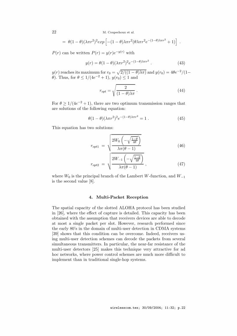
22 M. Coupechoux et al.
= θ(1 − θ)(λπr2)2exp[
−(1 − θ)λπr2(θλπr2e−(1−θ)λπr2
+ 1)]
.
P (r) can be written P (r) = y(r)e−y(r) with
y(r) = θ(1 − θ)(λπr2)2e−(1−θ)λπr2
. (43)
y(r) reaches its maximum for r0 =√
2/((1 − θ)λπ) and y(r0) = 4θe−2/(1−θ). Thus, for θ ≤ 1/(4e−2 + 1), y(r0) ≤ 1 and
ropt =
√
2
(1 − θ)λπ. (44)
For θ ≥ 1/(4e−2 + 1), there are two optimum transmission ranges thatare solutions of the following equation:
θ(1 − θ)(λπr2)2e−(1−θ)λπr2
= 1 . (45)
This equation has two solutions:
ropt1 =
√
√
√
√
√
2W0
(
−√
1−θ4θ
)
λπ(θ − 1)(46)
ropt2 =
√
√
√
√
√
2W−1
(
−√
1−θ4θ
)
λπ(θ − 1), (47)
where W0 is the principal branch of the Lambert W -function, and W−1
is the second value [8].
4. Multi-Packet Reception
The spatial capacity of the slotted ALOHA protocol has been studiedin [26], where the effect of capture is detailed. This capacity has beenobtained with the assumption that receivers devices are able to decodeat most a single packet per slot. However, research performed sincethe early 80’s in the domain of multi-user detection in CDMA systems[39] shows that this condition can be overcome. Indeed, receivers us-ing multi-user detection schemes can decode the packets from severalsimultaneous transmitters. In particular, the near-far resistance of themulti-user detectors [25] makes this technique very attractive for adhoc networks, where power control schemes are much more difficult toimplement than in traditional single-hop systems.
wirelesscom.tex; 30/09/2004; 11:32; p.22

Improving the MAC Layer of Multi-Hop Networks 23
In this paper, the result of [26] is extended in the case of multi-packetreception and a closed-form formula is provided for the throughput ofthe slotted ALOHA as a function of the probability, rn,k, for a receiverto decode k packets given that n have been sent in its neighborhood.
Throughout this section, a packet radio network of nodes is consid-ered, spatially distributed in the plane according to a Poisson processwith parameter λ. That means that the probability to find k nodes inany region, A, of area S(A) is:
P [k in A] =(λS(A))k
k!e−λS(A) . (48)
The considered network is large and the edge effects will be neglected.All nodes are assumed to operate with a half-duplex radio device.
This means that a collision of the second order can occur if a nodereceives a packet, while it is itself transmitting during the same slot. Inthis case, the packet is lost. The transmit power is constant and equalsP0.
As assumed in the introduction, nodes access the channel by usingthe slotted ALOHA protocol, i.e., time is divided in equal time-slots.At a given slot, a node sends a packet with a fixed probability p.Otherwise, it is able to receive one or several packets coming fromthe transmitters. Let R0 be the reception radius of a receiver. R0 isthe maximum distance from which can come a packet destined to thisreceiver. If there are n transmitters within R0 from the receiver, theprobability to decode k packets is rn,k.
It is assumed that packets destined towards a particular node in thenetwork are routed with equal probability towards one of the neigh-boring nodes that lies in the direction of the destination. All theseassumptions are taken from [26].
We are interested in the local throughput of the system, i.e., theexpected number of packet received per slot.
Before looking at the local throughput, let’s recall two preliminaryresults already given in [26]. A particular node a is considered and letthe random variable X be the number of correctly decoded packetsdestined to a in a given slot. The definition of four important events isalso needed:
− (A) the event that a does not transmit.
− (T ) the event that a particular sender t sends a packet to a.
− (Tn) the event that there are n senders in the neighborhood of a.
− (Dk) the event that a decodes exactly k packets in the given time-slot.
wirelesscom.tex; 30/09/2004; 11:32; p.23

24 M. Coupechoux et al.
The two basic results are:
P [A] = 1 − p , (49)
P [T ] =1 − e−λπR2
0/2
λπR20
, (50)
where p is the probability of transmission, λ is the density of the nodes,and R0 is the transmission range. Note that if nodes are spatiallydistributed according to a Poisson process with density λ, senders, at agiven time-slot, are spatially distributed according to a Poisson processwith density λp (see e.g. in [15]).
Now, the probability that a receives x packets given (A), (Tn), and(Dk) is:
P [X = x|A,Tn,Dk] =
(
kx
)
P [T ]x(1 − P [T ])k−x , k ≥ x , (51)
because among the k packets decoded, x are destined to a. This prob-ability is zero if k < x. This relation is now successively marginalized:
P [X = x|A,Tn] =n∑
k=0
P [X = x|A,Tn,Dk]P [Dk|A,Tn] (52)
=n∑
k=0
P [X = x|A,Tn,Dk]rn,k (53)
=n∑
k=x
(
kx
)
P [T ]x(1 − P [T ])k−xrn,k . (54)
The second line is justified by the fact that the events (Dk) and (A)are independent. The third line takes into account Equation 51. Now,assuming that the considered node a does not transmit:
P [X = x|A] =∞∑
n=0
P [X = x|A,Tn]P [Tn|A] (55)
=∞∑
n=0
P [X = x|A,Tn](λpπR2
0)n
n!e−λpπR2
0 (56)
=∞∑
n=0
n∑
k=x
(
kx
)
P [T ]x(1 − P [T ])k−xrn,k(λpπR2
0)n
n!e−λpπR2
0 .(57)
The second equation results from the fact that (Tn) and (A) are inde-pendent and that the density of the senders is λp as explained before.Note that if a is a sender at the considered slot, a cannot receive any
wirelesscom.tex; 30/09/2004; 11:32; p.24
Improving the MAC Layer of Multi-Hop Networks 25
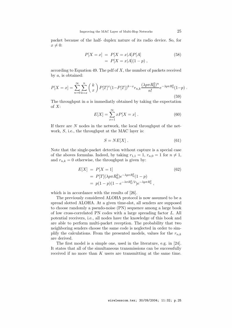
packet because of the half- duplex nature of its radio device. So, forx 6= 0:
P [X = x] = P [X = x|A]P [A] (58)
= P [X = x|A](1 − p) ,
according to Equation 49. The pdf of X, the number of packets receivedby a, is obtained:
P [X = x] =∞∑
n=0
n∑
k=x
(
kx
)
P [T ]x(1−P [T ])k−xrn,k(λpπR2
0)n
n!e−λpπR2
0(1−p) .
(59)The throughput in a is immediatly obtained by taking the expectationof X:
E[X] =∞∑
x=1
xP [X = x] . (60)
If there are N nodes in the network, the local throughput of the net-work, S, i.e., the throughput at the MAC layer is:
S = NE[X] . (61)
Note that the single-packet detection without capture is a special caseof the aboves formulas. Indeed, by taking r1,1 = 1, rn,0 = 1 for n 6= 1,and rn,k = 0 otherwise, the throughput is given by:
E[X] = P [X = 1] (62)
= P [T ](λpπR20)e
−λpπR2
0(1 − p)
= p(1 − p)(1 − e−λπR2
0/2)e−λpπR2
0 ,
which is in accordance with the results of [26].The previously considered ALOHA protocol is now assumed to be a
spread slotted ALOHA. At a given time-slot, all senders are supposedto choose randomly a pseudo-noise (PN) sequence among a large bookof low cross-correlated PN codes with a large spreading factor L. Allpotential receivers, i.e., all nodes have the knowledge of this book andare able to perform multi-packet reception. The probability that twoneighboring senders choose the same code is neglected in order to sim-plify the calculations. From the presented models, values for the rn,k
are derived.The first model is a simple one, used in the literature, e.g. in [24].
It states that all of the simultaneous transmissions can be successfullyreceived if no more than K users are transmitting at the same time.
wirelesscom.tex; 30/09/2004; 11:32; p.25

26 M. Coupechoux et al.
If there are more than K users transmitting at the same time, themulti-user receiver is overhelmed and a collision occurs. Thus:
rn,k =
1, if k = n and n ≤ K1, if k = 0 and n > K0, otherwise
(63)
The second model supposes that radio receivers devices are made ofa bank of Matched Filters (MF) that are able to decode each spreadingcode individually. If P0 is the transmit power, the received power at adistance r is assumed to be P (r) = P0/r
γ , where γ > 2 is the pathloss exponent. This expression is a far-field approximation that doesn’thold for small values of r. A packet is considered to be decoded if theSignal-to-Interference plus Noise Ratio (SINR), β, of a signal at theoutput of the MF reaches a SINR target β0, i.e., if:
β =P (r)
σ2 + 1L
∑n−1i=0
P0
rγi
≥ β0 , (64)
where σ2 is the power of the noise, n is the number of interferers, andL is the spreading length.
In order to analitycaly evaluate the rn,k parameters, the cdf of theSINR is needed in the case of a Poisson field of interferers. This problemhas been treated in [35] and in [34], where the characteristic function ofthe interference Y =
∑n−1i=0 P0/r
γi has been obtained. This expression
leads to the exact cdf of β and thus to the rn,k in the MF case. However,this is not the case for the Multi-User Detection (MUD) receiver. Thatis the reason why the rn,k probabilities are evaluated thanks to MonteCarlo simulations in order to allow a fair comparison with the MMSEdetector.
A Poisson field of interferers with density λp is generated on a twodimensional squared network [−Xmax;Xmax]×[−Y max;Y max]. Theconsidered receiver, a, is placed at (0; 0). R0 is fixed as the maximumdistance from which can come packets for the receiver. In the abscenceof interferer, R0 verifies the following expression: β0 = P0/(R
γ0σ2). n is
the number of senders inside the disk of radius R0 with center a. Foreach of these senders, the SINR is computed after summing the inter-ference from the whole network. If the SINR reaches the SINR target,the packet from this sender is assumed to be decoded. A snapshot of thesimulation is shown on Figure 4. Tab.III shows the parameter valuesused for the simulations.
Figure 4 shows the plot of the matrix rn,k for n ≤ 14 and p = 0.2.The mean number of senders in the disk of radius R0 is λpπR2
0 ' 5,so the probability that n > 14 is very low. This figure shows that for
wirelesscom.tex; 30/09/2004; 11:32; p.26

Improving the MAC Layer of Multi-Hop Networks 27
R0
-Xmax
Ymax
-Ymax
Xmax
Figure 17. Snapshot of the Monte Carlo simulation: the power of all the interferersare sumed at the receiver.
Table III. Parametervalues used for theMonte Carlo simulations
Parameter Value
Xmax 50
Y max 50
λ 0.25
p 0.2
L 32
P0 5
β0 0.025
σ2 0.2
γ 4
small values of n, all packets are decoded. Then, when n increases, thenumber of decoded packets decreases.
The third model assumes that receivers are able to perform multi-user detection thanks to a MMSE detector. While the traditional MFor Rake receiver treats interference from other users as additive noise,the MUD scheme jointly decodes all users.
wirelesscom.tex; 30/09/2004; 11:32; p.27

28 M. Coupechoux et al.
0
5
10
15
02
46
810
12140
0.2
0.4
0.6
0.8
1
kn
r n,k
Figure 18. Probabilities, rn,k, for a receiver to decode k packets given that n havebeen sent in the case of a MF bank.
The condition of decoding a packet is still based on the SINR at theoutput of the signal detector. According to [38], to check if the targetfor a given sender’s SINR, β0, can be met for a given system of senders,it suffices to check the following condition:
P
σ2 + 1L
∑n−1i=0 I(Pi, P, β0)
≥ β0 , (65)
where P = P0/rγ is the received power of the given sender, Pi is the
received power from the interferer i and I(Pi, P, β0) is the effectiveinterference of sender i on the considered sender at the target SINRβ0:
I(Pi, P, β0) =PPi
P + Piβ0. (66)
Equation 65, also used in [33] in the context of call admission control,is an approximation since it is true for large systems, when L → ∞,n → ∞ and L/n = α, and for random spreading sequences.
It can be shown that the characteristic function of the interferencefor a given sender and a given SINR target, β0 is:
φY (ω) = exp
(
iλpπω
∫ P/β0
0
(
P0
t− P0β0
P
)2/γ
eiωtdt
)
. (67)
While in the MF case φY (ω) is the characteristic function of a stablelaw, Equation 67 seems to be un-tractable for further computations.
wirelesscom.tex; 30/09/2004; 11:32; p.28
Improving the MAC Layer of Multi-Hop Networks 29
0
5
10
15
024681012140
0.1
0.2
0.3
0.4
0.5
0.6
0.7
0.8
0.9
1
k
n
r n,k
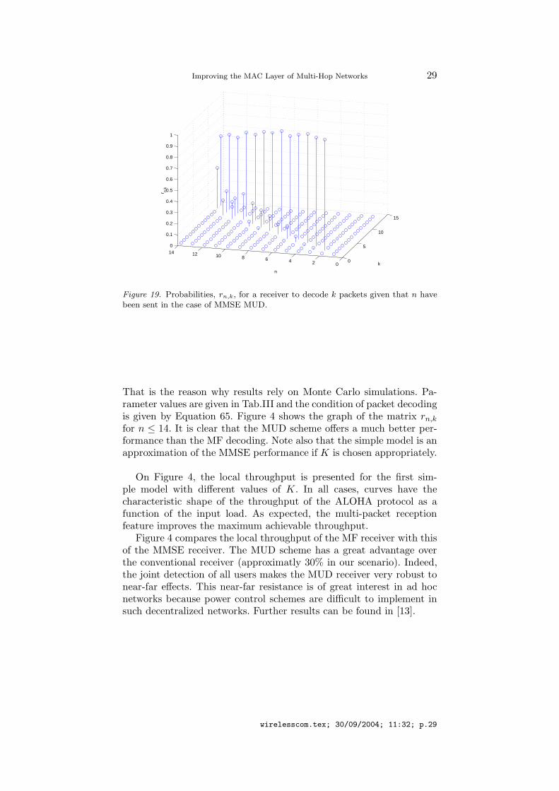
Figure 19. Probabilities, rn,k, for a receiver to decode k packets given that n havebeen sent in the case of MMSE MUD.
That is the reason why results rely on Monte Carlo simulations. Pa-rameter values are given in Tab.III and the condition of packet decodingis given by Equation 65. Figure 4 shows the graph of the matrix rn,k
for n ≤ 14. It is clear that the MUD scheme offers a much better per-formance than the MF decoding. Note also that the simple model is anapproximation of the MMSE performance if K is chosen appropriately.
On Figure 4, the local throughput is presented for the first sim-ple model with different values of K. In all cases, curves have thecharacteristic shape of the throughput of the ALOHA protocol as afunction of the input load. As expected, the multi-packet receptionfeature improves the maximum achievable throughput.
Figure 4 compares the local throughput of the MF receiver with thisof the MMSE receiver. The MUD scheme has a great advantage overthe conventional receiver (approximatly 30% in our scenario). Indeed,the joint detection of all users makes the MUD receiver very robust tonear-far effects. This near-far resistance is of great interest in ad hocnetworks because power control schemes are difficult to implement insuch decentralized networks. Further results can be found in [13].
wirelesscom.tex; 30/09/2004; 11:32; p.29

30 M. Coupechoux et al.
0 0.1 0.2 0.3 0.4 0.5 0.6 0.7 0.8 0.9 10
0.02
0.04
0.06
0.08
0.1
0.12
0.14
0.16
0.18
Probability of transmission p
Loca
l thr
ough
put E
[X]
K=1K=3K=5K=10
Figure 20. Local throughput in packets/time-slot for the simple model ofmulti-packet reception for different values of K, the maximum number of packetsthat can be decoded by the receiver.
0 0.1 0.2 0.3 0.4 0.5 0.6 0.7 0.8 0.9 10
0.05
0.1
0.15
0.2
0.25
Probability of transmission p
Loca
l thr
ough
put E
[X]
MFMMSE MUD
Figure 21. Local throughput in packets/time-slot for the MF receiver and theMMSE receiver.
wirelesscom.tex; 30/09/2004; 11:32; p.30

Improving the MAC Layer of Multi-Hop Networks 31
5. Conclusion
Ad hoc networks, and in particular mobile multi-hop networks, area very challenging environment for MAC designers. They don’t onlyface inherent problems related to the varying wireless channel, butthey also have to take into account the lack of infrastructure, thedistributed and moving nature of the network, or the limited featuresof the radio devices. Some answers have been provided by the IEEE802.11 standards. However, specific MAC have to be designed in orderto solve all issues of ad hoc networks. This paper proposes three ex-amples of improvement using cross-layer interactions. The first one isa new protocol, called CROMA, based on a slotted structure, whichshows the benefit of synchronization for improving the throughput andthe fairness of the system. The second presented concept is multi-userdiversity applied to random access and to routing in ad hoc networks.The advantage of such a method is highlighted by two examples ofschemes, and new analytical results are provided. At last, the capacityincrease achieved thanks to multi-packet reception allows to concludethat MUD technology is a very good candidate for the physical layerof next generations of ad hoc networks.
References
1. 802.11, A. S.: 1999, ‘Part 11: Wireless LAN Medium Access Control (MAC)and Physical Layer (PHY) Specifications’.
2. Alouini, M.-S. and A. J. Goldsmith: 1999, ‘Capacity of Rayleigh FadingChannels Under Different Adaptive Transmission and Diversity-CombiningTechniques’. IEEE Trans. on Vehicular Technology VOL. 48, N0. 4.
3. Arikan, E.: 1984, ‘Some Complexity Results about Packet Radio Networks’.IEEE Trans. on Information Theory VOL. IT-30.
4. Bao, L. and J. J. Garcia-Luna-Aceves: 2001, ‘A New Approach to Chan-nel Access Scheduling for Ad Hoc Networks’. In: Proc. of ACM/IEEEMOBICOM’01.
5. Bhargavan, V., A. Demers, S. Shenker, and L. Zhang: 1994, ‘MACAW: A MediaAccess Protocol for Wireless LAN’s’. In: Proc. of ACM SIGCOMM.
6. Chlamtac, I., A. Farago, and H. Zhang: 1997, ‘Time-Spread Multiple Access(TSMA) Protocols for Multihop Mobile Radio Networks’. IEEE/ACM Trans.on Networking VOL. 5, NO. 6.
7. Cidon, I. and M. Sidi: 1989, ‘Distributed Assignment Algorithms for MultihopPacket Radio Networks’. IEEE Trans. on Computers VOL. 38, NO. 10.
8. Corless, R. M., G. H. Gonnet, D. E. G. Hare, D. J. Jeffrey, and D. E. Knuth:1996, ‘On the Lambert W function’. Advances in Computational Mathematics5.
9. Coupechoux, M., B. Baynat, C. Bonnet, and V. Kumar: 2003, ‘Modeling of aSlotted MAC Protocol for MANETs’. In: Proc. of MADNET’03.
wirelesscom.tex; 30/09/2004; 11:32; p.31

32 M. Coupechoux et al.
10. Coupechoux, M., B. Baynat, C. Bonnet, and V. Kumar: 2004a, ‘CROMA - AEnhanced Dynamic Slot Allocation Protocol for MANETs’. to appear in ACMMONET.
11. Coupechoux, M., C. Bonnet, and V. Kumar: 2002, ‘A Scheduling Policy forDense and Highly Mobile Ad hoc Networks’. In: Proc. of WMAN’02.
12. Coupechoux, M. and T. Lestable: 2004, ‘On the Capacity of the ChannelAware Slotted Aloha over Rayleigh and Nakagami-m Channels’. In: Proc.of WiOpt’04, Cambridge, United Kingdom.
13. Coupechoux, M., T. Lestable, C. Bonnet, and V. Kumar: 2004b, ‘Throughputof the Multi-Hop Slotted Aloha with Multi-Packet Reception’. In: to appear inProc. of WONS’04.
14. Ephremides, A. and T. V. Truong: 1990, ‘Scheduling Broadcasts in MultihopRadio Networks’. IEEE Trans. on Communications VOL. 38, NO. 4.
15. Frey, A. and V. Schmidt: 1998, ‘Marked Point Process in the Plane I’. Advancesin Performance Analysis, Notable Publications Inc. VOL. 1.
16. Garcia-Luna-Aceves, J. J. and C. L. Fullmer: 1999, ‘Floor Acquisition MultipleAccess (FAMA) in Single-Channel Wireless Networks’. Mobile Networks andApplications VOL. 4, NO. 3.
17. Goldsmith, A. J. and P. P. Varaiya: 1997, ‘Capacity of Fading Channels withChannel Side Information’. IEEE Trans. on Information Theory VOL. 43,
N0. 6.18. Gradshteyn, I. S. and I. M. Ryzhik: 1980, Table of Integrals, Series, and
Products. Academic Press.19. Grossglauser, M. and D. Tse: 2001, ‘Mobility Increases the Capacity of Ad hoc
Wireless Networks’. In: Proc. of INFOCOM’01.20. Gupta, P. and P. R. Kumar: 2000, ‘The Capacity of Wireless Networks’. IEEE
Trans. on Information Theory VOL. 46.21. Jain, R., D. Chiu, and W. Hawe: 1984, ‘A Quantitative Measure of Fairness
and Discrimination for Resource Allocation in Shared Computer Systems’. In:DEC Research Report TR-301.
22. Ju, J.-H. and V. O. K. Li: 1998, ‘An Optimal Topology-Tranparent Schedul-ing Method in Multihop Packet Radio Networks’. IEEE/ACM Trans. onNetworking VOL. 6, NO. 3.
23. Knopp, R. and P. A. Humblet: 1995, ‘Information Capacity and Power Controlin Single-Cell Multi-User Communications’. In: Proc. of ICC’95.
24. Liu, Q., E.-H. Yang, and Z. Zhang: 2001, ‘Throughput Analysis of CDMASystems Using Multiuser Receivers’. IEEE Trans. on Communications VOL.
49, N0. 7.25. Lupas, R. and S. Verdu: 1990, ‘Near-Far Resistance of Multiuser Detectors in
Asynchronous Channels’. IEEE Trans. on Communications VOL. 38, N0. 4.26. Nelson, R. and L. Kleinrock: 1984, ‘The Spatial Capacity of a Slotted
ALOHA Multihop Packet Radio Network with Capture’. IEEE Trans. onCommunications VOL. 32, N0. 6.
27. ns2: -, ‘http://www.isi.edu/nsnam/ns’.28. P. Bender, e. a.: 2000, ‘CDMA/HDR: a Bandwidth Efficient High Speed Wire-
less Data Service for Nomadic Users’. IEEE Communications Magazine VOL.
38, N0. 7.29. P.Karn: 1990, ‘MACA - a New Channel Access Method for Packet Radio’. In:
Proc. of ARRL/CRRL.30. Qin, X. and R. Berry: 2003, ‘Exploiting Multiuser Diversity for Medium Access
Control in Wireless Networks’. In: Proc. of INFOCOM’03.
wirelesscom.tex; 30/09/2004; 11:32; p.32
Improving the MAC Layer of Multi-Hop Networks 33
31. Ramanathan, S.: 1997, ‘A Unified Framework and Algorithm for (T/F/C)DMAChannel Assignment in Wireless Networks’. In: Proc. of IEEE INFOCOM’97.
32. Rom, R. and M. Sidi: 1990, Multiple Access Protocols, Performance andAnalysis. Springer-Verlag.
33. Sankaran, C. and A. Ephremides: 2002, ‘The Use of Multiuser Detectorsfor Multicasting in Wireless Ad hoc CDMA Networks’. IEEE Trans. onInformation Theory VOL. 48, N0. 11.
34. Sousa, E. S.: 1990, ‘Interference Modeling in a Direct-Sequence Spread-Spectrum Packet Radio Network’. IEEE Trans. on Communications VOL.
38, N0. 9.35. Sousa, E. S. and J. A. Silvester: 1990, ‘Optimum Transmission Ranges in a
Direct-Sequence Spread-Spectrum Multihop Packet Radio Network’. IEEEJournal on Select. Area in Communications VOL. 8, N0. 5.
36. Stewart, W. J.: 1994, An Introduction to the Numerical Solution of MarkovChains. Princeton University Press.
37. Tang, Z. and J. J. Garcia-Luna-Aceves: 1999, ‘A Protocol for Topology-Dependent Transmission Scheduling in Wireless Networks’. In: Proc. ofWCNC’99.
38. Tse, D. N. C. and S. V. Hanly: 1999, ‘Linear Multiuser Receivers: Effec-tive Interference, Effective Bandwidth and User Capacity’. IEEE Trans. onInformation Theory VOL. 45, N0. 2.
39. Verdu, S.: 1998, Multiuser Detection. Cambridge University Press.40. Viswanath, P., D. Tse, and R. Laroia: 2002, ‘Opportunistic Beamforming using
Dumb Antennas’. IEEE Trans. on Information Theory VOL. 48, N0. 6.41. Xu, S. and T. Saadawi: 2001, ‘Does the IEEE 802.11 MAC Protocol Work Well
in Multihop Wireless Ad Hoc Networks?’. IEEE Communication MagazineVOL. 39, NO. 6.
42. Zhu, C. and M. S. Corson: 1998, ‘A Five-Phase Reservation Protocol (FPRP)for Mobile Ad Hoc Networks’. In: Proc. of INFOCOM’98.
wirelesscom.tex; 30/09/2004; 11:32; p.33
wirelesscom.tex; 30/09/2004; 11:32; p.34