
Topology Control in Mobile Ad Hoc Networks with Cooperative Communications
74
Topology Control in Mobile Ad Hoc Networks with Cooperative Communications ABSTRACT: Cooperative communication has received tremendous interests in wireless networks. Most existing works on cooperative communications are focused on link-level physical layer issues. Consequently, the impacts of cooperative communications on network-level upper layer issues, such as topology control, routing and network capacity, are largely ignored. In this paper, we propose a Capacity-Optimized Cooperative (COCO) topology control scheme to improve the network capacity in MANETs by jointly considering both upper layer network capacity and physical layer cooperative communications. Using simulation examples, we show that physical layer cooperative communications have significant impacts on the performance of topology control and network capacity, and the proposed topology control scheme can substantially improve the network capacity in MANETs with cooperative communications.
-
Upload
independent -
Category
Documents
-
view
4 -
download
0
Transcript of Topology Control in Mobile Ad Hoc Networks with Cooperative Communications

Topology Control in Mobile Ad HocNetworks
with Cooperative CommunicationsABSTRACT:
Cooperative communication has received tremendous interests in
wireless networks. Most existing works on cooperative communications
are focused on link-level physical layer issues. Consequently, the
impacts of cooperative communications on network-level upper layer
issues, such as topology control, routing and network capacity, are
largely ignored. In this paper, we propose a Capacity-Optimized
Cooperative (COCO) topology control scheme to improve the network
capacity in MANETs by jointly considering both upper layer network
capacity and physical layer cooperative communications. Using
simulation examples, we show that physical layer cooperative
communications have significant impacts on the performance of topology
control and network capacity, and the proposed topology control scheme
can substantially improve the network capacity in MANETs with
cooperative communications.


CONTENTS
1.INTRODUCTION
1.1. INTRODUCTION TO PROJECT1.2. PURPOSE OF THE PROJECT 1.3. EXISTING SYSTEM & ITS DISADVANTAGES1.4. PROPOSED SYSTEM & ITS ADVANTAGES
2.SYSTEM ANALYSIS
2.1. STUDY OF THE SYSTEM 2.2. INPUT & OUTPUT REPRESENTATION2.3. PROCESS MODELS USED WITH JUSTIFICATION2.4. SYSTEM ARCHITECTURE
3.FEASIBILITY STUDY
3.1. TECHNICAL FEASIBILITY3.2. OPERATIONAL FEASIBILITY3.3. ECONOMIC FEASIBILITY
4.SOFTWARE REQUIREMENT SPECIFICATIONS
4.1. FUNCIONAL REQUIREMENTS 4.2. PERFORMANCE REQUIREMENTS4.3. SOFTWARE REQUIREMENTS4.4. HARDWARE REQUIREMENTS
4.4.1. INTRODUCTION TO Android4.4.2. INTRODUCTION TO C++/PYTHON
5.SYSTEM DESIGN
5.1 . INTRODUCTION 5.2 UML DIAGRAMS
6. OUTPUT SCREENS
7.SYSTEM TESTING
7.1 INTRODUCTION TO TESTING7.2 TESTING STRATEGIES
8.SYSTEM SECURITY
8.1 INTRODUCTION8.2 SECURITY IN SOFTWARE
9. BIBLIOGRAPHY

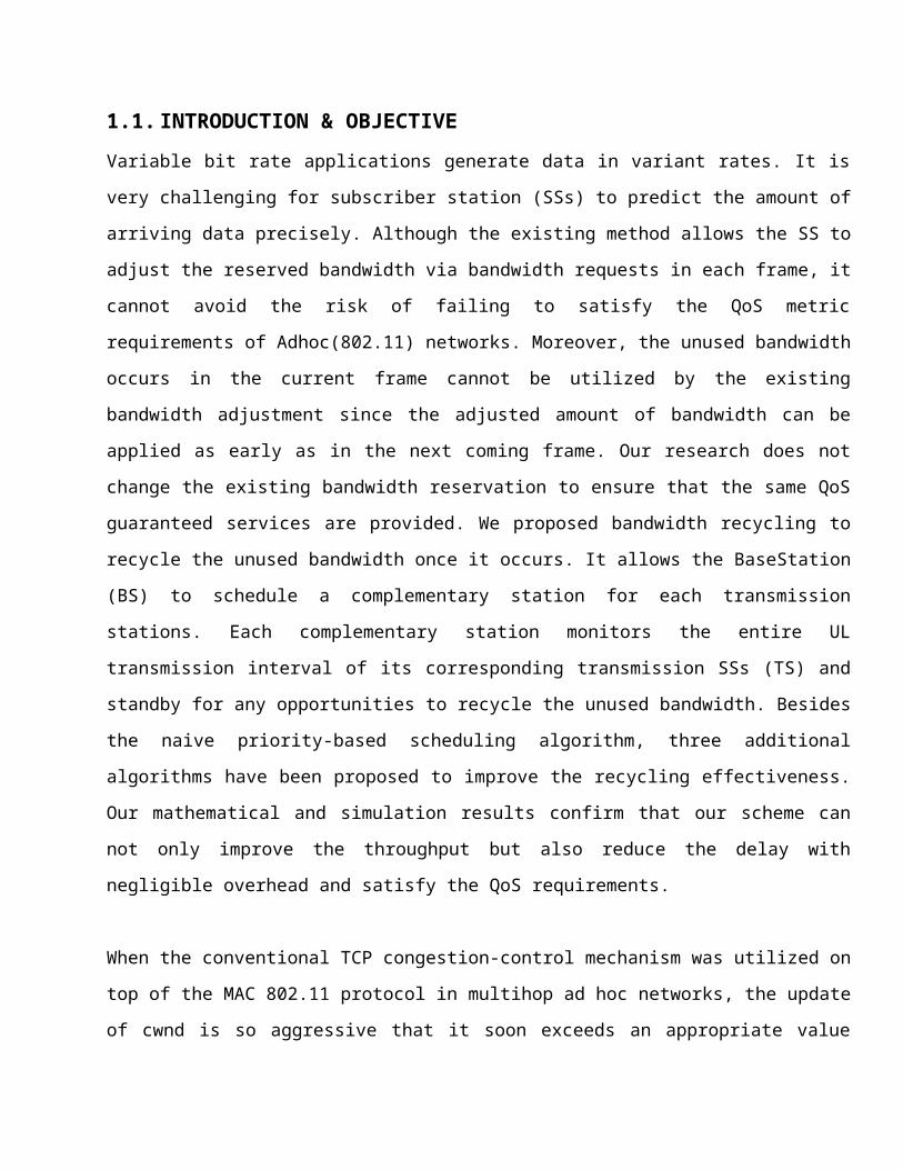
1.1.INTRODUCTION & OBJECTIVEVariable bit rate applications generate data in variant rates. It is
very challenging for subscriber station (SSs) to predict the amount of
arriving data precisely. Although the existing method allows the SS to
adjust the reserved bandwidth via bandwidth requests in each frame, it
cannot avoid the risk of failing to satisfy the QoS metric
requirements of Adhoc(802.11) networks. Moreover, the unused bandwidth
occurs in the current frame cannot be utilized by the existing
bandwidth adjustment since the adjusted amount of bandwidth can be
applied as early as in the next coming frame. Our research does not
change the existing bandwidth reservation to ensure that the same QoS
guaranteed services are provided. We proposed bandwidth recycling to
recycle the unused bandwidth once it occurs. It allows the BaseStation
(BS) to schedule a complementary station for each transmission
stations. Each complementary station monitors the entire UL
transmission interval of its corresponding transmission SSs (TS) and
standby for any opportunities to recycle the unused bandwidth. Besides
the naive priority-based scheduling algorithm, three additional
algorithms have been proposed to improve the recycling effectiveness.
Our mathematical and simulation results confirm that our scheme can
not only improve the throughput but also reduce the delay with
negligible overhead and satisfy the QoS requirements.
When the conventional TCP congestion-control mechanism was utilized on
top of the MAC 802.11 protocol in multihop ad hoc networks, the update
of cwnd is so aggressive that it soon exceeds an appropriate value

according to the real BDP. It may result in a severe contention,
segment losses, and a restart of the congestion window. In this
situation, TCP connections cannot stably work and yield very low
throughput, which has been a major factor for reducing the network
performance. Previous studies have given some modified TCP mechanisms.
However, there is still space to improve the TCP performance. In our
proposed CWA–CD mechanism, we have split the real RTT into two parts—
the congestion RTT and the contention RTT—and revealed that the
contention RTT has nothing to do with the BDP and that the BDP is
determined by only the congestion RTT. We obtained the contention RTT
information from forward data and backward ACK at the MAC layer and
estimated the contention status through the deviation of the
contention RTT. Then, we made a modification of the window adaptation
mechanism, in which the cwnd value was changed according to several
factors such as the V CRH and timeout.The deviation of the contention
RTT reflects the direct indication of the contention situation, and
this mechanism is timelier and more precise. Furthermore, the relevant
congestion window adaptation mechanism is simple and steady, and it
does not blindly reset the cwnd but adjust the cwnd value based on the
contention status. The experiment shows that the proposed mechanism is
more precise and much stable, and it significantly improves the
throughput in static scenarios.We have considered an overshooting
problem of TCP within the multihop network in this paper. In addition,
this mechanism can be used in the connection of the ad hoc network
with the normal Internet, on the condition that any node with
contention in the connection uses our mechanism to contribute the

measurement of theV CR and the receiver feedbacks the recorded V CRH.
We have used a segment-driven method to sample and calculate the V
CRH, which is easy to implement. However, a small problem occurs when
the amount of segments is small.
In this case, the time span between segments is large, and thus, some
segments as part of the V CRH calculation may be outmoded to some
extent. This problem degrades the accuracy in detecting the
contention. We can choose another timestampdriven method to alleviate
this problem. In other words, every time a new segment arrives, the
timestamp of the old segments is checked to determine whether we can
remove some old segments before calculating the V CRH. However, the
latter method is more complicated. We can combine the packet- and
timestamp-driven methods to improve the stability of cwnd updating for
further work. In addition, we will investigate the adaptation of CWA–
CD in other well-known TCP versions. Our proposed mechanism focuses on
link contentions and does not consider the mobility factor. Link
failures due to mobility are part of the main sources of link
unreliability in mobile ad hoc networks (MANETs), which we have
previously investigated. In our future work, we will give a
comprehensive consideration of these factors to improve the
performance of the network.
This illustration is supported using a real time implementation and
simulation in 802.11network scenario.
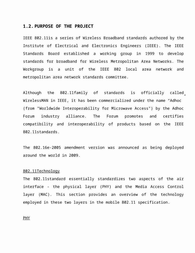
1.2.PURPOSE OF THE PROJECT
IEEE 802.11is a series of Wireless Broadband standards authored by the
Institute of Electrical and Electronics Engineers (IEEE). The IEEE
Standards Board established a working group in 1999 to develop
standards for broadband for Wireless Metropolitan Area Networks. The
Workgroup is a unit of the IEEE 802 local area network and
metropolitan area network standards committee.
Although the 802.11family of standards is officially called
WirelessMAN in IEEE, it has been commercialized under the name “Adhoc”
(from "Worldwide Interoperability for Microwave Access") by the Adhoc
Forum industry alliance. The Forum promotes and certifies
compatibility and interoperability of products based on the IEEE
802.11standards.
The 802.16e-2005 amendment version was announced as being deployed
around the world in 2009.
802.11Technology
The 802.11standard essentially standardizes two aspects of the air
interface - the physical layer (PHY) and the Media Access Control
layer (MAC). This section provides an overview of the technology
employed in these two layers in the mobile 802.11 specification.
PHY
802.16e uses Scalable OFDMA to carry data, supporting channel
bandwidths of between 1.25 MHz and 20 MHz, with up to 2048 sub-
carriers. It supports adaptive modulation and coding, so that in
conditions of good signal, a highly efficient 64 QAM coding scheme is
used, whereas when the signal is poorer, a more robust BPSK coding
mechanism is used. In intermediate conditions, 16 QAM and QPSK can
also be employed. Other PHY features include support for Multiple-in
Multiple-out (MIMO) antennas in order to provide good non-line-of-
sight propagation (NLOS) characteristics (or higher bandwidth) and
Hybrid automatic repeat request (HARQ) for good error correction
performance.
Although the standards allow operation in any band from 2 to 66 GHz,
mobile operation is best in the lower bands which are also the most
crowded, and therefore most expensive.
MAC
The 802.11MAC describes a number of Convergence Sublayers which
describe how wireline technologies such as Ethernet, Asynchronous
Transfer Mode (ATM) and Internet Protocol (IP) are encapsulated on the
air interface, and how data is classified, etc. It also describes how
secure communications are delivered, by using secure key exchange
during authentication, and encryption using Advanced Encryption
Standard (AES) or Data Encryption Standard (DES) during data transfer.
Further features of the MAC layer include power saving mechanisms
(using Sleep Mode and Idle Mode) and handover mechanisms.
A key feature of 802.11is that it is a connection oriented technology.
The subscriber station (SS) cannot transmit data until it has been
allocated a channel by the Base Station (BS). This allows 802.16e to
provide strong support for Quality of Service (QoS).
The Worldwide Interoperability for Microwave Access (Adhoc), based on
IEEE 802.11standard standards, is designed to facilitate services with
high transmission rates for data and multimedia applications in
metropolitan areas. The physical (PHY) and medium access control (MAC)
layers of Adhoc have been specified in the IEEE 802.11standard. Many
advanced communication technologies such as Orthogonal Frequency-
Division Multiple Access (OFDMA) and multiple-input and multiple-
output (MIMO) are embraced in the standards.
Supported by these modern technologies,Adhoc is able to provide a
large service coverage, high data rates and QoS guaranteed services.
Because of these features, Adhoc is considered as a promising
alternative for last mile broadband wireless access (BWA). In order to
provide QoS guaranteed services, the subscriber station (SS) is
required to reserve the necessary bandwidth from the base station (BS)
before any data transmissions. In order to serve variable bit rate
(VBR) applications, the SS tends to keep the reserved bandwidth to
maintain the QoS guaranteed services. Thus, the amount of reserved
bandwidth transmitted data may be more than the amount of transmitted
data and may not be fully utilized all the time. Although the amount
of reserved bandwidth is adjustable via making bandwidth requests
(BRs), the adjusted bandwidth is applied as early as to the next
coming frame. The unused bandwidth in the current frame has no chance
to be utilized. Moreover, it is very challenging to adjust the amount
of reserved bandwidth precisely. The SS may be exposed to the risk of
degrading the QoS requirements of applications due to the insufficient
amount of reserved bandwidth.
To improve the bandwidth utilization while maintaining the same QoS
guaranteed services, our research objective is twofold: 1) The
existing bandwidth reservation is not changed to maintain the same QoS
guaranteed services. 2) Our research work focuses on increasing the
bandwidth utilization by utilizing the unused bandwidth. We propose a
scheme, named Bandwidth Recycling, which recycles the unused bandwidth
while keeping the same QoS guaranteed services without introducing
extra delay. The general concept behind our scheme is to allow other
SSs to utilize the unused bandwidth left by the current transmitting
SS. Since the unused bandwidth is not supposed to occur regularly, our
scheme allows SSs with non-real time applications, which have more
flexibility of delay requirements, to recycle the unused bandwidth.
Consequently, the unused bandwidth in the current frame can be
utilized. It is different from the bandwidth adjustment in which the
adjusted bandwidth is enforced as early as in the next coming frame.
Moreover, the unused bandwidth is likely to be released temporarily
(i.e., only in the current frame) and the existing bandwidth
reservation does not change. Therefore, our scheme improves the
overall throughput
while providing the same QoS guaranteed services. According to the
IEEE 802.11standard, SSs scheduled on the uplink (UL) map should have
transmission opportunities in the current frame. Those SSs are called
transmission SSs (TSs) in this paper. The main idea of the proposed
scheme is to allow the BS to schedule a backup SS for each TS. The
backup SS is assigned to standby for any opportunities to recycle the
unused bandwidth of its corresponding TS. We call the backup SS as the
complementary station (CS). In the IEEE 802.11standard,
BRs are made in per-connection basis. However, the BS allocates
bandwidth in per-SS basis. It gives the SS flexibility to allocate the
granted bandwidth to each connection locally. Therefore, the unused
bandwidth is defined as the granted bandwidth which is still available
after serving all connections running on the SS. In our scheme, when a
TS has unused bandwidth, it should transmit a message, called
releasing message (RM), to inform its corresponding CS to recycle the
unused bandwidth. However, because of the variety of geographical
distance between TS and CS and the transmission power of the TS, the
CS may not receive the RM. In this case, the benefit of our scheme may
be reduced. In this research, we investigate the probability that the
CS receives a RM successfully. Our theoretical analysis shows that
this probability is least 42%, which is confirmed by our simulation.
By further investigating the factors that affect the effectiveness of
our scheme, two factors are concluded:
1) The CS cannot receive the RM.

2) The CS does not have non-real time data to transmit while receiving
a RM.
To mitigate those factors, additional scheduling algorithms are
proposed. Our simulation results show that the proposed algorithm
further improve the average throughput by 40% in a steady network
QoS
Quality of service (QoS) in 802.16e is supported by allocating each
connection between the SS and the BS (called a service flow in
802.11terminology) to a specific QoS class. In 802.16e, there are 5
QoS classes:
Unsolicited grant service (UGS): Supports real-time traffic with
fixed-size data packets on a periodic basis
Real-time polling service (rtPS): Supports real-time traffic with
variable-size data packets on a periodic basis
Extended rtPS (ertPS): Supports real-time traffic that generates
variable-size data packets on a periodic basis with a sequence of
active and silence intervals
Non-real-time polling service (nrtPS): Supports delay-tolerant
traffic that requires a minimum reserved rate
Best effort (BE) service: Supports regular data services
The BS and the SS use a service flow with an appropriate QoS class
(plus other parameters, such as bandwidth and delay) to ensure that

application data receives QoS treatment appropriate to the
application.
An implementation using this algorithm in combination with the Hybrid
Scheduling Algorithm, bandwidth recycling can be obtained while
ensuring QOS.
AN ad hoc network is a network with completely selforganizing and
self-configuring capabilities, requiring no existing network
infrastructure or administration. The Transmission
Control Protocol (TCP) is a transport-layer protocol designed to
provide a reliable end-to-end delivery of data over unreliable
networks, and it performs well over conventional
wired networks. However, TCP encounters some challenges in multihop ad
hoc networks. Due to the instability and shared wireless channels, ad
hoc networks may suffer from
impairments, e.g., route failures, drops due to Medium Access Control
(MAC) contentions and interference, and random channel bit errors. In
theory, TCP should work without considering the implementation at
lower layers, but the performance of TCP significantly degrades in
such unreliable networks.
Route failures, which may significantly affect the network
performance, have been considered an important research issue for a
long time. We have also investigated this problem, which includes an
optimization of the TCP protocol, considering route failures in

dynamic ad hoc networks. In this paper, we focus on the effect of
contention and interference factors on the network performance.
Multihop ad hoc networks that adopt IEEE Standard 802.11 MAC layer
suffer from contention and the hidden-node problem. A contention
problem in wireless networks occurs when multiple adjacent nodes
contend for a shared channel to transmit their packets. Another
problem is the hidden-node terminal problem. When two nodes
communicate with each other, other nodes that are within the
interference area of these two nodes cannot access the channel. As a
result, when a node attempts to transmit a packet, it should contend
with the neighbor nodes that are not adjacent to access the wireless
channel. The extended hidden-terminal problem is a representative
issue that results from the aforementioned property. In this problem,
some node may not reply to request-to-send (RTS) packets from a
neighbor node, because it cannot access the channel, which has been
occupied for communication with some other neighbor. If an RTS sender
cannot receive a clear-to-send (CTS) reply within a maximum number of
retransmissions (seven times in general), it regards this situation as
a link failure, and drops the data packets A TCP congestion-control
method is designed to increase the amount of segments up to network
capacity, which is represented as bandwidth-delay product (BDP), and
Chen et al analyzed the BDP in both wired and wireless networks. In
conventional networks, segments can pass through links back to back,
and then, these segments can chock up the whole network pipe. However,
a receiver should start to forward a segment after completely
receiving it from the sender in multihop ad hoc networks. In addition,
considering the channel contention and channel interference problem,
the BDP of a TCP connection is
much smaller than in wired networks. The value of the TCP congestion
window (cwnd) should be proportional to the BDP, and a congestion-
control algorithm in wired networks attempts to keep the value of cwnd
value near the BDP. However, as aforementioned, the real BDP in
multihop ad hoc networks is much smaller than in wired networks. If we
still adopt the original method to aggressively control the cwnd,
which always tends to go beyond the real BDP, the whole network is
overloaded and operates under a bad congestion environment. This case
is one example of a TCP cwnd overshooting problem, and this problem
significantly degrades the network performance.
To solve the aforementioned TCP congestion window overshooting
problem, we propose a novel mechanism called congestion window
adaptation through contention detection (CWA–CD) in this paper. The
main contribution of this paper is listed as follows.
1) We split the real round-trip time (RTT) into two parts:
1) congestion RTT and 2) contention RTT.
We reveal that the contention RTT has nothing to do with the BDP and
that the BDP is determined by only the congestion RTT if a link with
the worst contention status does not lead to link breakage. An
inadequate use of the contention RTT causes a TCP congestion window
overshooting problem.

2) We define a variable, variance of contention RTT per hop (V CRH),
to evaluate the degree of link contentions. First, it can represent
the degree of link contention. Second,
the variance is a random variable that reflects the contention
situation observed during the recent observation window. Third, the
variance can also reflect the status
of a bottleneck.
3) We make a modification of the TCP congestion window adaptation
mechanism. The CWA–CD adapts the cwnd value based on not only RTO and
acknowledgement (ACK) but also theV CRH. It is timely and accurate,
and thus, it is effective in limiting the congestion window size from
overshooting.
1.3. EXISTING SYSTEM
1. Ad hoc network is a network with completely self organizing andself-configuring capabilities, requiring no existing networkinfrastructure or administration.
2. Transmission Control Protocol (TCP) is a transport-layer protocoldesigned to provide a reliable end-to-end delivery of data overunreliable networks.
3. TCP encounters some challenges in multihop ad hoc networks4. Due to the instability and shared wireless channels, ad hoc
networks may suffer from various impairments, e.g., routefailures, drops due to Medium Access Control (MAC) contentionsand interference, and random channel bit errors.
5. TCP should work without considering the implementation at lowerlayers, but the performance of TCP significantly degrades in suchunreliable networks.
6. Optimization of the TCP protocol is required, considering routefailures in dynamic ad hoc networks to increase networkperformance.
1.4. PROPOSED SYSTEM
1. Proposes to develop and implement an optimized TCP protocol tohandle route failures.
2. A contention problem in wireless networks occurs when multipleadjacent nodes contend for a shared channel to transmit theirpackets.
3. Another problem is the hidden-node terminal problem that ariseswhen two nodes communicate with each other, other nodes that arewithin the interference area of these two nodes cannot access thechannel.
4. As a result, when a node attempts to transmit a packet, it shouldcontend with the neighbor nodes that are not adjacent to accessthe wireless channel.
5. TCP congestion-control method is designed to increase the amountof segments up to network capacity, which is represented asbandwidth-delay product (BDP)
6. Value of the TCP congestion window (cwnd) should be proportionalto the BDP, and a congestion-control algorithm in wired networksattempts to keep the value of cwnd value near the BDP to maintainan optimized performance. This process is called contentiondetection.(contention detection (CWA–CD) 3 steps are representedin page 2 of the base paper).
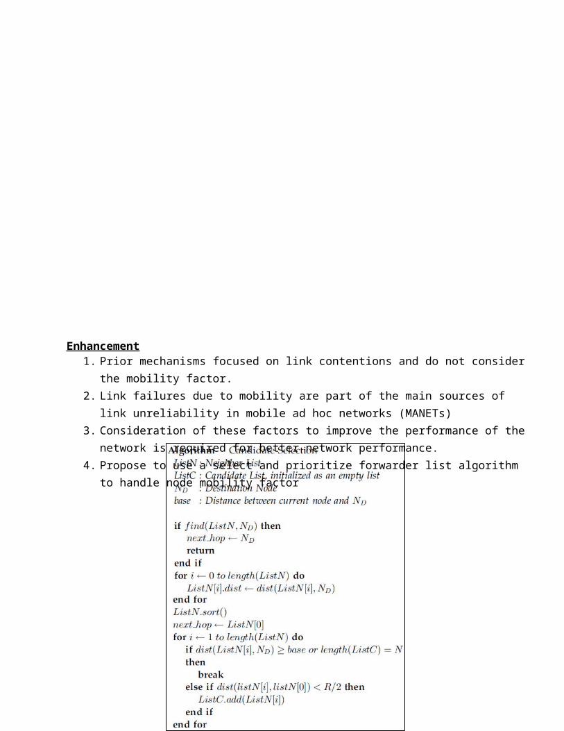
Enhancement1. Prior mechanisms focused on link contentions and do not consider
the mobility factor. 2. Link failures due to mobility are part of the main sources of
link unreliability in mobile ad hoc networks (MANETs)3. Consideration of these factors to improve the performance of the
network is required for better network performance.4. Propose to use a select and prioritize forwarder list algorithm
to handle node mobility factor

5. Algorithm shows the procedure to select and prioritize the forwarder list.
The candidate list will be attached to the packet header andupdated hop by hop(so nodes constantly updates either base station or neighbors about their location specifics for every small intervals of time ~500ms).
Only the nodes specified in the candidate list will act as forwarding candidates.
The lower the index of the node in the candidate list, the higher priority it has.
6. So a better ad-hoc network that is robust to node mobility is constructed using the above methods

2.1 STUDY OF THE SYSTEM
For simulating current project we consider a network traffic
simulation scenario. User interfaces have been developed using NS3/WAF
framework that are accessible like any native(console) applications in
the form of a script files
An ns3 script is a program written in the C++/Python programming
language that can be included in an HTML page, much in the same way an
image is included in a page. When you use a C++/Python technology-
enabled browser to view a page that contains an applet, the applet's
code is transferred to your system and executed by the browser's
C++/Python Virtual Machine (JVM).
For our demonstration we use a combination of both
The GUI’S at the top level have been categorized as
An Operational user interface that decodes specified instructions
that contains details about traffic conditions and network and
portrays them in a C++/Python applet integrated into a window
application.1.
2.2 INPUT & OUTPOUT REPRESENTETION
Input design is a part of overall system design. The main objective
during the input design is as given below:
To achieve the highest possible level of accuracy in while
transferring information into the application..
To ensure that the input is acceptable and understood by the
application ans to the user.
INPUT STAGES:
The main input stages can be listed as below:
Data recording
Data transcription
Data conversion
Data verification
Data control
Data transmission
Data validation
Data correction
INPUT TYPES:
Data Configuration System: Sets up the basic application
structures;
Simulator: Contains all logical system, including vehicles,
traffic lights and user;
Interface: Presents the graphical scene and processes input
commands from the user and both system.
INPUT MEDIA:
At this stage choice has to be made about the input media. To
conclude about the input media consideration has to be given to;
Type of input
Flexibility of format
Speed
Accuracy
Verification methods
Rejection rates
Ease of correction
Storage and handling requirements
Security
Easy to use
Portability(real devices or virtual devices like on screen
keyboard)
Keeping in view the above description of the input types and input
media, it can be said that most of the inputs are of the form of
internal and interactive. As Input data is to be the directly keyed
in by the user. The input should be independent of the nature of
devices but only on the actions like click of a button for responding.
Simulation models are generated from a set of data taken from a
stochastic system. It is necessary to check that the data is
statistically valid by fitting a statistical distribution and then
testing the significance of such a fit. Further, as with any modeling
process, the input data’s accuracy must be checked and any outliers
must be removed.
OUTPUT DESIGN:

When a simulation has been completed, the data needs to be analyzed.
The simulation's output data will only produce a likely estimate of
real-world events. Methods to increase the accuracy of output data
include: repeatedly performing simulations and comparing results,
dividing events into batches and processing them individually, and
checking that the results of simulations conducted in adjacent time
periods “connect” to produce a coherent holistic view of the system
OUTPUT DEFINITION
The outputs should be defined in terms of the following points:
Type of the output(Traffic simulation with nodes etc)
Content of the output(events replicated in the output)
Format of the output(Graphical but not textual unlike other
applications)
Location of the output(in an Applet embedded into a Window)
Frequency of the output(information arrivals)
Volume of the output(Looping number of nodes deployed corresponding
time specified)
Sequence of the output(Simulation, Events, Reports)
OUTPUT MEDIA:
In the next stage it is to be decided that which medium is the most
appropriate for the output. The main considerations when deciding
about the output media are:
Only Screen Shots are applicable.
The user is required to manually save the reports.

2.3 PROCESS MODEL USED WITH JUSTIFICATION
SDLC (Umbrella Mode l) :
SDLC is nothing but Software Development Life Cycle. It is a standard
which is used by software industry to develop good software.
Stages in SDLC:
Requirement Gathering
Umbrella Activity
Umbrella Activity
Umbrella Activity
Feasibility StudyTEAM FORMATIONProject
Specification PREPARATION
Business Requirement Documentation
ANALYSIS & DESIGN CODE UNIT TEST
DOCUMENT CONTROL
ASSESSMENT
TRAINING
INTEGRATION & SYSTEM TESTING
DELIVERY/INSTALLATI
ON
ACCEPTANCE TEST
Requirements
Gathering

Analysis
Designing
Coding
Testing
Maintenance
Requirements Gathering stage :
The requirements gathering process takes as its input the goals
identified in the high-level requirements section of the project plan.
Each goal will be refined into a set of one or more requirements.
These requirements define the major functions of the intended
application, define
operational data areas and reference data areas, and define the
initial data entities. Major functions include critical processes to
be managed, as well as mission critical inputs, outputs and reports. A
user class hierarchy is developed and associated with these major
functions, data areas, and data entities. Each of these definitions is
termed a Requirement. Requirements are identified by unique
requirement identifiers and, at minimum, contain a requirement title
and
textual description.
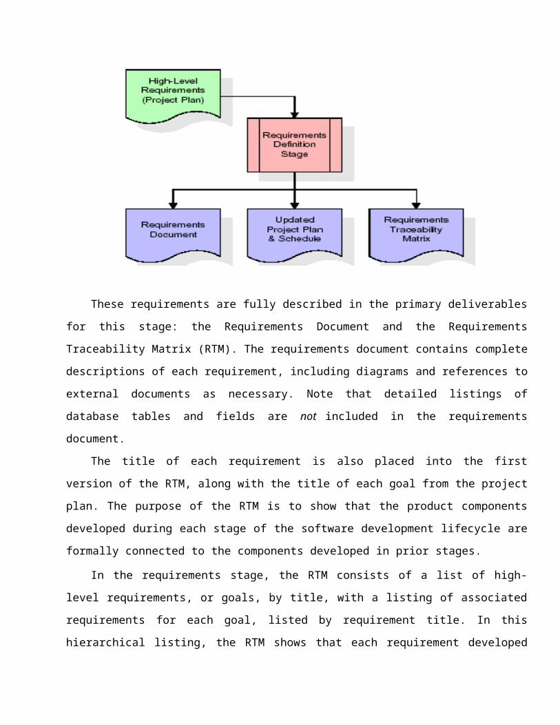
These requirements are fully described in the primary deliverables
for this stage: the Requirements Document and the Requirements
Traceability Matrix (RTM). The requirements document contains complete
descriptions of each requirement, including diagrams and references to
external documents as necessary. Note that detailed listings of
database tables and fields are not included in the requirements
document.
The title of each requirement is also placed into the first
version of the RTM, along with the title of each goal from the project
plan. The purpose of the RTM is to show that the product components
developed during each stage of the software development lifecycle are
formally connected to the components developed in prior stages.
In the requirements stage, the RTM consists of a list of high-
level requirements, or goals, by title, with a listing of associated
requirements for each goal, listed by requirement title. In this
hierarchical listing, the RTM shows that each requirement developed

during this stage is formally linked to a specific product goal. In
this format, each requirement can be traced to a specific product
goal, hence the term requirements traceability.
The outputs of the requirements definition stage include the
requirements document, the RTM, and an updated project plan.
Feasibility study is all about identification of problems in a
project.
No. of staff required to handle a project is represented as Team
Formation, in this case only modules are individual tasks will be
assigned to employees who are working for that project.
Project Specifications are all about representing of various
possible inputs submitting to the base station or access point and
corresponding outputs along with reports maintained by
administrator
Analysis S tage :
The planning stage establishes a bird's eye view of the intended
software product, and uses this to establish the basic project
structure, evaluate feasibility and risks associated with the project,
and describe appropriate management and technical approaches.

The most critical section of the project plan is a listing of high-
level product requirements, also referred to as goals. All of the
software product requirements to be developed during the requirements
definition stage flow from one or more of these goals. The minimum
information for each goal consists of a title and textual description,
although additional information and references to external documents
may be included. The outputs of the project planning stage are the
configuration management plan, the quality assurance plan, and the
project plan and schedule, with a detailed listing of scheduled
activities for the upcoming Requirements stage, and high level
estimates of effort for the out stages.
Designing Stage:
The design stage takes as its initial input the requirements
identified in the approved requirements document. For each
requirement, a set of one or more design elements will be produced as

a result of interviews, workshops, and/or prototype efforts. Design
elements describe the desired software features in detail, and
generally include functional hierarchy diagrams, screen layout
diagrams, tables of business rules, business process diagrams, pseudo
code, and a complete entity-relationship diagram with a full data
dictionary. These design elements are intended to describe the
software in sufficient detail that skilled programmers may develop the
software with minimal additional input.
When the design document is finalized and accepted, the RTM is updated
to show that each design element is formally associated with a
specific requirement. The outputs of the design stage are the design
document, an updated RTM, and an updated project plan.
Development (Coding) Stage:
The development stage takes as its primary input the design
elements described in the approved design document. For each design
element, a set of one or more software artifacts will be produced.

Software artifacts include but are not limited to menus, dialogs, data
management forms, data reporting formats, and specialized procedures
and functions. Appropriate test cases will be developed for each set
of functionally related software artifacts, and an online help system
will be developed to guide users in their interactions with the
software.
The RTM will be updated to show that each developed artifact is
linked to a specific design element, and that each developed artifact
has one or more corresponding test case items. At this point, the RTM
is in its final configuration. The outputs of the development stage
include a fully functional set of software that satisfies the
requirements and design elements previously documented, an online help
system that describes the operation of the software, an implementation
map that identifies the primary code entry points for all major system
functions, a test plan that describes the test cases to be used to

validate the correctness and completeness of the software, an updated
RTM, and an updated project plan.
Integration & Test Stage:
During the integration and test stage, the software artifacts,
online help, and test data are migrated from the development
environment to a separate test environment. At this point, all test
cases are run to verify the correctness and completeness of the
software. Successful execution of the test suite confirms a robust and
complete migration capability. During this stage, reference data is
finalized for production use and production users are identified and
linked to their appropriate roles. The final reference data (or links
to reference data source files) and production user list are compiled
into the Production Initiation Plan.

The outputs of the integration and test stage include an
integrated set of software, an online help system, an implementation
map, a production initiation plan that describes reference data and
production users, an acceptance plan which contains the final suite of
test cases, and an updated project plan.
Installation & Acceptance Test:
During the installation and acceptance stage, the software
artifacts, online help, and initial production data are loaded onto
the device or emulator. At this point, all test cases are run to
verify the correctness and completeness of the software. Successful
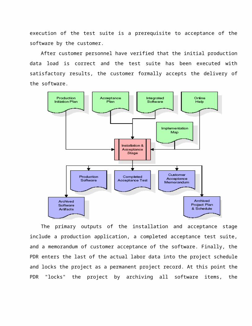
execution of the test suite is a prerequisite to acceptance of the
software by the customer.
After customer personnel have verified that the initial production
data load is correct and the test suite has been executed with
satisfactory results, the customer formally accepts the delivery of
the software.
The primary outputs of the installation and acceptance stage
include a production application, a completed acceptance test suite,
and a memorandum of customer acceptance of the software. Finally, the
PDR enters the last of the actual labor data into the project schedule
and locks the project as a permanent project record. At this point the
PDR "locks" the project by archiving all software items, the

implementation map, the source code, and the documentation for future
reference.
Maintenance:
Outer rectangle represents maintenance of a project, Maintenance
team will start with requirement study, understanding of documentation
later employees will be assigned work and they will under go training
on that particular assigned category.
For this life cycle there is no end, it will be continued so on like
an umbrella (no ending point to umbrella sticks).
2.4 SYSTEM ARCHITECTUREArchitecture flow:Below architecture diagram represents mainly flow of requests between
user and simulation system. In this scenario overall system is
designed in three tires separately using three layers called
presentation layer using C++/Python windows , business logic layer
using C++/Python and data link layer using config files. This project
was developed using 2-tire architecture. Its architecture is
represented in the following way.

Figure. TCP cwnd overshooting problem..

Flow Pattern:
Flow Pattern represents how the requests are flowing through one
layer to another layer and how the responses are getting by other
layers to presentation layer through C++/Python sources in
architecture diagram.


Feasibility Study:
Preliminary investigation examines project feasibility, the
likelihood the application will be useful to the user. The main
objective of the feasibility study is to test the Technical,
Operational and Economical feasibility for adding new modules and
debugging traditional desktop centric applications and porting them to
mobile devices. All systems are feasible if they are given unlimited
resources and infinite time. There are aspects in the feasibility
study portion of the preliminary investigation:
Technical Feasibility
Operation Feasibility
Economical Feasibility
3.1 TECHNICAL FEASIBILITY

The technical issue usually raised during the feasibility stage of the
investigation includes the following:
Does the necessary technology exist to do what is suggested?
Do the proposed equipment’s have the technical capacity to hold
the data required to use the new system?
Will the proposed system provide adequate response to inquiries,
regardless of the number or location of users?
Can the system be upgraded if developed?
Are there technical guarantees of accuracy, reliability, ease of access and data security?
As part of achieving technical competency for developing the proposed
system users are required to acquire skillset in C++/Python,
C++/Python.net and transient loop launching and detection mechanisms
using C++/Python from a small scale to large scale.
3.2 OPERATIONAL FEASIBILITY
OPERATIONAL FEASIBILITY
User-friendly
User will use the C++/Python window resources as screens for their
various transactions i.e. for starting client and base station or
access point, performing operations. Also the users are notified of
each successful operation. Basic usage of any client-base station
or access point centric application is good enough for this task.
These screens and notifications are generated in a user-friendly
manner.

Reliability
The usage of Mobility models ensures and enforces accurate
encryption and decryption procedures for authentication and
communication mechanisms along with Mobility models for session
validations.
Security
An auto session key generation interface ensures only authorized
node can join and access resources in the network.
Portability
The application will be developed using standard open source
technologies like C++/Python AWT and Windows. These technologies
will work on any standard system capable of running C++/Python.
Hence portability problems will not arise.
Availability
This software will be available always since it is maintained at
one place.
Maintainability
The system called the Bandwidth TCP CONGESTION WINDOW ADAPTATION
THROUGH CONTENTION DETECTION IN AD HOC NETWORK uses the 2-tier
architecture. The 1st tier is the Base station or access point,
which is said to be front-end and base station or access point
operations combo and is comprised of C++/Python window form and C+
+/Python sources and the 2nd tier is the Client which is said to be
front-end and client operations combo and is comprised of
C++/Python window forms and C++/Python sources. No third party
libraries were used and all the application modules are maintained
at one place and hence there are no maintenance issues.
3.3 ECONOMIC FEASILITY
Economical: Client setup, Base station or access point setup, No
logging operation and hence no data base is required
• Constructing own Base station or access points and not using http
base station or access points for communication ensures less cost
Open source technologies like C++/PYTHON, usage minimizes the cost
for the Developer.


4.1 FUNCTIONAL REQUIREMENTS SPECIFICATION
The present application has been divided in to four modules.
1. Network Joining Module (Request Classification for QoS
implementation)
2. Authentication Modules (Request Classification for QoS
implementation)
3. Operations Modules

1. Send(Request Classification for QoS implementation)
2. Receive
3. View Neighbors (Request Classification for QoS implementation)
4. Transactions
5. Log
1. Network Joining Module
This module is used to join in to the network with proper handshake
credentials such as ip address and port numbers which are provided to
the system for both client and base station or access point in the
form of configuration files.
Using these first the base station or access point is deployed. And
then each client connects to the base station or access point using
his own customized configuration files.
2. Authentication Modules : By using this module each node joins network completely by either
obtaining partial key shares from already existing nodes or in case of
insufficient number of nodes existence obtaining key directly from
monitoring node or base station or access point. Thus after this
successful operation a node completely joins the network.
3. Operations Modules :
By using this module nodes will get access to all the services
provided by the network. This module is having following sub
functionalities.
1. Send: By using this functionality nodes can send data in the
network by considering dynamic route changes classified by BS.
2. Receive: By using this functionality nodes can receive data fromthe network.
3. View neighbors: By using this functionality nodes can see all theexisting neighbor nodes in the network.
4. Transaction:A detailed information accumulated of performed
transactions(joining,sending,recieving) in the network.
5. Log: A log view maintained and displayed for all the
transactions in the network
4.2 PERFORMANCE REQUIREMENTS
Performance is measured in terms of the output provided by the
application. Requirement specification plays an important part in the
analysis of a system. Only when the requirement specifications are
properly given, it is possible to design a system, which will fit into
required environment. It rests largely with the users of the existing
system to give the requirement specifications because they are the
people who finally use the system. This is because the requirements
have to be known during the initial stages so that the system can be
designed according to those requirements. It is very difficult to
change the system once it has been designed and on the other hand
designing a system, which does not cater to the requirements of the
user, is of no use.
The requirement specification for any system can be broadly
stated as given below:

The system should be able to interface with the existing
system
The system should be accurate
The system should be better than the existing system
The existing system is completely dependent on the user to perform allthe duties.
4.3 SOFTWARE REQUIREMENTS: DEVELOPER VIEW
Operating System : Windows
Technology : C++/Python, Network Performance
Web Technologies : None
Web Server : None
Database : None
Software Tools :
1. C++/Python
2. Ubuntu Linux for development
3. NS3 Framework
4.4 HARDWARE REQUIREMENTS: DEVELOPER VIEW
Hardware requirements:
Hardware : Minimum Dual Core 2.8
Ghz (recommended for best simulation)
RAM : 1GB (minimum)
Others : Standard Monitor,Keyboard,Mouse
etc.
4.4.2. INTRODUCTION TO NS3

The difference between ns-2 and ns-3
ns-2 is a popular discrete-event network simulator developed underseveral previous research grants and activities. It remains in activeuse and will continue to be maintained.ns-3 is a new software development effort focused on improving uponthe core architecture, software integration, models, and educationalcomponents of ns-2ns-2 scripts in ns-3
ns-2 scripts will not run within ns-3. ns-2 uses OTcl as its scriptingenvironment. ns-3 uses C++ programs or python scripts to definesimulations.
ns-2 models in ns-3
Some ns-2 models that are mostly written in C++ have already beenported to ns-3: OLSR and Error Model were originally written for ns-2.OTcl-based models have not been and will not be ported since thiswould be equivalent to a complete rewrite.
Concept NS2 NS3Programming languages NS2 is implemented
using acombination of oTCL(for scriptsdescribing the networktopology) andC++ (The core of thesimulator). This system waschosen in the early1990s to avoid therecompilation ofC++ as it was very timeconsumingusing the hardwareavailable at thattime, oTCL
NS3 is implementedusing C++ With modern hardwarecapabilities,compilation time wasnot an issue likefor NS2, NS3 can bedeveloped withC++ entirely. A simulation scriptcan be written as aC++ program, which isnot possible inNS2. There is a limitedsupport for Pythonin scripting and

recompilation takeslesstime than C++. oTCL disadvantage:there is overheadintroduced with largesimulations. oTCL is the onlyavailable scriptinglanguage.
visualization.
Memory Management NS2 requires basicmanual C++memory managementfunctions.
Because NS3 isimplemented in C++,all normal C++ memorymanagementfunctions such as new,delete, malloc,and free are stillavailable. Automatic de-allocation of objectsissupported usingreference counting(track number ofpointers to anobject); this is usefulwhen dealingwith Packet objects.
Packets A packet consists of 2distinct regions;one for headers, andthe second storespayload data. NS2 never freesmemory used to storepackets until thesimulationterminates, it justreuses the allocatedpackets repeatedly, asa result, theheader region of anypacket includesall headers defined aspart of the used
A packet consists of asingle buffer ofbytes, and optionally acollection ofsmall tags containingmeta-data. The buffercorresponds exactly tothestream of bits thatwould be sent overa real network. Information is addedto the packet byusing subclasses;Header, which addsinformation to the

protocol even if thatparticular packetwon't use thatparticular header, but just to beavailable when thispacket allocation isreused.
beginning of thebuffer, Trailer, whichadds to the end. Unlike NS2, there isgenerally easyway to determine if aspecific headeris attached.
Performance
Simulation output
The total computationtime required torun a simulation scalesbetter in NS3than NS2. This is due to theremoval of theoverhead associatedwith interfacingoTcl with C++, and theoverheadassociated with theoTcl interpreter.
NS2 comes with apackage calledNAM (Network Animator),it's a Tcl basedanimation system thatproduces a visualrepresentation of thenetwork described.
NS3 performs betterthan NS2 interms of memorymanagement. The aggregationsystem preventsunneeded parametersfrom beingstored, and packetsdon't containunused reserved headerspace.
NS3 employs a package known asPyViz, which is apython based realtimevisualization package.
Important notes about NS3:
NS3 is not backward compatible with NS2; it's built from the scratchto replace NS2. NS3 is written in C++, Python Programming Language can be optionallyused as an interface. NS3 is trying to solve problems present in NS2. There is very limited number of contributed codes made with NS3compared to NS2
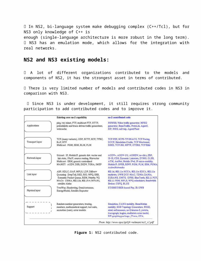
In NS2, bi-language system make debugging complex (C++/Tcl), but forNS3 only knowledge of C++ isenough (single-language architecture is more robust in the long term). NS3 has an emulation mode, which allows for the integration withreal networks.
NS2 and NS3 existing models:
A lot of different organizations contributed to the models andcomponents of NS2, it has the strongest asset in terms of contributed. There is very limited number of models and contributed codes in NS3 incomparison with NS3.
Since NS3 is under development, it still requires strong communityparticipation to add contributed codes and to improve it.
Figure 1: NS2 contributed code.
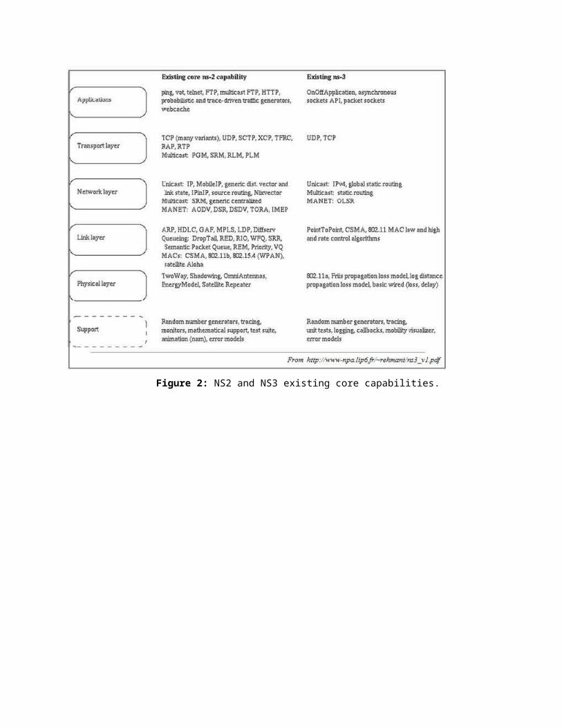
Figure 2: NS2 and NS3 existing core capabilities.


5.1 INTRODUCTION
Systems design
Introduction: Systems design is the process or art of defining thearchitecture, components, modules, interfaces, and data for a system
to satisfy specified requirements. One could see it as the application
of systems theory to product development. There is some overlap and
synergy with the disciplines of systems analysis, systems architecture
and systems engineering.
5.2 UML DIAGRAMS
Unified Modeling Language:
The Unified Modeling Language allows the software engineer to express
an analysis model using the modeling notation that is governed by a
set of syntactic semantic and pragmatic rules.
A UML system is represented using five different views that describe
the system from distinctly different perspective. Each view is defined
by a set of diagram, which is as follows.
User Model View

i. This view represents the system from the users
perspective.
ii. The analysis representation describes a usage scenario
from the end-users perspective.
Structural model view
i. In this model the data and functionality are arrived
from inside the system.
ii. This model view models the static structures.
Behavioral Model View
It represents the dynamic of behavioral as parts of the
system, depicting the interactions of collection between
various structural elements described in the user model and
structural model view.
Implementation Model View
In this the structural and behavioral as parts of the system
are represented as they are to be built.
Environmental Model View
In this the structural and behavioral aspects of the
environment in which the system is to be implemented are
represented.

UML is specifically constructed through two different domains they
are:
UML Analysis modeling, this focuses on the user model and
structural model views of the system.
UML design modeling, which focuses on the behavioral modeling,
implementation modeling and environmental model views.
Use case Diagrams represent the functionality of the system from a
user’s point of view. Use cases are used during requirements
elicitation and analysis to represent the functionality of the system.
Use cases focus on the behavior of the system from external point of
view.
Actors are external entities that interact with the system. Examples of actors include users like administrator, bank customer …etc., or another system like central database.

UML DIAGRAMS


7.1 INTRODUCTION TO TESTING
Introduction to Testing:
Testing is a process, which reveals errors in the program. It is
the major quality measure employed during software development. During
software development. During testing, the program is executed with a
set of test cases and the output of the program for the test cases is
evaluated to determine if the program is performing as it is expected
to perform.

7.2 TESTING IN STRATEGIES
In order to make sure that the system does not have errors,
the different levels of testing strategies that are applied at
differing phases of software development are:
Unit Testing:
Unit Testing is done on individual modules as they are completed
and become executable. It is confined only to the designer's
requirements.
Each module can be tested using the following two Strategies:
Black Box Testing:
In this strategy some test cases are generated as input
conditions that fully execute all functional requirements for the
program. This testing has been uses to find errors in the
following categories:
Incorrect or missing functions
Interface errors
Errors in data structure or external database access
Performance errors
Initialization and termination errors.
In this testing only the output is checked for correctness.
The logical flow of the data is not checked.
White Box testing :

In this the test cases are generated on the logic of each
module by drawing flow graphs of that module and logical decisions
are tested on all the cases. It has been uses to generate the test
cases in the following cases:
Guarantee that all independent paths have been Executed.
Execute all logical decisions on their true and false Sides.
Execute all loops at their boundaries and within their
operational bounds
Execute internal data structures to ensure their validity.
Integrating Testing :
Integration testing ensures that software and subsystems work
together a whole. It tests the interface of all the modules to
make sure that the modules behave properly when integrated
together. In this case the communication between the device and
Google Translator Service.
System Testing :
Involves in-house testing in an emulator of the entire system
before delivery to the user. It's aim is to satisfy the user the
system meets all requirements of the client's specifications.
Acceptance Testing :

It is a pre-delivery testing in which entire system is tested in a
real android device on real world data and usage to find errors.
Test Approach :
Testing can be done in two ways:
Bottom up approach
Top down approach
Bottom up Approach:
Testing can be performed starting from smallest and lowest
level modules and proceeding one at a time. For each module in
bottom up testing a short program executes the module and provides
the needed data so that the module is asked to perform the way it
will when embedded with in the larger system. When bottom level
modules are tested attention turns to those on the next level that
use the lower level ones they are tested individually and then
linked with the previously examined lower level modules.
Top down approach:
This type of testing starts from upper level modules. Since
the detailed activities usually performed in the lower level
routines are not provided stubs are written. A stub is a module
shell called by upper level module and that when reached properly
will return a message to the calling module indicating that proper

interaction occurred. No attempt is made to verify the correctness
of the lower level module.
Validation:
The system has been tested and implemented successfully and thus
ensured that all the requirements as listed in the software
requirements specification are completely fulfilled. In case of
erroneous input corresponding error messages are displayed
TestNumber
ModuleName
Test Name Date
Tester
Expected Output
1 Base station or accesspoint invoke
checking for various port numbers beyond 5000
should work for all unused port number beyond 5000
2 Track nodes
update other nodes about joining and leaving of other nodes
Reflect changes in all nodes
3 Detectactivenode
checking for state of node
Reflect changes in all nodes
4 Detectpassive node
checking for state of node
Reflect changes in all nodes
5 Result display client details
client should be check the main window
6 Login username with ip should see

combo login operations window7 neighb
or search
search for new nodes
new nodes results
8 destination node
check for destination node innetwork
receiver node information
9 Login username with ip combo login
User Keys Authenticated from Base stationor access point
8.1 INTRODUCTION
System Security:
TCP CONGESTION WINDOW ADAPTATION THROUGH CONTENTION DETECTION IN AD HOC NETWORK
8.1 Introduction:A specific authentication procedure is required to use the
application. An automated mechanism where the client directly fetches
session keys, and encryption public keys directly from the base
station or access point at time of authentication.
ADVANCED
No login credentials were required to use the system.


9. BIBLIOGRAPHY
References for the Project Development Were Taken From the
following Books and Web Sites.
C++/PYTHON Technologies
NS3 Manual
C++/PYTHON The Complete Reference
C++/PYTHON Base station or access point pages by NickTodd
UNDERSTANDING AND DEPLOYING LOOP-FREE ALTERNATE FEATURE
Avoiding transient loops during IGP convergence in IPnetworks
An Algorithm for Multipath Computation using Distance-Vectors with Predecessor Information
Quality of Service Support in IEEE 802.11Networks -Claudio Cicconetti, Luciano Lenzini, and Enzo Mingozzi,University of Pisa Carl Eklund, Nokia Research Center