TM2000A PTP and NTP Time Server GPS ... - TimeMachines
24
TM2000A PTP and NTP Time Server GPS Time Sourced Installation and Operation Manual
-
Upload
khangminh22 -
Category
Documents
-
view
4 -
download
0
Transcript of TM2000A PTP and NTP Time Server GPS ... - TimeMachines

TM2000A
PTP and NTP Time ServerGPS Time Sourced
Installation and Operation Manual
Table of Contents 1 Introduction............................................................................................................................................1 2 Installation..............................................................................................................................................2
2.1 Location..........................................................................................................................................2 2.2 Connections....................................................................................................................................2
2.2.1 Antenna...................................................................................................................................2 2.2.2 Power......................................................................................................................................2 2.2.3 Network..................................................................................................................................2 2.2.4 Front Panel Indications...........................................................................................................2
3 Configuration.........................................................................................................................................3 3.1 Web Page – Default username/password is “admin/tmachine”......................................................3 3.2 Default IP address is 192.168.1.20.................................................................................................3 3.3 Settings Page..................................................................................................................................4
3.3.1 TM2000 Name........................................................................................................................4 3.3.2 Disable Web Interface.............................................................................................................4 3.3.3 IP Address...............................................................................................................................5 3.3.4 Broadcast................................................................................................................................5 3.3.5 Netmask..................................................................................................................................5 3.3.6 Gateway..................................................................................................................................5 3.3.7 DNS1 and DNS2....................................................................................................................5 3.3.8 Password.................................................................................................................................5
3.4 Status Page.....................................................................................................................................6 3.4.1 Time Source............................................................................................................................6 3.4.2 Location..................................................................................................................................6 3.4.3 Date/Time...............................................................................................................................7 3.4.4 Satellites Used........................................................................................................................7 3.4.5 GPS Fix...................................................................................................................................7 3.4.6 NTP Lookups..........................................................................................................................7 3.4.7 MAC.......................................................................................................................................7 3.4.8 Uptime....................................................................................................................................7 3.4.9 Version....................................................................................................................................7 3.4.10 Satellites................................................................................................................................7 3.4.11 NTP Peers.............................................................................................................................7 3.4.12 Clients...................................................................................................................................8
3.5 Update Page....................................................................................................................................9 3.6 SNMP Setup.................................................................................................................................10
3.6.1 MIB File-Download TMI-COMMON-SHI.txt....................................................................10 3.6.2 Enable...................................................................................................................................10 3.6.3 SNMP Trap Version..............................................................................................................10 3.6.4 Notification Method..............................................................................................................11 3.6.5 Trap Receiver IP Address......................................................................................................11 3.6.6 SNMP V2 Community Name...............................................................................................11 3.6.7 SNMP V3 R/W User Name..................................................................................................11 3.6.8 SNMP V3 R/W Password.....................................................................................................11 3.6.9 SNMP V3 Engine ID............................................................................................................11
3.6.10 SNMP MIB File..................................................................................................................11 3.7 NTP Settings Page........................................................................................................................12
3.7.1 Start / Stop NTP Server........................................................................................................12 3.7.2 Allow 2D Fix for NTP..........................................................................................................13 3.7.3 Disable Holdover Limit........................................................................................................13 3.7.4 NTP Holdover Accuracy.......................................................................................................13 3.7.5 Remote NTP Servers Enable................................................................................................13 3.7.6 Remote NTP Servers List.....................................................................................................13 3.7.7 Serve Time Only With Authentication..................................................................................13 3.7.8 Authentication-Upload Key List...........................................................................................14 3.7.9 Set TM2000A time manually................................................................................................14
3.8 PTP Settings Page.........................................................................................................................15 3.8.1 PTP Update Method One/Two Step......................................................................................15 3.8.2 Domain Number...................................................................................................................16 3.8.3 Priority 1 & Priority 2...........................................................................................................16 3.8.4 PTP Transmission Method....................................................................................................16 3.8.5 PTP Post-Holdover Behavior................................................................................................16 3.8.6 Multicast Configuration – Log Announce Interval...............................................................16 3.8.7 Multicast Configuration – Log Sync Interval.......................................................................16 3.8.8 Multicast Configuration – Log Min Delay Request Interval................................................16 3.8.9 Multicast Configuration – Log min Peer Delay Request Interval........................................16
3.9 About Page...................................................................................................................................17 3.9.1 Download Log Files.............................................................................................................17 3.9.2 Reboot System......................................................................................................................17
4 Troubleshooting...................................................................................................................................18 4.1 GPS Lock.....................................................................................................................................18 4.2 Resetting to Factory Defaults.......................................................................................................18
5 Locator Data Query..............................................................................................................................19 6 Specifications.......................................................................................................................................20
6.1 Time Server Features and Specifications.....................................................................................20 6.2 GPS Module Specifications..........................................................................................................20 6.3 Antenna Specifications.................................................................................................................21
TimeMachines, Inc.300 S68th St Place, Suite 100
Lincoln, NE 68510
402-486-0511
Engineered and Manufactured in Lincoln, Ne, USA
Rev 0.3.4 9-12-2019
1 Introduction
The Time Machines PTP Network Time Server is a simple to use GPS sourced time server that will supply accurate time for all computers and time keeping devices on the network. By placing a time server on the local network, PTP and NTP time packets are provided without requiring systems to go tothe Internet to get a Stratum 1 time synchronization. The system uses an active GPS antenna to maintain the current time as broadcast by United States GPS satellites. With this device installed on your local network, there is no longer the worry that if the Internet connection goes down, time synchronization is lost across the network. In addition, the TM2000A includes a high precision internalclock based on an OCXO (Oven controller oscillator) that allows the unit to serve accurate time beyondloss of the GPS antenna signal.
The unit is small and can be placed anywhere within the network layout. The built in high sensitivity GPS receiver is able to lock multiple satellites from within many buildings or from a window location, removing the requirement that outdoor antennas be installed.
Setup and use of this time server is straightforward. Simply connect both the included power supply and the GPS antenna to the base unit and then connect the base unit to the local network. Go to a computer on the network and browse to the device at its default address to enter the software setup within the control box. Set parameters to match your network and the system will start to send out timepackets to any device on the system that asks for an update from it. Two servers can be setup to provide redundancy and more capacity.
At customer request and input, as of version 0.3.4, support for setting internal time from other NTP servers, SNMP, and manual time set have been added.
When paired with our digital Power Over Ethernet (PoE) or WiFi clocks, synchronized time is assured no matter the state of your network, or the state of the internet time server the clocks are pointed to. Accuracy is also improved because the network delay of the internet is highly variable, while the local LAN connection is likely sub-millisecond delay.
TimeMachine GPS based time servers are suited to any application where coordination of events at multiple locations is required. Without coordinated network time, searching for problems across multiple system logs becomes much more difficult. Education, industrial facilities, military installations, public safety command rooms, government, broadcasting, and hospitals are all candidatesfor synchronized time systems.
Installation and Operations Manual | Page 1Web / timemachinescorp.com Email / [email protected] Phone / (402) 486-0511
2 Installation
2.1 LocationTo receive GPS signals the Time Server's antenna must be located in a location where it can “see” the sky. The GPS module itself is highly sensitive and able to “see” the GPS satellite signals from within many structures. Multi-Story or metal structures may block the GPS signals such that the antenna mustbe located elsewhere. In these cases, the GPS antenna may be located in a window. The Time Server box can be located anywhere on the network. All that is required is power and a wired network connection. In the worst case, an outdoor antenna may be required.
2.2 Connections
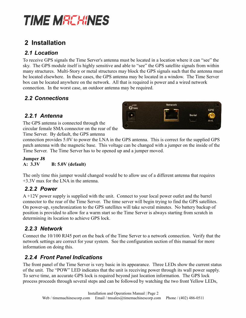
2.2.1 AntennaThe GPS antenna is connected through thecircular female SMA connector on the rear of theTime Server. By default, the GPS antennaconnection provides 5.0V to power the LNA in the GPS antenna. This is correct for the supplied GPS patch antenna with the magnetic base. This voltage can be changed with a jumper on the inside of the Time Server. The Time Server has to be opened up and a jumper moved.
Jumper J8A: 3.3V B: 5.0V (default)
The only time this jumper would changed would be to allow use of a different antenna that requires +3.3V max for the LNA in the antenna.
2.2.2 PowerA +12V power supply is supplied with the unit. Connect to your local power outlet and the barrel connector to the rear of the Time Server. The time server will begin trying to find the GPS satellites. On power-up, synchronization to the GPS satellites will take several minutes. No battery backup of position is provided to allow for a warm start so the Time Server is always starting from scratch in determining its location to achieve GPS lock.
2.2.3 NetworkConnect the 10/100 RJ45 port on the back of the Time Server to a network connection. Verify that the network settings are correct for your system. See the configuration section of this manual for more information on doing this.
2.2.4 Front Panel IndicationsThe front panel of the Time Server is very basic in its appearance. Three LEDs show the current status of the unit. The “POW” LED indicates that the unit is receiving power through its wall power supply. To serve time, an accurate GPS lock is required beyond just location information. The GPS lock process proceeds through several steps and can be followed by watching the two front Yellow LEDs,
Installation and Operations Manual | Page 2Web / timemachinescorp.com Email / [email protected] Phone / (402) 486-0511
LOCK and SEC. Initally, when no lock is present, the Yellow LEDs will be OFF. When a 2D lock is achieved, the LOCK LED will begin to BLINK. This is the first stage of GPS lock process. When the LOCK LED goes to a solid ON state, the GPS now has a 3D lock. The last stage of the GPS lock is thetiming lock. This signifies that the GPS has the most accurate time base available for use in serving time. To achieve the greatest PTP accuracy, this is required. Once the timing lock has occurred, the SEC LED will begin to blink once per second.
It is also possible for the LOCK LED to turn off, or blink, after a GPS timing lock has occurred and theSEC LED continues to blink. This signifies that the TM2000A has an accurate internal time and is serving time, but is trying to re-establish the timing lock because it was lost for some reason.
3 Configuration
3.1 Web Page – Default username/password is “admin/tmachine”
3.2 Default IP address is 192.168.1.20All Time Server parameters are accessed on the configuration web page. The page can be accessed by pointing any web browser at the IP address of the Time Server. The initial IP address is 192.168.1.20 from the factory.
Installation and Operations Manual | Page 3Web / timemachinescorp.com Email / [email protected] Phone / (402) 486-0511

3.3 Settings Page
3.3.1 TM2000 NameThis is a generic entry that has no effect on the TM2000A operation other than to allow the user to enter a name for the device to help recognize it when parameter updates are required.
3.3.2 Disable Web InterfaceThis is a security option. Once the device is configured and operating as expected, it is possible to check this box, save the setting, and then reboot that device. From that point forward, the web server is
Installation and Operations Manual | Page 4Web / timemachinescorp.com Email / [email protected] Phone / (402) 486-0511

disabled. To recover from this mode, the device must be reset to factory parameters by holding the front button for about 5 seconds. The IP address will be reset and the web page will be active again. This allows for a physical security measure to be used to protect settings of the device.
3.3.3 IP AddressThe IP address of the unit set to by entering a standard IPv4 dotted quad in this field. 192.168.1.20 or 10.10.0.96 are examples of acceptable formats for this field. Clicking the Submit button will set the entered IP parameters.
3.3.4 BroadcastThe Broadcast entry is used to control the propagation of network broadcast packets on the network and to what level they will propagate from the device. This is frequently opposite of the Netmask setting. This is used by the PTP functions to advertise the presence of the server. Clicking the Submit button will set the entered IP parameters. THIS IS NOT the address to point NTP and PTP clients at, they should given the IP Address.
3.3.5 NetmaskThe Netmask entry determines what addresses are on the local network and what addresses are reached through the Gateway. Typical Netmasks are 255.255.0.0 or 255.255.255.0. Consult the network administrator for more information on how this entry should be set. Clicking the Submit button will setthe entered IP parameters.
3.3.6 GatewayThe Gateway IP address is used when a destination address is determine to not be on the local network.Consult the network administrator for this setting. Clicking the Submit button will set the entered IP parameters.
3.3.7 DNS1 and DNS2Enter the IP addresses for the DNS servers on your network.
3.3.8 PasswordThe Password of the unit can be changed in this field. The existing password is not displayed for security purposes. Enter the new password and click the “Change Password” button to update. The TM2000A will then prompt for the new password to be entered to continue access to the web pages.
* Default Username/Password is “admin”/“tmachine”.
Installation and Operations Manual | Page 5Web / timemachinescorp.com Email / [email protected] Phone / (402) 486-0511
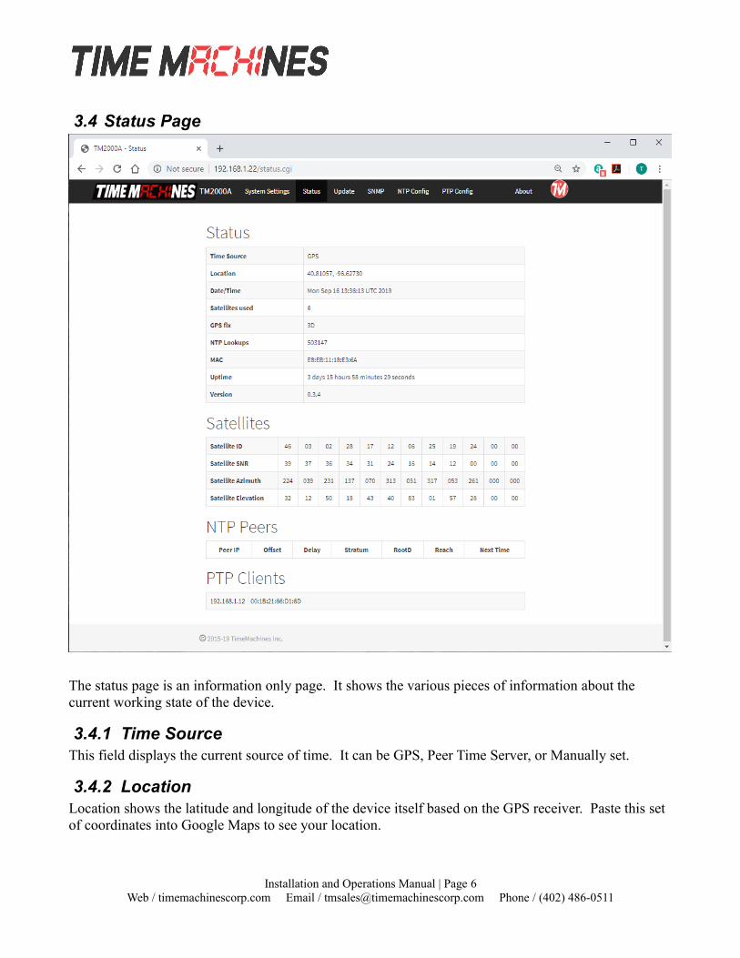
3.4 Status Page
The status page is an information only page. It shows the various pieces of information about the current working state of the device.
3.4.1 Time SourceThis field displays the current source of time. It can be GPS, Peer Time Server, or Manually set.
3.4.2 LocationLocation shows the latitude and longitude of the device itself based on the GPS receiver. Paste this set of coordinates into Google Maps to see your location.
Installation and Operations Manual | Page 6Web / timemachinescorp.com Email / [email protected] Phone / (402) 486-0511
3.4.3 Date/TimeThe Date/Time entry shows the current UTC date and time of the device. This is not updated realtime. Refreshing the page will update this time. Note that it is the clients responsibility to adjust for timezone and daylight savings adjustments.
3.4.4 Satellites UsedThis shows the current number of satellites that are in view and locked by the GPS receiver.
3.4.5 GPS FixThis displays the level of the current GPS lock.
No GPS Fix – Check cable connections. If connected correctly, likely the antenna needs a better view of the sky. Obstructions, building materials, window tinting can all cause possible signal issues.
2D - GPS satellites found.
3D – Required for serving time.
3.4.6 NTP LookupsThis field updates on a page reload and shows how many NTP time requests have been requested from client devices.
3.4.7 MACThis is an information only field and displays the MAC address of the Time Server.
3.4.8 UptimeTime elapsed since last boot up.
3.4.9 VersionDisplays current software version running on device.
3.4.10 SatellitesThis table shows the current list of locked satellites, their signal strengths (SNR), as well as their current location over the planet. Refreshing the web page updates the table to their current values.
3.4.11 NTP PeersIf time is being updated from a Peer time server, then this table shows the current list of Peer servers that are being checked to maintain the time in the TM2000A. Several Fields are displayed for each time server.
• Peer IP – The Peer IP address is the first field displayed.
• Offset – This is the offset of the peer time servers' time when compared to the internal clock of the TM2000A.
• Delay – The round trip delay to the peer time server
Installation and Operations Manual | Page 7Web / timemachinescorp.com Email / [email protected] Phone / (402) 486-0511
• Stratum – This field shows the stratum level being reported by the peer time server
• RootD – This is the root delay value of the peer time server. This is the time servers reported delay from its location to the root of the NTP time setup. A stratum 1 server is considered to be at the root of an NTP setup/design.
• Reach – This is a bit field that shows the result of the last 8 lookup attempts of the peer time server. A value of 0xff signifies that the last 8 attempts have been answered by the time server. A successful lookup causes a 1 to be shifted in to the LSB of the byte and all other bits to be shifted 1 bit to the left. A non 0xff value signifies that either the server has just started or that some lookup requests are not getting answered.
• Next Time – This is the time that the next request for time from the peer time server will occur. The NTP client of the TM2000A will start out with a check every 30 seconds or so and then expand out if time is tracking well to a couple of minutes. The TM2000A doesn't allow the time sync to extend beyond a few minutes to maintain accurate internal time.
3.4.12 ClientsThis area is used to show the current PTP clients. This will display entries only if the TM2000A is in Unicast PTP mode. In multicast mode, the TM2000A isn't aware of all clients getting time from it.
Installation and Operations Manual | Page 8Web / timemachinescorp.com Email / [email protected] Phone / (402) 486-0511

3.5 Update Page
The update page is used to update firmware of the unit. The firmware updates will be archived and available for download from the timemachinescorp.com website. Save the file to the local computers drives. Most likely the file will need to be unzipped. The file type that is used for the update is a .img file. Browse to it using the Choose File button on the Update Page. Once the file is found the update can begin. This process takes 20 to 25 minutes and power should not be removed during the process orthe device may be unrecoverable. There are periods of time where there may be little or no indication of the update process occurring, so its important to give it plenty of time. Once completed, the unit willreset and resume operation. Login to the device with a web browser to confirm the version update.
Installation and Operations Manual | Page 9Web / timemachinescorp.com Email / [email protected] Phone / (402) 486-0511
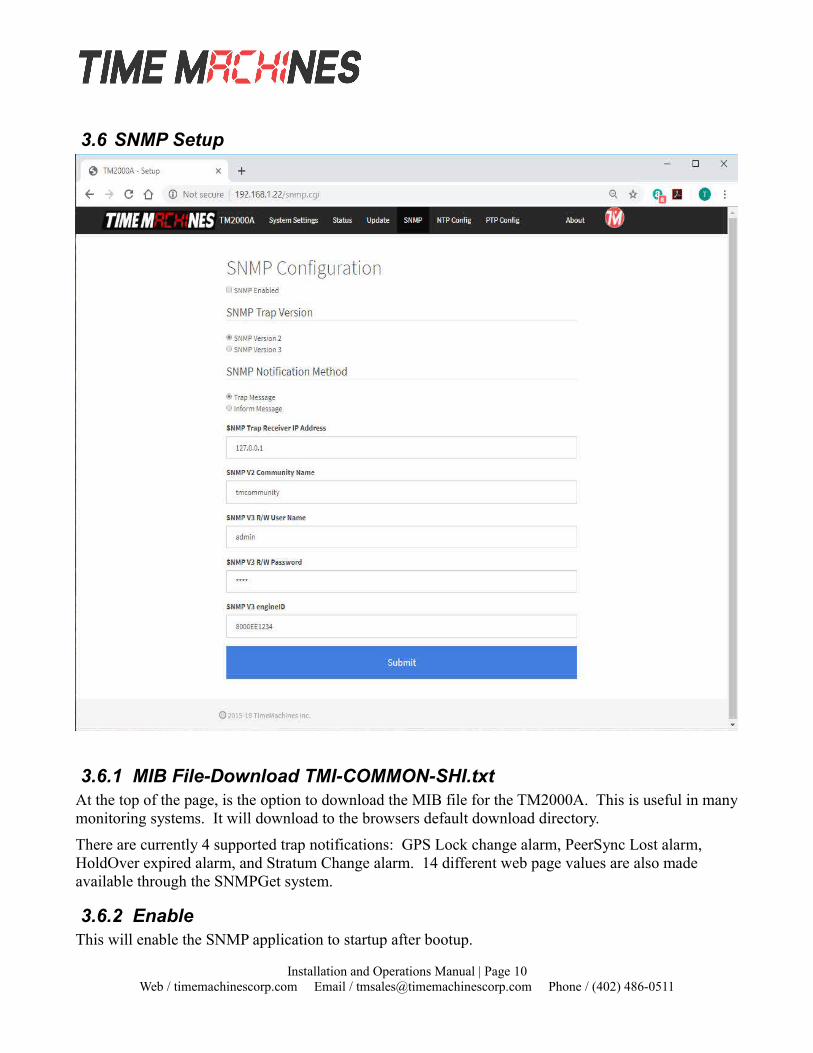
3.6 SNMP Setup
3.6.1 MIB File-Download TMI-COMMON-SHI.txtAt the top of the page, is the option to download the MIB file for the TM2000A. This is useful in manymonitoring systems. It will download to the browsers default download directory.
There are currently 4 supported trap notifications: GPS Lock change alarm, PeerSync Lost alarm, HoldOver expired alarm, and Stratum Change alarm. 14 different web page values are also made available through the SNMPGet system.
3.6.2 EnableThis will enable the SNMP application to startup after bootup.
Installation and Operations Manual | Page 10Web / timemachinescorp.com Email / [email protected] Phone / (402) 486-0511
3.6.3 SNMP Trap VersionThis sets the version to SNMPv2 or SNMPv3. It affects format of the trap/inform messages in the next option. If set to V2, then the trap/inform message will only identify itself with the community name with no other security features. The V3 mode supports a username/password combination to be used where the password is hashed with MD5. Full encryption of the SNMP packet is not supported.
3.6.4 Notification MethodThis sets the notification method to either Trap or Inform. A Trap messages is an un-acknowledged status packet, while the Inform message is acknowledged by the receiver. The Inform message creates a higher reliability that the receiver received the packet and can act on it. The Trap method is also widely used. Version 2 of these messages is a simpler format and setup, but without the username/password authentication. Version 3 will require the username and password to be setup on the SNMP web page, as well as using the Engine ID setting to synchronize the encryption when using Trap messages.
Trap/Inform messages are status checked one time per minute.
3.6.5 Trap Receiver IP AddressEnter the IP Address of the device being used to receive the trap/inform packets
3.6.6 SNMP V2 Community NameThe SNMP community name is used as a simple authentication for Version 2 SNMP packets.
3.6.7 SNMP V3 R/W User NameEnter the desired SNMPv3 username.
3.6.8 SNMP V3 R/W PasswordEnter the SNMPv3 password associated with the username.
3.6.9 SNMP V3 Engine IDWhen using SNMPv3 Trap messages, the engine ID needs to match between the trap receiver and the TM2000A as the sender. This entry specifically allows setting of the SNMP engineID. This is handled in this way because the bulk of the file system for the TM2000A is not R/W and parameters that are updated by the SNMP daemon are stored in RAM and lost on a power cycle/reboot. A reboot may be required when setting up Trap messages. Inform messages are a simpler implementation and may be simpler to setup for V3 SNMP.
Installation and Operations Manual | Page 11Web / timemachinescorp.com Email / [email protected] Phone / (402) 486-0511
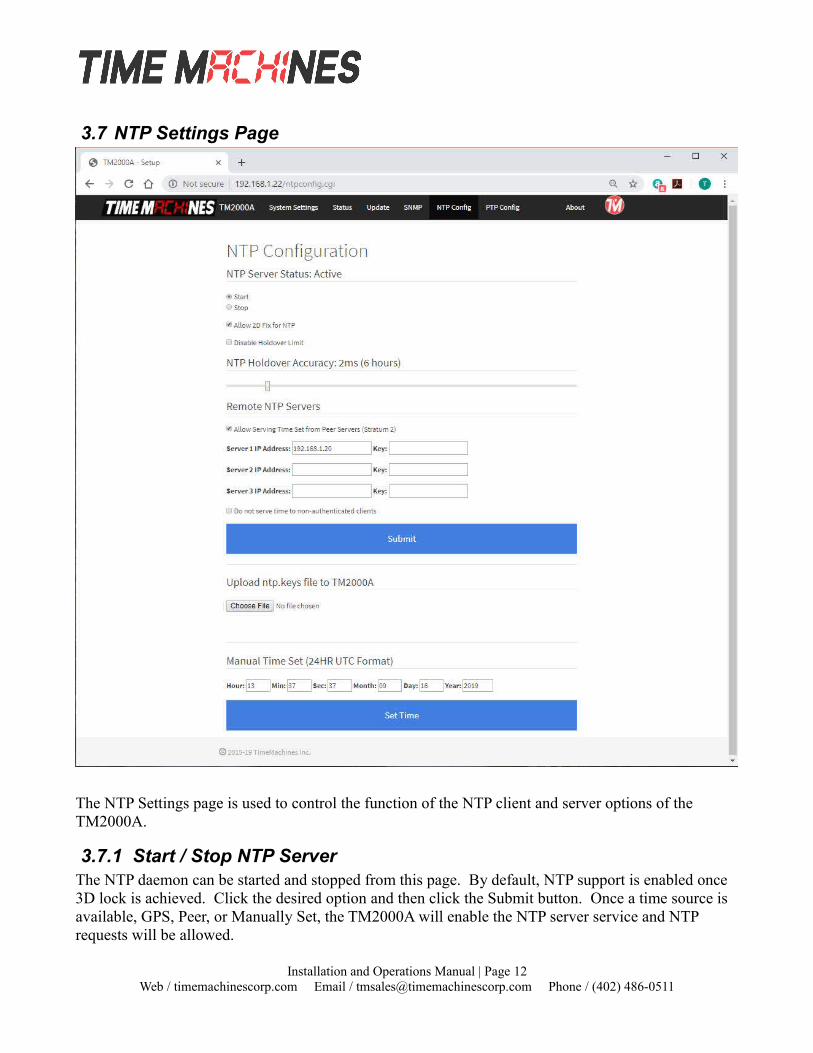
3.7 NTP Settings Page
The NTP Settings page is used to control the function of the NTP client and server options of the TM2000A.
3.7.1 Start / Stop NTP ServerThe NTP daemon can be started and stopped from this page. By default, NTP support is enabled once 3D lock is achieved. Click the desired option and then click the Submit button. Once a time source is available, GPS, Peer, or Manually Set, the TM2000A will enable the NTP server service and NTP requests will be allowed.
Installation and Operations Manual | Page 12Web / timemachinescorp.com Email / [email protected] Phone / (402) 486-0511
3.7.2 Allow 2D Fix for NTPThis checkbox will allow the TM2000A to start serving time once a 2D lock is achieved by the GPS receiver. It is generally better to get a 3D lock as timing accuracy is improved and more stable. The GPS module maker doesn't guarantee accuracy until a 3D lock is achieved, but this option exists if needed. If the TM2000A is capable of getting a 3D lock, then this option should generally be un-checked.
3.7.3 Disable Holdover LimitWhen checked, this option allows the holdover limit of the device to extend forever. The TM2000A requires a GPS lock to initially set its time, but by checking this option, it can then be run without a GPS lock. The time WILL drift off of standard at a rate that is dependent on the accuracy of the OCXOof the device, but this option is included for cases where exact accuracy isn't required, just synchronization of devices withing a closed system. Drift has been measured as high as 0.1 seconds per week. This setting also governs the holdover behavior of the PTP modes.
3.7.4 NTP Holdover AccuracyThis slide bar is used to set your required accuracy during holdover when 3D lock is lost. This will range from 1ms @ 3 hrs to 10ms @ 30 hrs. The device will change to Stratum 16 when the set holdover time is expired and 3D lock is not achieved. The accuracy of this setting is an average determined from experimental testing of a number of TM2000A units compared to a reference clock source while running without a GPS lock. Some units will perform better, some a bit worse. This slider also governs the the raw holdover time of the PTP modes.
3.7.5 Remote NTP Servers EnableEnabling this option, and setting a list of remote NTP servers will allow the TM2000A to get its time from another NTP server using the NTP protocol. When operating in this mode, the TM2000A can begin serving time shortly after it has booted up because it doesn't have to wait for the GPS to lock. It will also allow the TM2000A to operate without a GPS at all if desired. If at some point after boot up, GPS lock is obtained, then the GPS becomes the time source and Peer NTP lookups are stopped. Once the TM2000A has obtained a lock, if it is lost it will not return to the Peer NTP servers for time maintenance, even after the holdover period has expired.
3.7.6 Remote NTP Servers ListThe NTP Servers list allows setting of up to three different time sources. The TM2000A runs a version of the Linux NTP daemon that will select the “best” source for setting its time, but will also keep tabs on all of the time sources. If authentication is being used, a key values, 1-65535 can be entered into thekey field on the same line as the server.
3.7.7 Serve Time Only With AuthenticationChecking this option will set the server into an authenticated client only mode. Normally, if a ntp.keys file has been uploaded, and the client sends authentication credentials, the TM2000A will check and respond with authentication. If a client does not send an NTP request with authentication information, then the TM2000A will respond with a non-authenticated packet. However, if this mode is selected, the TM2000A will only respond to clients that have valid authentication included in the NTP request.
Installation and Operations Manual | Page 13Web / timemachinescorp.com Email / [email protected] Phone / (402) 486-0511
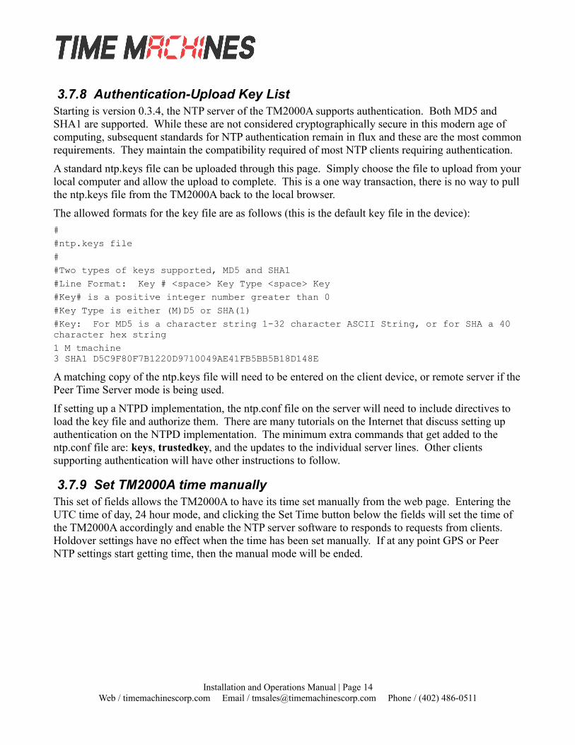
3.7.8 Authentication-Upload Key ListStarting is version 0.3.4, the NTP server of the TM2000A supports authentication. Both MD5 and SHA1 are supported. While these are not considered cryptographically secure in this modern age of computing, subsequent standards for NTP authentication remain in flux and these are the most commonrequirements. They maintain the compatibility required of most NTP clients requiring authentication.
A standard ntp.keys file can be uploaded through this page. Simply choose the file to upload from yourlocal computer and allow the upload to complete. This is a one way transaction, there is no way to pullthe ntp.keys file from the TM2000A back to the local browser.
The allowed formats for the key file are as follows (this is the default key file in the device):
#
#ntp.keys file
#
#Two types of keys supported, MD5 and SHA1
#Line Format: Key # <space> Key Type <space> Key
#Key# is a positive integer number greater than 0
#Key Type is either (M)D5 or SHA(1)
#Key: For MD5 is a character string 1-32 character ASCII String, or for SHA a 40 character hex string
1 M tmachine3 SHA1 D5C9F80F7B1220D9710049AE41FB5BB5B18D148E
A matching copy of the ntp.keys file will need to be entered on the client device, or remote server if thePeer Time Server mode is being used.
If setting up a NTPD implementation, the ntp.conf file on the server will need to include directives to load the key file and authorize them. There are many tutorials on the Internet that discuss setting up authentication on the NTPD implementation. The minimum extra commands that get added to the ntp.conf file are: keys, trustedkey, and the updates to the individual server lines. Other clients supporting authentication will have other instructions to follow.
3.7.9 Set TM2000A time manuallyThis set of fields allows the TM2000A to have its time set manually from the web page. Entering the UTC time of day, 24 hour mode, and clicking the Set Time button below the fields will set the time of the TM2000A accordingly and enable the NTP server software to responds to requests from clients. Holdover settings have no effect when the time has been set manually. If at any point GPS or Peer NTP settings start getting time, then the manual mode will be ended.
Installation and Operations Manual | Page 14Web / timemachinescorp.com Email / [email protected] Phone / (402) 486-0511

3.8 PTP Settings Page
3.8.1 PTP Update Method One/Two StepThis setting controls the Sync packet generation mode of the TM2000A. Default normal operation is touse 1 Step. In this mode, a single Sync packet is generated at the requested/setup rate and HW time stamping is applied to the packet just before it goes onto the Ethernet wire. In the two step mode, two
Installation and Operations Manual | Page 15Web / timemachinescorp.com Email / [email protected] Phone / (402) 486-0511

Sync packets are generated, without hardware time stamping, to allow the receiver to determine the accuracy. If at all possible, One Step mode is preferred as it is simply more accurate. Two step is the lower accuracy option, but it included as a setup option now to allow flexibility of use.
3.8.2 Domain NumberUse this entry to set the Domain number to be included in the PTP packets. The domain number is a method to allow multiple PTP servers on the same network, but to separate their traffic between client devices.
3.8.3 Priority 1 & Priority 2Allows setting the Priority 1 value in the packets
3.8.4 PTP Transmission MethodThe PTP transmission method can be set to either Multicast or Unicast. Select the desired mode of operation and click the Submit button.
3.8.5 PTP Post-Holdover BehaviorThere are two options here: Update Clock Class to 52 which in the PTP protocol means: “A clock of clock Class 52 shall not be a slave to another clock in the domain.” If set to Faulty, it will report as Faulty and should not be synced to by a client. Holdover time limits for the TM2000A are set in the NTP settings page.
3.8.6 Multicast Configuration – Log Announce IntervalSet the announce message interval. The rate of sync packets is 2^(-value). The default setting of 1, sets the interval at 2^(-1) = 0.5 packets per second, or every 2 seconds.
3.8.7 Multicast Configuration – Log Sync IntervalSets the requested Sync Message Interval. The rate of sync packets is 2^(value). The default of -7, therefore makes the default rate 2^-7 = 128 packets per second.
3.8.8 Multicast Configuration – Log Min Delay Request IntervalThe minimum permitted mean time interval between Delay_Req messages. A shorter interval makes the TM2000A react faster to the changes in the path delay. It's specified as a power of two in seconds. Generally, this setting doesn't need adjustment on the TM2000A.
3.8.9 Multicast Configuration – Log min Peer Delay Request IntervalThe minimum permitted mean time interval between Pdelay_Req messages. It's specified as a power oftwo in seconds. Generally, this setting doesn't need adjustment on the TM2000A.
Installation and Operations Manual | Page 16Web / timemachinescorp.com Email / [email protected] Phone / (402) 486-0511

3.9 About Page
The About Page shows contact information and software version of the device as well a couple of diagnostic buttons.
3.9.1 Download Log FilesClicking the Download button will cause the TM2000A to create a binary format log file and initiate anHTTP download. The binary log can be used by TimeMachines as an aid in troubleshooting.
3.9.2 Reboot SystemClicking the Reboot button will cause the TM2000A to do a software based reset. This is a full kernel reset of the unit and takes 20-30 seconds to complete.
Installation and Operations Manual | Page 17Web / timemachinescorp.com Email / [email protected] Phone / (402) 486-0511

4 Troubleshooting
4.1 GPS LockGetting GPS lock on the Time Server is required for it to function. Most GPS lock issues come down to issues with Antenna location, or cabling. If there are problems getting GPS lock (I.e.the Lock LED doesn't turn on and the 1 PPS LED doesn't flash each second) trying moving the antenna outside and see if that resolves the issue. If it does, try a window and see if lock is maintained. If that works, movethe antenna back to its original location and see if lock is lost. This will help determine where lock can be received and where it cannot. If no lock is achieved outdoors, then something is either wrong with the cabling or the Time Server itself. Contact TimeMachines for help.
4.2 Resetting to Factory DefaultsFront Panel Button - Push and hold the front panel button with a small object for 5 seconds. Thiswill cause the TM2000A to reset to factory default settings.
The front panel button, accessible with a paperclip or other small object, accessible from the front panelof the TM2000A is used to reset the units software settings to factory original. This is useful when a password is forgotten or the IP address cannot be determined. To do this, insert a paperclip or ball point pen end through the hole in the front of the unit until you feel the button depress. Hold this button down for a few seconds and release the button by extracting the paperclip/pen. It should now have the factory default password and IP address information.
Installation and Operations Manual | Page 18Web / timemachinescorp.com Email / [email protected] Phone / (402) 486-0511
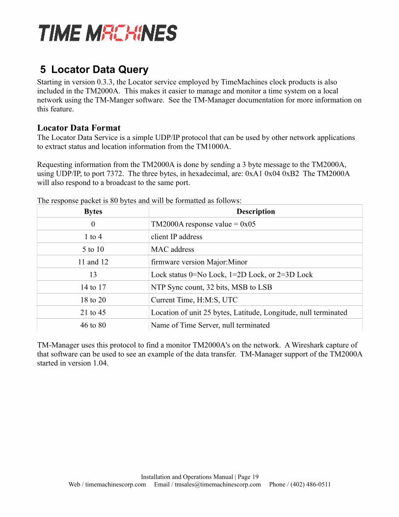
5 Locator Data QueryStarting in version 0.3.3, the Locator service employed by TimeMachines clock products is also included in the TM2000A. This makes it easier to manage and monitor a time system on a local network using the TM-Manger software. See the TM-Manager documentation for more information onthis feature.
Locator Data FormatThe Locator Data Service is a simple UDP/IP protocol that can be used by other network applications to extract status and location information from the TM1000A.
Requesting information from the TM2000A is done by sending a 3 byte message to the TM2000A, using UDP/IP, to port 7372. The three bytes, in hexadecimal, are: 0xA1 0x04 0xB2 The TM2000A will also respond to a broadcast to the same port.
The response packet is 80 bytes and will be formatted as follows:Bytes Description
0 TM2000A response value = 0x05
1 to 4 client IP address
5 to 10 MAC address
11 and 12 firmware version Major:Minor
13 Lock status 0=No Lock, 1=2D Lock, or 2=3D Lock
14 to 17 NTP Sync count, 32 bits, MSB to LSB
18 to 20 Current Time, H:M:S, UTC
21 to 45 Location of unit 25 bytes, Latitude, Longitude, null terminated
46 to 80 Name of Time Server, null terminated
TM-Manager uses this protocol to find a monitor TM2000A's on the network. A Wireshark capture of that software can be used to see an example of the data transfer. TM-Manager support of the TM2000Astarted in version 1.04.
Installation and Operations Manual | Page 19Web / timemachinescorp.com Email / [email protected] Phone / (402) 486-0511

6 Specifications
6.1 Time Server Features and Specifications• Receive time information from GPS satellites anywhere on the surface of the earth
• RFC1119/1305 NTP Protocol to serve time (Network Time Protocol)
• RFC1769/2030/4330 SNTP Protocol (Simple Network Time Protocol)
• IEEE 1588:2008 Version 2 PTP protocol
• Server Time Level: Stratum 1
• NTP Server Time Precision: better than 1mS + network jitter.
• PTP Server Time Precision: better than 3uS + network jitter.
• All networked computing platforms support time synchronization either natively or with add ondrivers including: Windows, Macintosh, and Linux. Many other devices can access the device as well including VoIP phones and digital clocks.
• 10M/100M adaptive network interface
• Unit is capable of serving 750+ NTP synchronizations per second. That provides support for over 600,000+ devices updating every 15 minutes on the network.
• Active Patch GPS antenna included. Magnetic base.
• Compliant with FCC Part 15B, and CE marked for radiated emissions and is a lead free product.
• Power Requirements: 5W at startup and 2.5W continuous at 12V DC
• Environmental Requirements: Commercial temperature range, 0-70C, 95% humidity non-condensing. Altitude -304m to 18,000m.
• Networking: Static or DHCP IPv4 addressing. Standard browser interface for setup.
• Indications: Power, GPS Signal Lock, and 1PPS indications
• Rear Connections: Power, Cat5 Ethernet, Serial (status information only, 115200,n81), and GPS antenna via SMA connection. Supports +3.3V and 5V active GPS antennas with internal jumper setting.
• Serial port outputs data every two seconds, including the following items:- IP, Time, GPS fix, Time known, ptpClockClass, ptpClockAccuracy, ntpStratum.
• Mechanical Dimensions: 5 in. x 4.2 in. x 1.3in.
6.2 GPS Module Specifications• Based on MediaTek MT3339 Chipset
• 22 channel low power receiver module
Installation and Operations Manual | Page 20Web / timemachinescorp.com Email / [email protected] Phone / (402) 486-0511

• Sensitivity: -165dBm
• GPS Time Precision: +/- 10ns RMS jitter.
• Antenna Connection: 1575.42MHz (L1 Band)
• TTFF (Time To First Fix)
• Cold start @-125dBm typically 33 seconds
• Re-acquisition (<10s obstruction) typically 1 second
6.3 Antenna Specifications• Active patch antenna with magnetic base.
• Size: 1.57 in. x 1.89 in. x 0.51 in thick, 43 grams.
• Amplifier: LNA +20dB Noise: 1.5dB VSWR: 2.0 Voltage: 2.7-6.0V.
• Cable: RG174, 5m length, SMA male.
• Environmental: -40 to +85C
• Waterproof to IPx6
(Specifications are subject to change without notice)
Installation and Operations Manual | Page 21Web / timemachinescorp.com Email / [email protected] Phone / (402) 486-0511