TM 11-5820-509-35 - RadioNerds
590
TM 11-5820-509-35 TECHNICAL MANUAL DIRECT SUPPORT, GENERAL SUPPORT, AND DEPOT MAINTENANCE MANUAL INCLUDING REPAIR PARTS AND SPECIAL TOOLS LISTS RADIO SET AN/PRC-47 This copy is a reprint which includes current pages from Changes 1 and 2. HEADQUARTERS DEPARTMENT OF THE ARMY NOVEMBER 1974
-
Upload
khangminh22 -
Category
Documents
-
view
0 -
download
0
Transcript of TM 11-5820-509-35 - RadioNerds
TM 11-5820-509-35
TECHNICAL MANUAL
DIRECT SUPPORT, GENERAL SUPPORT,AND DEPOT
MAINTENANCE MANUALINCLUDING REPAIR PARTS AND SPECIAL TOOLS LISTS
RADIO SET AN/PRC-47
This copy is a reprint which includes current pages from Changes 1 and 2.
HEADQUARTERS DEPARTMENT OF THE ARMYNOVEMBER 1974
WARNING
Avoid contact with the high-voltage circuits and the antenna terminal of the radio transmitter-receiverwhile performing trouble isolation procedures personal injury may result.
WARNINGThe 650- and 1500-volts potentials at the power amplifier screen and plate electrodes are extremelydangerous. Avoid contact with these circuits.
WARNINGPlace the POWER-LIGHTS switch to POWER OFF, disconnect the primary power source cable from thefront of RT-671/PRC-47, and discharge the plate circuit capacitors and high-voltage filter capacitors inthe power supply before proceeding with the following test. Personal injury or death can result fromthese dangerous voltages.
WARNINGAvoid contact with the high-voltage circuits of Signal Data translator CV-1377A/PRC-47 (A3), PowerSupply PP-3518/PRC-47 (A5). and in the power amplifier compartment. These voltages can causepersonal injury or death.
WARNINGBefore removing any equipment cover or module from Radio Receiver-Transmitter RT-671/PRC-47,disconnect all power from the unit.
WARNINGHigh voltages are present in the circuits associated with Signal Data Translator CV-1377A/PRC-47,Power Supply PP-3518/PRC-47, and the power amplifier compartment. These voltages are dangerousand can cause personal injury or death. Ground the two high-voltage terminals on the main chassis (J1-A1 and J1-A2) to discharge the capacitors in the high voltage circuits before beginning maintenancewithin the chassis or inside any module.
WARNINGBefore further disassembly, short-circuit connector pins P1-A1 and P1-A2 to ground to discharge thehigh-voltage filter capacitors. Personal injury or death can result from these voltages.
WARNINGHigh voltages are present on circuit components associated with the power amplifier stage. Thesevoltages are dangerous and can be fatal. Before beginning tube replacement, ground the two high-voltage terminals (J1-A1 and J1-A2) on the main chassis to discharge the filter capacitors in thisequipment.

*TM 11-5820-509-35
TECHNICAL MANUAL HEADQUARTERSDEPARTMENT OF THE ARMY
No. 11-5820-509-35 WASHINGTON, DC, 29 November 1974
Direct Support, General Support andDepot Maintenance Manual
(Including Repair Parts and Special Tools List)RADIO SET AN/PRC-47
Paragraph Page
CHAPTER 1. INTRODUCTIONScope................................................................................................................................. 1-1 1-1Indexes of publications ....................................................................................................... 1-2 1-1Reporting of errors ............................................................................................................. 1-3 1-1Reporting equipment improvement recommendations (EIR)................................................ 1-3.1Administrative storage ........................................................................................................ 1-3.2Destruction of Army electronics materiel ............................................................................. 1-3.3Historical revisions to equipment ........................................................................................ 1-4
2. FUNCTION OF EQUIPMENTSection I. System Function
System applications ........................................................................................................... 2-1 2-1Block diagram explanations ................................................................................................ 2-2 2-1Overall block diagram......................................................................................................... 2-3 2-1General description ............................................................................................................ 2-4 2-3Receive signal path .. ......................................................................................................... 2-5 2-8Transmit signal path ........................................................................................................... 2-6 2-9Frequency control circuits .. ................................................................................................ 2-7 2-9Power supply circuits ...... ................................................................................................... 2-8 2-12
Section II. Theory of Receiver-Transmitter OperationAudio Frequency Amplifier
AM-3506/PRC-47 (A8A1) ................................................................................................ 2-9 2-14Amplifier-Modulator
AM-3507/PRC-47 (A8A2) ................................................................................................ 2-10 2-18Signal Data Translator
CV-1377A/PRC-47 (A8A3) .............................................................................................. 2-11 2-21Power Supply PP-3518/PRC-47 (A8A5) .............................................................................. 2-12 2-27Radio Frequency Oscillator0-1032/PRC-47 (A8A6)....................................................................................................... 2-13 2-28Oscillator Control................................................................................................................C-4311/PRC-47 (A8A7) ...................................................................................................... 2-14 2-29Electrical Equipment Chassis..............................................................................................CH-474/PRC-47 (A8A4)...................................................................................................... 2-15 2-31
CHAPTER 3. DIRECT SUPPORT MAINTENANCE ..................................................................................Section I. General Troubleshooting Techniques
Scope................................................................................................................................. 3-1 3-1Tools, test equipment, and materials required . ................................................................... 3-2 3-2
Section II. Direct Support Troubleshooting...........................................................................................Overall troubleshooting....................................................................................................... 3-3 3-3Troubleshooting Radio Receiver-Transmitter RT-671/PRC-47 (A8) ..................................... 3-4 3-3Localizing Tests.................................................................................................................. 3-5 3-75
Section III. Isolating TroubleTrouble isolation within a module........................................................................................ 3-6 3-87Dc resistance of coils and transformer windings.................................................................. 3-7 3-88
Section IV. RepairGeneral parts replacement techniques ................................................................................ 3-8 3-95General removal and replacement procedures ................................................................... 3-9 3-96
Section V. Assembly and DisassemblyGeneral .............................................................................................................................. 3-10 3-97Removal and replacement of receiver-transmitter case ....................................................... 3-11 3-97
*This manual supersedes TM 11-5820-509-35, 20 November 1963, Including all changes.
Change 2 i
TM 11-5820-509-35
Paragraph Page
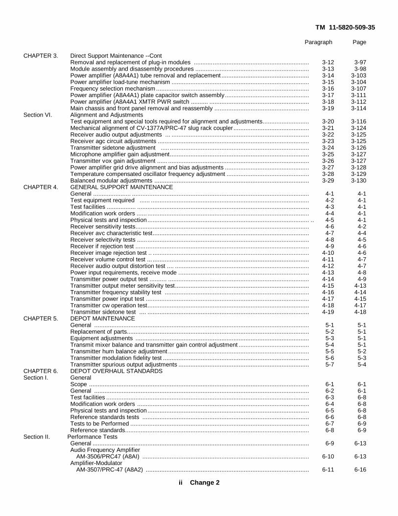
CHAPTER 3. Direct Support Maintenance --ContRemoval and replacement of plug-in modules ................................................................... 3-12 3-97Module assembly and disassembly procedures .................................................................. 3-13 3-98Power amplifier (A8A4A1) tube removal and replacement ................................................... 3-14 3-103Power amplifier load-tune mechanism ................................................................................ 3-15 3-104Frequency selection mechanism......................................................................................... 3-16 3-107Power amplifier (A8A4A1) plate capacitor switch assembly................................................. 3-17 3-111Power amplifier (A8A4A1 XMTR PWR switch .......... .......................................................... 3-18 3-112Main chassis and front panel removal and reassembly ....................................................... 3-19 3-114
Section VI. Alignment and AdjustmentsTest equipment and special tools required for alignment and adjustments........................... 3-20 3-116Mechanical alignment of CV-1377A/PRC-47 slug rack coupler ............................................ 3-21 3-124Receiver audio output adjustments ... ................................................................................ 3-22 3-125Receiver agc circuit adjustments ........................................................................................ 3-23 3-125Transmitter sidetone adjustment ..... ................................................................................. 3-24 3-126Microphone amplifier gain adjustment................................................................................. 3-25 3-127Transmitter vox gain adjustment ...... .................................................................................. 3-26 3-127Power amplifier grid drive alignment and bias adjustments ................................................. 3-27 3-128Temperature compensated oscillator frequency adjustment ................................................ 3-28 3-129Balanced modular adjustments .......................................................................................... 3-29 3-130
CHAPTER 4. GENERAL SUPPORT MAINTENANCEGeneral ...................... ....................................................................................................... 4-1 4-1Test equipment required ...... ............................................................................................ 4-2 4-1Test facilities ................. .................................................................................................... 4-3 4-1Modification work orders ...... .............................................................................................. 4-4 4-1Physical tests and inspection .............................................................................................. .. 4-5 4-1Receiver sensitivity tests..................................................................................................... 4-6 4-2Receiver avc characteristic test........................................................................................... 4-7 4-4Receiver selectivity tests .................................................................................................... 4-8 4-5Receiver if rejection test ..................................................................................................... 4-9 4-6Receiver image rejection test .. ........................................................................................... 4-10 4-6Receiver volume control test ... ........................................................................................... 4-11 4-7Receiver audio output distortion test .... .............................................................................. 4-12 4-7Power input requirements, receive mode ............................................................................ 4-13 4-8Transmitter power output test .......... .................................................................................. 4-14 4-9Transmitter output meter sensitivity test.............................................................................. 4-15 4-13Transmitter frequency stability test .................................................................................... 4-16 4-14Transmitter power input test ............................................................................................... 4-17 4-15Transmitter cw operation test.............................................................................................. 4-18 4-17Transmitter sidetone test .... .............................................................................................. 4-19 4-18
CHAPTER 5. DEPOT MAINTENANCEGeneral ............................................................................................................................. 5-1 5-1Replacement of parts.......................................................................................................... 5-2 5-1Equipment adjustments ..................................................................................................... 5-3 5-1Transmit mixer balance and transmitter gain control adjustment ......................................... 5-4 5-1Transmitter hum balance adjustment .................................................................................. 5-5 5-2Transmitter modulation fidelity test ..................................................................................... 5-6 5-3Transmitter spurious output adjustments ............................................................................ 5-7 5-4
CHAPTER 6. DEPOT OVERHAUL STANDARDSSection I. General
Scope ................................................................................................................................ 6-1 6-1General ............................................................................................................................. 6-2 6-1Test facilities ...................................................................................................................... 6-3 6-8Modification work orders .................................................................................................... 6-4 6-8Physical tests and inspection .............................................................................................. 6-5 6-8Reference standards tests ................................................................................................. 6-6 6-8Tests to be Performed ........................................................................................................ 6-7 6-9Reference standards........................................................................................................... 6-8 6-9
Section II. Performance TestsGeneral .............................................................................................................................. 6-9 6-13Audio Frequency Amplifier
AM-3506/PRC47 (A8AI) ................................................................................................. 6-10 6-13Amplifier-Modulator
AM-3507/PRC-47 (A8A2) ............................................................................................... 6-11 6-16
ii Change 2

TM 11-5820-509-35
Paragraph PageCHAPTER 6. Depot Overhaul Standards-Cont.
Signal Data TranslatorCV-1377A/PRC-47 (A8A3) .............................................................................................. 6-12 6-18
Power SupplyPP-3518/PRC-47 (A8A51)............................................................................................... 6-13 6-24
Radio Frequency Oscillator0-1032/PRC-47 (A8A6) ................................................................................................... 6-14 6-27
Oscillator ControlC-4311/PRC-47 (A8A7)................................................................................................... 6-15 6-31
Section III. Special Test FixturesGeneral .............................................................................................................................. 6-16 6-37Test Fixture for Audio Frequency Amplifier
AM 3506/PRC-47 ............................................................................................................ 6-17 6-37Test Fixture for Amplifier-Modulator
AM-3507/PRC-47............................................................................................................ 6-18 6-41Test Fixture for Signal Data Translator
CV-1377A/PRC-47 .......................................................................................................... 6-19 6-45Test Fixture for Power Supply
PP-3518/PRC-47 ............................................................................................................ 6-20 6-50Test Fixture for Radio Frequency Oscillator
0-1032/PRC-47 ............................................................................................................... 6-21 6-54Test Fixture for Oscillator Control
C-4311/PRC-47............................................................................................................... 6-22 6-56
CHAPTER 7. CIRCUIT DIAGRAMSIntroduction..................................................................................................................... 7-1 7-1
APPENDIX A. REFERENCES .................................................................................................................... A-1
APPENDIX B. DIRECT SUPPORT, GENERAL SUPPORT, AND DEPOT MAINTENANCEREPAIR PARTS AND SPECIAL TOOLS LIST
Section I. IntroductionScope ................................................................................................................................ B-1 B-1General .............................................................................................................................. B-2 B-1Explanation of columns ...................................................................................................... B-3 B-1Special information (Not applicable).................................................................................... B-4 B-2How to locate repair part .................................................................................................... B-5 B-2Federal supply code for manufacturer (FSCM) .................................................................... B-6 B-2
II. Repair parts for DS, GS, and depot maintenance................................................................. B-4III. Special tools, test, and support equipment ........................................................................... B-196IV. Index-federal stock number and reference number cross-reference to figure and item
number................................................................................................................................ B-197V. Index-reference designation cross-reference to page number ............................................... B-259
INDEX ........................................................................................................................................... INDEX 1
iii
TM 11-5820-509-35
LIST OF ILLUSTRATIONSFigureNo. Title Page2-1 Radio Set AN/PRC-47, Overall Block Diagram .................................................................................................. 2-22-2 Receiver-Transmitter Circuits, Block Diagram.................................................................................................... 2-42-3 Frequency Control Circuits, Block Diagram........................................................................................................ 2-62-4 Power Supply Circuits, Block Diagram .............................................................................................................. 2-82-5 Compressor/Amplifier Circuits, Schematic Diagram .......................................................................................... 2-142-6 Output Amplifier, CW Oscillator, and VOX Circuits, Schematic Diagram ........................................................... 2-162-7 Receiver Amplifier, AGC Circuit, and Sidetone Gate, Schematic Diagram.......................................................... 2-182-8 Balanced Modulator, ALC Amplifier Circuit, Schematic Diagram ....................................................................... 2-192-9 IF. Amplifier Circuit, Schematic Diagram .......................................................................................................... 2-202-10 Last If. Amplifier and Product Detector Circuit, Schematic Diagram ................................................................... 2-212-11 Isolation Amplifier Circuits, Schematic Diagram ................................................................................................ 2-222-12 Receive Mixer/Transmit Mixer Circuits, Schematic Diagram .............................................................................. 2-242-13 Hf Oscillator and Varicap Control Circuits, Schematic Diagram ......................................................................... 2-262-14 5- to 14-MHz Amplifier/Limiter Circuits, Schematic Diagram . ............................................................................ 2-272-15 Discriminator Circuit Waveforms ...................................................................................................................... 2-303-1 Preliminary Troubleshooting Diagram ............................................................................................................... 3-43-2 Receiver Tests, Troubleshooting Test Setup . .................................................................................................... 3-53-3 Transmitter Tests, Troubleshooting Test Setup.................................................................................................. 3-63-4 Radio Receiver-Transmitter RT-671/PRC-47 (A8), Top View, Location of
Assemblies and Test Points ............................................................................................................................. 3-73-5 Radio Receiver-Transmitter RT-671/PRC-47 (A8), Bottom View, Location of
Assemblies and Test Points ............................................................................................................................. 3-83-6 Audio Frequency Amplifier AM-3506/PRC-47 (A8A1), Top View, Cover
Removed, Location of Subassemblies and Test Points ..................................................................................... 3-93-7 Amplifier-Modulator AM-3507/PRC-47 (A8A2), Side View, Cover Removed,
Location of Subassemblies E1 and E2, and Test Points .................................................................................... 3-103-8 Amplifier-Modulator AM-3507/PRC-47 (A8A2), Side View, Cover Removed,
Location of Subassemblies E3, E4, and E5, and Test Points ............................................................................ 3-103-9 Signal Data Translator CV-1377A/PRC-47 (A8A3), Top View, Location of
Subassemblies and Test Points ........................................................................................................................ 3-113-10 Signal Data Translator CV-1377A/PRC-47 (A8A3), Bottom View, Location
of Subassemblies ............................................................................................................................................. 3-123-11 Power Supply PP-3518/PRC-47 (A8A5), Top View, Cover Removed,
Location of Subassemblies and Test Points ...................................................................................................... 3-133-12 Radio Frequency Oscillator 0-1032/PRC-47 (A8A6), Side View, Cover
Removed, Location of Subassemblies El and E2, and Test Points .................................................................... 3-143-13 Radio Frequency Oscillator 0-1032/PRC-47 (A8A6), Side View, Cover
Removed, Location of Chassis Subassembly and Test Points .......................................................................... 3-153-14 Oscillator Control C-4311/PRC-47 (A8A7), Top View, Cover Removed,
Location of Subassemblies and Test Points ...................................................................................................... 3-163-15 Oscillator Control C-4311/PRC-47 (A8A7), Bottom View, Location of
Subassemblies ................................................................................................................................................. 3-173-16 Audio Frequency Amplifier AM-3506/PRC-47 (A8A1), Cover Removed,
Chassis Subassembly ...................................................................................................................................... 3-183-17 Audio Frequency Amplifier AM-3506/PRC-47 (A8A1), Cover Removed,
Subassembly E1 ............................................................................................................................................... 3-193-18 Audio Frequency Amplifier AM-3506/PRC-47 (A8A1), Cover Removed,
Subassembly E2 .............................................................................................................................................. 3-203-19 Audio Frequency Amplifier AM-3506/PRC-47 (A8A1), Cover Removed,
Subassembly E3 ............................................................................................................................................... 3-213-20 Amplifier-Modulator AM-3507/PRC-47 (A8A2), Cover Removed,
Subassemblies E1 and E2................................................................................................................................. 3-22
iv

TM 11-5820-509-35
LIST OF ILLUSTRATIONS (cont)FigureNo. Title Page3-21 Amplifier-Modulator AM-3507/PRC-47 (A8A2), Cover Removed,
Subassemblies E3, E4 and E5 ......................................................................................................................... 3-233-22 Signal Data Translator CV-1377A/PRC-47 (A8A3), Card Assembly TB1 ........................................................... 3-243-23 Signal Data Translator CV-1377A/PRC-47 (A8A3), Card Assembly TB2 ........................................................... 3-243-24 Signal Data Translator CV-1377A/PRC-47 (A8A3), Switch Assemblies S1,
S2, and S3, Top View, Card Assemblies E1 and E3 .......................................................................................... 3-253-25 Signal Data Translator CV-1377A/PRC-47 (A8A3), Switch Assemblies S1,
S2, and S3, Bottom View, Card Assemblies E2 and E4 .................................................................................... 3-253-26 Signal Data Translator CV-1377A/PRC-47 (A8A3), Switch Assembly S1,
Rear View . ....................................................................................................................................................... 3-263-27 Signal Data Translator CV-1377A/PRC-47 (A8A3), Switch Assembly S2,
Rear View ........................................................................................................................................................ 3-263-28 Signal Data Translator CV-1377A/PRC-47 (A8A3), Switch Assembly S3,
Rear View ........................................................................................................................................................ 3-273-29 Signal Data Translator CV-1377A/PRC-47 (ASA3), Switch Assembly S4,
Rear View ........................................................................................................................................................ 3-273-30 Signal Data Translator CV-1377A/PRC-47 (A8A3), Switch Assembly S5,
Rear View ........................................................................................................................................................ 3-283-31 Signal Data Translator CV-1377A/PRC-47 (A8A3), VFO Coil Subassembly,
Top View........................................................................................................................................................... 3-283-32 Signal Data Translator CV-1377A/PRC-47 (A8A3), VFO Coil Subassembly,
Bottom View ..................................................................................................................................................... 3-293-33 Signal Data Translator CV-1377A/PRC-47 (A8A3), Switch Assembly S6,
VFO Circuit ...................................................................................................................................................... 3-303-34 Signal Data Translator CV-1377A/PRC-47 (A8A3), Switch Assembly S7,
Front View......................................................................................................................................................... 3-313-35 Signal Data Translator CV-1377A/PRC-47 (A8A3), Switch Assembly S8,
Rear View ........................................................................................................................................................ 3-313-36 Signal Data Translator CV-1377A/PRC-47 (A8A3), Switch Assembly S9,
Rear View (Rotor at Index Position no.1.) ......................................................................................................... 3-323-37 Signal Data Translator CV-1377A/PRC-47 (A8A3), Card Assembly E46 ............................................................ 3-333-38 Signal Data Translator CV-1377A/PRC-47 (A8A3), Card Assembly E47 ............................................................ 3-343-39 Signal Data Translator CV-1377A/PRC-47 (A8A3), Card Assembly E48 ............................................................ 3-353-40 Signal Data Translator CV-1377A/PRC-47 (A8A3), Driver Tube (V3)
Compartment, Bottom View .............................................................................................................................. 3-363-41 Signal Data Translator CV-1377A/PRC-47 (A8A3), Bottom View ...................................................................... 3-373-42 Signal Data Translator CV-1377A/PRC-47 (A8A3), Typical Switch Card (S1
through S8) Showing Rotor at Index Position no.1 ............................................................................................ 3-383-43 Signal Data Translator CV-1377A/PRC-47 (A8A3), Rear View, Frequency
Range Switch Shaft Retaining Ring ................................................................................................................... 3-383-44 Signal Data Translator CV-1377A/PRC-47 (A8A3), Front View, Coupler
Position at 2,000 kHz Dial Setting ..................................................................................................................... 3-393-45 Power Supply PP-3518/PRC-47 (A8A5), Bottom View, Chassis ......................................................................... 3-393-46 Power Supply PP-3518/PRC-47 (A8A5), Subassembly No. 1, Front View ......................................................... 3-403-47 Power Supply PP-3518/PRC-47 (A8A5), Subassembly No. 1, Rear View........................................................... 3-403-48 Power Supply PP-3518/PRC-47 (A8A5), Subassembly No. 2 ............................................................................ 3-413-49 Power Supply PP-3518/PRC-47 (A8A5), Subassembly No. 3 ............................................................................ 3-413-50 Power Supply PP-3518/PRC-47 (A8A5), Upper Chassis Assembly . .................................................................. 3-423-51 Power Supply PP-3518/PRC-47 (A8A5), Voltage Regulator Assembly TB1........................................................ 3-433-52 Radio Frequency Oscillator 0-1032/PRC-47 (A8A6), Side View, Cover
Removed, Card Assemblies E1 and E2 ............................................................................................................. 3-443-53 Radio Frequency Oscillator 0-1032/PRC-47 (A8A6), Side View, Cover
Removed, Chassis Assembly ........................................................................................................................... 3-45
v

TM 11-5820-509-35
LIST OF ILLUSTRATIONS (cont)FigureNo. Title Page
3-54 Oscillator Control C-4311/PRC-47 (A8A7), Card Assembly E1 .......................................................................... 3-463-55 Oscillator Control C-4311/PRC-47 (A8A7), Card Assembly E2. ......................................................................... 3-473-56 Oscillator Control C-4311/PRC-47 (A8A7), Card Assembly TBI ......................................................................... 3-483-57 Oscillator Control C-4311/PRC-47 (A8A7), Card Assembly E4 .......................................................................... 3-493-58 Oscillator Control C-4311/PRC-47 (A8A7), Card Assembly E5 .......................................................................... 3-503-59 Oscillator Control C-4311/PRC-47 (A8A7), Card Assembly E6 .......................................................................... 3-513-60 Oscillator Control C-4311/PRC-47 (A8A7), Card Assemblies E7 and E8,
Front View ........................................................................................................................................................ 3-523-61 Oscillator Control C-4311/PRC-47 (A8A7), Line Filter Assembly at Con-
nector P1, Cover Removed ............................................................................................................................... 3-523-62 Oscillator Control C-4311/PRC-47 (A8A7), Switch Card S5 With Rotor
Shown in Index Position no.1............................................................................................................................. 3-533-63 Oscillator Control C-4311/PRC-47 (A8A7), Front View, Coupler Position at
2000 kHz Dial Setting ....................................................................................................................................... 3-533-64 Power Amplifier Compartment (A8A4AI) Top-View, Cover Removed.................................................................. 3-543-65 Power Amplifier Compartment (A8A4A1) Bottom View, Cover Removed ........................................................... 3-553-66 Power Amplifier Compartment (A8A4A1) Power Amplifier Subassembly
Parts Location .................................................................................................................................................. 3-563-67 Radio Receiver-Transmitter RT-671/PRC-47 (A8), Bottom View, Cover
Removed .......................................................................................................................................................... 3-573-68 Audio Frequency Amplifier AM-3506/PRC-47 (A8A1), Subassembly El,
Voltage and Resistance Diagram ...................................................................................................................... 3-583-69 Audio Frequency Amplifier AM-3506/PRC-47 (A8A1), Subassembly E2,
Voltage and Resistance Diagram....................................................................................................................... 3-593-70 Audio Frequency Amplifier AM-3506/PRC-47 (A8AI), Subassembly E3,
Voltage and Resistance Diagram....................................................................................................................... 3-603-71 Audio Frequency Amplifier AM-3506/PRC-47 (A8A1), Chassis Assembly,
Voltage and Resistance Diagram....................................................................................................................... 3-613-72 Amplifier-Modulator AM-3507/PRC-47 (A8A2), Subassemblies E1 and E2,
Voltage and Resistance Diagram....................................................................................................................... 3-623-73 Amplifier-Modulator AM-3507/PRC-47 (A8A2), Subassembly E3, Voltage
and Resistance Diagram ................................................................................................................................... 3-633-74 Amplifier-Modulator AM-3507/PRC-47 (A8A2), Subassembly E4, Voltage
and Resistance Diagram ................................................................................................................................... 3-643-75 Amplifier-Modulator AM-3507/PRC-47 (A8A2), Subassembly E5, Voltage
and Resistance Diagram ................................................................................................................................... 3-653-76 Signal Data Translator CV-1377A/PRC-47 (A8A3), Driver Tube (V3)
Compartment, Voltage and Resistance Diagram................................................................................................ 3-663-77 Power Supply PP-3518/PRC-47 (A8A5), Voltage Regulator Assembly TB1,
Voltage and Resistance Diagram....................................................................................................................... 3-663-78 Radio Frequency Oscillator 0-1032/PRC-47 (A8A6), Subassembly E1,
Voltage and Resistance Diagram....................................................................................................................... 3-673-79 Radio Frequency Oscillator 0-1032/PRC-47 (A8A6), Subassembly E2,
Voltage and Resistance Diagram....................................................................................................................... 3-683-80 Radio Frequency Oscillator 0-1032/PRC-47 (A8A6), Chassis Assembly,
Voltage and Resistance Diagram....................................................................................................................... 3-693-81 Electrical Equipment Chassis CH-474/PRC-47 (A8), Power Oscillator
Assembly, Voltage and Resistance Diagram...................................................................................................... 3-703-82 Electrical Equipment Chassis CH-474/PRC-47, PA Filter Box FL2 (A8A4)
Voltage and Resistance Diagram....................................................................................................................... 3-713-83 Oscillator Control C-4311/PRC-47 tA8A7), Top View, Waveform Diagram......................................................... 3-723-84 Cable Assembly Set AN/PRA-4, Equipment Supplied ........................................................................................ 3-90
vi
TM 11-5820-509-35
LIST OF ILLUSTRATIONS (cont)FigureNo. Title Page
3-85 Radio Receiver-Transmitter RT-671/PRC-47 (A8) Top View, Location ofModules and Stiffeners .............................................................................................................................. 3-91
3-86 Radio Receiver-Transmitter RT-671/PRC-47 (A8), Bottom View, Location ofModule Retaining Screws ........................................................................................................................... 3-92
3-87 Radio Receiver-Transmitter RT-671/PRC-47 (A8), Front Panel View,Location of Access Openings and Panel Components ................................................................................ 3-93
3-88 Frequency Selector Control, Switch Coupler Alignment Diagram ................................................................ 3-943-89 Radio Receiver-Transmitter RT-671/PRC-47, Power Amplifier Compartment
(A8A4A1) Load-Tune Coil Assembly, Exploded View .................................................................................. 3-943-90 Radio Receiver-Transmitter RT-671/PRC-47, Frequency Selector Mechanism
(A8A4A1) Exploded View ........................................................................................................................... 3.943-91 Radio Receiver-Transmitter RT-671/PRC-47, Power Amplifier Compartment
(A8A4A1) Plate Capacitor Switch, Exploded View ...................................................................................... 3-943-92 Radio Receiver-Transmitter RT-671/PRC-47, Power Amplifier Compartment
(A8A4A1) XMTR PWR Switch (S103), Exploded View ............................................................................... 3-943-93 Radio Receiver-Transmitter RT-671/PRC-47, Power Amplifier Compartment
(A8A4A1) XMTR PWR Switch (S103), Connection Diagram ...................................................................... 3-953-94 Audio Frequency Amplifier AM-3506/PRC-47 (A8A1), Top View, Location
of Tests Points and Adjustments ................................................................................................................ 3-1173-95 Amplifier-Modulator AM-3507/PRC-47 (A8A2), Top View, Location of Test
Points and Adjustments ............................................................................................................................. 3-1183-96 Signal Data Translator CV-1377A/PRC-47 (A8A3), Top View, Location of
Test Points and Adjustments ...................................................................................................................... 3-1193-97 Signal Data Translator CV-1377A/PRC-47 (A8A3), Rear View, Location of
Adjustments ............................................................................................................................................... 3-1203-98 Signal Data Translator CV-1377A/PRC-47 (A8A3), Right Side View,
Location, Location of Adjustment C344....................................................................................................... 3-1203-99 Radio Frequency Oscillator 0-1032/PRC-47 (A8A6), Top View, Location of
Test Points and Adjustments ..................................................................................................................... 3-1203-100 Oscillator Control C-4311/PRC-47 (A8A7), Top View, Location of Test
Points and Adjustments ............................................................................................................................. 3-1213-101 Oscillator Control C-4311/PRC-47 (A8A7), Bottom View, Location of
Adjustments .............................................................................................................................................. 3-1223-102 Oscillator Control C-4311/PRC-47 (A8A7), Rear View, Location of Capacitor
C15 ........................................................................................................................................................... 3-1233-103 Oscillator Control C-4311/PRC-47 (A8A7), Right Side, Location of
Adjustments .............................................................................................................................................. 3-1233-104 Oscillator Control C-431i/PRC-47 (A8A7), Left Side, Location of Adjustments............................................. 3-1233-105 Radio Receiver-Transmitter RT-671/PRC-47 (A8), Bottom View, Location of
Test Points and Adjustments ...................................................................................................................... 3-1243-106 Receiver Audio Output Adjustment, Test Equipment Setup ........................................................................ 3-1253-107 Receiver AGC Circuit Adjustment, Test Equipment Setup .......................................................................... 3-1263-108 Transmitter Sidetone Adjustment, Test Equipment Setup ........................................................................... 3-1273-109 Microphone Amplifier and VOX Gain Adjustments, Test Equipment Setup . ................................................ 3-1273-110 Power Amplifier Grid Drive Adjustment, Test Equipment Setup .................................................................. 3-1293-111 Temperature Compensated Oscillator Frequency Adjustment, Test
Equipment Setup........................................................................................................................................ 3-1303-112 Balanced Modulator Adjustments, Test Equipment Setup ........................................................................... 3-1314-1 Receiver Sensitivity, AVC, Selectivity, IF. Rejection, Image Rejection and
Volume Control Tests, Equipment Setup..................................................................................................... 4-34-2 Receiver Audio Output Distortion Test, Equipment Setup ........................................................................... 4-84-3 Receiver Power Input Requirements, Equipment Setup .............................................................................. 4-9
vii
TM 11-5820-509-35
FigureNo. Title Page
4-4 Transmitter Power Output and Output Meter Sensitivity Tests, Equipment Setup ........................................ 4-104-5 Transmitter Frequency Stability Tests, Equipment Setup ............................................................................ 4-144-6 Transmitter Power Input Test, Equipment Setup ........................................................................................ 4-164-7 Transmitter CW Operation and Sidetone Test, Equipment Setup ............................................................... 4-175-1 Transmit Mixer Balance and Transmit Gain Control Adjustments,
Equipment Setup ....................................................................................................................................... 5-15-2 Transmitter Hum Balance Adjustment and Modulation Fidelity Tests,
Equipment Setup ....................................................................................................................................... 5-35-3 Transmitter Spurious Output Adjustments, Equipment Setup ..................................................................... 5-56-1 Plug Gage, Slug Adjustment ...................................................................................................................... 6-26-2 Gage Overtravel, 0.041-inch ...................................................................................................................... 6-26-3 Output Attenuator, 50:1 ............................................................................................................................. 6-26-4 Test Fixture for AM-3506/PRC-47, Suggested Layout ................................................................................ 6-36-5 Test Fixture for AM-3507/PRC-47, Suggested Layout ................................................................................ 6-46-6 Test Fixture for CV-1377A/PRC-47, Suggested Layout ............................................................................... 6-56-7 Indexing Fixture for CV-1377A/PRC-47, Suggested Layout ........................................................................ 6-66-8 Test Fixture for PP-3518/PRC-47, Suggested Layout ................................................................................. 6-66-9 Test Fixture for 0-1032/PRC-47, Suggested Layout .................................................................................... 6-76-10 Test Fixture for C-4311/PRC-47, Suggested Layout ................................................................................... 6-86-11 Audio Frequency Amplifier AM-3506/PRC-47 (A8A1) Performance Tests,
Initial Test Equipment Connections ............................................................................................................ 6-146-12 Amplifier-Modulator AM-3507/PRC-47 (A8A2), Performance Tests, Initial
Test Equipment Connections ...................................................................................................................... 6-166-13 Signal Data Translator CV-1377A/PRC-47 (A8A3), Performance Tests,
Initial Test Equipment Connections ............................................................................................................ 6-196-14 Power Supply PP-3518/PRC-47 (A8A5), Performance Tests, Initial Test
Equipment Connections ............................................................................................................................. 6-256-15 Radio Frequency Oscillator 0-1032/PRC-47 (A8A6) Performance Tests,
Initial Test Equipment Connections ............................................................................................................ 6-286-16 Oscillator Control C-4311/PRC-47 (A8A7), Performance Tests, Initial Test
Equipment Connections ............................................................................................................................. 6-316-17 Test Fixture for Audio Frequency Amplifier AM-3506/PRC-47, Parts
Location .................................................................................................................................................... 6-396-18 Test Fixture for Audio Frequency Amplifier AM-3506/PRC-47, Chassis
Parts and Connector Location .................................................................................................................... 6-406-19 Test Fixture for Amplifier-Modulator AM-3507/PRC-47, Parts Location........................................................ 6-426-20 Test Fixture for Amplifier-Modulator AM-3507/PRC-47, Chassis Parts and
Subassembly A1 Placement ...................................................................................................................... 6-436-21 Test Fixture for Signal Data Translator CV-1377A/PRC-47, Front View,
Parts Location ........................................................................................................................................... 6-466-22 Test Fixture for Signal Data Translator CV-1377A/PRC-47, Parts Location ................................................. 6-476-23 Test Fixture for Signal Data Translator CV-1377A/PRC-47, Parts Location ................................................. 6-486-24 Test Fixture for Power Supply PP-3518/PRC-47, Parts Location ................................................................ 6-516-25 Test Fixture for Power Supply PP-3518/PRC-47, Internal Parts Location..................................................... 6-526-26 Test Fixture for Radio Frequency Oscillator 0-1032/PRC-47, Parts Location ............................................... 6-556-27 Test Fixture for Oscillator Control C-4311/PRC-47, Parts Location ............................................................. 6-577-1 Color code marking for military standard resistors, inductors, and capacitors
............................................................................................................................................................(Foldoutillustrations are Located in back of manual)
viii
TM 11-5820-509-35
LIST OF ILLUSTRATIONS (cont)FigureNo. Title Page
7-2 Receive Signal Path, Block Diagram........................................................................................................... 7-27-3 Transmit Signal Path, Block Diagram (Located in
backof manual.)
7-4 Frequency Control Circuits, Block Diagram................................................................................................. “7-5 Power Supply Circuits, DC Primary Power Input, Block Diagram ................................................................ “7-6 Power Supply Circuits, AC Primary Power Input, Block Diagram................................................................. “
7-7 Mechanical Schematic, Frequency Control Mechanism .............................................................................. “7-8 Electrical Equipment Chassis CH-474/PRC-47 (A8A4), Schematic Diagram
(2 sheets) .................................................................................................................................................. “
7-9 Audio Frequency Amplifier AM-3506/PRC-47 (A8A1), Schematic Diagram
7-10 Amplifier-Modulator AM-3507/PRC-47 (A8A2), Schematic Diagram ........................................................... “
7-11 Signal Data Translator CV-1377A/PRC-47 (A8A3), Schematic Diagram (2sheets) ......................................................................................................................................................
7-12 Power Supply PP-3518/PRC-47 (A8A5), Schematic Diagram .................................................................... “
7-13 Radio Frequency Oscillator 0-1032/PRC-47 (A8A6), Schematic Diagram.................................................... “
7-14 Oscillator Control C-4311/PRC-47 (A8A7), Schematic Diagram ................................................................. “
7-15 Test Fixture for Audio Frequency Amplifier AM-3506/PRC-47, Schematic Diagram .................................... 7-47-16 Test Fixture for Amplifier-Modulator AM-3507/PRC-47, Schematic Diagram ............................................... 7-57-17 Test Fixture for Signal Data Translator CV-1377A/PRC-47, Schematic ....................................................... 7-67-18 Test Fixture for Power Supply PP-3518/PRC-47, Schematic Diagram . ....................................................... 7-77-19 Test Fixture for Radio Frequency Oscillator 0-1032/PRC-47, Schematic Diagram ...................................... 7-87-20 Test Fixture for Oscillator Control C-4311/PRC-47, Schematic Diagram .................................................... 7-8
ix
TM 11-5820-509-35CHAPTER 1
INTRODUCTION
1-1. Scopea. This manual contains instructions for general
support, direct support and depot maintenance of RadioSet AN/PRC-47. It includes instructions that areappropriate to the general support, direct support anddepot maintenance routines for performance testing,troubleshooting, alignment, and repair of the equipment,the replacement of maintenance parts, and the repair ofspecific subassemblies. A list of tools, materials andtest equipment that are required for maintenance isincluded. A detailed theory of operation for theequipment is included in chapter 2.
b. Operator and Organizational MaintenanceManual, Radio Set AN/PRC-47 TM 11-5820-509-12,including Repair Parts and Special Tools List andMaintenance Allocation Chart, contains additionalinformation pertainent to this same equipment.
c. Only one model of Radio Set AN/PRC-47 isdocumented in this publication. An historical record ofequipment revisions is shown in paragraph 1-4.
1-2. Indexes of Publicationsa. DA Pam 310-4. Refer to the latest issue of DA
PAM 310-4 to determine whether there are new editions,changes, or additional publications that pertain to thisequipment.
b. DA Pam 310-7 Refer to DA Pam 310-7 todetermine whether there are modification work orders(MWO's) pertaining to this equipment.
NOTE
Other applicable forms and recordsare included in Operator andOrganizational Maintenance Manual,Radio Set AN/PRC-47, TM 11-5820-509-12.
1-3. Reporting of Errors
The reporting of errors, omissions, andrecommendations for improving this publication by theindividual user is encouraged. These reports should besubmitted on DA Form 2028 (Recommended Changesto Publications and Blank Forms) and forwarded directto Commander, U.S. Army Electronics Command,ATTN: DRSEL-MA-Q Fort Monmouth, NJ 07703.
1-3.1 Reporting Equipment ImprovementRecommendations (EIR)EIR will be prepared using DA Form 2407 (MaintenanceRequest). Instructions for preparing EIR's are providedin TM 38-750, The Army Maintenance ManagementSystem. EIR's should be mailed directly toCommander, US Army Electronics Command, ATTN:DRSEL-MA-Q, Fort Monmouth, NJ 07703.
1-3.2. Administrative StorageAdministrative storage of equipment issued to and usedby Army activities shall be in accordance with TM 740-90-1.
1-3.3 Destruction of Army Electronics MaterielDestruction of Army electronics materiel to preventenemy use shall be in accordance with TM 750-244-2.
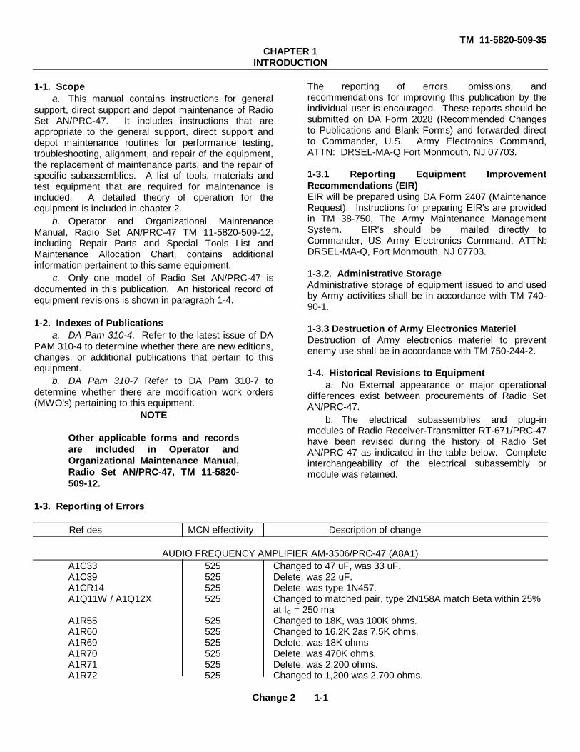
1-4. Historical Revisions to Equipmenta. No External appearance or major operational
differences exist between procurements of Radio SetAN/PRC-47.
b. The electrical subassemblies and plug-inmodules of Radio Receiver-Transmitter RT-671/PRC-47have been revised during the history of Radio SetAN/PRC-47 as indicated in the table below. Completeinterchangeability of the electrical subassembly ormodule was retained.
Ref des MCN effectivity Description of change
AUDIO FREQUENCY AMPLIFIER AM-3506/PRC-47 (A8A1)A1C33 525 Changed to 47 uF, was 33 uF.A1C39 525 Delete, was 22 uF.A1CR14 525 Delete, was type 1N457.A1Q11W / A1Q12X 525 Changed to matched pair, type 2N158A match Beta within 25%
at IC = 250 maA1R55 525 Changed to 18K, was 100K ohms.A1R60 525 Changed to 16.2K 2as 7.5K ohms.A1R69 525 Delete, was 18K ohmsA1R70 525 Delete, was 470K ohms.A1R71 525 Delete, was 2,200 ohms.A1R72 525 Changed to 1,200 was 2,700 ohms.
Change 2 1-1
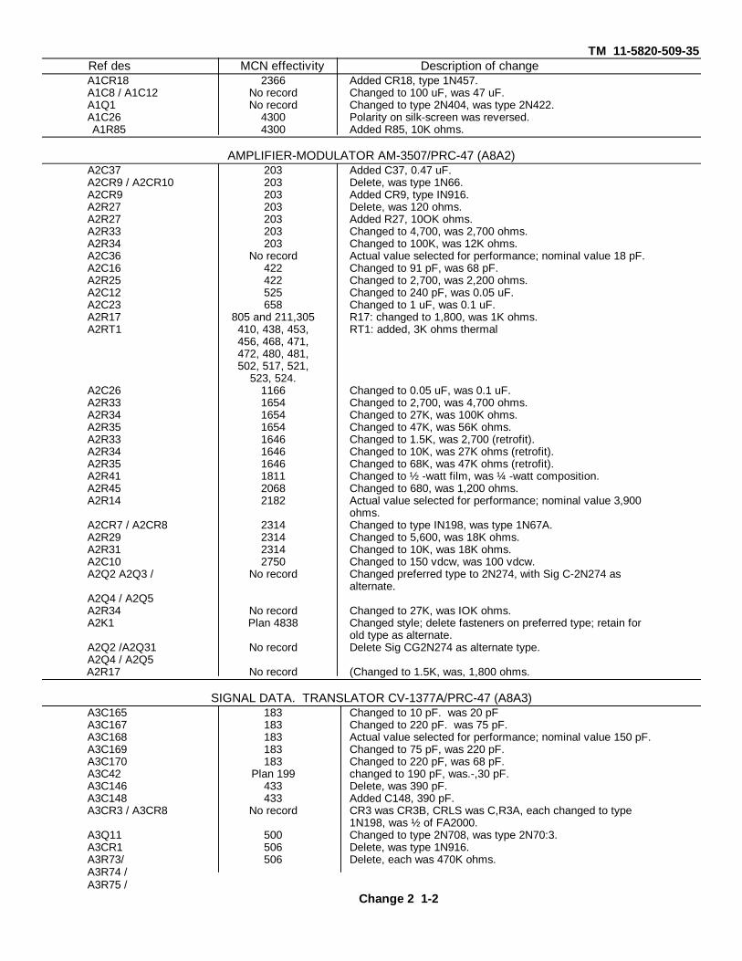
TM 11-5820-509-35Ref des MCN effectivity Description of changeA1CR18 2366 Added CR18, type 1N457.A1C8 / A1C12 No record Changed to 100 uF, was 47 uF.A1Q1 No record Changed to type 2N404, was type 2N422.A1C26 4300 Polarity on silk-screen was reversed.A1R85 4300 Added R85, 10K ohms.
AMPLIFIER-MODULATOR AM-3507/PRC-47 (A8A2)A2C37 203 Added C37, 0.47 uF.A2CR9 / A2CR10 203 Delete, was type 1N66.A2CR9 203 Added CR9, type IN916.A2R27 203 Delete, was 120 ohms.A2R27 203 Added R27, 10OK ohms.A2R33 203 Changed to 4,700, was 2,700 ohms.A2R34 203 Changed to 100K, was 12K ohms.A2C36 No record Actual value selected for performance; nominal value 18 pF.A2C16 422 Changed to 91 pF, was 68 pF.A2R25 422 Changed to 2,700, was 2,200 ohms.A2C12 525 Changed to 240 pF, was 0.05 uF.A2C23 658 Changed to 1 uF, was 0.1 uF.A2R17 805 and 211,305 R17: changed to 1,800, was 1K ohms.A2RT1 410, 438, 453, RT1: added, 3K ohms thermal
456, 468, 471,472, 480, 481,502, 517, 521,
523, 524.A2C26 1166 Changed to 0.05 uF, was 0.1 uF.A2R33 1654 Changed to 2,700, was 4,700 ohms.A2R34 1654 Changed to 27K, was 100K ohms.A2R35 1654 Changed to 47K, was 56K ohms.A2R33 1646 Changed to 1.5K, was 2,700 (retrofit).A2R34 1646 Changed to 10K, was 27K ohms (retrofit).A2R35 1646 Changed to 68K, was 47K ohms (retrofit).A2R41 1811 Changed to ½ -watt film, was ¼ -watt composition.A2R45 2068 Changed to 680, was 1,200 ohms.A2R14 2182 Actual value selected for performance; nominal value 3,900
ohms.A2CR7 / A2CR8 2314 Changed to type IN198, was type 1N67A.A2R29 2314 Changed to 5,600, was 18K ohms.A2R31 2314 Changed to 10K, was 18K ohms.A2C10 2750 Changed to 150 vdcw, was 100 vdcw.A2Q2 A2Q3 / No record Changed preferred type to 2N274, with Sig C-2N274 as
alternate.A2Q4 / A2Q5A2R34 No record Changed to 27K, was IOK ohms.A2K1 Plan 4838 Changed style; delete fasteners on preferred type; retain for
old type as alternate.A2Q2 /A2Q31 No record Delete Sig CG2N274 as alternate type.A2Q4 / A2Q5A2R17 No record (Changed to 1.5K, was, 1,800 ohms.
SIGNAL DATA. TRANSLATOR CV-1377A/PRC-47 (A8A3)A3C165 183 Changed to 10 pF. was 20 pFA3C167 183 Changed to 220 pF. was 75 pF.A3C168 183 Actual value selected for performance; nominal value 150 pF.A3C169 183 Changed to 75 pF, was 220 pF.A3C170 183 Changed to 220 pF, was 68 pF.A3C42 Plan 199 changed to 190 pF, was.-,30 pF.A3C146 433 Delete, was 390 pF.A3C148 433 Added C148, 390 pF.A3CR3 / A3CR8 No record CR3 was CR3B, CRLS was C,R3A, each changed to type
1N198, was ½ of FA2000.A3Q11 500 Changed to type 2N708, was type 2N70:3.A3CR1 506 Delete, was type 1N916.A3R73/ 506 Delete, each was 470K ohms.A3R74 /A3R75 /
Change 2 1-2
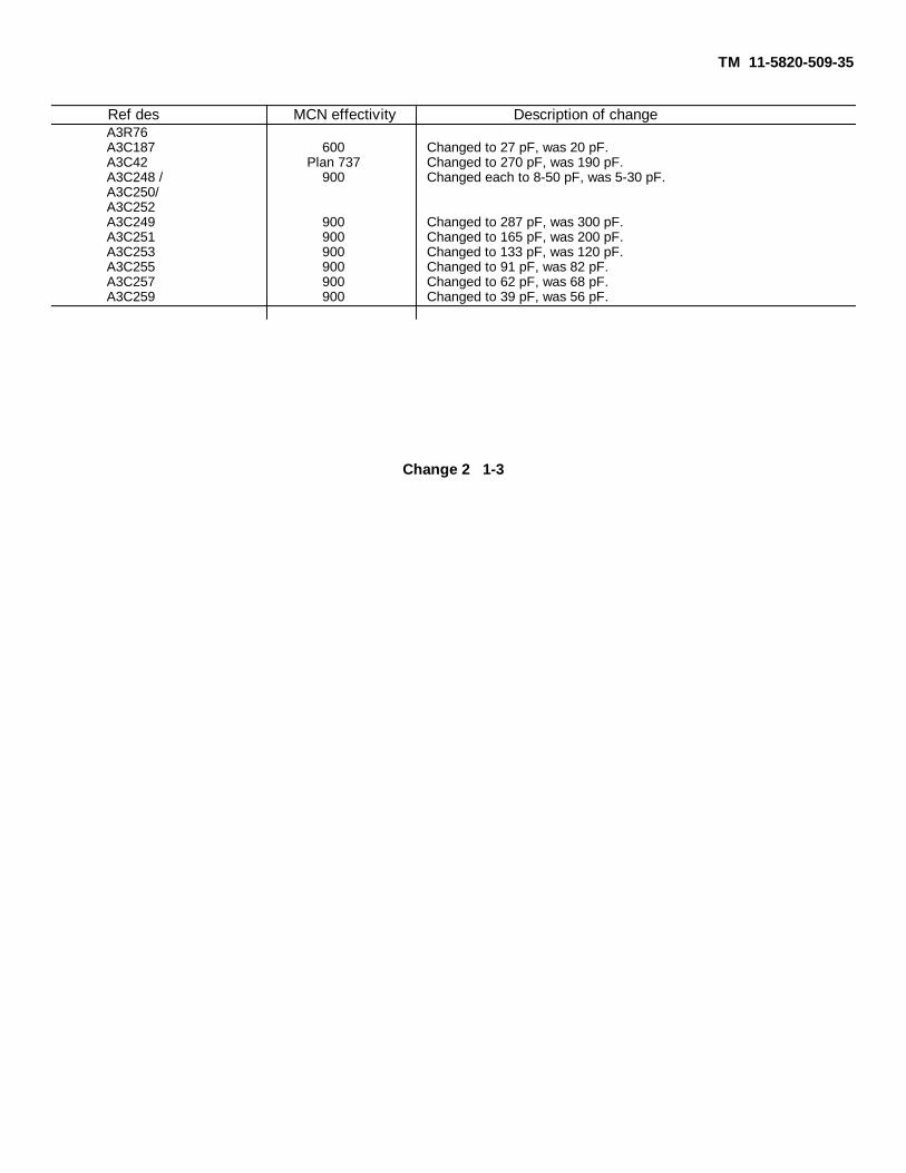
TM 11-5820-509-35
Ref des MCN effectivity Description of changeA3R76A3C187 600 Changed to 27 pF, was 20 pF.A3C42 Plan 737 Changed to 270 pF, was 190 pF.A3C248 / 900 Changed each to 8-50 pF, was 5-30 pF.A3C250/A3C252A3C249 900 Changed to 287 pF, was 300 pF.A3C251 900 Changed to 165 pF, was 200 pF.A3C253 900 Changed to 133 pF, was 120 pF.A3C255 900 Changed to 91 pF, was 82 pF.A3C257 900 Changed to 62 pF, was 68 pF.A3C259 900 Changed to 39 pF, was 56 pF.
Change 2 1-3

TM 11-5820-509-35
Ref des MCN effectivity Description of changeOSCILLATOR CONTROL C-4311/PRC-47 (ASA7 ) (cont)
A7CR16/A7CR17 5000 Added CR16, CR17, each type 1N754A.A7R46/A7R65 5000 Changed to 4,700, each was 12K ohms.A7C200/A7C201 5416 Added C200, C201, each 15 pF.A7R42/A7R62 5416 Changed to 47, each was 348 ohms.A7R48/A7R67 5416 Changed to 10K, each was 5,110 ohms.A7C6 No record Delete, was 150 pF.A7C9 No record Changed to 0.1 uF paper, was ceramic.A7C200/A7C201 No record Delete, each was 15 pF.A7R7 No record Changed to 1,800, was 2,700 ohms.A7R42/A7R62 No record Changed to 348, each was 47 ohms.
ELECTRICL EQUIPMENT CHASSIS CH-474/PRC-47 (A8A4 )A4R1 to R4 102, 116 to Changed R1 and R2 to 6.8, was 12 ohms.
121, 124 to Changed R3 and R4 to 470, was 800 ohms.134, 136 to
139 and 141.A4C26/C27 167 Added C26, C27, each 2.5 uF.A4L4 to L6 167 Added L4, 14 Turns; L5, L6, 10 mH.A4K6 214 Added K6, dpdt.A4R126 214 Added R126, 19.6K ohms.A4R127 214 Added R127, 1,210 ohms.A4C28 352 Added C28, 0.02 uF..A4C121 400 Changed to 20 pF, was 40 pF.A4R117 600 Changed to 5K, was 1 megohm.A4R118 600 Changed to 1K, was 39K ohms.A4C152 710 Deleted, was 82 pF.A4R129 713 Added R129, 470 ohms.A4C28 Plan 1464 Added C28, 0.02 uF.A4C228 2028 Deleted, was 0.01 uF.A4F4 No record Added F4, 1/500A.A4F5 No record Added F5, 1/10A.A4Q1/Q2 No record Each was type 2N2287, added alternate type 2N1166.A4R128 No record Added R128, 1OOK ohms.
1-5
TM 11-5820-509-35CHAPTER 2
FUNCTION OF EQUIPMENT
2-1. System Applicationsa. Radio Set AN/PRC-47 provides singlesideband
voice (usb only), continuous wave (cw) telegraphy, andfrequency shift keying (fsk) teletypewriter modes ofground radio communication in the high frequency (hf)spectrum from 2.000 to 11.999-MHz and is operationallycompatible with the AN/TRC-75 and similar radioequipment. The radio set is a two-man team, pack-transportable, transmitter-receiver that is contained intransportable carrying cases. It includes an antennasystem and all necessary accessory items for telegraphand telephone operation but does not include an fskinput/output device or teletypewriter machines. Thetransmitter provides 100 watts peak-enveloppower (pep)output when operating singlesideband, and whenequipped with a suitable blower/converter, such as CV-2455/PRC-47, will provide 100 watts average power inteletypewriter service. The receiver provides aminimum power output of 50 milliwatts from an inputsignal of 2.0 microvolts for a 10-dB signal-plus-noise tonoise ratio.
b. Radio Set AN/PRC-47 normally isimplemented for push-to-talk (ptt) operation. A fieldmodification can be easily accomplished in ElectricalEquipment Chassis Ch-474/PRC-47 that converts theequipment for voice-operated transmit (vox) operation.This vox option is implemented by strapping pin 11(push-to-talk) to pin 20 (vox) at connector JI (PowerSupply PP3318/PRC-47, module A5). The discussionbelow assumes that this option is implemented: In theabsence of this modification, only push-to-talk (ptt)operation is possible and reference to the vox mode andto the circuit description for the vox amplifier and relaydriver stages may be ignored.
2-2. Block Diagram Explanationsa. This section presents the general theory of
operation for Radio Set AN/PRC-47 on a block diagramlevel. The general theory first describes therelationships between the six major functional areas ofthe equipment. These areas are: the audio inputdevices, the cw telegraph key, the audio output devices,the external power sources, the antenna system, andthe Radio Receive Transmitter RT-671/PRC-47 (A8).
Except for RT-671/PRC-47, the other functionalequipments are considered accessory items and theseare each discussed in the several optionalconfigurations as they effect the general theory. Sincethe radio set is a compact, modularized, portabletransceiver, many of the circuits and devices used fortransmitting are also used for receiving. These circuitsare described as part of the applicable signal functionand appear in the appropriate block diagram for thatfunction.
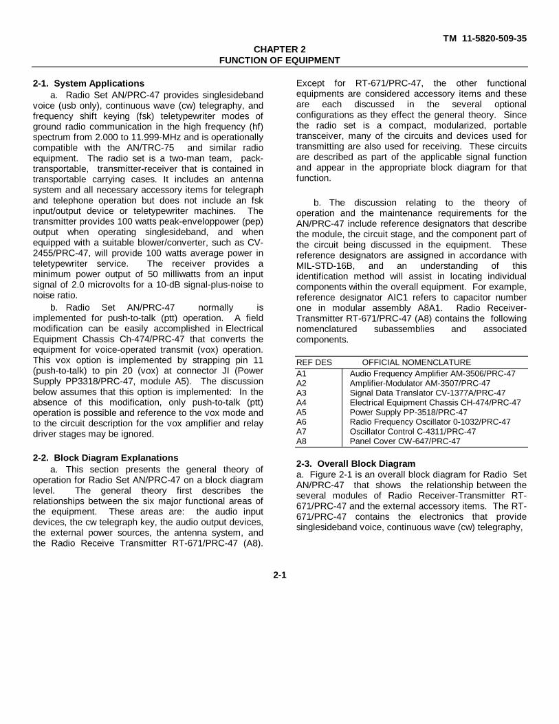
b. The discussion relating to the theory ofoperation and the maintenance requirements for theAN/PRC-47 include reference designators that describethe module, the circuit stage, and the component part ofthe circuit being discussed in the equipment. Thesereference designators are assigned in accordance withMIL-STD-16B, and an understanding of thisidentification method will assist in locating individualcomponents within the overall equipment. For example,reference designator AIC1 refers to capacitor numberone in modular assembly A8A1. Radio Receiver-Transmitter RT-671/PRC-47 (A8) contains the followingnomenclatured subassemblies and associatedcomponents.
REF DES OFFICIAL NOMENCLATUREA1 Audio Frequency Amplifier AM-3506/PRC-47A2 Amplifier-Modulator AM-3507/PRC-47A3 Signal Data Translator CV-1377A/PRC-47A4 Electrical Equipment Chassis CH-474/PRC-47A5 Power Supply PP-3518/PRC-47A6 Radio Frequency Oscillator 0-1032/PRC-47A7 Oscillator Control C-4311/PRC-47A8 Panel Cover CW-647/PRC-47
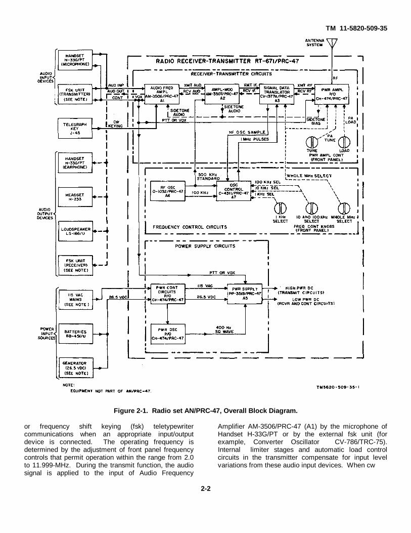
2-3. Overall Block Diagrama. Figure 2-1 is an overall block diagram for Radio SetAN/PRC-47 that shows the relationship between theseveral modules of Radio Receiver-Transmitter RT-671/PRC-47 and the external accessory items. The RT-671/PRC-47 contains the electronics that providesinglesideband voice, continuous wave (cw) telegraphy,
2-1
TM 11-5820-509-35
Figure 2-1. Radio set AN/PRC-47, Overall Block Diagram.
or frequency shift keying (fsk) teletypewritercommunications when an appropriate input/outputdevice is connected. The operating frequency isdetermined by the adjustment of front panel frequencycontrols that permit operation within the range from 2.0to 11.999-MHz. During the transmit function, the audiosignal is applied to the input of Audio Frequency
Amplifier AM-3506/PRC-47 (A1) by the microphone ofHandset H-33G/PT or by the external fsk unit (forexample, Converter Oscillator CV-786/TRC-75).Internal limiter stages and automatic load controlcircuits in the transmitter compensate for input levelvariations from these audio input devices. When cw
2-2
TM 11-5820-509-35
operation is desired, Telegraph Key J-45 is connected tothe AUDIO connector of RT-671/PRC-47. This devicekeys an oscillator in the receiver-transmitter circuits thatproduces an audio tone. This modulating signal, or thevoice input signal from the handset microphone or thefsk unit, is amplified in the AM-3506/PRC-47 A1), and ismixed in the AM-3507/PRC-47 (A2) with a 500-kHzstandard signal to produce a double-sideband,suppressed carrier signal. With the undesired sidebandand the carrier signals greatly attenuated, the remainingsinglesideband signal is heterodyned to the desired hfradio channel in the CV-1377A/PRC-47 (A3} by mixing itwith the hf oscillator signal from the frequency controlcircuits. This rf signal is then amplified by the driverstage and the power amplifier and then applied to theantenna system. A portion of the transmitter audio isreturned to the connected audio output device as asidetone signal to permit monitoring during thesetransmit periods.
b. During receive periods the receiver transmittercircuits process the incoming signal using some of theidentical circuits just mentioned in connection with thetransmit function. This receive signal is heterodyned toan intermediate frequency near 500 kHz and then it isdemodulated to recover the desired audio component.The audio signal is then applied to the connected audiooutput device. The receiver output is controlled by theVOLUME control on the front panel of RT-671/PRC-47.This control permits adjustment of the receiver outputfor a comfortable listening level with the earphone ofHandset H-33G/PT, with Headset H-233, or withloudspeaker LS-166/U. It also permits adjustment ofthe input level to the external fsk unit, if connected.
c. The frequency control circuits provide two highlystable signals that are used in the receiver transmittercircuits to generate hf singlesideband transmit signalsand to demodulate these signals to obtain audio outputin the receive mode. The 500-kHz standard signal isfixed-tuned and applied to the balanced modulatorcircuit of the transmitter and to the product detectorcircuit of the receiver. The 2.5 to 12.499-MHz hfoscillator signal is tunable in 1-kHz steps to providetransmitter output in the hf range between 2.0-11.999-MfHz.
d. The power supply circuits provide all operatingvoltages required by the AN/PRC-47.
These potentials are derived from either a 26.5 volt dcor a 115-volt, 400-Hz ac primary power source. If the
26.5-volt dc source is desired, Storage Battery BB-451/U or a suitable dc generator set may be used. Thepower supply circuits of the RT-671/PRC-47 providehigh-power dc voltages for the transmitter circuits, andlow-power potentials for the receiver circuits and forcontrol purposes.2-4. General Description
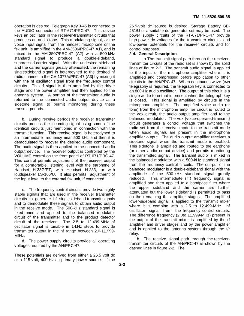
a The transmit signal path through the receiver-transmitter circuits of the radio set is shown by the solidlines of figure 2-2. The transmit audio signal is appliedto the input of the microphone amplifier where it isamplified and compressed before application to othercircuits in the AN/PRC-47. When continuous wave (cw)telegraphy is required, the telegraph key is connected toan 800-Hz audio oscillator. The output of this circuit is asingle audio tone that is present when the telegraph keyis closed. This signal is amplified by circuits in themicrophone amplifier. The amplified voice audio (ortone) from the microphone amplifier circuit is routed tothe vox circuit, the audio output amplifier, and to thebalanced modulator. The vox (voice-operated-transmit}circuit generates a control voltage that switches theradio set from the receive mode to the transmit modewhen audio signals are present in the microphoneamplifier output. The audio output amplifier receives asidetone signal when the transmit mode is enabled.This sidetone is amplified and routed to the earphone(or other audio output device) and permits monitoringthe transmitted signal. The transmit audio is mixed inthe balanced modulator with a 500-kHz standard signalfrom the frequency control circuits. The out-put of thebalanced modulator is a double-sideband signal with theamplitude of the 500-kHz standard signal greatlyreduced. This intermediate (if.) frequency signal isamplified and then applied to a bandpass filter wherethe upper sideband and the carrier are furtherattenuated but the lower sideband is permitted to passon the remaining if. amplifier stages. The amplifiedlower-sideband signal is applied to the transmit mixerwhere it is combine with a 2.5 to 12.499-MHz hfoscillator signal from the frequency control circuits.The difference frequency (2.0to 11.999-MHz) present inthe output of the transmit mixer is amplified by the rfamplifier and driver stages and by the power amplifierand is applied to the antenna system through the t/rrelay.
b. The receive signal path through the receiver-transmitter circuits of the AN/PRC-47 is shown by thedashed lines in figure 2-2. The
2-3

TM 11-5820-509-35
Figure 2-2. Receiver-Transmitter Circuits, Block Diagram
2-4

TM 11-5820-509-35
receive rf from the antenna system passes through thet/r relay directly to the rf amplifier stages. Tuned circuitsin these stages reject unwanted signals that may enterthe antenna system, and select only the desired band ofsignals for amplification before routing them to thereceiver mixer. In the receiver mixer, the rf signal isheterodyned with the 2.5 to 12.499-MHz hf oscillatorsignal to produce an intermediate frequency output near500-kHz. The if. amplifier and bandpass filter circuitsused for transmitting are also used in the receive mode.In these circuits the incoming signal is amplified whileundesired adjacent-channel and image signals areattenuated before the if. signal is applied to the productdetector. The output of the product detector is thedemodulated single-sideband receive if. signal. Thisaudio output is filtered and then amplified by thereceiver amplifier and audio output amplifier circuitsbefore being applied to the earphone or other connectedaudio output device.
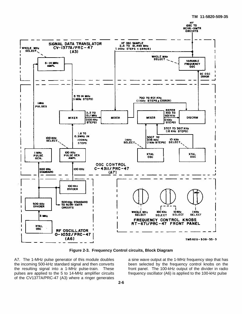
c. The frequency control circuits of Radio SetAN/PRC-47 are shown in figure 2-3. The hf oscillatorsignal for both the transmit and receive functions isobtained from the variable frequency oscillator (vfo) ofSignal Data Translator CV1377A/PRC-47 (A3). This
oscillator is coarse-tuned in ten 1-MHz stems by thewhole megahertz control knob on the front panel ofRT671/PRC-47. Fine tuning is accomplished by varyingthe vfo output inductor with the 10-kHz and the 100-kHzfrequency control knobs, or by the application of a dcerror voltage to the frequency determining circuits bythe discriminator of Oscillator Control C-4311/PRC-47IA7). This discriminator is part of a closed-loopfrequency control system that compares the vfo outputwith crystal-controlled reference oscillator frequenciesand then automatically adjusts the vfo output frequencyto synchronize it with the crystal standard frequencies.The crystal oscillators are adjustable in four decades:whole megahertz step, 100-kHz steps, 10-kHz steps,and 1-kHz steps. The whole megahertz and 100kHzsignals are derived from a common highly stabilizedcrystal-controlled source in Radio Frequency Oscillator0-1032/PRC-47 (A6). This 3-MHz primary signal is firstdivided by six to obtain the 500-kHz standard signalused by the receiver-transmitter circuits and by the I-MHz pulse generator in the CV-1377A/PRC-47 (A3).Then this 500-kHz output is further divided by five toobtain the 100-kHz signal used in the 100kHz pulsegenerator circuit of oscillator control
2-5
TM 11-5820-509-35
Figure 2-3. Frequency Control circuits, Block Diagram
A7. The 1-MHz pulse generator of this module doublesthe incoming 500-kHz standard signal and then convertsthe resulting signal into a 1-MHz pulse-train. Thesepulses are applied to the 5 to 14-MHz amplifier circuitsof the CV1377A/PRC-47 (A3) where a ringer generates
a sine wave output at the 1-MHz frequency step that hasbeen selected by the frequency control knobs on thefront panel. The 100-kHz output of the divider in radiofrequency oscillator (A6) is applied to the 100-kHz pulse
2-6

TM 11-5820-509-35
generator circuit of oscillator control (A7). This circuitgenerates a 100-kHz pulse-train and then converts it toa sine wave at any single 100-kHz frequency stepbetween 1.8and 0.9 MHz. The selected wholemegahertz output of the 5to 14-MHz amplifier in CV-1377A/PRC-47 (A3) is combine with the selected 100-kHz output of the 1.8 to 0.9-MHz circuits in a mixerwhose output is the difference between these two inputfrequencies. The resulting reference signal has a rangefrom 3.2 to 13.1MHz in 100-kHz steps, and it is combinewith the 2.5to 12.499-MHz vfo signal in a second mixercircuit. The resulting 700to 601-kHz signal representsthe hf oscillator output with an accrued frequency error.Two crystal oscillators in C-4311/PRC-47 (A7) providereference signals that are combine also in a mixer.These oscillators are adjusted by the gear-trainassociated with the 1-kHz and the 10-kHz frequencydials of the KILOCYCLES indicator on the front panel ofRT-671/PRC-47. The output of this third mixerrepresents the desired channel selection in 1-kHz steps,and this frequency is combined in the discriminatorcircuit with the output of the second mixer to obtain anerror voltage proportional to the vfo error signal. Theoutput of the discriminator controls the vfo and returns itto the desired operating frequency.
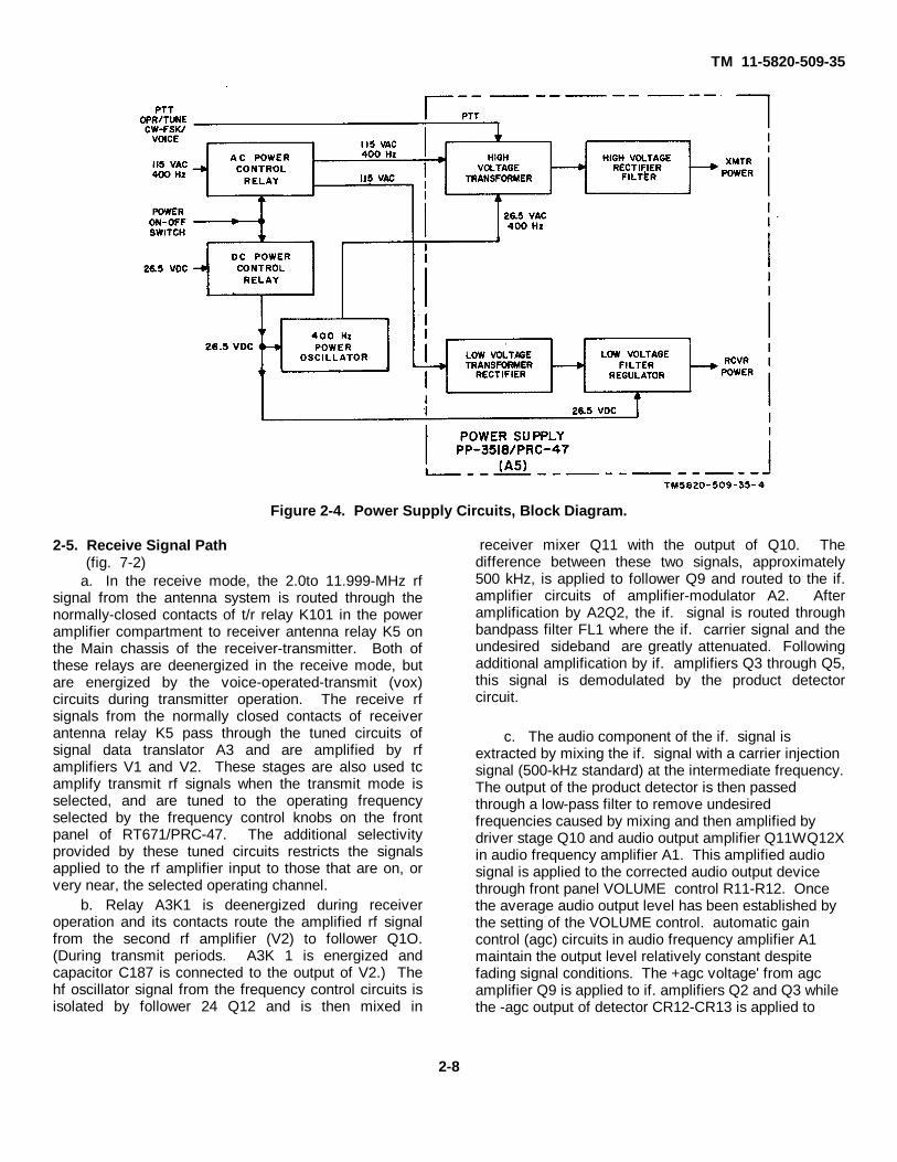
d. The power supply circuits of the AN/PRC47 areshown in figure 2-4. These circuits obtain primary powerfrom either the 115-volt, 400-Hz ac mains or from a 26.5volt dc primary power source similar to Storage BatteryBB-451/U. The appropriate circuit within the powersupply is automatically selected when the power cable isattached to the front panel connector of the radio set.Operation of the POWER-LIGHTS switch on the front ofRT-671/PRC-47 to the POWER ON position causes theappropriate power control relay to operate and connectthe appropriate input circuit to the selected primary
power source. Interlocking is provided so that alternatesource input circuits are disconnected. When thereceive mode is selected, all necessary voltages for theradio set are provided by the low-voltage filter regulatorcircuit of Power Supply PP-3518/PRC47 (A5). Thissubassembly filters and regulates the 26.5-volt dcprimary power when the dc mains are connected, butwhen the 115-volt, 400-Hz primary power source isattached, a portion of this voltage is rectified by the low-voltage circuits and then smoothed by the filter-regulatorbefore application to the circuits in the modules of theequipment. When the transmit mode is enabled, high-voltage power supply circuits provide heater. bias, andplate power for the vacuum tubes and bias voltages forthe transistorized circuits of the radio set. The high-voltage power supply circuits are enabled by operationof the push-to-talk (ptt) switch on the operator's handset,by placing the CW-FSK/VOICE switch on the front ofRT-671/PRC-47 to CW-FSK, or by setting the OPR-TUNE switch on the front of RT-671/PRC-47 to TUNE.When the 115-volt ac primary power mains areconnected, operation of the high-voltage transformerand rectifier-filter circuits is conventional. A multiple-secondary high-voltage transformer provides ac powerto the several rectifier-filter circuits that distribute therequired transmitter voltages. If the 26.5-volt dc primarypower source is connected, however. a portion of thispower is applied to a 400-Hz power oscillator on themain chassis of RT-671/PRC-47. This circuit performsthe normal inverter function and generates a square-wave voltage whose output amplitude is approximately26.5 volts at 400 Hz. The square-wave voltage fromthis power oscillator is applied to an appropriate primarywinding on the high-voltage transformer and suitableoutput voltages are obtained from the connectedrectifier-filter circuits.
2-7
TM 11-5820-509-35
Figure 2-4. Power Supply Circuits, Block Diagram.
2-5. Receive Signal Path(fig. 7-2)
a. In the receive mode, the 2.0to 11.999-MHz rfsignal from the antenna system is routed through thenormally-closed contacts of t/r relay K101 in the poweramplifier compartment to receiver antenna relay K5 onthe Main chassis of the receiver-transmitter. Both ofthese relays are deenergized in the receive mode, butare energized by the voice-operated-transmit (vox)circuits during transmitter operation. The receive rfsignals from the normally closed contacts of receiverantenna relay K5 pass through the tuned circuits ofsignal data translator A3 and are amplified by rfamplifiers V1 and V2. These stages are also used tcamplify transmit rf signals when the transmit mode isselected, and are tuned to the operating frequencyselected by the frequency control knobs on the frontpanel of RT671/PRC-47. The additional selectivityprovided by these tuned circuits restricts the signalsapplied to the rf amplifier input to those that are on, orvery near, the selected operating channel.
b. Relay A3K1 is deenergized during receiveroperation and its contacts route the amplified rf signalfrom the second rf amplifier (V2) to follower Q1O.(During transmit periods. A3K 1 is energized andcapacitor C187 is connected to the output of V2.) Thehf oscillator signal from the frequency control circuits isisolated by follower 24 Q12 and is then mixed in
receiver mixer Q11 with the output of Q10. Thedifference between these two signals, approximately500 kHz, is applied to follower Q9 and routed to the if.amplifier circuits of amplifier-modulator A2. Afteramplification by A2Q2, the if. signal is routed throughbandpass filter FL1 where the if. carrier signal and theundesired sideband are greatly attenuated. Followingadditional amplification by if. amplifiers Q3 through Q5,this signal is demodulated by the product detectorcircuit.
c. The audio component of the if. signal isextracted by mixing the if. signal with a carrier injectionsignal (500-kHz standard) at the intermediate frequency.The output of the product detector is then passedthrough a low-pass filter to remove undesiredfrequencies caused by mixing and then amplified bydriver stage Q10 and audio output amplifier Q11WQ12Xin audio frequency amplifier A1. This amplified audiosignal is applied to the corrected audio output devicethrough front panel VOLUME control R11-R12. Oncethe average audio output level has been established bythe setting of the VOLUME control. automatic gaincontrol (agc) circuits in audio frequency amplifier A1maintain the output level relatively constant despitefading signal conditions. The +agc voltage' from agcamplifier Q9 is applied to if. amplifiers Q2 and Q3 whilethe -agc output of detector CR12-CR13 is applied to
2-8
TM 11-5820-509-35
the grid circuits of rf amplifiers V1 and V2 in signal datatranslator A3.
2-6. Transmit Signal Path (fig. 7-3)
a. In the transmit mode, the audio signal isobtained from the microphone of Handset H 33G/PT orfrom the transmit output circuits of an external fsk unit.This signal is connected to the transmit audio input ofaudio frequency amplifier A1 where it is amplified bymicrophone amplifier Q1 and Q3, clipped by limitersCR5-CR6, further amplified by output amplifier Q4, andapplied to the audio input of the balanced modulator ofamplifier-modulator A2. Part, of the amplified audiooutput from Q4 is also applied to sidetone gate CR10.This gate is enabled during tansmit periods by the biasfrom sidetone rectifier CR101 in the power amplifiercompartment so that the sidetone audio from Q4 isrouted through driver Q10, audio output amplifier Q11W-QI2X and VOLUME control R11-R12 to theconnected audio output device. The sidetone audio isthen available for monitoring purposes.
b. Another part of the output signal from Q4 isapplied to vox detector CR7-CR8. When this signallevel exceeds a minimum threshold value, vox relay K 1transfers circuit functions in the RT-671/PRC-47 fromthe receive mode to the transmit mode. It the audiosignal drops below this threshold level, or disappearscompletely for a predetermined period of time, thesecircuits will automatically return to the receiveconfiguration. (Where the vox mode is notimplemented, vox relay K1 cannot cause operation ofthe ptt relay (A5K1) in power supply module A5. Thisrelay operates when the ptt switch on the operator'shandset is pressed and energizes the high-voltagepower supply circuits.) If continuous wave (cw)telegraphy is desired, the circuit functions describedabove apply except that Telegraph Key J-45 turns on,and shuts off, the audio tone generated by oscillator Q5.This tone replaces the voice audio at the input ofmicrophone amplifier Q3, and is amplified by theremaining circuits of audio frequency amplifier A 1. Inthe cw mode, the CW-FSK/VOICE switch on the frontpanel of RT-671 /PRC-47 is placed in the CW-FSKposition so that vex relay A1K1 and ptt relay A5K1 areboth energized The CW-FSK/VOICE switch must bereturned to the VOICE position when it is desired toreceive incoming telegraph or teletypewriter signals (i.e.,break-in operation is not possible).
c. That part of the audio signal from Q4 that isapplied to the balanced modulator of amplifier-modulator A2 is mixed with the 500-kHz stan-
dard signal from the frequency control circuits. Theresulting output from the balanced modulator is adouble-sideband, suppressed-carrier signal that isamplified by alc amplifier Q1 and if amplifier Q2 beforebeing applied to bandpass filter FL1. Only the lowersideband remains after this signal is applied to FL1 andthis single sideband is further amplified by Q3 throughQ5 before being applied to signal data translator A3. If.amplifiers Q3 through A5 and bandpass filter FL1 areshared with the receiver circuits of the receiver-transmitter, but during the transmit period the agc biasotherwise applied to Q2 and Q3 is removed so that theif. gain of this circuit will not vary as a function ofmodulation.
d. Transmit relay A2K1 fin amplifier-modulator A2)is energized for transmit operation by closure of voxrelay A1K1. The output of if. amplifier Q5 is routedthrough the closed contacts of A2K1 to the transmitmixer (CR3-CR8) in signal data translator A3. The 2.5-to 12.499-MHz hf oscillator signal from the frequencycontrol circuits is applied to the transmit mixer throughfollower Q13. The difference-frequency obtained byheterodyning this signal with the 500-kHz if. output ofQ5 is a 2.0to 11.999-MHz single-sideband rf signal thatis buffered by follower Q14 before being applied toamplifier QI5 and subsequently to rf amplifiers V1 andV2. The amplified hf output of V2 is further amplified bydriver V3 and power amplifier V101. The output circuitof the power amplifier is connected to the antennasystem when t/r relay K101 is closed. This stage istuned to the operating frequency shown on theKILOCYCLES indicator and is loaded to the antennasystem by the adjustment of POWER AMPLIFIERTUNE and POWER AMPLIFIER LOAD controls on thefront of RT-671/PRC-47. Optimum adjustment of thesecontrols is indicated by maximum deflection (maximumpower output) of XMTR OUTPUT meter M 101 on thefront of the receiver-transmitter.
2-7. Frequency Control Circuits (fig. 7-4)
a. The temperature-compensated crystal-oscillatorof radio frequency oscillator A6 is an extremely stablestandard that provides a 3-MHz output signal for thefrequency divider (locked oscillator) circuits of thismodule. The crystal is contained in a temperature-controlled oven to minimize frequency drift caused bychanges in ambient temperature, and the circuit isequipped with an adjustment that permits compensationfor long-term crystal aging effects. Transistor Q1 is theoscillator, and transistors Q2 and Q3
2-9
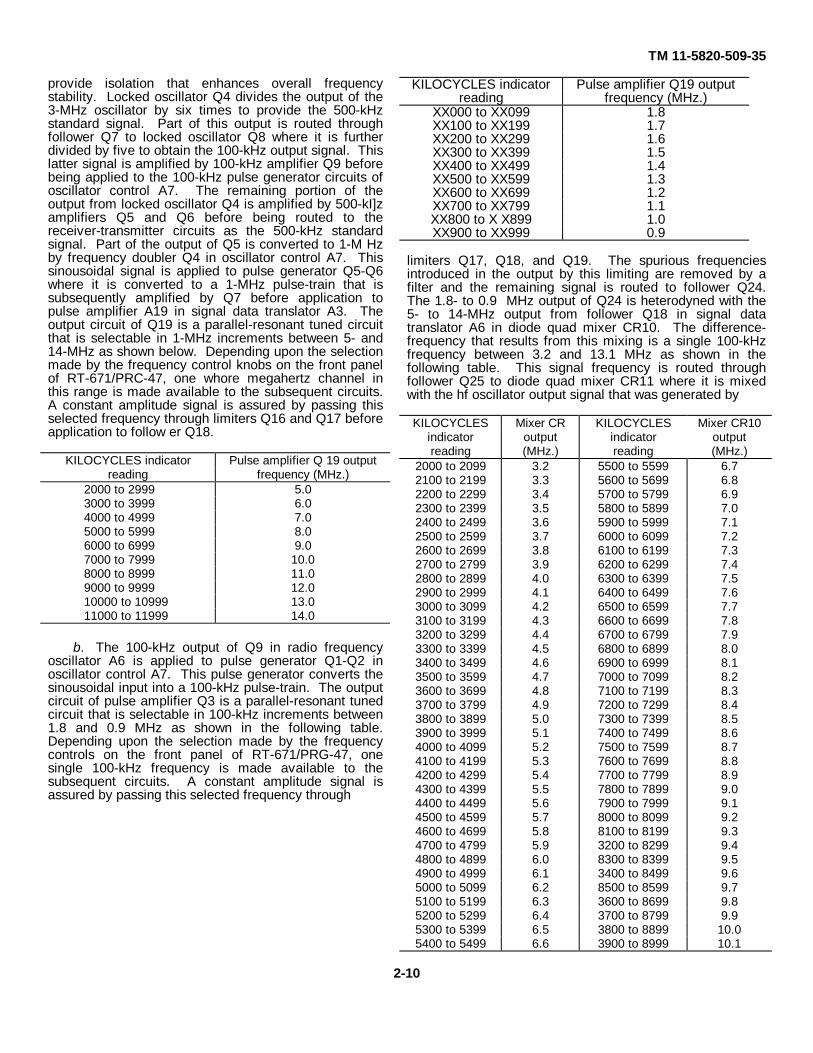
TM 11-5820-509-35
provide isolation that enhances overall frequencystability. Locked oscillator Q4 divides the output of the3-MHz oscillator by six times to provide the 500-kHzstandard signal. Part of this output is routed throughfollower Q7 to locked oscillator Q8 where it is furtherdivided by five to obtain the 100-kHz output signal. Thislatter signal is amplified by 100-kHz amplifier Q9 beforebeing applied to the 100-kHz pulse generator circuits ofoscillator control A7. The remaining portion of theoutput from locked oscillator Q4 is amplified by 500-kI]zamplifiers Q5 and Q6 before being routed to thereceiver-transmitter circuits as the 500-kHz standardsignal. Part of the output of Q5 is converted to 1-M Hzby frequency doubler Q4 in oscillator control A7. Thissinousoidal signal is applied to pulse generator Q5-Q6where it is converted to a 1-MHz pulse-train that issubsequently amplified by Q7 before application topulse amplifier A19 in signal data translator A3. Theoutput circuit of Q19 is a parallel-resonant tuned circuitthat is selectable in 1-MHz increments between 5- and14-MHz as shown below. Depending upon the selectionmade by the frequency control knobs on the front panelof RT-671/PRC-47, one whore megahertz channel inthis range is made available to the subsequent circuits.A constant amplitude signal is assured by passing thisselected frequency through limiters Q16 and Q17 beforeapplication to follow er Q18.
KILOCYCLES indicator Pulse amplifier Q 19 outputreading frequency (MHz.)
2000 to 2999 5.03000 to 3999 6.04000 to 4999 7.05000 to 5999 8.06000 to 6999 9.07000 to 7999 10.08000 to 8999 11.09000 to 9999 12.010000 to 10999 13.011000 to 11999 14.0
b. The 100-kHz output of Q9 in radio frequencyoscillator A6 is applied to pulse generator Q1-Q2 inoscillator control A7. This pulse generator converts thesinousoidal input into a 100-kHz pulse-train. The outputcircuit of pulse amplifier Q3 is a parallel-resonant tunedcircuit that is selectable in 100-kHz increments between1.8 and 0.9 MHz as shown in the following table.Depending upon the selection made by the frequencycontrols on the front panel of RT-671/PRG-47, onesingle 100-kHz frequency is made available to thesubsequent circuits. A constant amplitude signal isassured by passing this selected frequency through
KILOCYCLES indicator Pulse amplifier Q19 outputreading frequency (MHz.)
XX000 to XX099 1.8XX100 to XX199 1.7XX200 to XX299 1.6XX300 to XX399 1.5XX400 to XX499 1.4XX500 to XX599 1.3XX600 to XX699 1.2XX700 to XX799 1.1XX800 to X X899 1.0XX900 to XX999 0.9
limiters Q17, Q18, and Q19. The spurious frequenciesintroduced in the output by this limiting are removed by afilter and the remaining signal is routed to follower Q24.The 1.8- to 0.9 MHz output of Q24 is heterodyned with the5- to 14-MHz output from follower Q18 in signal datatranslator A6 in diode quad mixer CR10. The difference-frequency that results from this mixing is a single 100-kHzfrequency between 3.2 and 13.1 MHz as shown in thefollowing table. This signal frequency is routed throughfollower Q25 to diode quad mixer CR11 where it is mixedwith the hf oscillator output signal that was generated by
KILOCYCLES Mixer CR KILOCYCLES Mixer CR10indicator output indicator outputreading (MHz.) reading (MHz.)
2000 to 2099 3.2 5500 to 5599 6.72100 to 2199 3.3 5600 to 5699 6.82200 to 2299 3.4 5700 to 5799 6.92300 to 2399 3.5 5800 to 5899 7.02400 to 2499 3.6 5900 to 5999 7.12500 to 2599 3.7 6000 to 6099 7.22600 to 2699 3.8 6100 to 6199 7.32700 to 2799 3.9 6200 to 6299 7.42800 to 2899 4.0 6300 to 6399 7.52900 to 2999 4.1 6400 to 6499 7.63000 to 3099 4.2 6500 to 6599 7.73100 to 3199 4.3 6600 to 6699 7.83200 to 3299 4.4 6700 to 6799 7.93300 to 3399 4.5 6800 to 6899 8.03400 to 3499 4.6 6900 to 6999 8.13500 to 3599 4.7 7000 to 7099 8.23600 to 3699 4.8 7100 to 7199 8.33700 to 3799 4.9 7200 to 7299 8.43800 to 3899 5.0 7300 to 7399 8.53900 to 3999 5.1 7400 to 7499 8.64000 to 4099 5.2 7500 to 7599 8.74100 to 4199 5.3 7600 to 7699 8.84200 to 4299 5.4 7700 to 7799 8.94300 to 4399 5.5 7800 to 7899 9.04400 to 4499 5.6 7900 to 7999 9.14500 to 4599 5.7 8000 to 8099 9.24600 to 4699 5.8 8100 to 8199 9.34700 to 4799 5.9 3200 to 8299 9.44800 to 4899 6.0 8300 to 8399 9.54900 to 4999 6.1 3400 to 8499 9.65000 to 5099 6.2 8500 to 8599 9.75100 to 5199 6.3 3600 to 8699 9.85200 to 5299 6.4 3700 to 8799 9.95300 to 5399 6.5 3800 to 8899 10.05400 to 5499 6.6 3900 to 8999 10.1
2-10
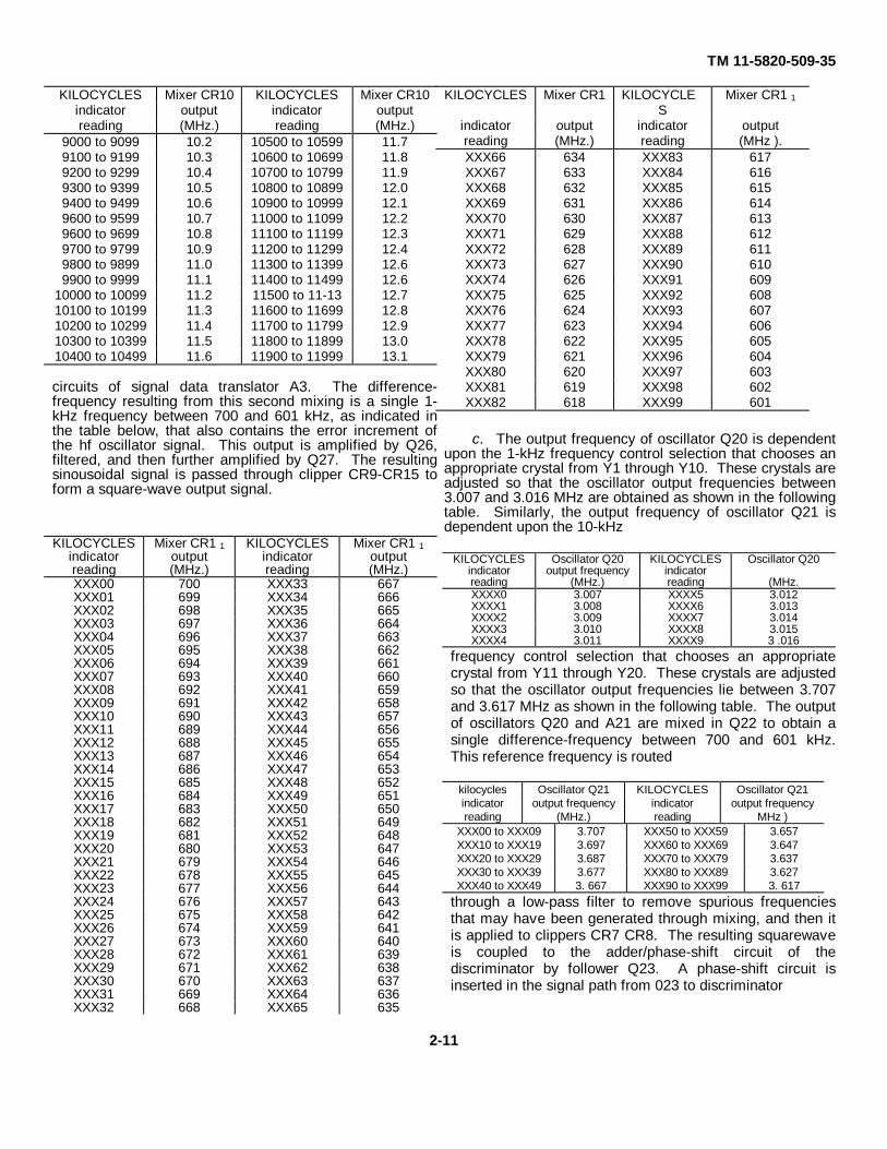
TM 11-5820-509-35
KILOCYCLES Mixer CR10 KILOCYCLES Mixer CR10indicator output indicator outputreading (MHz.) reading (MHz.)
9000 to 9099 10.2 10500 to 10599 11.79100 to 9199 10.3 10600 to 10699 11.89200 to 9299 10.4 10700 to 10799 11.99300 to 9399 10.5 10800 to 10899 12.09400 to 9499 10.6 10900 to 10999 12.19600 to 9599 10.7 11000 to 11099 12.29600 to 9699 10.8 11100 to 11199 12.39700 to 9799 10.9 11200 to 11299 12.49800 to 9899 11.0 11300 to 11399 12.69900 to 9999 11.1 11400 to 11499 12.6
10000 to 10099 11.2 11500 to 11-13 12.710100 to 10199 11.3 11600 to 11699 12.810200 to 10299 11.4 11700 to 11799 12.910300 to 10399 11.5 11800 to 11899 13.010400 to 10499 11.6 11900 to 11999 13.1
circuits of signal data translator A3. The difference-frequency resulting from this second mixing is a single 1-kHz frequency between 700 and 601 kHz, as indicated inthe table below, that also contains the error increment ofthe hf oscillator signal. This output is amplified by Q26,filtered, and then further amplified by Q27. The resultingsinousoidal signal is passed through clipper CR9-CR15 toform a square-wave output signal.
KILOCYCLES Mixer CR1 KILOCYCLES
Mixer CR1 1
indicator output indicator outputreading (MHz.) reading (MHz ).XXX66 634 XXX83 617XXX67 633 XXX84 616XXX68 632 XXX85 615XXX69 631 XXX86 614XXX70 630 XXX87 613XXX71 629 XXX88 612XXX72 628 XXX89 611XXX73 627 XXX90 610XXX74 626 XXX91 609XXX75 625 XXX92 608XXX76 624 XXX93 607XXX77 623 XXX94 606XXX78 622 XXX95 605XXX79 621 XXX96 604XXX80 620 XXX97 603XXX81 619 XXX98 602XXX82 618 XXX99 601
c. The output frequency of oscillator Q20 is dependentupon the 1-kHz frequency control selection that chooses anappropriate crystal from Y1 through Y10. These crystals areadjusted so that the oscillator output frequencies between3.007 and 3.016 MHz are obtained as shown in the followingtable. Similarly, the output frequency of oscillator Q21 isdependent upon the 10-kHz
KILOCYCLES Mixer CR1 1 KILOCYCLES Mixer CR1 1indicator output indicator outputreading (MHz.) reading (MHz.)XXX00 700 XXX33 667XXX01 699 XXX34 666XXX02 698 XXX35 665XXX03 697 XXX36 664XXX04 696 XXX37 663XXX05 695 XXX38 662XXX06 694 XXX39 661XXX07 693 XXX40 660XXX08 692 XXX41 659XXX09 691 XXX42 658XXX10 690 XXX43 657XXX11 689 XXX44 656XXX12 688 XXX45 655XXX13 687 XXX46 654XXX14 686 XXX47 653XXX15 685 XXX48 652XXX16 684 XXX49 651XXX17 683 XXX50 650XXX18 682 XXX51 649XXX19 681 XXX52 648XXX20 680 XXX53 647XXX21 679 XXX54 646XXX22 678 XXX55 645XXX23 677 XXX56 644XXX24 676 XXX57 643XXX25 675 XXX58 642XXX26 674 XXX59 641XXX27 673 XXX60 640XXX28 672 XXX61 639XXX29 671 XXX62 638XXX30 670 XXX63 637XXX31 669 XXX64 636XXX32 668 XXX65 635
KILOCYCLES Oscillator Q20 KILOCYCLES Oscillator Q20indicator output frequency indicatorreading (MHz.) reading (MHz.XXXX0 3.007 XXXX5 3.012XXXX1 3.008 XXXX6 3.013XXXX2 3.009 XXXX7 3.014XXXX3 3.010 XXXX8 3.015XXXX4 3.011 XXXX9 3 .016
frequency control selection that chooses an appropriatecrystal from Y11 through Y20. These crystals are adjustedso that the oscillator output frequencies lie between 3.707and 3.617 MHz as shown in the following table. The outputof oscillators Q20 and A21 are mixed in Q22 to obtain asingle difference-frequency between 700 and 601 kHz.This reference frequency is routed
kilocycles Oscillator Q21 KILOCYCLES Oscillator Q21indicator output frequency indicator output frequencyreading (MHz.) reading MHz )
XXX00 to XXX09 3.707 XXX50 to XXX59 3.657XXX10 to XXX19 3.697 XXX60 to XXX69 3.647XXX20 to XXX29 3.687 XXX70 to XXX79 3.637XXX30 to XXX39 3.677 XXX80 to XXX89 3.627XXX40 to XXX49 3. 667 XXX90 to XXX99 3. 617
through a low-pass filter to remove spurious frequenciesthat may have been generated through mixing, and then itis applied to clippers CR7 CR8. The resulting squarewaveis coupled to the adder/phase-shift circuit of thediscriminator by follower Q23. A phase-shift circuit isinserted in the signal path from 023 to discriminator
2-11

TM 11 5820-509-35
amplifier Q8 and the reference frequency is summedwith the output of clippers CR9-CR15 in the adder. Theunshifted output of Q23 is also summed with the outputof CR9-CR15 in the adder circuit associated withdiscriminator amplifier Q11. Transistor pairs Q8-Q11,Q9-Q12, and Q10-Q13 are each carefully selected toprovide identical gain in each discriminator channel.When the hf oscillator signal from signal data translatorA3 differs only slightly from the reference oscillatorsignal (by 5 kHz, or less), the envelope of the summedsignals in these two discriminator channels will remainout of phase by an amount dependent upon thefrequency error between the two signals. The leadingedge of the summed signal envelope triggers frequencydiscriminators Q10 and Q13 so that they operate like abistable multivibrator at a rate equal to the phase-difference between the two envelopes. The errorvoltage at the output of these two transistors may beeither positive or negative, depending upon whether thehf oscillator signal is higher or lower than the frequencyof the reference oscillator signal. The amount offrequency-difference between the two signalsdetermines the amplitude of this dc error voltage. Thedc error voltages are applied to voltage-controlledcapacitors in the frequency-determining circuits of the hfoscillator in signal data translator A3. As the frequencyof the hf oscillator is corrected, the error frequency atthe input to the discriminator is reduced and theresulting dc error voltage at the output of this circuitagain approaches zero Coarse frequency control of thehf oscillator is obtained by the adjustment of thefrequency control knobs on the front panel of RT-671/PRC-47. The 2 5- to 12.499-MHz hf oscillatorsignal is isolated and amplified by buffer amplifier Q21before being routed to follower Q2 and the subsequentcircuits. Amplifiers Q6-Q7 and associated follower Q8provide hf oscillator signals to the receiver-transmittercircuits; while amplifiers Q3-Q4 and associated followerQ5 provide the injection signal for diode quad mixerCR11 in oscillator control A7.
d. In some instances, transients may cause thediscriminator circuits of oscillator control A7 to losecapture of the hf oscillator in signal data translator A3.The automatic capture circuit consists of detector CR12-CR13, transistor switch Q28, and relay driver Q29 inassociation wi th antilock relay K6 on the main chassisof RT671/PRC-47. As the loss of capture occurs, thevoltage drop across emitter resistor R142 decreases; thebase of transistor switch Q28 becomes less positive,and 28 conducts less
than previously. The reduced conduction of Q28 causesthe base of relay driver Q29 to become more positiveand it conducts. As Q29 conducts, relay K6 is operatedand a small dc voltage is applied to the dc error A anddc error B inputs to the varicap control circuit of signaldata translator A3. Since this small voltage is used tocalibrate the hf oscillator initially, the frequency of thiscircuit returns to a value within the capture range of thediscriminator circuits. After capture is assured, antilockrelay K6 is deenergized (as the voltage again appears atthe base of transistor switch Q28). The dc errorvoltages at the output of the discriminator regain controlof the hf oscillator frequency-determining circuits andadjust the output frequency accordingly.
2-8. Power Supply Circuits (fig. 7-5 and 7-6)
a. When the 115-volt, 400-Hz ac primary source isused to power the radio set, the cable is attached to thePOWER receptacle on the front panel of RT-671/PRC-47 and this voltage is routed to the radio set by fuse F2.A portion of this input voltage is applied to low-voltagetransformer T2 in power supply module A5 where thelow-voltage circuit steps down this potential, rectifies it,and filters it in conventional bridge-rectifier, capacitor-input LC filter circuits. The resulting 24-volt dc output isrouted to audio frequency amplifier A1 and passesthrough the normally-closed contacts of B + relay K3 tothe signal data translator. A conventional series-typeelectronic voltage regulator, consisting of transistors Q1through Q3 and their associated circuits, is used toprovide a regulated 20 volts dc output. This potential isapplied to the continuously energized circuits of thereceiver-transmitter, and to the voice-operated circuitsof amplifier-modulator A2 and signal data translator A3.An output from low-voltage rectifier CR26 through CR29provides 26.5 volts dc [unregulated and unfiltered) forcircuits in audio frequency amplifier A I, signal datatranslator A3, and the panel lamps on the front ofRT671/PRC-47. A branch of this same circuit arms thepush-to-talk relay (A5K1) in the power supply module.
b. A portion of the incoming 115-volt primarypower is applied to step-down transformer T2, isrectified by bridge-rectifier CR3 through CR6, andapplied to ac power control relay K2. The contacts ofthis relay route the primary power to high-voltagetransformer T1 in power supply A5 whenever POWER-LIGHTS switch S1 on the
2-12
TM 11-5820-509-35
front of RT-671/PRC-47 (or a remote control on-offswitch) is placed to ON. Push-to-talk relay A5K 1 in thepower supply module is operated by any one of thefollowing conditions provided that overtemperaturecutout K103 in the power amplifier compartment has notopened: by CW-FSK/VOICE switch S2 (when placed tothe CW-FSK position by OPR-TUNE switch S102 (whenplaced to the TUNE position); and by the handset pttswitch (when it is pressed). Thermal override switchS3B is physically part of BATTERY TEST switch S3A,and it must be held fully depressed to permit operationof the radio set after overtemperature cutout K103 hasoperated.
c. In the transmit mode, ac power control relay K2and B + relay K3 in the main chassis of the radio set,and push-to-talk relay A5K1 are all operated. The 115-volt ac primary power is routed through the contacts ofK2 and A5K1 to the 115-volt primary winding of high-voltage transformer T1. This primary winding is tappedfor operation with the power oscillator described inparagraph 2-8 e. High-voltage transformer T1 containsseveral secondary windings that provide a variety of acand dc outputs during transmitter operation. A 6.3-voltac winding provides heater power for the poweramplifier stage and for the rf amplifiers and the driver insignal data translator A3. An additional secondarywinding is provided for each of the four rectifier-filtercircuits that supply dc potentials to other parts of thetransmitter. Rectifier CR1 through CR4 and itsassociated filter and bias adjusting network provide-110volts dc and-32 volts dc for the grid circuits of the poweramplifier (V101) and the driver (A3V3) respectively.Each of these outputs is individually adjustable toprovide optimum operation of the vacuum tube withwhich it is associated. Rectifier CR6 through CR17 is afullwave bridge-type circuit employing three diodes ineach leg. The output of this rectifier is filtered bycapacitor C6 and resistors R6 and R7 to provide 1500volts dc for the plate circuit of power amplifier V101.Rectifier CR18 through CR21 provides an output that isfiltered by capacitors C19 and resistors R9 and R10 andit operates the screen circuit of the power amplifier tube.The rectified output of CR22 through CR25 is routed tothe filter circuit consisting of capacitor C20 and resistorsR11 and R12. The output of this circuit is applied to thedriver stage (V3) of signal data translator A3 and aportion of it is dropped through resistor R8 before being
applied as a 150-volt dc plate and screen voltage to rfamplifiers V1 and V2 of signal data translator A3.
d. When a 26.5-volt dc primary source is used foroperation of the radio set, this source is connected tothe POWER receptacle on the front of RT-671 /PRC-47instead of the 115-volt ac power cable. The 26.5-voltincoming power is routed through fuse F1 and thecontacts of dc power control relay K 1 to the powersupply circuits of the radio set. With no ac powerconnected, dc power control relay K1 is operated whenthe POWER-LIGHTS switch (S1) on the front panel ofRT-671/PRC-4? (or a remote control on-off switch) isplaced to ON. As this relay operates, the contacts in the115-volt ac circuit are opened, and the contactsassociated with the 26.5-volt circuit are closed so thatpower is applied to: the 26.5-volt dc circuits of audiofrequency amplifier A1, signal data translator A3, andthe panel lamp circuits on the front of RT-671/PRC47;the filter consisting of inductor L1 and capacitors C25and C26 to the normally-closed contacts of B + relay K3to the 24-volt dc circuits of audio frequency amplifierA1; through the normally-closed contacts of B + relay K3to the 24-volt dc circuits of signal data translator A3; andto voltage regulator Q1 through Q3. The push-to-talkrelay in the power supply is armed so that it may beoperated by selection of the transmit mode, andregulated dc is routed from the output of the voltageregulator to the 20-volt circuits of the radio set andthrough the contacts of B + relay K3 to the circuits ofamplifier-modulator A2 and signal data translator A3that are voice-operated.
e. Push-to-talk relay K1 in power supply A5 isoperated by selection of the transmit mode. (Refer toparagraph 2-8 b for a detailed discussion of operation ofrelay K1.) In addition to a contact-pair in the 115-volt accircuit to high-voltage transformer T1, another contact-pair is associated with the center-tap of this primarywinding. As these contacts close, dc power is applied to400-Hz power oscillator Q1-Q2, and a 26.5-volt, 400-Hzsquarewave ac is generated and applied to part of thetransformer primary winding. With this square wavevoltage applied, operation of the transformer, rectifier,and filter circuits is identical to the description shown inparagraph 2-8 c except that a contact-pair on ac powercontrol relay K1 selects a tap on the 6.3volt ac filamentwinding of T1 for proper output to the connectedvacuum tube filament circuits.
2-13

TM 11- 5820- 509-35
2-9. Audio Frequency Amplifier AM -3506/PRC-47(A8A1) (fig. 2-5 through 2-7)
a. The audio from the microphone is applied tomicrophone amplifier Q1 and to the shunt compressorcircuit (CR17). After amplification, part of the outputsignal from Q1 is routed to audio amplifier Q3 and theremainder is amplified in compressor amplifier Q2. Theamplified output of Q2 is then coupled by transformerT1 to compressor rectifier CR1 through CR4, filtered bycapacitors C3 and C4, and applied as an un. groundedforward bias voltage across compressor CR17. Thisbridge rectifier assembly is connected so that twovariable-resistance paths are available to the incomingaudio signal. The amount of forward bias applied bycompressor rectifier CR1 through CR4 determines thepath
resistance through the diode legs of CR17 so that audiopeaks from the microphone input are limited and theamplified output from Q1 remains essentially constantfor wide variations in microphone input level. When theincoming audio is a low-level signal, the forward biasapplied to compressor CR17 is small and the individualdiodes are operated in their high forward-resistanceregion. As the audio signal increases, the bias voltagefrom compressor rectifier CR1 through CR4 alsoincreases and the diodes of CR17 operate in a lowerforward-resistance region and load the input circuit ofmicrophone amplifier Q1. The operating bias for thecarbon microphone element in the handset is obtainedfrom the 20-volt dc power connection. Resistor R3 andcapacitor C] provide decoupling and control the amountof bias applied to this microphone circuit.
Figure 2-5 Compressor/Amplifier Circuit Schematic Diagram.
b. When the radio set Is operated in either the cwor fsk mode, or when OPR/TUNE switch S102 is placedin the TUNE position, a ground is
connected to the cw key input (P1-18) and to the audiooscillator circuit. When this ground is connected to thecold end of its tank circuit (L2-
2-14

TM 11-5820-509-35
C21, Hartley oscillator Q5 is enabled and an output ofapproximately 800 Hz is obtained. The oscillator output,or the voice audio from microphone amplifier Q1, isapplied to audio amplifier Q3. The resulting amplifiedoutput from Q3 is limited by CR5-CR6 and then appliedto output amplifier Q4 through microphone amplifiergain control R27 This control is a screwdriveradjustment that establishes the maximum transmit audiooutput level at the secondary of transformer T2 andconnector P1-22. A portion of the output from Q4 isalso applied to vex detector CR7-CR8 through vox gaincontrol R40. The resulting positive voltage controls theconduction of vox amplifiers Q6 and Q7. When aminimum threshold voltage is available at the output ofCR7-CR8, as determined by the output level of Q4 andthe setting of vox gain control R40, transistors Q6-Q7conduct and relay Kl is energized. The time required toclose the vox relay following application of an audiosignal to the input of the vox detector is called the attacktime. Similarly, the time required for the vox relay torelease after removal of the audio signal from the inputof the vex detector is called the release, or dropout,time. A fast attack, slow release characteristic isobtained by suitably selecting capacitor C26 and resistorR43, in association with diode CR9 When the audioinput level is below the vox threshold, C26 chargesthrough Q6 and R43. When fully charged, nearly
all of the supply voltage appears across C26 so that thebase of Q6 is near ground potential and it remains cutoff. When the audio input level exceeds the thresholdvalue, however, the base of vex amplifier Q7 is biasedmore positively and this transistor conducts. Theamount of conduction is limited only by the amount ofnegative feedback in the loop from the collector of Q7through C26, through the base-emitter junction of Q6,and back to the base of Q7. As Q7 begins to conduct,the negative charge on the base of Q6 rapidlydisappears as C26 discharges through the low forward-resistance of CR9. At a point on the discharge curve ofC26, however, transistor Q6 reaches cutoff, thenegative feedback path to Q7 is opened, and transistorQ7 immediately switches to full conduction. As thisoccurs, vex relay K1 is operated through the groundsupplied by the collector-emitter junction of Q7. Whenaudio input disappears, or the level drops below thethreshold established by the circuit, a more negativepotential is applied to the base of Q7, and it is driventoward cutoff. Total and immediate cutoff is preventedby the presence of a small positive voltage in thefeedback loop, but as C26 charges, a point is reachedon the charge curve where nearly all the supply voltageagain appears across this capacitor. The base of Q6again approaches ground, transistor Q7 is again cut off,and vox relay Kl releases.
2-15

TM 11-5820-509-35
Figure 2.6 Output Amplifier, CW Used
c. Vox relay K1 is also operated by pressing thepush-to-talk (ptt) switch on the handset, by placing CW-FSK/VOICE switch S2 to CW-FSK, or by placing OPR-TUNE switch S102 to TUNE. When any of thesecontrols is operated, push-to-talk relay A5K1 (in PowerSupply PP-3518/PRC-
47) is also operated and the high-voltage power supplycircuits are energized for transmitter operation. Unlessthe vex option para 2-1 b) is implemented in ElectricalEquipment Chassis CH-474/PRC-47, only push-to-talkoperation is permissible with the existing circuits. Asvox
2-16

TM 11-5820-509-35
relay K1 is energized, the 26.5-volt dc output at P1-7also operates t/r relay K10l and screen voltage relayK103 in the power amplifier compartment, and B + relayK3, 500-kHz relay K4, and receiver antenna relay K5 inthe main chassis of the receiver-transmitter.
d. The receive audio signal from amplifier-modulator A2 is applied to driver Q10 in audiofrequency amplifier A1 through receiver gain controlR54. This control is a screwdriver adjustment that setsthe maximum signal level available at the receiveraudio output terminals. Driver Q10 amplifies thisincoming signal and routes it through transformer T3 topush-pull audio output amplifier Q11-Q12. The resultingamplified audio signal is applied through transformer T5and the VOLUME control to the connected audio outputdevice. A portion of the incoming receive audio s analis also applied to agc gate CR11 by automatic gaincontrol R52. Agc gate CR11 is disabled during thetransmit period by a reserve bias of 26.5 volts dc that isapplied to it from vox relay K1. While disabled, no Agcvoltages are available for if. amplifiers Q2 and Q3 ofamplifier-modulator A2 or to rf amplifiers V1 and V2 insignal data translator A3. As a result, these stagesoperate at full circuit gain, using fixed bias duringtransmit periods. In the receive mode, Agc gate CR11is enabled, however, and the audio signal from Agc gaincontrol R52 i. applied to agc amplifier OR The
output of this amplifier is divided between the +agccircuit containing Q9, and the-agc circuit containingCR12-CR13. Agc amplifier Q9 is biased in thenonlinear region of its operating characteristic andfunctions as a common-emitter detector. The collectorof Q9 is returned to ground through the bias networkassociated with if. amplifiers Q2 and Q3 in amplifier-modulator A2 and this permits a positive dc voltage tobe ap plied to these stages that is proportional to theaverage level of receive audio signal. Audio filtering atthe output of Q9 is provided by capacitor C42. Theother part of the amplified output from Q8 is rectified bydetector CRl2-CR13, filtered by capacitor C41, and isthen applied as a negative bias to the grid circuits of rfamplifiers V 1 and V2 in signal data translator A3.Sidetone gate CR10 is enabled in the transmit mode bysidetone bias rectifier CR101 in the power amplifiercompartment of the receiver transmitter. Whenengaged, the sidetone audio from output amplifier Q4 isapplied to driver Q10 through sidetone gain control R46and receiver gain control R54. After the maximumoutput level of audio output amplifier Q11-Q12 has beenestablished by the setting of R54, the sidetone outputavailable during transmit periods is set by thescrewdriver adjustment of R46. In the receive mode,sidetone gate CR10 is disabled and no output from themicrophone circuit is contributed to the driver output.
2-17
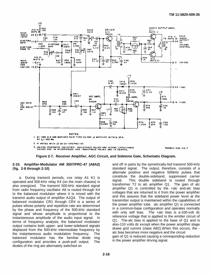
TM 11-5820-509-35
Figure 2-7. Receiver Amplifier, AGC Circuit, and Sidetone Gate, Schematic Diagram.
2-10. Amplifier-Modulator AM 3507/PRC-47 (A8A2){fig. 2-8 through 2-10)
a. During transmit periods, vox relay A1 K1 isoperated and 500-kHz relay K4 (on the main chassis) isalso energized. The transmit 500-kHz standard signalfrom radio frequency oscillator A6 is routed through K4to the balanced modulator where it is mixed with thetransmit audio output of amplifier A1Q4. The output ofbalanced modulator CR1 through CR4 is a series ofpulses whose polarity and repetition rate are determinedby the phase and frequency of the 500-kHz standardsignal and whose amplitude is proportional to theinstantaneous amplitude of the audio input signal. Interms of frequency analysis, the balanced modulatoroutput contains both upper- and lower-sideband signalsdisplaced from the 500-kHz intermediate frequency bythe instantaneous audio modulation frequency. Thebalanced modulator has the familiar diode ringconfiguration and provides a push-pull output. Thediodes of the ring are alternately switched on
and off in parts by the symetrically-fed transmit 500-kHzstandard signal. The output, therefore, consists of aalternate positive and negative 500kHz pulses thatconstitute the double-sideband, suppressed carriersignal. This double sideband is routed throughtransformer T2 to alc amplifier Q1. The gain of alcamplifier Q1 is controlled by the +alc and-alc biasvoltages that are returned to it from the power amplifierand this assures that the sideband power level at thetransmitter output is maintained within the capabilities ofthe power amplifier tube. alc amplifier Q1 is connectedin a common-base configuration and operates normallywith only self bias. The +alc bias is a-100-volt dcreference voltage that is applied to the emitter circuit ofQ1. The-alc bias is applied to the base of Q1 and isalso-110 volts dc except when the power amplifier stagedraws grid current (class AB2).When this occurs, the -alc bias becomes more negative and the circuitgain of Q1 is reduced causing a corresponding reductionin the power amplifier driving signal.
2-18

TM 11 5820-509-35
Figure 2-8. Balanced Modulator and A LC Circuit , Schematic Diagram.
b. The double-sideband signal from alc amplifierQ1 is further amplified by the common base circuit of if.amplifier Q2 and then applied to the mechanical filter.Bandpass filter FL1 is adjusted to pass only the lower-sideband output of Q2 and
to greatly attenuate the opposite sideband and the 500-kHz standard signal. Further amplification of this lower-sideband signal is obtained in if. amplifiers Q3 and Q4.
2-19

TM 11-5820-509-35
Figure 2-9 If. Amplifier Circuit, Schematic Diagram.
c. The intermediate frequency signal from if.amplifier Q4 is further amplified by Q5. The output ofthis common-emitter amplifier is routed to the normally-open contacts of transmit relay K1, and then by way oftransformer T3 to the product detector. In the transmitmode, the 26.5-volt dc potential from vox relay AlK1operates transmit relay Kl and routes the transmit 500-kHz if. output from P4-A3 to the transmit mixer of signaldata translator A3. When the receive mode is selected,however, the receive if. signal from amplifier Q5 isrouted to the product detector circuit by transformer T3.Product detector CR7-CR8 consists of two push-pull
connected diode mixers that are alternately switched onand off at the 500-kHz standard signal rate. The receive500-kHz standard signal is present only when thereceive mode is enabled and there is no 26.5-volt vexsignal applied to 500-kHz relay K4. The audiocomponent at the output of the product detector is thedifference between the instantaneous values of theincoming lower-sideband if. signal and the receive 500-kHz standard signal. This audio output is routed throughthe low-pass filter consisting of C30, C31, and L8 toremove the remaining if. component before furtheramplification by circuits in audio frequency amplifier A1
2-20
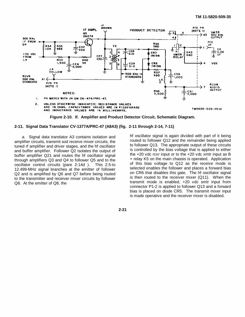
TM 11-5820-509-35
Figure 2-10. If. Amplifier and Product Detector Circuit, Schematic Diagram.
2-11. Signal Data Translator CV-1377A/PRC-47 (A8A3) (fig. 2-11 through 2-14, 7-11)
a. Signal data translator A3 contains isolation andamplifier circuits, transmit sod receive mixer circuits, thetuned rf amplifier and driver stages, and the hf oscillatorand buffer amplifier. Follower Q2 isolates the output ofbuffer amplifier Q21 and routes the hf oscillator signalthrough amplifiers Q3 and Q4 to follower Q5 and to theoscillator control circuits (pare 2-14d ). This 2.5-to12.499-MHz signal branches at the emitter of followerQ2 and is amplified by Q6 and Q7 before being routedto the transmitter and receiver mixer circuits by followerQ8. At the emitter of Q8, the
hf oscillator signal is again divided with part of it beingrouted to follower Q12 and the remainder being appliedto follower Q13. The appropriate output of these circuitsis controlled by the bias voltage that is applied to eitherthe +20 vdc rcvr input or to the +20 vdc xmtr input as B+ relay K5 on the main chassis is operated. Applicationof this bias voltage to Q12 as the receive mode isselected enables the follower and places a forward biason CR6 that disables this gate. The hf oscillator signalis then routed to the receiver mixer (Q11). When thetransmit mode is enabled, +20 vdc smtr input fromconnector P1-2 is applied to follower Q13 and a forwardbias is placed on diode CR5. The transmit mixer inputis made operative and the receiver mixer is disabled.
2-21

TM 11-5820-509-35
Figure 2-11. Isolation Amplifier Circuits, Schematic Diagram.
b. The hf oscillator signal from follower Q 12 isapplied to the emitter of receiver mixer Q11 when thereceive mode is selected. The incoming receive rfsignal from second rf amplifier V2 is routed through thenormally-closed contacts of relay K1, through followerQ10, to the base of receiver mixer Q11. The collectorof this transistor is tuned to the difference-frequency ofthese two signals by the parallel-tuned circuit consistingof capacitors C167 through C169 and inductor
L100. Since the enabling bias @ +20 vdc xmtr) is notapplied, gate CR2 also remains enabled and this signalis routed through follower Q9 to the if. amplifier circuitsof amplifier-modulator A2. During receiver operationfollower Q14 and amplifier Q15 are unbiased andremain disabled. As the transmit mode is selected,however, the +20 vdc xmtr bias is applied to P1-2 andtransistors Q14 and Q15 are enabled. Forward bias isalso applied to gate CR2 so that it is disabled and
2-22

TM 11-5820-509-35
to relay K 1. As K1 operates, the transmit rf output fromsecond rf amplifier V2 is routed directly to the gird circuitof driver V3. The transmit if. single sideband signal isapplied to the junction of resistors R58 and R59. The hfoscillator signal from follower Ql3 is then routed totransformer T1 whose secondary winding contains diodemixers CR3 and CR8. These diodes are switched onand off at the hf oscillator rate and the resultingwaveform across R148 is a pulse-train whose repetitionrate and polarity are determined by the 500-kHz transmitif. signal.
The absolute level of the difference-frequency obtainedby mixing is controlled by transmit gain control R148,and the parallel trap consisting of capacitor C186 andinductor L101 attenuates any 500-kHz standard signalthat may remain after mixing. Potentiometer R150across the secondary winding of transformer T1 is usedto balance the transmitter mixer circuit to obtainmaximum suppression of the hf oscillator signal. The2.0to 11.999-MHz signal produced by the transmit mixeris coupled through follower Q14 and amplifier Q15 tothe rf stages(V1 and V2).
2-23
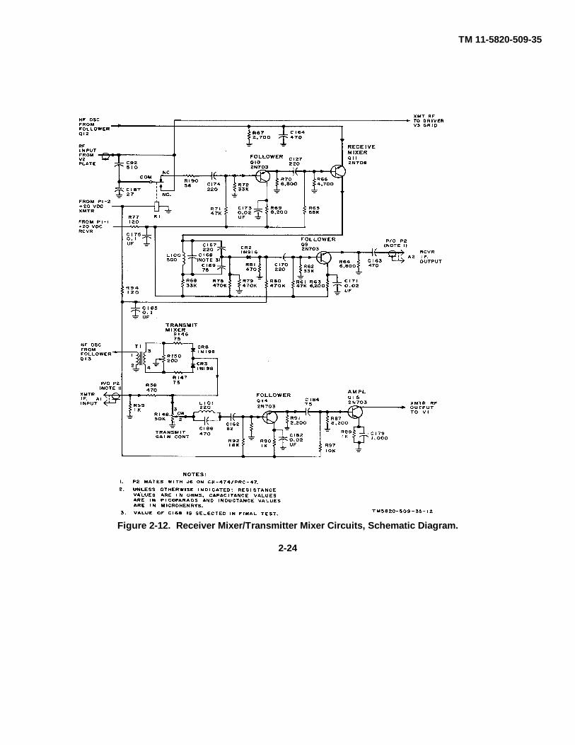
TM 11-5820-509-35
Figure 2-12. Receiver Mixer/Transmitter Mixer Circuits, Schematic Diagram.
2-24
TM 11-5820-509-35
c. The rf amplifier and driver stages, as shown infigure 7-12, are conventional vacuum-tube amplifierswith bandswitching plate tank circuits. In the transmitmode, the rf signal from amplifier Ql5 is applied to thegrid circuit of first rf amplifier V1, routed to second rfamplifier V2, and further amplified by driver V3 beforebeing applied to the grid circuit of the power amplifierstage. The rf amplifier/driver bandswitching circuits arecoarse-tuned by adjustment of the whole megahertzfrequency control knob on the front panel of the RT-671/PRC-47. As this selection is made, a switch position isselected that connects an appropriate tuned circuitcomponent to each stage. The bands of frequenciesthat are selected at each switch position is shown in thefollowing table
Bandswitch KILOCYCLES indicatorposition reading (MHz.)
1 2.000 to 2.9992 3.000 to 3.9993 4.000 to 4.9994 5.000 to 5.9995 6.000 to 6.9996 7.000 to 7.9997 8.000 to 8.9998 9.000 to 9.9999 10.000 to 10.999
10 11.000 to 11.999
Fine tuning by adjustment of the 100- and 10-kHzfrequency control knobs on the front panel of thereceiver-transmitter varies the inductance of series coilsL1 through L5 and L145 to obtain proper tracking.When the receive mode is selected, the additional tunedcircuits associated with bandswitches S1, S2, and S3are inserted in the grid circuit of the first rf amplifier(V1). These grid circuit components are ganged withthe whole megahertz, 100-kHz, and 10-kHz frequencycontrol knobs and are adjusted with the plate circuitcomponents. These additional tuned circuits in the gridof V1 provide greater image
rejection and reduce adjacent-channel interference byimproving the input selectivity during receiver operation.Receiver overloading is minimized by the use ofautomatic gain control techniques. The agc bias appliedto the control grid circuits of rf amplifiers V1 and V2 isobtained from circuits in audio frequency amplifier AI(pare 2-9d).
d. The hf oscillator signal is generated by transistorQ20 using the shunt- and series-tuned circuitsassociated with bandswitches S6 and S10. OscillatorQ20 is a common-base Colpitts configuration thatemployee voltage-controlled capacitors in a shuntnetwork across the frequency-determining tank circuit toprovide automatic error-correction of the transmitter-receiver operating frequency by compensating voltagesdeveloped in the discriminator circuits of oscillatorcontrol A7. Coarse frequency control of the hf oscillator(vfo) is provided by ganging the hf oscillatorbandswitches with the whole megahertz frequencycontrol shaft that adjusts the rf amplifier and drivercircuits. Fine frequency control is provided byapplication of error-correcting voltages to the error voltsA and/or error volts B inputs that control varicaps CR9and CR10. A small time lag exists between theapplication of the error voltage by the discriminatorcircuits of oscillator control A7 and the change in hfoscillator frequency. This is largely due to the slowresponse of the varicap capacitance. As a result, someover-correction can occur and some hunting existsduring the frequency control mode. The 2.5- to 12.499-hf oscillator signal is amplified and buffered by Q21before application to follower Q2 and the isolationamplifier circuits. Capacitor C344 and slug rack L145permit the initial hf oscillator frequency settings to bemade prior to tracking adjustments. PotentiometerR162 in the base of buffer amplifier Q21 permits the hfoscillator output level to be con troled over narrowlimits.
2-25

TM 11-5820-509-35
Figure 2-13. Hf Oscillator and Varicap Control Circuits, Schematic Diagram.
2-26

TM 11-5820-509-35
e. The 1-MHz pulse output from oscillator controlA7 is applied to the emitter circuit of pulse amplifierQ19. This grounded-base pulse amplifier providesfrequency multiplication since it is biased in its nonlinearcharacter. The natural ringing frequency of the circuit isenhanced by the hi-Q tank components that areselected in 1-M Hz increments between 5 and 14 MHzby the rotation of switch S9. This selection is made bythe whole
megahertz frequency control knob on the front panel ofRT-671/PRC-47. The output frequency of the pulseamplifier remains in synchronism with the 1-MHz pulsesapplied to its input, and limiters Q16 and Q17 clip the 5-to 14-MHz output to maintain it at a constant level. Theresulting signal is routed to circuits in oscillator controlA7 by follower Q18.
Figure 2-14. 5- to 14-MHz Amplifier/Limiter Circuit, Schematic Diagram.
2-12. Power Supply PP-3518/PRC-47 (A8A5)(fig. 7-12)
a. The primary power input circuits to power supplyA5 are conventional. Low voltage transformer T2 isenergized continuously by the ac primary power sourceafter closure of ac power control relay-K2, but high-voltage transformer T1
is energized only in the transmit mode by operation ofthe push-to-talk relay (K1). A unique feature of powersupply A5 is the same components are used regardlessof the type of primary power source connected to theequipment. When an ac source is connected to theinput terminals, transformer T2 is energized and
2-27
TM 11-5820 -509-35
rectifiers CR26 through CR29 supply unfiltered 26.5volts dc at terminal P1-22. In addition, filtered +24 voltsdc and regulated and filtered +20 volts dc are alsoavailable from this circuit. During the transmit period,push-to-talk relay K1 is energized by a ground placed onthe push-to-talk (ptt) key line (P1-11). As K1 contactsclose, ac primary power is applied to terminals I and 5on high-voltage transformer T1. Voltage step-up occursin all secondary windings of this transformer exceptthose identified by terminals 12, 13, and 14. Thiswinding is used to power the vacuum-tube filamentcircuits and is a step-down winding. The rectifier filtercircuits associated with the secondary windings of high-voltage transformer T2 are conventional. The negativepotential furnished by bias rectifiers CR1 through CR4 isfiltered by the resistance-capacitance network consistingof R1-C1. The resulting output voltage is divided topermit independent control of the-110-volt dc and the-32-volt dc grid bias potentials required for operation ofpower amplifier V101 and driver A3V3. PotentiometersR3 and R4 provide moderate adjustment of these levels.
b. When a dc primary power source is connectedto the receiver-transmitter, P1-22 becomes +26.5 voltsdc input for the low-voltage circuits. Transformer T2remains deenergized with the dc power sourceconnected, but filter C25-L1-C26 and the associatedregulator network are used to provide +24 volts dc andregulated +20 volts dc to the connected circuits just asin the case of ac operation. The power oscillator circuit,located in the main chassis of the receiver-transmitter,operates as an inverter that provides a 26.5-voltsquarewave voltage to terminals 2 and 4 of high-voltagetransformer T2. Terminal 3 on this primary windingprovides a convenient means for applying power to thepower oscillator and the insertion of push-to-talk relayK1 contacts in this lead permits proper control duringtransmit periods.
c. The filtered +24 volts dc from the low-voltagepower supply circuit is applied to the voltage regulatorinput. Zener diode CR31 and resistor R20 provide areference voltage at the emitter of transistor Q2. Thebase of this transistor samples the fluctations in outputvoltage that appear at the wiper of potentiometer R22,and these variations are amplified by Q1 and Q2 toprovide a control bias that controls series regulator Q3.Variations in the bias applied to Q3 produce variationsin the collector-emitter current flow of this transistor, andhave an effect similar to the addition or removal of aseries resistance in
the output circuit to the load. For example, if the outputvoltage of the regulator begins to rise, current throughthe base-emitter circuit of Q2 will also increase. Theresulting voltage drop across resistor R19 lowers thepotential at the base of Q 1 and reduces the conductioncurrent in this transistor. The decrease in collector-emitter current flow in Q1 results in a correspondingdecrease in conduction current in series regulator Q3.This reduces the output voltage of the regulatorterminals to near its steady-state value. The outputvoltage of the regulator is adjusted by settingpotentiometer R22 while monitoring the output voltageat tip jack J8.
2-13. Radio Frequency Oscillator O-l032/PRC-47 (A8A6) (fig. 7-13)
a. The temperature-compensated crystal oscillatorcircuit provides a highly accurate stabilized oscillatorfrequency of 3.000 MHz. This circuit consists oftransistor Q1 in association with the crystal, inductor L1,and voltage-controlled capacitor C12. Low values ofcrystal drive (approximately 10 microwatts) aremaintained to enhance the long-term stability and toinsure that the self-rectified voltage appearing acrossC12 remains below the minimum required forcompensation over the entire operating temperaturerange. As the ambient temperature varies overconsiderable limits, crystal frequency drift is maintainedbelow 35 parts-per-million (ppm). Compensation foraging effects in the crystal circuit is provided for byvariable capacitor C1. This device permits adjustmentof the output frequency by approximately +4 ppm. Thecorrection voltage supplied to voltage. variablecapacitor C12 is derived from the temperature-sensitivenetwork consisting of thermal resistors RT1 throughRT3, and resistors R1 through R6, and R18. The effectof rapid ambient temperature changes on the outputfrequency of the temperature-compensated crystaloscillator is minimized by the encapsulation of thecrystal and its compensating network within a foaminsulating block. Amplifier Q2 and follower Q3 isolatethe crystal oscillator circuit from variations in loading.
b. The 3.000-MHz output of the temperature-compensated crystal oscillator is applied to a frequencydivider circuit. Locked oscillator Q4 provides an outputthat is one-sixth of the input frequency but remains insynchronism with this input signal. The naturalfrequency of locked oscillator Q4 is determined by thenetwork consisting of capacitors C13 through C16 in
2-28
TM 11-5820-509-35
association with Inductor L3. These capacitors form avoltage divider network that not only provides aconvenient means for obtaining a positive feedbackvoltage for the emitter circuit, but also permits selectionof the proper output voltage for subsequent stages. Theoutput of 500. kHz amplifier Q5 is divided with part ofthe signal being routed to the l-MHz pulse generatorcircuit of oscillator control A7 and the remainder passingthrough 500-kHz amplifier Q6 before being applied tothe balanced modulator and product detector circuits ofamplifier-modulator A2. Both Q5 and Q6 areconventional amplifier circuits that have tip jacksprovided in each output path to facilitate measurementof output levels and waveforms.
c. The 500-kHz signal from locked oscillator Q4 isalso routed to the 100-kHz circuits. Follower Q7provides isolation before applying this signal to Q8. Afrequency division of five occurs in locked oscillator Q8with the natural period of this stage being determined bythe network consisting of capacitors C28 through C31 inassociation with inductor L7. The capacity voltage-divider in the output of this stage also provides taps forconveniently obtaining positive feedback voltage for theemitter circuit, and provides proper output voltage forfollowing stages. The 100-kHz signal from Q8 remainsin synchronism with the input signal and hence the3.000-MHz crystal oscillator output. 100-kHz amplifierQ9 is a conventional circuit that routes the output of Q8to the 100-kHz pulse generator circuit of oscillatorcontrol A7 and effectively isolates these circuits.
2-14. Oscillator Control C-4311JPRC-47 (A8A8) (fig. 2-15 and 7-14)
a. Oscillator control A7 contains pulse generatorcircuits, tuned amplifier/limiter circuits, crystaloscillator/mixer circuits, and a two-channeldiscriminator. The 500-kHz standard signal from A6Q5is applied to the 1-MHz pulse generator circuit consistingof transistors Q4 through Q6 and their associatedcomponents. Following amplification by Q7, theresulting 1-MHz pulse train is applied to the 5- to 14-MHz amplifier circuits of signal data translator A3. The1-M Hz pulse generator circuit consists of frequencydoubler Q4, pulse generator Q5-Q6, and amplifier Q7.Doubler Q4 is operated in the nonlinear portion of itscharacteristic to produce an output rich in harmonics ofthe 500-kHz input signal. The tuned circuits consistingof capacitors C14 and C15 in association with inductorL1 is resonant at the second harmonic of the input signaland provides an output of 1-M Hz.
Transistors Q5 and Q6 are arranged in a Schmitt triggercircu it that uses inductor L2 for a common emitter load.The inductor maintains a constant dc emitter current(common mode current) that flows in each transistor asthey are alternately switched at a l-MHz rate. Theresulting pulse train is amplified by Q7 before beingrouted to signal data translator A3.
b. The 100-kHz signal from amplifier A6Q9 isapplied to the 100-kHz pulse generator circuitsconsisting of pulse generator Ql-Q2 and pulse amplifierQ3. Transistors Q1 and Q2 form a Schmitt triggercircuit that provides a squarewave output at the 100-kHzswitching rate. The coupling network that interconnectsQ2 with the base of pulse amplifier Q3 differentiates thissquarewave signal and produces troth positive-goingand negative-going pulses at the base of Q3. LimiterCR1 conducts during the negative-going transitions andshorts these pulses to ground, but during the positive-going transitions, the pulses ring the parallel-resonanttank circuit contained on the 1.8- to 0.9-MHz tuned-circuit board. Switch S3 in the 1.8- to 0.9-MHz tuned-circuit assembly is controlled by the 100-kHz shaftassociated with the middle frequency-control knob onthe front of the receiver-transmitter. The selectionmade by this knob resonates the parallel circuit toenhance the pulse amplitude applied to the amplifier-limiter circuits. Transistors Q7 through Q19 clip andamplify the sinousoidal output of pulse amplifier Q3 toassure that a constant level is maintained across theentire frequency range from 1.8to 0.9-kHz. Spuriousfrequencies introduced by limiting are attenuated by thebandpass filter consisting of capacitors C66 through C70and inductors L16 through L18 that are connectedacross the output of transistor Q19.
c. Crystal oscillators Q20 and Q21 areconventional common-emitter circuits that have abandswitching turret in each base. The crystalsassociated with switch S1 are selected by the position ofthe shaft associated with the 1-kHz frequency-controlknob on the front panel of the receiver-transmitter. Thecrystals associated with switch S2 are selected by theposition of the 10-kHz shaft associated with the middlefrequency. control knob on the front of the RT-671/PRC-47. The output signals from oscillators Q20and Q21 are combine in mixer Q22 to provide one-hundred 1-kHz channels between 601- and 700-kHz.The circuit duality of these oscillators and a similarity oftemperature coefficient for 811 crystals associated withthese oscillators provides an
2-29
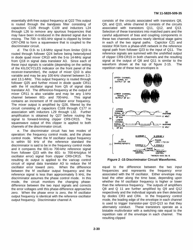
TM 11-5820-509-35
essentially drift-free output frequency at Q22 This outputis routed through the bandpass filter consisting ofcapacitors C105 through C109 and inductors L24through L26 to remove any spurious frequencies thatmay have been in-troduced in the desired signal due tomixing. The 700- to 601-kHz signal is clipped by limiterCR7-CR8 to form a squarewave that is coupled to thediscriminator circuit.
d. The O.9- to 1.8-MHz signal from limiter Q19 isrouted through follower Q24 before being heterodynedin diode quad mixer CR10 with the 5-to 14-MHz signalfrom Q18 in signal data translator A3. Since each ofthese input signals is variable (depending on the settingof the KILOCYCLES indicator on the front panel of thereceiver-transmitter), the output of mixer Q10 is alsovariable and may be any 100-kHz channel between 3.2-and 13.1-MHz. This output frequency is routed throughfollower Q25 and further mixed in diode quade CR11with the hf oscillator signal from Q5 of signal datatranslator A3. The difference-frequency at the output ofmixer CR11 is also variable and may be any 1-kHzchannel between 601- and 700-kHz. This signalcontains an increment of hf oscillator error frequency.The mixer output is amplified by Q26, filtered by thecircuit consisting of capacitors C169 through C177 inassociation with inductors L29 through L32. Furtheramplification is obtained by Q27 before routing thesignal to forward-limiting clipper CR9-CR15. Thesquarewave output of this clipper is applied to bothchannels of the discriminator circuit.
e. The discriminator circuit has two modes ofoperation: the frequency control mode, and the phasecontrol mode. When the hf oscillator output frequencyis within 50 kHz of the reference standard thediscriminator is said to be in the frequency control modeand it compares the 601-to 700-kHz reference signalfrom follower Q23 with the 601- to 700-kHz(plus hfoscillator error) signal from clipper CR9-CR15. Theresulting dc output is applied to the varicap controlcircuit of signal data translator A3 to reduce the hfoscillator error toward zero. When the differencebetween the hf oscillator output frequency and thereference signal is less than approximately 5 kHz, thediscriminator assumes the phase control mode. In thismode, the circuit monitors the changing phase-difference between the two input signals and correctsthe error voltages until this phase-difference approacheszero. When the phase error is zero, the hf oscillatoroutput frequency is identical with the reference oscillatoroutput frequency. Discriminator channel A
consists of the circuits associated with transistors Q8,Q9, and Q10, while channel B consists of the circuitsassociated with transistors Q11, Q12, and Q13.Selection of these transistors into matched pairs and thecareful adjustment of bias and coupling components inthese two channels assures nearly identical stage gainsin each of the two signal paths. Capicitor C21 andresistor R34 form a phase-shift network in the referencesignal path from follower Q23 to the input of Q11. Thereference signals are summed with the unshifted outputof clipper CR9-CR15 in both channels and the resultingsignal at the output of Q8 and Q11 is similar to thewaveform shown at the top of figure 2-15. Therepetition rate of these two envelopes is
Figure 2 -15 Discriminator Circuit Waveforms.
equal to the difference between the two inputfrequencies and represents the frequency errorassociated with the hf oscillator. Either envelope maylead the other along the time base, depending uponwhether the hf oscillator frequency is higher or lowerthan the reference frequency. The outputs of amplifiersQ8 and Q 11 are further amplified by Q9 and Q12respectively and the individual signals are then detectedby diodes CR3 and CR4. In the frequency controlmode, the leading edge of the envelope in each channelis used to trigger transistor-pair Q10-Q13 so that theyalternately conduct. These transistors operate as abistable multivibrator with a switching rate equal to therepetition rate of the envelope in each channel. Theresulting clipped
2-30

TM 1 1-5820-509-35
envelope at the collector of these transistors is similar tothe center waveforms in figure 2-15. {It should berecalled that the waveforms can be reversed dependingupon whether the upper channel leads the lowerchannel, or vice versa.} The integrator circuit at theoutput of Q11 (C93-R104) and at Q13 (C92-R103)change the output waveshape into dc levels known aserror voltage A and error voltage B respectively. (Themnemonic used has no real significance except todifferentiate between the respective channels and theiroutputs.) In the phase control mode, the envelopefrequency will approach zero and the bistable switchingof transistors Q10 and Q13 will stop. The error voltagesat the output of the discriminator will be equal to the dcenvelope values, and will vary as the phase-differencebetween the two channels varies. The phase controlmode continues until the phase-difference between thehf oscillator and the reference oscillator is constant. Atthis time, the phase-difference is equal to the fixedphase-shift introduced by network C21-R34 at the inputto transistor Q8, and the voltages at the error A anderror B outputs are approximately 1.5 volts dc asindicated in the lower waveform of figure 2-15. (Thewaveforms used to illustrate the operation of thediscriminator circuits are not continuously available formeasurement at signal test points, but are only presentduring brief intervals immediately following a channelselection.)
f. A portion of the signal applied to the base oftransistor amplifier Q27 is developed across emitterresistor R142. This signal is rectified by voltage-doublerCR12-CR13 in the automatic capture circuit and isapplied to the base of dc amplifier Q28. The resultingpositive voltage causes conduction of Q28 whose outputclamps the base of transistor switch Q29 at a positivelevel just below that required for its conduction. If nosignal is present at the emitter of Q27, dc amplifier Q28is turned off and the positive voltage at the base oftransistor switch Q29 rises causing this transistor toconduct. The ground supplied through the collector-emitter junction of Q29 is applied to antilock relay K6 onthe main chassis of the receiver-transmitter and thisrelay is operated. As K6 contacts close, a voltage ofapproximately 1 0 volts dc is applied to the error A andthe error B inputs to the varicap control circuit in signaldata translator A3. Since this fixed voltage condition isalso the calibrating condition for the hf oscillator, theoutput error is reduced and capture is once againobtained. After capture, a voltage-drop again appearsacross the emitter resistor (Rl42) of Q27 and transistorQ29
is again turned off so that the discriminator may againassume control of the error-correction circuits of the hfoscillator.
2-15. Electrical Equipment Chassis CH-474/PRC-47(A8A4) (fig. 7-8)
a. When a dc power source is connected to thereceiver-transmitter, and dc power control relay K1 isoperated, +26.5 volts dc is applied to capacitor C1 anddiodes CR1 and CR2 of the power oscillator circuit. Asthe push-to-talk relay (A5K1) is energized, the +26.5volts dc is routed through its contacts and the primarywinding of high-voltage transformer A5T1 to the emittercircuits of Q1 and Q2. Any difference in the operatingcharacteristics of these two transistors will cause a slightpotential difference to exist between their emitters. Thisdifference is coupled to their respective base circuits bythe windings of saturable reactor T1, and causes onetransistor to conduct more heavily than the other. Forexample, suppose that the emitter of Q2 is initially alittle more positive than the emitter of Q1. This voltageis coupled through reactor T1, and causes the base ofQ2 to become more positive and its conduction isreduced. At the same time, the transformer-action of T1places a slightly less positive charge on the base of Q1and the conduction of this transistor is increased. Theregenerative action continues until the core of reactorT1 is saturated, and then the flux-change ceases. Atthis point, the bias is removed from the base of eachtransistor, the magnetic flux in the core collapses, andthe regenerative cycle begins in the reverse direction.The period required for a complete cycle is dependentupon the core properties of the reactor and the dynamiccharacteristics of the two transistors. The squarewavegenerated in the primary winding of high-voltagetransformer A5T1 is approximately 400-Hz. Diodes CR1and CR2 limit the voltage swing of each emitter landhence the peak voltage applied to the primary windingof A5T1) to about 26.5 volts peak.
b. During the transmit cycle, the rf output of driverA3V3 is applied to the grid circuit of power amplifier V101 This single-sideband signal is amplified by V101and routed through the power amplifier LOAD-TUNEcircuit and the t/r relay to the connected load. The gridbias for the power amplifier is derived from the-110-voltdc output of bias rectifier CR1 through CR4 in powersupply A5. The level of the rf input signal at the poweramplifier grid circuit is controlled so that maximum drivecan be used without introducing
2-31
TM 11-5820-509-35
excessive distortion in the transmitted signal. Thisautomatic level control (alc) is accomplished byreducing the gain of the transmit if. input signalwhenever excessive drive is detected at the poweramplifier grid circuit. The (alc) voltage is developedacross grid resistor R104 whenever the power amplifierdraws grid current (class A B2 operation), and thisnegative bias is added to the -110 volts dc used as areference and the combined total (alc) sample controlsthe gain of (alc) amplifier Q1 in amplifier-modulator A2.
c. An rf voltage sample is taken from the platecircuit of the power amplifier across the voltage dividerconsisting of capacitors C105 and C144. This sample isrouted to the filament centertap of driver V3 in signaldata translator A3 as a negative feedback that improvesthe linearity of the rf output signal. Another voltagesample is taken from the power amplifier plate circuitacross capacitor voltage divider C124-C140. Thissample is rectified by sidetone rectifier CR101, filteredby capacitors C125, C126, and resistor R108, andapplied as an enabling bias to sidetone gate CR10 inaudio frequency amplifier A1. XMTR PWR switch S103on the front panel of the receiver-transmitter selects theappropriate XMTR OUTPUT meter range, poweramplifier control grid bias, and power amplifier plate andscreen voltages to assure linear operation of this circuitat reduced power levels during tune-up and preliminaryloading adjustments. In the LOW
power mode , the amplifier plate voltage is limited to+650 volts dc (derived from the normal screen voltagepower supply) and the screen voltage is correspondinglyreduced to limit the screen-grid dissipation to reasonablevalues during periods of off-resonance operation. The rfcurrent flowing in the output circuit of the poweramplifier stage is monitored by XMTR OUTPUT meterM101 to determine when proper resonance conditionsexist in the output coupling network. Current bansformer T101 samples the output rf and develops avoltage across resistor R129 that is proportional to thiscurrent. Diode CR102 rectifies this rf voltage andapplies it to meter sensitively adjustment (M ADT)R117. Diode CR103 protects the meter from voltageoverloads, and capacitor C106 bypasses rf currentsaround the meter movement. When the BATTERYTEST switch on the front panel of the receiver-transmitter is pressed, XMTR OUTPUT meter M101measures the terminal voltage of the connectedbatteries. Closure of this switch also overrides thermalcutout K103 for emergency operation of the receiver-transmitter during overtemperature conditions in thepower amplifier compartment. The POWERAMPLIFIER LOAD and POWER AMPLIFIER TUNEcontrols operate inductors L109 through L112 and thewhole megahertz control selects an appropriate shuntcapacitor from the group C108 through C121 toterminate the power amplifier plate circuit impedance.
2-32
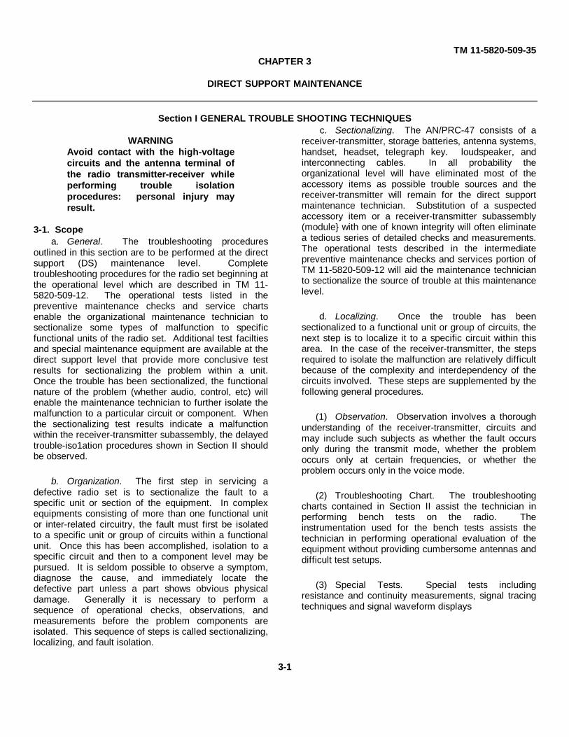
TM 11-5820-509-35CHAPTER 3
DIRECT SUPPORT MAINTENANCE
Section I GENERAL TROUBLE SHOOTING TECHNIQUES
WARNINGAvoid contact with the high-voltagecircuits and the antenna terminal ofthe radio transmitter-receiver whileperforming trouble isolationprocedures: personal injury mayresult.
3-1. Scopea. General. The troubleshooting procedures
outlined in this section are to be performed at the directsupport (DS) maintenance level. Completetroubleshooting procedures for the radio set beginning atthe operational level which are described in TM 11-5820-509-12. The operational tests listed in thepreventive maintenance checks and service chartsenable the organizational maintenance technician tosectionalize some types of malfunction to specificfunctional units of the radio set. Additional test faciltiesand special maintenance equipment are available at thedirect support level that provide more conclusive testresults for sectionalizing the problem within a unit.Once the trouble has been sectionalized, the functionalnature of the problem (whether audio, control, etc) willenable the maintenance technician to further isolate themalfunction to a particular circuit or component. Whenthe sectionalizing test results indicate a malfunctionwithin the receiver-transmitter subassembly, the delayedtrouble-iso1ation procedures shown in Section II shouldbe observed.
b. Organization. The first step in servicing adefective radio set is to sectionalize the fault to aspecific unit or section of the equipment. In complexequipments consisting of more than one functional unitor inter-related circuitry, the fault must first be isolatedto a specific unit or group of circuits within a functionalunit. Once this has been accomplished, isolation to aspecific circuit and then to a component level may bepursued. It is seldom possible to observe a symptom,diagnose the cause, and immediately locate thedefective part unless a part shows obvious physicaldamage. Generally it is necessary to perform asequence of operational checks, observations, andmeasurements before the problem components areisolated. This sequence of steps is called sectionalizing,localizing, and fault isolation.
c. Sectionalizing. The AN/PRC-47 consists of areceiver-transmitter, storage batteries, antenna systems,handset, headset, telegraph key. loudspeaker, andinterconnecting cables. In all probability theorganizational level will have eliminated most of theaccessory items as possible trouble sources and thereceiver-transmitter will remain for the direct supportmaintenance technician. Substitution of a suspectedaccessory item or a receiver-transmitter subassembly(module} with one of known integrity will often eliminatea tedious series of detailed checks and measurements.The operational tests described in the intermediatepreventive maintenance checks and services portion ofTM 11-5820-509-12 will aid the maintenance technicianto sectionalize the source of trouble at this maintenancelevel.
d. Localizing. Once the trouble has beensectionalized to a functional unit or group of circuits, thenext step is to localize it to a specific circuit within thisarea. In the case of the receiver-transmitter, the stepsrequired to isolate the malfunction are relatively difficultbecause of the complexity and interdependency of thecircuits involved. These steps are supplemented by thefollowing general procedures.
(1) Observation. Observation involves a thoroughunderstanding of the receiver-transmitter, circuits andmay include such subjects as whether the fault occursonly during the transmit mode, whether the problemoccurs only at certain frequencies, or whether theproblem occurs only in the voice mode.
(2) Troubleshooting Chart. The troubleshootingcharts contained in Section II assist the technician inperforming bench tests on the radio. Theinstrumentation used for the bench tests assists thetechnician in performing operational evaluation of theequipment without providing cumbersome antennas anddifficult test setups.
(3) Special Tests. Special tests includingresistance and continuity measurements, signal tracingtechniques and signal waveform displays
3-1

TM 11-5820-509-35are included in section II to aid the maintenancetechnician in localizing an equipment malfunction.
e. Isolation. After the trouble has been localized toa stage or a circuit, the final step is to isolate themalfunction to a specific component. Methods forperforming this procedure include:
(1) Visual Inspection. Examine all resistors,capacitors, vacuum tubes, transistors, coils, and othercomponents associated with the faulty circuit forevidence of broken wires, burned insulation, and. otherobvious signs of physical damage.
(2) Voltage and Resistance Measurements.The voltage and resistance measurements provided insection I! aid in determining
whether normal values are being obtained and point outthe part of a specific circuit that may be defective.
(3) Electrical Inspection. The dc resistance oftransformers and coils is shown in tabular form insection II to aid the maintenance technician indetermining whether a winding is defective.
3-2. Tools, Test Equipment, and Materials RequiredThe following table lists the test equipment required fortroubleshooting Radio Set AN/PRC-47 at the directsupport maintenance level. This list also shows thetechnical manual identification number for each itemspecified.
Test Equipment FSN Technical manual
Multimeter ME-26A/U 6625-542-8407 11-6625-200-15Oscilloscope AN/USM-50 11-5129Signal Generator SG-103/URM-25FFrequency Counter AN/URM-79/UAudio Oscillator TS-382/U 6625-246-8729 11-6625-935-12Dummy Load DA-75/UCable Assembly Set AN/PRA-4 5995-973-3686Output Meter TS-585/U 11-5017Radar and Radio Repair Tool Kit TK-87/U
Cable Assembly Set AN/PRA-4 (fig. 3-84) is usedwhenever the procedure requires measurement oradjustment within a module, and includes
an antenna simulator and input/output cables thatsimplify the bench testing procedures.
Manufacturer'sQty Nomenclature part number Use
1 Special extender cable no. 1 549-6255-00 Extends Power Supply PP 3518/PRC 47 frommain chassis.
1 Special extender cable no. 2 549-6256-00 Extends Audio Frequency Amplifier AM3506/PRC-47 from main chassis.
1 Special extender cable no. 3 549-6257-00 Extends Oscillator Control C 4311/PRC 47from main chassis.
4 Special extender cable no. 4 549 6258-00 Extends Signal Data Translator CV1377A/PRC 47 (4 reqd), Oscillator Control C43 11 /PRC -47 (1 reqd), or AmplifierModulator AM 3507/PRC-47 (1 reqd) frommain chassis.
1 Special extender cable no. 5 549-6259-00 Extends Amplifier-Modulator AM-3507/PRC47, or Radio Frequency Oscillator 01032/PRC-47 from main chassis.
1 Front panel test lead. 549-6260-00 Extends AUDIO connectors to test microphoneand speaker.
1 Antenna test lead 549-6261-00 Connects to 50-ohm dummy load.1 RG-58/U coaxial cable 3 ft. long 553-9759-002 Connects antenna simulator to 50-ohm
dummy load.1 RG-58/U coaxial cable 5 ft. long 553-9760-002 Connects antenna simulator to test
equipment.1 Adapter, BNC to Type N coax 357-9291-00 Transition fitting between RG-58/U and
dummy load.1 Antenna simulator 553-9758-005 Simulates 15-foot whip antenna when con-
nected to 50-ohm load. 12 position switch selects operating frequency.
1 Canvas carrying case 553-9764-003 Bag to store and transport Cable Assembly Set An/PRA-4.
3-2

TM 11-5820-509-35Section II. DIRECT SUPPORT TROUBLESHOOTING
3-3. Overalla. General. When a malfunction of the radio set
occurs, the first step in correcting the deficiency is tosectionalize the cause to a specific functional area in theequipment. The tests at operational and organizational-level have undoubtedly isolated the malfunction tocircuits within Radio Receiver-Transmitter RT-671/PRC-47. The sectionalizing tests listed below are arranged inan order of increasing circuit complexity and mechanicaldisassembly requirements within four major functionalareas of the radio set. These areas contain the powersupply, frequency generation, receiver-transmitter, andrelay circuits. When performed in the order listed, thesetests provide the maintenance technician with an orderlyapproach to the isolation of defective circuits andmodules within the interrelated transceiversubassembly. Test jacks are installed in the top of eachmodule that permit connection of test instruments tothese circuits so that evaluation can be made of thesignals and voltage levels. Similar test points and jacksare accessible from the bottom of the main chassis thatpermit connection of test instruments to the poweramplifier and selected primary power circuits.
b. Use of Charts. The voltage and resistancecharts and the waveform diagrams shown in this sectionprovide the maintenance technician with a go/no-gocriteria that will assist him in locating the circuitdeficiency and permit him to restore the circuitparameters) to values within the tolerances specified.Before proceeding to any chart, the technician mustestablish the conditions for the test that are indicated,must perform the initial equipment connections, andestablish the radio set operating conditions called for inthe procedure. Using this approach, the technician mayenter the chart at any functional area and proceedthrough only that portion of the procedures that arerequired to correct the deficiency.
3-4. Troubleshooting Radio Receiver-Transmitter RT-671/PRC-47 (A8)
CAUTIONDo not apply power to the receiver-transmitter unless operationaltrouble symptoms are known and areof such a nature as to eliminate thepossibility of further damage whenthe power is applied.
a. Testing for Shorts.(1) When to Check. When any of the
following conditions apply, check for short circuits andrepair any existing deficiency before applying power tothe receiver-transmitter.
(a) When the receiver-transmitter isbeing serviced and the fault symptoms are unknown.
(b) When an inspection of fuses F1through F5 shows that a fuse has blown.
(2) Conditions for Tests.(a) Disconnect all cables from the front
panel of the receiver-transmitter.(b) Remove the dust cover from the
receiver-transmitter using the procedure of paragraph 3-11.
(3) Measurements. Using the multitester,make the resistance measurements shown in the chartbelow. Unless otherwise indicated in the point ofmeasurement column of this chart, all resistancemeasurements are made from the test point shown tochassis ground. The normal indication shown is anaverage value and may vary from one unit to anotherand from one multitester to another. Any reading thatdisagrees widely from the value shown will cause themaintenance technician to proceed to the isolatingprocedure indicated. Location of a defective part mustinitiate the repair procedure shown in section IV.
(4) Short Circuit Test.Point of
measurement Normal indication Isolating procedureBetween A5J1 (fig. 3-4, 3-111 and 40.000 ohms
chassis ground,
Between A5J2 and chassis ground. 50,000 ohms
Between A5J3 and chassis ground. 10 ohms
(Will depend on setting of A5R4). Very low reading, improperadjustment of A5R4 or short at driver grid (A3C293). Highreading may indicate A5R4 open.
(Will depend on setting of A5R3). Very low reading, shortedfeedthru C26 or inductor L122 in pa compartment. defectiveXMTR PWR switch or shorted plate bypass C123. Highreading may indicate A5R3). open.
Very low reading: shorted C208, C221, or C235 in FL2. shortedprimary at T3, or short in filament bypass C104. High readingmay indicate open winding at T1, defective tube V101, oropen hum balance control R121.
3-3
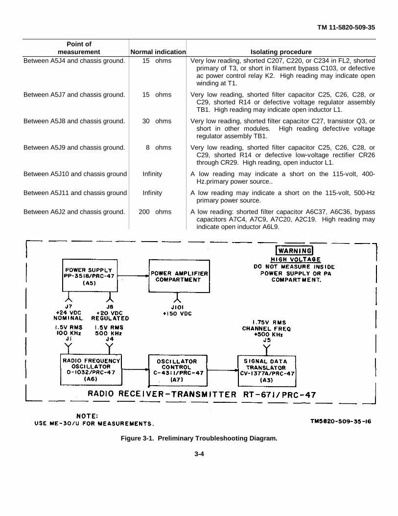
TM 11-5820-509-35
Point ofmeasurement Normal indication Isolating procedure
Between A5J4 and chassis ground.
Between A5J7 and chassis ground.
Between A5J8 and chassis ground.
Between A5J9 and chassis ground.
Between A5J10 and chassis ground
Between A5J11 and chassis ground
Between A6J2 and chassis ground.
15 ohms
15 ohms
30 ohms
8 ohms
Infinity
Infinity
200 ohms
Very low reading, shorted C207, C220, or C234 in FL2, shortedprimary of T3, or short in filament bypass C103, or defectiveac power control relay K2. High reading may indicate openwinding at T1.
Very low reading, shorted filter capacitor C25, C26, C28, orC29, shorted R14 or defective voltage regulator assemblyTB1. High reading may indicate open inductor L1.
Very low reading, shorted filter capacitor C27, transistor Q3, orshort in other modules. High reading defective voltageregulator assembly TB1.
Very low reading, shorted filter capacitor C25, C26, C28, orC29, shorted R14 or defective low-voltage rectifier CR26through CR29. High reading, open inductor L1.
A low reading may indicate a short on the 115-volt, 400-Hz.primary power source..
A low reading may indicate a short on the 115-volt, 500-Hzprimary power source.
A low reading: shorted filter capacitor A6C37, A6C36, bypasscapacitors A7C4, A7C9, A7C20, A2C19. High reading mayindicate open inductor A6L9.
Figure 3-1. Preliminary Troubleshooting Diagram.
3-4

TM 11-5820-509-35
Figure 3-2. Receiver Tests, Troubleshooting Test Setup.
3-5
TM 11-5820-509-35
Figure 3-3. Transmitter Tests, Troubleshooting Test Setup.
3-6

TM 11-5820-509-35
Figure 3-4. Radio Receiver-Transmitter RT-671/PRC-47 (A8), Top View, Location of Assemblies and Test Points.3-7
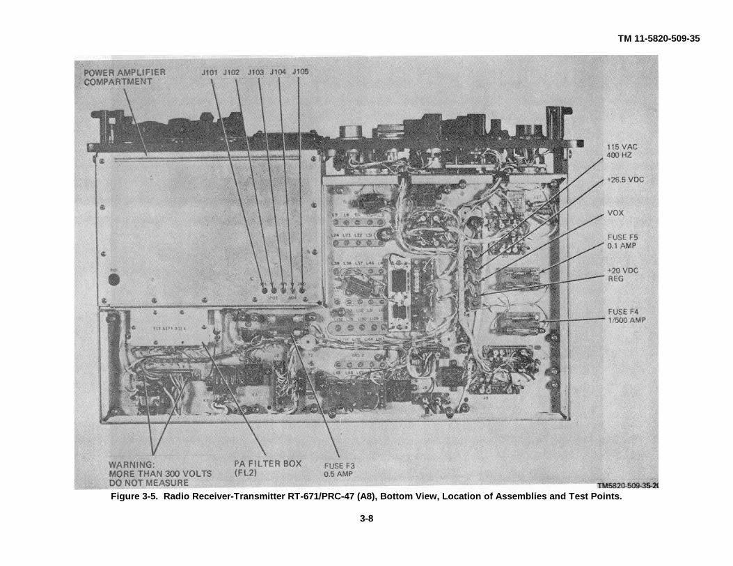
TM 11-5820-509-35
Figure 3-5. Radio Receiver-Transmitter RT-671/PRC-47 (A8), Bottom View, Location of Assemblies and Test Points.
3-8

TM 11-5820-509-35
Figure 3-6. Audio Frequency Amplifier AM-3506/PRC-47 (A8A1), Top View, Cover Removed, Location ofSubassemblies and Test Points..
3-9
TM 11-5820-509-35
Figure 3-7. Amplifier-Modular AM-3507/PRC-47 (A8A2), Side View, Cover Removed,Location of Subassemblies E1 and E2 and Test Points
Figure 3-8. Amplifier-Modular AM-3507/PRC-47 (A8A2), Side View, Cover Removed, Location ofSubassemblies E3, E4 and E5 and Test Points
3-10
TM 11-5820-509-35
Figure 3-9. Signal Data Translator CV 1377/PRC-47 (A8A3), Top View, Location of Subassemblies and TestPoints.
3-11

TM 11-5820-509-35
Figure 3-10. Signal Data Translator CV-1377A PRC-47 (A8A3), Bottom View, Location of Subassemblies.
3-12
TM 11-5820-509-35
Figure 3-11. Power Supply PP-3518/PRC-47 (A8A5), Top View, Cover Removed, Location of Subassemblies andTest Points.
3-13
TM 11-5820-509-35
Figure 3-12. Radio Frequency Oscillator O-1032/PRC-47 (A8A6), Side View, Cover Removed, Location ofSubassemblies E1 and E2, and Test Points.
3-14

TM-11-5820-509-35
Figure 3-13. Radio Frequency Oscillator O-1032/PRC-47(A8A6), Side View, Cover Removed,Location of Chassis Subassembly and Test Points.
3-15

TM-11-5820-509-35
Figure 3-14. Oscillator Control C-4311/PRC-47 (A8A7), Top View, Cover Removed, Location of Subassembliesand Test Points.
3-16

TM-11-5820-509-35
Figure 3-15. Oscillator Control C-4311/PRC-47(A8A7), Bottom View, Location of Subassemblies.3-17
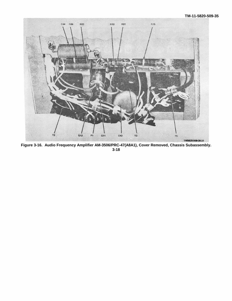
TM-11-5820-509-35
Figure 3-16. Audio Frequency Amplifier AM-3506/PRC-47(A8A1), Cover Removed, Chassis Subassembly.3-18
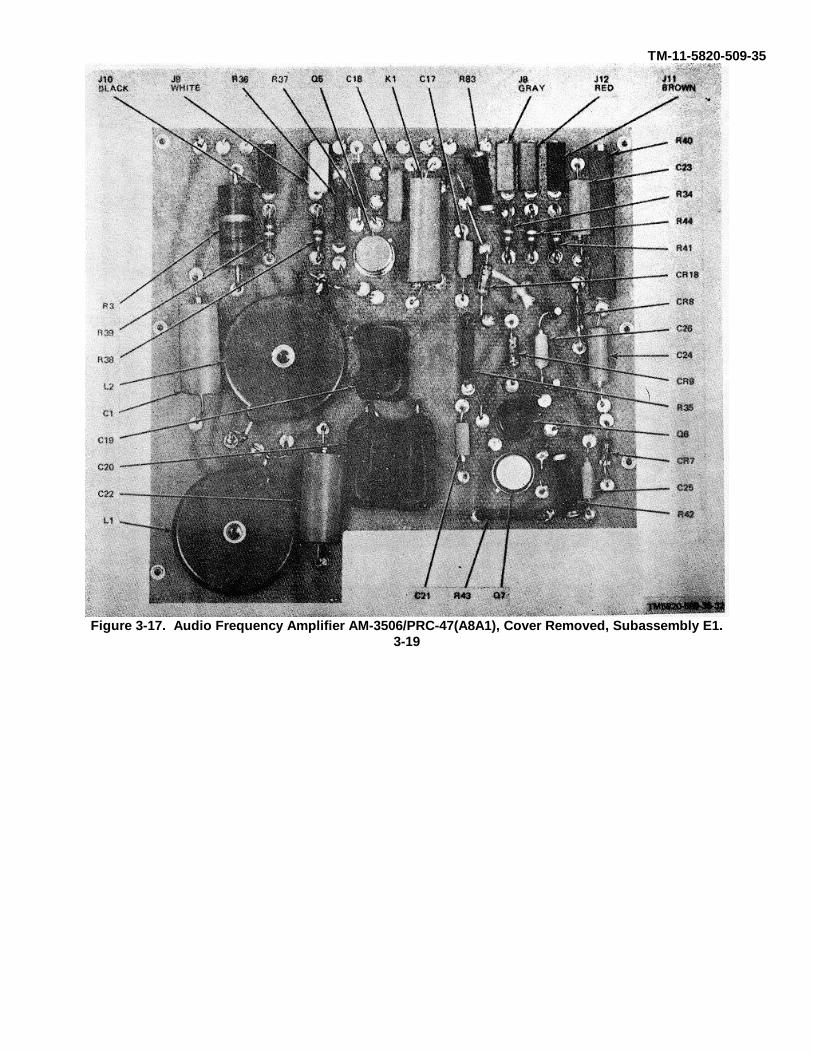
TM-11-5820-509-35
Figure 3-17. Audio Frequency Amplifier AM-3506/PRC-47(A8A1), Cover Removed, Subassembly E1.3-19
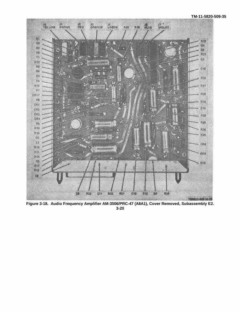
TM-11-5820-509-35
Figure 3-18. Audio Frequency Amplifier AM-3506/PRC-47 (A8A1), Cover Removed, Subassembly E2.3-20
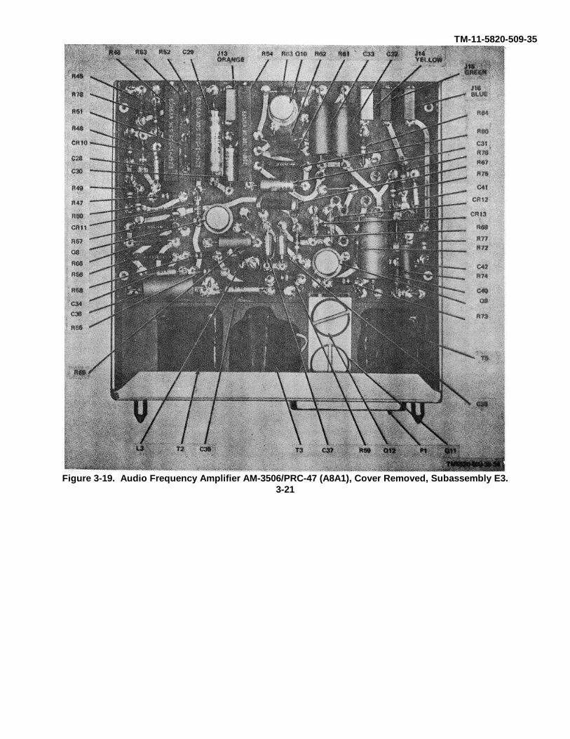
TM-11-5820-509-35
Figure 3-19. Audio Frequency Amplifier AM-3506/PRC-47 (A8A1), Cover Removed, Subassembly E3.3-21
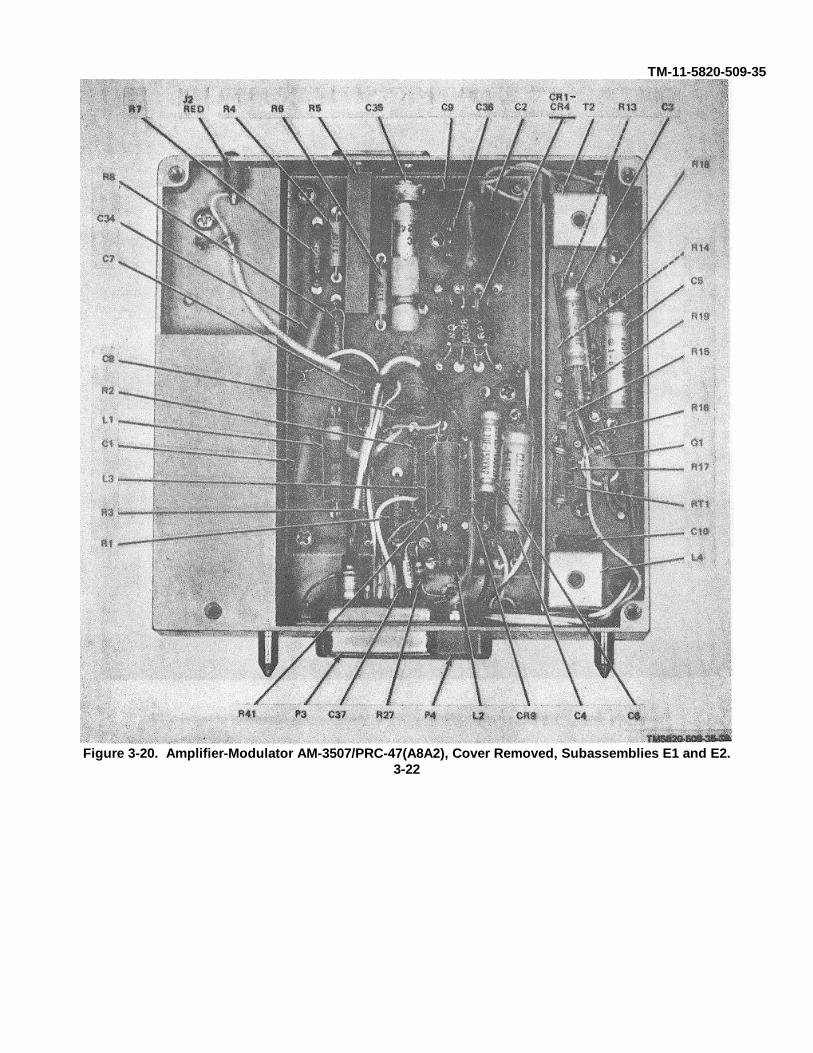
TM-11-5820-509-35
Figure 3-20. Amplifier-Modulator AM-3507/PRC-47(A8A2), Cover Removed, Subassemblies E1 and E2.3-22
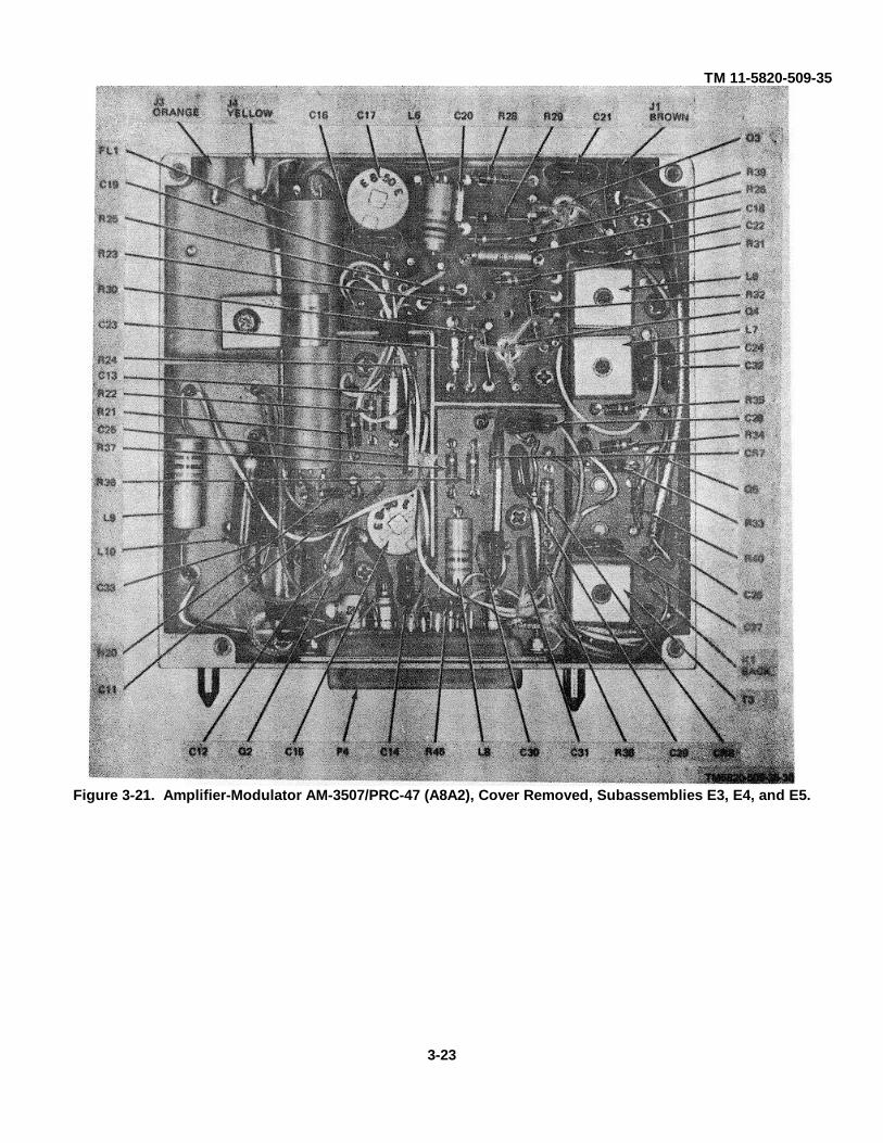
TM 11-5820-509-35
Figure 3-21. Amplifier-Modulator AM-3507/PRC-47 (A8A2), Cover Removed, Subassemblies E3, E4, and E5.
3-23

TM 11-5820-509-35
Figure 3-23. Signal Data Translator CV-1377A/PRC-47 (A8A3), Card Assembly TB2.
Figure 3-22. Signal Data Translator CV-1377A/PRC-47 (A8A3), Card Assembly TB1.
3-24
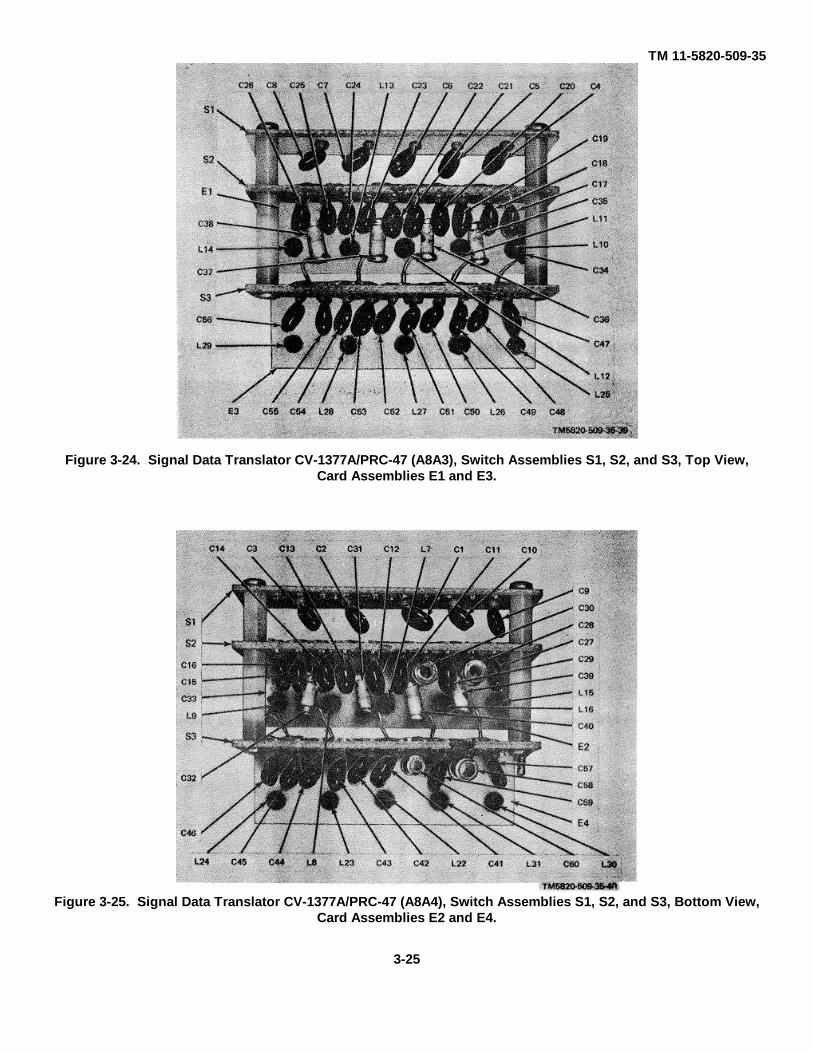
TM 11-5820-509-35
Figure 3-25. Signal Data Translator CV-1377A/PRC-47 (A8A4), Switch Assemblies S1, S2, and S3, Bottom View,Card Assemblies E2 and E4.
Figure 3-24. Signal Data Translator CV-1377A/PRC-47 (A8A3), Switch Assemblies S1, S2, and S3, Top View,Card Assemblies E1 and E3.
3-25
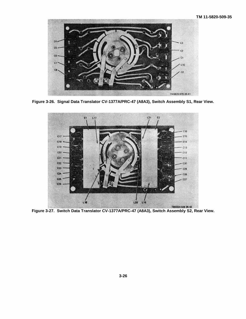
TM 11-5820-509-35
Figure 3-27. Switch Data Translator CV-1377A/PRC-47 (A8A3), Switch Assembly S2, Rear View.
Figure 3-26. Signal Data Translator CV-1377A/PRC-47 (A8A3), Switch Assembly S1, Rear View.
3-26
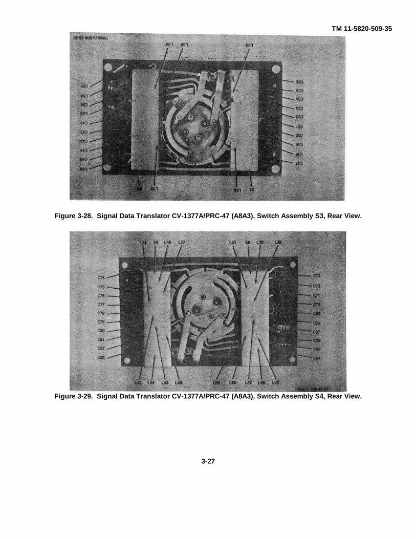
TM 11-5820-509-35
Figure 3-29. Signal Data Translator CV-1377A/PRC-47 (A8A3), Switch Assembly S4, Rear View.
Figure 3-28. Signal Data Translator CV-1377A/PRC-47 (A8A3), Switch Assembly S3, Rear View.
3-27
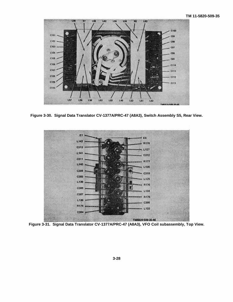
TM 11-5820-509-35
Figure 3-31. Signal Data Translator CV-1377A/PRC-47 (A8A3), VFO Coil subassembly, Top View.
Figure 3-30. Signal Data Translator CV-1377A/PRC-47 (A8A3), Switch Assembly S5, Rear View.
3-28

TM 11-5820-509-35
Figure 3-32. Signal Data Translator CV-1377A/PRC-47 (A8A3), VFO, Coil Subassembly, Bottom View.
3-29
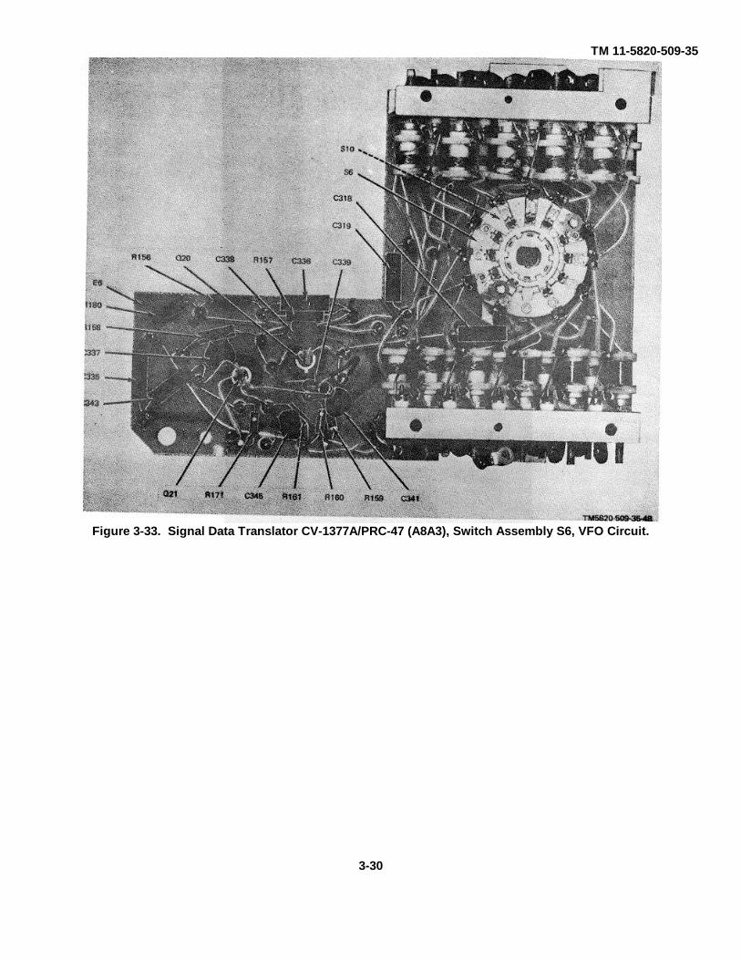
TM 11-5820-509-35
Figure 3-33. Signal Data Translator CV-1377A/PRC-47 (A8A3), Switch Assembly S6, VFO Circuit.
3-30
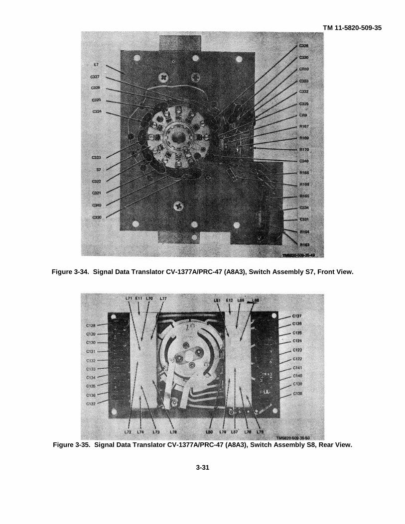
TM 11-5820-509-35
Figure 3-35. Signal Data Translator CV-1377A/PRC-47 (A8A3), Switch Assembly S8, Rear View.
3-31
Figure 3-34. Signal Data Translator CV-1377A/PRC-47 (A8A3), Switch Assembly S7, Front View.
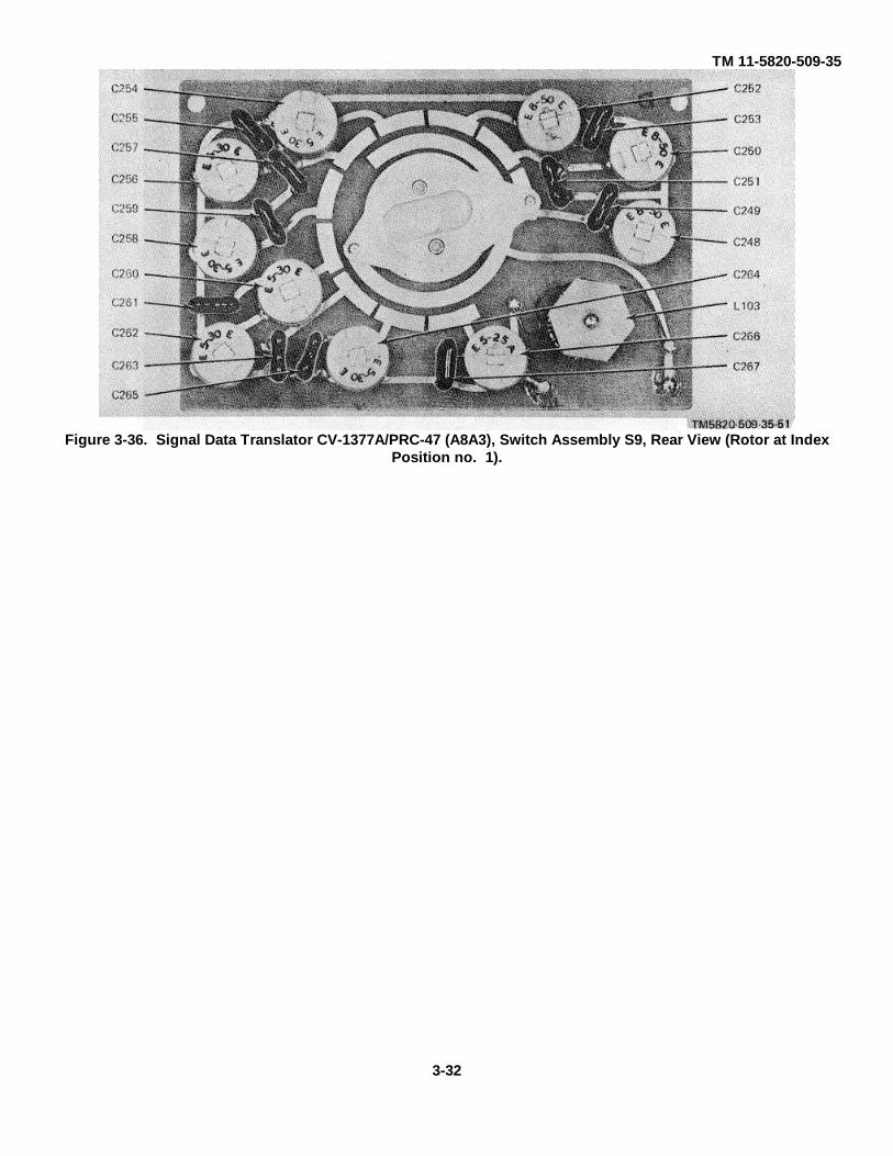
TM 11-5820-509-35
Figure 3-36. Signal Data Translator CV-1377A/PRC-47 (A8A3), Switch Assembly S9, Rear View (Rotor at IndexPosition no. 1).
3-32

TM 11-5820-509-35
Figure 3-37. Signal Data Translator CV-1377A/PRC-47 (A8A3), Card Assembly E46.
3-33
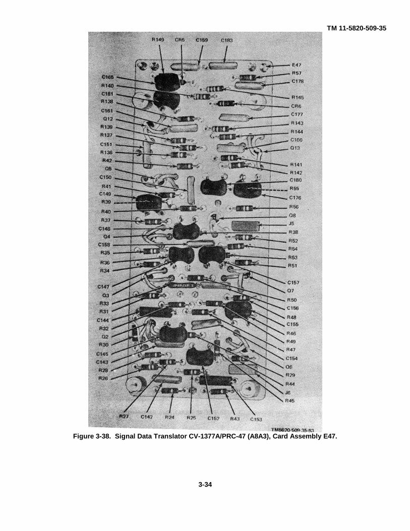
TM 11-5820-509-35
Figure 3-38. Signal Data Translator CV-1377A/PRC-47 (A8A3), Card Assembly E47.
3-34

TM 11-5820-509-35
Figure 3-39. Signal Data Translator CV-1377A/PRC-47 (A8A3), Card Assembly E48.
3-35

TM 11-5820-509-35
Figure 3-40. Signal Data Translator CV-1377A/PRC-47 (A8A3), Driver Tube (V3) Compartment, Bottom View.
3-36
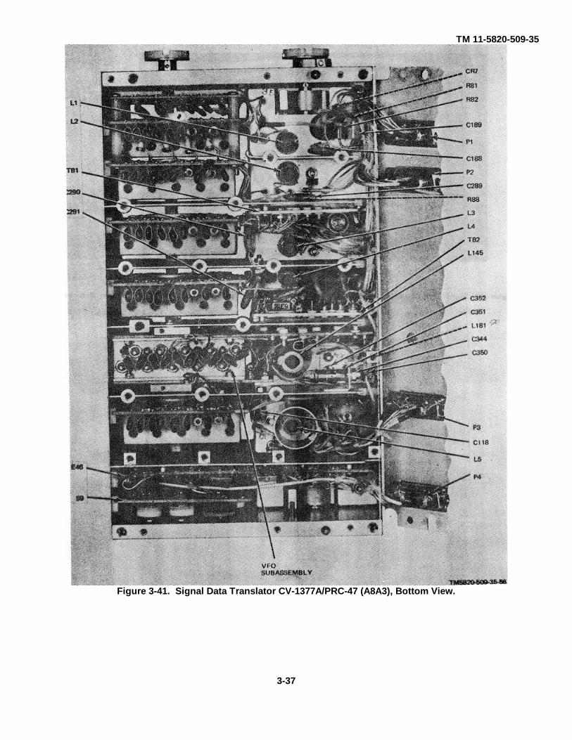
TM 11-5820-509-35
Figure 3-41. Signal Data Translator CV-1377A/PRC-47 (A8A3), Bottom View.
3-37
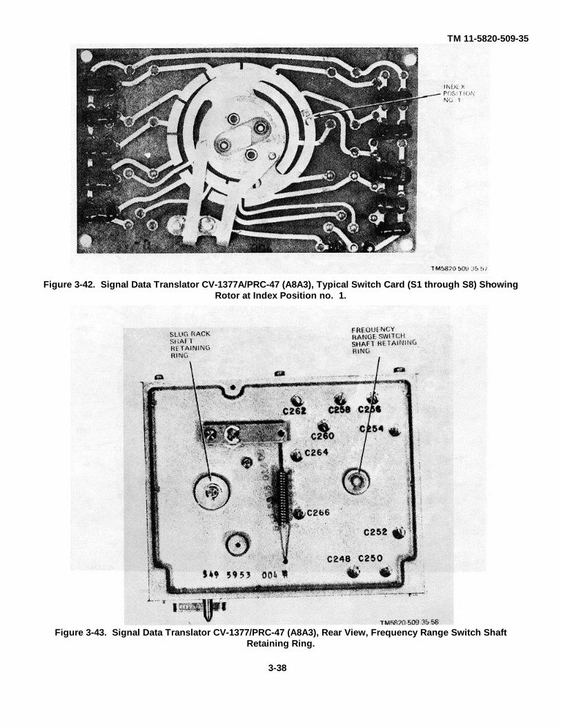
TM 11-5820-509-35
Figure 3-43. Signal Data Translator CV-1377/PRC-47 (A8A3), Rear View, Frequency Range Switch ShaftRetaining Ring.
Figure 3-42. Signal Data Translator CV-1377A/PRC-47 (A8A3), Typical Switch Card (S1 through S8) ShowingRotor at Index Position no. 1.
3-38
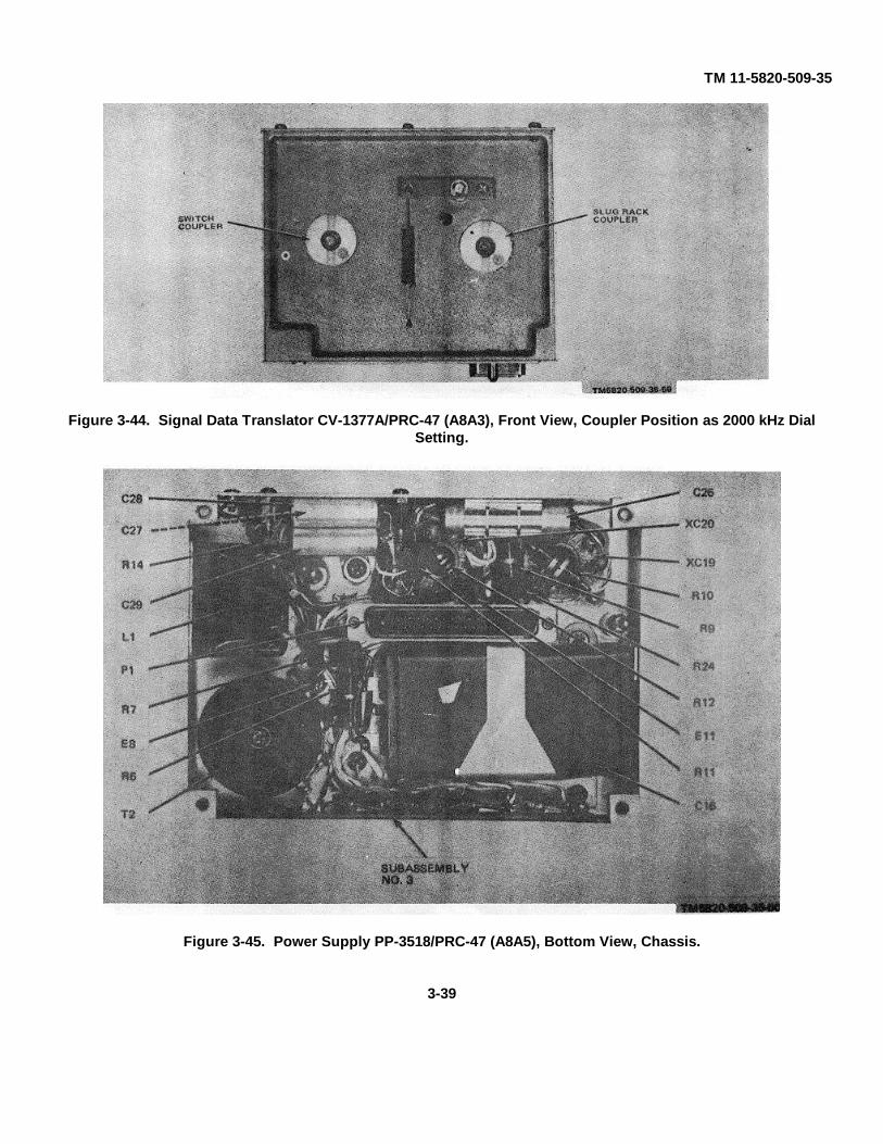
TM 11-5820-509-35
Figure 3-44. Signal Data Translator CV-1377A/PRC-47 (A8A3), Front View, Coupler Position as 2000 kHz DialSetting.
Figure 3-45. Power Supply PP-3518/PRC-47 (A8A5), Bottom View, Chassis.
3-39
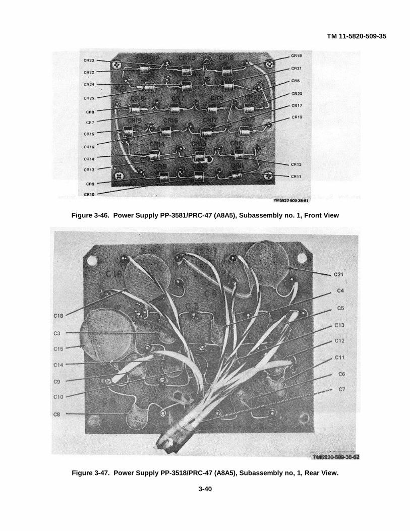
TM 11-5820-509-35
Figure 3-46. Power Supply PP-3581/PRC-47 (A8A5), Subassembly no. 1, Front View
Figure 3-47. Power Supply PP-3518/PRC-47 (A8A5), Subassembly no, 1, Rear View.
3-40

TM 11-5820-509-35
Figure 3-48. Power Supply PP-3518/PRC-47 (A8A5), Subassembly no. 2.
Figure 3-49. Power Supply PP-3518/PRC 47 (A8A5), Subassembly no. 3.
3-41
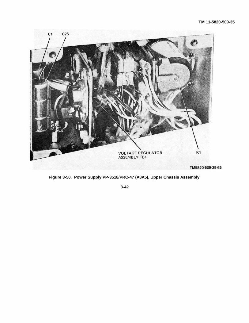
TM 11-5820-509-35
Figure 3-50. Power Supply PP-3518/PRC-47 (A8A5), Upper Chassis Assembly.
3-42

TM 11-5820-509-35
Figure 3-51. Power Supply PP-3518/PRC-47 (A8A5), Voltage Regulator Assembly TB1.
3-43
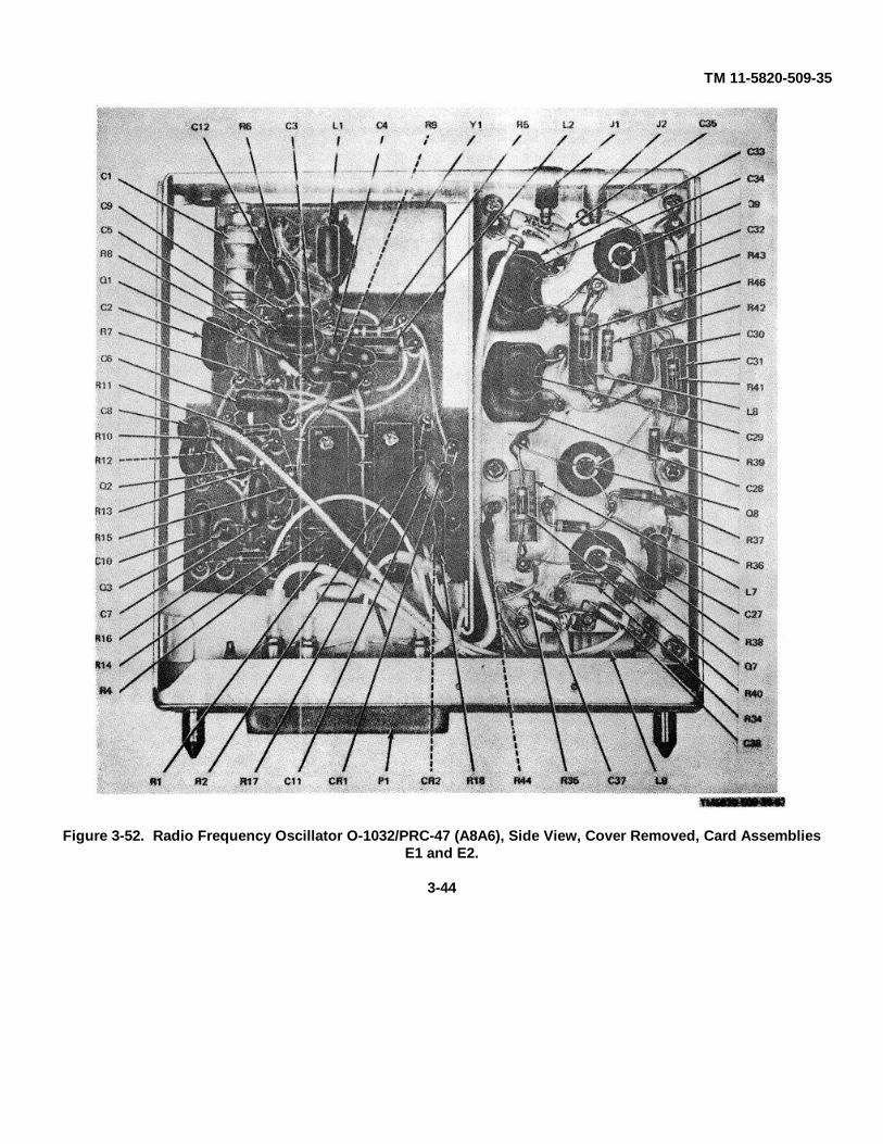
TM 11-5820-509-35
Figure 3-52. Radio Frequency Oscillator O-1032/PRC-47 (A8A6), Side View, Cover Removed, Card AssembliesE1 and E2.
3-44

TM 11-5820-509-35
Figure 3-53. Radio Frequency Oscillator O-1032/PRC-47 (A8A6), Side View, Cover Removed, Chassis Assembly.
3-45

TM 11-5820-509-35
Figure 3-54. Oscillator Control C-4311/PRC-47 (A8A7), Card Assembly E1.
3-46
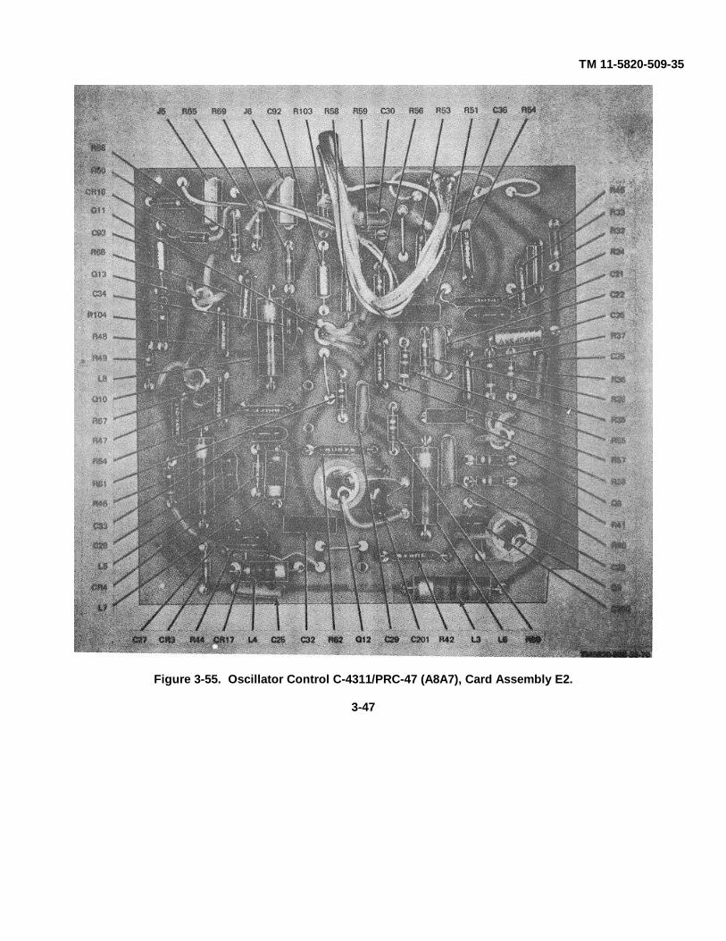
TM 11-5820-509-35
Figure 3-55. Oscillator Control C-4311/PRC-47 (A8A7), Card Assembly E2.
3-47
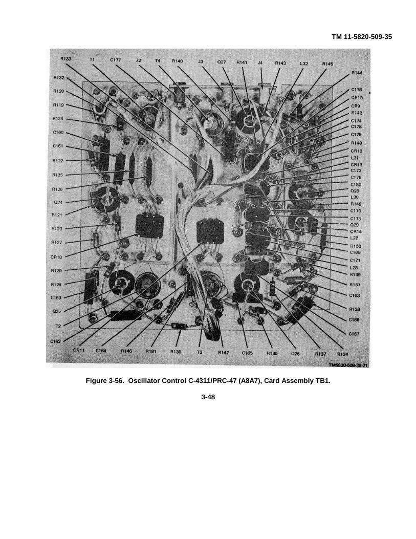
TM 11-5820-509-35
Figure 3-56. Oscillator Control C-4311/PRC-47 (A8A7), Card Assembly TB1.
3-48
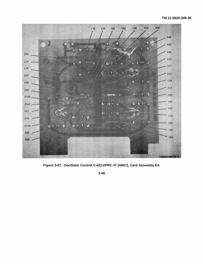
TM 11-5820-509-35
Figure 3-57. Oscillator Control C-4311/PRC 47 (A8A7), Card Assembly E4.
3-49
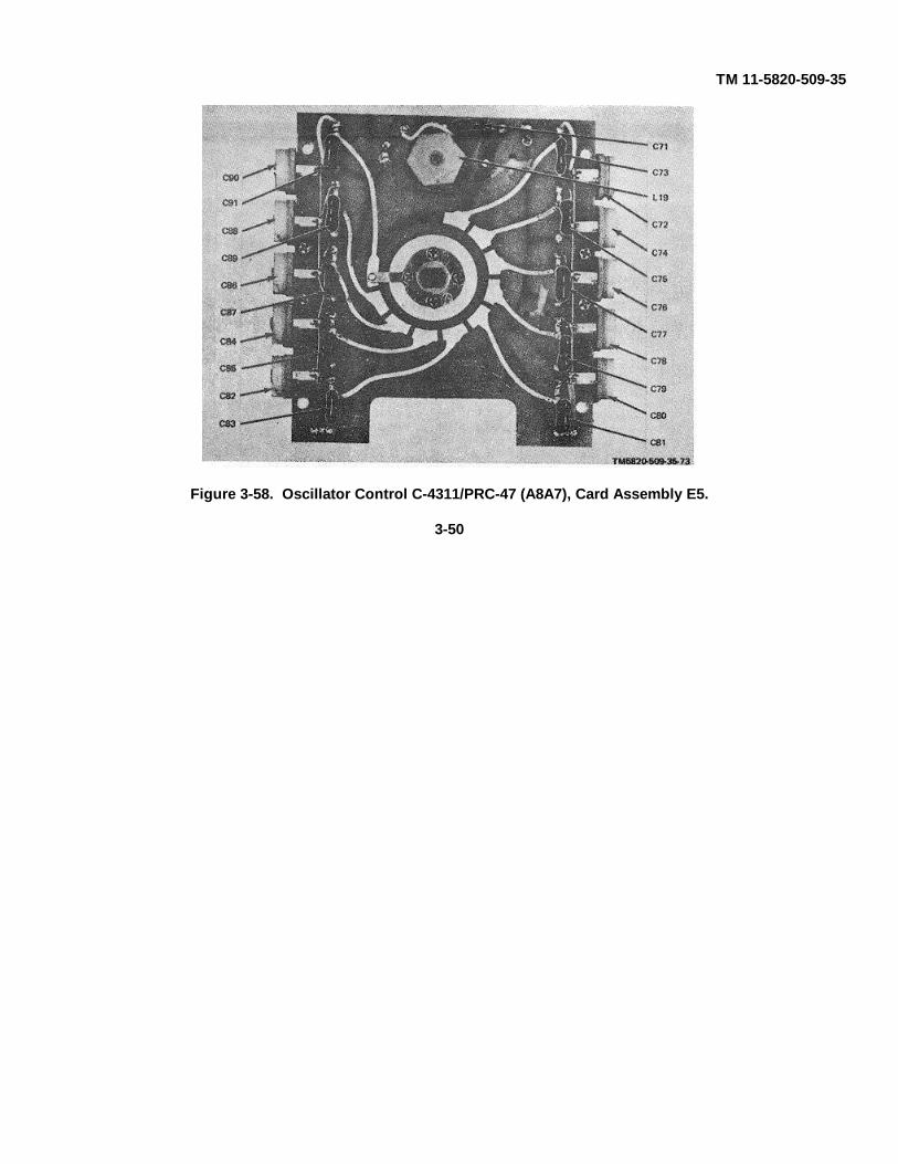
TM 11-5820-509-35
Figure 3-58. Oscillator Control C-4311/PRC-47 (A8A7), Card Assembly E5.
3-50

TM 11-5820-509-35
Figure 3-59. Oscillator Control C-4311/PRC-47 (A8A7), Card Assembly E6.
3-51

TM 11-5820-509-35
Figure 3-60. Oscillator Control C-4311/PRC-47 (A8A7), Card Assemblies E7 and E8, Front View.
Figure 3-61. Oscillator Control C-4311 PRC-47 (A8A7), Line Filter Assembly At Connector P1, Cover Removed.
3-52
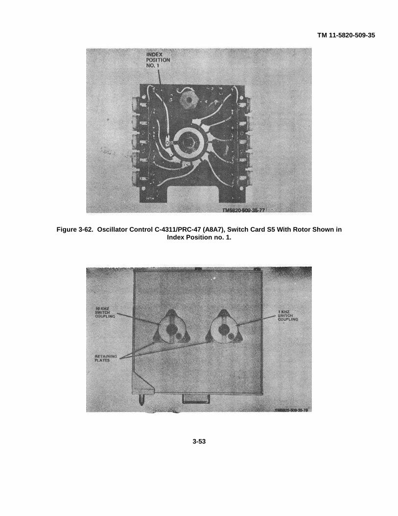
TM 11-5820-509-35
Figure 3-62. Oscillator Control C-4311/PRC-47 (A8A7), Switch Card S5 With Rotor Shown inIndex Position no. 1.
3-53
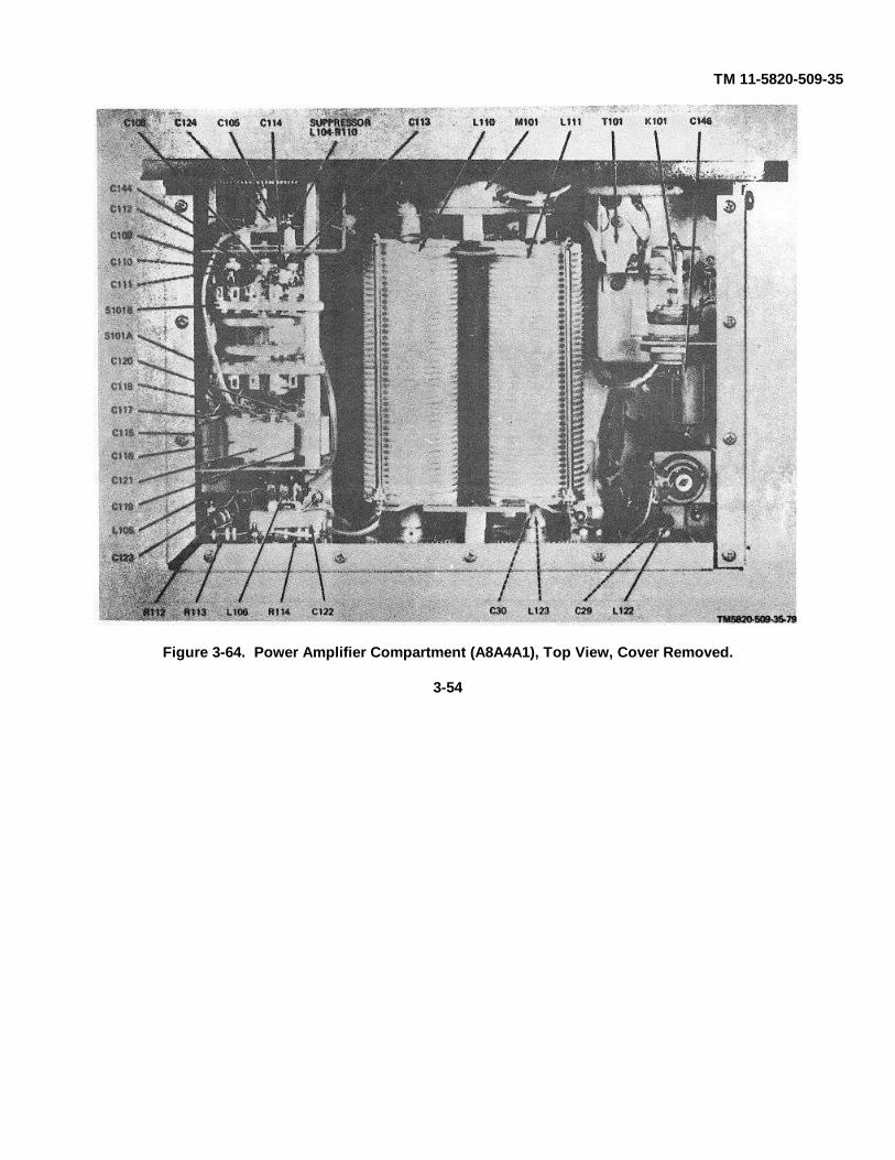
TM 11-5820-509-35
Figure 3-64. Power Amplifier Compartment (A8A4A1), Top View, Cover Removed.
3-54
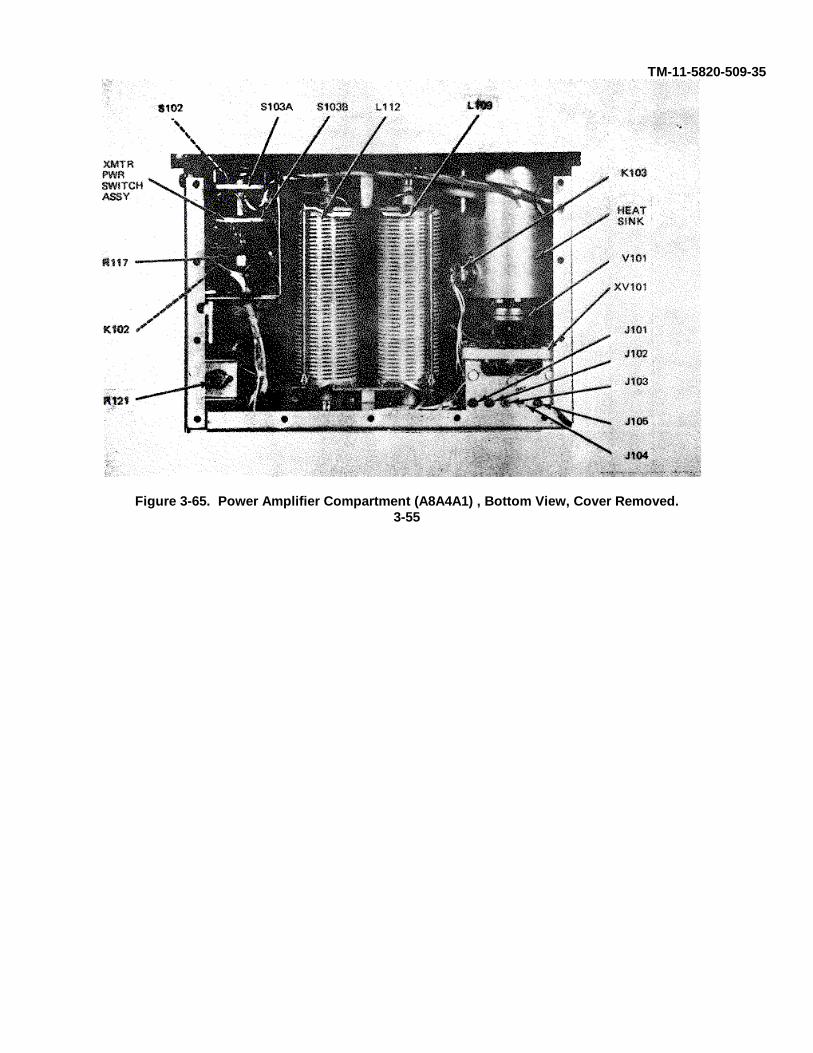
TM-11-5820-509-35
Figure 3-65. Power Amplifier Compartment (A8A4A1) , Bottom View, Cover Removed.3-55
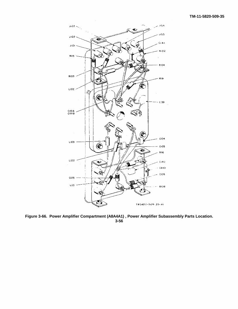
TM-11-5820-509-35
Figure 3-66. Power Amplifier Compartment (A8A4A1) , Power Amplifier Subassembly Parts Location.3-56
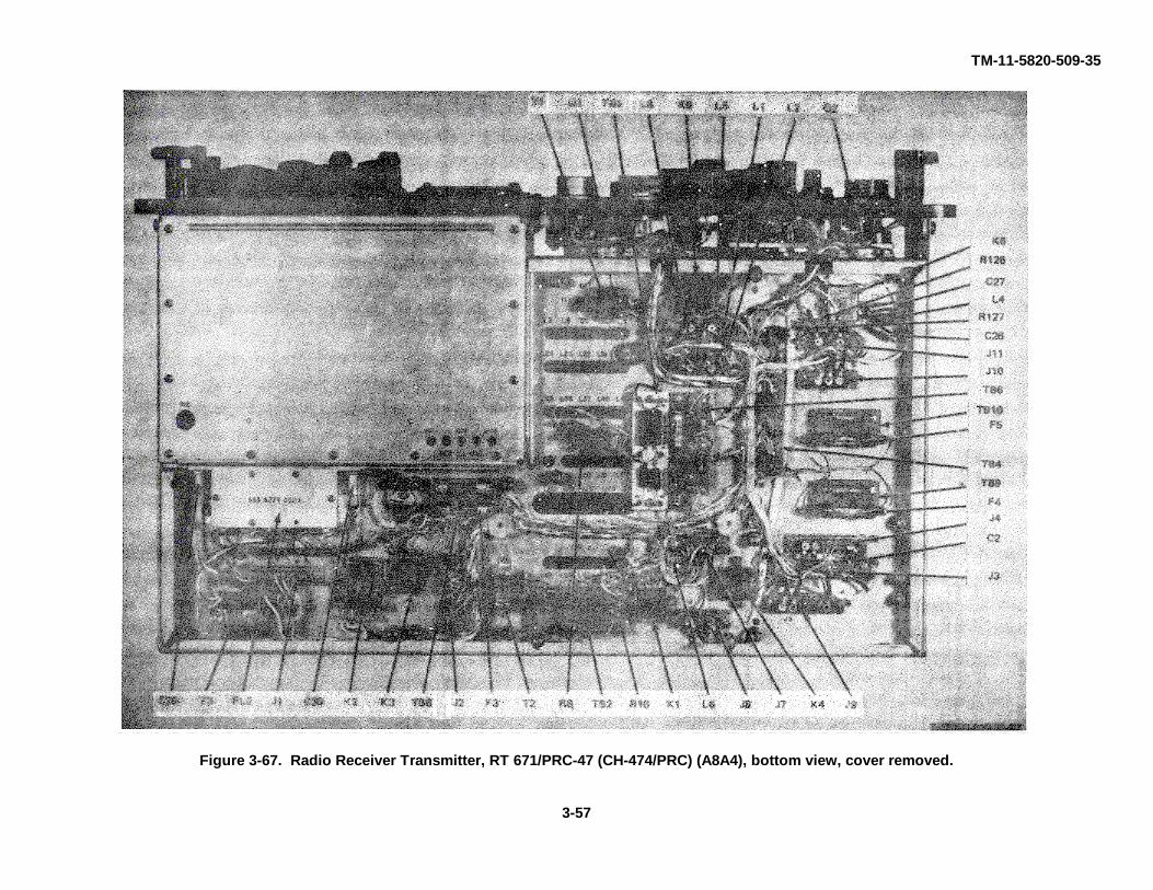
TM-11-5820-509-35
Figure 3-67. Radio Receiver Transmitter, RT 671/PRC-47 (CH-474/PRC) (A8A4), bottom view, cover removed.
3-57
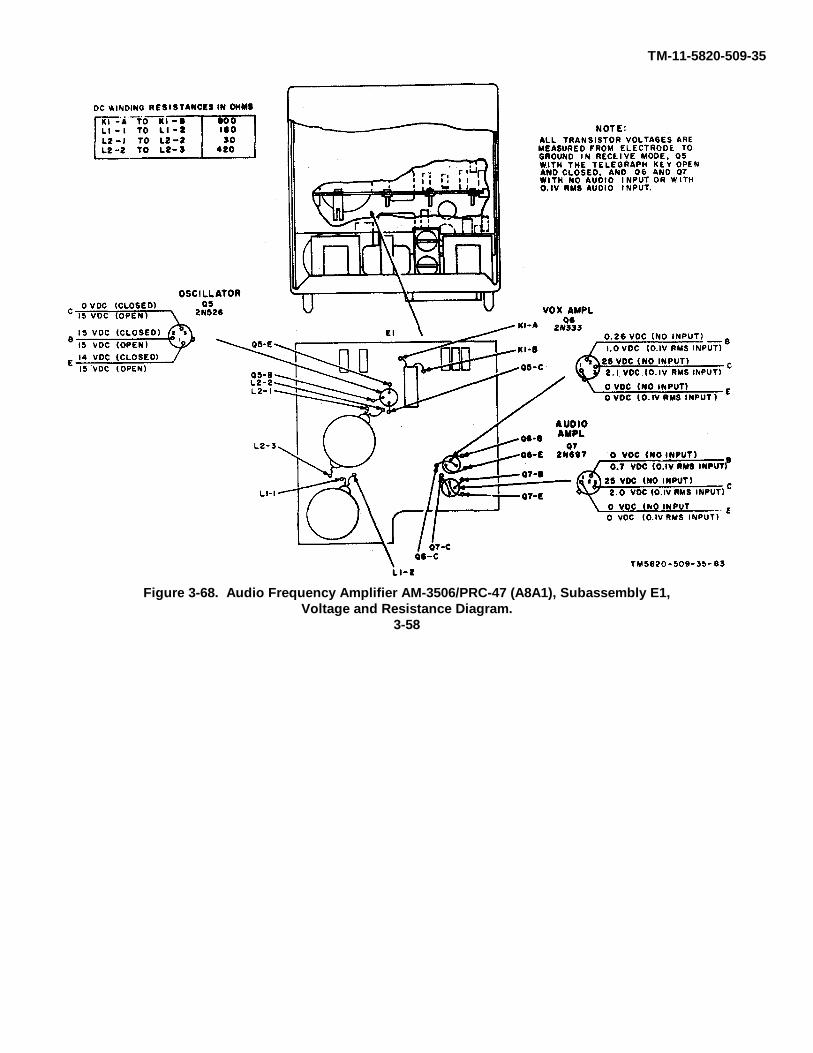
TM-11-5820-509-35
Figure 3-68. Audio Frequency Amplifier AM-3506/PRC-47 (A8A1), Subassembly E1,Voltage and Resistance Diagram.
3-58
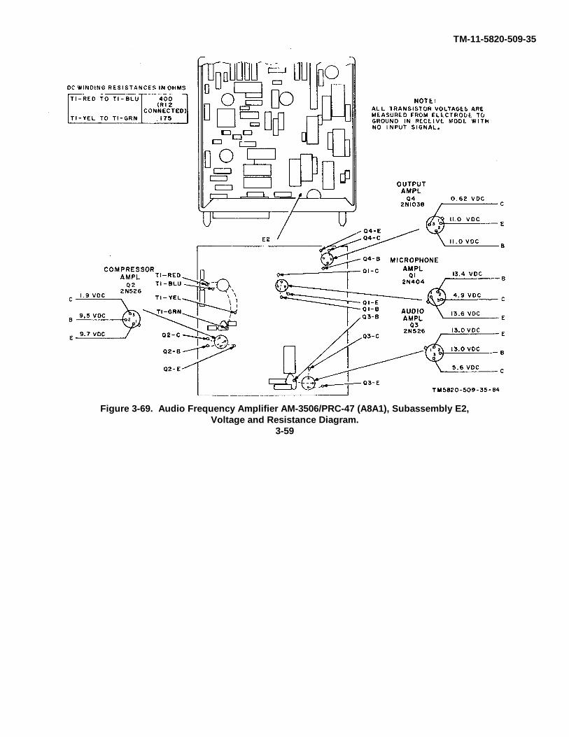
TM-11-5820-509-35
Figure 3-69. Audio Frequency Amplifier AM-3506/PRC-47 (A8A1), Subassembly E2,Voltage and Resistance Diagram.
3-59
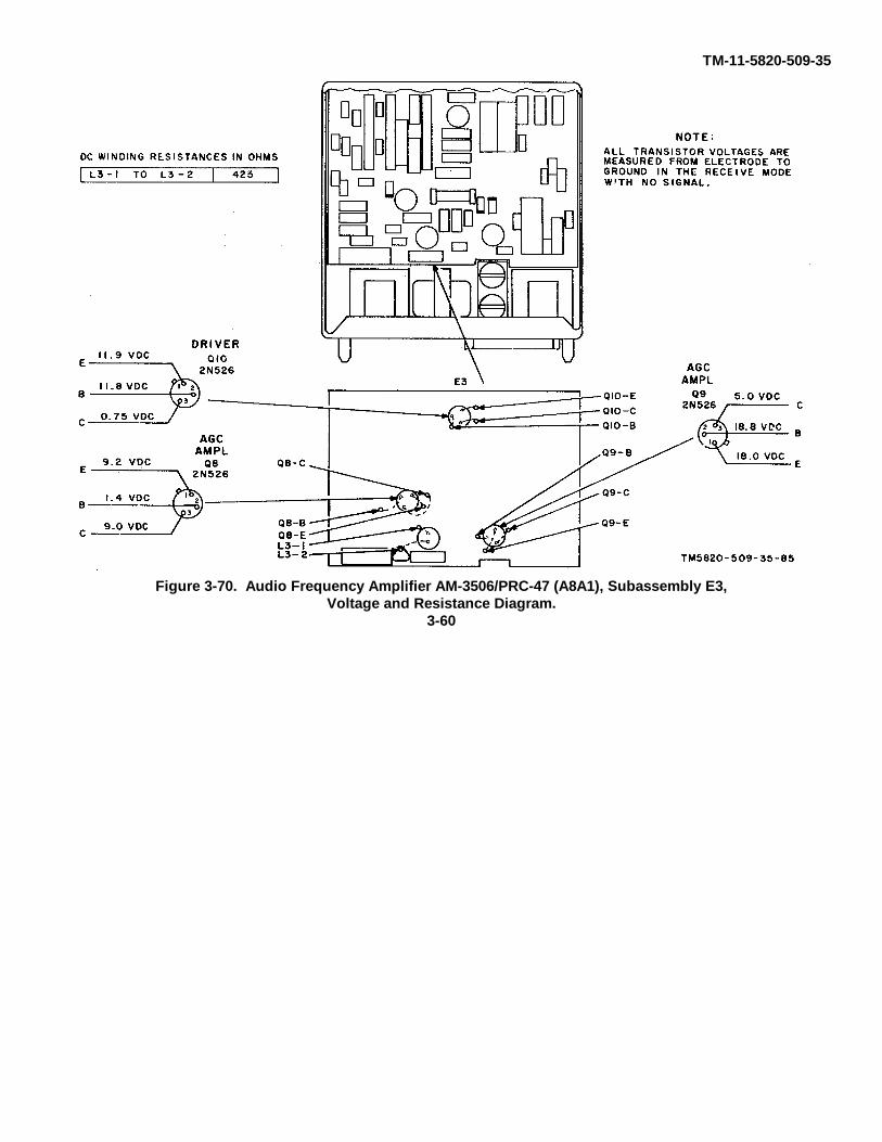
TM-11-5820-509-35
Figure 3-70. Audio Frequency Amplifier AM-3506/PRC-47 (A8A1), Subassembly E3,Voltage and Resistance Diagram.
3-60
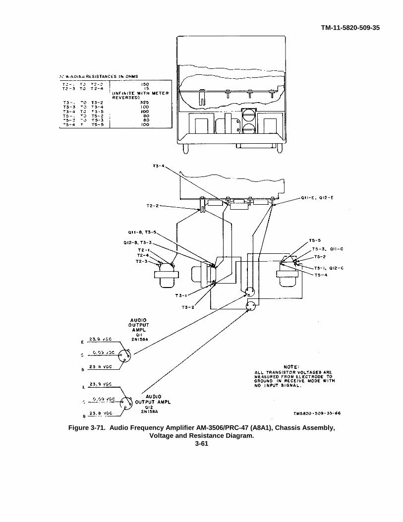
TM-11-5820-509-35
Figure 3-71. Audio Frequency Amplifier AM-3506/PRC-47 (A8A1), Chassis Assembly,Voltage and Resistance Diagram.
3-61
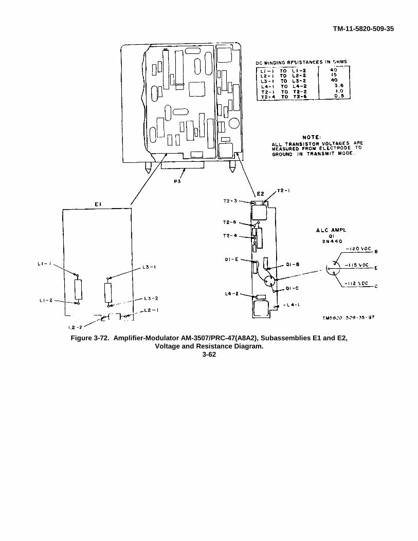
TM-11-5820-509-35
Figure 3-72. Amplifier-Modulator AM-3507/PRC-47(A8A2), Subassemblies E1 and E2,Voltage and Resistance Diagram.
3-62
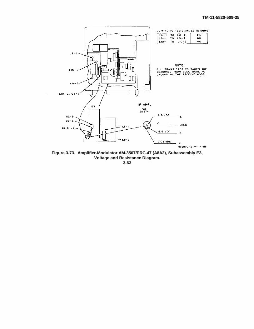
TM-11-5820-509-35
Figure 3-73. Amplifier-Modulator AM-3507/PRC-47 (A8A2), Subassembly E3,Voltage and Resistance Diagram.
3-63

TM-11-5820-509-35
Figure 3-74. Amplifier-Modulator AM-3507/PRC-47 (A8A2), Subassembly E4,Voltage and Resistance Diagram.
3-64
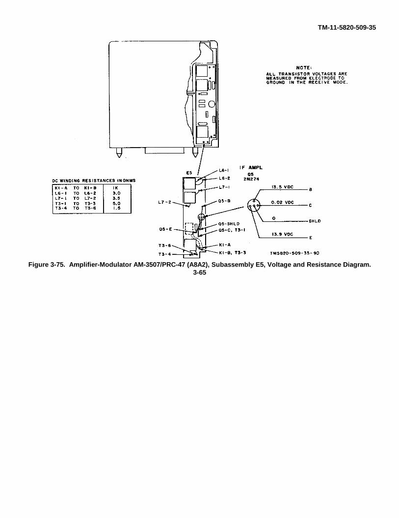
TM-11-5820-509-35
Figure 3-75. Amplifier-Modulator AM-3507/PRC-47 (A8A2), Subassembly E5, Voltage and Resistance Diagram.3-65
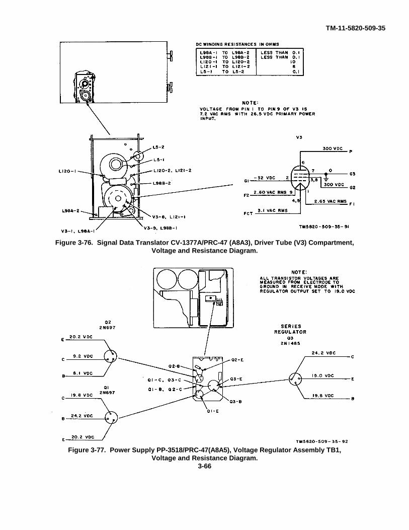
TM-11-5820-509-35
Figure 3-76. Signal Data Translator CV-1377A/PRC-47 (A8A3), Driver Tube (V3) Compartment,Voltage and Resistance Diagram.
Figure 3-77. Power Supply PP-3518/PRC-47(A8A5), Voltage Regulator Assembly TB1,Voltage and Resistance Diagram.
3-66

TM-11-5820-509-35
Figure 3-78. Radio Frequency Oscillator O-1032/PRC-47 (A8A6), Subassembly E1,Voltage and Resistance Diagram.
3-67
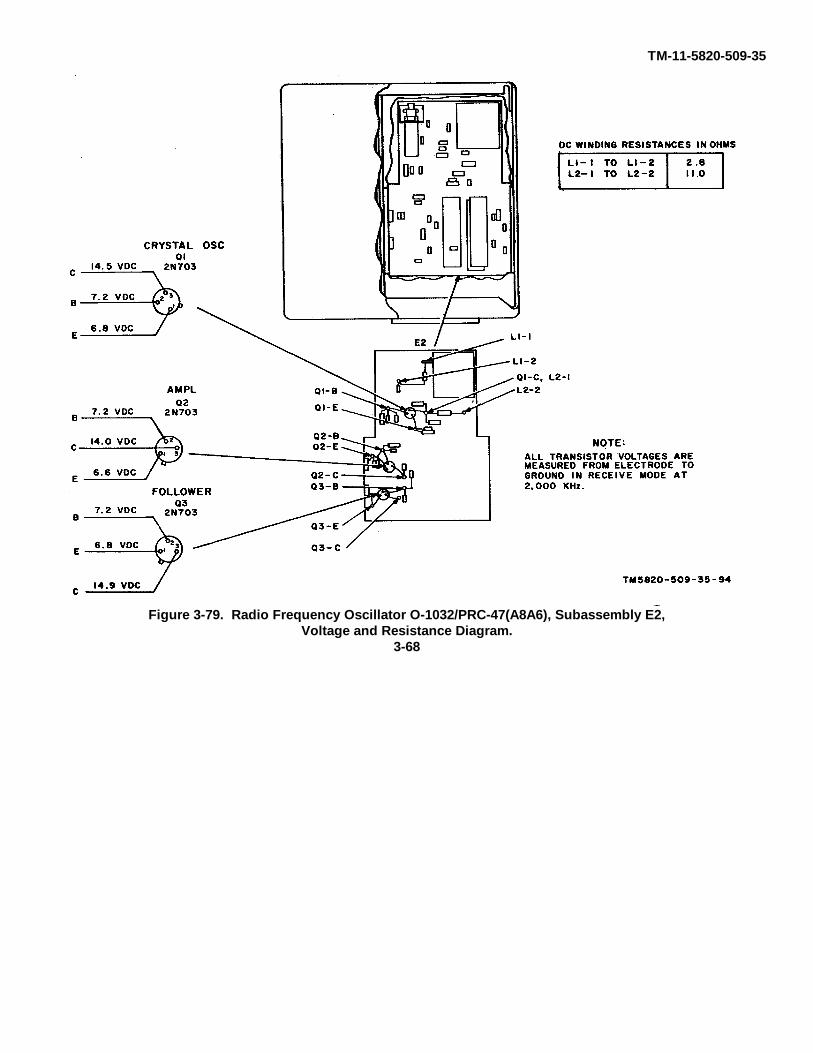
TM-11-5820-509-35
Figure 3-79. Radio Frequency Oscillator O-1032/PRC-47(A8A6), Subassembly E2,Voltage and Resistance Diagram.
3-68
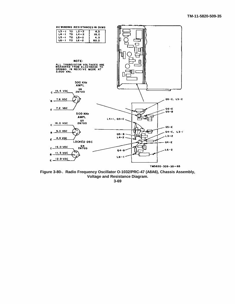
TM-11-5820-509-35
Figure 3-80-. Radio Frequency Oscillator O-1032/PRC-47 (A8A6), Chassis Assembly,Voltage and Resistance Diagram.
3-69

TM-11-5820-509-35
Figure 3-81. Electrical Equipment Chassis CH-474/PRC-47 (A8), Power Oscillator Assembly, Voltage andResistance Diagram.
3-70
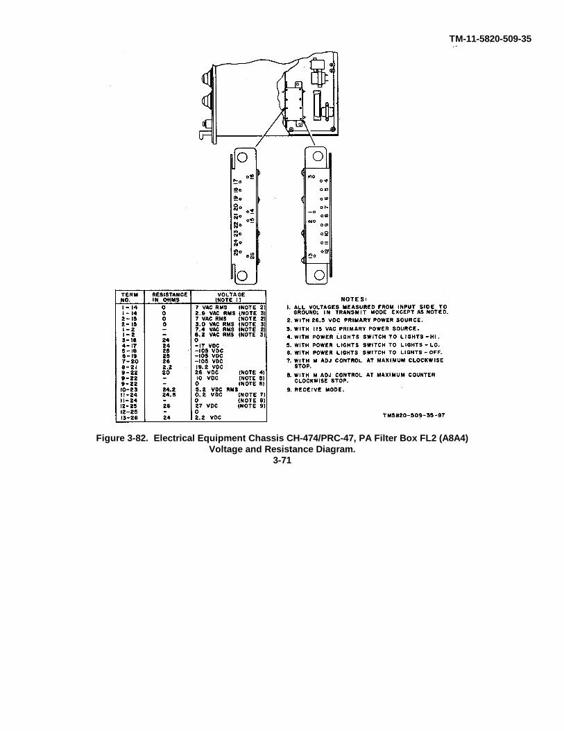
TM-11-5820-509-35
Figure 3-82. Electrical Equipment Chassis CH-474/PRC-47, PA Filter Box FL2 (A8A4)Voltage and Resistance Diagram.
3-71
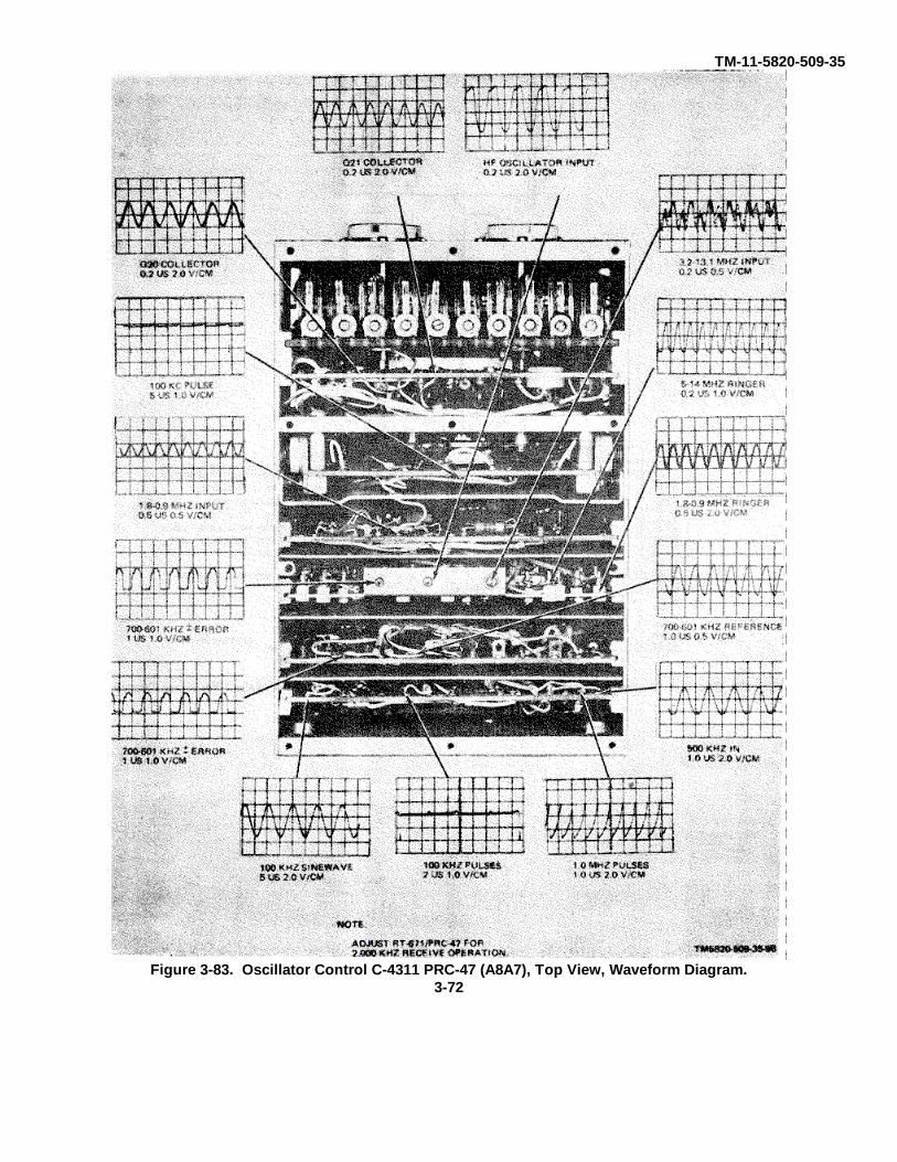
TM-11-5820-509-35
Figure 3-83. Oscillator Control C-4311 PRC-47 (A8A7), Top View, Waveform Diagram.3-72

TM 11-5820-509-35
b. Sectionalizing Test Settings.(1) General. The extender cables and
components of Cable Assembly Set AN/PRA-4 are usedduring the bench tests of Radio Receiver-TransmitterRT-671/PRC-47. For these tests it is not necessary toremove and extend the modular subassemblies, but thedust cover must be removed to gain access to the testpoints at the top of each module and beneath the poweramplifier compartment. Remove the dust cover usingthe procedures listed in paragraph 3-11. Thetroubleshooting checks for the receiver portion of theequipment differ greatly from those specified for thetransmitter circuits, and the test setup conditionslikewise differ. Use the appropriate setup and initialprocedures described in steps (2) and (3) below.
CAUTIONDo not key the transmitter unless therf output is terminated in a 50-ohmdummy load, a quarter-wave whip, ora suitable long-wire antenna. Neverkey the transmitter while SignalGenerator SG-103/URM-25F isconnected to the ANTENNA terminalof the RT-671 /PRC-47.
(2) Receiver Test Setup and Initial Settings(fig. 3-2).
(a) Connect the dummy load (or a 50-ohm noninductive resistor) to the ANTENNA terminal ofRT-671/PRC-47 using the antenna test lead from theAN/PRA-4.
(b) Connect the signal generator to theANTENNA terminal.
(c) Connect the primary power sourceto be used to the POWER connector on the front of RT-671 /PRC-47.
(d) Connect a 300-ohm audio load topin L of AUDIO connector on the front panel of RT-671/PRC-47; then attach multitester leads across thisresistor.
(e) Set the front panel controls and thetest equipment conditions as directed in the chart ofparagraph 3-4 c (2).
(3) Transmitter Test Setup and Initial Settings( fig. 3-3 ).
(a) Connect the RT-671/PRC-47ANTENNA terminal to the antenna simulator of AN/PRA-4.
(b) Connect the antenna simulator to
the dummy load using the 3-foot length of RG-58/Ucoaxial cable from the AN/PRA-4.
(c) Connect the multitester (with rfprobe attached) to the VTVM terminals of the antennasimulator using the 5-foot length of RG-58/U coaxialcable.
(d) Connect the primary power sourceto be used to the POWER connector on the front of RT-671 /PRC-47.
(e) Adjust the control knobs to providea reading of 3002 on the KILOCYCLES indicator on thefront of RT-671/PRC-47; then place the CW-FSK/VOICE switch to VOICE, the XMTR PWR switch toLO, and the OPR-TUNE switch to OPR.
c. Sectionalizing Trouble. The followingprocedures sectionalize the malfunction to the powerdistribution, receiver-transmitter, frequency generation,or relay control circuits of the RT-671/PRC-47. If aspecific symptom is indicated by the intermediatepreventive maintenance checks and services performedat the organizational level, or by the short circuit tests ofparagraph 3 4 a(4). enter the chart in that functionalarea; otherwise, perform all steps.
CAUTIONDo not perform these checks unlessthe short circuit tests indicate thatfurther damage to the equipment isunlikely.
(1) Preliminary Procedures.(a) Energize the primary power source
(if separately controlled); then rotate the POWER -LIGHTS switch on the front panel of RT-671/PRC-47 tothe POWER ON position.
(b) Press the BATTERY TEST switchon the front panel of RT-671/PRC-47 and observe thatthe XMTR OUTPUT meter reads in the banded area ofits scale. {If this indication is not obtained, perform thepower distribution circuit checks before proceedingfurther.)
(2) Troubleshooting Chart.CAUTION
Do not place the CW-FSK/VOICEswitch to CW-FSK in any of thefollowing tests unless the transmitteroutput is properly terminated in adummy load or a suitable antennasystem. Never switch to CW-FSKwhen the signal generator isconnected to the ANTENNA terminal.
3-73
TM 11-5820-509-35
Item Indication Probable trouble Procedure
1 Multimeter at A5J7 (fig. 3-4) does Popover control relay circuits of R1 Proceed to popover distributionnot read +24 volts dc. or K2, or low voltage circuits of circuit checks (para 3-5b).
PP-3518/PRC 47 (A51 aredefective.
2 Multimeter at A5J8 (fig. 3-4) does Low-voltage power circuits or Proceed to power distributionnot read +20 volts dc regulated. regulator of PP-3518/PRC-47 circuit checks (para 3-5b ).
(A5) are defective.3 Multimeter with rf probe at A3J5 Signal Data Translator CV- Proceed to frequency generation
(fig. 3-4) does not read 1.75 1377A/PRC-47 (A3) defective. circuit checks (para 3-5b).volts peak-to-peak.
4 Frequency counter at A3J5 does Signal Data Translator CV- Proceed to frequency generationnot read 3502 kHz. 1377A/PRC-47 (A3) defective. circuit checks (para 3-5c ).
Place POWER-LIGHTS switch on the front of RT-671/PRC-47 to POWER OFF. Connect test equipment for receiver tests (fig.3-2). Adjust frequency control knobs for reading of 2225 on KILOCYCLES indicator. Adjust signal generator output level to2.0 microvolts at 2226 Hz. On RT671/PRC-47, rotate VOLUME control to maximum clockwise stop, then place POWER-LIGHTS switch to POWER ON.
5 Multimeter with rf probe at A2J3 Signal Data Translator CV- Proceed to receiver circuit checks(fig.. 3-4} does not read 100 1377A/PRC-47 (A3) defective. (para 3-5d ).micro-volts rms.
6 Multimeter with rf probe at A2J4 Radio Frequency Oscillator 0- Proceed to frequency generation(fig. 3-4) does rot read 1.5 volts 1032/PRC-47 (A6) defective. and/or relay circuit checks (pararms. 3-5c and/or 3-5f ).
7 Multimeter with rf probe at A1J13 Amplifier-Modulator AM- Proceed to receiver circuit checks(fig. 3-4) does not read 0.1 volt 3507/PRC-47 (A2) defective. (para 3-5d).rms (1000 Hz approx.)
CAUTIONBefore proceeding further, disconnect signal generator and dummy load from ANTENNAterminal. Place POWER-LIGHTS switch on the front of RT-671/PRC-47 tom POWER OFF.Connect the test equipment for transmitter tests (fig. 3-3). Set KILOCYCLES indicator on thefront of RT-671/PRC-47 to 2000. Return POWER-LIGHTS switch to POWER ON, and tune thepower amplifier as follows:
CAUTIONDo not permit the OPR-TUNE switch to remain in TUNE position for more than a few seconds at atime while the output circuit is being adjusted. Circuit damage can result.
(1) Place OPR-TUNE switch to TUNE.(2) Immediately adjust POWER AMPLIFIER
TUNE controls for maximum indication on XMTROUTPUT meter.
(3) Return the OPR-TUNE switch to OPR.Connect audio oscillator to A1J1 (fig. 3-4) and set theoutput level to 0.1 volt rms at 1, 000 Hz.
Item Indication Probable trouble Procedure
CAUTIONDo not permit CW-FSEC/VOICE switch to remain in the CW-FSK position for mere than a few at a time; output circuit dodgecan result.
8 With CW-FSK/VOICE switch to High-voltage power supply circuits Proceed to power distributionCW-FSK, multimeter at J101 of PP-3618/PRC-47 (A5) circuit checks (para 3-5b).(fig 3-5) does not read +65 defective.volts dc.
9 Multitester with rf probe at an- Amplifier-Modulator AM- Proceed to transmitter circuittenna simulator does not read 3507/PRC-7 (A2), or power checks (para 3-5e ).13.7 volts rms with CW- amplifier stage defective.FSK/VOICE switch at CW-FSK.
NOTEplace CW-FSK/VOICE switch to VOICE, rotate XMTR PWR switch to Hi, and retune the outputcircuit to peak the XMTR OUTPUT meter readings.
3-74

TM 11-5820-509-35
Item Indication Probable trouble Procedure
10 With CW-FSK/VOICE switch to High-voltage power supply circuits Proceed to power distributionCW-FSK, multitester at J101 of PP-3518/PRC-47 (A5) circuit checks (para 3-5b).(fig. 3-5) - does not read +150 defective.volts dc.
11 Multitester with rf probe at an- Power amplifier circuit defective. Proceed to transmitter circuittenna simulator - not read checks (para 3-5e ).30.7 volts rms with CW-FSK/VOICE switch to CW-FSK.
3-5. Localizing Teatsa. General. The localizing tests isolate the
equipment malfunction to a specific circuit on the mainchassis of RT-671/PRC-47, or to a circuit within a plug-in module of the equipment. These tests are performedafter the sectionalizing tests of paragraph 3-4 c, ororganizational-level tests, have determined that thetrouble symptom exists within a given functional area. Achart is provided for each of the following functionalareas of the equipment: power distribution circuits,receiver circuits, transmitter circuits, and frequencygeneration circuits. The test conditions and the testequipment connections for each group of tests isdetailed in its chart. Carefully observe the equipmentconnections and test conditions to assure that the resultsobtained are in agreement with the test point valuespecified.
b. Power Distribution Circuit Tests. These testsare divided into two parts: those where 115-volts, 400-Hz ac primary power is used, and those where 26.5-volts dc primary power is used. The remaining circuits(those unaffected by the type of primary power used)are listed separately.
(1) Primary Power Source 115-volt, 400-Hz.NOTE
Connect the test equipment fortransmitter tests (fig. 3-3) andperform the initial procedures listedin paragraph 34 b (3). Unlessotherwise specified, make all voltagemeasurements between the testpoint listed and chassis ground.
Item Indication Probable trouble Procedure
NOTEPlate the POWER-LIGHTS switch on the front of RT-671 /PRC-47 to POWER ON.
1 Ac voltage measured between test a. Fuse F2 (POWER 5A AC) is a. Check and replace fuse F2 (fig.jacks A5J10 and A5J11 (fig. 3- blown or 115-volt primary power 3-87) or repair primary power4) is not 115 volts ac rms. circuit is defective. circuit and/or cable.
Note. Do not perform this test if b. +26.5 volts dc is not present b. Check continuity of T2 primary26.5-volts dc primary power at coil of ac power control relay winding from F2 holder tosource is being used to power K2 (terminal K2-1). connector P1-L. Replace T2 ifthe equipment. Proceed to next open circuit, or if shorted tochart. chassis. Check continuity of
diodes CR3 thru CR6. Replaceany shorted or open diodes.
c. POWER-LIGHTS switch on c. Check continuity of circuit fromfront panel, or associated circuit K2-5 to chassis ground withdefective. POWER-LIGHTS switch at
POWER ON. Repair circuit orreplace switch.
d. Ac power control relay K2 coil d. Replace relay K2 if windingdefective. resistance is not 300 ± 30 oh-
ms.e. Contacts on dc power control e. Check continuity of normally-
relay K1 or circuit from K1 to closed contacts K1-2 to K1-8;K2 defective. replace K1 if open circuit. Check
continuity from Kl-8 Lo K2-4;repair circuit if open.
f. Contacts of ac power control f. Replace relay K2.relay K2 are defective.
2 Dc voltage measured between a. Ac primary power circuit to a. Check continuity of primaryA5J9 (fig. 3-4) and chassis PP 3518/PRC-47 (A5) is power circuit between K1-2 andground is not +26.5 volts dc. defective. connector J1-13. Repair circuit
on main chassis if open circuit.b. Low-voltage transformer A5T2, b. Check continuity of A5T2
or its associated circuit in PP- primary between J1-3 and J1-13.3518/PRC-47 (A5) is defective. Repair circuit or replace PP-
3518/PRC 47.3-75
TM 11-5820-509-35
(2) Primary Power Source 26.5-volt dc.
Item Indication Probable trouble Procedure
NOTEPlace the POWFR-LIGHTS switch on the front of RT-671/PRC-47 to POWER ON.
1 Dc voltage measured between a. Fuse F1 (POWER 20A DC) is a. Check and replace fuse F1 (fig.A5J9 (fig. 3-4) and chassis blown or primary power circuit 3-87). Check continuity of inputground is not +26.5 volts dc. is defective. at L4; replace L4 if open. Check
Note. Do not perform this test if capacitors C26 and C27 for115-volts, 400-Hz primary power shorts; replace if shorted.source is being used to power b. +6.5 volts dc is not present at b. Check continuity from F1the equipment. Use previous the coil of relay K1 (terminals holder to K1-1 and K1-4, and tochart (1). K1-1 to K1-4.) connector P1-J. Repair if open.
c. Diode CR8 and/or R16 c. Check continuity of CR8 anddefective. R16 for opens and shorts to
ground. Replace defectivecomponent.
d. POWER-LIGHTS switch on d. Check continuity from K2-5 tofront panel, or associated circuit chassis ground with POWER-defective. LIGHTS switch at POWER-
ON. Repair circuit or replaceswitch.
e. Dc power control relay K1 coil e. Replace K1 if windingdefective. resistance is not 1628 ± 10%
ohms.f. Contacts of K1 are defective. f. Check dc voltage at K1-7 with
POWER-LIGHTS switch toPOWER ON. Replace K1 ifreading is zero volts.
g. Dc circuit from K1 to PP- g. Check continuity from K1-7 to3518/PRC47 is defective. connector J1-22; and each point
for short to ground. Repair asrequired.
2 Transmitter bias and high-voltage a. Circuit to high-voltage trans- a. Remove front panel power plugoutput is low or zero when 26.5- former A5T1 in PP-3518/PRC- and check continuity from J1-14volt dc primary power input is 47 is defective. to J1-1; repair primary circuit toused, but normal with 115-volt, A5T1 or replace transformer.400-Hz primary power source. b. Contacts of push-to-talk relay b. Check voltage at A5K1-5 with
A5K1 are defective. ptt relay operated: (normal+26.5 volts dc). Replace A5K1if no voltage present.
c. Circuit between J1 and power c. Check continuity of power cableoscillator defective. jumpers (pins A-B. C-D, and J-
K) and circuits from J1-1/J1-2,J1-14/J1-15, and J1-16/J1-17;repair circuit or replace cable.Check continuity from P1-A toQ2 emitter, and from P1-C to Q1emitter; repair circuit if open.
d. Emitter circuit components d. Check continuity of C1, CR1,defective. CR2, and R5 for opens and
shorts: replace defective com-ponent.
e. Base circuit components e. Check continuity of R1 throughdefective. R4: replace defective component.
Check winding of reactor foropens: normal readings are T1-1to T1-2, 1.0 ohm: T1-2 to T1-3,60 ohms: T1-3 to T1-4 1.0 ohm;replace T1 if defective.
f. Power transistors Q1 and Q2 f. Replace with proper typedefective. number.
3-76

TM 11-5820-509-35
(3) Power Distribution Circuits and Components
Item Indication Probable trouble Procedure
1 XMTR OUTPUT meter M101 a. +26.5-volt dc lamp circuit a. Check continuity from K1-7 todoes not read in the banded defective. POWER-LIGHTS switch S1-6:portion of its scale when to antilock relay K6- 1, to in-BATTERY TEST switch is ductor L3, and resistor R23.pressed. Repair circuit as required.
b. Resistor R23 defective. b. Check resistance of R23(normal 681K ohms). Replace ifdefective.
c. BATTERY TEST switch S2 c. Check continuity from R23 to(fig. 3-87) defective. S3A (NO) to S3A (COM) with
switch pressed: replace S3 ifdefective.
d. PA filter box FL2 (fig. 3-5) d. Check continuity from S3Adefective. (COM) to FL2-11. Repair circuit
if open. Check resistance be-tween FL2-11 and FL2-24(normal 29.0 ohms). Repair FL2if abnormal reading.
Caution:Before continuing this procedure, disconnect the lead from the positive ( + ) terminal of XMTR OUTPUT meter M101. Do notattempt to measure the meter movement resistance.
e. PA filter box circuit shorted to e. Check for short to ground atground. FL2-11 and FL2-24. Repair
circuit C216, C203, L203, asrequired.
f. Meter bypass circuit defective. f. Check continuity from FL2-24to lead removed from + meterterminal. Repair if open. CheckC107 for short; replace ifnecessary.
Note:Reconnect the positive ( + ) meter lead removed above before proceeding to the next procedural step.
g. XMTR OUTPUT meter g. Remove and replace M101.defective.
2 Panel lamps in main compartment a. Panel lamps DS1 and DS2 a. Replace burned out lamp bulbs.(DS1 and DS2) (fig. 3-87) fail to burned out.light when POWER-LIGHTS b. Lamp circuit defective. b. Check continuity from S1-10 toswitch is rotated to LIGHTS each lampholder; check con-Hl. tinuity from each lampholder to
ground. Repair any defectivecircuits.
c. POWER-LIGHTS switch (lamp c. Replace switch S1.circuit) defective.
3 Panel lamps in power amplifier a. Panel lamps DS101 and DS102 a. Replace burned out lamp bulbs.compartment (DS101 and are burned out.DS102) (fig. 3-87) fail to light b. Lamp circuit defective. b. Check continuity from S1-10 towheat DS1 and DS2 are lighted. FL2-9; repair circuit if defective.
c. PA filter FL2 (gig.. 3-5) defec- c. Check resistance from FL2-9 tofive. FL2-22 (normal 29 ohms}.
Repair circuit C218, C229, C206,and L205 as required.
d. Lampholder or circuit to FL2 d. Check continuity from FL2-22defective. to each lampholder, and from
each lampholder to ground.Repair any defective circuits orreplace lampholder.
4 Panel lamps remain bright or go Dimming resistor R6 is defective. Check resistance of R6 (normalout when POWER-LIGHTS 180 ohms; replace if necessary.switch is rotated to LIGHTS Check continuity from S1-9 toLO. S1-6; replace S1 if defective.
3-77
TM 11-5820-509-35
Item Indication Probable trouble Procedure
5 Dc voltage measured between Low-voltage power supply, filter, Perform isolation procedures onA5J7 (fig. 3-4) and chassis or voltage regulator defective. PP-3518/PRC-47 (see para 3-6).ground is not +24 volts dc.
6 No receive audio output or low a. +24-volt circuit between J1-19 a. Check continuity from J1-19 toand distorted output from and J2-9 defective. J2-9: repair open circuit.headset. b. Audio frequency amplifier AM- b. Repair or replace AM-
3506/PRC.47 defective. 3506/PRC-47 (para 3-6).7 Dc plate and Wren voltage at 1st- a. +24-volt circuit between J1-19 a. Check continuity from J1-19 to
and 2d- rf amplifiers in signal and J5-5 defective. K3-6: from K3-6 to K3-4; fromdata translator not present. K3-4 to L5: and from L5 to J5-
5.Check resistance of L5 (normal
72.0 ohms): repair circuit orreplace K3 or L5 if required.
b. Signal Data Translator CV- b. Repair or replace CV-1377A/PRC-47 (A3) defective. 1377A/PRC-47 (para 3-6).
8 Dc voltage measured between Low-voltage power supply, filter, Perform isolation procedures onA5J8 (fig. 3-4) and chassis or voltage regulator defective. PP-3518/PRC-47 (A5) (para 3-6)ground is not +20 volts dc or replace power supply.regulated.
9 20 volts dc is not present at a. Fuse F3 (½ A) (fig. 3-5) is a. Check and replace fuse F3.receiver circuits. burned out.
b. 20-volt circuit from power b. Check continuity from F3 tosupply A5 to receiver circuits is each circuit: (J2-13, J4-3, J5-3,defective. J8-1, J9-1, J11-1, K3-8, K3-2,
L1, and J5-1). L1 resistance is1.2 ohms. Repair circuit orreplace K3 or L1 if defective.
10 Dc plate and screen voltage at V3 a. Fuse F5 (1/10A) (fig. 3-5) is a. Check F5 and replace fuse.not present. burned out.
b. 300-volt circuit between J1-21 b. Check continuity from J1-21 toand J7-2 or KC3-7 defective. F5, from F5 to J7-2 and to R8.
(R8 normal 4,750 ohms). Checkcontinuity from R8 to K3-7.Repair circuit or replace R8 ifdefective.
11 Filaments of rf amplifiers V1 and a. Filament circuit of vacuum a. Check filament circuit in eachV2, and driver V3 in signal data tube(s) open. tube for continuity. Replacetranslator A3 do not light. defective vacuum tube.
b. Filament winding of high- b. Voltage test-Measure at A5J3voltage transformer A5T2 to A5J4 with 115-volt acdefective. primary power input; normal 6.3
vac rms. (with 26.5 volt dcprimary power input, readingfrom A5J3 to J5-4 is 6.3 vacpeak. Replace T2 if windingdefective.
c. Filament circuit between J1-5 c. Check continuity from J1-5 toand T3-1, or J1-4 (or J1-8) and T3-1 and to FL2-1: from J1-4 toT3-2 and relay K2 is defective. K2-2, to K2-8, to T3-2, and
FL2-2 for open circuits or shortto ground. Repair circuit, orreplace relay K2 if defective.Check continuity from J1-8 toK2-3 and repair if required.
d. Filament transformer T3 d. Check resistance of primarydefective. (normal 0.75 ohms) and
secondary (normal 0.75 ohms).Replace if defective. Checkcontinuity from T3 secondary toJ7-3 and J7-4. Repair if open.
e. Signal data translator A3 e. Repair or replace CV-defective. 1377A/PRC-47 (para 3-6),
3-78
TM 11-5820- 509-35
Item Indication Probable trouble Procedure
12 Filaments of power amplifier stage a. Filament circuit vacuum tube a. Check continuity of filamentdo not Light. open. circuit within V101; replace tube
(para 3-14) if defective.b. Filament chokes L120 and L121 b. Check continuity of chokes
defective. L120 and L121 (normal 0.09ohms). Replace if defective.
Note.Make the following checks after unsoldering the filament lines from PA filter box FL2-14 and FL2-15. (Tag each wire).
c. Filament circuit in FL2 c. Check continuity from FL2-1 todefective. FL2-14 and from FL2-2 to FL2-
15, and test each terminal forshorts to ground. Repair circuitor replace C221, C208, C235,C220, C207, or C234 if defective.
Note:Reconnect the two filament lines to terminals FL2-14 and FL2-15 of the PA filter box.
d. Filament bypass capacitors or d. Check continuity of R121hum balance resistor or circuit (normal 50 ohms); check con-defective. tinuity of circuit from L120 to
XV101-1 and L121 to XV101-7.Repair circuit, or replace R121 ifdefective.
Note.Disconnect capacitors C103 and C104 from XVIO1 before proceeding with the following tests. (Tag each lead).
e. Filament bypass capacitors e. Check C103 and C104 forshorted to chassis ground. shorts; replace if defective.
Note.Reconnect capacitors C103 and C104 to the filament pins of tube socket XV101.
13 Dc bias voltage measured between a. -32-volt dc bias circuit of PP- a. Perform adjustment routine ofA3J3 and chassis ground is not 3518/PRC-47 incorrectly ad- paragraph 3-27, replace PP--25 volts dc. justed or defective. 3518/PRC-47, .or repair (para 3-
6) if defective.b. Fuse F4 (1/500A) (fig. 3-5) is b. Check and replace fuse F4, if
burnt out. defective.c. Inductor L6 is open or shorted c. Check continuity of L6 (normal
to ground. 72.0 ohms): check L6 for shortsto ground. Replace L6 ifdefective.
d. -32-volt bias circuit on main d. Check continuity from J1-23 tochassis defective. XF4-1, from XF4-2 to L6-1,
from L6-2 to J7-1. Repair asrequired.
e. -32-volt bias circuit in signal e. Repair CV-1377A/PRC-47data translator A3 defective. using procedure of paragraph 3-
6.14 Dc bias voltage measured between a. -110-volt dc bias circuit of a. Perform adjustment routine of
J102 (fig. 3-5) and chassis is not PP-3518/PRC-47 incorrectly paragraph 3-27, replace PP--110 volts dc. adjusted or defective. 3518/PRC-47, or repair (para 3-
6) if defective.b. XMTR PWR switch S103 not b. Place S103 to XMTR PWR HI.
at HI position.c. XMTR PWR switch S103 c. Check continuity of S103 (in HI
defective. position) from S103-1 to S103-4or S103-5. Rotate S103 to LOposition and check from S103.1to S103-2. Measure resistance ofR107 {normal 100K ohms).Repair circuit or replace S103 orR107 as required.
3-79
TM 11-5820-I509-
Item Indication Probable trouble Procedure
d. -110-volt dc bias circuit in PA d. Rotate XMTR PWR switch tofilter box FL2 defective. OFF and check continuity from
FL2-7 to FL2-20 (normal 29ohms); check for shorts toground. Replace C222, C209,C233, or L201 as required orrepair circuit.
e. -110-volt bias circuit between e. Check continuity from J1-9 toJ1-9 and FL2-7 defective. FL2-7; repair as required.
f. -110-volt bias circuit between f. Check continuity from S103-1 toS103 and J102 defective. L102; repair circuit if necessary.
Check C101B for shorts; replaceif necessary.
g. J102 circuit defective. g. Check continuity from J102 toS103-1 (normal 10K ohms).Replace R103 or J102 asrequired.
WARNING.The 650- and 1600-voit potentials at the power amplifier screen and plate electrodes are extremely dangerous. Avoid contactwith these circuits.
15 Plate and screen voltages to power a. +650-volt screen circuit a. Check continuity of screenamplifier stage is low or not defective. circuit from J1-A1 to C30, frompresent. C30 to L123-1, from L123-2 to
S103A-5, to S103B-3. Repaircircuit if open.
b. Capacitor C30 shorted to b. Check C30 for short to ground;ground. replace if necessary.
c. Switch S103 defective. c. With XMTR PWR switch atLO, check continuity fromS103A-3 to S103A-5; fromS103B-10 to S103B-11. RotateXMTR PWR switch to HI andcheck continuity from S103A-3to S103A-8 and from S103B-3 toS103B-10. Replace S103 ifdefective.
d. Screen grid voltage divider d. With XMTR PWR switch atdefective. HI, or OFF, check resistance
between S103B-11 and S103B-3(normal 50K ohms) and betweenS103B-11 and chassis ground(normal 100K ohms). ReplaceR105, R106, and/or R128 ifdefective.
e. Screen grid circuit from S103B- e. Check continuity from S103B-10 to power amplifier socket 10 to K102-7, from K102-8 todefective. K102-4, and from K102-3 to
L103-1. Resistance of L103 is 50ohms. Check continuity fromL103-2 to XV101-2 and XV101-6. Check C139 for short toground. Repair circuit or replaceL103 or C139 if defective.
f. Screen voltage relay K102 filter f. Check continuity across C146network defective. and measure resistance of R125
(normal 560 ohms). ReplaceC146 if shorted and R125 ifdefective
g. Plate circuit from S103A-3 to g. Check continuity from S103A-3power amplifier plate electrode to R112, to L106-1, from L106-2defective. to 1.109-1, and from L109-2 to
V101 plate cap. Measureresistance of L106 (normal 2.1ohms) and L109 (normal lessthan 1 ohm) and check C123 forshort to ground. Repair circuit,or replace C123. L106.L104 /R110, or TUNE coil L109.
3-80

TM 11-5820-509-35
Item Indication Probable trouble Procedure
h. Shorted capacitor in power h. Check continuity of L105amplifier plate circuit. (normal 3.2 ohms} and verify
that none of the plate tankcapacitors is shorted: replaceL105, C105, C108 thru C122 ifdefective.
i. Plate voltage circuit in main i. Check continuity from S103A.8chassis defective. to L122-1, from L122-2 to C29,
and from C29 to J1-A2.Resistance of L122 is 11.6 ohms.Repair circuit or replacedefective component.
c. Frequency Generation Circuit Tests. Performthe following procedures in the order listed for isolation
of malfunctions to a module within the frequencygeneration and control circuits.
Item Indication Probable trouble Procedure
Place the POWER LIGHTS switch on the front panel of RT -671/PRC 47 to POWER OFF. Connect the test equipment forreceiver tests (fig. 3 2). Adjust the frequency control knobs for a reading of 2225 on the KILOCYCLES indicator; adjust thesignal generator for 2.0 microvolts output at 2226 kHz. Rotate the VOLUME control on the front of RT-671/PRC-47 to itsmaximum clockwise stop and then place POWER-LIGHTS switch to POWER ON
1 No signal, or erratic operation at a. Hf oscillator circuit in signal a. Measure waveform at A7J3;selected frequency. data translator A3 defective. normal is 3.5 volts pep at a 0.3-
microsecond rate. Measurewaveform at test jack A3J5;normal reading 8.0 volts p-p at a0.3-microsecond rate. Repair hfoscillator circuit (para 3-13c) orreplace CV-1377A /PRC-47.
b. Hf oscillator circuit on main b. Check continuity from J10-A2chassis defective. to J5 A2; repair defective cir-
cuit.c. 500-kHz standard signal circuit c. Check waveform at test jack
of radio frequency oscillator A6 A6J4. Normal reading is 4.25defective. volts pep: measure waveform at
test jack A6J3. Normal readingis 3.5 volts pep; repair oscillatorcircuit (para 3-13e) or replace 0-1032/PRC-47 if defective.
d. 500-kHz standard signal circuit d. Check continuity from J9-A2 toin main chassis defective. K4-8, from K4-8 to K4-2 and
K4-7, and from K4-2 to J4-1.Repair circuit as necessary orreplace K4 if defective. Alsocheck continuity from J9-A3 toJ10-A3 and repair if open.
e. 1-MHz pulse generator circuit e. Measure waveform at J11-A1in oscillator control A7 defec- (main chassis). Normal readingtive. 5.5 volts pep. pulses at
1.0-microsecond rate. Repair 1-MHz pulse circuit (para 3-13f )or replace C-4311/PRC-47.
f. 5- to 14-MHz amplifier circuit f. Measure waveform at J11-A2in signal data translator A3 is is (main chassis). Normal readingdefective. 3.0 volts p-p at 0.5-microsecond
rate. Check continuity from J11-A2 to J8-A2 and from J11-A1 toJ8-A1. Repair circuit (para 3-13c ) or replace CV-1377A/PRC-47.
3-81
TM 11-5820-509-35
Item Indication Probable trouble Procedure
g. 100 kHz oscillator signal circuit g. Check waveform at A6J1.of radio frequency oscillator A6 Normal reading is 4.5 volts pepdefective. at a J0 microsecond rate. Repair
100-kHz circuit (para 3-13e) orreplace 0 1032/PRC-47.
h. 1.8 to 0.9 MHz pulse circuit of h. Check waveform at base ofoscillator control A7 is defective. follower Q24 /normal reading 0.6
volts pip at 0.5-microsecondrate.) Check continuity from J9-A1 to J10-A1: repair circuit(para 3-13f ) or replace C-4311JPRC 47.
i. Dc error signals from i. If voltages not near zero afterdiscriminator circuit of oscillator synchronizing, repaircontrol A7 defective. discriminator circuit or replace
C-4311 /PRC-47.j. Dc error signal circuit or an- j. Check continuity from J6-3 to
tilock relay K6 defective. J11-5 and K6-4: also from J6-2tp J11-4 and K6-8: verify thatrelay K6 operates when a groundis applied to J11-3. Repaircircuit or replace relay K6 ifdefective.
2 KILOCYCLES indicator does not Frequency generation circuits not Check the drive mechanism andtrack with signal generator. properly aligned. align frequency generation
Note: Signal generator should be circuits.1-kHz higher thanKILOCYCLES indicator readingto produce a 1000 Hz audio toneat the receiver output.
d. Receiver Circuit Tests. Perform the folio wineprocedures in the order listed for isolation of
malfunctions to a module within the receiver circuits.
Item Indication Probable trouble Procedure
Place POWER-LIGHTS switch on the front of RT-671/PRC-47 to POWER OFF. If the procedures of step c have not beenperformed immediately prior to these tests, connect the test equipment for receiver tests (fig. 3-2.) Adjust the KILOCYCLESindicator for a reading of 2225. Adjust the signal generator to 2226 kHz and set its output level to 2.0 microvolts. On RT-671/PRC-47, set VOLUME control to its maximum clockwise stop, then place POWER-LIGHTS switch to POWER ON.
1 No signal at grid of 1st rf am- a. T/r relay K101 or circuit to a. Check continuity from AN-plifier A3V1. antenna terminal defective. TENNA terminal to K101
(COM). Repair circuit if open.Check continuity from KI01(NC) to K101 (COM). ReplaceK101 if circuit is open.
b. Receiver antenna relay K5 or b. Check continuity from K101circuit on main chassis defective. (NC) to K5 (NC): repair if circuit
is open. Check continuity fromK5 (NC) to K5 (COM): replaceK5 if contacts are open. Checkcontinuity from K5 (COM) toJ5-A1: repair if defective.
2 No receive input at A2J3 on a. Receive circuit of signal data a. Repair CV-1377A/PRC-47 (paraamplifier-modulator A2. translator A3 defective. 3-13c ) or replace module.
b. Receive if. circuit on main b. Check continuity from J6-A2 tochassis defective. J4-A2: repair if defective.
c. Receive if. circuit at amplifier- c. Repair AM-3507/PRC-47 (paramodulator input defective. 3-13b ) or replace module.
3 No receive audio at test point a. If. amplifier circuits, product a. Repair AM-3506/PRC-47 (pareA1J13 on audio frequency detector, or af low-pass filter 3-13a ) or replace module.amplifier A1. defective.
b. Receive audio circuit on main b. Check continuity from J4-7 tochassis defective. J2-23: repair if defective.
3-82
TM 11-5820-509- 35
Item Indication Probable trouble Procedure
4 No audio output (or low output) at a. Driver A1Q10 not adjusted a. Check audio output at A1J14headset terminals. properly or defective. (normal 11 volts p-p); adjust
receiver gain control (para 3-22),repair AM-3506/PRC-47, orreplace module.
b. Audio output amplifier A1Q11- b. Repair AM-3506/PRC-47 (paraA1Q12 defective. 3-13a ) or replace module.
c. Audio output circuit on main c. Check continuity from J2-24 tochassis defective. VOLUME control; from
VOLUME control to P2-L andP3-L. Repair circuit if necessary.Check VOLUME control forcontinuity throughout itsrotation, check C20 and C24 forshorts, and resistance of R24and R25 (normal 15K ohms).Replace any defective com-ponent, repair the circuit asnecessary.
5 Excessive distortion on receive a. The -agc circuit of audio a. Check -agc level at A1J15{due to front-end or if. frequency amplifier A2 defective. (normal 0 to -0.5 volts dc);overloading). adjust agc gain (para 3-23)
Repair AM-3506/PRC47 (para3-13a) or replace module.
b. The -agc circuit on the main b. Check continuity from J2-20 tochassis is defective. L2-1, from L2-2 to J6-4; repair
as required. Measure resistanceof L2 (normal 1.2 ohms); replaceif defective.
c. The +agc circuit of audio c. Check +agc level at A1J16frequency amplifier A2 defective. {normal +5 to +6 volts dc);
repair AM-3506/PRC-47 (para 3-13a) or replace module.
d. The +agc circuit on the main d. Check continuity from J2-16 tochassis is defective. J4-5; repair as necessary.
e. The -agc circuit in signal data e. Repair CV-1377A/PRC-47 (paratranslator A3, or the +agc 3-13c ) or AM-3506/PRC-47circuit in audio frequency (para 3-13a), or replace theamplifier A2 defective. defective module.
e. Transmitter Circuit Tests. Perform the followingprocedures in the order listed for isolation of
malfunctions to a module within the transmitter circuits.
Item Indication Probable trouble Procedure
Place the POWER-LIGHTS switch on the front panel of RT-671/PRC-47 to POWER OFF. Connect the test equipment fortransmitter tests (fig 3-3). Adjust the KILOCYCLES indicator to read 2000. Verify that the selector switch on the antennasimulator is at the 2.0 MHz position. Resonate the power amplifier at the operating frequency using the OPR-TUNE switch
Caution:Do not leave the OPR-TUNE switch in the TUNE position for more than a few seconds at a time. Damage to the poweramplifier plate circuit can result.Connect the audio oscillator to A1J1 (fig. 3 4) and adjust its output level to 0.1 volt rms at 1.000 Hz.
1 No transmit audio, or low audio a. Audio frequency amplifier A1 a. Check audio at A1J7 (normallevel, at balanced modulator not adjusted properly or 0.25 volts rms): adjustinput (J3-3). defective. microphone amplifier gain
control A1R27 (para 3 25),repair AM-3506/PRC-47 (para 3-13a ) or replace defectivemodule.
b. Transmit audio circuit in main b. Check continuity from J3-3 tochassis defective. J2-22. from J2-C to J3-C and
J2-25. Check microphone circuitfrom P2-E to P3-E and J2 2.Repair as required. Checkcapacitors C22 and C23 forshorts: replace defective com-ponents.
3-83
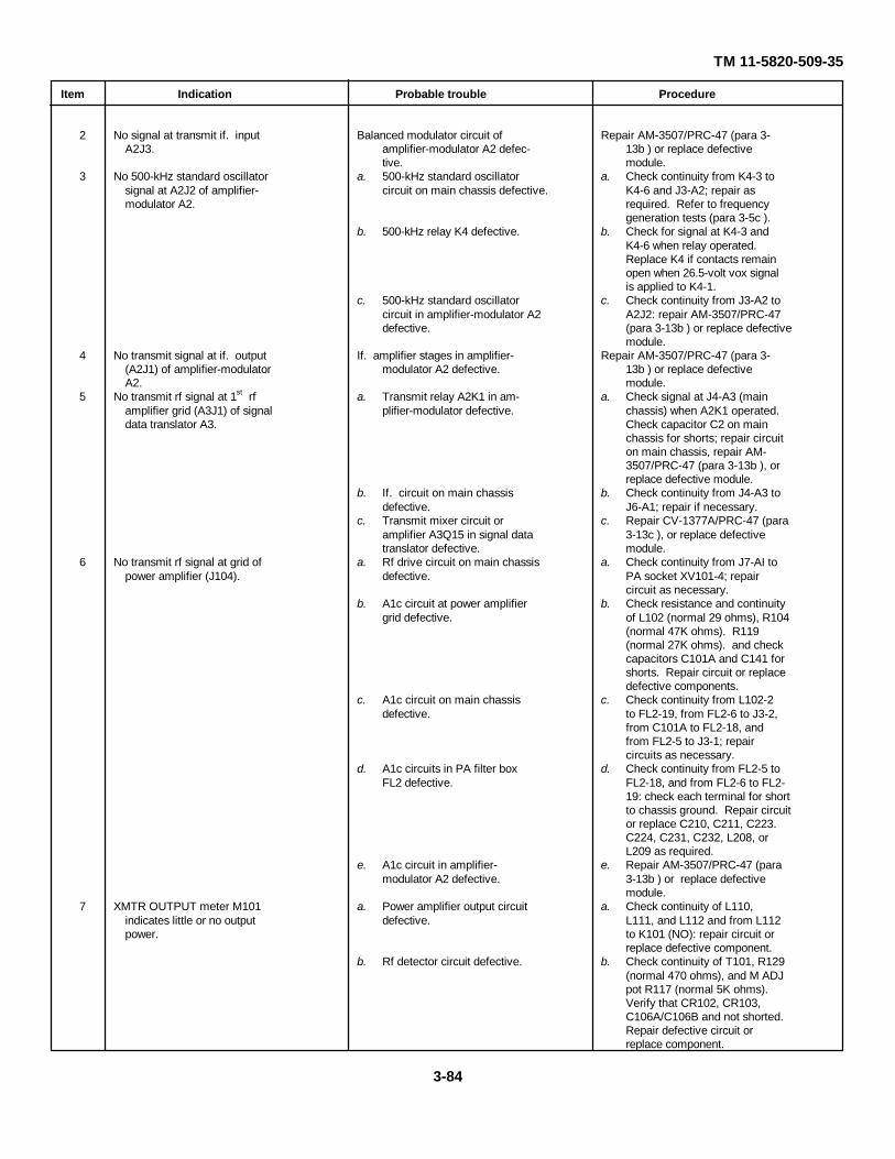
TM 11-5820-509-35
Item Indication Probable trouble Procedure
2 No signal at transmit if. input Balanced modulator circuit of Repair AM-3507/PRC-47 (para 3-A2J3. amplifier-modulator A2 defec- 13b ) or replace defective
tive. module.3 No 500-kHz standard oscillator a. 500-kHz standard oscillator a. Check continuity from K4-3 to
signal at A2J2 of amplifier- circuit on main chassis defective. K4-6 and J3-A2; repair asmodulator A2. required. Refer to frequency
generation tests (para 3-5c ).b. 500-kHz relay K4 defective. b. Check for signal at K4-3 and
K4-6 when relay operated.Replace K4 if contacts remainopen when 26.5-volt vox signalis applied to K4-1.
c. 500-kHz standard oscillator c. Check continuity from J3-A2 tocircuit in amplifier-modulator A2 A2J2: repair AM-3507/PRC-47defective. (para 3-13b ) or replace defective
module.4 No transmit signal at if. output If. amplifier stages in amplifier- Repair AM-3507/PRC-47 (para 3-
(A2J1) of amplifier-modulator modulator A2 defective. 13b ) or replace defectiveA2. module.
5 No transmit rf signal at 1st rf a. Transmit relay A2K1 in am- a. Check signal at J4-A3 (mainamplifier grid (A3J1) of signal plifier-modulator defective. chassis) when A2K1 operated.data translator A3. Check capacitor C2 on main
chassis for shorts; repair circuiton main chassis, repair AM-3507/PRC-47 (para 3-13b ), orreplace defective module.
b. If. circuit on main chassis b. Check continuity from J4-A3 todefective. J6-A1; repair if necessary.
c. Transmit mixer circuit or c. Repair CV-1377A/PRC-47 (paraamplifier A3Q15 in signal data 3-13c ), or replace defectivetranslator defective. module.
6 No transmit rf signal at grid of a. Rf drive circuit on main chassis a. Check continuity from J7-AI topower amplifier (J104). defective. PA socket XV101-4; repair
circuit as necessary.b. A1c circuit at power amplifier b. Check resistance and continuity
grid defective. of L102 (normal 29 ohms), R104(normal 47K ohms). R119(normal 27K ohms). and checkcapacitors C101A and C141 forshorts. Repair circuit or replacedefective components.
c. A1c circuit on main chassis c. Check continuity from L102-2defective. to FL2-19, from FL2-6 to J3-2,
from C101A to FL2-18, andfrom FL2-5 to J3-1; repaircircuits as necessary.
d. A1c circuits in PA filter box d. Check continuity from FL2-5 toFL2 defective. FL2-18, and from FL2-6 to FL2-
19: check each terminal for shortto chassis ground. Repair circuitor replace C210, C211, C223.C224, C231, C232, L208, orL209 as required.
e. A1c circuit in amplifier- e. Repair AM-3507/PRC-47 (paramodulator A2 defective. 3-13b ) or replace defective
module.7 XMTR OUTPUT meter M101 a. Power amplifier output circuit a. Check continuity of L110,
indicates little or no output defective. L111, and L112 and from L112power. to K101 (NO): repair circuit or
replace defective component.b. Rf detector circuit defective. b. Check continuity of T101, R129
(normal 470 ohms), and M ADJpot R117 (normal 5K ohms).Verify that CR102, CR103,C106A/C106B and not shorted.Repair defective circuit orreplace component.
3-84

TM 11-5820-509-35
Item Indication Probable trouble Procedure
Note.Place XMTR PWR switch (S103) to OFF before proceeding with the remainder of these tests.
c. XMTR PWR switch circuit c. Check continuity from CR103defective. cathode to S103B-7, from
S103B-7 to S103B-8, fromS103B-8 to FL2-26. from FL2-13to BATTERY TEST switch S3A(NC) and check value of R118(normal 1K ohms). Checkcontinuity from FL2-26 to FL2-13 and check each terminal forshorts to ground. Repair circuitor replace defective component.
8 No sidetone, or low sidetone level, a. Sidetone detector circuit in a. Check continuity from J103 toon transmit. power amplifier compartment FL2-17, check resistance of R116
defective. (normal 2.2K ohms), R108(normal 100 ohms), and checkCR101, C124, C125, C126, andC140 for shorts. Repair circuit orreplace defective component.
b. Sidetone circuit in PA filter b. Check continuity from FL2-17box FL2 defective. to FL2-4 and check each ter-
minal for shorts to ground.Replace L210, C212, C225, orC236 if defective.
c. Sidetone circuit in main chassis c. Check continuity from FL2-4 todefective. J2-17. Repair as necessary.
d. Sidetone circuit in audio d. Repair AM-3506/PRC-47 (parafrequency amplifier A1 defective. 3-13a ) or replace defective
module.
Warning:Place the POWER-LIGHTS switch to POWER OFF, disconnect the primary power source cable from the front of RT-671/PRC-47, and discharge the plate circuit capacitors and high-voltage filter capacitors in the power supply before proceeding withthe following test. Personal injury or death can result from these dangerous voltages.
9 Excessive non-linearity in power a. Feedback circuit in power a. Check continuity from C144 toamplifier stage. amplifier compartment defective. J7-A2; check capacitors C105
and C144 for shorts; repaircircuit or replace defectivecomponent.
b. Feedback circuit in signal data b. Repair CV-1377A/PRC-47translator A3 defective. (para 3-13c ) or replace defective
c. Power amplifier grid bias module.adjusted incorrectly. c. Perform adjustment routine of
paragraph 327.f. Relay and Mode Control Tests. Perform the
following procedures in the order for isolation ofmalfunctions to components on the main chassis of thereceiver-transmitter.
Item Indication Probable trouble Procedure
Connect power to the receiver-transmi1ter, attach the antenna simulator and the dummy load as for transmitter tests (fig. 3-3) and place the front panel controls as follows: CW-FSK/VOICE switch to VOICE: OPR-TUNE switch to OPR; KILOCYCLESindicator to 2225; XMTR PWR switch to LO.
1 Equipment does not switch to a. Hand set ptt switch defective. a. Replace handset and tightentransmit mode when ptt switch audio input connector.on handset is pressed. b. Handset ptt circuit on main b. Check continuity from Jl-11 to
chassis defective. J2-11, to P2-F, to P3-F, to FL2-12; also from FL2-25 to S102(COM 1) and from S102 (NO 1)to S102 (NO 2) and to FL2-16.Check continuity from FL2-3 toP2-H, to P3-H, to S3B (COM),to S2 (COM) and from S2 (NO)to P3-F. Repair defective circuit.
3-85
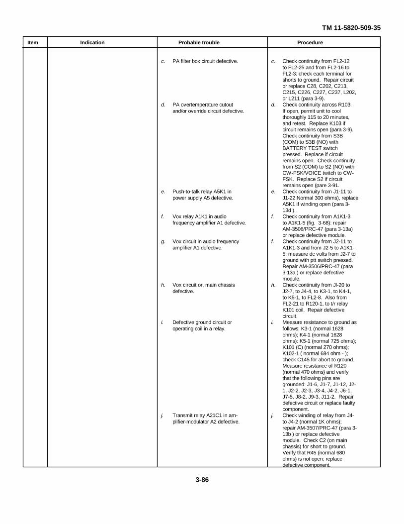
TM 11-5820-509-35
Item Indication Probable trouble Procedure
c. PA filter box circuit defective. c. Check continuity from FL2-12to FL2-25 and from FL2-16 toFL2-3: check each terminal forshorts to ground. Repair circuitor replace C28, C202, C213,C215, C226, C227, C237, L202,or L211 (para 3-9).
d. PA overtemperature cutout d. Check continuity across R103.and/or override circuit defective. If open, permit unit to cool
thoroughly 115 to 20 minutes,and retest. Replace K103 ifcircuit remains open (para 3-9).Check continuity from S3B(COM) to S3B (NO) withBATTERY TEST switchpressed. Replace if circuitremains open. Check continuityfrom S2 (COM) to S2 (NO) withCW-FSK/VOICE twitch to CW-FSK. Replace S2 if circuitremains open (pare 3-91.
e. Push-to-talk relay A5K1 in e. Check continuity from J1-11 topower supply A5 defective. J1-22 Normal 300 ohms), replace
A5K1 if winding open (para 3-13d ).
f. Vox relay A1K1 in audio f. Check continuity from A1K1-3frequency amplifier A1 defective. to A1K1-5 (fig. 3-68): repair
AM-3506/PRC-47 (para 3-13a)or replace defective module.
g. Vox circuit in audio frequency f. Check continuity from J2-11 toamplifier A1 defective. A1K1-3 and from J2-5 to A1K1-
5: measure dc volts from J2-7 toground with ptt switch pressed.Repair AM-3506/PRC-47 (para3-13a ) or replace defectivemodule.
h. Vox circuit or, main chassis h. Check continuity from Jl-20 todefective. J2-7, to J4-4, to K3-1, to K4-1,
to K5-1, to FL2-8. Also fromFL2-21 to R120-1, to t/r relayK101 coil. Repair defectivecircuit.
i. Defective ground circuit or i. Measure resistance to ground asoperating coil in a relay. follows: K3-1 (normal 1628
ohms); K4-1 (normal 1628ohms): K5-1 (normal 725 ohms);K101 (C) (normal 270 ohms);K102-1 ( normal 684 ohm - );check C145 for abort to ground.Measure resistance of R120(normal 470 ohms} and verifythat the following pins aregrounded: J1-6, J1-7, J1-12, J2-1, J2-2, J2-3, J3-4, J4-2, J6-1,J7-5, J8-2, J9-3, J11-2. Repairdefective circuit or replace faultycomponent.
j. Transmit relay A21C1 in am- j. Check winding of relay from J4-plifier-modulator A2 defective. to J4-2 (normal 1K ohms);
repair AM-3507/PRC-47 (para 3-13b ) or replace defectivemodule. Check C2 (on mainchassis) for short to ground.Verify that R45 (normal 680ohms) is not open; replacedefective component.
3-86
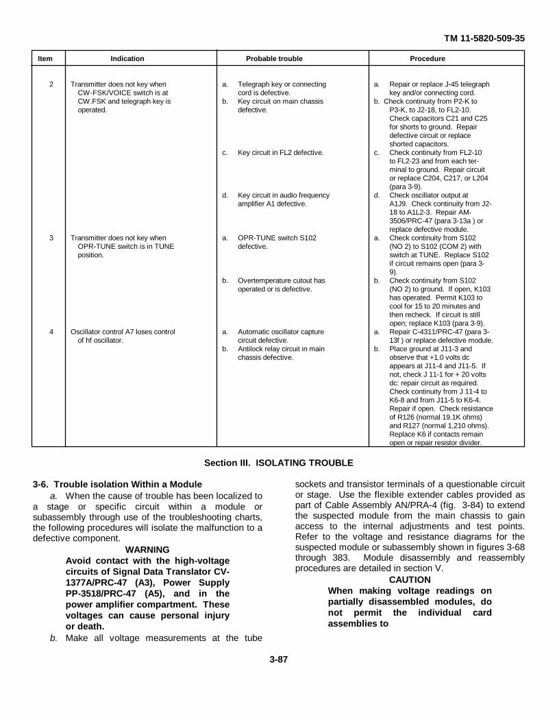
TM 11-5820-509-35
Item Indication Probable trouble Procedure
2 Transmitter does not key when a. Telegraph key or connecting a. Repair or replace J-45 telegraphCW-FSK/VOICE switch is at cord is defective. key and/or connecting cord.CW.FSK and telegraph key is b. Key circuit on main chassis b. Check continuity from P2-K tooperated. defective. P3-K, to J2-18, to FL2-10.
Check capacitors C21 and C25for shorts to ground. Repairdefective circuit or replaceshorted capacitors.
c. Key circuit in FL2 defective. c. Check continuity from FL2-10to FL2-23 and from each ter-minal to ground. Repair circuitor replace C204, C217, or L204(para 3-9).
d. Key circuit in audio frequency d. Check oscillator output atamplifier A1 defective. A1J9. Check continuity from J2-
18 to A1L2-3. Repair AM-3506/PRC-47 (para 3-13a ) orreplace defective module.
3 Transmitter does not key when a. OPR-TUNE switch S102 a. Check continuity from S102OPR-TUNE switch is in TUNE defective. (NO 2) to S102 (COM 2) withposition. switch at TUNE. Replace S102
if circuit remains open (para 3-9).
b. Overtemperature cutout has b. Check continuity from S102operated or is defective. (NO 2) to ground. If open, K103
has operated. Permit K103 tocool for 15 to 20 minutes andthen recheck. If circuit is stillopen; replace K103 (para 3-9).
4 Oscillator control A7 loses control a. Automatic oscillator capture a. Repair C-4311/PRC-47 (para 3-of hf oscillator. circuit defective. 13f ) or replace defective module.
b. Antilock relay circuit in main b. Place ground at J11-3 andchassis defective. observe that +1.0 volts dc
appears at J11-4 and J11-5. Ifnot, check J 11-1 for + 20 voltsdc: repair circuit as required.Check continuity from J 11-4 toK6-8 and from J11-5 to K6-4.Repair if open. Check resistanceof R126 (normal 19.1K ohms)and R127 (normal 1,210 ohms).Replace K6 if contacts remainopen or repair resistor divider.
Section III. ISOLATING TROUBLE
3-6. Trouble isolation Within a Modulea. When the cause of trouble has been localized to
a stage or specific circuit within a module orsubassembly through use of the troubleshooting charts,the following procedures will isolate the malfunction to adefective component.
WARNINGAvoid contact with the high-voltagecircuits of Signal Data Translator CV-1377A/PRC-47 (A3), Power SupplyPP-3518/PRC-47 (A5), and in thepower amplifier compartment. Thesevoltages can cause personal injuryor death.
b. Make all voltage measurements at the tube
sockets and transistor terminals of a questionable circuitor stage. Use the flexible extender cables provided aspart of Cable Assembly AN/PRA-4 (fig. 3-84) to extendthe suspected module from the main chassis to gainaccess to the internal adjustments and test points.Refer to the voltage and resistance diagrams for thesuspected module or subassembly shown in figures 3-68through 383. Module disassembly and reassemblyprocedures are detailed in section V.
CAUTIONWhen making voltage readings onpartially disassembled modules, donot permit the individual cardassemblies to
3-87
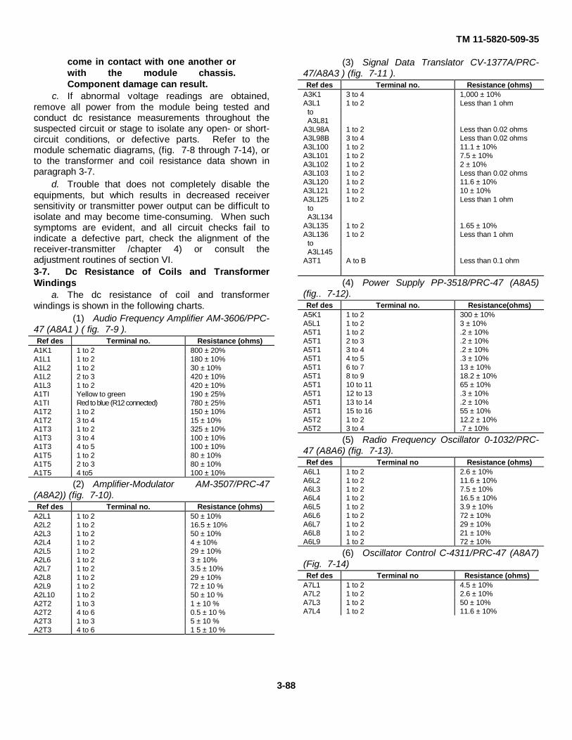
TM 11-5820-509-35
come in contact with one another orwith the module chassis.Component damage can result.
c. If abnormal voltage readings are obtained,remove all power from the module being tested andconduct dc resistance measurements throughout thesuspected circuit or stage to isolate any open- or short-circuit conditions, or defective parts. Refer to themodule schematic diagrams, (fig. 7-8 through 7-14), orto the transformer and coil resistance data shown inparagraph 3-7.
d. Trouble that does not completely disable theequipments, but which results in decreased receiversensitivity or transmitter power output can be difficult toisolate and may become time-consuming. When suchsymptoms are evident, and all circuit checks fail toindicate a defective part, check the alignment of thereceiver-transmitter /chapter 4) or consult theadjustment routines of section VI.3-7. Dc Resistance of Coils and TransformerWindings
a. The dc resistance of coil and transformerwindings is shown in the following charts.
(1) Audio Frequency Amplifier AM-3606/PPC-47 (A8A1 ) ( fig. 7-9 ).Ref des Terminal no. Resistance (ohms)
A1K1 1 to 2 800 ± 20%A1L1 1 to 2 180 ± 10%A1L2 1 to 2 30 ± 10%A1L2 2 to 3 420 ± 10%A1L3 1 to 2 420 ± 10%A1TI Yellow to green 190 ± 25%A1TI Red to blue (R12 connected) 780 ± 25%A1T2 1 to 2 150 ± 10%A1T2 3 to 4 15 ± 10%A1T3 1 to 2 325 ± 10%A1T3 3 to 4 100 ± 10%A1T3 4 to 5 100 ± 10%A1T5 1 to 2 80 ± 10%A1T5 2 to 3 80 ± 10%A1T5 4 to5 100 ± 10%
(2) Amplifier-Modulator AM-3507/PRC-47(A8A2)) (fig. 7-10).Ref des Terminal no. Resistance (ohms)
A2L1 1 to 2 50 ± 10%A2L2 1 to 2 16.5 ± 10%A2L3 1 to 2 50 ± 10%A2L4 1 to 2 4 ± 10%A2L5 1 to 2 29 ± 10%A2L6 1 to 2 3 ± 10%A2L7 1 to 2 3.5 ± 10%A2L8 1 to 2 29 ± 10%A2L9 1 to 2 72 ± 10 %A2L10 1 to 2 50 ± 10 %A2T2 1 to 3 1 ± 10 %A2T2 4 to 6 0.5 ± 10 %A2T3 1 to 3 5 ± 10 %A2T3 4 to 6 1 5 ± 10 %
(3) Signal Data Translator CV-1377A/PRC-47/A8A3 ) (fig. 7-11 ).Ref des Terminal no. Resistance (ohms)
A3K1 3 to 4 1,000 ± 10%A3L1 1 to 2 Less than 1 ohm
toA3L81
A3L98A 1 to 2 Less than 0.02 ohmsA3L98B 3 to 4 Less than 0.02 ohmsA3L100 1 to 2 11.1 ± 10%A3L101 1 to 2 7.5 ± 10%A3L102 1 to 2 2 ± 10%A3L103 1 to 2 Less than 0.02 ohmsA3L120 1 to 2 11.6 ± 10%A3L121 1 to 2 10 ± 10%A3L125 1 to 2 Less than 1 ohm
toA3L134
A3L135 1 to 2 1.65 ± 10%A3L136 1 to 2 Less than 1 ohm
toA3L145
A3T1 A to B Less than 0.1 ohm
(4) Power Supply PP-3518/PRC-47 (A8A5)(fig.. 7-12).Ref des Terminal no. Resistance(ohms)
A5K1 1 to 2 300 ± 10%A5L1 1 to 2 3 ± 10%A5T1 1 to 2 .2 ± 10%A5T1 2 to 3 .2 ± 10%A5T1 3 to 4 .2 ± 10%A5T1 4 to 5 .3 ± 10%A5T1 6 to 7 13 ± 10%A5T1 8 to 9 18.2 ± 10%A5T1 10 to 11 65 ± 10%A5T1 12 to 13 .3 ± 10%A5T1 13 to 14 .2 ± 10%A5T1 15 to 16 55 ± 10%A5T2 1 to 2 12.2 ± 10%A5T2 3 to 4 .7 ± 10%
(5) Radio Frequency Oscillator 0-1032/PRC-47 (A8A6) (fig. 7-13).Ref des Terminal no Resistance (ohms)
A6L1 1 to 2 2.6 ± 10%A6L2 1 to 2 11.6 ± 10%A6L3 1 to 2 7.5 ± 10%A6L4 1 to 2 16.5 ± 10%A6L5 1 to 2 3.9 ± 10%A6L6 1 to 2 72 ± 10%A6L7 1 to 2 29 ± 10%A6L8 1 to 2 21 ± 10%A6L9 1 to 2 72 ± 10%
(6) Oscillator Control C-4311/PRC-47 (A8A7)(Fig. 7-14)Ref des Terminal no Resistance (ohms)
A7L1 1 to 2 4.5 ± 10%A7L2 1 to 2 2.6 ± 10%A7L3 1 to 2 50 ± 10%A7L4 1 to 2 11.6 ± 10%
3-88
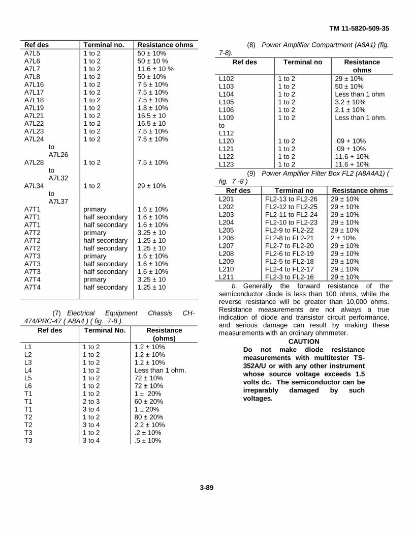
TM 11-5820-509-35
Ref des Terminal no. Resistance ohmsA7L5 1 to 2 50 ± 10%A7L6 1 to 2 50 ± 10 %A7L7 1 to 2 11.6 ± 10 %A7L8 1 to 2 50 ± 10%A7L16 1 to 2 7 5 ± 10%A7L17 1 to 2 7.5 ± 10%A7L18 1 to 2 7.5 ± 10%A7L19 1 to 2 1.8 ± 10%A7L21 1 to 2 16.5 ± 10A7L22 1 to 2 16.5 ± 10A7L23 1 to 2 7.5 ± 10%A7L24 1 to 2 7.5 ± 10%
toA7L26
A7L28 1 to 2 7.5 ± 10%toA7L32
A7L34 1 to 2 29 ± 10%toA7L37
A7T1 primary 1.6 ± 10%A7T1 half secondary 1.6 ± 10%A7T1 half secondary 1.6 ± 10%A7T2 primary 3.25 ± 10A7T2 half secondary 1.25 ± 10A7T2 half secondary 1.25 ± 10A7T3 primary 1.6 ± 10%A7T3 half secondary 1.6 ± 10%A7T3 half secondary 1.6 ± 10%A7T4 primary 3.25 ± 10A7T4 half secondary 1.25 ± 10
(7) Electrical Equipment Chassis CH-474/PRC-47 ( A8A4 ) ( fig. 7-8 ).
Ref des Terminal No. Resistance(ohms)
L1 1 to 2 1.2 ± 10%L2 1 to 2 1.2 ± 10%L3 1 to 2 1.2 ± 10%L4 1 to 2 Less than 1 ohm.L5 1 to 2 72 ± 10%L6 1 to 2 72 ± 10%T1 1 to 2 1 ± 20%T1 2 to 3 60 ± 20%T1 3 to 4 1 ± 20%T2 1 to 2 80 ± 20%T2 3 to 4 2.2 ± 10%T3 1 to 2 .2 ± 10%T3 3 to 4 .5 ± 10%
(8) Power Amplifier Compartment (A8A1) (fig.7-8).
Ref des Terminal no Resistanceohms
L102 1 to 2 29 ± 10%L103 1 to 2 50 ± 10%L104 1 to 2 Less than 1 ohmL105 1 to 2 3.2 ± 10%L106 1 to 2 2.1 ± 10%L109 1 to 2 Less than 1 ohm.toL112L120 1 to 2 .09 + 10%L121 1 to 2 .09 + 10%L122 1 to 2 11.6 + 10%L123 1 to 2 11.6 + 10%
(9) Power Amplifier Filter Box FL2 (A8A4A1) (fig. 7 -8 )
Ref des Terminal no Resistance ohmsL201 FL2-13 to FL2-26 29 ± 10%L202 FL2-12 to FL2-25 29 ± 10%L203 FL2-11 to FL2-24 29 ± 10%L204 FL2-10 to FL2-23 29 ± 10%L205 FL2-9 to FL2-22 29 ± 10%L206 FL2-8 to FL2-21 2 ± 10%L207 FL2-7 to FL2-20 29 ± 10%L208 FL2-6 to FL2-19 29 ± 10%L209 FL2-5 to FL2-18 29 ± 10%L210 FL2-4 to FL2-17 29 ± 10%L211 FL2-3 to FL2-16 29 ± 10%
b. Generally the forward resistance of thesemiconductor diode is less than 100 ohms, while thereverse resistance will be greater than 10,000 ohms.Resistance measurements are not always a trueindication of diode and transistor circuit performance,and serious damage can result by making thesemeasurements with an ordinary ohmmeter.
CAUTIONDo not make diode resistancemeasurements with multitester TS-352A/U or with any other instrumentwhose source voltage exceeds 1.5volts dc. The semiconductor can beirreparably damaged by suchvoltages.
3-89
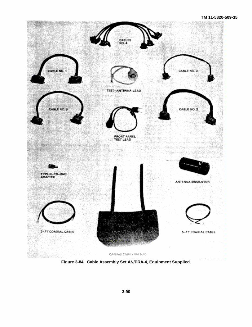
TM 11-5820-509-35
Figure 3-84. Cable Assembly Set AN/PRA-4, Equipment Supplied.
3-90
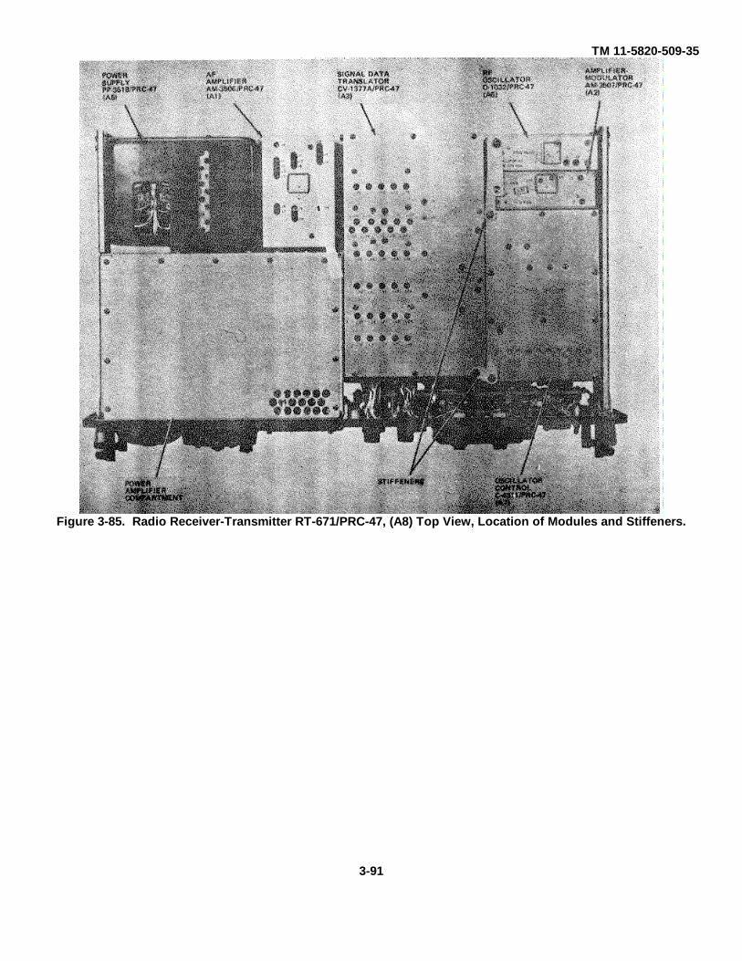
TM 11-5820-509-35
Figure 3-85. Radio Receiver-Transmitter RT-671/PRC-47, (A8) Top View, Location of Modules and Stiffeners.
3-91
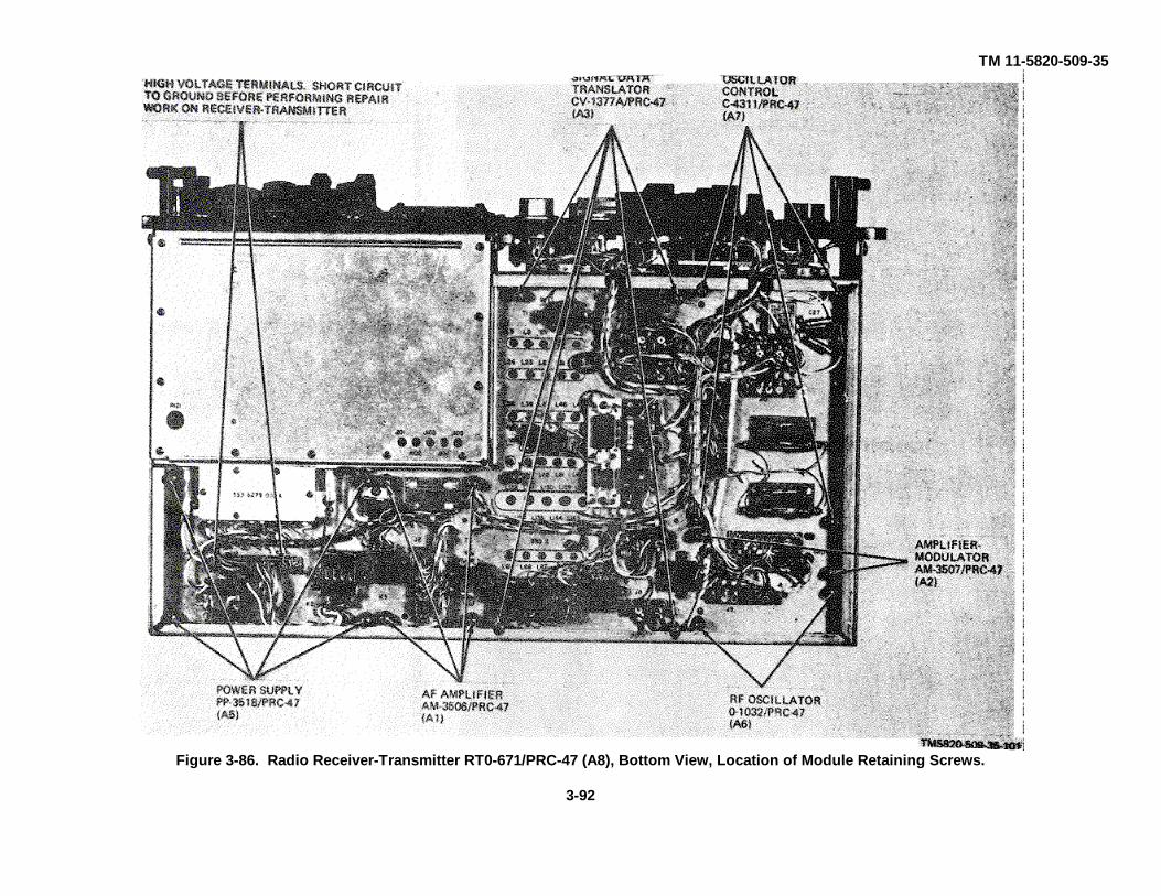
TM 11-5820-509-35
Figure 3-86. Radio Receiver-Transmitter RT0-671/PRC-47 (A8), Bottom View, Location of Module Retaining Screws.
3-92

TM 11-5820-509-35
Figure 3-87. Radio Receiver-Transmitter RT-671/PRC-47 (A8), Front Panel View, Location of Access Opening and Panel Components.
3-93

TM 11-5820-509-35
Figure 3-88. Frequency Selector Control, Switch Coupler Alignment Diagram
Figure 3-89. Radio Receiver-Transmitter RT-671/PRC-47, Power Amplifier Compartment (A8A4A) ), Load-TuneCoil Assembly, Exploded View.
(Located in back of manual.)
Figure 3-90. Radio Receiver-Transmitter RT-671/PRC-47, Frequency Selection Mechanism (A8A4A1 ), ExplodedView.
(Located in back of manual.)
Figure 3-91. Radio Receiver-Transmitter RT-671/PRC-47, Power Amplifier Compartment (A8A4A1 ), PlateCapacitor Switch, Exploded View.
Located in back of manual.)
Figure 3-92. Radio Receiver-Transmitter RT-671/PRC-47, Power Amplifier Compartment (A8A4A1 ), XMTR PWRSwitch (S103 ), Exploded View.
(Located in back of manual.)
3-94
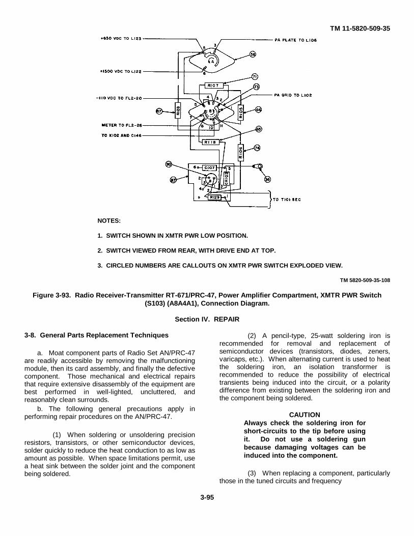
TM 11-5820-509-35
NOTES:
1. SWITCH SHOWN IN XMTR PWR LOW POSITION.
2. SWITCH VIEWED FROM REAR, WITH DRIVE END AT TOP.
3. CIRCLED NUMBERS ARE CALLOUTS ON XMTR PWR SWITCH EXPLODED VIEW.
TM 5820-509-35-108
Figure 3-93. Radio Receiver-Transmitter RT-671/PRC-47, Power Amplifier Compartment, XMTR PWR Switch(S103) (A8A4A1), Connection Diagram.
Section IV. REPAIR
3-8. General Parts Replacement Techniques
a. Moat component parts of Radio Set AN/PRC-47are readily accessible by removing the malfunctioningmodule, then its card assembly, and finally the defectivecomponent. Those mechanical and electrical repairsthat require extensive disassembly of the equipment arebest performed in well-lighted, uncluttered, andreasonably clean surrounds.
b. The following general precautions apply inperforming repair procedures on the AN/PRC-47.
(1) When soldering or unsoldering precisionresistors, transistors, or other semiconductor devices,solder quickly to reduce the heat conduction to as low asamount as possible. When space limitations permit, usea heat sink between the solder joint and the componentbeing soldered.
(2) A pencil-type, 25-watt soldering iron isrecommended for removal and replacement ofsemiconductor devices (transistors, diodes, zeners,varicaps, etc.). When alternating current is used to heatthe soldering iron, an isolation transformer isrecommended to reduce the possibility of electricaltransients being induced into the circuit, or a polaritydifference from existing between the soldering iron andthe component being soldered.
CAUTIONAlways check the soldering iron forshort-circuits to the tip before usingit. Do not use a soldering gunbecause damaging voltages can beinduced into the component.
(3) When replacing a component, particularlythose in the tuned circuits and frequency
3-95

TM 11-5820-509-35
generation sections of the equipment, always adjust thereplacement component lead length, componentplacement, and proximity to adjacent devices as nearlyas possible to the original installation. This minimizesthe final alignment adjustments for the stage.
(4) High power semiconductor devices areoften mounted on heat sinks. Whenever a device isreplaced, always replace the insulating washer(s) if theyhave been used in the original installation.
CAUTIONBefore installing insulating washers,treat them with silicone fluid orcompound to enhance the heatconductivity through the washer.Check the continuity between thesemiconductor case and the heatsink before making other electricalconnections to the replacementdevice.
(5) When replacing ceramic or glasscomponents, use a heat sink and avoid excessivepressure when gripping the component or its leadsduring soldering and attachment.
(6) Subminiature tubes are wired directly intothe subassemblies: apply heat to these electrode leadscarefully to avoid damage to the tube envelope
(7) Avoid overheating the capacitor bodywhen replacing ceramic feed-through capacitors in achassis. The plating can be destroyed by excessiveheat.
(8) When tightening the setscrews in a collar-type clamp, the setscrews must be tightened against thecenter of the mechanical part.
(9) Special care must be exercised whensoldering the terminal posts of some variable capacitors.Excessive heat can loosen the stator plates of someassemblies.
3-9. General Removal and Replacement Procedures
a. These general procedures are in addition to thespecific routines listed in section V and are intended toact as guidelines to assist the maintenance technician inthe removal and re placement of components inassemblies of Radio Receiver-Transmitter RT-671/PRC-47.
b. Whenever component parts are removed forrepairs, adjustments, or internal measurements:
(1) Remove all power from the equipment,and ground the high-voltage circuits at chassisconnectors J1-A1 and J1-A2.
(2) Before removing Signal Data TranslatorCV-1377A/PRC-47 (A8A3) or Oscillator Control C-4311/PRC-47 (A8A7) adjust the front panel frequencycontrol knobs to provide a reading of 2000 on theKILOCYCLES indicator. This places the shaft couplersof these modules in the proper position to facilitatemodule removal from the main chassis.
(3) When servicing the driver tube (A3V3)and the power amplifier tube (V101), remove the tubeand its heat sink as a unit from the subassembly.Carefully observe the orientation of these tubes in theirheat sink before separating them; installation of thereplacement tube is easier if the heat sink is properlyoriented outside the subassembly.
(4) Disassemble only those items andcomponent subassemblies that are required to performthe desired maintenance. Any defective part thatcannot be repaired should be replaced.
(5) Soldering must be in accordance withMilitary Specification MIL-S-6872. Use only rosin-coresolder. A wire solder containing 60-percent tin and 40-percent lead, having a diameter of l/16-inch andmeeting the general requirements of this specification isavailable in one-pound quantities under Federal StockNumber 3439-753-1874.
(6) Clean all parts after soldering to removeresidual rosin. Denatured alcohol (FSN 6810-222-2373)is recommended for this purpose.
(7) Replacement wiring should be the samelength and gage as the wire it replaces and should bedressed to conform to the routing of the originalconductor.
(8) Remove a defective part from a printedcircuit card by clipping its leads as close to the terminalhole as possible.
(9) Clear the terminal hole of a printed circuitcard by applying only enough heat to cause the solder toflow; then clear the solder and clipped component leadout of the terminal hole with a small pick.
(10) Insert the lead wire(s) of the replacementcomponent into the terminal holes of the printed circuitcard and adjust their individual lengths and dress tolocate the replacement component in the same positionas the original one (use parts location photographs toverify the location of this replacement part). Solder theleads using a heat sink; then clip off the excess leadwire.
c. Printed circuit card repair is not recommendedunless the repair is minor The following procedures arerecommended when such repair is desired.
(1) Eliminate the progress of a crack in thecircuit card by drilling a stop hole (no. 65 drill) at theend of the crack.
(2) If a Crack extends under or through the
3-96

TM 11-5820-509-35
printed circuit, a suitable conventional wire may besoldered to the circuit to bridge the area of a crack.Standoff terminals or eyelets may be added to facilitateconnection of component leads provided the circuit isnot altered.
(3) If an area of the printed circuit has liftedfrom the board without cracking, and for a length of notmore than one inch, the printed circuit can be fastenedback to the board as follows:
(a) Clean the raised area of the circuitwith technical acetone, FSN 6810-184-4795 (onegallon).
(b) Prepare a bonding material bymixing equal quantities of epoxy sealing compound(FSN 8030-589-8477, 1/2 pt.) and hardener (FSN8030543-2587, 1/2 pt.). Mix only enough to do theimmediate Job since it cannot be retained for later use.
(c) Press the circuit net and apply thebonding agent so that it extends about 1/16-inch beyondthe raised circuit in all directions.
(d) Permit the bonding agent to air dryfor at least 24 hours before using the card or doingfurther work on the circuit.
Section V. ASSEMBLY AND DISASSEMBLY
3-10. General
The tools required for removal of modules are includedin Tool Kit, Radar and Radio Repair, TK87/U. Moduleretaining screws are shown in figure 3-86. Beforeremoving Signal Data Translator CV-1377A/PRC-47(A3) or Oscillator Control C-4311/PRC-47 (A7), set theKILOCYCLES indicator on the front panel of RT-671/PRC-47 to 2000. This is necessary to align the driveshaft couplings of these modules in a vertical position sothat the modules can be easily removed from thechassis without coupling damage.
WARNINGBefore removing any equipmentcover or module from RadioReceiver-Transmitter RT-671 /PRC-47, disconnect all power from theunit.
3-11. Removal and Replacement of Receiver-Transmitter Case
a. Removal.(1) Loosen the six screws that secure Panel
Cover CW-647/PRC-47 to the RT-671/PRC-47; removethe cover.
(2) Invert the RT-671/PRC-47 so that it restsface down on the handles attached to the front panel.
(3) Loosen and remove the six screws on thebottom of the case that secure the case to ElectricalEquipment Chassis CH-474/PRC-47.
(4) Carefully lift the case from the receiver-transmitter.
b. Replacement.(1) Invert the Radio Receiver-Transmitter RT-
671/PRC-47 so that it rests on the handles attached tothe front panel.
(2) Clean the interior of the case to removeany accumulated dust or dirt.
(3) Carefully lower the case over theelectronic equipment chassis until the six screw holes inthe bottom of it are properly aligned to permit insertionof the screws. Install the six screws and tightensecurely.
(4) Invert the unit to its normal operatingposition and install Panel Cover CW-647/PRC-47;tighten the six attaching screws.
3-12. Removal and Replacement of Plug-in Modules
WARNINGHigh voltages are present in thecircuits associated with Signal DataTranslator CV-1377A/PRC-47, PowerSupply PP-3618/PRC-47, and thepower amplifier compartment. Thesevoltages are dangerous and cancause personal injury or death.Ground the two high-voltageterminals on the main chassis (J1-A1and J1-A2) to discharge thecapacitors in the high-voltagecircuits before beginningmaintenance within the chassis orinside any module.
a. General. Before loosening the module retainingscrews (fig. 3-86), remove the upper module stiffeners(fig. 3-85). To remove the module from the mainchassis, loosen the captive hardware and carefully liftthe module from the chassis connector. The followingdetailed procedures apply to all plug-in modules ofRadio Receiver-Transmitter RT-671/PRC-47.
b. Removal.(1) Invert RT-671/PRC-47 to expose the main
chassis components and wiring.(2) Loosen the four captive screws Five for
Signal Data Translator CV-1377A/PRC-47, and twoeach for Amplifier-Modulator AM-3507/PRC-47 andRadio Frequency Oscillator O-
3-97
TM 11-5820-509-35
1032/PRC-47) at the locations shown in figure 386.(3) Return the receiver-transmitter to its
upright position.(4) If the module being removed is Signal
Data Translator CV-1377A/PRC-47 (A3) or OscillatorControl C-4311/PRC-47 (A7), adjust the KILOCYCLESindicator to 2000 before attempting to remove themodule from the main chassis.
(5) Carefully pull the module straight out of itsmating chassis connector using the handle on top of themodule if available.
c. Replacement.(1) Align the module guide pins with the guide holes
in the main chassis.
CAUTIONBefore attempting to install SignalData Translator CV-1377A/PRC-47 atlocation A8A3 or Oscillator ControlC-4311/PRC47 at location A8A7 onthe main chassis, set theKILOCYCLES indicator to 2000, thenadjust the module shaft coupling tothe orientation shown in figure 3-44(CV-1377A/PRC-47) or figure 3-63 (C-4311/PRC-47) to prevent damage tothe module or its drive shaft duringreplacement.
(2) Press the module firmly into its chassisconnector.
(3) Tighten the module retaining screws (fig.3-86) to secure the module to the chassis.
(4) If no further modules are to be servicedand maintenance procedures are complete, replace themodule stiffeners (fig. 3-85) and return the receiver-transmitter to its case using the procedures detailed inparagraph 3-11b.
3-13. Module Assembly and DisassemblyProcedures
a. Audio Frequency Amplifier AM-3506/PRC47(A8A1 ). (fig. 3-6, 3-16 through 3-19)
(1) Disassembly Procedures.(a) Loosen and remove the two 4-40 x
5/16 pan head screws and their associated washers thatsecure the cover to the module chassis; carefullyremove the cover by lifting it from the module.
(b) To remove card assembly E3(containing the driver and agc amplifier stages), loosenand remove the four 2-56 x 1/4 flat head screws (twoper side) that secure this card assembly to the sides ofthe module chassis; carefully fold the card assemblyforward out of the chassis.
(c) To remove card assembly E2(containing the microphone and audio amplifier stages),loosen and remove the six 2-56 x 1/4 flat head screws(three per side) that secure this card assembly to thesides of the modules chassis carefully fold this cardforward (away from E1).
(d) To remove card assembly E1(containing the cw oscillator and vox circuits), firstperform step (c) to remove card assembly E2; thenloosen and remove the six remaining 2-56 x 1/4 nethead screws 13 per side) that secure this card assemblyto the sides of the module chassis. Carefully fold thiscard forward to expose the components mounted to theface of it. (R83 is connected to the back of this card,opposite R85).
(e) The component parts attacheddirectly to the module chassis may be individuallyremoved as required for repair or replacement.
NOTEIf interconnecting wires between thecard assemblies or between a cardand the module connector, orbetween individual components onthe chassis are removed to affectrepairs, tag each wire carefully sothat it may be reconnected to itsproper terminal location.
(2) Repair Procedures. Replace anydefective component or repair the circuit using theprocedures outlined in section IV. Component partsshown on the module schematic diagram (fig. 7-9) arelocated on figures 3-16 through 3-19.
CAUTIONWhen using a soldering iron toremove or to replace a componentpart, use only enough heat to causethe solder to flow. Excess heat candamage the component and may alsodamage the printed circuit. (3)Reassembly Procedures.
(a) Replace and solder any wiresremoved from the module connector or between thecard assemblies during disassembly and repairprocedures.
(b) Install the circuit cards in theirrespective locations (fig. 3-6) beginning with cardassembly E1, if it has been removed.
CAUTIONWhen installing card assemblies E 1and E2 in the chassis dress themodule cabling to prevent stressingthe cards. Card or componentdamage can result if these cardassemblies are forced into place.
(c) Secure the card assemblies in placewith the 2-56 x 1/4 flat head screws (eight per side).
(d) Replace the module cover andsecure it in place with two 4-40 x 5/16 pan head screwsand associated flat washers inserted through the holesin the top of the cover.
3-98

TM 11-5820-509-35
NOTEWhen replacing the module cover,observe the notch orientation in thebottom edges of the cover; verifythat the cover is fully seated beforeattempting to install the retainingscrews and washers.
b. Amplifier-Modulator AM-3507/PRC-47 (A8A2).(fig. 3-7 3-8, 3-20 and 3-21)
(1) Disassembly Procedures.(a) Remove the four 4-40 x 3/16 flat
head screws that secure each side cover to the modulechassis.
NOTEIf interconnecting wires betweencard assemblies or between a cardand the module connector must beremoved to affect repairs tag eachwire carefully so that it may bereconnected to its proper terminallocation.
(b) To remove card assembly E1disconnect the two shielded wires (from test point J2and P3-A2) from the terminal adjacent to capacitors C7and C8 (fig. 3-7). Next remove the four remainingwires that interconnect P3 (terminals 1 through 4) withterminals on the card. Remove the five wires thatinterconnect card assembly E1 with card assembly E2(two wires are adjacent to transformer T2). Finallyremove the four 4-40 x 3/16 pan head screws thatsecure the card assembly to the module chassis.
(c) To remove card assembly E2disconnect the seven wires (2 near transformer T2) thatinterconnect this card assembly with the remainingcircuits of the module. Loosen and remove the two 4-40x 3/16 pan head screws that secure the card assemblyto the module chassis.
(d) Card assemblies E3 E4 and E5 areaccessible from the opposite side of the module chassis.Disassemble and tag the circuit components if they areremoved.
(2) Repair Procedures. Replace anydefective component or repair the circuit using theprocedures outlined in section IV. Component partsshown on the module schematic diagram Fig 7-10, arelocated on figures 3-20 and 3 21.
CAUTIONWhen using a soldering iron toremove or to replace a component,part use only enough heat to cause:the solder to flow. Excess heat candamage the component and may alsodamage the printed circuit.
(3) Reassembly Procedures.(a) Replace and solder any wires
removed from the module connector or between thecard assemblies during` disassembly or repairprocedures.
(b) Install the card assemblies in theirrespective locations (fig. 3-7 and 3-8) and secure themin place with the 4-40 x 3/16 pan head screws.
(c) Replace the module side coversand secure them with the 4-40 x 3/16 flat head screws(four per side) to the module chassis.
NOTEBe sure to place the proper cover oneach side of the module so that itssilkscreen agrees with the assemblyit covers.
c. Signal Data Translator CV-1377A/PRC-47(A8A3). (fig. 3-9 3-10 3-22 through 3-44)
(1) Disassembly Procedures.(a) Remove the 4-40 x I/4 screws that
secure the top and/or bottom covers to the modulechassis.
(b) To remove card assemblies E47and E48 remove the four 4-40 x 1/4 flat head screwsfrom the right side of the module chassis and lift thecard assemblies upward and out of the unit through thetop of the chassis.
(c) To remove card assemblies TB 1and TB2 remove the two 4-40 x 1/4 flat head screwsfrom the right side of the chassis and lift the cardassembly out through the bottom of the chassis.
(d) To remove card assembly E46,remove the two 2-56 x 3/16 screws from the divider andlift the card assembly out through the bottom of thechassis.
(e) To remove any switch cardassembly first verify that the frequency range switchshaft coupling is in the position shown in figure 3-44;then perform steps (f) through (h).
(f) Remove the C-shaped retaining ringfrom the rear of the frequency range switch shaft (fig. 3-43).
(g) Withdraw the shaft from the modulethrough the coupler end of the unit.
(h) Slide out the desired switch card(s).
NOTEIf the vfo subassembly with switchcards S6 and S7 is to be removedloosen and remove the two 4-40 x3/16 screws at the right side of themodule before lifting the vfosubassembly out. l he assemblyconsisting of switch cards S1 S2 andS3 (as well as the vfo subassembly)are fastened together and must beremoved as a unit. Furtherdisassembly may be required dbefore repair to an individualcomponent or card can be affected.If interconnecting wires orcomponent leads interconnect theseindividual cards carefully tag eachlead before removing it to assure thatit can be reconnected to the
3-99
TM 11-5820-509-35
proper location on the card duringreassembly procedures.
(2) Repair Procedures. Replace anydefective component or repair the circuit using theprocedures outlined in section IV. Component partsshown on the module schematic diagram (fig. 7-12) arelocated on figures 3-22 through 343).
CAUTIONWhen using a soldering iron toremove or to replace a componentpart, use only enough heat to causethe solder to flow. Excess heat candamage the component and may alsodamage the printed circuit.
(a) Vacuum tubes V1 and V2 (part ofcard assemblies TB1 and TB2 respectively) areconnected directly to terminals on the card. To removethese tubes, unsolder each electrode lead carefully fromthe terminal and then remove the tube from its shield.(Install a new tube and solder each electrode lead to itsproper terminal location as shown in figures 3-22 and 3-23).
(b) To replace driver tube V3 (fig. 3-9),remove the four screws that secure the heat sink to theright side of the module chassis. Remove the heat sinkand the tube from socket XV3. (Install the new tube inthe tube socket and replace the heat sink and itscorrugated contactor over the replacement tube beforeagain installing the four retaining screws.
(3) Reassembly Procedures.(a) Replace and solder any wires
removed from the module connector or between cardassemblies during the disassembly and repairprocedures.
CAUTIONBefore replacing the switch cards inthe module, make sure that eachswitch rotor is placed in position no.1 (fig. 3-42). Equipment damage canresult if the band switches are notproperly oriented before insertion inthe module.
(b) Reassemble switch group Sl-S2-S3(fig. 3-24, 3-25) and vfo-S6-S7 (fig. 3-31, 3-321 if theywere disassembled.
(c) Install card assemblies TB1, TB2,E46, E47, E48 nod the vfo subassembly in their properlocations in the module chassis using the appropriatehardware.
(d) Install the switch cards and switchcard groups in their respective slots if they have beenremoved.
NOTEThe keyway in switch cardassemblies S6-S7 and S10 must beoriented toward the bottom of be
module chassis before insertingthese cards in their respective slots.
(e) With all switches installed, carefullyreplace the frequency range switch shaft with the groovein the coupling end of it oriented as shown in figure 3-44.
CAUTIONWhen inserting the frequency rangeswitch shaft be careful that the rotorposition of the switches is notdisturbed. Do not use excess forcewhen threading this shaft throughthe switch rotors; switch parts canbe damaged unless extreme care isused.
(f) Replace the C-shaped retaining ringin the groove at the rear end of the frequency rangeswitch shaft.
(g) Replace the top and bottom coverson the module and secure them with the 4-40 screwsremoved in step c(1)(a).
(h) Before installing the module in themain chassis of the receiver-transmitter, observe theCAUTION in step 3-12c.
d. Power Supply PP-3518/PRC-47 (A8A5) (fig. 3-11, 3-45 through 3-51).
(1) Disassembly Procedures.(a) Loosen and remove the two 4-40 x
5/16 pan head screws and the one 4-40 x 5/16 flat headscrew that secure the plastic cover of the module to thechassis: remove the cover.
WARNINGBefore further disassembly. short-circuit connector pins Pl-A1 and P1-A2 to ground to discharge the high-voltage filter capacitors. Personalinjury or death can result from thesevoltages.
(b) To remove subassembly no. 1 (fig.346, 3-47), loosen and remove the four 4-40 x 1/4 panhead screws and carefully fold the subassembly downand out of the way.
(c) To remove subassembly no. 2 (fig.3-48), loosen and remove the four 4-40 x 3/8 pan headscrews and carefully fold the subassembly up out of theway.
(d) To remove subassembly no. 3 (fig.3-49). loosen and remove the two 4-40 x 5/16 net headscrews, their flat washers and stop nuts: carefully lift thesubassembly out 0 f the chassis.
(e) The remove voltage regulatorsubassembly TB1 (fig. 3-51). loosen and remove the 4-40 x 1/16 pan head screw that secures the bracket andthe terminal post to the chassis; then loosen the 6-32 x 16-32 p an head screw that secures T2 and the othervoltages regulator bracket to the module e chassisThere is a flat washer under the.
3-100

TM 11-5820-509-35
head of this 6-32 screw, and a net washer, lock washer,and hex nut above the chassis at the bracket end).
NOTEIf interconnecting wires betweensubassemblies, or betweencomponents and the moduleconnector must be removed to affectrepairs, tag each wire carefully sothat it may be reconnected to itsprop. terminal location.
(c) Major piece parts that are mounteddirectly to the chassis may be removed by firstdisconnecting the component lead and then removingthe mounting hardware that secures the component tothe module chassis.
(2) Repair Procedures. Replace anydefective component or repair the circuit using theprocedures outlined in section IV. Component partsshown on the module schematic (fig. 7-12) are locatedin figures 3-45 through 3-51.
CAUTIONWhen using a soldering iron toremove or replace a component part,use only enough heat to cause thesolder to flow. Excess heat candamage the component and may alsodamage the printed circuit card.
(3) Reassembly Procedures.(a) Replace and solder any wires
removed from the module connector or betweensubassemblies during the disassembly or repairprocedures.
(b) Install the subassemblies in theirrespective locations and secure each in place with theappropriate hardware. If voltage regulator subassemblyTB1 has been removed, install this assembly beforeattaching subassemblies no. 1 and no. 2 to the modulechassis.
(c) Replace the plastic cover over themodule and secure it with the hardware removed earlier.
e. Radio Frequency Oscillator 0-1032/P:RC-47(A8A6). (fig. 3-12, 3-13, 3-52 and 3-53)
(1) Disassembly Procedures.(a) Loosen and remove the two 4-40 x
5/16 pan head screws in the top of the module cover,then pull the cover from the chassis of the module.
(b) To remove the card assemblies (fig.312 and 3-13), loosen and remove the six 2-56 x 3/16pan head screws that secure them to the modulechassis; carefully lift each card assembly out of themodule.
NOTEThe 500-kHz circuits are mounteddirectly to the module chassis.Defective individual components ofthis circuit may be removed andreplaced as required. Ifinterconnecting wires between themodule connector and the
subassemblies or between individualassemblies are removed to affectrepairs, tag each wire carefully sothat it may be reconnected to itsproper terminal location.
(2) Repair Procedures. Replace anydefective component or repair the circuit using theprocedures outlined in section IV. Component partsshown on the module schematic diagram (fig. 7-3) arelocated in figures 3-52 and 3-53.
CAUTIONDo not attempt to repair cardassembly E2. This subassembly andthe encapsulated crystal circuit mustbe carefully removed and returned tothe depot for repair and adjustment.Failure to do so may result in off-frequency operation or malfunctionof the equipment. When using asoldering iron to remove or replace acomponent part, use only enoughhead to cause solder to flow. Excessheat can damage the component andmay also damage the printed circuit.
(a) Remove card assembly E2 asfollows:
1. Unsolder and tag the wires thatconnect to card assembly E1 and to resistor R44 on thechassis; disconnect the shielded wire on the back ofcard assembly E2.
2. Carefully press card assemblyE2 out of its location through the side of the module.
NOTEPress the top of the card over the lipof the chassis toward the rear of theunit, then work the card upward untilthe bottom of the card can beremoved over the rim at the bottomof the module chassis.
(3) Reassembly Procedures.(a) If card assembly E2 has been
removed, carefully install the replacement unit in thesame location. Refer to figure 3-52 for properorientation o f this card assembly.
NOTEBefore installing card assembly E2,be sure that the sponge rubbercovering is installed over the top ofthe card and encloses the oscillatorsubassembly and its tank circuitcomponents.
(b) Solder any wires removed from themodule connector or between card assemblies duringdisassembly or repair procedures.
(c) Install the card assemblies in theirassigned positions (fig. 3-12).
3-101
TM 11 5820-509-35
(d) Secure card assembly E1 to themodule chassis with the six 2-56 x 3/16 pan headscrews.
(e) Replace the module cover andverify that it is seated properly before securing it inplace with the two 4-40 x 5/16 pan head screws andtheir associated flat washers.
f. Oscillator Control C-4311/PRC-47 (A8A7). ( fig. 3-14, 3-15, 3-54 through 3-63)
(1) Disassembly Procedures.(a) Remove the module covers by
loosening and removing the 4-40 screws that secure thetop and/or bottom covers to the module chassis.
NOTESeveral circuit card assemblies ofthis module are interconnected withlead wires. W here necessary,unsolder the interconnecting wireand tag it carefully so that it may becorrectly reconnected to theappropriate terminal duringreassembly procedures.
(b) Remove the 4-40 x 3/16 flat headscrew on the right side of the chassis near the bottomthat secures the nylon cable clamp to the chassis.Carefully slide card assembly E1 out through the bottomof the module; then slide out card assembly E2 and TB1in that order.
(c) To remove card assembly E4, firstunsolder the wire that connects this card to cardassembly E5 (fig. 3-14). Then remove card assemblyE4 through the bottom of the module.
(d) To remove card assembly E5, it isfirst necessary to remove switch card assemblies E6, E7and E8. With these cards removed (as a unit), cardassembly E5 can be readily withdrawn from the modulechassis using the procedures detailed in steps (e)through (i).
(e) Verify that the switch couplers arealigned as shown in figure 3-63 with the grooves in thecoupling half vertical and the index spots in the positionsshown.
NOTEThe coupler associated with switchS2 must be positioned at itsmaximum counterclockwise stop (10turns) in addition to having thegroove in the coupling half orientedvertically.
(f) Remove the two switch shafts byfirst loosening and removing the six 2-56 x 1/4 pan headscrews (3 per plate) from the triangular-shaped switchretaining plates behind the shaft couplers (fig. 3-63).Carefully withdraw these two shafts by grasping thecoupler and sliding them out through the front of themodule.
CAUTIONDo not disturb the position of theswitch rotors when withdrawing
these shafts. If the shaft sticks in aswitch rotor, a slight rocking motionwill free it so that it can be furtherwithdrawn.
(g) Carefully lift the interconnectedswitch card assemblies (E6, E7, and E8) out of themodule chassis as a unit through the bottom of themodule chassis.
NOTEIf the interconnecting wire betweencard assemblies E4 and E5 has notbeen disconnected, unsolder thiswire, withdraw it through the hold inthe partition, and tag it carefully forreconnection later.
(h) Loosen and remove the four 4-40 x1/4. flat head screws (2 per. side) that secure thepartition (between E4 and E5) to the sides of the-modulechassis; withdraw the partition through the bottom of themodule chassis.
(i) Loosen and remove the four 4-40 x7/8 pan head screws, their associated washers, and thefour 1/2-inch spacers used to attach card assembly E5to the bearing plate; carefully back the card off the stubshaft of the gear assembly and withdraw the cardthrough the bottom of the module chassis.
(j) Individual card assemblies (E6, E7,and E8) may be serviced by disconnecting theinterconnecting wires and disassembling the cards fromone another.
NOTEDisassemble these groups of cardsonly to the extent necessary to affectthe required maintenance procedure.
(2) Repair Procedures. Replace anydefective component or repair the circuit using theprocedures outlined in section IV. Component partsshown in the module schematic diagram (fig. 7-14) arelocated in figures 3-54 through 3-63.
CAUTIONWhen using a soldering iron toremove or replace a component part,use only enough heat to causesolder to flow. Excess heat candamage the component and may alsodamage the printed circuit.
(3) Reassembly Procedure.(a) Replace and solder any wires that
were removed from the module connector or fromindividual card assemblies during disassembly or repairprocedures.
(b) Verify that the switch rotors on cardassemblies E5, E7 and E8 are in position no. 1 (fig. 3-62).
(c) Replace and solder the wires thatinterconnect card assemblies E6, E7, and E8, if this unitassembly was disassembled for maintenance or repair.
3-102

TM 11 5820-509-35
NOTEInstall all card assemblies throughthe bottom of the module chassiswith the card notches toward thebottom of the module and the cornernotches to the right hand side.
(d) Verify that the gear assembly (thatdrives the switch on card assembly E5) is also in the no.1 position (against its maximum counterclockwise stopwhen viewed from the front of the module). If not, rotatethe Geneva drive shaft that extends to the rear of thegear assembly until the stop is reached.
(e) Install card assembly E5 throughthe bottom of the module chassis and carefully slide theD-hold of the switch rotor on to the stub shaft thatextends to the rear of the gear assembly.
(f) Carefully insert the four 4-40 x 7/8pan head screws (with associated lock washer and flatwasher in place) through the bearing plate and theninstall the 1/2-inch spacers before securing the cornersof the card assembly.
(g) Install the unit assembly composedof switch cards E6, E7, and E8 as a unit, through thebottom of the module chassis into their respective slots(fig. 3-15).
(h) Orient the shaft couplers to agreewith figure 3-63 and carefully insert these shafts into theswitch rotors of card assemblies E7 and E8. (The gearshaft that drives card assembly E5 through the switchassembly has the drive end deeply slotted, the oppositeshaft is not slotted on the end.)
CAUTIONDo not disturb the position of theswitch rotors of card assemblies E7and E8 when installing the driveshafts, improper switch operationand equipment damage can result.
(i) Install the triangular-shaped switchshaft retaining plates under each shaft coupling andsecure each in place with three 2-56 x 1/4 pan headscrews and associated lock washers (fig. 363).
(j) Insert card assemblies E4, TB1, andE2 in that order before installing card assembly E1 in itsslot.
(k) Install the nylon cable clamp usingthe 4-40 x 3/16 flat head screw.
(l) Insert the metal partition betweencard assemblies E4 and E5 and secure it in place withthe four 4-40 x 1/4 flat head screws (two per sides.
(m) Thread the interconnecting wirefrom E4 through the hold in the metal partition andattach and solder it to the proper terminal on cardassembly E5 (fig. 3-14).
(n) Install the top cover with the 4-40pan head screws; invert the chassis and install thebottom cover with the 4-40 x 1/4 flat head screws.
NOTEObserve that the grounding fingersattached to the bottom coverproperly engage the slotted portionof card assembly E1.
3-14. Power Amplifier (A8A4A1) Tube Removal andReplacement(fig. 3-65 and 3-87)
WARNINGHigh voltages are present on circuitcomponents associated with thepower amplifier stage. Thesevoltages are dangerous and can befatal. Before beginning tubereplacement, ground the two high-voltage terminals (J1-A1 and J1-A2)on the main chassis to discharge thefilter capacitors in this equipment.
a. Removal.(1) Loosen the four 8-32 x 1/2 flat head
screws and remove the access cover (fig. 3-87) fromthe front of RT-671 /PRC-47. Do not damage thegasket when removing the access cover.
(2) Loosen and remove the 4-40 x 1/4 panhead screws that secure the bottom cover to the poweramplifier compartment; remove this cover.
(3) Loosen and remove the two 4-40 x 1/8pan head screws that secure overtemperature cutoutK103 to the power amplifier tube heat sink (fig. 3-65);remove K103.
(4) Remove the plate cap from V101 andpush its attached lead into the power amplifiercompartment through the clearance hole in the side ofthe heat sink.
(5) Grasp the tube at its base and disengageit from its socket. Withdraw the tube and the heat sinktogether through the access hole in the front panel ofthe receiver-transmitter.
(6) Place a soft pencil mark on the heatsinkopposite the oversize pin on the base of the poweramplifier tube. Gently pull the heat sink from around thetube.
b. Replacement.(1) Insert a new power amplifier tube in the
heat sink using care to observe the orientation of theoversize pin on the tube base.
(2) Insert the tube and its heat sink throughthe front panel access hole and press the tube firmly into its socket.
3-103

TM 11-5820-509-35
NOTECarefully rotate the heatsink aroundthe axis of the power amplifier tubeuntil its mounting holes match theholes in the front panel of thereceiver-transmitter.
(3) Thread the plate cap and its lead throughthe clearance hole in the heat sink and carefully attach itto the plate electrode.
(4) Position the overtemperature cutout onthe heat sink and carefully secure it in place with the two4-40 x 1/8 pan head screws.
(5) Orient the access hole cover and itsgasket on the opening in the front panel of the RT-671/PRC-47 and secure them in place with the four 8-32x 1/2 flat head screws.
NOTEThis cover should be positioned sothat the attached chart can be easilyread.
(6) Replace the bottom cover on the poweramplifier compartment and secure it in place with the 4-40 x 1/4 pan head screws.
3-15. Power Amplifier Load and Tune Mechanism(fig-3-89)
CAUTIONDisassemble the load-tunemechanism only to the extentnecessary to affect repairs. Useextreme care to avoid damage ormisalignment of roller springassemblies 139), (45), (60), 174), (86),and 188).
a. Disassembly Procedures.(1) Loosen and remove the 4-40 x 1/4 screws
(11 per cover) that secure the top and bottom covers tothe power amplifier compartment; remove both covers.
(2) Remove E-ring (17) from its groove in theshaft of LOCK knob (15) and unscrew the knob fromstud (18). Open dial stop (14).
(3) Loosen setscrews (2) and (20) andremove POWER AMPLIFIER LOAD control knob (1)and POWER AMPLIFIER TUNE control knob (21) fromtheir respective shafts.
(4) Remove screws 14), (5), (23), and (24);then remove pointers (6) and (25). Withdraw primaryscales (3) and (22) from collars (7) and (26).
(5) Loosen and remove collars (7) and (26);then remove secondary scales (8) and (27).
(6) If panel bushings (9) and (28) aredefective, remove them from the front panel of RT-671/PRC-47 as follows:
(a) Loosen and remove hex nuts (68)and (99).
(b) Withdraw panel bushings (9) and(28) from the front panel. Use care so that gaskets (10)and (29) and nylon sleeve bearings (69) and (95) are notlost or damaged.
NOTEBe sure that washers (67) and (100)remain on the shafts of inductors(64) and (101) respectively.
(7) Unsolder and tag the two insulated buswires that connect to lower front contact springassembly (74).
(8) Carefully remove roller contacts (41),(56), (82), and (91) and their associated rods (42), (51),(79), and (92) by removing 0-80 x 1/8 round headscrews (38), (44), (49), (57), (76), (85), (901 and (94)and their associated washers.
(9) Remove E-ring (98) and spur gear (96)from stub shaft (97).
(10) Perform the procedures of paragraph 3-19a and carefully remove the front panel of the receiver-transmitter so that sleeve bearings (35), (48), (69), and(95) remain on their respective shafts.
(11) If dial stop (14), support plate (12), lowerfront mounting block (73) or lower front contact springassembly (74) are defective, remove them as follows:
(a) Remove lower front contact springassembly (74) from lower front mounting block (73) byremoving 6-32 x 1/4 net head screws (77) and (78).
(b) Remove the dial stop assembly andlower front mounting block (73) from the panel of thereceiver-transmitter by removing 6-32 x 7/16 flat headscrew (13) and stud (18).
NOTEIf either dial stop (14) or supportplate (12) is defective, replace thisassembly as a unit.
(12) If upper front contact spring assembly (45)or upper front mounting block (46) is defective, proceedas follows:
(a) Remove the four 4-40 x 1/2 panhead screws that secure XMTR OUTPUT meter to thefront panel of the receiver-transmitter. Carefullywithdraw the meter so that its gasket is not damaged.Do not unsolder the meter leads.
(b) Remove 6-32 x 5/16 flat headscrews (31) and (32) that secure upper front mountingblock (46) and upper front contact spring assembly (45)to meter shield (33).
(c) Carefully remove upper frontcontact spring assembly (45) from upper front mountingblock (46) by removing 6-32 x 1/4 flat head screws (52)and (53).
(d) Remove meter shield (33) from the
3-104

TM 11-5820-509-35
back of XMTR OUTPUT meter compartment byremoving 4-40 x 1/4 flat head screws (34) and (47).
CAUTIONUse extreme care when removinginductors (36), (64), (70) and (101) toprevent damage to side contactspring assemblies (60) and (86).
(13) Carefully withdraw POWER AMPLIFIERLOAD inductor (64) from gear plate (117) being carefulnot to damage sleeve bearing (84) or to lose washer(67).
(14) Remove POWER AMPLIFIER TUNEinductor (101) as follows:
(a) Loosen screw (102) in shaft collar(103) until the collar moves freely on the inductor shaft.
(b) Hold the shaft collar as inductor(101) is withdrawn from sleeve bearing (106).
(15) Remove 6-32 x 1/4 flat head screw (115),washer (116) and associated shims and carefullywithdraw inductor (36) from gear plate (117) so thatsleeve bearing (37) is not damaged.
(16) Remove 6-32 x 1/4 flat head screw (110),washer (111) and associated shims and carefullywithdraw inductor (70) from gear plate (117) so thatsleeve bearing (59) is not damaged.
(17) Remove side contact spring assemblies(60) and (86) by carefully removing 6-32 x 5/16 flat headscrews (112) and (109) respectively.
(18) Loosen and remove 6-32 x 5/16 flat headscrews (113) and (114) and carefully withdraw upperroller spring assembly (39) and upper rear mountingblock (40).
(19) Remove upper rear mounting block (40)from upper roller spring assembly (39) by removing 6-32x 1/4 flat head screws (54) and (55).
(20) Remove E-ring (63) and gear and stopassembly (62) from stub shaft (61).
(21) Remove lower roller spring assembly frommounting block (87) by loosening and removing 6-32 x1/4 flat head screws (80) and (81).
(22) Remove gear plate (117) by looseningand removing the six 6-32 x 1/4 pan head screws thatsecure the gear plate to the rear wall of the poweramplifier compartment.
(23) Remove lower rear mounting block (87)from year plate (117) by removing 6-32 x 5/16 flat headscrews (107) and (108).
b. Repair Procedures.(1) Examine all items of the disassembled
power amplifier load and tune mechanism for damageand excessive wear. Replace those items that aredefective.
NOTEItems most subject to wear andbreakage include coil windings, gearteeth, inductor rollers, roller rods,sleeve bearings, inductor shafts andnylon mounting blocks.
(2) Lubricate the rollers of the power amplifierload and tune inductors only if they squeak. Place oneor two drops of Beacon #325 lubricant on each rollerrod, then wipe the entire rod with a clean soft cloth.Sufficient oil film will remain on the rod to adequatelylubricate the roller.
CAUTIONDo not over-lubricate. Malfunction ofroller contacts, arcing, and damageto adjacent components in the poweramplifier compartment can occur.
c. Reassembly Procedures. Reassemblyprocedures are detailed in three specific areas: thecomponents mounted directly to the rear of the poweramplifier compartment (gear plate, rear contact springassemblies, side contact spring assemblies, etc.), thecomponents associated with the four inductors (sleevebearings, shaft collars, gears, etc.), and finally thereassembly of the front panel to the power amplifier loadand tune mechanism. Depending upon whether totaldisassembly was necessary, some steps of the followingprocedures may be omitted.
(1) Attach lower rear mounting block (87) togear plate (117) with 6-32 x 5/16 flat head screws (107)and (108) and tighten them securely.
(2) Attach gear plate (117) to the rear wall ofthe power amplifier compartment with the six 632 x 1/4pan head screws; tighten them securely.
(3) Install gear and stop assembly (62) onstub shaft (61) and secure it in place with E-ring (63).
(4) Install lower rear roller spring assembly(88) on mounting block (87) with 6-32 x 1/4 flat headscrews (80) and 81).
(5) Install upper roller spring assembly (39)on mounting block (40) with 6-32 x 1/4 flat head screws(54) and (55).
(6) Install the spacer-contact spring assembly(step 5) to gear plate (117) by securing upper mountingblock (40) with 6-32 x 5/16 flat head screws (113) and(114).
(7) Install side contact spring assemblies /60)and (86) to gear plate (117) and secure them in placewith 6-32 x 5/6 flat head screws (112) and (109)respectively.
(8) Install sleeve bearings (37), (59), (84),and (106) in gear plate (117).
(9) Carefully insert the shaft of inductor (36)3-105

TM 11-5820-509-35
into sleeve bearing (37) and mesh the gear with idlergear (62) and side contact spring assembly (60). Install6-32 x 1/4 flat head screw 1115), washer (116), andsufficient shims to provide 0.010 to 0.013 inch clearancebetween the gear face and the sleeve bearing (37).
(10) Rotate inductor (36) counterclockwise(from the front panel end of inductor shaft) until the gearstops are oriented as shown in detail A of figure 3-89.
(11) Carefully install inductor (64) in sleevebearing (84) and mesh the shaft gear with idler gear (62)and the lower contact of side contact spring assembly(60).
NOTEAlign the scribe marks on idler gear(62) and the gear of inductor (641 asshown in detail A of figure 3-89.
(12) Carefully install inductor (70) in sleevebearing (59) and mesh the shaft gear with idler gear (62)and side contact spring assembly (86). Align the scribemark on the gear of inductor (70) with the scribe markon idler gear (62) as shown in detail A of figure 3-89.Install 6-32 x 1/4 flat head screw (110), washer (111),and sufficient shims to provide 0.010 to 0.013 inchclearance between the gear face and sleeve bearing(59).
(13) Install shaft collar (103) on the rearextension of inductor (101); do not tighten. Carefullyinstall the inductor in sleeve bearing (106) so that thelower contact of side contact spring assembly (86) isproperly seated and the shaft collar-is against sleevebearing (106).
(14) Install shaft collar (72) and washer (67) onthe front extension of inductor (64); do not tighten.Install washer (100) on the front shaft extension ofinductor (101).
(15) Install vernier drive panel bushings (9)and (28), with gaskets (10) and (29), into the front panel(30) and secure in place with hex nuts (68) and (99)respectively.
(16) Install sleeve bushings (69) and (95) invernier dial panel bushings (9) and (28) respectivelythrough the back of the panel.
(17) Install sleeve bearings (35) and (48) inmeter shield (33); then attach the meter shield plate tothe back of XMTR OUTPUT meter compartment with 4-40 x 1/4 flat head screws (34) and (47).
(18) Attach mounting block (46) to metershield (33) with 6-32 x 6tl6 flat head screws (31) and(32); then replace the XMTR OUTPU T meter and itsgasket on the front of the receiver-transmitter andsecure it in place with four 4-40 x 1/2 pan head screws.
(19) Attach lower front mounting block (73)and the dial LOCK assembly to the front panel with 6-32x 1/2 flat head screw (13) and stud (181.
(20) Perform the remaining procedures ofparagraph 3-19c and then carefully install the front panelso that the shafts of inductors (64) and (101) extendthrough sleeve bearings (69) and (95) respectively, andshafts of inductors (36) and (70) are inserted in sleevebearings (35) and (48) respectively .
(21) After securing the front panel in place onthe main chassis, adjust shaft collars (72) and (103) sothat the clearance between the shaft collar face and itsassociated sleeve bearing is 0.010 to 0.013 inch.Tighten them securely.
(22) Install idler gear (96) on stub shaft (97)and secure it in place with E-ring (98).
(23) Rotate POWER AMPLIFIER TUNEcontrol shaft until the stop on inductor (101) is againstthe stop on idler gear (96) as shown in detail B of figure3-89. If idler gear (96) cannot rotate one completerevolution away from its stop, remove E-ring (98) andremesh idler gear (96) one tooth away from the stop.
(24) Attach contact spring assembly (45) toupper front mounting block (46) with 6-32 x 1/4 flat headscrews (52) and (53); then attach contact springassembly (74) to lower front mounting block (73) with 6-32 x 1/4 flat head screws (77) and (78). Use extremecare not to strip the threads in the mounting blocks bytightening these screws too tightly.
(25) Solder the two insulated bus wires thatconnect to the lower front contact spring assembly (74)and apply a liberal amount of epoxy insulating cementto each contact after the solder has cooled.
(26) Install roller contacts (41), (56), (82), and(91) on rods (42), (51), (79), and (92) respectively andsecure them in place with 0-80 x 1/8 round head screws(38), (44), (49), (57), (761, (85), (90) and (94) and theirassociated washers.
NOTEWith POWER AMPLIFIER TUNE andPOWER AMPLIFIER LOAD inductorsagainst their stops, place the rollercontact of each inductor on the rearturn of its associated coil.
(27) Install secondary vernier scales (8) and(27) and secure in place with collars (7) and (26)respectively.
(28) Install scales (3) and (22) on collars (7)and (26) and then attach pointers (6) sod (25) to thesecondary scales with 1-72 x 1/8 round head screws (4),(5), (23), and (24).
(29) Install knobs (1) and (21) on theirrespective inductor shafts. Hold the inductors
3-106
TM 11-5820-509-35
against their stops and rotate scales (3) and (22) usingknobs (1) and (21) respectively so that the index marksare at 0; then tighten setscrews (2) and (20).
NOTERepeat step (29) until both controlsare set at 0 when the inductors areagainst their respective stops.
(30) Insert LOCK knob (15), with washer (16)attached, into the hole in dial stop (14) and screw theknob into place on stud (18). Then install E-ring (17) inthe groove of the LOCK knob shaft.
3-16. Frequency Selection Mechanism(fig. 3-90)
a. Disassembly Procedures.
NOTEDisassemble the frequency selectionmechanism only to the extentnecessary to accomplish repair ormaintenance. Before beginning, setthe KILOCYCLES indicator on thefront of the receiver-transmitter to2000.
(1) Remove Signal Data Translator CV-1377A/PRC-47 (A3) and Oscillator Control C.4311/PRC-47 (A7) from their locations in the RT.671/PRC-47 using the procedures of paragraph 3-126
(2) Loosen setscrews 12), (4), and (6), twoper knob, and remove frequency control knobs (1),(3),and (5) from their shafts.
(3) Loosen and remove 6-32 x 3/8 pan headscrews (102), (108),(119),(134), and (137) and washers(101), (107), (118), (132),1133), and (136) that attachthe gear plate (103) to sleeve nuts (25),(39),(42), (75),and (100).
NOTEBefore proceeding, dress the cableaway from the back of the gear plateas far as possible so that the gearplate can be withdrawn sufficiently todisengage the center frequency-control shaft (78).
(4) Carefully withdraw gear plate (103) fromthe shoulders of sleeve nuts no. 2 (42) and (100) toprovide access to all gears and gearshaft assemblies.
NOTEWhen withdrawing the gear plate, donot lose flat washer (27); it mayadhere to sleeve bearing (26). Placethis washer on spur gearshaft (28)for future installation.
(5) Remove idler gears (18), (29), (37), and(43) only if the gear or its stub shaft 114),(15), (17), or135) is defective. Remove E-ring (19) (30), (38), or144) to remove the defective idle; gear.
NOTEStub shaft (35), in addition to beingpressed into the front panel of thereceiver-transmitter, is secured inplace by 6-32x 5/16 flat head screw(10) that is accessible by removingthe front panel unit nameplate.
(6) Bevel gear assemblies (24) and (65) areremovable by withdrawing either shaft out of the rear ofthe panel until it is removed from panel bearing (23) or(66). Do not remove retaining rings (89) or (64) unlessthese bearings are defective.
CAUTIONDo not attempt to disassemble gear-shaft assemblies that are pinnedtogether. If either the gear or theshaft is defective, replace the entireassembly as a unit.
(7) Loosen and remove 6-32 x 1/2 flat headscrews (7),18), (9), (11), and (12) to remove sleeve nuts(25), (39), (42), 175) and (100).
NOTESleeve nuts (42) and (100) haveshoulders provided to index themounting holes in gear plate (103)for alignment.
(8) Remove panel bearings (23), (66), and(79) only if they are defective. Whenever any one ofthese panel bearings is replaced, replace gasket (221(67), and/or (80) with it.
(9) The spur gear-pinion assembly consistingof gear (72), shaft collar (70), bearing (68), andgearshaft (127) is removed by pressing the pinion end ofthe shaft through the gear plate. Further disassembly ofthis spur gear-pinion assembly is performed as follows:
(a) Remove washer (73) from the endof the shaft.
(b) Loosen setscrews (71) in shaftcollar (70) and withdraw spur gear (72) from the shaft.
(c) Remove shaft collar (70) from theshaft and release C-ring (69).
(d) Remove panel bearing (68) fromthe pinion shaft.
NOTEIf either the pinion or its gearshaft(127) is defective, replace the pinion-gearshaft assembly as a unit.
(10) Remove the center frequency-controlgearshaft assembly (78) as follows:
(a) Release pawl spring (111) from eye(b) Remove E-ring (124) from stub
shaft (122) and rotate gear and stop assembly (123)until it can be removed from the stub shaft.
(c) Remove setscrew (126) from gearand
3-107
TM 11-5820-509-35
stop assembly (125) and withdraw the gear assemblyfrom shaft (78).
(d) Withdraw gearshaft assembly (78)toward the front side of gear plate (103)
NOTEC-ring (77) and bearing (76) need notbe removed from the gearshaftassembly unless one of them isdefective.
(11) Remove frequency indicator assembly148) from gear plate (103) by removing 4-40 x 5/16 panhead screws (116), (121), and (130) with washers (115),(120), and (129).
NOTEDo not attempt disassembly offrequency indicator assembly (48).Except for bevel gear (47), thisassembly must be replaced as a unit.
(12) Remove gearshaft-coupler assembly(128) as follows:
(a) Remove C-rings (32) and (33) fromtheir groves.
(b) Withdraw gearshaft-couplerassembly (128) from bearing (34).
(13) Remove coupling half no. 2 (114) fromgear plate (103) as follows:
(a) Loosen setscrews (86) in shaftcollar (83) and withdraw pinion (28) from the shaft ofcoupling half 1114).
(b) Remove shaft collar (83) from theshaft; remove washer (82); then remove coupling half(114) from sleeve bearing (81).
(14) Remove coupling half no. 1 (106) andcoupling half no. 3 (135) from gear plate (103) asfollows:
(a) Release pawl springs (97) and (56)from eye screws (87) and (57) respectively.
(b) Remove coupling half no. 1 (106)by loosening setscrews (96), two per collar, andwithdraw spur gear (21), shaft collars (92) and (93), andspur gear detent (91) from the shaft.
(c) Remove coupling half no. 3 (135)by loosening setscrews (621, two per collar, andwithdraw spur gear 141), shaft collars (60) and (61), andspur gear detent (59) from the shaft.
(d) Withdraw coupling halfs (106) and(135) from the associated sleeve bearing, (90) or 158),by pulling toward the rear of the unit.
(15) Pawls (54), (98), and (110) are removedfrom gear plate (103) as follows:
(a) Release pawl springs (56), (97), and(111) from their respective eye screws (57), (87), and(117).
(b) Remove snap rings (53), (95), and1113) from posts (52), (94), and (112); then removepawls 154 ). (98), and ( I 10) from the posts.
(c) Posts (52), (94), and (] 121 areremoved from gear plate (103) by removing hex nuts(138), (105), and (85) together with washers (138),(104), and 184).
(d) Pawl springs (56), (97), and (111)are removed from the associated pawl by removingspring pins (55), (99) and (109) respectively.
b. Repair Procedures.(1) Examine all parts of the disassembled
frequency selection mechanism for damage orexcessive wear. Particular attention should be directedto the condition of gear teeth, bearings, sleeve bearings,and springs. Replace any part that appears defective.
(2) Do not lubricate any gears or bearings.These parts are permanently lubricated and over-lubrication can damage the part or cause malfunction ofother adjacent components.
(3) Whenever the panel bearings (23), (66),or (79) are replaced, replace gaskets (22), (67), and/or(80) also. This will assure the splash-proof condition ofthe equipment.
c. Reassembly Procedures. Reassemblyprocedures are detailed in three parts: the componentsmounted directly to the front panel (idler gears, stubshafts, etc.), the components associate with the gearplate (frequency indicator assembly, detents, pawls,springs, etc.), and the reassembly of the gear plate tothe front panel. Depending upon whether totaldisassembly of the geartrain was required, some stepsof the following procedure may be omitted.
(1) Whenever panel bearings (23), (66), or179) are replaced, insert gaskets (22), (67) and/or (80)into the bearing housing and press them flat beforeinserting the bearing.
(2) Replace idler gear stub shafts (14), (15),(17), and (35) only if they are defective. Press thereplacement shaft into place on the front panel; securestub shaft (35) with 6-32 x 5/16 flat head screw ( 10).
CAUTIONNever press stub shafts or panelbearings into the front panel withoutfirst removing all panel-mountedcomponents that could be damagedby this procedure. Protect the finishof the front panel while installingthese shafts: retouch wherevernecessary.
(3) Install idler gears (18). (29), (37). and(431 on their stub shafts and secure with E-rings (19),(30), (38) and (44) respectively.
(4) Install sleeve nuts (25), (39), (42), (75),and ( 100 ) at their proper locations and secure them inplace with 6-32 x 1/2 flat head screws (7), (8), (9), (11),and (12).
3-108
TM 11-5820-509-35
NOTESleeve nuts (42) and (100) haveshoulders on them; be sure that theyare installed in the proper location toprovide proper alignment for thegear plate.
(5) Replace E-ring (89) in the groove near theend of bevel gear assembly (24); then insert theopposite end of this gear assembly into bearing (23)from the rear until the gear face rests against thebearing race and meshes with idler gear (18).
(6) install C-ring (64) in the groove near therear end of the bevel gear assembly (65); then installbearing 163) against this C-ring. Insert the bevel gearassembly into bearing 166) from the rear, but do notmesh this gear with gear and stop assembly (37).
NOTERotate gear and stop assembly 137)counterclockwise until stop (36)rests against the top of roll pin (16).Return the gear clockwise two gearteeth away from the stop and hold inthis position while performing thenext step.
(7) Rotate bevel gear assembly 165) until oneflat on the knob end of the shaft is to the right (asviewed from the front of the panel) and the other istoward the bottom. Then mesh the spur gear of bevelgear assembly 165) with gear and stop assembly 137).
(8) Pawls (54), 198). and (110) are installedin their respective locations on the gear plate as follows:
(a) Install posts (52), (94), and (112) ongear plate (103) and secure in place with hex nuts (139),(105), and (85) together with washers (138), (104), and(84) respectively.
(b) Install pawls (54), (981, and (110)on their respective posts and secure in place with snaprings (53), (95), and (113).
(c) Pawl springs (56), (97), and (111)are secured to the pawls with spring pins (55), (99), and(109) respectively.
(9) Coupling half no. 1 (106) and couplinghalf no. 3 (135) are attached to the gear plate asfollows:
(a) Insert sleeve bearings (58) and 190)into the gear plate (103) from the front side.
(b) Insert the shaft of coupling half no.1 ( 106) through sleeve bearing (90); then install spurgear detent (91) and shaft collar (92); secure in place bytightening setscrews 196)
(c) Install shaft collar (93) on the shaftof coupling half no. 1 (106) and install spur gear no. 2(21). Tighten setscrews (96) to secure the shaft collar/93) to the shaft.
(d) Insert the shaft of coupling half no.3 (135) through sleeve bearing (58); then install spurgear detent 159) and shaft collar (60); secure in place bytightening setscrews 162).
(e) Install shaft collar (61) on the shaftof coupling half no. 3 (135) and then install spur gear(41). Tighten setscrews (62) to secure the shaft collar inplace.
(f) Hook the free end of pawl springs(56) and /97) in eye screws (57) and (87).
(10) Insert gearshaft-coupler assembly (128)through gear plate (103) from the rear; then installbearing (34) on the shaft of this assembly. Secure thebearing in place with C-ring (33) and then install C-ring(32) in the remaining groove near the end of the shaft.
(11) Assemble spur gear-pinion assembly asfollows:
(a) Install bearing (68) on pinion shaft(127) and secure in place with C-ring (69).
(b) Install shaft collar (70) on the shaftof spur gear 1127); then install spur gear no. 4 (72) onthe shaft but under the collar. Tighten setscrews (71) tosecure the spur gear to the pinion shaft.
(12) Install the spur gear-pinion assembly (step11) in gear plate (103) from the front side being carefulto mesh pinion (127) with gearshaft-coupler assembly1128).
(13) Replace the center frequency-controlshaft assembly as follows:
(a) Install C-ring (77) on gearshaftassembly (78); then install bearing (76) against the C-ring.
(b) Insert gearshaft assembly (78) intothe gear plate (103) so that bearing (76) seats properly.
(c) Install gear and stop assembly (125)on the outboard end of gearshaft assembly (78) with thedetent nearest the gear plate. Align the setscrew hole ingear and stop assembly (125) with the countersink in theshaft and tighten setscrew (126) securely.
(d) Rotate the center frequency-controlshaft clockwise (as viewed from the front of the panel)until gear and stop assembly (123) can be installed onstub shaft (122). Secure it in place with E-ring (124).
(e) Rotate the center frequency-controlshaft counterclockwise until gear and stop assemblies(123) and (125) are at their stops.
(f) Install the free end of pawl spring(111) into eye screw (117). As the pawl indexes thespur gear detent of gear and stop assembly (125), thestops of gear and stop assemblies (123) and (125) willpart slightly.
3-109
TM 11-5820-509-35
NOTEProper assembly is achieved whenonly 1/4 detent position is possibleas the center frequency-control shaftis rotated counterclockwise; severalturns of this shaft are possible in theclockwise direction.
(14) Assemble gearshaft-coupling half no. 2as follows:
(a) Install sleeve bearing (81) in gearplate (1031 and insert the shaft of coupling half no. 2(114) into this bearing.
(b) Install washer 182) on the shaft;then install shaft collar (831. Install spur gearshaft (28)and the shaft and secure the assembly by tighteningsetscrews (86).
(15) If bevel gear (47) has been removed fromthe kilohertz drive shaft of frequency indicator assembly(48), install this gear and secure it in place withsetscrews 146).
(16) Install frequency indicator assembly 148)on the gear plate so that the pins in the frequencyindicator assembly index the holes in the gear plate.Secure in place with screws (116), (121), and (130) withwashers (115), (120), and (129). (17) Install sleevebearings (20), (26), and (40), and ball bearings (31) and(74) into the rear of the front panel.
(18) Install the gear plate, with shafts, to theback of the panel as follows:
(a) Position coupling half no. 1 (106)and coupling half no. 3 (135) so that the bosses oneach coupling face are vertically oriented within 0.5angular degree.
NOTELoosen shaft collars (60) and/or (92)to obtain adjustment of the verticalorientation of these coupling halfs.Tighten the setscrews securely whenthey are properly adjusted.
(b) Rotate bevel-spur gear assemblyno. 1 (65) until idler (37) is against its stop.
(c) Rotate frequency indicatorassembly (48) until the digit wheels read 2000. Maintainthis reading during the remainder of this procedure.
CAUTIONExercise extreme care wheninstalling the gear plate assembly.Gear teeth or nylon gears can bedamaged if they are improperlymeshed during assembly.
(d) Carefully insert center gearshaftassembly (78) into panel bearing (79).
(e) Maintain the bosses on the face ofcoupling half no. 2 (114) and on gearshaft-coupler
assembly (128) vertically oriented, and carefully insertthe front end of these shafts into their respective sleevebearings.
NOTEAfter spur gearshaft (28) meshes withidler gear 129), but before the pinionshaft extension engages sleevebearing 126), install flat washer (27)on the end of the gearshaft.
(f) Continue to insert the gearshaftsinto their sleeve bearings and rock the three front panelshafts and individual idler gears until all gears mesh andgear plate (103) is firmly seated on the shoulders ofsleeve nuts (42) and (100).
(g) Check the KILOCYCLES indicatorfor proper wheel alignment at reading 2000. If any digitis misaligned, adjust bevel gear (47) or idler gears of thegear train.
(h) Secure the gear plate to the sleevenuts with 6-32 x 3/8 pan head screws (102), (108),(1191, and (137) with washers (101), (107), (118), and (136).
NOTECable clamp (131) is secured withgear plate (103) to sleeve nut (39)with 6-32 x 3/8 pan head screw (134)and washers (321) and (133).1Duringinstallation, dress the cable close tothe gear plate to prevent interferencewith the coupling of Signal DataTranslator CV-1377A/PRC-47.
(19) Assure that the faces of coupling halfs.(106), (114) and (135) are within the dimensionaltolerances shown in figure 3-88. If adjustment isrequired, loosen the setscrews in shaft collars (92) and(93), (83), or 160) and (61) to permit the couplings toslide in or out on the axis. Tighten all setscrewssecurely when proper alignment is obtained.
NOTEThe setscrews in the shaft collars areaccessible from the underside of theRT-671/PRC-47 with modest rotationof the kilohertz and megahertzfrequency-control shafts. Exercisecare to maintain the boss orientationof the coupling halfs. during thisadjustment. Always recheck toassure that they are verticallyoriented within 0.5 angular degreewhen the KILOCYCLES indicator isadjusted to 2000.
(20) Align the power amplifier plate capacitorswitch to agree with the instruction in paragraph 3-17c(11).
3-110
TM 11-5820-509-35
3-17. Power Amplifier (A8A4A1) Plate CapacitorSwitch Assembly(fig. 3-91)
a. Disassembly Procedures. Disassemble thepower amplifier plate capacitor switch assembly only tothe extent necessary to accomplish the needed repair.
(1) Remove the top and bottom covers fromthe power amplifier compartment by removing the 4-40x 1/4 screws that secure these covers in place.
(2) Remove the front panel covers to whichthe POWER AMPLIFIER LOAD-TUNE chart is attachedby removing the four 6-32 x 3/8 flat head screws thatsecure it in place.
CAUTIONExercise extreme care not to damagethe rubber gasket that is used withthe POWER AMPLIFIER LOAD-TUNEchart cover.
(3) Rotate the megahertz frequency-controlshaft from the front panel to gain access to thesetscrews of shaft collar (10). Loosen setscrews (9).
(4) Carefully withdraw fiber switch shaft 12)from the switch assembly through the access opening inthe front panel, and remove shaft collar (10), spur gear(8), and washer (7) as it is withdrawn. If sleeve bearing(6) is loose in its housing, remove this part to preventloss.
(5) Unsolder the insulated bus wire attachedto capacitor (82); tag this bus wire.
NOTEThis lead connects the rotor ofswitch wafer (19) with the largetransmitting-type capacitor (C122)mounted on the rear wall of thepower amplifier compartment.
(6) Unsolder the shielded lead at the junctionof capacitors (76) and (77). Loosen screw (301 andremove the shield and solder lug (29A) Install screw (30)and washer (29) and tag the shield.
(7) Unsolder the insulated bus wire attachedto the TUNE inductor spring contact assembly. Thisconnection is directly behind the POWER AMPLIFIERTUNE control knob and is accessible from the bottom ofthe power amplifier compartment; tag this wire.
(8) Remove the power amplifier tube accesscover from the front of RT-671/PRC-47 by removing thefour 8-32 x 1/2 flat head screws. Carefully remove theplate cap from this tube.
(9) Remove the two 6-32 x 1/2 flat headscrews (1) and (3) that secure the plate capacitor switchassembly to the front panel.
(10) Loosen and remove hex nuts (107) and(108) with washers (106) and (109); withdraw two 4-40 x
5/16 flat head screws (104) and (106) and releasebracket (86) from the side of power amplifiercompartment (111).
(11) Carefully remove the switch assemblythrough the top of the power amplifier compartment.
(12) Disassemble the rear switch wafer-bracketassembly as follows:
(a) Unsolder insulated bus wireattached to solder lug (69).
(b) Remove 6-32 x 3/8 pan headscrews (87) and (103) with washers (86) and (102) thatsecure bracket (85) to sleeve nuts (46) and (72).
(c) Remove sleeve nuts (46) and (72)and fiber washers (45) and (71) from studs (13) and(16); withdraw rear switch wafer (26) and bracketassembly (85) as a unit.
(d) To remove the capacitors frombracket (85), carefully remove solder lugs (43), (49),(53), (57), (61), (65) and/or (69) from capacitors (44),(50), (54), (58), (62), (66), and/or (70); then remove 6-32x I/4 pan head screws (89), (91), (93), (95), (97), (99),and/or (101) with associated washers.
(13) Disassemble the front switch wafer-capacitor plate assembly as follows:
(a) Withdraw sleeve nuts (5) and (11)from the heat deflector end of the switch assemblywithout removing studs (13) and (16).
NOTEExercise extremes in removing thestuds to assure that sleeve spacers(14), (17), (21), and (24) and fiberwashers (15), (18), (20), (22), (23), and(25) are not lost.
(b) To remove the capacitors from plate (73)carefully unsolder the capacitor pigtail before removingthe attaching hardware. The 3-48 x 3/16 pan headscrews (28), (30), (32), (34), (36), (38), and (40) withwashers (27), (29), (31), (33), (35), (37), and (39) securecapacitors (78) through (84) to capacitor plate (73).
b. Repair Procedures.
(1) Examine all parts of the disassembledpower amplifier plate capacitor switch assembly fordamage or excessive wear. Particular attention shouldbe directed to the panel sleeve bearing, drive gearteeth, switch contact fingers, and ceramic switch parts.Replace any component or part that is defective.
(2) Do not lubricate any gear, sleeve bearing,or switch contact in this assembly. Damage to otherplate circuit components or circuit malfunction can occurif lubricants are used.
(3) Examine the rubber gasket used inconjunction with the access cover; replace this gasket ifit is grossly deformed or broken.
3-111
TM 11-5820-509-35
c. Reassembly Procedures. Reassembly of thepower amplifier plate capacitor switch assembly isdetailed in two parts: the switch components andassociated parts; and the installation of the assembledswitch into its position in the power amplifiercompartment. Depending on the amount ofdisassembly that was performed, and the componentparts that were replaced, some steps of the followingprocedure may be omitted.
(1) Reassemble the front switch wafer-capacitor plate as follows:
(a) Attach capacitors (78) through (84)to plate (73) with screws (28), (30), (32), (34), (36), (38),and (40) using washers (27), (29), (31), (33), (35), (37),and (39). Solder capacitor pigtails to the appropriateterminal of wafer (19).
(b) Tighten studs (13) and-(16) insleeve nuts (5) and (11).
(c) Insert studs (13) and (16) throughplate (73), heat deflector (12), spacers (14) and (17),fiber washers (15) and 118). switch wafer (19), fiberwashers (20) and (23), spacers (21) and (24), fiberwashers (22) and (25), switch wafer (26), and fiberwashers (45) and (71) into sleeve nuts (46) and (72);tighten the sleeve nuts snugly before attaching bracket(85). Secure the bracket in place with 6-32 x 3/8 panhead screws (87) and (103) using washers (86) and(102).
(2) Solder the insulated bus wire that passesthrough heat deflector (12) to solder lug (69).
(3) Carefully install the switch assemblythrough the top of the power amplifier compartment andsecure it in place with two 6-32 x 1/2 flat head screws(1) and (3).
(4) Connect the shielded wire to the junctionof capacitors (76) and (77) on plate (73), then secure theshield attached to soldering lug 29A under screw (30)and washer (29) and tighten.
(5) Install 4-40 x 5/16 flat head screws (104)and (105) through the side of power amplifiercompartment (111) and secure bracket (85) with hexnuts (107) and (108) and lock washers (106) and (109)
(6) Solder the insulated bus wire attached tosuppressor 1741 to the lower front contact springassembly (fig. 3-89, item 74).
NOTEApply a liberal amount of epoxyinsulating cement to this solder jointafter it has cooled. This will lessencorona effects.
(7) Carefully attach the plate cap to theelectrode of the power amplifier tube.
(8) Solder the insulated bus wire connectedto the large transmitting capacitor (C122) on the rearwall of the power amplifier compartment to the centerpost of capacitor (82).
(9) Dress the two insulated bus wires and thepower amplifier tube plate lead away from the load andtune inductors and from other metallic objects in thepower amplifier compartment.
(10) Insert sleeve bearing (6) into the shafthole from the rear of panel (4). Carefully install fiberswitch shaft (2) through the panel and sleeve bearing(6); then assemble washer (7), spur gear (8), and shaftcollar (9) on this shaft before inserting it in the rotors ofswitch wafers (19) and (26).
CAUTIONRock the fiber shaft gently as it isinserted into the switch wafers toindex the switch properly withoutdamage.
(11) The shorting contacts of the switch rotorsare oriented as shown in figure 3-91 when theKILOCYCLES indicator on the front of RT-671/PRC-47reads 2000. Align these rotors properly beforetightening setscrews (9) in shaft collar (10).
NOTEThe front face of spur gear (8) mustbe flush with the front face of themating idler gear in the gear trainbefore the shaft collar is secured inplace.
(12) If no further effort is required in the poweramplifier compartment, replace the top and bottomcover and secure them with the 4-40 screws.
3-18. Power Amplifier (A8A4A1) XMTR PWR Switch(fig. 3-92, 3-93)
a. Disassembly Procedures. Disassemble thepower amplifier XMTR PWR switch assembly only to theextent necessary to accomplish repair.
(1) Remove the front panel of the receiver-transmitter using the procedures detailed in paragraph 319a.
(2) Loosen rubber grommets (26) and (42)from relay bracket (24); unsolder and tag the leadsattached to switch wafers (56) and (73), and to resistor-switch subassembly (87): carefully withdraw the XMTRPWR switch.
(3) Disassemble the XMTR PWR switch asfollows:
(a) Loosen and remove hex nuts (89)and (92), and net washers (88), and (91). Unsolder andtag resistors (65) and (74) from resistor-switchsubassembly 187) and carefully remove thesubassembly from screws (47) and (48).
(b) Remove flat washers (79) and (86)and
3-112
TM 11-5820-509-35
withdraw M ADJ shaft (72) from the switch shaft ofdetent (49).
(c) unsolder and tag the wires at M ADJpotentiometer (90); then loosen and remove hex nut (8;)and lock washer (81).
(d) Remove nuts (77), (78), (84), and(85), net washers (76) and (83), fiber washers (50), (52),(53), (55), (62), (64), (68), (70), (75), and (82) withspacers (51), (54), (63), and (69). Carefully withdrawswitch wafers (56) and (73) from screws (47), and (48).
(4) Remove relay bracket (24) from thepower amplifier compartment as follows:
(a) Unsolder and tag the two wiresconnected to the outboard terminal of capacitor (40).
(b) Loosen and remove screws 193)and (94) and their associated hardware; then removethe relay bracket through the bottom of the chassis.
(c) The shielded receive antenna leadfrom relay (17) must be carefully unsoldered from therelay terminal and withdrawn through grommet (29)before cutting the lacing cord that secures it to the cableharness.
CAUTIONUse extreme care when working nearrelay (17). Excessive heat or roughhandling can break the glassenvelope of this relay.
(5) Remove rf transformer (12) as follows:(a) Unsolder the insulated bus wire
from the lower terminal of relay (17). Carefullystraighten this wire and withdraw it from the small holenear the top of transformer (12).
(b) Carefully unsolder the rf detectorleads (small wires) from the terminals near the bottomof the transformer.
(c) Remove attaching screws (14) and(15) with flat washers (13) and (16) that secure thetransformer to relay bracket (24).
(6) Remove relay (17) by carefullyunsoldering the wires from the base of the unit. Loosenhex nut (31) and remove lock washer (30).
NOTEIf the relay is defective, unsolder theantenna bus (short heavy wire) towhich the solder lug is attached;save this bus wire for installation onthe replacement relay.
(7) Defective piece parts attached to relaybracket (24), including capacitor (28), resistors (19) and(33), terminals (20), (32), and (41), and/or relay (59),may be unsoldered from their respective circuits, their
leads tagged, and then the attaching hardware (if any)removed.
b. Repair Procedures.(1) Examine all parts of the disassembled
XMTR PWR switch for damage or excessive wear.Particular attention should be given to switch shafts,ceramic switch parts, and contact fingers, potentiometeroperation and hardware appearance. Replace any partsthat show signs of damage, excess wear, or corrosion.
(2) Do not lubricate the switch contacts ordetent. Damage to switch parts and adjacent circuitscan result from lubrication of this assembly .
c. Reassembly Procedures. Depending on theamount of disassembly required and the parts that havebeen removed, some steps of the following proceduremay be omitted.
(1) Replace, attach, and solder the pieceparts to their respective circuits on the inside of relaybracket (24):
(a) Relay (59) is secured to the relaybracket with 4-40 x 1/4 pan head screws (18) and (34),lock washers (58) and (60) and hex nuts (57) and (61).
(b) Terminals (20), (32), and 141) aresecured to their respective positions inside the relaybracket with 4-40 x 1/4 pan head screws (39), (25), and(35) respectively.
(c) Feed-thru capacitor (40) is securedto the rear wall of the relay bracket with hex nut (22) andlock washer (23); capacitor (28) is placed in clip (27)before soldering.
(2) Install relay bracket (24) in the poweramplifier compartment and secure it to the side wall with4-40 x 5/16 pan head screw (93), flat washer (94) lockwasher (97) and nut (99).
(3) Insert the shielded wire (receive antenna)through grommet (29) and secure the shield (with lug 98attached) with 4-40 x 5/16 pan head screw (94), flatwasher (96), lock washer (100), and hex nut (101).
(4) Insert relay (17) in the large hole in relaybracket (24); orient the relay with the armature terminalto the right. Install lock washer (30) and secure in placewith hex nut (31). Install and solder the leads on thebase of the relay.
(5) Install transformer (12) to the top of relaybracket (24) and secure with 4-40 x 5/16 pan headscrews (14) and (15) using flat washers (13) and (16).Attach the two rf detector leads (small wires) to theterminals near the bottom of the transformer; then passthe insulated bus wire through the small hole near thetop of the transformer. Attach this bus lead to thenormally open (lower) contact of relay (17) and carefullysolder it. Dress this lead away from the envelope ofrelay (17) and then dress it downward on the oppositeside of the transformer toward the front of the lowerroller inductor.
3-113
TM 11-5820-509-35
(6) Install and solder the receive antennalead (center of the shielded conductor) to the normallyclosed contact (left side) of relay (17). Attach the shortinsulated bus wire between the ANTENNA connector(bowl insulator) and the remaining contact of relay (17) ifit has been removed.
(7) Reassemble the XMTR PWR switch(S103) as follows:
(a) Insert 4-40 x 2 1/4 round headscrews (47) and (48) into detent (49); then install fiberwashers (53) and (55), and spacers (51) and (54) onthese screws.
(b) Install front switch wafer (56), fiberwashers (62) and (68), spacers (63) and (69), fiberwashers (64) and (70) and then install rear switch wafer(73).
(c) Install fiber washers (75) and (82),flat washers (76) and (83), and hex nuts (77) and (84).Tighten securely.
(d) Insert potentiometer shaft (72) intothe shaft of detent (49).
(e) Install hex nuts (78) and (85), andflat washers (79) and (86) on the ends of screws (47)and (48); thread them onto these screws for a distanceof about 5/8-inch.
(f) Insert potentiometer (90) into thehole near the center of resistor-switch subassembly (87);secure it in place with lock washer (81) and hex nut (80).Attach and solder the potentiometer leads.
(g) Install resistor-switch subassembly(87) on the ends of screws (47) and (48) until the slot inthe potentiometer rotor mates with the boss on the endof the potentiometer shaft (72).
NOTERotate the potentiometer shaft untilthe boss engages the slot in therotor shaft of the potentiometer.
(h) Install flat washers (88) and (91)and hex nuts (89) and (92) on the ends of screws (47)and (48).
NOTEAdjust hex nuts (78), (85), (89), and(92) until resistor-switchsubassembly 187) is perpendicular tothe axis of the SMTR PWR switch,and the rotor of potentiometer (90)turns freely as shaft (72) is rotated.
(i) Tighten the nuts against theoutboard surface of resistor-switch subassembly (87).
(j) Connect the resistors andinterconnecting leads between switch wafers and the
resistor-switch subassembly in accordance with thedetails shown on the connection diagram (fig. 3-93).
(8) Attach the leads of OPR-TUNE switch(44).
(9) Insert the SMTR PWR switch (S103) intothe relay bracket and connect the tagged wires.
(10) Dress the cable harnesses neatly ingrommets (26) and (42) and lace the harnesses, ifrequired.
(11) Install the front panel of the receiver-transmitter using the procedures detailed in paragraph3-19c.
3-19. Main Chassis and Front Panel Removal andReassembly(fig. 3-5, 3-87, 3-89 through 3-93)
a. Disassembly Procedures. No specialprocedures are required to remove piece parts from themain chassis of the receiver-transmitter. The leads ofeach defective electrical component must first beunsoldered and tagged, and then the mounting hardwareremoved. Remove the front panel and its associatedparts from the main chassis using the followingprocedures.
(1) Perform the procedures for removal of thepower amplifier load and tune mechanism detailed insteps (1) through (9) of paragraph 315a.
(2) Loosen and remove the two circularretaining nuts and hex nut that secure the AUDIO andPOWER receptacles to the front panel.
(3) On the front of the receiver-transmitter,place the XMTR PWR switch to LO; the OPR-TUNEswitch to OPR; the CW-FSK/VOICE switch to VOICE;the POWER-LIGHTS switch to POWER OFF; androtate the M ADJ control to it' clockwise stop.
(4) Loosen the setscrews and remove theknobs from M ADJ, SMTR POOR, VOLUME andPOWER-LIGHTS controls.
(5) Loosen and remove the hex nuts (andboots) that secure the OPR-TUNE, BATTERY TEST,and CW-FSK/VOICE switches to the front panel.
(6) Unsolder and tag the wires attached toPOWER 20A DC and POWER 5A AC fuses, the fourpanel lamps, and SMTR OUTPUT meter.
(7) Remove the four 8-32 x I/2 net headscrews that secure the power amplifier tube accesscover to the front panel; carefully remove the cover andits gasket.
(8) Remove the power amplifier tube usingthe procedures detailed in paragraph 3-14a.
(9) Loosen the pan head screw and carefullyremove the bus wire and solder lug from the back of theANTENNA connector (bowl insulator).
3-114

TM 11-5820-509-35
(10) Loosen and remove the four 6-32 x 3/8flat head screws that attach the POWER AMPLIFIERLOAD-TUNE chart cover to the front panel of thereceiver-transmitter.
(11) Refer to figure 3-91. Loosen setscrews(9) and withdraw fiber shaft (2), shaft collar (10), spurgear (8), and washer (7) from the plate capacitor switchassembly. Remove panel bushing (6) and then loosenand remove 6-32 x 1/2 flat head screws (1) and (3) thatsecure the switch assembly to the front panel.
(12) Loosen and remove the three 6-32 x %flat head screws that secure the relay bracket aroundthe SMTR PWR switch assembly on the front panel ofthe receiver-transmitter.
(13) Loosen and remove the nine 8-32 x I/2pan head screws and the associated washers and nutsthat secure the main chassis to bosses on the rear of thefront panel (three screws at each end and three in thecenter).
(14) Cut the nylon lacing cord that secures thecable harness to the center boss at the extreme rightend of the front panel.
(15) Carefully remove the front panel from thechassis assembly releasing individual components asthe panel is slowly withdrawn.
(16) Remove any other panel-mountedcomponents that are required to repair the front panel.(Disassembly of the frequency selection mechanism isdetailed in paragraph 3-16.)
(17) Remove lower front contact springassembly and upper front contact spring assembly usingthe detailed procedure listed in steps (11) and (12) ofparagraph 3-15a.
b. Repair Procedures. Replace any defectivepanel-mounted component or individual piece partremoved to affect repairs. Individual parts located in themain chassis should be replaced only if they aredefective. Component parts are shown on the mainchassis schematic diagram (fig. 7-8) and are located infigures 3-64 through 367.
CAUTIONWhen using a soldering iron toremove or replace component parts,use only enough heat to causesolder to flow. Excess heat candamage the component and may alsodamage its associated terminal ormounting board.
c. Reassembly Procedures.(1) Install individual panel-mounted
components that have been removed for repair. (Seeparagraph 3-16c for detailed assembly procedures ofthe frequency selection mechanism .)
(2) Perform all internal repair and reassemblyprocedures required by paragraphs 3-15 through 3-18
prior to attachment of the front panel to the main chassisor RT-671/PRC-47.
(3) Assemble the front panel to the mainchassis as follows:
(a) Refer to figure 3-92. Bring the frontpanel close to the front of the main chassis and installOPR-TUNE switch (44) in its appropriate location usingwashers (45) and (46), and nut (3).
NOTEBe sure that the key of washer (46) isproperly seated in the pilot hole inthe front panel before hex nut (3) istightened.
(b) Carefully insert the shafts of XMTRPOOR, POWER AMPLIFIER LOAD, and POWERAMPLIFIER TUNE controls, the shafts of the two upperload inductors, the AUDIO connector, VOLUME control,POWER-LIGHTS switch and POWER connector intotheir mounting holes; do not secure in place untilinstructed to do so.
NOTEBefore continuing this procedure,assure that the nylon bushingsassociated with the shafts of POWERAMPLIFIER LOAD and POWERAMPLIFIER TUNE controls areproperly seated in the panelbushings.
(c) Install at least two of the 8-32 x 1/2pan head screws in opposite ends of the main chassisside panels so that the front panel components can besecured in place easily; do not attach washers and nutsto these screws.
(d) Refer to figure 3-92. Install washer(8) and hex nut (6) on the shaft of X MTR PWR switch(S103) and tighten securely. Then install and tightenthe 6-32 x 1/2 flat head screws (7), (9), and (10) thatsecure switch bracket (24) to the front panel.
(e) Install and tighten the circular nutsand hex nut that secure the AUDIO and POWERreceptacles to the panel.
(f) Install the washer and hex nut thatsecures the VOLUME control and POWER-LIGHTSswitch to the front panel; tighten them securely.
(g) Install the remaining 8-32 x 1/2 panhead screws in the side panels of the main chassis;secure all nine screws (3 at each end and 3 in thecenter) using the appropriate washers and nuts.
(4) Install the knobs on XMTR POOR, M ADJ, VOLU M E, and POW ER-L I G H TS controls.Orient each knob properly before tightening thesetscrews.
3-115
TM 11-5820-509-35
(5) Connect the b us wire from the t/r relay tothe ANTENNA connector (bowl insulator).
(6) Install the power amplifier tube using theprocedure detailed in paragraph 3-14c.
(7) Replace the cover and rf gasket over thepower amplifier tube access hole; secure in place withfour 8-32 x 1/2 flat head screws.
(8) Solder the wires to POWER 20A DC andPOWER 5A AC fuses, to the four panel lamp-, and toXMTR OUTPUT meter.
(9) Install BATTERY TEST pushbutton andCW-FSK/VOICE switch and secure each in place withthe hex nut (boot).
(10) Refer to figure 3-91. Install 6-32 x I/2 flathead screws (1) and (3) into spacers (5) and (11) of thepower amplifier plate capacitor switch and tighten themsecurely; then install fiber shaft (2), panel bushing (6),washer (7), spur gear (8), and shaft collar (9) into theswitch assembly.
NOTERotate the frequency control knobson the front panel of the receiver-transmitter to obtain a KILOCYCLESindicator reading of 2000; then orientthe rotors of switch wafers (19) and(26) as shown in figure 391 beforetightening the setscrews in the shaftcollar.
(11) Install the access cover and gasket overthe power amplifier plate capacitor access hole andsecure it in place with the four 6-32 x 3/8 flat headscrews. Do not damage the gasket used with this coverduring installation.
(12) Perform steps (21) through (30) of thepower amplifier load and tune mechanism proceduresdetailed in paragraph 3-15c.
(13) If all repairs are complete, install the topand bottom covers on the power amplifier compartmentusing the 4-40 screws (11 per cover).
Section VI. ALIGNMENT AND ADJUSTMENTS
3-20. Test Equipment and Special TOOTH Required for Alignment and Adjustments
a. The following test equipment and special toolsare required for alignment and adjustments of Radio SetAN/PRC-47. Each type of test equipment is discussedbelow to point out its characteristics and use.
Item Technical manual
Multimeter ME-26A/U TM 11-6625-200-15Oscilloscope AN/USM-50 TM 11-5129Signal Generator SG-103/URM-25FFrequency Counter AN/URM-79/U TM 11-6625-935-12Audio Oscillator TS-382/UDummy Load DA-75/UCable Assembly Set AN/PRA-4Output Meter TS-585/1)
b. Multimeter ME-26A/U. A vacuum-tubevoltmeter used for general-purpose measurements.
c. Oscilloscope AN/USM-50. A visual display usedfor low-level measurements and audio waveformstudies.
d. Signal Generator SG-103/URM-25F. A 10-kHzto 50-MHz signal generator used to provide intermediatefrequency test signals for receiver evaluation tests.
e. Frequency Counter AN/URM-79/U. A frequencycounting device used to establish the exact operatingfrequency of the signal generator.
f. Audio Oscillator TS-382/U. An audio oscillatorwith a range of 20-to 200,000-Hz and a maximumoutput of 100 milliwatts. Used as a signal source foraudio inputs for transmitter tests.
g. Dummy Load DA-75/U. A 50-ohm rf badcapable of dissipating 500 watts of rf power withoutexternal cooling. Used to terminate the transmitteroutput during transmitter tests.
h. Output Meter TS-585/U. A calibrated outputindicating device with adjustable load. Used duringmeasurements of audio output during receiver tests.
i. Cable Assembly Set AN/PRA-4. An assortmentof extender cables for modules of the Radio Receiver-Transmitter RT-671/PRC-47, special test cables, and aspecial whip antenna simulator. Used whenever amodule must be operated while removed from the mainchassis of the receiver-transmitter, and duringevaluation tests. The whip antenna simulator provides aminiaturized antenna system for bench testing thetransmitter.
3-116
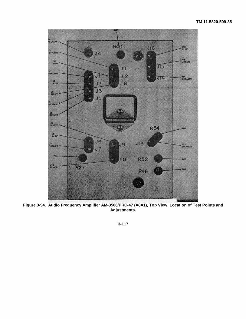
TM 11-5820-509-35
Figure 3-94. Audio Frequency Amplifier AM-3506/PRC-47 (A8A1), Top View, Location of Test Points andAdjustments.
3-117
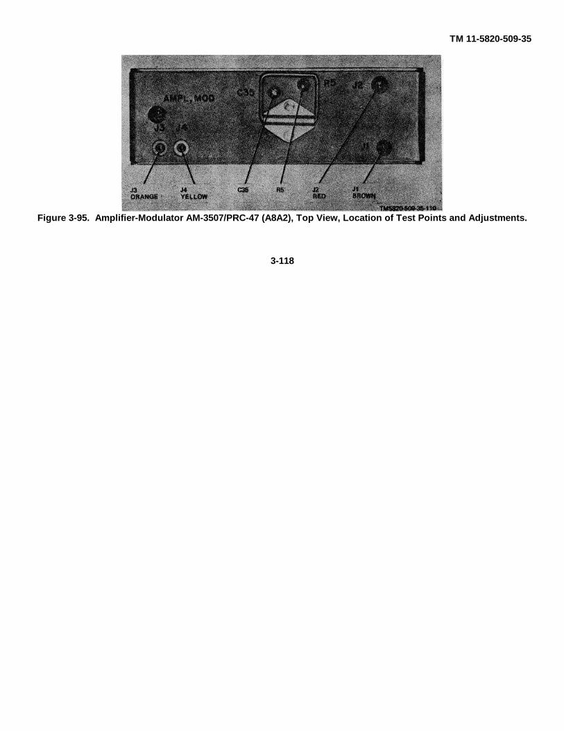
TM 11-5820-509-35
Figure 3-95. Amplifier-Modulator AM-3507/PRC-47 (A8A2), Top View, Location of Test Points and Adjustments.
3-118
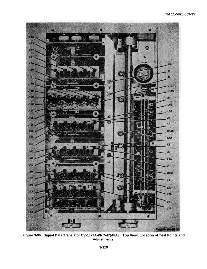
TM 11-5820-509-35
Figure 3-96. Signal Data Translator CV-1377A-PRC-47(A8A3), Top View, Location of Test Points andAdjustments.
3-119
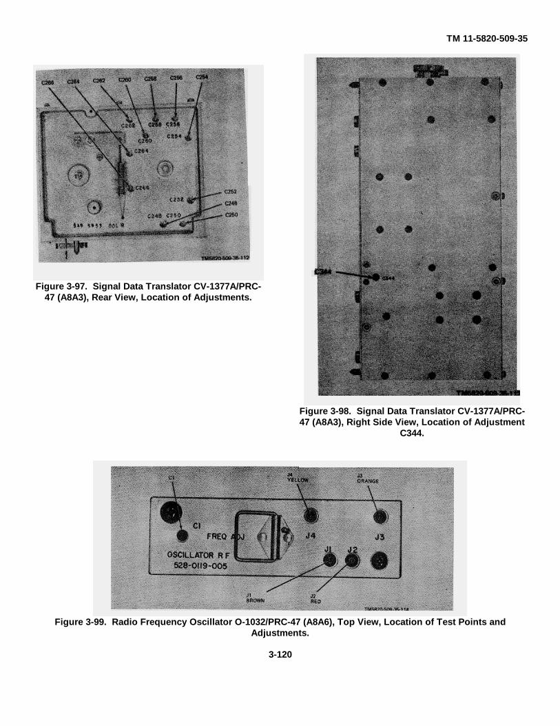
TM 11-5820-509-35
Figure 3-97. Signal Data Translator CV-1377A/PRC-47 (A8A3), Rear View, Location of Adjustments.
Figure 3-98. Signal Data Translator CV-1377A/PRC-47 (A8A3), Right Side View, Location of Adjustment
C344.
Figure 3-99. Radio Frequency Oscillator O-1032/PRC-47 (A8A6), Top View, Location of Test Points andAdjustments.
3-120
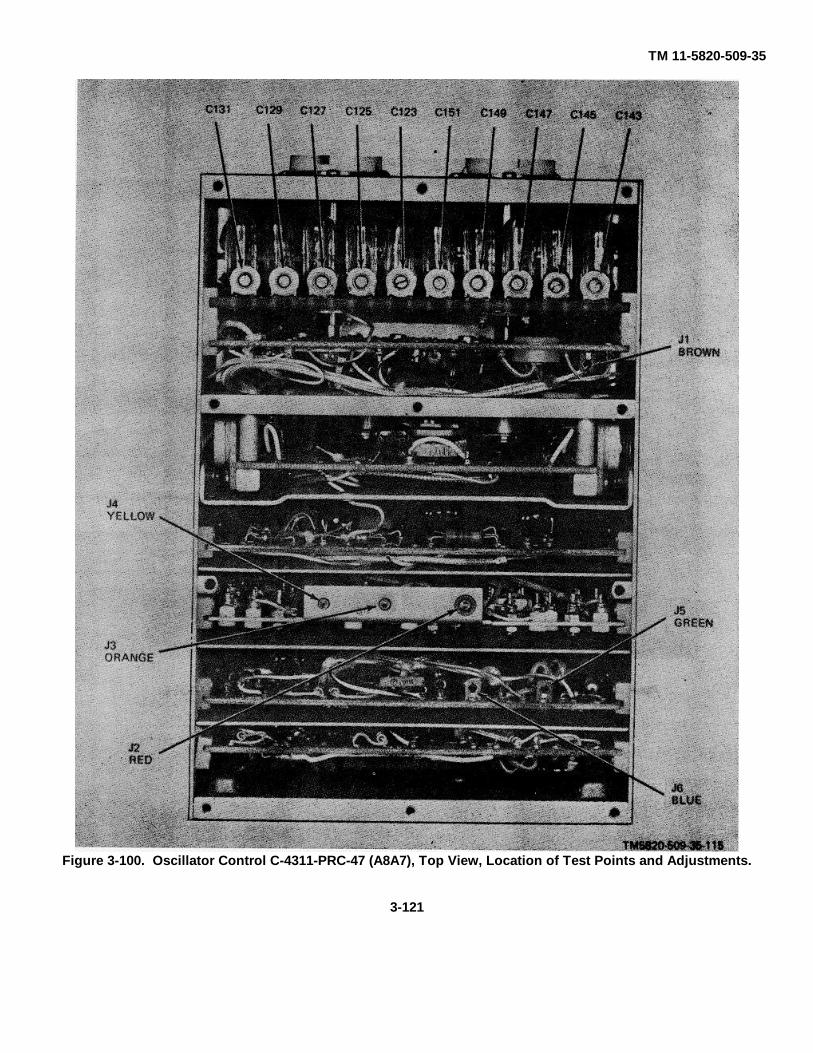
TM 11-5820-509-35
Figure 3-100. Oscillator Control C-4311-PRC-47 (A8A7), Top View, Location of Test Points and Adjustments.
3-121

TM 11-5820-509-35
Figure 3-101. Oscillator Control C-4311/PRC-47 (A8A7), Bottom View, Location of Adjustments.
3-122
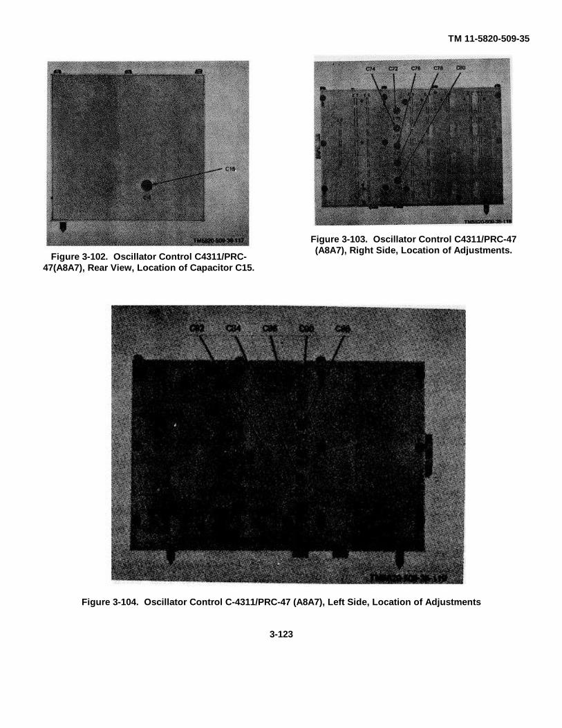
TM 11-5820-509-35
Figure 3-102. Oscillator Control C4311/PRC-47(A8A7), Rear View, Location of Capacitor C15.
Figure 3-103. Oscillator Control C4311/PRC-47(A8A7), Right Side, Location of Adjustments.
Figure 3-104. Oscillator Control C-4311/PRC-47 (A8A7), Left Side, Location of Adjustments
3-123
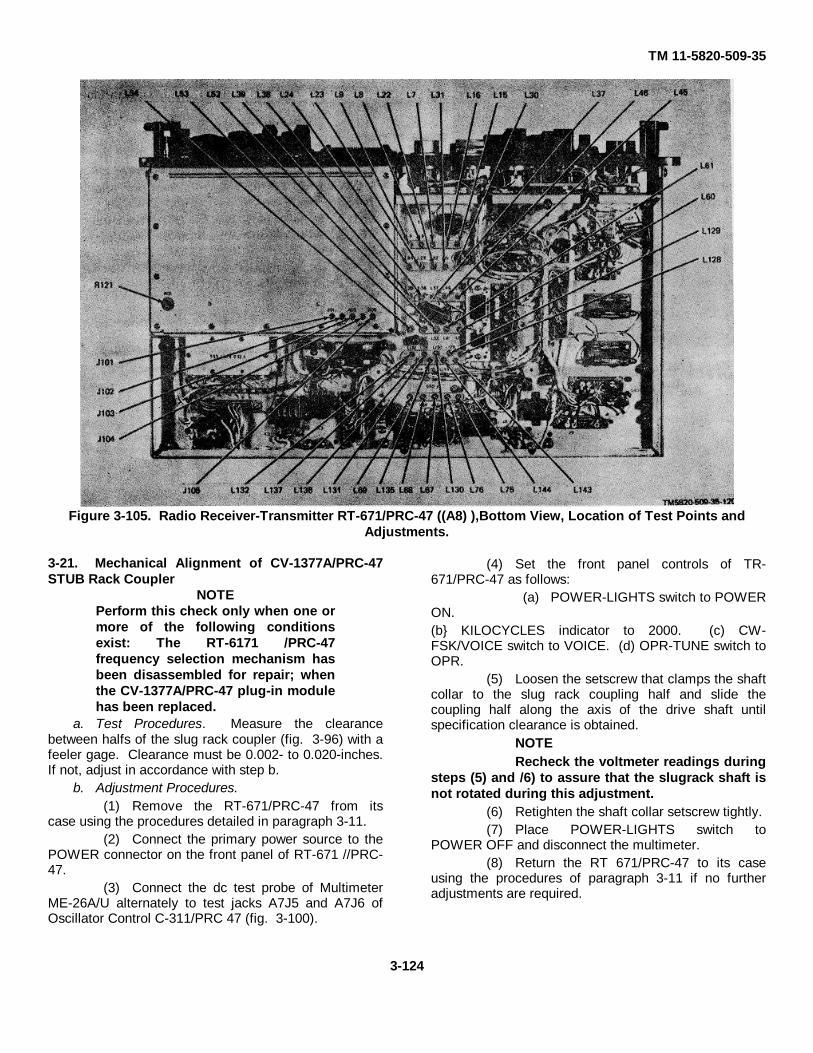
TM 11-5820-509-35
Figure 3-105. Radio Receiver-Transmitter RT-671/PRC-47 ((A8) ),Bottom View, Location of Test Points andAdjustments.
3-21. Mechanical Alignment of CV-1377A/PRC-47STUB Rack Coupler
NOTEPerform this check only when one ormore of the following conditionsexist: The RT-6171 /PRC-47frequency selection mechanism hasbeen disassembled for repair; whenthe CV-1377A/PRC-47 plug-in modulehas been replaced.
a. Test Procedures. Measure the clearancebetween halfs of the slug rack coupler (fig. 3-96) with afeeler gage. Clearance must be 0.002- to 0.020-inches.If not, adjust in accordance with step b.
b. Adjustment Procedures.(1) Remove the RT-671/PRC-47 from its
case using the procedures detailed in paragraph 3-11.(2) Connect the primary power source to the
POWER connector on the front panel of RT-671 //PRC-47.
(3) Connect the dc test probe of MultimeterME-26A/U alternately to test jacks A7J5 and A7J6 ofOscillator Control C-311/PRC 47 (fig. 3-100).
(4) Set the front panel controls of TR-671/PRC-47 as follows:
(a) POWER-LIGHTS switch to POWERON.(b} KILOCYCLES indicator to 2000. (c) CW-FSK/VOICE switch to VOICE. (d) OPR-TUNE switch toOPR.
(5) Loosen the setscrew that clamps the shaftcollar to the slug rack coupling half and slide thecoupling half along the axis of the drive shaft untilspecification clearance is obtained.
NOTERecheck the voltmeter readings during
steps (5) and /6) to assure that the slugrack shaft isnot rotated during this adjustment.
(6) Retighten the shaft collar setscrew tightly.(7) Place POWER-LIGHTS switch to
POWER OFF and disconnect the multimeter.(8) Return the RT 671/PRC-47 to its case
using the procedures of paragraph 3-11 if no furtheradjustments are required.
3-124
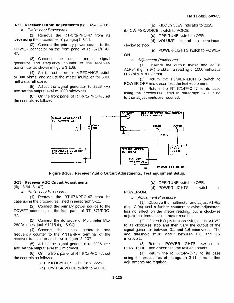
TM 11-5820-509-35
3-22. Receiver Output Adjustments (fig. 3-94, 3-106)a. Preliminary Procedures.
(1) Remove the RT-671/PRC-47 from itscase using the procedures of paragraph 3-11.
(2) Connect the primary power source to thePOWER connector on the front panel of RT-671/PRC-47.
(3) Connect the output meter, signalgenerator and frequency counter to the receiver-transmitter as shown in figure 3-106.
(4) Set the output meter IMPEDANCE switchto 300 ohms, and adjust the meter multiplier for 5000milliwatts full scale.
(5) Adjust the signal generator to 2226 kHzand set the output level to 1000 microvolts.
(6) On the front panel of RT-671/PRC-47, setthe controls as follows:
(a) KILOCYCLES indicator to 2225.(b} CW-FSK/VOICE: switch to VOICE.
(c) OPR-TUNE switch to OPR.(d) VOLUME control to maximum
clockwise stop.(e) POWER-LIGHTS switch to POWER
ON.b. Adjustment Procedures.
(1) Observe the output meter and adjustA1R54 (fig. 3-94) to obtain a reading of 1000 milliwatts(18 volts in 300 ohms).
(2) Return the POWER-LIGHTS switch toPOWER OFF and disconnect the test equipment.
(3) Return the RT-671/PRC-47 to its caseusing the procedures listed in paragraph 3-11 if nofurther adjustments are required.
Figure 3-106. Receiver Audio Output Adjustments, Test Equipment Setup.
3-23. Receiver AGC Circuit Adjustments(fig. 3-94, 3-107)
a. Preliminary Procedures.(1) Remove the RT-671/PRC-47 from its
case using the procedures listed in paragraph 3-11.(2) Connect the primary power source to the
POWER connector on the front panel of RT- 671/PRC-47.
(3) Connect the dc probe of Multimeter ME-26A/V to test jack A1J15 (fig. 3-94).
(4) Connect the signal generator andfrequency counter to the ANTENNA terminal of thereceiver-transmitter as shown in figure 3- 107.
(5) Adjust the signal generator to 2226 kHzand set the output level to 1 microvolt.
(6) On the front panel of RT-671/PRC-47, setthe controls as follows:
(a) KILOCYCLES indicator to 2225.(b) CW FSK/VOICE switch to VOICE.
(c) OPR-TUNE switch to OPR.(d) POWER-LIGHTS switch to
POWER-ON.b. Adjustment Procedure.
(1) Observe the multimeter and adjust A1R52(fig. 3-94) until a further counterclockwise adjustmenthas no effect on the meter reading, but a clockwiseadjustment increases the meter reading.
(2) If step b (1) is unsuccessful, adjust A1R52to its clockwise stop and then vary the output of thesignal generator between 0.1 and 1.6 microvolts. Theagc threshold must occur between 0.6 and 1.2microvolts.
(3) Return POWER-LIGHTS switch toPOWER OFF and disconnect the test equipment.
(4) Return the RT-671/PRC-47 to its caseusing the procedures of paragraph 3-11 if no furtheradjustments are required.
3-125

TM 11-5820-509-35
Figure 3-107. Receiver AGC Circuit Adjustment, Test Equipment Setup.
3-24. Transmitter Sidetone Adjustment(fig. 3-94, 3-108)
a. Preliminary Procedures.
(1) Remove the RT-671/PRC-47 from itscase using the procedures of paragraph 3-11.
(2) Connect the primary power source to thePOWER connector on the front panel of RT-671 /PRC-47.
(3) Connect the output meter and dummyload to the receiver-transmitter as shown in figure 3-108.
(4) Set the output meter IMPEDANCE switchto 300 ohms, and adjust the meter multiplier for 500milliwatts full scale.
(5) On the front panel of RT-671/PRC-47, setthe controls as follows:
(a) KILOCYCLES indicator to 2000.(b) CW-FSK/VOICE switch to VOICE.(c) OPR-TUNE switch to OPR.(d) XMTR PWR switch to LO.(e) VOLUME control to maximum
clock-wise stop.(f) POWER-LIGHTS switch to POWER
ON.
CAUTIONDo not permit the OPR-TUNE switchto remain in the TUNE position formore than a few seconds at a timewhile the POWER AMPLIFIER TUNEand POWER AMPLIFIER LOAD
controls are being adjusted. Circuitdamage can occur.
(6) Set the POWER AMPLIFIER LOAD andPOWER AMPLIFIER TUNE controls to the turnscounter values shown on the LOAD-TUNE chart; thenplace the OPR-TUNE switch to TUNE and quickly peakthe load and tune controls for maximum deflection ofthe XMTR OUTPUT meter.
NOTEAdjust M ADJ control as required tomaintain the XMTR OUTPUT meterpointer on a useful portion of thescale.
(7) Return the OPR-TUNE switch to OPR andset XMTR PWR switch to HI.
(8) Again place the OPR-TUNE switch toTUNE and peak the POWER AMPLIFIER LOAD andPOWER AMPLIFIER TUNE controls as necessary formaximum XMTR OUTPUT meter deflection.
b. Adjustment Procedures.
(1) Observe the output meter and adjustA1R46 (fig. 3-94) to obtain a reading of 100 milliwatts(5.5 volts in 300 ohms).
(2) Return the XMTR PWR switch to OFF,the POWER-LIGHTS switch to POWER OFF, anddisconnect the test equipment.
(3) Return the RT-671/PRC-47 to its caseusing the procedures of paragraph 3-11 if no furtheradjustments are required.
3-126
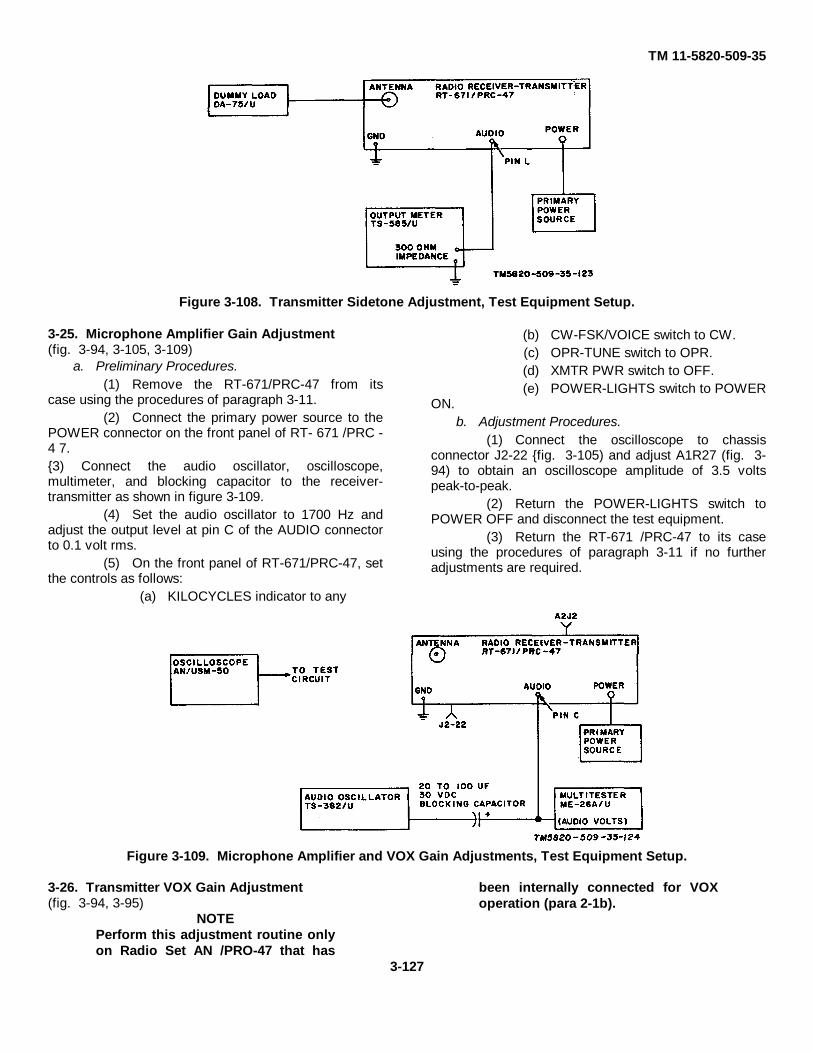
TM 11-5820-509-35
Figure 3-108. Transmitter Sidetone Adjustment, Test Equipment Setup.
3-25. Microphone Amplifier Gain Adjustment(fig. 3-94, 3-105, 3-109)
a. Preliminary Procedures.(1) Remove the RT-671/PRC-47 from its
case using the procedures of paragraph 3-11.(2) Connect the primary power source to the
POWER connector on the front panel of RT- 671 /PRC -4 7.{3) Connect the audio oscillator, oscilloscope,multimeter, and blocking capacitor to the receiver-transmitter as shown in figure 3-109.
(4) Set the audio oscillator to 1700 Hz andadjust the output level at pin C of the AUDIO connectorto 0.1 volt rms.
(5) On the front panel of RT-671/PRC-47, setthe controls as follows:
(a) KILOCYCLES indicator to any
(b) CW-FSK/VOICE switch to CW.(c) OPR-TUNE switch to OPR.(d) XMTR PWR switch to OFF.(e) POWER-LIGHTS switch to POWER
ON.b. Adjustment Procedures.
(1) Connect the oscilloscope to chassisconnector J2-22 {fig. 3-105) and adjust A1R27 (fig. 3-94) to obtain an oscilloscope amplitude of 3.5 voltspeak-to-peak.
(2) Return the POWER-LIGHTS switch toPOWER OFF and disconnect the test equipment.
(3) Return the RT-671 /PRC-47 to its caseusing the procedures of paragraph 3-11 if no furtheradjustments are required.
Figure 3-109. Microphone Amplifier and VOX Gain Adjustments, Test Equipment Setup.
3-26. Transmitter VOX Gain Adjustment(fig. 3-94, 3-95)
NOTEPerform this adjustment routine onlyon Radio Set AN /PRO-47 that has
been internally connected for VOXoperation (para 2-1b).
3-127
TM 11-5820-509-35
a. Preliminary Procedures.(1) Perform the microphone amplifier gain
adjustment procedures detailed in paragraph 3-25 a (1)through 3-25 b (1).
(2) Reduce the audio oscillator output to 0.01+ 0.002 volts rms as indicated on the multimeter.
b. Adjustment Procedures.(1) Connect the oscilloscope to test jack A2J2
(fig. 3 95).(2) Adjust A1R40 (fig. 3-94) until a 500-kHz
signal appears on the oscilloscope trace. (this indicatesthe operation of vox relay A1K1.)
(3) Return the POWER-LIGHTS switch toPOWER OFF and disconnect the test equipment.
(4) Return the RT-671/PRC-47 to its caseusing the procedures of paragraph 3-11 if no furtheradjustments are required.3-27. Power Amplifier Grid Drive Alignment and
Bias Adjustments(fig. 3-96, 3-105, 3-110)
NOTEPerform this alignment routine onlyafter it has been determined that anequipment malfunction is caused byimproper alignment (tracking) ofSignal Data Translator CV-1377A/PRC-47 (A8A3).
a. Preliminary Procedures.(1) Remove the RT-671/PRC-47 from its
case using the procedures of paragraph 3-11.(2) Connect the primary power source to the
POWER connector of RT-671/PRC-47.(3) Connect the rf probe of the multimeter to
test jack J104 (fig. 3-105) of the power amplifier.(4) Connect the antenna simulator of
AN/PRA-4 and the dummy load to the receiver-transmitter as shown in figure 3-110. Set the selectorswitch on the antenna simulator to the 2.0 MHz position.
(5) On the front panel of RT-671/PRC-47, setthe controls as follows:
(a) KILOCYCLES indicator to 2000(b) CW-FSK/VOICE switch to VOICE.(c) OPR-TUNE switch to OPR.(d) XMTR PWR switch to LO.(e) POWER-LIGHTS switch to POWER
ON.CAUTION
Do not permit the OPR-TUNE switchto remain in the TUNE position formore than a few seconds at a timewhile the POWER AMPLIFIER LOAD
and the POWER AMPLIFIER TUNEcontrols are being adjusted. Circuitdamage can occur.
(6) Set the POWER AMPLIFIER LOAD andPOWER AMPLIFIER TUNE controls to the turns-counter values indicated on the LOAD-TUNE chart; thenplace the OPR-TUNE switch to TUNE and quickly peakthe load and tune controls for maximum deflection ofthe pointer on the XMTR OUTPUT meter.
NOTEAdjust M ADJ control as required tomaintain the XMTR OUTPUT meterpointer on the useful portion of themeter scale.
(7) Return the OPR-TUNE switch to OPR andset the XMTR PWR switch to HI.
(8) Again place the OPR-TUNE switch toTUNE and peak the POWER AMPLIFIER LOAD andPOWER AMPLIFIER TUNE controls as necessary formaximum XMTR OUTPUT meter deflection.
b. Alignment Procedures.(1) Adjust A3L67 (fig. 3-105) for maximum rf
grid drive as indicated on the multimeter connected totest point J104.
(2) On the front panel of RT-671/PRC-47,place the OPR-TUNE switch to OPR, set theKILOCYCLES indicator to 3000, and place the XMTRPWR switch to LO. On the antenna simulator rotate theselector switch to 3.0 MHz position; then repeat steps(6) through (8) of the preliminary procedures above.
(3) Adjust A3L68 (fig. 3-105) for maximum rfgrid drive as indicated by the multimeter connected totest point J104.
(4) Repeat step b (2) except setKILOCYCLES indicator to 4000 and set the rotary switchon the antenna simulator to the 4.0 MHz position.
(5) Adjust A3L69 (fig. 3-105) for maximum rfgrid drive as indicated by the multimeter connected totest point J104.
(6) Repeat step b (2) except setKILOCYCLES indicator to 5000 and set the rotary switchon the antenna simulator to the 5.0 M H z position.
(7) Adjust A3L70 (fig. 3-96) for maximum rfgrid drive as indicated by the multimeter connected totest point J104.
(8) Repeat step b (2) except setKILOCYCLES indicator to 6000 and set the rotary switchon the antenna simulator to the 6.0 MHz position.
(9) Adjust A3L71 (fig. 3-96) for maximum rfgrid drive as indicated by the multimeter connected totest pint J104.
(10) Repeat step b (2) except set
3-128

TM 11-5820-509-35
KILOCYCLES indicator to 7000 and set the rotary switchon the antenna simulator to the 7.0 MHz position.
(11) Adjust A3L72 (fig. 3-96) for maximum rfgrid drive as indicated by the multimeter connected totest point J104.
(12) Repeat step b (2) except setKILOCYCLES indicator to 8000 and set the rotary switchon the antenna simulator to the 8.0 MHz position.
(13) Adjust A3L73 (fig. 3-96) for maximum rfgrid cave as indicated by the multimeter connected toteat point J104.
(14) Repeat step b (2) except setKILOCYCLES indicator to 9000 and set the rotary switchon the antenna simulator to the 9.0 MHz position.
(15) Adjust A3L74 (fig. 3-96) for maximum rfgrid drive as indicated by the multimeter connected totest point J104.
(16) Repeat step b (2) except setKILOCYCLES indicator to 10000 and set the rotaryswitch on the antenna simulator to the 10.0 MHzposition.
(17) Adjust A3L76 (fig. 3-105) for maximum rfgrid drive as indicated by the multimeter connected totest point J104.
(18) Repeat step b (2) except setKILOCYCLES indicator to 11000 and set the rotary
switch on the antenna simulator to the 11.0 MHzposition.
(19) Adjust A3L76 (fig. 3-105) for maximum rfgrid drive as indicated by the multimeter connected toteat point J104.
c. Power Amplifier Bias Adjustments.NOTE
Perform these adjustments only aftercompleting the alignmentprocedures of step b above.
(1) Connect the dc probe of the multimeter tothe following test jacks on Power Supply PP.3518/PRC-47 (A8A5).
(a) At ABJ1 the correct reading is -32±1 volt; if not, adjust A5R4 as required.
(b) At A5J2 the correct reading is -110±13.3 volts; if not, adjust A5R3 as required.
(c) At A5J8 the correct reading is +19±0.6 volts; if not, adjust A5R22 as required.
(2) Return the XMTR PWR switch to OFF, thePOWER-LIGHTS switch to POWER OFF, disconnectthe test equipment, and return the RT-671/PRC-47 to itscase using the procedures of paragraph 3-11 if nofurther adjustments are required.
Figure 3-110. Power Amplifier Grid Drive Adjustment, Test Equipment Setup.
3-28. Temperature Compensated OscillatorFrequency Adjustment (fig. 3-111)
NOTEPerform this adjustment only if RadioFrequency Oscillator 0-1032/PRC-47(A8A6) has been repaired orreplaced, or if this module issuspected of generating an incorrectoutput frequency.
a. Preliminary Procedures.(1) Remove the RT-671/PRC-47 from its
case using the procedures of paragraph 3-11.
(2) Connect the primary power source to thePOWER connector of RT-671/PRC-47.
(3) Connect the frequency counter to test jackA6J4 (fig. 3-99) of Radio Frequency Oscillator O-1032/PRC-47.
(4) On the front panel of RT-671/PRC-47, setthe controls as follows:
(a) KILOCYCLES indicator to 2000.(b) CW-FSK/VOICE switch to VOICE.(c) OPR-TUNE switch to OPR.(d) XMTR PWR switch to OFF.(e) POWER-LIGHTS switch to POWER
3-129

TM 11-5820-509-35
Figure 3-111. Temperature Compensated Oscillator Rotor Frequency Adjustment Test Equipment Setup.
b. Alignment Procedures.
(1) Measure the output frequency using thefrequency counter connected to A6J4.
(2) If the output frequency does not readexactly 5000,000.0 Hz, adjust A6C1 (fig. 3-99) ON.
until the frequency counter readscorrectly.
(3) Return the POWER-LIGHTS switch toPOWER OFF and disconnect the test equipment.
(4) Return the RT-671/PRC-47 to its caseusing the procedures of paragraph 3-11 if no furtheradjustments are required.3-29. Balanced Modulator Adjustments(fig. 3-112)
a. Preliminary Procedures.(1) Remove the RT-671/PRC-47 from its
case using the procedures listed in paragraph 3-11.(2) Connect the primary power source to the
POWER connector on the front panel of RT 671 /PRC-47.
(3) Connect the dummy load to the receivertransmitter; extend Amplifier-Modulator AM 3507/PRC-47 (A8A2) from the main chassis of RT 671/PRC-47using extender cable no. 4 from Cable Assembly SetAN /PRA-4; then remove the module side cover toexpose the adjustment screw in the top of transformerT2.
(4) Set the front panel controls of RT-671/PRC-47 as follows:
(a) KILOCYCLES indicator to 2000.(b) CW-FSK/VOICE switch to VOICE.(c) OPR-TUNE switch to OPR.(d) XMTR PWR switch to LO.(e) POWER-LIGHTS switch to POWER
CAUTIONDo not permit the OPR-TUNE switchto remain in the TUNE position formore than a few seconds at a timewhile the POWER AMPLIFIER TUNEand POWER AMPLIFIER LOADcontrols are being adjusted. Circuitdamage can occur.
(5) Set the POWER AMPLIFIER TUNE andPOWER AMPLIFIER LOAD controls to the turns-counter values shown on the LOAD-TUNE chart.
(6) Place the OPR-TUNE switch to TUNE;quickly peak the POWER AMPLIFIER TUNE andPOWER AMPLIFIER LOAD controls for maximumdeflection on the XMTR OUTPUT meter. Immediatelyreturn the PPR-TUNE switch to OPR.
NOTEAdjust M ADJ control as required tomaintain the XMTR OUTPUT meterpointer on a useful portion of thescale.
(7) Place the XMTR PWR switch to HI andrepeat step (6).
3-130
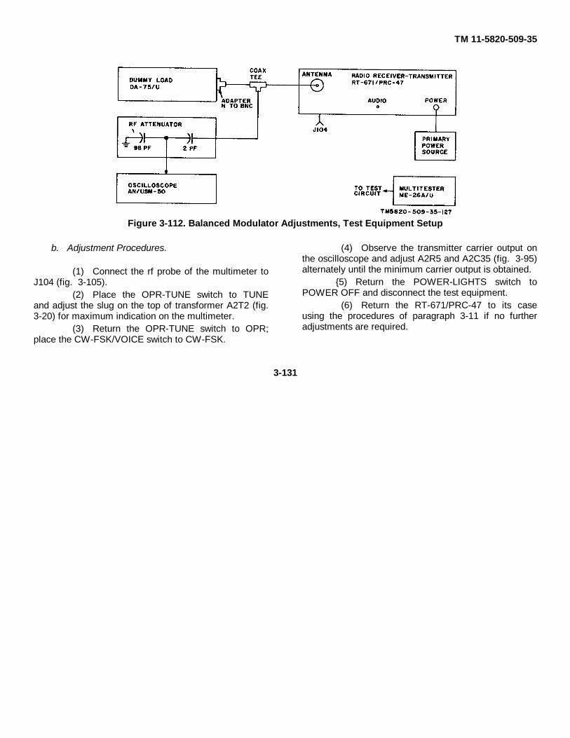
TM 11-5820-509-35
Figure 3-112. Balanced Modulator Adjustments, Test Equipment Setup
b. Adjustment Procedures.
(1) Connect the rf probe of the multimeter toJ104 (fig. 3-105).
(2) Place the OPR-TUNE switch to TUNEand adjust the slug on the top of transformer A2T2 (fig.3-20) for maximum indication on the multimeter.
(3) Return the OPR-TUNE switch to OPR;place the CW-FSK/VOICE switch to CW-FSK.
(4) Observe the transmitter carrier output onthe oscilloscope and adjust A2R5 and A2C35 (fig. 3-95)alternately until the minimum carrier output is obtained.
{5) Return the POWER-LIGHTS switch toPOWER OFF and disconnect the test equipment.
(6) Return the RT-671/PRC-47 to its caseusing the procedures of paragraph 3-11 if no furtheradjustments are required.
3-131
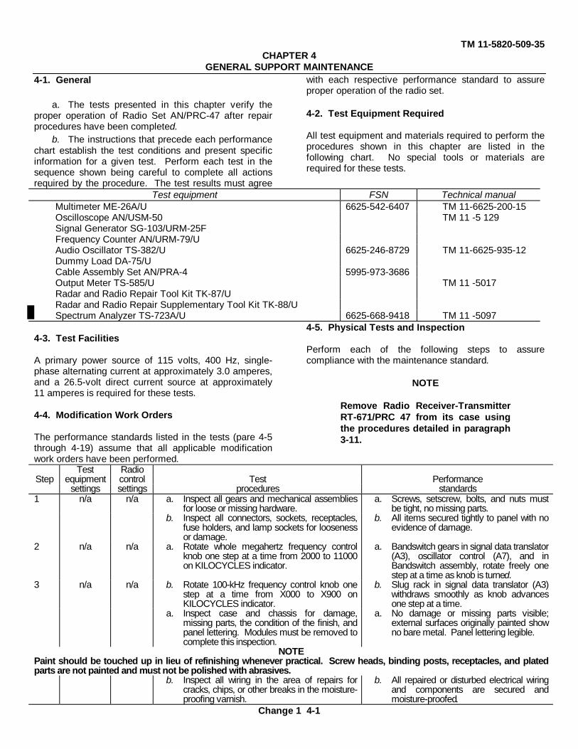
TM 11-5820-509-35CHAPTER 4
GENERAL SUPPORT MAINTENANCE4-1. General
a. The tests presented in this chapter verify theproper operation of Radio Set AN/PRC-47 after repairprocedures have been completed.
b. The instructions that precede each performancechart establish the test conditions and present specificinformation for a given test. Perform each test in thesequence shown being careful to complete all actionsrequired by the procedure. The test results must agree
with each respective performance standard to assureproper operation of the radio set.
4-2. Test Equipment Required
All test equipment and materials required to perform theprocedures shown in this chapter are listed in thefollowing chart. No special tools or materials arerequired for these tests.
Test equipment FSN Technical manualMultimeter ME-26A/U 6625-542-6407 TM 11-6625-200-15Oscilloscope AN/USM-50 TM 11 -5 129Signal Generator SG-103/URM-25FFrequency Counter AN/URM-79/UAudio Oscillator TS-382/U 6625-246-8729 TM 11-6625-935-12Dummy Load DA-75/UCable Assembly Set AN/PRA-4 5995-973-3686Output Meter TS-585/U TM 11 -5017Radar and Radio Repair Tool Kit TK-87/URadar and Radio Repair Supplementary Tool Kit TK-88/USpectrum Analyzer TS-723A/U 6625-668-9418 TM 11 -5097
4-3. Test Facilities
A primary power source of 115 volts, 400 Hz, single-phase alternating current at approximately 3.0 amperes,and a 26.5-volt direct current source at approximately11 amperes is required for these tests.
4-4. Modification Work Orders
The performance standards listed in the tests (pare 4-5through 4-19) assume that all applicable modificationwork orders have been performed.
4-5. Physical Tests and Inspection
Perform each of the following steps to assurecompliance with the maintenance standard.
NOTE
Remove Radio Receiver-TransmitterRT-671/PRC 47 from its case usingthe procedures detailed in paragraph3-11.
Test RadioStep equipment control Test Performance
settings settings procedures standards1 n/a n/a a. Inspect all gears and mechanical assemblies
for loose or missing hardware.a. Screws, setscrew, bolts, and nuts must
be tight, no missing parts.b. Inspect all connectors, sockets, receptacles,
fuse holders, and lamp sockets for loosenessor damage.
b. All items secured tightly to panel with noevidence of damage.
2 n/a n/a a. Rotate whole megahertz frequency controlknob one step at a time from 2000 to 11000on KILOCYCLES indicator.
a. Bandswitch gears in signal data translator(A3), oscillator control (A7), and inBandswitch assembly, rotate freely onestep at a time as knob is turned.
3 n/a n/a b. Rotate 100-kHz frequency control knob onestep at a time from X000 to X900 onKILOCYCLES indicator.
b. Slug rack in signal data translator (A3)withdraws smoothly as knob advancesone step at a time.
a. Inspect case and chassis for damage,missing parts, the condition of the finish, andpanel lettering. Modules must be removed tocomplete this inspection.
a. No damage or missing parts visible;external surfaces originally painted showno bare metal. Panel lettering legible.
NOTEPaint should be touched up in lieu of refinishing whenever practical. Screw heads, binding posts, receptacles, and platedparts are not painted and must not be polished with abrasives.
b. Inspect all wiring in the area of repairs forcracks, chips, or other breaks in the moisture-proofing varnish.
b. All repaired or disturbed electrical wiringand components are secured andmoisture-proofed.
Change 1 4-1
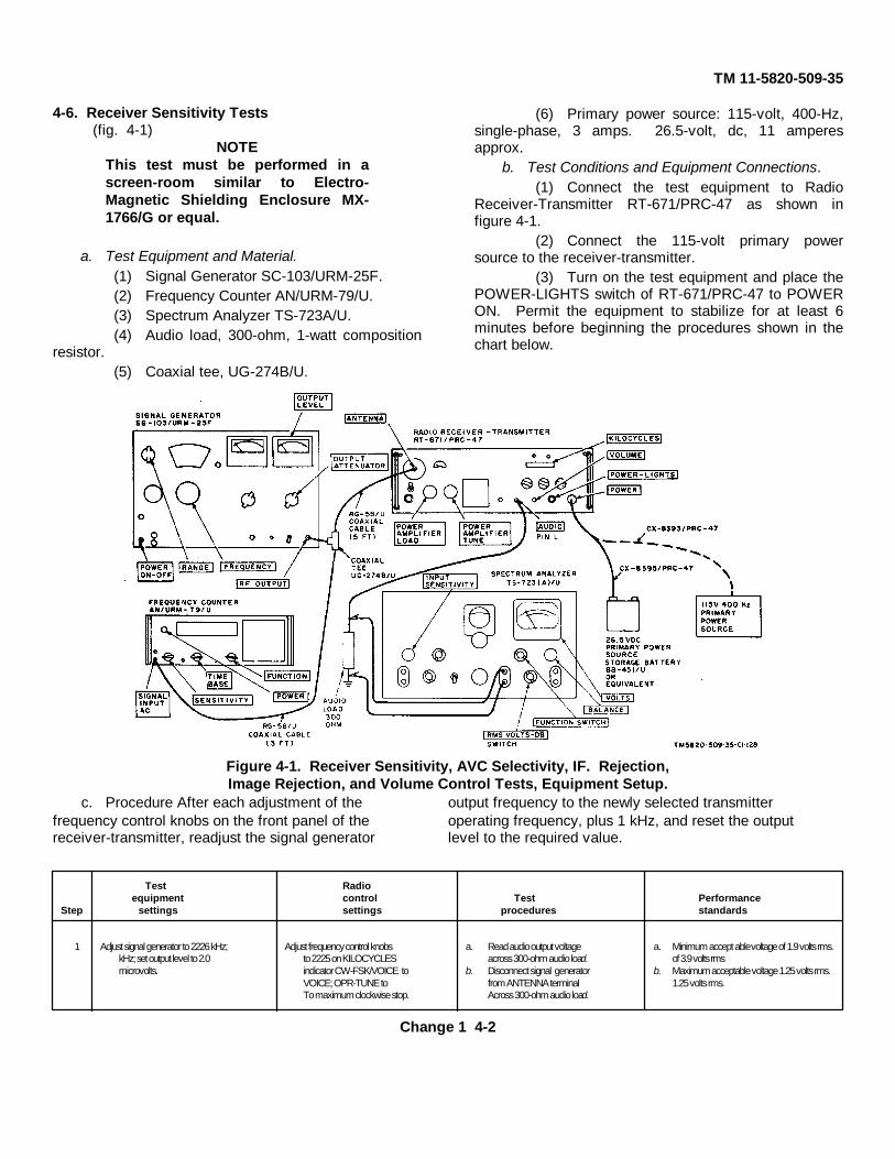
TM 11-5820-509-35
4-6. Receiver Sensitivity Tests(fig. 4-1)
NOTEThis test must be performed in ascreen-room similar to Electro-Magnetic Shielding Enclosure MX-1766/G or equal.
a. Test Equipment and Material.(1) Signal Generator SC-103/URM-25F.(2) Frequency Counter AN/URM-79/U.(3) Spectrum Analyzer TS-723A/U.(4) Audio load, 300-ohm, 1-watt composition
resistor.(5) Coaxial tee, UG-274B/U.
(6) Primary power source: 115-volt, 400-Hz,single-phase, 3 amps. 26.5-volt, dc, 11 amperesapprox.
b. Test Conditions and Equipment Connections.(1) Connect the test equipment to Radio
Receiver-Transmitter RT-671/PRC-47 as shown infigure 4-1.
(2) Connect the 115-volt primary powersource to the receiver-transmitter.
(3) Turn on the test equipment and place thePOWER-LIGHTS switch of RT-671/PRC-47 to POWERON. Permit the equipment to stabilize for at least 6minutes before beginning the procedures shown in thechart below.
Figure 4-1. Receiver Sensitivity, AVC Selectivity, IF. Rejection,Image Rejection, and Volume Control Tests, Equipment Setup.
c. Procedure After each adjustment of the output frequency to the newly selected transmitterfrequency control knobs on the front panel of the operating frequency, plus 1 kHz, and reset the outputreceiver-transmitter, readjust the signal generator level to the required value.
Test Radioequipment control Test Performance
Step settings settings procedures standards
1 Adjust signal generator to 2226 kHz; Adjust frequency control knobs a. Read audio output voltage a. Minimum accept able voltage of 1.9 volts rms.kHz; set output level to 2.0 to 2225 on KILOCYCLES across 300-ohm audio load. of 3.9 volts rmsmicrovolts. indicator CW-FSK/VOICE to b. Disconnect signal generator b. Maximum acceptable voltage 1.25 volts rms.
VOICE; OPR-TUNE to from ANTENNA terminal 1.25 volts rms.To maximum clockwise stop. Across 300-ohm audio load.
Change 1 4-2
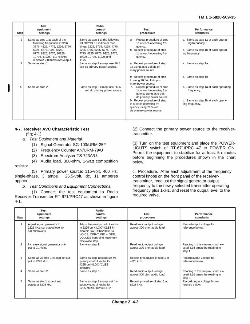
TM 1 1-5820-509-35
Test Radioequipment control Test Performance
Step settings settings procedures standards
2 Same as step 1 at each of the Same as step 1 at the following a. Repeat procedure of step a. Same as step 1a at each operat-following frequencies: 3226, KILOCYCLES indicator read- 1a at each operating fre- ing frequency.3776, 4226, 4776, 5226, 5776, dings: 3225, 3775, 4225, 4775, quency.6226, 6776,7226, 8226, 5225,5775, 6225, 6775, 7225, b. Repeat procedure of step b. Same as step 1b at each operat-8776, 9226, 9776, 10226, 7775, 8225, 8775, 9225, 9775, 1b at each operating fre- ing frequency.10776, 11226. 11776 kHz; 10225,10775, 11225,and quency.maintain 2.0 microvolts output. 1175.
3 Same as step 1 . Same as step 1 except use 26.5 a. Repeat procedure of step a. Same as step 1a.volt dc primary power source. 1a using 26.5-volt dc pri-
mary power source.
b. Repeat procedure of step b. Same as step 1blb using 26.5-volt dc pri-mary power source.
4. Same as step 2. Same as step 2 except use 26. 5 a. Repeat procedure of step a. Same as step 1a at each operatingvolt dc primary power source. 1a at each operating fre- frequency.
quency using 26.5-voltdc primary power source.
b. Repeat procedure of step b. Same as step 1b at each opera-lb at each operating fre- ting frequency.quency using 26.5-voltde primary power source.
4-7. Receiver AVC Characteristic Test(fig; 4-1)
a. Test Equipment and Material.(1) Signal Generator SG-103/URM-25F(2) Frequency Counter AN/URM-79/U(3) Spectrum Analyzer TS 723A/U.(4) Audio load, 300-ohm, 1-watt composition
resistor.(5) Primary power source: 115-volt, 400 Hz,
single-phase, 3 amps. 26.5-volt, dc, 11 amperesapprox.
b. Test Conditions and Equipment Connections.(1) Connect the test equipment to Radio
Receiver-Transmitter RT-671/PRC47 as shown in figure4-1.
(2) Connect the primary power source to the receiver-transmitter.
(3) Turn on the test equipment and place the POWER-LIGHTS switch of RT-671/PRC 47 to POWER ON.Permit the equipment to stabilize for at least 5 minutesbefore beginning the procedures shown in the chartbelow.
c. Procedure. After each adjustment of the frequencycontrol knobs on the front panel of the receiver-transmitter, readjust the signal generator outputfrequency to the newly selected transmitter operatingfrequency plus 1kHz, and reset the output level to therequired valve.
Test Radioequipment control Test Performance
Step settings settings procedures standards
1 Adjust signal generator to Adjust frequency control knobs Read audio output voltage Record output voltage for2226 kHz; set output level to to 2225 on KILOCYCLES in- across 300-ohm audio load. reference below.5.0 microvolts. dicator; CW-FSK/VOICE to
VOICE; OPR-TUNE to OPR;VOLUME control to maximumclockwise stop.
2 Increase signal generator out- Same as step 1. Read audio output voltage Reading in this step must not ex-put to 0.1 volts. across 300-ohm audio load. ceed 3.16 times the reading in
step 1.
3 Same as 35 step 1 except set cut- Same as step 1except set fre- Repeat procedures of step 1 at Record output voltage forput to 4226 kHz. quency control knobs for 4225 kHz. reference below.
4225 on KILOCYCLESindicator.
4 Same as step 2. Same as step 3. Read audio output voltage Reading in this step must not ex-across 300 ohm audio load. ceed 3.16 times the reading in
step 3.5 Same as step1 except set Same as step 1 except set fre- Repeat procedure of step 1 at Record output voltage for re-
output at 6226 kHz. quency control knobs for 6225 kHz. ference below.6225 on KILOCYCLES in-
Change 2 4-3
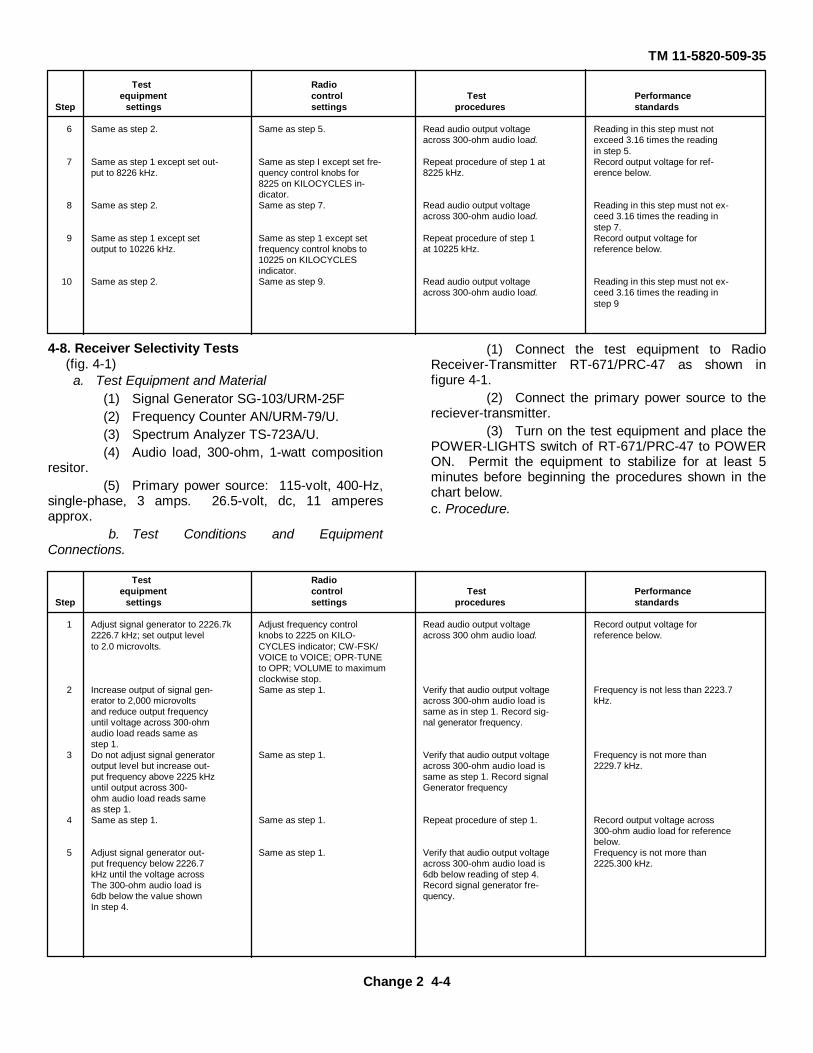
TM 11-5820-509-35
Test Radioequipment control Test Performance
Step settings settings procedures standards
6 Same as step 2. Same as step 5. Read audio output voltage Reading in this step must notacross 300-ohm audio load. exceed 3.16 times the reading
in step 5.7 Same as step 1 except set out- Same as step I except set fre- Repeat procedure of step 1 at Record output voltage for ref-
put to 8226 kHz. quency control knobs for 8225 kHz. erence below.8225 on KILOCYCLES in-dicator.
8 Same as step 2. Same as step 7. Read audio output voltage Reading in this step must not ex-across 300-ohm audio load. ceed 3.16 times the reading in
step 7.9 Same as step 1 except set Same as step 1 except set Repeat procedure of step 1 Record output voltage for
output to 10226 kHz. frequency control knobs to at 10225 kHz. reference below.10225 on KILOCYCLESindicator.
10 Same as step 2. Same as step 9. Read audio output voltage Reading in this step must not ex-across 300-ohm audio load. ceed 3.16 times the reading in
step 9
4-8. Receiver Selectivity Tests(fig. 4-1)a. Test Equipment and Material
(1) Signal Generator SG-103/URM-25F(2) Frequency Counter AN/URM-79/U.(3) Spectrum Analyzer TS-723A/U.(4) Audio load, 300-ohm, 1-watt composition
resitor.(5) Primary power source: 115-volt, 400-Hz,
single-phase, 3 amps. 26.5-volt, dc, 11 amperesapprox.
b. Test Conditions and EquipmentConnections.
(1) Connect the test equipment to RadioReceiver-Transmitter RT-671/PRC-47 as shown infigure 4-1.
(2) Connect the primary power source to thereciever-transmitter.
(3) Turn on the test equipment and place thePOWER-LIGHTS switch of RT-671/PRC-47 to POWERON. Permit the equipment to stabilize for at least 5minutes before beginning the procedures shown in thechart below.c. Procedure.
Test Radioequipment control Test Performance
Step settings settings procedures standards
1 Adjust signal generator to 2226.7k Adjust frequency control Read audio output voltage Record output voltage for2226.7 kHz; set output level knobs to 2225 on KILO- across 300 ohm audio load. reference below.to 2.0 microvolts. CYCLES indicator; CW-FSK/
VOICE to VOICE; OPR-TUNEto OPR; VOLUME to maximumclockwise stop.
2 Increase output of signal gen- Same as step 1. Verify that audio output voltage Frequency is not less than 2223.7erator to 2,000 microvolts across 300-ohm audio load is kHz.and reduce output frequency same as in step 1. Record sig-until voltage across 300-ohm nal generator frequency.audio load reads same asstep 1.
3 Do not adjust signal generator Same as step 1. Verify that audio output voltage Frequency is not more thanoutput level but increase out- across 300-ohm audio load is 2229.7 kHz.put frequency above 2225 kHz same as step 1. Record signaluntil output across 300- Generator frequencyohm audio load reads sameas step 1.
4 Same as step 1. Same as step 1. Repeat procedure of step 1. Record output voltage across300-ohm audio load for referencebelow.
5 Adjust signal generator out- Same as step 1. Verify that audio output voltage Frequency is not more thanput frequency below 2226.7 across 300-ohm audio load is 2225.300 kHz.kHz until the voltage across 6db below reading of step 4.The 300-ohm audio load is Record signal generator fre-6db below the value shown quency.In step 4.
Change 2 4-4
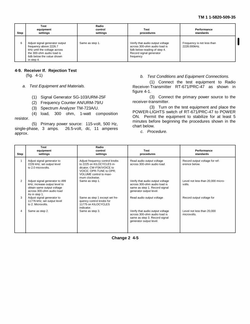
TM 1 1-5820-509-35
Test Radioequipment control Test Performance
Step settings settings procedures standards
6 Adjust signal generator output Same as step 1. Verify that audio output voltage Frequency is not less thanfrequency above 2226.7 across 300-ohm audio load is 2228.000kHz.kHz until the voltage across 6db below reading of step 4.the 300-ohm audio load is Record signal generator6db below the value shown frequencyin step 4.
4-9. Receiver If. Rejection Test(fig. 4-1)
a. Test Equipment and Materials.
(1) Signal Generator SG-103/URM-25F(2) Frequency Counter AN/URM-79/U(3) Spectrum Analyzer TM-723A/U.(4) load, 300 ohm, 1-watt composition
resistor.(5) Primary power source: 115-volt, 500 Hz,
single-phase, 3 amps. 26.5-volt, dc, 11 amperesapprox.
b. Test Conditions and Equipment Connections.(1) Connect the test equipment to Radio
Receiver-Transmitter RT-671/PRC-47 as shown infigure 4-1.
(3) Connect the primary power source to thereceiver-transmitter.
(3) Turn on the test equipment and place thePOWER-LIGHTS switch of RT-671/PRC-47 to POWERON. Permit the equipment to stabilize for at least 5minutes before beginning the procedures shown in thechart below.
c. Procedure.
Test Radioequipment control Test Performance
Step settings settings procedures standards
1 Adjust signal generator to Adjust frequency control knobs Read audio output voltage Record output voltage for ref-2226 kHz; set output level to 2225 on KILOCYCLES in- across 300-ohm audio load. erence below.to 2.0 microvolts. dicator; CW-FSK/VOICE to
VOICE; OPR-TUNE to OPR;VOLUME control to maxi-mum clockwise.
2 Adjust signal generator to 499 Same as step 1. Verify that audio output voltage Level not less than 20,000 micro-kHz; increase output level to across 300-ohm audio load is volts.obtain same output voltage same as step 1. Record signalacross 300-ohm audio load generator output level.As in step 1.
3 Adjust signal generator to Same as step 1 except set fre- Read audio output voltage Record output voltage for11776 kHz; set output level quency control knobs forto 2. Microvolts. 11775 on KILOCYCLES
indicator.4 Same as step 2. Same as step 3. Verify that audio output voltage Level not less than 20,000
across 300-ohm audio load is microvolts.same as step 3. Record signalgenerator output level.
Change 2 4-5
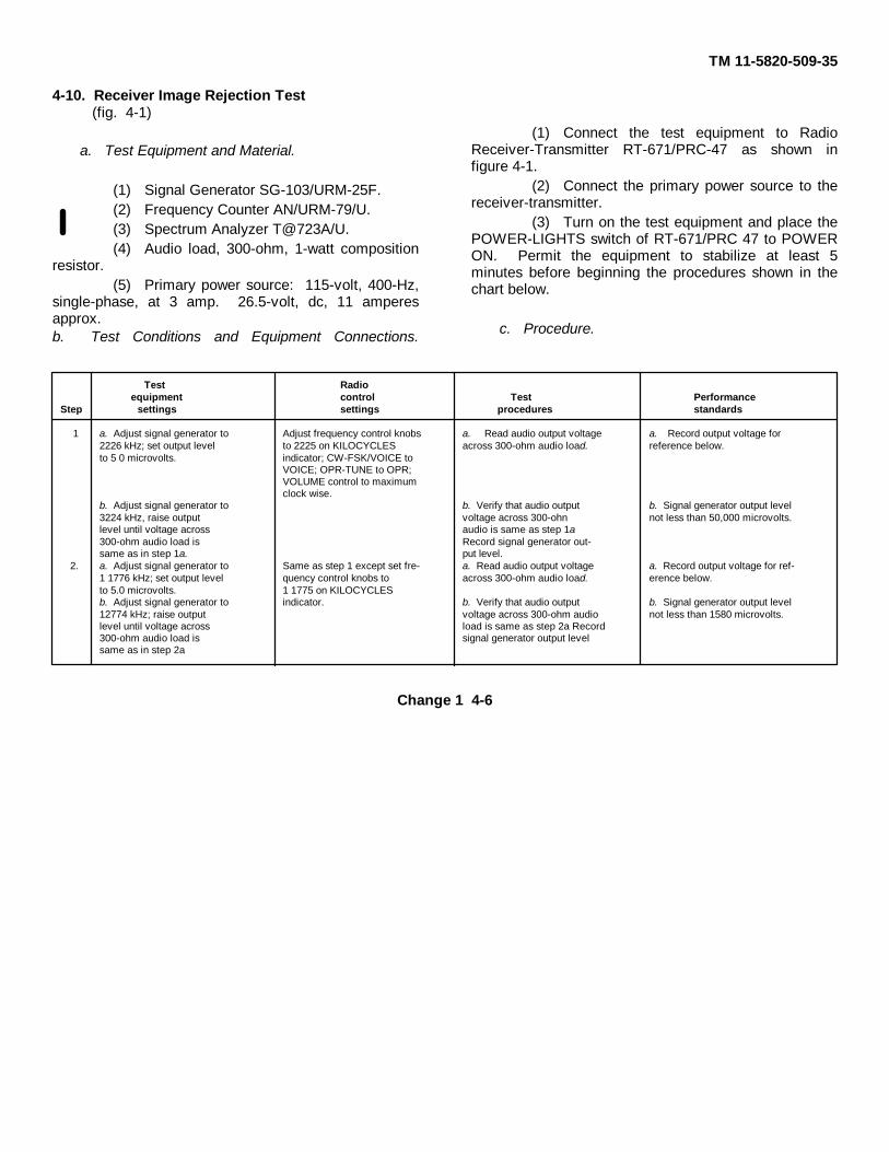
TM 11-5820-509-35
4-10. Receiver Image Rejection Test(fig. 4-1)
a. Test Equipment and Material.
(1) Signal Generator SG-103/URM-25F.(2) Frequency Counter AN/URM-79/U.(3) Spectrum Analyzer T@723A/U.(4) Audio load, 300-ohm, 1-watt composition
resistor.(5) Primary power source: 115-volt, 400-Hz,
single-phase, at 3 amp. 26.5-volt, dc, 11 amperesapprox.b. Test Conditions and Equipment Connections.
(1) Connect the test equipment to RadioReceiver-Transmitter RT-671/PRC-47 as shown infigure 4-1.
(2) Connect the primary power source to thereceiver-transmitter.
(3) Turn on the test equipment and place thePOWER-LIGHTS switch of RT-671/PRC 47 to POWERON. Permit the equipment to stabilize at least 5minutes before beginning the procedures shown in thechart below.
c. Procedure.
Test Radioequipment control Test Performance
Step settings settings procedures standards
1 a. Adjust signal generator to Adjust frequency control knobs a. Read audio output voltage a. Record output voltage for2226 kHz; set output level to 2225 on KILOCYCLES across 300-ohm audio load. reference below.to 5 0 microvolts. indicator; CW-FSK/VOICE to
VOICE; OPR-TUNE to OPR;VOLUME control to maximumclock wise.
b. Adjust signal generator to b. Verify that audio output b. Signal generator output level3224 kHz, raise output voltage across 300-ohn not less than 50,000 microvolts.level until voltage across audio is same as step 1a300-ohm audio load is Record signal generator out-same as in step 1a. put level.
2. a. Adjust signal generator to Same as step 1 except set fre- a. Read audio output voltage a. Record output voltage for ref-1 1776 kHz; set output level quency control knobs to across 300-ohm audio load. erence below.to 5.0 microvolts. 1 1775 on KILOCYCLESb. Adjust signal generator to indicator. b. Verify that audio output b. Signal generator output level12774 kHz; raise output voltage across 300-ohm audio not less than 1580 microvolts.level until voltage across load is same as step 2a Record300-ohm audio load is signal generator output levelsame as in step 2a
Change 1 4-6
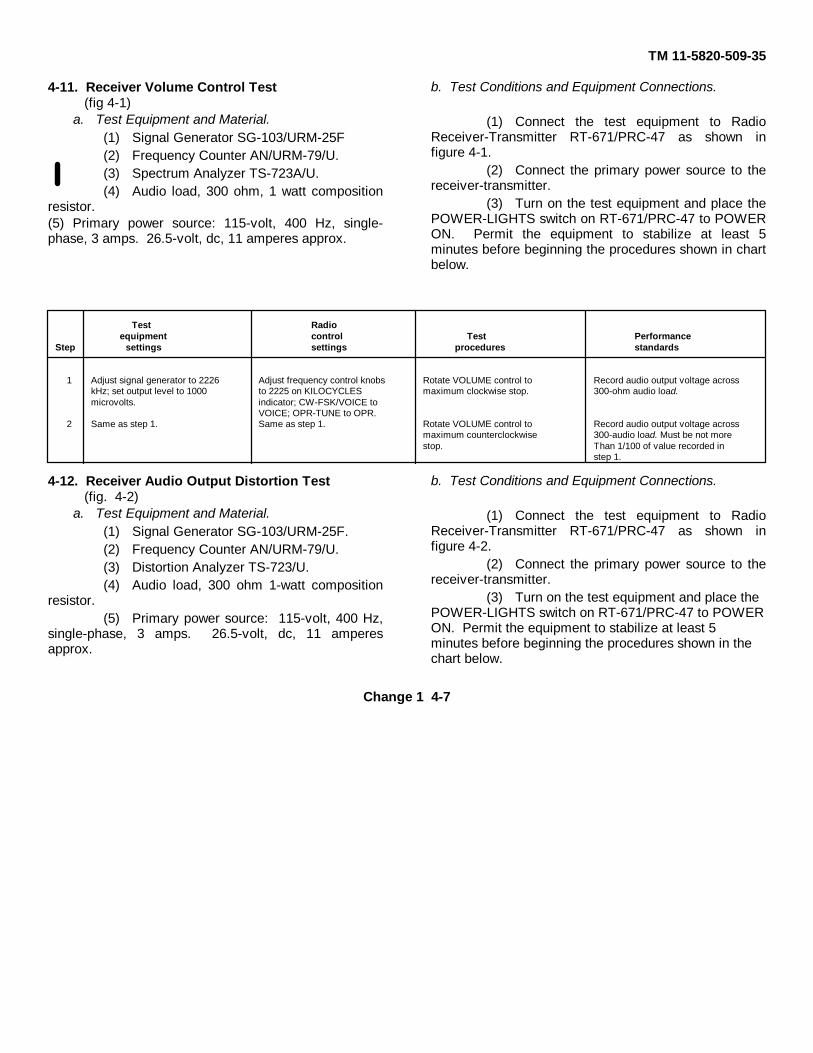
TM 11-5820-509-35
4-11. Receiver Volume Control Test(fig 4-1)
a. Test Equipment and Material.(1) Signal Generator SG-103/URM-25F(2) Frequency Counter AN/URM-79/U.(3) Spectrum Analyzer TS-723A/U.(4) Audio load, 300 ohm, 1 watt composition
resistor.(5) Primary power source: 115-volt, 400 Hz, single-phase, 3 amps. 26.5-volt, dc, 11 amperes approx.
b. Test Conditions and Equipment Connections.
(1) Connect the test equipment to RadioReceiver-Transmitter RT-671/PRC-47 as shown infigure 4-1.
(2) Connect the primary power source to thereceiver-transmitter.
(3) Turn on the test equipment and place thePOWER-LIGHTS switch on RT-671/PRC-47 to POWERON. Permit the equipment to stabilize at least 5minutes before beginning the procedures shown in chartbelow.
Test Radioequipment control Test Performance
Step settings settings procedures standards
1 Adjust signal generator to 2226 Adjust frequency control knobs Rotate VOLUME control to Record audio output voltage acrosskHz; set output level to 1000 to 2225 on KILOCYCLES maximum clockwise stop. 300-ohm audio load.microvolts. indicator; CW-FSK/VOICE to
VOICE; OPR-TUNE to OPR.2 Same as step 1. Same as step 1. Rotate VOLUME control to Record audio output voltage across
maximum counterclockwise 300-audio load. Must be not morestop. Than 1/100 of value recorded in
step 1.
4-12. Receiver Audio Output Distortion Test(fig. 4-2)
a. Test Equipment and Material.(1) Signal Generator SG-103/URM-25F.(2) Frequency Counter AN/URM-79/U.(3) Distortion Analyzer TS-723/U.(4) Audio load, 300 ohm 1-watt composition
resistor.(5) Primary power source: 115-volt, 400 Hz,
single-phase, 3 amps. 26.5-volt, dc, 11 amperesapprox.
b. Test Conditions and Equipment Connections.
(1) Connect the test equipment to RadioReceiver-Transmitter RT-671/PRC-47 as shown infigure 4-2.
(2) Connect the primary power source to thereceiver-transmitter.
(3) Turn on the test equipment and place thePOWER-LIGHTS switch on RT-671/PRC-47 to POWERON. Permit the equipment to stabilize at least 5minutes before beginning the procedures shown in thechart below.
Change 1 4-7
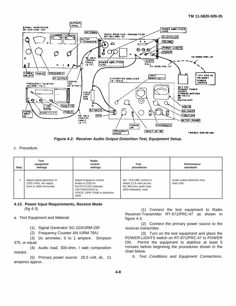
TM 11-5820-509-35
Figure 4-2. Receiver Audio Output Distortion Test, Equipment Setup.
c. Procedure.
Test Radioequipment control Test Performance
Step settings settings procedures standards
1 Adjust signal generator to Adjust frequency control Set VOLUME control to Audio output distortion less2225.3 kHz: set output knobs to 2225 on obtain 12.9 volts across than 15%.level to 1000 microvolts KILOCYCLES indicator: the 300-ohm audio load
CW-FSK/VOICE to (500 milliwatts); readVOICE: OPR-TUNE to distortion.OPR.
4-13. Power Input Requirements, Receive Mode(fig 4-3)
a. Test Equipment and Material.
(1) Signal Generator SG-103/URM-25F(2) Frequency Counter AN /URM 79/U(3) Dc ammeter, 0 to 1 ampere. Simpson
375, or equal.(4) Audio load, 300-ohm, I watt composition
resistor.(5) Primary power source: 26.5 volt, dc. 11
amperes approx .
(1) Connect the test equipment to RadioReceiver-Transmitter RT-671/PRC-47 as shown infigure 4-3.
(2) Connect the primary power source to thereceiver-transmitter.
(3) Turn on the test equipment and place thePOWER-LIGHTS switch on RT-671/PRC-47 to POWERON. Permit the equipment to stabilize at least 5minutes before beginning the procedures shown in thechart below.
b. Test Conditions and Equipment Connections.
4-8

TM 11-5820-509-35
Figure 4-3. Receiver Power Input Requirements, Equipment Setup.
c. Procedure.
Test Radioequipment control Test Performance
Step settings settings procedures standards
1 Adjust signal generator to Adjust frequency control Read dc ammeter. Dc ammeter reads not more2226 kHz; set output level knobs to 2225 on than 0.875 amperes.to 1000 microvolts. KILOCYCLES indicator;
CW-FSK/VOICE toVOICE; OPR-TUNE toOPR.
4-14. Transmitter Power Output Test(fig. 4-4)
a. Test Equipment and Material.
(1) Antenna simulator (p/o Cable AssemblySet AN/PRA-4)
(2) Dummy Load DA-75/13(3) Multimeter ME-26A/U(4) Primary power source: 26.5-volt, dc, 11
amperes approx.b. Test Conditions and Equipment Connections.
(1) Connect the test equipment to Radio Receiver-Transmitter RT-671/PRC-47 as shown in figure 4-4.
(2) Connect the primary power source to the receiver-transmitter.
(3) Turn on the test equipment and place the POWER-LIGHTS switch on RT-671/PRC-47 to POWER ON.Permit the equipment to stabilize at least 5 minutesbefore beginning the procedures shown in the chartbelow.
4-9

TM 11-5820-509-35
Figure 4-4. Transmitter Power Output and Output Meter Sensitivity Tests, Equipment Setup.
c. Procedure.
(1) Set the selector switch on the antennasimulator to the 2000 kHz position.
(2) On RT-671/PRC-47, set theKILOCYCLES indicator to 2000; place CW-FSK/VOICEswitch to VOICE; XMTR PWR switch to LO; and OPR-TUNE switch to OAR.
(3) Place the turns-counters of POWERAMPLIFIER TUNE and POWER AMPLIFIER LOADcontrols to the settings recommended on the LOAD-TUNE chart on the front of the receiver-transmitter.
CAUTIONBefore making the followingmeasurements, resonate the POWER
AMPLIFIER TUNE and POWER AMPLIFIER LOADcontrols on the front of the receiver-transmitter formaximum deflection on the XMTR OUTPUT meter.Use the OPR-TUNE switch to control power amplifierplate power. Do not permit the power amplifier tooperate for more than a few seconds in the unloaded oroff-resonant condition, serious equipment damage canresult. Between each procedural step of the followingchart, resonate the power amplifier output circuit at thenew operating frequency.
Test Radioequipment control Test Performance
Step settings settings procedures standards
1 a. Set vtvm RANGE switch a. Place OPR-TUNE switch a. Read rf voltage across a. Vtvm reads not less thanto 30 VOLTS. to TUNE. dummy load. 13.7 volts rms.b. n/a b. n/a b. Immediately return b. n/a
OPH-TUNE switch toOPR.
c. Set vtvm RANGE switch c. Place XMTR PWR c. Read rf voltage across c. Vtvm reads not less thanto 100 VOLTS. switch to HI; then place dummy load. 30.7 volts rms.
OPR-TUNE to TUNE.d. n/a d. n/a d. Immediately return d. n/a
OPR-TUNE switch toOPR: then place XMTRPWR switch to LO
4-10

TM 11-5820-509-35
Test Radioequipment control Test Performance
Step settings settings procedures standards
2 a. Same as step 1a. Set a. Same as step 1a except a. Read rf voltage across a. Vtvm reads not less thanswitch on antenna adjust KILOCYCLES dummy load. 15.3 volts rms.simulator to 3000 kHz indicator to 3000.position.b. n/a b. n/a b. Immediately return b. n/a
OPR-TUNE switch toOPR.
c. Same as step 1c. c. Same as step 1c. c. Read rf voltage across c. Vtvm reads not less thandummy load. 34.3 volts rms.
d. n/a d. n/a d. Immediately return d. n/aOPR-TUNE switch toOPR: then place XMTRPWR switch to LO.
3 a. Same as step 1a; set a. Same as step la except a. Read rf voltage across a. Vtvm reads not less thanswitch on antenna adjust KILOCYCLES dummy load. 16.8 volts rms.simulator to 4000 kHz indicator to 4000.position.b. n/a b. n/a b. Immediately return b. n/a
OPR-TUNE switch toOPR.
c. Same as step 1c. c. Same as step 1c. c. Read rf voltage across c. Vtvm reads not less thandummy load. 38.9 volts rms.
d. n/a d. n/a d. Immediately return d. n/aOPR-TUNE switch toOPR: then place XMTRPWR switch to LO.
4 a. Same as step 1a; set a. Same as step 1a except a. Read rf voltage across a. Vtvm reads not less thanswitch on antenna adjust KILOCYCLES dummy load. 19.4 volts rms.Simulator to 5000 kHz indicator to 5000.position.b. n/a b. n/a b. Immediately return b. n/a
OPR-TUNE switch toOPR.
c. Same as step 1c. c. Same as step 1c. c. Read rf voltage across c. Vtvm reads not less thandummy load. 43.4 volts rms.
d. n/a d. n/a d. Immediately return d. n/aOPR-TUNE switch toOPR; then place XMTRPWR switch to LO.
5 a. Same as step 1a; set a. Same as step la except a. Read rf voltage across a. Vtvm reads not less thanswitch on antenna adjust KILOCYCLES dummy load. 20.6 volts rms.simulator to 6000 kHz indicator to 6000.position.b. n/a b. n/a b. Immediately return b. n/a
OPR-TUNE switch toOPR.
c. Same as step 1c. c. Same as step 1c. c. Read rf voltage across c. Vtvm reads not less thandummy load. 47.5 volts rms.
d. n/a d. n/a d. Immediately return d. n/aOPR-TUNE switch toOPR; then place XMTRPWR switch to LO.
6 a. Same as step 1a; set a. Same as step 1a except a. Read rf voltage across a. Vtvm reads not less thanswitch on antenna adjust KILOCYCLES dummy load. 22.7 volts rms.Simulator to 7000 kHz indicator to 7000.b. n/a b. N/a b. Immediately return b. n/a
OPR-TUNE switch toOPR.
c. Same as step 1c. c. Same as step 1c. c. Read rf voltage across c. Vtvm reads not less thandummy load. 50.4 volts rms.
d. n/a d. n/a d. Immediately return d. n/aOPR-TUNE switch toOPR; then place XMTRPWR switch to LO.
4-11

TM 11-5820-509-35
Test Radioequipment control Test Performance
Step settings settings procedures standards
7 a. Same as step 1a; set a. Same as step 1a except a. Read rf voltage across a. Vtvm reads not less thanswitch on antenna adjust KILOCYCLES dummy load. 23.8 volts rms.Simulator to 8000 kHz indicator to 8000.position.b. n/a b. n/a b. Immediately return b. n/a
OPR-TUNE switch toOPR.
c. Same as step 1c. c. Same as step 1c. c. Read rf voltage across c. Vtvm reads not less thandummy load. 53.2 volts rms.
d. n/a d. n/a d. Immediately return d. n/aOPR-TUNE switch toOPR; then place XMTRPWR switch to LO.
8 a. Same as step 1a; set a. Same as step 1a except a. Read rf voltage across a. Vtvm reads not less thanswitch on antenna adjust KII.OCYCLES dummy load. 24.7 volts rms.simulator to 9000 kHz indicator to 9000.position.b. n/a b. n/a b. Immediately return b. n/a
OPR-TUNE switch toOPR.
c. Same as step 1c. c. Same as step 1c. c. Read rf voltage across c. Vtvm reads not less thandummy load. 55.3 volts rms.
d. n/a d. n/a d. Immediately return d. n/aOPR-TUNE switch toOPR; then place XMTRPWR switch to LO.
9 a. Same as step 1a; set a. Same as step la except a. Read rf voltage across a. Vtvm reads not less thanswitch on antenna adjust KILOCYCLES dummy load. 25.7 volts rms.simulator to 10,000 kHz indicator to 10000.position.b. n/a b. n/a b. Immediately return b. n/a
OPR-TUNE switch toOPR.
c. Same as step 1c. c. Same as step 1c. c. Read rf voltage across c. Vtvm reads not less thandummy load. 57.4 volts rms.
d. n/a d. n/a d. Immediately return d. n/aOPR-TUNE switch toOPR; then place XMTRPWR switch to LO.
10 a. Same as step 1a: set a. Same as step la except a. Read rf voltage across a. Vtvm reads not less thanswitch on antenna adjust KILOCYCLES dummy load. 26.6 volts rms.simulator to 11,000 kHz indicator to 11000.position.b. n/a b. n/a b. Immediately return b. n/a
OPR-TUNE switch toOPR.
c. Same as step 1c. c. Same as step 1c. c. Read rf voltage across c. Vtvm reads not less thandummy load. 59.0 volts rms.
d. n/a d. n/a d. Immediately return d. n/aOPR-TUNI switch toOPR; then place XMTRPWR switch to L1,O.
11 a. Same as step 1a: set a. Same as step 1a except a. Read rf voltage across a. Vtvm reads not less thanswitch on antenna adjust KILOCYCLES dummy load. 26.6 volts rms.simulator to 11,999 kHz indicator to 11999.position.b. n/a b. n/a b. Immediately return b. n/a
OPR-TUNE switch toOPR.
c. Same as step 1c. c. Same as step 1c. c. Read rf voltage across c. Vtvm reads not less thandummy load 59.8 volts rms.
d. n/a d. n/a d. Immediately return d. n/aOPRH-TUNF. switch toOPR;: then place XMTRPWR switch to 1,()
4-12
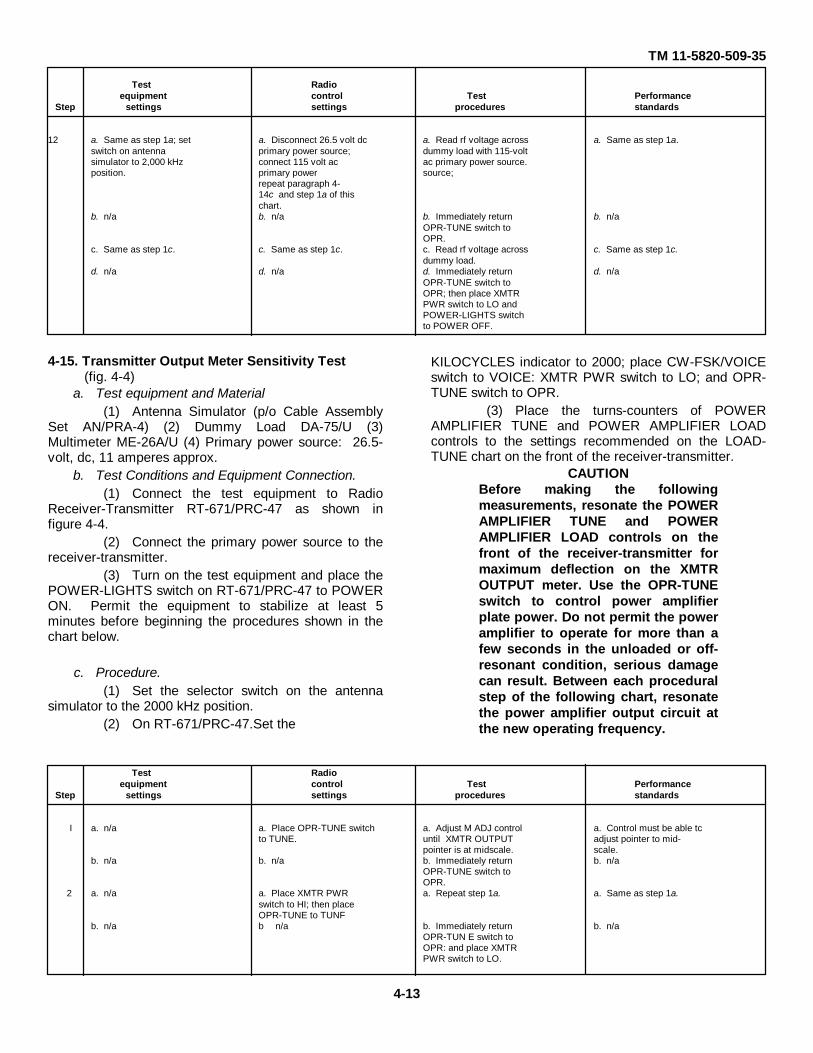
TM 11-5820-509-35
Test Radioequipment control Test Performance
Step settings settings procedures standards
12 a. Same as step 1a; set a. Disconnect 26.5 volt dc a. Read rf voltage across a. Same as step 1a.switch on antenna primary power source; dummy load with 115-voltsimulator to 2,000 kHz connect 115 volt ac ac primary power source.position. primary power source;
repeat paragraph 4-14c and step 1a of thischart.
b. n/a b. n/a b. Immediately return b. n/aOPR-TUNE switch toOPR.
c. Same as step 1c. c. Same as step 1c. c. Read rf voltage across c. Same as step 1c.dummy load.
d. n/a d. n/a d. Immediately return d. n/aOPR-TUNE switch toOPR; then place XMTRPWR switch to LO andPOWER-LIGHTS switchto POWER OFF.
4-15. Transmitter Output Meter Sensitivity Test(fig. 4-4)
a. Test equipment and Material(1) Antenna Simulator (p/o Cable Assembly
Set AN/PRA-4) (2) Dummy Load DA-75/U (3)Multimeter ME-26A/U (4) Primary power source: 26.5-volt, dc, 11 amperes approx.
b. Test Conditions and Equipment Connection.(1) Connect the test equipment to Radio
Receiver-Transmitter RT-671/PRC-47 as shown infigure 4-4.
(2) Connect the primary power source to thereceiver-transmitter.
(3) Turn on the test equipment and place thePOWER-LIGHTS switch on RT-671/PRC-47 to POWERON. Permit the equipment to stabilize at least 5minutes before beginning the procedures shown in thechart below.
c. Procedure.(1) Set the selector switch on the antenna
simulator to the 2000 kHz position.(2) On RT-671/PRC-47.Set the
KILOCYCLES indicator to 2000; place CW-FSK/VOICEswitch to VOICE: XMTR PWR switch to LO; and OPR-TUNE switch to OPR.
(3) Place the turns-counters of POWERAMPLIFIER TUNE and POWER AMPLIFIER LOADcontrols to the settings recommended on the LOAD-TUNE chart on the front of the receiver-transmitter.
CAUTIONBefore making the followingmeasurements, resonate the POWERAMPLIFIER TUNE and POWERAMPLIFIER LOAD controls on thefront of the receiver-transmitter formaximum deflection on the XMTROUTPUT meter. Use the OPR-TUNEswitch to control power amplifierplate power. Do not permit the poweramplifier to operate for more than afew seconds in the unloaded or off-resonant condition, serious damagecan result. Between each proceduralstep of the following chart, resonatethe power amplifier output circuit atthe new operating frequency.
Test Radioequipment control Test Performance
Step settings settings procedures standards
I a. n/a a. Place OPR-TUNE switch a. Adjust M ADJ control a. Control must be able tcto TUNE. until XMTR OUTPUT adjust pointer to mid-
pointer is at midscale. scale.b. n/a b. n/a b. Immediately return b. n/a
OPR-TUNE switch toOPR.
2 a. n/a a. Place XMTR PWR a. Repeat step 1a. a. Same as step 1a.switch to HI; then placeOPR-TUNE to TUNF
b. n/a b n/a b. Immediately return b. n/aOPR-TUN E switch toOPR: and place XMTRPWR switch to LO.
4-13
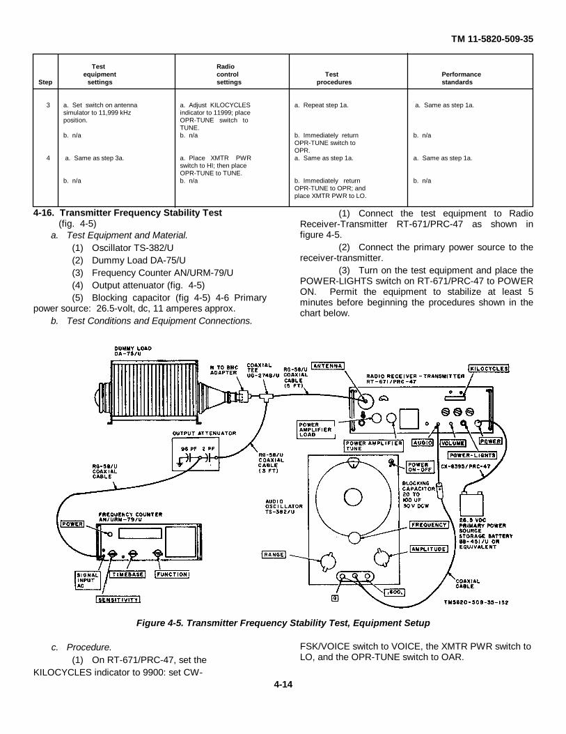
TM 11-5820-509-35
Test Radioequipment control Test Performance
Step settings settings procedures standards
3 a. Set switch on antenna a. Adjust KILOCYCLES a. Repeat step 1a. a. Same as step 1a.simulator to 11,999 kHz indicator to 11999; placeposition. OPR-TUNE switch to
TUNE.b. n/a b. n/a b. Immediately return b. n/a
OPR-TUNE switch toOPR.
4 a. Same as step 3a. a. Place XMTR PWR a. Same as step 1a. a. Same as step 1a.switch to HI; then placeOPR-TUNE to TUNE.
b. n/a b. n/a b. Immediately return b. n/aOPR-TUNE to OPR; andplace XMTR PWR to LO.
4-16. Transmitter Frequency Stability Test(fig. 4-5)
a. Test Equipment and Material.(1) Oscillator TS-382/U(2) Dummy Load DA-75/U(3) Frequency Counter AN/URM-79/U(4) Output attenuator (fig. 4-5)(5) Blocking capacitor (fig 4-5) 4-6 Primary
power source: 26.5-volt, dc, 11 amperes approx.b. Test Conditions and Equipment Connections.
(1) Connect the test equipment to RadioReceiver-Transmitter RT-671/PRC-47 as shown infigure 4-5.
(2) Connect the primary power source to thereceiver-transmitter.
(3) Turn on the test equipment and place thePOWER-LIGHTS switch on RT-671/PRC-47 to POWERON. Permit the equipment to stabilize at least 5minutes before beginning the procedures shown in thechart below.
Figure 4-5. Transmitter Frequency Stability Test, Equipment Setup
c. Procedure.(1) On RT-671/PRC-47, set the
KILOCYCLES indicator to 9900: set CW-
FSK/VOICE switch to VOICE, the XMTR PWR switch toLO, and the OPR-TUNE switch to OAR.
4-14
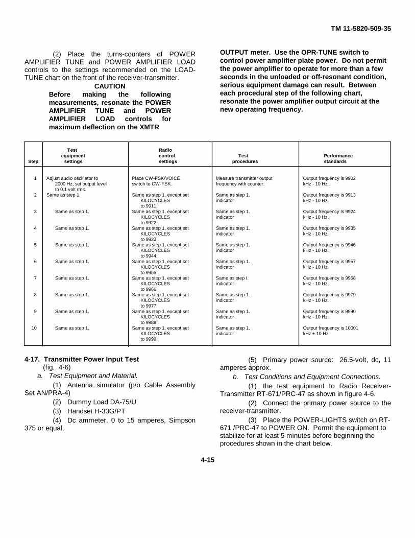
TM 11-5820-509-35
(2) Place the turns-counters of POWERAMPLIFIER TUNE and POWER AMPLIFIER LOADcontrols to the settings recommended on the LOAD-TUNE chart on the front of the receiver-transmitter.
CAUTIONBefore making the followingmeasurements, resonate the POWERAMPLIFIER TUNE and POWERAMPLIFIER LOAD controls formaximum deflection on the XMTR
OUTPUT meter. Use the OPR-TUNE switch tocontrol power amplifier plate power. Do not permitthe power amplifier to operate for more than a fewseconds in the unloaded or off-resonant condition,serious equipment damage can result. Betweeneach procedural step of the following chart,resonate the power amplifier output circuit at thenew operating frequency.
Test Radioequipment control Test Performance
Step settings settings procedures standards
1 Adjust audio oscillator to Place CW-FSK/VOICE Measure transmitter output Output frequency is 99022000 Hz; set output level switch to CW-FSK. frequency with counter. kHz - 10 Hz.to 0.1 volt rms.
2 Same as step 1. Same as step 1, except set Same as step 1. Output frequency is 9913KILOCYCLES indicator kHz - 10 Hz.to 9911.
3 Same as step 1. Same as step 1, except set Same as step 1. Output frequency Is 9924KILOCYCLES indicator kHz - 10 Hz.to 9922.
4 Same as step 1. Same as step 1, except set Same as step 1. Output frequency is 9935KILOCYCLES indicator kHz - 10 Hz.to 9933.
5 Same as step 1. Same as step 1, except set Same as step 1. Output frequency is 9946KILOCYCLES indicator kHz - 10 Hz.to 9944.
6 Same as step 1. Same as step 1, except set Same as step 1. Output frequency is 9957KILOCYCLES indicator kHz - 10 Hz.to 9955.
7 Same as step 1. Same as step 1, except set Same as step I. Output frequency is 9968KILOCYCLES indicator kHz - 10 Hz.to 9966.
8 Same as step 1. Same as step 1, except set Same as step 1. Output frequency is 9979KILOCYCLES indicator kHz - 10 Hz.to 9977.
9 Same as step 1. Same as step 1, except set Same as step 1. Output frequency is 9990KILOCYCLES indicator kHz - 10 Hz.to 9988.
10 Same as step 1. Same as step 1, except set Same as step 1. Output frequency is 10001KILOCYCLES indicator kHz ± 10 Hz.to 9999.
4-17. Transmitter Power Input Test(fig. 4-6)
a. Test Equipment and Material.(1) Antenna simulator (p/o Cable Assembly
Set AN/PRA-4)(2) Dummy Load DA-75/U(3) Handset H-33G/PT(4) Dc ammeter, 0 to 15 amperes, Simpson
375 or equal.
(5) Primary power source: 26.5-volt, dc, 11amperes approx.
b. Test Conditions and Equipment Connections.(1) the test equipment to Radio Receiver-
Transmitter RT-671/PRC-47 as shown in figure 4-6.(2) Connect the primary power source to the
receiver-transmitter.(3) Place the POWER-LIGHTS switch on RT-
671 /PRC-47 to POWER ON. Permit the equipment tostabilize for at least 5 minutes before beginning theprocedures shown in the chart below.
4-15
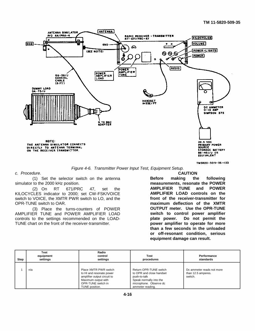
TM 11-5820-509-35
Figure 4-6. Transmitter Power Input Test, Equipment Setup.c. Procedure.
(1) Set the selector switch on the antennasimulator to the 2000 kHz position.
(2) On RT 671/PRC 47, set theKILOCYCLES indicator to 2000; set CW-FSK/VOICEswitch to VOICE, the XMTR PWR switch to LO, and theOPR-TUNE switch to OAR.
(3) Place the turns-counters of POWERAMPLIFIER TUNE and POWER AMPLIFIER LOADcontrols to the settings recommended on the LOAD-TUNE chart on the front of the receiver-transmitter.
CAUTIONBefore making the followingmeasurements, resonate the POWERAMPLIFIER TUNE and POWERAMPLIFIER LOAD controls on thefront of the receiver-transmitter formaximum deflection of the XMTROUTPUT meter. Use the OPR-TUNEswitch to control power amplifierplate power. Do not permit thepower amplifier to operate for morethan a few seconds in the unloadedor off-resonant condition, seriousequipment damage can result.
Test Radioequipment control Test Performance
Step settings settings procedures standards
1 n/a Place XMTR PWR switch Return OPR-TUNE switch Dc ammeter reads not moreto HI and resonate power to OPR and close handset than 12.5 amperes.amplifier output circuit to push-to-talk switch.Maximum output with Speak normally into theOPR-TUNE switch in microphone. Observe dcTUNE position. ammeter reading.
4-16
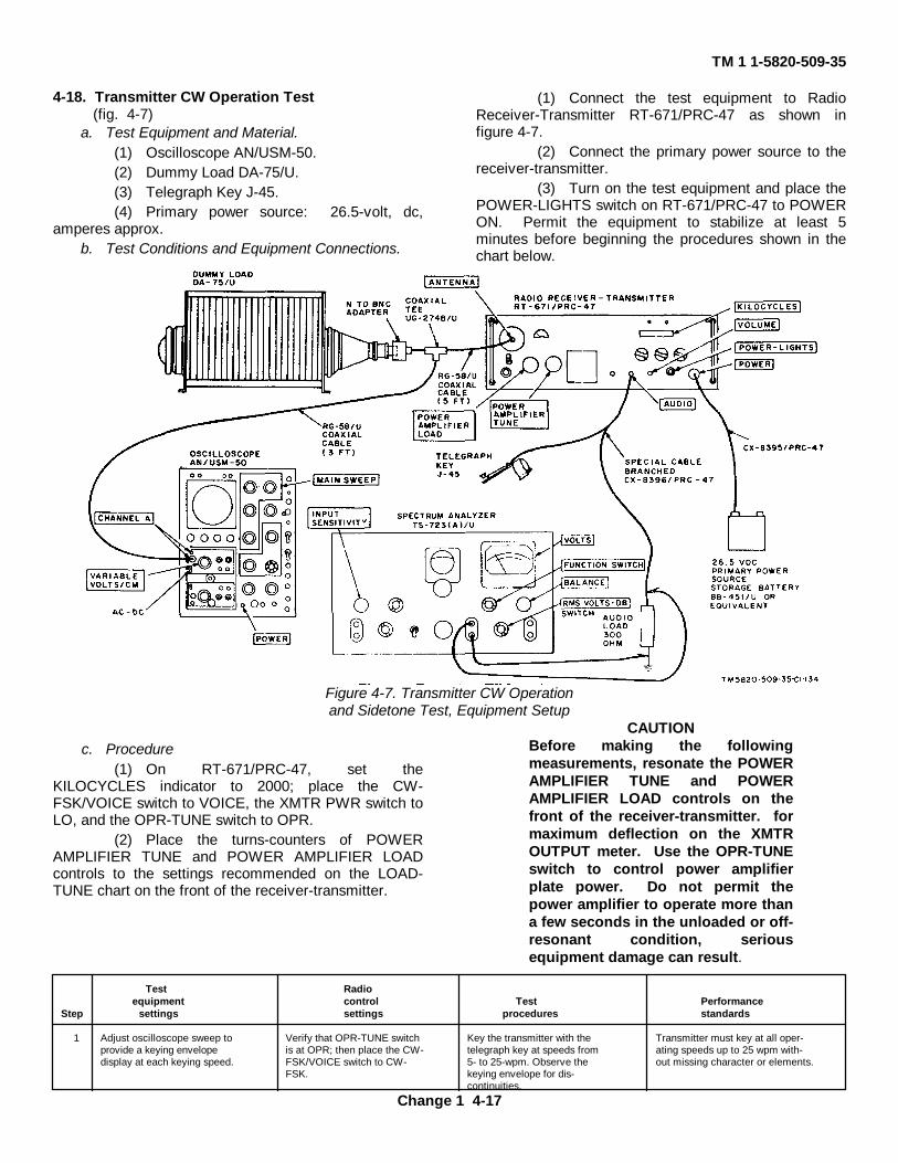
TM 1 1-5820-509-35
4-18. Transmitter CW Operation Test(fig. 4-7)
a. Test Equipment and Material.(1) Oscilloscope AN/USM-50.(2) Dummy Load DA-75/U.(3) Telegraph Key J-45.(4) Primary power source: 26.5-volt, dc,
amperes approx.b. Test Conditions and Equipment Connections.
(1) Connect the test equipment to RadioReceiver-Transmitter RT-671/PRC-47 as shown infigure 4-7.
(2) Connect the primary power source to thereceiver-transmitter.
(3) Turn on the test equipment and place thePOWER-LIGHTS switch on RT-671/PRC-47 to POWERON. Permit the equipment to stabilize at least 5minutes before beginning the procedures shown in thechart below.
Figure 4-7. Transmitter CW Operationand Sidetone Test, Equipment Setup
c. Procedure(1) On RT-671/PRC-47, set the
KILOCYCLES indicator to 2000; place the CW-FSK/VOICE switch to VOICE, the XMTR PWR switch toLO, and the OPR-TUNE switch to OPR.
(2) Place the turns-counters of POWERAMPLIFIER TUNE and POWER AMPLIFIER LOADcontrols to the settings recommended on the LOAD-TUNE chart on the front of the receiver-transmitter.
CAUTIONBefore making the followingmeasurements, resonate the POWERAMPLIFIER TUNE and POWERAMPLIFIER LOAD controls on thefront of the receiver-transmitter. formaximum deflection on the XMTROUTPUT meter. Use the OPR-TUNEswitch to control power amplifierplate power. Do not permit thepower amplifier to operate more thana few seconds in the unloaded or off-resonant condition, seriousequipment damage can result.
Test Radioequipment control Test Performance
Step settings settings procedures standards
1 Adjust oscilloscope sweep to Verify that OPR-TUNE switch Key the transmitter with the Transmitter must key at all oper-provide a keying envelope is at OPR; then place the CW- telegraph key at speeds from ating speeds up to 25 wpm with-display at each keying speed. FSK/VOICE switch to CW- 5- to 25-wpm. Observe the out missing character or elements.
FSK. keying envelope for dis-continuities.
Change 1 4-17
TM 1 1-5820-509-35
4-19. Transmitter Sidetone Test(fig. 4-7)
a. Test Equipment and Material.(1) Spectrum Analyzer TS-723A/U.(2) Dummy Load DA-75/U.(3) Telegraph Key J-45.(4) Audio load, 300-ohm, 1-watt compos-
ition resistor.(5) Primary power source: 26.5-volt, dc,
11 amperes approx.b. Test Conditions and Equipment Connections.
(1) Connect the test equipment to RadioReceiver-Transmitter RT-671/PRC-47 as shown infigure 4-7.
(2) Connect the primary power source to thereceiver-transmitter.
(3) Turn on the test equipment and place thePOWER-LIGHTS switch on RT-671/PRC-47 to POWERON. Permit the equipment to stabilize for at least 5minutes before beginning the procedures shown in thechart below.
c. Procedure.(1) On RT-671/PRC-47, set the
KILOCYCLES indicator to 2000; set CW-FSK/VOICEswitch to VOICE, the XMTR PWR switch to LO, and theOPR-TUNE switch to OAR.
(2) Place the turns-counters of POWERAMPLIFIER TUNE and POWER AMPLIFIER LOADcontrols on the front panel of RT-671/PRC-47 to thesettings recommended on the LOAD-TUNE! chart.
CAUTIONBefore making the followingmeasurements, resonate the POWERAMPLIFIER TUNE and POWERAMPLIFIER LOAD controls on thefront panel of the receiver-transmitter. for maximum deflectionon the XMTR PWR meter. Use theOPR-TUNE switch to control poweramplifier plate power. Do not permitthe power amplifier to operate formore than a few seconds at a time inthe unloaded or off-resonantcondition, serious equipmentdamage can result.
Test Radioequipment control Test Performance
Step settings settings procedures standards
I Set meter range switch to 10 Place XMTR PWR switch to HI Hold telegraph key closed and Meter reads not less than 3.9 voltsVOLTS R.M.S. and peak the power amplifier; measure voltage across 300- rms.
return OPR-TUNE to OPR, an ohmn audio loadswitch C W-FSK/VOICE switchto C'W-I£SK; set VOLUMEcontrol to maximum clockwisestop.
2 Same as step 1. Same as step 1, except set Same as step 1. Same as step 1.KILOCY('LI:S indicator to11999. Resonate the poweramplifier output circuit withXMTR PWR switch at LOand then at HI.
Change 1 4-18

TM 11-5820-509-35
CHAPTER 5
DEPOT MAINTENANCE
5-1. Generala. Instructions are included in this chapter that
detail the adjustment, alignment, and bench checkout ofthe separate subassemblies of the receiver-transmitterbefore re-installation of these modules in the radio setfollowing overhaul procedures. Several receiver-transmitter tests are included in this chapter that cannotbe performed at lower echelon activities because of thepeculiar test equipment requirements.
b. The trouble isolation sections of chapter 3describe in detail the procedures necessary to isolatetrouble within the modules and subassemblies of thereceiver-transmitter. The general replacementtechniques contained in paragraph 3-8 apply equally tothe depot maintenance level.
CAUTIONRemove all power from Radio Receiver-Transmitter RT-671/PRC-47 before beginningany repair procedures.
5-2. Replacement of Partsa. Parts removal and replacement techniques are
described in paragraph 3-9 of this technical manual.b. Removal and replacement of the plug-in
modules and subassemblies of the receiver transmitterare provided in paragraph 3-12.
c. Module disassembly and reassembly techniquesare listed in paragraph 3-13.
d. Mechanical subassemblies are disassembledand reassembled using the procedures detailed inparagraphs 3-15 through 3-19. No further specialinstructions are required in connection with thesesubassemblies and modules.
5-3. Equipment AdjustmentsThe following instructions detail complete module andsubassembly electrical adjustments and calibratingprocedures to assure that the receiver transmitter meetsthe performance requirements specified by the originalprocurement document.
5-4. Transmit Mixer Balance and Transmitter GainControl Adjustment(fig. 5-1)
a. Test Equipment and Material.(1) Spectrum Analyzer AN/UPM-110(2) Converter, Hewlett-Packard K15-8551B(3) Dummy Load DA-75/U(4) Attenuator (see fig. 5-1)(5) Multimeter ME-26A/U(6) Primary power source: 115-volt, 400-Hz,
single-phase, 3 amp.b. Test Conditions and Equipment Connections.
(1) Connect the test equipment to RadioReceiver-Transmitter RT-671/PRC-47 as shown infigure 5-1. Do not connect ME-26A/U until instructed todo so.
(2) Connect the primary power source to thereceiver-transmitter.
(3) Turn on the test equipment and place thePOWER-LIGHTS switch on RT-671/PRC-47 to POWERON. Permit the equipment to stabilize for at least 5minutes before beginning the procedures listed in thechart below.
Figure 5-1. Transmit Mixer Balance and Transmitter Gain Control Adjustment, Equipment Setup.5-1
TM 11-5820-509-35
c. Procedure.(1) On the RT-671/PRC-47, set the
KILOCYCLES indicator to 11000; place the CW-FSK/VOICE switch to VOICE, XMTR PWR switch to LO,and OPR-TUNE switch to OPR.
(2) Place the turns-counters of POWERAMPLIFIER TUNE and POWER AMPLIFIER LOADcontrols to the settings recommended on the LOAD-TUNE chart on the front of the receiver- transmitter .
CAUTIONBefore making the following measurements
and adjustments, resonate the POWERAMPLIFIER TUNE and POWER AMPLIFIERLOAD controls on the front of the receiver-transmitter for maximum deflection on theXMTR OUTPUT meter. Use the OPR-TUNEswitch to control power amplifier plate power.Do not permit the power amplifier to operatefor more than a few seconds in the unloadedcondition, serious damage to the equipmentcan result.
Test Radioequipment control Test Performance
Step settings settings procedures standards
1 Set spectrum analyzer to Resonate power amplifier Adjust transmit mixer Adjust for minimum11,000 kHz. with XMTR PWR switch balance pot A3R150 analyzer reading.
at HI. (fig. 3 95).2 Same as step 1 Same as step 1 Immediately return OPR Not applicable.
TUNE switch to OPR.3 Set multimeter to RF VOLTS, Place OPR-TUNE switch Adjust transmit gain Continue to adjust until
and connect the rf again to TUNE control A3R148 (fig. 3-95) meter indication stopsprobe to J104 (fig.. 3 99). clockwise. rising.
5-5. Transmitter Hum Balance Adjustment(fig. 5-2)
a. Test Equipment and Material.(1) Spectrum Analyzer AN/UPM-110(2) Converter. Hewlett-Packard K15-8551B(3) Dummy Load NA-75/U(4) Attenuator (see fig. 5-2).(5) Multimeter ME-26A/U(6) Audio Oscillator TS-382/U(7) Primary power source: 115-volt, 400-Hz,
single-phase, 3 amp.
b. Test Conditions and Equipment Connections.(1) Connect the test equipment to Radio
Receiver-Transmitter RT-671/PRC-47 as shown infigure 5-2. Do not connect ME-26A/U until instructed todo so.
(2) Connect the primary power source to thereceiver-transmitter.
(3) Turn on the test equipment and place thePOWER-LIGHTS switch on the RT-671/PRC-47 toPOWER ON. Permit the equipment to stabilize for atleast 5 minutes before beginning the procedures listed inthe chart below.
5-2
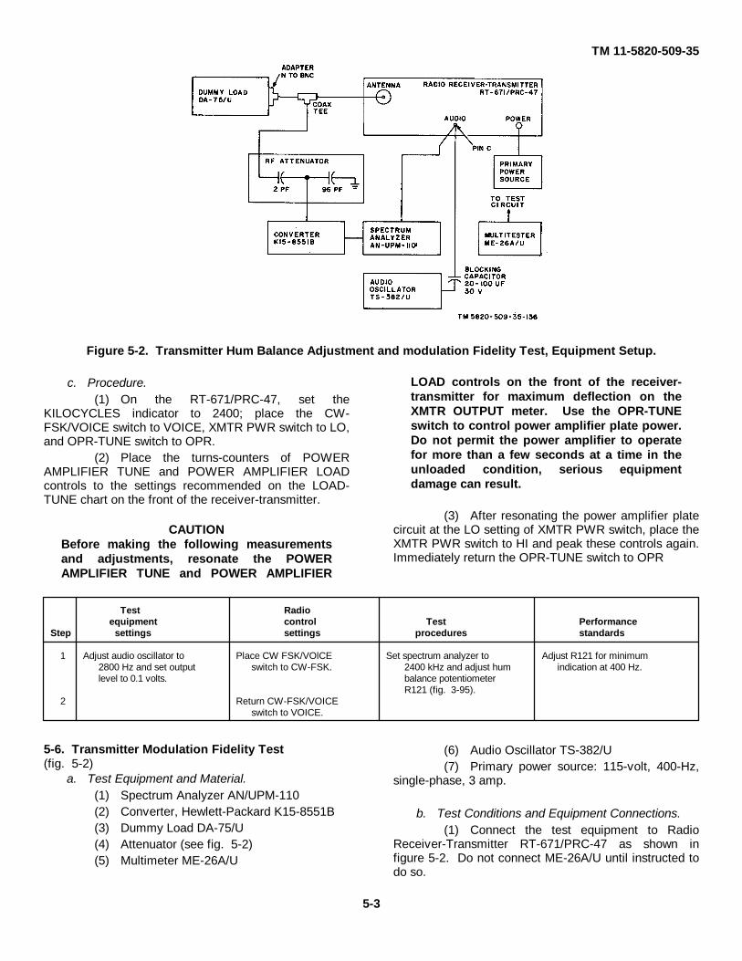
TM 11-5820-509-35
Figure 5-2. Transmitter Hum Balance Adjustment and modulation Fidelity Test, Equipment Setup.
c. Procedure.(1) On the RT-671/PRC-47, set the
KILOCYCLES indicator to 2400; place the CW-FSK/VOICE switch to VOICE, XMTR PWR switch to LO,and OPR-TUNE switch to OPR.
(2) Place the turns-counters of POWERAMPLIFIER TUNE and POWER AMPLIFIER LOADcontrols to the settings recommended on the LOAD-TUNE chart on the front of the receiver-transmitter.
CAUTIONBefore making the following measurementsand adjustments, resonate the POWERAMPLIFIER TUNE and POWER AMPLIFIER
LOAD controls on the front of the receiver-transmitter for maximum deflection on theXMTR OUTPUT meter. Use the OPR-TUNEswitch to control power amplifier plate power.Do not permit the power amplifier to operatefor more than a few seconds at a time in theunloaded condition, serious equipmentdamage can result.
(3) After resonating the power amplifier platecircuit at the LO setting of XMTR PWR switch, place theXMTR PWR switch to HI and peak these controls again.Immediately return the OPR-TUNE switch to OPR
Test Radioequipment control Test Performance
Step settings settings procedures standards
1 Adjust audio oscillator to Place CW FSK/VOlCE Set spectrum analyzer to Adjust R121 for minimum2800 Hz and set output switch to CW-FSK. 2400 kHz and adjust hum indication at 400 Hz.level to 0.1 volts. balance potentiometer
R121 (fig. 3-95).2 Return CW-FSK/VOICE
switch to VOICE.
5-6. Transmitter Modulation Fidelity Test(fig. 5-2)
a. Test Equipment and Material.(1) Spectrum Analyzer AN/UPM-110(2) Converter, Hewlett-Packard K15-8551B(3) Dummy Load DA-75/U(4) Attenuator (see fig. 5-2)(5) Multimeter ME-26A/U
(6) Audio Oscillator TS-382/U(7) Primary power source: 115-volt, 400-Hz,
single-phase, 3 amp.
b. Test Conditions and Equipment Connections.(1) Connect the test equipment to Radio
Receiver-Transmitter RT-671/PRC-47 as shown infigure 5-2. Do not connect ME-26A/U until instructed todo so.
5-3
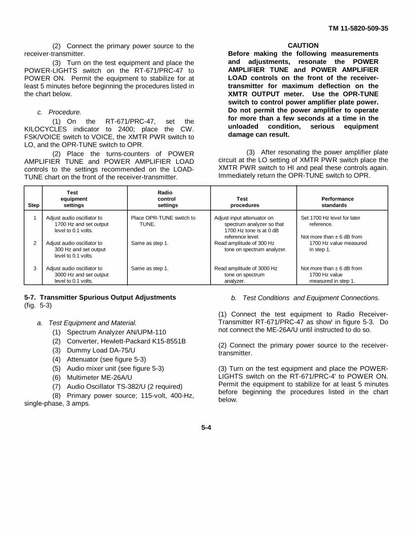
TM 11-5820-509-35
(2) Connect the primary power source to thereceiver-transmitter.
(3) Turn on the test equipment and place thePOWER-LIGHTS switch on the RT-671/PRC-47 toPOWER ON. Permit the equipment to stabilize for atleast 5 minutes before beginning the procedures listed inthe chart below.
c. Procedure.(1) On the RT-671/PRC-47, set the
KILOCYCLES indicator to 2400; place the CW.FSK/VOICE switch to VOICE, the XMTR PWR switch toLO, and the OPR-TUNE switch to OPR.
(2) Place the turns-counters of POWERAMPLIFIER TUNE and POWER AMPLIFIER LOADcontrols to the settings recommended on the LOAD-TUNE chart on the front of the receiver-transmitter.
CAUTIONBefore making the following measurementsand adjustments, resonate the POWERAMPLIFIER TUNE and POWER AMPLIFIERLOAD controls on the front of the receiver-transmitter for maximum deflection on theXMTR OUTPUT meter. Use the OPR-TUNEswitch to control power amplifier plate power.Do not permit the power amplifier to operatefor more than a few seconds at a time in theunloaded condition, serious equipmentdamage can result.
(3) After resonating the power amplifier platecircuit at the LO setting of XMTR PWR switch place theXMTR PWR switch to HI and peal these controls again.Immediately return the OPR-TUNE switch to OPR.
Test Radioequipment control Test Performance
Step settings settings procedures standards
1 Adjust audio oscillator to Place OPR-TUNE switch to Adjust input attenuator on Set 1700 Hz level for later1700 Hz and set output TUNE. spectrum analyzer so that reference.level to 0.1 volts. 1700 Hz tone is at 0 dB
reference level. Not more than ± 6 dB from2 Adjust audio oscillator to Same as step 1. Read amplitude of 300 Hz 1700 Hz value measured
300 Hz and set output tone on spectrum analyzer. in step 1.level to 0.1 volts.
3 Adjust audio oscillator to Same as step 1. Read amplitude of 3000 Hz Not more than ± 6 dB from3000 Hz and set output tone on spectrum 1700 Hz valuelevel to 0.1 volts. analyzer. measured in step 1.
5-7. Transmitter Spurious Output Adjustments(fig. 5-3)
a. Test Equipment and Material.(1) Spectrum Analyzer AN/UPM-110(2) Converter, Hewlett-Packard K15-8551B(3) Dummy Load DA-75/U(4) Attenuator (see figure 5-3)(5) Audio mixer unit (see figure 5-3)(6) Multimeter ME-26A/U(7) Audio Oscillator TS-382/U (2 required)(8) Primary power source; 115-volt, 400-Hz,
single-phase, 3 amps.
b. Test Conditions and Equipment Connections.
(1) Connect the test equipment to Radio Receiver-Transmitter RT-671/PRC-47 as show' in figure 5-3. Donot connect the ME-26A/U until instructed to do so.
(2) Connect the primary power source to the receiver-transmitter.
(3) Turn on the test equipment and place the POWER-LIGHTS switch on the RT-671/PRC-4' to POWER ON.Permit the equipment to stabilize for at least 5 minutesbefore beginning the procedures listed in the chartbelow.
5-4
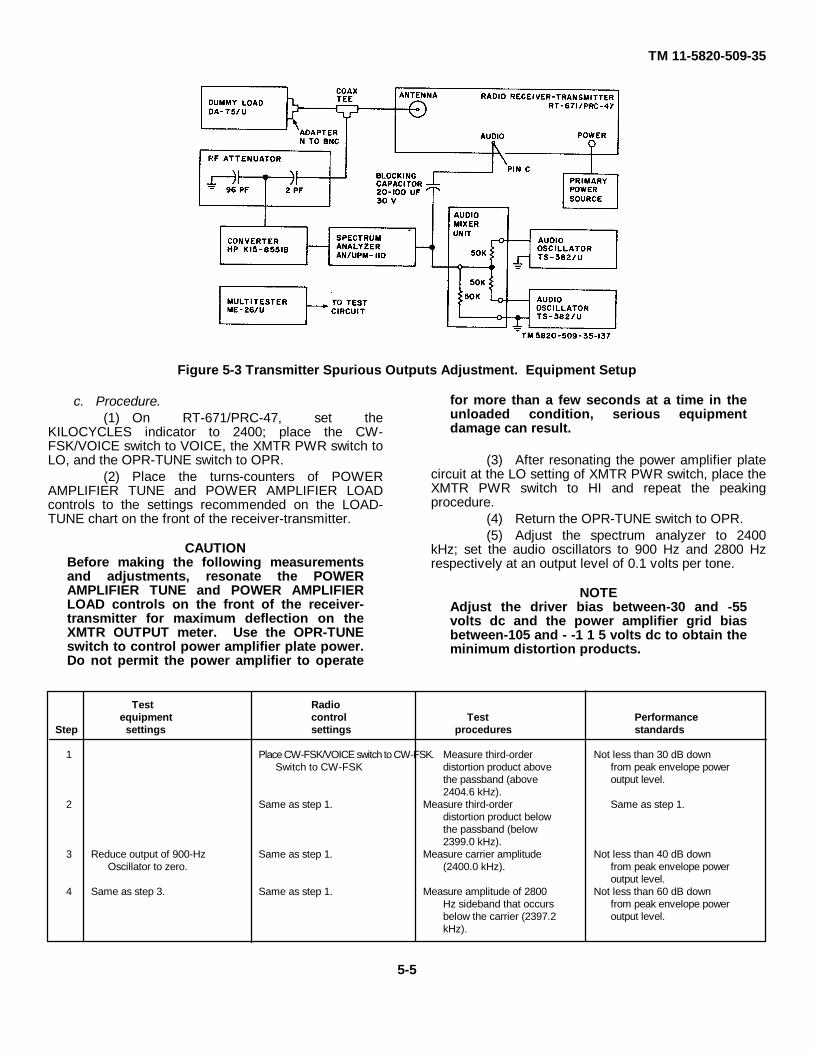
TM 11-5820-509-35
Figure 5-3 Transmitter Spurious Outputs Adjustment. Equipment Setup
c. Procedure.(1) On RT-671/PRC-47, set the
KILOCYCLES indicator to 2400; place the CW-FSK/VOICE switch to VOICE, the XMTR PWR switch toLO, and the OPR-TUNE switch to OPR.
(2) Place the turns-counters of POWERAMPLIFIER TUNE and POWER AMPLIFIER LOADcontrols to the settings recommended on the LOAD-TUNE chart on the front of the receiver-transmitter.
CAUTIONBefore making the following measurementsand adjustments, resonate the POWERAMPLIFIER TUNE and POWER AMPLIFIERLOAD controls on the front of the receiver-transmitter for maximum deflection on theXMTR OUTPUT meter. Use the OPR-TUNEswitch to control power amplifier plate power.Do not permit the power amplifier to operate
for more than a few seconds at a time in theunloaded condition, serious equipmentdamage can result.
(3) After resonating the power amplifier platecircuit at the LO setting of XMTR PWR switch, place theXMTR PWR switch to HI and repeat the peakingprocedure.
(4) Return the OPR-TUNE switch to OPR.(5) Adjust the spectrum analyzer to 2400
kHz; set the audio oscillators to 900 Hz and 2800 Hzrespectively at an output level of 0.1 volts per tone.
NOTEAdjust the driver bias between-30 and -55volts dc and the power amplifier grid biasbetween-105 and - -1 1 5 volts dc to obtain theminimum distortion products.
Test Radioequipment control Test Performance
Step settings settings procedures standards
1 Place CW-FSK/VOICE switch to CW-FSK. Measure third-order Not less than 30 dB downSwitch to CW-FSK distortion product above from peak envelope power
the passband (above output level.2404.6 kHz).
2 Same as step 1. Measure third-order Same as step 1.distortion product belowthe passband (below2399.0 kHz).
3 Reduce output of 900-Hz Same as step 1. Measure carrier amplitude Not less than 40 dB downOscillator to zero. (2400.0 kHz). from peak envelope power
output level.4 Same as step 3. Same as step 1. Measure amplitude of 2800 Not less than 60 dB down
Hz sideband that occurs from peak envelope powerbelow the carrier (2397.2 output level.kHz).
5-5
TM 11-5820-509-35CHAPTER 6
DEPOT OVERHAUL STANDARDS
Section I. GENERAL
6-1. Scope
This chapter contains the depot-level performancestandards tests and defines the acceptable limits ofoperational performance for a repaired Radio SetAN/PRC-47. Section I contains general informationapplicable to the test procedures and test equipment,and includes construction details and schematicdiagrams for special test fixtures required for bench testof modular subassemblies of the AN/PRC-47. Section IIlists the performance tests and specific procedures to beconducted for the evaluation and adjustment of plug-inmodules of the radio set. These tests are
conducted using the bench test facilities provided by thespecial test fixtures described in section I. Section II Itabulates the overall equipment performance testsindicated elsewhere in this technical manual, lists theoverall equipment adjustments and alignment routines,and provides a table of final equipment standards ofperformance.
6-2. General
a. The following table provides a list of testequipment required for performance of these standardstests.
Test equipment FSN Technical manualAc Ammeter, 0.5 amperes (Weston #904, or equal)Ac Voltmeter, 10 mv to 15,000 mv 12500 volts dc insulation)Audio Oscillator TS-382/U 6625-246-8729 TM 11-6625-935-12Cable Assembly Set AN/PRA-4 5995-973-3686Coaxial Adapter, Tee UG-28A/UCoaxial Adapter, Tee UG-274B/UDc Ammeter 0-1 ampere (Simpson #375. or equal)Dc Ammeter 0-15 ampere (Simpson #375, or equal)Distortion Analyzer TS-723/UFrequency Counter AN/URM-79/UMultimeter ME-26A/U 6625-542-6407 TM 11-6625-200-15Oscilloscope AN/USM-50 TM 11-5129Output Meter TS-585/U TM 11-5017Power Supply, 7 vdc 600 ma (Harrison 6203B, or equal)Power Supply, 26 vdc, 500 ma (Harrison 6202B, or equal)Power Supply, 26 vdc, 15 Amp. (Harrison 6434B, or equal)Power Supply, 110 vdc, 5 ma. (Harrison 6207B, or equal)Radar and Radio Repair Tool Kit TK-115/GReceiver R-1433/URResistance Decade Box MX-3991/VSignal Generator SG-103/URM-25F (2 required)Spectrum Analyzer AN/UPM-110 TM 11-6626-326-12Up-converter for AN /UPM - l 10 (Hewlett Packard K 15-855 1B)Voltmeter ME-30A/U
b.The following table lists the special tools and test fixtures required for performance standards testsSpecial tool FSN Ref drawing
Gage. thickness (feeler) 0.002 to 0,020 5210-031-1504Gage, plug (depth) (u/w CV-1377A/PRC-47) Fig. 6-1Gage, overtravel 0.041.inch Fig. 6-2Output attenuator, 50: 1 Fig. 6-3Test fixture for AM-3506/PRC-47 Fig. 6-4Test fixture for AM-3507/PRC-47 Fig. 6-5Test fixture for CV-1377A/PRC-47 Fig. 6-6Indexing fixture for CV-1377A/PRC-47 Fig. 6-7Test fixture for PP-3518/PRC-47 Fig. 6-8Test fixture for 0-1032/PRC-47 Fig. 6-9Test fixture for C-4311/PRC-47 Fig. 6-10
6-1
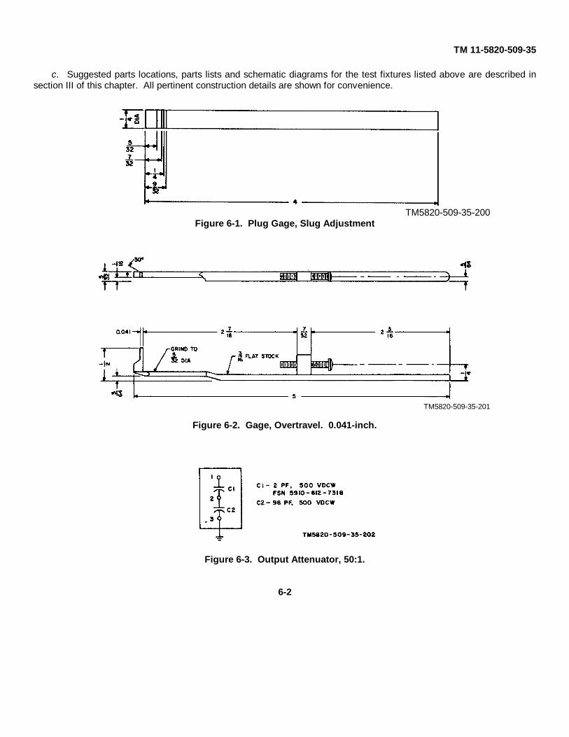
TM 11-5820-509-35
c. Suggested parts locations, parts lists and schematic diagrams for the test fixtures listed above are described insection III of this chapter. All pertinent construction details are shown for convenience.
TM5820-509-35-200Figure 6-1. Plug Gage, Slug Adjustment
TM5820-509-35-201
Figure 6-2. Gage, Overtravel. 0.041-inch.
Figure 6-3. Output Attenuator, 50:1.
6-2
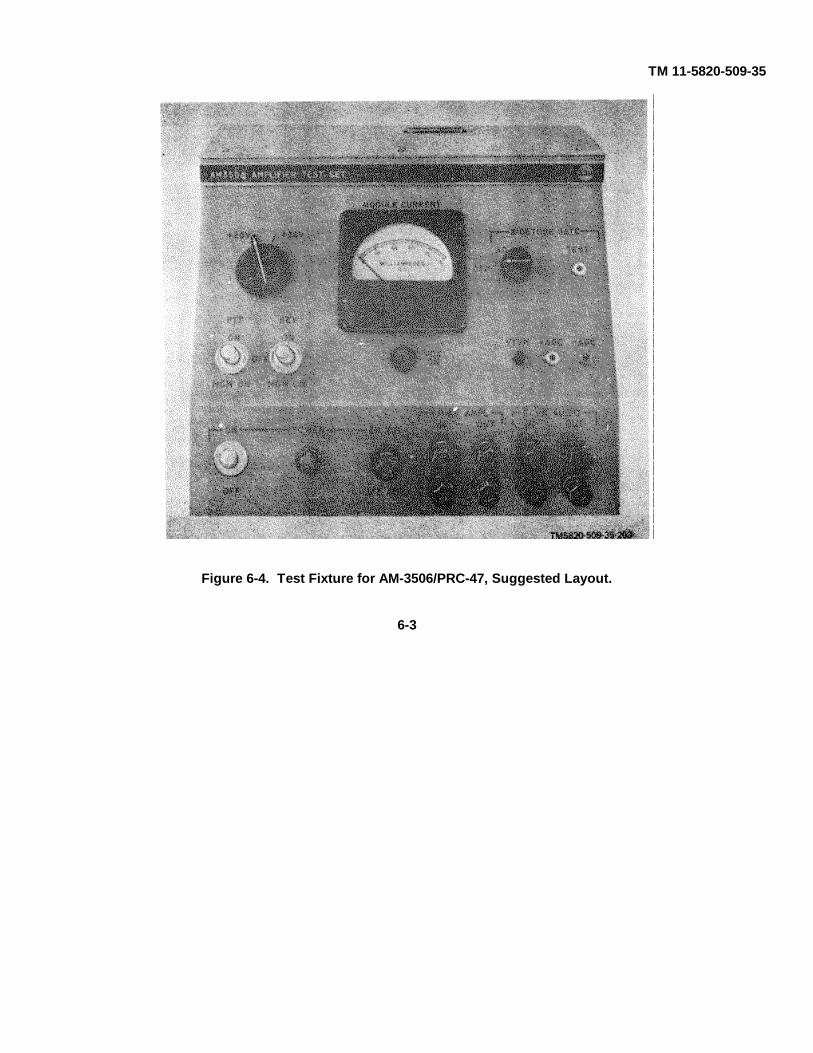
TM 11-5820-509-35
Figure 6-4. Test Fixture for AM-3506/PRC-47, Suggested Layout.
6-3

TM 11-5820-509-35
Figure 6-5. Test Fixture for AM-3507/PRC-47, Suggested Layout.
6-4

TM 11-5820-509-35
Figure 6-6. Test Fixture for CV-1377A/PRC-47, Suggested Layout.
6-5
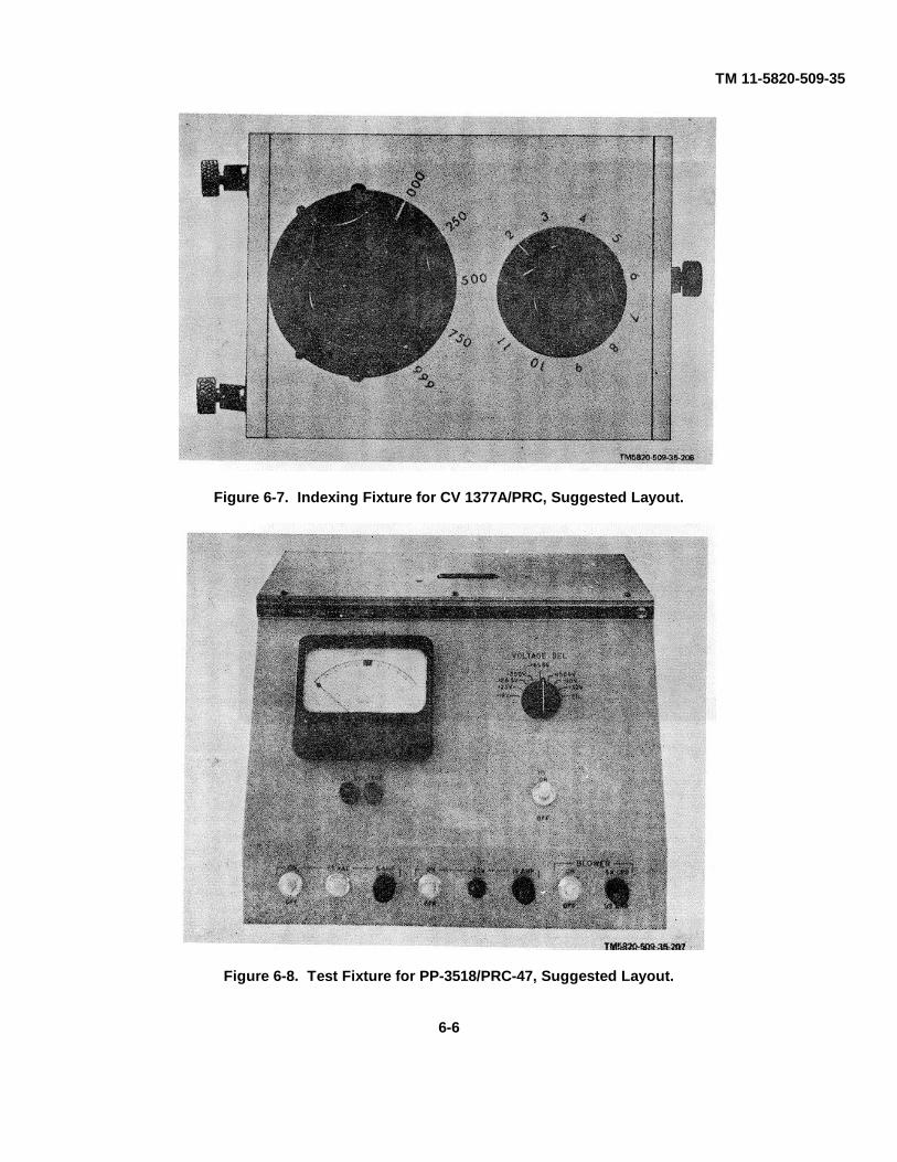
TM 11-5820-509-35
Figure 6-7. Indexing Fixture for CV 1377A/PRC, Suggested Layout.
Figure 6-8. Test Fixture for PP-3518/PRC-47, Suggested Layout.
6-6
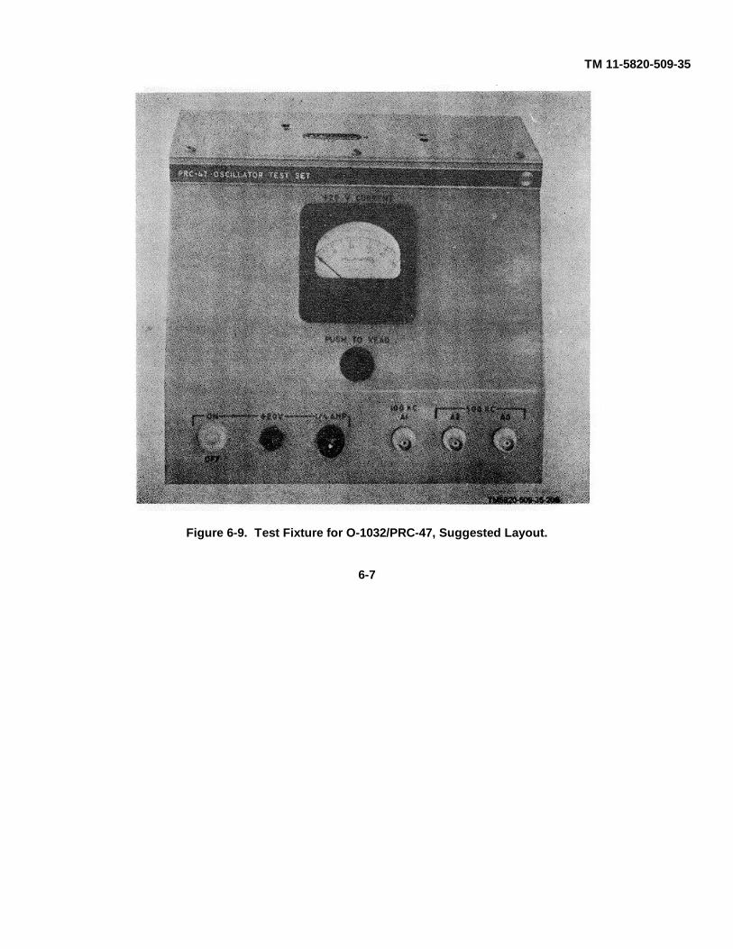
TM 11-5820-509-35
Figure 6-9. Test Fixture for O-1032/PRC-47, Suggested Layout.
6-7

TM 11-5820-509-35
Figure 6-10. Test Fixture for C-4311/PRC-47, Suggested Layout.
6-3. Test FacilitiesA primary power source of 115 volts, 400-Hz, single-phase alternating current at approximately 3.0 amperes,and a 26.6-volt direct current primary power source atapproximately 16 amperes is required for these tests. Inaddition, normal test instrument primary power facilities(60- or 400- Hz) will be required. The test fixtures, ortheir equivalent, shown in figures 6-4 through 6-10, willbe required.
6-4. Modification Work OrdersThe performance standards listed in the following testsassume that all modification work orders (MWO's) havebeen performed. Consult DA Pam 310-7 for a list ofMWO's for Radio Set AN/PRC-47.
6-5. Physical Tests and InspectionPerform general inspection of all modular
subassemblies of the radio set to determine whether thedefective circuit has been repaired. If doubt arises as tothe completeness of the repair procedures, a limitednumber of performance standards tests will verify circuitperformance.
6-6. Reference Standards TestsThe following reference standards tests are required toprovide assurance that satisfactory operatingparameters have been maintained or restored as aresult of depot overhaul procedures. Each group oftests, performed on a specific modular subassembly, isconducted using the test fixture for that module togetherwith the equipment configuration specified in theprocedure. Certain initial conditions must beestablished before the performance tests and referencestandards can be judiciously compared. Unlessspecified, all tests shall be performed in the order listedin the procedures to avoid ambiguity.
6-8

TM 11-5820-509-356-7. Tests to be Performed
a. Audio Amplifier AM-3506/PRC47. The followingtests must be performed using the test fixture for theAM-3506/PRC-47 (fig. 64). A schematic diagram, partslayout photographs and parts lists for this test fixture areincluded in section III.
(1) Initial settings and adjustments.(2) Maximum output levels, receive mode.(3) Frequency response and distortion,
receive mode.(4) AVC signal gate operation, receive mode.(5) Harmonic distortion and frequency
response, transmit mode.(6) Frequency response at nominal output,
transmit mode.(7) CW oscillator operation test.6-7.
b. Amplifier-Modulator AM-3507/PRC-47. Thefollowing tests must be performed using the test fixturefor AM-3507/PRC-47 (fig. 6-5). A schematic diagram,parts layout photographs, and parts lists for this testfixture are included in section III.
(1) Initial settings and adjustments.(2) Output, receive mode.(3) Distortion.(4) Selectivity.(5) Response, receive mode.
c. Signal Data Translator CV-1377A/PRC-47. Thefollowing tests are to be performed using the test fixturefor CV-1377A/PRC-47 (fig. 6-6) together with theindexing fixture (fig. 6-7). Configuration drawings, partslayout photographs, parts lists and schematic diagramsfor these test fixtures are included in section III.
(1) Mechanical alignment.(2) 5- to 14-MHz ringer circuit alignment.(3) Oscillator output adjustment.(4) Oscillator alignment and tracking ad"
justment(5) Rf alignment, receive mode.(6) Rf alignment, transmit mode.(7) Oscillator control isolation amplifier test.
d. Power Supply PP-3518/PRC-47. The followingtests must be performed using the test fixture for PP-3518/PRC-47 (fig. 6-8). A schematic diagram, partslayout photographs, and parts lists for this test fixtureare included in section III.
(1) Initial settings and adjustments.(2) Performance tests, 26.5-volts dc
primary power source.
(a) Input current.(b) Power amplifier plate voltage.(c) Power amplifier screen voltage.(d) Driver plate voltage.(e) Relay voltage.(I) Filtered low voltage.(g) Regulated voltage.(h) Filament voltage.(i) Power amplifier bias voltage.(j) Driver bias voltage.(k) Voltage regulator operation.
(3) Performance tests, 110-volts, 400-Hzprimary power source.
(a) Input current.(b) Relay voltage.(c) Filtered low voltage.(d) Regulated voltage.(e) Filament voltage.
e. Radio Frequency Oscillator O-1032/PRC-47.The following tests must be performed using the testfixture for 0-1032/PRC-47 (fig. 6-9). A schematicdiagram, parts layout photographs, and parts lists forthis test fixture are included in section III.
(1) Initial settings and adjustments.(2) Locked oscillator, divider, and output
amplifier performance.(3) Locked oscillator Q4 and 500-kHz
amplifier adjustments.(4) Locked oscillator Q8 and 100-kHz
amplifier adjustments.(5) Final frequency calibration.
f. Oscillator Control C-4311/PRC-47. Thefollowing tests must be performed using the test fixturefor the C-4311/PRC-47 (fig. 6-10). A schematicdiagram, parts layout photographs, and parts lists forthis test fixture are included in section III.
(1) Pulse generator output.(2) 1.8- to 0.9-MHz ringer circuit alignment.(3) Crystal oscillator alignment.(4) 601- to 600-kHz filter test.(5) 550- to 750-kHz filter test.(6) Frequency discriminator test.(7) Error voltage balance adjustment.(8) Anti-lock test.(9) SMO mixers test.
6-8. Reference StandardsThe following chart lists the reference standardsprocedures and the expected result or standard value.
6-9
TM 11-5820-509-35
Section Action required Reference standard
AM -3506/PRC-47
AM-3507/PRC-47
CY-1377A/PRC 47
1. Make initial settings and adjustments.
2. Record maximum output levels, receivemode.
3. Record frequency response anddistortion, receive mode.
4. Record AVC signal gate operating level.5. Measure input level and record harmonic
distortion and frequency response belowthe clipping and compression thresholdlevels.
6. Record frequency response at nominaloutput level.
7. Record operation of CW oscillator
1. Make initial settings and adjustments.
2. Perform output test, receive mode.
3. Record distortion in audio pass. band.
4. Record selectivity
5. Record frequency response. receivemode.
1. Perform mechanical alignment.
2. Align 5- to 14-MHz ringer circuit.
1. (a) Set R54 for I watt output.(b) Set R27 for 3.5 volts p-p at MIKE AMPL OUT jack.(c) Set R40 so that VOX ON lamp lights.(d) Set R46 for 20 volts pep at RX AUDIO OUT jack.
Waveshape is symmetrical.2. (a) At RX AUDIO OUT jack, not less than 1 watt (18 volts
rms across 300 ohms).(b) At +AGC jack, not less than +14 volts dc.(c) At -AGC jack, more negative than -5.5 volts dc.
3. (a) Frequency response. shall not vary more than ± 3 dBfrom the 1700 Hz value in range from 300 to 3000-Hz.
(b) Distortion shall be no more than 8% in range from 300to3000-Hz.
(c) +AGC jack, not less than 7.0 volts dc in range from 300-to 3000 Hz.
(d) -AGC jack, not less than-3.0 volts dc in range from 300-to 3000 Hz.
4. + AGC jack, not more than 0.5 volts dc.5. (a) Input level not more than 0.015 volts rms At 1700 Hz for
sinusoidal output.(b) Harmonic distortion shall not exceed 5% from 300. to
3000. Hz.(c) Frequency response shall not vary more than ± 2.5 dB
from the 1700 Hz value in the range from 300- to 3000-Hz.
6. Frequency response shall not vary more than ± 2.0 dB fromthe 1700 Hz value in the range from 300 To 3000.Hz
7. (a) MIKE AMPL OUT jack, 3.5 volts peak-to-peak.(b) MIKE AMPL OUT jack, 800 ± 50 Hz.(c) No clicks or chirps heard in loudspeaker.(d) VOX ON lamp lights.
1. (a) Set C15, C17, L6, L7, and T3 for maximum at AUDIOOUT jack.
(b) Select value of R14, if necessary. to obtain 0.5 voltsrms at XMTR OUT jack.
(c) Set R5 and C35 for minimum carrier leakage at XMTROUT jack.
2. Read signal generator output necessary to produce 0.1 voltrms at AUDIO OUT jack. shall not exceed 200microvolts.
3. (a) Read AUDIO OUT jack. not more than 5% from 497.0 to499.7 kHz.
(b) Oscilloscope at AUDIO OUT shows no spikes or ripplewith O.05 volt input signal and AGC switch on.
4. The frequency difference between -60 dB points in the passband shall not be more than 6.0 kHz.
5. Frequency response shall not vary more than 3 db above, nor 4dB below the reference value at 498.3 kHz in the rangefrom 497.0 to 499.7 kHz.
1. (a) Set slugs of L1 L2. and L3 to a depth of 7/32 from bottomof coil form.
(b) Set slug of L4 to depth of 5/32 from bottom of coil form.(c) Set slug of L5 to depth of 1/4 from bottom of coil form.(d) Set slug of L145 to depth of 9/32 from bottom of coil
form.2. Set C248. C250. C252. C254. C256, C258. C260, C262,
C264 and C266 At 1-MHz increments for maximumoutput at 5 to 14 MHz jack. Must Be at least 0.9 voltpeak to-peak.
6-10
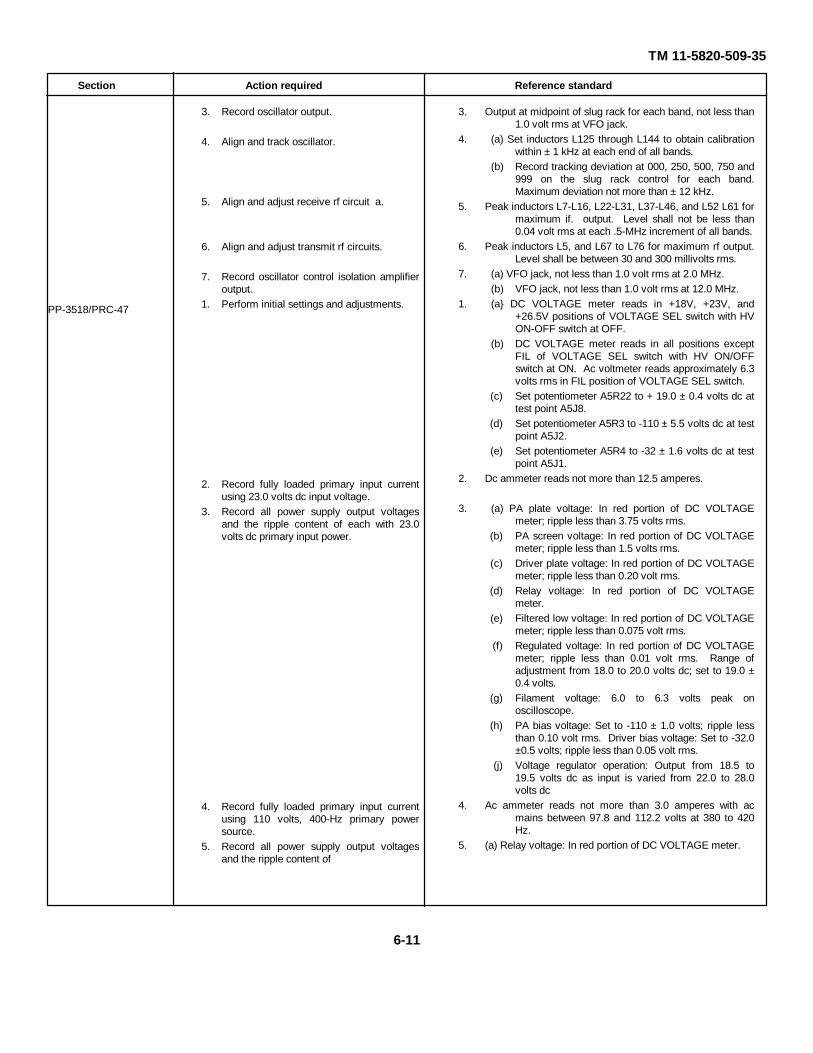
TM 11-5820-509-35
Section Action required Reference standard
PP-3518/PRC-47
3. Record oscillator output.
4. Align and track oscillator.
5. Align and adjust receive rf circuit a.
6. Align and adjust transmit rf circuits.
7. Record oscillator control isolation amplifieroutput.
1. Perform initial settings and adjustments.
2. Record fully loaded primary input currentusing 23.0 volts dc input voltage.
3. Record all power supply output voltagesand the ripple content of each with 23.0volts dc primary input power.
4. Record fully loaded primary input currentusing 110 volts, 400-Hz primary powersource.
5. Record all power supply output voltagesand the ripple content of
3. Output at midpoint of slug rack for each band, not less than1.0 volt rms at VFO jack.
4. (a) Set inductors L125 through L144 to obtain calibrationwithin ± 1 kHz at each end of all bands.
(b) Record tracking deviation at 000, 250, 500, 750 and999 on the slug rack control for each band.Maximum deviation not more than ± 12 kHz.
5. Peak inductors L7-L16, L22-L31, L37-L46, and L52 L61 formaximum if. output. Level shall not be less than0.04 volt rms at each .5-MHz increment of all bands.
6. Peak inductors L5, and L67 to L76 for maximum rf output.Level shall be between 30 and 300 millivolts rms.
7. (a) VFO jack, not less than 1.0 volt rms at 2.0 MHz.(b) VFO jack, not less than 1.0 volt rms at 12.0 MHz.
1. (a} DC VOLTAGE meter reads in +18V, +23V, and+26.5V positions of VOLTAGE SEL switch with HVON-OFF switch at OFF.
(b) DC VOLTAGE meter reads in all positions exceptFIL of VOLTAGE SEL switch with HV ON/OFFswitch at ON. Ac voltmeter reads approximately 6.3volts rms in FIL position of VOLTAGE SEL switch.
(c) Set potentiometer A5R22 to + 19.0 ± 0.4 volts dc attest point A5J8.
(d) Set potentiometer A5R3 to -110 ± 5.5 volts dc at testpoint A5J2.
(e) Set potentiometer A5R4 to -32 ± 1.6 volts dc at testpoint A5J1.
2. Dc ammeter reads not more than 12.5 amperes.
3. (a) PA plate voltage: In red portion of DC VOLTAGEmeter; ripple less than 3.75 volts rms.
(b) PA screen voltage: In red portion of DC VOLTAGEmeter; ripple less than 1.5 volts rms.
(c) Driver plate voltage: In red portion of DC VOLTAGEmeter; ripple less than 0.20 volt rms.
(d) Relay voltage: In red portion of DC VOLTAGEmeter.
(e) Filtered low voltage: In red portion of DC VOLTAGEmeter; ripple less than 0.075 volt rms.
(f) Regulated voltage: In red portion of DC VOLTAGEmeter; ripple less than 0.01 volt rms. Range ofadjustment from 18.0 to 20.0 volts dc; set to 19.0 ±0.4 volts.
(g) Filament voltage: 6.0 to 6.3 volts peak onoscilloscope.
(h) PA bias voltage: Set to -110 ± 1.0 volts; ripple lessthan 0.10 volt rms. Driver bias voltage: Set to -32.0±0.5 volts; ripple less than 0.05 volt rms.
(j) Voltage regulator operation: Output from 18.5 to19.5 volts dc as input is varied from 22.0 to 28.0volts dc
4. Ac ammeter reads not more than 3.0 amperes with acmains between 97.8 and 112.2 volts at 380 to 420Hz.
5. (a) Relay voltage: In red portion of DC VOLTAGE meter.
6-11
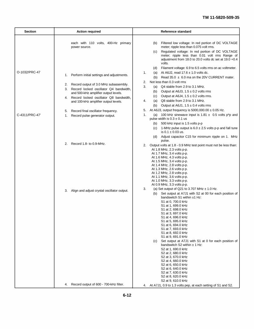
TM 11-5820-509-35
Section Action required Reference standard
O-1032/PRC-47
C-4311/PRC-47'
each with 110 volts, 400-Hz primarypower source.
1. Perform initial settings and adjustments.
2. Record output of 3.0 MHz subassembly.3. Record locked oscillator Q4 bandwidth,
and 500-kHz amplifier output levels.4. Record locked oscillator Q8 bandwidth,
and 100-kHz amplifier output levels.
5. Record final oscillator frequency.1. Record pulse generator output.
2. Record 1.8- to 0.9-MHz.
3. Align and adjust crystal oscillator output.
4. Record output of 600 - 700-kHz filter.
(b) Filtered low voltage: In red portion of DC VOLTAGEmeter; ripple less than 0.075 volt rms.
(c) Regulated voltage: In red portion of DC VOLTAGEmeter; ripple less than 0.01 volt rms Range ofadjustment from 18.0 to 20.0 volts dc set at 19.0 +0.4volts.
(d) Filament voltage: 6.9 to 6.5 volts rms on ac voltmeter.1. (a) At A6J2, read 17.6 ± 1.0 volts dc.
(b) Read 35.0 ± 6.0 ma on the 20V CURRENT mater.2. Not less than 0.3 volt rms3. (a) Q4 stable from 2.9 to 3.1 MHz.
(b) Output at A6J3, 1.5 ± 0.2 volts rms(c) Output at A6J4, 1.5 ± 0.2 volts rms.
4. (a) Q8 stable from 2.9 to 3.1 MHz.(b) Output at A6J1, 1.5 ± 0.4 volts rms
5. At A6J3, output frequency is 5000,000.00 ± 0.05 Hz.1. (a) 100 kHz sinewave input is 1.81 ± 0.5 volts p*p and
pulse width is 0.3 ± 0.1 us(b) 500 kHz input is 1.5 volts p-p(c) 1-MHz pulse output is 6.0 ± 2.5 volts p-p and fall tune
is 0.1 ± 0.03 us.(d) Adjust capacitor C15 for minimum ripple on 1. MHz
pulse.2. Output volts at 1.8 - 0.9 MHz test point must not be less than:
At 1.8 MHz, 2.3 volts p-p.At 1.7 MHz, 3.4 volts p-p.At 1.6 MHz, 4.3 volts p-p.At 1.5 MHz, 3.4 volts p-p.At 1.4 MHz, 2.8 volts p-p.At 1.3 MHz, 2.6 volts p p.At 1.2 MHz, 2.8 volts p-p.At 1.1 MHz, 3.6 volts p-p.At 1.0 MHz, 3.3 volts p-p.At 0.9 MHz, 3.3 volts p-p.
3. (a) Set output of Q21 to 3.707 MHz ± 1.0 Hz.(b) Set output at A7J1 with S2 at 00 for each position of
bandswitch S1 within ±1 Hz:S1 at 0, 700.0 kHzS1 at 1, 699.0 kHzS1 at 2, 698.0 kHzS1 at 3, 697.0 kHzS1 at 4, 696.0 kHzS1 at 5, 695.0 kHzS1 at 6, 694.0 kHzS1 at 7, 693.0 kHzS1 at 8, 692.0 kHzS1 at 9, 691.0 kHz
(c) Set output at A7J1 with S1 at 0 for each position ofbandswitch S2 within ± 1 Hz:S2 at 1, 690.0 kHzS2 at 2, 680.0 kHzS2 at 3, 670.0 kHzS2 at 4, 660.0 kHzS2 at 6, 650.0 kHzS2 at 6, 640.0 kHzS2 at 7, 630.0 kHzS2 at 8, 620.0 kHzS2 at 9, 610.0 kHz
4. At A7J1, 0.9 to 1.3 volts pep, at each setting of S1 and S2.
6-12

TM 11-5820-509-35
Section Action required Reference standard
5. Record output of 560 - 750-kHz filter.
6. Record frequency discriminator operation.
7. Adjust error voltages.
8. Verify successful antilock circuitoperation.
9. Record SMO mixer output.
5. At A7J4, from 575- to 725-kHz, 0.6 to 1.0 volt pep; at 650 and775 kHz, 0.7 volts p-p. maximum, and at 500 and 800 kHz,0.2 volts pep maximum.
6. (a) At A7J5, not less than 4.0 volts dc from 650 to 700 kHz; A7J6 not more than 1.5 volts for same frequencies. At A7J5, not more than 1.6 volts dc from 700 to 750 kHz; A7J6 not less than 4.0 volts for same frequencies.
(b) At A7J5, not less than 4.0 volts dc from 600 to 650kHz; A7J6 not more than 1.5 volts for samefrequencies. At A7J5, not more than 1.5 volts dcfrom 660 to 700 kHz; A7J6 not less than 4.0 volts forsame frequencies.
(c) At A7J5, not less than 4.0 volts dc from 560 to 600kHz; A7J6 not more than 1.5 volts for samefrequencies. At A7J5, not more than 1.5 volts dcfrom 600 to 650 kHz; A7J6 not less than 4.0 volts forsame frequencies.
7. Select R144 to provide balanced 10 kHz modulation levels atthe output circuits of Q9 and Q12.
8. ANTI-LOCK lamp operates satisfactory and A7J4reads 1.05volts pep.
9. At A7J4, 1.5 ± 0.4 volts pep throughout tuning range ofequipment.
Section II. PERFORMANCE TESTS
6-9. GeneralThis section contains the tests and performance datarequired to determine whether the repaired equipmentmeets the original performance requirementsestablished for Radio Set AN/PRC-47.6-10. Audio Frequency Amplifier AM-3506/PRC-47 (A8A1)
(Fig. 7-15)a. Test Equipment and Material.
(1) Audio Oscillator TS-382/U(2) Distortion Analyzer TS-723/U(3) Frequency Counter AN/URM-79/U(4) Loudspeaker LS-166/U (or Headset H233)
from AN /PRC -47(5) Multimeter ME-26A/U(6) Oscilloscope AN/USM-50(7) Output Meter TS-585/U(8) Power Supply (24 volts dc!, Harrison
6202B, or equal(9) Power Supply (-7 volts dc), Harrison
6203B or equal(10) Test fixture for AM-3506/PRC-47 (fig. 6-4)(11) Voltmeter ME-30A/U
b. Test Conditions and Equipment Connections.
CAUTIONBefore connecting the powersupplies to the test fixture, set theiroutput voltages to 24.0 ± 2.0 voltsand -7.0 ± 0.5 volts respectively.Then return the power on-off switchto off until instructed to applyprimary power to them.
(1) Connect the audio oscillator, frequencycounter, output meter and the two power supplies to thetest fixture as shown in figure 6-11. (The connectionsfor the remaining test equipment are detailed in theappropriate procedural steps below.
(2) Remove the dust cover from the module,set all potentiometers to mid-range ill turns from eitherend), and carefully insert the module into connector J1on the test fixture.
(3) Apply primary power to all test equipmentand turn on the power control switch of each unit.Immediately adjust the output of the 24 volts powersupply to 24.0 ± 0.5 volts dc and then place the POWERswitch of the test fixture to ON.
(4) Place the +20 V - +24 V switch to the +20V position and observe that the MODULE CURRENTmeter reads approximately 25 ma. Place the switch to+24 V and note the MODULE CURRENT indication isapproximately 55 ma.
6-13

TM 11-5820-509-35(5) Adjust the output of the -7 volts power
supply using the SIDETONE GATE TEST jack (J3) andthe SIDETONE GATE ADJUST control on the testfixture. The reading at J3 must be set to -7.0 ± 0.2 voltsdc. Then place the power control switch on the -7 voltspower supply to off.
(6) Permit the test equipment and the moduleto stabilize for at least 5 minutes before beginning thefollowing procedures.
(7) Set the IMPEDANCE switch on the outputmeter to 300 OHMS, and adjust the meter multiplier for5000 milliwatts full scale.
NOTEPerform the initial adjustments andeach of the following tests in theorder listed to avoid erroneous testresults or maladjustment of themodule gain settings.
Figure 6-11. Audio Frequency Amplifier AM-3506/PRC- 47 (A8A 7 ) Performance Tests, Initial Test EquipmentConnections
c. Initial Settings and Adjustments.(1) Set the audio oscillator output frequency
to 1700 Hz and adjust the output level to 0.1 volt rms atRCVR AUDIO IN jacks (38 and J14).
(2) Observe the output meter and adjustreceiver gain control R54 (fig. 3-94) until the meterreads 1.0 watt output (18.0 volts rms) at RCVR AUDIOOUT jacks (J7 and J13).
(3) Move the audio oscillator and thefrequency counter to MIKE AMPL IN jacks (J5 and J11).reset the output level of the audio oscillator to 0.1 voltrms at 1700 Hz, if necessary.
(4) Connect the oscilloscope to MIKE AMPLOUT jacks (J6 and J12). Place the PTT switch of thetest fixture to ON and adjust microphone amplifier gaincontrol R27 (fig- 3-94) until a deflection of 3.5 voltspeak-to-peak is observed on the oscilloscope.
(5) Reduce the output level of the audiooscillator to 0. Reset it to 0.010 ± 0.002 volt rms atMIKE AMPL IN jacks (J5 and J11) and adjustpotentiometer R40 (fig. 3-94) until the VOX ON lamp(DS2) on the test fixture lights
(6) Move the oscilloscope input to RCVRAUDIO OUT jacks (J7 and J13). Energize the- 7 voltsdc power supply and reset SIDETONE GATE ADJUSTcontrol for -7.1 ± 0.1 volts dc at SIDETONE GATETEST jack (J3), if necessary. Increase the output levelof the audio oscillator to 0.1 volt rms at 1700 Hz.
(7) Adjust potentiometer R46 (fig. 3-94) untilan oscilloscope deflection of 20 volts peak-to-peak isobserved. Be sure that the waveshape is symmetrical(not clipped).
d. Maximum Output Levels, Receive Mode.(1) Turn off the -7 volts dc power supply by
6-14
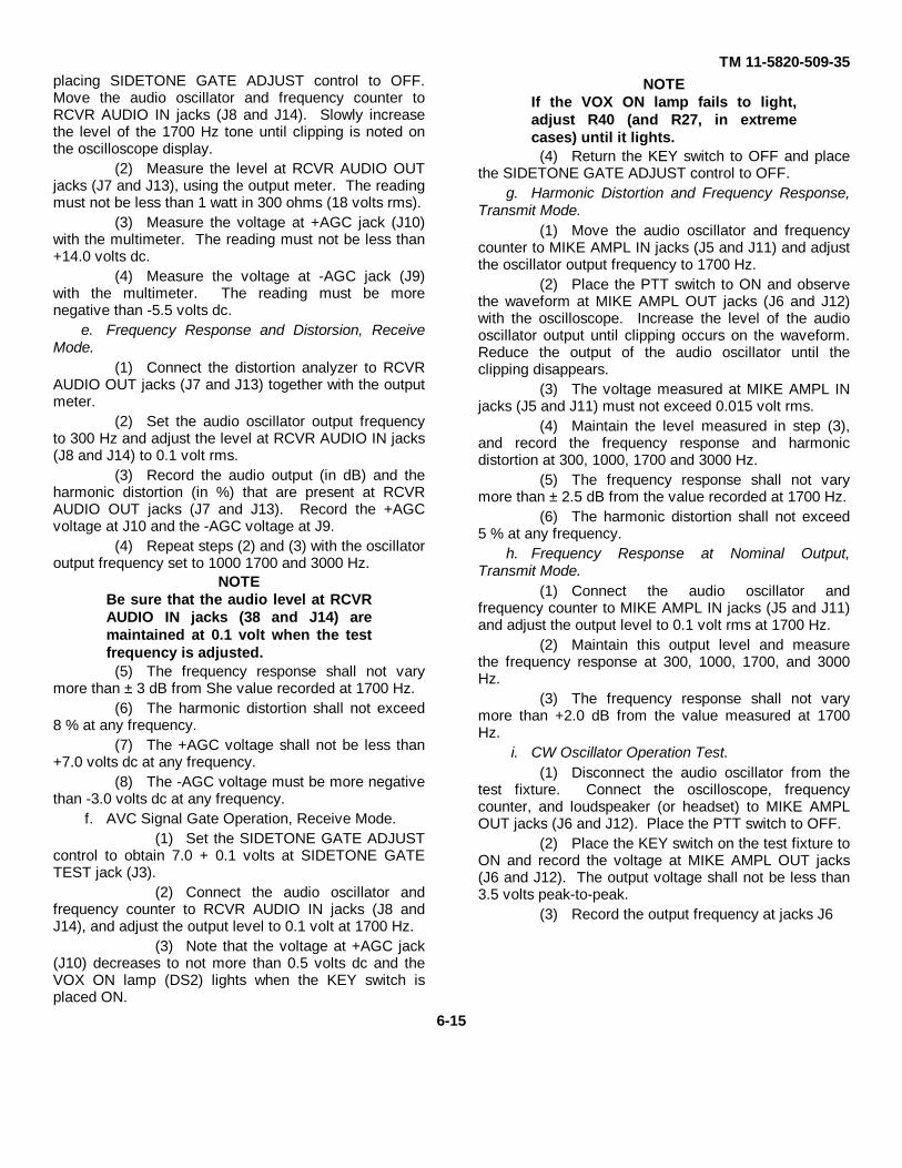
TM 11-5820-509-35placing SIDETONE GATE ADJUST control to OFF.Move the audio oscillator and frequency counter toRCVR AUDIO IN jacks (J8 and J14). Slowly increasethe level of the 1700 Hz tone until clipping is noted onthe oscilloscope display.
(2) Measure the level at RCVR AUDIO OUTjacks (J7 and J13), using the output meter. The readingmust not be less than 1 watt in 300 ohms (18 volts rms).
(3) Measure the voltage at +AGC jack (J10)with the multimeter. The reading must not be less than+14.0 volts dc.
(4) Measure the voltage at -AGC jack (J9)with the multimeter. The reading must be morenegative than -5.5 volts dc.
e. Frequency Response and Distorsion, ReceiveMode.
(1) Connect the distortion analyzer to RCVRAUDIO OUT jacks (J7 and J13) together with the outputmeter.
(2) Set the audio oscillator output frequencyto 300 Hz and adjust the level at RCVR AUDIO IN jacks(J8 and J14) to 0.1 volt rms.
(3) Record the audio output (in dB) and theharmonic distortion (in %) that are present at RCVRAUDIO OUT jacks (J7 and J13). Record the +AGCvoltage at J10 and the -AGC voltage at J9.
(4) Repeat steps (2) and (3) with the oscillatoroutput frequency set to 1000 1700 and 3000 Hz.
NOTEBe sure that the audio level at RCVRAUDIO IN jacks (38 and J14) aremaintained at 0.1 volt when the testfrequency is adjusted.
(5) The frequency response shall not varymore than ± 3 dB from She value recorded at 1700 Hz.
(6) The harmonic distortion shall not exceed8 % at any frequency.
(7) The +AGC voltage shall not be less than+7.0 volts dc at any frequency.
(8) The -AGC voltage must be more negativethan -3.0 volts dc at any frequency.
f. AVC Signal Gate Operation, Receive Mode.(1) Set the SIDETONE GATE ADJUST
control to obtain 7.0 + 0.1 volts at SIDETONE GATETEST jack (J3).
(2) Connect the audio oscillator andfrequency counter to RCVR AUDIO IN jacks (J8 andJ14), and adjust the output level to 0.1 volt at 1700 Hz.
(3) Note that the voltage at +AGC jack(J10) decreases to not more than 0.5 volts dc and theVOX ON lamp (DS2) lights when the KEY switch isplaced ON.
NOTEIf the VOX ON lamp fails to light,adjust R40 (and R27, in extremecases) until it lights.
(4) Return the KEY switch to OFF and placethe SIDETONE GATE ADJUST control to OFF.
g. Harmonic Distortion and Frequency Response,Transmit Mode.
(1) Move the audio oscillator and frequencycounter to MIKE AMPL IN jacks (J5 and J11) and adjustthe oscillator output frequency to 1700 Hz.
(2) Place the PTT switch to ON and observethe waveform at MIKE AMPL OUT jacks (J6 and J12)with the oscilloscope. Increase the level of the audiooscillator output until clipping occurs on the waveform.Reduce the output of the audio oscillator until theclipping disappears.
(3) The voltage measured at MIKE AMPL INjacks (J5 and J11) must not exceed 0.015 volt rms.
(4) Maintain the level measured in step (3),and record the frequency response and harmonicdistortion at 300, 1000, 1700 and 3000 Hz.
(5) The frequency response shall not varymore than ± 2.5 dB from the value recorded at 1700 Hz.
(6) The harmonic distortion shall not exceed5 % at any frequency.
h. Frequency Response at Nominal Output,Transmit Mode.
(1) Connect the audio oscillator andfrequency counter to MIKE AMPL IN jacks (J5 and J11)and adjust the output level to 0.1 volt rms at 1700 Hz.
(2) Maintain this output level and measurethe frequency response at 300, 1000, 1700, and 3000Hz.
(3) The frequency response shall not varymore than +2.0 dB from the value measured at 1700Hz.
i. CW Oscillator Operation Test.(1) Disconnect the audio oscillator from the
test fixture. Connect the oscilloscope, frequencycounter, and loudspeaker (or headset) to MIKE AMPLOUT jacks (J6 and J12). Place the PTT switch to OFF.
(2) Place the KEY switch on the test fixture toON and record the voltage at MIKE AMPL OUT jacks(J6 and J12). The output voltage shall not be less than3.5 volts peak-to-peak.
(3) Record the output frequency at jacks J6
6-15

TM 11-5820-509-35
and J12. The cw oscillator output frequency shall be800 ± 50 Hz.
(4) Operate the KEY switch between theMOM ON and OFF positions and observe thewaveshape on the oscilloscope and listen to the outputtone in the loudspeaker. The tone must be free fromchirps and clicks, and the waveform shall display nosharp transients.
(5) When the KEY switch is held ON, theVOX ON lamp lights.6-11. Amplifier-Modulator AM-3507/PRC-47 (A8A2)
(fig. 7-10)a. Test Equipment and Material.
(1) Audio Oscillator TS-382/U(2) Converter (for spectrum analyzer),
Hewlett-Packard K15-8551B(3) Distortion Analyzer TS-723/U(4) Frequency Counter AN /URM -79/U(5) Multimeter ME-26A/U(6) Oscilloscope AN/USM-50(7) Power Supply (24 volts dc), Harrison
6202B, or equal
(8) Power Supply (-110 volts dc), Harrison6207B, or equal
(9) Resistance Decade Box MX-3991/V(10) Signal Generator SG-103/URM-25F(11) Spectrum Analyzer AN/UPM-110(12) Test fixture for AM-3507/PRC-47 (fig. 6-
5)(13) Voltmeter ME 30A/U
b. Test Conditions and Equipment Connections.CAUTION
Before connecting the powersupplies to the test fixture, set theiroutput voltages to 26.0 ± 2.0 voltsand -110 ± 5 volts respectively. Thenreturn the power on-off switches tothe off position until instructed toapply primary power to them.
(1) Connect the test instruments to the testfixture as shown in figure 6-12. (The connections for theremaining test equipment are detailed in the appropriateprocedural steps below.)
Figure 6-12. Amplifier-Modulator AM 3507/PRC-47 (A8A2), Performance Tests, Initial Test EquipmentConnections.
6-16
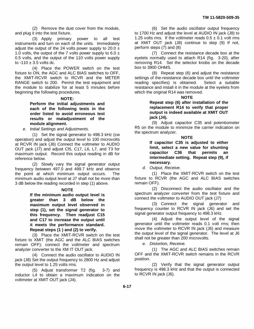
TM 11-5820-509-35
(2) Remove the dust cover from the module,and plug it into the test fixture.
(3) Apply primary power to all testinstruments and turn on each of the units. Immediatelyadjust the output of the 24 volts power supply to 20.0 ±1.0 volts, the output of the 7 volts power supply to 6.0 ±0.5 volts, and the output of the 110 volts power supplyto -110 ± 3.5 volts dc.
(4) Place the POWER switch on the testfixture to ON, the AGC and ALC BIAS switches to OFF,the XMIT-RCVR switch to RCVR and the METERRANGE switch to 200. Permit the test equipment andthe module to stabilize for at least 5 minutes beforebeginning the following procedures.
NOTE:Perform the initial adjustments andeach of the following tests in theorder listed to avoid erroneous testresults or maladjustment of themodule alignment.
e. Initial Settings and Adjustments.(1) Set the signal generator to 498.3 kHz (cw
operation) and adjust the output level to 100 microvoltsat RCVR IN jack (J6) Connect the voltmeter to AUDIOOUT jack (J7} and adjust Cl5, C17, L6, L7, and T3 formaximum output. Record this output reading in dB forreference below.
(2) Slowly vary the signal generator outputfrequency between 497.0 and 499.7 kHz and observethe point at which minimum output occurs. Theminimum audio output level at J7 shall not be more than3 dB below the reading recorded in step (1) above.
NOTEIf the minimum audio output level isgreater than 3 dB below themaximum output level observed instep (1), set the signal generator tothis frequency. Then readjust C15and C17 to increase the output untilit meets the performance standard.Repeat steps (1 ) and (2) to verify.
(3) Place the XMIT-RCVR switch on the testfixture to XMIT (the AGC and the ALC BIAS switchesremain OFF); connect the voltmeter and spectrumanalyzer converter to the XM IT OUT jack.
(4) Connect the audio oscillator to AUDIO INjack (J8) Set the output frequency to 2800 Hz and adjustthe output level to 1.25 volts rms.
(5) Adjust transformer T2 (fig. 3-7) andinductor L4 to obtain a maximum indication on thevoltmeter at XMIT OUT jack (J4).
(6) Set the audio oscillator output frequencyto 1700 Hz and adjust the level at AUDIO IN jack (J8) to1.25 volts rms. If the voltmeter reads 0.5 ± 0.1 volt rmsat XMIT OUT jack (J8) continue to step (9) If not,perform steps (7) and (8)
(7) Connect the resistance decade box at theeyelets normally used to attach R14 (fig. 3-20), afterremoving R14. Set the selector knobs on the decadebox to 3900 OHMS.
(8) Repeat step (6) and adjust the resistancesettings of the-resistance decade box until the voltmeterreading specifies) is obtained. Select a suitableresistance and install it in the module at the eyelets fromwhich the original R14 was removed.
NOTERepeat step (6) after installation of thereplacement R14 to verify that properoutput is indeed available at XMIT OUTjack (J4).
(9) Adjust capacitor C35 and potentiometerR5 on the module to minimize the carrier indication onthe spectrum analyzer.
NOTEIf capacitor C35 is adjusted to eitherlimit, select a new value for shuntingcapacitor C36 that permits anintermediate setting. Repeat step (9), ifnecessary.
d. Output, Receive.(1) Place the XMIT-RCVR switch on the test
fixture to RCVR (the AGC and ALC BIAS switchesremain OFF).
(2) Disconnect the audio oscillator and thespectrum analyzer converter from the test fixture andconnect the voltmeter to AUDIO OUT jack (J7)
(3) Connect the signal generator andfrequency counter to RCVR IN jack (J6) and set thesignal generator output frequency to 498.3 kHz.
(4) Adjust the output level of the signalgenerator until the voltmeter reads 0.1 volt rms; thenmove the voltmeter to RCVR IN jack (J6) and measurethe output level of the signal generator. The level at J6shall not be greater than 200 microvolts.
e. Distortion, Receive.(1) The AGC and ALC BIAS switches remain
OFF and the XMIT-RCVR switch remains in the RCVRposition.
(2) Verify that the signal generator outputfrequency is 498.3 kHz and that the output is connectedto RCVR IN jack (J6).
6-17
TM 11-5820-509-35
(3) Adjust the output level of the signalgenerator until the voltmeter reads 0.1 volt rms atAUDIO OUT jack (J7)
(4) Place the AGC switch to ON and set AGCADJUST control for a voltmeter reading of 0.05 volt rmsat AUDIO OUT jack (J7).
(5) Connect the distortion analyzer to AUDIOOUT jack (J7) and observe that the harmonic distortiondoes not exceed 5 %.
(6) Repeat steps (2) through (4) except adjustthe signal generator output frequency to 497.0 kHz.Repeat with signal generator output frequency set to499.7 kHz. The harmonic distortion observed shall notexceed 5 % at either frequency.
(7) Disconnect the distortion analyzer andconnect the oscilloscope at AUDIO OUT jack (J7).
(8) Increase the output of the signal generatorto 0.05 volt rms and vary the signal generator outputfrequency between 497 and 500 kHz.
(9) There shall be no spikes or ripple on theaudio signal and no sudden increase in output levelindicated on the oscilloscope trace.
f. Selectivity, Receive.(1) Place the AGC and ALC BIAS switches to
OFF and the XMIT-RCVR switch to RCVR. Verify thatthe voltmeter is connected to AUDIO OUT jack (J7)
(2) Verify that the signal generator outputfrequency is set to 498.3 kHz and that the voltmeterreads 0.1 volt rms.
(3) Move the voltmeter to RCVR IN jack (J6)and increase the signal generator output level by 60 dB.Return the voltmeter to AUDIO OUT jack (J7) and varythe signal generator output frequency below 498.3 kHzuntil the voltmeter again reads 0.1 volt rms. Record thesignal generator frequency.
(4) Adjust the signal generator outputfrequency above 498.3 kHz until the voltmeter againreads 0.1 volt rms. Record the signal generator outputfrequency. The difference between the frequencyobtained in step (4) and the frequency obtained in step(3) shall not be greater than 6.0 kHz.
g. Frequency Response, Receive.(1) Reduce the signal generator output and
reset the output frequency to 498.3 kHz. Adjust theoutput level of the signal generator until the volmeterreads 0.1 volt rms.
(2) Adjust the signal generator to 497.0 kHzand record the output (in dB) with reference to 0 dB forthe voltmeter reading in step (1).
(3) Adjust the signal generator to 499.7 kHz
and record the output (in dB) with reverence to 0 dB forthe voltmeter reading in step (1). The output level shallnot increase more than 3 dB above the reference in step(1), nor decrease more than 4 dB below that referenceat 497.0 and 499.7 kHz.6-12. Signal Data Translator CV-1377A/PRC-47
(A8A3)(fig. 7-11)
a. Test Equipment and Material.(1) Gauge, overtravel 0.041-in. (fig. 6-2)(2) Gauge, plug (depth) (fig. 6-1)(3) Gauge, thickness 0.0.02 to 0.020-in.
(FSN 5210-031- 1504)(4) Frequency Counter AN/URM-78/U(5) Multimeter ME-26A/U(6) Oscilloscope AN/USM-50(7) Power Supply (24 volts dc) Harrison
6202B (2 required)(8) Power Supply 1110 volts dc), Harrison
6207 B.(9) Receiver R-1433/UR 6-6).
(10) Signal Generator SG-103/URM-25F.(11) Test Fixture for CV-1377A/PRC-47 (fig.(12) Test Fixture, indexing (fig. 6-7).(13) Voltmeter ME-30A/U.
b. Test Conditions and Equipment ConnectionsCAUTION
Before connecting the powersupplies to the test fixture, set theiroutput voltages to 14.0 ± 2.0 volts,26.5 ± 2.0 volts, and -110 ± 5 volts dcrespectively. Then return the poweron-off switches to the off positionuntil instructed to apply primarypower to them.
(1) connect the test instruments to the testfixture as shown in figure 6-13. (The connections for theremaining test equipment are detailed in the appropriateprocedural step below.)
(2) Before placing the CV-1377A/PRC-47 intothe test fixture, remove the top and bottom covers fromthe module. Perform the mechanical alignmentprocedures (step c ) it the slug rack or its associatedinductors have been replaced.
(3) Place all switches on the test fixture toOFF and all of the controls to zero.
(4) Apply power to all test equipment and turnon each of them. Place the test fixture POWER ON-OFF switch to ON and reset the output of the powersupplies to 19.0 ± 1.0 volts dc at connector J 1-3, 26.5 ±1.5 volts dc at connector J 1-4, and -110 ± 3.5 volts dcat connector J5-E.
6-18
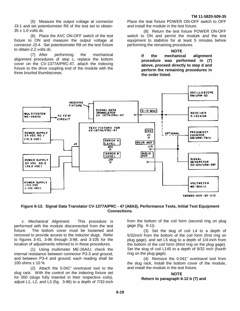
TM 11-5820-509-35(5) Measure the output voltage at connector
J3-1 and set potentiometer R6 of the test set to obtain-35 ± 1.0 volts dc.
(6) Place the AVC ON-OFF switch of the testfixture to ON and measure the output voltage atconnector J3-4. Set potentiometer R8 on the test fixtureto obtain-2.2 volts dc.
(7) After performing the mechanicalalignment procedures of step c, replace the bottomcover on the CV-1377A/PRC-47, attach the indexingfixture to the drive coupling end of the module with thethree knurled thumbscrews.
Place the teat fixture POWER ON-OFF switch to OFFand install the module in the test fixture.
(8) Return the test fixture POWER ON-OFFswitch to ON and permit the module and the testequipment to stabilize for at least 5 minutes beforeperforming the remaining procedures.
NOTEIf the mechanical alignmentprocedure was performed in (7)above, proceed directly to step d andperform the remaining procedures inthe order listed.
Figure 6-13. Signal Data Translator CV-1377A/PRC - 47 (A8A3), Performance Tests, Initial Test EquipmentConnections.
c. Mechanical Alignment. This procedure isperformed with the module disconnected from the testfixture. The bottom cover must be loosened andremoved to provide access to the inductor slugs. Referto figures 3-41, 3-96 through 3-98, and 3-105 for thelocation of adjustments referred to in these procedures.
(1) Using multimeter ME-26A/U, check theinternal resistance between connector P3-3 and ground,and between P3-4 and ground; each reading shall be100 ohms ± 10 %
(2) Attach the 0.041" overtravel tool to theslug rack. With the control on the indexing fixture setfor 000 (slugs fully inserted in their respective coils),adjust L1, L2, and L3 (fig. 3-96) to a depth of 7/32-inch
from the bottom of the coil form (second ring on pluggage (fig. 6-1)).
(3) Set the slug of coil L4 to a depth of5/32inch from the bottom of the coil form (first ring onplug gage), and set L5 slug to a depth of 1/4-inch fromthe bottom of the coil form (third ring on the plug gage).Set the slug of coil L145 to a depth of 9/32 inch (fourthring on the plug gage).
(4) Remove the 0.041" overtravel tool fromthe slug rack, install the bottom cover of the module,and install the module in the test fixture.
NOTEReturn to paragraph 6-12 b (7) and
6-19
TM 11-5820-509-35
continue the procedures afterperforming the remaining initialsetup instructions.
d. 5- to 14- MHz Ringer Circuit Alignment.(1) Connect the oscilloscope and receiver (or
frequency counter) and the multimeter rf probe to the 5-14 MHz tip jack at the right side of the upper shelf of thetest fixture.
(2) Set the switch on the indexing fixture (fig.6-7) to 2, and the slug rack control to 000 position.
(3) On the test fixture, place the POWERON-OFF switch to ON, the FUNCTION SEL switch toRCVR, the AVC switch to ON, the LOOP SEL switch toCLOSED, and OSC CONT switches to 0 and 00.
(4) Adjust capacitor C248 (fig. 3-97) toprovide a 5.000 MHz reading on the receiver (orfrequency counter) Set the oscilloscope sweep rate to1.0 microseconds/cm. and readjust capacitor C248 forminimum 1-MHz ripple (amplitude modulation) on theoscilloscope wavetrain. The remaining 5.0 MHzwavetrain amplitude shall be not less than 0.9 voltspeak-to-peak.
(5) Rotate the switch on the indexing fixtureto 3 and set the receiver to 6.0 MHz.
(6) Adjust capacitor C250 to provide a 6.000M Hz reading on the receiver (or frequency counter).Readjust capacitor C250 for minimum 1-MHz ripple onthe oscilloscope wavetrain. The remaining 6.0 MHzwavetrain amplitude shall not be less than 0.9 voltspeak-to-peak.
(7) Rotate the switch on the indexing fixtureto 4 and set the receiver to 7.0 MHz.
(8) Adjust capacitor C252 to provide a 7.000MHz reading on the receiver (or frequency counter).Readjust capacitor C252 for minimum 1-MHz ripple onthe oscilloscope wavetrain. The remaining 7.0 MHzwavetrain amplitude shall not be less than 0.9 volt peak-to-peak.
(9) Rotate the switch on the indexing fixtureto 5 and set the receiver to 8.0 MHz.
(10) Adjust capacitor C254 to provide an 8.000MHz reading on the receiver (or frequency counter).Readjust capacitor C254 for minimum 1-MHz ripple onthe oscilloscope wavetrain. The remaining 8.0 MHzwavetrain amplitude shall not be less than 0.9 volt peak-to-peak.
(11) Rotate the switch on the indexing fixtureto 6 and set the receiver to 9.0 MHz.
(12) Adjust capacitor C256 to provide a 9.000MHz reading on the receiver (or frequency counter).Readjust capacitor C256 for minimum 1-MHz ripple onthe oscilloscope wavetrain. The remaining 9.0 MHzwavetrain amplitude shall not be less than 0.9 volt peak-to-peak.
(13) Rotate the switch-on the indexing fixtureto 7 and set the receiver to 10.0 MHz.
(14) Adjust capacitor C258 to provide a 10.000MHz reading on the receiver (or frequency counter).Readjust capacitor C258 for minimum 1-MHz ripple onthe oscilloscope wavetrain. The remaining 10.0 MHzwavetrain amplitude shall not be less than 0.9 volt peak-to-peak.
(15) Rotate the switch on the indexing fixtureto 8 and set the receiver to 11.0 M Hz.
(16) Adjust capacitor C260 to provide an11.000 MHz reading on the receiver (or frequencycounter}. Readjust capacitor C260 for minimum 1-MHzripple on the oscilloscope wavetrain. The remaining11.0 MHz wavetrain amplitude shall not be less than 0.9volt peak-to-peak.
(17) Rotate the switch on the indexing fissureto 9 and set the receiver to 12.0 MHz.
(18) Adjust capacitor C262 to provide a 12.000MHz reading on the receiver (or frequency counter).Readjust capacitor C262 for minimum 1-MHz ripple onthe oscilloscope wavetrain. The remaining 12.0 MHzwavetrain amplitude shall not be less than 0.9 volt peak-to-peak.
(19) Rotate the switch on the indexing fixtureto 10 and set the receiver to 13.0 MHz.
(20) Adjust capacitor C264 to provide a 13.000MHz reading on the receiver (or frequency counter).Readjust capacitor C264 for minimum 1-MHz ripple onthe oscilloscope wavetrain. The remaining 13.0 MHzwavetrain amplitude shall not be less than 0.9 volt peak-to-peak.
(21) Rotate the switch on the indexing fixtureto 11 and set the receiver to 14.0 M Hz.
(22) Adjust capacitor C266 to provide a 14.000MHz reading on the receiver (or frequency counter}.Readjust capacitor C266 for minimum 1-MHz ripple-onthe oscilloscope wavetrain. The remaining 14.0 MHzwavetrain amplitude shall not be less than 0.9 volt peak-to-peak.
e. Oscillator Output Test(1) Rotate the indexing fixture switch (fig. 67)
to 2, and set the slug rack control to 500.(2) On the test fixture, set the LOOP SEL
switch to CLOSED, place OSC CONTROL switch S1 to0, and set OSC CONTROL switch S2 to 50.
(3) Connect the multimeter rf probe to thetest fixture VFO jack.
(4) Read the multimeter; then rotate theswitch on the indexing fixture to 3, and the OSCCONTROL switch S1 to 1 and read the multimeteragain. Continue the simultaneous advancement of theindexing fixture switch and the OSC CONTROL switchS1 throughout their range. The multimeter reading shallnot be leas than 1.0 volt at any band position.
6-20
TM 11-5820-509-35
f. Oscillator Alignment and Tracking Adjustment.(1) On the test fixture, place the POWER
ON-OFF switch to OFF and the LOOP SEL switch toOPEN.
(2) Remove the module from the test fixtureand adjust capacitor C344 (fig. 3-98) to its mechanicalmidpoint.
(3) Return the test fixture POWER ON-OFFswitch to ON and adjust ERROR A ADJ and ERROR BADJ controls to provide 1.0 ± 0.05 volt dc at test pointsJ19 and J20. Record the voltage at each of these testpoints.
(4) Again place the test fixture POWER ON-OFF switch to OFF and install the module in the testfixture.
(5) With the multimeter connected to J19,close the test fixture POWER ON-OFF switch to ONand note that the ERROR B LEVEL does not changemore than ± 0.1 volt from the reading recorded in step(3).
(6) Move the multimeter to J20 and observethat ERROR A LEVEL does not change more than ± 0.1volt from the reading recorded in step (31.
(7) Adjust the receiver to 2.500 MHz andloosely couple the receiver antenna to the VFO jack onthe test fixture. (The frequency counter may beconnected to the test fixture VFO jack as an alternatemethod.)
(8) On the indexing fixture (fig. 6-7), set theswitch to 2, and rotate the slug rack control to 000position.
(9) Adjust inductor L135 (fig. 3-105) until thevfo output is 2,500 ± 1 kHz.
(10) Rotate the slug rack control on theindexing fixture to the 999 position and adjust inductorL125 (fig. 3-96) until the vfo output is 3,500 ± 1 kHz.
(11) Repeat steps (9) and (10) until bothfrequency settings are within the ± 1 kHz limit specified.
(12) On the indexing fixture, set the switch to 3and rotate the slug rack control to 000. Adjust inductorL136 (fig. 3-105) until the vfo output is 3,500 ± 1 kHz.
(13) Rotate the slug rack control on theindexing fixture to the 999 position and adjust inductorL126 (fig. 3-96) until the vfo output is 4,500 ± 1 kHz
(14) Repeat steps (12) and (13) until bothfrequency settings are within the ° 1 kHz limit specified.
(15) On the indexing fixture, set the switch to 4and rotate the slug rack control to 000. Adjust inductorL137 (fig. 3-105) until the vfo output is 4,500 ± 1 kHz.
(16) Rotate the slug rack control on theindexing fixture to the 999 position and adjust inductorL127 (fig. 3-96) until the vfo output is 5,500 ± 1 kHz.
(17) Repeat steps (16) and (17) until bothfrequency settings are within the ± 1 kHz limit specified.
(18) On the indexing fixture, set the switch to 5and rotate the slug rack control to 000. Adjust inductorL138 (fig. 3-96) until the vfo output is 5,500 ± 1 kHz.
(19) Rotate the slug rack control on theindexing fixture to the 999 position and adjust inductorL128 (fig. 3-105) until the vfo output is 6,500 ± 1 kHz.
(20) Repeat steps (18) and (19) until bothfrequency settings are within the ± 1 kHz km specified.
(21) On the indexing fixture, set the switch toand rotate the slug rack control to 000. Adjust inductorL139 (fig. 3-96) until the vfo output is 6,500 ± 1 kHz.
(22) Rotate the slug rack control on theindexing fixture to the 999 position and adjust inductorL129 (fig. 3-105) until the vfo output is 7,600 ± 1 kHz.
(23) Repeat steps (21) and (22) until bothfrequency settings are within the ± 1 kHz limit specified.
(24) On the indexing fixture, set the switch to 7and rotate the slug rack control to 000. Adjust inductorL140 (fig. 3-96) until the vfo output is 7,500 ± 1 kHz.
(25) Rotate the slug rack control on theindexing fixture to the 999 position and adjust inductorL130 (fig. 3-105) until the vfo output is 8,600 ± 1 kHz.
(26) Repeat steps (24) and (25) until bothfrequency settings are within the ± 1 kHz limit specified.
(27) On the indexing fixture, set the switch to 8and rotate the slug rack control to 000. Adjust inductorL141 (fig. 3-96) until the vfo output is 8,500 ± 1 kHz.
(28) Rotate the slug rack control on theindexing fixture to the 999 position and adjust inductorL131 (fig. 3-105) until the vfo output is 9,500 ± 1 kHz.
(29) Repeat steps (27) and (28) until bothfrequency settings are within the ± 1 kHz limit specified.
(30) On the indexing fixture, set the switch to 9and rotate the slug rack control to 000. Adjust
6-21

TM 11-5820-509-35
inductor L142 (fig. 3-96) until the vfo output is 9,500 ± 1kHz.
(31) Rotate the slug rack control on theindexing fixture to the 999 position and adjust inductorL132 (fig. 3-105) until the vfo output is 10,500 ± 1 kHz.
(32) Repeat steps (30) and (31) until bothfrequency settings are within the ± 1 kHz limit specified.
(33) On the indexing fixture, set the switch to10 and rotate the slug rack control to 000. Adjustinductor L143 (fig. 3-105) until the vfo output is 10,500± 1 kHz.
(34) Rotate the slug rack control on theindexing fixture to the 999 position and adjust inductorL133 (fig. 3-96) until the vfo output is 11,500 ± 1 kHz.
(35) Repeat steps (33) and (34) until bothfrequency settings are within the ± 1 kHz limit specified.
(36) On the indexing fixture, set the switch to11 and rotate the slug rack control to 000. Adjustindictor L144 (fig. 3-105) until the vfo output is 11,500 ±1 kHz.
(37) Rotate the slug rack control on theindexing fixture to the 999 position and adjust inductorL134 (fig. 3-96) until the vfo output is 12,500 ± 1 kHz.
(38) Repeat steps (36) and (37) until bothfrequency settings are within the ± 1 kHz limit specified.
(39) Without further adjustment to theinductors mentioned above, record the oscillator outputfrequencies for each setting of the band switch and theslug rack control on the indexing fixture. The maximumallowable deviation from the desired oscillator output is± 12 kHz within any one band.
NOTEIf the frequency deviates more thanthis amount from the desired value,tracking correction is necessary. Ifthe majority of the bands is high (orlow) at the 500 position of the slugrack control, adjust C344 (fig. 3-98).If C344 fails to compensate fortracking error, replace one or more ofthe capacitors (C299, C301, C303,C305, C307, C309, C311, C313, C315or C317) in the shunt coilassemblies. The low frequency endof bands 3 through 11 (M Hz) can beraised or lowered to a maximumdeviation of ± 8 kHz to assist intracking at mid-band. Do not adjustthe low -frequency end of the 2.0 MHz band.
g. Rf Alignment, Receive Mode(1) On the test fixture, place the FUNCTION
SEL switch to RCVR, the LOOP SEL switch toCLOSED, and then place the POWER ON-OFF switchto ON. Set OSC CONTROL to 0 and 09.
(2) Rotate the switch on the indexing fixture(fig. 6-7) to 2 and set the slug rack control to the 000position.
(3) Adjust the signal generator to 2.0 MHz,CW operation, and connect the RF OUTPUT jack to theRCVR ANT jack of the test fixture.
(4) Connect the voltmeter to the AUDIO OUTjack of the test fixture and adjust the signal generatoroutput frequency and level controls until an indication isobtained on the voltmeter.
(5) Adjust inductors L7, L22, L37, and L52(fig. 3-105) to obtain maximum voltmeter reading.Minimum limit is 0.04 volts rms.
NOTEAdjust the output level of the signalgenerator and the voltmeter scalemultiplier as required to reduce thepossibility of limiting within theseveral modules.
(6) Rotate the switch of the indexing fixture to3 and set the output of the signal generator toapproximately 3.0 MHz. Adjust the output level andfrequency of the signal generator until an indication isobtained on the voltmeter.
(7) Adjust inductors L8, L23, L38, and L53(fig. 3-105) to obtain maximum voltmeter reading.Minimum limit is 0.04 volts rms.
(8) Rotate the switch of the indexing fixture to4 and set the output of the signal generator toapproximately 4.0 MHz. Adjust the output level andfrequency of the signal generator until an indication isobtained on the voltmeter.
(9) Adjust inductors L9, L24, L39, and L54(fig. 3-105) to obtain maximum voltmeter reading.Minimum limit is 0.04 volts rms.
(10) Rotate the switch of the indexing fixture to5 and set the output of the signal generator toapproximately 5.0 MHz. Adjust the output level andfrequency of the signal generator until an indication isobtained on the voltmeter.
(11) Adjust inductors L10, L25 L40, and L55(fig. 3-96) to obtain maximum voltmeter reading.Minimum limit is 0.04 volts rms.
(12) Rotate the switch of the indexing fixture to6 and set the output of the signal generator toapproximately 6.0 MHz. Adjust the output level andfrequency of the signal generator until an indication isobtained on the voltmeter.
(13) Adjust inductors L11, L26, L41, and
6-22
TM 11-5820-509-35L56 (fig. 3-96) to obtain maximum voltmeter reading.Minimum limit is 0.04 volts rms.
(14) Rotate the switch of the indexing fixture to7 and set the output of the signal generator toapproximately 7.0 MHz. Adjust the output level andfrequency of the signal generator until an indication isobtained on the voltmeter.
(15) Adjust inductors L12, L27, L42, and L57(fig. 3-96) to obtain maximum voltmeter reading.Minimum limit is 0.04 volts rms.
(16) Rotate the switch on the indexing fixtureto 8 and set the output of the signal generator toapproximately 8.0 MHz. Adjust the output level andfrequency of the signal generator until an indication isobtained on the voltmeter.
(17) Adjust inductors L13, L28, L43, and L58(fig. 3-96) to obtain maximum voltmeter reading.Minimum limit is 0.04 volts rms.
(18) Rotate the switch of the indexing fixture to9 and set the output of the signal generator toapproximately 9.0 MHz. Adjust the output level andfrequency of the signal generator until an indication isobtained on the voltmeter.
(19) Adjust inductors L14, L29, L44, and L59(fig. 3-96) to obtain maximum voltmeter reading.Minimum limit is 0.04 volts rms.120) Rotate the switch of the indexing fixture to 10 andset the output of the signal generator to approximately10.0 MHz. Adjust the output level and frequency of thesignal generator until an indication is obtained on thevoltmeter.
(21) Adjust inductors L15, L30, L45, and L60(fig. 3-105) to obtain maximum voltmeter reading.Minimum limit is 0.04 volts rms.
(22) Rotate the switch of the indexing fixture to11 and set the output of the signal generator toapproximately 11.0 MHz. Adjust the output level andfrequency of the signal generator until an indication isobtained on the voltmeter.
(23) Adjust inductors L16, L31, L46 and L61(fig. 3-105) to obtain maximum voltmeter reading.Minimum limit is 0.04 volts rms.
h. Rf Alignment, Transmit Mode.(1) On the test fixture, place the FUNCTION
SEL switch to XMIT, the LOOP SEL switch to CLOSED,then place the POWER ON-OFF switch to ON, andOSC CONTROL switches to 0 and 00.
(2) Rotate the switch on the indexing fixture(fig. 6-7) to 2 and set the slug rack control to the 000position.
(3) On the top of the module, rotate the rfgain control (R148) to its clockwise stop.
(4) Adjust the signal generator to 500 kHz,CW operation, and connect the RF OUTPUT jack to 500KHZ IN jack (J18) on the test fixture.
(5) Connect the rf probe of the multimeter toRF OUT jack (J13) on the test fixture and adjustinductor L67 (fig. 3-105) to obtain maximum output.
NOTEAdjust the output level of the signalgenerator as required to limit themaximum indication on themultimeter to 80 volts rms.
(6) On the indexing fixture, rotate the slugrack control to the 999 position. On the test fixture setOSC CONTROL switches to 9 and 99; then adjustinductor L5 ((fig.. 3-96) for maximum output indication.
(7) Reset the slug rack control on theindexing fixture to the 000 position and set the OSCCONTROL switches to 0 and 00; then repeat steps (5)and (6) until further adjustment no longer increases theoutput level.
(8) Record the signal generator output levelnecessary to produce 80 volts rms at J13, as theindexing fixture is placed at the 000, 500, and 999positions (set OSC CONTROL switches on the testfixture to identical values as the indexing fixture). Theoutput level must remain between 30 and 300 millivoltsat each setting across the band.
(9) On the indexing fixture set the switch to 3and rotate the slug rack control to the 000 position. Setthe OSC CONTROL switches on the test fixture to 0 and00; then adjust inductor L68 (fig. 3-105) for maximumoutput voltage.
(10) Repeat step (8).(11) On the indexing fixture, set the switch to 4
and rotate the slug rack control to its 000 position. Setthe OSC CONTROL switches on the test fixture to 0 and00; then adjust inductor L69 (fig. 3-105) for maximumoutput voltage.
(12) Repeat step (8).(13) On the indexing fixture, set the switch to 5
and rotate the slug rack control to its 000 position. Setthe OSC CONTROL switches on the test fixture to 0 and00; then adjust inductor L70 (fig. 3-96) for maximumoutput voltage.
(14) Repeat step (8).(15) On the indexing fixture, set the switch to 6
and rotate the slug rack control to its 000 position. Setthe OSC CONTROL switches on the test fixture to 0 and00; then adjust inductor L71 (fig. 3-96) for maximumoutput voltage.
(16) Repeat step (8).(17) On the indexing fixture, set the switch to 7
and rotate the slug rack control to its 000 position. Setthe OSC CONTROL switches on the test fixture to 0 and00; then adjust inductor L72 (fig. 3-96) for maximumoutput voltage.
(18) Repeat step (8).
6-23
TM 11-5820-509-35(19) On the indexing fixture, set the switch to 8
and rotate the slug rack control to its 000 position. Setthe OSC CONTROL switches on the test fixture to 0 and00; then adjust inductor L73 (fig. 3-96) for maximumoutput voltage.
(20) Repeat step (8).(21) On the indexing fixture, set the switch to 9
and rotate the slug rack control to its 000 position. Setthe OSC CONTROL switches on the test fixture to 0 and00; then adjust inductor L74 (fig. 3-96) for maximumoutput voltage.
(22) Repeat step (8).(23) On the indexing fixture, set the switch to
10 and rotate the slug rack control to its 000 position.Set the OSC CONTROL switches on the test fixture to 0and 00; then adjust inductor L76 (fig. 3-105) formaximum output voltage.
(24) Repeat step (8).(25) On the indexing fixture, set the switch to
11 and rotate the slug rack control to its 000 position.Set the OSC CONTROL switches on the test fixture to 0and 00; then adjust inductor L76 (fig. 3-105) formaximum output voltage.
(26) Repeat step (8).
NOTEPotentiometer R148 may be adjustedto compensate for out-of-toleranceoperation. Care should be taken torecheck critical frequencies to assurethat they remain in tolerance afterthis adjustment.(27) Disconnect the signal generator from the
500 KHZ IN jack of the test fixture. Adjustpotentiometer R150 (fig. 3-96) for minimum outputvoltage on the multimeter.
i. Oscillator Control Isolation Amplifier Test.(1) Connect the multimeter rf probe to the
test set VFO jack.(2) On the test fixture, place the FUNCTION
SEL switch to RCVR, the AVC switch to ON, the LOOPSEL switch to CLOSED, OSC CONTROL switch S1 to 0and OSC CONTROL switch S2 to 00; then place thePOWER ON-OFF switch to ON.
(3) Set the switch on the indexing fixture (fig.6-7) to 2 and rotate the slug rack control to the 000position.
(4) Record the output voltage at VFO jack.This voltage shall not be less than 1.0 volt rms.
(5) Set the switch on the indexing fixture to11 and leave the slug rack control at the 000 position.On the test fixture, place the OSC CONTROL switch S1to 9 and OSC CONTROL switch S2 to 00.
(6) Repeat step (4).
6-13. Power Supply PP-3518/PRC-47. (A8A5)(fig. 7-12)
a. Test Equipment and Material.(1) Ammeter, AC (0 to 5 amperes)(2) Ammeter, DC (0 to 1 ampere)(3) Ammeter, DC (0 to 15 amperes)(4) Oscilloscope AN/USM-50(5) Power Supply (24 volts dc), Harrison
6434B or equal(6) Multimeter ME-26A/U(7) Test fixture for PP-3518/PRC-47(8) Voltmeter ME-30A/U.
b. Test Conditions and Equipment Connections.
CAUTIONBefore connecting the Harrison6434B power supply to the testfixture, set its output voltage to 24.0± 2.0 volts dc. Return the power on-off switch of this power supply to offuntil instructed to apply primarypower to it.
(1) Connect the ac primary power sources tothe test set with the ac ammeter properly connected tothe 115 volts ac 400 Hz mains. (See fig. 6-14.)
NOTEObserve that the current transformer,if used, has the proper turns ratio forthe ammeter.
WARNINGNever permit the secondary of thecurrent transformer to remain open-circuited with power applied to theprimary power source. Fatalvoltages can exist across thiswinding.
(2) Connect the dc power supply to the testfixture with the 0 to 15 ampere dc ammeter connectedto the positive (+) lead from this power supply. (See fig.6-14.)
NOTEIf an ammeter shunt is required withthe dc ammeter being used, be surethat the voltage drop and currentrating match the dc ammeter.
(3) Connect the remainder of the testinstruments to the test fixture as shown in figure 614.
(4) Remove the top cover from the PP-3518/PRC-47 power supply module to be tested, andinstall this module in the connector on top of the testfixture.
(5) On the test fixture, place the HV ON-OFFswitch to OFF, the +23V ON-OFF switch to OFF, andthe VOLTAGE SEL switch to
6-24
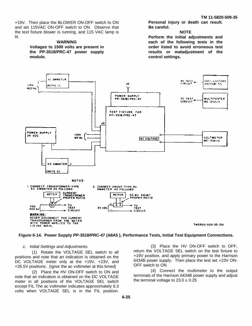
TM 11-5820-509-35+19V. Then place the BLOWER ON-OFF switch to ONand set 115VAC ON-OFF switch to ON. Observe thatthe text fixture blower is running, and 115 VAC lamp islit.
WARNINGVoltages to 1500 volts are present inthe PP-3518/PRC-47 power supplymodule.
Personal injury or death can result.Be careful.
NOTEPerform the initial adjustments andeach of the following tests in theorder listed to avoid erroneous testresults or maladjustment of thecontrol settings.
Figure 6-14. Power Supply PP-3518/PRC-47 (A8A5 ), Performance Tests, Initial Test Equipment Connections.
c. Initial Settings and Adjustments.(1) Rotate the VOLTAGE SEL switch to all
positions and note that an indication is obtained on theDC VOLTAGE meter only at the +19V, +23V, and+26.5V positions. (Ignor the ac voltmeter at this timed)
(2) Place the HV ON-OFF switch to ON andnote that an indication is obtained on the DC VOLTAGEmeter in all positions of the VOLTAGE SEL switchexcept FIL The ac voltmeter indicates approximately 6.3volts when VOLTAGE SEL is in the FIL position.
(3) Place the HV ON-OFF switch to OFF,return the VOLTAGE SEL switch on the test fixture to+19V position, and apply primary power to the Harrison6434B power supply. Then place the test set +23V ON-OFF switch to ON
(4) Connect the multimeter to the outputterminals of the Harrison 6434B power supply and adjustthe terminal voltage to 23.0 ± 0.25
6-25

TM 11-5820-509-35
volts dc. Then move the multimeter dc lead to test jackJ8 (fig. 3-11) on Power Supply PP-3518/PRC-47.
(6) Adjust potentiometer A5R22 (fig. 3-11)until the multitester reads 19.0 ± 0.4 volts dc.
(6) Connect the multimeter negative ( - ) leadto test jack J2 (fig. 3-11) on Power Supply PP-3518/PRC-47.
(7) Adjust potentiometer A5R3 (fig. 3-11)until the multimeter reads -110 + 5.5 volts dc.
(8) Connect the multimeter negative ( - ) leadto test jack J1 (fig. 3-11) on Power Supply PP-3518/PRC-47.
(9) Adjust potentiometer A5R4 {fig. 3-11)until the multimeter reads-32 ± 1.6 volts dc.
d. Performance Tests, 26.5-volts DC PrimaryPower Source. The tests listed in paragraphs e to o areto be conducted in the sequence shown after theseinitial conditions have been satisfied.
(1) Connect the test equipment to the testfixture as shown in figure 6-14 using the 0- to 15 amperedc ammeter.
(2) Install Power Supply PP-3518/PRC-47 inthe test fixture; then apply power to the Harrison 6434Bpower supply.
(3) On the test fixture, place the BLOWERON-OFF switch to ON, rotate the VOLTAGE SEL switchto +19V, the +23V ON-OFF switch to ON, and then setthe HV ON-OFF switch to ON .
(4) Adjust the terminal voltage of the Harrison6434B power supply to 23.0 ± 0.25 volts .
(5) Record the data required in paragraphs ethrough o below and compare with the referencestandard .
e. Input Current. The dc ammeter shall indicatenot more than 12.5 amperes.
f. Power Amplifier Plate Voltage.(1) Rotate the VOLTAGE SEL switch to
+1500V. The DC VOLTAGE meter shall indicate in thered portion of the meter scale.
(2) The ac voltmeter shall read not more than3.75 volts rms.
g. Power Amplifier Screen Voltage.(1) Rotate the VOLTAGE SEL switch to
+650V. The DC VOLTAGE meter shall indicate in thered portion of the meter scale.
(2) The ac voltmeter shall read not more than1.50 volts rms
h. Driver Plate Voltage.(1) Rotate the VOLTAGE SEL switch to
+300V. The DC VOLTAGE meter shall indicate in thered portion of the meter scale.
(2) The ac voltmeter shall read not more than0.20 volt rms.
i. Relay Voltage.(1) On the test fixture, place the HV ON -OFF
switch to OFF and rotate the VOLTAGE SEL switch to+26.5V.
(2) The DC VOLTAGE meter shall indicate inthe red portion of the meter scale.
j. Filtered Low Voltage.(1) Rotate the VOLTAGE SEL switch to
+23V. The DC VOLTAGE meter shall indicate in thered portion of the meter scale.
(2) The ac voltmeter shall read not more than0.075 volt rms.
k. Regulated Voltage.(1) Rotate the VOLTAGE SEL switch to
+19V. The DC VOLTAGE meter shad indicate in thered portion of the meter scale.
(2) The ac voltmeter shall read not more than0.010 volt rms.
(3) Connect the multimeter to test jack J8(fig. 3-11) on Power Supply PP-3518/PRC-47. On thetest fixture, place HV ON-OFF switch to ON and adjustA5R22 (fig. 3-11) to the counterclockwise stop and thento the clockwise stop. The multimeter shall read notmore than 18 volts dc nor less than 20 volts dc at themechanical end stops respectively.
(4) Readjust A5R22 until the multimeterreads 19.0 + 0.4 volts dc; then return the HV ON-OFFswitch on the test fixture to OFF.
l. Filament Voltage.(1) Rotate the VOLTAGE SEL switch to FIL.(2) Connect the oscilloscope to AC
VOLTAGE jacks on the test fixture in place of the acvoltmeter; then place the HV ON-OFF switch to ON. ;
(3) The oscilloscope shall indicate between6.0 and 6.3 volts ac peak.
(4) Return the HV ON-OFF switch on the testfixture to OFF and disconnect the oscilloscope.
m. Power Amplifier Bias Voltage.(1) Connect the ac voltmeter to the AC
VOLTAGE jacks on the test fixture and rotate theVOLTAGE SEL switch to -110V
(2) Connect the multimeter to test jack J2 onPower Supply PP-3518/PRC-47.
(3) Place the HV ON-OFF switch to ON andadjust A5R3 (fig. 3-11 ) to -110 ± 1.0 volts.
(4) The ac voltmeter shall read not more than0.10 volt rms.
(5) Return the HV ON-OFF switch to OFFand disconnect the multimeter.
n. Driver Bias Voltage.(1) Rotate the VOLTAGE SEL switch to - 32V
6-26

TM 11-5820-509-35
(2) Connect the multimeter to test jack J1 onPower Supply PP-3518/PRC-47.
(3) Place the HV ON-OFF switch to ON andadjust A5R4 (fig. 3-11) to -32.0 ± 0.5 volts.
(4) The ac voltmeter shall read not more than0.05 volt rms.
(5) Return the HV ON-OFF switch to OFFand disconnect the multimeter.
o. Voltage Regulator Operation.(1) On the test fixture, place the HV ON-OFF
switch to ON.(2) Connect the multimeter to the output
terminals of the Harrison 6434B power supply and adjustthe terminal voltage to 22.0 ± 0.1 volts.
(3) Move the multimeter to test jack J8 (fig.3-11) on Power Supply PP-3518/PRC-47. The voltageat J8 shall read not less than 18.5 volts dc nor morethan 19.5 volts dc.
(4) Repeat step (2) except set terminalvoltage of Harrison 6434B power supply to 28.0 ± 0.1volts dc
(5) Repeat step (3). Multimeter readingssame as shown in step (3).
p. Performance Tests, 110-Volts, 400-Hz PrimaryPower Source. The tests listed in paragraph q through uare to be conducted in the sequence shown after theseinitial conditions are satisfied:
(1) Connect the test equipment to the testfixture as shown in figure 6- 14 using the ac ammeter inthe 115-volts, 400-Hz mains.
(2) Install Power Supply PP-3518/PRC-47 inthe test fixture.
NOTEDo not apply primary power to theHarrison 6434B power supply.
(3) On the test fixture, place the BLOWERON-OFF switch to ON, rotate the VOLTAGE SEL switchto +19V, the +23V switch to OFF, and then set the HVON-OFF switch to ON.
(4) Record the data required in paragraphs qthrough u below and compare with the referencestandard.
q. Input Current. The ac ammeter shall indicatenot more than 3.0 amperes when the ac main is 97.8 to112.2 volts at 380- to 420-Hz.
r. Relay Voltage.(1) On the test fixture, place the HV ON-OFF
switch to OFF and rotate the VOLTAGE SEL switch to+26.5V.
(2) The DC VOLTAGE meter shall indicate inthe red portion of the meter scale.
s. Filtered Low Voltage.(1) Rotate the VOLTAGE SEL switch to
+23V. The DC VOLTAGE meter shall indicate in thered portion of the meter scale.
(2) The ac voltmeter shall read not more than0.075 volt rms.
t. Regulated Voltage.(1) Rotate the VOLTAGE SEL switch to
+19V. The DC VOLTAGE meter shall indicate in thered portion of the meter scale.
(2) The ac voltmeter shall read not more than0.010 volt rms.
(3) Connect the multimeter to test jack J8(fig. 3-11) on Power Supply PP-3518/PRC-47. On thetest fixture, place the HV ON-OFF switch to ON andadjust A5R22 to the counterclockwise stop, and then tothe clockwise stop. The multimeter shall read not morethan 18 volts dc nor less than 20 volts dc at themechanical end stops respectively.
(4) Readjust A5R22 for 19.0 ± 0.4 volts dc;then return the HV ON-OFF switch to OFF.
u. Filament Voltage.(1) Rotate the VOLTAGE SEL switch to FIL,
and place the HV ON-OFF switch to ON.(2) The ac voltmeter shall read 5.9 to 6.5
volts rms.(3) Return the HV ON-OFF switch to OFF.
6-14. Radio Frequency Oscillator 0-1032/PRC-47 (A8A6)(fig. 7-13)
a. Test Equipment and Material.(1) Frequency Counter AN/URM-79/U(2) Multimeter ME-26A/U(3) Oscilloscope AN/USM-50(4) Power Supply (24 volts dc) Harrison
6202B (or equal)(5) Signal Generator SG-103/URM-25F(6) Test fixture for 0-1032/PRC-47
b. Test Conditions and Equipment ConnectionCAUTION
Before connecting the power supplyto the test fixture, set the outputvoltage to 19.0 ± 2.0 volts; thenreturn the power on-off switch to theoff position until instructed to applyprimary power.
(1) Connect the test instruments to the testfixture as shown in figure 6-15. (The connections for theremaining test equipment are detailed in the appropriateprocedural steps below.)
(2) Before placing the O-1032/PRC-47 intothe test fixture, remove the module cover. Installmodule in test fixture.
(3) Place the power on-off switch of thepower supply to on and then place the +20 V ON-OFFswitch to ON.
(4) Adjust the output voltage of the powersupply to 20.0 ± 0.2 volts dc.
6-27

TM 11-5820-509-35
Figure 6-15. RF Oscillator O-1032/PRC-47 (A8A6), Performance Tests, Initial Test Equipment Connections.
c. Initial Settings and Adjustments.(1) Connect the multimeter dc probe to test
point J2 on the module and record the reading obtained.This value must be 17.5 ± 1.0 volts dc.
(2) Press the PUSH TO READ pushbutton onthe front of the test fixture and read the current drawn bythe module. The +20V CURRENT meter must read35.0 ± 5.0 milliamperes.
(3) Connect the multimeter rf probe and thefrequency counter to the junction of Q4, R23, and R24(fig. 3-53) and record the output voltage of thetemperature compensated oscillator. This voltage shallnot be less than 0.3 volt rms and the output frequencyshall be approximately 3.0 MHz.
NOTEDo not adjust or calibrate thetemperature compensated oscillatorat this time. Final calibrationprocedures are detailed in step g.
d. Locked Oscillator, Divider, and Output AmplifierPerformance.
(1) On the test fixture, place the +20 ON-OFFswitch to OFF.
(2) Carefully disconnect the inner conductorof the miniature coaxial cable from the junction of Q4-R23-R24 (fig. 3-53).
(3) Connect the frequency counter to theoutput of the signal generator; then connect the openend of capacitor C1 to the terminal in the module fromwhich the coaxial cable was disconnected.
(4) Place the +20V ON-OFF switch on thetest fixture to ON; then set the signal generator outputfrequency to 3.000 MHz.
(5) Using the rf probe of the multimeter,adjust the signal generator output level {at the base oflocked oscillator Q4) to the value measured in step c (3)above.
NOTEBe sure to maintain this output levelfor the remainder of this test.
(6) A stable 6:1 Lissajous pattern must beobtained on the oscilloscope. If not, perform the lockedoscillator and 500-kHz amplifier adjustments in step ebefore continuing.
(7) Vary the signal generator frequency from2.90 to 3.10 MHz while observing-the oscilloscopedisplay. The 6:1 Lissajous pattern must remain clearand stable throughout the signal generator outputfrequency excursion.
(8) Connect the rf probe of the multimeter totest jack J3 on the module and record the 500 kHzoutput voltage. Repeat the measurement at test jack J4on the module. The multimeter shall read 1.5 ± 0.2volts rms. If not, perform the locked oscillator and 500kHz amplifier adjustments in step e before continuing.
(9) Connect the vertical input of theoscilloscope to the 100 KHZ A1 connector on the frontpanel of the test fixture. (Do not disturb the signalgenerator and frequency counter con nections in themodule.)
6-28
TM 11-5820-509-35(10) A clear, stable 5:1 Lissajous pattern must
be displayed on the oscilloscope. If not, perform thelocked oscillator and 100-kHz amplifier adjustments instep f before continuing.
(11) Connect the rf probe of the multimeter totest jack J1 on the module and record the 100 kHzoutput voltage. The multimeter shall read 1.5 ± 0.4volts rms. If not, perform the locked oscillator and 100-kHz amplifier adjustments in step f before continuing.
(12) Repeat step (7) and observe that the 5:1Lissajous pattern remains stable and clear through thefrequency excursion.
(13) Disconnect the test equipment from themodule; place the +20V ON-OFF switch on the testfixture to OFF, and reconnect the center conductor ofthe miniature coaxial cable removed in step (2) above.
e. Locked Oscillator Q4 and 500-kHz AmplifierAdjustments.
NOTEPerform these procedures only if thestability or output level of the 500kHz amplifier circuits is deficient.The locked oscillator and amplifieradjustments are performed byselecting specific values forcapacitors C14, C20, C25 and
resistors R30 and R45 from thetables below.
(1) On the test fixture, place the +20V ON-OFF switch to OFF, and remove the O-1032/PRC-47from the test fixture.
(2) Disconnect the miniature coaxial cablefrom the junction of Q4-R23-R24 as in step d (2) unlessit has already been removed, and then replace themodule in the test fixture.
(3) Connect the test equipment to the testfixture as shown in figure 6-15 and connect the openend of capacitor C1 to the terminal in the module fromwhich the coaxial cable was just removed.
(4) Return the +20V ON-OFF switch on thetest fixture to ON; then set the signal generator outputfrequency to 3.0 MHz. Adjust the output level of thesignal generator at the base of the locked oscillator (Q4)to the value measured in step c (3).
NOTEMaintain this output level throughthe remainder of this adjustmentprocedure.
(5) A clear, stable 6:1 Lissajous pattern mustbe observed as the signal generator is varied from 2.90through 3.10 MHz. Select a value of capacitance forC14 from the following table that provides this pattern(refer to fig. 3-53 and 7-13 for part locations).
Capacitor Selection Table
Value Part No. Value Part No.5 ± 0.5 pf DM 15C050D01 120 ± 6.0 pf CMO5E121J0310 ± 0.5 pf DM 15C100J01 130 ± 6.5 pf CM05E131J0312 ± 0.6 pf DM 15C120J01 140 ± 1.4 pf DM15E141F0500WV4CR15 ± 0.7pf DM 15C150J01 150 ± 7.5 pf CM05F151J0318 ± 0.9 pf DM 15C180J01 160 ± 8.0 pf CM05F161J0320 ± 1.0 pf CM05E200J03 169 ± 1.7 pf DM15E1690F0300WV4CR22 ± 1.1 pf CM05E220J03 180 ± 9.0 pf CM05F181J0324 ± 1.2 pf CM05E240J03 190 ± 1.9 pf DM15E191F0500WV4CR27 ± 1.3 pf CM05E270J03 200 ± 10.0 pf CM05F201J0330 ± 1.5 pf CM05E300J03 220 ± 11.0 pf CM05F221J0333 ± 1.6 pf CM05E330J03 240 ± 12.0 pf CM05F241J0336 ± 1.8 pf CM05E360J03 270 ± 13.5 pf CM05F271J0339 ± 1.9 pf CM05E390J03 300 ± 15.0 pf CM05F301J0343 ± 2.1 pf CM05E430J03 330 ± 16.5 pf CM05F331J0347 ± 2.3 pf CM05E470J03 360 ± 18.0 pf CM05F361J0351 ± 2.5 pf CM05E510J03 390 ± 19.5 pf CM05F391J0356 ± 2.8 pf CM05E560J03 430 ± 21.5 pf DM15F43 lJ0362 ± 3.1 pf CM05E620J03 470 ± 23.5 pf DM15F471J0368 ± 3.4 pf CM05E680J03 510 ± 25.5 pf DM15F511J0375 ± 3.7 pf CM05E750J03 560 ± 28.0 pf DM15F561J300WV4CR82 ± 4.1 pf CM05E820J03 620 ± 31.0 pf DM15F621J300WV4CR91 ± 4.5 pf CM05E910J03 750 ± 37.5 pf CM05F751J03100 ± 5,0 pf CM05E101J03 820 ± 41.0 pf DM15F821J0300WV4CR110 ± 5.5 pf CM05E111J03
6-29
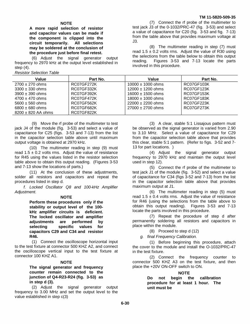
TM 11-5820-509-35NOTE
A more rapid selection of resistorand capacitor values can be made ifthe component is clipped into thecircuit temporarily. All selectionsmay be soldered at the conclusion ofthe procedure just before final retest.
(6) Adjust the signal generator outputfrequency to 2970 kHz at the output level established instep (4).
(7) Connect the rf probe of the multimeter totest jack J3 of the 0-1032/PRC-47 (fig. 3-53) and selecta value of capacitance for C20 (fig. 3-53 and fig. 7-13)from the table above that provides maximum voltage atJ3.
(8) The multimeter reading in step (7) mustread 1.5 ± 0.2 volts rms. Adjust the value of R30 usingthe selections from the table below to obtain this outputreading. Figures 3-53 and 7-13 locate the partsinvolved in this procedure.
Resistor Selection Table
Value Part No. Value Part No.2700 ± 270 ohms RC07GF272K 10000 ± 1000 ohms RC07GF103K3300 ± 330 ohms RC07GF332K 12000 ± 1200 ohms RC07GF123K3900 ± 390 ohms RC07GF392K 16000 ± 1500 ohms RC07GF153K4700 ± 470 ohms RC07GF472K 18000 ± 1000 ohms RC07GF183K5600 ± 560 ohms RC07GF562K 22000 ± 2200 ohms RC07GF223K6800 ± 680 ohms RC07GF682K 27000 ± 2700 ohms RC07GF273K8200 ± 820 AA ohms RC07GF822K
(9) Move the rf probe of the multimeter to testjack J4 of the module (fig. 3-53) and select a value ofcapacitance for C25 (figs. 3-53 and 7-13) from the listin the capacitor selection table above until maximumoutput voltage is obtained at 2970 kHz.
(10) The multimeter reading in step (9) mustread 1.5 ± 0.2 volts rms. Adjust the value of resistancefor R45 using the values listed in the resistor selectiontable above to obtain this output reading. (Figures 3-53and 7-13 show the locations of parts.)
(11) At the conclusion of these adjustments,solder all resistors and capacitors and repeat theprocedures listed in step d.
f. Locked Oscillator Q8 and 100-kHz AmplifierAdjustment.
NOTEPerform these procedures only if thestability or output level of the 100-kHz amplifier circuits is deficient.The locked oscillator and amplifieradjustments are performed byselecting specific values forcapacitors C29 and C34 and resistorR46.
(1) Connect the oscilloscope horizontal inputto the test fixture at connector 500 KHZ A2, and connectthe oscilloscope vertical input to the test fixture atconnector 100 KHZ A1.
NOTEThe signal generator and frequencycounter remain connected to thejunction of Q4-R23-R24 (fig. 3-53) asin step d (3).
(2) Adjust the signal generator outputfrequency to 3.00 MHz and set the output level to thevalue established in step c(3)
(3) A clear, stable 5:1 Lissajous pattern mustbe observed as the signal generator is varied from 2.90to 3.10 MHz. Select a value of capacitance for C29from the capacitor selection table above that providesthis clear, stable 5:1 pattern. (Refer to figs. 3-52 and 7-13 for part locations. )
(4) Adjust the signal generator outputfrequency to 2970 kHz and maintain the output levelused in step 12).
(5) Connect the rf probe of the multimeter totest jack J1 of the module (fig. 3-52) and select a valueof capacitance for C34 (figs 3-52 and 7-13) from the listin the capacitor selection table above that providesmaximum output at J1.
(6) The multimeter reading in step (5) mustread 1.5 ± 0.4 volts rms. Adjust the value of resistancefor R46 {using the selections from the table above toobtain this output reading). Figures 3-53 and 7-13locate the parts involved in this procedure.
(7) Repeat the procedure of step d afterpermanently soldering all resistors and capacitors inplace within the module.
(8) Proceed to step d (12)g. final Frequency Calibration.
(1) Before beginning this procedure, attachthe cover to the module and install the O-1032/PRC-47in the test fixture.
(2) Connect the frequency counter toconnector 500 KHZ A3 on the test fixture, and thenplace the +20V ON-OFF switch to ON.
NOTEDo not begin the calibrationprocedure for at least 1 hour. Theunit must be
6-30
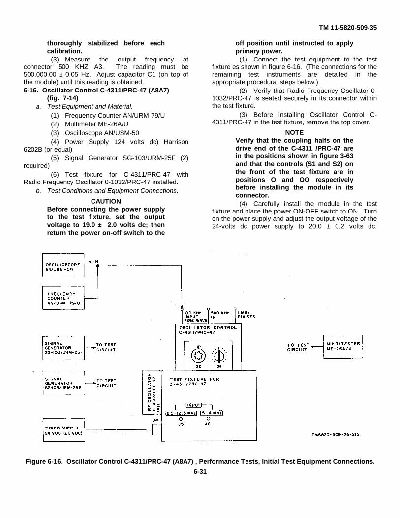
TM 11-5820-509-35
thoroughly stabilized before eachcalibration.
(3) Measure the output frequency atconnector 500 KHZ A3. The reading must be500,000.00 ± 0.05 Hz. Adjust capacitor C1 (on top ofthe module) until this reading is obtained.6-16. Oscillator Control C-4311/PRC-47 (A8A7)
(fig. 7-14)a. Test Equipment and Material.
(1) Frequency Counter AN/URM-79/U(2) Multimeter ME-26A/U(3) Oscilloscope AN/USM-50(4) Power Supply 124 volts dc) Harrison
6202B (or equal)(5) Signal Generator SG-103/URM-25F (2)
required)(6) Test fixture for C-4311/PRC-47 with
Radio Frequency Oscillator 0-1032/PRC-47 installed.b. Test Conditions and Equipment Connections.
CAUTIONBefore connecting the power supplyto the test fixture, set the outputvoltage to 19.0 ± 2.0 volts dc; thenreturn the power on-off switch to the
off position until instructed to applyprimary power.
(1) Connect the test equipment to the testfixture es shown in figure 6-16. (The connections for theremaining test instruments are detailed in theappropriate procedural steps below.)
(2) Verify that Radio Frequency Oscillator 0-1032/PRC-47 is seated securely in its connector withinthe test fixture.
(3) Before installing Oscillator Control C-4311/PRC-47 in the test fixture, remove the top cover.
NOTEVerify that the coupling halfs on thedrive end of the C-4311 /PRC-47 arein the positions shown in figure 3-63and that the controls (S1 and S2) onthe front of the test fixture are inpositions O and OO respectivelybefore installing the module in itsconnector.
(4) Carefully install the module in the testfixture and place the power ON-OFF switch to ON. Turnon the power supply and adjust the output voltage of the24-volts dc power supply to 20.0 ± 0.2 volts dc.
Figure 6-16. Oscillator Control C-4311/PRC-47 (A8A7) , Performance Tests, Initial Test Equipment Connections.6-31

TM 11-5820-509-35
c. Pulse Generator Output.(1) Connect the vertical input of the
oscilloscope and the frequency counter to 100 kHzsinewave input test point (fig. 3-83) and verify that theamplitude of the waveform is 1.8 ± 0.5 volts peak-to-peak, and that the pulse width is 0.3 ± 0.1 microsecond.
NOTEThe pulse width is the intervalbetween the points on the wave-formwhere 10 % of the peak amplitudeoccurs.
(2) Connect the oscilloscope and frequencycounter to the 500 kHz input test point (fig. 3-83) andverify that a 500-kHz sinewave signal of approximately1.5 volts peak-to-peak is present.
(3) Connect the vertical input of theoscilloscope and the frequency counter to the 1 MHzpulses test point (fig. 3-83) and verify that the amplitudeof the waveform is 6.0 ± 2.5 volts peak-to-peak, and thatthe pulse fall time is 0.1 ± 0.03 microsecond.
NOTEThe pulse fall time is the totalinterval required for the wave toreturn to the base line from its peakvalue.
(4) With the oscilloscope connected as instep (3), adjust capacitor C15 (fig. 3-102) for minimum500 kHz signal in the 1 MHz pulses. Repeat step (3) if amajor adjustment is made.
d. 1.8- to 0.9-MHz Ringer Circuit Alignment.
NOTEVerify that the ringer circuit isoperating properly and not merelyoscillating. If oscillating, thefrequency will change smoothly asthe setting of the trimmer capacitoris varied. If ringing, the wavetrainwill he ragged until properadjustment of the trimmer isobtained, and then the wavetrain willstabilize.
(1) Verify that switches S1 and S2 on thefront panel of the test fixture are at O and OOrespectively.
(2) Adjust the oscilloscope sweep rate to 10microseconds per centimeter and connect the verticalinput and the frequency counter to the 1.8 - 0.9 MHzinput test point (fig. 3-83).
(3) Adjust capacitor C90 (fig. 3-104) forminimum 100-kHz modulation on the oscilloscope traceand observe that the waveform amplitude is not lessthan 2.3 volts peak-to-peak and that the frequencycounter indicates 1.8 MHz.
(4) On the front panel of the test fixture,leave switch S1 at O and rotate switch S2 one completerevolution clockwise to a reading of 1.0.
(5) Adjust capacitor C88 (fig. 3-104) forminimum 100-kHz modulation on the oscilloscope traceand observe that the waveform amplitude is not lessthan 3.4 volts peak-to-peak and the frequency counterindicates 1.7 MHz.
(6) Repeat step (4) except rotate switch S2one complete revolution clockwise to a reading of 2.0.
(7) Adjust capacitor C86 (fig. 3-104) forminimum 100-kHz modulation on the oscilloscope traceand observe that the waveform amplitude is not lessthan 4.3 volts peak-to-peak and the frequency counterindicates 1.6 MHz.
(8) Repeat step (4) except rotate switch S2one complete revolution clockwise to a reading of 3.0.
(9) Adjust capacitor C84 {fig. 3-104) forminimum 100-kHz modulation on the oscilloscope traceand observe that the waveform amplitude is not lessthan 3.4 volts peak-to-peak and the frequency counterindicates 1.5 MHz.
(10) Repeat step (4) except rotate switch S2one complete revolution clockwise to a reading of 4.0.
(11) Adjust capacitor C82 (fig. 3-104) forminimum 100-kHz modulation on the oscilloscope traceand observe that the waveform amplitude is not lessthan 2.8 volts peak-to-peak and the frequency counterindicates 1.4 MHz.
(12) Repeat step (4) except rotate switch S2one complete revolution clockwise to a reading of 5.0.
(13) Adjust capacitor C80 (fig. 3-103) forminimum 100-kHz modulation on the oscilloscope traceand observe that the waveform amplitude is not lessthan 2.6 volts peak-to-peak and the frequency counterindicates 1.3 MHz.
(14) Repeat step (4) except rotate switch S2one complete revolution clockwise to a reading of 6.0.
(15) Adjust capacitor C78 (fig. 3-103) forminimum 100-kHz modulation on the oscilloscope traceand observe that the waveform amplitude is not lessthan 2.8 volts peak-to-peak and the frequency counterindicates 1.2 MHz.
(16) Repeat step (4) except rotate switch S2one complete revolution clockwise to a reading of 7.0.
(17) Adjust capacitor C76 (fig. 3-103) forminimum 100-kHz modulation on the oscilloscope traceand observe that the waveform amplitude is not lessthan 3.6 volts peak-to-peak and the frequency counterindicates 1.1 MHz.
(18) Repeat step (4) except rotate switch S2one complete revolution clockwise to a reading of 8.0.
(19) Adjust capacitor C74 (fig. 3-103) forminimum 100-kHz modulation on the oscilloscope
6-32
TM 11-5820-509-35
trace and observe that the waveform amplitude is notless 3.3 volts peak-to-peak and the frequency counterindicates 1.0 MHz.
(20) Repeat step (4) except rotate switch S2one complete revolution clockwise to a reading of 9.0.
(21) Adjust capacitor C72 (fig. 3-103) forminimum 100-kHz modulation on the oscilloscope traceand observe that the waveform amplitude is not lessthan 3.3 volts peak-to-peak and the frequency counterindicates 0.9 MHz.
e. Crystal Oscillator Alignment.(1) Set switches S1 and S2 on the front panel
of the test fixture to O and OO respectively.(2) Attach clips to the leads of a 0.01
microfarad capacitor and install it from the outer case ofvariable capacitor C131 (fig. 3-100) to chassis ground(module drive end plate).
(3) Place the frequency counter input probeat the base of transistor Q21 (common junction of C100,C101, R111, and R112 on fig. 3-59) and verify thatoscillator Q21 output frequency is 3,707,000.00 ± 1.0Hz. If not, adjust capacitor C133 (fig. 3-101) on thebottom of the module to obtain this reading.
(4) Remove the 0.01 microfarad capacitorinstalled in step (2) and connect the oscilloscope verticalinput and the frequency counter to jack J1 (fig. 3-100).Verify that the output frequency is 700,000.00 ± 1.0 Hz.If not, adjust capacitor C113 (fig. 3-101) on the bottomof the module to obtain this reading.
(5) Repeat step (4) with switch S1 on thefront of the test fixture at 1. Verify that the outputfrequency is 699,000.00 ± 1.0 Hz. If not, adjustcapacitor C115 (fig. 3-101) on the bottom of the moduleto obtain this reading.
(6) Repeat step (4) with switch S1 on thefront of the test fixture at 2. Verify that the outputfrequency is 698,000.00 ± 1.0 Hz. If not, adjustcapacitor C117 (fig. 3-101) on the bottom of the moduleto obtain this reading.
(7) Repeat step (4) with switch S1 on thefront of the test fixture at 3. Verify that the outputfrequency is 697,000.00 ± 1.0 Hz. If not, adjustcapacitor C119 (fig. 3-101) on the bottom of the moduleto obtain this reading.(81 Repeat step (4) with switch S1 on the front of thetest fixture at 4. Verify that the output frequency is696,000.00 ± 1.0 Hz. If not, adjust capacitor C121 (fig.3-101) on the bottom of the module to obtain thisreading.
(9) Repeat step (4) with switch S1 on thefront of the test fixture at 5. Verify that the outputfrequency is 695,000.00 ± 1.0 Hz. If not, adjustcapacitor C123 (fig. 3-100) on the top of the module toobtain this reading.
(10) Repeat step (4) with switch S1 on thefront of the test fixture at 6. Verify that the outputfrequency is 694,000.00 ± 1.0 Hz. If not, adjustcapacitor C125 (fig. 3-100) on the top of the module toobtain this reading.
(11) Repeat step (4) with switch S1 on thefront of the test fixture at 7. Verify that the outputfrequency is 693,000.00 ± 1.0 Hz. If not, adjustcapacitor C127 (fig. 3-100) on the top of the module toobtain this reading.
(12) Repeat step (4) with switch S1 on thefront of the test fixture at 8. Verify that the outputfrequency is 692,000.00 ± 1.0 Hz. If not, adjustcapacitor C129 (fig. 3-100) on the top of the module toobtain this reading.
(3) Repeat step (4) with switch S1 on thefront of the test fixture at 9 Verify that the outputfrequency is 691,000.00 ± 1.0 Hz. If not, adjustcapacitor C131 (fig.. 3-100) on the top of the module toobtain this reading.
(14) On the test fixture, return switch S1 to 0.Rotate switch S1 to 1.0 and verify that the outputfrequency is 690,000.00 + 1.0 Hz. If not adjustcapacitor C135 (fig. 3-101) on the bottom of the moduleto obtain this reading.
(15) Repeat step (14) except place switch S2on the front of the test fixture to 2.0 and verify that theoutput frequency is 680,000.00 ± 1.0 Hz. If not, adjustcapacitor C137 (fig. 3-101) on the bottom of the moduleto obtain this reading.
(16) Repeat step (14) except place switch S2on the front of the test fixture to 3.0 and verify that theoutput frequency is 670,000.00 ± 1.0 Hz. If not, adjustcapacitor C139 (fig. 3-101) on the bottom of the moduleto obtain this reading.
(17) Repeat step (14) except place switch S2on the front of the test fixture to 4.0 and verify that theoutput frequency is 660,000.00 ± 1.0 Hz. If not, adjustcapacitor C141 /fig. 3-101) on the bottom of the moduleto obtain this reading.
(18) Repeat step (14) except place switch S2on the front of the test fixture to 5.0 and verify that theoutput frequency is 650,000.00 ± 1.0 Hz. If not, adjustcapacitor C143 (fig. 3-100) on the top of the module toobtain this reading
(19) Repeat step (14) except place switch S2on the front of the test fixture to 6.0 and verify that theoutput frequency is 640,000.00 ± 1.0 Hz. If not, adjustcapacitor C145 (fig. 3-100) on the top of the module toobtain this reading.
(20) Repeat step (14) except place switch S2on the front of the test fixture to 7.0 and verify that theoutput frequency is 630,000.00 ± 1.0
6-33

TM 11-5820-509-35
Hz. If not, adjust capacitor C147 (fig. 3-100) on the topof the module to obtain this reading.
(21) Repeat step (14) except place switch S2on the front of the test fixture to 8.0 and verify that theoutput frequency is 620,000.00 ± 1.0 Hz. If not, adjustcapacitor C149 (fig. 3-100) on the top of the module toobtain this reading.
(22) Repeat step (14) except place switch S2on the front of the test fixture to 9.0 and verify that theoutput frequency is 610,000.00 ± 1.0 Hz. If not, adjustcapacitor C151 (fig. 3-100) on the top of the module toobtain this reading.
f. 601- to 700-kHz Filter Test.(1) Connect the oscilloscope vertical input
and the frequency counter to jack J1 (fig. 3-100).(2) On the test fixture, set switches S1 and
S2 to O and OO respectively and verify that thewaveform amplitude is 1.1 ± 0.2 volts peak-to-peak andthe output frequency is 700 kHz.(3} Rotate switches S1 and S2 to 1 and 1.0 respectivelyand verify that the waveform amplitude is 1.1 ± 0.2 voltspeak-to-peak and the output frequency is 689 kHz.
(4) Rotate switches S1 and S2 to 2 and 2.0respectively and verify that the waveform amplitude is1.1 ± 0.2 volts peak-to-peak and the output frequency is678 kHz.
(5) Rotate switches S1 and S2 to 3 and 3.0respectively and verify that the waveform amplitude is1.1 ± 0.2 volts peak-to-peak and the output frequency is667 kHz.
(6) Rotate switches S1 and S2 to 4 and 4.0respectively and verify that the waveform amplitude is1.1 ± 0.2 volts peak-to-peak and the output frequency is656 kHz.
(7) Rotate switches S1 and S2 to 5 and 5.0respectively and verify that the waveform amplitude is1.1 ± 0.2 volts peak-to-peak and the output frequency is645 kHz.
(8) Rotate switches S1 and S2 to 6 and 6.0respectively and verify that the waveform amplitude is1.1 ± 0.2 volts peak-to-peak and the output frequency is634 kHz.
(9) Rotate switches S1 and S2 to 7 and 7.0respectively and verify that the waveform amplitude is1.1 ± 0.2 volts peak-to-peak and the output frequency is623 kHz.
(10) Rotate switches S1 and S2 to 8 and 8.0respectively and verify that the waveform amplitude is1.1 ± 0.2 volts peak-to-peak and the output frequency is612 kHz.
(11) Rotate switches S1 and S2 to 9 and 9.0respectively and verify that the waveform amplitude is1.1 ± 0.2 volts peak-to-peak and the output frequency is601 kHz.
g. 550- to 750-kHz Filter Test.(1) Attach clips to the leads of a 0.01
microfarad capacitor and install it from the outer case ofvariable capacitor C131 (fig. 3-100) to chassis ground(module drive end plate).
(2) Attach clips to the leads of a second 0.01microfarad capacitor and connect it between the signalgenerator and transformer T3 at its junction with C165and R147.
(3) Connect the oscilloscope vertical inputand the frequency counter to jack J4 (fig. 3-100) andvary the signal generator output frequency from 500- to800-kHz. Observe the frequency at which maximumoutput occurs and set the signal generator output toprovide 1.0 volt peak-to-peak at jack J4.
(4) Set the output frequency of the signalgenerator to 500 kHz, and verify that the outputamplitude does not exceed 0.2 volt peak-to-peak.
(5) Set the output frequency of the signalgenerator to 525 kHz, and verify that the outputamplitude does not exceed 0.7 volt peak-to-peak.
(6) Set the output frequency of the signalgenerator to 550 kHz, and verify that the outputamplitude remains between 0.3 and 1.0 volt peak-to-peak.
(7) Repeat step (6) with the signal generatorset to 575 kHz.
(8) Repeat step (6) with the signal generatorset to 600 kHz.
(9) Repeat step (6) with the signal generatorset to 625 kHz.
(10) Repeat step (6) with the signal generatorset to 650 kHz.
(11) Repeat step (6) with the signal generatorset to 675 kHz.
(12) Repeat step (6) with the signal generatorset to 700 kHz.
(13) Repeat step (6) with the signal generatorset to 725 kHz.
(14) Set the output frequency of the signalgenerator to 750 kHz, and verify that the outputamplitude does not exceed 0;7 volt peak-to-peak.
(15) Set the output frequency of the signalgenerator to 800 kHz, and verify that the outputamplitude does not exceed 0.2 volt peak-to-peak.
h. Frequency Discriminator Test(1) Disconnect the 0.01 microfarad capacitor
from the outer case of variable capacitor C131 tochassis ground installed in step g (1)
(2) Verify that the signal generator isconnected to the junction of T3-C165-R147 (fig. 3-56)with the 0.01 microfarad capacitor. and connect theoscilloscope to jack J4 (fig. 3-14) and the multimeter tojack J5 (fig. 3-15) on the module.
6-34

TM 11-5820-509-35
(3) On the test fixture, set switches S1 andS2 to O and OO respectively and then adjust the signalgenerator output frequency to 650 kHz and set the ouputlevel to 0.1 volt rms.
(4) Observe that the multimeter reads notless than 4.0 volts dc at jack J5. Then move themultimeter probe to jack J6 (fig. 3-14) and observe thatthe multimeter reads not more than 1.5 volts dc.
(5) Adjust the signal generator outputfrequency to 690 kHz at an output level of 0.1 volt rmsand verify that the conditions recorded in step (4) areobtained.
(6) Adjust the signal generator outputfrequency to 710 kHz at an output level of 0.1 volt rms.
(7) Observe that the multimeter reads notmore than 1.5 volts dc at jack J5. Then move themultimeter probe to jack J6 (fig. 3-14) and observe thatthe multimeter reads not less than 4.0 volts dc.
(8) Adjust the signal generator outputfrequency to 750 kHz at an output level of 0.1 volt rmsand verify that the conditions recorded in step (7) areobtained.
(9) Adjust the signal generator outputfrequency to 550 kHz at a level of 0.1 volt rms and notethat the waveform at jack J4 is slightly clipped.
(10) On the test fixture, rotate switch S2 to 6.0with S1 remaining at O. Adjust the signal generatoroutput frequency to 600 kHz at an output level of 0.1volt rms.
(11) Observe that the multimeter reads notless than 4.0 volts dc at jack J5 (fig.. 3-14). Then movethe multimeter probe to jack J6 (fig. 3-14) and observethat the multimeter reads not more than 1.5 volts dc.
(12) Adjust the signal generator outputfrequency to 640 kHz at an output level of 0.1 volt rmsand verify that the conditions recorded in step (11) areobtained.
(13) Adjust the signal generator outputfrequency to 660 kHz at an output level of 0.1 volt rms.
(14) Observe that the multimeter reads notmore than 1.5 volts dc at jack J5. Then move themultimeter probe to jack J6 (fig. 3-14) and observe thatthe multimeter reads not less than 4.0 volts dc.
(15) Adjust the signal generator outputfrequency to 700 kHz at an output level of 0.1 volt rmsand verify that the conditions recorded in step (14) areobtained.
(16) On the test fixture, rotate switches S1 andS2 to 9.0 and 9 respectively and adjust the
signal generator output frequency to 550 kHz at anoutput level of 0.1 volt rms.
(17) Observe that the multimeter reads notless than 4.0 volts dc at jack J5 (fig. 3-14). Then movethe multimeter probe to jack J6 (fig. 3-14) and observethat the multimeter reads not less than 1.5 volts dc.
(18) Adjust the signal generator outputfrequency to 590 kHz at an output level of 0.1 volt rmsand verify that the conditions recorded in step (17) areobtained.
(19) Adjust the signal generator outputfrequency to 610 kHz at an output level of 0.1 volt rms.120) Observe that the multimeter reads not more than1.5 volts dc at jack J5 (fig. 3-14). Then move themultimeter probe to jack J6 (fig. 3-14) and observe thatthe multimeter reads not less than 4.0 volts dc.
(21) Adjust the signal generator outputfrequency to 650 kHz at an output level of 0.1 volt rmsand verify that the conditions recorded in step (20) areobtained.
(22) Verify that the oscilloscope is connectedto jack J4 and that the multimeter reads not less than4.0 volts dc at jack J6, as in step (20). Then disconnectthe signal generator, and observe that the multimeterreading remains essentially unchanged.
(23) Adjust the signal generator outputfrequency to 490 kHz at an output level of 0.1 volt rmsand reconnect the output terminals to the commonjunction of T3-C165-R147 (fig. 3-56) in the moduleusing the 0.01 microfarad capacitor as in step (2).
(24) Adjust the signal generator outputfrequency toward 600 kHz while observing themultimeter reading. A sharp decrease in the meterreading (to approximately 1.5 volts dc) must occur at, orabove, 525 kHz.
(25) Connect the multimeter to jack J5 (fig. 3-14) and observe that the discriminator output is not lessthan 4.0 volts dc. Then disconnect the signal generatorfrom the module and observe that the multimeterreading remains essentially unchanged.
(26) Adjust the signal generator outputfrequency to 810 kHz at an output level of 0.1 volt rmsand reconnect the output terminals to the commonjunction of T3-C165-R147 (fig. 3-56) in the moduleusing the 0.01 microfarad capacitor as in step (2).
(27) Adjust the signal generator outputfrequency toward 600 kHz while observing themultimeter reading. A sharp decrease in the meterreading (to approximately 1.5 volts dc) must occur at, orbelow, 675 kHz.
6-35
TM 11-5820-509-35
NOTEIf the error line voltages (measured atjacks J5 and J6) are not within thelimits specified in steps (4) through(21), or if the error line voltagereversals measured in steps (24) and
(27) occur between 550- and 650-kHz,substitute a new value for resistanceR144 (fig. 3-56) from the followingtable using the procedure in step i toobtain optimum operatingcharacteristics.
Resistance Selection Chart
Value Part No. Value Part No.10.0 ± 1.0 ohms RC07GF100K 470 ± 47 ohms RC07GF471K82.0 ± 8.2 ohms RC07GF820K 680 ± 68 ohms RC07GF681K150 ± 15 ohms RC07GF151K 820 ± 82 ohms RC07GF 821K220 ± 22 ohms RC07GF 221K 1000 ± 100 ohms RC07GF102K330 ± 33 ohms RC07GF331K 1600 ± 150 ohms RC07GF152K
i. Error Voltage Balance Adjustment.
NOTEPerform these procedures only if theerror voltages or voltage reversals instep h are beyond acceptable limits.
(1) On the test fixture, set switch S1 to 0 andswitch S2 to 6.0.
(2) Connect the signal generator outputterminals to the common junction of T3-C165R147 (fig.3-56) and adjust the output frequency to 660 kHz at anoutput level of 0.1 volt rms.
(3) Refer to figures 3-55 and 7-14. Connectthe oscilloscope alternately to the collector circuit oftransistor Q9 (common junction of Q9-C25-L3) and thecollector circuit of transistor Q12 (common junction ofQ12-C32-L6) while substituting values for resistor R144(fig. 3-56).
(4) Select a suitable value of resistance forR144 from the chart above that provides maximum 10-kHz modulation at both Q9 and Q12 collector circuits.
NOTESome compromise in this resistancevalue will be required to obtainnearly equal levels of modulation atboth collector circuits.
j. Anti-lock Test.(1) Connect the signal generator output
terminals to the common junction of T3-C165R147 (fig.3-56) and adjust the output frequency to 700 kHz at anoutput level of 0.1 volt rms.
(2) Connect the oscilloscope to jack J4 on themodule.
(3) Observe that the ANIT-LOCK lamp on thetest fixture is lit.
(4) Increase the signal generator output leveluntil the ANTI-LOCK lamp goes out. The voltage at jackJ4 shall be 1.05 volts peak-to-peak on the oscilloscope.
(5) Lower the signal generator output leveluntil the ANTI-LOCK lamp lights, and observe that the
voltage at jack J4 remains at 1.05 volts peak-to-peakapproximately.
k. SMO Mixers Test.(1) Connect signal generator no. 1 to the 5-
14 MHZ INPUT jack on the front of the test fixture.(2) Connect the oscilloscope probe to the
primary of transformer T1 (fig. 3-56, at junction withcoaxial input cable near jack J2) on terminal board TB1.
(3) Adjust the output frequency of signalgenerator no. 1 to 5.0 MHz at an output level of 2.4volts peak-to-peak on the oscilloscope.(4) Connect signal generator no. 2 to the 2.512.5 MHZINPUT jack on the front of the test fixture, and move theoscilloscope probe to jack J3 (fig. 3-14).
(5) Adjust the output frequency of signalgenerator no. 2 to 2.55 MHz at an output level of 6.0volts peak-to-peak on the oscilloscope.
(6) Connect the oscilloscope probe to jack J4(fig. 3-14) and observe that the mixer output level is 1.5± 0.4 volts peak-to-peak.
(7) Repeat step (2) and adjust the outputfrequency of signal generator no. 1 to 6.0 MHz at anoutput level of 2.1 volts peak-to-peak on theoscilloscope.
(8) Repeat step (4) and adjust the outputfrequency of signal generator no. 2 to 3.55 MHz at anoutput level of 4.4 volts peak-to-peak on theoscilloscope.
(9) Repeat step (6). The mixer output shallbe 1.5 ± 0.4 volts peak-to-peak.
(10) Repeat step (2) and adjust the outputfrequency of signal generator no. 1 to 7.0 MHz at anoutput level of 1.8 volts peak-to-peak on theoscilloscope.
(11) Repeat step (4) and adjust the outputfrequency of signal generator no. 2 to 4.55 MHz at anoutput level of 6.0 volts peak-to-peak on theoscilloscope.
6-36

TM 11-5820-509-35
(12) Repeat step (6). The mixer output shallbe 1.5 ± 0.4 volts peak-to-peak.
(13) Repeat step (2) and adjust the outputfrequency of signal generator no. 1 to 8.0 MHz at anoutput level of 1.5 volts peak-to-peak on theoscilloscope.
(14) Repeat step (4) and adjust the outputfrequency of signal generator no. 2 to 5.55 MHz at anoutput level of 6.8 volts peak-to-peak on theoscilloscope.
(15) Repeat step (6). The mixer output shallbe 1.5 ± 0.4 volts peak-to-peak.
(16) Repeat step (2) and adjust the outputfrequency of signal generator no. 1 to 9.0 MHz at anoutput level of 1.4 volts peak-to-peak on theoscilloscope.
(17) Repeat step (4) and adjust the outputfrequency of signal generator no. 2 to 6.55 MHz at anoutput level of 8.0 volts peak-to-peak on theoscilloscope.
(18) Repeat step (6). The mixer output shallbe 1.5 ± 0.4 volts peak-to-peak.
(19) Repeat step (2) and adjust the outputfrequency of signal generator no. 1 to 10.0 MHz at anoutput level of 1.3 volts peak-to-peak on theoscilloscope.
(20) Repeat step (4) and adjust the outputfrequency of signal generator no. 2 to 7.55 MHz at anoutput level of 4.3 volts peak-to-peak on theoscilloscope.
(21) Repeat step (6). The mixer output shallbe 1.5 + 0.4 volts peak-to-peak.
(22) Repeat step (2) and adjust the outputfrequency of signal generator no. 1 to 11.0 MHz at anoutput level of 1.3 volts peak-to-peak on theoscilloscope.
(23) Repeat step (4) and adjust the outputfrequency of signal generator no. 2 to 8.55 MHz at anoutput level of 3.6 volts peak-to-peak on theoscilloscope.
(24) Repeat step (6) The mixer output shall be1.5 ± 0.4 volts peak-to-peak.
(25) Repeat step (2) and adjust the outputfrequency of signal generator no. 1 to 12.0 MHz at anoutput level of 1.2 volts peak-to-pea_ on theoscilloscope.
(26) Repeat step (4) and adjust the outputfrequency of signal generator no. 2 to 9.55 MHz at anoutput level of 3.7 volts peak-to-peak on theoscilloscope.
(27) Repeat step (6). The mixer output shallbe 1.5 ± 0.4 volts peak-to-peak.
(28) Repeat step (2) and adjust the outputfrequency of signal generator no. 1 to 13.0 MHz at anoutput level of 1.2 volts peak-to-peak on theoscilloscope.
(29) Repeat step (4) and adjust the outputfrequency of signal generator no. 2 to 10.56 MHz at anoutput level of 3.4 volts peak-to-peak on theoscilloscope.
(30) Repeat step (6). The mixer output shallbe 1.5 ± 0.4 volts peak-to-peak.
(31) Repeat step (2) and adjust the outputfrequency of signal generator no. 1 to 14.0 MHz at anoutput level of 1.1 volts peak-to-peak on theoscilloscope.
(32) Repeat step (4) and adjust the outputfrequency of signal generator no. 2 to 11.55 MHz at anoutput level of 3.3 volts peak-to-peak on theoscilloscope.
(33) Repeat step (6). The mixer output shallbe 1 5 ± 0 4 volts peak-to-peak
Section III. SPECIAL TEST FIXTURES6-16. GeneralThis section describes the special test fixtures requiredfor performance of the reference standards testsdescribed in the preceding sections of this chapter.Information is included that permits fabrication of theindividual test fixtures from readily available parts, andincludes parts lists, schematic diagrams and partslocation photographs.6-17. Test Fixture for Audio Frequency Amplifier
AM-3506JPRC-47.(fig. 7-15)
a. The test fixture for Audio Frequency
Amplifier AM-3506/PRC-47 contains all switches, jacks,lamps and meters necessary to electrically test andadjust the module without providing a completeAN/PRC-47 Radio Set. Power for the test fixture andthe module under test is provided externally andconnected to the test fixture by a specially fabricatedcable attached to power connector J2 at the rear of thetest fixture.
b. The operating controls on the front panel of thetest fixture (fig. 6-4) perform the following functions:
(1) POWER ON-OFF switch. This toggleswitch controls the +24 volts dc and -7 volts dc
6-37
TM 11-5820-509-35
input voltages to the test fixture and the module.(2) POWER ON lamp. This indicator is lit
when power is connected to the test fixture and thePOWER ON-OFF switch is in the ON position.
(3) POWER 24 VDC 1/2 AMP fuse. Thisprotective device is connected in the +24 volts dcprimary power circuit to protect it from overload.
(4) PTT ON-OFF-MOM ON switch. Thistoggle switch enables the transmit mode in the modulewhen placed in either the ON or MOM ON positions forsimulated voice operation.
(5) KEY ON OFF-MOM ON switch. Thistoggle switch enables the transmit mode in the modulewhen placed in either the ON or MOM ON positions forsimulated telegraph operation.
(6) +20V/ +24V switch. This rotary switchplaces the MODULE CURRENT meter in series witheither the +20 volts power input to the module, or the
+24 volts power input to the module to determine thecircuit current drain.
(7) MODULE CURRENT meter. This 0- 150millimmeter indicates the dc current drain of the module.
(8) VOX ON lamp. This indicator is litwhenever the PTT ON-OFF-MOM ON switch is placedto ON or MOM ON.
(9) SIDETONE GATE ADJUST control. Thispotentiometer varies the sidetone gate bias applied tothe receiver amplifier circuit of the module.
(10) Test jacks and binding poets are providedfor the attachment of signal leads and test equipmentand are self-explanatory.
c. The piece parts required for fabrication of thetest fixture are listed in the following chart andsuggested parts placement is shown in figures 6-17 and6-18. Schematic diagram (fig. 715) illustrates theinternal circuit of the test fixture.
6-38

TM 11-5820-509-35
Figure 6-17. Test Fixture for Audio Frequency Amplifier AM-3506/PRC47, Parts Location.6-39

TM 11-5820-509-35
Figure 6-18. Test Fixture for Audio Frequency Amplifier AM-3506/PRC-47, Chassis Parts and ConnectorLocation.
Symbol Description Mfgr Part No. Mfgr CodeTest Fixture for Audio Frequency Amplifier AM-3506/PRC-47
C1 Capacitor fixed, 100 uf P100M10%,%, 60 vdcw (FSN 5910-829-0109TA; D31971 66280DS1, DS2 Lamp (FSN 6240 069 6349) MS25237-327-15F1 Fuse (FSN 5920-281-0224) F02A250V1-2ASH1 thru H4 Contact, electrical 767 5609-001 13499J1 Connector (FSN 5935-883-0218) DBMF25S 71468J2 Connector MS3102A24-28PJ3 Jack (FSN 5935-685-9396) MS16108-1AJ4 Jack (FSN 6935-578-3489) MS16108-2AJ5 thru J8 Binding poet (FSN 5940-816-8363) DF30GNC 58474J9 Jack (FSN 5935-577-2338) MS16108-6AJ10 Jack (FSN 5935-681-5689) MS16108-8AJ11 thru J14 Binding poet (FSN 5940-556-6194) DF30BC 58474M1 Ammeter, 0 - 160 ma. MS31-2-218 82386R1 Resistor fixed, 33 ohms 10%, 2 W (FSN 6806-270-2630) RC42GF330KR2 Resistor, fixed, 61.1 ohms 1%, 1/4 W (FSN 5905-957-8633 RN60D51 R1FR3 Resistor, fixed 300 ohms, 6%, 2 W (FSN 5905-279-2024 RC42GF301JR4 Resistor var., 1000 ohms 10% 12.6 W E-0119 01121R5 Resistor, fixed 147 ohms, 1%, 'A W (FSN 5905-069-3910 RN60D1470FR6 Resistor, fixed, 22,000 ohms 10% 1 W (FSN 5906-299-2019) RC32GF223KS1 Switch (FSN 6930-665-15B2) MS35059-23S2 Switch, wafer 3 cir. 266738-H1 76864S3, S4 Switch (FSN 5930-665-1523) ST42H
6-40
TM 11-5820-509-35
Symbol Description Mfgr Part No. Mfgr CodeVR1 Semiconductor device, diode, 20 V 5% 1N2984BXDS1, XDS2 Light (FSN 6210-825-2051) 101-3830-9 72619
Lens, p/o XDS1 (FSN 6210-511-8208) 101-972 72619Lens p/o XDS2 (FSN 6210-174-4680) 101-974 72619
XF1 Fuseholder (FSN 5920-284-7144) HKPH 71400Note. All manufacturer's codes are 5-digit numbers. The corresponding manufacturer's name and address arelisted in SB 708-42 Catalog Handbook (H4-2).
6-18. Teat Fixture for Amplifier-Modulator AM-3507/PRC-47
(fig. 7-16)a. The teat fixture for Amplifier-Modulator AM-
3507/PRC-47 contains all switches, jacks, tamps, andmeter necessary to electrically test and adjust themodule without providing a complete AN/PRC-47 RadioSet. Power for the test fixture and the module undertest is provided externally and is connected to the testfixture by a specially fabricated cable attached to powerconnector J3 at the rear of the teat fixture.
b. The operating controls on the front panel of thetest fixture (fig. 6-5) perform the following functions:
(1) POWER ON-OFF switch. This toggleswitch controls the +20 volts dc the +6 volts dc and the -110 volts dc input voltages to the test fixture and themodule.
(2) POWER lamp. This indicator is lit whenpower is connected to the +20 volts dc input of the teatfixture and the POWER ON-OFF switch is in the ONposition.
(3) POWER 1/2 AMP 28 VDC fuse. Thisprotective device is connected in the +20 volts dcprimary power circuit to protect it from overload.
(4) ALC BIAS ON-OFF switch. This switchcontrols the +6 volt dc alc bias applied to the moduleunder test.
(5) ALC BIAS ADJUST control. Thispotentiometer varies the magnitude of effective bias onthe -alc line to the module being tested
(6) MICROAMPERES meter. This 0 - 50microammeter indicates the amount of alc bias currentflowing in the module.
(7) METER RANGE 50 - 200 switch. Thisswitch, when placed in the 200 position, connects ashunt across MICROAMPERES meter to extend itsrange to 200 microamperes.
(8) XMIT RCVR switch. This toggle switchselects the transmit mode, or the receive mode ofoperation for the module under test.
(9) AGC ON-OFF switch. This toggle switch,when placed in the ON position, applies positive agcbias to the module under test.
(10) AGC ADJUST control. Thispotentiometer varies the magnitude of bias applied tothe agc bias input to the module being tested.
(11) Test jacks and coaxial connectors areprovided for the attachment of signal leads and testequipment and are self-explanatory.
c. The piece parts required for fabrication of thetest fixture are listed in the following chart andsuggested parts placement is shown in figures 6-19 and6-20. Schematic diagram (fig. 716) illustrates theinternal circuit of the test fixture.
d. The following calibration procedure is requiredprior to initial use of the test fixture, and should beverified from time to time prior to its use.
(1) Remove the dust cover from the testfixture and connect the 20 volts dc power supply to thepower cable.
(2) Apply primary power to the 20 volts dcpower supply and adjust the power supply outputvoltage to 20.0 ± 0.5 volts.
(3) Connect the frequency counter andmultimeter rf probe to connector J2 at pin A2.
(4) Place the POWER ON-OFF switch on thetest fixture to ON and permit the test fixture to stabilizefor at least five minutes. Place the XMIT-RCVR switchto XMIT.
(5) Adjust capacitor C6 (fig. 6-20 and fig. 7.16) until the frequency counter indicates 500,000.00 ±1.0 Hz; then adjust potentiometer R4 (fig. 6-20 and fig.7-16) for a multimeter reading of +1.5 volts rms.
6-41
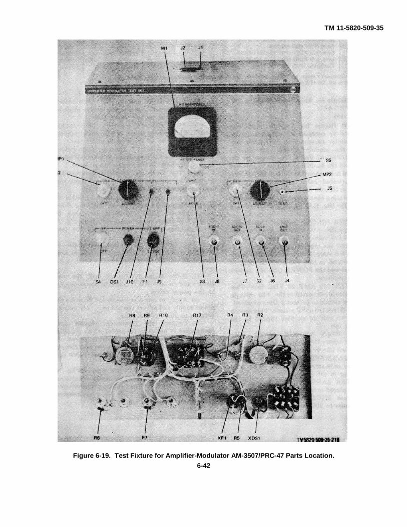
TM 11-5820-509-35
Figure 6-19. Test Fixture for Amplifier-Modulator AM-3507/PRC-47 Parts Location.6-42

TM 11-5820-509-35
Figure 6-20. Test Fixture for Amplifier-Modulator AM-3507/PRC-47, Chassis Parts and Subassembly A1Placement.
6-43

TM 11-5820-509-35
Symbol Description Mfgr Part No. Mfgr Code
Test Fixture for Amplifier-Modulator AM-3507/PRC-47C1, C2 Capacitor, fixed, 47uf, 20%, 20 vdcw (FSN 5910-800-1130) 150D476X0020R2 56289C3 Capacitor, fixed, 47 uf 20%, 35 vdcw (FSN 5910-834-8493) 150D476X0035S2 56289DS1 Lamp (FSN 6240-059-5349) MS25237-327- 15Fl Fuse (FSN 5920-281-t)224) F02A250V1 -2ASJ1 Connector (FSN 5935-089-1165) DBMF13W3S 71468J2 Connector (FSN 5935-983-2615ZB) DNMF7W2S 71468J3 Connector MS3102A24-28PJ4 Connector (FSN 5935-755-2,741) UG912AU
Contact, p/o J4 (FSN 5935-021-2118) DM53743-5058 91146J5 Jack (FSN 5935-6t71-5689) MS16108-8AJ6 thru J8 Connector (FSN 5935-755-2741) UG912AU
Contact, p/o J6 thru J8 (FSN 5935-02H2118) DM53743-5058 91146J9 Jack (FSN 5935-577-2326) MS16108-3AJ10 Jack (FSN 5935-578-3489) MS16108-2AM1 Ammeter, DC 0 - 50 microamperes 3860 55026MP1, MP2 Knob, pointer, p/o S3 757-0230-003 13499
Skirt, knob, p/o MP1, MP2 757-0220-003 13499Q1 Transistor (FSN 5961-808-7498) 2N1038R1 Resistor, var. 1000 ohms, 5%, 3A W (FSN 5905-717-5884) RT12C2P102R2 Resistor, var. 1 Megohm, 10%, 2 W RV4NAYSD 105AR3 Resistor, fixed, 30,000 ohms 5%, 1/2 W (FSN 5905-192-3978) RC20GF303JR4 Resistor, fixed, 47,000 ohms 10% 1/2 W (FSN 5905-295-3410) RC20GF473KR5 Resistor, fixed, 68 ohms, 5% 1/2 W (FSN 5905-195-5571) RC20GF680JR6, R7 Resistor, fixed, 1000 ohms, 10%, 1/2 W RC20GF102RR8 Resistor, var. 10,000 ohms, 10% 2 W RV4NAYSD103AR9, R10 Resistor, fixed, 22,000 ohms, 10% 1/2 W (FSN 5905-171-2004) RC2OGF223KR11 Resistor, fixed, 2610 ohms, 1%, 1/4 W (FSN 5905-068-1538) RN60D2611F 81349R12 Resistor, fixed, 1960 ohms, 1 % 1/4 W (FSN 5905-069-3914) RN60D1961F 81349R13 Resistor, fixed,.46.4 ohms, 1%, 1/4 W (FSN 5905-069-3908) RN60D46R4F 81349R14 Resistor, fixed, 1000 ohms, 1%, % W (FSN 5095-883-91981 RN65D 1001 F 81349R15 Resistor, var. 1000 ohms, 20%, 1/2 W (FSN 5905-502-3156) RV6LAYSA102BR16 Resistor, fixed, 6190 ohms, 1%, 1/4 W {FSN 5905-984-7682CX) RN60D6191F 81349R17 Resistor, fixed, 68 ohms, 10%, 1/4 W (FSN 5905-726-6836NT) RC07GF680K 81349S1 Switch, (FSN 5930-655-1514) ST42AS2 Switch, (FSN 5930-229-3390) ST42DS3, S4 Switch, (FSN 5293-108-6744) 7665K4S5 Switch, (FSN 5930-655- 1514) ST42AT1 Transformer (FSN 5950-812-0292ZX) A12425 70674XDS1 Light, (FSN 6210-825-2051) 101-3830-9 72619
Lens, p/o XDS1 (FSN 6210-511-8208) 101-972 72619XF1 Fuseholder (FSN 5920-284-7144) HKPH 71400
A1 Oscillator Assembly 768-7834-001 13499
C1 Capacitor, fixed, 3300 pf, 5%, 500 vdcw CM06F332J03C2 Capacitor, fixed, 4700 pf, 5% 500 vdcw CM06F472J03C3 Capacitor, fixed, 1000 pf, 5% 500 vdcw CM06F102J03C4 Capacitor, fixed, 390 pf, 5%, 500 vdcw CM05F391J03C5 Capacitor, fixed, 820 pf, 5%, 500 vdcw CM06F821J03C6 Capacitor, var. 8 to 50 pf, 500 vdcw 503001E2P034R 72982C7 Capacitor, fixed, 0.33 uf, P80M20%%, 25 vdcw 56289C8 Capacitor, fixed, 4.7 uf, 20%, 35 vdcw (FSN 5910-542-7387) 150D475X0035B2 56289C9 Capacitor, fixed, 10,000 pf, 20% 500 vdcw CK63AW 103MC10 Capacitor, fixed, 1000 pf, 5%, 500 vdcw CM06F102J03L1 Coil, rf, 47 uh (FSN 5950-842-2245) MS90538-04L2 Coil, rf, 1000 uh (FSN 5950-060-9188) MS90539-15Q1, Q2 Transistor (FSN 5960-809-1870) 2N 1285
Socket, p/o Q1, Q2 (FSN 5935-759-5852CX) 05-3307-51 91662Retainer, p/o Q1, Q2 (FSN 5935-523-1777E222) 0004-7202S 91662
R1 Resistor, fixed, 10,000 ohms, 10% 1/2 W (FSN 5905-185-8518) RC20GF103KR2 Resistor, fixed, 0.10 Megohm, 10% 1/2 W- (FSN 5905-192 RC20GF104K
3987CA)R3 Resistor, fixed, 10,000 ohms, 10% 1/2 W (FSN 5905-185-8518, RC07GF103KR4 Resistor, var. 1000 ohms, 20 %, 1/2 W ( FSN 5905-502-3 156) RV6LAYSA102B
6-44
TM 11-5820-509-35
Symbol Description Mfgr Part No. Mfgr Code
R5 Resistor, fixed, 10,000 ohms, 10%, 1/2 W (FSN 5905-185-8518) RC20GF103KR6 Resistor, fixed, 3300 ohms, 10%, 1/2 W (FSN 5905-195-6502) RC20GF332KY1 Crystal Unit, Quartz, 500.000 kHz (FSN 5955-892-3210) CR46AU500-00KCXY1 Socket (FSN 5935-201 7119) TS0205CO1
Note. All manufacturer's codes are 5-digit numbers. The corresponding manufacturer's name and address are listed in SB 708-42 Catalog Handbook (H4-2).
6-19. Test Fixture for Signal Data TranslatorCV-1377A/PRC-47(fig. 7-17)
a. The test fixture for Signal Data Translator CV-1377A/PRC-47 contains all switches, jacks, and lampsnecessary to electrically test and adjust the modulewithout providing a complete AN/PRC-47 Radio Set.Indexing fixture (fig. 6-7) is attached to the coupling endof the module to permit accurate indexing of thebandswitch and the slug rack during maintenanceprocedures. Power for the test fixture and the moduleunder test is provided externally and is connected to thetest fixture by a specially fabricated cable attached topower connector J5 at the rear of the test fixture.
b. The operating controls on the front panel of thetest fixture (fig. 6-6) perform the following functions:
(1) POWER ON -OFF switch. This toggleswitch controls the 115 volts, 400 Hz ac, the +19.5 voltsdc, and the +26.5 volts dc input voltages to the testfixture and the module under test.
(2) POWER lamp. This indicator is lit whenpower is connected to the 115 volts, 400 Hz primarypower circuit and the POWER ON-OFF switch is in theON position.
(3) POWER 115 VAC 1/4 AMP fuse. Thisprotective device is connected to the 115 volts, 400 Hzprimary power circuit to protect it from overload.
(4) POWER 19 VDC 1/2 AMP fuse. Thisprotective device is connected to the +19.5 volts dcprimary power circuit to protect it from overload.
(5) POWER 6.3 VAC 1 AM P fuse. Thisprotective device is connected to the secondary windingof transformer T1 and protects this 6.3 volts windingfrom overload.
(6) POWER 26.5 VDC 1 AMP fuse. Thisprotective device is connected in the +26.5 voltsprimary power circuit to protect it from overload.
(7) AVC ON-OFF switch. This toggle switchselects a variable negative bias for the avc circuits whenplaced in the ON position.
(8) FUNCTION SEL RCVR-XMIT switch.This toggle switch selects the receive or transmit modefor the module under test.
(9) ERROR B ADJ control. Thispotentiometer controls the level of external error voltageB.
(10) ERROR A ADJ control. Thispotentiometer controls the level of external error voltageA.
(11) LOOP SEL OPEN-CLOSED switch. Thistoggle switch selects external error voltages A and B inthe OPEN position to permit calibration of the CV-1377A/PRC-47 master Oscillator. In the CLOSEDposition, the error voltages generated by the C-4311/PRC-47 are applied to the master oscillator.
(12) OSC CONTROL S1 switch. This rotaryswitch selects the proper crystal for operation withoscillator Q20.
(13) OSC CONTROL S2 switch. This rotaryswitch selects the proper crystal for operation withoscillator Q21.
(14) Test jacks and binding posts are providedfor the attachment of signal leads and test equipmentand are self-explanatory.
c. The piece parts required for fabrication of thetest fixture are listed in the following chart andsuggested parts placement is shown in figures 6-21through 6-23 inclusive. Schematic diagram {fig. 7-17)illustrates the internal circuit of the test fixture.
6-45
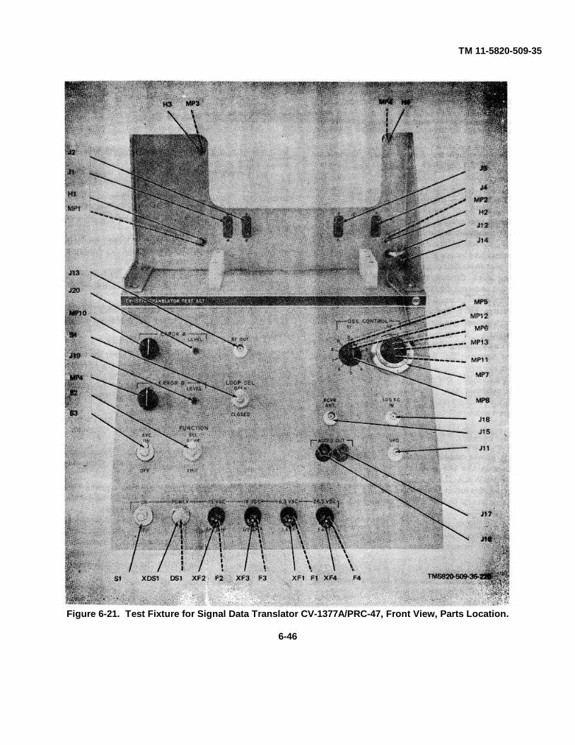
TM 11-5820-509-35
Figure 6-21. Test Fixture for Signal Data Translator CV-1377A/PRC-47, Front View, Parts Location.
6-46
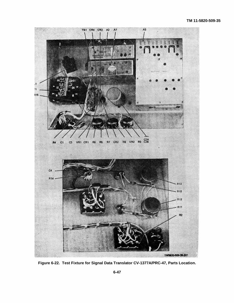
TM 11-5820-509-35
Figure 6-22. Test Fixture for Signal Data Translator CV-1377A/PRC-47, Parts Location.
6-47
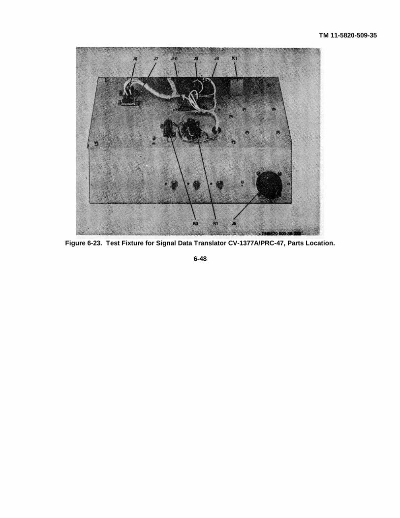
TM 11-5820-509-35
Figure 6-23. Test Fixture for Signal Data Translator CV-1377A/PRC-47, Parts Location.
6-48

TM 11-5820-509-35
Symbol Description Mfgr Part No. Mfgr Code
Test Fixture for Signal Data Translator CV-1377A/PRC-47
C1 Capacitor, fixed, 10,000 pf, 20%, 500 vdcw CK63AW103MC2 Capacitor, fixed, 35 uf, P100M10%%, 450 vdcw ((FSN 5910-954- D42974 56289
3038)C3 Capacitor, fixed, 4 of, 15%, 100 vdcw (FSN 5910-838-5715) CL21CN040SP3C4 Capacitor, fixed, 5.0 + 0.5 pf, 500 vdcw CC20CH050D 81349CR1 thru CR4 Semiconductor device, diode /FSN 5961-845-0766) 1N2615DS1 Lamp (FSN 6240-682-3411) NE51H 08806F1 Fuse (FSN 5920-280-4465) F02A250V1ASF2 Fuse (FSN 5920443-2641) F02A250V1-4ASF3 Fuse (FSN 5920-281-0224) F02A250V1-2ASF4 Fuse (FSN 5920-280 4465) F02A25CVlASH1, H2 Thumbscrew 761-9648-015 13499H3, H4 Thumbscrew 761-9648-004 13499J1 thru J4 Connector /FSN 5935-983-2615ZB) DAMF7W2S 71468
Connector p/o J1 thru J4 (FSN 5825-981-1466ZX) DM53743-5005 71468Connector insert p/o J1 thru J4 (FSN 5935480-02fi8) DM53742-5000 71468
J5 Connector MS3102A24-28PJ6 Connector /FSN 5935-983-2615ZB, DAMF7W2S 71468
Connector insert p/o J6 (FSN 5935480-0268) DM53742-5000 71468J7 Connector (FSN 5936489-6921) DAMF3W3S 71468
Connector insert p/o J7 /FSN 5935-080-0268) DM63742-5000 71468J8 Connector /(FSN 5935-983-2615ZB) DAMF7W2S 71468
Connector insert p/o J8 (FSN 59354804268) DM53742-5000 71468J9 Connector (FSN 5936 089-1166) DBMF13W3S 71468
Connector insert p/o J9 (FSN 5935480-0268) DM53742-5000 71468J10 Connector (FSN 5935-983-2615ZB) DAMF7W2S 71468J11 Connector (FSN 5935-755-2741) UC912AUJ12 Jack /FSN 5935-577-W) MS16108-5AJ13 Connector (FSN 6935-755-2741) UG912AUJ14 Jack /FSN 5935-577-2337) MS16108-5AJ15 Connector /FSN 5935-755-2741) UC912AUJ16 Binding post /FSN 5940-556-6194) DF30BC 58474J17 Binding post /FSN 5940-356-2493) DF30RC 58474J18 Connector /FSN 5985-755-2741) UC912AUJ19, J20 Jack /FSN 5935-578-3489) MS16108-2AK1 Relay, armature 22700-18 77523L1 Reactor, 0.05 H. (FSN 5950-984-2278ZX) A12408 70674MP1, MP2 Spring, Helical compression (FSN 5821-506-7304) 340-0001-000 91314MP3, MP4 Spring, Helical compression (FSN 5340-811-9737) 340-0419-000 91314MP5, MP6 Coupling, split hub (FSN 5821-510-4843) 540-7421-003 13499MP7 Dial (FSN 5355-587-6846) RBC 73138MP8 Pointer, knob 757-0230-001 13499
Skirt, knob p/o MP8 757-0220-001 13499MP9, MP10 Knob, round {FSN 5355-931-1492ZXI 757-0228-002 13499MP11 Shaft, str 761-9639-019 13499MP12, MP13 Clamp, loop (FSN 5821-396-3116) 504-7537-002 13499R1 Resistor, fixed, 470 ohms, 5%, 3 W (FSN 5905-925-5518ZX) RW69V471R2 Resistor, fixed, 0.33 Megohm, 10%, 1/2 W {FSN 5905-221-5860) RC20CF334K
5860)R3 Resistor, fixed, 4750 ohms, I %, 15 W (FSN 5905-952-9232) RE70G4751R4 Resistor, fixed, 27,000 ohms, 10%, 1/2 W (FSN 6905-195-6758) RC20GF273KR5 Resistor, fixed, 82,000 ohms, 10%, '1/2 W ((FSN 5905-254-7097) RC20GF823KR6 Resistor, var. 10,000 ohms, 10%, 2 W RV4NAYSD103AR7 Resistor, fixed, 15,000 ohms, 10%, * W /FSN 5906-190-8876) RG20GF153KR8 Resistor, var. 10,000 ohms, 10%, 2 W RV4NAYSD103AR10, R11 Resistor, fixed, 0.27 Megohm, 10%, 1/2 W (FSN 5905-643 RC20G F274K
5140)R12, R13 Resistor, var. 0.25 Megohm, 10%, 2 W RV4NAYSD254R14 Resistor, fixed, 27,000 ohms, 10%, 1/2 W (FSN 5905-196-6768) RC20GF273KR15 Resistor, fixed, 6800 ohms, 10%, 1/2 W (FSN 5905-245-00231 RC20CF682KS1, S2 Switch (FSN 5293-108-6744) 7665K4S3 Switch (FSN 5930-229-3390) ST42DS4 Switch (FSN 5293-108-6744) 7666K4TB1 Terminal board 332-14-07-039 71786
6-49
TM 11-5820-509-35
Symbol Description Mfgr Part No. Mfgr Code
T1 Transformer (FSN 5950-982-3748ZX) BC3069 97315VR1 Semiconductor device, zener diode 39 v, 5% 1N975BVR2 Semiconductor device, zener diode 6.2 v, 5% (FSN 5960-752- 1N753A
0179)XDS1 Lampholder 95408H935 72619XF1 thru XF4 Fuseholder (FSN 5920-284-7144) HKPH 71400
Note. All manufacturer's codes are 5-digit numbers. The corresponding manufacturer's name and address are listed in SB 708-42 Catalog Handbook (H4-2).
6-20. Test Fixture for Power Supply PP-3518/PRC-47(fig. 7-18)
a. The test fixture for Power Supply PP-3518/PRC-47 contains all switches, jacks, meters, and lampsnecessary to electrically test and adjust the modulewithout providing a complete AN/PRC-47 Radio Set.Power for the test fixture and the module under test isprovided externally and is connected to the test fixtureby a specially fabricated cable attached to powerconnector J2 at the rear of the test fixture.
b. The operating controls on the front panel of thetest fixture (fig. 6-8) perform the following functions:
(1) 115 VAC ON-OFF switch. This toggleswitch controls the 115 volts, 400 Hz ac and interlocksthe +23 volt dc circuit between the module under testand the test fixture load circuits.
(2) 115 VAC lamp. This indicator is lit whenpower is connected to the 115 volts, 400 Hz primarypower circuit and the 115 VAC ON-OFF switch is in theON position.
13) 115 VAC 5 AMP fuse. This protectivedevice is connected to the 115 volts, 400 Hz primarypower circuit to protect it from overload.
(4) +23V ON-OFF switch. This toggle switchcontrols the +23 volts dc primary power circuit andinterlocks it with the 115 volts, 400 Hz primary powercircuits to prevent both being energized at one time.
(5) +23V lamp. This indicator is lit whenpower is connected to the +23 volt primary power circuitand the +23V ON-OFF switch is in the ON position.
(6) +23V 15 AMP fuse. This protectivedevice is connected to the +23 volt primary power circuitto protect it from overload.
(7) BLOWER ON-OFF switch. This toggleswitch controls the 115 volts, 60 Hz primary powerapplied to the blower.
(8) BLOWER 60 CPS 1/2 AMP fuse. Thisprotective device is connected to the 115 volts, 60 Hzprimary power circuit that energizes the blower motorand protects it from overload.
(9) HV ON-OFF switch. This toggle switchenables the push-to-talk relay (K1) in the power supplymodule when high voltage output is desired.
(10) VOLTAGE SEL switch. This 9-positionrotary switch selects the power supply module circuit tobe monitored and connects it to the DC VOLTAGEmeter, or the AC VOLTAGE, jacks for measurement.All power supply module outputs can be selected by thisswitch.
(11) DC VOLTAGE meter. This 0-lO0microammeter is used to indicate the several dc outputvoltages of the power supply module as selected by theVOLTAGE SEL switch.
(12) AC VOLTAGE jacks. These jacks areprovided to connect an external ac instrument formeasuring the filament voltage output of the powersupply module.
c. The piece parts required for fabrication of thetest fixture are listed in the following chart andsuggested parts placement is shown in figures 6-24 and6-25. Schematic diagram (fig. 7-18) illustrates theinternal circuit of the test fixture.
6-50

TM 11-5820-509-35
Figure 6-24. Test Fixture for Power Supply PP-3518/PrC-47, Parts Location.
6-51

TM 11-5820-509-35
Figure 6-25. Test Fixture for Power Supply PP-3518/PRC-47, Internal Parts Location.
6-52
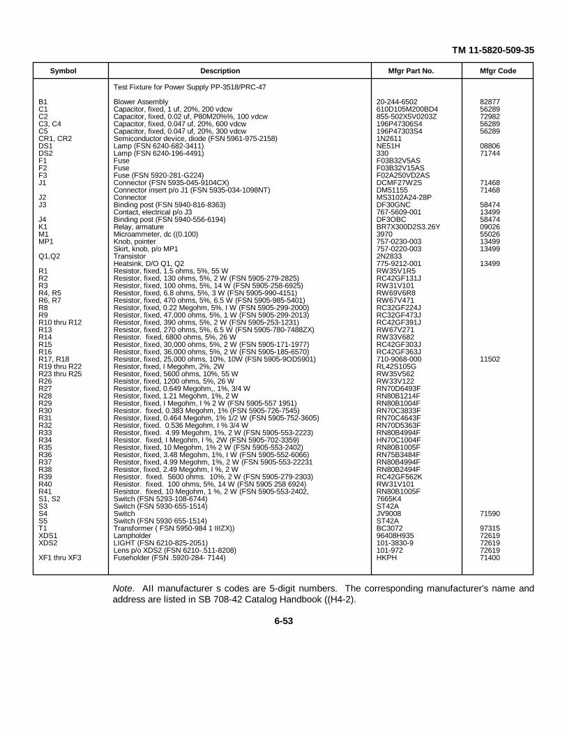
TM 11-5820-509-35
Symbol Description Mfgr Part No. Mfgr Code
Test Fixture for Power Supply PP-3518/PRC-47
B1 Blower Assembly 20-244-6502 82877C1 Capacitor, fixed, 1 uf, 20%, 200 vdcw 610D105M200BD4 56289C2 Capacitor, fixed, 0.02 uf, P80M20%%, 100 vdcw 855-502X5V0203Z 72982C3, C4 Capacitor, fixed, 0.047 uf, 20%, 600 vdcw 196P47306S4 56289C5 Capacitor, fixed, 0.047 uf, 20%, 300 vdcw 196P47303S4 56289CR1, CR2 Semiconductor device, diode (FSN 5961-975-2158) 1N2611DS1 Lamp (FSN 6240-682-3411) NE51H 08806DS2 Lamp (FSN 6240-196-4491) 330 71744F1 Fuse F03B32V5ASF2 Fuse F03B32V15ASF3 Fuse (FSN 5920-281-G224) F02A250VD2ASJ1 Connector (FSN 5935-045-9104CX) DCMF27W2S 71468
Connector insert p/o J1 (FSN 5935-034-1098NT) DM51155 71468J2 Connector MS3102A24-28PJ3 Binding post (FSN 5940-816-8363) DF30GNC 58474
Contact, electrical p/o J3 767-5609-001 13499J4 Binding post (FSN 5940-556-6194) DF3OBC 58474K1 Relay, armature BR7X300D2S3.26Y 09026M1 Microammeter, dc ((0.100) 3970 55026MP1 Knob, pointer 757-0230-003 13499
Skirt, knob, p/o MP1 757-0220-003 13499Q1,Q2 Transistor 2N2833
Heatsink, D/O Q1, Q2 775-9212-001 13499R1 Resistor, fixed, 1.5 ohms, 5%, 55 W RW35V1R5R2 Resistor, fixed, 130 ohms, 5%, 2 W (FSN 5905-279-2825) RC42GF131JR3 Resistor, fixed, 100 ohms, 5%, 14 W (FSN 5905-258-6925) RW31V101R4, R5 Resistor, fixed, 6.8 ohms, 5%, 3 W (FSN 5905-990-4151) RW69V6R8R6, R7 Resistor, fixed, 470 ohms, 5%, 6.5 W (FSN 5905-985-5401) RW67V471R8 Resistor, fixed, 0.22 Megohm, 5%, I W (FSN 5905-299-2000) RC32GF224JR9 Resistor, fixed, 47,000 ohms, 5%, 1 W (FSN 5905-299-2013) RC32GF473JR10 thru R12 Resistor, fixed, 390 ohms, 5%, 2 W (FSN 5905-253-1231) RC42GF391JR13 Resistor, fixed, 270 ohms, 5%, 6.5 W (FSN 5905-780-7488ZX) RW67V271R14 Resistor. fixed, 6800 ohms, 5%, 26 W RW33V682R15 Resistor, fixed, 30,000 ohms, 5%, 2 W (FSN 5905-171-1977) RC42GF303JR16 Resistor, fixed, 36,000 ohms, 5%, 2 W (FSN 5905-185-6570) RC42GF363JR17, R18 Resistor, fixed, 25,000 ohms, 10%, 10W (FSN 5905-9OD5901) 710-9068-000 11502R19 thru R22 Resistor, fixed, I Megohm, 2%, 2W RL42S105GR23 thru R25 Resistor, fixed, 5600 ohms, 10%, 55 W RW35V562R26 Resistor, fixed, 1200 ohms, 5%, 26 W RW33V122R27 Resistor, fixed, 0.649 Megohm,, 1%, 3/4 W RN70D6493FR28 Resistor, fixed, 1.21 Megohm, 1%, 2 W RN80B1214FR29 Resistor, fixed, I Megohm, I % 2 W (FSN 5905-557 1951) RN80B1004FR30 Resistor. fixed, 0.383 Megohm, 1% (FSN 5905-726-7545) RN70C3833FR31 Resistor, fixed, 0.464 Megohm, 1% 1/2 W (FSN 5905-752-3605) RN70C4643FR32 Resistor, fixed. 0.536 Megohm, I % 3/4 W RN70D5363FR33 Resistor, fixed. 4.99 Megohm, 1%, 2 W (FSN 5905-553-2223) RN80B4994FR34 Resistor. fixed, I Megohm, I %, 2W (FSN 5905-702-3359) HN70C1004FR35 Resistor, fixed, 10 Megohm, 1% 2 W (FSN 5905-553-2402) RN80B1005FR36 Resistor, fixed, 3.48 Megohm, 1%, I W (FSN 5905-552-6066) RN75B3484FR37 Resistor, fixed, 4.99 Megohm, 1%, 2 W (FSN 5905-553-22231 RN80B4994FR38 Resistor, fixed, 2.49 Megohm, I %, 2 W RN80B2494FR39 Resistor. fixed. 5600 ohms. 10%, 2 W (FSN 5905-279-2303) RC42GF562KR40 Resistor. fixed. 100 ohms, 5%, 14 W (FSN 5905 258 6924) RW31V101R41 Resistor. fixed, 10 Megohm, 1 %, 2 W (FSN 5905-553-2402, RN80B1005FS1, S2 Switch (FSN 5293-108-6744) 7665K4S3 Switch (FSN 5930-655-1514) ST42AS4 Switch JV9008 71590S5 Switch (FSN 5930 655-1514) ST42AT1 Transformer ( FSN 5950-984 1 IIIZX)) BC3072 97315XDS1 Lampholder 96408H935 72619XDS2 LIGHT (FSN 6210-825-2051) 101-3830-9 72619
Lens p/o XDS2 (FSN 6210-.511-8208) 101-972 72619XF1 thru XF3 Fuseholder (FSN .5920-284- 7144) HKPH 71400
Note. AII manufacturer s codes are 5-digit numbers. The corresponding manufacturer's name andaddress are listed in SB 708-42 Catalog Handbook ((H4-2).
6-53

TM 11-5820-509-35
6-21. Test Fixture for Radio FrequencyOscillator 0-1032/PRC-47(fig. 7-19)
a. The test fixture for Radio Frequency Oscillator0-1032JPRC-47 contains all switches, jacks, meter andlamps necessary to electrically test and adjust themodule without providing a complete AN/PRC-47 RadioSet. Power for the test fixture and the module undertest is provided externally and is connected to the testfixture by a specially fabricated cable attached to powerconnector J2 at the rear of the test fixture.
b. The operating controls on the front panel of thetest fixture (fig. 6-9) perform the following functions:
(1) +20V ON-OFF switch. This toggle switchcontrols the +20 volts dc primary power circuit to themodule under test.
(2) +20V lamp. This indicator is lit whenpower is connected to the +20 volts dc primary power
circuit and the +20V ON-OFF switch is in the ONposition.
(3) +20V 1/4 AMP fuse. This protectivedevice is connected to the +20 volts dc primary powercircuit to protect it from overload.
(4) +20 V CURRENT meter. This 0 - 60milliammeter indicates the amount of current beingdrawn by the module under test.
(5) PUSH TO READ button. This shuntingswitch is opened when pressed to permit the +20 VCURRENT meter to indicate the module current drain.
(6) Coaxial connectors are provided for theconnection of signal leads and test equipment and theseare self-explanatory.
c. The piece parts required for fabrication of thetest fixture are listed in the following chart andsuggested parts placement is shown in figure 6-26.Schematic diagram {fig. 7-19) illustrates the internalcircuit of the test fixture.
6-54
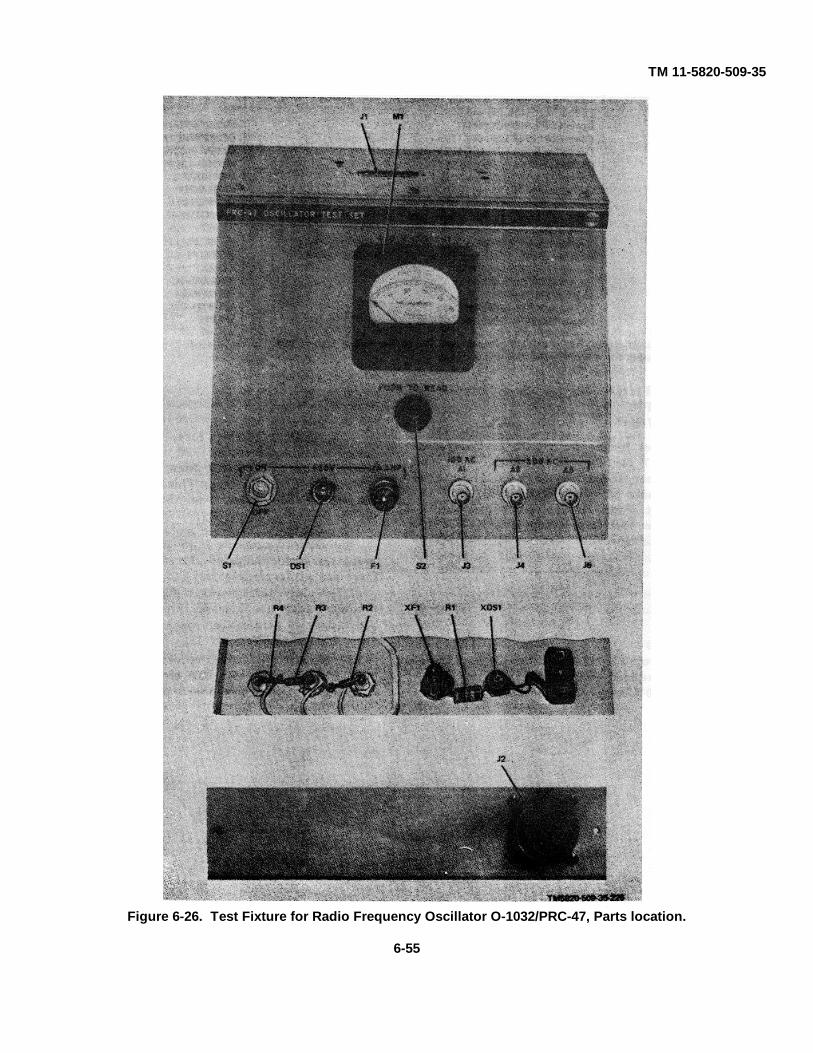
TM 11-5820-509-35
Figure 6-26. Test Fixture for Radio Frequency Oscillator O-1032/PRC-47, Parts location.
6-55
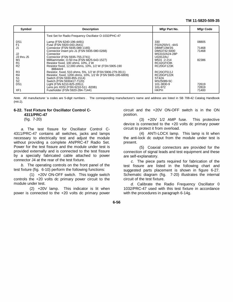
TM 11-5820-509-35
Symbol Description Mfgr Part No. Mfgr Code
Test Set for Radio Frequency Oscillator O-1032/PHC-47
DS1 Lamp (FSN 6240-196-4491) 330 08805F1 Fuse (FSN 5920-043-2641) F02A250V1 -4ASJ1 Connector (FSN 5935-089-1165) DBMF13W3S 71468
Connector insert p/o J1 (FSN 5935-080-0268) DM53742-5000 71468J2 Connector MS3102A24-28PJ3 thru J5 Connector (FSN 5935-755-2741) UG912AUM1 MillIiammeter, O-50 ma (FSN 6825-643-1527) M531 -2-214 82386R1 Resistor fixed, 100 ohms, 10%, 2 W RC42GFIOlKR2 Resistor fixed, 12,000 ohms, 10%, 1/2 W (FSN 5905-190 RC20GF123K
8884AHIR3 Resistor, fixed, 510 ohms, 5%, 1/2 W (FSN 5906-279-3511) RC20CF511JR4 Resistor, fixed, 1200 ohms, 10%, 1/2 W (FSN 5905-195-6809) RC20GP122KS1 Switch (FSN 5930-855-1514) ST42AS2 Switch (FSN 5930417-7120) MS25089-5CDS1 Light (FSN 6210-825-20511 101-3830-9 72619
Lens p/o XDSI (FSN 6210-511 -82081 101-972 72819XF1 Fuseholder (FSN 5920-284-71441 HKPH 71400
Note. All manufacturer 'a codes are 5-digit numbers . The corresponding manufacturer's name and address are listed in SB 708-42 Catalog Handbook(H4-2).
6-22. Test Fixture for Oscillator Control C-4311/PRC-47(fig. 7-20)
a. The test fissure for Oscillator Control C-4311/PRC-47 contains all switches, jacks and lampsnecessary to electrically test and adjust the modulewithout providing a complete AN/PRC-47 Radio Set.Power for the test fissure and the module under test isprovided externally and is connected to the test fissureby a specially fabricated cable attached to powerconnector J4 at the rear of the test fixture.
b. The operating controls on the front panel of thetest fixture (fig. 6-10) perform the following functions:
(1) +20V ON-OFF switch. This toggle switchcontrols the +20 volts dc primary power circuit to themodule under test.
(2) +20V lamp. This indicator is lit whenpower is connected to the +20 volts dc primary power
circuit and the +20V ON-OFF switch is in the ONposition.
(3) +20V 1/2 AMP fuse. This protectivedevice is connected to the +20 volts dc primary powercircuit to protect it from overload.
(4) ANTI-LOCX lamp. This lamp is lit whenthe anti-lock dc output from the module under test ispresent.
(5) Coaxial connectors are provided for theconnection of signal leads and test equipment and theseare self-explanatory.
c. The piece parts required for fabrication of thetest fissure are listed in the following chart andsuggested parts placement is shown in figure 6-27.Schematic diagram (fig. 7-20) illustrates the internalcircuit of the test fixture.
d. Calibrate the Radio Frequency Oscillator 01032/PRC-47 used with this test fixture in accordancewith the procedures in paragraph 6-14g.
6-56
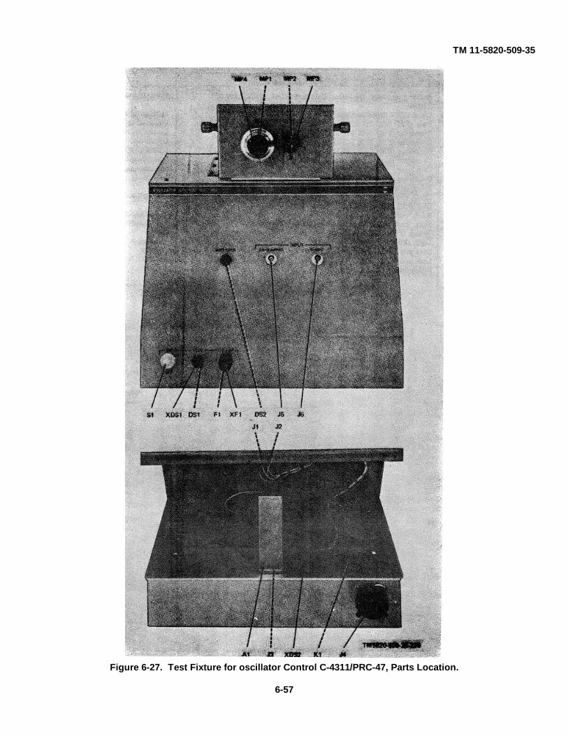
TM 11-5820-509-35
Figure 6-27. Test Fixture for oscillator Control C-4311/PRC-47, Parts Location.
6-57
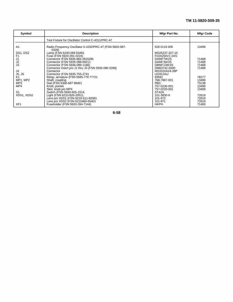
TM 11-5820-509-35
Symbol Description Mfgr Part No. Mfgr Code
Test Fixture for Oscillator Control C-4311/PRC-47
A1 Radio Frequency Oscillator 0-1032/PRC-47 (FSN 5820-087- 528 0119 005 134990328)
DS1, DS2 Lamp (FSN 6240-069 63491 MS25237-327-15F1 Fuse (FSN 5920-281-0224) F02A250V1-2ASJ1 Connector /FSN 5935-983-2615ZBI DAMF7W2S 71468J2 Connector (FSN 5935-089-69211 DAMF3W3S 71468J3 Connector (FSN 5936-089-1166) DBMF13W3S 71468
Connector insert p/o J1 thru J3 (FSN 5935-080 0268) DM63742-5000 71468J4 Connector MS3102A24-28PJ5, J6 Connector (FSN 5935-755-2741 UG912AUK1 Relay, armature (FSN 5945-779 77721 93591 78277MP1, MP2 Shaft, coupling 768-7887-001 13499MP3 Dial (FSN 6366-687 68461 RBC 73138MP4 Knob, pointer 757-0230-001 13499
Skirt, knob p/o MP4 757-0220-001 13499S1 Switch (FSN 5930-655-1514, ST42AXDS1, XDS2 Light (FSN 6210-826-20511 101-3830-9 72619
Lens p/o XDS1 (FSN 6210-511-82081 101-972 72619Lens p/o XDS2 (FSN 6210460-65401 101-971 72619
XF1 Fuseholder (FSN 5920-284-7144) HKPH 71400
6-58
TM 11-5820-509-35
CHAPTER 7CIRCUIT DIAGRAMS
7 1. IntroductionThis chapter contains block diagrams, mechanicalschematics, main schematic diagrams and test fixturediagrams for Radio Receiver-Transmitter RT 671/PTC-47. The information is assembled in the following order:
a. MIL standard color codes (fig. 7-1).
b. Block diagrams (fig. 7-2 through 7-6).
c. Mechanical schematic (fig. 7-7).
d. Main schematic diagrams (fig. 7 8 through 7-14).
e. Test fixture diagrams (fig. 7-15 through 7-20).
All special symbols appearing on these drawings aredefined in the notes that are part of the diagrams inwhich they appear.
Figure 7-1. Color Code Marking for Military Standard Resistors, Inductor, and Capacitors.(Located in back of manual.)
7-1
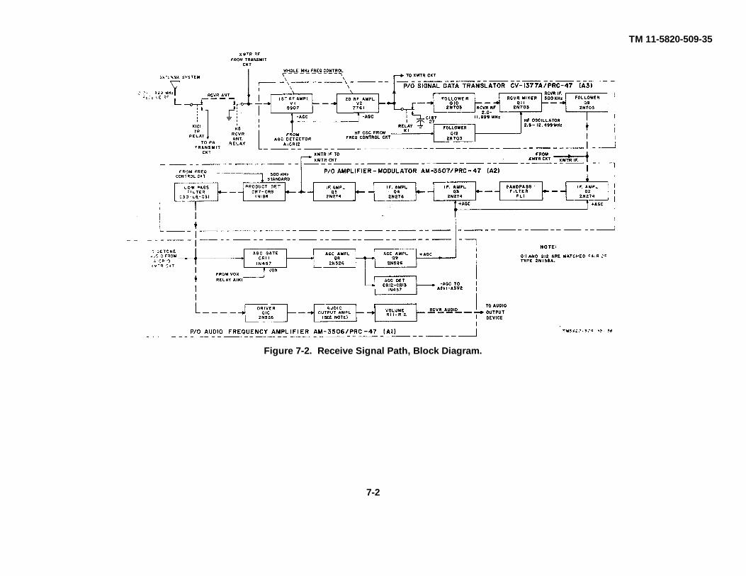
TM 11-5820-509-35
Figure 7-2. Receive Signal Path, Block Diagram.
7-2

TM 11-5820-509-35
Figure 7-3. Transmit Signal Path, Block Diagram.(Located in back of manual.)
Figure 7-4. Frequency Control Circuits, Block Diagram.(Located in back of manual.)
Figure 7-5. Power Supply Circuits, Dc Primary Power Input, Block Diagram.(Located in bade of manual.)
Figure 7-6. Power Supply Circuits, Ac Primary Power Input, Block Diagram.(Located in back of manual.)
Figure 7-7. Mechanical Schematic, Frequency Control Mechanism.(Located in back of manual.)
Figure 7-8 (1). Electrical Equipment Chassis CH-474/PRC-47(A8A4), Schematic Diagram (sheet 1 of 2).(Located in back of manual.)
Figure 7-8 (2). Electrical Equipment Chassis CH-474/PRC-47 (A8A4)., Schematic Diagram (sheet 2 of 2).(Located in back of manual.)
Figure 7-9. Audio Frequency Amplifier AM-3506/PRC-47(A8A1), Schematic Diagram.(Located in back of manual.)
Figure 7-10. Amplifier-Modulator AM-3507/PRC-47 (A8A2). Schematic Diagram.(Located in back of manual.)
Figure 7-11 (1) . Signal Data Translator CV -1377A/PRC-47 (A8A3), Schematic Diagram (sheet 1 of 2).(Located in back of manual.)
Figure 7-11 (2) Signal Data Translator CV-1377A/PRC-47 (A8A3). Schematic Diagram (sheet 2 of 2).(Located in back of manual.)
Figure 7-12. Power Supply PP-3518/PRC-47 (A8A5), Schematic Diagram.(Located in back of manual I
7-13. Radio Frequency Oscillator O-1032/PRC-47 (A8A6) , Schematic Diagram.(Located in back of manual.)
Figure 7-14. Oscillator Control C-4311/PRC-47 (A8A7), Schematic Diagram.(Located in back of manual.)
7-3
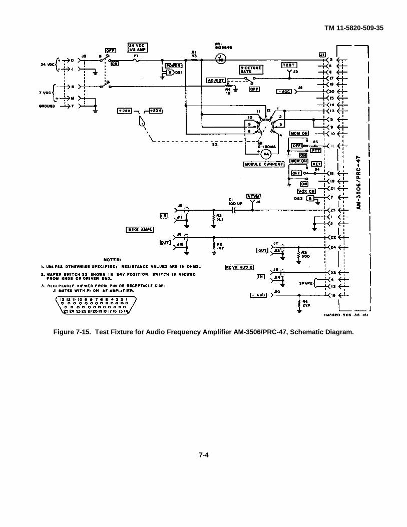
TM 11-5820-509-35
Figure 7-15. Test Fixture for Audio Frequency Amplifier AM-3506/PRC-47, Schematic Diagram.
7-4
TM 11-5820-509-35
Figure 7-16. Test Fixture for Amplifier-Modulator AM-3507/PRC-47, Schematic Diagram.
7-5
TM 11-5820-509-35
Figure 7-17. Test Fixture for Signal Data Translator CV-1377A/PRC-47, Schematic Diagram.
7-6
TM 11-5820-509-35
Figure 7-18. Test Fixture for Power Supply PP-3518/PRC-47, Schematic Diagram.
7-7
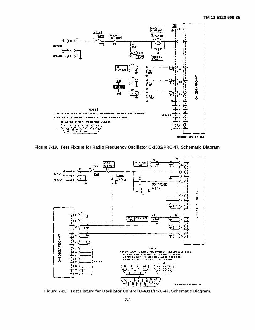
TM 11-5820-509-35
Figure 7-20. Test Fixture for Oscillator Control C-4311/PRC-47, Schematic Diagram.
Figure 7-19. Test Fixture for Radio Frequency Oscillator O-1032/PRC-47, Schematic Diagram.
7-8
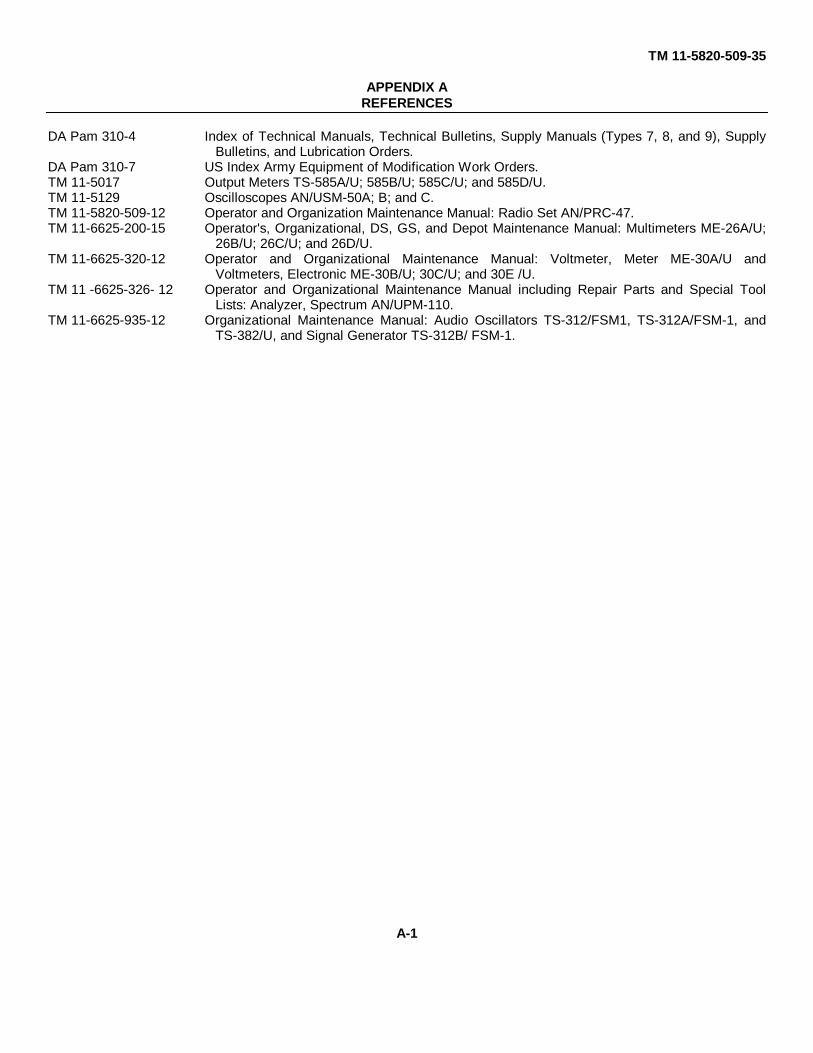
TM 11-5820-509-35
APPENDIX AREFERENCES
DA Pam 310-4 Index of Technical Manuals, Technical Bulletins, Supply Manuals (Types 7, 8, and 9), SupplyBulletins, and Lubrication Orders.
DA Pam 310-7 US Index Army Equipment of Modification Work Orders.TM 11-5017 Output Meters TS-585A/U; 585B/U; 585C/U; and 585D/U.TM 11-5129 Oscilloscopes AN/USM-50A; B; and C.TM 11-5820-509-12 Operator and Organization Maintenance Manual: Radio Set AN/PRC-47.TM 11-6625-200-15 Operator's, Organizational, DS, GS, and Depot Maintenance Manual: Multimeters ME-26A/U;
26B/U; 26C/U; and 26D/U.TM 11-6625-320-12 Operator and Organizational Maintenance Manual: Voltmeter, Meter ME-30A/U and
Voltmeters, Electronic ME-30B/U; 30C/U; and 30E /U.TM 11 -6625-326- 12 Operator and Organizational Maintenance Manual including Repair Parts and Special Tool
Lists: Analyzer, Spectrum AN/UPM-110.TM 11-6625-935-12 Organizational Maintenance Manual: Audio Oscillators TS-312/FSM1, TS-312A/FSM-1, and
TS-382/U, and Signal Generator TS-312B/ FSM-1.
A-1

TM 11-5820-509-35
APPENDIX BDIRECT SUPPORT, GENERAL SUPPORT, AND
DEPOT MAINTENANCE REPAIR PARTSAND SPECIAL TOOLS LISTSection I. INTRODUCTION
B-1. ScopeThis appendix lists repair parts and special toolsrequired for the performance of direct support, generalsupport, and depot maintenance of Radio Set AN/PRC-47.B-2. GeneralThis Repair Parts and Special Tools List is divided intothe following sections.:
a. Repair Parts-Section II. A list of repair partsauthorized for the performance of maintenance ofmaintenance at the direct support, general support, anddepot level.
b. Special Tools, Test, and Support Equipment-Section III. A list of special tools, test and supportequipment authorized for the performance ofmaintenance at the direct support, general support, anddepot level.
c. Index - Federal Stock Number and ReferenceNumber Cross Reference to Figure and Item Number -Section IV. A list of Federal stock numbers is ascendingnumerical sequence, followed by a list of referencenumbers in ascending alphanumeric sequence, crossreferenced to the illustration figure number andreference designation.
d. Index - Reference Designation Cross-Referenceto Page Number - Section V. A list of referencedesignations cross-referenced to page numbers.B-3. Explanation of ColumnsThe following provides an explanation of columns in thetabular lists
a. Source, Main tenance and Recoverability Codes(SMR ), Column 1.
(1) Source code indicates the selection statusand source for the listed item. Source codes are:Code ExplanationP Repair parts which are stocked in or supplied
from the GSA/DSA, or Army supply systemand authorized for use at indicatedmaintenance categories.
Code ExplanationP2 Repair parts which are procured and stocked
for insurance purposes because the combator military essentiality of the end itemdictates that a minimum quantity beavailable in the supply system.
P9 Assigned to items which are NSA designcontrolled: unique repair parts, special tools,test, measuring and diagnostic equipment'which are stocked and supplied by the ArmyCOMSEC logistic system, and which are notsubject to the provisions of AR 380-41.
P10 Assigned to items which are NSA designcontrolled special sods, test, measuring anddiagnostic equipment for COMSEC support,which are accountable under the provisionsof AR 380-41, and which are stocked andsupplied by the Army COMSEC logisticsystem.
M Repair parts which are not procured orstocked, but are to be manufactured atindicated maintenance levels.
A Assemblies which are not procured or stockedas such but are made up of two or moreunite. Such component units carry individualstock numbers and descriptions, areprocured and stocked separately, and can beassembled to form the required assembly atindicated maintenance categories.
X Parts and assemblies which are not procuredor stocked and the mortality of whichnormally is below that of the applicable enditem or component. The failure of such partor assembly should result in retirement of theend item from the supply system.
X1 Repair parts which are not procured orstocked. The requirement for such items willbe filled by use of the next higher assemblyor component.
X2 Repair parts which are not stocked. Theindicated maintenance category requiringsuch repair parts will attempt to obtain samethrough cannibalization. Where such repairparts are not obtainable throughcannibalization, requirements will berequisitioned, with accompanyingjustification, through normal supply channels.
G Major assemblies that are procured with PEMAfunds for initial issue only as exchangeassemblies at DSU and GSU level. Theseassemblies will not be stocked above DS andGS level or returned to depot supply level.
B-1
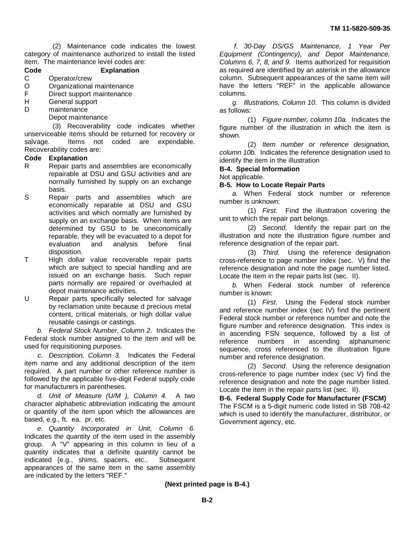
TM 11-5820-509-35
(2) Maintenance code indicates the lowestcategory of maintenance authorized to install the listeditem. The maintenance level codes are:Code ExplanationC Operator/crewO Organizational maintenanceF Direct support maintenanceH General supportD maintenance
Depot maintenance(3) Recoverability code indicates whether
unserviceable items should be returned for recovery orsalvage. Items not coded are expendable.Recoverability codes are:Code ExplanationR Repair parts and assemblies are economically
repairable at DSU and GSU activities and arenormally furnished by supply on an exchangebasis.
S Repair parts and assemblies which areeconomically reparable at DSU and GSUactivities and which normally are furnished bysupply on an exchange basis. When items aredetermined by GSU to be uneconomicallyreparable, they will be evacuated to a depot forevaluation and analysis before finaldisposition.
T High dollar value recoverable repair partswhich are subject to special handling and areissued on an exchange basis. Such repairparts normally are repaired or overhauled atdepot maintenance activities.
U Repair parts specifically selected for salvageby reclamation unite because d precious metalcontent, critical materials, or high dollar valuereusable casings or castings.
b. Federal Stock Number, Column 2. Indicates theFederal stock number assigned to the item and will beused for requisitioning purposes.
c. Description, Column 3. Indicates the Federalitem name and any additional description of the itemrequired. A part number or other reference number isfollowed by the applicable five-digit Federal supply codefor manufacturers in parentheses.
d. Unit of Measure (U/M ), Column 4. A twocharacter alphabetic abbreviation indicating the amountor quantity of the item upon which the allowances arebased, e.g., ft. ea. pr, etc.
e. Quantity Incorporated in Unit, Column 6.Indicates the quantity of the item used in the assemblygroup. A "V" appearing in this column in lieu of aquantity indicates that a definite quantity cannot beindicated {e.g., shims, spacers, etc.. Subsequentappearances of the same item in the same assemblyare indicated by the letters "REF."
f. 30-Day DS/GS Maintenance, 1 Year PerEquipment (Contingency), and Depot Maintenance,Columns 6, 7, 8, and 9. Items authorized for requisitionas required are identified by an asterisk in the allowancecolumn. Subsequent appearances of the same item willhave the letters "REF" in the applicable allowancecolumns.
g. Illustrations, Column 10. This column is dividedas follows:
(1) Figure number, column 10a. Indicates thefigure number of the illustration in which the item isshown.
(2) Item number or reference designation,column 10b. Indicates the reference designation used toidentify the item in the illustrationB-4. Special InformationNot applicable.B-5. How to Locate Repair Parts
a. When Federal stock number or referencenumber is unknown:
(1) First. Find the illustration covering theunit to which the repair part belongs.
(2) Second. Identify the repair part on theillustration and note the illustration figure number andreference designation of the repair part.
(3) Third. Using the reference designationcross-reference to page number index (sec. V) find thereference designation and note the page number listed.Locate the item in the repair parts list (sec. II).
b. When Federal stock number of referencenumber is known:
(1) First. Using the Federal stock numberand reference number index (sec IV) find the pertinentFederal stock number or reference number and note thefigure number and reference designation. This index isin ascending FSN sequence, followed by a list ofreference numbers in ascending alphanumericsequence, cross referenced to the illustration figurenumber and reference designation.
(2) Second. Using the reference designationcross-reference to page number index (sec V) find thereference designation and note the page number listed.Locate the item in the repair parts list (sec. II).B-6. Federal Supply Code for Manufacturer (FSCM)The FSCM is a 5-digit numeric code listed in SB 708-42which is used to identify the manufacturer, distributor, orGovernment agency, etc.
(Next printed page is B-4.)
B-2

SECTION II TM 11-5820-509-35
****REPAIR PARTS FOR DIRECT SUPPORT, GENERAL SUPPORT, AND DEPOT MAINTENANCE****
(1) (2) (3) (4) (5) (6) (7) (8) (9) (10)30 DAY DS 30 DAY GS 1 YR DEPOT
MAINTENANCE MAINTENANCE ALW MAINTSMR FEDERAL UNIT QTY ALLOWANCE ALLOWANCE PER ALW ILLUSTRATION
CODE STOCK DESCRIPTION Usable OF INC 100 PERNUMBER Reference Number & Mfr. Code on Code MEAS IN (a) (b) (c) (a) (b) (c) EQUIP 100 (a) (b)
UNIT 1-20 21-50 51-100 1-20 21-50 51-100 CNTGCY EQUIP FIG ITEMNO. NO.
5820-861-3539 RADI0 SET: EA 1ANPRC47; (80058)
A--F-S 5820-062-6748 CASE, RADIO SET: EA 1 A1CY3700PRC47; (80058)
P--D 5820-007-9544 CASE, TRANSIT: EA 1 * * A1NP2021-0187-00; (98376)
M-D PLATE, IDENTIFICATION EA 1 A1NP2767-0502-00; (13499)
P-F-S 6135-087-2301 ADAPTER, BATTERY TERMINAL EA 1 * * * * * * * * A2MX4430PRC47; (80058)
Y-D BRACKET, COVER-PRESSED: EA 1 A2MP1549-6252-003; (13499)
P-D 5935-08-6228 CONNECTOR, RECEPTACLE, ELECTRICAL: EA 2 * * A2J1` 549-6245-002; (13499)
P-D 5310-349-847 NUT, PLAIN, HEXAGON: EA 3 * * A2J1H1P334-0284-000; (77250)
P-D 5310-158-5240 WASHER, FLAT: EA 2 * * A2JH2549-6244-002; (13499)
P-D 5935-088-6228 CONNECTOR, RECEPTACLE. ELECTRICAL: EA REF REF REF A2J2549-6245-002; (13499)
P-D NUT, PLAIN, HEXAGON: EA REF REF REF A2J2H1P334-0284-000; (77250)
P-D NUT, PLAIN, HEXAGON: EA REF REF REF A2J2H2P334-0284-000; (77250)
P-D WASHER, FLAT: EA REF REF REF A2J2H3549-6244-002; (13499)
M-D COVER, BATTERY BOX: EA 1 A2MP2549-6250-003; (13499)
M-D 5935-951-3054 COVER, ELECTRICAL CONNECTOR: EA 1 A2MP310-243964-143; (77820)
M-D PIN, LOCATING: EA 1 A2MP4549-6242-002; (13499)
M-D PLATE, IDENTIFICATION: EA 1 A2MP5737-4765-000; (13499)
P-D STRIKE, CATCH: EA 2 * * A2A1549-6247-002; (13499)
X1-D CATCH, LUGGAGE: EA 1 REF REF A2A1MP1SCB83314-2A; (98003)
X1-D SCREW, MACHINE: EA REF A2A1MP1H1549-6246-02; (13499)
P-D STRIKE, CATCH: EA REF REF REF A2A2549-6247-002; (13499)
X1-D CATCH, LUGGAGE: EA REF REF REF A2A2MP1SCB83314-2A; (98003)
X1-D SCREW, MACHINE: EA REF A2A2MP1H1549-6246-002; (13499)
P--F 5820-970-6766 ADAPTER, CABLE TO CONNECTOR: EA 1 * * * * * * * * A3U239PRC47; (80058)
X1-D BODY, ADAPTER: EA 1 A3NP1549-6493-003; (13499)
B-4
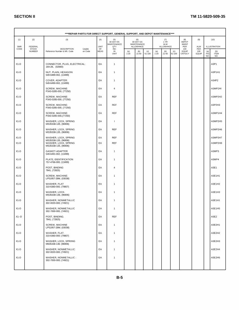
SECTION II TM 11-5820-509-35
****REPAIR PARTS FOR DIRECT SUPPORT, GENERAL SUPPORT, AND DEPOT MAINTENANCE****
(1) (2) (3) (4) (5) (6) (7) (8) (9) (10)30 DAY DS 30 DAY GS 1 YR DEPOT
MAINTENANCE MAINTENANCE ALW MAINTSMR FEDERAL UNIT QTY ALLOWANCE ALLOWANCE PER ALW ILLUSTRATION
CODE STOCK DESCRIPTION Usable OF INC 100 PERNUMBER Reference Number & Mfr. Code on Code MEAS IN (a) (b) (c) (a) (b) (c) EQUIP 100 (a) (b)
UNIT 1-20 21-50 51-100 1-20 21-50 51-100 CNTGCY EQUIP FIG ITEMNO. NO.
X1-D CONNECTOR, PLUG, ELECTRICAL: EA 1 A3P1164-28,. (02660)
X1-D NUT, PLAIN, HEXAGON: EA 1 A3P1H1549-6489-002, (13499)
X1-D COVER, ADAPTER: EA 1 A34P2549-6490-002, (13499)
X1-D SCREW, MACHINE: EA 4 A3MP2HlP343-0285-000, (77250)
X1-D SCREW, MACHINE: EA REF A3MP2H2P343-0285-000, (77250)
X1-D SCREW, MACHINE: EA REF A3P2H3P343-0285-000, (77250)
X1-D SCREW, MACHINE: EA REF A3MP1H4P343-0285-000,(77250)
X1-D WASHER, LOCK, SPRING EA I A3MP2H5MS35338-135, (96906)
X1-D WASHER, LOCK, SPRING EA REF A3MP2H6MS35338-135, (96906)
X1-D WASHER, LOCK, SPRING EA REF A3MP2H7MS35338-135, (96906)
X1-D WASHER, LOCK, SPRING EA REF A3MP2H8MS35338-135, (96906)
X1-D GASKET-ADAPTER EA 1 A3MP3549-6491-002, (13499)
X1-D PLATE, IDENTIFICATION EA 1 A3MP4757-4766-000, (13499)
X1-D POST, BINDING EA 4 A3E17841, (72825)
X1-D SCREW, MACHINE: EA 1 A3E1H1LP51957-28M, (03038)
X1-D WASHER, FLAT EA 1 A3E1H2310-6360-000, (79807)
X1-D WASHER, LOCK- EA 1 A3E1H3MS35338-136, (96906)
X1-D WASHER, NONMETALLIC EA 1 A3E1H1302-0020-000; (74921)
X1-D WASHER, NONMETALLIC EA 1 A3E1H5302-7000-000, (74921)
X1--D POST, BINDING. EA REF A3E27841; (72825)
X1-D SCREW, MACHINE EA 1 A3E2H1LP51957-28M; (03038)
X1-D WASHER, FLAT. EA 1 A3E2H2310-6360-000; (79807)
X1-D WASHER, LOCK, SPRIING EA 1 A3E2H3M635338-136; (96906)
X1-D WASHER, NONMETALLIC: EA 1 A3E2H4302-0020-000; (74921)
X1-D WASHER, NONMETALLIC : EA 1 A3E2H5302-7000-000; (74921)
B-5
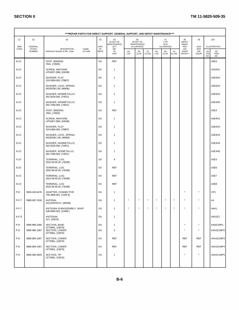
SECTION II TM 11-5820-509-35
****REPAIR PARTS FOR DIRECT SUPPORT, GENERAL SUPPORT, AND DEPOT MAINTENANCE****
(1) (2) (3) (4) (5) (6) (7) (8) (9) (10)30 DAY DS 30 DAY GS 1 YR DEPOT
MAINTENANCE MAINTENANCE ALW MAINTSMR FEDERAL UNIT QTY ALLOWANCE ALLOWANCE PER ALW ILLUSTRATION
CODE STOCK DESCRIPTION Usable OF INC 100 PERNUMBER Reference Number & Mfr. Code on Code MEAS IN (a) (b) (c) (a) (b) (c) EQUIP 100 (a) (b)
UNIT 1-20 21-50 51-100 1-20 21-50 51-100 CNTGCY EQUIP FIG ITEMNO. NO.
X1-D POST, BINDING EA REF A3E37841, (72825)
X1-D SCREW, MACHINE EA 1 A3S3H1LP51957-28M; (03038)
X1-D WASHER, FLAT EA 1 A3E3H2310-6360-000; (79807)
X1-D WASHER, LOCK, SPRING EA 1 A3E3H3MS35338-136; (96906)
X1-D WASHER, NONMETALLIC: EA 1 A3E3H4302-0020-000, (74921)
X1-D WASHER, NONMETALLIC. EA 1 A3E3H5302-7000-000; (74921)
X1-D POST, BINDING. EA REF A3E47841, (72825)
X1-D SCREW, MACHINE: EA 1 A3E4H1LP51957-28M, (03038)
X1-D WASHER, FLAT. EA 1 A3E4H2310-6360-000, (79807)
X1-D WASHER, LOCK, SPRING EA 1 A3E4H3MS35338-136; (96906)
X1-D WASHER, NGNMETALLIC. EA 1 A3E4H4302-0020-000; (74921)
X1-D WASHER, NOIMETALLIC: EA 1 A3E4H5302-7000-000; (74921)
Y1-D TERMINAL, LUG. EA 4 A3E52522-06-00-20, (78189)
X1-D TERMINAL, LUG. EA REF A3E62522-06-00-20, (78189)
X1-D TERMINAL, LUG: EA REF A3E72522-06-00-20, (78189)
X1-D TERMINAL, LUG EA REF A3E82522-06-00-20, (78189)
P-D 5935-432-6476 ADAPTER, CONNECTOR EA 1 * * CP1756-2809-001, (1349 9)
P-F-T 5985-087-2326 ANTENN- EA 1 * * * * * * * * A4AS1320PRC47, (80058)
P-F-T ANTENNA SUBASSEMBLY, WHIP. EA 1 * * * * * * * * A4A1548-9095-002; (13499 )
A-F-S ANTENNA EA 1 A4A1E1147, (23675)
P-D 5895-984-1066 SECTION, BASE EA 1 * * A4AE1MP1CF76991, (23675)
P-D 5895-98h-1067 SECTION, LOWER EA 3 * * A4A1E1MP2CF75961, (23675)
P-D 5895-984-1067 SECTION, LOWER EA REF REF REF A4A1E1MP3CF75961, (23675)
P-D 5895-984-1067 SECTION, LOWER EA REF REF REF A4A1E1MP4CF75961, (23675)
P-D 5895-060-4825 SECTION, TIP EA 1 * * A4A1E1MP5CF75991, (23675)
B-6
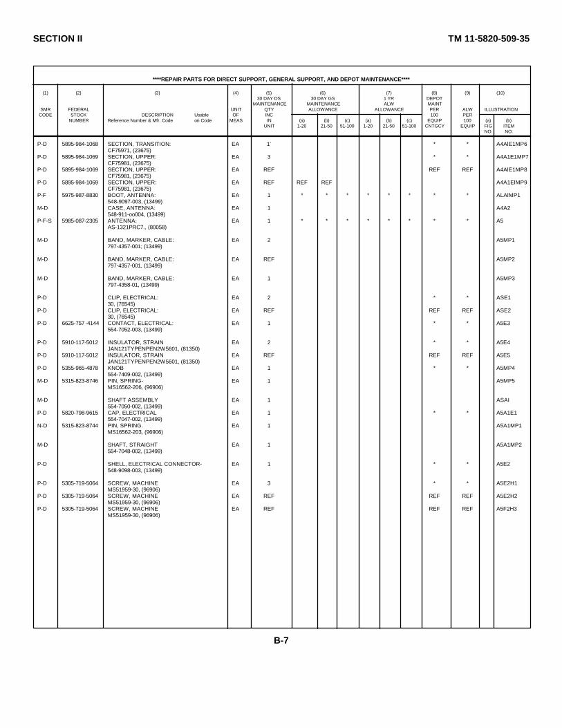
SECTION II TM 11-5820-509-35
****REPAIR PARTS FOR DIRECT SUPPORT, GENERAL SUPPORT, AND DEPOT MAINTENANCE****
(1) (2) (3) (4) (5) (6) (7) (8) (9) (10)30 DAY DS 30 DAY GS 1 YR DEPOT
MAINTENANCE MAINTENANCE ALW MAINTSMR FEDERAL UNIT QTY ALLOWANCE ALLOWANCE PER ALW ILLUSTRATION
CODE STOCK DESCRIPTION Usable OF INC 100 PERNUMBER Reference Number & Mfr. Code on Code MEAS IN (a) (b) (c) (a) (b) (c) EQUIP 100 (a) (b)
UNIT 1-20 21-50 51-100 1-20 21-50 51-100 CNTGCY EQUIP FIG ITEMNO. NO.
P-D 5895-984-1068 SECTION, TRANSITION: EA 1' * * A4AlE1MP6CF75971, (23675)
P-D 5895-984-1069 SECTION, UPPER: EA 3 * * A4A1E1MP7CF75981, (23675)
P-D 5895-984-1069 SECTION, UPPER: EA REF REF REF A4AlE1MP8CF75981, (23675)
P-D 5895-984-1069 SECTION, UPPER: EA REF REF REF A4A1ElMP9CF75981, (23675)
P-F 5975-987-8830 BOOT, ANTENNA: EA 1 * * * * * * * * ALAlMP1548-9097-003, (13499)
M-D CASE, ANTENNA: EA 1 A4A2548-911-oo004, (13499)
P-F-S 5985-087-2305 ANTENNA: EA 1 * * * * * * * * A5AS-1321PRC7., (80058)
M-D BAND, MARKER, CABLE: EA 2 A5MP1797-4357-001; (13499)
M-D BAND, MARKER, CABLE: EA REF A5MP2797-4357-001, (13499)
M-D BAND, MARKER, CABLE: EA 1 A5MP3797-4358-01, (13499)
P-D CLIP, ELECTRICAL: EA 2 * * ASE130, (76545)
P-D CLIP, ELECTRICAL: EA REF REF REF ASE230, (76545)
P-D 6625-757 -4144 CONTACT, ELECTRICAL: EA 1 * * A5E3554-7052-003, (13499)
P-D 5910-117-5012 INSULATOR, STRAIN EA 2 * * A5E4JAN121TYPENPEN2W5601, (81350)
P-D 5910-117-5012 INSULATOR, STRAIN EA REF REF REF A5E5JAN121TYPENPEN2W5601, (81350)
P-D 5355-965-4878 KNOB EA 1 * * A5MP4554-7409-002, (13499)
M-D 5315-823-8746 PIN, SPRING- EA 1 A5MP5MS16562-206, (96906)
M-D SHAFT ASSEMBLY EA 1 ASAI554-7050-002, (13499)
P-D 5820-798-9615 CAP, ELECTRICAL EA 1 * * A5A1E1554-7047-002, (13499)
N-D 5315-823-8744 PIN, SPRING. EA 1 A5A1MP1MS16562-203, (96906)
M-D SHAFT, STRAIGHT EA 1 A5A1MP2554-7048-002, (13499)
P-D SHELL, ELECTRICAL CONNECTOR- EA 1 * * A5E2548-9098-003, (13499)
P-D 5305-719-5064 SCREW, MACHINE EA 3 * * A5E2H1MS51959-30, (96906)
P-D 5305-719-5064 SCREW, MACHINE EA REF REF REF A5E2H2MS51959-30, (96906)
P-D 5305-719-5064 SCREW, MACHINE EA REF REF REF A5F2H3MS51959-30, (96906)
B-7
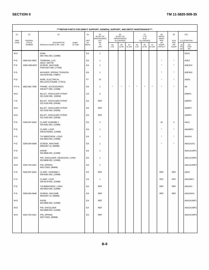
SECTION II TM 11-5820-509-35
****REPAIR PARTS FOR DIRECT SUPPORT, GENERAL SUPPORT, AND DEPOT MAINTENANCE****
(1) (2) (3) (4) (5) (6) (7) (8) (9) (10)30 DAY DS 30 DAY GS 1 YR DEPOT
MAINTENANCE MAINTENANCE ALW MAINTSMR FEDERAL UNIT QTY ALLOWANCE ALLOWANCE PER ALW ILLUSTRATION
CODE STOCK DESCRIPTION Usable OF INC 100 PERNUMBER Reference Number & Mfr. Code on Code MEAS IN (a) (b) (c) (a) (b) (c) EQUIP 100 (a) (b)
UNIT 1-20 21-50 51-100 1-20 21-50 51-100 CNTGCY EQUIP FIG ITEMNO. NO.
M-D SHIM EA 1 A5H1554-7051-002, (13499)
P-D 5940-501-5832 TERMINAL LUG. EA 1 * * A5E335107, (00779)
P-D 5305-O59-8247 SCREW, MACHINE EA 1 * * A5E3H1P343-0327-000, (77250)
P-D WASHER, SPRING TENSION: EA 1 * * A5E3H2310-0078-000, (79807)
P-D WIRE, ELECTRICAL FT 47 * * A5W1955-o421UTXhi9W, (77872)
P-F-S 5820-981-7539 FRAME, ACCESSORIES EA 1 * * * * * * * * A6549-6277-000, (13499)
M-D BILLET, SHOULDER STRAP: EA 4 A6MP1021-0192-000, (24036)
Y-D BILLET, SHOULDER STRAP EA REF A6MP2021-0192-000; (24036)
M-D BILLET, SHOULDER STRAP- EA REF A6MP3021-0192-000, (24036)
M-D BILLET, SHOULDER STRAP. EA REF A6MP4021-0192-000, (24036)
P-D 5340-947-6204 CLAMP ASSEMBLY EA 2 10 4 A6A1519-6281-002, (13499)
P-D CLAMP, LOOP. EA 1 * * A6AlMP1549-62782002, (13499)
P-D TH'JMBSCREW, LONG EA 1 * * A6AlA1553-9810-003, (13499)
P-D 5305-054-5648 SCREW, MACHINE: EA 1 * * A6A1A1H1MS51957-14; (96906)
P-D KINOB- EA 1 A6A1A1MP1553-9806-002, (13499)
M-D PIN, SHOULDER, HEADLESS, LONG EA 1 A6A1A1MP2553-9808-002, (13499)
M-D 5315-754-1621 PIN, SPRING EA 1 A6A1A1MP3MS171503, (96906)
P-D 5340-947-620o CLAMP, ASSEMBLY EA REF REF REF A6A2549-6281-002, (13499)
P-D CLAMP, LOOP EA 1 REF REF A6A2MP1549-6278-002, (13499)
P-D THUMBSCREW, LONG EA REF REF REF A6A2A1553-9810-003, (13499)
P-D 5305-054-5648 SCREW, MACHINE EA REF REF REF A6A2AIH1MS51957-14, (96906)
M-D KNOB. EA REF A6A2A1MP1553-9806-002, (13499)
M-D PIN, SHOULDER EA REF A6A2A1MP2553-9808-002, (13499)
M-D 5315-754-1621 PIN, SPRING EA REF A6A2A1MP3MS171503, (96906)
B-8
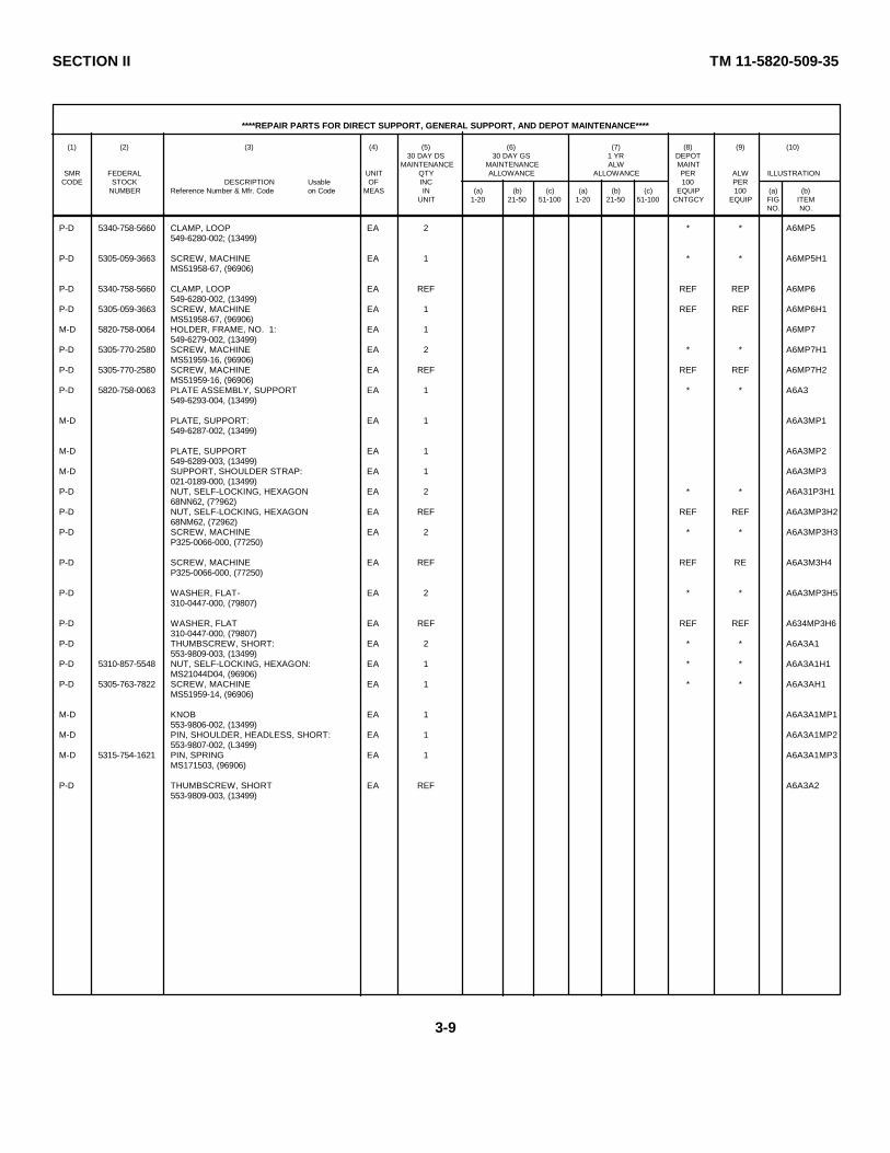
SECTION II TM 11-5820-509-35
****REPAIR PARTS FOR DIRECT SUPPORT, GENERAL SUPPORT, AND DEPOT MAINTENANCE****
(1) (2) (3) (4) (5) (6) (7) (8) (9) (10)30 DAY DS 30 DAY GS 1 YR DEPOT
MAINTENANCE MAINTENANCE ALW MAINTSMR FEDERAL UNIT QTY ALLOWANCE ALLOWANCE PER ALW ILLUSTRATION
CODE STOCK DESCRIPTION Usable OF INC 100 PERNUMBER Reference Number & Mfr. Code on Code MEAS IN (a) (b) (c) (a) (b) (c) EQUIP 100 (a) (b)
UNIT 1-20 21-50 51-100 1-20 21-50 51-100 CNTGCY EQUIP FIG ITEMNO. NO.
P-D 5340-758-5660 CLAMP, LOOP EA 2 * * A6MP5549-6280-002; (13499)
P-D 5305-059-3663 SCREW, MACHINE EA 1 * * A6MP5H1MS51958-67, (96906)
P-D 5340-758-5660 CLAMP, LOOP EA REF REF REP A6MP6549-6280-002, (13499)
P-D 5305-059-3663 SCREW, MACHINE EA 1 REF REF A6MP6H1MS51958-67, (96906)
M-D 5820-758-0064 HOLDER, FRAME, NO. 1: EA 1 A6MP7549-6279-002, (13499)
P-D 5305-770-2580 SCREW, MACHINE EA 2 * * A6MP7H1MS51959-16, (96906)
P-D 5305-770-2580 SCREW, MACHINE EA REF REF REF A6MP7H2MS51959-16, (96906)
P-D 5820-758-0063 PLATE ASSEMBLY, SUPPORT EA 1 * * A6A3549-6293-004, (13499)
M-D PLATE, SUPPORT: EA 1 A6A3MP1549-6287-002, (13499)
M-D PLATE, SUPPORT EA 1 A6A3MP2549-6289-003, (13499)
M-D SUPPORT, SHOULDER STRAP: EA 1 A6A3MP3021-0189-000, (13499)
P-D NUT, SELF-LOCKING, HEXAGON EA 2 * * A6A31P3H168NN62, (7?962)
P-D NUT, SELF-LOCKING, HEXAGON EA REF REF REF A6A3MP3H268NM62, (72962)
P-D SCREW, MACHINE EA 2 * * A6A3MP3H3P325-0066-000, (77250)
P-D SCREW, MACHINE EA REF REF RE A6A3M3H4P325-0066-000, (77250)
P-D WASHER, FLAT- EA 2 * * A6A3MP3H5310-0447-000, (79807)
P-D WASHER, FLAT EA REF REF REF A634MP3H6310-0447-000, (79807)
P-D THUMBSCREW, SHORT: EA 2 * * A6A3A1553-9809-003, (13499)
P-D 5310-857-5548 NUT, SELF-LOCKING, HEXAGON: EA 1 * * A6A3A1H1MS21044D04, (96906)
P-D 5305-763-7822 SCREW, MACHINE EA 1 * * A6A3AH1MS51959-14, (96906)
M-D KNOB EA 1 A6A3A1MP1553-9806-002, (13499)
M-D PIN, SHOULDER, HEADLESS, SHORT: EA 1 A6A3A1MP2553-9807-002, (L3499)
M-D 5315-754-1621 PIN, SPRING EA 1 A6A3A1MP3MS171503, (96906)
P-D THUMBSCREW, SHORT EA REF A6A3A2553-9809-003, (13499)
3-9
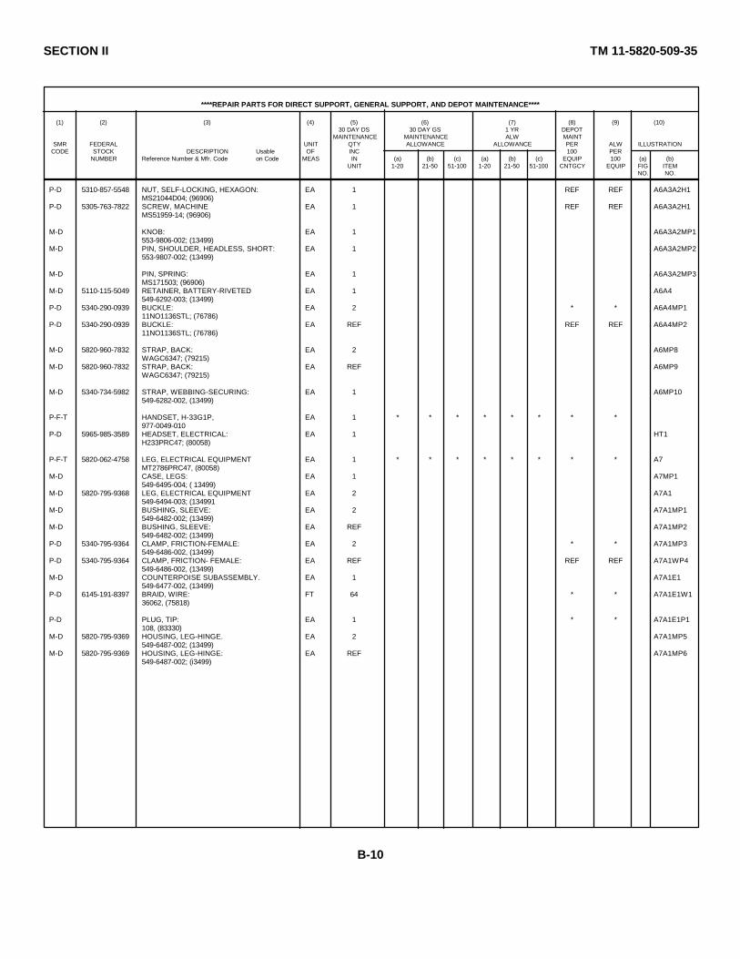
SECTION II TM 11-5820-509-35
****REPAIR PARTS FOR DIRECT SUPPORT, GENERAL SUPPORT, AND DEPOT MAINTENANCE****
(1) (2) (3) (4) (5) (6) (7) (8) (9) (10)30 DAY DS 30 DAY GS 1 YR DEPOT
MAINTENANCE MAINTENANCE ALW MAINTSMR FEDERAL UNIT QTY ALLOWANCE ALLOWANCE PER ALW ILLUSTRATION
CODE STOCK DESCRIPTION Usable OF INC 100 PERNUMBER Reference Number & Mfr. Code on Code MEAS IN (a) (b) (c) (a) (b) (c) EQUIP 100 (a) (b)
UNIT 1-20 21-50 51-100 1-20 21-50 51-100 CNTGCY EQUIP FIG ITEMNO. NO.
P-D 5310-857-5548 NUT, SELF-LOCKING, HEXAGON: EA 1 REF REF A6A3A2H1MS21044D04; (96906)
P-D 5305-763-7822 SCREW, MACHINE EA 1 REF REF A6A3A2H1MS51959-14; (96906)
M-D KNOB: EA 1 A6A3A2MP1553-9806-002; (13499)
M-D PIN, SHOULDER, HEADLESS, SHORT: EA 1 A6A3A2MP2553-9807-002; (13499)
M-D PIN, SPRING: EA 1 A6A3A2MP3MS171503; (96906)
M-D 5110-115-5049 RETAINER, BATTERY-RIVETED: EA 1 A6A4549-6292-003; (13499)
P-D 5340-290-0939 BUCKLE: EA 2 * * A6A4MP111NO1136STL; (76786)
P-D 5340-290-0939 BUCKLE: EA REF REF REF A6A4MP211NO1136STL; (76786)
M-D 5820-960-7832 STRAP, BACK: EA 2 A6MP8WAGC6347; (79215)
M-D 5820-960-7832 STRAP, BACK: EA REF A6MP9WAGC6347; (79215)
M-D 5340-734-5982 STRAP, WEBBING-SECURING: EA 1 A6MP10549-6282-002, (13499)
P-F-T HANDSET, H-33G1P, EA 1 * * * * * * * *977-0049-010
P-D 5965-985-3589 HEADSET, ELECTRICAL: EA 1 HT1H233PRC47; (80058)
P-F-T 5820-062-4758 LEG, ELECTRICAL EQUIPMENT EA 1 * * * * * * * * A7MT2786PRC47, (80058)
M-D CASE, LEGS: EA 1 A7MP1549-6495-004; ( 13499)
M-D 5820-795-9368 LEG, ELECTRICAL EQUIPMENT EA 2 A7A1549-6494-003; (134991
M-D BUSHING, SLEEVE: EA 2 A7A1MP1549-6482-002; (13499)
M-D BUSHING, SLEEVE: EA REF A7A1MP2549-6482-002; (13499)
P-D 5340-795-9364 CLAMP, FRICTION-FEMALE: EA 2 * * A7A1MP3549-6486-002, (13499)
P-D 5340-795-9364 CLAMP, FRICTION- FEMALE: EA REF REF REF A7A1WP4549-6486-002, (13499)
M-D COUNTERPOISE SUBASSEMBLY. EA 1 A7A1E1549-6477-002, (13499)
P-D 6145-191-8397 BRAID, WIRE: FT 64 * * A7A1E1W136062, (75818)
P-D PLUG, TIP: EA 1 * * A7A1E1P1108, (83330)
M-D 5820-795-9369 HOUSING, LEG-HINGE. EA 2 A7A1MP5549-6487-002; (13499)
M-D 5820-795-9369 HOUSING, LEG-HINGE: EA REF A7A1MP6549-6487-002; (i3499)
B-10

SECTION II TM 11-5820-509-35
****REPAIR PARTS FOR DIRECT SUPPORT, GENERAL SUPPORT, AND DEPOT MAINTENANCE****
(1) (2) (3) (4) (5) (6) (7) (8) (9) (10)30 DAY DS 30 DAY GS 1 YR DEPOT
MAINTENANCE MAINTENANCE ALW MAINTSMR FEDERAL UNIT QTY ALLOWANCE ALLOWANCE PER ALW ILLUSTRATION
CODE STOCK DESCRIPTION Usable OF INC 100 PERNUMBER Reference Number & Mfr. Code on Code MEAS IN (a) (b) (c) (a) (b) (c) EQUIP 100 (a) (b)
UNIT 1-20 21-50 51-100 1-20 21-50 51-100 CNTGCY EQUIP FIG ITEMNO. NO.
M-D LEG, SECTION, ELECTRICAL EQUIPMENT: EA 1 A7A1MP7549-6478-002, (13499)
M-D LEG, SECTION, ELECTRICAL EQUIPMENT: EA 1 A7A1MP8549-6479-002, (13499)
M-D 5820-795-9R71 PLATE, LEG MOUNTING: EA 1 A7A1MP9549-6483-002, (13499)
P-D 5820-795-9370 RETAINER, LEG: EA 2 A7A1MP10549-6484-002; (13499)
P-D 5310-934-9765 NUT, PLAIN, HEXAGON: EA 2 A7A1MP10H1NS35650-304, (96906)
P-D 5310-934-9765 NUT, PLAIN, HEXAGON: EA REF REF REF A7A1MP10H2MS35650-304, (96906)
P-D 5305-071-1325 SCREW, MACHINE: EA 2 * * A7A1MP10H3MS51960-68, (96906)
P-D 5305-071-1325 SCREW, MACHINE: EA REF REF REF A7A1MP10H4NS51960-68, (96906)
P-D 5310-933-8120 WASHER, LOCK, SPRING: EA 2 * * A7A1MP10H5MS35338-138, (96906)
P-D 5310-933-8120 WASHER, LOCK, SPRING: EA REF REF REF A7A1MP10H6MS35338-138; (96906)
P-D 5820-795-9370 RETAINER, LEG: EA REF REF REF A7A1MP11549-6484-002; (13499)
P-D 5310-934-9765 NUT, PLAIN, HEXAGON: EA 2 REF REF A7A1MP11H1MS35650-304; (96906)
P-D 5310-93&9765 NUT, PLAIN, HEXAGON: EA REF REF REF A7A1MP11H2MS35650-3o40, (96906)
P-D 5305-071-1325 SCREW, MACHINE: EA 2 REF REF A7A1MP11H3NS51960-68, (96906)
P-D 5305-71-1325 SCREW, MACHINE: EA REF REF REF A7A1MP11H4MS51960-68, (96906)
P-D 5310-933-8120 WASHER, LOCK, SPRING: EA 2 REF REF A7A1MP11H5Ns35338-138; (96906)
P-D 5310-9338120 WASHER, LOCK, SPRING: EA REF REF REF A7A1MP11H6NS35338-138, (96906)
P-D 5305-788-9883 STUD, WING: EA 2 * * A7A1A549-6475-002, (13499)
M-D PIN, GROOVED, HEADLESS: EA 1 A7A1A1MP1MS35672-14, (96906)
M-D PIN, SHOULDERED, HEADLESS: EA 1 A7A1A1MP2549-6476-002, (13499)
M-D WING, STUD: EA 1 A7A1A1MP3549-6480-002, (13499)
P-D 5305-788-9883 STUD, WING EA REF REF REF A7A1A2549-667-0002; (13499)
M-D PIN, GROOVED, HEADLESS: EA 1 A7A1A2MP1MS35672-14, (96906)
M-D PIN, SHOULDERED, HEADLESS: EA 1 A7A1A2MP2549-76-002, (13&99)
B-11

SECTION II TM 11-5820-509-35
****REPAIR PARTS FOR DIRECT SUPPORT, GENERAL SUPPORT, AND DEPOT MAINTENANCE****
(1) (2) (3) (4) (5) (6) (7) (8) (9) (10)30 DAY DS 30 DAY GS 1 YR DEPOT
MAINTENANCE MAINTENANCE ALW MAINTSMR FEDERAL UNIT QTY ALLOWANCE ALLOWANCE PER ALW ILLUSTRATION
CODE STOCK DESCRIPTION Usable OF INC 100 PERNUMBER Reference Number & Mfr. Code on Code MEAS IN (a) (b) (c) (a) (b) (c) EQUIP 100 (a) (b)
UNIT 1-20 21-50 51-100 1-20 21-50 51-100 CNTGCY EQUIP FIG ITEMNO. NO.
M-D WING, STUD: EA 1 A7A1A2MP3549-6480-002, (13499)
P-D 5310-938-8387 WASHER: EA 2 * * A7A1H1542-1598-003, (13499)
P-D 5310-685-7469 WASHER: EA REF REF REF A7A1H2542-1598-003; (13499)
M-D LEG, ELECTRICAL EQUIPMENT: EA REF A7A2549-6494-003; (13499)
M-D 3120-368-7946 BUSHING, SLEEVE: EA 2 A7A2MP1549-6482-002; (13499)
M-D 3120-768-7946 BUSHING, SLEEVE: EA REF A7A2MP2549-6482-002; (13499)
P-D 5340-795-9364 CLAMP, FRICTION-FEMALE: EA 2 REF REF A7A2MP3549-6486-002; (13499)
P-D 5340-795-9364 CLAMP, FRICTION-FEMALE: EA REF REF REP A7A2MP45,9-6486-002; ( 13199)
M-D COUNTERPOISE: EA 1 A7A2E1549-6477-002; ( 1399)
P-D 6145-191-8397 BRAID, WIRE: FT 63 REF REF A7A2E1W136062; (75818)
P-D PLUG, TIP: EA REF REF REF A7A2E1P1108; (83330)
M-D HOUSING, LEG-HINGE: EA 2 A7A2MP5549-6487-oo2, ( 1 3499)
M-D HOUSING, LEG-HINGE: EA REF A7A2MP6549-6487-002; (13499)
M-D 5820-T66-1827 LEG SECTION, ELECTRICAL EQUIPMENT: EA 1 A7A2MP7549-6478-002; (13499)
M-D 5820-766-1828 LEG SECTION, ELECTRICAL EQUIPMENT: EA 1 A7A2MP8549-6479-002; (13499)
M-D PLATE, LEG MOUNTING: EA 1 A7A2MP9P-D 5820-795-9370 RETAINER LEG: EA 2 REF REF A7A2MP10
549-6484L-02; (13499)
P-D 5310-934-9765 NUT, PLAIN, HEXAGON: EA 2 REF REF A7A2MP10H1MS35650-304; (96906)
P-D 5310-934-9765 NUT, PLAIN, HEXAGON: EA REF REF REF A7A2MP10H2MS35650-304; (96906)
P-D 5305-071-1325 SCREW, MACHINE: EA 2 REF REF A7A2MP10H3MS51960-68; (96906)
P-D 5305-071-1325 SCREW, MACHINE: EA REF REF REF A7A2MP10H4MS51960-68; (96906)
P-D 5310-933-8120 WASHER, LOCK, SPRING: EA 2 REF REF A7A2MP10H5MS35338-138; (96906)
P-D 5310-9338120 WASHER, LOCK, SPRING: EA REF REF REF A7A2MP10H6MS35338-138; (96906)
P-D 5820-795-9370 RETAINER, LEG. EA REF REF REF A7A2MP11549-6484-002; (13499)
P-D 5310-934-9765 NUT, PLAIN, HEXAGON: EA 2 REF REF A7A2MP11H1MS35650-304, (96906)
B-12
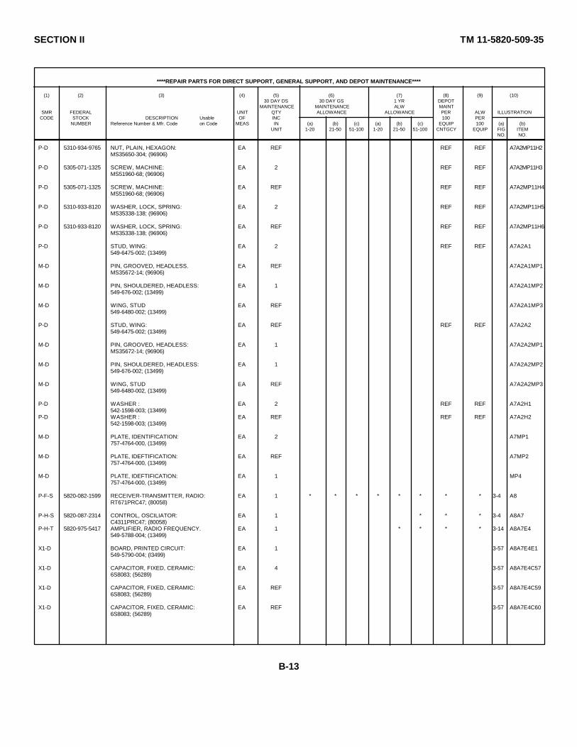
SECTION II TM 11-5820-509-35
****REPAIR PARTS FOR DIRECT SUPPORT, GENERAL SUPPORT, AND DEPOT MAINTENANCE****
(1) (2) (3) (4) (5) (6) (7) (8) (9) (10)30 DAY DS 30 DAY GS 1 YR DEPOT
MAINTENANCE MAINTENANCE ALW MAINTSMR FEDERAL UNIT QTY ALLOWANCE ALLOWANCE PER ALW ILLUSTRATION
CODE STOCK DESCRIPTION Usable OF INC 100 PERNUMBER Reference Number & Mfr. Code on Code MEAS IN (a) (b) (c) (a) (b) (c) EQUIP 100 (a) (b)
UNIT 1-20 21-50 51-100 1-20 21-50 51-100 CNTGCY EQUIP FIG ITEMNO. NO.
P-D 5310-934-9765 NUT, PLAIN, HEXAGON: EA REF REF REF A7A2MP11H2MS35650-304; (96906)
P-D 5305-071-1325 SCREW, MACHINE: EA 2 REF REF A7A2MP11H3MS51960-68; (96906)
P-D 5305-071-1325 SCREW, MACHINE: EA REF REF REF A7A2MP11H4MS51960-68; (96906)
P-D 5310-933-8120 WASHER, LOCK, SPRING: EA 2 REF REF A7A2MP11H5MS35338-138; (96906)
P-D 5310-933-8120 WASHER, LOCK, SPRING: EA REF REF REF A7A2MP11H6MS35338-138; (96906)
P-D STUD, WING: EA 2 REF REF A7A2A1549-6475-002; (13499)
M-D PIN, GROOVED, HEADLESS. EA REF A7A2A1MP1MS35672-14; (96906)
M-D PIN, SHOULDERED, HEADLESS: EA 1 A7A2A1MP2549-676-002; (13499)
M-D WING, STUD EA REF A7A2A1MP3549-6480-002; (13499)
P-D STUD, WING: EA REF REF REF A7A2A2549-6475-002; (13499)
M-D PIN, GROOVED, HEADLESS: EA 1 A7A2A2MP1MS35672-14; (96906)
M-D PIN, SHOULDERED, HEADLESS: EA 1 A7A2A2MP2549-676-002; (13499)
M-D WING, STUD EA REF A7A2A2MP3549-6480-002, (13499)
P-D WASHER : EA 2 REF REF A7A2H1542-1598-003; (13499)
P-D WASHER : EA REF REF REF A7A2H2542-1598-003; (13499)
M-D PLATE, IDENTIFICATION: EA 2 A7MP1757-4764-000, (13499)
M-D PLATE, IDEFTIFICATION: EA REF A7MP2757-4764-000, (13499)
M-D PLATE, IDEFTIFICATION: EA 1 MP4757-4764-000, (13499)
P-F-S 5820-082-1599 RECEIVER-TRANSMITTER, RADIO: EA 1 * * * * * * * * 3-4 A8RT671PRC47; (80058)
P-H-S 5820-087-2314 CONTROL, OSCILIATOR: EA 1 * * * 3-4 A8A7C4311PRC47; (80058)
P-H-T 5820-975-5417 AMPLIFIER, RADIO FREQUENCY. EA 1 * * * * 3-14 A8A7E4549-5788-004; (13499)
X1-D BOARD, PRINTED CIRCUIT: EA 1 3-57 A8A7E4E1549-5790-004; (l3499)
X1-D CAPACITOR, FIXED, CERAMIC: EA 4 3-57 A8A7E4C576S8083; (56289)
X1-D CAPACITOR, FIXED, CERAMIC: EA REF 3-57 A8A7E4C596S8083; (56289)
X1-D CAPACITOR, FIXED, CERAMIC: EA REF 3-57 A8A7E4C606S8083; (56289)
B-13
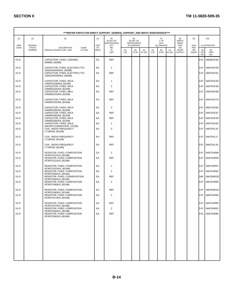
SECTION II TM 11-5820-509-35
****REPAIR PARTS FOR DIRECT SUPPORT, GENERAL SUPPORT, AND DEPOT MAINTENANCE****
(1) (2) (3) (4) (5) (6) (7) (8) (9) (10)30 DAY DS 30 DAY GS 1 YR DEPOT
MAINTENANCE MAINTENANCE ALW MAINTSMR FEDERAL UNIT QTY ALLOWANCE ALLOWANCE PER ALW ILLUSTRATION
CODE STOCK DESCRIPTION Usable OF INC 100 PERNUMBER Reference Number & Mfr. Code on Code MEAS IN (a) (b) (c) (a) (b) (c) EQUIP 100 (a) (b)
UNIT 1-20 21-50 51-100 1-20 21-50 51-100 CNTGCY EQUIP FIG ITEMNO. NO.
X1-D CAPACITOR, FIXED, CERAMIC. EA REF 3-57 A8A6E4C636S8083, (56289)
X1-D CAPACITOR, FIXED, ELECTROLYTIC. EA 2 3-57 A8A7E4C58150D104X0035A2, (56289)
X1-D CAPACITOR, FIXED, ELECTROLYTIC: EA REF 3-57 A8A7E4C61150D104X0035A2; (56289)
X1-D CAPACITOR, FIXED, MICA: EA 1 3-57 A8A7E4C56CM05CD100D03; (81349)
X1-D CAPACITOR, FIXED, MICA EA 3 3-57 A8A7E4C66CM05ED220J03; (81349)
X1-D CAPACITOR, FIXED, MICA EA REF 3-57 A8A7E4C68CM05ED220J03; (81349)
X1-D CAPACITOR, FIXED, MICA EA REF 3-57 A8A7E4C70CM05ED220J03, (81349)
X1-D CAPACITOR, FIXED, MICA: EA 3 3-57 A8A7E4C65CM05ED390J03, (81349)
X1-D CAPACITOR, FIXED, MICA EA REF 3-57 A8A7E4C67CM05ED390J03, (81349)
X1-D CAPACITOR, FIXED, MICA EA REF 3-57 A8A7E4C69CM05ED390J03, (81349)
X1-D CAPACITOR, FIXED, MICA: EA 1 3-57 A8A7E4C62DM15F471J300WV4CR, (72136)
X1-D COIL, RADIO FREQUENCY EA 3 3-57 A8A7E4L16LT10K020; (81349)
X1-D COIL, RADIO FREQUENCY EA REF 3-57 A8A7E4L17LT10K020; (81349)
X1-D COIL, RADIO FREQUENCY EA REF 3-57 A8A7E4L18LT10K020; (81349)
X1-D RESISTOR, FIXED, COMPOSITION EA 2 3-57 A8ATE4R88RCR07G121KS; (81349)
X1-D RESISTOR, FIXED, COMPOSITION EA REF 3-57 A8A7E4R93RCR07G121KS; (81349)
X1-D RESISTOR, FIXED, COMPOSITION EA 1 3-57 A8A7E4R97RCRO7G221KS, (81349)
X1-D RESISTOR, FIXED, COMPOSITION EA 2 3-57 A8A7E4R92RCR07G561KS, (81349)
X1-D RESISTOR, FIXED, CODMPOSITION: EA REF 3A8 A8A7E4R102RCR07G561KS; (81349)
X1-D RESISTOR, FIXED, COMPOSITION: EA 2 3-57 A8A7E4R95RCR07G392KS; (81349)
X1-D RESISTOR, FIXED, COMPOSITION. EA REF 3-57 A8A7E4R101RCR07G392KS; (81349)
X1-D RESISTOR, FIXED, COMPOSITION EA 2 3-57 A8A7E4R90RCR07G472KS; (81349)
X1-D RESISTOR, FIXED, COMPOSITION EA REF 3-57 A8A7E4R99RCR07G472KS; (81349)
X1-D RESISTOR, FIXED, COMPOSITION EA 2 3-57 A8A7E4R91RCR07G562KS, (81349)
X1-D RESISTOR, FIXED, COMPOSITION EA REF 3-51 A8A7E4R96RCR07G562KS; (81349)
B-14
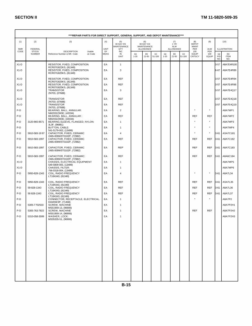
SECTION II TM 11-5820-509-35
****REPAIR PARTS FOR DIRECT SUPPORT, GENERAL SUPPORT, AND DEPOT MAINTENANCE****
(1) (2) (3) (4) (5) (6) (7) (8) (9) (10)30 DAY DS 30 DAY GS 1 YR DEPOT
MAINTENANCE MAINTENANCE ALW MAINTSMR FEDERAL UNIT QTY ALLOWANCE ALLOWANCE PER ALW ILLUSTRATION
CODE STOCK DESCRIPTION Usable OF INC 100 PERNUMBER Reference Number & Mfr. Code on Code MEAS IN (a) (b) (c) (a) (b) (c) EQUIP 100 (a) (b)
UNIT 1-20 21-50 51-100 1-20 21-50 51-100 CNTGCY EQUIP FIG ITEMNO. NO.
X1-D RESISTOR, FIXED, COMPOSITION EA 1 3-57 A8A7E4R100RCR07G822KS, (81349)
X1-D RESISTOR, FIXED, COMPOSITION EA 3 6-67 A8A7E4R89RCR07G825KS, (81349)
X1-D RESISTOR, FIXED, COMPOSITION: EA REF 3-57 A8A7E4R94RCR07G825KS, (81349)
X1-D RESISTOR, FIXED, COMPOSITION EA REF 3-57 A8A7E4R98RCR07G825KS, (81349)
X1-D TRANSISTOR EA 3 3-57 A8A7E4Q172N703, (07688)
X1-D TRANSISTOR EA REF 3-57 A8A7E4Q182N703; (07688)
X1-D TRANSISTOR EA REF 3-57 A8A7E4Q192N703, (07688)
P-D BEARING, BALL, ANNULAR: EA 2 * * A8A7MP1NM2032ZM3E; (43334)
P-D BEARING, BALL, ANNULAR:: EA REF REF REF A8A7MP2NM2032ZM3E; (43334)
P-D 3120-865-8571 BEARING,SLEEVE, FLANGED, NYLON: EA 1 * * A8A7MP33L3F, (96881)
P-D BUTTON, CABLE: EA 1 * * A8ATMP4541-5179-002; (13499)
P-D 5910-583-19 97 CAPACITOR, FIXED, CERAMIC EA 4 * * 3-61 ASA7C1812465-009W5T0102P, (72982)
P-D 5910-583-1997 CAPACITOR, FIXED, CERAMIC EA REF REF REF 3-61 A8A7C1822465-009W5T0102P, (72982)
P-D 5910-583-1997 CAPACITOR, FIXED, CERAMIC EA REP REF REF 3-61 A8A7C1832465-009W5T0102P, (72982)
P-D 5910-583-1997 CAPACITOR, FIXED, CERAMIC: EA REF REF REF 3-61 A8A6C1842465-009W5T0102P, (72982)
X1-D CHASSIS, ELECTRICAL EQUIPMENT EA 1 A8A7MP5549-5809-005, (13499)
X1-D CHASSIS, FILTER: EA 1 A8A7MP6756-0318-004, (13499)
P-D 5950-828-1343 COIL, RADIO FREQUENCY EA 4 * * 3-61 A8A7L34LT10K043; (81349)
P-D 5950-828-1343 COIL, RADIO FREQUENCY EA REF REF REF 3-61 ASA7L35LT10K043, (81349)
P-D 59-828-1343 COIL, RADIO FREQUENCY EA REF REF REF 3-61 A8A7L36LT10K043; (81349)
P-D 59 828-1343 COIL, RADIO FREQUENCY EA REF REF REF 3-61 A8A7L37LT10K043; (81349)
P-D CONNECTOR, RECEPTACLE, ELECTRICAL. EA 1 * * A8A7P2DAM3W3P, (71468)
P-D 5305-7702533 SCREW, MACHINE EA 1 A8A7P2H1MS51959-13, (96906)
P-D 5305-763-7822 SCREW, MACHINE EA 1 REF REF A8A7P2H2MS51959-14, (96906)
P-D 5310-058-3599 WASHER, LOCK: EA 1 A8A7P2H3MS35335-51, (96906)
B-15

SECTION II TM 11-5820-509-35
****REPAIR PARTS FOR DIRECT SUPPORT, GENERAL SUPPORT, AND DEPOT MAINTENANCE****
(1) (2) (3) (4) (5) (6) (7) (8) (9) (10)30 DAY DS 30 DAY GS 1 YR DEPOT
MAINTENANCE MAINTENANCE ALW MAINTSMR FEDERAL UNIT QTY ALLOWANCE ALLOWANCE PER ALW ILLUSTRATION
CODE STOCK DESCRIPTION Usable OF INC 100 PERNUMBER Reference Number & Mfr. Code on Code MEAS IN (a) (b) (c) (a) (b) (c) EQUIP 100 (a) (b)
UNIT 1-20 21-50 51-100 1-20 21-50 51-100 CNTGCY EQUIP FIG ITEMNO. NO.
X1-D WASHER, LOCK, SPRING: EA 1 REF REF A8A7P2H4MS35338-135; (96906)
P-D 5935-810-6598 CONECTOR, RECEPTACLE, ELECTRICAL EA 1 * * 3-61 A8A7P1DAM7W2P, (71468)
P-D 5310-614-3500 NUT, SELF-LOCKING, HEXAGON: EA 2 * * A8A7P1H168-1660-40; (72962)
P-D 5310-614-3500 NUT, SELF-LOCKING, HEXAGON: EA REF REF REF A8A7P1H268-1660-40; (72962)
P-D 5305-763-7822 SCREW, MACHINE. EA 2 REF REF A8A7P1H3MS51959-14, (96906)
P-D 5305-763-7822 SCREW, MACHINE EA REF REF REF A8A7P1H4MS51959-14, (96906)
P-D 5935-885-6505 CONTACT, ELECTRICAL, COAXIAL INSERT: EA 5 * * A8A7P1A1DM53740-5000; (71468)
P-D 5935-885-6505 CONTACT, ELECTRICAL, COAXIAL INSERT: EA REF REF REF A8A7P1A2DM53740-5000; (71468)
P-D 5935-885-6505 CONTACT, ELECTRICAL, COAXIAL INSERT: EA REF FEF REF A8A7P2A1DM53740-5000; (71468)
P-D 5935-885-6505 CONTACT, ELECTRICAL, COAXIAL INSERT: EA REF REF REF A8A7P2A2DM53740-5000; (71468)
P-D 5935-885-6505 CONTACT, ELECTRICAL, COAXIAL INSERT: EA REF REF REF A9A7P2A3DM53740-5000; (71468)
P-H-S CONTROL, SUBASSEMBLY, OSCILLATOR: EA 1 * * * * * 3-4 A8A7E7549-5776-004, (13499)
P-D CAPACITOR ASSEMBLY: EA 1 * * 3-60 A8A7E7A1549-5777-004; (13499)
P-D 5310-6114-3500 NUT, SELF-LOCKING, HEXAGON: EA 2 REF REF A8A7E7A1H268-1660-40; (72962)
P-D 5305-054-5653 SCREW, MACHINE: EA 2 * * A8A7E7A1H2MS51957-19; (96906)
P-D 5310-530-3549 WASHER, NONMETALLIC, FLAT EA * * * A8A7E7A1H48942; (76854)
X1-D BOARD, PRINTED CIRCUIT EA 1 3-60 A8A7E7A1E8549-5764-003; (13499)
X1-D CAPACITOR, FIXED, MICA: EA 20 3-60 A8A7E7A1C114CM05ED300G03, (81349)
X1-D CAPACITOR, FIXED, MICA: EA REF 3-60 A8A7E7A1C116CM05ED300G03, (81349)
X1-D CAPACITOR, FIXED, MICA: EA REF 3-60 A8A7E7A1C118CM05ED300G03, (81349)
X1-D CAPACITOR, FIXED, MICA: EA REF 3-60 A8A7E7A1C120CM05ED300G03, (81349)
X1-D CAPACITOR, FIXED, MICA: EA REF 3-60 A8A7E7A1C122CM05ED300G03, (81349)
X1-D CAPACITOR, FIXED, MICA: EA REF 3-60 A8A7E7A1C124CM05ED300G03, (81349)
X1-D CAPACITOR, FIXED, MICA: EA REF 3-60 A8A7E7A1C126CM05ED300G03, (81349)
X1-D CAPACITOR, FIXED, MICA: EA REF 3-60 A8A7E7A1C128CM05ED300G03, (81349)
*SELECT PER OPERATIONAL REQUIREMENT.
B-16

SECTION II TM 11-5820-509-35
****REPAIR PARTS FOR DIRECT SUPPORT, GENERAL SUPPORT, AND DEPOT MAINTENANCE****
(1) (2) (3) (4) (5) (6) (7) (8) (9) (10)30 DAY DS 30 DAY GS 1 YR DEPOT
MAINTENANCE MAINTENANCE ALW MAINTSMR FEDERAL UNIT QTY ALLOWANCE ALLOWANCE PER ALW ILLUSTRATION
CODE STOCK DESCRIPTION Usable OF INC 100 PERNUMBER Reference Number & Mfr. Code on Code MEAS IN (a) (b) (c) (a) (b) (c) EQUIP 100 (a) (b)
UNIT 1-20 21-50 51-100 1-20 21-50 51-100 CNTGCY EQUIP FIG ITEMNO. NO.
X1-D CAPACITOR, FIXED, MICA: EA REF 3-60 A8A7E7CM05ED300G03, (81349) A1C130 *
X1-D CAPACITOR, FIXED, MICA: EA REF 3-60 A8A7E7CM05ED300G03, (81349) A1C132 *
X1-D CAPACITOR, FIXED, MICA: EA REF 3-60 A8A7E7CM05ED300G03, (81349) A1C134 *
X1-D CAPACITOR, FIXED, MICA: EA REF 3-60 A8A7E7CM05ED300G03, (81349) A1C136 *
X1-D CAPACITOR, FIXED, MICA: EA REF 3-60 A8A7E7CM05ED300G03, (81349) A1C138 *
X1-D CAPACITOR, FIXED, MICA:- EA REF 3-60 A8A7E7CM05ED300G03, (81349) A1C140 *
X1-D CAPACITOR, FIXED, MICA: EA REF 3-60 A8A7E7CM05ED300C03, (81349) A1C142 *
X1-D CAPACITOR, FIXED, MICA: EA REF 3-60 A8A7E7 *CM05ED300G03, (81349) A1C144
X1-D CAPACITOR, FIXED, MICA: EA REF 3-60 A8A7E7 *CM05ED300G03, (81349) A1C146
X1-D CAPACITOR, FIXED, MICA: EA REF 3-60 A8A7E7CM05ED300G03, (81349) A1C148 *
X1-D CAPACITOR, FIXED, MICA: EA REF 360 A8A7E7CM05ED300G03, (81349) A1C150 *
X1-D CAPACITOR, FIXED, MICA: EA REF 3-60 A8A7E7CM05ED300G03, (81349) A1C152 *
X1-D CAPACITOR, FIXED, MICA: EA 20 3-60 A8A7E7CM05ED330G03, (81349) A1C114 *
X1-D CAPACITOR, FIXED, MICA: EA REF 3-60 A8A7E7CM05ED330G03, (81349) A1C116 *
X1-D CAPACITOR, FIXED, MICA: EA REF 3-60 A8A7E7CM05ED330G03, (81349) A1C118 *
X1-D CAPACITOR, FIXED, MICA: EA REF 3-60 A8A7E7CM05ED330G03, (81349) A1C120 *
X1-D CAPACITOR, FIXED, MICA: EA REF 3-60 A8A7E7CM05ED330G03, (81349) A1C122 *
X1-D CAPACITOR, FIXED, MICA: EA REF 3-60 A8A7E7CM05ED330G03, (81349) A1C124 *
X1-D CAPACITOR, FIXED, MICA: EA REF 3-60 A8A7E7CM05ED330G03, (81349) A1C126 *
X1-D CAPACITOR, FIXED, MICA: EA REF 3-60 A8A7E7CM05ED330G03, (81349) A1C128 *
X1-D CAPACITOR, FIXED, MICA: EA REF 3-60 A8A7E7CM05ED330G03, (81349) A1C130 *
X1-D CAPACITOR, FIXED, MICA: EA REF 3-60 A8A7E7CM05ED330G03, (81349) A1C132 *
X1-D CAPACITOR, FIXED, MICA: EA REF 3-60 A8A7E7CM05ED330G03, (81349) A1C134 *
X1-D CAPACITOR, FIXED, MICA: EA REF 3-60 A8A7E7CM05ED330G03, (81349) A1C136 *
X1-D CAPACITOR, FIXED, MICA: EA REF 3-60 A8A7E7CM05ED330G03, (81349) A1C138 *
*SELECT PER OPERATIONAL REQUIREENT
B-17
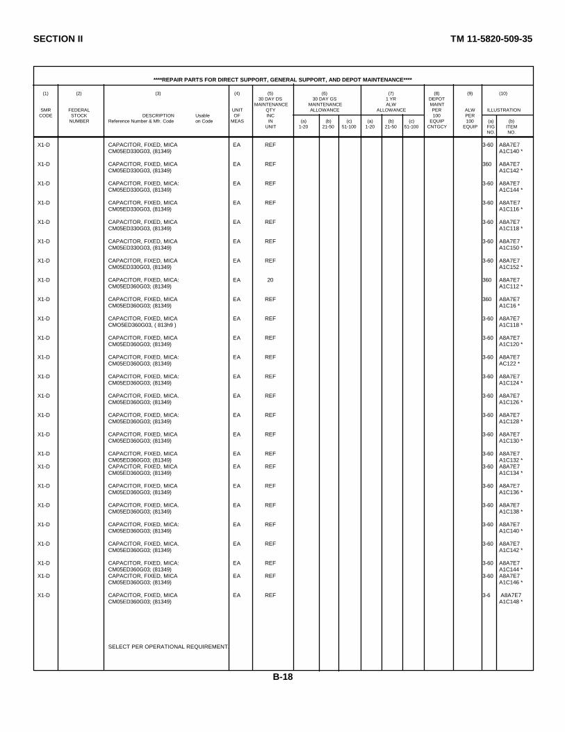
SECTION II TM 11-5820-509-35
****REPAIR PARTS FOR DIRECT SUPPORT, GENERAL SUPPORT, AND DEPOT MAINTENANCE****
(1) (2) (3) (4) (5) (6) (7) (8) (9) (10)30 DAY DS 30 DAY GS 1 YR DEPOT
MAINTENANCE MAINTENANCE ALW MAINTSMR FEDERAL UNIT QTY ALLOWANCE ALLOWANCE PER ALW ILLUSTRATION
CODE STOCK DESCRIPTION Usable OF INC 100 PERNUMBER Reference Number & Mfr. Code on Code MEAS IN (a) (b) (c) (a) (b) (c) EQUIP 100 (a) (b)
UNIT 1-20 21-50 51-100 1-20 21-50 51-100 CNTGCY EQUIP FIG ITEMNO. NO.
X1-D CAPACITOR, FIXED, MICA EA REF 3-60 A8A7E7CM05ED330G03, (81349) A1C140 *
X1-D CAPACITOR, FIXED, MICA EA REF 360 A8A7E7CM05ED330G03, (81349) A1C142 *
X1-D CAPACITOR, FIXED, MICA: EA REF 3-60 A8A7E7CM05ED330G03, (81349) A1C144 *
X1-D CAPACITOR, FIXED, MICA EA REF 3-60 A8ATE7CM05ED330G03, (81349) A1C116 *
X1-D CAPACITOR, FIXED, MICA EA REF 3-60 A8A7E7CM05ED330G03, (81349) A1C118 *
X1-D CAPACITOR, FIXED, MICA EA REF 3-60 A8A7E7CM05ED330G03, (81349) A1C150 *
X1-D CAPACITOR, FIXED, MICA EA REF 3-60 A8A7E7CM05ED330G03, (81349) A1C152 *
X1-D CAPACITOR, FIXED, MICA: EA 20 360 A8A7E7CM05ED360G03; (81349) A1C112 *
X1-D CAPACITOR, FIXED, MICA EA REF 360 A8A7E7CM05ED360G03; (81349) A1C16 *
X1-D CAPACITOR, FIXED, MICA EA REF 3-60 A8A7E7CMO5ED360G03, ( 813h9 ) A1C118 *
X1-D CAPACITOR, FIXED, MICA EA REF 3-60 A8A7E7CM05ED360G03; (81349) A1C120 *
X1-D CAPACITOR, FIXED, MICA: EA REF 3-60 A8A7E7CM05ED360G03; (81349) AC122 *
X1-D CAPACITOR, FIXED, MICA: EA REF 3-60 A8A7E7CM05ED360G03; (81349) A1C124 *
X1-D CAPACITOR, FIXED, MICA. EA REF 3-60 A8A7E7CM05ED360G03; (81349) A1C126 *
X1-D CAPACITOR, FIXED, MICA: EA REF 3-60 A8A7E7CM05ED360G03; (81349) A1C128 *
X1-D CAPACITOR, FIXED, MICA EA REF 3-60 A8A7E7CM05ED360G03; (81349) A1C130 *
X1-D CAPACITOR, FIXED, MICA EA REF 3-60 A8A7E7CM05ED360G03; (81349) A1C132 *
X1-D CAPACITOR, FIXED, MICA EA REF 3-60 A8A7E7CM05ED360G03; (81349) A1C134 *
X1-D CAPACITOR, FIXED, MICA EA REF 3-60 A8A7E7CM05ED360G03; (81349) A1C136 *
X1-D CAPACITOR, FIXED, MICA. EA REF 3-60 A8A7E7CM05ED360G03; (81349) A1C138 *
X1-D CAPACITOR, FIXED, MICA: EA REF 3-60 A8A7E7CM05ED360G03; (81349) A1C140 *
X1-D CAPACITOR, FIXED, MICA. EA REF 3-60 A8A7E7CM05ED360G03; (81349) A1C142 *
X1-D CAPACITOR, FIXED, MICA: EA REF 3-60 A8A7E7CM05ED360G03; (81349) A1C144 *
X1-D CAPACITOR, FIXED, MICA EA REF 3-60 A8A7E7CM05ED360G03; (81349) A1C146 *
X1-D CAPACITOR, FIXED, MICA EA REF 3-6 A8A7E7CM05ED360G03; (81349) A1C148 *
SELECT PER OPERATIONAL REQUIREMENT.
B-18

SECTION II TM 11-5820-509-35
****REPAIR PARTS FOR DIRECT SUPPORT, GENERAL SUPPORT, AND DEPOT MAINTENANCE****
(1) (2) (3) (4) (5) (6) (7) (8) (9) (10)30 DAY DS 30 DAY GS 1 YR DEPOT
MAINTENANCE MAINTENANCE ALW MAINTSMR FEDERAL UNIT QTY ALLOWANCE ALLOWANCE PER ALW ILLUSTRATION
CODE STOCK DESCRIPTION Usable OF INC 100 PERNUMBER Reference Number & Mfr. Code on Code MEAS IN (a) (b) (c) (a) (b) (c) EQUIP 100 (a) (b)
UNIT 1-20 21-50 51-100 1-20 21-50 51-100 CNTGCY EQUIP FIG ITEMNO. NO.
X1-D CAPACITOR, FIXED, MICA: EA REF 3-60 A8A7E7CM05ED360G03; (81349) A1C150 *
X1-D CAPACITOR, FIXED, MICA: EA REF 3-60 A8A7E7CM05ED360G03; (81349) A1C152 *
X1-D CAPACITOR, FIXED. MICA: EA 20 3-60 A8A7E7CM05ED390G03; (81349) A1C114 *
X1-D CAPACITOR, FIXED, MICA: EA REF 3-60 A8A7E7CM05ED390G03; (81349) A1C116 *
X1-D CAPACITOR, FIXED, MICA: EA REF 3-60 A8A7E7CM05ED390G03; (81349) A1C118 *
X1-D CAPACITOR, FIXED, MICA: EA REF 3-60 A8A7E7CM05ED390G03; (81349) A1C120 *
X1-D CAPACITOR, FIXED, MICA: EA REF 3-60 A8A7E7CM05ED390G03; (81349) A1C122 *
X1-D CAPACITOR, FIXED, MICA:: EA REF 3-60 A8A7E7CM05ED390G03; (81349) A1C124 *
X1-D CAPACITOR, FIXED, MICA: EA REF 3-60 A8A7E7CM05ED390G03; (81349) A1C126 *
X1-D CAPACITOR, FIXED, MICA: EA REF 3-60 A8A7E7CM05ED390G03; (81349) A1C128 *
X1-D CAPACITOR, FIXED, MICA: EA REF 3-60 A8A7E7CM05ED390G03; (81349) A1C130 *
X1-D CAPACITOR, FIXED, MICA: EA REF 3-60 A8A7E7CM05ED390G03; (81349) A1C132 *
X1-D CAPACITOR, FIXED, MICA: EA REF 3-60 A8A7E7CM05ED390G03; (81349) A1C134 *
X1-D CAPACITOR, FIXED, MICA: EA REF 3-60 A8A7E7CM05ED390G03; (81349) A1C136 *
X1-D CAPACITOR, FIXED, MICA: EA REF 3-60 A8A7E7CM05ED390G03; (81349) A1C138 *
X1-D CAPACITOR, FIXED, MICA: EA REF 3-60 A8A7E7CM05ED390G03; (81349) A1C140 *
X1-D CAPACITOR, FIXED, MICA: EA REF 3-60 A8A7E7CM05ED390G03; (81349) A1C142 *
X1-D CAPACITOR, FIXED, MICA: EA REF 3-60 A8A7E7CM05ED390G03; (81349) A1C144 *
X1-D CAPACITOR, FIXED, MICA: EA REF 3-60 A8A7E7CM05ED390G03; (81349) A1C144 *
X1-D CAPACITOR, FIXED, MICA: EA REF 3-60 A8A7E7CM05ED390G03; (81349) A1C146 *
X1-D CAPACITOR, FIXED, MICA: EA REF 3-60 A8A7E7CM05ED390G03; (81349) A1C148 *
X1-D CAPACITOR, FIXED, MICA: EA REF 3-60 A8A7E7CM05ED390G03; (81349) A1C150 *
X1-D CAPACITOR, FIXED, MICA: EA REF 3-60 A8A7E7 ·CM05ED390G03; (81349) A1C152 *
X1-D CAPACITOR, FIXED, MICA: EA 20 3-60 A8A7E7CM05ED430G03, (81349) A1C114 *
X1-D CAPACITOR, FIXED, MICA: EA REF 3-60 A8A7E7CM05ED430G03, (81349) A1C116 *
X1-D CAPACITOR, FIXED, MICA: EA REF 3-60 A8A7E7CM05ED430G03, (81349) A1C118 *
SELECT PER OPERATIONAL REQUIREMENT.
B-19

SECTION II TM 11-5820-509-35
****REPAIR PARTS FOR DIRECT SUPPORT, GENERAL SUPPORT, AND DEPOT MAINTENANCE****
(1) (2) (3) (4) (5) (6) (7) (8) (9) (10)30 DAY DS 30 DAY GS 1 YR DEPOT
MAINTENANCE MAINTENANCE ALW MAINTSMR FEDERAL UNIT QTY ALLOWANCE ALLOWANCE PER ALW ILLUSTRATION
CODE STOCK DESCRIPTION Usable OF INC 100 PERNUMBER Reference Number & Mfr. Code on Code MEAS IN (a) (b) (c) (a) (b) (c) EQUIP 100 (a) (b)
UNIT 1-20 21-50 51-100 1-20 21-50 51-100 CNTGCY EQUIP FIG ITEMNO. NO.
X1-D CAPACITOR, FIXED, MICA: EA REF 3-60 A8A7E7CM05ED430G03, (81349) A1C120 *
X1-D CAPACITOR, FIXED, MICA: EA REF 3-60 A8A7E7CM05ED430G03, (81349) A1C122 *
X1-D CAPACITOR, FIXED, MICA: EA REF 3-60 ABA7E7CM05ED430G03, (81349) A1C124 *
X1-D CAPACITOR, FIXED, MICA: EA REF 3-60 A8A7E7 ·CM05ED430G03, (81349) A1C126 *
X1-D CAPACITOR, FIXED, MICA:: EA REF 3-60 A8A7E7CM05ED430G03, (81349) A1C128 *
X1-D CAPACITOR, FIXED, MICA: EA REF 3-60 A8A7E7CM05ED4300O3, (81349) A1C130 *
X1-D CAPACITOR, FIXED, MICA: EA REF 3-60 A8A7E7CM05ED430G03, (81349) A1C132 *
X1-D CAPACITOR, FIXED, MICA: EA REF 3-60 A8A7E7 ·CM05ED430G03, (81349) A1C134 *
X1-D CAPACITOR, FIXED, MICA: EA REF 3-60 A8A7E7CM05ED430G03, (81349) A1C136 *
X1-D CAPACITOR, FIXED, MICA: EA REF 3-60 A8A7E7CM05ED430G03, (81349) A1C138 *
X1-D CAPACITOR, FIXED, MICA: EA REF 3-60 A8A7E7CM05ED430G03, (81349) A1C140 *
X1-D CAPACITOR, FIXED, MICA: EA REF 3-60 A8A7E7 ·CM05ED430G03, (81349) A1C142 *
X1-D CAPACITOR, FIXED, MICA: EA REF 3-60 A8A7E7CM05ED430G03, (81349) A1C144 *
X1-D CAPACITOR, FIXED, MICA: EA REF 3-60 A8A7E7CM05ED430G03, (81349) A1C146 *
X1-D CAPACITOR, FIXED, MICA: EA REF 3-60 A8ATE7CM05ED430G03, (81349) A1C148 *
X1-D CAPACITOR, FIXED, MICA: EA REF 3-60 A8A7E7 ·CM05ED430G03, (81349) A1C150 *
X1-D CAPACITOR, FIXED, MICA: EA REF 3-60 A8A7E7CM05ED430G03, (81349) A1C152 *
P-H-S 5820-953-5772 OSCILLATOR SUBASSEMBLY, CRYSTAL: EA 1 * * * * * 3-60 A8A7E7A2549-5778-004, (13499)
X1-D BOARD, PRINTED CIRCUIT: EA 1 3-60 A8A7E7549-5780-004, (13499) A2E1
P-D 5910-683-7114 CAPACITOR, VARIABLE, GLASS: EA 20 * * 3-60 A8ATE7VC10GWY, (73899) A2C113
P-D 5910-683-7114 CAPACITOR, VARIABLE, GLASS: EA REF REF REF 3-60 A8A7E7VC10GWY, (73899) A2C115
P-D 5910-683-7114 CAPACITOR, VARIABLE, GLASS: EA REF REF REF 3-60 A8A7E7VC10GWY, (73899) A2C117
P-D 5910-683-7114 CAPACITOR, VARIABLE, GLASS: EA REF REF REF 3-60 A8A7E7VC10GWY, (73899) A2C119
P-D 5910-683-7114 CAPACITOR, VARIABLE, GLASS: EA REF REF REF 3-60 A8A7E7VC10GWY, (73899) A2C121
P-D 5910-683-7114 CAPACITOR, VARIABLE, GLASS: EA REF REF REF 3-60 A8A7E7VC10GWY, (73899) A2C123
* SELECT PER OPERATIONAL REQUIREMENT.
B-20
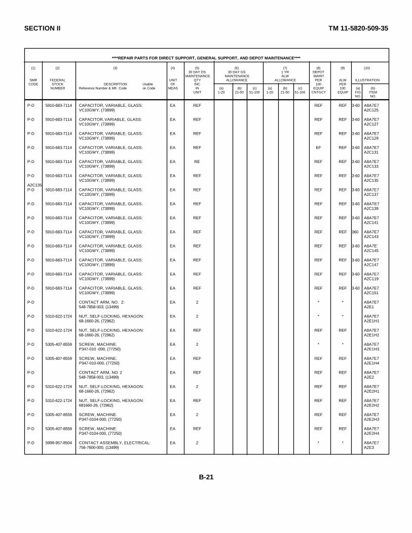
SECTION II TM 11-5820-509-35
****REPAIR PARTS FOR DIRECT SUPPORT, GENERAL SUPPORT, AND DEPOT MAINTENANCE****
(1) (2) (3) (4) (5) (6) (7) (8) (9) (10)30 DAY DS 30 DAY GS 1 YR DEPOT
MAINTENANCE MAINTENANCE ALW MAINTSMR FEDERAL UNIT QTY ALLOWANCE ALLOWANCE PER ALW ILLUSTRATION
CODE STOCK DESCRIPTION Usable OF INC 100 PERNUMBER Reference Number & Mfr. Code on Code MEAS IN (a) (b) (c) (a) (b) (c) EQUIP 100 (a) (b)
UNIT 1-20 21-50 51-100 1-20 21-50 51-100 CNTGCY EQUIP FIG ITEMNO. NO.
P-D 5910-683-7114 CAPACITOR, VARIABLE, GLASS: EA REF REF REF 3-60 A8A7E7VC10GWY, (73899) A2C125
P-D 5910-683-7114 CAPACITOR, VARIABLE, GLASS: EA REF REF REF 3-60 A8A7E7VC10GWY, (73899) A2C127
P-D 5910-683-7114 CAPACITOR, VARIABLE, GLASS: EA REF REF REF 3-60 A8A7E7VC10GWY, (73899) A2C129
P-D 5910-683-7114 CAPACITOR, VARIABLE, GLASS: EA REF EF REF 3-60 A8A7E7VC10GWY, (73899) A2C131
P-D 5910-683-7114 CAPACITOR, VARIABLE, GLASS: EA RE REF REF 3-60 A8A7E7VC10GWY, (73899) A2C133
P-D 5910-683-7114 CAPACITOR, VARIABLE, GLASS: EA REF REF REF 3-60 A8A7E7VC10GWY, (73899) A2C135
A2C135P-D 5910-683-7114 CAPACITOR, VARIABLE, GLASS: EA REF REF REF 3-60 A8A7E7
VC10GWY, (73899) A2C137
P-D 5910-683-7114 CAPACITOR, VARIABLE, GLASS: EA REF REF REF 3-60 A8ATE7VC10GWY, (73899) A2C139
P-D 5910-683-7114 CAPACITOR, VARIABLE, GLASS: EA REF REF REF 3-60 A8A7E7VC10GWY, (73899) A2C141
P-D 5910-683-7114 CAPACITOR, VARIABLE, GLASS: EA REF REF REF 360 A8A7E7VC10GWY, (73899) A2C143
P-D 5910-683-7114 CAPACITOR, VARIABLE, GLASS: EA REF REF REF 3-60 A8A7E'VC10GWY, (73899) A2C145
P-D 5910-683-7114 CAPACITOR, VARIABLE, GLASS: EA REF REF REF 3-60 A8A7E7VC10GWY, (73899) A2C147
P-D 5910-683-7114 CAPACITOR, VARIABLE, GLASS: EA REF REF REF 3-60 A8A7E7VC10GWY, (73899) A2C119
P-D 5910-683-7114 CAPACITOR, VARIABLE, GLASS: EA REF REF REF 3-60 A8A7E7VC10GWY, (73899) A2C151
P-D CONTACT ARM, NO. 2: EA 2 * * A8A7E7548-7858-003; (13499) A2E1
P-D 5310-622-1724 NUT, SELF-LOCKING, HEXAGON: EA 2 * * A8A7E768-1660-26, (72962) A2E1H1
P-D 5310-622-1724 NUT, SELF-LOCKING, HEXAGON: EA REF REF REF A8A7E768-1660-26, (72962) A2E1H2
P-D 5305-407-8559 SCREW, MACHINE: EA 2 * * A8A7E7P347-010 -000, (77250) A2E1H3
P-D 5305-407-8559 SCREW, MACHINE: EA REF REF REF A8A7E7P347-010-000, (77250) A2E1H4
P-D CONTACT ARM, NO. 2 EA REF REF REF A8A7E7548-7858-003, (13499) A2E2
P-D 5310-622-1724 NUT, SELF-LOCKING, HEXAGON: EA 2 REF REF A8A7E768-1660-26, (72962) A2E2H1
P-D 5310-622-1724 NUT, SELF-LOCKING, HEXAGON: EA REF REF REF A8A7E7681660-26, (72962) A2E2H2
P-D 5305-407-8559 SCREW, MACHINE: EA 2 REF REF A8A7E7P347-0104-000, (77250) A2E2H3
P-D 5305-407-8559 SCREW, MACHINE: EA REF REF REF A8A7E7P347-0104-000, (77250) A2E2H4
P-D 5999-957-8504 CONTACT ASSEMBLY, ELECTRICAL: EA 2 * * A8A7E7756-7600-000, (13499) A2E3
B-21
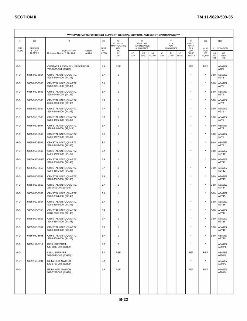
SECTION II TM 11-5820-509-35
****REPAIR PARTS FOR DIRECT SUPPORT, GENERAL SUPPORT, AND DEPOT MAINTENANCE****
(1) (2) (3) (4) (5) (6) (7) (8) (9) (10)30 DAY DS 30 DAY GS 1 YR DEPOT
MAINTENANCE MAINTENANCE ALW MAINTSMR FEDERAL UNIT QTY ALLOWANCE ALLOWANCE PER ALW ILLUSTRATION
CODE STOCK DESCRIPTION Usable OF INC 100 PERNUMBER Reference Number & Mfr. Code on Code MEAS IN (a) (b) (c) (a) (b) (c) EQUIP 100 (a) (b)
UNIT 1-20 21-50 51-100 1-20 21-50 51-100 CNTGCY EQUIP FIG ITEMNO. NO.
P-D CONTACT ASSEMBLY, ELECTRICAL EA REF REF REF A8A7E7756-7600-004, (13499) A2E4
P-D 5955-950-8554 CRYSTAL UNIT, QUARTZ: EA 1 * * 3-60 A8A7E7S289-3490-000, (94148) A2Y1
P-D 5955-950-8560 CRYSTAL UNIT, QUARTZ: EA 1 * * 3-60 A8A7E7S289-3491-000; (94148) A2Y2
P-D 5955-950-8561 CRYSTAL UNIT, QUARTZ EA 1 * * 3-60 A8A7E7S289-3492-000; (94148) A2Y3
P-D 5955-950-8568 CRYSTAL UNIT, QUARTZ EA 1 * * 3-60 A8A7E7S289-3493-000, (94148) A2Y4
P-D 5955-950-8562 CRYSTAL UNIT, QUARTZ EA 1 * * 3-60 A8A7E7S289-3494-000, (94148) A2Y5
P-D 5955-950-8563 CRYSTAL UNIT, QUARTZ EA 1 * * 3-60 A8A7E7S289-3495-000, (94148) A2Y6
P-D 5955-950-8564 CRYSTAL UNIT, QUARTZ EA 1 * * 3-60 A8A7E7S289-3496-000, (91,148 ) A2Y7
P-D 5955-950-8565 CRYSTAL UNIT, QUARTZ EA 1 * * 3-60 A8A7E7S289-3497-000, (94148) A2Y8
P-D 5955-950-8566 CRYSTAL UNIT, QUARTZ: EA 1 * * 3-60 A8A7E7S289-3498-000, (94148) A2Y9
P-D 5955-950-8567 CRYSTAL UNIT, QUARTZ EA 1 * * 3-60 A8A7E7S289-3499-000, (94148) A2Y10
P-D 59559 950-8550 CRYSTAL UNIT, QUARTZ EA 1 * * 3-60 A8A7E7S289-3500-000, (94148) A2Y11
P-D 5955-950-8569 CRYSTAL UNIT, QUARTZ EA 1 * * 3-60 A8A7E7S289-3501-000, (94148) A2Y12
P-D 5955-950-8551 CRYSTAL UNIT, QUARTZ EA 1 * * 3-60 A8A7E7S289-3502-000, (94148) A2Y13
P-D 5955-950-8552 CRYSTAL UNIT, QUARTZ. EA 1 * * 3-60 A8A7E7289-3503-000, (94148) A2Y14
P-D 5955-950-8553 CRYSTAL UNIT, QUARTZ: EA 1 * * 3-60 A8A7E7S289-3504-000, (94148) A2Y15
P-D 5955-950-8554 CRYSTAL UNIT, QUARTZ EA 1 * * 3-60 A8A7E7S289-3505-000, (94148) A2Y16
P-D 5955-950-8555 CRYSTAL UNIT, QUARTZ EA 1 * * 3-60 A8A7E7S289-3506-000; (94148) A2Y17
P-D 5955-950-8556 CRYSTAL UNIT, QUARTZ EA 1 * * 3-60 A8A7E7S289-3507-000, (94148) A2Y18
P-D 5955-950-8557 CRYSTAL UNIT, QUARTZ EA 1 * * 3-60 A8A7E7S289-3508-000, (94148) A2Y19
P-D 5955-950-8558 CRYSTAL UNIT, QUARTZ- EA 1 * * 3-60 A8A7E7S289-3509-000, (94148) A2Y20
P-D 5365-159-3714 DISK, SUPPORT. EA 2 * * A8A7E7549-5843-002, (13499) A2MP1
P-D DISK, SUPPORT EA REF REF REF A8A7E7549-5843-002, (13499) A2MP2
P-D 5999-165-3691 RETAINER, SWITCH EA 4 * * A8A7E7549-5737-002, (13499) A2MP3
P-D RETAINER, SWITCH EA REF REF REF A8A7E7549-5737-002, (13499) A2MP4
B-22
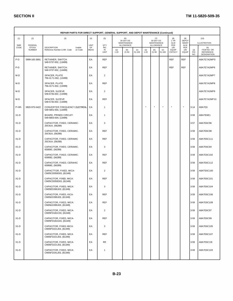
SECTION II TM 11-5820-509-35
REPAIR PARTS FOR DIRECT SUPPORT, GENERAL SUPPORT, AND DEPOT MAINTENANCE (Continued)
(1) (2) (3) (4) (5) (6) (7) (8) (9) (10)30 DAY DS 30 DAY GS 1 YR DEPOT
MAINTENANCE MAINTENANCE ALW MAINT ILLUSTRATIONSMR FEDERAL UNIT QTY ALLOWANCE ALLOWANCE PER ALW
CODE STOCK DESCRIPTION Usable OF INC 100 PER (b)NUMBER Reference Number & Mfr. Code on Code MEAS IN (a) (b) (c) (a) (b) (c) EQUIP 100 (a) ITEM NO. OR
UNIT 1-20 21-50 51-100 1-20 21-50 51-100 CNTGCY EQUIP FIG REFERENCENO. DESIGNATION
P-D 5999-165-3691 RETAINER, SWITCH EA REF REF REF A8A7E7A2MPS549-5737-002, (13499)
P-D RETAINER, SWITCH. EA REF REF REF A8A7E7A2MP6549-3737-002, (13499)
M-D SPACER, PLATE EA 2 A8A7E7A2MP7756-4171-002, (13499)
M-D SPACER, PLATE EA REF A8A7E7A2MP8756-4171-002, (13499)
M-D SPACER, SLEEVE EA 2 A8A7E7A2MP9549-5735-002, (13499)
M-D SPACER, SLEEVE EA REF A8A7E7A2MP10549-5735-002, (13499)
P-HR- 5820-975-5422 CONVERTER,'FREQUENCY, ELECTRICAL- EA 1 * * * * * 3-14 A8A7E6549-5801-004, (13499)
X1-D BOARD, PRINED CIRCUIT: EA 1 3-59 ABA7E6E1549-5803-004; (13499)
X1-D CAPACITOR, FIXED, CERAMIC- EA 3 3-57 A8A7E6C9620C91A, (56289)
X1-D CAPACITOR, FIXED, CERAMIC. EA REF 3-59 A8A7E6C9820C91A, (56289)
X1-D CAPACITOR, FIXED, CERAMIC EA REF 3-59 A8A7E6C11120C91A; (56289)
X1-D CAPACITOR, FIXED, CERAMIC. EA 3 3-59 A8A7E6C946S8082, (56289)
X1-D CAPACITOR, FIXED, CERAMIC. EA REF 3-59 A8A7E6C1026S8082, (56289)
X1-D CAPACITOR, FIXED, CERAHIC EA REF 3-59 A8A7E6C1126S8082, (56289)
X1-D CAPACTTOR, FIXED, MICA- EA 2 3-59 A8ATE6C100CM05CD050D03, (81349)
X1-D CAPACITOR, FIXED, MICA: EA REF 3-59 A8A7E6C101CM05CD050D03, (81349)
X1-D CAPACITOR, FIXED, MICA: EA 3 3-59 A8A7E6C104CM05ED390J03; (81349)
X1-D CAPACITOR, FIXED, KICA- EA REF 3-59 A8A7E6C106CM05ED390J03, (81349)
X1-D CAPACITOR, FIXED, MICA: EA REF 3-59 A8A7E6C108CM05ED390J03, (81349)
X1-D CAPACITOR, FIXED, MICA- EA 2 3-59 A8A7E6C97CM05FD181C03, (81349)
X1-D CAPACITOR, FIXED, MICA- EA REF 3-59 A8A7E6C99CM05FD181G03, (81349)
X1-D CAPACITOR, FIXED, MICA: EA 3 3-59 A8A7E6C105CM05FD221J03, (81349)
X1-D CAPACITOR, FIXED, MICA EA REF 3-59 A8A7E6C107CM05FD221J03, (81349)
X1-D CAPACITOR, FIXED, MICA- EA RE 3-59 A8A7E6C1l9CM05FD221J03, (81349)
X1-D CAPACITOR, FIXED, MICA: EA 1 3-59 A8A7E6C103CM05FD241J03, (81349)
B-23
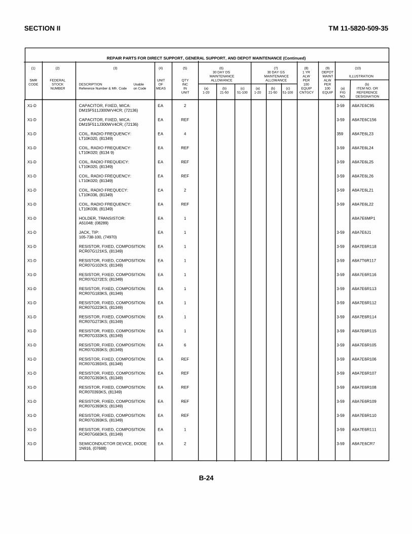
SECTION II TM 11-5820-509-35
REPAIR PARTS FOR DIRECT SUPPORT, GENERAL SUPPORT, AND DEPOT MAINTENANCE (Continued)
(1) (2) (3) (4) (5) (6) (7) (8) (9) (10)30 DAY DS 30 DAY GS 1 YR DEPOT
MAINTENANCE MAINTENANCE ALW MAINT ILLUSTRATIONSMR FEDERAL UNIT QTY ALLOWANCE ALLOWANCE PER ALW
CODE STOCK DESCRIPTION Usable OF INC 100 PER (b)NUMBER Reference Number & Mfr. Code on Code MEAS IN (a) (b) (c) (a) (b) (c) EQUIP 100 (a) ITEM NO. OR
UNIT 1-20 21-50 51-100 1-20 21-50 51-100 CNTGCY EQUIP FIG REFERENCENO. DESIGNATION
X1-D CAPACITOR, FIXED, MICA: EA 2 3-59 A8A7E6C95DM15F511J300WV4CR; (72136)
X1-D CAPACITOR, FIXED, MICA: EA REF 3-59 A8A7E6C156DM15F511J300WV4CR; (72136)
X1-D COIL, RADIO FREQUENCY: EA 4 359 A8A7E6L23LT10K020, (81349)
X1-D COIL, RADIO FREQUENCY: EA REF 3-59 A8A7E6L24LT10K020; (8134 9)
X1-D COIL, RADIO FREQUEICY: EA REF 3-59 A8A7E6L25LT10K020, (81349)
X1-D COIL, RADIO FREQUENCY: EA REF 3-59 A8A7E6L26LT10K020; (81349)
X1-D COIL, RADIO FREQUECY: EA 2 3-59 A8A7E6L21LT10K036, (81349)
X1-D COIL, RADIO FREQUENCY: EA REF 3-59 A8A7E6L22LT10K036; (81349)
X1-D HOLDER, TRANSISTOR: EA 1 A8A7E6MP1A51048; (08289)
X1-D JACK, TIP: EA 1 3-59 A8A7E6J1105-738-100, (74970)
X1-D RESISTOR, FIXED, COMPOSITION: EA 1 3-59 A8A7E6R118RCR07G121KS, (81349)
X1-D RESISTOR, FIXED, COMPOSITION: EA 1 3-59 A8A7T6R117RCR07G102KS; (81349)
X1-D RESISTOR, FIXED, COMPOSITION: EA 1 3-59 A8A7E6R116RCR07G272ES; (81349)
X1-D RESISTOR, FIXED, COMPOSITION: EA 1 3-59 A8A7E6R113RCR07G183KS, (81349)
X1-D RESISTOR, FIXED, COMPOSITION: EA 1 3-59 A8A7E6R112RCR07G223KS, (81349)
X1-D RESISTOR, FIXED, COMPOSITION: EA 1 3-59 A8A7E6R114RCR07G273KS; (81349)
X1-D RESISTOR, FIXED, COMPOSITION: EA 1 3-59 A8A7E6R115RCR07G333KS, (81349)
X1-D RESISTOR, FIXED, COMPOSITION: EA 6 3-59 A8A7E6R105RCR07G393KS; (81349)
X1-D RESISTOR, FIXED, COMPOSITION: EA REF 3-59 A8A7E6R106RCR07G393XS, (81349)
X1-D RESISTOR, FIXED, COMPOSITION: EA REF 3-59 A8A7E6R107RCR07G393KS, (81349)
X1-D RESISTOR, FIXED, COMPOSITION: EA REF 3-59 A8A7E6R108RCR070393KS, (81349)
X1-D RESISTOR, FIXED, COMPOSITION: EA REF 3-59 A8A7E6R109RCR07G393KS; (81349)
X1-D RESISTOR, FIXED, COMPOSITION: EA REF 3-59 A8A7E6R110RCR07G393KS, (81349)
X1-D RESISTOR, FIXED, COMPOSITION: EA 1 3-59 A8A7E6R111RCR07G683KS, (81349)
X1-D SEMICONDUCTOR DEVICE, DIODE EA 2 3-59 A8A7E6CR71N916, (07688)
B-24

SECTION II TM 11-5820-509-35
REPAIR PARTS FOR DIRECT SUPPORT, GENERAL SUPPORT, AND DEPOT MAINTENANCE (Continued)
(1) (2) (3) (4) (5) (6) (7) (8) (9) (10)30 DAY DS 30 DAY GS 1 YR DEPOT
MAINTENANCE MAINTENANCE ALW MAINT ILLUSTRATIONSMR FEDERAL UNIT QTY ALLOWANCE ALLOWANCE PER ALW
CODE STOCK DESCRIPTION Usable OF INC 100 PER (b)NUMBER Reference Number & Mfr. Code on Code MEAS IN (a) (b) (c) (a) (b) (c) EQUIP 100 (a) ITEM NO. OR
UNIT 1-20 21-50 51-100 1-20 21-50 51-100 CNTGCY EQUIP FIG REFERENCENO. DESIGNATION
X1-D SEMICONDUCTOR DEVICE, DIODE: EA REF 3-59 A8A7E6CR81N916, (07688)
X1-D TRANSISTOR: EA 1 3-59 A8A7E6Q232N697, (07688)
X1-D TRANSISTOR: EA 3 3-59 A8A7E6Q202N703, (07688)
X1-D TRANSISTOR: EA REF 3-59 A8A7E6Q212N703; (07688)
X1-D TRANSISTOR: EA REF 3-59 A8A7E6Q222N703, (07688)
M-D COVER, FILTER: EA 1 A8A7MP7756-0317-003; (13499)
P-D 5305-206-1270 SCREW, MACHINE: EA 2 * * A8A7MP7H1P343-0284-000; (77250)
P-D 5305-206-1270 SCREW, MACHINE: EA REF REF REF A8A7MP7H2P343-0284-000, (77250)
P-D 5310-184-8996 WASHER, SPRING TENSION: EA 2 * * A8A7MP7H3310-0396-00; (79807)
P-D 5310-184-8996 WASHER, SPRING TENSION: EA REF REF REF A8A7MP7H4310-0396-00; (79807)
M-D COVER, OSCILLATOR CONTROL: EA 1 A8A7MP8548-7762-003; (13499)
P-D 5305-054-5647 SCREW, MACHINE: EA 11 * * A8A7MP8H1MS51957-13, (96906)
P-D 5305-054-5647 SCREW, MACHINE: EA REF REF REF A8A7MP8H2MS51957-13; (96906)
P-D 5305-054-5647 SCREW, MACHINE: EA REF REF REF A8A7MP8H3MS51957-13, (96906)
P-D 5305-054-5647 SCREW, MACHINE: EA REF REF REF A8A7MP8H4MS51957-13, (96906)
P-D 5305-054-5647 SCREW, MACHINE: EA REF REF REF A8A7MP8H5MS51957-13, (96906)
P-D 5305-054-5647 SCREW, MACHINE: EA REF REF REF A8A7MP8H6MS51957-13, (96906)
P-D 5305-054-5647 SCREW, MACHINE: EA REF REF REF A8A7MP8H7MS51957-13, (96906)
P-D 5305-054-5647 SCREW, MACHINE: EA REF REF REF A8A7MP8H8MS51957-13, (96906)
P-D 5305-054- 5647 SCREW, MACHINE: EA REF REF REF A8A7MP8H9MS51957-13, (96906)
P-D 5305-054-5647 SCREW, MACHINE: EA REF REF REF A8A7MP8H10MS51957-13, (96906)
P-D 5305-054-5647 SCREW, MACHINE: EA REF REF REF A8A7MP8H111MS51957-13, (96906)
P-D WASHER, LOCK, SPRING: EA 11 REF REF A8A7MP8H12MS35338-135, (96906)
P-D WASHER, LOCK, SPRING: EA REF REF REF A8A7MPHF13M4S35338-135, (96906)
P-D WASHER, LOCK, SPRING: EA REF REF REF A8A7MPNH14MS35338-135, (96906)
B-25

SECTION II TM 11-5820-509-35
REPAIR PARTS FOR DIRECT SUPPORT, GENERAL SUPPORT, AND DEPOT MAINTENANCE (Continued)
(1) (2) (3) (4) (5) (6) (7) (8) (9) (10)30 DAY DS 30 DAY GS 1 YR DEPOT
MAINTENANCE MAINTENANCE ALW MAINT ILLUSTRATIONSMR FEDERAL UNIT QTY ALLOWANCE ALLOWANCE PER ALW
CODE STOCK DESCRIPTION Usable OF INC 100 PER (b)NUMBER Reference Number & Mfr. Code on Code MEAS IN (a) (b) (c) (a) (b) (c) EQUIP 100 (a) ITEM NO. OR
UNIT 1-20 21-50 51-100 1-20 21-50 51-100 CNTGCY EQUIP FIG REFERENCENO. DESIGNATION
P-D WASHER, LOCK, SPRING: EA REF REF REF A8A7MP8H15MS35338-135; (96906)
P-D WASHER, LOCK, SPRING: EA REF REF REF A8A7MP8H16MS35338-135, (96906)
P-D WASHER, LOCK, SPRING: EA REF REF REF A8A7MP8H17MS35338-135; (96906)
P-D WASHER, LOCK, SPRING: EA REF REF REF A8A7MP8H18MS35338-135, (96906)
P-D WASHER, LOCK, SPRING: EA REF REF REF A8A7MP8H19MS35338-135, (96906)
P-D WASHER, LOCK, SPRING: EA REF REF REF A8A7MP8H20MS35338-135; (96906)
P-D WASHER, LOCK, SPRING: EA REF REF REF A8A7MP8H21MS35338-135; (96906)
P-D WASHER, LOCK, SPRING: EA REF REF REF A8A7MP8H22MS35338-135; (96906)
P-H-T 5820-975-5423 DISCRIMINATOR, PHASE AND FREQUENCY: EA 1 * * * * * 3-14 A8A7E2549-5794-004, (13499)
X1-D BOARD, PRINTED CIRCUIT: EA 1 3-55 A8A7E2E2549-57T1-003; (13499)
X1-D CAPACITOR, FIXED, CERAMIC: EA 2 A8A7E2C22658082, (56289)
X1-D CAPACITOR, FIXED, CERAMIC: EA REF 3-55 A8A7E2C306S8082, (56289)
X1-D CAPACITOR, FIXED, CERAMIC: EA 6 3-55 A8A7E2C23658083, (56289)
X1-D CAPACITOR, FIXED, CERAMIC: EA REF 3-55 A8A7E2C256S8083, (56289)
X1-D CAPACITOR, FIXED, CERAMIC: EA REF 3-55 A8A7E2C29658083, (56289)
X1-D CAPACITOR, FIXED, CERAMIC: EA REF 3-55 A8A7E2C32658083, (56289)
X1-D CAPACITOR, FIXED, CERAMIC: EA REF 3-55 A8A7E2C35658083; (56289)
X1-D CAPACITOR, FIXED, CERAMIC: EA REF 3-55 A8A7E2C36658083; (56289)
X1-D CAPACITOR, FIXED, ELECTROLYTIC: EA 1 3-55 A8A7E2C26150D335X0035B2; (56289)
X1-D CAPACITOR, FIXED, ELECTROLYTIC: EA 2 3-55 A8A7E2C92150D10X0035A2, (56289)
X1-D CAPACITOR, FIXED, ELECTROLYTIC: EA REF 3-55 A8A7E2C93150D104X0035A2; (56289)
X1-D CAPACITOR, FIXED, MICA: EA 2 3-55 A8A7E2C28CM05FD151J03, (81349)
X1-D CAPACITOR, FIXED, MICA: EA REF 3-55 A8A7E2C34CM405FD151J03; (81349)
X1-D CAPACITOR, FIXED, MICA: EA 2 3-55 A8A7E2C27CMN5FD271J03; (81349)
X1-D CAPACITOR, FIXED, MICA: EA REF 3-55 A8A7E2C33CM405FD271J03; (81349)
B-26

SECTION II TM 11-5820-509-35
REPAIR PARTS FOR DIRECT SUPPORT, GENERAL SUPPORT, AND DEPOT MAINTENANCE (Continued)
(1) (2) (3) (4) (5) (6) (7) (8) (9) (10)30 DAY DS 30 DAY GS 1 YR DEPOT
MAINTENANCE MAINTENANCE ALW MAINT ILLUSTRATIONSMR FEDERAL UNIT QTY ALLOWANCE ALLOWANCE PER ALW
CODE STOCK DESCRIPTION Usable OF INC 100 PER (b)NUMBER Reference Number & Mfr. Code on Code MEAS IN (a) (b) (c) (a) (b) (c) EQUIP 100 (a) ITEM NO. OR
UNIT 1-20 21-50 51-100 1-20 21-50 51-100 CNTGCY EQUIP FIG REFERENCENO. DESIGNATION
P--D RESISTOR, FIXED, COMPOSITION: EA 1 * * 3-56 A8A7TB1R124RCR07G470KS; (81349)
P--D RESISTOR, FIXED, COMPOSITION: EA 1 * * 3-56 A8A7TB1R135RCR070680KS; (81349)
P--D 5905-104-8363 RESISTOR, FIXED, COMPOSITION: EA 1 * * 3-54 A8A7TB1R144*RCR07G820KS; (81349)
P--D RESISTOR, FIXED, COMPOSITION: EA 1 * * 3-56 A8A7TB1R131RCR07G101KS; (81349)
P--D RESISTOR, FIXED, COMPOSITION: EA 1 * * 3-56 A8A7TB1R144*RCR07G151KS, (81349)
P--D RESISTOR, FIXED, COMPOSITION: EA 2 * * 3-56 A8A7TB1R139RCR070221KS, (81349)
P--D RESISTOR, FIXED, COMPOSTION: EA REF REF REF 3-56 A8A7TB1R144*· RCR0TG221KS; (81349)
P--D RESISTOR, FIXED, COMPOSITION: EA 1 * * 3-56 A8A7TB1R144*RCR07G331KS;(81349)
P--D 5905-120-9154 RESISTOR, FIXED, COMPOSITION: EA 1 * * 3-56 A8A7TB1R144*RCR07G471KS; (8134 9)
P--D 5905-135-6046 RESISTOR, FIXED, COMPOSITION: EA 2 * * 3-56 A8A7TB1R142RCR0TG681KS, (81349)
P--D RESISTOR, FIXED, COMPOSITION: EA REF REF REF 3-56 A8A7TB1R144*RCR0TG681KS; (81349)
P--D RESISTOR, FIXED, COMPOSITION: EA 1 * * 3-56 A8A7TB1R144*RCRC7G821KS; (81349)
P--D RESISTOR, FIXED, COMPOSITION: EA 5 * * 3-56 ASA7TBlR120RCR07G02XS; (81349)
P--D RESISTOR FIXED, COMPOSITION: EA REF REF REF 3-56 A8A7TBIR144*RCR07C102KS; (81349)
P--D RESISTOR, FIXED, COMPOSITION: EA REF REF REF 3-56 A8A7TB1R145RCR7cG102KS, (81349)
P--D RESISTOR, FIXED, COMPOSITION: EA REF REF REF 3-56 A8A7TB1R146RCR07G102KS; (81349)
P--D RESISTOR, FIXED, COMPOSITION: EA REF REF REF 3-56 A8A7TB1R147RCR07G102KS; (81349)
P--D RESISTOR, FIXED, COMPOSITION: EA 2 · * 3-56 A8A7TB1R143RCR07G152KS; (81349)
P--D RESISTOR, FIXED, COMPOSITION: EA REF REF REF 3-56 A8A7TB1R144*RCR07G152KS, (813*9)
P--D RESISTOR, FIXED, COMPOSITION: EA 1 * 3-56 A8A7TB1R123RCR07G222KS; (81349)
P--D 5905-686-4527 RESISTOR, FIXED, COMPOSITION: EA 1 * * 3-56 A8A7TB1R134RCR07G272KS; (81349)
P--D 5905-070-9391 RESISTOR, FIXED, COMPOSITION: EA 1 * * 3-56 A8A7TB1R141RCR07G392KS, (81349)
P--D RESISTOR, FIXED, COMPOSITION. EA 2 * * 3-56 A8A7TB1R119RCR07G472Ks; (81349)
P--D RESISTOR, FIXED, COMPOSITION: EA REF REF REF 3-56 A8A7TB1R130RCR07G72KS; (81349)
P--D 5905-070-9392 RESISTOR, FIXED, COMPOSITION. EA 1 * * 3-56 A8A7TB1R151RCR07G562KS; (81349)*SELECT PER OPERATIONAL REQUIRMENT.
B-35

SECTION II TM 11-5820-509-35
REPAIR PARTS FOR DIRECT SUPPORT, GENERAL SUPPORT, AN DEPOT MAINTENANCE (Continued)
(1) (2) (3) (4) (5) (6) (7) (8) (9) (10)30 DAY DS 30 DAY GS 1 YR DEPOT
MAINTENANCE MAINTENANCE ALW MAINT ILLUSTRATIONSMR FEDERAL UNIT QTY ALLOWANCE ALLOWANCE PER ALW
CODE STOCK DESCRIPTION Usable OF INC 100 PER (b)NUMBER Reference Number & Mfr. Code on Code MEAS IN (a) (b) (c) (a) (b) (c) EQUIP 100 (a) ITEM NO. OR
UNIT 1-20 21-50 51-100 1-20 21-50 51-100 CNTGCY EQUIP FIG REFERENCENO. DESIGNATION
P--D RESISTOR, FIXED, COMPOSITION: EA 1 * * 3-56 A8A7TB1R140RCR07G822KS; (81349)
P--D 5905-816-8554 RESISTOR, FIXED, COMPOSITION: EA 1 * * 3-56 A8A7TB1R127RCR07GC103KS, (81349)
P--D 5905-686-4529 RESISTOR, FIXED, COMPOSITION: EA 1 * * 3-56 A8A7TB1R128RCR07G123KS, (81349)
P--D RESISTOR, FDXED, COMPOSITION: EA 3 * * 3-56 A8A7TB1R129RCR07G223KS, (81349)
P--D RESISTOR, FIXED, COMPOSITION: EA REF REF REF A8A7TB1R136RCR07G223KS, (81349)
P--D RESISTOR, FIXED, COMPOSITION- EA REF REF REF 3-56 A8A7TB1R137RCR07G223KS; (81349)
P--D 5905-752-3157 RESISTOR, FIXED, COMPOSITION: EA 1 * * 3-56 A8A7TB1R148RCR07C273KS, (81349)
P--D RESISTOR, FIXED, COMPOSITION: EA 2 REF REF 3-56 A8A7TB1R121RCR07G683KS, (81349)
P--D RESISTOR, FIXED, COMPOSITION: EA REF REF REF 3-56 A8A7TB1R122RCR007683xc, (81349)
P--D 5905-988-2310 RESISTOR, FIXED, FIIM: EA * * 3-56 A8A7TB1R125RN60D1000F, (81349)
P--D 5905-988-2310 RESISTOR, FDE-, FIIM. EA REF REF REF 3-56 A8A7TB1R126RN60D1000F; (81349)
P--D 5905-988-2310 RESISTOR, FIXED, FIIX: EA REF REF REF 3-56 A8A7TB1R132RN60D1000F, (81349)
P--D 5905-988-2310 RESISTOR, FIXED, FILM: EA REF REF REF 3-56 A8A7TB1R133RN60D1000F, (81349)
P--D 5905-781-8015 RESISTOR, FIXED, FILM: EA 1 * * 3-56 A8A7TB1R149RN60D3800F; (81349)
P--D 5905-985-5465 RESISTOR, FIXED, FILM: EA 1 * * 3-56 A8A7TB1R150RN60D1962F, (81349)
P--D SEMICONDUCTOR DEVICE, DIODE: EA 2 * * 3-56 A8A7TB1CR121N198, (07688)
P--D SEMICONDUCTOR DEVICE, DIODE: EA REF REF REF 3-56 A8A7TB1CR131N198, (07688)
P--D 5961-752-5230 SEMICONDUCTOR DEVICE, DIODE: EA 2 * * 3-56 A8A7TB1CR151N916, (07688)
P--D 5961-752-5230 SEMICONDUCTOR DEVICE, DIODE: EA REF REF REF 3-56 A8A7TBlCR91N916; (07688)
P--D S1MICONDUCTOR DEVICE, DIODE: EA 1 * * 3-56 A8A7TBlCR14JAMlN754A, (81350)
P--D 5961-724-6164 SEMICONDUCTOR DEVICE, DIODE: EA 2 * * 3-56 A8A7TBlCR10FA4092, (07263)
P--D 5961-724-6164 SEMICONDUCTDR DEVICE, DIODE: EA REF REF REF 3-56 A8A7TB1CR11FA4092, (07263)
P--D 5940-423-2988 TERMINAL, STUD-GROUND: EA 17 * * A8A7TB1E2AB397-2, (12615)
P--D 5310-934-9740 NUT, PLAIN, HBXAGON: EA 1 * * A8A7TB1E2H1MS35649-225; (96906)
P--D 5310-18-8990 WASHER, SPRING TENSION: EA 1 * * * A8A7TB1E2H2310-0075-000; (79807)
B-36
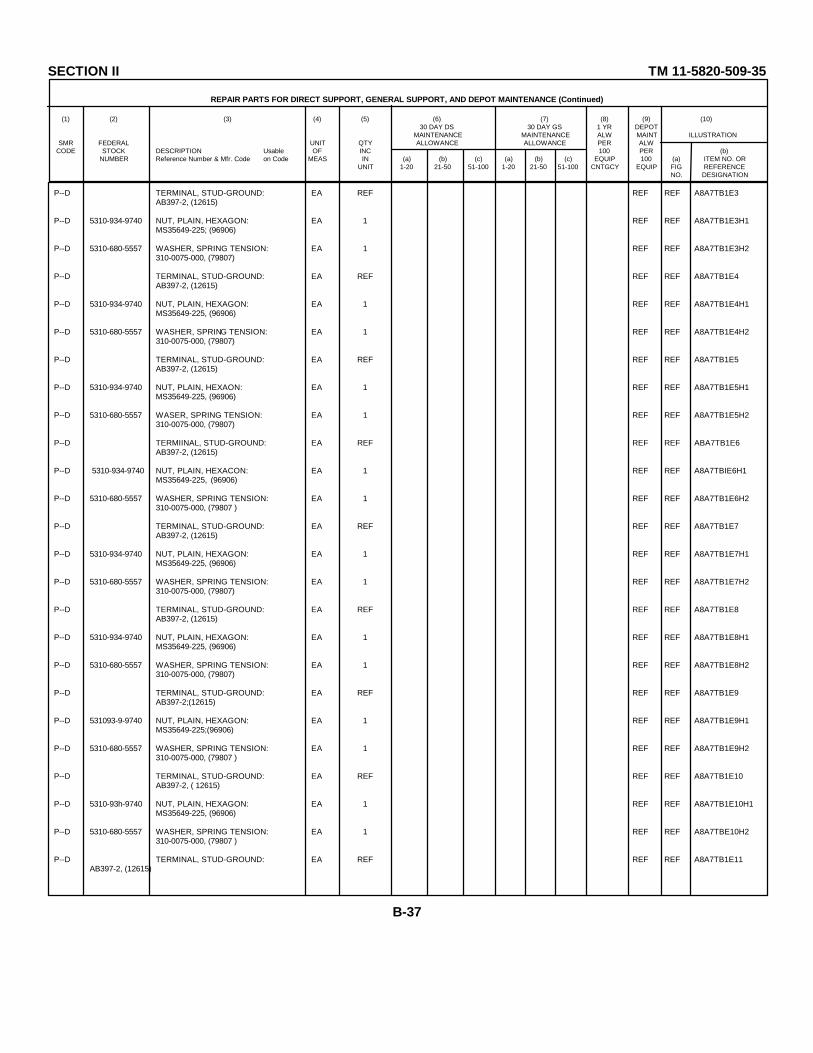
SECTION II TM 11-5820-509-35
REPAIR PARTS FOR DIRECT SUPPORT, GENERAL SUPPORT, AND DEPOT MAINTENANCE (Continued)
(1) (2) (3) (4) (5) (6) (7) (8) (9) (10)30 DAY DS 30 DAY GS 1 YR DEPOT
MAINTENANCE MAINTENANCE ALW MAINT ILLUSTRATIONSMR FEDERAL UNIT QTY ALLOWANCE ALLOWANCE PER ALW
CODE STOCK DESCRIPTION Usable OF INC 100 PER (b)NUMBER Reference Number & Mfr. Code on Code MEAS IN (a) (b) (c) (a) (b) (c) EQUIP 100 (a) ITEM NO. OR
UNIT 1-20 21-50 51-100 1-20 21-50 51-100 CNTGCY EQUIP FIG REFERENCENO. DESIGNATION
P--D TERMINAL, STUD-GROUND: EA REF REF REF A8A7TB1E3AB397-2, (12615)
P--D 5310-934-9740 NUT, PLAIN, HEXAGON: EA 1 REF REF A8A7TB1E3H1MS35649-225; (96906)
P--D 5310-680-5557 WASHER, SPRING TENSION: EA 1 REF REF A8A7TB1E3H2310-0075-000, (79807)
P--D TERMINAL, STUD-GROUND: EA REF REF REF A8A7TB1E4AB397-2, (12615)
P--D 5310-934-9740 NUT, PLAIN, HEXAGON: EA 1 REF REF A8A7TB1E4H1MS35649-225, (96906)
P--D 5310-680-5557 WASHER, SPRING TENSION: EA 1 REF REF A8A7TB1E4H2310-0075-000, (79807)
P--D TERMINAL, STUD-GROUND: EA REF REF REF A8A7TB1E5AB397-2, (12615)
P--D 5310-934-9740 NUT, PLAIN, HEXAON: EA 1 REF REF A8A7TB1E5H1MS35649-225, (96906)
P--D 5310-680-5557 WASER, SPRING TENSION: EA 1 REF REF A8A7TB1E5H2310-0075-000, (79807)
P--D TERMIINAL, STUD-GROUND: EA REF REF REF ABA7TB1E6AB397-2, (12615)
P--D 5310-934-9740 NUT, PLAIN, HEXACON: EA 1 REF REF A8A7TBIE6H1MS35649-225, (96906)
P--D 5310-680-5557 WASHER, SPRING TENSION: EA 1 REF REF A8A7TB1E6H2310-0075-000, (79807 )
P--D TERMINAL, STUD-GROUND: EA REF REF REF A8A7TB1E7AB397-2, (12615)
P--D 5310-934-9740 NUT, PLAIN, HEXAGON: EA 1 REF REF A8A7TB1E7H1MS35649-225, (96906)
P--D 5310-680-5557 WASHER, SPRING TENSION: EA 1 REF REF A8A7TB1E7H2310-0075-000, (79807)
P--D TERMINAL, STUD-GROUND: EA REF REF REF A8A7TB1E8AB397-2, (12615)
P--D 5310-934-9740 NUT, PLAIN, HEXAGON: EA 1 REF REF A8A7TB1E8H1MS35649-225, (96906)
P--D 5310-680-5557 WASHER, SPRING TENSION: EA 1 REF REF A8A7TB1E8H2310-0075-000, (79807)
P--D TERMINAL, STUD-GROUND: EA REF REF REF A8A7TB1E9AB397-2;(12615)
P--D 531093-9-9740 NUT, PLAIN, HEXAGON: EA 1 REF REF A8A7TB1E9H1MS35649-225;(96906)
P--D 5310-680-5557 WASHER, SPRING TENSION: EA 1 REF REF A8A7TB1E9H2310-0075-000, (79807 )
P--D TERMINAL, STUD-GROUND: EA REF REF REF A8A7TB1E10AB397-2, ( 12615)
P--D 5310-93h-9740 NUT, PLAIN, HEXAGON: EA 1 REF REF A8A7TB1E10H1MS35649-225, (96906)
P--D 5310-680-5557 WASHER, SPRING TENSION: EA 1 REF REF A8A7TBE10H2310-0075-000, (79807 )
P--D TERMINAL, STUD-GROUND: EA REF REF REF A8A7TB1E11AB397-2, (12615)
B-37

SECTION II TM 11-5820-509-35
REPAIR PARTS FOR DIRECT SUPPORT, GENERAL SUPPORT, AND DEPOT MAINTENANCE (Continued)
(1) (2) (3) (4) (5) (6) (7) (8) (9) (10)30 DAY DS 30 DAY GS 1 YR DEPOT
MAINTENANCE MAINTENANCE ALW MAINT ILLUSTRATIONSMR FEDERAL UNIT QTY ALLOWANCE ALLOWANCE PER ALW
CODE STOCK DESCRIPTION Usable OF INC 100 PER (b)NUMBER Reference Number & Mfr. Code on Code MEAS IN (a) (b) (c) (a) (b) (c) EQUIP 100 (a) ITEM NO. OR
UNIT 1-20 21-50 51-100 1-20 21-50 51-100 CNTGCY EQUIP FIG REFERENCENO. DESIGNATION
P--D 5310-934-9740 NUT, PLAIN, HEXAGON: EA 1 REF REF ASA7TB1E11H1MS35649-225, (96906)
P--D 5310-680-5557 WASHER, SPRING TENSION: EA 1 REF REF A8A7TB1E11H2310-0075-000, (79807)
P--D TETBONAL, STUD-GROUND: EA REF REF REF A8A7TB1E12AB397-2, (12615)
P--D 5310-93h-9740 NUT, PLAIN, HEXAGON: EA 1 REF REF A8A7TB1E12HlMS35649-225, (96906)
P--D 5310-680-5557 WASHER, SPRING TENSION: EA 1 REF REF A8A7TB1E12H2310-0075-000, (79807)
P--D TERKMNAL, STUD-GROUND: EA REF REF REF A8A7TB1E13AB397-2, (12615)
P--D 5310-934-9740 NUT, PLAIN, HEXAGON: EA 1 REF REF A8SATB1E13H1MS35649-225, (96906)
P--D 5310-680-5557 WASHER, SPRING TENSION: EA 1 REF REF A8A7TB1E13H2310-0075-000, (79807)
P--D TENIAL, STUD-GROUND: EA REF REF REF A8A7TB1E14AB397-2, (12615)
P--D 5310-934-9740 NUT, PLAIN, HEXAGON: EA 1 REF REF A8A7TB1E4H1MS35649-225, (96906)
P--D 5310-680-5557 WASHER, SPRING TENSION: EA 1 REF REF A8A7TB1E14H2310-0075-000, (79807)
P--D TERMINAL, STUD-GROUND: EA REF REF REF A8A7TB1E15AB397-2; (12615)
P--D 5310-934-9740 NUT, PLAIN, HXAGON: EA 1 REF REF A8A7TBlE15HIMS35649-225, (96906)
P--D 5310-680-5557 WASHER, SPRING TENSION: EA 1 REF REF A8A7TB1E15H2310-0075-000, (79807)
P--D TERMINAL, STUD-GROUND: EA REF REF REF A8A7TB1E16AB397-2, (12615)
P--D 5310-934-9740 NUT, PLAIN, HEXAGON: EA 1 REF REF A8A7TBlE16H1M6356L9-225, (96906)
P--D 5310-680-5557 WASHER, SPRING TENSION: EA 1 REF REF A8A7TB1E16H2310-0075-000; (79807)
P--D TERMINAL, STUD-GROUND: EA REF REF REF A8A7TBlE17AB397-2, (12615)
P--D 5310-93b-9740 NUT, PLAIN, HEXAGON: EA 1 REF REF A8A7TBlE17HlMS35649-225, (96906)
P--D 5310-680-5557 WASHER, SPRING TENSION: EA 1 REF REF A8A7TBE17TH2310-0075-000, (79807)
P--D TERMINAL, STUD-GROUND: EA REF REF REF A8A7TBlE18AB397-2, (12615)
P--D 5310-934-9740 NUT, PLAIN, HEXACON: EA 1 REF REF A8A7TBlE8H1W635649-225, (96906)
P--D 5310-680-5557 WASHER, SPRING TENSION: EA 1 REF REF A8A7TBLE18H2310-0075-000, (79807)
P--D 5950-960-7338 TRANSFORMER, RADIO FREQUENCY: EA 2 · * * 3-56 A8A7TB1T1553-9312-003, (13499)
P--D 5310-934-9740 NUT, PLAIN, HEXAGON: EA 2 REF REF A8A7TB1T1H1MS35649-225; (96906)
B-38

SECTION II TM 11-5820-509-35
REPAIR PARTS FOR DIRECT SUPPORT, GENERAL SUPPORT, AND DEPOT MAINTENANCE (Continued)
(1) (2) (3) (4) (5) (6) (7) (8) (9) (10)30 DAY DS 30 DAY GS 1 YR DEPOT
MAINTENANCE MAINTENANCE ALW MAINT ILLUSTRATIONSMR FEDERAL UNIT QTY ALLOWANCE ALLOWANCE PER ALW
CODE STOCK DESCRIPTION Usable OF INC 100 PER (b)NUMBER Reference Number & Mfr. Code on Code MEAS IN (a) (b) (c) (a) (b) (c) EQUIP 100 (a) ITEM NO. OR
UNIT 1-20 21-50 51-100 1-20 21-50 51-100 CNTGCY EQUIP FIG REFERENCENO. DESIGNATION
P--D 5310-934-9740 NUT, PLAIN, HEXAGON: EA REF REF REF A8A7TBITIH2MS35649-225, (96906)
P--D 5305-922-3506 SCREW, MACHINE: EA 2 * * A8A7TBiT1H3330-2352-000, (70601)
P--D SCREW, MACHINE: EA REF REF REF A8A7TB1T1H4330-2352-000, (70601)
P--D WASHER, NONMETALLIC, FLAT: EA 2 * * A8A7TB1T1H5302-0050-OOO;( 74921)
P--D WASHER, NONMETALLIC, FLAT: EA REF REF REF A8A7TB1T1H6302-0050-000, ( 74921)
P--D WASHER, NONMETALLIC, FLAT: EA 2 * * A8A7TB1T1H7303-1000-000, (79807)
P--D WASHER, NONMETALLIC, FLAT: EA REF REF REF A8A7TB1T1H8303-1000-000; ((9807 )
P--D 5950-960-7338 TRANSFORMER, RADIO FREQUENCY: EA REF REF REF 3-56 A8A7TB1T3553-9312-003; (13499)
P--D 5310-934-9740 NUT, PLAIN, HEXAGON: EA 2 REF REF A8AfTB1T3H1MS35649-225;(96906)
P--D 5310-934-9740 NUT, PLAIN, HEXAGON: EA REF REF REF A8A7TB1T3H2MS35649-225; (96906)
P--D SCREW, MACHINE: EA 2 REF REF A8A7I'B1T3H3330-2352-000; (70601)
P--D SCREW, MACHINE; EA REF REF REF A8A77TB1T3H4330-2352-000; (70601)
P--D WASHER.NONMETALLIC, FLAT: EA 2 REF REF A8A7TB1T3H5302-0050-000;(74921)
P--D WASHER, NONMETALLIC, FLAT: EA REF REF REF A8A7TB1T3H6302-0050-000; (74921)
P--D WASHER, NONMETALLIC, FLAT: EA 2 REF REF A8A7TB1T3H7303-1000-000;(79807)
P--D WASHER, NONMETALLIC, FLAT: EA REF REF REF A8A7TB1T3H8303-1000-O00;(79807)
P--D 5950-960-7339 TRANSFORMER, RADIO FREQUENCY: EA 2 * 3-56 A8A7TB1T2553-9313-003, (13499)
P--D 595O-960-7339 TRANSFORMER, RADIO FREQUENCY: EA REF REF REF 3-56 A8A7TB1T4553-9313-003; (13499)
P--D 5961-787-5305 TRANSISTOR: EA 1 * * 3-56 A87TB1Q294JX11B2023; (03508)
P--D 5961-836-0176 TRANSISTOR: EA 4 * * 3-56 A8A7TB1Q242N703, (07688)
P--D 5961-836-0376 TRANSISTOR: EA REF REF REF 3-56 A8A7TB1Q252N703, (07688)
P--D 5961-836-0376 TRANSISTOR: EA REF REF REF 3-56 A8A7TB1Q262N703, (07688)
P--D 5961-836-0376 TRANSISTOR: EA REF REF REF 3-56 A8ATB1Q282N703, (07688)
P--D 5961-842-6937 TRANSISTOR: EA 1 * * 3-56 A8A7TB1Q27JAN2N706, (81350)
P-H-T 5820-975-5419 MULTIPLIER, FREQUENCY: EA 1 * * * * * 3-15 A8A7E5549-5783-004, (13499)
B-39

SECTION II TM 11-5820-509-35
REPAIR PARTS FOR DIRECT SUPPORT, GENERAL SUPPORT, AND DEPOT MAINTENANCE (Continued)
(1) (2) (3) (4) (5) (6) (7) (8) (9) (10)30 DAY DS 30 DAY GS 1 YR DEPOT
MAINTENANCE MAINTENANCE ALW MAINT ILLUSTRATIONSMR FEDERAL UNIT QTY ALLOWANCE ALLOWANCE PER ALW
CODE STOCK DESCRIPTION Usable OF INC 100 PER (b)NUMBER Reference Number & Mfr. Code on Code MEAS IN (a) (b) (c) (a) (b) (c) EQUIP 100 (a) ITEM NO. OR
UNIT 1-20 21-50 51-100 1-20 21-50 51-100 CNTGCY EQUIP FIG REFERENCENO. DESIGNATION
P--D SCREW, MACHINE: EA 4 * * A8A7E5HLMS51957-20, (96906)
P--D D5310-245-880 WASHER: EA 4 * * A8A7E5H4310-6325-000; (79807)
P--D WASHER, LOCK, SPRING: EA 4 REF REF A8A7ESH4MS35338-135, (96906)
X1-D BOARD, PRINTED CIRCUIT: EA 1 13-58 A6A7E5E1549-5785-004, (13499)
X1-D SCREW, MACHINE: EA 4 A8A7E5E1HiMS51957-14, (96906)
X1-D SCREW, MACHINE: EA REF A8A7E5E1H2MS51957-14, (96906)
X1-D SCREW, MACHINE: EA REF A8A7E5E1H3MS51957-14, (96906)
X1D SCREW, MACHINE: EA REF A8A7E5E1H4MS51957-14, (96906)
X1-D BRACKET, FREQUENCY MULTIPLIER: EA 2 A8A7ESMP1549-5742-002, (13499)
X1-D BRACKET, FREQUENCY MIULTIPLIER: EA REF A8A7E5MP2549-5742-002, (1399)
X1-D CAPACITOR, FIXED, MICA: EA 1 3-58 A8A7ESC71CM05CD00D03, (81349)
X1-D CAPACITOR, FIXED, MICA: EA 1 3-58 A8A7ESC91CM0SED360J03, (81349)
X1-D CAPACITOR, FIXED, MICA: EA 1 3-58 A8A7ESC89CM05ED560J03; (81349)
X1-D CAPACITOR, FIXED, MICA: EA 1 3-58 A8A7E5C87CM0SED680J03, (81349)
X1-D CAPACITOR, FIXED, MICA: EA 1 3-58 A8A7E5C85CM05ED820J03, (81349)
X1-D CAPACITOR, FIXED, MICA: EA 1 3-58 ASA7ESC83CM0SFD131J03, (81349)
Y1-D CAPACITOR, FIXED, MICA: EA 1 3-58 A8A7E5C81CM0SFD131J03, (81349)
X1-D CAPACITOR, FIXED, MICA: EA 1 3-58 A8A7E5C79C',-D1i6co03, (131 9)
X1-D CAPACITOR, FIXED, MICA: EA 1 3-58 A8A7ESC77CM05FD201G03, (8-179)
X1-D CAPACITOR, FIXED, MICA: EA 1 358 A8A7ESC75CM05FD271G03, (813-9)
XI-D CAPACITOR, FIXED, MICA: EA 1 3-58 A8A7E5C73CM05FD361G03, (81349)
X1-D CAPACITOR, VARIABLE, CERAMIC: EA 10 3-58 A8A7E5C72557-018-8-50E
X1-D SCREW, MACHINE: EA 2 A8A7E5C72H1MS51957-14, (96906)
X1-D SCREW, MACHINE: EA REF A8A7E5C72F2MS51957-14; (96906)
X1-D CAPACITOR, VARIABLE, CERAMIC: EA REF 3-58 A8A7E5C74557-018-8-50E; (72982)
B-40

SECTION II TM 11-5820-509-35
REPAIR PARTS FOR DIRECT SUPPORT, GENEERAL SUPPORT, AND DEPOT MAINTENANCE (Continued)
(1) (2) (3) (4) (5) (6) (7) (8) (9) (10)30 DAY DS 30 DAY GS 1 YR DEPOT
MAINTENANCE MAINTENANCE ALW MAINT ILLUSTRATIONSMR FEDERAL UNIT QTY ALLOWANCE ALLOWANCE PER ALW
CODE STOCK DESCRIPTION Usable OF INC 100 PER (b)NUMBER Reference Number & Mfr. Code on Code MEAS IN (a) (b) (c) (a) (b) (c) EQUIP 100 (a) ITEM NO. OR
UNIT 1-20 21-50 51-100 1-20 21-50 51-100 CNTGCY EQUIP FIG REFERENCENO. DESIGNATION
X1-D SCREW,MACHINE: EA 2 A8A7E5C74H1MS51957-14 (96906)
X1-D SCREW, MACHINE: EA REF A8A7ESC74H2MS51957-14; (9690 6)
X1-D CAPACITOR, VARIABLE, CERAMIC: EA REF 3-58 A8A7ESC76557-018-8-50E.(72982)
Y1-D SCREW, MACHINE: EA 2 A8A7ESC76H1MS51957-14, (96906)
X1-D SCREW,MACHINE: EA REF A8A7LSC76H2MS51957-14, (96906)
X1-D CAPACITOR, VARIABLE CERAMIC: EA REF 3-58 A8A7E5C78557-018-8-50E, (72982)
X1-D SCREW,MACHINE: EA 2A 8A7E5C78H1MS51957-14.(96906)
X1-D SCREW, MACHINE: EA REF A3A7E5C78H2MS51957-14; (96906)
X1-D CAPACITOR, VARIABLE, CERAMIC: EA REF 3-58 A8A7E5C80557-018-8-50E, (72982)
X1-D SCREW, MACHINE: EA 2 A8A7ESC80H1MS51957-14; (96906)
X1-D SCREW, MACHINE: EA REF A8A7ESC80H2MS51957-14.(96906)
X1-D CAPACITOR, VARIABLE, CERAMIC: EA REF 3-58 A8A7E5C82557-018-8-50E; (72982)
X1-D SCREW, MACHINE: EA 2 A8A7E5C8-H1MS51957-14, (96906)
X1-D SCREW, MACHINE: EA REF A8A7E5C82H2MS51957-14, (96906)
X1-D CAPACITOR, VARIABLE, CERAMIC: EA REF 3-58 A8A7E5C84557-018-8-50 E (72982)
X1-D SCREW, MACHINE: EA 2 A8A7ESC84H1MS51957-14;' (96906)
X1-D SCREW, MACHINE: EA REF A8A7E5C84H2MS51957-14, (96906)
X1-D CAPACITOR, VARIABLE, CERAMIC: EA REF 3-58 A8A7ESC86557-018-8-50E, (72982)
X1-D SCREW, MACHINE: EA 2 A8A7ESC86H1S51957-14; (96906)
X1-D SCREW, MACHINE: EA REF A8A7E5C86H2MS51957-14, (96906)
X1-D CAPACITOR, VARIABLE, CERAMIC: EA REF 3-58 A8A7E5C88557-0188-8-5E, (72982)
X1-D SCREW, MOCHINE: EA 2 A8A7ESC88H1MS51957-14;(96906)
X1-D SCREW, MACHIME: EA REF A8A7E5C88H21S51957-14, (96906)
X1-D CAPACITOR, VARIABLE, CERAMIC: EA REF 3-58 A8A7E5C90557-018-8-50E; (72982)
X1-D SCREW, MACHINE: EA 2 A8A7E5C90H1MS51957-14, (96906)
B-41

SECTION II TM 11-5820-509-35
REPAIR PARTS FOR DIRECT SUPPORT, GENERAL SUPPORT, AND DEPOT MAINTENANCE (Continued)
(1) (2) (3) (4) (5) (6) (7) (8) (9) (10)30 DAY DS 30 DAY GS 1 YR DEPOT
MAINTENANCE MAINTENANCE ALW MAINT ILLUSTRATIONSMR FEDERAL UNIT QTY ALLOWANCE ALLOWANCE PER ALW
CODE STOCK DESCRIPTION Usable OF INC 100 PER (b)NUMBER Reference Number & Mfr. Code on Code MEAS IN (a) (b) (c) (a) (b) (c) EQUIP 100 (a) ITEM NO. OR
UNIT 1-20 21-50 51-100 1-20 21-50 51-100 CNTGCY EQUIP FIG REFERENCENO. DESIGNATION
X1-D SCREW, MACHINE: EA REF A8A7ESC90H2MS51957-14, (96906)
X1-D CLAP, CABLE: EA 1 A8A7E5MP3549-56L 3-002, (13499)
X1-D SCREW, MACHINE: EA 1 A8A7E5SP3H1P34L3-02P7-000, (77250)
X1-D COIL, RADIO FREQUENCY: EA 1 3-58 A8A7ESL19549-574R-002 (13499)
X1-D CONTACT, ELECTRICAL-NO1: EA 2 A8A7ESE25L9-5746-002 (13499)
X1-D NUT, SELF-LOCKING, HEXAGON: EA 4 A8A7E5E2H165-1660-26; (72962)
X1-D NUT, SELF-LOCKING, HEXAGON: EA REF A8A7E5E2H268-1660-26, (72962)
X1-D NUT, SELF-LOCKING, HEXAGON: EA REF A8A7E5E2H368-1660-26, (72962)
X1-D NUT,SELF-LOCKING, HEXAGON: EA REF A8A7E5E2H468-1660-26, (72962)
X1-D SCREW, MACHINE: EA 4 A8A7E5E2H5MS51957-4, (96906)
X1-D SCREW, MACHINE: EA REF A8A7ESE2H6MS51957-4, (96906)
X1-D SCREW, MACHINE: EA REF A8A7ESE2H7MS51957-4, (96906)
X1-D SCREW, MACHINE: EA REF A8A7E5E2H8MS51957-L, (96906)
X1-D CONTACT, ELECTRICAL-NO1: EA REF A8A7E5E3549-57L6-002, (13499)
X1-D PETAINER, SWITCH EA 2 A8A7ES4P4549-5744-002, (13499)
X1-D RETAINER, SWITCH: EA REF A8A7E5KP5549-5744-002, (13499)
X1-D ROTOR, ELECTRICAL SWITCH: EA 1 A8A7E5E4549-5743-002, (13499)
X1-D SLEEVE, SPACING: EA 1 A8A7E54P6756-7602-002, (13499)
M-D PLATE, BASE, CONTROL: EA 1 A8A7MP95L9-5755-003, (13499)
P--D SCREW, SELF-LOCKING: EA 1 REF REF A8A7MP9K1LP51959-13M, (03038)
P--D SCREW, SELF-LOCKING: EA REF REF REF A8A74P9H2LP51959-13M, (0303e)
P--D SCREW, SELF-LOCKING: EA REF REF REF A8A774P9H3LP51959-13M, (03038)
P--D SCREW, SELF-LOCKING: EA PEF REF REF A8AMiP9H4LP51959-13M, (03038)
P--D SCREW, SELF-LOCKING: EA REF REF REF A8A714P9H5LP51959-13M; (03038)
P--D SCREW, SELF-LOCKING: EA REF REF REF A8A7MP9H6LP51959-13M, (03038)
B-42
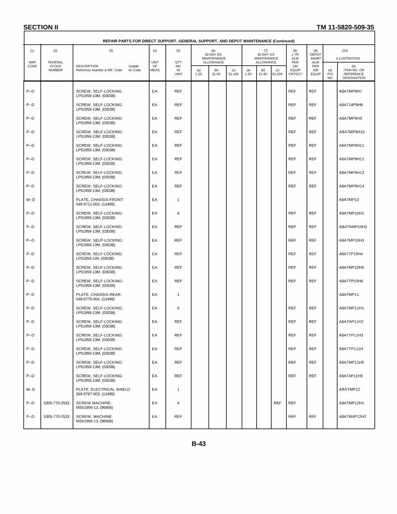
SECTION II TM 11-5820-509-35
REPAIR PARTS FOR DIRECT SUPPORT, GENERAL SUPPORT, AND DEPOT MAINTENANCE (Continued)
(1) (2) (3) (4) (5) (6) (7) (8) (9) (10)30 DAY DS 30 DAY GS 1 YR DEPOT
MAINTENANCE MAINTENANCE ALW MAINT ILLUSTRATIONSMR FEDERAL UNIT QTY ALLOWANCE ALLOWANCE PER ALW
CODE STOCK DESCRIPTION Usable OF INC 100 PER (b)NUMBER Reference Number & Mfr. Code on Code MEAS IN (a) (b) (c) (a) (b) (c) EQUIP 100 (a) ITEM NO. OR
UNIT 1-20 21-50 51-100 1-20 21-50 51-100 CNTGCY EQUIP FIG REFERENCENO. DESIGNATION
P--D SCREW, SELF-LOCKING EA REF REF REF A8A7MP9H7LP51959-13M; (03038)
P--D SCREW, SELF-LOCKING: EA REF REF REF A8A714P9H8LP51959-13M; (03038)
P--D SCREW, SELF-LOCKING: EA REF REF REF A8A7MP9H9LP51959-13M; (03038)
P--D SCREW, SELF-LOCKING: EA REF REF REF ABA7MP9H10LP51959-13M; (03038)
P--D SCREW, SELF-LOCKING: EA REF REF REF A8A7MP9H11LP51959-13M; (03038)
P--D SCREW, SELF-LOCKING: EA REF REF REF A8A7MP9H12LP51959-13M; (03038)
P--D SCREW, SELF-LOCKING: EA REF REF REF A8A7MP9H13LP51959-13M; (03038)
P--D SCREW, SELF-LOCKING: EA REF REF REF A8A7MP9H14LP51959-13M; (03038)
M--D PLATE, CHASSIS-FRONT: EA 1 A8A7MP10549-5711-002; (13499)
P--D SCREW, SELF-LOCKING: EA 6 REF REF A8A7MP10H1LP51959-13M; (03038)
P--D SCREW, SELF-LOCKING: EA REF REF REF ABATM4P10H2LP51959-13M; (03038)
P--D SCREW, SELP-LOCKING: EA REF REF REF A8A7MP10H3LP51959-13M; (03038)
P--D SCREW, SELF-LOCKING: EA REF REF REF A8A77P10H4LP51959-139; (03038)
P--D SCREW, SELF-LOCKING: EA REF REF REF A8A7MP10H5LP51959-13M; (03038)
P--D SCREW, SELF-LOCKING: EA REF REF REF A8A7TP10H6LP51959-13M; (03038)
P--D PLATE, CHASSIS-REAR: EA 1 A8A7MP11549-5775-004, (13499)
P--D SCREW, SELF-LOCKING: EA 6 REF REF A8A7MP11H1LP51959-13M; (03038)
P--D SCREW, SELF-LOCKING: EA REF REF REF A8A7AP11H2LP51959-13M; (03038)
P--D SCREW, SELF-LOCKING: EA REF REF REF A8A7TP11H3LP51959-13M; (03038)
P--D SCREW, SELF-LOCKING: EA REF REF REF A8A7TP111HLP51959-13M; (03038)
P--D SCREW, SELF-LOCKING: EA REF REF REF A8A7MP11H5LP51959-13M; (03038)
P--D SCREW, SELF-LOCKING: EA REF REF REF A8A74P11H6LP51959-13M; (03038)
M--D PLATE, ELECTRICAL SHIELD EA 1 ARATMP12569-5767-003; (13499)
P--D 5305-770-2533 SCREW,MACHINE: EA 4 REF REF A8A7MP12H1MS51959-13; (96906)
P--D 5305-770-2533 SCREW, MACHINE: EA REF REF REF A8A7M4P12H2MS51959-13; (96906)
B-43
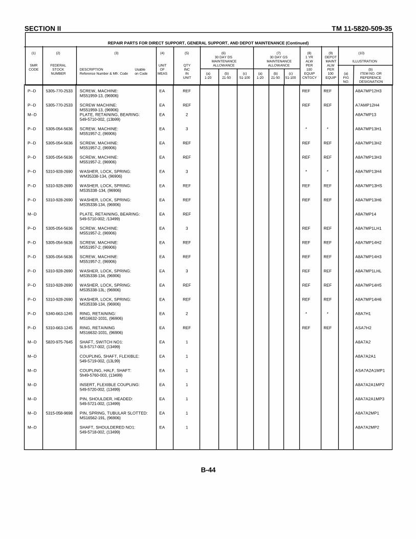
SECTION II TM 11-5820-509-35
REPAIR PARTS FOR DIRECT SUPPORT, GENERAL SUPPORT, AND DEPOT MAINTENANCE (Continued)
(1) (2) (3) (4) (5) (6) (7) (8) (9) (10)30 DAY DS 30 DAY GS 1 YR DEPOT
MAINTENANCE MAINTENANCE ALW MAINT ILLUSTRATIONSMR FEDERAL UNIT QTY ALLOWANCE ALLOWANCE PER ALW
CODE STOCK DESCRIPTION Usable OF INC 100 PER (b)NUMBER Reference Number & Mfr. Code on Code MEAS IN (a) (b) (c) (a) (b) (c) EQUIP 100 (a) ITEM NO. OR
UNIT 1-20 21-50 51-100 1-20 21-50 51-100 CNTGCY EQUIP FIG REFERENCENO. DESIGNATION
P--D 5305-770-2533 SCREW, MACHINE: EA REF REF REF A8A7MP12H3MS51959-13, (96906)
P--D 5305-770-2533 SCREW MACHINE: EA REF REF REF A7AMP12H4MS51959-13, (96906)
M--D PLATE, RETAINING, BEARING: EA 2 A8A7MP13549-5710-002, (13b99)
P--D 5305-054-5636 SCREW, MACHINE: EA 3 * * A8A7MP13H1MS51957-2, (96906)
P--D 5305-054-5636 SCREW, MACHINE: EA REF REF REF A8A7MP13H2MS51957-2, (96906)
P--D 5305-054-5636 SCREW, MACHINE: EA REF REF REF A8A7MP13H3MS51957-2, (96906)
P--D 5310-928-2690 WASHER, LOCK, SPRING: EA 3 * * A8A7MP13H4WM35338-134, (96906)
P--D 5310-928-2690 WASHER, LOCK, SPRING: EA REF REF REF A8A7MP13HSMS35338-134, (96906)
P--D 5310-928-2690 WASHER, LOCK, SPRING: EA REF REF REF A8A7MP13H6MS35338-134, (96906)
M--D PLATE, RETAINING, BEARING: EA REF A8A7MP14549-5710-002; /13499)
P--D 5305-054-5636 SCREW, MACHINE: EA 3 REF REF A8A7MP1LH1MS51957-2, (96906)
P--D 5305-054-5636 SCREW, MACHINE: EA REF REF REF A8A7MP14H2MS51957-2; (96906)
P--D 5305-054-5636 SCREW, MACHINE: EA REF REF REF A8A7MP14H3MS51957-2, (96906)
P--D 5310-928-2690 WASHER, LOCK, SPRING: EA 3 REF REF A8A7MP1LHLMS35338-134, (96906)
P--D 5310-928-2690 WASHER, LOCK, SPRING: EA REF REF REF A8A7MP14H5MS35338-13L; (96906)
P--D 5310-928-2690 WASHER, LOCK, SPRING: EA REF REF REF A8A7MP14H6MS35338-134, (96906)
P--D 5340-663-1245 RING, RETAINING: EA 2 * * A8A7H1MS16632-1031, (96906)
P--D 5310-663-1245 RING, RETAINING EA REF REF REF ASA7H2MS16632-1031, (96906)
M--D 5820-975-7645 SHAFT, SWITCH NO1: EA 1 A8A7A25L9-5717-002, (13499)
M--D COUPLING, SHAFT, FLEXIBLE: EA 1 A8A7A2A1549-5719-002, (13L99)
M--D COUPLING, HALF, SHAFT: EA 1 ASA7A2A1MP15h49-5760-003, (13499)
M--D INSERT, FLEXIBLE COUPLING: EA 1 A8A7A2A1MP2549-5720-002, (13499)
M--D PIN, SHOULDER, HEADED: EA 1 A8A7A2A1MP3549-5721-002, (13499)
M--D 5315-058-9698 PIN, SPRING, TUBULAR SLOTTED: EA 1 A8A7A2MP1MS16562-191, (96906)
M--D SHAFT, SHOULDERED NO1: EA 1 A8A7A2MP2549-5718-002, (13499)
B-44
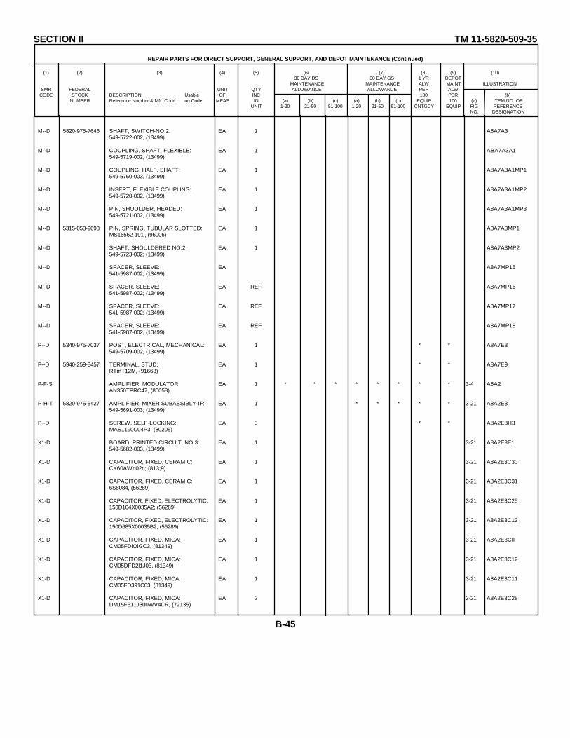
SECTION II TM 11-5820-509-35
REPAIR PARTS FOR DIRECT SUPPORT, GENERAL SUPPORT, AND DEPOT MAINTENANCE (Continued)
(1) (2) (3) (4) (5) (6) (7) (8) (9) (10)30 DAY DS 30 DAY GS 1 YR DEPOT
MAINTENANCE MAINTENANCE ALW MAINT ILLUSTRATIONSMR FEDERAL UNIT QTY ALLOWANCE ALLOWANCE PER ALW
CODE STOCK DESCRIPTION Usable OF INC 100 PER (b)NUMBER Reference Number & Mfr. Code on Code MEAS IN (a) (b) (c) (a) (b) (c) EQUIP 100 (a) ITEM NO. OR
UNIT 1-20 21-50 51-100 1-20 21-50 51-100 CNTGCY EQUIP FIG REFERENCENO. DESIGNATION
M--D 5820-975-7646 SHAFT, SWITCH-NO.2: EA 1 A8A7A3549-5722-002, (13499)
M--D COUPLING, SHAFT, FLEXIBLE: EA 1 ABA7A3A1549-5719-002, (13499)
M--D COUPLING, HALF, SHAFT: EA 1 A8A7A3A1MP1549-5760-003, (13499)
M--D INSERT, FLEXIBLE COUPLING: EA 1 A8A7A3A1MP2549-5720-002, (13499)
M--D PIN, SHOULDER, HEADED: EA 1 A8A7A3A1MP3549-5721-002, (13499)
M--D 5315-058-9698 PIN, SPRING, TUBULAR SLOTTED: EA 1 A8A7A3MP1MS16562-191 , (96906)
M--D SHAFT, SHOULDERED NO.2: EA 1 A8A7A3MP2549-5723-002; (13499)
M--D SPACER, SLEEVE: EA A8A7MP15541-5987-002, (13499)
M--D SPACER, SLEEVE: EA REF A8A7MP16541-5987-002; (13499)
M--D SPACER, SLEEVE: EA REF A8A7MP17541-5987-002; (13499)
M--D SPACER, SLEEVE: EA REF A8A7MP18541-5987-002, (13499)
P--D 5340-975-7037 POST, ELECTRICAL, MECHANICAL: EA 1 * * A8A7E8549-5709-002, (13499)
P--D 5940-259-8457 TERMINAL, STUD: EA 1 * * A8A7E9RTmT12M, (91663)
P-F-S AMPLIFIER, MODULATOR: EA 1 * * * * * * * * 3-4 A8A2AN350TPRC47, (80058)
P-H-T 5820-975-5427 AMPLIFIER, MIXER SUBASSIBLY-IF: EA 1 * * * * * 3-21 A8A2E3549-5691-003; (13499)
P--D SCREW, SELF-LOCKING: EA 3 * * A8A2E3H3MAS1190C04P3; (80205)
X1-D BOARD, PRINTED CIRCUIT, NO.3: EA 1 3-21 A8A2E3E1549-5682-003, (13499)
X1-D CAPACITOR, FIXED, CERAMIC: EA 1 3-21 A8A2E3C30CK60AWn02n; (813;9)
X1-D CAPACITOR, FIXED, CERAMIC: EA 1 3-21 A8A2E3C316S8084, (56289)
X1-D CAPACITOR, FIXED, ELECTROLYTIC: EA 1 3-21 A8A2E3C25150D104X0035A2; (56289)
X1-D CAPACITOR, FIXED, ELECTROLYTIC: EA 1 3-21 A8A2E3C13150D685X00035B2, (56289)
X1-D CAPACITOR, FIXED, MICA: EA 1 3-21 A8A2E3CIlCM05FDlOlGC3, (81349)
X1-D CAPACITOR, FIXED, MICA: EA 1 3-21 A8A2E3C12CM05DFD2l1J03, (81349)
X1-D CAPACITOR, FIXED, MICA: EA 1 3-21 A8A2E3C11CM05FD391C03, (81349)
X1-D CAPACITOR, FIXED, MICA: EA 2 3-21 A8A2E3C28DM15F511J300WV4CR, (72135)
B-45
SECTION II TM 11-5820-509-35
REPAIR PARTS FOR DIRECT SUPPORT, GENERAL SUPPORT, AND DEPOT MAINTENANCE (Continued)
(1) (2) (3) (4) (5) (6) (7) (8) (9) (10)30 DAY DS 30 DAY GS 1 YR DEPOT
MAINTENANCE MAINTENANCE ALW MAINT ILLUSTRATIONSMR FEDERAL UNIT QTY ALLOWANCE ALLOWANCE PER ALW
CODE STOCK DESCRIPTION Usable OF INC 100 PER (b)NUMBER Reference Number & Mfr. Code on Code MEAS IN (a) (b) (c) (a) (b) (c) EQUIP 100 (a) ITEM NO. OR
UNIT 1-20 21-50 51-100 1-20 21-50 51-100 CNTGCY EQUIP FIG REFERENCENO. DESIGNATION
X1-D CAPACITOR, FIXED, MICA: EA REF 3-21 A8A2E3C29DM15F511J300WV4CR; (72136)
X1-D CAPACITOR, VARIABLE, CERAMIC: EA 1 3-21 A8A2E3C15557-099-8-50E; (72982)
X1-D COIL, RADIO FREQUENCY: EA 1 3-21 A8A2E3L8LTlOK043; (81349)
X1-D RESISTOR, FIXED, COOMPOSITION: EA 2 3-21 A8A2E3R36RCR07G561KS; (81349)
X1-D RESISTOR, FIXED, COMPOSITION: EA REF 3-21 A8A2E3R37RCR07G561KS; (81349)
X1-D RESISTOR, FIXED, COMPOSITION: EA 2 3-21 A8A2E3R20RCR07C222KS; (81349)
X1-D RESISTOR, FIXED, COMPOSITION: EA REF 3-21 A8A2E3R21RCR07G222KS; (81349)
X1-D RESISTOR, FIXED, COMPOSITION: EA 1 3-21 A8A2E3R38RCRD7G562KS; (81349)
X1-D RESISTOR, FIXED, COMPOSITION: EA 1 3-21 A8A2E3R24RCR07GC103KS; (81349)
X1-D RESISTOR, FIXED, COMPOSITION: EA 1 3-21 A8A2E3R22RCR07G183KS; (81349)
X1-D SEMICONDUCTOR DEVICE, DIODE: EA 2 3-21 A8A2E3CR71N198; (07688)
X1-D SEMICONDUCTOR DEVICE, DIODE: EA REF 3-21 A8A2E3CR81N198; (07688)
X1-D TRANSISTOR: EA 1 3-21 A8A2E3Q22N274, (07688)
P-H-T 5880-975-5428 AMPLIFIER SURASSEMBLY IF BOARD: EA 1 * * * * * 3-21 A8A2E4549-5692-004; (13499)
P--D SCREW, SELF-LOCKING: EA 3 * * AA2E4H3NASllo90C4P3; (80205)
X1-D BOARD, PRINTED CIRCUIT-NO.4: EA 1 3-21 A8A2E4E1549-5684-003; (13499)
X1-D CAPACITOR, FIXED, ELECTROLYTIC: EA 1 3-21 A8A2E4C18150D156X0020B2; (56289)
X1-D CAPACITOR, FIXED, ELECTROLYTIC: EA 2 3-21 A8A2E4C19150D104X0035A2; (56289)
X1-D CAPACITOR, FIXED, ELECTROLYTIC: EA REF 3-21 A8A2E4C20150D0lXO035A2; (56289)
X1-D CAPACITOR, FIXED, ELECTROLYTIC: EA 1 3-21 A8A2E4C23150D0105X935A2; (56289)
X1-D CAPACITOR, FIXED, MICA: EA 1 3-21 A8A2E4C16CMD5FD910G03; (81349)
X1-D CAPACITOR, FIXED, MICA: EA 1 3-21 A8A2E4C22CMD05FD221J03; (81349)
X1-D CAPACITOR, FIXED, MICA: EA 1 3-21 A8A2E4C21DM15F511J300WV4CR; (72136)
X1-D CAPACITOR, VARIABLE, CERAMIC: EA 1 3-21 A8A2E4C17557-099-8-50E; (72982)
X1-D COIL, RADIO FREQUENCY: EA 1 3-21 A8A2E4L5LT10K043; (81349)
B-46
SECTION II TM 11-5820-509-35
REPAIR PARTS FOR DIRECT SUPPORT, GENERAL SUPPORT, AND DEPOT MAINTENANCE (Continued)
(1) (2) (3) (4) (5) (6) (7) (8) (9) (10)30 DAY DS 30 DAY GS 1 YR DEPOT
MAINTENANCE MAINTENANCE ALW MAINT ILLUSTRATIONSMR FEDERAL UNIT QTY ALLOWANCE ALLOWANCE PER ALW
CODE STOCK DESCRIPTION Usable OF INC 100 PER (b)NUMBER Reference Number & Mfr. Code on Code MEAS IN (a) (b) (c) (a) (b) (c) EQUIP 100 (a) ITEM NO. OR
UNIT 1-20 21-50 51-100 1-20 21-50 51-100 CNTGCY EQUIP FIG REFERENCENO. DESIGNATION
X1-D RESISTOR, FIXED, CCMPOSITION: EA 1 321 ASA2E4R23RCR07G102KS, (81349)
X1-D RESISTOR, FIXED, COMPOSITION: EA 2 3-21 A8A2E4R26RCR07C222KS, (81349)
X1-D RESISTOR, FIXED, COMPOSITION: EA REF 3-21 A8A2E4R30RCR07G222KS, (8134 9)
X1-D RESISTOR, FIXED, COMPOSITION: EA 1 3-21 A8A2E4R25RCR07G272KS; (81349)
X1-D RESISTOR, FIXED, COMPOSITION: EA 1 3-21 A8A2E4R29RCRo7G562KS; (81349)
X1-D RESISTOR, FIXED, COMPOSITION: EA 2 3-21 A8A2E4R31RCR07GlC0S; (81349)
X1-D RESISTOR, FIXED, COMPOSITION: EA REF 3-21 A8A2E4R39RCR07CG103KS; (81349)
X1-D RESISTOR, FIXED, COMPOSITION: EA 1 3-21 A8A2E4R32RCRo7TG273KS; (81349)
X1-D RESISTOR, FIXED, COMPOSITION: EA 1 3-21 A8A2E4R28RCR07C683KS; (81349)
X1-D TRANSISTOR: EA 2 3-21 A8A2E4Q32N274; (07688)
X1-D TRANSISTOR: EA REF 3-21 A8A2E4Q421274; (07688)
P-H-T 5820-975-429 AMPLIFIER SUBASSEMBLY, IF BOARD: EA 1 * * * * * 3-21 A8A2E5549-5693-004; (13499)
P--D SCREW, SELF-LOCKING: EA 2 REF REF 3-21 A8A2E5H2NAS119CO4P3; (80205 )
X1-D BOARD, PRINTED CIRCUIT-NO.5: EA 1 A8A2E5E1519-5686-003; (13499)
X1-D CAPACITOR, FIXED, CERAMIC: EA 1 3-21 A8A2E5C26658084; (56289)
X1-D CAPACITOR, FIXED, MICA: EA 2 3-21 A8A2E5C27CM05FD21J03; (81349)
X1-D CAPACITOR, FIXED, MICA: EA REF 321 A8A2E5C32CM05FD221J03; (81349)
X1-D CAPACITOR, FIXED, MICA: EA 1 3-21 A8A2E5C24CM05FD391GC3; (81349)
X1-D COIL, RADIO FREQUENCY: EA 2 3-21 A8A2E5L6X419-1; (81815)
X1-D COIL, RADIO FREQUENCY: EA REF 3-21 A8A2E5L7X419-1; (81815)
X1-D RELAY, ARMATURE: EA 1 321 A8A2E5K13100L037-1001; (80294)
X1-D RESISTOR, FIXED, COMPSITION: EA 1 3-21 A8A2E5R40RCR07CG390KS; (81349)
X1-D RESISTOR, FIXED, COMPOSITION: EA 1 3-21 A8A2E5R33RCR07G152KS; (81349)
X1-D RESISTOR, FIXED, COMPOSITION: EA 1 3-21 A8A2E5R34RCR07C273KS; (81349)
X1-D RESISTOR, FIXED, COMPOSITION: EA 1 3-21 A8A2E5R35RCR07G683KS; (81349)
B-47

SECTION II TM 11-5820-509-35
REPAIR PARTS FOR DIRECT SUPPORT, GENERAL SUPPORT, AND DEPOT MAINTENANCE (Continued)
(1) (2) (3) (4) (5) (6) (7) (8) (9) (10)30 DAY DS 30 DAY GS 1 YR DEPOT
MAINTENANCE MAINTENANCE ALW MAINT ILLUSTRATIONSMR FEDERAL UNIT QTY ALLOWANCE ALLOWANCE PER ALW
CODE STOCK DESCRIPTION Usable OF INC 100 PER (b)NUMBER Reference Number & Mfr. Code on Code MEAS IN (a) (b) (c) (a) (b) (c) EQUIP 100 (a) ITEM NO. OR
UNIT 1-20 21-50 51-100 1-20 21-50 51-100 CNTGCY EQUIP FIG REFERENCENO. DESIGNATION
X1-D TRANSISTOR: EA 1 3-21 A8A2E5Q52N274; (07688)
X1-D TRANSFORMER, INTERMEDIATE FREQUENCY: EA 1 3-21 A8A2E5Q3X418-1; (31815)
P--D CAPACITOR, FIXED, CERAMIC: EA 1 REF REF 3-21 A6A2C33CK13BX103; (81349)
P--D 5910-663-7276 CAPACITOR, FIXED, ELECTROLYTIC: EA 1 * * 3-20 A8A2C37150DL7LX0035A2; (56289)
P--D 5999-165-3692 CHASSIS, ELECTRICAL EQUIPMENT: EA 1 * * 3-20 A8A2A1549-6404-004; (13499)
Xi-D JACK, TIP: EA 1 3-21 A8A2A1J172-153BRN; (12615)
X1-D JACK, TIP: EA 1 3-20 A8A2A1J272-153RED; (12615)
X1-D JACK, TIP: EA 1 3-21 A8A2A1J372-153ORN; (12615)
X1-D JACK, TIP: EA 1 3-21 A8A2A1J472-153YEL; (12615)
P--D 5950-070-7642 COIL, RADIO FREQUENCY: EA 1 REF REF 3-21 A8A2L1I0LTl0K053; (813L9)
P--D 5950-070-7644 COIL, RADIO FREQUENCY: EA 1 * * 3-21 A8A2L9LTl0K060; (81349)
P--D 5935-810-6598 CONNECTOR, RECEPTACLE: EA 1 REF REF 3-21 A8A2P1DAM7W2P; (71468)
P--D 5310-622-1724 NUT, SELF-LOCKING: EA 2 PEF REF A8A2P3H168-1660-26; (72962)
P--D 5310-622-1724 NUT, SELF-LOCKING: EA REF REF REF A8A2P3H268-1660-26; (72962)
P--D SCREW, MACHINE: EA 2 * * A8A2P3H3MS51959-3, (96906)
P--D SCREW, MACHINE: EA REF REF REF A8A2P3H4MS51959-3; (96906)
P--D 5310-167-0797 WASHER, FLAT: EA 2 * * A8A2P3H5310-0044-000; (79807)
P--D 5310-167-0797 WASHER, FLAT: EA REF REF REF A8A2P3H6310-0444-000; (79807)
P--D 5935-811-1382 CONNECTOR, RECEPTACLE: EA 1 * * 3-21 A8A2P4DBM13W3P; (71468)
P--D 5310-622-1724 NUT, SELF-LOCKING: EA 2 REF REF A8A2P4H168-1660-26; (72962)
P--D 5310-622-1724 NUT, SELF-LOCKING: EA REF REF REF A8A2P4H268-1660-26; (72962)
P--D 5305-764-2964 SCREW, MACHINE: EA 2 * * A8A2P4H3KS51959-4; (96906)
P--D 5305-764-2964 SCREW, MACHINE: EA REF REF REF A8A2P4H4MS51959-4; (96906)
P--D 5310-167-0797 WASHER, FLAT: EA 2 REF REF A8A2P4H5310-0044-000; (79807)
P--D 5310-167-0797 WASHER, FLAT: EA REF REF REF A8A2P4H6310-0044-000; (79807)
B-48
SECTION II TM 11-5820-509-35
REPAIR PARTS FOR DIRECT SUPPORT, GENERAL SUPPORT, AND DEPOT MAINTENANCE (Continued)
(1) (2) (3) (4) (5) (6) (7) (8) (9) (10)30 DAY DS 30 DAY GS 1 YR DEPOT
MAINTENANCE MAINTENANCE ALW MAINT ILLUSTRATIONSMR FEDERAL UNIT QTY ALLOWANCE ALLOWANCE PER ALW
CODE STOCK DESCRIPTION Usable OF INC 100 PER (b)NUMBER Reference Number & Mfr. Code on Code MEAS IN (a) (b) (c) (a) (b) (c) EQUIP 100 (a) ITEM NO. OR
UNIT 1-20 21-50 51-100 1-20 21-50 51-100 CNTGCY EQUIP FIG REFERENCENO. DESIGNATION
P--D 5935-885-6505 CONTACT, ELECTRICAL: EA 3 REF REF A8A2P3A1DM53740-5000; (71468)
P--D 5935-885-6505 CONTACT, ELECTRICAL: EA REF REF REF A8A2P4A1DM53740-5000; (71468)
P--D 5935-885-6505 CONTACT, ELECTRICAL: EA REF REF REF A8A2P4A2DM53740-5000; (71468)
P--D 5935-885-6508 CONTACT, ELECTRICAL: EA 1 * * A8A2P4A3DM53741-5002; (71468)
P-H-T 5820-088-2515 CONTROL, AMPLIFIER, BOARD NO.2: EA 1 * * * * * 3-20 A8A2E2549-5678-003, (13499)
P--D SCREW, SELF-LOCKING: EA 2 REF REF 3-20 A8A2E2H2NAS190C04P3; (80205)
X1-D BOARD, PRIITED CIRCUIT-NO.2: EA 1 3-20 A8A2E2E1549-5680-003; (13499)
X1-D CAPACITOR, FIXED, CERAMIC: EA 1 3-20 A8A2E2C10SSM-1-77; (86335)
X1-D CAPACITOR, FIXED, ELECTROLYTIC: EA 1 3-20 A8A2E2C329F461; (06001)
X1-D CAPACITOR, FIXED, ELECTROLYTIC: EA 1 3-20 A8A2E2C5CL23BE400UNE; (81349)
X1-D COIL, RADIO FREQUENCY: EA 1 3-20 A8A2E2L4X419-1; (81815)
X1-D RESISTOR, FIXED, COMPOSITION: EA 1 3-20 A8A2E2R13RCR07G470KS; (81349)
X1-D RESISTOR, AIXED, COMPOSITION: EA 1 3-20 A8A2E2R17RCR07G152KS; (81349)
X1-D RESISTOR, FIXED, COMPOSITION: EA 1 3-20 A8A2E2R14*RCR07G182KS; (81349)
X1-D RESISTOR, FIXED, COMPOSITION: EA 2 3-20 A8A2E2R14*RCR07G222KS; (81349)
X1-D RESISTOR, FIXED, COMPOSITION: EA REF 3-20 A8A2E2R15RCR07G222KS; (81349)
XI-D RESISTOR, FIXED, COMPOSITION: EA 1 3-20 A8A2E2R14*RCR07G272KS; (81349)
X1-D RESISTOR, FIXED, COMPOSITION: EA 1 3-20 A8A2E2R11*RCR07G332KS; (81349)
X1-D RESISTOR, FIXED, COMPOSITION: EA 1 3-20 A8A2E2R14*RCR07G392KS; (81349)
X1-D RESISTOR, FIXED, COMPOSITION: EA 1 3-20 A8A2E2R14*RCR07GC72KS; (81349)
X1-D RESISTOR, FIXED, COMPOSITION: EA 1 3-20 A8A2E2R14*RCR07G562KS; (81349)
X1-D RESISTOR, FIXED, COMPOSITION: EA 1 3-20 A8A2E2R14*RCR07G682KS; (81349)
X1-D RESISTOR, FIXED, COMPOSITION: EA 1 3-20 A8A2E2R14*RCR07G822KS; (81349)
X1-D RESISTOR, FIXED, COMPOSITION: EA 1 3-20 A8A2E2R14*RCR07G103KS; (81349)
X1-D RESISTOR, FIXED, COMPOSITION EA 1 3-20 A8A2E2R16RCR07GC153KS; (81349)*SELECT RER OPERATIONAL REQUIREMENT.
B-49
SECTION II TM 11-5820-509-35
REPAIR PARTS FOR DIRECT SUPPORT, GENERAL SUPPORT, AND DEPOT MAINTNENANCE (Continued)
(1) (2) (3) (4) (5) (6) (7) (8) (9) (10)30 DAY DS 30 DAY GS 1 YR DEPOT
MAINTENANCE MAINTENANCE ALW MAINT ILLUSTRATIONSMR FEDERAL UNIT QTY ALLOWANCE ALLOWANCE PER ALW
CODE STOCK DESCRIPTION Usable OF INC 100 PER (b)NUMBER Reference Number & Mfr. Code on Code MEAS IN (a) (b) (c) (a) (b) (c) EQUIP 100 (a) ITEM NO. OR
UNIT 1-20 21-50 51-100 1-20 21-50 51-100 CNTGCY EQUIP FIG REFERENCENO. DESIGNATION
X1-D RESISTOR, FIXED, COMPOSITION: EA 1 3-20 A8A2E2R19RCR07GL73KS; (813L9)
X1-D RESISTOR, FIXED, COMPOSITION: EA 1 3-20 A8A2E2R18RCR20G473KS; (81349)
X1-D RESISTOR, THERMAL: EA 1 3-20 A8A2E2R17763H10; (10646)
X1-D TRANSFORMER, INTERMEDIATE FREQUEDCY: EA 1 3-20 A8A2E2T2X377-1; (81815)
X1-D TRANSISTOR: EA 1 3-20 A8A2E2Ql2N440; (07688)
M--D COVER, CHASSIS-FRODT: EA 1 A8A2MP1549-6412-003; (13499)
P--D SCREW, SELF-LOCKING: EA 4 REF REF A8A2MP1H1LP51959-13M; (03038)
P--D SCREW, SELF-LOCKING: EA REF REF REF A8A2MP1H2LP51959-13M; (03038)
P--D SCREW, SELF-LOCKING: EA REF REF REF A8A2MP1H3LP51959-13M; (03038)
P--D SCREW, SELF-LOCKING: EA REF REF REF A8A2MP1H4LP51959-13M, (03038)
M--D COVER, CHASSIS-REAR: EA 1 A8A2MP2549-6411-003, (13499)
P--D SCREW, SELF-LOCKING: EA 4 REF REF A8A2MP2H1LP51959-13M, (03038)
P--D SCREW, SELF-LOCKING: EA REF REF REF A8A2MP2H2LP51959-13M; (03038)
P--D SCREW, SELF-LOCKING: EA REF REF REF A8A2MP2H3LP51959-13M; (03038)
P--D SCREW, SELF-LOCKING: EA REF REF REF A8A2MP2H4LP51959-13M; (03038)
P--D 5915-846-0453 FILTER, MECHANICAL: EA 1 * * 3-21 A8A2FL1526-9376-000; (13499)
P--D 5325-286-6047 GROMMET, RUBBER: EA 1 * * A8A2H1MS35L89-1; (96906)
P-H-T 5820-975-5L26 MODULATOR, RADIO TRANSMITTER: EA 1 * * * * * 3-20 A8A2E1549-5688-004; (13499)
P--D SCREW, SELF-LOCKING: EA REF REF REF A8A2ELHLNAS1190C04P3; (80205)
X1-D BOARD, PRINTED CIRCUIT, NO 1: EA 1 A8A2E1E1549-5690-004; (13499)
X1-D CAPACITOR, FIXED, CERAMIC: EA 2 3-20 A8A2E1C16S8082; (56289)
X1-D CAPACITOR, FIXED, CERAMIC: EA REF 3-20 A8A2E1C346S8082; (56289)
X1-D CAPACITOR, FIXED, ELECTROLYTIC: EA 1 3-20 A8JA2E10629F461; (06001)
X1-D CAPACITOR, FIXED, ELECTROLYTIC: EA 1 3-20 A8A2E1C4CL21BQ040SPE; (81349)
X1-D CAPACITOR, FIXED, MICA: EA 1 3-20 A6A2E1C36*DM15C150J500VDC; (72136)
* SELECT PER OPERATIONAL REQUIREMENT.
B-50
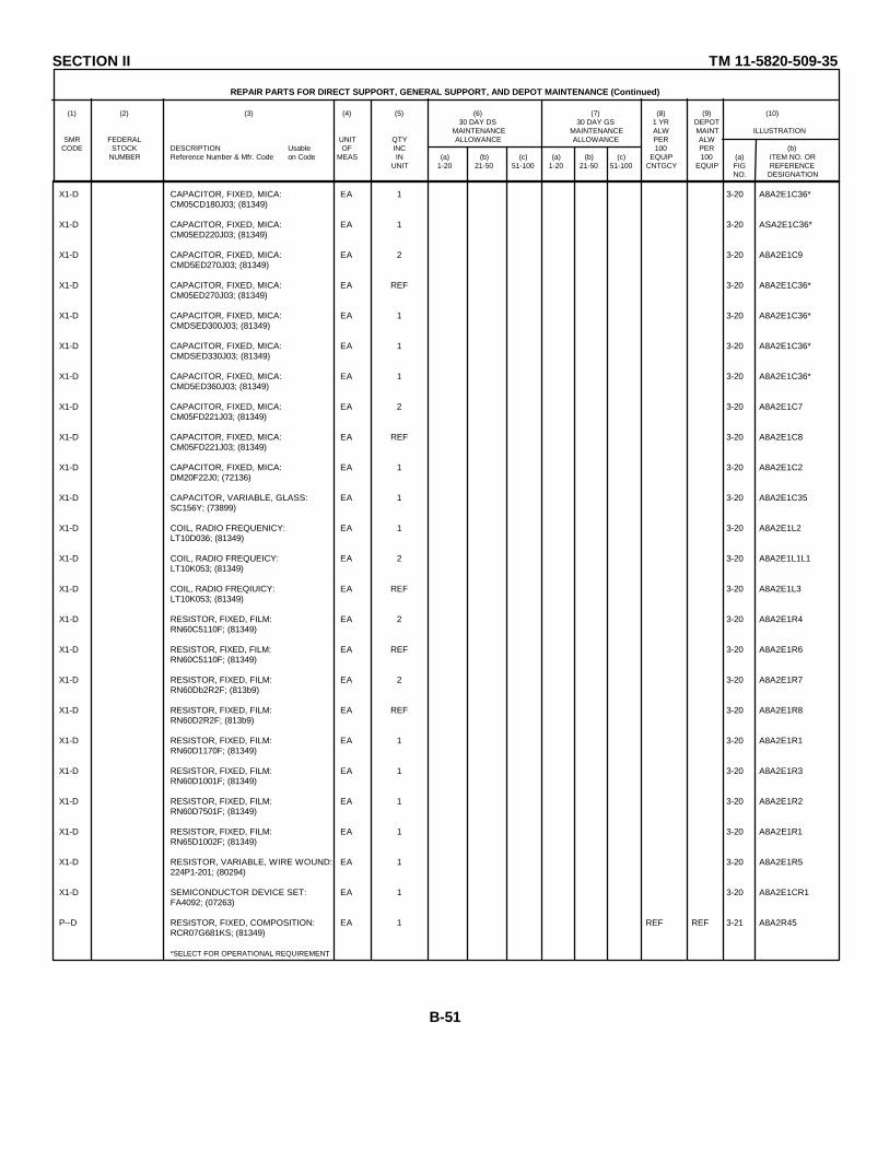
SECTION II TM 11-5820-509-35
REPAIR PARTS FOR DIRECT SUPPORT, GENERAL SUPPORT, AND DEPOT MAINTENANCE (Continued)
(1) (2) (3) (4) (5) (6) (7) (8) (9) (10)30 DAY DS 30 DAY GS 1 YR DEPOT
MAINTENANCE MAINTENANCE ALW MAINT ILLUSTRATIONSMR FEDERAL UNIT QTY ALLOWANCE ALLOWANCE PER ALW
CODE STOCK DESCRIPTION Usable OF INC 100 PER (b)NUMBER Reference Number & Mfr. Code on Code MEAS IN (a) (b) (c) (a) (b) (c) EQUIP 100 (a) ITEM NO. OR
UNIT 1-20 21-50 51-100 1-20 21-50 51-100 CNTGCY EQUIP FIG REFERENCENO. DESIGNATION
X1-D CAPACITOR, FIXED, MICA: EA 1 3-20 A8A2E1C36*CM05CD180J03; (81349)
X1-D CAPACITOR, FIXED, MICA: EA 1 3-20 ASA2E1C36*CM05ED220J03; (81349)
X1-D CAPACITOR, FIXED, MICA: EA 2 3-20 A8A2E1C9CMD5ED270J03; (81349)
X1-D CAPACITOR, FIXED, MICA: EA REF 3-20 A8A2E1C36*CM05ED270J03; (81349)
X1-D CAPACITOR, FIXED, MICA: EA 1 3-20 A8A2E1C36*CMDSED300J03; (81349)
X1-D CAPACITOR, FIXED, MICA: EA 1 3-20 A8A2E1C36*CMDSED330J03; (81349)
X1-D CAPACITOR, FIXED, MICA: EA 1 3-20 A8A2E1C36*CMD5ED360J03; (81349)
X1-D CAPACITOR, FIXED, MICA: EA 2 3-20 A8A2E1C7CM05FD221J03; (81349)
X1-D CAPACITOR, FIXED, MICA: EA REF 3-20 A8A2E1C8CM05FD221J03; (81349)
X1-D CAPACITOR, FIXED, MICA: EA 1 3-20 A8A2E1C2DM20F22J0; (72136)
X1-D CAPACITOR, VARIABLE, GLASS: EA 1 3-20 A8A2E1C35SC156Y; (73899)
X1-D COIL, RADIO FREQUENICY: EA 1 3-20 A8A2E1L2LT10D036; (81349)
X1-D COIL, RADIO FREQUEICY: EA 2 3-20 A8A2E1L1L1LT10K053; (81349)
X1-D COIL, RADIO FREQIUICY: EA REF 3-20 A8A2E1L3LT10K053; (81349)
X1-D RESISTOR, FIXED, FILM: EA 2 3-20 A8A2E1R4RN60C5110F; (81349)
X1-D RESISTOR, FIXED, FILM: EA REF 3-20 A8A2E1R6RN60C5110F; (81349)
X1-D RESISTOR, FIXED, FILM: EA 2 3-20 A8A2E1R7RN60Db2R2F; (813b9)
X1-D RESISTOR, FIXED, FILM: EA REF 3-20 A8A2E1R8RN60D2R2F; (813b9)
X1-D RESISTOR, FIXED, FILM: EA 1 3-20 A8A2E1R1RN60D1170F; (81349)
X1-D RESISTOR, FIXED, FILM: EA 1 3-20 A8A2E1R3RN60D1001F; (81349)
X1-D RESISTOR, FIXED, FILM: EA 1 3-20 A8A2E1R2RN60D7501F; (81349)
X1-D RESISTOR, FIXED, FILM: EA 1 3-20 A8A2E1R1RN65D1002F; (81349)
X1-D RESISTOR, VARIABLE, WIRE WOUND: EA 1 3-20 A8A2E1R5224P1-201; (80294)
X1-D SEMICONDUCTOR DEVICE SET: EA 1 3-20 A8A2E1CR1FA4092; (07263)
P--D RESISTOR, FIXED, COMPOSITION: EA 1 REF REF 3-21 A8A2R45RCR07G681KS; (81349)
*SELECT FOR OPERATIONAL REQUIREMENT.
B-51
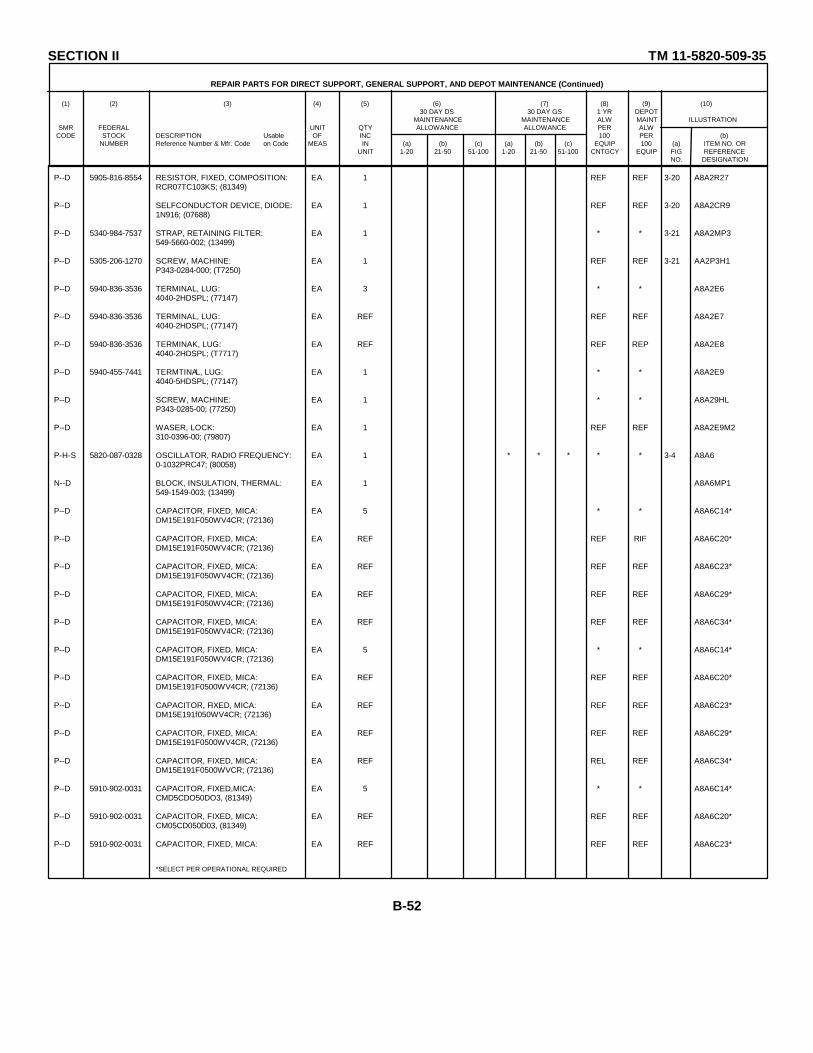
SECTION II TM 11-5820-509-35
REPAIR PARTS FOR DIRECT SUPPORT, GENERAL SUPPORT, AND DEPOT MAINTENANCE (Continued)
(1) (2) (3) (4) (5) (6) (7) (8) (9) (10)30 DAY DS 30 DAY GS 1 YR DEPOT
MAINTENANCE MAINTENANCE ALW MAINT ILLUSTRATIONSMR FEDERAL UNIT QTY ALLOWANCE ALLOWANCE PER ALW
CODE STOCK DESCRIPTION Usable OF INC 100 PER (b)NUMBER Reference Number & Mfr. Code on Code MEAS IN (a) (b) (c) (a) (b) (c) EQUIP 100 (a) ITEM NO. OR
UNIT 1-20 21-50 51-100 1-20 21-50 51-100 CNTGCY EQUIP FIG REFERENCENO. DESIGNATION
P--D 5905-816-8554 RESISTOR, FIXED, COMPOSITION: EA 1 REF REF 3-20 A8A2R27RCR07TC103KS; (81349)
P--D SELFCONDUCTOR DEVICE, DIODE: EA 1 REF REF 3-20 A8A2CR91N916; (07688)
P--D 5340-984-7537 STRAP, RETAINING FILTER: EA 1 * * 3-21 A8A2MP3549-5660-002; (13499)
P--D 5305-206-1270 SCREW, MACHINE: EA 1 REF REF 3-21 AA2P3H1P343-0284-000; (T7250)
P--D 5940-836-3536 TERMINAL, LUG: EA 3 * * A8A2E64040-2HDSPL; (77147)
P--D 5940-836-3536 TERMINAL, LUG: EA REF REF REF A8A2E74040-2HDSPL; (77147)
P--D 5940-836-3536 TERMINAK, LUG: EA REF REF REP A8A2E84040-2HDSPL; (T7717)
P--D 5940-455-7441 TERMTINAL, LUG: EA 1 * * A8A2E94040-5HDSPL; (77147)
P--D SCREW, MACHINE: EA 1 * * A8A29HLP343-0285-00; (77250)
P--D WASER, LOCK: EA 1 REF REF A8A2E9M2310-0396-00; (79807)
P-H-S 5820-087-0328 OSCILLATOR, RADIO FREQUENCY: EA 1 * * * * * 3-4 A8A60-1032PRC47; (80058)
N--D BLOCK, INSULATION, THERMAL: EA 1 A8A6MP1549-1549-003; (13499)
P--D CAPACITOR, FIXED, MICA: EA 5 * * A8A6C14*DM15E191F050WV4CR; (72136)
P--D CAPACITOR, FIXED, MICA: EA REF REF RIF A8A6C20*DM15E191F050WV4CR; (72136)
P--D CAPACITOR, FIXED, MICA: EA REF REF REF A8A6C23*DM15E191F050WV4CR; (72136)
P--D CAPACITOR, FIXED, MICA: EA REF REF REF A8A6C29*DM15E191F050WV4CR; (72136)
P--D CAPACITOR, FIXED, MICA: EA REF REF REF A8A6C34*DM15E191F050WV4CR; (72136)
P--D CAPACITOR, FIXED, MICA: EA 5 * * A8A6C14*DM15E191F050WV4CR; (72136)
P--D CAPACITOR, FIXED, MICA: EA REF REF REF A8A6C20*DM15E191F0500WV4CR; (72136)
P--D CAPACITOR, FIXED, MICA: EA REF REF REF A8A6C23*DM15E191f050WV4CR; (72136)
P--D CAPACITOR, FIXED, MICA: EA REF REF REF A8A6C29*DM15E191F0500WV4CR, (72136)
P--D CAPACITOR, FIXED, MICA: EA REF REL REF A8A6C34*DM15E191F0500WVCR; (72136)
P--D 5910-902-0031 CAPACITOR, FIXED,MICA: EA 5 * * A8A6C14*CMD5CDO50DO3, (81349)
P--D 5910-902-0031 CAPACITOR, FIXED, MICA: EA REF REF REF A8A6C20*CM05CD050D03, (81349)
P--D 5910-902-0031 CAPACITOR, FIXED, MICA: EA REF REF REF A8A6C23*
*SELECT PER OPERATIONAL REQUIRED.
B-52

SECTION II TM 11-5820-509-35
REPAIR PARTS FOR DIRECT SUPPORT, GENERAL SUPPORT, AND DEPOT MAINTENANCE (Continued)
(1) (2) (3) (4) (5) (6) (7) (8) (9) (10)30 DAY DS 30 DAY GS 1 YR DEPOT
MAINTENANCE MAINTENANCE ALW MAINT ILLUSTRATIONSMR FEDERAL UNIT QTY ALLOWANCE ALLOWANCE PER ALW
CODE STOCK DESCRIPTION Usable OF INC 100 PER (b)NUMBER Reference Number & Mfr. Code on Code MEAS IN (a) (b) (c) (a) (b) (c) EQUIP 100 (a) ITEM NO. OR
UNIT 1-20 21-50 51-100 1-20 21-50 51-100 CNTGCY EQUIP FIG REFERENCENO. DESIGNATION
P--D 5910-902-0031 CAPACITOR, FIXED, MICA: EA REF REF REF A8A6C29*CM05CD050D03; (81349)
P--D 5910-902-0031 CAPACITOR, FIXED, MICA: EA REF REF REF A8A6C34*CM05CD050D03; (81349)
P--D 5910-902-0335 CAPACITOR, FIXED, MICA: EA 5 * * A8A6C14*CM05CD050D03; (81349)
P--D 5910-902-0335 CAPACITOR, FIXED, MICA: EA REF REF REF A8A6C20*CM05CD050D03; (81349)
P--D 5910-902-0335 CAPACITOR, FIXED, MICA: EA REF REF REF A8A6C23*CM05CD050D03; (81349)
P--D 5910-902-0335 CAPACITOR, FIXED, MICA: EA REF REF REF A8A6C29*CM05CD050D03; (81349)
P--D 5910-902-0335 CAPACITOR, FIXED, MICA: EA REF REF REF A8A6C34*CM05CD050D03; (81349)
P--D 5910-936-7372 CAPACITOR, FIXED, MICA: EA 5 * * A8A6C14*CM05CD120J03; (81349)
P--D 5910-936-7372 CAPACITOR, FIXED, MICA: EA REF REF REF A8A6C20*CM05CD120J03; (81349)
P--D 5910-936-7372 CAPACITOR, FIXED, MICA: EA REF REF REF A8A6C23*CM05CD120J03; (81349)
P--D 5910-936-7372 CAPACITOR, FIXED, MICA: EA RKF REF REF A8A6C29*CM05CD120J03; (81349)
P--D 5910-936-7372 CAPACITOR, FIXED, MICA: EA REF REF REF AA6C34*CM05CD120J03; (81349)
P--D CAPACITOR, FIXED, MICA: EA 5 * * A8A6C19*DM15C150J500VDC; (72136)
P--D CAPACITOR, FIXED, MICA: EA REF REF RKF A8A6C20*DM15C150J500VDC; (72136)
P--D CAPACITOR, FIXED, MICA: EA REF REF REF A8A6C23*DM15C150J500VDC; (72136)
P--D CAPACITOR, FIXED, MICA: EA REF REF REF A8A6CR29*DM15C150J500VDC; (72136)
P--D CAPACITOR, FIXED, MICA: EA RKF REF REF A8A6C34*DM15C150J500VDC; (72136)
P--D 5910-832-8080 CAPACITOR, FIXED, MICA: EA 5 * * A8A6C14*CM05ED200J03; (81349)
P--D 5910-832-8080 CAPACITOR, FIXED, MICA: EA REF REF REF A8A6C20*CM05ED200J03; (81349)
P--D 5910-832-8080 CAPACITOR, FIXED, MICA: EA REF REF REF AA6C23*CM05ED200J03; (81349)
P--D 5910-832-8080 CAPACITOR, FIXED, MICA: EA REF REF REF A8A6C29*CM05ED200J03; (81349)
P--D 5910-832-8080 CAPACITOR, FIXED, MICA: EA REF REF REF A8A6C34*CM05ED200J03; (81349)
P--D 5910-954-5496 CAPACITOR, FIXED, MICA: EA 5 * * A8A6Cl4*CM05ED200J03; (81349)
P--D 5910-954-5496 CAPACITOR, FIXED, MICA: EA REF REF REF A8A6C20*CM05ED200J03; (81349)
P--D 5910-954-5496 CAPACITOR, FIXED, MICA: EA REF REF REF A8A6C23*CM05ED200J03; (81349)
*SELECT PER OPERATIONAL REQUIREMENT.
B-53
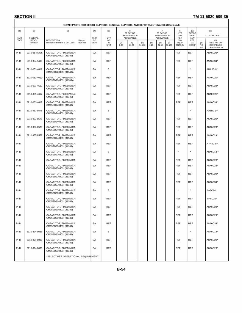
SECTION II TM 11-5820-509-35
REPAIR PARTS FOR DIRECT SUPPORT, GENERAL SUPPORT, AND DEPOT MAINTENANCE (Continued)
(1) (2) (3) (4) (5) (6) (7) (8) (9) (10)30 DAY DS 30 DAY GS 1 YR DEPOT
MAINTENANCE MAINTENANCE ALW MAINT ILLUSTRATIONSMR FEDERAL UNIT QTY ALLOWANCE ALLOWANCE PER ALW
CODE STOCK DESCRIPTION Usable OF INC 100 PER (b)NUMBER Reference Number & Mfr. Code on Code MEAS IN (a) (b) (c) (a) (b) (c) EQUIP 100 (a) ITEM NO. OR
UNIT 1-20 21-50 51-100 1-20 21-50 51-100 CNTGCY EQUIP FIG REFERENCENO. DESIGNATION
P--D 5910-954-5496 CAPACITOR, FIXED MICA: EA REF REF REF A8A6C29*CM05ED220J03; (81349)
P--D 5910-954-5496 CAPACITOR, FIXED MICA: EA REF REF REF A9A6C34*CM05ED220J03; (81349)
P--D 5910-051-4612 CAPACITOR, FIXED MICA: EA 5 * * ABA6C14*CM05ED220J03; (81349))
P--D 5910-051-4612- CAPACITOR, FIXED MICA: EA REF REF REF A8A6C20*CM05ED220J03; (81349))
P--D 5910-051-4612 CAPACITOR, FIXED MICA: EA REF REF REF A8A6C23*CM05ED220J03; (81349)
P--D 5910-051-4612 CAPACITOR, FIXED MICA: EA REF REF REF A8AEC29*CM05ED220J03; (81349)
P--D 5910-051-4612 CAPACITOR, FIXED MICA: EA REF REF REF A8A6C34*CM05ED240J03; (81349)
P--D 5910-957-8578 CAPACITOR, FIXED MICA: EA 5 * AA6BC14*CM05ED240J03; (81349)
P--D 5910-957-8578 CAPACITOR, FIXED MICA: EA REF REF REF A6A6C20*CM05ED240J03; (81349)
P--D 5910-957-8578 CAPACITOR, FIXED MICA: EA REF REF REF A8A6C23*CM05ED240J03; (81349)
P--D 5910-957-8578 CAPACITOR, FIXED MICA: EA REF REF REF A8A6C29*CM05ED240J03; (81349)
P--D CAPACITOR, FIXED MICA: EA REF REF REF AYA6C34*CM05ED270J03; (81349)
P--D CAPACITOR, FIXED MICA: EA 5 * * A8A6C14 *CM05ED270J03; (81349)
P--D CAPACITOR, FIXED MICA: EA REF REF REF A8A6C20*
P--D CAPACITOR, FIXED MICA: EA REF REF REF A8A6C23*CM05ED270J03; (81349)
P--D CAPACITOR, FIXED MICA: EA REF REF REF A8A6C29*CM05ED270J03; (81349)
P--D CAPACITOR, FIXED MICA: EA REF REF REF A8A6C34*CM05ED270J03; (81349)
P--D CAPACITOR, FIXED MICA: EA 5 * * AA6C14*CM05ED300J03; (81349)
P--D CAPACITOR, FIXED MICA: EA REF REF REF 8A6C20*CM05ED300J03; (81349)
P--D CAPACITOR, FIXED MICA: EA REF REF REF A8A6C23*CM05ED300J03; (81349)
P--D CAPACITOR, FIXED MICA: EA REF REF REF A8A6C29*CM05ED300J03; (81349)
P--D CAPACITOR, FIXED MICA: EA REF REF REF A8A6C34*CM05ED300J03; (81349)
P--D 5910-824-8036 CAPACITOR, FIXED MICA: EA 5 * * A8A6C14*CM05ED330J03; (81349)
P--D 5910-824-8036 CAPACITOR, FIXED MICA: EA REF REF REF A8A6C20*CM05ED330J03; (81349)
P--D 5910-824-8036 CAPACITOR, FIXED MICA: EA REF REF REF A8A6C23*CM05ED330J03; (81349)
*SELECT PER OPERATIONAL REQUIREMENT.
B-54
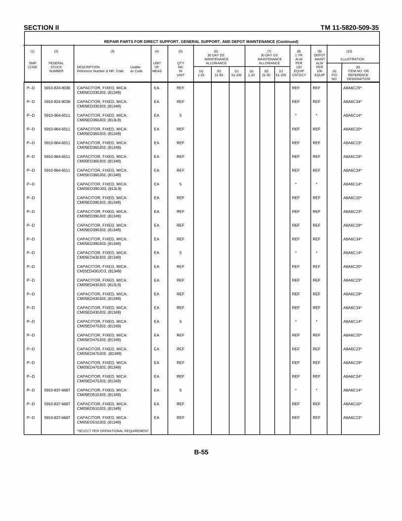
SECTION II TM 11-5820-509-35
REPAIR PARTS FOR DIRECT SUPPORT, GENERAL SUPPORT, AND DEPOT MAINTENANCE (Continued)
(1) (2) (3) (4) (5) (6) (7) (8) (9) (10)30 DAY DS 30 DAY GS 1 YR DEPOT
MAINTENANCE MAINTENANCE ALW MAINT ILLUSTRATIONSMR FEDERAL UNIT QTY ALLOWANCE ALLOWANCE PER ALW
CODE STOCK DESCRIPTION Usable OF INC 100 PER (b)NUMBER Reference Number & Mfr. Code on Code MEAS IN (a) (b) (c) (a) (b) (c) EQUIP 100 (a) ITEM NO. OR
UNIT 1-20 21-50 51-100 1-20 21-50 51-100 CNTGCY EQUIP FIG REFERENCENO. DESIGNATION
P--D 5910-824-8036 CAPACITOR, FIXED, MICA: EA REF REF REF A8A6C29*CM05ED330J03; (81349)
P--D 5910-824-8036 CAPACITOR, FIXED, MICA: EA REF REF REF A8A6C34*CM05ED330J03; (81349)
P--D 5910-964-6511 CAPACITOR, FIXED, MICA: EA 5 * * A8A6C14*CM05ED360J03; (813L9)
P--D 5910-964-6511 CAPACITOR, FIXED, MICA: EA REF REF REF A8A6C20*CM05ED360J03; (81349)
P--D 5910-964-6511 CAPACITOR, FIXED, MICA: EA REF REF REF A8A6C23*CM05ED360J03; (81349)
P--D 5910-964-6511 CAPACITOR, FIXED, MICA: EA REF REF REF A8A6C29*CM05ED360J03; (81349)
P--D 5910-964-6511 CAPACITOR, FIXED, MICA: EA REF REF REF A8A6C34*CM05ED360J03; (81349)
P--D CAPACITOR, FIXED, MICA: EA 5 * * A8A6C14*CM05ED390J03; (813L9)
P--D CAPACITOR, FIXED, MICA: EA REF REF REF A8A6C20*CM05ED390J03; (81349)
P--D CAPACITOR, FIXED, MICA: EA REF REF REF A8A6C23*CM05ED390J03; (81349)
P--D CAPACITOR, FIXED, MICA: EA REF REF REF A8A6C29*CM05ED390J03; (81349)
P--D CAPACITOR, FIXED, MICA: EA REF REF REF A8A6C34*CM05ED390J03; (81349)
P--D CAPACITOR, FIXED, MICA: EA 5 * * A8A6C14*CM05ED430J03; (81349)
P--D CAPACITOR, FIXED, MICA: EA REF REF REF A8A6C20*CM)5ED430JO3, (81349)
P--D CAPACITOR, FIXED, MICA: EA REF REF REF A8A6C23*CM05ED430J03; (813L9)
P--D CAPACITOR, FIXED, MICA: EA REF REF REF A8A6C29*CM05ED430J03; (81349)
P--D CAPACITOR, FIXED, MICA: EA REF REF REF A8A6C34*CM05ED430J03; (81349)
P--D CAPACITOR, FIXED, MICA: EA 5 * * A8A6C14*CM05ED470J03; (81349)
P--D CAPACITOR, FIXED, MICA: EA REF REF REF A8A6C20*CM05ED470J03; (81349)
P--D CAPACITOR, FIXED, MICA: EA REF REF REF A8A6C23*CM05ED470J03; (81349)
P--D CAPACITOR, FIXED, MICA: EA REF REF REF A8A6C29*CM05ED470J03; (81349)
P--D CAPACITOR, FIXED, MICA: EA REF REF REF A8A6C34*CM05ED470J03; (81349)
P--D 5910-837-6687 CAPACITOR, FIXED, MICA: EA 5 * * A8A6C14*CM05ED510J03; (81349)
P--D 5910-837-6687 CAPACITOR, FIXED, MICA: EA REF REF REF A8A6C20*CM05ED510J03; (81349)
P--D 5910-837-6687 CAPACITOR, FIXED, MICA: EA REF REF REF A8A6C23*CM05ED510J03; (81349)
*SELECT PER OPERATIONAL REQUIREMENT
B-55
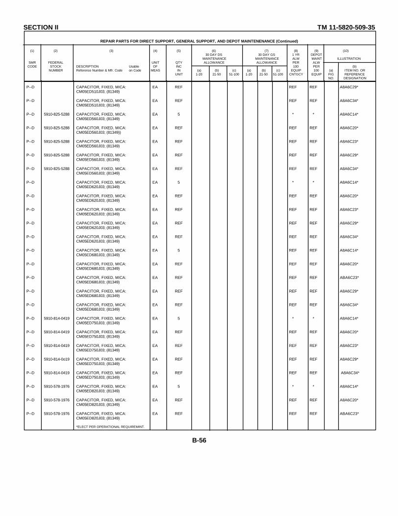
SECTION II TM 11-5820-509-35
REPAIR PARTS FOR DIRECT SUPPORT, GENERAL SUPPORT, AND DEPOT MAINTENENANCE (Continued)
(1) (2) (3) (4) (5) (6) (7) (8) (9) (10)30 DAY DS 30 DAY GS 1 YR DEPOT
MAINTENANCE MAINTENANCE ALW MAINT ILLUSTRATIONSMR FEDERAL UNIT QTY ALLOWANCE ALLOWANCE PER ALW
CODE STOCK DESCRIPTION Usable OF INC 100 PER (b)NUMBER Reference Number & Mfr. Code on Code MEAS IN (a) (b) (c) (a) (b) (c) EQUIP 100 (a) ITEM NO. OR
UNIT 1-20 21-50 51-100 1-20 21-50 51-100 CNTGCY EQUIP FIG REFERENCENO. DESIGNATION
P--D CAPACITOR, FIXED, MICA: EA REF REF REF A8A6C29*CM05ED510J03; (81349)
P--D CAPACITOR, FIXED, MICA: EA REF REF REF A8A6C34*CM05ED510J03; (81349)
P--D 5910-825-5288 CAPACITOR, FIXED, MICA: EA 5 * * A8A6C14*CM05ED560J03; (81349)
P--D 5910-825-5288 CAPACITOR, FIXED, MICA: EA REF REF REF A8A6C20*CM05ED560J03; (81349))
P--D 5910-825-5288 CAPACITOR, FIXED, MICA: EA REF REF REF A8A6C23*CM05ED560J03; (81349)
P--D 5910-825-5288 CAPACITOR, FIXED, MICA: EA REF REF REF A8A6C29*CM05ED560J03; (81349)
P--D 5910-825-5288 CAPACITOR, FIXED, MICA: EA REF REF REF A8A6C34*CM05ED560J03; (81349)
P--D CAPACITOR, FIXED, MICA: EA 5 * * A8A6C14*CM05ED620J03; (81349)
P--D CAPACITOR, FIXED, MICA: EA REF REF REF A8A6C20*CM05ED620J03; (81349)
P--D CAPACITOR, FIXED, MICA: EA REF REF REF A8A6C23*CM05ED620J03; (81349)
P--D CAPACITOR, FIXED, MICA: EA REF REF REF A8A6C29*CM05ED620J03; (81349)
P--D CAPACITOR, FIXED, MICA: EA REF REF REF A8A6C34*CM05ED620J03; (81349)
P--D CAPACITOR, FIXED, MICA: EA 5 REF REF A8A6C14*CM05ED680J03; (81349)
P--D CAPACITOR, FIXED, MICA: EA REF REF REF A8A6C20*CM05ED680J03; (81349)
P--D CAPACITOR, FIXED, MICA: EA REF REF REF ABA6C23*CM05ED680J03; (81349)
P--D CAPACITOR, FIXED, MICA: EA REF REF REF A8A6C29*CM05ED680J03; (81349)
P--D CAPACITOR, FIXED, MICA: EA REF REF REF A8A6C34*CM05ED680J03; (81349)
P--D 5910-814-0419 CAPACITOR, FIXED, MICA: EA 5 * * A8A6C14*CM05ED750J03; (81349)
P--D 5910-814-0419 CAPACITOR, FIXED, MICA: EA REF REF REF A8A6C20*CM05ED750J03; (81349)
P--D 5910-814-0419 CAPACITOR, FIXED, MICA: EA REF REF REF A8A6C23*CM05ED750J03; (81349)
P--D 5910-814-0o19 CAPACITOR, FIXED, MICA: EA REF REF REF A8A6C29*CM05ED750J03; (81349)
P--D 5910-814-0419 CAPACITOR, FIXED, MICA: EA REF REF REF A8A6C34*CM05ED750J03; (81349)
P--D 5910-578-1976 CAPACITOR, FIXED, MICA: EA 5 * * A8A6C14*CM05ED820J03; (81349)
P--D 5910-578-1976 CAPACITOR, FIXED, MICA: EA REF REF REF A8A6C20*CM05ED820J03; (81349)
P--D 5910-578-1976 CAPACITOR, FIXED, MICA: EA REF REF REF ABA6C23*CM05ED820J03; (81349)
*ELECT PER OPERATIONAL REQUIREMINT.
B-56
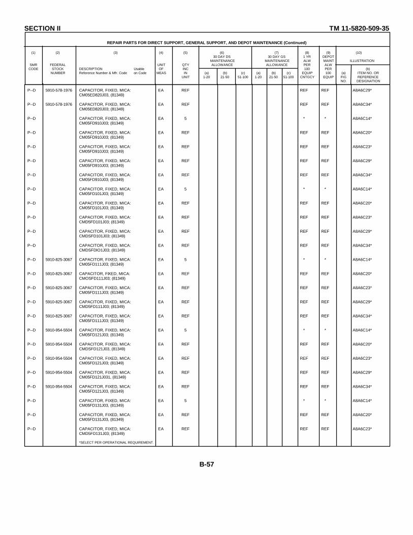
SECTION II TM 11-5820-509-35
REPAIR PARTS FOR DIRECT SUPPORT, GENERAL SUPPORT, AND DEPOT MAINTENANCE (Continued)
(1) (2) (3) (4) (5) (6) (7) (8) (9) (10)30 DAY DS 30 DAY GS 1 YR DEPOT
MAINTENANCE MAINTENANCE ALW MAINT ILLUSTRATIONSMR FEDERAL UNIT QTY ALLOWANCE ALLOWANCE PER ALW
CODE STOCK DESCRIPTION Usable OF INC 100 PER (b)NUMBER Reference Number & Mfr. Code on Code MEAS IN (a) (b) (c) (a) (b) (c) EQUIP 100 (a) ITEM NO. OR
UNIT 1-20 21-50 51-100 1-20 21-50 51-100 CNTGCY EQUIP FIG REFERENCENO. DESIGNATION
P--D 5910-578-1976 CAPACITOR, FIXED, MICA: EA REF REF REF A8A6C29*CM05ED820J03, (81349)
P--D 5910-578-1976 CAPACITOR, FIXED, MICA: EA REF REF REF A8A6C34*CM05ED820J03; (81349)
P--D CAPACITOR, FIXED, MICA: EA 5 * * A8A6C14*CM05FD910J03; (81349)
P--D CAPACITOR, FIXED, MICA: EA REF REF REF A8A6C20*CM05FD910J03; (81349)
P--D CAPACITOR, FIXED, MICA: EA REF REF REF A8A6C23*CM05FD910J03; (81349)
P--D CAPACITOR, FIXED, MICA: EA REF REF REF A8A6C29*CM05FD910J03; (81349)
P--D CAPACITOR, FIXED, MICA: EA REF REF REF A8A6C34*CM05FD910J03; (81349)
P--D CAPACITOR, FIXED, MICA: EA 5 * * A8A6C14*CM05FD101J03; (81349)
P--D CAPACITOR, FIXED, MICA: EA REF REF REF A8A6C20*CM05FD101J03; (81349)
P--D CAPACITOR, FIXED, MICA: EA REF REF REF A8A6C23*CMD5FD101J03; (81349)
P--D CAPACITOR, FIXED, MICA: EA REF REF REF A8A6C29*CMDSFD101J03; (81349)
P--D CAPACITOR, FIXED, MICA: EA REF REF REF A8A6C34*CMDSFDlO1J03; (81349)
P--D 5910-825-3067 CAPACITOR, FIXED, MICA: EA 5 * * A8A6C14*CM05FD111J03; (81349)
P--D 5910-825-3067 CAPACITOR, FIXED, MICA: EA REF REF REF A8A6C20*CMOSFD111J03; (81349)
P--D 5910-825-3067 CAPACITOR, FIXED, MICA: EA REF REF REF A8A6C23*CM05FD111J03; (81349)
P--D 5910-825-3067 CAPACITOR, FIXED, MICA: EA REF REF REF A8A6C29*CMD5FD111J03; (81349)
P--D 5910-825-3067 CAPACITOR, FIXED, MICA: EA REF REF REF A8A6C34*CM05FD111J03; (81349)
P--D 5910-954-5504 CAPACITOR, FIXED, MICA: EA 5 * * A8A6C14*CM05FD121J03; (81349)
P--D 5910-954-5504 CAPACITOR, FIXED, MICA: EA REF REF REF A8A6C20*CMDSFD121J03, (81349)
P--D 5910-954-5504 CAPACITOR, FIXED, MICA: EA REF REF REF A8A6C23*CM05FD121J03; (81349)
P--D 5910-954-5504 CAPACITOR, FIXED, MICA: EA REF REF REF A8A6C29*CM05FD121J031, (81349)
P--D 5910-954-5504 CAPACITOR, FIXED, MICA: EA REF REF REF A8A6C34*CM05FD121J03, (81349)
P--D CAPACITOR, FIXED, MICA: EA 5 * * A8A6C14*CM05FD131J03, (81349)
P--D CAPACITOR, FIXED, MICA: EA REF REF REF A8A6C20*CM05FD131J03, (81349)
P--D CAPACITOR, FIXED, MICA: EA REF REF REF A8A6C23*CMD5FD131J03; (81349)
*SELECT PER OPERATIONAL REQUIREMENT.
B-57

SECTION II TM 11-5820-509-35
REPAIR PARTS FOR DIRECT SUPPORT, GENERAL SUPPORT, AND DEPOT MAINTENANCE (Continued)
(1) (2) (3) (4) (5) (6) (7) (8) (9) (10)30 DAY DS 30 DAY GS 1 YR DEPOT
MAINTENANCE MAINTENANCE ALW MAINT ILLUSTRATIONSMR FEDERAL UNIT QTY ALLOWANCE ALLOWANCE PER ALW
CODE STOCK DESCRIPTION Usable OF INC 100 PER (b)NUMBER Reference Number & Mfr. Code on Code MEAS IN (a) (b) (c) (a) (b) (c) EQUIP 100 (a) ITEM NO. OR
UNIT 1-20 21-50 51-100 1-20 21-50 51-100 CNTGCY EQUIP FIG REFERENCENO. DESIGNATION
P--D CAPACITOR, FIXED, MICA: EA REF REF REF A8A6C29*CM05FD131J03; (813h9)
P--D CAPACITOR, FIXED, MICA: EA REF REF REF A8A6C34*CM05FD131J03; (813L9)
P--D CAPACITOR, FIXED, MICA: EA 5 * * A8A6C14*CM05FD151J03; (81349)
P--D CAPACITOR, FIXED, MICA: EA REF REF REF A8A6C20*CMO5FD151J03; (81349)
P--D CAPACITOR, FIXED, MICA: EA REF REF REF A8A6C23*CM05FD151J03; (81349)
P--D CAPACITOR, FIXED, MICA: EA REF REF REF A8A6C29*CM05FD151J03; (81349)
P--D CAPACITOR, FIXED, MICA: EA REF REF REF A8A6C34*CM05FD151J03; (81349)
P--D CAPACITOR, FIXED, MICA: A 5 * * A8A6C14*CM05FD161J03; (81349)
P--D CAPACITOR, FIXED, MICA: EA REF REF REF A8A6C20*CM05FD161J03; (81349)
P--D CAPACITOR, FIXED, MICA: EA REF REF REF A8A6C23*CM05FD161J03; (81349)
P--D CAPACITOR, FIXED, MICA: EA REF REF REF A8A6C29*CM0SFD161J03; (81349)
P--D CAPACITOR, FIXED, MICA: EA REF REF REF A8A6C34*CM05FD161J03; (81349)
P--D CAPACITOR, FIXED, MICA: EA 5 * * AA6C14*CM05FD181J03; (81349)
P--D CAPACITOR, FIXED, MICA: EA REF REF REF AA6C20*CM05FD181J03; (81349)
P--D CAPACITOR, FIXED, MICA: EA REF REF REF A8A6C23*CM05FD181J03; (81349)
P--D CAPACITOR, FIXED, MICA: EA REF REF REF A8A6C29*CM05FD181J03; (81349)
P--D CAPACITOR, FIXED, MICA: EA REF REF REF A8A6C34*CM05FD181J03; (81349)
P--D CAPACITOR, FIXED, MICA: EA 5 * * A8A6C14*CMD5FD201J03; (81349)
P--D CAPACITOR, FIXED, MICA: EA REF REF REF A8A6C20*CM05FD201J03; (81349)
P--D CAPACITOR, FIXED, MICA: EA REF REF REF A8A6C23*CM05FD201J03; (81349)
P--D CAPACITOR, FIXED, MICA: EA REF REF REF A8A6C29*CM05FD201J03; (81349)
P--D CAPACITOR, FIXED, MICA: EA REF REF REF A8A6C34*CM05FD201J03; (81349)
P--D CAPACITOR, FIXED, MICA: EA 5 * * A8A6C14*CM05FD221J03; (81349)
P--D CAPACITOR, FIXED, MICA: EA REF REF REF A8A6C20*CM05FD221J03; (81349)
P— D CAPACITOR, FIXED, MICA: EA REF REF REF A8A6C23*CM05FD221J03; (81349)
*SELECT PER OPERATIONAL REQUIREMENT.
B-58
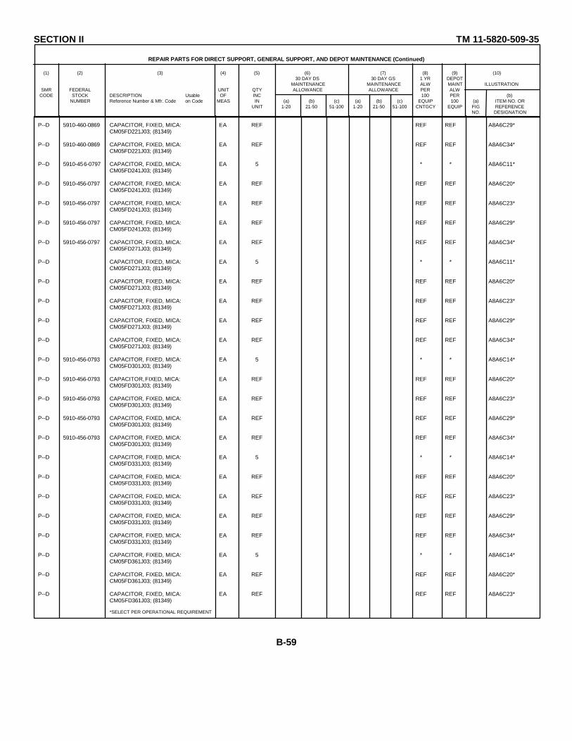
SECTION II TM 11-5820-509-35
REPAIR PARTS FOR DIRECT SUPPORT, GENERAL SUPPORT, AND DEPOT MAINTENANCE (Continued)
(1) (2) (3) (4) (5) (6) (7) (8) (9) (10)30 DAY DS 30 DAY GS 1 YR DEPOT
MAINTENANCE MAINTENANCE ALW MAINT ILLUSTRATIONSMR FEDERAL UNIT QTY ALLOWANCE ALLOWANCE PER ALW
CODE STOCK DESCRIPTION Usable OF INC 100 PER (b)NUMBER Reference Number & Mfr. Code on Code MEAS IN (a) (b) (c) (a) (b) (c) EQUIP 100 (a) ITEM NO. OR
UNIT 1-20 21-50 51-100 1-20 21-50 51-100 CNTGCY EQUIP FIG REFERENCENO. DESIGNATION
P--D 5910-460-0869 CAPACITOR, FIXED, MICA: EA REF REF REF A8A6C29*CM05FD221J03; (81349)
P--D 5910-460-0869 CAPACITOR, FIXED, MICA: EA REF REF REF A8A6C34*CM05FD221J03; (81349)
P--D 5910-456-0797 CAPACITOR, FIXED, MICA: EA 5 * * A8A6C11*CM05FD241J03; (81349)
P--D 5910-456-0797 CAPACITOR, FIXED, MICA: EA REF REF REF A8A6C20*CM05FD241J03; (81349)
P--D 5910-456-0797 CAPACITOR, FIXED, MICA: EA REF REF REF A8A6C23*CM05FD241J03; (81349)
P--D 5910-456-0797 CAPACITOR, FIXED, MICA: EA REF REF REF A8A6C29*CM05FD241J03; (81349)
P--D 5910-456-0797 CAPACITOR, FIXED, MICA: EA REF REF REF A8A6C34*CM05FD271J03; (81349)
P--D CAPACITOR, FIXED, MICA: EA 5 * * A8A6C11*CM05FD271J03; (81349)
P--D CAPACITOR, FIXED, MICA: EA REF REF REF A8A6C20*CM05FD271J03; (81349)
P--D CAPACITOR, FIXED, MICA: EA REF REF REF A8A6C23*CM05FD271J03; (81349)
P--D CAPACITOR, FIXED, MICA: EA REF REF REF A8A6C29*CM05FD271J03; (81349)
P--D CAPACITOR, FIXED, MICA: EA REF REF REF A8A6C34*CM05FD271J03; (81349)
P--D 5910-456-0793 CAPACITOR, FIXED, MICA: EA 5 * * A8A6C14*CM05FD301J03; (81349)
P--D 5910-456-0793 CAPACITOR, FIXED, MICA: EA REF REF REF A8A6C20*CM05FD301J03; (81349)
P--D 5910-456-0793 CAPACITOR, FIXED, MICA: EA REF REF REF A8A6C23*CM05FD301J03; (81349)
P--D 5910-456-0793 CAPACITOR, FIXED, MICA: EA REF REF REF A8A6C29*CM05FD301J03; (81349)
P--D 5910-456-0793 CAPACITOR, FIXED, MICA: EA REF REF REF A8A6C34*CM05FD301J03; (81349)
P--D CAPACITOR, FIXED, MICA: EA 5 * * A8A6C14*CM05FD331J03; (81349)
P--D CAPACITOR, FIXED, MICA: EA REF REF REF A8A6C20*CM05FD331J03; (81349)
P--D CAPACITOR, FIXED, MICA: EA REF REF REF A8A6C23*CM05FD331J03; (81349)
P--D CAPACITOR, FIXED, MICA: EA REF REF REF A8A6C29*CM05FD331J03; (81349)
P--D CAPACITOR, FIXED, MICA: EA REF REF REF A8A6C34*CM05FD331J03; (81349)
P--D CAPACITOR, FIXED, MICA: EA 5 * * A8A6C14*CM05FD361J03; (81349)
P--D CAPACITOR, FIXED, MICA: EA REF REF REF A8A6C20*CM05FD361J03; (81349)
P--D CAPACITOR, FIXED, MICA: EA REF REF REF A8A6C23*CM05FD361J03; (81349)
*SELECT PER OPERATIONAL REQUIREMENT
B-59

SECTION II TM 11-5820-509-35
REPAIR PARTS FOR DIRECT SUPPORT, GENERAL SUPPORT, AND DEPOT MAINTENANCE (Continued)
(1) (2) (3) (4) (5) (6) (7) (8) (9) (10)30 DAY DS 30 DAY GS 1 YR DEPOT
MAINTENANCE MAINTENANCE ALW MAINT ILLUSTRATIONSMR FEDERAL UNIT QTY ALLOWANCE ALLOWANCE PER ALW
CODE STOCK DESCRIPTION Usable OF INC 100 PER (b)NUMBER Reference Number & Mfr. Code on Code MEAS IN (a) (b) (c) (a) (b) (c) EQUIP 100 (a) ITEM NO. OR
UNIT 1-20 21-50 51-100 1-20 21-50 51-100 CNTGCY EQUIP FIG REFERENCENO. DESIGNATION
P--D 5910-255-1608 CAPACITOR, FIXED, MICA: EA REF REF REF A8A6C29*CM05FD361J03, (81349)
P--D 5910-255-1608 CAPACITOR, FIXED, MICA: EA REF REF REF A8A6C34*CM05FD361J03, (81349)
P--D CAPACITOR, FIXED, MICA: EA 5 * * A8A6C14*CMOSFD391J03, (81349)
P--D CAPACITOR, FIXED, MICA: EA REF REF REF A8A6C20*CM5O'D391J03; (81349)
P--D CAPACITOR, FIXED, MICA: EA REF REF REF A8A6C23*CMO5FD391J03, (813h9)
P--D CAPACITOR, FIXED, MICA: EA REF REF REF A8A6C29*CM05FD391J03, (81349)
P--D CAPACITOR, FIXED, MICA: EA REF REF REF A8A6C34*CM05FD391J03, (81349)
P--D 5910-023-2068 CAPACITOR, FIXED, MICA: EA 5 * * AA6C114*DM15F131J300WV4CR; (72136)
P--D 5910-023-2068 CAPACITOR, FIXED, MICA: EA REF REF REF A8A6C20*DM15F431J300WV4CR; (72136)
P--D 5910-023-2068 CAPACITOR, FIXED, MICA: EA REF REF REF A8A6C23*DM15F431J300WV4CR; (72136)
P--D 5910-023-2068 CAPACITOR, FIXED, MICA: EA REF REF REF A8A6C29*DM15F1471J300WV4CR; (72136)
P--D 5910-023-2068 CAPACITOR, FIXED, MICA: EA REF REF REF A8A6C34*DM15F4311J300WV4CR; (72136)
P--D 5910-997-5399 CAPACITOR, FIXED, MICA: EA 5 * * A8A6C14*DM15F471J3000WV4CR; (72136)
P--D 5910-997-5399 CAPACITOR, FIXED, MICA: EA REF REF REF A8A6C20*DM15F471J300WV4CR; (72136)
P--D 5910-997-5399 CAPACITOR, FIXED, MICA: EA REF REF REF A8A6C23*DM15F471J300WV4CR; (72156 )
P--D 5910-997-5399 CAPACITOR, FIXED, MICA: EA REF REF REF A8A6C29*DM15F471J300WV4CR; (72136)
P--D 5910-997-5399 CAPACITOR, FIXED, MICA: EA REF REF REF A8A6C34*DM15F471J300WV4CR; (72136)
P--D 5910-686-6126 CAPACITOR, FIXED, MICA: EA 5 * * AA6C1*DM15F511J300WV4CR; (72136)
P--D 5910-686-6126 CAPACITOR, FIXED, MICA: EA REF REF REF A8A6C20*DM15F511J3000V4CR; (72136)
P--D 5910-686-6126 CAPACITOR, FIXED, MICA: EA REF REF REF A8A6C23*DM15F511J300WV4CR; (72136 )
P--D 5910-686-6126 CAPACITOR, FIXED, MICA: EA REF REF REF A8A6C29*DM15F511J300WV4CR; (72136)
P--D 5910-686-6126 CAPACITOR, FIXED, MICA: EA REF REF REF A8A6C34*DM15F511J300WV4CR; (72136)
P--D 5910-958-8257 CAPACITOR, FIXED, MICA: EA 5 * * A8A6C14*DM15E621J0300WV4CR; (72136)
P--D CAPACITOR, FIXED, MICA: EA REF REF REF A8A6C20*DM15E621J0300DWV4CR; (72136)
P--D CAPACITOR, FIXED, MICA: EA REF REF REF A8A6C23*DM15E621J0300WV4CR; (72136)
*SELECT PER OPERATIONAL REQUIREMENT.
B-60
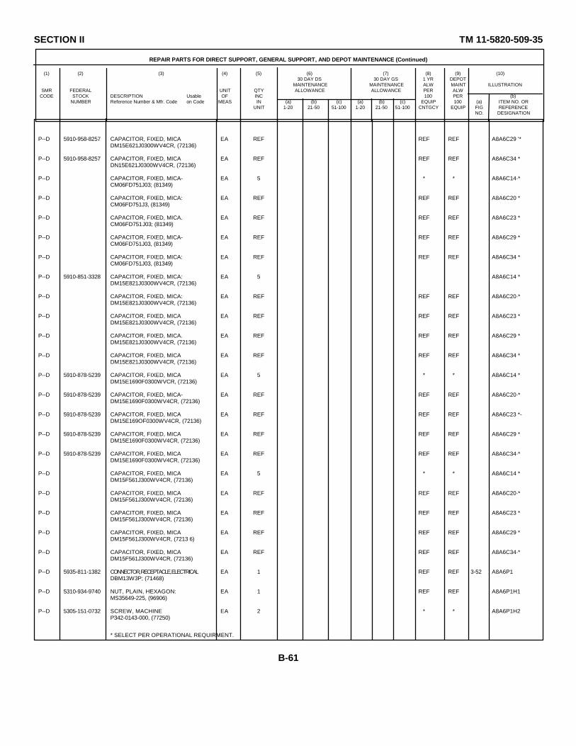
SECTION II TM 11-5820-509-35
REPAIR PARTS FOR DIRECT SUPPORT, GENERAL SUPPORT, AND DEPOT MAINTENANCE (Continued)
(1) (2) (3) (4) (5) (6) (7) (8) (9) (10)30 DAY DS 30 DAY GS 1 YR DEPOT
MAINTENANCE MAINTENANCE ALW MAINT ILLUSTRATIONSMR FEDERAL UNIT QTY ALLOWANCE ALLOWANCE PER ALW
CODE STOCK DESCRIPTION Usable OF INC 100 PER (b)NUMBER Reference Number & Mfr. Code on Code MEAS IN (a) (b) (c) (a) (b) (c) EQUIP 100 (a) ITEM NO. OR
UNIT 1-20 21-50 51-100 1-20 21-50 51-100 CNTGCY EQUIP FIG REFERENCENO. DESIGNATION
P--D 5910-958-8257 CAPACITOR, FIXED, MICA EA REF REF REF A8A6C29 '*DM15E621J0300WV4CR, (72136)
P--D 5910-958-8257 CAPACITOR, FIXED, MICA EA REF REF REF A8A6C34 *DN15E621J0300WV4CR, (72136)
P--D CAPACITOR, FIXED, MICA- EA 5 * * A8A6C14·*CM06FD751J03; (81349)
P--D CAPACITOR, FIXED, MICA: EA REF REF REF A8A6C20 *CM06FD751J3, (81349)
P--D CAPACITOR, FIXED, MICA. EA REF REF REF A8A6C23 *CM06FD751J03; (81349)
P--D CAPACITOR, FIXED, MICA- EA REF REF REF A8A6C29 *CM06FD751J03, (81349)
P--D CAPACITOR, FIXED, MICA: EA REF REF REF A8A6C34 *CM06FD751J03, (81349)
P--D 5910-851-3328 CAPACITOR, FIXED, MICA: EA 5 A8A6C14 *DM15E821J0300WV4CR, (72136)
P--D CAPACITOR, FIXED, MICA: EA REF REF REF A8A6C20·*DM15E821J0300WV4CR, (72136)
P--D CAPACITOR, FIXED, MICA EA REF REF REF A8A6C23 *DM15E821J0300WV4CR, (72136)
P--D CAPACITOR, FIXED, MICA. EA REF REF REF A8A6C29 *DM15E821J0300WV4CR, (72136)
P--D CAPACITOR, FIXED, MICA EA REF REF REF A8A6C34 *DM15E821J0300WV4CR, (72136)
P--D 5910-878-5239 CAPACITOR, FIXED, MICA EA 5 * * A8A6C14 *DM15E1690F0300WVCR, (72136)
P--D 5910-878-5239 CAPACITOR, FIXED, MICA- EA REF REF REF A8A6C20·*DM15E1690F0300WV4CR, (72136)
P--D 5910-878-5239 CAPACITOR, FIXED, MICA EA REF REF REF A8A6C23 *-DM15E169OF0300WV4CR, (72136)
P--D 5910-878-5239 CAPACITOR, FIXED, MICA EA REF REF REF A8A6C29 *DM15E1690F0300WV4CR, (72136)
P--D 5910-878-5239 CAPACITOR, FIXED, MICA EA REF REF REF A8A6C34·*DM15E1690F0300WV4CR, (72136)
P--D CAPACITOR, FIXED, MICA EA 5 * * A8A6C14 *DM15F561J300WV4CR, (72136)
P--D CAPACITOR, FIXED, MICA EA REF REF REF A8A6C20·*DM15F561J300WV4CR, (72136)
P--D CAPACITOR, FIXED, MICA EA REF REF REF A8A6C23 *DM15F561J300WV4CR, (72136)
P--D CAPACITOR, FIXED, MICA EA REF REF REF A8A6C29 *DM15F561J300WV4CR, (7213 6)
P--D CAPACITOR, FIXED, MICA EA REF REF REF A8A6C34·*DM15F561J300WV4CR, (72136)
P--D 5935-811-1382 CONNECTOR, RECEPTACLE, ELECTRICAL EA 1 REF REF 3-52 A8A6P1DBM13W3P; (71468)
P--D 5310-934-9740 NUT, PLAIN, HEXAGON: EA 1 REF REF A8A6P1H1MS35649-225, (96906)
P--D 5305-151-0732 SCREW, MACHINE EA 2 * * A8A6P1H2P342-0143-000, (77250)
* SELECT PER OPERATIONAL REQUIRMENT.
B-61
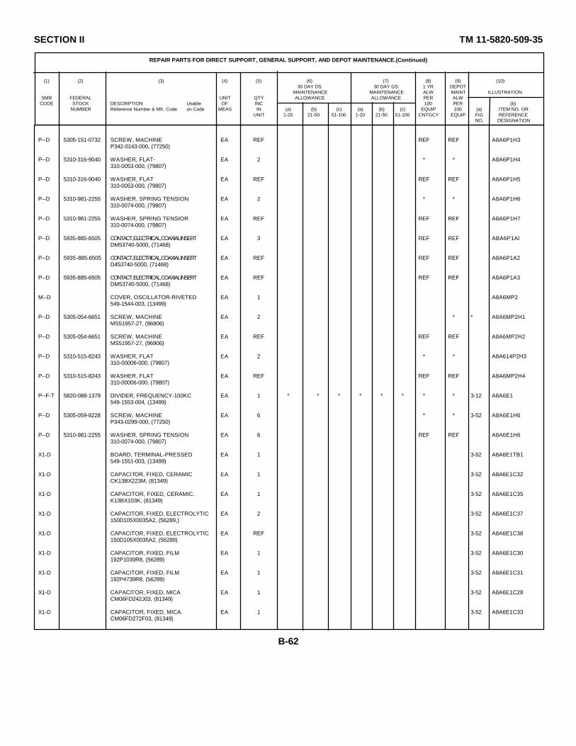
SECTION II TM 11-5820-509-35
REPAIR PARTS FOR DIRECT SUPPORT, GENERAL SUPPORT, AND DEPOT MAINTENANCE.(Continued)
(1) (2) (3) (4) (5) (6) (7) (8) (9) (10)30 DAY DS 30 DAY GS 1 YR DEPOT
MAINTENANCE MAINTENANCE ALW MAINT ILLUSTRATIONSMR FEDERAL UNIT QTY ALLOWANCE ALLOWANCE PER ALW
CODE STOCK DESCRIPTION Usable OF INC 100 PER (b)NUMBER Reference Number & Mfr. Code on Code MEAS IN (a) (b) (c) (a) (b) (c) EQUIP 100 (a) ITEM NO. OR
UNIT 1-20 21-50 51-100 1-20 21-50 51-100 CNTGCY EQUIP FIG REFERENCENO. DESIGNATION
P--D 5305-151-0732 SCREW, MACHINE EA REF REF REF A8A6P1H3P342-0143-000, (77250)
P--D 5310-316-9040 WASHER, FLAT- EA 2 * * A8A6P1H4310-0053-000, (79807)
P--D 5310-316-9040 WASHER, FLAT EA REF REF REF A8A6P1H5310-0053-000, (79807)
P--D 5310-981-2255 WASHER, SPRING TENSION EA 2 * * A8A6P1H6310-0074-000, (79807)
P--D 5310-981-2255 WASHER, SPRING TENSIOR EA REF REF REF A8A6P1H7310-0074-000, (79807)
P--D 5935-885-6505 CONTACT, ELECTRICAL, COAXIAL INSERT EA 3 REF REF ABA6P1AlDM53740-5000, (71468)
P--D 5935-885-6505 CONTACT, ELECTRICAL, COAXIAL INSERT EA REF REF REF A8A6P1A2D453740-5000, (71468)
P--D 5935-885-6505 CONTACT, ELECTRICAL, COAXIAL INSERT EA REF REF REF A8A6P1A3DM53740-5000, (71468)
M--D COVER, OSCILLATOR-RIVETED EA 1 A8A6MP2549-1544-003, (13499)
P--D 5305-054-6651 SCREW, MACHINE EA 2 * * A8A6MP2H1MS51957-27, (96906)
P--D 5305-054-6651 SCREW, MACHINE EA REF REF REF A8A6MP2H2MS51957-27, (96906)
P--D 5310-515-8243 WASHER, FLAT EA 2 * * A8A614P2H3310-00006-000, (79807)
P--D 5310-515-8243 WASHER, FLAT EA REF REF REF A8A6MP2H4310-00006-000, (79807)
P--F-T 5820-088-1379 DIVIDER, FREQUENCY-100KC EA 1 * * * * * * * * 3-12 A8A6E1549-1553-004, (13499)
P--D 5305-059-8228 SCREW, MACHINE EA 6 * * 3-52 A8A6E1H6P343-0299-000, (77250)
P--D 5310-981-2255 WASHER, SPRING TENSION EA 6 REF REF A8A6E1H6310-0074-000, (79807)
X1-D BOARD, TERMINAL-PRESSED EA 1 3-52 A8A6E1TB1549-1551-003, (13499)
X1-D CAPACITOR, FIXED, CERAMIC EA 1 3-52 A8A6E1C32CK13BX223M, (81349)
X1-D CAPACITOR, FIXED, CERAMIC. EA 1 3-52 A8A6E1C35K13BX103K, (81349)
X1-D CAPACITOR, FIXED, ELECTROLYTIC EA 2 3-52 A8A6E1C37150D105X0035A2, (56289,)
X1-D CAPACITOR, FIXED, ELECTROLYTIC EA REF 3-52 A8A6E1C38150D105X0035A2, (56289)
X1-D CAPACITOR, FIXED, FILM EA 1 3-52 A8A6E1C30192P1039R8, (56289)
X1-D CAPACITOR, FIXED, FILM EA 1 3-52 A8A6E1C31192P4739R8, (56289)
X1-D CAPACITOR, FIXED, MICA EA 1 3-52 A8A6E1C28CM06FD242J03, (81349)
X1-D CAPACITOR, FIXED, MICA. EA 1 3-52 A8A6E1C33CM06FD272F03, (81349)
B-62
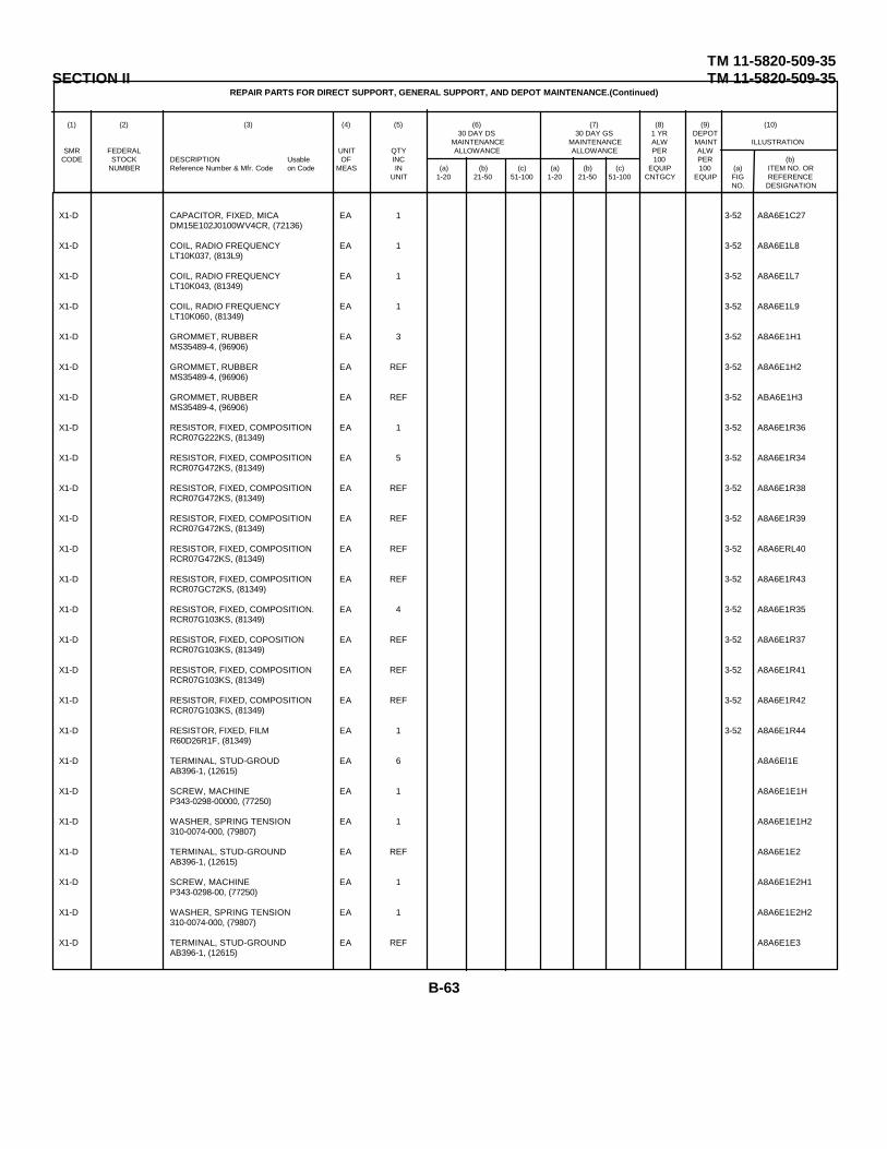
TM 11-5820-509-35SECTION II TM 11-5820-509-35
REPAIR PARTS FOR DIRECT SUPPORT, GENERAL SUPPORT, AND DEPOT MAINTENANCE.(Continued)
(1) (2) (3) (4) (5) (6) (7) (8) (9) (10)30 DAY DS 30 DAY GS 1 YR DEPOT
MAINTENANCE MAINTENANCE ALW MAINT ILLUSTRATIONSMR FEDERAL UNIT QTY ALLOWANCE ALLOWANCE PER ALW
CODE STOCK DESCRIPTION Usable OF INC 100 PER (b)NUMBER Reference Number & Mfr. Code on Code MEAS IN (a) (b) (c) (a) (b) (c) EQUIP 100 (a) ITEM NO. OR
UNIT 1-20 21-50 51-100 1-20 21-50 51-100 CNTGCY EQUIP FIG REFERENCENO. DESIGNATION
X1-D CAPACITOR, FIXED, MICA EA 1 3-52 A8A6E1C27DM15E102J0100WV4CR, (72136)
X1-D COIL, RADIO FREQUENCY EA 1 3-52 A8A6E1L8LT10K037, (813L9)
X1-D COIL, RADIO FREQUENCY EA 1 3-52 A8A6E1L7LT10K043, (81349)
X1-D COIL, RADIO FREQUENCY EA 1 3-52 A8A6E1L9LT10K060, (81349)
X1-D GROMMET, RUBBER EA 3 3-52 A8A6E1H1MS35489-4, (96906)
X1-D GROMMET, RUBBER EA REF 3-52 A8A6E1H2MS35489-4, (96906)
X1-D GROMMET, RUBBER EA REF 3-52 ABA6E1H3MS35489-4, (96906)
X1-D RESISTOR, FIXED, COMPOSITION EA 1 3-52 A8A6E1R36RCR07G222KS, (81349)
X1-D RESISTOR, FIXED, COMPOSITION EA 5 3-52 A8A6E1R34RCR07G472KS, (81349)
X1-D RESISTOR, FIXED, COMPOSITION EA REF 3-52 A8A6E1R38RCR07G472KS, (81349)
X1-D RESISTOR, FIXED, COMPOSITION EA REF 3-52 A8A6E1R39RCR07G472KS, (81349)
X1-D RESISTOR, FIXED, COMPOSITION EA REF 3-52 A8A6ERL40RCR07G472KS, (81349)
X1-D RESISTOR, FIXED, COMPOSITION EA REF 3-52 A8A6E1R43RCR07GC72KS, (81349)
X1-D RESISTOR, FIXED, COMPOSITION. EA 4 3-52 A8A6E1R35RCR07G103KS, (81349)
X1-D RESISTOR, FIXED, COPOSITION EA REF 3-52 A8A6E1R37RCR07G103KS, (81349)
X1-D RESISTOR, FIXED, COMPOSITION EA REF 3-52 A8A6E1R41RCR07G103KS, (81349)
X1-D RESISTOR, FIXED, COMPOSITION EA REF 3-52 A8A6E1R42RCR07G103KS, (81349)
X1-D RESISTOR, FIXED, FILM EA 1 3-52 A8A6E1R44R60D26R1F, (81349)
X1-D TERMINAL, STUD-GROUD EA 6 A8A6El1EAB396-1, (12615)
X1-D SCREW, MACHINE EA 1 A8A6E1E1HP343-0298-00000, (77250)
X1-D WASHER, SPRING TENSION EA 1 A8A6E1E1H2310-0074-000, (79807)
X1-D TERMINAL, STUD-GROUND EA REF A8A6E1E2AB396-1, (12615)
X1-D SCREW, MACHINE EA 1 A8A6E1E2H1P343-0298-00, (77250)
X1-D WASHER, SPRING TENSION EA 1 A8A6E1E2H2310-0074-000, (79807)
X1-D TERMINAL, STUD-GROUND EA REF A8A6E1E3AB396-1, (12615)
B-63

SECTION II TM 11-5820-509-35
REPAIR PARTS FOR DIRECT SUPPORT, GENERAL SUPPORT, AND DEPOT MAINTENANCE.(Continued)
(1) (2) (3) (4) (5) (6) (7) (8) (9) (10)30 DAY DS 30 DAY GS 1 YR DEPOT
MAINTENANCE MAINTENANCE ALW MAINT ILLUSTRATIONSMR FEDERAL UNIT QTY ALLOWANCE ALLOWANCE PER ALW
CODE STOCK DESCRIPTION Usable OF INC 100 PER (b)NUMBER Reference Number & Mfr. Code on Code MEAS IN (a) (b) (c) (a) (b) (c) EQUIP 100 (a) ITEM NO. OR
UNIT 1-20 21-50 51-100 1-20 21-50 51-100 CNTGCY EQUIP FIG REFERENCENO. DESIGNATION
X1-D CAPACITOR, FIXED, MICA EA 1 3-52 A8A6E1C27DM15E102J0100WV4CR, (72136)
X1-D COIL, RADIO FREQUENCY EA 1 3-52 A8A6E1L8LT10K037, (813L9)
X1-D COIL, RADIO FREQUENCY EA 1 3-52 A8A6E1L7LT10K043, (81349)
X1-D COIL, RADIO FREQUENCY EA 1 3-52 A8A6E1L9LT10K060, (81349)
X1-D GROMMET, RUBBER EA 3 3-52 A8A6E1H1MS35489-4, (96906)
X1-D GROMMET, RUBBER EA REF 3-52 A8A6E1H2MS35489-4, (96906)
X1-D GROMMET, RUBBER EA REF 3-52 ABA6E1H3MS35489-4, (96906)
X1-D RESISTOR, FIXED, COMPOSITION EA 1 3-52 A8A6E1R36RCR07G222KS, (81349)
X1-D RESISTOR, FIXED, COMPOSITION EA 5 3-52 A8A6E1R34RCR07G472KS, (81349)
X1-D RESISTOR, FIXED, COMPOSITION EA REF 3-52 A8A6E1R38RCR07G472KS, (81349)
X1-D RESISTOR, FIXED, COMPOSITION EA REF 3-52 A8A6E1R39RCR07G472KS, (81349)
X1-D RESISTOR, FIXED, COMPOSITION EA REF 3-52 A8A6ERL40RCR07G472KS, (81349)
X1-D RESISTOR, FIXED, COMPOSITION EA REF 3-52 A8A6E1R43RCR07GC72KS, (81349)
X1-D RESISTOR, FIXED, COMPOSITION. EA 4 3-52 A8A6E1R35RCR07G103KS, (81349)
X1-D RESISTOR, FIXED, COPOSITION EA REF 3-52 A8A6E1R37RCR07G103KS, (81349)
X1-D RESISTOR, FIXED, COMPOSITION EA REF 3-52 A8A6E1R41RCR07G103KS, (81349)
X1-D RESISTOR, FIXED, COMPOSITION EA REF 3-52 A8A6E1R42RCR07G103KS, (81349)
X1-D RESISTOR, FIXED, FILM EA 1 3-52 A8A6E1R44R60D26R1F, (81349)
X1-D TERMINAL, STUD-GROUD EA 6 A8A6El1EAB396-1, (12615)
X1-D SCREW, MACHINE EA 1 A8A6E1E1HP343-0298-00000, (77250)
X1-D WASHER, SPRING TENSION EA 1 A8A6E1E1H2310-0074-000, (79807)
X1-D TERMINAL, STUD-GROUND EA REF A8A6E1E2AB396-1, (12615)
X1-D SCREW, MACHINE EA 1 A8A6E1E2H1P343-0298-00, (77250)
X1-D WASHER, SPRING TENSION EA 1 A8A6E1E2H2310-0074-000, (79807)
X1-D TERMINAL, STUD-GROUND EA REF A8A6E1E3AB396-1, (12615)
B-63

SECTION II TM 11-5820-509-35
REPAIR PARTS FOR DIRECT SUPPORT, GENERAL SUPPORT, AND DEPOT MAINTENANCE (Continued)
(1) (2) (3) (4) (5) (6) (7) (8) (9) (10)30 DAY DS 30 DAY GS 1 YR DEPOT
MAINTENANCE MAINTENANCE ALW MAINT ILLUSTRATIONSMR FEDERAL UNIT QTY ALLOWANCE ALLOWANCE PER ALW
CODE STOCK DESCRIPTION Usable OF INC 100 PER (b)NUMBER Reference Number & Mfr. Code on Code MEAS IN (a) (b) (c) (a) (b) (c) EQUIP 100 (a) ITEM NO. OR
UNIT 1-20 21-50 51-100 1-20 21-50 51-100 CNTGCY EQUIP FIG REFERENCENO. DESIGNATION
X1-D SCREW, MACHINE: EA 1 A8A6EIE3H1P343-0298-000; (77250)
X1-D WASHER, SPRING TENSION: EA 1 A8A6E1E3H2310-0074-000; (79807)
X1-D TERMINAL, STUD-GROUND: EA REF A8A6E1E4AB396-1; (12615)
X1-D SCREW, MACHINE: EA 1 A8A6E1E4H1P343-0298-000; (77250)
X1-D WASHER, SPRING TENSION: EA 1 A8A6E1E4H2310-0074-000; (79807 )
X1-D TERMINAL, STUD-GROUND: EA REF A8A6E1E5AB396-1; (12615)
X1-D SCREW, MACHINE: EA 1 A8A6E1E5H1P343-0298-000; (77250)
X1-D WASHER, SPRING TENSION; EA 1 A8A6EIE5H2310-0074-000; (79807)
X1-D TERMINAL, STUD-GROUND EA REF A8A6L1E6AB396-1; (12615)
X1-D SCREW, MACHINE; EA 1 A8A6E1E6H1P34-3-0298-000; (77250)
X1-D WASHER, SPRING TENSION: EA 1 A8A6E1E6H2310-007-400; (79807)
X1-D TRANSISTOR: EA 3 A8A6E1E6H22N703; (07688)
X1-D TRANSISTOR: EA REF 3-52 A8A6E1Q82N703; (07688)
X1-D TRANSISTOR: EA REF 3-52 A8A6E1Q92N703; (07688)
P--D 5340-157-7860 MOUNT, RESILIENT-BASE; EA 1 * * A8A6MP3549-1545-003, (13499)
P-H-T 5821-019-6291 OSCILLATOR, RADIO FREQUENCY: EA 1 * * * * * 3-52 A8A6L2549-1680-004, ( 13499)
X1-D BOARD, TERMI'AL-PRESSED: EA 1 3-52 A8A6E2TB1549-1682-004; (13499)
X1-D CAPACITOR, FIXED, MICA: EA 1 3-52 A8A6L2C11805-014X5V0103Z; (72982)
X1-D CAPACITOR, FIXED, MICA: EA 2 3-52 A8A6E2C6CM05FD101J03; (81349)
X1-D CAPACITOR, FIXED, MICA: EA REF 3-52 A8A6E2C7CM05FD101J03; (81349)
X1-D CAPACITOR, FIXED, MICA: EA 2 3-52 A8A6E2C2DM15F511J300WV4CR; (72136)
X1-D CAPACITOR, FIXED, MICA: EA REF 3-52 A8A6E2C4DM15F511J300WV4CR; (72136)
X1-D CAPACITOR, FIXED, MICA: EA 4 3-52 A8A6E2C31115E102J0100WV4CR; (72136)
X1-D CAPACITOR, FIXED, MICA: EA REF 3-52 A8A6E2C5DM15E102J0100WV4CR; (72136)
X1-D CAPACITOR, FIXED, MICA: EAR REF 3-52 A8A6E2C8DM15E102J0100WV4CR; (72136)
B-64

SECTION II TM 11-5820-509-35
****REPAIR PARTS FOR DIRECT SUPPORT, GENERAL SUPPORT, AND DEPOT MAINTENANCE (Continued)****
(1) (2) (3) (4) (5) (6) (7) (8) (9) (10)30 DAY DS 30 DAY GS 1 YR DEPOT
MAINTENANCE MAINTENANCE ALW MAINTSMR FEDERAL UNIT QTY ALLOWANCE ALLOWANCE PER ALW ILLUSTRATION
CODE STOCK DESCRIPTION Usable OF INC 100 PERNUMBER Reference Number & Mfr. Code on Code MEAS IN (a) (b) (c) (a) (b) (c) EQUIP 100 (a) (b)
UNIT 1-20 21-50 51-100 1-20 21-50 51-100 CNTGCY EQUIP FIG ITEMNO. NO.
X1-D CAPACITOR, FIXED, MTICA EA REF 3-52 A8A6E2C10DM15ElO2JO-ocWv4CR, (72136)
X1-D CAPACITOR, FIXED, MICA EA 2 3-52 A8A6E2C9 *CM05CDOlOD03, (81349)
X1-D CAPACITOR, FIXED, MICA EA REF A8A6E2C13*CM04CDOiOD03, (81349)
X1-D CAPACITOR, FIXED, MICA EA 2 3-52 A8A6E2C9"DMIOC020DO, (14655)
X1-D , CAPACITOR, FIXED, MICA. EA REF A8A6E2C13*DMTOCO20DO, (14655)
X1-D CAPACITOR, FIXED, MTCA EA 2 3-52 A8A6E2C9·*DHlOCO30DO, (i14655)
X1-D CAPACITOR, FIXED, MECA 'A REF A8A6E2C13*DMOCO30DO, (14655)
X1-D CAPACITOR, FIXED, MICA EA 2 3-52 A8A6E2C9 *CM(4CDo50D03; (81349)
X1-D CAPACITOR, FIXED, MICA' EA REF A8A6E2C13*CMO4CDO50DO3, (81349)
X1-D CAPACITOR, FIXED, MTCA. LA 2 3-52 A8A6E2C9 *CMD4CD1OODO3, (81349)
X1-D CAPACITOR, FIXED, MICA EA REF A8A6E2C13*CM04CDlOODO3, (81349)
X1-D CAPACITOR, FIXED, MICA EA 2 3-52 A8A6E2C9 *CM04CD120J03, (81349)
X1-D CAPACITOR, FIXED, MICA EA REF A8A6E2C13*CMD4CD120J03, (81349)
X1-D CAPACITOR, FIXED, MICA- EA 2 3-52 A8A6E2C9*CM04CD150J03, (81349)
X1-D CAPACITOR, FIXED, MICA EA E A8A6E2C13*CM04DCD150J03, (81349)
XI-D CAPACTTOR, FIXED, MTICA EA 2 3-52 A8A6E2C9 *DM1OC022DO3, (72136)
X1-D CAPACITOR, FIXED, MICA EA REF A8A6E2C13*DMlOC022DW3, (72136)
X1-D CAPACITOR, FIXED, MTCA- EA 2 3-52 A8A6E2C9*DMIOC024DO3, (72136)
X1-D CAPACITOR, FIXED, MTCA EA REF A8A6E2C13*DMlOC024D03, (72136)
X1-D CAPACITOR, FIXED, MICA EA 2 3-52 A8A6E2C9*DMlOCO27D03, (72136)
X1-D CAPACITOR, FIXED, MTICA. EA REF A8A6E2C13*DMOC027DO3, (72136)
X1-D CAPACITOR, FIXED, MICA EA 2 3-52 A8A6E2C9*DM1OCO33DO3, (72136)
X1-D CAPACITOR, FIXED, MICA. EA REF A8A6E2C13*DMOCo33D03, (72i36)
XI-D CAPACITOR, FIXED, MICA EA 2 3-52 A8A6E2C9*DMlOC036D03, (72136)
X1-D CAPACITOR, FIXED, MICA EA REF A8A6E2C13*DM1OC036DO3, (72136)
* SELECT PER OPERATIONAL REQUIREMENT.
B-65

SECTION II TM 11-5820-509-35
****REPAIR PARTS FOR DIRECT SUPPORT, GENERAL SUPPORT, AND DEPOT MAINTENANCE (Continued)****
(1) (2) (3) (4) (5) (6) (7) (8) (9) (10)30 DAY DS 30 DAY GS 1 YR DEPOT
MAINTENANCE MAINTENANCE ALW MAINT ILLUSTRATIONSMR FEDERAL UNIT QTY ALLOWANCE ALLOWANCE PER ALW
CODE STOCK DESCRIPTION Usable OF INC 100 PER (b)NUMBER Reference Number & Mfr. Code on Code MEAS IN (a) (b) (c) (a) (b) (c) EQUIP 100 (a) ITEM NO. OR
UNIT 1-20 21-50 51-100 1-20 21-50 51-100 CNTGCY EQUIP FIG REFERENCENO. DESIGNATION
X1-D CAPACITOR, FIXED, MICA' EA 2 3-52 A8A6E2C9 *DMlOC039D03, (72136)
X1-D CAPACITOR, FIXED, MICA EA REF A8A6E2C13 *DMIOC039D03; (72136)
X1-D CAPACITOR, FIXED, MICA. MA 2 3-52 A8A6Z2C9 8EMlOCO43D03, (72136)
X1-D CAPACITOR, FIXED, MICA EA REF A8A6E2C13 *DMiOCOh3D03; (72136)
X1-D CAPACITOR, FIXED, MICA: EA 2 3-52 A8A62C9 *DMOC047D03; (72136)
X1-D CAPACITOR, FIXED, MICA EA REF A8A6E2C13 *DM1OC0o7DO3, (72136)
X1-D CAPACITOR, FIXED, MICA. EA 2 3-52 A8A6Z2C9 *DMlOCO56D03; (72136)
X1-D CAPACITOR, FIXED, MICA: EA REF A8A6E2C13 *DltOC056D03, (72136)
X1-D CAPACITOR, FIXED, MICA- EA 2 3-52 A8A6Z2C9 8 *Dmoco66DO3, (72136)
X1-D CAPACITOR, FIXED, MICA EA REF A8F6E2C13 *DMioco66D03, (72136)
X1-D CAPACITOR, FIXED, MICA- EA 2 3-52 AA62C9 *MT1oCo68D03, (72136)
X1-D CAPACITOR, FIXED, MTCA- EA REF AaA6f2C13 8DMOC068D03; (72136)
X1-D CAPACITOR, FIXED, MTCA: EA 2 3-52 A8A6Z2C9 *DMlOC075DO3; (72136)
X1-D CAPACITOR, FIXED, MICA- A REF A8A6E2C13 *DMiOC075D03, (72136)
X1-D CAPACITOR, FIXED, MICA- EA 2 3-52 A8A6E2C9 *DMlOCo82Do3, (72136)
X1-D CAPACITOR, FIXED, MICA. EA REF A8A6E2C13 *DM10Co82D03, (72136)
X1-D CAPACITOR, FIXED, MICA: EA 2 3-52 A8A6E2C9 *DMTOCO91D03; (72136)
X1-D CAPACITOR, FIXED, MICA- EA RF A8A6E2C13 *DMlOCO91D03; (72136)
X1-D CAPACITOR, VARIABLE, GLASS EA 1 3-52 A8A6E2C1682268, (19644)
X1-D CAPACITOR, VOLTAGE, VARIABLE: EA 1 3-52 A8A6E2C12hN4795B, (01281)
X1-D COIL, RADIO FREQUENCY- EA 1 3-52 AaA6E2LILTlOK003; (81349)
X1-D COIL, RADIO FREQUENCY: EA 1 3-52 A8A6Z2L2LTlOK029, (81349)
X1-D OSCILLATOR, SUBASSEMLY EA 1 3-52 A8A6E2AI756-7606-003, (13499)
XI-D RESISTOR, FIXED, CDNPOSITION EA 1 3-52 A8A6E2R17RCR07G221KS, (81349)
X1-D RESISTOR, FIXED, COMPOSITION. EA 1 3-52 A8A6E2R13RCR07G56iKS, (813h9)
* SELECT PER OPERATIONAL REQUIREMENT.
B-66
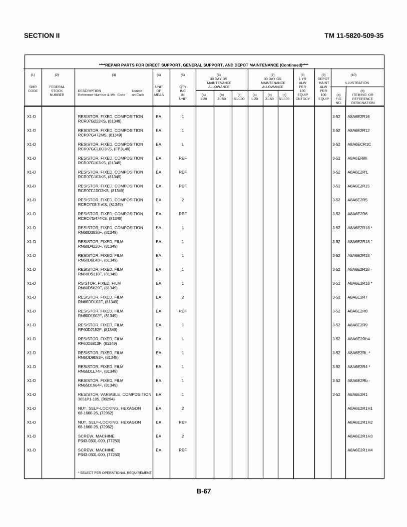
SECTION II TM 11-5820-509-35
****REPAIR PARTS FOR DIRECT SUPPORT, GENERAL SUPPORT, AND DEPOT MAINTENANCE (Continued)****
(1) (2) (3) (4) (5) (6) (7) (8) (9) (10)30 DAY DS 30 DAY GS 1 YR DEPOT
MAINTENANCE MAINTENANCE ALW MAINT ILLUSTRATIONSMR FEDERAL UNIT QTY ALLOWANCE ALLOWANCE PER ALW
CODE STOCK DESCRIPTION Usable OF INC 100 PER (b)NUMBER Reference Number & Mfr. Code on Code MEAS IN (a) (b) (c) (a) (b) (c) EQUIP 100 (a) ITEM NO. OR
UNIT 1-20 21-50 51-100 1-20 21-50 51-100 CNTGCY EQUIP FIG REFERENCENO. DESIGNATION
X1-D RESISTOR, FIXED, COMPOSITION EA 1 3-52 A8A6E2R16RCR07G222KS, (81349)
X1-D RESISTOR, FIXED, COMPOSITION EA 1 3-52 A8A6E2R12RCR07G472MS, (81349)
X1-D RESISTOR, FIXED, COMPOSITION EA L 3-52 A8A6ECR1CRCR07GC10O3KS, (FP3L49)
X1-D RESISTOR, FIXED, COMPOSITION EA REF 3-52 A8A6ERilliRCR07G103KS, (81349)
X1-D RESISTOR, FIXED, COMPOSITION EA REF 3-52 A8A6E2R'LRCR07G103KS, (81349)
X1-D RESISTOR, FIXED, COMPOSITION EA REF 3-52 A8A6E2R15RCR07C10O3KS, (81349)
X1-D RESISTOR, FIXED, COMPOSITION EA 2 3-52 A8A6E2R5RCRO7Gh7hKS, (81349)
X1-D RESISTOR, FIXED, COMPOSITION EA REF 3-52 A8A6E2R6RCRO7G474KS, (81349)
X1-D RESISTOR, FIXED, COMPOSITION EA 1 3-52 A8A6E2R18 *RN60D3830F, (81349)
X1-D RESISTOR, FIXED, FILM EA 1 3-52 A8A6E2R18 "RN60D4220F, (81349)
X1-D RESISTOR, FIXED, FILM EA 1 3-52 A8A6E2R18 'RN60D6L40F, (81349)
X1-D RESISTOR, FIXED, FILM EA 1 3-52 A8A6E2R18 -RN60D5110F, (81349)
X1-D RSISTOR, FIXED, FILM EA 1 3-52 A8A6E2R18 *RN60D5620F, (81349)
X1-D RESISTOR, FIXED, FILM EA 2 3-52 A8A6E2R7RN60DD102F, (81349)
X1-D RESISTOR, FIXED, FILM EA REF 3-52 A8A6E2R8RN60D1002F, (81349)
X1-D RESISTOR, FIXED, FILM: EA 1 3-52 A8A6E2R9RP60D2152F, (81349)
X1-D RESISTOR, FIXED, FILM EA 1 3-52 A8A6E2Rb4RF60D6813F, (81349)
X1-D RESISTOR, FIXED, FILM EA 1 3-52 A8A6E2RL *RN6OD9093F, (81349)
X1-D RESISTOR, FIXED, FILM EA 1 3-52 A8A6E2R4 *RN65D1L74F, (81349)
X1-D RESISTOR, FIXED, FILM EA 1 3-52 A8A6E2Rb -RN65D1964F, (81349)
X1-D RESISTOR, VARIABLE, COMPOSITION EA 1 3-52 A8A6E2R13051P1-105, (80294)
X1-D NUT, SELF-LOCKING, HEXAGON EA 2 A8A6E2R1H168-1660-26, (72962)
X1-D NUT, SELF-LOCKING, HEXAGON EA REF A8A6E2R1H268-1660-26, (72962)
X1-D SCREW, MACHINE EA 2 A8A6E2R1H3P343-0301-000, (77250)
X1-D SCREW, MACHINE EA REF A8A6E2R1H4P343-0301-000, (77250)
* SELECT PER OPERATIONAL REQUIREMENT
B-67
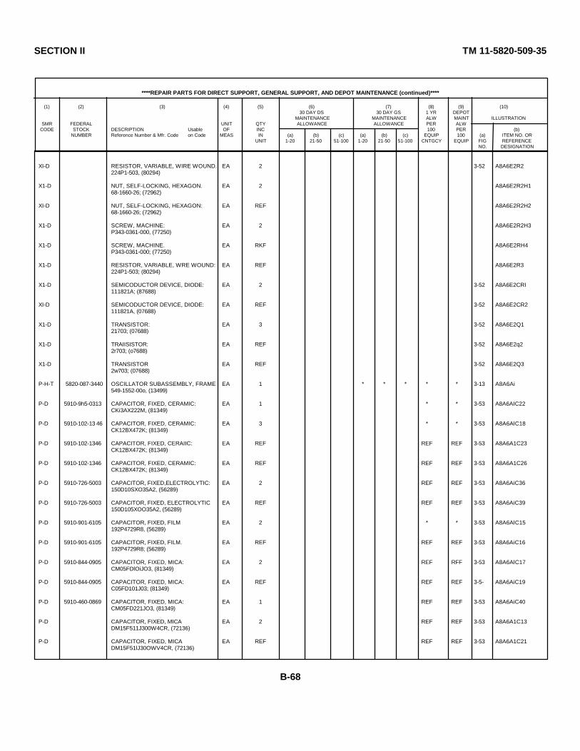
SECTION II TM 11-5820-509-35
****REPAIR PARTS FOR DIRECT SUPPORT, GENERAL SUPPORT, AND DEPOT MAINTENANCE (continued)****
(1) (2) (3) (4) (5) (6) (7) (8) (9) (10)30 DAY DS 30 DAY GS 1 YR DEPOT
MAINTENANCE MAINTENANCE ALW MAINT ILLUSTRATIONSMR FEDERAL UNIT QTY ALLOWANCE ALLOWANCE PER ALW
CODE STOCK DESCRIPTION Usable OF INC 100 PER (b)NUMBER Reference Number & Mfr. Code on Code MEAS IN (a) (b) (c) (a) (b) (c) EQUIP 100 (a) ITEM NO. OR
UNIT 1-20 21-50 51-100 1-20 21-50 51-100 CNTGCY EQUIP FIG REFERENCENO. DESIGNATION
XI-D RESISTOR, VARIABLE, WIRE WOUND. EA 2 3-52 A8A6E2R2224P1-503, (80294)
X1-D NUT, SELF-LOCKING, HEXAGON. EA 2 A8A6E2R2H168-1660-26; (72962)
XI-D NUT, SELF-LOCKING, HEXAGON: EA REF A8A6E2R2H268-1660-26; (72962)
X1-D SCREW, MACHINE: EA 2 A8A6E2R2H3P343-0361-000, (77250)
X1-D SCREW, MACHINE. EA RKF A8A6E2RH4P343-0361-000; (77250)
X1-D RESISTOR, VARIABLE, WRE WOUND: EA REF A8A6E2R3224P1-503; (80294)
X1-D SEMICODUCTOR DEVICE, DIODE: EA 2 3-52 A8A6E2CRI111821A; (87688)
XI-D SEMICODUCTOR DEVICE, DIODE: EA REF 3-52 A8A6E2CR2111821A, (07688)
X1-D TRANSISTOR: EA 3 3-52 A8A6E2Q121703; (07688)
X1-D TRAIISISTOR: EA REF 3-52 A8A6E2q22r703; (o7688)
X1-D TRANSISTOR EA REF 3-52 A8A6E2Q32w703; (07688)
P-H-T 5820-087-3440 OSCILLATOR SUBASSEMBLY, FRAME EA 1 * * * * * 3-13 A8A6Ai549-1552-00o, (13499)
P-D 5910-9h5-0313 CAPACITOR, FIXED, CERAMIC: EA 1 * * 3-53 A8A6AIC22CKi3AX222M, (81349)
P-D 5910-102-13 46 CAPACITOR, FIXED, CERAMIC: EA 3 * * 3-53 A8A6AlC18CK12BX472K; (81349)
P-D 5910-102-1346 CAPACITOR, FIXED, CERAIIC: EA REF REF REF 3-53 A8A6A1C23CK12BX472K; (81349)
P-D 5910-102-1346 CAPACITOR, FIXED, CERAMIC: EA REF REF REF 3-53 A8A6A1C26CK12BX472K; (81349)
P-D 5910-726-5003 CAPACITOR, FIXED,ELECTROLYTIC: EA 2 REF REF 3-53 A8A6AiC36150D10SXO35A2, (56289)
P-D 5910-726-5003 CAPACITOR, FIXED, ELECTROLYTIC EA REF REF REF 3-53 A8A6AiC39150D105XOO35A2, (56289)
P-D 5910-901-6105 CAPACITOR, FIXED, FILM EA 2 * * 3-53 A8A6AlC15192P4729R8, (56289)
P-D 5910-901-6105 CAPACITOR, FIXED, FILM. EA REF REF REF 3-53 A8A6AiC16192P4729R8; (56289)
P-D 5910-844-0905 CAPACITOR, FIXED, MICA: EA 2 REF RFF 3-53 A8A6AlC17CM05FDlOiJO3, (81349)
P-D 5910-844-0905 CAPACITOR, FIXED, MICA: EA REF REF REF 3-5- A8A6AiC19C05FD101J03; (81349)
P-D 5910-460-0869 CAPACITOR, FIXED, MICA: EA 1 REF REF 3-53 A8A6AiC40CM05FD221JO3, (81349)
P-D CAPACITOR, FIXED, MICA EA 2 REF REF 3-53 A8A6A1C13DM15F511J300W4CR, (72136)
P-D CAPACITOR, FIXED, MICA EA REF REF REF 3-53 A8A6A1C21DM15F51lJ30OWV4CR, (72136)
B-68
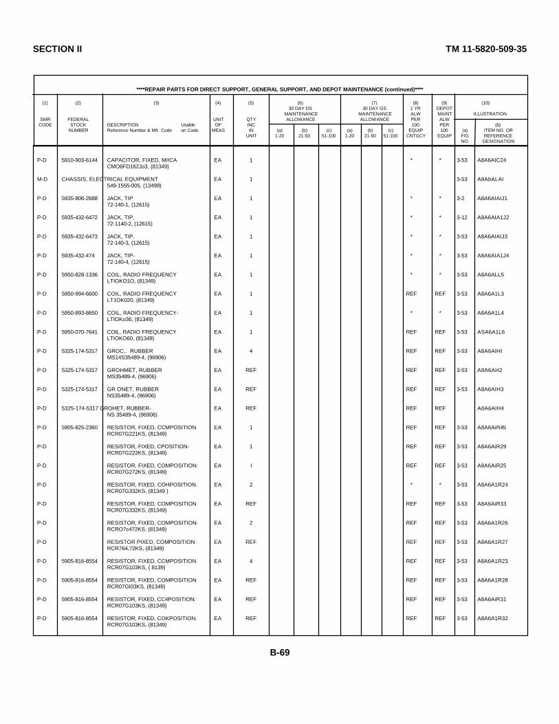
SECTION II TM 11-5820-509-35
****REPAIR PARTS FOR DIRECT SUPPORT, GENERAL SUPPORT, AND DEPOT MAINTENANCE (continued)****
(1) (2) (3) (4) (5) (6) (7) (8) (9) (10)30 DAY DS 30 DAY GS 1 YR DEPOT
MAINTENANCE MAINTENANCE ALW MAINT ILLUSTRATIONSMR FEDERAL UNIT QTY ALLOWANCE ALLOWANCE PER ALW
CODE STOCK DESCRIPTION Usable OF INC 100 PER (b)NUMBER Reference Number & Mfr. Code on Code MEAS IN (a) (b) (c) (a) (b) (c) EQUIP 100 (a) ITEM NO. OR
UNIT 1-20 21-50 51-100 1-20 21-50 51-100 CNTGCY EQUIP FIG REFERENCENO. DESIGNATION
P-D 5910-903-6144 CAPACITOR, FIXED, MIICA EA 1 * * 3-53 A8A6AIC24CMO6FD162Jo3, (81349)
M-D CHASSIS, ELECTRICAL EQUIPMENT EA 1 3-53 A8AbALAI549-1555-005, (13499)
P-D 5935-806-2688 JACK, TIP EA 1 * * 3-2 A8A6AIAIJ172-140-1, (12615)
P-D 5935-432-6472 JACK, TIP, EA 1 * * 3-12 A8A6AIA1J272-1140-2, (12615)
P-D 5935-432-6473 JACK, TIP. EA 1 * * 3-53 A8A6AIAIJ372-140-3, (12615)
P-D 5935-432-474 JACK, TIP- EA 1 * * 3-53 A8A6AIA1J472-140-4, (12615)
P-D 5950-828-1336 COIL, RADIO FREQUENCY EA 1 * * 3-53 A8A6ALL5LTIOKO1O, (81349)
P-D 5950-994-6600 COIL, RADIO FREQUENCY EA 1 REF REF 3-53 A8A6A1L3LT1OK020, (81349)
P-D 5950-893-8650 COIL, RADIO FREQUENCY- EA 1 * * 3-53 A8A6A1L4LTlOKo36, (81349)
P-D 5950-070-7641 COIL, RADIO FREQUENCY EA 1 REF REF 3-53 ASA6A1L6LTiOKO60, (81349)
P-D 5325-174-5317 GROC,. RUBBER EA 4 REF REF 3-53 A8A6AlHIMS14S35489-4, (96906)
P-D 5325-174-5317 GROHMET, RUBBER EA REF REF REF 3-53 A8A6AH2MS35489-4, (96906)
P-D 5325-174-5317 GR ONET, RUBBER EA REF REF REF 3-53 A8A6AIH3NS35489-4, (96906)
P-D 5325-174-5317 GROHET, RUBBER- EA REF REF REF A8A6AlH4NS 35489-4, (96906)
P-D 5905-825-2360 RESISTOR, FIXED, CCMPOSITION EA 1 REF REF 3-53 A8A6AiR45RCR07G221KS, (81349)
P-D RESISTOR, FIXED, CPOSITION- EA 1 REF REF 3-53 A8A6AiR29RCR07G222KS, (81349)
P-D RESISTOR, FIXED, COMPOSITION: EA I REF REF 3-53 A8A6AiR25RCR07G272KS, (81349)
P-D RESISTOR, FIXED, COHPOSITION. EA 2 * * 3-53 A8A6A1R24RCR07G332KS, (81349 )
P-D RESISTOR, FIXED, COMPOSITION EA REF REF REF 3-53 A8A6AiR33RCR07G332KS, (81349)
P-D RESISTOR, FIXED, COMPOSITION: EA 2 REF REF 3-53 A8A6A1R26RCRO7c472KS; (81349)
P-D RESISTOR PIXED, COMPOSITION EA REF REF REF 3-53 A8A6A1R27RCR764,72KS, (81349)
P-D 5905-816-8554 RESISTOR, FIXED, CCMPOSITION EA 4 REF REF 3-53 A8A6A1R23RCR07G103KS, ( 8139)
P-D 5905-816-8554 RESISTOR, FIXED, COMPOSITION EA REF REF REF 3-53 A8A6A1R28RCR07Gl03KS, (81349)
P-D 5905-816-8554 RESISTOR, FIXED, CC4POSITION: EA REF REF REF 3-53 A8A6AiR31RCR07G103KS, (81349)
P-D 5905-816-8554 RESISTOR, FIXED, COKPOSITION. EA REF REF REF 3-53 A8A6A1R32RCR07G103KS, (81349)
B-69
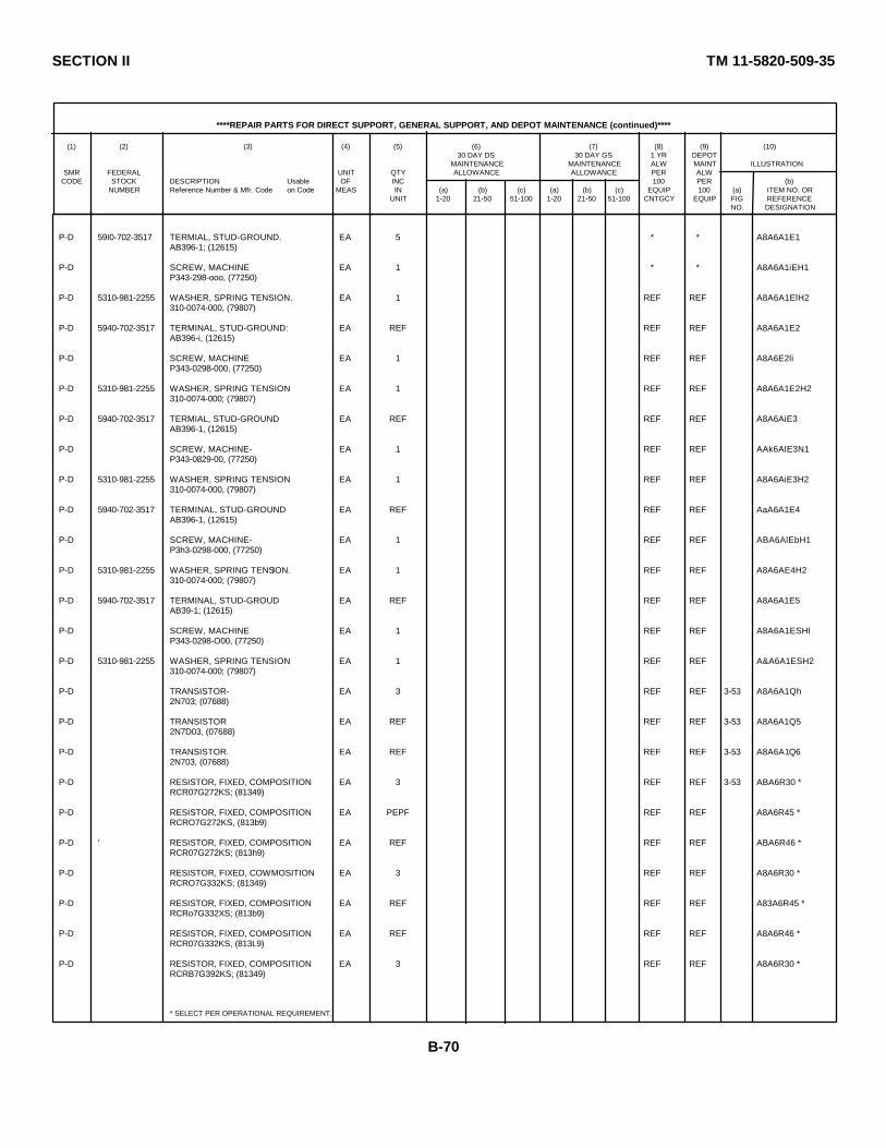
SECTION II TM 11-5820-509-35
****REPAIR PARTS FOR DIRECT SUPPORT, GENERAL SUPPORT, AND DEPOT MAINTENANCE (continued)****
(1) (2) (3) (4) (5) (6) (7) (8) (9) (10)30 DAY DS 30 DAY GS 1 YR DEPOT
MAINTENANCE MAINTENANCE ALW MAINT ILLUSTRATIONSMR FEDERAL UNIT QTY ALLOWANCE ALLOWANCE PER ALW
CODE STOCK DESCRIPTION Usable OF INC 100 PER (b)NUMBER Reference Number & Mfr. Code on Code MEAS IN (a) (b) (c) (a) (b) (c) EQUIP 100 (a) ITEM NO. OR
UNIT 1-20 21-50 51-100 1-20 21-50 51-100 CNTGCY EQUIP FIG REFERENCENO. DESIGNATION
P-D 59I0-702-3517 TERMIAL, STUD-GROUND. EA 5 * * A8A6A1E1AB396-1; (12615)
P-D SCREW, MACHINE EA 1 * * A8A6A1iEH1P343-298-ooo, (77250)
P-D 5310-981-2255 WASHER, SPRING TENSION. EA 1 REF REF A8A6A1ElH2310-0074-000, (79807)
P-D 5940-702-3517 TERMINAL, STUD-GROUND: EA REF REF REF A8A6A1E2AB396-i, (12615)
P-D SCREW, MACHINE EA 1 REF REF A8A6E2liP343-0298-000, (77250)
P-D 5310-981-2255 WASHER, SPRING TENSION EA 1 REF REF A8A6A1E2H2310-0074-000; (79807)
P-D 5940-702-3517 TERMIAL, STUD-GROUND EA REF REF REF A8A6AiE3AB396-1, (12615)
P-D SCREW, MACHINE- EA 1 REF REF AAk6AlE3N1P343-0829-00, (77250)
P-D 5310-981-2255 WASHER, SPRING TENSION EA 1 REF REF A8A6AiE3H2310-0074-000, (79807)
P-D 5940-702-3517 TERMINAL, STUD-GROUND EA REF REF REF AaA6A1E4AB396-1, (12615)
P-D SCREW, MACHINE- EA 1 REF REF ABA6AlEbH1P3h3-0298-000, (77250)
P-D 5310-981-2255 WASHER, SPRING TENSION. EA 1 REF REF A8A6AE4H2310-0074-000; (79807)
P-D 5940-702-3517 TERMINAL, STUD-GROUD EA REF REF REF A8A6A1E5AB39-1; (12615)
P-D SCREW, MACHINE EA 1 REF REF A8A6A1ESHlP343-0298-O00, (77250)
P-D 5310-981-2255 WASHER, SPRING TENSION EA 1 REF REF A&A6A1ESH2310-0074-000; (79807)
P-D TRANSISTOR- EA 3 REF REF 3-53 A8A6A1Qh2N703; (07688)
P-D TRANSISTOR EA REF REF REF 3-53 A8A6A1Q52N7D03, (07688)
P-D TRANSISTOR. EA REF REF REF 3-53 A8A6A1Q62N703, (07688)
P-D RESISTOR, FIXED, COMPOSITION EA 3 REF REF 3-53 ABA6R30 *RCR07G272KS; (81349)
P-D RESISTOR, FIXED, COMPOSITION EA PEPF REF REF A8A6R45 *RCRO7G272KS, (813b9)
P-D ' RESISTOR, FIXED, COMPOSITION EA REF REF REF ABA6R46 *RCR07G272KS; (813h9)
P-D RESISTOR, FIXED, COWMOSITION EA 3 REF REF A8A6R30 *RCRO7G332KS; (81349)
P-D RESISTOR, FIXED, COMPOSITION EA REF REF REF A83A6R45 *RCRo7G332XS; (813b9)
P-D RESISTOR, FIXED, COMPOSITION EA REF REF REF A8A6R46 *RCR07G332KS, (813L9)
P-D RESISTOR, FIXED, COMPOSITION EA 3 REF REF A8A6R30 *RCRB7G392KS; (81349)
* SELECT PER OPERATIONAL REQUIREMENT.
B-70

SECTION II TM 11-5820-509-35
****REPAIR PARTS FOR DIRECT SUPPORT, GENERAL SUPPORT, AND DEPOT MAINTENANCE (continued)****
(1) (2) (3) (4) (5) (6) (7) (8) (9) (10)30 DAY DS 30 DAY GS 1 YR DEPOT
MAINTENANCE MAINTENANCE ALW MAINT ILLUSTRATIONSMR FEDERAL UNIT QTY ALLOWANCE ALLOWANCE PER ALW
CODE STOCK DESCRIPTION Usable OF INC 100 PER (b)NUMBER Reference Number & Mfr. Code on Code MEAS IN (a) (b) (c) (a) (b) (c) EQUIP 100 (a) ITEM NO. OR
UNIT 1-20 21-50 51-100 1-20 21-50 51-100 CNTGCY EQUIP FIG REFERENCENO. DESIGNATION
P-D 5905-070-9391 RESISTOR, FIXED, COMPOSITION EA REF REF REF A8A6R45 *RCRO7G392KS, (81349)
P-D 5905-070-9391 RESISTOR., FIXED, COMPOSITION: EA REF REF REF A8A6R46 *RCR07G392KS, (81349)
P-D 5905-752-3340 RESISTOR, FIXED, COMPOSITION. EA 3 REF REF A8A6R0 *RCRO7G472KS, (81349)
P-D 5905-752-3340 RESISTOR, FIXED, COMPOSITION EA REF REF REF A8A6R5 *RCRO7G472KS; (81349)
P-D 5905-752-3340 RESISTOR, FIXED, COMPOSITION. EA REF REF REF A8A6R46 *RCRO7C472KS, (81349)
P-D 5905-070-9392 RESISTOR, FIXED, COMPOSITION. EA 3 REF REF A8A6R30 *RCR07G562KS, (81349)
P-D 5905-070-9392 RESISTOR, FIXED, COMPOSITION- EA REF REF REF A8A6RS5 *RCRO7G562KS, (81349)
P-D 5905-070-9392 RESISTOR, FIXED, COMPOSITION- EA REF REF REF A8A6R46 *RCRO7G562KS, (81349)
P-D RESISTOR, FXED, COMPOSITION- EA 3 * * A8A6R30 *RCRo7C682KS, '(81349)
P-D RESISTOR, FIXED, COMPOSITIOD: EA REF REF REF A8A6Rb45 *RCRO7G682Ks, (81349)
P-D RESISTOR, FIXED, COMPOSITIOD- EA REF REF REF A8A6R46 *RCRO7G682Ks, (81349)
P-D 5905-834-9874 RESISTOR, FIXED, COMPOSITION EA 3 REF REF A8A6R30 *RCR07C822Ks, (81349)
P-D 5905-834-9874 RESISTOR, FIXED, COMPOSITION EA REF REF REF A8A6R45 *RCR7CG822KS, (81349)
P-D 5905-834-9874 RESISTOR, FIXED, COMPOSITION. EA REF REF REF A8A6R46 *RCRo7c822Ks, (81349)
P-D 5905-816-8554 RESISTOR, FIXED, COMPOSITION- EA 3 REF REF A8A6R30 *RCRo7GlO3KS; (81349)
P-D 5905-816-8554 RESISTOR, FIXED, COMPOSITION' EA REF REF REF A8A6R4S *RCR07GC103KS, (813b9)
P-D 5905-816-8554 RESISTOR, FIXED, COMPOSITION- EA REF REF REF A8A6R46 *RCR07G103KS, (81349)
P-D RESISTOR, FIXED, COMPOSITION EA 3 REF REF A8A6R30 *RCR07G123KS, (81349)
P-D RESISTOR, FIXED, COMPOSITION- EA REF REF REF A8A6Rb5 *RCR07G123KS, (81349)
P-D RESISTOR, FIXED, COMPOSITION EA REF REF REF A8A6R46 *RCR07123KS, (81349)
P-D RESISTOR, FIXED, COMPOSITION' EA, 3 * * A8A6R30 *RCR7GC153KS, (81349)
P-D RESISTOR, FTXED, COMPOSITION. EA REF REF REF A8A6R45 *RCRO7G153KS, (81349)
P-D RESISTOR, FIXED, COMPOSITION EA REF REF REF A8A6Rb6 *RCR07G153KS, (81349)
P-D RESISTOR, FIXED, COMPOSITION EA 3 REF REF A8A6R30 *RCRO7G183KS; (81349)
P-D RESISTOR, FIXED, COMPOSITION EA REF * * ASA6R4S *RCR07G183KS, (81349)
* SELECT PER OPERATIONAL REQUIREMENT.
B-71
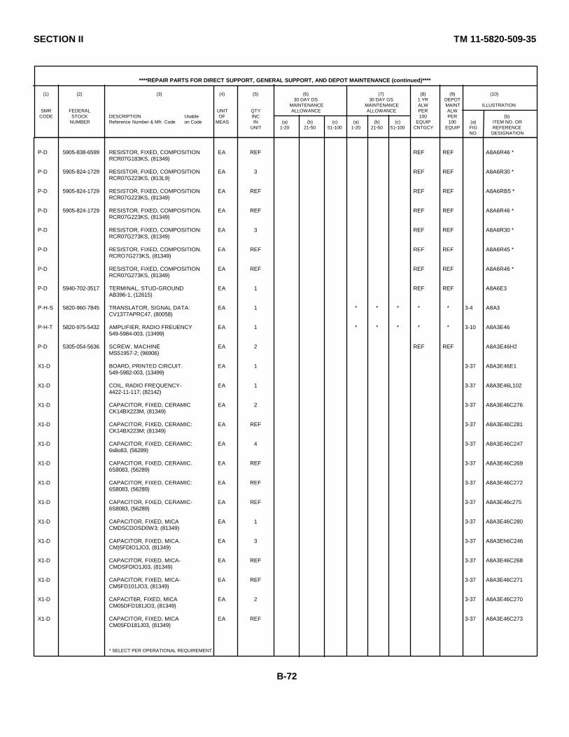
SECTION II TM 11-5820-509-35
****REPAIR PARTS FOR DIRECT SUPPORT, GENERAL SUPPORT, AND DEPOT MAINTENANCE (continued)****
(1) (2) (3) (4) (5) (6) (7) (8) (9) (10)30 DAY DS 30 DAY GS 1 YR DEPOT
MAINTENANCE MAINTENANCE ALW MAINT ILLUSTRATIONSMR FEDERAL UNIT QTY ALLOWANCE ALLOWANCE PER ALW
CODE STOCK DESCRIPTION Usable OF INC 100 PER (b)NUMBER Reference Number & Mfr. Code on Code MEAS IN (a) (b) (c) (a) (b) (c) EQUIP 100 (a) ITEM NO. OR
UNIT 1-20 21-50 51-100 1-20 21-50 51-100 CNTGCY EQUIP FIG REFERENCENO. DESIGNATION
P-D 5905-838-6599 RESISTOR, FIXED, COMPOSITION EA REF REF REF A8A6R46 *RCR07G183KS, (81349)
P-D 5905-824-1729 RESISTOR, FIXED, COMPOSITION EA 3 REF REF A8A6R30 *RCR07G223KS, (813L9)
P-D 5905-824-1729 RESISTOR, FIXED, COMPOSITION EA REF REF REF A8A6RB5 *RCR07G223KS, (81349)
P-D 5905-824-1729 RESISTOR, FIXED, COMPOSITION. EA REF REF REF A8A6R46 *RCR07G223KS, (81349)
P-D RESISTOR, FIXED, COMPOSITION: EA 3 REF REF A8A6R30 *RCR07G273KS, (81349)
P-D RESISTOR, FIXED, COMPOSITION. EA REF REF REF A8A6R45 *RCRO7G273KS, (81349)
P-D RESISTOR, FIXED, COMPOSITION EA REF REF REF A8A6R46 *RCR07G273KS, (81349)
P-D 5940-702-3517 TERMINAL, STUD-GROUND EA 1 REF REF A8A6E3AB396-1, (12615)
P-H-S 5820-960-7845 TRANSLATOR, SIGNAL DATA: EA 1 * * * * * 3-4 A8A3CV1377APRC47, (80058)
P-H-T 5820-975-5432 AMPLIFIER, RADIO FREUENCY EA 1 * * * * * 3-10 A8A3E46549-5984-003, (13499)
P-D 5305-054-5636 SCREW, MACHINE EA 2 REF REF A8A3E46H2MS51957-2; (96906)
X1-D BOARD, PRINTED CIRCUIT. EA 1 3-37 A8A3E46E1549-5982-003, (13499)
X1-D COIL, RADIO FREQUENCY- EA 1 3-37 A8A3E46L1024422-11-117; (82142)
X1-D CAPACITOR, FIXED, CERAMIC EA 2 3-37 A8A3E46C276CK14BX223M, (81349)
X1-D CAPACITOR, FIXED, CERAMIC: EA REF 3-37 A8A3E46C281CK14BX223M; (81349)
X1-D CAPACITOR, FIXED, CERAMIC: EA 4 3-37 A8A3E46C2476s8o83, (56289)
X1-D CAPACITOR, FIXED, CERAMIC. EA REF 3-37 A8A3E46C2696S8083, (56289)
X1-D CAPACITOR, FIXED, CERAMIC: EA REF 3-37 A8A3E46C2726S8083, (56289)
X1-D CAPACITOR, FIXED, CERAMIC- EA REF 3-37 A8A3E46c2756S8083, (56289)
X1-D CAPACITOR, FIXED, MICA EA 1 3-37 A8A3E46C280CMDSCDOSD0W3; (81349)
X1-D CAPACITOR, FIXED, MICA. EA 3 3-37 A8A3Eh6C246CM)5FDlO1JO3, (81349)
X1-D CAPACITOR, FIXED, MICA- EA REF 3-37 A8A3E46C268CMDSFDlO1J03, (81349)
X1-D CAPACITOR, FIXED, MICA- EA REF 3-37 A8A3E46C271CM5FD101JO3, (81349)
X1-D CAPACIT6R, FIXED, MICA EA 2 3-37 A8A3E46C270CM05DFD181JO3, (81349)
X1-D CAPACITOR, FIXED, MICA EA REF 3-37 A8A3E46C273CM05FD181J03, (81349)
* SELECT PER OPERATIONAL REQUIREMENT.
B-72

SECTION II TM 11-5820-509-35
****REPAIR PARTS FOR DIRECT SUPPORT, GENERAL SUPPORT, AND DEPOT MAINTENANCE (continued)****
(1) (2) (3) (4) (5) (6) (7) (8) (9) (10)30 DAY DS 30 DAY GS 1 YR DEPOT
MAINTENANCE MAINTENANCE ALW MAINT ILLUSTRATIONSMR FEDERAL UNIT QTY ALLOWANCE ALLOWANCE PER ALW
CODE STOCK DESCRIPTION Usable OF INC 100 PER (b)NUMBER Reference Number & Mfr. Code on Code MEAS IN (a) (b) (c) (a) (b) (c) EQUIP 100 (a) ITEM NO. OR
UNIT 1-20 21-50 51-100 1-20 21-50 51-100 CNTGCY EQUIP FIG REFERENCENO. DESIGNATION
X1-D CAPACITOR, FIXED, MICA. EA 1 3-37 A8A3E46C274DM15F471J300WV4CR, (72136)
X1-D RESISTOR, FIXED, COMPOSITION EA 3 3-37 A8A3E46R125RCR07G121KS, (81349)
X1-D RESISTOR, FIXED, COMPOSITION EA REF 3-37 A8A3E46R130RCR07G121KS, (81349)
X1-D RESISTOR, FIXED, COMPOSITION EA REF 3-37 A8A3E46RI35RCR07G121KS, (81349)
X1-D RESISTOR, FIXED, COMPOSITION EA 1 3-37 A8A3E46R134RCRO7CG331KS, (81349)
X1-D RESISTOR, FIXED, COMPOSITION EA 6 3-37 A8A3E46Rl19RCR07GC10O2KS, (81349)
X1-D RESISTOR, FIXED, COMPOSITION EA REF 3-37 A8A3E462RCR07C10cKS, (81349)
Xi-D RESISTOR, FIXED, COMPOSITION EA REF 3-37 A8A3E46R124RCR07G102KS, (81349)
X1-D RESISTOR, FIXED, COMPOSITION EA REF 3-37 A8A3E46R128RCR07G102KS, (81349)
X1-D RESISTOR, FIXED, COMPOSITION EA REF 3-37 A8A3E46R129RCRO7GlO2KS; (81349)
X1-D RESISTOR, FIXED, COMPOSITION EA REF 3-37 A8A3E46R133RCR07G102KS, (81349)
X1-D RESISTOR, FIXED, COMPOSITION EA 1 3-37 A8A3E46R120RCR07GC153KS; (81349)
X1-D RESISTOR, FIXED, COMPOSITION. EA 2 3-37 A8A3E46R122RCR07G223KS, (81349)
X1-D RESISTOR, FIXED, COMPOSITION EA REF 3-37 A8A3E46R132RCR07G223KS, (81349)
X1-D RESISTOR, FIXED, COMPOSITION- EA 1 3-37 A8A3E46R127RCRO7CG822KS, (81349)
X1-D RESISTOR, FIXED, COMPOSITION: EA 3 3-37 A8A3E46R121RCR07G273KS, (81349)
X1-D RESISTOR, FIXED, COMPOSITION EA RE2 3-37 A8A3E46R126RCR07G273KS, (81349)
X1-D RESISTOR, FIXED, COMPOSITION EA REF 3-37 A8A3E46R131RCR07C273KS, (81349)
X1-D TRANSISTOR EA 4 3-37 A8A3E46Q162N703, 07688)
X1-D TRANSISTOR EA REF 3-37 A8A3E46Q172N703, (07688)
X1-D TRANSISTOR EA REF 3-37 A8A3E46Q182N703, (07688)
X1-D TRANSISTOR EA REF 3-37 A8A3E46Q192N703, (07688)
P-H-T 5820-975-5430 AMPLIFIER, RADIO FREQUENCY EA 1 * * * * * 3-9 A8A3E47549-5996-oo00, (13499)
X1-D BOARD, PRINTED CIRCUIT EA 1 3-38 A8A3E47E1549-5995-004, (13499)
X1-D CAPACITOR, FIXED, CERAMIC EA 2 3-38 A8A3E47C144CK14BX223M, (81349)
B-73
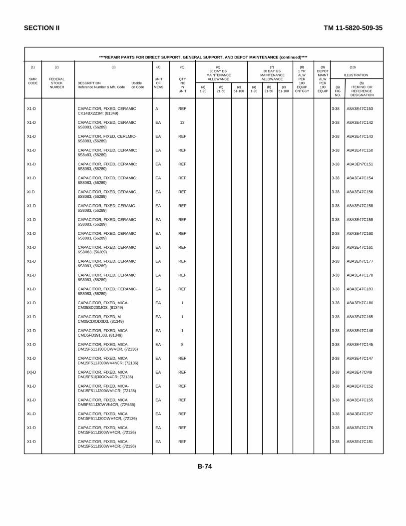
SECTION II TM 11-5820-509-35
****REPAIR PARTS FOR DIRECT SUPPORT, GENERAL SUPPORT, AND DEPOT MAINTENANCE (continued)****
(1) (2) (3) (4) (5) (6) (7) (8) (9) (10)30 DAY DS 30 DAY GS 1 YR DEPOT
MAINTENANCE MAINTENANCE ALW MAINT ILLUSTRATIONSMR FEDERAL UNIT QTY ALLOWANCE ALLOWANCE PER ALW
CODE STOCK DESCRIPTION Usable OF INC 100 PER (b)NUMBER Reference Number & Mfr. Code on Code MEAS IN (a) (b) (c) (a) (b) (c) EQUIP 100 (a) ITEM NO. OR
UNIT 1-20 21-50 51-100 1-20 21-50 51-100 CNTGCY EQUIP FIG REFERENCENO. DESIGNATION
X1-D CAPACITOR, FIXED, CERAMIC A REF 3-38 A8A3E47C153CK14BX223M; (81349)
X1-D CAPACITOR, FIXED, CERAMIC EA 13 3-38 A8A3E47C1426S8083, (56289)
X1-D CAPACITOR, FIXED, CERLMIC- EA REF 3-38 A8A3E47C1436S8083, (56289)
X1-D CAPACITOR, FIXED, CERAMIC: EA REF 3-38 A8A3E47C1506S8o83, (56289)
X1-D CAPACITOR, FIXED, CERAMIC: EA REF 3-38 A8A3Eh7C1516S8083, (56289)
X1-D CAPACITOR, FIXED, CERAMIC. EA REF 3-38 A8A3E47C1546S8083, (56289)
XI-D CAPACITOR, FIXED, CERAMIC. EA REF 3-38 A8A3E47C1566S8083; (56289)
X1-D CAPACITOR, FIXED, CERAMC- EA REF 3-38 A8A3E47C1586S8083, (56289)
X1-D CAPACITOR, FIXED, CERAMIC EA REF 3-38 A8A3E47C1596S8083, (56289)
X1-D CAPACITOR, FIXED, CERAMIC EA REF 3-38 A8A3E47C1606S8083, (56289)
X1-D CAPACITOR, FIXED, CERAMIC EA REF 3-38 A8A3E47C1616S8083, (56289)
X1-D CAPACITOR, FIXED, CERAMIC EA REF 3-38 A8A3Eh7C1776S8083, (56289)
X1-D CAPACITOR, FIXED, CERAMIC EA REF 3-38 A8A3E47C1786S8083, (56289)
X1-D CAPACITOR, FIXED, CERAMIC- EA REF 3-38 A8A3E47C1836S8083, (56289)
X1-D CAPACITOR, FIXED, MICA- EA 1 3-38 A8A3Eh7C180CM05SD200JO3, (81349)
X1-D CAPACITOR, FIXED, M EA 1 3-38 A8A3E47C165CM05CDlOD0D3, (81349)
X1-D CAPACITOR, FIXED, MICA EA 1 3-38 A8A3E47C148CMD5FD391J03, (81349)
X1-D CAPACITOR, FIXED, MICA. EA 8 3-38 A8A3E47C145DM15F511J30OOWVCR, (72136)
X1-D CAPACITOR, FIXED, MICA EA REF 3-38 A8A3E47C147DM15F511J300WV4hCR; (72136)
)X]-D CAPACITOR, FIXED, MICA EA REF 3-38 A8A3E47Cl49DM15F51lj30OOv4CR; (72136)
X1-D CAPACITOR, FIXED, MICA- EA REF 3-38 A8A3E47C152DM15F511J300WVhCR; (72136)
X1-D CAPACITOR, FIXED, MICA EA REF 3-38 A8A3E47C155DM5F511J30WVh4CR, (72%36)
XL-D CAPACITOR, FIXED, MICA EA REF 3-38 A8A3E47C157DM15F511J30OWV4CR, (72136)
X1-D CAPACITOR, FIXED, MICA. EA REF 3-38 A8A3E47C176DM15F511J300WV4CR, (72136)
X1-D CAPACITOR, FIXED, MICA: EA REF 3-38 A8A3E47C181DM15F511J300WV4CR; (72136)
B-74

SECTION II TM 11-5820-509-35
****REPAIR PARTS FOR DIRECT SUPPORT, GENERAL SUPPORT, AND DEPOT MAINTENANCE (continued)****
(1) (2) (3) (4) (5) (6) (7) (8) (9) (10)30 DAY DS 30 DAY GS 1 YR DEPOT
MAINTENANCE MAINTENANCE ALW MAINT ILLUSTRATIONSMR FEDERAL UNIT QTY ALLOWANCE ALLOWANCE PER ALW
CODE STOCK DESCRIPTION Usable OF INC 100 PER (b)NUMBER Reference Number & Mfr. Code on Code MEAS IN (a) (b) (c) (a) (b) (c) EQUIP 100 (a) ITEM NO. OR
UNIT 1-20 21-50 51-100 1-20 21-50 51-100 CNTGCY EQUIP FIG REFERENCENO. DESIGNATION
XL-D JACK, TIP EA 1 3-38 A8A3E47J5105-734-1oo; (74970)
X1-D JACK, TIP: EA 1 3-38 A8A3E47J6105-740-100, (74970)
X1-D RESISTOR, FIXED, COMPOSITION EA 2 3-38 ABA3E47R24RCR07G270KS, (81349)
X1-D RESISTOR, FIXED, COMPOSITION EA REF 3-38 ABA3E47R30RCR07G270KS, (81349)
X1-D RESISTOR, FIXED, COMPOSITION EA 1 3-38 A8A3E47R41RCR07C101KS, (81349)
X1-D RESISTOR, FI-XED, COMPOSITION EA 3 3-38 A8A3E47R43RCR07C121KS; (81349)
X1-D RESISTOR, FIXED, COMPOSITION. EA RE 3-38 ABA3E47R57RCR07G121KS; (81349)
X1-D RESISTOR, FIXED, COMPOSITION' EA REF 3-38 A8A3E47Rl19RCR7OG121KS, (81349)
X1-D RESISTOR, FIXED, COMPOSITION EA 1 3-38 A8A3E47R143RCR07G331KS, (81349)
X1-D RESISTOR, FIXED, C0MPOSITION EA 5 3-38 A8A3E47R28RCRO7G561KS, (81349)
X1-D RESISTOR, FIXED, CM0POSITION: EA REF 3-38 A8A3E47R37RCR07G561KS, (81349)
X1-D RESISTOR, FIXED, COMPOSITION EA REF 3-38 A8A3E47Rs4RCR07G561KS, (81349)
X1-D RESISTOR, FIXED, COMPOSITION EA REF 3-38 ABA3E47R139RCRO7G561KS, (31349)
X1-D RESISTOR, FIXED, COMPOSITION EA REF 3-38 A8A3E47R144RCR07G561KS, (81349)
X1-D RESISTOR, FIXED, COMPOSITION EA 1 3-38 A8A3E47R42RCR07G821KS, (81349)
X1-D RESISTOR, FIXFD, COMPOSITION- EA 7 3-38 A8A3E47R34RCRO7G1021S, (81349)
X1-D RESISTOR, FIXED, COMPOSITION EA REX 3-38 A8A3E47R46RCR07G1o2KS, (81349)
X1-D RESISTOR, FIXED, COMPOSITION EA REF 3-38 A8A3E47R47RCR07GlO2KS, (81349)
X1-D RESISTOR, FIXED, COMPOSITION EA REF 3-38 A8A3E47R5ORCRO7G102KS, (81349)
X1-D RESISTOR, FIXED, 00CMPSITION EA RE 3-38 ABA3E47R51RCR07G102KS; (81349)
X1-D RESISTOR, FIXED, COMPOSITION EA REF 3-38 ABA3E47R55RCRD7G102KS, (81349)
X1-D RESISTOR, FIXED, COMPOSITION EA REF 3-38 A8A3E47R138RCR07G102KS, (81349)
X1-D RESISTOR, FIXED, COMPOSITION EA 2 3-38 A8A3E47R29RCRO7G222KS, (81349)
X1-D RESISTOR, FIXED, COMPOSITION EA REF 3-38 A8A3E47R32RCR07G222KS, (81349)
XL-D RESISTOR, FIXED, COMPOSITION EA 1 3-38 A8A3E47R36RCR07G332KS, (81349)
B-75

SECTION II TM 11-5820-509-35
****REPAIR PARTS FOR DIRECT SUPPORT, GENERAL SUPPORT, AND DEPOT MAINTENANCE (continued)****
(1) (2) (3) (4) (5) (6) (7) (8) (9) (10)30 DAY DS 30 DAY GS 1 YR DEPOT
MAINTENANCE MAINTENANCE ALW MAINT ILLUSTRATIONSMR FEDERAL UNIT QTY ALLOWANCE ALLOWANCE PER ALW
CODE STOCK DESCRIPTION Usable OF INC 100 PER (b)NUMBER Reference Number & Mfr. Code on Code MEAS IN (a) (b) (c) (a) (b) (c) EQUIP 100 (a) ITEM NO. OR
UNIT 1-20 21-50 51-100 1-20 21-50 51-100 CNTGCY EQUIP FIG REFERENCENO. DESIGNATION
X1-D RESISTOR, FIXED, COMPOSITION. EA 1 3-38 A8A3E47R142RCR07G472S, (81349)
XI-D RESISTOR, FIXED, COMPOSITION: EA 1 3-38 A8A3E47R39RCRO7G682KS, (e13h9)
X1-D RESISTOR, FIXED, COMPOSITION. EA 3 3-38 A8A3Eh7Rh0RCRo7C822KS; (813h9)
XI-D RESISTOR, FIXED, COMPOSTION: EA REF 3-38 A8A3E47Rh5RCRo7c822KS; (81349)
X1-D RESISTOR, FIXED, COMPOSITION: EA REF 3-38 A8A3E47R4gRCR07G822KS, (81349)
XI-D RESISTOR, FIXED, CODPOSITION: EA 4 3-38 A8A3Eh7R25RCR07GlO3KS; (813h9)
XI-D RESISTOR, FIXED, COMPOSITION: EA REF 3-38 A8A3E47Rh4RCR07G103KS; (81349)
X1-D RESISTOR, FIXED, COMPOSITION: FA RF 3-38 A8A3E47R48RCR07CG03KS; (81349)
X1-D RESISTOR, FIXED, COMPOSITION: EA REF 3-38 A8A3E47R56RCR07G103KS, (813h9)
XI-D RESISTOR, FIXED, COMPOSITION: EA 7 3-38 A8A3E47R31RCR07G123KS; (8134 9)
X1-D RESISTOR, FIXED, CODPOSITION: EA REF 3-38 A8A3Eh7R35RCR07G123KS; (81349)
X1-D RESISTOR, FIXED, COMPOSITION. EA REF 3-38 A8A3Eh7R52RCRD7G123KS, (81349)
X1-D RESISTOR, FIXED, COMPOSITION- EA REF 3-38 A8A3Eh7R53RCR07G123KS, (81349)
X1-D RESISTOR, FIXED, COMPOSITION: EA REF 3-38 A8A3E47R136RCR07G123KS; (813h9)
XI-D RESISTOR, FIXED, COMPOSITION- EA REF 3-38 A8A3Eb7R137RCR07G123KS; (81349)
X1-D RESISTOR, FIXED, COMPOSITION: EA REF 3-38 A8A3E47R1RCR07GI?3KS; (813h9)
X1-D RESISTOR, FIXED, COMPOSITIOB- EA 2 3-38 A8A3E47R26RCR07G?21KS; (81349)
X1-D RESJSTOR, FIXED, COMPOSITION EA REF 3-38 A8A3E47R27RCR07G?23XS; (81349)
X1-D RESISTOR, FIXED, COMPOSITION: EA 2 3-38 A8A3E47Rl40RCR07C333KS, ('813b9)
X1-D RESISTOR, FIXED, COMPOSITION EA REF 3-38 AA3E47Rl45RCR07G333KS; (813h9)
X1-D RESISTOR, FIXED, FILM EA 2 3-38 A8A3E47R33Rn60D1960F; (81349)
X1-D RESISTOR, FIXED, FILM. EA REF 3-38 A8A3E47R38RN6,D]960F, (81349)
X1-D SEMICONDUCTOR DEVICE, DIODE- EA 2 3-38 A8A3E47CR516645; (07688)
XI-D SEMICONDUCTOR DEVICE, DIODE EA REF 3-38 A8A3E47CR61N6h5, (o7688)
X]-D TRANSISTOR. EA 7 3-38 A8A3E47Q22N703, (07688)
B-76
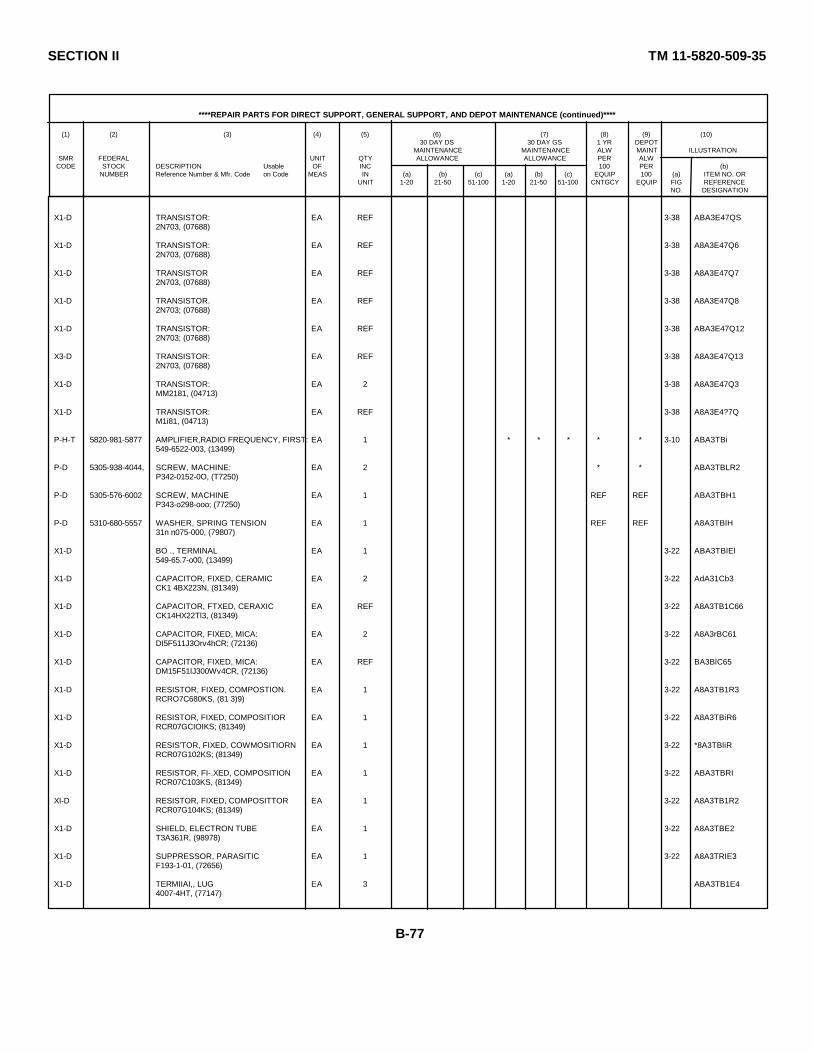
SECTION II TM 11-5820-509-35
****REPAIR PARTS FOR DIRECT SUPPORT, GENERAL SUPPORT, AND DEPOT MAINTENANCE (continued)****
(1) (2) (3) (4) (5) (6) (7) (8) (9) (10)30 DAY DS 30 DAY GS 1 YR DEPOT
MAINTENANCE MAINTENANCE ALW MAINT ILLUSTRATIONSMR FEDERAL UNIT QTY ALLOWANCE ALLOWANCE PER ALW
CODE STOCK DESCRIPTION Usable OF INC 100 PER (b)NUMBER Reference Number & Mfr. Code on Code MEAS IN (a) (b) (c) (a) (b) (c) EQUIP 100 (a) ITEM NO. OR
UNIT 1-20 21-50 51-100 1-20 21-50 51-100 CNTGCY EQUIP FIG REFERENCENO. DESIGNATION
X1-D TRANSISTOR: EA REF 3-38 ABA3E47QS2N703, (07688)
X1-D TRANSISTOR: EA REF 3-38 A8A3E47Q62N703, (07688)
X1-D TRANSISTOR EA REF 3-38 A8A3E47Q72N703, (07688)
X1-D TRANSISTOR. EA REF 3-38 A8A3E47Q82N703; (07688)
X1-D TRANSISTOR: EA REF 3-38 ABA3E47Q122N703; (07688)
X3-D TRANSISTOR: EA REF 3-38 A8A3E47Q132N703, (07688)
X1-D TRANSISTOR: EA 2 3-38 A8A3E47Q3MM2181, (04713)
X1-D TRANSISTOR: EA REF 3-38 A8A3E4?7QM1i81, (04713)
P-H-T 5820-981-5877 AMPLIFIER,RADIO FREQUENCY, FIRST: EA 1 * * * * * 3-10 ABA3TBi549-6522-003, (13499)
P-D 5305-938-4044, SCREW, MACHINE: EA 2 * * ABA3TBLR2P342-0152-0O, (T7250)
P-D 5305-576-6002 SCREW, MACHINE EA 1 REF REF ABA3TBH1P343-o298-ooo; (77250)
P-D 5310-680-5557 WASHER, SPRING TENSION EA 1 REF REF A8A3TBlH31n n075-000, (79807)
X1-D BO ., TERMINAL EA 1 3-22 ABA3TBlEl549-65.7-o00, (13499)
X1-D CAPACITOR, FIXED, CERAMIC EA 2 3-22 AdA31Cb3CK1 4BX223N, (81349)
X1-D CAPACITOR, FTXED, CERAXIC EA REF 3-22 A8A3TB1C66CK14HX22Tl3, (81349)
X1-D CAPACITOR, FIXED, MICA: EA 2 3-22 A8A3rBC61DI5F511J3Orv4hCR; (72136)
X1-D CAPACITOR, FIXED, MICA: EA REF 3-22 BA3BlC65DM15F51IJ300Wv4CR, (72136)
X1-D RESISTOR, FIXED, COMPOSTION. EA 1 3-22 A8A3TB1R3RCRO7C680KS, (81 3)9)
X1-D RESISTOR, FIXED, COMPOSITIOR EA 1 3-22 A8A3TBiR6RCR07GCIOIKS; (81349)
X1-D RESIS'TOR, FIXED, COWMOSITIORN EA 1 3-22 *8A3TBliRRCR07G102KS; (81349)
X1-D RESISTOR, FI-.XED, COMPOSITION EA 1 3-22 ABA3TBRIRCR07C103KS, (81349)
XI-D RESISTOR, FIXED, COMPOSITTOR EA 1 3-22 A8A3TB1R2RCR07G104KS; (81349)
X1-D SHIELD, ELECTRON TUBE EA 1 3-22 A8A3TBE2T3A361R, (98978)
X1-D SUPPRESSOR, PARASITIC EA 1 3-22 A8A3TRIE3F193-1-01, (72656)
X1-D TERMIIAI,, LUG EA 3 ABA3TB1E44007-4HT, (77147)
B-77
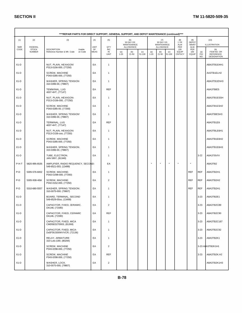
SECTION II TM 11-5820-509-35
****REPAIR PARTS FOR DIRECT SUPPORT, GENERAL SUPPORT, AND DEPOT MAINTENANCE (continued)****
(1) (2) (3) (4) (5) (6) (7) (8) (9) (10)30 DAY DS 30 DAY GS 1 YR DEPOT
MAINTENANCE MAINTENANCE ALW MAINT ILLUSTRATIONSMR FEDERAL UNIT QTY ALLOWANCE ALLOWANCE PER ALW
CODE STOCK DESCRIPTION Usable OF INC 100 PER (b)NUMBER Reference Number & Mfr. Code on Code MEAS IN (a) (b) (c) (a) (b) (c) EQUIP 100 (a) ITEM NO. OR
UNIT 1-20 21-50 51-100 1-20 21-50 51-100 CNTGCY EQUIP FIG REFERENCENO. DESIGNATION
X1-D NUT, PLAIN, HEXAGON' EA 1 ABA3TB1E4H1P313-0156-000, (77250)
X1-D SCREW, MACHINE EA 1 AA3TB1ELH2P343-0285-000, (77250)
X1-D WASHER, SPRING TENSION EA 1 ABA3TB1EhH3310-0396-00, (79807)
X1-D TEMWINAL, LUG EA REF A8A3TBlE54007-4HT, (77147)
X1-D NUT, PLAIN, HEXAGON- EA 1 A8A3TB1ES5HP313-O156-000, (T7250)
X1-D SCREW, MACHINE EA 1 A8A3TB1E5H2P343-0285-00, (77250)
X1-D WASHER, SPRING TENSION' EA 1 A8A3TBlE5H3310-0396-00, (79807)
X1-D TERMINAL, LUG EA REF A8A3TB1E64007-4HT, (77147)
X1-D NUT, PLAIN, HEXAGON: EA 1 A8A3TBLE6H1P313-O156-ooo, (77250)
X1-D SCREW, MACHINE EA 1 A8A3TB1E6H2P343-0285-000, (77250)
X1-D WASHER, SPRING TENSION. EA 1 A8A3TB1E6H3310-0396-00, (79807)
X1-D TUBE, ELECTRON. EA 1 3-22 A8A3TBVlVJAN 5907, (81349)
P-H-T 5820-995-6535 AMPLIFIER, RADIO REQUENCY, SECOND- EA * * * * * A8A3TB2549-6521-003, (13499)
P-D 5305-576-6002 SCREW, MACHINE- EA 1 REF REF A8A3TB2H1P343-O298-000, (77250)
P-D 5305-938-40bl SCREW, MACHINE: EA 2 REF REF A8A3TB2H2P342-0152-000, (77250)
P-D 5310-680-5557 WASHER, SPRING TENSION: EA 1 REF REF A8A3TB2H1310-0075-000; (79807)
X1-D BOARD, TERMINAL, SECOND EA 1 3-23 A8A3TB2E1549-6529-00oo, (13499)
X1-D CAPACITOR, FIXED, CERAMIC. EA 2 3-23 A8A3TB2C89DA146; (71590)
X1-D CAPACITOR, FIXED, CERAMIC EA REF 3-23 A8A3TB2C90DA146, (71590)
X1-D CAPACITOR, FIXED, MICA EA 1 3-23 A8A3TB2C187CMD5ED270003, (813h9)
X1-D CAPACITOR, FIXED, MICA- EA 1 3-23 A8A3TB2C92Ds5F5llJ300WVVCR; (72136)
X1-D RELAY, ARMATURE: EA 1 3-23 A8A3TB2K1310-Lols-100l, (80294)
X1-D SCREW, MACHINE EA 2 3-23 A8A3TB2K1H1P343-0298-000, (77250)
X1-D SCREW, MACHINE EA REF 3-23 A8A3TB2K.H2P343-0298-000, (77250)
X1-D WASHER, LOCK. EA 2 A8A3TB2K1H3310-0075-000, (79807)
B-78
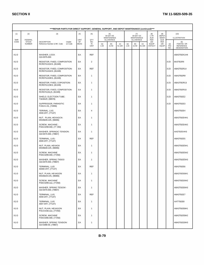
SECTION II TM 11-5820-509-35
****REPAIR PARTS FOR DIRECT SUPPORT, GENERAL SUPPORT, AND DEPOT MAINTENANCE (continued)****
(1) (2) (3) (4) (5) (6) (7) (8) (9) (10)30 DAY DS 30 DAY GS 1 YR DEPOT
MAINTENANCE MAINTENANCE ALW MAINT ILLUSTRATIONSMR FEDERAL UNIT QTY ALLOWANCE ALLOWANCE PER ALW
CODE STOCK DESCRIPTION Usable OF INC 100 PER (b)NUMBER Reference Number & Mfr. Code on Code MEAS IN (a) (b) (c) (a) (b) (c) EQUIP 100 (a) ITEM NO. OR
UNIT 1-20 21-50 51-100 1-20 21-50 51-100 CNTGCY EQUIP FIG REFERENCENO. DESIGNATION
X1-D WASHER, LOCK EA REF A8A3TB2K1H4310-0075-000
X1-D RESISTOR, FIXED, COMPOSITION EA 2 3-23 8A3TB2RllRCR07G101KS, (81349)
X1-D RESISTOR, FIXED, COMPOSITION- EA REF 3-23 A8A3TB2R14RCR07G101KS; (81349)
X1-D RESISTOR, FIXED, COMPOSITION EA 1 3-23 A8A3TB2R9RCR07G103KS, (81349)
X1-D RESISTOR, FIXED, COPOSITION: EA 1 3-23 ABA3TB2R13RCR07G123KS; (81349)
X1-D RESISTOR, FIXED, CONPOSITION- EA 1 3-23 A8A3TB2R10RCR07G10L(S, (81349)
X1-D SHIELD, ELECTODN TUBE: EA 1 3-23 A8A3TB2E2T3A361R; (98978)
X1-D SUPPRISSOR, PARASITIC EA 1 3-23 A8A3TB2E3F1913-1-01, (72656)
X1-D TERIINAL, LUG. EA 4 A8A3TB2E44040-2HT, (77147)
X1-D NUT. PLAIN, HEXAGCN: EA 1 A8A3TB2E4H1MS35649-225, (96906)
X1-D SCREW, MACHINE:: EA 1 A8A3TB2E4H2P343-0299-000, (77 250)
X1-D WASHER, SPRINGIC TENSION: EA 1 AA3TB2E4H3310-0075-000, (79807)
X1-D TERMINAL, LUG- EA REF A8A3TB2E54040-2HT, (77147)
X1-D NUT, PLAIN, HEXAOII EA 1 A8A3TB2E5H1MS35649-225, (96906)
X1-D SCREW, MACHINE EA 1 A8A3TB2E5H2P343-0299-000, (77250)
X1-D WASHER, SPRING TNSIOI EA 1 A8A3TB2E5H3310-0075-000, (79807)
X1-D TERMINAL, LUG EA REF A8A3TB2E640400-2HT; (77147)
X1-D NUT, PLAIN, HEXAGON EA 1 A8A3TB2E6H1MS35649-225, (96906)
X1-D SCREW, MACHINE' EA 1 A8A3TB2E6H2P343-0299-ooo, (77250)
X1-D WASHER, SPRING TESION'- EA 1 A8A3TB2E6H3310-0075-000, (79807)
X1-D TERMINAL, LUG EA REF A8A3TB2E74040-2HT, (77147)
X1-D TERMINAL, LUG EA 1 AATTB2E84007-4HT, (77147)
X1-D NUT, PLAIN, HEXAGON EA 1 A8A3TB2E8H1P313-0156-ooo, (77250)
X1-D SCREW, MACHINE EA 1 A8A3TB2E8H2P343-0285-000, (77250)
X1-D WASHER, SPRING TENSION EA 1 A8A3TB2E8H3310-0396-00, (79807)
B-79
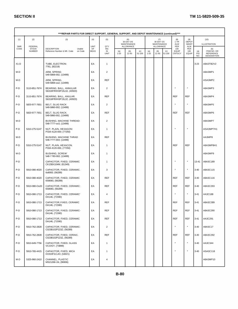
SECTION II TM 11-5820-509-35
****REPAIR PARTS FOR DIRECT SUPPORT, GENERAL SUPPORT, AND DEPOT MAINTENANCE (continued)****
(1) (2) (3) (4) (5) (6) (7) (8) (9) (10)30 DAY DS 30 DAY GS 1 YR DEPOT
MAINTENANCE MAINTENANCE ALW MAINT ILLUSTRATIONSMR FEDERAL UNIT QTY ALLOWANCE ALLOWANCE PER ALW
CODE STOCK DESCRIPTION Usable OF INC 100 PER (b)NUMBER Reference Number & Mfr. Code on Code MEAS IN (a) (b) (c) (a) (b) (c) EQUIP 100 (a) ITEM NO. OR
UNIT 1-20 21-50 51-100 1-20 21-50 51-100 CNTGCY EQUIP FIG REFERENCENO. DESIGNATION
X1-D TUBE, ELECTRON: EA 1 3-23 A8A3TB2V27761, (82219)
M-D ARM, SPRING EA 2 A8A3MP1549-5869-002, (13499)
M-D ARM, SPRING. EA REF ASA3MP2549-5869-oo2; (13499)
P-D 3110-851-7674 BEARING, BALL, ANNULAR EA 2 * * A8A3MP3S6316FRHH3P15L02, (40920)
P-D 3110-851-7674 BEARING, BALL, ANULAR. EA REF REF REF A8A3MP4S6316FRHH3P15L02, (40920)
P-D 5820-977-7651 BELT, SLUG RACK EA 2 * * A8A3MP5549-5860-002; (13499)
P-D 5820-977-7651 BELT, SLUG RACK. EA REF REF REF A8A3MP6549-5860-002, (13499)
M-D BUSHING, MACHINE THREAD: EA 2 A8A3MP7548-7777-oo3, (13499)
P-D 5310-275-5147 NUT, PLAIN, HEXAGON: EA 1 * * ASA3MP7H1P334-4120-000; (77250)
M-D BUSHING, MACHINE THRAD EA REF AA3MP8548-7777-003; (13499)
P-D 5310-275-5147 NUT, PLAIN, HEXACON. EA 1 REF REF A8A3MP8H1P334-4120-000, (77250)
M-D BUSHING, SCREW' EA 1 A8A3MP9548-7783-002; (13499)
P-D CAPACITOR, FIXED, CERAMIC EA 1 * * 13-41 A8A3C189CK15BX104M; (81349)
P-D 5910-080-4020 CAPACITOR, FIXED, CERAMIC. EA 3 * * 3-40 A8A3C1156s8083; (56289)
P-D 5910-080-4020 CAPACITOR, FIXED, CERAMIC EA REF REF REF 3-40 A8A3C1166S8083, (56289)
P-D 5910-080-Oo20 CAPACITOR, FIXED, CERAMIC: EA REF REF REF 3-40 A8A3C2936S8083, (56289)
P-D 5910-080-1713 CAPACITOR, FIXED, CERAMIC' EA 4 * * 3-41 AA3C188DA146, (71590)
P-D 5910-080-1713 CAPACITOR, FIXED, CERAMIC EA REF REF REF 3-41 A8A3C289DA146, (71590)
P-D 5910-080-1713 CAPACITOR, FIXED, CERAMIC- EA REF REF REF 3-41 A8A3C290DA146, (71590)
P-D 5910-080-1713 CAPACITOR, FIXED, CERAMIC EA REF REF REF 3-41 AA3C291DA146, (71590)
P-D 5910-762-2828 CAPACITOR, FIXED, CERAMIC: EA 2 * * 3-40 A8A3C17C023B102P223Z; (56289)
P-D 5910-762-2828 CAPACITOR, FIXED, CERAIC. EA REF REF REF 3-40 A8A3C292C023B102P223Z, (56289)
P-D 5910-649-7756 CAPACITOR, FIXED, GLASS EA 1 * * 3-40 AA3C344VC22GY, (73899)
P-D 5910-765-4415 CAPACITOR, FIXED, MICA EA 1 * * 3-40 ASA3C118D1910F511JO; (53021)
M-D 5325-960-2410 CHANNEL, PLASTIC EA 4 A8A3MP10MS21266-1N, (96906)
B-80

SECTION II TM 11-5820-509-35
****REPAIR PARTS FOR DIRECT SUPPORT, GENERAL SUPPORT, AND DEPOT MAINTENANCE (continued)****
(1) (2) (3) (4) (5) (6) (7) (8) (9) (10)30 DAY DS 30 DAY GS 1 YR DEPOT
MAINTENANCE MAINTENANCE ALW MAINT ILLUSTRATIONSMR FEDERAL UNIT QTY ALLOWANCE ALLOWANCE PER ALW
CODE STOCK DESCRIPTION Usable OF INC 100 PER (b)NUMBER Reference Number & Mfr. Code on Code MEAS IN (a) (b) (c) (a) (b) (c) EQUIP 100 (a) ITEM NO. OR
UNIT 1-20 21-50 51-100 1-20 21-50 51-100 CNTGCY EQUIP FIG REFERENCENO. DESIGNATION
M-D 5325-960-241o CHANNEL, PLASTIC EA REF A8A3MP11M 21266-1l, (96906)
M-D 5325-960-2410 CHANNEL, PLASTIC- EA REF A8A3MP12MS21266-1N, (96906)
M-D 5325-960-2410 CHANEL, PLASTIC EA REF A8A3MP13MS21266-1N, (9690 6)
M-D CHASSIS, ELECTRICAL EQUIPM'- EA 1 A8A3Al548-7886-00o, (13l99)
P-D 5935-027-2636 JAC, TIP EA 1 * * 3-9 A8A3AlJ169003-1183 BROWN (73680)
P-D 5934-432-6501 JAC, TIP EA 1 * * 3-9 ABA3A1J269003-1183 RED (73680)
P-D 5935-683-7648 JACK, TIP EA 1 * * 3-9 A8A3AlJ369003-1183 0RANGE (73680)
P-D 5935-683-7649 JACK, TP EA 1 * * 3-9 ABA3A1Jh69003-1183YELLOW (73680)
P-D CLAMP, LOOP-TUIER- EA 1 * * ASA3Pl12504-7577-002, (13499)
P-D 5310-276-1104 NUT, PLAIN, SQUARE. 1 * * * A8A3MP12HP334-0o85-000, (77250)
P-D 5305-952-1410 SCREW, CAP- EA 1 * * ABA3MP12H2324-1682-100, (o8664)
MD 5820-977-7650 CLIP-TAPE EA 2 AA3MP13549-5862-002; (13499)
P-D 5305-141-4310 SCREW, MACHINE EA 1 * * A8A3M13H1P347-0021-O00, (77250)
M-D 5820-977-7650 CLIP-TAPE EA REF A8A3MP14549-5862-002; (13499)
P-D 5305-141-4310 SCREW, MACHIINE EA 1 REF REF A8A3MPi1H1P347-0021-000, (77250)
P-D 5950-766-7833 COIL, RADIO FREQUENCY. EA 1 * * 3-40 ABA3L98240-1994-000, (13499)
P-D 5305-770-2533 SCREW, MACHINE EA 1 REF REF A8A3L98H1MS51959-13, (96906)
P-D 5310-782-1349 WASHER, LAT EA 1 REF REF A8A3L98H2310-0045-000, (79807)
P-D 5950-932-2727 COIL, RADIO FREQUENCY EA 2 * * 3-40 A8A3L120LT10K029, (81349)
P-D 5950-932-2727 COIL, RADIO FREQUENCY- EA REF REF REF 3-40 ABA3L121LT1CK029, (81349)
P-D 5950-960-7850 COIL, RADIO FREQUENCY. EA 1 * * 3-41 A8A3L145548-7797-004, (13499 )
P-D SCREW, MACHINE EA 3 * * A8A3L145HP347-0024-ooo, (77250)
P-D SCREW, MACHINE EA REF REF REF A8A3L145H2P347-0024-000, (77250)
P-D SCREW, MACHINE EA REF REF REF A8A3L145H3P347-0024-000, (77250)
P-D 5950-950-4176 COIL, RADIO FREQUENCY. EA 3 * * 3-41 AA3L15L9-5972-002, (13499)
B-81

SECTION II TM 11-5820-509-35
****REPAIR PARTS FOR DIRECT SUPPORT, GENERAL SUPPORT, AND DEPOT MAINTENANCE (continued)****
(1) (2) (3) (4) (5) (6) (7) (8) (9) (10)30 DAY DS 30 DAY GS 1 YR DEPOT
MAINTENANCE MAINTENANCE ALW MAINT ILLUSTRATIONSMR FEDERAL UNIT QTY ALLOWANCE ALLOWANCE PER ALW
CODE STOCK DESCRIPTION Usable OF INC 100 PER (b)NUMBER Reference Number & Mfr. Code on Code MEAS IN (a) (b) (c) (a) (b) (c) EQUIP 100 (a) ITEM NO. OR
UNIT 1-20 21-50 51-100 1-20 21-50 51-100 CNTGCY EQUIP FIG REFERENCENO. DESIGNATION
P-D 5950-950-4176 COIL, RADIO FREQUENCY- EA REF REF REF 3-41 A8A3L2549-5972-002, (13499)
P-D 5950-950-4176 COIL, RADIO FREQUINCY: EA REF REF REF 3-41 A8A3L3519-5972-002; (13499)
P-D 5950-044-2428 COIL, RADIO FREQUENCY: EA 1 * * 3-1 A8A3L5756-3160-003, (13499)
P-D 5950-044-2429 COIL, RADIO FREQUENCY: EA 1 * * 3-41 A8A3L4756-4179-003, (13499)
P-D CONNECTOR, RECEPTACLE, ELECTRICAL- EA 4 REF REF 3-41 AA3P1DAMW2P; (71468)
P-D 5310-685-7739 NUT, PLAIN, CAP EA 1 * * A8A3PH1334-0043-000; (21537)
P-D 5310-275-0889 NUT, PLAIN, HEXAOON EA 1 * * A8A3P1H2P313-0132-000, (77250)
P-D 5305-770-2533 SCREW, MACHINE. EA 1 REF REF A8A3P1H3MS51959-13, (96906)
P-D 5305-763-7822 SCREW, MACHINE: EA 1 REF REF A8A3P1H4Ms51959-14; (96906)
P-D WASHER, FLAT EA 1 REF REF ABA3P1H5310-6325-000, (79807)
P-D 5310-058-2949 WASHER, LOCK EA 2 * * ARA3P1H6310-0278-000, (70318)
P-D 5310-058-2949 WASHER, LOCK EA REF REF REF 48A3P1H7310-0278-000, (70318)
P-D CONNECTOR, RECEPTACLE, ELECTRICAL EA REF REF REF 3-41 A8A3P2DAMTW2P, (71468)
P-D 5310-685-7 739 NUT, PLAIN, CAP EA 1 REF REF A8A3P2H1334-0043-000, (21537)
P-D 5310-275-0889 NUT, PLAIN, HEXAGON- EA 1 REF REF A8A3P2H2P313-0132-000; (77250)
P-D 5305-770-2533 SCREW, MACHINE EA 2 REF REF A8A3P2H3MS51959-13, (96906)
P-D 5305-770-2533 SCREW, MACHINE EA REF REF REF A8A3P2H4MS51959-13, (96906)
P-D 5310-058-2949 WASHER, LOCK EA 1 REF REF A8A3P2H5310-0278-000, (70318)
P-D CONNECTOR, RECEPTACLE, ELECTRICAL. EA REF REF REF 3-41 A8A3P3DAMTW2P, (71468)
P-D 5310-685-7739 NUT, PLAIN, CAP' EA 1 REF REF A8A3P3H133-00oo3-000, (21537)
P-D 5310-275-0889 NUT, PLAIN, HEXAGON EA 1 REF REF A8A3P3H2P313-0132-000, (77250)
P-D 5305-770-2533 SCREW, MACHINE: EA 2 REF REF A8A3P3H 3MS51959-13, (96906)
P-D 5305-770-2533 SCREW, MACHINE EA REF REF REF A8A3P3H 4MS51959-13, (96906)
P-D 5310-058-2949 WASHER, LOCK EA 1 REF REF A8A3P3H 5310-0278-000; (70318)
P-D CONNECTOR, RECEPTACLE, ELECTRIICAL EA REF REF REF 3-41 A8A3P4DAM7W2P, (71468)
B-82

SECTION II TM 11-5820-509-35
****REPAIR PARTS FOR DIRECT SUPPORT, GENERAL SUPPORT, AND DEPOT MAINTENANCE (continued)****
(1) (2) (3) (4) (5) (6) (7) (8) (9) (10)30 DAY DS 30 DAY GS 1 YR DEPOT
MAINTENANCE MAINTENANCE ALW MAINT ILLUSTRATIONSMR FEDERAL UNIT QTY ALLOWANCE ALLOWANCE PER ALW
CODE STOCK DESCRIPTION Usable OF INC 100 PER (b)NUMBER Reference Number & Mfr. Code on Code MEAS IN (a) (b) (c) (a) (b) (c) EQUIP 100 (a) ITEM NO. OR
UNIT 1-20 21-50 51-100 1-20 21-50 51-100 CNTGCY EQUIP FIG REFERENCENO. DESIGNATION
P-D 5310-685-7739 NUT, PLAIN, CAP EA 1 REF REF A8A3P4H1334-0043-00o, (21537)
P-D 5310-275-0889 NUT, PLAIN, HEXAGON EA 1 REF REF A8A3P4H2P313-0132-000, (77250)
P-D 5305-770-2533 SCREW, MACHINE EA 2 REF REF A8A3P4H3MS519-13, (96906)
P-D 5305-770-2533 SCREW, MACHINE EA REF REF REF A8A3P4H4MS51959-13, (96906)
P-D 5310-058-2949 WASHER LOCK EA 1 REF REF A8A3P4HS310-0278-000; (70318)
P-D 5935-885-6505 CONTACT, ELECTRICAL EA 8 REF REF A8A3PlAlDM53740-5000, (71468)
P-D 5935-885-6505 CONTACT, ELECTRICAL EA REF REF REF AsA3PlA2DM53740-5OO, (71468)
P-D 5935-885-6505 CONTACT, ELECTRICAL EA REF REF REF ASA3P2AIDM53740-5000, (71468)
P-D 5935-885-6505 CONTACT, ELECTRICAL. EA REF REF REF A8A3P2A2DM53740-5000, (71468)
P-D 5935-885-6505 CONTACT, ELECTRICAL EA REF REF REF A8A3P3A1DM53740-5000; (71468)
P-D 5935-885-6505 CONTACT, ELECTRICAL EA REF REF REF A8A3P3A2DM53740-500ooo, (71468)
P-D 5935-885-6505 CONTACT, ELECTRICAL. EA REF REF REF A8A3P4A1DM53740-5000; (71468)
P-D 5935-885-65b5 CONTACT, ELECTRICAL EA REF REF REF A8A3PlA2DM53740-5000; (71468)
P-D 5950-4501161 CORE, ADJUSTABLE TUNING EA 6 * * 3-9 AsA3E157-3540, (78488)
P-D CORE, ADJUSTABLE TUNING EA REF REF REF 3-9 AsA3E257-3540, (78488)
P-D CORE, ADJUSTABLE TUNING EA REF REF REF REF 3-9 A8A3E357-3540; (78L88)
P-D CORE, ADJUSTABLE TUNING EA REF REF REF 3-9 AsA3E457-3540, (78L88)
P-D CORE, ADJUSTABLE TUNING EA REF REF REF 3-9 ASA3E557-3540, (78488)
P-D CORE, ADJUSTABLE TUNING EA REF REF REF 3-9 A8A3E657-3540, (78488)
M-D COUPLING HALF ASSERBLY. EA 1 AsA3A2549-5881-002; (13499)
M-D COUPLING HALF, SHAFT EA 1 AA3A2MP1549-5853-002, (13499)
M-D INSERT, FLEXIBLE COOUPLING EA 1 AsA3A2MP2553-9786-003, (13499)
M-D PIN, LOCATING EA 1 A8A3A2MP3549-5721 -002, (13499)
M-D COVER, CIRCUIT BOARD EA 1 A8A3MP15549-6525-003, (13499)
P-D 5305-805-9801 SCREW, MACHINE EA 4 33 20 ASA3P15H1P347-0090-00,0, (77250)
B-83
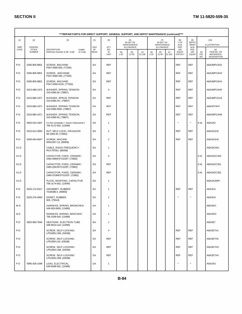
SECTION II TM 11-5820-509-35
****REPAIR PARTS FOR DIRECT SUPPORT, GENERAL SUPPORT, AND DEPOT MAINTENANCE (continued)****
(1) (2) (3) (4) (5) (6) (7) (8) (9) (10)30 DAY DS 30 DAY GS 1 YR DEPOT
MAINTENANCE MAINTENANCE ALW MAINT ILLUSTRATIONSMR FEDERAL UNIT QTY ALLOWANCE ALLOWANCE PER ALW
CODE STOCK DESCRIPTION Usable OF INC 100 PER (b)NUMBER Reference Number & Mfr. Code on Code MEAS IN (a) (b) (c) (a) (b) (c) EQUIP 100 (a) ITEM NO. OR
UNIT 1-20 21-50 51-100 1-20 21-50 51-100 CNTGCY EQUIP FIG REFERENCENO. DESIGNATION
P-D 5305-805-9801 SCREW, MACHINE- EA REF REF REF A8A3MP15H2P347-0090-000, (77250)
P-D 5305-805-9801 SCREW, .MACHIINE: EA REF REF REF A8A3MP15H3P347-0090-000, (77250)
P-D 5305-805-9801 SCREW, MACHINE: EA REF REF REF A8A3MP15H4P347-0090-DOD; (77250)
P-D 5310-685-1971 WASHER, SPRING TENSION EA 4 REF REF A8A3MP15H5310-0396-00; (79807)
P-D 5310-685-1971 WASHER, SPRIJG TENSION EA REF REF REF A8A3MP151i6310-0396-OC, (79807)
P-D 5310-685-1971 WASHER, SPRING TENSION- EA REF REF REF A8A3P15H7310-0396-0000, (79807)
P-D 5310-685-1971 WASHER, SPRING TENSION: EA REP REF REF A8A3MP15H8310-0396-00; (79807)
P-D 5820-015-1607 FILTER ASSEMBLY, RADIO FREQUENCY EA 1 * * 3-41 A8A3A2756-3172-002; (13499)
P-D 5310-614-3500 NUT, SELF-LOCKI, OIKXAGON: EA 2 REF REF A8A3A2H268-1660-40, (72962)
P-D 5305-054-5647 SCREW, MACHIIE: EA 2 REF REF A8A3A2H2MS51957-13; (96906)
X1-D CABLE, RADIO FREQUENCY: EA 1 A8A3A2W1RG178TBU; (80058)
X1-D CAPACITOR, FIXED, CERAMIC: EA 3 3-41 A8A3A2C3502465-008WST0102P; (72982)
X1-D CAPACITOR, FIXED, CERAMIC- EA REF 3-41 A8A3A2C3512465-)0WS5TO102P; (72982)
X1-D CAPACITOR, FIXED, CERAMIC: EA REF 3-41 A8A3A2C3522465-OO8WST0102P, (72982)
X1-D PLATE, MOINTING, CAPACITOR. EA 1 A8A3A2MPl756-3174-002, (13h99)
P-D 5325-174-5317 GROMMET, RUBBER. EA 1 REF REF A8A3H1YS35489-4, (96906)
P-D 5325-276-4993 DORET, RUBBER. EA 1 * * A8A3H2905, (75543)
M-D HARNESS, WIRING, BRANCHED: EA 1 A8A3W1549-583-0000; (13499)
N-D RARNESS, WIRING, BRACHED: EA 1 A8A3W2756-3168-0o5; (13499)
P-D 5820-960-7844 HEATSINK, ELECTRON TUBE EA 1 A8A3E7549-6523-oo3; (13499)
P-D SCREW, SELF-LOCKING: EA 4 REF REF A8A3E7H1LP51959-13M, (03038)
P-D SCREW, SELF-LOCKING. EA REF REF REF A8A3E7H2LP51959-134; (03038)
P-D SCREW, SELF-LOCKING: EA REF REF REF A8A3E7H3LP51959-13M, (03038)
P-D SCREW, SELF-LOCKING' EA REF REF REF A8A3E7H4LP51959-13M; (03038)
P-D 5995-426-1599 LEAD, ELECTRICAL. EA 1 * * A8A3A3549-6598-002, (13499)
B-84

SECTION II TM 11-5820-509-35
****REPAIR PARTS FOR DIRECT SUPPORT, GENERAL SUPPORT, AND DEPOT MAINTENANCE (continued)****
(1) (2) (3) (4) (5) (6) (7) (8) (9) (10)30 DAY DS 30 DAY GS 1 YR DEPOT
MAINTENANCE MAINTENANCE ALW MAINT ILLUSTRATIONSMR FEDERAL UNIT QTY ALLOWANCE ALLOWANCE PER ALW
CODE STOCK DESCRIPTION Usable OF INC 100 PER (b)NUMBER Reference Number & Mfr. Code on Code MEAS IN (a) (b) (c) (a) (b) (c) EQUIP 100 (a) ITEM NO. OR
UNIT 1-20 21-50 51-100 1-20 21-50 51-100 CNTGCY EQUIP FIG REFERENCENO. DESIGNATION
P-D 531-275-O889 NUT, PLAIN, HEXAGON: EA 2 REF REF A8A3A3H2P313-0132-000, (77250)
P-D 5305-051-567 SCREW, MACHINE: EA 2 REF REF A8A3A3H2MS51957-13, (96906)
P-D 5310-29-0960 WASHER, LOCK: EA 2 * * A3A3H21704-03; (78189)
X1-D BRAID, WIRE: EA 1 A8A3A3W136109; (75818)
X1-D TERMINAL, LUG: EA 2 A8A3A3E1321k2; (0sTT9)
X1-D TERMINAL, LUG: EA REF A8A3A3E232442; (00779)
P-D 6150-182-1993 LEAD, ELECTRICAL-GROUND STRIP: EA 2 * * AA3E8553-9321-002; (13499)
P-D LEAD, ELECTRICAL-GROUND STRIP: EA REF REF REF A8A3E9553-9321-002; (13499)
P-4-T 5820-042-5719 MIXER STAGE, FREQUENCY: EA 1 * * * * * 3-9 A8A3E48549-6000-004; (13199)
P-D SCREW, SELF-LOCKING: EA 4 REF REF A8A3E48H4LP51959-13M; (03038)
X1-D BOARD, PRINTED CIRCUIT: EA 1 3-39 A8A3E48E1549-5999-004 ; (13499)
X1-D CAPACITOR, FIXED, CIRCUIT: EA 1 3-39 A8A348C17920C91A, (56289)
X1-D CAPACITOR, FIXED, CIRCUIT: EA 4 3-39 A8A3E8,166658083; (56289)
X1-D CAPACITOR, FIXED, CERAMIC: EA REF 3-39 A8A3E48C1716S8083; (56289)
X1-D CAPACITOR, FIXED, CERAMIC: EA REF 3-39 A8A3E48C1736S8083; (56289)
X1-D CAPACITOR, FIXED, CERAMIC: EA REF 3-39 A8A3E48C1826S8083, (56289)
X1-D CAPACITOR, FIXED, ELECTROLYTIC. EA 2 3-39 ASA3E48C175150DlOX0035A2, (56289)
X1-D CAPACITOR, FIXED, EILCTROLYTIC. EA REF 3-39 A8A3ES8C185150D10OX0035A2, (56289)
X1l-D CAPACITOR, FIXED, MICA: EA 2 3-39 A8A3E48C169CMD5ED750co3; (813J9)
X1-D CAPACITOR, FIXED, MICA: EA RKF 3-39 A8A3E48C184CM05ED750O03, (81349)
X1-D CAPACITOR, FIXED, MICA: EA 2 3-39 A8A3E48C162CM05ED820Jo3; (81349)
X1-D CAPACITOR, FIXED, MICA: EA REF 3-39 A8A3E48C174CMD5ED820Jo3; (81349)
X1-D CAPACITOR, FIXED, MICA: EA 1 3-39 ASA3E48C168·CMD5FD121c03; (81349)
X1-D CAPACITOR, FIXED, MICA: EA 1 3-39 A8A3E48C168CM05FD131C03; (813&9)
X1-D CAPACITOR, FIXED, MICA: EA 1 3-39 A8A3E48C168CMD5FD151C03, (813&9)
* SELECT PER OPERATIONAL EQUIPMENT-
B-85

SECTION II TM 11-5820-509-35
****REPAIR PARTS FOR DIRECT SUPPORT, GENERAL SUPPORT, AND DEPOT MAINTENANCE (continued)****
(1) (2) (3) (4) (5) (6) (7) (8) (9) (10)30 DAY DS 30 DAY GS 1 YR DEPOT
MAINTENANCE MAINTENANCE ALW MAINT ILLUSTRATIONSMR FEDERAL UNIT QTY ALLOWANCE ALLOWANCE PER ALW
CODE STOCK DESCRIPTION Usable OF INC 100 PER (b)NUMBER Reference Number & Mfr. Code on Code MEAS IN (a) (b) (c) (a) (b) (c) EQUIP 100 (a) ITEM NO. OR
UNIT 1-20 21-50 51-100 1-20 21-50 51-100 CNTGCY EQUIP FIG REFERENCENO. DESIGNATION
X1-D CAPACITOR, FIXED, MICA EA 1 3-39 A8A3E48C168CM05FD161GO3, (81349)
X1-D CAPACITOR, FIXED, MICA EA 3 3-39 ASA3Eh8C167CM05FD221GO3; (81349)
X1-D CAPACITOR, FIXED, MICA- EA REF 3-39 ASA3E48c170CM05FD221G03, (81349)
X1-D CAPACITOR, FIXED,MICA. EA REF 3-39 A8A3Eh8ClT2CM05FD221GO3, (81349)
X1-D CAPACITOR, FIXED, MICA: EA 3 3-39 ASA3E48C163DM15F471J300WV4CR, (72136)
X1-D CAPACITOR, FIXED, MICA' EA REF 3-39 ASA3E48c16hDM15F471J300WV4CR, (72136)
X1-D CAPACITOR, FIXED, MICA. EA REF 3-39 ASA3E48cI86DK5F471J300WV4CR; (72136)
X1-D CAPACITOR, FIXED, MICA: EA 1 3-39 AA3E,48c168DM15F1330F0500WV4 CR, (72136)
X1-D CAPACITOR, FIXED, MICA- EA 1 3-39 A8A3zE8c168 ·DM15E141F0500WV4CR, (72136)
X1-D CAPACITOR, FIXED, MICA: EA 1 3-39 ASA3E8C1i68DM15E1270F0500WV4CR
X1-D COIL, RADIO FREQUENCY EA 1 3-39 A8A3E48L101LT0lK020, (81349)
X1-D COIL, RADIO FREQUENCY- EA 1 3-39 AA03E48L100LT1OK029, (81349)
XI-D RESISTOR, FIXED, COMPOSITION EA 1 3-39 ABA3EH8R190RCR07G560KS; (81349)
X1-D DRESISTOR, FIXED, COMPOSITION EA 2 3-39 A8A3E48R77RCR07G121KS, (81349)
X1-D RESISTOR, FIXED, COWOSITION EA REF 3-39 A§A3E48R94RCR07G121KS, (81349)
X1-D RESISTOR, FIXED, COMPOSITION: EA 1 3-39 A8A3E48R58RCR07CG71KS; (81340)
X1-D RESISTOR, FIXED, COMPOSITION EA 3 3-39 ASA3E48R59RCR07C102KS, (81 349)
X1-D RESISTOR, FIXED, COMPOSITION EA REF 3-39 A8A3E48R89RCR07G102KS, (81349)
X1-D RESISTOR, FIXED, COMPOSITION. EA REF 3-39 A8A3E48R90RCR07G102KS; (81349)
X1-D RESISTOR, FIXED, COMPOSITIOD- EA 1 3-39 ASA3E48R91RCR07G222KS, (81349)
X1-D RESISTOR, FIXED, COMPOSITION- EA 1 3-39 A8A3E48R67RCR07G272KS, (81349)
X1-D RESISTOR, FIXED, COMPOSITION- EA 1 3-39 AkA3E48R66RCR07CG72KS, (81349)
X1-D RESISTOR, FIXED, COMPOSITION EA 2 3-39 ASA3E48R64RCR07G682KS; (81349)
X1-D RESISTOR, FIXED, COBMPOSITION EA REF 3-39 A8A3E48R70RCR07C682KS, (81349)
* SELECT PER OPERATIONAL EQUIPMENT
B-86
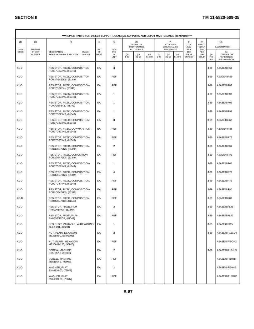
SECTION II TM 11-5820-509-35
****REPAIR PARTS FOR DIRECT SUPPORT, GENERAL SUPPORT, AND DEPOT MAINTENANCE (continued)****
(1) (2) (3) (4) (5) (6) (7) (8) (9) (10)30 DAY DS 30 DAY GS 1 YR DEPOT
MAINTENANCE MAINTENANCE ALW MAINT ILLUSTRATIONSMR FEDERAL UNIT QTY ALLOWANCE ALLOWANCE PER ALW
CODE STOCK DESCRIPTION Usable OF INC 100 PER (b)NUMBER Reference Number & Mfr. Code on Code MEAS IN (a) (b) (c) (a) (b) (c) EQUIP 100 (a) ITEM NO. OR
UNIT 1-20 21-50 51-100 1-20 21-50 51-100 CNTGCY EQUIP FIG REFERENCENO. DESIGNATION
X1-D RESISTOR, FIXED, COMPOSITION EA 3 3-39 A8A3E48R63RCR07G822KS, (81349)
X1-D RESISTOR, FIXED, COMPOSITION EA REF 3-39 ABA3E48R69RCRO7G822KS, (81349)
X1-D RESISTOR, FIXED, COMPOSITION- EA REF 3-39 A8A3E48R87RCR07G822Ks; (81349)
X1-D RESISTOR, FIXED, COMPOSITION EA 1 3-39 A8A3E48R97RCR07G103KS, (81349)
X1-D RESISTOR, FIXED, COMPOSITION. EA 1 3-39 A8A3E48R92RCR7Gl183XS, (81349)
X1-D RESISTOR, FIXED, COMPOSITION EA 1 3-39 A8A3E48R93RCR07G223KS, (81349)
X1-D RESISTOR, FIXED, COMPOSITION: EA 3 3-39 A8A3E48R62RCR07G333KS, (81349)
X1-D RESISTOR, FIXED, COWMK)STION- EA REF 3-39 ABA3E48R68RCR07G333KS, (81349)
X1-D RESISTOR, FIXED, COMPOSITION- EA REF 3-39 A8A3E48R72RCR07G333KS, (81349)
X1-D RESISTOR, FIXED, COMPOSITION- EA 2 3-39 A8A3E48R61RCRO7G473KS; (81349)
X1-D RESISTOR, FIXED, COMOSITION EA REF 3-39 ABA3E48R71RCRO7G473KS; (81349)
X1-D RESISTOR, FIXED, COMPOSITION- EA 1 3-39 A8A3E48R65RCR07G683KS; (81349)
X1-D RESISTOR, FIXED, COMPOSITION. EA 4 3-39 A8A3E48R78RCRO7G474KS, (81349)
X1-D RESISTOR, FIXED, COMPOSITION. EA REF 3-39 A8A3E48R79RCR07G474KS; (81349)
X1-D RESISTOR, FIXED, COMPOSITION- EA REF 3-39 A8A3E48R80RCR7CG474KS; (81349)
XC-D RESISTOR, FIXED, COMPOSITION EA REF 3-39 A8A3E48R81RCRO7G474Ks; (81349)
X1-D RESISTOR, FIXED, FILM EA 2 3-39 A8A3E48RL46RN60D75ROF, (81349)
X1-D RESISTOR, FIXED, FILM- EA REF 3-39 A8A3E48RL47RN60DTSROF, (81349)
X1-D RESISTOR, VARIABLE, WIREWOUND- EA 1 3-39 A8A3E48Rl15224L1-201, (80294)
X1-D NUT, PLAIN, EEXAGON: EA 2 3-39 A8A3E48R1501HMS3569g-225; (96906)
X1-D NUT, PLAIN , HEXAGON EA REF A8A3E48Rl5OH2MS35649-225, (96906)
X1-D SCREW, MACHINE. EA 2 3-39 A8A3E48R15oH3NS51957-5, (96906)
X1-D SCREW, MACHINE- EA REF A8A3E48Rl50oHMS51957-5, (96906)
X1-D WASHER, FLAT EA 2 A8A3E48Rl50H5310-6320-00, (79807)
X1-D WASHER, FLAT EA REF A8A3E48R15OH6310-6320-00, (79807)
B-87
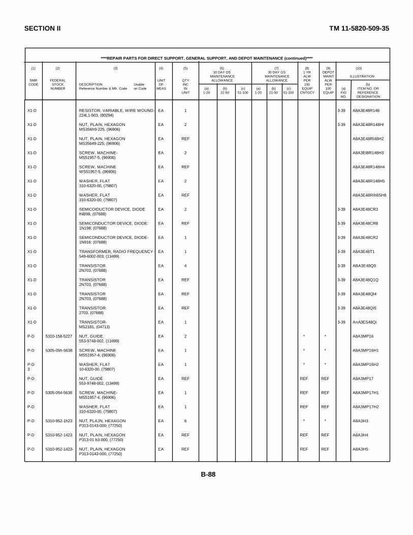
SECTION II TM 11-5820-509-35
****REPAIR PARTS FOR DIRECT SUPPORT, GENERAL SUPPORT, AND DEPOT MAINTENANCE (continued)****
(1) (2) (3) (4) (5) (6) (7) (8) (9) (10)30 DAY DS 30 DAY GS 1 YR DEPOT
MAINTENANCE MAINTENANCE ALW MAINT ILLUSTRATIONSMR FEDERAL UNIT QTY ALLOWANCE ALLOWANCE PER ALW
CODE STOCK DESCRIPTION Usable OF INC 100 PER (b)NUMBER Reference Number & Mfr. Code on Code MEAS IN (a) (b) (c) (a) (b) (c) EQUIP 100 (a) ITEM NO. OR
UNIT 1-20 21-50 51-100 1-20 21-50 51-100 CNTGCY EQUIP FIG REFERENCENO. DESIGNATION
X1-D RESISTOR, VARIABLE, WIRE WOUND- EA 1 3-39 A8A3E48R148224L1-503, (80294)
X1-D NUT, PLAIN, HEXAGON EA 2 3-39 A8A3E48R148HlMS356h9-225, (96906)
X1-D NUT, PLAIN, HEXAGON EA REF A8A3E48Rl48H2MS35649-225; (96906)
X1-D SCREW, MACHINE- EA 2 A8A3El8R148H3MS51957-5, (96906)
X1-D SCREW, MACHINE EA REF A8A3E48R148H4WS51957-5, (96906)
X1-D WASHER, FLAT EA 2 A8A3E48R148H5310-6320-00, (79807)
X1-D WASHER, FLAT EA REF A8A3E48Rih8SH6310-6320-00; (79807)
X1-D SEMICOIDUCTOR DEVICE, DIODE EA 2 3-39 A8A3E48CR3lNB98, (07688)
X1-D SEMICONDUCTOR DEVICE, DIODE: EA REF 3-39 A8A3E48CR81N198; (07688)
X1-D SEMICONDUCTOR DEVICE, DIODE- EA 1 3-39 A8A3E48CR21N916; (07688)
X1-D TRANSFORMER, RADIO FREQUENCY- EA 1 3-39 A8A3E48T1549-6002-003; (13499)
X1-D TRANSISTOR. EA 4 3-39 ABA3E48Q92N703, (07688)
X1-D TRANSISTOR EA REF 3-39 A8A3E48Q1Q2N703, (07688)
X1-D TRANSISTOR EA REF 3-39 A8A3E48Ql42N703, (07688)
X1-D TRANSISTOR: EA REF 3-39 A8A3E48QI52703, (07688)
X1-D TRANSISTOR- EA 1 3-39 AnA3ES48QiMS2181, (04713)
P-D 5310-158-5227 NUT, GUIDE. EA 2 * * A8A3MP16553-9748-002, (13499)
P-D 5305-05h-5638 SCREW, MACHINE EA 1 * * A8A3MP16H1MS51957-4; (96906)
P-D WASHER, FLAT EA 1 * * A8A3MP16H23 10-6320-00, (79807)
P-D NUT, GUIDE EA REF REF REF A8A3MP17553-9748-002, (13499)
P-D 5305-054-5638 SCREW, MACHINE- EA 1 REF REF A8A3MP17H1MS51957-4, (96906)
P-D WASHER, FLAT EA 1 REF REF A8A3MP17H2310-6320-00, (79807)
P-D 5310-952-1h23 NUT, PLAJN, HEXAGON EA 6 * * A8A3H3P313-0143-000; (77250)
P-D 5310-952-1423 NUT, PLAIN, HEXAGON EA REF REF REF A8A3H4P313-01 b3-000, (77250)
P-D 5310-952-1423- NUT, PLAIN, HEXAGON EA REF REF REF A8A3H5P313-0143-000, (77250)
B-88
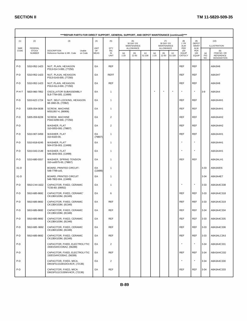
SECTION II TM 11-5820-509-35
****REPAIR PARTS FOR DIRECT SUPPORT, GENERAL SUPPORT, AND DEPOT MAINTENANCE (continued)****
(1) (2) (3) (4) (5) (6) (7) (8) (9) (10)30 DAY DS 30 DAY GS 1 YR DEPOT
MAINTENANCE MAINTENANCE ALW MAINT ILLUSTRATIONSMR FEDERAL UNIT QTY ALLOWANCE ALLOWANCE PER ALW
CODE STOCK DESCRIPTION Usable OF INC 100 PER (b)NUMBER Reference Number & Mfr. Code on Code MEAS IN (a) (b) (c) (a) (b) (c) EQUIP 100 (a) ITEM NO. OR
UNIT 1-20 21-50 51-100 1-20 21-50 51-100 CNTGCY EQUIP FIG REFERENCENO. DESIGNATION
P-D 5310-952-1423 NUT, PLAIN, HEXAGON EA REF REF REF A8A3H6P313-014 3-000, (77250)
P-D 5310-952-1423 NUT, PLA1N, HEXAGON EA REFF REF REF A8A3H7P313-0143-000, (77250)
P-D 5310-952-1423 NUT, PLAIN, HEXAGON EA REF REF REF A8A3H8P313-01L3-000, (77250)
P-H-T 5820-960-7852 OSCILLATOR SUBASSEMBLY EA 1 * * * * * 3-9 A8A3A45L8-7794-005, (13499)
P-D 5310-622-1724 NUT, SELF-LOCKING, HEXAGON EA 1 REF REF A8A3A4H168-1660-26, (72962)
P-D 5305-054-5638 SCREW, MACHINE EA 1 REF REF A8A3A4H1MS51957-4, (96906)
P-D 5305-059-8228 SCREW, MACHINE EA 2 REF REF A8A3A4H2P343-0299-000, (77250)
P-D WASHER, FLAT EA 2 REF REF A8A3A4H2310-0053-000; (79807)
P-D 5310-907-0459 WASHER, FLAT EA 1 REF REF A8A3A4H1310-6320-00, (79807)
P-D 5310-818-6245 WASHER, FLAT' EA 1 * * A8A3A4H1504-0726-003, (13499)
P-D 5310-043-2149 WASHER, FLAT EA 1 * * A8A3A4H1546-3043-003, (13499)
P-D 5310-680-5557 WASHER, SPRING TENSION EA 1 REF REF A8A3ALH1310-oo0075-00, (79807)
X1-D BOARD, PRINTED CIRCUIT- EA 1 3-33 A8A3AlE6548-7799-oo5, (13499)
X1-D BOARD, PRINTED CIRCUIT EA 1 3-34 A8A3A4E7548-7802-004, (13499)
P-D 5910-244-1622 CAPACITOR, FIXED, CERAMIC EA 1 * * 3-33 A8A3A4C338TC50-83; (09052)
P-D 5910-685-9692 CAPACITOR, FIXED, CERAMIC' EA 6 REF REF 3-33 A8A3A4C318CK13BX103M, (81349)
P-D 5910-685-9692 CAPACITOR, FIXED, CERAMIC EA REF REF REF 3-33 A8A3A4C319CK13BX103M, (81349)
P-D 5910-685-9692 CAPACITOR, FIXED, CERAMIC EA REF REF REF 3-34 A8A3A4C334CK13BX103M, (81349)
P-D 5910-685-9692 CAPACITOR, FIXED, CERAMIC EA REF REF REF 3-33 A8A3A4C335CK13BX103M, (81349)
P-D 5910-685 -9692 CAPACITOR, FIXED, CERAMIC EA REF REF REF 3-33 A8A3A4C336CK13BX103M, (81349)
P-D 5910-685-9692 CAPACITOR, FIXED, CERAMIC EA REF REF REF 3-33 A8A3ALC3h3CK13BX103M, (81349)
P-D CAPACITOR, FIXED, ELECTROLYTIC EA 2 * * 3-34 A8A3A4C331150D154XCO35A2, (56289)
P-D CAPACITOR, FIXED, ELECTROLYTIC EA REF REF REF 3-34 ABA3A4C332150D154XC035A2, (56289)
P-D CAPACITOR, FIXED, MICA. EA 2 * * 3-34 A8A3A4C330DM15F511G301DOv4CR, (72136)
P-D CAPACITOR, FIXED, MICA: EA REF REF REF 3-34 A8A3A4C333DM15F511CG30WV4CR, (72136)
B-89
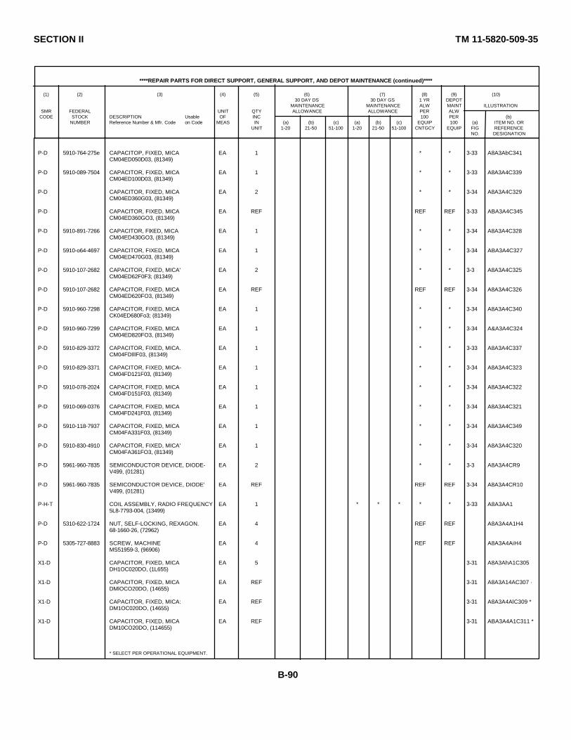
SECTION II TM 11-5820-509-35
****REPAIR PARTS FOR DIRECT SUPPORT, GENERAL SUPPORT, AND DEPOT MAINTENANCE (continued)****
(1) (2) (3) (4) (5) (6) (7) (8) (9) (10)30 DAY DS 30 DAY GS 1 YR DEPOT
MAINTENANCE MAINTENANCE ALW MAINT ILLUSTRATIONSMR FEDERAL UNIT QTY ALLOWANCE ALLOWANCE PER ALW
CODE STOCK DESCRIPTION Usable OF INC 100 PER (b)NUMBER Reference Number & Mfr. Code on Code MEAS IN (a) (b) (c) (a) (b) (c) EQUIP 100 (a) ITEM NO. OR
UNIT 1-20 21-50 51-100 1-20 21-50 51-100 CNTGCY EQUIP FIG REFERENCENO. DESIGNATION
P-D 5910-764-275e CAPACITOP, FIXED, MICA EA 1 * * 3-33 A8A3AbC341CM04ED050D03, (81349)
P-D 5910-089-7504 CAPACITOR, FIXED, MICA EA 1 * * 3-33 A8A3A4C339CM04ED100D03, (81349)
P-D CAPACITOR, FIXED, MICA EA 2 * * 3-34 A8A3A4C329CM04ED360G03, (81349)
P-D CAPACITOR, FIXED, MICA EA REF REF REF 3-33 ABA3A4C345CM04ED360GO3, (81349)
P-D 5910-891-7266 CAPACITOR, FIXED, MICA EA 1 * * 3-34 A8A3A4C328CM04ED430GO3, (81349)
P-D 5910-o64-4697 CAPACITOR, FIXED, MICA EA 1 * * 3-34 ABA3A4C327CM04ED470G03, (81349)
P-D 5910-107-2682 CAPACITOR, FIXED, MICA' EA 2 * * 3-3 A8A3A4C325CM04ED62F0F3; (81349)
P-D 5910-107-2682 CAPACITOR, FIXED, MICA EA REF REF REF 3-34 A8A3A4C326CM04ED620FO3, (81349)
P-D 5910-960-7298 CAPACITOR, FIXED, MICA EA 1 * * 3-34 A8A3A4C340CK04ED680Fo3; (81349)
P-D 5910-960-7299 CAPACITOR, FIXED, MICA EA 1 * * 3-34 A&A3A4C324CM04ED820FO3, (81349)
P-D 5910-829-3372 CAPACITOR, FIXED, MICA. EA 1 * * 3-33 A8A3A4C337CM04FDlllF03, (81349)
P-D 5910-829-3371 CAPACITOR, FIXED, MICA- EA 1 * * 3-34 A8A3A4C323CM04FD121F03, (81349)
P-D 5910-078-2024 CAPACITOR, FIXED, MICA EA 1 * * 3-34 A8A3A4C322CM04FD151F03, (81349)
P-D 5910-069-0376 CAPACITOR, FIXED, MICA EA 1 * * 3-34 A8A3A4C321CM04FD241F03, (81349)
P-D 5910-118-7937 CAPACITOR, FIXED, MICA EA 1 * * 3-34 A8A3A4C349CM04FA331F03, (81349)
P-D 5910-830-4910 CAPACITOR, FIXED, MICA' EA 1 * * 3-34 A8A3A4C320CM04FA361FO3, (81349)
P-D 5961-960-7835 SEMICONDUCTOR DEVICE, DIODE- EA 2 * * 3-3 A8A3A4CR9V499, (01281)
P-D 5961-960-7835 SEMICONDUCTOR DEVICE, DIODE' EA REF REF REF 3-34 A8A3A4CR10V499, (01281)
P-H-T COIL ASSEMBLY, RADIO FREQUENCY EA 1 * * * * * 3-33 A8A3AA15L8-7793-004, (13499)
P-D 5310-622-1724 NUT, SELF-LOCKING, REXAGON. EA 4 REF REF A8A3A4A1H468-1660-26, (72962)
P-D 5305-727-8883 SCREW, MACHINE EA 4 REF REF A8A3A4AiH4MS51959-3, (96906)
X1-D CAPACITOR, FIXED, MICA EA 5 3-31 A8A3AhA1C305DH1OC020DO, (1L655)
X1-D CAPACITOR, FIXED, MICA EA REF 3-31 A8A3A14AC307 ·DMlOCO20DO, (14655)
X1-D CAPACITOR, FIXED, MICA: EA REF 3-31 A8A3A4AlC309 *DM1OC020DO, (14655)
X1-D CAPACITOR, FIXED, MICA EA REF 3-31 ABA3A4A1C311 *DM10CO20DO, (114655)
* SELECT PER OPERATIONAL EQUIPMENT.
B-90
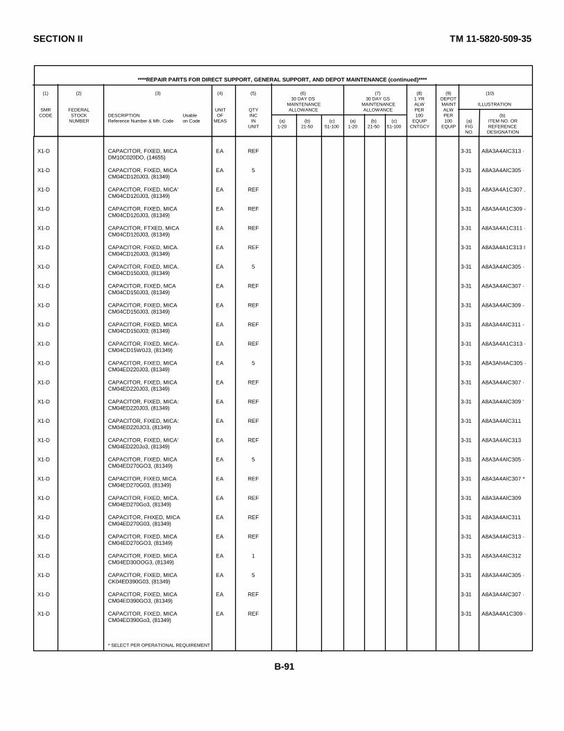
SECTION II TM 11-5820-509-35
****REPAIR PARTS FOR DIRECT SUPPORT, GENERAL SUPPORT, AND DEPOT MAINTENANCE (continued)****
(1) (2) (3) (4) (5) (6) (7) (8) (9) (10)30 DAY DS 30 DAY GS 1 YR DEPOT
MAINTENANCE MAINTENANCE ALW MAINT ILLUSTRATIONSMR FEDERAL UNIT QTY ALLOWANCE ALLOWANCE PER ALW
CODE STOCK DESCRIPTION Usable OF INC 100 PER (b)NUMBER Reference Number & Mfr. Code on Code MEAS IN (a) (b) (c) (a) (b) (c) EQUIP 100 (a) ITEM NO. OR
UNIT 1-20 21-50 51-100 1-20 21-50 51-100 CNTGCY EQUIP FIG REFERENCENO. DESIGNATION
X1-D CAPACITOR, FIXED, MICA EA REF 3-31 A8A3A4AlC313 ·DM10C020DO, (14655)
X1-D CAPACITOR, FIXED, MICA EA 5 3-31 A8A3A4AlC305 ·CM04CD120J03, (81349)
X1-D CAPACITOR, FIXED, MICA' EA REF 3-31 A8A3A4A1C307 .CM04CD120J03, (81349)
X1-D CAPACITOR, FIXED, MICA EA REF 3-31 A8A3A4A1C309 -CM04CD120J03, (81349)
X1-D CAPACITOR, FTXED, MICA EA REF 3-31 A8A3A4A1C311 ·CM04CD120J03, (81349)
X1-D CAPACITOR, FIXED, MICA. EA REF 3-31 A8A3A4A1C313 ICM04CD120J03, (81349)
X1-D CAPACITOR, FIXED, MICA. EA 5 3-31 A8A3A4AlC305 ·CM04CD150J03, (81349)
X1-D CAPACITOR, FIXED, MCA EA REF 3-31 A8A3A4AlC307 ·CM04CD150J03, (81349)
X1-D CAPACITOR, FIXED, MICA EA REF 3-31 A8A3A4AlC309 -CM04CD150J03, (81349)
X1-D CAPACITOR, FIXED, MICA EA REF 3-31 A8A3A4AlC311 -CM04CD150J03; (81349)
X1-D CAPACITOR, FIXED, MICA- EA REF 3-31 A8A3A4A1C313 ·CM04CD15W0J3, (81349)
X1-D CAPACITOR, FIXED, MICA EA 5 3-31 A8A3Ah4AC305 ·CM04ED220J03, (81349)
X1-D CAPACITOR, FIXED, MICA EA REF 3-31 A8A3A4AlC307 ·CM04ED220J03, (81349)
X1-D CAPACITOR, FIXED, MICA: EA REF 3-31 A8A3A4AlC309 'CM04ED220J03, (81349)
X1-D CAPACITOR, FIXED, MICA: EA REF 3-31 A8A3A4AlC311CM04ED220JO3, (81349)
X1-D CAPACITOR, FIXED, MICA' EA REF 3-31 A8A3A4AlC313CM04ED220Jo3, (81349)
X1-D CAPACITOR, FIXED, MICA EA 5 3-31 A8A3A4AlC305 ·CM04ED270GO3, (81349)
X1-D CAPACITOR, FIXED, MICA EA REF 3-31 A8A3A4AlC307 *CM04ED270G03, (81349)
X1-D CAPACITOR, FIXED, MICA. EA REF 3-31 A8A3A4AlC309CM04ED270Go3, (81349)
X1-D CAPACITOR, FHXED, MICA EA REF 3-31 A8A3A4AIC311CM04ED270G03, (81349)
X1-D CAPACITOR, FIXED, MICA EA REF 3-31 A8A3A4AlC313 ·CM04ED270GO3, (81349)
X1-D CAPACITOR, FIXED, MICA EA 1 3-31 A8A3A4AlC312CM04ED30OOG3, (81349)
X1-D CAPACITOR, FIXED, MICA EA 5 3-31 A8A3A4AlC305 ·CK04ED390G03, (81349)
X1-D CAPACITOR, FIXED, MICA EA REF 3-31 A8A3A4AlC307 ·CM04ED390GO3, (81349)
X1-D CAPACITOR, FIXED, MICA EA REF 3-31 A8A3A4A1C309 ·CM04ED390Go3, (81349)
* SELECT PER OPERATIONAL REQUIREMENT
B-91
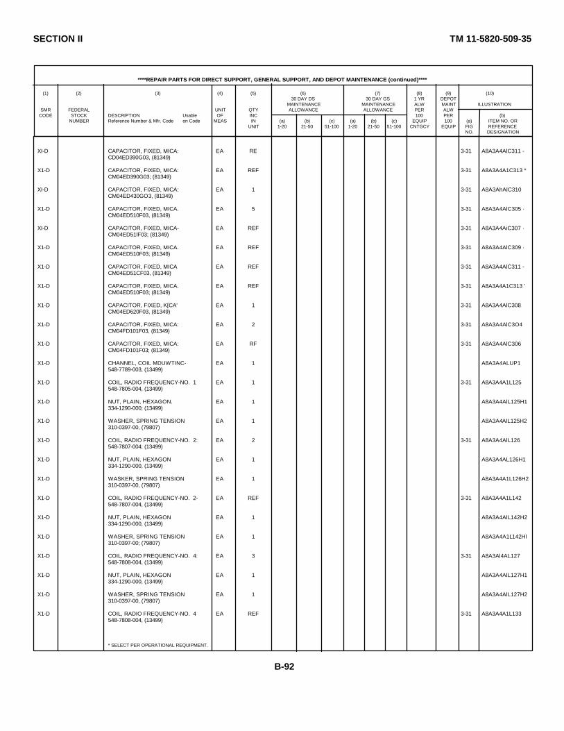
SECTION II TM 11-5820-509-35
****REPAIR PARTS FOR DIRECT SUPPORT, GENERAL SUPPORT, AND DEPOT MAINTENANCE (continued)****
(1) (2) (3) (4) (5) (6) (7) (8) (9) (10)30 DAY DS 30 DAY GS 1 YR DEPOT
MAINTENANCE MAINTENANCE ALW MAINT ILLUSTRATIONSMR FEDERAL UNIT QTY ALLOWANCE ALLOWANCE PER ALW
CODE STOCK DESCRIPTION Usable OF INC 100 PER (b)NUMBER Reference Number & Mfr. Code on Code MEAS IN (a) (b) (c) (a) (b) (c) EQUIP 100 (a) ITEM NO. OR
UNIT 1-20 21-50 51-100 1-20 21-50 51-100 CNTGCY EQUIP FIG REFERENCENO. DESIGNATION
XI-D CAPACITOR, FIXED, MICA: EA RE 3-31 A8A3A4AlC311 -CD04ED390G03, (81349)
X1-D CAPACITOR, FIXED, MICA: EA REF 3-31 A8A3A4A1C313 *CM04ED390G03; (81349)
XI-D CAPACITOR, FIXED, MICA: EA 1 3-31 A8A3AhAlC310CM04ED430GO3, (81349)
X1-D CAPACITOR, FIXED, MICA. EA 5 3-31 A8A3A4AlC305 ·CM04ED510F03, (81349)
XI-D CAPACITOR, FIXED, MICA- EA REF 3-31 A8A3A4AiC307 ·CM04ED51lF03; (81349)
X1-D CAPACITOR, FIXED, MICA. EA REF 3-31 A8A3A4AlC309 ·CM04ED510F03; (81349)
X1-D CAPACITOR, FIXED, MICA EA REF 3-31 A8A3A4AlC311 -CM04ED51CF03, (81349)
X1-D CAPACITOR, FIXED, MICA. EA REF 3-31 A8A3A4A1C313 'CM04ED510F03; (81349)
X1-D CAPACITOR, FIXED, K[CA' EA 1 3-31 A8A3A4AlC308CM04ED620F03, (81349)
X1-D CAPACITOR, FIXED, MICA: EA 2 3-31 A8A3A4AlC3O4CM04FD101F03, (81349)
X1-D CAPACITOR, FIXED, MICA: EA RF 3-31 A8A3A4AlC306CM04FD101F03; (81349)
X1-D CHANNEL, COIL MDUWTINC- EA 1 A8A3A4ALUP1548-7789-003, (13499)
X1-D COIL, RADIO FREQUENCY-NO. 1 EA 1 3-31 A8A3A4A1L125548-7805-004, (13499)
X1-D NUT, PLAIN, HEXAGON. EA 1 A8A3A4AlL125H1334-1290-000; (13499)
X1-D WASHER, SPRING TENSION EA 1 A8A3A4AlL125H2310-0397-00, (79807)
X1-D COIL, RADIO FREQUENCY-NO. 2: EA 2 3-31 A8A3A4AlL126548-7807-004; (13499)
X1-D NUT, PLAIN, HEXAGON EA 1 A8A3A4AL126H1334-1290-000, (13499)
X1-D WASKER, SPRING TENSION EA 1 A8A3A4A1L126H2310-0397-00, (79807)
X1-D COIL, RADIO FREQUENCY-NO. 2- EA REF 3-31 A8A3A4A1L142548-7807-004, (13499)
X1-D NUT, PLAIN, HEXAGON EA 1 A8A3A4AlL142H2334-1290-000, (13499)
X1-D WASHER, SPRING TENSION EA 1 A8A3A4A1L142Hl310-0397-00; (79807)
X1-D COIL, RADIO FREQUENCY-NO. 4: EA 3 3-31 A8A3Al4AL127548-7808-004, (13499)
X1-D NUT, PLAIN, HEXAGON EA 1 A8A3A4AlL127H1334-1290-000, (13499)
X1-D WASHER, SPRING TENSION EA 1 A8A3A4AlL127H2310-0397-00, (79807)
X1-D COIL, RADIO FREQUENCY-NO. 4 EA REF 3-31 A8A3A4A1L133548-7808-004, (13499)
* SELECT PER OPERATIONAL REQUIPMENT.
B-92
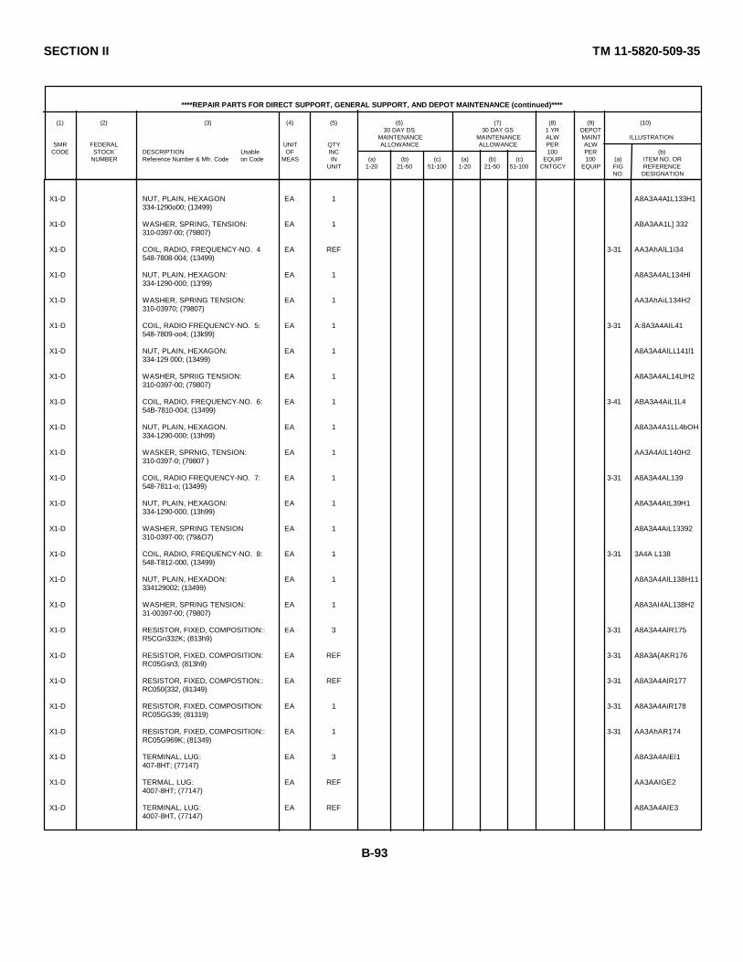
SECTION II TM 11-5820-509-35
****REPAIR PARTS FOR DIRECT SUPPORT, GENERAL SUPPORT, AND DEPOT MAINTENANCE (continued)****
(1) (2) (3) (4) (5) (6) (7) (8) (9) (10)30 DAY DS 30 DAY GS 1 YR DEPOT
MAINTENANCE MAINTENANCE ALW MAINT ILLUSTRATIONSMR FEDERAL UNIT QTY ALLOWANCE ALLOWANCE PER ALW
CODE STOCK DESCRIPTION Usable OF INC 100 PER (b)NUMBER Reference Number & Mfr. Code on Code MEAS IN (a) (b) (c) (a) (b) (c) EQUIP 100 (a) ITEM NO. OR
UNIT 1-20 21-50 51-100 1-20 21-50 51-100 CNTGCY EQUIP FIG REFERENCENO. DESIGNATION
X1-D NUT, PLAIN, HEXAGON EA 1 A8A3A4A1L133H1334-1290o00; (13499)
X1-D WASHER, SPRING, TENSION: EA 1 ABA3AA1L] 332310-0397-00; (79807)
X1-D COIL, RADIO, FREQUENCY-NO. 4 EA REF 3-31 AA3AhAlL1i34548-7808-004; (13499)
X1-D NUT, PLAIN, HEXAGON: EA 1 A8A3A4AL134Hl334-1290-000; (13'99)
X1-D WASHER, SPRING TENSION: EA 1 AA3AhAiL134H2310-03970; (79807)
X1-D COIL, RADIO FREQUENCY-NO. 5: EA 1 3-31 A:8A3A4AIL41548-7809-oo4; (13k99)
X1-D NUT, PLAIN, HEXAGON: EA 1 A8A3A4AILL141l1334-129 000; (13499)
X1-D WASHER, SPRIIG TENSION: EA 1 A8A3A4AL14LlH2310-0397-00; (79807)
X1-D COIL, RADIO, FREQUENCY-NO. 6: EA 1 3-41 ABA3A4AiL1L454B-7810-004; (13499)
X1-D NUT, PLAIN, HEXAGON. EA 1 A8A3A4A1LL4bOH334-1290-000; (13h99)
X1-D WASKER, SPRNIG, TENSION: EA 1 AA3A4AlL140H2310-0397-0; (79807 )
X1-D COIL, RADIO FREQUENCY-NO. 7: EA 1 3-31 A8A3A4AL139548-7811-o; (13499)
X1-D NUT, PLAIN, HEXAGON: EA 1 A8A3A4AtL39H1334-1290-000; (13h99)
X1-D WASHER, SPRING TENSION EA 1 A8A3A4AiL13392310-0397-00; (79&O7)
X1-D COIL, RADIO, FREQUENCY-NO. 8: EA 1 3-31 3A4A L138548-T812-000, (13499)
X1-D NUT, PLAIN, HEXADON: EA 1 A8A3A4AlL138H11334129002; (13499)
X1-D WASHER, SPRING TENSION: EA 1 A8A3AI4AL138H231-00397-00; (79807)
X1-D RESISTOR, FIXED, COMPOSITION:: EA 3 3-31 A8A3A4AlR175R5CGn332K; (813h9)
X1-D RESISTOR, FIXED. COMPOSITION: EA REF 3-31 A8A3A{AKR176RC05Gsn3, (813h9)
X1-D RESISTOR, FIXED, COMPOSTION:: EA REF 3-31 A8A3A4AlR177RC050{332, (81349)
X1-D RESISTOR, FIXED, COMPOSITION: EA 1 3-31 A8A3A4AiR178RC05GG39; (81319)
X1-D RESISTOR, FIXED, COMPOSITION:: EA 1 3-31 AA3AhAR174RC05G969K; (81349)
X1-D TERMINAL, LUG: EA 3 A8A3A4AlEl1407-8HT; (77147)
X1-D TERMAL, LUG: EA REF AA3AAIGE24007-8HT; (77147)
X1-D TERMINAL, LUG: EA REF A8A3A4AlE34007-8HT, (77147)
B-93
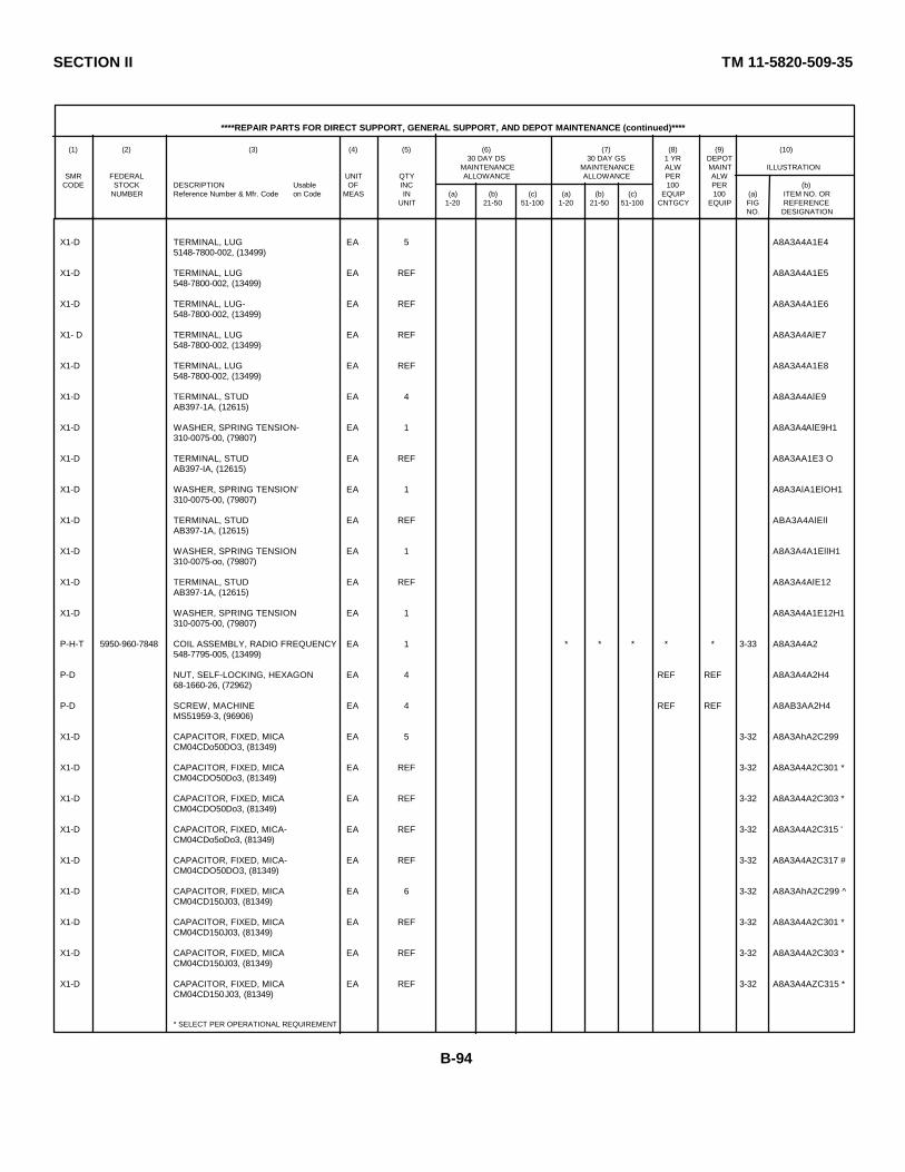
SECTION II TM 11-5820-509-35
****REPAIR PARTS FOR DIRECT SUPPORT, GENERAL SUPPORT, AND DEPOT MAINTENANCE (continued)****
(1) (2) (3) (4) (5) (6) (7) (8) (9) (10)30 DAY DS 30 DAY GS 1 YR DEPOT
MAINTENANCE MAINTENANCE ALW MAINT ILLUSTRATIONSMR FEDERAL UNIT QTY ALLOWANCE ALLOWANCE PER ALW
CODE STOCK DESCRIPTION Usable OF INC 100 PER (b)NUMBER Reference Number & Mfr. Code on Code MEAS IN (a) (b) (c) (a) (b) (c) EQUIP 100 (a) ITEM NO. OR
UNIT 1-20 21-50 51-100 1-20 21-50 51-100 CNTGCY EQUIP FIG REFERENCENO. DESIGNATION
X1-D TERMINAL, LUG EA 5 A8A3A4A1E45148-7800-002, (13499)
X1-D TERMINAL, LUG EA REF A8A3A4A1E5548-7800-002, (13499)
X1-D TERMINAL, LUG- EA REF A8A3A4A1E6548-7800-002, (13499)
X1- D TERMINAL, LUG EA REF A8A3A4AlE7548-7800-002, (13499)
X1-D TERMINAL, LUG EA REF A8A3A4A1E8548-7800-002, (13499)
X1-D TERMINAL, STUD EA 4 A8A3A4AlE9AB397-1A, (12615)
X1-D WASHER, SPRING TENSION- EA 1 A8A3A4AlE9H1310-0075-00, (79807)
X1-D TERMINAL, STUD EA REF A8A3AA1E3 OAB397-IA, (12615)
X1-D WASHER, SPRING TENSION' EA 1 A8A3AlA1ElOH1310-0075-00, (79807)
X1-D TERMINAL, STUD EA REF ABA3A4AlEllAB397-1A, (12615)
X1-D WASHER, SPRING TENSION EA 1 A8A3A4A1EllH1310-0075-oo, (79807)
X1-D TERMINAL, STUD EA REF A8A3A4AlE12AB397-1A, (12615)
X1-D WASHER, SPRING TENSION EA 1 A8A3A4A1E12H1310-0075-00, (79807)
P-H-T 5950-960-7848 COIL ASSEMBLY, RADIO FREQUENCY EA 1 * * * * * 3-33 A8A3A4A2548-7795-005, (13499)
P-D NUT, SELF-LOCKING, HEXAGON EA 4 REF REF A8A3A4A2H468-1660-26, (72962)
P-D SCREW, MACHINE EA 4 REF REF A8AB3AA2H4MS51959-3, (96906)
X1-D CAPACITOR, FIXED, MICA EA 5 3-32 A8A3AhA2C299CM04CDo50DO3, (81349)
X1-D CAPACITOR, FIXED, MICA EA REF 3-32 A8A3A4A2C301 *CM04CDO50Do3, (81349)
X1-D CAPACITOR, FIXED, MICA EA REF 3-32 A8A3A4A2C303 *CM04CDO50Do3, (81349)
X1-D CAPACITOR, FIXED, MICA- EA REF 3-32 A8A3A4A2C315 'CM04CDo5oDo3, (81349)
X1-D CAPACITOR, FIXED, MICA- EA REF 3-32 A8A3A4A2C317 #CM04CDO50DO3, (81349)
X1-D CAPACITOR, FIXED, MICA EA 6 3-32 A8A3AhA2C299 ^CM04CD150J03, (81349)
X1-D CAPACITOR, FIXED, MICA EA REF 3-32 A8A3A4A2C301 *CM04CD150J03, (81349)
X1-D CAPACITOR, FIXED, MICA EA REF 3-32 A8A3A4A2C303 *CM04CD150J03, (81349)
X1-D CAPACITOR, FIXED, MICA EA REF 3-32 A8A3A4AZC315 *CM04CD150J03, (81349)
* SELECT PER OPERATIONAL REQUIREMENT
B-94
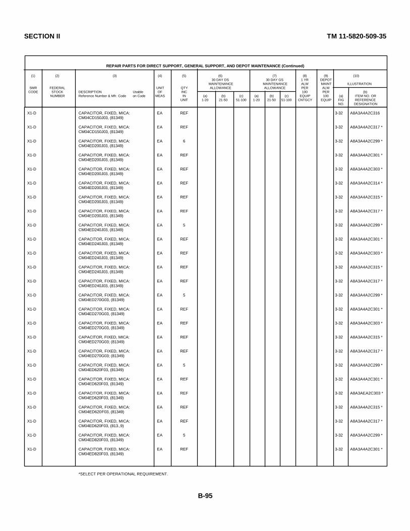
SECTION II TM 11-5820-509-35
REPAIR PARTS FOR DIRECT SUPPORT, GENERAL SUPPORT, AND DEPOT MAINTENANCE (Continued)
(1) (2) (3) (4) (5) (6) (7) (8) (9) (10)30 DAY DS 30 DAY GS 1 YR DEPOT
MAINTENANCE MAINTENANCE ALW MAINT ILLUSTRATIONSMR FEDERAL UNIT QTY ALLOWANCE ALLOWANCE PER ALW
CODE STOCK DESCRIPTION Usable OF INC 100 PER (b)NUMBER Reference Number & Mfr. Code on Code MEAS IN (a) (b) (c) (a) (b) (c) EQUIP 100 (a) ITEM NO. OR
UNIT 1-20 21-50 51-100 1-20 21-50 51-100 CNTGCY EQUIP FIG REFERENCENO. DESIGNATION
X1-D CAPACITOR, FIXED, MICA: EA REF 3-32 A8A3A4A2C316CM04CD150J03, (81349)
X1-D CAPACITOR, FIXED, MICA: EA REF 3-32 A8A3A4A2C317 *CM04CD150J03, (81349)
X1-D CAPACITOR, FIXED, MICA: EA 6 3-32 A8A3A4A2C299 *CM04ED200J03, (81349)
X1-D CAPACITOR, FIXED, MICA: EA REF 3-32 A8A3A4A2C301 *CM04ED200J03, (81349)
X1-D CAPACITOR, FIXED, MICA: EA REF 3-32 A8A3A4A2C303 *CM04ED200J03, (81349)
X1-D CAPACITOR, FIXED, MICA: EA REF 3-32 A8A3A4A2C314 *CM04ED200J03, (81349)
X1-D CAPACITOR, FIXED, MICA: EA REF 3-32 A8A3A4A2C315 *CM04ED200J03, (81349)
X1-D CAPACITOR, FIXED, MICA: EA REF 3-32 A8A3A4A2C317 *CM04ED200J03, (81349)
X1-D CAPACITOR, FIXED, MICA: EA 5 3-32 A8A3A4A2C299 *CM04ED240J03, (81349)
X1-D CAPACITOR, FIXED, MICA: EA REF 3-32 A8A3A4A2C301 *CM04ED240J03, (81349)
X1-D CAPACITOR, FIXED, MICA: EA REF 3-32 A8A3A4A2C303 *CM04ED240J03, (81349)
X1-D CAPACITOR, FIXED, MICA: EA REF 3-32 A8A3A4A2C315 *CM04ED240J03, (81349)
X1-D CAPACITOR, FIXED, MICA: EA REF 3-32 A8A3A4A2C317 *CM04ED240J03, (81349)
X1-D CAPACITOR, FIXED, MICA: EA 5 3-32 A8A3A4A2C299 *CM04ED270G03, (81349)
X1-D CAPACITOR, FIXED, MICA: EA REF 3-32 A8A3A4A2C301 *CM04ED270G03, (81349)
X1-D CAPACITOR, FIXED, MICA: EA REF 3-32 A8A3A4A2C303 *CM04ED270G03, (81349)
X1-D CAPACITOR, FIXED, MICA: EA REF 3-32 A8A3A4A2C315 *CM04ED270G03; (81349)
X1-D CAPACITOR, FIXED, MICA: EA REF 3-32 A8A3A4A2C317 *CM04ED270G03; (81349)
X1-D CAPACITOR, FIXED, MICA: EA 5 3-32 A8A3A4A2C299 *CM04ED620F03, (81349)
X1-D CAPACITOR, FIXED, MICA: EA REF 3-32 A8A3A4A2C301 *CM04ED620F03, (81349)
X1-D CAPACITOR, FIXED, MICA: EA REF 3-32 A8A3AEA2C303 *CM04ED620F03, (81349)
X1-D CAPACITOR, FIXED, MICA: EA REF 3-32 A8A3A4A2C315 *CM04ED620F03, (81349)
X1-D CAPACITOR, FIXED, MICA: EA REF 3-32 A8A3A4A2C317 *CM04ED620F03, (813.,9)
X1-D CAPACITOR, FIXED, MICA: EA 5 3-32 A8A3A4A2C299 *CM04ED820F03, (81349)
X1-D CAPACITOR, FIXED, MICA: EA REF 3-32 A8A3A4A2C301 *CM04ED820F03, (81349)
*SELECT PER OPERATIONAL REQUIREMENT.
B-95

SECTION II TM 11-5820-509-35
REPAIR PARTS FOR DIRECT SUPPORT, GENERAL SUPPORT, AND DEPOT MAINTENANCE (Continued)
(1) (2) (3) (4) (5) (6) (7) (8) (9) (10)30 DAY DS 30 DAY GS 1 YR DEPOT
MAINTENANCE MAINTENANCE ALW MAINT ILLUSTRATIONSMR FEDERAL UNIT QTY ALLOWANCE ALLOWANCE PER ALW
CODE STOCK DESCRIPTION Usable OF INC 100 PER (b)NUMBER Reference Number & Mfr. Code on Code MEAS IN (a) (b) (c) (a) (b) (c) EQUIP 100 (a) ITEM NO. OR
UNIT 1-20 21-50 51-100 1-20 21-50 51-100 CNTGCY EQUIP FIG REFERENCENO. DESIGNATION
X1-D CAPACITOR, FIXED, MICA: EA REF 3-32 A8A3A4A2C303 *CM04EDB20F03, (81349)
X1-D CAPACITOR, FIXED, MICA: EA REF 3-32 A8A3A4A2C315 *CM04ED820F03, (81349)
X1-D CAPACITOR, FIXED, MICA: EA REF 3-32 A8A3A4A2C317 *CM04ED820F03; (81349)
X1-D CAPACITOR, FIXED, MICA: EA 5 3-32 A8A3A4A2C299 *CM04FD910F03; (81349)
X1-D CAPACITOR, FIXED, MICA: EA REF 3-32 A8A3A4A2C301 *CM04FD910F03, (81349)
X1-D CAPACITOR, FIXED, MICA: EA REF 3-32 A8A3ALA2C303 *CM04FD910F03, (81349)
X1-D CAPACITOR, FIXED, MICA: EA REF 3-32 A8A3A4A2C315 *CM04FD910F03, (81349)
X1-D CAPACITOR, FIXED, MICA: EA REF 3-32 A8A3A4A2C317 *CM04FD910F03, (81349)
X1-D CAPACITOR, FIXED, MICA: EA 5 3-32 A8A3A4A2C299 *CM04FD101F03, (81349)
X1-D CAPACITOR, FIXED, MICA: EA REF 3-32 A8A3A4A2C301 *CM04FD101F03, (81349)
X1-D CAPACITOR, FIXED, MICA: EA REF 3-32 A8A3A4A2C303 *CM04FD101F03, (81349)
X1-D CAPACITOR, FIXED, MICA: EA REF 3-32 A8A3A4A2C315 *CM04FD101F03, (81349)
X1-D CAPACITOR, FIXED, MICA: EA REF 3-32 A8A3A4A2C317 *CM04FD101F03, (81349)
X1-D CAPACITOR, FIXED, MICA: EA 5 3-32 A8A3A4A2C299 *CM04FD111F03, (81349)
X1-D CAPACITOR, FIXED, MICA: EA REF 3-32 A8A3A4A2C301 *CM04FD111F03, (81349)
X1-D CAPACITOR, FIXED, MICA: EA REF 3-32 A8A3A4A2C303 *CM04FD111F03, (81349)
X1-D CAPACITOR, FIXED, MICA: EA REF 3-32 A8A3A4A2C315 *CM04FD111F03, (81349)
X1-D CAPACITOR, FIXED, MICA: EA REF 3-32 A8A3A4A2C317 *CM04FD111F03, (81349)
X1-D CAPACITOR, FIXED, MICA: EA 1 3-32 A8A3A4A2C302CM04FD121F03, (81349)
X1-D CAPACITOR, FIXED, MICA: EA 5 3-32 A8A3A4A?C299 *CM04FD131F03, (81349)
X1-D CAPACITOR, FIXED, MICA: EA REF 3-32 A8A3A4A2C301 *CM04FD131F03, (81349)
X1-D CAPACITOR, FIXED, MICA: EA REF 3-32 A8A3A4A2C303 *CM04FD131F03, (81349)
X1-D CAPACITOR, FIXED, MICA: EA REF 3-32 A8A3A4A2C315 *CM04FD131F03, (81349)
X1-D CAPACITOR, FIXED, MICA: EA REF 3-32 A8A3A4A2C317 *CM04FD131F03, (81349)
X1-D CAPACITOR, FIXED, MICA: EA 6 3-32 A8A3A4A2C299 *CM04FD151F03, (81349)
* SELECT PER OPERATIONAL REQUIREMENT.
B-96
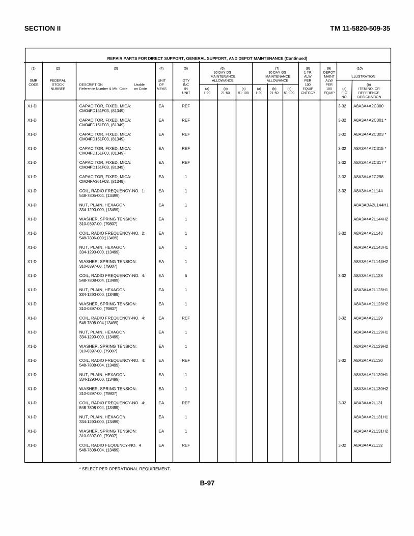
SECTION II TM 11-5820-509-35
REPAIR PARTS FOR DIRECT SUPPORT, GENERAL SUPPORT, AND DEPOT MAINTENANCE (Continued)
(1) (2) (3) (4) (5) (6) (7) (8) (9) (10)30 DAY DS 30 DAY GS 1 YR DEPOT
MAINTENANCE MAINTENANCE ALW MAINT ILLUSTRATIONSMR FEDERAL UNIT QTY ALLOWANCE ALLOWANCE PER ALW
CODE STOCK DESCRIPTION Usable OF INC 100 PER (b)NUMBER Reference Number & Mfr. Code on Code MEAS IN (a) (b) (c) (a) (b) (c) EQUIP 100 (a) ITEM NO. OR
UNIT 1-20 21-50 51-100 1-20 21-50 51-100 CNTGCY EQUIP FIG REFERENCENO. DESIGNATION
X1-D CAPACITOR, FIXED, MICA: EA REF 3-32 A8A3A4A2C300CM04FD151F03, (81349)
X1-D CAPACITOR, FIXED, MICA: EA REF 3-32 A8A3A4A2C301 *CM04FD151F03, (81349)
X1-D CAPACITOR, FIXED, MICA: EA REF 3-32 A8A3A4A2C303 *CM04FD151F03, (81349)
X1-D CAPACITOR, FIXED, MICA: EA REF 3-32 A8A3A4A2C315 *CM04FD151F03, (81349)
X1-D CAPACITOR, FIXED, MICA: EA REF 3-32 A8A3A4A2C317 *CM04FD151F03, (81349)
X1-D CAPACITOR, FIXED, MICA: EA 1 3-32 A8A3A4A2C298CM04FA361F03, (81349)
X1-D COIL, RADIO FREQUENCY-NO. 1: EA 1 3-32 A8A3A4A2L144548-7805-004, (13499)
X1-D NUT, PLAIN, HEXAGON: EA 1 A8A3ABA2L144H1334-1290-000, (13499)
X1-D WASHER, SPRING TENSION: EA 1 A8A3A4A2L144H2310-0397-00, (79807)
X1-D COIL, RADIO FREQUENCY-NO. 2: EA 1 3-32 A8A3A4A2L143548-7806-000;(13499)
X1-D NUT, PLAIN, HEXAGON: EA 1 A8A3A4A2L143H1334-1290-000, (13499)
X1-D WASHER, SPRING TENSION: EA 1 A8A3A4A2L143H2310-0397-00, (79807)
X1-D COIL, RADIO FREQUENCY-NO. 4: EA 5 3-32 A8A3A4A2L128548-7808-004, (13499)
X1-D NUT, PLAIN, HEXAGON: EA 1 A8A3A4A2L128H1334-1290-000, (13499)
X1-D WASHER, SPRING TENSION: EA 1 A8A3A4A2L128H2310-0397-00, (79807)
X1-D COIL, RADIO FREQUENCY-NO. 4: EA REF 3-32 A8A3A4A2L129548-7808-004 (13499)
X1-D NUT, PLAIN, HEXAGON: EA 1 A8A3A4A2L129H1334-1290-000, (13499)
X1-D WASHER, SPRING TENSION: EA 1 A8A3A4A2L129H2310-0397-00, (79807)
X1-D COIL, RADIO FREQUENCY-NO. 4: EA REF 3-32 A8A3A4A2L130548-7808-004, (13499)
X1-D NUT, PLAIN, HEXAGON: EA 1 A8A3A4A2L130H1334-1290-000, (13499)
X1-D WASHER, SPRING TENSION: EA 1 A8A3A4A2L130H2310-0397-00, (79807)
X1-D COIL, RADIO FREQUENCY-NO. 4: EA REF 3-32 A8A3A4A2L131548-7808-004, (13499)
X1-D NUT, PLAIN, HEXAGON: EA 1 A8A3A4A2L131H1334-1290-000, (13499)
X1-D WASHER, SPRING TENSION: EA 1 A8A3A4A2L131H2310-0397-00, (79807)
X1-D COIL, RADIO FEQUENCY-NO. 4 EA REF 3-32 A8A3A4A2L132548-7808-004, (13499)
* SELECT PER OPERATIONAL REQUIREMENT.
B-97

SECTION II TM 11-5820-509-35
REPAIR PARTS FOR DIRECT SUPPORT, GENERAL SUPPORT, AND DEPOT MAINTENANCE (Continued)
(1) (2) (3) (4) (5) (6) (7) (8) (9) (10)30 DAY DS 30 DAY GS 1 YR DEPOT
MAINTENANCE MAINTENANCE ALW MAINT ILLUSTRATIONSMR FEDERAL UNIT QTY ALLOWANCE ALLOWANCE PER ALW
CODE STOCK DESCRIPTION Usable OF INC 100 PER (b)NUMBER Reference Number & Mfr. Code on Code MEAS IN (a) (b) (c) (a) (b) (c) EQUIP 100 (a) ITEM NO. OR
UNIT 1-20 21-50 51-100 1-20 21-50 51-100 CNTGCY EQUIP FIG REFERENCENO. DESIGNATION
X1-D NUT, PLAIN, HEXAGON: EA 1 A8A3A4A2L132H1334-1290-000, (13499)
X1-D WASHER, SPRING TENSION: EA 1 A8A3A4A2L132H2310-0397-00; (79807)
X1-D COIL, RADIO FREQUENCY-NO. 9: EA 1 3-32 A8A3A4A2L137548-7813-004, (13499)
X1-D NUT, PLAIN, HEXAGON: EA 1 A8A384A2L137H1334-1290-000, (13499)
X1-D WASHER, SPRING TENSION: EA 1 A8A3A4A2L137H2310-0397-00, (79807)
X1-D COIL, RADIO FREQUENCY-NO. 10: EA 1 3-32 A8A3A4A2L136548-7814-004, (13499)
X1-D NUT, PLAIN, HEXAGON: EA 1 A8A3A4A2L136H1334-1290-000, (13499)
X1-D WASHER, SPRING TENSION: EA 1 A8A3A4A2L136H2310-0397-00, (79807)
X1-D COIL, RADIO FREQUENCY-NO. 11: EA 1 3-32 A8A3A4A2L135548-7815-004, (13499)
X1-D NUT, PLAIN, HEXAGON EA 1 A8A3A4A2L135H1334-1290-000; (13499)
X1-D WASHER, SPRING TENSION: EA 1 A8A3A2L135H2310-0397-00, (79807)
X1-D RESISTOR, FIXED, COMPOSITION: EA 2 3-32 A8A3A4A2R173RCR05GF682K; (81349)
X1-D RESISTOR, FIXED, COMPOSITION: EA REF 3-32 A8A3A4A2R179RCR05GF682K, (81349)
X1-D RESISTOR, FIXED, COMPOSITION: EA 1 3-32 A8A3A4A2R172RC05GF822K, (81349)
X1-D TERMINAL, LUG: EA 3 A8A3A4A2E14007-8HT; (77147)
X1-D TERMINAL, LUG: EA REF A8A3A4A2E24007-8HT, (77147)
X1-D TERMINAL, LUG: EA REF A8A3A4A2E34007-8HT, (77147)
X1-D TERMNAL, LUG: EA 5 A8A3A4A2E4548-7800-002; (13499)
X1-D TERMINAL, LUG EA REF A8A3A4A2E5548-7800-002, (13499)
X1-D TERMINAL, LUG: EA REF A8A3A4A2E6548-7800-002, (13499)
X1-D TERMINAL, LUG: EA REF A8A3A4A2E7548-7800-002, (13499)
X1-D TERMINAL, LUG: EA REF A8A3A4A2E8548-7800-002, (13499)
X1-D TERMINAL, STUD: EA 4 A8A3A4A2E9AB397-1A, (12615)
X1-D WASHER, SPRING TENSION. EA 1 A8A3A4A2E9H1310-0075-00, (79807)
X1-D TERMINAL, STUD EA REF A8A3A4A2E10AB397-1A, (12615)
B-98
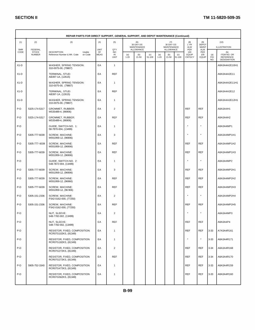
SECTION II TM 11-5820-509-35
REPAIR PARTS FOR DIRECT SUPPORT, GENERAL SUPPORT, AND DEPOT MAINTENANCE (Continued)
(1) (2) (3) (4) (5) (6) (7) (8) (9) (10)30 DAY DS 30 DAY GS 1 YR DEPOT
MAINTENANCE MAINTENANCE ALW MAINT ILLUSTRATIONSMR FEDERAL UNIT QTY ALLOWANCE ALLOWANCE PER ALW
CODE STOCK DESCRIPTION Usable OF INC 100 PER (b)NUMBER Reference Number & Mfr. Code on Code MEAS IN (a) (b) (c) (a) (b) (c) EQUIP 100 (a) ITEM NO. OR
UNIT 1-20 21-50 51-100 1-20 21-50 51-100 CNTGCY EQUIP FIG REFERENCENO. DESIGNATION
X1-D WASHER, SPRING TENSION: EA 1 A8A3A4A2E10H1310-0075-00, (79807)
X1-D TERMINAL, STUD: EA REF A8A3A4A2E11AB397-1A, (12615)
X1-D WASHER, SPRING TENSION: EA 1 A8A3A4A2E11H1310-0075-00, (79807)
X1-D TERMINAL, STUD: EA REF A8A3A4A2E12AB397-1A, (12615)
X1-D WASHER, SPRING TENSION: EA 1 A8A3A4A2E12H1310-0075-00, (79807)
P-D 5325-174-5317 GROMMET, RUBBER: EA 2 REF REF A8A3A4H1MS35489-4, (96906)
P-D 5325-174-5317 GROMMET, RUBBER: EA REF REF REF A8A3A4H2MS35489-4, (96906)
P-D GUIDE, SWITCH-NO. 1: EA 1 * * A8A3A4MP158-7870-004, (13499)
P-D 5305-777-6039 SCREW, MACHINE: EA 3 * * A8A3A4MP1H1MS51959-12, (96906)
P-D 5305-777- 6039 SCREW, MACHINE: EA REF REF REF A8A3A4MP1H2MS51959-12, (96906)
P-D 5305-777-6039 SCREW, MACHINE: EA REF REF REF A8A3A4MP1H3MS51959-12, (96906)
P-D GUIDE, SWITCH-NO. 2: EA 1 * * A8A3A4MP2548-7872-004, (13499)
P-D 5305-777-6039 SCREW, MACHINE: EA 3 REF REF A8A3A4MP2H1MS51959-12, (96906)
P-D 5305-777-6039 SCREW, MACHINE: EA REF REF REF A8A3A4MP2H2MS51959-12, (96960)
P-D 5305-777-6039 SCREW, MACHINE: EA REF REF REF A8A3A4MP2H3MS51959-12, (96 906)
P-D 5305-151-2336 SCREW, MACHINE: EA 2 * * A8A3A4MP2H4P342-0162-000, (77250)
P-D 5305-151-2336 SCREW, MACHINE: EA REF REF REF A8A3A4MP2H5P342-0162-000, (77250)
P-D NUT, SLEEVE: EA 2 * * A8A3A4MP3548-7782-002, (13499)
P-D NUT, SLEEVE: EA REF REF REF A8A3A4P4548-7782-002, (13499)
P-D RESISTOR, FIXED, COMPOSITION: EA 1 REF REF 3-33 A7A3A4R161RCR07G102KS, (81349)
P-D RESISTOR, FIXED, COMPOSITION EA 1 * * 3-33 A8A3A4R171RCR07G182KS, (81349)
P-D RESISTOR, FIXED, COMPOSITION EA 2 REF REF 3-34 A8A3A4R168RCR07G272KS, (81349)
P-D RESISTOR, FIXED, COMPOSITION EA REF REF REF 3-34 A8A3A4R170RCR07G272KS, (81349)
P-D 5905-752-3340 RESISTOR, FIXED, COMPOSITION EA 1 REF REF 3-33 A8A3A4R159RCR07G472KS, (81349)
P-D RESISTOR, FIXED, COMPOSITION EA 1 REF REF 3-33 A8A3A4R160RCR07G562KS, (81349)
B-99

SECTION II TM 11-5820-509-35
REPAIR PARTS FOR DIRECT SUPPORT, GENERAL SUPPORT, AND DEPOT MAINTENANCE (Continued)
(1) (2) (3) (4) (5) (6) (7) (8) (9) (10)30 DAY DS 30 DAY GS 1 YR DEPOT
MAINTENANCE MAINTENANCE ALW MAINT ILLUSTRATIONSMR FEDERAL UNIT QTY ALLOWANCE ALLOWANCE PER ALW
CODE STOCK DESCRIPTION Usable OF INC 100 PER (b)NUMBER Reference Number & Mfr. Code on Code MEAS IN (a) (b) (c) (a) (b) (c) EQUIP 100 (a) ITEM NO. OR
UNIT 1-20 21-50 51-100 1-20 21-50 51-100 CNTGCY EQUIP FIG REFERENCENO. DESIGNATION
P-D RESISTOR, FIXED, COMPOSITION: EA 4 * * 3-34 A8A3A4R165RCR07G104KS; (81349 )
P-D RESISTOR, FIXED, COMPOSITION: EA REF REF REF 3-34 A8A3A4R166RCR07G104KS; (81349)
P-D RESISTOR, FIXED, COMPOSITION EA REF REF REF 3-34 A8A3A4R167RCR07G104KS; (81349)
P-D RESISTOR, FIXED, COMPOSITION. EA REF REF REF 3-34 A8A3A4R169RCR07G104KS, (81349)
P-D 5905-068-1538 RESISTOR, FIXED, FILM: EA 1 * * 3-33 A8A3A4R157RW60D2611F, (81349)
P-D 5905-985-5435 RESISTOR, FIXED, FILM: EA 1 * * 3-34 A8A3A4R164RW60D7501F; (81349)
P-D 5905-892-6578 RESISTOR, FIXED: EA 1 * * 3-34 A8A3A4R163RN60D1212F; (81349)
P-D 5905-761-1905 RESISTOR, FIXED, FILM: EA 2 * * 3-33 A8A3A4R158RW60D1332F; (81349)
P-D 5905-761-1905 RESISTOR, FIXED, FILM: EA REF REF REF 3-33 A8A3A4R180RW60D1332F; (81349)
P-D 5905-990-2246 RESISTOR, FIXED, FILM: EA 1 * * 3-33 A8A3A4R156RN60D1101F; (81349)
M-D SPACER, SLEEVE: EA 2 A8A3A4MP5548-7786-003, (13499)
M-D SPACER, SLEEVE: EA REF A8A3A4MP6548-7786-003; (13499)
M-D SPACER, SLEEVE: EA 2 A8A3A4MP7548-7787-003; (13499)
M-D SPACER, SLEEVE: EA REF A8A3A4MP8548-7787-003, (13499)
M-D SPACER, SLEEVE: EA 2 A8A3A4MP9548-7788-03, (13499)
M-D SPACER, SLEEVE: EA REF A8A3A4MP10548-7788-003, (13499)
P-D 5930-960-7842 SWITCH, SECTION ROTARY: EA 1 * * 3-34 A8A3A4S7232084FC, (76854)
P-D 5930-078-1717 SWITCH, SECTION ROTARY: EA 1 * * 3-33 A8A3A4S10232085FC; (76854)
P-D 5930-960-7841 SWITCH, SECTION ROTARY: EA 1 * * 3-33 A8A3AS6232668FC; (76854)
P-D TERMINAL, LUG: EA 4 REF REF A8A3AE14040-2HT, (77147)
P-D 5305-576-6002 SCREW, MACHINE: EA 1 REF REF A8A3A4E1H1P343-0298-000; (77250)
P-D 5310-680-5557 WASHER, SPRING TENSION: EA 1 REF REF A8A3A4E1H2310-0075-000; (79807)
P-D TERMINAL, LUG: EA REF REF RED A8A3A4E24040-2HT, (77147)
P-D 5305-576-6002 SCREW, MACHINE: EA 1 REF REF A8A3A4E2H1P343-0298-000, (77250)
P-D 5310-680-5557 WASHER, SPRING TENSION: EA 1 REF REF A8A3A4E2H2310-0075-000; (79807)
B-100
SECTION II TM 11-5820-509-35
REPAIR PARTS FOR DIRECT SUPPORT, GENERAL SUPPORT, AND DEPOT MAINTENANCE (Continued)
(1) (2) (3) (4) (5) (6) (7) (8) (9) (10)30 DAY DS 30 DAY GS 1 YR DEPOT
MAINTENANCE MAINTENANCE ALW MAINT ILLUSTRATIONSMR FEDERAL UNIT QTY ALLOWANCE ALLOWANCE PER ALW
CODE STOCK DESCRIPTION Usable OF INC 100 PER (b)NUMBER Reference Number & Mfr. Code on Code MEAS IN (a) (b) (c) (a) (b) (c) EQUIP 100 (a) ITEM NO. OR
UNIT 1-20 21-50 51-100 1-20 21-50 51-100 CNTGCY EQUIP FIG REFERENCENO. DESIGNATION
P-D TERMINAL, LUG: EA REF REF REF A8A3A4E34040-2HT, (77147)
P-D 5310-208-7021 NUT, PLAIN, HEXAGON: EA 1 * * A8A3A4E3H1P313-0156-000, (77250)
P-D 5305-576-6002 SCREW, MACHINE: EA 1 REF REF A8A3A4E3H2P343-0298-000, (77250)
P-D 5310-680-5557 WASHER, SPRING TENSION: EA 1 REF REF A8A3A4E3H3310-0075-000, (79807)
P-D TERMINAL, LUG: EA REF REF REF A8A3A4E44040-2HT, (77147)
P-D 5310-208-702 1 NUT, PLAIN, HEXAGON: EA 1 REF REF A8A3A4E4H1P313-0156-000, (77250)
P-D 5305-576-6002 SCREW, MACHINE EA 1 REF REF A8A3A4E4H2P341-0298-000, (77250)
P-D 5305-680-5557 WASHER, SPRING TENSION: EA 1 REF REF A8A3A4E4H3310-0075-000, (79807)
P-D 5961-953-4485 TRANSISTOR: EA 2 * * 3-33 A8A3A4Q202N917, (07688)
P-D 5961-953-4485 TRANSISTOR: EA REF REF REF 3-33 A8A3A4Q212N917, (07688)
M-D PAD, RUBBER: EA 4 A8A3MP18548-7761-002, (13499)
M-D PAD, RUBBER: EA REF A8A3MP19548-7761-002, (13499)
M-D PAD, RUBBER: EA REF A8A3MP20548-7761-002, (13499)
M-D PAD, RUBBER: EA REF A8A3MP21548-7761-002; (13499)
P-D 5315-847-3735 PIN, SPRING, SELF-LOCKING: EA 2 * * A8A3MP22MS16562-190, (96906)
P-D 5315-847-3735 PIN, SPRING, SELF-LOCKING: EA REF REF REF A8A3MP23MS16562-190, (96906)
M-D PLATE ASSEMBLY, TOP: EA 1 A8A3MP24548-7912-00, (13499)
P-D 5305-777-6039 SCREW, MACHINE: EA 4 REF REF A8A3MP24H1MS51959-12, (96906)
P-D 5305-777-6039 SCREW, MACHINE: EA REF REF REF A8A3MP24H2MS51959-12, (96906)
P-D 5305-777-6039 SCREW, MACHINE EA REF REF REF A8A3MP243MS51959-12, (96906)
P-D 5305-777-6039 SCREW, MACHINE EA REF REF REF A8A3MP24H4MS51959-12, (96906)
P-D 5305-054-5647 SCREW, MACHINE EA 16 REF REF A8A3MP24H5MS51957-13, (96906)
P-D 5305-054-5647 SCREW, MACHINE: EA REF REF REF A8A3MP24H6MS51957-13, (96906)
P-D 5305-054-5647 SCREW, MACHINE: EA REF REF REF A8A3MP24H7MS51957-13, (96906)
P-D 5305-054-5647 SCREW, MACHINE: EA REF REF REF A8A3MP24H8MS51957-13, (96906)
B-101

SECTION II TM 11-5820-509-35
REPAIR PARTS FOR DIRECT SUPPORT, GENERAL SUPPORT, AND DEPOT MAINTENANCE (Continued)
(1) (2) (3) (4) (5) (6) (7) (8) (9) (10)30 DAY DS 30 DAY GS 1 YR DEPOT
MAINTENANCE MAINTENANCE ALW MAINT ILLUSTRATIONSMR FEDERAL UNIT QTY ALLOWANCE ALLOWANCE PER ALW
CODE STOCK DESCRIPTION Usable OF INC 100 PER (b)NUMBER Reference Number & Mfr. Code on Code MEAS IN (a) (b) (c) (a) (b) (c) EQUIP 100 (a) ITEM NO. OR
UNIT 1-20 21-50 51-100 1-20 21-50 51-100 CNTGCY EQUIP FIG REFERENCENO. DESIGNATION
P-D 5305-054-5647 SCREW, MACHINE: EA REF REF REF A8A3MP24H9MS51957-13, (96906)
P-D 5305-054-5647 SCREW, MACHINE: EA REF REF REF A8A3MP24H10MS51957-13, (96906)
P-D 5305-054-5647 SCREW, MACHINE: EA REF REF REF A8A3MP24H11MS51957-13; (96906)
P-D 5305-054-5647 SCREW, MACHINE: EA REF REF REF A8A3MP24H12MS51957-13, (96906)
P-D 5305-054-5647 SCREW, MACHINE: EA REF REF REF A8A3MP24H13MS51957-13, (96906)
P-D 5305-054-5647 SCREW, MACHINE: EA REF REF REF A8A3MP24H14MS51957-13, (96906)
P-D 5305-054-5647 SCREW, MACHINE: EA REF REF REF A8A3MP24H15MS51957-13, (96906)
P-D 5305-054-5647 SCREW, MACHINE: EA REF REF REF A8A3MP24H16MS51957-13, (96906)
P-D 5305-054-5647 SCREW, MACHINE: EA REF REF REF A8A3MP24H17MS51957-13, (96906)
P-D 5305-054-5647 SCREW, MACHINE: EA REF REF REF A8A3MP24H18MS51957-13, (96906)
P-D 5305-054-5647 SCREW, MACHINE: EA REF REF REF A8A3MP24H19MS51957-13; (96906)
P-D 5305-054-5647 SCREW, MACHINE: EA REF REF REF A8A3MP24H20MS51957-13; (96906)
P-D WASHER, LOCK: EA 16 REF REF A8A3MP24H21MS35338-13, (96906)
P-D WASHER, LOCK: EA REF REF REF A8A3MP24H22MS35338-135, (96906)
P-D WASHER, LOCK: EA REF REF REF A8A3MP24H23MS35338-135, (96906)
P-D WASHER, LOCK: EA REF REF REF A8A3MP24H24MS35338-135, (96906)
P-D WASHER, LOCK: EA REF REF REF A8A3MP24H25MS35338-135; (96906)
P-D WASHER, LOCK: EA REF REF REF A8A3MP24H26MS35338-135, (96906)
P-D WASHER, LOCK: EA REF REF REF A8A3MP24H27MS35338-135, (96906)
P-D WASHER, LOCK: EA REF REF REF A8A3MP24H28MS35338-135; (96906)
P-D WASHER, LOCK: EA REF REF REF A8A3MP24H29MS35338-135, (96906)
P-D WASHER, LOCK: EA REF REF REF A8A3MP24H30MS35338-135, (96906)
P-D WASHER, LOCK: EA REF REF REF A8A3MP24H31MS35338-135; (96906)
P-D WASHER, LOCK: EA REF REF REF A8A3MP24H32MS35338-135, (96906)
P-D WASHER, LOCK: EA REF REF REF A8A3MP24H33MS35338-135, (96906)
B-102
SECTION II TM 11-5820-509-35
REPAIR PARTS FOR DIRECT SUPPORT, GENERAL SUPPORT, AND DEPOT MAINTENANCE (Continued)
(1) (2) (3) (4) (5) (6) (7) (8) (9) (10)30 DAY DS 30 DAY GS 1 YR DEPOT
MAINTENANCE MAINTENANCE ALW MAINT ILLUSTRATIONSMR FEDERAL UNIT QTY ALLOWANCE ALLOWANCE PER ALW
CODE STOCK DESCRIPTION Usable OF INC 100 PER (b)NUMBER Reference Number & Mfr. Code on Code MEAS IN (a) (b) (c) (a) (b) (c) EQUIP 100 (a) ITEM NO. OR
UNIT 1-20 21-50 51-100 1-20 21-50 51-100 CNTGCY EQUIP FIG REFERENCENO. DESIGNATION
P-D WASHER, LOCK: EA REF REF REF A8A3MP24M34MS35338-135, (96906)
P-D WASHER, LOCK: EA REF REF REF A8A3MP24H35MS35338-135, (96906)
P-D WASHER, LOCK: EA REF REF REF A8A3MP24H36MS35338-135, (96906)
M-D PLATE, CONNECTOR: EA 1 A8A3MP25548-7882-OO4, (13499)
P-D SCREW, SELF-LOCKING: EA 23 REF REF A8A3MP25H1LP51959-13M, (03038)
P-D SCREW, SELF-LOCKING: EA REF REF REF A8A3MP25H2LP51959-13M, (03038)
P-D SCREW, SELF-LOCKING: EA REF REF REF A8A3MP25H3LP51959-13M, (03038)
P-D SCREW, SELF-LOCKING: EA REF REF REF A8A3MP25H4LP51959-13M, (03038)
P-D SCREW, SELF-LOCKING: EA REF REF REF A8A3MP25H5LP51959-13M, (03038)
P-D SCREW, SELF-LOCKING: EA REF REF REF A8A3MP25H6LP51959-13M, (03038)
P-D SCREW, SELF-LOCKING: EA REF REF REF A8A3MP25H7LP51959-13M, (03038)
P-D SCREW, SELF-LOCKING: EA REF REF REF A8A3MP25H8LP51959-13M, (03038)
P-D SCREW, SELF-LOCKING: EA REF REF REF A8A3MP25H9LP51959-13M, (03038)
P-D SCREW, SELF-LOCKING: EA REF REF REF A8A3MP25H10LP51959-13M, (03038)
P-D SCREW, SELF-LOCKING: EA REF REF REF A8A3MP25H11LP51959-13M, (03038)
P-D SCREW, SELF-LOCKING: EA REF REF REF A8A3MP25H12LP51959-13M, (03038)
P-D SCREW, SELF-LOCKING: EA REF REF REF A8A3MP25H13LP51959-13M, (03038)
P-D SCREW, SELF-LOCKING: EA REF REF REF A8A3MP25H15LP51959-13M, (03038)
P-D SCREW, SELF-LOCKING: EA REF REF REF A8A3MP25H16LP51959-13M, (03038)
P-D SCREW, SELF-LOCKING: EA REF REF REF A8A3MP25H17LP51959-13M, (03038)
P-D SCREW, SELF-LOCKIING: EA REF REF REF A8A3MP25H18LP51959-13M, (03038)
P-D SCREW, SELF-LOCKING: EA REF REF REF A8A3MP25H19LP51959-13M, (03038)
P-D SCREW, SELF-LOCKING: EA REF REF REF A8A3MP25H20LP51959-13M, (03038)
P-D SCREW, SELF-LOCKING: EA REF REF REF A8A3MP25H21LP51959-13M, (03038)
B-103
SECTION II TM 11-5820-509-35
REPAIR PARTS FOR DIRECT SUPPORT, GENERAL SUPPORT, AND DEPOT MAINTENANCE (Continued)
(1) (2) (3) (4) (5) (6) (7) (8) (9) (10)30 DAY DS 30 DAY GS 1 YR DEPOT
MAINTENANCE MAINTENANCE ALW MAINT ILLUSTRATIONSMR FEDERAL UNIT QTY ALLOWANCE ALLOWANCE PER ALW
CODE STOCK DESCRIPTION Usable OF INC 100 PER (b)NUMBER Reference Number & Mfr. Code on Code MEAS IN (a) (b) (c) (a) (b) (c) EQUIP 100 (a) ITEM NO. OR
UNIT 1-20 21-50 51-100 1-20 21-50 51-100 CNTGCY EQUIP FIG REFERENCENO. DESIGNATION
P-D SCREW, SELF-LOCKING: EA REF REF REF A8A3MP25H22LP51959-13M; (03038)
P-D SCREW, SELF-LOCKING: EA REF REF REF A8A3MP25H23LP51959-13M, (03038)
M-D PLATE, ELECTRICAL SHIELD: EA 1 A8A3MP26549-6601-003, (13h99)
M-D PLATE, FRONT PRESSED: EA 1 A8A3A5549-5921-003, (13499)
P-D SCREW, SELF-LOCKING: EA 6 REF REF A8A3A5H6LP51959-13M, (03038)
M-D 5340-479-9197 INSERT, SCREW THREAD: EA 2 A8A3A5MP1MS122119, (96906)
M-D 5340-479-9197 INSERT, SCREW THREAD: EA REF A8A3A5MP2MS122119; (96906)
M-D PIN, LOCATING: EA 1 A8A3A5MP3549-5878-002; (13499)
M-D PLATE, FRONT: EA 1 A8A3A5MP4549-5952-004; (13499)
M-D SHAFT, STRAIGHT-ARM: EA 1 A8A3A5MP5549-5866-002, (13499)
M-D PLATE, MOUNTING, COIL: EA 1 A8A3MP26548-7779-003, (13499)
P-D 5305-764-2966 SCREW, MACHINE: EA 3 * * A8A3MP26H1MS51959-2, (96906)
P-D 5305-764-2966 SCREW, MACHINE: EA REF REF REF A8A3MP26H2MS51959-2, (96906)
P-D 5305-764-2966 SCREW, MACHINE: EA REF REF REF A8A3MP26H3MS51959-2, (96906)
M-D PLATE, REAR-PRESSED: EA 1 A8A3A6549-5922-003, (13499)
P-D SCREW, SELF-LOCKING: EA 6 REF REF A8A3A6H6LP51959-13M, (03038)
M-D 5340-479-9197 INSERT, SCREW THREAD: EA 2 A8A3A6MP1MS122119, (96906)
M-D 5340-479-9197 INSERT, SCREW THREAD: EA REF A8A3A6MP2MS122119, (96906)
M-D PIN, LOCATING: EA 1 A8A3A6MP3549-5878-002, (13499)
P-D 5315-614-3586 PIN, SPRING, TUBULAR, SLOTTED: EA 2 * * A8A3A6MP4MS16562-212, (96906)
P-D 5315-614-3586 PIN, SPRING, TUBULAR, SLOTTED: EA REF REF REF A8A3A6MP5MS16562-212, (96906)
M-D PLATE, REAR: EA 1 A8A3A6MP6549-5953-004, (13499)
M-D 5325-975-7643 SHAFT, STRAIGHT-ARM: EA 1 A8A3A6MP7549-5866-002, (13499)
P-D 3020-985-3351 PULLEY; FLAT-IDLER: EA 2 * * A8A3MP27549-5859-002, (13499)
P-D 3020-985-3351 PULLEY, FLAT-IDLER: EA REF REF REF A8A3MP28549-5859-002, (13499)
B-104
SECTION II TM 11-5820-509-35
REPAIR PARTS FOR DIRECT SUPPORT, GENERAL SUPPORT, AND DEPOT MAINTENANCE (Continued)
(1) (2) (3) (4) (5) (6) (7) (8) (9) (10)30 DAY DS 30 DAY GS 1 YR DEPOT
MAINTENANCE MAINTENANCE ALW MAINT ILLUSTRATIONSMR FEDERAL UNIT QTY ALLOWANCE ALLOWANCE PER ALW
CODE STOCK DESCRIPTION Usable OF INC 100 PER (b)NUMBER Reference Number & Mfr. Code on Code MEAS IN (a) (b) (c) (a) (b) (c) EQUIP 100 (a) ITEM NO. OR
UNIT 1-20 21-50 51-100 1-20 21-50 51-100 CNTGCY EQUIP FIG REFERENCENO. DESIGNATION
M-D 5820-975-7641 RAIL, RACK-LEFT: EA 1 A8A3MP29549-5865-002, (13499)
M-D 5820-975-7640 RAIL, RACK-RIGHT: EA 1 A8A3MP30549-5864-002, (13499)
P-D 5960-617-5785 RETAINER, ELECTRON TUBE: EA 1 A8A3MP31541-6522-002, (13499)
P-D 5905-825-2360 RESISTOR, FIXED, COMPOSITION: EA 1 REF REF 3-41 A8A3R181RCR07G221KS, (81349)
P-D RESISTOR, FIXED, COMPOSITION: EA 1 REF REF 3-41 A8A3R88RCR07G102KS, (81349)
P-D 5905-752-3157 RESISTOR, FIXED, COMPOSITION: EA 1 REF REF 3-40 A8A3R18RCR07G273KS, (81349)
P-D 5905-686-4530 RESISTOR, FIXED, COMPOSITION: EA 1 REF REF 3-40 A8A3R19RCR07G104KS, (81349)
P-D 5905-816-8554 RESISTOR, FIXED, COMPOSITION: EA 1 REF REF 3-40 A8A3R17RCR07G103KS, (81349)
P-D 5905-033-9852 RESISTOR, FIXED, COMPOSITION: EA 1 * * 3-40 A8A3R20RCR32G101KS, (81349)
P-D RESISTOR, FIXED, COMPOSITION: EA 2 * * 3-41 A8A3R82RC42GF123K, (81349)
P-D RESISTOR, FIXED, COMPOSITION: EA REF REF REF 3-41 A8A3R182RC42GF123K, (81349)
P-D 5340-282-1633 RING, RETAINING: EA 4 * * A8A3H9MS16633-1018, (96906)
P-D 5340-282-1633 RING, RETAINING: EA REF REF REF A8A3H10MS16633-1018, (96906)
P-D 5340-282-1633 RING, RETAINING: EA REF REF REF A8A3H11MS16633-1018, (96906)
P-D 5340-282-1633 RING, RETAINING: EA REF REF REF A8A3H12MS16633-1018, (96906)
P-D 5340-598-1267 RING, RETAINING: EA 6 * * A8A3H135133-15C, (79136)
P-D 5340-598-1267 RING, RETAINING: EA REF REF REF A8A3H145133-15C, (79136)
P-D 5340-598-1267 RING, RETAINING: EA REF REF REF A8A3H155133-15C, (79136)
P-D 5340-598-1267 RING, RETAINING: EA REF REF REF A8A3H168433-15C, (79136)
P-D 5340-598-1267 RING, RETAINING: EA REF REF REF A8A3H175133-15C, (79136)
P-D 5340-598-1267 RING, RETAINING: EA REF REF REF A8A3H185133-15C, (79136)
P-D 5365-200-8530 RING, RETAINING: EA 5 * * A8A3H195133-15C, (79136)
P-D RING, RETAINING: EA REF REF REF A8A3H205101-37MD, (89462)
P-D RING, RETAINING: EA REF REF REF A8A3H215101-37MD, (89462)
P-D RING, RETAINING: EA REF REF REF A8A3H225101-37MD, (89L62)
B-105
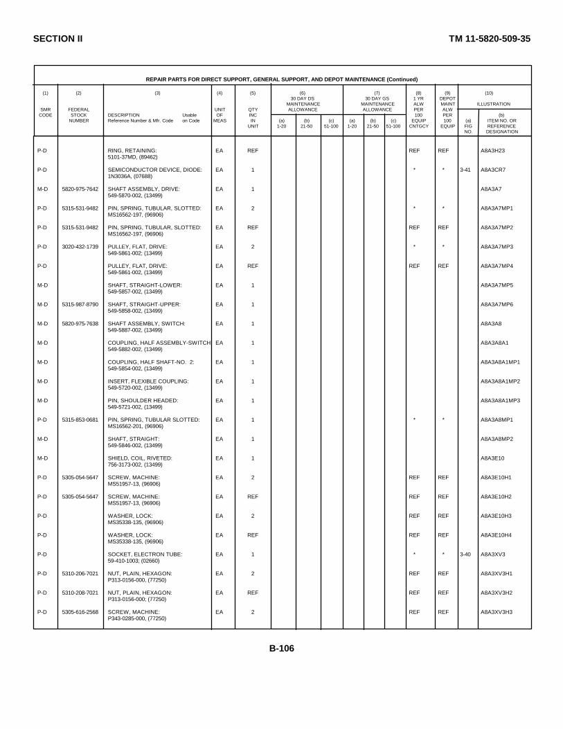
SECTION II TM 11-5820-509-35
REPAIR PARTS FOR DIRECT SUPPORT, GENERAL SUPPORT, AND DEPOT MAINTENANCE (Continued)
(1) (2) (3) (4) (5) (6) (7) (8) (9) (10)30 DAY DS 30 DAY GS 1 YR DEPOT
MAINTENANCE MAINTENANCE ALW MAINT ILLUSTRATIONSMR FEDERAL UNIT QTY ALLOWANCE ALLOWANCE PER ALW
CODE STOCK DESCRIPTION Usable OF INC 100 PER (b)NUMBER Reference Number & Mfr. Code on Code MEAS IN (a) (b) (c) (a) (b) (c) EQUIP 100 (a) ITEM NO. OR
UNIT 1-20 21-50 51-100 1-20 21-50 51-100 CNTGCY EQUIP FIG REFERENCENO. DESIGNATION
P-D RING, RETAINING: EA REF REF REF A8A3H235101-37MD, (89462)
P-D SEMICONDUCTOR DEVICE, DIODE: EA 1 * * 3-41 A8A3CR71N3036A, (07688)
M-D 5820-975-7642 SHAFT ASSEMBLY, DRIVE: EA 1 A8A3A7549-5870-002, (13499)
P-D 5315-531-9482 PIN, SPRING, TUBULAR, SLOTTED: EA 2 * * A8A3A7MP1MS16562-197, (96906)
P-D 5315-531-9482 PIN, SPRING, TUBULAR, SLOTTED: EA REF REF REF A8A3A7MP2MS16562-197, (96906)
P-D 3020-432-1739 PULLEY, FLAT, DRIVE: EA 2 * * A8A3A7MP3549-5861-002; (13499)
P-D PULLEY, FLAT, DRIVE: EA REF REF REF A8A3A7MP4549-5861-002, (13499)
M-D SHAFT, STRAIGHT-LOWER: EA 1 A8A3A7MP5549-5857-002, (13499)
M-D 5315-987-8790 SHAFT, STRAIGHT-UPPER: EA 1 A8A3A7MP6549-5858-002, (13499)
M-D 5820-975-7638 SHAFT ASSEMBLY, SWITCH: EA 1 A8A3A8549-5887-002, (13499)
M-D COUPLING, HALF ASSEMBLY-SWITCH: EA 1 A8A3A8A1549-5882-002, (13499)
M-D COUPLING, HALF SHAFT-NO. 2: EA 1 A8A3A8A1MP1549-5854-002, (13499)
M-D INSERT, FLEXIBLE COUPLING: EA 1 A8A3A8A1MP2549-5720-002, (13499)
M-D PIN, SHOULDER HEADED: EA 1 A8A3A8A1MP3549-5721-002, (13499)
P-D 5315-853-0681 PIN, SPRING, TUBULAR SLOTTED: EA 1 * * A8A3A8MP1MS16562-201, (96906)
M-D SHAFT, STRAIGHT: EA 1 A8A3A8MP2549-5846-002, (13499)
M-D SHIELD, COIL, RIVETED: EA 1 A8A3E10756-3173-002, (13499)
P-D 5305-054-5647 SCREW, MACHINE: EA 2 REF REF A8A3E10H1MS51957-13, (96906)
P-D 5305-054-5647 SCREW, MACHINE: EA REF REF REF A8A3E10H2MS51957-13, (96906)
P-D WASHER, LOCK: EA 2 REF REF A8A3E10H3MS35338-135, (96906)
P-D WASHER, LOCK: EA REF REF REF A8A3E10H4MS35338-135, (96906)
P-D SOCKET, ELECTRON TUBE: EA 1 * * 3-40 A8A3XV359-410-1003; (02660)
P-D 5310-206-7021 NUT, PLAIN, HEXAGON: EA 2 REF REF A8A3XV3H1P313-0156-000, (77250)
P-D 5310-208-7021 NUT, PLAIN, HEXAGON: EA REF REF REF A8A3XV3H2P313-0156-000; (77250)
P-D 5305-616-2568 SCREW, MACHINE: EA 2 REF REF A8A3XV3H3P343-0285-000, (77250)
B-106

SECTION II TM 11-5820-509-35
REPAIR PARTS FOR DIRECT SUPPORT, GENERAL SUPPORT, AND DEPOT MAINTENANCE (Continued)
(1) (2) (3) (4) (5) (6) (7) (8) (9) (10)30 DAY DS 30 DAY GS 1 YR DEPOT
MAINTENANCE MAINTENANCE ALW MAINT ILLUSTRATIONSMR FEDERAL UNIT QTY ALLOWANCE ALLOWANCE PER ALW
CODE STOCK DESCRIPTION Usable OF INC 100 PER (b)NUMBER Reference Number & Mfr. Code on Code MEAS IN (a) (b) (c) (a) (b) (c) EQUIP 100 (a) ITEM NO. OR
UNIT 1-20 21-50 51-100 1-20 21-50 51-100 CNTGCY EQUIP FIG REFERENCENO. DESIGNATION
P-D 5305-616-2568 SCREW, MACHINE: EA REF REF REF A8A3XV3H4P33-0285-000, (77250)
P-D 5310-685-1971 WASHER, SPRING TENSION: EA 2 REF REF ABA3XV3H5310-0396-00, (79807)
P-D 5310-685-1971 WASHER, SPRING TENSION: EA REF REF REF A8A3XV3H6310-0396-00, (79807)
M-D SPACER, SLEEVE, SLOTTED: EA 4 A8A3MP32549-5886-002, (13499)
M-D SPACER, SLEEVE, SLOTTED: EA REF A8A3MP33549-5886 -002, (13499)
M-D SPACER, SLEEVE, SLOTTED: EA REF A8A3MP34549-5886-002 (13499)
M-D SPACER, SLEEVE, SLOTTED: EA REF A8A3MP35549-5886-002, (13499)
M-D 5340-984-7536 SPRING, HELICAL EXTENSION: EA 2 A8A3MP36549-5868-002, (13499)
M-D 5340-984-7536 SPRING, HELICAL EXTENSION: EA REF A8A3MP37549-5868-002, (13499)
M-D STRIP, SHIELD NO. 1: EA 1 A8A3E12756-3175-003; (13499)
M-D STRIP, SHIELD NO. 2: EA 1 A8A3E13756-3176-003, (13499)
M-D STRIP, SHIELD NO. 3: EA 1 A8A3E14756-3177-003; (13499)
P-D 5305-054-5636 SCREW, MACHINE: EA 2 REF REF A8A3E13H1MS51957-2, (96906)
P-D 5305-054-5636 SCREW, MACHINE: EA REF REF REF A8A3E13H2MS51957-2, (96906)
P-D 5310-928-2690 WASHER, LOCK: EA 2 REF REF A8A3E13H3MS35338-134, (96906)
P-D 5310-928-2690 WASHER, LOCK: EA REF REF REF A8A3E13H4MS35338-134, (96906)
P-D STRIP, SHIELDING, ELECTRICAL: EA 1 A8A3E15548-7792-004, (13499)
P-D 5305-054-5636 SCREW, MACHINE: EA 2 REF REF A8A3E15H1MS51957-2, (96906)
P-D 5305-054-5636 SCREW, MACHINE: EA REF REF REF A8A3E15H2MS51957-2, (96906)
P-D 5310-928-2690 WASHER, LOCK: EA 2 REF REF A8A3E15H3MS35338-134, (96906)
P-D 5310-928-2690 WASHER, LOCK: EA REF REF REF A8A3E15H4MS35338-134, (96906)
P-D 5820-007-9545 TABLE, ADJUSTABLE SLUG: EA 1 * * A8A3MP38549-5893-003, (13499)
P-D 5305-054-5647 SCREW, MACHINE: EA 4 REF REF A8A3MP38H1MS51957-13, (96 906)
P-D 5305-054-5647 SCREW, MACHINE: EA REF REF REF A8A3MP38H2MS51957-13, (96906)
P-D 5305-054-5647 SCREW, MACHINE: EA REF REF REF A8A3MP38H3MS51957-13, (96906)
B-107
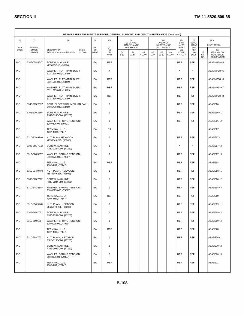
SECTION II TM 11-5820-509-35
REPAIR PARTS FOR DIRECT SUPPORT, GENERAL SUPPORT, AND DEPOT MAINTENANCE (Continued)
(1) (2) (3) (4) (5) (6) (7) (8) (9) (10)30 DAY DS 30 DAY GS 1 YR DEPOT
MAINTENANCE MAINTENANCE ALW MAINT ILLUSTRATIONSMR FEDERAL UNIT QTY ALLOWANCE ALLOWANCE PER ALW
CODE STOCK DESCRIPTION Usable OF INC 100 PER (b)NUMBER Reference Number & Mfr. Code on Code MEAS IN (a) (b) (c) (a) (b) (c) EQUIP 100 (a) ITEM NO. OR
UNIT 1-20 21-50 51-100 1-20 21-50 51-100 CNTGCY EQUIP FIG REFERENCENO. DESIGNATION
P-D 5305-054-5647 SCREW, MACHINE: EA REF REF REF A8A3MP38H4MS51957-13, (96906)
P-D WASHER, FLAT-MAIN IDLER: EA 4 * * A8A3MP38H5502-1515-002; (13499)
P-D WASHER, FLAT-MAIN IDLER: EA REF REF REF A8A3MP38H6502-1515-002; (13499)
P-D WASHER, FLAT-MAIN IDLER: EA REF REF REF A8A3MP38H7502-1515-002; (13499)
P-D WASHER, FLAT-MAIN IDLER: EA REF REF REF A8A3MP38H8502-1515-002, (13499)
P-D 5340-975-T637 POST, ELECTRICAL MECHANICAL: EA 1 REF REF A8A3E16549-5709-002; (13499)
P-D 5305-616-2568 SCREW, MACHINE: EA 1 REF REF A8A3E16H1P343-0285-000; (77250)
P-D WASHER, SPRING TENSION: EA 1 REF REF A8A3E16H2310-0396-00; (79807)
P-D TERMINAL, LUG: EA 13 A8A3E174007-4HT; (77147)
P-D 5310-93h-9740 NUT, PLAIN, HEXAGON: EA 1 REF REF A8A3E17H1MS35649-225, (96906)
P-D 5305-685-7072 SCREW, MACHINE: EA 1 * * A8A3E17H2P330-2284-000, (77250)
P-D 5310-680-5557 WASHER, SPRING TENSION: EA 1 REF REF A8A3E17H3310-0075-000, (79807)
P-D TERMINAL, LUG: EA REF REF REF A8A3E184007-4HT, (77147)
P-D 5310-934-97T0 NUT, PLAIN, HEXAGON: EA 1 REF REF A8A3E18H1MS35649-225, (96906)
P-D 5305-685-7072 SCREW, MACHINE: EA 1 REF REF A8A3E18H2P330-2284-000, (77250)
P-D 5310-680-5557 WASHER, SPRING TENSION: EA 1 REF REF A8A3E18H3310-0075-000, (79807)
P-D TERMINAL, LUG: EA REF REF REF A8A3E194007-4HT, (77147)
P-D 5310-934-9740 NUT, PLAIN, HEXAGON: EA 1 REF REF A8A3E19H1MS35649-225, (96906)
P-D 5305-685-7072 SCREW, MACHINE: EA 1 REF REF A8A3E19H2P330-2284-000; (77250)
P-D 5310-680-5557 WASHER, SPRING TENSION: EA 1 REF REF A8A3E19H3310-0075-000, (79807)
P-D TERMINAL, LUG: EA REF REF REF A8A3E204007-4HT, (77147)
P-D 5310-208-7021 NUT, PLAIN, HEXAGON: EA 1 REF REF A8A3E20H1P313-0156-000, (77250)
P-D SCREW, MACHINE: EA 1 A8A3E20H2P325-0092-000; (77250)
P-D WASHER, SPRING TENSION: EA 1 REF REF A8A3E20H3310-0396-00, (79807)
P-D TERMINAL, LUG: EA REF REF REF A8A3E214007-4HT, (77147)
B-108
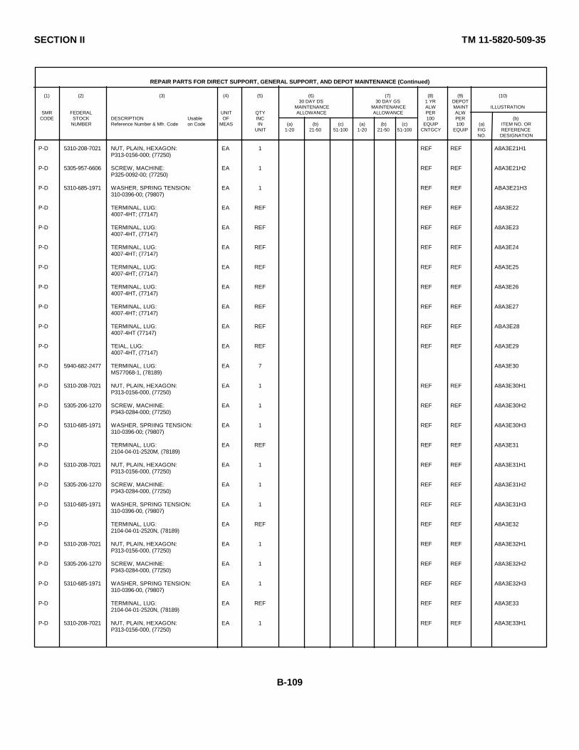
SECTION II TM 11-5820-509-35
REPAIR PARTS FOR DIRECT SUPPORT, GENERAL SUPPORT, AND DEPOT MAINTENANCE (Continued)
(1) (2) (3) (4) (5) (6) (7) (8) (9) (10)30 DAY DS 30 DAY GS 1 YR DEPOT
MAINTENANCE MAINTENANCE ALW MAINT ILLUSTRATIONSMR FEDERAL UNIT QTY ALLOWANCE ALLOWANCE PER ALW
CODE STOCK DESCRIPTION Usable OF INC 100 PER (b)NUMBER Reference Number & Mfr. Code on Code MEAS IN (a) (b) (c) (a) (b) (c) EQUIP 100 (a) ITEM NO. OR
UNIT 1-20 21-50 51-100 1-20 21-50 51-100 CNTGCY EQUIP FIG REFERENCENO. DESIGNATION
P-D 5310-208-7021 NUT, PLAIN, HEXAGON: EA 1 REF REF A8A3E21H1P313-0156-000; (77250)
P-D 5305-957-6606 SCREW, MACHINE: EA 1 REF REF A8A3E21H2P325-0092-00; (77250)
P-D 5310-685-1971 WASHER, SPRING TENSION: EA 1 REF REF ABA3E21H3310-0396-00; (79807)
P-D TERMINAL, LUG: EA REF REF REF A8A3E224007-4HT; (77147)
P-D TERMINAL, LUG: EA REF REF REF A8A3E234007-4HT, (77147)
P-D TERMINAL, LUG: EA REF REF REF A8A3E244007-4HT; (77147)
P-D TERMINAL, LUG: EA REF REF REF A8A3E254007-4HT; (77147)
P-D TERMINAL, LUG: EA REF REF REF A8A3E264007-4HT, (77147)
P-D TERMINAL, LUG: EA REF REF REF A8A3E274007-4HT; (77147)
P-D TERMINAL, LUG: EA REF REF REF ABA3E284007-4HT (77147)
P-D TEIAL, LUG: EA REF REF REF A8A3E294007-4HT, (77147)
P-D 5940-682-2477 TERMINAL, LUG: EA 7 A8A3E30MS77068-1, (78189)
P-D 5310-208-7021 NUT, PLAIN, HEXAGON: EA 1 REF REF A8A3E30H1P313-0156-000, (77250)
P-D 5305-206-1270 SCREW, MACHINE: EA 1 REF REF A8A3E30H2P343-0284-000; (77250)
P-D 5310-685-1971 WASHER, SPRIING TENSION: EA 1 REF REF A8A3E30H3310-0396-00; (79807)
P-D TERMINAL, LUG: EA REF REF REF A8A3E312104-04-01-2520M, (78189)
P-D 5310-208-7021 NUT, PLAIN, HEXAGON: EA 1 REF REF A8A3E31H1P313-0156-000, (77250)
P-D 5305-206-1270 SCREW, MACHINE: EA 1 REF REF A8A3E31H2P343-0284-000, (77250)
P-D 5310-685-1971 WASHER, SPRING TENSION: EA 1 REF REF A8A3E31H3310-0396-00, (79807)
P-D TERMINAL, LUG: EA REF REF REF A8A3E322104-04-01-2520N, (78189)
P-D 5310-208-7021 NUT, PLAIN, HEXAGON: EA 1 REF REF A8A3E32H1P313-0156-000, (77250)
P-D 5305-206-1270 SCREW, MACHINE: EA 1 REF REF A8A3E32H2P343-0284-000, (77250)
P-D 5310-685-1971 WASHER, SPRING TENSION: EA 1 REF REF A8A3E32H3310-0396-00, (79807)
P-D TERMINAL, LUG: EA REF REF REF A8A3E332104-04-01-2520N, (78189)
P-D 5310-208-7021 NUT, PLAIN, HEXAGON: EA 1 REF REF A8A3E33H1P313-0156-000, (77250)
B-109

SECTION II TM 11-5820-509-35
REPAIR PARTS FOR DIRECT SUPPORT, GENERAL SUPPORT, AND DEPOT MAINTENANCE (Continued)
(1) (2) (3) (4) (5) (6) (7) (8) (9) (10)30 DAY DS 30 DAY GS 1 YR DEPOT
MAINTENANCE MAINTENANCE ALW MAINT ILLUSTRATIONSMR FEDERAL UNIT QTY ALLOWANCE ALLOWANCE PER ALW
CODE STOCK DESCRIPTION Usable OF INC 100 PER (b)NUMBER Reference Number & Mfr. Code on Code MEAS IN (a) (b) (c) (a) (b) (c) EQUIP 100 (a) ITEM NO. OR
UNIT 1-20 21-50 51-100 1-20 21-50 51-100 CNTGCY EQUIP FIG REFERENCENO. DESIGNATION
P-D 5305-206-1270 SCREW, MACHINE: EA 1 REF REF A8A3E33H2P343-0284-000, (77250)
P-D 5310-685-1971 WASHER, SPRING TENSION: EA 1 REF REF A8A3E33H3310-0396-00, (79807)
P-D TERMINAL, LUG: EA REF REF REF A8A3E342104-04-01-2520N, (78189)
P-D 5310-208-7021 NUT, PLAIN, HEXAGON: EA 1 REF REF A8A3E34H1P313-0156-000, (77250)
P-D 5305-206-1270 SCREW, MACHINE: EA 1 REF REF A8A3E34H2P343-0284-000, (77250)
P-D 5310-685-1971 WASHER, SPRING TENSION: EA 1 REF REF A8A3E34H3310-0396-00; (79807)
P-D TERMINAL, LUG: EA REF REF REF A8A3E352104-04-01-2520N, (78189)
P-D 5310-208-7021 NUT, PLAIN, HEXAGON: EA 1 REF REF A8A3E35H1P313-0156-000, (77250)
P-D 5305-206-1270 SCREW, MACHINE: EA 1 REF REF A8A3E35H2P343-0284-000, (77250)
P-D 5310-685-1971 WASHER, SPRING TENSION: EA 1 REF REF A8A3E35H3310-0396-00; (79807)
P-D TERMINAL, LUG: EA REF REF REF A8A3E362104-04-01-2520N; (78189)
P-D 5310-208-7021 NUT, PLAIN, HEXAGON: EA 1 REF REF A8A3E36H1P313-0156-000, (77250)
P-D 5305-206- 1270 SCREW, MACHINE: EA 1 REF REF A8A3E36H2P343-0284-000, (77250)
P-D 5310-685-1971 WASHER, SPRING TENSION: EA 1 REF REF A8A3E36H3310-0396-00, (79807)
P-D 5940-836-3536 TERMINAL, LUG: EA 1 REF REF A8A3E374040-2HDSPL, (77147)
P-D 5310-934-9740 NUT, PLAIN, HEXAGON: EA 1 REF REF A8A3E37H1MS35669-225, (77250)
P-D 5305-616-1815 SCREW, MACHINE: EA 1 A8A3E37H2P342-0142-000; (77250)
P-D WASHER, SPRING, TENSION: EA 1 REF REF A8A3E37H3310-0075-00, (7 9807)
P-D 5940-455-7441 TERMINAL, LUG: EA 7 REF REF A8A3E38040-5HDSPL, (77147)
P-D 5310-208-7021 NUT, PLAIN, HEXAGON: EA 2 REF REF A8A3E38H1P313-0156-000; (77250)
P-D 5310-208-7021 NUT, PLAIN, HEXAGON: EA REF REF REF A8A3E38H2P313-0156-000; (77250)
P-D 5305-680-9157 SCREW, MACHINE: EA 1 * * A8A3E38H3P347-0007-000, (77250)
P-D 5310-685-1971 WASHER, SPRING, TENSION: EA 2 REF REF A8A3E38H4310-0396-00, (79807)
P-D 5310-685-1971 WASHER, SPRING, TENSION: EA REF REF REF A8A3E38H5310-0396-00, (79807)
P-D 5940-455-7441 TERMINAL, LUG: EA REF REF REF A8A3E394040-5HDSPL, (77147)
B-110
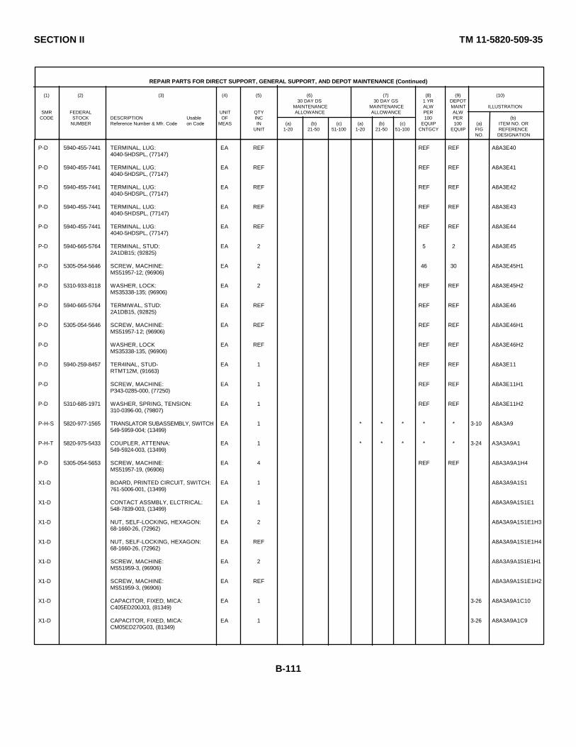
SECTION II TM 11-5820-509-35
REPAIR PARTS FOR DIRECT SUPPORT, GENERAL SUPPORT, AND DEPOT MAINTENANCE (Continued)
(1) (2) (3) (4) (5) (6) (7) (8) (9) (10)30 DAY DS 30 DAY GS 1 YR DEPOT
MAINTENANCE MAINTENANCE ALW MAINT ILLUSTRATIONSMR FEDERAL UNIT QTY ALLOWANCE ALLOWANCE PER ALW
CODE STOCK DESCRIPTION Usable OF INC 100 PER (b)NUMBER Reference Number & Mfr. Code on Code MEAS IN (a) (b) (c) (a) (b) (c) EQUIP 100 (a) ITEM NO. OR
UNIT 1-20 21-50 51-100 1-20 21-50 51-100 CNTGCY EQUIP FIG REFERENCENO. DESIGNATION
P-D 5940-455-7441 TERMINAL, LUG: EA REF REF REF A8A3E404040-5HDSPL, (77147)
P-D 5940-455-7441 TERMINAL, LUG: EA REF REF REF A8A3E414040-5HDSPL, (77147)
P-D 5940-455-7441 TERMINAL, LUG: EA REF REF REF A8A3E424040-5HDSPL, (77147)
P-D 5940-455-7441 TERMINAL, LUG: EA REF REF REF A8A3E434040-5HDSPL, (77147)
P-D 5940-455-7441 TERMINAL, LUG: EA REF REF REF A8A3E444040-5HDSPL, (77147)
P-D 5940-665-5764 TERMINAL, STUD: EA 2 5 2 A8A3E452A1DB15; (92825)
P-D 5305-054-5646 SCREW, MACHINE: EA 2 46 30 A8A3E45H1MS51957-12; (96906)
P-D 5310-933-8118 WASHER, LOCK: EA 2 REF REF A8A3E45H2MS35338-135; (96906)
P-D 5940-665-5764 TERMIWAL, STUD: EA REF REF REF A8A3E462A1DB15, (92825)
P-D 5305-054-5646 SCREW, MACHINE: EA REF REF REF A8A3E46H1MS51957-12; (96906)
P-D WASHER, LOCK EA REF REF REF A8A3E46H2MS35338-135, (96906)
P-D 5940-259-8457 TER4INAL, STUD- EA 1 REF REF A8A3E11RTMT12M, (91663)
P-D SCREW, MACHINE: EA 1 REF REF A8A3E11H1P343-0285-000, (77250)
P-D 5310-685-1971 WASHER, SPRING, TENSION: EA 1 REF REF A8A3E11H2310-0396-00, (79807)
P-H-S 5820-977-1565 TRANSLATOR SUBASSEMBLY, SWITCH: EA 1 * * * * * 3-10 A8A3A9549-5959-004; (13499)
P-H-T 5820-975-5433 COUPLER, ATTENNA: EA 1 * * * * * 3-24 A3A3A9A1549-5924-003, (13499)
P-D 5305-054-5653 SCREW, MACHINE: EA 4 REF REF A8A3A9A1H4MS51957-19, (96906)
X1-D BOARD, PRINTED CIRCUIT, SWITCH: EA 1 A8A3A9A1S1761-5006-001, (13499)
X1-D CONTACT ASSMBLY, ELCTRICAL: EA 1 A8A3A9A1S1E1548-7839-003, (13499)
X1-D NUT, SELF-LOCKING, HEXAGON: EA 2 A8A3A9A1S1E1H368-1660-26, (72962)
X1-D NUT, SELF-LOCKING, HEXAGON: EA REF A8A3A9A1S1E1H468-1660-26, (72962)
X1-D SCREW, MACHINE: EA 2 A8A3A9A1S1E1H1MS51959-3, (96906)
X1-D SCREW, MACHINE: EA REF A8A3A9A1S1E1H2MS51959-3, (96906)
X1-D CAPACITOR, FIXED, MICA: EA 1 3-26 A8A3A9A1C10C405ED200J03, (81349)
X1-D CAPACITOR, FIXED, MICA: EA 1 3-26 A8A3A9A1C9CM05ED270G03, (81349)
B-111
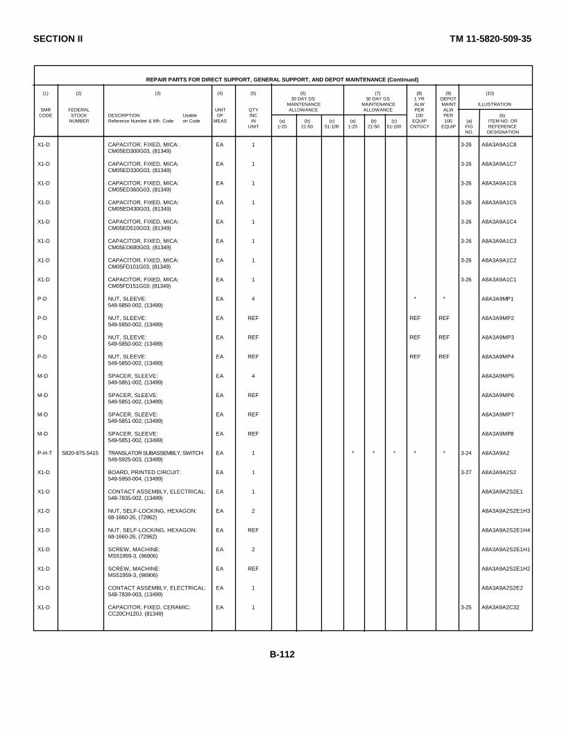
SECTION II TM 11-5820-509-35
REPAIR PARTS FOR DIRECT SUPPORT, GENERAL SUPPORT, AND DEPOT MAINTENANCE (Continued)
(1) (2) (3) (4) (5) (6) (7) (8) (9) (10)30 DAY DS 30 DAY GS 1 YR DEPOT
MAINTENANCE MAINTENANCE ALW MAINT ILLUSTRATIONSMR FEDERAL UNIT QTY ALLOWANCE ALLOWANCE PER ALW
CODE STOCK DESCRIPTION Usable OF INC 100 PER (b)NUMBER Reference Number & Mfr. Code on Code MEAS IN (a) (b) (c) (a) (b) (c) EQUIP 100 (a) ITEM NO. OR
UNIT 1-20 21-50 51-100 1-20 21-50 51-100 CNTGCY EQUIP FIG REFERENCENO. DESIGNATION
X1-D CAPACITOR, FIXED, MICA: EA 1 3-26 A8A3A9A1C8CM05ED300G03, (81349)
X1-D CAPACITOR, FIXED, MICA: EA 1 3-26 A8A3A9A1C7CM05ED330G03, (81349)
X1-D CAPACITOR, FIXED, MICA: EA 1 3-26 A8A3A9A1C6CM05ED360G03, (81349)
X1-D CAPACITOR, FIXED, MICA: EA 1 3-26 A8A3A9A1C5CM05ED430G03, (81349)
X1-D CAPACITOR, FIXED, MICA: EA 1 3-26 A8A3A9A1C4CM05ED510G03; (81349)
X1-D CAPACITOR, FIXED, MICA: EA 1 3-26 A8A3A9A1C3CM05ED680G03, (81349)
X1-D CAPACITOR, FIXED, MICA: EA 1 3-26 A8A3A9A1C2CM05FD101G03, (81349)
X1-D CAPACITOR, FIXED, MICA: EA 1 3-26 A8A3A9A1C1CM05FD151G03; (81349)
P-D NUT, SLEEVE: EA 4 * * A8A3A9MP1549-5850-002, (13499)
P-D NUT, SLEEVE: EA REF REF REF A8A3A9MP2549-5850-002, (13499)
P-D NUT, SLEEVE: EA REF REF REF A8A3A9MP3549-5850-002; (13499)
P-D NUT, SLEEVE: EA REF REF REF A8A3A9MP4549-5850-002, (13499)
M-D SPACER, SLEEVE: EA 4 A8A3A9MP5549-5851-002, (13499)
M-D SPACER, SLEEVE: EA REF A8A3A9MP6549-5851-002, (13499)
M-D SPACER, SLEEVE: EA REF A8A3A9MP7549-5851-002; (13499)
M-D SPACER, SLEEVE: EA REF A8A3A9MP8549-5851-002, (13499)
P-H-T 5820-975-5415 TRANSLATOR SUBASSEMBLY, SWITCH: EA 1 * * * * * 3-24 A8A3A9A2549-5925-003, (13499)
X1-D BOARD, PRINTED CIRCUIT: EA 1 3-27 A8A3A9A2S2549-5950-004, (13499)
X1-D CONTACT ASSEMBLY, ELECTRICAL: EA 1 A8A3A9A2S2E1548-7835-002, (13499)
X1-D NUT, SELF-LOCKING, HEXAGON: EA 2 A8A3A9A2S2E1H368-1660-26, (72962)
X1-D NUT, SELF-LOCKING, HEXAGON: EA REF A8A3A9A2S2E1H468-1660-26, (72962)
X1-D SCREW, MACHINE: EA 2 A8A3A9A2S2E1H1MS51959-3, (96906)
X1-D SCREW, MACHINE: EA REF A8A3A9A2S2E1H2MS51959-3, (96906)
X1-D CONTACT ASSEMBLY, ELECTRICAL: EA 1 A8A3A9A2S2E2548-7839-003, (13499)
X1-D CAPACITOR, FIXED, CERAMIC: EA 1 3-25 A8A3A9A2C32CC20CH120J, (81349)
B-112
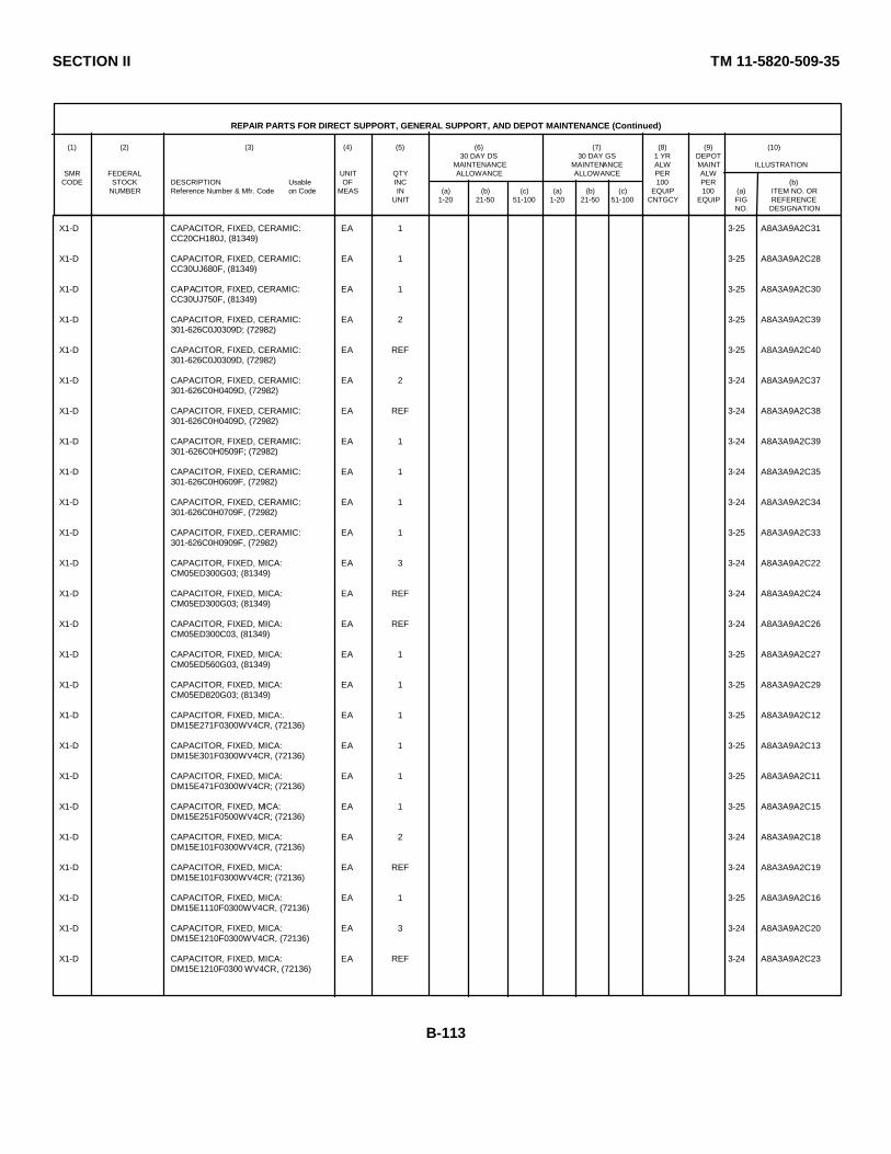
SECTION II TM 11-5820-509-35
REPAIR PARTS FOR DIRECT SUPPORT, GENERAL SUPPORT, AND DEPOT MAINTENANCE (Continued)
(1) (2) (3) (4) (5) (6) (7) (8) (9) (10)30 DAY DS 30 DAY GS 1 YR DEPOT
MAINTENANCE MAINTENANCE ALW MAINT ILLUSTRATIONSMR FEDERAL UNIT QTY ALLOWANCE ALLOWANCE PER ALW
CODE STOCK DESCRIPTION Usable OF INC 100 PER (b)NUMBER Reference Number & Mfr. Code on Code MEAS IN (a) (b) (c) (a) (b) (c) EQUIP 100 (a) ITEM NO. OR
UNIT 1-20 21-50 51-100 1-20 21-50 51-100 CNTGCY EQUIP FIG REFERENCENO. DESIGNATION
X1-D CAPACITOR, FIXED, CERAMIC: EA 1 3-25 A8A3A9A2C31CC20CH180J, (81349)
X1-D CAPACITOR, FIXED, CERAMIC: EA 1 3-25 A8A3A9A2C28CC30UJ680F, (81349)
X1-D CAPACITOR, FIXED, CERAMIC: EA 1 3-25 A8A3A9A2C30CC30UJ750F, (81349)
X1-D CAPACITOR, FIXED, CERAMIC: EA 2 3-25 A8A3A9A2C39301-626C0J0309D; (72982)
X1-D CAPACITOR, FIXED, CERAMIC: EA REF 3-25 A8A3A9A2C40301-626C0J0309D, (72982)
X1-D CAPACITOR, FIXED, CERAMIC: EA 2 3-24 A8A3A9A2C37301-626C0H0409D, (72982)
X1-D CAPACITOR, FIXED, CERAMIC: EA REF 3-24 A8A3A9A2C38301-626C0H0409D, (72982)
X1-D CAPACITOR, FIXED, CERAMIC: EA 1 3-24 A8A3A9A2C39301-626C0H0509F; (72982)
X1-D CAPACITOR, FIXED, CERAMIC: EA 1 3-24 A8A3A9A2C35301-626C0H0609F, (72982)
X1-D CAPACITOR, FIXED, CERAMIC: EA 1 3-24 A8A3A9A2C34301-626C0H0709F, (72982)
X1-D CAPACITOR, FIXED,.CERAMIC: EA 1 3-25 A8A3A9A2C33301-626C0H0909F, (72982)
X1-D CAPACITOR, FIXED, MICA: EA 3 3-24 A8A3A9A2C22CM05ED300G03; (81349)
X1-D CAPACITOR, FIXED, MICA: EA REF 3-24 A8A3A9A2C24CM05ED300G03; (81349)
X1-D CAPACITOR, FIXED, MICA: EA REF 3-24 A8A3A9A2C26CM05ED300C03, (81349)
X1-D CAPACITOR, FIXED, MICA: EA 1 3-25 A8A3A9A2C27CM05ED560G03, (81349)
X1-D CAPACITOR, FIXED, MICA: EA 1 3-25 A8A3A9A2C29CM05ED820G03; (81349)
X1-D CAPACITOR, FIXED, MICA:. EA 1 3-25 A8A3A9A2C12DM15E271F0300WV4CR, (72136)
X1-D CAPACITOR, FIXED, MICA: EA 1 3-25 A8A3A9A2C13DM15E301F0300WV4CR, (72136)
X1-D CAPACITOR, FIXED, MICA: EA 1 3-25 A8A3A9A2C11DM15E471F0300WV4CR; (72136)
X1-D CAPACITOR, FIXED, MICA: EA 1 3-25 A8A3A9A2C15DM15E251F0500WV4CR; (72136)
X1-D CAPACITOR, FIXED, MICA: EA 2 3-24 A8A3A9A2C18DM15E101F0300WV4CR, (72136)
X1-D CAPACITOR, FIXED, MICA: EA REF 3-24 A8A3A9A2C19DM15E101F0300WV4CR; (72136)
X1-D CAPACITOR, FIXED, MICA: EA 1 3-25 A8A3A9A2C16DM15E1110F0300WV4CR, (72136)
X1-D CAPACITOR, FIXED, MICA: EA 3 3-24 A8A3A9A2C20DM15E1210F0300WV4CR, (72136)
X1-D CAPACITOR, FIXED, MICA: EA REF 3-24 A8A3A9A2C23DM15E1210F0300 WV4CR, (72136)
B-113

SECTION II TM 11-5820-509-35
REPAIR PARTS FOR DIRECT SUPPORT, GENERAL SUPPORT, AND DEPOT MAINTENANCE (Continued)
(1) (2) (3) (4) (5) (6) (7) (8) (9) (10)30 DAY DS 30 DAY GS 1 YR DEPOT
MAINTENANCE MAINTENANCE ALW MAINT ILLUSTRATIONSMR FEDERAL UNIT QTY ALLOWANCE ALLOWANCE PER ALW
CODE STOCK DESCRIPTION Usable OF INC 100 PER (b)NUMBER Reference Number & Mfr. Code on Code MEAS IN (a) (b) (c) (a) (b) (c) EQUIP 100 (a) ITEM NO. OR
UNIT 1-20 21-50 51-100 1-20 21-50 51-100 CNTGCY EQUIP FIG REFERENCENO. DESIGNATION
X1-D CAPACITOR, FIXED, MICA: EA REF 3-24 A8A3A9A2C25DM15E1210F0300WV4CR, (72136)
X1-D CAPACITOR, FIXED, MICA: EA 2 3-24 A8A3A9A2C17DM15E1510F0300WV4CR, (72136)
X1-D CAPACITOR, FIXED, MICA: EA REF 3-24 A8A3A9A2C21DM15E1510F0300WV4CR, (72136)
X1-D CAPACITOR, FIXED, MICA: EA 1 3-25 A8A3A9A2C14DM15E1650F0300WV4CR, (72136)
X1-D COIL ASSEMBLY, RADIO FREQUENCY: EA 1 3-25 A8A3A9A2E2549-5889-003, (13 499)
X1-D COIL ASSEMBLY, RADIO FREQUENCY: EA 1 3-24 A8A3A9A2E1549-5890-003, (13499)
X1-D COIL, RADIO FREQUENCY-NO. 1: EA 1 3-27 A8A3A9A2L17549-5931-003, (13499)
X1-D COIL, RADIO FREQUENCY-NO. 3: EA 1 3-27 A8A3A9A2L18549-5933-003, (13499)
X1-D COIL, RADIO FREQUENCY-NO. 5: EA 1 3-27 A8A3A9A2L19549-5935-003, (13499)
X1-D COIL, RADIO FREQUENCY-NO. 6: EA 1 3-27 A8A3A9A2L20549-5936-003; (13499)
X1-D COIL, RADIO FREQUENCY-NO. 7: EA 1 3-27 A8A3A9A2L21549-5937-003, (13499)
P-H-S 5820-975-5416 TRANSLATOR SUBASSEMBLY, SWITCH: EA 1 * * * * * 3-24 A8A3A9A3549-5926-003, (13499)
P-D 5305-054-5647 SCREW, MACHINE: EA 4 REF REF A8A3A9A3H4MS51957-13; (96906)
X1-D BOARD, PRINTED CIRCUIT, SWITCH: EA 1 A8A3A9A3S3549-5950-004, (13499)
X1-D CONTACT ASSEMBLY, ELECTRICAL: EA 1 A8A3A9A3S3E1548-7835-003, (13499)
X1-D NUT, SELF-LOCKING, HEXAGON: EA 2 A8A3A9A3S3E1H168-1660-26, (72962)
X1-D NUT, SELF-LOCKING, HEXAGON: EA REF A8A3A9A3S3E1H268-1660-26, (72962)
X1-D SCREW, MACHINE: EA 2 A8A3A9A3S3E1H3MS51959-3, (96906)
X1-D SCREW, MACHINE: EA REF A8A3A9A3S3E1H4MS51959-3, (96906)
X1-D CONTACY ASSEMBLY, ELECTRICAL: EA 1 A8A3A9A3S3E2548-7839-003, (13499)
X1-D CAPACITOR, FIXED, CERAMIC: EA 1 3-28 A8A3A9A3C6CCC20UJ510F, (81349)
X1-D CAPACITOR, FIXED, CERAMIC: EA 1 3-28 A8A3A9A3C58CC30UJ680F, (81349)
X1-D CAPACITOR, FIXED, MICA: EA 1 3-28 A8A3A9A3C56CM05ED270C03, (81349)
X1-D CAPACITOR, FIXED, MICA: EA 1 3-28 A8A3A9A3C54CM05ED330G03, (81349)
X1-D CAPACITOR, FIXED, MICA: EA 1 3-28 A8A3A9A3C44CMD5ED60G03, (81349)
B-114
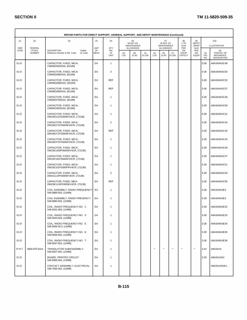
SECTION II TM 11-5820-509-35
REPAIR PARTS FOR DIRECT SUPPORT, GENERAL SUPPORT, AND DEPOT MAINTENANCE (Continued)
(1) (2) (3) (4) (5) (6) (7) (8) (9) (10)30 DAY DS 30 DAY GS 1 YR DEPOT
MAINTENANCE MAINTENANCE ALW MAINT ILLUSTRATIONSMR FEDERAL UNIT QTY ALLOWANCE ALLOWANCE PER ALW
CODE STOCK DESCRIPTION Usable OF INC 100 PER (b)NUMBER Reference Number & Mfr. Code on Code MEAS IN (a) (b) (c) (a) (b) (c) EQUIP 100 (a) ITEM NO. OR
UNIT 1-20 21-50 51-100 1-20 21-50 51-100 CNTGCY EQUIP FIG REFERENCENO. DESIGNATION
X1-D CAPACITOR, FIXED, MICA: EA 1 3-28 A8A3A9A3C48CM05ED620G03, (81349)
X1-D CAPACITOR, FIXED, MICA: EA 3 3-28 A8A3A9A3C50CM05ED680G03, (81349)
X1-D CAPACITOR, FIXED, MICA: EA REF 3-28 A8A3A9A3C52CM05ED680G03; (81349)
X1-D CAPACITOR, FIXED, MICA: EA REF 3-28 A8A3A9A3C57CM05ED680G03, (81349)
X1-D CAPACITOR, FIXED, MICA: EA 1 3-28 A8A3A9A3C46CM05ED750G03, (81349)
X1-D CAPACITOR, FIXED, MICA: EA 1 3-28 A8A3A9A3C59CM05ED820G03; (81349)
X1-D CAPACITOR, FIXED, MICA: EA 1 3-28 A8A3A9A3C41DM15E511F0300WV4CR, (72136)
X1-D CAPACITOR, FIXED, MICA: EA 2 3-28 A8A3A9A3C42DM15E271F0300WV4CR, (72136)
X1-D CAPACITOR, FIXED, MICA: EA REF 3-28 A8A3A9A3C45DM15E271F0300WV4CR, (72136)
X1-D CAPACITOR, FIXED, MICA: EA 1 3-28 A8A3A9A3C43DM15E471F0300WV4CR, (72136)
X1-D CAPACITOR, FIXED, MICA: EA 1 3-28 A89AA9A3C49DM15E1330F0500WV4CR, (72136)
X1-D CAPACITOR, FIXED, MICA: EA 1 3-28 A8A3A9A3C47DM15E191F0500WV4CR; (72136)
X1-D CAPACITOR, FIXED, MICA: EA 1 3-28 A8A3A9A3C51DM15E101F0300FWV4CR, (72136)
X1-D CAPACITOR, FIXED, MICA: EA 2 3-28 A8A3A9A3C53DM151110F0300WV4CR, (72136)
X1-D CAPACITOR, FIXED, MICA: EA REF 3-28 A8A3A9A3C55DM15E1110F0300WV4CR, (72136)
X1-D COIL ASSEMBLY, RADIO FREQUENCY: EA 1 3-28 A8A3A9A3E4549-5889-003; (13499)
X1-D COIL ASSEMBLY, RADIO FREUENCY: EA 1 3-28 A8A3A9A3E3549-5890-003, (13499)
X1-D COIL, RADIO FREQUENCY-NO. 1: EA 1 3-28 A8A3A9A3E32549-5931-003; (13499)
X1-D COIL, RADIO FREQUENCY-NO. 3: EA 1 3-28 A8A3A9A3E33549-5933-003; (13499)
X1-D COIL, RADIO FREQUENCY-NO. 5: EA 1 3-28 A8A3A9A3E34549-5935-00 3, (13499)
X1-D COIL, RADIO FREQUENCY-NO. 6: EA 1 3-28 A8A3A9A3E35549-5936-003, (13499)
X1-D COIL, RADIO FREQUENCY-NO. 7: EA 1 3-28 A8A3A9A3E36549-5937-003, (13499)
P-H-T 5820-975-5414 TRANSLATOR SUBASSEMBLY: EA 1 * * * * * 3-10 A8A3A10549-5927-003, (13499)
X1-D BOARD, PRINTED CIRCUIT: EA 1 3-29 A8A3A10S4549-5950-004, (13499)
X1-D CONTACT ASSEMBLY, ELECTRICAL: EA 1 A8A3A10S4E1548-7835-002, (13499)
B-115
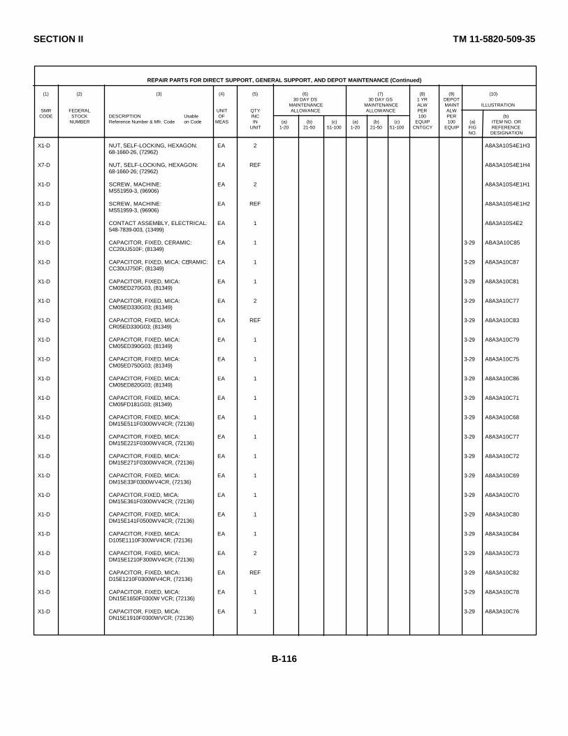
SECTION II TM 11-5820-509-35
REPAIR PARTS FOR DIRECT SUPPORT, GENERAL SUPPORT, AND DEPOT MAINTENANCE (Continued)
(1) (2) (3) (4) (5) (6) (7) (8) (9) (10)30 DAY DS 30 DAY GS 1 YR DEPOT
MAINTENANCE MAINTENANCE ALW MAINT ILLUSTRATIONSMR FEDERAL UNIT QTY ALLOWANCE ALLOWANCE PER ALW
CODE STOCK DESCRIPTION Usable OF INC 100 PER (b)NUMBER Reference Number & Mfr. Code on Code MEAS IN (a) (b) (c) (a) (b) (c) EQUIP 100 (a) ITEM NO. OR
UNIT 1-20 21-50 51-100 1-20 21-50 51-100 CNTGCY EQUIP FIG REFERENCENO. DESIGNATION
X1-D NUT, SELF-LOCKING, HEXAGON: EA 2 A8A3A10S4E1H368-1660-26, (72962)
X7-D NUT, SELF-LOCKING, HEXAGON: EA REF A8A3A10S4E1H468-1660-26; (72962)
X1-D SCREW, MACHINE: EA 2 A8A3A10S4E1H1MS51959-3, (96906)
X1-D SCREW, MACHINE: EA REF A8A3A10S4E1H2MS51959-3, (96906)
X1-D CONTACT ASSEMBLY, ELECTRICAL: EA 1 A8A3A10S4E2548-7839-003, (13499)
X1-D CAPACITOR, FIXED, CERAMIC: EA 1 3-29 ABA3A10C85CC20UJ510F; (81349)
X1-D CAPACITOR, FIXED, MICA: CERAMIC: EA 1 3-29 A8A3A10C87CC30UJ750F; (81349)
X1-D CAPACITOR, FIXED, MICA: EA 1 3-29 A8A3A10C81CM05ED270G03, (81349)
X1-D CAPACITOR, FIXED, MICA: EA 2 3-29 A8A3A10C77CM05ED330G03; (81349)
X1-D CAPACITOR, FIXED, MICA: EA REF 3-29 A8A3A10C83CR05ED330G03; (81349)
X1-D CAPACITOR, FIXED, MICA: EA 1 3-29 A8A3A10C79CM05ED390G03; (81349)
X1-D CAPACITOR, FIXED, MICA: EA 1 3-29 A8A3A10C75CM05ED750G03; (81349)
X1-D CAPACITOR, FIXED, MICA: EA 1 3-29 A8A3A10C86CM05ED820G03; (81349)
X1-D CAPACITOR, FIXED, MICA: EA 1 3-29 A8A3A10C71CM05FD181G03; (81349)
X1-D CAPACITOR, FIXED, MICA: EA 1 3-29 A8A3A10C68DM15E511F0300WV4CR; (72136)
X1-D CAPACITOR, FIXED, MICA: EA 1 3-29 A8A3A10C77DM15E221F0300WV4CR, (72136)
X1-D CAPACITOR, FIXED, MICA: EA 1 3-29 A8A3A10C72DM15E271F0300WV4CR, (72136)
X1-D CAPACITOR, FIXED, MICA: EA 1 3-29 A8A3A10C69DM15E33F0300WV4CR, (72136)
X1-D CAPACITOR, FIXED, MICA: EA 1 3-29 A8A3A10C70DM15E361F0300WV4CR; (72136)
X1-D CAPACITOR, FIXED, MICA: EA 1 3-29 A8A3A10C80DM15E141F0500WV4CR; (72136)
X1-D CAPACITOR, FIXED, MICA: EA 1 3-29 A8A3A10C84D105E1110F300WV4CR; (72136)
X1-D CAPACITOR, FIXED, MICA: EA 2 3-29 A8A3A10C73DM15E1210F300WV4CR; (72136)
X1-D CAPACITOR, FIXED, MICA: EA REF 3-29 A8A3A10C82D15E1210F0300WV4CR, (72136)
X1-D CAPACITOR, FIXED, MICA: EA 1 3-29 A8A3A10C78DN15E1650F0300W VCR; (72136)
X1-D CAPACITOR, FIXED, MICA: EA 1 3-29 A8A3A10C76DN15E1910F0300WVCR; (72136)
B-116

SECTION II TM 11-5820-509-35
REPAIR PARTS FOR DIRECT SUPPORT, GENERAL SUPPORT, AND DEPOT MAINTENANCE (Continued)
(1) (2) (3) (4) (5) (6) (7) (8) (9) (10)30 DAY DS 30 DAY GS 1 YR DEPOT
MAINTENANCE MAINTENANCE ALW MAINT ILLUSTRATIONSMR FEDERAL UNIT QTY ALLOWANCE ALLOWANCE PER ALW
CODE STOCK DESCRIPTION Usable OF INC 100 PER (b)NUMBER Reference Number & Mfr. Code on Code MEAS IN (a) (b) (c) (a) (b) (c) EQUIP 100 (a) ITEM NO. OR
UNIT 1-20 21-50 51-100 1-20 21-50 51-100 CNTGCY EQUIP FIG REFERENCENO. DESIGNATION
X1-D COIL ASSEMBLY, RADIO FREQUENCY: EA 1 3-29 A8A3A10E6549-5689-003; (13499)
X1-D COIL ASSEMBLY, RADIO FREQUENCY: EA 1 3-29 ASA3A10E5549-5890-003, (1399)
X1-D COIL, RADIO FREQUENCY-NO. 1: EA 1 3-29 A8A3A10L47549-5931-003; (13499)
X1-D COIL, RADIO FREQUENCY-NO. 3: EA 1 3-29 A8A3A10L48549-5933-003; (13499)
X1-D COIL, RADIO FREQUENCY-NO. 5: EA 1 3-29 A8A3A10L49549-5935-003; (13499)
X1-D COIL, RADIO FREQUENCY-NO. 6: EA 1 3-29 A8A3A10L50549-5936-003, (13499)
X1-D COIL, RADIO FREQUENCY-NO. 7: EA 1 3-29 A8A3A10L51549-5937-003, (13499)
P-H-T 5820-975-5413 TRANSLATOR SUBASSEMBLY, RF: EA 1 * * * * * 3-10 A8A3A11549-5928-003, (13499)
X1-D BOARD, PRINTED CIRCUIT: EA 1 3-30 A8A3A11S5549-5950-004, (13499)
X1-D CONTACT ASSEMBLY, ELECTRICAL: EA 1 A8A3A11S5E1548-7835-002; (13499)
X1-D SCREW, MACHINE: EA 2 A8A3A11S5E1H1MS51959-3; (96906)
X1-D SCREW, MACHINE: EA REF A8A3A11S5E1H2MS51959-3; (96906)
X1-D NUT, SELF-LOCKING, HEXAGON: EA 2 A8A3A11S5E1H368-1660-26, (72962)
X1-D NUT, SELF-LOCKING, HEXAGON: EA REF A8A3A11S5E1H468-1660-26, (72962)
X1-D CONTACT ASSEMBLY, ELECTRICAL: EA 1 A8A3A11S5E2548-7839-003, (13499)
X1-D CAPACITOR, FIXED, CERAMIC: EA 2 3-30 A8A3A11C112CC20UJ620F, (81349)
X1-D CAPACITOR, FIXED, CERAMIC: EA REF 3-30 A8A3A11C114CC20UJ620F, (81349)
X1-D CAPACITOR, FIXED, MICA: EA 2 3-30 A8A3A11C104CM05ED270G03, (81349)
X1-D CAPACITOR, FIXED, MICA: EA REF 3-30 A8A3A11C110CM05ED270G03, (81349)
X1-D CAPACITOR, FIXED, MICA: EA 1 3-30 A8A3A11C108CM05RD430G03; (81349)
X1-D CAPACITOR, FIXED, MICA: EA 1 3-30 A8A3A11C111CM05ED510G03, (81349)
X1-D CAPACTTOR, FIXED, MICA: EA 1 3-30 A8A3A11C98CMD5ED560G03, (8134 9)
X1-D CAPACITOR, FIXED, MICA: EA 3 3-30 A8A3A11C100CM05ED620G03; (81349)
X1-D CAPACITOR, FIXED, MICA: EA REF 3-30 A8A3A11C106CM05ED620G03, (81349)
X1-D CAPACITOR, FIXED, MICA: EA REF 3-30 A8A3A11C113CM05ED620G03; (81349)
B-117

SECTION II TM 11-5820-509-35
REPAIR PARTS FOR DIRECT SUPPORT, GENERAL SUPPORT, AND DEPOT MAINTENANCE (Continued)
(1) (2) (3) (4) (5) (6) (7) (8) (9) (10)30 DAY DS 30 DAY GS 1 YR DEPOT
MAINTENANCE MAINTENANCE ALW MAINT ILLUSTRATIONSMR FEDERAL UNIT QTY ALLOWANCE ALLOWANCE PER ALW
CODE STOCK DESCRIPTION Usable OF INC 100 PER (b)NUMBER Reference Number & Mfr. Code on Code MEAS IN (a) (b) (c) (a) (b) (c) EQUIP 100 (a) ITEM NO. OR
UNIT 1-20 21-50 51-100 1-20 21-50 51-100 CNTGCY EQUIP FIG REFERENCENO. DESIGNATION
X1-D CAPACITOR, FIXED, MICA: EA 1 3-30 A8A3A11C102CM05FD910G03; (81349)
X1-D CAPACITOR, FIXED, MICA: EA 1 3-30 A8A3A11C95DM15E511F0300WV4CR; (72136)
X1-D CAPACITOR, FIXED, MICA: EA 2 3-30 A8A3A11C96DM15E271F0300WV4CR; (72136)
X1-D CAPACITOR, FIXED, MICA: EA REF 3-30 A8A3A11C99DM15E271F0300WV4CR; (72136)
X1-D CAPACITOR, FIXED, MICA: EA 1 3-30 A8A3A11C97DM15E431F0300WV4CR, (72136)
X1-D CAPACITOR, FIXED, MICA: EA 2 3-30 A8A3A11C105DM15E101F0300WV4CR; (72136)
X1-D CAPACITOR, FIXED, MICA: EA REF 3-30 A8A3A11C107DM15E101F0300WV4CR; (72136)
X1-D CAPACITOR, FIXED, MICA: EA 2 3-30 A8A3A11C101DM15E1650F0300WV4CR, (72136)
X1-D CAPACITOR, FIXED, MICA: EA REF 3-30 A8A3A11C103DM15E1650F0300WV4CR; (72136)
X1-D CAPACITOR, FIXED, MICA: EA 1 3-30 A8A3A11C109DM15E960F0500WV4CR; (72136)
X1-D COIL ASSEMBLY, RADIO FREQUENCY: EA 1 3-30 A8A3A11E8549-5889-003, (13499)
X1-D COIL ASSEMBLY, RADIO FREQUENCY: EA 1 3-30 A8A3A11E7549-5890-003; (13499)
X1-D COIL, RADIO FREQUENCY-NO. 1: EA 1 3-30 A8A3A11L62549-5931-003, (13499)
X1-D COIL, RADIO FREQUENCY-NO. 3: EA 1 3-30 A8A3A11L63549-5933-003; (13499)
X1-D COIL, RADIO FREQUENCY-NO. 5 EA 1 A8A3A11L64549-5935-003, (13499)
X1-D COIL, RADIO FREQUENCY-NO. 6: EA 1 3-30 A8A3A11L65549-5936-003, (13499)
X1-D COIL, RADIO REQUEIICY-NO. 7: EA 1 3-30 A8A3A11L66549-5937-003; (13499)
P-H-T 5820-795-9365 TRANSLATOR SUBASSEMBLY, SWITCH: EA 1 * * * * * A8A3A12756-3164-003, (13499)
X1-D BOARD, PRINTED CIRCUIT, SWITCH: EA 1 3-35 A8A3A12S8549-5950-003; (13499)
X1-D CONTACT ASSEMBLY, ELECTRICAL: EA 1 A8A3A12S8E1548-7835-002; (13499)
X1-D NUT, SELF-LOCKING, HEXAGON: EA 2 A8A3A12S8E1H168-1660-26; (72962)
X1-D NUT, SELF-LOCKING, HEXAGON: EA REF A8A3A12S8E1H268-1660-26; (72962)
X1-D SCREW, MACHINE: EA 2 A8A3A12S8E1H3MS51959-3, (96906)
X1-D SCREW, MACHINE: EA REF A8A3A12S8E1H4MS51959-3; (96906)
X1-D CONTACT ASSEMBLY, ELECTRICAL: EA 1 A8A3A12S8E2548-7839-003, (13499)
B-118
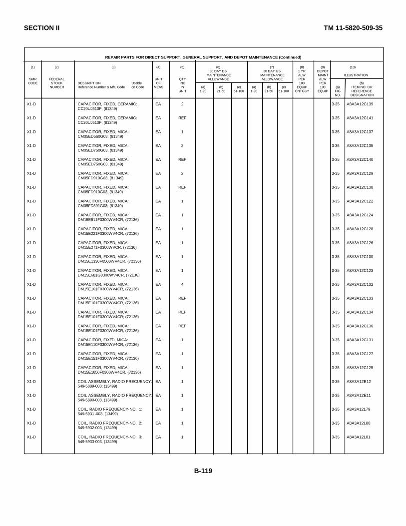
SECTION II TM 11-5820-509-35
REPAIR PARTS FOR DIRECT SUPPORT, GENERAL SUPPORT, AND DEPOT MAINTENANCE (Continued)
(1) (2) (3) (4) (5) (6) (7) (8) (9) (10)30 DAY DS 30 DAY GS 1 YR DEPOT
MAINTENANCE MAINTENANCE ALW MAINT ILLUSTRATIONSMR FEDERAL UNIT QTY ALLOWANCE ALLOWANCE PER ALW
CODE STOCK DESCRIPTION Usable OF INC 100 PER (b)NUMBER Reference Number & Mfr. Code on Code MEAS IN (a) (b) (c) (a) (b) (c) EQUIP 100 (a) ITEM NO. OR
UNIT 1-20 21-50 51-100 1-20 21-50 51-100 CNTGCY EQUIP FIG REFERENCENO. DESIGNATION
X1-D CAPACITOR, FIXED, CERAMIC: EA 2 3-35 A8A3A12C139CC20UJ510F, (81349)
X1-D CAPACITOR, FIXED, CERAMIC: EA REF 3-35 A8A3A12C141CC20UJ510F, (81349)
X1-D CAPACITOR, FIXED, MICA: EA 1 3-35 A8A3A12C137CM05ED560G03; (81349)
X1-D CAPACITOR, FIXED, MICA: EA 2 3-35 A8A3A12C135CM05ED750G03, (81349)
X1-D CAPACITOR, FIXED, MICA: EA REF 3-35 A8A3A12C140CM05ED750G03, (81349)
X1-D CAPACITOR, FIXED, MICA: EA 2 3-35 A8A3A12C129CM05FD910G03, (81 349)
X1-D CAPACITOR, FIXED, MICA: EA REF 3-35 A8A3A12C138CM05FD910G03, (81349)
X1-D CAPACITOR, FIXED, MICA: EA 1 3-35 A8A3A12C122CM05FD391G03; (81349)
X1-D CAPACITOR, FIXED, MICA: EA 1 3-35 A8A3A12C124DM15E511F0300WV4CR, (72136)
X1-D CAPACITOR, FIXED, MICA: EA 1 3-35 A8A3A12C128DM15E221F0300WV4CR, (72136)
X1-D CAPACITOR, FIXED, MICA: EA 1 3-35 A8A3A12C126DM15E271F0300WVCR, (72136)
X1-D CAPACITOR, FIXED, MICA: EA 1 3-35 A8A3A12C130DM15E1330F0500WV4CR, (72136)
X1-D CAPACITOR, FIXED, MICA: EA 1 3-35 A8A3A12C123DM15E681G0300WV4CR, (72136)
X1-D CAPACITOR, FIXED, MICA: EA 4 3-35 A8A3A12C132DM15E101F0300WV4CR, (72136)
X1-D CAPACITOR, FIXED, MICA: EA REF 3-35 A8A3A12C133DM15E101F0300WV4CR, (72136)
X1-D CAPACITOR, FIXED, MICA: EA REF 3-35 A8A3A12C134DM15E101F0300WV4CR; (72136)
X1-D CAPACITOR, FIXED, MICA: EA REF 3-35 A8A3A12C136DM15E101F0300WV4CR, (72136)
X1-D CAPACITOR, FIXED, MICA: EA 1 3-35 A8A3A12C131DM15E110F0300WV4CR, (72136)
X1-D CAPACITOR, FIXED, MICA: EA 1 3-35 A8A3A12C127DM15E151F0300WV4CR, (72136)
X1-D CAPACITOR, FIXED, MICA: EA 1 3-35 A8A3A12C125DM15E1650F0300WV4CR, (72136)
X1-D COIL ASSEMBLY, RADIO FRECUENCY: EA 1 3-35 A8A3A12E12549-5889-003; (13499)
X1-D COIL ASSEMBLY, RADIO FREQUENCY: EA 1 3-35 A8A3A12E11549-5890-003, (13499)
X1-D COIL, RADIO FREQUENCY-NO. 1: EA 1 3-35 A8A3A12L79549-5931 -003, (13499)
X1-D COIL, RADIO FREQUENCY-NO. 2: EA 1 3-35 A8A3A12L80549-5932-003, (13499)
X1-D COIL, RADIO FREQUENCY-NO. 3: EA 1 3-35 A8A3A12L81549-5933-003, (13499)
B-119
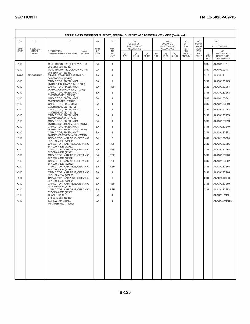
SECTION II TM 11-5820-509-35
REPAIR PARTS FOR DIRECT SUPPORT, GENERAL SUPPORT, AND DEPOT MAINTENANCE (Continued)
(1) (2) (3) (4) (5) (6) (7) (8) (9) (10)30 DAY DS 30 DAY GS 1 YR DEPOT
MAINTENANCE MAINTENANCE ALW MAINT ILLUSTRATIONSMR FEDERAL UNIT QTY ALLOWANCE ALLOWANCE PER ALW
CODE STOCK DESCRIPTION Usable OF INC 100 PER (b)NUMBER Reference Number & Mfr. Code on Code MEAS IN (a) (b) (c) (a) (b) (c) EQUIP 100 (a) ITEM NO. OR
UNIT 1-20 21-50 51-100 1-20 21-50 51-100 CNTGCY EQUIP FIG REFERENCENO. DESIGNATION
X1-D COIL, RADIO FREQUENCY-NO. 8: EA 1 3-35 A8A3A12L78756-3166-003, (13499)
X1-D COIL, RADIO FREQUENCY-NO. 9: EA 1 3-35 A8A3A12L77756-3167-003; (13499)
P-H-T 5820-975-5431 TRANSLATOR SUBASSEMBLY: EA 1 3-10 A8A3A13549-5908-003; (13499)
X1-D CAPACITOR, FIXED, MICA: EA 2 3-36 A8A3A13C265DM15C100K500WVRCR, (72136)
X1-D CAPACITOR, FIXED, MICA: EA REF 3-36 A8A3A13C267DM15C100K500WVRCR, (72136)
X1-D CAPACITOR, FIXED, MICA: EA 1 3-36 A8A3A13C263CM05ED200J03, (81349)
X1-D CAPACITOR, FIXED, MICA: EA 1 3-36 A8A3A13C261CM05ED270J03, (81349)
X1-D CAPACITOR, FIXD, MICA: EA 1 3-36 A8A3A13C259CM05ED390G03; (81349)
X1-D CAPACITOR, FIXED, MICA: EA 1 3-36 A8A3A13C257CM05ED620G03, (81349)
X1-D CAPACITOR, FIXED, MICA: EA 1 3-36 A8A3A13C255CM05FD910G03, (81349)
X1-D CAPACITOR, FIXED, MICA: EA 1 3-36 A8A3A13C253DM15E1330F0500WV4CR; (72136)
X1-D CAPACITOR, FIXED, MICA: EA 1 3-36 A8A3A13C249DM15E2870F0500WV4CR, (72136)
X1-D CAPACITOR, FIXED, MICA: EA 1 3-36 A8A3A13C251DM15E1650F0300WV4CR, (72136)
X1-D CAPACITOR, VARIABLE, CERAMIC: EA 6 3-36 A8A3A13C254557-099-5-30E, (72982)
X1-D CAPACITOR, VARIABLE, CERAMIC: EA REF 3-36 A8A3A13C256557-099-5-30E, (72982)
X1-D CAPACITOR, VARIABLE, CERAMIC: EA REF 3-36 A8A3A13C258557-099-5-30E; (72982)
X1-D CAPACITOR, VARIABLE, CERAMIC. EA REF 3-36 A8A3A13C260557-099-5-30E, (72982)
X1-D CAPACITOR, VARIABLE, CERAMIC: EA REF 3-36 A8A3A13C262557-099-5-30E, (72982)
X1-D CAPACITOR, VARIABLE, CERAMIC: EA REF 3-36 A8A3A13C264557-099-5-30E, (72982)
X1-D CAPACITOR, VARIABLE, CERAMIC: EA 1 3-36 A8A3A13C266557-099-5-25A, (72982)
X1-D CAPACITOR, VARIABLE, CERAMIC: EA 3 3-36 A8A3A13C248557-099-8-50E; (72982)
X1-D CAPACITOR, VARIABLE, CERAMIC: EA REF 3-36 A8A3A13C260557-099-8-50E, (72982)
X1-D CAPACITOR, VARIABLE, CERAMIC: EA REF 3-36 A8A3A13C252557-099-8-50E, (72982)
X1-D CLAMP, CABLE: EA 1 A8A3A13MP1549-5643-002, (13499)
X1-D SCREW, MACHINE. EA 1 A8A3A13MP1H1P343-0286-000, (77250)
B-120

SECTION II TM 11-5820-509-35
REPAIR PARTS FOR DIRECT SUPPORT, GENERAL SUPPORT, AND DEPOT MAINTENANCE (Continued)
(1) (2) (3) (4) (5) (6) (7) (8) (9) (10)30 DAY DS 30 DAY GS 1 YR DEPOT
MAINTENANCE MAINTENANCE ALW MAINT ILLUSTRATIONSMR FEDERAL UNIT QTY ALLOWANCE ALLOWANCE PER ALW
CODE STOCK DESCRIPTION Usable OF INC 100 PER (b)NUMBER Reference Number & Mfr. Code on Code MEAS IN (a) (b) (c) (a) (b) (c) EQUIP 100 (a) ITEM NO. OR
UNIT 1-20 21-50 51-100 1-20 21-50 51-100 CNTGCY EQUIP FIG REFERENCENO. DESIGNATION
X1-D COIL, RADIO FREQUENCY: EA 1 3-36 A8A3A13L103549-5885-002, (13499)
X1-D SWITCH SUBASSEMBLY: EA 1 A8A3A13S9549-5951-000, (13499)
P-D TUBE, ELECTRON: EA 1 * * 3-9 A8A3V37905; (49956)
M-D 5820-977-6242 WEDGE-TAPE: EA 2 A8A3MP39549-5863-002, (13499)
P-D SCREW, MACHINE: EA 2 REF REF A8A3MP39H1MS51959-3, (96906)
P-D SCREW, MACHINE: EA REF REF REF A8A3MP39H2MS51959-3, (96906)
M-D 5820-977-6242 WEDGE-TAPE: EA REF A8A3MP40549-5863-002; (13499)
P-D SCREW, MACHINE: EA 2 REF REF A8A3MP40H1MS51959-3, (96906)
P-D SCREW, MACHINE: EA REF REF REF A8A3MP40H2MS51959-3, (96906)
P-D WASHER: EA 10 * * A8A3H9553-5032-003, (13499)
P-D WASHER: EA REF REF REF A8A3H10553-5032-003; (13499)
P-D WASHER: EA REF REF REF A8A3H11553-5032-003, (13499)
P-D WASHER: EA REF REF REF A8A3H12553-5032-003, (13499)
P-D WASHER: EA REF REF REF A8A3H13553-5032-003, (13499)
P-D WASHER: EA REF REF REF A8A3H14553-5032-003, (13499)
P-D WASHER: EA REF REF REF A8A3H15553-5032-003, (13499)
P-D WASHER: EA REF REF REF A8A3H16553-5032-003, (13499)
P-D WASHER: EA REF REF REF A8A3H17553-5032-003, (13499)
P-D WASHER: EA REF REF REF A8A3H18553-5032-003, (13499)
P-H-S 5820-087-2299 AMPLIFIER, AUDIO FREQUENCY: EA 1 * * * * * 3-4 A8A1AM3506PRC47, (80058)
P-H-T 5820-087-3439 AMPLIFIER SUBASSEMBLY, AF: EA 1 * * * * * 3-6 A8A1E2549-5651-004, (] 3499)
P-D SCREW, MACHINE EA 6 REF REF A8A1E2H6MS51959-3, (96906)
X1-D BOARD, PRINTED CIRCUIT EA 1 3-18 A8A1E2E1549-5653-004, (13499)
X1-D CAPACITOR, FIXED, ELECTROLYTIC EA 1 3-18 A8A1E2C5150D156X0C20B2, (56289)
X1-D CAPACITOR, FIXED, ELECTROLYTIC. EA 1 3-18 A8A1E2C9150D226X0015B2, (56289)
B-121
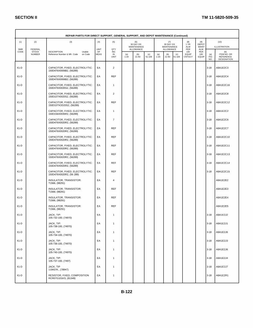
SECTION II TM 11-5820-509-35
REPAIR PARTS FOR DIRECT SUPPORT, GENERAL SUPPORT, AND DEPOT MAINTENANCE (Continued)
(1) (2) (3) (4) (5) (6) (7) (8) (9) (10)30 DAY DS 30 DAY GS 1 YR DEPOT
MAINTENANCE MAINTENANCE ALW MAINT ILLUSTRATIONSMR FEDERAL UNIT QTY ALLOWANCE ALLOWANCE PER ALW
CODE STOCK DESCRIPTION Usable OF INC 100 PER (b)NUMBER Reference Number & Mfr. Code on Code MEAS IN (a) (b) (c) (a) (b) (c) EQUIP 100 (a) ITEM NO. OR
UNIT 1-20 21-50 51-100 1-20 21-50 51-100 CNTGCY EQUIP FIG REFERENCENO. DESIGNATION
X1-D CAPACITOR, FIXED, ELECTROLYTIC: EA 2 3-18 A8A1E2C3150D476X0006B2, (56289)
X1-D CAPACITOR, FIXED, ELECTROLYTIC: EA REF 3-18 A8A1E2C4150D476X0006B2; (56289)
X1-D CAPACITOR, FIXED, ELECTROLYTIC: EA 1 3-18 A8A1E2C16150D476X0035S2, (56289)
X1-D CAPACITOR, FIXED, ELECTROLYTIC: EA 2 3-18 A8A1E2C8150D107X0020S2, (56289)
X1-D CAPACITOR, FIXED, ELECTROLYTIC: EA REF 3-18 A8A1E2C12150D107XOD20S2, (56289)
X1-D CAPACITOR, FIXED, ELECTROLYTIC: EA 1 3-18 A8A1E2C2150D156X0035R2, (56289)
X1-D CAPACITOR, FIXED, ELECTROLYTIC: EA 7 3-18 A8A1E2C6150D476X0020R2, (56289)
X1-D CAPACITOR, FIXED, ELECTROLYTIC: EA REF 3-18 A8A1E2C7150D476X0020R2, (56289)
X1-D CAPACITOR, FIXED, ELECTROLYTIC: EA REF 3-18 A8A1E2C10150D476X0020R2, (56289)
X1-D CAPACITOR, FIXED, ELECTROLYTIC: EA REF 3-18 A8A1E2C11150D476X0020R2, (56289)
X1-D CAPACITOR, FIXED, ELECTROLYTIC: EA REF 3-18 A8A1E2C13150D476X0020R2, (56289)
X1-D CAPACITOR, FIXED, ELECTROLYTIC: EA REF 3-18 A8A1E2C14150D476X0020R2, (56289)
X1-D CAPACITOR, FIXED, ELECTROLYTIC: EA REF 3-18 A8A1E2C15150D476X0020R2, (56 289)
X1-D INSULATOR, TRANSISTOR: EA 4 A8A1E2E2T1566, (98291)
X1-D INSULATOR, TRANSISTOR: EA REF A8A1E2E3T1566; (98291)
X1-D INSULATOR, TRANSISTOR: EA REF A8A1E2E4T1566, (98291)
X1-D INSULATOR, TRANSISTOR: EA REF A8A1E2E5T1566, (98291)
X1-D JACK, TIP: EA 1 3-18 A8A1E2J2105-732-100; (74970)
X1-D JACK, TIP: EA 1 3-18 A8A1E2J1105-738-100, (74970)
X1-D JACK, TIP: EA 1 3-18 A8A1E2J6105-734-100, (74970)
X1-D JACK, TIP: EA 1 3-18 A8A1E2J3105-736-100, (74970)
X1-D JACK, TIP: EA 1 3-18 A8A1E2J6105-740-100, (74970)
X1-D JACK, TIP: EA 1 3-18 A8A1E2J4105-737-100, (7497)
X1-D JACK, TIP EA 1 3-18 A8A1E2J7119437K., (78947)
X1-D RESISTOR, FIXED, COMPOSITION EA 1 3-18 A8A1E2R1RCR07G101KS, (81349)
B-122

SECTION II TM 11-5820-509-35
REPAIR PARTS FOR DIRECT SUPPORT, GENERAL SUPPORT, AND DEPOT MAINTENANCE (Continued)
(1) (2) (3) (4) (5) (6) (7) (8) (9) (10)30 DAY DS 30 DAY GS 1 YR DEPOT
MAINTENANCE MAINTENANCE ALW MAINT ILLUSTRATIONSMR FEDERAL UNIT QTY ALLOWANCE ALLOWANCE PER ALW
CODE STOCK DESCRIPTION Usable OF INC 100 PER (b)NUMBER Reference Number & Mfr. Code on Code MEAS IN (a) (b) (c) (a) (b) (c) EQUIP 100 (a) ITEM NO. OR
UNIT 1-20 21-50 51-100 1-20 21-50 51-100 CNTGCY EQUIP FIG REFERENCENO. DESIGNATION
X1-D RESISTOR, FIXED, COMPOSITION: EA 1 3-18 A8A1E2R20RCR07G472KS; (81349)
X1-D RESISTOR, FIXED, COMPOSITION: EA 1 3-18 A8A1E2R19RCR07G103KS; (81349)
X1-D RESISTOR, FIXED, COMPOSITION: EA 2 3-18 A8A1E2R18RCR07G223KS, (81349)
X1-D RESISTOR, FIXED, COMPOSITION: EA REF 3-18 A8A1E2R26RCR07G223KS; (81349)
X1-D RESISTOR, FIXED, COMPSITION: EA 4 3-18 A8A1E2R4RCR07G104KS; (81349)
X1-D RESISTOR, FIXED, COMPOSITION: EA REF 3-18 A8A1E2R7RCR07G101KS; (81349)
X1-D RESISTOR, FIXED, COMPOSITION: EA REF 3-18 A8A1E2R13RCR07G104KS, (81349)
X1-D RESISTOR, FIXED, COMPOSITION: EA REF 3-18 A8A1E2R28RCR07G104KS, (81349)
X1-D RESISTOR, FIXED, COMPOSITION: EA 1 3-18 A8A1E2R2RC520G470KS; (81349)
X1-D RESISTOR, FIXED, FILM: EA 1 3-18 A8A1E2R32RN60D46RF, (81349)
X1-D RESISTOR, FIXED, FILM: EA 5 3-18 A8A1E2R9RN60D1001F, (81349)
X1-D RESISTOR, FIXED, FILM: EA REF 3-18 A8A1E2R10RN60D1001F; (81349)
X1-D RESISTOR, FIXED, FILM: EA REF 3-18 A8A1E2R14RN60D1001F; (81349)
X1-D RESISTOR, FIXED, FILM: EA REF 3-18 A8A1E2R24RN60D1001F; (81349)
X1-D RESISTOR, FIXED, FILM: EA REF 3-18 A8A1E2R23RN60D1001F, (81349)
X1-D RESISTOR, FIXED, FILM: EA 1 3-18 A8A1E2R22RN60D1471F; (81349)
X1-D RESISTOR, FIXED, FILM: EA 3 3-18 A8A1E2R17RJ60D1961F, (81349)
X1-D RESISTOR, FIXED, FILM: EA REF 3-18 A8A1E2R25RJ60D1961F, (81349)
X1-D RESISTOR, FIXED, FILM: EA REF 3-18 A8A1E2R31RN60D1961F, (81349)
X1-D RESISTOR, FIXED, FILM: EA 1 3-18 A8A1E2R11RN60D2151F, (81349)
X1-D RESISTOR, FIXED, FILM: EA 2 3-18 A8A1E2R6RN60D2611F, (813;9)
X1-D RESISTOR, FIXED, FILM: EA REF 3-18 A8A1E2R30RN60D2611F, (81349)
X1-D RESISTOR, FIXED, FIILM: EA 1 3-18 A8A1E2R15RN60D3481F; (81349)
X1-D RESISTOR, FIXED, FILM: EA 1 3-18 A8A1E2R16RN60D5111F, (81349)
X1-D RESISTOR, FIXED, FILM: EA 1 3-18 A8A1E2R29RN60D6191F, (81349)
B-123
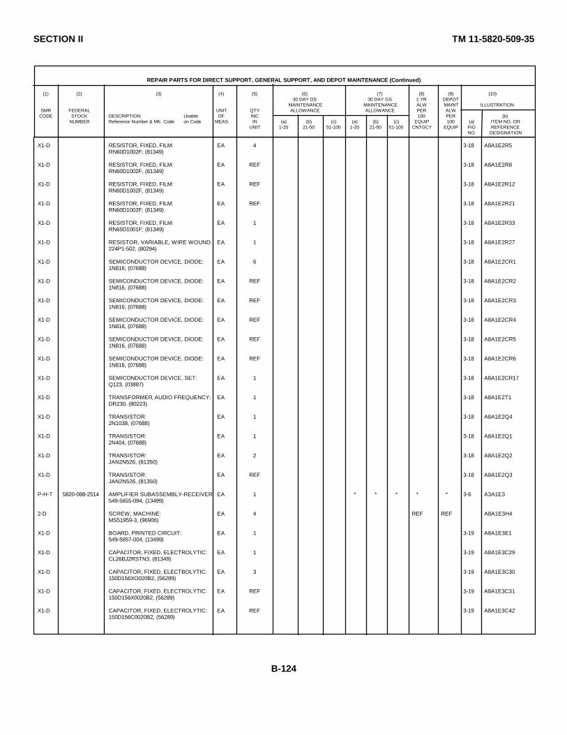
SECTION II TM 11-5820-509-35
REPAIR PARTS FOR DIRECT SUPPORT, GENERAL SUPPORT, AND DEPOT MAINTENANCE (Continued)
(1) (2) (3) (4) (5) (6) (7) (8) (9) (10)30 DAY DS 30 DAY GS 1 YR DEPOT
MAINTENANCE MAINTENANCE ALW MAINT ILLUSTRATIONSMR FEDERAL UNIT QTY ALLOWANCE ALLOWANCE PER ALW
CODE STOCK DESCRIPTION Usable OF INC 100 PER (b)NUMBER Reference Number & Mfr. Code on Code MEAS IN (a) (b) (c) (a) (b) (c) EQUIP 100 (a) ITEM NO. OR
UNIT 1-20 21-50 51-100 1-20 21-50 51-100 CNTGCY EQUIP FIG REFERENCENO. DESIGNATION
X1-D RESISTOR, FIXED, FILM: EA 4 3-18 A8A1E2R5RN60D1002F; (81349)
X1-D RESISTOR, FIXED, FILM: EA REF 3-18 A8A1E2R8RN60D1002F, (81349)
X1-D RESISTOR, FIXED, FILM: EA REF 3-18 A8A1E2R12RN60D1002F, (81349)
X1-D RESISTOR, FIXED, FILM: EA REF 3-18 A8A1E2R21RN60D1002F; (81349)
X1-D RESISTOR, FIXED, FILM: EA 1 3-18 A8A1E2R33RN65D1001F; (81349)
X1-D RESISTOR, VARIABLE, WIRE WOUND: EA 1 3-18 A8A1E2R27224P1-502, (80294)
X1-D SEMICONDUCTOR DEVICE, DIODE: EA 6 3-18 A8A1E2CR11N816; (07688)
X1-D SEMICONDUCTOR DEVICE, DIODE: EA REF 3-18 A8A1E2CR21N816, (07688)
X1-D SEMICONDUCTOR DEVICE, DIODE: EA REF 3-18 A8A1E2CR31N816; (07688)
X1-D SEMICONDUCTOR DEVICE, DIODE: EA REF 3-18 A8A1E2CR41N816, (07688)
X1-D SEMICONDUCTOR DEVICE, DIODE: EA REF 3-18 A8A1E2CR51N816, (07688)
X1-D SEMICONDUCTOR DEVICE, DIODE: EA REF 3-18 A8A1E2CR61N816, (07688)
X1-D SEMICONDUCTOR DEVICE, SET: EA 1 3-18 A8A1E2CR17Q123, (03887)
X1-D TRANSFORMER, AUDIO FREQUENCY: EA 1 3-18 A8A1E2T1DR230, (80223)
X1-D TRANSISTOR: EA 1 3-18 A8A1E2Q42N1038, (07688)
X1-D TRANSISTOR: EA 1 3-18 A8A1E2Q12N404, (07688)
X1-D TRANSISTOR: EA 2 3-18 A8A1E2Q2JAN2N526, (81350)
X1-D TRANSISTOR: EA REF 3-18 A8A1E2Q3JAN2N526, (81350)
P-H-T 5820-088-2514 AMPLIFIER SUBASSEMBLY-RECEIVER: EA 1 * * * * * 3-6 A3A1E3549-5655-094, (13499)
2-D SCREW, MACHINE: EA 4 REF REF A8A1E3H4MS51959-3, (96906)
X1-D BOARD, PRINTED CIRCUIT: EA 1 3-19 A8A1E3E1549-5657-004, (13499)
X1-D CAPACITOR, FIXED, ELECTROLYTIC: EA 1 3-19 A8A1E3C29CL26BJ2RSTN3, (81349)
X1-D CAPACITOR, FIXED, ELECTBOLYTIC: EA 3 3-19 A8A1E3C30150D156XO020B2, (56289)
X1-D CAPACITOR, FIXED, ELECTROLYTIC: EA REF 3-19 A8A1E3C31150D156X0020B2, (56289)
X1-D CAPACITOR, FIXED, ELECTROLYTIC: EA REF 3-19 A8A1E3C42150D156C0020B2, (56289)
B-124
SECTION II TM 11-5820-509-35
REPAIR PARTS FOR DIRECT SUPPORT, GENERAL SUPPORT, AND DEPOT MAINTENANCE (CONTINUED)
(1) (2) (3) (4) (5) (6) (7) (8) (9) (10)30 DAY DS 30 DAY GS 1 YR DEPOT
MAINTENANCE MAINTENANCE ALW MAINT ILLUSTRATIONSMR FEDERAL UNIT QTY ALLOWANCE ALLOWANCE PER ALW
CODE STOCK DESCRIPTION Usable OF INC 100 PER (b)NUMBER Reference Number & Mfr. Code on Code MEAS IN (a) (b) (c) (a) (b) (c) EQUIP 100 (a) ITEM NO. OR
UNIT 1-20 21-50 51-100 1-20 21-50 51-100 CNTGCY EQUIP FIG REFERENCENO. DESIGNATION
X1-D CAPACITOR, FIXED, ELECTROLYTIC: EA 1 3-19 A8A1E3C35150D476X0006B2; (56289)
X1-D CAPACITOR, FIXED, ELECTROLYTIC: EA 1 3-19 A8A1E3C40150D107X0020S2, (56289)
X1-D CAPACITOR, FIXED, ELECTROLYTIC: EA 2 3-19 A8A1E3C32150D336X0020R2, (56289)
X1-D CAPACITOR, FIXED, ELECTROLYTIC: EA REF 3-19 A8A1E3C36150D336X0O20R2, (56289)
X1-D CAPACITOR, FIXED, ELECTROLYTIC: EA 1 3-19 A8A1E3C33150D476X0020R2, (56289)
X1-D CAPACITOR, FIXED, ELECTROLYTIC: EA 2 3-19 A8A1E3C28150D105X9035A2, (56289)
X1-D CAPACITOR, FIXED, ELICTROLYTIC: EA REF 3-19 A8A1E3C34150D105X9035A2, (56289)
X1-D CAPACITOR, FIXED, ELECTROLYTIC: EA 3 3-19 A8A1E3C37150D1697; (56289)
X1-D CAPACITOR, FIXED, ELECTROLYTIC: EA REF 3-19 A8A1E3C38150D1697; (56289)
X1-D CAPACITOR, FIXED, ]LECTROLYTIC: EA REF 3-19 A8A1E3C41150D1697; (56289)
X1-D INSULATOR TRANSISTOR: EA 3 A8A1E3E2X1-D INSULATOR, TRASISTOR: EA REF A8A1E3E3
T1566, (98291)X1-D INSULATOR, TRAUSISTOR: EA REF A81E3E4
T1566; (98291)X1-D JACK, TIP: EA 1 3-19 A8A1E3J15
105-73100oo; (74970)X1-D JACK, TIP: EA 1 3-19 ABA1E3J13
105-736-100; (74970)X1-D JACK, TIP: EA 1 3-19 A8A1E3J16
105-740-100; (74970)X1-D JACK, TIP: EA 1 3-19 ASA1E3J1I
105-737-100, (74970)X1-D REACTOR: EA 1 3-19 A8A1E3L3
DR905; (80223)X1-D RESISTOR, FIXED, COMPOSITION: EA 1 3-19 A8A1E3R72
RCR07Gi22KS, (81349)X1-D RESISTOR, FIXED, CDMPOSITION: EA 1 3-19 A8A1E3R45
RCR07Gl52KS; (81349)X1-D RESISTOR, FIXED, CODPOSITION: EA 1 3-19 A8A1E3R63
RCR07G272KS, (81349)X1-D RESISTOR, FIXED, CODPOSITION: EA 1 3-19 A8A1E3R51
RCRO7G332K, (81349)X1-D RESISTOR, FIXED, COWOSITION: EA 4 3-19 A8A1E3R47
RCR07G103KS; (81349)X1-D RBSISTOR, FIXED, COMPOSITION: EA REF 3-19 A8A1E3R53
RCR07G103KS, (81349)X1-D RESISTOR, FIXED, COOSITION: EA REF 3-19 A8A1E3R64
RCR07G103KS, (81349)
B-125
SECTION II TM 11-5820-509-35
REPAIR PARTS FOR DIRECT SUPPORT, GENERAL SUPPORT, AND DEPOT MAINTENANCE (CONTINUED)
(1) (2) (3) (4) (5) (6) (7) (8) (9) (10)30 DAY DS 30 DAY GS 1 YR DEPOT
MAINTENANCE MAINTENANCE ALW MAINT ILLUSTRATIONSMR FEDERAL UNIT QTY ALLOWANCE ALLOWANCE PER ALW
CODE STOCK DESCRIPTION Usable OF INC 100 PER (b)NUMBER Reference Number & Mfr. Code on Code MEAS IN (a) (b) (c) (a) (b) (c) EQUIP 100 (a) ITEM NO. OR
UNIT 1-20 21-50 51-100 1-20 21-50 51-100 CNTGCY EQUIP FIG REFERENCENO. DESIGNATION
X1-D RESISTOR, FIXED, COMPOSITION: EA REF 3-19 A8A1E3R68RCR07G1T3KS; (81349)
X1-D RESISTOR, FIXED, COMPOSITION: EA 2 3-19 A8A1E3R58RCR07G123KS; (81349)
X1-D RESISTOR, FIXED, COMPOSITION: EA REF 3-19 A8A1E3R78RCRO7G123KS; (81349)
X1-D RESISTOR, FIXED, COMPOSITIOW: EA 1 3-19 A8A1E3R55RCR07G183KS; (81349)
X1-D RESISTOR, FIXED, COMPOSITION: EA 2 3-19 A8A1E3R48RCRO7G223KS; (81349)
X1-D RESISTOR, FIXED, COMPOSITION: EA REF 3-19 A8A1E3R74RCROTG223KS; (81349)
X1-D RESISTOR, FIXED, COMPOSITION: EA 2 3-19 A8A1E3R59RCRO7C273KS; (81349)
X1-D RESISTOR, FIXED, COMPOSITION: EA REF 3-15 A8A1E3R73RCR07G273KS; (81349)
X1-D RESISTOR, FIXED, COMPOSITION: EA 3 3-15 A8A1E3R49RCR07G104KS; (81349)
X1-D RESISTOR, FIXED, COMPOSITION: EA REF 3-19 A8A1E3R76RCR07G104KS; (81349)
X1-D RESISTOR, FIXED, COMPOSITION: EA REF 3-19 A8A1E3R77RCR07G104KS; (81349)
X1-D RESISTOR, FIXED, COMPOSITION: EA 1 3-19 A8A1E3R50RCR07G184KS, (81349)
X1-D RESISTOR, FIXED, COMPOSITION: EA 1 3-19 A8A1E3R75RCR07G474KS; (81349)
X1-D RESISTOR, FIXED, FILM: EA 1 3-19 A8A1E3R65RR60D51RlF; (81349)
X1-D RESISTOR, FIXED, FILM: EA 1 3-19 A8A1E3R66RN60D4221F; (81349)
X1-D RESISTOR, FIXED, FILM: EA 2 3-19 A8A1E3R61RN60D5111F, (81349)
X1-D RESISTOR, FIXED, FILM: EA REF 3-19 A8A1E3R62RN60D5111Y; (81349)
X1-D RESISTOR, FIXED, FILM: EA 1 3-19 A8A1E3R56RN60D1102F; (81349)
X1-D RESISTOR, FIXED, FILM EA 1 3-19 A8A1E3R57RN60D1102F; (81349)
X1-D RESISTOR, FIXED, FILM: EA 1 3-19 A8A1E3R60RN60D1622F; (81349)
X1-D RESISTOR, THERMAL: EA 1 3-15 A8A1E3R67763F28; (10646)
X1-D RESISTOR, VARIABLE, WIIREWOUND: EA 1 3-15 A8A1E3R54224P1-102; (80294)
X1-D RESISTOR, VARIABLE, WIREOIRD: EA 2 3-19 A8A1E3R46224P1-503, (80294)
X1-D RESISTOR, VARIABLE, WIREWOUND EA REF 3-15 A8A1E3R52224P1-503; (80294 )
X1-D SEMICONDUCTOR DEVICE, DIODE: EA 3 3-15 A8A1E3CR1111457; (07688)
B-126
SECTION II TM 11-5820-509-35
REPAIR PARTS FOR DIRECT SUPPORT, GENERAL SUPPORT, AND DEPOT MAINTENANCE (CONTINUED)
(1) (2) (3) (4) (5) (6) (7) (8) (9) (10)30 DAY DS 30 DAY GS 1 YR DEPOT
MAINTENANCE MAINTENANCE ALW MAINT ILLUSTRATIONSMR FEDERAL UNIT QTY ALLOWANCE ALLOWANCE PER ALW
CODE STOCK DESCRIPTION Usable OF INC 100 PER (b)NUMBER Reference Number & Mfr. Code on Code MEAS IN (a) (b) (c) (a) (b) (c) EQUIP 100 (a) ITEM NO. OR
UNIT 1-20 21-50 51-100 1-20 21-50 51-100 CNTGCY EQUIP FIG REFERENCENO. DESIGNATION
X1-D SEMICONDUCTOR DEVICE, DIODE: EA REF 3-19 A8A1E3CR12LN457, (07688)
X1-D SEMICONDUCTOR DEVICE, DIODE: EA REF 3-19 A8A1E3CR131N457; (07688)
X1-D SEMICONDUCTOR DEVICE, DIODE: EA 1 3-19 A8A1E3CR10X1-D TRANSISTOR: EA 3 3-19 A8A1E3Q8
JAN2N526, (81350)X1-D TRANSISTOR: EA REF 3-19 A8A1E3Q9
JAN2N526, (81350)X1-D TRANSISTOR: EA REF 3-19 A8A1E3Q10
JAN2N526; (81350)P--D CAPACITOR, FIXED, CERAMIC: EA 1 * * 3-16 A8A1C43
33C58; (01939)P--D 5910-834-8493 CAPACITOR, FIXED, ELECTROLYTIC: EA 1 * * 3-16 A8A1C44
150D476X003582, (56289)P--D CHASSIS, ELECTRICAL EQUIPMENT: EA 1 A8A1MP1
549-5659-005, (13499)P--D 5935-808-7502 CONNECTOR, RECEPTACLE: EA 1 * * 3-16 A8A1P1
DBM25P, (71i68)P--D 5310-622-1724 NUT, SELF-LOCKING, HEXAGON: EA 2 REF REF A8A1P1H1
68-1660-26, (72962)P--D 5310-622-1724 NUT, SELF-LOCKING, HEXAGON: EA REF REF REF A8A1P1H2
68-1660-26; (72962)P--D 5305-770-2533 SCREW, MACHINE: EA 2 REF REF A8A1P1H3
MS51959-13; (77250)P--D 5305-770-2533 SCREW, MACHINE EA REF REF REF A8A1P1H4
MS51959-13; (77250)P--D WASHER, FLAT: EA 2 REF REF A8A1P1H5
310-0044-000; (79807)P--D WASHER, FLAT: EA REF REF REF A8A1P1H6
310-0044-000; (79807)P--H-T 5820-975-5412 CONTROL OSCILLATOR GROUP: EA 1 * * * * * 3-6 A8A1E1
549-5654-004; (13499)P--D 5305-727-8833 SCREW, MACHINE: EA 6 REF REF A8A1E1H6
MS51959-3, (96906)X1-D BOARD, PRINTED CIRCUIT EA 1 3-17 A8A1E1E1
549-5650-003, (13499)X1-D CAPACITOR, FIXED, CERAMIC: EA 1 3-17 A8A1E1C18
6S8083, (56289)X1-D CAPACITOR, FIXED, ELECTROLYTIC: EA 2 3-17 A8A1E1C1
150D476X0035S2, (56289)X1-D CAPACITOR, FIXED, ELECTROLYTIC: EA REF 3-17 A8A1E1C22
150D476X0o35S2, (56289)X1-D CAPACITOR, FIXED, ELECTROLYTIC: EA 1 3-17 A8A1E1C26
150D394X9035A2, (56289)X1-D CAPACITOR, FIXED, ELECTROLYTIC: EA 1 3-17 A8A1E1C26 ·
150D564X9035A2, (56289)X1-D CAPACITOR, FIXED, ELECTROLYTIC: EA 1 3-17 A8A1E1C26
150D684X0035A2, (56289)
*SELECT PER OPERATIONAL REQUIREMENT.
B-127
SECTION II TM 11-5820-509-35
REPAIR PARTS FOR DIRECT SUPPORT, GENERAL SUPPORT, AND DEPOT MAINTENANCE (CONTINUED)
(1) (2) (3) (4) (5) (6) (7) (8) (9) (10)30 DAY DS 30 DAY GS 1 YR DEPOT
MAINTENANCE MAINTENANCE ALW MAINT ILLUSTRATIONSMR FEDERAL UNIT QTY ALLOWANCE ALLOWANCE PER ALW
CODE STOCK DESCRIPTION Usable OF INC 100 PER (b)NUMBER Reference Number & Mfr. Code on Code MEAS IN (a) (b) (c) (a) (b) (c) EQUIP 100 (a) ITEM NO. OR
UNIT 1-20 21-50 51-100 1-20 21-50 51-100 CNTGCY EQUIP FIG REFERENCENO. DESIGNATION
X1-D CAPACITOR, FIXED, ELECTROLYTIC: EA 1 3-17 ARAE1C17150D105X9035A2, (56289)
X1-D CAPACITOR, FIXED, ELECTROLYTIC: EA 2 3-17 A8A1E1C23150D336X9010B2, (56289)
X1-D CAPACITOR, FIXED, ELECTROLYTIC: EA REF 3-17 A8A1E1C24150D336X9010B2, (56289)
X1-D CAPACITOR, FIXED, ELECTROLYTIC: EA 1 3-17 A8A1E1C26 *150D474X9035A2, (56289)
X1-D CAPACITOR, FIXED, ELECTROLYTIC: EA 1 3-17 A8A1E1C26 *150D334X9035A2, (56289)
X1-D CAPACITOR, FIXED, ELECTROLYTIC: EA 2 3-17 A8A1E1C21150D1697; (56289)
X1-D CAPACITOR, FIXED, ELECTROLYTIC: EA REF 3-17 A8A1E1C25150D1697, (56289)
X1-D CAPACITOR, FIXED, MICA: EA 1 3-17 A8A1E1C19CM06FD302F03, (81349)
X1-D CAPACITOR, FIXED, MICA: EA 1 3-17 A8A1E1C20DM30F153F03, (72136)
X1-D COIL, RADIO FREQMUEICY: EA 1 3-17 A8A1El1L1MP206-31B, (95105)
X1-D SCREW, MACHIN: EA 1 A8A1E1L1H1P343-0329-000; (77250)
X1-D JACK, TIP: EA 1 3-17 A8A1E1J9105-731-100, (74970)
X1-D JACK, TIP: EA 1 3-17 A8A1E1J12105-732-100; (74970)
X1-D JACK, TIP: EA 1 3-17 A8A1E1J10105-733-100, (74970)
X1-D JACK, TIP: EA 1 3-17 A8A1E1J11105-738-100, (74970)
X1-D JACK, TIP: EA 1 3-17 A8A1E1J8105-743-100, (74970)
X1-D REACTOR: EA 1 3-17 A8A1E1L2678-0084-000; (13499)
X1-D SCREW, MACHINE: EA 1 A8A1E1L2H1P343-0329-000; (77250)
X1-D RELAY, ARMATURE: EA 1 3-17 A8A1E1K13SAK1005, (01526)
X1-D RESISTOR, FIXED, COMPOSITION: EA 5 3-17 A8A1E1R34RCRO7G104KS, (81349)
X1-D RESISTOR, FIXED, COMPOSITION: EA REF 3-17 A8A1E1R38RCR07D104KS, (81349)
X1-D RESISTOR, FIXED, COMPOSITION: EA REF 3-17 A8A1E1R39RCR07G104KS, (81349)
X1-D RESISTOR, FIXED, COMPOSITION: EA REF 3-17 A81E1R41RCR07G104KS, (81349)
X1-D RESISTOR, FIXED, COMPOSITION: EA REF 3-17 A8A1E1R44RCR07GlC0KS, (81349)
X1-D RESISTOR, FIXED, COMPOSITION: EA 1 3-17 A8A1E1R3RC42GF681K; (81349)
B-128
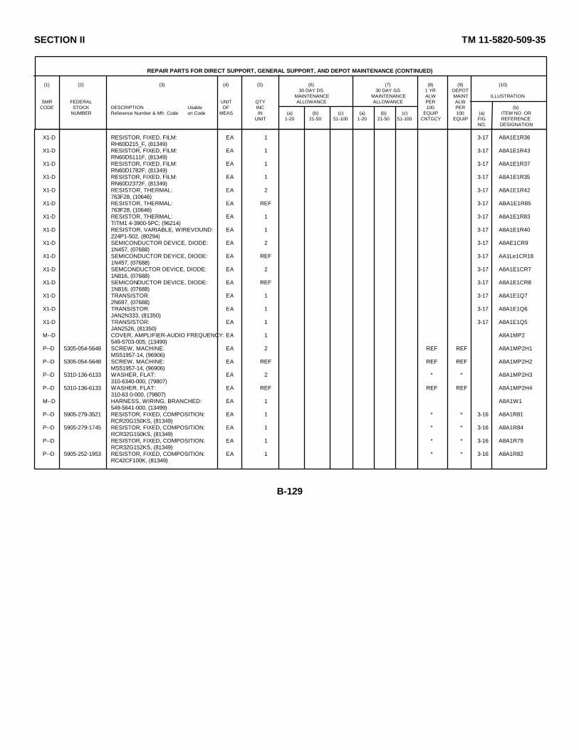
SECTION II TM 11-5820-509-35
REPAIR PARTS FOR DIRECT SUPPORT, GENERAL SUPPORT, AND DEPOT MAINTENANCE (CONTINUED)
(1) (2) (3) (4) (5) (6) (7) (8) (9) (10)30 DAY DS 30 DAY GS 1 YR DEPOT
MAINTENANCE MAINTENANCE ALW MAINT ILLUSTRATIONSMR FEDERAL UNIT QTY ALLOWANCE ALLOWANCE PER ALW
CODE STOCK DESCRIPTION Usable OF INC 100 PER (b)NUMBER Reference Number & Mfr. Code on Code MEAS IN (a) (b) (c) (a) (b) (c) EQUIP 100 (a) ITEM NO. OR
UNIT 1-20 21-50 51-100 1-20 21-50 51-100 CNTGCY EQUIP FIG REFERENCENO. DESIGNATION
X1-D RESISTOR, FIXED, FILM: EA 1 3-17 A8A1E1R36RH60D215_F, (81349)
X1-D RESISTOR, FIXED, FILM: EA 1 3-17 A8A1E1R43RN60D5111F, (81349)
X1-D RESISTOR, FIXED, FILM: EA 1 3-17 A8A1E1R37RN60D1782F; (81349)
X1-D RESISTOR, FIXED, FILM: EA 1 3-17 A8A1E1R35RN60D2372F, (81349)
X1-D RESISTOR, THERMAL: EA 2 3-17 A8A1E1R42763F28, (10646)
X1-D RESISTOR, THERMAL: EA REF 3-17 ABA1E1R85763F28, (10646)
X1-D RESISTOR, THERMAL: EA 1 3-17 A8A1E1R83TITM1 4-3900-5PC; (96214)
X1-D RESISTOR, VARIABLE, WIREVOUND: EA 1 3-17 A8A1E1R40224P1-502, (80294)
X1-D SEMICONDUCTOR DEVICE, DIODE: EA 2 3-17 A8AE1CR91N457, (07688)
X1-D SEMICONDUCTOR DEYICE, DIODE: EA REF 3-17 AA1Le1CR181N457, (07688)
X1-D SEMCONDUCTOR DEVICE, DIODE: EA 2 3-17 A8A1E1CR71N816, (07688)
X1-D SEMICONDUCTOR DEVICE, DIODE: EA REF 3-17 A8A1E1CR81N816; (07688)
X1-D TRANSISTOR: EA 1 3-17 A8A1E1Q72N697, (07688)
X1-D TRANSISTOR: EA 1 3-17 A8A1E1Q6JAN2N333, (81350)
X1-D TRANSISTOR: EA 1 3-17 A8A1E1Q5JAN2526, (81350)
M--D COVER, AMPLIFIER-AUDIO FREQUENCY: EA 1 A8A1MP2549-5703-005; (13499)
P--D 5305-054-5648 SCREW, MACHINE: EA 2 REF REF A8A1MP2H1MS51957-14, (96906)
P--D 5305-054-5648 SCREW, MACHINE: EA REF REF REF A8A1MP2H2MS51957-14, (96906)
P--D 5310-136-6133 WASHER, FLAT: EA 2 * * A8A1MP2H3310-6340-000, (79807)
P--D 5310-136-6133 WASHER, FLAT: EA REF REF REF A8A1MP2H4310-63 0-000, (79807)
M--D HARNESS, WIRING, BRANCHED: EA 1 A8A1W1549-5641-000, (13499)
P--D 5905-279-3521 RESISTOR, FIXED, COMPOSITION: EA 1 * * 3-16 A8A1R81RCR20G150KS, (81349)
P--D 5905-279-1745 RESISTOR, FIXED, COMPOSITION: EA 1 * * 3-16 A8A1R84RCR32G150KS, (81349)
P--D RESISTOR, FIXED, COMPOSITION: EA 1 * * 3-16 A8A1R79RCR32G152KS, (81349)
P--D 5905-252-1953 RESISTOR, FIXED, COMPOSITION: EA 1 * * 3-16 A8A1R82RC42CF100K, (81349)
B-129
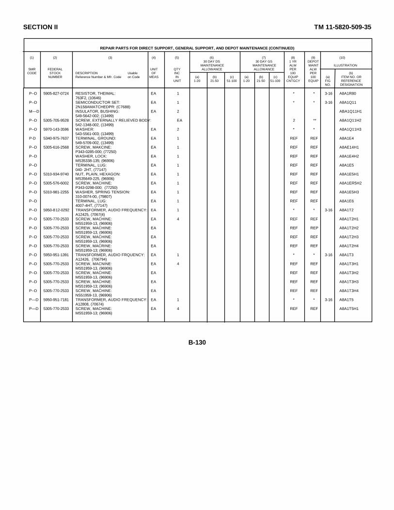
SECTION II TM 11-5820-509-35
REPAIR PARTS FOR DIRECT SUPPORT, GENERAL SUPPORT, AND DEPOT MAINTENANCE (CONTINUED)
(1) (2) (3) (4) (5) (6) (7) (8) (9) (10)30 DAY DS 30 DAY GS 1 YR DEPOT
MAINTENANCE MAINTENANCE ALW MAINT ILLUSTRATIONSMR FEDERAL UNIT QTY ALLOWANCE ALLOWANCE PER ALW
CODE STOCK DESCRIPTION Usable OF INC 100 PER (b)NUMBER Reference Number & Mfr. Code on Code MEAS IN (a) (b) (c) (a) (b) (c) EQUIP 100 (a) ITEM NO. OR
UNIT 1-20 21-50 51-100 1-20 21-50 51-100 CNTGCY EQUIP FIG REFERENCENO. DESIGNATION
P--D 5905-827-0724 RESISTOR, THEIMAL: EA 1 * * 3-16 A8A1R80763F2, (10646)
P--D SEMICONDUCTOR SET: EA 1 * * 3-16 A8A1Q112N158AMATCHEDPR: (C7688)
M— D INSULATOR, BUSHING: EA 2 ABA1Q11H1549-5642-002; (13499)
P--D 5305-705-9528 SCREW, EXTERNALLY RELIEVED BODY: EA 2 ** A8A1Q11H2542-1348-002, (13499)
P--D 5970-143-3596 WASHER: EA 2 * * A8A1Q11H3543-5561-003; (13499)
P-D 5340-975-7637 TERMINAL, GROUND: EA 1 REF REF A8A1E4549-5709-002, (13499)
P--D 5305-616-2568 SCREW, MAKCINE: EA 1 REF REF A8AE14H1P343-0285-000; (77250)
P--D WASHER, LOCK: EA 1 REF REF A8A1E4H2MS35338-135; (96906)
P--D TERMINAL, LUG: EA 1 REF REF A8A1E5040- 2HT, (77147)
P--D 5310-934-9740 NUT, PLAIN, HEXAGON: EA 1 REF REF A8A1E5H1MS35649-225, (96906)
P--D 5305-576-6002 SCREW, MACHINE: EA 1 REF REF A8A1ER5H2P343-0298-000; (77250)
P--D 5310-981-2255 WASHER, SPRING TENSION: EA 1 REF REF A8A1E5H3310-0074-00, (79807)
P--D TERMINAL, LUG: EA 1 REF REF A8A1E64007-4HT, (77147)
P--D 5950-812-0292 TRANSFORMER, AUDIO FREQUENCY: EA 1 * * 3-16 A8A1T2A12425, (7067{4)
P--D 5305-770-2533 SCREW, MACHINE: EA 4 REF REF A8A1T2H1MS51959-13, (96906)
P--D 5305-770-2533 SCREW, MACHINE: EA REF REP A8A1T2H2MS51959-13, (96906)
P--D 5305-770-2533 SCREW, MACHINE: EA REF REF A8A1T2H3MS51959-13, (96906)
P--D 5305-770-2533 SCREW, MACRINE: EA REF REF A8A1T2H4MS51959-13; (96906)
P--D 5950-951-1391 TRANSFORMER, AUDIO FRQUENCY: EA 1 * * 3-16 A8A1T3A12426, (706794)
P--D 5305-770-2533 SCREW, MACNINE: EA 4 REF REF A8A1T3H1MS51959-13, (96906)
P--D 5305-770-2533 SCREW, MACHINE: EA REF REF A8A1T3H2MS51959-13, (96906)
P--D 5305-770-2533 SCREW, MACHINE: EA REF REF A8A1T3H3MS51959-13; (96906)
P--D 5305-770-2533 SCREW, MACHINE: EA REF REF A8A1T3H4NS51959-13, (96906)
P— D 5950-951-7181 TRANSFORMER, AUDIO FREQUENCY: EA 1 * * 3-16 A8A1T5A12808, (70674)
P— D 5305-770-2533 SCREW, MACHINE: EA 4 REF REF A8A1T5H1MS51959-13; (96906)
B-130

SECTION II TM 11-5820-509-35
REPAIR PARTS FOR DIRECT SUPPORT, GENERAL SUPPORT, AND DEPOT MAINTENANCE (CONTINUED)
(1) (2) (3) (4) (5) (6) (7) (8) (9) (10)30 DAY DS 30 DAY GS 1 YR DEPOT
MAINTENANCE MAINTENANCE ALW MAINT ILLUSTRATIONSMR FEDERAL UNIT QTY ALLOWANCE ALLOWANCE PER ALW
CODE STOCK DESCRIPTION Usable OF INC 100 PER (b)NUMBER Reference Number & Mfr. Code on Code MEAS IN (a) (b) (c) (a) (b) (c) EQUIP 100 (a) ITEM NO. OR
UNIT 1-20 21-50 51-100 1-20 21-50 51-100 CNTGCY EQUIP FIG REFERENCENO. DESIGNATION
P--D 5305-770-2533 SCREW, MACHINE: EA REF REF REF A8A1T5H2NS51959-13; (96906)
P--D 5305-770-2533 SCREW, MACHINE: EA REF REF REF A8A1T5H3S51959-13; (96906)
P--D 5305-770-2533 SCREW, MACHINE: EA REF REF REF A8A1T5H4MS51959-13; (96906)
P--D 5820-087-2304 POWER SUPPLY: EA 1 * * * * * 3-4 A8A5PP351SPRC7T; (80058)
P--D 5999-965-5571 ADAPTER, CABLE: EA 5 * * A8A5E12YE1620F32; (09922)
P--D ADAPTER, CABLE: EA REF REF REF A8A5E13YE1620F32; (09922)
P--D ADAPTER, CABLE: EA REF REF REF A8ASE14YE1620F32; (09922)
P--D ADAPTER, CABLE: EA REF REF REF A8A5E15YE1620F32, (09922)
P--D ADAPTER, CABLE: EA REF REF REF A8A5E16YE1620F32; (09922)
P--D 5910-780-8675 CAPACITOR, FIXED, ELECTROLYTIC: EA 4 * * 3-50 A8A5C25600D476G050DE5; (56289)
P--D CAPACITOR, FIXED, ELECTRLYTIC: EA REF REF REF 3-45 A8A5C27600D476G050DE5; (56289)
P--D CAPACITOR, FIXED, ELECTROLYTIC: EA REF REF REF 3-45 ABA5C28600D476G050DE5; (56289)
P--D CAPACITOR, FIXED, ELECTROLYTIC: EA REF REF REF 3-45 A8A5C29600D476G050DE5; (56289)
P--D 5910-968-5427 CAPACITOR, FIXED, ELECTROLYTIC: EA 1 * * 3-45 A8A5C26600D107G050DJ5; (56289)
P--D 5910-421-2325 CAPACITOR, FIXED, ELECTROLYTIC: EA 1 * * 3-50 A8A5C1600D136F20050DG5; (56289)
P--D 5910-954-3038 CAPACITOR, FIXED, ELECTROLYTIC: EA 2 * * 3-11 A8A5C19AD42974; (56289)
P--D 5910-954-3038 CAPACITOR, FIXED, ELECTROLYTIC: EA REF REF REF 3-11 A8ASC19BD42974; (56289)
P--D 5910-949-1438 CAPACITOR, FIXED, PAPER: EA 1 * * 3-45 A8A5C16930-0524-000; (13499)
M--D CHASSIS, ELECTRICAL, EQUIPMENT: EA 1 A8A5MP1549-5835-005; (13499)
M--D CHASSIS, ELECRICAL, EQUIPMENT: EA 1 3-11 A8A5A1549-6406-004; (13499)
P--D SCREW, MACHINE: EA 1 * * A8A5A1H1P330-2290-000; (77250)
P--D 5305-05-6651 SCREW, MACHINE: EA 2 REF REF A8A5A1H2MS51957-27; (96906)
P--D 5935-766-646 JACK, TIP: EA 1 * * 3-11 A8A5A1J1072-153BLK; (12615)
P--D JACK, TIP: EA 2 * * 3-11 A8A5A1J172-153BRN: (12615)
P--D JACK, TIP: EA REF REF REF 3-11 A8A5A1J1172-153BRN; (12615)
B-131

SECTION II TM 11-5820-509-35
REPAIR PARTS FOR DIRECT SUPPORT, GENERAL SUPPORT, AND DEPOT MAINTENANCE (CONTINUED)
(1) (2) (3) (4) (5) (6) (7) (8) (9) (10)30 DAY DS 30 DAY GS 1 YR DEPOT
MAINTENANCE MAINTENANCE ALW MAINT ILLUSTRATIONSMR FEDERAL UNIT QTY ALLOWANCE ALLOWANCE PER ALW
CODE STOCK DESCRIPTION Usable OF INC 100 PER (b)NUMBER Reference Number & Mfr. Code on Code MEAS IN (a) (b) (c) (a) (b) (c) EQUIP 100 (a) ITEM NO. OR
UNIT 1-20 21-50 51-100 1-20 21-50 51-100 CNTGCY EQUIP FIG REFERENCENO. DESIGNATION
P--D 5935-061-1363 JACK, TIP: EA 1 * * 3-11 A8A5A1J272-153RED; (12615)
P--D 5935-080-9292 JACK, TIP: EA 1 * * 3-11 A8A5A1J372-1530RN; (12615)
P--D 5935-080-9293 JACK, TIP: EA 1 * * 3-11 A8A5A1J472-153YEL; (12615)
P--D 5935-988-4769 JACK, TIP: EA 1 * * 3-11 A8A5A1J572-153GRN, (12615)
P--D 5935-951-4052 JACK, TIP: EA 1 * * 3-11 A8A5A1J672-153BLU; (12615)
P--D 5935-951-4053 JACK, TIP: EA 1 * · 3-11 A8A5A1J772-153VI0, (12615)
P--D 5935-960-7324 JACK, TIP. EA 1 * * 3-11 A8A5A1J872-153GRA; (12615)
P--D 5935-954-4470 JACK, TIP: EA 1 * * 3-11 A8A5A1J972-153WHT, (12615)
P--D CLAMP, LOOP: EA 1 * * A8A5MP2HP4N; (09922)
P--D 5305-05h-6653 SCREW, MACHINE: EA 1 * * A8A5MP2H2MS51957-29; (96906)
P--D 5310-531-9514 WASHER, FLAT: EA 1 * * A8A5MP2H1310-6360-000; (79807)
P--D CONNECTOR, RECEPTACLE: EA 1 * * 3-45 A8A5P1DCM27W2P; (71h68)
P--D SCREW, MACHINE: EA 1 * * A8A5P1B1P330-2286-000, (77250)
P--D 5305-054-5637 SCREW, MACHINE: EA 2 * * A8A5P1H2MS51957-3, (96906)
P--D 5305-054-5637 SCREW, MACHINE: EA REF REF REF A8A5P1H3MS51957-3, (96906)
P--D 5305-054-5638 SCREW, MACHINE: EA 1 REF REF A8A5P1H4MS51957-4, (96906)
P--D WASHER, FLAT: EA 2 REF REF A8A5P1H5310-6320-00, (79807)
P--D WASHER, FLAT: EA REF REF REF A8A5P1H6310-6320-00; (79807)
M--D COVER, POWER SUPPLY: EA 1 A8A5MP3549-5815-003, (13499)
P--D 5305-685-1490 SCREW, MACHINE: EA 1 REF REF A8A5MP3H1P330-2290-000, (77250)
P--D 5305-764-2964 SCREW, MACHINE: EA 2 REF REF A8A5MP3H2MS51959-4; (96906)
P--D 5305-764-2964 SCREW, MACHINE: EA REF REF REF A8A5MP3H3MS51959-4, (96906)
P--D 5310-782-1349 WASHER, FLAT: EA 2 REF REF A8A5MP3H4310-0045-00, (79807)
P--D 5310-782-1349 WASHER, FLAT: EA REF REF REF A8A5MP3H5310-0045-00; (79807)
M-D HARNESS, WIRING, BRANCHED: EA 1 A8A5W1549-5810-000, (13499)
B-132
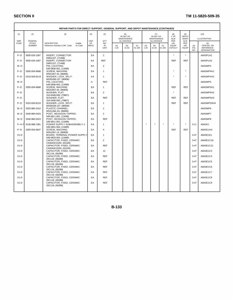
SECTION II TM 11-5820-509-35
REPAIR PARTS FOR DIRECT SUPPORT, GENERAL SUPPORT, AND DEPOT MAINTENANCE (CONTINUED)
(1) (2) (3) (4) (5) (6) (7) (8) (9) (10)30 DAY DS 30 DAY GS 1 YR DEPOT
MAINTENANCE MAINTENANCE ALW MAINT ILLUSTRATIONSMR FEDERAL UNIT QTY ALLOWANCE ALLOWANCE PER ALW
CODE STOCK DESCRIPTION Usable OF INC 100 PER (b)NUMBER Reference Number & Mfr. Code on Code MEAS IN (a) (b) (c) (a) (b) (c) EQUIP 100 (a) ITEM NO. OR
UNIT 1-20 21-50 51-100 1-20 21-50 51-100 CNTGCY EQUIP FIG REFERENCENO. DESIGNATION
P--D 5935-034-1097 INSERT, CONNECTOR: EA 2 * * A8A5P1A1DM51157, (71468)
P--D 5935-034-1097 INSERT, CONNECTOR: EA REF REF REF A8A5P1A2DM51157, (71468)
M--D PIN, LOCATING: EA 2 A8A5MP4549-5836-002, (13499)
P--D 5305-054-6668 SCREW, MACHINE: EA 1 * * A8A5MP4H1MS51957-43, (96906)
P--D 5310-933-8119 WASHER, LOCK, SPLIT: EA 1 * * A8A5MP4H2MS35338-137, (96906)
M--D PIN, LOCATING: A REF A8A5MP5549-5836-002; (13499)
P--D 5305-054-6668 SCREW, MACHINE: EA 1 REF REF A8A5MP5H1MS51957-43, (96906)
P--D WASHER, FLAT: EA 2 * A8A5MP5H2310-0048-000; (79807)
P--D WASHER, FLAT: EA REF REF REF A8A5MP5H3310-0048-000; (79807)
P--D 5310-933-8119 WASHER, LOCK, SPLIT: EA 1 REF REF A8A5MPS5H4MS35338-137, (96906)
M--D 5325-960-2410 PLASTIC CHANNEL: EA 2 A8A5MP6MS21266-1N, (96906)
M--D 5340-984-0423 POST, HEXAGON-TAPPED: EA 2 A8A5MP7549-5811-002, (13499)
M--D 5340-984-0423 POST, HEXAGON-TAPPED: EA REF A8A5MP8549-5811-002, (13499)
P--H-T 6130-088-1381 POWER SUPPLY SUBASSEMBLY-1: EA 1 * * * * * 3-11 A8A5E1549-5831-004; (13499)
P--D 5305-054-5647 SCREW, MACHINE: EA 4 REF REF A8A5E1H4MS51957-13, (96906)
X1-D BOARD, TERMINAL-POWER SUPPLY: EA 1 3-47 A8A5E1E1549-5833-004, (13499)
X1-D CAPACITOR, FIXED, CERAMIC: EA 2 3-47 A8A5E1C18CK60AW102M, (81349)
X1-D CAPACITOR, FIXED, CERAMIC: EA REF 3-47 A8A5E1C21CK60AW102M, (81349)
X1-D CAPACITOR, FIXED, CERAMIC: EA 12 3-47 A8A5E1C320C119, (56289)
X1-D CAPACITOR, FIXED, CERAMIC: EA REF 3-47 A8A5E1C420C119, (56289)
X1-D CAPACITOR, FIXED, CERAMIC: EA REF 3-47 A8A5E1C520C119, (56289)
X1-D CAPACITOR, FIXED, CERAMIC: EA REF 3-47 A8A5E1C620C119, (56289)
X1-D CAPACITOR, FIXED, CERAMIC: EA REF 3-47 A8A5E1C720C119, (56289)
X1-D CAPACITOR, FIXED, CERAMIC: EA REF 3-47 A8A5E1C820C119, (56289)
X1-D CAPACITOR, FIXED, CERAMIC: EA REF 3-47 A8A5E1C920C119, (56289)
B-133

SECTION II TM 11-5820-509-35
REPAIR PARTS FOR DIRECT SUPPORT, GENERAL SUPPORT, AND DEPOT MAINTENANCE (CONTINUED)
(1) (2) (3) (4) (5) (6) (7) (8) (9) (10)30 DAY DS 30 DAY GS 1 YR DEPOT
MAINTENANCE MAINTENANCE ALW MAINT ILLUSTRATIONSMR FEDERAL UNIT QTY ALLOWANCE ALLOWANCE PER ALW
CODE STOCK DESCRIPTION Usable OF INC 100 PER (b)NUMBER Reference Number & Mfr. Code on Code MEAS IN (a) (b) (c) (a) (b) (c) EQUIP 100 (a) ITEM NO. OR
UNIT 1-20 21-50 51-100 1-20 21-50 51-100 CNTGCY EQUIP FIG REFERENCENO. DESIGNATION
X1-D CAPACITOR, FIXED, CERAMIC: EA REF 3-47 A8A5E1C1020C119; (56289)
X1-D CAPACITOR, FIXED, CERAMIC: EA REF 3-47 A8A5E1C1120C119; (56289)
X1-D CAPACITOR, FIXED, CERAMIC: EA REF 3-47 A8A5E1C1220C119; (56289)
X1-D CAPACITOR, FIXED, CERAMIC: EA REF 3-17 A8A5E1C1320C119; (56289)
X1-D CAPACITOR, FIXED, CERAMIC: EA REF 3-47 A8A5E1C1420C119; (56289)
X1-D CAPACITOR, FIXED, CERAMIC: EA 1 3-7T A8A5E1C15DD16-103; (71590)
X1-D SEMICONDUCTOR DEVICE, DIODE: EA 20 3-46 A8A5E1CR61N3641; (07688)
X1-D SEMICONDUCTOR DEVICE, DIODE: EA REF 3-46 A8A5E1CR71N3641, (07688)
X1-D SEMICONDUCTOR DEVICE, DIODE: EA REF 3-46 A8A5E1CR8lN3641; (07688)
X1-D SEMICONDUCTOR DEVICE, DIODE: EA REF 3-6 A8A5E1CR91N3641; (07688)
X1-D SEMICONDUCTOR DEVICE, DIODE: EA REF 3-46 A8A5E1CR101N3641; (07688)
X1-D SEMICONDUCTOR DEVICE, DIODE: EA REF 3-6 A8A5E1CR111N3641; (07688)
X1-D SEMICONDUCTOR DEVICE, DIODE: EA REF 3-46 A8A5E1CR121N3641, (07688)
X1-D SEMICONDUCTOR DEVICE, DIODE: EA REF 3-46 A8A5E1CR131N3641, (07688)
X1-D SEMICONDUCTOR DEVICE, DIODE: EA REF 3-46 A8A5E1CR141N3641; (07688)
X1-D SEMICONDUCTOR DEVICE DIODE: EA REF 3-46 A8A5E1CR151N3641; (07688)
X1-D SEMICONDUCTOR DEVICE, DIODE: EA REF 3-46 ARA5E1CR161N3641, (07688)
X1-D SEMICONDUCTOR DEVICE, DIODE: EA REF 3-46 A8A5E1CR171N3641; (07688)
X1-D CONDUCTOR DEVICE, DIODE: EA REF 3-46 A8A5E1CR181N3641; (07688)
X1-D SEDCONDUCTOR DEVICE, DIODE: EA REF 3-46 A8A5E1CR191N3641, (07688)
X1-D SEMCOIIUCTOR DEVICE, DIODE: EA REF 3-46 A8A5E1CR201N3641, (07688)
X1-D SEMICONDUCTOR DEVICE, DIODE: EA REF 3-46 A8A5E1CR211N3641; (07688)
X1-D SEMICONDUCTOR DEVICE, DIODE: EA REF 3-46 A8A5E1CR221N3641; (07688)
X1-D SEMICONDUCTOR DEVICE, DIODE: EA REF 3-46 A8A5E1CP231N3641, (07688)
X1-D SEMICONDUCTOR DEVICE, DIODE: EA REF 3-46 A8A5E1CR241N3641; (07688)
B-134
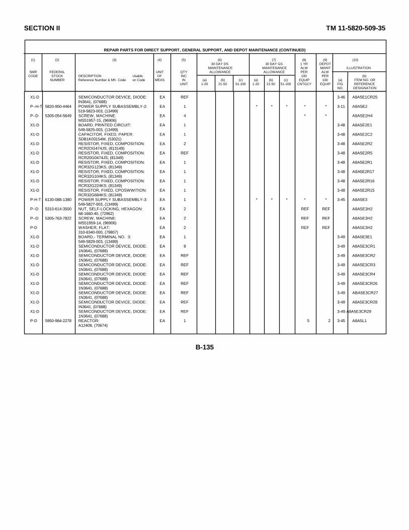
SECTION II TM 11-5820-509-35
REPAIR PARTS FOR DIRECT SUPPORT, GENERAL SUPPORT, AND DEPOT MAINTENANCE (CONTINUED)
(1) (2) (3) (4) (5) (6) (7) (8) (9) (10)30 DAY DS 30 DAY GS 1 YR DEPOT
MAINTENANCE MAINTENANCE ALW MAINT ILLUSTRATIONSMR FEDERAL UNIT QTY ALLOWANCE ALLOWANCE PER ALW
CODE STOCK DESCRIPTION Usable OF INC 100 PER (b)NUMBER Reference Number & Mfr. Code on Code MEAS IN (a) (b) (c) (a) (b) (c) EQUIP 100 (a) ITEM NO. OR
UNIT 1-20 21-50 51-100 1-20 21-50 51-100 CNTGCY EQUIP FIG REFERENCENO. DESIGNATION
X1-D SEMICONDUCTOR DEVICE, DIODE: EA REF 3-46 A8A5E1CR25lN3641, (07688)
P--H-T 5820-950-4464 POWER SUPPLY SUBASSEMBLY-2: EA 1 * * * * * 3-11 A8A5E2519-5823-003, (13499)
P--D 5305-054-5649 SCREW, MACHINE: EA 4 * * A8A5E2H4MS51957-15, (96906)
X1-D BOARD, PRINTED CIRCUIT: EA 1 3-48 A8A5E2E1549-5825-003, (13499)
X1-D CAPACITOR, FIXED, PAPER: EA 1 3-48 A8A5E2C2SDB1K03154M, (53021)
X1-D RESISTOR, FIXED, COMPOSITION: EA 2 3-48 A8A5E2R2RCR2OG474JS; (813149)
X1-D RESISTOR, FIXED, COMPOSITION: EA REF 3-48 A8A5E2R5RCR20G0474JS; (81349)
X1-D RESISTOR, FIXED, COMPOSITION: EA 1 3-48 A8A5E2R1RCR32G123KS, (81349)
X1-D RESISTOR, FIXED, COMPOSITION: EA 1 3-48 A8A5E2R17RCR32G104KS, (81349)
X1-D RESISTOR, FIXED, COMPOSITION: EA 1 3-48 A8A5E2R16RCR32G224KS; (81349)
X1-D RESISTOR, FIXED, CPOSWWITION: EA 1 3-48 A8A5E2R15RCR32G684KS; (81349)
P-H-T 6130-088-1380 POWER SUPPLY SUBASSEMBLY-3: EA 1 * * * * * 3-45 A8A5E3549-5827-003, (13499)
P--D 5310-614-3500 NUT, SELF-LOCKING, HEXAGON: EA 2 REF REF A8A5E3H268-1660-40, (72962)
P--D 5305-763-7822 SCREW, MACHINE: EA 2 REF REF A8A5E3H2MS51959-14, (96906)
P-D WASHER, FLAT: EA 2 REF REF A8A5E3H2310-6340-000, (79807)
X1-D BOARD,- TERMINAL NO. 3: EA 1 3-49 A8A5E3E1549-5829-003, (13499)
X1-D SEMICONDUCTOR DEVICE, DIODE: EA 8 3-49 A8A5E3CR11N3641, (07688)
X1-D SEMICONDUCTOR DEVICE, DIODE: EA REF 3-49 A8A5E3CR21N3641; (07688)
X1-D SEMICONDUCTOR DEVICE, DIODE: EA REF 3-49 A8A5E3CR31N3641, (07688)
X1-D SEMICONDUCTOR DEVICE, DIODE: EA REF 3-49 A8A5E3CR41N3641, (07688)
X1-D SEMICONDUCTOR DEVICE, DIODE: EA REF 3-49 A8A5E3CR261N3641, (07688)
X1-D SEMICONDUCTOR DEVICE, DIODE: EA REF 3-49 ABA5E3CR271N3641, (07688)
X1-D SEMICONDUCTOR DEVICE, DIODE: EA REF 3-49 A8A5E3CR28IN3641, (07688)
X1-D SEMICONDUCTOR DEVICE, DIODE: EA REF 3-49 A8A5E3CR291N3641, (07688)
P-D 5950-984-2278 REACTOR: EA 1 5 2 3-45 A8A5L1A12408, (70674)
B-135
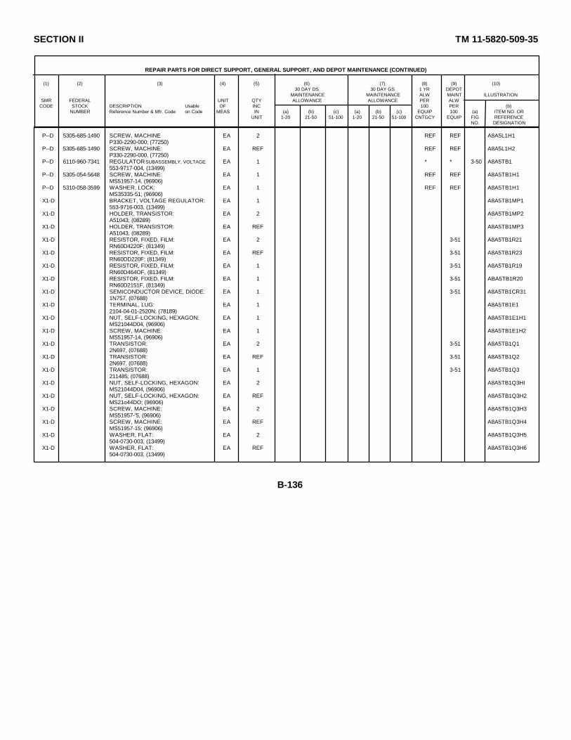
SECTION II TM 11-5820-509-35
REPAIR PARTS FOR DIRECT SUPPORT, GENERAL SUPPORT, AND DEPOT MAINTENANCE (CONTINUED)
(1) (2) (3) (4) (5) (6) (7) (8) (9) (10)30 DAY DS 30 DAY GS 1 YR DEPOT
MAINTENANCE MAINTENANCE ALW MAINT ILLUSTRATIONSMR FEDERAL UNIT QTY ALLOWANCE ALLOWANCE PER ALW
CODE STOCK DESCRIPTION Usable OF INC 100 PER (b)NUMBER Reference Number & Mfr. Code on Code MEAS IN (a) (b) (c) (a) (b) (c) EQUIP 100 (a) ITEM NO. OR
UNIT 1-20 21-50 51-100 1-20 21-50 51-100 CNTGCY EQUIP FIG REFERENCENO. DESIGNATION
P--D 5305-685-1490 SCREW, MACHINE EA 2 REF REF A8A5L1H1P330-2290-000; (77250)
P--D 5305-685-1490 SCREW, MACHINE: EA REF REF REF A8A5L1H2P330-2290-000, (77250)
P--D 6110-960-7341 REGULATOR SUBASSEMBLY, VOLTAGE: EA 1 * * 3-50 A8A5TB1553-9717-004, (13499)
P--D 5305-054-5648 SCREW, MACHINE: EA 1 REF REF A8A5TB1H1MS51957-14, (96906)
P--D 5310-058-3599 WASHER, LOCK: EA 1 REF REF A8A5TB1H1MS35335-51; (96906)
X1-D BRACKET, VOLTAGE REGULATOR: EA 1 A8A5TB1MP1553-9716-003, (13499)
X1-D HOLDER, TRANSISTOR: EA 2 A8A5TB1MP2A51043; (08289)
X1-D HOLDER, TRANSISTOR: EA REF A8A5TB1MP3A51043, (08289)
X1-D RESISTOR, FIXED, FILM: EA 2 3-51 A8A5TB1R21RN60D4220F; (81349)
X1-D RESISTOR, FIXED, FILM: EA REF 3-51 A8A5TB1R23RN60DD220F; (81349)
X1-D RESISTOR, FIXED, FILM: EA 1 3-51 A8A5TB1R19RN60D464OF, (81349)
X1-D RESISTOR, FIXED, FILM: EA 1 3-51 ABA5TB1R20RN60D2151F, (81349)
X1-D SEMICONDUCTOR DEVICE, DIODE: EA 1 3-51 A8A5TB1CR311N757, (07688)
X1-D TERMINAL, LUG: EA 1 A8A5TB1E12104-04-01-2520N; (78189)
X1-D NUT, SELF-LOCKING, HEXAGON: EA 1 A8A5TB1E1H1MS21044D04, (96906)
X1-D SCREW, MACHINE: EA 1 A8A5TB1E1H2MS51957-14, (96906)
X1-D TRANSISTOR: EA 2 3-51 A8A5TB1Q12N697, (07688)
X1-D TRANSISTOR: EA REF 3-51 A8A5TB1Q22N697, (07688)
X1-D TRANSISTOR: EA 1 3-51 A8A5TB1Q3211485; (07688)
X1-D NUT, SELF-LOCKING, HEXAGON: EA 2 A8A5TB1Q3HIMS21044D04, (96906)
X1-D NUT, SELF-LOCKING, HEXAGON: EA REF A8A5TB1Q3H2MS21o44DO; (96906)
X1-D SCREW, MACHINE: EA 2 A8A5TB1Q3H3MS51957-'5, (96906)
X1-D SCREW, MACHINE: EA REF A8A5TB1Q3H4MS51957-15; (96906)
X1-D WASHER, FLAT: EA 2 A8A5TB1Q3H5504-0730-003, (13499)
X1-D WASHER, FLAT: EA REF A8A5TB1Q3H6504-0730-003, (13499)
B-136

SECTION II TM 11-5820-509-35
REPAIR PARTS FOR DIRECT SUPPORT, GENERAL SUPPORT, AND DEPOT MAINTENANCE (CONTINUED)
(1) (2) (3) (4) (5) (6) (7) (8) (9) (10)30 DAY DS 30 DAY GS 1 YR DEPOT
MAINTENANCE MAINTENANCE ALW MAINT ILLUSTRATIONSMR FEDERAL UNIT QTY ALLOWANCE ALLOWANCE PER ALW
CODE STOCK DESCRIPTION Usable OF INC 100 PER (b)NUMBER Reference Number & Mfr. Code on Code MEAS IN (a) (b) (c) (a) (b) (c) EQUIP 100 (a) ITEM NO. OR
UNIT 1-20 21-50 51-100 1-20 21-50 51-100 CNTGCY EQUIP FIG REFERENCENO. DESIGNATION
X1-D WASHER, NONMETALLIC: EA 2 A8A5TB1Q3H7302-0024-00C, (05284)
X1-D WASHER, NONMETALLIC: EA REF A8A5TB1Q3H8302-0024-000; (05284)
P--D 5945-984-1796 RELAY, ARMATURE: EA 1 * * 3-50 A8A5K145-4594, (04221)
P--D 5305-777-6039 SCREW, MACHINE: EA 2 REF REF A8A5K1H1MS51959-12, (96906)
P--D 5305-777-6039 SCREW, MACHINE: EA REF REF REF A8A6K1H2MS51959-12, (96906)
P--D 5905-900-0431 RESISTOR, FIXED, COMPOSITION: EA 1 * * 3-45 A8A5R14RCR20G473KS, (81349)
P--D 5905-221-5860 RESISTOR, FIXED, COMPOSITION: EA 1 * 3-45 A8A5R12RCR200334KS, (81349)
P--D 5905-279-1979 RESISTOR, FIXED, COMPOSITION: EA 1 * * 3-45 A8A5R9RC42GF101K, (81349)
P--D RESISTOR, FIXED, COMPOSITION: EA 1 * * 3-45 A8A5R10RC42GF104K, (81349)
P--D RESISTOR, FIXED, COMPOSITION: EA 2 * * 3-45 A8A5R6RC42GF105K; (81349)
P--D RESISTOR, FIXED, COMPOSITION: EA REF REF REF 3-45 A8A5R7RC42GF105K, (81349)
P--D 5905-982-3329 RESISTOR, FIXED, WIRE WOUND: EA 1 * * 3-45 A8A5R24RW69V221, (81349)
P--D 5905-088-0635 RESISTOR, FIXED, WIRE WOUND: EA 1 * * 3-45 A8A5R11RW69V471, (81349)
P--D 5905-819-1340 RESISTOR, VARIABLE, WIRE WOUND: EA 1 * * 3-11 A8A5R22224L1-201, (80294)
P--D SCREW, MACHINE: EA 1 REF REF A8A5R22H1330-2352-000, (70601)
P--D 5305-054-5638 SCREW, MACHINE: EA 1 REF REF A8A5R22H2MS51957-4, (96906)
P--D 5310-275-9230 WASHER, FLAT: EA 1 REF REF A8A5R22H3310-0044-000, (79807)
P--D 5310-551-9286 WASHER, NONMETALLIC: EA 1 * * A8A5R22H4302-0023-000, (05284)
P--D RESISTOR, VARIABLE, WIRE WOUND: EA 1 * * 3-11 A8A5R3224L1-503, (80294)
P--D SCREW, MACHINE: EA 1 REF REF A8A5R3K1330-2352-000, (70601)
P--D 5305-054-5638 SCREW, MACHINE: EA 1 REF REF A8A5R3H2MS51957-4, (96906)
P--D 5310-275-9230 WASHER, FLAT: EA 1 REF REF A8A5R3H3310-0044-000, (79807)
P--D 5310-551-9286 WASHER, NONMETALLIC: EA 1 REF REF A8A5R3H4302-0023-000, (05284)
P--D 5905-682-1379 RESISTOR, VARIABLE, WIRE WOUND: EA 1 * * 3-11 A8A5R4224L2-104, (80294)
P--D SCREW, MACHINE: EA 1 REF REF A8A544H1330-2352-000; (70601)
B-137

SECTION II TM 11-5820-509-35
REPAIR PARTS FOR DIRECT SUPPORT, GENERAL SUPPORT, AND DEPOT MAINTENANCE (CONTINUED)
(1) (2) (3) (4) (5) (6) (7) (8) (9) (10)30 DAY DS 30 DAY GS 1 YR DEPOT
MAINTENANCE MAINTENANCE ALW MAINT ILLUSTRATIONSMR FEDERAL UNIT QTY ALLOWANCE ALLOWANCE PER ALW
CODE STOCK DESCRIPTION Usable OF INC 100 PER (b)NUMBER Reference Number & Mfr. Code on Code MEAS IN (a) (b) (c) (a) (b) (c) EQUIP 100 (a) ITEM NO. OR
UNIT 1-20 21-50 51-100 1-20 21-50 51-100 CNTGCY EQUIP FIG REFERENCENO. DESIGNATION
P--D 5305-054-5638 SCREW, MACHINE: EA 1 REF REF A8A5R4H2MS51957-4; (96906)
P--D 5310-275-9230 WASHER, FLAT: EA 1 REF REF A8A5R4H3310-0044-000, (79807)
P--D 5310-551-9286 WASHER, NONMETALLIC: EA 1 REF REF A8A5R4H4302-0023-000, (05284)
P--D 5910-986-7754 RETAINER, CAPACITOR: EA 1 * * A8A5MP9549-5813-003, (13499)
P--D 5305-054-6652 SCREW, MACHINE: EA 1 * * A8A5MP9H1MS51957-28; (96906)
P--D 5310-531-9514 WASHER, FLAT: EA 1 REF REF A8A5MP9H2310-6360-000, (79807)
P--D 5935-840-5485 SOCKET, ELECTRON TUBE: EA 2 * * 3-45 A8A5XC1988-8TM, (02660)
P--D 5310-614-3500 NUT, SELF-LOCKING, HEXAGON: EA 2 REF REF A8A5XC19H168-1660-40, (72962)
P--D 5310-611-3500 NUT, SELF-LOCKING, HEXAGON: EA REF REF REF A8A5XC19H268-1660-40; (72962)
P--D 5305-685-1490 SCREW, MACHINE: EA 2 REF REF A8A5XC19H3P330-2290-000; (77250)
P--D 5305-685-1490 SCREW, MACHINE: E/ REF REF REF ABA5XC19H4P330-2290-000, (77250)
P--D 5935-840-5485 SOCKET, ELECTRON TUBE: EA REF REF REF 3-45 A8A5XC2088-8TM; (02660)
P--D 5310-614-3500 NUT, SELF-LOCKIING, HEXAGON: EA 1 REF REF A8A5XC20H168-1660-10; (72962)
P--D 5305-685-1490 SCREW, MACHINE: EA 2 REF REF A8A5XC20H2P330-2290-000; (77250)
P--D 5305-685-1490 SCREW, MACHINE: EA REF REF REF-' A8ASXC20H3P330-2290-000, (77250)
P--D 5310-058-3599 WASHER, LOCK: EA 1 REF REF A8ASXC20H4MS35335-51; (96906)
P--D 5340-975-7637 TERMINAL, GROUND: EA 1 REF REF A8A5E4549-5709-002; (13499)
P--D 5305-685-1490 SCREW, MACHINE: EA 1 REF REF A8A5E4H1P330-2290-000; (77250)
P--D WASHER, LOCK: EA 1 REF REF A8A5E14H2MS35338-135; (96906)
P--D TERMINAL, LUG: EA 1 REF REF A8A5E54040-2HT; (77147)
P--D 5310-938-20 13 NUT, PLAIN, HEXAGON: EA 1 * * A8A5E5H1MS35649-224; (96906)
P--D SCREW, MACHINE: EA 1 * * A8A5E5H2P330-2285-000; (77250)
P--D 5310-928-2690 WASHER, LOCK: EA 1 REF REF A8A5E5H3MS35338-134; (96906)
P--D TERMINAL, LUG: EA 1 REF REF A8A5E62104-04-01-2520N; (78189)
P--D 5310-275-0889 NUT, PLAIN, HEXAGON: EA 1 REF REF A8A5E6H1P313-0132-000; (77250)
B-138
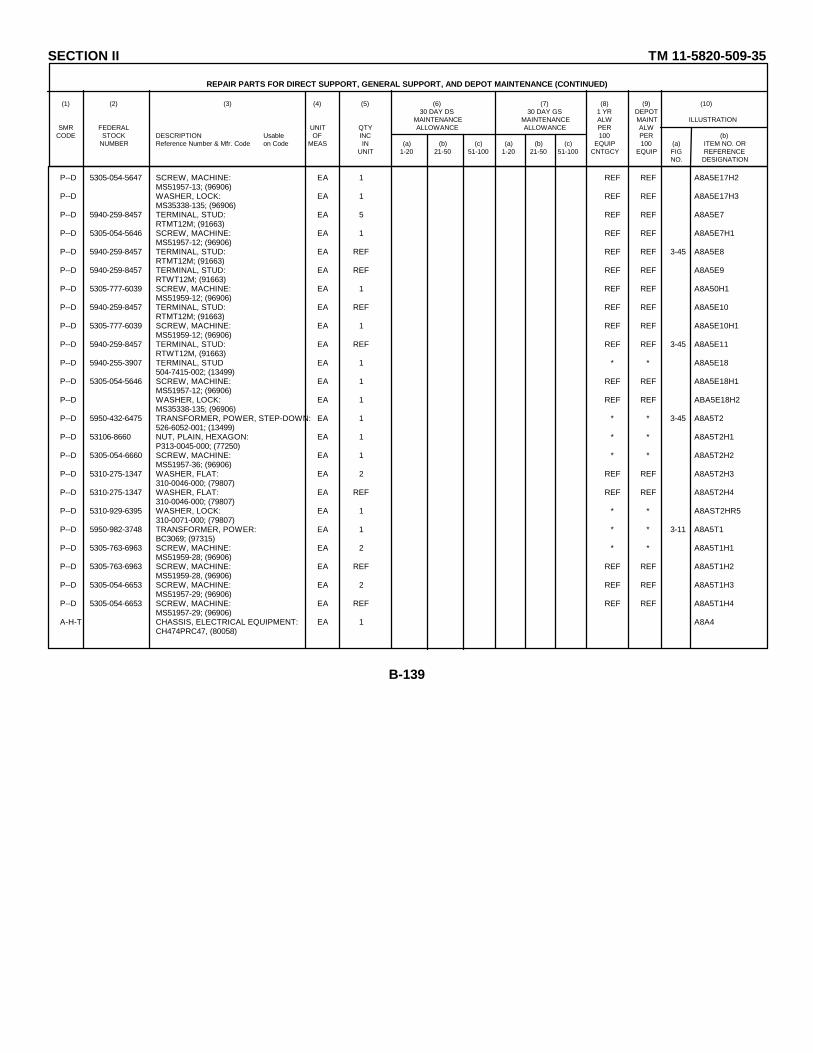
SECTION II TM 11-5820-509-35
REPAIR PARTS FOR DIRECT SUPPORT, GENERAL SUPPORT, AND DEPOT MAINTENANCE (CONTINUED)
(1) (2) (3) (4) (5) (6) (7) (8) (9) (10)30 DAY DS 30 DAY GS 1 YR DEPOT
MAINTENANCE MAINTENANCE ALW MAINT ILLUSTRATIONSMR FEDERAL UNIT QTY ALLOWANCE ALLOWANCE PER ALW
CODE STOCK DESCRIPTION Usable OF INC 100 PER (b)NUMBER Reference Number & Mfr. Code on Code MEAS IN (a) (b) (c) (a) (b) (c) EQUIP 100 (a) ITEM NO. OR
UNIT 1-20 21-50 51-100 1-20 21-50 51-100 CNTGCY EQUIP FIG REFERENCENO. DESIGNATION
P--D 5305-054-5647 SCREW, MACHINE: EA 1 REF REF A8A5E17H2MS51957-13; (96906)
P--D WASHER, LOCK: EA 1 REF REF A8A5E17H3MS35338-135; (96906)
P--D 5940-259-8457 TERMINAL, STUD: EA 5 REF REF A8A5E7RTMT12M; (91663)
P--D 5305-054-5646 SCREW, MACHINE: EA 1 REF REF A8A5E7H1MS51957-12; (96906)
P--D 5940-259-8457 TERMINAL, STUD: EA REF REF REF 3-45 A8A5E8RTMT12M; (91663)
P--D 5940-259-8457 TERMINAL, STUD: EA REF REF REF A8A5E9RTWT12M; (91663)
P--D 5305-777-6039 SCREW, MACHINE: EA 1 REF REF A8A50H1MS51959-12; (96906)
P--D 5940-259-8457 TERMINAL, STUD: EA REF REF REF A8A5E10RTMT12M; (91663)
P--D 5305-777-6039 SCREW, MACHINE: EA 1 REF REF A8A5E10H1MS51959-12; (96906)
P--D 5940-259-8457 TERMINAL, STUD: EA REF REF REF 3-45 A8A5E11RTWT12M, (91663)
P--D 5940-255-3907 TERMINAL, STUD EA 1 * * A8A5E18504-7415-002; (13499)
P--D 5305-054-5646 SCREW, MACHINE: EA 1 REF REF A8A5E18H1MS51957-12; (96906)
P--D WASHER, LOCK: EA 1 REF REF ABA5E18H2MS35338-135; (96906)
P--D 5950-432-6475 TRANSFORMER, POWER, STEP-DOWN: EA 1 * * 3-45 A8A5T2526-6052-001; (13499)
P--D 53106-8660 NUT, PLAIN, HEXAGON: EA 1 * * A8A5T2H1P313-0045-000; (77250)
P--D 5305-054-6660 SCREW, MACHINE: EA 1 * * A8A5T2H2MS51957-36; (96906)
P--D 5310-275-1347 WASHER, FLAT: EA 2 REF REF A8A5T2H3310-0046-000; (79807)
P--D 5310-275-1347 WASHER, FLAT: EA REF REF REF A8A5T2H4310-0046-000; (79807)
P--D 5310-929-6395 WASHER, LOCK: EA 1 * * A8AST2HR5310-0071-000; (79807)
P--D 5950-982-3748 TRANSFORMER, POWER: EA 1 * * 3-11 A8A5T1BC3069; (97315)
P--D 5305-763-6963 SCREW, MACHINE: EA 2 * * A8A5T1H1MS51959-28; (96906)
P--D 5305-763-6963 SCREW, MACHINE: EA REF REF REF A8A5T1H2MS51959-28, (96906)
P--D 5305-054-6653 SCREW, MACHINE: EA 2 REF REF A8A5T1H3MS51957-29; (96906)
P--D 5305-054-6653 SCREW, MACHINE: EA REF REF REF A8A5T1H4MS51957-29; (96906)
A-H-T CHASSIS, ELECTRICAL EQUIPMENT: EA 1 A8A4CH474PRC47, (80058)
B-139
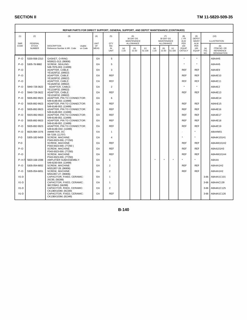
SECTION II TM 11-5820-509-35
REPAIR PARTS FOR DIRECT SUPPORT, GENERAL SUPPORT, AND DEPOT MAINTENANCE (CONTINUED)
(1) (2) (3) (4) (5) (6) (7) (8) (9) (10)30 DAY DS 30 DAY GS 1 YR DEPOT
MAINTENANCE MAINTENANCE ALW MAINT ILLUSTRATIONSMR FEDERAL UNIT QTY ALLOWANCE ALLOWANCE PER ALW
CODE STOCK DESCRIPTION Usable OF INC 100 PER (b)NUMBER Reference Number & Mfr. Code on Code MEAS IN (a) (b) (c) (a) (b) (c) EQUIP 100 (a) ITEM NO. OR
UNIT 1-20 21-50 51-100 1-20 21-50 51-100 CNTGCY EQUIP FIG REFERENCENO. DESIGNATION
P--D 5330-558-2310 GASKET, O-RING: EA 5 * * A8A4H5MS9021-013; (96906)
P--D 5305-78-9882 SCREW, SEALING: EA 5 * * A8A4H5548-7976-003; (13499)
P--D ADAPTER, CABLE: EA 3 REF REF A8A4E9YE1620F32, (09922)
P--D ADAPTER, CABLE: EA REF REF REF A8A4E10YE1620F32; (09922)
P--D ADAPTER, CABLE: EA REF REF REF A8A4E11YE1620F32; (09922)
P--D 5940-728-3622 ADAPTER, CABLE: EA 2 * * A8A4E2YE1216F32; (09922)
P--D 5940-728-3622 ADAPTER, CABLE: EA REF REF REF A8A4E13YE1216F32; (09922)
P--D 5935-892-9923 ADAPTER, PIN TO CONNECTOR: EA 6 A8A4E14549-6148-002; (13499)
P--D 5935-892-9923 ADAPTER, PIN TO CONNECTOR: EA REF REF REF A8AhE15549-6148-002; (13499)
P--D 5935-892-9923 ADAPTER, PIN TO CONNECTOR: EA REF REF REF A8A4E16549-6148-002; (13499)
P--D 5935-892-9923 ADAPTER, PIN TO CONNECTOR: EA REF REF REF A8A4E17549-6148-002, (13499)
P--D 5935-892-9923 ADAPTER, PIN TO CONNECTOR: EA REF REF REF A8A4E18549-6148-002, (13499)
P--D 5935-892-9923 ADAPTER, PIN TO CONNECTOR: EA REF REF REF A8A4E19549-6148-O02; (13499)
P--D 6625-984-1076 AMMETER, DC: EA 1 · * ABA4M0159-7159; (11707)
P-D 5305-182-9459 SCREW, MACHINE: EA 4 * * A8A4K101H1P343-0023-000, (77250)
P-D SCREW, MACHINE: EA REF REF REF A8A4M101H2P343-0023-000; (77250 )
P--D SCREW, MACHINE: EA REF REF REF A8A4101H3P343-0023-000; (77250)
P--D SCREW, MACHINE: EA REF REF REF A8A4M101H4P343-0023-000, (77250)
P--H-T 5820-168-1598 AMPLIFIER SUBASSEMBLY: EA 1 * * * * * A8A4A549-6230-004; (13499)
P--D 5305-054-6652 SCREW, MACHINE: EA 2 REF REF A8A4A1H2MS51957-28; (96906)
P--D 5305-054-6651 SCREW, MACHINE: EA 2 REF REF A8A4A1H2MS51957-27; (96906)
X1-D CAPACITOR, FIXED, CERAMIC: EA 1 3-66 A8A4A1C10120C95; (56289)
X1-D CAPACITOR, FIXED, CERAMIC: EA 1 3-66 A8A4AC13936C228A3; (56289)
X1-D CAPACITOR, FIXED, CERAMIC: EA 2 3-66 A8A4A1C125CK13BX103M; (81349)
X1-D CAPACITOR, FIXED, CERAMIC: EA REF 3-66 A8A4A1C126CK13BX103M; (81349)
B-140

SECTION II TM 11-5820-509-35
REPAIR PARTS FOR DIRECT SUPPORT, GENERAL SUPPORT, AND DEPOT MAINTENANCE (CONTINUED)
(1) (2) (3) (4) (5) (6) (7) (8) (9) (10)30 DAY DS 30 DAY GS 1 YR DEPOT
MAINTENANCE MAINTENANCE ALW MAINT ILLUSTRATIONSMR FEDERAL UNIT QTY ALLOWANCE ALLOWANCE PER ALW
CODE STOCK DESCRIPTION Usable OF INC 100 PER (b)NUMBER Reference Number & Mfr. Code on Code MEAS IN (a) (b) (c) (a) (b) (c) EQUIP 100 (a) ITEM NO. OR
UNIT 1-20 21-50 51-100 1-20 21-50 51-100 CNTGCY EQUIP FIG REFERENCENO. DESIGNATION
X1-D CAPACITOR, FIXED, CERAMIC: EA 1 3-66 A8A4A1C141HTS127-2000Z; (00656)
X1-D CAPACITOR, FIXED, CERAMIC: EA 2 3-66 A8A4A1C1036S8084; (56289)
X1-D CAPACITOR, FIXED, CERAMIC: EA REF 3-66 A8A4A1C1046S8084, (56289)
X1-D CAPACITOR, FIXED, CERAMC: EA 1 3-66 A8A4A1C140CM05ED680J03; (81349)
X1-D CHASSIS, ELECTRICAL EQUIPMENT: EA 1 A8A4A1A1549-6219-003; (13499)
X1-D SCREW, MACHINE: EA 2 A8A4A1A1H2P343-0172-00; (77250)
X1-D WASHER, FLAT: EA 1 A8A4A1A1H1310-0046-000; (79807)
X1-D WASHER, NONMETALLIC: EA 4 A8A4A1A1H4302-0026-000; (05284)
X1-D JACK, TIP: EA 1 3-66 A8A4A1A1J172-14O-1; (12615)
X1-D JACK, TIP: EA 1 366 A8A4A1A1J272-140-2; (12615)
X1-D JACK, TIP: EA 1 366 A8A4A1A1J372-140-3, (12615)
X1-D JACK, TIP: EA 1 3-66 A8A4A1A1J472-140-4; (12615)
XL-D JACK, TIP: EA 1 3-66 A8A4A1A1J572-140-5, (12615)
X1-D CHASSIS, ELECTRICAL EQUIPMENT: EA 1 A8A4A1MP1549-6221-003; (13499)
X1-D SCREW, MACHINE: EA 2 A8A4hAMP1H1P343-0172-00, (77250)
X1-D SCREW, MACHINE: EA REF A8A4A1MP1H2P343-0172-00; (77250)
X1-D WASHER, FLAT: EA 2 A8A4A1MP1H3310-0046-000: (79807)
X1-D WASHER, FLAT: EA REF A8A4A1MP1H4310-0046-000; (79807)
X1-D WASHER, NONMETALLIC: EA 4 A8A4A1MP1H5302-0026-000, (052814)
X1-D WASHER, NONMETALLIC: EA REF A8A4A1MP1lH6302-0026-000, (05284)
X1-D WASHER, NONMETALLIC: EA REF A8A4A1MP1H7302-0026-000, (05284 )
X1-D WASHER, NONMETALLIC: EA REF A8A4A1MP1H8302-0026-000; (05284)
X1-D COIL, RADIO FREQUENCY: FA 2 3-66 A8A4A1L120MS16221-1, (96906)
X1-D COIL, RADIO FREQUENCY: EA REF 3-66 A8A4A1L121MS16221-1; (96906)
X1-D COIL, RADIO FREQUENCY: EA 1 3-66 A8A4AL102LT10K043; (81349)
B-141

SECTION II TM 11-5820-509-35
REPAIR PARTS FOR DIRECT SUPPORT, GENERAL SUPPORT, AND DEPOT MAINTENANCE (CONTINUED)
(1) (2) (3) (4) (5) (6) (7) (8) (9) (10)30 DAY DS 30 DAY GS 1 YR DEPOT
MAINTENANCE MAINTENANCE ALW MAINT ILLUSTRATIONSMR FEDERAL UNIT QTY ALLOWANCE ALLOWANCE PER ALW
CODE STOCK DESCRIPTION Usable OF INC 100 PER (b)NUMBER Reference Number & Mfr. Code on Code MEAS IN (a) (b) (c) (a) (b) (c) EQUIP 100 (a) ITEM NO. OR
UNIT 1-20 21-50 51-100 1-20 21-50 51-100 CNTGCY EQUIP FIG REFERENCENO. DESIGNATION
X1-D COIL, RADIO FREQUENCY: EA 1 3-66 A8A4A1L103LT10K053, (81349)
X1-D RESISTOR, FIXED, COMPOSITION: EA 2 3-66 A8A4A1R102RCR20C103KS, (81349)
X1-D RESISTOR, FIXED, COMPOSITION: EA REF 3-66 ABA4A1R103RCR20CG103KS; (81349)
X1-D RESISTOR, FIXED, COMPOSITION: EA 1 3-66 A8A4A1R119RCR2OG273KS, ( 81349)
X1-D RESISTOR, FIXED, COMPOSITION: EA 1 3-66 A8A4A1R116RCR32G222KS, (81349)
X1-D RESISTOR, FIXED, COMPOSITION: EA 1 3-66 A8A4AR104RCR32G473KS, (81349)
X1-D RESISTOR, FIXED, CO4POSITION: EA 1 3-66 A8A4AlR115RCR32G125KS; (81349)
X1-D RESISTOR, FIXED, COMPOSITION: EA 1 3-66 A8A4AlR1O8RC42GF101K, (81349)
X1-D SEMICONDUCTOR DEVICE, DIODE: EA 1 3-66 AA4A1CR101JAN1N663, (81350)
X1-D SOCKET, ELECTRON TUBE: EA 1 A8A4A1XV101122-248-202, (74970)
X1-D TERMINAL, LUG: EA 1 A8A4A1E1614B, (57714 )
P--D 5905-251-6530 ATTENUATOR, VARIABLE: EA 1 * * A8A4R1128156, (01121)
P--D 5975-987-8829 BOOT, DUST AND MOISTURE SEAL: EA 1 * * A8A4R11R1N9033-1-4, (97539)
P--D 6250-984-1092 BASE, LAMPHOLDER: EA 1 * * A8A4A2549-6141-002, (13499)
P--D 5305-616-2568 SCREW, MACHINE: EA 2 REF REF A8A4A2H2P34 3-0285-000, (77250)
P--D WASHER, LOCK: EA 2 * * A8A4A2H21804-00, (78189)
X1-D BUSHING, SLEEVE: EA 2 A8A4A24Pl549-6139-002; (13499)
X1-D BUSHING, SLEEVE: EA REF A8A4A2MP2549-6139-002, (13499)
X1-D PLATE, MOUNTING, LAMPHOLDER: EA 1 A8A4A24P3549-6140-002, (13499)
P--D 3120-709-5460 BEARING, SLEEVE: EA 6 * * A8A4P16L2FF; (96881)
P--D 3120-709-5460 BEARING, SLEEVE: EA REF REF REF A8A4MP26L2FF, (96881)
P--D 3120-709-5460 BEARING, SLEEVE: EA REF REF REF A8A4MP36L2FF; (96881)
P--D 3120-709-5460 BEARING, SLEEVE: EA REF REF REF A8A4MP46L2FF, (96881)
P--D 3120-709-5460 BEARING, SLEEVE: EA REF REF REF A8A4MP56L2FF; (96881)
P--D 3120-709-5460 BEARING, SLEEVE: EA REF REF REF AF8A4P66L2FF, (96881)
B-142

SECTION II TM 11-5820-509-35
REPAIR PARTS FOR DIRECT SUPPORT, GENERAL SUPPORT, AND DEPOT MAINTENANCE (CONTINUED)
(1) (2) (3) (4) (5) (6) (7) (8) (9) (10)30 DAY DS 30 DAY GS 1 YR DEPOT
MAINTENANCE MAINTENANCE ALW MAINT ILLUSTRATIONSMR FEDERAL UNIT QTY ALLOWANCE ALLOWANCE PER ALW
CODE STOCK DESCRIPTION Usable OF INC 100 PER (b)NUMBER Reference Number & Mfr. Code on Code MEAS IN (a) (b) (c) (a) (b) (c) EQUIP 100 (a) ITEM NO. OR
UNIT 1-20 21-50 51-100 1-20 21-50 51-100 CNTGCY EQUIP FIG REFERENCENO. DESIGNATION
P--D 3120-793-6354 BEARING, SLEEVE: EA 2 * * A8A4P78L2FF, (96881)
P--D 3120-793-6354 BEARING, SLEEVE: EA REF REF REF A8A4MP88L2FF, (96881)
P--D 6740-618-6314 BEARING, SLEEVE: EA 1 * * A8A4MP94L4F; (96881)
M--D BLOCK, MOUNTING-REAR: EA 2 A8A4MP10549-6167-002; (13499)
P--D 5305-937-2556 SCREW, MACHINE: EA 2 * * A8A4MP10H1P330-2296-000; (77250)
P--D 5305-937-2566 SCREW, MACHINE: EA REF REF REF A8A4MP10H2P330-2296-000, (77250)
M--D BLOCK, MOUNTING-REAR: EA REF A8A4MP11549-6167-002; (13499)
P--D 5305-937-2566 SCREW, MACHINE: EA 2 REF REF A8A4MP11H1P330-2296-000; (77250)
P--D 5305-937-2566 SCREW, MACHINE: EA REF REF REF A8A4MP11H2P330-2296-000, (77250)
P--D BOARD ASSEMBLY, COMPONENT,NO.1: EA 1 * * 3-67 A8A4TB1549-6391-003; (13499)
P--D 5305-054-5649 SCREW, MACHINE: EA 2 REF REF A8A4TB1H2MS51957-15, (96906)
P--D WASHER, LOCK, SPRING: EA 2 REF REF A8A4TB1H2MS35338-135, (96906)
X1-D BOARD, TERMINAL, NO. 1-FLARED: EA 1 A8A4TB1E1549-6390-003, (13499)
X1-D RESISTORS, FIXED, WIRE WOUND: EA 2 A8A4TB1R1RW69V6R8; (81349)
X1-D RESISTOR, FIXED, WIRE WOUND: EA REF A8A4TB1R2RW69V6R8; (81349,
X1-D RESISTOR, FIXED, WIRE WOUND: EA 2 A8A4TB1R3RW67V471; (81349)
X1-D RESISTOR, FIXED, WIRE WOUND: EA REF A8A4TB1R4RW67V471; (81349)
P--H-T 5820-984-7544 BOARD ASSEMBLY,COMPONENT,NO.6: EA 1 * * * * * 3-67 A8A4TB6549-6395-003; (13499)
X1-D BOARD, TERMINAL, NO. 6: EA 1 A8A4TB6E1549-6394-003; (13499)
X1-D SCREW, MACHINE: EA 2 A8A4TB6H2MS51957-15; (96906)
X1-D WASHER, FLAT: EA 2 A8A4TB6H2310-6325-000, (79807)
X1- D WASHER, LOCK, SPRING: EA 2 A8A4TB6H2MS35338-135; (96906)
X1-D CAPACITOR, FIXED, ELECTROLYTIC: EA 1 A8A4TB6C1610D105M200BD5, (56289)
X1-D RESISTOR, FIXED, COMPOSITION: EA 1 A8A4TB6R5RC42GF562K; (81349)
X1-D RESISTOR, FIXED, FILM: EA 1 A8A4TB6R23RN60D6813F; (81349)
B-143
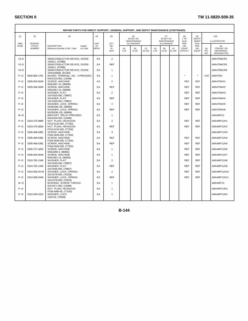
SECTION II TM 11-5820-509-35
REPAIR PARTS FOR DIRECT SUPPORT, GENERAL SUPPORT, AND DEPOT MAINTENANCE (CONTINUED)
(1) (2) (3) (4) (5) (6) (7) (8) (9) (10)30 DAY DS 30 DAY GS 1 YR DEPOT
MAINTENANCE MAINTENANCE ALW MAINT ILLUSTRATIONSMR FEDERAL UNIT QTY ALLOWANCE ALLOWANCE PER ALW
CODE STOCK DESCRIPTION Usable OF INC 100 PER (b)NUMBER Reference Number & Mfr. Code on Code MEAS IN (a) (b) (c) (a) (b) (c) EQUIP 100 (a) ITEM NO. OR
UNIT 1-20 21-50 51-100 1-20 21-50 51-100 CNTGCY EQUIP FIG REFERENCENO. DESIGNATION
X1-D SEMICONDUCTOR DEVICE, DIODE: EA 2 A8A4TB6CR11N2611, (07688)
X1-D SEMICONDUCTOR DEVICE, DIODE: EA REF A8A4TB6CR21N2611, (07688)
X1-D SEMICONDUCTOR DEVICE, DIODE: EA 1 A8A4TB6CR8JAN1N485B, (81350)
P--D 5940-984-1791 BOARD, TERMINAL, NO. 4-PRESSED: EA 1 * * 3-67 A8A4TB4549-6210-003, (13499)
P--D 5305-054-5649 SCREW, MACHINE: EA 2 REF REF A8A4TB4H1MS51957-15; (96906)
P--D 5305-05b-5649 SCREW, MACHINE: EA REF REF REF A8A4TB4H2MS51957-15, (96906)
P--D WASHER, FLAT: EA 2 REF REF A8A4TB4H3310-6325-000, (79807)
P--D WASHER, FLAT: EA REF REF REF A8A4TB4H4310-6325-000, (79807)
P--D WASHER, LOCK, SPRING: EA 2 REF REF A8A4TB4H5MS35338-135, (96906)
P--D WASHER, LOCK, SPRING: EA REF REF REF A8A4TB4H6MS35338-135, (96906)
M--D BRACKET, RELAY-PRESSED: EA 1 A8A4MP12549-6234-003, (13499)
P--D 5310-275-0889 NUT, PLAIN, HEXAGON: EA 2 REF REF A8A4MP12H1P313-0132-000, (77250)
P--D 5310-275-3839 NUT, PLAIN, HEXAGON: EA REF REF REF A8A4MP12H2P313-0132-000, (77250)
P--D 5305-469-5382 SCREW, MACHINE: EA 3 A8A4MP12H3P342-0026-000, (77250)
P--D 5305-469-5382 SCREW, MACHINE: EA REF REF REF A8A4MP12H4P342-0026-000, (77250)
P--D 5305-469-5382 SCREW, MACHINE: EA REF REF REF A8A4MP12H5P342-0026-000, (77250)
P--D 5305-727-o833 SCREW, MACHINE: EA 1 REF REF A8A4MP12H6MS51959-3, (96906)
P--D 5305-054-5648 SCREW, MACHINE: EA 1 REF REF A8A4MP12H7MS51957-14, (96906)
P--D 5310-782-1349 WASHER, FLAT: EA 2 REF REF A8A4MP12H8310-0045-000, (79807)
P--D 5310-782-1349 WASHER, FLAT: EA REF REF REF A8A4MP12H9310-0045-000, (79807)
P--D 5310-058-29 49 WASHER, LOCK, SPRING: EA 2 REF REF A8A4MP12H10310-0278-000, (70318)
P--D 5310-058-2949 WASHER, LOCK, SPRING: EA REF REF REF A8A4MP12H11310-0278-000, (70318)
M--D BUSHING, SCREW THREAD: EA 1 A8A4MP13553-9271-003, (13499)
P--D NUT, PLAIN, HEXAGON: EA 1 ABA4MP13H1P334-4060-00, (77250)
P--D 5310-209-1522 WASHER, LOCK EA 1 A8A4MP13H21220-02, (78189)
B-144

SECTION II TM 11-5820-509-35
REPAIR PARTS FOR DIRECT SUPPORT, GENERAL SUPPORT, AND DEPOT MAINTENANCE (CONTINUED)
(1) (2) (3) (4) (5) (6) (7) (8) (9) (10)30 DAY DS 30 DAY GS 1 YR DEPOT
MAINTENANCE MAINTENANCE ALW MAINT ILLUSTRATIONSMR FEDERAL UNIT QTY ALLOWANCE ALLOWANCE PER ALW
CODE STOCK DESCRIPTION Usable OF INC 100 PER (b)NUMBER Reference Number & Mfr. Code on Code MEAS IN (a) (b) (c) (a) (b) (c) EQUIP 100 (a) ITEM NO. OR
UNIT 1-20 21-50 51-100 1-20 21-50 51-100 CNTGCY EQUIP FIG REFERENCENO. DESIGNATION
P--D 5310-674-7630 BUTTON, CABLE: EA 1 REF REF A8A4MP14541-5179-00; (13499)
P--D 5305-763-7822 SCREW, MACHINE: EA 1 REF REF A8A4MP14H1MS51959-14, (96906)
P--D 5821-658-3718 BUTTON, CABLE: EA 1 * * A8A41P15541-5181-002, (13499)
P--D 5305-770-2579 SCREW, MACHINE: EA 1 * * A8A4MP15H1P330-2292-000, (77250 )
P--D BUTTON, CABLE: EA 2 * * A8A4MP16541-5182-002; (13499)
P--D 5305-770-2579 SCREW, MACHINE: EA 1 REF REF A8A4MP16H1P330-2292-000, (77250)
P--D BUTTON, CABLE: EA REF REF REF A8A4mP17541-5182-002; (13499)
P--D 5305-770-2579 SCREW, MACHINE: EA 1 REF REF A8A4MP17H1P330-2292-000;, (77250)
P--D 5910-668-3647 CAPACITOR, FIXED, CERAMIC: EA 1 * * 3-64 A8A4C123DA858-003, (71590)
P--D 5305-059-8247 SCREW, MACHINE: EA 1 REF REF A8A4C123H1P343-0327-000; (77250)
P--D 5305-059-8248 SCREW, MACHINE- EA 1 * * A8A4C123H2P343-0238-000, (77250)
P--D 5310-939-0903 WASHER, LOCK: EA 1 * * A8A4C123H31806-00, (78189)
P--D 5310-184-8978 WASHER, SPRING TENSION: EA 1 REF REF A8A4C123H4310-0078-000, (79807)
P--D 5910-838-9421 CAPACITOR, FIXED, CERAMIC: EA 6 * * A8A4C20CK60AW102M, (81349)
P--D 5910-838-9421 CAPACITOR, FIXED CERAMIC: EA REF REF REF A8A4C21CK60AW102M, (81349)
P--D 5910-838-9421 CAPACITOR, FIXED, CERAMIC: EA REF REF REF A8A4C22CK60AW102M, (81349)
P--D 5910-838-9h21 CAPACITOR, FIXED, CERAMIC: EA REF REF REF A8A4C23CK60AW102M; (81349)
P--D 5910-838-9421 CAPACITOR, FIXED, CERAMIC: EA REF REF REF A8A4C24CK60AW102M; (81349)
P--D 5910-838-9421 CAPACITOR, FIXED, CERAMIC: EA REF REF REF A8A4C25CK60AW102M, (81349)
P--D CAPACITOR, FIXED, CERAMIC: EA 1 * * 3-67 A8A4C2CK14BX223M, (81349)
P--D 5910-080-1713 CAPACITOR, FIXED, CERAMIC: EA 1 REF REF A8A4C28DA146, (71590)
P--D 5910-966-9460 CAPACITOR, FIXED, CERAMIC: EA 2 * * 3-67 A8A4C29243200X5S0102M, (72982)
P--D 5310-559-0575 NUT, PLAI, HEXAGON: EA 1 * * A8A4C29H1P334-0254-00, (77250)
P--D 5310-187-0159 WASHER, LOCK: EA 1 * * A8A4C29H21218-02, (78189)
P--D 5910-966-9460 CAPACITOR, FIXED, CERAMIC: EA REF REF REF 3-67 A8A4C30243200X5S0102M; (72982)
B-145

SECTION II TM 11-5820-509-35
REPAIR PARTS FOR DIRECT SUPPORT, GENERAL SUPPORT, AND DEPOT MAINTENANCE (CONTINUED)
(1) (2) (3) (4) (5) (6) (7) (8) (9) (10)30 DAY DS 30 DAY GS 1 YR DEPOT
MAINTENANCE MAINTENANCE ALW MAINT ILLUSTRATIONSMR FEDERAL UNIT QTY ALLOWANCE ALLOWANCE PER ALW
CODE STOCK DESCRIPTION Usable OF INC 100 PER (b)NUMBER Reference Number & Mfr. Code on Code MEAS IN (a) (b) (c) (a) (b) (c) EQUIP 100 (a) ITEM NO. OR
UNIT 1-20 21-50 51-100 1-20 21-50 51-100 CNTGCY EQUIP FIG REFERENCENO. DESIGNATION
P--D 5310-559-0575 NUT, PLAIN, HEXAGON: EA 1 REF REF A8A4C30H1P334-0254-00, (77250)
P--D 5310-187-0159 WASHER, LOCK: EA 1 REF REF A8A4C30H21218-02, (78189)
P--D 5910-162-5179 CAPACITOR, FIXED, ELECTROLYTIC: EA 2 * * 3-67 A8A,4C26610D255F100BD5; (56289)
P--D 5910-162-5179 CAPACITOR, FIXED, ELCTROLYTIC: EA REF REF REF 3-67 A8A4C27610D255F100BD5, (56289)
P--D 5910-115-3567 CAPACITOR, FIXED, MICA: EA 1 * * A8A4C145CL24BJ180TP3, (81349)
P--D 5910-951-4822 CAPACITOR, FIXED, MICA: EA 1 * * 3-64 A8A4C122CM60B622J01; (81349)
P--D 5305-584-86,24 SCREW, MACHINE: EA 2 * * A8A4C122H1P330-2253-000, (77250)
P--D SCREW, MACHINE EA REF REF REF A8A4C122H2P330-2253-000, (77250)
P--D 5910-889-4562 CAPACITOR, FIXED, PAPER: EA 1 * * 3-64 A8A4C146P109666, (56289)
P--D 5310-208-6841 NUT, PLAIN, HEXAGON: EA 1 * * A8A4C146H1P334-0249-00, (77250)
P--D 5310-178-8631 WASHER. LOCK: EA 1 * * A8A4C146H2MS35333-75, (96906)
M--D CHART, LOAD AND TUNE: EA 1 A8A4MP18549-6231-004, (13499)
P--D 5305-150-3079 SCREW, MACHINE: EA 4 * * A8A4MP18H1P343-0017-000, (77250)
P--D SCREW, MACHINE: EA REF REF REF A8A4MP18H2P343-0017-000; (77250)
P--D SCREW, MACHINE: EA REF REF REF A8A4MP18H3P343-0017-000, (77250)
P--D SCREW, MACHINE: EA REF REF REF A8A4MP18H4P343-0017-000, (77250)
M--D CHASSIS, ELECTRICAL EQUIPMENT: EA 1 A8A4MP19549-6115-004, (13499)
P--D 5340-720-6320 CLAMP, LOOP: EA 1 * * A8A4MP20C3044-1-35, (78553)
P--D 5975-72(-5153 CLAMP. LOOP: EA 122 * * A8A4MP21MS17821-4-9, (96906)
P--D 5821-098-513i CLAMP, LOOP: EA 2 REF REF A8A4MP22504-7577-002, (13499)
P--D 5310-276-1101, NUT, PLAIN, SQUARE: EA 1 REF REF A8A4MP22H1P334-0485-00; (77250)
P--D 5305-637-4225 SCREW, CAP, SOCKET HEAD: EA 1 * * A8A4MP22H2B2A440-9C1, (08664)
P--D 5310-058-2949 WAEKHER, LOCK: EA 1 REF REF A8A4MP22H3310-0278-000, (70318)
P--D 5821-098-5131 CLAMP, LOOP-TUNER: EA REF REF REF A8A4MP23504-7577-002, (13499)
P--D 5310-276-1104 NUT, PLAIN, SQUARE: EA 1 REF RFF A8A4MP23H1P334-0485-00, (77250)
B-146

SECTION II TM 11-5820-509-35
REPAIR PARTS FOR DIRECT SUPPORT, GENERAL SUPPORT, AND DEPOT MAINTENANCE (CONTINUED)
(1) (2) (3) (4) (5) (6) (7) (8) (9) (10)30 DAY DS 30 DAY GS 1 YR DEPOT
MAINTENANCE MAINTENANCE ALW MAINT ILLUSTRATIONSMR FEDERAL UNIT QTY ALLOWANCE ALLOWANCE PER ALW
CODE STOCK DESCRIPTION Usable OF INC 100 PER (b)NUMBER Reference Number & Mfr. Code on Code MEAS IN (a) (b) (c) (a) (b) (c) EQUIP 100 (a) ITEM NO. OR
UNIT 1-20 21-50 51-100 1-20 21-50 51-100 CNTGCY EQUIP FIG REFERENCENO. DESIGNATION
P--D 5305-637-4225 SCREW, CAP, SOCKET HEAD: EA 1 REF REF A8A4MP23H2B2A440-901, (0866)
P--D 5310-05-2949 WASHER, LOCK: EA 1 REF REF A8A4MP23R3310-0278-000, (70318)
P--D 5950-703-0907 COIL, RADIO FREQUENCY: EA 3 * * 3-67 A8A4L1LT4K048; (81349)
P--D 5950-703-0907 COIL, RADIO FREQUENCY: EA REF REF REF 3-67 A8A4L2LT4K048, (81349)
P--D 5950-703-0907 COIL, RADIO FREQUENCY: EA REF REF REF 3-67 A8A4L3LT4KO48, (81349)
P--D COIL, RADIO FREQUENCY: EA 1 * * 3-64 A8A4L105MS16221-22, (96906)
P--D 5950-988-3060 COIL, RADIO FREQUENCY: EA 1 * * 3-64 A8A4Ll06BP906; (99800)
P--D 5950-932-2727 COIL, RADIO FREQUENCY: EA 2 REF REF 3-64 A6A4L122LT10K029, (81349)
P--D 5950-932-2727 COIL, RADIO FREQUENCY: EA REF REF REF 3-64 A8A4L123LT10K029, (81349)
P--D 5950-070-7644 COIL., RADIO FREQUENCY: EA 2 REF REF 3-67 A8A4L5LT10K060, (81349)
P--D 5950-070-7644 COIL, RADIO FREQUENCY: EA REF REF REF 3-67 A8A4L6LT10K060; (81349)
P--H-T 5950-978-6204 COIL, RADIO FREQUENCY-NO. 1: EA 1 * * * * * 3-64 A8A4L111549-6212-003, (13499)
P--D 5305-765-4244 SCREW, MACHINE: EA 1 * * A8A4L111H1MS51959-41, (96906)
P--D 5310-889-2614 WASHER, RECESSED: EA 1 * * A8A4L111H2549-6145-002, (13499)
X1-D CONTACT, ELECTRICAL-COIL: EA 2 A8A4L111E1549-6153-002, (13499)
X1-D CONTACT, ELECTRICAL-COIL: EA REF A8A4L111E2549-6153-002, (13499)
X1-D FORM, COIL: EA 1 A8A4L111E3190-0255-000, (13499)
X1-D GEAR ASSEMBLY, SPUR-NO. 1: EA 1 A8A4L111MP1549-6172-002, (13499)
X1-D GEAR, SPUR-NO. 1A: EA 1 A8A4L111MP2549-6158-002, (13499)
X1-D PIN, SPRING: EA 1 A8A4L111MP3MS16562-190, (96906)
X1-D STOP, DIAL-NO. 1: EA 1 A8A4L111MP4549-6162-002, (13499)
X1-D SCREW, MACHINE: EA 1 A8A4L111MP4H1MS51959-12, (96906)
X1-D INSULATOR, WASHER: EA 2 A8A4L111E4549-6154-002, (13499)
X1-D INSULATOR, WASHER: EA REF A8A4L111E5549-6154-002; (13499)
X1-D LEAD, ELECTRICAL-COIL: EA 2 ABA4L111E6549-6163-002, (13499)
B-147

SECTION II TM 11-5820-509-35
REPAIR PARTS FOR DIRECT SUPPORT, GENERAL SUPPORT, AND DEPOT MAINTENANCE (CONTINUED)
(1) (2) (3) (4) (5) (6) (7) (8) (9) (10)30 DAY DS 30 DAY GS 1 YR DEPOT
MAINTENANCE MAINTENANCE ALW MAINT ILLUSTRATIONSMR FEDERAL UNIT QTY ALLOWANCE ALLOWANCE PER ALW
CODE STOCK DESCRIPTION Usable OF INC 100 PER (b)NUMBER Reference Number & Mfr. Code on Code MEAS IN (a) (b) (c) (a) (b) (c) EQUIP 100 (a) ITEM NO. OR
UNIT 1-20 21-50 51-100 1-20 21-50 51-100 CNTGCY EQUIP FIG REFERENCENO. DESIGNATION
X1-D LEAD, ELECTRICAL-COIL: EA REF A8A4L111E7549-6163-002; (13499)
X1-D PIN, SPRING, SELF-LOCKING: EA 1 A8A4L111MP599-012-062-0500; (72 962)
X1-D SHAFT, STRAIGHT-COIL, SHORT: EA 1 A8A4L111MP6549-6159-002; (13499)
X1-D SLEEVE, POWDERED IRON: EA 1 A8A4L111E8X8242, (92054)
X1-D WIRE, ELECTRICAL MAGNET: FT 17 A8A4L111W1CR14H2277; (99155)
P--H-T 5950-978-6205 COIL, RADIO FREQUENCY-NO. 2: EA 1 * * 3-64 A8A4L110549-6213-003; (13499)
X1-D SCREW, MACHINE: EA 1 A8A4L110H1MS51959-41, (96906)
X1-D WASHER, RECESSED: EA 1 A8A4L110H2549-6145-002, (13499)
X1-D CONTACT, ELECTRICAL-COIL: EA 2 A8A4L110E1549-6153-002; (13499)
X1-D CONTACT, ELECTRICAL-COIL: EA REF A8A4L110E2549-6153-002, (13499)
X1-D FORM, COIL: EA 1 A8A4L110E3190-0255-000, (13499)
X1-D GEAR, SPUR-NO. 2A: EA 1 A8A4L110MP1549-6176-002, (13499)
X1-D INSULATOR, WASHER: EA 2 A8A4L110E4549-6154-002, (13499)
X1-D INSULATOR, WASHER: EA REF A8A4L110E5549-6154-002, (13499)
X1-D LEAD, ELECTRICAL: EA 2 A8A4L110E6549-6163-002; (13h99)
X1-D LEAD, ELECTRICAL: EA REF A8A4L110E7549-6163-002; (13499)
X1-D PIN, SPRING, SELF-LOCKING: EA 1 A8A4L110MP299-012-062-0500, (72962)
X1-D SHAFT, STRAIGHT-COIL, SHORT: EA 1 A8A4L110MP3549-6159-002; (13499)
X1-D WIRE, ELECTRICAL: FT 17 A8AL1110W1CR14M2277, (99155)
P--H-T 5950-988-3058 COIL, RADIO FREQUENCY-NO. 3: EA 1 * * 3-65 A8A4L112549-6214-003; (13499)
X1-D CONTACT, ELECTRICAL-COIL: EA 2 A8A4L112E1549-6153-002; (13499)
X1-D CONTACT, ELECTRICAL-COIL: EA REF A8A4L112E2549-6153-002, (13499)
X1-D FORM, COIL: EA 1 A8A4L112E3190-0255-000; (13499)
X1-D GEAR, SPUR, 47 TEETH: EA 1 A8A4L112YP1549-6175-002, (13499)
X1-D INSERT, SHAFT-COIL: EA 1 A8AhL112lP2549-6178-002, (13499)
X1-D INSULATOR, WASHER: EA 2 A8AlL112E4549-6154-002, (13499)
B-148
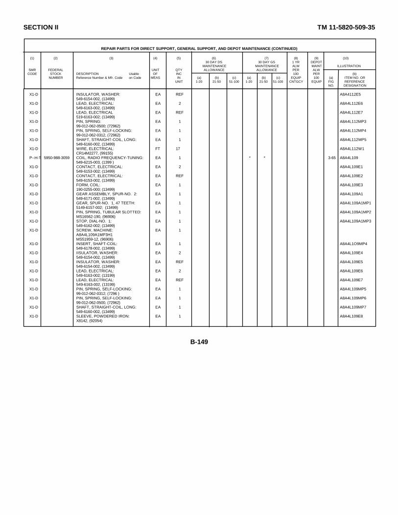
SECTION II TM 11-5820-509-35
REPAIR PARTS FOR DIRECT SUPPORT, GENERAL SUPPORT, AND DEPOT MAINTENANCE (CONTINUED)
(1) (2) (3) (4) (5) (6) (7) (8) (9) (10)30 DAY DS 30 DAY GS 1 YR DEPOT
MAINTENANCE MAINTENANCE ALW MAINT ILLUSTRATIONSMR FEDERAL UNIT QTY ALLOWANCE ALLOWANCE PER ALW
CODE STOCK DESCRIPTION Usable OF INC 100 PER (b)NUMBER Reference Number & Mfr. Code on Code MEAS IN (a) (b) (c) (a) (b) (c) EQUIP 100 (a) ITEM NO. OR
UNIT 1-20 21-50 51-100 1-20 21-50 51-100 CNTGCY EQUIP FIG REFERENCENO. DESIGNATION
X1-D INSULATOR, WASHER: EA REF A8A4112E5549-6154-002, (13499)
X1-D LEAD, ELECTRICAL: EA 2 A8A4L112E6549-6163-002, (13499)
X1-D LEAD, ELECTRICAL EA REF A8A4L112E7519-6163-002; (13499)
X1-D PIN, SPRING: EA 1 A8A4L112MP399-012-062-0500; (72962)
X1-D PIN, SPRING, SELF-LOCKING: EA 1 A8A4L112MP499-012-062-0312, (72962)
X1-D SHAFT, STRAIGHT-COIL, LONG: EA 1 A8A4L112MP5549-6160-002, (13499)
X1-D WIRE, ELECTRICAL: FT 17 A8A4L112W1CR14M2277, (99155)
P--H-T 5950-988-3059 COIL, RADIO FREQUENCY-TUNING: EA 1 * * 3-65 A8A4L109549-6215-003, (1399 )
X1-D CONTACT, ELECTRICAL: EA 2 A8A4L109E1549-6153-002; (13499)
X1-D CONTACT, ELECTRICAL: EA REF A8A4L109E2549-6153-002, (13499)
X1-D FORM, COIL: EA 1 A8A4L109E3190-0255-000; (13499)
X1-D GEAR ASSEMBLY, SPUR-NO. 2: EA 1 A8A4L109A1549-6171-002, (13499)
X1-D GEAR, SPUR-NO. 1, 47 TEETH: EA 1 A8A4L109A1MP15149-6157-002; (13499)
X1-D PIN, SPRING, TUBULAR SLOTTED: EA 1 A8A4L109A1MP2MS16562-190, (96906)
X1-D STOP, DIAL-NO. 1: EA 1 A8A4L109A1MP3549-6162-002; (13499)
X1-D SCREW, MACHINE: EA 1A8A4L109A1MP3H1MS51959-12, (96906)
X1-D INSERT, SHAFT-COIL: EA 1 A8A4L1O9MP4549-6178-002, (13499)
X1-D IISULATOR, WASHER: EA 2 A8A4L109E4549-6154-002, (13499)
X1-D INSULATOR, WASHER: EA REF A8A4L109E5549-6154-002, (13499)
X1-D LEAD, ELECTRICAL: EA 2 A8A4L109E6549-6163-002; (13199)
X1-D LEAD, ELECTRICAL: EA REF A8A4L109E7549-6163-002, (13199)
X1-D PIN, SPRING, SELF-LOCKING: EA 1 A8A4L109MP599-012-062-0312; (7296 )
X1-D PIN, SPRING, SELF-LOCKING: EA 1 A8A4L109MP699-012-062-0500, (72962)
X1-D SHAFT, STRAIGHT-COIL, LONG: EA 1 A8A4L109MP7549-6160-002, (13499)
X1-D SLEEVE, POWDERED IRON: EA 1 A8A4L109E8X8142, (92054)
B-149
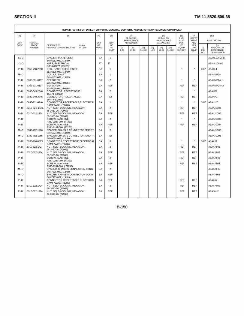
SECTION II TM 11-5820-509-35
REPAIR PARTS FOR DIRECT SUPPORT, GENERAL SUPPORT, AND DEPOT MAINTENANCE (CONTINUED)
(1) (2) (3) (4) (5) (6) (7) (8) (9) (10)30 DAY DS 30 DAY GS 1 YR DEPOT
MAINTENANCE MAINTENANCE ALW MAINT ILLUSTRATIONSMR FEDERAL UNIT QTY ALLOWANCE ALLOWANCE PER ALW
CODE STOCK DESCRIPTION Usable OF INC 100 PER (b)NUMBER Reference Number & Mfr. Code on Code MEAS IN (a) (b) (c) (a) (b) (c) EQUIP 100 (a) ITEM NO. OR
UNIT 1-20 21-50 51-100 1-20 21-50 51-100 CNTGCY EQUIP FIG REFERENCENO. DESIGNATION
X1-D SPACER, PLATE-COIL: EA 1 A8A4L109MP8549-6152-002, (13499)
X1-D WIRE, ELECTRICAL: FT 17 A8A4L109W1CR14M2277, (99155)
P--D 5950-798-2558 COIL, RADIO FREQUENCY: EA 1 * * 3-67 A8A4L4553-6325-002, (13499)
M--D COLLAR, SHAFT: EA 1 A8A4MP24549-6137-002, (13499)
P--D 5305-531-0137 SETSCREW: EA 2 * * A8A4MP24H1335-0020-000; (08664)
P--D 5305-531-0137 SETSCREW: EA REF REF REF A8A4MP24H2335-0020-000, (08664)
P--D 5935-549-2646 CONNECTOR. RECEPTACLE: EA 2 * * A8A4P2164-7J, (02660)
P--D 5935-549-2646 CONNECTOR, RECEPTACLE: EA REF REF REF A8A4P3164-7J, (02660)
P--D 5935-931-6246 CONNECTOR,RECEPTACLE,ELECTRICAL: EA 1 * * 3-67 A8A4J10DAMF3W3S, (71785)
P--D 5310-622-1721, NUT, SELF-LOCKING, HEXAGON: EA 2 REF REF A8A4J10H168-1660-26, (72962)
P--D 5310-622-1724 NUT, SELF-LOCKING, HEXAGON: EA REF REF REF A8A4J10H268-1660-26, (72962)
P--D SCREW, MACHINE: EA 2 * * A3A4J10H3P330-2287-000, (77250)
P--D SCREW, MACHINE: EA REF REF REF A8A4J10H4P330-2287-000, (77250)
M--D 5340-792-1266 SPACER,CHASSIS CONNECTOR-SHORT: EA 2 A8A4J10H5549-6074-002, (13499)
M--D 5340-792-1266 SPACER,CHASSIS CONNECTOR-SHORT: EA REF A8A4J10H6549-6074-002, (13499)
P--D 5935-974-6873 CONNECTOR,RECEPTACLE,ELECTRICAL: EA 6 * * 3-67 A8A4J3DAMF7W2S, (71785)
P--D 5310-622-1724 NUT, SELF-LOCKING, HEXAGON: EA 2 REF REF A8A4J3H168-1660-26; (72962)
P--D 5310-622-1724 NUT, SELF-LOCKING, HEXAGON: EA REF REF REF A8A4J3H268-1660-26, (72962)
P--D SCREW, MACHINE: EA 2 REF REF A8A4J3H3P330-2287-000, (77250)
P--D SCREW, MACHINE: EA REF REF REF A8A4J3H4P330-2287-000, ( 77250)
M--D SPACER, CHASSIS CONNECTOR-LONG: EA 2 A8A4J3H5548-7975-002, (13499)
M--D SPACER, CHASSIS CONNECTOR-LONG EA REF A8A4J3H6548-7975-002, (13499)
P--D CONNECTOR,RECEPTACLE,ELECTRICAL: EA REF REF REF A8A4J6DAMF7W2S, (71785)
P--D 5310-622-1724 NUT, SELF-LOCKING, HEXAGON: EA 2 REF REF A8A4J6H168-1660-26, (72962)
P--D 5310-622-1724 NUT, SELF-LOCKING, HEXAGON: EA REF REF REF A8AJ6H268-1660-26; (72962)
B-150
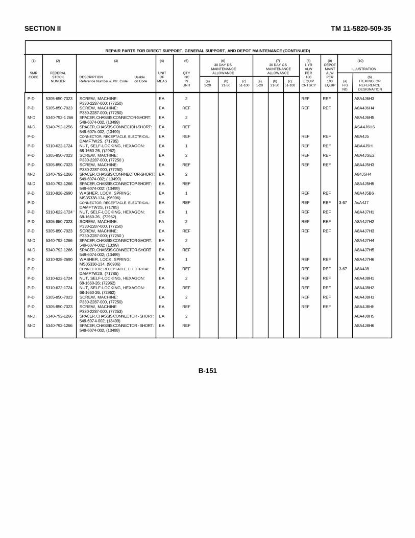
SECTION II TM 11-5820-509-35
REPAIR PARTS FOR DIRECT SUPPORT, GENERAL SUPPORT, AND DEPOT MAINTENANCE (CONTINUED)
(1) (2) (3) (4) (5) (6) (7) (8) (9) (10)30 DAY DS 30 DAY GS 1 YR DEPOT
MAINTENANCE MAINTENANCE ALW MAINT ILLUSTRATIONSMR FEDERAL UNIT QTY ALLOWANCE ALLOWANCE PER ALW
CODE STOCK DESCRIPTION Usable OF INC 100 PER (b)NUMBER Reference Number & Mfr. Code on Code MEAS IN (a) (b) (c) (a) (b) (c) EQUIP 100 (a) ITEM NO. OR
UNIT 1-20 21-50 51-100 1-20 21-50 51-100 CNTGCY EQUIP FIG REFERENCENO. DESIGNATION
P-D 5305-650-7023 SCREW, MACHINE: EA 2 REF REF A8A4J6H3P330-2287-000; (77250)
P-D 5305-850-7023 SCREW, MACHINE: EA REF REF REF A8A4J6H4P330-2287-000; (77250)
M-D 5340-792-1 266 SPACER, CHASSIS CONNEC'IOR-SHORT: EA 2 A8A4J6H5549-6074-002, (13499)
M-D 5340-792-1256 SPACER, CHASSIS CONNEC1DH-SHORT: EA REF ASA4J6H6549-607h-002, (13499)
P-D CONNECTOR, RECEPTACLE, ELECTRICAL: EA REF REF REF A8A4J5DAMF7W2S, (71785)
P-D 5310-622-1724 NUT, SELF-LOCKING, HEXAGON: EA 1 REF REF ABA4J5HI68-1660-26, ('(2962)
P-D 5305-850-7023 SCREW, MACHINE: EA 2 REF REF A8A4JSE2P330-2287-000, (77250 )
P-D 5305-850-7023 SCREW, MACHINE: EA REF REF REF A8A4J5H3P330-2287-000, (77250)
M-D 5340-792-1266 SPACER, CHASSIS CONRNECTOR-SHORT: EA 2 A84J5H4549-6074-002; ( 13499)
M-D 5340-792-1266 SPACER, CHASSIS CONNECTOP-SHORT: EA REF A8A4J5H5549-6074-002: (13499)
P-D 5310-928-2690 WASHER, LOCK, SPRING: EA 1 REF REF A8A4J5B6MS35338-134, (96906)
P-D CONNECTOR, RECEPTACLE, ELECTRICAL: EA REF REF REF 3-67 AsA4J7DAMFTW2S, (71785)
P-D 5310-622-1724 ' NUT, SELF-LOCKING, HEXAGON: EA 1 REF REF A8A4J7H168-1660-26 , (72962)
P-D 5305-850-7023 SCREW, MACHINE: FA 2 REF REF A8A4J7H2P330-2287-000, (77250)
P-D 5305-850-7023 SCREW, MACHINE: EA REF REF REF A8A4J7H3P330-2287-000; (77250 )
M-D 5340-792-1266 SPACER, CHASSIS CONNECTOR-SHORT: EA 2 A8A4J7H4549-6074-002; (13;99)
M-D 5340-792-1266 SPACER, CHASSIS CONNECTOR-SHORT: EA REF A8A4J7H5549-6074-002; (13499)
P-D 5310-928-2690 WASHER, LOCK, SPRING: EA 1 REF REF A8A4J7H6MS35338-134, (96906)
P-D CONNECTOR, RECEPTACLE, ELECTRICAL: EA REF REF REF 3-67 A8A4J8DAMF7W2S, (71785)
P-D 5310-622-1724 NUT, SELF-LOCKING, HEXAGON: EA 2 REF REF A8A4J8H168-1660-26; (72962)
P-D 5310-622-1724 NUT, SELF-LOCKING, HEXAGON: EA REF REF REF A8A4J8H268-1660-26, (72962)
P-D 5305-850-7023 SCREW, MACHINE: EA 2 REF REF A8A4J8H3P330-2287-000, (77250)
P-D 5305-850-7023 SCREW, MACHINE EA REF REF REF A8A4J8HhP330-2287-000, (77253)
M-D 5340-792-1266 SPACER, CHASSIS CONNECTOR - SHORT: EA 2 A8A4J8H5549-6074-002; (13499)
M-D 5340-792-1266 SPACER, CHASSIS CONNECTOR - SHORT: EA REF A8A4J8H6549-6074-002, (13499)
B-151

SECTION II TM 11-5820-509-35
REPAIR PARTS FOR DIRECT SUPPORT, GENERAL SUPPORT, AND DEPOT MAINTENANCE (CONTINUED)
(1) (2) (3) (4) (5) (6) (7) (8) (9) (10)30 DAY DS 30 DAY GS 1 YR DEPOT
MAINTENANCE MAINTENANCE ALW MAINT ILLUSTRATIONSMR FEDERAL UNIT QTY ALLOWANCE ALLOWANCE PER ALW
CODE STOCK DESCRIPTION Usable OF INC 100 PER (b)NUMBER Reference Number & Mfr. Code on Code MEAS IN (a) (b) (c) (a) (b) (c) EQUIP 100 (a) ITEM NO. OR
UNIT 1-20 21-50 51-100 1-20 21-50 51-100 CNTGCY EQUIP FIG REFERENCENO. DESIGNATION
P-D CONNECTOR, RECEPTACLE, ELECTRICAL EA REF REF REF 3-67 A8A4J11DAMF7W2S, (71785)
P-D 5310-622-1724 NUT, SELF-LOCKING, HEXACGON EA 2 REF REF A8A4J11H168-1660-26, (72962)
P-D 5310-622-1724 N1T, SELF-LOCKING, HEXAON EA REF REF REF A8A4J11H268-1660-26, (72962)
P-D 5305-850-7023 SCREW, MACHINE EA 2 REF REF A8A4J11H3P330-2287-000, (77250 )
P-D 5305-850-7023 SCREW, MACHINE EA REF REF REF A8A4J11H4P330-2287-000, (77250 )
M-D 5340-792-1266 SPACER, CHASSIS CONNECTOR-SHORT EA 2 A8A4J11H5549-6074-002; (13499)
M-D 5340-792-1266 SPACER, CHASSIS CONNECTOR-SHORT: EA REF A8A4J11H6549-6074-002; (13499)
P-D 5935-081-2270 CONNECTOR, RECEPTACLE, ELECTRICAL EA 2 * * 3-67 A8A1J4DBIF13W3S, (71468)
P-D 5310-622-1724 NUT, SELF-LOCKING, HEXAGON EA 2 REF REF A8A4J4H168-1660-26, (72962)
P-D 5310-622-1724 NUT, SELF-1OCKING, HEXAGON EA REF REF REF A8A4J4H268-1660-26, (72962)
P-D 5305-850-7023 SCREW, MACHINE EA 2 REF REF A8A4j4H3P330-2287-000, (77250)
P-D 5305-850-7023 SCREW, MACHINE EA REF REF REF A8A4J4H4P330-2287-000, (77250)
M-D SPACER, CHASSIS CONNECTOR-LONG EA 2 ASA4J4H5548-7975-002, (13499)
M-D SPACER, CHASSIS CONNECTOR-LONG. EA REF A8A4J4H6518-7975-002, (13499)
P-D 5935-081-2270 CONNECTOR, RECEPTACLE, ELECTRICAL EA REF REF REF 3-67 A8A4J9DBMF13W3S, (71468)
P-D 5310-622-1724 NUT, SELF-LOCKING, HEXAGON- EA 2 REF REF A8A4J9H168-1660-26, (72962)
P-D 5310-622-1724 NUT, SELF-LOCKING, HEXAGON EA REF REF REF A8A4J9H268-1660-26, (72962)
P-D SCREW, MACHINE. EA 2 * * A8A4J9H3P330-2288-000, (77250)
P-D SCREW, MACHINE EA REF REF REF A8A4J9H4P330-2288-000, (77250)
M-D SPACER, CHASSIS CONNECTOR-LONG EA 2 A8A4J9H5548-7975-002, (13499)
M-D SPACER, CHASSIS CONNECTOR-T,ONG EA REF A8A4J9H6548-7975-002, (13499)
P-D 5935-951-7196 CONNECTOR, RECEPTACLE, E1ECTRICAL EA 1 * * 3-67 A8A4JDCMF27W2S, (71468)
P-D 5310-622-1724 NUT, SELF-LOCKING, HEXAGON EA 2 REF REF A8A4J1H168-1660-26, (72962)
P-D 5310-622-1724 NUT, SELF-LOCKING, HEXAGON. EA REF REF REF A8A4J1H268-1660-26; (72962)
P-D 5305-850-7023 SCREW, MACHINE. EA 2 REF REF AbA4J1H3P330-2287-000, (77250)
B-152

SECTION II TM 11-5820-509-35
REPAIR PARTS FOR DIRECT SUPPORT, GENERAL SUPPORT, AND DEPOT MAINTENANCE (CONTINUED)
(1) (2) (3) (4) (5) (6) (7) (8) (9) (10)30 DAY DS 30 DAY GS 1 YR DEPOT
MAINTENANCE MAINTENANCE ALW MAINT ILLUSTRATIONSMR FEDERAL UNIT QTY ALLOWANCE ALLOWANCE PER ALW
CODE STOCK DESCRIPTION Usable OF INC 100 PER (b)NUMBER Reference Number & Mfr. Code on Code MEAS IN (a) (b) (c) (a) (b) (c) EQUIP 100 (a) ITEM NO. OR
UNIT 1-20 21-50 51-100 1-20 21-50 51-100 CNTGCY EQUIP FIG REFERENCENO. DESIGNATION
P--D 5305-850-7023 SCREW, MACHINE: EA REF REF REF A8A4J1H4P330-2287-000; (77250)
M--D SPACER, CHASSIS CONNECTOR-SHORT: EA 2 A8A4J1H5549-6074-002, (13499)
M--D SPACER, CHASSIS CONNECTOR-SHORT: EA REF A8A4J1H6549-6074-002, (13499)
P--D 5935-883-0218 CONNECTOR,RECEPTACLE,ELECTRICAL: EA 1 * * 3-67 A8A4J2DBMF23S, (71468)
P--D 5310-622-1724 NUT, SELF-LOCKING, HEXAGON: EA 2 REF REF A8A4J2H168-1660-26; (72962)
P--D 5310-622-1724 NUT, SELF-LOCKING, HEXAGON: EA REF REF REF A8A4J2H268-1660-26, (72962)
P--D 5305-850-7023 SCREW, MACHINE: EA 2 REF REF A8A4J2H3P330-2287-O00; (77250)
P--D 5305-850-7023 SCREW, MACHINE: EA REF REF REF A8A4J2H4P330-2287-000, (77250)
M--D SPACER, CHASSIS CONNECTOR-LONG: EA 2 A8A4J2H5548-7975-002, (13499)
M--D SPACER, CHASSIS CONNECTOR-LONG: EA REF A8A4J2H6548-7975-002, (13499)
P--D 5935-807-8202 CONNECTOR,RECEPTACLE,ELECTRICAL: EA 1 * * A8A4P1PT07C18-11P, (77820)
P--D 5820-984-1799 CONTACT ASSEMBLY, ELECTRICAL: EA 1 * * A8A4E131549-6174-002, (13499)
P--D SCREW, MACHINE: EA 1 REF REF A8A4E13111P330-2296-000, (7725 0)
P--D 5935-773-8947 CONTACT, ELECTRICAL: EA 2 13 6 A8A4E20548-7911-002, (13499)
P--D 5935-773-8947 CONTACT, ELECTRICAL: EA REF REF REF A8A4E21548-7911-002, (13499)
P--D 5820-951-4081 CONTACT, ELECTRICAL: EA 2 * * A8A4E22549-6142-002, (13499)
P--D 5820-951-4081 CONTACT, ELECTRICAL: EA REF REF REF A8A4E23549-6142-002, (13499)
P--D 5820-088-4916 CONTACT, ELECTRICAL: EA 1 8 3 A8A4E24549-6173-002, (13499)
P--D SCREW, MACHINE: EA 1 REF REF A8A4E24H1P330-2296-000, (77250)
P--D 5820-979-0033 CONTACT, ELECTRICAL: EA 4 * * A8A4E25549-6177-002, (13499)
P--D 5820-979-0033 CONTACT, ELECTRICAL: EA REF REF REF A8A4E26549-6177-002, (13499)
P--D 5820-979-0033 CONTACT, ELECTRICAL: EA REF REF REF A8A4E27549-6177-002, (1399 )
P--D 5820-979-0033 CONTACT, ELECTRICAL: EA REF REF REF A8A4E28549-6177-002, (13499)
P--D 5935-733-6655 CONTACT,ELECTRICAL,COAXIAL INSERT: EA 20 * * A8A43A2DM53743-5058, (71468)
P--D 5935-733-6655 CONTACT,ELECTRICAL,COAXIAL INSERT: EA REF REF REF A8A4JhA1DM53743-5058, (71460)
B-153
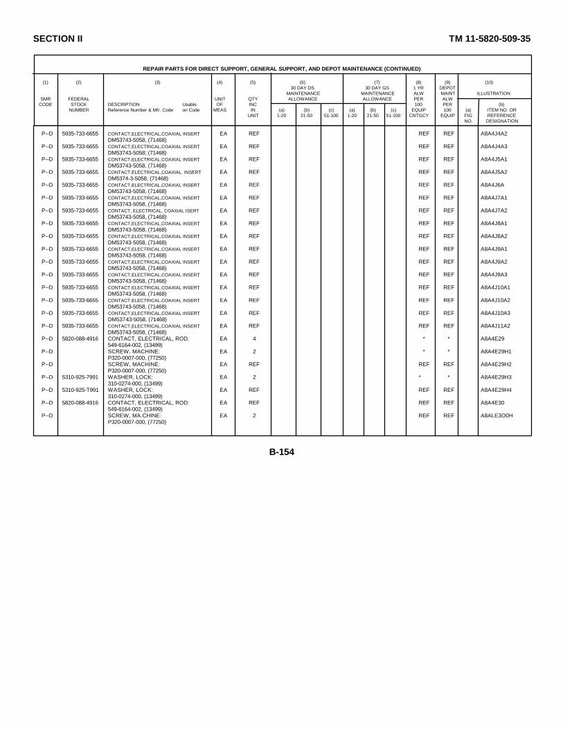
SECTION II TM 11-5820-509-35
REPAIR PARTS FOR DIRECT SUPPORT, GENERAL SUPPORT, AND DEPOT MAINTENANCE (CONTINUED)
(1) (2) (3) (4) (5) (6) (7) (8) (9) (10)30 DAY DS 30 DAY GS 1 YR DEPOT
MAINTENANCE MAINTENANCE ALW MAINT ILLUSTRATIONSMR FEDERAL UNIT QTY ALLOWANCE ALLOWANCE PER ALW
CODE STOCK DESCRIPTION Usable OF INC 100 PER (b)NUMBER Reference Number & Mfr. Code on Code MEAS IN (a) (b) (c) (a) (b) (c) EQUIP 100 (a) ITEM NO. OR
UNIT 1-20 21-50 51-100 1-20 21-50 51-100 CNTGCY EQUIP FIG REFERENCENO. DESIGNATION
P--D 5935-733-6655 CONTACT,ELECTRICAL,COAXIAL INSERT: EA REF REF REF A8A4J4A2DM53743-5058, (71468)
P--D 5935-733-6655 CONTACT,ELECTRICAL,COAXIAL INSERT: EA REF REF REF A8A4J4A3DM53743-5058; (71468)
P--D 5935-733-6655 CONTACT,ELECTRICAL,COAXIAL INSERT: EA REF REF REF A8A4J5A1DM53743-5058, (71468)
P--D 5935-733-6655 CONTACT,ELECTRICAL,COAXIAL. INSERT: EA REF REF REF A8A4J5A2DM5374-3-5058, (71468)
P--D 5935-733-6655 CONTACT,ELECTRICAL,COAXIAL INSERT: EA REF REF REF A8A4J6ADM53743-5058, (71468)
P--D 5935-733-6655 CONTACT,ELECTRICAL,COAXIAL INSERT: EA REF REF REF A8A4J7A1DM53743-5058, (71468)
P--D 5935-733-6655 CONTACT, ELECTRICAL, COAXIAL ISERT EA REF REF REF A8A4J7A2DM53743-5058, (71468)
P--D 5935-733-6655 CONTACT,ELECTRICAL,COAXIAL INSERT: EA REF REF REF A8A4J8A1DM53743-5058, (71468)
P--D 5935-733-6655 CONTACT,ELECTRICAL,COAXIAL INSERT: EA REF REF REF A8A4J8A2DM53743-5058, (71468)
P--D 5935-733-6655 CONTACT,ELECTRICAL,COAXIAL INSERT: EA REF REF REF A8A4J9A1DM53743-5058, (71468)
P--D 5935-733-6655 CONTACT,ELECTRICAL,COAXIAL INSERT: EA REF REF REF A8A4J9A2DM53743-5058, (71468)
P--D 5935-733-6655 CONTACT,ELECTRICAL,COAXIAL INSERT: EA REF REF REF A8A4J9A3DM53743-5058, (71468)
P--D 5935-733-6655 CONTACT,ELECTRICAL,COAXIAL INSERT: EA REF REF REF A8A4J10A1DM53743-5058, (71468)
P--D 5935-733-6655 CONTACT,ELECTRICAL,COAXIAL INSERT: EA REF REF REF A8A4J10A2DM53743-5058, (71468)
P--D 5935-733-6655 CONTACT,ELECTRICAL,COAXIAL INSERT: EA REF REF REF A8A4J10A3DM53743-5058, (71468)
P--D 5935-733-6655 CONTACT,ELECTRICAL,COAXIAL INSERT: EA REF REF REF A8A4J11A2DM53743-5058, (71468)
P--D 5820-088-4916 CONTACT, ELECTRICAL, ROD: EA 4 * * A8A4E29549-6164-002, (13499)
P--D SCREW, MACHINE: EA 2 * * A8A4E29H1P320-0007-000, (77250)
P--D SCREW, MACHINE: EA REF REF REF A8A4E29H2P320-0007-000, (77250)
P--D 5310-925-7991 WASHER, LOCK: EA 2 * * A8A4E29H3310-0274-000, (13499)
P--D 5310-925-T991 WASHER, LOCK: EA REF REF REF A8A4E29H4310-0274-000, (13499)
P--D 5820-088-4916 CONTACT, ELECTRICAL, ROD: EA REF REF REF A8A4E30549-6164-002, (13499)
P--D SCREW, MA.CHINE: EA 2 REF REF A8ALE3O0HP320-0007-000, (77250)
B-154
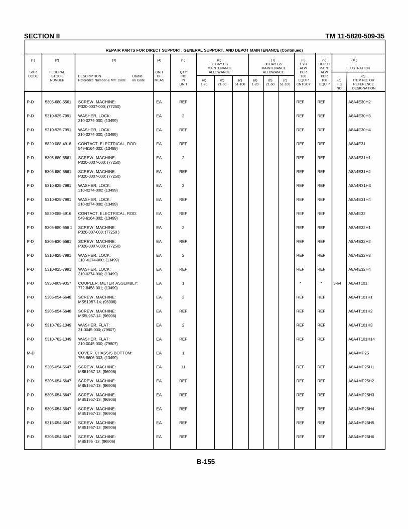
SECTION II TM 11-5820-509-35
REPAIR PARTS FOR DIRECT SUPPORT, GENERAL SUPPORT, AND DEPOT MAINTENANCE (Continued)
(1) (2) (3) (4) (5) (6) (7) (8) (9) (10)30 DAY DS 30 DAY GS 1 YR DEPOT
MAINTENANCE MAINTENANCE ALW MAINT ILLUSTRATIONSMR FEDERAL UNIT QTY ALLOWANCE ALLOWANCE PER ALW
CODE STOCK DESCRIPTION Usable OF INC 100 PER (b)NUMBER Reference Number & Mfr. Code on Code MEAS IN (a) (b) (c) (a) (b) (c) EQUIP 100 (a) ITEM NO. OR
UNIT 1-20 21-50 51-100 1-20 21-50 51-100 CNTGCY EQUIP FIG REFERENCENO. DESIGNATION
P-D 5305-680-5561 SCREW, MACHINE: EA REF REF REF A8A4E30H2P320-0007-000; (77250)
P-D 5310-925-7991 WASHER, LOCK: EA 2 REF REF A8A4E30H3310-0274-000; (13499)
P-D 5310-925-7991 WASHER, LOCK: EA REF REF REF A8A4E30H4310-0274-000; (13499)
P-D 5820-088-4916 CONTACT, ELECTRICAL, ROD: EA REF REF REF A8A4E31549-6164-002; (13499)
P-D 5305-680-5561 SCREW, MACHINE: EA 2 REF REF A8A4E31H1P320-0007-000; (77250)
P-D 5305-680-5561 SCREW, MACHINE: EA REF REF REF A8A4E31H2P320-0007-000; (77250)
P-D 5310-925-7991 WASHER, LOCK: EA 2 REF REF A8A4R31H3310-0274-000; (13499)
P-D 5310-925-7991 WASHER, LOCK: EA REF REF REF A8A4E31H4310-0274-000; (13499)
P-D 5820-088-4916 CONTACT, ELECTRICAL, ROD: EA REF REF REF A8A4E32549-6164-002; (13499)
P-D 5305-680-556 1 SCREW, MACHINE: EA 2 REF REF A8A4E32H1P320-007-000; (77250 )
P-D 5305-630-5561 SCREW, MACHINE: EA REF REF REF A8A4E32H2P320-0007-000; (77250)
P-D 5310-925-7991 WASHER, LOCK: EA 2 REF REF A8A4E32H3310 -0274-000; (13499)
P-D 5310-925-7991 WASHER, LOCK: EA REF REF REF A8A4E32H4310-0274-000; (13499)
P-D 5950-809-9357 COUPLER, METER ASSEMBLY: EA 1 * * 3-64 A8A4T101772-8458-001; (13499)
P-D 5305-054-5648 SCREW, MACHINE: EA 2 REF REF A8A4T101H1MS51957-14; (96906)
P-D 5305-054-5648 SCREW, MACHINE: EA REF REF REF A8A4T101H2MS5L957-14; (96906)
P-D 5310-782-1349 WASHER, FLAT: EA 2 REF REF A8A4T101H331-0045-000; (79807)
P-D 5310-782-1349 WASHER, FLAT: EA REF REF REF A8A4T101H14310-0045-000; (79807)
M-D COVER, CHASSIS BOTTOM: EA 1 A8A4MP25756-8606-003; (13499)
P-D 5305-054-5647 SCREW, MACHINE: EA 11 REF REF A8A4MP25H1MS51957-13; (96906)
P-D 5305-054-5647 SCREW, MACHINE: EA REF REF REF A8A4MP25H2MS51957-13; (96906)
P-D 5305-054-5647 SCREW, MACHINE: EA REF REF REF A8A4MP25H3MS51957-13; (96906)
P-D 5305-054-5647 SCREW, MACHINE: EA REF REF REF A8A4MP25H4MS51957-13; (96906)
P-D 5315-054-5647 SCREW, MACHINE: EA REF REF REF A8A4MP25H5MS51957-13; (96906)
P-D 5305-054-5647 SCREW, MACHINE: EA REF REF REF A8A4MP25H6MS5195 -13; (96906)
B-155
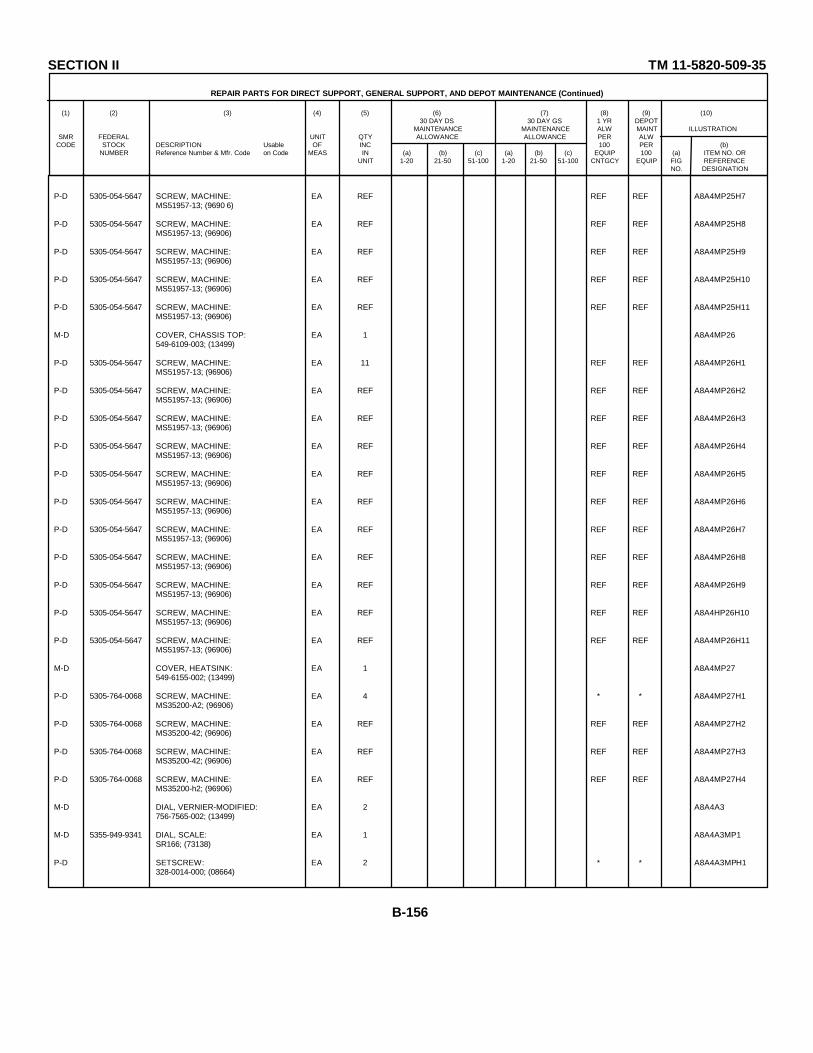
SECTION II TM 11-5820-509-35
REPAIR PARTS FOR DIRECT SUPPORT, GENERAL SUPPORT, AND DEPOT MAINTENANCE (Continued)
(1) (2) (3) (4) (5) (6) (7) (8) (9) (10)30 DAY DS 30 DAY GS 1 YR DEPOT
MAINTENANCE MAINTENANCE ALW MAINT ILLUSTRATIONSMR FEDERAL UNIT QTY ALLOWANCE ALLOWANCE PER ALW
CODE STOCK DESCRIPTION Usable OF INC 100 PER (b)NUMBER Reference Number & Mfr. Code on Code MEAS IN (a) (b) (c) (a) (b) (c) EQUIP 100 (a) ITEM NO. OR
UNIT 1-20 21-50 51-100 1-20 21-50 51-100 CNTGCY EQUIP FIG REFERENCENO. DESIGNATION
P-D 5305-054-5647 SCREW, MACHINE: EA REF REF REF A8A4MP25H7MS51957-13; (9690 6)
P-D 5305-054-5647 SCREW, MACHINE: EA REF REF REF A8A4MP25H8MS51957-13; (96906)
P-D 5305-054-5647 SCREW, MACHINE: EA REF REF REF A8A4MP25H9MS51957-13; (96906)
P-D 5305-054-5647 SCREW, MACHINE: EA REF REF REF A8A4MP25H10MS51957-13; (96906)
P-D 5305-054-5647 SCREW, MACHINE: EA REF REF REF A8A4MP25H11MS51957-13; (96906)
M-D COVER, CHASSIS TOP: EA 1 A8A4MP26549-6109-003; (13499)
P-D 5305-054-5647 SCREW, MACHINE: EA 11 REF REF A8A4MP26H1MS51957-13; (96906)
P-D 5305-054-5647 SCREW, MACHINE: EA REF REF REF A8A4MP26H2MS51957-13; (96906)
P-D 5305-054-5647 SCREW, MACHINE: EA REF REF REF A8A4MP26H3MS51957-13; (96906)
P-D 5305-054-5647 SCREW, MACHINE: EA REF REF REF A8A4MP26H4MS51957-13; (96906)
P-D 5305-054-5647 SCREW, MACHINE: EA REF REF REF A8A4MP26H5MS51957-13; (96906)
P-D 5305-054-5647 SCREW, MACHINE: EA REF REF REF A8A4MP26H6MS51957-13; (96906)
P-D 5305-054-5647 SCREW, MACHINE: EA REF REF REF A8A4MP26H7MS51957-13; (96906)
P-D 5305-054-5647 SCREW, MACHINE: EA REF REF REF A8A4MP26H8MS51957-13; (96906)
P-D 5305-054-5647 SCREW, MACHINE: EA REF REF REF A8A4MP26H9MS51957-13; (96906)
P-D 5305-054-5647 SCREW, MACHINE: EA REF REF REF A8A4HP26H10MS51957-13; (96906)
P-D 5305-054-5647 SCREW, MACHINE: EA REF REF REF A8A4MP26H11MS51957-13; (96906)
M-D COVER, HEATSINK: EA 1 A8A4MP27549-6155-002; (13499)
P-D 5305-764-0068 SCREW, MACHINE: EA 4 * * A8A4MP27H1MS35200-A2; (96906)
P-D 5305-764-0068 SCREW, MACHINE: EA REF REF REF A8A4MP27H2MS35200-42; (96906)
P-D 5305-764-0068 SCREW, MACHINE: EA REF REF REF A8A4MP27H3MS35200-42; (96906)
P-D 5305-764-0068 SCREW, MACHINE: EA REF REF REF A8A4MP27H4MS35200-h2; (96906)
M-D DIAL, VERNIER-MODIFIED: EA 2 A8A4A3756-7565-002; (13499)
M-D 5355-949-9341 DIAL, SCALE: EA 1 A8A4A3MP1SR166; (73138)
P-D SETSCREW: EA 2 * * A8A4A3MPH1328-0014-000; (08664)
B-156
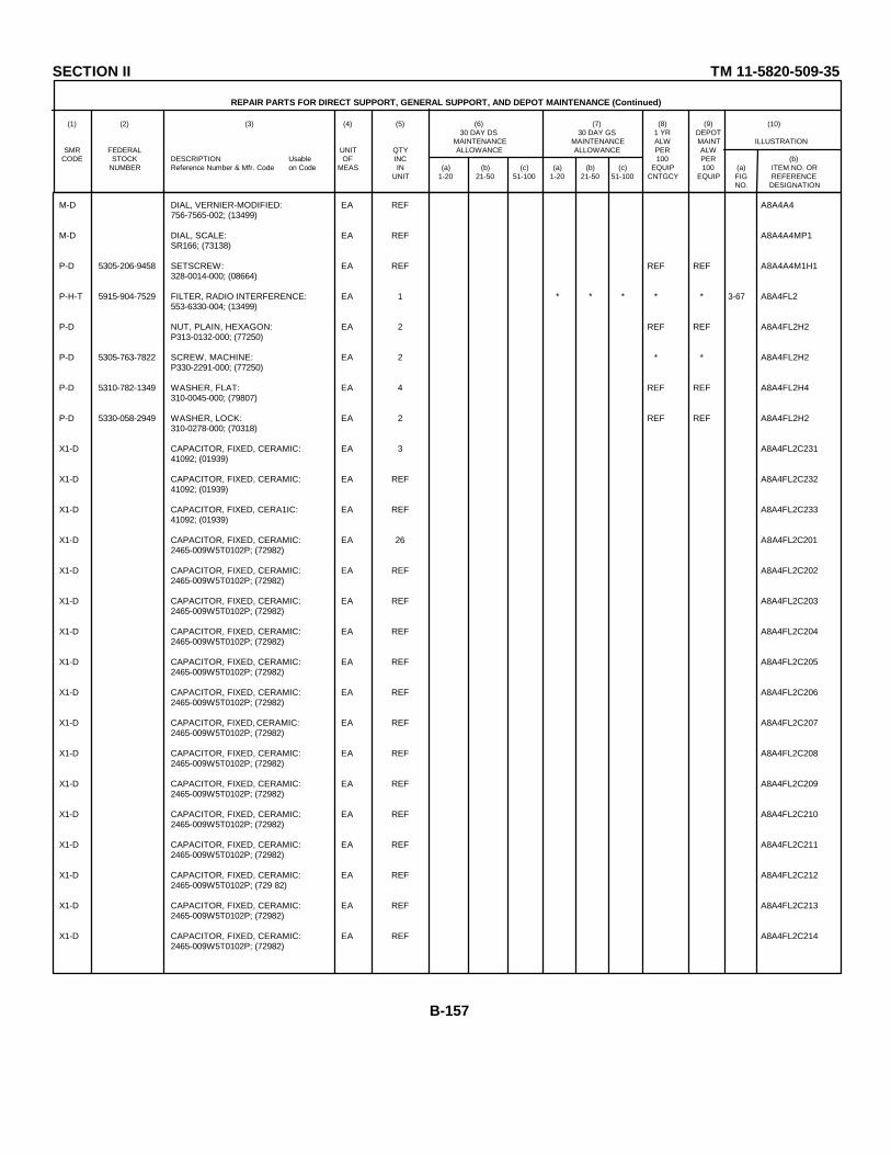
SECTION II TM 11-5820-509-35
REPAIR PARTS FOR DIRECT SUPPORT, GENERAL SUPPORT, AND DEPOT MAINTENANCE (Continued)
(1) (2) (3) (4) (5) (6) (7) (8) (9) (10)30 DAY DS 30 DAY GS 1 YR DEPOT
MAINTENANCE MAINTENANCE ALW MAINT ILLUSTRATIONSMR FEDERAL UNIT QTY ALLOWANCE ALLOWANCE PER ALW
CODE STOCK DESCRIPTION Usable OF INC 100 PER (b)NUMBER Reference Number & Mfr. Code on Code MEAS IN (a) (b) (c) (a) (b) (c) EQUIP 100 (a) ITEM NO. OR
UNIT 1-20 21-50 51-100 1-20 21-50 51-100 CNTGCY EQUIP FIG REFERENCENO. DESIGNATION
M-D DIAL, VERNIER-MODIFIED: EA REF A8A4A4756-7565-002; (13499)
M-D DIAL, SCALE: EA REF A8A4A4MP1SR166; (73138)
P-D 5305-206-9458 SETSCREW: EA REF REF REF A8A4A4M1H1328-0014-000; (08664)
P-H-T 5915-904-7529 FILTER, RADIO INTERFERENCE: EA 1 * * * * * 3-67 A8A4FL2553-6330-004; (13499)
P-D NUT, PLAIN, HEXAGON: EA 2 REF REF A8A4FL2H2P313-0132-000; (77250)
P-D 5305-763-7822 SCREW, MACHINE: EA 2 * * A8A4FL2H2P330-2291-000; (77250)
P-D 5310-782-1349 WASHER, FLAT: EA 4 REF REF A8A4FL2H4310-0045-000; (79807)
P-D 5330-058-2949 WASHER, LOCK: EA 2 REF REF A8A4FL2H2310-0278-000; (70318)
X1-D CAPACITOR, FIXED, CERAMIC: EA 3 A8A4FL2C23141092; (01939)
X1-D CAPACITOR, FIXED, CERAMIC: EA REF A8A4FL2C23241092; (01939)
X1-D CAPACITOR, FIXED, CERA1IC: EA REF A8A4FL2C23341092; (01939)
X1-D CAPACITOR, FIXED, CERAMIC: EA 26 A8A4FL2C2012465-009W5T0102P; (72982)
X1-D CAPACITOR, FIXED, CERAMIC: EA REF A8A4FL2C2022465-009W5T0102P; (72982)
X1-D CAPACITOR, FIXED, CERAMIC: EA REF A8A4FL2C2032465-009W5T0102P; (72982)
X1-D CAPACITOR, FIXED, CERAMIC: EA REF A8A4FL2C2042465-009W5T0102P; (72982)
X1-D CAPACITOR, FIXED, CERAMIC: EA REF A8A4FL2C2052465-009W5T0102P; (72982)
X1-D CAPACITOR, FIXED, CERAMIC: EA REF A8A4FL2C2062465-009W5T0102P; (72982)
X1-D CAPACITOR, FIXED, CERAMIC: EA REF A8A4FL2C2072465-009W5T0102P; (72982)
X1-D CAPACITOR, FIXED, CERAMIC: EA REF A8A4FL2C2082465-009W5T0102P; (72982)
X1-D CAPACITOR, FIXED, CERAMIC: EA REF A8A4FL2C2092465-009W5T0102P; (72982)
X1-D CAPACITOR, FIXED, CERAMIC: EA REF A8A4FL2C2102465-009W5T0102P; (72982)
X1-D CAPACITOR, FIXED, CERAMIC: EA REF A8A4FL2C2112465-009W5T0102P; (72982)
X1-D CAPACITOR, FIXED, CERAMIC: EA REF A8A4FL2C2122465-009W5T0102P; (729 82)
X1-D CAPACITOR, FIXED, CERAMIC: EA REF A8A4FL2C2132465-009W5T0102P; (72982)
X1-D CAPACITOR, FIXED, CERAMIC: EA REF A8A4FL2C2142465-009W5T0102P; (72982)
B-157
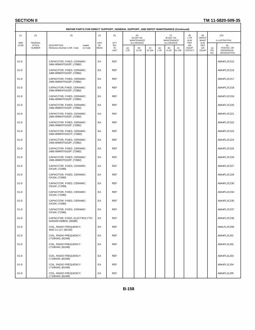
SECTION II TM 11-5820-509-35
REPAIR PARTS FOR DIRECT SUPPORT, GENERAL SUPPORT, AND DEPOT MAINTENANCE (Continued)
(1) (2) (3) (4) (5) (6) (7) (8) (9) (10)30 DAY DS 30 DAY GS 1 YR DEPOT
MAINTENANCE MAINTENANCE ALW MAINT ILLUSTRATIONSMR FEDERAL UNIT QTY ALLOWANCE ALLOWANCE PER ALW
CODE STOCK DESCRIPTION Usable OF INC 100 PER (b)NUMBER Reference Number & Mfr. Code on Code MEAS IN (a) (b) (c) (a) (b) (c) EQUIP 100 (a) ITEM NO. OR
UNIT 1-20 21-50 51-100 1-20 21-50 51-100 CNTGCY EQUIP FIG REFERENCENO. DESIGNATION
X1-D CAPACITOR, FIXED, CERAMIC: EA REF A8A4FL2C2152465-009W5T0102P; (72982)
X1-D CAPACITOR, FIXED, CERAMIC: EA REF A8A4FL2C2162465-009W5T0102P; (72982)
X1-D CAPACITOR, FIXED, CERAMIC: EA REF A8A4FL2C2172465-009W5T0102P; (72982)
X1-D CAPACITOR, FIXED, CERAMIC: EA REF A8A4FL2C2182465-009W5T0102P; (72982)
X1-D CAPACITOR, FIXED, CERAMIC: EA REF A8A4FL2C2192465-009W5T0102P; (72982)
X1-D CAPACITOR, FIXED, CERAMIC: EA REF A8A4FL2C2202465-009W5T0102P; (72982)
X1-D CAPACITOR, FIXED, CERAMIC: EA REF A8A4FL2C2212465-009W5T0102P; (72982)
X1-D CAPACITOR, FIXED, CERAMIC: EA REF A8A4FL2C2222465-009W5T0102P; (72982)
X1-D CAPACITOR, FIXED, CERAMIC: EA REF A8A4FL2C2232465-009W5T0102 P; (72982)
X1-D CAPACITOR, FIXED, CERAMIC: EA REF A8A4FL2C2242465-009W5T0102P; (72982)
X1-D CAPACITOR, FIXED, CERAMIC: EA REF A8A4FL2C2252465-009W5T0102P; (72982)
X1-D CAPACITOR, FIXED, CERAMIC: EA REF A8A4FL2C2262465-009W5T0102P; (72982)
X1-D CAPACITOR, FIXED, CERAMIC: EA REF A8A4FL2C227CK104; (71590)
X1-D CAPACITOR, FIXED, CERAMIC: EA REF A8A4FL2C229CK104; (71590)
X1-D CAPACITOR, FIXED, CERAMIC: EA REF A8A4FL2C230CK104; (71590)
X1-D CAPACITOR, FIXED, CERAMIC: EA REF A8A4FL2C234CK104; (71590)
X1-D CAPACITOR, FIXED, CERAMIC: EA REF A8A4FL2C235CK104; (71590)
X1-D CAPACITOR, FIXED, CERAMIC: EA REF A8A4FL2C237CK104; (71590)
X1-D CAPACITOR, FIXED, ELECTROLYTIC: EA REF A8A4FL2C236610D25F100BD5; (56289)
X1-D COIL, RADIO FREQUENCY: EA REF A8ALFL2C2064422-11-117; (82142)
X1-D COIL, RADIO FREQUENCY: EA REF A8A4FL2L201LT10K043; (81349)
X1-D COIL, RADIO FREQUENCY: EA REF A8A4FL2L202LT10K043; (81349)
X1-D COIL, RADIO FREQUENCY: EA REF A8A4FL2L203LT10K043; (81349)
X1-D COIL, RADIO FREQUENCY: EA REF A8A4FL2L204LT10K043; (81349)
X1-D COIL, RADIO FREQUENCY: EA REF A8A4FL2L205LT10K043; (81349)
B-158
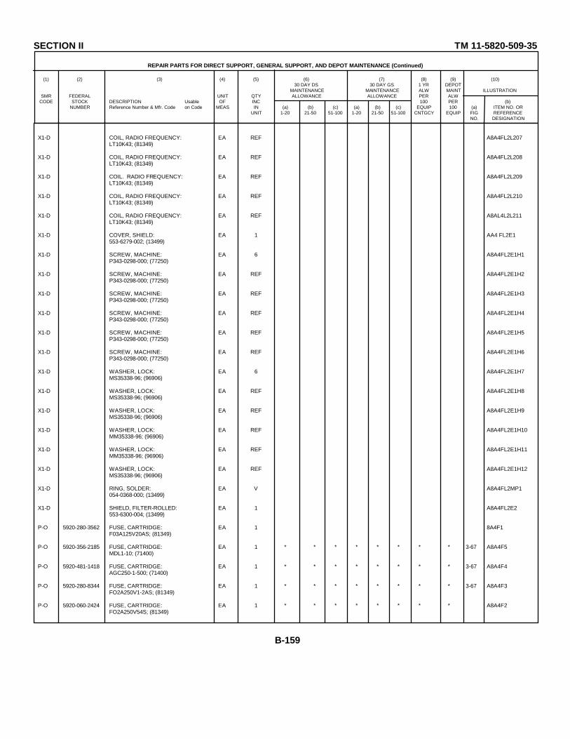
SECTION II TM 11-5820-509-35
REPAIR PARTS FOR DIRECT SUPPORT, GENERAL SUPPORT, AND DEPOT MAINTENANCE (Continued)
(1) (2) (3) (4) (5) (6) (7) (8) (9) (10)30 DAY DS 30 DAY GS 1 YR DEPOT
MAINTENANCE MAINTENANCE ALW MAINT ILLUSTRATIONSMR FEDERAL UNIT QTY ALLOWANCE ALLOWANCE PER ALW
CODE STOCK DESCRIPTION Usable OF INC 100 PER (b)NUMBER Reference Number & Mfr. Code on Code MEAS IN (a) (b) (c) (a) (b) (c) EQUIP 100 (a) ITEM NO. OR
UNIT 1-20 21-50 51-100 1-20 21-50 51-100 CNTGCY EQUIP FIG REFERENCENO. DESIGNATION
X1-D COIL, RADIO FREQUENCY: EA REF A8A4FL2L207LT10K43; (81349)
X1-D COIL, RADIO FREQUENCY: EA REF A8A4FL2L208LT10K43; (81349)
X1-D COIL. RADIO FREQUENCY: EA REF A8A4FL2L209LT10K43; (81349)
X1-D COIL, RADIO FREQUENCY: EA REF A8A4FL2L210LT10K43; (81349)
X1-D COIL, RADIO FREQUENCY: EA REF A8AL4L2L211LT10K43; (81349)
X1-D COVER, SHIELD: EA 1 AA4 FL2E1553-6279-002; (13499)
X1-D SCREW, MACHINE: EA 6 A8A4FL2E1H1P343-0298-000; (77250)
X1-D SCREW, MACHINE: EA REF A8A4FL2E1H2P343-0298-000; (77250)
X1-D SCREW, MACHINE: EA REF A8A4FL2E1H3P343-0298-000; (77250)
X1-D SCREW, MACHINE: EA REF A8A4FL2E1H4P343-0298-000; (77250)
X1-D SCREW, MACHINE: EA REF A8A4FL2E1H5P343-0298-000; (77250)
X1-D SCREW, MACHINE: EA REF A8A4FL2E1H6P343-0298-000; (77250)
X1-D WASHER, LOCK: EA 6 A8A4FL2E1H7MS35338-96; (96906)
X1-D WASHER, LOCK: EA REF A8A4FL2E1H8MS35338-96; (96906)
X1-D WASHER, LOCK: EA REF A8A4FL2E1H9MS35338-96; (96906)
X1-D WASHER, LOCK: EA REF A8A4FL2E1H10MM35338-96; (96906)
X1-D WASHER, LOCK: EA REF A8A4FL2E1H11MM35338-96; (96906)
X1-D WASHER, LOCK: EA REF A8A4FL2E1H12MS35338-96; (96906)
X1-D RING, SOLDER: EA V A8A4FL2MP1054-0368-000; (13499)
X1-D SHIELD, FILTER-ROLLED: EA 1 A8A4FL2E2553-6300-004; (13499)
P-O 5920-280-3562 FUSE, CARTRIDGE: EA 1 8A4F1F03A125V20AS; (81349)
P-O 5920-356-2185 FUSE, CARTRIDGE: EA 1 * * * * * * * * 3-67 A8A4F5MDL1-10; (71400)
P-O 5920-481-1418 FUSE, CARTRIDGE: EA 1 * * * * * * * * 3-67 A8A4F4AGC250-1-500; (71400)
P-O 5920-280-8344 FUSE, CARTRIDGE: EA 1 * * * * * * * * 3-67 A8A4F3FO2A250V1-2AS; (81349)
P-O 5920-060-2424 FUSE, CARTRIDGE: EA 1 * * * * * * * * A8A4F2FO2A250V54S; (81349)
B-159
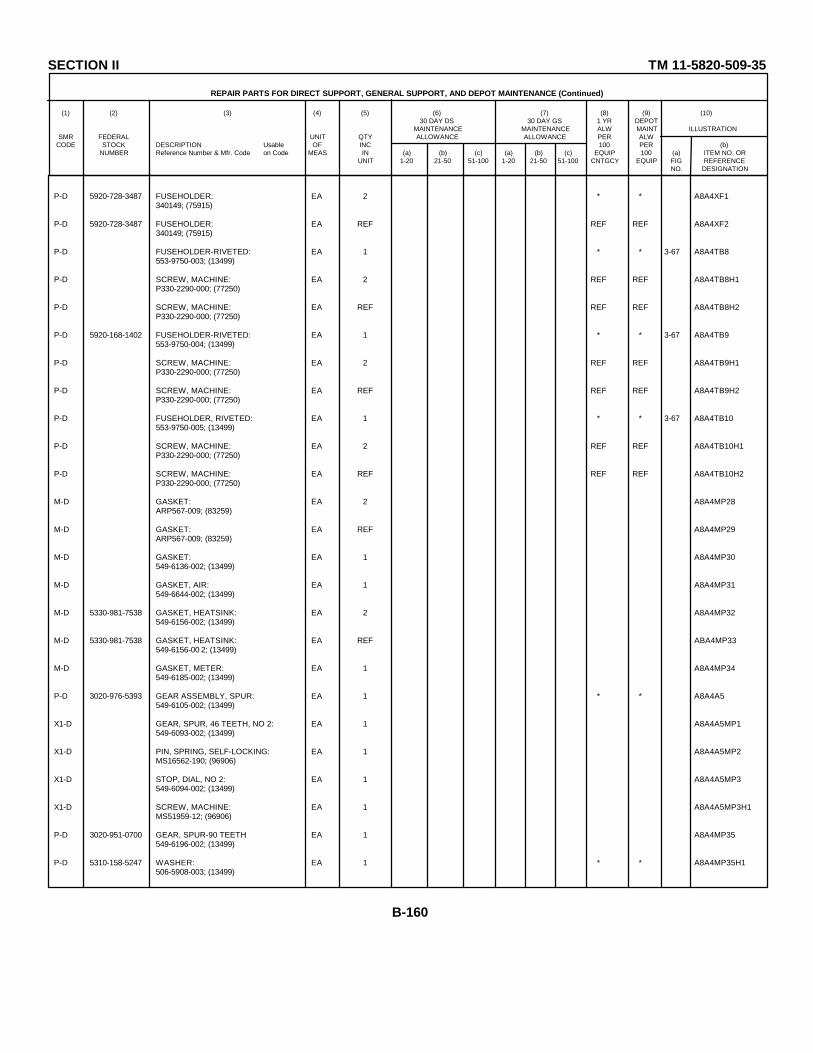
SECTION II TM 11-5820-509-35
REPAIR PARTS FOR DIRECT SUPPORT, GENERAL SUPPORT, AND DEPOT MAINTENANCE (Continued)
(1) (2) (3) (4) (5) (6) (7) (8) (9) (10)30 DAY DS 30 DAY GS 1 YR DEPOT
MAINTENANCE MAINTENANCE ALW MAINT ILLUSTRATIONSMR FEDERAL UNIT QTY ALLOWANCE ALLOWANCE PER ALW
CODE STOCK DESCRIPTION Usable OF INC 100 PER (b)NUMBER Reference Number & Mfr. Code on Code MEAS IN (a) (b) (c) (a) (b) (c) EQUIP 100 (a) ITEM NO. OR
UNIT 1-20 21-50 51-100 1-20 21-50 51-100 CNTGCY EQUIP FIG REFERENCENO. DESIGNATION
P-D 5920-728-3487 FUSEHOLDER: EA 2 * * A8A4XF1340149; (75915)
P-D 5920-728-3487 FUSEHOLDER: EA REF REF REF A8A4XF2340149; (75915)
P-D FUSEHOLDER-RIVETED: EA 1 * * 3-67 A8A4TB8553-9750-003; (13499)
P-D SCREW, MACHINE: EA 2 REF REF A8A4TB8H1P330-2290-000; (77250)
P-D SCREW, MACHINE: EA REF REF REF A8A4TB8H2P330-2290-000; (77250)
P-D 5920-168-1402 FUSEHOLDER-RIVETED: EA 1 * * 3-67 A8A4TB9553-9750-004; (13499)
P-D SCREW, MACHINE: EA 2 REF REF A8A4TB9H1P330-2290-000; (77250)
P-D SCREW, MACHINE: EA REF REF REF A8A4TB9H2P330-2290-000; (77250)
P-D FUSEHOLDER, RIVETED: EA 1 * * 3-67 A8A4TB10553-9750-005; (13499)
P-D SCREW, MACHINE: EA 2 REF REF A8A4TB10H1P330-2290-000; (77250)
P-D SCREW, MACHINE: EA REF REF REF A8A4TB10H2P330-2290-000; (77250)
M-D GASKET: EA 2 A8A4MP28ARP567-009; (83259)
M-D GASKET: EA REF A8A4MP29ARP567-009; (83259)
M-D GASKET: EA 1 A8A4MP30549-6136-002; (13499)
M-D GASKET, AIR: EA 1 A8A4MP31549-6644-002; (13499)
M-D 5330-981-7538 GASKET, HEATSINK: EA 2 A8A4MP32549-6156-002; (13499)
M-D 5330-981-7538 GASKET, HEATSINK: EA REF ABA4MP33549-6156-00 2; (13499)
M-D GASKET, METER: EA 1 A8A4MP34549-6185-002; (13499)
P-D 3020-976-5393 GEAR ASSEMBLY, SPUR: EA 1 * * A8A4A5549-6105-002; (13499)
X1-D GEAR, SPUR, 46 TEETH, NO 2: EA 1 A8A4A5MP1549-6093-002; (13499)
X1-D PIN, SPRING, SELF-LOCKING: EA 1 A8A4A5MP2MS16562-190; (96906)
X1-D STOP, DIAL, NO 2: EA 1 A8A4A5MP3549-6094-002; (13499)
X1-D SCREW, MACHINE: EA 1 A8A4A5MP3H1MS51959-12; (96906)
P-D 3020-951-0700 GEAR, SPUR-90 TEETH: EA 1 A8A4MP35549-6196-002; (13499)
P-D 5310-158-5247 WASHER: EA 1 * * A8A4MP35H1506-5908-003; (13499)
B-160
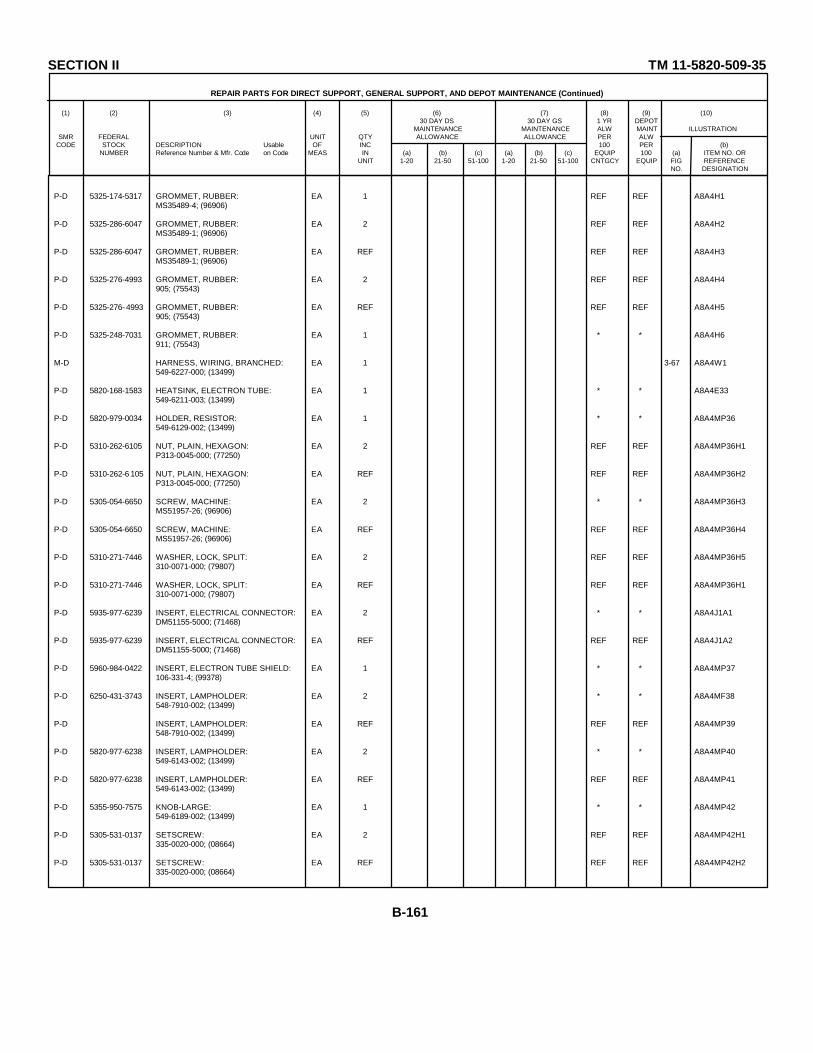
SECTION II TM 11-5820-509-35
REPAIR PARTS FOR DIRECT SUPPORT, GENERAL SUPPORT, AND DEPOT MAINTENANCE (Continued)
(1) (2) (3) (4) (5) (6) (7) (8) (9) (10)30 DAY DS 30 DAY GS 1 YR DEPOT
MAINTENANCE MAINTENANCE ALW MAINT ILLUSTRATIONSMR FEDERAL UNIT QTY ALLOWANCE ALLOWANCE PER ALW
CODE STOCK DESCRIPTION Usable OF INC 100 PER (b)NUMBER Reference Number & Mfr. Code on Code MEAS IN (a) (b) (c) (a) (b) (c) EQUIP 100 (a) ITEM NO. OR
UNIT 1-20 21-50 51-100 1-20 21-50 51-100 CNTGCY EQUIP FIG REFERENCENO. DESIGNATION
P-D 5325-174-5317 GROMMET, RUBBER: EA 1 REF REF A8A4H1MS35489-4; (96906)
P-D 5325-286-6047 GROMMET, RUBBER: EA 2 REF REF A8A4H2MS35489-1; (96906)
P-D 5325-286-6047 GROMMET, RUBBER: EA REF REF REF A8A4H3MS35489-1; (96906)
P-D 5325-276-4993 GROMMET, RUBBER: EA 2 REF REF A8A4H4905; (75543)
P-D 5325-276- 4993 GROMMET, RUBBER: EA REF REF REF A8A4H5905; (75543)
P-D 5325-248-7031 GROMMET, RUBBER: EA 1 * * A8A4H6911; (75543)
M-D HARNESS, WIRING, BRANCHED: EA 1 3-67 A8A4W1549-6227-000; (13499)
P-D 5820-168-1583 HEATSINK, ELECTRON TUBE: EA 1 * * A8A4E33549-6211-003; (13499)
P-D 5820-979-0034 HOLDER, RESISTOR: EA 1 * * A8A4MP36549-6129-002; (13499)
P-D 5310-262-6105 NUT, PLAIN, HEXAGON: EA 2 REF REF A8A4MP36H1P313-0045-000; (77250)
P-D 5310-262-6 105 NUT, PLAIN, HEXAGON: EA REF REF REF A8A4MP36H2P313-0045-000; (77250)
P-D 5305-054-6650 SCREW, MACHINE: EA 2 * * A8A4MP36H3MS51957-26; (96906)
P-D 5305-054-6650 SCREW, MACHINE: EA REF REF REF A8A4MP36H4MS51957-26; (96906)
P-D 5310-271-7446 WASHER, LOCK, SPLIT: EA 2 REF REF A8A4MP36H5310-0071-000; (79807)
P-D 5310-271-7446 WASHER, LOCK, SPLIT: EA REF REF REF A8A4MP36H1310-0071-000; (79807)
P-D 5935-977-6239 INSERT, ELECTRICAL CONNECTOR: EA 2 * * A8A4J1A1DM51155-5000; (71468)
P-D 5935-977-6239 INSERT, ELECTRICAL CONNECTOR: EA REF REF REF A8A4J1A2DM51155-5000; (71468)
P-D 5960-984-0422 INSERT, ELECTRON TUBE SHIELD: EA 1 * * A8A4MP37106-331-4; (99378)
P-D 6250-431-3743 INSERT, LAMPHOLDER: EA 2 * * A8A4MF38548-7910-002; (13499)
P-D INSERT, LAMPHOLDER: EA REF REF REF A8A4MP39548-7910-002; (13499)
P-D 5820-977-6238 INSERT, LAMPHOLDER: EA 2 * * A8A4MP40549-6143-002; (13499)
P-D 5820-977-6238 INSERT, LAMPHOLDER: EA REF REF REF A8A4MP41549-6143-002; (13499)
P-D 5355-950-7575 KNOB-LARGE: EA 1 * * A8A4MP42549-6189-002; (13499)
P-D 5305-531-0137 SETSCREW: EA 2 REF REF A8A4MP42H1335-0020-000; (08664)
P-D 5305-531-0137 SETSCREW: EA REF REF REF A8A4MP42H2335-0020-000; (08664)
B-161
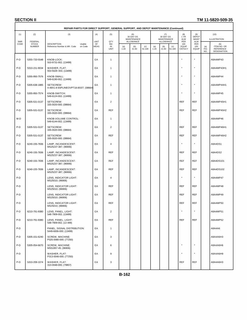
SECTION II TM 11-5820-509-35
REPAIR PARTS FOR DIRECT SUPPORT, GENERAL SUPPORT, AND DEPOT MAINTENANCE (Continued)
(1) (2) (3) (4) (5) (6) (7) (8) (9) (10)30 DAY DS 30 DAY GS 1 YR DEPOT
MAINTENANCE MAINTENANCE ALW MAINT ILLUSTRATIONSMR FEDERAL UNIT QTY ALLOWANCE ALLOWANCE PER ALW
CODE STOCK DESCRIPTION Usable OF INC 100 PER (b)NUMBER Reference Number & Mfr. Code on Code MEAS IN (a) (b) (c) (a) (b) (c) EQUIP 100 (a) ITEM NO. OR
UNIT 1-20 21-50 51-100 1-20 21-50 51-100 CNTGCY EQUIP FIG REFERENCENO. DESIGNATION
P-D 5355-733-5548 KNOB-LOCK: EA 1 * * A8A4MP43553-9731-002; (13499)
P-D 5310-151-9034 WASHER, FLAT: EA 1 * * A8A4MP43H1553-5029- 003; (13499)
P-D 5355-950-7576 KNOB-SMALL: EA 1 * * A8A4MP44549-6190-002; (13499)
P-D 5305-638-1885 SETSCREW: EA 1 * * A8A4MP44H14-48X1-8 6SPLINEOVPT18-8SST; (08664)
P-D 5355-950-7574 KNOB-SWITCH: EA 1 * * A8A4MP45549-6124-002; (13499)
P-D 5305-531-0137 SETSCREW: EA 2 REF REF A8A4MP45H1335-0020-000; (08664)
P-D 5305-531-0137 SETSCREW: EA REF REF REF A8A4MP45H2335-0020-000; (08664)
M-D KNOB-VOLUME CONTROL: EA 1 A8A4MP46549-6144-002; (13499)
P-D 5305-531-0137 SETSCREW: EA 2 REF REF A8A4MP46H1335-0020-000; (08664)
P-D 5305-531-0137 SETSCREW: EA REF REF REF A8A4MP46H2335-0020-000; (08664)
P-D 6240-155-7836 LAMP, INCANDESCENT: EA 4 * * A8A4DS1MS25237-387; (96906)
P-D 6240-155-7836 LAMP, INCANDESCENT: EA REF REF REF A8A4DS2MS25237-387; (96906)
P-D 6240-155-7836 LAMP, INCANDESCENT: EA REF REF REF A8A4DS101MS25237-387; (96906)
P-D 6240-155-7836 LAMP, INCANDESCENT: EA REF REF REF A8A4DS102MS25237-387; (96906)
P-D LENS, INDICATOR LIGHT: EA 4 * * A8A4MP47MS25010; (96906)
P-D LENS, INDICATOR LIGHT: EA REF REF REF A8A4MP48MS25010; (96906)
P-D LENS, INDICATOR LIGHT: EA REF REF REF A8A4MP49MS25010; (96906)
P-D LENS, INDICATOR LIGHT: EA REF REF REF A8A4MP50MS25010; (96906)
P-D 6210-791-9380 LENS, PANEL, LIGHT: EA 2 * * A8A4MP51548-7909-002; (13499)
P-D 6210-791-9380 LENS, PANEL, LIGHT: EA REF REF REF A8A4MP52548-7909-002; (13 499)
P-D PANEL, SIGNAL DISTRIBUTION: EA 1 A8A4A65449-6006-000; (13499)
P-D 5305-151-6240 SCREW, MACHINE: EA 3 A8A4A6H3P325-0080-000; (77250)
P-D 5305-054-6670 SCREW, MACHINE: EA 6 * * A8A4A6H6MS51957-45; (96906)
P-D WASHER, FLAT: EA 9 * * A8A4A6H9P313-0046-000; (77250)
P-D 5310-209-1074 WASHER, FLAT: EA 3 REF REF A8A4A6H3310-0048-000; (79807)
B-162
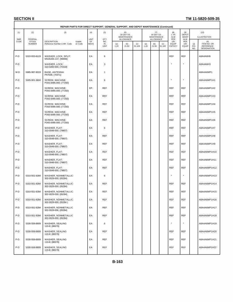
SECTION II TM 11-5820-509-35
REPAIR PARTS FOR DIRECT SUPPORT, GENERAL SUPPORT, AND DEPOT MAINTENANCE (Continued)
(1) (2) (3) (4) (5) (6) (7) (8) (9) (10)30 DAY DS 30 DAY GS 1 YR DEPOT
MAINTENANCE MAINTENANCE ALW MAINT ILLUSTRATIONSMR FEDERAL UNIT QTY ALLOWANCE ALLOWANCE PER ALW
CODE STOCK DESCRIPTION Usable OF INC 100 PER (b)NUMBER Reference Number & Mfr. Code on Code MEAS IN (a) (b) (c) (a) (b) (c) EQUIP 100 (a) ITEM NO. OR
UNIT 1-20 21-50 51-100 1-20 21-50 51-100 CNTGCY EQUIP FIG REFERENCENO. DESIGNATION
P-D 5310-933-8119 WASHER, LOCK, SPLIT: EA 6 REF REF A8A4A6H6MS35335-137; (96906)
P-D WASHER, LOCK: EA 3 * * A8A4A6H3310-0283-000; (70318)
M-D 5985-987-9019 BASE, ANTENNA: EA 1 A8A4A6MP1P57035; (70371)
P-D 5305-901-3604 SCREW, MACHINE: EA 6 * * A8A4A6MP1H1P343-0095-000; (77250)
P-D SCREW, MACHINE: EP. REF REF REF A8A4A6MP1H2P343-0095-000; (77250)
P-D SCREW, MACHINE: EA REF REF REF A8A4A6MP1H3P343-0095-000; (77250)
P-D SCREW, MACHINE: EA REF REF REF A8A4A6MP1H4P343-0095-000; (77250)
P-D SCREW, MACHINE: EA REF REF REF A8A4A6MP1H5P343-0095-000; (77250)
P-D SCREW, MACHINE: EA REF REF REF A8A4A6MP1H6P343-0095-000; (77250)
P-D WASHER, FLAT: EA 6 REF REF A8A4A6MP1H7310-0048-000; (79807)
P-D WASHER, FLAT: EA REF REF REF A8A4A6MP1H8310-0048-000; (79807)
P-D WASHER, FLAT: EA REF REF REF A8A4A6MP1H9310-0048-000; (79807)
P-D WASHER, FLAT: EA REF REF REF A8A4A6MP1H10310-0048-000; (79807)
P-D WASHER, FLAT: EA REF REF REF A8A4A6MP1H11310-0048-000; (79807)
P-D WASHER, FLAT: EA REF REF REF A8A4A6MP1H12310-0048-000; (79807)
P-D 5310-551-9284 WASHER, NONMETALLIC: EA 6 * * A8A4A6MP1H13302-0029-000; (05284)
P-D 5310-551-9284 WASHER, NONMETALLIC: EA REF REF REF A8A4A6MP1H14302-0029-000; (05284)
P-D 5310-551-9284 WASHER, NONMETALLIC: EA REF REF REF A8A4A6MP1H15302-0029-030; (05284)
P-D 5310-551-9284 WASHER, NONMETALLIC: EA REF REF REF A8A4A6MP1H16302-0029-000; (05284 )
P-D 5310-551-9284 WASHER, NONMETALLIC EA REF REF REF A8A4A6MP1H17302-0029-006; (05284)
P-D 5310-551-9284 WASHER, NONMETALLIC EA REF REF REF A8A4A6MP1H18302-0029-000; (05284)
P-D 5330-559-8909 WASHER, SEALING EA 6 * * A8A4A6MP1H19110-8; (86579)
P-D 5330-559-8909 WASHER, SEALING EA REF REF REF A8A4A6MP1H20110-8; (86579)
P-D 5330-559-8909 WASHER, SEALING EA REF REF REF A8A4A6MP1H21110-8; (86579)
P-D 5330-559-8909 WASHER, SEALING EA REF REF REF A8A4A6MP1H22110-8; (86579)
B-163

SECTION II TM 11-5820-509-35
REPAIR PARTS FOR DIRECT SUPPORT, GENERAL SUPPORT, AND DEPOT MAINTENANCE (Continued)
(1) (2) (3) (4) (5) (6) (7) (8) (9) (10)30 DAY DS 30 DAY GS 1 YR DEPOT
MAINTENANCE MAINTENANCE ALW MAINT ILLUSTRATIONSMR FEDERAL UNIT QTY ALLOWANCE ALLOWANCE PER ALW
CODE STOCK DESCRIPTION Usable OF INC 100 PER (b)NUMBER Reference Number & Mfr. Code on Code MEAS IN (a) (b) (c) (a) (b) (c) EQUIP 100 (a) ITEM NO. OR
UNIT 1-20 21-50 51-100 1-20 21-50 51-100 CNTGCY EQUIP FIG REFERENCENO. DESIGNATION
P-D 5330-559-8909 WASHER, SEALING EA REF REF REF A8A4A6MP1H23110-8; (86579)
P-D 5330-559-8909 WASHER, SEALING: EA REF REF REF A8A4A6MP1H24110-8; (86579)
P-D BEARING, BALL, ANNULAR: EA 9 REF REF A8A4A6MP2S6316FRHH3P15L02; (40920)
P-D BEARING, BALL, ANNULAR: EA REF REF REF A8A4A6MP3S6316FRHH3P15L02; (40920)
P-D BEARING, BALL, ANNULAR: EA REF REF REF A8A4A6MP4S6316FRHH3P15L02; (40920)
P-D BEARING, BALL, ANNULAR: EA REF REF REF A8A4A6MP5S6316FRHH3P15L02; (40920)
P-D BEARING, BALL, ANNULAR: EA REF REF REF A8A4A6MP6S6316FRHH3P15L02; (40920)
P-D BEARING, BALL, ANNULAR: EA REF REF REF A8A4A6MP7S6316FRHH3P15L02; (40920)
P-D BEARING, BALL, ANNULAR: EA REF REF REF A8A4A6MP8S6316FRHH3P15L02; (40920)
P-D BEARING, BALL, ANNULAR : EA REF REF REF ABA4A6MP9S6316FRHH3P15L02; (40920)
P-D BEARING, BALL, ANNULAR: EA REF REF REF A8A4A6MP10S6316FRIH3P15L02; (40920)
P-D 3120-865-8571 BEARING, SLEEVE EA 7 REF REF A8A4A6MP113L3F; (96881)
P-D 3120-865-8571 BEARING, SLEEVE EA REF REF REF ABA4A6MP123L3F; (96881)
P-D 3120-865-8571 BEARING, SLEEVE EA REF REF REF A8A4A6MP133L3F; (96881)
P-D 3120-865-8571 BEARING, SLEEVE EA REF REF REF A8A4A6MP143L3F; (96881)
P-D 3120-865-8571 BEARING, SLEEVE. EA REF REF REF A8A4A6MP153L3F; (96881)
P-D 3120-865-8571 BEARING, SLEEVE EA REF REF REF A8A4A6MP163L3F; (96881)
P-D 3120-865-8571 BEARING, SLEEVE EA REF REF REF A8A4A6MP173L3F; (96881)
P-D 5820-977-7652 BEARING, SLEEVE EA 2 * * A8A4A6MP18549-6089-002; (13499)
P-D NUT, HEXAGON EA 1 * * A8A4A6MP18H1500-6308-001; (13499)
P-D 5820-977-7652 BEARING, SLEEVE EA REF REF REF A8A4A6MP19549-6089-002; (13499)
P-D NUT, HEXAGON EA 1 REF REF ABA4A6MP19H1500-6308-001; (13499)
M-D 5820-977-1564 BLOCK, MOUNTING, FRONT EA 1 A8A4A6MP20549-6100-002; (13 499)
P-D 5305-415-2207 SCREW, MACHINE EA 1 * * ABA4A6MP20H1P342-0025-000; (77250)
M-D 5820-977-1553 BLOCK, MOUNTING-METER SHIELD EA 1 A8A4A6MP21549-6101-002; (13499)
B-164
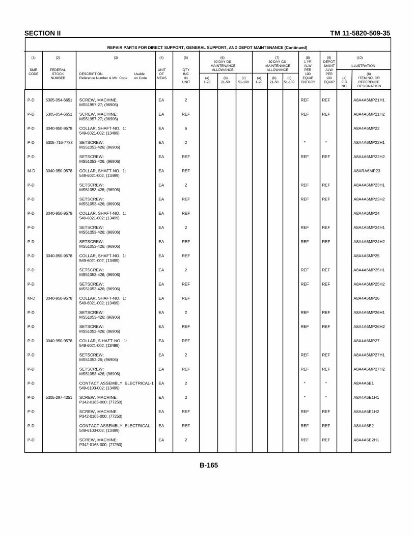
SECTION II TM 11-5820-509-35
REPAIR PARTS FOR DIRECT SUPPORT, GENERAL SUPPORT, AND DEPOT MAINTENANCE (Continued)
(1) (2) (3) (4) (5) (6) (7) (8) (9) (10)30 DAY DS 30 DAY GS 1 YR DEPOT
MAINTENANCE MAINTENANCE ALW MAINT ILLUSTRATIONSMR FEDERAL UNIT QTY ALLOWANCE ALLOWANCE PER ALW
CODE STOCK DESCRIPTION Usable OF INC 100 PER (b)NUMBER Reference Number & Mfr. Code on Code MEAS IN (a) (b) (c) (a) (b) (c) EQUIP 100 (a) ITEM NO. OR
UNIT 1-20 21-50 51-100 1-20 21-50 51-100 CNTGCY EQUIP FIG REFERENCENO. DESIGNATION
P-D 5305-054-6651 SCREW, MACHINE: EA 2 REF REF A8A4A6MP21H1MS51957-27; (96906)
P-D 5305-054-6651 SCREW, MACHINE: EA REF REF REF A8A4A6MP21H2MS51957-27; (96906)
P-D 3040-950-9578 COLLAR, SHAFT-NO. 1: EA 6 A8A4A6MP22549-6021-002; (13499)
P-D 5305-716-7733 SETSCREW: EA 2 * * A8A4A6MP22H1MS51053-426; (96906)
P-D SETSCREW: EA REF REF REF A8A4A6MP22H2MS51053-426; (96906)
M-D 3040-950-9578 COLLAR, SHAFT-NO. 1: EA REF A8ARA6MP23549-6021-002; (13499)
P-D SETSCREW: EA 2 REF REF A8A4A6MP23H1MS51053-426; (96906)
P-D SETSCREW: EA REF REF REF A8A4A6MP23H2MS51053-426; (96906)
P-D 3040-950-9578 COLLAR, SHAFT-NO. 1: EA REF A8A4A6MP24549-6021-002; (13499)
P-D SETSCREW: EA 2 REF REF A8A4A6MP24H1MS51053-426; (96906)
P-D SETSCREW: EA REF REF REF A8A4A6MP24H2MS51053-426; (96906)
P-D 3040-950-9578 COLLAR, SHAFT-NO. 1: EA REF A8A4A6MP25549-6021-002; (13499)
P-D SETSCREW: EA 2 REF REF A8A4A6MP25H1MS51053-426; (96906)
P-D SETSCREW: EA REF REF REF A8A4A6MP25H2MS51053-426; (96906)
M-D 3040-950-9578 COLLAR, SHAFT-NO. 1: EA REF A8A4A6MP26549-6021-002; (13499)
P-D SETSCREW: EA 2 REF REF A8A4A6MP26H1MS51053-426; (96906)
P-D SETSCREW: EA REF REF REF A8A4A6MP26H2MS51053-426; (96906)
P-D 3040-950-9578 COLLAR, S HAFT-NO. 1: EA REF A8A4A6MP27549-6021-002; (13499)
P-D SETSCREW: EA 2 REF REF A8A4A6MP27H1MS51053-26; (96906)
P-D SETSCREW: EA REF REF REF A8A4A6MP27H2MS51053-426; (96906)
P-D CONTACT ASSEMBLY, ELECTRICAL-1: EA 2 * * A8A4A6E1549-6103-002; (13499)
P-D 5305-297-4351 SCREW, MACHINE: EA 2 * * A8A4A6E1H1P342-0165-000; (77250)
P-D SCREW, MACHINE: EA REF REF REF A8A4A6E1H2P342-0165-000; (77250)
P-D CONTACT ASSEMBLY, ELECTRICAL-: EA REF REF REF A8A4A6E2549-6103-002; (13499)
P-D SCREW, MACHINE: EA 2 REF REF A8A4A6E2H1P342-0165-000; (77250)
B-165

SECTION II TM 11-5820-509-35
REPAIR PARTS FOR DIRECT SUPPORT, GENERAL SUPPORT, AND DEPOT MAINTENANCE (Continued)
(1) (2) (3) (4) (5) (6) (7) (8) (9) (10)30 DAY DS 30 DAY GS 1 YR DEPOT
MAINTENANCE MAINTENANCE ALW MAINT ILLUSTRATIONSMR FEDERAL UNIT QTY ALLOWANCE ALLOWANCE PER ALW
CODE STOCK DESCRIPTION Usable OF INC 100 PER (b)NUMBER Reference Number & Mfr. Code on Code MEAS IN (a) (b) (c) (a) (b) (c) EQUIP 100 (a) ITEM NO. OR
UNIT 1-20 21-50 51-100 1-20 21-50 51-100 CNTGCY EQUIP FIG REFERENCENO. DESIGNATION
P-D SCREW, MACHINE: EA REF REF REF A8A4A6E2H2P342-0165-000; (77250)
M-D COUPLING, HALF, SHAFT, NO. 2: EA 1 A8A4A6MP61549-6048-002; (13499)
M-D COUPLING, HALF, SHAFT, NO 3: EA 2 A8A4A6MP285149-6049-002; (13499 )
M-D COUPLING, HALF, SHAFT, NO. 3: EA REF A8A4A6MP29549-6049-002; (13499)
M-D GASKET, BEARING: EA 2 A8A4A6MP30549-6090-002; (13499)
M-D GASKET, BEARING: EA REF A8A4A6MP31549-6090-002; (13499)
M-D 5330-618-3447 GASKET, RUBBER, CIRCULAR: EA 3 A8A4A6MP32MS9021-008; (96906)
M-D 5330-618-3447 GASKET, RUBBER, CIRCULAR: EA REF A8A4A6MP33MS9021-008; (96906)
M-D 5330-618-3447 GASKET, RUBBER, CIRCULAR: EA REF A8A4A6MP34MS9021-008; (969 06)
M-D GASKET, TERMINAL FEED THRU: EA 1 A8A4A6MP35549-6091-002; (13499)
P-H-T 5820-977-1563 GEAR ASSEMBLY, BEVEL, SPUR, NO. 1: EA 1 * * 1 8 3 A8A4A6A15149-6045-002; (13499)
X1-D GEAR, BEVEL, NO 1: EA 1 A8A4A6A1MP1549-6029-002; (13499)
X1-D GEAR, SPUR, NO. 6: EA 1 A8A4A6A1MP2549-6042-002; (13499)
X1-D PIN, GROOVED, HEADLESS: EA 2 A8A4A6A1MP3MS35672-1; (96906)
X1-D PIN, GROOVED, HEADLESS: EA REF A8A4A6A1MP4MS35672-1; (96906)
X1-D PIN, GROOVED, HEADLESS: EA 1 A8A4A6A1MP5MS35672-7; (96906)
X1-D SHAFT, STRAIGHT-NO 4: EA 1 A8A4A6A1MP6549-6050-002; (13499)
P-D 5820 -977-1558 GEAR ASSEMBLY, BEVEL, SPUR-NO 3: EA 1 8 3 A8A4A6A2549-6047-002; (13499)
X1-D GEAR, BEVEL, NO 1: EA 1 A8A4A6A2MP1549-6029-002; (13499)
X1-D GEAR, SPUR, NO. 9: EA 1 A8A4A6A2MP2549-6043-002; (13499)
X1-D PIN, GROOVED, HEADLESS: EA 2 A8A4A6A2MP3MS35672-1; (96906)
X1-D PIN, GROOVED, HEADLESS: EA REF A8A4A6A2MP4MS35672-1; (96906)
X1-D PIN, GROOVED, HEADLESS: EA 1 A8A4A6A2MP5MS35672-7; (96906)
X1-D SHAFT, STRAIGHT-NO 2: EA 1 A8A4A6A2MP6549-6041-002; (13499)
P-D 3020-976-5392 GEAR ASSEMBLY, SPUR-NO. 1: EA 1 8 3 A8A4A6A3549-6104-002; (13499)
B-166

SECTION II TM 11-5820-509-35
REPAIR PARTS FOR DIRECT SUPPORT, GENERAL SUPPORT, AND DEPOT MAINTENANCE (Continued)
(1) (2) (3) (4) (5) (6) (7) (8) (9) (10)30 DAY DS 30 DAY GS 1 YR DEPOT
MAINTENANCE MAINTENANCE ALW MAINT ILLUSTRATIONSMR FEDERAL UNIT QTY ALLOWANCE ALLOWANCE PER ALW
CODE STOCK DESCRIPTION Usable OF INC 100 PER (b)NUMBER Reference Number & Mfr. Code on Code MEAS IN (a) (b) (c) (a) (b) (c) EQUIP 100 (a) ITEM NO. OR
UNIT 1-20 21-50 51-100 1-20 21-50 51-100 CNTGCY EQUIP FIG REFERENCENO. DESIGNATION
X1-D GEAR, SPUR, NO 1: EA 1 A8A4A6A3MP1549-6092-002; (13499)
X1-D PIN, SPRING: EA 1 A8A4A6A3MP2MS16562-190; (96906)
X1-D STOP, DIAL, NO. 2: EA 1 A8A4A6A3MP3549-6094-002; (13499)
X1-D SCREW, MACHINE: EA 1 A8A4A6A3MP3H1MS51959-12; (96906)
P-D 3020-088-6021 GEAR, BEVEL, NO 2: EA 1 8 3 A8A4A6MP36549-6121-002; (13499)
P-D SETSCREW: EA 2 REF REF A8A4A6MP36H1MS51053-L26; (96906)
P-D SETSCREW: EA REF REF REF A8A4A6MP36H2MS51053-426; (96906)
P-D 5820-977-1559 GEARSSHAFT, BEVEL, SPUR-PRESSED: EA 1 8 3 A8A4A6A4549-6055-002; (13499)
X1-D GEAR, BEVEL, NO 2: EA 1 A8A4A6A4MP1549-6038-002; (13499)
X1-D GEARSHAFT, SPUR-NO. 1: EA 1 A8A4A6A4MP2549-6033-002; (13499)
M-D GEARSHAFT-COUPLER ASSEMBLY: EA 1 A8A4A6A5549-6046-002; (13499)
S4-D COUPLING HALF, SHAFT-NO. 1: EA 1 A8A4A6A5MP1549-6040-002; (13499)
P-D 5305-766-2422 SCREW, MACHINE: EA 4 33 20 A8A4A6A5MP1H1MS51959-1; (96906)
P-D 5305-766-2422 SCREW, MACHINE: EA REF REF REF A8A4A6A5MP1H2MS51959-1; (96906)
P-D 5305-766-2422 SCREW, MACHINE: EA REF REF REF A8A4A6A5MP1H3MS51959-1; (96906)
P-D 5305-766-2422 SCREW, MACHINE: EA REF REF REF A8A4A6A5MP1H4MS51959-1; (96906)
P-D 3040-977-1551 GEARSHAFT, SPUR-NO 2: EA 1 8 3 A8A4A6MP37549-6034-002; (13499)
P-D 5820-977-1558 GEARSHAFT, SPUR-12 TEETH: EA 1 8 3 A8A4A6MP38549-6030-002; (13499)
P-D GEAR, SPUR, DETENT: EA 1 8 3 A3A4A6MP39549-6052-002; (13499)
P-D GEAR, SPUR, NO.: EA 1 8 3 A8A4A6MP40549-6036-oo002; (13499)
P-D 3020-985-2235 GEAR, SPUR, NO 4: EA 1 8 3 A8A4A6A6549-6039-002; (13499)
X1-D HUB-GEAR: EA 1 A8A4A6A6MP1549-6035-002; (13499)
P-D 5305-764-2966 SCREW, MACHINE: EA 4 REF RE A8A4A6A6MP1H1MS51959-2; (96906)
P-D 5305-764-2966 SCREW, MACHINE: EA REF REF REF A8A4A6A6MP1H2MS51959-2; (96906)
P-D 5305-764-2966 SCREW, MACHINE: EA REF REF REF A8A4A6A6MP1H3MS51959-2; (96906)
B-167
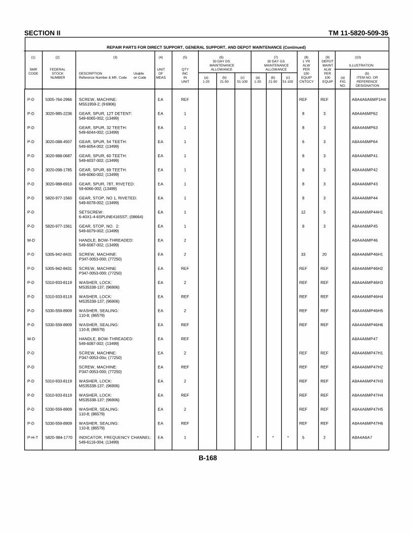
SECTION II TM 11-5820-509-35
REPAIR PARTS FOR DIRECT SUPPORT, GENERAL SUPPORT, AND DEPOT MAINTENANCE (Continued)
(1) (2) (3) (4) (5) (6) (7) (8) (9) (10)30 DAY DS 30 DAY GS 1 YR DEPOT
MAINTENANCE MAINTENANCE ALW MAINT ILLUSTRATIONSMR FEDERAL UNIT QTY ALLOWANCE ALLOWANCE PER ALW
CODE STOCK DESCRIPTION Usable OF INC 100 PER (b)NUMBER Reference Number & Mfr. Code on Code MEAS IN (a) (b) (c) (a) (b) (c) EQUIP 100 (a) ITEM NO. OR
UNIT 1-20 21-50 51-100 1-20 21-50 51-100 CNTGCY EQUIP FIG REFERENCENO. DESIGNATION
P-D 5305-764-2966 SCREW, MACHINE: EA REF REF REF A8A4A6A6MP1H4MS51959-2; (96906)
P-D 3020-985-2236 GEAR, SPUR, 12T DETENT: EA 1 8 3 A8A4A6MP62549-6065-002; (13499)
P-D GEAR, SPUR, 32 TEETH: EA 1 8 3 A8A4A6MP63549-6044-002; (13499)
P-D 3020-088-4507 GEAR, SPUR, 54 TEETH: EA 1 6 3 A8A4A6MP64549-6054-002; (13499)
P-D 3020-988-0687 GEAR, SPUR, 60 TEETH: EA 1 8 3 A8A4A6MP41549-6037-002; (13499)
P-D 3020-098-1785 GEAR, SPUR, 69 TEETH: EA 1 8 3 A8A4A6MP42549-6060-002; (13499)
P-D 3020-988-6910 GEAR, SPUR, 78T, RIVETED: EA 1 8 3 A8A4A6MP4359-6066-002; (13499)
P-D 5820-977-1560 GEAR, STOP, NO 1, RIVETED: EA 1 8 3 A8A4A6MP44549-6078-002; (13499)
P-D SETSCREW: EA 1 12 5 A8A4A6MP44H16-40X1-4-6SPLINE416SST; (08664)
P-D 5820-977-1561 GEAR, STOP, NO. 2: EA 1 8 3 A8A4A6MP45549-6079-002; (13499)
M-D HANDLE, BOW-THREADED: EA 2 A8A4A6MP46549-6087-002; (13499)
P-D 5305-942-8431 SCREW, MACHINE: EA 2 33 20 A8A4A6MP46H1P347-0053-000; (77250)
P-D 5305-942-8431 SCREW, MACHINE: EA REF REF REF A8A4A6MP46H2P347-0053-000; (77250)
P-D 5310-933-8119 WASHER, LOCK: EA 2 REF REF A8A4A6MP46H3MS35338-137; (96906)
P-D 5310-933-8119 WASHER, LOCK: EA REF REF REF A8A4A6MP46H4MS35338-137; (96906)
P-D 5330-559-8909 WASHER, SEALING: EA 2 REF REF A8A4A6MP46H5110-8; (86579)
P-D 5330-559-8909 WASHER, SEALING: EA REF REF REF A8A4A6MP46H6110-8; (86579)
M-D HANDLE, BOW-THREADED: EA REF A8A4A6MP47549-6087-002; (13499)
P-D SCREW, MACHINE: EA 2 REF REF A8A4A6MP47H1P347-0053-00o; (77250)
P-D SCREW, MACHINE: EA REF REF REF A8A4A6MP47H2P347-0053-000; (77250)
P-D 5310-933-8119 WASHER, LOCK: EA 2 REF REF A8A4A6MP47H3MS35338-137; (96906)
P-D 5310-933-8119 WASHER, LOCK: EA REF REF REF A8A4A6MP47H4MS35338-137; (96906)
P-D 5330-559-8909 WASHER, SEALING: EA 2 REF REF A8A4A6MP47H5110-8; (86579)
P-D 5330-559-8909 WASHER, SEALING: EA REF REF REF A8A4A6MP47H6110-8; (86579)
P-H-T 5820-984-1770 INDICATOR, FREQUENCY CHANNEL: EA 1 * * * 5 2 A8A4A6A7549-6116-004; (13499)
B-168
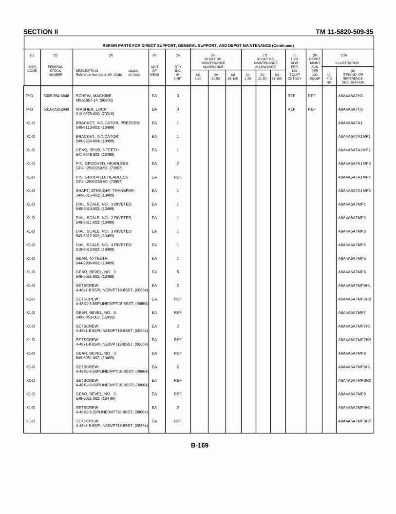
SECTION II TM 11-5820-509-35
REPAIR PARTS FOR DIRECT SUPPORT, GENERAL SUPPORT, AND DEPOT MAINTENANCE (Continued)
(1) (2) (3) (4) (5) (6) (7) (8) (9) (10)30 DAY DS 30 DAY GS 1 YR DEPOT
MAINTENANCE MAINTENANCE ALW MAINT ILLUSTRATIONSMR FEDERAL UNIT QTY ALLOWANCE ALLOWANCE PER ALW
CODE STOCK DESCRIPTION Usable OF INC 100 PER (b)NUMBER Reference Number & Mfr. Code on Code MEAS IN (a) (b) (c) (a) (b) (c) EQUIP 100 (a) ITEM NO. OR
UNIT 1-20 21-50 51-100 1-20 21-50 51-100 CNTGCY EQUIP FIG REFERENCENO. DESIGNATION
P-D 5305-054-5648 SCREW, MACHINE: EA 3 REF REF A8A4A6A7H3MS51957-14; (96906)
P-D 5310-058-2949 WASHER, LOCK: EA 3 REF REF A8A4A6A7H3310-0278-000; (70318)
X1-D BRACKET, INDICATOR, PRESSED: EA 1 A8A4A6A7A1549-6113-003; (13499)
X1-D BRACKET, INDICATOR: EA 1 A8A4A6A7A1MP1549-6254-004; (13499)
X1-D GEAR, SPUR, 8 TEETH: EA 1 A8A4A6A7A1MP2541-8646-002; (13499)
X1-D PIN, GROOVED, HEADLESS: EA 2 A8A4A6A7A1MP3GP4-125X0250-50; (73957)
X1-D PIN, GROOVED, HEADLESS: EA REF A8A4A6A7A1MP4GP4-125X0250-50; (73957)
X1-D SHAFT, STRAIGHT-TRANSFER: EA 1 A8A4A6A7A1MP5549-6015-002; (13499)
X1-D DIAL, SCALE, NO. 1 RIVETED: EA 1 A8A4A6A7MP1549-6010-002; (13499)
X1-D DIAL, SCALE, NO. 2 RIVETED: EA 1 A8A4A6A7MP2549-6011-002; (13499)
X1-D DIAL, SCALE, NO. 3 RIVETED: EA 1 A8A4A6A7MP3549-6012-002; (13499)
X1-D DIAL, SCALE, NO. 4 RIVETED: EA 1 A8A4A6A7MP4519-6013-002; (13499)
X1-D GEAR, 40 TEETH: EA 1 A8A4A6A7MP5544-2986-002; (13499)
X1-D GEAR, BEVEL, NO. 3: EA 5 A8A4A6A7MP6549-6051-002; (13499)
X1-D SETSCREW: EA 2 A8A4A6A7MP6H14-48x1-8 6SPLINE0VPT18-8SST; (08664)
X1-D SETSCREW: EA REF A8A4A6A7MP6H24-48X1-8 6SPLINE0VPT18-8SST; (08664)
X1-D GEAR, BEVEL, NO. 3: EA REF A8A4A6A7MP7549-6051-002; (13499)
X1-D SETSCREW: EA 2 A8A4A6A7MP7H14-48x1-8 6SPLINED0PT18-8SST; (08664)
X1-D SETSCREW: EA REF A8A4A6A7MP7H24-48x1-8 6SPLINE0VPT18-8SST; (08664)
X1-D GEAR, BEVEL, NO. 3: EA REF A8A4A6A7MP8549-6051-002; (13499)
X1-D SETSCREW- EA 2 A8A4A6A7MP8H14-48X1-8 6SPLINE0VPT18-8SST; (08664)
X1-D SETSCREW EA REF A8A4A6A7MP8H24-48X1-8 6SPLINE0VPT18-8SST; (08664)
X1-D GEAR, BEVEL, NO. 3: EA REF A8A4A6A7MP9549-6051-002; (134 99)
X1-D SETSCREW EA 2 A8A4A6A7MP9H14-48X1-8 (SPLINE0VPT18-8SST; (08664)
X1-D SETSCREW. EA REF A8A4A6A7MP9H24-48x1-8 6SPLINE0VPT18-8SST; (08664)
B-169
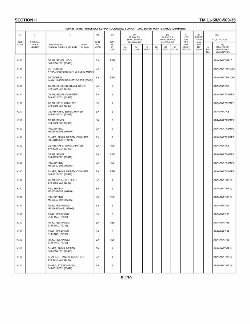
SECTION II TM 11-5820-509-35
REPAIR PARTS FOR DIRECT SUPPORT, GENERAL SUPPORT, AND DEPOT MAINTENANCE (Continued)
(1) (2) (3) (4) (5) (6) (7) (8) (9) (10)30 DAY DS 30 DAY GS 1 YR DEPOT
MAINTENANCE MAINTENANCE ALW MAINT ILLUSTRATIONSMR FEDERAL UNIT QTY ALLOWANCE ALLOWANCE PER ALW
CODE STOCK DESCRIPTION Usable OF INC 100 PER (b)NUMBER Reference Number & Mfr. Code on Code MEAS IN (a) (b) (c) (a) (b) (c) EQUIP 100 (a) ITEM NO. OR
UNIT 1-20 21-50 51-100 1-20 21-50 51-100 CNTGCY EQUIP FIG REFERENCENO. DESIGNATION
X1-D GEAR, BEVEL, NO 3: EA REF A8A4A6A7MP10549-6051-002; (13499)
X1-D SETSCREW: EA 2 A8A4A6A7MP10H14-48X1-8 6SPLINE0VPT18-8SST; (08664)
X1-D SETSCREW: EA REF A8A4A6A7MP10H24-48X1-8 6SPLINE0VPT18-8SST (08664)
X1-D GEAR, CLUSTER, BEVEL-SPUR: EA ] A8A4A6A7A2549-6024-002; (13499)
X1-D GEAR, BEVEL-COUNTER: EA 1 A8A4A6A7A2MP1549-6022-002; (13499)
X1-D GEAR, SPUR-COUNTER: EA 1 A8A4A6A7A2MP2549-6023-002; (13499)
X1-D GEARSHAFT, BEVEL PINNED: EA 2 A8A4A6A7A3549-6225-002; (13499)
X1-D GEAR, BEVEL: EA 2 A8A4A6A7A3MP1549-6224-002; (13499)
X1-D PIN, SPRING: EA 2 A8A4A6A7A3MP2MS16562-192; (96906)
X1-D SHAFT, SHOULDERED, COUNTER: EA 2 A8A4A6A7A3MP35R9-6018-002; (13499)
X1-D GEARSHAFT, BEVEL PINNED: EA REF A8A4A6A7A4549-6225-002; (13499)
X1-D GEAR, BEVEL: EA REF A8A4A6A7A4MP1549-6224-002; (13499)
X1-D PIN, SPRING: EA REF A8A4A6A7A4MP2MS16562-192; (96906)
X1-D SHAFT, SHOULDERED, COUNTER: EA REF A8A4A6A7A4MP3549-6018-002; (13499)
X1-D GEAR, SPUR, 36 TEETH: EA 1 A8A4A6A7MP11549-6058-002; (13499)
X1-D PIN, SPRING: EA 2 A8A4A6A7MP12MS16562-192; (96906)
X1-D PIN, SPRING: EA REF A8A4A6A7MP13MS16562-192; (96906)
X1-D RING, RETAINING: EA 1 A8A4A6A7H1MS16632-1018; (96906)
X1-D RING, RETAINING: EA 2 A8A4A6A7H25133-15C; (79136)
X1-D RING, RETAINING: EA REF A8A4A6A7H35133-15C; (79136)
X1-D RING, RETAINING: EA 2 A8A4A6A7H45133-18C; (79136)
X1-D RING, RETAINING: EA REF A8A4A6A7H55133-18C; (79136)
X1-D SHAFT, SHOULDERED: EA 1 A8A4A6A7MP14549-6053-002; (13499)
X1-D SHAFT, STRAIGHT-COUNTER: EA 1 A8A4A6A7MP15549-6014-002; (13499)
X1-D SHAFT, STRAIGHT-NO 1: EA 1 A8A4A6A7MP16549-6016-002; (13499)
B-170
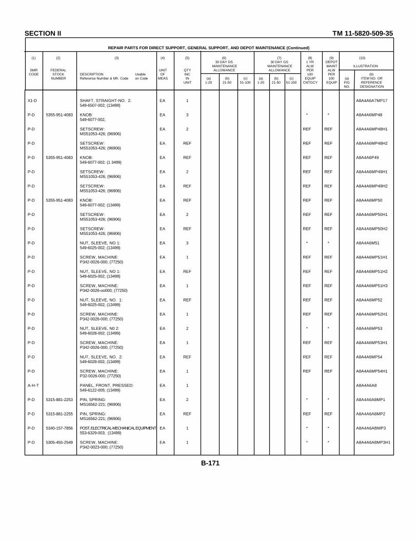
SECTION II TM 11-5820-509-35
REPAIR PARTS FOR DIRECT SUPPORT, GENERAL SUPPORT, AND DEPOT MAINTENANCE (Continued)
(1) (2) (3) (4) (5) (6) (7) (8) (9) (10)30 DAY DS 30 DAY GS 1 YR DEPOT
MAINTENANCE MAINTENANCE ALW MAINT ILLUSTRATIONSMR FEDERAL UNIT QTY ALLOWANCE ALLOWANCE PER ALW
CODE STOCK DESCRIPTION Usable OF INC 100 PER (b)NUMBER Reference Number & Mfr. Code on Code MEAS IN (a) (b) (c) (a) (b) (c) EQUIP 100 (a) ITEM NO. OR
UNIT 1-20 21-50 51-100 1-20 21-50 51-100 CNTGCY EQUIP FIG REFERENCENO. DESIGNATION
X1-D SHAFT, STRAIGHT-NO. 2: EA 1 A8A4A6A7MP17549-6507-002; (13499)
P-D 5355-951-4083 KNOB: EA 3 * * A8A4A6MP48549-6077-002,
P-D SETSCREW: EA 2 REF REF A8A4A6MP48H1MS51053-426; (96906)
P-D SETSCREW: EA REF REF REF A8A4A6MP48H2MS51053-426; (96906)
P-D 5355-951-4083 KNOB: EA REF REF REF A8A4A6P49549-6077-002; (1 3499)
P-D SETSCREW: EA 2 REF REF A8A4A6MP49H1MS51053-426; (96906)
P-D SETSCREW: EA REF REF REF A8A4A6MP49H2MS51053-426; (96906)
P-D 5355-951-4083 KNOB: EA REF REF REF A8A4A6MP50549-6077-002; (13499)
P-D SETSCREW: EA 2 REF REF A8A4A6MP50H1MS51053-426; (96906)
P-D SETSCREW: EA REF REF REF A8A4A6MP50H2MS51053-426; (96906)
P-D NUT, SLEEVE, NO 1: EA 3 * * A8A4A6M51549-6025-002; (13499)
P-D SCREW, MACHINE: EA 1 REF REF A8A4A6MP51H1P342-0026-000; (77250)
P-D NUT, SLEEVE, NO 1: EA REF REF REF A8A4A6MP51H2549-6025-002; (13499)
P-D SCREW, MACHINE: EA 1 REF REF A8A4A6MP51H3P342-0026-oo000; (77250)
P-D NUT, SLEEVE, NO. 1: EA REF REF REF A8A4A6MP52549-6025-002; (13499)
P-D SCREW, MACHINE: EA 1 REF REF A8A4A6MP52H1P342-0026-000; (77250)
P-D NUT, SLEEVE, N0 2: EA 2 * * A8A4A6MP53549-6028-002; (13499)
P-D SCREW, MACHINE: EA 1 REF REF A8A4A6MP53H1P342-0026-000; (77250)
P-D NUT, SLEEVE, NO. 2: EA REF REF REF A8A4A6MP54549-6028-002; (13499)
P-D SCREW, MACHINE: EA 1 REF REF A8A4A6MP54H1P32-0026-000; (77250)
A-H-T PANEL, FRONT, PRESSED: EA 1 A8A4A6A8549-6122-005; (13499)
P-D 5315-881-2253 PIN, SPRING: EA 2 * * A8A4A6A8MP1MS16562-221; (96906)
P-D 5315-881-2255 PIN, SPRING: EA REF REF REF A8A4A6A8MP2MS16562-221; (96906)
P-D 5340-157-7856 POST, ELECTRICAL-MECHANICAL EQUIPMENT: EA 1 * * A8A4A6ABMP3553-6329-003; (13499)
P-D 5305-455-2549 SCREW, MACHINE: EA 1 * * A8A4A6A8MP3H1P342-0023-000; (77250)
B-171
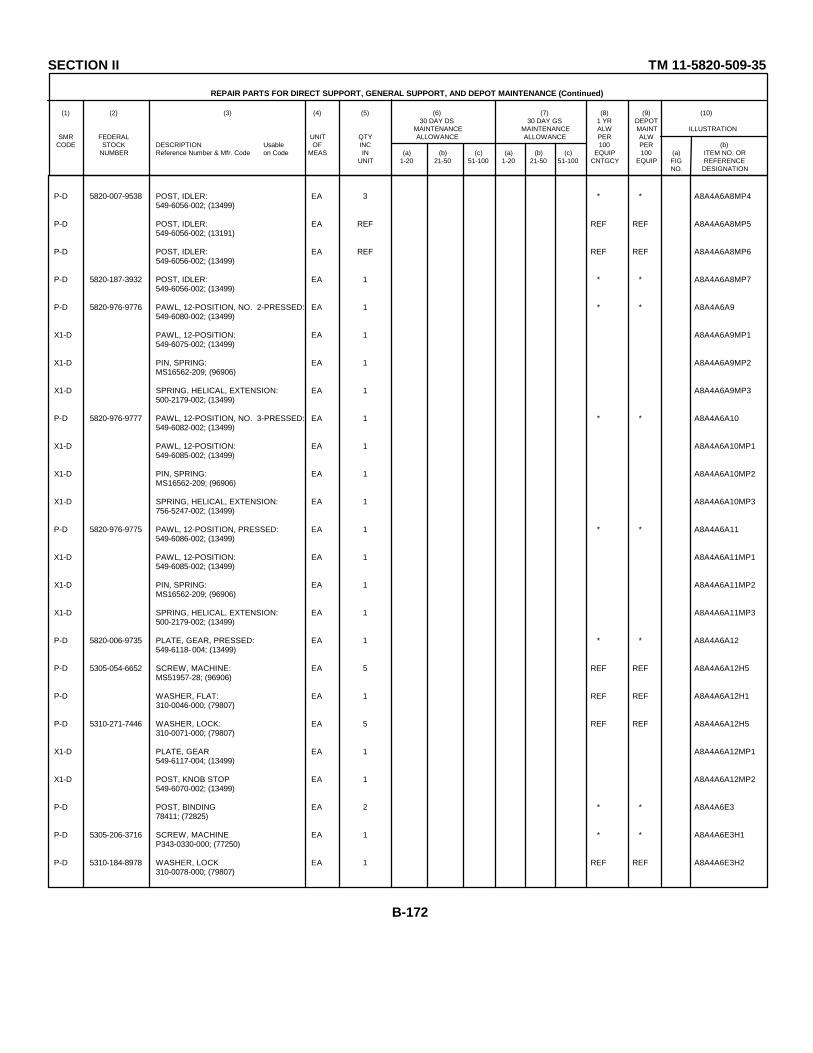
SECTION II TM 11-5820-509-35
REPAIR PARTS FOR DIRECT SUPPORT, GENERAL SUPPORT, AND DEPOT MAINTENANCE (Continued)
(1) (2) (3) (4) (5) (6) (7) (8) (9) (10)30 DAY DS 30 DAY GS 1 YR DEPOT
MAINTENANCE MAINTENANCE ALW MAINT ILLUSTRATIONSMR FEDERAL UNIT QTY ALLOWANCE ALLOWANCE PER ALW
CODE STOCK DESCRIPTION Usable OF INC 100 PER (b)NUMBER Reference Number & Mfr. Code on Code MEAS IN (a) (b) (c) (a) (b) (c) EQUIP 100 (a) ITEM NO. OR
UNIT 1-20 21-50 51-100 1-20 21-50 51-100 CNTGCY EQUIP FIG REFERENCENO. DESIGNATION
P-D 5820-007-9538 POST, IDLER: EA 3 * * A8A4A6A8MP4549-6056-002; (13499)
P-D POST, IDLER: EA REF REF REF A8A4A6A8MP5549-6056-002; (13191)
P-D POST, IDLER: EA REF REF REF A8A4A6A8MP6549-6056-002; (13499)
P-D 5820-187-3932 POST, IDLER: EA 1 * * A8A4A6A8MP7549-6056-002; (13499)
P-D 5820-976-9776 PAWL, 12-POSITION, NO. 2-PRESSED: EA 1 * * A8A4A6A9549-6080-002; (13499)
X1-D PAWL, 12-POSITION: EA 1 A8A4A6A9MP1549-6075-002; (13499)
X1-D PIN, SPRING: EA 1 A8A4A6A9MP2MS16562-209; (96906)
X1-D SPRING, HELICAL, EXTENSION: EA 1 A8A4A6A9MP3500-2179-002; (13499)
P-D 5820-976-9777 PAWL, 12-POSITION, NO. 3-PRESSED: EA 1 * * A8A4A6A10549-6082-002; (13499)
X1-D PAWL, 12-POSITION: EA 1 A8A4A6A10MP1549-6085-002; (13499)
X1-D PIN, SPRING: EA 1 A8A4A6A10MP2MS16562-209; (96906)
X1-D SPRING, HELICAL, EXTENSION: EA 1 A8A4A6A10MP3756-5247-002; (13499)
P-D 5820-976-9775 PAWL, 12-POSITION, PRESSED: EA 1 * * A8A4A6A11549-6086-002; (13499)
X1-D PAWL, 12-POSITION: EA 1 A8A4A6A11MP1549-6085-002; (13499)
X1-D PIN, SPRING: EA 1 A8A4A6A11MP2MS16562-209; (96906)
X1-D SPRING, HELICAL, EXTENSION: EA 1 A8A4A6A11MP3500-2179-002; (13499)
P-D 5820-006-9735 PLATE, GEAR, PRESSED: EA 1 * * A8A4A6A12549-6118- 004; (13499)
P-D 5305-054-6652 SCREW, MACHINE: EA 5 REF REF A8A4A6A12H5MS51957-28; (96906)
P-D WASHER, FLAT: EA 1 REF REF A8A4A6A12H1310-0046-000; (79807)
P-D 5310-271-7446 WASHER, LOCK: EA 5 REF REF A8A4A6A12H5310-0071-000; (79807)
X1-D PLATE, GEAR EA 1 A8A4A6A12MP1549-6117-004; (13499)
X1-D POST, KNOB STOP EA 1 A8A4A6A12MP2549-6070-002; (13499)
P-D POST, BINDING EA 2 * * A8A4A6E378411; (72825)
P-D 5305-206-3716 SCREW, MACHINE EA 1 * * A8A4A6E3H1P343-0330-000; (77250)
P-D 5310-184-8978 WASHER, LOCK EA 1 REF REF A8A4A6E3H2310-0078-000; (79807)
B-172

SECTION II TM 11-5820-509-35
REPAIR PARTS FOR DIRECT SUPPORT, GENERAL SUPPORT, AND DEPOT MAINTENANCE (Continued)
(1) (2) (3) (4) (5) (6) (7) (8) (9) (10)30 DAY DS 30 DAY GS 1 YR DEPOT
MAINTENANCE MAINTENANCE ALW MAINT ILLUSTRATIONSMR FEDERAL UNIT QTY ALLOWANCE ALLOWANCE PER ALW
CODE STOCK DESCRIPTION Usable OF INC 100 PER (b)NUMBER Reference Number & Mfr. Code on Code MEAS IN (a) (b) (c) (a) (b) (c) EQUIP 100 (a) ITEM NO. OR
UNIT 1-20 21-50 51-100 1-20 21-50 51-100 CNTGCY EQUIP FIG REFERENCENO. DESIGNATION
P-D 5330-618-9563 WASHER, SEALING: EA 1 * A8A4A6E3H3110-6; (86579)
P-D 5940-258-1836 POST, BINDING: EA REF REF REF A8A4A6E47841; (72825)
P-D SCREW, MACHINE: EA 1 REF REF A8A4A6E4H1P343-0330-000; (77250)
P-D 5310-184-8978 WASHER, LOCK: EA 1 REF REF A8A4A6E4H2310-0078-000; (79807)
P-D 5330-618 -9563 WASHER, SEALING: EA 1 REF REF A8A4A6E4H3110-6; (86579)
P-D POST, PIVOT-CENTER KNOB: EA 3 * * A8A4A6MP55549-6076-002; (13499)
P-D 5310-262-6105 NUT, PLAIN, HEXAGON: EA 1 REF REF A8A4A6MP55H1P313-0045-000; (77250)
P-D 5310-271-7446 WASHER, LOCK: EA 1 REF REF A8A4A6MP55H2310-0071-000; (79807)
P-D POST, PIVOT-CENTER KNOB: EA REF REF REF A8A4A6MP56549-6076-002; (13499)
P-D 5310-262-6105 NUT, PLAIN, HEXAGON: EA 1 REF REF A8A4A6MP56H1P313-0045-000; (77250 )
P-D 5310-271-7446 WASHER, LOCK: EA 1 REF REF A8A4A6MP56H2310-0071-000; (79807)
P-D POST, PIVOT-CENTER KNOB: EA REF REF REF A8A4A6MP57549-6076-002; ( 13499)
P-D 5310-262-6105 NUT, PLAIN, HEXAGON: EA 1 REF REF A8A4A6MP57H1P313-0045-000; (77250 )
P-D 5310-271-7446 WASHER, LOCK: EA 1 REF REF A8A4A6MP57H2310-0071-000; (79807)
P-D 5340-602-6075 RING, RETAINING: EA 3 * * A8A4A6H1MS16624-18; (96906)
P-D 5340-602-6075 RING, RETAINING: EA REF REF REF A8A4A6H2MS16624-18; (96906)
P-D 5340-602-6075 RING, RETAINING: EA REF REF REF A8A4A6H3MS16624-18; (96906)
P-D 5340-720-8064 RING, RETAINING: EA 1 * * A8A4A6H4MS16624-1025; (96906)
P-D 5340-634-7444 RING, RETAINING: EA 4 * * A8A4A6H5MS16632-1018; (96906)
P-D 5340-634-7444 RING, RETAINING: EA REF REF REF A8A4A6H6MS16632-1018; (96906)
P-D 5340-634-7444 RING, RETAINING: EA REF REF REF A8A4A6H7MS16632-1018; (96906)
P-D 5340-634-7444 RING, RETAINING: EA REF REF REF A8A4A6H8MS16632-1018; (96906)
P-D 5340-200-3475 RING, RETAINING: EA 6 * * A8A4A6H95133-18C; (79136)
P-D 5340-200-3475 RING, RETAINING: EA REF REF REF A8A4A6H105133-18C; (79136)
P-D 5340-200-3475 RING, RETAINING: EA REF REF REF A8A4A6H115133-18C; (79136)
B-173

SECTION II TM 11-5820-509-35
REPAIR PARTS FOR DIRECT SUPPORT, GENERAL SUPPORT, AND DEPOT MAINTENANCE (Continued)
(1) (2) (3) (4) (5) (6) (7) (8) (9) (10)30 DAY DS 30 DAY GS 1 YR DEPOT
MAINTENANCE MAINTENANCE ALW MAINT ILLUSTRATIONSMR FEDERAL UNIT QTY ALLOWANCE ALLOWANCE PER ALW
CODE STOCK DESCRIPTION Usable OF INC 100 PER (b)NUMBER Reference Number & Mfr. Code on Code MEAS IN (a) (b) (c) (a) (b) (c) EQUIP 100 (a) ITEM NO. OR
UNIT 1-20 21-50 51-100 1-20 21-50 51-100 CNTGCY EQUIP FIG REFERENCENO. DESIGNATION
P-D 5340-200-3475 RING, RETAINING: EA REF REF REF A8A4A6H125133-18C; (T9136)
P-D 5340-200-3475 RING, RETAINING: EA REF REF REF A8A4A6H135133-18C; (79136)
P-D 5340-200-3475 RING, RETAINING: EA REF REF REF A8A4A6H145133-18C; (79136)
P-D 5305-984-2144 SCREW, EYE: EA 3 * * A8A4A6MP58549-6081-002; (13499)
P-D 5305-984-2144 SCREW, EYE: EA REF REF REF A8A4A6MP59549-6081-002; (13499)
P-D 5305-984-2144 SCREW, EYE: EA REF REF REF A8A4A6MP60549-6081-002; (13499)
M-D SHIELD, METER: EA 1 A8A4A6E5549-6114-003; (13499)
P-D SCREW, SELF-LOCKING: EA 4 REF REF A8A4A6E5H1LP51959-13M; ( 03038)
P-D SCREW, SELF-LOCKING: EA REF REF REF A8A4A6E5H2LP51959-13M; (03038)
P-D SCREW, SELF-LOCKING: EA REF REF REF A8A4A6E5H3LP51959-13M; (03038)
P-D SCREW, SELF-LOCKING: EA REF REF REF A8A4A6E5H4LP51959-13M; (03038)
P-D 5820-089-4996 STOP ASSEMBLY, DIAL: EA 1 * * A8A4A6A13553-9737-003; (13499)
P-D STUD, SHOULDERED: EA 1 * * A8A4A6A13H1553-9732-002; (13499)
X1-D PIN, GROOVED, HEADLESS: EA 2 A8A4A6A13MP1GP4-062X0250-50; (73957)
X1-D PIN, GROOVED, HEADLESS: EA REF A8A4A6A13MP2 GP4-062X0250-50; (73957)
X1-D PLATE, SUPPORT-STOP: EA 1 A8A4A6A13MP3553-9736-002; (13499)
X1-D STOP, DIAL: EA 1 A8A4A6A13MP4553-9735-002; (13499)
P-D 5940-156-7344 TERMINAL, LUG: EA 1 * * A8A4A6E62104-06-02-2520N; (78189)
P-D 5340-124-3383 WASHER: EA 3 * * A8A4A6H15543-5656-003; (13499)
P-D 5340-124-3383 WASHER: EA REF REF REF A8A4A6H16543-5656-003; (13499)
P-D 5340-124-3383 WASHER: EA REF REF REF A8A4A6H17543-5656-003; (13499)
M-D PLATE, CHART: EA 1 A8A4MP53553-9773-002; (13499)
P-D 5305-439-2737 SCREW, MACHINE: EA 4 * * A8A4MP53H1P343 3-0018-000; (77250 )
P-D SCREW, MACHINE: EA REF REF REF A8A4MP53H2P343-0018-000; (77250)
P-D SCREW, MACHINE: EA REF REF REF A8A4MP53H3P343-0018-000; (77250)
B-174
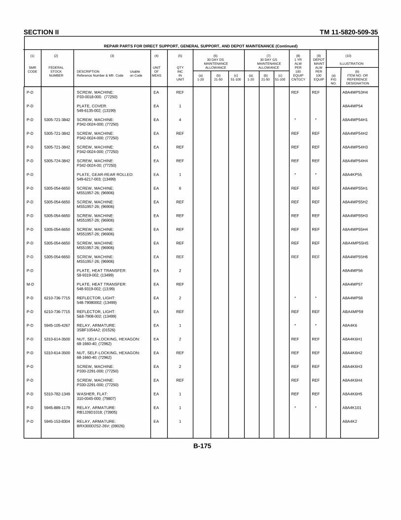
SECTION II TM 11-5820-509-35
REPAIR PARTS FOR DIRECT SUPPORT, GENERAL SUPPORT, AND DEPOT MAINTENANCE (Continued)
(1) (2) (3) (4) (5) (6) (7) (8) (9) (10)30 DAY DS 30 DAY GS 1 YR DEPOT
MAINTENANCE MAINTENANCE ALW MAINT ILLUSTRATIONSMR FEDERAL UNIT QTY ALLOWANCE ALLOWANCE PER ALW
CODE STOCK DESCRIPTION Usable OF INC 100 PER (b)NUMBER Reference Number & Mfr. Code on Code MEAS IN (a) (b) (c) (a) (b) (c) EQUIP 100 (a) ITEM NO. OR
UNIT 1-20 21-50 51-100 1-20 21-50 51-100 CNTGCY EQUIP FIG REFERENCENO. DESIGNATION
P-D SCREW, MACHINE: EA REF REF REF A8A4MP53H4P33-0018-000. (77250)
P-D PLATE, COVER: EA 1 A8A4MP54549-6135-002; (13199)
P-D 5305-721-3842 SCREW, MACHINE: EA 4 * * A8A4MP54H1P342-0024-000; (77250)
P-D 5305-721-3842 SCREW, MACHINE: EA REF REF REF A8A4MP54H2P342-0024-000; (77250)
P-D 5305-721-3842 SCREW, MACHINE: EA REF REF REF A8A4MP54H3P342-0024-000; (77250)
P-D 5305-724-3842 SCREW, MACHINE: EA REF REF REF A8A4MP54H4P342-0024-00; (77250)
P-D PLATE, GEAR-REAR ROLLED: EA 1 * * A8A4KP55549-6217-003; (13499)
P-D 5305-054-6650 SCREW, MACHINE: EA 6 REF REF A8A4MP55H1MS51957-26; (96906)
P-D 5305-054-6650 SCREW, MACHINE: EA REF REF REF A8A4MP55H2MS51957-26; (96906)
P-D 5305-054-6650 SCREW, MACHINE: EA REF REF REF A8A4MP55H3MS51957-26; (96906)
P-D 5305-054-6650 SCREW, MACHINE: EA REF REF REF A8A4MP55H4MS51957-26; (96906)
P-D 5305-054-6650 SCREW, MACHINE: EA REF REF REF ABA4MP55H5MS51957-26; (96906)
P-D 5305-054-6650 SCREW, MACHINE: EA REF REF REF A8A4MP55H6MS51957-26; (96906)
P-D PLATE, HEAT TRANSFER: EA 2 A8A4MP5658-9319-002; (13499)
M-D PLATE, HEAT TRANSFER: EA REF A8A4MP57548-9319-002; (13;99)
P-D 6210-736-7715 REFLECTOR, LIGHT: EA 2 * * A8A4MP58548-79080002; (13499)
P-D 6210-736-7715 REFLECTOR, LIGHT: EA REF REF REF ABA4MP595&8-7908-002; (13499)
P-D 5945-105-4267 RELAY, ARMATURE: EA 1 * * A8A4K63SBF1054A2; (01526)
P-D 5310-614-3500 NUT, SELF-LOCKING, HEXAGON: EA 2 REF REF A8A4K6H168-1660-40; (72962)
P-D 5310-614-3500 NUT, SELF-LOCKING, HEXAGON: EA REF REF REF A8A4K6H268-1660-40; (72962)
P-D SCREW, MACHINE: EA 2 REF REF A8A4K6H3P330-2291-000; (77250)
P-D SCREW, MACHINE: EA REF REF REF A8A4K6H4P330-2291-000; (77250)
P-D 5310-782-1349 WASHER, FLAT: EA 1 REF REF A8A4K6H5310-0045-000; (79807)
P-D 5945-889-1179 RELAY, ARMATURE: EA 1 * * A8A4K101RB1J26D1018; (73905)
P-D 5945-153-8304 RELAY, ARMATURE: EA 1 A8A4K2BRX300D2S2-26V; (09026)
B-175
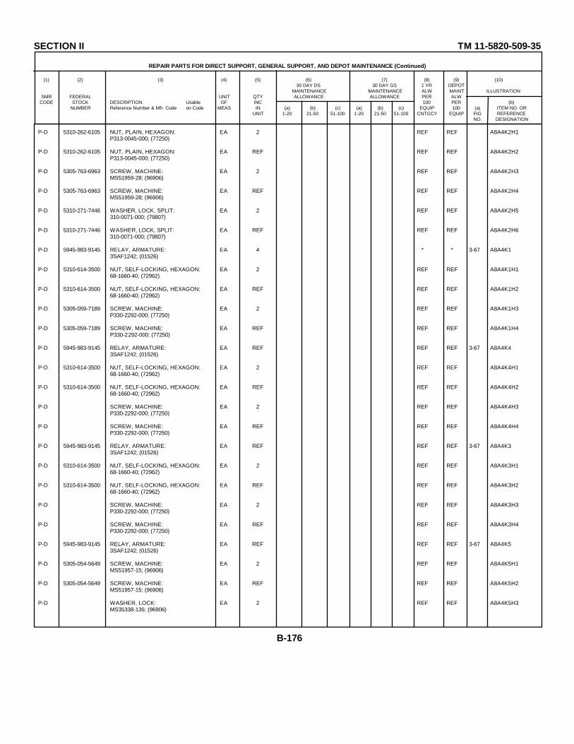
SECTION II TM 11-5820-509-35
REPAIR PARTS FOR DIRECT SUPPORT, GENERAL SUPPORT, AND DEPOT MAINTENANCE (Continued)
(1) (2) (3) (4) (5) (6) (7) (8) (9) (10)30 DAY DS 30 DAY GS 1 YR DEPOT
MAINTENANCE MAINTENANCE ALW MAINT ILLUSTRATIONSMR FEDERAL UNIT QTY ALLOWANCE ALLOWANCE PER ALW
CODE STOCK DESCRIPTION Usable OF INC 100 PER (b)NUMBER Reference Number & Mfr. Code on Code MEAS IN (a) (b) (c) (a) (b) (c) EQUIP 100 (a) ITEM NO. OR
UNIT 1-20 21-50 51-100 1-20 21-50 51-100 CNTGCY EQUIP FIG REFERENCENO. DESIGNATION
P-D 5310-262-6105 NUT, PLAIN, HEXAGON: EA 2 REF REF A8A4K2H1P313-0045-000; (77250)
P-D 5310-262-6105 NUT, PLAIN, HEXAGON: EA REF REF REF A8A4K2H2P313-0045-000; (77250)
P-D 5305-763-6963 SCREW, MACHINE: EA 2 REF REF A8A4K2H3MS51959-28; (96906)
P-D 5305-763-6963 SCREW, MACHINE: EA REF REF REF A8A4K2H4MS51959-28; (96906)
P-D 5310-271-7446 WASHER, LOCK, SPLIT: EA 2 REF REF A8A4K2H5310-0071-000; (79807)
P-D 5310-271-7446 WASHER, LOCK, SPLIT: EA REF REF REF A8A4K2H6310-0071-000; (79807)
P-D 5945-983-9145 RELAY, ARMATURE: EA 4 * * 3-67 A8A4K13SAF1242; (01526)
P-D 5310-614-3500 NUT, SELF-LOCKING, HEXAGON: EA 2 REF REF A8A4K1H168-1660-40; (72962)
P-D 5310-614-3500 NUT, SELF-LOCKING, HEXAGON: EA REF REF REF A8A4K1H268-1660-40; (72962)
P-D 5305-059-7189 SCREW, MACHINE: EA 2 REF REF A8A4K1H3P330-2292-000; (77250)
P-D 5305-059-7189 SCREW, MACHINE: EA REF REF REF A8A4K1H4P330-2292-000; (77250)
P-D 5945-983-9145 RELAY, ARMATURE: EA REF REF REF 3-67 A8A4K43SAF1242; (01526)
P-D 5310-614-3500 NUT, SELF-LOCKING, HEXAGON: EA 2 REF REF A8A4K4H168-1660-40; (72962)
P-D 5310-614-3500 NUT, SELF-LOCKING, HEXAGON: EA REF REF REF A8A4K4H268-1660-40; (72962)
P-D SCREW, MACHINE: EA 2 REF REF A8A4K4H3P330-2292-000; (77250)
P-D SCREW, MACHINE: EA REF REF REF A8A4K4H4P330-2292-000; (77250)
P-D 5945-983-9145 RELAY, ARMATURE: EA REF REF REF 3-67 A8A4K33SAF1242; (01526)
P-D 5310-614-3500 NUT, SELF-LOCKING, HEXAGON: EA 2 REF REF A8A4K3H168-1660-40; (72962)
P-D 5310-614-3500 NUT, SELF-LOCKING, HEXAGON: EA REF REF REF A8A4K3H268-1660-40; (72962)
P-D SCREW, MACHINE: EA 2 REF REF A8A4K3H3P330-2292-000; (77250)
P-D SCREW, MACHINE: EA REF REF REF A8A4K3H4P330-2292-000; (77250)
P-D 5945-983-9145 RELAY, ARMATURE: EA REF REF REF 3-67 A8A4K53SAF1242; (01526)
P-D 5305-054-5649 SCREW, MACHINE: EA 2 REF REF A8A4K5H1MS51957-15; (96906)
P-D 5305-054-5649 SCREW, MACHINE: EA REF REF REF A8A4K5H2MS51957-15; (96906)
P-D WASHER, LOCK: EA 2 REF REF A8A4K5H3MS35338-135; (96906)
B-176

SECTION II TM 11-5820-509-35
REPAIR PARTS FOR DIRECT SUPPORT, GENERAL SUPPORT, AND DEPOT MAINTENANCE (Continued)
(1) (2) (3) (4) (5) (6) (7) (8) (9) (10)30 DAY DS 30 DAY GS 1 YR DEPOT
MAINTENANCE MAINTENANCE ALW MAINT ILLUSTRATIONSMR FEDERAL UNIT QTY ALLOWANCE ALLOWANCE PER ALW
CODE STOCK DESCRIPTION Usable OF INC 100 PER (b)NUMBER Reference Number & Mfr. Code on Code MEAS IN (a) (b) (c) (a) (b) (c) EQUIP 100 (a) ITEM NO. OR
UNIT 1-20 21-50 51-100 1-20 21-50 51-100 CNTGCY EQUIP FIG REFERENCENO. DESIGNATION
P-D WASHER, LOCK: EA REF REF REF A8A4K5H4MS35338-135; (96906)
P-D 5945-889-1180 RELAY, ARMATURE: EA 1 * * 3-65 A8A4K1023SAC1025; (01526)
P-D 5310-275-0889 NUT, PLAIN, HEXAGON: EA 2 REF REF A8A4K102H1P313-0132-000; (77250)
P-D 5310-275-0889 NUT, PLAIN, HEXAGON: EA REF REF REF A8A4K102H2P313-0132-000; (77250)
P-D 5305-054-5647 SCREW, MACHINE: EA 2 REF REF A8A4K102H3MS51957-13; (96906)
P-D 5305-054-5647 SCREW, MACHINE: EA REF REF REF A8A4K102H4MS51957-13; (96906)
P-D 5310-058-2949 WASHER, LOCK: EA 2 REF REF A8A4K102H5310-0278-000; (70318)
P-D 5310-058-2949 WASHER, LOCK: EA REF REF REF A8A4K102H6310-0278-000; (70318)
P-D 5905-228-6088 RESISTOR, FIXED, COMPOSITION: EA 1 * * A8A4R9RCR32G331K5; (81349)
P-D 5905-247-8732 RESISTOR, FIXED COMPOSITION: EA 1 * * A8A4R120RCR32G471KS; (81349)
P-D 5905-104-8355 RESISTOR, FIXED, COMPOSITION EA 1 * * A8A4R125RCR32G561KS; (81349)
P-D RESISTOR, FIXED, COMPOSITION EA 2 * * A8A4R24RCR32G153KS; (81349)
P-D RESISTOR, FIXED, COMPOSITION EA REF REF REF A8A4R25RCR32G153KS; (81349)
P-D 5905-484-0278 RESISTOR, FIXED, COMPOSITION EA 3 * * 3-64 A8A4R112RCR32G335KS; (81349)
P-D 5905-484-0278 RESISTOR, FIXED, COMPOSITION EA REF REF REF 3-64 A8A4R113RCR32G335KS; (81349)
P-D 5905-484-0278 RESISTOR, FIXED, COMPOSITION EA REF REF REF 3-64 A8A4R114RCR32G335KS; (81349)
P-D RESISTOR, FIXED, COMPOSITION EA 1 * * A8A4R6RC42GF181K; (81349)
P-D RESISTOR, FIXED, COMPOSITION EA 1 * * A8A4R10RC42CF331K; (81349)
P-D 5905-988-2313 RESISTOR, FIXED, FILM EA 1 * * 3-67 A8A4R127RN60D1211F; (81349)
P-D 5905-985-5465 RESISTOR, FIXED, FILM EA 1 REF REF 3-67 A8A4R126RN60D1962F; (81349)
P-D 5905-952-9232 RESISTOR, FIXED, WIREWOUND EA 1 * * 3-67 A8A4R8RE70G4751; (81349)
P-D 5310-614-3500 NUT, SELF-LOCKING, HEXAGON EA 2 REF REF A8A4R8H168-1660-40; (72962)
P-D 5310-614-3500 NUT, SELF-LOCKING, HEXAGON EA REF REF REF A8A4R8H268-1660-40; (72962)
P-D 5305-801-9932 SCREW, MACHINE EA 2 REF REF A8A4R8H3P330-2291-000; (77250)
P-D 5305-801-9932 SCREW, MACHINE EA REF REF REF A8A4R8H4P330-2291-000; (77250)
B-177

SECTION II TM 11-5820-509-35
REPAIR PARTS FOR DIRECT SUPPORT, GENERAL SUPPORT, AND DEPOT MAINTENANCE (Continued)
(1) (2) (3) (4) (5) (6) (7) (8) (9) (10)30 DAY DS 30 DAY GS 1 YR DEPOT
MAINTENANCE MAINTENANCE ALW MAINT ILLUSTRATIONSMR FEDERAL UNIT QTY ALLOWANCE ALLOWANCE PER ALW
CODE STOCK DESCRIPTION Usable OF INC 100 PER (b)NUMBER Reference Number & Mfr. Code on Code MEAS IN (a) (b) (c) (a) (b) (c) EQUIP 100 (a) ITEM NO. OR
UNIT 1-20 21-50 51-100 1-20 21-50 51-100 CNTGCY EQUIP FIG REFERENCENO. DESIGNATION
P-H-T 5820-977-1566 RESISTOR-SWITCH ASSEMBLY: EA 1 * * * * * A8A4A7549-6229-003; (13499)
P-D BOOT, DUST AND MOISTURE SEAL: EA 1 * * A8A4A7H1R9030-1-4; (97539)
P-D 5310-167-0837 WASHER: EA 1 * * A8A4A7H2AN960-616L; (88044)
X1-D RESISTOR, FIXED COMPOSITION: EA 1 A8A4A7R118RCRO20G102KS; ( 81349)
X1-D RESISTOR, FIXED, COMPOSITION: EA 1 A8A4A7R107RCR32G104KS; (81349)
X1-D RESISTOR, FIXED, COMPOSITION: EA 3 A8A4A7R105RC42GF104K; (81349)
X1-D RESISTOR, FIXED, COMPOSITION: EA REF A8A4A7R106RC42GF104K; (81349)
X1-D RESISTOR, FIXED, COMPOSITION: EA REF A8A4A7R128RC42GF104K; (81349)
X1-D RESISTOR-SWITCH SUBASSEMBLY: EA 1 A8A4A7A1549-6194-002; (13499)
X1-D WASHER, FLAT: EA 4 A8A4A7A1H1310-0045-000; (79807)
X1-D NUT, PLAIN, HEXAGON: EA 4 A8A4A7A1H2P313-0132-000; (77250)
X1-D BOARD, TERMINAL, RIVETED: EA 1 A8A4A7A1E1549-6193-002; (13499)
X1-D CAPACITOR, FIXED, CERAMIC: EA 1 A8A4A7A1C10620C95; (56289)
X1-D CAPACITOR, FIXED, CERAMIC: EA 1 A8A4A7A1C107CK13BX103M; (81349)
X1-D RESISTOR, FIXED, COMPOSITION: EA 1 A8A4A7A1R129RCR20G47LKS; (81349)
X1-D RESISTOR, VARIABLE, COMPOSITION: EA 1 3-65 A8A4A7A1R117G3629; (01121)
X1-D NUT, PLAIN, HEXAGON: EA 1 A8A4A7A1R117H1P334-0253-00; (77250)
X1-D WASHER, LOCK: EA 1 A8A4A7A1R117H21714-05; (78189)
X1-D SEMICONDUCTOR DEVICE, DIODE: EA 1 A8A4A7A1CR103IM3287; (07688)
X1-D SEMICONDUCTOR DEVICE, DIODE: EA 1 A8A4A7A1CR102JAN1N663; (81350)
X1-D SHAFT, SHOULDERED-RESISTOR: EA 1 A8A4A7MP1549-6191-002; (13499)
X1-D SWITCH, ROTARY: EA 1 A8A4A7S103225251N2C; (76854)
P-D RESISTOR, VARIABLE, WIRE WOUND: EA 1 * * 3-65 A8A4R12144968-50; (44655)
P-D NUT, PLAIN, HEXAGON: EA 1 * * A8A4R121H1P334-0253-00; (77250)
P-D WASHER, SPRING, TENSION: EA 1 * * A8A4R121H2310-0082-000; (79807)
B-178

SECTION II TM 11-5820-509-35
REPAIR PARTS FOR DIRECT SUPPORT, GENERAL SUPPORT, AND DEPOT MAINTENANCE (Continued)
(1) (2) (3) (4) (5) (6) (7) (8) (9) (10)30 DAY DS 30 DAY GS 1 YR DEPOT
MAINTENANCE MAINTENANCE ALW MAINT ILLUSTRATIONSMR FEDERAL UNIT QTY ALLOWANCE ALLOWANCE PER ALW
CODE STOCK DESCRIPTION Usable OF INC 100 PER (b)NUMBER Reference Number & Mfr. Code on Code MEAS IN (a) (b) (c) (a) (b) (c) EQUIP 100 (a) ITEM NO. OR
UNIT 1-20 21-50 51-100 1-20 21-50 51-100 CNTGCY EQUIP FIG REFERENCENO. DESIGNATION
P-D 5340-598-1300 RING, RETAINING: EA 2 * * A8A4H15133-25C; (79136)
P-D 5340-598-1300 RING, RETAINING: EA REF REF REF A8A4H25133-25C; (79136)
P-D 5340-205-6694 RING, RETAINING: EA 4 * * A8A4H35133-6C; (79136)
P-D 5340-205-6694 RING, RETAINING: EA REF REF REF A8A4H45133-6C; (79136)
P-D 5340-205-6694 RING, RETAINING: EA REF REF REF A8A4H55133-6C; (79136)
P-D 5340-205-6694 RING, RETAINING: EA REF REF REF A8A4H65133-6C; (79136)
P-D 5820-984-2139 SEMICONDUCTOR DEVICE-RESISTORASSEMBLY: EA 1 * * A8A4A15549-6126-002; (13499)
P-D WASHER, FLAT: EA 2 REF REF A8A4A15H2310-6325-000; (79807)
P-D WASHER, LOCK, SPRING: EA 2 REF REF A8A4A15H2MS35338-135; (96906)
P-D 5305-054-5649 SCREW, MACHINE: EA 2 REF REF A8A4A15H2MS51957-15; (96906)
X1-D BOARD, TERMINAL, NO. 2-PRESSED: EA 1 A8A4A15E1549-6205-003; (13499)
X1-D RESISTOR, FIXED, COMPOSITION: EA 1 A8A4A15R16RCR20G472KS; (81349)
X1-D SEMICONDUCTOR DEVICE, DIODE: EA 4 A8A4A15CR31N3639; (07688)
X1-D SEMICONDUCTOR DEVICE, DIODE: EA REF A8A4A15CR41N3639; (07688)
X1-D SEMICONDUCTOR DEVICE, DIODE: EA REF A8A4A15CR51N3639; (07688)
X1-D SEMICONDUCTOR DEVICE, DIODE: EA REF A8A4A15CR61N3639; (07688)
M-D SHAFT, SHOULDERED-SWITCH: EA 1 A8A4MP60549-6195-002; (13499)
M-D 5340-695-2558 SLEEVE, SPRING: EA 21 A8A4MP61340-0642-00; (91314)
P-D 5305-922-6281 SCREW, MACHINE: EA 1 * * A8A4MP61H1P347-005-000; (77250)
P-D 5310-933-8119 WASHER, LOCK, SPLIT: EA 1 REF REF A8A4MP61H2MS35338-137; (96906)
M-D 5340-695-2558 SLEEVE, SPRING: EA REF A8A4MP62340-0642-00; (91314)
P-D 5305-660-2196 SCREW, MACHINE: EA 1 REF REF A8A4MP62H1P347-0056-000; (77250)
P-D 5310-933-8119 WASHER, LOCK, SPLIT: EA 1 REF REF A8A4MP62H2MS35338-137; (96906)
M-D 5340-695-2558 SLEEVE, SPRING: EA REF A8A4MP63340-0642-00; (91314)
P-D 5305-660-2196 SCREW, MACHINE EA 1 REF REF A8A4MP63H1P347-0056-000; (77250)
B-179
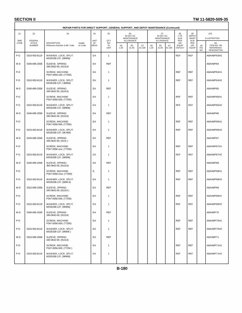
SECTION II TM 11-5820-509-35
REPAIR PARTS FOR DIRECT SUPPORT, GENERAL SUPPORT, AND DEPOT MAINTENANCE (Continued)
(1) (2) (3) (4) (5) (6) (7) (8) (9) (10)30 DAY DS 30 DAY GS 1 YR DEPOT
MAINTENANCE MAINTENANCE ALW MAINT ILLUSTRATIONSMR FEDERAL UNIT QTY ALLOWANCE ALLOWANCE PER ALW
CODE STOCK DESCRIPTION Usable OF INC 100 PER (b)NUMBER Reference Number & Mfr. Code on Code MEAS IN (a) (b) (c) (a) (b) (c) EQUIP 100 (a) ITEM NO. OR
UNIT 1-20 21-50 51-100 1-20 21-50 51-100 CNTGCY EQUIP FIG REFERENCENO. DESIGNATION
P-D 5310-933-8119 WASHER, LOCK, SPLIT: EA 1 REF REF A8A4MP63H2MS35338-137; (96906)
M-D 5340-695-2558 SLEEVE, SPRING: EA REF A8A4MP64340-0062-00; (91314)
P-D SCREW, MACHINE: EA 1 REF REF A8A4MP64H1P347-0056-o00; (77250)
P-D 5310-933-8119 WASHER, LOCK, SPLIT: EA 1 REF REF A8A4MP64H2MS35338-137; ( 96906)
M-D 5340-695-2558 SLEEVE, SPRING: EA REF A8A4MP65340-0642-00; (91314)
P-D SCREW, MACHINE: EA 1 REF REF A8A4MP65H1P347-0056-000; (77250)
P-D 5310-933-8119 WASHER, LOCK, SPLIT: EA 1 REF REF A8A4MP65H2MS35338-137; (96906)
M-D 5340-695-2558 SLEEVE, SPRING: EA REF A8A4MP66340-0642-00; (91314)
P-D SCREW, MACHINE: EA 1 REF REF A8A4MP66H1P347-0056-000; (77250)
P-D 5310-933-8119 WASHER, LOCK, SPLIT: EA 1 REF REF A8A4MP66H2MS35338-137; (96 906)
M-D 5340-695-2558 SLEEVE, SPRING: EA REF A8A4MP67340-0642-00; (9131 )
P-D SCREW, MACHINE: EA 1 REF REF A8A4MP67H1P347-0056-ooo; (77250)
P-D 5310-933-8119 WASHER, LOCK, SPLIT: EA 1 REF REF A8A4MP67H2MS35338-137; (96906)
M-D 5340-695-2558 SLEEVE, SPRING: EA REF A8A4MP683k0-0642-00; (91314)
P-D SCREW, MACHINE: E, 1 REF REF A8A4MP68H1P347-0056-Ooo; (77250)
P-D 5310-933-8119 WASHER, LOCK, SPLIT: EA 1 REF REF A8A4MP68H2MS35338-137; (9690 6)
M-D 5310-695-2558 SLEEVE, SPRING: EA REF A8A4MP69340-0642-00; (91314 )
P-D SCREW, MACHINE: EA 1 REF REF A8A4MP69H1P347-0056-000; (77250)
P-D 5310-933-8119 WASHER, LOCK, SPLIT: EA 1 REF REF A8A4MP69H2MS35338-137; (96906)
M-D 5340-695-2558 SLEEVE, SPRING: EA REF A8A4MP70340-0642-00; (91314)
P-D SCREW, MACHINE: EA 1 REF REF A8A4MP70H1P347-0056-000; (77250)
P-D 5310-933-8119 WASHER, LOCK, SPLIT: EA 1 REF REF A8A4MP70H2MS35338-137; (96906 )
M-D 5310-695-2558 SLEEVE, SPRING: EA REF A8A4MP71340-0642-00; (91314)
P-D SCREW, MACHINE: EA 1 REF REF A8A4MP71H1P347-0056-000; (77250 )
P-D 5310-933-8119 WASHER, LOCK, SPLIT: EA 1 REF REF A8A4MP71H2MS35338-137; (96906)
B-180
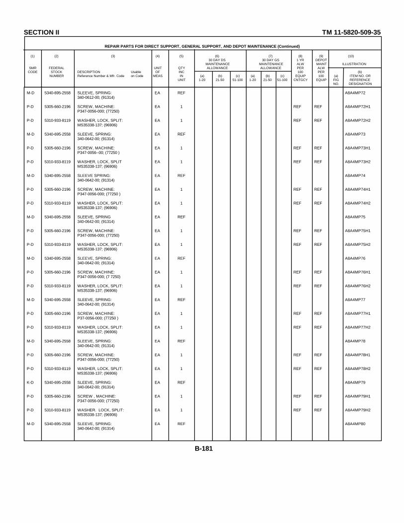
SECTION II TM 11-5820-509-35
REPAIR PARTS FOR DIRECT SUPPORT, GENERAL SUPPORT, AND DEPOT MAINTENANCE (Continued)
(1) (2) (3) (4) (5) (6) (7) (8) (9) (10)30 DAY DS 30 DAY GS 1 YR DEPOT
MAINTENANCE MAINTENANCE ALW MAINT ILLUSTRATIONSMR FEDERAL UNIT QTY ALLOWANCE ALLOWANCE PER ALW
CODE STOCK DESCRIPTION Usable OF INC 100 PER (b)NUMBER Reference Number & Mfr. Code on Code MEAS IN (a) (b) (c) (a) (b) (c) EQUIP 100 (a) ITEM NO. OR
UNIT 1-20 21-50 51-100 1-20 21-50 51-100 CNTGCY EQUIP FIG REFERENCENO. DESIGNATION
M-D 5340-695-2558 SLEEVE, SPRING: EA REF A8A4MP72340-0612-00; (91314)
P-D 5305-660-2196 SCREW, MACHINE: EA 1 REF REF A8A4MP72H1P347-0056-000; (77250)
P-D 5310-933-8119 WASHER, LOCK, SPLIT: EA 1 REF REF A8A4MP72H2MS35338-137; (96906)
M-D 5340-695-2558 SLEEVE, SPRING: EA REF A8A4MP73340-0642-00; (91314)
P-D 5305-660-2196 SCREW, MACHINE: EA 1 REF REF A8A4MP73H1P347-0056--00; (77250 )
P-D 5310-933-8119 WASHER, LOCK, SPLIT EA 1 REF REF A8A4MP73H2MS35338-137; (96906)
M-D 5340-695-2558 SLEEVE SPRING: EA REF A8A4MP74340-0642-00; (91314)
P-D 5305-660-2196 SCREW, MACHINE: EA 1 REF REF A8A4MP74H1P347-0056-000; (77250 )
P-D 5310-933-8119 WASHER, LOCK, SPLIT: EA 1 REF REF A8A4MP74H2MS35338-137; (96906)
M-D 5340-695-2558 SLEEVE, SPRING EA REF A8A4MP75340-0642-00; (91314)
P-D 5305-660-2196 SCREW, MACHINE: EA 1 REF REF A8A4MP75H1P347-0056-000; (77250)
P-D 5310-933-8119 WASHER, LOCK, SPLIT: EA 1 REF REF A8A4MP75H2MS35338-137; (96906)
M-D 5340-695-2558 SLEEVE, SPRING: EA REF A8A4MP76340-0642-00; (91314)
P-D 5305-660-2196 SCREW, MACHINE: EA 1 REF REF A8A4MP76H1P347-0056-000; (7 7250)
P-D 5310-933-8119 WASHER, LOCK, SPLIT: EA 1 REF REF A8A4MP76H2MS35338-137; (96906)
M-D 5340-695-2558 SLEEVE, SPRING: EA REF A8A4MP77340-0642-00; (91314)
P-D 5305-660-2196 SCREW, MACHINE: EA 1 REF REF A8A4MP77H1P37-0056-000; (77250 )
P-D 5310-933-8119 WASHER, LOCK, SPLIT: EA 1 REF REF A8A4MP77H2MS35338-137; (96906)
M-D 5340-695-2558 SLEEVE, SPRING: EA REF A8A4MP78340-0642-00; (91314)
P-D 5305-660-2196 SCREW, MACHINE: EA 1 REF REF A8A4MP78H1P347-0056-000; (77250)
P-D 5310-933-8119 WASHER, LOCK, SPLIT: EA 1 REF REF A8A4MP78H2MS35338-137; (96906)
K-D 5340-695-2558 SLEEVE, SPRING: EA REF A8A4MP79340-0642-00; (91314)
P-D 5305-660-2196 SCREW , MACHINE: EA 1 REF REF A8A4MP79H1P347-0056-000; (77250)
P-D 5310-933-8119 WASHER. LOCK, SPLIT: EA 1 REF REF A8A4MP79H2MS35338-137; (96906)
M-D 5340-695-2558 SLEEVE, SPRING: EA REF A8A4MP80340-0642-00; (91314)
B-181

SECTION II TM 11-5820-509-35
REPAIR PARTS FOR DIRECT SUPPORT, GENERAL SUPPORT, AND DEPOT MAINTENANCE (Continued)
(1) (2) (3) (4) (5) (6) (7) (8) (9) (10)30 DAY DS 30 DAY GS 1 YR DEPOT
MAINTENANCE MAINTENANCE ALW MAINT ILLUSTRATIONSMR FEDERAL UNIT QTY ALLOWANCE ALLOWANCE PER ALW
CODE STOCK DESCRIPTION Usable OF INC 100 PER (b)NUMBER Reference Number & Mfr. Code on Code MEAS IN (a) (b) (c) (a) (b) (c) EQUIP 100 (a) ITEM NO. OR
UNIT 1-20 21-50 51-100 1-20 21-50 51-100 CNTGCY EQUIP FIG REFERENCENO. DESIGNATION
P-D 5305-660-2196 SCREW, MACHINE: EA 1 REF REF A8A4MP80H1P347-0056-000; (77250 )
P-D 5310-933-8119 WASHER, LOCK, SPLIT: EA 1 REF REF A8A4MP80H2MS35338-137; (96906)
M-D 5340-695-2558 SLEEVE, SPRING: EA REF A8A4MP813400-062-00; (91314)
P-D 5305-660-2196 SCREW, MACHINE: EA 1 REF REF A8A4MP81H1P347-0056-000; (77250)
P-D 5310-933-8119 WASHER, LOCK, SPLIT: EA 1 REF REF A8A4MP81H2MS35338-137; (96906)
P-D 5940-056-8696 SOLDER, SLEEVE: EA 2 * * A8A4MP82D144-01; (08795)
P-D 5940-056-8696 SOLDER, SLEEVE: EA REF REF REF A8A4MP83D144-01; (08795)
M-D SPACER, PLATE-RELAY: EA 1 A8A4MP84549-6149-002; (13499)
M-D SPACER, SLEEVE: EA 6 A8A4MP85541-6017-002; (13499)
M-D SPACER, SLEEVE: EA REF A8A4MP85A541-6017-002; (13499)
M-D SPACER, SLEEVE: EA REF A8A4MP86541-6017-002; (13499)
M-D SPACER, SLEEVE: EA REF A8A4MP87541-6017-002; (13499)
M-D SPACER, SLEEVE: EA REF A8A4MP88541-6017-002; (13499)
M-D SPACER, SLEEVE: EA REF A8A4MP89541-6017-002; (13499)
P-D 5820-984-1798 SPRING ASSEMBLY: EA 2 * * A8A4MP90549-6102-002; (13499)
P-D SCREW, MACHINE: EA 2 REF REF A8A4MP90H1P342-0165-000; (77250)
P-D SCREW, MACHINE: EA REF REF REF A8A4MP90H2P342-0165-000; (77250)
P-D 5820-984-1798 SPRING SUBASSEMBLY: EA REF REP REF A8A4MP91549-6102-002; (13499)
P-D SCREW, MACHINE: EA 2 REF REF A8A4MP91H1P342-0165-000; (77250)
P-D SCREW, MACHINE: EA REF REF REF A8A4MP91H2P342-0165-000; (77250)
M-D 5841-514-2298 SPRING, HELICAL COMPRESSION: EA 4 A8A4MP92340-0127-000; (91314)
M-D 5841-514-2298 SPRING, HELICAL COMPRESSION: EA REF A8A4MP93340-0127-000; (91314)
M-D 5841-514-2298 SPRING, HELICAL COMPRESSION: EA REF A8A4MP94340-0127-000; (91314)
M-D 5841-514-2298 SPRING, HELICAL COMPRESSION: EA REF A8A4MP95340-0127-000; (91314)
P-D 5930-999-9195 SWITCH, PUSH: EA 1 * * A8A483PM6; (04009 )
B-182
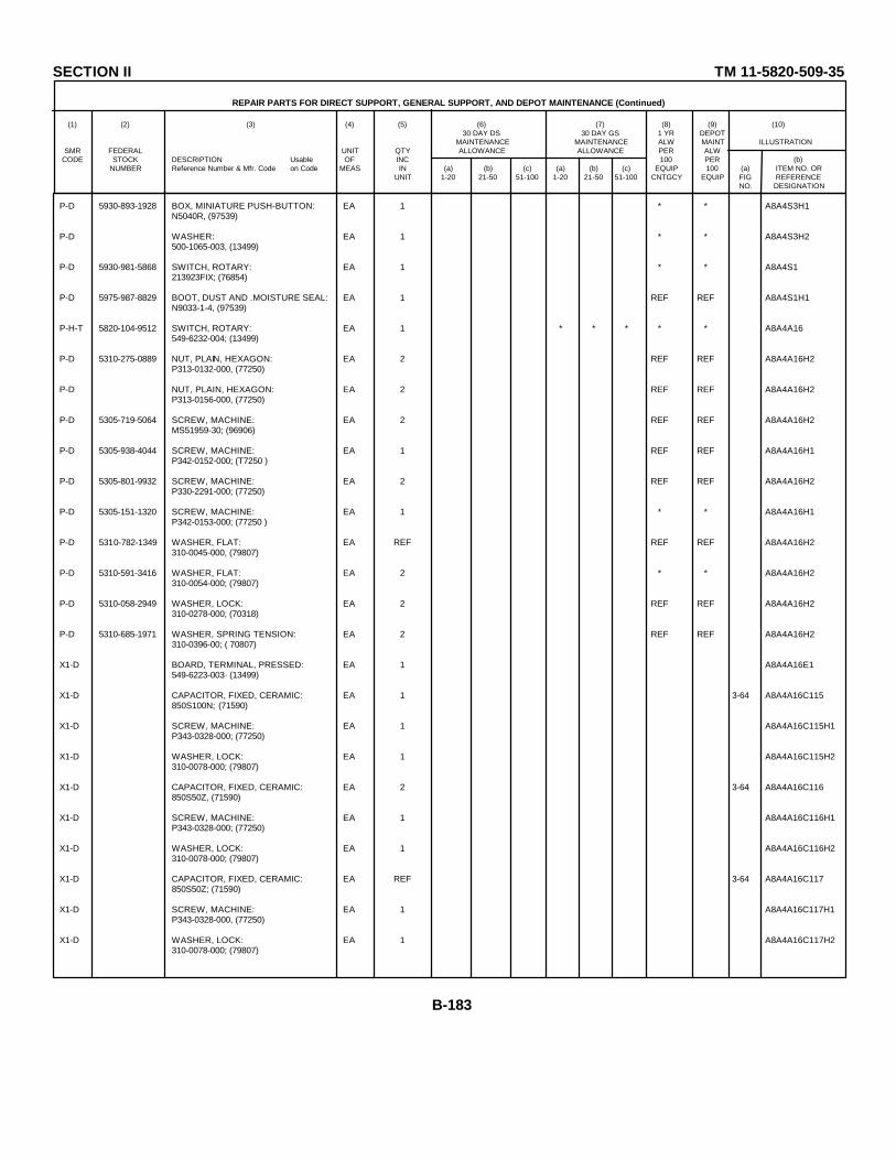
SECTION II TM 11-5820-509-35
REPAIR PARTS FOR DIRECT SUPPORT, GENERAL SUPPORT, AND DEPOT MAINTENANCE (Continued)
(1) (2) (3) (4) (5) (6) (7) (8) (9) (10)30 DAY DS 30 DAY GS 1 YR DEPOT
MAINTENANCE MAINTENANCE ALW MAINT ILLUSTRATIONSMR FEDERAL UNIT QTY ALLOWANCE ALLOWANCE PER ALW
CODE STOCK DESCRIPTION Usable OF INC 100 PER (b)NUMBER Reference Number & Mfr. Code on Code MEAS IN (a) (b) (c) (a) (b) (c) EQUIP 100 (a) ITEM NO. OR
UNIT 1-20 21-50 51-100 1-20 21-50 51-100 CNTGCY EQUIP FIG REFERENCENO. DESIGNATION
P-D 5930-893-1928 BOX, MINIATURE PUSH-BUTTON: EA 1 * * A8A4S3H1N5040R, (97539)
P-D WASHER: EA 1 * * A8A4S3H2500-1065-003, (13499)
P-D 5930-981-5868 SWITCH, ROTARY: EA 1 * * A8A4S1213923FIX; (76854)
P-D 5975-987-8829 BOOT, DUST AND .MOISTURE SEAL: EA 1 REF REF A8A4S1H1N9033-1-4, (97539)
P-H-T 5820-104-9512 SWITCH, ROTARY: EA 1 * * * * * A8A4A16549-6232-004; (13499)
P-D 5310-275-0889 NUT, PLAIN, HEXAGON: EA 2 REF REF A8A4A16H2P313-0132-000, (77250)
P-D NUT, PLAIN, HEXAGON: EA 2 REF REF A8A4A16H2P313-0156-000, (77250)
P-D 5305-719-5064 SCREW, MACHINE: EA 2 REF REF A8A4A16H2MS51959-30; (96906)
P-D 5305-938-4044 SCREW, MACHINE: EA 1 REF REF A8A4A16H1P342-0152-000; (T7250 )
P-D 5305-801-9932 SCREW, MACHINE: EA 2 REF REF A8A4A16H2P330-2291-000; (77250)
P-D 5305-151-1320 SCREW, MACHINE: EA 1 * * A8A4A16H1P342-0153-000; (77250 )
P-D 5310-782-1349 WASHER, FLAT: EA REF REF REF A8A4A16H2310-0045-000, (79807)
P-D 5310-591-3416 WASHER, FLAT: EA 2 * * A8A4A16H2310-0054-000; (79807)
P-D 5310-058-2949 WASHER, LOCK: EA 2 REF REF A8A4A16H2310-0278-000; (70318)
P-D 5310-685-1971 WASHER, SPRING TENSION: EA 2 REF REF A8A4A16H2310-0396-00; ( 70807)
X1-D BOARD, TERMINAL, PRESSED: EA 1 A8A4A16E1549-6223-003· (13499)
X1-D CAPACITOR, FIXED, CERAMIC: EA 1 3-64 A8A4A16C115850S100N; (71590)
X1-D SCREW, MACHINE: EA 1 A8A4A16C115H1P343-0328-000; (77250)
X1-D WASHER, LOCK: EA 1 A8A4A16C115H2310-0078-000; (79807)
X1-D CAPACITOR, FIXED, CERAMIC: EA 2 3-64 A8A4A16C116850S50Z, (71590)
X1-D SCREW, MACHINE: EA 1 A8A4A16C116H1P343-0328-000; (77250)
X1-D WASHER, LOCK: EA 1 A8A4A16C116H2310-0078-000; (79807)
X1-D CAPACITOR, FIXED, CERAMIC: EA REF 3-64 A8A4A16C117850S50Z; (71590)
X1-D SCREW, MACHINE: EA 1 A8A4A16C117H1P343-0328-000, (77250)
X1-D WASHER, LOCK: EA 1 A8A4A16C117H2310-0078-000; (79807)
B-183
SECTION II TM 11-5820-509-35
REPAIR PARTS FOR DIRECT SUPPORT, GENERAL SUPPORT, AND DEPOT MAINTENANCE (Continued)
(1) (2) (3) (4) (5) (6) (7) (8) (9) (10)30 DAY DS 30 DAY GS 1 YR DEPOT
MAINTENANCE MAINTENANCE ALW MAINT ILLUSTRATIONSMR FEDERAL UNIT QTY ALLOWANCE ALLOWANCE PER ALW
CODE STOCK DESCRIPTION Usable OF INC 100 PER (b)NUMBER Reference Number & Mfr. Code on Code MEAS IN (a) (b) (c) (a) (b) (c) EQUIP 100 (a) ITEM NO. OR
UNIT 1-20 21-50 51-100 1-20 21-50 51-100 CNTGCY EQUIP FIG REFERENCENO. DESIGNATION
X1-D CAPACITOR, FIXED, CERAMIC: EA 1 3-64 A8A4A16C118850S40Z; (71590)
X1-D SCREW, MACHINE: EA 1 A8A4A16C118H1P343-0328-000; (77250)
X1-D WASHER, LOCK: EA 1 A8A4A16C118H2310-0078-000; (79807)
X1-D CAPACITOR, FIXED, CERAMIC: EA 3 3-64 A8A4A16C118850S20Z; (71590)
X1-D SCREW, MACHINE: EA 1 A8A4A16C119H1P343-0328-000; (77250)
X1-D WASHER, LOCK: EA 1 A8A4A16C119H2310-0078-000; (79807)
X1-D CAPACITOR, FIXED, CERAMIC: EA REF 3-64 A8A4A16C120850520Z; (71590)
X1-D SCREW, MACHINE: EA 1 A8A4A16C120H1P343-0328-000; (77250)
X1-D WASHER, LOCK: EA 1 A8A4A16C120H2310-0078-000; (79807)
X1-D CAPACITOR, FIXED, CERAMIC: EA REF 3-64 A8A4A16C121850200Z; (71590)
X1-D SCREW, MACHINE: EA 1 A8A4A16C121H1P343-0328-000; (77250)
X1-D WASHER, LOCK: EA 1 A8A4A16C121H2310-0078-000; (79807)
X1-D CAPACITOR, FIXED, CERAMIC: EA 1 3-64 A8A4A16C105AG5-1-1-2Z; (00656)
X1-D CAPACITOR, FIXED, CERAMIC: EA 1 3-64 A8A4A16C1242DHT55T209CAA; (71590)
X1-D CAPACITOR, FIXED, CERAMIC: EA 1 3-64 A8A4A16C144HTS17-3000Z; (00656)
X1-D CAPACITOR, FIXED, MICA: EA 5 3-64 A8A4A16C109MHW5455E151JQ; (00853)
X1-D SCREW, MACHINE: EA 1 A8A4A16C109H1P343-0382-000; (77250)
X1-D WASHER, LOCK: EA 1 A8A4A16C109H2310-0395-00; (79807)
X1-D CAPACITOR, FIXED, MICA: EA REF 3-64 A8A4A16C111MHW5S55E151JQ; (00853)
X1-D SCREW, MACHINE: EA 1 A8A4A16C111H1P343-0382-000; (77250)
X1-D WASHER, LOCK EA 1 A8A4A16C111H2310-0395-00; (79807)
X1-D CAPACITOR, FIXED, MICA EA REF 3-64 A8A4A16C112MRW5455E151JQ; (00853)
X1-D SCREW, MACHINE EA 1 A8A4A16C112H1P343-0382-000; (77250)
X1-D WASHER, LOCK EA 1 A8A4A16C112H2310-0395-00; (7 9807)
X1-D CAPACITOR, FIXED, MICA EA REF 3-64 A8A4A16C113MHWS55E151JQ; (00853)
B-184

SECTION II TM 11-5820-509-35
REPAIR PARTS FOR DIRECT SUPPORT, GENERAL SUPPORT, AND DEPOT MAINTENANCE (Continued)
(1) (2) (3) (4) (5) (6) (7) (8) (9) (10)30 DAY DS 30 DAY GS 1 YR DEPOT
MAINTENANCE MAINTENANCE ALW MAINT ILLUSTRATIONSMR FEDERAL UNIT QTY ALLOWANCE ALLOWANCE PER ALW
CODE STOCK DESCRIPTION Usable OF INC 100 PER (b)NUMBER Reference Number & Mfr. Code on Code MEAS IN (a) (b) (c) (a) (b) (c) EQUIP 100 (a) ITEM NO. OR
UNIT 1-20 21-50 51-100 1-20 21-50 51-100 CNTGCY EQUIP FIG REFERENCENO. DESIGNATION
X1-D SCREW, M4CHINE: EA 1 A8A4A16C113H1P343-0382-000; (77250)
X1-D WASHER, LOCK: EA 1 A8A4A16C113H2310-0395-00; (79807)
X1-D CAPACITOR, FIXED, MICA: EA REF 3-64 A8A4A16C114MHWS55E1S1JQ; (00853)
X1-D SCREW, MACHINE: EA 1 A8A4A16C114H1P343-0382-000; (T7250)
X1-D WASHER, LOCK: EA 1 A8A4A16C114H2310-0395-00; (7980 7)
X1-D CAPACITOR, FIXED, MICA: EA 2 3-64 A8A4A16C108MHWS5455E5S1JQ; (00853)
X1-D SCREW, MACHINE: EA 1 A8A4A16C108H1P343-0382-000; (77250)
X1-D WASHER, LOCK: EA 1 A8A4A16C108H2310-0395-00; (79807)
X1-D CAPACITOR, FIXED, MICA: EA REF 3-64 A8A4A16C110MHW5455E501JQ; (00853)
X1-D SCREW, MACHINE: EA 1 A8A4A16C110H1P343-0382-000; (77250)
X1-D WASHER, LOCK: EA 1 A8A4A16C110H2310-0395-00; (79807)
X1-D CAP, PLATE: EA 1 A8A4A16MP1SA91; (07886)
X1-D DEFLECTOR, AIR, ROLLED: EA 1 A8ARA16MP2553-2413-003; (13499)
X1-D POST, ELECTRICAL-MECHANICAL: EA 2 A8A4A16MP3540-9223-003; (13499)
X1-D POST, ELECTRICAL-MECHANICAL: EA REF A8A4A16MP4540-9223-003; (13499)
X1-D POST, ELECTRICAL-MECHANICAL: E1 2 A8A4A16MP5540-9229-003; (13499)
X1-D WASHER, NONMETALLIC: EA 1 A8A4A16MP5H1302-0024-000; (052b8)
X1-D POST, ELECTRICAL-MECHANICAL: EA REF A8A4A16MP6540-9229- 003; (13499)
X1-D WASHER, NONMETALLIC: EA 1 A8A4A16MP6H1302-0024-000; (05284)
X1-D RETAINER, CAPACITOR. EA 1 A8A4A16MP7549-6197-002; (13499)
X1-D SCREW, MACHINE EA 2 A8A4A16MP7H1P343-0330-000; (77250)
X1-D SCREW, MACHINE EA REF A8A4A16MP7H2P343-0330-000; (77250)
X1-D WASHER, LOCK EA 2 A8A4A16MP7H3310-0078-000; (79807)
X1-D WASHER, LOCK EA REF A8A4A16MP7H4310-0078-000; (79807)
X1-D SPACER, SLEEVE EA 2 A8A4A16MP8541-6038-002; (13499)
B-185

SECTION II TM 11-5820-509-35
REPAIR PARTS FOR DIRECT SUPPORT, GENERAL SUPPORT, AND DEPOT MAINTENANCE (Continued)
(1) (2) (3) (4) (5) (6) (7) (8) (9) (10)30 DAY DS 30 DAY GS 1 YR DEPOT
MAINTENANCE MAINTENANCE ALW MAINT ILLUSTRATIONSMR FEDERAL UNIT QTY ALLOWANCE ALLOWANCE PER ALW
CODE STOCK DESCRIPTION Usable OF INC 100 PER (b)NUMBER Reference Number & Mfr. Code on Code MEAS IN (a) (b) (c) (a) (b) (c) EQUIP 100 (a) ITEM NO. OR
UNIT 1-20 21-50 51-100 1-20 21-50 51-100 CNTGCY EQUIP FIG REFERENCENO. DESIGNATION
X1-D STUD, CONTINUOUS THREAD: EA 1 A8A4A16MP8H1P312-0088-000; (77250)
X1-D WASHER, NONMETALLIC: EA 1 A8A4A16MP8H2302-0024-000; (05284)
X1-D SPACER, SLEEVE: EA REF A8A4A16MP9541-6038-002; (13499)
X1-D STUD, CONTINUOUS THREAD: EA 1 A8A4A16MP9H1P312-0088-000; (77250)
X1-D WASHER, NONMETALLIC: EA 1 A8A4A16MP9H2302-002-000ooo; (05284)
X1-D SPACER, SLEEVE: EA 2 A8A4A16P10541-6039-002; (13499)
X1-D WASHER, NONMETALLIC: EA 2 A8A4A16MP10H1302-0024-000; (05284)
X1-D WASHER, NONMETALLIC: EA REF A8A4A16MP10H2302-002-000; (05284)
X1-D SPACER, SLEEVE: EA REF A8A4A16MP11541-6039-002; (13499)
X1-D WASHER, NONMETALLIC: EA 2 A8A4A16MP11H1302-0024-000; (05284)
X1-D WASHER, NONMETALLIC: EA REF A8A4A16MP11H2302-0024-000; (05284)
X1-D SUPPRESSER, PARASITIC: EA 1 3-64 A8A4A16104-R110549-6198-002; (13499)
X1-D SWITCH SECTION, ROTARY, POWER: EA 2 3-64 A8A4A16S101APA234-026; (71590)
X1-D SWITCH SECTION, ROTARY: EA REF 3-64 A8A4A16S101BPA234-026; (71590)
X1-D TERMINAL, LUG: EA 1 A8A4A16E22504-04-00-2220N; (78189)
X1-D TERMINAL, LUG: EA 7 A8A4A16E32104-06-02-2520N; (78189)
X1-D SCREW, MACHINE: EA 1 A8A4A16E3H1P343-0327-000; (77250)
X1-D WASHER, LOCK: EA 1 A8A4A16E3H21806-00; (78189)
X1-D TERMINAL, LUG: EA REF A8A4A16E42104-06-02-2520; (78189)
X1-D SCREW, MACHINE: EA 1 A8A4A16E4H1P343-0327-000; (77250)
X1-D WASHER, LOCK: EA 1 A8A4A16E4H21806-00; (78189)
X1-D TERMINAL, LUG: EA REF A8A4A16E52104-06-02-2520N; (78189)
X1-D SCREW, MACHINE: EA 1 A8A4A16E5H1P343-0327-000; (77250)
X1-D WASHER, LOCK: EA 1 A8A4A16E5H21806-00; (78189)
X1-D TERMINAL, LUG: EA REF A8A4A16E62104-06-02-2520N; (78189)
B-186

SECTION II TM 11-5820-509-35
REPAIR PARTS FOR DIRECT SUPPORT, GENERAL SUPPORT, AND DEPOT MAINTENANCE (Continued)
(1) (2) (3) (4) (5) (6) (7) (8) (9) (10)30 DAY DS 30 DAY GS 1 YR DEPOT
MAINTENANCE MAINTENANCE ALW MAINT ILLUSTRATIONSMR FEDERAL UNIT QTY ALLOWANCE ALLOWANCE PER ALW
CODE STOCK DESCRIPTION Usable OF INC 100 PER (b)NUMBER Reference Number & Mfr. Code on Code MEAS IN (a) (b) (c) (a) (b) (c) EQUIP 100 (a) ITEM NO. OR
UNIT 1-20 21-50 51-100 1-20 21-50 51-100 CNTGCY EQUIP FIG REFERENCENO. DESIGNATION
X1-D SCREW, MACHINE: EA 1 A8A4A16E6H1P343-0327-000; (77250)
X1-D WASHER, LOCK: EA 1 A8A4A16E6H21806-00; (78189)
X1-D TERMINAL, LUG: EA REF A8A4A16E72104-06-02-2520N; (78189)
X1-D SCREW, MACHINE: EA 1 A8A4A16E7H1P343-0327-000; (77250)
X1-D WASHER, LOCK: EA 1 A8A4A16E7H21806-00; (78189)
X1-D TERMINAL, LUG: EA REF A8A4A16E82104-06-02-2520N; (78189)
X1-D SCREW, MACHINE: EA 1 A8A4A16E8H1P343-0327-000; (77250)
X1-D WASHER, LOCK: EA 1 A8A4A16E8H21806-00; (78189)
X1-D TERMINAL, LUG: EA REF A8A4A16E92104-06-02-2520N; (78189)
X1-D SCREW, MACHINE: EA 1 A8A4A16E9H1P343-0327-000; (77250)
X1-D WASHER, LOCK: EA 1 A8A4A16E9H21806-00; (78189)
P-D 5930-636-1425 SWITCH, THERMOSTATIC: EA 1 * * 3-65 A8A4K103C4344-4-75; (82647)
P-D 5305-054-5646 SCREW, MACHINE: EA 2 REF REF A8A4K103H1MS51957-12; (96906)
P-D 5305-054-5646 SCREW, MACHINE: EA REF REF REF A8A4K103H2MS51957-12; (96906)
P-D 5310-058-2949 WASHER, LOCK: EA 2 REF REF A8A4K103H3310-0278-000; (70318)
P-D 5310-058-2949 WASHER, LOCK: EA REF REF REF A8A4K103H4310-0278-000; (70318)
P-D 5930-820-9131 SWITCH, TOGGLE: EA 1 * * 3-65 A8A4S102T2150; (99707)
P-D 5975-836-3373 BOOT, DUST AND MOISTURE PROOF: EA 1 * * A8A4S102H1N5030B; (97539)
P-D 5310-768-7967 WASHER: EA 1 REF REF A8A4S102H2500-1065-003; (13499)
P-D 5930-578-9817 SWITCH, TOGGLE: EA 1 * * A8A4S2T3103; (81640)
P-D 5975-836-3373 BOOT, DUST AND MOISTURE PROOF: EA 1 REF REF A8A4S2H1N5030B; (97539)
P-D 5310-768-7967 WASHER: EA 1 REF REF A8A4S2H2500-1065-003; (13499)
P-D TERMINAL, LUG: EA 1 REF REF A8A4E344007-4HT; (77147)
P-D 5940-878-3768 TERMINAL, LUG: EA 2 * * A8A4E354007-6HT; (77147)
P-D NUT, PLAIN, HEXAGON: EA 1 * * A8A4E35H1P313-0140-000; (77250)
B-187

SECTION II TM 11-5820-509-35
REPAIR PARTS FOR DIRECT SUPPORT, GENERAL SUPPORT, AND DEPOT MAINTENANCE (Continued)
(1) (2) (3) (4) (5) (6) (7) (8) (9) (10)30 DAY DS 30 DAY GS 1 YR DEPOT
MAINTENANCE MAINTENANCE ALW MAINT ILLUSTRATIONSMR FEDERAL UNIT QTY ALLOWANCE ALLOWANCE PER ALW
CODE STOCK DESCRIPTION Usable OF INC 100 PER (b)NUMBER Reference Number & Mfr. Code on Code MEAS IN (a) (b) (c) (a) (b) (c) EQUIP 100 (a) ITEM NO. OR
UNIT 1-20 21-50 51-100 1-20 21-50 51-100 CNTGCY EQUIP FIG REFERENCENO. DESIGNATION
P-D SCREW, MACHINE: EA 1 REF REF A8A4E35H2P343-0328-0; (77250)
P-D WASHER, LOCK: EA 1 REF REF A8A4E35H31806-00; (78189)
P-D TERMINAL, LUG: EA REF REF REF A8A4E364007-6HT; (77147)
P-D TERMINAL, LUG: EA 4 REF REF A8A4E372104-04-01-2520N; (78189)
P-D 5310-275-0889 NUT, PLAIN, HEXAGON: EA 1 REF REF A8A4E37H1P313-0132-000; (77250)
P-D 5305-685-1490 SCREW, MACHINE: EA 1 REF REF A8A4E37H2P330-2290-000; (77250)
P-D WASHER, FLAT: EA 1 REF REF A8A4E37H3310-6325-000; (79807)
P-D 5310-058-2949 WASHER, LOCK: EA 1 REF REF A8A4E37H4310-0278-000; (70318)
P-D TERMINAL, LUG: EA REF REF REF A8A4E382104-04-01-2520N; (78189)
P-D 5310-275-0889 NUT, PLAIN, HEXAGON: EA 1 REF REF A8A4E38H1P313-0132-000; (77250)
P-D 5305-685-1490 SCREW, MACHINE: EA 1 REF REF A8A4E38H2P330-2290-000; (77250)
P-D WASHER, FLAT: EA REF REF REF A8A4E38H3310-6325-000; (79807)
P-D 5310-058-2949 WASHER, LOCK: EA I REP REF A8A4E38H4310-0278-000; (70318)
P-D TERMINAL, LUG: EA REF REF REF A8A4E392104-04-01-2520N; (78189)
P-D 5310-275-0889 NUT, PLAIN, HEXAGON EA 1 REF REF A8A4E39H1P313-0132-000; (77250)
P-D 5305-685-1490 SCREW, MACHINE EA 1 REF REF A8A4E39H2P330-2290-000; (77250)
P-D WASHER, FLAT EA 1 REF REF A8A4E39H3310-6325-000; (79807)
P-D 5310-058-2949 WASHER, LOCK EA 1 REF REF A8A4E39H4310-0278-000; (70318)
P-D TERMINAL, LUG EA REF REF REF A8A4E402104-04-01-2520N; (78189)
P-D 5940-156-7344 TERMINAL, LUG EA 5 REF REF A8A4E412104-06-02-2520N, (78189)
P-D SCREW, MACHINE EA 1 REF REF A8A4E41H1P343-0328-000; (77250)
P-D WASHER, LOCK: EA 1 REF REF A8A4E41H2806-00; (78189)
P-D 5940-156-7344 TERMINAL, LUG EA REF REF REF A8A4E422104-06-02-2520N; (78189)
P-D SCREW, MACHINE EA 1 REF REF A8A4E42H1P343-0328-000, (77250)
P-D WASHER, LOCK EA 1 REF REF A8A4E42H21806-00; (78189)
B-188

SECTION II TM 11-5820-509-35
REPAIR PARTS FOR DIRECT SUPPORT, GENERAL SUPPORT, AND DEPOT MAINTENANCE (Continued)
(1) (2) (3) (4) (5) (6) (7) (8) (9) (10)30 DAY DS 30 DAY GS 1 YR DEPOT
MAINTENANCE MAINTENANCE ALW MAINT ILLUSTRATIONSMR FEDERAL UNIT QTY ALLOWANCE ALLOWANCE PER ALW
CODE STOCK DESCRIPTION Usable OF INC 100 PER (b)NUMBER Reference Number & Mfr. Code on Code MEAS IN (a) (b) (c) (a) (b) (c) EQUIP 100 (a) ITEM NO. OR
UNIT 1-20 21-50 51-100 1-20 21-50 51-100 CNTGCY EQUIP FIG REFERENCENO. DESIGNATION
P-D 5940-156-7344 TERMINAL, LUG: EA REF REF REF A8A4E432104-06-02-2520N; (78189)
P-D 5940-156-7344 TERMINAL, LUG: EA REF REF REF A8A4E582104-06-02-2520N; (78189)
P-D 5940-156-7344 TERMINAL, LUG EA REF REF REF A8A4E592104-06-02-2520N; (78189)
P-D 5940-836-3536 TERMINAL, LUG: EA 9 REF REF A8A4E444040-2HDSPL; (77147)
P-D 5940-836-3536 TERMINAL, LUG EA REF REF REF A8A4E454040-2HDSPL (77147)
P-D 5940-836-3536 TERMINAL, LUG: EA REF REF REF A8A4E464040-2HDSPL; (77147)
P-D 5940-836-3536 TERMINAL, LUG: EA REF REF REF A8A4E474040-2HDSPL; (77147)
P-D 5940-836-3536 TERMINAL, LUG: EA REF REF REF A8A4E484040-2HDSPL; (77147)
P-D 5940-836-3536 TERMINAL, LUG: EA REF REF REF A8A4E494040-2HDSPL; (77147)
P-D 5940-836-3536 TERMINAL, LUG: EA REF REF REF A8A4E504040-2HDSPL; (77147)
P-D 5940-836-3536 TERMINAL, LUG: EA REF REF REF A8A4E514040-2HDSPL; (77147)
P-D 5940-836-3536 TERm1AL, LUG: EA REF REF REF A8A4E524040-2HDSPL; (77147)
P-D 5940-455-7441 TERMINAL, LUG: EA 1 REF REF A8A4E534040-5HDSPL, (77147)
P-D 5940-903-5951 TERMINAL, LUG EA 1 * * A8A4E540167-3; (94375)
P-D 5940-501-8634 TERMINAL, LUG: EA 1 * * A8A4E1394021; (77147)
P-D SCREW, MACHINE EA 1 * * A8A4E139H1P343-0307-000; (77250)
P-D WASHER, LOCK: EA 1 * * A8A4E139H21808-00; (78189)
P-D 5940-700-2953 TERMINAL, LUG EA 3 * * A8A4E55549-6138-002; (13499)
P-D 5310-275-0889 NUT, PLAIN, HEXAGON EA 1 REF REF A8A4E55H1P313-0132-000; (77250)
P-D 5305-685-1490 SCREW, MACHINE EA 1 REF REF A8A4E55H2P330-2290-00; (77250)
P-D 5310-058-2949 WASHER, LOCK EA 1 REF REF A8A4E55H3310-278-000; (70318)
P-D WASHER, PLAIN, FLAT: EA 1 REF REF A8A4E55H4310-6325-000; (79807)
P-D 5940-700-2953 TERMINAL, LUG EA REF REF REF A8A4E56549-6138-002; (13499)
P-D 5310-275-0889 NUT, PLAIN, HEXAGON: EA 1 REF REF A8A4E56H1P313-0132-000; (77250)
P-D 5305-685-1490 SCREW, MACHINE: EA 1 REF REF A8A4E56H2P330-2290-000, (77250)
B-189

SECTION II TM 11-5820-509-35
REPAIR PARTS FOR DIRECT SUPPORT, GENERAL SUPPORT, AND DEPOT MAINTENANCE (Continued)
(1) (2) (3) (4) (5) (6) (7) (8) (9) (10)30 DAY DS 30 DAY GS 1 YR DEPOT
MAINTENANCE MAINTENANCE ALW MAINT ILLUSTRATIONSMR FEDERAL UNIT QTY ALLOWANCE ALLOWANCE PER ALW
CODE STOCK DESCRIPTION Usable OF INC 100 PER (b)NUMBER Reference Number & Mfr. Code on Code MEAS IN (a) (b) (c) (a) (b) (c) EQUIP 100 (a) ITEM NO. OR
UNIT 1-20 21-50 51-100 1-20 21-50 51-100 CNTGCY EQUIP FIG REFERENCENO. DESIGNATION
P-D WASHER, LOCK: EA 1 REF REF A8A4E56H3310-0278-00; (70318)
P-D WASHER, PLAIN, FLAT: EA 1 REF REF A8A4E56H4310-6325-000; (79807)
P-D 5940-700-2953 TERMINAL, LUG: EA REF REF REF A8A4E57549-6138-002; (13499)
P-D 5310-275-0889 NUT, PLAIN, HEXAGON: EA 1 REF REF A8A4E57H1P313-0132-000; (T7250)
P-D 5305-685-1490 SCREW, MACHINE: EA 1 REF REF A8A4E57H2P330-2290-00 0; (77250)
P-D WASHER, FLAT: EA 1 REF REF A8A4E57H3310-6325-000; (79807)
P-D WASHER, LOCK: EA 1 REF REF A8A4E57H4310-0278-000; (70318)
P-D 5940-259-8457 TERMINAL, STUD: EA 2 REF REF A8A4E7RTMT12M; (91663)
P-D 5305-777-6039 SCREW, MACHINE: EA 1 REF REF A8A4E7H1MS51959-12; (96906)
P-D 59o0-259-8457 TERMINAL, STUD: EA REF REF REF A8A4E8RTM12M; (91663)
P-D 5305-777-6039 SCREW, MACHINE: EA 1 REF F-F A8A4E8H1MS51959-12; (96906)
P-D 5940-061-0050 TERMINAL, LUG: EA 8 * * A8A4E150RTMT16M; (91663)
P-D 5305-054-5647 SCREW, MACHINE: EA 1 REF REF A8A4E150H1MS51957-13 (96906)
P-D 5940-061-0050 TERMINAL, STUD: EA REF REF REF A8A4E151RTMT16M; (91663)
P-D 5305-054-5647 SCREW, MACHINE: EA 1 REF REF A8A4E151H1MS51957-13; (96906)
P-D 59h0-061-0050 TERMINAL, STUD: EA REF REF REF A8A4E152RTMT16M; (91663)
P-D 5305-054-5617 SCREW, MACHINE: EA 1 REF REF A8A4E152H1MS51957-13; (96906)
P-D 5940-061-0050 TERMINAL, STUD: EA RF REF REF A8A4E153RTMT16M; (91663)
P-D 5305-054-5647 SCREW, MACHINE: EA 1 REF REF A8A4E153H1MS51957-13; (96906)
P-D 5940-067-0050 TERMINAL, STUD: EA REF REF REF A8A4E154RTMT16M; (91663)
P-D 5305-054-5647 SCREW, MACHINE: EA 1 REF REF A8A4E154H1MS51957-13; (96906)
P-D 5940-061-0050 TERMINAL, STUD: EA REF REF REF A8A4E160RTMT16M; (91663)
P-D 5305-054-5647 SCREW, MACHINE: EA 1 REF REF A8A4E160H1MS51957-13; (96906)
P-D 5940-061 -0050 TERMINAL, STUD: EA REF REF REF A8A4E167RTMT16M; (91663)
P-D 5305-054-5647 SCREW, MACHINE: EA 1 REF REF F A8A4E167H1MS51957-13; (96906)
B-190
SECTION II TM 11-5820-509-35
REPAIR PARTS FOR DIRECT SUPPORT, GENERAL SUPPORT, AND DEPOT MAINTENANCE (Continued)
(1) (2) (3) (4) (5) (6) (7) (8) (9) (10)30 DAY DS 30 DAY GS 1 YR DEPOT
MAINTENANCE MAINTENANCE ALW MAINT ILLUSTRATIONSMR FEDERAL UNIT QTY ALLOWANCE ALLOWANCE PER ALW
CODE STOCK DESCRIPTION Usable OF INC 100 PER (b)NUMBER Reference Number & Mfr. Code on Code MEAS IN (a) (b) (c) (a) (b) (c) EQUIP 100 (a) ITEM NO. OR
UNIT 1-20 21-50 51-100 1-20 21-50 51-100 CNTGCY EQUIP FIG REFERENCENO. DESIGNATION
P-D WASHER, LOCK: EA 1 REF REF A8A4E167H2310-0278-000; (70318)
P-D 5940-061-0050 TERMINAL, STUD: EA REF REF REF A8A4E168RTMT16M; (91663)
P-D 5305-054-5647 SCREW, MACHINE: EA 1 REF REF A8A4E168H1MS51957-13; (96906)
P-D WASHER, LOCK: EA 1 REF REF A8A4E168H2310-0278-00 0; (70318)
P-D 5940-877-8430 TERMINAL, STUD: EA 6 * * A8A4E1TF300; (98291)
P-D 5305-764-2966 SCREW, MACHINE: EA 1 REF REF A8A4E1H1MS51959-2; (96906)
P-D WASHER, SPRING, TENSION: EA 1 REF REF A8A4E1H2310-0075-000; (79807)
P-D 5940-877-8430 TERMINAL, STUD: EA REF REF REF A8A4E2TF300; (98291)
P-D 5305-764-2966 SCREW, MACHINE: EA 1 REF REF A8A4E2H1MS51959-2; (96906)
P-D 5940-877-8430 TERMINAL, STUD: EA REF REF REF A8A4E3TF300; (98291)
P-D 5305-764-2966 SCREW, MACHINE: EA 1 REF REF A8A4E3H1MS51959-2; (96906)
P-D 5940-877-8430 TERMINAL, STUD: EA REF REF REF A8A4E4TF300; (98291)
P-D 5305-764-2966 SCREW, MACHINE: EA 1 REF REF A8A4E4H1MS51959-2; (96906)
P-D 5940-877-8430 TERMINAL, STUD: EA REF REF REF A8A4E5TF300; (98291)
P-D 5940-877-8430 TERMINAL, STUD: EA REF REF REF A6A4E6TF300; (98291)
P-D 5950-951-1923 TRANSFORMER, POWER: EA 1 * * 3-67 A8A4T236665; (73386)
P-D 5310-614-3500 NUT, SELF-LOCKING, HEXAGON: EA 2 REF REF A8A4T2H168-1660-40; (72962)
P-D 5310-614-3500 NUT, SELF-LOCKING, HEXAGON: EA REF REF REF A8A4T2H268-1660-40; (72962)
P-D 5305-685-1490 SCREW, MACHINE: EA 2 REF REF A8A4T2H3P330-2290-000; (77250)
P-D SCREW, MACHINE: EA REF REF REF A8A4T2H4P330-2290-000; (77250)
P-D 5950-987-8827 TRANSFORMER, POWER: EA 1 * * 3-67 A8A4T330697; (97965)
P-D 5310-614-3500 NUT, SELF-LOCKING, HEXAGON: EA 2 REF REF A8A4T3H168-1660-4 0; (72962)
P-D 5310-614-3500 NUT, SELF-LOCKING, HEXAGON: EA REF REF REF A8A4T3H268-1660-40; (72962)
P-D SCREW, MACHINE: EA 2 REF REF A8A4T3H3P330-2290-000; (77250)
P-D SCREW, MACHINE: EA REF REF REF A8A4T3H4P330-2290-000; (77250)
B-191
SECTION II TM 11-5820-509-35
REPAIR PARTS FOR DIRECT SUPPORT, GENERAL SUPPORT, AND DEPOT MAINTENANCE (Continued)
(1) (2) (3) (4) (5) (6) (7) (8) (9) (10)30 DAY DS 30 DAY GS 1 YR DEPOT
MAINTENANCE MAINTENANCE ALW MAINT ILLUSTRATIONSMR FEDERAL UNIT QTY ALLOWANCE ALLOWANCE PER ALW
CODE STOCK DESCRIPTION Usable OF INC 100 PER (b)NUMBER Reference Number & Mfr. Code on Code MEAS IN (a) (b) (c) (a) (b) (c) EQUIP 100 (a) ITEM NO. OR
UNIT 1-20 21-50 51-100 1-20 21-50 51-100 CNTGCY EQUIP FIG REFERENCENO. DESIGNATION
P-D 5950-984-1111 TRANSFORMER, POWER: EA 1 * * 3-67 A8A4T1BC3072; (97315)
P-D SCREW, MACHINE: EA 2 REF REF A8A4T1H1P330-2290-000; (77250)
P-D SCREW, MACHINE: EA REF REF REF A8A 4T1H2P330-2290-000; (77250)
P-D 5961-945-5436 TRANSISTOR: EA 2 * 3-67 A8A4Q12N1166; (07688)
P-D NUT, PLAIN, HEXAGON: EA 2 REF REF A8A4Q1H1P313-0045-000; (77250)
P-D NUT, PLAIN, HEXAGON: EA REF REF REF A8A4Q1H2P313-0045-000; (77250)
P-D SCREW, MACHINE: EA 2 * , A8A4Q1H3P325-0064-000; (77250)
P-D SCREW, MACHINE: EA REF REF REF A8A4Q1H4P325-0064-ooo; (77250)
P-D WASHER, LOCK, SPLIT: EA 2 REF REF A8A4Q1H5310-0071-000; (79807)
P-D WASHER, LOCK, SPLIT: EA REF REF REF A8A4Q1H6310-0071-000; (79807)
P-D TRANSISTOR: EA REF REF REF 3-67 A8A4Q22N1166; (07688)
P-D NUT, SELF-LOCKING, HEXAGON: EA 2 REF REF A8A4Q2H1P313-0045-000; (77250)
P-D NUT, SELF-LOCKING, HEXAGON: EA REF REF REF A8A4Q2H2P313-0045-000; (77250)
P-D SCREW, MACHINE: EA 2 REF REF A8A4Q2H3P325-0064-000; (77250)
P-D SCREW, MACHINE: EA REF REF REF A8A4Q2H4P325-0064-000; (77250)
P-D WASHER, LOCK, SPLIT: EA 2 REF REF A8A4Q2H5310-0071-000; (79807)
P-D WASHER, LOCK, SPLIT: EA REF REF REF A8A4Q2H6310-0071-000; (79807)
P-D TUBE, ELECTRON: EA 1 * * 3-65 A8A4V101117WA; (06980)
P-D 5340-803-2373 WASHER: EA 6 * * A8A4H7542-1589-003; (13499)
P-D 5340-803-2373 WASHER: EA REF REF REF A8A4H8542-1589-003; (13499)
P-D 5340-803-2373 WASHER: EA REF REF REF A8A4H9542-1589-003; (13499)
P-D 5340-803-2373 WASHER: EA REF REF REF A8A4H10542-1589-003; (13499)
P-D 5340-803-2373 WASHER: EA REF REF REF A8A4H11542-1589-003; (13499)
P-D 5340-803-2373 WASHER: EA REF REF REF A8A4H12542-1589-003; (13499)
P-D 5310-158-5265 WASHER, FLAT: EA 6 * * A8A4H13302-0016-000; (13499)
B-192
SECTION II TM 11-5820-509-35
REPAIR PARTS FOR DIRECT SUPPORT, GENERAL SUPPORT, AND DEPOT MAINTENANCE (Continued)
(1) (2) (3) (4) (5) (6) (7) (8) (9) (10)30 DAY DS 30 DAY GS 1 YR DEPOT
MAINTENANCE MAINTENANCE ALW MAINT ILLUSTRATIONSMR FEDERAL UNIT QTY ALLOWANCE ALLOWANCE PER ALW
CODE STOCK DESCRIPTION Usable OF INC 100 PER (b)NUMBER Reference Number & Mfr. Code on Code MEAS IN (a) (b) (c) (a) (b) (c) EQUIP 100 (a) ITEM NO. OR
UNIT 1-20 21-50 51-100 1-20 21-50 51-100 CNTGCY EQUIP FIG REFERENCENO. DESIGNATION
P-D WASHER, FLAT: EA REF REF REF A8A4H14302-0016-000; (13499)
P-D WASHER, FLAT: EA REF REF REF A8A4H15302-0016-000; (13499)
P-D WASHER, FLAT: EA REF REF REF A8A4H16302-0016-000; (13499)
P-D WASHER, FLAT: EA REF REF REF A8A4H17302-0016-000; (13499)
P-D WASHER, FLAT: EA REF REF REF A8A4H18302-0016-000; (13499)
M-D BLOCK, STEPPED, MODULE-SECURING: EA 1 A8MP1549-6654-002; (13499)
P-D 5305-054-5649 SCREW, MACHINE: EA 1 REF REF A8MP1H1MS51957-15; (96906)
P-D 5305-054-5651 SCREW, MACHINE: EA 1 * * A8MP1H2MS51957-17; (96906)
P-D 5310-782-1349 WASHER, FLAT: EA 2 REF REF A8MP1H3310-005-000; (79807)
P-D 5310-782-1349 WASHER, FLAT: EA REF REF REF A8MP1H4310-0045-000, (79807)
P-D 5310-933-8118 WASHER, LOCK, SPRING: EA 1 REF REF A8MP1H5MS35338-135; (96906)
M-D CASE, RECEIVER, TRANSMITTER: EA 1 A8MP2021-0194-000; (74284)
M-D COVER, ASSEMBLY: EA 1 A8MP3756-3009-002; (13499)
M-D COVER, PANEL: EA 1 A8A8522-3354-004; (13499)
P-D 53O6-960-7330 STUD, WING: EA 2 * * A8A8H2548-7643-002; (13499)
P-D 5305-981-5875 STUD, WING: EA 4 * * A8A8H4549-6398-002; (13499)
P-D 5310-158-5256 WASHER: EA 2 * * A8A8H2553-5002-003; (13499)
P-D 5310-158-5253 WASHER: EA 4 * * A8A8H4553-5004-003, (13499)
P-D 5310-151-9030 WASHER, SEALING: EA 2 * * A8A8H22110-0216CADPL; (25184)
P-D 5330-618-9563 WASHER, SEALING: EA 4 REF REF A8A8H4110-6; (86579)
M-D COVER, PANEL: EA 1 A8A8MP1021-0195-000; (714284)
P-D CLAMP, FUSEHOLDER-CEMENTED: EA 1 * * A8A8MP2548-7897-002; (13499)
P-D 5305-455-2512 SCREW, MACHINE: EA 2 * * A8A8MP2H1P342-1959-000; (77250)
P-D SCREW, MACHINE: EA REF REF REF A8A8MP2H2P342-1959-000; (77250)
M-D PLATE, IDENTIFICATION: EA 1 A8A8MP3757-4768-000; (13499)
B-193

SECTION II TM 11-5820-509-35
REPAIR PARTS FOR DIRECT SUPPORT, GENERAL SUPPORT, AND DEPOT MAINTENANCE (Continued)
(1) (2) (3) (4) (5) (6) (7) (8) (9) (10)30 DAY DS 30 DAY GS 1 YR DEPOT
MAINTENANCE MAINTENANCE ALW MAINT ILLUSTRATIONSMR FEDERAL UNIT QTY ALLOWANCE ALLOWANCE PER ALW
CODE STOCK DESCRIPTION Usable OF INC 100 PER (b)NUMBER Reference Number & Mfr. Code on Code MEAS IN (a) (b) (c) (a) (b) (c) EQUIP 100 (a) ITEM NO. OR
UNIT 1-20 21-50 51-100 1-20 21-50 51-100 CNTGCY EQUIP FIG REFERENCENO. DESIGNATION
M-D PLATE, INSTRUCTION: EA 1 A8A8MP4M4496; (91345)
M-D PLATE, INSTRUCTION: EA 1 A8A8MP559-6658-004; (13L99)
P-D SCREW, TAPPING, THREAD-FORMING: EA 8 * * A8A8MP5H1330-1194-000; (45722)
P-D SCREW, TAPPING, THREAD-FORMING: EA REF REF REF A8A8MP5H2330-1194-000; (L5722)
P-D SCREW, TAPPING, THREAD FORMING: EA REP REF REF A8A8MP5H3330-1194-000; (45722)
P-D SCREW, TAPPING, THREAD -FORMING: EA REF REF REF A8A8MP5H4330-1194-000; (45722)
P-D SCREW, TAPPING, THREAD-FORMING: EA REF REF REF A8A8MP5H5330-1194-000; (45722)
P-D SCREW, TAPPING, THREAD-FORMING: EA REF REF REF A8A8MP5H6330-1194-000; (45722)
P-D SCREW, TAPPING, THREAD-FORMING: EA REF REF REF A8A8MP5H7330-1194-000; (45722)
P-D SCREW, TAPPING, THREAD-FORMING: EA REF REP REF A8A8MP5H8330-1194-000; (45722)
P-D WASHER, LOCK: EA 8 * * A8A8MP5H9310-0280-000; (70318)
P-D WASHER, LOCK: EA REF REF REF A8A8MP5H10310-0280-000; (70318)
P-D WASHER, LOCK: EA REF REF REF A8A8MP5H11310-0280-000; (70318)
P-D WASHER, LOCK: EA REF REF REF A8A8MP5H12310-0280-000; (70318)
P-D WASHER, LOCK: EA REF REF REF A8A8MP5H13310-0280-000; (70318)
P-D WASHER, LOCK: EA REF REF REF A8A8MP5H14310-0280-000; (70318)
P-D WASHER, LOCK: EA REF REF REF A8A8MP5H15310-0280-000; (70318)
P-D WASHER, LOCK: EA REF REF REF A8A8MP5H16310-0280-000; (70318)
M-D GASKET, PANEL: EA 1 A8A9548-9308-003; (13499)
P-D 5330-892-4773 RUBBER, ROUNDSECTION: EA 5 * * A8A9MP1R1412NSC41 7-32INDIA; (08076)
M-D PLATE, ELECTRICAL SHIELD: EA 1 A8MP4756-0482-000; (13499)
M-D PLATE, IDENTIFICATION: EA 1 A8MP5757-4767-000; (13499)
P-D 5305-494-7333 SCREW, MACHINE: EA 2 * * A8MP5H1P343-0019-000; (77250)
P-D SCREW, MACHINE: EA REF REF REF A8MP5H2P343-0019-000; (77250)
P-D WASHER, LOCK: EA 2 REF REF A8MP5H3MS35338-135; (96906)
B-194
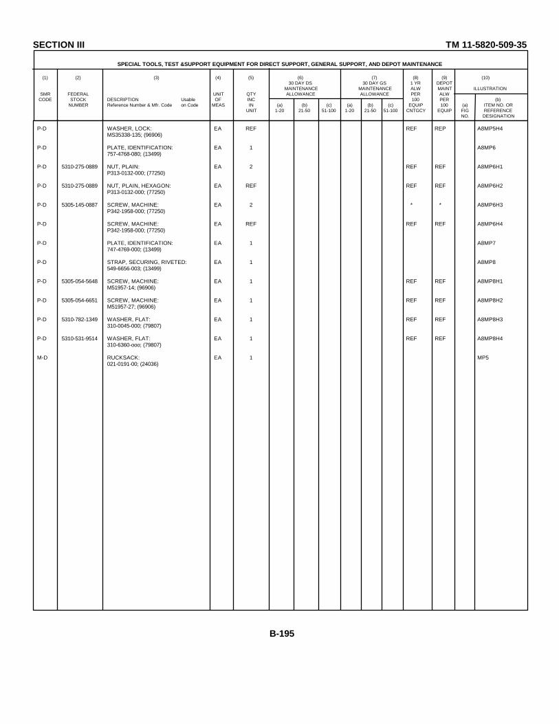
SECTION III TM 11-5820-509-35
SPECIAL TOOLS, TEST &SUPPORT EQUIPMENT FOR DIRECT SUPPORT, GENERAL SUPPORT, AND DEPOT MAINTENANCE
(1) (2) (3) (4) (5) (6) (7) (8) (9) (10)30 DAY DS 30 DAY GS 1 YR DEPOT
MAINTENANCE MAINTENANCE ALW MAINT ILLUSTRATIONSMR FEDERAL UNIT QTY ALLOWANCE ALLOWANCE PER ALW
CODE STOCK DESCRIPTION Usable OF INC 100 PER (b)NUMBER Reference Number & Mfr. Code on Code MEAS IN (a) (b) (c) (a) (b) (c) EQUIP 100 (a) ITEM NO. OR
UNIT 1-20 21-50 51-100 1-20 21-50 51-100 CNTGCY EQUIP FIG REFERENCENO. DESIGNATION
P-D WASHER, LOCK: EA REF REF REP A8MP5H4MS35338-135; (96906)
P-D PLATE, IDENTIFICATION: EA 1 A8MP6757-4768-080; (13499)
P-D 5310-275-0889 NUT, PLAIN: EA 2 REF REF A8MP6H1P313-0132-000; (77250)
P-D 5310-275-0889 NUT, PLAIN, HEXAGON: EA REF REF REF A8MP6H2P313-0132-000; (77250)
P-D 5305-145-0887 SCREW, MACHINE: EA 2 * * A8MP6H3P342-1958-000; (77250)
P-D SCREW, MACHINE: EA REF REF REF A8MP6H4P342-1958-000; (77250)
P-D PLATE, IDENTIFICATION: EA 1 A8MP7747-4769-000; (13499)
P-D STRAP, SECURING, RIVETED: EA 1 A8MP8549-6656-003; (13499)
P-D 5305-054-5648 SCREW, MACHINE: EA 1 REF REF A8MP8H1M51957-14; (96906)
P-D 5305-054-6651 SCREW, MACHINE: EA 1 REF REF A8MP8H2M51957-27; (96906)
P-D 5310-782-1349 WASHER, FLAT: EA 1 REF REF A8MP8H3310-0045-000; (79807)
P-D 5310-531-9514 WASHER, FLAT: EA 1 REF REF A8MP8H4310-6360-ooo; (79807)
M-D RUCKSACK: EA 1 MP5021-0191-00; (24036)
B-195
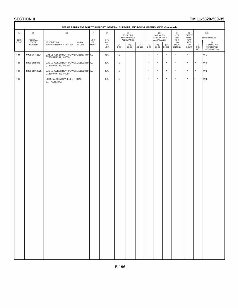
SECTION II TM 11-5820-509-35
REPAIR PARTS FOR DIRECT SUPPORT, GENERAL SUPPORT, AND DEPOT MAINTENANCE (Continued)
(1) (2) (3) (4) (5) (6) (7) (8) (9) (10)30 DAY DS 30 DAY GS 1 YR DEPOT
MAINTENANCE MAINTENANCE ALW MAINT ILLUSTRATIONSMR FEDERAL UNIT QTY ALLOWANCE ALLOWANCE PER ALW
CODE STOCK DESCRIPTION Usable OF INC 100 PER (b)NUMBER Reference Number & Mfr. Code on Code MEAS IN (a) (b) (c) (a) (b) (c) EQUIP 100 (a) ITEM NO. OR
UNIT 1-20 21-50 51-100 1-20 21-50 51-100 CNTGCY EQUIP FIG REFERENCENO. DESIGNATION
P-H 5995-087-2324 CABLE ASSEMBLY, POWER, ELECTRICAL EA 1 * * * * * * W1CX8393PRC47; (80058)
P-H 5995-082-0487 CABLE ASSEMBLY, POWER, ELECTRICAL EA 1 * * * * * * W2CX8394PRC47; (80058)
P-H 5995-087-2325 CABLE ASSEMBLY, POWER, ELECTRICAL EA 1 * * * * * * W3CX8395PRC47; (80058)
P-H CORD ASSEMBLY, ELECTRICAL EA 1 * * * * * * W410747J, (82872)
B-196

TM-11-5820-509-35SECTION IV INDEX-FEDERAL STOCK NUMBER AND REFERENCE NUMBER CROSS REFERENCE
TO FIGURE AND ITEM NUMBER OR REFERENCE DESIGNATION (CONTINUED)
FEDERAL FIGURE ITEM NUMBER OR FEDERAL FIGURE ITEM NUMBER ORSTOCK NUMBER REF. DESIGNATION STOCK NUMBER REF. DESIGNATION
NUMBER NUMBER
3010-984-1099 A8A7A1 3120-865-8571 A8A4A6MP133020-088-1785 ASA4A6M42 3120-865-8571 AA4A6MP143020-088-4507 A8SAA6P64 3120-865-8571 A8A4A6L1P153020-088-6021 A8A4P36 3120-865-8571 A8A4A6UP163020-951-0700 A8A4P35 3120-865-8571 A8A4A6W173020-976-5392 A8A4A6A3 3120-865-8571 AA7YP33020-976-5393 A8AS5 5110-115-5049 A6A43020-985-2235 A8AA6A6 5305-053-1523 A8A7A1A31H2
3020-985-2236 A8A4AQ62 5305-054-5636 ASA3E13H13020-985-3351 ASA3NP27 5305-054-5636 A8A3E13H23020-985-3351 A8SA328 5305-054-5636 A8A3E15H13020-988-0687 A8A46YMP41 5305-054-5636 A8A3E15H23020-988-6910 A8A4A6MP43 5305-054-5636 A8A3E46123040-950-9578 A8A4A6P22 5305-054-5636 A8A7MP13H13040-950-9578 A8A4A6MP23 5305-054-5636 A8A7MP13}123040-950-9578 A8A4A6P24 5305-054-5636 A8A7MP13l33040-950-9578 A8A46MP25 5305-054-5636 A8A7YP14H1
3040-950-9578 6A8A46P26 5305-054-5636 A8A7MP14H23040-950-9578 A84A6UP27 5305-054-5636 A8A711P14H33040-977-1551 AMAE6MP37 5305-054-5637 A8A5P1123110-851-7674 A8A3YP3 5305-054-5637 A8A5P11133110-851-7674 8A3NP4 5305-054-5646 APA3E111113120-709-5460 8A4UP1 5305-054-5646 A8A3E46H13120-709-5460 A8A4P2 5305-054-5646 A8A4K103H13120-709-5460 A84P3 5305-054-5646 A8A4K103H23120-709-5460 A8AP4 5305-054-5646 A8A5E18H13120-709-5460 A8A4P5 5305-054-5646 A8A5hnI13120-709-5460 8A4Y6 5305-054-5647 AeA3A2H23120-793-6354 A8A4P7 5305-054-5647 A8A3A3H23120-793-6354 A8AP8 5305-054-5647 A8A3A9A31143120-865-8571 A8A4AIP11 5305-054-5647 A8A3ElOHl3120-865-8571 A84AW6EP12 5305-054-5647 A8A3EXOH2
B-197

TM-11-5820-509-35SECTION IV INDEX-FEDERAL STOCK NUMBER AND REFERENCE NUMBER CROSS REFERENCE
TO FIGURE AND ITEM NUMBER OR REFERENCE DESIGNATION (CONTINUED)
FEDERAL FIGURE ITEM NUMBER OR FEDERAL FIGURE ITEM NUMBER ORSTOCK NUMBER REF. DESIGNATION STOCK NUMBER REF. DESIGNATION
NUMBER NUMBER
5305-054-5647 A8A3MP24H10 5305-054-5647 A8A4MP25H115305-054-5647 A8A3MP24H11 5305-054-5647 A8A4MP25H25305-054-5647 A8A3MP24H12 5305-054-5647 A8A4MP25H35305-054-5647 A8A3AP24H13 5305-054-5647 A8A4/P25H45305-054-5647 A8A3MP24H14 5305-054-5647 A8A4MP25H55305-054-5647 A8A3MP24H15 5305-054-5647 A8A4MP25H65305-054-5647 A8A3MP24H16 5305-054-5647 A8A4MP25H75305-054-5647 A8A3MP24H17 5305-054-5647 A8A4MP25H85305-054-5647 A8A31P24H18 5305-054-5647 A8A4MP25H95305-054-5647 A8A3UP24H19 5305-054-5647 A8A4P26H15305-054-5647 A8A3MP24H20 5305-054-5647 A8AIP26H105305-054-5647 A8A31P24H5 5305-054-5647 A8A49P26H115305-054-5647 A8A3MP24H6 5305-054-5647 A8A4UP26H25305-054-5647 A8A3MP24H7 5305-054-5647 A8A4MP26H35305-054-5647 A8A3MP24H8 5305-054-5647 A8A4MP26H45305-054-5647 A8A3MP24H9 5305-054-5647 A8A4MP26H55305-054-5647 A8A3P238H1 5305-054-5647 A8A4MP26H65305-054-5647 A8A3MP38H2 5305-054-5647 A8A4MP26H75305-054-5647 A8A3MP38H3 5305-054-5647 A8AMP26H85305-054-5647 A8A3MP38H4 5305-054-5647 A8A4MP26H95305-054-5647 A8A4E150H1 5305-054-5647 A8A5E1H45305-054-5647 A8A4E151H1 5305-054-5647 A8A5E17H25305-054-5647 A8A4E152H1 5305-054-5647 A8A7AlA3H15305-054-5647 A8A4E153H1 5305-054-5647 A8A7MP8H15305-054-5647 A8A4E154H1 5305-054-5647 A8A7MP8H105305-054-5647 A8A4E160H1 5305-054-5647 A8A7MP8H115305-054-5647 A8A4E167H1 5305-054-5647 A8A7MP8H25305-054-5647 A8A4E168H1 5305-054-5647 A8A7MP8H35305-054-5647 A8A4K1O2H3 5305-054-5647 A8AMP8H45305-054-5647 A8A4K102H4 5305-054-5647 A8A7MP8H55305-054-5647 A8A41T25H1 5305-054-5647 A8A7MP8H65305-054-5647 A8A4MP25H10 5305-054-5647 A8A7MP8H7
B-198
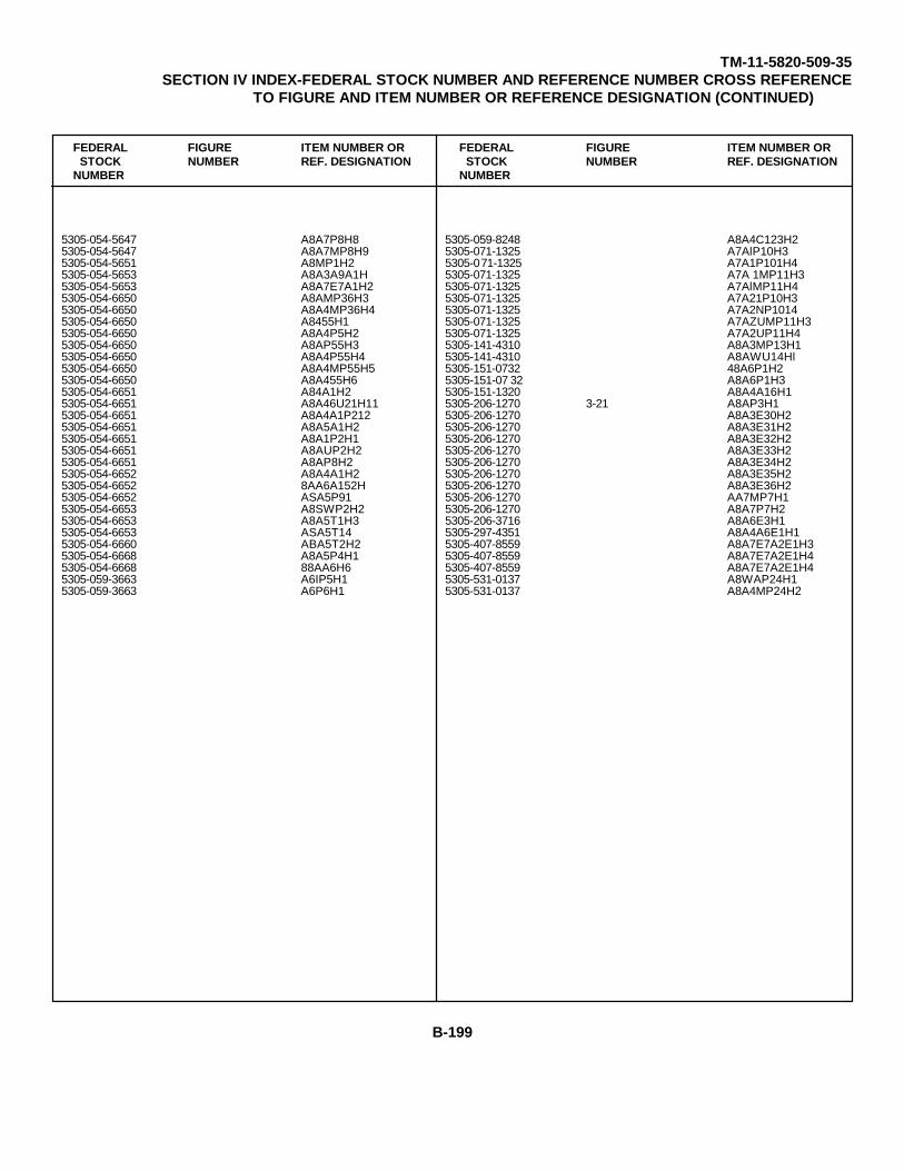
TM-11-5820-509-35SECTION IV INDEX-FEDERAL STOCK NUMBER AND REFERENCE NUMBER CROSS REFERENCE
TO FIGURE AND ITEM NUMBER OR REFERENCE DESIGNATION (CONTINUED)
FEDERAL FIGURE ITEM NUMBER OR FEDERAL FIGURE ITEM NUMBER ORSTOCK NUMBER REF. DESIGNATION STOCK NUMBER REF. DESIGNATION
NUMBER NUMBER
5305-054-5647 A8A7P8H8 5305-059-8248 A8A4C123H25305-054-5647 A8A7MP8H9 5305-071-1325 A7AlP10H35305-054-5651 A8MP1H2 5305-071-1325 A7A1P101H45305-054-5653 A8A3A9A1H 5305-071-1325 A7A 1MP11H35305-054-5653 A8A7E7A1H2 5305-071-1325 A7AlMP11H45305-054-6650 A8AMP36H3 5305-071-1325 A7A21P10H35305-054-6650 A8A4MP36H4 5305-071-1325 A7A2NP10145305-054-6650 A8455H1 5305-071-1325 A7AZUMP11H35305-054-6650 A8A4P5H2 5305-071-1325 A7A2UP11H45305-054-6650 A8AP55H3 5305-141-4310 A8A3MP13H15305-054-6650 A8A4P55H4 5305-141-4310 A8AWU14Hl5305-054-6650 A8A4MP55H5 5305-151-0732 48A6P1H25305-054-6650 A8A455H6 5305-151-07 32 A8A6P1H35305-054-6651 A84A1H2 5305-151-1320 A8A4A16H15305-054-6651 A8A46U21H11 5305-206-1270 3-21 A8AP3H15305-054-6651 A8A4A1P212 5305-206-1270 A8A3E30H25305-054-6651 A8A5A1H2 5305-206-1270 A8A3E31H25305-054-6651 A8A1P2H1 5305-206-1270 A8A3E32H25305-054-6651 A8AUP2H2 5305-206-1270 A8A3E33H25305-054-6651 A8AP8H2 5305-206-1270 A8A3E34H25305-054-6652 A8A4A1H2 5305-206-1270 A8A3E35H25305-054-6652 8AA6A152H 5305-206-1270 A8A3E36H25305-054-6652 ASA5P91 5305-206-1270 AA7MP7H15305-054-6653 A8SWP2H2 5305-206-1270 A8A7P7H25305-054-6653 A8A5T1H3 5305-206-3716 A8A6E3H15305-054-6653 ASA5T14 5305-297-4351 A8A4A6E1H15305-054-6660 ABA5T2H2 5305-407-8559 A8A7E7A2E1H35305-054-6668 A8A5P4H1 5305-407-8559 A8A7E7A2E1H45305-054-6668 88AA6H6 5305-407-8559 A8A7E7A2E1H45305-059-3663 A6IP5H1 5305-531-0137 A8WAP24H15305-059-3663 A6P6H1 5305-531-0137 A8A4MP24H2
B-199
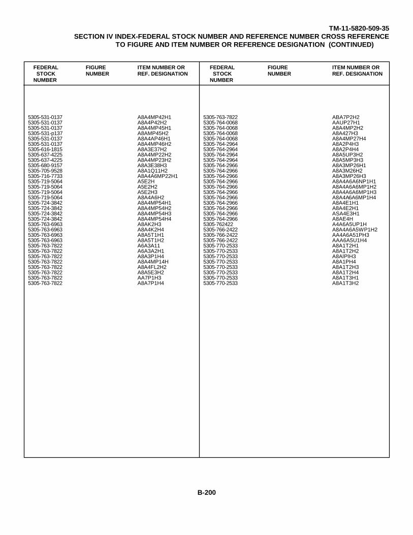
TM-11-5820-509-35SECTION IV INDEX-FEDERAL STOCK NUMBER AND REFERENCE NUMBER CROSS REFERENCE
TO FIGURE AND ITEM NUMBER OR REFERENCE DESIGNATION (CONTINUED)
FEDERAL FIGURE ITEM NUMBER OR FEDERAL FIGURE ITEM NUMBER ORSTOCK NUMBER REF. DESIGNATION STOCK NUMBER REF. DESIGNATION
NUMBER NUMBER
5305-531-0137 A8A4MP42H1 5305-763-7822 ABA7P2H25305-531-0137 A8A4P42H2 5305-764-0068 AAUP27H15305-531-0137 A8A4MP45H1 5305-764-0068 A8A4MP2H25305-531-p137 A8AMP45H2 5305-764-0068 A8A427H35305-531-0137 A8A4AP46H1 5305-764-0068 A8A4MP27H45305-531-0137 A8A4MP46H2 5305-764-2964 A8A2P4H35305-616-1815 A8A3E37H2 5305-764-2964 A8A2P4H45305-637-4225 A8A4MP22H2 5305-764-2964 A8A5UP3H25305-637-4225 A8A4MP23H2 5305-764-2964 A8A5MP3H35305-680-9157 A8A3E38H3 5305-764-2966 A8A3MP26H15305-705-9528 A8A1Q11H2 5305-764-2966 A8A3M26H25305-716-7733 A8A4A6MP22H1 5305-764-2966 A8A3MP26H35305-719-5064 A5E2H 5305-764-2966 A8A4A6A6NP1H15305-719-5064 A5E2H2 5305-764-2966 A8A4A6A6MP1H25305-719-5064 A5E2H3 5305-764-2966 A8A4A6A6MP1H35305-719-5064 A8A4A6H2 5305-764-2966 A8A4A6A6MP1H45305-724-3842 A8A4MP54H1 5305-764-2966 A8A4E1H15305-724-3842 A8A4MP54H2 5305-764-2966 A8A4E2H15305-724-3842 A8A4MP54H3 5305-764-2966 ASA4E3H15305-724-3842 A8A4MP54H4 5305-764-2966 A8AE4H5305-763-6963 A8AK2H3 5305-762422 A4A6A5UP1H5305-763-6963 A8A4K2H4 5305-766-2422 A8A4A6A5WP1H25305-763-6963 A8A5T1H1 5305-766-2422 AA4A6A51PH35305-763-6963 A8A5T1H2 5305-766-2422 AAA6A5U1H45305-763-7822 A6A3A11 5305-770-2533 A8A1T2H15305-763-7822 A6A3A2H1 5305-770-2533 A8A1T2H25305-763-7822 A8A3P1H4 5305-770-2533 A8AlPlH35305-763-7822 A8A4MP14H 5305-770-2533 A8A1PH45305-763-7822 A8A4FL2H2 5305-770-2533 A8A1T2H35305-763-7822 A8A5E3H2 5305-770-2533 A8A1T2H45305-763-7822 AA7P1H3 5305-770-2533 A8A1T3H15305-763-7822 A8A7P1H4 5305-770-2533 A8A1T3H2
B-200

TM-11-5820-509-35SECTION IV INDEX-FEDERAL STOCK NUMBER AND REFERENCE NUMBER CROSS REFERENCE
TO FIGURE AND ITEM NUMBER OR REFERENCE DESIGNATION (CONTINUED)
FEDERAL FIGURE ITEM NUMBER OR FEDERAL FIGURE ITEM NUMBER ORSTOCK NUMBER REF. DESIGNATION STOCK NUMBER REF. DESIGNATION
NUMBER NUMBER
5305-770-2533 A8A1T3H3 5305-938-4044 A8A4A166H15305-770-2533 AA1T3H4 5305-942-8431 A8A46MP46H15305-770-2533 A8AlT5H1 5305-942-8431 A8A4A6MP46H25305-770-2533 A8A1T5H2 5305-981-5875 A8A8H45305-770-2533 A8A1T5H3 5305-984-2144 A8A4A6MP565305-770-2533 A8A1T5H4 5305-984-2144 A8A4A6MP585305-770-2533 ASA3L98H1 5305-984-2144 A8A4A6MP605305-770-2533 A8A3P1H3 5306-960-7330 A8A8H25305-770-2533 A8A3P2H3 5310-058-3599 A8A45TB1Hl5305-770-2533 A8A3P2H4 5310-058-3599 A8A5XC20H45305-770-2533 A8A3P3H3 5310-058-3599 A8A7P2H35305-770-2533 A8A3P3H4 5310-167-0797 A8A2P3H55305-770-2533 A8A3P4H3 5310-167-0797 A8A2P3H65305-770-2533 A8A3P4H4 5310-167-0797 A8A2P4H55305-770-2533 A8A7NP12H1 5310-167-0797 A8A2P4H65305-770-2533 A8A7MP12H2 5310-167-0837 A8A4A7H25305-770-2533 A8A7MP12H3 5310-178-8631 A8A4C146H25305-770-2533 A8A7NP12H4 5310-184-8990 A8A7TB1E2H25305-770-2533 A8A7P21H 5310-184-8996 A8A7MP7H35305-770-2579 ASA4MP15H1 5310-184-8996 A8A7MP7H45305-770-2579 A8A4MP16H1 5310-187-0159 A8A4C29H25305-770-2579 A8A4MP17H1 5310-187-0159 A8A4C30H25305-770-2580 A6MP7H1 5310-208-6841 A8A4C146H15305-770-2580 A6MP7H2 5310-209-0960 A8AA3A3H25305-788-9882 A8A4H5 5310-275-5147 AA3MP7H15305-805-9801 A8A3MP15H1 5310-275-5147 A8A3MP8H15305-805-9801 A8A3MP15H2 5310-276-1104 A8A3P12H15305-805-9801 A8A3MP1H3 5310-276-1104 A8A4MP22H15305-805-9801 ASA3MP15H4 5310-276-110 4 A8A4MP23H15305-922-6281 A8A4MP61H1 5310-530-3549 A8SA7A1H45305-938-4044 A8A3TB1H2 5310-551-9284 A8A4A6MP1H135305-938-4044 A8A3TB2H2 5310-551-9284 A8A4A6P1H14
B-201

TM-11-5820-509-35SECTION IV INDEX-FEDERAL STOCK NUMBER AND REFERENCE NUMBER CROSS REFERENCE
TO FIGURE AND ITEM NUMBER OR REFERENCE DESIGNATION (CONTINUED)
FEDERAL FIGURE ITEM NUMBER OR FEDERAL FIGURE ITEM NUMBER ORSTOCK NUMBER REF. DESIGNATION STOCK NUMBER REF. DESIGNATION
NUMBER NUMBER
5310-551-9284 A8A4A6MP1H15 5310-614-3500 A8A7P1H25310-551-9284 A8A4A6MP1H16 5310-616-8660 A8A5T2H15310-551-9284 A8A4A6MP1Hl17 5310-685-7739 A8A3P1H15310-551-9284 A8A4A6MP1H18 5310-685-7739 A8A3P2H15310-551-9286 A8A5R22H4 5310-685-7739 A8A3P3H15310-551-9286 A8A5R3H4 5310-685-7739 A8A3P4H15310-551-9286 A8A5R4H4 5310-925-7991 A8A4E29H35310-558-4187 A8A4MP13H2 5310-925-7991 A8A4E29H45310-559-0575 A8A4C29H1 5310-925-7991 A8A4E30H35310-559-0575 A8A4C30H1 5310-925-7991 A8A4E30H45310-591-3416 A8A4A16H2 5310-925-7991 A8A4E31H35310-614-3500 A8A3A2H2 5310-925-7991 A8A4E31H45310-614-3500 A8A4K1H1 5310-925-7991 A8A4E32H35310-614-3500 A8A4K1H2 5310-925-7991 A8A4E32H45310-614-3500 A8A4K3H1 5310-928-2690 A8A3E13H35310-614-3500 A8A4K3H2 5310-928-2690 A8A3E13H45310-614-3500 A8A4K4H1 5310-928-2690 A8A3E15H35310-614-3500 A8A4K4H2 5310-928-2690 A8A3E15H45310-614-3500 A8A4K6H1 5310-928-2690 A8A4J5H65310-614-3500 A8A4K6H2 5310-928-2690 A8A4J7H65310-614-3500 A8A4R8H1 5310-928-26 90 A8A5E5H35310-614-3500 A8A4R8H2 5310-928-2690 A8A7MP13H45310-614-3500 A8A4T2H1 5310-928-2690 A8A7MP13H55310-614-3500 A8A4T2H2 5310-928-2690 A8A7MP13H65310-614-3500 A8A4T3H1 5310-928-2690 A8A7MP14H45310-614-3500 A8A4T3H2 5310-928-2690 A8A7MP14H55310-614-3500 A8A5E3H2 5310-928-2690 A8A7MAP14H65310-614-3500 A8A5XC19H1 5310-929-6395 A8A5T2F55310-614-3500 A8A5XC19H2 5310-933-8119 A8A4A6H69310-614-3500 A8A5XC20H1 5310-933-8119 A8A4A6UP46H35310-614-3500 A8A7E7A1H2 5310-933-8119 A8A4A6MP46H45310-614-3500 A8A7P1H1 5310-933-8119 48A4A6MP47H3
B-202

TM-11-5820-509-35SECTION IV INDEX-FEDERAL STOCK NUMBER AND REFERENCE NUMBER CROSS REFERENCE
TO FIGURE AND ITEM NUMBER OR REFERENCE DESIGNATION (CONTINUED)
FEDERAL FIGURE ITEM NUMBER OR FEDERAL FIGURE ITEM NUMBER ORSTOCK NUMBER REF. DESIGNATION STOCK NUMBER REF. DESIGNATION
NUMBER NUMBER
5310-933-8119 A8A4A6MP47H4 5310-934-9765 A7A1MP10H15310-933-8119 A8A4MP61H2 5310-934-9765 A7A1MP10H25310-933-8119 A8A4MP62H2 5310-934-9765 A7A1MP11H15310-933-8119 A8A4MP63H2 5310-934-9765 A7A1MP11H25310-933-8119 A8A4MP64H2 5310-934-9765 A7A2MP10H15310-933-8119 A8A4MP65H2 5310-934-9765 A7A2MP10H25310-933-8119 A8A4MP66H2 5310-934-9765 A7A2MP11H15310-933-8119 A8A4UP67H2 5310-934-9765 A7A2MP11H25310-933-8119 A8A4MP68H2 5310-938-2013 A8A5E5H15310-933-8119 A8A4MP69H2 5310-938-8387 A7A1H15310-933-8119 A8A4MP70H2 5310-938-8387 A7A1H25310-933-8119 A8A4MP70H2 5310-938-8387 A7A2H15310-933-8119 A8A4MP72H2 5310-938-8387 A7A2H25310-933-8119 A8A47MP3H2 5310-939-0903 A8A4C123H35310-933-8119 A8A4MP74H2 5310-948-8598 A8A4A6NP545310-933-8119 A8A4MP75H2 5310-952-1423 A8A3H35310-933-8119 A8A4MP76H2 5310-952-1423 A8A3H45310-933-8119 A8A4MP77H2 5310-952-1423 A8A3H55310-933-8119 A8A4MP78H2 5310-952-1423 A8A3H65310-933-8119 A8A4MP79H2 5310-952-1423 A8A3H75310-933-8119 A8A4MP80H2 5310-952-1423 A8A3H85310-933-8119 A8A4MP81H2 5315-058-9698 A8A7A2MP15310-933-8119 A8A5MP4H2 5315-058-9698 A8A7A3MP15310-933-8119 A8A5MP8H4 5315-531-9482 A8A3A7MP15310-933-8120 A7A1MP10H5 5315-531-9482 A8A3A7MP25310-933-8120 A7A1MP10H6 5315-614-3586 A8A3A6NP45310-933-8120 A7A1MP11H5 5315-614-3586 A8A3A6MP55310-933-8120 A7A1MP11H6 5315-823-8744 A5A1MP15310-933-8120 A7A2MP10H5 5315-823-8746 A5MP55310-933-8120 A7A2MP10H6 5315-853-0681 A8A3ASMP15310-933-8120 A7A2MP11H5 5315-881-2253 A8A4A6A8MP15310-933-8120 A7A2MP11H6 5315-881-2253 A8A4A6A8P2
B-203
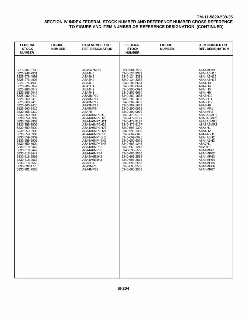
TM-11-5820-509-35SECTION IV INDEX-FEDERAL STOCK NUMBER AND REFERENCE NUMBER CROSS REFERENCE
TO FIGURE AND ITEM NUMBER OR REFERENCE DESIGNATION (CONTINUED)
FEDERAL FIGURE ITEM NUMBER OR FEDERAL FIGURE ITEM NUMBER ORSTOCK NUMBER REF. DESIGNATION STOCK NUMBER REF. DESIGNATION
NUMBER NUMBER
5315-987-8790 A8A3A7MP6 5330-981-7538 A8A4MP335325-248-7031 A8A4H6 5340-124-3383 A8A4A6H155325-276-4993 A8A3H2 5340-124-3383 A8A4A6H165325-276-4993 A8A4H4 5340-124-3383 A8A4A6H175325-276-4993 A8A4H5 5340-205-6694 A8A4H35325-286-6047 A8A2H1 5340-205-6694 A8A4H45325-286-6047 A8A4H2 5340-205-6694 A8A4H55325-286-6047 A8A4H3 5340-205-6694 A8A4H65325-960-2410 A8A3MP10 5340-282-1633 A8A3H105325-960-2410 A8A3MP11 5340-282-1633 A8A3H115325-960-2410 A8A3MP12 5340-282-1633 A8A3H125325-960-2410 A8A3MP13 5340-282-1633 A8A3H95325-960-2410 A8A5MP6 5340-290-0939 A8A4MP15330-558-2310 A8AH5 5340-290-0939 A8A4MP25330-559-8909 A8A4A6MP1H19 5340-479-9197 A8A3A5MP15330-559-8909 A8A4A6MP1H20 5340-479-9197 A8A3A5MP25330-559-8909 A8A4A6MP1H21 5340-479-9197 A8A3A6MP15330-559-8909 A8A4A6MP1H22 5340-479-9197 A8A3A6MP25330-559-8909 A8A4A6MP1H23 5340-598-1300 A8A4H15330-559-8909 A8A4A6MP1H24 5340-598-1300 A8A4H25330-559-8909 A8A4A6MP46H5 5340-602-6075 A8A4A6H15330-559-8909 A8A4A6MP46H6 5340-602-6075 A8A4A6H25330-559-8909 A8A4A6MP47H5 5340-602-6075 A8A4A6H35330-559-8909 A8A4A6MP47H6 5340-663-1245 A8A7H15330-618-3447 A8A4A6MP32 5340-663-1245 ASA7H25330-618-3447 A8A4A6MP33 5340-695-2558 A8A4MP615330-618-3447 A8A4A6MP34 5340-695-2558 A8A4MP625330-618-9563 A8A4A6E3H3 5340-695-2558 A8A4MP635330-618-9563 A8A4A6E4H3 5340-695-2558 A8A4MP645330-618-9563 A8A8H4 5340-695-2558 A8A4MP655330-892-4773 A8A9MP1 5340-695-2558 A8A4MP665330-981-7538 A8A4MP32 5340-695-2558 A8A4MP67
B-204

TM-11-5820-509-35SECTION IV INDEX-FEDERAL STOCK NUMBER AND REFERENCE NUMBER CROSS REFERENCE
TO FIGURE AND ITEM NUMBER OR REFERENCE DESIGNATION (CONTINUED)
FEDERAL FIGURE ITEM NUMBER OR FEDERAL FIGURE ITEM NUMBER ORSTOCK NUMBER REF. DESIGNATION STOCK NUMBER REF. DESIGNATION
NUMBER NUMBER
5340-695-2558 A8A4MP68 5340-975-7637 A8A3E165340-695-2558 A8A4MP69 5340-975-7637 A8A5E45340-695-2558 A8A4MP70 5340-975-7637 A8A7E85340-695-2558 A8A4MP71 5340-984-0423 A8A5MP75340-695-2558 A8A4MP72 5340-984-0423 A8A5MP85340-695-2558 A8A4MP73 5340-984-7536 A8A3MP365340-695-2558 A8A4MP74 5340-984-7536 A8A3MP375340-695-2558 A8A4MP75 5340-984-7537 A8A3MP35340-695-2558 A8A4MP76 5355-733-5548 A8A4MP435340-695-2558 A8A4MP77 5355-950-7574 A8A4MP455340-695-2558 A8A4MP78 5355-950-7575 A8A4MP425340-695-2558 A8A4MP79 5355-950-7576 A8A4MP445340-695-2558 A8A4MP80 5355-951-4083 A8A4A6MP485340-695-2558 A8A4MP81 5355-951-4083 A8A4A6MP495340-720-6320 A8A4MP20 5355-951-4083 A8A4A6MP505340-720-8064 A8A4A6H4 5355-965-4878 A5MP45340-734-5982 A6MP10 5820-015-1607 A8A3A25340-758-5660 A6MP5 5820-042-5719 A8A3E485340-758-5660 A6MP6 5820-062-4758 A75340-795-9364 A7A1MP3 5820-066-2122 A8A7TB1E15340-795-9364 A7A1MP4 5820-087-0328 A8A65340-795-9364 A7A2MP3 5820-087-2299 A8A15340-795-9364 A7A2MP4 5820-087-2304 A8A55340-803-2373 A8A4H10 5820-087-2314 A8A75340-803-2373 A8A4H11 5820-087-3439 A8A1E25340-803-2373 A8A4H12 5820-087-3440 A8A6A15340-803-2373 A8AMH7 5820-088-1379 A8A6E15340-803-2373 A8A4H8 5820-088-2514 A8A1E35340-803-2373 A8A4H9 5820-088-2515 A8A2E25340-947-6204 A6A1 5820-088-4936 A8A4E245340-947-6204 A6A2 5820-088-4916 A8A4E295340-975-7637 A8A1E4 5820-088-4916 A8A4E30
B-205

TM-11-5820-509-35SECTION IV INDEX-FEDERAL STOCK NUMBER AND REFERENCE NUMBER CROSS REFERENCE
TO FIGURE AND ITEM NUMBER OR REFERENCE DESIGNATION (CONTINUED)
FEDERAL FIGURE ITEM NUMBER OR FEDERAL FIGURE ITEM NUMBER ORSTOCK NUMBER REF. DESIGNATION STOCK NUMBER REF. DESIGNATION
NUMBER NUMBER
5820-088-4916 A8A4E31 5820-975-5417 3-14 A8A7E45820-088-4916 A8A4E32 5820-975-5419 3-15 A8A7E55820-089-4996 A8A4A6A13 5820-975-5421 3-15 A8A7E15820-104-9512 A8A4A16 5820-975-5422 3-14 A8A7E65820-168-1583 A8A4E33 5820-975-5423 3-14 A8A7E25820-168-1598 A8A4A1 5820-975-5426 3-20 A8A2E15820-758-0063 A6A3 5820-975-5427 3-21 A8A2E35820-758-0064 A6MP7 5820-975-5428 3-21 A8A2E45820-788-9615 A5A1E1 5820-975-5429 3-21 A8A2E55820-795-9365 A8A3A12 5820-975-5430 3-9 A8A3E475820-795-9370 A7A1MP10 5820-975-5431 3-10 A8A3A135820-795-9370 A7A1MP11 5820-975-5432 3-10 A8A3E465820-795-9370 A7A2MP10 5820-975-5433 3-24 A8A3A9A15820-795-9370 A7AZP11 5820-975-7638 A8A3A85820-946-3338 3-19 A8A1E3E1 5820-975-7640 A8A3MP305820-946-3347 3-58 A8A7E5E1 5820-975-7641 A8A3MP295820-950-4464 3-11 A8A5E2 5820-975-7642 A8A3A75820-951-4081 A8A4E22 5820-975-7645 A8A7A25820-951-4081 A8A4E23 5820-975-7646 A8A7A35820-953-5772 3-60 A8A7E7A2 5820-976-9775 A8A4A6A115820-960-7832 A6MP8 5820-976-9776 A8A4A6A95820-960-7832 A6EP9 5820-976-9777 A8A4A6A105820-960-7844 A8A3E7 5820-977-1553 A8A4A6MP215820-960-7845 3-4 A8A3 5820-977-1558 A8A4A6A25820-960-7852 3-9 A8A3A4 5820-977-1558 A8A4A6MP385820-970-6766 1-7 A3 5820-977-1559 A8A4A6A45820-975-5412 3-6 A8A1E1 5820-977-1560 A8A4A6AP445820-975-5413 3-10 A8A3A11 5820-977-1561 A8A4A61AP455820-975-5414 3-10 A8A3A10 5820-977-1563 A8A4A6A15820-975-5415 3-24 A8A3A9A2 5820-977-1564 A8A4A6MP205820-975-5416 3-24 A8A3A9A3 5820-977-1565 3-10 A8A3A9
B-206
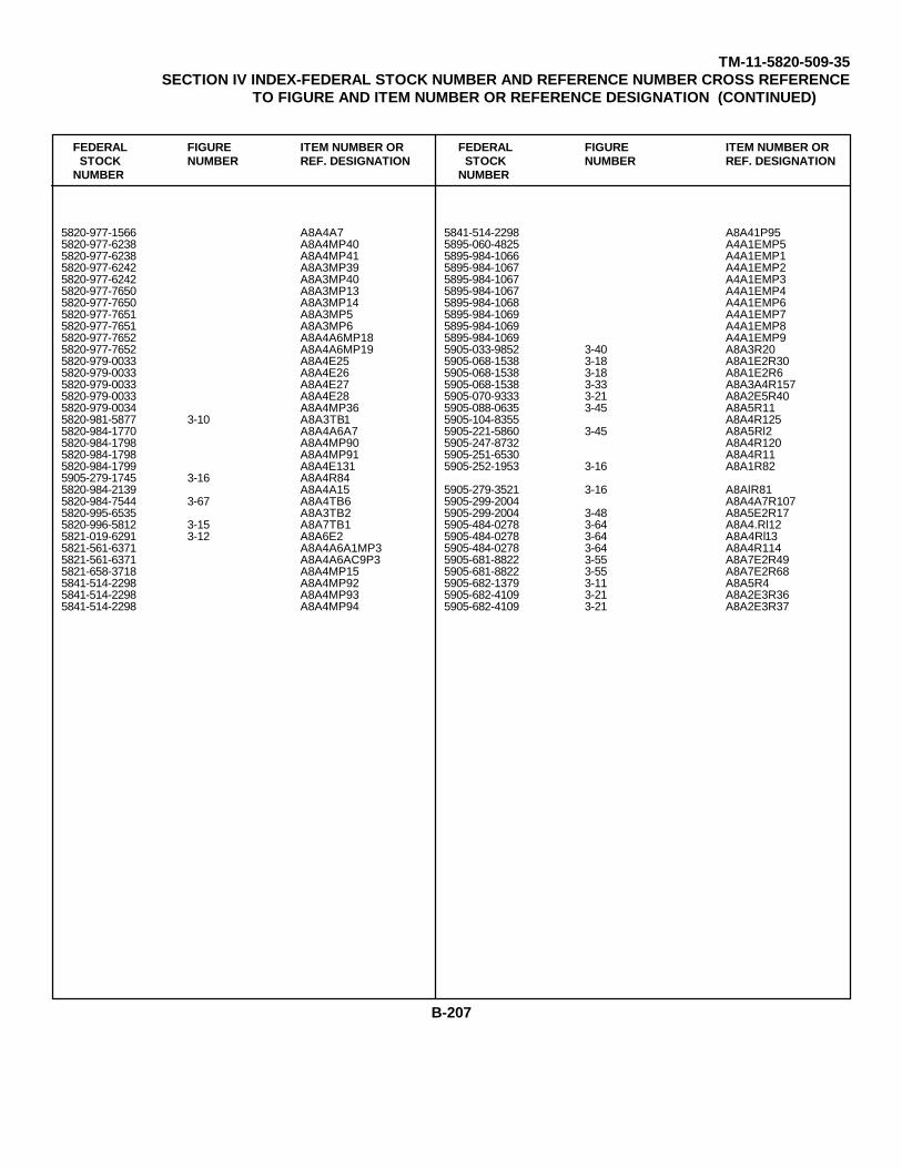
TM-11-5820-509-35SECTION IV INDEX-FEDERAL STOCK NUMBER AND REFERENCE NUMBER CROSS REFERENCE
TO FIGURE AND ITEM NUMBER OR REFERENCE DESIGNATION (CONTINUED)
FEDERAL FIGURE ITEM NUMBER OR FEDERAL FIGURE ITEM NUMBER ORSTOCK NUMBER REF. DESIGNATION STOCK NUMBER REF. DESIGNATION
NUMBER NUMBER
5820-977-1566 A8A4A7 5841-514-2298 A8A41P955820-977-6238 A8A4MP40 5895-060-4825 A4A1EMP55820-977-6238 A8A4MP41 5895-984-1066 A4A1EMP15820-977-6242 A8A3MP39 5895-984-1067 A4A1EMP25820-977-6242 A8A3MP40 5895-984-1067 A4A1EMP35820-977-7650 A8A3MP13 5895-984-1067 A4A1EMP45820-977-7650 A8A3MP14 5895-984-1068 A4A1EMP65820-977-7651 A8A3MP5 5895-984-1069 A4A1EMP75820-977-7651 A8A3MP6 5895-984-1069 A4A1EMP85820-977-7652 A8A4A6MP18 5895-984-1069 A4A1EMP95820-977-7652 A8A4A6MP19 5905-033-9852 3-40 A8A3R205820-979-0033 A8A4E25 5905-068-1538 3-18 A8A1E2R305820-979-0033 A8A4E26 5905-068-1538 3-18 A8A1E2R65820-979-0033 A8A4E27 5905-068-1538 3-33 A8A3A4R1575820-979-0033 A8A4E28 5905-070-9333 3-21 A8A2E5R405820-979-0034 A8A4MP36 5905-088-0635 3-45 A8A5R115820-981-5877 3-10 A8A3TB1 5905-104-8355 A8A4R1255820-984-1770 A8A4A6A7 5905-221-5860 3-45 A8A5Rl25820-984-1798 A8A4MP90 5905-247-8732 A8A4R1205820-984-1798 A8A4MP91 5905-251-6530 A8A4R115820-984-1799 A8A4E131 5905-252-1953 3-16 A8A1R825905-279-1745 3-16 A8A4R845820-984-2139 A8A4A15 5905-279-3521 3-16 A8AlR815820-984-7544 3-67 A8A4TB6 5905-299-2004 A8A4A7R1075820-995-6535 A8A3TB2 5905-299-2004 3-48 A8A5E2R175820-996-5812 3-15 A8A7TB1 5905-484-0278 3-64 A8A4.Rl125821-019-6291 3-12 A8A6E2 5905-484-0278 3-64 A8A4Rl135821-561-6371 A8A4A6A1MP3 5905-484-0278 3-64 A8A4R1145821-561-6371 A8A4A6AC9P3 5905-681-8822 3-55 A8A7E2R495821-658-3718 A8A4MP15 5905-681-8822 3-55 A8A7E2R685841-514-2298 A8A4MP92 5905-682-1379 3-11 A8A5R45841-514-2298 A8A4MP93 5905-682-4109 3-21 A8A2E3R365841-514-2298 A8A4MP94 5905-682-4109 3-21 A8A2E3R37
B-207
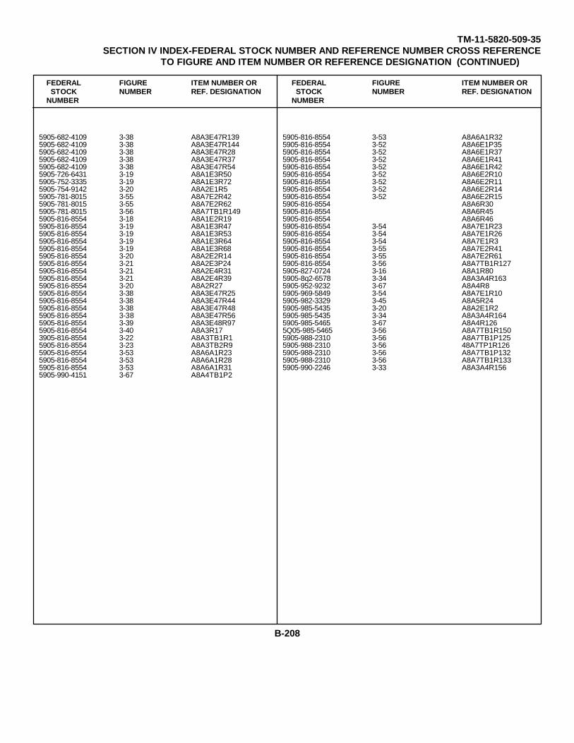
TM-11-5820-509-35SECTION IV INDEX-FEDERAL STOCK NUMBER AND REFERENCE NUMBER CROSS REFERENCE
TO FIGURE AND ITEM NUMBER OR REFERENCE DESIGNATION (CONTINUED)
FEDERAL FIGURE ITEM NUMBER OR FEDERAL FIGURE ITEM NUMBER ORSTOCK NUMBER REF. DESIGNATION STOCK NUMBER REF. DESIGNATION
NUMBER NUMBER
5905-682-4109 3-38 A8A3E47R139 5905-816-8554 3-53 A8A6A1R325905-682-4109 3-38 A8A3E47R144 5905-816-8554 3-52 A8A6E1P355905-682-4109 3-38 A8A3E47R28 5905-816-8554 3-52 A8A6E1R375905-682-4109 3-38 A8A3E47R37 5905-816-8554 3-52 A8A6E1R415905-682-4109 3-38 A8A3E47R54 5905-816-8554 3-52 A8A6E1R425905-726-6431 3-19 A8A1E3R50 5905-816-8554 3-52 A8A6E2R105905-752-3335 3-19 A8A1E3R72 5905-816-8554 3-52 A8A6E2R115905-754-9142 3-20 A8A2E1R5 5905-816-8554 3-52 A8A6E2R145905-781-8015 3-55 A8A7E2R42 5905-816-8554 3-52 A8A6E2R155905-781-8015 3-55 A8A7E2R62 5905-816-8554 A8A6R305905-781-8015 3-56 A8A7TB1R149 5905-816-8554 A8A6R455905-816-8554 3-18 A8A1E2R19 5905-816-8554 A8A6R465905-816-8554 3-19 A8A1E3R47 5905-816-8554 3-54 A8A7E1R235905-816-8554 3-19 A8A1E3R53 5905-816-8554 3-54 A8A7E1R265905-816-8554 3-19 A8A1E3R64 5905-816-8554 3-54 A8A7E1R35905-816-8554 3-19 A8A1E3R68 5905-816-8554 3-55 A8A7E2R415905-816-8554 3-20 A8A2E2R14 5905-816-8554 3-55 A8A7E2R615905-816-8554 3-21 A8A2E3P24 5905-816-8554 3-56 A8A7TB1R1275905-816-8554 3-21 A8A2E4R31 5905-827-0724 3-16 A8A1R805905-816-8554 3-21 A8A2E4R39 5905-8q2-6578 3-34 A8A3A4R1635905-816-8554 3-20 A8A2R27 5905-952-9232 3-67 A8A4R85905-816-8554 3-38 A8A3E47R25 5905-969-5849 3-54 A8A7E1R105905-816-8554 3-38 A8A3E47R44 5905-982-3329 3-45 A8A5R245905-816-8554 3-38 A8A3E47R48 5905-985-5435 3-20 A8A2E1R25905-816-8554 3-38 A8A3E47R56 5905-985-5435 3-34 A8A3A4R1645905-816-8554 3-39 A8A3E48R97 5905-985-5465 3-67 A8A4R1265905-816-8554 3-40 A8A3R17 5Q05-985-5465 3-56 A8A7TB1R1503905-816-8554 3-22 A8A3TB1R1 5905-988-2310 3-56 A8A7TB1P1255905-816-8554 3-23 A8A3TB2R9 5905-988-2310 3-56 48A7TP1R1265905-816-8554 3-53 A8A6A1R23 5905-988-2310 3-56 A8A7TB1P1325905-816-8554 3-53 A8A6A1R28 5905-988-2310 3-56 A8A7TB1R1335905-816-8554 3-53 A8A6A1R31 5905-990-2246 3-33 A8A3A4R1565905-990-4151 3-67 A8A4TB1P2
B-208
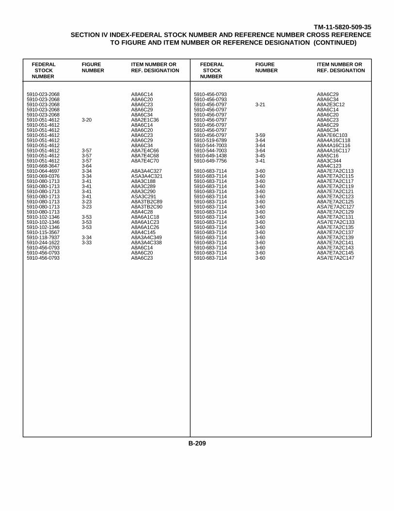
TM-11-5820-509-35SECTION IV INDEX-FEDERAL STOCK NUMBER AND REFERENCE NUMBER CROSS REFERENCE
TO FIGURE AND ITEM NUMBER OR REFERENCE DESIGNATION (CONTINUED)
FEDERAL FIGURE ITEM NUMBER OR FEDERAL FIGURE ITEM NUMBER ORSTOCK NUMBER REF. DESIGNATION STOCK NUMBER REF. DESIGNATION
NUMBER NUMBER
5910-023-2068 A8A6C14 5910-456-0793 A8A6C295910-023-2068 A8A6C20 5910-456-0793 A8A6C345910-023-2068 A8A6C23 5910-456-0797 3-21 A8A2E3C125910-023-2068 A8A6C29 5910-456-0797 A8A6C145910-023-2068 A8A6C34 5910-456-0797 A8A6C205910-051-4612 3-20 A8A2E1C36 5910-456-0797 A8A6C235910-051-4612 A8A6C14 5910-456-0797 A8A6C295910-051-4612 A8A6C20 5910-456-0797 A8A6C345910-051-4612 A8A6C23 5910-456-0797 3-59 A8A7E6C1035910-051-4612 A8A6C29 5910-519-6789 3-64 A8A4A16C1185910-051-4612 A8A6C34 5910-544-7003 3-64 A8A4A16C1165910-051-4612 3-57 A8A7E4C66 5910-544-7003 3-64 A8A4A16C1175910-051-4612 3-57 A8A7E4C68 5910-649-1438 3-45 A8A5C165910-051-4612 3-57 A8A7E4C70 5910-649-7756 3-41 A8A3C3445910-668-3647 3-64 A8A4C1235910-064-4697 3-34 A8A3A4C327 5910-683-7114 3-60 A8A7E7A2C1135910-069-0376 3-34 ASA3A4C321 5910-683-7114 3-60 A8A7E7A2C1155910-080-1713 3-41 A8A3C188 5910-683-7114 3-60 A8A7E7A2C1175910-080-1713 3-41 A8A3C289 5910-683-7114 3-60 A8A7E7A2C1195910-080-1713 3-41 A8A3C290 5910-683-7114 3-60 A8A7E7A2C1215910-080-1713 3-41 ASA3C291 5910-683-7114 3-60 A8A7E7A2C1235910-080-1713 3-23 A8A3TB2C89 5910-683-7114 3-60 A8A7E7A2C1255910-080-1713 3-23 A8A3TB2C90 5910-683-7114 3-60 ASA7E7A2C1275910-080-1713 A8A4C28 5910-683-7114 3-60 A8A7E7A2C1295910-102-1346 3-53 A8A6A1C18 5910-683-7114 3-60 A8A7E7A2C1315910-102-1346 3-53 A8A6A1C23 5910-683-7114 3-60 ASA7E7A2C1335910-102-1346 3-53 A8A6A1C26 5910-683-7114 3-60 A8A7E7A2C1355910-115-3567 A8A4C145 5910-683-7114 3-60 A8A7E7A2C1375910-118-7937 3-34 A8A3A4C349 5910-683-7114 3-60 A8A7E7A2C1395910-244-1622 3-33 A8A3A4C338 5910-683-7114 3-60 A8A7E7A2C1415910-456-0793 A8A6C14 5910-683-7114 3-60 A8A7E7A2C1435910-456-0793 A8A6C20 5910-683-7114 3-60 A8A7E7A2C1455910-456-0793 A8A6C23 5910-683-7114 3-60 ASA7E7A2C147
B-209
TM-11-5820-509-35SECTION IV INDEX-FEDERAL STOCK NUMBER AND REFERENCE NUMBER CROSS REFERENCE
TO FIGURE AND ITEM NUMBER OR REFERENCE DESIGNATION (CONTINUED)
FEDERAL FIGURE ITEM NUMBER OR FEDERAL FIGURE ITEM NUMBER ORSTOCK NUMBER REF. DESIGNATION STOCK NUMBER REF. DESIGNATION
NUMBER NUMBER
5910-683-7114 3-60 A8A7E7A2C149 5910-825-3067 A8A6C235910-683-7114 3-60 A8A7E7A2C151 5910-825-3067 A8A6C295910-683-7276 3-20 A8A3C37 5910-825-3067 A8A6C345910-688-6457 3-41 A8A3A2C350 5910-825-3067 3-58 A8A7E5C835910-688-6457 3-41 A8A3A2C351 5910-825-5288 A8A6C145910-688-6457 3-41 A8A3A2C352 5910-825-5288 A8A6C205910-762-2828 3-40 A8A3C117 5910-825-5288 A8A6C235910-762-2828 3-40 A8A3C292 5910-825-5288 A8A6C295910-765-4415 3-40 A8A3C118 5910-825-5288 A8A6C345910-765-4419 3-17 A8A1E1C25 5910-825-5288 3-58 A8A7E5C895910-765-4419 3-19 A8A1E3C37 5910-827-0019 3-19 A8A1E3C325910-765-4419 3-19 A8A1E3C38 5910-827-0019 3-19 A8A1E3C365910-765-4419 3-19 A8A1E3C41 5910-851-3328 A8A6C145910-780-8675 3-50 A8A5C25 5910-851-3328 A8A6C205910-780-8675 3-45 A8A5C27 5910-851-3328 A8A6C235910-780-8675 3-45 A8A5C28 5910-851-3328 A8A6C295910-780-8675 3-45 A8ASC29 5910-851-3328 A8A6C345910-808-8971 3-17 A8A1E1C26 5910-878-5239 A8A6C145910-809-5679 3-17 A8A1E1C26 5910-878-5239 A8A6C205910-814-0419 A8A6C14 5910-878-5239 A8A6C235910-814-0419 A8A6C20 5910-878-5239 A8A6C295910-814-0419 A8A6C23 5910-878-5239 A8A6C345910-814-0419 A8A6C29 5910-889-4562 3-64 A8A4C1465910-814-0419 A8A6C34 5910-901-6105 3-53 A8A6AlC155910-824-8036 3-20 A8A2E1C36 5910-901-6105 3053 A8A6AlC165910-824-8036 A8A6C14 5910-936-7372 A8A6C145910-824-8036 A8A6C20 5910-936-7372 A8A6C205910-824-8036 A8A6C23 5910-936-7372 A8A6C235910-824-8036 A8A6C29 5910-936-7372 A8A6C295910-824-8036 A8A6C34 5910-936-7372 A8A6C345910-825-3067 A8A6C14 5910-945-0313 3-53 A8A6A1C225910-825-3067 A8A6C20 5910-954-3038 3-11 A8ASC19A
B-210
TM-11-5820-509-35SECTION IV INDEX-FEDERAL STOCK NUMBER AND REFERENCE NUMBER CROSS REFERENCE
TO FIGURE AND ITEM NUMBER OR REFERENCE DESIGNATION (CONTINUED)
FEDERAL FIGURE ITEM NUMBER OR FEDERAL FIGURE ITEM NUMBER ORSTOCK NUMBER REF. DESIGNATION STOCK NUMBER REF. DESIGNATION
NUMBER NUMBER
5910-954-3038 3-11 A8A5C19B 5910-964-6511 3-58 A8A7E5C915910-954-5496 3-36 A8A3A13C263 5910-966-9460 3-67 A8A4C295910-954-5496 3-26 A8A3A9A1C10 5910-966-9460 3-67 A8A4C305910-954-5496 3-38 A8A3E47C180 5910-968-5427 3-45 A8A5C265910-954-5496 AA6C14 5910-995-0614 3-39 A8A3E48C1675910-954-5496 A8A6C20 5910-995-0614 3-39 A8A3E48C1705910-954-5496 A8A6C23 5910-995-0614 3-39 A8A3E48C1725910-954-5496 A8A6C29 5910-995-0614 3-56 A8A7TB1C1675910-954-5496 A8A6C34 5910-995-0614 3-56 A8A7TB1C1765910-954-5496 3-54 A8A7E1C2 5915-846-0453 3-21 A8A2FL15910-954-5497 3-58 A8A7E5C77 5915-904-7529 3-67 A8A4FL25910-954-5497 3-56 A8A7B1C17 5920-060-2424 ASA4F25910-954-5497 3-56 A8A7TB1C173 5910-168-1402 3-67 A8A4TB95910-954-5497 3-56 AA7TB1C175 5920-280-3562 AS8AF15910-954-5504 3-39 A8A3E48C168 5920-280-8344 3-67 A8A4F35910-954-5504 A8A6C14 5920-356-2185 3-67 A8A4F55910-954-5504 A8A6C20 5920-728-3487 A8A4XF15910-954-5504 A8A6C23 5920-728-3487 A8A4XF25910-954-5504 A8A6C29 5930-078-1717 3-33 A8A3A4S105910-954-5504 A8A6C34 5930-578-9817 ASA4S25910-957-8578 A8A6C14 5930-636-1425 3-65 A8A4KI035910-957-8578 A8A6C20 5930-820-9131 3-65 A8A4S1025910-957-8578 A8A6C23 5930-893-192 8 A8A4S3H15910-957-8578 A8A6C29 5930-960-7842 3-34 A8A3A4S75910-957-8578 A8A6C34 5930-981-5868 A8A4S15910-960-7298 3-34 A8A3A4C340 5930-981-5883 A8A3A13S95910-964-6511 3-20 A8A2E1C36 5930-987-8798 A8A7E5E45910-964-6511 A8A6C14 5930-999-9195 A8A4S35910-964-6511 A8A6C20 5935-027-2636 3-9 A8A3AlJ15910-964-6511 A8A6C23 5935-034-1097 A8A5P1Al5910-964-6511 A8A6C29 5935-034-1097 A8A5P1A25910-964-6511 A8A6C34 5935-081-2270 3-67 A8AJ4
B-211
TM-11-5820-509-35SECTION IV INDEX-FEDERAL STOCK NUMBER AND REFERENCE NUMBER CROSS REFERENCE
TO FIGURE AND ITEM NUMBER OR REFERENCE DESIGNATION (CONTINUED)
FEDERAL FIGURE ITEM NUMBER OR FEDERAL FIGURE ITEM NUMBER ORSTOCK NUMBER REF. DESIGNATION STOCK NUMBER REF. DESIGNATION
NUMBER NUMBER
5935-081-2270 3-67 A8A4J9 5935-807-8202 A8A4P15935-088-6228 A2J1 5935-808-7502 3-16 A8A1P15935-088-6228 A2J2 5935-811-1382 3-21 A8A2P45935-432-6422 3-12 A8A6A1AlJ2 5935-811-1382 3-52 A8A6P15935-432-6473 3-53 A8A6AlA1J3 5935-840-548 5 3-45 A8A5XC195935-549-2646 A8A4P2 5935-840-5485 3-45 AA5XC205935-549-2646 A8A4P3 5935-883-0218 3-67 A8A4J25935-683-7648 3-9 A8A3A1J3 5935-885-6505 A8A2P3A15935-683-7649 3-9 A8A3A1J4 5935-885-6505 A8A2P4A15935-733-6655 A8A4J10A1 5935-885-6505 A8A2P4A25935-733-6655 A8A4J10A2 5935-885-6505 A8A3P1A15935-733-6655 ABA4J10A3 5935-885-6505 A8A3P1A25935-733-6655 A8A4J11A1 5935-885-6505 A8A3P2A15935-733-6655 A8AJ11A2 5935-885-6505 A8A3P2A25935-733-6655 A8A4J3A2 5935-885-6505 A8A3P3A15935-733-6655 A8A4J4A1 5935-885-6505 A8A3P3A25935-733-6655 A8A4J4A2 5935-885-6505 A8A3P4A15935-733-6655 A8A4J4A3 5935-885-6505 A8A3P4A25935-733-6655 A8A4J5A1 5935-885-6505 A8A6P1A15935-733-6655 A8A4J5A2 5935-885-6505 A8A6P1A25935-733-6655 A8A4J6A1 5935-885-6505 A8A6P1A35935-733-6655 A8A4J6A2 5935-885-6505 A8A7P1A15935-733-6655 A8A4J7A1 5935-885-6505 A8A7P1A25935-7?3-6655 A8A4J7A2 5935-885-6505 A8A7P2A15935-733-6655 A8A4J8A1 5935-885-6505 ABA7P2A25935-733-6655 A8A4J8A2 5935-885-6505 A8A7P2A35935-733-6655 A8A4J9A1 5935-885-6508 A8A2P4A35935-733-6655 A8A4J9A2 5935-892-9923 A8A4E145935-733-6655 A8A4J9A3 5935-892-9923 A8A4E155935-766-6465 3-11 ABA5A1J10 5935-892-9923 A8A4E165935-773-8947 A8A4E20 5935-892-9923 A8A4E175935-773-8947 A8A4E21 5935-892-9923 A8A4E18
B-212

TM-11-5820-509-35SECTION IV INDEX-FEDERAL STOCK NUMBER AND REFERENCE NUMBER CROSS REFERENCE
TO FIGURE AND ITEM NUMBER OR REFERENCE DESIGNATION (CONTINUED)
FEDERAL FIGURE ITEM NUMBER OR FEDERAL FIGURE ITEM NUMBER ORSTOCK NUMBER REF. DESIGNATION STOCK NUMBER REF. DESIGNATION
NUMBER NUMBER
5935-892-9923 A8A4E19 5940-455-7441 A8A3E395935-951-3054 A2MP3 5940-455-7441 ASA3E405939-951-4052 3-11 A8A5A1J6 5940-455-7441 A8A3E415935-951-4053 3-11 A8A5A1J7 5940-455-7441 A8A3E425935-951-7196 3-67 A8A4J1 5940-455-7441 A8A3E435935-954-4470 3-11 A8A5A1J9 5940-455-7441 A8A3E445935-960-7324 3-11 A8A5A1J8 5940-455-7441 A8A4E535935-977-6239 A8A4J1A1 5940-501-5832 A5E35935-977-6239 A8A4J1A2 5940-501-8634 A8A3E1395935-988-4769 3-11 A8A5A1J5 5940-665-5764 A8A3E455940-056-8696 A8A4MP82 5940-665-5764 A8A3E465940-056-8696 A8A4MP83 5940-700-2953 A8A4E555940-061-0050 A8A4E150 5940-700-2953 A8A4E565940-061-0050 A8A4E151 5940-700-2953 A8A4E575940-061-0050 A8A4E152 5940-728-3622 A8A4E125940-061-0050 A8A4E153 5940-728-3622 A8A4E135940-061-0050 A8A4E154 5940-836-3536 A8A2E65940-061-0050 A8A4E160 5940-836-3536 ASA2E75940-061-0050 A8A4E167 5940-836-3536 A8A2E85940-061-0050 A8A4E168 5940-836-3536 A8A3E375940-255-3907 A8A5E18 5940-836-3536 A8A4E445940-259-8457 A8A3E10 5940-836-3536 ASA4E455940-259-8457 A8A4E7 5940-836-3536 ASA4E465940-259-8457 A8A4E8 5940-836-3536 A8A4E475940-259-8457 A8A5E10 5940-836-3536 A8A4E485940-259-8457 3-45 A8A5E11 5940-836-3536 A8A4E495940-259-8457 A8A4E7 5940-836-3536 A8A4E505940-259-8457 3-45 A8A5E8 5940-836-3536 A8A4E515940-259-8457 A8A5E9 5940-836-3536 A8A4E525940-259-8457 A8A7E9 5940-877-8430 A8A4E15940-455-7441 A8A2E95940-455-7441 A8A3E38 5940-877-8430 A8A4E2
213

TM-11-5820-509-35SECTION IV INDEX-FEDERAL STOCK NUMBER AND REFERENCE NUMBER CROSS REFERENCE
TO FIGURE AND ITEM NUMBER OR REFERENCE DESIGNATION (CONTINUED)
FEDERAL FIGURE ITEM NUMBER OR FEDERAL FIGURE ITEM NUMBER ORSTOCK NUMBER REF. DESIGNATION STOCK NUMBER REF. DESIGNATION
NUMBER NUMBER
5940-877-8430 A8A4E3 5950-960-7338 3-56 A8A7TB1T35940-877-8430 A8A4E4 5950-960-7339 3-56 A8A7TB1T25940-877-8430 A8A4E5 5950-960-7339 3-56 A8A7B1T45940-877-8430 A8A4E6 5950-960-7841 3-33 A8A3A4S65940-903-5951 A8A4E54 5950-960-7848 3-33 A8A3A4A25940-984-1791 3-67 A8A4TB4 5950-960-7850 3-41 A8A3L1455945-105-4267 A8A4K6 5950-960-7859 3-32 A8A3A4A2L1435945-889-1179 A8A4K101 5950-978-6204 3-64 A8AL1115945-889-1180 3-65 A8A4K102 5950-978-6205 3-64 A8A1L1105945-983-9145 3-67 A8A4K1 5950-982-3748 3-11 ASA5T15945-983-9145 3-67 A8A4K3 5950-984-1111 3-67 A8A4T15945-983-9145 3-67 A8A4K4 5950-984-1787 3-29 A8A3A10E55945-983-9145 3-67 ASA4K5 5950-984-1787 3-30 A8A3A11E75945-984-1796 3-50 A8A5K1 5950-984-1787 3-35 A8A3A12E115950-044-2428 3-41 A8A3L5 5950-984-1787 3-24 A8A3A9A2E15950-044-2429 3-41 A8A3L4 5950-984-1787 3-28 A8A3A9A3E35950-703-0907 3-67 A8A4L1 5950-984-2278 3-45 A8A5L15950-703-0907 3-67 A8A4L2 5950-987-8827 3-67 A8A4T35950-703-0907 3-67 A8A4L3 5950-988-3058 3-65 A8A4L1125950-798-2558 3-67 A8A4L4 5950-988-3059 3-65 A8A4L1095950-809-9357 3-64 A8A4T101 5955-950-8569 3-60 A8A7E7A2Y125950-812-0292 3-16 A8A1T2 5960-617-5785 A8A3MP315950-828-1336 3-53 A8A6A1L5 5960-960-7338 3-56 A8A7TB1T15950-828-1343 3-61 A8A7L34 5960-984-0422 A8A4MP375950-828-1343 3-61 A8A7L35 5961-945-5436 3-67 A8A4Q15950-828-1343 3-61 A8A7L36 5961-945-5436 3-67 A8A4Q25950-828-1343 3-61 A8A7L37 5961-960-7835 3-34 A8A3A4CR105950-950-4176 3-41 A8A3L1 5961-960-7835 3-34 A8A3A4CE95950-950-4176 3-41 A8A3L2 5961-953-4485 3-33 A8A3A4Q205950-950-4176 3-41 A8A3L3 5961-953-4485 3-33 A8A3A4Q215950-951-1391 3-16 A8A1T3 5961-975-2158 A8A4TB6CR15950-951-7181 3-16 A8A1T5 5965-985-3589 HT1
B-214

TM-11-5820-509-35SECTION IV INDEX-FEDERAL STOCK NUMBER AND REFERENCE NUMBER CROSS REFERENCE
TO FIGURE AND ITEM NUMBER OR REFERENCE DESIGNATION (CONTINUED)
FEDERAL FIGURE ITEM NUMBER OR FEDERAL FIGURE ITEM NUMBER ORSTOCK NUMBER REF. DESIGNATION STOCK NUMBER REF. DESIGNATION
NUMBER NUMBER
5970-143-3596 A8A1Q11H3 6740-618-6314 A8A4MP9
5971-117-5012 A5E4 ITEM NO. ORREF NO. MFG CO. FIG NO. REF DES.
5971-117-5012 A5E55975-727-5153 A8A4MP21 AB396-1 12615 A8A6A1E15975-836-3373 A8A4S102H1 AB396-1 12615 A8A6A1E25975-836-3373 A8A4S2H1 AB396-1 12615 A8A6A1E35975-987-8829 A8A4R1H AB396-1 12615 A8A6A1E45975-987-8829 A8A4S1H1 AB396-1 12615 A8A6A1E5
5975-987-8830 1-1 A4A1MP1 AB396-1 12615 A8A6E1E15985-087-2305 1-7 A5 AB396-1 12615 A8A6E1E25985-087-2326 1-1 A4 AB396-1 12615 A8A6E1E3
5985-987-9019 A8A4A6MP1 AB396-1 12615 A8A6E1E45995-082-0487 1-7 W2 AB396-1 12615 A8A6E1E55995-087-2324 1-7 W1 AB396-1 12615 A8A6E1E6
5995-087-2325 1-1 W3 AB396-1 12615 A8A6E3
6110-960-7341 3-50 A8A5TB1 AB397-1A 12615 A8A3A4AE106130-088-1380 3-45 A8A5E3 AB397-1A 12615 A8A3A4A1E116130-088-1381 3-11 A8A5E1 AB397-1A 12615 A8A3A4A1E126135-087-2301 A2 AB397-1A 12615 A8A3A4A1E96145-191-8397 A7A1E1W1 AB397-1A 12615 A8A3A4A2E106145-191-8397 A7A2E1W1 AB397-1A 12615 A8A3A4A2E116210-736-7715 A8A4MP58 AB397-1A 12615 A8A3A4A2E126210-736-7715 A8A4MP59 AB397-1A 12615 A8A3A4A2E9
6210-791-9380 A8A4MP51 AB397-2 12615 A8A7TB1E106210-791-9380 A8A4UP52 AB397-2 12615 A8A7TB1E116240-155-7836 A8A4DS1 AB397-2 12615 A8A7TB1E126240-155-7836 A8A4DS101 AB397-2 12615 A8A7TB1E136240-155-7836 A8A4DS102 AB397-2 12615 A8A7TB1E14
6240-155-7836 A8A4DS2 AB397-2 12615 A8A7TB1E156250-984-1092 A8A4A2 AB397-2 12615 A8A7TB1E166625-757-4344 A5E3 AB397-2 12615 A8A7TB1E176625-984-1076 A8A4M101 AB397-2 12615 A8A7TB1E18
B-215

TM-11-5820-509-35SECTION IV INDEX-FEDERAL STOCK NUMBER AND REFERENCE NUMBER CROSS REFERENCE
TO FIGURE AND ITEM NUMBER OR REFERENCE DESIGNATION (CONTINUED)
FEDERAL FIGURE ITEM NUMBER OR FEDERAL FIGURE ITEM NUMBER ORSTOCK NUMBER REF. DESIGNATION STOCK NUMBER REF. DESIGNATION
NUMBER NUMBER
ITEM NO. ORREF NO. MFG CO. FIG NO. REF DES.
AB397-2 12615 A8A7TB1E2
AB397-2 12615 A8A7TB1E3AB397-2 12615 A8A7TB1E4
AB397-2 12615 ASA7TB1E5
AB397-2 12615 A8A7TB1E6
AB397-2 12615 A8A7TB1E7AB397-2 12615 A8A7TB1E8
AB397-2 12615 A8A7TB1E9
AGC250-1-500 71400 3-67 A8A4F4AG5-1-1-2Z 00656 3-64 A8A4A6C105
AM3506PRC47 80058 3-4 A8A1
AM3507PRC47 80058 3-4 A8AQANPRC47 80058 1-1
AN960-616L 88044 ASA4A7H2ARP567-009 83259 A8A4MP28
ARP567-009 83259 A8A4MP29
AS1320PRC47 80058 1-1 A4AS1321PRC47 80058 1-7 A5A12408 70674 3-45 A8A5L1
B-216
TM 11-5820-509-35SECTION IV. INDEX-FEDERAL STOCK NUMBER & REFERENCE NUMBER CROSS-REFERENCE
TO FIGURE & ITEM NUMBER (Continued)
FEDERAL FIGURE ITEM NUMBER OR FEDERAL FIGURE ITEM NUMBER OR FEDERAL FIGURE ITEM NUMBER ORSTOCK NUMBER REF. DESIGNATION STOCK NUMBER REF. DESIGNATION STOCK NUMBER REF. DESIGNATION
NUMBER NUMBER NUMBER
MFG FIG ITEM NO OR MFG FIG ITEM NO OR MFG FIG ITEM NO ORREF NO. CO. NO. REF DES. REF NO. CO. NO. REF DES REF NO. CO. NO. REF DES
A12425 70674 3-16 A8A1T2
A12426 70674 3-16 A8A1T3
A12808 70671 3-16 A8A1T5
A51003 08289 A8A5TB1MP2
A51043 08289 A8A5TB1MP3
A51048 08289 A8A7E2MP1
A51048 08289 A8A7E2MP2
A51048 08289 A8A7E6MP1
BC3069 97315 3-11 A8A5T1
BC3072 97315 3-67 A8A4T1
BP906 99800 3-64 A8A4L106
BR7X300D2S2-26V 09026 A8A4K2
B2A440-9C1 08664 A8A4MP22H2
B2A440-9C1 00864 A8A4MP23H2
CC20CH120J 81349 3-25 A8A3A9A2C32
CC20CH180J 81349 3-25 A8A3A9A2C31
CC20UJ510F 81349 3-29 A8A3A10C85
CC20UJ510F 81349 3-35 A8A3A12C139
CC20UJ510F 81349 3-35 A8A3A12C141
CC20UJ510F 81349 3-28 A8A3A9A3C60
CC20UJ620F 81349 3-30 A8A3A11C112
CC20UJ620F 81349 3-30 A8A3A11C114
CC30UJ680F 81349 3-25 A8A3A9A2C28
CC30UJ680F 81349 3-28 A8A3A9A3C58
CC30UJ7500F 81349 3-29 A8A3A110C87
CC30UJ750F 81349 3-25 A8A3A9A2C30
CF75961 23675 A4A1E1MP2
CF75961 23675 A4A1E1MP3
CF75961 23675 A4A1E1MP4
CF75971 23675 A4A1E1MP6
CF75981 23675 A4A1E1MP7
CF75981 23675 A4A1E1MP8
CF75981 23675 A4A1E1MP9
CF75991 23675 A4A1E1MP5
CF76991 23675 A4A1E1MP1
CH474PRC47 80058 A8A4
CK104 71590 A8A4FL2C227
CK104 71590 A8A4FL2C229
CK104 71590 A8A4FL2C230
CK104 71590 A8A4FL2C234
CK104 71590 A8A4FL2C235
CK104 71590 A8A4FL2C237
CK12BX472K 81349 3-53 A8A6A1C18
CK12BX472K 81349 3-53 A8A6A1C23
CK12BX472K 81349 3-53 A8A6A1C26
CK13AX222M 81349 3-53 A8A6A1C22
CK13BX103K 81349 3-52 A8A6E1C35
CK13BX103M 81349 3-21 A8A2C33
CK13BX103M 81349 3-33 A8A3A4C318
CK13BX103M 81349 3-33 A8A3A4C319
CK13BX103M 81349 3-34 A8A3A4C334
CK13BX103M 81349 3-33 A8A3A4C335
CK13BX103M 81349 3-33 A8A3A4C336
CK13BX103M 81349 3-33 A8A3A4C343
CK13BX103M 81349 3-66 A8A4A1C125
CK13BX103M 81349 3-66 A8A4A1C126
CK13BX103M 81349 A8A4A7A1C107
CK13BX103M 81349 3-56 A8A7TB1C160
CK13BX103M 81349 3-56 A8A7TB1C161
CK13BX103M 81349 3-56 A8A7TB1C162
CK13BX103M 81349 3-56 A8A7TB1C163
CK13BX103M 81349 3-56 A8A7TB1C164
CK13BX103M 81349 3-56 A8A7TB1C165
CK13BX103M 81349 3-56 A8A7TB1C166
CK13BX103M 81349 3-56 A8A7TB1C177
CK14BX223M 81349 3-37 A8A3E46C276
CK14BX223M 81349 3-37 A8A3E46C281
CK14BX223M 81349 3-38 A8A3E47C144
CK14BX223M 31349 3-38 A8A3E47C153
CK14BX223M 81349 3-22 A8A3TB1C63
CK14BX223M 81349 3-22 A8A3TB1C66
CK14BX223M 81349 3-67 A8A4C2
CK14BX223M 81349 3-52 A8A6E1C32
CK15BX104M 81349 3-41 A8A3C189
CK60AW102M 81349 3-21 A8A2E3C30
CK60AW102M 81349 A8A4C20
CK60AW102M 81349 A8A4C21
CK60AW102M 81349 A8A4C22
CK60AW102M 81349 A8A4C23
CK60AW102M 81349 A8A4C24
CK60AW102M 81349 A8A4C25
CK60AW102M 81349 3-47 A8A5E1C18
CK60AW102M 81349 3-47 A8A5E1C21
CL21BQ040SPE 81349 3-20 A8A2E1C4
CL23BE400UNE 81349 3-20 A8A2E2C5
CL24BJ180TP3 81349 A8A4C145
CL26BJ2R5TN3 81349 3-19 A8A1E3C29
CM04CD010D03 81349 A8A6E2C13
CM04CD010D03 81349 3-52 A8A6E2C9
CM04CD010DC3 81349 3-55 A8A7E2C200
CM04CD010D03 81349 3-55 A8A7E2C201
CM04CD050D03 81349 3-32 A8A3A4A6C299
CM04CD050D03 81349 3-32 A8A3A4A2C301
CM04CD050D03 81349 3-32 A8A3A4A2C303
CM04CD050D03 81349 3-32 A8A3A4A2C315
CM04CD050D03 81349 3-32 A8A3A4A2C317
CM04CD050D03 81349 3-33 A8A3A4C341
CM04CD050D03 81349 A8A6E2C13
CM04CD050D03 81349 3-52 A8A6E2C9
CM04CD050D03 81349 3-55 A8A7E2C200
CM04CD050D03 81349 3-55 A8A7E2C201
CM04CD100D03 81349 3-33 A8A3A4C339
CM04CD100D03 81349 A8A6E2C13
CM04CD100D03 81349 3-52 A8A6E2C9
CM04CD100D03 81349 3-55 A8A7E2C200
CM04CD0100D3 81349 3-55 A8A7E2C201
CM04CD120J03 81349 3-31 A8A3A4A1C305
CM04CD120J03 81349 3-31 A8A3A4A1C307
CM04CD120J03 81349 3-31 A8A3A4A1C309
CM04CD120J03 81349 3-31 A8A3A4A1C311
CM04CD120J03 81349 3-31 A8A3A4A1C313
CM04CD120J03 81349 A8A6E2C13
CM04CD120J03 81349 3-52 A8A6E2C9
CM04CD150J03 81349 3-31 A8A3A4A1C305
B-217

TM 11-5820-509-35SECTION IV. INDEX-FEDERAL STOCK NUMBER & REFERENCE NUMBER CROSS-REFERENCE
TO FIGURE & ITEM NUMBER (Continued)
FEDERAL FIGURE ITEM NUMBER OR FEDERAL FIGURE ITEM NUMBER OR FEDERAL FIGURE ITEM NUMBER ORSTOCK NUMBER REF. DESIGNATION STOCK NUMBER REF. DESIGNATION STOCK NUMBER REF. DESIGNATION
NUMBER NUMBER NUMBER
MFG FIG ITEM NO OR MFG FIG ITEM NO OR MFG FIG ITEM NO ORREF NO. CO. NO. REF DES. REF NO. CO. NO. REF DES REF NO. CO. NO. REF DES
CM04CD150J03 81349 3-31 A8A3A4A1C307
CM04CD150J03 81349 3-31 A8A3A4A1C309
CM04CD150J03 81349 3-31 A8A3A4A1C311
CM04CD150J03 81349 3-31 A8A3A4A1C313
CM04CD150J03 81349 3-32 A8A3A4A2C299
CM04CD150J03 81349 3-32 A8A3A4A2C301
CM04CD150J03 81349 3-32 A8A3A4A2C303
CM04CD150J03 81349 3-32 A3AA34A2C315
CM04CD150J03 81349 3-32 A8A3A4A2C316
CM04CD150J03 81349 3-32 A8A3A4A2C317
CM04CD150J03 81349 A8A6E2C13
CM04CD150J03 81349 3-52 A8A6E2C9
CM04CD150J03 81349 3-55 A8A7E2C200
CM04CD150J03 81349 3-55 A8A7E2C201
CM04ED200J03 81349 3-32 A8A3A4A2C299
CM04ED200J03 81349 3-32 A8A3A4A2C301
CM04ED200J03 81349 3-32 A8A3A4A2C303
CM04ED200J03 81349 3-32 A8A3A4A2C314
CM04ED200J03 81349 3-32 A8A3A4A2C315
CM04ED200J03 81349 3-32 A8A3A4A2C317
CM04ED220J03 81349 3-31 A8A3A4A1C305
CM04ED220J03 81349 3-31 A8A3A4A1C307
CM04ED220J03 81349 3-31 A8A3A4A1C309
CM04ED220J03 81349 3-31 A8A3A4A1C311
CM04ED220J03 81349 3-31 A8A3A4A1C313
CM04ED240J03 81349 3-32 A8A3A4A2C299
CM04ED240J03 81349 3-32 A8A3A4A2C301
CM04ED240J03 81349 3-32 A8A3A4A2C303
CM04ED240J03 81349 3-32 A8A3A4A2C315
CM04ED240J03 81349 3-32 A8A3A4A2C317
CM04ED270G03 81349 3-31 A8A3A4A1C305
CM04ED270G03 81349 3-31 A8A3A4A1C307
CM04ED270G03 81349 3-31 A8A3A4A1C309
CM04ED270G03 81349 3-31 A8A3A4A1C311
CM04ED270G03 81349 3-31 A8A3A4A1C313
CM04ED270G03 81349 3-32 A8A3A4A2C299
CM04ED270GC3 81349 3-32 A8A3A4A2C301
CM04ED270G03 81349 3-32 A8A3A4A2C303
CM0LED270G03 81349 3-32 A8A3A4A2C315
CM04ED270G03 81349 3-32 A8A3A4A2C317
CM04ED300G03 81349 3-31 A8A3A4A1C312
CM04ED360G03 81349 3-34 A8A3A4C329
CM04ED360G03 81349 3-33 A8A3A4C345
CM04ED390G03 81349 3-31 A8A3ALA1C305
CM04ED290G03 81349 3-31 A8A3A4A1C307
CM04ED290G03 81349 3-31 A8A3A4A1C309
CM04ED390G03 81349 3-31 A8A3A4A1C311
CM04ED390003 81349 3-31 A8A3ALA1C3i3
CM04ED430G03 81349 3-31 A8A3A4A1C310
CM04ED430G03 81349 3-34 A8A3A4C328
CM04ED470G03 81349 3-34 A8A3A4C327
CM04ED510F03 81349 3-31 A8A3A4A1C305
CM04ED510F03 81349 3-31 A8A3A4A1C307
CM04ED510F03 81349 3-31 A8A3A4A1C309
CM04ED510F03 81349 3-31 A8A3A4A1C311
CM04ED510F03 81349 3-31 A8A3A4A1C313
CM04ED620F03 81349 3-31 A8A3A4A1C308
CM04ED620F03 81349 3-32 A8A3A4A2C299
CM04ED620F03 81349 3-32 A8A3A4A2C301
CM04ED620F03 81349 3-32 A8A3A4A2C303
CM04ED620F03 81349 3-32 A8A3A1A2C315
CM04ED620F03 81349 3-32 A8A3A4A2C317
CM04ED620F03 81349 3-34 A8A3A4C325
CM04ED620F03 81349 3-34 A8A3A4C326
CM04ED680F03 81349 3-34 A8A3ALC340
CM04ED820F03 81349 3-32 A8A3A4A2C299
CM04ED820F03 81349 3-32 A8A3A4A2C301
CM04ED820F03 81349 3-32 A8A3A4A2C303
CM04ED820F03 81349 3-32 A8A3A4A2C315
CM04ED82F003 81349 3-32 A8A3A4A2C317
CM04ED820F03 81349 3-34 P8A3A4C324
CM04FA331F03 81349 3-31 A8A3A4C3L9
CM04FA361F03 81349 3-32 A8A3A4A2C298
CM04FA361F03 81349 3-34 A8A3A4C320
CM04FD101F03 81349 3-31 A8A3AA11C304
CM04FD101F03 81349 3-31 A8A3A4A1C306
CM04FD101F03 81349 3-32 A8A3ALA2C299
CM04FD101F03 81349 3-32 A8A3A4A2C301
CM04FD101F03 81349 3-32 A8A3A4A2C303
CM04FD101F03 81349 3-32 A8A3A4A2C315
CM04FD101F03 81349 3-32 A8A3ALA2C317
CM04FD111F03 81349 3-32 A8A3A4A2C299
CM04FD111F03 81349 3-32 A8A3A4A2C301
CM04FD111F03 81349 3-32 A8A3A4A2C303
CM04FD111F03 81349 3-32 A8A3A4A2C315
CM04FD111F03 81349 3-32 A8A3A4A2C317
CM04FD111F03 81349 3-33 A8A3A4C337
CM04FD121F03 81349 3-32 A8A3A4A2C302
CM04FD121F03 81349 3-34 A8A3A4C323
CM04FD131F03 81349 3-32 A8A3A4A2C299
CM04FD131F03 81349 3-32 A8A3A4A2C301
CM04FD131F03 81349 3-32 A8A3A4A2C303
CM04FD131F03 81349 3-32 A8A3A4A2C315
CM04FD131F03 81349 3-32 A8A3A4A2C317
CM04FD151F03 81349 3-32 A8A3A4A2C299
CM04FD151F03 81349 3-32 A8A3A4A2C300
CM04FD151F03 81349 3-32 A8A3A4A2C301
CM04FD151F03 81349 3-32 A8A3A4A2C303
CM04FD151F03 81349 3-32 A8A3A4A2C315
CM04FD151F03 81349 3-32 A8A3A4A2C317
CM04FD151F03 81349 3-31 A8A3A4C322
CM04FD241F03 81349 3-31 A8A3A4C321
CM04FD910F03 81349 3-32 A8A3A4A2C299
CM04FD910F03 81349 3-32 A8A3A4A2C301
CM04FD910F03 81349 3-32 A8A3A4A2C303
CM04FD910F03 81349 3-32 A8A3A4A2C315
CM04FD910F03 81349 3-32 A8A3A4A2C317
CM05CD050D03 81349 3-37 A8A3E46C280
CM05CD050D03 81349 A8A6C14
CM05CD050D03 81349 A8A6C20
CM05CD050D03 81349 A8A6C23
CM05CD050D03 81349 A8A6C29
CM05CD050D03 81349 A8A6C3L
CM05CD050D03 81349 3-59 A8A7E6C100
B-218

TM 11-5820-509-35SECTION IV. INDEX-FEDERAL STOCK NUMBER & REFERENCE NUMBER CROSS-REFERENCE
TO FIGURE & ITEM NUMBER (Continued)
FEDERAL FIGURE ITEM NUMBER OR FEDERAL FIGURE ITEM NUMBER OR FEDERAL FIGURE ITEM NUMBER ORSTOCK NUMBER REF. DESIGNATION STOCK NUMBER REF. DESIGNATION STOCK NUMBER REF. DESIGNATION
NUMBER NUMBER NUMBER
MFG FIG ITEM NO OR MFG FIG ITEM NO OR MFG FIG ITEM NO ORREF NO. CO. NO. REF DES. REF NO. CO. NO. REF DES REF NO. CO. NO. REF DES
CM05CD050D03 81349 3-59 A8A7E6C101
CM05CD100D03 81349 3-38 A8A3E47C165
CM05CD110D03 81349 A8A6C14
CM05CD100D03 81349 A8A6200
CM05CD100D03 81349 A8A6C23
CM05CD100D03 81349 A8A6C29
CM05CD01D03 81349 A8A6C34
CM05CD100D3 81349 3-57 A8A7E4C56
CM05CD100D3 81349 3-58 A8A7E5C71
CM05CD120J03 81349 A8A6C14
CM05CD120J03 81349 A8A6C20
CM05CD120J03 81349 A8A6C23
CM05CD120J03 81349 A8A6C29
CM05CD120J03 81349 A8A6C34
CM05CD180J03 81349 3-20 A8A2E1C36
CM05CD180J03 81349 A8A6C14
CM05CD180J03 81349 A8A6C20
CM05CD180J03 81349 A8A6C23
CM05CD180J03 81349 A8A6C29
CM05CD180J03 81349 A8A6C31
CM05CD180J03 81349 3-54 A8A7E1C12
CM05CD180J03 81349 3-54 A8A7E1C16
CM05ED200J03 81349 3-36 A8A3A13C263
CM05ED200J03 81349 3-26 A8A3A9A1C10
CM05ED200J03 81349 3-38 A8A3E47C180
CM05ED200J03 81349 A8A6C14
CM05ED200J03 81349 A8A6C20
CM05ED200J03 81349 A8A6C23
CM05ED200J03 81349 A8A6C29
CM05ED200J03 81349 A8A6C34
CM05ED200J03 81349 3-54 A8A7E1C2
CM05ED220J03 81349 3-20 A8A2E1C36
CM05ED220J03 81349 A8A6C14
CM05ED220J03 81349 A8A6C20
CM05ED220J03 81349 A8A6C23
CM05ED220J03 81349 A8A6C29
CM05ED220J033 81349 A8A6C34
CM05ED220J03 81349 3-57 A8A7E4C66
CM05ED220J03 81349 3-57 A8A7E4C68
CM05ED220J03 81349 3-57 A8A7E4C70
CM05ED240J03 81349 A8A6C11
CM05ED240J03 81349 A8A6C20
CM05ED240J03 81349 A8A6C23
CM05ED240J03 81349 A8A6C29
CM05ED240J03 81349 A8A6C34
CM05ED270G03 81349 3-29 A8A3A10C81
CM05ED270G03 81349 3-30 A8A3A11C104
CM05ED270G03 81349 3-30 A8A3A11C110
CM05ED270G03 81349 3-26 A8A3A9A1C9
CM05ED270G03 81349 3-28 A8A3A9A3C56
CM05ED270G03 81349 3-23 A8A3TB2C187
CM05ED270J03 81349 3-20 A8A2E1C36
CM05ED270J03 81349 3-20 A8A2E1C9
CM05ED270J03 81349 3-36 A8A3A13C261
CM05ED270J03 81349 A8A6C14
CM05ED270J03 81349 A8A6C20
CM05ED270J03 81349 A8A6C23
CM05ED270J03 81349 A8A6C29
CM05ED270J03 81349 A8A6C34
CM05ED270J03 81349 3-51 A8A7E1C3
CM05ED300G03 81349 3-26 A8A3A9A1C8
CM05ED300G03 81349 3-24 A8A3A9A2C22
CM05ED300G03 81349 3-24 A8A3A9A2C24
CM05ED300G03 81349 3-24 A8A3A9A2C26
CM05ED300G03 81349 3-60 A8A7E7A1C114
CM05ED300G03 81349 3-60 A8A7E7A1C116
CM05ED300G03 81349 3-60 A8A7E7A1C118
CM05ED300G03 81349 3-60 A8A7E7A1C120
CM05ED300G03 81349 3-60 A8A7E7A1C122
CM05ED300G03 81349 3-60 A8A7E7A1C124
CM05ED300G03 81349 3-60 A8A7E7A1C126
CM05ED300G03 81349 3-60 A8A7E7A1C128
CM05ED300G03 81349 3-60 A8A7E7A1C130
CM05ED300G03 81349 3-60 A8A7E7A1C132
CM05ED300G03 81349 3-60 A8A7E7A1C134
CM05ED300G03 81349 3-60 A8A7E7A1C136
CM05ED300G03 81349 3-60 A8A7E7A1C138
CM05ED300G03 81349 3-60 A8A7E7A1C110
CM05ED300G03 81349 3-60 A8A7E7A1C142
CM05ED300G03 81349 3-60 A8A7E7A1C144
CM05ED300G0 3 81349 3-60 A8A7E7A1C146
CM05ED300G03 81349 3-60 A8A7E7A1C148
CM05ED300C03 81349 3-60 A8A7E7A1C150
CM05ED300G03 81349 3-60 A8A7E7A1C152
CM05ED300J03 81349 3-20 A8A2E1C36
CM05ED300J03 81349 A8A6C14
CM05ED300J03 81349 A8A6C20
CM05ED300J03 81349 A8A6C23
CM05ED300J03 81349 A8A6C29
CM05ED300J03 81349 A8A6C34
CM05ED330G03 81349 3-29 A8A3A10C77
CM05ED330G03 81349 3-29 A8A3A10C83
CM05ED330G03 81349 3-26 A8A3A9A1C7
CM05ED330G03 81349 3-28 A8A3A9A3C54
CM05ED330G03 81349 3-60 A8A7E7A1C114
CM05ED330G03 81349 3-60 A8A7E7A1C116
CM05ED330G03 81349 3-60 A8A7E7A1C118
CM05ED330G03 81349 3-60 A8A7E7A1C120
CM05ED330G03 81349 3-60 A8A7E7A1C122
CM05ED330G03 81349 3-60 A8A7E7A1C124
CM05ED330G03 81349 3-60 A8A7E7A1C126
CM05ED330G03 81349 3-60 A8A7E7A1C128
CM05ED330G03 81349 3-60 A8A7E7A1C130
CM05ED330G03 81349 3-60 A8A7E7A1C132
CM05ED330G03 81349 3-60 A8A7E7A1C134
CM05ED330G03 81349 3-60 A8A7E7A1C136
CM05ED330G03 81349 3-60 A8A7E7A1C138
CM05ED330G03 81349 3-60 A8A7E7A1C140
CM05ED330G03 81349 3-60 A8A7E7A1C142
CM05ED330G03 81349 3-60 A8A7E7A1C144
CM05ED330G03 81349 3-60 A8A7E7A1C146
CM05ED330G03 81349 3-60 A8A7E7A1C148
CM05ED330G03 81349 3-60 A8A7E7A1C150
CM05ED330G03 81349 3-60 A8A7E7A1C152
B-219
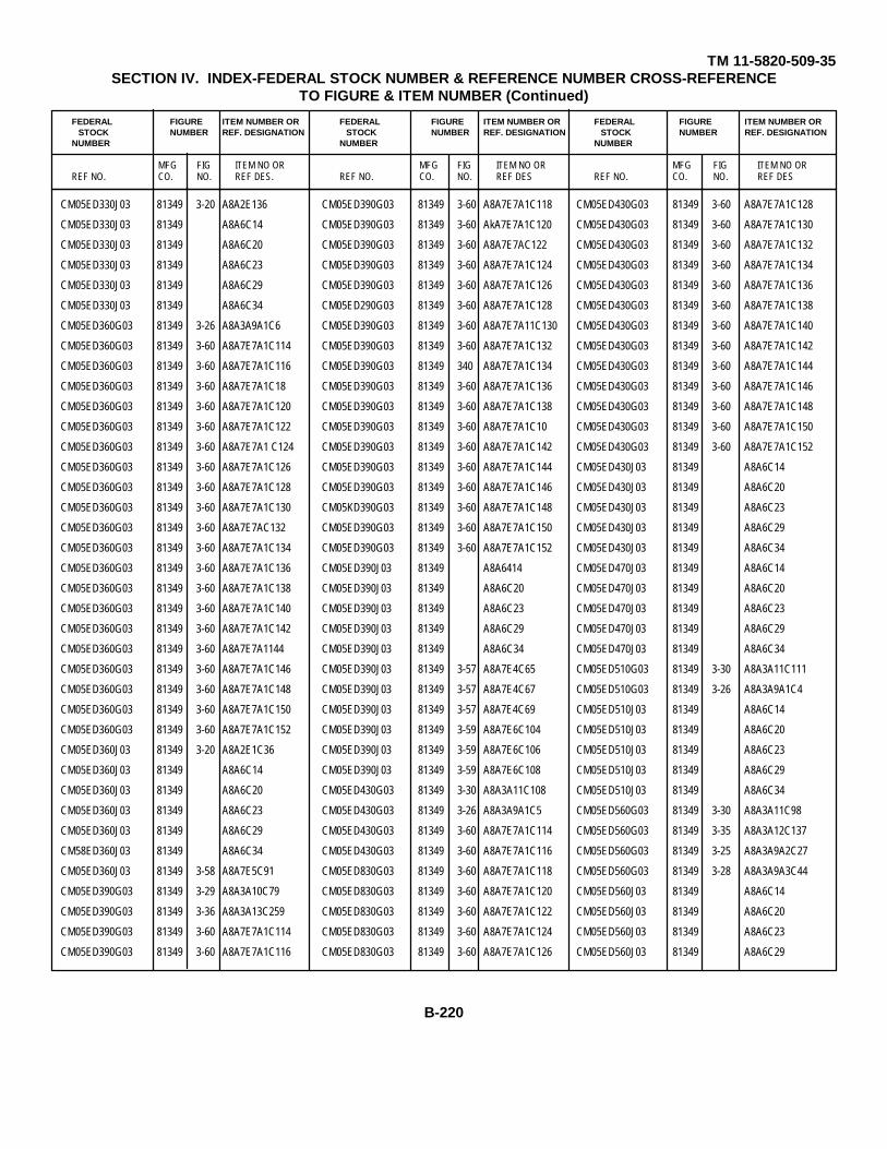
TM 11-5820-509-35SECTION IV. INDEX-FEDERAL STOCK NUMBER & REFERENCE NUMBER CROSS-REFERENCE
TO FIGURE & ITEM NUMBER (Continued)
FEDERAL FIGURE ITEM NUMBER OR FEDERAL FIGURE ITEM NUMBER OR FEDERAL FIGURE ITEM NUMBER ORSTOCK NUMBER REF. DESIGNATION STOCK NUMBER REF. DESIGNATION STOCK NUMBER REF. DESIGNATION
NUMBER NUMBER NUMBER
MFG FIG ITEM NO OR MFG FIG ITEM NO OR MFG FIG ITEM NO ORREF NO. CO. NO. REF DES. REF NO. CO. NO. REF DES REF NO. CO. NO. REF DES
CM05ED330J03 81349 3-20 A8A2E136
CM05ED330J03 81349 A8A6C14
CM05ED330J03 81349 A8A6C20
CM05ED330J03 81349 A8A6C23
CM05ED330J03 81349 A8A6C29
CM05ED330J03 81349 A8A6C34
CM05ED360G03 81349 3-26 A8A3A9A1C6
CM05ED360G03 81349 3-60 A8A7E7A1C114
CM05ED360G03 81349 3-60 A8A7E7A1C116
CM05ED360G03 81349 3-60 A8A7E7A1C18
CM05ED360G03 81349 3-60 A8A7E7A1C120
CM05ED360G03 81349 3-60 A8A7E7A1C122
CM05ED360G03 81349 3-60 A8A7E7A1 C124
CM05ED360G03 81349 3-60 A8A7E7A1C126
CM05ED360G03 81349 3-60 A8A7E7A1C128
CM05ED360G03 81349 3-60 A8A7E7A1C130
CM05ED360G03 81349 3-60 A8A7E7AC132
CM05ED360G03 81349 3-60 A8A7E7A1C134
CM05ED360G03 81349 3-60 A8A7E7A1C136
CM05ED360G03 81349 3-60 A8A7E7A1C138
CM05ED360G03 81349 3-60 A8A7E7A1C140
CM05ED360G03 81349 3-60 A8A7E7A1C142
CM05ED360G03 81349 3-60 A8A7E7A1144
CM05ED360G03 81349 3-60 A8A7E7A1C146
CM05ED360G03 81349 3-60 A8A7E7A1C148
CM05ED360G03 81349 3-60 A8A7E7A1C150
CM05ED360G03 81349 3-60 A8A7E7A1C152
CM05ED360J03 81349 3-20 A8A2E1C36
CM05ED360J03 81349 A8A6C14
CM05ED360J03 81349 A8A6C20
CM05ED360J03 81349 A8A6C23
CM05ED360J03 81349 A8A6C29
CM58ED360J03 81349 A8A6C34
CM05ED360J03 81349 3-58 A8A7E5C91
CM05ED390G03 81349 3-29 A8A3A10C79
CM05ED390G03 81349 3-36 A8A3A13C259
CM05ED390G03 81349 3-60 A8A7E7A1C114
CM05ED390G03 81349 3-60 A8A7E7A1C116
CM05ED390G03 81349 3-60 A8A7E7A1C118
CM05ED390G03 81349 3-60 AkA7E7A1C120
CM05ED390G03 81349 3-60 A8A7E7AC122
CM05ED390G03 81349 3-60 A8A7E7A1C124
CM05ED390G03 81349 3-60 A8A7E7A1C126
CM05ED290G03 81349 3-60 A8A7E7A1C128
CM05ED390G03 81349 3-60 A8A7E7A11C130
CM05ED390G03 81349 3-60 A8A7E7A1C132
CM05ED390G03 81349 340 A8A7E7A1C134
CM05ED390G03 81349 3-60 A8A7E7A1C136
CM05ED390G03 81349 3-60 A8A7E7A1C138
CM05ED390G03 81349 3-60 A8A7E7A1C10
CM05ED390G03 81349 3-60 A8A7E7A1C142
CM05ED390G03 81349 3-60 A8A7E7A1C144
CM05ED390G03 81349 3-60 A8A7E7A1C146
CM05KD390G03 81349 3-60 A8A7E7A1C148
CM05ED390G03 81349 3-60 A8A7E7A1C150
CM05ED390G03 81349 3-60 A8A7E7A1C152
CM05ED390J03 81349 A8A6414
CM05ED390J03 81349 A8A6C20
CM05ED390J03 81349 A8A6C23
CM05ED390J03 81349 A8A6C29
CM05ED390J03 81349 A8A6C34
CM05ED390J03 81349 3-57 A8A7E4C65
CM05ED390J03 81349 3-57 A8A7E4C67
CM05ED390J03 81349 3-57 A8A7E4C69
CM05ED390J03 81349 3-59 A8A7E6C104
CM05ED390J03 81349 3-59 A8A7E6C106
CM05ED390J03 81349 3-59 A8A7E6C108
CM05ED430G03 81349 3-30 A8A3A11C108
CM05ED430G03 81349 3-26 A8A3A9A1C5
CM05ED430G03 81349 3-60 A8A7E7A1C114
CM05ED430G03 81349 3-60 A8A7E7A1C116
CM05ED830G03 81349 3-60 A8A7E7A1C118
CM05ED830G03 81349 3-60 A8A7E7A1C120
CM05ED830G03 81349 3-60 A8A7E7A1C122
CM05ED830G03 81349 3-60 A8A7E7A1C124
CM05ED830G03 81349 3-60 A8A7E7A1C126
CM05ED430G03 81349 3-60 A8A7E7A1C128
CM05ED430G03 81349 3-60 A8A7E7A1C130
CM05ED430G03 81349 3-60 A8A7E7A1C132
CM05ED430G03 81349 3-60 A8A7E7A1C134
CM05ED430G03 81349 3-60 A8A7E7A1C136
CM05ED430G03 81349 3-60 A8A7E7A1C138
CM05ED430G03 81349 3-60 A8A7E7A1C140
CM05ED430G03 81349 3-60 A8A7E7A1C142
CM05ED430G03 81349 3-60 A8A7E7A1C144
CM05ED430G03 81349 3-60 A8A7E7A1C146
CM05ED430G03 81349 3-60 A8A7E7A1C148
CM05ED430G03 81349 3-60 A8A7E7A1C150
CM05ED430G03 81349 3-60 A8A7E7A1C152
CM05ED430J03 81349 A8A6C14
CM05ED430J03 81349 A8A6C20
CM05ED430J03 81349 A8A6C23
CM05ED430J03 81349 A8A6C29
CM05ED430J03 81349 A8A6C34
CM05ED470J03 81349 A8A6C14
CM05ED470J03 81349 A8A6C20
CM05ED470J03 81349 A8A6C23
CM05ED470J03 81349 A8A6C29
CM05ED470J03 81349 A8A6C34
CM05ED510G03 81349 3-30 A8A3A11C111
CM05ED510G03 81349 3-26 A8A3A9A1C4
CM05ED510J03 81349 A8A6C14
CM05ED510J03 81349 A8A6C20
CM05ED510J03 81349 A8A6C23
CM05ED510J03 81349 A8A6C29
CM05ED510J03 81349 A8A6C34
CM05ED560G03 81349 3-30 A8A3A11C98
CM05ED560G03 81349 3-35 A8A3A12C137
CM05ED560G03 81349 3-25 A8A3A9A2C27
CM05ED560G03 81349 3-28 A8A3A9A3C44
CM05ED560J03 81349 A8A6C14
CM05ED560J03 81349 A8A6C20
CM05ED560J03 81349 A8A6C23
CM05ED560J03 81349 A8A6C29
B-220
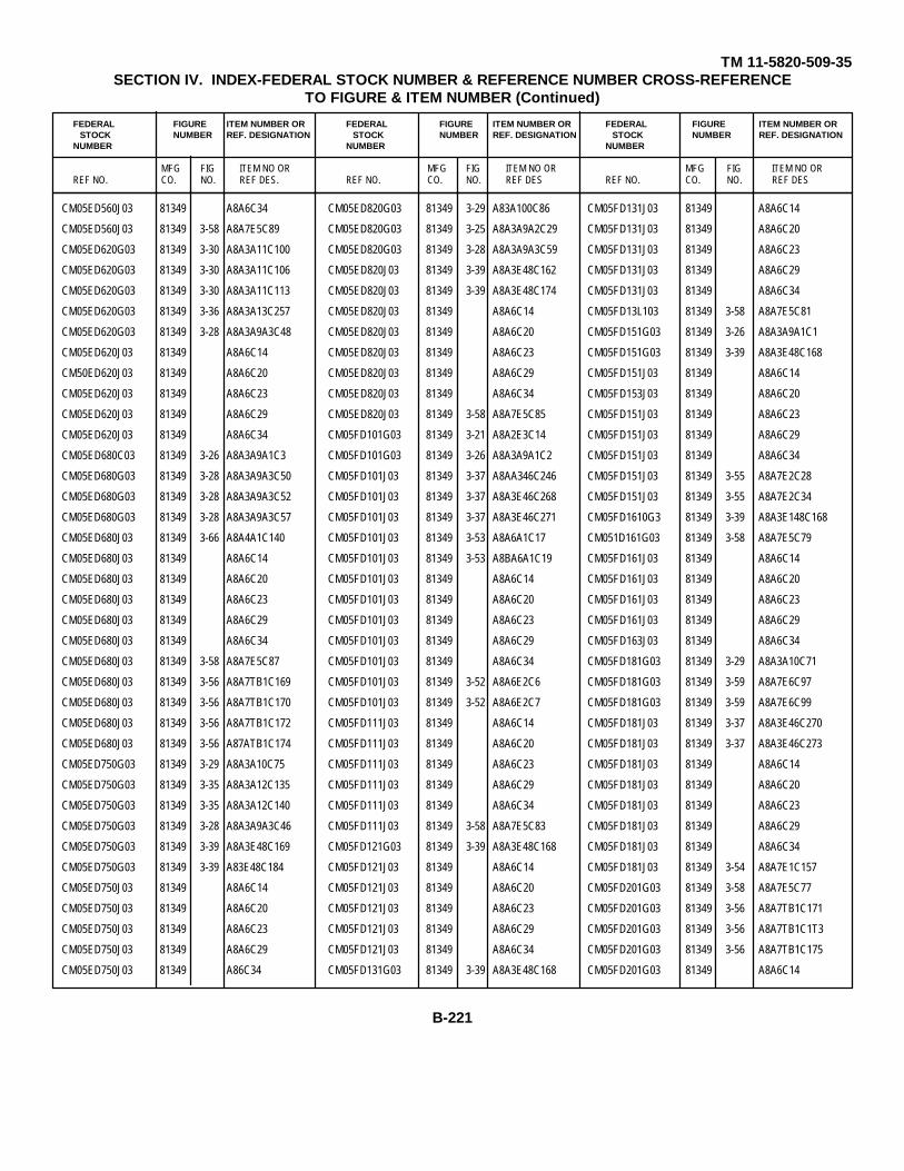
TM 11-5820-509-35SECTION IV. INDEX-FEDERAL STOCK NUMBER & REFERENCE NUMBER CROSS-REFERENCE
TO FIGURE & ITEM NUMBER (Continued)
FEDERAL FIGURE ITEM NUMBER OR FEDERAL FIGURE ITEM NUMBER OR FEDERAL FIGURE ITEM NUMBER ORSTOCK NUMBER REF. DESIGNATION STOCK NUMBER REF. DESIGNATION STOCK NUMBER REF. DESIGNATION
NUMBER NUMBER NUMBER
MFG FIG ITEM NO OR MFG FIG ITEM NO OR MFG FIG ITEM NO ORREF NO. CO. NO. REF DES. REF NO. CO. NO. REF DES REF NO. CO. NO. REF DES
CM05ED560J03 81349 A8A6C34
CM05ED560J03 81349 3-58 A8A7E5C89
CM05ED620G03 81349 3-30 A8A3A11C100
CM05ED620G03 81349 3-30 A8A3A11C106
CM05ED620G03 81349 3-30 A8A3A11C113
CM05ED620G03 81349 3-36 A8A3A13C257
CM05ED620G03 81349 3-28 A8A3A9A3C48
CM05ED620J03 81349 A8A6C14
CM50ED620J03 81349 A8A6C20
CM05ED620J03 81349 A8A6C23
CM05ED620J03 81349 A8A6C29
CM05ED620J03 81349 A8A6C34
CM05ED680C03 81349 3-26 A8A3A9A1C3
CM05ED680G03 81349 3-28 A8A3A9A3C50
CM05ED680G03 81349 3-28 A8A3A9A3C52
CM05ED680G03 81349 3-28 A8A3A9A3C57
CM05ED680J03 81349 3-66 A8A4A1C140
CM05ED680J03 81349 A8A6C14
CM05ED680J03 81349 A8A6C20
CM05ED680J03 81349 A8A6C23
CM05ED680J03 81349 A8A6C29
CM05ED680J03 81349 A8A6C34
CM05ED680J03 81349 3-58 A8A7E5C87
CM05ED680J03 81349 3-56 A8A7TB1C169
CM05ED680J03 81349 3-56 A8A7TB1C170
CM05ED680J03 81349 3-56 A8A7TB1C172
CM05ED680J03 81349 3-56 A87ATB1C174
CM05ED750G03 81349 3-29 A8A3A10C75
CM05ED750G03 81349 3-35 A8A3A12C135
CM05ED750G03 81349 3-35 A8A3A12C140
CM05ED750G03 81349 3-28 A8A3A9A3C46
CM05ED750G03 81349 3-39 A8A3E48C169
CM05ED750G03 81349 3-39 A83E48C184
CM05ED750J03 81349 A8A6C14
CM05ED750J03 81349 A8A6C20
CM05ED750J03 81349 A8A6C23
CM05ED750J03 81349 A8A6C29
CM05ED750J03 81349 A86C34
CM05ED820G03 81349 3-29 A83A100C86
CM05ED820G03 81349 3-25 A8A3A9A2C29
CM05ED820G03 81349 3-28 A8A3A9A3C59
CM05ED820J03 81349 3-39 A8A3E48C162
CM05ED820J03 81349 3-39 A8A3E48C174
CM05ED820J03 81349 A8A6C14
CM05ED820J03 81349 A8A6C20
CM05ED820J03 81349 A8A6C23
CM05ED820J03 81349 A8A6C29
CM05ED820J03 81349 A8A6C34
CM05ED820J03 81349 3-58 A8A7E5C85
CM05FD101G03 81349 3-21 A8A2E3C14
CM05FD101G03 81349 3-26 A8A3A9A1C2
CM05FD101J03 81349 3-37 A8AA346C246
CM05FD101J03 81349 3-37 A8A3E46C268
CM05FD101J03 81349 3-37 A8A3E46C271
CM05FD101J03 81349 3-53 A8A6A1C17
CM05FD101J03 81349 3-53 A8BA6A1C19
CM05FD101J03 81349 A8A6C14
CM05FD101J03 81349 A8A6C20
CM05FD101J03 81349 A8A6C23
CM05FD101J03 81349 A8A6C29
CM05FD101J03 81349 A8A6C34
CM05FD101J03 81349 3-52 A8A6E2C6
CM05FD101J03 81349 3-52 A8A6E2C7
CM05FD111J03 81349 A8A6C14
CM05FD111J03 81349 A8A6C20
CM05FD111J03 81349 A8A6C23
CM05FD111J03 81349 A8A6C29
CM05FD111J03 81349 A8A6C34
CM05FD111J03 81349 3-58 A8A7E5C83
CM05FD121G03 81349 3-39 A8A3E48C168
CM05FD121J03 81349 A8A6C14
CM05FD121J03 81349 A8A6C20
CM05FD121J03 81349 A8A6C23
CM05FD121J03 81349 A8A6C29
CM05FD121J03 81349 A8A6C34
CM05FD131G03 81349 3-39 A8A3E48C168
CM05FD131J03 81349 A8A6C14
CM05FD131J03 81349 A8A6C20
CM05FD131J03 81349 A8A6C23
CM05FD131J03 81349 A8A6C29
CM05FD131J03 81349 A8A6C34
CM05FD13L103 81349 3-58 A8A7E5C81
CM05FD151G03 81349 3-26 A8A3A9A1C1
CM05FD151G03 81349 3-39 A8A3E48C168
CM05FD151J03 81349 A8A6C14
CM05FD153J03 81349 A8A6C20
CM05FD151J03 81349 A8A6C23
CM05FD151J03 81349 A8A6C29
CM05FD151J03 81349 A8A6C34
CM05FD151J03 81349 3-55 A8A7E2C28
CM05FD151J03 81349 3-55 A8A7E2C34
CM05FD1610G3 81349 3-39 A8A3E148C168
CM051D161G03 81349 3-58 A8A7E5C79
CM05FD161J03 81349 A8A6C14
CM05FD161J03 81349 A8A6C20
CM05FD161J03 81349 A8A6C23
CM05FD161J03 81349 A8A6C29
CM05FD163J03 81349 A8A6C34
CM05FD181G03 81349 3-29 A8A3A10C71
CM05FD181G03 81349 3-59 A8A7E6C97
CM05FD181G03 81349 3-59 A8A7E6C99
CM05FD181J03 81349 3-37 A8A3E46C270
CM05FD181J03 81349 3-37 A8A3E46C273
CM05FD181J03 81349 A8A6C14
CM05FD181J03 81349 A8A6C20
CM05FD181J03 81349 A8A6C23
CM05FD181J03 81349 A8A6C29
CM05FD181J03 81349 A8A6C34
CM05FD181J03 81349 3-54 A8A7E1C157
CM05FD201G03 81349 3-58 A8A7E5C77
CM05FD201G03 81349 3-56 A8A7TB1C171
CM05FD201G03 81349 3-56 A8A7TB1C1T3
CM05FD201G03 81349 3-56 A8A7TB1C175
CM05FD201G03 81349 A8A6C14
B-221

TM 11-5820-509-35SECTION IV. INDEX-FEDERAL STOCK NUMBER & REFERENCE NUMBER CROSS-REFERENCE
TO FIGURE & ITEM NUMBER (Continued)
FEDERAL FIGURE ITEM NUMBER OR FEDERAL FIGURE ITEM NUMBER OR FEDERAL FIGURE ITEM NUMBER ORSTOCK NUMBER REF. DESIGNATION STOCK NUMBER REF. DESIGNATION STOCK NUMBER REF. DESIGNATION
NUMBER NUMBER NUMBER
MFG FIG ITEM NO OR MFG FIG ITEM NO OR MFG FIG ITEM NO ORREF NO. CO. NO. REF DES. REF NO. CO. NO. REF DES REF NO. CO. NO. REF DES
CM05FD201J03 81349 A8A6C20
C't405FD201J03 81349 A8A6C23
CM05FD201J03 81349 A8A6C29
CM05FD201J03 81349 A8A6C34
CM05FD221G03 81349 3-39 A8A3E48C167
CM05FD221G03 81349 3-39 A8A3E48C170
CM05FD221G03 81349 3-39 A8A3E48C172
CM05FD221G03 81349 3-56 A8A7TB1C167
CM05FD221G03 81349 3-56 A8A7TB1C176
CM05FD221J03 81349 3-20 A88A2E1C7
CM05FD221J03 81349 3-20 A8A2E1C8
CM05FD221J03 81349 3-21 A8A2E4C22
CM05FD221J03 81349 3-21 A8A2E5C27
CM05FD221J03 81349 3-21 A8A2E5C32
CM05FD221J03 81349 3-53 A8A6A1C40
CM05FD221J03 81349 A8A6C14
CM05FD221J03 81349 A8A6C20
CM05FD221J03 81349 A8A6C23
CM05FD221J03 81349 A8A6C29
CM05FD221J03 81349 A8A6C34
CM05FD221J03 81349 3-54 A8A7E1C14
CM05FD221J03 81349 3-59 A8A7E6C105
CM05FD221J03 81349 3-59 A8A7E6C107
CM05FD221J03 81349 3-59 A8A7E6C109
CM05FD221J03 81349 3-21 A8A2E5C12
CM05FD241J03 81349 A8A6C14
CM05FD241J03 81349 A8A6C20
CM05FD241J03 81349 A8A6C23
CM05FD241J03 81349 A8A6C29
CM05FD241J03 81349 A8A6C34
CM05FD241J03 81349 3-59 A8A7E6C103
CM05FD271G03 81349 3-58 A8A7E5C75
CM05FD271J03 81349 A8A6C14
CM05FD271J03 81349 A8A6C20
CM05FD271J03 81349 A8A6C23
CM05FD271J03 81349 A8A6C29
CM05FD271J03 81349 A8A6C34
CM05FD271J03 81349 3-55 A8A7E2C27
CM05FD271J03 81349 3-55 A8A7E2C33
CM05FD301J03 81349 A8A6C14
CM}5FD301J03 81349 A8A6C20
CM05FD301J03 81349 A8A6C23
CM05FD301J03 81349 A8A6C29
CM05FD301J03 81349 A8A6C34
CM05FD331J03 81349 A8A6C14
CM05FD331J03 81349 A8A6C20
CM05FD331J03 81349 A8A6C23
CM05FD331J03 81349 A8A6C29
CM05FD331J03 81349 A8A6C34
CM05FD361G03 81349 3-58 A8A7E5C73
CM05FD361J03 81349 A88A6C1
CM05FD361J03 81349 A8A6C20
CM05FD361J03 81349 A8A6C23
CM05FD361J03 81349 A8A6C29
CM05FD361J03 81349 A8A6C34
CM05FD391G03 81349 3-21 A8A2E3C11
CM05FD391G03 81349 3-21 A8A2E5C24
CM05FD391G03 81349 3-35 A8A3A12C122
CM05FD391J03 81349 3-38 A8A3E47C148
CM05FD391J03 81349 A8A6C14
CM05FD391J03 81349 A8A6C20
CM05FD391J03 81349 A8A6C23
CM55FD391J03 81349 A8A6C29
CM05FD391J03 81349 A8A6C34
CM05FD910G03 81349 3-21 A8A2E4C16
CM05FD910G03 81349 3-30 A8A3A11C102
CM05FD910G03 81349 3-35 A8A3A12C129
CM05FD910G03 81349 3-35 A8A3A12C138
CM05FD910G03 81349 3-36 A8A3A13C255
CM05FD910J03 81349 A8A6C14
CM05FD310J03 81349 A8A6C20
CM05FD910J03 81349 A8A6C23
CM05FD910J03 81349 A8A6C29
CM05FD910J03 81349 A8A6C34
CM06FD162J03 81349 3-53 A8A6A1C24
CM06FD242J03 81349 3-52 A8A6E1C28
CM06FD272F03 81349 3-52 A8A6E1C33
CM06FD302F03 81349 3-17 A8A1E1C19
CM06FD751J03 81349 A8A6C14
CM06FD751J03 81349 A8A6C20
CM06FD751J03 81349 A8A6C23
CM06FD751J03 81349 A8A6C29
CM06FD751J03 81349 A8A6C34
CM60B622J01 81349 3-64 A5A4C122
CR14M2277 99155 A8A4109W1
CR14M2277 99155 A8A4110W1
CR14M2277 99155 A8A4111W1
CR14M2277 99155 A8A4112W1
CV1377APRC47 80058 3-4 A8A3
CX8393PRC47 80058 1-7 W1
CX8394PRC47 80958 1-7 W2
CX8395PRC47 80058 1-1 W3
CY3700PRC47 80058 1-4 A1
C023B102P223Z 56289 3-40 A8A3C117
C023B102P223Z 56289 3-40 A8A3C292
C3044-1-35 78553 A8A4MP20
C4311PRC47 80058 3-4 A8A7
C4344-4-75 82647 3-65 A8A4K103
DAMF3W3S 71785 3-67 A8A4J10
DAMF7W2S 71785 3-67 A8A4J11
DAMF7W2S 71785 3-67 A8A4J3
DAMF7W2S 71785 A8A4J5
DAMF7W2S 71785 A8A4J6
DAMF7W2S 71785 3-67 A8A4J7
DAMF7W2S 71785 3-67 A8A4J8
DAM3W3P 71468 A8A7P2
DAM7W2P 71468 3-20 A8A2P3
DAM7W2P 71468 3-41 A8A3P1
DAM7W2P 71468 3-41 A8A3P2
DAM7W2P 71468 3-L1 A8A3P3
DAM7W2P 71468 3-41 A8A3P4
DAM7W2P 71468 3-61 A8A7P1
DA146 71590 3-41 A8A3C188
DA146 71590 3-41 A8A3C289
B-222
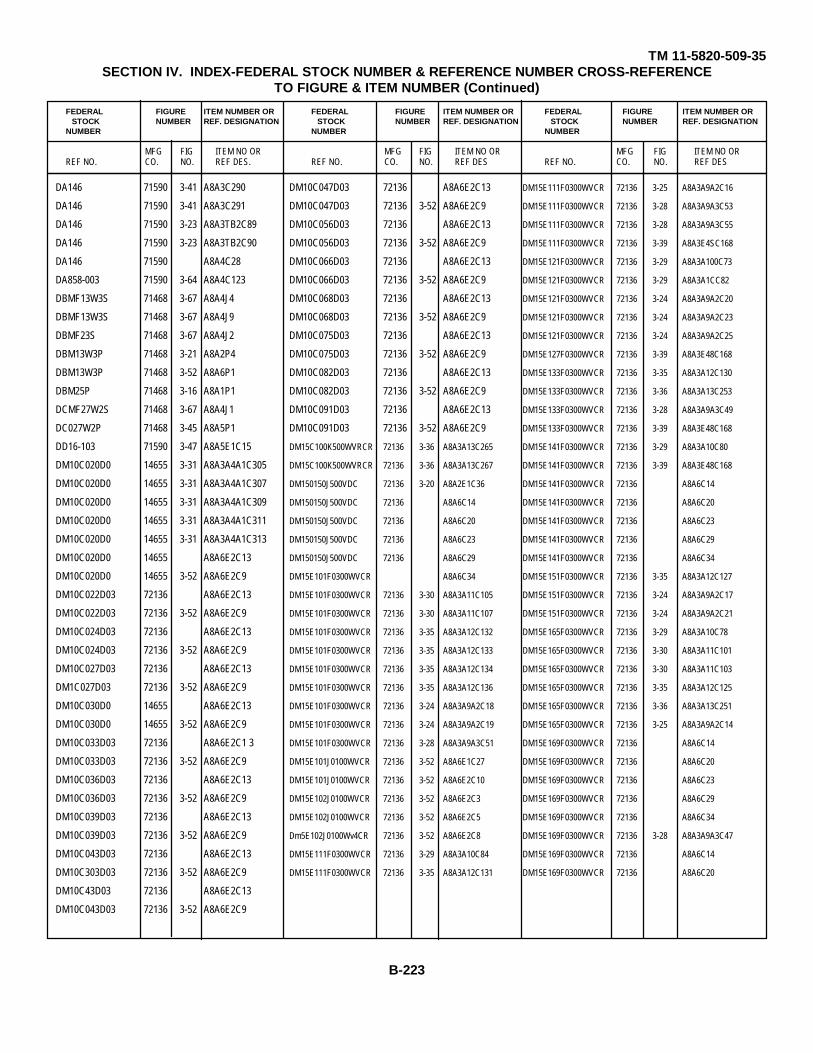
TM 11-5820-509-35SECTION IV. INDEX-FEDERAL STOCK NUMBER & REFERENCE NUMBER CROSS-REFERENCE
TO FIGURE & ITEM NUMBER (Continued)
FEDERAL FIGURE ITEM NUMBER OR FEDERAL FIGURE ITEM NUMBER OR FEDERAL FIGURE ITEM NUMBER ORSTOCK NUMBER REF. DESIGNATION STOCK NUMBER REF. DESIGNATION STOCK NUMBER REF. DESIGNATION
NUMBER NUMBER NUMBER
MFG FIG ITEM NO OR MFG FIG ITEM NO OR MFG FIG ITEM NO ORREF NO. CO. NO. REF DES. REF NO. CO. NO. REF DES REF NO. CO. NO. REF DES
DA146 71590 3-41 A8A3C290
DA146 71590 3-41 A8A3C291
DA146 71590 3-23 A8A3TB2C89
DA146 71590 3-23 A8A3TB2C90
DA146 71590 A8A4C28
DA858-003 71590 3-64 A8A4C123
DBMF13W3S 71468 3-67 A8A4J4
DBMF13W3S 71468 3-67 A8A4J9
DBMF23S 71468 3-67 A8A4J2
DBM13W3P 71468 3-21 A8A2P4
DBM13W3P 71468 3-52 A8A6P1
DBM25P 71468 3-16 A8A1P1
DCMF27W2S 71468 3-67 A8A4J1
DC027W2P 71468 3-45 A8A5P1
DD16-103 71590 3-47 A8A5E1C15
DM10C020D0 14655 3-31 A8A3A4A1C305
DM10C020D0 14655 3-31 A8A3A4A1C307
DM10C020D0 14655 3-31 A8A3A4A1C309
DM10C020D0 14655 3-31 A8A3A4A1C311
DM10C020D0 14655 3-31 A8A3A4A1C313
DM10C020D0 14655 A8A6E2C13
DM10C020D0 14655 3-52 A8A6E2C9
DM10C022D03 72136 A8A6E2C13
DM10C022D03 72136 3-52 A8A6E2C9
DM10C024D03 72136 A8A6E2C13
DM10C024D03 72136 3-52 A8A6E2C9
DM10C027D03 72136 A8A6E2C13
DM1C027D03 72136 3-52 A8A6E2C9
DM10C030D0 14655 A8A6E2C13
DM10C030D0 14655 3-52 A8A6E2C9
DM10C033D03 72136 A8A6E2C1 3
DM10C033D03 72136 3-52 A8A6E2C9
DM10C036D03 72136 A8A6E2C13
DM10C036D03 72136 3-52 A8A6E2C9
DM10C039D03 72136 A8A6E2C13
DM10C039D03 72136 3-52 A8A6E2C9
DM10C043D03 72136 A8A6E2C13
DM10C303D03 72136 3-52 A8A6E2C9
DM10C43D03 72136 A8A6E2C13
DM10C043D03 72136 3-52 A8A6E2C9
DM10C047D03 72136 A8A6E2C13
DM10C047D03 72136 3-52 A8A6E2C9
DM10C056D03 72136 A8A6E2C13
DM10C056D03 72136 3-52 A8A6E2C9
DM10C066D03 72136 A8A6E2C13
DM10C066D03 72136 3-52 A8A6E2C9
DM10C068D03 72136 A8A6E2C13
DM10C068D03 72136 3-52 A8A6E2C9
DM10C075D03 72136 A8A6E2C13
DM10C075D03 72136 3-52 A8A6E2C9
DM10C082D03 72136 A8A6E2C13
DM10C082D03 72136 3-52 A8A6E2C9
DM10C091D03 72136 A8A6E2C13
DM10C091D03 72136 3-52 A8A6E2C9
DM15C100K500WVRCR 72136 3-36 A8A3A13C265
DM15C100K500WVRCR 72136 3-36 A8A3A13C267
DM150150J500VDC 72136 3-20 A8A2E1C36
DM150150J500VDC 72136 A8A6C14
DM150150J500VDC 72136 A8A6C20
DM150150J500VDC 72136 A8A6C23
DM150150J500VDC 72136 A8A6C29
DM15E101F0300WVCR A8A6C34
DM15E101F0300WVCR 72136 3-30 A8A3A11C105
DM15E101F0300WVCR 72136 3-30 A8A3A11C107
DM15E101F0300WVCR 72136 3-35 A8A3A12C132
DM15E101F0300WVCR 72136 3-35 A8A3A12C133
DM15E101F0300WVCR 72136 3-35 A8A3A12C134
DM15E101F0300WVCR 72136 3-35 A8A3A12C136
DM15E101F0300WVCR 72136 3-24 A8A3A9A2C18
DM15E101F0300WVCR 72136 3-24 A8A3A9A2C19
DM15E101F0300WVCR 72136 3-28 A8A3A9A3C51
DM15E101J0100WVCR 72136 3-52 A8A6E1C27
DM15E101J0100WVCR 72136 3-52 A8A6E2C10
DM15E102J0100WVCR 72136 3-52 A8A6E2C3
DM15E102J0100WVCR 72136 3-52 A8A6E2C5
Dm5E102J0100Wv4CR 72136 3-52 A8A6E2C8
DM15E111F0300WVCR 72136 3-29 A8A3A10C84
DM15E111F0300WVCR 72136 3-35 A8A3A12C131
DM15E111F0300WVCR 72136 3-25 A8A3A9A2C16
DM15E111F0300WVCR 72136 3-28 A8A3A9A3C53
DM15E111F0300WVCR 72136 3-28 A8A3A9A3C55
DM15E111F0300WVCR 72136 3-39 A8A3E4SC168
DM15E121F0300WVCR 72136 3-29 A8A3A100C73
DM15E121F0300WVCR 72136 3-29 A8A3A1CC82
DM15E121F0300WVCR 72136 3-24 A8A3A9A2C20
DM15E121F0300WVCR 72136 3-24 A8A3A9A2C23
DM15E121F0300WVCR 72136 3-24 A8A3A9A2C25
DM15E127F0300WVCR 72136 3-39 A8A3E48C168
DM15E133F0300WVCR 72136 3-35 A8A3A12C130
DM15E133F0300WVCR 72136 3-36 A8A3A13C253
DM15E133F0300WVCR 72136 3-28 A8A3A9A3C49
DM15E133F0300WVCR 72136 3-39 A8A3E48C168
DM15E141F0300WVCR 72136 3-29 A8A3A10C80
DM15E141F0300WVCR 72136 3-39 A8A3E48C168
DM15E141F0300WVCR 72136 A8A6C14
DM15E141F0300WVCR 72136 A8A6C20
DM15E141F0300WVCR 72136 A8A6C23
DM15E141F0300WVCR 72136 A8A6C29
DM15E141F0300WVCR 72136 A8A6C34
DM15E151F0300WVCR 72136 3-35 A8A3A12C127
DM15E151F0300WVCR 72136 3-24 A8A3A9A2C17
DM15E151F0300WVCR 72136 3-24 A8A3A9A2C21
DM15E165F0300WVCR 72136 3-29 A8A3A10C78
DM15E165F0300WVCR 72136 3-30 A8A3A11C101
DM15E165F0300WVCR 72136 3-30 A8A3A11C103
DM15E165F0300WVCR 72136 3-35 A8A3A12C125
DM15E165F0300WVCR 72136 3-36 A8A3A13C251
DM15E165F0300WVCR 72136 3-25 A8A3A9A2C14
DM15E169F0300WVCR 72136 A8A6C14
DM15E169F0300WVCR 72136 A8A6C20
DM15E169F0300WVCR 72136 A8A6C23
DM15E169F0300WVCR 72136 A8A6C29
DM15E169F0300WVCR 72136 A8A6C34
DM15E169F0300WVCR 72136 3-28 A8A3A9A3C47
DM15E169F0300WVCR 72136 A8A6C14
DM15E169F0300WVCR 72136 A8A6C20
B-223

TM 11-5820-509-35SECTION IV. INDEX-FEDERAL STOCK NUMBER & REFERENCE NUMBER CROSS-REFERENCE
TO FIGURE & ITEM NUMBER (Continued)
FEDERAL FIGURE ITEM NUMBER OR FEDERAL FIGURE ITEM NUMBER OR FEDERAL FIGURE ITEM NUMBER ORSTOCK NUMBER REF. DESIGNATION STOCK NUMBER REF. DESIGNATION STOCK NUMBER REF. DESIGNATION
NUMBER NUMBER NUMBER
MFG FIG ITEM NO OR MFG FIG ITEM NO OR MFG FIG ITEM NO ORREF NO. CO. NO. REF DES. REF NO. CO. NO. REF DES REF NO. CO. NO. REF DES
DM15E191F0500WV4CR 72136 A8A6C23
DM15E191F0500WV4CR 72136 A8A6C29
DM15E191F0500WV4CR 72136 A8A6C34
DM15E191F0300WV4CR 72136 3-29 A8A3A10C76
DM15E221F0300WV4CR 72136 3-29 A8A3A10C74
EM15E221F0300WV4CR 72136 3-35 A8A3A12C128
EM15E251F0500WV4CR 72136 3-25 A8A3A9A2C15
EM15E271F0300WV4CR 72136 3-29 A8A3A10C72
EM15E271F0300WV4CR 72136 3-30 A8A3A11C96
EM15E271F0300WV4CR 72136 3-30 A8A3A11C99
EM15E271F0300WV4CR 72136 3-35 A8A3A12C126
EM15E271F0300WV4CR 72136 3-25 A8A3A9A2C12
EM15E271F0300WV4CR 72136 3-28 A8A3A9A3C42
EM15E271F0300WV4CR 72136 3-28 A8A3A9A3C45
DM15E2870F0500WV4CR 72136 3-35 A8A3A13C249
DM15E301F0300WV4CR 72136 3-25 A8A3A9A2C13
DM15E331F0300WV4CR 72136 3-29 A8A3A10C69
DM15E361F0300WV4CR 72136 3-29 A8A3A10C70
DM15E431F0300WV4CR 72136 3-30 A8A3A11C97
DM15E471F0300WV4CR 72136 3-25 A8A3A9A2C11
DM15E471F0300WV4CR 72136 3-28 A8A3A9A3C43
DM15E511F0300WV4CR 72136 3-29 A8A3A10C68
DM15E511F0300WV4CR 72136 3-30 A8A3A11C95
DM15E511F0300WV4CR 72136 3-35 A8A3A12C124
DM15E511F0300WV4CR 72136 3-28 A8A3A9A3C41
DM15E621J0300WV4CR 72136 A8A6C14
DM15E621J0300WV4CR 72136 A8A6C20
DM15E621J0300WV4CR 72136 A8A6C23
DM15E621J0300WV4CR 72136 A8A6C29
DM15E621J0300WV4CR 72136 A8A6C34
DM15E681G300WV4CR 72136 3-35 A8A3A12C123
DM15E821J0300WV4CR 72136 A8A6C14
DM15E821J0300WV4CR 72136 A8A6C20
DM15E821J0300WV4CR 72136 A8A6C23
DM15E821J0300WV4CR 72136 A8A6C29
DM15E821J0300WV4CR 72136 A8A6C34
DM15E960F0500WV4CR 72136 3-30 A6A3A11C109
DM15F431J300WV4CR 72136 A8A6C14
DM15F431J300WV4CR 72136 A8A6C20
DM15F431J300WV4CR 72136 A8A6C23
DM15F431J300WV4CR 72136 A8A6C29
DM15F431J300WV4CR 72136 A8A6C34
DM15F471J300WV4CR 72136 3-37 A8A3E46C274
DM15F471J300WV4CR 72136 3-39 A8A3E48C163
DM15F471J300WV4CR 71236 3-39 A8A3E48C164
DM15F471J300WV4CR 72136 3-39 A8A3E48C186
DM15F471J300WV4CR 72136 A8A6C14
DM15F471J300WV4CR 72136 A8A6C20
DM15F471J300WV4CR 72136 A8A6C23
DM15F471J300WV4CR 72136 A8A6C29
DM15F471J300WV4CR 72136 A8A6C34
DM15F471J300WV4CR 72136 3-57 A8A7E4C62
DM15F511J300WV4CR 72136 3-34 A8A3A4C330
DM15F511J300WV4CR 72136 3-34 A8A3A4C333
DM15F511J300WV4CR 72136 3-21 A8A2E3C28
DM15F511J300WV4CR 72136 3-21 A8A2E3C29
DM15F511J300WV4CR 72136 3-21 A8A2E4C21
DM15F511J300WV4CR 72136 3-38 A8A3E47C145
DM15F511J300WV4CR 72136 3-38 A8A3E47C147
DM15F511J300WV4CR 72136 3-38 A8A3E47C149
DM15F511J300WV4CR 72136 3-38 A8A3E47C152
DM15F511J300WV4CR 72136 3-38 A8A3E47C155
DM15F511J300WV4CR 72136 3-38 A8A3E47C157
DM15F511J300WV4CR 72136 3-38 A8A3E47C176
DM15F511J300WV4CR 72136 3-38 A8A3E47C181
DM15F511J300WV4CR 72136 3-22 A8A3TB1C61
DM15F511J300WV4CR 72136 3-22 A8A3TB1C65
DM15F511J300WV4CR 72136 3-23 A8A3TB2C92
DM15F511J300WV4CR 72136 3-53 A8A6A1C13
DM15F511J300WV4CR 72136 3-53 A8A6A1C21
DM15F511J300WV4CR 72136 A8A6C14
DM15F511J300WV4CR 72136 A8A6C20
DM15F511J300WV4CR 72136 A8A6C23
DM15F511J300WV4CR 72136 A8A6C29
DM15F511J300WV4CR 72136 A8A6C34
DM15F511J300WV4CR 72136 3-52 A8A6E2C2
DM15F511J300WV4CR 72136 3-52 A8A6E2C4
DM15F511J300WV4CR 72136 3-55 A8A7E2C21
DM15F511J300WV4CR 72136 3-59 A8A7E6C156
DM15F511J300WV4CR 72136 3-59 A8A7E6C95
DM15F561J300WV4CR 72136 A8A6C14
DM15F561J300WV4CR 72136 A8A6C20
DM15F561J300WV4CR 72136 A8A6C23
DM15F561J300WV4CR 72136 A8A6C29
DM15F561J300WV4CR 72136 A8A6C34
DM20F222J0 72136 3-20 A8A2E1C2
DM30F153F03 72136 3-17 A8ALE1C20
DM51155-5000 71468 A8A4J1A1
DM51155-5000 71468 A8A4J1A2
DM51157 71468 A8A5P11A1
DM51157 71468 A8A5P1A2
DM53740-5000 71468 A8A2P3A1
DM53740-5000 71468 A8A2P4A1
DM53740-5000 71468 A8A2P4A2
DM53740-5000 71468 A8A3P1A1
DM53740-5000 71468 A8A3P1A2
DM53740-5000 71468 A8A3P2A1
DM53740-5000 71468 A8A3P2A2
DM53740-5000 71468 A8A3P3A1
DM53740-5000 71468 A8A3P3A2
DM53740-5000 71468 A8A3P4A1
DM53740-5000 71468 A8A3P1A2
DM53740-5000 71468 A8A6P1A1
DM53740-5000 71468 A8A6P1A2
DM53740-5000 71468 A8A6P1A3
DM53740-5000 71468 A8A7P1A1
DM53740-5000 71468 A8A7P1A2
DM53740-5000 71468 A8A7P2A1
DM53740-5000 71168 A8A7P2A2
DM53740-5000 71468 A8A7P2A3
DM53741-5042 71468 A8A2P4A3
DM53743-5058 71468 A8A4J10A1
DM53743-5058 71468 A8A4J10A2
DM53743-5058 71468 A8A4J10A3
B-224
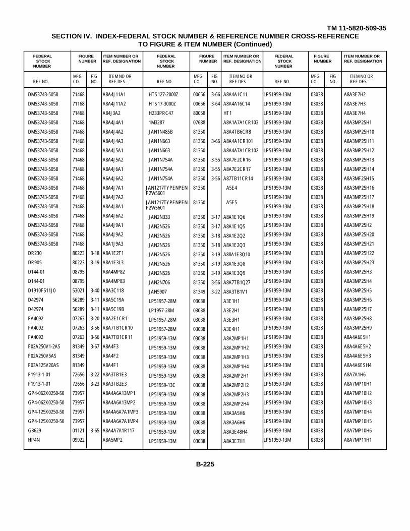
TM 11-5820-509-35SECTION IV. INDEX-FEDERAL STOCK NUMBER & REFERENCE NUMBER CROSS-REFERENCE
TO FIGURE & ITEM NUMBER (Continued)
FEDERAL FIGURE ITEM NUMBER OR FEDERAL FIGURE ITEM NUMBER OR FEDERAL FIGURE ITEM NUMBER ORSTOCK NUMBER REF. DESIGNATION STOCK NUMBER REF. DESIGNATION STOCK NUMBER REF. DESIGNATION
NUMBER NUMBER NUMBER
MFG FIG ITEM NO OR MFG FIG ITEM NO OR MFG FIG ITEM NO ORREF NO. CO. NO. REF DES. REF NO. CO. NO. REF DES REF NO. CO. NO. REF DES
DM53743-5058 71468 A8A4J11A1
DM53743-5058 71168 A8A4J11A2
DM53743-5058 71468 A84J3A2
DM53743-5058 71468 A8A4J4A1
DM53743-5058 71468 A8A4J4A2
DM53743-5058 71468 A8A4J4A3
DM53743-5058 71468 A8A4J5A1
DM53743-5058 71468 A8A4J5A2
DM53743-5058 71468 A8A4J6A1
DM53743-5058 71468 A6A4J6A2
DM53743-5058 71468 A8A4J7A1
DM53743-5058 71468 A8A4J7A2
DM53743-5058 71468 A8A4J8A1
DM53743-5058 71468 A8A4J6A2
DM53743-5058 71468 A6A4J9A1
DM53743-5058 71468 A8A4J9A2
DM53743-5058 71468 A8A1J9A3
DR230 80223 3-18 A8A1E2T1
DR905 80223 3-19 A8A1E3L3
D144-01 08795 A8A4MP82
D144-01 08795 A8A4MP83
D1910F511J0 53021 3-40 A8A3C118
D42974 56289 3-11 A8A5C19A
D42974 56289 3-11 A8A5C19B
FA4092 07263 3-20 A8A2E1CR1
FA4092 07263 3-56 A8A7TB1CR10
FA4092 07263 3-56 A8A7TB1CR11
F02A250V1-2AS 81349 3-67 A8A4F3
F02A250V5AS 81349 A8A4F2
F03A125V20AS 81349 A8A4F1
F1913-1-01 72656 3-22 A8A3TB1E3
F1913-1-01 72656 3-23 A8A3TB2E3
GP4-062X0250-50 73957 A8A4A6A13MP1
GP4-062X0250-50 73957 A8A4A6A13MP2
GP4-125X0250-50 73957 A8A4A6A7A1MP3
GP4-125X0250-50 73957 A8A4A6A7A1MP4
G3629 01121 3-65 A8A4A7A1R117
HP4N 09922 A8A5MP2
HTS127-2000Z 00656 3-66 A8A4A1C11
HTS17-3000Z 00656 3-64 A8A4A16C14
H233PRC47 80058 HT1
1M3287 07688 A8A1A7A1CR103
JAN1N485B 81350 A8A4TB6CR8
JAN1N663 81350 3-66 A8A4A1CR101
JAN1N663 81350 A8A4A7A1CR102
JAN1N754A 81350 3-55 A8A7E2CR16
JAN1N754A 81350 3-55 A8A7E2CR17
JAN1N754A 81350 3-56 A87TB11CR14
JAN1217TYPENPEN 81350 A5E4P2W5601
JAN1217TYPENPEN 81350 A5E5P2W5601
JAN2N333 81350 3-17 A8A1E1Q6
JAN2N526 81350 3-17 A8A1E1Q5
JAN2N526 81350 3-18 A8A1E2Q2
JAN2N526 81350 3-18 A8A1E2Q3
JAN2N526 81350 3-19 A88A1E3Q10
JAN2N526 81350 3-19 A8A1E3Q8
JAN2N526 81350 3-19 A8A1E3Q9
JAN2N706 81350 3-56 A8A7TB1Q27
JAN5907 81349 3-22 A8A3TB1V1
LP51957-28M 03038 A3E1H1
LP1957-28M 03038 A3E2H1
LP51957-28M 03038 A3E3H1
LP51957-28M 03038 A3E4H1
LP51959-13M 03038 A8A2MP1H1
LP51959-13M 03038 A8A2MP1H2
LP51959-13M 03038 A8A2MP1H3
LP51959-13M 03038 A8A2MP1H4
LP51959-13M 03038 A8A2MP2H1
LP51959-13C 03038 A8A2MP2H2
LP51959-13M 03038 A8A2MP2H3
LP51959-13M 03038 A8A2MP2H4
LP51959-13M 03038 A8A3A5H6
LP51959-13M 03038 A8A3A6H6
LP51959-13M 03038 A8A3E48H4
LP51959-13M 03038 A8A3E7H1
LP51959-13M 03038 A8A3E7H2
LP51959-13M 03038 A8A3E7H3
LP51959-13M 03038 A8A3E7H4
LP51959-13M 03038 A8A3MP25H1
LP51959-13M 03038 A8A3MP25H10
LP51959-13M 03038 A8A3MP25H11
LP51959-13M 03038 A8A3MP25H12
LP51959-13M 03038 A8A3MP25H13
LP51959-13M 03038 A8A3MP25H14
LP51959-13M 03038 A8A3MF25H15
LP51959-13M 03038 A8A3MP25H16
LP51959-13M 03038 A8A3MP25H17
LP51959-13M 03038 A8A3MP25H18
LP51959-13M 03038 A8A3MP25H19
LP51959-13M 03038 A8A3MP25H2
LP51959-13M 03038 A8A3MP25H20
LP51959-13M 03038 A8A3MP25H21
LP51959-13M 03038 A8A3MP25H22
LP51959-13M 03038 A8A3MP25H23
LP51959-13M 03038 A8A3MP25H3
LP51959-13M 03038 A8A3MP25H4
LP51959-13M 03038 A8A3MP25H5
LP51959-13M 03038 A8A3MP25H6
LP51959-13M 03038 A8A3MP25H7
LP51959-13M 03038 A8A3MP25H8
LP51959-13M 03038 A8A3MP25H9
LP51959-13M 03038 A8A4A6E5H1
LP51959-13M 03038 A8A4A6E5H2
LP51959-13M 03038 A8A4A6E5H3
LP51959-13M 03038 A8A4A6ESH4
LP51959-13M 03038 A8A7A1H6
LP51959-13M 03038 A8A7MP10H1
LP51959-13M 03038 A8A7MP10H2
LP51959-13M 03038 A8A7MP10H3
LP51959-13M 03038 A8A7MP10H4
LP51959-13M 03038 A8A7MP10H5
LP51959-13M 03038 A8A7MP10H6
LP51959-13M 03038 A8A7MP11H1
B-225
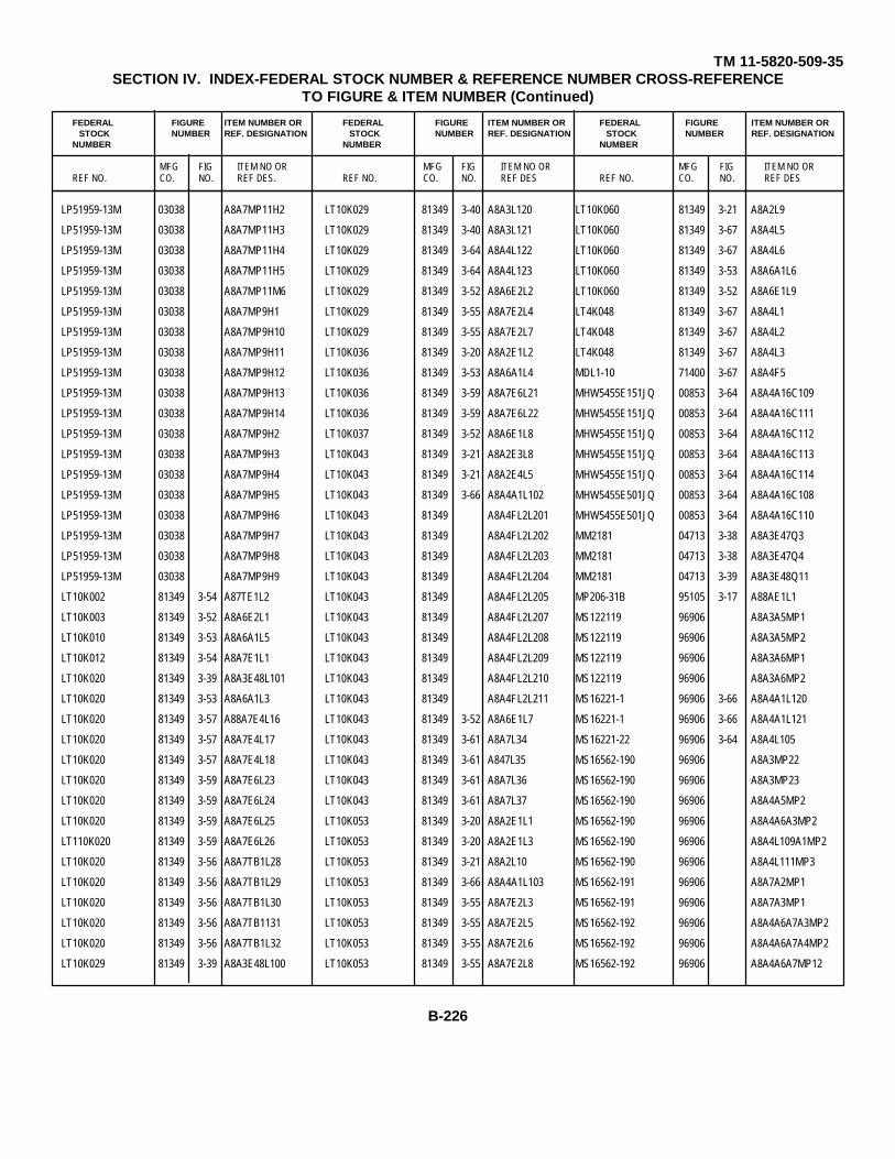
TM 11-5820-509-35SECTION IV. INDEX-FEDERAL STOCK NUMBER & REFERENCE NUMBER CROSS-REFERENCE
TO FIGURE & ITEM NUMBER (Continued)
FEDERAL FIGURE ITEM NUMBER OR FEDERAL FIGURE ITEM NUMBER OR FEDERAL FIGURE ITEM NUMBER ORSTOCK NUMBER REF. DESIGNATION STOCK NUMBER REF. DESIGNATION STOCK NUMBER REF. DESIGNATION
NUMBER NUMBER NUMBER
MFG FIG ITEM NO OR MFG FIG ITEM NO OR MFG FIG ITEM NO ORREF NO. CO. NO. REF DES. REF NO. CO. NO. REF DES REF NO. CO. NO. REF DES
LP51959-13M 03038 A8A7MP11H2
LP51959-13M 03038 A8A7MP11H3
LP51959-13M 03038 A8A7MP11H4
LP51959-13M 03038 A8A7MP11H5
LP51959-13M 03038 A8A7MP11M6
LP51959-13M 03038 A8A7MP9H1
LP51959-13M 03038 A8A7MP9H10
LP51959-13M 03038 A8A7MP9H11
LP51959-13M 03038 A8A7MP9H12
LP51959-13M 03038 A8A7MP9H13
LP51959-13M 03038 A8A7MP9H14
LP51959-13M 03038 A8A7MP9H2
LP51959-13M 03038 A8A7MP9H3
LP51959-13M 03038 A8A7MP9H4
LP51959-13M 03038 A8A7MP9H5
LP51959-13M 03038 A8A7MP9H6
LP51959-13M 03038 A8A7MP9H7
LP51959-13M 03038 A8A7MP9H8
LP51959-13M 03038 A8A7MP9H9
LT10K002 81349 3-54 A87TE1L2
LT10K003 81349 3-52 A8A6E2L1
LT10K010 81349 3-53 A8A6A1L5
LT10K012 81349 3-54 A8A7E1L1
LT10K020 81349 3-39 A8A3E48L101
LT10K020 81349 3-53 A8A6A1L3
LT10K020 81349 3-57 A88A7E4L16
LT10K020 81349 3-57 A8A7E4L17
LT10K020 81349 3-57 A8A7E4L18
LT10K020 81349 3-59 A8A7E6L23
LT10K020 81349 3-59 A8A7E6L24
LT10K020 81349 3-59 A8A7E6L25
LT110K020 81349 3-59 A8A7E6L26
LT10K020 81349 3-56 A8A7TB1L28
LT10K020 81349 3-56 A8A7TB1L29
LT10K020 81349 3-56 A8A7TB1L30
LT10K020 81349 3-56 A8A7TB1131
LT10K020 81349 3-56 A8A7TB1L32
LT10K029 81349 3-39 A8A3E48L100
LT10K029 81349 3-40 A8A3L120
LT10K029 81349 3-40 A8A3L121
LT10K029 81349 3-64 A8A4L122
LT10K029 81349 3-64 A8A4L123
LT10K029 81349 3-52 A8A6E2L2
LT10K029 81349 3-55 A8A7E2L4
LT10K029 81349 3-55 A8A7E2L7
LT10K036 81349 3-20 A8A2E1L2
LT10K036 81349 3-53 A8A6A1L4
LT10K036 81349 3-59 A8A7E6L21
LT10K036 81349 3-59 A8A7E6L22
LT10K037 81349 3-52 A8A6E1L8
LT10K043 81349 3-21 A8A2E3L8
LT10K043 81349 3-21 A8A2E4L5
LT10K043 81349 3-66 A8A4A1L102
LT10K043 81349 A8A4FL2L201
LT10K043 81349 A8A4FL2L202
LT10K043 81349 A8A4FL2L203
LT10K043 81349 A8A4FL2L204
LT10K043 81349 A8A4FL2L205
LT10K043 81349 A8A4FL2L207
LT10K043 81349 A8A4FL2L208
LT10K043 81349 A8A4FL2L209
LT10K043 81349 A8A4FL2L210
LT10K043 81349 A8A4FL2L211
LT10K043 81349 3-52 A8A6E1L7
LT10K043 81349 3-61 A8A7L34
LT10K043 81349 3-61 A847L35
LT10K043 81349 3-61 A8A7L36
LT10K043 81349 3-61 A8A7L37
LT10K053 81349 3-20 A8A2E1L1
LT10K053 81349 3-20 A8A2E1L3
LT10K053 81349 3-21 A8A2L10
LT10K053 81349 3-66 A8A4A1L103
LT10K053 81349 3-55 A8A7E2L3
LT10K053 81349 3-55 A8A7E2L5
LT10K053 81349 3-55 A8A7E2L6
LT10K053 81349 3-55 A8A7E2L8
LT10K060 81349 3-21 A8A2L9
LT10K060 81349 3-67 A8A4L5
LT10K060 81349 3-67 A8A4L6
LT10K060 81349 3-53 A8A6A1L6
LT10K060 81349 3-52 A8A6E1L9
LT4K048 81349 3-67 A8A4L1
LT4K048 81349 3-67 A8A4L2
LT4K048 81349 3-67 A8A4L3
MDL1-10 71400 3-67 A8A4F5
MHW5455E151JQ 00853 3-64 A8A4A16C109
MHW5455E151JQ 00853 3-64 A8A4A16C111
MHW5455E151JQ 00853 3-64 A8A4A16C112
MHW5455E151JQ 00853 3-64 A8A4A16C113
MHW5455E151JQ 00853 3-64 A8A4A16C114
MHW5455E501JQ 00853 3-64 A8A4A16C108
MHW5455E501JQ 00853 3-64 A8A4A16C110
MM2181 04713 3-38 A8A3E47Q3
MM2181 04713 3-38 A8A3E47Q4
MM2181 04713 3-39 A8A3E48Q11
MP206-31B 95105 3-17 A88AE1L1
MS122119 96906 A8A3A5MP1
MS122119 96906 A8A3A5MP2
MS122119 96906 A8A3A6MP1
MS122119 96906 A8A3A6MP2
MS16221-1 96906 3-66 A8A4A1L120
MS16221-1 96906 3-66 A8A4A1L121
MS16221-22 96906 3-64 A8A4L105
MS16562-190 96906 A8A3MP22
MS16562-190 96906 A8A3MP23
MS16562-190 96906 A8A4A5MP2
MS16562-190 96906 A8A4A6A3MP2
MS16562-190 96906 A8A4L109A1MP2
MS16562-190 96906 A8A4L111MP3
MS16562-191 96906 A8A7A2MP1
MS16562-191 96906 A8A7A3MP1
MS16562-192 96906 A8A4A6A7A3MP2
MS16562-192 96906 A8A4A6A7A4MP2
MS16562-192 96906 A8A4A6A7MP12
B-226
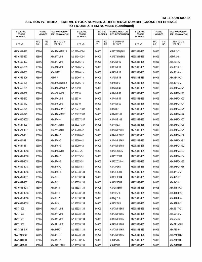
TM 11-5820-509-35SECTION IV. INDEX-FEDERAL STOCK NUMBER & REFERENCE NUMBER CROSS-REFERENCE
TO FIGURE & ITEM NUMBER (Continued)
FEDERAL FIGURE ITEM NUMBER OR FEDERAL FIGURE ITEM NUMBER OR FEDERAL FIGURE ITEM NUMBER ORSTOCK NUMBER REF. DESIGNATION STOCK NUMBER REF. DESIGNATION STOCK NUMBER REF. DESIGNATION
NUMBER NUMBER NUMBER
MFG FIG ITEM NO OR MFG FIG ITEM NO OR MFG FIG ITEM NO ORREF NO. CO. NO. REF DES. REF NO. CO. NO. REF DES REF NO. CO. NO. REF DES
MS16562-192 96906 A8A4A6A7MP13 MS21044D04 96906 A8A57B1Q3H1 MS35338-135 96906 A3MP2H7
MS16562-197 96906 A8A3A7MP1 MS21044D04 96906 A8A57B1Q3H2 MS35338-135 96906 A3MP2H8
MS16562-197 96906 A8A3A7MP2 MS21266-1N 96906 A8A3MP10 MS35338-135 96906 A8A1E4H2
MS16562-201 96906 A8A3A8MP1 MS21266-1N 96906 A8A3MP11 MS35338-135 96906 A8A3E10H3
MS16562-203 96906 A5A1MP1 MS21266-1N 96906 A8A3MP12 MS35338-135 96906 A8A3E10H4
MS16562-206 96906 A5MP5 MS21266-1N 96906 A8A3MP13 MS35338-135 96906 A8A3E45H2
MS16562-209 96906 A8A4A6A10MP2 MS21266-1N 96906 A8A5MP6 MS35338-135 96906 A8A3E46H2
MS16562-209 96906 A8A4A6A11MP2 MS25010 96906 A8A4MP47 MS35338-135 96906 A8A3MP24H21
MS16562-209 96906 A84A6A9MP2 MS25010 96906 A8A4MP48 MS35338-135 96906 A8A3MP24H22
MS16562-212 96906 A8A3A6MP4 MS25010 96906 A8A4MP49 MS35338-135 96906 A8A3MP24H23
MS16562-212 96906 A8A3A6MP5 MS25010 96906 A8A4MP50 MS35338-135 96906 A8A3MP24H24
MS16562-221 96906 A8A4A6A8MP1 MS25237-387 96906 A8A4DS1 MS35338-135 96906 A8A3MP24H25
MS16562-221 96906 A8A4A6A8MP2 MS25237-387 96906 A8A4DS101 MS35338-135 96906 A8A3MP24H26
MS16620-1025 96906 A8A4A6H4 MS25237-387 96906 A8A4DS102 MS35338-135 96906 A8A3MP24H27
MS16624-1031 96906 A8A7A1A3H1 MS25237-387 96906 A8A4DS2 MS35338-135 96906 A8A3MP24H28
MS16624-1031 96906 A8A7A1A4H1 MS35200-42 96906 A8A4MP27H1 MS35338-135 96906 A8A3MP24H29
MS16624-18 96906 A8A4A6H1 MS35200-42 96906 A8A4MP27H2 MS35338-135 96906 A8A3MP24H30
MS16624-18 96906 A8A4A6H2 MS35200-42 96906 A8A4MP27H3 MS35338-135 96906 A8A3MP24H31
MS16624-18 96906 A8A4A6H3 MS35200-42 96906 A8A4MP27H4 MS35338-135 96906 A8A3MP24H32
MS16632-1018 96906 A8A4A6A7H1 MS3533-75 96906 A8A4C146H2 MS35338-135 96906 A8A3MP24H33
MS16632-1018 96906 A8A4A6H5 MS35335-51 96906 A8A5TB1H1 MS35338-135 96906 A8A3MP24H34
MS16632-1018 96906 A8A4A6H6 MS35335-51 96906 A8A5XC20H4 MS35338-135 96906 A8A3MP24H35
MS16632-1018 96906 A8A4A6H7 MS35335-51 96906 A8A7P2H3 MS35338-135 96906 A8A3MP24H36
MS16632-1018 96906 A8A4A6H8 MS35338-134 96906 A8A3E13H3 MS35338-135 96906 A8A4A15H2
MS16632-1031 96906 A8A7H1 MS35338-134 96906 A8A3E13H4 MS35338-135 96906 A8A4K5H3
MS16632-1031 96906 A8A7H2 MS35338-134 96906 A8A3E15H3 MS35338-135 96906 A8A4K5H4
MS16633-1018 96906 A8A3H10 MS35338-134 96906 A8A3E15H4 MS35338-135 96906 A8A4TB1H2
MS16633-1018 96906 A8A3H11 MS35338-134 96906 A8A4J5H6 MS35338-135 96906 A8A4TB4H5
MS16633-1018 96906 A8A3H12 MS35338-134 96906 A8A4J7H6 MS35338-135 96906 A8A4TB4H6
MS16633-1018 96906 A8A3H9 MS35338-134 96906 A8A5E5H3 MS35338-135 96906 A8A4TB6H2
MS171503 96906 A6A1A1MP3 MS35338-134 96906 A8A7MP13H4 MS35338-135 96906 A8A5E17H3
MS171503 96906 A6A2A1MP3 MS35338-134 96906 A8A7MP13H5 MS35338-135 96906 A8A5E18H2
MS171503 96906 A6A3A1MP3 MS35338-134 96906 A8A7MP13H6 MS35338-135 96906 A8A5E4H2
MS171503 96906 A6A3A1MP3 MS35338-134 96906 A8A7MP14H4 MS35338-135 96906 A8A7A1A3H1
MS17821-4-9 96906 A8A4MP21 MS35338-134 96906 A8A7MP14H5 MS35338-135 96906 A8A7E5H4
MS21044D04 96906 A6A3A1H1 MS35338-134 96906 A8A7MP14H6 MS35338-135 96906 A8A7MP8H2
MS21044D04 96906 A6A3A2H1 MS35338-135 96906 A3MP2H5 MS35338-135 96906 A8A7MP8H3
MS21044D04 96906 A8A5781E1H1 MS35338-135 96906 A3MP3H6 MS35338-135 96906 A8A7MP8H4
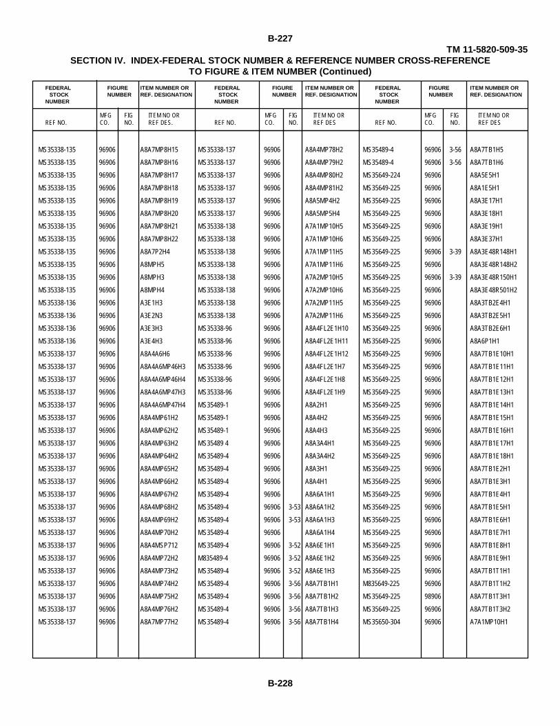
B-227TM 11-5820-509-35
SECTION IV. INDEX-FEDERAL STOCK NUMBER & REFERENCE NUMBER CROSS-REFERENCETO FIGURE & ITEM NUMBER (Continued)
FEDERAL FIGURE ITEM NUMBER OR FEDERAL FIGURE ITEM NUMBER OR FEDERAL FIGURE ITEM NUMBER ORSTOCK NUMBER REF. DESIGNATION STOCK NUMBER REF. DESIGNATION STOCK NUMBER REF. DESIGNATION
NUMBER NUMBER NUMBER
MFG FIG ITEM NO OR MFG FIG ITEM NO OR MFG FIG ITEM NO ORREF NO. CO. NO. REF DES. REF NO. CO. NO. REF DES REF NO. CO. NO. REF DES
MS35338-135 96906 A8A7MP8H15 MS35338-137 96906 A8A4MP78H2 MS35489-4 96906 3-56 A8A7TB1H5
MS35338-135 96906 A8A7MP8H16 MS35338-137 96906 A8A4MP79H2 MS35489-4 96906 3-56 A8A7TB1H6
MS35338-135 96906 A8A7MP8H17 MS35338-137 96906 A8A4MP80H2 MS35649-224 96906 A8A5E5H1
MS35338-135 96906 A8A7MP8H18 MS35338-137 96906 A8A4MP81H2 MS35649-225 96906 A8A1E5H1
MS35338-135 96906 A8A7MP8H19 MS35338-137 96906 A8A5MP4H2 MS35649-225 96906 A8A3E17H1
MS35338-135 96906 A8A7MP8H20 MS35338-137 96906 A8A5MP5H4 MS35649-225 96906 A8A3E18H1
MS35338-135 96906 A8A7MP8H21 MS35338-138 96906 A7A1MP10H5 MS35649-225 96906 A8A3E19H1
MS35338-135 96906 A8A7MP8H22 MS35338-138 96906 A7A1MP10H6 MS35649-225 96906 A8A3E37H1
MS35338-135 96906 A8A7P2H4 MS35338-138 96906 A7A1MP11H5 MS35649-225 96906 3-39 A8A3E48R148H1
MS35338-135 96906 A8MPH5 MS35338-138 96906 A7A1MP11H6 MS35649-225 96906 A8A3E48R148H2
MS35338-135 96906 A8MPH3 MS35338-138 96906 A7A2MP10H5 MS35649-225 96906 3-39 A8A3E48R150H1
MS35338-135 96906 A8MPH4 MS35338-138 96906 A7A2MP10H6 MS35649-225 96906 A8A3E48R501H2
MS35338-136 96906 A3E1H3 MS35338-138 96906 A7A2MP11H5 MS35649-225 96906 A8A3TB2E4H1
MS35338-136 96906 A3E2N3 MS35338-138 96906 A7A2MP11H6 MS35649-225 96906 A8A3TB2E5H1
MS35338-136 96906 A3E3H3 MS35338-96 96906 A8A4FL2E1H10 MS35649-225 96906 A8A3TB2E6H1
MS35338-136 96906 A3E4H3 MS35338-96 96906 A8A4FL2E1H11 MS35649-225 96906 A8A6P1H1
MS35338-137 96906 A8A4A6H6 MS35338-96 96906 A8A4FL2E1H12 MS35649-225 96906 A8A7TB1E10H1
MS35338-137 96906 A8A4A6MP46H3 MS35338-96 96906 A8A4FL2E1H7 MS35649-225 96906 A8A7TB1E11H1
MS35338-137 96906 A8A4A6MP46H4 MS35338-96 96906 A8A4FL2E1H8 MS35649-225 96906 A8A7TB1E12H1
MS35338-137 96906 A8A4A6MP47H3 MS35338-96 96906 A8A4FL2E1H9 MS35649-225 96906 A8A7TB1E13H1
MS35338-137 96906 A8A4A6MP47H4 MS35489-1 96906 A8A2H1 MS35649-225 96906 A8A7TB1E14H1
MS35338-137 96906 A8A4MP61H2 MS35489-1 96906 A8A4H2 MS35649-225 96906 A8A7TB1E15H1
MS35338-137 96906 A8A4MP62H2 MS35489-1 96906 A8A4H3 MS35649-225 96906 A8A7TB1E16H1
MS35338-137 96906 A8A4MP63H2 MS35489 4 96906 A8A3A4H1 MS35649-225 96906 A8A7TB1E17H1
MS35338-137 96906 A8A4MP64H2 MS35489-4 96906 A8A3A4H2 MS35649-225 96906 A8A7TB1E18H1
MS35338-137 96906 A8A4MP65H2 MS35489-4 96906 A8A3H1 MS35649-225 96906 A8A7TB1E2H1
MS35338-137 96906 A8A4MP66H2 MS35489-4 96906 A8A4H1 MS35649-225 96906 A8A7TB1E3H1
MS35338-137 96906 A8A4MP67H2 MS35489-4 96906 A8A6A1H1 MS35649-225 96906 A8A7TB1E4H1
MS35338-137 96906 A8A4MP68H2 MS35489-4 96906 3-53 A8A6A1H2 MS35649-225 96906 A8A7TB1E5H1
MS35338-137 96906 A8A4MP69H2 MS35489-4 96906 3-53 A8A6A1H3 MS35649-225 96906 A8A7TB1E6H1
MS35338-137 96906 A8A4MP70H2 MS35489-4 96906 A8A6A1H4 MS35649-225 96906 A8A7TB1E7H1
MS35338-137 96906 A8A4MSP712 MS35489-4 96906 3-52 A8A6E1H1 MS35649-225 96906 A8A7TB1E8H1
MS35338-137 96906 A8A4MP72H2 M835489-4 96906 3-52 A8A6E1H2 MS35649-225 96906 A8A7TB1E9H1
MS35338-137 96906 A8A4MP73H2 MS35489-4 96906 3-52 A8A6E1H3 MS35649-225 96906 A8A7TB1T1H1
MS35338-137 96906 A8A4MP74H2 MS35489-4 96906 3-56 A8A7TB1H1 M835649-225 96906 A8A7TB1T1H2
MS35338-137 96906 A8A4MP75H2 MS35489-4 96906 3-56 A8A7TB1H2 MS35649-225 98906 A8A7TB1T3H1
MS35338-137 96906 A8A4MP76H2 MS35489-4 96906 3-56 A8A7TB1H3 MS35649-225 96906 A8A7TB1T3H2
MS35338-137 96906 A8A7MP77H2 MS35489-4 96906 3-56 A8A7TB1H4 MS35650-304 96906 A7A1MP10H1
B-228

TM 11-5820-509-35SECTION IV. INDEX-FEDERAL STOCK NUMBER & REFERENCE NUMBER CROSS-REFERENCE
TO FIGURE & ITEM NUMBER (Continued)
FEDERAL FIGURE ITEM NUMBER OR FEDERAL FIGURE ITEM NUMBER OR FEDERAL FIGURE ITEM NUMBER ORSTOCK NUMBER REF. DESIGNATION STOCK NUMBER REF. DESIGNATION STOCK NUMBER REF. DESIGNATION
NUMBER NUMBER NUMBER
MFG FIG ITEM NO OR MFG FIG ITEM NO OR MFG FIG ITEM NO ORREF NO. CO. NO. REF DES. REF NO. CO. NO. REF DES REF NO. CO. NO. REF DES
MS35650-304 96906 A7A1MP10H2 MS51957-12 96906 A8A3E4H1 MS51957-13 96906 A8A4K102H3
MS35650-304 96906 A7A1MP11H1 MS51957-12 96906 A8A4K103H1 MS51957-13 96906 A8A4K102H4
MS35650-304 96906 A7A1MP11H2 MS51957-12 96906 A8A4K103H2 MS51957-13 96906 A8A4MP25H1
MS35650-304 96906 A7A2MP10H1 MS51957-12 96906 A8A5E18H1 MS51957-13 96906 A8A4MP25H10
MS35650-304 96906 A7A2MP10H2 MS51957-12 96906 A8A5E7H1 MS51957-13 96906 A8A4MP25H11
MS35650-304 96906 A7A2MP11H1 MS51957-13 96906 A8A3A2H2 MS51957-13 96906 A8A4MP25H2
MS35650-304 96906 A7A6MP11H2 M851957-13 96906 A8A3A3H2 MS51957-13 96906 A8A4MP25H3
MS35672-1 96906 A8A4A6A1MP3 MS51957-13 96906 A8A3A9A3H4 MS51957-13 96906 A8A4MP25H4
MS35672-1 96906 A8A4A6A1MP4 MS51957-13 96906 A8A3E10H1 MS51957-13 96906 A8A4MP25H5
MS35672-1 96906 A8A4A6A2MP3 MS51957-13 96906 A8A3E10H2 MS51957-13 96906 A8A4MP25H6
MS35672-1 96906 A8A4A6A2MP4 MS51957-13 96906 A8A3MP24H10 MS51957-13 96906 A8A4MP25H7
MS35672-14 96906 A7A1A1MP1 MS51957-13 96906 A8A3MP24H11 MS51957-13 96906 A8A4MP25H8
MS35672-14 96906 A7A1A2MP1 MS51957-13 96906 A8A3MP24H12 MS51957-13 96906 A8A4MP25H9
MS35672-14 96906 A7A2A1MP1 MS51957-13 96906 A8A3MP24H13 MS51957-13 96906 A8A4MP26H1
MS35672-14 96906 A7A2A2MP1 MS51957-13 96906 A8A3MP24H14 MS51957-13 96906 A8A4MP26H10
MS35672-7 96906 A8A4A6A1MP5 MS51957-13 96906 A8A3MP24H15 MS51957-13 96906 A8A4MP26H11
MS35672-7 96906 A8A4A6A2MP5 MS51957-13 96906 A8A3MP24H16 MS51957-13 96906 A8A4MP26H2
MS1053-426 96906 A8A4A6MP22H1 MS51957-13 96906 A8A3MP24H17 MS51957-13 96906 A8A4MP26H3
MS1053-426 96906 A8A4A6MP22H2 MS51957-13 96906 A8A3MP24H18 MS51957-13 96906 A8A4MP26H4
MS1053-426 96906 A8A4A6MP23H1 MS51957-13 96906 A8A3MP24H19 MS51957-13 96906 A8A4MP26H5
MS1053-426 96906 A8A4A6MP23H2 MS51957-13 96906 A8A3MP24H20 MS51957-13 96906 A8A4MP26H6
MS1053-426 96906 A8A4A6MP24H1 MS51957-13 96906 A8A3MP24H5 MS51957-13 96906 A8A4MP26H7
MS1053-426 96906 A8A4A6MP24H2 MS51957-13 96906 A8A3MP24H6 M151957-13 96906 A8A4MP26H8
MS1053-426 96906 A8A4A6MP25H1 MS51957-13 96906 A8A3MP24H7 MS51957-13 96906 A8A4MP26H9
MS1053-426 96906 A8A4A6MP25H2 MS51957-13 96906 A8A3MP24H8 MS51957-13 96906 A8A5E1H4
MS1053-426 96906 A8A4A6MP26H1 MS51957-13 96906 A8A3MP24H9 MS51957-13 96906 A8A5E17H2
MS1053-426 96906 A8A4A6MP26H2 MS51957-13 96906 A8A3MP38H1 MS51957-13 96906 A8A7A1A3H1
MS1053-426 96906 A8A4A6MP27H1 MS51957-13 96906 A8A3MP38H2 MS51957-13 96906 A8A7MP8H1
MS1053-426 96906 A8A4A6MP27H2 MS51957-13 96906 A8A3MP38H3 MS51957-13 96906 A8A7MP8H10
MS1053-426 96906 A8A4A6MP36H1 MS51957-13 96906 A8A3MP38H4 MS51957-13 96906 A8A7MP8H11
MS1053-426 96906 A8A44A6P36H2 MS51957-13 96906 A8A4E150H1 MS51957-13 96906 A8A7MP8H2
MS1053-426 96906 A8A4A6MP48H1 MS51957-13 96906 A8A4E151H1 MS51957-13 96906 A8A7MP8H3
MS1053-426 96906 A8A4A6MP48H2 MS51957-13 96906 A8A4E152H1 MK51957-13 96906 A8A7MP8H4
MS1053-426 96906 A8A4A6MP49H1 MS51957-13 96906 A8A4E153H1 MS51957-13 96906 A8A7MP8H5
MS1053-426 96906 A8A4A6MP49H2 MS51957-13 96906 A8A4E154H1 MP51957-13 96906 A8A7MP8H6
MS1053-426 96906 A8A4A6MP50H1 MS51957-13 96906 A8A4E160H1 MS51957-13 96906 A8A7MP8H7
MS1053-426 96906 A8AA6MP50H2 MS51957-13 96906 A8A1E167H1 MS51957-13 96906 A8A7MP8H8
MS51957-12 96906 A8A3E45H1 MS51957-13 96906 A8A4E168H1 MS51957-13 96906 A8A7MP8H9
B-229
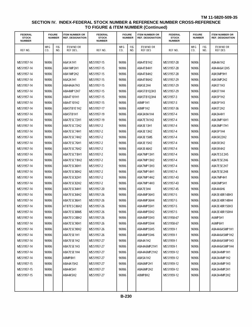
TM 11-5820-509-35SECTION IV. INDEX-FEDERAL STOCK NUMBER & REFERENCE NUMBER CROSS-REFERENCE
TO FIGURE & ITEM NUMBER (Continued)
FEDERAL FIGURE ITEM NUMBER OR FEDERAL FIGURE ITEM NUMBER OR FEDERAL FIGURE ITEM NUMBER ORSTOCK NUMBER REF. DESIGNATION STOCK NUMBER REF. DESIGNATION STOCK NUMBER REF. DESIGNATION
NUMBER NUMBER NUMBER
MFG FIG ITEM NO OR MFG FIG ITEM NO OR MFG FIG ITEM NO ORREF NO. CO. NO. REF DES. REF NO. CO. NO. REF DES REF NO. CO. NO. REF DES
MS51957-14 96906 A6A1A1H1 MS51957-15 96906 A8A4TB1H2 MS51957-28 96906 A8A4A1H2
MS51957-14 96906 A8A1MP2H1 MS51957-15 96906 A8A4TB4H1 MS51957-28 96906 A8A4A6A12H5
MS51957-14 96906 A8A1MP2H2 MS51957-15 96906 A8A4TB4H2 MS51957-28 96906 A8A5MP9H1
MS51957-14 96906 A6A2A1H1 MS51957-15 96906 A8A4TB6H2 MS51957-29 96906 A8A5MP2H2
MS51957-14 96906 A8A4A6A7H3 MS51957-15 96906 A8A5E2H4 MS51957-29 96906 A8A5T1H3
MS51957-14 96906 A8A4MP12H7 MS51957-15 96906 A8A5TB1Q3H3 MS51957-29 96906 A8A5T1H4
MS51957-14 96906 A8A4T101H1 MS51957-15 96906 A8A5TB1Q3H4 MS51957-3 96906 A8A5P1H2
MS51957-14 96906 A8A4T101H2 MS51957-15 96906 A8MP1H1 MS51957-3 96906 A8A5P1H3
MS51957-14 96906 A8A5TB1E1H2 MS51957-17 96906 A8MP1H2 MS51957-36 96906 A8A5T2H2
MS51957-14 96906 A8A5TB1H1 MS51957-19 96906 A8A3A9A1H4 MS51957-4 96906 A8A3A4H1
MS51957-14 96906 A8A7E5C72H1 MS51957-19 96906 A8A7E7A1H2 MS51957-4 96906 A8A3MP16H1
MS51957-14 96906 A8A7E5C72H2 MS51957-2 96906 A8A3E13H1 MS51957-4 96906 A8A3MP17H1
MS51957-14 96906 A8A7E5C74H1 MS51957-2 96906 A8A3E13H2 MS51957-4 96906 A8A5P1H4
MS51957-14 96906 A8A7E5C74H2 MS51957-2 96906 A8A3E15MS MS51957-4 96906 A8A5R22H2
MS51957-14 96906 A8A7E5C76H1 MS51957-2 96906 A8A3E15H2 MS51957-4 96906 A8A5R3H2
MS51957-14 96906 A8A7E5C76H2 MS51957-2 96906 A8A3E46H2 MS51957-4 96906 A8A5R4H2
MS51957-14 96906 A8A7E5CTBH1 MS51957-2 96906 A8A7MP13H1 MS51957-4 96906 A8A7ESE2H5
MS51957-14 96906 A8A7E5CTBH2 MS51957-2 96906 A8A7MP13H2 MS51957-4 96906 A8A7E5E2H6
MS51957-14 96906 A8A7E5C80H1 MS51957-2 96906 A8A7MP13H3 MS51957-4 96906 A8A7E5E2H7
MS51957-14 96906 A8A7E5C80H2 MS51957-2 96906 A8A7MP14H1 MS51957-4 96906 A8A7E5E2H8
MS51957-14 96906 A8A7E5C82H1 MS51957-2 96906 A8A7MP14H2 MS51957-43 96906 A8A7MP4H1
MS51957-14 96906 A8A7E5C82H2 MS51957-2 96906 A8A7MP14H3 MS51957-43 96906 A8A5MP5H1
MS51957-14 96906 A8A7E5C84H1 MS51957-20 96906 A8A7E5H4 MS51957-45 96906 A8A4A6H6
MS51957-14 96906 A8A7E5C84H2 MS51957-26 96906 A8A4MP36H3 MS51957-5 96906 A8A3E48R148H3
MS51957-14 96906 A8A7E5C86H1 MS51957-26 96906 A8A4MP36H4 MS51957-5 96906 A8A3E48R148H4
MS51957-14 96906 ATB7ESC86H2 MS51957-26 96906 A8A4MP55H1 MS51957-5 96906 A8A3E48R150H3
MS51957-14 96906 A8A7E5C88MS MS51957-26 96906 A8A4MP55H2 MS51957-5 96906 A8A3E48R150H4
MS51957-14 96906 A8A7ESC88H2 MS51957-26 96906 A8A4MP55H3 MS51958-67 96906 A6MP5H1
MS51957-14 96906 A8A7E5C90H1 MS51957-26 96906 A8A4MP55H4 MS51958-67 96906 A6MP6H1
MS51957-14 96906 A8A7E5C90H2 MS51957-26 96906 A8A4MP55H5 MS51959-1 96906 A8A4A6A5MP1H1
MS51957-14 96906 A8A7E5E1H1 MS51957-26 96906 A8A4MP55H6 MS51959-1 96906 A8A4A6A5MP1H2
MS51957-14 96906 A8A7E5E1H2 MS51957-27 96906 A8A4A1H2 MS51959-1 96906 A8A4A6A5MP1H3
MS51957-14 96906 A8A7E5E1H3 MS51957-27 96906 A8A4A6MP21H1 MS51959-1 96906 A8A4A6A5MP1H4
MS51957-14 96906 A8A7E5E1H4 MS51957-27 96906 A8A4A6MP21H2 MS51959-12 96906 A8A3A4MP1H1
MS51957-14 96906 A8MP8H1 MS51957-27 96906 A8A5A1H2 MS51959-12 96906 A8A3A4MP1H2
MS51957-15 96906 A8A4A15H2 MS51957-27 96906 A8A6MP2H1 MS51959-12 96906 A8A3A4MP1H3
MS51957-15 96906 A8A4K5H1 MS51957-27 96906 A8A6MP2H2 MS51959-12 96906 A8A3A4MP2H1
MS51957-15 96906 A8A4K5H2 MS51957-27 96906 A8MP8H2 MS51959-12 96906 A8A3A4MP2H2
B-230
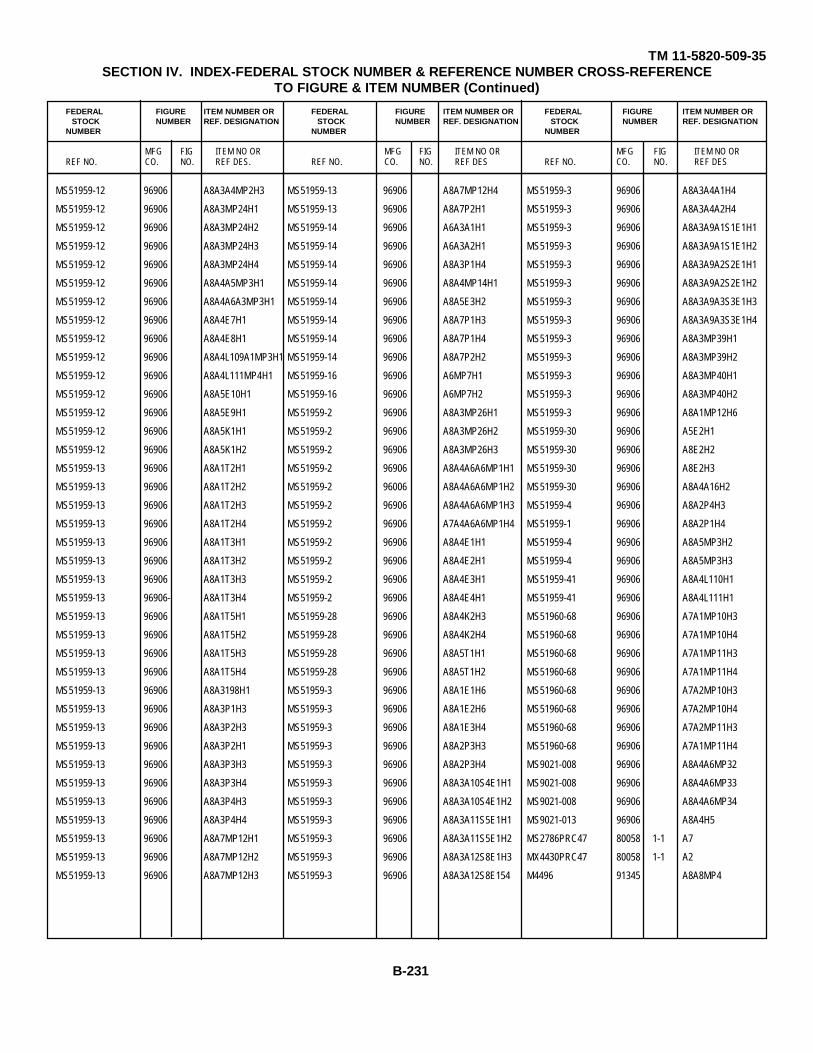
TM 11-5820-509-35SECTION IV. INDEX-FEDERAL STOCK NUMBER & REFERENCE NUMBER CROSS-REFERENCE
TO FIGURE & ITEM NUMBER (Continued)
FEDERAL FIGURE ITEM NUMBER OR FEDERAL FIGURE ITEM NUMBER OR FEDERAL FIGURE ITEM NUMBER ORSTOCK NUMBER REF. DESIGNATION STOCK NUMBER REF. DESIGNATION STOCK NUMBER REF. DESIGNATION
NUMBER NUMBER NUMBER
MFG FIG ITEM NO OR MFG FIG ITEM NO OR MFG FIG ITEM NO ORREF NO. CO. NO. REF DES. REF NO. CO. NO. REF DES REF NO. CO. NO. REF DES
MS51959-12 96906 A8A3A4MP2H3 MS51959-13 96906 A8A7MP12H4 MS51959-3 96906 A8A3A4A1H4
MS51959-12 96906 A8A3MP24H1 MS51959-13 96906 A8A7P2H1 MS51959-3 96906 A8A3A4A2H4
MS51959-12 96906 A8A3MP24H2 MS51959-14 96906 A6A3A1H1 MS51959-3 96906 A8A3A9A1S1E1H1
MS51959-12 96906 A8A3MP24H3 MS51959-14 96906 A6A3A2H1 MS51959-3 96906 A8A3A9A1S1E1H2
MS51959-12 96906 A8A3MP24H4 MS51959-14 96906 A8A3P1H4 MS51959-3 96906 A8A3A9A2S2E1H1
MS51959-12 96906 A8A4A5MP3H1 MS51959-14 96906 A8A4MP14H1 MS51959-3 96906 A8A3A9A2S2E1H2
MS51959-12 96906 A8A4A6A3MP3H1 MS51959-14 96906 A8A5E3H2 MS51959-3 96906 A8A3A9A3S3E1H3
MS51959-12 96906 A8A4E7H1 MS51959-14 96906 A8A7P1H3 MS51959-3 96906 A8A3A9A3S3E1H4
MS51959-12 96906 A8A4E8H1 MS51959-14 96906 A8A7P1H4 MS51959-3 96906 A8A3MP39H1
MS51959-12 96906 A8A4L109A1MP3H1 MS51959-14 96906 A8A7P2H2 MS51959-3 96906 A8A3MP39H2
MS51959-12 96906 A8A4L111MP4H1 MS51959-16 96906 A6MP7H1 MS51959-3 96906 A8A3MP40H1
MS51959-12 96906 A8A5E10H1 MS51959-16 96906 A6MP7H2 MS51959-3 96906 A8A3MP40H2
MS51959-12 96906 A8A5E9H1 MS51959-2 96906 A8A3MP26H1 MS51959-3 96906 A8A1MP12H6
MS51959-12 96906 A8A5K1H1 MS51959-2 96906 A8A3MP26H2 MS51959-30 96906 A5E2H1
MS51959-12 96906 A8A5K1H2 MS51959-2 96906 A8A3MP26H3 MS51959-30 96906 A8E2H2
MS51959-13 96906 A8A1T2H1 MS51959-2 96906 A8A4A6A6MP1H1 MS51959-30 96906 A8E2H3
MS51959-13 96906 A8A1T2H2 MS51959-2 96006 A8A4A6A6MP1H2 MS51959-30 96906 A8A4A16H2
MS51959-13 96906 A8A1T2H3 MS51959-2 96906 A8A4A6A6MP1H3 MS51959-4 96906 A8A2P4H3
MS51959-13 96906 A8A1T2H4 MS51959-2 96906 A7A4A6A6MP1H4 MS51959-1 96906 A8A2P1H4
MS51959-13 96906 A8A1T3H1 MS51959-2 96906 A8A4E1H1 MS51959-4 96906 A8A5MP3H2
MS51959-13 96906 A8A1T3H2 MS51959-2 96906 A8A4E2H1 MS51959-4 96906 A8A5MP3H3
MS51959-13 96906 A8A1T3H3 MS51959-2 96906 A8A4E3H1 MS51959-41 96906 A8A4L110H1
MS51959-13 96906- A8A1T3H4 MS51959-2 96906 A8A4E4H1 MS51959-41 96906 A8A4L111H1
MS51959-13 96906 A8A1T5H1 MS51959-28 96906 A8A4K2H3 MS51960-68 96906 A7A1MP10H3
MS51959-13 96906 A8A1T5H2 MS51959-28 96906 A8A4K2H4 MS51960-68 96906 A7A1MP10H4
MS51959-13 96906 A8A1T5H3 MS51959-28 96906 A8A5T1H1 MS51960-68 96906 A7A1MP11H3
MS51959-13 96906 A8A1T5H4 MS51959-28 96906 A8A5T1H2 MS51960-68 96906 A7A1MP11H4
MS51959-13 96906 A8A3198H1 MS51959-3 96906 A8A1E1H6 MS51960-68 96906 A7A2MP10H3
MS51959-13 96906 A8A3P1H3 MS51959-3 96906 A8A1E2H6 MS51960-68 96906 A7A2MP10H4
MS51959-13 96906 A8A3P2H3 MS51959-3 96906 A8A1E3H4 MS51960-68 96906 A7A2MP11H3
MS51959-13 96906 A8A3P2H1 MS51959-3 96906 A8A2P3H3 MS51960-68 96906 A7A1MP11H4
MS51959-13 96906 A8A3P3H3 MS51959-3 96906 A8A2P3H4 MS9021-008 96906 A8A4A6MP32
MS51959-13 96906 A8A3P3H4 MS51959-3 96906 A8A3A10S4E1H1 MS9021-008 96906 A8A4A6MP33
MS51959-13 96906 A8A3P4H3 MS51959-3 96906 A8A3A10S4E1H2 MS9021-008 96906 A8A4A6MP34
MS51959-13 96906 A8A3P4H4 MS51959-3 96906 A8A3A11S5E1H1 MS9021-013 96906 A8A4H5
MS51959-13 96906 A8A7MP12H1 MS51959-3 96906 A8A3A11S5E1H2 MS2786PRC47 80058 1-1 A7
MS51959-13 96906 A8A7MP12H2 MS51959-3 96906 A8A3A12S8E1H3 MX4430PRC47 80058 1-1 A2
MS51959-13 96906 A8A7MP12H3 MS51959-3 96906 A8A3A12S8E154 M4496 91345 A8A8MP4
B-231
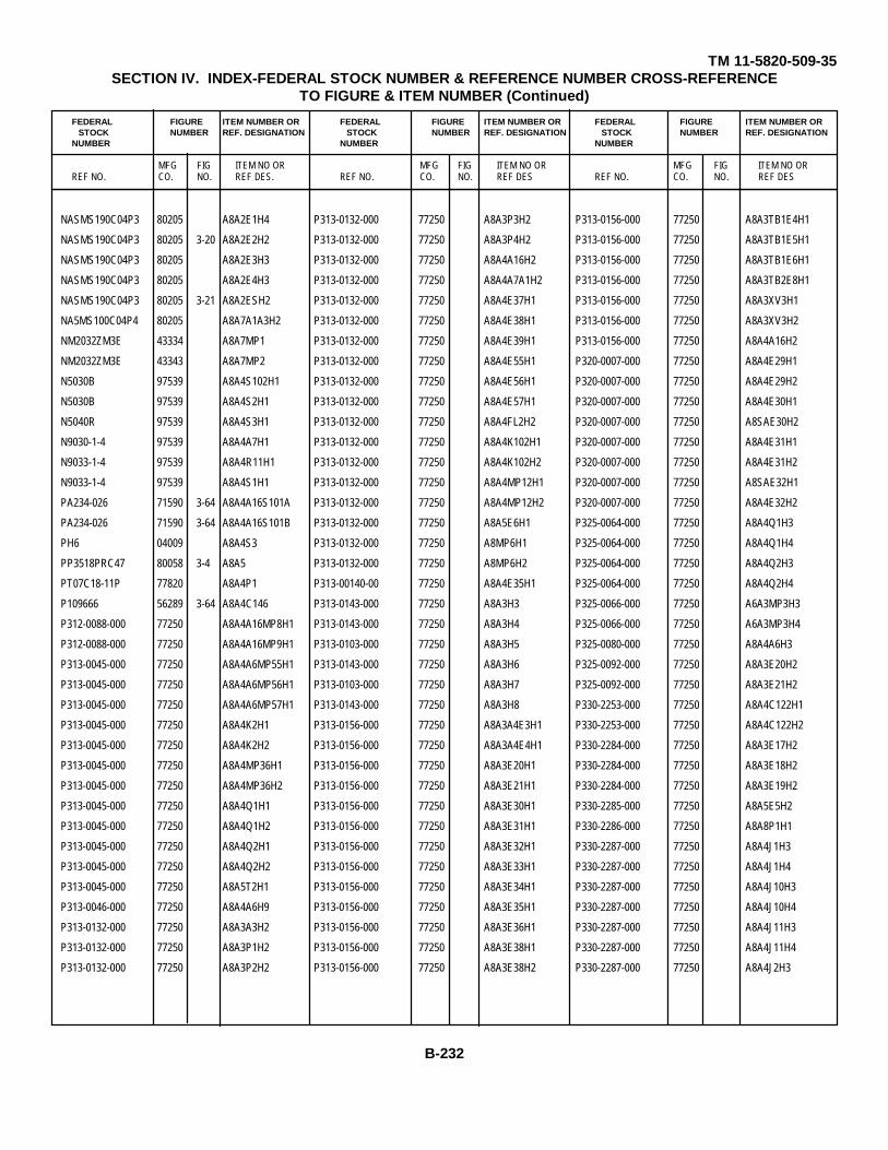
TM 11-5820-509-35SECTION IV. INDEX-FEDERAL STOCK NUMBER & REFERENCE NUMBER CROSS-REFERENCE
TO FIGURE & ITEM NUMBER (Continued)
FEDERAL FIGURE ITEM NUMBER OR FEDERAL FIGURE ITEM NUMBER OR FEDERAL FIGURE ITEM NUMBER ORSTOCK NUMBER REF. DESIGNATION STOCK NUMBER REF. DESIGNATION STOCK NUMBER REF. DESIGNATION
NUMBER NUMBER NUMBER
MFG FIG ITEM NO OR MFG FIG ITEM NO OR MFG FIG ITEM NO ORREF NO. CO. NO. REF DES. REF NO. CO. NO. REF DES REF NO. CO. NO. REF DES
NASMS190C04P3 80205 A8A2E1H4 P313-0132-000 77250 A8A3P3H2 P313-0156-000 77250 A8A3TB1E4H1
NASMS190C04P3 80205 3-20 A8A2E2H2 P313-0132-000 77250 A8A3P4H2 P313-0156-000 77250 A8A3TB1E5H1
NASMS190C04P3 80205 A8A2E3H3 P313-0132-000 77250 A8A4A16H2 P313-0156-000 77250 A8A3TB1E6H1
NASMS190C04P3 80205 A8A2E4H3 P313-0132-000 77250 A8A4A7A1H2 P313-0156-000 77250 A8A3TB2E8H1
NASMS190C04P3 80205 3-21 A8A2ESH2 P313-0132-000 77250 A8A4E37H1 P313-0156-000 77250 A8A3XV3H1
NA5MS100C04P4 80205 A8A7A1A3H2 P313-0132-000 77250 A8A4E38H1 P313-0156-000 77250 A8A3XV3H2
NM2032ZM3E 43334 A8A7MP1 P313-0132-000 77250 A8A4E39H1 P313-0156-000 77250 A8A4A16H2
NM2032ZM3E 43343 A8A7MP2 P313-0132-000 77250 A8A4E55H1 P320-0007-000 77250 A8A4E29H1
N5030B 97539 A8A4S102H1 P313-0132-000 77250 A8A4E56H1 P320-0007-000 77250 A8A4E29H2
N5030B 97539 A8A4S2H1 P313-0132-000 77250 A8A4E57H1 P320-0007-000 77250 A8A4E30H1
N5040R 97539 A8A4S3H1 P313-0132-000 77250 A8A4FL2H2 P320-0007-000 77250 A8SAE30H2
N9030-1-4 97539 A8A4A7H1 P313-0132-000 77250 A8A4K102H1 P320-0007-000 77250 A8A4E31H1
N9033-1-4 97539 A8A4R11H1 P313-0132-000 77250 A8A4K102H2 P320-0007-000 77250 A8A4E31H2
N9033-1-4 97539 A8A4S1H1 P313-0132-000 77250 A8A4MP12H1 P320-0007-000 77250 A8SAE32H1
PA234-026 71590 3-64 A8A4A16S101A P313-0132-000 77250 A8A4MP12H2 P320-0007-000 77250 A8A4E32H2
PA234-026 71590 3-64 A8A4A16S101B P313-0132-000 77250 A8A5E6H1 P325-0064-000 77250 A8A4Q1H3
PH6 04009 A8A4S3 P313-0132-000 77250 A8MP6H1 P325-0064-000 77250 A8A4Q1H4
PP3518PRC47 80058 3-4 A8A5 P313-0132-000 77250 A8MP6H2 P325-0064-000 77250 A8A4Q2H3
PT07C18-11P 77820 A8A4P1 P313-00140-00 77250 A8A4E35H1 P325-0064-000 77250 A8A4Q2H4
P109666 56289 3-64 A8A4C146 P313-0143-000 77250 A8A3H3 P325-0066-000 77250 A6A3MP3H3
P312-0088-000 77250 A8A4A16MP8H1 P313-0143-000 77250 A8A3H4 P325-0066-000 77250 A6A3MP3H4
P312-0088-000 77250 A8A4A16MP9H1 P313-0103-000 77250 A8A3H5 P325-0080-000 77250 A8A4A6H3
P313-0045-000 77250 A8A4A6MP55H1 P313-0143-000 77250 A8A3H6 P325-0092-000 77250 A8A3E20H2
P313-0045-000 77250 A8A4A6MP56H1 P313-0103-000 77250 A8A3H7 P325-0092-000 77250 A8A3E21H2
P313-0045-000 77250 A8A4A6MP57H1 P313-0143-000 77250 A8A3H8 P330-2253-000 77250 A8A4C122H1
P313-0045-000 77250 A8A4K2H1 P313-0156-000 77250 A8A3A4E3H1 P330-2253-000 77250 A8A4C122H2
P313-0045-000 77250 A8A4K2H2 P313-0156-000 77250 A8A3A4E4H1 P330-2284-000 77250 A8A3E17H2
P313-0045-000 77250 A8A4MP36H1 P313-0156-000 77250 A8A3E20H1 P330-2284-000 77250 A8A3E18H2
P313-0045-000 77250 A8A4MP36H2 P313-0156-000 77250 A8A3E21H1 P330-2284-000 77250 A8A3E19H2
P313-0045-000 77250 A8A4Q1H1 P313-0156-000 77250 A8A3E30H1 P330-2285-000 77250 A8A5E5H2
P313-0045-000 77250 A8A4Q1H2 P313-0156-000 77250 A8A3E31H1 P330-2286-000 77250 A8A8P1H1
P313-0045-000 77250 A8A4Q2H1 P313-0156-000 77250 A8A3E32H1 P330-2287-000 77250 A8A4J1H3
P313-0045-000 77250 A8A4Q2H2 P313-0156-000 77250 A8A3E33H1 P330-2287-000 77250 A8A4J1H4
P313-0045-000 77250 A8A5T2H1 P313-0156-000 77250 A8A3E34H1 P330-2287-000 77250 A8A4J10H3
P313-0046-000 77250 A8A4A6H9 P313-0156-000 77250 A8A3E35H1 P330-2287-000 77250 A8A4J10H4
P313-0132-000 77250 A8A3A3H2 P313-0156-000 77250 A8A3E36H1 P330-2287-000 77250 A8A4J11H3
P313-0132-000 77250 A8A3P1H2 P313-0156-000 77250 A8A3E38H1 P330-2287-000 77250 A8A4J11H4
P313-0132-000 77250 A8A3P2H2 P313-0156-000 77250 A8A3E38H2 P330-2287-000 77250 A8A4J2H3
B-232
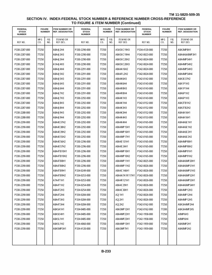
TM 11-5820-509-35SECTION IV. INDEX-FEDERAL STOCK NUMBER & REFERENCE NUMBER CROSS-REFERENCE
TO FIGURE & ITEM NUMBER (Continued)
FEDERAL FIGURE ITEM NUMBER OR FEDERAL FIGURE ITEM NUMBER OR FEDERAL FIGURE ITEM NUMBER ORSTOCK NUMBER REF. DESIGNATION STOCK NUMBER REF. DESIGNATION STOCK NUMBER REF. DESIGNATION
NUMBER NUMBER NUMBER
MFG FIG ITEM NO OR MFG FIG ITEM NO OR MFG FIG ITEM NO ORREF NO. CO. NO. REF DES. REF NO. CO. NO. REF DES REF NO. CO. NO. REF DES
P330-2287-000 77250 A8A4J2H4 P330-2290-000 77250 A5A5XC19H3 P334-4120-000 77250 A8A3MP8H1
P330-2287-000 77250 A8A4J3H3 P330-2290-000 77250 A8A5XC19H4 P342-0023-000 77250 A8A4A6A8MP3H1
P330-2287-000 77250 A8A4J3H4 P330-2290-000 77250 A8A5XC20H2 P342-0024-000 77250 A8A4MP54H1
P330-2287-000 77250 A1A4J4H3 P330-2290-000 77250 A8A5XC20H3 P342-0024-000 77250 A8A4MP54H2
P330-2287-000 77250 A8A4J4H4 P330-2291-000 77250 A8A4A16H2 P342-0024-000 77250 A8A4MP54H3
P330-2287-000 77250 A8A4J5H2 P330-2291-000 77250 A8A4FL2H2 P342-0024-000 77250 A8A4MP54H4
P330-2287-000 77250 A8A4J5H3 P330-2291-000 77250 A8A4K6H3 P342-0142-000 77250 A8A3E37H2
P330-2287-000 77250 A8A4J6H3 P330-2291-000 77250 A8A4K6H4 P342-0143-000 77250 A8A1P1H3
P330-2287-000 77250 A8A4J6H4 P330-2291-000 77250 A8A4R8H3 P342-0143-000 77250 A8A1P1H4
P330-2287-000 77250 A8A4J7H2 P330-2291-000 77250 A8A4R8H4 P342-0143-000 77250 A8A6P1H2
P330-2287-000 77250 A8A4J7H3 P330-2292-000 77250 A8A4K1H3 P342-0143-000 77250 A8A6P1H3
P330-2287-000 77250 A8A4J8H3 P330-2292-000 77250 A8A4K1H4 P342-0152-000 77250 A8A3TB1H2
P330-2287-000 77250 A8A4J8H4 P330-2292-000 77250 A8A4K3H3 P342-0152-000 77250 A8A3TB2H2
P330-2288-000 77250 A8A4J9H3 P330-2292-000 77250 A8A4K3H4 P342-0152-000 77250 A8A4A16H1
P330-2288-000 77250 A8A4J9H4 P330-2292-000 77250 A8A4K4H3 P342-0153-000 77250 A8A4A16H1
P330-2290-000 77250 A8A4E37H2 P330-2292-000 77250 A8A4K4H4 P342-0165-000 77250 A8A4A6E1H1
P330-2290-000 77250 A8A4E38H2 P330-2292-000 77250 A8A4MP15H1 P342-0165-000 77250 A8A4A6E1H2
P330-2290-000 77250 A8A4E39H2 P330-2292-000 77250 A8A4MP16H1 P342-0165-000 77250 A8A4A6E2H1
P330-2290-000 77250 A8A4E55H2 P330-2292-000 77250 A8A4MP17H1 P342-0165-000 77250 A8A4A6E2H2
P330-2290-000 77250 A8A4E56H2 P330-2296-000 77250 A8A4E131H1 P342-0165-000 77250 A8A4MP90H1
P330-2290-000 77250 A8A4E57H2 P330-2296-000 77250 A8A4E24H1 P342-0165-000 77250 A8A4MP90H2
P330-2290-000 77250 A8A4TB10H1 P330-2296-000 77250 A8A4MP10H1 P342-0165-000 77250 A8A4MP91H1
P330-2290-000 77250 A8A4TB10H2 P330-2296-000 77250 A8A4MP10H2 P342-0165-000 77250 A8A4MP91H2
P330-2290-000 77250 A8A4TB8H1 P330-2296-000 77250 A8A4MP11H1 P342-0025-000 77250 A8A4A6MP20H1
P330-2290-000 77250 A8A4TB8H2 P330-2296-000 77250 A8A4MP11H2 P342-0026-000 77250 A8A4A6MP51H1
P330-2290-000 77250 A8A4TB9H1 P334-0249-000 77250 A8A4C146H1 P342-0026-000 77250 A8A4A6MP51H3
P330-2290-000 77250 A8A4TB9H2 P334-0253-000 77250 A8A4A7A1R117H1 P342-0026-000 77250 A8A4A6MP52H1
P330-2290-000 77250 A7A4T1H1 P334-0253-000 77250 A8A4R121H1 P342-0026-000 77250 A8A4A6MP53H1
P330-2290-000 77250 A8A4T1H2 P334-0254-000 77250 A8A4C29H1 P342-0026-000 77250 A8A4A6MP54H1
P330-2290-000 77250 A8A4T2H3 P334-0254-000 77250 A8A4C30H1 P342-0026-000 77250 A8A4MP12H3
P330-2290-000 77250 A8A4T2H4 P334-0284-000 77250 A2J1H1 P342-0026-000 77250 A8A4MP12H4
P330-2290-000 77250 A8A4T3H3 P334-0284-000 77250 A2J2H1 P342-0026-000 77250 A8A4MP12H5
P330-2290-000 77250 A8A4T3H4 P334-0284-000 77250 A2J2H2 P342-0162-000 77250 A8A3A4MP2H4
P330-2290-000 77250 A8A5A1H1 P334-0485-000 77250 A8A3MP12H1 P342-0162-000 77200 A8A3A4MP2H5
P330-2290-000 77250 A8A5E4H1 P334-0485-000 77250 A8A4MP22H1 P342-1958-000 77250 A8MP6H3
P330-2290-000 77250 A8A5L1H1 P334-0485-000 77250 A8A4MP23H1 P342-1958-000 77250 A8MP6H4
P330-2290-000 77250 A8A5L1H2 P334-4060-000 77250 A8A4MP13H1 P342-1959-000 77250 A8A8MP2H1
P330-2290-000 77250 A8A5MP3H1 P334-4120-000 77250 A8A3MP7H1 P342-1959-000 77250 A8A8MP2H2
B-233
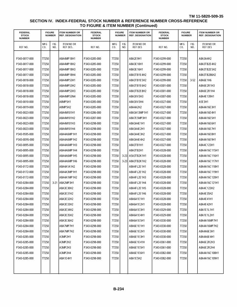
TM 11-5820-509-35SECTION IV. INDEX-FEDERAL STOCK NUMBER & REFERENCE NUMBER CROSS-REFERENCE
TO FIGURE & ITEM NUMBER (Continued)
FEDERAL FIGURE ITEM NUMBER OR FEDERAL FIGURE ITEM NUMBER OR FEDERAL FIGURE ITEM NUMBER ORSTOCK NUMBER REF. DESIGNATION STOCK NUMBER REF. DESIGNATION STOCK NUMBER REF. DESIGNATION
NUMBER NUMBER NUMBER
MFG FIG ITEM NO OR MFG FIG ITEM NO OR MFG FIG ITEM NO ORREF NO. CO. NO. REF DES. REF NO. CO. NO. REF DES REF NO. CO. NO. REF DES
P343-0017-000 77250 A8A4MP18H1 P343-0285-000 77250 A8A2E9H1 P343-0299-000 77250 A8A3A4H2
P343-0017-000 77250 A8A4MP18H2 P343-0285-000 77250 A8A3E10H1 P343-0299-000 77250 A8A3TB2E4H2
P343-0017-000 77250 A8A4MP18H3 P343-0285-000 77250 A8A3E16H1 P343-0299-000 77250 A8A3TB2E5H2
P343-0017-000 77250 A8A4MP18H4 P343-0285-000 77250 A8A3TB1E4H2 P343-0299-000 77250 A8A3TB286H2
P343-0018-000 77250 A8A4MP53H1 P343-0285-000 77250 A8A3TB1E5H2 P343-0299-000 77250 3-52 A8A6E1H6
P343-0018-000 77250 A8A4MP53H2 P343-0285-000 77250 A8A3TB1E6H2 P343-0301-000 77250 A8A6E2R1H3
P343-0018-000 77250 A8A4MP53H3 P343-0285-000 77250 A8A3TB2E8H2 P343-0301-000 77250 A8A6E2R1H4
P343-0018-000 77250 A8A4MP53N4 P343-0285-000 77250 A8A3XV3H3 P343-0307-000 77250 A8A4E139H1
P343-0010-000 77250 A8MP5H1 P343-0285-000 77250 A8A3XV3H4 P343-0327-000 77250 A5E3H1
P343-0019-000 77250 A8MP5H2 P343-0285-000 77250 A8A4A2H2 P343-0327-000 77250 A8A4A16E3H1
P343-0023-000 77250 A8A4M101H1 P343-0286-000 77250 A8A3A13MP1H1 P343-0327-000 77250 A8A4A16E4H1
P343-0023-000 77250 A8A4M101H2 P343-0287-000 77250 A8A7E5MP3H1 P343-0327-000 77250 A8A4A16E5H1
P343-0023-000 77250 A8A4M101H3 P343-0298-000 77250 A8A3A4E1H1 P343-0327-000 77250 A8A4A16E6H1
P343-0023-000 77250 A8A4M101H4 P343-0298-000 77250 A8A3A4E2H1 P343-0327-000 77250 A8A4A16E7H1
P343-9595-000 77250 A8A4A6MP1H1 P343-0298-000 77250 A8A3A4E3H2 P343-0327-000 77250 A8A4A16E8H1
P343-0D95-000 77250 A8A4A6MP1H2 P343-0298-000 77250 A8A3A4E4H2 P343-0327-000 77250 A8A4A16E9H1
P343-0095-000 77250 A8A4A6MP1H3 P343-0298-000 77250 A8A3TB1H1 P343-0327-000 77250 A8A4C123H1
P343-0095-000 77250 A8A4A6MP1H4 P343-0298-000 77250 A8A3TB2H1 P343-0328-000 77250 A8A4A16C115H1
P343-0095-000 77250 A8A4A6MP1H5 P343-0298-000 77250 3-23 A5A3TB2K1H1 P343-0328-000 77250 A8A4A16C116H1
P343-0095-000 77250 A8A4A6MP1H6 P343-0298-000 77250 3-23 A8A3TB2K1H2 P343-0328-000 77250 A8A4A16C117H1
P343-0172-000 77250 A8A4A1A1H2 P343-0298-000 77250 A8A4FL2E1H1 P343-0328-000 77250 A8A4A16C118H1
P343-0172-000 77250 A8A4A3MP1H1 P343-0298-000 77250 A8A4FL2E1H2 P343-0328-000 77250 A8A4A16C119H1
P343-0172-000 77250 A8A4A1MP1H2 P343-0298-000 77250 A8A4FL2E1H3 P343-0328-000 77250 A8A4A16C120H1
P343-0284-000 77250 3-21 A8A2MP3H1 P343-0298-000 77250 A8A4FL2E1H4 P343-0328-000 77250 A8A4A16C121H1
P343-0284-000 77250 A8A3E30H2 P343-0298-000 77250 A8A4FL2E1H5 P343-0328-000 77250 A8A4C123H2
P343-0284-000 77250 A8A3E31H2 P343-0298-000 77250 A8A4FL2E1H6 P343-0328-000 77250 A8A4E35H2
P343-0284-000 77250 A8A3E32H2 P343-0298-000 77250 A8A6A1E1H1 P343-0328-000 77250 A8A4E41H1
P343-0284-000 77250 A8A3E33H2 P343-0298-000 77250 A8A6A1E2H1 P343-0328-000 77250 A8A4E42H1
P343-0284-000 77250 A8A3E34H2 P343-0298-000 77250 A8A6A1E3H1 P343-0329-000 77250 A8A1E1L1H1
P343-0284-000 77250 A8A3E35H2 P343-0298-000 77250 A8A6A1E4H1 P343-0329-000 77250 A8A1E1L2H1
P343-0284-000 77250 A8A3E36H2 P343-0298-000 77250 A8A6A1E5H1 P343-0330-000 77250 A8A4A16MP7H1
P343-0284-000 77250 A8A7MP7H1 P343-0298-000 77250 A8A6E1E1H1 P343-0330-000 77250 A8A4A16MP7H2
P343-0284-000 77250 A8A7MP7H2 P343-0298-000 77250 A8A6E1E2H1 P343-0330-000 77250 A8A4A6E3H1
P343-0285-000 77250 A3MP2H1 P343-0298-000 77250 A8A6E1E3H1 P343-0330-000 77250 A8A4A6E4H1
P343-0285-000 77250 A3MP2H2 P343-0298-000 77250 A8A6E1E41H P343-0361-000 77250 A8A6E2R2H3
P343-0285-000 77250 A3MP2H3 P343-0298-000 77250 A8A6E1E5H1 P343-0361-000 77250 A8A6E2R2H4
P343-0285-000 77250 A3MP2H4 P343-0298-000 77250 A8A6E1E6H1 P343-0382-000 77250 A8A4A16C108H1
P343-0285-000 77250 A8A1E4H1 P343-0298-000 77250 A8A1E5H2 P343-0382-000 77250 A8A4A16C109H1
B-234
TM 11-5820-509-35SECTION IV. INDEX-FEDERAL STOCK NUMBER & REFERENCE NUMBER CROSS-REFERENCE
TO FIGURE & ITEM NUMBER (Continued)
FEDERAL FIGURE ITEM NUMBER OR FEDERAL FIGURE ITEM NUMBER OR FEDERAL FIGURE ITEM NUMBER ORSTOCK NUMBER REF. DESIGNATION STOCK NUMBER REF. DESIGNATION STOCK NUMBER REF. DESIGNATION
NUMBER NUMBER NUMBER
MFG FIG ITEM NO OR MFG FIG ITEM NO OR MFG FIG ITEM NO ORREF NO. CO. NO. REF DES. REF NO. CO. NO. REF DES REF NO. CO. NO. REF DES
P343-0382-000 77250 A8A4A16C110H1 P347-0090-000 77250 A8A3MP15H3 RCR07G102KS 81349 3-22 A8A3TB1R5
P343-0382-000 77250 A8A4A16C111H1 P347-0090-000 77250 A8A3MP15H4 RCR07GC12KS 81349 3-54 A8A7E1R14
P343-0382-000 77250 A8A4A16C112H1 P347-0104-000 77250 A8A7E7A2E1H3 RCR07102GKS 81349 3-54 A8A7E1R19
P343-0382-00G 77250 A8A4A16C113H1 P347-0104-000 77250 A8A7E7A2E1H4 RCR07G102KS 81349 3-54 A8A77E1R30
P343-0382-000 77250 A8A4A16C114H1 P347-0104-000 77250 ACA7E7A2E2H3 RCR07G102KS 81349 3-55 A8A7E2R103
P347-0007-000 77250 A8A3E38H3 P347-0104-000 77250 A8A7E7A2E2H4 RCR07G102KS 81349 3-55 A8A7E2R104
P347-0021-000 77250 A8A3MP13H1 P57035 70371 A8A4A6MP1 RCR07G102KS 81349 3-55 A8A7E2R39
P347-0021-000 77250 A8A3MP14H1 Q123 03887 3-18 A8A1E2CR17 RCR07G102KS 81349 3-55 A8A7E2R50
P347-0024-000 77250 A8A3L145H1 R81J26D1018 73905 A8A4K101 RCR07G102KS 81349 3-55 A8A7E2R59
P347-0024-000 77250 A8A3L145H2 RCR05GF682K 81349 3-32 A8A3A4A2R173 RCR07G102KS 81349 3-55 A8A7E2R69
P347-0024-000 77250 A8A3114SH3 RCR05GF682K 81349 3-32 A8A3A4A2R179 RCR07C102KS 81349 3-59 A8A7E6R117
P347-0053-000 77250 A8A4A6MP46H1 RCR07G100KS 81349 3-56 A8A7TB1R144 RCR07G102KS 81349 3-56 A8A7TB1R120
P347-0053-000 77250 A8A4A6MP46H2 RCR07G101KS 81349 3-18 A8A1E2R1 RCR07G102KS 81349 3-56 A8A7TB1R144
P347-0053-000 77250 A8A4A6MP47H1 RCR07G101KS 81349 3-38 A8A3E47R41 RCR07G102KS 81349 3-56 A8A7TB7R145
P347-0053-000 77250 A8A4A6MP47H2 RCR07G101KS 81349 3-22 A8A3TB1R6 RCR07G102KS 81349 3-56 A8A7TB1R146
P347-0056-000 77250 A8A4MP61H1 RCR07G101KS 81349 3-23 A8A3TB2R11 RCR07G102KS 81349 3-56 A8A7TB1R147
P347-0056-000 77250 A8A4MP62H1 RCR07G101KS 81349 3-23 A8A3TB2R14 RCR07G103KS 81349 3-18 A8A1E2R19
P347-0056-000 77250 A8A4MP63H1 RCR07G101KS 81349 3-55 A8A7E2R45 RCR07G103KS 81349 3-19 A8A1E3R47
P347-0056-000 77250 A8A4MP64H1 RCR07G101KS 81349 3-56 A8A7TB1R131 RCR07G103KS 81349 3-19 A8A1E3R53
P3n7-0056-000 77250 A8A4MP65H1 RCR07G102KS 81349 3-21 A8A2E4R23 RCR07G103KS 81349 3-19 A8A1E3R64
P347-0056-000 77250 A8A4MP66H1 RCR07G102KS 81349 3-33 A8A3A4R161 RCR07G103KS 81349 3-19 A8A1E3R68
P347-0056-000 77250 A8A4MP67H1 RCR07G102KS 81349 3-37 A8A3E46R119 RCR07G103KS 81349 3-20 A8A2E2R14
P347-0056-000 77250 A8A4MP68H1 RCR07G102KS 81349 3-37 A8A3E46R123 RCR07G103KS 81349 3-21 A8A2E3R24
P347-0056-000 77250 A8A4MP69H1 RCR07G102KS 81349 3-37 A8A3E46R124 RCR07C103KS 81349 3-21 A8A2E4R31
P347-0056-000 77250 A8A4MP71H1 RCR07G102KS 81349 3-37 A8A3E46R128 RCR07C103KS 81349 3-21 A8A2E4R39
P347-0056-000 77250 A8A4MP77H1 RCR07G102KS 81349 3-37 A8A3E46R129 RCR07G103KS 81349 3-20 A8A2R27
P347-0056-000 77250 A8A4MP72H1 RCR07G102KS 81349 3-37 A8A3E46R133 RCR07G103KS 81349 3-38 A8A3E47R25
P347-0056-000 77250 A8A4MP73H1 RCR07G102KS 81349 3-38 A8A3E47R138 RCR07G103KS 81349 3-38 A8A3E47R44
P347-0056-000 77250 A8A4MP74H1 RCR07G102KS 81349 3-38 A8A3E47R34 RCR07G103KS 81349 3-38 A8A3E47R48
P347-0056-000 77250 A8A4MP77H1 RCR07G102KS 81349 3-38 A8A3E47R46 RCR07C103KS 81349 3-'8 A8A3E47R56
P347-0056-000 77250 A8A4MP76H1 RCR07G102KS 81349 3-38 A8A3E47R47 RCR07G103KS 81349 3-39 A8A3E48R97
P347-0056-000 77250 A8A4MP77H1 RCR07G102KS 81349 3-38 A8A3E47R50 RCR07G103KS 81349 3-40 A8A3R17
P347-0056-000 77250 A8A4MP78H1 RCR07G102KS 81349 3-38 A8A3E47R51 RCR07C103KS 81349 3-22 A8A3781R1
P347-0056-000 77250 A8A4MP79H1 RCR07G102KS 81349 3-38 A8A3E47R55 RCR07G103KS 81349 3-23 A8A3782R9
P347-0056-000 77250 A8A4MP80H1 RCR07G102KS 81349 3-39 A8A3E48R59 RCR07G103KS 81349 3-53 A8A6A1R23
P347-0056-000 77250 A8A4MP81H1 RCR07G102KS 81349 3-39 A8A3E48R89 RCR07G103KS 81349 3-53 A8A6A1R28
P347-0090-000 77250 A8A3MP15H1 RCR07G102KS 81349 3-39 A8A3E48R90 RCR07G103KS 81349 3-53 A8A6A1R31
P347-0090-000 77250 A8A3MP15H2 RCR07G102KS 81349 3-41 A8A3R88 RCR07G103KS 81349 3-53 A8A6A1R32
B-235

TM 11-5820-509-35SECTION IV. INDEX-FEDERAL STOCK NUMBER & REFERENCE NUMBER CROSS-REFERENCE
TO FIGURE & ITEM NUMBER (Continued)
FEDERAL FIGURE ITEM NUMBER OR FEDERAL FIGURE ITEM NUMBER OR FEDERAL FIGURE ITEM NUMBER ORSTOCK NUMBER REF. DESIGNATION STOCK NUMBER REF. DESIGNATION STOCK NUMBER REF. DESIGNATION
NUMBER NUMBER NUMBER
MFG FIG ITEM NO OR MFG FIG ITEM NO OR MFG FIG ITEM NO ORREF NO. CO. NO. REF DES. REF NO. CO. NO. REF DES REF NO. CO. NO. REF DES
RCR07G103KS 81349 3-52 A8A6E1R35 RCR07G121KS 81319 3-37 A8A3E46RL25 RCR07GC53KS 81349 3-20 ABA2E2R16
RCR07G103KS 81349 3-52 A8A6E1R37 RCR07G121KS 81349 3-37 A8A3E46R130 RCR07G153KS 81349 3-37 A8A3E46R120
RCR07G103KS 81349 3-52 A8A6E1R41 RCR07G121CS 81349 3-37 A8A3E46R135 RCR07G153KS 81349 A8A6R30
RCR07G103KS 81349 3-52 A8A6E1RH2 PCR07G121KS 81349 3-38 A8A3E47R149 RCC07G153KS 81349 A8A6R45
RCR07G103KS 81349 3-52 A8A6E2R10 RCR07G121KS 81319 3-38 A8A3E47R43 RCR07G153KS 81349 A8A6R46
RCR07G103KS 81349 3-52 A8A6E2R11 RCR07G121KS 81349 3-38 A8A3E47R57 RCR07G181KS 81319 3-51 A8A7E1R12
RCR07G103KS 81349 3-52 A8A6E2R14 RCR07G121KS 81349 3-39 A8A3E48R77 RCR07G182KS 81349 3-20 A8A2E2R14
RCR07G103KS 81349 3-52 A8A6E2R15 RCR07G121KS 81349 3-39 A8A3E18R94 RCR07G182KS 81319 3-33 A8A3A4R171
RCR07G103KS 81349 A8A6R30 RCR07G121KS 81349 3-54 A8A7E1R15 RCR07G182KS 81349 3-54 A8A7E1R4
RCR07G103KS 81349 A8A6R45 RCR07G121KS 81349 3-54 A8A7E1R20 RCR07G182KS 81349 3-54 A8A7E1R7
RCR07G103KS 81349 A8A6R46 RCR07G121KS 81349 3-54 A8A7E1R31 RCR07G183KS 81349 3-19 A8A1E3R55
RCR07G103KS 81349 3-54 A8A7E1R23 RCR07G121KS 81349 3-54 A8A7E1R8 RCR07G183KS 81349 3-21 A8A2E3R22
RCR07G103KS 81349 3-54 A8A7E1R26 RCR07G121KS 81349 3-57 A8A7TE4R88 RCR07G183KS 81349 3-39 A8A3E48R92
RCR07G103KS 81349 3-54 A8A7E1R3 RCR07G121KS 81349 3-57 A8AT7ER93 RCR07G183KS 81319 A8A6R30
RCR07G103KS 813h9 3-55 A8ATE2R41 RCR07G121KS 81349 3-59 A8A7E6R118 RCR07G183KS 81349 A8A6R45
RCR07G103KS 813149 3-55 A8A7E2R61 RCR07G122KS 81319 3-19 A8A1E3R72 RCR07G183xS 81349 A8A6R46
RCR07G103KS 81349 3-56 A8A7TB1R127 RCR07G123KS 81349 3-19 A8A1E3R58 RCR07G183KS 81349 3-59 A8A7E6R113
RCR07G104KS 81349 3-17 A8A1E1R34 RCR07G123KS 81349 3-19 A8A1E3178 RCR07G184KS 81349 3-19 A8ALE3R50
RCR07G104KS 81349 3-17 A8A1E1R38 RCR07G123KS 81349 3-38 A8A3E47R136 RCR07G221KS 81349 3-41 A8A3R181
RCR07G104KS 81349 3-17 A8A1E1R39 RCR07G123KS 81349 3-38 A8A3E47R137 RCR07G221KS 81349 3-53 A8A6A11R45
RCR07G104KS 81349 3-17 A8A1E1R41 RCR07G123KS 81349 3-38 A8A3E47R141 RCR07G221KS 81349 3-52 A8A6E2R17
RCR07G104KS 81349 3-17 A8A1E1R44 RCR07G123KS 81349 3-38 A8A3E47R31 RCR07G221KS 81349 3-57 A8A7E4R97
RCR07G104KS 81349 3-18 A8A1E2R13 RCR07G123KS 81349 3-38 A8A3E47R35 RCR07G221KS 81349 3-56 A8ATTB1R139
RCR07G104KS 81349 3-18 A8A1E2R28 RCR07G123KS 81349 3-38 A8A3E47R52 RCR07C221KS 81349 3-56 A8A7TB1R144
RCR07G104KS 81349 3-18 A8A1E2R4 RCR07G123KS 81349 3-38 A8A3E47R53 RCR07G222KS 81349 3-20 A8A2E2R14
RCR07G104KS 81349 3-18 A8A1E2R7 RCR07G123KS 81349 3-23 A8A3TB2R13 RCR07G222KS 81349 3-20 A8A2E2R15
RCR07G104KS 81349 3-19 A8A1E3R49 RCR07G123KS 813149 A8A6R30 RCR07G222KS 81349 3-21 A8A2E3R?0
RCR07G104KS 81349 3-19 A8A1.E3R76 RCR07G123KS 81349 A8A6R45 RCR07G222KS 81349 3-21 A8A2E3R21
RCR07G104KS 81349 3-19 A8A1E3R77 RCR07G123KS 81349 A8A6R46 RCR07G222KS 81349 3-21 A8A2E4R26
RCR07G104KS 81349 3-34 A8A3A4R165 RCR07G123KS 81349 3-55 A8A7E2R36 RCR07G222KS 81349 3-21 A8A2E4R30
RCR07G104KS 81349 3-31 A8A3A4R166 RCR07G123KS 81349 3-55 A8A7E2R56 RCR07G222KS 81349 3-38 A8A3E47R29
RCR07G104KS 81349 3-34 A8A3A4R167 RCR07G123KS 81349 3-56 A8A7TB1R128 RCR07G222KS 81349 3-38 A8A3E47R32
RCR07G104KS 81349 3-34 A8A3A4R169 RCR07G151KS 81349 3-56 A8A7TB1R144 RCR07G222KS 81345 3-39 A8A3E48R39
RCR07G104KS 81349 3-40 A8A3R19 RCR07G152KS 81349 3-19 A8A1E3R45 RCR07G222KS 81349 3-53 A8A6A1R29
RCR07G104KS 81349 3-22 A8A3TB1R2 RCR07G152KS 81349 3-20 A8A1E2R17 RCR07G222KS 813149 3-52 A8A6E1R36
RCR07G104KS 81349 3-23 A8A3TB2R10 RCR07G152KS 81349 3-21 A8A2E5R33 RCR07G222KS 81349 3-52 A8A6E2R16
RCR07G104KS 81349 3-54 A8A7E1R2 RCR07G152KS 81349 3-56 A8ATB11R143 RCR07G222KS 81349 3-54 A8A7E1R18
RCR07G104KS 81349 3-54 A8A7E1R22 RCR07G152KS 81349 3-56 A8ATTB1R144 RCR07G222KS 81349 3-54 A8A7E1R11
B-236
TM 11-5820-509-35SECTION IV. INDEX-FEDERAL STOCK NUMBER & REFERENCE NUMBER CROSS-REFERENCE
TO FIGURE & ITEM NUMBER (Continued)
FEDERAL FIGURE ITEM NUMBER OR FEDERAL FIGURE ITEM NUMBER OR FEDERAL FIGURE ITEM NUMBER ORSTOCK NUMBER REF. DESIGNATION STOCK NUMBER REF. DESIGNATION STOCK NUMBER REF. DESIGNATION
NUMBER NUMBER NUMBER
MFG FIG ITEM NO OR MFG FIG ITEM NO OR MFG FIG ITEM NO ORREF NO. CO. NO. REF DES. REF NO. CO. NO. REF DES REF NO. CO. NO. REF DES
RCR07G222KS 81349 3-54 A8A7E1R29 RCR07G273KS 81349 3-21 A8A2E4R32 RCR07G393KS 81349 3-59 A8A7E6R105
RCR07G222KS 81349 3-56 A8A7TB1R123 RCR07G273KS 81349 3-21 A8A2E5R34 RCR07G393KS 81349 3-59 A8A7E6R106
RCR07G223KS 81349 3-18 A8A1E2R18 RCR07G273KS 81349 3-37 A8A3E46R121 RCR07G393KS 81349 3-59 A8A7E6R107
RCR07G223KS 81349 3-18 A8A1E2R26 RCR07C273KS 81349 3-37 A8A3E46R126 RCR07G393KS 81349 3-59 A8A7E6R108
RCR07G223KS 81349 3-19 A8A1E3R48 RCR07G273KS 81349 3-37 A8A3E46R131 RCR07G393KS 81349 3-59 A8A7E6R109
RCR07G223KS 81349 3-19 A8A1E3R74 RCR07G273kS 81349 3-40 A8A3R18 RCR07G393KS 81349 3-59 A8A7E6R110
RCR07G223KS 81349 3-37 A8A3E46R122 RCR07G273KS 81349 A8A6R30 RCR07G470KS 81349 3-20 A8A2E2R13
RCR07G223KS 81349 3-37 A8A3E46R132 RCR07G273KS 81349 A8A6R45 RCR07G470KS 81349 3-56 A8A7TB1R124
RCR07G223KS 81349 3-38 A8A3E47R26 RCR07G273KS 81349 A8A6R46 RCR07G471KS 81349 3-39 A8A3E48R58
RCR07G223KS 81349 3-38 A8A3E47R27 RCR07G273KC 81349 3-59 A8A7E6R114 RCR07G471KS 81349 3-56 A8A7TB1R144
RCR07G223KS 81349 3-39 A8A3E48R93 RCR07G273KS 81349 3-56 A8A7TB1R148 RCR07G472KS 81349 3-18 A8A1ER20
RCR07G223KS 81349 A8A6R30 RCR07G274KS 81349 3-55 A8A7E2R49 RCR07G472KS 81349 3-20 A5A2E2R14
RCR07G223KS 81349 A8A6R45 RCR07G274KS 81349 3-55 A8A7E2R68 RCR07G472KS 81349 3-33 A8A3A4R159
RCR07G223KS 81349 A8A6R46 RCR07G331KS 81349 3-37 A8A3E46R134 RCR07G472KS 81349 3-38 A8A3E47R142
RCR07G223KS 81349 3-54 A8A7ER3 RCR07G331KS 81349 3-38 A8A3E47R143 RCR07G472KS 81349 3-39 A8A3E48R66
RCR07G223KS 81349 3-55 A8A7E2R40 RCR07G331KS 81349 3-56 A8A7TB1R144 RCR07G472KS 81349 3-53 A8A6A1R26
RCR07C223KS 81349 3-55 8A8AE2R60 RCR07G332KS 81349 3-19 A8A1E3R51 RCR07G472KS 81349 3-53 A8A6A1R27
RCR07C223KS 81349 3-59 A8A7E6R112 RCR07G332KS 81349 3-20 ARA2E2R14 RCR07G472KS 81349 3-52 A8A6E1R34
RCR07G223KS 81349 3-56 A8A7781R129 RCR07G332KS 81349 3-38 A8A3E47R36 RCR07G472KS 81349 3-52 A8A6E1R38
RCR07G223KS 81349 A8A7781R136 RCR07G332KS 81349 3-53 A8A6A1R24 RCR07G472KS 81349 3-52 A8A6E1R39
RCR07G223KS 81349 3-56 A8A7781R137 RCR07G332KS 81349 3-53 A8A6A1R33 RCR07G472KS 81349 3-52 A8A6E1R40
RCR07G270KS 81349 3-38 A8A3E47R24 RCR07G332KS 81349 A8A6R30 RCR07G472KS 81349 3-52 A8A6E1R43
RCR07G270KS 81349 3-38 A8A3E47R30 RCR07G332KS 81349 A8A6R45 RCR07G472KS 81349 3-52 A8A6E2R12
RCR07G272KS 81349 3-19 A8A1E3R63 RCR07G332KS 81349 A8A6R46 RCR07G772KS 81149 A8A6R30
RCR07G272KS 81349 3-20 A8A2E2R14 RCR07G333KS 81349 3-38 A8A3E47R140 RCR07G472KS 81349 A8A6R45
RCR07G272KS 81349 3-21 A8A2Et4R25 RCR07G333KS 81349 3-38 A8A3E47R145 RCR07G472KS 81349 A8A6R46
RCR07G272KS 81349 3-34 A8A3A4R168 RCR07G333KS 81349 3-39 A8A3E48R62 RCR07G472KS 81349 3-54 A8A7E1R25
RCR07G272KS 81349 3 34 A8A3A4R170 RCR07G333KS 81349 3-39 A8A3E48R68 RCR07G472KS 81349 3-54 A8A7E1R28
RCR07G272KS 81349 3-39 A8A3E48R67 RCR07G333KS d1349 3-39 A8A3E48R72 RCR07G472KS 81349 3-54 A8A7E1R6
RCR07G272KS 81349 3-53 A8A6A1R25 RCR07G333KS 81349 3-59 A8A7E6R115 RCR07G472KS 81349 3-54 A8A7E1R9
RCR07G272KS 81349 3-53 A8A6R30 RCR07G390KS 81349 3-21 A8A2E5R40 RCR07G472KS 81349 3-55 A8A7E2R46
RCR07G272KS 81349 A8A6R45 RCR07G392KS 81349 3-20 A8A2E2R14 RCR07G472KS 81349 3-55 A8A7E2R65
RCR07G272KS 81349 A8A6R46 RCR07G392KS 81349 A8A6R30 RCR07G472KS 81349 3-57 A8A7E4R90
RCR07G272KS 81349 3-54 A8A7E1R17 RCR07G392KS 81349 A8A6R45 RCR07G472KS 81349 3-57 A8A7E4R99
RCR07G272KS 81349 3-59 A8A7E6R16 RCR07G392KS 81349 A8A6R46 RCR07G472KS 81349 3-56 A8A7TB1R119
RCR07G272KS 81349 3-56 A8A781R134 RCR07G392KS 81349 3-57 A8A7E4R101 RCR07G472KS 81349 3-56 A8A7TB1R130
RCR07G273KS 81349 3-19 A8A1E3R59 RCR07G392KS 81349 3-57 A8A7E4R95 RCR07G473KS 81349 3-20 A8A2E2R19
RCR07G273KS 81349 3-19 A8A1E3R73 RCR07G392KS 81349 3-56 A8A7TB1R141 RCR07G473KS 81349 3-39 A8A3E48R61
B-237
TM 11-5820-509-35SECTION IV. INDEX-FEDERAL STOCK NUMBER & REFERENCE NUMBER CROSS-REFERENCE
TO FIGURE & ITEM NUMBER (Continued)
FEDERAL FIGURE ITEM NUMBER OR FEDERAL FIGURE ITEM NUMBER OR FEDERAL FIGURE ITEM NUMBER ORSTOCK NUMBER REF. DESIGNATION STOCK NUMBER REF. DESIGNATION STOCK NUMBER REF. DESIGNATION
NUMBER NUMBER NUMBER
MFG FIG ITEM NO OR MFG FIG ITEM NO OR MFG FIG ITEM NO ORREF NO. CO. NO. REF DES. REF NO. CO. NO. REF DES REF NO. CO. NO. REF DES
RCR07G473KS 81349 3-39 A8A3E48R71 RCR07G681KS 81349 3-56 A8A7TB1R142 RCR20G103KS 81349 3-66 A8A4A1R103
RCR07G473KS 81349 3-54 A8A7E1R16 RCR07G681KS 81349 3-56 AA77TB1R144 RCR20G150KS 81349 3-16 A8A1R81
RCR07G473KS 81349 3-54 A8A7E1R27 RCR07G682KS 81349 3-20 A8A2E2R14 RCR20G273KS 81349 3-66 A8A4A1R119
RCR07G473KS 81349 3-55 A8A7E2R35 RCR70G682KS 81349 3-38 A8A3E47R39 RCR20G334KS 81349 3-45 A8A5R12
RCR07G473KS 81349 3-55 A8A7E2R55 RCR07G682KS 81349 3-39 A8A3E48R64 RCR20G470KS 81349 3-18 A8A1E2R2
RCR07G474KS 81349 3-19 AA1E3R?75 RCR07G682KS 81349 3-39 A8A3E48R70 RCR20G471KS 81349 A8A4A7A1R129
RCR07G474KS 81349 3-39 A8A3E48R78 RCR07G682KS 81349 A8A6R30 RCR20G472KS 81349 A8A4A15R16
RCR07G874KS 81349 3-39 A8A3E48R79 RCR07G682KS 81349 A8A6R45 RCR20G473KS 81349 3-20 A8A2E2R18
RCR07G474KS 81349 3-39 A8A3E48R80 RCR07G682KS 81349 A8A6R46 RCR20G473KS 81349 3-45 A8A5R14
RCR07G474KS 81349 3-39 A8A3E48R81 RCR77G683KS 81349 3-21 A8A2E4R28 RCR20G474JS 81349 3-48 A8A8E2R2
RCR07G474KS 81349 3-52 A8A6E2R5 RCR07G683KS 81349 3-21 A8A2E5R35 RCR20G474JS 81349 3-48 A8A8E2R5
RCR07G474KS 81349 3-52 A8A6E2R6 RCR07G683KS 81349 3-39 A8A3E48R65 RCR32G101KS 81349 3-40 A8A3R20
RCR07G474KS 81349 3-54 A8A7E1R1 RCR07G683KS 81349 3-54 A8A7E1R24 RCR32G104KS 81349 A8A4A7R107
RCR07G474KS 81349 3-54 A8A7E1R21 RCR07G683KS 81349 3-54 A8A7E1R5 RCR32G104KS 81349 3-48 A8A8E2R17
RCR07G560KS 81349 3-39 A8A3E48R190 RCR07G683KS 81349 3-59 A8A7E6R111 RCR32G123KS 81349 3-48 AA8E2R1
RCR07G561KS 81349 3-21 A8A2E3R36 RCR07C683KS 81349 3-56 A8A7TB1R121 RCR32G125KS 81349 3-66 A8A4A1R115
RCR07G561KS 81349 3-21 A8A2E3R37 RCR07G683KS 81349 3-56 A8A7TB1R122 RCR32G150KS 81349 3-16 A8A1R84
RCR07G561KS 81349 3-38 A8A3E47R139 RCR07G820KS 81349 3-54 A8A7TB1R144 RCR32G152KS 81349 3-16 A8A1R79
RCR07G561KS 81349 3-38 A8A3E47R144 RCR07G821KS 81349 3-38 A8A3E47R42 RCR32G153KS 81349 A8A4R24
RCR07G561KS 81349 3-38 A8A3E47R28 RCR07G821KS 81349 3-56 A8A7781R144 RCR32G153KS 81349 A8A4R25
RCR07G561KS 81349 3-38 A8A3E47R37 RCR07G822KS 81349 3-20 A8A2E2R14 RCR32G222KS 81349 3-66 A8A4A1R116
RCR07G561KS 81349 3-38 A8A3E47R54 RCR07G822KS 81349 3-37 A8A3E46R127 RCR32G224KS 81349 3-48 A8A8E2R16
RCR07G561KS 81349 3-52 A8A6E2R13 RCR07G822KS 81349 3-38 A8A3E47R40 RCR320331KS 81349 A8A4R9
RCR07G561KS 81349 3-57 A8A7E4R102 RCR07G822KS 81349 3-38 A8A3E47R45 RCR32G335KS 81349 3-64 A8A4R112
RCR07G561KS 81349 3-57 A8A7E4R92 RCR07G822KS 8134Q 3-38 A8A3E47R49 RCR32G335KS 81349 3-64 A8A4R113
RCR07G562KS 81349 3-20 A8A2E2R14 RCR07G822KS 8134Q 3-39 A8A3E48R63 RCR32G335KS 81349 3-64 A8A4R114
RCR07G562KS 81349 3-21 A8A2E3R38 RCR07G822KS 81349 3-39 A8A3E48R69 RCR32G471KS 81349 A8A4R120
RCR07G562KS 83349 3-21 A8A2E4R29 RCR07G828KS 81349 3-39 A8A3E48R87 RCR320473KS 81349 3-66 A8A4A1R104
RCR07G562KS 81349 3-33 A8A3A4R160 RCR07G822KS 81349 A8A6R30 RCR32G561KS 81349 A8A4R125
RCR07G562KS 81349 A8A6R30 RCR07G822KS 8134Q A8A6R45 RCR32G684KS 81349 3-48 A8A8E2R15
RCR07G562KS 81349 A8A6R45 RCR07G822KS 81349 A8A6R46 RC05GF332K 81349 3-31 A8A3A4A1R175
RCR07G562KS 81349 A8A6R46 RCR07G822KS 81349 3-57 A8A7E4R100 RC05GF332K 81349 3-31 A8A3A4A1R176
RCR07G562KS 81349 3-57 A8A7E4R91 RCR07G822KS 81349 3-56 A8A7TB1R140 RC0SGF332K 81349 3-31 A8A3A4A1R177
RCR07G562KS 81149 3-57 A8A7E4R96 RCR07G82SKS 81349 3-57 A8A7E4R89 RC05GF392K 81349 3-31 A8A3A4A1P178
RCR07G562KS 81349 3-56 A8A7TB1R151 RCRP7G825KS 81349 3-57 A8A7E4R94 RC05GF562K 81349 3-31 A8A3A4A1R174
RCR07G680KS 81349 3-22 A8A3TB1R3 RCR07G825KS 81349 3-57 A8A7E4R98 RC05GF822K 81349 3-32 A8A3A4A2R172
RCR07G680KS 81349 3-56 A8A7TB1R135 RCR20G102KS 81349 A8A4A7R118 RC42GF100K 81349 3-16 A8A1R82
RCR07G681KS 81349 3-21 A8A2R45 RCR20G103KS 81349 3-66 A8A4A1R102 RC42GF101K 81349 3-66 A8A4A1R108
B-238
TM 11-5820-509-35SECTION IV. INDEX-FEDERAL STOCK NUMBER & REFERENCE NUMBER CROSS-REFERENCE
TO FIGURE & ITEM NUMBER (Continued)
FEDERAL FIGURE ITEM NUMBER OR FEDERAL FIGURE ITEM NUMBER OR FEDERAL FIGURE ITEM NUMBER ORSTOCK NUMBER REF. DESIGNATION STOCK NUMBER REF. DESIGNATION STOCK NUMBER REF. DESIGNATION
NUMBER NUMBER NUMBER
MFG FIG ITEM NO OR MFG FIG ITEM NO OR MFG FIG ITEM NO ORREF NO. CO. NO. REF DES. REF NO. CO. NO. REF DES REF NO. CO. NO. REF DES
RC20GF101K 81349 3-45 A8A5R9 R160D1101F 81349 3-33 A8A3A4R156 RN60D3830F 81349 3-52 A8A6E2R18
RC42GF104K 81349 A8A4A7R105 RN60D1102F 81349 3-19 A8A183R57 RN60D42R2F 81349 3-20 A8A2E1R7
RC42GF104K 81349 A8A4A7R106 RN60D1211F 81349 3-67 A8A4R127 RN60D42R2F 81349 3-20 A8A2E1R8
RC42GF104K 81349 A8A4A7R128 RN60D1211F 81349 3-55 AA77E2R34 RN60D4220F 81349 3-51 AA85781R21
RC42GF104K 81349 3-45 A8A5R10 RN60D1211F 81349 3-55 A8A7E2R53 RN60D4220F 81349 3-51 A8A8781R23
RC42GF105K 81349 3-45 A8A5R6 RN60D1212F 81349 3-34 A8A3A4R163 RN60D4220F 81349 3-52 A8A6E2R18
RC42GF105K 81349 3-45 A8A5R71 RN60D1332F 81349 3-33 A8A3A4R158 RN60D4221F 81349 3-19 A8A1E3R66
RC42GF123K 81349 3-41 A8A3R182 RN60D1332F 81349 3-33 A8A3A4R180 RN60D46R4F 81349 3-18 A8A1E2R32
RC42GF123K 81349 3-41 A8A3R82 RN60D1470F 81349 3-20 AA2E1R1 RN60D4640F 81349 3-51 A8A5781R19
RC42GF181K 81349 A8A4R6 RN160D471F 81349 3-18 A8A1E2R22 D160D4640F 81349 3-52 A8A6E2R18
RC42GF331K 81349 A8A4R10 RN60D1622F 81349 3-19 AA11E3R60 RN60D4641F 81349 3-55 A8A7E2R37
RC42GF562K 81349 A8A4786R5 RN60D1782F 81349 3-17 A8A1E1R37 RN60D4641F 81349 3-55 8A7E2R577
RC42GF681K 81349 3-17 A8A1E1R3 RN60D1960F 81349 3-38 A8A3E47R33 RN60D4642F 81349 3-54 A8A7E1R10
RE70G4751 81349 3-67 AR84R8 RN60D1960F 81349 3-38 A8A3E47R38 RN60D51R1F 81349 3-19 A8A1E3R65
RG178BU 80058 A8A3A2W1 RN60D1961F 81349 3-18 AA1E2R17 RN60D5110F 81349 3-52 A8A6E2R18
RN60C5110F 81349 3-20 A8A2E1R4 RN60D1961F 81349 3-18 A8A1E2R25 RN60D5111F 81349 3-17 A8A1E1R43
RN60C5110F 81349 3-20 A8A2E1R6 RN60D1961F 81349 3-18 A8A1E2R31 RN60D5111F 81349 3-18 A8A1E2R16
RN60D1000F 81349 3-56 A8A7781R125 RN60D1962F 81349 3-67 A8A4R126 RN60D5111F 81349 3-19 A8A1E3R61
RN60D1000F 81349 3-56 A8A7781R126 RN60D1962F 81349 3-56 AA77781R150 RN60D5111F 81349 3-19 A8A1E3R62
RN60D1000F 81349 3-56 A8A7781R132 RN60D2151F 81349 3-17 A8A1E1R36 RN60D5111F 81349 3-55 A8A7E2R32
RN60D1000F 81349 3-56 A8A7781R133 RN60D2151F 81349 3-18 A8A1E2R111 RN6GDD11F 81349 3-55 A8A7E2R51
RN60D1001F 81349 3-18 A8A1E2R10 RN60D2151F 81349 3-51 A8A5781R20 RN60D5620F 81349 3-52 A8A6E2R18
RN60D1001F 81349 3-18 A8A1E2R14 RN60D2152F 81349 3-52 A8A6E2R9 RN60D6191F 81349 3-18 A8A1E2R29
RN60D1001F 81349 3-18 A8A1E2R23 RN60D2372F 81349 3-177 A8A1E1R35 RN60D6813F 81349 A8A4786R23
RN60D1001F 61349 3-18 A8A1E2824 RN60D26R1F 81349 3-52 A8A6E1R44 RN60D6813F 81349 3-52 A8A6E2R4
RN60D1001F 81349 3-18 A8A1E2R9 RN60D2611F 81349 3-18 A8A1E2R30 RN60D75R0F 81349 3-39 A8A3E48R146
RN60D1001F 81349 3-20 A8A2E1R3 RN60D2611F 81349 3-18 AA11E2R6 RN60D75R0F 81349 3-39 A8A3E48R147
RN60D1002F 81349 3-18 A8A1E2R12 RN60D2611F 81349 3-33 A8A3A4R157 RN60D7501F 81349 3-20 A8A2E1R2
RN60D1002F 81349 3-18 A8A1E2R21 RN60D3160F 81349 3-55 A8A7E2R38 RN60D7501F 81349 3-34 A6A3A4R164
RN60D1002F 81349 3-18 A8A1E2R5 RN60D3160F 81349 3-55 A8A7E2R58 RN60D9093F 81349 3-52 A88A6E2R4
RN60D1002F 81349 3-18 A8A1E2R8 RN60D3162F 81349 3-55 AA7A7E2R47 RN60D1001F 81349 3-18 A8A1E2R33
RN60D1002F 81349 3-19 A8A1E3R56 RN60D3162F 81349 3-55 A8A772R66 RN65D1002F 81349 3-20 A8A2E1R41
RN60D1002F 81349 3-52 A8A6E2R7 R160D3480F 81349 3-55 A8A7E2R42 RN65D1474F 81349 3-52 A8A6E2R4
RN60D1002F 81349 3-52 A8A6E2R8 RN60D3480F 81349 3-55 A8A7E2R62 RN65D1964F 81349 3-52 A8A6E2R4
RN60D1002F 81349 3-55 A8A7E2R44 RN60D3480F 81349 3-56 A8A7781R149 RTMT12M 91663 A8A3E10
RN60D1002F 81349 3-55 A8A7E2R48 RN60D3481F 81349 3-18 A8A1E2R15 RTMT12M 91663 A8A4E7
RN60D1002F 81349 3-55 A8A7E2R64 RN60D3481F 81349 3-55 A8A7E2R33 RTMT12M 91663 A8A4E8
RN60D1002F 81349 3-55 A8A7E2R67 RN60D3481F 81349 3-55 A8A7E2R54 RTMT12M 91663 A8A5E10
B-239
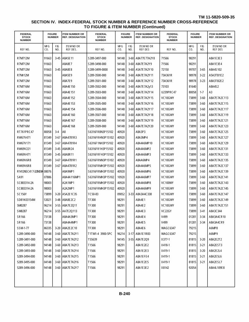
TM 11-5820-509-35SECTION IV. INDEX-FEDERAL STOCK NUMBER & REFERENCE NUMBER CROSS-REFERENCE
TO FIGURE & ITEM NUMBER (Continued)
FEDERAL FIGURE ITEM NUMBER OR FEDERAL FIGURE ITEM NUMBER OR FEDERAL FIGURE ITEM NUMBER ORSTOCK NUMBER REF. DESIGNATION STOCK NUMBER REF. DESIGNATION STOCK NUMBER REF. DESIGNATION
NUMBER NUMBER NUMBER
MFG FIG ITEM NO OR MFG FIG ITEM NO OR MFG FIG ITEM NO ORREF NO. CO. NO. REF DES. REF NO. CO. NO. REF DES REF NO. CO. NO. REF DES
R7M712M 91663 3-45 A8A5E11 S289-3497-000 94148 3-60 A8A77E77A2Y8 71566 98291 A8A1E3E3
R7M712M 91663 A8A8E7 S289-3498-000 94148 3-60 A8A7E7A2Y9 71566 98291 A8A1E3E4
R7M712M 91663 3-45 A8A8E8 S289-3499-0000 94148 3-60 A5A7E7A2Y10 72150 99707 3-65 A8A4S102
R7Mr12M 91663 A8A5E9 S289-3500-000 94148 3-60 A8A7E7A2Y11 73A361R 98978 3-22 A5A3TB1E2
R7M712M 91663 A8A7E9 S289-3501-000 94148 3-60 A8A7E7A2Y12 73A361R 98978 3-23 A8A3TB2E2
R7M716M 91663 A8A4E150 S289-3502-000 94148 3-60 A8A7E7A2y13 73103 81640 A8A4S2
R7M716M 91663 A8A4E151 S289-3503-000 94148 3-60 A8A7E7A2Y14 U239PRC47 80058 1-7 A3
R7M716M 91663 A8A4E152 S289-3504-000 94148 3-60 A8A7E7A2Y15 VC10GWY 73899 3-60 A8A7E7A2C113
R7M716M 91663 A8A4E153 S289-3505-000 94148 3-60 A8A7E7A2Y16 VC10GWY 73899 3-60 A8A7E7A2C115
R7M716M 91663 A8A4E154 S289-3506-000 94148 3-60 A8A7E7A2Y17 VC10GWY 73899 3-60 A8A7E7A2C117
R7M716M 91663 A8A4E160 S289-3507-000 94148 3-60 A8A7E7A2Y18 VC10GWY 73899 3-60 A8A7E7A2C119
R7M716M 91663 A8A4E167 S289-3508-000 94148 3-60 A8A7E7A2Y19 VC10GWY 73899 3-60 A8A7E7A2C121
R7M716M 91663 A8A4E168 S289-3509-000 94148 3-60 A8A7E7A2Y20 VC10GWY 73899 3-60 A8A7E7A2C123
RT761PRC47 80058 3-4 A8 S6316FR8N3P15102 40920 A8A3P3 VC10GWY 73899 3-60 A8A7E7A2C125
RW67V471 81349 3-67 A8A4781R3 S6316FRHN3P15102 40920 A8A3MP4 VC10GWY 73899 3-60 A8A7E7A2C127
RW67V171 81349 3-67 A8A4781R4 S6316F1NH3P15102 40920 A8A4A6MP10 VC10GWY 73899 3-60 A8A7E7A2C129
RW69V221 81349 3-45 A8A8R24 S6316FR1H3P15102 40920 A8A4A6MP2 VC10GWY 73899 3-60 A8A7E7A2C131
RW69V471 81349 3-45 A8A8R11 S6316FRFH3P15102 40920 A8A4A6MP3 VC10GWY 73899 3-60 A8A7E7A2C133
RW69V6R8 81349 3-67 A8A4781R1 S6316FRNN3P15102 40920 A8AA6MP4 VC10GWY 73899 3-60 A8A7E7A2C135
RW69V6R8 81349 3-67 A8A4781R2 S6316FRMH3P15102 40920 A8A4A6MP5 VC10GWY 73899 3-60 A8A7E7A2C137
R1412NSC41 7-32INDIA 08076 A8A9MP1 S6316FRMH3P15102 40920 A8A4A6MP6 VC10GWY 73899 3-60 A8A7E7A2C139
SA91 07886 A8A4A116MP1 S6316FRMH3P15102 10920 A8A4A6MP7 VC10GWY 73899 3-60 A8A7E7A2C141
SC883314-2A 98003 A2A1MP1 S6316FRMH3P15102 40920 A8A4A6MP8 VC100WY 73899 3-60 A8A7E7A2C143
SC883314-2A 98003 A2A2MP1 S6316FRMH3P15102 40920 A8A4A6MP9 VC10GWY 73899 3-60 A8A7E7A2C145
SC156Y 73899 3-20 A5A2E1C35 TC50-83 09052 3-33 A8A3A4C338 VC10GWY 73899 3-60 A8A7E7A2C147
SD81K03154M 53021 3-48 A8A8E2C2 TF300 98291 A8A4E1 VC10GWY 73899 3-60 A8A7E7A2C149
5M0287 96214 3-55 A8A7E2Q11 TF300 98291 A8A4E2 VC10GWY 73899 3-60 A8A7E7A2C151
SM0287 96214 3-55 AA7E2Q113 TF300 98291 A8A4E3 VC22GY 73899 3-41 A8A3C344
SR166 73138 A8A4A3MP1 TF300 98291 A8A4E4 V499 01281 3-34 A8A3A4CR10
SR166 73138 A8A4A4MP1 TF300 98291 A8A4E5 V499 01281 3-34 A8A3A4CR9
SSM-1-77 86335 3-20 A8A2E2C10 TF300 98291 A8A4E6 WAGC6347 79215 A6MP8
S289-3490-000 94148 3-60 A8A7E7A2Y1 T1TM1-4 3900-5PC 96214 3-17 A8A1E1R83 WAGC6347 79215 A6MP9
S289-3491-000 94148 3-60 A8A7E7A2Y2 T55639 94145 3-55 A8A7E2Q9 X377-1 81815 3-20 A8A2E2T2
S289-3492-000 94148 3-60 A8A7E7A2Y3 T1566 98291 A8A1E2E2 X418-1 81815 3-21 A8A2EST3
S289-3493-000 94148 3-60 A8A7E7A2Y4 T1566 98291 A8A1E2E3 X419-1 81815 3-20 A8A2E2L4
5289-3494-000 94148 3-60 A8A7E7A2Y5 T1566 98291 A8A1EFE4 X419-1 81815 3-21 A8A2E5L6
5289-3495-000 04148 3-60 A8A7E7A2Y6 T1566 98291 A8A1E2E5 X419-1 81815 3-21 A8A2ESL7
5289-3496-000 94148 3-60 A8A7E7A2Y7 T1566 98291 A8A1E3E2 X8142 92054 A8A4L109E8
B-240

TM 11-5820-509-35SECTION IV. INDEX-FEDERAL STOCK NUMBER & REFERENCE NUMBER CROSS-REFERENCE
TO FIGURE & ITEM NUMBER (Continued)
FEDERAL FIGURE ITEM NUMBER OR FEDERAL FIGURE ITEM NUMBER OR FEDERAL FIGURE ITEM NUMBER ORSTOCK NUMBER REF. DESIGNATION STOCK NUMBER REF. DESIGNATION STOCK NUMBER REF. DESIGNATION
NUMBER NUMBER NUMBER
MFG FIG ITEM NO OR MFG FIG ITEM NO OR MFG FIG ITEM NO ORREF NO. CO. NO. REF DES. REF NO. CO. NO. REF DES REF NO. CO. NO. REF DES
X8242 92054 A8A4L111E8 1N3641 07688 3-46 A58A8E1CR0 1N816 07688 3-17 A8A1E1CR8
YE1216F32 09922 A8A4E12 1N3641 07688 3-46 A5A8E1CR11 1N816 07688 3-18 A8A1E2CR1
YE1216F32 09922 A8A4E13 1N3641 07688 3-46 A8A5E1CR12 N816 07688 3-18 A8A1E2CR2
YE1620F32 09922 AA4E010 1N3641 07688 3-46 A5A8E1CR13 1N816 07688 3-18 A8A1E2CR3
YE1620F32 09922 A8A4E11 1N3641 07688 3-46 A8A8E1CR14 N816 07688 3-18 A8A1E2CR4
YE1620F32 09922 A8A4E9 1N3641 07688 3-46 A5A8E1CR15 1N816 07688 3-18 A8A1E2CR5
YE1620F32 09922 A8A5E12 1N3641 07688 3-46 A8A5E1CR16 1N816 07688 3-18 A8A1E2CR6
YE1620F32 09922 A8A8E13 1N3641 07688 3-46 A8A8E1CR17 1N816 07688 3-19 A5A1E3CR10
YE1620F32 09922 A8A8E14 1N3641 07688 3-46 A8A8E1CR18 1N821A 07688 3-52 A8A6E2CR1
YE1620F32 09922 A8A8E15 1N3641 07688 3-46 A8A5E1CR99 1N821A 07688 3-52 A8A6E2CR2
YE1620F32 09922 A8A8E16 1N3641 07688 3-46 A8A5E1CR20 1N916 07688 3-20 A8A2CR9
0-1032PRC47 80058 3-4 A8A6 1N3641 07688 3-46 A8A5E1CR21 1N916 07688 3-39 A8A3E48CR2
0167-3 94375 A8A4E54 1N3641 07688 3-46 A8A5E1CR22 1N916 07688 3-54 A8A741CR1
021-0187-00 98376 1-4 A1MP1 1N3641 07688 3-46 A8A5E1CR23 1N916 07688 3-55 AA77E2CR3
021-0189-000 13499 A6A3YP3 1N3641 07688 3-46 A8A5E1CR24 199116 07688 3-55 A8A7E2CR4
021-0191-00 24036 MP5 1N3641 07688 3-46 A5A5E1CR25 1N916 07688 3-59 A8A7E6CR7
021-0192-000 24036 1-3 A6MP1 1D3641 07688 3-46 A8A5E1CR6 1N916 07688 3-59 A8A7E6CR8
021-0192-000 24036 1-3 A6MP2 1N3641 07688 3-46 A8A5E1CR7 1N916 07688 3-56 A8A7711CR15
021-0192-000 24036 1-3 A6MP3 1N3641 07688 3-46 A8A5E1CR8 15911 07688 3-56 A8A7781CR9
021-0192-000 24036 1-3 A6MP4 1N3641 07688 3-46 A8A8E1CR9 10-243964-143 77820 A2MP3
021-0194-000 74284 A8MP2 1N3641 07688 3-49 A8A8E3CR1 105-731-100 74970 3-17 A8A1E1J9
021-0195-000 74284 A8A8MP1 1N3641 07688 3-49 A8A8E3CR2 105-732-100 74970 3-17 A8A1E1J12
054-0368-000 13499 A8A4FL2MP1 1N3641 07688 3-49 A8A8E3CR26 105-732-100 74970 3-18 A8A1E2J2
11N011365T1 76786 A6A4AMP1 1N3641 07688 3-49 A8A8E3CR27 105-733-100 74970 3-17 A8A1E1J10
11N01136ST1 76786 A6A44MP2 1N3641 07688 3-49 A8A8E3CR28 105-734-100 74970 3-18 A8A1E2J5
1N198 07688 3-21 A8A2E3CR7 1N3641 07688 3-49 A8A8E3CR29 105-734-100 74970 3-19 A8A1E3J15
1N198 07688 3-21 A8A2E3CR6 1N3641 07688 3-49 A8A8E3CR3 105-734-100 74970 3-38 A8A3E47J5
1N198 07688 3-39 A8A3E48CR3 1N3641 07688 3-49 A88A53CR4 105-734-100 74970 3-55 A8A7E2J5
1N198 07688 3-39 A8A3E48CR8 1N457 07688 3-17 A8A1E1CR18 105-736-100 74970 3-18 A8A1E2J3
1N198 07688 3-56 A5A7781CR12 1N457 07688 3-17 A8A1E1CR9 105-736-100 74970 3-19 A8A1E3J13
1N198 07688 3-56 A8A7781CR13 1N457 07688 3-19 A5A1E3CR11 105-737-100 74970 3-18 A8A1E2J4
1N2611 07688 A8A4786CR1 1N457 07688 3-19 A8A1E3CR12 105-737-100 74970 3-19 A8A1E3J14
1N2611 07688 A8A4786CR2 1N457 07688 3-19 A8A1E3CR13 105-738-100 74970 3-17 A5A1E1J11
1N3036A 07688 3-41 A8A3CR7 1N47958 01281 3-52 A8A6E2C12 105-738-100 74970 3-18 A8A1E2J1
1N3639 07688 A8A4A15CR3 1N645 07688 3-38 A8A3E47CR5 105-738-100 74970 3-59 A8A7E6J1
1N3639 07688 A8A4A15CR4 1N645 07688 3-38 A8A3E47CR6 105-740-100 74970 3-18 A8A1E2J6
1N3639 07688 AA4AA15CR5 1N757 07688 3-51 A8A5781CR31 105-740-100 77970 3-19 48A1E316
1N3639 07688 A8A4A15CR6 1N816 07688 3-17 A8A1E1CR7 105-740-100 74970 3-38 A8A3E47J6
B-241
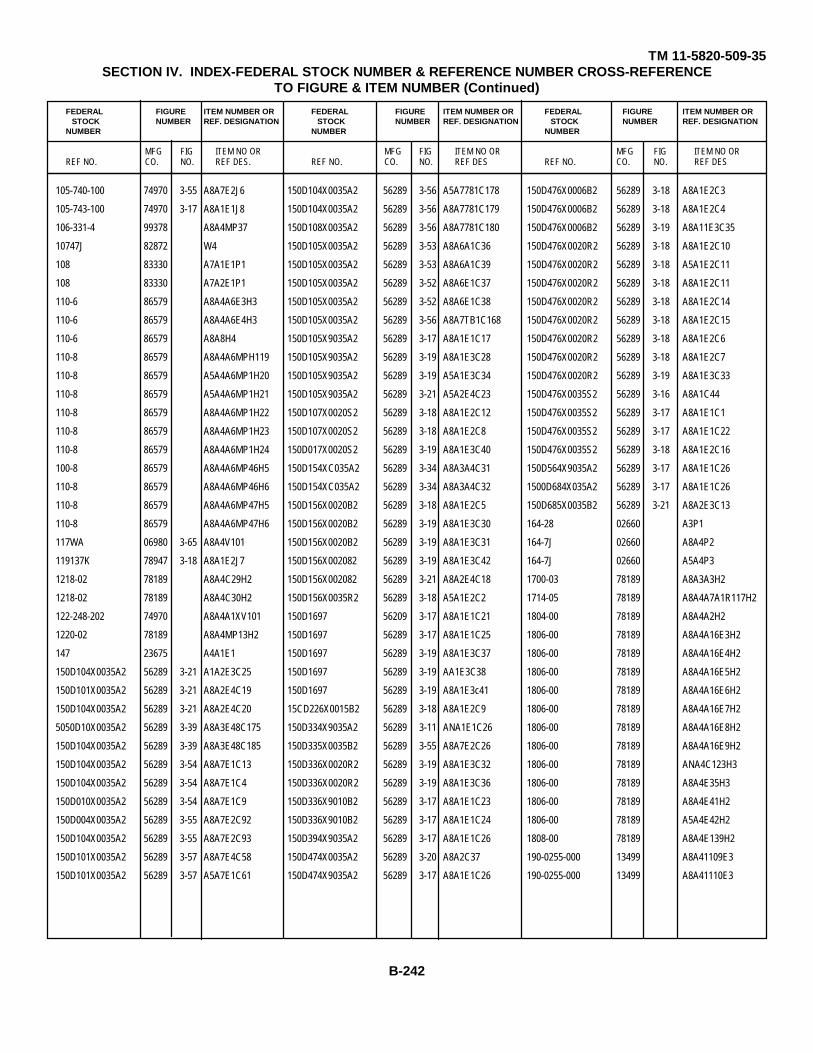
TM 11-5820-509-35SECTION IV. INDEX-FEDERAL STOCK NUMBER & REFERENCE NUMBER CROSS-REFERENCE
TO FIGURE & ITEM NUMBER (Continued)
FEDERAL FIGURE ITEM NUMBER OR FEDERAL FIGURE ITEM NUMBER OR FEDERAL FIGURE ITEM NUMBER ORSTOCK NUMBER REF. DESIGNATION STOCK NUMBER REF. DESIGNATION STOCK NUMBER REF. DESIGNATION
NUMBER NUMBER NUMBER
MFG FIG ITEM NO OR MFG FIG ITEM NO OR MFG FIG ITEM NO ORREF NO. CO. NO. REF DES. REF NO. CO. NO. REF DES REF NO. CO. NO. REF DES
105-740-100 74970 3-55 A8A7E2J6 150D104X0035A2 56289 3-56 A5A7781C178 150D476X0006B2 56289 3-18 A8A1E2C3
105-743-100 74970 3-17 A8A1E1J8 150D104X0035A2 56289 3-56 A8A7781C179 150D476X0006B2 56289 3-18 A8A1E2C4
106-331-4 99378 A8A4MP37 150D108X0035A2 56289 3-56 A8A7781C180 150D476X0006B2 56289 3-19 A8A11E3C35
10747J 82872 W4 150D105X0035A2 56289 3-53 A8A6A1C36 150D476X0020R2 56289 3-18 A8A1E2C10
108 83330 A7A1E1P1 150D105X0035A2 56289 3-53 A8A6A1C39 150D476X0020R2 56289 3-18 A5A1E2C11
108 83330 A7A2E1P1 150D105X0035A2 56289 3-52 A8A6E1C37 150D476X0020R2 56289 3-18 A8A1E2C11
110-6 86579 A8A4A6E3H3 150D105X0035A2 56289 3-52 A8A6E1C38 150D476X0020R2 56289 3-18 A8A1E2C14
110-6 86579 A8A4A6E4H3 150D105X0035A2 56289 3-56 A8A7TB1C168 150D476X0020R2 56289 3-18 A8A1E2C15
110-6 86579 A8A8H4 150D105X9035A2 56289 3-17 A8A1E1C17 150D476X0020R2 56289 3-18 A8A1E2C6
110-8 86579 A8A4A6MPH119 150D105X9035A2 56289 3-19 A8A1E3C28 150D476X0020R2 56289 3-18 A8A1E2C7
110-8 86579 A5A4A6MP1H20 150D105X9035A2 56289 3-19 A5A1E3C34 150D476X0020R2 56289 3-19 A8A1E3C33
110-8 86579 A5A4A6MP1H21 150D105X9035A2 56289 3-21 A5A2E4C23 150D476X0035S2 56289 3-16 A8A1C44
110-8 86579 A8A4A6MP1H22 150D107X0020S2 56289 3-18 A8A1E2C12 150D476X0035S2 56289 3-17 A8A1E1C1
110-8 86579 A8A4A6MP1H23 150D107X0020S2 56289 3-18 A8A1E2C8 150D476X0035S2 56289 3-17 A8A1E1C22
110-8 86579 A8A4A6MP1H24 150D017X0020S2 56289 3-19 A8A1E3C40 150D476X0035S2 56289 3-18 A8A1E2C16
100-8 86579 A8A4A6MP46H5 150D154XC035A2 56289 3-34 A8A3A4C31 150D564X9035A2 56289 3-17 A8A1E1C26
110-8 86579 A8A4A6MP46H6 150D154XC035A2 56289 3-34 A8A3A4C32 1500D684X035A2 56289 3-17 A8A1E1C26
110-8 86579 A8A4A6MP47H5 150D156X0020B2 56289 3-18 A8A1E2C5 150D685X0035B2 56289 3-21 A8A2E3C13
110-8 86579 A8A4A6MP47H6 150D156X0020B2 56289 3-19 A8A1E3C30 164-28 02660 A3P1
117WA 06980 3-65 A8A4V101 150D156X0020B2 56289 3-19 A8A1E3C31 164-7J 02660 A8A4P2
119137K 78947 3-18 A8A1E2J7 150D156X002082 56289 3-19 A8A1E3C42 164-7J 02660 A5A4P3
1218-02 78189 A8A4C29H2 150D156X002082 56289 3-21 A8A2E4C18 1700-03 78189 A8A3A3H2
1218-02 78189 A8A4C30H2 150D156X0035R2 56289 3-18 A5A1E2C2 1714-05 78189 A8A4A7A1R117H2
122-248-202 74970 A8A4A1XV101 150D1697 56209 3-17 A8A1E1C21 1804-00 78189 A8A4A2H2
1220-02 78189 A8A4MP13H2 150D1697 56289 3-17 A8A1E1C25 1806-00 78189 A8A4A16E3H2
147 23675 A4A1E1 150D1697 56289 3-19 A8A1E3C37 1806-00 78189 A8A4A16E4H2
150D104X0035A2 56289 3-21 A1A2E3C25 150D1697 56289 3-19 AA1E3C38 1806-00 78189 A8A4A16E5H2
150D101X0035A2 56289 3-21 A8A2E4C19 150D1697 56289 3-19 A8A1E3c41 1806-00 78189 A8A4A16E6H2
150D104X0035A2 56289 3-21 A8A2E4C20 15CD226X0015B2 56289 3-18 A8A1E2C9 1806-00 78189 A8A4A16E7H2
5050D10X0035A2 56289 3-39 A8A3E48C175 150D334X9035A2 56289 3-11 ANA1E1C26 1806-00 78189 A8A4A16E8H2
150D104X0035A2 56289 3-39 A8A3E48C185 150D335X0035B2 56289 3-55 A8A7E2C26 1806-00 78189 A8A4A16E9H2
150D104X0035A2 56289 3-54 A8A7E1C13 150D336X0020R2 56289 3-19 A8A1E3C32 1806-00 78189 ANA4C123H3
150D104X0035A2 56289 3-54 A8A7E1C4 150D336X0020R2 56289 3-19 A8A1E3C36 1806-00 78189 A8A4E35H3
150D010X0035A2 56289 3-54 A8A7E1C9 150D336X9010B2 56289 3-17 A8A1E1C23 1806-00 78189 A8A4E41H2
150D004X0035A2 56289 3-55 A8A7E2C92 150D336X9010B2 56289 3-17 A8A1E1C24 1806-00 78189 A5A4E42H2
150D104X0035A2 56289 3-55 A8A7E2C93 150D394X9035A2 56289 3-17 A8A1E1C26 1808-00 78189 A8A4E139H2
150D101X0035A2 56289 3-57 A8A7E4C58 150D474X0035A2 56289 3-20 A8A2C37 190-0255-000 13499 A8A41109E3
150D101X0035A2 56289 3-57 A5A7E1C61 150D474X9035A2 56289 3-17 A8A1E1C26 190-0255-000 13499 A8A41110E3
B-242

TM 11-5820-509-35SECTION IV. INDEX-FEDERAL STOCK NUMBER & REFERENCE NUMBER CROSS-REFERENCE
TO FIGURE & ITEM NUMBER (Continued)
FEDERAL FIGURE ITEM NUMBER OR FEDERAL FIGURE ITEM NUMBER OR FEDERAL FIGURE ITEM NUMBER ORSTOCK NUMBER REF. DESIGNATION STOCK NUMBER REF. DESIGNATION STOCK NUMBER REF. DESIGNATION
NUMBER NUMBER NUMBER
MFG FIG ITEM NO OR MFG FIG ITEM NO OR MFG FIG ITEM NO ORREF NO. CO. NO. REF DES. REF NO. CO. NO. REF DES REF NO. CO. NO. REF DES
190-0255-000 13499 A8A4L111E3 2N703 01688 3-39 A8A3E48Q9 20C119 56289 A8A8E1C7
190-0255-000 13499 A8A41112E3 2N703 07688 3-53 A8A6A1Q4 20C119 56289 3-47 A8A5E1C8
192P1039R8 56289 3-52 A8A6E1C30 2N703 07688 3-53 A8A6A1Q5 20C119 56289 3-47 ARA5E1c9
192P4729R8 56289 3-53 A8A6A1C15 2N703 07688 3-53 A8A6A1Q6 20C91A 56289 3-39 A8A3E48C179
192P4729R8 56289 3-53 A8A6A1C16 2N703 07688 3-52 A8A6E1Q7 20C91A 56289 3-59 A8A7E6C111
192P4739R8 56289 3-52 ACA6E1C31 2N703 07688 3-52 A8A6E1Q8 20C91A 56289 3-57 A8A7E6C96
2A1DB15 92825 A8A3E45 2N703 07688 3-52 A8A6E1Q9 20C91A 56289 3-59 A8A7E6C98
2A1DB15 92825 A8A3E46 2N703 07688 3-52 A8A6E2Q1 20C95 56289 3-66 A8A4A1C101
2DHT55T209CAA 71590 3-64 A8A4A16C124 2N703 07688 3-52 A8A6E1Q2 20C95 56289 A8A4A7C106
2N1038 07688 3-18 A8A1E2Q4 2N703 07688 3-52 A8A6E2Q3 2104-04-01-2520N 78189 A8A3E30
2N1166 07688 3-67 A8A1Q4 2N703 07688 3-54 A8A7E1Q1 2104-04-01-2520N 78189 A8A3E31
2N1166 07688 3-67 A8A4Q2 2N703 07688 3-54 A8A7E7Q2 2104-04-01-2520N 78189 A8A3E32
2N1485 07688 3-51 A8A5TB1Q3 2N703 07688 3-54 A8A7E1Q3 3104-04-01-2520N 78;89 A8A3E33
2N158AMATCHEDPR 07688 3-16 A8A1Q1 2N703 07688 3-54 A8A7E1Q4 2104-04-01-2520N 78189 A8A3E34
2N274 07688 3-21 A8A2E3Q2 2N703 07688 3-54 A8A7E1Q5 2104-04-01-2520N 78189 A8A3E35
2N274 07688 3-21 A8A2E4Q3 2N703 07688 3-54 A8A7E1Q6 2104-04-01-2520N 78189 A8A3E36
2N274 07688 3-21 A8A2E4Q1 2N703 07688 3-54 A8A7E1Q7 2104-04-01-2520N 78189 A8A4E37
2N274 07688 3-21 A8A2E5Q5 2N703 07688 3-57 A8A7E1Q7 1104-04-01-2520N 78189 A8A4838
2N404 07688 3-18 A8A1E2Q1 2N703 07688 3-57 A8A7E4Q18 2104-04-01-2520N 78189 A8A4E39
2N440 07688 3-20 A8A2E2Q1 2N703 07688 3-57 A8A7E4Q19 2100-04-01-2520N 78189 A8A4E40
2N697 07688 3-17 A8A2E1Q7 2N703 07688 3-59 A8A7E6Q20 2104-04-01-2520N 78189 A8A5TB1E1
2N697 07688 3-51 A8A5781Q1 2N703 07688 3-59 A7A7E6Q21 2104-04-01-2520N 78189 A8A5E6
2N697 07688 3-51 A5A5781Q2 2N703 07688 3-59 A8A7E6Q22 2104-06-02-2520N 78189 A8A4A16E3
2N697 07688 3-59 A8A7E6Q23 2N703 07688 3-56 A8A7TB1Q24 2104-06-02-2520N 78189 A8A4A1A6E4
2N703 07688 3-37 A8A3E46Q16 2N703 07688 3-56 A8A7TB1Q25 2104-06-02-2520N 78189 AAP14A16E5
2N703 07688 3-37 A8A3E46Q17 2N703 07688 3-56 A8A7TB1Q26 2104-06-02-2520N 78189 A8A4A16E6
2N703 07688 3-37 A8A3E46Q18 2N703 07688 3-56 A8A7TB1Q28 2104-06-02-2520N 78189 A8A4A16E7
2N703 07688 3-37 A8A3E46Q19 2N917 07688 3-33 A8A3A4Q20 2104-06-02-2520N 78189 A8A4A16E8
2N703 07688 3-38 A8A3E47Q12 2N917 07688 3-33 A8A3A4Q21 2104-06-02-2520N 78189 A8A4A16E9
2N703 07688 3-38 A8A3E47Q13 20C119 56289 3-47 A8A5E1C10 2104-06-02-2520N 78189 A8A4A6E6
2N703 07688 3-38 A8A3E47Q2 20C119 56289 3-47 A8A5E1C11 2104-06-02-2520N 78189 A8A4E41
2N703 07688 3-38 A8A3E47Q5 20C119 56289 3-47 A8A5E1C12 2104-06-02-2520N 78189 A8A4142
2N703 07688 3-38 A8A3E47Q6 20C119 56289 3-47 A8A5E1C13 2100-06-02-2520N 78189 A8A4E43
2N703 07688 3-38 A8A3E47Q7 20C119 56289 3-47 A8A5E1C14 2104-06-02-2520N 78189 A8A4E58
2N703 07688 3-38 A8A3E47Q8 20C119 56289 3-47 A8A5E1C3 2104-06-02-2520N 78189 ArA4E59
2N703 07688 3-39 A8A3E48Q10 20C119 56289 3-47 A8A5E1C4 2110-0216CADPL 25184 A8A8H2
2N703 07688 3-39 A8A3E48Q14 20C119 56289 3-47 A8A5E1C5 213923F1X 76854 A8A4S1
2N703 07688 3-39 A8A3E48Q15 20C119 56289 3-47 A8A5E1C6 224L1-201 80294 3-39 A8A3E48R150
B-243
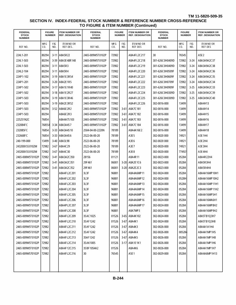
TM 11-5820-509-35SECTION IV. INDEX-FEDERAL STOCK NUMBER & REFERENCE NUMBER CROSS-REFERENCE
TO FIGURE & ITEM NUMBER (Continued)
FEDERAL FIGURE ITEM NUMBER OR FEDERAL FIGURE ITEM NUMBER OR FEDERAL FIGURE ITEM NUMBER ORSTOCK NUMBER REF. DESIGNATION STOCK NUMBER REF. DESIGNATION STOCK NUMBER REF. DESIGNATION
NUMBER NUMBER NUMBER
MFG FIG ITEM NO OR MFG FIG ITEM NO OR MFG FIG ITEM NO ORREF NO. CO. NO. REF DES. REF NO. CO. NO. REF DES REF NO. CO. NO. REF DES
224L1-201 80294 3-11 A8A5R22 2465-009W5T0102P 72982 A8A4FL2C217 30 76545 A5E2
224L1-503 80294 3-39 A8A3E48R148 2465-009W5T0102P 72982 A8A4FL2C218 301-626C0H0409D 72982 3-24 A8A3A9A2C37
224L1-503 80294 3-11 A8A5R3 2465-009W5T0102P 72982 A8A4FL2C219 301-626C0H0409D 72982 3-24 A8A3A9A2C38
224L2-104 80294 3-11 A8A5R4 2465-009W5T0102P 72982 A8A4FL2C220 301-626C0H0509F 72982 3-24 A8A3A9A2C36
224P1-102 80294 3-19 A8A1E3R54 2465-009W5T0102P 72982 A8A4FL2C221 301-626C0H0609F 72982 3-24 A8A3A9A2C35
224P1-201 80294 3-20 A8A2E1R5 2465-009W5T0102P 72982 A8A4FL2C222 301-626C0H0709F 72982 3-24 A8A3A9A2C34
224P1-502 80294 3-17 A8A1E1R40 2865-009W5T0102P 72982 A8A4FL2C223 301-626C0H0909F 72982 3-25 A8A3A9A2C33
224P1-502 80294 3-18 A8A1E2R27 2465-009W5T0102P 72982 A8A4FL2C224 301-626C0H0309D 72982 3-25 A8A3A9A2C39
224P1-503 80294 3-19 A8A1E3R46 2465-009W5T0102P 72982 A8A4FL2C225 301-626C0H0309D 72982 3-25 A8A3A9A2C40
224P1-503 80294 3-19 A8A2E3R52 2465-009W5T0102P 72982 A8A4FL2C226 302-0016-000 13499 A8A4H13
224P1-503 80294 3-52 A8A6E2R2 2465-009W5T0102P 72982 3-61 A8A7C181 302-0016-000 13499 A8A4H14
224P1-503 80294 A8A6E2R3 2465-009W5T0102P 72982 3-61 A8A7C182 302-0016-000 13499 A8A4H15
225251N2C 76854 A8A4A7S103 2465-009W5T0102P 72982 3-61 A8A7C183 302-0016-000 13499 A8A4H16
232084FC 768554 3-34 A8A3A4S7 2465-009W5T0102P 72982 3-61 A8A7C184 302-0016-000 13499 A8A4H17
232085FC 76854 3-33 A8A3A4S10 2504-04-00-2220N 78189 A8A4A16E2 302-0016-000 13499 A8A4H18
232668FC 76854 3-33 A8A3A4S6 2522-06-00-20 78189 A3E5 302-0020 000 74921 A3E1H4
240-199-000 13499 3-40 A8A3L98 2522-06-00-20 78189 A3E6 302-0020 000 74921 A3E2H4
243200X5S0102M 72982 3-67 A8A4C29 2522-06-00-20 78189 A3E7 302-0020-000 74921 A3E3H4
243200X5S0102M 72982 3-67 A8A4C30 2522-06-00-20 78189 A3E8 302-0020-000 774921 A3E4H4
2465-008W5T0102P 72982 3-41 A8A3A2C350 28156 01121 A8A4R11 302-0023-000 05284 A8A4R22H4
2465-008W5T0102P 72982 3-41 A8A3A2C351 29F461 06001 3-20 A8A2E1C6 302-0023-000 05284 A8A5R3H4
2465-008W5T0102P 72982 3-41 A8A3A2C352 29F461 06001 3-20 A8A2E2C3 302-0023-000 05284 A8A5R4H4
2465-009W5T0102P 72982 A8A4FL2C201 3L3F 96881 A8A4A6MP11 302-0024-000 05284 A8A4A16MP10H1
2465-009W5T0102P 72982 A8A4FL2C202 3L3F 96881 A8A4A6MP12 302-0024-000 0528H A8A4A16MP10H2
2465-009W5T0102P 72982 A8A4FL2C203 3L3F 96881 A8A4A6MP13 302-0024-000 05284 A8A4A16MP11H1
2465-009W5T0102P 72982 A8A4FL2C204 3L3F 96881 A8A4A6MP14 302-0024-000 05284 A8A4A16MP11H2
2465-009W5T0102P 72982 A8A4FL2C205 3L3F 96881 A8A4A6MP15 302-0024-000 05284 A8A4A16MP5H1
2465-009W5T0102P 72982 A8A4FL2C206 3L3F 96881 A8A4A6MP16 302-0024-000 05284 A8A4A16MA6H1
2465-009W5T0102P 72982 A8A4PL2C207 3L3F 96881 A8A4A6MP17 302-0024-000 05284 A8A4A16MP8H2
2465-009W5T0102P 77982 A8A4FL2C208 3L3F 96881 A8A7MP3 302-0024-000 05284 A8A4A16MP9H2
2465-009W5T0102P 72982 A8A4FL2C209 3SAC1025 01526 3-65 A8A4K102 302-0024-000 05284 A8A5TB1Q3H7
2465-009W5T0102P 72982 A8A4FL2C210 3SAF1242 01526 3-67 A8A4K1 302-0024-000 05284 A8A5TB1Q3H8
2465-009W5T0102P 72982 A8A4FL2C211 3SAF1242 01526 3-67 A8A4K3 302-0026-000 05284 A8A4A1A1H4
2465-009W5T0102P 72982 A8A4FL2C212 3SAF1242 01526 3-67 A8A4K4 302-0026-000 005284 A8A4A1MP1H5
2465-009W5T0102P 72982 A8A4FL2C213 35AF1242 01526 3-67 A8A4K5 302-0026-000 05284 A8A4A1MP1H8
2465-009W5T0102P 72982 A8A4FL2C214 3SAK1005 01526 3-17 A8A1E1K1 302-0026-000 05284 A8A4A1MP1H6
2465 009W5T0102P 72982 A8A4F12C215 3SBF1054A2 01526 A8A4K6 302-0026-000 05284 A8A4A1MP1H7
2465-009W570102P 72982 A8A4FL2C216 30 76545 A5E1 302-0029-000 05284 A8A4A6MP1H13
B-244

TM 11-5820-509-35SECTION IV. INDEX-FEDERAL STOCK NUMBER & REFERENCE NUMBER CROSS-REFERENCE
TO FIGURE & ITEM NUMBER (Continued)
FEDERAL FIGURE ITEM NUMBER OR FEDERAL FIGURE ITEM NUMBER OR FEDERAL FIGURE ITEM NUMBER ORSTOCK NUMBER REF. DESIGNATION STOCK NUMBER REF. DESIGNATION STOCK NUMBER REF. DESIGNATION
NUMBER NUMBER NUMBER
MFG FIG ITEM NO OR MFG FIG ITEM NO OR MFG FIG ITEM NO ORREF NO. CO. NO. REF DES. REF NO. CO. NO. REF DES REF NO. CO. NO. REF DES
302-0029-000 05284 A8A4A6MP1H14 310-0045-000 79807 A8A5MP3H4 310-0071-000 79807 A8A4Q2H6
302-0029-000 05284 A8A4A6MP1H15 310-0045-000 70807 A8A5MP3H5 310-0071-000 79807 A8A5T2H5
302-0029-000 05284 A8A4A6MP1H16 310-0045-000 79807 A8A7A1A3H2 310-0074-000 79807 A8A1E5H3
302-0029-000 05284 A8A4A6MP1H17 310-0045-000 79807 A8MP1H3 310-0074-000 79807 A8A6A1E1H2
302-0029-000 05284 A8A4A6MP1H18 310-0045-000 79807 A8MP1H4 310-0074-000 79807 A8A6A1E2H2
302-0050-000 74921 A8A7TB1T1H5 310-0045-000 79807 A8MP8H3 310-0074-000 79807 A8A6A1E3H2
302-0050-000 74921 A8A7TB1T1H6 310-0046-000 79807 A8A4A1A1H1 310-0074-000 79807 A8A6A1E4H2
302-0050-000 74921 A8A7TB1T1H5 310-0046-000 79807 A8A4A1MP1H3 310-0074-000 79807 A8A6A1E5H2
302-0050-000 74921 A8A7TB1T1H6 310-0046-000 79807 A8A4A1MP1H4 310-0074-000 79807 A8A6E1E1H2
302-7000-000 74921 A3E1H5 310-0046-000 79807 A8A4A6A12H1 310-0074-000 79807 A8A6E1E2H2
302-7000-000 74921 A3E2H5 310-0046-000 79807 A8A5T2H3 310-0074-000 79807 A8A6E1E3H2
302-7000-000 74921 A3E3H5 310-0046-000 79807 A8A5T2H4 310-0074-000 79807 A8A6E1E4H2
302-7000-000 74921 A3E4H5 310-0046-000 79807 A8A6MP2H3 310-0074-000 79807 A8A6E1E5H2
303-1000-000 79807 A8A7TB1T1H7 310-0046-000 79807 A8A6MP2H4 310-0074-000 79807 A8A6E1E6H2
303-1000-000 79807 A8A7TB1T1H8 310-0048-000 79807 A8A4A6H3 310-0074-000 79807 A8A6E1H6
303-1000-000 79807 A8A7TB1T3H7 310-0048 000 79807 A8A4A6MP1H10 310-0074-000 79807 A8A6P1H6
303-1000-000 79807 A8A7TB1T3H8 310-0048-000 79807 A8A4A6MP1H11 310-0074-000 79807 A8A6P1H7
3051P1-105 80294 3-52 A8A6E2R1 310-0048-000 79807 A8A4A6MP1H12 310-0075-000 79807 A8A3A4A1E10H1
30697 97965 3-67 A8A4T3 310-0048-000 79087 A8A4A6MP1H7 310-0075-000 79807 A8A3A4A1E11H1
3100L037-1001 80294 3-21 A8A2E5K1 310-0048-000 79807 A8A4A6MP1H8 310-0075-000 79807 A8A3A4A1E12H1
310-0044-000 79807 A8A1P1H5 310-0048-000 79807 A8A4A6MP1H9 310-0075-000 79807 A8A3A4A1E9H1
310-0044-000 79807 A8A1P1H6 310-0048-000 79807 A8A5MP5H2 310-0075-000 79807 A8A3A4A1E10H1
310-0044-000 79807 A8A2P3H5 310-0048-000 79807 A8A5MP5H3 310-0075-000 79807 A8A3A4A1E11H1
310-0044-000 79807 A8A2P3H6 310-0053-000 79807 A8A3A4H2 310-0075-000 79807 A8A3A4A2E12H1
310-0044-000 79807 A8A2P4H5 310-0053-000 79807 A8A6P1H4 310-0075-000 79807 A8A3A4AE9H1
310-0044-000 79807 A8A2P4H6 310-0053-000 79807 A8A6P1H5 310-0075-000 79807 A8A3A4E1H2
310-0044-000 79807 A8A5R22H3 310-0054-000 79807 A8A4A16H2 310-0075-000 79807 A8A3A4E1H2
310-0044-000 79807 A8A5R3H3 310-0071-000 79807 A8A4A6A12H5 310-0075-000 79807 A8A3A4E3H3
310-0044 000 79807 A8A5R4H3 310-0071-000 79807 A8A4A6MP55H2 310-0075-000 79807 A8A3A4E4H3
310-0045-000 79807 A8A3L98H2 310-0071-000 79807 A8A4A6MP56H2 310-0075-000 79807 A8A3A4H1
310-0045-000 79807 A8A4A16H2 310-0071-000 798D7 A8A4A6MP57H2 310-0075-000 79807 A8A3E17H3
310-0045-000 79807 A&A4A7A1H1 310-0071-000 79807 A8A4K2H5 310-0075-000 79807 A8A3E18H3
310-0045-000 79807 A8A4FL2H4 310-0071-000 79807 A8A4K2H6 310-0075-000 79807 A8A3E19H3
310-0045 000 79807 A8A4K6H5 310-0071-000 79807 A8A4MP36H1 310-0075-000 79807 A8A3E37H3
310-0045-000 79807 A8A4MP12H8 310-0071-000 79807 A8A4MP36H5 310-0075-000 79807 A8A3TB1H1
310-0045-000 79807 A8A4MP12H9 310-0071-000 79807 A8A4Q1H5 310-0075-000 79807 A8A3TB2E4H3
310-0045-000 79807 A8A4MP01H3 310-0071-000 79807 A8A4A1H6 310-0075-000 79807 A8A3TB2ESH3
310-0045-000 79807 A8A4T101H4 310-0071-000 79807 A8A4A1H5 310-0075 000 79807 A8A3TB2E6H3
B-245

TM 11-5820-509-35SECTION IV. INDEX-FEDERAL STOCK NUMBER & REFERENCE NUMBER CROSS-REFERENCE
TO FIGURE & ITEM NUMBER (Continued)
FEDERAL FIGURE ITEM NUMBER OR FEDERAL FIGURE ITEM NUMBER OR FEDERAL FIGURE ITEM NUMBER ORSTOCK NUMBER REF. DESIGNATION STOCK NUMBER REF. DESIGNATION STOCK NUMBER REF. DESIGNATION
NUMBER NUMBER NUMBER
MFG FIG ITEM NO OR MFG FIG ITEM NO OR MFG FIG ITEM NO ORREF NO. CO. NO. REF DES. REF NO. CO. NO. REF DES REF NO. CO. NO. REF DES
310-0075-000 79807 A8A3TB2H1 310-0274-000 13499 A8A4E30H4 310-0395-00 79807 A8A4A16C108H2
310-0075-000 79807 A8A3TB2K1H3 310-0274-000 13499 A8A4E31H3 310-0395-00 79807 A8A4A16C109H2
310-0075-000 79807 A8A3TB2K1H4 310-0274-000 13499 A8A4E31H4 310-0395-00 79807 A8A4A16C110H2
310-0075-000 79807 A8A4E1H2 310-0274-000 13499 A8A4E32H3 310-0395-00 79807 A8A4A16C111H2
310-0075-000 79807 A8A7TB1E10H2 310-0274-000 13499 A8A4E32H4 310-0395-00 79807 A8A4A16C112H2
310-0075-000 79807 A8A7TB1E11H2 310-0278-000 70318 A8A3P1H6 310-0395-00 79807 A8A4A16C113H2
310-0075-000 79807 A8A7TB1E12H2 310-0278-000 70318 A8A3P1H7 310-0395-00 79807 A8A4A16C114H2
310-0075-000 79087 A8A7TB1E13H2 310-0278-000 70318 A8A3P2H5 310-0396-00 79807 A8A2E9H2
310-0075-000 79807 A8A7TB1E14H2 310-0278-000 70318 A8A3P3H5 310-0396-00 79807 A8A3E10H2
310-0075-000 79807 A8A7TB1E15H2 310-0278-000 70318 A3A3P4H5 310-0396-00 79807 A8A3E16H2
310-0075-000 79807 A8A7TB1E16H2 310-0278-000 70318 A8A4A16H2 310-0396-00 79807 A8A3E20H3
310-0075-000 79807 A8A7TB1E17H2 310-0278-000 70318 A8A4A6A7H3 310-0396-00 79807 A8A3E21H3
310-0075-000 79807 A8A7TB1E18H2 310-0278-000 70318 A8A4E167H2 310-0396-00 79807 A8A3E30H3
310-0075-000 79807 A8A7TB1E2H2 310-0278-000 70318 A8A4E168H2 310-0396-00 79807 A8A3E31H3
310-0075-000 79807 A8A7TB1E3H2 310-0278-000 70318 A8A4E37H4 310-0396-00 79807 A8A3E32H3
310-0075-000 79807 A8A7TB1E4H2 310-0278-000 70318 A8A4E38H4 310-0396-00 79807 A8A3E33H3
310-0075-000 79807 A8A7TB1E5H2 310-0278-000 70318 A8A4E39H4 310-0396-00 79807 A5A3E34H3
310-0075-000 79807 A8A7TB1E6H2 310-0278-000 70318 A8A4E55H3 310-0396-00 79807 A8A3E35H3
310-0075-000 79807 A8A7TB1E7H2 310-0278-000 70318 A84AE56H3 310-0396-00 79807 A8A3E36H3
310-0075-000 79807 A8A7TB1E8H2 310-0278-000 70318 A8A4E57H4 310-0396-00 79087 A8A3E38H4
310-0075-000 79807 AHA7TB1E9H2 310-0278-000 70318 A8A4FL2H2 310-0396-00 79807 A8A3E38H5
310-0075-000 79807 A8E3H2 310-0278-000 70318 A8A4K102H5 310-0396-00 79807 A8A3MP15H5
310-0078-000 79807 A8A4A16C115H2 310-0278-000 70318 A8A4K102H6 310-0396-00 79807 A8A3MP15H6
310-0078-000 79807 A8A4A16C116H2 310-0278-000 70318 A8A4K103H3 310-0396-00 79807 A8A3MP15H7
310-0077-000 79807 A8A4A16C117H2 310-0278-000 70318 A8A4K103H4 310-0396-00 79807 A8A3MP15H8
310-0078-000 79807 A8A4A16C118H2 310-0278-000 70318 A8A4MP12H10 310-0396-00 79807 A8A3TP1E4H3
310-0078-000 79807 A8A4A16C119H2 310-0278-000 70318 A8A4MP12H11 310-0396-00 79807 A8A3TP1E5H3
310-0078-000 79807 A8A4A16C120H2 310-0278-000 70318 A8A4MP22H3 310-0396-00 79807 A8A3TP1E6H3
310-0078-000 79807 A8A4A16C121H2 310-0278-000 70318 A8A4MP23H3 310-0396-00 79807 A8A3TP2E8H3
310-0078-000 79807 A8A4A16MP7H3 310-0280-000 70318 A8A8MP5H10 310-0396-00 79087 A8A3XV3H5
310-0078-000 79807 A8A4A16MP7H4 310-0280-000 70318 A8A8MP5H11 310-0396-00 79087 A8A3XV3H6
310-0078-000 79807 A8A4A6E3H2 310-0280-000 70318 A8A8MP5H12 310-0396-00 79087 A8A4A16H2
310-0078-000 79807 A8A4A6E4H2 310-0280-000 70318 A8A8MP5H13 310-0396-00 79087 A8A7MP7H3
310-0078-000 79807 A8A4C123R4 310-0280-000 70318 A8A8MP5H14 310-0396-00 79807 A8A7MP7H4
310-0082-000 79807 A8A4R121H2 310-0280-000 70318 A8A8MP5H15 310-0397-00 79807 A8A3A4A1L125H2
310-0274-000 13499 A8A4E29H3 310-0280-000 70318 A8A8MP5H16 310-0397-00 79807 A8A3A4A1L126H2
310-0274-000 13499 A8A4E29H4 310-0280-000 70318 A8A8MP5H9 310-0397-00 79807 A8A3A4A1L127H2
310-0274-000 13499 A8A4E30H3 310-0283-000 70318 A8A4A6H3 310-0397-00 79807 A8A3A4A2L128H2
B-246

TM 11-5820-509-35SECTION IV. INDEX-FEDERAL STOCK NUMBER & REFERENCE NUMBER CROSS-REFERENCE
TO FIGURE & ITEM NUMBER (Continued)
FEDERAL FIGURE ITEM NUMBER OR FEDERAL FIGURE ITEM NUMBER OR FEDERAL FIGURE ITEM NUMBER ORSTOCK NUMBER REF. DESIGNATION STOCK NUMBER REF. DESIGNATION STOCK NUMBER REF. DESIGNATION
NUMBER NUMBER NUMBER
MFG FIG ITEM NO OR MFG FIG ITEM NO OR MFG FIG ITEM NO ORREF NO. CO. NO. REF DES. REF NO. CO. NO. REF DES REF NO. CO. NO. REF DES
310-0397-00 79087 A8A3A4A1L139H2 310-6325-000 79807 A8A7E5H4 334-0043-000 21537 A8A3P2H1
310-3097-00 79087 A8A3A4A1L140H2 310-6340-000 79807 A8A1MP2H3 334-0043-000 21537 A8A3P3H1
310-0397-00 79807 A8A3A4A1L141H2 310-6340-000 79807 A8A1MP2H4 334-0043-000 21537 A8A3P4H1
310-0397-00 79807 A8A3A4A1L142H1 310-6340-000 79807 A8A5E3H2 334-1290-000 13499 A8A3A4A1L125H1
310-0397-00 79807 A8A3A4A2L143H2 310-6360-000 79807 A3E1H2 334-1290-000 13499 A8A3A4A1L126H1
310-0397-00 79807 A8A3A4A2L129H2 310-6360-000 79807 A3E2H2 334-1290-000 13499 A8A3A4A1L127H1
310-0397-00 79807 A8A3A4A2L130H2 310-6360-000 79807 A3E3H2 334-1290-000 13499 A8A3A4A1L133H1
310-0397-00 79807 A8A3A4A2L131H2 310-6360-000 79807 A3E4H2 334-1290-000 13499 A6A3A4A1L134H1
310-0397-00 79807 A8A3A4A2L132H2 310-6360-000 79807 A8A5MP2H1 334-1290-000 13499 A8A3A4A1L138M1
310-0397-00 79807 A8A3A4A1L133H2 310-6360-000 79807 A6A5MP9H2 334-1290-000 13499 A8A3A4A1L139H1
310-0397-00 79807 A8A3A4A1L134H2 310-6360-000 79807 A8MP8H4 334-1290-000 13499 A8A3A4A1L140H1
310-0397-00 79807 A8A3A4A1L138H2 3100L015-1001 80294 3-23 APA3702K1 334-1290-000 13499 A8A3A4A1L141H1
310-0397-00 79807 A8A3A4A2L135H2 311-0774-000 70318 A8A7A1A2MP6 334-1290-000 13499 A8A3A4A1L142H2
310-0397-00 79087 A8A3A4A2L136H2 311-0774-000 70318 A8A7A1A2MP7 334-1290-000 13499 A8A3A4A2L128H1
310-0397-00 79087 A8A3A4A2L137H2 311-0774-000 70318 A8A7A1A2MP8 334-1290-000 13499 A8A3A4A2L129H1
310-0397-00 79807 A6A3A4A2L144H2 311-0774-000 70318 A8A7A1A2MP9 334-1290-000 13499 A8A3A4A2L130H1
310-0447-000 79807 A6A3MP3H5 324-1682-100 08664 A8A3MP12H2 334-1290-000 13499 A8A3A4A2L131H1
310-0447-000 79807 A6A3MP3H6 32442 00779 A8A3A3E1 334-1290-000 13499 A8A3A4A2L132H1
310-6320-00 79807 A6A3A4H1 32442 00779 A8A3A3E2 334-1290-000 13499 A8A3A4A2L135H1
310-6320-00 79807 A8A3E48R148iH5 328-0014-000 08664 A6A4A3MP1H1 334-1290-000 13499 A8A3A4A2L136H1
310-6320-00 79807 A8A3E48R148H6 328-0014-000 08664 A8A4A4MP1H1 334-1290-000 13499 A8A3A4A2L137H1
310-6320-00 79807 A8A3E48R150H5 33C58 01939 3-16 A8A1C43 334-1290-000 13499 A8A3A4A2L143H1
310-6320-00 79807 A8A3E48R150H6 330-1194-000 45722 A8A8MP5H1 334-1290-000 13499 A8A3A4A2L144H1
310-6320-00 79807 A8A3MP16H2 330-1194-000 45722 A8A8MP5H2 335-0020-000 08664 A8A4MP24H1
310-6320-00 79807 A8A3MP17H2 330-1194-000 45722 A8A8MP5H3 335-0020-000 08664 A8A1MP24H2
310-6320-00 79807 A8A5P1H5 330-1194-000 45722 A8A8MP5H4 335-0020-000 08664 A8A4MP42H1
310-6320.00 79807 A8A5P1H6 330-1194-000 45722 A8A8MP5H5 335-0020-000 08664 A8A4MP42H2
310-6325-000 79807 A8A3P1H5 330-1194-000 45722 A8A8MP5H6 335-0020-000 08664 A8A4MP45H1
310-6325-000 79807 A8A4A15H2 330-1194-000 45722 A8A8AMP5H7 335-0020-000 08664 A8A4MP45H2
310-6325-000 79807 A8A4E37H3 330-1194-000 45722 A8A8MP5H8 335-0020-000 08664 A8A4MP46H1
310-6325-000 79807 A8A4E38H3 330-2352-000 70601 A8A5R22H1 335-0020-000 08664 A8A4MP46H2
310-6325-000 79807 A8A4E39H3 330-2352-000 70601 A8A5R3H1 340-0127-000 91314 A8A4MP92
310-6325-000 79807 A8A4E55H4 330-2352-000 70601 A8A5R4H1 340-0127-000 91314 A8A4MP93
310-6325-000 79807 A8A4E56H4 330-2352-000 70601 A8A778171H3 340-0127-000 91314 A8A4MP94
310-6325-000 79807 A8A4E577H3 330-2352-000 70601 A8A778171H4 340-0127-000 91314 A8A4MP95
310-6325-000 79807 A8A4784H3 330-2352-000 70601 A8A778173H3 340-0642-00 91314 A8A4MP61
310-6325-000 79807 A8A4784H4 330-2352-000 70601 A8A778173H4 340-0642-00 91314 A8A4AP62
310-6325-000 79807 A8A4786H2 334-0043-000 21537 A8A3P1H1 340-0642-00 91314 A8A4MP63B-247
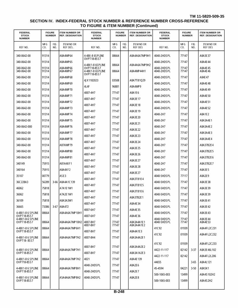
TM 11-5820-509-35SECTION IV. INDEX-FEDERAL STOCK NUMBER & REFERENCE NUMBER CROSS-REFERENCE
TO FIGURE & ITEM NUMBER (Continued)
FEDERAL FIGURE ITEM NUMBER OR FEDERAL FIGURE ITEM NUMBER OR FEDERAL FIGURE ITEM NUMBER ORSTOCK NUMBER REF. DESIGNATION STOCK NUMBER REF. DESIGNATION STOCK NUMBER REF. DESIGNATION
NUMBER NUMBER NUMBER
MFG FIG ITEM NO OR MFG FIG ITEM NO OR MFG FIG ITEM NO ORREF NO. CO. NO. REF DES. REF NO. CO. NO. REF DES REF NO. CO. NO. REF DES
340-0642-00 91314 A8A4MP64 4-48X-8 6SPLINE 08664 A8A4A6A7MP9H1 4040-2HDSPL 77147 A8A3E37OVPT18-8SS7
340-0642-00 91314 A8A4MP65 4040-2HDSPL 77147 A8A4E444-48X1-8 6SPLINE 08664 A8A4A6A7MP9H2
340-0642-00 91314 A8A4MP66 OVPT18-8SS7 4040-2HDSPL 77147 A8A4E45340-0642-00 91314 A8A4MP67 4-48X1-8 6SPLINE 08664 A8A4MP44H1 4040-2HDSPL 77147 A8A4E46
OVPT18-8SS7340-0642-00 91314 A8A4MP68 4040-2HDSPL 77147 A84E47
4JX1182023 03508 A8A7TB1Q29340-0642-00 91314 A8A4MP69 4040-2HDSPL 77147 A8A4E48
4L4F 96881 A8A4MP9340-0642-00 91314 A8A4MP70 4040-2HDSPL 77147 A8A4E49
4007-4H7 77147 A8A1E6340-0642-00 91314 A8A4MP71 4040-2HDSPL 77147 A8A4E50
4007-4H7 77147 A8A3E17340-0642-00 91314 A8A4MP72 4040-2HDSPL 77147 A8A4E51
4007-4H7 77147 A8A3E18340-0642-00 91314 A8A4MP73 4040-2HDSPL 77147 A8A4E52
4007-4H7 77147 A8A3E19340-0642-00 91314 A8A4MP74 4040-2H7 77147 A8A1E2
4007-4H7 77147 A8A3E20340-0642-00 91314 A8A4MP75 4040-2H7 77147 A8A3A4E1
4007-4H7 77147 A8A3E21340-0642-000 91314 A8A4MP76 4040-2H7 77147 A8A3A4E2
4007-4H7 77147 A8A3E22340-0642-00 91314 A8A4MP77 4040-2H7 77147 A8A3A4E3
4007-4H7 77147 A8A3E23340-0642-00 91314 A8A4MP78 4040-2H7 77147 A8A3A4E4
4007-4H7 77147 A8A3E24340-0642-00 91314 A87AMP79 4040-2H7 77147 A8A37B2E4
4007-4H7 77147 A8A3E25340-0642-00 91314 A8A4MP80 4040-2H7 77147 A8A37B2E5
4007-4H7 77147 A8A3E26340-0642-00 91314 A8A4MP81 4040-2H7 77147 A8A37B2E6
4007-4H7 77147 A8A3E27340149 75915 A81A4XF1 4040-2H7 77147 A8A37B2E7
4007-4H7 77147 A8A3E28340164 75915 A8A4XF2 4040-2H7 77147 A8A3E5
4007-4H7 77147 A8A3E2735107 00779 ASE3 4040-5HDSPL 77117 A8A2E9
4007-4H7 77147 A8A3TB1E436C228A3 56289 3-66 A8A4A1C139 4040-5HDSPL 77147 A8A3E38
4007-4H7 77147 A8A3TB1E546062 75818 A7A1E1W1 4040-5HDSPL 77147 A8A3E39
4007-4H7 77147 A8A3TB1E636062 75818 A7A2E1W1 4040-5HDSPL 77147 A8A3E39
4007-4H7 77147 A8A37B2E136109 75818 A8A3A3W1 4040-5HDSPL 77147 A8A3E41
4007-4H7 77147 A8A4E3436665 73386 3-67 A8A472 4040-5HDSPL 77147 A8A3E42
4007-6H7 77147 A8A4E354-48X1-8 6 SPLINE 08664 A8A4A6A7MP10H1 4040-5HDSPL 77147 A8A3E43OVPT18-8SS7 4007-6H7 77147 A8A4E364-48X1-8-6 SPLINE 4040-5HDSPL 77147 A8A3E44OVPT18-8SS7 08664 A8A4A6A7MP10H2 4007-8H7 77147 A8A3A4A1E1 4040-5HDSPL 77147 A8A4E53
4007-8H7 77147 A8A3A4A1E24-48X1-8 6 SPLINE 08664 A8A4A6A7MP6H1 41C92 01939 A8A4FL2C231OVPT18-8SS7 4007-8H7 77147 A8A4A1E3
41C92 01939 A8A4FL2C2324-48X1-8 6 SPLINE 08664 A8A4A6A7MP7H2 4007-8H4 77147 A8A3A4A2E1OVPT18- 8SS7
41C92 01939 A8A4FL2C2334007-8H7 77147 A8A3A4A2E2
4-48X1-8 6 SPLINE 08664 A8A4A6A7MP7H1 4422-11-117 82142 3-37 A8A3E46L102OVPT18-8SS7 4007-8H7 77147 A8A3A1A2E3
4422-11-117 82142 A8A4FL2L2064-48X1-8 6 SPLINE 08664 A8A4A6A7MP7H2 4021 77147 A8A4E139OVP718-8SS7 44655 3-65 A8A4L121
4040-2HDSPL 77147 A8A2E64-48X1-8 6 SPLINE 08664 A8A4A6A7MP8H1 45-4594 04221 3-50 A8A5K1OVPT18-8SS7 4040-2HDSPL 77147 A8A2E7
500-1065-003 13499 A8A4S102H24-48X1-8 6 SPLINE 08664 A5A4A6A7MP8H2 4040-2HDSPL 77147 A8A2E8OVPT18-8SS7 500-1065-003 13499 A8A4S2H2
B-248
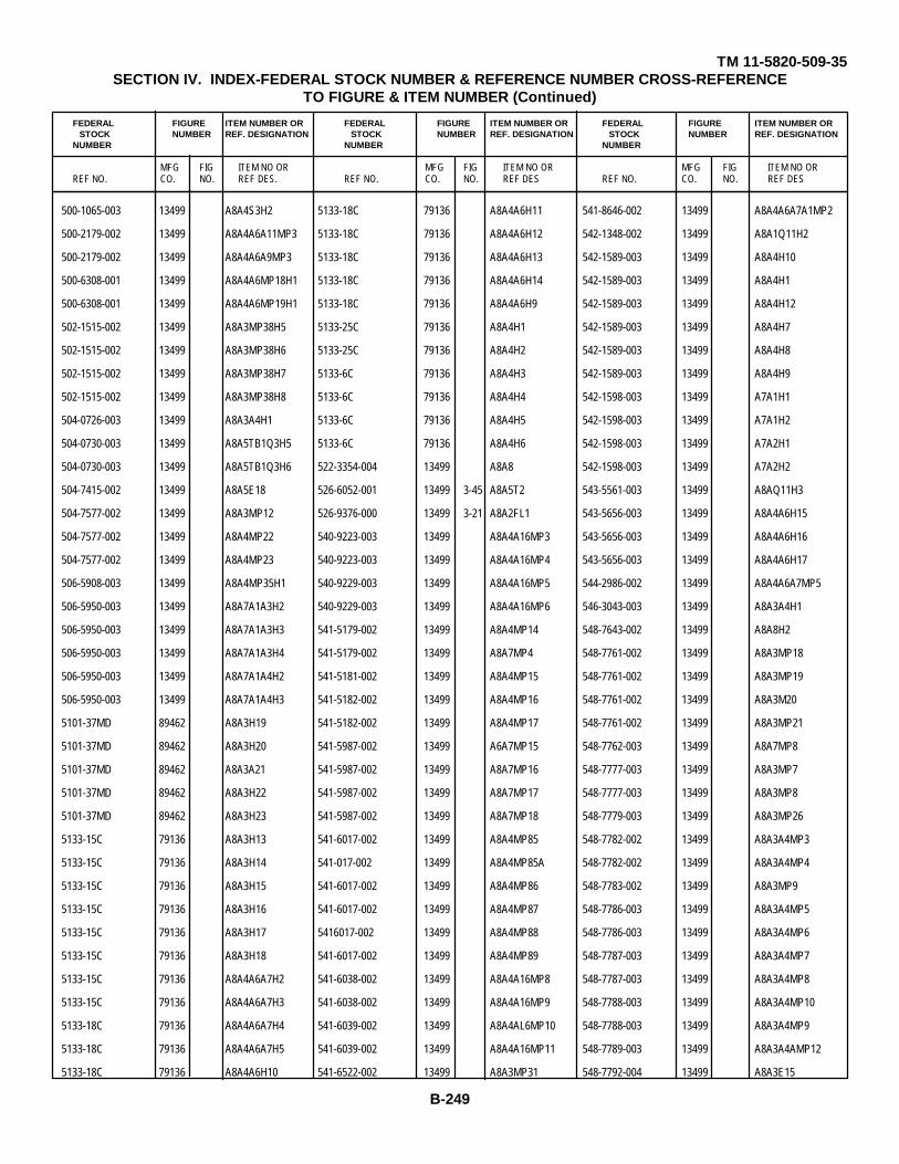
TM 11-5820-509-35SECTION IV. INDEX-FEDERAL STOCK NUMBER & REFERENCE NUMBER CROSS-REFERENCE
TO FIGURE & ITEM NUMBER (Continued)
FEDERAL FIGURE ITEM NUMBER OR FEDERAL FIGURE ITEM NUMBER OR FEDERAL FIGURE ITEM NUMBER ORSTOCK NUMBER REF. DESIGNATION STOCK NUMBER REF. DESIGNATION STOCK NUMBER REF. DESIGNATION
NUMBER NUMBER NUMBER
MFG FIG ITEM NO OR MFG FIG ITEM NO OR MFG FIG ITEM NO ORREF NO. CO. NO. REF DES. REF NO. CO. NO. REF DES REF NO. CO. NO. REF DES
500-1065-003 13499 A8A4S3H2 5133-18C 79136 A8A4A6H11 541-8646-002 13499 A8A4A6A7A1MP2
500-2179-002 13499 A8A4A6A11MP3 5133-18C 79136 A8A4A6H12 542-1348-002 13499 A8A1Q11H2
500-2179-002 13499 A8A4A6A9MP3 5133-18C 79136 A8A4A6H13 542-1589-003 13499 A8A4H10
500-6308-001 13499 A8A4A6MP18H1 5133-18C 79136 A8A4A6H14 542-1589-003 13499 A8A4H1
500-6308-001 13499 A8A4A6MP19H1 5133-18C 79136 A8A4A6H9 542-1589-003 13499 A8A4H12
502-1515-002 13499 A8A3MP38H5 5133-25C 79136 A8A4H1 542-1589-003 13499 A8A4H7
502-1515-002 13499 A8A3MP38H6 5133-25C 79136 A8A4H2 542-1589-003 13499 A8A4H8
502-1515-002 13499 A8A3MP38H7 5133-6C 79136 A8A4H3 542-1589-003 13499 A8A4H9
502-1515-002 13499 A8A3MP38H8 5133-6C 79136 A8A4H4 542-1598-003 13499 A7A1H1
504-0726-003 13499 A8A3A4H1 5133-6C 79136 A8A4H5 542-1598-003 13499 A7A1H2
504-0730-003 13499 A8A5TB1Q3H5 5133-6C 79136 A8A4H6 542-1598-003 13499 A7A2H1
504-0730-003 13499 A8A5TB1Q3H6 522-3354-004 13499 A8A8 542-1598-003 13499 A7A2H2
504-7415-002 13499 A8A5E18 526-6052-001 13499 3-45 A8A5T2 543-5561-003 13499 A8AQ11H3
504-7577-002 13499 A8A3MP12 526-9376-000 13499 3-21 A8A2FL1 543-5656-003 13499 A8A4A6H15
504-7577-002 13499 A8A4MP22 540-9223-003 13499 A8A4A16MP3 543-5656-003 13499 A8A4A6H16
504-7577-002 13499 A8A4MP23 540-9223-003 13499 A8A4A16MP4 543-5656-003 13499 A8A4A6H17
506-5908-003 13499 A8A4MP35H1 540-9229-003 13499 A8A4A16MP5 544-2986-002 13499 A8A4A6A7MP5
506-5950-003 13499 A8A7A1A3H2 540-9229-003 13499 A8A4A16MP6 546-3043-003 13499 A8A3A4H1
506-5950-003 13499 A8A7A1A3H3 541-5179-002 13499 A8A4MP14 548-7643-002 13499 A8A8H2
506-5950-003 13499 A8A7A1A3H4 541-5179-002 13499 A8A7MP4 548-7761-002 13499 A8A3MP18
506-5950-003 13499 A8A7A1A4H2 541-5181-002 13499 A8A4MP15 548-7761-002 13499 A8A3MP19
506-5950-003 13499 A8A7A1A4H3 541-5182-002 13499 A8A4MP16 548-7761-002 13499 A8A3M20
5101-37MD 89462 A8A3H19 541-5182-002 13499 A8A4MP17 548-7761-002 13499 A8A3MP21
5101-37MD 89462 A8A3H20 541-5987-002 13499 A6A7MP15 548-7762-003 13499 A8A7MP8
5101-37MD 89462 A8A3A21 541-5987-002 13499 A8A7MP16 548-7777-003 13499 A8A3MP7
5101-37MD 89462 A8A3H22 541-5987-002 13499 A8A7MP17 548-7777-003 13499 A8A3MP8
5101-37MD 89462 A8A3H23 541-5987-002 13499 A8A7MP18 548-7779-003 13499 A8A3MP26
5133-15C 79136 A8A3H13 541-6017-002 13499 A8A4MP85 548-7782-002 13499 A8A3A4MP3
5133-15C 79136 A8A3H14 541-017-002 13499 A8A4MP85A 548-7782-002 13499 A8A3A4MP4
5133-15C 79136 A8A3H15 541-6017-002 13499 A8A4MP86 548-7783-002 13499 A8A3MP9
5133-15C 79136 A8A3H16 541-6017-002 13499 A8A4MP87 548-7786-003 13499 A8A3A4MP5
5133-15C 79136 A8A3H17 5416017-002 13499 A8A4MP88 548-7786-003 13499 A8A3A4MP6
5133-15C 79136 A8A3H18 541-6017-002 13499 A8A4MP89 548-7787-003 13499 A8A3A4MP7
5133-15C 79136 A8A4A6A7H2 541-6038-002 13499 A8A4A16MP8 548-7787-003 13499 A8A3A4MP8
5133-15C 79136 A8A4A6A7H3 541-6038-002 13499 A8A4A16MP9 548-7788-003 13499 A8A3A4MP10
5133-18C 79136 A8A4A6A7H4 541-6039-002 13499 A8A4AL6MP10 548-7788-003 13499 A8A3A4MP9
5133-18C 79136 A8A4A6A7H5 541-6039-002 13499 A8A4A16MP11 548-7789-003 13499 A8A3A4AMP12
5133-18C 79136 A8A4A6H10 541-6522-002 13499 A8A3MP31 548-7792-004 13499 A8A3E15
B-249

TM 11-5820-509-35SECTION IV. INDEX-FEDERAL STOCK NUMBER & REFERENCE NUMBER CROSS-REFERENCE
TO FIGURE & ITEM NUMBER (Continued)
FEDERAL FIGURE ITEM NUMBER OR FEDERAL FIGURE ITEM NUMBER OR FEDERAL FIGURE ITEM NUMBER ORSTOCK NUMBER REF. DESIGNATION STOCK NUMBER REF. DESIGNATION STOCK NUMBER REF. DESIGNATION
NUMBER NUMBER NUMBER
MFG FIG ITEM NO OR MFG FIG ITEM NO OR MFG FIG ITEM NO ORREF NO. CO. NO. REF DES. REF NO. CO. NO. REF DES REF NO. CO. NO. REF DES
548-7793-004 13499 3-33 A8A3A4A1 548-7835-002 13499 A8A3A12S8E1 548-9319-002 13499 A8A4MP56
548-7794-005 13499 3-9 A8A3A4 548-7835-002 13499 A8A3A9A2S2E1 548-9319-002 13499 A8A4MP57
548-7795-005 13499 3-33 A8A3A4A2 548-7835-003 13499 A8A3A9A3S3E1 548-9308-003 13499 A8A9
548-7797-004 13499 3-41 A8A3L145 548-7839-003 13499 A8A3A10S4E2 549-1544-003 13499 A8A6MP2
548-7799-005 13499 3-33 A8A3A4E6 548-7339-003 13499 A8A3A11S5E2 549-1545-003 13499 A8A6MP3
548-7800-002 13499 A8A3A4A1E4 548-7839-003 13499 A8A3A12S8E2 549-1549-003 13499 A8A6MP1
548-7800-002 13499 A8A3A4A1E5 548-7839-003 13499 A8A3A9A1S1E1 549-1551-003 13499 3-52 A8A6E1TB1
518-7800-002 13499 A8A3A4A1E6 548-7839-003 13499 A8A3A9A2S2E2 549-1552-004 13499 3-13 A8A6A1
548-7800-002 13499 A8A3A4A1E7 548-7839-003 13499 A8A3A9A3S3E2 549-1553-004 13499 3-12 A8A6E1
548-7800-002 13499 A8A3A4A1E8 548-7858-003 13499 A8A7E7A2E1 549-1555-005 13499 3-53 A8A6A1A1
548-7800-002 13499 A8A3A4A2E4 548-7858-003 13499 A8A7E7A2E2 549-1680-004 13499 3-12 A6A6E2
518-7800-002 13499 A8A3A4A2E5 548-7870-004 13499 A8A3A4MP1 549-1682-004 13499 3-52 A8A6E2TB1
548-7800-002 13499 A8A3A4A2E6 548-7872-004 13499 A8A3A4MP2 549-5641-000 13499 A8AW11
548-7800-002 13499 A8A3A4A2E7 548-7882-004 13499 A8A3MP25 549-5642-002 13499 A8A1Q11H1
518-7800-002 13499 A8A3A4A2E8 548-7886-004 13499 A8A3A1 549-5643-002 13499 A8A3A13MP1
548-7802-004 13499 3-34 A8A3A4E7 548-7897-002 13499 A8A8MP2 549-5643-002 13499 A8A7E5MP3
548-7805-004 13499 3-31 A8A3A4A1L125 548-7908-002 13499 A8A4MP58 549-5650-003 13499 3-17 A8A1E1E1
548-7805-004 13499 3-32 A8A3A4A2L141 548-7908-002 13499 A8A4MP59 549-5651-004 13499 3-6 A8A1E2
548-7806-004 13499 3-32 A8A3A4A2L143 548-7909-002 13499 A8A4MP51 549-5653-004 13499 3-18 A8A1E2E1
548-7807-004 13499 3-31 A8A3A4A1L126 548-7909-002 13499 A8A4MP52 549-5654-004 13499 3-6 A8A1E1
548-7807-004 13499 3-31 A8A3A4A1L142 548-7910-002 13499 A8A4MP38 549-5655-004 13499 3-6 A8A1E3
548-7808-004 13499 3-31 A8A3A4A1L127 548-7910-002 13499 A8A4MP39 549-5657-004 13499 3-19 A8A1E3E1
548-7308-004 13499 3-31 A8A3A4A1L133 548-7911-002 13499 A8A4E20 549-5659-005 13499 A8A1MP1
548-7808-004 13499 3-31 A8A3A4A1L134 548-7911-002 13499 A8A4E21 549-5660-002 13499 3-21 A8A2MP3
548-7808-004 13499 3-32 A8A3A4A2L128 548-7912-004 13499 A8A3M24 549-5678-003 13499 3-20 A8A2E2
548-7808-004 13499 3-32 A8A3A4A2L129 548-7975-002 13499 A8A4J2H5 549-5680-003 13499 3-20 A8A2E2E1
548-7808-004 13499 3-32 A8A3A4A2L130 548-7975-002 13499 A8A4J2H6 549-5682-003 13499 3-21 A8A2E3E1
548-7808-004 13499 3-32 A8A3A4A2L131 548-7975-002 13499 A8A4J3H5 549-5684-003 13499 3-21 A8A2ELE1
548-7808-004 13499 3-32 A8A3A4A2L132 548-7975-002 13499 A8A4J3H6 549-5686-003 13499 A8A2E5E1
548-7809-000 13499 3-31 A8A3A4A1L141 548-7975-002 13499 A8ALJ4H5 589-868-0000 13499 3-20 A8A2E1
548-7810-004 13499 3-11 A8A3A4A1L140 558-7975-002 13499 A8A4J4H6 549-5690-000 13499 A8A2E1E1
548-7811-004 13499 3-31 A8A3A4A1L139 548-7975-002 13499 A8A4J9H5 549-5691-004 13499 3-21 A8A2E3
548-7812-004 13499 3-31 A8A3A4A1L138 548-7975-002 13499 A8A4J9H6 549-5692-004 13499 3-21 A8A2E3
548-7813-004 13499 3-32 A8A3A4A2L137 548-7976-003 13499 A8A4H5 549-5693-004 13499 3-21 A8A2E5
548-7814-004 13499 3-32 A8A3A4A2L136 548-9095-002 13499 A4A1 549-5703-005 13499 A8A1MP2
548-7815-004 13499 3-32 A8A3A4A2L135 548-9097-003 13499 1-1 A4A1MP1 549-5709-002 13499 A8A1E4
548-7835-002 13499 A8A3A1054E1 548-9098-003 13499 A5E2 549-5709-002 13499 A8A3E16
548-7835-002 13499 A8A3A1155E1 548-9101-004 13499 1-7 A4A2 549-5709-002 13499 A8A5E4
B-250

TM 11-5820-509-35SECTION IV. INDEX-FEDERAL STOCK NUMBER & REFERENCE NUMBER CROSS-REFERENCE
TO FIGURE & ITEM NUMBER (Continued)
FEDERAL FIGURE ITEM NUMBER OR FEDERAL FIGURE ITEM NUMBER OR FEDERAL FIGURE ITEM NUMBER ORSTOCK NUMBER REF. DESIGNATION STOCK NUMBER REF. DESIGNATION STOCK NUMBER REF. DESIGNATION
NUMBER NUMBER NUMBER
MFG FIG ITEM NO OR MFG FIG ITEM NO OR MFG FIG ITEM NO ORREF NO. CO. NO. REF DES. REF NO. CO. NO. REF DES REF NO. CO. NO. REF DES
549-5709-002 13499 A8A7E8 549-5744-002 13499 A8A7E5MP5 549-5813-003 13499 A8A5M9
549-5710-002 13499 A8A7MP13 549-5746-002 13499 A8A7E5E2 549-5815-003 13499 A8A5MP3
549-5710-002 13499 A8A7MP14 549-5746-002 13499 A8A7E5E3 549-5823-003 13499 A8A8E2
549-5711-002 13499 A8A7MP10 549-5748-002 13499 3-58 A8A7E5L19 549-5825-003 13499 3-48 A6A5E2EH
549-5717-002 13499 A8A7A2 549-5749-002 13499 A8A7A1A2MP3 549-5827-003 13499 3-45 A8A5E3
549-5718-002 13499 A8A7A2MP2 549-5749-002 13499 A8A7A1A2MP4 549-5829-003 13499 3-49 A8A5E3E
549-5719-002 13499 A8A7A2A1 549-5750-002 13499 A8A7A1A2MP5 549-5831-004 13499 3-11 A8A5E1
549-5719-002 13499 A8A7A3A1 549-5751-002 13499 A8A7A1A2MP1 549-5833-004 13499 3-47 A8A5E1E1
549-5720-002 13499 A8A3A8A1MP2 549-5751-002 13499 A8A7A1A2MP2 549-5835-005 13499 A8A5MP1
549-5720-002 13499 A8A7A2A1MP2 549-5752-002 13499 A8A7W1 549-5836-002 13499 A8A5MP4
549-5720-002 13499 A8A7A3A1MP2 549-5755-003 13499 A8A77P9 549-5836-002 13499 A8A5MP5
549-5721-002 13499 A8A3A2M3 549-5760-003 13499 A8A7A2A1MP1 549-5838-000 13499 A8A3W1
549-5721-002 13499 A8A3A8A1MP3 549-5760-003 13499 A8A7A3A1MP1 549-5843-002 13499 A8A7E7A2MP1
549-5721-002 13499 A8A7A2A1MP3 549-5761-003 13499 A8A7A1 549-5843-002 13499 A8A7E7A2MP2
549-5721-002 13499 A8A73A3 549-5762-003 13499 A8A7A1A4MP3 549-5846-002 13499 A8A3A8MP2
549-5722-002 13499 A8A7A3 549-5764-003 13499 3-60 A8A7E7A1E8 549-5850-002 13499 A8A3A9MP1
549-5723-002 13499 A8A7A3M2 549-5767-003 13499 A8A7MP12 549-5850-002 13499 A8A3A9MP2
549-5724-002 13499 A6A7A1A3 549-5771-003 13499 3-55 A8A7E2E2 549-5850-002 13499 A8A3A99 3
549-5725-002 13499 A8A7A1A3W3 549-5775-004 13499 A8A7MP11 549-5850-002 13499 A8A3A9MP4
549-5726-002 13499 A8A77AA31P1 549-5776-004 13499 3-4 A8A7E7 549-5851-002 13499 A8A3A9MP5
549-5727-002 13499 A8A7ALA3A1 549-5777-004 13499 3-60 A8A7E7A1 549-5851-002 13499 A8A3A9MP6
549-5728-002 13499 A8A7A1A3A1MP2 549-5778-004 13499 3-60 A8A7E7A2 549-5851-002 13499 A8A3A9MP7
549-5729-002 13499 A8A7A1A3A1MP1 549-578-0004 13499 3-60 A8A7E7A2E1 549-5851-002 13499 A8A39MA9P8
549-5730-002 13499 A8A71A1A4 549-5783-004 13499 3-15 A8A7E5 549-5853-002 13499 A8A3A2MP
549-5731-002 13499 A8A7A1A4W1 549-5785-004 13499 3-58 A8A7E5E1 549-5854-002 13499 A6A3A8A1MP1
549-5732-002 13499 A8A7A1A4MP2 549-5788-000 13499 3-14 A8A7E4 549-5857-002 13499 A8A3A7MP5
549-5733-002 13499 A8A7A1A1 549-5790-004 13499 3-57 A8A7E4E1 549-5858-002 13499 A8A3A7MP6
549-5734-002 13499 A8A7A1A1MP2 549-5794-004 13499 3-14 A8A7E2 549-5859-002 13499 A8A3M27
549-5735-002 13499 A8A7E7A2MP10 549-5796-004 13499 3-15 A8A7E1 549-5859-002 13499 A8A3MP28
549-5735-002 13499 A8A7E7A2MP9 549-5798-004 13499 3-54 A8A7E1E1 549-5860-002 13499 A8A3MP5
549-5737-002 13499 A8A7E7A2MP3 549-5801-004 13499 3-14 A8A7E6 549-5860-002 13499 A8A3MP6
549-5735-002 13499 A8A7E7A2MP4 549-5803-004 13499 3-59 A8A7E6E1 549-5861-002 13499 A8A3A7MP3
549-5737-002 13499 A8A7E7A2MP5 549-5806-004 13499 A8A7A1A2MP10 549-5861-002 13499 A8A3A7MP4
549-5737-002 13499 A8A71E7A2MP6 549-5807-004 13499 A8A7A1A2 549-5862-002 13499 A8A3MP13
549-5742-002 13499 A8A7E5MP1 549-5809-005 13499 A8A7A1MP5 549-5862-002 13499 A8A3MP14
549-5742-002 13499 A8A7E5MP2 549-5810-000 13499 A8A5W1 549-5863-002 13499 A8A3MP39
549-5743-002 13499 A8A7E5E4 549-5811-002 13499 A8A5MP7 549-5863-002 13499 A8A3MP40
549-5744-002 13499 A8A7E5MP4 549-5811-002 13499 A8A5MP8 549-5864-002 13499 A8A3MP30
B-251
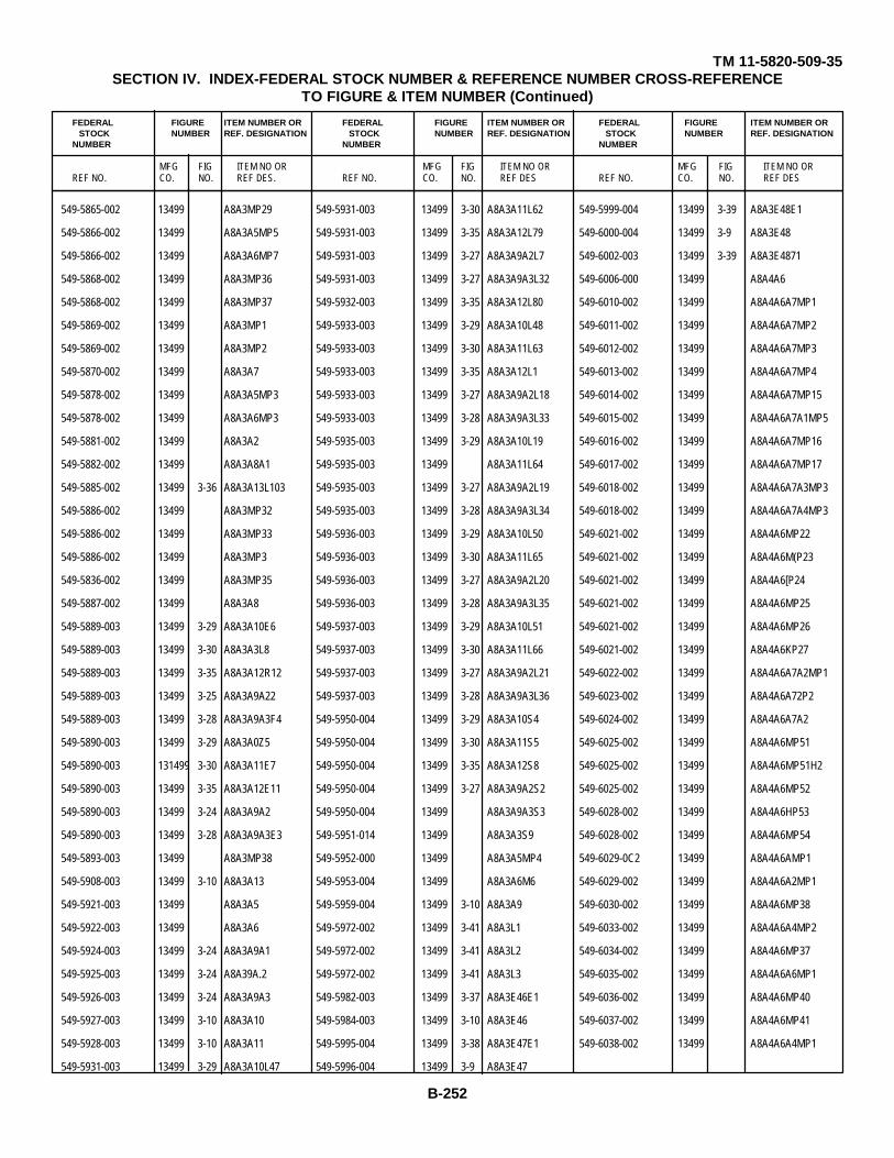
TM 11-5820-509-35SECTION IV. INDEX-FEDERAL STOCK NUMBER & REFERENCE NUMBER CROSS-REFERENCE
TO FIGURE & ITEM NUMBER (Continued)
FEDERAL FIGURE ITEM NUMBER OR FEDERAL FIGURE ITEM NUMBER OR FEDERAL FIGURE ITEM NUMBER ORSTOCK NUMBER REF. DESIGNATION STOCK NUMBER REF. DESIGNATION STOCK NUMBER REF. DESIGNATION
NUMBER NUMBER NUMBER
MFG FIG ITEM NO OR MFG FIG ITEM NO OR MFG FIG ITEM NO ORREF NO. CO. NO. REF DES. REF NO. CO. NO. REF DES REF NO. CO. NO. REF DES
549-5865-002 13499 A8A3MP29 549-5931-003 13499 3-30 A8A3A11L62 549-5999-004 13499 3-39 A8A3E48E1
549-5866-002 13499 A8A3A5MP5 549-5931-003 13499 3-35 A8A3A12L79 549-6000-004 13499 3-9 A8A3E48
549-5866-002 13499 A8A3A6MP7 549-5931-003 13499 3-27 A8A3A9A2L7 549-6002-003 13499 3-39 A8A3E4871
549-5868-002 13499 A8A3MP36 549-5931-003 13499 3-27 A8A3A9A3L32 549-6006-000 13499 A8A4A6
549-5868-002 13499 A8A3MP37 549-5932-003 13499 3-35 A8A3A12L80 549-6010-002 13499 A8A4A6A7MP1
549-5869-002 13499 A8A3MP1 549-5933-003 13499 3-29 A8A3A10L48 549-6011-002 13499 A8A4A6A7MP2
549-5869-002 13499 A8A3MP2 549-5933-003 13499 3-30 A8A3A11L63 549-6012-002 13499 A8A4A6A7MP3
549-5870-002 13499 A8A3A7 549-5933-003 13499 3-35 A8A3A12L1 549-6013-002 13499 A8A4A6A7MP4
549-5878-002 13499 A8A3A5MP3 549-5933-003 13499 3-27 A8A3A9A2L18 549-6014-002 13499 A8A4A6A7MP15
549-5878-002 13499 A8A3A6MP3 549-5933-003 13499 3-28 A8A3A9A3L33 549-6015-002 13499 A8A4A6A7A1MP5
549-5881-002 13499 A8A3A2 549-5935-003 13499 3-29 A8A3A10L19 549-6016-002 13499 A8A4A6A7MP16
549-5882-002 13499 A8A3A8A1 549-5935-003 13499 A8A3A11L64 549-6017-002 13499 A8A4A6A7MP17
549-5885-002 13499 3-36 A8A3A13L103 549-5935-003 13499 3-27 A8A3A9A2L19 549-6018-002 13499 A8A4A6A7A3MP3
549-5886-002 13499 A8A3MP32 549-5935-003 13499 3-28 A8A3A9A3L34 549-6018-002 13499 A8A4A6A7A4MP3
549-5886-002 13499 A8A3MP33 549-5936-003 13499 3-29 A8A3A10L50 549-6021-002 13499 A8A4A6MP22
549-5886-002 13499 A8A3MP3 549-5936-003 13499 3-30 A8A3A11L65 549-6021-002 13499 A8A4A6M(P23
549-5836-002 13499 A8A3MP35 549-5936-003 13499 3-27 A8A3A9A2L20 549-6021-002 13499 A8A4A6[P24
549-5887-002 13499 A8A3A8 549-5936-003 13499 3-28 A8A3A9A3L35 549-6021-002 13499 A8A4A6MP25
549-5889-003 13499 3-29 A8A3A10E6 549-5937-003 13499 3-29 A8A3A10L51 549-6021-002 13499 A8A4A6MP26
549-5889-003 13499 3-30 A8A3A3L8 549-5937-003 13499 3-30 A8A3A11L66 549-6021-002 13499 A8A4A6KP27
549-5889-003 13499 3-35 A8A3A12R12 549-5937-003 13499 3-27 A8A3A9A2L21 549-6022-002 13499 A8A4A6A7A2MP1
549-5889-003 13499 3-25 A8A3A9A22 549-5937-003 13499 3-28 A8A3A9A3L36 549-6023-002 13499 A8A4A6A72P2
549-5889-003 13499 3-28 A8A3A9A3F4 549-5950-004 13499 3-29 A8A3A10S4 549-6024-002 13499 A8A4A6A7A2
549-5890-003 13499 3-29 A8A3A0Z5 549-5950-004 13499 3-30 A8A3A11S5 549-6025-002 13499 A8A4A6MP51
549-5890-003 131499 3-30 A8A3A11E7 549-5950-004 13499 3-35 A8A3A12S8 549-6025-002 13499 A8A4A6MP51H2
549-5890-003 13499 3-35 A8A3A12E11 549-5950-004 13499 3-27 A8A3A9A2S2 549-6025-002 13499 A8A4A6MP52
549-5890-003 13499 3-24 A8A3A9A2 549-5950-004 13499 A8A3A9A3S3 549-6028-002 13499 A8A4A6HP53
549-5890-003 13499 3-28 A8A3A9A3E3 549-5951-014 13499 A8A3A3S9 549-6028-002 13499 A8A4A6MP54
549-5893-003 13499 A8A3MP38 549-5952-000 13499 A8A3A5MP4 549-6029-0C2 13499 A8A4A6AMP1
549-5908-003 13499 3-10 A8A3A13 549-5953-004 13499 A8A3A6M6 549-6029-002 13499 A8A4A6A2MP1
549-5921-003 13499 A8A3A5 549-5959-004 13499 3-10 A8A3A9 549-6030-002 13499 A8A4A6MP38
549-5922-003 13499 A8A3A6 549-5972-002 13499 3-41 A8A3L1 549-6033-002 13499 A8A4A6A4MP2
549-5924-003 13499 3-24 A8A3A9A1 549-5972-002 13499 3-41 A8A3L2 549-6034-002 13499 A8A4A6MP37
549-5925-003 13499 3-24 A8A39A.2 549-5972-002 13499 3-41 A8A3L3 549-6035-002 13499 A8A4A6A6MP1
549-5926-003 13499 3-24 A8A3A9A3 549-5982-003 13499 3-37 A8A3E46E1 549-6036-002 13499 A8A4A6MP40
549-5927-003 13499 3-10 A8A3A10 549-5984-003 13499 3-10 A8A3E46 549-6037-002 13499 A8A4A6MP41
549-5928-003 13499 3-10 A8A3A11 549-5995-004 13499 3-38 A8A3E47E1 549-6038-002 13499 A8A4A6A4MP1
549-5931-003 13499 3-29 A8A3A10L47 549-5996-004 13499 3-9 A8A3E47
B-252
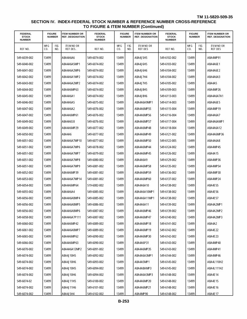
TM 11-5820-509-35SECTION IV. INDEX-FEDERAL STOCK NUMBER & REFERENCE NUMBER CROSS-REFERENCE
TO FIGURE & ITEM NUMBER (Continued)
FEDERAL FIGURE ITEM NUMBER OR FEDERAL FIGURE ITEM NUMBER OR FEDERAL FIGURE ITEM NUMBER ORSTOCK NUMBER REF. DESIGNATION STOCK NUMBER REF. DESIGNATION STOCK NUMBER REF. DESIGNATION
NUMBER NUMBER NUMBER
MFG FIG ITEM NO OR MFG FIG ITEM NO OR MFG FIG ITEM NO ORREF NO. CO. NO. REF DES. REF NO. CO. NO. REF DES REF NO. CO. NO. REF DES
549-6039-002 13499 A8A4A6A6 549-6074-002 13499 A8A4J5H5 549-6102-002 13499 A8A4MP91
549-6040-002 13499 A8A4A6A5MP1 549-6074-002 13499 A8A4J6H5 549-6103-002 13499 A8A4A6E1
549-6041-002 13499 A8A4A6A2MP6 549-6074-002 13499 A8A4J6H6 549-6104-002 13499 A8A4A6E2
549-6042-002 13499 A8A4A6A1MP2 549-6074-002 13499 A8A4J7H4 549-6104-002 13499 A8A4A6A3
549-6043-002 13499 A8A4A6A2MP2 549-6074-002 13499 A8A4J7H5 549-6105-002 13499 A8A4A5
549-6044-002 13499 A8A4A6MP63 549-6074-002 13499 A8A4J8H5 549-6109-003 13499 A8A4MP26
549-6045-002 13499 A8A4A6A1 549-6074-002 13499 A8A4J8H6 549-6113-003 13499 A8A4A6A7A1
549-6046-002 13499 A8A4A6A5 549-6075-002 13499 A8A4A6A9MP1 549-6114-003 13499 A8A4A6E5
549-6047-002 13499 A8A4A6A2 549-6076-002 13499 A8A4A6MP55 549-6115-004 13499 A8A4MP19
549-6047-002 13499 A8A4A6MP61 549-6076-002 13499 A8A4A6MP56 549-6116-004 13499 A8A4A6A7
549-6049-002 13499 A8A4A6S8 549-6076-002 13499 A8A4A6MP57 549-6117-004 13499 A8A4A6AMP1
549-6049-002 13499 A8A4A6MP29 549-6077-002 13499 A8A4A6MP48 549-6118-004 13499 A8A4A6A12
549-6050-002 13499 A8A4A6 549-6077-002 13499 A8A4A6MP49 549-6121-002 13499 A8A4A6MP36
549-6051-002 13499 A8A4A6A7MP10 549-6077-002 13499 A8A4A6MP50 549-6122-005 13499 A8A4A6A8
549-6051-002 13499 A8A4A6A7MP6 549-6078-002 13499 A8A4A6MP44 549-6124-002 13499 A8A4MP45
549-6051-002 13499 A8A4A6A7MP7 549-6079-002 13499 A8A4A6MP45 549-6126-002 13499 A8A4A15
549-6051-002 13499 A8A4A6A7MP8 549-6080-002 13499 A8A4A6A9 549-6129-002 13499 A8A4MP36
549-6051-002 13499 A8A4A6A7MP9 549-6081-002 13499 A8A4A6MP58 549-6135-002 13499 A8A4MP54
549-6052-002 13499 A8A4A6MP39 549-6081-002 13499 A8A4A6MP59 549-6136-002 13499 A8A4MP30
549-6053-002 13499 A8A4A6A7MP14 549-6081-002 13499 A8A4A6MP60 549-6137-002 13499 A8A4MP24
549-6054-002 13499 A8A4A6MP64 519-6082-002 13499 A8A4A6A10 549-6138-002 13499 A8A4E55
549-6055-002 13499 A8A4A6A4 549-6085-002 13499 A8A4A6A10MP1 549-6138-002 13499 A8A4E56
549-6056-002 13499 A8A4A6A8MP4 549-6085-002 13499 A8A4A6A11MP1 549-6138-002 13499 A8A4E57
549-6056-002 13499 A8A4A6A8MP5 549-6086-002 13499 A8A4A6A11 549-6139-002 13499 A8A4A2MP1
549-6056-002 13499 A8A4A6A8MP6 549-6087-002 13499 A8A4A6MP46 549-6139-002 13499 A8A4A2MP2
549-6058-002 13499 A8A4A6A7P111 549-6087-002 13499 A8A4A6MP47 549-6140-002 13499 A8A4A2MP3
549-6060-002 13499 A8A4A6MP42 549-6089-002 13499 A8A4A6MP18 549-6141-002 13499 A8A4A2
549-6061-002 13499 A8A4A6A8MP7 549-6089-002 13499 A8A4A6MP19 549-6142-002 13499 A8A4E22
549-6065-002 13499 A8A4A6MP62 549-6090-002 13499 A8A4A6MP30 549-6142-002 13499 A8A4E23
549-6066-002 13499 A8A4A6MP63 549-6090-002 13499 A8A4A6P31 549-6143-002 13499 A8A4MP40
549-6070-002 13499 A8A4A6A12MP2 549-6091-002 13499 A8A4A6MP35 549-6143-002 13499 A8A4MP41
549-6074-002 13499 A8A4J10H5 549-6092-002 13499 A8A4A6A3MP1 549-6144-002 13499 A8A4MP46
549-6074-002 13499 A8A4J10H6 549-6093-002 13499 A8A4A5MP1 549-6145-002 13499 A8A4L110H2
549-6074-002 13499 A8A4J10H5 549-6094-002 13499 A8A4A8AMP3 549-6145-002 13499 A8A4L111H2
549-6074-002 13499 A8A4J10H6 549-6094-002 13499 A8A4A6A3MP3 549-6148-002 13499 A8A4E14
549-6074-02 13499 A8A4J11H5 549-6100-002 13499 A8A4A6MP20 549-6148-002 13499 A8A4E15
549-6074-002 13499 A8A4J11H6 549-6101-002 13499 A8A4A6MP21 549-6148-002 13499 A8A4E16
549-6074-002 13499 A8A4J5H4 549-6102-002 13499 A8A4MP90 549-6148-002 13499 A8A4E17
B-253

TM 11-5820-509-35SECTION IV. INDEX-FEDERAL STOCK NUMBER & REFERENCE NUMBER CROSS-REFERENCE
TO FIGURE & ITEM NUMBER (Continued)
FEDERAL FIGURE ITEM NUMBER OR FEDERAL FIGURE ITEM NUMBER OR FEDERAL FIGURE ITEM NUMBER ORSTOCK NUMBER REF. DESIGNATION STOCK NUMBER REF. DESIGNATION STOCK NUMBER REF. DESIGNATION
NUMBER NUMBER NUMBER
MFG FIG ITEM NO OR MFG FIG ITEM NO OR MFG FIG ITEM NO ORREF NO. CO. NO. REF DES. REF NO. CO. NO. REF DES REF NO. CO. NO. REF DES
549-6148-002 13499 A8A4E18 549-6163-002 13499 A8A4L12E7 549-6221-003 13499 A8A4AHP1
549-6148-002 13499 A8A4E19 549-6164-002 13499 A8A4E29 549-6223-003 13499 A8A4A16E1
549-6149-002 13499 A8A4MP84 549-6164-002 13499 A8A4E30 549-6224-002 13499 A8A4A6A7A3KP1
549-6152-002 13499 A8A4L109MP8 549-6164-002 13499 A8A4E31 549-6224-002 13499 A8A4A6A7A4MP1
549-6153-002 13499 A8A4L109E1 549-6164-002 13499 A8A4E32 549-6225-002 13499 A8A4A6A7A3
549-6153-002 13499 A8A4L109E2 549-6167-002 13499 A8A4MP10 549-6225-002 13499 A8A4A6A7A4
549-6153-002 13499 A8A4L110E1 549-6167-002 13499 A8A4MP11 549-6227-000 13499 3-67 A8A4w1
549-6153-002 13499 A8A4L110E2 549-6171-002 13499 A8A4L109A1 549-6229-003 13499 A8A4A7
549-6153-002 13499 A8A4L111E1 549-6172-002 13499 A8A4L111MP1 549-6230-004 13499 A8A4A1
549-6153-002 13499 A8A4L111E2 549-6173-002 13499 A8A4E24 549-6231-004 13499 A8A4MP18
549-6153-002 13499 A8A4L112E1 549-6174-002 13499 A8A4E131 549-6232-004 13499 A8A4A16
549-6153-002 13499 A8A4L112E2 549-6175-002 13499 A8A4L112MP1 549-6234-003 13499 A8A4MP12
549-6154-002 13499 A8A4L109E4 549-6176-002 13499 A8A4L110MP1 549-6242-002 13499 A2MP4
549-6154-002 13499 A8A4L109E5 549-6177-002 13499 A8A4E25 549-6244-002 13499 A2J1H2
549-6154-002 13499 A8A4L110E4 549-6177-002 13499 A8A4E26 549-6244-002 13499 A2J2H3
549-6154-002 13499 A8A4L110E5 549-6177-002 13499 A8A4E27 549-6245-002 13499 A2J1
549-6154-002 13499 A8A4L111E4 549-6177-002 13499 A8A4E28 549-6245-002 13499 A2J2
549-6154-002 13499 A8A4LL11E5 549-6178-002 13499 A8A4L109MP4 549-6246-002 13499 A2ALP1H1
549-6154-002 13499 A8A4L112E4 549-6178-002 13499 A8A4L112MP2 549-6246-002 13499 A2A12MH1
549-6154-002 13499 A8A4L112E5 549-6185-002 13499 A8A4MP34 549-6247-002 13499 A2A1
549-6155-002 13499 A8A4MP27 549-6189-002 13499 A8A4MP42 549-6247-002 13499 A2A2
549-6156-002 13499 A8A4MP32 549-6190-002 13499 A8A4MP44 549-6250-003 13499 A2MP2
549-6156-002 13499 A8A4MP33 549-6191-002 13499 A8A4A7MP1 549-6252-003 13499 A2P81
549-6157-002 13499 A8A4L109A1MP1 549-6193-002 13499 A8A4A7A1E1 549-6254-004 13499 A8A4AA6A7A1M
549-6158-002 13499 A8A4L111MP2 549-6194-002 13499 A8A4A7A1 549-6277-000 13499 A6
549-6159-002 13499 A8A4L1110MP3 549-6195-002 13499 A8A4MP60 549-6278-002 13499 A6A1MP1
549-6159-002 13499 A8A4L11MP6 549-6196-002 13499 A8A4MP35 549-6278-002 13499 A6A2MP1
549-6160-002 13499 A8A4L109MP7 549-6197-002 13499 A8A4A16MP7 549-6279-002 13499 A6MP7
549-6160-002 13499 A8A4L112MP5 549-6198-002 13499 A8A4A116L104- 549-6280-002 13499 A6MP5R110
549-6162-002 13499 A8A4L109A1MP3 549-6280-002 13499 A6MP6549-6205-003 13499 A864A15E1
549-6162-002 13499 A8A4L111MP4 549-6281-002 13499 A6A1549-6210-003 13499 3-67 A8A4TB4
549-6163-002 13499 A8A4L109E6 549-6281-002 13499 A6A2549-6211-003 13499 A8A4E33
549-6163-002 13499 A8A4L109E7 549-6282-002 13499 A6MP10549-6212-003 13499 3-64 A8A4L111
549-6163-002 13499 AA4L1110E6 549-6287-002 13499 A6A3MP11549-6213-003 13499 3-64 A8A4L110
549-6163-002 13499 A8A4L110E7 549-6289-003 13499 A6A3MP2549-6214-003 13499 3-65 A8A4L112
549-6163-002 13499 A8A4L111E6 549-6390-003 13499 A85ATB1E1549-6215-003 13499 3-65 A8A4L109
549-6163-002 13499 A8A4L111E7 549-6391-003 13499 3-67 A8A4TB1549-6217-003 13499 A8A4MP55
549-6163-002 13499 A8A4L112E6 549-6292-003 13499 A6A4549-6219-003 13499 A8A44A41
B-254
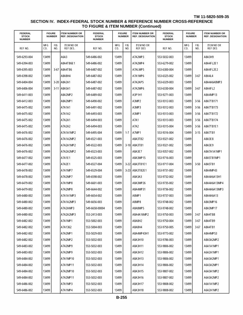
TM 11-5820-509-35SECTION IV. INDEX-FEDERAL STOCK NUMBER & REFERENCE NUMBER CROSS-REFERENCE
TO FIGURE & ITEM NUMBER (Continued)
FEDERAL FIGURE ITEM NUMBER OR FEDERAL FIGURE ITEM NUMBER OR FEDERAL FIGURE ITEM NUMBER ORSTOCK NUMBER REF. DESIGNATION STOCK NUMBER REF. DESIGNATION STOCK NUMBER REF. DESIGNATION
NUMBER NUMBER NUMBER
MFG FIG ITEM NO OR MFG FIG ITEM NO OR MFG FIG ITEM NO ORREF NO. CO. NO. REF DES. REF NO. CO. NO. REF DES REF NO. CO. NO. REF DES
549-6293-004 13499 A6A3 549-6486-002 13499 A7A2MP3 553-5032-003 13499 A8A3H9
549-6394-003 13499 A8A4TB6E1 549-6486-002 13499 A7A2MP4 553-6279-002 13499 A8A4FL2E1
549-6395-003 13499 3-67 A8A4TB6 549-6487-002 13499 A7ALMP5 553-6300-004 13499 A8A4FL2E2
549-6398-002 13499 A8A8H4 549-6487-002 13499 A7A1MP6 553-6325-002 13499 3-67 A8A4L4
549-6404-004 13499 3-20 A8A2A1 549-6487-002 13499 A7A2AP5 553-6329-003 13499 A8A4A6A8MP3
549-6406-004 13499 3-11 A8A5A1 549-6487-002 13499 A7A2MP6 553-6330-004 13499 3-67 A8A4FL2
549-6411-003 13499 A8A2MP2 549-6489-002 13499 A3P1H1 553-9271-003 13499 A8A4MP13
549-6412-003 13499 A8A2MP1 549-6490-002 13499 A3MP2 553-9312-003 13499 3-56 A8A7TB171
549-6475-002 13499 A7A1A1 549-6491-002 13499 A3MP3 553-9312-003 13499 3-56 A8A7TB173
549-6475-002 13499 A7A1A2 549-6493-003 13499 A3MP1 553-9313-003 13499 3-56 A8A7TB172
549-6475-002 13499 A7A2A1 549-6494-003 13499 A7A1 553-9313-003 13499 3-56 A8A7TB174
549-6475-002 13499 A7A2A2 549-6494-003 13499 A7A2 553-9315-004 13499 3-56 A8A7TB1E1
549-6476-002 13499 A7A1A1MP2 549-6495-004 13499 1-7 A7MP1 553-9316-004 13499 3-15 A8A7TB1
549-6476-002 13499 A7A1A2MP2 549-6521-003 13499 A8A3TB2 553-9321-002 13499 A8A3E8
549-6476-002 13499 A7A2A1MP2 549-6522-003 13499 3-10 A8A3TB1 553-9321-002 13499 A8A3E9
549-6476-002 13499 A7A2A2MP2 549-6523-003 13499 A8A3E7 553-9357-002 13499 A8A7A1A1MP1
549-6477-002 13499 A7A1E1 549-6525-003 13499 A8A3MP15 553-9716-003 13499 A8A5TB1MP1
549-6477-002 13499 A7A2E1 549-6527-004 13499 3-22 A8A3TB1E1 553-9717-004 13499 3-50 A8A5TB1
549-6478-002 13499 A7A1MP7 549-6529-004 13499 3-23 A8A3TB2E1 553-9731-002 13499 A8A4MP43
549-6478-002 13499 A7A2MP7 549-6598-002 13499 A8A3A3 553-9732-002 13499 A8A4A6A13H1
549-6479-002 13499 A7A1MP8 549-6601-003 13499 A8A3MP26 553-9735-002 13499 A8A4A6A13MP4
549-6479-002 13499 A7A2MP8 549-6644-002 13499 A8A4MP31 553-9736-002 13499 A8A4A6A13MP3
549-6480-002 13499 A7A1A1MP3 549-6654-002 13499 A8MP1 553-9737-003 13499 A8A4A6A13
549-6480-002 13499 A7A1A2MP3 549-6656-003 13499 A8MP8 553-9748-002 13499 A8A3MP16
549-6480-002 13499 A7A2AMP3 549-6658-00004 13499 A8A8MP5 553-9748-002 13499 A8A3MP17
549-6480-002 13499 A7A2A2MP3 553-2413-003 13499 A8A4A16MP2 553-9750-003 13499 3-67 A8A4TB8
549-6482-002 13499 A7A1MP1 553-5002-003 13499 A8A8H2 553-9750-004 13499 3-67 A8A4TB9
549-6482-002 13499 A7A1362 553-5004-003 13499 A8A8H4 553-9750-005 13499 3-67 A8A4TB1
549-6482-002 13499 A7A2MP1 553-5029-003 13499 A8A4MP43H1 553-9773-002 13499 A8A4MP53
549-6482-002 13499 A7A2MP2 553-5032-003 13499 A8A3H10 553-9786-003 13499 A8A3A2MP2
549-6483-002 13499 A7A2MP9 553-5032-003 13499 A8A3H11 553-9806-002 13499 A6A1A1MP1
549-6483-002 13499 A7A2MP9 553-5032-003 13499 A8A3H12 553-9806-002 13499 A6A2A1MP1
549-6484-002 13499 A7A1MP10 553-5032-003 13499 A8A3H13 553-9806-002 13499 A6A3A2MP1
549-6484-002 13499 A7A1MP11 553-5032-003 13499 A8A3H14 553-9806-002 13499 A6A3A2MP1
549-6484-002 13499 A7A2MP10 553-5032-003 13499 A8A3H15 553-9807-002 13499 A6A3A1MP2
549-6484-002 13499 A7A2MP11 553-5032-003 13499 A8A3H16 553-9807-002 13499 A6A3A2MP2
549-6486-002 13499 A7A1MP3 553-5032-003 13499 A8A3H17 553-9808-002 13499 A6A1A1MP2
549-6486-002 13499 A7A1MP4 553-5032-003 13499 A8A3H18 553-9808-002 13499 A6A2A1MP2
B-255

TM 11-5820-509-35SECTION IV. INDEX-FEDERAL STOCK NUMBER & REFERENCE NUMBER CROSS-REFERENCE
TO FIGURE & ITEM NUMBER (Continued)
FEDERAL FIGURE ITEM NUMBER OR FEDERAL FIGURE ITEM NUMBER OR FEDERAL FIGURE ITEM NUMBER ORSTOCK NUMBER REF. DESIGNATION STOCK NUMBER REF. DESIGNATION STOCK NUMBER REF. DESIGNATION
NUMBER NUMBER NUMBER
MFG FIG ITEM NO OR MFG FIG ITEM NO OR MFG FIG ITEM NO ORREF NO. CO. NO. REF DES. REF NO. CO. NO. REF DES REF NO. CO. NO. REF DES
553-9809-003 13499 A6A3A1 57-3510 78488 3-9 A8A3E6 6S8083 56289 3-38 A8A3E47C160
553-9809-003 13499 A6A3A2 59-410-1003 02660 3-40 A8A3XV3 6S8083 56289 3-38 A8A3E47C161
553-9810-003 13499 A6A1A1 59-7159 11707 A8A1M101 6S8083 56289 3-38 A8A3E47C177
553-9810-003 13499 A6A2A1 6-4011-4 6SPLINE 08664 A8A4A6MP44H1 6S8083 56289 3-38 A8A3E47C178416657
554-7047-002 13499 A5A1E1 6S8083 56289 3-38 A8A3E47C1836L2FF 96881 A8A4MP1
554-7048-002 13499 A5A1MP2 6S8083 56289 3-39 A8A3E48C1666L2FF 96881 A8A4MP2
554-7049-002 13499 A5MP4 6S8083 56289 3-39 A8A3E48C1716L2FF 96881 A8A4MP3
554-7050-002 13499 A5A1 6S8083 56289 3-39 A8A3E48C1736L2FF 96881 A8A4MP4
554-7051-002 13499 A5H4 6S8083 56289 3-39 A8A3E48C1826L2FF 96881 A8A4MP5
554-7052-003 13499 A5E3 6S8083 56289 3-54 A8A7E1C116L2FF 96881 A8A4MP6
557-018-8-05E 72982 3-58 A8A7E5C72 6S8083 56289 3-54 A8A7E1C186S8082 56289 3-20 A8A2E1C1
557-018-8-50E 72982 3-58 A8A7E5C74 6S8083 56289 3-54 A8A7E1C56S8082 56289 3-20 A8A2E134
557-018-8-50E 72982 3-58 A8A7E5C76 6S8083 56289 3-55 A8A7E2C236S8082 56289 3-54 A8A7E1C1
557-018-8-50E 72982 3-58 A8A7E5C78 6S8083 56289 3-55 A857E2C256S8082 56289 3-54 A8A7E1C10
557-018-8-50E 72982 3-58 A8A7E5C80 6S8083 56289 3-55 A8A7E2C296S8082 56289 3-54 A8A7E1C19
557-018-8-50E 72982 3-58 A8A7E5C82 6S8083 56289 3-55 A87E2C326S8082 56289 3-54 A8A7E1C7
557-018-8-50E 72982 3-58 A8A7E5C84 6S8083 56289 3-55 A8A7E2C356S8082 56289 3-54 A8A7E1C8
557-018-8-50E 72982 3-58 A8A7E5C86 6S8083 56289 3-55 A8A7E2C366S8082 56289 A8A7E2C22
557-018-8-50E 72982 3-58 A8A7E5C88 6S8083 56289 3-57 A8A7E4C576S8082 56289 3-55 A8A7E2C30
557-018-8-50E 72982 3-58 A8A7E5C90 6S8083 56289 3-57 A8A7E4C596S8082 56289 3-59 A8A7E6C102
557-099-5-25A 72982 3-36 A8A3A13C266 6S8083 56289 3-57 A8A7E4C606S8082 56289 3-59 A8A7E6C112
557-099-5-30E 72982 3-35 A8A3613C254 6S8083 56289 3-57 A8A7E4C636S8082 56289 3-59 A8A7E6C94
557-099-5-30E 72982 3-36 A8A3A13C256 6S8084 56289 3-21 A8A2E3C316S8083 56289 3-17 A8A1E1C18
557-099-5-30E 72982 3-36 A8A3A13C258 6S8084 56289 3-21 A8A2E5C266S8083 56289 3-40 A8A3C115
557-099-5-30E 72982 3-36 A8A3A13C260 6S8084 56289 3-66 A8A4A1C1036S8083 56289 3-40 A8A3C116
557-099-5-30E 72982 3-63 A8A3A13C262 6S8084 56289 3-66 A8A4A1C1046S8083 56289 3-40 A8A3C293
557-099-5-30E 72982 3-36 A8A3A13C264 600D1070050DJ5 56289 3-45 A8A5C266S8083 56289 3-37 A8A3E46C247
557-099-5-30E 72982 3-54 A8A7E1C15 600D136F200DG5 56259 3-50 A8A5C16S8083 56289 3-37 A8A3E46C269
557-099-8-50E 72982 3-21 A8A2E3C15 600D476G050ED5 56289 3-50 A8A5B256S8083 56289 3-37 A8A3E46C272
557-399-8-50E 72982 3-21 A8A2E1C17 600D476G050DE5 56289 3-45 A8A5C276S8083 56289 3-37 A8A3E46C275
557-099-8-50E 72982 3-36 A8A3A13C215 600D476G050DE5 56289 3-15 A8A5C286S8083 56289 3-38 A8A3E47C142
557-099-8-50E 72982 3-36 A8A31A13C250 600D476G050DE5 56289 3-45 A8A5C296S8083 56289 3-38 A8A3E47C143
557-099-8-50E 72982 3-36 A8A3613C252 610D105M200BD5 56289 A81ATB6C16S8083 56289 3-38 A8A3E47C150
57-3540 78488 3-9 A8A3E1 610D255F100BD5 56289 3-67 A8A4C266S8083 56289 3-38 A8A3E470151
57-3540 78488 3-9 A8A3E2 610D255F100BD5 56289 3-67 A84AC276S8083 56289 3-38 A8A3E47C154
57-3540 78488 3-9 A8A3E3 610D255F100BD5 56289 A8A4FL2C2366S8083 56289 3-38 A8A3E47C156
57-3540 78488 3-9 A8A3E4 614B 57714 A8A4A1E16S8083 56289 3-38 A8A3E47C158
57-3540 78488 3-9 A8A3E5 678-0084-000 13499 3-17 A8A1E1L26S8083 56289 3-38 A8A3E47C159
B-256

TM 11-5820-509-35
SECTION IV INDEX-FEDERAL STOCK NUMBER & REFERENCE NUMBER CROSS-REFERENCETO FIGURE & ITEM NUMBER (Continued)
FEDERAL FIGURE ITEM NUMBER OR FEDERAL FIGURE ITEM NUMBER OR FEDERAL FIGURE ITEM NUMBER ORSTOCK NUMBER REF. DESIGNATION STOCK NUMBER REF. DESIGNATION STOCK NUMBER REF. DESIGNATION
NUMBER NUMBER NUMBER
MFG FIG ITEM NO OR MFG FIG ITEM NO OR MFG FIG ITEM NO ORREF NO. CO. NO. REF DES. REF NO. CO. NO. REF DES REF NO. CO. NO. REF DES
68NM62 72962 A6A3MP3H1 68-1660-26 72962 A8A4J7H1 68-1660-40 72962 A8A7P1H26BNM62 72962 A6A3MP3H2 68-1660-26 72962 A8A4J8H1 682268 19644 3-52 A8A6E2C168-1660-26 72962 A8A1P1H1 68-1660-26 72962 A8A2J8H2 69003-1183BR0WN 73680 3-9 A8A3A1J168-1660-26 72962 A8A1P1H2 68-1660-26 72962 A8A4J9H1 69003-1183WRANGE 73680 3-9 ASA3A1J368-1660-26 72962 A8A2P3H1 68-1660-26 72962 A8A4J9H2 69003-1183RED 73680 3-9 A8A3A1J268-1660-26 72962 A8A2P3H2 68-1660-26 72962 A8A6E2R1H1 69003-1183YELL0W 73680 3-9 A8A3A1J468-1660-26 72962 A8A2P4H1 68-1660-26 72962 A8A6E2R1H2 72-140-1 12615 3-66 A8A4A1A1J168-1660-26 72962 ASA2P4H2 68-1660-26 72962 A8A6E2R2H1 72-140-1 12615 3-12 A8A6A1A1J168-1660-26 72962 A8A3Ao0S4ELH3 68-1660-26 72962 A8A6E2R2H2 72-10o-2 12615 3-66 A8A4A1A1J268-1660-26 72962 A8A3A10S4E1H4 68-1660-26 72962 A8A7E5E2H1 72-120-2 12615 3-12 A8A6ALA1J26-1660-26 72962 A8A3A11S5E1H3 68-1660-26 72962 A8A7ESE2H2 72-120-3 12615 3-66 A8A4AA11J368-1660-26 72962 A8A3A11S5E1H4 68-1660-26 72962 A8A7ESE2H3 72-140-3 12615 3-53 A8A6A1A1J368-1660-26 72962 A83A112S8E1H1 68-1660-26 72962 A8A7ESE2Hr 72-140-4 12615 3-66 A8A4A1A1J468-1660-26 72962 A8A3A12S8E1H2 68-1660-26 72962 ASA7E7A2E1H1 72-140-4 12615 3-53 A8A6A1A1J468-1660-26 72962 A8A3A4A1H4 68-1660-26 72962 A8A7E7A2E1H2 72-140-5 12615 3-66 A8A4A1A1J568-1660-26 72962 A8A3A4A2H4 68-1660-26 72962 A8A7E7A2E2H1 72-153BLK 12615 3-11 A8A5A1J1068-1660-26 72962 A8A3A4H1 68-1660-26 72962 A8A7E7A2E2H2 72-153BLU 12615 3-11 A8A5A1J668-1660-26 72962 A8A3A9A1S1E1H3 68-1660-40 72962 A8A3A2H2 72-153BRN 12615 3-21 A8A2A1J168-1660-26 72962 A8A3A9A1S1E1H4 68-1660-40 72962 A8A4K1H1 72-153BRN 12615 3-11 A8A5A1J168-1660-26 72962 A8A3A9A2S2E1H3 68-1660-40 72962 A8A4K1H2 72-153BRN 12615 3-11 A8A5AJ1168-1660-26 72962 A8A3A9A2S2E1H4 68-1660-40 72962 A8A4K3H1 72-153GRA 12615 3-11 A8A5A1J868-1660-26 72962 A8A3A9A3S3E1H1 68-1660-40 72962 A8A4K3H2 72-153GRN 12615 3-11 A8A5A1J568-1660-26 72962 A8A3A9A3S3E1H2 68-1660-40 72962 A8A4A4H1 72-1530RN 12615 3-21 A8A2A1J368-1660-26 72962 A8A4J1H1 68-1660-40 72962 A8A4K4H2 72-1530RN 12615 3-11 A8A5A1J368-1660-26 72962 A8A4J1H2 68-1660-o0 72T962 A8A4K6H1 72-1530NN 12615 3-56 A8A7TB1E1J368-1660-26 72962 A8A4J10N1 68-1660-40 72962 A8A4K6H2 2-153RED 12615 3-20 A8A2A1J268-1660-26 72962 A8A4J10H2 68-1660-04o 72962 A8A4R8H1 72-153RED a12615 3-11 A8A5A1J268-1660-26 72962 A8A4J11H1 68-1660-40 72962 A8A4R8H2 72-153RED 12615 3-56 A8A7TB1E1J268-166o-26 72962 A8A4J11H2 68-1660-40 72962 A8A4T2H1 72-153RED 12615 3-11 A8A5AIJ7T68-1660-26 72962 A8A4J2H1 68-1660-40 72962 A8A4T2H2 72-153WHT 12615 3-11 A8A5A1J968-1660-26 72962 A8A4J2H2 68-1660-40 72962 A8A4T3H1 72-153YEL 12615 3-21 A8A5A1J468-1660-26 72962 A8A4J3H1 68-1660-40 72962 A8A4T3H2 72-153YEL 12615 3-11 A8A5A1J468-1660-26 72962 A8A4J3H2 68-1660-40 72962 A8A5E3H2 7T2-153YEL 12615 3-54 A8A7TB1E1J468-1660-26 72962 A8ABJ4H1 68-1660-40 72962 A8A5XC19H1 737-4765-000 13499 A2MP568-1660-26 72962 A8A4J4H2 68-1660-40 72962 A8A5XC19H2 747-4769-000 13499 A8MP768-1660-26 72962 A8A4J5H1 68-1660-40 72962 A8A5XC20H1 756-0317-003 13499 A8A7MP768-1660-26 72962 A8A4J6H1 68-1660-4o 72962 A8A7E7A1H2 756-0318 -oo4 13499 A8A7MP668-1660-26 72962 A8A4J6H2 68-1660-40 72962 A8A7P1H1 756-0482-004 13499 A8MP4
B-257

TM 11-5820-509-35
SECTION IV INDEX-FEDERAL STOCK NUMBER & REFERENCE NUMBER CROSS-REFERENCETO FIGURE & ITEM NUMBER (Continued)
FEDERAL FIGURE ITEM NUMBER OR FEDERAL FIGURE ITEM NUMBER OR FEDERAL FIGURE ITEM NUMBER ORSTOCK NUMBER REF. DESIGNATION STOCK NUMBER REF. DESIGNATION STOCK NUMBER REF. DESIGNATION
NUMBER NUMBER NUMBER
MFG FIG ITEM NO OR MFG FIG ITEM NO OR MFG FIG ITEM NO ORREF NO. CO. NO. REF DES. REF NO. CO. NO. REF DES REF NO. CO. NO. REF DES
756-2809-001 13499 CP1 772-8458-001 13499 3-64 A8A4T101756-3009-002 13499 A8MP3 7761 82219 3-23 A8A3TB2V2756-3160-003 13499 3-41 A8A315 7841 72825 A3E1756-3164-004 13499 A8A3A2 7841 72825 A3E2756-3166-003 13499 3-35 A8A3A12178 7841 72825 A3E3756-3167-003 13499 3-35 A843A12177 7841 72825 A3E4756-3168-005 13499 A8A3W2 7841 72825 A8A4A6E3756-3172-002 13499 3-41 A8A3A2 7841 72825 A8A4A6E4756-3173-002 13499 A8A3E11 7905 49956 3-9 A8A3V3756-3174-002 13499 A8A3A2MP1 797-4357-001 13499 A8MP1756-3175-003 13499 A8A3E12 797-4357-001 13499 A8MP2756-3176-003 13499 A8A3E13 797-4358-001 13499 A8MP3756-3177-003 13499 A8A3E14 812FF 96881 A8A4MP7756-4171-002 13499 A8A7E7A2MP7 812FF 96881 A8A4MP8756-4171-002 13499 A8A7E7A2MP8 805-014XV0103Z 72982 3-52 A8A6E2C11756-4179-003 13499 3-41 A8A314 850S100N 71590 3-64 A8A4A16C115756-5247-002 13499 A8A4A6A10MP3 850S20z 71590 3-64 A8A4A16C111756-7565-002 13499 A8A4A3 850S20Z 71590 3-64 A8A4A16C120756-7565-002 13499 A8A4A4 850S20Z 71590 3-64 A8A4A16C121756-7600-004 13499 A8A7E7A2E3 850S40Z 71590 3-64 A8A4A16C118756-7600-004 13499 A8A7E7A2E4 850S50Z 71590 3-64 A8A4A16C116756-7602-002 13499 A8A7ESMP6 850S50Z 71590 3-64 A8A4A16CI17756-7606-003 13499 3-52 A8A6E2A1 88-8TM 02660 3-45 A8A5XC19756-8606-003 13499 A8A4MP25 88-8TM 02660 3-45 A8A5XC20757-4763-000 13499 MP4 8942 76854 A8A7E7A1H4157-1764-000 13499 A7P1 905 75543 A8A3H2757-4764-000 13499 A7MP2 905 75543 A8A4H4757-4766-0000 13499 A3P4 905 75543 A8A4H5757-4767-000 13499 A8MP5 911 75543 A8A1H6757-4768-00000 13499 AA8MP3 930-0524-00000 13499 3-45 ASA5C16757-4768-000 13499 A8MP6 955-0211UJX149 77872 A5W1761-5006-001 13499 A8A3A9An1S 99-012-062-0312 72962 A8A41109MP5763F2 10646 3-16 A8A1R80 99-012-062-0312 72962 A8A41112MP4763F28 10646 3-17 ASA1ER1R2 99-012-062-0500 72962 A8A411009MP6763F28 10646 3-17 A8A1E1R85 99-012-062-0500 72962 A8A4110MP2763F28 10646 3-19 ABA1E3R67 99-012-062-0500 72962 A8A41111MP5763H10 10646 3-20 A8A2E2RT1 99-012-062-0500 72962 A8A41112MP3767-0502-000 13499 A4MP2
B-258

TM 11-5820-509-35
SECTION V INDEX-REFERENCE DESIGNATIONCROSS-REFERENCE TO PAGE NUMBER
REFERENCE PAGE REFERENCE PAGE REFERENCE PAGEDESIGNATION NUMBER DESIGNATION NUMBER DESIGNATION NUMBER
A1 4A1MP1 4A1MP2 4A2 4A2A1 4A2A1MP1 4A2A1MP1H1 4A2A2A2A2MP1 4A2A2MP1H1 4A2J1 4A2J1H1 4A2J1H2 4A2J2 4A2J2H1 4A2J2H2 4A2J2H3 4A2MP1 4A2MP2 4A2MP3 4A2MP4 4A2MP5 4A3 4A3E1 5A3E1H1 5A3E1H2 5A3E1H3 5A3E1H4 5A3E1H5 5A3E2 5A3E2H1 5A3E2H2 5A3E2H3 5A3E2H4 5A3E2H5 5A3E3 6A3E3H1 6A3E3H2 6
A3E3H3 6A3E3H4 6A3E3H5 6A3E4 6A3E4R1 6A3E4H2 6A3E4H3 6A3E4H4 6A3E4H5 6A3E5 6A3E6 6A3E7 6A3E8 6A3MP1 4A3MP2 5A3MP2H11 5A3MP2H2 5A3MP2H3 5A3MP2H4 5A3MP2H5 5A3MP2H6 5A3MP2H7 5A3MP2H8 5A3MP3 5A3MP4 5A3P1 5A3P1H1 5A4 6A4A1 6A4A1E1 6A4A1E1MP1 6A4A1E1MP2 6A4A1E1MP3 6A4A1E1MP4 6A4A1E1MP5 6A4A1E1MP6 7A4A1E1MP7 7A4A1E1MPB 7
A4A1E1MP9 7A4A1MP1 7A4A2 7A5 7A5A1 7A5A1E1 7A5A1MP1 7A5A1MP2 7A5E1 7A5E2 7A5E2 7A5E2H1 7A5E2H2 7A5E2H3 7A5E3 7A5E3 8A5E3H1 8A5E3H2 8A5E4 7A5E5 7A5H1 8A5MP1 7A5MP2 7A5MP3 7A5MP4 7A5MP5 7A5W1 8A6 8A6A1 8A6AJA1 8A6A1A1H1 8A6A1A1MP1 8A6A1A1MP2 8A6A1A1MP3 8A6A1MP1 8A6A2 8A6A2A1 8A6A2A1H1 8
B-259

TM 11-5820-509-35
SECTION V INDEX-REFERENCE DESIGNATIONCROSS-REFERENCE TO PAGE NUMBER
REFERENCE PAGE REFERENCE PAGE REFERENCE PAGEDESIGNATION NUMBER DESIGNATION NUMBER DESIGNATION NUMBER
A6A2A1MP1 8A6A2A1MP2 8A6A2A1MP3 8A6A2MP1 8A6A3 9A6A3A1 9A6A3A1H1 9A6A3A1R1 9A6A3A1MP1 9A6A3A1MP2 9A6A3A1MP3 9A6A3A2 9A6A3A2R1 10A6A3A2H1 10A6A3A2H1 10A6A3A2MP2 10A6A3A2MP3 10A6A3MP1 9A6A3MP2 9A6A3MP3 9A6A3MP3H1 9A6A3MP3H2 9A6A3MP3H3 9A5A3MP3H4 9A6A3MP3H5 9A6A3MP3H6 9A6A4 10A6A4MP1 10A6A4MP2 10A6MP1 8A6MP10 10A6MP2 8A6MP3 8A6MP4 8A6MP5 9A6MP5H1 9A6MP6 9A6MP6H1 9
A6MP7 9A6MP7H1 9A6MP7H2 9A6MP8 10A6MP9 10A7 10A7A1 10A7A1A1 11A7A1A1MP1 11A7A1A1MP2 11A7A1A1MP3 11A7A1A2 11A7A1A2MP1 11A7A1A2MP2 11A7A1A2MP3 12A7A1E1 10A7A1E1MP1 10A7A1E1MP1 10A7A1H1 12A7A1H2 12A7A1MP1 10A7A1MP10 11A7A1MP10R1 11A7A1MP10H2 11A7A1MP10H3 11A7A1MP10H4 11A7A1MP10H5 11A7A1MP10H6 11A7A1MP11 11A7A1MP11H1 11A7A1KP11H2 11A7A1MP11H3 11A7A1MP11H4 11A7A1MP11H5 11A7A1MP11H6 11A7A1MP2 10A7A1MP3 10A7A1J4P4 10
A7A1MP5 10A7A1MP6 10A7A1MP7 11A7A1MP8 11A7A1MP9 11A7A2 12A7A2A1 11A7A2A1MP1 13A7A2A1MP2 13A7A2A1MP3 13A7A2A2 13A7A2A2MP1 13A7A2A2MP2 13A7A2A2MP3 13A7A2E1 12A7A2E1P1 12A7A21W1 12A7A2H1 13A7A2H2 13A7A2MP1 12A7A2MP10 12A7A2MP10H1 12A7A2MP10H2 12A7A2MP10H3 12A7A2MP10H4 12A7A2MP10H5 12A7A2MP10H6 12A7A2MP11 12A7A2MP11H1 12A7A2MP11H2 13A7A2MP11H3 13A7A2MP11H4 13A7A2MP11H5 13A7A2MP11H6 13A7A2MP2 12A7A2MP3 12A7A2MP4 12A7A2MP5 12
B-260

TM 11-5820-509-35
SECTION V INDEX-REFERENCE DESIGNATIONCROSS-REFERENCE TO PAGE NUMBER
REFERENCE PAGE REFERENCE PAGE REFERENCE PAGEDESIGNATION NUMBER DESIGNATION NUMBER DESIGNATION NUMBER
A1 4A1MP1 4A1MP2 4A2 4A2A1 4A2A1MP1 4A2A1MP1H1 4A2A2A2A2MP1 4A2A2MP1H1 4A2J1 4A2J1H1 4A2J1H2 4A2J2 4A2J2H1 4A2J2H2 4A2J2H3 4A2MP1 4A2MP2 4A2MP3 4A2MP4 4A2MP5 4A3 4A3E1 5A3E1H1 5A3E1H2 5A3E1H3 5A3E1H4 5A3E1H5 5A3E2 5A3E2H1 5A3E2H2 5A3E2H3 5A3E2H4 5A3E2H5 5A3E3 6A3E3H1 6A3E3H2 6
A3E3H3 6A3E3H4 6A3E3H5 6A3E4 6A3E4R1 6A3E4H2 6A3E4H3 6A3E4H4 6A3E4H5 6A3E5 6A3E6 6A3E7 6A3E8 6A3MP1 4A3MP2 5A3MP2H11 5A3MP2H2 5A3MP2H3 5A3MP2H4 5A3MP2H5 5A3MP2H6 5A31dP2H7 5A3MP2H8 5A3MP3 5A3MP4 5A3P1 5A3P1H1 5A4 6A4A1 6A4A1E1 6A4A1E1MP1 6A4A1E1MP2 6A4A1E1MP3 6A4A1E1MP4 6A4A1E1MP5 6A4A1E1MP6 7A4A1E1MP7 7A4A1E1MPB 7
A4A1E1MP9 7A4A1MP1 7A4A2 7A5 7A5A1 7A5A1E1 7A5A1MP1 7A5A1MP2 7A5E1 7A5E2 7A5E2 7A5E2H1 7A5E2H2 7A5E2H3 7A5E3 7A5E3 8A5E3H1 8A5E3H2 8A5E4 7A5E5 7A5H1 8A5MP1 7A5MP2 7A5MP3 7A5MP4 7A5MP5 7A5W1 8A6 8A6A1 8A6AJA1 8A6A1A1H1 8A6A1A1MP1 8A6A1A1MP2 8A6A1A1MP3 8A6A1MP1 8A6A2 8A6A2A1 8A6A2A1H1 8
B-259

TM 11-5820-509-35
SECTION V INDEX-REFERENCE DESIGNATIONCROSS-REFERENCE TO PAGE NUMBER
REFERENCE PAGE REFERENCE PAGE REFERENCE PAGEDESIGNATION NUMBER DESIGNATION NUMBER DESIGNATION NUMBER
A6A2A1MP1 8A6A2A1MP2 8A6A2A1MP3 8A6A2MP1 8A6A3 9A6A3A1 9A6A3A1H1 9A6A3A1R1 9A6A3A1MP1 9A6A3A1MP2 9A6A3A1MP3 9A6A3A2 9A6A3A2R1 10A6A3A2H1 10A6A3A2H1 10A6A3A2MP2 10A6A3A2MP3 10A6A3MP1 9A6A3MP2 9A6A3MP3 9A6A3MP3H1 9A6A3MP3H2 9A6A3MP3H3 9A5A3MP3H4 9A6A3MP3H5 9A6A3MP3H6 9A6A4 10A6A4MP1 10A6A4MP2 10A6MP1 8A6MP10 10A6MP2 8A6MP3 8A6MP4 8A6MP5 9A6MP5H1 9A6MP6 9A6MP6H1 9
A6MP7 9A6MP7H1 9A6MP7H2 9A6MP8 10A6MP9 10A7 10A7A1 10A7A1A1 11A7A1A1MP1 11A7A1A1MP2 11A7A1A1MP3 11A7A1A2 11A7A1A2MP1 11A7A1A2MP2 11A7A1A2MP3 12A7A1E1 10A7A1E1MP1 10A7A1E1MP1 10A7A1H1 12A7A1H2 12A7A1MP1 10A7A1MP10 11A7A1MP10R1 11A7A1MP10H2 11A7A1MP10H3 11A7A1MP10H4 11A7A1MP10H5 11A7A1MP10H6 11A7A1MP11 11A7A1MP11H1 11A7A1KP11H2 11A7A1MP11H3 11A7A1MP11H4 11A7A1MP11H5 11A7A1MP11H6 11A7A1MP2 10A7A1MP3 10A7A1J4P4 10
A7A1MP5 10A7A1MP6 10A7A1MP7 11A7A1MP8 11A7A1MP9 11A7A2 12A7A2A1 11A7A2A1MP1 13A7A2A1MP2 13A7A2A1MP3 13A7A2A2 13A7A2A2MP1 13A7A2A2MP2 13A7A2A2MP3 13A7A2E1 12A7A2E1P1 12A7A21W1 12A7A2H1 13A7A2H2 13A7A2MP1 12A7A2MP10 12A7A2MP10H1 12A7A2MP10H2 12A7A2MP10H3 12A7A2MP10H4 12A7A2MP10H5 12A7A2MP10H6 12A7A2MP11 12A7A2MP11H1 12A7A2MP11H2 13A7A2MP11H3 13A7A2MP11H4 13A7A2MP11H5 13A7A2MP11H6 13A7A2MP2 12A7A2MP3 12A7A2MP4 12A7A2MP5 12
B-260
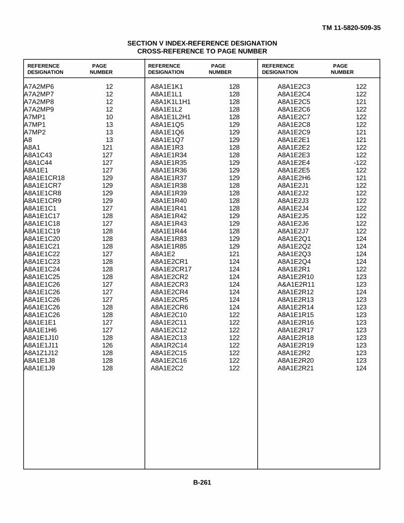
TM 11-5820-509-35
SECTION V INDEX-REFERENCE DESIGNATIONCROSS-REFERENCE TO PAGE NUMBER
REFERENCE PAGE REFERENCE PAGE REFERENCE PAGEDESIGNATION NUMBER DESIGNATION NUMBER DESIGNATION NUMBER
A7A2MP6 12A7A2MP7 12A7A2MP8 12A7A2MP9 12A7MP1 10A7MP1 13A7MP2 13A8 13A8A1 121A8A1C43 127A8A1C44 127A8A1E1 127A8A1E1CR18 129A8A1E1CR7 129A8A1E1CR8 129A8A1E1CR9 129A8A1E1C1 127A8A1E1C17 128A8A1E1C18 127A8A1E1C19 128A8A1E1C20 128A8A1E1C21 128A8A1E1C22 127A8A1E1C23 128A8A1E1C24 128A8A1E1C25 128A8A1E1C26 127A8A1E1C26 127A8A1E1C26 127A6A1E1C26 128A8A1E1C26 128A8A1E1E1 127A8A1E1H6 127A8A1E1J10 128A8A1E1J11 126A8A1Z1J12 128A8A1E1J8 128A8A1E1J9 128
A8A1E1K1 128A8A1E1L1 128A8A1K1L1H1 128A8A1E1L2 128A8A1E1L2H1 128A8A1E1Q5 129A8A1E1Q6 129A8A1E1Q7 129A8A1E1R3 128A8A1E1R34 128A8A1E1R35 129A8A1E1R36 129A8A1E1R37 129A8A1E1R38 128A8A1E1R39 128A8A1E1R40 128A8A1E1R41 128A8A1E1R42 129A8A1E1R43 129A8A1E1R44 128A8A1E1R83 129A8A1E1R85 129A8A1E2 121A8A1E2CR1 124A8A1E2CR17 124A8A1E2CR2 124A8A1E2CR3 124A8A1E2CR4 124A8A1E2CR5 124A8A1E2CR6 124A8A1E2C10 122A8A1E2C11 122A8A1E2C12 122A8A1E2C13 122A8A1R2C14 122A8A1E2C15 122A8A1E2C16 122A8A1E2C2 122
A8A1E2C3 122A8A1E2C4 122A8A1E2C5 121A8A1E2C6 122A8A1E2C7 122A8A1E2C8 122A8A1E2C9 121A8A1E2E1 121A8A1E2E2 122A8A1E2E3 122A8A1E2E4 -122A8A1E2E5 122A8A1E2H6 121A8A1E2J1 122A8A1E2J2 122A8A1E2J3 122A8A1E2J4 122A8A1E2J5 122A8A1E2J6 122A8A1E2J7 122A8A1E2Q1 124A8A1E2Q2 124A8A1E2Q3 124A8A1E2Q4 124A8A1E2R1 122A8A1E2R10 123A&A1E2R11 123A8A1E2R12 124A8A1E2R13 123A8A1E2R14 123A8A1E1R15 123A8A1E2R16 123A8A1E2R17 123A8A1E2R18 123A8A1E2R19 123A8A1E2R2 123A8A1E2R20 123A8A1E2R21 124
B-261

TM 11-5820-509-35
SECTION V INDEX-REFERENCE DESIGNATIONCROSS-REFERENCE TO PAGE NUMBER
REFERENCE PAGE REFERENCE PAGE REFERENCE PAGEDESIGNATION NUMBER DESIGNATION NUMBER DESIGNATION NUMBER
A8A1E2R22 123A8A1E2R23 123A8A1E2R24 123A8A1E2R25 123A8A1E2R26 123A8A1E2R27 124A8A1E2R28 123A8A1E2R29 123A8A1E2R30 123A8A1E2R31 123A8A1E2R32 123A8A1E2R33 124A8A1E2R4 123A8A1E2R5 124A8A1E2R6 123A8A1E2R7 123A8A1E2R8 124A8A1E2R9 123A8A1E2T1 124A8A1E3CR10 127A8A1E3CR11 126A8A1E3CR12 127A8A1E3CR13 127A8A1F3C28 125A8A1E3C29 124A8A1E3C30 124A8A1E3C31 124A8A1E3C32 125A8A1E3C33 125A8A1E3C34 125A8A1E3C35 125A8A1E3C36 125A8A1E3C37 125A8A1E3C38 125A8A1E3C40 125A8A1E3C41 125A8A1E3C42 124A8A1E3 124
A8A1E3E1 124A8A1E3E2 125A8A1E3E3 125A8A1E3E4 125A8A1E3H4 124A8A1E3J13 125A8A1E3J14 125A8A1E3J15 125A8A1E3J16 125A8A1E3L3 125A8A1E3Q10 127A8A1E3Q8 127A8A1E3Q9 127A8A1E3R45 125A8A1E3R46 126A8A1E3R47 125A8A1E3R48 126A8A1E3R49 126A8A1E3R50 126A8A1E3R51 125A8A1E3R52 126A8A1E3R53 125A8A1E3R54 126A8A1E3R55 126A8A1E3R56 126A8A1E3R57 126A8A1E3R58 126A8A1E3R59 126A6A1E3R60 126A8A1E3R61 126A8A1E3R62 126A8A1E3R63 125A8A1E3R64 127A8A1E3R65 126A8A1E3R66 126A8A1E3R67 126A8A1E3R68 126A8A1E3R72 125
A8A1E3R73 126A8A1E3R74 126A8A1E3R75 126A8A1E3R76 126A8A1E3R77 126A8A1E3R78 126A8A1E4 130A8A1E4H1 130A8A1E4H2 130A8A1E5 130A8A1E5H1 130A8A1E5H2 130A8A1E5H3 130A8A1E6 130A8A1MP1 127A8A1MP2 129A8A1MP2H1 129A8A1MP2R2 129A8A1MP2H3 129A8A1MP2H4 129A8A1P1 127A8A1P1H1 127A8A1P1H2 127A8A1P1H3 127A8A1P1R4 127A8A1P1H5 127A8A1P1H6 127A8A1Q11 130A8A1Q11H1 130A8A1Q11H2 130A8A1Q11H3 130A8A1R79 129A8A1R80 130A8A1R81 129A8A1R82 129A8A1R84 129A8A1T2 130A8A1T2H1 130
B-262
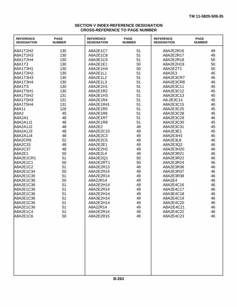
TM 11-5820-509-35
SECTION V INDEX-REFERENCE DESIGNATIONCROSS-REFERENCE TO PAGE NUMBER
REFERENCE PAGE REFERENCE PAGE REFERENCE PAGEDESIGNATION NUMBER DESIGNATION NUMBER DESIGNATION NUMBER
A8A1T2H2 130A8A1T2H3 130A8A1T2H4 130A8A1T3 130A8A1T3H1 130A8A1T3H2 130A8A1T3H3 130A8A1T3H4 130A8A1TS 130A8A1T5H1 130A8A1T5H2 131A8A1T5H3 131A8A1T5H4 131A8A11 129A8A2 45A8A2A1 48A8A2A1J1 48A8A2A1J2 48A8A2A1J3 48A8A2A1J4 48A8A2CR9 52A8A2C33 48A8A2C37 48A8A2E1 50A8A2E1CR1 51A8A2E1C1 50A8A2E1C2 51A8A2E1C34 50A8A2E1C35 51A8A2E1C36 50A8A2E1C36 51A8A2E1C36 51A8A2E1C36 51A8A2E1C36 51A8A2E1C36 51A8A2E1C36 51A8A2E1C4 51A8A2E1C6 50
A8A2E1C7 51A8A2E1C8 51A8A3E1C9 51A8A2E1E1 50A8A2E1H4 50A8A2E1L1 51A8A2E1L2 51A8A2E1L3 51A8A2E1H1 51A8A2E1R2 51A8A2E1H3 51A8A2E1R4 51A8A2E1R41 51A8A2E1R5 51A8A2E1R6 51A8A2E1R7 51A8A2E1R8 51A8A2E2 49A8A2E2C10 49A8A2E2C3 49A8A2E2C5 49A8A2E2E1 49A8A2E2H2 49A8A2E2L4 49A8A2E2Q1 50A8A2E2RT1 50A8A2E2R13 49A8A2E2R14 49A8A2E2R14 49A8A22R14 49A8A2E2H14 49A8A2E2R14 49A8A2E2H14 49A8A3E2H14 49A8A2E2H14 49A8A22R14 49A8A2E2R14 49A8A2E2R15 49
A8A2E2R16 49A8A2E2R17 49A8A2E2R18 50A8A2E2H19 50A8A2E2T2 50A8A2E3 45A8A2E3CR7 46A8A2E3CR8 46A8A2E3C11 45A8A2E3C12 45A8A2E3C13 45A8-2E3C14 45A8A2E3C15 46A8A2E3C25 45A8A2E3C28 45A8A2E3C29 46A8A2E3C30 45A8A2E3C31 45A8A2E3E1 45A8A2E3H3 45A8A2E3L8 46A8A2E3Q2 46A8A2E3H20 46A8A2E3R21 46A8A2E3R22 46A8A2E3R24 46A8A2E3R36 46A8A2E3R37 46A8A2E3R38 46A8A2E4 46A8A2E4C16 46A8A2E4C17 46A8A3E4C18 46A8A2E4C19 46A8A2E4C20 46ABA2E4C21 46A8A2E4C22 46A8A2E4C23 46
B-263
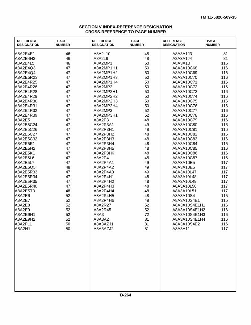
TM 11-5820-509-35
SECTION V INDEX-REFERENCE DESIGNATIONCROSS-REFERENCE TO PAGE NUMBER
REFERENCE PAGE REFERENCE PAGE REFERENCE PAGEDESIGNATION NUMBER DESIGNATION NUMBER DESIGNATION NUMBER
A8A2E4E1 46A8A2E4H3 46A8A2E4L5 46A8A2E4Q3 47A8A2E4Q4 47A8A2EbR23 47A8A2E4R25 47A8A2E4R26 47A8A2E4R28 47A8A2E4R29 47A8A2E4R30 47A8A2E4R31 47A8A2E4R32 47A8A2E4R39 47A8A2E5 47A8A2E5C24 47A8A2E5C26 47A8A2E5C27 47A8A2E5C32 47A8A2E5E1 47A8A2E5H2 47A8A2E5K1 47A8A2E5L6 47A8A2E5L7 47A8A2E5Q5 48A8A2E5R33 47A8A2E5R34 47A8A2E5R35 47A8A2E5R40 47A8A2E5T3 48A8A2E6 52A8A2E7 52A8A2E8 52A8A2E9 52A8A2E9H1 52A8A2E9H2 52A8A2FL1 50A8A2H1 50
A8A2L10 48A8A2L9 48A8A2MP1 50A8A2MP1H1 50A8A2MP1H2 50A8A2MP1H3 50A8A2MP1H4 50A8A2MP2 50A8A2MP2H1 50A8A2MP2H2 50A8A2MP2H3 50A8A2MP2H4 50A8A2MP3 52A8A2MP3H1 52A8A2P3 48A8A2P3A1 49A8A2P3H1 48A8A2P3H2 48A8A2P3H3 48A8A2P3H4 48A8A2P3H5 48A8A2P3H6 48A8A2P4 48A8A2P4A1 49A8A2P4A2 49A8A2P4A3 49A8A2P4H1 48A8A2P4H2 48A8A2P4H3 48A8A2P4H4 48A8A2P4H5 48A8A2P4H6 48A8A2R27 52A8A2R45 52A8A3 72A8A3AZ 81A8A3AZJ1 81A8A3AZJ2 81
A8A3A1J3 81A8A3A1J4 81A8A3A10 115A8A3A10C68 116A8A3A10C69 116A8A3A10C70 116A8A3A10C71 116A8A3A10C72 116A8A3A10C73 116A8A3A10C74 116A8A3A10C75 116A8A3A10C76 116A8A3A10C77 116A8A3A10C78 116A8A3A10C79 116A8A3A10C80 116A8A3A10C81 116A8A3A10C82 116A8A3A10C83 116A8A3A10C84 116A8A3A10C85 116A8A3A10C86 116A8A3A10C87 116A8A3A10E5 117A8A3A10E6 117A8A3A10L47 117A8A3A10L48 117A8A3A10L49 117A8A3A10L50 117A8A3A10L51 117A8A3A10S4 115A8A3A10S4E1 115A8A3A10S4E1H1 116A8A3A10S4E1H2 116A8A3A10S4E1H3 116A8A3A10S4E1H4 116A8A3A10S4E2 116A8A3A11 117
B-264

TM 11-5820-509-35
SECTION V INDEX-REFERENCE DESIGNATIONCROSS-REFERENCE TO PAGE NUMBER
REFERENCE PAGE REFERENCE PAGE REFERENCE PAGEDESIGNATION NUMBER DESIGNATION NUMBER DESIGNATION NUMBER
A8A3A11C100 117A8A3A11C101 118A8A3A11C102 118A8A3A11C103 118A8A3A11C104 117A8A3A11C105 118A8A3A11C106 117A8A3A11C107 118A8A3A11C108 117A8A3A11C109 118A8A3A11C110 117A8A3A11C111 117A8A3A11C112 117A8A3A11C113 117A8A3A11C114 117A8A3A11C95 118A8A3A11C96 118A8A3A11C97 118A8A3A11C98 117A8A3A11C99 118A8A3A11E7 118A8A3A11E8 118A8A3A11L62 118A8A3A11L63 118A8A3A11L64 118A8A3A11L65 118A8A3A11L66 118A8A3A11S5 117A8A3A11S5E1 117A8A3A11S5E1H1 117A8A3A1155E1H2 117A8A3A11S5E1H3 117A8A3A11S5E1H4 117A8A3A11S5E2 117A8A3A12 118A8A3A12C122 119A8A3A12C123 119A8A3A12C124 119
A8A3A12C125 119A8A3A12C126 119A8A3A12C127 119A8A3A12C128 119A8A3A12C129 119A8A3A12C130 119A8A3A12C131 119A8A3A12C132 119A3A3A12C133 119A8A3A12C134 119A8A3A12C135 119A8A3A12C136 119A3A3A12C137 119A8A3A12C138 119A8A3A12C139 119A8A3A12C140 119A8A3A12C141 119A8A3A12E11 119A8A3A12E12 119A8A3A12L77 120A8A3A12L78 120A8A3A12L79 119A8A3A12L80 119A8A3A12L81 119A8A3A12S8 118A8A3A12S8E1 118A8A3A12S8E1H1 118A8A3A12S8E1H2 118A8A3A12S8E1H3 118A8A3A12S8E1H4 118A8A3A12S8E2 118A8A3A13 120A8A3A13C248 120A8A3A13C249 120A8A3A13C250 120A8A3A13C251 120A8A3A13C252 120A8A3A13C253 120
A8A3A13C254 1?0A8A3A13C255 1?0A8A3A13C256 120A8A3A13C257 120A8A3A13C253 120A8A3A13C259 120A8A3A13C260 120A8A3A13C261 120A8A3A13C262 120A8A3A13C263 120A8A3A13C264 120A8A3A13C265 120A8A3A13C266 120A8A3A13C267 120A8A3A13L103 121A8A3A13MP1 120A8A3A13MP1H1 120A8A3A13S9 121A8A3A2 83A8A3A2 84A8A3A2C350 84A8A3A2C351 84A8A3A2C352 89A8A3A2H2 84A8A3A2H2 84A8A3A2MP1 83A8A3A2MP1 84A8A3A2MP2 83A8A3A2MP3 83A8A3A2W1 84A8A3A3 84A8A3A3E1 85A8A3A3E2 85A8A3A3H2 85A8A3A3H2 85A8A3A3H2 85A8A3A3W1 85ABA3A4 89
B-265
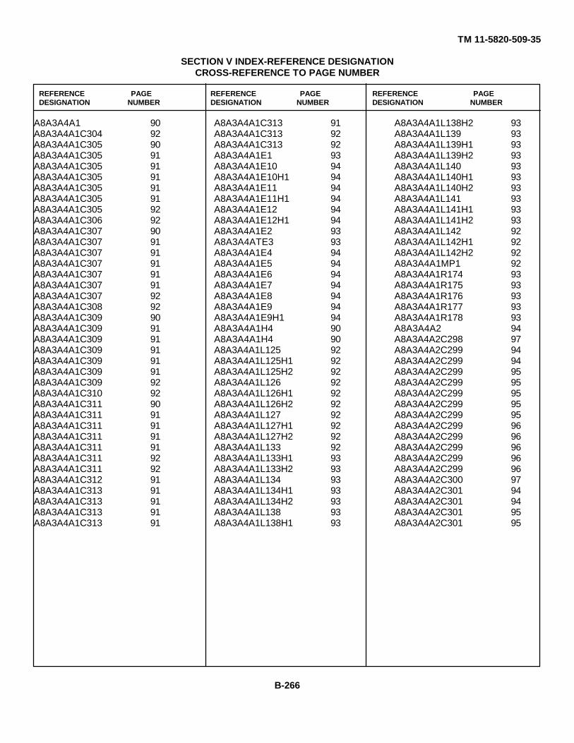
TM 11-5820-509-35
SECTION V INDEX-REFERENCE DESIGNATIONCROSS-REFERENCE TO PAGE NUMBER
REFERENCE PAGE REFERENCE PAGE REFERENCE PAGEDESIGNATION NUMBER DESIGNATION NUMBER DESIGNATION NUMBER
A8A3A4A1 90A8A3A4A1C304 92A8A3A4A1C305 90A8A3A4A1C305 91A8A3A4A1C305 91A8A3A4A1C305 91A8A3A4A1C305 91A8A3A4A1C305 91A8A3A4A1C305 92A8A3A4A1C306 92A8A3A4A1C307 90A8A3A4A1C307 91A8A3A4A1C307 91A8A3A4A1C307 91A8A3A4A1C307 91A8A3A4A1C307 91A8A3A4A1C307 92A8A3A4A1C308 92A8A3A4A1C309 90A8A3A4A1C309 91A8A3A4A1C309 91A8A3A4A1C309 91A8A3A4A1C309 91A8A3A4A1C309 91A8A3A4A1C309 92A8A3A4A1C310 92A8A3A4A1C311 90A8A3A4A1C311 91A8A3A4A1C311 91A8A3A4A1C311 91A8A3A4A1C311 91A8A3A4A1C311 92A8A3A4A1C311 92A8A3A4A1C312 91A8A3A4A1C313 91A8A3A4A1C313 91A8A3A4A1C313 91A8A3A4A1C313 91
A8A3A4A1C313 91A8A3A4A1C313 92A8A3A4A1C313 92A8A3A4A1E1 93A8A3A4A1E10 94A8A3A4A1E10H1 94A8A3A4A1E11 94A8A3A4A1E11H1 94A8A3A4A1E12 94A8A3A4A1E12H1 94A8A3A4A1E2 93A8A3A4ATE3 93A8A3A4A1E4 94A8A3A4A1E5 94A8A3A4A1E6 94A8A3A4A1E7 94A8A3A4A1E8 94A8A3A4A1E9 94A8A3A4A1E9H1 94A8A3A4A1H4 90A8A3A4A1H4 90A8A3A4A1L125 92A8A3A4A1L125H1 92A8A3A4A1L125H2 92A8A3A4A1L126 92A8A3A4A1L126H1 92A8A3A4A1L126H2 92A8A3A4A1L127 92A8A3A4A1L127H1 92A8A3A4A1L127H2 92A8A3A4A1L133 92A8A3A4A1L133H1 93A8A3A4A1L133H2 93A8A3A4A1L134 93A8A3A4A1L134H1 93A8A3A4A1L134H2 93A8A3A4A1L138 93A8A3A4A1L138H1 93
A8A3A4A1L138H2 93A8A3A4A1L139 93A8A3A4A1L139H1 93A8A3A4A1L139H2 93A8A3A4A1L140 93A8A3A4A1L140H1 93A8A3A4A1L140H2 93A8A3A4A1L141 93A8A3A4A1L141H1 93A8A3A4A1L141H2 93A8A3A4A1L142 92A8A3A4A1L142H1 92A8A3A4A1L142H2 92A8A3A4A1MP1 92A8A3A4A1R174 93A8A3A4A1R175 93A8A3A4A1R176 93A8A3A4A1R177 93A8A3A4A1R178 93A8A3A4A2 94A8A3A4A2C298 97A8A3A4A2C299 94A8A3A4A2C299 94A8A3A4A2C299 95A8A3A4A2C299 95A8A3A4A2C299 95A8A3A4A2C299 95A8A3A4A2C299 95A8A3A4A2C299 96A8A3A4A2C299 96A8A3A4A2C299 96A8A3A4A2C299 96A8A3A4A2C299 96A8A3A4A2C300 97A8A3A4A2C301 94A8A3A4A2C301 94A8A3A4A2C301 95A8A3A4A2C301 95
B-266
TM 11-5820-509-35
SECTION V INDEX-REFERENCE DESIGNATIONCROSS-REFERENCE TO PAGE NUMBER
REFERENCE PAGE REFERENCE PAGE REFERENCE PAGEDESIGNATION NUMBER DESIGNATION NUMBER DESIGNATION NUMBER
A8A3A4A2C301 95A8A3A4A2C301 95A8A3A4A2C301 95A8A3A4A2C301 96A8A3A4A2C301 96A8A3A4A2C301 96A8A3A4A2C301 96A8A3A4A2C301 97A8A3A4A2C302 96A8A3A4A2C303 94A8A3A4A2C303 94A8A3A4A2C303 95A8A3A4A2C303 95A8A3A4A2C303 95A8A3A4A2C303 95A8A3A4A2C303 96A8A3A4A2C303 96A8A3A4A2C303 96A8A3A4A2C303 96A8A3A4A2C303 96A8A3A4A2C303 97A8A3A4A2C314 95A8A3A4A2C315 94A8A3A4A2C315 94A8A3A4A2C315 95A8A3A4A2C315 95A8A3A4A2C315 95A8A3A4A2C315 95A8A3A4A2C315 96A8A3A4A2C315 96A8A3A4A2C315 96A8A3A4A2C315 96A8A3A4A2C315 96A8A3A4A2C315 97A8A3A4A2C316 95A8A3A4A2C317 94A8A3A4A2C317 95A8A3A4A2C317 95
A8A3A4A2C317 95A8A3A4A2C317 95A8A3A4A2C317 95A8A3A4A2C317 96A8A3A4A2C317 96A8A3A4A2C317 96A8A3A4A2C317 96A8A3A4A2C317 96A8A3A4A2C317 97A8A3A4A1E1 98A8A3A4A2E10 98A8A3A4A2E10H1 99A8A3A4A2E11 99A8A3A4A2E11H1 99A8A3A4A2E12 99A8A3A4A2E12H1 99A8A3A4A2E2 98A8A3A4A2E3 98A8A3A4A2E4 98A8A3A4A2E5 98A8A3A4A2E6 98A8A3A4A2E7 98A8A3A4A2E8 98A8A3A4A2E9 98A8A3A4A2E9R1 98A8A3A4A2R4 94A8A3A4A2134 94A8A3A4A2L128 97A8A3A4A2L128H1 97A8A3A4A2L128H2 97A8A3A4A2L129 97A8A3A4A2L129H1 97A8A3A4A2L129H2 97A8A3A4A2L130 97A8A3A4A2L130H1 97A8A3A4A2L130H2 97A8A3A4A2L131 97A8A3A4A2L131H1 97
A8A3A4A2L131H2 97A8A3A4A2L132 97A8A3A4A2L132H1 98A8A3A4A2L132H2 98A8A3A4A2L135 98A8A3A4A2L135H1 98A8A3A4A2L135H2 98A8A3A4A2L136 98A8A3A4A2L136H1 98A8A3A4A2L136H2 98A8A3A4A2L137 96A8A3A4A2L137H1 98A8A3A4A2L137H2 98A8A3A4A2L143 97A8A3A4A2L143H1 98A8A3A4A2L143H2 97A8A3A4A2L144 97A8A3A4A2L144H1 97A8A3A4A2L144H2 97A8A3A4A2R172 98A8A3A4A2R173 98A8A3A4A2R179 98A8A3A4CR10 90A8A3A4CR9 90A8A3A4C318 89A8A3A4C319 89A8A3A4C320 90A8A3A4C321 90A8A3A4C322 90A8A3A4C323 90A8A3A4C324 90A8A3A4C325 90A8A3A4C326 90A8A3A4C327 90A8A3A4C328 90A8A3A4C329 90A8A3A4C330 89A8A3A4C331 89
B-267

TM 11-5820-509-35
SECTION V INDEX-REFERENCE DESIGNATIONCROSS-REFERENCE TO PAGE NUMBER
REFERENCE PAGE REFERENCE PAGE REFERENCE PAGEDESIGNATION NUMBER DESIGNATION NUMBER DESIGNATION NUMBER
A8A3A4C332 89A8A314C333 89A8A3A4C334 89A8A3A4C335 89A8A3A4C336 89A8A3A4C337 90A8A3A4C338 89A8A3A4C339 90A8A3A4C340 90A8A3A4C341 90A8A3A4C343 89A8A3A4C345 90A8A3A4C349 90A8A3A4E1 100A8A3A4E1H1 100A8A3A4EH2 100A8A3A4E21 100A8A3A4E21 100A8A3A4E1H2 100A8A3A4E3 101A8A3A4E3H1 101A8A3A4E3H2 101A8A3A4E3H3 101A8A3A4L4 101A8A3A4E4H1 101A8A3A4E4H2 101A8A3A4E4H3 101A8A3A4E6 89A8A3A4E7 89A8A3A4H1 89A8A3A4H1 89A8A3A4B2 89A8A3A4H1 89A8A3A4H1 89A8A3A4H1 89A8A3A4H1 99A8A3A4H2 89ABA3A4H2 89
A8A3A4H2 99A8A3A4MP1 99A8A3A4MP1H1 99A8A3A4MP1H2 99A8A3A4MP1H3 99A8A3A4MP10 100A8A3A4MP2 99A8A3A4MP2H1 99A8A3A4MP2H2 99A8A3A4MP2H3 99AAA3A4MP2H4 99A8A3A4MP2H5 99A3A3A4MP3 99A8A3A4MP4 99A8A3A4MP5 100A8A3A4MP6 100A8A3A4MP7 100A8-3A4MP8 100A8A3A4MP9 100A8A3A4Q20 101A8A3A4Q21 101A8A3A4R156 100A8A3A4R157 100A8A3A4R158 100A8A3A4R159 99A8A3A4R160 99A8A3A4R161 99A8A3A4R163 100A8A3A4R164 100A8A3A4R165 100A8A3A4R166 100A8A3A4R167 100A8A3A4R168 99A8A3A4R169 100A8A3A4R170 99A8A3A4R171 99A8A3A4R180 100A8A3A4S10 100
A8A3A4S6 100A8A3A4S7 100A8A3A5 104A8A3A5H6 104A8A3A5MP1 104A8A3A5MP2 104A843A5MP3 104A8A3A5MP4 104A8A3A5MP5 104A8A3A6 104A8A3A6H6 104A8A3A6MP1 104A8A3A6MP2 104A6A3A6MP3 104A8A3A6MP4 104A8A3A6MP5 104A8A3A6MP6 104A8A3A6MP7 104A8A3A7 106A8A3A7MP1 106A8A3A7MP2 106A8A3A7MP3 106A8A3A7MP4 106ABA3A7MP5 106A8A3A706 106A8A3A8 106A8A3A8A1 106A8A3A8AMP1 106A8A3A8A1MP2 106A8A3A8A1MP3 106A8A3A8MP1 106A8A3A8MP2 106A8A3A9 111A8A3A9A1 111A8A3A9A1C1 112A8A3A9A1C10 111A8A3A9A1C2 112A8A3A9A1C3 112
B-268
TM 11-5820-509-35
SECTION V INDEX-REFERENCE DESIGNATIONCROSS-REFERENCE TO PAGE NUMBER
REFERENCE PAGE REFERENCE PAGE REFERENCE PAGEDESIGNATION NUMBER DESIGNATION NUMBER DESIGNATION NUMBER
A8A3A9A1C4 112A8A3A9A1C5 112A8A3A9A1C6 112A8A3A9A1C7 112A8A3A9A1C8 112A8A3A9A1C9 111A8A3A9ALH4 111A8A3A9A1S1 111A8A3A9A1S1E1 111A8A3A9A1S1E1H1 111A8A3A9A1S1E1H2 111A8A3A9A1S1E1H3 111A8A3A9A1S1E1H4 111A8A3A9A2 112A8A3A9A2C11 113A8A3A9A2C12 113A8A3A9A2C13 113A8A3A9A2C14 113A8A3A9A2C15 113A8A3A9A2C16 113A8A3A9A2C17 113A8A3A9A2C18 113A8A3A9A2C19 113A8A3A9A2C20 113A8A3A9A2C21 114A8A3A9A2C22 113A8A3A9A2C23 113A8A3A9A2C24 113A8A3A9A2C25 114A8A3A9A2C26 113A8A3A9A2C27 113A8A3A9A2C78 113A8A3A9A2C29 113A8A3A9A2C30 113A8A3A9A7C31 113A8A3A9A2C32 113A8A3A9A2C33 113A8A3A9A2C34 113
AbA3A9A2C35 113A8A3A9A2C36 113A8A3A9A2C37 113A8A3A9A2C38 113A8A3A9A2C39 113A8A3A9A2C40 113A8A3A9A2E1 114A8A3A9A2E2 114A8A3A9A2L17 114A8A3A9A2L18 114A8A3A9A2L19 114A8A3A9APL20 114A8A3A9A2L21 114A8A3A9A2S2 112A8A3A9A2S2K1 112A8A3A9A2S2E1H1 112A8A3A9A2S2E1H2 112A8A3A9A2S2E1H3 112A8A3A9A251E1H4 112A8A3A9A2S2E2 112A8A3A9A3 114A8A3A9A3C41 115A8A3A9A3C42 115A8A3A9A3C43 115A8A3A9A3C44 114ABA3A9A3C45 115A8A3A9A3C46 115A8A3A9A3C47 115A8A3A9A3C48 115A8A3A9A3C49 115A8A3A9A3C50 115A8A3A9A3C51 115A8A3A9A3C52 115A8A3A9A3C53 115A8A3A9A3C54 114A8A3A9A3C55 115A8A3A9A3C56 114A8A3A9A3C57 115
A8A3A9A3C58 114A8A3A9A3C59 115A8A3A9A3C60 114A8A3A9A3E3 115A8A3A9A3E4 115A8A3A9A3H4 114A8A3A9A3L32 115A8A3A9A3L23 115A8A3A9A3L34 115A8A3A9A3L35 115A8A3A9A3L36 115A8A3A9A3S3 114ASA3A9A3S3E1 114A8A3A9A3S3E1H1 114A8A3A9A3S3E1H2 114A8A3A9A3S3E1H3 114A8A3A9A3S3E1H4 114A8A3A9A3S3E2 114A8A3A9MP1 112A8A3A9MP2 112A8A3A9MP3 112A8A3A9MP4 132A8A3A9MP5 112A8A3A9MP6 112A8A3A9MP7 112A8A3A9MP8 112A8A3CR7 80A8A3C115 80A8A3C116 80A8A3C117 80A8A3C318 80A8A3C188 80A8A3C189 80A8A3C289 80A8A3C290 80A8A3C291 80A8A3C292 80A8A3C293 80
B-269

TM 11-5820-509-35
SECTION V INDEX-REFERENCE DESIGNATIONCROSS-REFERENCE TO PAGE NUMBER
REFERENCE PAGE REFERENCE PAGE REFERENCE PAGEDESIGNATION NUMBER DESIGNATION NUMBER DESIGNATION NUMBER
A8A3C344 80ABA3E1 83A8A3E10 106A8A3E10H1 106A8A3E10H2 106A8A3E10H3 106A8A3E10H4 106A8A3E11 111A8A3E11H1 111A8A3E1H2 111A8A3E12 107A8A3E13 107A8A3E13H1 107A8A3E13H2 107A8A3E11H3 107A8A3E13H4 107A8A3E14 107A8A3E15 107A8A3E15H1 107A8A3E15H2 107A8A3E15H3 107A8A3E15H4 107A8A3E16 108A8A3E16 108A8A3E16H 108A8A3E17 108A8A3E17H1 108A8A3F17H2 108A8A3E17H3 108A8A3E18 108A8A3E18H1 108A8A3E18H2 108A8A3E18H3 108A8A3E19 108A8A3E19H1 108A8A3E19H2 108A8A3E19H3 108A8A3E2 83
A8A3E20 108A8A3E20E1 108A8A3E20E2 108A8A3E20H3 108A8A3E21 108A8A3E21H1 109A8A3E21H2 109A8A3E21H3 109A8A3E22 109A8A3E23 109A8A3E24 109A8A3E25 109A8A3E26 109A8A3E27 109A8A3E28 109A8A3E29 109A8A3E3 83A8A3E30 109A8A3E30H21 109A8A3E30H2 109A8A3E30H3 109A8A3E31 109A8A3E31H1 109A8A3E31H2 109A8A3E1H3 109A8A3E32 109A8A3E32H1 109A8A3E32H2 109A8A3E32H3 109A8A3E33 109A8A3E33H1 109ABA3E33H2 110A8A3E33H3 110A8A3E34 11oA8A3E34H1 11OA8A3E34H2 110A8A3E4H3 110A8A3E35 110
A8A3E35H1 110ABA3E35H2 110A8A3E35H3 110A8A3E36 110A8A3E36H1 110A8A3E36H2 110A8A3E36H3 110A8A3E37 110A8A3E37H1 110A8A3E37H2 110A8A3E37H3 110A8A3E38 110A8A3E38H1 110A8A3E38E12 110A8A3E38B3 11oA8A3E38H4 110ABA3E385 110A8A3E39 110A8A3E4 83A8A3E40 111A8A3E41 111A8A3E42 111A8A3E43 111A8A3E44 111A8A3E45 111A8A3E45H1 111A8A3E45H2 111A8A3E46 72A8A3E46 111A8A3E46C246 72A8A3E46C247 72A8A3E46C268 72A8A3E46C269 72A8A3E46C270 72A8A3E46C271 72A8A3E46C272 72A8A3E46C273 72A8A3E46C274 73
B-270
TM 11-5820-509-35
SECTION V INDEX-REFERENCE DESIGNATIONCROSS-REFERENCE TO PAGE NUMBER
REFERENCE PAGE REFERENCE PAGE REFERENCE PAGEDESIGNATION NUMBER DESIGNATION NUMBER DESIGNATION NUMBER
A8A3E46C275 72A8A3E46C276 72A8A3E46C280 72A8A3E46C281 72A8A3E46E1 72A8A3E46H1 111A8A3E46H2 72A8A3E46H2 111A8A3E46L102 72A8A3E46Q16 73A8A3E46Q17 73A8A3E46Q18 73A8A3E46Q19 73A8A3E46R119 73A8A3E46R120 73A8A3E46R121 73A8A3E46R122 73A8A3E46R123 73A8A3E46R124 73A8A3E46R125 73A8A3E46R126 73A8A3E46R127 73A8A3E46R128 73A8A3E46R129 73A8A3E46R130 73A8A3E46R131 73A8A3E46R132 73A8A3E46R133 73A8A3E46R134 73A8A3E46R135 73A8A3E47 73A8A3E47CR5 76A8A3E47CR6 76A8A3E47C142 74A8A3E47C143 74A8A3E47C144 73A8A3E47C145 74A8A3E47C147 74
A8A3ED7C148 74A8A3E47C149 74A8A3E47C150 74A8A3E47C151 74A8A3E47C152 74A8A3E47C153 74A8A3E47C154 74A8A3E47C155 74A8A3E47C156 74A8A3E47C157 74A8A3E47C158 74A8A3E47C159 74A8A3E47C160 74A8A3E47C161 74A8A3E47C165 74A8A3E47C176 74A8A3E47C177 74A8A3E47C178 74A8A3E47C180 74A8A3E47C181 74A8A3E47C183 74A8A3E47E1 73A8A3E47J5 75A8A3E47J6 75A8A3E47Q12 77A8A3E47Q13 77A8A3E47Q2 76A8A3E47Q3 77A8A3E47Q4 77A8A3E47Q5 77A8A3E47Q6 77A8A3E47Q7 77A8A3E47Q8 77A8A3E47R136 76A8A3E47R137 76A8A3E47R138 75A8A3E47R139 75A8A3E47R140 76
A8A3E47R141 76A8A3E47R142 76A8A3E47R143 75A8A3E47R144 75A8A3E47R145 76A8A3E47R149 75A8A3E47R24 75A8A3E47R25 76A8A3E47R26 76A8h3E47R27 76A8A3E47R28 75A8A3E47R29 75A8A3E47R30 75A8A3E47R31 76A8A3E47R32 75A8A3E47R33 76A8A3E47R34 75A8A3E47H35 76A8A3E47R36 75A8A3E47R37 75A8A3E47R38 76A8A3E47R39 76A8A3E47R40 76A8A3E47R41 75A8A3E47R42 75A8A3E47R43 75A8A3E47R44 76A8A3E47R45 76A8A3E47R46 75A8A3E47R47 75A8A3E47R48 76A8A3E47R49 76A8A3E47R50 75A8A3E47R51 75A8A3E47P52 76A8A3E47R53 76A8A3E47R54 75A8A3E47R55 75
B-271
TM 11-5820-509-35
SECTION V INDEX-REFERENCE DESIGNATIONCROSS-REFERENCE TO PAGE NUMBER
REFERENCE PAGE REFERENCE PAGE REFERENCE PAGEDESIGNATION NUMBER DESIGNATION NUMBER DESIGNATION NUMBER
A8A3E47R56 76A8A3E47R57 75A8A3E48 85A8A3E48CR2 88A8A3E48CR3 88A8A3£48CR8 88A8A3E48C162 85A8A3E48C163 86A8A3E48C164 86A8A3E48C166 85A8A3E48C167 86A8A3E48C168 85A8A3E48C168 85A8A3E48C168 85A8A3E48C168 86A8A3E48C168 86A8A3E48C168 86A8A3E48C168 86A8A3E48C168 86A8A3E48C169 85A8A3E48C170 86A8A3E48C171 85A8A3E48C172 86A8A3E48C173 85A8A3E48C174 85A8A3E48C175 85A8A3E48C179 85A8A3E48C182 85A8A3E48C18L 85A8A3E48C185 85A8A3E48C186 86A8A3E48E1 85A8A3E48H4 85A8A3E48L101 86A8A3E48L101 86A8A3E48Q10 88A8A3E48Q11 88A8A3F48Q14 88
A8A3E48Q15 88A8A3E48Q9 88A8A3E48R146 87A8A3E48R147 87A8A3E48R148 88A8A3E48R148H1 88A8A3E48R148H2 88A8A3E48R148H3 88A8A3E48R148H4 88A8A3E48R148H5 88A8A3E48R148H6 88A8A3E48R150 87A8A3E48R150H1 87A8A3E48R150H2 87A8A3E48R150H3 87A8A3E48R150H4 87A8A3E48R150H5 87A8A3E48R150H6 87A8A3E48R190 86A843E48R58 86A8A3E48H59 86A8A3E48R61 87A8A3E48R62 87A8A3E48R63 87A8A3E48R64 86A8A3E48R65 87A8A3E48R66 86A8A3E48R67 86A8A3E48R68 87A8A3E48R69 87A8A3E48R7o 86A8A3E48R71 87A8A3E48R72 87A8A3E48R77 86A8A3E48R78 87A8A3E48R79 87A8A3E48R80 87A8A3E48R81 87
A8A3E48R87 87A8A3E48R89 86A8A3E48R90 86A8A3E48R91 86A8A3E48R92 87A8A3E48R93 87A8A3E48R94 86A8A3E48R97 87A8A3E48T1 88A8A3E5 83A8A3E6 83A8A3E7 84A8A3E7E1 84A8A3E7H2 84A8A367H3 84A8A3E7H4 84A8A3E8 85A8A3E9 85A8A3H1 84A8A3H10 105A8A3H10 121A8A3H11 105A8A3H11 121A8A3H12 105A8A3H12 121A8A3H13 105A8A3H13 121A8A3H14 105A8A3H14 121A8A3H15 105A8A3H15 121A8A3H16 105A8A3H16 121A8A3H17 105A8A3H17 121A8A3H18 105A8A3H18 121A8A3H19 105
B-272
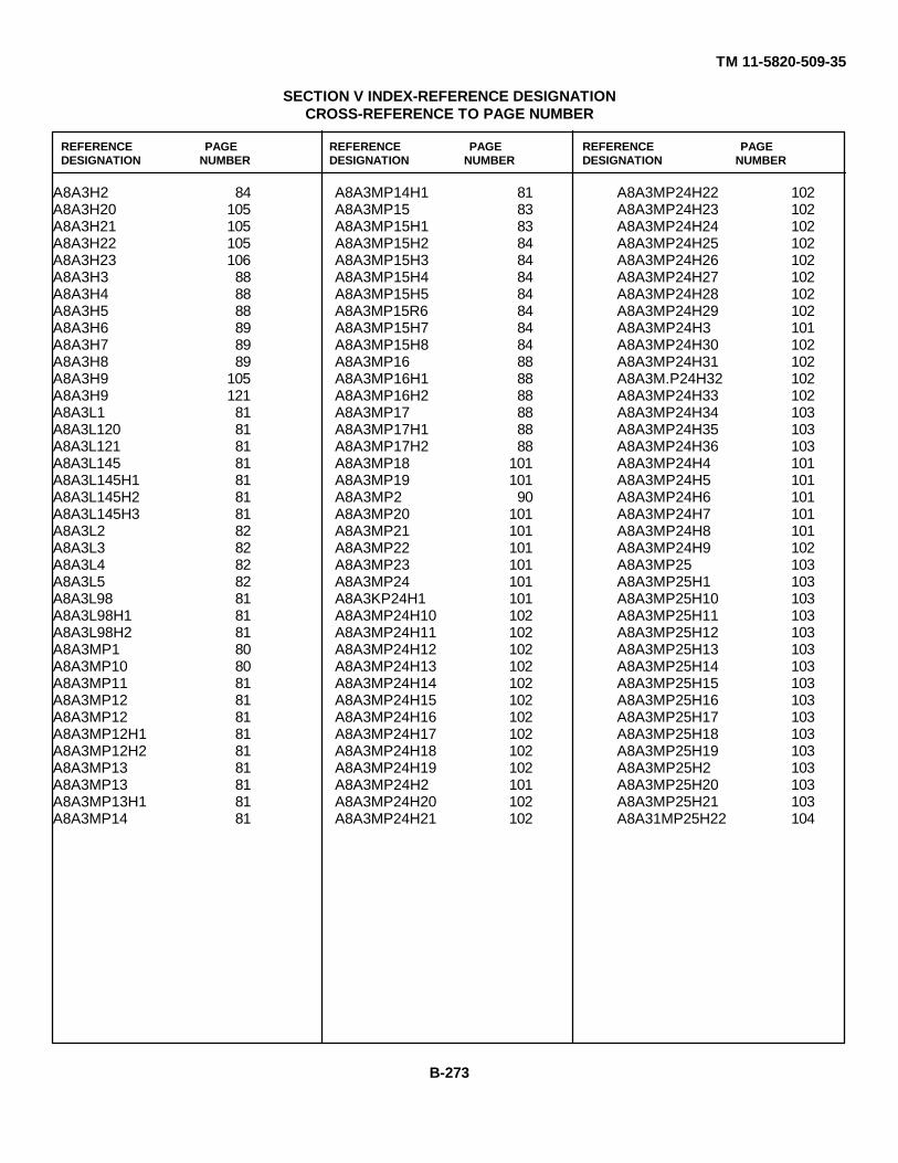
TM 11-5820-509-35
SECTION V INDEX-REFERENCE DESIGNATIONCROSS-REFERENCE TO PAGE NUMBER
REFERENCE PAGE REFERENCE PAGE REFERENCE PAGEDESIGNATION NUMBER DESIGNATION NUMBER DESIGNATION NUMBER
A8A3H2 84A8A3H20 105A8A3H21 105A8A3H22 105A8A3H23 106A8A3H3 88A8A3H4 88A8A3H5 88A8A3H6 89A8A3H7 89A8A3H8 89A8A3H9 105A8A3H9 121A8A3L1 81A8A3L120 81A8A3L121 81A8A3L145 81A8A3L145H1 81A8A3L145H2 81A8A3L145H3 81A8A3L2 82A8A3L3 82A8A3L4 82A8A3L5 82A8A3L98 81A8A3L98H1 81A8A3L98H2 81A8A3MP1 80A8A3MP10 80A8A3MP11 81A8A3MP12 81A8A3MP12 81A8A3MP12H1 81A8A3MP12H2 81A8A3MP13 81A8A3MP13 81A8A3MP13H1 81A8A3MP14 81
A8A3MP14H1 81A8A3MP15 83A8A3MP15H1 83A8A3MP15H2 84A8A3MP15H3 84A8A3MP15H4 84A8A3MP15H5 84A8A3MP15R6 84A8A3MP15H7 84A8A3MP15H8 84A8A3MP16 88A8A3MP16H1 88A8A3MP16H2 88A8A3MP17 88A8A3MP17H1 88A8A3MP17H2 88A8A3MP18 101A8A3MP19 101A8A3MP2 90A8A3MP20 101A8A3MP21 101A8A3MP22 101A8A3MP23 101A8A3MP24 101A8A3KP24H1 101A8A3MP24H10 102A8A3MP24H11 102A8A3MP24H12 102A8A3MP24H13 102A8A3MP24H14 102A8A3MP24H15 102A8A3MP24H16 102A8A3MP24H17 102A8A3MP24H18 102A8A3MP24H19 102A8A3MP24H2 101A8A3MP24H20 102A8A3MP24H21 102
A8A3MP24H22 102A8A3MP24H23 102A8A3MP24H24 102A8A3MP24H25 102A8A3MP24H26 102A8A3MP24H27 102A8A3MP24H28 102A8A3MP24H29 102A8A3MP24H3 101A8A3MP24H30 102A8A3MP24H31 102A8A3M.P24H32 102A8A3MP24H33 102A8A3MP24H34 103A8A3MP24H35 103A8A3MP24H36 103A8A3MP24H4 101A8A3MP24H5 101A8A3MP24H6 101A8A3MP24H7 101A8A3MP24H8 101A8A3MP24H9 102A8A3MP25 103A8A3MP25H1 103A8A3MP25H10 103A8A3MP25H11 103A8A3MP25H12 103A8A3MP25H13 103A8A3MP25H14 103A8A3MP25H15 103A8A3MP25H16 103A8A3MP25H17 103A8A3MP25H18 103A8A3MP25H19 103A8A3MP25H2 103A8A3MP25H20 103A8A3MP25H21 103A8A31MP25H22 104
B-273

TM 11-5820-509-35
SECTION V INDEX-REFERENCE DESIGNATIONCROSS-REFERENCE TO PAGE NUMBER
REFERENCE PAGE REFERENCE PAGE REFERENCE PAGEDESIGNATION NUMBER DESIGNATION NUMBER DESIGNATION NUMBER
A8A3MP25H23 104A8A3MP25H3 103A8A3MP25H4 103A8A3MP25H5 103A8A3MP25H6 103A8A3MP25H7 103A8A3MP25H8 103A8A3MP25H9 103A8A3MP26 104A8A3MP26 104A8A3MP26H1 104A8A3MP26H2 104A8A3MP26H3 104A8A3MP27 104A8A3MP28 104A8A3MP29 105A8A3MP3 80A8A3MP30 105A8A3MP31 105A8A3MP32 107A8A3MP33 107A6A3MP34 107A8A3MP35 107A8A3MP36 107A8A3MP37 107A8A3MP38 107A8A3MP38H1 107A8A3MP38H2 107A8A3MP38H3 107A8A3MP38H4 108A8A3MP38H5 108A8A3MP38H6 108A8A3MP38H7 108A8A3MP38H8 108A8A3MP39 121A8A3MP39H1 121A8A3MP39H2 121A8A3MP4 80
A8A3MP40 121A8A3MP40H1 121A8A3MP40H2 121A8A3MP5 80A8A3MP6 80A8A3MP7 80A8A3MP7H1 80A8A3MP8 80A8A3MP8H1 80A8A3MP9 80A8A3P1 82A8A3P1A1 83A8A3P1A2 83A8A3P1H1 82A8A3P1H2 82A8A3P1H3 82A8A3P1H4 82A8A3P1H5 82A8A3P1H16 82A8A3P1H7 82A8A3P2 82A8A3P2A1 83A8A3P2A2 83A8A3P2H1 82A8A3P2H2 82A8A3P2H3 82A8A3P2H4 82A8A3P2H5 a2A8A3P3 82A8A3P3A1 83A8A3P3A2 83A8A3P3H1 82A8A3P3H2 82A8A3P3H3 82A8A3P3H4 82A8A3P3H5 82A8A3P4 82A8A3P4A1 83
A8A3P4A2 83A8A3P4H1 83A8A3P4H2 83A8A3P4H3 83A8A3P4H4 83A8A3P4H5 83A8A3H17 105A8A3R18 105A8A3R181 105A8A3R182 105A8A3R19 105A8A3R20 105A8A3R82 105A8A3R88 105A8A3TB1 77A8A3TB1C61 77A8A3TB1C63 77A8A3TB1C65 77A8A3TB1C66 77A8A3TB1E1 77A8A3TB1E2 77A8A3TB1E3 77A8A3TB1E4 77A8A3TB1E4H1 78A8A3TB1E4H2 78A8A3TB1E4H3 78A8A3TB1E5 78A8A3TB1E5H1 78A8A3TB1E5H2 78A8A3TB1E5H3 78A8A3TB1E6 78A8A3TB1E6H1 78A8A3TB1E6H2 78A8A3TB1E6H3 78A8A3TB1H1 77A8A3TB1H1 77A8A3TB1H2 77A8A3TB1R1 77
B-274

TM 11-5820-509-35
SECTION V INDEX-REFERENCE DESIGNATIONCROSS-REFERENCE TO PAGE NUMBER
REFERENCE PAGE REFERENCE PAGE REFERENCE PAGEDESIGNATION NUMBER DESIGNATION NUMBER DESIGNATION NUMBER
A8A3TB1R2 77A8A31B1R3 77A8A3TB1R5 77A8A3TB1R6 77A8A3TB1V1 78A8A3TB2 78A8A3TB2C187 78A8A3T82C89 78A8A3TB2C90 78A8A3TB2C92 78A8A3TB2E1 78A83TB2E27 9A8A3TB2E3 79A8A3TB2E4 79A8A3TB2E4H1 79A8A3TB2E4H2 79A8A3TB2E4H3 79A83TB2E5 79A8A3TB2E5H1 79A8A3TB2E5H2 79A8A3TB2E5H3 79A8A3TB2E6 79A8A3TB2E6H1 79A8A3TB2E6-2 79A8A3T132E6H3 79A8A3TB2E7 79A8A3TB2E13 79A8A3TB2E8H1 79A8A3TB2E-H2 79A8A3TB2E8H3 79A8A3-1-B2H1 78A8A3-B2H1 78A8A3TB2H2 7BA8A3TB2X1 78A8A3TB2 78A8A3TB2K1-2 78A8A3TB2K1H3 78A8A3TB2K1B4 79
A8A3TB1R10 79A8A3TB2R11 79A8A3TB2R13 79A8A3TB2R14 79A8A3TB2R9 79A8A3TB2V2 80A8A3XV31 106A8A3XV3H1 106A8A3XV3H2 106A8A3XV3H3 106A8A3XV3H4 107A8A3XV3H5 107A8A3XV3H6 107A8A3V3 121A8A3W1 84A8A3W2 84A8A4 139A8A4A1 140A8A4A1A1 141A84A1A1H1 141A84A1A1H2 141A8A4A1A1H4 141A8A4A1A1J1 141A8A4A1A1J2 141A8A4A1A1J3 141A8A4A1A1J4 141A8A4A1A1J5 141A8A4A1CR101 142A8A4A1C101 140A84A1C103 141A8A4A1C104 141A84A1C125 140A84A1C126 140A8A4A1C139 140A8A4A1C140 141A8A4A1C141 141A8A4A1E1 142A8A4A1H2 140
A8A4A1H2 140A8A4A1L102 141A8A4A1L103 142A8A4A1L120 141A8A4A1L121 141A8A4A1MP1 141A8A4A1MP1H1 141A8A4A1MP1H2 141A8A4A1MP1H3 141A8A4A1MP1H4 141A8A4A1MP1H5 141A8A4A1MP1H6 141A8A4A1MP1H7 141A8A4A1MP1H8 141A8A4A1R102 142A8A4A1R103 142A8A4A1R104 142A8A4A1R108 142A8A4A1R115 142A8A4A1R116 142A8A4A1R119 142A8A4A11V101 142A8A4A15 179A8A4A15CR3 179A8A4A15CR4 179A84A15CR5 179A8A4A15CR6 179A8A4A15E1 179A8A4A15H2 179A8A4A15H2 179A8A4A15H2 179A8A4A15R16 179A8A4A16 183A8A4A16C105 184A8A4A16C108 185A8A4A16C106H1 185A8A4A16C108H2 185A8A4A16C109 184
B-275
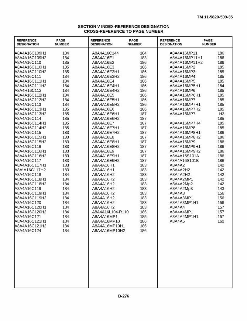
TM 11-5820-509-35
SECTION V INDEX-REFERENCE DESIGNATIONCROSS-REFERENCE TO PAGE NUMBER
REFERENCE PAGE REFERENCE PAGE REFERENCE PAGEDESIGNATION NUMBER DESIGNATION NUMBER DESIGNATION NUMBER
A8A4A16C109H1 184A8A4A16C109H2 184A8A4A16C110 185A8A4A16C110H1 185A8A4A16C110H2 185A8A4A16C111 184A8A4A16C111H1 184A8A4A16C111H2 184A8A4H16C112 184A8A4A16C112H1 184A8A4A16C112H2 184A8A4A16C113 184A8A4A16C113H1 185A8A4A16C113H2 185A8A4A16C114 185A8A4A16C114H1 185A8A4A16C114H2 185A8A4A16C115 183A8A4A16C115H1 183A8A4A16C115H2 183A8A4A16C116 183A8A4A16C116H1 183A8A4A16C116H2 183A8A4A16C117 183A8A4A16C117H1 183A8A!A16C117H2 183A8A4A16C118 184A8A4A16C118H1 184A8A4A16C118H2 184A8A4A16C119 184A8A4A16C119H1 184A8A4A16C119H2 184A8A4A16C120 184A8A4A16C120H1 184A8A4A16C120H2 184A8A4A16C121 184A8A4A16C121H1 184A8A4A16C121H2 184A8A4A16C124 184
A8A4A16C144 184A8A4A16E1 183A8A4A16E2 186A8A4A16E3 186A8A4A16E3H1 186A8A4A16E3H2 186A8A4A16E4 186A8A4A16E4H1 186A8A4A16E4H2 186A8A4A16E5 186A8A4A16E5H1 186A8A4A16E5H2 186A8A4A16E6 186A8A4A16E6H1 187A8A4A16E6H2 187A8A4A16E7 187A8A4A16E7H1 187A8A4A16E7H2 187A8A4A16E8 187A8A4A16E8H1 187A8A4A16E8H2 187A8A4A16E9 187A8A4A16E9H1 187A8A4A16E9H2 187A8A4A16H1 183A8A4A16H1 183A8A4A16H2 183A8A4A16H2 183A8A4A16H2 183A8A4A16H2 183A8A4A16H2 183A8A4A16H2 183A8A4A16H2 183A8A4A16H2 183A8A4A16L104-R110 186A8A4A16MP1 185A8A4A16MP10 186A8A4A16MP10H1 186A8A4A16MP10H2 186
A8A4A16MP11 186A8A4A16MP11H1 186A8A4A16MP11H2 186A8A4A16MP2 185A8A4A16MP3 185A8A4A16MP4 185A8A4A16MP5 185A8A4A16MP5H1 184A8A4A16MP6 185A8A4A16MP6H1 185A8A4A16MP7 185A8A4A16MP7H1 185A8A4A16MP7H2 185A8A4A16MP7 H3
185A8A4A16MP7H4 185A8A4A16MP8 185A8A4A16MP8H1 186A8A4A16MP8H2 186A8A4A16MP9 186A8A4A16MP9H1 186A8A4A16MP9H2 186A8A4A16S101A 186A8A4A16S101B 186A8A4A2 142A8A4A2H2 142A8A4A2H2 142A8A4A2MP1 142A8A4A2Mp2 142A8A4A2Mp3 143A8A4A3 156A8A4A3MP1 156A8A4A3MP1H1 156A8A4A4 157A8A4A4MP1 157A8A4A4MP1H1 157A8A4A5 160
B-276

TM 11-5820-509-35
SECTION V INDEX-REFERENCE DESIGNATIONCROSS-REFERENCE TO PAGE NUMBER
REFERENCE PAGE REFERENCE PAGE REFERENCE PAGEDESIGNATION NUMBER DESIGNATION NUMBER DESIGNATION NUMBER
A8A4A5MP1 160A8A4A5MP2 160A8A4A5MP3 160A8A4A5MP3H1 160A8A4A6 162A8A4A6A1 166A8A4A6A1MP1 166A8A4A6A1MP2 166A8A4A6A1MP3 166A8A4A6A1MP4 166A8A4A6A1MP5 166A8A4A6A1MP6 166A8A4A6A10 172A8A4A6A10MP1 172A8A4A6A10MP2 172A8A4A6A10MP3 172A8A4A6A11 172A8A4A6A11MP1 172A8A4A6A11MP2 172A8A4A6A11MP3 172A8A4A6A12 172A8A4A6A12H1 172A8A4A6A12H5 172A8A4A6A12H5 172A8A4A6A12MP1 172A8A4A6A12MP2 172A8A4A6A13 174A8A4A6A13H1 174A8A4A6A13MP1 174A8A4A6A13MP2 174A8A4A6A13MP3 174A8A4A6A13MP4 174A8A4A6A2 166A8A4A6A2MP1 166A8A4A6A2MP2 166A8A4A6A2MP3 166A8A4A6A2MP4 166A8A4A6A2MP5 166
A8A4A6A2MP6 166A8A4A6A3 166A8A4A6A3MP1 167A8A4A6A3MP2 167A8A4A6A3MP3 167A8A4A6A3MP3 167A8A4A6A4 167A8A4A6A4MP1 167A8A4A6A4MP2 167A8A4A6A5 167A8A4A6A5MP1 167A8A4A6A5MP111 167A8A4A6A5MP112 167A8A4A6A5MP113 167A8A4A6A5MP114 167A8A4A6A6 167A8A4A6A6MP1 167A8A4A6A6MP1H1 167A8A4A6A6MP1H2 167A8A4A6A6MP1H3 167A8A4A6A6MP1H4 166A8A4A6A7 168A8A4A6A7A1 169A8A4A6A7A1MP1 169A8A4A6A7A1MP2 169A8A4A6A7A1MP3 169A8A4A6A7A1MP4 169A8A4A6A7A1MP5 169A8A8A6A7A2 170A8A4A6A7A2MP1 170A8A4A6A7A2MP2 170A8A4A6A7A3 170A8A4A6A7A3MP1 170A8A4A6A7A3MP2 170A8A4A6A7A3MP3 170A8A4A6A7A4 170A8A4A6A7A4MP1 170A8A4A6A7A4MP2 170
A8A4A6A7A4MP3 170A8A4A6A7H1 170A8A4A6A7H2 170A8A4A6A7H3 170A8A4A6A7H3 170A8A4A6A7H3 170A8A4A6A7H4 170A8A4A6A7H5 170A8A4A6A7MP1 169A8A4A6A7MP10 170A8A4A6A7MP10H1 170A8A4A6A7MP10H2 170A8A4A6A7MP11 170A8A4A6A7MP12 170A8A4A6A7MP13 170A8A4A6A7MP14 170A8A4A6A7MP15 170A8A4A6A7MP16 170A8A4A6A7MP17 171A8A4A6A7MP2 169A8A4A6A7MP3 169A8A4A6A7MP4 169A8A4A6A7MP5 169A8A4A6A7MP6 169A8A4A6A7MP6H1 169A8A4A6A7MP6H2 169A8A4A6A7MP7 169A8A4A6A7MP7H1 169A8A4A6A7MP7H2 169A8A4A6A7MP8 169A8A4A6A7MP8H1 169A8A4A6A7MP8H2 169A8A4A6A7MP9 169A8A4A6A7MP9R1 169A8A4A6A7MP9H2 169A8A4A6A8 171A8A4A6A8MP1 171A8A4A6A8MP2 171
B-277

TM 11-5820-509-35
SECTION V INDEX-REFERENCE DESIGNATIONCROSS-REFERENCE TO PAGE NUMBER
REFERENCE PAGE REFERENCE PAGE REFERENCE PAGEDESIGNATION NUMBER DESIGNATION NUMBER DESIGNATION NUMBER
A8A4A6A8MP3 171A8A4A6A8MP3H1 171A8A4A6A8MP4 172A8A4A6A8MP5 172A8A4A6A8MP6 172A8A4A6A8MP7 172A8A4A6A9 172A8A4A6A9MP1 172A8A4A6A9MP2 172A8A4A6A9MP3 172A8A4A6E1 165A8A4A6E1H1 165A8A4A6E1H2 165AsA4A6E2 165A8A4A6E2H1 165A8A4A6E2H2 166A8A4A6E3 172A8A4A6E3H1 172A8A4A6E3H2 172A8A4A6E3H3 172A8A4A6E4 173A8A4A6E4H1 173A8A4A6E4H2 173A8A4A6E4H3 173A8A4A6E5 174A8A4A6E5H1 174A8A4A6E5H2 174A8A4A6E5H3 174A8A4A6E5H4 174A8A4A6E6 174A8A4A6H1 173A8A4A6H10 173A8A4A6H11 173A8A4A6H12 174A8A4A6H13 174A8A4A6H14 174A8A4A6H15 174A8A4A6H16 174
A8A4A6H17 174A8A4A6H2 173A8A4A6H3 162A8A4A6H3 162A8A4A6H3 163A8A4A6H3 173A8A4A6H4 173A8A4A6H5 173A8A4A6H6 162A8A4A6H6 163A8A4A6H6 173A8A4A6H7 173A8A4A6H8 173A8A4A6H9 173A8A4A6H9 173A8A4A6MP1 163A8A4A6MP1H1 163A8A4A6MP1H10 163A8A4A6MP1H11 163A8A4A6MP1H12 163A8A4A6MP1H13 163A8A4A6MP1H14 163A8A4A6MP1H15 163A8A4A6MP1H16 163A8A4A6MP1H17 163A8A4A6MP1H18 163A8A4A6MP1H19 163A8A4A6MP1H2 163A8A4A6MP1H20 163A8A4A6MP1H21 163A8A4A6MP1H22 163A8A4A6MP1H23 164A8A4A6MP1H24 164A8A4A6MP1H3 163A8A4A6MP1H4 163A8A4A6MP1H5 163A8A4A6MP1H6 163A8A4A6MP1H7 163
A8A4A6MP1H8 163A8A4A6MP1H9 163A8A4A6MP10 164A8A4A6MP11 164A8A4A6MF12 164A8A4A6MP13 164A8A4A6MP14 164A8A4A6MP15 164A8A4A6MP16 164A8A4A6MP17 164A8A4A6MP18 164A8A4A6MP18H1 164A8A4A6MP19 164A8A4A6MP19H1 164A8A4A6MP2 164A8A4A6MP20 164A8A4A6MP20H1 164A8A4A6MP21 164A8A4A6MP21H1 165A8A4A6MP21H2 165A8A4A6MP22 165A8A4A6MP22H1 165A8A4A6MP22H2 165A8A4A6MP23 165A8A1A6MP23H1 165A8A4A6MP23H2 165A8A4A6MP24 165A8A4A6MP24H1 165A8A4A6MP24H2 165A8A4A6MP25 165A8A4A6MP25H1 165A8A4A6MP25H2 165A8A4A6MP26 165A8A4A6MP26H1 165A8A4A6MP26H2 165A8A4A6MP27 165A8A4A6MP27H1 165A8A4A6MP27H2 165
B-278
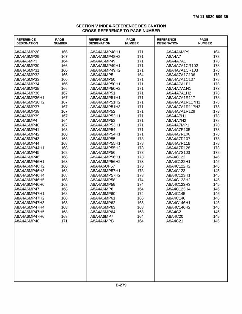
TM 11-5820-509-35
SECTION V INDEX-REFERENCE DESIGNATIONCROSS-REFERENCE TO PAGE NUMBER
REFERENCE PAGE REFERENCE PAGE REFERENCE PAGEDESIGNATION NUMBER DESIGNATION NUMBER DESIGNATION NUMBER
A8A4A6MP28 166A8A4A6MP29 167A8A4A6MP3 164A8A4A6MP30 166A8A4A6MP31 166A8A4A6MP32 166A8A4A6MP33 166A8A4A6MP34 166A8A4A6MP35 166A8A4A6MP36 167A8A4A6MP36H1 167A8A4A6MP36H2 167A8A4A6MP37 167A8A4A6MP38 167A8A4A6MP39 167A8A4A6MP4 164A8A4A6MP40 167A8A4A6MP41 168A8A4A6MP42 168A8A4A6MP43 168A8A4A6MP44 168A8A4A6MP44H1 168A8A4A6MP45 168A8A4A6MP46 168A8A4A6MP46H1 168A8A4A6MP46H2 168A8A4A6MP46H3 168A8A4A6MP46H4 168A8A4A6MP46H5 168A8A4A6MP46H6 168A8A4A6MP47 168A8A4A6MP47H1 168A8A4A6MP47H2 168A8A4A6MP47H3 168A8A4A6MP47H4 168A8A4A6MP47H5 168A8A4A6MP47H6 168A8A4A6MP48 171
A8A4A6MP48H1 171A8A4A6MP48H2 171A8A4A6MP49 171A8A4A6MP49H1 171A8A4A6MP49H2 171A8A4A6MP5 164A8A4A6MP50 171A8A4A6MP50H1 171A8A4A6MP50H2 171A8A4A6MP51 171A8A4A6MP51H1 171A8A4A6MP51H2 171A8A4A6MP51H3 171A8A4A6MP52 171A8A4A6MP52H1 171A8A4A6MP53 171A8A4A6MP53H1 171A8A4A6MP54 171A8A4A6MP54H1 171A8A4A6MP55 173A8A4A6MP55H1 173A8A4A6MP55H2 173A8A4A6MP56 173A8A4A6MP56H1 173A8A4A6MP56H2 173A8A4A6UP57 173A8A4A6MP57H1 173A8A4A6MP57H2 173A8A4A6MP58 174A8A4A6MP59 174A8A4A6MP6 164A8A4A6MP60 174A8A4A6MP61 166A8A4A6MP62 168A8A4A6MP63 168A8A4A6MP64 168A8A4A6MP7 164A8A4A6MPB 164
A8A4A6MP9 164A8A4A7 178A8A4A7A1 178A8A4A7A1CR102 178A8A4A7A1CR103 178A8A4A7A1C106 178A8A4A7A1C107 178A8A4A7A1E1 178A8A4A7A1H1 178A8A4A7A1H2 178A8A4A7A1R117 178A8A4A7A1R117H1 178A8A4A7A1R117H2 178A8A4A7A1R129 178A8A4A7H1 178A8A4A7H2 178A8A4A7MP1 178A8A4A7R105 178A8A4A7R106 178A8A4A7R107 178A8A4A7R118 178A8A4A7R128 178A8A4A7S103 178A8A4C122 146A8A4C122H1 146A8A4C122H2 146A8A4C123 145A8A4C123H1 145A8A4C123H2 145A8A4C123H3 145A8A4C123H4 145A8A4C145 146A8A4C146 146A8A4C146H1 146A8A4C146H2 146A8A4C2 145A8A4C20 145A8A4C21 145
B-279
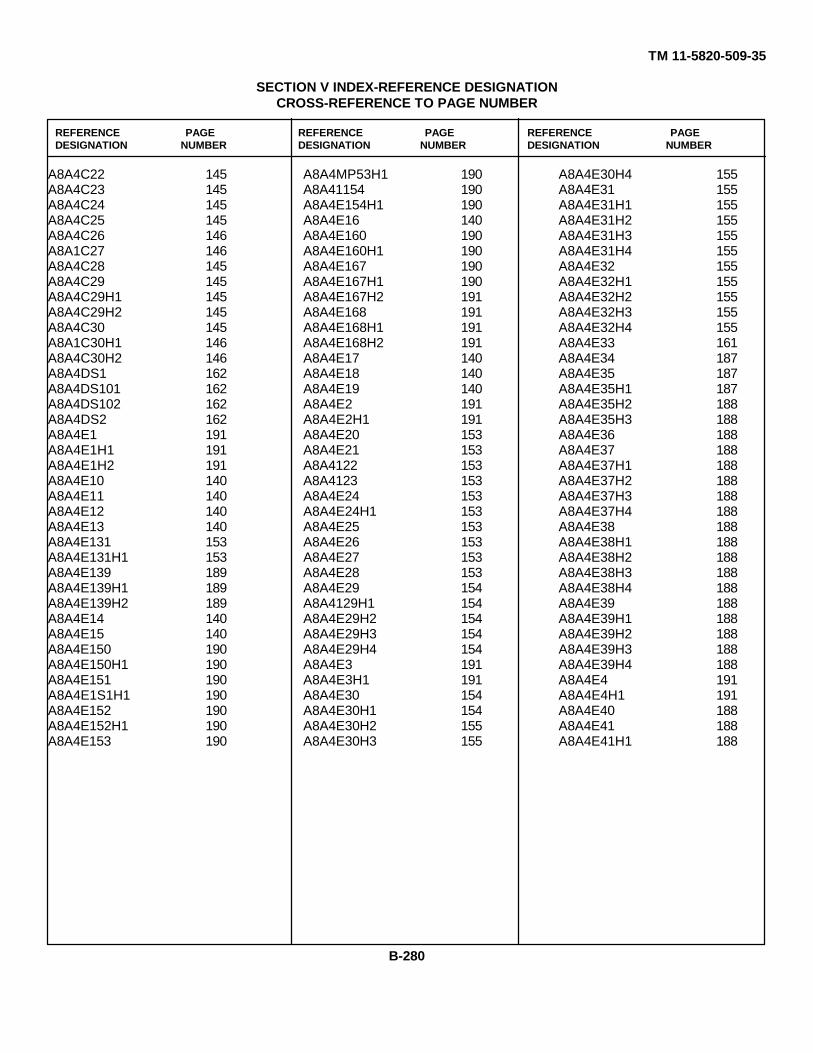
TM 11-5820-509-35
SECTION V INDEX-REFERENCE DESIGNATIONCROSS-REFERENCE TO PAGE NUMBER
REFERENCE PAGE REFERENCE PAGE REFERENCE PAGEDESIGNATION NUMBER DESIGNATION NUMBER DESIGNATION NUMBER
A8A4C22 145A8A4C23 145A8A4C24 145A8A4C25 145A8A4C26 146A8A1C27 146A8A4C28 145A8A4C29 145A8A4C29H1 145A8A4C29H2 145A8A4C30 145A8A1C30H1 146A8A4C30H2 146A8A4DS1 162A8A4DS101 162A8A4DS102 162A8A4DS2 162A8A4E1 191A8A4E1H1 191A8A4E1H2 191A8A4E10 140A8A4E11 140A8A4E12 140A8A4E13 140A8A4E131 153A8A4E131H1 153A8A4E139 189A8A4E139H1 189A8A4E139H2 189A8A4E14 140A8A4E15 140A8A4E150 190A8A4E150H1 190A8A4E151 190A8A4E1S1H1 190A8A4E152 190A8A4E152H1 190A8A4E153 190
A8A4MP53H1 190A8A41154 190A8A4E154H1 190A8A4E16 140A8A4E160 190A8A4E160H1 190A8A4E167 190A8A4E167H1 190A8A4E167H2 191A8A4E168 191A8A4E168H1 191A8A4E168H2 191A8A4E17 140A8A4E18 140A8A4E19 140A8A4E2 191A8A4E2H1 191A8A4E20 153A8A4E21 153A8A4122 153A8A4123 153A8A4E24 153A8A4E24H1 153A8A4E25 153A8A4E26 153A8A4E27 153A8A4E28 153A8A4E29 154A8A4129H1 154A8A4E29H2 154A8A4E29H3 154A8A4E29H4 154A8A4E3 191A8A4E3H1 191A8A4E30 154A8A4E30H1 154A8A4E30H2 155A8A4E30H3 155
A8A4E30H4 155A8A4E31 155A8A4E31H1 155A8A4E31H2 155A8A4E31H3 155A8A4E31H4 155A8A4E32 155A8A4E32H1 155A8A4E32H2 155A8A4E32H3 155A8A4E32H4 155A8A4E33 161A8A4E34 187A8A4E35 187A8A4E35H1 187A8A4E35H2 188A8A4E35H3 188A8A4E36 188A8A4E37 188A8A4E37H1 188A8A4E37H2 188A8A4E37H3 188A8A4E37H4 188A8A4E38 188A8A4E38H1 188A8A4E38H2 188A8A4E38H3 188A8A4E38H4 188A8A4E39 188A8A4E39H1 188A8A4E39H2 188A8A4E39H3 188A8A4E39H4 188A8A4E4 191A8A4E4H1 191A8A4E40 188A8A4E41 188A8A4E41H1 188
B-280
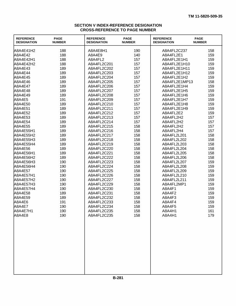
TM 11-5820-509-35
SECTION V INDEX-REFERENCE DESIGNATIONCROSS-REFERENCE TO PAGE NUMBER
REFERENCE PAGE REFERENCE PAGE REFERENCE PAGEDESIGNATION NUMBER DESIGNATION NUMBER DESIGNATION NUMBER
A8A4E41H2 188A8A4E42 188A8A4E42H1 188A8A4E42H2 188A8A4E43 189A8A4E44 189A8A4E45 189A8A4E46 189A8A4E47 189A8A4E48 189A8A4E49 189A8A4E5 191A8A4E50 189A8A4E51 189A8A4E52 189A8A4E53 189A8A4E54 189A8A4E55 189A8A4E55H1 189A8A4E55H2 189A8A4E55H3 189A8A4E55H4 189A8A4E56 189A8A4E56H1 189A8A4E56H2 189A8A4E56H3 190A8A4E56H4 190A8A4E57 190A8A4E57H1 190A8A4E57H2 190A8A4E57H3 190A8A4E57H4 190A8A4E58 189A8A4E59 189A8A4E6 191A8A4E7 190A8A4E7H1 190A8A4E8 190
A8A4E8H1 190A8A4E9 140A8A4FL2 157A8A4FL2C201 157A8A4FL2C202 157A8A4FL2C203 157A8A4FL2C204 157A8A4FL2C205 157A8A4FL2C206 157A8A4FL2C207 157A8A4FL2C208 157A8A4FL2C209 157A8A4FL2C210 157A8A4FL2C211 157A8A4FL2C212 157A8A4FL2C213 157A8A4FL2C214 157A8A4FL2C215 158A8A4FL2C216 158A8A4FL2C217 158A8A4FL2C218 158A8A4FL2C219 158A8A4FL2C220 158A8A4FL2C221 158A8A4FL2C222 158A8A4FL2C223 158A8A4FL2C224 158A8A4FL2C225 158A8A4FL2C226 158A8A4FL2C227 158A8A4FL2C229 158A8A4FL2C230 158A8A4FL2C231 158A8A4FL2C232 158A8A4FL2C233 158A8A4FL2C234 158A8A4FL2C235 158A8A4FL2C235 158
A8A4FL2C237 158A8A4FL2E1 159A8A4FL2E1H1 159A8A4FL2E1H10 159A8A4FL2E1H11 159A8A4FL2E1H12 159A8A4FL2E1H2 159A8A4FL2E1MP13 158A8A4FL2E1H4 159A8A4FL2E1H5 159A8A4FL2E1H6 159A8A4FL2E1H7 159A8A4FL2E1H8 159A8A4FL2E1H9 159A8A4FL2E2 159A8A4FL2H2 157A8A4FL2H2 157A8A4FL2H2 157A8A4FL2H4 157A8A4FL2L201 158A8A4FL2L202 158A8A4FL2L203 158A8A4FL2L204 158A8A4FL2L205 158A8A4FL2L206 158A8A4FL2L207 159A8A4FL2L208 159A8A4FL2L209 159A8A4FL2L210 159A8A4FL2L211 159A8A4FL2MP1 159A8A4F1 159A8A4F2 159A8A4F3 159A8A4F4 159A8A4F5 159A8A4H1 161A8A4H1 179
B-281
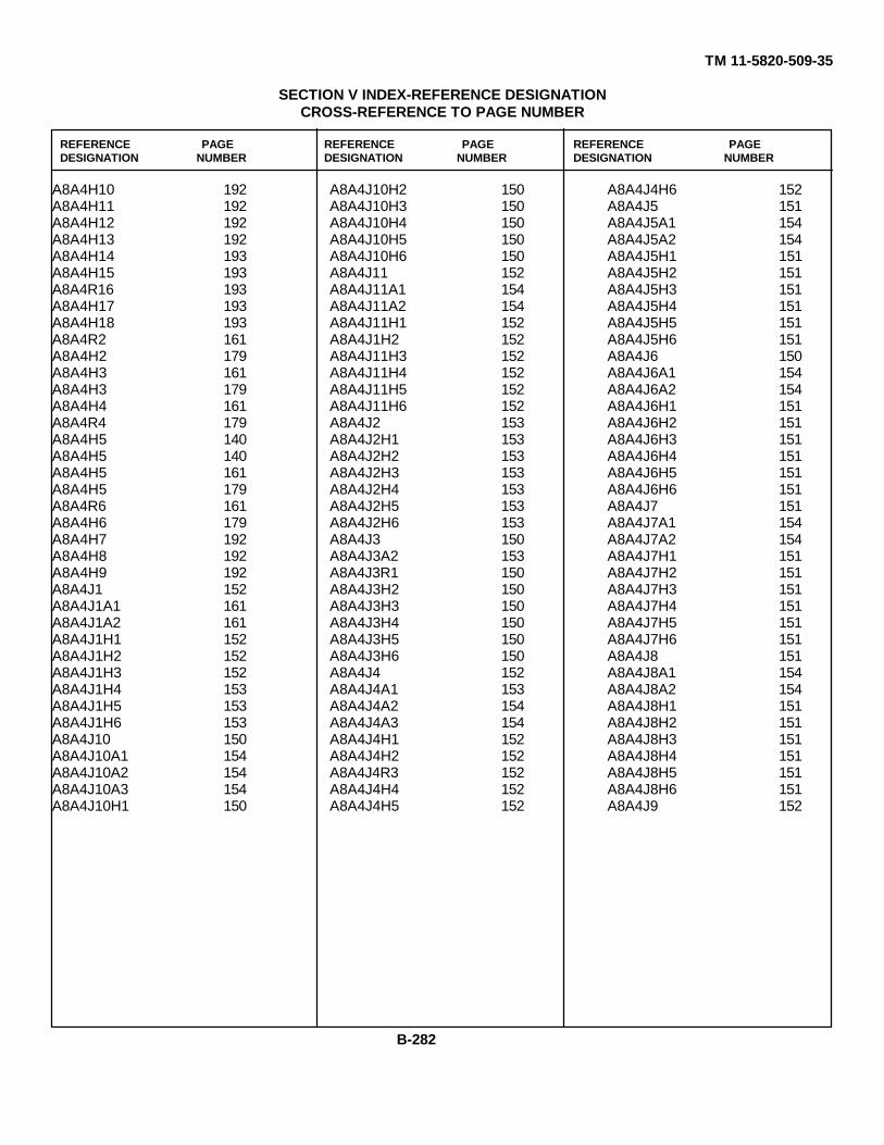
TM 11-5820-509-35
SECTION V INDEX-REFERENCE DESIGNATIONCROSS-REFERENCE TO PAGE NUMBER
REFERENCE PAGE REFERENCE PAGE REFERENCE PAGEDESIGNATION NUMBER DESIGNATION NUMBER DESIGNATION NUMBER
A8A4H10 192A8A4H11 192A8A4H12 192A8A4H13 192A8A4H14 193A8A4H15 193A8A4R16 193A8A4H17 193A8A4H18 193A8A4R2 161A8A4H2 179A8A4H3 161A8A4H3 179A8A4H4 161A8A4R4 179A8A4H5 140A8A4H5 140A8A4H5 161A8A4H5 179A8A4R6 161A8A4H6 179A8A4H7 192A8A4H8 192A8A4H9 192A8A4J1 152A8A4J1A1 161A8A4J1A2 161A8A4J1H1 152A8A4J1H2 152A8A4J1H3 152A8A4J1H4 153A8A4J1H5 153A8A4J1H6 153A8A4J10 150A8A4J10A1 154A8A4J10A2 154A8A4J10A3 154A8A4J10H1 150
A8A4J10H2 150A8A4J10H3 150A8A4J10H4 150A8A4J10H5 150A8A4J10H6 150A8A4J11 152A8A4J11A1 154A8A4J11A2 154A8A4J11H1 152A8A4J1H2 152A8A4J11H3 152A8A4J11H4 152A8A4J11H5 152A8A4J11H6 152A8A4J2 153A8A4J2H1 153A8A4J2H2 153A8A4J2H3 153A8A4J2H4 153A8A4J2H5 153A8A4J2H6 153A8A4J3 150A8A4J3A2 153A8A4J3R1 150A8A4J3H2 150A8A4J3H3 150A8A4J3H4 150A8A4J3H5 150A8A4J3H6 150A8A4J4 152A8A4J4A1 153A8A4J4A2 154A8A4J4A3 154A8A4J4H1 152A8A4J4H2 152A8A4J4R3 152A8A4J4H4 152A8A4J4H5 152
A8A4J4H6 152A8A4J5 151A8A4J5A1 154A8A4J5A2 154A8A4J5H1 151A8A4J5H2 151A8A4J5H3 151A8A4J5H4 151A8A4J5H5 151A8A4J5H6 151A8A4J6 150A8A4J6A1 154A8A4J6A2 154A8A4J6H1 151A8A4J6H2 151A8A4J6H3 151A8A4J6H4 151A8A4J6H5 151A8A4J6H6 151A8A4J7 151A8A4J7A1 154A8A4J7A2 154A8A4J7H1 151A8A4J7H2 151A8A4J7H3 151A8A4J7H4 151A8A4J7H5 151A8A4J7H6 151A8A4J8 151A8A4J8A1 154A8A4J8A2 154A8A4J8H1 151A8A4J8H2 151A8A4J8H3 151A8A4J8H4 151A8A4J8H5 151A8A4J8H6 151A8A4J9 152
B-282
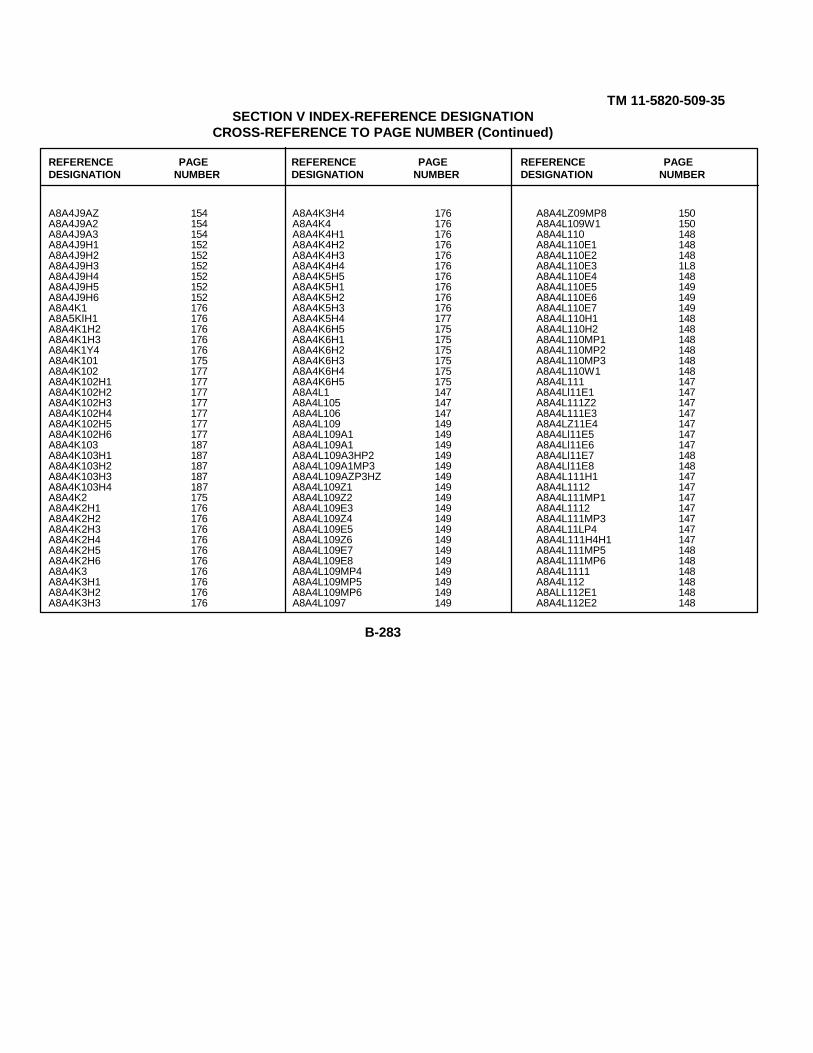
TM 11-5820-509-35SECTION V INDEX-REFERENCE DESIGNATION
CROSS-REFERENCE TO PAGE NUMBER (Continued)
REFERENCE PAGE REFERENCE PAGE REFERENCE PAGEDESIGNATION NUMBER DESIGNATION NUMBER DESIGNATION NUMBER
A8A4J9AZ 154A8A4J9A2 154A8A4J9A3 154A8A4J9H1 152A8A4J9H2 152A8A4J9H3 152A8A4J9H4 152A8A4J9H5 152A8A4J9H6 152A8A4K1 176A8A5KlH1 176A8A4K1H2 176A8A4K1H3 176A8A4K1Y4 176A8A4K101 175A8A4K102 177A8A4K102H1 177A8A4K102H2 177A8A4K102H3 177A8A4K102H4 177A8A4K102H5 177A8A4K102H6 177A8A4K103 187A8A4K103H1 187A8A4K103H2 187A8A4K103H3 187A8A4K103H4 187A8A4K2 175A8A4K2H1 176A8A4K2H2 176A8A4K2H3 176A8A4K2H4 176A8A4K2H5 176A8A4K2H6 176A8A4K3 176A8A4K3H1 176A8A4K3H2 176A8A4K3H3 176
A8A4K3H4 176A8A4K4 176A8A4K4H1 176A8A4K4H2 176A8A4K4H3 176A8A4K4H4 176A8A4K5H5 176A8A4K5H1 176A8A4K5H2 176A8A4K5H3 176A8A4K5H4 177A8A4K6H5 175A8A4K6H1 175A8A4K6H2 175A8A4K6H3 175A8A4K6H4 175A8A4K6H5 175A8A4L1 147A8A4L105 147A8A4L106 147A8A4L109 149A8A4L109A1 149A8A4L109A1 149A8A4L109A3HP2 149A8A4L109A1MP3 149A8A4L109AZP3HZ 149A8A4L109Z1 149A8A4L109Z2 149A8A4L109E3 149A8A4L109Z4 149A8A4L109E5 149A8A4L109Z6 149A8A4L109E7 149A8A4L109E8 149A8A4L109MP4 149A8A4L109MP5 149A8A4L109MP6 149A8A4L1097 149
A8A4LZ09MP8 150A8A4L109W1 150A8A4L110 148A8A4L110E1 148A8A4L110E2 148A8A4L110E3 1L8A8A4L110E4 148A8A4L110E5 149A8A4L110E6 149A8A4L110E7 149A8A4L110H1 148A8A4L110H2 148A8A4L110MP1 148A8A4L110MP2 148A8A4L110MP3 148A8A4L110W1 148A8A4L111 147A8A4Ll11E1 147A8A4L111Z2 147A8A4L111E3 147A8A4LZ11E4 147A8A4Ll11E5 147A8A4Ll11E6 147A8A4Ll11E7 148A8A4Ll11E8 148A8A4L111H1 147A8A4L1112 147A8A4L111MP1 147A8A4L1112 147A8A4L111MP3 147A8A4L11LP4 147A8A4L111H4H1 147A8A4L111MP5 148A8A4L111MP6 148A8A4L1111 148A8A4L112 148A8ALL112E1 148A8A4L112E2 148
B-283
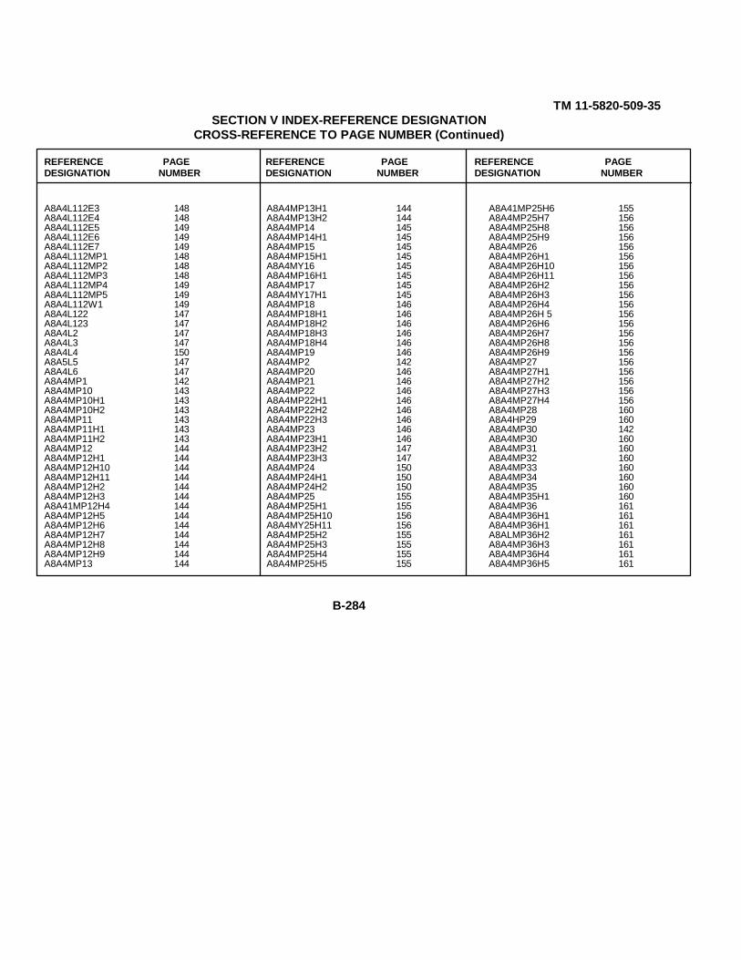
TM 11-5820-509-35SECTION V INDEX-REFERENCE DESIGNATION
CROSS-REFERENCE TO PAGE NUMBER (Continued)
REFERENCE PAGE REFERENCE PAGE REFERENCE PAGEDESIGNATION NUMBER DESIGNATION NUMBER DESIGNATION NUMBER
A8A4L112E3 148A8A4L112E4 148A8A4L112E5 149A8A4L112E6 149A8A4L112E7 149A8A4L112MP1 148A8A4L112MP2 148A8A4L112MP3 148A8A4L112MP4 149A8A4L112MP5 149A8A4L112W1 149A8A4L122 147A8A4L123 147A8A4L2 147A8A4L3 147A8A4L4 150A8A5L5 147A8A4L6 147A8A4MP1 142A8A4MP10 143A8A4MP10H1 143A8A4MP10H2 143A8A4MP11 143A8A4MP11H1 143A8A4MP11H2 143A8A4MP12 144A8A4MP12H1 144A8A4MP12H10 144A8A4MP12H11 144A8A4MP12H2 144A8A4MP12H3 144A8A41MP12H4 144A8A4MP12H5 144A8A4MP12H6 144A8A4MP12H7 144A8A4MP12H8 144A8A4MP12H9 144A8A4MP13 144
A8A4MP13H1 144A8A4MP13H2 144A8A4MP14 145A8A4MP14H1 145A8A4MP15 145A8A4MP15H1 145A8A4MY16 145A8A4MP16H1 145A8A4MP17 145A8A4MY17H1 145A8A4MP18 146A8A4MP18H1 146A8A4MP18H2 146A8A4MP18H3 146A8A4MP18H4 146A8A4MP19 146A8A4MP2 142A8A4MP20 146A8A4MP21 146A8A4MP22 146A8A4MP22H1 146A8A4MP22H2 146A8A4MP22H3 146A8A4MP23 146A8A4MP23H1 146A8A4MP23H2 147A8A4MP23H3 147A8A4MP24 150A8A4MP24H1 150A8A4MP24H2 150A8A4MP25 155A8A4MP25H1 155A8A4MP25H10 156A8A4MY25H11 156A8A4MP25H2 155A8A4MP25H3 155A8A4MP25H4 155A8A4MP25H5 155
A8A41MP25H6 155A8A4MP25H7 156A8A4MP25H8 156A8A4MP25H9 156A8A4MP26 156A8A4MP26H1 156A8A4MP26H10 156A8A4MP26H11 156A8A4MP26H2 156A8A4MP26H3 156A8A4MP26H4 156A8A4MP26H 5 156A8A4MP26H6 156A8A4MP26H7 156A8A4MP26H8 156A8A4MP26H9 156A8A4MP27 156A8A4MP27H1 156A8A4MP27H2 156A8A4MP27H3 156A8A4MP27H4 156A8A4MP28 160A8A4HP29 160A8A4MP30 142A8A4MP30 160A8A4MP31 160A8A4MP32 160A8A4MP33 160A8A4MP34 160A8A4MP35 160A8A4MP35H1 160A8A4MP36 161A8A4MP36H1 161A8A4MP36H1 161A8ALMP36H2 161A8A4MP36H3 161A8A4MP36H4 161A8A4MP36H5 161
B-284

TM 11-5820-509-35SECTION V INDEX-REFERENCE DESIGNATION
CROSS-REFERENCE TO PAGE NUMBER (Continued)
REFERENCE PAGE REFERENCE PAGE REFERENCE PAGEDESIGNATION NUMBER DESIGNATION NUMBER DESIGNATION NUMBER
A8A4MP37 161A8A4MP38 161A8A4MP39 161A8A4MP4 142A8A4MP40 161A8A4MP41 161A8A4MP42 161A8A4MP42H1 161A8A4MP42H2 161A8A4MP43 102A8A4MP43H1 162A8A4MP44 162A8A4MP44H1 162A8A4MP45 162A8A4M45H1 162A8A4MP45H2 162A8A4MP46 162A8A4MP46H1 162A8A4MP46H2 162A8A4MP47 162A8A4MP48 162A8A4MP49 162A8A4MP5 142A8A4MP50 162A8A4MP51 162A8A4MP52 162A8A4MP53 174A8A4MP53H1 174A8A4MPS3H2 174A8A4MPS3H3 174A8A4MP53H4 175A8A4MP54 175A8A4MP54H1 175A8A4MP54H2 175A8A4MP54H3 175A8A4MP54H4 175A8A4MP55 175A8A4MP55H1 175
A8A4MP55H2 175A8A4MP55H3 175A8A4MP55H4 175A8A4MP55H5 175A8A4MP55H6 175A8A4MP56 175A8A4MP57 175A8A4MP58 175A8A4MP59 175A8A4MP6 142A8A4MP60 179A8A4MP61 179A8A4MP61H1 179A8A4MP61H2 179A8A4MP62 179A8A4MP62H1 179A8A4MP62H2 179A8A4MP63 179A8A4MP63H1 179A8A4MP63H2 180A8A4MP64 180A8A4MP64H1 180A8A4MP64H2 180A8A4MP65 180A8A4MP65H1 180A8A4MP65H2 180A8A4MP66 180A8A4MP66H1 180A8A4MP66H2 180A8A4MP67 180A8A4MP67H1 180A8A4MP67H2 180A8A4MP68 180A8A4MP68H1 180A8A4MP68H2 180A8A4MP69 180A8A4MP69H1 180A8A4MP69H2 180
A8A4MP7 143A8A4MP70 180A8A4MP70H1 180A8A4MP70H2 180A8A4MP71 180A8A4MP71H1 180A8A4MP71H2 180A8A4MP72 181A8A4MP72H1 181A8A4MP72H2 181A8A4MP73 181A8A4MP73H1 181A8A4MP73H2 181A8A4MP74 181A8A4MP74H1 181A8A4074H2 181A8A4MP75 181A8A4MP75H1 181A8A4MP75H2 181A8A4MP76 181A8A4MP76H1 181A8A4PP76H2 181A8A4MP77 181A8A4MP77H1 181A8A4MP77H2 181A8A4MP78 181A8A4MP78H1 181A8A4MP78H2 181A8A4MP79 181A8A4MP79H1 181A8A4M79H2 181A8A4MP8 143A8A4MP80 181A8A4MP80H1 182A8A4MP80H2 182A8A4MP81 182A8A4MP81H1 182A8A4MP81112 182
B-285
TM 11-5820-509-35SECTION V INDEX-REFERENCE DESIGNATION
CROSS-REFERENCE TO PAGE NUMBER (Continued)
REFERENCE PAGE REFERENCE PAGE REFERENCE PAGEDESIGNATION NUMBER DESIGNATION NUMBER DESIGNATION NUMBER
ANALMP32 182A8ALMPP3 182A8A4MP54 182A8A4MP85 182A8A4MP85A 182A8A4MP66 182A8ALMP87 182A8A4MP88 182A8A4MP89 182A8A4MP90 143A8A4MP90 182A8A4MP90H1 182A8A4MP90H2 132A8A4MP91 182A8A4MP91H1 182A8A4MP91H2 182A8A4MP92 182A8A4MP93 182A8A4MP94 182A8A4MP95 182A8A4M101 140A8A4M101H1 140A8ALM101H2 140A8ALM101H3 140A8A4M101H4 140A8A4MP1 153A8A4P2 150A8A4P3 150A8A4Q1 192A8A4Q1H1 192A8A4Q1H2 192A8A4Q1H3 192A8ALQ1H4 192A8A4Q1H5 192A8A4Q1H6 192A8A4Q2 192A8A4Q2H1 192A8A4Q2H2 192
A8A4Q2H3 192A8A4Q2H4 192A8A4Q2H5 192A8A4Q2H6 192A8A4R10 177A8A4R11 142A8A4R11H1 142A8A4R112 177A8A4R113 177A8A4R114 177A8A4R120 177A8A4R121 178A8A4R121H1 178A8A4R121H2 178A8A4R125 177A8A4R126 177A8A4R127 177A8A4R24 177A6A4R25 177A8A4R6 177A8A4R8 177A8A4R8H1 177ANA4R8H2 177A8A4R8H3 177A8A4R8H4 177A8A4R9 177A8A4S1 183A8A4S1H1 183A8A4S102 187A8A4S102H1 187A8A4S102H2 187A3A4S2 187A8A4S2H1 1 87A8A4S2H2 187A8A4S3 182A8A4S3H1 183A8A4S3H2 183A8A4TB1 143
A8A4TB1E1 143A8A4TB1H2 143A8A4TB1H2 143A8A4TB1R1 143A8A4TB1R2 143A8A4TB1R3 143A8A4TB1R4 143A8A4TB10 160A8A4TB10H1 160A8A4TB10H2 160A8A4TB4 144A8A4TB4H1 144A8A4TB4H2 144A8A4TB4H3 144A8A4TB4H4 144A8A4TB4H5 144A8A4TB4H6 144A8A4TB6 143A8A4TB6CR1 144A8A4TB6CR2 144A8A4TB6CR8 144A8A4TB6C1 143A8A4TB6E1 143A8A4TB6H2 143A8A4TB6H2 143A8A4T36H2 143A8A4TB6R23 143A8A4TB6R5 143A8A4TB8 160A8A4TB8H1 160A8A4TB8H2 160A8A4TB9 160A8A4TB9H1 160A8A4TB9H2 160A8A4T1 192A8A4T1H1 192A8A4T1H2 192A8A4T101 155
B-286
TM 11-5820-509-35SECTION V INDEX-REFERENCE DESIGNATION
CROSS-REFERENCE TO PAGE NUMBER (Continued)
REFERENCE PAGE REFERENCE PAGE REFERENCE PAGEDESIGNATION NUMBER DESIGNATION NUMBER DESIGNATION NUMBER
A8A4T101R1 155A8A4T101R2 155A8A4T101H3 155A8A4T101H4 155A8A4T2 191A8A4T2H1 191A8A4T2H2 191A8A4T2R3 191A8A4T2Rb 191A8A4T3 191A8A4T3H1 191A8A4T3H2 191A8A4T3H3 191A8A4T3H4 191A8A4V101 192A8A4U1 161A8A4XF1 160A8A4XP2 160A8A5 131A8A5A1 131A8A5A1R1 131A8A5A1H2 131A8A5A1J1 131A8A5A1J10 131A8A5A1J11 131A8A5A1J2 132A8A5A1J3 132A8ASA1J4 132A8A5A1J5 132A8A5A1J6 132A8A5A1J7 132A8A5A1J8 132A8A5A1J9 132A8A5C1 131A8ASC16 131A8A5C19A 131A8A5C19B 131A8A5C25 131
A8A5C26 131A8A5C27 131A8A5C28 131A8A5C29 131A8A5E1 133A8A5E1CR10 134A8A5E1CR11 134A8A5E1CR12 134A8A5E1CRJ3 134A8A5E1CR14 134A8A5E1CR15 134A8A5E1CR16 134A8A5E1CR17 134A8A5E1CR18 134A8A5E1CR19 134A8A5E1CR20 134A8A5E1CR21 134A8A5E1CR22 134A8A5E1CR23 134A8A5E1CR24 134A8A5E1CR25 135A8A5E1CR6 134A8A5E1CR7 134A8A5E1CR8 134A8A5E1CR9 134A8A5E1C10 134A8A5E1C11 134A8A5E1C12 134A8A5E1C13 134A8A5E1C14 134A8A5E1C15 134A8A5E1C18 133A8A5E1C21 133A8A5E1C3 133A8A5E1C4 133A8A5E1C5 133A8A5E1C6 133A8A5E1C7 133
A8A5E1C8 133A8A5E1C9 133A8A5E1E1 133A8A5E1H4 133A8A5E10 139A8A5E10H1 139A8A5E11 139A8A5E12 131A8ASE13 131A8A5E14 131A8ASE15 131A8ASE16 131A8A5E17H2 139A8A5E17H3 139A8A5E18 139A8A5E18H1 139A8A5E18H2 139A8A5E2 135A8A5E2C2 135A8A5E2E1 135A8A5EPH4 135A8A5E2R1 135A8A5E2R15 135A8A5E2R16 135A8A5E2R17 13SA8A5E2R2 135A8ASEPR5 135A8A5E3 135A8A5E3CR1 135A8A5E3CR2 135A8A5E3CR26 135A8A5E3CR27 135A8A5E3CR28 135A8A5E3CR29 135A8A5E3C133 135A8A5E3CR4 135A8A5E3E1 135A8A5E3H2 135
B-287

TM 11-5820-509-35SECTION V INDEX-REFERENCE DESIGNATION
CROSS-REFERENCE TO PAGE NUMBER (Continued)
REFERENCE PAGE REFERENCE PAGE REFERENCE PAGEDESIGNATION NUMBER DESIGNATION NUMBER DESIGNATION NUMBER
A8A5E3H2 135A8A5E3H2 135A8A5E4 138A8A5E4H1 138A8A5E1H2 138A8A5ES 138A8A5ESH1 138A8A5ESH2 138A8A5ESH3 138A8A5E6 138A8A5E67H4 138A8A5E7 139A8A5E7H1 139A8A5E8 139A8A5E9 139A8A5E9H1 139A8A5K1 137A8A5K1H1 137A8A5H2 137A8A5L1 135A8A5LH1 136A8A5L1H2 136A8A5MP1 131A8A5MP2 132A8A5MP2H1 132A8A5MP2H2 132A8A5MP3 132A8A5MP3H1 132A8A5MP3H2 132A8A5MP3H3 132A8A5MP3H4 132A8A5MP3H5 132A8A5MP4 133A8A5MP4H1 133A8A5MP4H2 133A8A5MPS 133A8A5MP5H1 133A8A5MP5H2 133
A8A5MP5H3 133A8A5MP5H4 133A8A5MP6 133A8A5MP7 133A8A5MP8 133A8A5MP9 138A8A5MP9H1 138A8A5MP9H2 138A8A5P1 132A8A5PLA1 133A8A5P1A2 133A8A5P1H1 132A8A5P1H2 132A8A5P1H3 132A8A5P1H4 132A8A5P1H5 132A8A5P1H6 132A8A5R10 137A8A5R11 137A8A5R12 137A8A5R14 137A8A5R22 137A8A5R22H1 137A8A5R22H2 137A8A5R22H3 137A8A5R22S4 137A8A5R24 137A8A5R3 137A8A5R3R1 137A8A5R3H2 137A8A5R3H3 137A8A5R3H4 137A8A5R4 137A8A5R4H1 137A8A5R4H2 138A8A5R4H3 138A8A5R4H4 138A8A5R6 137
A8A5R7 137A8A5R9 137A8A5TB1 136A8A5TB1CR31 136A8A5TB1E1 136A8A5TB1E1H1 136A8A5TB1E1H2 136A8A5TB1H1 136A8A5TB1F1 136A8A5TB1MP1 136A3A5TB1MP2 136A8H5TB1MP3 136A8A5TB1Q1 136A8A5TB1Q2 136A8A5TB1Q3 136A8A5TB1Q3H1 136A8A5TB1Q3H2 13GA8A5TB1Q3H3 136A8A5TB1Q34 136A8A5TB1Q3H 136A8A5TB1Q3H6 136A8ASTB1Q3H7 137A8A5TB1Q3H8 137A8A5TB1R19 136A8A5TB1R20 136A8A5TB1R21 136A8A5TB1P23 136A8A5T1 139A8AT1H1 139A8A5T12 139A8A5T1H3 139A8A5T1H4 139A8AST2 139A8A5T2H1 139A8A5T2H2 139A8A5T2H3 139A8A5T2H4 139A8A5T2H 139
B-288

TM 11-5820-509-35SECTION V INDEX-REFERENCE DESIGNATION
CROSS-REFERENCE TO PAGE NUMBER (Continued)
REFERENCE PAGE REFERENCE PAGE REFERENCE PAGEDESIGNATION NUMBER DESIGNATION NUMBER DESIGNATION NUMBER
A8A5W1 132ANA1XC19 138A8ASXC19H1 138A8A5XC19H2 138A8PSXC19H3 138A8A5XC19H4 138A8ASXC20 138A8A5XC20H1 138A8A5XC20H2 138A8A5XC20H3 138A8A5XC20H4 138A8A6 52A8A6A1 68A8A6A1A1 69A8A6A1A1J1 69A8A6A1A1J2 69A8A6A1A1J3 69A8A6A1A1J4 69A8A6A1C13 68A8A6A1C15 68A8A6A1C16 68A8A6A1C17 68A8A6A1C18 68A8A6A1C19 68A8A6A1C21 68A8A6A1C22 68A8A6A1C23 68A8A6A1C24 69A8A6A1C26 68A8A6A1C36 68A8A6A1C39 68A8A6A1C40 68A8A6A1E1 70A8A6A1E1H1 70A8A6A1E1H2 70A8A6A1E2 70A8A6A1E2H1 70A8A6A1E2H2 70
A8A6A1E3 70A8A6A1E3H1 70A8A6A1E3H2 70A8A6A1E4 70A8A6A1E4H1 70A8A6A1E4H2 70A8A6A1E5 70A8A6A1E5H1 70A8A6A1E5H2 70A8A6A1H1 69A8A6A1H2 69A8A6A1H3 69A8A6A1H4 69A8A6A113 69A8A6A114 69A8A6A115 69A8A6A116 69A8A6A1Q4 70A8A6A1Q5 70A8A6A1Q6 70A8A6A1R23 69A8A6A1R24 69A8A6A1R25 69A3A6A1R26 69A8A6A1R27 69A8A6A1R28 69A8A6A1R29 69A8A6A1R31 69A8A6A1R32 69A8A6A1R33 69A8A6A1R45 69A8A6C14 52A8A6C14 52A8A6C11 52A8A6C11 53A8A6C14 53A8A6C14 53A8A6C14 53
A8A6C14 53A8A6C14 54A8A6C14 54A8A6C14 54A8A6C14 54A8A6C14 54A8A6C14 55A8A6C14 55A8A6C14 55A8A6C11 55A8A6C14 55A8A6C14 56A8A6C14 56A8A6C14 56A8A6C14 56A8A6C14 56A8A6C14 57A8A6C14 57A8A6C14 57A8A6C14 57A8A6C14 57A8A6C14 58A8A6C14 58A8A6C14 58A8A6C14 58A8A6C14 58A8A6C14 59A8A6C11 59A8A6C14 59A8A6C14 59A8A6C14 59A8A6C14 60A8A6C14 60A8A6C14 60A8A6C14 60A8A6C11 60AdA6C14 61A8A6C11 61
B-289

TM 11-5820-509-35SECTION V INDEX-REFERENCE DESIGNATION
CROSS-REFERENCE TO PAGE NUMBER (Continued)
REFERENCE PAGE REFERENCE PAGE REFERENCE PAGEDESIGNATION NUMBER DESIGNATION NUMBER DESIGNATION NUMBER
A8A6C14 61A8A6C14 61A8A6C20 52A8A6C20 52A8A6C20 52A8A6C20 53A8A6C20 53A8A6C20 53A8A6C20 53A8A6C20 53A8A6C20 54A8A6C20 54A8A6C20 54A8A6C20 54A8A6C20 54A8A6C20 55A8A6C20 55A8A6C20 55A8A6C20 55A8A6C20 55A8A6C20 56A8A6C20 56A8A6C20 56A8A6C20 56A8A6C20 56A8A6C20 57A8A6C20 57A8A6C20 57A8A6C20 57A8A6C20 57A8A6C20 58A8A6C20 58A8A6C20 58A8A6C20 58A8A6C20 58A8A6C20 59A8A6C20 59A8A6C20 59
A8A6C20 59A8A6C20 59A8A6C20 60A8A6C20 60A8A6C20 60A8A6C20 60A8A6C20 60A8A6C20 61A8A6C20 61A8A6C20 61A8A6C20 61A8A6C23 52A8A6C23 52A8A6C23 52A8A6C23 53A8A6C23 53A8A6C23 53A8A6C23 53A8A6C23 53A8A6C23 54A8A6C23 54A8A6C23 54A8A6C23 54A8A6C23 54A8A6C23 55A8A6C23 55A8A6C23 55A8A6C23 55A8A6C23 55A8A6C23 56A8A6C23 56A8A6C23 56A8A6C23 56A8A6C23 56A8A6C23 57A8A6C23 57A8A6C23 57A8A6C23 57
A8A6C23 57A8A6C73 58A8A6C23 58A8A6C23 58A8A6C23 58A8A6C23 58A8A6C23 59A8A6C23 59A8A6C23 59A8A6C23 59A8A6C23 59A8A6C23 60A8A6C23 60A8A6C23 60A8A6C23 60A8A6C23 60A8A6C23 61A8A6C23 61A8A6C23 61A8A6C23 61A8A6C29 52A8A6C29 52A8A6C29 53A8A6C29 53A8A6C29 53A8A6C29 53A8A6C29 53A8A6C29 54A8A6C29 54A8A6C29 54A8A6C29 54A8A6C29 54A8A6C29 55A8A6C29 55A8A6C29 55A8A6C29 55A8A6C29 55A8A6C29 56
B-290
TM 11-5820-509-35SECTION V INDEX-REFERENCE DESIGNATION
CROSS-REFERENCE TO PAGE NUMBER (Continued)
REFERENCE PAGE REFERENCE PAGE REFERENCE PAGEDESIGNATION NUMBER DESIGNATION NUMBER DESIGNATION NUMBER
A8A6C29 56A8A6C29 56A8A6C29 56A8A6C29 56A8A6C29 57A8A6C29 57A8A6C29 57A8A6C29 57A8A6C29 57A8A6C29 58A8A6C29 58A8A6C29 58A8A6C29 58A8A6C29 58A8A6C29 59A8A6C29 59A8A6C29 59A8A6C29 59A8A6C29 59A8A6C29 60A8A6C29 60A8A6C29 60A8A6C29 60A8A6C29 60A8A6C29 61A8A6C29 61A8A6C29 61A8A6C29 61A8A6C29 61A8A6C34 52A8A6C34 52A8A6C34 53A8A6C34 53A8A6C34 53A8A6C34 53A8A6C34 53A8A6C34 54A8A6C34 54
A8A6C34 54A8A6C34 54A8A6C34 54A8A6C34 55A8A6C34 55A8A6C34 55A8A6C34 55A8A6C34 55A8A6C34 56A8A6C34 56A8A6C34 56A8A6C34 56A8A6C34 56A8A6C34 57A8A6C34 57A8A6C34 57A8A6C34 57A8A6C34 57A8A6C34 58A8A6C34 58A8A6C34 58A8A6C34 58A8A6C34 58A8A6C34 59A8A6C34 59A8A6C34 59A8A6C34 59A8A6C34 59A8A6C34 60A8A6C34 60A8A6C34 60A8A6C34 60A8A6C34 60A8A6C34 61A8A6C34 61A8A6C34 61A8A6C34 61A8A6C34 61
A8A6E1 62A8A6E1C27 63A8A6E1C28 62A8A6E1C30 62A8A6E1C31 62A8A6E1C32 62A8A6E1C33 62A8A6E1C35 62A8A6E1C37 62A8A6E1C38 62A8A6E1P1 63A8A6E1E1HE 63A8A6E1E1H2 63A8A6E1E2 63A8A6E1E2H1 63A8A6E1E2H2 63A8A6E1E3 63A8A6E1E3HU 64A8A6E1E3H2 64A8A6E1E4 64A8A6E1E4H1 64A8A6E1E4H2 64A8A6E1E5 64A8A6E1E5H1 64A8A6E1E5H2 64A8A6E1E6 64A8A6E1E6HU 64A8A6E1E6E2 64A8A6E1H1 63A8A6E1H2 63A8A6E1H3 63A8A6E1H6 62A8A6E1H6 62A8A6E1L7 63A8A6E1L8 63A8A6E1L9 63'A8A6E1Q7 64A8A6E1Q8 64
B-291
TM 11-5820-509-35SECTION V INDEX-REFERENCE DESIGNATION
CROSS-REFERENCE TO PAGE NUMBER (Continued)
REFERENCE PAGE REFERENCE PAGE REFERENCE PAGEDESIGNATION NUMBER DESIGNATION NUMBER DESIGNATION NUMBER
A8A6E1Q9 64A8A6E1R34 63A8A6E1R35 63A8A6E1R36 63A8A6E1R37 63A8A6E1R38 63A8A6E1R39 63A8A6E1R40 63A8A6E1R41 63A8A6E1R42 63A8A6E1R43 63A8A6E1R44 63A8A6E1TB1 62A8A6E2 64A8A6E2A1 66A8A6E2CR1 68A8A6E2CR2 68A8A6E2C1 66A8A6E2C10 65A8A6E2C11 64A8A6E2C12 66A8A6E2C13 65A8A6E2C13 65A8A6E2C13 65A8A6E2C13 65A8A6E2C13 65A8A6E2C13 65A8A6E2C13 65A8A6E2C13 65A8A6E2C13 65A8A6E2C13 65A8A6E2C13 65A8A6E2C13 65A8A6E2C13 66A8A6E2C13 66A8A6E2C13 66A8A6E2C13 66A8A6E2C13 66
A8A6E2C13 66A8A6E2C13 66A8A6E2C13 66A8A6E2C13 66A8A6E2C2 64A8A6E2C3 64A8A6E2C4 64A8A6E2C5 64A8A6E2C6 64A8A6E2C7 64A8A6E2C8 64A8A6E2C9 65A8A6E2C9 65A8A6E2C9 65A8A6E2C9 65A8A6E2C9 65A8A6E2C9 65A8A6E2C9 65A8A6E2C9 65A8A6E2C9 65A8A6E2C9 65A8A6E2C9 65A8A6E2C9 65A8A6E2C9 66A8A6E2C9 66A8A6E2C9 66A8A6E2C9 66A8A6E2C9 66A8A6E2C9 66A8A6E2C9 66A8A6E2C9 66A8A6E2C9 66A8A6E2L1 66A8A6E2L2 66A8A6E2Q1 68A8A6E2Q2 68A8A6E2Q3 68A8A6E2R1 67
A8A6E2R1H1 67A8A6E2R1H2 67A8A6E2R1H3 67A8A6E2R1H4 67A8A6E2R10 67A8A6E2R11 67A8A6E2R12 67A8A6E2R13 66A8A6E2R14 67A8A6E2R15 67A8A6E2R16 67A8A6E2R17 66A8A6E2R18 67A8A6E2R18 67A8A6E2R18 67A8A6E2R18 67A8A6E2R18 67A8A6E2R2 60A8A6E2R2H1 68A8A6E2R2H2 68A8A6E2R2H3 68A8A6E2R2H4 68A8A6E2R3 68A8A6E2R4 67A8A6E2R4 67A8A6E2R4 67A8A6E2R4 67A8A6E2R5 67A8A6E2R6 67A&A6E2R7 67A8A6E2R8 67A8A6E2R9 67A8A6E2TB1 64A8A6E3 72A8A6MP1 52A8A6MP2 62A8A6MP2H1 62A8A6MP2H2 62
B-292
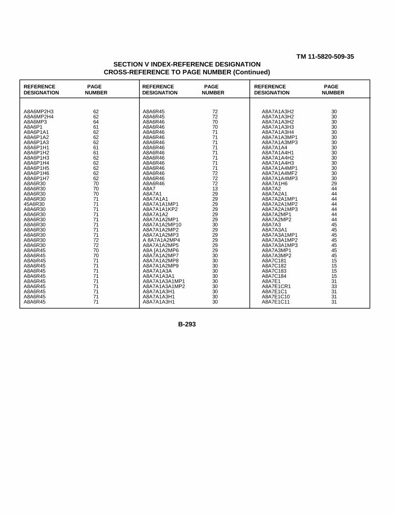
TM 11-5820-509-35SECTION V INDEX-REFERENCE DESIGNATION
CROSS-REFERENCE TO PAGE NUMBER (Continued)
REFERENCE PAGE REFERENCE PAGE REFERENCE PAGEDESIGNATION NUMBER DESIGNATION NUMBER DESIGNATION NUMBER
A8A6MP2H3 62A8A6MP2H4 62A8A6MP3 64A8A6P1 61A8A6P1A1 62A8A6P1A2 62A8A6P1A3 62A8A6P1H1 61A8A6P1H2 61A8A6P1H3 62A8A6P1H4 62A8A6P1H5 62A8A6P1H6 62A8A6P1H7 62A8A6R30 70A8A6R30 70A8A6R30 70A8A6R30 7145A6R30 71A8A6R30 71A8A6R30 71A8A6R30 71A8A6R30 71A8A6R30 71A8A6R30 71A8A6R30 72A8A6R30 72A8A6R45 70A8A6R45 70A8AbR45 71A8A6R45 71A8A6R45 71A8A6R45 71A8A6R45 71A8A6R45 71A8A6R45 71A8A6R45 71A8A6R45 71
A8A6R45 72A8A6R45 72A8A6R46 70A8A6R46 70A8A6R46 71A8A6R46 71A8A6R46 71A8A6R46 71A8A6R46 71A8A6R46 71A8A6R46 71A8A6R46 71A8A6R46 72A8A6R46 72A8A6R46 72A8A7 13A8A7A1 29A8A7A1A1 29A8A7A1A1MP1 29A8A7A1A1KP2 29A8A7A1A2 29A8A7A1A2MP1 29A8A7A1A2MP10 30A8A7A1A2MP2 29A8A7A1A2MP3 29A 8A7A1A2MP4 29A8A7A1A2MP5 29A8A [A1A2MP6 29A8A7A1A2MP7 30A8A7A1A2MP8 30A8A7A1A2MP9 30A8A7A1A3A 30A8A7A1A3A1 30A8A7A1A3A1MP1 30A8A7A1A3A1MP2 30A8A7A1A3H1 30A8A7A1A3H1 30A8A7A1A3H1 30
A8A7A1A3H2 30A8A7A1A3H2 30A8A7A1A3H2 30A8A7A1A3H3 30A8A7A1A3H4 30A8A7A1A3MP1 30A8A7A1A3MP3 30A8A7A1A4 30A8A7A1A4H1 30A8A7A1A4H2 30A8A7A1A4H3 30A8A7A1A4MP1 30A8A7A1A4MF2 30A8A7A1A4MP3 30A8A7A1H6 29A8A7A2 44A8A7A2A1 44A8A7A2A1MP1 44A8A7A2A1MP2 44A8A7A2A1MP3 44A8A7A2MP1 44A8A7A2MP2 44A8A7A3 45A8A7A3A1 45A8A7A3A1MP1 45A8A7A3A1MP2 45A8A7A3A1MP3 45A8A7A3MP1 45A8A7A3MP2 45A8A7C181 15A8A7C182 15A8A7C183 15A8A7C184 15A8A7E1 31A8A7E1CR1 33A8A7E1C1 31A8A7E1C10 31A8A7E1C11 31
B-293
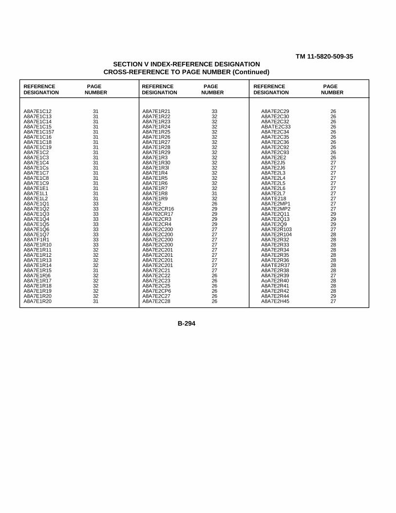
TM 11-5820-509-35SECTION V INDEX-REFERENCE DESIGNATION
CROSS-REFERENCE TO PAGE NUMBER (Continued)
REFERENCE PAGE REFERENCE PAGE REFERENCE PAGEDESIGNATION NUMBER DESIGNATION NUMBER DESIGNATION NUMBER
A8A7E1C12 31A8A7E1C13 31A8A7E1C14 31A8A7E1C15 31A8A7E1C157 31A8A7E1C16 31A8A7E1C18 31A8A7E1C19 31A8A7E1C2 31A8A7E1C3 31A8A7E1C4 31A8A7E1Cs 31A8A7E1C7 31A8A7E1C8 31A8A7E1C9 31A8A7E1E1 31A8A7E1L1 31A8A7E1L2 31A8A7E1Q1 33A8A7E1Q2 33A8A7E1Q3 33A8A7E1Q4 33A8A7E1Q5 33A8A7E1Q6 33A8A7E1Q7 33A8ATF1R1 33A8A7E1R10 33A8A7E1R11 32A8A7E1R12 32A8A7E1R13 32A8A7E1R14 32A8A7E1R15 31A8A7E1R)6 32A8A7E1R17 32A8A7E1R18 32A8A7E1R19 32A8A7E1R20 32A8A7E1R20 31
A8A7E1R21 33A8A7E1R22 32A8A7E1R23 32A8A7E1R24 32A8A7E1R25 32A8A7E1R26 32A8A7E1R27 32A8A7E1R28 32A8A7E1R29 32A8A7E1R3 32A8A7E1R30 32A8A7E1R3l 32A8A7E1R4 32A8A7E1R5 32A8A7E1R6 32A8A7E1R7 32A8A7E1R8 31A8A7E1R9 32A8A7E2 26A8A7E2CR16 29A8A792CR17 29A8A7E2CR3 29A8A7E2CR4 29A8A7E2C200 27A8A7E2C200 27A8A7E2C200 27A8A7E2C200 27A8A7E2C201 27A8A7E2C201 27A8A7E2C201 27A8A7E2C201 27A8A7E2C21 27A8A7E2C22 26A8A7E2C23 26A8A7E2C25 26A8A7E2CP6 26A8A7E2C27 26A8A7E2C28 26
A8A7E2C29 26A8A7E2C30 26A8A7E2C32 26ABATE2C33 26A8A7E2C34 26A8A7E2C35 26A8A7E2C36 26A8A7E2C92 26A8A7E2C93 26A8A7E2E2 26A8A7E2J5 27A8A7E2J6 27A8A7E2L3 27A8A7E2L4 27A8A7E2L5 27A8A7E2L6 27A8A7E2L7 27A8ATE218 27A8A7E2MP1 27A8A7E2MP2 27A8A7E2Q11 29A8A7E2Q13 29A8A7E2Q9 29A8A7E2R103 27A8A7E2R104 28A8A7E2R32 28A8A7E2R33 28A8A7E2R34 28A8A7E2R35 28A8A7E2R36 28A8ATE2R37 28A8A7E2R38 28A8A7E2R39 27AoA7E2R40 28A8A7E2R41 28A8A7E2R42 28A8A7E2R44 29A8A7E2H45 27
B-294

TM 11-5820-509-35SECTION V INDEX-REFERENCE DESIGNATION
CROSS-REFERENCE TO PAGE NUMBER (Continued)
REFERENCE PAGE REFERENCE PAGE REFERENCE PAGEDESIGNATION NUMBER DESIGNATION NUMBER DESIGNATION NUMBER
A8A7E2R46 28A8A7E2R47 29A8A7E2R48 29A8A7E2R49 28A8A7E2R50 27A8A7E2R51 28A8A7E2R53 28A8A7E2R54 28A8A7E2R55 28A8A7E2R56 28A8A7E2R57 28A8A7E2R58 28A8A7E2R59 27A8A7E2R60 28A8A7E2R61 28A8A7E2R62 28A8A7E2R64 29A8A7E2R65 28A8A7E2R66 29A8A7E2R67 29A8A7E2R68 28A8A7E2R69 27A8A7E4 13A8A7E4C56 14A8A7E4C57 13A8A7E4C58 14A8A7E4C59 13A8A7E4C60 13A8A7E4C61 14A8A7E4C62 14A8A7E4C63 14A8A7E4C65 14A8A7E4C66 14A8A7E4C67 14A8A7E4C68 14A8A7E4C69 14A8A7E4C70 14A8A7E4E1 13
A8A7E4L16 14A8A7E4L17 14A8A7E4118 14A8A7E4Q17 15A8A7E4Q18 15A8A7E4Q19 15A8A7E4R100 15A8A7E4R101 14A8A7E4R102 14A8A7E4R88 14A8A7E4R89 15A8A7E4R90 14A8A7E4R91 14A8A7E4R92 14A8A7E4R93 14A8A7E4R94 15A8A7E4R95 14A8A7E4R96 14A8A7E4R97 14A8A7E4R98 15A8A7E4R99 14A8A7E5 39A8A7E5C71 40A8A7E5C72 40A8A7E5C72H1 40A8A7E5C72H2 40A8A7E5C73 40A8A7E5C74 40A8A7E5C74H1 41A8A7E5C74H2 41A8A7E5C75 40A8A7E5C76 41A8A7E5C76H1 41A8A7E5C76H2 41A8A7E5C77 40A8A7E5C78 41A8A7E5C78H1 41A8A7E5C78H2 41
A8A7E5C9 40A8A7E5C80 41A8A7E5C80H1 41A8A7E5C80H2 41A8A7E5C81 40A8A7E5C82 41A8A7E5C82H1 41A8A7E5C82H2 41A8A7E5C83 40A8A7E5C84 41A8A7E5C84H1 41A8A7E5C84H2 41A8A7E5C85 40A8A7E5C86 41A8A7E5C86H1 41A8A7E5C86H2 41A8A7E5C87 40A8A7E5C88 41A8A7E5C88H1 41A8A7E5C88H2 41A8A7E5C89 40A8A7E5C90 41A8A7E5C90H1 41A8A7ESC90H2 42A8A7E5C91 40A8A7ESE1 40A8A7E5E1H1 40A8A7E5EEH2 40A8A7E5E1H3 40A8A7E5E1H4 40A8A7E5E2 42A8A7E5E2H1 42A8A7E5E2H2 42A8A7E5E2H3 42A8A7E5E2H4 42A8A7E5E2H5 42A8A7E5E2H6 42A8A7E5E2H7 42
B-295
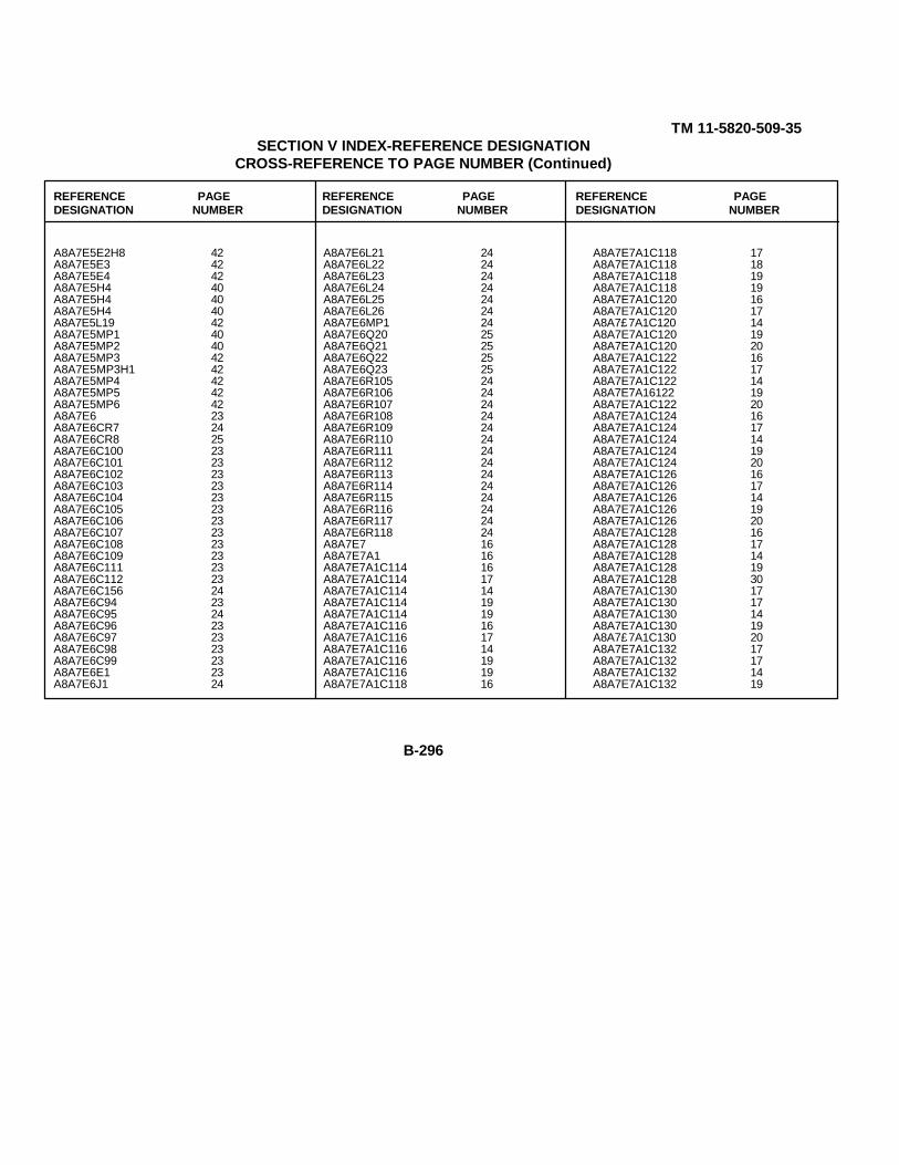
TM 11-5820-509-35SECTION V INDEX-REFERENCE DESIGNATION
CROSS-REFERENCE TO PAGE NUMBER (Continued)
REFERENCE PAGE REFERENCE PAGE REFERENCE PAGEDESIGNATION NUMBER DESIGNATION NUMBER DESIGNATION NUMBER
A8A7E5E2H8 42A8A7E5E3 42A8A7E5E4 42A8A7E5H4 40A8A7E5H4 40A8A7E5H4 40A8A7E5L19 42A8A7E5MP1 40A8A7E5MP2 40A8A7E5MP3 42A8A7E5MP3H1 42A8A7E5MP4 42A8A7E5MP5 42A8A7E5MP6 42A8A7E6 23A8A7E6CR7 24A8A7E6CR8 25A8A7E6C100 23A8A7E6C101 23A8A7E6C102 23A8A7E6C103 23A8A7E6C104 23A8A7E6C105 23A8A7E6C106 23A8A7E6C107 23A8A7E6C108 23A8A7E6C109 23A8A7E6C111 23A8A7E6C112 23A8A7E6C156 24A8A7E6C94 23A8A7E6C95 24A8A7E6C96 23A8A7E6C97 23A8A7E6C98 23A8A7E6C99 23A8A7E6E1 23A8A7E6J1 24
A8A7E6L21 24A8A7E6L22 24A8A7E6L23 24A8A7E6L24 24A8A7E6L25 24A8A7E6L26 24A8A7E6MP1 24A8A7E6Q20 25A8A7E6Q21 25A8A7E6Q22 25A8A7E6Q23 25A8A7E6R105 24A8A7E6R106 24A8A7E6R107 24A8A7E6R108 24A8A7E6R109 24A8A7E6R110 24A8A7E6R111 24A8A7E6R112 24A8A7E6R113 24A8A7E6R114 24A8A7E6R115 24A8A7E6R116 24A8A7E6R117 24A8A7E6R118 24A8A7E7 16A8A7E7A1 16A8A7E7A1C114 16A8A7E7A1C114 17A8A7E7A1C114 14A8A7E7A1C114 19A8A7E7A1C114 19A8A7E7A1C116 16A8A7E7A1C116 17A8A7E7A1C116 14A8A7E7A1C116 19A8A7E7A1C116 19A8A7E7A1C118 16
A8A7E7A1C118 17A8A7E7A1C118 18A8A7E7A1C118 19A8A7E7A1C118 19A8A7E7A1C120 16A8A7E7A1C120 17A8A7£7A1C120 14A8A7E7A1C120 19A8A7E7A1C120 20A8A7E7A1C122 16A8A7E7A1C122 17A8A7E7A1C122 14A8A7E7A16122 19A8A7E7A1C122 20A8A7E7A1C124 16A8A7E7A1C124 17A8A7E7A1C124 14A8A7E7A1C124 19A8A7E7A1C124 20A8A7E7A1C126 16A8A7E7A1C126 17A8A7E7A1C126 14A8A7E7A1C126 19A8A7E7A1C126 20A8A7E7A1C128 16A8A7E7A1C128 17A8A7E7A1C128 14A8A7E7A1C128 19A8A7E7A1C128 30A8A7E7A1C130 17A8A7E7A1C130 17A8A7E7A1C130 14A8A7E7A1C130 19A8A7£7A1C130 20A8A7E7A1C132 17A8A7E7A1C132 17A8A7E7A1C132 14A8A7E7A1C132 19
B-296

TM 11-5820-509-35SECTION V INDEX-REFERENCE DESIGNATION
CROSS-REFERENCE TO PAGE NUMBER (Continued)
REFERENCE PAGE REFERENCE PAGE REFERENCE PAGEDESIGNATION NUMBER DESIGNATION NUMBER DESIGNATION NUMBER
A8A7E7A1C132 20A8A7E7A1C134 17A8A7E7A1C134 17A8A7E7A1C134 14A8A7E7A1C134 19A8A7E7A1C134 20A8A7E7A1C136 17A8A7E7A1C136 17A8A7E7A1C136 14A8A7E7A1C136 19A8A7E7A1C136 20A8A7E7A1C138 17A8A7E7A1C138 17A8A7E7A1C138 14A8A7E7A1C138 19A8A7E7A1C138 20A8A7E7A1C140 17A8A7E7A1C140 14A8A7E7A1C140 14A8A7E7A1C140 19A8A7E7A1C140 20A8A7E7A1C142 17A8A7E7A1C142 14A8A7E7A1C142 14A8A7E7A1C142 19A8A7E7A1C142 20^8A7E7A1C144 17A8A7E7A1C144 14A8A7E7A1C144 14A8A7E7A1C144 19A8A7£7A1C144 20A8A7E7A1C146 17A8A7E7A1C146 14A8A7E7A1C146 14A8A7E7A1C146 19A8A7E7A1C146 20A8A7E7A1C148 17A8A7E7A1C148 14
A8A7E7A1C148 18A8A7E7A1C148 19A8A7E7A1C148 20A8A7E7A1C150 17A8A7E7A1C150 14A8A7E7A1C150 19A8A7E7A1C150 19A8A7E7A1C150 20A8A7E7A1C152 17A8A7E7A1C152 14A8A7E7A1C152 19A8A7E7A1C152 19A8A7E7A1C152 20A8A7E7A1E8 16A8A7E7A1H2 16A8A7E7A1H2 16A8A7E7A1H4 16A8A7E7A2 20A8A7E7A2C113 20A8A7E7A2C115 20A8A7E7A2C117 20A8A7E7A2C119 20A8A7E7A2C121 20A8A7E7A2C123 20A8A7E7A2C125 21A8A7E7A2C127 21A8A7E7A2C129 21A8A7E7A2C131 21A8A7E7A2C133 21A8A7E7A2C135 21A8A7E7A2C137 21A8A7E7A2C139 21A8A7E7A2C141 21A8A7E7A2C143 21A8A7E7A2C145 21A8A7E7A2C147 21A8A7E7A2C149 21A8A7E7A2C151 21
A8A7E7A2E1 20A8A7E7A2E1 21A8A7E7A2E1H1 21A8A7E7A2E1H2 21A8A7E7A2E1H3 21A8A7E7A2E1H4 21A8A7E7A2E2 21A8A7E7A2E2H1 21A8A7E7A2E2H2 21A8A7E7A2E2H3 21A8A7E7A2E2H4 21A8A7E7A2E3 21A8A7E7A2E4 22A8A7EJA2MP1 22A8A7E7A2MP10 23A8A7E7A2MP2 22A8A7E7A2MP3 22A8A7E7A2MP4 22A8A7E7A2MP5 23A8A7E7A2MP6 23A8A7E7A2MP7 23A8A7E7A2MP8 23A8A7E7A2MP9 23A8A7E7A2Y1 22A8A7E7A2Y10 22A8A7E7A2Y11 22A8A7E7A2Y12 22A8A7E7A2Y13 22A8A7E7A2Y14 22A8A7E7A2Y15 22A8A7E7A2Y16 22A8A7E7A2Y17 22A8A7E7A2Y18 22A8A7E7A2Y19 22A8A7E7A2Y2 22A8A7E7A2Y20 22A8A7E7A2Y3 22A8A7E7A2Y4 22
B-297

TM 11-5820-509-35SECTION V INDEX-REFERENCE DESIGNATION
CROSS-REFERENCE TO PAGE NUMBER (Continued)
REFERENCE PAGE REFERENCE PAGE REFERENCE PAGEDESIGNATION NUMBER DESIGNATION NUMBER DESIGNATION NUMBER
A8A7E7A2YC 22A8A7E7A2Y6 22A8A7E7A2Y7 22A8A7E7A2Y8 22A8A7E7A2Y9 22A8A7E8 45A8A7E9 45A8A7HL 44A8A7H2 44A8A7L34 15A8A7L35 15A8A7L36 15A8A7L37 15A8A7MP1 15A8A7MP10 43A8A7XP10BL 43A8A7MP10B2 43A8A7MP10B3 43A8A7MP10B4 43A8A7MP10H5 43A8A7MP10B6 43A8A7MP11 43A8A7XP11 43A8A7MP11B2 43A8A7MP11B3 43A8A7KP11K4 43A8A7MP11B5 43A8A7KP11H6 43A8A7XP12 43A8A7XP12B1 43A8A7MP12H2 43A8A7MP12H3 44A8A7MP12H4 44A8A7MP13 44A8A7MP13H1 44A8A7MP13H2 44A8A7MP1383 44A8A7MP13H4 44
A8A7KP13l15 44A8A7MP13116 44A8A7MP14 44A8A7MP14BL 44A8A7MP14H2 44A8A7MP14B3 44A8A7HP14B4 44A8A7MP14B5 44A8A7KP14B6 44A8A7MP15 45A8A7MP16 45A8A7MP17 45A8A7MP18 45A8A7MP2 15A8A7KP3 15A8A7MP4 15A8A7MP5 15A8A7MP6 15A8A7MP7 25A8A7MP7BL 25A8A7MP7B2 25A8A7MP783 25A8A7MP7B4 25A8A7MP8 25A8A7KP8BL 25A8A7MP8BL0 25A8A7MP82111 25A8A7MP8HL2 25A8A7MP8BL3 25A8A7MP8H14 25A8A7MP8BL5 26A8A7MP8BL6 26A8A7MP8B17 26A8A7MP8B18 26A8A7KP8HL9 26A8A7MP8H2 25A8A7KP8B20 26A8A7MP8B21 26
A8A7MP8H22 26A8A7MP8H3 25A8A7MP8H4 25A8A7MP8H5 25A8A7MP8H6 25A8A7MP8H7 25A8A7MP8H8 25A8A7MP8H9 25A8A7MP9 42A8A7MP9H1 42A8A7MP9HL0 43A8A7MP9HL1 43A8A7MP9HL2 43A8A7MP9HL3 43A8A7MP9HL4 43A8A7MP9H2 42A8A7MP9B3 42A8A7MP9H4 42A8A7MP9H5 42A8A7MP9H6 42A8A7MP9H7 43A8A7MP9H8 43A8A7MP9H9 43A8A7P1 16A8A7PlA1 16A8A7P1A2 16A8A7PlH1 16A8A7P1H2 16A8A7P1H3 16A8A7P1H4 16A8A7P2 15A8A7P2AL 16A8A7P2A2 16A8A7P2A3 16A8A7P2H1 15A8A7P2H2 15A8A7P2H3 15A8A7P2H4 16
B-298

TM 11-5820-509-35SECTION V INDEX-REFERENCE DESIGNATION
CROSS-REFERENCE TO PAGE NUMBER (Continued)
REFERENCE PAGE REFERENCE PAGE REFERENCE PAGEDESIGNATION NUMBER DESIGNATION NUMBER DESIGNATION NUMBER
A8A7TB1 33A8A7TB1CR10 36A8A7TB1CR11 36A8A7TB1CR12 36A8A7TB1CR13 36A8A7TB1CR14 36A8A7TB1CR15 36A8A7TB1CR9 36A8A7TB1C160 33A8A7TB1C161 33A8A7TB1C162 33A8A7TB1C163 33A8A7TB1C164 33A8A7TB1C165 33A8A7TB1C166 33A8A7TB1C167 34A8A7TB1C168 34A8A7TB1C169 34A8A7TB1C170 34A8A7TB1C171 34A8A7TB1C172 34A8A7TB1C173 34A8A7TB1C174 34A8A7TB1C175 34A8A7TB1C176 34A8A7TB1C177 33A8A7TB1C178 34A8A7TB1C179 34A8A7TB1C180 34A8A7TB1E1 33A8A7TB1E1J2 33A8A7TB1E1J3 33A8A7TB1E1J4 33A8A7TB1E10 37A8A7TB1E10E1 37A8A7TB1E10E2 37A8A7TB1E11 37A8A7TB1E11H1 38
A8A7TB1E11H2 38A8A7TB1E12 38A8A7TB1E12H1 38A8A7TB1E12H2 38A8A7TB1E13 38A8A7TB1E13 38A8A7TB1E13H2 38A8A7TB1E14 38A8A7TB1E14H1 38A8A7TB1E14H2 38A8A7TB1E15 38A8A7TB1E15B1 38A8A7TB1E15E2 38A8A7TB1E16 38A8A7TB1E16E1 38A8A7TB1E16E2 38A8A7TB1E17 38A8A7TB1E17H1 38A8A7TB1E17H2 38A8A7TB1E18 38A8A7TB1E18H1 38A8A7TB1E18R2 38A8A7TB1E2 36A8A7TB1E2B1 36A8A7TB1E2E2 36A8A7TB1E3 37A8A7TB1E3H1 37A8A7TB1E3B2 37A8A7TB1E4 37A8A7TB1E4E1 37A8A7TB1E4E2 37A8A7TB1E5 37A8A7TB1E5E1 37A8A7TB1E5E2 37A8A7TB1E6 37A8A7TB1E6E1 37A8A7TB1E6E2 37A8A7TB1E7 37
A8A7TB1E7H1 37A8A7TB1E7H2 37A8A7TB1E8 37A8A7TB1E8H1 37A8A7TB1E8H2 37A8A7TB1E9 37A8A7TB1E9R1 37A8A7TB1E9H2 37A8A7TB1H1 34A8A7TB1H2 34A8A7TB1H3 34A8A7TB1H4 34A8A7TB1H5 34A8A7TB1H6 34A8A7TB1128 34A8A7TB1129 34A8A7TB1130 34A8A7TB1131 34A8A7TB1132 34A8A7TB1Q24 39A8A7TB1Q25 39A8A7TB1Q26 39A8A7TB1Q27 39A8A7TB1Q28 39A8A7TB1Q29 39A8A7TB1R119 35A8A7TB1R120 35A8A7TB1R121 36A8A7TB1R122 36A8A7TB1R123 35A8A7TB1R124 35A8A7TB1R125 36A8A7TB1R126 36A8A7TB1R127 36A8A7TB1R128 36A8A7TB1R129 36A8A7TB1R130 35A8A7TB1R131 35
B-299

TM 11-5820-509-35SECTION V INDEX-REFERENCE DESIGNATION
CROSS-REFERENCE TO PAGE NUMBER (Continued)
REFERENCE PAGE REFERENCE PAGE REFERENCE PAGEDESIGNATION NUMBER DESIGNATION NUMBER DESIGNATION NUMBER
A8A7TR1R132 36A8A7TB1R133 36A8A7TB1R134 35A8A7TB1R135 35A8A7TB13136 36A8A7TR1R137 36A8A7TB1R139 35A8A7TB1R 14 0 36A8A7TB1R141 35A847TB1R142 35A8A7TB1R143 35A8A7TB1R143 34A8A7TB1R144 35A8A7TB1R141 35A8A7TB1R144 35A8A7TB1R141 35A8A7TR1R144 35A8A7TB1R141 35A8A7TE1R1kh 35A6A7TB1R144 35A6A7TB1R144 35A6A7TB1R145 35A6A7TB1R146 35A8A7TB1R147 35A8A7TB1R148 36A8A7TB1R149 36A8A7TB1R150 36A8A7TB1R151 35A8A7TB1T152 38A8A7TB1T1H1 38A8A7TB1T1H2 39A8A7TB1T1H3 39A8A7TB1T1H4 39A8A7TB1T1H5 39A8A7TB1T1H6 39A8A7TB1T1H7 39A8A7TB1T1H8 39A6A7TB1T2 39
A8A7TB1T3 39A8A7TB1T3H1 39A8A7TB1T3H2 39A8A7TB1T3H3 39A8A7TB1T3H4 39A8A7TB1T3H5 39A8A7TB1T3H6 39A8A7TB1T3H7 39A8A7TB1T3H8 39A8A7TB1T4 39A8A7W1 33A8A8 193A8A8H2 193A8A8H2 193A8A8H2 193A8A8H4 193A8A8H4 193A8A8H4 193A8A8MP1 193A8A8MP2 193A8A8MP2H1 193A8A8MP2H2 193A8A8MP3 193A8A8MP4 194A8A8MP5 194A8A8MP5H1 194A8A8MP5H10 194A3A8MPSH11 194A3A8MP5H12 194A8A8MP5H13 194A8A8MP5H14 194A6A8MP5H15 194A8A8MP5H16 194A8A8MP5H2 191A8A8MP5H3 194A8A8MP5H4 194A8A8MP5H5 194A8A8MPSH6 194
A8A8M5H7 194A8A8MP5H8 144A8A8MP5H9 194A8A9 194A8A9MP1 191A8MP1 193A8MP1H1 193A8MP1H2 193A8MP1H3 193A8MP1H4 193A8MP1H5 193A8MP2 193A8MP3 193A8MP4 194A8MP5 194A8MP5H1 194A8MP5R2 194A8MP5H3 194A8MP5114 195A8MP6 195A8MP6H1 195A8MP612 195A8h1P6H3 195A8MP6H4 195A8MP7 195A8MP8 195A8MP8H1 195A8MP8H2 195A8MP8H3 95A8MP8H4 195CP1 6HT1 10MP4 13MP5 195W1 196W2 196W3 196W4 196
B-300
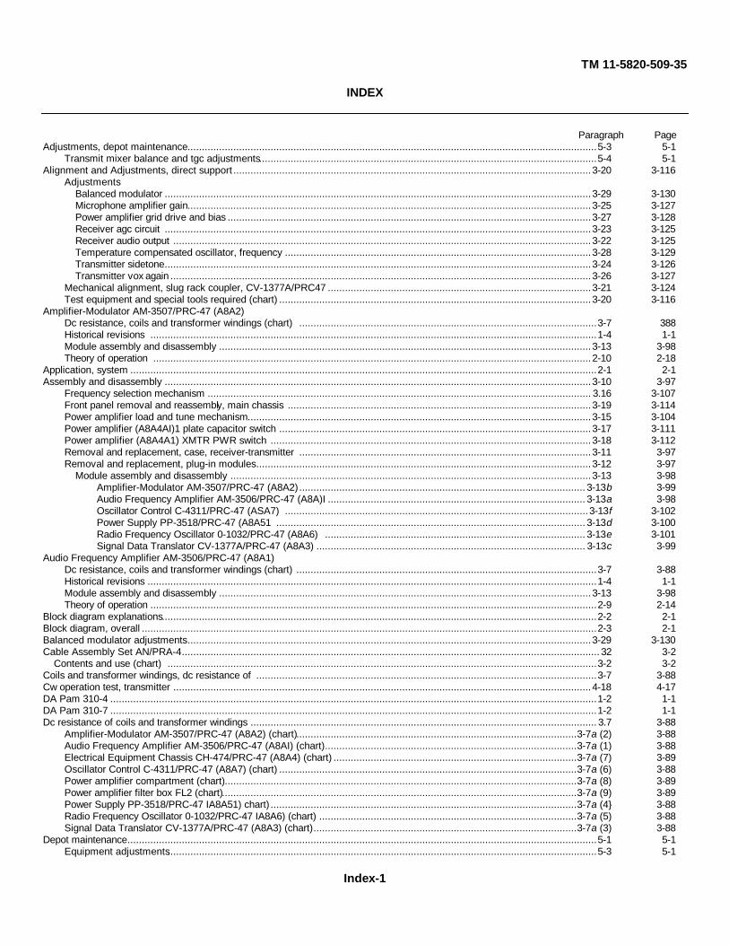
TM 11-5820-509-35
INDEX
Paragraph PageAdjustments, depot maintenance...............................................................................................................................................5-3 5-1
Transmit mixer balance and tgc adjustments......................................................................................................................5-4 5-1Alignment and Adjustments, direct support .............................................................................................................................3-20 3-116
AdjustmentsBalanced modulator .....................................................................................................................................................3-29 3-130Microphone amplifier gain.............................................................................................................................................3-25 3-127Power amplifier grid drive and bias ...............................................................................................................................3-27 3-128Receiver agc circuit .....................................................................................................................................................3-23 3-125Receiver audio output ..................................................................................................................................................3-22 3-125Temperature compensated oscillator, frequency ...........................................................................................................3-28 3-129Transmitter sidetone.....................................................................................................................................................3-24 3-126Transmitter vox again ...................................................................................................................................................3-26 3-127
Mechanical alignment, slug rack coupler, CV-1377A/PRC47 ............................................................................................3-21 3-124Test equipment and special tools required (chart) .............................................................................................................3-20 3-116
Amplifier-Modulator AM-3507/PRC-47 (A8A2)Dc resistance, coils and transformer windings (chart) ........................................................................................................3-7 388Historical revisions ............................................................................................................................................................1-4 1-1Module assembly and disassembly ..................................................................................................................................3-13 3-98Theory of operation .........................................................................................................................................................2-10 2-18
Application, system ...................................................................................................................................................................2-1 2-1Assembly and disassembly .....................................................................................................................................................3-10 3-97
Frequency selection mechanism ...................................................................................................................................... 3.16 3-107Front panel removal and reassembly, main chassis ..........................................................................................................3-19 3-114Power amplifier load and tune mechanism........................................................................................................................3-15 3-104Power amplifier (A8A4AI)1 plate capacitor switch .............................................................................................................3-17 3-111Power amplifier (A8A4A1) XMTR PWR switch ................................................................................................................3-18 3-112Removal and replacement, case, receiver-transmitter ......................................................................................................3-11 3-97Removal and replacement, plug-in modules .....................................................................................................................3-12 3-97
Module assembly and disassembly ..............................................................................................................................3-13 3-98Amplifier-Modulator AM-3507/PRC-47 (A8A2) .................................................................................................... 3-13b 3-99Audio Frequency Amplifier AM-3506/PRC-47 (A8A)I .......................................................................................... 3-13a 3-98Oscillator Control C-4311/PRC-47 (ASA7) ..........................................................................................................3-13f 3-102Power Supply PP-3518/PRC-47 (A8A51 ............................................................................................................ 3-13d 3-100Radio Frequency Oscillator 0-1032/PRC-47 (A8A6) ........................................................................................... 3-13e 3-101Signal Data Translator CV-1377A/PRC-47 (A8A3) .............................................................................................. 3-13c 3-99
Audio Frequency Amplifier AM-3506/PRC-47 (A8A1)Dc resistance, coils and transformer windings (chart) .........................................................................................................3-7 3-88Historical revisions .............................................................................................................................................................1-4 1-1Module assembly and disassembly ..................................................................................................................................3-13 3-98Theory of operation ............................................................................................................................................................2-9 2-14
Block diagram explanations........................................................................................................................................................2-2 2-1Block diagram, overall ...............................................................................................................................................................2-3 2-1Balanced modulator adjustments.............................................................................................................................................3-29 3-130Cable Assembly Set AN/PRA-4.................................................................................................................................................. 32 3-2
Contents and use (chart) ......................................................................................................................................................3-2 3-2Coils and transformer windings, dc resistance of .......................................................................................................................3-7 3-88Cw operation test, transmitter ..................................................................................................................................................4-18 4-17DA Pam 310-4 ..........................................................................................................................................................................1-2 1-1DA Pam 310-7 ..........................................................................................................................................................................1-2 1-1Dc resistance of coils and transformer windings ......................................................................................................................... 3.7 3-88
Amplifier-Modulator AM-3507/PRC-47 (A8A2) (chart)..................................................................................................3-7a (2) 3-88Audio Frequency Amplifier AM-3506/PRC-47 (A8AI) (chart)........................................................................................3-7a (1) 3-88Electrical Equipment Chassis CH-474/PRC-47 (A8A4) (chart) .....................................................................................3-7a (7) 3-89Oscillator Control C-4311/PRC-47 (A8A7) (chart) ........................................................................................................3-7a (6) 3-88Power amplifier compartment (chart)...........................................................................................................................3-7a (8) 3-89Power amplifier filter box FL2 (chart)............................................................................................................................3-7a (9) 3-89Power Supply PP-3518/PRC-47 IA8A51) chart) ...........................................................................................................3-7a (4} 3-88Radio Frequency Oscillator 0-1032/PRC-47 IA8A6) (chart) ..........................................................................................3-7a (5) 3-88Signal Data Translator CV-1377A/PRC-47 (A8A3) (chart)............................................................................................3-7a (3) 3-88
Depot maintenance....................................................................................................................................................................5-1 5-1Equipment adjustments......................................................................................................................................................5-3 5-1
Index-1

TM 11-5820-509-35Paragraph Page
Transmitter hum balance adjustment .................................................................................................................................5-5 5-2Transmit mixer balance and tgc adjustment .......................................................................................................................5-4 5-1Transmitter modulation fidelity test......................................................................................................................................5-6 5-3Transmitter spurious output adjustments ...........................................................................................................................5-7 5-4
Description, general theory ........................................................................................................................................................2-4 2-3Frequency control circuits .................................................................................................................................................2-7 2-9Power supply circuits ........................................................................................................................................................2-8 2-12Receive signal path ............................................................................................................................................................2-5 2-8Transmit signal path ..........................................................................................................................................................2-6 2-9
DT support maintenance............................................................................................................................................................3-1 3-1General troubleshooting techniques....................................................................................................................................3-1 3-1Tools, test equipment, and materials...................................................................................................................................3-2 3-2
Cable Assembly Set AN/PRA-4 (chart) ..........................................................................................................................3-2 3-2Direct support troubleshooting ...................................................................................................................................................3-3 3-3
Overall troubleshooting ......................................................................................................................................................3-3 3-3Radio Receiver-Transmitter RT-671/PRC-47 (AH) .....................................................................................................3-4 3-3
Localizing trouble ...................................................................................................................................................3-5 3-75Frequency generation circuits (chart) .............................................................................................................. 3-5c 3-81Power distribution circuits (chart, common parts)........................................................................................3-5b (3) 3-77Power distribution circuits (chart, 26.5 vdc) ...............................................................................................3-5b (2) 3-76Power distribution circuits (chart, 115 vac) .................................................................................................3-5b (1) 3-75
Receiver circuit tests (chart) ........................................................................................................................................3-5d 3-82Relay and mode control tests (chart) ...............................................................................................................3-5f 3-85Transmitter circuit tests (chart) .......................................................................................................................3-5e 3-83
Receiver test setup and initial settings .............................................................................................................3-4b (2) 3-73Sectionalizing trouble (chart)...................................................................................................................................3-4 3-3Short circuit tests (chart) .......................................................................................................................................3-4 3-3Transmitter test setup and initial settings ................................................................................................................3-4 3-3
Distortion test, receiver audio output, general support ..............................................................................................................4-12 4-7EIectrical Equipment Chassis CH-474/PRC-47
Dc resistance, coils and transformer windings (chart) ........................................................................................................3-7 38Field modifications (vox option) ..........................................................................................................................................2-1 2-1Historical revisions ............................................................................................................................................................1-4 1-1Theory of operation ..........................................................................................................................................................2-15 2-31
Equipment publication improvements, reporting of .....................................................................................................................1-3 1-1Field modification, vox mode operation ......................................................................................................................................2-1 2-1Filter box, power amplifier (FL2), resistance of coils ...................................................................................................................3-7 3-8Frequency generation circuit tests, troubleshooting ....................................................................................................................3-5 3-75Frequency selection mechanism, assembly and disassembly ..................................................................................................3-16 3-107Frequency stability test, transmitter, general support ...............................................................................................................4-16 4-14Front panel removal and reassembly, main chassis and ...........................................................................................................3-19 3-114General description, theory ........................................................................................................................................................2-4 2-3
Frequency control circuits .................................................................................................................................................2-7 2-9Power supply circuit . ......................................................................................................................................................2-8 2-12Receive signal path ...........................................................................................................................................................2-5 2-8Transmit signal path ..........................................................................................................................................................2-6 2-9
General removal and replacement procedures, repair ................................................................................................................3-8 3-95Removal and replacement, case, receiver-transmitter ......................................................................................................3-11 3-97Removal and replacement, plug-in modules .....................................................................................................................3-12 3-97Removal and replacement, power amplifier (A8A4A1) tube ...............................................................................................3-14 3-95Removal and replacement, subminiature tube.....................................................................................................................3-8 3-95
General replacement techniques, repair ....................................................................................................................................3-8 3-95General support maintenance ....................................................................................................................................................4-1 4-1
Modification work orders.....................................................................................................................................................4-4 4-1Physical tests and inspection (chart) .................................................................................................................................4-5 4-1Receiver audio output distortion test ................................................................................................................................4-12 4-7Receiver avc characteristic tests .......................................................................................................................................4-7 4-4Receiver if. rejection test ..................................................................................................................................................4-9 4-6Receiver image rejection test .............................................................................................................................................4-1 4-6Receiver power input requirements ..................................................................................................................................4-13 4-8Receiver selectivity tests ...................................................................................................................................................4-8 4-5Receiver sensitivity tests ....................................................................................................................................................4-6 4-2Receiver volume control test.............................................................................................................................................4-11 4-7Test equipment required (chart) .........................................................................................................................................4-2 4-1Test facilities .....................................................................................................................................................................4-3 4-1Transmitter cw operation test ..........................................................................................................................................4-18 4-17
Index-2
TM 11-5820-509-35Paragraph Page
Transmitter frequency stability test ..................................................................................................................................4-16 4-14Transmitter output mw sensitivity test ..............................................................................................................................4-15 4-13Transmitter power input test...............................................................................................................................................4-1 4-45Transmitter power output test ..........................................................................................................................................4-14 4-9Transmitter sidetone test .................................................................................................................................................4-19 4-18
Historical revisions to equipment ...............................................................................................................................................1-4 1-1Amplifier-Modulator AM-3507/PRC.47 (ASA2} .................................................................................................................1-4b 1-1Audio Frequency Amplifier AM.3506/PRC47 (ASAI) .........................................................................................................1-4b 1-1Electrical Equipment Chassis CH-474/PRC-47 (A884) .....................................................................................................1-4b 1-1Oscillator Control C-431I/PRC47 (ASA7) .........................................................................................................................1-4b 1-1Power Supply PP-3518/PRC-47 (A8A5) ..........................................................................................................................1-4b 1-1Radio Frequency Oscillator O-1032/PRC47 (ASA6) ..........................................................................................................1-4b 1-1Signal Data Translator CV-1377A/PRC-47 (ASA3) ..........................................................................................................1-4b 1-1
If. rejection test, receiver, general support. ..............................................................................................................................4-9 4-6Image rejection test, receiver, general support..........................................................................................................................4-10 4-6Improvements, equipment publication, reporting of ....................................................................................................................1-3 1-1Index of publications .................................................................................................................................................................1-2 1-1Inspection, physical tests and (chart) ........................................................................................................................................4-5 4-1Localizing trouble, receiver-transmitter ......................................................................................................................................3-5 3-75
Frequency generation circuits (chart) ............................................................................................................................... 3-5c 3-81Power distribution circuits (chart, common parts) .........................................................................................................35b (3) 3-77Power distribution circuit (chart, 26.5 vdc) ..................................................................................................................3-5b (2) 3-76Power distribution circuits (chart, 115 vac) .................................................................................................................3-5b (1) 3-75Receiver circuit tests (chart) .............................................................................................................................................3-5d 3-82Relay and mode control tests (chart) .................................................................................................................................3-5f 3-85Transmitter circuit tests (chart).........................................................................................................................................3-5e 3-83
Lubrication procedure, power amplifier load-tune mechanism ...................................................................................................3-15 3-104Microphone amplifier gain adjustment .....................................................................................................................................3-26 3-127Module, trouble isolation ............................................................................................................................................................3-6 3-87
Dc resistance measurements (chart) .................................................................................................................................3-7 3-88Official nomenclature (chart) .....................................................................................................................................................2-2 2-1Omissions, and recommendations, report of errors and .............................................................................................................1-3 1-1Oscillator Control C-4311/PRC-47
Dc resistance, coils and transformer windings (chart) .................................................................................................3-7a (6) 3-88Historical revisions ............................................................................................................................................................1-4 1-1Module assembly and disassembly ..................................................................................................................................3-13 3-98Theory of operation .........................................................................................................................................................2-14 2-29
Output meter sensitivity test, transmitter, general support ........................................................................................................4-15 4-13Panel Cover CW647/PRC-47 ...................................................................................................................................................2-2 2-1Physical tests and inspection, general support ...........................................................................................................................4-5 4-1
(chart) ..............................................................................................................................................................................4-5 4-1Power amplifier compartment
Dc resistance, coils and transformer windings (chart) ........................................................................................................3-7 3-88Grid drive and bias adjustments ......................................................................................................................................3-27 3-128
Power amplifier filter box (FL2IDc resistance, coils and transformer windings (chart) ........................................................................................................3-7 3-88
Power amplifier load and tune mechanismAssembly and disassembly .............................................................................................................................................3-15 3-104Lubrication process ..........................................................................................................................................................3-15 3-104
Power amplifier plate capacitor switchAssembly and disassembly ..............................................................................................................................................3-17 3-111
Power amplifier tube removal and replacement ........................................................................................................................3-14 3-103Power amplifier XMTR PWR switch
Assembly and disassembly ..............................................................................................................................................3-18 3-112Power distribution circuits, troubleshooting
Common parts (chart) .......................................................................................................................................................3-5 3-7526.5-volt dc circuits (chart) ................................................................................................................................................3-5 3-75115-volt ac circuits (chart) .................................................................................................................................................3-5 3-75
Power input requirements, receive mode .................................................................................................................................4-13 4-8Power input test, transmitter ....................................................................................................................................................4-17 4-15Power output test, transmitter ..................................................................................................................................................4-14 4-9Power supply circuits, theory of operation ..................................................................................................................................2-8 2-12Power Supply PP-3518/PRC47 (A5)
Dc resistance, coils and transformer windings (chart) ........................................................................................................3-7 3-88Historical revisions ............................................................................................................................................................1-4 1-1Module assembly and disassembly ..................................................................................................................................3-13 3-98Theory of operation .........................................................................................................................................................2-12 2-27
Index-3

TM 11-5820-509-35Paragraph Page
Radio Frequency Oscillator 0-1032/PRC47 (A6)Dc resistance, coils and transformer windings (chart) .........................................................................................................3-7 3-88Historical revisions ............................................................................................................................................................1-4 1-1Module assembly and disassembly...................................................................................................................................3-13 3-98Temperature compensated oscillator, frequency adjustment..............................................................................................3-28 3-129Theory of operation .........................................................................................................................................................2-13 2-28
Radio Receiver-Transmitter RT-671/PRC-47Alignment and adjustments .............................................................................................................................................3-20 3-116
Balanced modulator adjustments ................................................................................................................................3-2 9 3-130Microphone amplifier gain adjustment ..........................................................................................................................3-25 3-127Mechanical alignment, CV-1377A/PRC-47, slug rack coupler .......................................................................................3-21 3-124Power amplifier grid drive and bias adjustment .............................................................................................................3-27 3-128Receiver agc circuit adjustments ...................................................................................................................................3-2 3-125Receiver audio output adjustments ...............................................................................................................................3-22 3-125Temperature compensated oscillator, frequency adjustment..........................................................................................3-28 3-129Transmitter vox gain adjustment ..................................................................................................................................3-26 3-127
Depot maintenance ...........................................................................................................................................................5-1 5-1Equipment adjustments .................................................................................................................................................5-3 5-1Transmitter hum balance adjustment .............................................................................................................................5-5 5-2Transmit mixer balance and tgc adjustment ...................................................................................................................5-4 5-1Transmitter modulation fidelity test .................................................................................................................................5-6 5-3Transmitter spurious output adjustments........................................................................................................................5-7 5-4
General support maintenance.............................................................................................................................................4-1 4-1Physical tests and inspection (chart) .................................................................................................................................4-5 4-1Receiver audio output distortion test .................................................................................................................................4-12 4-7Receiver avc characteristic tests .......................................................................................................................................4-7 4-4Receiver if. rejection tests .................................................................................................................................................4-9 4-4Receiver image rejection test ...........................................................................................................................................4-10 4-6Receiver power input requirements ..................................................................................................................................4-13 4-8Receiver selectivity test .....................................................................................................................................................4-8 4-5Receiver sensitivity tests ...................................................................................................................................................4-6 4-2Receiver volume control test.............................................................................................................................................4-11 4-7Transmitter cw operation test ..........................................................................................................................................4-18 4-17Transmitter frequency stability test ..................................................................................................................................4-16 4-14Transmitter output meter sensitivity test ...........................................................................................................................4-15 4-13Transmitter power input test ............................................................................................................................................4-17 4-15Transmitter power output test...........................................................................................................................................4-14 4-9Transmitter sidetone test .................................................................................................................................................4-19 4-18
Module assembly and disassembly .........................................................................................................................................3-13 3-98Removal and replacement, case .............................................................................................................................................3-11 3-97Troubleshooting, direct support..................................................................................................................................................3-4 3-3
Localizing trouble...............................................................................................................................................................3-5 3-75Frequency generation circuits test (chart) ..................................................................................................................... 3-5c 3-81Power distribution circuits (chart, common parts) .....................................................................................................3-5b (3) 3-77Power distribution circuits (chart, 26.5 vdc) ..............................................................................................................3-5b (2) 3-76Power distribution circuits (chart, 115 vac) ...............................................................................................................3-5b (1) 3-75Receiver circuit tests (chart) ........................................................................................................................................3-5d 3-82Relay and mode control tests (chart)..............................................................................................................................3-5f 3-85Transmitter circuit test (chart) ......................................................................................................................................3-5e 3-83
Receiver test setup and initial settings .........................................................................................................................3-4b (2) 3-73Sectionalizing trouble (chart) .............................................................................................................................................3-4 3-3Short circuit test (chart) .....................................................................................................................................................3-4 3-3Transmitter test setup and initial settings ............................................................................................................................3-4 3-3
Receive signal path, theory .......................................................................................................................................................2-5 2-8General removal and replacement procedures....................................................................................................................3-8 3-95
Printed circuit card repair................................................................................................................................................3-8 3-96General replacement techniques.........................................................................................................................................3-8 3-95
Power amplifier tube removal and replacement..............................................................................................................3-14 3-103Subminiature tube replacement.......................................................................................................................................3-8 3-95
Module assembly and disassembly...................................................................................................................................3-13 3-98Amplifier-Modulator AM-350/PRC-47 (A8A2).............................................................................................................. 3-13b 3-99Audio Frequency Amplifier AM-3506/PRC-47 (A8A1).................................................................................................. 3-13a 3-98Oscillator Control C-4311/PRC-47(A8A7) ....................................................................................................................3-13f 3-102Radio Frequency Oscillator 0-1032/PRC-47 (A8A6) .................................................................................................... 3-13d 3-100Power Supply PP-3518/PRC47 (A8A5) ........................................................................................................................3-13 3-101Signal Data Translator CV-1377A/PRC-47 (A8A3) ........................................................................................................3-13 3-99
Index-4
TM 11-5820-509-35Paragraph Page
Subassembly removal and replacementFrequency selection mechanism...................................................................................................................................3-16 3-107Front panel removal and reassembly, main chassis ......................................................................................................3-19 3-114Power amplifier load and tune mechanism.....................................................................................................................3-15 3-104Power amplifier plate capacitor switch ..........................................................................................................................3-17 3-111Power amplifier XMTR PWR switch..............................................................................................................................3-18 3-112Receiver-transmitter case ............................................................................................................................................3-11 3-97
Reporting of equipment publication improvements......................................................................................................................1-3 1-1Removal and replacement procures ..........................................................................................................................................3-8 3-95
Case, receiver-transmitter ...............................................................................................................................................3-11 3-97Frequency selection mechanism ......................................................................................................................................3-16 3-107Main chassis and front panel removal and reassembly .....................................................................................................3-19 3-114Plug-in modules ..............................................................................................................................................................3-12 3-97Power amplifier load and tune mechanism........................................................................................................................3-15 3-104Power amplifier plate capacitor switch ..............................................................................................................................3-17 3-111Power amplifier (A8A4A1) tube removal and replacement .................................................................................................3-14 3-103Power amplifier XMTR PWR switch ................................................................................................................................3-18 3-112
Resistance of coils and transformer windingsAmplifier-Modulator AM3507/PRC-47 (A8A2)..............................................................................................................3-7a (2) 3-88Audio Frequency Amplifier AM3506/PRC-47 (A8A1)....................................................................................................3-7a (1) 3-88Electrical Equipment Chassis CH-474/PRC-47 ............................................................................................................3-7a (7) 3-89Oscillator Control C-4311/PRC-47 (A8A7) ...................................................................................................................3-7a (6) 3-88Power amplifier compartment .....................................................................................................................................3-7a (8) 3-89Power amplifier filter box (FL2) ...................................................................................................................................3-7a (9) 3-89Power Supply PP-3518/PRC-47 (A8A5) .....................................................................................................................3-7a (4) 3-88Radio Frequency Oscillator O-1032/PRC-47 (A8A6) ....................................................................................................3-7a (5) 3-88Signal Data Translator CV-1377A/PRC47 (A8A3) ........................................................................................................3-7a (3) 3-88
Revisions to equipment, historical .............................................................................................................................................1-4 1-1Amplifier-Modulator AM-3507/PRC-47 (A8SA2) ...............................................................................................................1-4b 1-1Audio Frequency Amplifier AM-3506/PRC-47 (A8A1) .......................................................................................................1-4b 1-1Electrical Equipment Chassis CH-474/PRC-47 ................................................................................................................1-4b 1-1Oscillator Control C-4311/PRC-47 (A8A7) . ....................................................................................................................1-4b 1-1Power Supply PP-3518/PRC-47 (A8AS) ..........................................................................................................................1-4b 1-1Radio Frequency Oscillator O-1032/PRC47 (A8A6) .........................................................................................................1-4b 1-1Signal Data Translator CV-1377A/PRC-47 (A8A3) ...........................................................................................................1-4b 1-1
Scope ..............................................................................................................................................................................1-1 1-1Sectionalizing trouble, receiver-transmitter (chart) ......................................................................................................................3-4 3-3Selectivity tests, receiver, general support .................................................................................................................................4-8 4-5Sensitivity tests, receiver, general support .................................................................................................................................4-6 4-2Short circuit teats, receiver-transmitter (chart) ............................................................................................................................3-4 3-3Sidetone adjustment, transmitter..............................................................................................................................................3-24 3-126Sidetone test, transmitter, general support ...............................................................................................................................4-19 4-18Signal Data Translator CV-1377A/PRC-47 (A8A3)
Dc resistance, coils and transformer windings (chart) ........................................................................................................3-7 3-88Historical revisions ............................................................................................................................................................1-4 1-1Mechanical alignment, slug rack coupler ..........................................................................................................................3-21 3-124Module assembly and disassembly ..................................................................................................................................3-13 3-98Theory of operation ..........................................................................................................................................................2-11 2-21
Standards, depot overhaul .........................................................................................................................................................6-1 6-1Subminiature tube replacement .................................................................................................................................................3-8 3-95System application.....................................................................................................................................................................2-1 2-1System block diagram, explanation ...........................................................................................................................................2-3 2-1System function ........................................................................................................................................................................2-1 2-1Temperature compensated oscillator, frequency adjustment ....................................................................................................3-28 3-129Test equipment (chart), direct support .......................................................................................................................................3-2 3-2Test equipment (chart). general support....................................................................................................................................4-2 4-1Test facilities, general support ...................................................................................................................................................4-3 4-1Theory, general description ........................................................................................................................................................2-4 2-3
Frequency control circuits ..................................................................................................................................................2-7 2-9Power supply circuits .........................................................................................................................................................2-8 2-12Receive signal path ............................................................................................................................................................2-5 2-8Transmit signal path...........................................................................................................................................................2-6 2-9
Theory of operation....................................................................................................................................................................2-9 2-14Amplifier-Modulator AM-3507/PRC-47 (A8A2)..................................................................................................................2-10 2-18
Frequency Amplifier AM-3506/PRC-47 (A8A)I ...............................................................................................................2-9 2-14Electrical Equipment Chassis CH-474/PRC-47 IA8A4 ......................................................................................................2-15 2-31
Index-5
TM 11-5820-509-35Paragraph Page
Oscillator Control C-4311/PRC-47 (A8A7) .......................................................................................................................2-14 2-29Power Supply PP-3518/PRC-47 (A8A5) ..........................................................................................................................2-12 2-27Radio Frequency Oscillator O-1032/PRC-47 (A8A6) ........................................................................................................2-13 2-28Signal Data Translator CV-1377A/PRC-47 (A8A3)............................................................................................................2-11 2-21
Tools, test equipment and material, direct support .....................................................................................................................3-2 3-2Transformer windings, dc resistance of coils and .......................................................................................................................3-7 3-88Transmitter hum balance adjustment ........................................................................................................................................5-5 6-2Transmit mixer balance and tgc adjustments . ..........................................................................................................................5-4 5-1Transmitter modulation fidelity test ............................................................................................................................................5-6 5-3Transmit signal path, theory.......................................................................................................................................................2-6 2-9Transmitter spurious output adjustment ....................................................................................................................................6-7 6-4Trouble, isolating ......................................................................................................................................................................3-6 3-87
Isolation within a module ....................................................................................................................................................3-9 3-87Troubleshooting techniques, direct support ...............................................................................................................................3-1 3-1Troubleshooting, direct support .................................................................................................................................................3-3 3-3
Radio Receiver-Transmitter RT-671/PRC-47 .....................................................................................................................3-4 3-3Localizing trouble ...........................................................................................................................................................3-5 3-75
Frequency generation circuits (chart) ................................................................................................................... 3-6c 3-81Power distribution circuits (chart, common parts) .............................................................................................3-5b (3) 3-77Power distribution circuits (chart, 26.5 vdc) .....................................................................................................3-5b (2) 3-7Power distribution circuits (chart 115 vac) ........................................................................................................3-5b (1) 3-75Receiver circuit tests (c hart) .................................................................................................................................3-5d 3-82Relay and mode control tests (chart) .....................................................................................................................3-5f 3-85Transmitter circuit tests (chart) ............................................................................................................................3-5e 3-83
Receiver test setup and initial settings ....................................................................................................................3-4b (2) 3-73Sectionalizing trouble (chart)...........................................................................................................................................3-4 3-3Short circuit tests (chart) ...............................................................................................................................................3-4 3-3Transmitter test setup and initial settings .......................................................................................................................3-4 3-3
Volume control test, receiver, general support ..........................................................................................................................4-11 4-7Vox gain adjustment, transmitter .............................................................................................................................................3-26 3-127Vox operation, field modification ................................................................................................................................................2-1 2-1
Index-6

TM 11-5820-509-35
By Order of the Secretary of the Army:
FRED C. WEYANDGeneral, United States Army,
Official: Vice Chief of Staff.VERNE L. BOWERSMajor General, United States Army,The Adjutant General.
DISTRIBUTION:To be distributed in accordance with DA Form 12-51 (qty rqr block No. 339) direct and general support
maintenance requirements for AN/PRC-47.
U.S. GOVERNMENT PRINTING OFFICE: 1994 - 300-421/01031
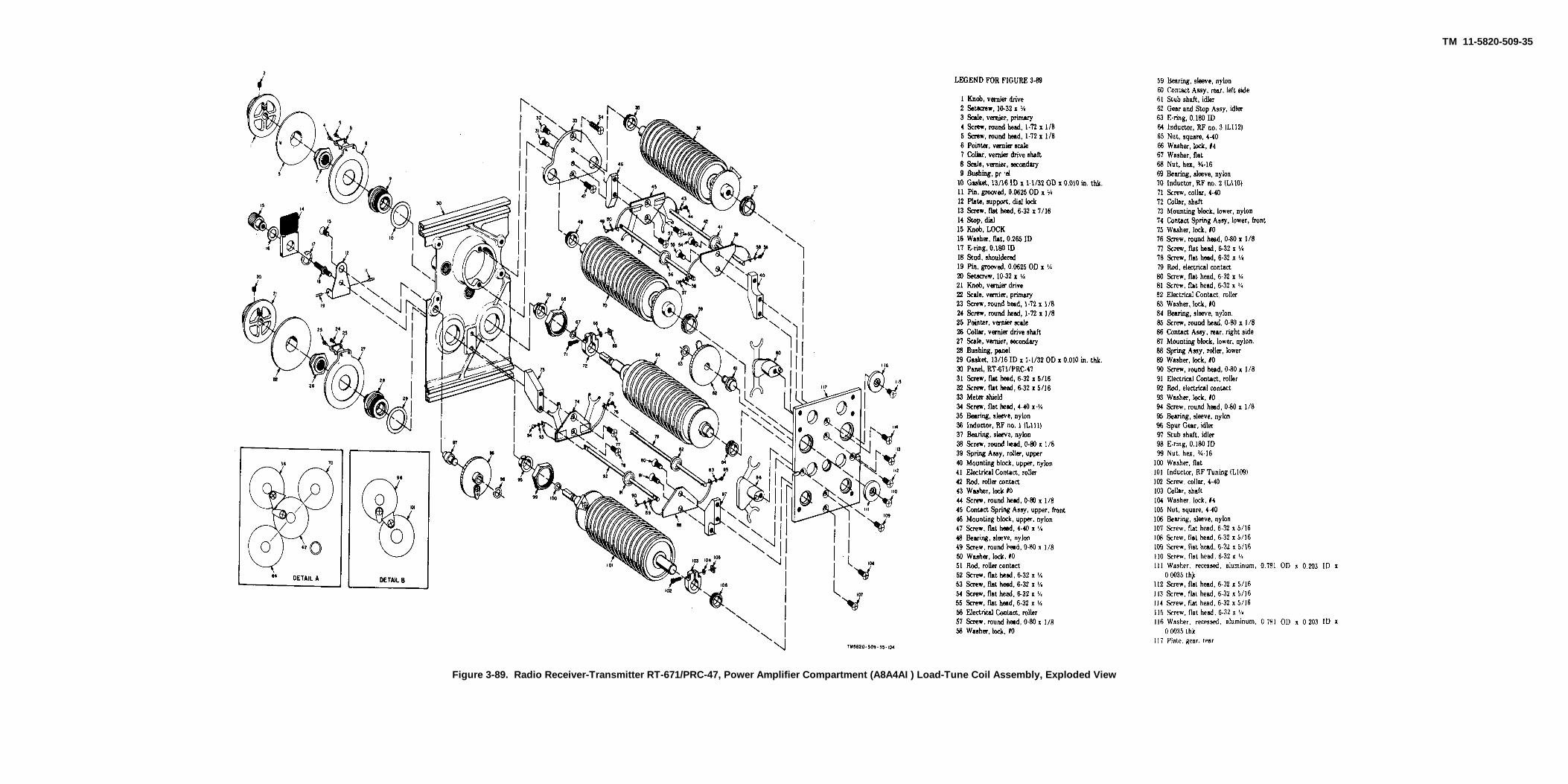
TM 11-5820-509-35
Figure 3-89. Radio Receiver-Transmitter RT-671/PRC-47, Power Amplifier Compartment (A8A4AI ) Load-Tune Coil Assembly, Exploded View
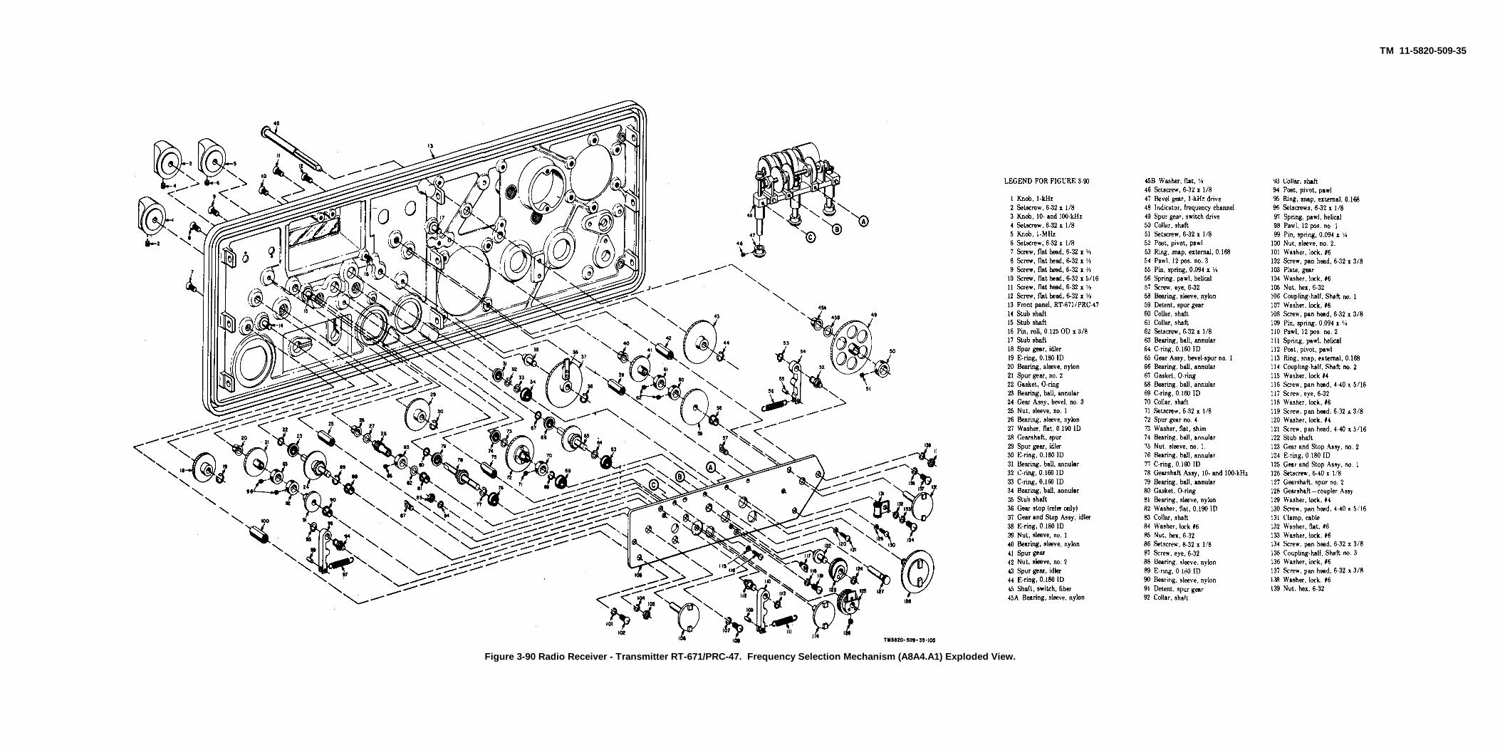
TM 11-5820-509-35
Figure 3-90 Radio Receiver - Transmitter RT-671/PRC-47. Frequency Selection Mechanism (A8A4.A1) Exploded View.
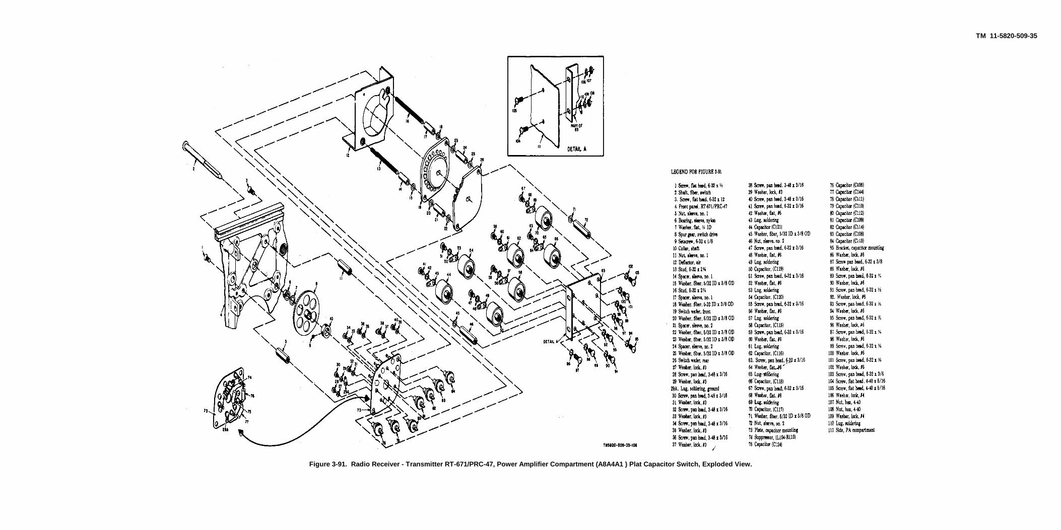
TM 11-5820-509-35
Figure 3-91. Radio Receiver - Transmitter RT-671/PRC-47, Power Amplifier Compartment (A8A4A1 ) Plat Capacitor Switch, Exploded View.
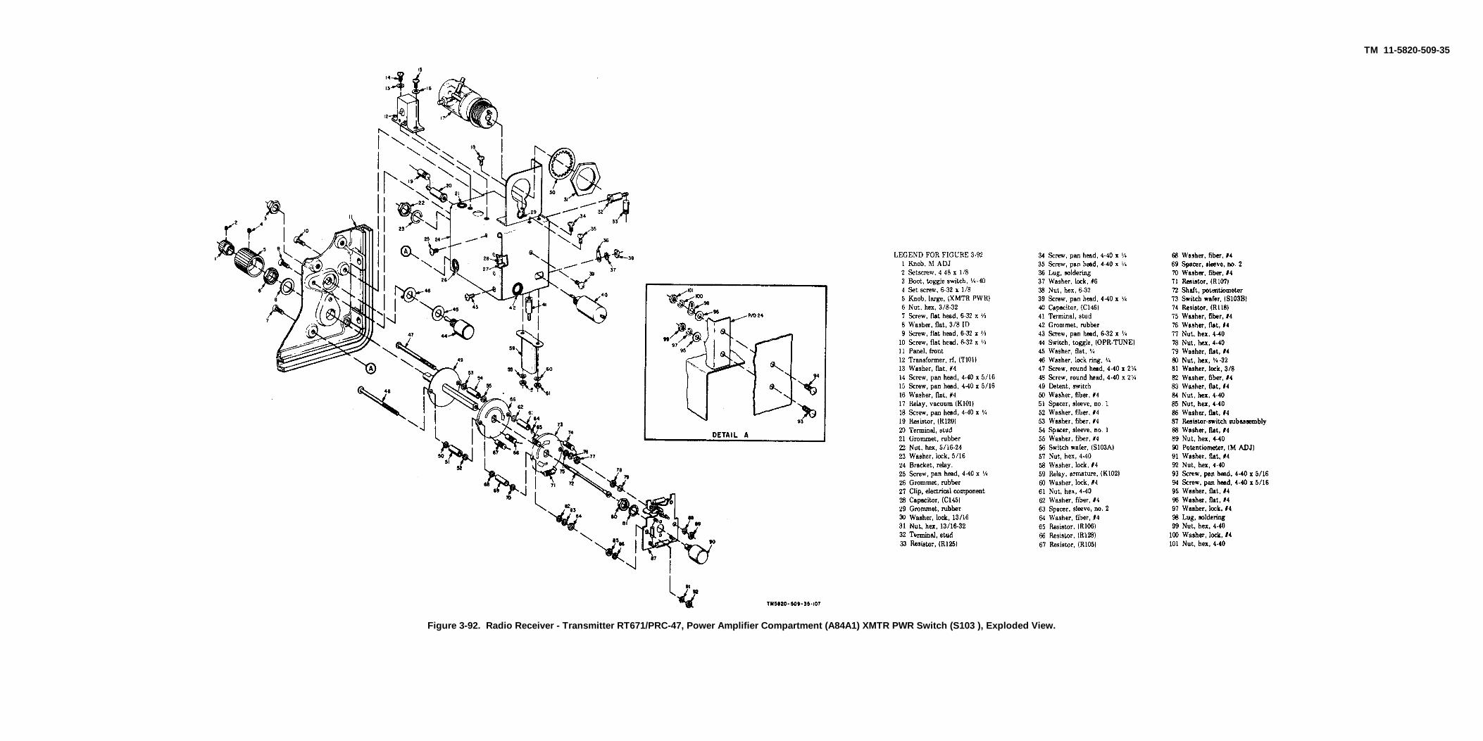
TM 11-5820-509-35
Figure 3-92. Radio Receiver - Transmitter RT671/PRC-47, Power Amplifier Compartment (A84A1) XMTR PWR Switch (S103 ), Exploded View.
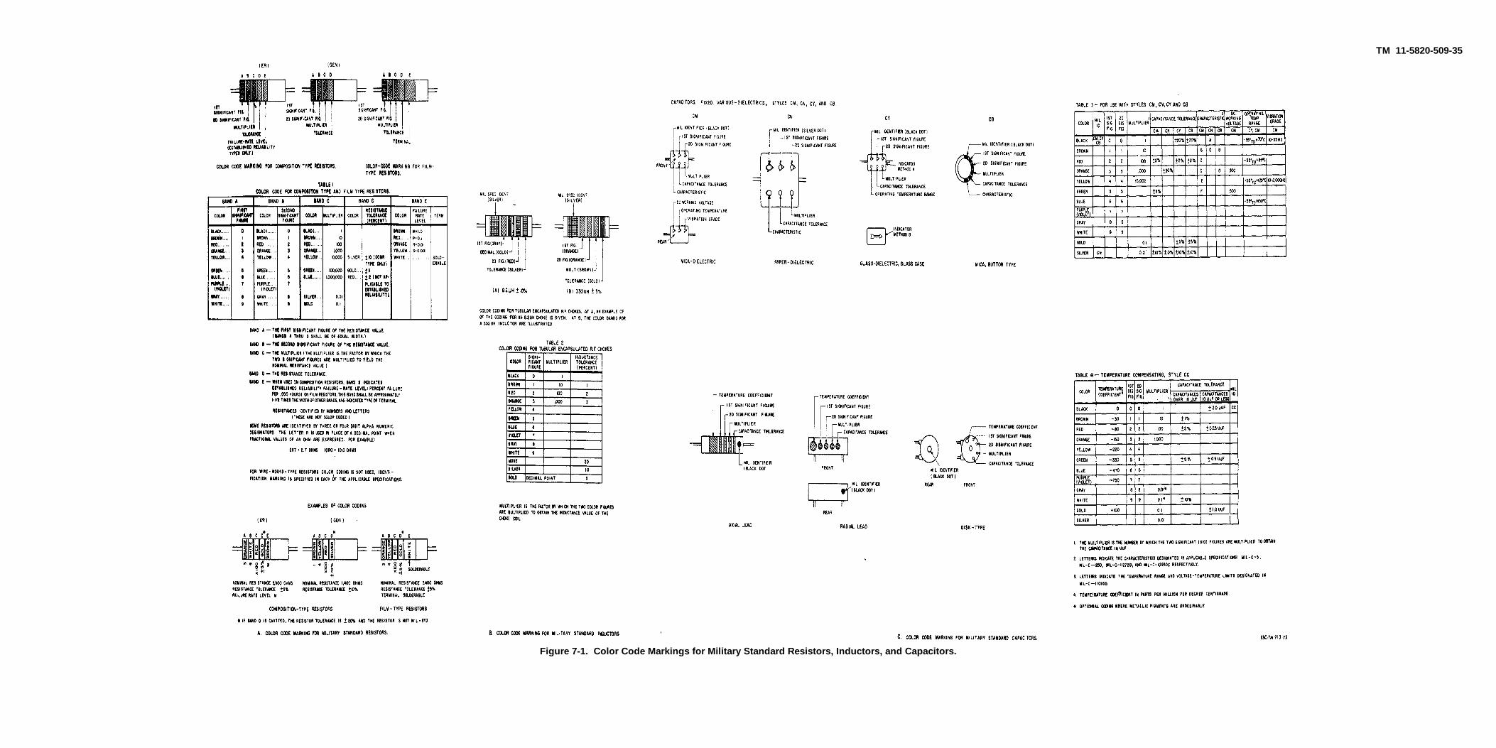
TM 11-5820-509-35
Figure 7-1. Color Code Markings for Military Standard Resistors, Inductors, and Capacitors.
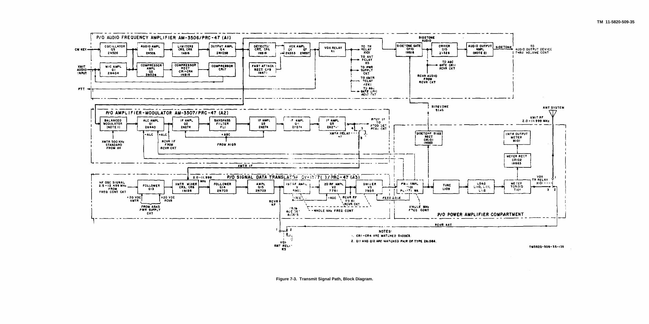
TM 11-5820-509-35
Figure 7-3. Transmit Signal Path, Block Diagram.

TM 11-5820-509-35
Figure 7-4. Frequency Control Circuits, Block Diagram.

TM 11-5820-509-35
Figure 7-5. Power Supply Circuits, Dc Primary Power Input, Block Diagram.
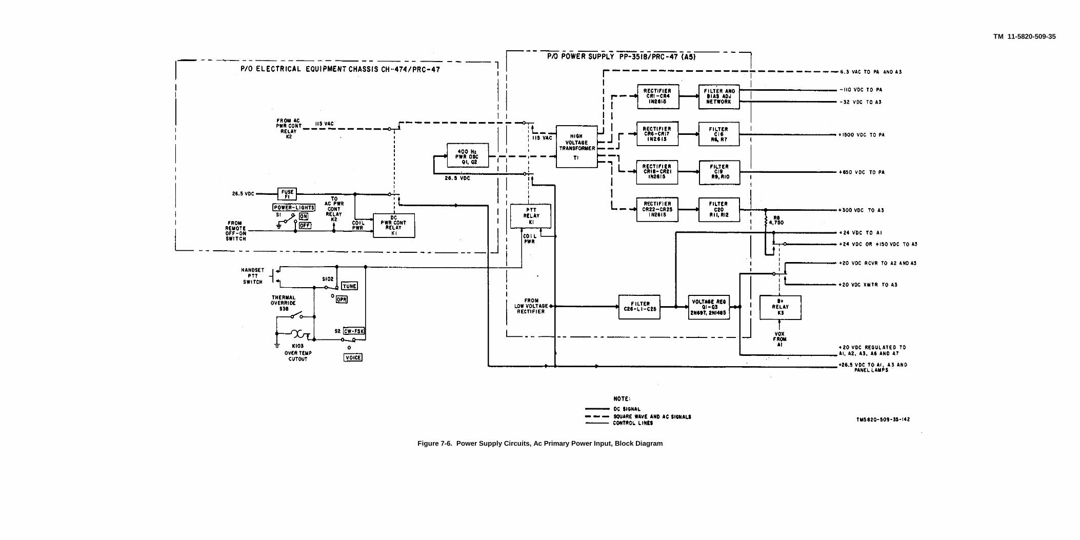
TM 11-5820-509-35
Figure 7-6. Power Supply Circuits, Ac Primary Power Input, Block Diagram

TM 11-5820-509-35
Figure 7-7. Mechanical Schematic. Frequency Control Mechanism

TM 11-5820-509-35
Figure 7-8 (1). Electrical Equipment Chassis CH-474/PRC-47 (A8A4), Schematic Diagram (sheet 1 of 2).
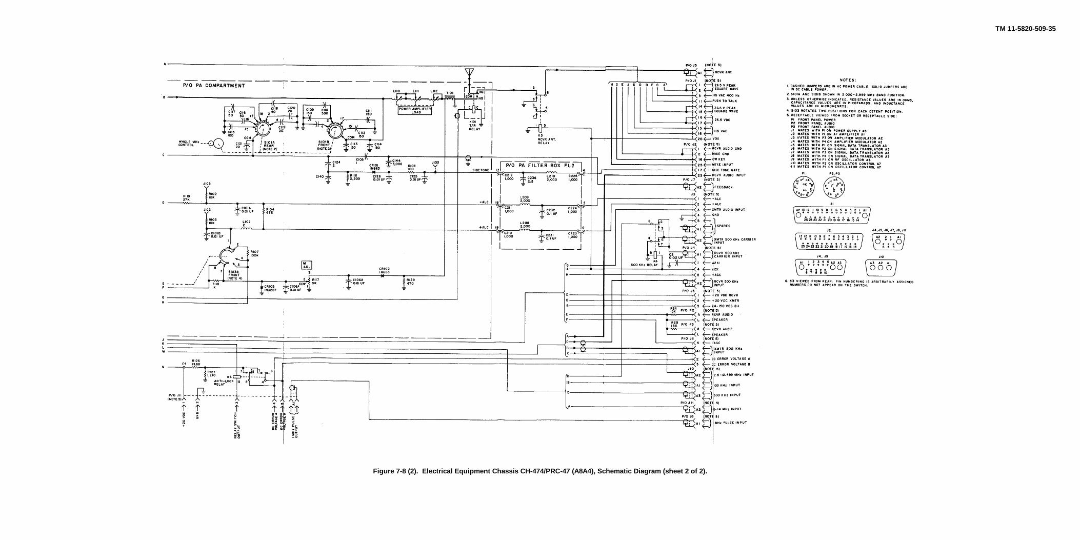
TM 11-5820-509-35
Figure 7-8 (2). Electrical Equipment Chassis CH-474/PRC-47 (A8A4), Schematic Diagram (sheet 2 of 2).
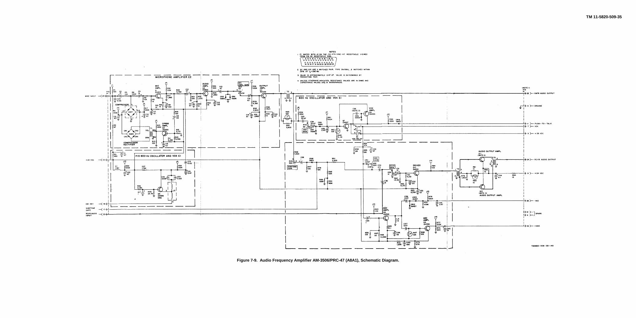
TM 11-5820-509-35
Figure 7-9. Audio Frequency Amplifier AM-3506/PRC-47 (A8A1), Schematic Diagram.

TM 11-5820-509-35
Figure 7-10. Amplifier-Modulator AM3507/PRC-47 (A8A2 ), Schematic Diagram.
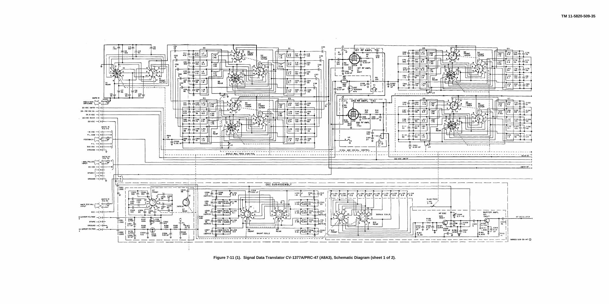
TM 11-5820-509-35
Figure 7-11 (1). Signal Data Translator CV-1377A/PRC-47 (A8A3), Schematic Diagram (sheet 1 of 2).

TM 11-5820-509-35
Figure 7-11 (2). Signal Data Translator CV-1377A/PRC-47 (A8A3), Schematic Diagram (sheet 2 of 2).
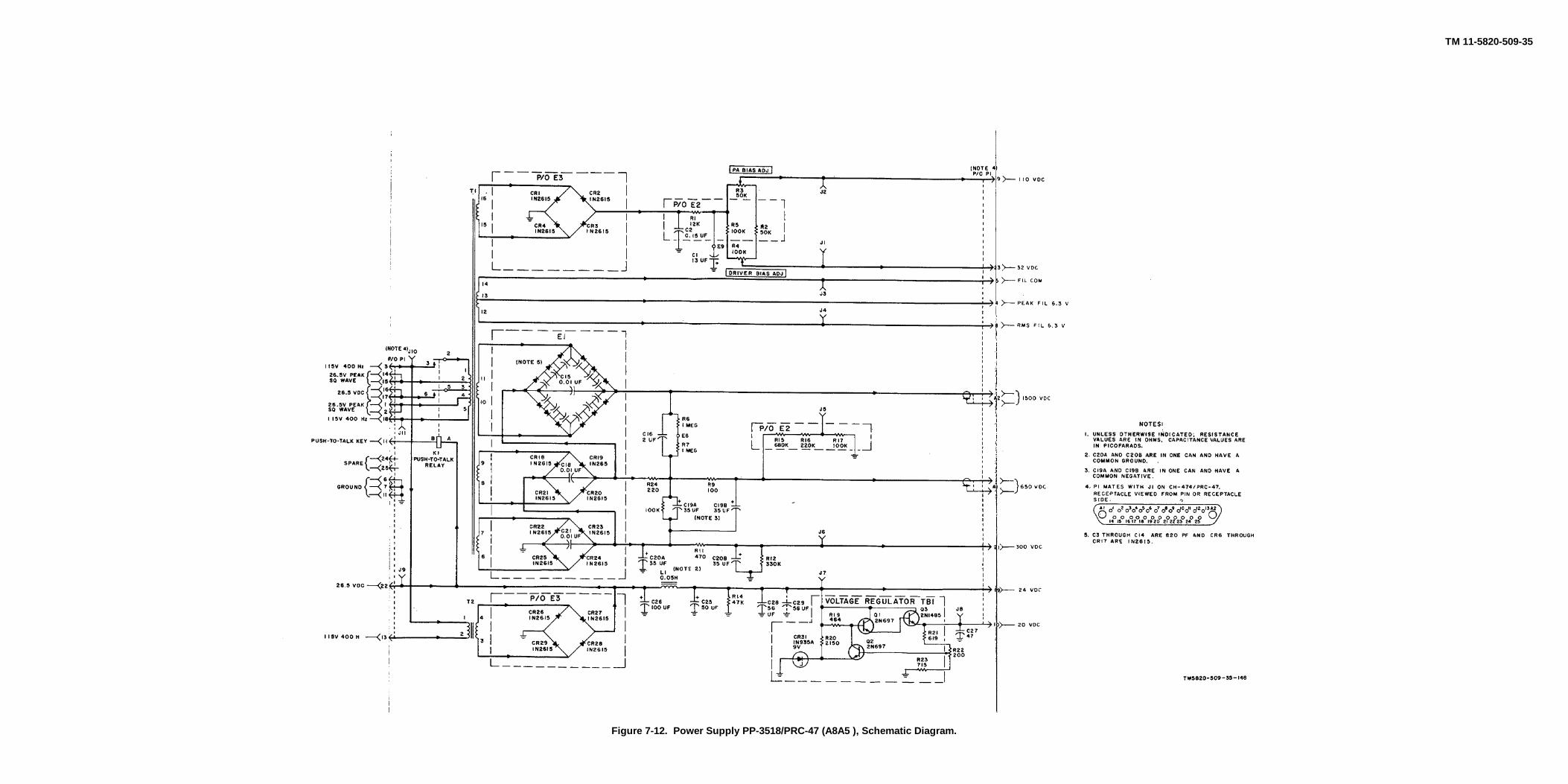
TM 11-5820-509-35
Figure 7-12. Power Supply PP-3518/PRC-47 (A8A5 ), Schematic Diagram.
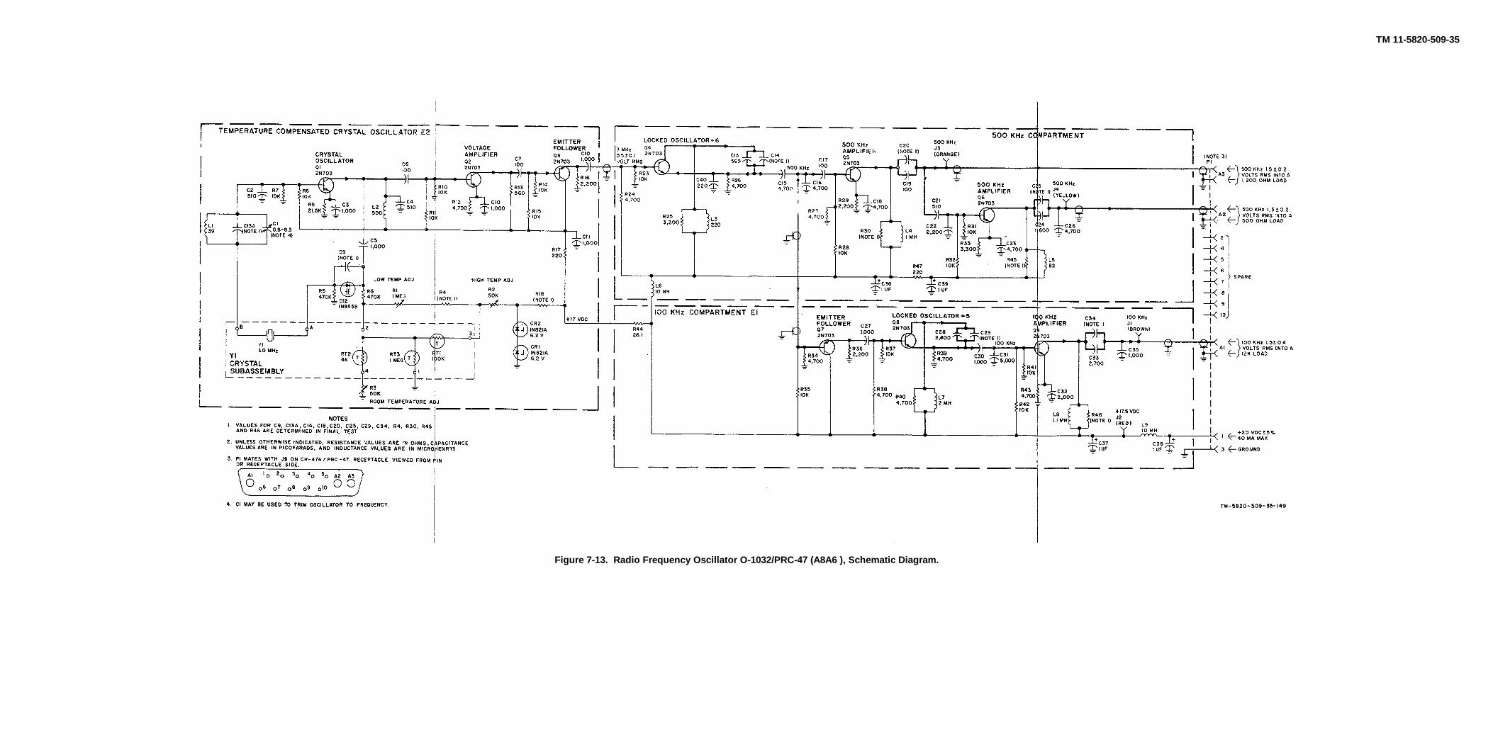
TM 11-5820-509-35
Figure 7-13. Radio Frequency Oscillator O-1032/PRC-47 (A8A6 ), Schematic Diagram.

TM 11-5820-509-35
Figure 7-14. Oscillator Control C-4311/PRC-47 (A8A7), Schematic Diagram.


PIN: 015740-000