ISSUED FOR TENDER\2013-509-(2015-02-0
372
PWGSC Ontario Region Project DRAWINGS AND SPECIFICATIONS Page 1 Number R.066381.001 2015-02-06 DRAWINGS A0 – COVER SHEET A1 – LAB FLOOR PLAN & REFLECTED CEILING PLAN A2 – INTERIOR ELEVATIONS A2a – INTERIOR ELEVATIONS A3 – DETAILS & INTERIOR ELEVATIONS A4 – PARTIAL ROOF PLAN A5 – DETAILS E1 – ELECTRICAL LEGENDS, DRAWING LIST, LIGHTING AND PANEL SCHEDULES E2 – 7TH FLOOR ELECTRICAL DEMOLITION WORK E3 - 7TH FLOOR ELECTRICAL NEW WORK E4 – PENTHOUSE POWER AND SYSTEMS DEMOLITION WORK E5– PENTHOUSE POWER AND SYSTEMS NEW WORK M1 – NOTES, SPECIFICATION, DRAWING LIST, LEGEND & DETAILS M2 – MECHANICAL SCHEDULES M3 – PLUMBING & UTILITIES - 7TH FLOOR - DEMOLITION M4 – PLUMBING & UTILITIES - PENTHOUSE - DEMOLITION M5 – PLUMBING & UTILITIES - 7TH FLOOR - NEW WORK M6 – PLUMBING & UTILITIES - PENTHOUSE - NEW WORK M7 – HVAC - 7TH FLOOR - DEMOLITION M8 – HVAC - PENTHOUSE - DEMOLITION M9 – HVAC - 7TH FLOOR - NEW WORK M10 – HVAC - PENTHOUSE - NEW WORK M11 – APPENDIX - HVAC REFERENCE - REVIT SECTION VIEWS M12 – APPENDIX - HVAC REFERENCE - REVIT SECTION VIEWS M13 – APPENDIX - HVAC REFERENCE - REVIT 3D RENDERINGS S1 – GENERAL REQUIREMENTS S2 – PART ROOF FRAMING PLAN AND DETAILS SPECIFICATIONS Section Title Pages Division 00 - Procurement and Contracting Requirements 00 00 00 SPECIFICATION TITLE SHEET 1 00 01 07 PROFESSIONAL SEALS PAGE 1 Division 01 - General Requirements 01 11 00 SUMMARY OF WORK 3 01 14 00 WORK RESTRICTIONS 2 01 31 19 PROJECT MEETINGS 2 01 32 16 CONSTRUCTION PROGRESS SCHEDULE - BAR (GANTT) CHART 3 01 33 00 SUBMITTAL PROCEDURES 5 01 35 00 CLEANROOM CERTIFICATION AND ACCEPTANCE PROCEDURES 3 01 35 29 HEALTH AND SAFETY REQUIREMENTS 5 01 35 43 ENVIRONMENTAL PROCEDURES 2 01 41 00 REGULATORY REQUIREMENTS 2 01 45 00 QUALITY CONTROL 3 01 56 00 TEMPORARY BARRIERS AND ENCLOSURES 2 01 61 00 COMMON PRODUCT REQUIREMENTS 5 01 73 00 EXECUTION 2 01 74 11 CLEANING 2
-
Upload
khangminh22 -
Category
Documents
-
view
3 -
download
0
Transcript of ISSUED FOR TENDER\2013-509-(2015-02-0

PWGSC Ontario Region Project
DRAWINGS AND SPECIFICATIONS Page 1
Number R.066381.001 2015-02-06
DRAWINGS A0 – COVER SHEET A1 – LAB FLOOR PLAN & REFLECTED CEILING PLAN A2 – INTERIOR ELEVATIONS A2a – INTERIOR ELEVATIONS A3 – DETAILS & INTERIOR ELEVATIONS A4 – PARTIAL ROOF PLAN A5 – DETAILS E1 – ELECTRICAL LEGENDS, DRAWING LIST, LIGHTING AND PANEL SCHEDULES E2 – 7TH FLOOR ELECTRICAL DEMOLITION WORK E3 - 7TH FLOOR ELECTRICAL NEW WORK E4 – PENTHOUSE POWER AND SYSTEMS DEMOLITION WORK E5– PENTHOUSE POWER AND SYSTEMS NEW WORK M1 – NOTES, SPECIFICATION, DRAWING LIST, LEGEND & DETAILS M2 – MECHANICAL SCHEDULES M3 – PLUMBING & UTILITIES - 7TH FLOOR - DEMOLITION M4 – PLUMBING & UTILITIES - PENTHOUSE - DEMOLITION M5 – PLUMBING & UTILITIES - 7TH FLOOR - NEW WORK M6 – PLUMBING & UTILITIES - PENTHOUSE - NEW WORK M7 – HVAC - 7TH FLOOR - DEMOLITION M8 – HVAC - PENTHOUSE - DEMOLITION M9 – HVAC - 7TH FLOOR - NEW WORK M10 – HVAC - PENTHOUSE - NEW WORK M11 – APPENDIX - HVAC REFERENCE - REVIT SECTION VIEWS M12 – APPENDIX - HVAC REFERENCE - REVIT SECTION VIEWS M13 – APPENDIX - HVAC REFERENCE - REVIT 3D RENDERINGS S1 – GENERAL REQUIREMENTS S2 – PART ROOF FRAMING PLAN AND DETAILS
SPECIFICATIONS
Section Title Pages
Division 00 - Procurement and Contracting Requirements
00 00 00 SPECIFICATION TITLE SHEET 1
00 01 07 PROFESSIONAL SEALS PAGE 1
Division 01 - General Requirements
01 11 00 SUMMARY OF WORK 3
01 14 00 WORK RESTRICTIONS 2 01 31 19 PROJECT MEETINGS 2 01 32 16 CONSTRUCTION PROGRESS SCHEDULE - BAR (GANTT) CHART 3 01 33 00 SUBMITTAL PROCEDURES 5 01 35 00 CLEANROOM CERTIFICATION AND ACCEPTANCE PROCEDURES 3 01 35 29 HEALTH AND SAFETY REQUIREMENTS 5 01 35 43 ENVIRONMENTAL PROCEDURES 2 01 41 00 REGULATORY REQUIREMENTS 2 01 45 00 QUALITY CONTROL 3 01 56 00 TEMPORARY BARRIERS AND ENCLOSURES 2 01 61 00 COMMON PRODUCT REQUIREMENTS 5 01 73 00 EXECUTION 2 01 74 11 CLEANING 2

PWGSC Ontario Region Project
DRAWINGS AND SPECIFICATIONS Page 2
Number R.066381.001 2015-02-06
SPECIFICATIONS (CONT’D)
Section Title Pages
Division 01 - General Requirements (Cont’d)
01 74 20 CONSTRUCTION/DEMOLITION WASTE MANAGEMENT AND DISPOSAL 2 01 77 00 CLOSEOUT PROCEDURES 2 01 78 00 CLOSEOUT SUBMITTALS 5 01 79 00 DEMONSTRATION AND TRAINING 2 01 91 00 COMMISSIONING 5
Division 02 - Existing Conditions 02 41 46 DEMOLITION 2 02 41 99 DEMOLITION FOR MINOR WORKS 2 02 82 00.01 ASBESTOS ABATEMENT – MINIMUM PREACAUTIONS 5 02 82 00.02 ASBESTOS ABATEMENT – INTERMEDIATE PREACAUTIONS 7
Division 03 - Concrete 03 30 00 CAST-IN-PLACE CONCRETE 3
Division 04 – Masonry
04 20 00 UNIT MASONRY 3
Division 05 - Metals
05 12 23 STRUCTURAL STEEL FOR BUILDINGS 5
05 50 01 METAL FABRICATIONS 3 05 51 29 METAL STAIRS AND LADDERS 3
Division 07 - Thermal and Moisture Protection 07 52 16 MODIFIED BITUMINOUS ROOFING 7 07 90 00 JOINT SEALANTS 3 Division 08 - Openings 08 11 13 STEEL HOLLOW METAL DOORS AND FRAMES 3 08 71 11 FINISH HARDWARE 4 Division 09 - Finishes 09 21 99 PARTITIONS FOR MINOR WORKS 5 09 51 23 ACOUSTIC TILE CEILINGS 2 09 91 23 INTERIOR PAINTING 3 09 96 00 SEAMLESS FLOOR COATING FOR LABORATORY 4 Division 12 - Furnishings 12 35 53.13 STEEL LABORATORY CASEWORK 7 12 35 60 FUME HOODS 9 Division 21 - Fire Suppression 21 00 00 FIRE PROTECTION 1
Division 22 - Plumbing 22 00 00 PLUMBING 7
Division 23 - Heating, Ventilating and Air-Conditioning (HVAC) 23 05 00 COMMON WORK RESULTS - MECHANICAL 8
23 05 05 INSTALLATION OF PIPEWORK 5 23 05 14 VARIABLE FREQUENCY DRIVES 7 23 05 17 PIPE WELDING 3

PWGSC Ontario Region Project
DRAWINGS AND SPECIFICATIONS Page 3
Number R.066381.001 2015-02-06
END
SPECIFICATIONS (CONT’D)
Section Title Pages
Division 23 - Heating, Ventilating and Air-Conditioning (HVAC) (Cont’d) 23 05 23.01 VALVES - BRONZE 3 23 05 23.03 VALVES - CAST STEEL 4 23 05 29 HANGERS AND SUPPORTS FOR HVAC PIPING AND EQUIPMENT 6 23 05 33 HEAT TRACING FOR HVAC PIPING AND TANKS 3 23 05 48 VIBRATION AND SEISMIC CONTROLS FOR HVAC PIPING AND EQUIPMENT 4 23 05 93 MECHANICAL TESTING, ADJUSTING AND BALANCING (TAB) MAJOR WORKS 5 23 20 00 HEATING AND COOLING - HYDRONIC SYSTEMS 7 23 22 13 STEAM AND CONDENSATE HEATING PIPING 4 23 22 14 STEAM SPECIALTIES 3 23 30 00 HEATING, VENTILATING AND AIR CONDITIONING - AIR SYSTEMS 6 23 34 00 HEAT RECOVERY EXHAUST UNIT 8
23 41 00 PARTICULATE AIR FILTRATION 3 23 74 00 CUSTOM OUTDOOR HVAC EQUIPMENT 11
Division 25 - Integrated Automation
25 10 10 AUTOMATIC CONTROL SYSTEM - EXTEND EXISTING EMCS 19
25 50 00 LABORATORY AIR CONTROLS 5
Division 26 - Electrical
26 05 00 COMMON WORK RESULTS FOR ELECTRICAL 6
26 05 20 WIRE AND BOX CONNECTORS (0-1000 V) 1 26 05 21 WIRES AND CABLES (0-1000 V) 2 26 05 28 GROUNDING - SECONDARY 1 26 05 31 SPLITTERS, JUNCTION, PULL BOXES AND CABINETS 1 26 05 32 OUTLET BOXES, CONDUIT BOXES AND FITTINGS 2 26 05 33.01 SURFACE AND LIGHTING FIXTURE RACEWAYS 1 26 05 34 CONDUITS, CONDUIT FASTENINGS AND CONDUIT FITTINGS 2 26 27 26 WIRING DEVICES 2 26 28 16.02 MOULDED CASE CIRCUIT BREAKERS 1 26 28 23 DISCONNECT SWITCHES - FUSED AND NON-FUSED 1 26 50 00 LIGHTING 2
Division 28 - Electronic Safety and Security 28 31 00.01 MULTIPLEX FIRE ALARM SYSTEM 3
APPENDIX ‘A’ – Hazardous Building Materials Assessment


PWGSC Ontario SPECIFICATION TITLE SHEET Section 00 00 00Region Project Page 1Number R.066381.001 2015-02-06 PROJECT TITLE Environmental Canada - Ultra-trace Laboratory Renovation
Canada Centre for Inland Waters (CCIW)867 Lakeshore Road, Burlington, Ontario
PROJECT NUMBER R.066381.001
PROJECT DATE 2014-10-29
END


PWGSC Ontario PROFESSIONAL SEALS Section 00 01 07 Region Project Page 1 Number R.066381.001 2015-02-06
Consultant for Building Code Review: N/A
Building Code Designation Number (BCDN): N/A
Architect Structural Engineer
Mechanical Engineer Electrical Engineer
Civil Engineer N/A Interior Designer N/A
END


PWGSC Ontario SUMMARY OF WORK Section 01 11 00Region Project Page 1Number R.066381.001 2015-02-06 PART 1 - GENERAL 1.1 SECTION .1 Title and description of Work.INCLUDES
.2 Contract Method.
.3 Work by others.
.4 Future work.
.5 Work sequence.
.6 Contractor use of premises.
.7 Owner occupancy.
.8 Partial Owner occupancy. 1.2 PRECEDENCE .1 For Federal Government projects, Division 01 Sections take precedence over technical
specification sections in other Divisions of this Project Manual. 1.3 WORK COVERED .1 Work of this contract comprises renovation of 46 m2 of existing space into a ISOCLASS 7BY CONTRACT (CLASS 10,000) clean lab for the analysis of ultra trace levels of plastics. There shall beDOCUMENTS no components/materials installed or used within lab which contain plasticizers, unless
amount considered negligible as determined by lab users and approved for use in writing.
.2 Area of work will include approximately 40 m2 of space on 6th floor to accomodateinstallation of new plumbing services, 110 m2 on 7th floor, and 340 m2 on penthouseand roof to accommodate new HVAC and associated work.
1.4 CONTRACT .1 Construct work under lump sum contract.METHOD 1.5 COST .1 Within 48 hours of notification of acceptance of bid furnish a cost breakdown by SectionBREAKDOWN aggregating contract amount.
.2 Show separately cost of equipment purchased exempt from Ontario Retail Sales Tax
under your Ontario Sales Tax license number.
.3 Within 48 hours of acceptance of bid submit a list of subcontractors.
PWGSC Ontario SUMMARY OF WORK Section 01 11 00Region Project Page 2Number R.066381.001 2015-02-06 1.6 WORK BY .1 Work of Project which will be executed after completion of Work of this Contract, andOTHERS which is specifically excluded from this Contract:
.1 Access control by Owner. Contractor to rough-in conduit. 1.7 WORK SEQUENCE .1 Construct Work in stages to accommodate Owner's continued use of premises during
construction.
.2 Coordinate Progress Schedule.
.3 Required stages:.1 Work within adjacent Lab must be limited to ten (10) working days. Following the
ten (10) working days, provide after hours access to per form work will be permittedif Owners continued daily use of space is not affected.
1.8 CONTRACTOR USE .1 Contractor has unrestricted use of site until Substantial Performance.OF PREMISES
.2 Contractor shall limit use of premises for Work, to allow;.1 Continued Owner occupancy.
.3 Coordinate use of premises under direction of Departmental Representative.
.4 Obtain and pay for use of additional storage or work areas needed for operations under
this Contract. 1.9 OWNER .1 Owner will occupy premises during entire construction period for execution of normalOCCUPANCY operations.
.2 Cooperate with Owner in scheduling operations to minimize conflict and to facilitateOwner usage.
1.10 ALTERATIONS TO .1 Remove, temporarily store, clean, alter to suit and reinstall:EXISTING BUILDING .1 Existing cogeneration circulation pump, P1.
.2 Provide new openings required in existing construction.
.3 Block in openings where items removed with material and finish to match existingadjoining construction.
PWGSC Ontario SUMMARY OF WORK Section 01 11 00Region Project Page 3Number R.066381.001 2015-02-06 PART 2 - PRODUCTS 2.1 NOT USED .1 Not used. PART 3 - EXECUTION 3.1 NOT USED .1 Not used.
END

PWGSC Ontario WORK RESTRICTIONS Section 01 14 00Region Project Page 1Number R.066381.001 2015-02-06 PART 1 - GENERAL 1.1 ACCESS AND .1 Design, construct and maintain temporary "access to" and "egress from" work areas,EGRESS including stairs, runways, ramps or ladders, independent of finished surfaces and in
accordance with relevant municipal, provincial and other regulations. 1.2 USE OF SITE AND .1 Execute work with least possible interference or disturbance to normal use of premises.FACILITIES Make arrangements with Departmental Representative to facilitate work as stated.
.2 Maintain existing services to building and provide for personnel and vehicle access.
.3 Where security is reduced by work provide temporary means to maintain security.
.4 Departmental Representative will assign sanitary facilities for use by Contractor'spersonnel. Keep facilities clean.
.5 Use only elevators, existing in building for moving workers and material.
.1 Protect walls of passenger elevators, to approval of Departmental Representativeprior to use.
.2 Accept liability for damage, safety of equipment and overloading of existingequipment.
.6 Closures: protect work temporarily until permanent enclosures are completed.
1.3 ALTERATIONS, .1 Execute work with least possible interference or disturbance to building operations,ADDITIONS OR occupants, public and normal use of premises. Arrange with Departmental RepresentativeREPAIRS TO EXISTING to facilitate execution of work.BUILDING 1.4 EXISTING .1 Notify, Departmental Representative of intended interruption of services and obtainSERVICES required permission.
.2 Where Work involves breaking into or connecting to existing services, give DepartmentalRepresentative 72 hours of notice for necessary interruption of mechanical or electricalservice throughout course of work. Keep duration of interruptions minimum. Carry outinterruptions after normal working hours of occupants, preferably on weekends.
.3 Construct barriers in accordance with Section 01 56 00.
1.5 SPECIAL .1 Carry out odour generating work (welding, painting) Monday to Friday from 18:00 toREQUIREMENTS 04:00 hours only and on Saturdays, Sundays, and statutory holidays.
.2 Carry out noise generating Work Monday to Friday from 18:00 to 07:00 hours and onSaturdays, Sundays, and statutory holidays.
.3 Submit schedule in accordance with Section 01 32 16.

PWGSC Ontario WORK RESTRICTIONS Section 01 14 00Region Project Page 2Number R.066381.001 2015-02-06 1.5 SPECIAL .4 Ensure Contractor's personnel employed on site become familiar with and obey REQUIREMENTS regulations including safety, fire, traffic and security regulations. (Cont'd)
.5 Keep within limits of work and avenues of ingress and egress.
.6 Ingress and egress of Contractor vehicles at site is limited to six (6).
.7 Deliver materials outside of peak traffic hours 17:00 to 07:00 and 13:00 to 15:00 unlessotherwise approved by Departmental Representative.
.8 Prior to cutting or drilling horizontal or vertical surfaces including concrete, concrete
block or other structural substrate, determine location of reinforcing, service lines, pipes,conduits or other items by x-ray, ground penetrating radar or other appropriate method.Submit findings to Departmental Representative prior to cutting or drilling.
1.6 SECURITY .1 Where security has been reduced by Work of Contract, provide temporary means to
maintain security.
.2 Security clearances:.1 Obtain requisite clearance, as instructed, for each individual required to enter
premises..2 Personnel will be checked daily at start of work shift and provided with pass which
must be worn at all times. Pass must be returned at end of work shift and personnelchecked out.
1.7 BUILDING .1 Comply with smoking restrictions. Smoking is not permitted.SMOKINGENVIRONMENT PART 2 - PRODUCTS 2.1 NOT USED .1 Not Used. PART 3 - EXECUTION 3.1 NOT USED .1 Not Used.
END

PWGSC Ontario PROJECT MEETINGS Section 01 31 19Region Project Page 1Number R.066381.001 2015-02-06 PART 1 - GENERAL 1.1 ADMINISTRATIVE .1 Schedule and administer project meetings throughout the progress of the work at the call
of Departmental Representative.
.2 Prepare agenda for meetings.
.3 Distribute written notice of each meeting 7 days in advance of meeting date toDepartmental Representative.
.4 Provide physical space and make arrangements for meetings.
.5 Preside at meetings.
.6 Record the meeting minutes. Include significant proceedings and decisions. Identify
actions by parties.
.7 Reproduce and distribute copies of minutes within three days after meetings and transmitto Departmental Representative, meeting participants and affected parties not inattendance.
.8 Representative of Contractor, Subcontractor and suppliers attending meetings will be
qualified and authorized to act on behalf of party each represents. 1.2 PRECONSTRUC- .1 Within 15 days after award of Contract, request a meeting of parties in contract to discussTION MEETING and resolve administrative procedures and responsibilities.
.2 Departmental Representative, Contractor, major Subcontractors, field inspectors andConsultants will be in attendance.
.3 Establish time and location of meeting and notify parties concerned minimum 5 days
before meeting.
.4 Incorporate mutually agreed variations to Contract Documents into Agreement, prior tosigning.
.5 Agenda to include:
.1 Appointment of official representative of participants in the Work.
.2 Schedule of Work: in accordance with Section 01 32 16.
.3 Schedule of submission of shop drawings, samples, mock-ups, colour chips. Submitsubmittals in accordance with Section 01 33 00.
.4 Requirements for temporary facilities, site sign, offices, storage, garbagecontainers, utilities, duct tight screens and barriers in accordance with Section01 56 00.
.5 Delivery schedule of specified equipment.
.6 Site security.
.7 Health and safety in accordance with Section 01 35 29.
.8 Proposed changes, change orders, procedures, approvals required, mark-uppercentages permitted, time extensions, overtime, administrative requirements.
.9 Owner provided products.
.10 Record drawings and specifications in accordance with Sections 01 33 00 and01 78 00.
.11 Maintenance manuals in accordance with Section 01 78 00.
.12 Take-over procedures, acceptance, warranties.

PWGSC Ontario PROJECT MEETINGS Section 01 31 19Region Project Page 2Number R.066381.001 2015-02-06 1.2 PRECONSTRUC- .5 Agenda to include:(Cont'd) TION MEETING .13 Monthly progress claims, administrative procedures, photographs, hold backs. (Cont'd) .14 Appointment of inspection and testing agencies or firms.
.15 Insurances, transcript of policies. 1.3 PROGRESS .1 During course of Work, schedule progress meetings bi-weekly.MEETINGS
.2 Contractor, major Subcontractors involved in Work, Departmental Representative andOwner are to be in attendance.
.3 Notify parties minimum 5 days prior to meetings.
.4 Record minutes of meetings and circulate to attending parties and affected parties not in
attendance within 2 days after meeting.
.5 Agenda to include the following:.1 Review, approval of minutes of previous meeting..2 Review of Work progress since previous meeting..3 Field observations, problems, conflicts..4 Problems which impede construction schedule..5 Review of off-site fabrication delivery schedules..6 Corrective measures and procedures to regain projected schedule..7 Revision to construction schedule..8 Progress schedule, during succeeding work period..9 Review submittal schedules: expedite as required..10 Maintenance of quality standards..11 Review proposed changes for affect on construction schedule and on completion
date..12 Other business.
PART 2 - PRODUCTS 2.1 NOT USED .1 Not Used. PART 3 - EXECUTION 3.1 NOT USED .1 Not Used.
END

PWGSC Ontario CONSTRUCTION PROGRESS SCHEDULE - BAR (GANTT) Section 01 32 16Region Project CHART Page 1Number R.066381.001 2015-02-06 PART 1 - GENERAL 1.1 DEFINITIONS .1 Activity: element of Work performed during course of Project. Activity normally has
expected duration, and expected cost and expected resource requirements. Activities canbe subdivided into tasks.
.2 Bar Chart (GANTT Chart): graphic display of schedule-related information. In typical bar
chart, activities or other Project elements are listed down left side of chart, dates areshown across top, and activity durations are shown as date-placed horizontal bars.Generally Bar Chart should be derived from commercially available computerized projectmanagement system.
.3 Baseline: original approved plan (for project, work package, or activity), plus or minus
approved scope changes.
.4 Construction Work Week: Monday to Friday, inclusive, will provide five day work week anddefine schedule calendar working days as part of Bar (GANTT) Chart submission.
.5 Duration: number of work periods (not including holidays or other nonworking periods)
required to complete activity or other project element. Usually expressed as workdays orworkweeks.
.6 Master Plan: summary-level schedule that identifies major activities and key milestones.
.7 Milestone: significant event in project, usually completion of major deliverable.
.8 Project Schedule: planned dates for performing activities and the planned dates for
meeting milestones. Dynamic, detailed record of tasks or activities that must beaccomplished to satisfy Project objectives. Monitoring and control process involves usingProject Schedule in executing and controlling activities and is used as basis for decisionmaking throughout project life cycle.
.9 Project Planning, Monitoring and Control System: overall system operated by
Departmental Representative to enable monitoring of project work in relation toestablished milestones.
1.2 REQUIREMENTS .1 Ensure Master Plan and Detail Schedules are practical and remain within specified
Contract duration.
.2 Plan to complete Work in accordance with prescribed milestones and time frame.
.3 Limit activity durations to maximum of approximately 10 working days, to allow forprogress reporting.
.4 Ensure that it is understood that Award of Contract or time of beginning, rate of progress,
Certificate of Substantial Performance and Certificate of Completion as defined times ofcompletion are of essence of this contract.
1.3 SUBMITTALS .1 Provide submittals in accordance with Section 01 33 00.
.2 Submit to Departmental Representative within 10 working days of Award of Contract Bar(GANTT) Chart as Master Plan for planning, monitoring and reporting of project progress.

PWGSC Ontario CONSTRUCTION PROGRESS SCHEDULE - BAR (GANTT) Section 01 32 16Region Project CHART Page 2Number R.066381.001 2015-02-06 1.3 SUBMITTALS .3 Submit Project Schedule to Departmental Representative within 5 working days of (Cont'd) receipt of acceptance of Master Plan. 1.4 PROJECT .1 Project milestones form interim targets for Project Schedule.MILESTONES .1 Demolition.
.2 RTV equipment delivery.
.3 Roof penetrations.
.4 Working within adjacent Lab to be completed within 10 working days.
.5 Mechanical and electrical rough-ins.
.6 Ceiling installation.
.7 Fume hood and case work installation. 1.5 MASTER PLAN .1 Structure schedule to allow orderly planning, organizing and execution of Work as Bar
Chart (GANTT).
.2 Departmental Representative will review and return revised schedules within 5 workingdays.
.3 Revise impractical schedule and resubmit within 5 working days.
.4 Accepted revised schedule will become Master Plan and be used as baseline for
updates. 1.6 PROJECT .1 Develop detailed Project Schedule derived from Master Plan.SCHEDULE
.2 Ensure detailed Project Schedule includes as minimum milestone and activity types asfollows:.1 Award..2 Shop Drawings, Samples..3 Permits..4 Mobilization..5 Demolition..6 Structural steel platforms..7 Interior Architecture (Walls, Floors and Ceiling)..8 Plumbing..9 Lighting..10 Electrical..11 Piping..12 Controls..13 Heating, Ventilating, and Air Conditioning..14 Fume hoods and case work..15 Testing and Commissioning..16 Supplied equipment long delivery items..17 Departmental Representative supplied equipment required dates.
1.7 PROJECT .1 Update Project Schedule on bi-weekly basis reflecting activity changes and completions,SCHEDULE REPORTING as well as activities in progress.

PWGSC Ontario CONSTRUCTION PROGRESS SCHEDULE - BAR (GANTT) Section 01 32 16Region Project CHART Page 3Number R.066381.001 2015-02-06 1.8 PROJECT .1 Discuss Project Schedule at regular site meetings specified in Section 01 31 19, identifyMEETINGS activities that are behind schedule and provide measures to regain slippage. Activities
considered behind schedule are those with projected start or completion dates later thancurrent approved dates shown on baseline schedule.
.2 Weather related delays with their remedial measures will be discussed and negotiated.
PART 2 - PRODUCTS 2.1 NOT USED .1 Not used. PART 3 - EXECUTION 3.1 NOT USED .1 Not used.
END


PWGSC Ontario SUBMITTAL PROCEDURES Section 01 33 00Region Project Page 1Number R.066381.001 2015-02-06 PART 1 - GENERAL 1.1 ADMINISTRATIVE .1 Submit to Departmental Representative submittals listed for review. Submit
promptly and in orderly sequence to not cause delay in Work. Failure tosubmit in ample time is not considered sufficient reason for extension ofContract Time and no claim for extension by reason of such default will beallowed.
.2 Do not proceed with Work affected by submittal until review is complete.
.3 Present shop drawings, product data, samples and mock-ups in SI Metric
units.
.4 Where items or information is not produced in SI Metric units convertedvalues are acceptable.
.5 Review submittals prior to submission to Departmental Representative. This
review represents that necessary requirements have been determined andverified, or will be, and that each submittal has been checked andco-ordinated with requirements of Work and Contract Documents. Submittalsnot stamped, signed, dated and identified as to specific project will bereturned without being examined and considered rejected.
.6 Notify Departmental Representative, in writing at time of submission,
identifying deviations from requirements of Contract Documents statingreasons for deviations.
.7 Verify field measurements and affected adjacent Work are co-ordinated.
.8 Contractor's responsibility for errors and omissions in submission is not
relieved by Departmental Representative's review of submittals.
.9 Contractor's responsibility for deviations in submission from requirements ofContract Documents is not relieved by Departmental Representative review.
.10 Keep one reviewed copy of each submission on site.
.11 Submit number of hard copies specified for each type and format of submittal
and also submit in electronic format as pdf files. Forward pdf and Autocaddwg files on USB compatible with PWGSC encryption requirements or throughemail or alternate electronic file sharing service such as ftp, as directed byDepartmental Representative.
1.2 SHOP DRAWINGS .1 The term "shop drawings" means drawings, diagrams, illustrations, schedules,AND PRODUCT DATA performance charts, brochures and other data which are to be provided by
Contractor to illustrate details of a portion of Work.
.2 Submit drawings stamped and signed by professional engineer registered orlicensed in Province of Ontario of Canada.
.3 Indicate materials, methods of construction and attachment or anchorage,
erection diagrams, connections, explanatory notes and other informationnecessary for completion of Work. Where articles or equipment attach orconnect to other articles or equipment, indicate that such items have been

PWGSC Ontario SUBMITTAL PROCEDURES Section 01 33 00Region Project Page 2Number R.066381.001 2015-02-06 1.2 SHOP DRAWINGS .3 (Cont'd) AND PRODUCT DATA co-ordinated, regardless of Section under which adjacent items will be (Cont'd) supplied and installed. Indicate cross references to design drawings and
specifications.
.4 Allow 5 working days for Departmental Representative's review of eachsubmission.
.5 Adjustments made on shop drawings by Departmental Representative are not
intended to change Contract Amount. If adjustments affect value of Work,state such in writing to Departmental Representative prior to proceeding withWork.
.6 Make changes in shop drawings as Departmental Representative may require,
consistent with Contract Documents. When resubmitting, notify DepartmentalRepresentative in writing of revisions other than those requested.
.7 Accompany submissions with transmittal letter, in duplicate, containing:
.1 Date.
.2 Project title and number.
.3 Contractor's name and address.
.4 Identification and quantity of each shop drawing, product data andsample..5 Other pertinent data.
.8 Submissions shall include:
.1 Date and revision dates.
.2 Project title and number.
.3 Name and address of:.1 Subcontractor..2 Supplier..3 Manufacturer.
.4 Contractor's stamp, signed by Contractor's authorized representativecertifying approval of submissions, verification of field measurements andcompliance with Contract Documents..5 Details of appropriate portions of Work as applicable:
.1 Fabrication.
.2 Layout, showing dimensions, including identified fielddimensions, and clearances..3 Setting or erection details..4 Capacities..5 Performance characteristics..6 Standards..7 Operating weight..8 Wiring diagrams..9 Single line and schematic diagrams..10 Relationship to adjacent work.
.9 After Departmental Representative's review, distribute copies.
.10 Submit one electronic copy of shop drawings for each requirement requested
in specification Sections and as Departmental Representative may reasonablyrequest.
.11 Submit one electronic copy of test reports for requirements requested in
specification Sections and as requested by Departmental Representative.

PWGSC Ontario SUBMITTAL PROCEDURES Section 01 33 00Region Project Page 3Number R.066381.001 2015-02-06 1.2 SHOP DRAWINGS .11 (Cont'd) AND PRODUCT DATA .1 Report signed by authorized official of testing laboratory that material, (Cont'd) product or system identical to material, product or system to be provided has
been tested in accord with specified requirements..2 Testing must have been within 3 years of date of contract award forproject.
.12 Submit one electronic copy of certificates for requirements requested in
specification Sections and as requested by Departmental Representative..1 Statements printed on manufacturer's letterhead and signed byresponsible officials of manufacturer of product, system or material attestingthat product, system or material meets specification requirements..2 Certificates must be dated after award of project contract complete withproject name.
.13 Submit one electronic copy of manufacturers instructions for requirements
requested in specification Sections and as requested by DepartmentalRepresentative..1 Pre-printed material describing installation of product, system ormaterial, including special notices and Material Safety Data Sheetsconcerning impedances, hazards and safety precautions.
.14 Submit one electronic copy of Manufacturer's Field Reports for requirements
requested in specification Sections and as requested by DepartmentalRepresentative.
.15 Documentation of the testing and verification actions taken by manufacturer's
representative to confirm compliance with manufacturer's standards orinstructions.
.16 Submit and one electronic copy of Operation and Maintenance Data for
requirements requested in specification Sections and as requested byDepartmental Representative.
.17 Delete information not applicable to project.
.18 Supplement standard information to provide details applicable to project.
.19 If upon review by Departmental Representative, no errors or omissions are
discovered or if only minor corrections are made, electronic copies will bereturned and fabrication and installation of Work may proceed. If shopdrawings are rejected, noted copy will be returned and resubmission ofcorrected shop drawings, through same procedure indicated above, must beperformed before fabrication and installation of Work may proceed.
.20 Provide hard copies of large format shop drawings and product data as
requested by Departmental Representative.
.21 The review of shop drawings by Public Works and Government ServicesCanada (PWGSC) is for sole purpose of ascertaining conformance withgeneral concept..1 This review shall not mean that PWGSC approves detail designinherent in shop drawings, responsibility for which shall remain with Contractorsubmitting same, and such review shall not relieve Contractor of responsibilityfor errors or omissions in shop drawings or of responsibility for meetingrequirements of construction and Contract Documents..2 Without restricting generality of foregoing, Contractor is responsible fordimensions to be confirmed and correlated at job site, for information that
PWGSC Ontario SUBMITTAL PROCEDURES Section 01 33 00Region Project Page 4Number R.066381.001 2015-02-06 1.2 SHOP DRAWINGS .21 (Cont'd) AND PRODUCT DATA .2 (Cont'd) (Cont'd) pertains solely to fabrication processes or to techniques of construction and
installation and for co-ordination of Work of sub-trades. 1.3 SAMPLES .1 Submit for review samples in duplicate as requested in respective
specification Sections. Label samples with origin and intended use.
.2 Deliver samples prepaid to Departmental Representative's business address.
.3 Notify Departmental Representative in writing, at time of submission ofdeviations in samples from requirements of Contract Documents.
.4 Where colour, pattern or texture is criterion, submit full range of samples.
.5 Adjustments made on samples by Departmental Representative are not
intended to change Contract Amount. If adjustments affect value of Work,state such in writing to Departmental Representative prior to proceeding withWork.
.6 Make changes in samples which Departmental Representative may require,
consistent with Contract Documents.
.7 Reviewed and accepted samples will become standard of workmanship andmaterial against which installed Work will be verified.
1.4 MOCK-UPS .1 Erect mock-ups in accordance with Section 01 45 00. 1.5 PHOTOGRAPHIC .1 Submit electronic copy of colour digital photography in jpg format, standardDOCUMENTATION resolution monthly with progress statement and as directed by Departmental
Representative.
.2 Project identification: name and number of project and date of exposureindicated.
.3 Number of viewpoints: up to ten (10) locations.
.1 Viewpoints and their location as determined by DepartmentalRepresentative.
.4 Frequency of photographic documentation: monthly.
.1 Upon completion of: of Work, and as directed by DepartmentalRepresentative.
1.6 CERTIFICATES .1 Immediately after award of Contract, submit Workers' Safety and InsuranceAND TRANSCRIPTS Board Experience Report.
.2 Submit transcription of insurance immediately after award of Contract.
PWGSC Ontario SUBMITTAL PROCEDURES Section 01 33 00Region Project Page 5Number R.066381.001 2015-02-06 1.7 FEES, PERMITS .1 Provide authorities having jurisdiction with information requested.AND CERTIFICATES
.2 Pay fees and obtain certificates and permits required.
.3 Furnish certificates and permits.
.4 Submit acceptable certificate stating that suspended ceiling systems provideadequate support for electrical fixtures, as required by current bulletin ofElectrical Inspection Department of Ontario Hydro and OBC.
PART 2 - PRODUCTS 2.1 NOT USED .1 Not Used. PART 3 - EXECUTION 3.1 NOT USED .1 Not Used.
END


PWGSC Ontario CLEANROOM CERTIFICATION AND ACCEPTANCE Section 01 35 00Region Project PROCEDURES Page 1Number R.066381.001 2015-02-06 1 GENERAL .1 All conditions of the Contract apply to the work of this Section.REQUIREMENTS 2 WORK INCLUDED .1 The Contractor shall hire and pay for the services of a NEBB Certified Cleanroom
Performance Testing (CPT) Firm for this project.
.2 This section provides the services required by the NEBB Certified CleanroomPerformance Testing (CPT) Firm hereinafter referred to as the NEBB CPT Firm, tomeasure and record the cleanroom conditions and resolve all nonconforming areas priorto attesting that the cleanroom is complete and ready for Owner's testing and occupancy.
.3 At completion of the certification period, the Departmental Representative may engage
the services of an independent quality assurance testing and certifying agency to performrandom spot checks of all data collected during the NEBB CPT Firm's certifying period.This quality assurance agency, if used, will act only on behalf of the DepartmentalRepresentative to ensure that certification measurements and data are within industrytolerances and will verify that space conditions and system operations have not changed.
.4 The NEBB CPT Firm shall perform the following tests described below:
.1 Airflow Volume Tests
.2 ULPA Filter Integrity Inspection
.3 Room Particle Count Tests
.4 Enclosure Pressurization Tests
.5 HEPA/ULPA Filter Repair and Replacement: If defective ceiling filters are identifiedduring the course of the certification testing, the NEBB CPT Firm shall immediately notifythe Contractor, and repair or replacement shall be performed at the direction of the CPTat no cost to the owner.
.6 In the event of conflict regarding requirements for the referenced cleanroom testing and
certification between this section and any other section, the provisions of this section shallgovern.
3 REFERENCE .1 International Standard ISO 14644 - Part 1 through Part 8 inclusive.STANDARDS
.2 IES-RP-CC-006.2-1993, Testing Cleanrooms and IES-RP-CC-001.3-1993, HEPA andULPA Filters.
.3 NEBB Procedural Standards for Certified Testing of Cleanrooms, 3rd Edition - 2009.
4 SYSTEM .1 Definitions:DESCRIPTION .1 As-Built Facility: Cleanroom which is complete and operating with all services
connected and functioning, but which has no production equipment or operatingpersonnel.
.2 At-Rest Facility: Cleanroom which is complete and has production equipmentinstalled and operating, but which has no personnel.
.3 Operating Facility: Cleanroom in normal operation, including productionequipment and personnel.
.4 Cleanroom Certifying Agency: The NEBB Certified Performance Testing (CPT)Firm.
.5 Balancing Agency: The NEBB Testing, Adjusting and Balancing (TAB) Firm.

PWGSC Ontario CLEANROOM CERTIFICATION AND ACCEPTANCE Section 01 35 00Region Project PROCEDURES Page 2Number R.066381.001 2015-02-06 4 SYSTEM .1 Definitions:(Cont'd) DESCRIPTION .6 Quality Assurance Agency: The Owner's Cleanroom Quality Assurance Certifying (Cont'd) Firm or agency.
.2 Class of clean areas shall be as listed below:.1 All Cleanroom areas: "As Built" Class 1000 and "At Rest" Class 10,000.
5 SITE .1 Certification shall not proceed until all other work on the cleanroom has been completedCONDITIONS and the commencement of certification work has been approved by the Departmental
Representative.
.2 Condition of Cleanroom prior to Testing:.1 The HVAC system installation for the cleanroom, including all of the exhaust
systems and make-up air systems associated with the cleanroom operation, shallhave been completed, including all air and hydronic testing, adjusting andbalancing work, and a TAB report submitted.
.2 All wall and ceiling penetrations sealed to airflow.
.3 All final clean down procedures shall be complete. 6 MATERIALS .1 The NEBB CPT Firm shall supply all (materials), tools, (equipment) and instrumentation
required to perform the cleanroom system testing and certification as described in thissection, including cleanroom garments required to maintain integrity of certification.
7 INSTRUMENTATION .1 Only state-of-the-art test equipment and instrumentation shall be used in the certification
test procedures as described in Chapter 14 - Equipment and Instrumentation of the NEBBProcedural Standards for Certified Testing of Cleanrooms, 3rd Edition - 2009.
.2 The test instrumentation shall be used as described in the certification test procedures
found in the NEBB Procedural Standards for Certified Testing of Cleanrooms, 3rd Edition- 2009.
8 PREPARATION .1 The NEBB CPT Firm shall supervise and conduct all tests in the presence of the
Departmental Representative and the Contractor's representative.
.2 The as-built cleanroom certification tests shall be performed after the HVAC TAB workhas been completed and the Departmental Representative is satisfied that the installationis ready for certification testing. Final clean down and commissioning procedures alsoshall be completed.
.3 All cleanroom recirculation fans, make-up air fans, process fume exhaust systems and
automatic control loops shall be in operation during tests. All mechanical systems and allfans related to cleanroom systems shall be verified to be operating as specified anddelivering design airflow.
.4 The NEBB Firm will work with the air balancing company for final adjustments to set up
air flows and room pressures.

PWGSC Ontario CLEANROOM CERTIFICATION AND ACCEPTANCE Section 01 35 00Region Project PROCEDURES Page 3Number R.066381.001 2015-02-06 9 FIELD TESTING .1 Airflow Volume Tests:AND CERTIFYING .1 1. Follow the cleanroom certification test procedures found in Chapter 5, SectionPROCEDURES 5.1.3 - Airflow Test Procedures of the NEBB Procedural Standards for Certified
Testing of Cleanrooms, 3rd Edition - 2009.
.2 ULPA/HEPA Filter Integrity Inspection:.1 Each ULPA/HEPA Filter shall be visually inspected for damage. The filter medium
shall be inspected using a high intensity light source directed at the medium andviewed from the opposite side to identify defects. The Owner's consultant willdetermine whether any defective filter will be repaired or replaced.
.3 Room Particle Count Tests:
.1 Follow the cleanroom certification test procedures found in Chapter 7 - RoomCleanliness Classification Testing of the NEBB Procedural Standards for CertifiedTesting of Cleanrooms, Second Edition - 1996 and FED STD 209 E.
10 ACCEPTANCE .1 Verification Procedures:CRITERIA .1 If specified, the NEBB CPF Firm shall demonstrate to the Departmental
Representative and Contractor's representatives the test instrumentation to be usedand the certification performance test procedures to be followed.
.2 At the completion of all certification performance tests, the NEBB CPT Supervisorshall review all certification test data with the Departmental Representative andContractor's representatives and establish the base operating condition ofcleanrooms and clean spaces.
.3 Documentation:.1 The NEBB CPT Supervisor shall review the certification test report data for
compliance after each test, and then sign/stamp the final reports forsubmittal to the Departmental Representative and Contractor.
END


PWGSC Ontario HEALTH AND SAFETY REQUIREMENTS Section 01 35 29Region Project Page 1Number R.066381.001 2015-02-06 PART 1 - GENERAL 1.1 REFERENCES .1 Canadian Standards Association (CSA): Canada
.1 CSA S350-M1980(R2003), Code of Practice for Safety in Demolition ofStructures.
.2 National Building Code 2010 (NBC):
.1 NBC 2010, Division B, Part 8 Safety Measures at Construction andDemolition Sites.
.3 National Fire Code 2010 (NFC):
.1 NFC 2010, Division B, Part 5 Hazardous Processes and Operations,subsection 5.6.1.3 Fire Safety Plan.
.4 Province of Ontario:
.1 Occupational Health and Safety Act Revised Statutes of Ontario 1990,Chapter O.1 as amended, and Regulations for Construction Projects, O. Reg.213/91 as amended..2 O. Reg. 490/09, Designated Substances..3 Workplace Safety and Insurance Act, 1997..4 Municipal statutes and authorities.
.5 Treasury Board of Canada Secretariat (TBS):
.1 Treasury Board, Fire Protection Standard April 1, 2010www.tbs-sct.gc.ca/pol/doc-eng.aspx ?id=17316§ion=text.
1.2 SUBMITTALS .1 Make submittals in accordance with Section 01 33 00.
.2 Submit site-specific Health and Safety Plan: Within 7 days after date ofNotice to Proceed and prior to commencement of Work. Health and SafetyPlan must include:.1 Results of site specific safety hazard assessment..2 Results of safety and health risk or hazard analysis for site tasks andoperations..3 Measures and controls to be implemented to address identified safetyhazards and risks..4 Provide a Fire Safety Plan, specific to the work location, in accordancewith NBC, Division B, Article 8.1.1.3 prior to commencement of work. Theplan shall be coordinated with, and integrated into, the existing Building,Emergency Procedures and Evacuation Plan in place at the site.Departmental Representative will provide Building, Emergency Proceduresand Evacuation Plan. Deliver two copies of the Fire Safety Plan to theDepartmental Representative not later than 14 days before commencing work..5 Contractor's and Sub-contractors' Safety Communication Plan..6 Contingency and Emergency Response Plan addressing standardoperating procedures specific to the project site to be implemented duringemergency situations. Coordinate plan with existing Building, EmergencyResponse requirements and procedures provided by DepartmentalRepresentative.
.3 Departmental Representative will review Contractor's site-specific Health and
Safety Plan and provide comments to Contractor within 5 days after receipt ofplan. Revise plan as appropriate and resubmit plan to Departmental

PWGSC Ontario HEALTH AND SAFETY REQUIREMENTS Section 01 35 29Region Project Page 2Number R.066381.001 2015-02-06 1.2 SUBMITTALS .3 (Cont'd) (Cont'd) Representative within 5 days after receipt of comments from Departmental
Representative.
.4 Departmental Representative's review of Contractor's final Health and Safetyplan should not be construed as approval and does not reduce theContractor's overall responsibility for construction Health and Safety.
.5 Submit names of personnel and alternates responsible for site safety and
health.
.6 Submit records of Contractor's Health and Safety meetings when requested.
.7 Submit electronic copies of Contractor's authorized representative's work sitehealth and safety inspection reports to Departmental Representative, weekly.
.8 Submit copies of orders, directions or reports issued by health and safety
inspectors of the authorities having jurisdiction.
.9 Submit copies of incident and accident reports.
.10 Submit Material Safety Data Sheets (MSDS).
.11 Submit Workplace Safety and Insurance Board (WSIB)- Experience RatingReport.
.12 Submit Designated substance and hazardous materials handling procedures
as required by Division 02 of this specification. 1.3 FILING OF .1 File Notice of Project with Provincial authorities prior to commencement ofNOTICE Work. 1.4 WORK PERMIT .1 Obtain building permits related to project prior to commencement of Work.
.2 Obtain Hot Work Permit from Departmental Representative. 1.5 SAFETY .1 Perform site specific safety hazard assessment related to project.ASSESSMENT 1.6 MEETINGS .1 Schedule and administer Health and Safety meeting with Departmental
Representative prior to commencement of Work. 1.7 REGULATORY .1 Comply with the Acts and regulations of the Province of Ontario.REQUIREMENTS
.2 Comply with specified standards and regulations to ensure safe operations atsite.

PWGSC Ontario HEALTH AND SAFETY REQUIREMENTS Section 01 35 29Region Project Page 3Number R.066381.001 2015-02-06 1.8 PROJECT/SITE .1 Work at site will involve contact with designated substances as described inCONDITIONS Designated Substance Report.
.2 Work consists of removal of asbestos containing transite, fume hood exhaustpipe and associated fans. Contractor to carry out work in accordance with sitespecific health and safety plan and in accordance with Division 02 of thisspecification.
1.9 GENERAL .1 Develop written site-specific Health and Safety Plan based on hazardREQUIREMENTS assessment prior to beginning site Work and continue to implement, maintain,
and enforce plan until final demobilization from site. Health and Safety Planmust address project specifications.
.2 Departmental Representative may respond in writing, where deficiencies or
concerns are noted and may request re-submission with correction ofdeficiencies or concerns either accepting or requesting improvements.
.3 Relief from or substitution for any portion or provision of minimum Health and
Safety standards specified herein or reviewed site-specific Health and SafetyPlan shall be submitted to Departmental Representative in writing.
1.10 COMPLIANCE .1 Comply with Ontario Occupational Health and Safety Act, R.S.O. 1990REQUIREMENTS Chapter 0.1, as amended. 1.11 RESPONSIBILITY .1 Be responsible for health and safety of persons on site, safety of property on
site and for protection of persons adjacent to site and environment to extentthat they may be affected by conduct of Work.
.2 Comply with and enforce compliance by employees with safety requirements
of Contract Documents, applicable federal, provincial, territorial and localstatutes, regulations, and ordinances, and with site-specific Health and SafetyPlan.
.3 Where applicable the Contractor shall be designated "Constructor", as
defined by Occupational Health and Safety Act for the Province of Ontario. 1.12 UNFORSEEN .1 Should any unforeseen or peculiar safety-related factor, hazard, or conditionHAZARDS become evident during performance of Work, immediately stop work and
advise Departmental Representative verbally and in writing.
.2 Follow procedures in place for Employees Right to Refuse Work as specifiedin the Occupational Health and Safety Act for the Province of Ontario.
1.13 POSTING OF .1 Ensure applicable items, articles, notices and orders are posted inDOCUMENTS conspicuous location on site in accordance with Acts and Regulations of
Province of Ontario, and in consultation with Departmental Representative..1 Contractor's Safety Policy..2 Constructor's Name.

PWGSC Ontario HEALTH AND SAFETY REQUIREMENTS Section 01 35 29Region Project Page 4Number R.066381.001 2015-02-06 1.13 POSTING OF .1 (Cont'd) DOCUMENTS .3 Notice of Project. (Cont'd) .4 Name, trade, and employer of Health and Safety Representative or
Joint Health and Safety Committee members (if applicable)..5 Ministry of Labour Orders and reports..6 Occupational Health and Safety Act and Regulations for ConstructionProjects for Province of Ontario..7 Address and phone number of nearest Ministry of Labour office..8 Material Safety Data Sheets..9 Written Emergency Response Plan..10 Site Specific Safety Plan..11 Valid certificate of first aider on duty..12 WSIB "In Case of Injury At Work" poster..13 Location of toilet and cleanup facilities.
1.14 CORRECTION OF .1 Immediately address health and safety non-compliance issues identified byNON-COMPLIANCE authority having jurisdiction or by Departmental Representative.
.2 Provide Departmental Representative with written report of action taken tocorrect non-compliance of health and safety issues identified.
.3 Departmental Representative may stop Work if non-compliance of health and
safety regulations is not corrected. 1.15 POWDER .1 Powder actuated devices are not to be used.ACTUATED DEVICES 1.16 WORK STOPPAGE .1 Give precedence to safety and health of public and site personnel and
protection of environment over cost and schedule considerations for Work.
.2 Assign responsibility and obligation to Competent Supervisor to stop or startWork when, at Competent Supervisor's discretion, it is necessary or advisablefor reasons of health or safety. Departmental Representative may also stopWork for health and safety considerations.
PART 2 - PRODUCTS 2.1 NOT USED .1 Not used.

PWGSC Ontario HEALTH AND SAFETY REQUIREMENTS Section 01 35 29Region Project Page 5Number R.066381.001 2015-02-06 PART 3 - EXECUTION 3.1 NOT USED .1 Not used.
END

PWGSC Ontario ENVIRONMENTAL PROCEDURES Section 01 35 43Region Project Page 1Number R.066381.001 2015-02-06 PART 1 - GENERAL 1.1 DEFINITIONS .1 Environmental Pollution and Damage: presence of chemical, physical, biological
elements or agents which adversely affect human health and welfare; unfavourably alterecological balances of importance to human life; affect other species of importance tohumans; or degrade environment aesthetically, culturally and/or historically.
.2 Environmental Protection: prevention/control of pollution and habitat or environment
disruption during construction. 1.2 REFERENCES .1 U.S. Environmental Protection Agency (EPA)/Office of Water
.1 EPA 832/R-92-005-92, Storm Water Management for Construction Activities,Chapter 3.
.2 EPA General Construction Permit (GCP) 2012. 1.3 ACTION AND .1 Submit in accordance with Section 01 33 00.INFORMATIONALSUBMITTALS .2 Before commencing construction activities or delivery of materials to site, submit
Environmental Protection Plan for review by Departmental Representative.
.3 Environmental Protection Plan must include comprehensive overview of known orpotential environmental issues to be addressed during construction.
.4 Address topics at level of detail commensurate with environmental issue and required
construction tasks.
.5 Include in Environmental Protection Plan:.1 Names of persons responsible for ensuring adherence to Environmental Protection
Plan..2 Names and qualifications of persons responsible for manifesting hazardous waste
to be removed from site..3 Names and qualifications of persons responsible for training site personnel..4 Descriptions of environmental protection personnel training program..5 Drawings indicating locations of proposed containers, garbage and hazardous
waste containers, material storage areas, structures, sanitary facilities, andincluding methods to control runoff and to contain materials on site.
.6 Spill Control Plan to include procedures, instructions, and reports to be used inevent of unforeseen spill of regulated substance.
.7 Non-Hazardous solid waste disposal plan identifying methods and locations forsolid waste disposal.
.8 Air pollution control plan detailing provisions to assure that dust, debris, materials,and trash, are contained on project site.
.9 Contaminant Prevention Plan identifying potentially hazardous substances to beused on job site; intended actions to prevent introduction of such materials into air,water, or ground; and detailing provisions for compliance with Federal, Provincial,and Municipal laws and regulations for storage and handling of these materials.
.10 Waste Water Management Plan identifying methods and procedures formanagement and discharge of waste waters which are directly derived fromconstruction activities, such as concrete curing water, clean-up water, disinfectionwater, hydrostatic test water, and water used in flushing of lines.
PWGSC Ontario ENVIRONMENTAL PROCEDURES Section 01 35 43Region Project Page 2Number R.066381.001 2015-02-06 1.4 FIRES .1 Fires and burning of rubbish on site is not permitted. 1.5 POLLUTION .1 Control emissions from equipment and plant in accordance with local authorities'CONTROL emission requirements. 1.6 NOTIFICATION .1 Departmental Representative will notify Contractor in writing of observed noncompliance
with Federal, Provincial or Municipal environmental laws or regulations, permits, andother elements of Contractor's Environmental Protection plan.
.2 Contractor: after receipt of such notice, inform Departmental Representative of proposed
corrective action and take such action for approval by Departmental Representative..1 Take action only after receipt of written approval by Departmental Representative.
.3 Departmental Representative will issue stop order of work until satisfactory corrective
action has been taken.
.4 No time extensions granted or equitable adjustments allowed to Contractor for suchsuspensions.
PART 2 - PRODUCTS 2.1 NOT USED .1 Not Used. PART 3 - EXECUTION 3.1 CLEANING .1 Progress Cleaning: clean in accordance with Section 01 74 11.
.1 Leave Work area clean at end of each day.
.2 Bury rubbish and waste materials on site where directed after receipt of written approvalfrom Departmental Representative.
.3 Ensure public waterways, storm and sanitary sewers remain free of waste and volatile
materials disposal.
.4 Final Cleaning: upon completion remove surplus materials, rubbish, tools andequipment in accordance with Section 01 74 11.
.5 Waste Management: separate waste materials for reuse and recycling in accordance with
Section 01 74 20..1 Remove recycling containers and bins from site and dispose of materials at
appropriate facility.
END

PWGSC Ontario REGULATORY REQUIREMENTS Section 01 41 00Region Project Page 1Number R.066381.001 2015-02-06 PART 1 - GENERAL 1.1 REFERENCES AND .1 Perform Work in accordance with National Building Code of Canada (NBC)CODES 2010, National Fire Code of Canada (NFC) 2010 and Ontario Building Code
(OBC) 2012, including all amendments up to bid closing date and othercodes of provincial or local application provided that in case of conflict ordiscrepancy, more stringent requirements apply as directed by theDepartmental Representative.
.2 Meet or exceed requirements of:
.1 Contract documents.
.2 Specified standards, codes and referenced documents. 1.2 HAZARDOUS .1 Stop work immediately and notify Departmental Representative if materialsMATERIAL DISCOVERY which may contain designated substances or PCB's, other than those
identified in Designated Substance Report are discovered in course of work. 1.3 BUILDING .1 Comply with smoking restrictions.SMOKINGENVIRONMENT 1.4 IAQ - INDOOR .1 Comply with CSA-Z204-94(R1999), Guideline for Managing Indoor AirAIR QUALITY Quality in Office Buildings and CSA B651-12. 1.5 TAXES .1 Pay applicable Federal, Provincial and Municipal taxes. 1.6 EXAMINATION .1 Examine existing conditions and determine conditions affecting work. PART 2 - PRODUCTS 2.1 NOT USED .1 Not Used.

PWGSC Ontario REGULATORY REQUIREMENTS Section 01 41 00Region Project Page 2Number R.066381.001 2015-02-06 PART 3 - EXECUTION 3.1 NOT USED .1 Not Used.
END

PWGSC Ontario QUALITY CONTROL Section 01 45 00Region Project Page 1Number R.066381.001 2015-02-06 PART 1 - GENERAL 1.1 SECTION .1 Inspection and testing, administrative and enforcement requirements.INCLUDES
.2 Tests and mix designs.
.3 Mock-ups.
.4 Mill tests.
.5 Equipment and system adjust and balance. 1.2 INSPECTION .1 Allow Departmental Representative access to Work. If part of Work is in preparation at
locations other than Place of Work, allow access to such Work whenever it is in progress.
.2 Give timely notice requesting inspection if Work is designated for special tests,inspections or approvals by Departmental Representative instructions, or law of Place ofWork.
.3 If Contractor covers or permits to be covered Work that has been designated for special
tests, inspections or approvals before such is made, uncover such Work, have inspectionsor tests satisfactorily completed and make good such Work.
.4 Departmental Representative may order any part of Work to be examined if Work is
suspected to be not in accordance with Contract Documents. If, upon examination suchwork is found not in accordance with Contract Documents, correct such Work and pay costof examination and correction. If such Work is found in accordance with ContractDocuments, Departmental Representative shall pay cost of examination andreplacement.
1.3 INDEPENDENT .1 Independent Inspection/Testing Agencies will be engaged by DepartmentalINSPECTION Representative for purpose of inspecting and/or testing portions of Work, above andAGENCIES beyond those required of the Contractor. Cost of such services will be borne by
Departmental Representative.
.2 Provide equipment required for executing inspection and testing by appointed agencies.
.3 Employment of inspection/testing agencies does not relax responsibility to perform Workin accordance with Contract Documents.
.4 If defects are revealed during inspection and/or testing, appointed agency will request
additional inspection and/or testing to ascertain full degree of defect. Correct defect andirregularities as advised by Departmental Representative at no cost to DepartmentalRepresentative. Pay costs for retesting and reinspection.
1.4 ACCESS TO WORK .1 Allow inspection/testing agencies access to Work, off site manufacturing and fabrication
plants.
.2 Co-operate to provide reasonable facilities for such access.
PWGSC Ontario QUALITY CONTROL Section 01 45 00Region Project Page 2Number R.066381.001 2015-02-06 1.5 PROCEDURES .1 Notify appropriate agency and Departmental Representative in advance of requirement
for tests, in order that attendance arrangements can be made.
.2 Submit samples and/or materials required for testing, as specifically requested inspecifications. Submit with reasonable promptness and in an orderly sequence so as notto cause delay in Work.
.3 Provide labour and facilities to obtain and handle samples and materials on site.
Provide sufficient space to store and cure test samples. 1.6 REJECTED WORK .1 Remove defective Work, whether result of poor workmanship, use of defective products or
damage and whether incorporated in Work or not, which has been rejected byDepartmental Representative as failing to conform to Contract Documents. Replace orre-execute in accordance with Contract Documents.
.2 Make good other Contractor's work damaged by such removals or replacements promptly.
.3 If in opinion of Departmental Representative it is not expedient to correct defective Work
or Work not performed in accordance with Contract Documents, DepartmentalRepresentative may deduct from Contract Amount difference in value between Workperformed and that called for by Contract Documents, amount of which shall bedetermined by Departmental Representative.
1.7 REPORTS .1 Submit electronic copies of inspection and test reports to Departmental Representative.
.2 Provide copies to Subcontractor of work being inspected or tested, manufacturer orfabricator of material being inspected or tested.
1.8 TESTS AND MIX .1 Furnish test results and mix designs as may be requested.DESIGNS
.2 The cost of tests and mix designs beyond those called for in Contract Documents orbeyond those required by law of Place of Work shall be appraised by DepartmentalRepresentative and may be authorized as recoverable.
1.9 MOCK-UPS .1 Prepare mock-ups for Work specifically requested in specifications. Include for Work of all
Sections required to provide mock-ups.
.2 Prepare mock-ups for Departmental Representative's review with reasonable promptnessand in an orderly sequence, so as not to cause any delay in Work.
.3 Failure to prepare mock-ups in ample time is not considered sufficient reason for an
extension of Contract Time and no claim for extension by reason of such default will beallowed.
.4 If requested, Departmental Representative will assist in preparing a schedule fixing dates
for preparation.
.5 Mock-ups may remain as part of Work.

PWGSC Ontario QUALITY CONTROL Section 01 45 00Region Project Page 3Number R.066381.001 2015-02-06 1.10 MILL TESTS .1 Submit mill test certificates as required of specification Sections. 1.11 EQUIPMENT AND .1 Submit testing, adjusting and balancing reports for mechanical, electrical systems.SYSTEMS
.2 Submit Commissioning Documentation in accordance with Section 01 91 00. PART 2 - PRODUCTS 2.1 NOT USED .1 Not Used. PART 3 - EXECUTION 3.1 NOT USED .1 Not Used.
END


PWGSC Ontario TEMPORARY BARRIERS AND ENCLOSURES Section 01 56 00Region Project Page 1Number R.066381.001 2015-02-06 PART 1 - GENERAL 1.1 SECTION .1 Barriers.INCLUDES
.2 Environmental Controls.
.3 Traffic Controls.
.4 Fire Routes. 1.2 REFERENCES .1 Canadian General Standards Board (CGSB):
.1 CAN/CGSB-1.189-2000, Exterior Alkyd Primer for Wood.
.2 CAN/CGSB-1.59-97, Alkyd Exterior Gloss Enamel.
.2 Canadian Standards Association (CSA):.1 CSA-O121-08 (R2013), Douglas Fir Plywood.
1.3 INSTALLATION .1 Provide temporary controls in order to execute Work expeditiously.AND REMOVAL
.2 Remove from site all such work after use. 1.4 GUARD RAILS AND .1 Provide secure, rigid guard rails and barricades around open shafts and open edges, ofBARRICADES roofs.
.2 Provide as required by governing authorities. 1.5 WEATHER .1 Provide weather tight closures to unfinished openings in floors and roofs.ENCLOSURES
.2 Close off floor areas where walls are not finished; seal off other openings; enclosebuilding interior work.
.3 Design enclosures to withstand wind pressure and snow loading.
1.6 DUST TIGHT .1 Provide dust tight screens or partitions to localize dust generating activities, and forSCREENS protection of workers, finished areas of Work and public.
.2 Maintain and relocate protection until such work is complete. 1.7 PUBLIC TRAFFIC .1 Provide and maintain competent signal flag operators, traffic signals, barricades andFLOW flares, lights, or lanterns as required to perform Work and protect the public during
hoisting procedures.

PWGSC Ontario TEMPORARY BARRIERS AND ENCLOSURES Section 01 56 00Region Project Page 2Number R.066381.001 2015-02-06 1.8 FIRE ROUTES .1 Maintain access to property including overhead clearances for use by emergency
response vehicles. 1.9 PROTECTION FOR .1 Protect surrounding private and public property from damage during performance ofOFF-SITE AND PUBLIC Work.PROPERTY
.2 Be responsible for damage incurred. 1.10 PROTECTION OF .1 Provide protection for finished and partially finished building finishes and equipmentBUILDING FINISHES during performance of Work.
.2 Provide necessary screens, covers, and hoardings.
.3 Confirm with Departmental Representative locations and installation schedule 3 daysprior to installation.
.4 Be responsible for damage incurred due to lack of or improper protection.
PART 2 - PRODUCTS 2.1 NOT USED .1 Not Used. PART 3 - EXECUTION 3.1 NOT USED .1 Not Used.
END

PWGSC Ontario COMMON PRODUCT REQUIREMENTS Section 01 61 00Region Project Page 1Number R.066381.001 2015-02-06 PART 1 - GENERAL 1.1 SECTION .1 Product quality, availability, storage, handling, protection, and transportation.INCLUDES
.2 Manufacturer's instructions.
.3 Quality of Work, coordination and fastenings.
.4 Existing facilities. 1.2 REFERENCES .1 Within text of specifications, reference may be made to reference standards.
.2 Conform to these standards, in whole or in part as specifically requested in specifications.
.3 If there is question as to whether any product or system is in conformance with applicablestandards, Departmental Representative reserves right to have such products or systemstested to prove or disprove conformance.
.4 The cost for such testing will be born by Departmental Representative in event of
conformance with Contract Documents or by Contractor in event of non-conformance.
.5 Conform to latest date of issue of referenced standards in effect on date of submission ofBids, except where specific date or issue is specifically noted.
.6 OPSS Ontario Provincial Standard Specifications and OPSD Ontario Provincial
Standard Drawings quoted in these specifications are available online athttp://www.raqsa.mto.gov.on.ca/ techpubs/ops.nsf/OPSHomepage.
1.3 QUALITY .1 Products, materials, equipment and articles (referred to as products throughout
specifications) incorporated in Work shall be new, not damaged or defective, and of bestquality (compatible with specifications) for purpose intended. If requested, furnishevidence as to type, source and quality of Products provided.
.2 Defective products, whenever identified prior to completion of Work, will be rejected,
regardless of previous inspections. Inspection does not relieve responsibility, but isprecaution against oversight or error. Remove and replace defective products at ownexpense and be responsible for delays and expenses caused by rejection.
.3 Should any dispute arise as to quality or fitness of products, decision rests strictly with
Departmental Representative based upon requirements of Contract Documents.
.4 Unless otherwise indicated in specifications, maintain uniformity of manufacture for anyparticular or like item throughout building.
.5 Permanent labels, trademarks and nameplates on products are not acceptable in
prominent locations, except where required for operating instructions, or when located inmechanical or electrical rooms.

PWGSC Ontario COMMON PRODUCT REQUIREMENTS Section 01 61 00Region Project Page 2Number R.066381.001 2015-02-06 1.4 AVAILABILITY .1 Immediately upon signing Contract, review product delivery requirements and anticipate
foreseeable supply delays for any items. If delays in supply of products are foreseeable,notify Departmental Representative of such, in order that substitutions or other remedialaction may be authorized in ample time to prevent delay in performance of Work.
.2 In event of failure to notify Departmental Representative at commencement of Work and
should it subsequently appear that Work may be delayed for such reason, DepartmentalRepresentative reserves right to substitute more readily available products of similarcharacter, at no increase in Contract Amount or Contract Time.
1.5 METRIC SIZED .1 SI metric units of measurement are used exclusively on the drawings and in theMATERIALS specifications for this project.
.2 The Contractor is required to provide metric products in the sizes called for in theContract Documents except where a valid claim can be made that a particular product isnot available on the Canadian market.
.3 Claims for exemptions from use of metric sized products shall be in writing and fully
substantiated with supportive documentation. Promptly submit application toDepartmental Representative for consideration and ruling. Non-metric sized products maynot be used unless Contractor's application has been approved in writing by theDepartmental Representative.
.4 Difficulties caused by the Contractor's lack of planning and effort to obtain modular
metric sized products which are available on the Canadian market will not be consideredsufficient reasons for claiming that they cannot be provided.
.5 Claims for additional costs due to provision of specified modular metric sized products
will not be considered. 1.6 STORAGE, .1 Handle and store products in manner to prevent damage, adulteration, deterioration andHANDLING AND soiling and in accordance with manufacturer's instructions when applicable.PROTECTION
.2 Store packaged or bundled products in original and undamaged condition withmanufacturer's seal and labels intact. Do not remove from packaging or bundling untilrequired in Work.
.3 Store products subject to damage from weather in weatherproof enclosures.
.4 Store cementitious products clear of earth or concrete floors, and away from walls.
.5 Keep sand, when used for grout or mortar materials, clean and dry. Store sand on
wooden platforms and cover with waterproof tarpaulins during inclement weather.
.6 Store sheet materials on flat, solid supports and keep clear of ground. Slope to shedmoisture.
.7 Store and mix paints in heated and ventilated room. Remove oily rags and other
combustible debris from site daily. Take every precaution necessary to preventspontaneous combustion.
.8 Remove and replace damaged products at own expense and to satisfaction of
Departmental Representative.

PWGSC Ontario COMMON PRODUCT REQUIREMENTS Section 01 61 00Region Project Page 3Number R.066381.001 2015-02-06 1.6 STORAGE, .9 Touch-up damaged factory finished surfaces to Departmental Representative's HANDLING AND satisfaction. Use touch-up materials to match original. Do not paint over name plates. PROTECTION (Cont'd) 1.7 TRANSPORTATION .1 Pay costs of transportation of products required in performance of Work.
.2 Transportation cost of products supplied by Owner will be paid for by DepartmentalRepresentative. Unload, handle and store such products.
1.8 MANUFACTURER'S .1 Unless otherwise indicated in specifications, install or erect products in accordance withINSTRUCTIONS manufacturer's instructions. Do not rely on labels or enclosures provided with products.
Obtain written instructions directly from manufacturers.
.2 Notify Departmental Representative in writing, of conflicts between specifications andmanufacturer's instructions, so that Departmental Representative may establish course ofaction.
.3 Improper installation or erection of products, due to failure in complying with these
requirements, authorizes Departmental Representative to require removal andre-installation at no increase in Contract Amount or Contract Time.
1.9 QUALITY .1 Ensure Quality of Work is of highest standard, executed by workers experienced andOF WORK skilled in respective duties for which they are employed. Immediately notify Departmental
Representative if required Work is such as to make it impractical to produce requiredresults.
.2 Do not employ anyone unskilled in their required duties. Departmental Representative
reserves right to require dismissal from site, workers deemed incompetent or careless.
.3 Decisions as to standard or fitness of Quality of Work in cases of dispute rest solely withDepartmental Representative, whose decision is final.
1.10 CO-ORDINATION .1 Ensure cooperation of workers in laying out Work. Maintain efficient and continuous
supervision.
.2 Be responsible for coordination and placement of openings, sleeves and accessories. 1.11 CONCEALMENT .1 In finished areas, conceal pipes, ducts and wiring in floors, walls and ceilings, except
where indicated otherwise.
.2 Before installation, inform Departmental Representative if there is interference. Install asdirected by Departmental Representative.
PWGSC Ontario COMMON PRODUCT REQUIREMENTS Section 01 61 00Region Project Page 4Number R.066381.001 2015-02-06 1.12 REMEDIAL WORK .1 Perform remedial work required to repair or replace parts or portions of Work identified as
defective or unacceptable. Coordinate adjacent affected Work as required.
.2 Perform remedial work by specialists familiar with materials affected. Perform in amanner to neither damage nor put at risk any portion of Work.
1.13 LOCATION OF .1 Consider location of fixtures, outlets, and mechanical and electrical items indicated asFIXTURES approximate.
.2 Inform Departmental Representative of conflicting installation. Install as directed. 1.14 FASTENINGS .1 Provide metal fastenings and accessories in same texture, colour and finish as adjacent
materials, unless indicated otherwise.
.2 Prevent electrolytic action between dissimilar metals and materials.
.3 Use non-corrosive hot dip galvanized steel fasteners and anchors for securing exteriorwork, unless stainless steel or other material is specifically requested in affectedspecification Section.
.4 Space anchors within individual load limit or shear capacity and ensure they provide
positive permanent anchorage. Wood, or any other organic material plugs are notacceptable.
.5 Keep exposed fastenings to a minimum, space evenly and install neatly.
.6 Fastenings which cause spalling or cracking of material to which anchorage is made are
not acceptable. 1.15 FASTENINGS - .1 Use fastenings of standard commercial sizes and patterns with material and finishEQUIPMENT suitable for service.
.2 Use heavy hexagon heads, semi-finished unless otherwise specified. Use No.304 stainlesssteel for exterior areas. Protect against dissimilar metal corrosion.
.3 Bolts may not project more than one diameter beyond nuts.
.4 Use plain type washers on equipment, sheet metal and soft gasket lock type washers
where vibrations occur. Use resilient washers with stainless steel. 1.16 PROTECTION OF .1 Prevent overloading of any part of building. Do not cut, drill or sleeve any load bearingWORK IN PROGRESS structural member, unless specifically indicated without written approval of Departmental
Representative.

PWGSC Ontario COMMON PRODUCT REQUIREMENTS Section 01 61 00Region Project Page 5Number R.066381.001 2015-02-06 1.17 EXISTING .1 When breaking into or connecting to existing services or utilities, execute Work at timesUTILITIES directed by local governing authorities, with minimum of disturbance to Work, and/or
building occupants.
.2 Protect, relocate or maintain existing active services. When services are encountered,cap off in manner approved by authority having jurisdiction. Stake and record location ofcapped service.
PART 2 - PRODUCTS 2.1 NOT USED .1 Not Used. PART 3 - EXECUTION 3.1 NOT USED .1 Not Used.
END

PWGSC Ontario EXECUTION Section 01 73 00Region Project Page 1Number R.066381.001 2015-02-06 PART 1 - GENERAL 1.1 SUBMITTALS .1 Submittals: in accordance with Section 01 33 00.
.2 Submit written request in advance of cutting or alteration which affects:.1 Structural integrity of elements of project..2 Integrity of weather-exposed or moisture-resistant elements..3 Efficiency, maintenance, or safety of operational elements..4 Visual qualities of sight-exposed elements..5 Work of Owner or separate contractor.
.3 Include in request:
.1 Identification of project.
.2 Location and description of affected Work.
.3 Statement on necessity for cutting or alteration.
.4 Description of proposed Work, and products to be used.
.5 Alternatives to cutting and patching.
.6 Effect on Work of Owner or separate contractor.
.7 Written permission of affected separate contractor.
.8 Date and time work will be executed. 1.2 PREPARATION .1 Inspect existing conditions, including elements subject to damage or movement during
cutting and patching.
.2 After uncovering, inspect conditions affecting performance of Work.
.3 Beginning of cutting or patching means acceptance of existing conditions.
.4 Provide supports to assure structural integrity of surroundings; provide devices andmethods to protect other portions of project from damage.
.5 Provide protection from elements for areas which are to be exposed by uncovering work;
maintain excavations free of water. 1.3 EXECUTION .1 Execute cutting, fitting, and patching to complete Work.
.2 Fit several parts together, to integrate with other Work.
.3 Uncover Work to install ill-timed Work.
.4 Remove and replace defective and non-conforming Work.
.5 Provide openings in non-structural elements of Work for penetrations of mechanical andelectrical Work.
.6 Execute Work by methods to avoid damage to other Work, and which will provide proper
surfaces to receive patching and finishing.
.7 Employ original installer to perform cutting and patching for weather-exposed andmoisture-resistant elements, and sight-exposed surfaces.
PWGSC Ontario EXECUTION Section 01 73 00Region Project Page 2Number R.066381.001 2015-02-06 1.3 EXECUTION .8 Cut rigid materials using masonry saw or core drill. Pneumatic or impact tools not (Cont'd) allowed on masonry work without prior approval.
.9 Restore work with new products in accordance with requirements of Contract Documents.
.10 Submit proposed materials, finishes and installation method for patching toDepartmental Representative for approval, prior to patching.
.11 Refinish surfaces to match adjacent finishes: Refinish continuous surfaces to nearest
intersection. Refinish assemblies by refinishing entire unit.
.12 Fit Work airtight to pipes, sleeves, ducts, conduit, and other penetrations throughsurfaces.
.13 At penetration of fire rated wall, ceiling, or floor construction, completely seal voids with
firestopping material in accordance with manufacturer's listing, full thickness of theconstruction element.
.14 Conceal pipes, ducts and wiring in floor, wall and ceiling construction of finished areas
except where indicated otherwise. 1.4 WASTE .1 Separate waste materials for reuse, recycling and disposal in accordance with authoritiesMANAGEMENT AND having jurisdiction.DISPOSAL PART 2 - PRODUCTS 2.1 NOT USED .1 Not Used. PART 3 - EXECUTION 3.1 NOT USED .1 Not Used.
END

PWGSC Ontario CLEANING Section 01 74 11Region Project Page 1Number R.066381.001 2015-02-06 PART 1 - GENERAL 1.1 SECTION .1 Progressive cleaning.INCLUDES
.2 Final cleaning. 1.2 PROJECT .1 Maintain Work in tidy condition, free from accumulation of waste products and debris,CLEANLINESS other than that caused by Owner or other Contractors.
.2 Remove waste materials from site at regularly scheduled times or dispose of as directedby Departmental Representative. Do not burn waste materials on site.
.3 Clear snow and ice from work area to maintain schedule.
.4 Make arrangements with and obtain permits from authorities having jurisdiction for
disposal of waste and debris.
.5 Provide on-site containers for collection of waste materials and debris.
.6 Provide and use clearly marked separate bins for recycling.
.7 Remove waste material and debris from site and deposit in waste container at end ofeach working day.
.8 Clean interior areas prior to start of finish work, and maintain areas free of dust and other
contaminants during finishing operations.
.9 Store volatile waste in covered metal containers, and remove from premises at end ofeach working day.
.10 Provide adequate ventilation during use of volatile or noxious substances. Use of
building ventilation systems is not permitted for this purpose.
.11 Use only cleaning materials recommended by manufacturer of surface to be cleaned,and as recommended by cleaning material manufacturer.
.12 Schedule cleaning operations so that resulting dust, debris and other contaminants will
not fall on wet, newly painted surfaces nor contaminate building systems. 1.3 FINAL CLEANING .1 When Work is Substantially Performed, remove surplus products, tools, construction
machinery and equipment not required for performance of remaining Work.
.2 Remove waste products and debris other than that caused by others, and leave Workclean and suitable for occupancy.
.3 Prior to final review, remove surplus products, tools, construction machinery and
equipment.
.4 Remove waste products and debris other than that caused by Owner or other Contractors.
.5 Remove waste materials from site at regularly scheduled times or dispose of as directedby Departmental Representative. Do not burn waste materials on site.
PWGSC Ontario CLEANING Section 01 74 11Region Project Page 2Number R.066381.001 2015-02-06 1.3 FINAL CLEANING .6 Make arrangements with and obtain permits from authorities having jurisdiction for (Cont'd) disposal of waste and debris.
.7 Clean and polish glass, mirrors, hardware, wall tile, stainless steel, chrome, porcelainenamel, baked enamel, plastic laminate, and mechanical and electrical fixtures. Replacebroken, scratched or disfigured glass.
.8 Remove stains, spots, marks and dirt from decorative work, electrical and mechanical
fixtures, furniture fitments, walls, and floors.
.9 Clean lighting reflectors, lenses, and other lighting surfaces.
.10 Wax, seal, shampoo or prepare floor finishes, as recommended by manufacturer.
.11 Inspect finishes, fitments and equipment and ensure specified workmanship andoperation.
.12 Remove dirt and other disfiguration from exterior surfaces.
.13 Clean roofs, downspouts, and drainage systems.
.14 Remove debris and surplus materials from crawl areas and other accessible concealed
spaces. PART 2 - PRODUCTS 2.1 NOT USED .1 Not Used. PART 3 - EXECUTION 3.1 NOT USED .1 Not Used.
END

PWGSC Ontario CONSTRUCTION/DEMOLITION WASTE MANAGEMENT AND Section 01 74 20Region Project DISPOSAL Page 1Number R.066381.001 2015-02-06 PART 1 - GENERAL 1.1 CONSTRUCTION & .1 Carefully deconstruct and source separate materials/equipment and divert, from D&CDEMOLITION WASTE waste destined for landfill to maximum extent possible. Reuse, recycle, compost,
anaerobic digest or sell material for reuse except where indicated otherwise. On site salesare not permitted.
.2 Source separate waste and maintain waste audits in accordance with the Environmental
Protection Act, Ontario Regulation 102/94 and Ontario Regulation 103/94..1 Provide facilities for collection, handling and storage of source separated wastes..2 Source separate the following waste:
.1 Brick and portland cement concrete.
.2 Corrugated cardboard.
.3 Wood, not including painted or treated wood or laminated wood.
.4 Gypsum board, unpainted.
.5 Steel.
.6 Exhaust system ductwork and fans.
.7 Glass drainage piping.
.3 Submit proof that all waste is being disposed of at a licensed land fill site or wastetransfer site. A copy of the disposal/waste transfer site's license and a letter verifying thatsaid landfill site will accept the waste must be supplied to Departmental Representativeprior to removal of waste from the demolition site.
1.2 WASTE .1 Province of: Ontario.PROCESSING SITES .1 Ministry of Environment and Energy, 135 St. Clair Avenue West, Toronto, ON,
M4V 1P5..2 Telephone: 800-565-4923 or 416-323-4321..3 Fax: 416-323-4682.
.2 Recycling Council of Ontario: 215 Spadina Avenue, #225, Toronto, ON, M5T 2C7.
.1 Telephone: 416-657-2797.
.2 Fax: 416-960-8053.
.3 Email: [email protected].
.4 Internet: http://www.rco.on.ca/. PART 2 - PRODUCTS 2.1 NOT USED .1 Not Used.

PWGSC Ontario CONSTRUCTION/DEMOLITION WASTE MANAGEMENT AND Section 01 74 20Region Project DISPOSAL Page 2Number R.066381.001 2015-02-06 PART 3 - EXECUTION 3.1 CANADIAN .1 Government Chief Responsibility for the Environment.GOVERNMENTALDEPARTMENTS CHIEFRESPONSIBILITY FORTHE ENVIRONMENT Province Address General Fax Inquiries Ontario Ministry of (416) (416) Environment 323-4321 323-4682 and Energy (800) 135 St Clair 565-4923 Avenue West Toronto, ON M4V 1P5 Environment (416) Canada 734-4494 Toronto, ON
END

PWGSC Ontario CLOSEOUT PROCEDURES Section 01 77 00Region Project Page 1Number R.066381.001 2015-02-06 PART 1 - GENERAL 1.1 INSPECTION AND .1 Contractor's Inspection: Contractor and all Subcontractors shall conduct an inspection ofDECLARATION Work, identify deficiencies and defects, and repair as required to conform to Contract
Documents..1 Notify Departmental Representative in writing of satisfactory completion ofContractor's Inspection and that corrections have been made..2 Request Departmental Representative's Inspection.
.2 Departmental Representative's Inspection: Departmental Representative and Contractor
will perform inspection of Work to identify obvious defects or deficiencies. Contractor tocorrect Work accordingly.
.3 Completion: submit written certificate that following have been performed:
.1 Work has been completed and inspected for compliance with Contract Documents.
.2 Defects have been corrected and deficiencies have been completed.
.3 Equipment and systems have been tested, adjusted and balanced and are fullyoperational..4 Certificates required as detailed in appropriate sections of this specification..5 Operation of systems have been demonstrated to Owner's personnel..6 Cleanroom acceptance procedure..7 System commissioning..6 Work is complete and ready for final inspection.
.4 Final Inspection: when items noted above are completed, request final inspection of
Work by Departmental Representative and Contractor. If Work is deemed incomplete byDepartmental Representative, complete outstanding items and request reinspection.
1.2 CLEANING .1 In accordance with Section 01 74 11.
.2 Remove waste and surplus materials, rubbish and construction facilities from the site inaccordance with Section 01 74 11.
PART 2 - PRODUCTS 2.1 NOT USED .1 Not Used.

PWGSC Ontario CLOSEOUT PROCEDURES Section 01 77 00Region Project Page 2Number R.066381.001 2015-02-06 PART 3 - EXECUTION 3.1 NOT USED .1 Not Used.
END

PWGSC Ontario CLOSEOUT SUBMITTALS Section 01 78 00Region Project Page 1Number R.066381.001 2015-02-06 PART 1 - GENERAL 1.1 SECTION .1 As-built, samples, and specifications.INCLUDES
.2 Equipment and systems.
.3 Product data, materials and finishes, and related information.
.4 Operation and maintenance data.
.5 Spare parts, special tools and maintenance materials.
.6 Warranties and bonds.
.7 Final site survey. 1.2 SUBMISSION .1 Prepare instructions and data using personnel experienced in maintenance
and operation of described products.
.2 Copy will be returned after final inspection, with DepartmentalRepresentative's comments.
.3 Revise content of documents as required prior to final submittal.
.4 Two weeks prior to Substantial Performance of the Work, submit to the
Departmental Representative, two final copies of maintenance manuals andcommissioning documentation in English
.5 Ensure spare parts, maintenance materials and special tools provided are
new, undamaged or defective, and of same quality and manufacture asproducts provided in Work.
.6 If requested, furnish evidence as to type, source and quality of products
provided.
.7 Defective products will be rejected, regardless of previous inspections.Replace products at own expense.
.8 Pay costs of transportation.
1.3 FORMAT .1 Organize data in the form of an instructional manual.
.2 Binders: vinyl, hard covered, 3 'D' ring, loose leaf 219 x 279 mm with spineand face pockets.
.3 When multiple binders are used, correlate data into related consistent
groupings. Identify contents of each binder on spine.
.4 Cover: Identify each binder with type or printed title 'Project RecordDocuments'; list title of project and identify subject matter of contents.

PWGSC Ontario CLOSEOUT SUBMITTALS Section 01 78 00Region Project Page 2Number R.066381.001 2015-02-06 1.3 FORMAT .5 Arrange content by systems, under Section numbers and sequence of Table (Cont'd) of Contents.
.6 Provide tabbed fly leaf for each separate product and system, with typeddescription of product and major component parts of equipment.
.7 Text: Manufacturer's printed data, or typewritten data.
.8 Drawings: provide with reinforced punched binder tab. Bind in with text; fold
larger drawings to size of text pages.
.9 Provide 1:1 scaled CAD files in dwg format. Forward pdf, and Autocad dwgfiles on USB compatible with PWGSC encryption requirements or throughemail or alternate electronic file sharing service such as ftp, as directed byDepartmental Representative.
1.4 CONTENTS - EACH .1 Table of Contents: provide title of project;VOLUME .1 Date of submission; names,
.2 Addresses, and telephone numbers of Contractor Design-Builder withname of responsible parties;
.3 Schedule of products and systems, indexed to content of volume.
.2 For each product or system:.1 List names, addresses and telephone numbers of subcontractors and
suppliers, including local source of supplies and replacement parts.
.3 Product Data: mark each sheet to clearly identify specific products andcomponent parts, and data applicable to installation; delete inapplicableinformation.
.4 Drawings: supplement product data to illustrate relations of component parts
of equipment and systems, to show control and flow diagrams.
.5 Typewritten Text: as required to supplement product data. Provide logicalsequence of instructions for each procedure, incorporating manufacturer'sinstructions.
.6 Training: Refer to Section 01 79 00.
1.5 AS-BUILTS AND .1 In addition to requirements in General Conditions, maintain at the site forSAMPLES Departmental Representative one record copy of:
.1 Contract Drawings.
.2 Specifications.
.3 Amendments and addenda.
.4 Change Orders and other modifications to the Contract.
.5 Reviewed shop drawings, product data, and samples.
.6 Field test records.
.7 Inspection certificates.
.8 Manufacturer's certificates.
.2 Store record documents and samples in field office apart from documentsused for construction. Provide files, racks, and secure storage.

PWGSC Ontario CLOSEOUT SUBMITTALS Section 01 78 00Region Project Page 3Number R.066381.001 2015-02-06 1.5 AS-BUILTS AND .3 Label record documents and file in accordance with Section number listings SAMPLES in List of Contents of this Project Manual. Label each document "PROJECT (Cont'd) RECORD" in neat, large, printed letters.
.4 Maintain record documents in clean, dry and legible condition. Do not userecord documents for construction purposes.
.5 Keep record documents and samples available for inspection by
Departmental Representative.
.6 Turn one set, paper copy and electronic copy, of AS-BUILT drawings andspecifications over to Departmental Representative on completion of work.Submit files on USB compatible with PWGSC encryption requirements orthrough email or alternate electronic file sharing service such as ftp, asdirected by Departmental Representative.
.7 If project is completed without significant deviations from Contract drawings
and specifications submit to Departmental Representative one set of drawingsand specifications marked "AS-BUILT".
1.6 EQUIPMENT AND .1 Each Item of Equipment and Each System: include description of unit orSYSTEMS system, and component parts. Give function, normal operation characteristics,
and limiting conditions. Include performance curves, with engineering dataand tests, and complete nomenclature and commercial number ofreplaceable parts.
.2 Panel board circuit directories: provide electrical service characteristics,
controls, and communications.
.3 Include installed colour coded wiring diagrams.
.4 Operating Procedures: include start-up, break-in, and routine normaloperating instructions and sequences. Include regulation, control, stopping,shut-down, and emergency instructions. Include summer, winter, and anyspecial operating instructions.
.5 Maintenance Requirements: include routine procedures and guide for
trouble-shooting; disassembly, repair, and reassembly instructions; andalignment, adjusting, balancing, and checking instructions.
.6 Provide servicing and lubrication schedule, and list of lubricants required.
.7 Include manufacturer's printed operation and maintenance instructions.
.8 Include sequence of operation by controls manufacturer.
.9 Provide original manufacturer's parts list, illustrations, assembly drawings, and
diagrams required for maintenance.
.10 Provide installed control diagrams by controls manufacturer.
.11 Provide Contractor's coordination drawings, with installed colour codedpiping diagrams.
.12 Provide charts of valve tag numbers, with location and function of each
valve, keyed to flow and control diagrams.
PWGSC Ontario CLOSEOUT SUBMITTALS Section 01 78 00Region Project Page 4Number R.066381.001 2015-02-06 1.6 EQUIPMENT AND .13 Provide list of original manufacturer's spare parts, current prices, and SYSTEMS recommended quantities to be maintained in storage. (Cont'd)
.14 Include test and balancing reports as specified.
.15 Additional requirements: As specified in individual specification sections. 1.7 MATERIALS AND .1 Building Products, Applied Materials, and Finishes: include product data,FINISHES with catalogue number, size, composition, and colour and texture
designations.
.2 Instructions for cleaning agents and methods, precautions against detrimentalagents and methods, and recommended schedule for cleaning andmaintenance.
.3 Moisture-protection and Weather-exposed Products: include manufacturer's
recommendations for cleaning agents and methods, precautions againstdetrimental agents and methods, and recommended schedule for cleaningand maintenance.
.4 Additional Requirements: as specified in individual specifications sections.
1.8 SPARE PARTS .1 Provide spare parts, in quantities specified in individual specification
sections.
.2 Provide items of same manufacture and quality as items in Work.
.3 Deliver to site; place and store.
.4 Receive and catalogue all items. Submit inventory listing to DepartmentalRepresentative. Include approved listings in Maintenance Manual.
.5 Obtain receipt for delivered products and submit prior to final payment.
1.9 MAINTENANCE .1 Provide maintenance and extra materials, in quantities specified inMATERIALS individual specification sections.
.2 Provide items of same manufacture and quality as items in Work.
.3 Deliver to site; place and store.
.4 Receive and catalogue all items. Submit inventory listing to DepartmentalRepresentative. Include approved listings in Maintenance Manual.
.5 Obtain receipt for delivered products and submit prior to final payment.

PWGSC Ontario CLOSEOUT SUBMITTALS Section 01 78 00Region Project Page 5Number R.066381.001 2015-02-06 1.10 WARRANTIES AND .1 Separate each warranty or bond with index tab sheets keyed to Table ofBONDS Contents listing.
.2 List subcontractor, supplier, and manufacturer, with name, address, andtelephone number of responsible principal.
.3 Obtain warranties and bonds, executed in duplicate by subcontractors,
suppliers, and manufacturers, within ten days after completion of theapplicable item of work.
.4 Except for items put into use with Owner's permission, leave date of
beginning of time of warranty until the Date of Certificate of SubstantialPerformance is determined.
.5 Verify that documents are in proper form, contain full information, and are
notarized.
.6 Co-execute submittals when required.
.7 Retain warranties and bonds until time specified for submittal. PART 2 - PRODUCTS 2.1 NOT USED .1 Not Used. PART 3 - EXECUTION 3.1 NOT USED .1 Not Used.
END


PWGSC Ontario DEMONSTRATION AND TRAINING Section 01 79 00Region Project Page 1Number R.066381.001 2015-02-06 PART 1 - GENERAL 1.1 SECTION .1 Procedures for demonstration and instruction of equipment and systems to DepartmentalINCLUDES Representative's O&M personnel.
.2 O&M personnel includes property facility manager, building operators, maintenancestaff, security staff and technical specialists, as applicable.
1.2 RELATED .1 Section 12 35 60 - Fume Hoods.SECTIONS
.2 Section 23 05 93 - Mechanical Testing, Adjusting and Balancing (TAB) Major Works.
.3 Section 23 74 00 - Packaged Outdoor HVAC Equipment.
.4 Section 25 10 10 - Automatic Control System - Extend Existing EMCS. 1.3 DESCRIPTION .1 Demonstrate scheduled operation and maintenance of equipment and systems to
Departmental Representative's personnel two weeks prior to date of final inspection.
.2 Departmental Representative will provide list of personnel to receive instructions, andwill coordinate their attendance at agreed-upon times.
1.4 QUALITY CONTROL .1 When specified in individual Sections, require manufacturer to provide authorized
representative to demonstrate operation of equipment and systems, instruct DepartmentalRepresentative's personnel, and provide written report that demonstration and instructionshave been completed.
.2 Submit training schedule of time and date for demonstration and training of each item
of equipment and each system in accordance with the training plan four weeks prior todesignated dates, for Departmental Representative's approval.
.3 Submit reports within one week after completion of demonstration, that demonstration
and instructions have been satisfactorily completed.
.4 Report shall give time and date of each demonstration and training, with list of personspresent.
1.5 CONDITIONS FOR .1 Equipment has been inspected and put into operation.DEMONSTRATIONS
.2 Testing, adjusting, and balancing has been performed in accordance with Section23 05 93 and equipment and systems are fully operational.
.3 Provide copies of completed operation and maintenance manuals for use in
demonstrations and instructions.

PWGSC Ontario DEMONSTRATION AND TRAINING Section 01 79 00Region Project Page 2Number R.066381.001 2015-02-06 1.6 PREPARATION .1 Verify that conditions for demonstration and instructions comply with requirements.
.2 Verify that designated O&M personnel are present. 1.7 DEMONSTRATION .1 Demonstrate start-up, operation, control, adjustment, trouble-shooting, servicing, andAND INSTRUCTIONS maintenance of each item of equipment at agreed upon times, at the equipment
location.
.2 Instruct personnel in all phases of operation and maintenance using operation andmaintenance manuals as the basis of instruction.
.3 Review contents of manual in detail to explain all aspects of operation and
maintenance.
.4 Prepare and insert additional data in operations and maintenance manuals when theneed for additional data becomes apparent during instructions.
1.8 TIME ALLOCATED .1 Ensure amount of time required for instruction of each item of equipment or system asFOR INSTRUCTIONS follows:
.1 Section 12 35 60 - Fume Hoods: 4 hours of instruction.
.2 Section 23 74 00 - Packaged Outdoor HVAC Equipment: 8 hours of instruction.
.3 Section 25 10 10 - Automatic Control System - Extend Existing EMCS: 8 hours ofinstruction.
PART 2 - PRODUCTS 2.1 NOT USED .1 Not Used. PART 3 - EXECUTION 3.1 NOT USED .1 Not Used.
END

PWGSC Ontario COMMISSIONING Section 01 91 00Region Project Page 1Number R.066381.001 2015-02-06 PART 1 - GENERAL 1.1 SPECIAL .1 This project requires a special enhanced commissioning. The Contractor must read andWARNING fully understand the special requirements specified in this Section prior to bidding this
project. The Contractor must ensure all sub-contractors and suppliers have read and fullyunderstand the special requirements in this section and the referenced sections prior tobidding this project.
.2 Contractor must engage a qualified independent System Commissioning Administrator
(SCA) to coordinate and organize all Pre-Commissioning Testing, Adjusting, Balancing,Cleanroom Acceptance Procedures, Cleanroom Protocols, Final Commissioning andO&M Training. The SCA must complete the Contractor's Commissioning Documentationas specified in this Section.
.3 A total of 4% of the total construction price will be held back by PWGSC for unfinished
commissioning work. 1.2 RELATED .1 Section 23 05 93 - Mechanical Testing, Adjusting and Balancing (TAB) Major Works.SECTIONS 1.3 GENERAL .1 "Commissioning" for this project is defined as a planned program of activities which
enhance quality management and information transfer that extends throughout all stagesof project delivery.
.2 System Commissioning Administrator will be referred to as SCA throughout these
specifications.
.3 An NEBB certified cleanroom performance testing firm in accordance with Section01 35 00 will be referred to as CPT firm throughout this specifications.
.4 Commissioning activities shall include the standard activities and the enhanced activities
which are traditionally not provided by the design and construction industry and which aredefined in this document.
1.4 REFERENCE .1 The most stringent requirements of the following commissioning standards andSTANDARDS guidelines shall apply:
.1 Associated Air Balance Council (AABC): National Standard for FieldMeasurements and Instrumentation, Total Systems Balance, Air Distribution -Hydronics System 2002.
.2 ASHRAE Guideline 1.1-2007, HVAC&R Technical Requirements for theCommissioning Process.
.3 ASHRAE Guideline 4-2008, Preparation of Operating and MaintenanceDocumentation for Building System.
.4 NEBB Procedural Standards for Building Systems Commissioning (1999).
.5 PWGSC Document: MDI528-2013, Laboratory Fume Hoods.
PWGSC Ontario COMMISSIONING Section 01 91 00Region Project Page 2Number R.066381.001 2015-02-06 1.5 ROLES AND .1 The key members of the commissioning team include the Contractor, the SCA, the CPTRESPONSIBILITIES firm, and the Departmental Representative.
.2 The Contractor is responsible for the following standard commissioning activities andenhanced commissioning activities during project construction, commissioning andoperation phases..1 Construction Phase:
.1 Engage a qualified independent System Commissioning Administrator(SCA) as single point of contact for all matters relating to commissioning.
.2 Conduct commissioning meetings and prepare minutes of meetings.
.3 Submit shop drawings.
.4 Conduct equipment installation and startup tests, and submit test reports.
.5 Perform TAB and submit TAB report.
.6 Conduct System Startup Verification Testing and complete StartupChecklists and PI Report forms.
.2 Commissioning Phase:.1 Conduct commissioning meetings and prepare minutes of meetings..2 Conduct Functional Performance Testing and complete PV Report forms
(enhanced activity)..3 Demonstrate system operation..4 Submit O&M Manuals..5 Conduct O&M training.
.3 Contractor's Responsibilities during Operation Phase:.1 Conduct commissioning meetings and prepare minutes of meetings..2 Conduct deferred Functional Performance Testing and complete PV Report
forms..3 Provide fine-tuning..4 Provide specified inspection and maintenance services during warranty
period.
.3 The SCA will carry out the following commissioning activities related to the Contractor:.1 Prepare Startup Checklists, PI and PV Report forms (enhanced activity)..2 Review and approve shop drawings (standard activity)..3 Review and inspect installation, and prepare construction deficiencies report
(standard activity)..4 Review and approve TAB report (standard activity)..5 Direct and approve System Startup Verification Testing (enhanced activity)..6 Direct and approve Functional Performance Testing (enhanced activity)..7 Review and approve Maintenance Manuals (standard activity)..8 Coordinate activities of the CPT firm in accordance with Section 01 35 00..9 Direct Fume Hood testing in accordance with MD15128-2013 for laboratory fume
hoods..10 Review and approve "As-Built" drawings (standard activity)..11 Review O&M training (standard activity)..12 Prepare commissioning report (enhanced activity)..13 Witness post-acceptance commissioning testing (enhanced activity)..14 Direct and approve post-acceptance fine-tuning and review warranty services..15 Update commissioning report (enhanced activity).
.4 The Departmental Representative will carry out the following commissioning activities
related to the Contractor and the SCA:.1 Review and approve the qualifications of the System Commissioning Administrator
(SCA) submitted by the Contractor..2 Review and approve Startup Checklists, PI and PV Report forms prepared by the
Consultant..3 Review shop drawings..4 Witness System Startup Verification Testing conducted by the Contractor and
review test reports.

PWGSC Ontario COMMISSIONING Section 01 91 00Region Project Page 3Number R.066381.001 2015-02-06 1.5 ROLES AND .4 (Cont'd) RESPONSIBILITIES .5 Witness Functional Performance Testing and review test reports. (Cont'd) .6 Witness Cleannroom Performance Testing.
.7 Witness Fume Hood Testing in accordance with MD15128-2013 guideline.
.8 Review and approve O&M training conducted by the Contractor.
.9 Review commissioning documentation.
.10 Review and approval commissioning report.
.11 Witness the post-acceptance commissioning testing and review test reports.
.12 Review and approval updated commissioning report. 1.6 QUALIFICATIONS .1 The System Commissioning Administrator: a qualified independent SystemOF SYSTEM Commissioning Administrator (SCA) for scheduling, coordination and supervision ofCOMMISSIONING Contractor's commissioning activities during construction, acceptance, andADMINISTRATOR (SCA) post-acceptance stages. The System Commissioning Administrator shall provide
Contractor's Commissioning Documentation.
.2 The System Commissioning Administrator shall be a NEBB qualified SCA in buildingsystems commissioning. The Contractor shall hire and submit the name of SCA withdocumentation confirming qualifications within 15 working days of award of contract.
1.7 SCHEDULING .1 Within 15 working days of contract award, the Contractor shall submit bar chart
commissioning schedules indicating anticipated date of start, duration, and date ofcompletion for the following key activities:.1 Commissioning meetings..2 Shop drawings..3 Pre-startup installation inspections and tests..4 System and Equipment Startup and Verification..5 TAB..6 Functional Performance Test..7 Cleanroom Performance Testing..8 Fume Hood Testing..9 O&M manuals..10 "As-Built" drawings..11 O&M Training.
.2 The Commissioning shall be carried out to meet the approved project schedule.
1.8 CONTRACTOR'S .1 The Contractor's Commissioning Documentation shall include the following:COMMISSIONING .1 Commissioning Schedule.DOCUMENTATION .2 Minutes of commissioning meetings.
.3 Shop drawings and product data.
.4 Installation inspection and test reports.
.5 TAB reports.
.6 Startup Checklists.
.7 Product Information (PI) Report forms.
.8 Performance Verification (PV) Report forms.
.9 "As-Built" drawings.
.10 Maintenance Manuals.
.11 O&M Training Schedule

PWGSC Ontario COMMISSIONING Section 01 91 00Region Project Page 4Number R.066381.001 2015-02-06 1.9 PRE- .1 Requirements of Pre-commissioning Verification: a full range of checks and tests toCOMMISSIONING determine that all components, equipment, systems, and interfaces between systems (eg.,TESTING - STARTUPS emergency, fire, and life safety) operate in accordance with contact documents. This
includes all operating modes, interlocks, control responses, and specific responses toabnormal or emergency conditions. Verification of the proper operation of the controlsystem also includes verifying the interface of the control system with the TAB criteria andthe response of EMCS controllers and sensors. Also, the SCA shall select, at random, 10percent of the reported TAB and EMCS data for verification, and a failure of selecteditems shall result in the rejection of the final TAB report or the report of system startupand testing.
.2 The Startup Checklists and PI Report forms shall be completed by the Contractor and
verified by the SCA. 1.10 COMMISSIONING .1 Commissioning Testing shall include System Operation Demonstration and FunctionalTESTING Performance Testing of mechanical systems. Test each system independently and then in
unison with integrated systems.
.2 Requirements of Functional Performance Testing (FPT): FPT shall determine if theHVAC system is providing the required heating, ventilating, and cooling services inaccordance with the finalized design intent. FPT shall also determine the as-builtinstalled capacity of the heating and cooling plant and the heat transfer equipment. IfFPT cannot be completed due to seasonal reasons, lack of occupancy, deficienciesbeyond the scope of the mechanical work, or any other reason, this shall be noted alongwith an indication of when tests will be rescheduled. If any identified performancedeficiencies need to be corrected, the tests shall be repeated after corrective work iscarried out, and this process shall continue until acceptable performance is achieved.
.3 The Functional Performance Tests forms shall be completed by the Contractor, verified
by the SCA, and submitted for review by Departmental Representative. 1.11 EXTENT OT .1 Systems to be commissioned with the comprehensive commissioning to include:COMMISSIONING .1 RTU02.
.2 HRU01.
.3 Air valves.
.4 Steam System.
.5 Hydronic System.
.6 Fume Hoods and Controls.
.7 Building Automation System. 1.12 O&M TRAINING .1 The Contractor shall provide qualified training instructors to conduct O&M training.
.2 Four weeks prior to commencement of O&M training, the Contractor shall submit trainingschedule with course outline, agenda and a copy of training manual in accordance withthe training plan for review by the Departmental Representative.
.3 Training shall include familiarization sessions, hands-on instruction, and classroom
sessions as required.
.4 Classroom training shall include: review of Maintenance Manuals, Standard OperatingProcedures (SOP) Manual, System Operational Procedures for all modes of operation,

PWGSC Ontario COMMISSIONING Section 01 91 00Region Project Page 5Number R.066381.001 2015-02-06 1.12 O&M TRAINING .4 Classroom training shall include:(Cont'd) (Cont'd) acceptable tolerances for system adjustments and procedures for dealing with abnormal
and emergency situations. 1.13 COMMISSIONING .1 When the acceptable Functional Performance Testing, O&M Training, andREPORT AND commissioning documentation have been completed, the SCA shall prepare aPOST-ACCEPTANCE commissioning report. The report will identify the completed functional performanceCOMMISSIONING tests, the deferred functional performance tests, construction deficiencies, design
deficiencies, user's changes of requirement, and outstanding commissioning issues. Thereport will provide review comments on test results, O&M training and commissioningdocumentation, and will recommend follow-up actions to be taken duringpost-acceptance commissioning.
1.14 ADDITIONAL .1 Refer to other specifications sections for additional commissioning requirements.COMMISSIONINGREQUIREMENTS PART 2 - PRODUCTS 2.1 NOT USED .1 Not used. PART 3 - EXECUTION 3.1 NOT USED .1 Not used.
END


PWGSC Ontario DEMOLITION Section 02 41 46 Region Project Page 1
Number R.066381.001 2015-02-06
PART 1 GENERAL
.1 Read this section in conjunction with all other sections so as to comply with the requirements of Division 1 and the General Conditions of the Contract.
.2 Related Work Specified Elsewhere
Division 13, Section 02 82 10 Asbestos Abatement – Minimal Precautions Division 13, Section 02 82 11 Asbestos Abatement – Intermediate Precautions
.1 The execution of the Work must comply with all applicable federal, provincial, and local laws, rules, regulations, by-laws and guidance. The Contractor must be familiar with and adhere to all applicable regulations and will be subject to requirements of such whether specifically addressed herein or not.
.2 Refer to Section 02 41 99.
.1 If material resembling asbestos or other designated substance listed as hazardous be encountered, stop work, take preventative measures, and notify Departmental Representative immediately.
.1 Proceed only after receipt of written instructions have been received from Departmental Representative.
.2 Refer to the Hazardous Building Materials Assessment Report for 867 Lakeshore Road, Burlington Ontario, dated November 17, 2014 prepared by Pinchin for site conditions.
.1 Complete all asbestos abatement work as outlined in Sections 02 82 10 and 02 82 11 prior to proceeding with demolition work that may affect asbestos-containing materials.
.2 Use the following precautions when completing demolition work that may disturb Hazardous Materials.
.1 Follow the Lead on Construction Project Guideline, 2004, during demolition of materials, equipment, piping or surfaces with lead containing paint.
.2 Follow Silica on Construction Project Guideline, 2004 during demolition of block walls or when disturbing materials with silica.
.3 Use proper Personal Protective Equipment (PPE) during demolition of the exhaust ductwork and stacks, refer to Item 1.5 of this Section.
.1 Dismantle the ductwork and stacks as required to clean the interior of the stacks and ductwork prior to disposal.
.4 Following current applicable environmental and occupational health regulations and codes when removing, package and recycling mercury containing materials (fluorescent lamps, etc.).
.5 Remove contaminated or dangerous materials as defined by authorities having jurisdiction, relating to environmental protection, from site and dispose of in safe manner to minimize danger at site or during disposal.
.1 Protect all personnel at all times when completing demolition and cleaning of exhaust ductwork and stacks scheduled for demolition.
1.1 RELATED SECTIONS
1.2 REFERENCES
1.3 SITE CONDITIONS
1.4 OUTLINE OF WORK
1.5 PERSONAL PROTECTION

PWGSC Ontario DEMOLITION Section 02 41 46 Region Project Page 2
Number R.066381.001 2015-02-06
.2 Provide non-powered half-face respirators with P100 high efficiency (HEPA) /chemical cartridges filters to all personnel.
.3 Respirators shall be:
.1 Certified by the National Institute of Occupational Safety and Health (NIOSH) or other testing agency acceptable to the Ministry of Labour.
.2 Fitted so that there is an effective seal between the respirator and the worker’s face.
.3 Assigned to a worker for their exclusive use.
.4 Maintained in accordance with manufacturer’s specifications.
.5 Cleaned, disinfected and inspected by a competent person after use on each shift, or more often if required.
.6 Repaired or have damaged or deteriorated parts replaced.
.7 Stored in a clean and sanitary location.
.8 Provided with new filters as necessary, according to manufacturer's instructions.
.4 Personnel must have respirators fit checked by qualitative or quantitative fit-testing. Instruction must be provided by a competent person as defined by the Occupational Health and Safety Act.
.5 During work involving exhaust ductwork demolition or cleaning, personnel are to wear the following personal protective equipment:
.1 Chemical resistant gloves and apron.
.2 Protective coveralls.
.3 Protective eyewear.
.6 Decontaminate protective clothing by using a HEPA Vacuum, or by damp wiping prior to leaving the Work Area:
.7 Provide soap, towels and facilities for washing of hands and face, which shall be used by all personnel when leaving the Work Area.
.8 Prohibit smoking, eating, drinking, chewing in the Work Area.
.9 Use hard hats, safety shoes and other personal protective equipment required by applicable construction safety regulations.
END OF SECTION

PWGSC Ontario DEMOLITION FOR MINOR WORKS Section 02 41 99Region Project Page 1Number R.066381.001 2015-02-06 PART 1 - GENERAL 1.1 REFERENCES .1 CSA International
.1 CSA S350-M1980(R2003), Code of Practice for Safety in Demolition of Structures. 1.2 ACTION AND .1 Submit in accordance with Section 01 33 00 and 01 35 29.INFORMATIONALSUBMITTALS 1.3 SITE CONDITIONS .1 Review "Hazardous Building Materials Assessment Report" for 867 Lakeshore Road,
Burlington Ontario, dated November 17, 2014 prepared by Pinchin Ltd. and takeprecautions to protect the environment and workers. Refer to Section 02 41 46 forprecautions when completing demolition which may disturb hazardous materials.
.2 If material resembling spray or trowel-applied asbestos or other designated substance
listed as hazardous be encountered, stop work, take preventative measures, and notifyDepartmental Representative immediately..1 Proceed only after receipt of written instructions have been received from
Departmental Representative. PART 2 - PRODUCTS 2.1 NOT USED .1 Not used. PART 3 - EXECUTION 3.1 EXAMINATION .1 Inspect area of work with Departmental Representative and verify extent and location of
items designated for removal, disposal, alternative disposal, recycling, salvage and itemsto remain.
3.2 PROTECTION .1 Prevent movement, settlement, or damage to adjacent equipment, materials and parts
of building to remain in place. Provide bracing and shoring required.
.2 Keep noise, dust, and inconvenience to occupants to minimum.
.3 Protect building systems, services and equipment.
.4 Provide temporary dust screens, covers, railings, supports and other protection asrequired.
PWGSC Ontario DEMOLITION FOR MINOR WORKS Section 02 41 99Region Project Page 2Number R.066381.001 2015-02-06 3.3 CLEANING .1 Progress Cleaning: clean in accordance with Section 01 74 11.
.1 Leave Work area clean at end of each day.
.2 Final Cleaning: upon completion remove surplus materials, rubbish, tools andequipment in accordance with Section 01 74 11.
END

PWGSC Ontario ASBESTOS ABATEMENT – MINIMUM PREACAUTIONS Section 02 82 00.01 Region Project Page 1 Number R.066381.001 2015-02-06
PART 1 – GENERAL
.1 Comply with requirements of this Section when performing following work:
.1 Removing non-friable asbestos-containing materials, other than ceiling tiles, if the material is installed or removed without being broken, cut, drilled, abraded, ground, sanded or vibrated. This will include;
.2 Break, cut, grind, sand, drill, scrape, vibrate or abrade non-friable asbestos containing materials using non-powered hand-held tools, and the material is wetted to control the spread of dust or fibres.
.1 Requirements and procedures for asbestos abatement of asbestos-containing transite stacks and exhaust ductwork scheduled for demolition, asbestos-containing white caulking at interior door frames and expansion joints of concrete block walls affected by the renovations and presumed asbestos-containing roofing where required.
.1 Department of Justice Canada (JUS)
.1 Canadian Environmental Protection Act, 1999 (CEPA).
.2 Transport Canada (TC)
.1 Transportation of Dangerous Goods Act, 1992 (TDGA).
.3 O. Reg. 278/05, Designated Substance - Asbestos on Construction Projects and in Buildings and Repair Operations.
.4 O. Reg. 490/09, Designated Substances.
.5 A Guide to the Regulations respecting Asbestos on Construction Projects and in Buildings and Repair Operations released in November 2007, http://www.labour.gov.on.ca/english/hs/ asbestos/index.html.
.1 HEPA vacuum: High Efficiency Particulate Air filtered vacuum equipment with filter system capable of collecting and retaining fibres greater than 0.3 microns in any direction at 99.97% efficiency.
.2 Amended Water: water with nonionic surfactant wetting agent added to reduce water tension to allow thorough wetting of fibres.
.3 Asbestos-Containing Materials (ACMs): materials that contain 0.5 per cent or more asbestos by dry weight and are identified under Existing Conditions including fallen materials and settled dust.
.4 Asbestos Work Area: area where work takes place which will, or may, disturb ACMs.
.5 Authorized Visitors: Engineers, Consultants or designated representatives, and representatives of regulatory agencies.
.6 Competent worker person: in relation to specific work, means a worker who:
.1 Is qualified because of knowledge, training and experience to perform the work.
.2 Is familiar with the provincial and federal laws and with the provisions of the regulations that apply to the work.
.3 Has knowledge of all potential or actual danger to health or safety in the work.
.7 Friable material: means material that:
.1 When dry, can be crumbled, pulverized or powdered by hand pressure,
or
.2 is crumbled, pulverized or powdered.
.8 Non-Friable Material: material that when dry cannot be crumbled, pulverized or powdered by hand pressure.
.9 Occupied Area: any area of the building or work site that is outside Asbestos Work Area.
1.1 SUMMARY
1.2 SECTION INCLUDES
1.3 REFERENCES
1.4 DEFINITIONS

PWGSC Ontario ASBESTOS ABATEMENT – MINIMUM PREACAUTIONS Section 02 82 00.01 Region Project Page 2 Number R.066381.001 2015-02-06
.10 Polyethylene: polyethylene sheeting or rip-proof polyethylene sheeting with tape along edges, around penetrating objects, over cuts and tears, and elsewhere as required to provide protection and isolation.
.11 Sprayer: garden reservoir type sprayer or airless spray equipment capable of producing mist or fine spray. Must have appropriate capacity for work.
.1 Submittals in accordance with Section 01 11 01 or 01 33 00.
.2 Submit proof satisfactory to Departmental Representative that suitable arrangements have been made to dispose of asbestos-containing waste in accordance with requirements of authority having jurisdiction.
.3 Submit Provincial/Territorial and/or local requirements for Notice of Project Form.
.4 .Submit proof of Contractor's Asbestos Liability Insurance.
.5 Submit to Departmental Representative necessary permits for transportation and disposal of asbestos-containing waste and proof that asbestos-containing waste has been received and properly disposed.
.6 Submit proof that all asbestos workers and/or supervisor have received appropriate training and education by a competent person in the hazards of asbestos exposure, good personal hygiene and work practices while working in Asbestos Work Areas, and the use, cleaning and disposal of respirators and protective clothing.
.7 Submit proof satisfactory to Departmental Representative that employees have respirator fitting and testing. Workers must be fit tested (irritant smoke test) with respirator that is personally issued.
.1 Regulatory Requirements: comply with Federal, Provincial/Territorial, and local requirements pertaining to asbestos, provided that in case of conflict among these requirements or with these specifications, more stringent requirement applies. Comply with regulations in effect at time Work is performed.
.2 Health and Safety:
.1 Perform construction occupational health and safety in accordance with Section 01 35 29.06.
.2 Safety Requirements: worker protection.
.1 Protective equipment and clothing to be worn by workers while in Asbestos Work Area include:
.1 Air purifying half-mask respirator with N-100, R-100 or P-100 particulate filter, personally issued to worker and marked as to efficiency and purpose, suitable for protection against asbestos and acceptable to Provincial Authority having jurisdiction. The respirator to be fitted so that there is an effective seal between the respirator and the worker's face, unless the respirator is equipped with a hood or helmet. The respirator to be cleaned, disinfected and inspected after use on each shift, or more often if necessary, when issued for the exclusive use of one worker, or after each use when used by more than one worker. The respirator to have damaged or deteriorated parts replaced prior to being used by a worker; and, when not in use, to be stored in a convenient, clean and sanitary location. The employer to establish written procedures regarding the selection, use and care of respirators, and a copy of the procedures to be provided to and reviewed with each worker who is required to wear a respirator. A worker not to be assigned to an operation requiring the use of a respirator unless he or she is physically able to perform the operation while using the respirator.
.2 Disposable-type protective clothing that does not readily retain or permit penetration of asbestos fibres. Protective clothing to be provided by the employer and worn by every worker who enters the work area, and the protective clothing shall consist of a head covering and full body
1.5 SUBMITTALS
1.6 QUALITY ASSURANCE

PWGSC Ontario ASBESTOS ABATEMENT – MINIMUM PREACAUTIONS Section 02 82 00.01 Region Project Page 3 Number R.066381.001 2015-02-06
covering that fits snugly at the ankles, wrists and neck, in order to prevent asbestos fibres from reaching the garments and skin under the protective clothing to include suitable footwear, and to be repaired or replaced if torn.
.3 Eating, drinking, chewing, and smoking are not permitted in Asbestos Work Area.
.4 Before leaving Asbestos Work Area, the worker can decontaminate his or her protective clothing by using a vacuum equipped with a HEPA filter, or by damp wiping, before removing the protective clothing, or, if the protective clothing will not be reused, place it in a container for dust and waste. The container to be dust tight, suitable for asbestos waste, impervious to asbestos, identified as asbestos waste, cleaned with a damp cloth or a vacuum equipped with a HEPA filter immediately before removal from the work area, and removed from the work area frequently and at regular intervals.
.5 Facilities for washing hands and face shall be provided within or close to the Asbestos Work Area.
.6 Ensure workers wash hands and face when leaving Asbestos Work Area. Facilities for washing are to be provided by the contractor.
.7 Ensure that no person required to enter an Asbestos Work Area has facial hair that affects seal between respirator and face.
.1 Refer to Section 01 74 .21
.2 Separate waste materials for reuse and recycling in accordance with Master Section 01 11 01 or 01 74 20.
.3 Remove from site and dispose of packaging materials at appropriate recycling facilities.
.4 Collect and separate for disposal paper, plastic, polystyrene, corrugated cardboard, packaging material in appropriate on-site bins for recycling in accordance with Waste Management Plan.
.5 Separate for reuse and recycling and place in designated containers [steel] [metal] [plastic] waste in accordance with Waste Management Plan.
.6 Place materials defined as hazardous or toxic in designated containers.
.7 Handle and dispose of hazardous materials in accordance with the CEPA, TDGA, Regional and Municipal regulations.
.8 Fold up metal banding, flatten and place in designated area for recycling.
.9 Disposal of asbestos waste generated by removal activities must comply with Federal, Provincial, Territorial and Municipal regulations. Dispose of asbestos waste in sealed double thickness 0.15 mm thick (6 mil) bags or leak proof drums. Label containers with appropriate warning labels.
.10 Provide manifests describing and listing waste created. Transport containers by approved means to licensed landfill for burial.
.1 Refer to the Hazardous Building Materials Assessment Report for 867 Lakeshore Road, Burlington Ontario, dated November 17, 2014 prepared by Pinchin for site conditions.
.2 Notify Departmental Representative of friable material discovered during Work and not apparent from drawings, specifications, or report pertaining to Work. Do not disturb such material pending instructions from Departmental Representative.
.1 Coordinate the schedule with the Construction Manager and General Contractor.
1.7 WASTE MANAGEMENT AND DISPOSAL
1.8 EXISTING CONDITIONS
1.9 SCHEDULE
1.10 OWNER'S INSTRUCTIONS
PWGSC Ontario ASBESTOS ABATEMENT – MINIMUM PREACAUTIONS Section 02 82 00.01 Region Project Page 4 Number R.066381.001 2015-02-06
.1 Before beginning Work, provide Departmental Representative satisfactory proof that every worker has had instruction and training in hazards of asbestos exposure, in personal hygiene and work practices, and in use, cleaning, and disposal of respirators and protective clothing.
.2 Instruction and training related to respirators includes, following minimum requirements:
.1 Fitting of equipment.
.2 Inspection and maintenance of equipment.
.3 Disinfecting of equipment.
.4 Limitations of equipment.
.3 Instruction and training must be provided by a competent person.
PART 2 - PRODUCTS
.1 Drop Sheets:
.1 Polyethylene: 0.15 mm thick.
.2 FR polyethylene: 0.15 mm thick woven fibre reinforced fabric bonded both sides with polyethylene.
.2 Wetting Agent: 50% polyoxyethylene ester and 50% polyoxyethylene ether mixed with water in a concentration to provide thorough wetting of asbestos-containing material.
.3 Waste Containers: contain waste in two separate containers.
.1 Inner container: 0.15 mm thick sealable polyethylene waste bag.
.2 Outer container: sealable metal or fibre type where there are sharp objects included in waste material; otherwise outer container may be sealable metal or fibre type or second 0.15 mm thick sealable polyethylene bag.
.3 Labelling requirements: affix pre-printed cautionary asbestos warning in both official languages that is visible when ready for removal to disposal site.
.4 Slow - drying sealer: non-staining, clear, water - dispersible type that remains tacky on surface for at least 8 hours and designed for purpose of trapping residual asbestos fibres.
.5 Tape: fibreglass - reinforced duct tape suitable for sealing polyethylene under both dry conditions and wet conditions using amended water.
PART 3 - EXECUTION
.1 Do construction occupational health and safety in accordance with Section 01 35 29.06.
.2 Before beginning Work, isolate Asbestos Work Area using, minimum, preprinted cautionary asbestos warning signs in both official languages that are visible at access routes to Asbestos Work Area.
.1 Remove visible dust from surfaces in the work area where dust is likely to be disturbed during course of work.
.2 Use HEPA vacuum or damp cloths where damp cleaning does not create a hazard and is otherwise appropriate.
.3 Do not use compressed air to clean up or remove dust from any surface.
.3 Prevent spread of dust from Asbestos Work Area using measures appropriate to work to be done.
.1 Use FR polyethylene drop sheets over flooring such as carpeting that absorbs dust and over flooring in Asbestos Work Area where dust and contamination cannot otherwise be safely contained. Drop sheets are not to be reused.
2.1 MATERIALS
3.1 SITE PREPARATION

PWGSC Ontario ASBESTOS ABATEMENT – MINIMUM PREACAUTIONS Section 02 82 00.01 Region Project Page 5 Number R.066381.001 2015-02-06
.4 Wet materials containing asbestos to be cut, ground, abraded, scraped, drilled, or otherwise disturbed unless wetting creates hazard or causes damage.
.1 Use garden reservoir type low - velocity fine - mist sprayer.
.2 Perform Work to reduce dust creation to lowest levels practicable.
.3 Work will be subject to visual inspection and air monitoring.
.4 Contamination of surrounding areas indicated by visual inspection or air monitoring will require complete enclosure and clean-up of affected areas.
.5 Frequently and at regular intervals during Work and immediately on completion of work:
.1 Dust and waste to be cleaned up and removed using a vacuum equipped with a HEPA filter, or by damp mopping or wet sweeping, and placed in a waste container, and
.2 Drop sheets to be wetted and placed in a waste container as soon as practicable.
.6 Cleanup:
.1 Place dust and asbestos containing waste in sealed dust-tight waste bags. Treat drop sheets and disposable protective clothing as asbestos waste; wet and fold these items to contain dust, and then place in plastic bags.
.2 Clean exterior of each waste-filled bag using damp cloths or HEPA vacuum and place in second clean waste bag immediately prior to removal from Asbestos Work Area.
.3 Seal waste bags and remove from site. Dispose of in accordance with requirements of Provincial/Territorial and Federal Authority having jurisdiction. Supervise dumping and ensure that dump operator is fully aware of hazardous nature of material to be dumped and that the appropriate guidelines and regulations for asbestos disposal are followed.
.4 Perform final thorough clean-up of Work areas and adjacent areas affected by Work using HEPA vacuum.
END OF SECTION


PWGSC Ontario ASBESTOS ABATEMENT – INTERMEDIATE PREACAUTIONS Section 02 82 00.02 Region Project Page 1 Number R.066381.001 2015-02-06
PART 1 – GENERAL
.1 Comply with requirements of this Section when performing following Work:
.1 Removal or disturbance of one square metre or less of friable asbestos containing material during the repair, alteration, maintenance or demolition of all or part of machinery or equipment, or of a building.
.1 Requirements and procedures for asbestos abatement of asbestos containing materials of the type described within.
.1 O.Reg. 278/05, Designated Substance - Asbestos on Construction Projects and in Buildings and Repair Operations.
.2 A Guide to the Regulations respecting Asbestos on Construction Projects and in Buildings and Repair Operations released in November 2007, http://www.labour.gov.on.ca/english/hs/ asbestos/index.html.
.3 Canadian General Standards Board (CGSB)
.1 CAN/CGSB-1.205-[94], Sealer for Application of Asbestos Fibre Releasing Materials.
.4 Department of Justice Canada (JUS)
.1 Canadian Environmental Protection Act, 1999 (CEPA).
.5 Health Canada/Workplace Hazardous Materials Information System (WHMIS)
.1 Material Safety Data Sheets (MSDS).
.6 Transport Canada (TC)
.1 Transportation of Dangerous Goods Act, 1992 (TDGA).
.1 Amended Water: water with non-ionic surfactant wetting agent added to reduce water tension to allow wetting of fibres.
.2 Asbestos-Containing Materials (ACMs): materials that contain 0.5 per cent or more asbestos by dry weight and are identified under Existing Conditions including fallen materials and settled dust.
.3 Asbestos Work Area: area where work takes place which will, or may, disturb ACMs.
.4 Authorized Visitors: Engineers, Consultants or designated representatives, and representatives of regulatory agencies.
.5 Competent worker person: in relation to specific work, means a worker who:
.1 Is qualified because of knowledge, training and experience to perform the work.
.2 Is familiar with the provincial and federal laws and with the provisions of the regulations that apply to the work.
.3 Has knowledge of all potential or actual danger to health or safety in the work.
.6 Friable Materials: material that when dry can be crumbled, pulverized or powdered by hand pressure and includes such material that is crumbled, pulverized or powdered.
.7 Glove Bag: prefabricated glove bag as follows:
.1 Minimum thickness 0.25 mm (10 mil) polyvinyl-chloride bag.
.2 Integral 0.25 mm (10 mil) thick polyvinyl-chloride gloves and elastic ports.
.3 Equipped with reversible double pull double throw zipper on top and at approximately mid-section of the bag.
1.1 SUMMARY
1.2 SECTION INCLUDES
1.3 REFERENCES
1.4 DEFINITIONS

PWGSC Ontario ASBESTOS ABATEMENT – INTERMEDIATE PREACAUTIONS Section 02 82 00.02 Region Project Page 2 Number R.066381.001 2015-02-06
.4 Straps for sealing ends around pipe.
.8 HEPA vacuum: High Efficiency Particulate Air filtered vacuum equipment with filter system capable of collecting and retaining fibres greater than 0.3 microns in any direction at 99.97% efficiency.
.9 Non-Friable Material: material that when dry cannot be crumbled, pulverized or powdered by hand pressure.
.10 Occupied Area: any area of the building or work site that is outside Asbestos Work Area.
.11 Polyethylene: polyethylene sheeting or rip-proof polyethylene sheeting with tape along edges, around penetrating objects, over cuts and tears, and elsewhere as required to provide protection and isolation.
.12 Sprayer: garden reservoir type sprayer or airless spray equipment capable of producing mist or fine spray. Must have appropriate capacity for work.
.1 Submittals in accordance with Section 01 11 01 or 01 33 00.
.2 Submit proof satisfactory to Departmental Representative that suitable arrangements have been made to dispose of asbestos-containing waste in accordance with requirements of authority having jurisdiction.
.3 Submit Provincial/Territorial and/or local requirements for Notice of Project Form.
.4 .Submit proof of Contractor's Asbestos Liability Insurance.
.5 Submit to Departmental Representative necessary permits for transportation and disposal of asbestos-containing waste and proof that asbestos-containing waste has been received and properly disposed.
.6 Submit proof satisfactory to Departmental Representative that all asbestos workers have received appropriate training and education by a competent person in the hazards of asbestos exposure, good personal hygiene, entry and exit from Asbestos Work Area, aspects of work procedures and protective measures while working in Asbestos Work Areas, and the use, cleaning and disposal of respirators and protective clothing.
.7 Submit proof that supervisory personnel have attended asbestos abatement course, of not less than two days duration, approved by Departmental Representative. Minimum of one supervisor for every ten workers.
.8 Submit Worker's Compensation Board status and transcription of insurance.
.9 Submit documentation including test results, fire and flammability data, and Material Safety Data Sheets (MSDS) for chemicals or materials including:
.1 Encapsulants;
.2 Amended water;
.3 Slow drying sealer.
.10 Submit proof satisfactory to Departmental Representative that employees have respirator fitting and testing. Workers must be fit tested (irritant smoke test) with respirator that is personally issued.
.1 Regulatory Requirements: comply with Federal, Provincial/Territorial, and local requirements pertaining to asbestos, provided that in case of conflict among these requirements or with these specifications, more stringent requirement applies. Comply with regulations in effect at time Work is performed.
.2 Health and Safety:
.1 Do construction occupational health and safety in accordance with Section 01 35 29.06.
.2 Safety Requirements: worker protection.
.1 Protective equipment and clothing to be worn by workers while in Asbestos Work Area include:
1.5 SUBMITTALS
1.6 QUALITY ASSURANCE
PWGSC Ontario ASBESTOS ABATEMENT – INTERMEDIATE PREACAUTIONS Section 02 82 00.02 Region Project Page 3 Number R.066381.001 2015-02-06
.1 Air purifying half-mask respirator with N-100, R-100 or P-100 particulate filter, personally issued to worker and marked as to efficiency and purpose, suitable for protection against asbestos and acceptable to Provincial Authority having jurisdiction. The respirator to be fitted so that there is an effective seal between the respirator and the worker's face, unless the respirator is equipped with a hood or helmet. The respirator to be cleaned, disinfected and inspected after use on each shift, or more often if necessary, when issued for the exclusive use of one worker, or after each use when used by more than one worker. The respirator to have damaged or deteriorated parts replaced prior to being used by a worker; and, when not in use, to be stored in a convenient, clean and sanitary location. The employer to establish written procedures regarding the selection, use and care of respirators, and a copy of the procedures to be provided to and reviewed with each worker who is required to wear a respirator. A worker not to be assigned to an operation requiring the use of a respirator unless he or she is physically able to perform the operation while using the respirator.
.2 Disposable type protective clothing that does not readily retain or permit penetration of asbestos fibres. Protective clothing to be provided by the employer and worn by every worker who enters the work area, and the protective clothing to consist of a head covering and full body covering that fits snugly at the ankles, wrists and neck, in order to prevent asbestos fibres from reaching the garments and skin under the protective clothing. It includes suitable footwear, and it to be repaired or replaced if torn.
.2 Eating, drinking, chewing, and smoking are not permitted in Asbestos Work Area.
.3 Before leaving Asbestos Work Area, the worker can decontaminate his or her protective clothing by using a vacuum equipped with a HEPA filter, or by damp wiping, before removing the protective clothing, or, if the protective clothing will not be reused, place it in a container for dust and waste. The container to be dust tight, suitable for asbestos waste, impervious to asbestos, identified as asbestos waste, cleaned with a damp cloth or a vacuum equipped with a HEPA filter immediately before removal from the work area, and removed from the work area frequently and at regular intervals.
.4 Facilities for washing hands and face shall be provided within or close to the Asbestos Work Area.
.5 Ensure workers wash hands and face when leaving Asbestos Work Area. Facilities for washing are to be provided by the contractor.
.6 Ensure that no person required to enter an Asbestos Work Area has facial hair that affects seal between respirator and face.
.7 Visitor Protection:
.1 Provide protective clothing and approved respirators to Authorized Visitors to work areas.
.2 Instruct Authorized Visitors in the use of protective clothing, respirators and procedures.
.3 Instruct Authorized Visitors in proper procedures to be followed in entering into and exiting from Asbestos Work Area.
.1 Separate waste materials for reuse and recycling in accordance with Master Section 01 11 01 or 01 74 20.
.2 Remove from site and dispose of packaging materials at appropriate recycling facilities.
.3 Collect and separate for disposal paper, plastic, polystyrene, corrugated cardboard, packaging material in appropriate on-site bins for recycling in accordance with Waste Management Plan.
.4 Separate for reuse and recycling and place in designated containers [steel] [metal] [plastic] waste in accordance with Waste Management Plan.
1.7 WASTE MANAGEMENT AND DISPOSAL

PWGSC Ontario ASBESTOS ABATEMENT – INTERMEDIATE PREACAUTIONS Section 02 82 00.02 Region Project Page 4 Number R.066381.001 2015-02-06
.5 Place materials defined as hazardous or toxic in designated containers.
.6 Handle and dispose of hazardous materials in accordance with the CEPA, TDGA, Regional and Municipal regulations.
.7 Fold up metal banding, flatten and place in designated area for recycling.
.8 Disposal of asbestos waste generated by removal activities must comply with Federal, Provincial, Territorial and Municipal regulations. Dispose of asbestos waste in sealed double thickness 0.15 mm thick (6 mil) bags or leak proof drums. Label containers with appropriate warning labels.
.9 Provide manifests describing and listing waste created. Transport containers by approved means to licensed landfill for burial.
.1 Refer to the Hazardous Building Materials Assessment Report for 867 Lakeshore Road, Burlington Ontario, dated November 17, 2014 prepared by Pinchin for site conditions.
.2 Notify Departmental Representative of friable material discovered during Work and not apparent from drawings, specifications, or report pertaining to Work. Do not disturb such material pending instructions from Departmental Representative.
.1 Coordinate the schedule with the Construction Manager and General Contractor.
.1 Before beginning Work, provide Departmental Representative satisfactory proof that every worker has had instruction and training in hazards of asbestos exposure, in personal hygiene and work practices, and in use, cleaning, and disposal of respirators and protective clothing.
.2 Instruction and training related to respirators includes, following minimum requirements:
.1 Fitting of equipment.
.2 Inspection and maintenance of equipment.
.3 Disinfecting of equipment.
.4 Limitations of equipment.
.3 Instruction and training must be provided by a competent person.
PART 2 - PRODUCTS
.1 Drop Sheets:
.1 Polyethylene: 0.15 mm thick.
.2 FR polyethylene: 0.15 mm thick woven fibre reinforced fabric bonded both sides with polyethylene.
.2 Wetting Agent: 50% polyoxyethylene ester and 50% polyoxyethylene ether mixed with water in a concentration to provide thorough wetting of asbestos-containing material.
.3 Waste Containers: contain waste in two separate containers.
.1 Inner container: 0.15 mm thick sealable polyethylene waste bag.
.2 Outer container: sealable metal or fibre type where there are sharp objects included in waste material; otherwise outer container may be sealable metal or fibre type or second 0.15 mm thick sealable polyethylene bag.
.3 Labelling requirements: affix pre-printed cautionary asbestos warning in both official languages that is visible when ready for removal to disposal site.
.4 Glove bag:
1.8 EXISTING CONDITIONS
1.9 SCHEDULE
1.10 NOTIFICATION
2.1 MATERIALS

PWGSC Ontario ASBESTOS ABATEMENT – INTERMEDIATE PREACAUTIONS Section 02 82 00.02 Region Project Page 5 Number R.066381.001 2015-02-06
.1 Acceptable materials: safe-T-Strip products in configuration suitable for Work, or Alternative material approved by addendum during bid period in accordance with Instructions to Bidders.
.2 The glove bag to be equipped with:
.1 Sleeves and gloves that are permanently sealed to the body of the bag to allow the worker to access and deal with the insulation and maintain a sealed enclosure throughout the work period.
.2 Valves or openings to allow insertion of a vacuum hose and the nozzle of a water sprayer while maintaining the seal to the pipe, duct or similar structure.
.3 A tool pouch with a drain.
.4 A seamless bottom and a means of sealing off the lower portion of the bag.
.5 A high strength double throw zipper and removable straps, if the bag is to be moved during the removal operation.
.5 Tape: fibreglass - reinforced duct tape suitable for sealing polyethylene under both dry conditions and wet conditions using amended water.
.6 Slow - drying sealer: non-staining, clear, water - dispersible type that remains tacky on surface for at least 8 hours and designed for purpose of trapping residual asbestos fibres.
.1 Sealer: flame spread and smoke developed rating less than 50 [and be compatible with new fireproofing].
.7 Encapsulant: surface film forming or penetrating type conforming to CAN/CGSB-1.205 ULC listed.
PART 3 – EXECUTION
.1 Minimum of one Supervisor for every ten workers is required.
.2 Approved Supervisor must remain within Asbestos Work Area during disturbance, removal, or other handling of asbestos-containing materials.
.1 Do construction occupational health and safety in accordance with Section 01 35 29.06.
.2 Before beginning Work, at each access to Asbestos Work Area, install warning signs in both official languages in upper case 'Helvetica Medium' letters reading as follows, where number in parentheses indicates font size to be used: 'CAUTION ASBESTOS HAZARD AREA (25 mm) / NO UNAUTHORIZED ENTRY (19 mm) / WEAR ASSIGNED PROTECTIVE EQUIPMENT (19 mm) / BREATHING ASBESTOS DUST MAY CAUSE SERIOUS BODILY HARM (7 mm)'.
.3 Before beginning Work remove visible dust from surfaces in work area where dust is likely to be disturbed during course of work.
.1 Use HEPA vacuum or damp cloths where damp cleaning does not create hazard and is otherwise appropriate.
.2 Do not use compressed air to clean up or remove dust from any surface.
.4 Prevent spread of dust from Asbestos Work Area using measures appropriate to work to be done.
.1 Use FR polyethylene drop sheets over flooring such as carpeting that absorbs dust and over flooring in work areas where dust or contamination cannot otherwise be safely contained.
.2 When removing asbestos containing material from piping or equipment and "glove bag" method is not used, erect enclosure of polyethylene sheeting around work area, shut off mechanical ventilation system serving work area and seal ventilation ducts to and from work area.
.5 Pipe Insulation Removal Using Glove Bag:
.1 A glove bag not to be used to remove insulation from a pipe, duct or similar structure if:
.1 It may not be possible to maintain a proper seal for any reason including, without limitation:
3.1 SUPERVISION
3.2 SITE PREPARATION

PWGSC Ontario ASBESTOS ABATEMENT – INTERMEDIATE PREACAUTIONS Section 02 82 00.02 Region Project Page 6 Number R.066381.001 2015-02-06
.1 The condition of the insulation.
.2 The temperature of the pipe, duct or similar structure.
.2 The bag could become damaged for any reason including, without limitation.
.1 The type of jacketing.
.2 The temperature of the pipe, duct or similar structure.
.2 Upon installation of the glove bag, inspect bag for any damage or defects. If any damage or defects are found, the glove bag is to be repaired or replaced. The glove bag to be inspected at regular intervals for damage and defects, and repair or replaced, as appropriately. The asbestos containing contents of the damaged or defective glove bag found during removal are to be wetted and the glove bag and its contents are to be removed and disposed of in an appropriate waste disposal container. Any damaged or defective glove bags are not be reused.
.3 Place tools necessary to remove insulation in tool pouch. Wrap bag around pipe and close zippers. Seal bag to pipe with cloth straps.
.4 Place hands in gloves and use necessary tools to remove insulation. Arrange insulation in bag to obtain full capacity of bag.
.5 Insert nozzle of garden reservoir type sprayer into bag through valve and wash down pipe and interior of bag thoroughly. Wet surface of insulation in lower section of bag.
.6 To remove bag after completion of stripping, wash top section and tools thoroughly. Remove air from top section through elasticized valve using a HEPA vacuum. Pull polyethylene waste container over glove bag before removing from pipe. Release one strap and remove freshly washed tools. Place tools in water. Remove second strap and zipper. Fold over into waste container and seal.
.7 After removal of bag ensure that pipe is free of residue. Remove residue using HEPA vacuum or wet cloths. Ensure that surfaces are free of sludge which after drying could release asbestos dust into atmosphere. Seal exposed surfaces of pipe and ends of insulation with slow drying sealer to seal in any residual fibres.
.8 Upon completion of Work shift, cover exposed ends of remaining pipe insulation with polyethylene taped in place.
.6 Work is subject to visual inspection and air monitoring. Contamination of surrounding areas indicated by visual inspection or air monitoring will require complete enclosure and clean-up of affected areas.
.7 Cleanup:
.1 Frequently during Work and immediately after completion of work, clean up dust and asbestos containing waste using HEPA vacuum or by damp mopping.
.2 Place dust and asbestos containing waste in sealed dust tight waste bags. Treat drop sheets and disposable protective clothing as asbestos waste and wet and fold to contain dust and then place in waste bags.
.3 Immediately before their removal from Asbestos Work Area and disposal, clean each filled waste bag using damp cloths or HEPA vacuum and place in second clean waste bag.
.4 Seal and remove double bagged waste from site. Dispose of in accordance with requirements of Provincial/Territorial and Federal authority having jurisdiction. Supervise dumping and ensure that dump operator is fully aware of hazardous nature of material to be dumped and that guidelines and regulations for asbestos disposal are followed.
.5 Perform final thorough clean-up of Asbestos Work Areas and adjacent areas affected by Work using HEPA vacuum.
.1 From beginning of Work until completion of cleaning operations, Departmental Representative to take air samples on daily basis outside of Asbestos Work Area enclosures in accordance with Provincial Occupational Health and Safety Regulations and PWGSC requirements.
.1 Contractor will be responsible for monitoring inside enclosure in accordance with applicable Provincial Occupational Health and Safety Regulations.
.2 If air monitoring shows that areas outside Asbestos Work Area enclosures are contaminated, enclose, maintain and clean these areas in same manner as that applicable to Asbestos Work Area.
3.3 AIR MONIRORING

PWGSC Ontario ASBESTOS ABATEMENT – INTERMEDIATE PREACAUTIONS Section 02 82 00.02 Region Project Page 7 Number R.066381.001 2015-02-06
.3 Ensure that respiratory safety factors are not exceeded.
.4 During the course of Work, Departmental Representative to measure fibre content of air outside Work areas by means of air samples analyzed by Phase Contrast Microscopy (PCM).
.1 Stop Work when PCM measurements exceed 0.05 f/cc and correct procedures.
.5 During the course of Work, Departmental Representative to measure fibre content of air outside Work areas by means of fibrous aerosol monitors (FAM).
.1 When FAM readings exceed 0.25 f/cc, adopt more stringent Work procedures immediately and perform PCM test.
.2 Stop Work when PCM measurements exceed 0.01 f/cc and correct procedures.
END OF SECTION

PWGSC Ontario Region Project
CAST-IN-PLACE CONCRETE Section 03 30 00 Page 1
Number R.066381.001 2015-02-06
PART 1 - GENERAL
1.1 REFERENCES .1 ASTM International .1 ASTM C260/C260M-10a, Standard Specification for Air-Entraining Admixtures for
Concrete. .2 ASTM C494/C494M-13, Standard Specification for Chemical Admixtures for
Concrete. .3 ASTM C1017/C1017M-07, Standard Specification for Chemical Admixtures for
Use in Producing Flowing Concrete. .4 ASTM D1751-04(2013)e1, Standard Specification for Preformed Expansion
Joint Filler for Concrete Paving and Structural Construction (Nonextruding and Resilient Bituminous Types).
.2 CSA International
.1 CSA A23.1-09/A23.2-09, Concrete Materials and Methods of Concrete Construction/Methods of Test and Standard Practices for Concrete.
.2 CAN/CSA-A3000-08, Cementitious Materials Compendium (Cementitious Materials Compendium (Consists of A5-98, A8-98, A23.5-98, A362-98, A363-98, A456.1-98, A456.2-98, A456.3-98).
.3 National Building Code of Canada 2010.
PART 2 - PRODUCTS
2.1 MATERIALS .1 Portland cement: to CAN/CSA-A3000, Type 10.
.2 Slag cement: cementitious hydraulic slag, to CAN/CSA-A363.
.3 Water, fine aggregates, normal density coarse aggregates: to CAN/CSA-A23.1.
.4 Air entraining admixture: to ASTM C260.
.5 Chemical admixtures: to ASTM C494.
.6 Pozzolanic mineral admixtures: to ASTM C1017.
.7 Superplasticizing admixtures: to ASTM C494.
.8 Non-shrink grout: premixed compound consisting of non-metallic aggregate, cement, water reducing and plasticizing agents, of pouring consistency, capable of developing compressive strength of 50 MPa at 28 days.
.9 Dry Pack: compound consisting of non-metallic aggregate, cement and sufficient
water for the mixture to retain its shape when made into a ball by hand and capable of developing compressive strength of 35 MPa at 28 days.
.10 Premoulded joint filler: Bituminous impregnated fiber board: to ASTM D1751.

PWGSC Ontario Region Project
CAST-IN-PLACE CONCRETE Section 03 30 00 Page 2
Number R.066381.001 2015-02-06
2.2 CONCRETE MIXES .1 Provide certification that plant, equipment, and all materials to be used in concrete comply with requirements of CSA-A23.1.
.2 Provide certification that mix proportions selected will produce concrete of
specified quality and yield and that strength will comply with CSA-A23.1, Clause 4.4.5.
.3 Slag cement in combination with normal Portland cement to a maximum of 25%
may be used, except in suspended slabs, upon approval of Departmental Representative.
.4 Obtain Departmental Representative's consent before using chemical admixtures.
.5 Use of calcium chloride not permitted.
PART 3 - EXECUTION
3.1 WORKMANSHIP .1 Do cast-in-place concrete work in accordance with CSA-A23.1, and testing in accordance with CSA-A23.2, except where specified otherwise.
.2 Conform to National Building Code, 2010.
.3 Obtain Departmental Representative's review of reinforcing placement before placing
concrete. Provide 48 hours notice prior to placing of concrete. In slab construction, ensure that all bottom steel and top steel is in place and inspected before commencing concrete placement.
.4 Ensure that reinforcement and inserts are not disturbed during concrete placement.
.5 Prior to placing of concrete in adverse weather, obtain Departmental
Representative's review of proposed method for protection during placing and curing.
.6 Maintain accurate records of poured concrete items to indicate date, location of
pour quality, air temperature and test samples taken.
3.2 INSERTS .1 Set sleeves, ties, anchor bolts, pipe hangers and other inserts, as required by other trades, in concrete floors and walls. Also, openings as indicated or specified elsewhere. Sleeves, openings, etc., greater than 100 mm square not indicated on structural drawings must be reviewed by Departmental Representative.
.2 Do not provide for any openings through beams or columns without permission of
Departmental Representative.
.3 Do not eliminate or displace reinforcement to accommodate hardware. If inserts cannot be located as specified, obtain agreement for all modifications from Departmental Representative before placing of concrete.
.4 Obtain Departmental Representative's review of conduit routing in slabs prior to
placing of concrete.

PWGSC Ontario Region Project
CAST-IN-PLACE CONCRETE Section 03 30 00 Page 3
Number R.066381.001 2015-02-06
.5 Check locations and sizes of sleeves, openings, etc., shown on structural drawings with architectural, mechanical and electrical drawings.
3.3 GROUTING .1 Grout underside of steel column and beam bearing plates with non-shrink type grout to manufacturer's instructions, which results in 100% contact over grouted area.
3.4 FINISHING .1 Finish concrete to CAN/CSA-A23.1.
3.5 DEFECTIVE .1 Remove defective concrete, blemishes and embedded debris and repair as directed by CONCRETE Departmental Representative.
3.6 INSPECTION AND .1 Inspection and testing of concrete and concrete materials will be carried out by testing TESTING laboratory designated by Departmental Representative, in accordance with
CSA-A23.1, Clause 4.4.
.2 Costs of tests will be paid as per 01 45 00 - Quality Control.
.3 Ship prepaid 3 test cylinders from each 60 cubic meters (max.) of concrete placed to designated testing laboratory.
.4 Prepare one additional test cylinder during cold weather concreting. Cure cylinder on
job site under same conditions as concrete it represents.
END


PWGSC Ontario UNIT MASONRY Section 04 20 00 Region Project Page 1 Number R.066381.001 2015-02-06
PART 1 - GENERAL
1.1 RELATED SECTIONS
.1 Section 08 11 13: Steel Hollow Doors and Metal Frames. .2 Section 09 91 23: Interior Painting.
1.2 REFERENCES
.1 CCMPA Canadian Concrete Masonry Producers Association Metric Technical Manual, September 2013.
.2 CSA A23.1-09/A23.2-14, Concrete materials and methods of concrete
construction/Test methods and standard practices for concrete. .3 CAN/CSA-A165 Series-04(R2014) (CAN/CSA-A165.1 Concrete Masonry
Units) (CAN/CSA-A165.2 Concrete Brick Units) (CAN/CSA-A165.3 Prefaced Concrete Masonry Units).
.4 CAN/CSA-A179-04(R2014), Mortar and Grout for Unit Masonry. .5 CAN/CSA-A370-14, Connectors for Masonry. .6 CAN/CSA-A371-04(R2014), Masonry Construction for Buildings. .7 ASTM F593-02(2008)e1, Standard Specification for Stainless Steel Bolts,
Hex Cap Screws, and Studs.
1.3 SUBMITTALS
.1 Submit product data sheet for each item. Indicate VOC's mortar, grout, colour additives and admixtures.
PART 2 - PRODUCTS
2.1 MATERIALS
.1 Concrete block to CAN/CSA-A165.1: CCMPA Metric Size Codes indicated, 190 high x 390 mm long x thickness indicated. .1 H/15/A/M, hollow, normal weight for partitions, CCMPA size code 15 .2 Special shapes: Provide purpose-made shapes for lintels and bond
beams.
.2 Mortar: to CAN/CSA-A179, Proportion specification. Select type from table below. .1 Interior: Type N: load bearing walls and non- load bearing partitions. .2 Fine grout to Table 3.
.3 Connectors: to CAN/CSA-A370, minimum Level 2 corrosion protection.

PWGSC Ontario UNIT MASONRY Section 04 20 00 Region Project Page 2 Number R.066381.001 2015-02-06
.4 Reinforcement: to CAN/CSA-A371, adjustable.
.1 Truss type reinforcing with welded box ties at intersections approximately 400 mm oc, welded bar across box, 3.66 mm galvanized steel wire to ASTM F593, shop fabricated corners and intersections.
.2 Hook type box ties, 4.76 mm galvanized steel wire. .5 Reinforcing bars: to CSA G30.18, Grade 400, deformed. .6 Concrete aggregate: to CSA A23.1/A23.2, 10 mm maximum size.
PART 3 - EXECUTION
3.1 MIXING AND APPROVAL
.1 In accordance CAN/CSA-A179. .2 Do not commence masonry work until mortar is tested and approved by
Departmental Representative. .3 Concrete mix shall attain:
.1 25 MPa compressive strength at 28 days.
.2 100 mm slump at time of deposit.
3.2 PROTECTION
.1 Protect in accordance with CAN/CSA-A371, except following requirements supplement Clause 6.7.2: .1 Maintain temperature of mortar between 5°C and 50°C until used.
3.3 INSTALLATION AND WORKMANSHIP
.1 In accordance with CAN/CSA-A371. .2 Joints of uniform thickness. Tolerances suggested in notes to Clause 7.1 of
CAN/CSA-A371 apply. .3 Align vertical joints. .4 Lay maximum 1800 mm height of masonry per day. .5 Cut masonry with power saw. .6 Do masonry reinforcing, tying and connecting in accordance with
CAN/CSA-A370 and CAN/CSA-A371. If there is conflict in the requirements of these two standards, the more stringent requirement shall apply.
.7 Lightly wet set masonry surfaces before laying abutting masonry. .8 Remove surplus mortar and mortar droppings as work progresses. .9 Running bond courses.

PWGSC Ontario UNIT MASONRY Section 04 20 00 Region Project Page 3 Number R.066381.001 2015-02-06
.10 Concave joints, strike flush behind resilient base to height of base. .11 Build in items supplied by other sections. .12 Fill built-in interior hollow metal frames with mortar. .13 Reinforced lintels:
.1 Install reinforced block lintels at openings.
.2 Provide minimum bearing of 200 mm at each side of opening.
.3 Install reinforcing bars and fill with concrete.
.4 Set block lintels in place using specified mortar.
3.4 CLEANING
.1 Remove excess mortar and smears. .2 Point or replace defective mortar. .3 Scrub surfaces clean.
END


PWGSC Ontario Region Project
Section 05 12 23 Page 1
STRUCTURAL STEEL FOR BUILDINGS Number R.066381.001 2015-02-06
PART 1 - GENERAL
1.1 REFERENCES .1 National Building Code 2010.
.2 Canadian General Standards Board (CGSB) .1 CAN/CGSB 1.181-99 Ready-Mixed Organic Zinc-Rich Coating.
.3 American Society for Testing and Materials International, (ASTM)
.1 ASTM A 325M-05, Standard Specification for Structural Bolts, Steel, Heat Treated, 830 MPa Minimum Tensile Strength (Metric).
.4 Canadian Standards Association (CSA International)
.1 CAN/CSA G40.20/G40.21-13, General Requirements for Rolled or Welded Structural Quality Steel / Structural Quality Steel.
.2 CAN/CSA G164-M92 (R2003), Hot Dip Galvanizing of Irregularly Shaped Articles.
.3 CAN/CSA S16-14, Design of Steel Structures.
.4 CSA S136-12, North American Specification for the Design of Cold Formed Steel Structural Members.
.5 CSA W47.1-09, Certification of Companies for Fusion Welding of Steel.
.6 CSA W55.3-1965 (R2003), Resistance Welding Qualification Code for Fabricators of Structural Members Used in Buildings.
.7 CSA W59-13, Welded Steel Construction (Metal Arc Welding).
1.2 DESIGN .1 Design details and connections to requirements of CAN/CSA-S16 to resist REQUIREMENTS forces, moments and shears indicated.
.1 Unless beam supports concentrated loads, design beam connections to support reactions from maximum uniformly distributed load that can be safely supported by beam in bending.
.2 Where beam supports concentrated loads, request design reactions from Departmental Representative.
.2 Bolts shall be bearing type, except for connections of members noted as carrying
reversing axial load. For connection of members carrying reversing axial load, bolts in shear shall be slip critical, assuming a load factor of 1.5 for determining service loads
.3 Design brace frame connections in Code specified locations of seismic activity to
requirements of CAN/CSA-S16, Clause 27.
.4 Design and construction to be in accordance with the 2012 Ontario Building Code and the 2010 National Building Code, which ever governs.
1.4 SHOP DRAWINGS .1 Submit shop details, erection drawings and fieldwork drawings in accordance with Section 01 33 00. Shop drawings must be original. Reproduction of Engineer's design drawings is not acceptable. Allow 10 working days for shop drawing review.
.2 Erection drawings shall indicate all information necessary for assembly, including
member size, base plate elevation, anchor bolt size and location
.3 Clearly indicate shop and erection details including cuts, copes, connections, holes, threaded fasteners and welds. Indicate welds by AWS welding symbols.

PWGSC Ontario Region Project
Section 05 12 23 Page 2
STRUCTURAL STEEL FOR BUILDINGS Number R.066381.001 2015-02-06
.4 Steel grading shop drawings to indicate layout of pre-manufactured grating and connection details. Submit Manufacturer's cut sheets for the selected grating, indicating load capacity and estimated deflection.
.5 Submit, for information, final shop drawings for all mechanical and electrical equipment
to be installed. Drawings to indicate overall geometry of the equipment, geometry of floor openings, and weight of the unit.
.6 Each drawing submitted shall bear the signature and stamp of a qualified professional
engineer registered in Ontario.
.7 Do not proceed with work until final review of shop drawings.
1.5 QUALITY .1 If requested, submit certified copies of mill reports showing chemical and physical ASSURANCE properties of steel used in this Work.
.2 Work of this Section shall be done by a structural steel fabricator/erector who is fully
accredited and a current member in good standing of Canada Institute of Steel Construction.
.3 Welding shall be done by a fabricator fully certified to the conditions of CSA
Qualification Code W55.3 or W47.1 respectively. Conform to CAN/CSA-S16 where requirements are at variance.
.4 An inspection and testing company shall be selected to verify that materials and
fabrication, including alignment, plumbness, bearing, tolerances, connections, bolts, torque, welds, and painting conform to this specification, to CAN/CSA-S16, to CSA-W59, and to other applicable Standards. Welding inspections to be visual, except where non-destructive testing is deemed necessary by the Departmental Representative. Submit 4 copies of inspection reports, outlining progress of work, and stating whether or not it conforms to the Contract Documents.
.5 Advise Departmental Representative of proposed fabrication schedule, at least ten
working days prior to starting, to permit the Departmental Representative to arrange for inspection of Work in the shop.
.6 Co-operate with Departmental Representative in providing access to the work, including
scaffolding where necessary.
1.6 WASTE .1 Separate and recycle waste materials in accordance with Section 01 74 20. MANAGEMENT AND DISPOSAL .2 Remove from site and dispose of packaging materials at appropriate recycling facilities.
.3 Collect and separate for disposal paper, plastic polystyrene and corrugated cardboard
packaging material in appropriate on-site bins for recycling in accordance with Waste Management Plan.
.4 Divert unused metal materials from landfill to metal recycling facility approved by
Departmental Representative.
.5 Divert unused paint material from landfill to official hazardous material collections site approved by Departmental Representative.

PWGSC Ontario Region Project
Section 05 12 23 Page 3
STRUCTURAL STEEL FOR BUILDINGS Number R.066381.001 2015-02-06
.6 Do not dispose of unused paint materials into sewer systems, into lakes, streams, onto ground or in other location where it will pose health or environmental hazard.
PART 2 - PRODUCTS
2.1 MATERIALS .1 Structural steel: to CAN/CSA-G40.21, Grade 350W.
.2 HSS Sections: to CAN/CSA-G40.21, Grade 350W (Class C).
.3 Bolts, nuts and washers: to ASTM A325M. Bolts shall be bearing type, unless otherwise noted. To ASTM A325M, bolts shall be bearing type, except for connections of members noted as carrying loads which vary from compression to tension. For compression/tension loads in members, bolts in shear shall be slip critical assuming a load factor of 1.5 for determining service loads. For exposed exterior steel, provide galvanized bolts, nuts and washers.
.4 Welding materials: to CSA W59 and certified by Canadian Welding Bureau
.5 Shop galvanizing: hot dip galvanizing to CAN/CSA-G164, minimum zinc coating of
600 g/m2.
.6 Steel grating: pre-manufactured galvanized steel grating capable to carry design loads indicated on the drawings. Refer to thickness and depth indicated on drawings.
.7 All steel to be hot dipped galvanized unless otherwise indicated on plan.
.8 All beam connections to be two-sided unless noted.
.9 Centre all bearing plates under beams unless noted.
.10 Do not cut or core any openings in any structural steel members without prior written
approval from the Departmental Representative.
.11 Where a structural steel shape shown on the drawings is unavailable, a shape of equal or greater section properties and structural capacity shall be substituted, upon approval by Departmental Representative, at no extra cost.
2.2 FABRICATION .1 Fabricate structural steel in accordance with CAN/CSA S16 and in accordance with reviewed shop drawings. Mark and match-mark units for field assembly.
.2 Do not fabricate structural steel prior to receiving written acceptance from the
Departmental Representative of the weight of the mechanical and electrical equipment to be carried by the steel framing.
.3 Connections shall be as shown on final shop drawings. In general, use welded
connections for shop work, and high strength bolts for all field connections, except as otherwise indicated.
.4 Fabricate structural steel members to provide holes for securing other work and for
passage of other work through steel framing. Reinforce openings to maintain required

PWGSC Ontario Region Project
Section 05 12 23 Page 4
STRUCTURAL STEEL FOR BUILDINGS Number R.066381.001 2015-02-06
design strength. No openings shall be made without written approval of the Departmental Representative.
.5 Continuously seal members by continuous welds where indicated.
.6 Grind smooth where indicated in exposed work.
2.3 SHOP PAINTING .1 Clean, prepare surfaces and shop prime structural steel to CAN3-S16, CGSB Standards;
.2 Exterior Exposed Steel, Galvanized:
.1 Clean, prepare and galvanize to CSA G164 (610 g/m2, hot dipped).
PART 3 - EXECUTION
3.1 GENERAL .1 Erect structural steel as indicated in accordance with CAN/CSA S16, CAN/CSA S136, and in accordance with reviewed shop drawings.
.2 Welding: in accordance with CSA W59 and certified by Canadian Welding Bureau.
.3 Companies to be certified under Division 1 or 2.1 of CSA W47.1 for fusion welding of
steel structures and/or CSA W55.3 for resistance welding of structural components.
.4 Check dimensions on these drawings against dimensions on architectural, mechanical and electrical drawings before using them for fabrication or construction. Report discrepancies.
.5 Drawings have been drawn to scale where possible but dimensions should be scaled
with caution and at contractor's risk.
.6 Existing building location and tie-in points to be confirmed prior to construction.
3.2 CONNECTION TO .1 Verify dimensions and condition of existing work, report discrepancies and potential
EXISTING WORK problem areas to Departmental Representative for direction before commencing fabrication.
3.3 MARKING .1 Mark materials in accordance with CAN/CSA G40.20/G40.21. Do not use die stamping. If steel is to be left in unpainted condition, place marking at locations not visible from exterior after erection.
3.4 ERECTION .1 Erect structural steel as indicated in accordance with CAN/CSA S16, and in accordance with reviewed shop drawings.

PWGSC Ontario Region Project
Section 05 12 23 Page 5
STRUCTURAL STEEL FOR BUILDINGS Number R.066381.001 2015-02-06
.2 Install steel grating in accordance with Manufacturer's recommendations and approved shop drawings.
.3 Provide necessary erection equipment, bracing, shoring and temporary flooring as
required for erection and for all safety regulations. Brace and support structure during erection to ensure that it is maintained in alignment under construction and other loading and until all other construction elements contributing to stability are in place.
.4 Obtain permission of Departmental Representative prior to field cutting or altering of
structural members not shown on Drawings.
.5 Clean field welds, bolted connections and abraded areas. Apply zinc rich paint for galvanized steel to bolts, welds and burned or scratched surfaces at completion of erection.
.6 Continuously seal members by continuous welds where indicated.
3.5 FIELD QUALITY .1 Inspection and testing of materials and workmanship will be carried out by testing
CONTROL laboratory designated by Departmental Representative.
.2 Provide safe access and working areas for testing on site, as required by testing agency
and as authorized by Departmental Representative.
.3 Submit inspection reports to Departmental Representative within 3 days of completion of inspection.
.4 Cost of testing will be paid as per Section 01 45 00.
.5 Provide weatherproof covering to protect steel materials stored on site during
construction.
3.6 DEFECTIVE WORK .1 Remove and replace, or repair, damaged or defective work, at no cost to the Contract.
.2 Contractor shall be responsible for the cost of additional testing and re-inspection made necessary by the occurrence of deficient Work.
.3 Submit in writing details of proposed method of remedial work, for approval by the Departmental Representative. Details to be signed and sealed by a licensed Professional Engineer licensed in Ontario.
.4 Correction of misaligned holes or other field modifications by flame-cutting is not
permissible.
END


PWGSC Ontario METAL FABRICATIONS SECTION 05 50 01 Region Project Page 1 Number R.066381.001 2015-02-06
PART 1 - GENERAL 1.1 REFERENCES .1 American National Standards Institute (ANSI): .1 ANSI/NAAMM MBG 531-09, Metal Bar Grating Manual. .2 American Society for Testing and Materials International, (ASTM): .1 ASTM A123/A123M-13, Standard Specification for Zinc (Hot-Dip
Galvanized) Coatings on Iron and Steel Products. .2 ASTM A269-13, Standard Specification for Seamless and Welded
Austenitic Stainless Steel Tubing for General Service. .3 ASTM A666-10, Standard Specification for Annealed or Cold-Worked
Austenitic Stainless Steel Sheet, Strip, Plate, and Flat Bar. .4 ASTM F593-13a, Standard Specification for Stainless Steel Bolts, Hex
Cap Screws, and Studs. .3 Canadian General Standards Board (CGSB): .1 CAN/CGSB-1.181-99, Ready-Mixed Organic Zinc-Rich Coating .4 Canadian Standards Association (CSA): .1 CSA B651-12, Accessible Design for the Built Environment. .2 CSA G40.20-13/G40.21-13, General Requirements for Rolled or Welded
Structural Quality Steel/Structural Quality Steel. .3 CSA W59-13, Welded Steel Construction (Metal Arc Welding). .5 National Association of Architectural Metal Manufacturers (NAAMM): .1 NAAMM AMP-92, Metal Stair Manual. 1.2 DESIGN REQUIREMENTS .1 Design steel handrails and railings, handrail extensions, gratings and stairs in
accordance with CSA B651. 1.3 SUBMITTALS .1 Submit shop drawings and product data of each item specified in accordance
with Section 01 33 00. .1 Indicate materials, core thicknesses, finishes, connections, joints,
method of anchorage, number of anchors, supports, reinforcement, details and accessories.
.2 Indicate each item's conformance with CSA B651. PART 2 - PRODUCTS 2.1 MATERIALS .1 Steel: to CSA G40.20/G40.21, Grade 300W, minimum 30% recycled content. .2 Hollow Structural Sections (HSS): to CSA G40.20/G40.21, Grade 350W,
Class H, minimum 30% recycled content. .3 Galvanizing: hot dip, unpassivated, to ASTM A123/A123M, Coating Grade 85,
minimum 600 g/m2.

PWGSC Ontario METAL FABRICATIONS SECTION 05 50 01 Region Project Page 2 Number R.066381.001 2015-02-06
.4 Zinc rich primer for galvanized surfaces: zinc rich, ready-mix to
CAN/CGSB-1.181, Ecologo certified. .5 Steel bar grating treads: to ANSI/NAAMM MBG 531, Type W-19-4 steel with
checker plate nosing. .6 Stainless steel sheet, strip, plate and flat bar: to ASTM A666, type 304, AISI
No. 4 finish, minimum 75% recycled content. .7 Stainless steel tubing: to ASTM A269, Type 304, minimum 75% recycled content,
seamless or welded with AISI No. 4 finish. .8 SS bolts, nuts and washers: stainless steel to ASTM F593, minimum 75%
recycled content. 2.2 FABRICATION .1 Fit joints in true planes and securely fasten. .2 Weld to CSA W59. File or grind welds smooth and flush with adjoining surface. .3 Fabricate gratings within limits given in Metal Bar Grating Manual, Revised 1979. .4 Shop assemble work. .5 All stair and handrail components to be galvanized. .6 Fabricate fold down bench and storage unit in Air Lock Room L760b in stainless
steel. PART 3 - EXECUTION 3.1 INSTALLATION .1 Supply other sections with templates, instructions and built-in items. .2 Install work straight, plumb and level to a tolerance of 1:600. .3 Provide required reinforcing and anchorage. 3.2 STEEL HANDRAILS .1 Supply and install steel pipe handrails and handrail extensions. 3.3 STAIRS .1 Supply and install steel stairs to support minimum 5 kPa live load. .2 Design, detail and fabricate to NAAMM AMP 510, Metal Stair Manual. .3 Steel grate treads secure to angles welded to stringers. .4 Channel stringers with steel plate fascia on outer stringer.
PWGSC Ontario METAL FABRICATIONS SECTION 05 50 01 Region Project Page 3 Number R.066381.001 2015-02-06
.5 Clip angles for fastening furring under stair. .6 Anchor bolts and plates to connect stair to structure. 3.4 BENCH .1 Supply and install stainless steel bench to support minimum 5 kPa live load. .2 Turn down stainless steel at perimeter of bench 38 mm. .3 Secure bench in place.
END


PWGSC Ontario METAL STAIRS AND LADDERS Section 05 51 29Region Project Page 1Number R.066381.001 2015-02-06 PART 1 - GENERAL 1.1 REFERENCES .1 American National Standards Institute/National Association of Architectural Metal
Manufacturers (ANSI/NAAMM).1 ANSI/NAAMM MBG 531-09, Metal Bar Grating Manual.
.2 ASTM International
.1 ASTM A53/A53M-12, Standard Specification for Pipe, Steel, Black andHot-Dipped, Zinc-Coated Welded and Seamless.
.2 ASTM A307-12, Standard Specification for Carbon Steel Bolts and Studs, 60,000PSI Tensile Strength.
.3 ASTM A325M-13, Standard Specification for Structural Bolts, Steel, Heat Treated,830 MPa Minimum Tensile Strength Metric.
.3 CSA International
.1 CSA G40.20-13/G40.21-13, General Requirements for Rolled or Welded StructuralQuality Steel/Structural Quality Steel.
.2 CAN/CSA G164-M92 (R2003), Hot Dip Galvanizing of Irregularly Shaped Articles.
.3 CSA W59-13, Welded Steel Construction (Metal Arc Welding).
.4 Health Canada / Workplace Hazardous Materials Information System (WHMIS).1 Material Safety Data Sheets (MSDS).
.5 National Association of Architectural Metal Manufactures (NAAMM)
.1 NAAMM AMP 510-92, Metal Stair Manual. 1.2 SYSTEM .1 Design Requirements:DESCRIPTION .1 Design metal stair, balustrade and landing construction and connections to NBC
vertical and horizontal live load requirements..2 Detail and fabricate stairs to NAAMM Metal Stairs Manual.
1.3 SUBMITTALS .1 Product Data:
.1 Submit manufacturer's printed product literature, specifications and data sheet inaccordance with Section 01 33 00.
.2 Submit two copies of WHMIS MSDS - Material Safety Data Sheets in accordancewith Section 01 33 00. Indicate VOC's:.1 For finishes, coatings, primers and paints.
.2 Shop Drawings:
.1 Submit shop drawings in accordance with Section 01 33 00.
.2 Indicate construction details, sizes of steel sections and thickness of steel sheet.
.3 Submit shop drawing bearing stamp of a qualified professional engineerregistered in Canada.
1.4 QUALITY .1 Test Reports: Certified test reports showing compliance with specified performanceASSURANCE characteristics and physical properties.

PWGSC Ontario METAL STAIRS AND LADDERS Section 05 51 29Region Project Page 2Number R.066381.001 2015-02-06 1.4 QUALITY .2 Certificates: Product certificates signed by manufacturer certifying materials comply with ASSURANCE specified performance characteristics and criteria and physical requirements. (Cont'd)
.3 Pre-installation Meetings: Conduct pre-installation meeting to verify projectrequirements, manufacturer's installation instructions and manufacturer's warrantyrequirements.
1.5 WASTE .1 Separate and recycle waste materials in accordance with Section 01 74 20.MANAGEMENT ANDDISPOSAL .2 Remove from site and dispose of packaging materials at appropriate recycling facilities.
.3 Collect and separate for disposal paper, plastic, polystyrene, corrugated cardboardpackaging material for recycling in accordance with Waste Management Plan.
.4 Divert unused metal materials from landfill to metal recycling facility approved by
Departmental Representative. PART 2 - PRODUCTS 2.1 MATERIALS .1 Steel sections: to CAN/CSA-G40.20/G40.21 Grade 300 W.
.2 Steel plate: to CAN/CSA-G40.20/G40.21, Grade 260 W, pattern.
.3 Floor plate: to CAN/CSA-G40.20/G40.21, Grade 260 W..1 Thickness: 25 mm..2 Width: 25 mm..3 Design:
.4 Steel pipe: to ASTM A53/A53M, standard weight, schedule 40 seamless black.
.5 Steel tubing: to CAN/CSA-G40.20/G40.21, Grade, square wall thickness, sizes and
dimensions as indicated.
.6 Metal bar grating: to ANSI/NAAMM MBG 531, steel, Type W-19-4, with checkered platenosings.
.7 Welding materials: to CSA W59.
.8 Bolts: to ASTM A307.
.9 High strength bolts: to ASTM A325M.
2.2 FABRICATION .1 Fabricate to NAAMM, Metal Stair Manual.
.2 Weld connections where possible, otherwise bolt connections. Countersink exposedfastenings, cut off bolts flush with nuts. Make exposed connections of same material,colour and finish as base material on which they occur.
.3 Accurately form connections with exposed faces flush; mitres and joints tight. Make risers
of equal height.

PWGSC Ontario METAL STAIRS AND LADDERS Section 05 51 29Region Project Page 3Number R.066381.001 2015-02-06 2.2 FABRICATION .4 Grind or file exposed welds and steel sections smooth. (Cont'd)
.5 Shop fabricate stairs in sections as large and complete as practicable. 2.3 PLATE/GRATING .1 Form treads from 6mm thick steel plate to profile indicated, and secure to stringers with LSTAIRS 35 x 35 x 5 supports. Form landings from 6mm thick steel plate, reinforced by L 55 x 55 x
6 spaced at 600mm on centre.
.2 Form steel grating treads and landings from metal bar grating to profile indicated andsecure to stringers and supports as indicated. Form landings of steel grating and reinforceas required.
.3 Form stringers from MC 250 x 15.8.
2.4 PIPE/TUBING .1 Construct balusters and handrails from steel tubing.BALUSTRADES
.2 Cap and weld exposed ends of balusters and handrails.
.3 Terminate at abutting wall with end flange. 2.5 FINISHES _______ .1 Galvanizing: hot dipped galvanizing with zinc coating 600 g/m2 to CAN/CSA G164. PART 3 - EXECUTION 3.1 INSTALLATION OF .1 Install in accordance with NAAMM, Metal Stair Manual.STAIRS
.2 Install plumb and true in exact locations, using welded connections wherever possible toprovide rigid structure. Provide anchor bolts, bolts and plates for connecting stairs tostructure.
.3 Hand items over for casting into concrete or building into masonry to appropriate trades
together with setting templates.
.4 Do welding work in accordance with CSA W59 unless specified otherwise.
.5 Touch up shop primer to bolts, welds, and burned or scratched surfaces at completion oferection. stairs and ladders installation.
END


PWGSC Ontario MODIFIED BITUMINOUS ROOFING Section 07 52 16 Region Project Page 1 Number R.066381.001 2015-02-06
PART 1 - GENERAL 1.1 REFERENCES
.1 ASTM International
.1 ASTM A653/A653M-13, Standard Specification for Steel Sheet, Zinc-Coated (Galvanized) or Zinc-Iron Alloy-Coated (Galvanealled) by the Hot-Dip Process.
.2 Canadian General Standards Board (CGSB)
.1 CGSB 37-GP-9Ma-83, Primer, Asphalt, Unfilled, for Asphalt Roofing, Dampproofing and Waterproofing.
.2 CGSB 37-GP-56M-80b(A1985), Membrane, Modified, Bituminous, Prefabricated, and Reinforced for Roofing.
.3 CAN/CGSB 19.13-M87, Sealing Compound, One-Component, Elastomeric, Chemical Curing.
.4 CAN/CGSB 19.24-M90, Multicomponent, Chemical-Curing Sealing Compound.
.5 CAN/CGSB 37.5-M89, Cutback Asphalt Plastic Cement.
.3 Canadian Roofing Contractors Association (CRCA) .1 CRCA Roofing Specifications Manual-2011.
.4 Canadian Standards Association (CSA International)
.1 CSA-A123.4-13, Asphalt for Constructing Built-Up Roof Coverings and Waterproofing Systems.
.2 CSA O121-08 (R2013), Douglas Fir Plywood.
.3 CSA 0141-05 (R2014) – Softwood Lumber.
1.2 SHOP DRAWINGS AND PRODUCT DATA SHEETS
.1 Submit product data sheets for bitumen, primer, vapour retardant, vapour retardant adhesive, insulation, base sheet, cap sheet, plastic cement, roof drain, sheet metal and sealant in accordance with Section 01 33 00.
1.3 ENVIRONMENTAL CHOICE PROGRAM
.1 Provide insulation, adhesive and sealant products bearing the 'Ecologo' of the Environmental Choice Program, Department of the Environment, Canadian Environmental Protection Act, Environmental Choice Product Guidelines ECP/PCE-40-91 for Building Materials: Thermal Insulation; ECP/PCE-35-91 for Building Materials: Acoustical Products; ECP/PCE-44-92 for Adhesives, ECP/PCE-45-92 for Sealants and Caulking Compounds.
.2 Submit one copy of the licensing criteria statements and the verification of
compliance with Sections 3(a) and 3(b) of the ECP to the Departmental Representative. For primers, adhesives and sealants, indicate VOC in g/L.
1.4 ENVIRONMENTAL CONDITIONS
.1 Weather and surfaces dry. .2 Imminent weather forecast, dry.
PWGSC Ontario MODIFIED BITUMINOUS ROOFING Section 07 52 16 Region Project Page 2 Number R.066381.001 2015-02-06
1.5 WARRANTY
.1 For the work of this Section 07 52 16 the 12 month warranty period prescribed in General Conditions GC3.13 is extended to two years.
.2 Repair leaks in roofing assembly and membrane flashing within 48 hours of
notification. .3 Inspect roof 30 days before expiry of warranty period and correct defects
within 15 days of inspection.
1.6 GUARANTEE
.1 Provide a manufacturer's written material guarantee stating that the roofing membrane and membrane flashing will remain free of manufacturing defects and deterioration for a period of ten years from the date of Certificate of Completion.
1.7 PROTECTION
.1 Protect surrounding surfaces from bitumen splatter, cover walls in hoisting and pumping areas with tarpaulins.
.2 Locate kettles so smoke shall not enter buildings or discolour surfaces. .3 Protect finished roofing at work areas or access to work areas with minimum
12 mm plywood extending 3 m beyond area. .4 Prevent bitumen, precipitation and debris entering openings and drains
during work.
1.8 FIELD QUALITY CONTROL
.1 48 hours before commencing work, provide Departmental Representative with date each phase of work will begin.
1.9 DELIVERY AND STORAGE
.1 To manufacturer's instructions. .2 Do not store material on roof. .3 Under cover on elevated platform. .4 In original package, labels intact. .5 Remove and replace damaged, wet or broken material. .6 Stand rolls on end with the lap edge side up; protect edges. .7 Away from open flame or ignition sources.

PWGSC Ontario MODIFIED BITUMINOUS ROOFING Section 07 52 16 Region Project Page 3 Number R.066381.001 2015-02-06
PART 2 - PRODUCTS
2.1 MATERIAL
.1 Asphalt primer: to CGSB 37-GP-9Ma. .2 Bitumen: to CAN/CSA-A123.4, Type II .3 Insulation: extruded polystyrene (XPS) insulation to CAN/ULC-S701, Type
4, thickness as indicated, square edges. .4 Insulating fiberboard: To CAN/ULC-S706, Type 1-roof board, surface
coated, 13 mm thick.
.5 Sheet metal: .1 Prefinished steel: 0.46 mm core nominal thickness, minimum 25%
recycled content, Z275 zinc coating designation to ASTM A653/A653M.
.6 Plywood: Douglas Fir to CSA O121, Sheathing Grade, urea formaldehyde
free. .7 Wood blocking, sleepers and cants: CSA 0141. .8 Field applied wood preservative: copper napthenate to AWPA P8-11, green
colour. .9 Joint filler: extruded polyethylene, closed cell, Shore A hardness 20, tensile
strength 140 to 200 kPa, outsized 30 to 50%, CFC free. .10 Sealant: multi-component, chemical curing to CAN/CGSB-19.24, Type 2
non-sag, Class B non-glazing, or one component, elastomeric, chemical curing to CAN/CGSB-19.13.
.11 Sealant primer: type recommended by sealant manufacturer for applicable
substrate. .12 Roof membrane: Styrene Butadiene Styrene (SBS) to CGSB 37-GP-56M,
2-ply system, 1st ply (base sheet), Type 1, Class C, Grade 1, polyester reinforcing, minimum 2.0 mm thick, polyfilm/polyfilm surfaces; 2nd ply (cap sheet), Type 1, Class A, Grade 2, non-woven polyester reinforcing, minimum 4.0 mm thick, polyfilm/slate surfaces, grey colour.
.13 Membrane flashing: Styrene Butadiene Styrene (SBS) to CGSB
37-GP-56M, 3-ply system; 1st ply, Type 1, Class C, Grade 1, polyester reinforcing, minimum 2.5 mm thick, 2nd and 3rd plies same as 2-ply roof membrane.
.14 Pipe flange: size to suit existing vent stack. Minimum 300 mm high. .15 Pitch pocket: prefabricated polyurethane curb system, interlocking pocket,
size indicated. .1 Sealant: single component elastomeric polyurethane, isocyanate
free. .2 Mastic: fast setting, solvent free.

PWGSC Ontario MODIFIED BITUMINOUS ROOFING Section 07 52 16 Region Project Page 4 Number R.066381.001 2015-02-06
.16 Plastic cement: asphalt type to CAN/CGSB-37.5. .17 Precast concrete pavers: plain face, 50 mm thick. .18 Leveling pads: purpose made for pavers, adjustable. .19 Rigid insulation pads: extruded polystyrene to CAN/ULC-S701-11, Type 4,
25 mm thick.
PART 3 - EXECUTION
3.1 PREPARATION
.1 Remove only that portion of existing roof assembly which will immediately be replaced by new roofing assembly.
.2 Degranulate surface of existing membranes where new membranes to be
installed. .3 Mop wood fibre insulation in hot bitumen over existing membrane. .4 Remove water and condensation from deck. .5 Clean deck of foreign substances.
3.2 BLOCKING AND CURBS
.1 Secure treated wood blocking to deck over vapour retardant at entire perimeter of roof and at projections and penetrations.
.2 Treat surfaces cut after pressure treatment with wood preservative. .3 Secure plywood to horizontal and vertical surfaces as indicated. Support
end and fasten to substrate at rate on one fastener per 0.2 sqm. .4 Match height of blocking with height of insulation. .5 Securely anchor blocking and curbs to substrate at 300 mm o.c.
3.3 ASPHALT PREPARATION
.1 In accordance with manufacturer's recommendations. .2 Kettle temperature to achieve 220°C asphalt at roof and remain below flash
point. .3 Accurate thermometer available but independent of kettle. .4 Dispose of overheated bitumen.
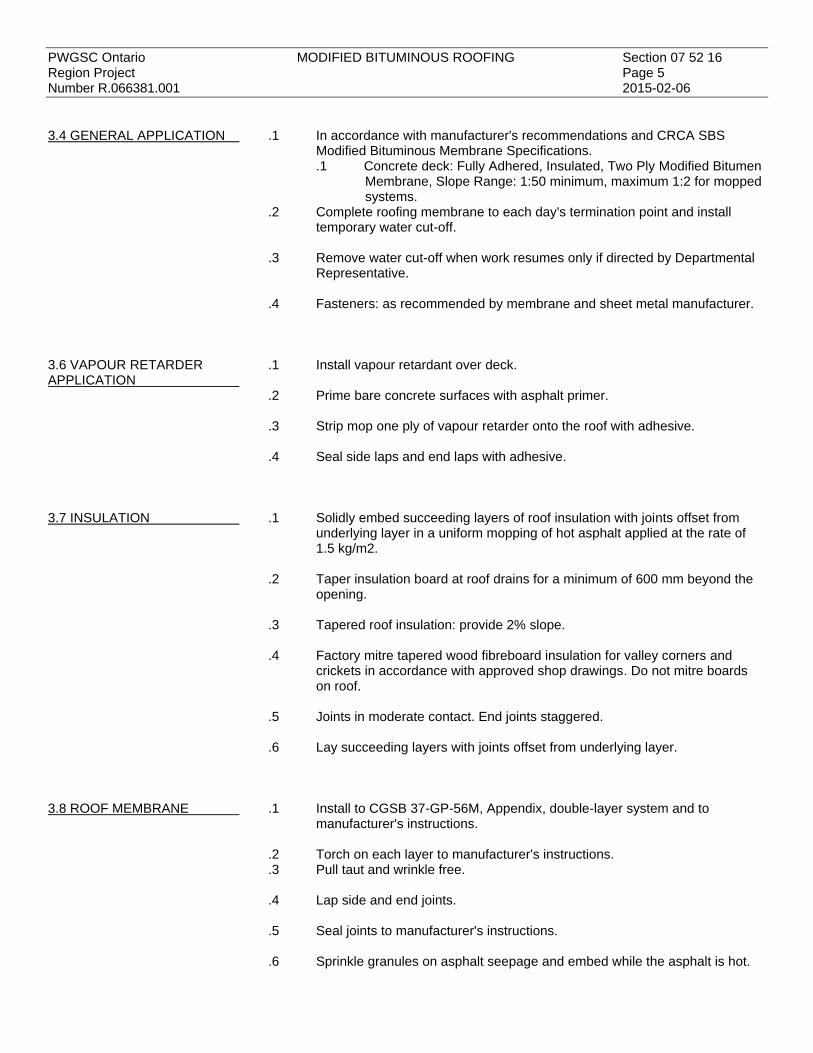
PWGSC Ontario MODIFIED BITUMINOUS ROOFING Section 07 52 16 Region Project Page 5 Number R.066381.001 2015-02-06
3.4 GENERAL APPLICATION
.1 In accordance with manufacturer's recommendations and CRCA SBS Modified Bituminous Membrane Specifications. .1 Concrete deck: Fully Adhered, Insulated, Two Ply Modified Bitumen
Membrane, Slope Range: 1:50 minimum, maximum 1:2 for mopped systems.
.2 Complete roofing membrane to each day's termination point and install temporary water cut-off.
.3 Remove water cut-off when work resumes only if directed by Departmental
Representative. .4 Fasteners: as recommended by membrane and sheet metal manufacturer.
3.6 VAPOUR RETARDER APPLICATION
.1 Install vapour retardant over deck. .2 Prime bare concrete surfaces with asphalt primer. .3 Strip mop one ply of vapour retarder onto the roof with adhesive. .4 Seal side laps and end laps with adhesive.
3.7 INSULATION
.1 Solidly embed succeeding layers of roof insulation with joints offset from underlying layer in a uniform mopping of hot asphalt applied at the rate of 1.5 kg/m2.
.2 Taper insulation board at roof drains for a minimum of 600 mm beyond the
opening. .3 Tapered roof insulation: provide 2% slope. .4 Factory mitre tapered wood fibreboard insulation for valley corners and
crickets in accordance with approved shop drawings. Do not mitre boards on roof.
.5 Joints in moderate contact. End joints staggered. .6 Lay succeeding layers with joints offset from underlying layer.
3.8 ROOF MEMBRANE
.1 Install to CGSB 37-GP-56M, Appendix, double-layer system and to manufacturer's instructions.
.2 Torch on each layer to manufacturer's instructions. .3 Pull taut and wrinkle free. .4 Lap side and end joints. .5 Seal joints to manufacturer's instructions. .6 Sprinkle granules on asphalt seepage and embed while the asphalt is hot.

PWGSC Ontario MODIFIED BITUMINOUS ROOFING Section 07 52 16 Region Project Page 6 Number R.066381.001 2015-02-06
3.9 MEMBRANE FLASHING
.1 Apply asphalt primer to vertical concrete and masonry surfaces to receive bitumen or metal flashing and allow to cure prior to application.
.2 Install to:
.1 CGSB 37-GP-56M, Appendix, double-layer system.
.2 Manufacturer's instructions.
.3 CRCA -2011 MBM flashing guidelines for modified bitumen membrane:
.3 Install pitch pockets and accessories in accordance with manufacturer's
written instructions.
3.10 METAL FLASHING
.1 Form to profile, free of oil canning. .2 Maximum 2400 mm length. .3 Square, plumb and in line to 1:400. .4 Double back exposed edges 13 mm. .5 Apply asphalt primer to metal flashing built into membrane. .6 Join metal flashing with evenly spaced, 25 mm wide, 'S' type seams. .7 Lock seam corner joints, do not rivet. .8 Extend to bottom of cant in moderate contact with roof membrane. .9 Nail concealed cleats in seams, minimum 200 mm above roof membrane. .10 Fasten into reglets with wedges at 450 mm centres. .11 Conceal fastenings. .12 Form pitch pocket and fill void with plastic cement as detailed. .13 Install to CRCA flashing guidelines for modified bitumen membrane
specified under membrane flashing.
3.11 PROJECTIONS
.1 Cut the membrane around the projection. .2 Set flange in plastic cement. .3 Flash around the flange with membrane flashing. .4 Extend cap sheet 225 mm beyond the flange and torch on. .5 Seal joints of the cap sheet and upstand of metal with sealant.

PWGSC Ontario MODIFIED BITUMINOUS ROOFING Section 07 52 16 Region Project Page 7 Number R.066381.001 2015-02-06
3.12 SEALANT
.1 Apply continuous bead to horizontal joints in metal flashing. .2 Apply continuous bead to top edge of metal flashing turned into reglet. .3 Apply to corner joints of metal flashing. .4 Apply to roof membrane at vent stacks, roof drains and pitch pockets as
detailed. .5 Clean and dry joints. .6 Mask adjoining surfaces to protect finishes. .7 Apply to manufacturer's instructions. .8 Form smooth, concave surfaces. .9 Remove masking tape and sealant smears from adjacent surfaces.
END


PWGSC Ontario JOINT SEALANTS Section 07 90 00 Region Project Page 1 Number R.066381.001 2015-02-06
PART 1 - GENERAL
1.1 REFERENCES
.1 ASTM International .1 ASTM C920-14a, Standard Specification for Elastomeric Joint
Sealants. .2 Canadian General Standards Board (CGSB) .1 CAN/CGSB 19.13-M87, Sealing Compound, One-Component,
Elastomeric, Chemical Curing. .2 CAN/CGSB 19.22-M89, Mildew-Resistant Sealing Compound for
Tubs and Tiles
1.2 ENVIRONMENTAL CHOICE PROGRAM
.1 Provide sealant products bearing the 'Ecologo' of the Environmental Choice Program, Department of the Environment, Canadian Environmental Protection Act, Environmental Choice Product Guidelines ECP/PCE-45-92 for Sealants and Caulking Compounds, except maximum VOC 60 g/L during application and curing.
.2 For primers and sealants, indicate VOC in g/L during application and curing.
1.3 PRODUCT DATA
.1 Submit manufacturer's literature indicating recommended surface preparation, sealant selection and primer for each substrate in accordance with Section 01 33 00.
PART 2 - PRODUCTS
2.1 SEALANTS
.1 Provide sealant products bearing Ecologo to ECP/PCE-45-92 with maximum VOC 60 g/L.
2.2 SEALANT MATERIAL DESIGNATIONS
.1 Exterior Silicones One Part '3'. .1 To ASTM C920, primerless, Type S, Grade NS, Class 50, SWRI
validated.
.2 Interior Silicones One Part. .1 To ASTM C920, primerless, Type S, Grade NT, Class 25,
CAN/CGSB 19.229. .3 Interior glazing sealant: one part silicone to ASTM C920, Type S, Grade NS,
Class 25, CAN/CGSB 19.13. .4 Interior sealant: one part silicone to ASTM C920, Type M, Grade NS,
Class 25, CAN/CGSB 19.13.

PWGSC Ontario JOINT SEALANTS Section 07 90 00 Region Project Page 2 Number R.066381.001 2015-02-06
2.3 SEALANT SELECTION
.1 Junction of exterior components (ie. metal flashing, steel): Designations 1. .2 Perimeters of interior frames, as detailed and itemized: Designations 4. .3 Interior masonry vertical control joints (block-to-block, block-to-concrete, and
intersecting masonry walls): Designations 1. .4 Perimeter of stainless steel base: Designations 2. .5 Interior glazing in metal frames: Designations 3.
2.4 JOINT CLEANER
.1 Non-corrosive and non-staining type, compatible with joint forming materials and sealant recommended by sealant manufacturer.
PART 3 - EXECUTION
3.1 PREPARATION OF JOINT SURFACES
.1 Examine joint sizes and conditions to establish correct depth to width relationship for installation of backup materials and sealants.
.2 Clean bonding joint surfaces of harmful matter substances including dust,
rust, oil grease, and other matter which may impair work. .3 Do not apply sealants to joint surfaces treated with sealer, curing
compound, water repellent, or other coatings unless tests have been performed to ensure compatibility of materials. Remove coatings as required.
.4 Ensure joint surfaces are dry and frost free. .5 Prepare surfaces in accordance with manufacturer's directions.
3.3 BACKUP MATERIAL
.1 Apply bond breaker tape where required to manufacturer's instructions. .2 Install joint filler to achieve correct joint depth and shape with approximately
30% compression.
3.4 MIXING
.1 Mix materials in accordance with sealant manufacturer's instructions.
3.5 APPLICATION
.1 Ventilate interior spaces during application and curing of sealants to maintain VOCs less than 50 g/l. Coordinate with building manager to ensure existing ventilation system or temporary ventilation supplies sufficient outside air.

PWGSC Ontario JOINT SEALANTS Section 07 90 00 Region Project Page 3 Number R.066381.001 2015-02-06
.2 Sealant. .1 Protect installed work of other trades from staining or contamination. .2 Apply sealant in accordance with manufacturer's application manual
and written instructions. .3 Mask edges of joint where irregular surface or sensitive joint border
exists to provide neat joint. remove tape after sealant applied. .4 Apply sealant in continuous beads. .5 Apply sealant using gun with proper size nozzle. .6 Use sufficient pressure to fill voids and joints solid. .7 Form surface of sealant with full bead, smooth, free from ridges,
wrinkles, sags, air pockets, embedded impurities. .8 Tool exposed surfaces before skinning begins to give slightly
concave shape.
.3 Curing. .1 Cure sealants in accordance with sealant manufacturer's
instructions. .2 Do not cover up sealants until proper curing has taken place.
.4 Cleanup. .1 Clean adjacent surfaces immediately and leave work neat and
clean. .2 Remove excess and droppings, using recommended cleaners as
work progresses. .3 Remove masking tape after initial set of sealant.
END


PWGSC Ontario STEEL HOLLOW METAL Section 08 11 13 Region Project DOORS AND FRAME Page 1 Project No. R.066381.001 2015-02-06
PART 1 - GENERAL
1.1 RELATED SECTIONS
.1 Section 01 33 00 - Submittal Procedures.
1.2 REFERENCES
.1 American National Standards Institute (ANSI): .1 ANSI/BHMA A156.16-2008, Auxiliary Hardware.
.2 American Society for Testing and Materials International (ASTM) .1 ASTM A568-11a/A568M-13ae1, Standard Specification for Steel,
Sheet, Carbon, Structural, and High-Strength, Low-Alloy, Hot-Rolled and Cold-Rolled, General Requirements for.
.2 ASTM A653/A653M-13, Standard Specification for Steel Sheet, Zinc-Coated (Galvanized) or Zinc-Iron Alloy-Coated (Galvannealed) by the Hot-Dip Process.
.3 Canadian General Standards Board (CGSB)
.1 CAN/CGSB-1.181-99, Ready-Mixed Organic Zinc-Rich Coating.
.4 Canadian Steel Door Manufacturers Association (CSDMA) www.csdma.org/english/publications.html .1 Recommended Dimensional Standards For Commercial Steel
Doors and Frames 2000. .2 Recommended Selection and Usage Guide for Commercial Steel
Door and Frame Products 2009. .3 Fire Labelling Guide 2009.
.5 National Fire Protection Association (NFPA) .1 NFPA 80-2010, Standard for Fire Doors and Other Opening
Protectives.
.6 Underwriters Laboratories Canada (ULC) .1 CAN/ULC-S104-10, Standard Method For Fire Tests of Door
Assemblies. .2 CAN/ULC-S105-09, Standard Specification for Fire Door Frames
Meeting the Performance Required by CAN/ULC-S104 .3 CAN/ULC S702-09-AM1, Standard for Thermal Insulation Mineral
Fibre for Buildings, Includes Amendment 1 (January 2012)
1.3 PRODUCT DATA SHEETS
.1 Submit product data sheets in accordance with Section 01 33 00.
1.4 QUALIFICATIONS
.1 The manufacturer of steel doors and frames supplied under this section will be a member of the CSDMA.

PWGSC Ontario STEEL HOLLOW METAL Section 08 11 13 Region Project DOORS AND FRAME Page 2 Project No. R.066381.001 2015-02-06
PART 2 - PRODUCTS
2.1 MATERIALS
.1 Metal: tension levelled sheet steel to ASTM A568/A568M, Class 1, with ZF075 zinc coating on both sides designation to ASTM A653/A653M, minimum 30% total recycled content.
.2 Door cores:
.1 Continuous interlocking steel ribs: 0.9 mm thick continuous interlocking steel stiffeners at 150 mm O.C., securely welded to each face sheet 150 mm O.C. maximum. .1 Voids between stiffeners Fibreglass: loose batt type,
density: 24 kg/m2 minimum, to CAN/ULC-S702, Type 1,
Ecologo certified. .3 Filler: polyester based. .4 Primer: zinc rich, organic, ready mix to CAN/CGSB-1.181, Ecologo certified. .5 Door bumpers: to ANSI/BHMA-A156.16, type L03011. .6 Gasket: self-adhering, closed cell foam of black vinyl copolymers. 7. Glass: 6 mm thick Georgian Wired Glass
2.2 FABRICATION
.1 To Canadian Steel Door Manufacturers Association (CSDMA), "Recommended Specifications for Commercial Steel Doors and Frames", "Recommended Dimensional Standards for Commercial Steel Doors and Frames" and CAN/ULC-S105 "Standard Specification for Fire Door Frames Meeting the Performance Required by CAN/ULC-S104".
.2 Doors: material thickness, opening classification and duty rating to CSDMA
"Recommended Selection and Usage Guide For Commercial Steel Doors", hollow steel construction, filled with insulation, edges continuously welded or filled and sanded flush with no visible seams.
.3 Frames: 1.6 mm steel, welded type. Anchors adjustable, type to suit each jamb condition.
.4 Glass mouldings: formed steel. .5 Temperature rise limit times for fire doors shall be listed on the ULC label. .6 Install 3 door bumpers on strike jamb of single doors.

PWGSC Ontario STEEL HOLLOW METAL Section 08 11 13 Region Project DOORS AND FRAME Page 3 Project No. R.066381.001 2015-02-06
PART 3 - EXECUTION
3.1 INSTALLATION
.1 Install frames, doors and hardware plumb, square and level in accordance with manufacturer's instructions and templates.
.2 Install labelled steel fire rated doors and frames to NFPA 80. .3 Provide even margins between doors and jambs and doors and flooring and
thresholds as follows: .1 Hinge side: 1.0 mm. .2 Latch side and head: 1.5 mm. .3 Flooring and thresholds: 13 mm.
.4 Secure anchorages and connections to adjacent construction. .5 Touch-up with primer scratched or damaged zinc finish.
END

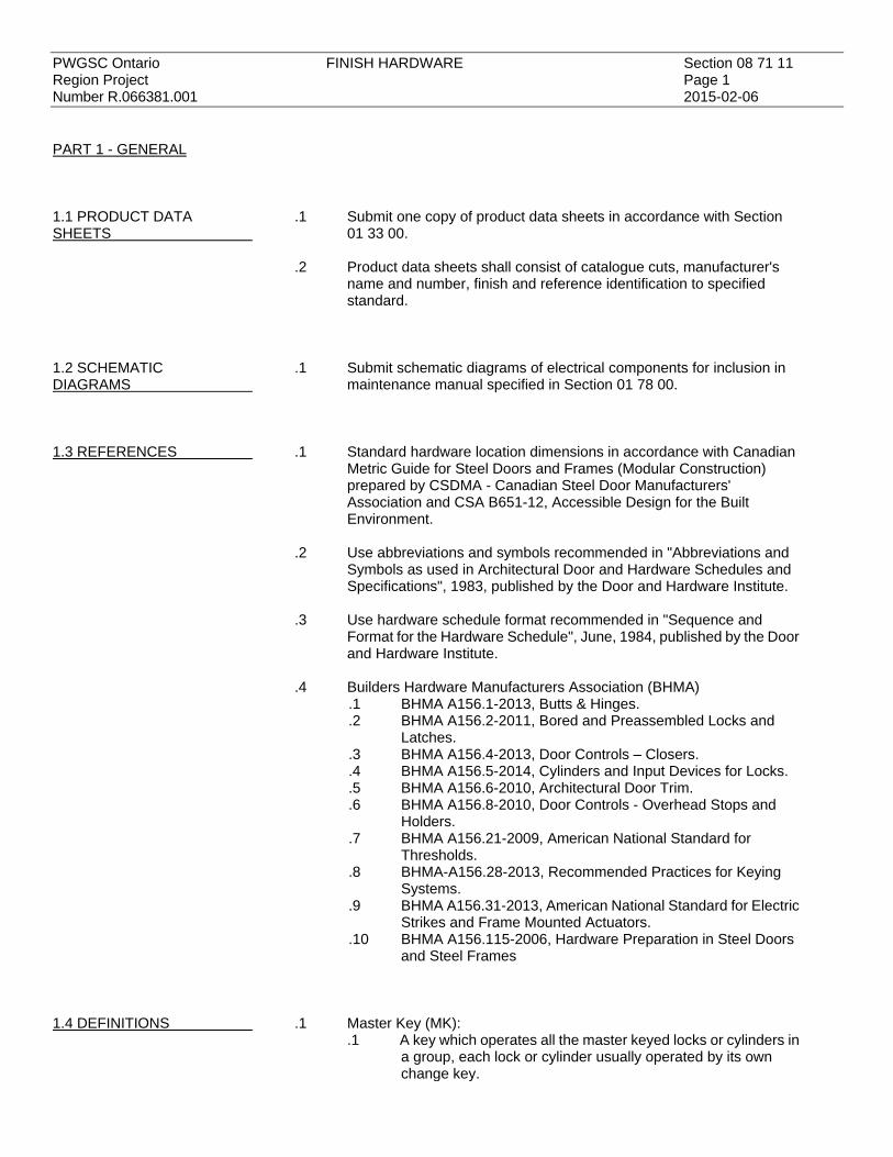
PWGSC Ontario FINISH HARDWARE Section 08 71 11 Region Project Page 1 Number R.066381.001 2015-02-06
PART 1 - GENERAL
1.1 PRODUCT DATA SHEETS
.1 Submit one copy of product data sheets in accordance with Section 01 33 00.
.2 Product data sheets shall consist of catalogue cuts, manufacturer's
name and number, finish and reference identification to specified standard.
1.2 SCHEMATIC DIAGRAMS
.1 Submit schematic diagrams of electrical components for inclusion in maintenance manual specified in Section 01 78 00.
1.3 REFERENCES
.1 Standard hardware location dimensions in accordance with Canadian Metric Guide for Steel Doors and Frames (Modular Construction) prepared by CSDMA - Canadian Steel Door Manufacturers' Association and CSA B651-12, Accessible Design for the Built Environment.
.2 Use abbreviations and symbols recommended in "Abbreviations and
Symbols as used in Architectural Door and Hardware Schedules and Specifications", 1983, published by the Door and Hardware Institute.
.3 Use hardware schedule format recommended in "Sequence and
Format for the Hardware Schedule", June, 1984, published by the Door and Hardware Institute.
.4 Builders Hardware Manufacturers Association (BHMA) .1 BHMA A156.1-2013, Butts & Hinges. .2 BHMA A156.2-2011, Bored and Preassembled Locks and
Latches. .3 BHMA A156.4-2013, Door Controls – Closers. .4 BHMA A156.5-2014, Cylinders and Input Devices for Locks. .5 BHMA A156.6-2010, Architectural Door Trim. .6 BHMA A156.8-2010, Door Controls - Overhead Stops and
Holders. .7 BHMA A156.21-2009, American National Standard for
Thresholds. .8 BHMA-A156.28-2013, Recommended Practices for Keying
Systems. .9 BHMA A156.31-2013, American National Standard for Electric
Strikes and Frame Mounted Actuators. .10 BHMA A156.115-2006, Hardware Preparation in Steel Doors
and Steel Frames
1.4 DEFINITIONS
.1 Master Key (MK): .1 A key which operates all the master keyed locks or cylinders in
a group, each lock or cylinder usually operated by its own change key.

PWGSC Ontario FINISH HARDWARE Section 08 71 11 Region Project Page 2 Number R.066381.001 2015-02-06
.2 To combinative a group of locks or cylinders such that each is operated by its own key as well as by a master key for the entire group.
.2 Master Key System:
.1 Any keying arrangement which has two or more levels of keying.
.2 A keying arrangement which has exactly two levels of keying.
1.5 REGULATORY REQUIREMENTS
.1 Use ULC listed and labelled hardware for doors in fire rated partitions and fire exits.
1.6 HARDWARE LIST
.1 Submit hardware schedule in accordance with Section 01 11 00. .2 Submit literature cuts, indicating hardware proposed, including make,
model, base material, function, ANSI Function where ANSI used in this specification, Grade, Type, Series, BHMA finish, trim, ULC listing, UL listing, manufacturer and other pertinent information. Indicate which model or accessory is being provided where more than one model or accessory appears on a page.
PART 2 - PRODUCTS
2.1 KEYING, ACCESSORIES AND FINISH
.1 Each lock different key under existing master key MK, 2 keys per lock. .1 Keying systems: to BHMA-A156.28.
.2 Provide accessories with hardware. .3 626 finish (satin chrome plated on brass or bronze) unless noted
otherwise. .4 Finish fasteners to match the exposed surface on which they appear. .5 Provide temporary construction keying. .6 Final keying: to BHMA-A156.5, Grade 1. .7 Security cylinder (interchangeable core): 7 pin, brass, restricted
keyway, key duplication by registered signatures only.
.8 Use lock and latch sets with solid metal, U shape, lever handles meeting requirements of CSA B651, Accessible Design for the Built Environment, clause 5.2.7 Door Hardware and Figure 20, unless specified otherwise.
.9 Provide lever handles of same style for bored and mortise locksets. .10 Door prep: to BHMA A156.115 for steel doors and frames.

PWGSC Ontario FINISH HARDWARE Section 08 71 11 Region Project Page 3 Number R.066381.001 2015-02-06
2.2 MATERIALS
.1 Hinge: to BHMA A156.1, Grade indicated, 626 satin chrome, use anti-friction (ball) bearing hinges with closers, one hinge for each 750 mm of door height, 115 mm hinges on 45 mm doors, button tips, non-removable pins. .1 Interior:
.1 Grade 1: A8111 - heavy weight, steel, 4 ball bearing. .2 Door closer: to BHMA A156.4, Grade 1, C02021 parallel arm mounting,
surface closer, modern type with cover, sprayed enamel finish, metallic 689 aluminum, size to suit door width and mass, hold-open arm. Disabled access doors: to operate at a minimum pressure not exceeding 38 N for exterior doors, 22 N for interior doors and close in not less than 5 seconds from an open position of 90°.
.3 Overhead stop: to BHMA- A156.8, concealed slide type, 110° opening,
stop and shock absorber effective at all times. Function C01511 Type 1 concealed.
.4 Lock and latch set : to BHMA- A156.2, Series 4000, Grade 1, bolted
through door, ANSI door prep BHMA-A156.115 for steel doors and frames, function indicated, 626 satin chrome, UL 437 listed cylinder.
.5 Electric strikes: to BHMA-A156.31, Grade 1, fail safe, 4.8 mm
horizontal adjustment capability, silent operation, E59321 - Mortised: for use with locks not having dead bolts.
.6 Kick plate: to BHMA-A156.6, type J103 stainless steel, 1.55 x 250 mm
x door width, 3 bevelled edges. .7 Threshold: to BHMA-A156.21, type J32190, 150 mm wide, aluminum
serrated exposed surface, finish 628. .8 Weatherstrip: extruded aluminum, mill finish, surface screw, non-rigid,
extruded vinyl chloride polymer or copolymer bulb at head and jamb: .9 Automatic door bottom (surface mounted): operable and automatic
door seal of aluminum frame and neoprene seal, automatic retract mechanism when door is open, listed and labelled for use in 90 min. fire doors.
PART 3 - EXECUTION
3.1 HARDWARE SCHEDULE
.1 Indicated hardware quantities are for one door only; provide this
quantity for each door listed. .
.2 Equip interior single door D1 with: .1 1-1/2 pair hinges, Grade 1, A8111. .2 1 card reader (conduit infrastructure only). .3 1 electric strike. .4 1 wall mounted request to exit (mounted in Air Lock)

PWGSC Ontario FINISH HARDWARE Section 08 71 11 Region Project Page 4 Number R.066381.001 2015-02-06
.5 1 lock and latch set (mortised), function F05, Grade 1, Classroom Lock. Latch bolt operated by knob from either side except when outside knob is locked from outside by key. When outside knob is locked, latch bolt is operated by key in outside knob or card reader or by rotating inside knob.
.6 1 set weatherstrip/sound seal gasketing.
.7 1 automatic door bottom seal.
.8 2 kickplate (one on each side of door).
.9 1 door closer.
.10 1 floor stop. .3 Equip interior single door D2 with:
.1 1-1/2 pair hinges, Grade 1, A8111.
.2 1 electric strike.
.3 1 wall mounted request to enter (mounted in Air Lock)
.4 1 wall mounted request to exit (mounted on lab side)
.5 1 lock and latch set (mortised), function F05, Grade 1, Classroom Lock. Latch bolt operated by knob from either side except when outside knob is locked from outside (Air Lock side) by key. When outside knob is locked, latch bolt is operated by key in outside knob or by rotating inside knob.
.6 1 set weatherstrip/sound seal gasketing.
.7 1 automatic door bottom seal.
.8 2 kickplate (one on each side of door).
.9 1 door closer.
.10 1 floor stop. .4 Equip interior single door D3 with:
.1 1-1/2 pair hinges, Grade 1, A8111.
.2 1 lock and latch set including deadbolt (mortised), function F05, Grade 1, Classroom Lock. Latch bolt operated by knob from either side except when outside knob is locked from outside by key. When outside knob is locked, latch bolt is operated by key in outside knob or by rotating inside knob.
.3 1 set weatherstrip/sound seal gasketing.
.4 1 automatic door bottom seal.
.5 2 kickplate (one on each side of door).
.6 1 door closer.
END

PWGSC Ontario PARTITIONS FOR MINOR WORKS Section 09 21 99 Region Project Page 1 Number R.066381.001 2015-02-06
PART 1 - GENERAL
1.1 REFERENCES
.1 ASTM International .1 ASTM C475/C475M-02(2007), Standard Specification for Joint
Compound and Joint Tape for Finishing Gypsum Board. .2 ASTM C645-09a, Standard Specification for Non-structural Steel
Framing Members. .3 ASTM C754-09a, Standard Specification for Installation of Steel
Framing Members to Receive Screw-Attached Gypsum Panel Products.
.4 ASTM C840-08, Standard Specification for Application and Finishing of Gypsum Board.
.5 ASTM C954-10, Standard Specification for Steel Drill Screws for the Application of Gypsum Panel Products or Metal Plaster Bases to Steel Studs from 0.033 in. (0.84 mm) to 0.122 in. (2.84 mm) in Thickness.
.6 ASTM C1047-10, Standard Specification for Accessories for Gypsum Wallboard and Gypsum Veneer Base.
.7 ASTM C1396/C1396M-09a, Standard Specification for Gypsum Wallboard.
.2 South Coast Air Quality Management District (SCAQMD), California State, Regulation XI. Source Specific Standards .1 SCAQMD Rule 1168-A2005, Adhesives and Sealants Applications.
.3 Underwriters' Laboratories of Canada (ULC) .1 CAN/ULC-S102-07, Standard Method of Test for Surface Burning
Characteristics of Building Materials and Assemblies.
1.2 ACTON AND INFORMATIONAL SUBMITTALS
.1 Submit in accordance with Section 01 33 00. .2 Product Data:
.1 Submit manufacturer's instructions, printed product literature and data sheets for gypsum, framing, sealants and include product characteristics, performance criteria, physical size, finish and limitations.
1.3 DELIVERY, STORAGE AND HANDLING
.1 Deliver, store and handle materials in accordance with Section 01 61 00 and with manufacturer's written instructions.
.2 Delivery and Acceptance Requirements: deliver materials to site in original
factory packaging, labelled with manufacturer's name and address. .3 Storage and Handling Requirements:
.1 Store materials indoors in dry location and in accordance with manufacturer's recommendations in clean, dry, well-ventilated area.
.2 Store materials inside, level, under cover. Protect from weather, damage from construction operations and other causes, in accordance with manufacturer's printed instructions.
.3 Handle materials to prevent damage to edges or surfaces. Protect metal accessories and trim from being bent or damaged.

PWGSC Ontario PARTITIONS FOR MINOR WORKS Section 09 21 99 Region Project Page 2 Number R.066381.001 2015-02-06
.4 Store and protect partition materials from nicks, scratches, and blemishes.
.5 Replace defective or damaged materials with new.
PART 2 - PRODUCTS
2.1 MATERIALS
.1 Performance / Design Criteria: .1 Partition assembly to be non-combustible construction fire
resistance rated ULC Des W453 and as detailed. .2 Non-structural Metal Framing:
.1 Non-load bearing channel stud framing: to ASTM C645, roll formed from 0.63 mm thickness hot dipped galvanized steel sheet, for screw attachment of gypsum board. Knock-out service holes at 460 mm centres.
.2 Floor and ceiling tracks: to ASTM C645, in widths to suit stud sizes, 41 mm flange height.
.3 Metal channel stiffener: 19 x 1.4 mm thick cold rolled steel, coated with rust inhibitive coating.
.3 Gypsum Board:
.1 Standard board: to ASTM C1396/C1396M, regular, 13 mm plain and 16 mm Fire Code, 1200 mm wide x maximum practical length, ends square cut, edges tapered.
.2 Metal furring runners, hangers, tie wires, inserts, anchors: to ASTM C1047.
.3 Drywall furring channels: 0.5 mm core thickness galvanized steel channels for screw attachment of gypsum board.
.4 Steel screws: to ASTM C954.
.5 Casing beads, corner beads, control joints and edge trim: to ASTM C1047, zinc-coated by electrolytic process, 0.5 mm base thickness, perforated flanges, one piece length per location.
2.2 ACCESSORIES
.1 Sealants: to ASTM C475. .1 VOC limit 250 g/L maximum to SCAQMD Rule 116.
PART 3 - EXECUTION
3.1 EXAMINATION
.1 Verification of Conditions: verify conditions of substrates previously installed under other Sections or Contracts are acceptable for product installation in accordance with manufacturer's written instructions prior to partition installation. .1 Inform Departmental Representative of unacceptable conditions
immediately upon discovery.
.2 Proceed with installation only after unacceptable conditions have been remedied.

PWGSC Ontario PARTITIONS FOR MINOR WORKS Section 09 21 99 Region Project Page 3 Number R.066381.001 2015-02-06
3.2 ERECTION OF FRAMING .1 Install steel framing members to receive screw-attached gypsum board in
accordance with ASTM C754 except where specified otherwise. .2 Align partition tracks at floor and ceiling and secure at 600 mm on centre
maximum. .3 Place studs vertically at 300 mm on centre and maximum of 12 mm from
abutting walls, and at each side of openings and corners. Position studs in tracks at floor and ceiling. Cross brace steel studs as required to provide rigid installation to manufacturer's instructions.
.4 Erect metal studding to tolerance of 1:1000. .5 Co-ordinate simultaneous erection of studs with installation of service lines.
When erecting studs ensure web openings are aligned.
.6 Include two studs extending from floor to ceiling at each side of openings
wider than stud centres specified. Secure studs together, 50 mm apart using column clips or other approved means of fastening placed alongside frame anchor clips.
.7 Install heavy gauge single jamb studs at openings. .8 Erect track at head of door/window openings and sills of sidelight/window
openings to accommodate intermediate studs. Secure track to studs at each end, in accordance with manufacturer's instructions. Install intermediate studs above and below openings in same manner and spacing as wall studs.
.9 Include 40 mm stud or furring channel secured between studs for
attachment of fixtures behind lavatory basins, toilet and bathroom accessories, and other fixtures including grab bars and towel rails, attached to steel stud partitions.
.10 Install steel studs or furring channel between studs for attaching electrical
and other boxes. .11 Extend partitions to ceiling height except where indicated. .12 Maintain clearance under beams and structural slabs to avoid transmission
of structural loads to studs. Use double track slip joint. .13 Install continuous insulating strips to isolate studs from uninsulated
surfaces. .14 Install horizontal stud framing at stud space adjacent door at 1200 mm and
2450 mm above finish floor.
3.3 ERECTION OF GYPSUM BOARD AND ACCESSORIES
.1 Do application and finishing of gypsum board in accordance with ASTM
C840 except where specified otherwise. .2 Erect hangers and runner channels for suspended gypsum board ceilings in
accordance with ASTM C840 except where specified otherwise.

PWGSC Ontario PARTITIONS FOR MINOR WORKS Section 09 21 99 Region Project Page 4 Number R.066381.001 2015-02-06
.3 Support light fixtures by providing additional ceiling suspension hangers within 150 mm of each corner and at maximum 600 mm around perimeter of fixture.
.4 Frame with furring channels, perimeter of openings for access panels, light
fixtures, diffusers, grilles. .5 Furr for gypsum board faced vertical bulkheads within and at termination of
ceilings. .6 Furr above suspended ceilings for gypsum board fire and sound stops and
to form plenum areas as indicated. .7 Install wall furring for gypsum board wall finishes in accordance with ASTM
C840, except where specified otherwise. .8 Install acoustical insulation and sealant in sound rated partitions to
correspond with tested assembly. .9 Install gypsum boards in direction that will minimize number of end-butt
joints. Stagger end joints 250 mm minimum.
3.4 APPLICATION
.1 Apply gypsum board after bucks, anchors, blocking, sound attenuation, electrical and mechanical work are approved.
.2 Apply gypsum board to metal furring or framing using screw fasteners.
Maximum spacing of screws 300 mm on centre.
3.5 INSTALLATION .1 Erect accessories straight, plumb or level, rigid and at proper plane. Use full length pieces where practical. Make joints tight, accurately aligned and rigidly secured. Mitre and fit corners accurately, free from rough edges. Secure at 150 mm on centre.
.2 Install casing beads around perimeter of suspended ceilings. .3 Install casing beads where gypsum board butts against surfaces having no
trim concealing junction and where indicated. Seal joints with sealant. .4 Install insulating strips continuously at edges of gypsum board and casing
beads abutting metal window and exterior door frames, to provide thermal break.
.5 Install access doors to electrical and mechanical fixtures specified in
respective sections. .1 Rigidly secure frames to furring or framing systems.
.6 Finish face panel joints and internal angles with joint system consisting of
joint compound, joint tape and taping compound installed according to manufacturer's directions and feathered out onto panel faces.

PWGSC Ontario PARTITIONS FOR MINOR WORKS Section 09 21 99 Region Project Page 5 Number R.066381.001 2015-02-06
.7 Finish corner beads, control joints and trim as required with two coats of joint compound and one coat of taping compound, feathered out onto panel faces.
.8 Fill screw head depressions with joint and taping compounds to bring flush
with adjacent surface of gypsum board so as to be invisible after surface finish is completed.
.9 Completed installation to be smooth, level or plumb, free from waves and
other defects and ready for surface finish.
3.6 CLEANING
.1 Progress Cleaning: clean in accordance with Section 01 74 11. .1 Leave Work area clean at end of each day.
.2 Final Cleaning: upon completion remove surplus materials, rubbish, tools
and equipment in accordance with Section 01 74 11.
3.7 PROTECTION .1 Protect installed products and components from damage during construction.
.2 Repair damage to adjacent materials caused by partition installation.
END


PWGSC Ontario ACOUSTIC TILE CEILINGS Section 09 51 23 Region Project Page 1 Number. R.066381.001 2015-02-06
PART 1 - GENERAL
1.1 REFERENCES .1 ASTM International .1 ASTM C635/C635M-13a, Standard Specification for the
Manufacture, Performance, and Testing of Metal Suspension Systems for Acoustical Tile and Lay-in Panel Ceilings.
.2 ASTM C636/C636M-13, Standard Practice for Installation of Metal Ceiling Suspension Systems for<brk/> Acoustical Tile and Lay-In Panels.
1.2 CERTIFICATES
.1 Submit certificate stating that suspended ceiling systems provide adequate support for electrical fixtures, as required by current bulletin of Electrical Inspection Department of Ontario Hydro.
.2 Submit duplicate 300 x 300 samples of each acoustical unit and 300 long
sample of ceiling grid. .3 Submit shop drawings stamped and signed by professional engineer licensed
in Province of Ontario indicating grid lay-out, insert and spacing and fastening details, splicing method for main and cross runners, and acoustical unit and ceiling system support.
.4 Submit manufacturer's instructions, printed product literature and data sheets
for acoustical suspension and units and include product characteristics, performance criteria, physical size, finish and limitations.
PART 2 - PRODUCTS
2.1 MATERIALS
.1 Heavy duty system to ASTM C635/C635M. Manufacture, Performance, and Testing of Metal Suspension Systems for Acoustical Tile and Lay-in Panel Ceilings.
.2 Acoustic units for suspended ceiling system and suitable for Class 10,000
clean room. .1 Top and Face plates: Aluminum alloy 5052-H32, 0.83 mm thick .2 Core: aluminum honeycomb, 13 mm cell size. .3 Adhesive: Panels are bonded using 100% solids epoxy .4 Size: to fit grid spacing of 610 x 1220 mm. .5 Thickness: 6 mm .6 Shape: flat. .7 Colour: gloss white
.3 Clean room ceiling suspension: .1 Ceiling grid and suspension: The grid system shall be 50 mm
extruded aluminum alloy 6063, temper T5 with a clear anodized finish. Grid profile shall have a continuous integral screw boss within the web for attachment of intersection connectors. Cross tees to have
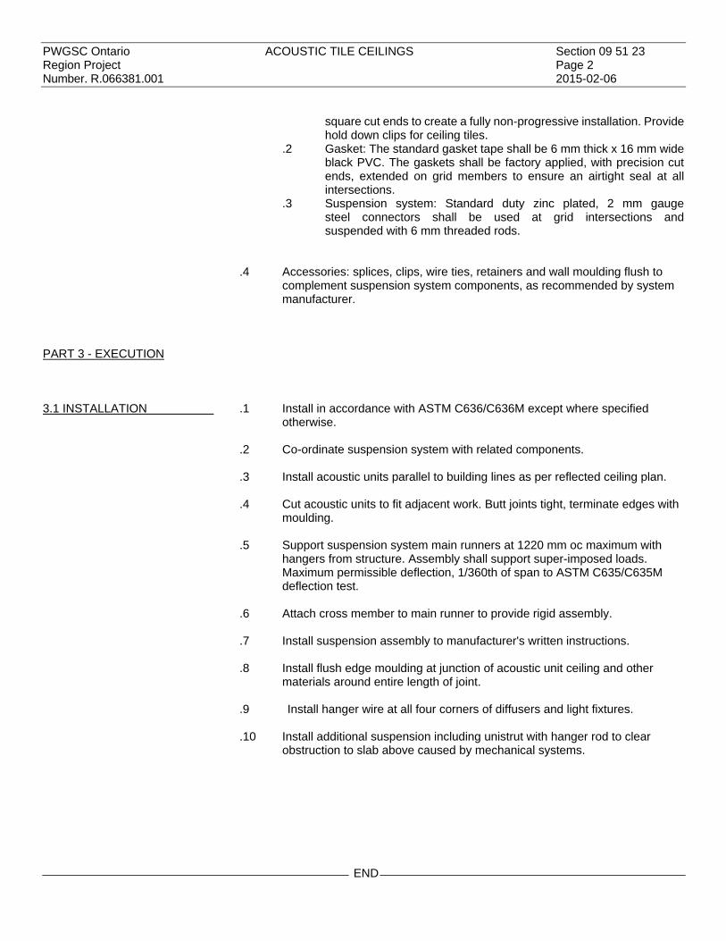
PWGSC Ontario ACOUSTIC TILE CEILINGS Section 09 51 23 Region Project Page 2 Number. R.066381.001 2015-02-06
square cut ends to create a fully non-progressive installation. Provide hold down clips for ceiling tiles.
.2 Gasket: The standard gasket tape shall be 6 mm thick x 16 mm wide black PVC. The gaskets shall be factory applied, with precision cut ends, extended on grid members to ensure an airtight seal at all intersections.
.3 Suspension system: Standard duty zinc plated, 2 mm gauge steel connectors shall be used at grid intersections and suspended with 6 mm threaded rods.
.4 Accessories: splices, clips, wire ties, retainers and wall moulding flush to
complement suspension system components, as recommended by system manufacturer.
PART 3 - EXECUTION
3.1 INSTALLATION
.1 Install in accordance with ASTM C636/C636M except where specified otherwise.
.2 Co-ordinate suspension system with related components. .3 Install acoustic units parallel to building lines as per reflected ceiling plan. .4 Cut acoustic units to fit adjacent work. Butt joints tight, terminate edges with
moulding. .5 Support suspension system main runners at 1220 mm oc maximum with
hangers from structure. Assembly shall support super-imposed loads. Maximum permissible deflection, 1/360th of span to ASTM C635/C635M deflection test.
.6 Attach cross member to main runner to provide rigid assembly. .7 Install suspension assembly to manufacturer's written instructions. .8 Install flush edge moulding at junction of acoustic unit ceiling and other
materials around entire length of joint. .9 Install hanger wire at all four corners of diffusers and light fixtures. .10 Install additional suspension including unistrut with hanger rod to clear
obstruction to slab above caused by mechanical systems.
END

PWGSC Ontario INTERIOR PAINTING Section 09 91 23 Region Project Page 1 Number R.066381.001 2015-02-06
PART 1 - GENERAL
1.1 REFERENCES
.1 Architectural Painting Specification Manual, Canadian Paint and Contractors Association (CPCA), 2000 plus amendments.
.2 CAN/CGSB-85.100-93, Painting.
1.2 SUBMITTALS
.1 Submit product data and manufacturer's installation/application instructions for each paint and coating product to be used in accordance with the requirements of Section 01 33 00.
.2 Submit gray range colour sample chips for review and selection. Indicate
where colour availability is restricted. Indicate gloss. .3 Submit WHMIS MSDS - Material Safety Data Sheets for paint and coating
materials in accordance with Section 01 33 00. .4 Upon completion, submit records of products used. List products in relation to
finish system and include the following: .1 Product name, type and use (i.e. materials and location). .2 Manufacturer's product number. .3 Colour code numbers. .4 Environment Canada Ecologo classification. .5 Manufacturer's Material Safety Data Sheets (MSDS). Indicate
VOC's in g/L. .6 CPCA approved product numbers.
1.3 ENVIRONMENTAL CHOICE PROGRAM
.1 Provide paint products bearing the 'Ecologo' of the Environmental Choice Program, Department of the Environment, Canadian Environmental Protection Act, Environmental Choice Product Guidelines CCD-047A - Paints, CCD-048 - Surface Coatings - Recycled Water-borne.
.2 Submit written proof in the form of CSA Certification Reports of Certification
under the Environmental Choice Program in accordance with Section 01 33 00 when requested. Alternatively, material in original containers bearing the 'Ecologo' will satisfy this requirement.
1.4 INTERIOR PAINT GLOSS TERMS
.1 Gloss terms: to ASTM D523-08 shall have following values:
Gloss Term Gloss Value Flat 0 to 10 Eggshell (Satin) 15 to 25 Semi-Gloss 45 to 55 Gloss, medium 60 to 80 Gloss, high 80 to 90

PWGSC Ontario INTERIOR PAINTING Section 09 91 23 Region Project Page 2 Number R.066381.001 2015-02-06
1.5 QUALITY CONTROL
.1 Provide a mock-up in accordance with requirements of Section 01 33 00, Departmental Representative and Paint Inspection Agency. Obtain CPCA Inspector's Cross Hatch Test Report prior to installation of mock-up.
.2 Prepare and repaint mock-up designated interior floor area, surface or item to
requirements specified herein, with specified paint or coating showing selected colour, gloss/sheen, textures and workmanship to Departmental Representative for review and approval.
.3 When approved, repainted room, surface and/or item shall become
acceptable standard of finish quality and workmanship for similar on-site interior repainting work.
1.6 VENTILATION
.1 Ventilate area of work as directed by Departmental Representative by use of approved portable supply and exhaust fans. Provide continuous ventilation during and after application of paint. Run ventilation system 24 hours per day during installation at 30% outside air; provide continuous ventilation for 7 days after completion of application of paint in accordance with Section 01 11 00.
PART 2 - PRODUCTS
2.1 INTERIOR MATERIAL AND SYSTEM
.1 Concrete Masonry Units: .1 INT 4.2G – Epoxy (tile-like) finish. .2 INT 4.2A – (Corridor walls) Latex.
.2 Metal Doors and Frames.
.1 INT 5.3K W.B. Light Industrial Coating, G5 finish. .1 One (1) coat bonding primer – MPI #17. .2 Two (2) coats waterborne light industrial coating – MPI #153
(G5). .3 Plaster and Gypsum Board: gypsum wallboard, drywall, "sheet rock type
material", etc., and textured finishes .1 INT 9.2E – (walls and ceilings) Epoxy (tile-like) finish.
PART 3 - EXECUTION
3.1 SURFACES PREPARATION
.1 To CAN/CGSB-85.100, CPCA Manual and as follows: .2 Interior existing masonry walls- sound paint surfaces:
.1 Wash area to be painted with water; use a mild detergent solution if necessary and rinse thoroughly until all detergent has been removed, and allow to dry.
.2 Use hand cleaning system exclusively. \

PWGSC Ontario INTERIOR PAINTING Section 09 91 23 Region Project Page 3 Number R.066381.001 2015-02-06
.3 Acceptable hand-tools are scrapers, wire brushes, sandpaper, steel wool, and dusters.
.4 Modify preparation as required based on results of Cross Hatch Test and mock-up.
3.2 APPLICATION
.1 Paint items as specified and/or indicated on drawings and schedules. .2 Paint items in accordance with the requirements set out in the CPCA
Architectural Specification Manual, and CAN/CGSB-85.100, Painting. .3 Brush or roll on finish to smooth, even, uniform surface.
END


PWGSC Ontario SEAMLESS FLOOR COATING Section 09 96 00 Region Project FOR LABORATORY Page 1 Number R.066381.001 2015-02-06
PART 1 - GENERAL
1.1 REFERENCES
.1 ASTM International .1 ASTM C307-03(2012), Standard Test method for Tensile Strength
of Chemical-resistant Mortar, Grouts and Monolithic Surfacings. .2 ASTM C579-01(2012), Standard Test Methods for Compressive
Strength of Chemical-Resistant Mortars, Grouts, Monolithic Surfacings, and Polymer Concretes.
.3 ASTM C580-02(2012) Standard Test Method for Flexural Strength and Modulus of Elasticity of Chemical-Resistant Mortars, Grouts, Monolithic Surfacings, and Polymer Concretes.
.4 ASTM C1028-07, Standard Test Method for Determining the Static Coefficient of Friction of Ceramic Tile and Other Like Surfaces by the Horizontal Dynamometer Pull Meter Method.
.5 ASTM D570-98(2010)e1, Standard Test Method for Water Absorption of Plastices.
.6 ASTM D635-10, Standard Test Method for Rate of Burning and/or Extent and Time of Burning of Plastics in a Horizontal Position.
.7 ASTM D2240(2010), Standard Test Method for Rubber Property-Durometer Hardness.
.8 ASTM D4060-10, Standard Test Method for Abrasion Resistance of Organic Coatings by the Taber Abraser.
.9 ASTM D5420-10, Standard Test Method for Impact Resistance of Flat, Rigid Plastic Specimen by Means of a Striker Impacted by a Falling Weight (Gardner Impact).
.10 ASTM D4541-09e1, Standard Test Method for Pull-Off Strength of Coatings Using Portable Adhesion Testers.
.9 CAN/ULC-S102-10, Standard Method of Test for Surface Burning
Characteristics of Building Materials and Assemblies.
1.2 PRODUCT DATA SHEETS
1 Submit product data sheets in accordance with Section 01 33 00 and 01 78 00.
1.3 WHMIS
.1 Submit two copies of MSDS - Material Safety Data Sheets to Departmental Representative.
.2 Indicate VOC's during application and curing. .3 Enforce use of personal protective equipment required by MSDS.
1.4 SAMPLES
.1 Submit samples in accordance with Section 01 33 00 and 01 78 00. .2 Submit duplicate 400 x 200 mm samples of each colour and finish coating
applied to concrete floor.

PWGSC Ontario SEAMLESS FLOOR COATING Section 09 96 00 Region Project FOR LABORATORY Page 2 Number R.066381.001 2015-02-06
1.5 QUALIFICATIONS
.1 Applied by applicator trained and licensed by epoxy material manufacturer for application of its products.
.2 Manufacturer's representative:
.1 Inspect substrate prior to commencement of work, during application of materials and upon completion of work.
.2 Provide technical assistance to the applicator and assist where required in correct installation of floor base coat mortar and floor top coat sealer.
1.6 ENVIRONMENTAL REQUIREMENTS
.1 Do not apply epoxy systems unless uniform minimum 16°C air temperature at installation area for 24 hours prior to and after application.
.2 Provide adequate ventilation or isolation measures to protect against toxic
fumes. .1 Ventilate area 24 hours per day, during installation and for 7 days
after installation is completed with minimum 30% outside air. .2 Ventilate at a rate sufficient to produce a negative pressure in the
work area and exhaust direct to the outside of the building. Do not re-circulate contaminants within the building.
1.7 MAINTENANCE DATA
.1 Provide maintenance data for coatings for incorporation into manual specified in Section 01 33 00 and 01 78 00.
PART 2 - PRODUCTS
2.1 MATERIALS
.1 Ensure compatibility for all epoxy materials including primers, resins, hardening agents, finish coats and sealer coats.
.2 All epoxy materials from same manufacturer. .4 Aggregate: silica sand to coating manufacturer's requirements.
2.2 FLOOR SYSTEM STANDARD EPOXY
.1 Floor system A: broadcast application. .1 Primer: as recommended by manufacturer. .2 Body coat: 2 part epoxy, 100% solids, minimum 3 mm thick, grey
colour and texture selected by Departmental Representative. .1 Compressive strength: to ASTM C579, 65 MPa. .2 Tensile strength: to ASTM C307, 5-6 mm/min., 17 MPa. .3 Flexural strength: to ASTM C580, 21.5 MPa. .4 Hardness: to ASTM D2240, shore D durometer 81. .5 Abrasion resistance: to ASTM D4060, H22 wheels,
1000 gm/wheel, 2464 mg maximum weight loss, 0.73 mm groove.
.6 Coefficient of friction: to ASTM C1028, 15.3 cm/min., dry 1.42, wet 1.23.

PWGSC Ontario SEAMLESS FLOOR COATING Section 09 96 00 Region Project FOR LABORATORY Page 3 Number R.066381.001 2015-02-06
.7 Flammability: to ASTM D635, 30 sec flame exposure: 19 mm, burning rate: 27.3 mm/minute; to CAN/ULC-S102, flame spread 31, smoked developed 195.
.8 Water absorption: to ASTM D570, 0.14%, 24 hrs. immediately.
.9 Impact resistance: to ASTM D5420, on concrete, minimum 5.3 J.
.3 Top coat: chemical resistant, anti-skid fine texture.
2.3 MIXES
.1 Mix floor base coat mortar and top coat sealer in accordance with manufacturer's written instructions.
PART 3 - EXECUTION
3.1 PREPARATION OF SURFACES
.1 Prepare surfaces in accordance with manufacturer's instructions. .2 Remove oil, dirt and grease with industrial detergent, as recommended by
epoxy manufacturer’s representative. .3 Mask surrounding surfaces to provide neat, clean juncture lines. .4 Protect adjacent surfaces and equipment from damage by overspray. .5 Complete work penetrating substrate before installing coating.
3.2 PREPARATION OF FLOORS
.1 Shot blast existing concrete floor surfaces and remove existing top coat floor finish and glue residue.
3.3 FLOOR SYSTEM APPLICATION
.1 Mix in accordance with material manufacturer's instructions. .2 Apply primer to in accordance with manufacturer's written instructions. .3 Apply body coat in accordance with manufacturer's written instructions.
Minimum total dry thickness 3 mm (1/8"). .4 Apply top coat in accordance with manufacturer's written instructions.
Minimum total dry film thickness 20 mils. .5 Slip resistant finish:
.1 Broadcast sharp silica sand aggregate into first coat of top coat while it is still wet.
.2 Remove excess aggregate.
.3 Encapsulate aggregate with second coat of top coat. .6 Co-ordinate with room finish schedule.

PWGSC Ontario SEAMLESS FLOOR COATING Section 09 96 00 Region Project FOR LABORATORY Page 4 Number R.066381.001 2015-02-06
3.4 TESTING .1 Perform two pull-off strength adhesion tests per floor area. .2 Do pull-off strength adhesion tests in accordance with ASTM D4541. .3 Patch floors where pull-off strength adhesion tests are performed. Patch
shall not be visible when viewed 600 mm above finished floor.
END

PWGSC Ontario STEEL LABORATORY CASEWORK Section 12 35 53.13 Region Project Page 1 Number R.066381.001 2015-02-06
PART 1 - GENERAL
1.1 REFERENCES
.1 American Society for Testing and Materials (ASTM) .1 ASTM A167-99 (2009), Specification for Stainless and
Heat-Resisting Chromium-Nickel Steel Plate, Sheet, and Strip. .2 ASTM A653/A 653M-11, Specification for Steel Sheet, Zinc-Coated
(Galvanized) or Zinc-Iron Alloy-Coated (Galvannealed) by the Hot-Dip Process.
.3 ASTM B117-11, Practice for Operating Salt Spray (Fog) Apparatus. .2 National Fire Protection Association (NFPA) .1 NFPA (Fire) 30, Flammable and Combustible Liquids Code, 2012
Edition.
1.2 WORK FURNISHED BUT NOT CONNECTED
1 Tailpieces, strainers, traps, integral sinks and drains. Install in countertops but hook-up by Divisions 22 and 23.
1.3 ACTION AND INFORMATION SUBMITTALS
.1 Submit in accordance with Section 01 33 00. .2 Product Data:
.1 Submit manufacturer's instructions, printed product literature and data sheets for steel laboratory casework and include product characteristics, performance criteria, physical size, finish and limitations.
.3 Shop Drawings:
.1 Submit drawings of laboratory casework.
.2 Indicate on drawings: .1 Details of laboratory casework construction and related and
dimensional position, with sections. .2 Location of each casework unit. .3 Location for roughing-in of plumbing, including sinks,
faucets, strainers and cocks and electrical services. .4 Test Reports:
.1 Include test reports by independent testing laboratories indicating results of furniture finish tests.
1.4 DELIVERY, STORAGE AND HANDLING
.1 Deliver, store and handle materials in accordance with Section 01 61 00 with manufacturer's written instructions.
.2 Delivery and Acceptance Requirements: deliver materials to site in original
factory packaging, labelled with manufacturer's name and address. .3 Storage and Handling Requirements:
.1 Store materials indoors and in accordance with manufacturer's recommendations in clean, dry, well-ventilated area.
.2 Store and protect steel laboratory casework from nicks, scratches, and blemishes.

PWGSC Ontario STEEL LABORATORY CASEWORK Section 12 35 53.13 Region Project Page 2 Number R.066381.001 2015-02-06
.3 Replace defective or damaged materials with new.
PART 2 - PRODUCTS
2.1 MATERIALS
.1 Galvanized steel sheet: commercial quality to ASTM A653 with Z275 zinc coating.
.2 Stainless steel sheet: to ASTM A167, Type 316, with type 4 finish. .3 Stainless steel tubing: AISI Type 304, commercial grade, seamless welded,
1.5 mm wall thickness. .4 Non-asbestos cement building board composed of Portland cement, marble
fillers and reinforcing fibres; flat fully compressed sheet, smooth surface one face, 12 mm thick, light grey.
.5 Sealants: clear silicone, bacteria resistant.
2.2 COUNTERTOP MATERIALS
.1 Stainless steel Type 316, with type 4 finish.
2.3 COUNTERTOP FABRICATION
.1 Fabricate laboratory countertops, splashbacks, reagent shelves as indicated.
.2 Use specified materials in designated locations as follows:
Code Materials TSST Stainless steel, 1.3 mm thick over 19 mm core.
.3 Fabricate countertop sections in as long a length as practicable. .4 Cut holes for fittings, accessories, and equipment. .5 Round or chamfer exposed edges and corners of cut-outs. .6 Form countertops and work surfaces of 1.3 mm thick stainless steel sheets
with edges returned as indicated (marine edge if counter has sink). .7 Reinforce sheet metal tops with 1.6 mm thick hat-shaped channels spaced
760 mm oc maximum. .8 Connect steel reinforced tops to cabinets with bolts. .9 Cove internal corners of sheet metal to 12 mm radius. Coat underside with 3
mm thick sound deadener. .10 Finish exposed edges and surfaces in same manner as specified for
working surface of countertop material.

PWGSC Ontario STEEL LABORATORY CASEWORK Section 12 35 53.13 Region Project Page 3 Number R.066381.001 2015-02-06
.11 Make allowances around periphery and where fixed objects pass through or project into countertop material to permit normal movement without restriction.
.12 Joints: field welded or mechanical watertight.
2.4 LABORATORY SERVICE FITTINGS
.1 Metals: use min 80% red brass alloy for valve bodies. Make handles and turrets of brass forgings. Use solid brass bar stock or specially selected alloys for assembly components and operating parts such as valve stems, renewable seats and needle cones.
.2 Completely enclose spring mechanisms. Design compression and needle
valve stems to operate inside and make them replaceable. Provide needle valves with stainless steel floating needles and removable seats.
.3 Equip remote controls with universal joints. .4 Provide fittings with wall flanges, shanks, lock nuts, couplings, nuts and
tailpieces. .5 Identify fittings as to type of service with coloured non-plastic removable
type buttons with engraved lettering and following colour coding.
SERVICE LETTERING COLOUR CODING
ENGLISH FRENCH
Cold Water CW EF Green
Hot Water HW EC Red
Vacuum VAC HER Yellow
Air AIR AIR Orange
Gas GAS GAZ Yellow - Orange
.6 Provide powder coating corrosion resistant finish for service fittings installed
inside fume hoods. Corrosion resistant finish to conform to following minimum requirements. .1 Acid resistance: acid applied at rate of 60 drops per minute for 10
minutes on fixture coatings held approx. at angle of 45. .1 Hydrochloric acid: 36.9% .2 Nitric acid: 70.6% .3 Sulfuric acid: 96.4% .4 Acetic acid: 96.4% .5 Discolouration and slight bubbling may occur with
concentrated sulphuric acid only. .2 Resistance to alkali and organic solvents: reagents and solvents
applied at rate of 60 drops per minute on fixture coatings held approx. at angle of 45: alkali (50% sodium hydroxide), ethyl alcohol, toluol, xylol, benzol, carbon tetrachloride, phenol and mineral oil.
.3 Resistance to salt fog spray: samples of fixtures placed in salt fog cabinet for period of 125 hours at temperature of 34 – 36C. Artificial sea water (composite per litre: 11 g MgC126H2O, 1.2 g Na2SO4, and 25 g NaC1). Fixtures tested to ASTM B117 for 1000 hours.
.4 Resistance to high humidity: samples of fixtures placed in high humidity cabinet maintained at 100% RH and 50 C for period of 125 hours.

PWGSC Ontario STEEL LABORATORY CASEWORK Section 12 35 53.13 Region Project Page 4 Number R.066381.001 2015-02-06
.5 Resistance to acid fumes: samples of fixtures placed in closed cylindrical glass containers approx. 20 L in volume, together with beaker of concentrated hydrochloric acid, nitric acid, and sulphuric
acid. Maintain 23 C temperature for period of 150 hours. .6 Laboratory water faucet: deck mounted, supplied and installed by
Division 22. Casework manufacture to prepare counter to accept faucet.
.7 Eyewash: deck mounted, supplied and installed by Division 22. Casework manufacture to prepare counter to accept faucet.
2.5 LABORATORY SINKS
.1 Equip laboratory sinks with tailpieces, cross strainer, plug and overflow unless otherwise indicated.
.2 Locate waste outlets at centre of basin. .3 Stainless steel sinks (SS): 1.4 mm, type 316 stainless steel, welded
construction without solder or fill, exposed surface polished No 4 finish. Fully integrated with countertop (seamless).
.4 Sink Schedule
No. Room No.
Size D.I.
Faucet Double
Sink Single Sink
Spray Goose-
neck Hot
Water Cold
Water Double Lever
Material Remarks
S1 L760 610 x 457 x 254 No No Yes No Yes Yes Yes Yes SS Provide Aerator
S2 L760 355 x 406 x 254 No Yes No No Yes Yes Yes Yes SS Provide Aerator
SS = stainless steel
2.6 CABINET HARDWARE .1 Pulls: recessed stainless steel.
.2 Hinges: 5 knuckle, stainless steel 75 mm. .3 Drawer: slides 50 K load, 7/8 extension, full extension zinc plated.
2.7 FABRICATION
.1 Fabricate steel laboratory casework to details. .2 Align end panels, top rails, bottoms and vertical posts, at intersections in
same plane, without overlap. .3 Grind exposed welds flush and smooth, burnish to match adjacent surfaces. .4 Provide 2 mm thick metal for tapping strips, gussets, drawer runners and
hinge reinforcements. .5 Use 1.5 mm thick metal for cabinet top rails, hanging brackets, frame and
base. .6 Use 1.2 mm thick metal for cabinet door outer pan and slide support, cross
rails, cabinet fronts, scribe strips and fillers.

PWGSC Ontario STEEL LABORATORY CASEWORK Section 12 35 53.13 Region Project Page 5 Number R.066381.001 2015-02-06
.7 Use 0.9 mm thick metal for drawer and door inner panels, drawer bodies and back panels to cabinets.
2.8 CABINETS
.1 Construct cabinet bodies of stainless steel sheet metal, flanged and returned at exposed gables to receive flush mounted drawer fronts and doors.
.2 Flange and set back top rails and bottom panels. .3 At base cabinets provide 38 mm long galvanized levelling screw for
adjusting to floor variations, in gussets and accessible through plugged openings in bottom.
.4 Provide removable backs, knee space panels on all service chases. .5 Acid storage base cabinets, 450 mm deep, shall be fabricate of 1.2 mm
thick stainless steel and interior shall be painted with white epoxy paint. Adjustable shelf shall be perforated stainless steel and epoxy coated. Interior pilasters shall be painted with white epoxy paint. Door hinges shall be 5-knuckle stainless steel. All interior metal components to be stainless steel and epoxy coated. Provide removable back panel to access pipe space and 50 mm threaded vent connection with polyolefin vent set. Provide label on door front indicating “Acid Storage”.
.6 Flammable storage cabinets, 450 mm deep, shall be constructed of 18
gauge steel painted in Safety Yellow and labeled in French and English “Flammable – Keep Fire Away”. Double wall construction with fireproof insulation. 3-point door lock and adjustable shelves. Adjustable satin coat shelf. Unit to be designed to meet NFPA Code 30 and OSHA standard.
.7 Provide removable bottom that is panned up at edges to contain spills.
2.9 DOORS .1 Fabricate doors of double pan construction, 19 mm thick, telescoped inner pan into outer pan with exposed vertical edge formed into channel shape having returned lip over inner pan, offset to receive lip.
.2 Use fibrous board or paper waffle sound deadener. .3 Provide reinforcement for hardware attachment to inner pan and conceal.
Install hardware. .4 Bevel inside edge of cut-out in front panel of glass door. .5 Set glass in continuous rubber gasket between panels.
2.10 DRAWERS .1 Fabricate drawer fronts of double pan construction, 19 mm thick, telescoped inner pan with exposed vertical edge formed into channel shape having return lip over inner pan, offset to receive lip.
.2 Fill front panels with fibrous board or waffle paper.
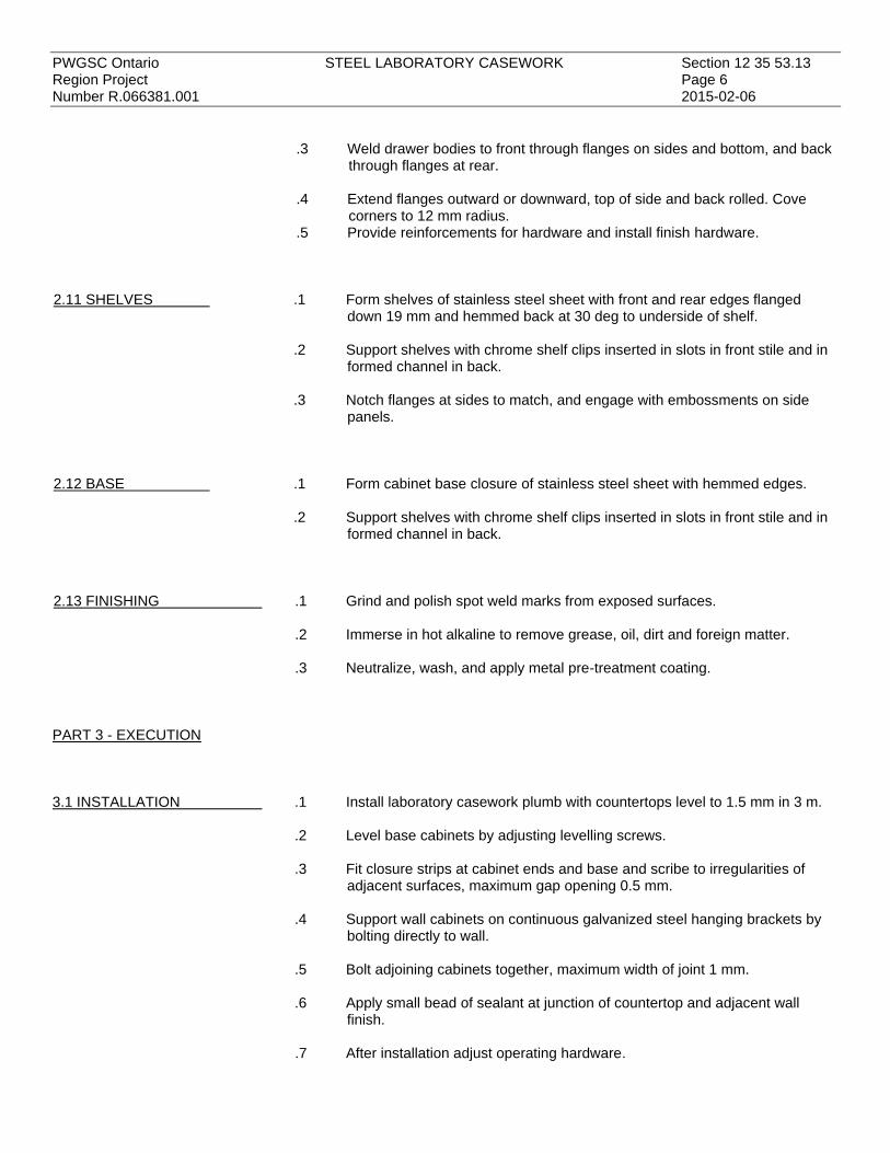
PWGSC Ontario STEEL LABORATORY CASEWORK Section 12 35 53.13 Region Project Page 6 Number R.066381.001 2015-02-06
.3 Weld drawer bodies to front through flanges on sides and bottom, and back through flanges at rear.
.4 Extend flanges outward or downward, top of side and back rolled. Cove
corners to 12 mm radius. .5 Provide reinforcements for hardware and install finish hardware.
2.11 SHELVES .1 Form shelves of stainless steel sheet with front and rear edges flanged down 19 mm and hemmed back at 30 deg to underside of shelf.
.2 Support shelves with chrome shelf clips inserted in slots in front stile and in
formed channel in back. .3 Notch flanges at sides to match, and engage with embossments on side
panels.
2.12 BASE .1 Form cabinet base closure of stainless steel sheet with hemmed edges. .2 Support shelves with chrome shelf clips inserted in slots in front stile and in
formed channel in back.
2.13 FINISHING .1 Grind and polish spot weld marks from exposed surfaces. .2 Immerse in hot alkaline to remove grease, oil, dirt and foreign matter. .3 Neutralize, wash, and apply metal pre-treatment coating.
PART 3 - EXECUTION
3.1 INSTALLATION
.1 Install laboratory casework plumb with countertops level to 1.5 mm in 3 m. .2 Level base cabinets by adjusting levelling screws. .3 Fit closure strips at cabinet ends and base and scribe to irregularities of
adjacent surfaces, maximum gap opening 0.5 mm. .4 Support wall cabinets on continuous galvanized steel hanging brackets by
bolting directly to wall. .5 Bolt adjoining cabinets together, maximum width of joint 1 mm. .6 Apply small bead of sealant at junction of countertop and adjacent wall
finish. .7 After installation adjust operating hardware.

PWGSC Ontario STEEL LABORATORY CASEWORK Section 12 35 53.13 Region Project Page 7 Number R.066381.001 2015-02-06
3.2 CLEANING .1 On completion, touch up marred or abraded finished surfaces. .2 Wipe down surfaces to remove fingerprints and markings and leave in clean
condition.
END


PWGSC Ontario FUME HOODS Section 12 35 60 Region Project Page 1 Number R.066381.001 2015-02-06
PART 1 - GENERAL
1.1 RELATED SECTIONS
.1 Section 12 35 53.13 - Steel Laboratory Casework. .2 Division 22, 23 and 25 - Ventilation, Controls, and Plumbing Services. .3 Division 26 - Electrical Services
1.2 REFERENCES
.1 American Society for Testing and Materials (ASTM) .1 ASTM A167-99, Specification for Stainless and Heat-Resisting
Chromium-Nickel Steel Plate, Sheet, and Strip. .2 ASTM A653/A 653M-03, Specification for Steel Sheet, Zinc-Coated
(Galvanized) or Zinc-Iron Alloy-Coated (Galvannealed) by the Hot-Dip Process.
.3 ASTM B117-03, Practice for Operating Salt Spray (Fog) Apparatus.
.4 ASTM B456-03, Specification for Electrodeposited Coatings of Copper Plus Nickel Plus Chromium and Nickel Plus Chromium.
.2 Fume hoods contained in this section shall be designed and constructed in
accordance with S.E.F.A. standards for laboratory fume hoods and ANSI/AIHA Z9.5-2003. Testing shall be to ANSI/ASHRAE 110-1995 and MD15128-2013
.5 ANSI/AIHA Z9.5-2003, American National Standard for Laboratory
Ventilation.
.6 ANSI/ASHRAE 110-1995, Method of Testing Performance of Laboratory Fume Hoods.
.7 PWGSC MD15128-2013 - Minimum Guidelines for Laboratory Fume Hoods.
1.3 EQUIPMENT SUPPLIED AND INSTALLED IN HOODS
1 Cocks, faucets, tail pieces, strainers, traps, electrical outlets, integral sinks and drains and pre-piping and pre-wiring within hood cabinet service spaces.
.2 Hook up to base building systems will be by Divisions 22, 23, 25 and 26.
1.4 OPERATING INSTRUCTIONS
.1 Instruction covering safe and proper operation of the fume hood shall be provided in three forms: .1 A corrosion resistant label attached to the fume hood exterior with
condensed information covering recommended locations for apparatus and accessories.
.2 A corrosion resistant label attached to interior baffle indicating baffle positions.
.3 Written instructions in booklet form providing additional detail information on safe, proper operation and maintenance.

PWGSC Ontario FUME HOODS Section 12 35 60 Region Project Page 2 Number R.066381.001 2015-02-06
1.5 SHOP DRAWINGS
.1 Submit shop drawings as per Section 01 33 00. .2 Indicate:
.1 Details of fume hood construction and related and dimensional position, with sections.
.2 Location of each unit. Coordinate with casework shop drawings, Sections 12 35 53.13
.3 Location for roughing-in of plumbing, including sinks, faucets, strainers and cocks and electrical services.
.4 Show all joint locations and detail for sealing joint.
.5 Details for seismic restraint of fume hood that meets the seismic zone for this project.
.3 Include test reports by independent testing laboratories indicating results of hood flow rates and compliance with ASHRAE 110.
1.6 DESIGN .1 Fume hoods shall be designed and constructed in accordance with MD 15128 – Laboratory Fume Hoods.
.2 Hoods shall function as ventilated, enclosed work spaces, designed to
capture, confine and exhaust fumes, vapours and particulate matter produced or generated within the enclosure.
.3 Fume hoods shall provide safe operation when properly installed and
connected to an exhaust system, and shall provide proper evacuation of air volume to permit the time hoods to operate at specified face velocity. Design hoods for consistent and safe air flow through face of hood with negative variations of face velocity not exceeding 20% of average face velocity at any designated measuring point as defined in this section.
.4 The design of the fume hood enclosure shall be an aerodynamically efficient
fume exhaust system, minimizing turbulence within the chamber and the volumes being exhausted from the laboratory. Hoods to be variable volume. Maximum sash opening: 457 mm with normal operation at 0.51 m/s face velocity and capable of safe operation at 0.38 m/s face velocity.
.5 Fume hoods to be plastic free. All components to be metal construction with
exception to glazing stops and setting blocks (glass must not be in contact with metal).
1.7 PERFORMANCE REQUIREMENTS
.1 Fume hoods shall be designed to meet or exceed the American Standard for Laboratory Ventilation and the American Industrial Hygiene Association standard as described in ASNI/AIHA Z95. This standard of performance has been verified through testing which was conducted and the PWGSC M15128 in accordance with the established protocol as set out by the ANSI/ASHRAE 110 standard. Fume hoods must be CSA certified.
.2 Test Results Summary: The test results confirm that the face velocity has a
maximum deviation of 20% of the individual velocity when the mean face velocity is 0.51 m/s for hoods per square meter of sash opening.
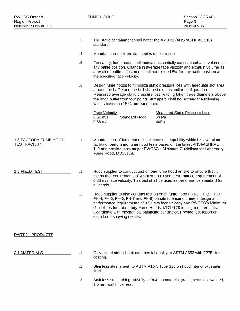
PWGSC Ontario FUME HOODS Section 12 35 60 Region Project Page 3 Number R.066381.001 2015-02-06
.3 The static containment shall better the AM0.01 (ANSI/ASHRAE 110) standard.
.4 Manufacturer shall provide copies of test results. .5 For safety, fume hood shall maintain essentially constant exhaust volume at
any baffle position. Change in average face velocity and exhaust volume as a result of baffle adjustment shall not exceed 5% for any baffle position at the specified face velocity.
.6 Design fume hoods to minimize static pressure loss with adequate slot area
around the baffle and the bell shaped exhaust collar configuration. Measured average static pressure loss reading taken three diameters above
the hood outlet from four points, 90 apart, shall not exceed the following values based on 1524 mm wide hood.
Face Velocity Measured Static Pressure Loss 0.51 m/s Standard Hood 63 Pa 0.38 m/s 40Pa
1.8 FACTORY FUME HOOD TEST FACILITY
.1 Manufacturer of fume hoods shall have the capability within his own plant facility of performing fume hood tests based on the latest ANSI/ASHRAE 110 and provide tests as per PWGSC’s Minimum Guidelines for Laboratory Fume Hood, MD15128.
1.9 FIELD TEST
.1 Hood supplier to conduct test on one fume hood on site to ensure that it meets the requirements of ASHRAE 110 and performance requirement of 0.38 m/s face velocity. This test shall be used as performance standard for all hoods.
.2 Hood supplier to also conduct test on each fume hood (FH-1, FH-2, FH-3,
FH-4, FH-5, FH-6, FH-7 and FH-8) on site to ensure it meets design and performance requirements of 0.51 m/s face velocity and PWGSC’s Minimum Guidelines for Laboratory Fume Hoods, MD15128 testing requirements. Coordinate with mechanical balancing contractor. Provide test report on each hood showing results.
PART 2 - PRODUCTS
2.1 MATERIALS
.1 Galvanized steel sheet: commercial quality to ASTM A653 with Z275 zinc coating.
.2 Stainless steel sheet: to ASTM A167, Type 316 on hood interior with satin
finish. .3 Stainless steel tubing: AISI Type 304, commercial grade, seamless welded,
1.5 mm wall thickness.

PWGSC Ontario FUME HOODS Section 12 35 60 Region Project Page 4 Number R.066381.001 2015-02-06
.4 Glazing: 6 mm safety laminate glass.
2.2 FUME HOOD MATERIALS
.1 Exterior Panels, Framing Members, and Furring Panels: Type 304-4 stainless steel, number 4 brush finish. .1 Screws: Interior fastening devices; truss head stainless steel screws
protected with plastic “snap-on” caps. .2 Upper front panel to be 1.2 mm thick stainless steel, with By-Pass
Grilles, finished same as exterior panels. .3 Lower Foil: To be Type 316 stainless steel mounted behind the
sash and sitting in a 50 mm deep trough flush with the countertop. For ease of cleaning, assembly shall swing up.
.4 Safety Glass: Laminated type 6 mm thick.
.5 Sash System: steel chain and sprocket, sash guides stainless steel.
.6 Sash Pull: To be full width, Type 316, 1.27 mm thick stainless steel with an AISI # 4 satin finish.
.7 Pulley Assembly For Sash Cable: 38 mm diameter nylon rim, ball bearing roller, with cable retaining device.
.8 Provide interior access panels on both sides, and secure using special moulded vinyl gasket designed to be easily removed and reinstalled without use of special tools.
.9 Baffle Support and Control Brackets: Same material as liner.
.10 Duct Stubs: Bell shaped Type 316, 1.27 mm stainless steel.
2.3 HOOD LININGS .1 Hood linings and baffles shall be stainless steel.
2.4 FUME HOOD FURRING PANELS
.1 Provide matching stainless steel furring panels to enclose the space between top edge of fume hoods and the finished ceiling and as detailed.
.2 Panels shall be flanged, notched and reinforced where required to form a
well-fitted enclosure, free from oil canning. Secure panels using cadmium-plated, self-tapping screws.
.3 Provide removable access panel on front face for maintenance purposes. .4 Finishes shall match fume hood to which it is connected
2.5 CONSTRUCTION .1 Fume hood superstructure shall be double wall construction consisting of an outer shell of stainless steel sheet and an inner hood liner. Double wall shall house and conceal steel framing members, attaching brackets and remote operating service fixture mechanisms. Overall double wall thickness: 120 mm maximum, providing maximum hood interior work area.
.2 Front double-wall posts shall be pre-punched to accept up to 5 plumbing
fittings per side, two electrical duplex outlets, light switch and fume hood controller. Electrical outlets and light switch shall be factory-wired and terminate at a junction box on roof of hood. All electrical devices shall be UL listed and CSA certified. Refer to 2.10 Schedule for fixture requirements.

PWGSC Ontario FUME HOODS Section 12 35 60 Region Project Page 5 Number R.066381.001 2015-02-06
.3 Exterior panel members shall be fastened by means of concealed devices. Exposed screws are not acceptable.
.4 Provide access to remote-controlled fixture valves concealed between walls
through removable panels on hood exterior and access panels on both inside liner walls. Assemble hood superstructure, fasten and connect inner and outer frame into a rigid self-supporting entity.
.5 Install fluorescent lighting fixture on exterior of roof. Provide a 6 mm safety
glass panel on hood “roof”, sealed to isolate the lighting fixture from fume chamber. The 2-lamp fixture in each hood shall be largest possible for fume hood size, and shall be rapid start type, UL and CSA certified. Provide lamps to fixtures. Average interior illumination levels within the fume chamber shall be 860 lux minimum. Ballast shall be sound rated to limit noise level. Finish fixture interior with white, high reflecting baked enamel.
.6 Work areas shall be defined as that area inside the superstructure from side
to side and from face of baffle to the inside face of sash and from the work surface to a height of 700 mm.
.7 Fume hood sash shall be full view vertical raising type providing a clear and
unobstructed side to side view of fume hood interior. Vertical sash shall raise in a flush stainless steel track. Bottom, top and side sash rails shall be 1.27 mm stainless steel welded to form an integral structure. Bottom rail shall be an integral, formed, full width, flush pull and shall be anchored on each side to sash cables at bottom. A single weight, pulley, cable, counter balance system shall be used for vertical operation of sash and prevent jamming to permit one finger operation at any point along full width sash pull and to maintain sash at any position without creep. Sash system shall be designed to prevent sash drop in the event of cable failure on one side. Superstructure shall have a single sash and counter balance system.
.8 Hoods shall be variable air volume type with a built in automatic
compensating by-pass. .9 Perimeter of sash opening shall have a streamlined shape side and top with
angled opening toward hood interior. Air shall enter under the bottom horizontal foil through a nominal 25 mm by-pass when the sash is in the closed position. Bottom foil shall be removable without the use of special tools. Sash shall close in front of air foil.
.10 Two-piece main baffles shall provide controlled air vectors into and through
the fume hood and be fabricated of the same material as the liner. Provide exhaust slots on the full perimeter of baffles, with a trip slot adjustable valve. A fixed, permanently-open, horizontal slot located at 812 mm above the work surface shall be provided at the overlapping mid-point of the main baffles.
.11 Electrical convenience duplex outlets shown mounted on the face of fume
hoods shall be installed in front posts and pre-wired to a junction box mounted on top of fume hood superstructure. Electrical devices shall be CSA approved.

PWGSC Ontario FUME HOODS Section 12 35 60 Region Project Page 6 Number R.066381.001 2015-02-06
.12 Sash height shall be limited to have two sets of integral sash height limiting hardware mounted on the exterior of the hood which prevents raising the vertical sash above certain points unless manually defeated by the operator. Set points shall be closed and at 450 mm above the countertop.
.13 The minimum sash height for set up shall be 900 mm. .14 Interior clear dimension front to back shall be 675 mm. .15 The fume hood exhaust collar cannot be higher than 2235 mm when
measured from the finished floor.
2.6 COUNTERTOPS .1 Stainless steel: .1 Stainless steel tops shall be fabricated of 1.27 mm Type 316
stainless steel with a # 4 satin finish. A 6.4 mm high raised rim shall be provided on all four sides to contain possible spillage. The overall thickness at the raised rim shall be 32 mm.
.2 The rear corners of the countertop shall contain slot openings to facilitate service lines being brought into the fume hood side walls for connection of service fittings.
.3 The joint between the countertop and the side and rear fume hood walls shall be solid welded, ground smooth and polished.
.4 Cup sinks shall be welded integral without seams or joints. Welds shall be ground smooth and polished. The underside shall be sprayed with a sound deadening emulsion.
.5 Cup sinks shall be complete with a 38 mm diameter drain fitting with integral debris catch, a stainless steel tailpiece 76 mm long, complete with brass connecting nut and nylon sealing washer.
2.7 FUME HOOD EXTERIOR FINISH
.1 Type 304-4 stainless steel, number 4 brush finish. Prepare all surfaces, make free of defects with welds ground smooth and indistinguishable from surrounding metal.
.2 Provide top closure panel of same material and finish as hood to enclose
ductwork up to finished ceiling and as detailed. Provide removable access panel at front side for servicing of fume hood air valve in ceiling space. Refer to architectural drawings for ceiling height.
2.8 LABORATORY SERVICE FITTINGS
.1 Metals: use min. 80% red brass alloy for valve bodies. Make handles and turrets of brass forgings. Use solid brass bar stock or specially selected alloys for assembly components and operating parts such as valve stems, renewable seats and needle cones.
.2 Completely enclose spring mechanisms. Design compression and needle
valve stems to operate inside and make them replaceable. Provide needle valves with stainless steel floating needles and removable seats.
.3 Equip remote controls with universal joints.
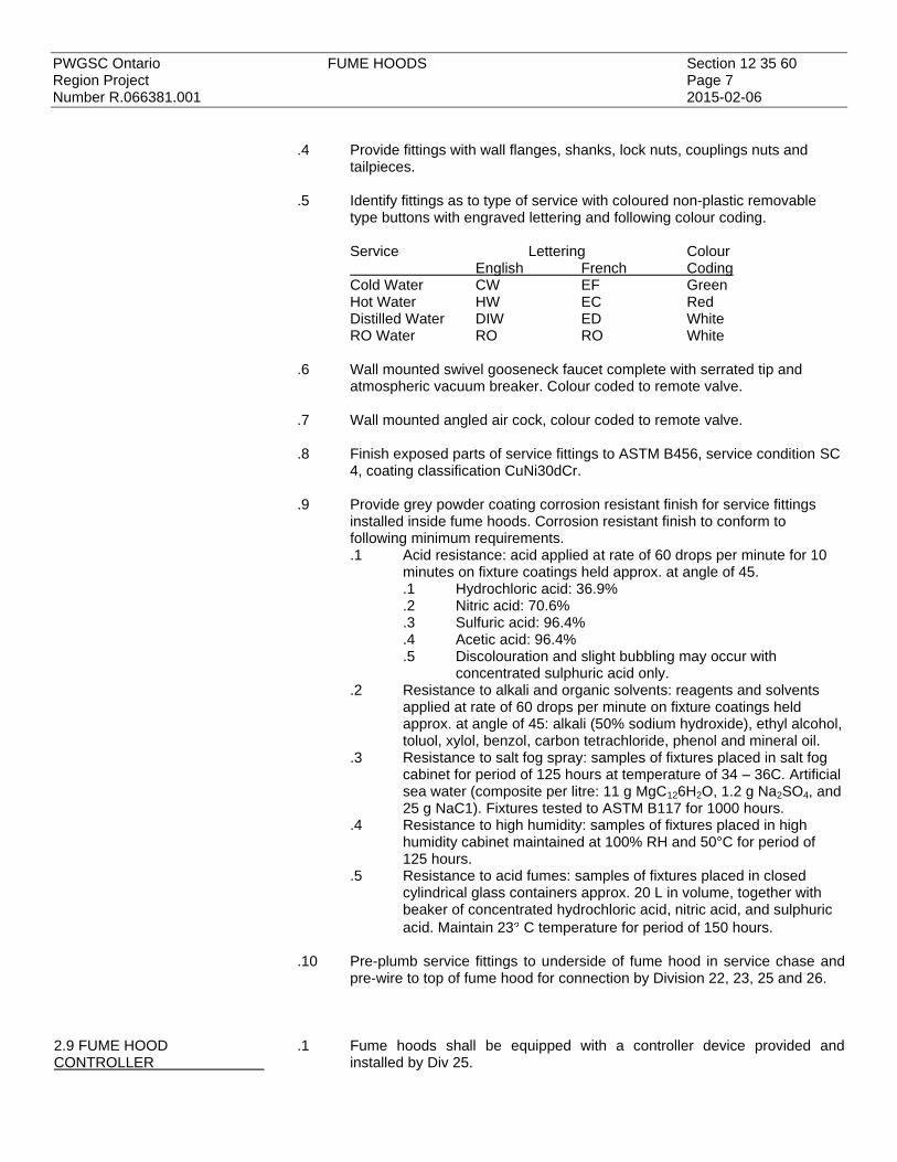
PWGSC Ontario FUME HOODS Section 12 35 60 Region Project Page 7 Number R.066381.001 2015-02-06
.4 Provide fittings with wall flanges, shanks, lock nuts, couplings nuts and tailpieces.
.5 Identify fittings as to type of service with coloured non-plastic removable
type buttons with engraved lettering and following colour coding.
Service Lettering Colour English French Coding Cold Water CW EF Green Hot Water HW EC Red Distilled Water DIW ED White RO Water RO RO White
.6 Wall mounted swivel gooseneck faucet complete with serrated tip and
atmospheric vacuum breaker. Colour coded to remote valve. .7 Wall mounted angled air cock, colour coded to remote valve. .8 Finish exposed parts of service fittings to ASTM B456, service condition SC
4, coating classification CuNi30dCr. .9 Provide grey powder coating corrosion resistant finish for service fittings
installed inside fume hoods. Corrosion resistant finish to conform to following minimum requirements. .1 Acid resistance: acid applied at rate of 60 drops per minute for 10
minutes on fixture coatings held approx. at angle of 45. .1 Hydrochloric acid: 36.9% .2 Nitric acid: 70.6% .3 Sulfuric acid: 96.4% .4 Acetic acid: 96.4% .5 Discolouration and slight bubbling may occur with
concentrated sulphuric acid only. .2 Resistance to alkali and organic solvents: reagents and solvents
applied at rate of 60 drops per minute on fixture coatings held approx. at angle of 45: alkali (50% sodium hydroxide), ethyl alcohol, toluol, xylol, benzol, carbon tetrachloride, phenol and mineral oil.
.3 Resistance to salt fog spray: samples of fixtures placed in salt fog cabinet for period of 125 hours at temperature of 34 – 36C. Artificial sea water (composite per litre: 11 g MgC126H2O, 1.2 g Na2SO4, and 25 g NaC1). Fixtures tested to ASTM B117 for 1000 hours.
.4 Resistance to high humidity: samples of fixtures placed in high humidity cabinet maintained at 100% RH and 50°C for period of 125 hours.
.5 Resistance to acid fumes: samples of fixtures placed in closed cylindrical glass containers approx. 20 L in volume, together with beaker of concentrated hydrochloric acid, nitric acid, and sulphuric
acid. Maintain 23 C temperature for period of 150 hours.
.10 Pre-plumb service fittings to underside of fume hood in service chase and pre-wire to top of fume hood for connection by Division 22, 23, 25 and 26.
2.9 FUME HOOD CONTROLLER
.1 Fume hoods shall be equipped with a controller device provided and installed by Div 25.

PWGSC Ontario FUME HOODS Section 12 35 60 Region Project Page 8 Number R.066381.001 2015-02-06
.2 Division 25 will provide cut out templates for the controller device. The fume hood manufacture shall provide the necessary cut outs.
2.10 FUME HOOD SCHEDULE .1 Refer to floor plan for cup sink locations.
NO. ROOM
NO. ROOM NAME
SIZE (WIDTH)
R. O. WATER
CUP SINK
GOOSE-NECK
REGULAR WATER H & C
ELECT. DUPLEX
OUTLETS
WORK SURFACE & INTERIOR
LINER
COMPRESSED AIR
REMARKS
FH 1 L760a Lab 2450 yes yes, side wall mtd.
Yes, side wall mtd.
both sides Stainless Steel yes, both side
walls Split sash
FH 2 L760a Lab 1825 yes yes, side wall mtd.
Yes, side wall mtd.
both sides Stainless Steel yes, both side
walls
FH 3 L760a Lab 2450 yes
yes, side wall mtd.
yes, deck mounted
Cold only both sides Stainless Steel yes, both side
walls
Double bowl stainless steel sink
355x406x254mm
Split sash FH 4 L760a Lab 2450 yes yes, side wall mtd.
Yes, side wall mtd.
both sides Stainless Steel yes, both side
walls Split sash
FH 5 L760a Lab 1525 yes yes, side wall mtd.
Yes, side wall mtd.
both sides Stainless Steel yes, both side
walls
FH 6 L760a Lab 1525 yes yes, side wall mtd.
Yes, side wall mtd.
both sides Stainless Steel yes, both side
walls
FH 7 L760a Lab 1225 yes yes, side wall mtd.
Yes, side wall mtd
both sides Stainless Steel yes, both side
walls
FH 8 L760a Lab 1225 yes yes, side wall mtd.
Yes, side wall mtd.
both sides Stainless Steel yes, both side
walls
mtd = mounted
PART 3 - EXECUTION
3.1 INSTALLATION
.1 Install fume hoods in positions shown, align and set level with levelling devices.
.2 Work in close cooperation with allied trades installing ductwork, wiring and
other services. .3 Turn over to Mechanical Trades, service fitting remote control rods and
valves for installation to fume hood superstructure and service lines.
3.2 CLEANING .1 On completion, touch up marred or abraded finished surfaces. .2 Wipe down surfaces to remove fingerprints and markings and leave in clean
condition.
3.2 TESTING .1 After hook-up of electrical, pumping, and gas lines test all controls.

PWGSC Ontario FUME HOODS Section 12 35 60 Region Project Page 9 Number R.066381.001 2015-02-06
.2 Set up and test alarms. .3 Do flow tests on all hoods. Coordinate with mechanical balancing contractor.
Provide test report for review and approval by Departmental Representative.
END


PWGSC Ontario FIRE PROTECTION Section 21 00 00Region Project Page 1Number R.066381.001 2015-02-06 PART 1 - GENERAL 1.1 MINIMUM .1 NFPA (Fire) 10, Standard for Portable Fire Extinguishers, 2010 Edition.STANDARDS
.2 National Building Code of Canada 2010.
.3 National Fire Code of Canada 2010. 1.2 SHOP DRAWINGS .1 Submit shop drawings and product data sheets in accordance with Sections 01 33 00,AND PRODUCT DATA 01 78 00 for review before commencing work.SHEETS PART 2 - PRODUCTS 2.1 PORTABLE FIRE .1 Extinguishers shall be ULC listed and labelled.EXTINGUISHERS
.2 Provide multi-purpose dry chemical extinguishers of 5 kg 10 kg capacity in Lab asindicated on drawings.
.3 Provide wall brackets and mount extinguishers 1 to 1.5 m above floor.
PART 3 - EXECUTION 3.1 INSTALLATION .1 Install material and fixtures in accordance with referenced standards and manufacturer's
written instructions.
END


PWGSC Ontario PLUMBING Section 22 00 00Region Project Page 1Number R.066381.001 2015-02-06 PART 1 - GENERAL 1.1 MINIMUM .1 Conform to or exceed:STANDARDS .1 Ontario Plumbing Code.
.2 Canadian Standards Association Standards.
.3 Local Municipal By-laws and Regulations.
.4 National Building Code of Canada (NBC) 2010.
.5 Ontario Building Code (OBC) 2012.
.6 National Fire Code of Canada 2010 (NFC). 1.2 REFERENCES .1 Material standards:
.1 ASME International (ASME).1 ASME B16.5-2013, Pipe Flanges and Flanged Fittings: NPS 1/2 through
NPS 24 Metric/Inch Standard..2 ASME B16.11-2011, Forged Fittings, Socket-Welding and Threaded..3 ASME B16.22-2013, Wrought Copper and Copper Alloy Solder Joint
Pressure Fittings..2 ASTM International
.1 ASTM A53/A53M-12, Standard Specification for Pipe, Steel, Black andHot-Dipped, Zinc-Coated, Welded and Seamless
.2 ASTM A181/A181M-13, Standard Specification for Carbon Steel Forgings,for General-Purpose Piping
.3 ASTM B16/B16M-10, Standard Specification for Free-Cutting Brass Rod,Bar and Shapes for Use in Screw Machines
.4 ASTM B62-09, Standard Specification for Composition Bronze or OunceMetal Castings.
.5 ASTM B88M-13, Standard Specification for Seamless Copper Water Tube(Metric).
.6 ASTM B209-10, Standard Specification for Aluminum and Aluminum-AlloySheet and Plate.
.7 ASTM B306-13, Standard Specification for Copper Drainage Tube (DWV)..3 CSA Group
.1 CAN/CSA B125.3-12, Plumbing Fittings..4 Canadian General Standards Board (CGSB)
.1 CGSB 51-GP-52Ma, Vapour Barrier, Jacket and Facing Material for Pipe,Duct and Equipment Thermal Insulation.
.2 CAN/CGSB-51.9-92, Mineral Fibre Thermal Insulation for Piping and RoundDucting.
.3 CAN/CGSB-51.53-95, Poly (Vinyl Chloride) Jacketing Sheet, for InsulatedPipes, Vessels and Round Ducts.
.5 International Safety Equipment Association (ISEA).1 ISEA Z358.1-2009, Emergency Eyewash and Shower Equipment.
1.3 SHOP DRAWINGS .1 Submit shop drawings and product data sheets in accordance with Sections 01 33 00 forAND PRODUCT DATA the following:SHEETS .1 Plumbing fixtures.
.2 Cleanouts.
.3 Trap seal primers.
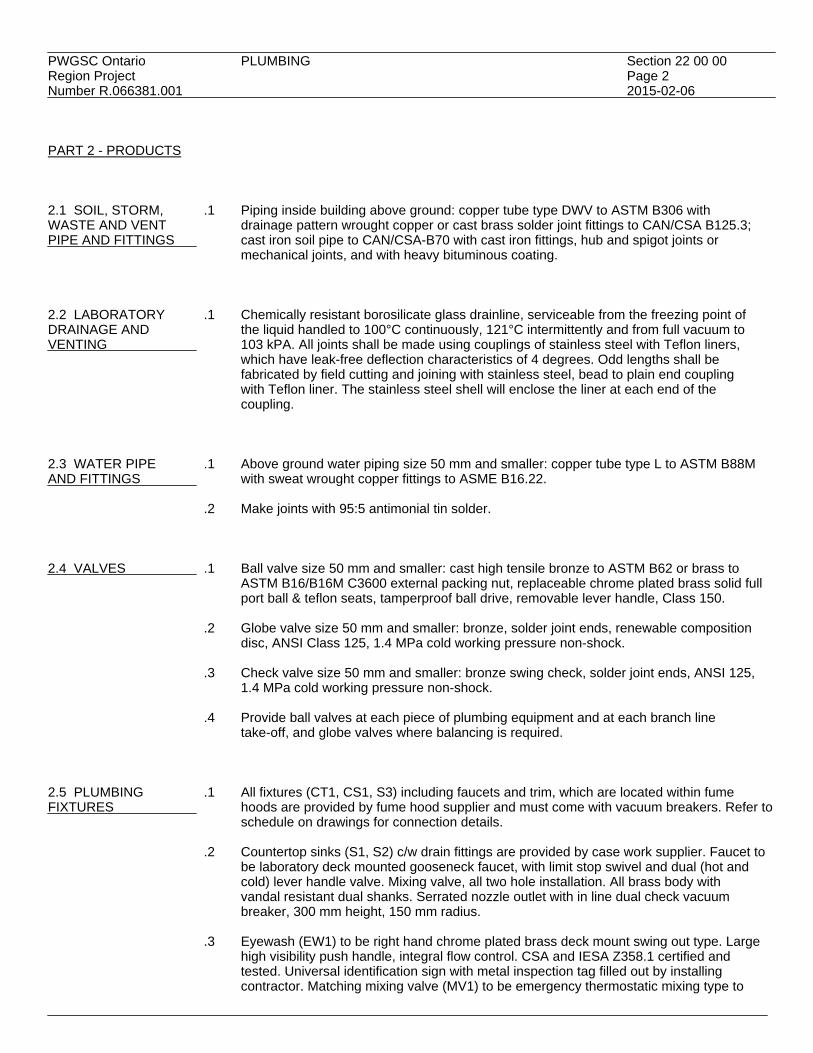
PWGSC Ontario PLUMBING Section 22 00 00Region Project Page 2Number R.066381.001 2015-02-06 PART 2 - PRODUCTS 2.1 SOIL, STORM, .1 Piping inside building above ground: copper tube type DWV to ASTM B306 withWASTE AND VENT drainage pattern wrought copper or cast brass solder joint fittings to CAN/CSA B125.3;PIPE AND FITTINGS cast iron soil pipe to CAN/CSA-B70 with cast iron fittings, hub and spigot joints or
mechanical joints, and with heavy bituminous coating. 2.2 LABORATORY .1 Chemically resistant borosilicate glass drainline, serviceable from the freezing point ofDRAINAGE AND the liquid handled to 100°C continuously, 121°C intermittently and from full vacuum toVENTING 103 kPA. All joints shall be made using couplings of stainless steel with Teflon liners,
which have leak-free deflection characteristics of 4 degrees. Odd lengths shall befabricated by field cutting and joining with stainless steel, bead to plain end couplingwith Teflon liner. The stainless steel shell will enclose the liner at each end of thecoupling.
2.3 WATER PIPE .1 Above ground water piping size 50 mm and smaller: copper tube type L to ASTM B88MAND FITTINGS with sweat wrought copper fittings to ASME B16.22.
.2 Make joints with 95:5 antimonial tin solder. 2.4 VALVES .1 Ball valve size 50 mm and smaller: cast high tensile bronze to ASTM B62 or brass to
ASTM B16/B16M C3600 external packing nut, replaceable chrome plated brass solid fullport ball & teflon seats, tamperproof ball drive, removable lever handle, Class 150.
.2 Globe valve size 50 mm and smaller: bronze, solder joint ends, renewable composition
disc, ANSI Class 125, 1.4 MPa cold working pressure non-shock.
.3 Check valve size 50 mm and smaller: bronze swing check, solder joint ends, ANSI 125,1.4 MPa cold working pressure non-shock.
.4 Provide ball valves at each piece of plumbing equipment and at each branch line
take-off, and globe valves where balancing is required. 2.5 PLUMBING .1 All fixtures (CT1, CS1, S3) including faucets and trim, which are located within fumeFIXTURES hoods are provided by fume hood supplier and must come with vacuum breakers. Refer to
schedule on drawings for connection details.
.2 Countertop sinks (S1, S2) c/w drain fittings are provided by case work supplier. Faucet tobe laboratory deck mounted gooseneck faucet, with limit stop swivel and dual (hot andcold) lever handle valve. Mixing valve, all two hole installation. All brass body withvandal resistant dual shanks. Serrated nozzle outlet with in line dual check vacuumbreaker, 300 mm height, 150 mm radius.
.3 Eyewash (EW1) to be right hand chrome plated brass deck mount swing out type. Large
high visibility push handle, integral flow control. CSA and IESA Z358.1 certified andtested. Universal identification sign with metal inspection tag filled out by installingcontractor. Matching mixing valve (MV1) to be emergency thermostatic mixing type to

PWGSC Ontario PLUMBING Section 22 00 00Region Project Page 3Number R.066381.001 2015-02-06 2.5 PLUMBING .3 (Cont'd) FIXTURES satisfy IESA Z358.1 and as recommended by manufacturer. Provide dual check vacuum (Cont'd) breaker on inlets.
.4 Emergency Shower (ES1) to be stainless steel flush to ceiling laboratory type withpolished stainless steel drench shower head with flow control. Brass stay open ball valvewith stainless steel ball and stem, 112 cm stainless steel pull rod with triangular handle,25 mm supply, universal sign, stainless steel pull rod ceiling escutcheon with cleanroombrush seal. Prepiped with 25 mm Schedule 40 galvanized steel pipe. CSA certified tomeet IESA Z358.1. Matching mixing valve (MV2) to be emergency thermostatic type tomeet IESA Z358.1 and manufacturer's recommendations. Mixing valve to be equippedwith recessed stainless steel access box, sized to accommodate mixing valve with inletisolation valves and dual check vacuum breakers.
2.6 FIXTURE .1 Refer to schedule on drawings.CONNECTIONS
.2 Vent all fixtures in accordance with NBC and Provincial Plumbing Code. 2.7 FIXTURE .1 Mounting heights for wall hung fixtures measured from finished floor:MOUNTING HEIGHTS .1 Standard: to comply with manufacturer's roughing-in details unless otherwiseAND CLEARANCES indicated or specified.
.2 Clearances to comply with NBCC and OBC. 2.8 WATER HAMMER .1 Provide arrestors sized and located on branch water supplies to each group of fixtures inARRESTORS accordance with Plumbing and Drainage Institute Standard PD1 - WH201.(SHOCK ABSORBERS)
.2 Construction: stainless steel with welded nested bellows. 2.9 TRAP SEAL .1 Provide trap seal primer to each floor drain. Trap seal primer shall be all brass withPRIMER integral vacuum breaker, NPS ½ solder inlet and outlet connections and NPS ½ drip line
connection. 2.10 CLEANOUTS .1 Provide cleanouts to conform to National Plumbing Code and where shown on drawings.
.2 Type: heavy CI male ferrule with bronze bolted plug.
.3 Make each cleanout accessible and wherever necessary, extend branch connections tofinished surfaces of wall, etc, and provide access covers or plates.
2.11 SLOPE OF .1 Drainage piping shall have a minimum slope as follows or otherwise required byDRAINS Plumbing Code.
.1 Size 75 mm and smaller: 2% slope.
.2 Size 100 mm and larger: 1% slope.

PWGSC Ontario PLUMBING Section 22 00 00Region Project Page 4Number R.066381.001 2015-02-06 2.12 PIPE .1 Insulate hot water piping with 25 mm thick rigid mineral fibre sleeving toINSULATION CAN/CGSB-51.9 and factory applied all service jacket to CGSB 51-GP-52Ma.
.2 Insulate cold water piping with 25 mm thick rigid mineral fibre sleeving toCAN/CGSB-51.9 and vapour barrier jacket to CGSB 51-GP-52Ma.
.3 Provide polyvinyl chloride (PVC)cover over insulated piping in exposed areas (not within
Lab):.1 One-piece moulded type and sheet to CAN/CGSB-51.53 with pre-formed shapes
as required..2 Colours: by Departmental Representative..3 Minimum service temperatures: -20°C..4 Maximum service temperature: 65°C..5 Moisture vapour transmission: 0.02 perm..6 Fastenings:
.1 Use solvent weld adhesive compatible with insulation to seal laps andjoints.
.2 Tacks.
.3 Pressure sensitive vinyl tape of matching colour.
.4 Provide aluminum cover over insulated piping in exterior areas:.1 To ASTM B209..2 Thickness: 0.50 mm sheet..3 Finish: smooth..4 Joining: longitudinal and circumferential slip joints with 50 mm laps..5 Fittings: 0.5 mm thick die-shaped fitting covers with factory-attached protective
liner..6 Metal jacket banding and mechanical seals: stainless steel, 19 mm wide, 0.5 mm
thick at 300 mm spacing.
.5 Insulate underside of roof drain body and horizontal storm drainage piping for 5 m fromdrain with 25 mm thick mineral fibre blanket and vapour barrier jacket.
.6 Fastenings:
.1 Use self-adhesive tape rated under 25 for flame spread and under 50 for smokedevelopment.
.2 Use quick-setting adhesive for joints and lap sealing of vapour barriers. Flamespread 10, smoke development 0.
.7 Provide canvas cover over all insulated pipes in exposed areas. Canvas cover: compact,
firm, ULC listed, heavy plain weave, cotton fabric at 220 g/m2. Provide two coats ofdiluted fire retardant lagging adhesive over canvas covering. Paint to match basebuilding standard.
.8 Fire and smoke rating to be in accordance with CAN/ULC S102:
.1 Maximum flame spread rating: 25.
.2 Maximum smoke developed rating: 50. 2.13 PIPING .1 Piping: to ASTM A53/A53M, schedule 80 seamless black steel.
.2 Fittings:.1 NPS 2 and smaller: to ASME B16.11, schedule 80 steel, socket welded.
.3 Couplings: to ASME B16.11, socket welded or threaded half coupling type.
.4 Unions: 1000 kPa malleable iron with brass-to-iron ground seat.

PWGSC Ontario PLUMBING Section 22 00 00Region Project Page 5Number R.066381.001 2015-02-06 2.13 PIPING .5 Dissimilar metal junctions: use dielectric unions. (Cont'd)
.6 Flanges:.1 NPS 2 and smaller: to ASME B16.5, forged steel, raised face and socket welded.
.7 Joints:
.1 NPS2 and smaller: socket welded.
.2 NPS 2-1/2 and larger: butt welded.
.8 Ball Valves:.1 Three piece design or top entry for ease of in-line maintenance..2 To ASTM A181/A181M, Class 70, carbon steel body screwed ends, carbon steel
ball and associated trim suitable for compressed air application..3 To withstand 1034 kPa maximum pressure.
.9 Couplers/Connectors:
.1 Industrial interchange series, full-bore.
.2 Maximum inlet pressure: 1700 kPa.
.3 Valve seat: moulded nylon.
.4 Body: zinc plated steel.
.5 Threads: NPT. PART 3 - EXECUTION 3.1 INSTALLATION .1 Install material and fixtures in accordance with referenced standards and manufacturer's
written instructions. 3.2 INSTALLATION .1 Provide complete domestic hot and cold water or non-potable water systems to serveOF DOMESTIC HOT fixtures and items specified and as shown on the drawings.AND COLD ANDNON-POTABLE WATER .2 Install piping passing through fire separations with a non-combustible material on onePIPING side of fire separation and seal with `approved' fire stop material.
.3 Route above ground piping in ceiling space or wall interiors for concealment whereverpossible unless specifically noted otherwise on drawings or if approved by Consultant.Coordinate pipe installation in walls with mason and/or drywaller or appropriate tradeinvolved.
.4 Install piping straight, parallel and close to walls and ceilings, with specified pitch. Use
standard fittings for direction changes.
.5 Install groups of piping parallel to one another spaced to permit application ofinsulation, identification and service access on trapeze hangers.
.6 Install eccentric reducers in horizontal piping to permit drainage and eliminate air
pockets.
.7 Where pipe sizes differ from connection sizes of equipment, install reducing fittings closeto equipment. Reducing bushings are not permitted.
.8 Ensure brass and copper pipe and tubing are free from surface damage. Replace
damaged pipe or tubing. Ream ends of pipe and tubes before installation.

PWGSC Ontario PLUMBING Section 22 00 00Region Project Page 6Number R.066381.001 2015-02-06 3.2 INSTALLATION .9 Install swing or swivel joints to connect risers to mains. Use couplings in risers from one OF DOMESTIC HOT floor outlet to next. AND COLD ANDNON-POTABLE WATER .10 Install flanges or unions to permit removal of equipment without disturbing piping PIPING systems. (Cont'd)
.11 Clean ends of pipes or tubing and recesses of fittings to be brazed or soldered. Assemblejoints without binding. Use 95/5 (lead free) solder for joining of copper piping.
.12 Grade piping at 0.5% to enable entire system to be drained. Install drain valves at low
points and extend drain piping to discharge into floor or hub drain or janitors sink.
.13 Install expansion joints and compensators, flexible connections, pipe loops and offsets asindicated. Support piping to prevent any stress or strain. Install guides for expansion jointsto manufacturer's instructions, otherwise for minimum 3 m (10') on each side of expansionjoint for sizes to 75 mm (3"). Provide steel anchors welded to steel piping, clamped tobuilding structure or embedded in concrete.
3.3 INSTALLATION .1 Provide complete drainage, vent and domestic water systems to serve fixtures and itemsOF DRAINAGE & specified and as shown on the drawings.VENT PIPING
.2 Laboratory pipes passing through walls and floors shall be fitted with pipe sleeves aminimum of 2" greater diameter than the pipe O.D. Caulk the annular space between thepipe and sleeve with approved sealing material. Piping shall not be installed in directcontact with concrete. Entire system shall be installed free of stress. Horizontal lines shallallow for lateral movement of pipe and shall be supported by padded hanger every 8 to10 feet. Vertical lines shall be supported by padded riser clamps, which shall restrictsideward and downward movements. All fabrication and installations to be in accordancewith manufacturer's installation manual.
.3 Install piping passing through fire separations with a non-combustible material on one
side of fire separation and seal with `approved' fire stop material.
.4 Route above ground piping in ceiling space or wall interiors for concealment whereverpossible unless specifically noted otherwise on drawings or if approved by Consultant.Coordinate pipe installation in walls with mason and/or drywaller or appropriate tradeinvolved.
.5 Install piping straight, parallel and close to walls and ceilings, with specified pitch. Use
standard fittings for direction changes.
.6 Install groups of piping parallel to one another, spaced to permit application ofinsulation, identification and service access on trapeze hangers.
.7 Install eccentric reducers in horizontal piping to permit drainage and eliminate air
pockets.
.8 Where pipe sizes differ from connection sizes of equipment, install reducing fittings closeto equipment. Reducing bushings are not permitted.
.9 Grade horizontal drainage and vent piping at minimum 2.0% or as noted on drawings.
.10 Install temporary bracing or supports when necessary to adequately support pipe during
installation, exercise care to prevent damage to pipe coatings and adjacent structuresand appurtenances.
PWGSC Ontario PLUMBING Section 22 00 00Region Project Page 7Number R.066381.001 2015-02-06 3.3 INSTALLATION .11 When pipe laying is not in progress, close off open ends of pipe with watertight bulkhead OF DRAINAGE & or plug. VENT PIPING (Cont'd) 3.4 ADJUSTING .1 Conform to water conservation requirements specified this section.
.2 Adjustments:.1 Adjust water flow rate to design flow rates..2 Adjust pressure to fixtures to ensure no splashing at maximum pressures.
.3 Checks:
.1 Emergency fixtures.
.2 Aerators: operation, cleanliness.
.3 Vacuum breakers: operation under all conditions.
.4 Thermostatic controls:.1 Verify temperature settings, operation of control, limit and safety controls.
.5 Refer to other Sections for requirements of commissioning.
END


PWGSC Ontario COMMON WORK RESULTS - MECHANICAL Section 23 05 00Region Project Page 1Number R.066381.001 2015-02-06 PART 1 - GENERAL 1.1 SPECIAL WARNING .1 This project requires a special enhanced mechanical commissioning. The Mechanical
Contractor must read and fully understand the special requirements specified in Section01 91 00, Commissioning, prior to bidding this project.
1.2 GENERAL .1 This Section covers items common to more than one section of the Mechanical Divisions
21, 22, 23 and 25.
.2 "Provide" shall mean "supply, install and connect".
.3 Provide new materials, equipment and plant of proven design and quality, and of currentmodels with published ratings for which replacement parts are readily available.
1.3 HALOCARBONS .1 Comply with Federal Halocarbon Regulations 2003 under the Canadian Environmental
Protection Act 1999, EPAM and PWGSC Ontario Region Halocarbon Information Sheetdated March 2010.
1.4 EQUIPMENT LIST .1 Complete list of equipment to be used on this project by adding manufacturer's name
and model number. Submit for approval within one week of award of contract.
.2 The Contractor is to complete the following list of equipment with manufacturer's nameand model number:.1 Heat exchanger: Maker and model ..2 Pumps: Maker and model ..3 Energy recovery exhaust units: Maker and model ..4 Laboratory exhaust fans: Maker and model ..5 Air valves: Maker and model ..6 Custom rooftop unit: Maker and model ..7 Controls: Maker and model ..8 Filter unit: Maker and model .
.3 It is the Contractor's responsibility to ensure that the equipment to be used will meet the
performance specifications and will fit the spaces allocated.
.4 Submit for approval within 48 h after Award of Contract. 1.5 CUTTING AND .1 Cutting and remedial work is specified in Sections 01 14 00 & 01 73 00.REMEDIAL WORK
.2 Assume full responsibility for laying out mechanical work and for any damage caused byincorrectly located equipment and mechanical services.
.3 Set sleeves and mark openings in concrete forms and in masonry before placing of
concrete and erection of masonry.

PWGSC Ontario COMMON WORK RESULTS - MECHANICAL Section 23 05 00Region Project Page 2Number R.066381.001 2015-02-06 1.6 CO-ORDINATION .1 Locate distribution systems, equipment and materials to provide minimum interference
and maximum useable space.
.2 Where interference occurs, Departmental Representative shall approve relocation ofequipment and materials.
1.7 DRAWINGS .1 Working drawings, except where dimensioned, indicate general mechanical layouts only.
Do not scale.
.2 Existing equipment and services shown on the drawings:.1 The information shown on the drawings is incomplete and is for reference only.
Some of the existing equipment, ducts, pipes and other services are not shown onthe drawings.
.2 The Contractor shall make arrangements to examine existing conditions,determine conditions affecting the work, and verify sizes and location of existingequipment, ducts, pipes and any other services.
.3 Unless the discrepancies are noted and reported to the DepartmentalRepresentative prior to close of the bid, the Contractor shall be responsible for thework to relocate existing equipment and to reroute existing ducts, pipes and anyother services required for the installation of new work at no extra cost to thecontract.
.3 If required by Departmental Representative, provide field drawings to show relative
positions of various services. Obtain approval before beginning work. 1.8 SHOP DRAWINGS .1 Submit shop drawings and product data sheets for major equipment listed in eachAND PRODUCT DATA section.SHEETS
.2 Submit early enough to permit Project Schedules to be met.
.3 Show materials; sizes, dimensions, performance ratings, curves and operatingcharacteristics, compliance with codes and standards, wiring, controls, piping diagrams,installation instructions, fabrication, assembly and installation details.
.4 For additional requirements pertaining to shop drawings and product data refer to
Sections 01 33 00 and 01 78 00. 1.9 OPERATION AND .1 Supply operating and maintenance instructions complete with names and addresses ofMAINTENANCE DATA spare parts suppliers in accordance with requirements of Sections 01 78 00 and 01 91 00. 1.10 EQUIPMENT .1 Uniformity:DESIGN AND .1 For equipment or material of same type or classification, use product of oneINSTALLATION manufacturer.
.2 Installation:.1 Install equipment to manufacturer's recommendations with adequate and easy
access for inspection, servicing and lubrication..2 Install equipment to permit maintenance and disassembly with minimum
disturbance to connecting piping and duct systems and without interference withbuilding structure or equipment.
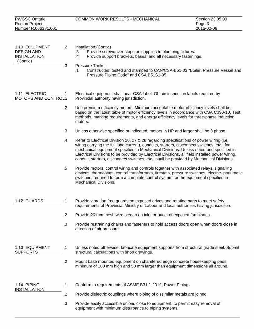
PWGSC Ontario COMMON WORK RESULTS - MECHANICAL Section 23 05 00Region Project Page 3Number R.066381.001 2015-02-06 1.10 EQUIPMENT .2 Installation:(Cont'd) DESIGN AND .3 Provide screwdriver stops on supplies to plumbing fixtures. INSTALLATION .4 Provide support brackets, bases, and all necessary fastenings. (Cont'd)
.3 Pressure Tanks:.1 Constructed, tested and stamped to CAN/CSA-B51-03 "Boiler, Pressure Vessel and
Pressure Piping Code" and CSA B51S1-05. 1.11 ELECTRIC .1 Electrical equipment shall bear CSA label. Obtain inspection labels required byMOTORS AND CONTROLS Provincial authority having jurisdiction.
.2 Use premium efficiency motors. Minimum acceptable motor efficiency levels shall bebased on the latest table of motor efficiency levels in accordance with CSA C390-10, Testmethods, marking requirements, and energy efficiency levels for three-phase inductionmotors.
.3 Unless otherwise specified or indicated, motors ½ HP and larger shall be 3 phase.
.4 Refer to Electrical Division 26, 27 & 28 regarding specifications of power wiring (i.e.
wiring carrying the full load current), conduits, starters, disconnect switches, etc., formechanical equipment specified in Mechanical Divisions. Unless noted and specified inElectrical Divisions to be provided by Electrical Divisions, all field installed power wiring,conduit, starters, disconnect switches, etc., shall be provided by Mechanical Divisions.
.5 Provide motors, control wiring and controls together with associated relays, signalling
devices, thermostats, control transformers, firestats, pressure switches, electric- pneumaticswitches, required to form a complete control system for the equipment specified inMechanical Divisions.
1.12 GUARDS .1 Provide vibration free guards on exposed drives and rotating parts to meet safety
requirements of Provincial Ministry of Labour and local authorities having jurisdiction.
.2 Provide 20 mm mesh wire screen on inlet or outlet of exposed fan blades.
.3 Provide restraining chains and fasteners to hold access doors open when doors close indirection of air pressure.
1.13 EQUIPMENT .1 Unless noted otherwise, fabricate equipment supports from structural grade steel. SubmitSUPPORTS structural calculations with shop drawings.
.2 Mount base mounted equipment on chamfered edge concrete housekeeping pads,minimum of 100 mm high and 50 mm larger than equipment dimensions all around.
1.14 PIPING .1 Conform to requirements of ASME B31.1-2012, Power Piping.INSTALLATION
.2 Provide dielectric couplings where piping of dissimilar metals are joined.
.3 Provide easily accessible unions close to equipment, to permit easy removal ofequipment with minimum disturbance to piping systems.

PWGSC Ontario COMMON WORK RESULTS - MECHANICAL Section 23 05 00Region Project Page 4Number R.066381.001 2015-02-06 1.14 PIPING .4 Valves: INSTALLATION .1 Provide easy access for servicing and operation. Install access doors where (Cont'd) concealed.
.2 Install with stems above horizontal.
.5 Drainage:.1 Provide easily accessible drain valves at low points to permit complete drainage of
piping systems..2 Extend equipment drain piping to discharge into floor or hub drain..3 Provide drain piping from drain pan of air handling units, full size of outlet
connection and equip with deep-seal trap.
.6 Expansion and Contraction:.1 Make adequate provision for expansion and contraction of piping systems..2 Use expansion joints and compensators, flexible connections, pipe loops and
offsets as indicated and required..3 Support piping to prevent any stress or strain from occurring at connections to
equipment..4 Install and guide expansion joints in accordance with manufacturer's
recommendations..5 Provide steel anchors welded to piping, fastened to building structure or
embedded in concrete pier so that forces acting on anchor points are restrainedwithout causing damage to structure or systems.
.6 Base design axial traverse on temperature difference between -18°C ambient andcorresponding fluid temperature plus 25% safety factor.
1.15 PIPE HANGERS .1 Fabricate hangers, supports and sway braces in accordance with ASME B31.1-2012.AND SUPPORTS
.2 Provide adjustable clevis type hangers on all sizes of pipe except where roller typehangers are required.
.3 Minimum 150 mm hanger rod length.
.4 Provide hangers on piping with heated or cooled contents as follows:
.1 Rigid hangers when rod length is 300 mm or more, pipe expansion to hanger rodlength ratio is less than 1:24 and hanger is supported from top of structural steel.
.2 Swing hangers when rod length is 300 mm or more, pipe expansion to hanger rodlength ratio is less than 1:6 and hanger is supported from top of structural steel.
.3 Roller hangers when rod length is less than 300 mm or pipe expansion to hangerrod length ratio is more than 1:6 or hanger is not supported from top of structuralsteel.
.5 On uninsulated copper piping, ensure steel hangers in contact with copper piping are
copper plated. Copper pipe shall not contact steel, iron or cinder materials. Covered12 mm diameter copper pipe may be supported on copper straps.
1.16 SLEEVES, .1 Sleeves:ESCUTCHEONS AND .1 Provide schedule 40 steel pipe sleeves where pipes pass through masonry orPLATES concrete walls or floors. Apply watertight caulking compound between pipe and
sleeve in exterior walls.
.2 Escutcheons and plates:.1 Provide on pipes passing through finished walls, partitions, floors and ceilings.

PWGSC Ontario COMMON WORK RESULTS - MECHANICAL Section 23 05 00Region Project Page 5Number R.066381.001 2015-02-06 1.16 SLEEVES, .2 Escutcheons and plates:(Cont'd) ESCUTCHEONS AND .2 Use chrome or nickel plated brass, solid type, with set screws for ceiling or wall PLATES mounting. For equipment rooms, use cast-iron type. (Cont'd) 1.17 TESTS .1 Give written 72 hours notice of date when tests will be made.
.2 Conduct tests in presence of Departmental Representative and representatives ofagencies having jurisdiction.
.3 Bear all costs in connection with all tests.
.4 Obtain acceptance certificates from authorities having jurisdiction. Work shall not be
considered complete until certificates are delivered to the Departmental Representative.
.5 Piping pressure tests:.1 Fill water piping with water and test at 1-1/2 times system operating pressure or at
860 kPa, whichever is greater..2 Maintain test pressures without loss for four hour period..3 Repair leaks and defects. Retest until approved by Departmental Representative.
.6 Flushing and cleaning:
.1 After pressure tests are completed and approved, prior to start-up and placing intooperation, flush and clean out piping systems.
.2 For water and oil systems fill with solution of water and approved non-foaming,phosphate free detergent. Circulate solution throughout piping systems.
.3 Flush and drain systems until free of dirt, sludge, oil, grease and other foreignmaterial. Clean strainers.
.4 Refill water systems with clean water.
.5 Use compressed air to remove moisture from interior surfaces of fuel oil pipingsystems before filling with oil.
.7 Testing plumbing systems:
.1 Conform to requirements of National Building Code, Ontario Plumbing Code, andMunicipal regulations.
.2 Test in presence of Departmental Representative and Municipal PlumbingInspector.
.8 Testing and balancing of heating, ventilating, and air-conditioning systems:
.1 Use qualified personnel approved by the Departmental Representative to test andbalance systems and keep records of operating results.
.2 After systems balanced and tests concluded, submit test and balance reportshowing relevant operating data of equipment and systems.
.3 Report shall certify compliance with requirements of drawings and specifications. 1.18 PAINTING .1 Apply at least one coat of corrosion resistant primer paint to ferrous supports and site
fabricated work.
.2 Prime and touch up marred finished paintwork to match original.
.3 Restore to new condition, finishes which have been damaged too extensively to bemerely primed and touched up.

PWGSC Ontario COMMON WORK RESULTS - MECHANICAL Section 23 05 00Region Project Page 6Number R.066381.001 2015-02-06 1.19 ACCESS DOORS .1 Supply access doors to concealed mechanical equipment for operating, inspecting,
adjusting and servicing.
.2 Flush mounted 600 x 600 mm for body entry and 300 x 300 mm for hand entry unlessotherwise noted. Doors to open 180°, have rounded safety corners, concealed hinges,screwdriver latches and anchor straps.
.3 Material:
.1 Special areas such as tiled or marble surfaces: use stainless steel with brushedsatin or polished finish as directed by Departmental Representative.
.2 Remaining areas: use prime coated steel.
.4 Installation:.1 Locate so that concealed items are accessible..2 Locate so that hand or body entry (as applicable) is achieved.
1.20 DRAIN VALVES .1 Minimum NPS 3/4 unless otherwise specified: bronze, with hose end male thread and
complete with cap and chain. 1.21 IDENTIFICATION .1 Existing identification systems:
.1 Apply existing identification system to new work.
.2 Where existing identification system does not cover for new work, use identificationsystem specified this section.
.3 Before starting work, obtain written approval of identification system fromDepartmental Representative.
.2 Identification of piping systems:
.1 Identify contents by background colour marking, pictogram (as necessary), legend;direction of flow by arrows. To CAN/CGSB- 24.3-92 except where specifiedotherwise.
.2 Pictograms:.1 Where required, to Workplace Hazardous Materials Information System
(WHMIS) regulations..3 Legend:
.1 Block capitals to sizes and colours listed in CAN/CGSB-24.3-92..4 Arrows showing direction of flow:
.1 Outside diameter of pipe or insulation less than 75 mm: 100 mm long x50 mm high.
.2 Outside diameter of pipe or insulation 75 mm and greater: 150 mm long x50 mm high.
.3 Use double-headed arrows where flow is reversible..5 Extent of background colour marking:
.1 To full circumference of pipe or insulation.
.2 Length to accommodate pictogram, full length of legend and arrows..6 Materials for background colour marking, legend, arrows:
.1 Pipes and tubing 20 mm and smaller: Waterproof and heat-resistantpressure sensitive plastic marker tags.
.2 All other pipes: Pressure sensitive plastic-coated cloth vinyl with protectiveovercoating, waterproof contact adhesive undercoating, suitable for ambientof 100% RH and continuous operating temperature of 150°C andintermittent temperature of 200°C.
.7 Colours and Legends:.1 Where not listed, obtain direction from Departmental Representative..2 Colours for legends, arrows: To following table:

PWGSC Ontario COMMON WORK RESULTS - MECHANICAL Section 23 05 00Region Project Page 7Number R.066381.001 2015-02-06 1.21 IDENTIFICATION .2 Identification of piping systems:(Cont'd) (Cont'd) .7 Colours and Legends:(Cont'd)
Background colour: Yellow Legend, arrows: BLACK Green WHITE Red WHITE
.3 Background colour marking and legends for piping systems:
Background Colour Contents Marking Legend City water Green CITY WATER Condenser water supply Green COND. WTR. SUPPLY Condenser water return Green COND. WTR. RETURN Chilled water supply Green CH. WTR. SUPPLY Chilled water return Green CH. WTR. RETURN Hot water heating supply Yellow HEATING SUPPLY Hot water heating return Yellow HEATING RETURN Domestic hot water supply Green DOM. HW SUPPLY Dom. HWS recirculation Green DOM. HW CIRC Domestic cold water supply Green DOM. CWS Storm water Green STORM Sanitary Green SAN Plumbing vent Green SAN. VENT Natural gas to Codes
.4 Identification ductwork systems:.1 50 mm high stencilled letters and directional arrows 150 mm long x 50 mm high..2 Colours: black, or co-ordinated with base colour to ensure strong contrast.
.5 Valve tags: brass tags with 12 mm stamped identification data filled with black paint.
.6 Location of identification on piping and ductwork systems:
.1 On long straight runs in open areas in boiler rooms, equipment rooms, galleries,tunnels: At not more than 17 m intervals and more frequently if required to ensurethat at least one is visible from any one viewpoint in operating areas and walkingaisles.
.2 Adjacent to each change in direction.
.3 At least once in each small room through which piping or ductwork passes.
.4 On both sides of visual obstruction or where run is difficult to follow.
.5 On both sides of separations such as walls, floors, partitions.
.6 Where system is installed in pipe chases, ceiling spaces, galleries, other confinedspaces, at entry and exit points, and at each access opening.
.7 At beginning and end points of each run and at each piece of equipment in run.
.8 At point immediately upstream of major manually operated or automaticallycontrolled valves, dampers, etc.
1.22 INSTRUCTION OF .1 In accordance with Section 01 79 00.OPERATING STAFF

PWGSC Ontario COMMON WORK RESULTS - MECHANICAL Section 23 05 00Region Project Page 8Number R.066381.001 2015-02-06 PART 2 - PRODUCTS 2.1 NOT USED .1 Not used. PART 3 - EXECUTION 3.1 NOT USED .1 Not used.
END

PWGSC Ontario INSTALLATION OF PIPEWORK Section 23 05 05Region Project Page 1Number R.066381.001 2015-02-06 PART 1 - GENERAL 1.1 REFERENCES .1 American Society of Mechanical Engineers (ASME)
.1 ASME BPVC-IX-2013, 2013 ASME Boiler and Pressure Vessel Code (BPVC),Section IX: Welding, Brazing, and Fusing Qualifications: Qualification Standard forWelding, Brazing, and Fusing Procedures; Welders; Brazers; and Welding, Brazingand Fusing Operators.
.2 ASME B31.1-2012, Power Piping.
.2 Canadian General Standards Board (CGSB).1 CAN/CGSB-1.181-99, Ready-Mixed Organic Zinc-Rich Coating.
.3 Canadian Standards Association (CSA International)
.1 CAN/CSA B51-14, Boiler, Pressure Vessel, and Pressure Piping Code.
.2 CAN/CSA B149.1-10, Natural Gas and Propane Instalaltion Code.
.4 Green Seal Environmental Standards (GS).1 GS-11-11, Standard for Paints and Coatings..2 GS-36-11, Standard for Commercial Adhesives.
.5 National Fire Code of Canada (NFCC 2005)
1.2 ACTION AND .1 Provide submittals in accordance with Section 01 33 00.INFORMATIONALSUBMITTALS .2 Proposed alterations to existing high pressure system are to be reviewed by certified
boiler inspector of authorized insurance company under contract with PWGSC. If existingsystem was registered (and a P# exists), they will prepare a Piping Data Report using theP# of existing system and submit it to Provincial Authority. They may require registrationof existing system or a drawing be prepared and stamped by a Professional Engineershowing proposed changes.
1.3 DELIVERY, .1 Deliver, store and handle materials in accordance with Section 01 61 00 and withSTORAGE AND manufacturer's written instructions.HANDLING 1.4 TSSA .1 The contractor shall be responsible for contacting the Technical Standards and Safety
Authority (TSSA) and comply with all requirement submissions and inspections of thesystem and pay all associated fees.
.2 The contractor shall be responsible to submit drawings, specifications, and other required
material to TSSA and to obtain a registration number for this installation in a timelymanner. Where an existing system is being altered the client will provide the existingregistration number to the contractor if available.
.3 The contractor shall contact TSSA to arrange for the inspection of the system prior to
putting the system into service. Submit copies of their approval to the DepartmentalRepresentative for their records.

PWGSC Ontario INSTALLATION OF PIPEWORK Section 23 05 05Region Project Page 2Number R.066381.001 2015-02-06 PART 2 - PRODUCTS 2.1 MATERIAL .1 Paint: zinc-rich to CAN/CGSB-1.181.
.1 Paints: Paint natural gas pipe in accordance with manufacturer'srecommendations for surface conditions and as required by Code.
.2 Primer: maximum VOC limit 250 g/L to Standard GS-11.
.3 Paints: maximum VOC limit 150 g/L to Standard GS-11 to SCAQMD Rule 1113.
.2 Sealants: maximum VOC limit to GSES GS-36.
.3 Sealants: maximum VOC limit to GSES GS-36.
.4 Adhesives: maximum VOC limit to GSES GS-36.
.5 Fire Stopping: ULC listed to intended application. PART 3 - EXECUTION 3.1 APPLICATION .1 Manufacturer's Instructions: comply with manufacturer's written recommendations,
including product technical bulletins, handling, storage and installation instructions, anddatasheets.
3.2 CONNECTIONS TO .1 In accordance with manufacturer's instructions unless otherwise indicated.EQUIPMENT
.2 Use valves and either unions or flanges for isolation and ease of maintenance andassembly.
.3 Use double swing joints when equipment mounted on vibration isolation and when
piping subject to movement. 3.3 CLEARANCES .1 Provide clearance around systems, equipment and components for observation of
operation, inspection, servicing, maintenance and as recommended by manufacturer andCAN/CSA B149.1.
.2 Provide space for disassembly, removal of equipment and components as recommended
by manufacturer & CAN/CSA B149.1 as indicated without interrupting operation of othersystem, equipment, components.
3.4 DRAINS .1 Install piping with grade in direction of flow except as indicated.
.2 Install drain valve at low points in piping systems, at equipment and at section isolatingvalves.
.3 Pipe each drain valve discharge separately to above floor drain.
.1 Discharge to be visible.

PWGSC Ontario INSTALLATION OF PIPEWORK Section 23 05 05Region Project Page 3Number R.066381.001 2015-02-06 3.4 DRAINS .4 Drain valves: NPS 3/4 gate or globe valves unless indicated otherwise, with hose end (Cont'd) male thread, cap and chain. 3.5 DIELECTRIC .1 General: compatible with system, to suit pressure rating of system.COUPLINGS
.2 Locations: where dissimilar metals are joined.
.3 NPS 2 and under: isolating unions or bronze valves.
.4 Over NPS 2: isolating flanges. 3.6 PIPEWORK .1 Install pipework to CAN/CSA B149.1.INSTALLATION
.2 Screwed fittings jointed with Teflon tape.
.3 Protect openings against entry of foreign material.
.4 Install to isolate equipment and allow removal without interrupting operation of otherequipment or systems.
.5 Assemble piping using fittings manufactured to ANSI standards.
.6 Install exposed piping, equipment, rectangular cleanouts and similar items parallel or
perpendicular to building lines.
.7 Install concealed pipework to minimize furring space, maximize headroom, conservespace.
.8 Slope steam piping, except where indicated, in direction of flow for positive drainage
and complete removal of condensate.
.9 Install to permit separate thermal insulation of each pipe.
.10 Group piping wherever possible and as indicated.
.11 Ream pipes, remove scale and other foreign material before assembly.
.12 Use eccentric reducers at pipe size changes to ensure positive drainage and venting.
.13 Provide for thermal expansion.
.14 Valves:.1 Install in accessible locations..2 Remove interior parts before soldering..3 Install with stems above horizontal position unless indicated..4 Valves accessible for maintenance without removing adjacent piping..5 Install globe valves in bypass around control valves.
.15 Check Valves:
.1 Install silent check valves on discharge of pumps with downward flow and asindicated.
.2 Install swing check valves in horizontal lines on discharge of pumps and asindicated.

PWGSC Ontario INSTALLATION OF PIPEWORK Section 23 05 05Region Project Page 4Number R.066381.001 2015-02-06 3.7 SLEEVES .1 General: install where pipes pass through masonry, concrete structures, fire rated
assemblies, and as indicated.
.2 Material: schedule 40 black steel pipe.
.3 Construction: use annular fins continuously welded at mid-point at foundation walls andwhere sleeves extend above finished floors.
.4 Sizes: 6 mm minimum clearance between sleeve and uninsulated pipe or between
sleeve and insulation.
.5 Installation:.1 Concrete, masonry walls, concrete floors on grade: terminate flush with finished
surface..2 Other floors: terminate 25 mm above finished floor..3 Before installation, paint exposed exterior surfaces with heavy application of
zinc-rich paint to CAN/CGSB-1.181.
.6 Sealing:.1 Foundation walls and below grade floors: fire retardant, waterproof non-hardening
mastic..2 Elsewhere:
.1 Provide space for firestopping.
.2 Maintain fire rating integrity..3 Sleeves installed for future use: fill with lime plaster or other easily removable
filler..4 Ensure no contact between copper pipe or tube and sleeve.
3.8 ESCUTCHEONS .1 Install on pipes passing through walls, partitions, floors, and ceilings in finished areas.
.2 Construction: one piece type with set screws..1 Chrome or nickel plated brass or type 302 stainless steel..
.3 Sizes: outside diameter to cover opening or sleeve.
.1 Inside diameter to fit around pipe or outside of insulation if so provided. 3.9 PREPARATION .1 Install firestopping within annular space between pipes, ducts, insulation and adjacentFOR FIRE STOPPING fire separation in accordance with listing requirements.
.2 Uninsulated unheated pipes not subject to movement: no special preparation.
.3 Uninsulated heated pipes subject to movement: wrap with non-combustible smoothmaterial to permit pipe movement without damaging fires topping material orinstallation.
.4 Insulated pipes and ducts: ensure integrity of insulation and vapour barriers.
3.10 FLUSHING OUT .1 Before start-up, clean and flush interior of new piping systems to remove manufacturingOF PIPING SYSTEMS residue and debris resulting from installation practices to acceptance of Departmental
Representative.
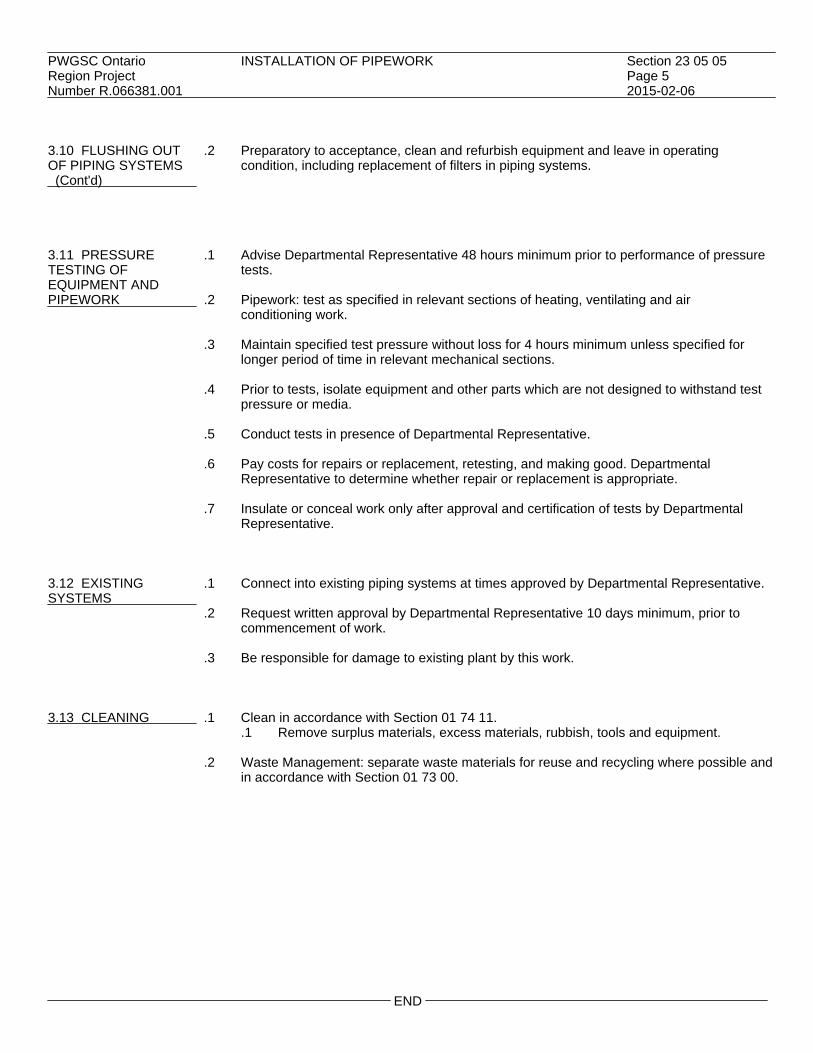
PWGSC Ontario INSTALLATION OF PIPEWORK Section 23 05 05Region Project Page 5Number R.066381.001 2015-02-06 3.10 FLUSHING OUT .2 Preparatory to acceptance, clean and refurbish equipment and leave in operating OF PIPING SYSTEMS condition, including replacement of filters in piping systems. (Cont'd) 3.11 PRESSURE .1 Advise Departmental Representative 48 hours minimum prior to performance of pressureTESTING OF tests.EQUIPMENT ANDPIPEWORK .2 Pipework: test as specified in relevant sections of heating, ventilating and air
conditioning work.
.3 Maintain specified test pressure without loss for 4 hours minimum unless specified forlonger period of time in relevant mechanical sections.
.4 Prior to tests, isolate equipment and other parts which are not designed to withstand test
pressure or media.
.5 Conduct tests in presence of Departmental Representative.
.6 Pay costs for repairs or replacement, retesting, and making good. DepartmentalRepresentative to determine whether repair or replacement is appropriate.
.7 Insulate or conceal work only after approval and certification of tests by Departmental
Representative. 3.12 EXISTING .1 Connect into existing piping systems at times approved by Departmental Representative.SYSTEMS
.2 Request written approval by Departmental Representative 10 days minimum, prior tocommencement of work.
.3 Be responsible for damage to existing plant by this work.
3.13 CLEANING .1 Clean in accordance with Section 01 74 11.
.1 Remove surplus materials, excess materials, rubbish, tools and equipment.
.2 Waste Management: separate waste materials for reuse and recycling where possible andin accordance with Section 01 73 00.
END


PWGSC Ontario VARIABLE FREQUENCY DRIVES Section 23 05 14Region Project Page 1Number R.066381.001 2015-02-06 PART 1 - GENERAL 1.1 REFERENCES .1 National Electrical Manufacturers Association (NEMA)
.1 ANSI/NEMA MG 1-2011, Motors and Generators, Part 31.
.2 Institute of Electrical and Electronics Engineers (IEEE).1 IEEE 519-1992, IEEE Recommended Practices and Requirements for Harmonic
Control in Electrical Power Systems.
.3 Canadian Standards Association (CSA).
.4 Underwriters Laboratories (UL).1 UL 508C Revision 7, Standard for Power Conversion Equipment.
1.2 SCOPE _________ .1 Provide Variable Frequency Drives (VFD's) for the equipment listed on Drawing
Schedules. All new VFD's to be one (1) manufacturer.
.2 Provide on-site commissioning (start-up) of the Variable Frequency Drives by factorytrained service personnel. Adequate time must be allowed to thoroughly and safely start,program, and test run the VFD with the building management system. A separate site visitto be provided for training of operation and maintenance personnel.
.3 The contractor is responsible for ensuring that the existing equipment is in top operating
condition before the commissioning of the VFD's occur. Any additional work required tobring the equipment into top operating condition should be brought to the DepartmentalRepresentative's attention.
1.3 SUBMITTALS .1 All bid submittals must include the following:
.1 A detailed description of all components in the VFD package, including line andload reactor impedance ratings and or filter design type, VFD current, HP, andvoltage rating.
.2 A list of any exceptions to this specification.
.3 Harmonic specification compliance calculations.
.2 All approval submittals shall include the following and approvals must be received priorto delivery of any goods:.1 Schematic wiring diagram showing all VFD package component connections and
all serial, digital and analog inputs and outputs to be connected to the controlsystem.
.2 Mechanical dimensional drawings with mounting details.
.3 On completion of the installation, the supplier shall provide the following:.1 Full commissioning report documenting all programmable settings, AC input
voltage, DC Bus voltage, current draw at maximum speed, amp vs speed curve anda description of ambient conditions.
.2 One operators manual for each VFD installed.
.3 One 216 mm x 279 mm wiring diagram for each VFD installed.

PWGSC Ontario VARIABLE FREQUENCY DRIVES Section 23 05 14Region Project Page 2Number R.066381.001 2015-02-06 1.4 GENERAL DESIGN .1 The VFD shall be of the Pulse Width Modulated (PWM) voltage source type, utilizing
CHARACTERISTIC fixed diode bridge input rectification and Insulated Gate BipolarTransistor (IGBT)/Intelligent Power Module (IPM) technology.
.2 The VFD's digital electronic control board(s) shall be manufactured using Surface Mount
Technology (SMT).
.3 The VFD shall be dual rated for variable torque applications, with the continuous dutyoutput current on the nameplate. The overload rating shall be 110% for 60 seconds. TheVFD shall be selected such that the continuous duty current rating shall be equal to orgreater than the connected motor full load current rating.
.4 All VFD's shall be factory CSA/CUL certified.
.5 All packaged drive systems shall be CSA certified.
.6 The VFD shall have the capability of operating multiple motors. The minimum VFD
continuous current rating shall be the sum of the full load current ratings of the connectedmotors.
.7 The VFD shall be capable of operating in an open circuit mode i.e. with the motor(s)
disconnected, for start-up and test purposes.
.8 The VFD shall have a minimum displacement power factor of 0.96 or higher at all outputfrequencies.
.9 The VFD and all options (e.g. line and load reactors, filters, bypass, etc.) must be
manufacturer wired & warrantied as an assembly in NEMA 1 use NEMA 3R for outdoorsenclosures. The enclosures may be of a Wall or Floor mount design, depending on therating, and be supplied with forced ventilation complete with cleanable air filters inenclosures where components produce excessive heat.
PART 2 - PRODUCTS 2.1 STANDARD VFD .1 Microprocessor Logic: The VFD shall include a 32 bit microprocessor and DSP (Digital
DESIGN FEATURE Signal Processor). A digital display keypad shall be provided for inputof parameter setting and operating commands. The digital display shall indicate outputfrequency, motor RPM, output current, as well as fault history information.
.2 Digital Inputs: The VFD shall include a minimum of five (5) digital inputs programmable
for function. Each input shall also be programmable to operate as a normally open (n/o)or normally closed (n/c) contact.
.3 Analog Inputs: The VFD shall accept an analog speed reference input signal of 0-5
V DC, 0-10 V DC, and/or 4-20 ma). If both inputs are active, the 0-10V DC (or 0-5 V DC) or4-20 mA signals shall be selectable by a digital input.
.4 Digital Outputs: The VFD shall include two(2) digital outputs each programmable for
drive run, frequency arrival (at set speed) or over torque. Each output shall also beprogrammable to operate as a normally open (n/o) or normally closed (n/c) contact.
.5 Analog Output: The VFD shall provide an analog pwm output signal (0-10 V DC, @
1 ma) proportional to the output frequency or output current.

PWGSC Ontario VARIABLE FREQUENCY DRIVES Section 23 05 14Region Project Page 3Number R.066381.001 2015-02-06 2.1 STANDARD VFD .6 Alarm Relay Outputs: The VFD shall provide an alarm relay which activates during a (Cont'd) fault condition. The relay contacts shall include a set of normally open/normally closed
(form c) contacts.
.7 Auto Restart: The VFD shall have the capability to automatically restart the motor afteran interruption in input power.
.8 Critical Frequency Rejection: The VFD shall provide a minimum of three(3) selectable
jump frequency points used to avoid critical resonance of the mechanical system.Frequency bandwidth for each jump frequency shall be programmable from 0 to +/- 9.9Hz.
.9 DC Injection Braking: The VFD DC braking control shall be capable of automatic
initiation prior to all start commands to stop a "wind-milling" fan motor before issuing arun command. The duration and amplitude of this setting is to be programmable throughthe operator interface.
.10 Acceleration/Deceleration Control: The VFD shall provide independent programmable
settings for accel/dec l time (0-999 seconds). The VFD shall also include a setting to allowthe motor to coast to a stop. Acceleration and deceleration shall be programmable forlinear, S-Curve, U-Curve or Reverse-U-Curve output.
.11 Carrier Frequency: The carrier frequency shall be programmable from 3 kHZ up to a
maximum of 16 kHz in 0.1 increments.
.12 Energy Savings:.1 The VFD shall be programmable for variable torque V/F curves to optimize energy
consumption..2 The VFD shall include an Automatic Energy Savings feature to further reduce
energy consumption by minimizing the current demand of the motor for a givenload, automatically.
.13 Automatic Voltage Regulation: The VFD shall maintain the rated starting torque
independent of the input voltage tolerance of +/-10%.
.14 Power Loss Ride-though: The VFD shall have a ride-through capability during anintermittent loss of power for up to 15 mSec.
.15 Min/Max Speed: Minimum and maximum speed settings shall be adjustable from 0 -
100%.
.16 Fault Log: A fault log will record the total number of faults an d display details of the lastthree faults, including reason for fault, frequency at time of fault, current at time of fault,and DC Bus Voltage at time of fault.
.17 Pre-set Speeds: Using the digital inputs a minimum of 7 programmable pre-set speeds
shall be selectable.
.18 Safety Interlocks: Terminals to be provide for connection of safety interlocks such asmotor thermistors Fire-stat and Freeze-stat. These interlocks shall shutdown operation ineither the Drive or Bypass operating modes.
.19 Door Mounted Operator Controls/Indicators: The basic operator controls shall consist of
the following: - Hand - Off - Auto Selector Switch - Potentiometer for setting speed in "Hand" - Indicating Lights for: - Power On
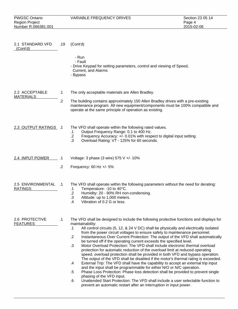
PWGSC Ontario VARIABLE FREQUENCY DRIVES Section 23 05 14Region Project Page 4Number R.066381.001 2015-02-06 2.1 STANDARD VFD .19 (Cont'd) (Cont'd)
- Run - Fault - Drive Keypad for setting parameters, control and viewing of Speed, Current, and Alarms - Bypass 2.2 ACCEPTABLE .1 The only acceptable materials are Allen Bradley.MATERIALS
.2 The building contains approximately 150 Allen Bradley drives with a pre-existingmaintenance program. All new equipment/components must be 100% compatible andoperate at the same principle of operation as existing.
2.3 OUTPUT RATINGS .1 The VFD shall operate within the following rated values.
.1 Output Frequency Range: 0.1 to 400 Hz.
.2 Frequency Accuracy: +/- 0.01% with respect to digital input setting.
.3 Overload Rating: VT - 125% for 60 seconds. 2.4 INPUT POWER .1 Voltage: 3 phase (3 wire) 575 V +/- 10%
.2 Frequency: 60 Hz +/- 5% 2.5 ENVIRONMENTAL .1 The VFD shall operate within the following parameters without the need for derating:RATINGS .1 Temperature: -10 to 40°C.
.2 Humidity: 20 - 90% RH non-condensing.
.3 Altitude: up to 1,000 meters.
.4 Vibration of 0.2 G or less. 2.6 PROTECTIVE .1 The VFD shall be designed to include the following protective functions and displays forFEATURES maintainability:
.1 All control circuits (5, 12, & 24 V DC) shall be physically and electrically isolatedfrom the power circuit voltages to ensure safety to maintenance personnel.
.2 Instantaneous Over Current Protection: The output of the VFD shall automaticallybe turned off if the operating current exceeds the specified level.
.3 Motor Overload Protection: The VFD shall include electronic thermal overloadprotection for automatic reduction of the overload limit at reduced operatingspeed, overload protection shall be provided in both VFD and bypass operation.The output of the VFD shall be disabled if the motor's thermal rating is exceeded.
.4 External Trip: The VFD shall have the capability to accept an external trip inputand the input shall be programmable for either N/O or N/C operation.
.5 Phase Loss Protection: Phase loss detection shall be provided to prevent singlephasing of the VFD input.
.6 Unattended Start Protection: The VFD shall include a user selectable function toprevent an automatic restart after an interruption in input power.

PWGSC Ontario VARIABLE FREQUENCY DRIVES Section 23 05 14Region Project Page 5Number R.066381.001 2015-02-06 2.6 PROTECTIVE .1 (Cont'd) FEATURES .7 Over Voltage Protection: The output of the VFD shall be automatically cut off if (Cont'd) the DC Bus voltage exceeds the specified level due to regenerative energy from
the motor..8 Ground Fault Protection: The VFD shall have the capability to sense current
imbalance during motor start-up for protection of the power circuit in the event of aground fault.
.9 Software Lock The VFD shall include a software function which prevents changesto the user defined settings.
.10 Power Module Protection: The IPM shall incorporate thermal and short circuitprotection circuits.
.11 CPU or EEPROM Error: VFD shall automatically be turned off in the event of anerror in the CPU or EEPROM.
.12 Option board communication error: VFD will automatically be turned off in theevent of an option board error.
2.7 RELIABILITY .1 A complete description of the manufacturer's quality assurance and testing program shall
be provided.
.2 Printed Circuit Boards / Pre-assembly: All blank circuit boards shall be checked forappearance, dimensions and continuity as per specification. All electronic componentsshall be subjected to a visual and functional test. Circuit board components shall bestored at 15-30°C @ 5 % humidity.
.3 Printed Circuit Board Inspection: All surface-mount devices shall be subjected to
microscopic inspection for component alignment and solder joint integrity. All completedcircuit boards shall undergo a thermal stress test with temperatures cycled between -5 to65°C.
.4 All VFD's of a series shall use one common logic printed circuit board for all units
supplied. 2.8 INPUT .1 All VFD's shall be furnished with the following protective devices as a minimum: All 575FILTERING volt systems require 5% impedance harmonically compensated Line reactors rated to
carry 150% total RMS current continuously for the reduction of line harmonics and to limitline voltage transients.
2.9 OUTPUT .1 All VFD's shall be furnished with LRC Sine wave output filter to match load.FILTERING 2.10 DISCONNECT .1 Provide fusible Input Disconnect complete with Class J 200 kA interrupt fuses (sized perSWITCH CEC tables), for all VFD installations. The Fusible disconnect shall be integrally mounted
and wired within the VFD NEMA 1 use NEMA 3R for outdoors enclosure and be providedwith a door interlock mechanism to prevent unauthorized entry with the power on. Inaddition the disconnect must have provision for padlocking in the off position. Servicepersonnel shall be able to open the door when the system is operating.
.2 Provide interlock wiring between remote motor disconnect and VFD to automatically
shut-off VFD on remote disconnection at motor.

PWGSC Ontario VARIABLE FREQUENCY DRIVES Section 23 05 14Region Project Page 6Number R.066381.001 2015-02-06 2.11 DIGITAL KEYPAD .1 Provide a multi-line display (minimum 4 lines) (68 characters) digital backlit keypad that
employs words and numbers for easy operator interface. Keypad shall be capable ofmonitoring, programming, and operating the VFD.
2.12 OVERLOAD RELAY .1 Provide a separately mounted Class 20 overload relay for each motor. Provide door
mounted overload reset buttons. PART 3 - EXECUTION 3.1 START-UP AND .1 The manufacturer shall provide start-up and commissioning of the variable frequencyCOMMISSIONING drive and its optional circuits by a factory certified service technician who is experiencedSERVICES in start-up and repair services. The commissioning personnel shall be the same personnel
that will provide the factory service and warranty repairs at the customer site. Salespersonnel and other agents who are not factory certified technicians for drive repair shallnot be acceptable as commissioning agents. The manufacturer shall have the ability torepair his products within 24 hours of notificati
.2 Start-up services shall include checking for verification of proper operation and
installation of the VFD, its options and its interface wiring to the building automationsystem. Included in this service shall be as a minimum:.1 Verification of contractor wire terminations and conduit runs to and from the VFD..2 One hour of customer operator training on the operation and service diagnostics at
the time of commissioning..3 Measurement for verification of proper operation of the following:
.1 Motor voltage and frequency. Verification of proper motor operation.
.2 Control input for proper building automation system interface and controlcalibration.
.3 Calibration check for the following set-points:.1 minimum speed.2 maximum speed.3 acceleration and deceleration rates.
.3 Commissioning agent to verify the programming of the VFD and to provide a written
copy of the settings to the engineer.
.4 Commissioning agent to lock out critical frequencies throughout the operating curve ofthe equipment as identified and required by the engineer. The agent shall recordamperages at six (minimum) different frequencies from minimum to maximum speed.
3.2 EXAMINATION .1 The contractor is to verify that the job site conditions for installation meet the factory
recommended and code required conditions for the VFD installation prior to start-up.These shall include as a minimum:.1 Clearance spacing..2 Compliance with environmental ratings of the VFD system..3 Separate conduit installation of the input wiring, the motor wiring, and control
wiring. At no time does any of this wiring run in parallel with each other..4 All power and control wiring is complete.
.2 The VFD is to be covered and protected from installation dust and contamination until
the environment is cleaned and ready for operation. The VFD system shall not beoperated while the unit is covered.

PWGSC Ontario VARIABLE FREQUENCY DRIVES Section 23 05 14Region Project Page 7Number R.066381.001 2015-02-06 3.2 EXAMINATION .3 Power shall not be applied until the manufacturer has started up his equipment. (Cont'd)
END


PWGSC Ontario PIPE WELDING Section 23 05 17Region Project Page 1Number R.066381.001 2015-02-06 PART 1 - GENERAL 1.1 REFERENCES .1 American National Standards Institute/American Society of Mechanical Engineers
(ANSI/ASME).1 ASME B31.1-2014, Power Piping..2 ANSI/ASME B31.3-2014, Process Piping..3 ASME Boiler and Pressure Vessel Code BPVC-2010:
.1 BPVC 2010 Section I: Power Boilers.
.2 BPVC 2010 Section V: Nondestructive Examination.
.3 BPVC 2010 Section IX: Welding and Brazing Qualifications.
.2 American National Standards Institute/American Water Works Association (ANSI/AWWA).1 ANSI/AWWA C206-11, Field Welding of Steel Water Pipe.
.3 American Welding Society (AWS)
.1 AWS C1.1M/C1.1-2000(R2012), Recommended Practices for Resistance Welding.
.2 AWS W1-2000, Welding Inspection Handbook.
.4 Canadian Standards Association (CSA International).1 CSA W47.2-11, Certification of Companies for Fusion Welding of Aluminum..2 CSA W48-14, Filler Metals and Allied Materials for Metal Arc Welding..3 CSA B51-14, Boiler, Pressure Vessel and Pressure Piping Code..4 CSA W117.2-12, Safety in Welding, Cutting and Allied Processes..5 CSA W178.1-14, Certification of Welding Inspection Organizations..6 CSA W178.2-14, Certification of Welding Inspectors.
1.2 ACTION AND .1 Provide submittals in accordance with Section 01 33 00.INFORMATIONALSUBMITTALS 1.3 QUALITY .1 Qualifications:ASSURANCE .1 Welders:
.1 Welding qualifications in accordance with CSA B51.
.2 Use qualified and licensed welders possessing certificate for each procedureperformed from authority having jurisdiction.
.3 Submit welder's qualifications to Departmental Representative.
.4 Each welder to possess identification symbol issued by authority havingjurisdiction.
.5 Certification of companies for fusion welding of aluminum in accordancewith CSA W47.2.
.2 Inspectors:.1 Inspectors qualified to CSA W178.2.
.3 Certifications:.1 Registration of welding procedures in accordance with CSA B51..2 Copy of welding procedures available for inspection..3 Safety in welding, cutting and allied processes in accordance with
CSA-W117.2.

PWGSC Ontario PIPE WELDING Section 23 05 17Region Project Page 2Number R.066381.001 2015-02-06 PART 2 - PRODUCTS 2.1 ELECTRODES .1 Electrodes: in accordance with CSA W48 Series. PART 3 - EXECUTION 3.1 APPLICATION .1 Manufacturer's Instructions: comply with manufacturer's written recommendations,
including product technical bulletins, handling, storage and installation instructions, anddatasheets.
3.2 QUALITY OF WORK .1 Welding: in accordance with ANSI/ASME B31.1, B31.3, ANSI/ASME Boiler and Pressure
Vessel Code, Sections I and IX and ANSI/AWWA C206, using procedures conforming toAWS B3.0, AWS C1.1, and applicable requirements of provincial authority havingjurisdiction.
3.3 INSTALLATION .1 Identify each weld with welder's identification symbol.REQUIREMENTS
.2 Backing rings:.1 Where used, fit to minimize gaps between ring and pipe bore..2 Do not install at orifice flanges.
.3 Fittings:
.1 NPS 2 and smaller: install welding type sockets.
.2 Branch connections: install welding tees or forged branch outlet fittings. 3.4 INSPECTION AND .1 Review weld quality requirements and defect limits of applicable codes and standardsTESTS - GENERAL with Departmental Representative before work is started.REQUIREMENTS
.2 Formulate "Inspection and Test Plan" in co-operation with Departmental Representative.
.3 Do not conceal welds until they have been inspected, tested and approved by inspector.
.4 Provide for inspector to visually inspect welds during early stages of welding proceduresin accordance with Welding Inspection Handbook. Repair or replace defects as requiredby codes and as specified.
3.5 SPECIALIST .1 General:EXAMINATIONS AND .1 Perform examinations and tests by specialist qualified to CSA W178.1 and CSATESTS W178.2 and approved by Departmental Representative.
.2 To ANSI/ASME Boiler and Pressure Vessels Code, Section V, CSA B51 andrequirements of authority having jurisdiction.
.3 Inspect and test 100% of welds in accordance with "Inspection and Test Plan" bynon-destructive visual examination.
.2 Hydrostatically test welds to ANSI/ASME B31.1.

PWGSC Ontario PIPE WELDING Section 23 05 17Region Project Page 3Number R.066381.001 2015-02-06 3.5 SPECIALIST .3 Visual examinations: include entire circumference of weld externally and wherever EXAMINATIONS AND possible internally. TESTS (Cont'd) .4 Failure of visual examinations:
.1 Upon failure of welds by visual examination, perform additional testing as directedby Departmental Representative of total of up to 10% of welds, selected at randomby Departmental Representative by radiographic tests.
.5 Full radiographic tests for steam and condensate piping systems.
.1 Radiography:.1 Conduct radiographic tests of up to 10% of welds, selected at random by
Departmental Representative from welds which would be most difficult torepair in event of failure after system is operational.
.2 Radiographic film:.1 Identify each radiographic film with date, location, name of welder, and
submit to Departmental Representative. Replace film if rejected because ofpoor quality.
.3 Interpretation of radiographic films:.1 By qualified radiographer.
.4 Failure of radiographic tests:.1 Extend tests to welds by welder responsible when those welds fails tests.
3.6 DEFECTS CAUSING .1 As described in ANSI/ASME B31.1 and ANSI/ASME Boiler and Pressure Vessels Code.REJECTION 3.7 REPAIR OF WELDS .1 Re-inspect and re-test repaired or re-worked welds at Contractor's expense.WHICH FAILED TESTS 3.8 CLEANING .1 Clean in accordance with Section 01 74 11.
.2 Waste Management: separate waste materials for reuse and recycling in accordance withSection 01 73 00.
END


PWGSC Ontario VALVES - BRONZE Section 23 05 23.01Region Project Page 1Number R.066381.001 2015-02-06 PART 1 - GENERAL 1.1 REFERENCES .1 American Society of Mechanical Engineers (ASME)
.1 ASME B1.20.1-2013, Pipe Threads, General Purpose (Inch).
.2 ASME B16.18-2012, Cast Copper Alloy Solder Joint Pressure Fittings.
.2 ASTM International.1 ASTM B62-09, Standard Specification for Composition Bronze or Ounce Metal
Castings.
.3 Manufacturers Standardization Society of the Valve and Fittings Industry, Inc. (MSS)..1 MSS-SP-80-2013, Bronze Gate Globe, Angle and Check Valves.
1.2 ACTION AND .1 Provide submittals in accordance with Section 01 33 00.INFORMATIONALSUBMITTALS 1.3 CLOSEOUT .1 Provide maintenance data for incorporation into manual specified in Section 01 78 00.SUBMITTALS 1.4 MAINTENANCE .1 Extra Materials/Spare Parts:MATERIAL SUBMITTALS .1 Furnish following spare parts:
.1 Valve seats: one for every 10 valves each size, minimum 1.
.2 Discs: one for every 10 valves, each size. Minimum 1.
.3 Stem packing: one for every 10 valves, each size. Minimum 1.
.4 Valve handles: 2 of each size.
.5 Gaskets for flanges: one for every 10 flanged joints..2 Tools:
.1 Furnish special tools for maintenance of systems and equipment.
.2 Include following:.1 Lubricant gun for expansion joints.
1.5 DELIVERY, .1 Deliver, store and handle materials in accordance with Section 01 61 00 and withSTORAGE AND manufacturer's written instructionsHANDLING
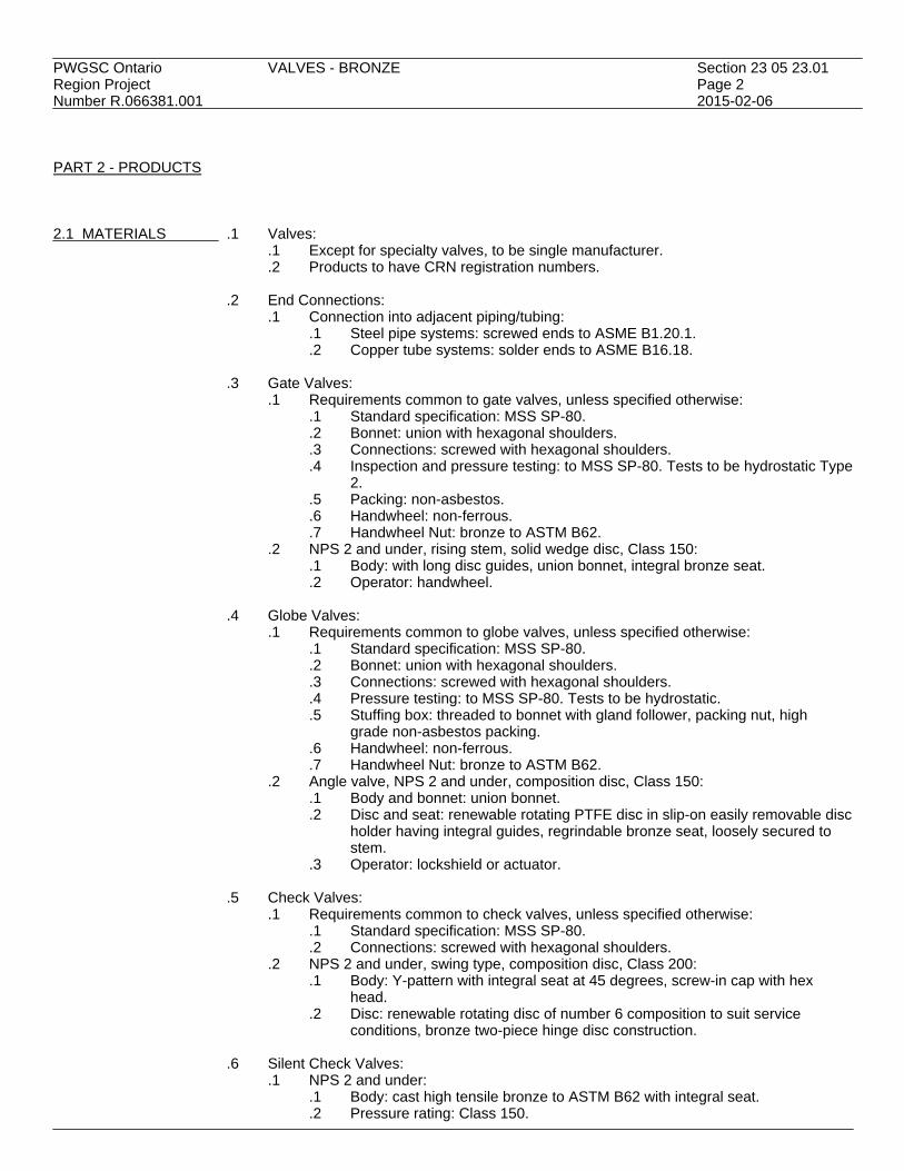
PWGSC Ontario VALVES - BRONZE Section 23 05 23.01Region Project Page 2Number R.066381.001 2015-02-06 PART 2 - PRODUCTS 2.1 MATERIALS .1 Valves:
.1 Except for specialty valves, to be single manufacturer.
.2 Products to have CRN registration numbers.
.2 End Connections:.1 Connection into adjacent piping/tubing:
.1 Steel pipe systems: screwed ends to ASME B1.20.1.
.2 Copper tube systems: solder ends to ASME B16.18.
.3 Gate Valves:.1 Requirements common to gate valves, unless specified otherwise:
.1 Standard specification: MSS SP-80.
.2 Bonnet: union with hexagonal shoulders.
.3 Connections: screwed with hexagonal shoulders.
.4 Inspection and pressure testing: to MSS SP-80. Tests to be hydrostatic Type2.
.5 Packing: non-asbestos.
.6 Handwheel: non-ferrous.
.7 Handwheel Nut: bronze to ASTM B62..2 NPS 2 and under, rising stem, solid wedge disc, Class 150:
.1 Body: with long disc guides, union bonnet, integral bronze seat.
.2 Operator: handwheel.
.4 Globe Valves:.1 Requirements common to globe valves, unless specified otherwise:
.1 Standard specification: MSS SP-80.
.2 Bonnet: union with hexagonal shoulders.
.3 Connections: screwed with hexagonal shoulders.
.4 Pressure testing: to MSS SP-80. Tests to be hydrostatic.
.5 Stuffing box: threaded to bonnet with gland follower, packing nut, highgrade non-asbestos packing.
.6 Handwheel: non-ferrous.
.7 Handwheel Nut: bronze to ASTM B62..2 Angle valve, NPS 2 and under, composition disc, Class 150:
.1 Body and bonnet: union bonnet.
.2 Disc and seat: renewable rotating PTFE disc in slip-on easily removable discholder having integral guides, regrindable bronze seat, loosely secured tostem.
.3 Operator: lockshield or actuator.
.5 Check Valves:.1 Requirements common to check valves, unless specified otherwise:
.1 Standard specification: MSS SP-80.
.2 Connections: screwed with hexagonal shoulders..2 NPS 2 and under, swing type, composition disc, Class 200:
.1 Body: Y-pattern with integral seat at 45 degrees, screw-in cap with hexhead.
.2 Disc: renewable rotating disc of number 6 composition to suit serviceconditions, bronze two-piece hinge disc construction.
.6 Silent Check Valves:
.1 NPS 2 and under:.1 Body: cast high tensile bronze to ASTM B62 with integral seat..2 Pressure rating: Class 150.

PWGSC Ontario VALVES - BRONZE Section 23 05 23.01Region Project Page 3Number R.066381.001 2015-02-06 2.1 MATERIALS .6 Silent Check Valves:(Cont'd) (Cont'd) .1 NPS 2 and under:(Cont'd)
.3 Connections: screwed ends to ASME B1.20.1 and with hex. shoulders.
.4 Disc and seat: renewable rotating disc.
.5 Stainless steel spring, heavy duty.
.6 Seat: regrindable.
.7 Ball Valves: Domestic water service only..1 NPS 2 and under:
.1 Body and cap: cast high tensile bronze to ASTM B62.
.2 Pressure rating: Class 125 2760-kPa CWP, 860 kPa steam.
.3 Connections: solder ends to ASME.
.4 Stem: tamperproof ball drive.
.5 Stem packing nut: external to body.
.6 Ball and seat: replaceable stainless steel solid ball and Teflon seats.
.7 Stem seal: TFE with external packing nut.
.8 Operator: removable lever handle. PART 3 - EXECUTION 3.1 INSTALLATION .1 Install rising stem valves in upright position with stem above horizontal.
.2 Remove internal parts before soldering.
.3 Install valves with unions at each piece of equipment arranged to allow servicing,maintenance, and equipment removal.
3.2 CLEANING .1 Remove surplus materials, excess materials, rubbish, tools and equipment.
END

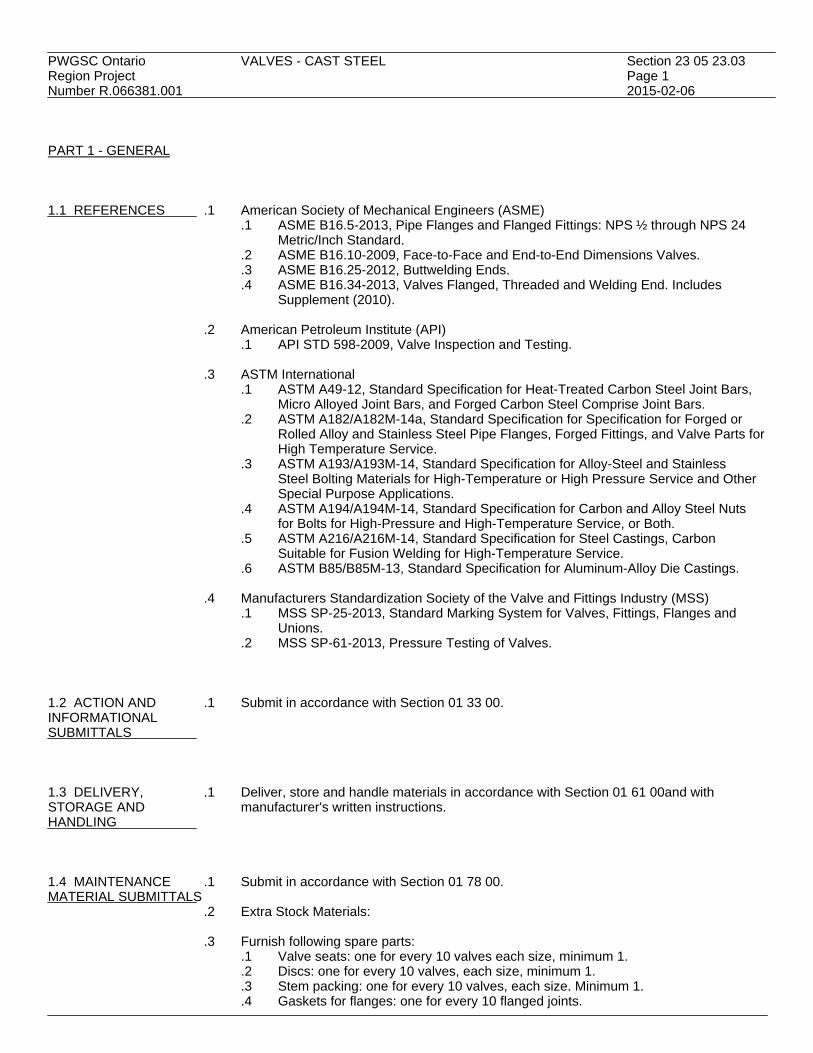
PWGSC Ontario VALVES - CAST STEEL Section 23 05 23.03Region Project Page 1Number R.066381.001 2015-02-06 PART 1 - GENERAL 1.1 REFERENCES .1 American Society of Mechanical Engineers (ASME)
.1 ASME B16.5-2013, Pipe Flanges and Flanged Fittings: NPS ½ through NPS 24Metric/Inch Standard.
.2 ASME B16.10-2009, Face-to-Face and End-to-End Dimensions Valves.
.3 ASME B16.25-2012, Buttwelding Ends.
.4 ASME B16.34-2013, Valves Flanged, Threaded and Welding End. IncludesSupplement (2010).
.2 American Petroleum Institute (API)
.1 API STD 598-2009, Valve Inspection and Testing.
.3 ASTM International.1 ASTM A49-12, Standard Specification for Heat-Treated Carbon Steel Joint Bars,
Micro Alloyed Joint Bars, and Forged Carbon Steel Comprise Joint Bars..2 ASTM A182/A182M-14a, Standard Specification for Specification for Forged or
Rolled Alloy and Stainless Steel Pipe Flanges, Forged Fittings, and Valve Parts forHigh Temperature Service.
.3 ASTM A193/A193M-14, Standard Specification for Alloy-Steel and StainlessSteel Bolting Materials for High-Temperature or High Pressure Service and OtherSpecial Purpose Applications.
.4 ASTM A194/A194M-14, Standard Specification for Carbon and Alloy Steel Nutsfor Bolts for High-Pressure and High-Temperature Service, or Both.
.5 ASTM A216/A216M-14, Standard Specification for Steel Castings, CarbonSuitable for Fusion Welding for High-Temperature Service.
.6 ASTM B85/B85M-13, Standard Specification for Aluminum-Alloy Die Castings.
.4 Manufacturers Standardization Society of the Valve and Fittings Industry (MSS).1 MSS SP-25-2013, Standard Marking System for Valves, Fittings, Flanges and
Unions..2 MSS SP-61-2013, Pressure Testing of Valves.
1.2 ACTION AND .1 Submit in accordance with Section 01 33 00.INFORMATIONALSUBMITTALS 1.3 DELIVERY, .1 Deliver, store and handle materials in accordance with Section 01 61 00and withSTORAGE AND manufacturer's written instructions.HANDLING 1.4 MAINTENANCE .1 Submit in accordance with Section 01 78 00.MATERIAL SUBMITTALS
.2 Extra Stock Materials:
.3 Furnish following spare parts:.1 Valve seats: one for every 10 valves each size, minimum 1..2 Discs: one for every 10 valves, each size, minimum 1..3 Stem packing: one for every 10 valves, each size. Minimum 1..4 Gaskets for flanges: one for every 10 flanged joints.

PWGSC Ontario VALVES - CAST STEEL Section 23 05 23.03Region Project Page 2Number R.066381.001 2015-02-06 PART 2 - PRODUCTS 2.1 MATERIAL .1 Valves:
.1 To be of single manufacturer.
.2 Test valves individually.
.2 Requirements common to valves, unless specified otherwise:.1 Pressure-temperature ratings: to ASME B16.34..2 Inspections and tests: to API 598..3 Pressure testing: to MSS SP-61..4 Flanged valves:
.1 Face-to-face dimensions: to ASME B16.10.
.2 Flange dimensions: to ASME B16.5 with 1.6 mm raised face..5 Butt-weld valves:
.1 End-to-end dimensions: to ASME B16.10.
.2 End dimensions: to ASME B16.25 bored for standard pipe schedule..6 Handwheel: non-heating type with raised rim of die-cast aluminum alloy to ASTM
B85 or malleable iron to ASTM A49..7 Markings: to MSS SP-25..8 Identification:
.1 Plate showing catalogue number, size, material of body disc, stem seat,fluid, pressure-temperature rating.
.2 Body markings: manufacturer, size, primary service rating, material symbol..9 CRN registration number required for all products.
2.2 GATE VALVES .1 NPS 2-1/2 - 12, rising stem, OS&Y, flexible wedge disc, flanged ends, Class 150:
.1 Body and multiple-bolted integral yoke and bonnet: cast steel to ASTMA216/A216M WCB, with full length disc guides designed to ensure correctre-assembly.
.2 Body/bonnet joint: flat face with corrugated metallic gasket.
.3 Bonnet studs: to ASTM A193/A193M Type B7.
.4 Bonnet nuts: to ASTM A194/A194M Type 2H.
.5 Stuffing box: including non-galling two-piece ball jointed packing gland, withswing-type eye bolts and nuts.
.6 Gland packing: containing corrosion inhibitor to prevent stem pitting.
.7 Yoke sleeve: Ni-Resist, minimum melting point above 954 degrees C.
.8 Hydraulic grease fitting: for lubrication of yoke sleeve bearing surfaces.
.9 Disc: with disc stem ring to connect to stem, guided throughout its travel..1 NPS 2 1/2 - 6: solid corrosion and heat resistant 13% chromium steel with
minimum hardness of 350 HB..2 NPS 8 and larger: carbon steel faced with corrosion and heat resistant 13
chromium steel with minimum hardness of 350 HB..10 Seat ring: seamless carbon steel with hard-faced cobalt-chromium-tungsten alloy
seating surface, slipped in, seal welded, ground to match disc..11 Stem: heat treated corrosion and heat resistant 13% chromium steel with
accurately-cut precision-machined Acme or 60 degrees V threads, top screwed forhandwheel nut, T-head disc-stem connection.
.12 Operator: see elsewhere in this Section.

PWGSC Ontario VALVES - CAST STEEL Section 23 05 23.03Region Project Page 3Number R.066381.001 2015-02-06 2.3 GLOBE VALVES .1 NPS 2-1/2 - 12, rising stem, OS&Y, flanged ends, Class 150:
.1 Body and multiple-bolted integral yoke and bonnet: cast steel to ASTMA216/A216M WCB.
.2 Body/bonnet joint: flat face with corrugated metallic gasket.
.3 Bonnet studs: to ASTM A193/A193M Type B7.
.4 Bonnet nuts: to ASTM A194/A194M Type 2H.
.5 Stuffing box: including non-galling two-piece ball-jointed packing gland, withswing-type eye bolts and nuts.
.6 Gland packing: containing corrosion inhibitor to prevent stem pitting.
.7 Yoke bushing: Ni-Resist, minimum melting point above 954 degrees C.
.8 Hydraulic grease fitting: for lubrication of yoke sleeve bearing surfaces.
.9 Disc: plug type with 15 degrees taper seat and bottom guide.
.10 Seat rings: with 1.6 mm thick cobalt-chromium-tungsten alloy facings withminimum hardness of 375 HB (cold), slipped in, seal welded, ground to match disc.
.11 Stem: heat treated corrosion and heat resistant 13% chromium steel with bonnetbushing, long engagement with yoke bushing for accurate seating, accurately-cutprecision-machined Acme or 60 degrees V threads, top screwed for handwheel nut.
.12 Operator: see elsewhere in this Section. 2.4 VALVE OPERATORS .1 Handwheel: on all valves.
.2 Handwheel with chain operators: on valves installed more than 2400 mm above floor inboiler rooms and mechanical equipment rooms.
.3 Motors:
.1 Application: full open and full close applications.
.2 Position and precision control. 2.5 BYPASSES FOR .1 Locations: on main valve to building.GATE AND GLOBEVALVES .2 Size of bypass valve:
.1 Main valve up to NPS 8: NPS 3/4.
.2 Main valve NPS 10 and over: NPS 1.
.3 Type of bypass valves:.1 On gate valve: globe, with composition disc, bronze trim, to Section 23 05 23.01..2 On globe valve: globe, with composition disc, bronze trim, to Section 23 05 23.01.
2.6 CHECK VALVES .1 NPS 2-1/2 and over, flanged ends, Class 150: swing check.
.1 Body and multiple-bolted cap: cast steel to ASTM A216/A216M WCB.
.2 Cap studs: to ASTM A193/A193M Type B7.
.3 Cap nuts: to ASTM A194/A194M Type 2H.
.4 Body/cap joint: male-female face with corrugated metallic gasket.
.5 Disc: heat treated corrosion and heat resistant 13% chromium steel.
.6 Seat rings: heat treated corrosion and heat resistant 13% chromium steel, slippedin, seal welded, ground to match disc.
.7 Hinge: ASTM A182/A182M.
.8 Hinge pin: ASTM A182/A182M.
.9 Hinge pin plugs: ASTM A182/A182M.
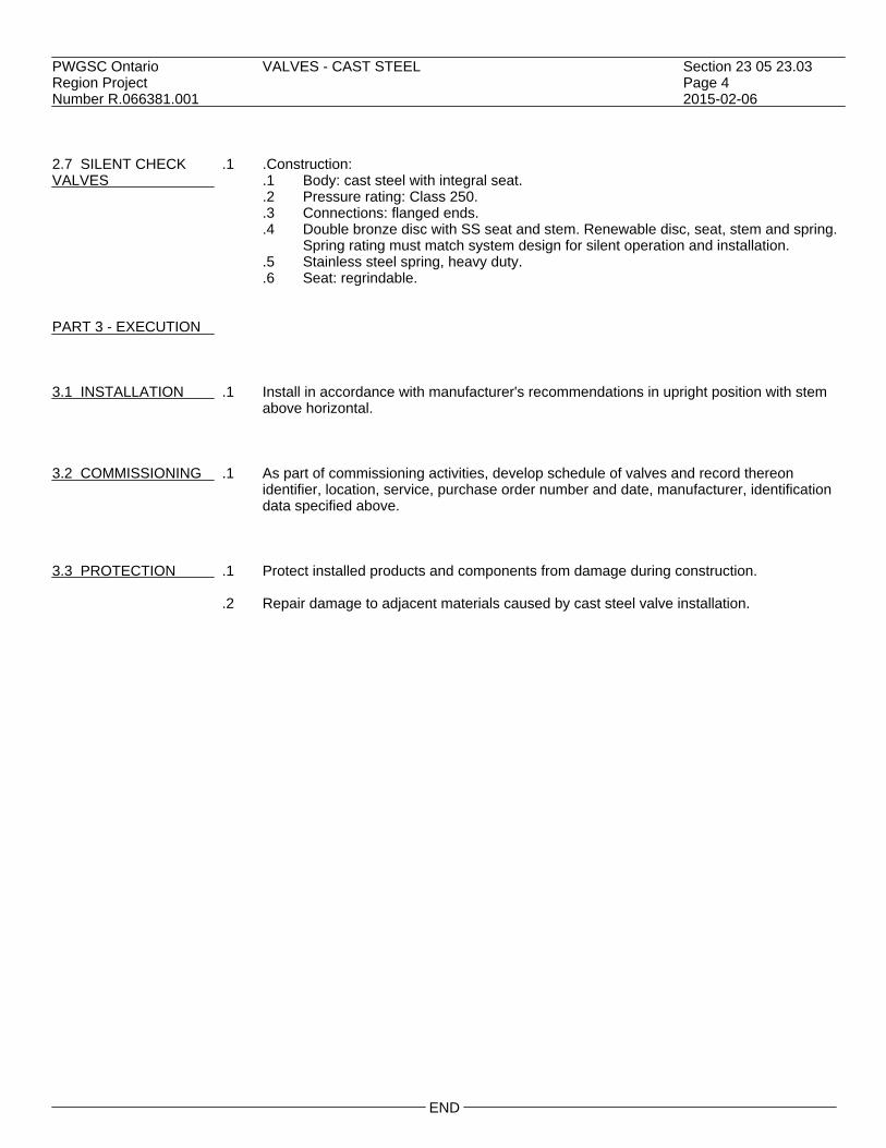
PWGSC Ontario VALVES - CAST STEEL Section 23 05 23.03Region Project Page 4Number R.066381.001 2015-02-06 2.7 SILENT CHECK .1 .Construction:VALVES .1 Body: cast steel with integral seat.
.2 Pressure rating: Class 250.
.3 Connections: flanged ends.
.4 Double bronze disc with SS seat and stem. Renewable disc, seat, stem and spring.Spring rating must match system design for silent operation and installation.
.5 Stainless steel spring, heavy duty.
.6 Seat: regrindable. PART 3 - EXECUTION 3.1 INSTALLATION .1 Install in accordance with manufacturer's recommendations in upright position with stem
above horizontal. 3.2 COMMISSIONING .1 As part of commissioning activities, develop schedule of valves and record thereon
identifier, location, service, purchase order number and date, manufacturer, identificationdata specified above.
3.3 PROTECTION .1 Protect installed products and components from damage during construction.
.2 Repair damage to adjacent materials caused by cast steel valve installation.
END

PWGSC Ontario HANGERS AND SUPPORTS FOR HVAC PIPING AND Section 23 05 29Region Project EQUIPMENT Page 1Number R.066381.001 2015-02-06 PART 1 - GENERAL 1.1 RELATED .1 Section 05 12 23 - Structural Steel for Buildings.REQUIREMENTS
.2 Section 05 50 01 - Metal Fabrications.
.3 Section 23 05 48 - Vibration and Seismic Controls for HVAC Piping and Equipment. 1.2 REFERENCES .1 American Society of Mechanical Engineers (ASME)
.1 ASME B31.1-2014, Power Piping.
.2 ASTM International.1 ASTM A125-96(2013)e1, Standard Specification for Steel Springs, Helical,
Heat-Treated..2 ASTM A307-12, Standard Specification for Carbon Steel Bolts and Studs, 60,000
PSI Tensile Strength..3 ASTM A563-07a(R2014), Standard Specification for Carbon and Alloy Steel Nuts.
.3 Factory Mutual (FM)
.4 Manufacturer's Standardization Society of the Valves and Fittings Industry (MSS)
.1 MSS SP 58-2009, Pipe Hangers and Supports - Materials, Design, ManufactureSelection, Application and Installation.
1.3 ACTION AND .1 Provide submittals in accordance with Section 01 33 00.INFORMATIONALSUBMITTALS .2 Product Data:
.1 Provide manufacturer's printed product literature and data sheets for hangers andsupports and include product characteristics, performance criteria, physical size,finish and limitations.
.3 Shop Drawings:
.1 Submit drawings stamped and signed by professional engineer registered orlicensed in Province of Ontario, Canada.
.2 Submit shop drawings for:.1 Connections to equipment and structure.
.4 Certificates:
.1 Submit certificates signed by manufacturer certifying that materials comply withspecified performance characteristics and physical properties.

PWGSC Ontario HANGERS AND SUPPORTS FOR HVAC PIPING AND Section 23 05 29Region Project EQUIPMENT Page 2Number R.066381.001 2015-02-06 PART 2 - PRODUCTS 2.1 SYSTEM .1 Design Requirements:DESCRIPTION .1 Construct pipe hanger and support to manufacturer's recommendations utilizing
manufacturer's regular production components, parts and assemblies..2 Base maximum load ratings on allowable stresses prescribed by ASME B31.1 or
MSS SP 58..3 Ensure that supports, guides, anchors do not transmit excessive quantities of heat
to building structure..4 Design hangers and supports to support systems under conditions of operation,
allow free expansion and contraction, prevent excessive stresses from beingintroduced into pipework or connected equipment.
.5 Provide for vertical adjustments after erection and during commissioning. Amountof adjustment in accordance with MSS SP 58.
.2 Performance Requirements:
.1 Design supports, platforms, catwalks, hangers to withstand seismic events asspecified Section 23 05 48.
2.2 GENERAL .1 Fabricate hangers, supports and sway braces in accordance with MSS SP 58 and ASME
B31.1.
.2 Use components for intended design purpose only. Do not use for rigging or erectionpurposes.
2.3 PIPE HANGERS .1 Finishes:
.1 Pipe hangers and supports: galvanized after manufacture.
.2 Use electro-plating galvanizing process.
.3 Ensure steel hangers in contact with copper piping are copper plated.
.2 Upper attachment structural: suspension from lower flange of I-Beam:.1 Cold piping NPS 2 maximum: malleable iron C-clamp with hardened steel cup
point setscrew, locknut and carbon steel retaining clip..1 Rod: 9 mm UL listed.
.2 Cold piping NPS 2-1/2 or greater, hot piping: malleable iron beam clamp, eyerod, jaws and extension with carbon steel retaining clip, tie rod, nuts and washers,UL listed to MSS-SP 58.
.3 Upper attachment structural: suspension from upper flange of I-Beam:
.1 Cold piping NPS 2 maximum: ductile iron top-of-beam C-clamp with hardenedsteel cup point setscrew, locknut and carbon steel retaining clip, UL listed to MSSSP 58.
.2 Cold piping NPS 2-1/2 or greater, hot piping: malleable iron top-of-beamjaw-clamp with hooked rod, spring washer, plain washer and nut UL listed.
.4 Upper attachment to concrete:
.1 Ceiling: carbon steel welded eye rod, clevis plate, clevis pin and cotters withweldless forged steel eye nut. Ensure eye 6 mm minimum greater than roddiameter.
.2 Concrete inserts: wedge shaped body with knockout protector plate UL listed toMSS SP 58.

PWGSC Ontario HANGERS AND SUPPORTS FOR HVAC PIPING AND Section 23 05 29Region Project EQUIPMENT Page 3Number R.066381.001 2015-02-06 2.3 PIPE HANGERS .5 Shop and field-fabricated assemblies: (Cont'd) .1 Trapeze hanger assemblies: coordinated with other trades and designed by
licensed engineer..2 Steel brackets: coordinated with other trades and designed by licensed engineer..3 Sway braces for seismic restraint systems: to Section 23 05 48.
.6 Hanger rods: threaded rod material to MSS SP 58:
.1 Ensure that hanger rods are subject to tensile loading only.
.2 Provide linkages where lateral or axial movement of pipework is anticipated.
.3 Do not use 22 mm or 28 mm rod.
.7 Pipe attachments: material to MSS SP 58:.1 Attachments for steel piping: carbon steel galvanized..2 Attachments for copper piping: copper plated black steel..3 Use insulation shields for hot pipework..4 Oversize pipe hangers and supports.
.8 Adjustable clevis: material to MSS SP 58 UL listed, clevis bolt with nipple spacer and
vertical adjustment nuts above and below clevis..1 Ensure "U" has hole in bottom for rivetting to insulation shields.
.9 Yoke style pipe roll: carbon steel yoke, rod and nuts with cast iron roll, to MSS SP 58.
.10 U-bolts: carbon steel to MSS SP 58 with 2 nuts at each end to ASTM A563.
.1 Finishes for steel pipework: galvanized.
.2 Finishes for copper, glass, brass or aluminum pipework: galvanized, with formedportion epoxy coated.
.11 Pipe rollers: cast iron roll and roll stand with carbon steel rod to MSS SP 58.
2.4 RISER CLAMPS .1 Steel or cast iron pipe: galvanized black carbon steel to MSS SP 58, type 42, UL listed.
.2 Copper pipe: carbon steel copper plated to MSS SP 58, type 42.
.3 Bolts: to ASTM A307.
.4 Nuts: to ASTM A563. 2.5 INSULATION .1 Insulated cold piping:PROTECTION SHIELDS .1 64 kg/m3 density insulation plus insulation protection shield to: MSS SP 58,
galvanized sheet carbon steel. Length designed for maximum 3 m span.
.2 Insulated hot piping:.1 Curved plate 300 mm long, with edges turned up, welded-in centre plate for pipe
sizes NPS 12 and over, carbon steel to comply with MSS SP 58. 2.6 CONSTANT .1 Springs: alloy steel to ASTM A125, shot peened, magnetic particle inspected, with +/-5%SUPPORT SPRING spring rate tolerance, tested for free height, spring rate, loaded height and provided withHANGERS Certified Mill Test Report (CMTR).
.2 Load adjustability: 10% minimum adjustability each side of calibrated load. Adjustmentwithout special tools. Adjustments not to affect travel capabilities.

PWGSC Ontario HANGERS AND SUPPORTS FOR HVAC PIPING AND Section 23 05 29Region Project EQUIPMENT Page 4Number R.066381.001 2015-02-06 2.6 CONSTANT .3 Provide upper and lower factory set travel stops. SUPPORT SPRING HANGERS .4 Provide load adjustment scale for field adjustments. (Cont'd)
.5 Total travel to be actual travel + 20%. Difference between total travel and actual travel25 mm minimum.
.6 Individually calibrated scales on each side of support calibrated prior to shipment,
complete with calibration record. 2.7 VARIABLE .1 Vertical movement: 13 mm minimum, 50 mm maximum, use single springSUPPORT SPRING pre-compressed variable spring hangers.HANGERS
.2 Vertical movement greater than 50 mm: use double spring pre-compressed variablespring hanger with 2 springs in series in single casing.
.3 Variable spring hanger complete with factory calibrated travel stops. Provide certificate
of calibration for each hanger.
.4 Steel alloy springs: to ASTM A125, shot peened, magnetic particle inspected, with +/-5%spring rate tolerance, tested for free height, spring rate, loaded height and provided withCMTR.
2.8 EQUIPMENT .1 Fabricate equipment supports not provided by equipment manufacturer from structuralSUPPORTS grade steel meeting requirements of Section 05 12 23. Submit calculations with shop
drawings. 2.9 EQUIPMENT .1 Provide templates to ensure accurate location of anchor bolts.ANCHOR BOLTS ANDTEMPLATES 2.10 PLATFORMS AND .1 To Section 05 50 01.CATWALKS 2.11 HOUSE-KEEPING .1 Provide 100 mm high concrete housekeeping pads for base-mounted equipment; sizePADS pads 50 mm larger than equipment; chamfer pad edges.
.2 Concrete: to Section 03 30 00. 2.12 OTHER .1 Fabricate equipment supports from structural grade steel meeting requirements ofEQUIPMENT SUPPORTS Section 05 12 23.
.2 Submit structural calculations with shop drawings.

PWGSC Ontario HANGERS AND SUPPORTS FOR HVAC PIPING AND Section 23 05 29Region Project EQUIPMENT Page 5Number R.066381.001 2015-02-06 PART 3 - EXECUTION 3.1 MANUFACTURER'S .1 Compliance: comply with manufacturer's written recommendations or specifications,INSTRUCTIONS including product technical bulletins, handling, storage and installation instructions, and
datasheet. 3.2 INSTALLATION .1 Install in accordance with:
.1 Manufacturer's instructions and recommendations.
.2 Vibration Control Devices:.1 Install on piping systems at pumps, boilers, chillers, cooling towers, and as
indicated.
.3 Clamps on riser piping:.1 Support independent of connected horizontal pipework using riser clamps and riser
clamp lugs welded to riser..2 Bolt-tightening torques to industry standards..3 Steel pipes: install below coupling or shear lugs welded to pipe..4 Cast iron pipes: install below joint.
.4 Clevis plates:
.1 Attach to concrete with 4 minimum concrete inserts, one at each corner.
.5 Provide supplementary structural steelwork where structural bearings do not exist or whereconcrete inserts are not in correct locations.
.6 Use approved constant support type hangers where:
.1 Vertical movement of pipework is 13 mm or more,
.2 Transfer of load to adjacent hangers or connected equipment is not permitted.
.7 Use variable support spring hangers where:.1 Transfer of load to adjacent piping or to connected equipment is not critical..2 Variation in supporting effect does not exceed 25 % of total load.
3.3 HANGER SPACING .1 Plumbing piping: to Provincial Code.
.2 Fire protection: to applicable fire code.
.3 Gas and fuel oil piping: up to NPS 1/2: every 1.8 m.
.4 Copper piping: up to NPS 1/2: every 1.5 m.
.5 Flexible joint roll groove pipe: in accordance with table below for steel, but not less thanone hanger at joints. Table listings for straight runs without concentrated loads and wherefull linear movement is not required.
.6 Within 300 mm of each elbow.
Maximum Pipe Maximum Maximum Size : NPS Spacing Steel Spacing Copper up to 1-1/4 2.4 m 1.8 m 1-1/2 3.0 m 2.4 m

PWGSC Ontario HANGERS AND SUPPORTS FOR HVAC PIPING AND Section 23 05 29Region Project EQUIPMENT Page 6Number R.066381.001 2015-02-06 3.3 HANGER SPACING .6 (Cont'd) (Cont'd)
2 3.0 m 2.4 m 2-1/2 3.7 m 3.0 m 3 3.7 m 3.0 m 3-1/2 3.7 m 3.3 m 4 3.7 m 3.6 m 5 4.3 m 6 4.3 m 8 4.3 m 10 4.9 m 12 4.9 m
.7 Pipework greater than NPS 12: to MSS SP 58. 3.4 HANGER .1 Install hanger so that rod is vertical under operating conditions.INSTALLATION
.2 Adjust hangers to equalize load.
.3 Support from structural members. Where structural bearing does not exist or inserts arenot in suitable locations, provide supplementary structural steel members.
3.5 HORIZONTAL .1 Angularity of rod hanger resulting from horizontal movement of pipework from cold to hotMOVEMENT position not to exceed 4 degrees from vertical.
.2 Where horizontal pipe movement is less than 13 mm, offset pipe hanger and support sothat rod hanger is vertical in the hot position.
3.6 FINAL .1 Adjust hangers and supports:ADJUSTMENT .1 Ensure that rod is vertical under operating conditions.
.2 Equalize loads.
.2 Adjustable clevis:.1 Tighten hanger load nut securely to ensure proper hanger performance..2 Tighten upper nut after adjustment.
.3 C-clamps:
.1 Follow manufacturer's recommended written instructions and torque values whentightening C-clamps to bottom flange of beam.
.4 Beam clamps:
.1 Hammer jaw firmly against underside of beam.
END

PWGSC Ontario HEAT TRACING FOR HVAC PIPING AND TANKS Section 23 05 33Region Project Page 1Number R.066381.001 2015-02-06 PART 1 - GENERAL 1.1 REFERENCES .1 National Electric Code - NEC 1996, Section 427-23. 1.2 PRODUCT DATA .1 Submit product data in accordance with Section 01 33 00. 1.3 ELECTRICAL .1 Electrical work to conform to Division 26 including the following:
.1 Control wiring and conduit is specified in Division 26 except for conduit, wiringand connections below 50 V which are related to control systems specified in Div.21, 22, 23 & 25. Refer to Division 26 for quality of materials and workmanship.
PART 2 - PRODUCTS 2.1 PIPE TRACING .1 General:HEATING CABLES .1 Furnish and install a complete ULC Listed and CSA Certified system of heating
cables, components, and controls to prevent pipes from freezing.
.2 Products:.1 The self-regulating heating cable shall consist of two (2) 14 AWG nickel-copper
bus wires embedded in parallel in a self-regulating polymer core that varies itspower output to respond to temperature all along its length, allowing the heatingcable to be cut to length in the field. The heating cable shall be covered by aradiation-crosslinked, fluoropolymer dielectric jacket. To provide a ground path andto enhance the heating cable's ruggedness, the heating cable shall have a braid oftinned copper and an outer jacket of high temperature fluoropolymer section427-23 of the NEC.
.2 In order to conserve energy and to prevent overheating, the heating cable shallhave a self-regulating factor of at least 90%. The self-regulating factor is defined asthe percentage reduction, without thermostatic control, of the heating cable outputgoing from 4.4°C pipe temperature operation to 65.6°C pipe temperatureoperation.
.3 The heating cable shall operate on line voltages of 120 volts without the use oftransformers.
.4 The heating cable for metal pipe freeze protection shall be sized according to thetable below. The required heating cable output rating is in watts per metre at 10°C.
Pipe Size Minimum Ambient Temperature (NPS) -17°C (0°F) -29°C (-20°F) 3 or less 16 watts 16 watts 4 16 watts 16 watts 6 26 watts 26 watts 8 26 watts 2 strips - 16 watts 10 2 strips - 16 watts 2 strips - 26 watts
.3 Heating-cable circuit shall be protected by a ground-fault device for equipmentprotection. This requirement is in accordance with section 427-22 of the NEC.

PWGSC Ontario HEAT TRACING FOR HVAC PIPING AND TANKS Section 23 05 33Region Project Page 2Number R.066381.001 2015-02-06 2.1 PIPE TRACING .4 Components: HEATING CABLES .1 All heating-cable components snail be UL Listed and CSA Certified, for use as part (Cont'd) of the system to provide pipe freeze protection. Component enclosures shall be
rated NEMA 4X to prevent water ingress and corrosion. Installation shall not requirethe installing contractor to cut into the heating-cable core to expose the bus wires.Connection systems that require the installing contractor to strip the bus wires, orthat use crimps or terminal blocks, shall not be acceptable. All components thatmake an electrical connection shall be re-enterable for servicing. No componentshall use silicone to seal the electrical connections. An exception will be made inareas where a conduit transition is required.
.5 System Control:
.1 Thermostatic Control - Ambient Sensing: The system shall be controlled by anambient sensing thermostat set at 4.4°C (40°F).
.6 Power connection, end seal, splice, outer jacket repair kits shall be applied in the field.
.7 Thermostat:
.1 The system shall be controlled by a thermostat either directly or through anappropriate contactor.
.8 Circuit Breaker:
.1 The system shall be protected by a ground fault circuit breaker with a 30 milliamptrip.
PART 3 - EXECUTION 3.1 MANUFACTURER'S .1 Compliance: comply with manufacturer's written recommendations or specifications,INSTRUCTIONS including product technical bulletins, handling, storage and installation instructions, and
datasheet. 3.2 INSTALLATION .1 System must be installed per manufacturer's recommendations.
.2 Apply the heating cable linearly on the pipe after piping has been successfullypressure-tested. Secure the heating cable to piping with cable ties or fibreglass tape.
.3 Apply "Electric Traced" labels to the outside of the thermal insulation.
.4 Distribute and fasten cable evenly on pipe using pipe strap or tape at maximum spacing
0.5 m. Ensure that heating cables do not touch or cross each other at any point. Run onlycold leads in conduit and ensure sensing bulb does not touch cable. Ground shield tobuilding ground. Coordinate cable installation with insulation application. Loopadditional cable at fittings, valves, and flanges.
.5 Make power and control connections.
3.3 TESTS .1 After insulation and before and after installing the thermal insulation, subject heating
cable to testing using a 2500 Vdc Megger. Minimum insulation resistance shall be20 megohms or greater.

PWGSC Ontario HEAT TRACING FOR HVAC PIPING AND TANKS Section 23 05 33Region Project Page 3Number R.066381.001 2015-02-06 3.3 TESTS .2 Where resistance of 50 megohms or less is measured, stop work and advise Departmental (Cont'd) Representative.
END


PWGSC Ontario VIBRATION AND SEISMIC CONTROLS FOR HVAC PIPING Section 23 05 48Region Project AND EQUIPMENT Page 1Number R.066381.001 2015-02-06 PART 1 - GENERAL 1.1 RELATED .1 Section 23 05 93 - Testing, Adjusting and Balancing of HVAC.REQUIREMENTS 1.2 REFERENCES .1 National Building Code of Canada (NBC) 2010. 1.3 SHOP DRAWINGS .1 Submit shop drawings in accordance with Section 01 33 00.
.2 Provide detailed drawings of all seismic control measures for equipment and piping..1 Submit shop drawing stamped and signed by professional engineer licensed in
Province of Ontario. PART 2 - PRODUCTS 2.1 GENERAL .1 Size, shape, type and performance of vibration isolation to be as provided by equipment
manufacturer to isolate all vibrations to structure being attached too. 2.2 ELASTOMERIC .1 Type EP1 - neoprene waffle or ribbed; 9mm minimum thick; 50 durometer; maximumPADS loading 350 kPa.
.2 Type EP2 - rubber waffle or ribbed; 9 mm minimum thick; 30 durometer natural rubber;maximum loading 415 kPa.
.3 Type EP3 - neoprene-steel-neoprene; 9 mm minimum thick neoprene bonded to 1.71
mm steel plate; 50 durometer neoprene, waffle or ribbed; holes sleeved with isolationwashers; maximum loading 350 kPa.
.4 Type EP4 - rubber-steel-rubber; 9 mm minimum thick rubber bonded to 1.71 mm steel
plate; 30 durometer natural rubber, waffle or ribbed; holes sleeved with isolation washers;maximum loading 415 kPa.
2.3 ELASTOMERIC .1 Type M1 - colour coded; neoprene in shear; maximum durometer of 60; threaded insertMOUNTS and two bolt-down holes; ribbed top and bottom surfaces. 2.4 SPRINGS .1 Design stable springs so that ratio of lateral to axial stiffness is equal to or greater than
1.2 times the ratio of static deflection to working height. Select for 50% travel beyondrated load. Units to be complete with levelling devices.
.2 Ratio of height when loaded to diameter of spring to be between 0.8 to 1.0.
.3 Cadmium plate for all installations.

PWGSC Ontario VIBRATION AND SEISMIC CONTROLS FOR HVAC PIPING Section 23 05 48Region Project AND EQUIPMENT Page 2Number R.066381.001 2015-02-06 2.4 SPRINGS .4 Colour code springs. (Cont'd) 2.5 SPRING MOUNT .1 Zinc or cadmium plated hardware; housings coated with rust resistant paint.
.2 Type M2 - stable open spring: support on bonded 6 mm minimum thick ribbed neopreneor rubber friction and acoustic pad.
.3 Type M3 - stable open spring: 6 mm minimum thick ribbed neoprene or rubber friction
and acoustic pad, bonded under isolator and on isolator top plate; levelling bolt forrigidly mounting to equipment.
.4 Type M4 - restrained stable open spring: supported on bonded 6 mm minimum thick
ribbed neoprene or rubber friction and acoustic pad; built-in resilient limit stops,removable spacer plates.
.5 Type M5 - enclosed spring mounts with snubbers for isolation up to 950 kg maximum.
2.6 HANGERS .1 Colour coded springs, rust resistant, painted box type hangers. Arrange to permit hanger
box or rod to move through a 30° arc without metal to metal contact.
.2 Type H1 - neoprene - in-shear, moulded with rod isolation bushing which passes throughhanger box.
.3 Type H2 - stable spring, elastomeric washer, cup with moulded isolation bushing which
passes through hanger box.
.4 Type H3 - stable spring, elastomeric element, cup with moulded isolation bushing whichpasses through hanger box.
.5 Type H4 - stable spring, elastomeric element with precompression washer and nut with
deflection indicator. 2.7 SEISMIC .1 General:CONTROL MEASURES .1 All new work is subject to seismic review and installation to maintain life safety
during seismic event..2 Seismic control systems to work in all directions..3 Fasteners and attachment points to resist same maximum load as seismic restraint..4 Drilled or power driven anchors and fasteners not permitted..5 No equipment, equipment supports or mounts to fail before failure of structure..6 Supports of cast iron or threaded pipe not permitted..7 Seismic control measures not to interfere with integrity of firestopping.
.2 Static equipment:
.1 Anchor equipment to equipment supports. Anchor equipment supports to structure.
.2 Suspended equipment:.1 Use one or more of following methods depending upon site conditions:
.1 Install tight to structure.
.2 Cross brace in all directions.
.3 Brace back to structure.
.4 Cable restraint system.

PWGSC Ontario VIBRATION AND SEISMIC CONTROLS FOR HVAC PIPING Section 23 05 48Region Project AND EQUIPMENT Page 3Number R.066381.001 2015-02-06 2.7 SEISMIC .2 Static equipment:(Cont'd) CONTROL MEASURES .3 Seismic restraints: (Cont'd) .1 Cushioning action to be gentle and steady.
.2 Shall never reach metal-like stiffness.
.3 Vibration isolated equipment:.1 Seismic control measures not to jeopardize noise and vibration isolation systems.
Provide 6 to 9 mm clearance during normal operation of equipment and systemsbetween seismic restraint and equipment.
.2 Incorporate seismic restraints into vibration isolation system to resist completeisolator unloading.
.3 As indicated.
.4 Piping systems:.1 All piping systems: hangers longer than 300 mm; brace at each hanger..2 To be compatible with requirements for anchoring and guiding of piping systems.
.5 Bracing methods:
.1 Approved by Departmental Representative.
.2 Structural angles or channels.
.3 Cable restraint system incorporating grommets, shackles and other hardware toensure alignment of restraints and to avoid bending of cables at connection points.Incorporate neoprene into cable connections to reduce shock loads.
PART 3 - EXECUTION 3.1 INSTALLATION .1 Seismic control measures to meet requirements of NBC.
.2 Install vibration isolation equipment in accordance with manufacturers instructions andadjust mountings to level equipment.
.3 Ensure piping, ducting and electrical connections to isolated equipment do not reduce
system flexibility and that piping, conduit and ducting passage through walls and floorsdo not transmit vibrations.
.4 Unless indicated otherwise, support piping connected to isolated equipment with spring
mounts or spring hangers with 25 mm minimum static deflection as follows:.1 Up to NPS4: first 3 points of support. NPS5 to NPS8: first 4 points of support.
NPS10 and Over: first 6 points of support..2 First point of support shall have a static deflection of twice deflection of isolated
equipment, but not more than 50 mm.
.5 Where isolation is bolted to floor use vibration isolation rubber washers.
.6 Block and shim level bases so that ductwork and piping connections can be made to arigid system at the operating level, before isolator adjustment is made. Ensure that thereis no physical contact between isolated equipment and building structure.
3.2 SITE VISIT .1 Manufacturer to visit site and provide written certification that installation is in
accordance with manufacturer's instructions and submit report to DepartmentalRepresentative.
.2 Provide Departmental Representative with notice 24 h in advance of visit.
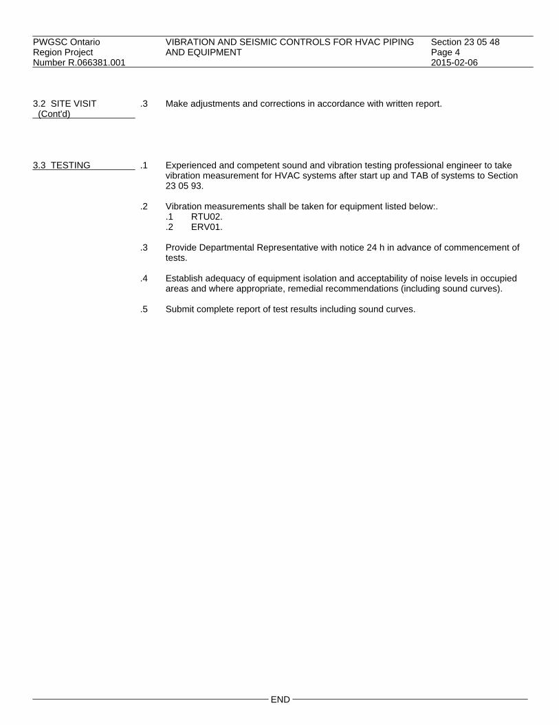
PWGSC Ontario VIBRATION AND SEISMIC CONTROLS FOR HVAC PIPING Section 23 05 48Region Project AND EQUIPMENT Page 4Number R.066381.001 2015-02-06 3.2 SITE VISIT .3 Make adjustments and corrections in accordance with written report. (Cont'd) 3.3 TESTING .1 Experienced and competent sound and vibration testing professional engineer to take
vibration measurement for HVAC systems after start up and TAB of systems to Section23 05 93.
.2 Vibration measurements shall be taken for equipment listed below:.
.1 RTU02.
.2 ERV01.
.3 Provide Departmental Representative with notice 24 h in advance of commencement oftests.
.4 Establish adequacy of equipment isolation and acceptability of noise levels in occupied
areas and where appropriate, remedial recommendations (including sound curves).
.5 Submit complete report of test results including sound curves.
END

PWGSC Ontario MECHANICAL TESTING, ADJUSTING AND BALANCING Section 23 05 93Region Project (TAB) MAJOR WORKS Page 1Number R.066381.001 2015-02-06 PART 1 - GENERAL 1.1 GENERAL .1 TAB means to test, adjust and balance to perform in accordance with requirements of
Contract Documents and to do all other work as specified in this section.
.2 Standard: TAB to be to most stringent of TAB standards of AABC, NEBB, SMACNA andASHRAE.
.3 Do TAB of all systems, equipment, components, controls specified in Mechanical
Divisions.
.4 TAB shall be performed by an independent TAB agency engaged by the Contractor. 1.2 QUALIFICATIONS .1 Names of all personnel it is proposed to perform TAB to be submitted to and approvedOF TAB PERSONNEL by Departmental Representative within 90 days of award of contract.
.2 Provide documentation confirming qualifications, successful experience.
.3 Qualifications: personnel performing TAB to be current member in good standing ofAABC, NEBB, or NBCTA.
.4 Quality Assurance: perform TAB under direction of supervisor qualified by AABC, NEBB,
or NBCTA. 1.3 PURPOSE OF TAB .1 Test to verify proper and safe operation, determine actual point of performance,
evaluate qualitative and quantitative performance of equipment, systems and controls atdesign, average and low loads using actual or simulated loads.
.2 Adjust and regulate equipment and systems so as to meet specified performance
requirements and to achieve specified interaction with all other related systems under allnormal and emergency loads and operating conditions.
.3 Balance systems and equipment to regulate flow rates to match load requirements over
full operating ranges. 1.4 EXCEPTIONS .1 TAB of systems and equipment regulated by codes, standards to be to satisfaction of
authority having jurisdiction. 1.5 CO-ORDINATION .1 Schedule time required for TAB (including repairs, re-testing) into project construction
and completion schedule so as to ensure completion before acceptance of project.
.2 Do TAB of each system independently and subsequently, where interlocked with othersystems, in unison with those systems.

PWGSC Ontario MECHANICAL TESTING, ADJUSTING AND BALANCING Section 23 05 93Region Project (TAB) MAJOR WORKS Page 2Number R.066381.001 2015-02-06 1.6 PRE-TAB REVIEW .1 Review contract documents before project construction is started and confirm in writing to
Departmental Representative adequacy of provisions for TAB and all other aspects ofdesign and installation pertinent to success of TAB.
.2 Review specified standards and report to Departmental Representative in writing all
proposed procedures which vary from standard.
.3 During construction, co-ordinate location and installation of all TAB devices, equipment,accessories, measurement ports and fittings.
1.7 START-UP .1 Follow start-up procedures as recommended by equipment manufacturer unless specified
otherwise.
.2 Follow special start-up procedures specified elsewhere in Mechanical Divisions. 1.8 OPERATION OF .1 Operate systems for length of time required for TAB and as required by DepartmentalSYSTEMS DURING TAB Representative for verification of TAB reports. 1.9 START OF TAB .1 Notify Departmental Representative 7 days prior to start of TAB.
.2 Start TAB only when building is essentially completed, including:.1 Installation of ceilings, doors, windows, other construction affecting TAB..2 Application of weatherstripping, sealing, caulking..3 All pressure, leakage, other tests specified elsewhere Divisions 21, 22, 23 and 25..4 All provisions for TAB installed and operational..5 Start-up, verification for proper, normal and safe operation of all mechanical and
associated electrical and control systems affecting TAB including but not limitedto:.1 Proper thermal overload protection in place for electrical equipment..2 Air systems:
.1 Filters in place, clean.
.2 Duct systems clean.
.3 Ducts, air shafts, ceiling plenums are airtight to within specifiedtolerances.
.4 Correct fan rotation.
.5 Fire, smoke, volume control dampers installed and open.
.6 Coil fins combed, clean.
.7 Access doors, installed, closed.
.8 All outlets installed, volume control dampers open..3 Liquid systems:
.1 Flushed, filled, vented.
.2 Correct pump rotation.
.3 Strainers in place, baskets clean.
.4 Isolating and balancing valves installed, open.
.5 Calibrated balancing valves installed, at factory settings.
.6 Chemical treatment systems complete, operational.
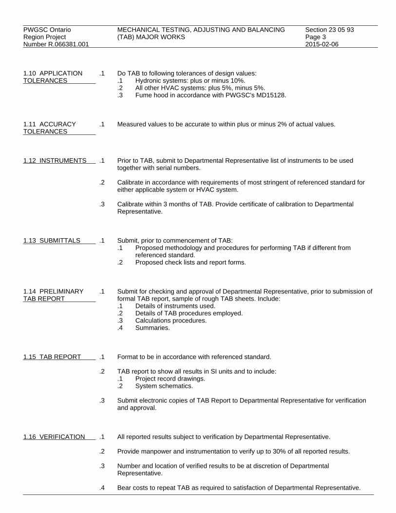
PWGSC Ontario MECHANICAL TESTING, ADJUSTING AND BALANCING Section 23 05 93Region Project (TAB) MAJOR WORKS Page 3Number R.066381.001 2015-02-06 1.10 APPLICATION .1 Do TAB to following tolerances of design values:TOLERANCES .1 Hydronic systems: plus or minus 10%.
.2 All other HVAC systems: plus 5%, minus 5%.
.3 Fume hood in accordance with PWGSC's MD15128. 1.11 ACCURACY .1 Measured values to be accurate to within plus or minus 2% of actual values.TOLERANCES 1.12 INSTRUMENTS .1 Prior to TAB, submit to Departmental Representative list of instruments to be used
together with serial numbers.
.2 Calibrate in accordance with requirements of most stringent of referenced standard foreither applicable system or HVAC system.
.3 Calibrate within 3 months of TAB. Provide certificate of calibration to Departmental
Representative. 1.13 SUBMITTALS .1 Submit, prior to commencement of TAB:
.1 Proposed methodology and procedures for performing TAB if different fromreferenced standard.
.2 Proposed check lists and report forms. 1.14 PRELIMINARY .1 Submit for checking and approval of Departmental Representative, prior to submission ofTAB REPORT formal TAB report, sample of rough TAB sheets. Include:
.1 Details of instruments used.
.2 Details of TAB procedures employed.
.3 Calculations procedures.
.4 Summaries. 1.15 TAB REPORT .1 Format to be in accordance with referenced standard.
.2 TAB report to show all results in SI units and to include:.1 Project record drawings..2 System schematics.
.3 Submit electronic copies of TAB Report to Departmental Representative for verification
and approval. 1.16 VERIFICATION .1 All reported results subject to verification by Departmental Representative.
.2 Provide manpower and instrumentation to verify up to 30% of all reported results.
.3 Number and location of verified results to be at discretion of DepartmentalRepresentative.
.4 Bear costs to repeat TAB as required to satisfaction of Departmental Representative.
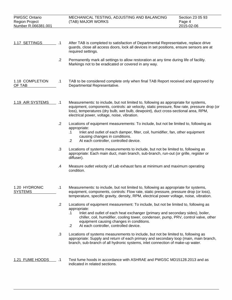
PWGSC Ontario MECHANICAL TESTING, ADJUSTING AND BALANCING Section 23 05 93Region Project (TAB) MAJOR WORKS Page 4Number R.066381.001 2015-02-06 1.17 SETTINGS .1 After TAB is completed to satisfaction of Departmental Representative, replace drive
guards, close all access doors, lock all devices in set positions, ensure sensors are atrequired settings.
.2 Permanently mark all settings to allow restoration at any time during life of facility.
Markings not to be eradicated or covered in any way. 1.18 COMPLETION .1 TAB to be considered complete only when final TAB Report received and approved byOF TAB Departmental Representative. 1.19 AIR SYSTEMS .1 Measurements: to include, but not limited to, following as appropriate for systems,
equipment, components, controls: air velocity, static pressure, flow rate, pressure drop (orloss), temperatures (dry bulb, wet bulb, dewpoint), duct cross-sectional area, RPM,electrical power, voltage, noise, vibration.
.2 Locations of equipment measurements: To include, but not be limited to, following as
appropriate:.1 Inlet and outlet of each damper, filter, coil, humidifier, fan, other equipment
causing changes in conditions..2 At each controller, controlled device.
.3 Locations of systems measurements to include, but not be limited to, following as
appropriate: Each main duct, main branch, sub-branch, run-out (or grille, register ordiffuser).
.4 Measure outlet velocity of Lab exhaust fans at minimum and maximum operating
condition. 1.20 HYDRONIC .1 Measurements: to include, but not limited to, following as appropriate for systems,SYSTEMS equipment, components, controls: Flow rate, static pressure, pressure drop (or loss),
temperature, specific gravity, density, RPM, electrical power voltage, noise, vibration.
.2 Locations of equipment measurement: To include, but not be limited to, following asappropriate:.1 Inlet and outlet of each heat exchanger (primary and secondary sides), boiler,
chiller, coil, humidifier, cooling tower, condenser, pump, PRV, control valve, otherequipment causing changes in conditions.
.2 At each controller, controlled device.
.3 Locations of systems measurements to include, but not be limited to, following asappropriate: Supply and return of each primary and secondary loop (main, main branch,branch, sub-branch of all hydronic systems, inlet connection of make-up water.
1.21 FUME HOODS .1 Test fume hoods in accordance with ASHRAE and PWGSC MD15128.2013 and as
indicated in related sections.

PWGSC Ontario MECHANICAL TESTING, ADJUSTING AND BALANCING Section 23 05 93Region Project (TAB) MAJOR WORKS Page 5Number R.066381.001 2015-02-06 1.22 OTHER TAB .1 Refer to other mechanical specification sections for additional requirements.REQUIREMENTS PART 2 - PRODUCTS 2.1 NOT USED .1 Not Used. PART 3 - EXECUTION 3.1 NOT USED .1 Not Used.
END

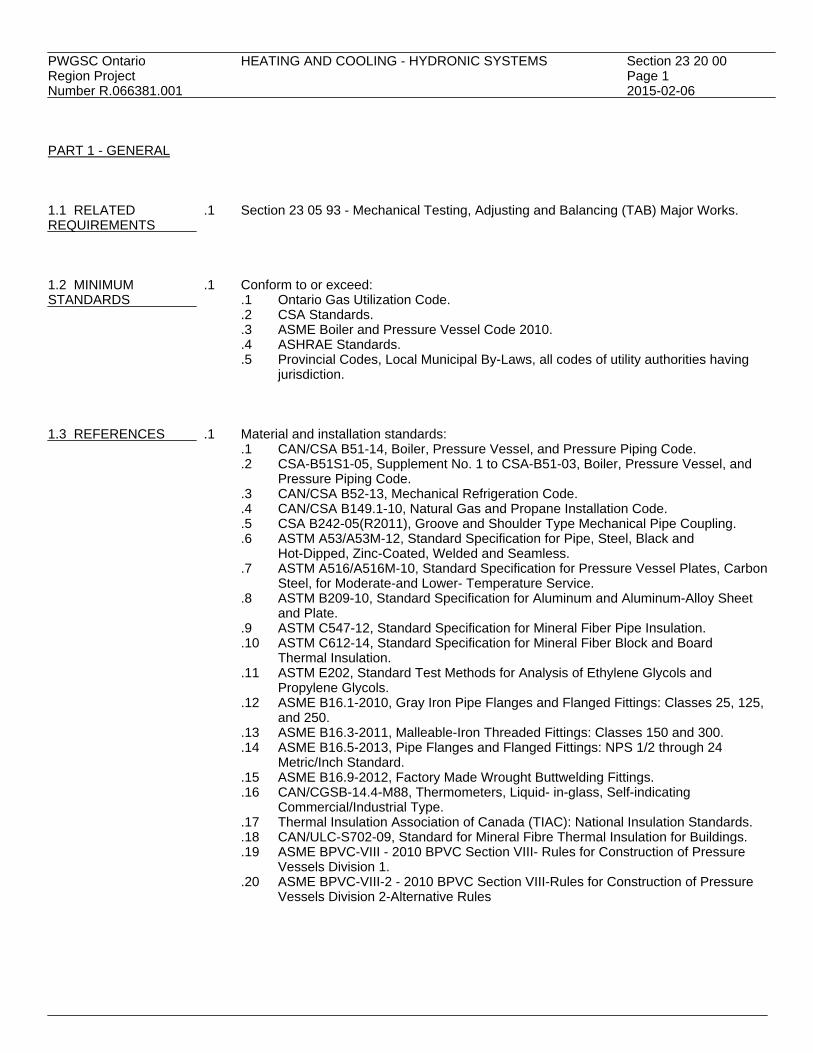
PWGSC Ontario HEATING AND COOLING - HYDRONIC SYSTEMS Section 23 20 00Region Project Page 1Number R.066381.001 2015-02-06 PART 1 - GENERAL 1.1 RELATED .1 Section 23 05 93 - Mechanical Testing, Adjusting and Balancing (TAB) Major Works.REQUIREMENTS 1.2 MINIMUM .1 Conform to or exceed:STANDARDS .1 Ontario Gas Utilization Code.
.2 CSA Standards.
.3 ASME Boiler and Pressure Vessel Code 2010.
.4 ASHRAE Standards.
.5 Provincial Codes, Local Municipal By-Laws, all codes of utility authorities havingjurisdiction.
1.3 REFERENCES .1 Material and installation standards:
.1 CAN/CSA B51-14, Boiler, Pressure Vessel, and Pressure Piping Code.
.2 CSA-B51S1-05, Supplement No. 1 to CSA-B51-03, Boiler, Pressure Vessel, andPressure Piping Code.
.3 CAN/CSA B52-13, Mechanical Refrigeration Code.
.4 CAN/CSA B149.1-10, Natural Gas and Propane Installation Code.
.5 CSA B242-05(R2011), Groove and Shoulder Type Mechanical Pipe Coupling.
.6 ASTM A53/A53M-12, Standard Specification for Pipe, Steel, Black andHot-Dipped, Zinc-Coated, Welded and Seamless.
.7 ASTM A516/A516M-10, Standard Specification for Pressure Vessel Plates, CarbonSteel, for Moderate-and Lower- Temperature Service.
.8 ASTM B209-10, Standard Specification for Aluminum and Aluminum-Alloy Sheetand Plate.
.9 ASTM C547-12, Standard Specification for Mineral Fiber Pipe Insulation.
.10 ASTM C612-14, Standard Specification for Mineral Fiber Block and BoardThermal Insulation.
.11 ASTM E202, Standard Test Methods for Analysis of Ethylene Glycols andPropylene Glycols.
.12 ASME B16.1-2010, Gray Iron Pipe Flanges and Flanged Fittings: Classes 25, 125,and 250.
.13 ASME B16.3-2011, Malleable-Iron Threaded Fittings: Classes 150 and 300.
.14 ASME B16.5-2013, Pipe Flanges and Flanged Fittings: NPS 1/2 through 24Metric/Inch Standard.
.15 ASME B16.9-2012, Factory Made Wrought Buttwelding Fittings.
.16 CAN/CGSB-14.4-M88, Thermometers, Liquid- in-glass, Self-indicatingCommercial/Industrial Type.
.17 Thermal Insulation Association of Canada (TIAC): National Insulation Standards.
.18 CAN/ULC-S702-09, Standard for Mineral Fibre Thermal Insulation for Buildings.
.19 ASME BPVC-VIII - 2010 BPVC Section VIII- Rules for Construction of PressureVessels Division 1.
.20 ASME BPVC-VIII-2 - 2010 BPVC Section VIII-Rules for Construction of PressureVessels Division 2-Alternative Rules

PWGSC Ontario HEATING AND COOLING - HYDRONIC SYSTEMS Section 23 20 00Region Project Page 2Number R.066381.001 2015-02-06 1.4 SHOP DRAWINGS .1 Submit shop drawings and product data sheets in accordance with Sections 01 33 00AND PRODUCT DATA and 01 78 00 for the following:SHEETS .1 Expansion tank.
.2 Heat exchangers.
.3 Pumps.
.4 Valves.
.5 Fittings. PART 2 - PRODUCTS 2.1 FLOODED TYPE .1 Packaged flooded type steam to glycol heat exchanger system c/w control panel, andHEAT EXCHANGER, accessories preassembled on welded, epoxy painted steel frame.HE2
.2 Fully factory tested.
.3 Shell and coil heat exchanger with 316L stainless steel welded construction, helicalcorrugated tubes, 2068 kPa design pressure at 216°C, CRN number for Ontario, ASMESection VIII Div. 01. Maximum liquid pressure drop at 15 kPa.
.4 Steam Components: automatic high performance shut-off valve, overflow protection
thermostatic air vent and vacuum breaker, pressure indicator.
.5 Condensate Components: 100 mesh strainer isolation gate valves, stainless steel checkvalve, manual/automatic ball valve for blow downs, industrial grade control valve withmodulating electric actuator, steam traps.
.6 Liquid Components: Butterfly isolation valves pressure gauge, thermometer with well,
flow switch CIP connections with ball valve, platinum 3-wire RTD with stainlessthermowell.
.7 Control: NEMA 12, CAS UL control pad with universal programmable controller low
voltage terminal strips for direct connection to building automation system for thefollowing joints:.1 Alarm.2 Glycol temperature SP adjust.3 Glycol temperature feedback
.8 Performance:
.1 Glycol side: 50% ethylene glycol
.2 Flow: 3.46 L/s
.3 Pressure Drop: 14.5 kPa
.4 Entering Temperature: 54.4°C
.5 Leaving Temperature: 71.1°C
.6 Steam: 360 kg/h saturated steam @ 345 kPa with 93°C subcooled condensate
.7 Capacity: 210 kW 2.2 HEATING AND .1 Pipe: black steel, schedule 40 to ASTM A53/A53M.COOLING PIPINGAND FITTINGS .2 Pipe joints:
.1 Size NPS 2 and smaller: screwed fittings with teflon tape.
.2 Size NPS 2-1/2 and larger: welded fittings and flanges to ASME B16.5.
.3 Roll grooved: mechanical coupling to CSA B242.

PWGSC Ontario HEATING AND COOLING - HYDRONIC SYSTEMS Section 23 20 00Region Project Page 3Number R.066381.001 2015-02-06 2.2 HEATING AND .3 Fittings: COOLING PIPING .1 Malleable iron screwed fittings: Class 150 to ASME B16.3. AND FITTINGS .2 Steel pipe flanges and flanged fittings: to ASME B16.5. (Cont'd) .3 Steel butt-welding fittings: to ASME B16.9.
.4 Unions: malleable iron to ASME B16.3.
.4 Ream pipes and tubes. Hammer and clean scale and dirt, inside and outside, beforeassembly.
2.3 HEATING AND .1 Gate valve size NPS 2 and smaller: Class 125, 860 kPa screwed, bronze body, solidCOOLING VALVES wedge disc and rising stem.
.2 Globe valve size NPS 2 and smaller: Class 150, 1 MPa screwed, bronze, screwed overbonnet, renewable composition disc.
.3 Globe valve size NPS 2-1/2 and larger: Class 125, 860 kPa, FF flange, cast iron body,
bronze trim, OS&Y, bolted bonnet, bronze disc and seat ring.
.4 Butterfly valve size NPS 2-1/2 to NPS 5: Class 150, 1 MPa WOG water, cast iron bodywith bronze disc and stainless steel stem, replaceable EPT-Nordel rubber seat wafer body,locking handle.
.5 Suction guide: pump fitting combination 90° elbow, stainless steel in-line strainer,
reducing elbow, flow stabilizing outlet guide vanes.
.6 Swing check valve size NPS 2 and smaller: Class 125, 860 kPa, bronze body, screwedends, swing disc, screw in cap, bronze disc, regrindable seat.
.7 Swing check valve size NPS 2-1/2 and larger: Class 125, 860 kPa cast iron body, FF
flanged, regrindable renewable seat, bronze disc, bolted cap.
.8 Silent check valve size NPS 2 and smaller: Class 125, 860 kPa, cast steel, wafer style,brass seatings, brass inner valve, stainless steel spring with heavy duty spring in verticaldown flow application.
.9 Silent check valve size NPS 2½ and larger; Class 125, 860 kPa, cast steel, wafer style,
bronze trim, stainless steel spring with heavy duty spring in vertical down flow application.
.10 Lubricated plug cocks NPS 2 and smaller: Class 150, 1 MPa, bronze body.
.11 Balancing valve: Class 125, 1.7 MPa maximum WP, 121°C maximum temperature,Y style globe valve with valved ports for connecting to differential pressure meter.Readout accuracy to be within plus or minus 2% of actual flow at design flow rate. Flowcontrol to include digital hand wheel and tamperproof concealed mechanical memory.
2.4 PIPE SLOPE .1 Slope water piping up in direction of flow 1:500.
.2 Slope horizontal water drainage piping down in direction of flow 1:240 minimum.

PWGSC Ontario HEATING AND COOLING - HYDRONIC SYSTEMS Section 23 20 00Region Project Page 4Number R.066381.001 2015-02-06 2.5 PIPE VENTING .1 Make reductions in water piping with eccentric reducing fittings so that air cannot collect
in piping except at air vents and air separators.
.2 Provide, at high points on lines and on equipment connections and as indicated,collecting chambers and high capacity float operated automatic air vents.
.3 Automatic air vents:
.1 Standard float vent with brass body and NPS 1/8 connection and rated at 690 kPaworking pressure.
.2 Float: solid material suitable for 115°C working temperature.
.4 Provide where indicated in-line air separator approved by ASME for 860 kPa workingpressure.
2.6 STRAINERS .1 Provide strainers ahead of each pump, each automatic control valve (except radiation)
and as indicated.
.2 Install in horizontal or down flow lines. Ensure clearance for removal of basket.
.3 Strainers:.1 Body: "Y" type, cast iron, semi-steel or bronze..2 Screen: stainless steel or monel..3 Ends: threaded for sizes NPS 2 and smaller, flanged for sizes over NPS 2..4 Working pressure: 860 kPa.
2.7 THERMOMETERS .1 Thermometers:AND PRESSURE GUAGES .1 To CAN/CGSB-14.4-M88, industrial, variable angle, liquid filled, 175 mm scale
length, direct reading..2 Thermometer wells to be brass or stainless steel..3 Install in supply and return water piping of coils and heat exchangers.
.2 Pressure gauges:
.1 100 mm dial, 1/2 of 1% accuracy, bronze stop cock, snubber for pulsating action,compound type for pump suction; direct reading. Select ranges so normaloperating pressure is at mid-scale.
.2 Install in supply and return water piping of coils, heat exchangers, in pump suctionand discharge; on make-up water/glycol assemblies.
2.8 DIAPHRAGM TYPE .1 Vertical, cylindrical galvanized steel pressurized diaphragm type expansion tank.EXPANSION TANK
.2 Capacity and size as indicated on the drawings.
.3 Diaphragm sealed in EPDM suitable for 115°C operating temperature and glycol system.
.4 Working pressure: 860 kPa with ASME stamp and certification.
.5 Air precharged to 248 kPa (initial fill pressure of system).

PWGSC Ontario HEATING AND COOLING - HYDRONIC SYSTEMS Section 23 20 00Region Project Page 5Number R.066381.001 2015-02-06 2.9 PLATE AND FRAME .1 Steam to glycol. 50% ethylene glycol.HEAT EXCHANGER .1 Designed, constructed and tested in with accordance ASME Boiler and
Pressure Vessel Code, CSA B51 and provincial pressure vessel regulations.
.2 Frames: carbon steel with baked epoxy enamel paint, stainless steel side bolts andshroud.
.3 Plates: type 304 stainless steel.
.4 CRN Ontario, 1034 kPa design pressure, 1345 kPa test pressure.
.5 Gaskets: as recommended by manufacturer to suit fluid temperature/type.
.6 Piping connections: as indicated.
.7 Capacity: maximum pressure drop to be 34 kPa.
Water Glycol Flow 8.82 L/s 8.82 L/s Entering Temperature 87.7°C 54.4°C Leaving Temperature 72.8°C 71.1°C 2.10 IN-LINE .1 Construction:STANDARD DUTY .1 Volute: cast iron radially split, with tapped openings for gauge connections, withCIRCULATING PUMPS screwed or flanged suction and discharge connections.
.2 Impeller: non-ferrous.
.3 Shaft: stainless steel shaft and sleeve.
.4 Seal assembly: mechanical for normal hot water application to 135°C.
.5 Coupling: flexible rigid self-aligning.
.6 Motor: resilient mounted, drip proof, sleeve bearing, NEMA MG1-1993 Part 31,Premium Efficiency.
.2 Capacity and size: as indicated.
.3 Ensure pump body does not support piping or equipment. Provide stanchions or hangers
for this purpose. Refer to manufacturer's installation instructions for details. 2.11 WATER .1 Micron filter:TREATMENT FOR .1 Capacity 5% of pump recirculating rate at operating pressure.CLOSED HYDRONIC .2 Six (6) sets of filter cartridges for each type, size of micron filter.SYSTEMS
.2 Pot Feeder:.1 Welded steel, pressure rating of 1200 kPa, and temperature rating of 90°C..2 Size: 20 L.
2.12 ETHYLENE .1 Provide pre-mixed ethylene propylene glycol in 50% concentration by weight asGLYCOL specified in schedules on drawings for glycol systems with corrosion inhibitors.

PWGSC Ontario HEATING AND COOLING - HYDRONIC SYSTEMS Section 23 20 00Region Project Page 6Number R.066381.001 2015-02-06 2.13 THERMAL .1 Insulate heating and cooling piping with 25 mm thick rigid mineral fibre sleeving andINSULATION AND factory applied all service jacket.JACKETING
.2 Fastenings: use self adhesive tape rated <25 for flame spread, and <50 for smokedevelopment.
.3 Provide canvas cover over insulated piping in exposed areas. Canvas cover to be
compact, firm, ULC listed heavy plain weave, cotton fabric at 220 g/m2. Provide twocoats of diluted fire retardant lagging adhesive over canvas covering.
.4 Provide polyvinyl chloride (PVC)cover over insulated piping in exposed areas (except
within Lab):.1 One-piece moulded type and sheet to CAN/CGSB-51.53 with pre-formed shapes
as required..2 Colours: by Departmental Representative..3 Minimum service temperatures: -20°C..4 Maximum service temperature: 65°C..5 Moisture vapour transmission: 0.02 perm..6 Fastenings:
.1 Use solvent weld adhesive compatible with insulation to seal laps andjoints.
.2 Tacks.
.3 Pressure sensitive vinyl tape of matching colour.
.5 Provide aluminum cover over insulated piping in exterior locations and within Lab:.1 To ASTM B209..2 Thickness: 0.50 mm sheet..3 Finish: smooth ..4 Joining: longitudinal and circumferential slip joints with 50 mm laps..5 Fittings: 0.5 mm thick die-shaped fitting covers with factory-attached protective
liner..6 Metal jacket banding and mechanical seals: stainless steel, 19 mm wide, 0.5 mm
thick at 300 mm spacing.
.6 Provide weatherproofing for all outdoor pipe insulation between insulation andaluminum jacket. Apply 2 mm thick prefabricated sheet type, high density cross linkedpolymer weatherproof sheet with rubberized asphalt adhesive surface.
.7 Make good all existing insulation where previously damaged by others or damaged by
work under this Contract. PART 3 - EXECUTION 3.1 INSTALLATION .1 Install material and equipment in accordance with referenced standards and
manufacturer's written instructions. 3.2 FLUSHING AND .1 Provide flushing and chemical cleaning of the following items to remove dirt, sludge, oil,CHEMICAL CLEANING grease and other foreign material:
.1 Coils.
.2 New pipework.
.3 Heat exchangers.

PWGSC Ontario HEATING AND COOLING - HYDRONIC SYSTEMS Section 23 20 00Region Project Page 7Number R.066381.001 2015-02-06 3.2 FLUSHING AND .2 Use qualified water treatment company to furnish a copy of recommended cleaning or CHEMICAL CLEANING boil-out procedures and cleaning chemicals for review by the Departmental (Cont'd) Representative.
.3 Flushing and cleaning shall be under the strict supervision of the water treatmentcompany. Submit report certified by the water treatment company that the recommendedcleaning procedures have been followed and that adequate cleaning of the equipmentand entire heating water system has been provided.
.4 The completion of flushing and cleaning shall be subject to the inspection and approval
of the Departmental Representative. Give forty-eight (48) hours advance notice of datewhen it will be ready for inspection. Drain entire heating water system and remove boilercover plates before inspection is conducted.
3.3 FILLING OF .1 Refill systems with clean water adding water treatment as required.HYDRONIC SYSTEMS
.2 Charge glycol systems with glycol solution of 50/50% ethylene by weight with inhibitorfor both testing and final operation.
.3 Retest for concentration to ASTM E202 after cleaning and provide report to
Departmental Representative. 3.4 EQUIPMENT .1 Provide factory trained technicians to perform start-up, adjustment and operating trainingSTART-UP for the following equipment:
.1 Flooded heat exchanger.
.2 Pumps/VFD's. 3.5 BALANCING .1 In accordance with Section 23 05 93.
END

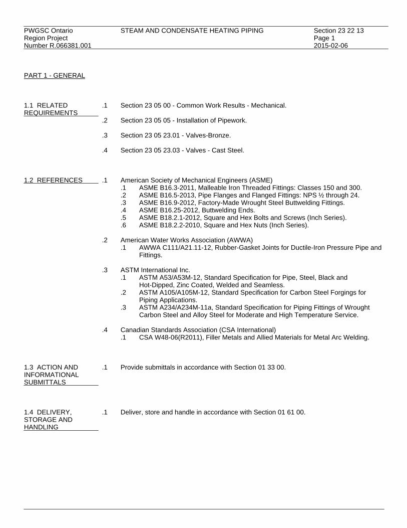
PWGSC Ontario STEAM AND CONDENSATE HEATING PIPING Section 23 22 13Region Project Page 1Number R.066381.001 2015-02-06 PART 1 - GENERAL 1.1 RELATED .1 Section 23 05 00 - Common Work Results - Mechanical.REQUIREMENTS
.2 Section 23 05 05 - Installation of Pipework.
.3 Section 23 05 23.01 - Valves-Bronze.
.4 Section 23 05 23.03 - Valves - Cast Steel. 1.2 REFERENCES .1 American Society of Mechanical Engineers (ASME)
.1 ASME B16.3-2011, Malleable Iron Threaded Fittings: Classes 150 and 300.
.2 ASME B16.5-2013, Pipe Flanges and Flanged Fittings: NPS ½ through 24.
.3 ASME B16.9-2012, Factory-Made Wrought Steel Buttwelding Fittings.
.4 ASME B16.25-2012, Buttwelding Ends.
.5 ASME B18.2.1-2012, Square and Hex Bolts and Screws (Inch Series).
.6 ASME B18.2.2-2010, Square and Hex Nuts (Inch Series).
.2 American Water Works Association (AWWA).1 AWWA C111/A21.11-12, Rubber-Gasket Joints for Ductile-Iron Pressure Pipe and
Fittings.
.3 ASTM International Inc..1 ASTM A53/A53M-12, Standard Specification for Pipe, Steel, Black and
Hot-Dipped, Zinc Coated, Welded and Seamless..2 ASTM A105/A105M-12, Standard Specification for Carbon Steel Forgings for
Piping Applications..3 ASTM A234/A234M-11a, Standard Specification for Piping Fittings of Wrought
Carbon Steel and Alloy Steel for Moderate and High Temperature Service.
.4 Canadian Standards Association (CSA International).1 CSA W48-06(R2011), Filler Metals and Allied Materials for Metal Arc Welding.
1.3 ACTION AND .1 Provide submittals in accordance with Section 01 33 00.INFORMATIONALSUBMITTALS 1.4 DELIVERY, .1 Deliver, store and handle in accordance with Section 01 61 00.STORAGE ANDHANDLING

PWGSC Ontario STEAM AND CONDENSATE HEATING PIPING Section 23 22 13Region Project Page 2Number R.066381.001 2015-02-06 PART 2 - PRODUCTS 2.1 PIPE .1 Steel pipe: to ASTM A53/A53M, Grade B, as follows:
.1 Steam;.1 NPS 1/2 to 1-1/2: Schedule 80, seamless..2 NPS 2 to NPS 6: Schedule 40-ERW, bend ends..3 NPS 8 and over: 10 mm wall, ERW.
.2 Condensate: Schedule 80, ERW, plain ends. 2.2 PIPE JOINTS .1 NPS 2 and under: screwed fittings with PTFE tape or lead-free dope.
.2 NPS 2-1/2 and over: welding fittings and flanges to CSA W48.
.3 Flanges: plain or raised face. Flange gaskets to AWWA C111/A21.11.
.4 Pipe thread: taper.
.5 Bolts and nuts: carbon steel, to ASME B18.2.1 and ASME B18.2.2.
.6 Buttwelding ends: to ASME B16.25. 2.3 FITTINGS .1 Pipe flanges:
.1 NPS 1/2 to 1-1/2: Class 150, full faced welded, to ASTM A105/A105M.
.2 NPS 2 and over: Class 150, full faced, weld neck, bored to suit pipe, to ASTMA105/A105M.
.2 Screwed fittings: Class 3000, 20 MPa, forged steel to ASTM A105/A105M.
.3 Bend ends: Schedule 40 to ASTM A234/A234AM Grade WPB.
.4 Steel pipe gaskets, flanges and flanged fittings: to ASME B16.5.
.5 Buttwelding fittings: steel to ASME B16.9.
.6 Unions: Class 3000, steel to steel, to ASTM A105/A105M and ASME B16.3.
2.4 VALVES .1 Connections:
.1 NPS 2 and smaller: screwed ends.
.2 NPS 2-1/2 and larger:.1 Equipment: Flanged ends..2 Elsewhere: Welded ends.
.2 Gate valves: Application: Steam service, for isolating equipment, control valves,
pipelines..1 NPS 2 and under:
.1 Class 150, rising stem, solid wedge disc, as specified Section 23 05 23.01..2 NPS 2-1/2 - 8:
.1 Class 150, rising stem, flexible wedge disc, cast iron, steel trim, as specifiedSection 23 05 23.03.

PWGSC Ontario STEAM AND CONDENSATE HEATING PIPING Section 23 22 13Region Project Page 3Number R.066381.001 2015-02-06 2.4 VALVES .2 Gate valves:(Cont'd) (Cont'd) .3 NPS 10 and over:
.1 Mechanical Rooms: Class 300, rising stem, flexible wedge disc, cast steelwith steel trim, as specified Section 23 05 23.03.
.3 Globe valves: Application: Steam service, throttling, flow control, emergency bypass.
.1 NPS 2 and under:.1 Class 150 with PFTE disc as specified Section 23 05 23.01.
.4 Gate valves: Application: pumped and gravity condensate return service, steam drip
point assemblies..1 NPS 2 and under:
.1 Class 150, rising stem, solid wedge disc, as specified Section 23 05 23.01..2 NPS 2-1/2 and over:
.1 Class 150, rising stem, solid wedge disc, cast steel, steel trim, as specifiedSection 23 05 23.03.
.5 Drain valves: Gate, Class 150, non-rising stem, solid wedge disc, as specified Section
23 05 23.01.
.6 Bypass valves around large size gate and globe valves: as specified Section23 05 23.03.
.7 Lift check valves:
.1 NPS 2 and under: lift, with composition disc, as specified Section 23 05 23.01.
.2 NPS 2-1/2 and over: as specified Section 23 05 23.03. PART 3 - EXECUTION 3.1 APPLICATION .1 Manufacturer's Instructions: comply with manufacturer's written recommendations,
including product technical bulletins, handling, storage and installation instructions, anddatasheets.
3.2 PIPING .1 Install pipework in accordance with Section 23 05 05, supplemented as specified below.
.2 Connect branch lines into top of mains.
.3 Install piping in direction of flow with slopes as follows, unless indicated:.1 Steam: 1:240..2 Condensate return: 1:70.
.4 Make provision for thermal expansion as indicated.
.5 Drip pocket: line size.
3.3 VALVES .1 Install globe valves around, NPS 8 and over, gate valves.

PWGSC Ontario STEAM AND CONDENSATE HEATING PIPING Section 23 22 13Region Project Page 4Number R.066381.001 2015-02-06 3.4 TESTING .1 Test system in accordance with Section 23 05 00.
.2 Test pressure: 1-1/2 times maximum system operating pressure or 1034 kPa whichever isgreater.
3.5 PERFORMANCE .1 General:VERIFICATION (PV) .1 Verify performance in accordance with Section 01 91 00.
.2 Timing, only after:.1 Pressure tests successfully completed..2 Flushing as specified has been completed..3 Water treatment system has been commissioned.
.3 PV Procedures:
.1 Verify complete drainage of condensate from steam coils.
.2 Verify proper operation of system components, including, but not limited to:.1 Steam traps - verify no blow-by..2 Flash tanks..3 Thermostatic vents.
.3 Monitor operation of provisions for controlled pipe movement including expansionjoints, loops, guides, anchors..1 If sliding type expansion joints bind or if bellows type expansion joints flex
incorrectly, shut down system, re-align, repeat start-up procedures. 3.6 CLEANING .1 Remove surplus materials, excess materials, rubbish, tools and equipment.
END

PWGSC Ontario STEAM SPECIALTIES Section 23 22 14Region Project Page 1Number R.066381.001 2015-02-06 PART 1 - GENERAL 1.1 RELATED .1 Section 23 05 05 - Installation of Pipework.REQUIREMENTS 1.2 REFERENCES .1 American Society for Mechanical Engineers (ASME International)
.1 ASME BPVC-VIII-1-2013, 2013 ASME Boiler and Pressure Vessel Code (BPVC),Section VIII, Division 1: Rules for Construction of Pressure Vessels.
.2 ASTM International Inc.
.1 ASTM A216/A216M-14, Standard Specification for Steel Castings, Carbon,Suitable for Fusion Welding for High-Temperature Service.
.2 ASTM A278/A278M-01(2011), Standard Specification for Gray Iron Castings forPressure - Containing Parts for Temperatures up to 650 Degrees F (350 degrees C).
.3 ASTM A351/A351M-14, Standard Specification for Castings, Austenitic, forPressure-Containing Parts.
.4 ASTM B62-09, Standard Specification for Composition Bronze or Ounce MetalCastings.
.3 Canadian Standards Association (CSA International)
.1 CAN/CSA B51-14, Boiler, Pressure Vessel, and Pressure Piping Code. 1.3 ACTION AND .1 Provide submittals in accordance with Section 01 33 00.INFORMATIONALSUBMITTALS 1.4 DELIVERY, .1 Deliver, store and handle in accordance with Section01 61 00.STORAGE ANDHANDLING PART 2 - PRODUCTS 2.1 GENERAL .1 All components installed must be rated for failure conditions of associated systems. 2.2 MATERIALS .1 Cast steel: to ASTM A216/A216M.
.2 Cast iron: to ASTM A278, Class 300.
.3 Bronze: to ASTM B62.
.4 Stainless steel: to ASTM A351/A351M.

PWGSC Ontario STEAM SPECIALTIES Section 23 22 14Region Project Page 2Number R.066381.001 2015-02-06 2.3 FLOAT AND .1 Application: for modulating steam service as indicated.THERMOSTATIC STEAMTRAPS 0-110 kPa .2 Materials: body - cast-steel; valve - stainless steel with stainless steel seat; float and
mechanisms - stainless steel; air vent - stainless steel thermostatic type.
.3 Capacity: as indicated. 2.4 INVERTED BUCKET .1 Application: for non-modulating steam services on heating coils, end of line drips,STEAM TRAP 0-1000 distribution main drip points and as indicated.kPa
.2 Materials: body - cast-steel; valve - stainless steel; bucket-stainless steel, with bimetal airvent.
.3 Capacity: as indicated.
2.5 THERMODYNAMIC .1 Application: where inverted buckets are not feasible.DISC STEAM TRAPS70-1000 kPa .1 Material: body - stainless steel carbon steel; disc - hardened stainless steel; strainer -
stainless steel; seat gasket - monel non-asbestos.
.2 Capacity: as indicated. 2.6 VACUUM BREAKERS .1 Application: on inlets to steam coils.0.85-68 kPa
.1 Materials: body and cap - stainless steel; spring - stainless steel; stem and seat - stainlesssteel.
.2 Capacity: as indicated.
2.7 SAFETY AND .1 Spring loaded type of cast iron with high capacity and semi-nozzle and to ASME code.RELIEF VALVES
.2 Material: body -cast iron; valve - housing malleable iron; spring - steel, cadmium plated;bronze/brass trim.
.3 Capacity: as indicated.
2.8 PIPE LINE .1 Application: ahead of condensate pumps, steam traps, control valves and elsewhere asSTRAINERS UP TO indicated.NPS 2
.2 Working pressure: 1034 kPa.
.3 Body: cast iron.
.4 Connections: screwed.
.5 Screen: stainless steel with 0.8 mm perforations.

PWGSC Ontario STEAM SPECIALTIES Section 23 22 14Region Project Page 3Number R.066381.001 2015-02-06 2.9 PIPE LINE .1 Application: ahead of condensate pumps, steam traps, control valves as indicated.STRAINERS NPS 2-1/2AND OVER .2 Working pressure: 1034 kPa.
.3 Body: cast iron.
.4 Connections: flanged.
.5 Blowdown connection: NPS 1-1/4 complete with gate valve and cap.
.6 Screen: stainless steel with 3.2 mm perforations. PART 3 - EXECUTION 3.1 APPLICATION .1 Manufacturer's Instructions: comply with manufacturer's written recommendations,
including product technical bulletins, handling, storage and installation instructions, anddatasheets.
.2 Maintain proper clearance around equipment to permit maintenance.
3.2 STRAINERS .1 Install as indicated.
.2 Ensure clearance for removal of basket.
.3 Install valved blow-down as indicated. 3.3 SAFETY RELIEF .1 Pipe to atmosphere independent of other vents and in accordance with applicable code.VALVE
.2 Support discharge pipe against reaction forces and to take up thermal movement.
.3 Drain pipe from drip pan elbow to terminate over floor drain. 3.4 STEAM TRAPS .1 Install unions on inlet and outlet in accordance with Section 23 05 05.
END

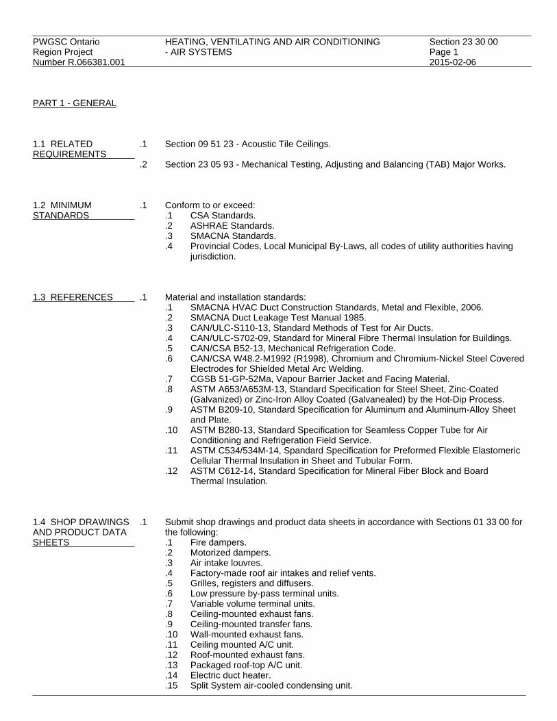
PWGSC Ontario HEATING, VENTILATING AND AIR CONDITIONING Section 23 30 00Region Project - AIR SYSTEMS Page 1Number R.066381.001 2015-02-06 PART 1 - GENERAL 1.1 RELATED .1 Section 09 51 23 - Acoustic Tile Ceilings.REQUIREMENTS
.2 Section 23 05 93 - Mechanical Testing, Adjusting and Balancing (TAB) Major Works. 1.2 MINIMUM .1 Conform to or exceed:STANDARDS .1 CSA Standards.
.2 ASHRAE Standards.
.3 SMACNA Standards.
.4 Provincial Codes, Local Municipal By-Laws, all codes of utility authorities havingjurisdiction.
1.3 REFERENCES .1 Material and installation standards:
.1 SMACNA HVAC Duct Construction Standards, Metal and Flexible, 2006.
.2 SMACNA Duct Leakage Test Manual 1985.
.3 CAN/ULC-S110-13, Standard Methods of Test for Air Ducts.
.4 CAN/ULC-S702-09, Standard for Mineral Fibre Thermal Insulation for Buildings.
.5 CAN/CSA B52-13, Mechanical Refrigeration Code.
.6 CAN/CSA W48.2-M1992 (R1998), Chromium and Chromium-Nickel Steel CoveredElectrodes for Shielded Metal Arc Welding.
.7 CGSB 51-GP-52Ma, Vapour Barrier Jacket and Facing Material.
.8 ASTM A653/A653M-13, Standard Specification for Steel Sheet, Zinc-Coated(Galvanized) or Zinc-Iron Alloy Coated (Galvanealed) by the Hot-Dip Process.
.9 ASTM B209-10, Standard Specification for Aluminum and Aluminum-Alloy Sheetand Plate.
.10 ASTM B280-13, Standard Specification for Seamless Copper Tube for AirConditioning and Refrigeration Field Service.
.11 ASTM C534/534M-14, Spandard Specification for Preformed Flexible ElastomericCellular Thermal Insulation in Sheet and Tubular Form.
.12 ASTM C612-14, Standard Specification for Mineral Fiber Block and BoardThermal Insulation.
1.4 SHOP DRAWINGS .1 Submit shop drawings and product data sheets in accordance with Sections 01 33 00 forAND PRODUCT DATA the following:SHEETS .1 Fire dampers.
.2 Motorized dampers.
.3 Air intake louvres.
.4 Factory-made roof air intakes and relief vents.
.5 Grilles, registers and diffusers.
.6 Low pressure by-pass terminal units.
.7 Variable volume terminal units.
.8 Ceiling-mounted exhaust fans.
.9 Ceiling-mounted transfer fans.
.10 Wall-mounted exhaust fans.
.11 Ceiling mounted A/C unit.
.12 Roof-mounted exhaust fans.
.13 Packaged roof-top A/C unit.
.14 Electric duct heater.
.15 Split System air-cooled condensing unit.

PWGSC Ontario HEATING, VENTILATING AND AIR CONDITIONING Section 23 30 00Region Project - AIR SYSTEMS Page 2Number R.066381.001 2015-02-06 1.4 SHOP DRAWINGS .1 (Cont'd) AND PRODUCT DATA .16 Split System blower coil unit. SHEETS .17 Air handling unit. (Cont'd) .18 Humidifier.
.19 Controls and instrumentation. PART 2 - PRODUCTS 2.1 STAINLESS STEEL .1 Material: type 316 L stainless steel sheets with longitudinal joints. Passivate and annealDUCTWORK stainless steel sheets before welding. For round ducts, roll sheets circular and weld flush.
Provide integral 20 mm flanges on abutting ends of manufactured ducts. Provide flangescompatible with air valve for rigid connection.
.2 Continuously weld all joints at factory, including flange connection using Inert Gas Metal
Arc process without burning parent metal, using filler rods type ER 316 L to CSA W48.2.Grind smooth and polish all joints.
.3 Construction:
.1 Construct ductwork from following thickness of stainless steel sheet..1 Rectangular ducts: 1.27 mm..2 Round ducts up to 500 mm diameter: 0.75 mm..3 Round ducts over 500 mm diameter: 0.95 mm.
.2 Reinforce rectangular ducts with galvanized angle frames including dielectricseparation material between matching surfaces at 1,200 mm on centres, 25 mm x25 mm x 3 mm up to 900 mm maximum dimensions and 50 mm x 50 mm x 6 mmfor larger ducts.
.4 Flexible connectors: neoprene coated woven fibreglass, coated both sides suitable for
outdoor installation, minimum mass 1.28 kg/m2 secured to ducts and fans with 25 mm x25 mm x 3 mm stainless steel type 316 L flat bars and bands using type 316 L stainlesssteel screws or bolts at 100 mm intervals.
.5 All elbows to be minimum 3 segment type. Branch connections of mains to be done with
45° entry to reduce static pressure loss.
.6 Application: Complete exhaust system. 2.2 MEDIUM PRESSURE .1 Material: lock-forming quality steel with Z275 designation zinc coating to ASTMRECTANGULAR A653/A653M, minimum 30% recycled content.DUCTWORK
.2 Gauge and construction of ducts and fittings shall be in accordance with SMACNA HVACDuct Construction Standards for rectangular duct for a positive static pressure up to1.5 kPa with leakage rate of 1.5% maximum.
.3 Seal classification: to SMACNA seal class A with longitudinal seams, transverse joints,
duct wall penetrations and connections made airtight with sealant.
.4 Hangers:.1 Ducts up to size 900 mm shall be supported with 25 mm x 1.6 mm thick
galvanized strap hangers spaced at not over 3 m centres..2 Ducts over 900 mm shall be supported with 10 mm steel rods and 50 x 50 x 6 mm
angles. Maximum spacing of hangers to be 2.5 m.

PWGSC Ontario HEATING, VENTILATING AND AIR CONDITIONING Section 23 30 00Region Project - AIR SYSTEMS Page 3Number R.066381.001 2015-02-06 2.2 MEDIUM PRESSURE .4 Hangers:(Cont'd) RECTANGULAR .3 Hanger attachments: manufactured concrete inserts, expansion shields and bolted DUCTWORK steel clamps. Do not weld rods to steel deck or use powder actuated fasteners. (Cont'd)
.5 Radius of duct elbow shall be at least equal to the width of the elbow. Use square elbowwith double thickness turning vanes when space is limited.
.6 Provide opposed blade volume dampers with lockable quadrant operators at all branch
ducts and as indicated.
.7 Provide 25 mm test plugs with chain and cap, where required and indicated toaccommodate testing and balancing instruments.
.8 Duct Leakage: in accordance with SMACNA HVAC Duct Leakage Test Manual.
.9 Applications: supply air ducting.
2.3 MEDIUM PRESSURE .1 Material: lock-forming quality steel with Z275 designation zinc coating to ASTMRIGID ROUND DUCTS A653/A653M, minimum 30% recycled content.
.2 Gauge and construction of ducts and fittings shall be in accordance with SMACNA HVACDuct Construction Standards for round ducts for a positive static pressure up to 2.5 kPawith leakage rate of 1.5% maximum.
.3 Round ducts, fittings and specialties shall be fabricated by one manufacturer. Use
conical tees at branch takeoffs. Do not use straight 90° tee.
.4 Seal classification: spiral wound round ducting up to 900 mm to SMACNA seal class Awith transverse joints, duct wall penetrations and connections made airtight with sealant.
.5 Hangers:
.1 Ducts with diameter up through 450 mm shall be supported with 40 x 1.6 mm thickgalvanized steel straps and 40 x 1.6 mm thick hanger rings spaced at not over 3 mcentres.
.2 Ducts with diameter from 475 mm through 900 mm shall be supported with 40 x3 mm thick galvanized steel straps and 40 x 3 mm thick hanger rings spaced at notover 3 m centres.
.3 Hanger attachments: manufactured concrete inserts, expansion shields and boltedsteel clamps. Do not weld rods to steel deck or use powder actuated fasteners.
.6 Provide round butterfly dampers with locking quadrants at all branch ducts and as
indicated.
.7 Duct Leakage: in accordance with SMACNA HVAC Duct Leakage Test Manual.
.8 Applications: supply and general exhaust. 2.4 FLEXIBLE .1 Factory fabricated Class 1 air duct to CAN/ULC-S110. Flame spread rating not to exceedDUCTWORK 25 and smoke developed rating not to exceed 50.
.2 Duct must withstand 2.5 kPa internal pressure.
.3 Material: spiral wound flexible aluminum with factory applied insulation c/w vapourbarrier.

PWGSC Ontario HEATING, VENTILATING AND AIR CONDITIONING Section 23 30 00Region Project - AIR SYSTEMS Page 4Number R.066381.001 2015-02-06 2.4 FLEXIBLE .4 Support flexible ducts at 1.2 m centres. Do not lay ducts across any lighting fixtures or hot DUCTWORK surfaces. (Cont'd)
.5 Maximum length of flexible duct connections: 1.5 m.
.6 Make connections between flexible duct and terminal devices airtight with duct tape. 2.5 DUCT SEALANTS .1 Sealant: oil resistant, polymer type flame resistant duct sealant. Temperature range ofAND TAPES -30°C to +93°C.
.2 Tape: polyvinyl treated, open weave fiberglass tape, 50 mm wide. 2.6 DUCT ACCESS .1 Provide for access to fire or other dampers and for service or inspection, and for cleanoutsDOORS where required, panel type access doors, 300 x 300 mm unless otherwise stated,
complete with two sash locks. Material to match that of duct. 2.7 BALANCING .1 Approved units of thicknesses and type of construction in accordance with SMACNADAMPERS HVAC Duct Construction Standards.
.2 Splitter dampers: where indicated with control rod with locking device on exterior of duct.Damper to be single thickness one gauge heavier than duct.
.3 Single blade butterfly dampers: where indicated with locking quadrant.
.1 Round butterfly dampers to be 1.6 mm thick in medium pressure ducts and 0.8 mmin low pressure ducts.
.2 Rectangular butterfly dampers to thicknesses indicated in SMACNA.
.4 Multi-leaf opposed blade dampers: designed to SMACNA details with locking quadrant. 2.8 GRILLES, .1 General:REGISTERS AND .1 Sizes indicated are nominal. Provide correct standard product nearest to nominal.DIFFUSERS .2 Construction: anodized aluminum.
.2 Exhaust Grille (EG1):.1 For surface-mount installation: single deflection, horizontal bar type with 45°
deflection, opposed blade damper with concealed operator and rubber sealingstrips, aluminum, ducted plenum.
.3 Transfer Grille (TG1):
.1 12 m x 12 m x 12 m eggcrate with frame, ducted.
.4 Filter Diffusers (SD1, SD2):.1 Filter housing shall be 600 mm x 1210 mm for installation in t-bar ceiling, Top
plate shall be one piece design with integral 300 mm inlet collar for Type SD2.Module size 610 x 610 with integral 250 mm inlet collar for Type SD1. Unit sizeshall be suitable for installation within ceiling grid specification Section 09 51 23.
.2 Perforated, adjustable diffuser plate inside housing shall serve to evenly distributeair over filter media. Plate shall also serve as damper to balance flow rate throughunit from inside room, 50 mm filter pack depth, 125 mm unit depth.

PWGSC Ontario HEATING, VENTILATING AND AIR CONDITIONING Section 23 30 00Region Project - AIR SYSTEMS Page 5Number R.066381.001 2015-02-06 2.8 GRILLES, .4 Filter Diffusers (SD1, SD2):(Cont'd) REGISTERS AND .3 Removable HEPA filter to be laser scanned by manufacturer, No DOP is to be DIFFUSERS performed on these filters. Provide spare set of HEPA filters for each unit. (Cont'd) .4 Filter media shall have 99.99% efficiency for particles 0.3 microns and larger.
.5 Hinged access.
.6 Pressure port. 2.9 REFRIGERATION .1 Conform to CAN/CSA B52, Mechanical Refrigeration Code. Pay all fees and submit allPIPING documentation in accordance with TSSA.
.2 Material: Type 'L' copper tube to ASTM B280. Joints to be brazed with brazing alloyscontaining silver or copper-phosphorous alloys having melting point above 938°C. Softsolder joints such as 50/50 or 95/5 are NOT acceptable.
.3 Use a flow of dry nitrogen through piping while being brazed to eliminate formation of
copper oxide scale on the inside of the piping.
.4 Insulate refrigeration liquid and suction line with 12 mm thick flexible elastomericunicellular pipe covering to ASTM C534/C534M.
2.10 THERMAL .1 Insulate all supply air ducting and exterior exhaust air ducting. Use minimum 50 mmINSULATION AND thick on exterior ducting.JACKETING
.2 Material:.1 On exposed rectangular ducting: 25 mm thick rigid mineral glass fibre board to
ASTM C612 and vapour barrier jacket to CGSB 51-GP-52Ma..2 On concealed rectangular ducting: 25 mm thick glass fibre blanket to CAN/ULC
S702 and vapour barrier jacket to CAN/CGSB 51-GP-52Ma..3 On round ducting: 25 mm thick glass fiber blanket to CAN/ULC S702 and vapour
barrier jacket to CGSB 51-GP-52Ma.
.3 Fastenings on rectangular ducts:.1 Use 50% coverage of insulation adhesive. Flame spread 15, smoke
development 0..2 If duct is over 635 mm wide, provide weld pins in addition to insulation adhesive.
Place weld pins at not more than 200 mm centres, and not less than 2 rows perside.
.4 Fastenings on round ducts: Use 100% coverage of insulation adhesive of flame
spread 15, smoke development 0, and 100 mm wide self-adhesive tape rated under 25for flame spread and under 50 for smoke development.
.5 Vapour barriers: Use quick-setting adhesive for joints and lap sealing of vapour barriers.
Flame spread 10, smoke development 0.
.6 Vapour barriers and insulation to be complete over the full length of duct or surface,without penetration for hangers, standing duct seams and without interruption at sleeves.
.7 Provide canvas cover over all insulated ducts in exposed areas. Canvas cover to be
compact, firm, ULC listed heavy plain weave, cotton fabric at 272 g/m2. Provide twocoats of diluted fire retardant lagging adhesive over canvas covering.
.8 Provide weatherproofing for all outdoor duct insulation. Apply two 3 mm thick coats of
asphalt or vinyl mastic to external type duct insulation, with a glass reinforcing fibre

PWGSC Ontario HEATING, VENTILATING AND AIR CONDITIONING Section 23 30 00Region Project - AIR SYSTEMS Page 6Number R.066381.001 2015-02-06 2.10 THERMAL .8 (Cont'd) INSULATION AND between coats lapping joints a minimum of 305 mm. Secure 10 mm thick plywood over JACKETING all horizontal ducts exposed to weather, and cover plywood with sheet metal. Turn over (Cont'd) all edges.
.9 Provide weatherproofing for all outdoor duct insulation. Aluminum:.1 To ASTM B209 with moisture barrier..2 Thickness: 0.50 mm sheet..3 Finish: Stucco embossed..4 Jacket banding and mechanical seals: 19 mm wide, 0.5 mm thick stainless steel.
.1 Stainless steel, type: 316. PART 3 - EXECUTION 3.1 INSTALLATION .1 Install material and equipment in accordance with referenced standards and
manufacturer's written instructions.
.2 Make good all existing insulation where previously damaged by others or damaged bywork under this contract.
3.2 AIR BALANCING .1 In accordance with Section 23 05 93.
END

PWGSC Ontario HEAT RECOVERY EXHAUST UNIT Section 23 34 00Region Project Page 1Number R.066381.001 2015-02-06 PART 1 - GENERAL 1.1 RELATED .1 Section 23 05 48 - Vibration and Seismic Controls for HVAC Piping and Equipment.REQUIREMENTS 1.2 REFERENCES .1 Air Conditioning and Mechanical Contractors (AMCA)
.1 AMCA 99-10, Standards Handbook.
.2 AMCA 211-13, Certified Ratings Program - Product Rating Manual for Fan AirPerformance.
.3 AMCA 260-13, Laboratory Methods of Testing Induced Flow Fans for Rating.
.4 AMCA 311-05, Certified Sound Ratings Program for Air Moving Devices.
.2 American National Standards Institute (ANSI)/American Society of Mechanical Engineers(ASME).1 ANSI/AMCA 204-05 (R2012), Balance Quality and Vibration Levels For Fans.2 ANSI/AMCA 210-07, Laboratory Methods of Testing Fans for Aerodynamic
Performance Rating..3 ANSI/AMCA 300-08, Reverberant Room Method for Sound Testing of Fans..4 ANSI/AMCA 301-06, Methods for Calculating Fan Sound Ratings from Laboratory
Test Data.
.3 American Society of Heating, Refrigerating and Air-Conditioning Engineers (ASHRAE).1 ASHRAE Applications Handbook.
.4 ASTM International Inc.
.1 ASTM B117-11, Standard Practice for Operating Salt Spray (Fog) Apparatus.
.2 ASTM C518-10, Standard Test Method for Steady-State Thermal TransmissionProperties by Means of the Heat Flow Meter Apparatus.
.3 ASTM D2247-11, Standard Practice for Testing Water Resistance of Coatings in100% Relative Humidity.
.4 ASTM D2794-93(2010), Standard Test Method for Resistance of Organic Coatingsto the Effects of Rapid Deformation (Impact).
.5 Health Canada/Workplace Hazardous Materials Information System (WHMIS)
.1 Material Safety Data Sheets (MSDS). 1.3 SYSTEM .1 Performance Requirements:DESCRIPTION .1 Catalogued or published ratings for manufactured items: obtained from tests
carried out by manufacturer or those ordered by manufacturer from independenttesting agency signifying adherence to codes and standards in force.
.2 Capacity: flow rate, static pressure, W, efficiency, revolutions per minute, power,model, size, sound power data and as indicated on schedule.
.3 Fans: statically and dynamically balanced, constructed in conformity with AMCA99.
.4 Sound ratings: comply with AMCA 301, tested to AMCA 300. Supply unit withAMCA certified sound rating seal.
.5 Performance ratings: based on tests performed in accordance with ANSI/AMCA210. Supply unit with AMCA certified rating seal.

PWGSC Ontario HEAT RECOVERY EXHAUST UNIT Section 23 34 00Region Project Page 2Number R.066381.001 2015-02-06 1.4 ACTION AND .1 Product Data:INFORMATIONAL .1 Submit manufacturer's printed product literature, specifications and datasheet inSUBMITTALS accordance with Section 01 33 00. Include product characteristics, performance
criteria, and limitations..1 Submit two copies of Workplace Hazardous Materials Information System
(WHMIS) Material Safety Data Sheets (MSDS) in accordance with Section01 33 00
.2 Shop Drawings:
.1 Submit shop drawings and product data in accordance with Section 01 33 00.
.3 Provide:.1 Fan performance curves showing point of operation, BHP kW and efficiency..2 Sound rating data at point of operation..3 AMCA 260 Certified Performance Data Sheet, for specific fan and nozzle
configuration..4 AHRI Certified coil performance details.
.4 Indicate:
.1 Provide dimensional drawings, product data and performance on each inducedflow exhaust fan unit.
.2 Provide fan curves for each fan at each specified point of operation. Airflow, staticpressure and brake horsepower shall be clearly shown on the submittal. Formultiple fan assemblies, fan curves shall be adjusted to show assembly operation.
.3 Primary airflow from laboratory exhaust system, bypass airflow through mixing box,overall airflow through fan, and discharge nozzle airflow shall be provided. Outletnozzle velocity and plume rise calculated per ASHRAE Applications Handbookshall also be provided for the specified fan performance and wind velocity.
.4 Provide delivery time from date of shop drawing review.Delivery must not exceed10 weeks from date of shop drawing review under any circumstances.
.5 Quality assurance submittals: submit following in accordance with Section 01 33 00.
.1 Certificates: submit certificates signed by manufacturer certifying that materialscomply with specified performance characteristics and physical properties.
.2 Instructions: submit manufacturer's installation instructions..1 Departmental Representative will make available 1 copy of systems
supplier's installation instructions.
.6 Closeout Submittals:.1 Provide operation and maintenance data for incorporation into manual specified
in Section 01 78 00. 1.5 QUALITY .1 Health and Safety Requirements: do construction occupational health and safety inASSURANCE accordance with Section 01 35 29.
.2 Performance ratings: Fans shall be licensed to bear the AMCA Certified Ratings Seal forSound and Air Performance. Acceptable manufacturers whose equipment is not licensedto bear the AMCA Certified Ratings Seal for Sound and Air Performance shall submitsound and air performance data obtained and calculated in accordance with AMCA 210,211, 300, and 311. These tests shall be performed by a laboratory that is accredited byAMCA.
.3 Units specified as Spark Resistant Construction shall conform to AMCA 99.

PWGSC Ontario HEAT RECOVERY EXHAUST UNIT Section 23 34 00Region Project Page 3Number R.066381.001 2015-02-06 1.5 QUALITY .4 Fan impeller shall be statically and dynamically balanced in accordance with AMCA ASSURANCE 204. Vibration tests shall be conducted and recorded on each assembled fan before (Cont'd) shipment at the specified fan RPM. These readings shall conform to the AMCA 204.
.5 Fan entrainment design shall have been verified by computational fluid dynamics (CFD).Computational fluid dynamics (CFD) evaluation of fan discharge and entrainment airflowmay also be provided as requested by the Departmental Representative.
1.6 MAINTENANCE .1 Extra Materials:
.1 Provide maintenance materials in accordance with Section 01 78 00..1 Spare parts to include:
.1 Matched sets of belts..2 Furnish list of individual manufacturer's recommended spare parts for equipment,
include:.1 Bearings and seals..2 Addresses of suppliers..3 List of specialized tools necessary for adjusting, repairing or replacing.
1.7 DELIVERY, .1 Packing, shipping, handling and unloading:STORAGE, AND .1 Deliver, store and handle in accordance with Section 01 61 00.HANDLING .2 Deliver, store and handle materials in accordance with manufacturer's written
instructions.
.2 Waste Management and Disposal:.1 Construction/Demolition Waste Management and Disposal: separate waste
materials for reuse and recycling in accordance with Section 01 74 20. PART 2 - PRODUCTS 2.1 GENERAL .1 Fan performance data shall follow AMCA Standard Conditions of 0 m elevation and
21°C. (Air Density shall be 0.01 kg/m)
.2 Fans selected shall allow for +15% variation of scheduled static pressure and airflow.
.3 Fan shall be AMCA Arrangement 1, 9 or 10, Belt Drive Upblast Centrifugal Airfoil Blowerwith high plane dilution nozzle as indicated on the plans.
.4 Fan systems shall incorporate integral lifting lugs for ease of installation.
2.2 FAN HOUSING AND .1 Fan housing shall be a minimum 14 gauge steel construction with specified coatings orCONSTRUCTION aerodynamically designed with high-efficiency inlet, engineered to reduce incoming air
turbulence. Casings to be smooth exterior and resin rich interior. Fan housing shall bemanufactured in specifically formulated resins, for maximum corrosion resistance, andreinforced with fibreglass for structural strength. Fastening bolts holding the casing to thesupport plate are to be encapsulated in FRP. All fibreglass ports shall include UVinhibitors.
.2 Adjustable motor plate, where applicable shall utilize threaded studs for positive belt
tensioning.

PWGSC Ontario HEAT RECOVERY EXHAUST UNIT Section 23 34 00Region Project Page 4Number R.066381.001 2015-02-06 2.2 FAN HOUSING AND .3 Fan shall be constructed with an integral housing drain to alleviate rainwater. CONSTRUCTION (Cont'd) .4 Fan shall include a bolted and gasketted access door.
.5 Belt driven fan shafts shall be AISI C1045 hot rolled or stainless steel and accuratelyturned, ground, and polished. Shafting shall be sized for a critical speed of at least 125%of maximum fan RPM.
.6 Unit fasteners exposed to corrosive airstream shall be of stainless steel construction.
.7 Unit components fabricated of steel shall be coated with an electrostatically applied,
high performance, baked phenolic epoxy powder coating with an ultraviolet protectivetopcoat. Coating thickness shall be 5.0 mils.
.8 Coating shall be salt spray tested per ASTM B117 for in excess of 1000 hours without
failure, humidity resistance tested per ASTM D2247 for in excess of 1000 hours withoutfailure, and impact resistance tested per ASTM D2794 and shall pass a minimum of 115cm-kg.
.9 Unit shall bear an engraved aluminum nameplate. Nameplate shall indicate design
airflow, static pressure, and maximum fan RPM.
.10 Hub seal to be neoprene. 2.3 DILUTION NOZZLE .1 Fans shall incorporate a double concentric accelerator or bifurcated fibreglass reinforced
plastic (FRP) induction nozzle selected for optimal performance. Nozzle shall beconstructed and designed to avoid extreme variations in velocity flows across the outlet(Windband), even against wind loading; maximum 20% of discharge velocity variationfrom the average.
.2 Induction nozzle shall be constructed and designed to efficiently handle up to 35.7 m/s
outlet velocity and shall have a optimally matched accelerator for the specified designconditions.
2.4 CENTRIFUGAL FAN .1 Fan impeller shall be die formed steel, nonoverloading, centrifugal backward inclined,IMPELLER airfoil type. Blades shall be continuously welded to the backplate and inlet shroud.
.2 Fan impeller hub shall be keyed and securely attached to the fan shaft.
.3 Fan shaft shall be AISI C1045 hot rolled or stainless steel and accurately turned, ground,and polished. Shafting shall be sized for a critical speed of at least 125% of maximumfan RPM.
.4 Fan impeller shall be statically and dynamically balanced in accordance with AMCA
204.
.5 Fan impeller shall be coated with minimum of 4.6 mil electrostatically applied bakedpolyester powder coating with UV inhibitors.
.6 Pillow block bearings shall utilize concentric mounting locking collars for attachment to
fan shaft.
.7 Belt driven fan bearings shall be selected for a minimum L10 life of not less than200,000 hours.
PWGSC Ontario HEAT RECOVERY EXHAUST UNIT Section 23 34 00Region Project Page 5Number R.066381.001 2015-02-06 2.4 CENTRIFUGAL FAN .8 Belt driven fan bearings shall have stainless steel lubrication lines run to a centralized IMPELLER location for ease of maintenance. (Cont'd) 2.5 HEAT RECOVERY .1 The unit cabinet shall be constructed with a no-thru-metal design. All interior andAND BYPASS PLENUM exterior metal components must be isolated from contact with each other by a
non-metallic material, including the distance between interior or exterior metal sheetsand any fasteners penetrating these sheets.
.2 The minimum thermal resistance value of the wall, floor or roof panels as measured at
the panel joints is to be R-1.46. Panel thermal performance to be tested according toASTM C518 by an independent testing agency, with report included in submittalpackage.
.3 Baserail to be manufactured of FRP profiles or structural FRP, or fully welded and
galvanized structural steel members adequately braced and reinforced to withstand allloads during shipment, rigging, installation, and operation. If a structural steel baserail isprovided, the baserail must be protected from the ambient environment by epoxy paintgalvanization or fiberglass-reinforced-plastic (FRP) laminate jacket that can withstand8,000 hours of salt spray testing per ASTM B117 with no corrosion or lifting present at thescribe.
.4 Unit baserail must be of suitable strength for the service required, and provided with
cross-members as required to meet shipping and rigging loads and be designed tosupport weight of plenum and fans with isolation on some rails.
.5 Baserails manufactured from steel or structural FRP must be designed for a maximum of
L/360 deflection and be completely seismically designed.
.6 The outside perimeter of the baserail must overhang the curb by 2". This overhang mustcreate a positive positioning system that ensures that the equipment is properly locatedon the curb, and that the unit is prevented from slipping off the curb by the geometricshape of the basrail, not through the use of fasteners or brackets.
2.6 FASTENERS .1 All fasteners, including bolts and self-tapping or self-drilling screws, are to be fabricated
of solid 316 stainless steel. Series 304 or any 400 series stainless steel is not acceptable.Documentation showing conformance to this specification is required in the submittalpackage.
2.7 CASING .1 Wall, roof and Floor Panels
.1 Minimum 32 mm thick double-wall panels providing an R-value of 1.46 or betterat the panel joints and corners.
.2 Outside Liner:
.1 Minimum 4 mm thickness F.R.P. or 16 gauge sheet with corrosion and UV resistantcoating to match.
.2 Finish:.1 Finish color is Industrial Grey for unit exterior..2 Provide finish coat or pigment that provides a minimum of 8,000 hours of
salt spray resistance without corrosion or lifting along the scribe when testedaccording to ASTM B117.

PWGSC Ontario HEAT RECOVERY EXHAUST UNIT Section 23 34 00Region Project Page 6Number R.066381.001 2015-02-06 2.7 CASING .2 Outside Liner:(Cont'd) (Cont'd) .3 Fasteners may be uncoated if they are fabricated from 316 stainless steel.
.4 All exterior roof and wall panels shall have no exposed bolts or screws.
.5 Self-drilling or self-tapping screws which penetrate the exterior liner are notpermitted.
.6 Roof slope:.1 Outdoor units are to be pitched towards roof edge(s) to ensure water runoff.
Whenever possible, roof slope shall be away from weather cowl, access doorsor isolation damper enclosures.
.3 Inside Liner:
.1 Minimum 4 mm thickness F.R.P. or 22 gauge 316 stainless steel sheet.
.4 The floor panels shall be of the same construction as the roof and wall panels. The floorpanels shall be installed on top of the unit structural baserail so that the baserail forms acomplete sub-base underneath the floor panels. Floor systems that require insulatedbaserails or insulated baserail cavities are not acceptable..1 Minimum 4 mm thickness F.R.P. or 16 gauge 316 stainless steel sheet steel
walk-on surface..2 Minimum 4 mm thickness F.R.P. or 22 gauge 316 stainless steel sheet steel
under-liner. 2.8 ACCESS DOORS .1 Access doors shall be of the same construction as the unit wall panels.
.2 Door construction shall have the following characteristics:.1 One piece construction.2 Mechanical-grip (automotive style) gasket is required. Adhesive-backed, or stick-on
gaskets, are not acceptable..1 Doors shall have rounded corners so that the door gasket only has one joint..2 Door gasket shall be easily removable and replaceable..3 Surface mount stainless steel latches with no thru-metal parts..4 Lift-off construction for ease of maintenance and replacebility..5 Stainless steel or Nylon hinge construction..6 All fasteners or bolts used in the door construction shall be 316 stainless
steel. 2.9 OUTDOOR AIR .1 Outdoor air bypass section to allow the fan(s) to maintain the required outlet velocity andBYPASS system pressure when the exhaust airflow is turned down. Include the following:
.1 Bypass air damper(s) shall be opposed-blade, airfoil design, extruded aluminumwith a clear anodized finish (salt water resistance), with linkage hardware installedin the side frame. All aluminum linkage hardware parts shall be clear anodizedand all non-aluminum linkage hardware parts shall be type 316 stainless steel.Dampers shall be suitable for applications up to 10 inches wg., in extrudedaluminum.
.2 Each bypass damper shall be housed inside a fiberglass reinforced plastic (FRP)weather cowl and birdscreen, to prevent the possibility of rainwater entrainment.
.3 All dampers shall have an extended control shaft for electronic, pneumatic ormanual control actuation.

PWGSC Ontario HEAT RECOVERY EXHAUST UNIT Section 23 34 00Region Project Page 7Number R.066381.001 2015-02-06 2.10 RECOVERY .1 All heat transfer coils must be built to the following minimum characteristics:COILS .1 Coil casing (tubesheets): minimum 16 gauge 304 stainless steel.
.2 Coil headers: Copper tube.
.3 Coil connections: threaded red brass.
.4 Coil tubes: minimum 5/8" O.D. copper tube, minimum 0.025" tubewall thicknessand minimum 0.032" return-bend tubewall thickness.
.5 Coil fins: minimum 0.075" aluminum, corrugated profile. Maximum 12 FPI.
.6 Coil coating: Baked Phenolic coating over entire coil, including headers,connections, tubesheets, fins, and return bends.
.2 Unless otherwise noted on the drawings, all coil connections shall pass through the
side-wall of the unit through factory penetrations, sealed airtight with grommets andcaulking.
.3 Coils shall be individually removable. Stacked coils will have independent stainless steel
or FRP structural rails permitting the removal of any individual coil without disturbing theother coils or coil piping.
.4 A triple sloped stainless steel drain pan must be provided under each coil with the
following characteristics:.1 Pitched in three directions to drain located at lowest point..2 Fully drainable..3 2" depth at the lowest point..4 304 stainless steel construction..5 Drain pan must be constructed to be independent of the unit floor structure, and
be easily removable and replaceable. The drain pan is to be installed on top ofthe floor panels, so that the insulation value of the floor panels is uncompromised.
.6 Drain pan shall include a transversal coil support rack minimum 304 stainless steel.The rack shall be slightly elevated from the bottom of the drain pan to prevent thecoil from sitting in the condensate. The rack shall also act as a sliding rail to allowthe removal of the coil from the unit.
.7 A strainer shall be an integral part of the drain pan to prevent any debris fromfalling into the drain.
.8 Provide double-wall blank-off panels to eliminate air bypass around the coil.Blank-off panels must be constructed of the same materials and design as the wallsof the unit and provide a minimum of R-1.46 at any point on the panel or jointsurface. Single-wall blank-off panels are not acceptable.
2.11 FAN MOTORS AND .1 Fan motors shall be premium efficiency, NEMA frame, nominal 1800 RPM TotallyDRIVES Enclosed Fan Cooled, Inverter Duty Labeled with a 1.15 service factor. Factory mounted
NEMA 3R or 4X disconnect switch shall be provided for each fan.
.2 Belt driven fan drive belts shall be oil and heat resistant, nonstatic type. Fixed drivesshall be sized for a minimum 2.0 service factor (200% of the motor horsepower) and shallbe readily and easily accessible for service.
.3 Belt driven fans shall utilize precision machined cast iron type sheaves, keyed and
securely attached to the wheel and motor shafts.
.4 Motor, belts and sleeves shall all be in weatherproof enclosure and have guards.

PWGSC Ontario HEAT RECOVERY EXHAUST UNIT Section 23 34 00Region Project Page 8Number R.066381.001 2015-02-06 2.12 ELECTRICAL .1 Provide a lighting system including the following:
.1 Two (2) vapor-proof marine light fixtures per accessible section.
.2 Low-power-draw LED bulbs.
.3 Either 13 mm replaceable EMT and 12 gauge wires, or 30 hour wireless lowvoltage system:.1 Lighting system shall have an auto-off system so that personnel cannot
accidentally leave the lights illuminated. This system may be a timer or amotion detection system.
.4 The entire lighting circuit shall be constructed with no-thru-metal construction,including any fasteners or conduit required to complete the installation.
.5 The electrical conduits shall be sealed from the filter section to the heat recoverycoil section to prevent any air by-pass and the possibility of condensation formingin the conduits.
.2 Provide a convenience outlet system including the following:
.1 15-amp GFCI service outlet, located beside the filter access door.
.2 Weatherproof housing for GFCI receptacle.
.3 All conduits leading to receptacles located on the unit exterior shall be sealed dueto the Heat Recovery Unit being in negative pressure.
.4 Installing contractor to provide 120V power wiring to GFCI receptacle. PART 3 - EXECUTION 3.1 MANUFACTURER'S .1 Compliance: comply with manufacturer's written recommendations or specifications,INSTRUCTIONS including product technical bulletins, handling, storage and installation instructions, and
datasheet. 3.2 FAN .1 Install fans as indicated, complete with resilient mountings specified in SectionINSTALLATION 23 05 48, flexible electrical leads and flexible connections.
.2 Provide sheaves and belts required for final air balance.
.3 Bearings and extension tubes to be easily accessible.
.4 Access doors and access panels to be easily accessible.
.5 Install FPVC flexible connections with stainless steel straps, provided by fanmanufacturer, between fan inlet and plenum.
3.3 ANCHOR BOLTS .1 Size anchor bolts to withstand seismic acceleration and velocity forces as specified.AND TEMPLATES 3.4 CLEANING .1 Upon completion and verification of performance of installation, remove surplus
materials, excess materials, rubbish, tools and equipment.
END

PWGSC Ontario PARTICULATE AIR FILTRATION Section 23 41 00Region Project Page 1Number R.066381.001 2015-02-06 PART 1 - GENERAL 1.1 REFERENCES .1 American Society of Heating, Refrigeration and Air-Conditioning Engineers (ASHRAE)
.1 ASHRAE 52.2-2007, Method of Testing General Ventilation Air-Cleaning Devicesfor Removal Efficiency by Particle Size.
1.2 SHOP DRAWINGS .1 Submit shop drawing and product data in accordance with Section 01 33 00.AND PRODUCT DATA
.2 Indicate the following: MSDS sheets for filtration media. 1.3 CLOSEOUT .1 Provide maintenance data for incorporation into manual specified in Section 01 78 00.SUBMITTALS 1.4 MAINTENANCE .1 Provide maintenance materials in accordance with Section 01 78 00.MATERIALS
.2 Furnish list of individual manufacturer's recommended spare parts for equipment such asframes and filters, addresses of suppliers, list of specialized tools necessary for adjusting,repairing or replacing for inclusion in operating manual.
1.5 EXTRA MATERIALS .1 Spare filters: in addition to filters to be installed immediately prior to acceptance by
Departmental Representative, supply 1 complete set of filters for each filter unit or filterbank in accordance with section 01 78 00.
PART 2 - PRODUCTS 2.1 GENERAL .1 Materials used for the Ultra Trace Organic Cleanroom must not emit / release organics,
PCB's or phthalates or plasticizers into supply air downstream of filter unit `FU1'. 2.2 FILTER UNIT .1 Filter unit `FU1' shall be a complete commercial modular double wall side access'FU1' housing package, designed for the removal of both organic and inorganic contaminants
from outside and recirculated air in gas or vapor atmospheres. The manufacturer shallhave a minimum of ten (10) years experience in the design, fabrication and testing ofsystems that are 99.95% efficient in the removal of these gases. The manufacturer shallbe a single source provider of equipment, media and testing services, and be certified toISO-9001 standards or adhere to quality standards equal to ISO-9001.
.2 Filter unit `FU1' includes the following components in the direction of airflow
.1 50 mm panel pre-filter
.2 Three (3) chemical media sections
.3 50 mm panel final-filter
.3 Housing shall be constructed of 16 gauge galvanized steel. The unit shall be providedwith gasketed side access doors for servicing all components. Doors shall be on both sides

PWGSC Ontario PARTICULATE AIR FILTRATION Section 23 41 00Region Project Page 2Number R.066381.001 2015-02-06 2.2 FILTER UNIT .3 (Cont'd) 'FU1' and shall be hinged with stainless steel hinges and pins, and include permanently (Cont'd) attached positive locking door latches of stainless steel which are of the adjustable type.
The handles shall be of cast zinc with stainless steel parts in the air stream. Gaskets shallbe provided to prevent air leakage around doors and between the doors and filters. Allthreaded stainless steel components shall be non-welded and easily removable.
.4 Housing shall be designed for outdoor operation with double wall, foam core panel
construction.
.5 Housing shall have extruded aluminum filter slide tracks bolted to vertical formedchannel supports at 610 mm maximum intervals across the width of the housing. Filtertracks shall include nylon pile seal to mate with the sealing face of all filters.
.6 The housing shall be provided 38.1 mm outward turned duct connection flanges on
entering and leaving sides. Housing shall be supported by 76.2 mm x 38.1 mm channels,on 610 mm centers.
.7 Pre-filters and final filters shall be 50 mm panel filters, medium efficiency, conforming to
the following when tested in accordance with ASHRAE standard 52:.1 Average atmospheric dust spot efficiency < 20%.2 Average synthetic dust weight arrestance < 340 g.
.8 Chemical media section housing shall be designed to accommodate 457 mm deep
modular media containment devices.
.9 Modular media containment device (module) shall have a nominal size of 610 mm widex 610 mm high x 457 mm deep in direction of airflow with a bed depth of 25.4 mm.Device shall be completely recyclable and/or disposable. Device shall be constructed of3.175 mm thick, black, high impact polystyrene. Module shall be factory-filled withselected chemical media.
.10 Chemical media shall be (in direction of airflow):
.1 Section 1 media shall be blended media type consisting of an equal mix (byvolume) of chemisorbant media and activated carbon media. The chemisorbantmedia shall be manufactured, generally spherical, porous pellets formed from acombination of powdered activated alumina and other binders, suitablyimpregnated with potassium permanganate to provide optimum absorption,absorption and oxidation of a wide variety of gaseous contaminants. Thepotassium permanganate shall be applied during pellet formation, such that theimpregnant is uniformly distributed throughout the pellet volume and is totallyavailable for reaction. Designed for removal of sulfur oxides and other odorouspollutents from make-up air. Containment removal by weight: (SO2 = 6.85%, NO2= 15.6%, Toluene = 10.3%)
.2 Section 2 shall be activated media consisting of generally spherical, porouspellets. Composed of carbon, alumina and other binders, Puracarb pellets areimpregnated during pellet formation, such that the impregnant is uniformlydistributed throughout the pellet volume and is totally available for reaction.Designed for enhanced neutralization potential for removal of containment gases(H2S = 20%, SO2 = 10%, CL2 =10%, NO - 2.6%, by weight).
.3 Section 3 shall be blank.

PWGSC Ontario PARTICULATE AIR FILTRATION Section 23 41 00Region Project Page 3Number R.066381.001 2015-02-06 PART 3 - EXECUTION 3.1 INSTALLATION .1 Install in accordance with manufacturer's recommendations and with adequate space forGENERAL access, maintenance and replacement. 3.2 ACTIVATED .1 During testing, adjusting and balancing, install substitute media.CARBON TYPE FILTERS
.2 Install permanent media only after all painting is completed. 3.3 REPLACEMENT .1 Filter media to be new and clean, as indicated by pressure gauge, at time ofMEDIA acceptance. 3.4 HEPA FILTERS .1 Use components and devices recommended by manufacturer to ensure complete
integrity and to ensure easy removal and replacement, even when dressed inanti-contamination clothing.
.2 Provide proper permanent facilities for challenging integrity with aerosol injector
downstream of pre-filters and test sampling manifold downstream of HEPA filter. Locationof injector and sampling manifold to be approved by manufacturer.
.3 During TAB, install substitute media having similar pressure drop.
.4 Before acceptance, perform tests to demonstrate integrity of complete installation.
3.5 FILTER GAUGES .1 Install type as indicated across each filter bank (pre-filter and final filter) in approved and
easy readable location.
.2 Mark each filter gauge with value of pressure drop for clean condition and manufacturer'srecommended replacement (dirty) value.
END


PWGSC Ontario CUSTOM OUTDOOR HVAC EQUIPMENT Section 23 74 00Region Project Page 1Number R.066381.001 2015-02-06 PART 1 - GENERAL 1.1 RELATED .1 Section 23 05 14 - Variable Frequency Drives.REQUIREMENTS 1.2 REFERENCES .1 Canadian Standards Association (CSA)
.1 CAN/CSA C746-06 (R2012), Performance Standard for Rating Large and SinglePackaged Vertical Air Conditioners and Heat Pumps.
.2 American Society of Heating, Refrigerating and Air Conditioning Engineers (ASHRAE)
.1 ASHRAE 52.1-1992, Gravimetric and Dust-Spot Procedures for TestingAir-Cleaning Devices Used in General Ventilation for Removing Particulate Matter.
.2 ASHRAE 52.2-2012, Method of Testing General Ventilation Air-Cleaning Devicesfor Removal Efficiency by Particle Size.
.3 Air Movement and Control Association (AMCA)
.1 AMCA 500, Laboratory Methods of Testing. 1.3 SHOP DRAWINGS .1 Submit shop drawings in accordance with Section 01 33 00.
.2 Indicate:.1 Equipment, piping, and connections, together with valves, strainers, control
assemblies, thermostatic controls, auxiliaries and hardware, and recommendedancillaries which are mounted, wired and piped ready for final connection tobuilding system, its size and recommended bypass connections.
.2 Piping, valves, fitting shipped loose showing final location in assembly.
.3 Control equipment shipped loose, showing final location in assembly wiringdiagram.
.4 Dimensions, internal and external construction details, recommended method ofinstallation with proposed structural steel support, mounting curb details, sizes andlocation of mounting bolt holes; include mass distribution drawings showing pointloads.
.5 Detailed composite wiring diagrams for control systems showing factory installedwiring and equipment on custom equipment or required for controlling devices orancillaries, accessories, controllers.
.6 Pump and fan performance curves.
.7 Details of vibration isolation.
.8 Estimate of sound levels to be expected across individual octave bands in dBreferred to A rating.
.9 Type of refrigerant used. 1.4 CLOSEOUT .1 Provide maintenance data for incorporation into manual specified in SectionSUBMITTALS 09 91 00and 01 78 00.
.2 Indicate:.1 Brief description of unit, indexed, with details of function, operation, control, and
service for components.

PWGSC Ontario CUSTOM OUTDOOR HVAC EQUIPMENT Section 23 74 00Region Project Page 2Number R.066381.001 2015-02-06 1.4 CLOSEOUT .3 Manufacturer's installation instructions shall govern and unless otherwise noted, SUBMITTALS operation, maintenance and service of items. Include names and addresses of spare part (Cont'd) suppliers.
.4 Include following:.1 Provide for units, manufacturer's name, type, year, number of units, and capacity.
1.5 WARRANTY .1 For refrigeration compressors, the 12 months warranty period prescribed in GC3.13 of
General Conditions is extended to 5 years. PART 2 - PRODUCTS 2.1 GENERAL .1 Unless stated otherwise, outdoor HVAC equipment (herein referred to as "unit") are to be
shipped to the job in one piece, factory assembled to achieve a close proximation to theintent of this specification will not be considered equal. All equipment shall wherespecified and applicable, be pre-wired, and factory certified by an approved testingagency such as CETL, ETLUS, UL, CSA prior to shipment.
.2 Pre-wired unit shall bear an approved label with all the necessary identification marks,
electrical data, and any necessary cautions as required by the Canadian Electrical Code.
.3 Unit must conform to regulations set out in the Canadian Energy Efficiency Act for largeair conditioners (condensing units). Packaged units shall be tested to CSA C746 and mustbear an EEV (energy efficiency verification) label provided by CSA.
.4 All electrical circuits shall undergo a dielectric strength test, and shall be factory tested
and checked as to proper function.
.5 The units and major components shall be products of manufacturers regularly engagedin the production of such equipment and with a minimum of fifteen continuous years ofproven production experience.
2.2 UNIT .1 Unit casing shall be of minimum 16 gauge (1.6mm) satin coat galvanized sheet metal.CONSTRUCTION Surfaces shall be cleaned with a degreasing solvent to remove oil and metal oxides and
primed with a two-part acid based etching primer. Finish coat shall be an electrostaticallyapplied enamel, to all exposed surfaces. All unprotected metal and welds shall be factorycoated.
.2 All walls, roofs and floors shall be of formed construction, with at least two breaks at each
joint. Joints shall be secured by sheet metal screws or pop rivets. Wall and floor jointsshall be broken in and roof joints broken out (exposed) for rigidity. All joints shall becaulked with a water resistant sealant.
.3 Units shall be provided with access doors to the following components: fans and motors,
filters, dampers and operators, coils access plenums and humidifiers/wet cells, electricalcontrol panels, compressor compartments. Access doors shall be large enough for easyaccess. Removal of screwed wall panels will not be acceptable.
.4 Access doors shall have heavy duty hinges, with extruded neoprene gasket, fully lined,
and a minimum of two Leverlok handles, operable from both sides for all units.

PWGSC Ontario CUSTOM OUTDOOR HVAC EQUIPMENT Section 23 74 00Region Project Page 3Number R.066381.001 2015-02-06 2.2 UNIT .5 Blower access doors shall incorporate 300 mm x 300 mm) single pane wire reinforced CONSTRUCTION tempered glass viewing window. (Cont'd)
.6 All units shall be internally insulated with 50 mm thick 24 kg./cu.m. density, neoprenecoated fibre glass thermal insulation.
.7 24 kg/cu.m. insulation shall be secured to metal panels with a fire retardant adhesive
and welded steel pins at 400 mm) o/c. All longitudinal insulation joints and butt endsshall be covered by a sheet metal break to prevent erosion of exposed edges. Drain pansand all floor areas shall be insulated on the underside.
.8 The following components shall be provided with a 22 gauge (.85 mm) solid, or
24 gauge (.70mm) perforated (40% free area) galvanized metal liner over insulatedareas:
Solid Liner Perf. Liner - Fan Sections _X_ ___ - Coil Sections _X_ ___ - Filter Sections _X_ ___ - Humidifier sections _X_ ___ - Access Sections _X_ ___ - Unit underside _X_ ___
.9 Cooling coil drain pans shall be fabricated of stainless steel and are an integral part ofthe floor paneling, a minimum of 51 mm) deep, with welded corners. Drain pans shallextend a minimum of 152 mm) downstream of coil face and be provided with a 38 mmS.S. M.P.T. drain connection. Drain pans must have a fast pan and be sloped andpitched such that there is no standing water. Intermediate fast pans shall be providedbetween cooling coils where required for effective moisture removal.
.10 Unit casing floors in walk in sections shall be fabricated with 3 mm aluminum checker
plate. Provide reinforcing channels under floor to minimize deflection. 500 lbs. persquare foot.
.11 Service corridor (integral) shall be insulated with 51 mm) thick nominal 48 kg/cu. m)
density acoustic insulation. Corridor shall also be fully lined with 22 gauge (0.85 mm)solid liner. Floor to be 3mm aluminum checker plate.
.12 Corridor shall also be provided with a 1500W electric baseboard heater and integral
thermostat. Corridor comes complete with ventilation fan, intake air opening, both withlow leak insulated motorized dampers and controlled to maintain temperature andprevent simultaneous heating and ventilating.
.13 Provide marine lights with Lexan bulb covers in each air side section provided with an
access door and in the unit corridor to maintain adequate light levels for service. Corridorlights to be controlled off motion sensor. Lights shall be wired in EMT conduit to a singleport connection 120V/1/60Hz power supply.
.14 Unit base frame to be standard designed and ready for installation on raised structural
frame as indicated on drawings.
.15 Inlet hood to be sized limit air velocity to maximum 2.5 m/s. 13 mm birdscreen upturnedrain gutters around perimeter hood.

PWGSC Ontario CUSTOM OUTDOOR HVAC EQUIPMENT Section 23 74 00Region Project Page 4Number R.066381.001 2015-02-06 2.3 FANS .1 Centrifugal fans shall be rated in accordance with AMCA Standard Test Code, Bulletin
210. Fan manufacturer shall be a member of AMCA. All fans and fan assemblies shall bedynamically balanced during factory test run. Fan shafts shall be selected for stableoperation at least 20% below the first critical RPM. Fan shafts shall be provided with arust inhibiting coating.
.2 Airfoil fans shall be equipped with greaseable, self-aligning ball type pillow block
bearings.
.3 Drives shall be adjustable on fans with motors 7 1/2 HP (5.6 kW) or smaller. On fans withlarger motors, fixed drives shall be provided. All drives shall be provided with a rustinhibiting coating. The air balancer shall provide for drive changes (if required) duringthe air balance procedure.
.4 Provide variable air volume fan control for unit via variable frequency drive i in
accordance with Section 23 05 14..1 Sine wave carrier input, PWM output..2 IGBT transistors..3 Adjustable acceleration and deceleration timing..4 Key pad to be removable, with display in English (no codes) and be able to
provide output status monitoring, output frequency, output voltage, output RPM,output current. Include fault log display with capacity for recent 31 faults with atime stamp. Diagnostic display menus to include reference speed command, heatsink temp., bus voltage, bus current, PWM frequency, active I/O command status,time from power up, software version, power base identification, continuous andpeak current settings.
.5 Line and load reactors required for all 575 volt applications.
.6 Drive shall be factory supplied and installed.
.7 Minimum CFM of 35% on DX systems.
.5 Fan-motor assemblies shall be provided with vibration isolators. Isolators shall be boltedto steel channel welded to unit floor, which is welded to the structural frame of the unit.The isolators shall be neoprene-in-shear type for single 230 mm to 380 mm diametersforward curve fans. All other fans shall incorporate vertical spring type isolators withleveling bolts, bridge bearing waffled pads with minimum 25 mm static deflectiondesigned to achieve high isolation efficiency. Provide seismic restraint type isolatorscontaining compressed spring. Use of separate bumper or snubber is not acceptable. Fansshall be attached to the discharge panel by a polyvinyl chloride coated polyester wovenfabric, with a sealed double locking fabric to metal connection.
.6 Fan motors shall be ODP super high efficiency. Fan motor comes complete with
grounding ring. 2.4 COILS .1 Coils shall be 16 mm O.D., constructed of Copper tube, aluminum fin, and copper
headers with schedule 40 steel pipe connectors.
.2 Fins constructed of aluminum or copper shall be rippled for maximum heat transfer andshall be mechanically bonded to the tubes by mechanical expansion of the tubes. Thecoils shall have a galvanized steel casing. All coils shall be factory tested with air at2070 kPa while immersed in an illuminated water tank.
.3 Headers with schedule 40 steel pipe connections utilize male N.P.T. up to 100 mm.
.4 Headers shall be outside the air handling unit, within service corridor where applicable,
for maximum serviceability. The non-headered end of the coil shall be fully concealed

PWGSC Ontario CUSTOM OUTDOOR HVAC EQUIPMENT Section 23 74 00Region Project Page 5Number R.066381.001 2015-02-06 2.4 COILS .5 Coils shall be removable from the unit at the header end, unless shown otherwise on the (Cont'd) drawings. All water coils shall be equipped with a capped vent tapping at the top of the
return header or connection, and a capped drain tapping at the bottom of the supplyheader or connection. Air vents shall be installed for start-up and commissioning.
.6 Water and glycol coils shall be circuited to provide adequate tube velocities to meet
design requirements. Internal turbulators are not acceptable.
.7 Water coils shall be ARI Certified.
.8 Refrigerant coils with multiple compressors shall be alternate tube circuited in order todistribute the cooling effect over the entire coil face at reduced load conditions. Provisionfor use of thermal expansion valves must be included for variable air volume and/ormake-up air applications.
2.5 ELECTRIC STEAM .1 The humidifier shall be an electrically heated immersion heater type with modulationHUMIDIFIER capability to achieve precise control of space humidity requirements.
.2 The humidifier shall be tested and approved by ETL.
.3 The humidifier shall have an evaporating reservoir with a gasket sealed cover which iscapable of operating at pressures of at least 48 cm (W.C.) without steam or water leaks.The reservoir shall be made of type 304 stainless steel with welded joints.
.4 The humidifier shall be designed to facilitate easy removal of the heater assembly for
periodic scale removal and inspection. The cover and heater assembly shall be securedto the unit by the use of quick release clamps. The heater assembly shall be removablefrom the side of the humidifier without disturbing the cover or injection tube system'ssteam supply piping.
.5 Humidifier shall be field convertible from an electric immersion heater style humidifier to
a steam heat exchanger style humidifier with a simple change of the side entry assembly.
.6 An adjustable surface water flusher shall be included to drain away a portion of the waterupon each refill cycle. This is to allow mineral deposits produced by earlier evaporationcycles to be removed. Flusher height should be adjustable for minimal water waste andefficient flushing.
.7 The immersion heater(s) shall be incoloy clad and designed for 80 watts per sq. inch.
Expansion and contraction of the heater(s) sheath allows mineral build-up to flake off.
.8 A brass body, solenoid operated water fill valve shall be factory mounted on the top nearthe front of the humidifier reservoir. A bottom fill system shall be utilized to prevent anycollapse of the steam head during the fill process. The fill valve shall be located to allowa minimum water gap of 3.81 cm. An inline strainer shall be factory mounted upstream ofthe fill valve to remove any water born particulate matter before the humidifier fill valve.The water strainer shall have a removable screen to permit periodic inspection andcleaning.
.9 The humidifier shall have a manual reset over-temperature switch factory installed on
the humidifier reservoir. The temperature switch shall provide humidifierover-temperature protection.
.10 A programmable microprocessor control module shall be factory mounted on the cover of
the control panel and shall electronically control the automatic refilling, low water cut-off,

PWGSC Ontario CUSTOM OUTDOOR HVAC EQUIPMENT Section 23 74 00Region Project Page 6Number R.066381.001 2015-02-06 2.5 ELECTRIC STEAM .10 (Cont'd) HUMIDIFIER high water cut-off, manual surface water flushing and safety switch interlock functions. (Cont'd) When in the flush mode the water fill valve shall stay open for 5 minutes, then close.
.11 The control module shall control all water level control functions through a Tri-Probesensor with stainless steel shield mounted on the top front of the humidifier reservoir. TheTri-Probe sensor shall electrically sense the water level within the reservoir.
.12 A motor operated drain valve with a brass body, and a cumulative timer will be
incorporated into the microprocessor controller. When the timer is activated the heater(s)will be de-energized and the drain valve will open. The drain period will be fieldadjustable in 1-hour increments between 1 and 500 hours with the drain durationadjustable in 1-minute increments between 1 and 120 minutes. During the drain period,the humidifying chamber will drain completely and the fill valve will be energized toprovide thorough rinsing action. After the drain period is completed, the drain valve willclose and the humidifier will refill and provide humidity on demand.
.13 A seasonal drain system shall automatically drain the humidifier after a selected
"NON-USE" period. The controller shall automatically reset the humidifier on a call forhumidity.
.14 The humidifier shall be provided with an ETL listed JIC NEMA 12 control cabinet,
mounted unit. The control cabinet shall be made of 14-gauge steel with ANSI 61 graypolyester powder coating, continuous hinge and oil-resistant gasket. The panel shallinclude a factory wired sub-panel with magnetic contactor(s), water level control module,fused control circuit transformer, numbered terminal block and heater fuse(s).
.15 The humidifier shall be piped to a matching steam distribution grid within the air
handling unit in accordance with manufacturer's recommendations. Distribution grid pipeconnections shall extend outside air handling un it wall for connection within securecorridor. Distribution grid to be short absorption type to eliminate possible carry over todownstream components.
2.6 FILTERS .1 Filter sections shall be provided with adequately sized access doors to allow easy
removal of filters. Filter removal shall be from one side as noted on the drawings.
.2 For units with filter banks up to 1825 mm high, the filter modules shall be designed toslide out of the unit. Side removal 25 mm or 50 mm filters shall slide into a formed metaltrack, sealing against metal spacers at each end of the track.
.3 50 mm Replaceable Media Filters: Disposable glass fibre media type enclosed in
permanent galvanized metal frames with metal retainers on both sides.
.4 50 mm Pleated Panel Disposable Filters: An optimum blend of natural and syntheticfiber media with a rust resistant support grid and high-wet strength beverage boardenclosing frame with diagonal support members bonded to the air entering and airexiting side of each pleat. The filter media shall have a minimum efficiency of 20-25%on ASHRAE 52.1, and a minimum of MERV 6 per ASHRAE 52.2. Rated U.L. Class 2.
.5 Rigid Style Support Media Box Filters:
.1 Air filters shall be high performance. 300 mm deep pleated, totally rigid anddisposable type. Each filter shall consist of media support grid, contour stabilizersand enclosing frame. Filters shall be classified by Underwriters Laboratories asClass 2.
.2 Filter shall have an average efficiency of 90-95% in accordance with ASHRAE52.1. The minimum MERV when tested under ASHRAE 52.2 shall be no less than
PWGSC Ontario CUSTOM OUTDOOR HVAC EQUIPMENT Section 23 74 00Region Project Page 7Number R.066381.001 2015-02-06 2.6 FILTERS .5 (Cont'd) (Cont'd) .2 (Cont'd)
MERV 14. Initial resistance at 500 feet per minute approach velocity shall notexceed 0.60" w.g.
2.7 DAMPERS .1 Damper frames shall be U--shaped galvanized metal sections securely screwed or welded
to the air handling unit chassis. Pivot rods of 13 mm aluminum shall turn in nylon orbronze bushings. Rods shall be secured to the blade by means of straps and set screws.
.2 Blades shall be 18 gauge (1.3mm) galvanized metal with two breaks on each edge and
three breaks on centerline for rigidity. The pivot rod shall "nest" in the centerline break.Damper edges shall interlock. Maximum length of damper between supports shall be1219 mm. Damper linkage brackets shall be constructed of galvanized metal.
.3 Dampers shall be certified low leak dampers tested to AMCA 500 by an accredited test
laboratory. These dampers include: rigidly formed galvanized steel frame with cornerreinforcing brackets, heavy duty galvanized damper blades secured with bolts tocontinuous 13 mm aluminum drive rods, all weather PVC double seal blade gasket,tempered aluminum alloy blade end seal, epoxy enamel coated, oil impregnated bronzebushings, and non-corrosive smooth acting linkage.
.4 Insulated dampers shall be Extruded aluminum, low leak, thermally broken, insulated
blade.
.5 Makeup Air Inlet Damper shall be insulated type and shall have a two position, normallyclosed electric damper operator. This damper operator shall be interlocked so that whenthe unit is shut down, or on a power failure, the damper shall return to the closed position.
2.8 COOLING .1 Compressors shall be hermetic type, 3600 RPM, set on resilient neoprene mounts andCOMPRESSORS complete with line voltage break internal overload protection, internal pressure relief
valve and crankcase heater. 2.9 AIR COOLED .1 Condenser coils shall be copper tube type, mechanically expanded into aluminum fins.CONDENSER WITH Coils shall be factory tested with air at 2070 kPa while immersed in an illuminated waterREHEAT tank.
.2 Condenser fans shall be direct driven propeller type arranged for vertical draw throughairflow. Motors shall be weather resistant type, with integral overload protection anddesigned for vertical shaft condenser fan applications. Fan and motor assemblies shall bemounted on a formed orifice plate for optimum efficiency with minimum noise level.
.3 Condenser and unit shall be built by the same manufacture, and the condenser shall
form an integral part of the unit.
.4 Modulating condenser reheat coil with stepper valve infinite modulating control. Systemmust include receiver(s), subcooling condenser circuit(s) check valves and all associatedpiping insulation and accessories.

PWGSC Ontario CUSTOM OUTDOOR HVAC EQUIPMENT Section 23 74 00Region Project Page 8Number R.066381.001 2015-02-06 2.10 MECHANICAL .1 Units shall be CETL, ETLUS approved and operate down to 10°C as standard. WhereCOOLING - GENERAL applicable, multiple refrigeration circuits shall be separate from each other. Refrigeration
circuits shall be complete with liquid line filter-driers, and service ports fitted withSchraeder fittings. Units with over 6 Ton hermetic compressors shall also incorporate loadcompensated thermal expansion valves with external equalizers and combination sightglass moisture indicators. Hermetic compressor units shall have condensers designed for8°C liquid subcooling and be equipped with suction line filters and liquid line manualshutoff valves. The complete piping system shall be purged and pressure tested with drynitrogen, then tested again under vacuum. Each system shall be factory run and adjustedprior to shipment.
.2 Units shall be supplied with R-410A refrigerant.
.3 Controls for hermetic compressor units shall include compressor and condenser fan motor
contactors, supply fan contactors and overload protection, control circuit transformer,cooling relays, ambient compressor lockout, automatic reset low pressure controls, andmanual reset high pressure controls on compressors over 6 tons. Head pressure actuatedfan cycling control shall be provided on all multiple condenser fan units.
.4 Provide hot gas bypass on the lead compressor to maintain adequate suction pressure in
the event of low loads. units to have a minimum of 4 compressors. 2.11 MECHANICAL .1 Packaged electronic refrigeration temperature control system with the capability ofCOOLING - CONTROL providing up to 5 stages of cooling control to maintain discharge temperature. The
minimum run and off time for compressors shall be 4 minutes at full load start up, andmay range up to 8 minutes under part load conditions. The controller shall incorporate aPI (proportional/integral) control scheme that reduces temperature drop by resetting to theset point after each stage is cycled on. Controller shall include modulating discharge airwith 0-10 VDC reset. Minimum discharge air set point reverts to minimum setpoint if theBMS control fails. Controller shall also be able to provide fully modulating condenserreheat control to maintain discharge temperature based on 0-10VDC reset. Provideterminal strip for alarm monitoring by EMCS.
2.12 GLYCOL HEAT .1 Shall be constructed of 16 mm O.D. seamless copper tube arranged in staggered patternRECLAIM COILS and mechanically bonded to aluminium fin. Fins shall have full depth collars. All coils to
be factory leak tested. 2.13 HYDRONIC .1 Pump shall be of in-line, close coupled, single stage design of bronze fitted construction.EQUIPMENT The pump internals shall be capable of being serviced without disturbing pipe
connections. Sealing of the liquid cavity shall be by mechanical seal of EPT suitable fora temperature range of 6.6°C to 121°C. The motor shall meet NEMA specifications andfurnished with regreasable ball bearings.
.2 System to be provided with glycol make up tank, expansion tank, pressure relief valve
and associated controls, coordinated with EMCS. 2.14 PIPING .1 Shall be of Schedule 40 steel with welded or flanged fittings, 150 psi rated. The piping
and coil system shall be drainable through drain cocks in the coil headers. Each coil shallbe equipped with manual air vents. The expansion tank shall be the air charged
PWGSC Ontario CUSTOM OUTDOOR HVAC EQUIPMENT Section 23 74 00Region Project Page 9Number R.066381.001 2015-02-06 2.14 PIPING .1 (Cont'd) (Cont'd) diaphragm type. Coils shall be removable by disconnecting flanges. A glycol solution
charging port shall be provided. 2.15 CONTROLS .1 Provide a system of motor control, including all necessary terminal blocks, motor
contactors, motor overload protection, grounding lugs, control transformers, auxiliarycontactors and terminals for the connection of control devices and relays as coordinatedwith controls contractor.
.2 Fire alarm circuits (where required) shall be powered from a relay in unit circuitry.
.3 Factory installed and wired non-fused disconnect switch in CEMA/NEMA configuration, or
disconnect with integral door closure mounted on face of control panel.
.4 Automatic controls shall be housed in a control panel mounted in unit corridor, whichwill meet that standard of the specific installation.
.5 Provide a discharge air low limit equipped with an automatic by-pass time delay to allow
for cold weather start-up. On a heating system failure, this device will shut down the fanand close the outdoor air damper. This device shall require resetting by interrupting theelectrical circuit.
.6 Unless otherwise indicated, all controls, including wiring, devices, sensors, relays
controllers, network devices and associated accessories, shall be provided by Div. 25 anddelivered to unit manufacturer for installation at factory. Unit controls to be in accordancewith Div. 25 sections.
PART 3 - EXECUTION 3.1 INSTALLATION .1 Install as per manufacturers' instructions on steel frame.
.2 Manufacturer to certify installation, supervise start-up and assist with commissioning ofunit.
.3 Run drain line from cooling coil condensate drain pan to discharge.
3.2 START-UP .1 General:
.1 In accordance with Section 01 91 00.
.2 Verify accessibility, serviceability of components including motorized dampers, filterscoils, fans, motors, operators, humidifiers, sensors, electrical disconnects.
.3 Verify accessibility, cleanability, drainage of drain pans for coils, humidifiers.
3.3 PERFORMANCE .1 General:VERIFICATION (PV) .1 In accordance with Section 01 91 00.

PWGSC Ontario CUSTOM OUTDOOR HVAC EQUIPMENT Section 23 74 00Region Project Page 10Number R.066381.001 2015-02-06 3.3 PERFORMANCE .2 Rooftop Air Handling Units VERIFICATION (PV) .1 Set zone mixing dampers for full cooling, except that where diversity factor forms (Cont'd) part of design set that % of zone dampers to full heating.
.2 Set outside air and return air dampers for minimum outside air.
.3 Set face and bypass dampers so face dampers are fully open and bypass dampersare fully closed.
.4 Check for smooth, vibrationless correct rotation of supply fan impeller.
.5 Measure supply fan capacity.
.6 Adjust impeller speed as necessary and repeat measurement of fan capacity.
.7 Measure pressure drop each component of air handling unit.
.8 Set outside air and return air dampers for the % of outside air required by designand repeat measurements of fan capacity.
.9 Reduce differences between fan capacity at minimum and maximum outside airless than 5%.
.10 Set face and bypass dampers to full bypass and repeat measurement of fancapacity.
.11 Reduce difference between fan capacity with F&BPD fully closed to bypass andfully open to bypass to less than 5%.
.12 Reduce difference between fan capacity at full cooling and fan capacity at fullheating to less than 5%.
.13 OAD: Verify for proper stroking, interlock with RAD.
.14 Measure DBT, WBT of SA, RA, EA.
.15 Measure air cooled condenser discharge DBT.
.16 Measure flow rates (minimum and maximum) of SA, RA, EA, relief air.
.17 Simulate maximum cooling load and measure refrigerant hot gas and suctiontemperatures and pressures.
.18 Use smoke test to verify no short-circuiting of EA, relief air to outside air intake or tocondenser intake.
.19 Simulate maximum heating load and:.1 Verify temperature rise across heat exchanger..2 Perform flue gas analysis. Adjust for peak efficiency..3 Verify combustion air flow to heat exchanger..4 Simulate minimum heating load and repeat measurements.
.20 Measure radiated and discharge sound power levels under maximum heatingdemand and under maximum cooling demand with compressors running.
.21 Verify operating control strategies, including:.1 Heat exchanger operating and high limit..2 Early morning warm-up cycle..3 Freeze protection..4 Economizer cycle operation, temperature of change-over..5 Alarms..6 Voltage drop across thermostat wiring..7 Operation of remote panel including pilot lights, failure modes.
.22 Set zone mixing dampers for full heating and repeat measurements.
.23 Measure leakage past zone mixing dampers by taking temperature measurements.Reduce leakage to less than 5%.
.24 Check for smooth, vibrationless, correct rotation of return fan impeller.
.25 Measure return fan capacity.
.26 Adjust impeller speed as necessary and repeat measurement of return fancapacity.
.27 Check capacity of heating unit.
.28 Measure DX refrigeration system performance.
.29 Refer to other sections of these specifications for PV procedures for othercomponents.

PWGSC Ontario CUSTOM OUTDOOR HVAC EQUIPMENT Section 23 74 00Region Project Page 11Number R.066381.001 2015-02-06 3.4 COMMISSIONING .1 In accordance with Section 01 91 00.REPORTS 3.5 TRAINING .1 In accordance with Section 01 79 00.
END


PWGSC Ontario AUTOMATIC CONTROL SYSTEM - EXTEND EXISTING EMCS Section 25 10 10Region Project Page 1Number R.066381.001 2015-02-06 PART 1 - GENERAL 1.1 GENERAL .1 The "provide" in this Division shall be interpreted as "supply, install, and connect".
.2 Energy Monitoring and Control System (EMCS) shall include Direct Digital Control(DDC)of mechanical systems as specified for this project.
.3 Building Automation System (BAS) shall include the EMCS as specified for this project.
1.2 DESCRIPTION OF .1 Extend the existing Networked DDC Control System to meet the requirements specifiedSYSTEM for this project. The new and extended DDC products and services shall be fully
compatible with the existing Delta Controls system. The extended Control System shallconsist of but is not limited to the following:.1 Master Control Units as specified..2 Software required to implement a complete and operational system..3 Input and output control devices including sensors, actuators, conduit and wiring,
as required to provide the operations specified. 1.3 SPECIAL WARNING .1 Installations exposed to the ultratrace lab or located downstream of FU1 shall be free of
plastics and shall not release any concentration of plasticizers to lab space. Any materialor component used within supply air stream or within lab space (including within fumehood) must be made of alternative materials or separated from the space by a customenclosure suitable to the item being isolated.
1.4 ACCEPTABLE .1 The System Manufacturer and supplier must have maintained a local office withinSYSTEM 100 kilometres of job site for at least 5 years with technical staff to provide technicalMANUFACTURERS AND information, routine and emergency maintenance on the system and all systemPRODUCTS components, and to provide training instructions to O&M staff.
.2 The System Manufacturer must have proven record of successful experience on projectsof similar type and size.
1.5 CO-ORDINATION .1 Contractor shall co-ordinate its work with Mechanical and Electrical Trades. Unless noted
otherwise, the Control Contractor shall provide all interface devices, control wiring, andcontrols as required to provide the control operation specified.
.2 Unless noted in Division 26, Contractor shall provide line voltage and low voltage control
wiring for equipment specified in Division 25. Refer to Division 26 for power wiring,starters, disconnect switches, etc., to be provided for mechanical equipment.
.3 Contractor shall provide all necessary power and dedicated circuits as required from local
120 volt branch circuits panel board for all Master Control Units. Install tamper locks onbreakers of circuit panel.
.4 Unless noted otherwise, all other installation work required for the complete installation
of EMCS, including all interface devices, control and power wiring, controls andcontrolled devices shall be provided by this Contractor.

PWGSC Ontario AUTOMATIC CONTROL SYSTEM - EXTEND EXISTING EMCS Section 25 10 10Region Project Page 2Number R.066381.001 2015-02-06 1.6 LOCKABLE PANELS .1 Provide lockable panel for each MCU or LCU. All panels shall be EEMAC rated to
environment requirements with hinged doors.
.2 Equip all panels for Master Control Units with standard keyed-alike cabinet locks, keyed tosame key.
1.7 NAMEPLATES .1 Provide nameplates on all control items listed or shown in the submittal and approved
control diagrams.
.2 Identify all panels and items mounted on panel face by laminated plastic nameplates3 mm thick. Lettering shall be accurately aligned and engraved into the white core. Sizeof nameplates shall be 20 mm by 100 mm minimum. Lettering shall be minimum 5 mmhigh normal black lettering.
.3 Identify Field Sensors and Controlled Devices by engraved metal plates attached to the
device by chain.
.4 Warning signage: provide each motor starter under remote automatic control (DO pointon I/O Point Schedules) with signage warning of automatic starting under control ofEMCS. (i.e. "Caution - this equipment is under automatic remote control of EMCS").
1.8 SHOP DRAWINGS .1 Submit shop drawings and product data in accordance with Section 01 33 00. Submit
control shop drawings within 15 days of Award of Contract.
.2 Shop drawings shall include:.1 Description of software programs included..2 Specification sheets for each piece of equipment or control devices to be
provided..3 Equipment and DDC Controllers location drawings..4 Mechanical control schematics..5 Sequence of operation for each mechanical system..6 DDC control point schedules.
1.9 INSTALLATION .1 Installation and Calibration:AND COMPLETION .1 Set control points and calibrate sensors immediately after installing controls.TESTS
.2 Completion Tests:.1 After installation of each part of the system and completion of mechanical and
electrical hook-up, perform tests to confirm correct installation and operation ofequipment.
.2 Check and calibrate each AI using a calibrated digital thermometer, humidistat,velometer or transducer.
.3 Check each DI to insure proper settings and switching contacts.
.4 Check each AO to insure proper operation of valves and dampers. Verify tightclosing, input and output signals.
.5 Check each DO to insure proper operation and lag time.
.6 Check all operating software.
.7 Check all application software. Provide samples of all logs and commands.
.8 Debug all software.
.9 The contractor shall be responsible for fine tuning and adjusting all controldevices and make modifications as required to provide a fully operational EMCS.
PWGSC Ontario AUTOMATIC CONTROL SYSTEM - EXTEND EXISTING EMCS Section 25 10 10Region Project Page 3Number R.066381.001 2015-02-06 1.9 INSTALLATION .2 Completion Tests:(Cont'd) AND COMPLETION .10 Submit test report with checklist showing all input/output control points and all TESTS software programs. (Cont'd)
.3 All reported results are subject to verification by the Departmental Representative. 1.10 SYSTEM STARTUP .1 The Contractor shall provide technical personnel and instrumentation to conduct startupVERIFICATION verification testing.TESTING
.2 Verification:.1 Perform point-by-point verification of entire system..2 Verify the calibration of all AI devices individually..3 Verify the calibration of all DI devices individually..4 Verify all AO devices are functional, start and span are correct, direction and
normal positions are correct..5 Verify that all DO devices operate properly and that the normal positions are
correct..6 Verify the system sequences of operation. Simulate all modes of operation..7 Verify the stability of all DDC loops and optimum start/stop routines..8 Check each alarm separately..9 Verify interlocks and conditional control response..10 Simulate alarm conditions to check the initiating value of variable and interlock
action.
.3 The contractor shall complete and submit System Startup Verification Forms. Each itemon the verification forms shall be signed off as verified (yes), or not verified (no) andactual date of verification.
1.11 OPERATION AND .1 The manual shall be custom designed for this project and contain only informationMAINTENANCE relevant to this project.MANUAL
.2 The manual shall provide full and complete coverage of the following subjects:.1 Operational Requirements: This document shall describe, in concise English
terms, all the functional and operational requirements for the system and itsfunctions that have been implemented.
.2 System Operation: Complete step by step procedures for operation of the system,including required actions at each operator station; operation of computerperipherals; input and output formats; and emergency, alarm, and failure recovery.Step-by-step instructions for system startup, back-up equipment operation, andexecution of all system functions and operating modes shall be provided.
.3 Maintenance: Documentation of all maintenance procedures for each and allsystem component including inspection, periodic preventive maintenance, faultdiagnosis, and repair or replacement of defective module.
.4 Test Procedures and Reports: The test implementation shall be recorded with adescription of the test exercise script of events and documented as Test Procedures.A provision for the measurement or observation of results , based on the previouslypublished Test Specification, forms the Test Reports.
.5 Configuration Control: Documentation of the basic system design andconfiguration with provisions and procedures for planning, implementing, andrecording any hardware or software modifications required during the installation,test, and operating lifetime of the system.

PWGSC Ontario AUTOMATIC CONTROL SYSTEM - EXTEND EXISTING EMCS Section 25 10 10Region Project Page 4Number R.066381.001 2015-02-06 1.12 TRAINING .1 Provide the services of competent instructors who will provide instruction to designated
personnel in the adjustment, operation and maintenance, including pertinent safetyrequirements, of the equipment and system specified. Instructors shall be thoroughlyfamiliar with all aspects of the subject matter they are to teach.
1.13 WARRANTY AND .1 The Contractor shall provide all services; materials and equipment necessary for theMAINTENANCE maintenance of the Automatic Control Systems for a period of 12 months concurrent with
the warranty period.
.2 The Contractor shall provide three minor inspections or as required by the manufacturerand one major inspection per year, and all service for the required maintenance. Majorinspection shall be scheduled in April or November. A major inspection shall involve apoint by point check and/or calibration. Provide dated database log to indicate executedpoint to point system check.
.3 Emergency Service: The Owner will initiate service calls when there is indication that the
Automatic Control System is not functioning properly. The Contractor shall have qualifiedpersonnel available during the contract period to provide service to the "critical" overallcontrol system components whenever required at no additional cost to the owner. Thecontractor shall furnish the Departmental Representative with a telephone number wherethe service personnel can be reached at all times. The service technician shall be on thejob ready to service the control system within 4 hours after receiving a request for service.The work shall be performed continuously until the control system is back in reliableoperating condition. This service shall be provided on a 24 hours basis 7 days a week.
.4 Upon completion of each inspection or emergency service, submit fully detailed report in
writing to Departmental Representative. PART 2 - PRODUCTS 2.1 BAS DATA .1 The Control Manufacturer shall design, supply, install and connect a dataCOMMUNICATION communication network to link all Terminal Control Units, Local Control Units, MasterNETWORK Control Units, and Operator Workstation.
.2 The data communication network shall include EMCS-LAN, EMCS-BUS, modems,network interface cards, network management hardware and software, and all networkcomponents including cables, connectors, repeater, hubs, and routers necessary for theinternetwork.
.3 EMCS Local Area Network (EMCS-LAN): a high speed, high-performance, local area
network over which Master Control Units (MCUs) and Operator Workstations (OWS)communicate with each other, directly on a peer to peer basis using the ISO 8802-3(Ethernet) Data Link/Physical layer protocol. Each LAN shall have a minimum capacity ofsupporting at least 50 MCUs.
.4 EMCS Communication Bus (EMCS-BUS): a local secondary bus or subnetwork that links
Local Control Units (LCUs) and Terminal Control Units (TCUs) to a Master Control Unit(MCU). The combined quantity of LCU's and TCUs directly connected to one EMCS-BUSsubnetwork shall not exceed 50. Data transmission rate to be 9600 Baud minimum.Acceptable secondary Communication Bus: RS-485 LAN, Lontalk.
.5 Master Control Units (MCUs): Stand-alone fully user programmable DDC Controllers that
reside on EMCS-LAN.

PWGSC Ontario AUTOMATIC CONTROL SYSTEM - EXTEND EXISTING EMCS Section 25 10 10Region Project Page 5Number R.066381.001 2015-02-06 2.1 BAS DATA .6 Local Control Units (LCUs): Stand-alone fully user programmable DDC Controllers that COMMUNICATION reside on EMCS-BUS. NETWORK (Cont'd) .7 Terminal Control Units (TCUs): Stand-alone DDC Controllers that reside on EMCS-BUS.
Terminal Control Unit is not fully user-programmable, but is configured with its hardwareand firmware to match a specific application.
2.2 OWS SOFTWARE .1 Provide to existing OWS the most recent software programs to permit command entry,
information management, alarm management and database management functions forthe new chillers and pumps.
.2 Workstation operating system shall be multitasking and Window based, e.g. Windows NT,
Windows XP.
.3 Workstation software shall include but not be limited to the following functions:.1 Operator's commands and programming..2 Access control..3 Graphics software..4 Alarm management..5 Reports and logs..6 Database back-up and download.
.4 Refer to the specification for additional requirements of each function.
2.3 OPERATOR'S .1 Provide software to enable non-programmer operator to perform global supervision tasksCOMMANDS AND such as to view, and edit if applicable, the status of any object and property in the system.PROGRAMMING
.2 Operator shall be able to terminate automatic software control, initiate DO and AOmanual commands, and return DO and AO manual commands to automatic softwarecontrols.
.3 Provide programming software at OWS to allow operator to create, edit, and download
custom application programs to support MCUs and LCUs. On-lineprogramming/configuration shall not interfere with normal system operation and control.
2.4 ACCESS CONTROL .1 A minimum of 4 levels of access shall be supported:
.1 Level 0 No Password = Data Access and Display.
.2 Level 1 = Operator Overrides.
.3 Level 2 = Level 1 + Database Modification and Generation.
.4 Level 3 = Level 3 + Password Assignment: Addition / Modification.
.2 User-definable, automatic log-off timers of from 1 to 60 minutes shall be provided toprevent operators from inadvertently leaving devices on-line. Default setting shall be 3minutes.
2.5 GRAPHICS .1 Provide OWS with upgraded graphics software necessary to permit the operator to create,SOFTWARE modify, delete, file, and recall all graphics. Operators shall be able to start and stop
equipment or change set points from graphical displays.

PWGSC Ontario AUTOMATIC CONTROL SYSTEM - EXTEND EXISTING EMCS Section 25 10 10Region Project Page 6Number R.066381.001 2015-02-06 2.5 GRAPHICS .2 The Contractor shall utilize the graphics software to generate the custom Building SOFTWARE Outline Drawings, Equipment and Sensors Location Diagrams, and Control Schematic (Cont'd) Diagrams for this project.
.3 Operator shall be able to build graphic displays that include on-line point data frommultiple MCU panels. Data shall be updated every 10 seconds or less.
.4 Windowing: the windowing environment of the OWS shall allow the user to
simultaneously view several graphics at the same time. 2.6 ALARM .1 Provide the software to notify the operator of the occurrence of an alarm condition. AllMANAGEMENT alarm messages shall be displayed and printed. Alarm messages shall include as a
minimum: location of alarm, time of occurrence, and type of alarm. Each point shallhave its own message. Assignment of messages to a point shall be an operator editablefunction.
2.7 MASTER CONTROL .1 The Master Control Unit (MCU) is to be a stand-alone DDC controller with the followingUNITS (MCU) characteristics:
.1 MCU shall be micro processor based, multi-tasking, multi-user, real-time digitalcontrol processors capable of supervising other lower level programmable controlunits through a secondary network. Each MCU shall consist of modular hardwarewith plug-in processors, communication controllers, power supplies, andinput/output modules.
.2 Each MCU shall provide at least two data communication ports for PC computer,modem and/or printer connection. MCU shall allow temporary use of portabledevices without interrupting the normal operation of permanently connectedmodems, printers, or Operator's Terminals.
.3 The Processor shall execute programmable logic control (Direct Digital or ClosedLoop Process Control) of associated HVAC equipment without interacting with anyother Processor or Operator Workstation.
.4 Basic functional requirements to include scanning of digital/analog input, digitalchange of state (alarm) monitoring, analog input (alarm) monitoring, on-off digitalcontrol with programmable logic, analog control using programmable logic(including PID) with adjustable dead bands and deviation alarms, control of HVACsystems, as specified under sequence of operation instructions.
.5 Provide a designated MCU with a 28.8 kbps auto call/auto receive modem tocommunicate with remote operator workstations on an intermittent basis viatelephone lines.
.2 Each MCU shall have sufficient capacity for its assigned D1, D0, A1, A0 points as
indicated on the DDC Input/Output Point Schedules. Unless noted on the Input/OutputPoint Schedule or approved by the Departmental Representative, all points associatedwith one mechanical system shall be connected directly to the same MCU.
.3 Unless noted or approved by the Departmental Representative, provide a minimum of
one Master Control Unit (MCU)for mechanical room.
.4 Minimum addressable memory shall be sufficient to support all performance andtechnical specifications. All operating system, executive, application, subroutines, andother configuration definition software, shall reside in non-volatile memory such asEPROM. All control description logic, application functions and operating data orsoftware shall reside in battery backed RAM 72 hours or EPROM and hence modifiableon-line through the operator panel or remote operators interface. Complete Ram Memorymust be downline loadable from Operator Workstation.

PWGSC Ontario AUTOMATIC CONTROL SYSTEM - EXTEND EXISTING EMCS Section 25 10 10Region Project Page 7Number R.066381.001 2015-02-06 2.7 MASTER CONTROL .5 Include an uninterruptible clock, with an accuracy of ±5 seconds per month and capable UNITS (MCU) of deriving month/day/hour/min./seconds. Rechargeable batteries to provide a minimum (Cont'd) of 72 hours of operation in the case of power failure.
.6 Integrated on-line diagnostics: each MCU panel shall continuously performself-diagnostics, communication diagnosis and diagnosis of all subsidiary equipment. TheMCUs shall provide both local and remote annunciation of any detected componentfailures, or repeated failure to establish communication. Diagnostic LEDs for power,communication and processor shall be provided at each MCU.
.7 Surge and transient protection: isolation shall be provided at all network terminations, as
well as all field point termination to suppress inducted voltage transients consistent withIEEE Standard 587.
.8 Electrical noise protection: operation shall be protected against electrical noise of 5 to
120 Hz and from keyed radios up to 5 W at 1 m. 2.8 MCU SOFTWARE .1 The software programs specified shall be provided as an integral part of the Master
Control Units and shall not be dependent upon any higher level computer for execution.Software shall include but not be limited to operating systems executive, controldescription logic, energy management and totalization. The MCU software shall alsosupport the operator interface functions specified in OWS software.
.2 Programming:
.1 Control description logic shall be written in general control type or high levellanguage. The operator shall, at his discretion, be able to alter the operatingparameters on-line from the MCU or OWS to tune a control loop.
.2 Any change to the program shall be performed on-line.
.3 Control description logic will have access to values or status of all points availableto the controller including global or common values, allowing cascading andinterlocking control.
.4 The MCU shall have the ability to perform the following pre-tested controlalgorithms:.1 Two Position Control..2 Proportional Control..3 Proportional plus Integral Control..4 PID Control..5 Automatic Control Loop Tuning.
.5 Equipment cycling protection: control software shall include a provision forlimiting the number of times each piece of equipment may be cycled within anyone-hour period.
.6 Heavy equipment delays: the system shall provide protection against excessivedemand situations during startup periods by automatically introducing time delaysbetween successive start commands to heavy electrical loads. Motors of 15 kW andlarger shall be included in the program.
.7 Fire shut-down: fans under the control of EMCS shall shut-down when a fire alarmsignal is received by the EMCS.
.8 Power fail shut-down: in the even of the loss of normal power, there shall be anorderly shutdown of all MCUs to prevent the loss of database or operating systemsoftware.
.9 Automatic restart: upon the resumption of normal power, as determined by theemergency power transfer switches or fire alarm panel, the automatic restartprogram shall analyze the status of all controlled equipment, compare it withnormal occupancy scheduling, and turn equipment on or off as necessary toresume normal operation.
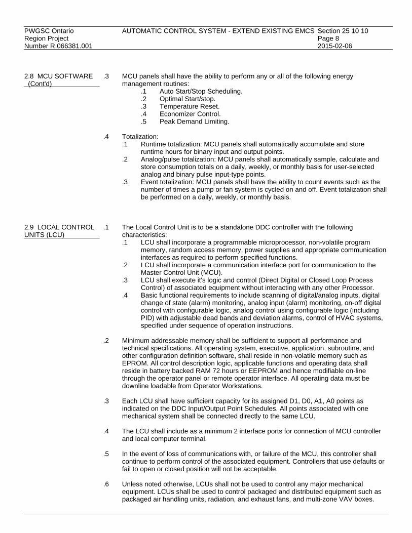
PWGSC Ontario AUTOMATIC CONTROL SYSTEM - EXTEND EXISTING EMCS Section 25 10 10Region Project Page 8Number R.066381.001 2015-02-06 2.8 MCU SOFTWARE .3 MCU panels shall have the ability to perform any or all of the following energy (Cont'd) management routines:
.1 Auto Start/Stop Scheduling.
.2 Optimal Start/stop.
.3 Temperature Reset.
.4 Economizer Control.
.5 Peak Demand Limiting.
.4 Totalization:.1 Runtime totalization: MCU panels shall automatically accumulate and store
runtime hours for binary input and output points..2 Analog/pulse totalization: MCU panels shall automatically sample, calculate and
store consumption totals on a daily, weekly, or monthly basis for user-selectedanalog and binary pulse input-type points.
.3 Event totalization: MCU panels shall have the ability to count events such as thenumber of times a pump or fan system is cycled on and off. Event totalization shallbe performed on a daily, weekly, or monthly basis.
2.9 LOCAL CONTROL .1 The Local Control Unit is to be a standalone DDC controller with the followingUNITS (LCU) characteristics:
.1 LCU shall incorporate a programmable microprocessor, non-volatile programmemory, random access memory, power supplies and appropriate communicationinterfaces as required to perform specified functions.
.2 LCU shall incorporate a communication interface port for communication to theMaster Control Unit (MCU).
.3 LCU shall execute it's logic and control (Direct Digital or Closed Loop ProcessControl) of associated equipment without interacting with any other Processor.
.4 Basic functional requirements to include scanning of digital/analog inputs, digitalchange of state (alarm) monitoring, analog input (alarm) monitoring, on-off digitalcontrol with configurable logic, analog control using configurable logic (includingPID) with adjustable dead bands and deviation alarms, control of HVAC systems,specified under sequence of operation instructions.
.2 Minimum addressable memory shall be sufficient to support all performance and
technical specifications. All operating system, executive, application, subroutine, andother configuration definition software, shall reside in non-volatile memory such asEPROM. All control description logic, applicable functions and operating data shallreside in battery backed RAM 72 hours or EEPROM and hence modifiable on-linethrough the operator panel or remote operator interface. All operating data must bedownline loadable from Operator Workstations.
.3 Each LCU shall have sufficient capacity for its assigned D1, D0, A1, A0 points as
indicated on the DDC Input/Output Point Schedules. All points associated with onemechanical system shall be connected directly to the same LCU.
.4 The LCU shall include as a minimum 2 interface ports for connection of MCU controller
and local computer terminal.
.5 In the event of loss of communications with, or failure of the MCU, this controller shallcontinue to perform control of the associated equipment. Controllers that use defaults orfail to open or closed position will not be acceptable.
.6 Unless noted otherwise, LCUs shall not be used to control any major mechanical
equipment. LCUs shall be used to control packaged and distributed equipment such aspackaged air handling units, radiation, and exhaust fans, and multi-zone VAV boxes.

PWGSC Ontario AUTOMATIC CONTROL SYSTEM - EXTEND EXISTING EMCS Section 25 10 10Region Project Page 9Number R.066381.001 2015-02-06 2.10 LCU SOFTWARE .1 Software shall include but not be limited to definitions and operating systems executive,
communications, control description logic, operator interface.
.2 Control description logic shall be written in general control type or high level language.
.3 Control description logic shall have access to values or status of all points available tothe controller including global or common values, allowing cascading and interlockingcontrol.
.4 Software to be generic and configurable from computer terminal or to be downloaded
from operator workstations. 2.11 TERMINAL .1 Each Terminal Control Unit (TCU) is to be a microprocessor-based standalone DDCCONTROL UNITS (TCU) controller with the following characteristics:
.1 Hardware and firmware are configured to control a specific type of terminalequipment such as conventional single zone VAV box or fan powered VAV box.
.2 The controller shall incorporate a communication interface port forcommunication to the Master Control Unit (MCU).
.3 Each TCU shall have sufficient capacity and memory to support its operatingsystem, data bases and specified functional requirements under sequence ofoperation instructions.
.2 Each TCU shall support multiple modes of operation including Day/Weekly Schedules,
Occupied/Unoccupied Mode, and Override Mode.
.3 Any Operator Workstation (OWS) connected to the communication network shall be ableto access all information including sensor values, operating status, setpoints, on/offschedules, alarm limits and other operating parameters of each TCU. Operator at OWSconnected to the network shall be able to make setpoint adjustments, assign high and lowalarm limits and make programming changes.
.4 Powerfail Protection: all system setpoints, proportional bands, control algorithms, and
any other programmable parameters shall be stored such that a power failure of anyduration will not require reprogramming the DDC controller.
2.12 TEMPERATURE .1 General: temperature sensors shall be RTD platinum type, unless otherwise noted.SENSORS ANDTRANSMITTERS .2 Temperature sensors shall be of the following types.
.1 Space RTD - suitable for wall mounting, with protective guard.
.2 Duct point RTD - suitable for insertion into air ducts at any angle, insertion lengthof 460 mm unless otherwise as noted on schedule or drawings.
.3 Immersion RTD - Spring loaded construction with compression fitting for 20 mmNPT well mounting. Lengths of 100 mm or 150 mm unless otherwise noted.
.4 Mixed Air Averaging RTD: continuous filament with probe length of 6000 mmminimum. Maximum 6 m2 cross section area per sensor. Probe to be bent, at fieldinstallation time, to a minimum radius of 100 mm at any point along the probelength without degradation in performance.
.5 Outdoor RTD: complete with noncorroding shield designed to minimize solar andwind effects, threaded fitting for mating to 13 mm conduit, probe length of100-150 mm.

PWGSC Ontario AUTOMATIC CONTROL SYSTEM - EXTEND EXISTING EMCS Section 25 10 10Region Project Page 10Number R.066381.001 2015-02-06 2.12 TEMPERATURE .3 Provide each sensor with a temperature transmitter having the following minimum SENSORS AND specifications: TRANSMITTERS .1 Output signal of 4-20 mA into maximum of 500 ohm load. (Cont'd) .2 Combined nonlinearity, repeatability and hysteresis effects not to exceed ±0.5% of
full scale output..3 Integral, zero and span adjustments..4 Temperature effect of ±1.0% full scale or less.
.4 Range of sensors to suit application and to be submitted with shop drawings.
2.13 HUMIDITY .1 Provide humidity sensors with the following minimum specifications:SENSORS AND .1 Operating range: 10-90% RH.TRANSMITTERS .2 Operating temperature: 0°C to 60°C.
.3 Accuracy: +2% RH at 25°C.
.4 Response time: 60 seconds from 90% to 10% RH.
.2 Provide transmitters for all supplied relative humidity sensors with the following minimumspecifications:.1 Output signal of 4-20 mA or 0 to 10 VDC..2 Maximum output linearity error of ±1.0% of full scale output..3 Integral zero and span adjustments..4 Temperature effect of ±1.0% full scale or less..5 Drift: not to exceed 1% over 12 months.
2.14 AIR SYSTEM .1 Sensors shall meet the following:STATIC PRESSURE .1 Multipoint element with self-averaging manifold.SENSORS ANDTRANSMITTERS .2 Maximum pressure loss: 160 Pa at 10 m/s. (air stream manifold).
.3 Accuracy: +1% of actual duct static pressure.
.2 Provide each sensor with a transmitter to meet the following requirements:.1 Output signal: 4 - 20 mA linear into 500 ohm maximum load..2 Calibrated span: not to exceed 150% of duct static pressure at maximum flow..3 Accuracy: +1.0% of full scale..4 Repeatability: within 0.5% of output..5 Linearity: within 1.5% of span..6 Deadband or hysteresis: 0.1% of span..7 External exposed zero and span adjustment..8 Range: 0 to 125 Pa static pressure downstream of VAV boxes and 0 to 373 Pa
static pressure upsteam of VAV boxes, unless otherwise noted. 2.15 AIR SYSTEM .1 Sensors shall meet the following requirements:VELOCITY SENSOR/ .1 Multipoint static and total pressure sensing element with self-averaging manifold,TRANSMITTER and with integral air equalizer and straightener section.
.2 Maximum pressure loss: 37 Pa at 10 m/s.
.3 Accuracy: +1% of actual duct velocity.
.2 Provide each sensor with a transmitter to meet the following requirements:.1 Output signal: 4 - 20 mA or 0 - 10VDC linear into 500 ohm maximum load..2 Calibrated span: not to exceed 25% of duct static pressure at maximum flow..3 Accuracy: +0.4% of span..4 Repeatability: within 0.1% of output.

PWGSC Ontario AUTOMATIC CONTROL SYSTEM - EXTEND EXISTING EMCS Section 25 10 10Region Project Page 11Number R.066381.001 2015-02-06 2.15 AIR SYSTEM .2 (Cont'd) VELOCITY SENSOR/ .5 Linearity: within 0.5% of span. TRANSMITTER .6 Deadband or hysteresis: 0.1% of span. (Cont'd) .7 External exposed zero and span adjustment.
.8 Air velocity range: 1 m/s to 10 m/s at 15°C. 2.16 PRESSURE/ .1 Provide pressure-to-current transmitters having the following minimum specifications:CURRENT .1 Internal materials of the transducer suitable for continuous contact with industrialTRANSMITTERS standard instrument air, compressed air, water or steam as applicable.
.2 Output signal of 4-20 mA into a maximum of 500 ohm load.
.3 Output variations of less than 0.2% full scale for supply voltage variations of ±10%.
.4 Combined nonlinearity, repeatability and hysteresis effects not to exceed ±0.5% offull scale output over entire range.
.5 Integral zero and span adjustment.
.6 Temperature effect of ±1.5% full scale/50°C or less.
.7 Output short circuit and open circuit protection.
.8 Over-pressure input protection to a minimum of twice rated input.
.9 Pressure ranges to suit application. 2.17 DIFFERENTIAL .1 Provide differential pressure transmitters having the following minimum specifications:PRESSURE .1 Internal materials to be suitable for continuous contact with the process materialTRANSMITTERS measured including compressed air, water, glycol, or steam as applicable.
.2 Output signal of 4-20 mA into maximum of 500 ohm load.
.3 Output variation of less than 0.2% full scale for supply voltage variations of ±10%.
.4 Combined nonlinearity repeatability and hysteresis effects not to exceed ±0.5% offull scale output over entire range.
.5 External exposed integral zero and span adjustment.
.6 Temperature effect of ±1.5% full scale/50°C or less.
.7 Output short circuit and open circuit protection.
.8 Over-pressure input protection to a minimum of twice rated input.
.9 Differential Pressure ranges to suit application. 2.18 PRESSURE .1 Provide pressure or differential pressure switches for ranges as indicated on pointSWITCHES schedule.
.2 Pressure sensing elements shall be bourdon tube, bellows or diaphragm type.
.3 Adjustable setpoint and differential.
.4 Pressure switches shall be snap action type rated at 120 volts, 15 amps AC or 24 voltsDC.
.5 Sensor assembly shall operate automatically and reset automatically when condition
returns to normal. 2.19 TEMPERATURE .1 Provide High/Low temperature switches for ranges as indicated on point schedule.SWITCHES
.2 Temperature sensing element shall be liquid, vapour or bimetallic type.
.3 Adjustable setpoint and differential.
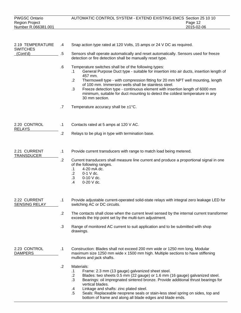
PWGSC Ontario AUTOMATIC CONTROL SYSTEM - EXTEND EXISTING EMCS Section 25 10 10Region Project Page 12Number R.066381.001 2015-02-06 2.19 TEMPERATURE .4 Snap action type rated at 120 Volts, 15 amps or 24 V DC as required. SWITCHES (Cont'd) .5 Sensors shall operate automatically and reset automatically. Sensors used for freeze
detection or fire detection shall be manually reset type.
.6 Temperature switches shall be of the following types:.1 General Purpose Duct type - suitable for insertion into air ducts, insertion length of
457 mm..2 Thermowell type - with compression fitting for 20 mm NPT well mounting, length
of 100 mm. Immersion wells shall be stainless steel..3 Freeze detection type - continuous element with insertion length of 6000 mm
minimum, suitable for duct mounting to detect the coldest temperature in any30 mm section.
.7 Temperature accuracy shall be ±1°C.
2.20 CONTROL .1 Contacts rated at 5 amps at 120 V AC.RELAYS
.2 Relays to be plug in type with termination base. 2.21 CURRENT .1 Provide current transducers with range to match load being metered.TRANSDUCER
.2 Current transducers shall measure line current and produce a proportional signal in oneof the following ranges..1 4-20 mA dc..2 0-1 V dc..3 0-10 V dc..4 0-20 V dc.
2.22 CURRENT .1 Provide adjustable current-operated solid-state relays with integral zero leakage LED forSENSING RELAY switching AC or DC circuits.
.2 The contacts shall close when the current level sensed by the internal current transformerexceeds the trip point set by the multi-turn adjustment.
.3 Range of monitored AC current to suit application and to be submitted with shop
drawings. 2.23 CONTROL .1 Construction: Blades shall not exceed 200 mm wide or 1250 mm long. ModularDAMPERS maximum size 1250 mm wide x 1500 mm high. Multiple sections to have stiffening
mullions and jack shafts.
.2 Materials:.1 Frame: 2.3 mm (13 gauge) galvanized sheet steel..2 Blades: two sheets 0.5 mm (22 gauge) or 1.6 mm (16 gauge) galvanized steel..3 Bearings: oil impregnated sintered bronze. Provide additional thrust bearings for
vertical blades..4 Linkage and shafts: zinc plated steel..5 Seals: Replaceable neoprene seals or stain-less steel spring on sides, top and
bottom of frame and along all blade edges and blade ends.

PWGSC Ontario AUTOMATIC CONTROL SYSTEM - EXTEND EXISTING EMCS Section 25 10 10Region Project Page 13Number R.066381.001 2015-02-06 2.23 CONTROL .3 Performance: DAMPERS .1 50 L/s/m2 maximum allowable leakage against 1000 Pa static pressure. (Cont'd) .2 Temperature range: minus 50°C to 100°C. 2.24 DAMPER .1 Provide direct coupled type electronic proportional damper operators where indicted orOPERATORS required.ELECTRONIC
.2 Spring return for "fail-safe" in Normally Open or Normally Closed position whererequired.
.3 Size operators to control dampers against maximum pressure or dynamic closing pressure
whichever is greater.
.4 For modulating services, provide feedback circuit to indicate actuator position.
.5 Power Requirements 12 VA maximum at 24 V AC.
.6 Input signal: 2 to 10 VDC or 4 to 20 mA. 2.25 CONTROL .1 Provide control valves as shown on drawings.VALVES
.2 Valves 50 mm and smaller to be bronze with screw end connections. Valve 62 mm andlarger to be cast iron with flanged end connections.
.3 All trim to be 316 SST.
.4 Valves to provide tight shut-off. Maximum leakage of 0.5% of rated flow.
.5 Valves to be Normally Open, Normally Closed 2 or 3- way as shown.
.6 Valves to have linear or equal percentage flow characteristics as indicated. Modulating
flow control valves to be globe style.
.7 Rangeability of valves to be minimum 50:1.
.8 Sizing Criteria:.1 Two-position service: Line size..2 Two-way modulating service: Pressure drop shall be equal to twice the pressure
drop through heat exchanger (load), 50% of the pressure difference between supplyand return mains, or 35 kPa, whichever is greater.
.3 Three-way modulating service: Pressure drop equal to twice the pressure dropthrough the coil exchanger (load), 35 kPa maximum.
2.26 ELECTRONIC .1 Provide Electronic Valve Proportional Actuators with spring return to normal positionsVALVE ACTUATORS indicated.
.2 Construction to be steel , cast iron or cast aluminum.
.3 For modulating services, provide feedback circuit to indicate actuator position.
.4 Control Voltage 0-20 V DC or 24 V AC.

PWGSC Ontario AUTOMATIC CONTROL SYSTEM - EXTEND EXISTING EMCS Section 25 10 10Region Project Page 14Number R.066381.001 2015-02-06 2.26 ELECTRONIC .5 Positioning time - nominal 60 seconds. VALVE ACTUATORS (Cont'd) 2.27 THREE POINT .1 Use of three point floating actuators shall be limited to zone control dampers, radiationFLOATING or terminal reheat control valves.ELECTRONICACTUATORS .2 Provide tri-state outputs from DDC controllers (two coordinated binary outputs) for control
of actuators.
.3 Control algorithms shall run the three point floating actuator to one end of its stroke onceevery 24 hours for verification of operator tracking.
2.28 DDC ROOM .1 Provide wall mounted DDC room thermostats where indicated on the drawings.THERMOSTATS
.2 DDC stat shall be digital controller complete with stainless steel cover plate. No readoutor adjustment buttons.
.3 Temperature sensing element shall be RTD 1,000 OHM at 21°C or thermistor
10,000 OHM at 25°C, range 4°C to 37°C.
.4 Provide signal transmission wiring and terminals or jack and connect to TCU. 2.29 LABORATORY .1 Provide dedicated laboratory air control in accordance with section 25 50 00.AIR CONTROL
.2 Laboratory air controls shall be seamlessly integrated with EMCS system, withoutreliance on proprietary software.
2.30 EXISTING .1 Unless noted otherwise or approved by the Departmental Representative in writing, allCONTROLS control devices required for a complete and working EMCS System shall be new and shall
be provided by the Contractor.
.2 The existing control dampers, control valves, sensors and end devices that may bereused are noted on the DDC Input/Output Point Schedules. Within 30 days of contractaward the Contractor shall test and inspect for satisfactory operation all existing deviceswhich are permitted to be reused. For those items considered nonfiction, the Contractorshall provide with the report, to support the findings, and obtain the DepartmentalRepresentative's instruction.
.3 The Contractor shall submit written requests to disconnect any controls and to obtain
equipment down time. Only after receiving these requests shall such work be allowed toproceed.
.4 The Contractor shall be held responsible for repair costs due to Contractor negligence or
abuse of owner equipment, or failure in reporting defective controls within 30 days ofcontract award.
.5 Shop drawings shall show all signal levels, pressures, etc., where tying into existing
control equipment.
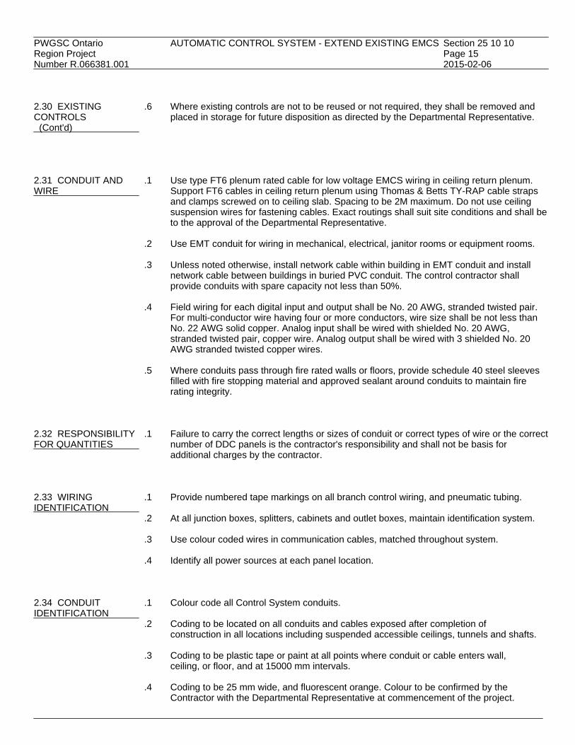
PWGSC Ontario AUTOMATIC CONTROL SYSTEM - EXTEND EXISTING EMCS Section 25 10 10Region Project Page 15Number R.066381.001 2015-02-06 2.30 EXISTING .6 Where existing controls are not to be reused or not required, they shall be removed and CONTROLS placed in storage for future disposition as directed by the Departmental Representative. (Cont'd) 2.31 CONDUIT AND .1 Use type FT6 plenum rated cable for low voltage EMCS wiring in ceiling return plenum.WIRE Support FT6 cables in ceiling return plenum using Thomas & Betts TY-RAP cable straps
and clamps screwed on to ceiling slab. Spacing to be 2M maximum. Do not use ceilingsuspension wires for fastening cables. Exact routings shall suit site conditions and shall beto the approval of the Departmental Representative.
.2 Use EMT conduit for wiring in mechanical, electrical, janitor rooms or equipment rooms.
.3 Unless noted otherwise, install network cable within building in EMT conduit and install
network cable between buildings in buried PVC conduit. The control contractor shallprovide conduits with spare capacity not less than 50%.
.4 Field wiring for each digital input and output shall be No. 20 AWG, stranded twisted pair.
For multi-conductor wire having four or more conductors, wire size shall be not less thanNo. 22 AWG solid copper. Analog input shall be wired with shielded No. 20 AWG,stranded twisted pair, copper wire. Analog output shall be wired with 3 shielded No. 20AWG stranded twisted copper wires.
.5 Where conduits pass through fire rated walls or floors, provide schedule 40 steel sleeves
filled with fire stopping material and approved sealant around conduits to maintain firerating integrity.
2.32 RESPONSIBILITY .1 Failure to carry the correct lengths or sizes of conduit or correct types of wire or the correctFOR QUANTITIES number of DDC panels is the contractor's responsibility and shall not be basis for
additional charges by the contractor. 2.33 WIRING .1 Provide numbered tape markings on all branch control wiring, and pneumatic tubing.IDENTIFICATION
.2 At all junction boxes, splitters, cabinets and outlet boxes, maintain identification system.
.3 Use colour coded wires in communication cables, matched throughout system.
.4 Identify all power sources at each panel location. 2.34 CONDUIT .1 Colour code all Control System conduits.IDENTIFICATION
.2 Coding to be located on all conduits and cables exposed after completion ofconstruction in all locations including suspended accessible ceilings, tunnels and shafts.
.3 Coding to be plastic tape or paint at all points where conduit or cable enters wall,
ceiling, or floor, and at 15000 mm intervals.
.4 Coding to be 25 mm wide, and fluorescent orange. Colour to be confirmed by theContractor with the Departmental Representative at commencement of the project.

PWGSC Ontario AUTOMATIC CONTROL SYSTEM - EXTEND EXISTING EMCS Section 25 10 10Region Project Page 16Number R.066381.001 2015-02-06 2.35 MANUFACTURER'S .1 Manufacturers' nameplates and CSA labels to be visible and legible after equipment isAND CSA LABELS installed. PART 3 - EXECUTION 3.1 GENERAL .1 All equipment shall be installed in according to manufacturers' published instructions.
.2 Provide programming for the system and adhere to the sequence of operation specified. 3.2 DDC INPUT/ .1 DDC Input/Output Point Schedule, as shown on the Mechanical Drawings and requiredOUTPUT POINT to implement specified control sequence.SCHEDULE
.2 Naming convention: PWGSC Standardized Identifiers and Expansions of BuildingNames, System Names and Point Names shall be used for identification. Identifiers shallbe not more than 10 alphanumeric characters, and Expansions shall not more than40 characters.
.3 The Application Programs shall be assigned with the specified DDC points as indicated
on the DDC Input/Output Schedule. In addition, the Application Program shall beassigned with the following point types:.1 Alarm Program with: all space temperature AI points, all supply air temperature AI
points, all supply air and return air humidity AI points, all air filter pressure drop AIpoints, all supply air static pressure AI points, all AI points of heating water supplyand return temperature, all AI points of chilled water supply and returntemperature, all DI points of fans and pumps.
.2 Auto Start/Stop Program with: all DO points of fans and pumps.
.3 Run Time Total Program with: all DO points.
.4 Heavy Equipment Delay Program with: all DO points of motors of 15 kw and larger.
.5 PID Control Program with: all AO points of control valves (except terminal heatingcontrol valves and radiation control valves) and control dampers (except terminalzone control dampers).
.6 Analog/PI Total Program with all AI or PI points of water meters and energymeters.
.4 All DI or DO points assigned with "alarm" and "run time total" programs shall be provided
with "critical" and "maintenance" alarms. All AI or AO points assigned with "alarm"program shall be provided with "critical" and "cautionary" alarms.
3.3 INSTALLATION OF .1 Install sensors in accordance with the manufacturer's recommendations.SENSORS
.2 Sensors used in mixing plenums shall be the averaging type. Averaging sensors shall beinstalled in a serpentine manner vertically across the duct. Each bend shall be supportedwith a capillary clip.
.3 Low-limit sensors used in mixing plenums shall be installed in a serpentine manner
horizontally across duct. Each bend shall be supported with a capillary clip. Provide 3 mof sensing element for each 1 m2 of cross section area.
.4 All pipe mounted temperature sensors shall be installed in wells. Install all liquid
temperature sensors with heat conducting fluid in thermal wells.

PWGSC Ontario AUTOMATIC CONTROL SYSTEM - EXTEND EXISTING EMCS Section 25 10 10Region Project Page 17Number R.066381.001 2015-02-06 3.3 INSTALLATION OF .5 Outdoor air temperature sensors shall be installed on north wall, complete with sun SENSORS shield at designated location. (Cont'd)
.6 Building static pressure sensors: Pipe the low pressure port of the differential air staticpressure sensor to the static pressure port located on the outside of the building through ahigh volume accumulator. Pipe the high pressure port to a location behind a thermostatcover.
.7 Supply duct static pressure sensor: Pipe the high pressure tap of the differential air static
pressure sensor to the duct using a pitot tube. Pipe the low pressure port to a tee in thehigh pressure tap tubing of the corresponding building static pressure sensor.
3.4 INSTALLATION .1 Install actuators in accordance with the manufacturer's recommendations.OF ACTUATORS
.2 Electronic dampers: Actuators shall be direct mounted on damper shaft or jackshaftunless shown as a linkage installation. For low leakage dampers with seals, the actuatorshall be mounted with a minimum 5 degree available for tightening the damper seals.
.3 Electronic Valves: Actuators shall be connected to valves with adapters approved by the
actuator manufacturer. Actuators and adapters shall be mounted following the actuatormanufacturer's recommendations.
3.5 SEQUENCE OF .1 Refer to the Schematic shown on the Mechanical Drawings for reference points.OPERATION FOR Actuators, valves, sensors, pipe walls, integration controllers by EMCS. Installation byRTU02 manufacturer. Cooling and humidification controls by unit manufacturer.
.2 Interlock: provide hard wire interlock of the return fan RF1 with its supply fan SF andFreeze Stat.
.3 Supply Fan (SF): is interlocked with exhaust fans (ERU2). When ERU2 is ON, SF shall be
ON. When ERU2 is OFF, SF shall be OFF. ERU2 to enable only after RTU02 is atminimum speed to maintain positive pressure during ERU2 startup sequence.
.4 Supply Fan VAV Volume Control: When SF is ON, the supply air volume shall be
controlled to maintain a constant supply duct static pressure at setpoint measureddownstream of FU1.
.5 Heating Supply Air Temperature Control: SAT shall be reset by the Outside Air
Temperature OAT to avoid overheating or overcooling. The SAT setpoint shall then beused to control the heating coil valve HCV while heating mode to maintain 22°Coccupied and 20°C unoccupied, with setpoint by space temperature valve supplied byEMCS.
.6 Humidification: The space air humidity setpoint shall be used by the humidifier control
(built-in to RTU02 by manufacturer) loop through the supply air humidity high limit tocontrol the humidifier to maintain a minimum space humidity level. With outside airtemperature higher than 15°C, the humidifier shall be OFF. Humidifier shall beinterlocked with flow switch to disable humidifier in event of no flow condition. The winterspace air humidity setpoint is to be 40% RH with alarm if space air humidity drops below30% RH. Exhaust air humidity setpoint shall be monitored by EMCS. EMCS to send resetsignal to humidifier control loop to maintain desired space humidity.
.7 Cooling Supply Air Temperature Control: SAT setpoint to be determined by RTU02.
Cooling/compressor controller by RTU02 manufacturer based on OA temperature. RTU02

PWGSC Ontario AUTOMATIC CONTROL SYSTEM - EXTEND EXISTING EMCS Section 25 10 10Region Project Page 18Number R.066381.001 2015-02-06 3.5 SEQUENCE OF .7 (Cont'd) OPERATION FOR built-in controller to control compressor and refrigeration circuit to maintain SAT setpoint. RTU02 EMCS to reset SAT setpoint based on space temperature. Cooling mode space (Cont'd) temperature setpoint to be 22°C occupied and 24°C unoccupied.
.8 Dehumidification: The outside air humidity ratio and setpoint shall be used by RTU02built-in cooling/compressor controller sequence compressors and refrigerant valves onreheat coil to maintain SAT setpoint. The outside air humidity ratio setpoint shall bereset by EMCS based on space air humidity setpoint. The summer space air humiditysetpoint is to be 50%.
.9 Heat Recovery Loop: The energy recovery loop shall open to continuously while OA
temperatures are below 18°C (unless dehumidification is enabled) and above 24°C.Three-way valve shall be modulated to maintain minimum -1°C fluid temperatureentering exhaust recover coil. Valve sensor and well supplied by EMCS contractor,installed by RTU manufacturer.
10. Differential pressure alarm across FU2 shall alarm if above setpoint.
3.6 SEQUENCE OF .1 Refer to the schematic shown on mechanical drawing for reference points. DampersOPERATION FOR supplied by ERU2 manufacturer. All other wiring, actuators, controllers to accommodateERU2 sequence by EMCS contractor.
.2 Lead exhaust fan (EF) shall be enabled following successful startup sequence of RTU02.EF startup sequence shall open associated inlet damper, open main bypass air damper.Following end switch activation of inlet damper, EF to be enabled at "start" speedsetpoint (determined during TAB to be point at which outlet velocity reaches 15.3 m/s).Modulate bypass air damper closed to achieve duct static pressure setpoint. When bypassair damper reaches fully closed position and static pressure setpoint still not met,modulate VFD speed to maintain duct static pressure.
.3 Following 168 hours of operation of lead exhaust fan, and during occupied mode, open
bypass damper to 50% minimum, enable lag EF and modulate fan VFD's opposite toeach other to maintain stable duct pressure conditions. Disable lead EF and adjust bypassdamper and lag VFD speed to steady duct static pressure. Repeat.
.4 Enable lag EF should lead EF alarm.
3.7 SEQUENCE OF .1 Refer to the schematic shown on mechanical drawing for point reference.OPERATION FORHEATING LOOP .2 Existing heating loop controls for RTU01 to remain as is and modified to accommodate
new work.
.3 Primary heating shall be provided through HE1, cogeneration heat exchanger. Monitorinlet and outlet temperatures.
.4 V1 diverting valve to be normally closed to pump loop. P1 to be normally off. Based on
user input cogeneration booster P1 to be enable and V1 to be modulated open asneeded.
.5 Mixing valve, V2, shall modulate to maintain loop temperature setpoint. Setpoint shall
be resent based on outdoor on schedule between 50°C and 71°C.

PWGSC Ontario AUTOMATIC CONTROL SYSTEM - EXTEND EXISTING EMCS Section 25 10 10Region Project Page 19Number R.066381.001 2015-02-06 3.7 SEQUENCE OF .6 Pumps P2 and P3 to operate duty standby so that lag pump is activated based on lead OPERATION FOR pump alarm/failure to operate. Pump VFD speed shall modulate to maintain supply loop HEATING LOOP pressure setpoint. (Cont'd)
.7 Based on user override or failure of cogenerate exchanger to maintain supplytemperature setpoints, steam heat backup sequence shall be activated as follows: Opendiverting valve, V3, to bypass, enable HE2 at built-in controller, and establish setpointaccording to OAT reset schedule. Monitor temperature and HE2 status.
END


PWGSC Ontario LABORATORY AIR CONTROLS Section 25 50 00Region Project Page 1Number R.066381.001 2015-02-06 PART 1 - GENERAL 1.1 RELATED .1 Section 25 10 10 - Automatic Control System - Extend Existing EMCS.SECTIONS 1.2 GENERAL .1 Conform to Section 25 10 10 with the following additions:
.1 Provide all products, equipment and services for the specified integratedlaboratory air flow and control systems.
.2 Integrated laboratory room air control system shall respond to full scale air flowchange commands within less than 1 second.
.3 Integrated Laboratory Air Control System shall include sash position sensors, fumehood monitors, laboratory control panels, make-up air Venturi control valves, supplyair Venturi control valves, exhaust air Venturi control valves plus on-site start-upand commissioning to result in a completely operational system.
.4 All control components except for pneumatic actuators shall be strictly electronic. 1.3 CALIBRATION OF .1 Each Venturi control valve shall be factory calibrated to the job specific air flows asVENTURI CONTROL indicated on the drawings. Valve shall be electronically calibrated/characterized at theVALVES factory by certified NIST traceable air stations. The valve's characterization shall be
determined at eight unique air flows including a test of the valve's pressureindependence at three different static pressures. Air flow checks shall be performed andrecorded for each air valve.
.2 Field adjustments shall not be required other than minor changes as required by the
balancing contractor. Accuracy and performance shall be guaranteed as specifiedregardless of field conditions such as duct entry and exit configurations.
.3 Each valve shall be individually marked with valve specific factory calibration data. As a
minimum, it should include valve tag number, serial number, model number, eight pointvalve characterization information,and quality control inspection numbers. Allinformation shall be stored on computer CD in ASCII format for future retrieval and forhard copy printout to be included with as-built documentation.
1.4 FUNCTIONAL .1 Use qualified personnel directed by the Departmental Representative to conductPERFORMANCE TESTS functional performance tests of Laboratory Air Control Systems. The test shall verify
system operation including, but not limited to, hood exhaust volume tracking,temperature control, room supply/exhaust differential, speed of response, accuracy,pressure independence and stability. Tests shall be performed with supply and exhaustvalve pressure drops varying from 75 to 750 Pa.
.2 If the results of the system testing show any deviation from the minimum specified
performance and operating characteristics, tests shall be repeated after correctivemeasures are carried out, and this process shall continue until acceptable performance isachieved.

PWGSC Ontario LABORATORY AIR CONTROLS Section 25 50 00Region Project Page 2Number R.066381.001 2015-02-06 PART 2 - MATERIALS 2.1 GENERAL .1 The laboratory airflow control systems shall be fully integrated with the EMCS. The
controllers shall be the same make and firmware revision as EMCS controllers. Gatewaysare not acceptable.
2.2 SASH POSITION .1 SPS shall consist of a precision 10 turn spring return potentiometer mechanicallySENSOR (SPS) coupled to a constant tension spring reel. A stainless steel, vinyl coated cable shall be
attached to the spring reel. It shall measure the height of a vertically moving fume hoodsash.
.2 SPS shall be type-tested for 200,000 full height sash movements without failure in order
to be used in these critical applications.
.3 All SPS's shall not have their output signal influenced by heat sources such as hot plates,Bunsen burners or combustion resting in the hood, or by cold sources such as dry iceeither inside or outside the hood. All SPS's shall be installed and wired by the fume hoodmanufacturer or authorized representative to provide an accurate signal proportional tofume hood sash opening without binding or other operational difficulties.
2.3 FUME HOOD .1 FHM shall receive the sash opening signals from the SPS, compute the total open sashMONITOR (FHM) area and initiate signal to exhaust air valve to maintain desired face velocity.
.2 FHM shall respond to maintain the desired flow rate as dictated by the SPS. System shallachieve either calibrated flow volume to within 10% in less than one second with lessthan 5% overshoot or undershoot regardless of the turndown range of the system.
.3 Face velocity sensor shall be installed on hood and wired to controller to monitor
conditions and provide alarm should face velocity fall out of setpoint range (adjustable).
.4 FHM shall illuminate one GREEN pilot light to indicate normal operation.
.5 Each FHC shall contain a visual and audible LOSS OF FACE VELOCITY alarm toindicate a low face velocity condition. Muting of the alarm shall only silence the audibleportion, while the visual alarm shall be maintained unless the low flow condition hasbeen removed. Alarm shall be triggered by:.1 A sensed face velocity..2 An alarm wire being disconnected.
.6 Provide a push button switch to mute audible alarms. The mute mode shall
automatically reset when the alarm condition ceases.
.7 Monitor shall be free of plasticizers. If plasticizers free material is not available, a customlatching, hinged cover (glass) on recessed monitor shall be provided and coordinated withfume hood supplier.

PWGSC Ontario LABORATORY AIR CONTROLS Section 25 50 00Region Project Page 3Number R.066381.001 2015-02-06 2.4 VENTURI CONTROL .1 Control valve shall utilize a Venturi section into which a cone shaped element slides toVALVES create a smoothly varying, annular orifice. Valve shall be constructed such that the
Venturi body's shape logarithmically necks down to the orifice area and thenlogarithmically re-expands to full valve inlet size to ensure a static regain with minimumpressure loss. Valve shall have an Equal Percentage flow characteristic to provideaccurate control at low flow values. Butterfly, opposed blade, bladder type dampers, orVAV boxes are not acceptable.
.2 Valve shall be pressure independent over a differential pressure range of 75 Pa to
750 Pa across the valve. Integral pressure independent assembly shall respond andmaintain specific air flow within one second of a change in duct static pressure.
.3 Valve air flow accuracy shall be ±5% of reading (not full scale) regardless of inlet or exit
duct configuration over an air flow turndown range of no less than 14 to 1. No entrance orexit duct diameter restrictions shall limit the specified speed of response, accuracy orpressure independence.
.4 Venturi control valves including make-up air valves (MAV) A/C supply air valves (SAV)
and exhaust air valves (EAV) shall be constructed of 14 gauge aluminum or 16 gaugegalvanized steel. All bearing surfaces shall be made of a composite Teflon or TeflonInfused (versus coated) aluminum. The valve shaft, pivot arm, shaft support brackets, andinternal mounting hardware shall be 316 L Stainless Steel.
.5 Exhaust air valves to have baked on phenolic coating for corrosion resistance.
.6 Install Venturi control valves horizontally or vertically to fit within available space and
provide for suitable access for maintenance.
.7 Venturi control valve shall use electronic based closed loop position feedback andcontrol to regulate air volume linearly proportional to a 0 to 10 Volt electronic controlsignal. Valve shall generate a 0 to 10 Volt feedback signal linearly proportional to airflow for internal volume control, monitoring, or air flow tracking control. Signal shall befactory calibrated to a stated L/s per volt scale factor using NIST traceableinstrumentation directly from the control arm or shaft position.
.8 Valve shall achieve 90% of its commanded volume within one second of being
commanded to its new volume set point (regardless of system stability) with less than a5% undershoot or overshoot.
.9 A static pressure switch pre-mounted to each Venturi control valve shall sense and alarm
should differential pressure fall below the range of pressure independent control valve asstated by valve manufacturer. The switch shall operate by measuring the pressure dropacross the variable orifice Venturi. This switch shall alarm at EMCS.
.10 Supply air valves to have outlet attenuator with solid liner and no plastics.
.11 Each device must be factory calibrated to job specific airflows.
2.5 LABORATORY .1 Provide a LCP to control the air flow balance of the laboratory room. Provide one LCPCONTROL PANEL per laboratory pressurization zone. Locate panel within ante room.(LCP)
.2 LCP shall be of electronic design and shall accept 0 to 10 volt input signals proportionalto air flows.
.3 LCP output shall control MAVs, SAVs and EAVs with 0 to 10 volt signals linearly
proportional to the desired supply or exhaust volumes.

PWGSC Ontario LABORATORY AIR CONTROLS Section 25 50 00Region Project Page 4Number R.066381.001 2015-02-06 2.5 LABORATORY .4 Provide integral field adjustable trimpots for all required calibration and scaling CONTROL PANEL adjustments. (LCP) (Cont'd) .5 LCP shall maintain a specified constant (adjustable) volumetric off set between the sum
of the room's total exhaust and the make-up/supply air volumes. The volumetric offsetshall be resetable via signal based on differential pressure between lab and corridor.
.6 LCP shall determine occupancy through either fume hood mounted pressure sensors to
achieve acceptable coverage. The LCP shall be able to reduce fumehood face velocitysetpoints based on occupancy. Occupancy signal shall be transmitted to EMCS.
.7 All room level points shall be available at EMCS for monitoring or trending.
.8 All communication shall be BACnet on a peer to peer basis with EMCS.
2.6 DIFFERENTIAL .1 PS shall be position insensitive even at pressure near 2.5 Pa.PRESSURE SENSORCONTROL .2 PS shall provide an output of 0 - 10 VDC for a full scale pressure input of 0 - 250 Pa
positive or negative.
.3 PS shall have integral filters at both ports.
.4 Accuracy including non-linearity and hysteresis shall be + 1% of range.
.5 Maximum drift due to temperature not to exceed + 0.05% per degree C.
.6 The corridor shall be the pressure reference point. The pressure between airlock andcorridor shall be monitored and alarm if out of range (8 pa negative setpoint). A doorcontactor shall disable alarm. The pressure between lab and corridor shall be monitoredto be 8 pa positive, and reset the volumetric offset within set range before alarming.
PART 3 - EXECUTION 3.1 GENERAL .1 Unless noted otherwise this section shall be responsible for supply and installation of all
materials specified under this Section including all pneumatic piping and control wiring.
.2 The 138 kPa compressed air, shall be clean and dry instrument quality. 3.2 START-UP, .1 Factory-trained and authorized personnel in the regular employ of the laboratory systemCALIBRATION integrator shall provide start-up, calibration, and commissioning services. These servicesCOMMISSIONING AND shall include the setting of fume hood face velocities, fume hood air flows, and theOTHER SERVICES setting of exhaust and supply air flows, specified.
.2 This supplier shall include for a second trip to the jobsite, not longer than 3 months afterthe project has been completed and handed over to the owner, to instruct the buildingmanagement personnel in the proper care and maintenance of the systems.
.3 This supplier shall include for a third trip to the jobsite, not longer than 3 months after
the completion of the project, to instruct the users in the correct operation of the system.
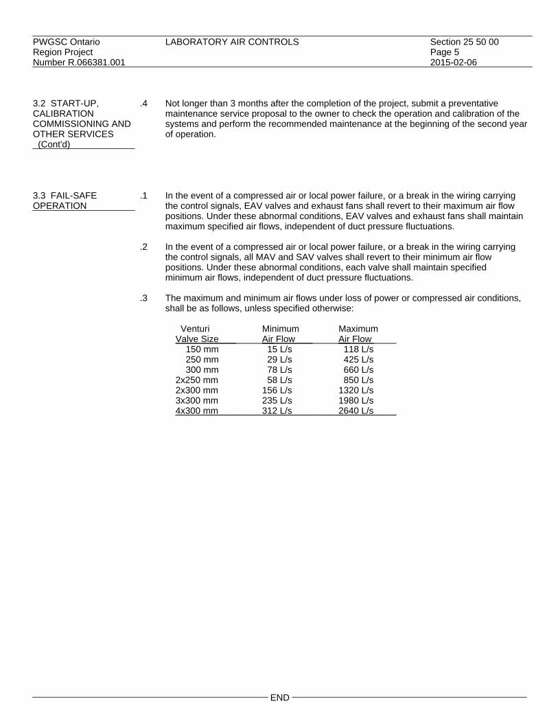
PWGSC Ontario LABORATORY AIR CONTROLS Section 25 50 00Region Project Page 5Number R.066381.001 2015-02-06 3.2 START-UP, .4 Not longer than 3 months after the completion of the project, submit a preventative CALIBRATION maintenance service proposal to the owner to check the operation and calibration of the COMMISSIONING AND systems and perform the recommended maintenance at the beginning of the second year OTHER SERVICES of operation. (Cont'd) 3.3 FAIL-SAFE .1 In the event of a compressed air or local power failure, or a break in the wiring carryingOPERATION the control signals, EAV valves and exhaust fans shall revert to their maximum air flow
positions. Under these abnormal conditions, EAV valves and exhaust fans shall maintainmaximum specified air flows, independent of duct pressure fluctuations.
.2 In the event of a compressed air or local power failure, or a break in the wiring carrying
the control signals, all MAV and SAV valves shall revert to their minimum air flowpositions. Under these abnormal conditions, each valve shall maintain specifiedminimum air flows, independent of duct pressure fluctuations.
.3 The maximum and minimum air flows under loss of power or compressed air conditions,
shall be as follows, unless specified otherwise:
Venturi Minimum Maximum Valve Size Air Flow Air Flow 150 mm 15 L/s 118 L/s 250 mm 29 L/s 425 L/s 300 mm 78 L/s 660 L/s 2x250 mm 58 L/s 850 L/s 2x300 mm 156 L/s 1320 L/s 3x300 mm 235 L/s 1980 L/s 4x300 mm 312 L/s 2640 L/s
END


PWGSC Ontario COMMON WORK RESULTS FOR ELECTRICAL Section 26 05 00Region Project Page 1Number R.066381.001 2015-02-06 PART 1 - GENERAL 1.1 RELATED .1 Section 26 05 32 - Outlet Boxes, Conduit Boxes and Fittings.REQUIREMENTS 1.2 REFERENCES .1 Definitions:
.1 Electrical and electronic terms: unless otherwise specified or indicated, terms usedin these specifications, and on drawings, are those defined by IEEE SP1122.
.2 Reference Standards:
.1 CSA Group.1 CSA C22.1-12, Canadian Electrical Code, Part 1 (22nd Edition), Safety
Standard for Electrical Installations..2 Institute of Electrical and Electronics (IEEE)/National Electrical Safety Code
Product Line (NESC).1 IEEE SP1122-2000, The Authoritative Dictionary of IEEE Standards Terms,
7th Edition. 1.3 ACTION AND .1 Submit in accordance with Section 01 33 00.INFORMATIONALSUBMITTALS .2 Product Data:
.1 Submit manufacturer's instructions, printed product literature and data sheets andinclude product characteristics, performance criteria, physical size, finish andlimitations.
.3 Shop drawings:
.1 Submit wiring diagrams and installation details of equipment indicating proposedlocation, layout and arrangement, control panels, accessories, piping, ductwork,and other items that must be shown to ensure co-ordinated installation.
.2 Identify on wiring diagrams circuit terminals and indicate internal wiring for eachitem of equipment and interconnection between each item of equipment.
.3 Indicate of drawings clearances for operation, maintenance, and replacement ofoperating equipment devices.
.4 Submit 600 x 600 mm minimum size drawings and product data to authorityhaving jurisdiction.
.5 If changes are required, notify Departmental Representative of these changesbefore they are made.
.4 Certificates:
.1 Provide CSA certified equipment and material.
.2 Where CSA certified equipment and material is not available, submit suchequipment and material to authority having jurisdiction for special approval beforedelivery to site.
.3 Submit test results of installed electrical systems and instrumentation.
.4 Permits and fees: in accordance with General Conditions of contract.
.5 Submit, upon completion of Work, load balance report as described in PART 3 -LOAD BALANCE.
.6 Submit certificate of acceptance from authority having jurisdiction uponcompletion of Work to Departmental Representative.

PWGSC Ontario COMMON WORK RESULTS FOR ELECTRICAL Section 26 05 00Region Project Page 2Number R.066381.001 2015-02-06 1.4 CLOSEOUT .1 Submit in accordance with Section 01 78 00.SUBMITTALS
.2 Operation and Maintenance Data: submit operation and maintenance data forincorporation into manual..1 Provide for each system and principal item of equipment as specified in technical
sections for use by operation and maintenance personnel..2 Operating instructions to include following:
.1 Wiring diagrams, control diagrams, and control sequence for each principalsystem and item of equipment.
.2 Start up, proper adjustment, operating, lubrication, and shutdownprocedures.
.3 Safety precautions.
.4 Procedures to be followed in event of equipment failure.
.5 Other items of instruction as recommended by manufacturer of each systemor item of equipment.
.3 Print or engrave operating instructions and frame under glass or in approvedlaminated plastic.
.4 Post instructions where directed.
.5 For operating instructions exposed to weather, provide weather-resistant materialsor weatherproof enclosures.
.6 Ensure operating instructions will not fade when exposed to sunlight and aresecured to prevent easy removal or peeling.
1.5 DELIVERY, .1 Deliver, store and handle materials in accordance with Section 01 61 00 and withSTORAGE AND manufacturer's written instructions.HANDLING
.2 Delivery and Acceptance Requirements: deliver materials to site in original factorypackaging, labelled with manufacturer's name and address.
.3 Storage and Handling Requirements:
.1 Store materials off ground, indoors, in dry location and in accordance withmanufacturer's recommendations in clean, dry, well-ventilated area.
.2 Store and protect from nicks, scratches, and blemishes.
.3 Replace defective or damaged materials with new.
.4 Packaging Waste Management: remove for reuse and return by manufacturer of pallets,crates, padding, and packaging materials as specified in Construction WasteManagement Plan.
PART 2 - PRODUCTS 2.1 DESIGN .1 Operating voltages: to CAN3-C235.REQUIREMENTS
.2 Motors, electric heating, control and distribution devices and equipment to operatesatisfactorily at 60 Hz within normal operating limits established by above standard..1 Equipment to operate in extreme operating conditions established in above
standard without damage to equipment.
.3 Language operating requirements: provide identification nameplates and labels forcontrol items in English and French.
.4 Use one nameplate or label for each language.

PWGSC Ontario COMMON WORK RESULTS FOR ELECTRICAL Section 26 05 00Region Project Page 3Number R.066381.001 2015-02-06 2.2 MATERIALS AND .1 Provide material and equipment in accordance with Section 01 61 00.EQUIPMENT
.2 Material and equipment to be CSA certified. Where CSA certified material andequipment are not available, obtain special approval from authority having jurisdictionbefore delivery to site and submit such approval as described in PART 1 - ACTION ANDINFORMATIONAL SUBMITTALS.
.3 Factory assemble control panels and component assemblies.
2.3 WIRING .1 Ensure lugs, terminals, screws used for termination of wiring are suitable for either copperTERMINATIONS or aluminum conductors. 2.4 EQUIPMENT .1 Identify electrical equipment with nameplates and labels as follows:IDENTIFICATION .1 Nameplates: lamicoid 3 mm thick plastic engraving sheet, black matt white finish
face, black core, lettering accurately aligned and engraved into core..2 Sizes as follows:
NAMEPLATE SIZES Size 1 10 x 50 mm 1 line 3 mm high letters Size 2 12 x 70 mm 1 line 5 mm high letters Size 3 12 x 70 mm 2 lines 3 mm high letters Size 4 20 x 90 mm 1 line 8 mm high letters Size 5 20 x 90 mm 2 lines 5 mm high letters Size 6 25 x 100 mm 1 line 12 mm high letters Size 7 25 x 100 mm 2 lines 6 mm high letters
.2 Labels: electronically printed, self-adhesive plastic labels with 6 mm high letters unlessspecified otherwise.
.3 Wording on nameplates and labels to be approved by Departmental Representative prior
to manufacture.
.4 Allow for minimum of twenty-five (25) letters per nameplate and label.
.5 Nameplates for terminal cabinets and junction boxes to indicate system and/or voltagecharacteristics.
.6 Identify equipment with Size 3 labels engraved "ASSET INVENTORY NO. [______]" as
directed by Departmental Representative.
.7 Disconnects, starters and contactors: indicate equipment being controlled and voltage.
.8 Terminal cabinets and pull boxes: indicate system and voltage.
.9 Transformers: indicate capacity, primary and secondary voltages. 2.5 WIRING .1 Identify wiring with permanent indelible identifying markings, coloured plastic tapes, onIDENTIFICATION both ends of phase conductors of feeders and branch circuit wiring.
.2 Maintain phase sequence and colour coding throughout.
.3 Colour coding: to CSA C22.1.

PWGSC Ontario COMMON WORK RESULTS FOR ELECTRICAL Section 26 05 00Region Project Page 4Number R.066381.001 2015-02-06 2.5 WIRING .4 Use colour coded wires in communication cables, matched throughout system. IDENTIFICATION (Cont'd) 2.6 CONDUIT AND .1 Colour code conduits, boxes and metallic sheathed cables.CABLEIDENTIFICATION .2 Code with plastic tape or paint at points where conduit or cable enters wall, ceiling, or
floor, and at 15 m intervals.
.3 Colours: 25 mm wide prime colour and 20 mm wide auxiliary colour.
Prime Auxiliary_ up to 250 V Yellow
up to 600 V Yellow Green
Telephone Green
Other Green Blue Communication Systems
Fire Alarm Red Other Red Yellow Security Systems 2.7 FINISHES .1 Shop finish metal enclosure surfaces by application of rust resistant primer inside and
outside, and at least two coats of finish enamel..1 Paint outdoor electrical equipment "equipment green" ..2 Paint indoor switchgear and distribution enclosures light gray.
PART 3 - EXECUTION 3.1 EXAMINATION .1 Verification of Conditions: verify that conditions of substrate previously installed under
other Sections or Contracts are acceptable for installation in accordance withmanufacturer's written instructions..1 Visually inspect substrate in presence of Departmental Representative..2 Inform Departmental Representative of unacceptable conditions immediately
upon discovery..3 Proceed with installation only after unacceptable conditions have been remedied
and after receipt of written approval to proceed from Departmental Representative. 3.2 INSTALLATION .1 Do complete installation in accordance with CSA C22.1 except where specified
otherwise.

PWGSC Ontario COMMON WORK RESULTS FOR ELECTRICAL Section 26 05 00Region Project Page 5Number R.066381.001 2015-02-06 3.3 NAMEPLATES AND .1 Ensure manufacturer's nameplates, CSA labels and identification nameplates are visibleLABELS and legible after equipment is installed. 3.4 LOCATION OF .1 Locate outlets in accordance with Section 26 05 32.OUTLETS
.2 Do not install outlets back-to-back in wall; allow minimum 150 mm horizontal clearancebetween boxes.
.3 Change location of outlets at no extra cost or credit, providing distance does not exceed
3000 mm, and information is given before installation.
.4 Locate light switches on latch side of doors..1 Locate disconnect devices in mechanical and elevator machine rooms on latch
side of floor. 3.5 MOUNTING .1 Mounting height of equipment is from finished floor to centreline of equipment unlessHEIGHTS specified or indicated otherwise.
.2 If mounting height of equipment is not specified or indicated, verify before proceedingwith installation.
.3 Install electrical equipment at following heights unless indicated otherwise.
.1 Local switches: 1200 mm.
.2 Wall receptacles:.1 General: 450 mm..2 Above top of continuous baseboard heater: 200 mm..3 Above top of counters or counter splash backs: 175 mm..4 In mechanical rooms: 1200 mm.
.3 Panelboards: as required by Code or as indicated.
.4 Telephone and interphone outlets: 450 mm.
.5 Wall mounted telephone and interphone outlets: 1200 mm.
.6 Fire alarm stations: 1200 mm.
.7 Fire alarm bells: 2100 mm. 3.6 CO-ORDINATION .1 Ensure circuit protective devices such as overcurrent trips, relays and fuses are installed toOF PROTECTIVE required values and settings.DEVICES 3.7 FIELD QUALITY .1 Load Balance:CONTROL .1 Measure phase current to panelboards with normal loads (lighting) operating at
time of acceptance; adjust branch circuit connections as required to obtain bestbalance of current between phases and record changes.
.2 Measure phase voltages at loads and adjust transformer taps to within 2% of ratedvoltage of equipment.
.3 Provide upon completion of work, load balance report as directed in PART 1 -ACTION AND INFORMATIONAL SUBMITTALS, phase and neutral currents onpanelboards, dry-core transformers and motor control centres, operating undernormal load, as well as hour and date on which each load was measured, andvoltage at time of test.

PWGSC Ontario COMMON WORK RESULTS FOR ELECTRICAL Section 26 05 00Region Project Page 6Number R.066381.001 2015-02-06 3.7 FIELD QUALITY .2 Conduct following tests in accordance with Section 01 45 00. CONTROL .1 Power distribution system including phasing, voltage, grounding and load (Cont'd) balancing.
.2 Circuits originating from branch distribution panels.
.3 Lighting and its control.
.4 Motors, heaters and associated control equipment including sequenced operationof systems where applicable.
.5 Systems: fire alarm.
.3 Carry out tests in presence of Departmental Representative.
.4 Provide instruments, meters, equipment and personnel required to conduct tests duringand at conclusion of project.
3.8 SYSTEM STARTUP .1 Instruct Departmental Representative and operating personnel in operation, care and
maintenance of systems, system equipment and components.
.2 Provide these services for such period, and for as many visits as necessary to putequipment in operation, and ensure that operating personnel are conversant with aspectsof its care and operation.
3.9 CLEANING .1 Progress Cleaning: clean in accordance with Section 01 74 11.
.1 Leave Work area clean at end of each day.
.2 Final Cleaning: upon completion remove surplus materials, rubbish, tools andequipment in accordance with Section 01 74 11.
.3 Waste Management: separate waste materials for reuse and recycling.
.1 Remove recycling containers and bins from site and dispose of materials atappropriate facility.
END

PWGSC Ontario WIRE AND BOX CONNECTORS (0-1000 V) Section 26 05 20Region Project Page 1Number R.066381.001 2015-02-06 PART 1 - GENERAL 1.1 REFERENCES .1 CSA International
.1 CAN/CSA-C22.2 No. 18-98(R2003), Outlet Boxes, Conduit Boxes and Fittings.
.2 CAN/CSA-C22.2 No. 65-13, Wire Connectors.
.2 National Electrical Manufacturers Association (NEMA) PART 2 - PRODUCTS 2.1 MATERIALS .1 Pressure type wire connectors to: CAN/CSA-C22.2 No. 65, with current carrying parts of
copper sized to fit copper conductors as required.
.2 Fixture type splicing connectors to: CAN/CSA-C22.2 No. 65, with current carrying parts ofcopper sized to fit copper conductors 10 AWG or less.
.3 Bushing stud connectors: to NEMA to consist of:
.1 Connector body and stud clamp for copper conductors.
.2 Clamp for copper conductors.
.3 Stud clamp bolts.
.4 Bolts for copper conductors.
.5 Sized for conductors as indicated.
.4 Clamps or connectors for armoured cable, flexible conduit, as required to:CAN/CSA-C22.2 No. 18.
PART 3 - EXECUTION 3.1 INSTALLATION .1 Remove insulation carefully from ends of conductors and cables and:
.1 Install mechanical pressure type connectors and tighten screws with appropriatecompression tool recommended by manufacturer. Installation shall meetsecureness tests in accordance with CAN/CSA-C22.2 No.65.
.2 Install fixture type connectors and tighten to CAN/CSA-C22.2 No.65. Replaceinsulating cap.
.3 Install bushing stud connectors in accordance with NEMA.
END


PWGSC Ontario WIRES AND CABLES (0-1000 V) Section 26 05 21Region Project Page 1Number R.066381.001 2015-02-06 PART 1 - GENERAL 1.1 RELATED .1 Section 26 05 00 - Common Work Results for Electrical.REQUIREMENTS
.2 Section 26 05 20 - Wire and Box Connectors - (0-1000 V).
.3 Section 26 05 34 - Conduits, Conduit Fastenings and Conduit Fittings. PART 2 - PRODUCTS 2.1 BUILDING WIRES .1 Conductors: stranded for 10 AWG and larger. Minimum size: 12 AWG.
.2 Copper conductors: size as indicated, with 1000 V insulation of cross-linked thermosettingpolyethylene material rated RW90 XLPE.
2.2 ARMOURED .1 Conductors: insulated, copper, size as indicated.CABLES
.2 Type: AC90.
.3 Armour: interlocking type fabricated from galvanized steel strip.
.4 Connectors: anti short connectors. PART 3 - EXECUTION 3.1 FIELD QUALITY .1 Perform tests in accordance with Section 26 05 00.CONTROL
.2 Perform tests using method appropriate to site conditions and to approval ofDepartmental Representative and local authority having jurisdiction over installation.
.3 Perform tests before energizing electrical system.
3.2 GENERAL CABLE .1 Terminate cables in accordance with Section 26 05 20.INSTALLATION
.2 Cable Colour Coding: to Section 26 05 00.
.3 Conductor length for parallel feeders to be identical.
.4 Lace or clip groups of feeder cables at distribution centres, pull boxes, and terminationpoints.
.5 Wiring in walls: typically drop or loop vertically from above to better facilitate future
renovations. Generally wiring from below and horizontal wiring in walls to be avoidedunless indicated.
.6 Branch circuit wiring to be 2-wire circuits only, i.e. common neutrals not permitted.

PWGSC Ontario WIRES AND CABLES (0-1000 V) Section 26 05 21Region Project Page 2Number R.066381.001 2015-02-06 3.3 INSTALLATION OF .1 Install wiring as follows:BUILDING WIRES .1 In conduit systems in accordance with Section 26 05 34. 3.4 INSTALLATION OF .1 Group cables wherever possible on channels.ARMOURED CABLES
END

PWGSC Ontario GROUNDING - SECONDARY Section 26 05 28Region Project Page 1Number R.066381.001 2015-02-06 PART 1 - GENERAL 1.1 NOT USED .1 Not used. PART 2 - PRODUCTS 2.1 EQUIPMENT .1 Grounding conductors: bare stranded copper, tinned, soft annealed, size as required.
.2 Insulated grounding conductors: green, copper conductors, size as required.
.3 Non-corroding accessories necessary for grounding system, type, size, material asindicated, including but not necessarily limited to:.1 Grounding and bonding bushings..2 Protective type clamps..3 Bolted type conductor connectors..4 Bonding jumpers, straps..5 Pressure wire connectors.
PART 3 - EXECUTION 3.1 INSTALLATION .1 Install complete permanent, continuous grounding system including, conductors,GENERAL connectors, accessories. Where EMT is used, run ground wire in conduit.
.2 Install connectors in accordance with manufacturer's instructions.
.3 Protect exposed grounding conductors from mechanical injury.
.4 Use mechanical connectors for grounding connections to equipment provided with lugs.
.5 Install bonding wire for flexible conduit, connected at both ends to grounding bushing,solderless lug, clamp or cup washer and screw. Neatly cleat bonding wire to exterior offlexible conduit.
.6 Make grounding connections in radial configuration only, with connections terminating
at single grounding point. Avoid loop connections.
.7 Bond single conductor, metallic armoured cables to cabinet at supply end, and providenon-metallic entry plate at load end.
3.2 EQUIPMENT .1 Install grounding connections to typical equipment included in, but not necessarilyGROUNDING limited to following list. Duct systems, frames of motors, motor control centres, starters,
control panels, building steel work, distribution panels.
END


PWGSC Ontario SPLITTERS, JUNCTION, PULL BOXES AND CABINETS Section 26 05 31Region Project Page 1Number R.066381.001 2015-02-06 PART 1 - GENERAL 1.1 RELATED .1 Section 26 05 00 - Common Work Results for Electrical.REQUIREMENTS 1.2 REFERENCES .1 Canadian Standards Association (CSA International)
.1 CSA C22.1-12, Canadian Electrical Code, Part 1, 22nd Edition. PART 2 - PRODUCTS 2.1 JUNCTION AND .1 Construction:welded steel enclosure.PULL BOXES
.2 Covers Flush Mounted: 25 mm minimum extension all around.
.3 Covers Surface Mounted: screw-on flat covers. PART 3 - EXECUTION 3.1 JUNCTION AND .1 Install pull boxes in inconspicuous but accessible locations.PULL BOXESINSTALLATION .2 Only main junction and pull boxes are indicated. Install additional pull boxes as
required by CSA C22.1. 3.2 IDENTIFICATION .1 Equipment Identification: to Section 26 05 00.
.2 Identification Labels: size 2 indicating system name, voltage and phase or as indicated.
END


PWGSC Ontario OUTLET BOXES, CONDUIT BOXES AND FITTINGS Section 26 05 32Region Project Page 1Number R.066381.001 2015-02-06 PART 1 - GENERAL 1.1 REFERENCES .1 Canadian Standards Association (CSA International)
.1 CSA C22.1-12, Canadian Electrical Code, Part 1, 22nd Edition. PART 2 - PRODUCTS 2.1 OUTLET AND .1 Size boxes in accordance with CSA C22.1.CONDUIT BOXESGENERAL .2 102 mm square or larger outlet boxes as required.
.3 Gang boxes where wiring devices are grouped.
.4 Blank cover plates for boxes without wiring devices.
.5 347 V outlet boxes for 347 V switching devices.
.6 Combination boxes with barriers where outlets for more than one system are grouped. 2.2 GALVANIZED .1 One-piece electro-galvanized construction.STEEL OUTLET BOXES
.2 102 mm square or octagonal outlet boxes for lighting fixture outlets.
.3 Extension and plaster rings for flush mounting devices in finished walls. 2.3 CONDUIT BOXES .1 Cast FS boxes with factory-threaded hubs and mounting feet for surface wiring of devices. 2.4 FITTINGS - .1 Bushing and connectors with nylon insulated throats.GENERAL
.2 Knock-out fillers to prevent entry of debris.
.3 Conduit outlet bodies for conduit up to 35 mm and pull boxes for larger conduits.
.4 Double locknuts and insulated bushings on sheet metal boxes.

PWGSC Ontario OUTLET BOXES, CONDUIT BOXES AND FITTINGS Section 26 05 32Region Project Page 2Number R.066381.001 2015-02-06 PART 3 - EXECUTION 3.1 INSTALLATION .1 Support boxes independently of connecting conduits.
.2 Fill boxes with paper, sponges or foam or similar approved material to prevent entry ofdebris during construction. Remove upon completion of work.
.3 For flush installations mount outlets flush with finished wall using plaster rings to permit
wall finish to come within 6 mm of opening.
.4 Provide correct size of openings in boxes for conduit, mineral insulated and armouredcable connections. Do not install reducing washers.
.5 Vacuum clean interior of outlet boxes before installation of wiring devices.
.6 Identify systems for outlet boxes as required.
END

PWGSC Ontario SURFACE AND LIGHTING FIXTURE RACEWAYS Section 26 05 33.01Region Project Page 1Number R.066381.001 2015-02-06 PART 1 - GENERAL 1.1 REFERENCES .1 Canadian Standards Association (CSA International)
.1 CAN/CSA-C22.2 No. 62-93(R2013), Surface Raceway Systems. PART 2 - PRODUCTS 2.1 SURFACE RACEWAY .1 Two piece steel assembly CAN/CSA-C22.2 No. 62.SYSTEM (WIRING LAID .1 Finish: Enamel, colour by Architect.IN)
.2 Switch, receptacle, extension boxes, adapters and fittings required for completeinstallation.
2.2 FITTINGS .1 Elbows, tees, supports, connectors couplings and fittings: to CAN/CSA-C22.2 No. 62. PART 3 - EXECUTION 3.1 INSTALLATION .1 Install raceway systems as indicated and in accordance with manufacturer's instructions.
.2 Install supports, elbows, tees, connectors, fittings, bushings, adaptors as required.
.3 Keep number of elbows, offsets and connections to minimum.
.4 Use wiring with mechanical protection in channel raceways.
.5 Install barriers in raceways for different services where required by code.
.6 Install wiring after installation of raceway system is complete.
END


PWGSC Ontario CONDUITS, CONDUIT FASTENINGS AND CONDUIT Section 26 05 34Region Project FITTINGS Page 1Number R.066381.001 2015-02-06 PART 1 - GENERAL 1.1 REFERENCES .1 Canadian Standards Association (CSA International)
.1 CAN/CSA C22.2 No. 18-98(R2003), Outlet Boxes, Conduit Boxes, Fittings andAssociated Hardware, A National Standard of Canada.
.2 CSA C22.2 No. 56-13, Flexible Metal Conduit and Liquid-Tight Flexible MetalConduit.
.3 CSA C22.2 No. 83-M1985(R2013), Electrical Metallic Tubing. PART 2 - PRODUCTS 2.1 CONDUITS .1 Electrical metallic tubing (EMT): to CSA C22.2 No. 83, with couplings.
.2 Flexible metal conduit: to CSA C22.2 No. 56, liquid-tight flexible metal. 2.2 CONDUIT .1 One hole steel straps to secure surface conduits 53 mm and smaller.FASTENINGS
.1 Two hole steel straps for conduits larger than 53 mm.
.2 Beam clamps to secure conduits to exposed steel work.
.3 Channel type supports for two or more conduits at 1.5 m on centre.
.4 Threaded rods, 6 mm diameter, to support suspended channels. 2.3 CONDUIT .1 Fittings: to CAN/CSA C22.2 No. 18, manufactured for use with conduit specified.FITTINGS Coating: same as conduit.
.2 Ensure factory "ells" where 90 degrees bends for 27 mm and larger conduits.
.3 Steel set-screw connectors and couplings for EMT. 2.4 FISH CORD .1 Polypropylene.

PWGSC Ontario CONDUITS, CONDUIT FASTENINGS AND CONDUIT Section 26 05 34Region Project FITTINGS Page 2Number R.066381.001 2015-02-06 PART 3 - EXECUTION 3.1 MANUFACTURER'S .1 Compliance: comply with manufacturer's written recommendations or specifications,INSTRUCTIONS including product technical bulletins, handling, storage and installation instructions, and
datasheets. 3.2 INSTALLATION .1 Install conduits to conserve headroom in exposed locations and cause minimum
interference in spaces through which they pass.
.2 Conceal conduits except in mechanical and electrical service rooms.
.3 Use electrical metallic tubing (EMT).
.4 Use flexible metal conduit for.
.5 Use liquid tight flexible metal conduit for connection to motors or vibrating equipment indamp, wet or corrosive locations.
.6 Minimum conduit size for lighting and power circuits: 21 mm.
.7 Bend conduit cold:
.1 Replace conduit if kinked or flattened more than 1/10th of its original diameter.
.8 Mechanically bend steel conduit over 21 mm diameter.
.9 Field threads on rigid conduit must be of sufficient length to draw conduits up tight.
.10 Install fish cord in empty conduits.
.11 Dry conduits out before installing wire. 3.3 SURFACE .1 Run parallel or perpendicular to building lines.CONDUITS
.2 Locate conduits behind infrared or gas fired heaters with 1.5 m clearance.
.3 Run conduits in flanged portion of structural steel.
.4 Group conduits wherever possible on channels.
.5 Do not pass conduits through structural members except as indicated.
.6 Do not locate conduits less than 75 mm parallel to steam or hot water lines withminimum of 25 mm at crossovers.
3.4 CONCEALED .1 Run parallel or perpendicular to building lines.CONDUITS
.2 Do not install horizontal runs in masonry walls.
.3 Do not install conduits in terrazzo or concrete toppings.
END

PWGSC Ontario WIRING DEVICES Section 26 27 26Region Project Page 1Number R.066381.001 2015-02-06 PART 1 - GENERAL 1.1 RELATED .1 Section 26 05 00 - Common Work Results for ElectricalREQUIREMENTS 1.2 REFERENCES .1 CSA International
.1 CSA C22.2 No. 42-10, General Use Receptacles, Attachment Plugs and SimilarDevices.
.2 CAN/CSA C22.2 No. 42.1-13, Cover Plates for Flush-Mounted Wiring Devices(Bi-national standard, with UL 514D).
.3 CSA C22.2 No. 55-M1986(R2012), Special Use Switches.
.4 CSA C22.2 No. 111-10, General-Use Snap Switches (Bi-national standard, with UL20).
PART 2 - PRODUCTS 2.1 SWITCHES .1 20 A, 120 V, 347 V, single pole, double pole, three-way, switches to: CSA C22.2 No. 55
and CSA C22.2 No. 111.
.2 Manually-operated general purpose AC switches with following features:.1 Terminal holes approved for No. 10 AWG wire..2 Silver alloy contacts..3 Nylon moulding for parts subject to carbon tracking..4 Suitable for back and side wiring..5 White toggle.
.3 Fully rated for tungsten filament and fluorescent lamps, and up to 80% of rated capacity
of motor loads and or heating loads.
.4 Switches of one manufacturer throughout project. 2.2 RECEPTACLES .1 Duplex receptacles, CSA type 5-15 R, 125 V, 15 A, U ground, to: CSA C22.2 No. 42 with
following features:.1 White nylon moulded housing..2 Suitable for No. 10 AWG for back and side wiring..3 Break-off links for use as split receptacles..4 Eight back wired entrances, four side wiring screws..5 Triple wipe contacts and rivetted grounding contacts.
.2 Other receptacles with ampacity and voltage as indicated.
.3 Receptacles of one manufacturer throughout project.
2.3 COVER PLATES .1 Cover plates for wiring devices to: CSA C22.2 No. 42.1.
.2 Sheet steel utility box cover for wiring devices installed in surface-mounted utility boxes.
PWGSC Ontario WIRING DEVICES Section 26 27 26Region Project Page 2Number R.066381.001 2015-02-06 2.3 COVER PLATES .3 Stainless steel, 1 mm thick cover plates cover plates, thickness 2.5 mm for wiring devices (Cont'd) mounted in flush-mounted outlet box.
.4 Sheet metal cover plates for wiring devices mounted in surface-mounted FS type conduitboxes.
.5 All cover plates in the lab shall be gasketted.
2.4 SOURCE QUALITY .1 Cover plates from one manufacturer throughout project.CONTROL PART 3 - EXECUTION 3.1 INSTALLATION .1 Switches:
.1 Install single throw switches with handle in "UP" position when switch closed.
.2 Install switches in gang type outlet box when more than one switch is required inone location.
.3 Mount toggle switches at height in accordance with Section 26 05 00 as indicated.
.2 Receptacles:.1 Install receptacles in gang type outlet box when more than one receptacle is
required in one location..2 Mount receptacles at height in accordance with Section 26 05 00 as indicated..3 Install GFI type receptacles as indicated.
.3 Cover plates:
.1 Install suitable common cover plates where wiring devices are grouped.
.2 Do not use cover plates meant for flush outlet boxes on surface-mounted boxes.
END

PWGSC Ontario MOULDED CASE CIRCUIT BREAKERS Section 26 28 16.02Region Project Page 1Number R.066381.001 2015-02-06 PART 1 - GENERAL 1.1 REFERENCES .1 CSA International
.1 CSA C22.2 No. 5-13, Molded-Case Circuit Breakers, Molded-Case Switches andCircuit-Breaker Enclosures.
PART 2 - PRODUCTS 2.1 BREAKERS .1 Moulded-case circuit breakers, and ground-fault circuit-interrupters: to CSA C22.2 No.GENERAL 5
.2 Bolt-on moulded case circuit breaker: quick- make, quick-break type, for manual andautomatic operation with temperature compensation for 40 degrees C ambient.
.3 Common-trip breakers: with single handle for multi-pole applications.
.4 Magnetic instantaneous trip elements in circuit breakers to operate only when value of
current reaches setting..1 Trip settings on breakers with adjustable trips to range from 3-8 times current
rating.
.5 Circuit breakers with interchangeable trips as indicated. 2.2 THERMAL .1 Moulded case circuit breaker to operate automatically by means of thermal andMAGNETIC BREAKERS magnetic tripping devices to provide inverse time
current tripping and instantaneous tripping for short circuit protection. 2.3 SOLID STATE .1 Moulded case circuit breaker to operate by means of solid-state trip unit with associatedTRIP BREAKERS current monitors to provide inverse time current trip under overload condition, and long
time, short time and instantaneous tripping for phase and ground fault short circuitprotection.
PART 3 - EXECUTION 3.1 INSTALLATION .1 Install circuit breakers as indicated.
END


PWGSC Ontario DISCONNECT SWITCHES - FUSED AND NON-FUSED Section 26 28 23Region Project Page 1Number R.066381.001 2015-02-06 PART 1 - GENERAL 1.1 RELATED .1 Section 26 05 00 - Common Work Results for Electrical.REQUIREMENTS 1.2 REFERENCES .1 Canadian Standards Association (CSA International).
.1 CSA C22.2 No. 4-04 (R2009), Enclosed and Dead-Front Switches.
.2 CSA C22.2 No. 39-13, Fuseholder Assemblies. PART 2 - PRODUCTS 2.1 DISCONNECT .1 Fusible, non-fusible, horsepower rated disconnect switch in CSA Enclosure, to CSA C22.2SWITCHES No. 4 size as indicated.
.2 Provision for padlocking in off switch position.
.3 Mechanically interlocked door to prevent opening when handle in ON position.
.4 Fuseholders: to CSA C22.2 No. 39 relocatable and suitable without adaptors, for typeand size of fuse indicated.
.5 Quick-make, quick-break action.
.6 ON-OFF switch position indication on switch enclosure cover.
2.2 EQUIPMENT .1 Provide equipment identification in accordance with Section 26 05 00.IDENTIFICATION
.2 Indicate name of load controlled on size 4 nameplate. PART 3 - EXECUTION 3.1 INSTALLATION .1 Install disconnect switches complete with fuses if applicable.
END


PWGSC Ontario LIGHTING Section 26 50 00Region Project Page 1Number R.066381.001 2015-02-06 PART 1 - GENERAL 1.1 REFERENCES .1 Canadian Standards Association (CSA International)
.2 Underwriters' Laboratories of Canada (ULC) PART 2 - PRODUCTS 2.1 LAMPS .1 Fluorescent lamps to be - T8, 32 Watt, medium bi-pin, rapid-start, 4100 K, 30,000 hour
lamp life, 2950 initial lumens, CRI 85; or as indicated. 2.2 BALLASTS .1 Fluorescent ballast: CBM and CSA certified, energy efficient type, IC electronic.
.1 Rating: voltage as indicated, for use with, rapid start lamps.
.2 Totally encased and designed for 40 degrees Celsius ambient temperature.
.3 Power factor: minimum 95 % with 95% of rated lamp lumens.
.4 Current crest factor: 1.7maximum.
.5 Harmonics: 10 % maximum THD.
.6 Operating frequency of electronic ballast: 20 kHz minimum.
.7 Total circuit power: 62 Watts.
.8 Ballast factor: greater than 0.90.
.9 Sound rated: Class A.
.10 Mounting: integral with luminaire. 2.3 FINISHES .1 Light fixture finish and construction to meet ULC listings and CSA certifications related to
intended installation. 2.4 OPTICAL CONTROL .1 As indicated in luminaire schedule.DEVICES 2.5 LUMINAIRES .1 As indicated in luminaire schedule.

PWGSC Ontario LIGHTING Section 26 50 00Region Project Page 2Number R.066381.001 2015-02-06 PART 3 - EXECUTION 3.1 INSTALLATION .1 Locate and install luminaires as indicated.
.2 Provide adequate support to suit ceiling system. 3.2 WIRING .1 Connect luminaires to lighting circuits:
.1 Install flexible or rigid conduit for luminaires as indicated. 3.3 LUMINAIRE .1 For suspended ceiling installations support luminaires independently of ceiling.SUPPORTS 3.4 LUMINAIRE .1 Align luminaires mounted in continuous rows to form straight uninterrupted line.ALIGNMENT
.2 Align luminaires mounted individually parallel or perpendicular to building grid lines.
END

PWGSC Ontario MULTIPLEX FIRE ALARM SYSTEM Section 28 31 00.01Region Project Page 1Number R.066381.001 2015-02-06 PART 1 - GENERAL 1.1 RELATED .1 Section 26 05 00 - Common Work Results for Electrical.REQUIREMENTS 1.2 REFERENCES .1 Underwriter's Laboratories of Canada (ULC)
.1 ULC-S524-06-AM1, Standard for the Installation of Fire Alarm Systems.
.2 ULC-S527-11, Standard for Control Units for Fire Alarm Systems.
.3 CAN/ULC-S530-91(R1999), Heat Actuated Fire Detectors for Fire Alarm Systems.
.4 CAN/ULC-S534-13, Standard for Smoke Alarms.
.5 CAN/ULC-S537-13, Standard for the Verification of Fire Alarm Systems. PART 2 - PRODUCTS 2.1 DESCRIPTION .1 The existing fire alarm system is Chubb-Edwards ESTwith main control panel located
main lobby.
.2 Equipment and devices: ULC listed and labelled and supplied by single manufacturer.
.3 Audible signal devices: to CAN/ULC-S524.
.4 Visual signal devices: to CAN/ULC-S526.
.5 Thermal detectors: to CAN/ULC-S530. 2.2 WIRING .1 Twisted copper conductors: rated 600 V.
.2 To initiating circuits: 18 AWG minimum, and in accordance with manufacturer'srequirements.
.3 To signal circuits: 16 AWG minimum, and in accordance with manufacturer's
requirements.
.4 To control circuits: 14 AWG minimum, and in accordance with manufacturer'srequirements.
2.3 AUTOMATIC .1 Addressable thermal fire detectors, combination fixed temperature and rate of rise,ALARM INITIATING non-restorable fixed temperature element, self-restoring rate of rise, fixed temperature 57DEVICES degrees C, rate of rise 8.3 degrees C per minute.
.1 Electronics to communicate detector's status to addressable module/transponder.
.2 Detector address to be set on detector in field.
.2 Addressable variable-sensitivity smoke detectors..1 Ionization type..2 Electronics to communicate detector's status to addressable module/transponder..3 Detector address to be set on detector in field.
PWGSC Ontario MULTIPLEX FIRE ALARM SYSTEM Section 28 31 00.01Region Project Page 2Number R.066381.001 2015-02-06 2.3 AUTOMATIC .2 (Cont'd) ALARM INITIATING .4 Sensitivity settings: settings, determined and operated by control panel. No DEVICES shifting in detector sensitivity due to atmospheric conditions (dust, dirt) within (Cont'd) certain parameters.
.5 Ability to annunciate minimum of 2 levels of detector contaminationautomatically with trouble condition at control panel.
2.4 AUDIBLE SIGNAL .1 Speakers:DEVICES .1 Cone type: recessed 200 mm square ceiling or wall mounted.
.1 Fire-retardant, moistureproof.
.2 Multiple taps adjustable from 0.25 to 2 W.
.3 Frequency response: 200 to 8000 Hz.
.4 Output sound level: 90 db at 3 m with 1 W tap.
.5 Dispersion angle: 120° range. 2.5 ANCILLARY .1 Remote relay unit to initiate fan shutdown.DEVICES PART 3 - EXECUTION 3.1 INSTALLATION .1 Install systems in accordance with CAN/ULC-S524.
.2 Locate and install detectors and connect to alarm circuit wiring. Mount detectors morethan 1 m from air outlets. Maintain at least 600 mm radius clear space on ceiling, belowand around detectors. Locate duct type detectors in straight portions of ducts.
.3 Connect alarm circuits to main control panel.
.4 Install signal devices and connect to signalling circuits.
.5 Connect signalling circuits to main control panel.
.6 Install remote relay units to control fan shut down.
.7 Splices are not permitted.
.8 Provide necessary raceways, cable and wiring to make interconnections to terminal
boxes, annunciator equipment and CCU, as required by equipment manufacturer.
.9 Ensure that wiring is free of opens, shorts or grounds, before system testing and handingover.
.10 Identify circuits and other related wiring at central control unit, annunciators, and
terminal boxes.

PWGSC Ontario MULTIPLEX FIRE ALARM SYSTEM Section 28 31 00.01Region Project Page 3Number R.066381.001 2015-02-06 3.2 FIELD QUALITY .1 Perform tests in accordance with Section 26 05 00 and CAN/ULC-S537.CONTROL
.2 Fire alarm system:.1 Test such device and alarm circuit to ensure manual stations, thermal and smoke
detectors transmit alarm to control panel and actuate alarm..2 Check annunciator panels to ensure zones are shown correctly..3 Simulate grounds and breaks on alarm and signalling circuits to ensure proper
operation of systems..4 Addressable circuits system style DCLA:
.1 Test each conductor on all DCLA addressable links for capability ofproviding 3 or more subsequent alarm signals on each side of singleopen-circuit fault condition imposed near midmost point of each link.Operate Acknowledge/Silence switch after reception of each of the 3 signals.Correct imposed fault after completion of each series of tests.
.2 Test each conductor on all DCLA addressable links for capability ofproviding 3 or more subsequent alarm signals during ground-fault conditionimposed near midmost point of each link. Operate Acknowledge/Silenceswitch after reception of each of the 3 signals. Correct imposed fault aftercompletion of each series of tests.
.5 Addressable circuits system style DCLB:.1 Test each conductor on all DCLB addressable links for capability of
providing 3 or more subsequent alarm signals on line side of singleopen-circuit fault condition imposed near electrically most remote device oneach link. Operate Acknowledge/Silence switch after reception of each of the3 signals. Correct imposed fault after completion of each series of tests.
.2 Test each conductor on all DCLB addressable links for capability ofproviding 3 or more subsequent alarm signals during ground-fault conditionimposed near electrically most remote device on each link. OperateAcknowledge/Silence switch after reception of each of the 3 signals. Correctimposed fault after completion of each series of tests.
.3 Include measured sound levels in all affected areas of work in the verification report.
END


APPENDIX ‘A’
Hazardous Building Materials Assessment