
tender_18177_vol_ii_20190226... - Gail tender
228
GAIL (India) Limited (A Govt. Of India Undertaking) (A Maharatna Company) Jubilee Tower, B-35 & 36, Sector-1, Noida (U.P.), India Phone Nos. 0120-2446400 TENDER/BID DOCUMENT NO: GAIL/NOIDA/C&P/18177 [E-TENDER NO. 8000014686] CONTRACT FOR CONSTRUCTION OF OFFICE BUILDING & MISC. WORK AT VARANASI (TENDER DOCUMENT VOLUME No. II)
-
Upload
khangminh22 -
Category
Documents
-
view
0 -
download
0
Transcript of tender_18177_vol_ii_20190226... - Gail tender

GAIL (India) Limited
(A Govt. Of India Undertaking)
(A Maharatna Company)
Jubilee Tower, B-35 & 36, Sector-1,
Noida (U.P.), India
Phone Nos. 0120-2446400
TENDER/BID DOCUMENT NO:
GAIL/NOIDA/C&P/18177 [E-TENDER NO. 8000014686]
CONTRACT FOR CONSTRUCTION OF OFFICE BUILDING & MISC. WORK
AT VARANASI
(TENDER DOCUMENT VOLUME No. II)

Volume II
Technical Specification and
Approved Makes (Section VII of Tender Document)

LIST OF APPROVED
MAKES OF MATERIALS
FOR CIVIL & INTERIOR
WORKS
PLEASE NOTE THAT BELOW MENTIONED ACCEPTED MAKES ARE ONLY FOR ITEMS
WHERE SPECIFIC MAKES HAS NOT BEEN MENTIONED IN THE DETAILED SCHEDULE OF
RATES-SOR OR ANY REASON THE SPECIFIED MAKE AS MENTIONED IN SOR IS NOT
AVAILABLE OR SUITABLE AS PER SITE CONDITIONS

Sr.
No Item Makes
1 CEMENT ACC, BIRLA, ULTRATECH,JK, SHREE CEMENT , LAFARGE
2 WHITE CEMENT BIRLA, JK
3 ANTI-TERMITE TREATMENT PEST CONTROL INDIA LTD., PESTCON INDIA, BAYER
4 LIQUID WATER PROOFING COMPOUNDS, SEALANTS, ADMIXTURES
PIDILITE, CICO, FOSROC, SIKA, STP, BASF
5 REINFORCEMENT STEEL SAIL, TISCO, RINL, VIZAG, RATHI, TATA, SRMB
6 STRUCTURAL STEEL SAIL, TATA, JINDAL, RATHI
7 VITRIFIED TILES/ CERAMIC TILES/ PORCELAIN TILES
SOMANY, KAJARIA, HR JHONSON, RAK
8 LAMINATE FLOOR PERGO, QUICKSTEP, BVG
9 CEMENT CONCRETE TILES PAVIT TILES, SUPER PRECAST AND INFRASTRUCTURES, ULTRA, DUROCRETE, EUROCON, KK Manholes
10 WELDING RODS ADVANI, ESAB, MODI
11 POLYCARBONATE SHEET DANPALON, EVEREST, POLYGAL, SABIC
12 OIL BOUND DISTEMPER BERGER, DULUX, ASIAN, NEROLAC
13 ACRYLIC SMOOTH EXTERIOR/ INTERIOR EMULSION PAINT
BERGER, DULUX, ASIAN, NEROLAC
14 WATER PROOFING CEMENT PAINT SNOWCEM, ACROCEM, DURACEM
15 TEXTURE PAINT ACRO PAINTS, DULUX, SPECTRUM, OIKOS, ASIAN
16
ENAMEL PAINT BERGER (LUXOL GOLD), ASIAN (APCOLITE), ICI DULUX (GLOSS)
17 CEMENT PRIMER NEROLAC, ASIAN, ICI,
18 WALL CARE PUTTY SNOWCEM, BIRLA, JK, SAINT GOBAIN
19 GYPSUM BOARD) USG Boral, Saint Gobain
20 FALSE CEILING (Grid Ceiling/Baffle Ceiling/ANY OTHER TYPE OF FALSE CEILING)
Armstrong, Credence, Grid Square, Durlum, Metacil
21 AUTOMATION OF DOOR / ROLLING SHUTTER
PRAKASH, GANDHI, VIJAY IRON WORKS
22 ALUMINUM SECTIONS FOR DOOR/WINDOW/VENTILATOR
JINDAL, HINDALCO, AVG ALFAB
23 STAINLESS STEEL HARDWARE, BRASS HARDWARE
GODREJ, KICH, OZONE, EVERITE, DORMA, HAFELE, HETTICH
24 ALUMINUM HARDWARE EVERITE, EBCO, HARDWYN, DORSET, HEFELE, HETTICH, DORMA
25 HYDRAULIC DOOR CLOSER DOORKING, EVERITE,DORMA, ACME, HETTICH, HEFELE
26 MORTICE LOCK, CUPBOARD LOCK, LEVER HANDLE FOR MORTICE LOCK
GODREJ, EVERITE, ACME, OZONE, KICH
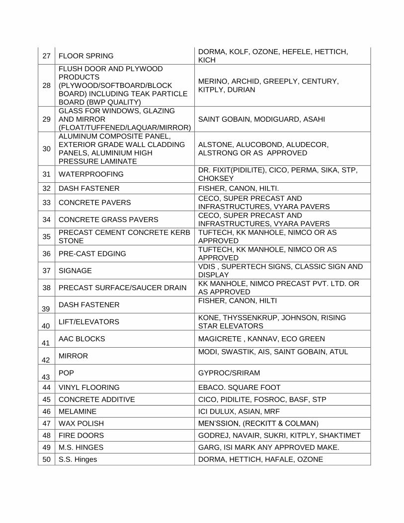
27 FLOOR SPRING DORMA, KOLF, OZONE, HEFELE, HETTICH, KICH
28
FLUSH DOOR AND PLYWOOD PRODUCTS (PLYWOOD/SOFTBOARD/BLOCK BOARD) INCLUDING TEAK PARTICLE BOARD (BWP QUALITY)
MERINO, ARCHID, GREEPLY, CENTURY, KITPLY, DURIAN
29 GLASS FOR WINDOWS, GLAZING AND MIRROR (FLOAT/TUFFENED/LAQUAR/MIRROR)
SAINT GOBAIN, MODIGUARD, ASAHI
30
ALUMINUM COMPOSITE PANEL, EXTERIOR GRADE WALL CLADDING PANELS, ALUMINIUM HIGH PRESSURE LAMINATE
ALSTONE, ALUCOBOND, ALUDECOR, ALSTRONG OR AS APPROVED
31 WATERPROOFING DR. FIXIT(PIDILITE), CICO, PERMA, SIKA, STP, CHOKSEY
32 DASH FASTENER FISHER, CANON, HILTI.
33 CONCRETE PAVERS CECO, SUPER PRECAST AND INFRASTRUCTURES, VYARA PAVERS
34 CONCRETE GRASS PAVERS CECO, SUPER PRECAST AND INFRASTRUCTURES, VYARA PAVERS
35 PRECAST CEMENT CONCRETE KERB STONE
TUFTECH, KK MANHOLE, NIMCO OR AS APPROVED
36 PRE-CAST EDGING TUFTECH, KK MANHOLE, NIMCO OR AS APPROVED
37 SIGNAGE VDIS , SUPERTECH SIGNS, CLASSIC SIGN AND DISPLAY
38 PRECAST SURFACE/SAUCER DRAIN KK MANHOLE, NIMCO PRECAST PVT. LTD. OR AS APPROVED
39
DASH FASTENER FISHER, CANON, HILTI
40
LIFT/ELEVATORS KONE, THYSSENKRUP, JOHNSON, RISING STAR ELEVATORS
41
AAC BLOCKS MAGICRETE , KANNAV, ECO GREEN
42
MIRROR MODI, SWASTIK, AIS, SAINT GOBAIN, ATUL
43
POP GYPROC/SRIRAM
44 VINYL FLOORING EBACO. SQUARE FOOT
45 CONCRETE ADDITIVE CICO, PIDILITE, FOSROC, BASF, STP
46 MELAMINE ICI DULUX, ASIAN, MRF
47 WAX POLISH MEN’SSION, (RECKITT & COLMAN)
48 FIRE DOORS GODREJ, NAVAIR, SUKRI, KITPLY, SHAKTIMET
49 M.S. HINGES GARG, ISI MARK ANY APPROVED MAKE.
50 S.S. Hinges DORMA, HETTICH, HAFALE, OZONE

51 MS PIPE JINDAL (HISAR), PRAKASH, SURYA,TATA,SAIL
52 WARDROBE/ CUBBOARDS HANDELS HETTICH , DORMA, HAFALE, OZONE
53 TILE JOINT FILLER DURACREATE , ROFF RAINBOW TILE MATE, WINSIL 20 / SILICON SEALANT OF GE BAYER SILICON, STP
54 STAINLESS STEEL JINDAL or as approved by EIC
55 STAINLESS STEEL RAILING JINDAL or as approved by EIC
56 RUBBER GASKET BIS APPROVED QUALITY
57 LAMINATES/VENEER CENTURY, DURIAN, GREEN, MERINO, ARCHID, KITPLY
58 PRELAMINATED PARTICLE BOARD GREEN LAM, MERINO, ARCHID, KITPLY, DURIAN
59 MDF BOARD DURIAN, MERINO, GREENLAM, CENTURY, KITPLY,ARCHID
60 ADHESIVE FOR WOOD WORK DUNLOP, FEVICOL, PIDILITE.
61 WEATHER PROOF SILICON GE BAYER, REMMERS, DUPONT, DOW CORNING
62 MODULAR FURNITURE
(TABLES/CHAIRS/MODULAR WORKS)
GODREJ/HNI ERGO/WIPRO/FEATHERLITE/DURIAN
63 LAQUAR GLASS ASAHI, MODIGUARD/SAINT GOBAIN
64 WALLPAPER NILAYA, ULGADOR
65 ACRYLIC SOLID SURFACE TRISTONE, MERINO, DU POINT, STARON, LG HAUS
66 POLYRETHANE SEALANT KRYTON, PIDLITE, FAREMATE, STP
67 TILE JOINT FILLER DURACREATE , ROFF RAINBOW TILE MATE, WINSIL 20 / SILICON SEALANT OF GE BAYER SILICON,
68 ASPHALT EMULSION STP / KARNAK, CHEMICAL CORPORATION
69
GLASS FILM 3M, GARWARE, LLUMAR
70
BLINDS Vista Levellor, Hunter Douglus, MAC, DYNA, INDO GERMAN
71 PLASTICIZER FOSROC, DR. FIXIT, CICO, STP, PIDILITE
72 GRC WALL CLADDING UNISTONE, MAHESH GRC/EVEREST
73 GRC JALI UNISTONE/ASIAN
74 DESIGNER FLOOR TILES BHARAT TILES/RAJA TILES
75 MOSAIC TILES MOSAICO/MRIDUL/SIMPOLO
76 CARPET FLOORING MILLIKEN/FORBO/SHAW/INTERFACE/KAARA
77 HIGH DENSITY PINE MDF EXIMCORP/CENTURY PLY
78 CALCIUM SILICATE BOARD HILUX BOARDS/SAINT GOBAIN
79 ACOUSTICAL WALL PANELLING ARMSTRONG/ANUTONE/BASOTECT/CREDENCE

Note: All work to be done in line with BOQ specifications and CPWD specifications and as per tender conditions.
80 ORIENTED STRAND BOARD EXIMCORP
81 MODULAR TOILETS MERINO/GREENLAM
82 FABRIC FOR SOFT BOARD COMRADE FABRICS/VISTA/SAVITON
83 PVC PLANTER MILAN PLAST/YUCABE/ECOVISION
84 GLASS RAILING UNISTONE AGRS/OZONE
85 TELESCOPIC SLIDING DRAWER CHANELS
HETTICH, EARL BIHARI, GODREJ, OZONE or as approved
86 MELAMINE POLISH BERGER/ASIAN PAINTS/ICI/JENSON & NICHOLSON
87 PLASTER OF PARIS GYPROC/SRIRAM
88 uPVC WINDOWS/DOORS Window Magic/Fenesta/Aluplast
89
ANY OTHER ITEMS NOT COVERED IN THE LIST OF MAKES BUT ARE REQUIRED TO EXECUTE THE WORK IN TOTALITY
ON APPROVAL OF ARCHITECT / CONSULTANT OR ENGINEER-IN-CHARGE

Technical Specifications for HVAC Works:
TECHNICAL SPECIFICATIONS:
SECTION-I: VARIABLE REFRIGERANT VOLUME SYSTEM (HEATING & COOLING BOTH) 1. SCOPE:
The scope of this section comprises the supply, erection testing and commissioning of fully inverter based Variable Refrigerant Volume System with Scroll Compressor suitable for heating & cooling both conforming to these specifications and in accordance with the requirements of Drawing and Schedule of Quantities
2. TYPE:
Units shall be 100 % inverter based air cooled, variable refrigerant volume air conditioner of R410A gas based consisting of one outdoor unit and multiple indoor units. Each indoor units having capability of cooling or heating (one mode at a time). The indoor units on any circuit can be of different type and also controlled individually. Ceiling mounted AHU with VRV kit Ceiling mounted Ductable ( HS) type Ceiling mounted Cassette type The system shall be capable of changing the rotating speed of inverter compressor by inverter controller to follow variations in cooling or heating load. Outdoor unit shall be suitable for mix match connection of all type of indoor units. Outdoor unit shall be factory assembled, tested and filled with first charge of refrigerant before delivering at site.
3. OUTDOOR UNIT:
The outdoor unit shall be factory assembled, weather proof casing, constructed from heavy gauge mild steel panels and coated with baked enamel finish. The unit should be completely factory wired , tested with all necessary controls and switch gears:
It should also be provided with duty cycling for switching starting sequence of multiple
outdoor units. The noise level shall not be more than 68 dB (A) at anechoic chamber conversion value,
measured horizontally 1m away and 1.5m above ground level. The outdoor unit shall be modular in design and should be allowed for side by side
installation The unit shall be provided with its own refrigerant cooled microprocessor control panel.
The outdoor unit should be fitted with low noise, aero spiral design fan with large airflow and should be designed to operate compressor-linking technology. The unit should also be capable to deliver 78 Pa external static pressure to meet long exhaust duct connection requirement.
The condensing unit shall be designed to operate safely when connected to multiple fan coil units, which have a combined operating nominal capacity up to 130 % of indoor units for outdoor units up to 36 HP.
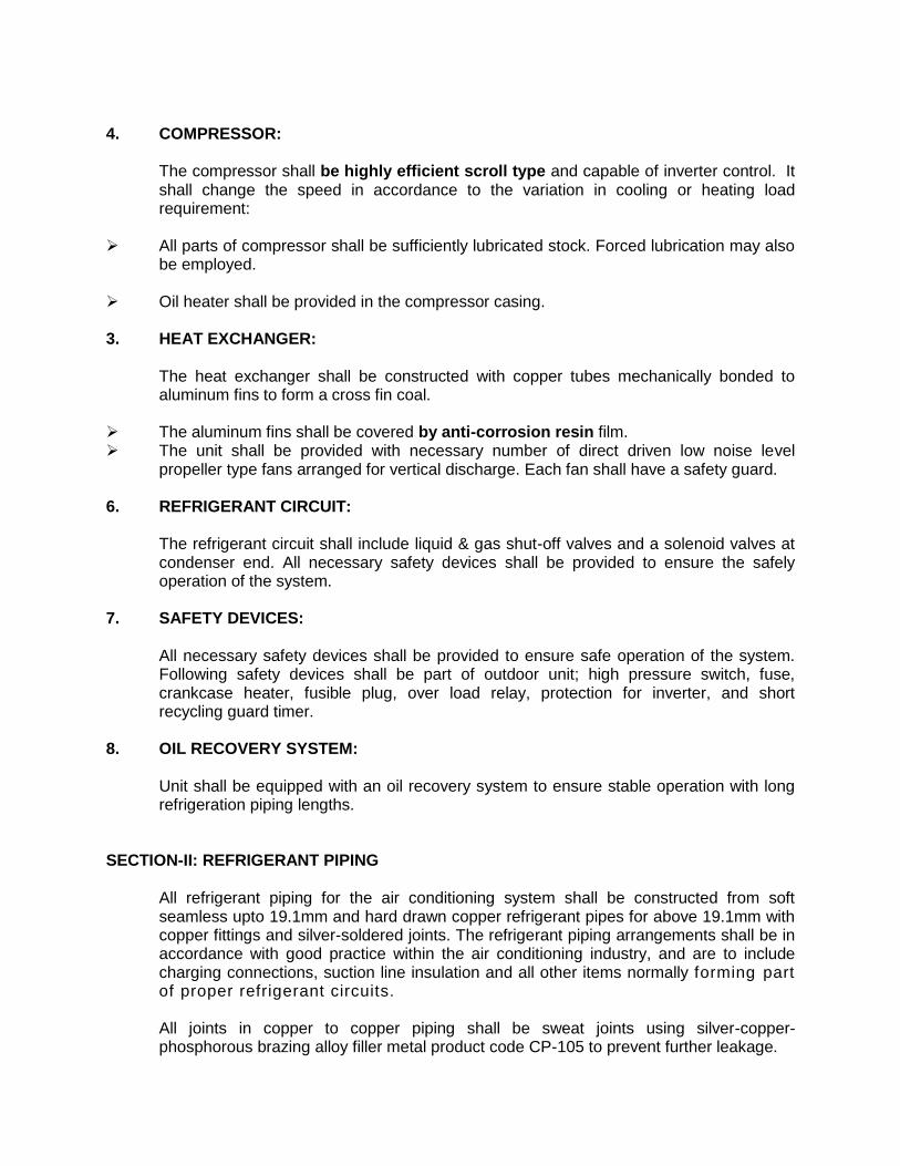
4. COMPRESSOR:
The compressor shall be highly efficient scroll type and capable of inverter control. It shall change the speed in accordance to the variation in cooling or heating load requirement:
All parts of compressor shall be sufficiently lubricated stock. Forced lubrication may also
be employed. Oil heater shall be provided in the compressor casing. 3. HEAT EXCHANGER:
The heat exchanger shall be constructed with copper tubes mechanically bonded to aluminum fins to form a cross fin coal.
The aluminum fins shall be covered by anti-corrosion resin film. The unit shall be provided with necessary number of direct driven low noise level
propeller type fans arranged for vertical discharge. Each fan shall have a safety guard. 6. REFRIGERANT CIRCUIT:
The refrigerant circuit shall include liquid & gas shut-off valves and a solenoid valves at condenser end. All necessary safety devices shall be provided to ensure the safely operation of the system.
7. SAFETY DEVICES:
All necessary safety devices shall be provided to ensure safe operation of the system. Following safety devices shall be part of outdoor unit; high pressure switch, fuse, crankcase heater, fusible plug, over load relay, protection for inverter, and short recycling guard timer.
8. OIL RECOVERY SYSTEM:
Unit shall be equipped with an oil recovery system to ensure stable operation with long refrigeration piping lengths.
SECTION-II: REFRIGERANT PIPING
All refrigerant piping for the air conditioning system shall be constructed from soft seamless upto 19.1mm and hard drawn copper refrigerant pipes for above 19.1mm with copper fittings and silver-soldered joints. The refrigerant piping arrangements shall be in accordance with good practice within the air conditioning industry, and are to include charging connections, suction line insulation and all other items normally forming part of proper refrigerant circuits.
All joints in copper to copper piping shall be sweat joints using silver-copper-phosphorous brazing alloy filler metal product code CP-105 to prevent further leakage.

Oxygen free nitrogen purging:- Brazing should be carried out using Oxygen free Nitrogen as an internal inert gas shield to prevent formation of oxides on the inside of the pipes and fitting. Purging is still required to remove internal shield gas and other particulate matter associated with the brazing operation.
Oxygen free nitrogen should be supplied continuously to the inside of the pre-assembled, un-brazed pipe work through a pressure regulator and flow controller of flow regulating device. Supply of nitrogen should not be discontinued till the brazed area of the pipe is cooled down.
Before jointing any copper pipe or fittings, its interiors shall be thoroughly cleaned by passing a clean cloth via wire or cable through its entire length. The piping shall be continuously kept clean of dirt etc. while constructing the joints. Subsequently, it shall be thoroughly blown out using nitrogen.
After the refrigerant piping installation has been completed, the refrigerant piping system shall be pressure tested using nitrogen at pressure of 580 PSIG. Pressure shall be maintained in the system for 24 hours. The system shall then be evacuated to minimum vacuum if 700mm hg and held for 24 hours.
The air-conditioning system supplier shall be design sizes and erect proper interconnections of the complete refrigerant circuit.
The thickness of copper piping shall not be less than mentioned below:
Pipe Size in mm(OD) Wall Thickness in mm
a) 41.3 1.4 b) 38.1 1.3 c) 34.9 1.2 d) 31.8 1.1 e) 28.6 1.0 f) 25.4 1.0 g) 22.2 1.0 h) 19.1 1.0 i) 15.9 1.0 j) 12.7 0.8 k) 9.5 0.8 l) 6.4 0.8
The suction line pipe size and the liquid line pipe size shall be selected according to the manufacturers specified outside diameter. All refrigerant pipes shall be properly supported and anchored to the building structure using steel hangers, anchors, brackets and supports which shall be fixed to the building structure by means of inserts or expansion shields of adequate size and number to support the load imposed thereon.
SECTION-III: FANS 1 SCOPE

The scope of this section comprises the supply, erection, testing and commissioning of
Axial Flow fans conforming to these Specifications and in accordance with the requirement of Drawings and Schedule of Quantities.
2 CAPACITY The air-moving capacity of fans shall be as shown on Drawings and in Schedule of
Quantities. 3 AXIAL FLOW FAN Fan shall be complete with motor, motor mount, belt driven (or direct driven) and
vibration isolation type, suspension arrangement as per approved for construction shop drawings.
a Casing: shall be constructed of heavy gage sheet steel. Fan casing, motor mount and
straightening vane shall be of welded steel construction. Motor mounting plate shall be minimum 15 mm thick and machined to receive motor flange.
An inspection door with handle and neoprene gasket shall be provided. Casing shall have flanged connection on both ends for ducted applications. Support brackets for ceiling suspension shall be welded to the casing for connection to hanger bolts. Straightening vanes shall be aerodynamically designed for maximum efficiency by converting velocity pressure to static pressure potential and minimizing turbulence. Casing shall be bonderized, primed and finish coated with enamel paint.
b. Rotor : hub and blades shall be cast aluminium or cast steel construction. Blades shall
be die-formed aerofoil shaped for maximum efficiency and shall vary in twist and width from hub to tip to effect equal air distribution along the blade length. Fan blades mounting on the hub shall be statically and dynamically balanced. Extended grease leads for external lubrication shall be provided. The fan pitch control may be manually readjusted at site upon installation, for obtaining actual air flow values, as specified and quoted.
c. Motor: shall be energy efficient squirrel-cage, totally-enclosed, fan cooled, standard
frame, constant speed, continuous duty, single winding, suitable for 415±8% volts, 50 cycles, 3 phase AC power supply, provided with class `F’ insulation. Motor shall be specially designed for quiet operation. The speed of the fans shall not exceed 800 RPM for fans with impeller diameter above 450 mm, and 1440 RPM for fans with impeller diameter 450 mm and less. For lowest sound level, fan shall be selected for maximum efficiency or minimum horsepower. Motor conduit box shall be mounted on exterior of fan casing, and lead wires from the motor to the conduit box shall be protected from the air stream by enclosing in a flexible metal conduit.
d. Drive : to fan shall be provided through belt drive with adjustable motor sheave and
standard sheet steel belt guard with vented front for heat dissipation. Belts shall be of oil-resistant type.
e. Vibration Isolation : The assembly of fan and motor shall be suspended from the slab by
vibration isolation suspension of rubber-in-shear type. f. Accessories : The following accessories shall be provided with all fans :

i. Outlet cone for static pressure regain. ii. Inlet cone. Fan silencers may be provided where specifically called for in Schedule of Quantities.
Fans shall be factory assembled and shipped with all accessories factory-mounted. 4 PERFORMANCE DATA All fans shall be selected for the lowest operating noise level. Capacity ratings,
power consumption, with operating points clearly indicated, shall be submitted and verified at the time of testing and commissioning of the installation.
5 TESTING
Capacity of all fans shall be measured by an anemometer. Measured air flow capacities shall conform to the specified capacities and quoted ratings. Power consumption shall be computed from measurements of incoming voltage and input current.
SECTION-IV: AIR HANDLING UNITS 1 SCOPE
It includes the supply, erection, testing and commissioning of double skin type air handling units, conforming to these Specifications and as detailed in the Schedule of Quantities and approved shop drawings.
2 TYPE
The air handling units shall be double skin construction, horizontal or vertical type through blow though type comprising of various sections i.e. filter section/s coil section/s and fan section. Mixing box (with dampers), (wherever the return air, or and fresh air are ducted) as included in schedule of quantities and shown in shop drawings.
3 CAPACITY
The air handling capacities in terms of air delivery, maximum motor horse power and static pressure shall be as identified in Schedule of Quantities and in shop drawings.
4 CASING Double skinned panels of AHUs shall be 46 mm thick for recirculation type AHUs.
These shall be made of galvanized steel, pressure injected with foam insulation (density 40 kg/m3) These panels shall be fixed to minimum 1.5 mm thick aluminium alloy structural framework with stainless steel screws. Outer sheet of double skinned panels shall be made of pre-plasticized galvanized sheet, and inner sheet of plain G.I. Sheet, both inner & out shafts shall be of 24 gauge.
The entire framework shall be mounted on an aluminium alloy or galvanized steel
channel base as per manufacturer’s design. Sealing of panels to the frame work shall be through heavy duty `O’ ring gaskets held captive in the framed extrusion. All panels shall be detachable or hinged. Handles for panels shall be made of hard nylon and

shall be operational from both inside and outside of the unit. Units supplied with various sections shall be suitable for on site assembly gaskets shall be continuous & concealed.
AHU shall have hinged, access door in the fan section and also in filter section where
filters are not accessible from outside. Access doors shall be part of double skinned panels.
AHU shall have 18 gauge stainless steel sheet condensate drain pan. It shall be
isolated from bottom floor panel through insulation as per manufacturer’s standards. 5 MIXING BOX
Mixing box shall be provided to AHUs if specified in Schedule of Quantities and shall be along with fresh air and return air dampers.
6 THERMAL BREAK PROFILE
TFA AHUs & AHUs with mixing box having ducted return air, shall be provided with thermal break profile whatever or not indicated in schedule of quantities.
7 DAMPERS
Dampers provided at supply air inlet, return air & fresh air intake shall be opposed blade type made of double skinned aerofoil aluminium sections, assembled within a rigid extruded aluminium alloy frame work with gasket. All linkages shall be made of aluminium or nylon, having teflon bushes. Dampers shall be provided with a bakelite knob for locking the damper blades in position. Linkages shall be extended wherever specified for motorized operation. Damper frames shall be manufacturer in such a way that blades never wrap. Air leakage in the closed position of dampers shall not exceed 1.5% of the total flow rate at the maximum design air total pressure.
8 MOTOR AND DRIVE
AHU fan motors shall be energy (TEFC) efficient (IE-2) suitable for 415±10% volts, 50 cycles, three phase, supply motor shall be totally enclosed fan-cooled class F, with IP-55 protection. Motors shall be designed for quiet operation and motor speed shall not exceed 1440 rpm. Drive forwarded to fan shall be provided through pulley belt-drive arrangement. Belts shall be oil-resistant type.
9 FAN
AHU fans as per schedule of quantities either be forward inclined blades (suitable for static pressure up to 70 mm Wg) or backward inclined blades (for static pressure above 70 mm Wg). AHU fan motor driven by variable frequency drive shall have backward inclined irrespective of static pressure casing of fan shall be made of galvanized steel sheet. Fans shall be selected for minimum efficiency of 75%. Fan wheels shall be made of galvanized steel. Fan shaft shall be of carbon steel, supported in self-aligning plummer block, grease lubricated bearings. Fan wheels be tested and balanced dynamically. Fan motor assembly shall be statically and dynamically balanced as per relevant ISO/AMCA standard. Computerized fan selection print outs shall be submitted along with the offer/ technical submittal.

Motors shall be totally enclosed, fan cooled, to be class `F’ insulation. It shall be
mounted inside the AHU casing on slide rails for easy belt tensioning. Motors drive shall be heavy duty V-belt, having constant pitch, suitably selected for rated motor horsepower. Both fan and motors assemblies shall be mounted on aluminium alloy or galvanized steel base frame, as per the manufacturer’s standard.
Anti vibration manuals consisting of spring & rubber combinations shall be provided for
isolating the unit casing against vibration transmission. Flame retardant, waterproof silicone rubber impregnated flexible connection shall be provided at the fan discharge.
10. DX COIL
The Dx coil section shall have 12.7 mm dia copper tubes minimum of 30 G thick & .43 mm inner groove tube and 0.15 mm thick aluminum fins firmly bonded to copper tubes assembled in zinc coated steel frame. Face and surface area shall be such as to ensure rated capacity from each unit and such that air velocity across each coil shall not exceed 2.54 M/sec. An appropriate panel of the coil section shall incorporate factory made openings for coil inlet & outlet connections. The coils shall be mounted over an adequately sized condensate drain pan. Particular, care shall be taken to ensure that condensate is drained totally without leaving any stagnant pools anywhere in the unit. Each coil shall be factory tested with 500-600 Psi. Tube shall be mechanical expanded for minimum thermal contact resistance with fins Fin spacing shall be 11 to 12 fins per inch. Flanges of resilient isolation material shall be provided both at the inlet and outlet connections of all Dx coils with necessary bushes of similar material to minimize transmission of vibration to connected piping. Coil shall have automatic air vents, the vent outlets being piped to the drain pan with copper pipe. Coil performance shall be rated in accordance with ARI standard 410.
The casing/frame of coil shall be heavy duty Stainless Steel. Coil shall be design with intertwined type if the multiple outdoor connected to single coil. Expansion kit & outdoor unit from manufacturer.
11 FILTERS Each AHU shall be supplied with a factory assembled filter section. This shall be
provided with washable synthetic type air filters having anodized aluminium frame. The filters shall have minimum 90% efficiency down to 10 microns. The media shall be supported with HDP mesh on one side and aluminium mesh on other side. Filter banks shall be easily accessible and designed for easy withdrawal and renewal of filter cells. Filter framework shall be and constructed from aluminium alloy and should be fully sealed.
12 ISOLATORS Vibration isolators shall be provided with all air handling units as per manufacturer’s
recommendation. Vibration isolators shall be cushy foot mounting type. Else these shall be of neoplane pads 2 Nos. each having minimum thickness of 25mm sandwiched in GI sheet. Minimum vibration isolation efficiency shall be 90%.
13 FRESH AIR INTAKES
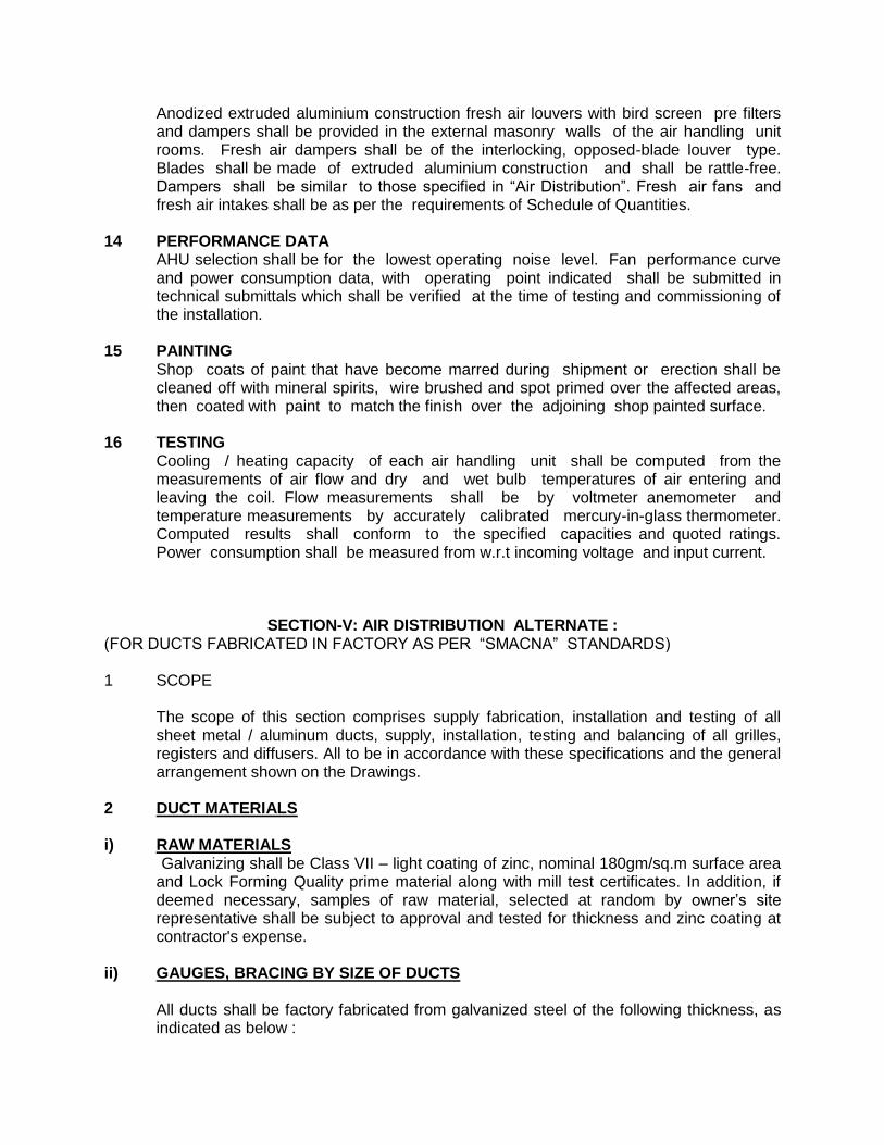
Anodized extruded aluminium construction fresh air louvers with bird screen pre filters and dampers shall be provided in the external masonry walls of the air handling unit rooms. Fresh air dampers shall be of the interlocking, opposed-blade louver type. Blades shall be made of extruded aluminium construction and shall be rattle-free. Dampers shall be similar to those specified in “Air Distribution”. Fresh air fans and fresh air intakes shall be as per the requirements of Schedule of Quantities.
14 PERFORMANCE DATA AHU selection shall be for the lowest operating noise level. Fan performance curve
and power consumption data, with operating point indicated shall be submitted in technical submittals which shall be verified at the time of testing and commissioning of the installation.
15 PAINTING Shop coats of paint that have become marred during shipment or erection shall be
cleaned off with mineral spirits, wire brushed and spot primed over the affected areas, then coated with paint to match the finish over the adjoining shop painted surface.
16 TESTING Cooling / heating capacity of each air handling unit shall be computed from the
measurements of air flow and dry and wet bulb temperatures of air entering and leaving the coil. Flow measurements shall be by voltmeter anemometer and temperature measurements by accurately calibrated mercury-in-glass thermometer. Computed results shall conform to the specified capacities and quoted ratings. Power consumption shall be measured from w.r.t incoming voltage and input current.
SECTION-V: AIR DISTRIBUTION ALTERNATE : (FOR DUCTS FABRICATED IN FACTORY AS PER “SMACNA” STANDARDS) 1 SCOPE
The scope of this section comprises supply fabrication, installation and testing of all sheet metal / aluminum ducts, supply, installation, testing and balancing of all grilles, registers and diffusers. All to be in accordance with these specifications and the general arrangement shown on the Drawings.
2 DUCT MATERIALS i) RAW MATERIALS Galvanizing shall be Class VII – light coating of zinc, nominal 180gm/sq.m surface area
and Lock Forming Quality prime material along with mill test certificates. In addition, if deemed necessary, samples of raw material, selected at random by owner’s site representative shall be subject to approval and tested for thickness and zinc coating at contractor's expense.
ii) GAUGES, BRACING BY SIZE OF DUCTS
All ducts shall be factory fabricated from galvanized steel of the following thickness, as indicated as below :
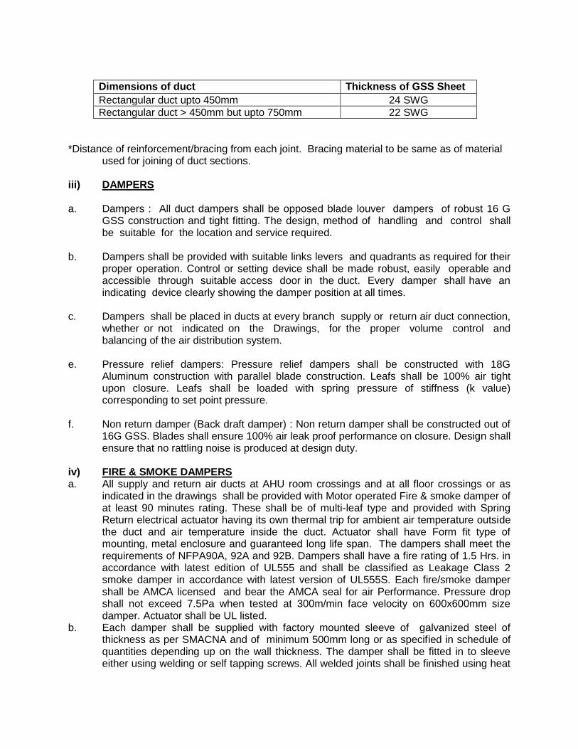
Dimensions of duct Thickness of GSS Sheet
Rectangular duct upto 450mm 24 SWG
Rectangular duct > 450mm but upto 750mm 22 SWG
*Distance of reinforcement/bracing from each joint. Bracing material to be same as of material
used for joining of duct sections. iii) DAMPERS a. Dampers : All duct dampers shall be opposed blade louver dampers of robust 16 G
GSS construction and tight fitting. The design, method of handling and control shall be suitable for the location and service required.
b. Dampers shall be provided with suitable links levers and quadrants as required for their
proper operation. Control or setting device shall be made robust, easily operable and accessible through suitable access door in the duct. Every damper shall have an indicating device clearly showing the damper position at all times.
c. Dampers shall be placed in ducts at every branch supply or return air duct connection,
whether or not indicated on the Drawings, for the proper volume control and balancing of the air distribution system.
e. Pressure relief dampers: Pressure relief dampers shall be constructed with 18G
Aluminum construction with parallel blade construction. Leafs shall be 100% air tight upon closure. Leafs shall be loaded with spring pressure of stiffness (k value) corresponding to set point pressure.
f. Non return damper (Back draft damper) : Non return damper shall be constructed out of
16G GSS. Blades shall ensure 100% air leak proof performance on closure. Design shall ensure that no rattling noise is produced at design duty.
iv) FIRE & SMOKE DAMPERS a. All supply and return air ducts at AHU room crossings and at all floor crossings or as
indicated in the drawings shall be provided with Motor operated Fire & smoke damper of at least 90 minutes rating. These shall be of multi-leaf type and provided with Spring Return electrical actuator having its own thermal trip for ambient air temperature outside the duct and air temperature inside the duct. Actuator shall have Form fit type of mounting, metal enclosure and guaranteed long life span. The dampers shall meet the requirements of NFPA90A, 92A and 92B. Dampers shall have a fire rating of 1.5 Hrs. in accordance with latest edition of UL555 and shall be classified as Leakage Class 2 smoke damper in accordance with latest version of UL555S. Each fire/smoke damper shall be AMCA licensed and bear the AMCA seal for air Performance. Pressure drop shall not exceed 7.5Pa when tested at 300m/min face velocity on 600x600mm size damper. Actuator shall be UL listed.
b. Each damper shall be supplied with factory mounted sleeve of galvanized steel of thickness as per SMACNA and of minimum 500mm long or as specified in schedule of quantities depending up on the wall thickness. The damper shall be fitted in to sleeve either using welding or self tapping screws. All welded joints shall be finished using heat

resistance steel paint . UL listed and approved Silicon sealant shall be applied at all corners as well as at joints between damper frame and sleeve. Damper Frame shall be a roll formed structural hat channel , reinforced at corners, formed from a single piece of 1.6mm galvanized steel . Damper blades shall be airfoil shaped (equivalent to 2.3mm thickness strength) roll formed using 0.8mm thick single piece of galvanized sheet. Bearings shall be of stainless steel fitted in an extruded hole in the damper frame. Blade edge seals shall be silicone rubber and galvanized steel mechanically locked in to the blade edge (adhesive type seals are not acceptable). Side Jam seals of stainless steel and Top and bottom seals of galvanized steel shall be provided. All galvanized steel used shall be with minimum 180GSM Zinc coating Bigger size Dampers shall be supplied in Multiple modules of sizes not exceeding in dimensions of certified module, jack shafted together. Multiple actuators shall be provided for large dampers with higher torque requirements as prescribed in UL.
c. The electric actuator shall be energized either upon receiving a signal from smoke
detector installed in AHU room supply air duct / return air duct. Electric Actuator of suitable Torque and as approved by UL shall be factory mounted and tested. The actuator shall be suitable for 24V AC supply.In addition actuator shall have elevated temperature rating of 250 deg.F. Electric Actuator shall have been energized hold open tested for a period of at least one year with no spring return failure. Each fire/smoke damper shall be equipped with a heat actuated release device which shall allow controlled closure of damper rather than instantaneous to prevent accident.( Electrical fusible link).The EFL shall allow the damper to reopen automatically after a test, smoke detection or power failure condition. The damper shall be equipped with a device to indicate OPEN and CLOSE position of Damper blades through a link mounted on the damper blade.
d. Each damper shall be provided with its own control panel, mounted on the wall and
suitable for 240 VAC supply. This control panel shall be suitable for spring return actuator and shall have atleast the following features:
Potential free contacts for AHU fan ON/ Off and remote alarm indication.
Accept signal from external smoke / fire detection system for tripping the electrical actuator.
Test and reset facility.
Indicating lights / contacts to indicate the following status:
Power Supply On
Alarm
Damper open and close position. e. Actuators shall be mounted on the sleeve by the damper supplier in his shop and shall
furnish test certificate for satisfactory operation of each Motor Operated Damper in conjunction with it’s control panel. Control panel shall be wall mounted type.

f. It shall be HVAC Contractor’s responsibility to co-ordinate with the Fire Alarm System Contractor for correctly hooking up the Motor Operated Damper to Fire Detection / Fire Management System. All necessary materials for hooking up shall be supplied and installed by HVAC Contractor under close co-ordination with the fire protection system contractor.
g. HVAC Contractor shall demonstrate the testing of all Dampers and its control panel after
necessary hook up with the fire protection / fire management system is carried out by energising all the smoke detectors with the help of smoke.
h. HVAC Contractor shall provide Fire retardant cables wherever required for satisfactory
operation and control of the Damper. j. HVAC Contractor shall strictly follow the instructions of the Damper Supplier or avail his
services at site before carrying out testing and installation at site. k. Fire/smoke damper shall be provided with factory fitted sleeves; however, access
doors shall be provided in the ducts within AHU room in accordance with the manufacturer’s recommendations.
l. The Contractor shall also furnish to the Owner, the necessary additional spare
actuators and temperature sensor (a minimum of 5% of the total number installed) at the time of commissioning of the installation.
v) FIRE DAMPERS a. Whenever a supply/return duct crosses from one fire zone to another, it shall be
provided with approved fire damper of at least 1½ hour fire rating as per UL555/1995 tested by CBRI. This shall be curtain type fire damper.
b. Fire damper blades shall be one piece folded high strength 16 gage galvanised steel
construction. In normal position, these blades shall be gathered and stacked at the frame head providing maximum air passage and preventing passing air currents from creating noise or chatter. The blades shall be held in position through fusible link of temp 70o C. The HVAC contractor shall supply UL classified Fire Dampers meeting or exceeding the specifications. Fire Dampers shall be furnished and installed at locations shown in Drawings and as described in Schedule of quantities. Fire Dampers shall have a fire rating of 1.5/3 Hrs.as specified in BOQ, in accordance with latest edition of UL555. Each Fire damper shall be AMCA licenced and shall bear the AMCA seal for air performance.
Damper shall be equipped with UL labelled Fusible Link with Temprature setting 165 or
212deg. F or as specified in Bill of quantities.Fire dampers shall have been tested to close under dynamic air flow conditions with pressure up to 1000 pa and velocities up to 10.2 m /sec. Fire damper shall be approved for Horizontal or vertical installation as may be required by the location shown in the drawings.
Damper Frame shall be a roll formed structural hat channel , reinforced at corners,
formed from a single piece of 1.6mm galvanized steel . Damper blades shall be roll formed 3-v groove (1.6mmthick) or airfoil shaped in case of 3 Hrs. fire rating (equivalent to 2.3mm thickness strength) roll formed using 0.8mm thick single piece of galvanized

sheet. Bearings shall be of stainless steel fitted in an extruded hole in the damper frame. All galvanized steel used shall be with minimum 180GSM Zinc coating Bigger size Dampers shall be supplied in Multiple modules of sizes not exceeding in dimensions of certified module jack shafted together.
Fire damper shall be equipped with a electric limit switch to indicate open and close
position of the damper blades. Fire Damper shall be installed in wall or floor opening using galvanized steel sleeve of
minimum 435mm length of sheet thickness as per SMACNA and as per Installation instruction of Manufacturer.
c. In case of fire, the intrinsic energy of the folded blades shall be utilized to close the
opening. The thrust of the suddenly released tension shall instantly drive the blades down and keep it down without the use of springs, weights or other devices subject to failure.
d. Fire damper sleeves and access doors shall be provided within the duct in accordance
with the manufacturer’s recommendation. e. The contractor shall also furnish to the Owner, the necessary additional fusible links
(spares), as recommended by the manufacturer, at the time of commissioning of the installation.
vi) SUPPLY AND RETURN AIR REGISTERS Supply & return air registers shall be of either steel or aluminium sections as specified
in schedule of quantities. Steel construction registers shall have primer Coat finish whereas extruded aluminium registers shall be either Anodised or Powder Coated as specified in Schedule of Quantities. These registers shall have individually adjustable louvers both horizontal and vertical. Supply air registers shall be provided with key operated opposed blade extruded aluminium volume control damper anodised in matt black shade.
The registers shall be suitable for fixing arrangement having concealed screws as approved by Architect. Linear continuous supply cum return air register shall be extruded aluminium construction with fixed horizontal bars at 15 Deg. inclination & flange on both sides only (none on top & bottom). The thickness of the fixed bar louvers shall be minimum 5.5 mm in front and 3.8 mm in rear with rounded edges. Flanges on the two sides shall be 20 mm/30 mm wide as approved by Architect. The grilles shall be suitable for concealed fixing. Volume control dampers of extruded aluminium anodised in black color shall be provided in supply air duct collars. For fan coil units horizontal fixed bar grilles as described above shall be provided with flanges on four sides, and the core shall be & suitable for clip fixing, permitting its removal without disturbing the flanges.
a. All registers shall be selected in consultation with the Architect. Different spaces shall require horizontal or vertical face bars, and different width of margin frames. These shall be procured only after obtaining written approval from Architect for each type of register.

b. All registers shall have a soft continuous rubber/foam gasket between the periphery of the register and the surface on which it has to be mounted. The effective area of the registers for air flow shall not be less than 66 percent of gross face area.
c. Registers specified with individually adjustable bars shall have adjustable pattern as
each grille bar shall be pivotable to provide pattern with 0 to +45 degree horizontal arc and upto 30 degree deflection downwards. Bars shall hold deflection settings under all conditions of velocity and pressure.
d. Bar longer than 45 cm shall be reinforced by set-back vertical members of approved
thickness. e. All volume control dampers shall be anodised aluminium in mat black shade. vii) SUPPLY AND RETURN AIR DIFFUSERS Supply and return air diffusers shall be as shown on the Drawings and indicated in
Schedule of Quantities. Mild steel diffusers/dampers shall be factory coated with rust-resistant primer. Aluminium diffusers shall be powder coated & made from extruded aluminium section as specified in schedule of quantities.
a. Rectangular Diffusers shall be steel / extruded aluminium construction, square &
rectangular diffusers with flush fixed pattern for different spaces as per schedule of quantities These shall be selected in consultation with the Architect. These shall be procured only after obtaining written approval from Architect for each type of diffuser.
b. Supply air diffusers shall be equipped with fixed air distribution grids, removable key-
operated volume control dampers, and anti-smudge rings as required in specific applications, and as per requirements of schedule of quantities. All extruded aluminium diffusers shall be provided with removable central core and concealed key operation for volume control damper.
c. Linear Diffuser shall be extruded aluminium construction with removable core,
one or two way blow type. Supply air diffusers shall be provided with volume control/ balancing dampers within the supply air collar. Diffusers for different spaces shall be selected in consultation with the Architect, and provided as per requirements of schedule of quantities. All diffusers shall have volume control dampers of extruded aluminium construction anodised in mat black shade.
d. Slot Diffuser shall be extruded aluminium construction multislot type with air pattern
controller provided in each slot. Supply air diffusers shall be provided with Hit & Miss volume control dampers in each slot of the supply air diffusers. Diffusers for different spaces shall be selected in consultation with the Architect and provided as per requirement of Schedule of Quantities.
e. Data centers shall be provided with floor grilles. Grilles shall be of nominal size of
600mm x 600mm and shall be fitted in floor tile of false floor. Grille shall be with dampers for flow control. Grill shall be heavy duty 16G Aluminium and shall take care of human traffic load. Damper shall be operable in situ without requirement of removal of grille.

SECTION-VI: TESTING & DOCUMENTATION: 1 TESTING AND BALANCING After the installation of the entire air distribution system is completed in all respects, all
ducts shall be tested for air leaks by visual inspection. The entire air distribution system shall be balanced using an anemometer. Measured air
quantities at fan discharge and at various outlets shall be identical to or less/excess than 5 percent in excess of those specified and quoted. Branch duct adjustments shall be permanently marked after air balancing is completed so that these can be restored to their correct position if disturbed at any time. Complete air balance report shall be submitted for scrutiny and approval, and four copies of the approved balance report shall be provided with completion documents.
2 DOCUMENTATION & MEASUREMENTS FOR DUCTING
All ducts fabricated and installed should be accompanied and supported by proper documentation viz:
a) Bill of material/Packing list for every duct section supplied.
Measurement sheet covering each fabricated duct piece showing dimensions and external surface area along with summary of external surface area of duct gauge-wise.
Each and every duct piece to have a tag number, which should correspond to the serial number, assigned to it in the measurement sheet. The above system will ensure speedy and proper site measurement and verification.
Unless otherwise specified, measurements for ducting for the project shall be on the basis of centerline measurements described herewith
Ductwork shall be measured on the basis of external surface area of ducts. Duct
measurements shall be taken before application of the insulation. The external surface area shall be calculated by measuring the perimeter comprising overall width and depth, including the corner joints, in the center of each duct section, multiplying with the overall length from flange face to flange face of each duct section and adding up areas of all duct sections. Plenums shall also be measured in a similar manner.
For tapered rectangular ducts, the average width and depth shall be considered for perimeter, whereas for tapered circular ducts, the diameter of the section midway between large and small diameter shall be adopted, the length of tapered duct section shall be the centerline distance between the flanges of the duct section.
For special pieces like bends, tees, reducers, branches and collars, mode of measurement shall be identical to that described above using the length along the centerline.
The quoted unit rate for external surface of ducts shall include all wastage allowances,
flanges and gaskets for joints, nuts and bolts, hangers and angles with double nuts for supports, rubber strip 5mm thick between duct and support, vibration isolator suspension where specified or required, inspection chamber/access panel, splitter damper with quadrant and lever for position indication, turning vanes, straightening vanes, and all

other accessories required to complete the duct installation as per the specifications. These accessories shall NOT be separately measured nor paid for.
b. Special Items for Air Distribution shall be measured by the cross-section area
perpendicular to air flow, as identified herewith : i. Grilles and registers - width multiplied by height, excluding flanges. Volume control
dampers shall form part of the unit rate for registers and shall not be separately accounted.
ii. Diffusers - cross section area for air flow at discharge area, excluding flanges. Volume
control dampers shall form part of unit rate for supply air diffusers and shall not be separately accounted.
iii. Linear diffusers - shall be measured by cross-sectional areas and shall exclude flanges
for mounting of linear diffusers. The supply air plenum for linear diffusers shall be measured with ducting as described earlier.
iv. Fire dampers - shall be measured by their cross sectional area perpendicular to the
direction of air flow. Quoted rates shall include the necessary collars and flanges for mounting, inspection pieces with access door, electrical actuators and panel. No special allowance shall be payable for extension of cross section outside the air stream.
v. Flexible connection - shall be measured by their cross sectional area perpendicular to
the direction of air flow. Quoted rates shall include the necessary mounting arrangement, flanges, nuts and bolts and treated-for-fire requisite length of canvas cloth.
APPROVED MAKES OF EQUIPMENT & MATERIALS
S.No Equipment / Material Approved Makes
1 VRV/VRF Units Daikin/ Toshiba/ Hitachi/ Mitsubishi Electric/ Trane/O General
2 Indoor units for VRV Daikin/ Toshiba/ Hitachi/ Mitsubishi Electric/ Trane/O General
3 Air handling Unit Zeco/ Edgetech /Wave
4 Split Air conditioners Daikin/ Toshiba/ Hitachi/ Mitsubishi Electric/ Trane/O General
5 Centrifugal Fan & Axial Flow Fan AMCA certified
Airflow/ Systemair/Kruger/ Flaktwoods
6 Factory Made Duct Eco Duct/ Zeco/ Ductofab / Rolastar/ Pioneer
7 Grille / Diffuser / Dampers Systemair / Ruskin Titus / Airflow/ Pineair
8 Insulation:
i XLPE along with adhesive Aerofoam/Aerolam/Thermobreak
Acoustic insulation:
i XLPE with antimicrobial property Aerofoam/Aerolam/Thermobreak

9 Smoke / Fire Damper (with UL listed actual )
Systemair / Ruskin Titus / Airflow/ Pineair
10 Protective Coating over Duct and Pipe Insulation
Paramount Polytreat / Foster / Pidilite
11 Copper Pipe & fittings Rajco/ Mandev Tubes/ Totaline/ Mehta Tubes
12 uPVC Drain Pipe Astral/ AKG/ Supreme/Finolex
13 PVC Pipe (For wiring purpose) AKG/ Diplast/ Canon/ Poly India/ Supreme/ Polycab/ Ravindra/ Kamplast
14 Starter, Contactor, Push Button & Relays
L&T/ Siemens/ ABB/ Schneider/Precision System
15 AirCurtain Mitzvah/Olefini/Almonard
16 Duct mounted air purification system
Zeco/RGF/Aqua air/Eflow

(TO BE FILLED IN BY THE CONTRACTOR)
OUTDOOR UNITS
(i) Manufacturer and model No
(ii) Type of unit (Whether inverter based or not)
(iii) Number of Inverter units and total configuration.
(iv) Overall dimensions (mm)
(v) Operating weight (including wt. Of water/ refrigerant in circulation (kg)
(vi) Noise level
(vii) Capacity of the unit.
AHU UNITS:
(i) Manufacturer and model No
(ii) Type of unit.
(iii) Overall dimensions (mm)
(iv) Operating weight (including wt. of water/ refrigerant in circulation (kg)
(v) Capacity of the unit
Note: 1. Attach Literature/Catalogue. 2. The firm is required to give the details of each type of indoor unit as in BOQ.
[Signature of the firm]

TECHNICAL SPECIFICATION FOR FIRE FIGHTING WORKS: SECTION – I FIRE FIGHTING SERVICES 1. SCOPE 1.1 The scope of work covers design & engineering, supply, erection, painting, testing,
commissioning, and handing over of complete Fire Protection System envisaged for all the buildings covered under the current phase of the project in line with stipulations of National Building Code – 2016.
Work under this sub-head consists of furnishing all Labour, Material, equipment and accessories necessary and required to completely install the Fire Fighting equipment etc., specified hereinafter and given in the Schedule of Quantities.
1.2 Without restricting to the generality of the foregoing, the work of Fire Fighting System
shall include the followings: a) Providing M.S. black steel pressure pipe line main including Valves, Fire Hydrants,
Excavation for Pipes, Laying of pipes, Painting of pipe and Making Connection to supply system.
b) Black Steel Pipe, Mains Laterals, Branches, Valves Hangers and Appurtenances. c) Hose Reels, Rubberized fabric lined hose pipes, Hose cabinets & Landing Valves. d) Portable Fire Extinguishers. e) Hydrants (Internal, External & related accessories). f) Sprinkler System as per Requirements of All Admin Building. g) Fire Fighting Pumps, Suction Delivery Lines, Electrical Panels & all other related
accessories (as per requirements). h) All civil and structural works, electrics, control & instrumentation, site & shop
painting for fire fighting system. 2. APPLICABLE / REFERENCE CODES
IS: 1239 (Part 1 & 2) - M.S. Pipe Heavy duty IS: 14846 Sluice valves (PN 1.6) IS: 6392-1971 - Steel Pipe Flanges IS:554 - Pipe threads where pressure tight joints are
Required IS:909 - U/G fire hydrants, sluice valve type IS:5312 (P-1) - NRV IS:778 - Gunmetal fullway valves with wheel tested
to 20kg/cm2 class II Butterfly valves - They shall be of specified quality
conforming to IS:13095 or BS:5155 IS:5290 - Internal hydrant shall comprise “Single
Headed Single Outlet GM Landing Valve” conforming to Type “A”.
IS:12585 - Hose tubing (Thermoplastic) IS:884 - Hose tubing, Globe valve, Stop cock &
Nozzle

IS:636 - Hose pipes rubber lined woven jacketed (RRL) & 63mm dia, conforming to type “A”
IS:903 - The couplings shall be of instantaneous [Branch pipe, nozzle, spring lock type Coupling etc]
IS:15683 - Portable fire extinguishers
3. Designs, Drawings and technical submittal
a) After Award of the Work :
The Contractor shall submit 03 (Three) sets of designs & shop drawings for the entire pumping installations to be provided under this contract along with supporting design calculations, charts etc, and proposed General Arrangement drawings for major equipments for Fire Hydrant and Sprinkler Systems within 30 ( Thirty ) days of award of work for approval before proceeding with the work. He shall also furnish all clarifications and explanations as may be desired by CPWD promptly for early finalization of the design.
The work to be executed as per approved shop drawings & technical submittal by the
contractor.
b) On Completion of Work :
The contractor shall submit O & M manuals for Hydrant and Sprinkler System including pumps, motors, diesel engines, MCC panels, Circuit Diagram, Manufacturers technical catalogues, detailed specification of items provided along with As-built drawings and copies of Test Certificates of all major equipments duly bound in neat and presentable booklet forms within 30 days of completion of the work.
4.0 Approval by Local Fire Service It shall be the responsibility of the contractor to get the approval in stages from the Local
fire Service as required. This shall be without any liability to the Engineer-in-charge . On successful completion of work, the contractor shall prepare as built drawings which
have been so approved by the Fire Service incorporating all changes that might have been effected during execution of the work.
The contractor shall also bring to the notice of the Engineer-in-charge any deviations from Local Fire Service/Building Bye Laws Norms and requirements in the systems that he shall install as well as architectural features that will affect approval from the Fire Service. No extra charges shall be paid on account of interaction with the Fire Service.
5.0 Coordination The Contractor shall be required to co ordinate his activities with all other services such
as Air Conditioning, Electrical and Civil (Interiors) etc. 6.0 Civil Works All civil works are included in Contractor’s scope of work unless otherwise specified. Civil
works like excavation for pipe laying underground with pedestal supports or chasing in the wall/ceiling or making hole in the RCC floor/ceiling or in brick wall for piping, grouting

etc. including making good after completion, small size pedestals or any other minor civil works required in connection with the installation of the system are included in the scope of work of this contract and it shall be deemed to be included in the contractor’s scope of work.
Only the foundation for pumps in pump room shall be casted by civil contractor as per scope of work covered under separate package as per requirement given the contractor.
The Contractor shall however furnish all details and relevant data required for design
and detailed engineering of all civil works included in this design. 7.0 PIPING SCOPE The scope of this section comprises the Supply, Laying, Erection, Testing and
Commissioning of pipes required for this project. 7.1 All piping laid shall be black steel unless otherwise stated. Pipes shall be given one
primary coat of red oxide paint before being installed. Pipes and jointing shall be as follows:
Pipe Size Material Jointing Method
Upto 50mm MS tube heavy class as per IS-1239
Fittings with threaded / screwed joints
65mm to 150mm
MS tube heavy class as per IS-1239
Fittings with Welded Joints
Slip on flanges
200mm to 350mm
Welded MS class-2 as per IS-3589 Thickness- 6.35mm
Fittings with Welded Joints
Slip on flanges
Pipe threads and flanges shall be as per IS.
7.1.1 All Fittings shall be new and from approved /reputed manufacturers, Fittings shall be of malleable castings of pressure ratings suitable for the piping system. Fittings used on welded piping shall be of the weld-able type.
7.1.2 Flanges shall be new and from standard manufacturer as per I.S.6392-1971, Table 17 with appropriate number of G.I. Washers, Nuts and Bolts, half threaded of GKW make or equivalent with 3 mm insertion neoprene gasket complete.
7.1.3 Tee off connection shall be through reducing tees, wherever possible. Otherwise ferrules welded to the main pipe shall be used. Drilling and tapping of the walls of the main pipe shall not be resorted to.
7.1.4 All equipment and valve connections shall be through flanges (Welded or screwed for galvanized steel)
7.1.5 All welded piping is subject to the approval of the Engineer in charge. Sufficient number of flanges and unions shall be provided.

7.2 PIPING INSTALLATION
7.2.1 The Tender drawings to have Cross reference and indicate schematically the size and location of pipes. Pipes runs and sizes may, however, be changed to meet the site conditions. The Contractor on the award of the work shall prepare detailed working drawings showing the cross section, longitudinal section, detail of fittings, locations of isolating drain and air valves etc. They must keep in view the specific openings in buildings and other structures through which the pipes are designed to pass.
7.2.2 Piping shall be properly supported on or suspended from stands, clamps, hangers etc, as specified and as required. The tenderer shall adequately design all the brackets, saddles, clamps, hangers etc. and be responsible for their structural integrity. Shop Drawings of all proposed supports to be submitted for approved before execution of work.
7.2.3 Pipe supports shall be of steel, adjustable for height and primer coated with rust preventive paint and finish coated black. Where pipe and clamp are of dissimilar material, a gasket shall be provided in between. Spacing of pipe supports on main headers shall not exceed 3.0 meters in any case, and additional supports shall be provided on all bends, tees, valves etc as per requirements. For the Sprinkler branching, the pipe supports shall be installed as per I.S. 15105.
Pipe hangers shall be fixed on walls and ceiling by means of metallic rawl plugs.
7.2.4 Vertical risers shall be parallel to walls and column lines and shall be straight and plumb. Risers passing from floor to floor shall be supported at each floor by clamps or collars attached to pipe and with a 12mm thick rubber pad or any other approved resilient material. Where pipes pass through the terrace floor, suitable curbing shall be provided to prevent water leakage. Risers shall also have a suitable concrete pipe support at the lowest point.
7.2.5 Pipe sleeves of 50mm larger diameter shall be provided wherever pipes pass through wall and the annular space filled with lead wool and finished with retaining rings.
7.2.6 Piping work shall be carried out with minimum disturbance to the other works being done at the site. A program of work shall be chalked out in consultation with the Engineer-in-charge.
7.2.7 Piping layout shall take due care for expansion and contraction in pipes.
7.2.8 All pipes using screwed fittings shall be accurately cut to the required sizes and threaded in accordance with IS: 554 and burrs removed before laying. Open ends of the piping shall be locked as the pipe is installed to avoid entrance of foreign matter. Wherever reducers are to be made in horizontal runs, eccentric reducers shall be used if the piping is to drain freely, in other locations, concentric reducers may be used.
7.2.9 Contractor shall provide suitable cement concrete, anchor blocks of adequate dimensions as per spacing mentioned above & at all bends, tee connection and other places required and necessary for overcoming pressure thrusts in pipes wherever pipes are installed on-ground/underground. Anchor blocks shall be of cement concrete 1:2:4 mix (1 cement: 2 coarse sand: 4 stone aggregate 20 mm nominal size).
7.3 PIPE PROTECTION 7.3.1 All pipes above ground and in exposed locations shall be painted with one coat of Red
Oxide Primer immediately after bringing the pipes to site and shall be painted with one coat of red oxide primer after erection and proper hydraulic testing, and two or more coats of Synthetic Enamel Paint of approved shade on finishing. All black steel pipes under floors or below ground shall be provided with protection against corrosion after proper hydraulic testing by application of 100mm wide and 4mm thick layer of anti-corrosive protection tape over the pipe, with overlap of 25mm minimum as per manufacturers specifications.
7.3.2 Where pipes are buried under ground, after treated, the same shall be back filled with the excavated soil. The top of the pipes shall not be less than 100cms below the ground level. Where this is not possible, the permission of Engineer-In –charge shall be obtained for burying the pipes at lesser depth. Underground pipe shall be laid at least 2M away from the face of the building preferably along the roads and foots paths.
7.3.3 Vibration Elimination:
Piping installation shall be carried out with vibration elimination fittings wherever required.
7.4 TESTING
7.4.1 All piping shall be tested to hydrostatic test pressure of minimum 14 kg/cm² or 1.5 times the design pressure whichever is higher for a period of not less than 24 hours. All leaks and defects in joints revealed during the testing shall be rectified to the satisfaction of the Engineer-in-charge.
7.4.2 Piping required subsequent to the above pressure test shall be re-tested in the same manner.
7.4.3 System may be tested in sections and such sections shall be securely capped.
7.4.4 The Engineer-in-charge shall be notified well in advance by the contractor of his intention to test a section of piping and all testing shall be witnessed by the Engineer-in-charge or his authorized representative.
7.4.5 The Contractor shall make sure that proper noiseless circulation of fluid is achieved through the system concerned. If proper circulation is not achieved due to air bound connections, the contractor shall rectify the defective connections. The Contractor shall bear all the expenses for carrying out the above rectification including the tarring - up and re - finishing of floors, walls etc. as required.
7.4.6 Complete Flushing out Test of Sprinklers installation shall be carried out to clean the
sprinkler pipes for foreign materials before fixing the sprinkler heads to avoid obstruction in the sprinklers

7.4.7 The Contractor shall provide all materials, tools, equipment, instruments, services and labour required to perform the test, and shall ensure that the plant room and other areas are cleaned up and spill over water is removed.
7.5 PAINTING
7.5.1 After the piping has been installed, tested and run for at least ten days. The piping shall be given two finish coats, 3 mils each of approved color.
7.5.2 The direction of flow of fluid in the pipes shall be visibly marked in white arrows or as directed by the Engineer-in-charge.
8.0 VALVES & ACCESSORIES 8.1 SLUICE / GATE VALVES
Sluice Valves above 65 mm shall be of Cast Iron body and Gunmetal seat. They shall conform to type PN 1.6 of IS:780. Sluice valves upto 65mm shall be of Gunmetal Full way Valve with wheel tested to 20 Kg./cm2 class-II as per I.S: 778. Valve wheels shall be of right hand type and have an arrow head engraved or cast thereon showing the direction for turning open and closing.
8.2 BUTTERFLY VALVES 8.2.1. The Butterfly Valve shall be suitable for waterworks. The Valves conforming to
IS : 13095 shall be provided. All valves shall be suitable to withstand the pressure in the system and rating shall be PN 1.6. All valves shall be right handed (i.e. handle or key shall be rotated clock wise to close the valve).
8.2.2 The direction of opening and closing shall be marked and an open / shut indicator fitted. 8.2.3 The material of valves shall be as under:- Body - Cast iron Disc - S.G Iron /Stainless Steel Shaft - Stainless Steel 8.2.4 The Valve shall be fitted between two flanges on either side of pipe flanges. The Valve
edge rubber shall be projected outside such that they are wedged within the pipe flanges to prevent leakages.
8.3 NON-RETURN VALVE
Non-return valves shall be of Cast Iron body and Stainless Steel seat. They shall conform to API-594 and have companion flanges. They shall be Dual Plate Type suitable for both horizontal and vertical installation. An arrow mark in the direction of flow shall be marked on the body of the valve.
8.4 AIR RELEASE VALVE
Air valves shall be provided at all high points in the piping system for venting valves shall be of the double float type, with G.M. body, vulcanite balls, rubber sealing,

etc. Air valves shall be of the sizes specified and shall be associated with an equal size forged ball valve.
8.5 BALL VALVE 8.5.1 The Ball Valve shall be made from forged brass and tested to 20 Kg/ cm² pressure. The
valve shall be internally threaded to receive pipe connections. 8.5.2 The Ball shall be made from brass and machined to perfect round shape and
subsequently chrome plated. The seat of the valve body bonnet gasket and gland packing shall be of Teflon.
8.5.3 The handle shall be of chrome plated steel with PVC jacket. The handle shall also
indicate the direction of ‘open’ and ‘closed’ situations. The gap between the ball and the teflon packing shall be sealed to prevent water seeping upto 14 Kg / cm² pressure.
8.5.4 The handle shall also be provided with a lug to keep the movement of the ball valve
within 90 degree. 8.6 SUCTION STRAINER
Strainers shall be preferably of the approved type with fabricated steel bodies designed to the test pressure of 16 Kg/ cm² . Strainers shall be fabricated by minimum 1.2 mm thick stainless steel sheet with 3 mm dia. perforation holes. Strainers shall be provided with flanges or threaded sockets as required. They shall be designed so as to enable blowing out accumulated dirt and facilitate removal and replacement of screen without disconnection of the main pipe.
8.7 PRESSURE GAUGES
Pressure gauges shall be of 150mm dia. dial and of appropriate range and be complete with shut off gauge valve etc. duly calibrated before installation. Care shall be taken to protect pressure gauges during pressure testing.
9.0 INTERNAL HYDRANTS 9.1 The Single headed Internal Hydrant outlet shall be as per IS: 5290 (Type-A), and as
specified in the bill of quantities. 9.1.1 A cap with chain is provided on the head of the outlet. The hydrant will have an
instantaneous pattern female coupling for connecting to Hose Pipe. 9.1.2 The Landing Valve shall be fitted to a Tee connection on the wet riser at the landing. 9.1.3 The Hydrant shall be constructed from gun metal and finished to a smooth polish on
screwed ends. The Hydrant shall have screwed inlet of 80mm dia. flanged type with 4 nos. holes. The Hydrant shall have a PVC plug with chain fixed to the main body of the Hydrant. The Hydrant shall be tested to minimum 20 kg / cm² test pressure. The Hydrant shall not leak at any screwed joint.

10.0 FIRST-AID HOSE REEL EQUIPMENT 10.1 First aid hose reel equipment shall comprise reel, drum which can swing upto 170
degrees, with hose, guide fixing wall bracket, hose tubing, globe valve, stopcock and nozzle. This shall conform to IS: 884 - 1969. The hose tubing shall confirm to IS: 444-1980 or IS: 12585 (Thermoplastic). The drum shall be fabricated from GI sheet of minimum 18 gauge thickness or as specified in the bill of quantities.
10.1.1 The hose tubing shall be 20 mm dia and 36 m long, or as specified in the bill of
quantities. The G.M nozzle 5mm and shutoff valve shall be of 25 mm size to shut off the water supply to the Hose Reel, or as specified in the bill of quantities.
10.1.2 The fixing bracket shall be of swinging type. Operating instructions shall be
engraved on the assembly. This heavy duty mild steel and cast iron brackets shall be conforming to IS: 884 - 1969. The first-aid hose reel shall be connected directly to the M.S. pipe riser through a 25mm dia pipe.
10.1.3 A MS bracket shall be fixed on the wall to which the first aid hose reel shall be bolted.
The bracket shall be of 40x40x5mm thick MS angle to form a square of 400x400 mm approx. This shall be fixed on the wall. After approval of sample by Engineer-in-charge further units shall be fabricated in factory and all joints shall be finished with grinder and shall be spray painted after single coat of primer.
11.0 HOSE PIPES, BRANCH PIPES AND NOZZLES 11.1 HOSE PIPES 11.1.1 Two numbers Hose Pipes for Single headed External and Internal hydrants shall be
rubber lined woven jacketed (RRL) and 63mm in dia. 15m long, (non percolating Reinforced rubber lined) conforming to IS:636 (Type A), or as specified in the bill of quantities. The hose shall be sufficiently flexible and capable of being rolled.
11.1.2 Each run of hose shall be complete with necessary Male & Female Gun Metal coupling
at the ends to match with the landing valve or with another run of hose pipe or with branch pipe. The couplings shall be of instantaneous spring lock type. This shall be conforming to IS: 903.
11.2 BRANCH PIPES 11.2.1 Standard short sized Branch pipe shall be constructed from alloy of Gunmetal material,
63 mm dia and be complete with male instantaneous spring lock type coupling for connection to the hose pipe. The branch pipe shall be externally threaded to receive the nozzle conforming to IS:903. The branch pipe shall to be tested to 20 kg/ cm2 pressure.
11.3 NOZZLES 11.3.1 The nozzle shall be of Gunmetal, 20 mm internal diameter. The screw threads at the
inlet connection shall match with the threading on the branch pipe. The inlet end shall have a hexagonal head to facilitate screwing of the nozzle on to the branch pipe with nozzle spanner.

11.3.2 End Couplings, Branch pipe, and Nozzles shall conform to IS:903 - 1985. 12.0 FIRE BRIGADE INLET CONNECTIONS 12.1 Fire Brigade Inlet connection shall be provided near the pump house and to the external
fire ring system as specified and as described in the BOQ, for the following purposes: (a) Fire Brigade suction draw out connection for fire static tank with provision of foot
valve.
(b) Fire brigade inlet connection to fire static tank.
iii) Fire brigade inlet connection to the external ring main. Each connection shall be in accordance with similar dia of Sluice valve and Non return valve.
12.2 The locations of these fire brigade connections shall be suitably decided with the approval of Engineer-in-charge and with a view that these are easily accessible to the fire brigade, without any possible hindrance.
13.0 VALVE CHAMBERS Contractor shall provide suitable Brick Masonry Chamber in cement mortar 1:4 (1
cement: 4 coarse sand) on cement concrete foundations 150 mm thick in 1:5:10 mix (1 cement: 5 fine sand: 10 graded stone aggregate 40 mm nominal size) 12 mm thick plaster inside and outside finished with a floating coat of neat cement inside with cast iron surface box approved by fire brigade including excavation, back filling complete.
14.0 PORTABLE FIRE EXTINGUISHER Portable fire extinguishers shall be provided as per Bill of Quantities and shall conform to
IS: 15683 and distribution of extinguishers in each buildings shall be in conformity with IS: 2190 - 2010.
14.1 ABC TYPE DRY POWDER EXTINGUISHER 14.1.1 The Extinguisher shall be filled with ABC Grade 40, Mono Ammonium Phosphate (MAP
base) from approved manufacturer. 14.1.2 The Capacity of the extinguisher when filled with Dry Chemical Powder (First filling) as
- -3 %. 14.1.3 It shall be operated upright, with a squeeze grip valve to control discharge. The plunger
neck shall have a safety city, fitted with a pin, to prevent accidental discharge. It shall be pressurized with Dry Nitrogen, as expelling. The Nitrogen to be charged at a pressure of 15 kg / cm².
14.1.4 Body shall be of mild steel conforming to relevant IS Standards. The neck ring shall be
also mild steel and welded to the body. The discharge valve body shall be forged brass or leaded bronze, while the spindle, spring and siphon tube shall be of brass. The nozzle shall be of brass, while the hose shall be of braided nylon. The body shall be cylindrical

in shape, with the dish and dome welded to it. Sufficient space for Nitrogen gas shall be provided inside the body, above the powder filling.
14.1.5 The Neck ring shall be externally threaded the threading portion being 1.6 cm. The filler
opening in the neck ring shall not less then 50 mm. Discharge nozzle shall be screwed to the hose. The design of the nozzle shall meet the performance requirement, so as to discharge at least 85 % of contents upto a throw of 4 meters, continuously, at least for 15 seconds. The hose, forming part of discharge nozzle, shall be 500 mm long, with 10 mm dia internally for 6 kg capacity and 12 mm for 10 kg capacity. It shall have a pressure gauge fitted to the valve assembly or the cylinder to indicate pressure available inside. The extinguisher shall be treated with anti corrosive paint, and it shall be labeled with words ABC 2.5 cm long, within a triangle of 5 cm on each face. The extinguisher body and valve assembly shall withstand internal pressure of 30 kg / cm² for a minimum period of 2 minutes. The pressure Gauge shall be imported and suited for the purpose.
14.2 WATER TYPE EXTINGUISHER (GAS PRESSURE TYPE) 14.2.1 The Extinguisher medium shall be primarily water stored under normal pressure, the
discharge being affected by release of Carbon Dioxide Gas from a 120 gms cylinder. 14.2.2 The capacity of Extinguisher, when filled upto the indicated level, shall be 9 liters. 14.2.3 The skin thickness of the cylinder shall be fabricated from Mild Steel sheet, welded as
required, with dish and dome, being of same thickness, and of size not exceeding the diameter of body. The diameter of body to be not less than 150 mm and not exceeding 200 mm. The neck shall be externally threaded up to minimum depth of 16 mm, and leaded tin bronze.
14.2.4 The cap shall be of leaded tin bronze, and screwed on the body upto a minimum of 1.6
cm depth, with parallel screw thread to match the neck ring. The siphon tube to be of brass or G.I and the strainer of brass. The cartridge holder, knob, discharge fittings and plunger to be of Brass/Leaded tin bronze, and plunger of stainless steel, spring of stainless steel. It shall have a snifter valve to act as breather. The cap shall have handle fixed to it. The discharge hose shall be braided nylon, of 10 mm dia and 600 mm long, with a nozzle of brass fitted at end.
14.2.5 The extinguisher shall be treated for anti corrosion internally and externally, and
externally painted with Fire Red paint. The paint shall be stove enameled / powder coated. The cartridge shall be as per IS, and have 60 gm. Net carbon dioxide gas for expelling. The extinguisher, body and cap shall be treated to an internal hydraulic pressure of 25 kg/cm². It shall have external marking with letter A, of 2.5 cm height, in block letters within a triangle of 5 cm each side. The extinguisher shall be upright in operation, with the body placed on ground, and discharge tube with nozzle held in one hand to give a throw of not less than 6 meter, and continue so for at least 60 sec. The extinguisher body shall be clearly marked with ISI stamp (IS 15683).
14.3 CARBON DIOXIDE EXTINGUISHER
14.3.1 The Carbon Dioxide Extinguisher shall be as per IS: 15683.

14.3.2 The Body shall be constructed of seamless tube conforming to IS: 7285, and having a convex dome and flat base. Its dia shall be maximum 140 mm, and the overlay height shall not exceed 720 mm.
14.3.3 The discharge mechanism shall be through a control valve conforming to IS: 3224. The
internal siphon tube shall be of copper or aluminum conforming to relevant specifications.
14.3.4 Hose pipe shall be high pressure braided Rubber hose with a minimum burst pressure
of 140 kg/cm², and shall be approximately 1.0 meters in length having internal dia of 10 mm. The discharge horn shall be of high quality unbreakable plastic with gradually expanding shape, to convert liquid carbon dioxide into gas form. The handgrip of Discharge horn shall be insulated with Rubber of appropriate thickness.
14.3.5 The gas shall be conforming to IS: 307 and shall be stored at about 85 kg/cm². The
expansion ratio between stored liquid carbon dioxide to expanded gas shall be 1:9 times and total discharge time shall be minimum 10 sec. and Maximum 25 sec.
14.3.6 The extinguisher shall fulfill the following test pressures: a. Cylinder: 236 kg/cm² b. Control Valve: 125 kg/cm² c. Burst pressure of Hose: 140 kg/cm² minimum. 14.3.7 It shall be an upright type. The cylinder, including the control valve and high pressure
Discharge Hose must comply with relevant Statutory Regulations, and be approved by chief Controller of Explosives, Nagpur and also bear IS marking.
14.3.8 The Extinguisher including components shall be ISI Mark. 15.0 FIRE FIGHTING PUMPS This chapter covers the general requirement of water pumps for Main fire pump, jockey
(pressurization) pump and diesel engine driven fire pump. CAPACITY: The discharge and head of the pumps shall be as mentioned in Bill of
Quantities. 15.1 FIRE, JOCKEY & DIESEL ENGINE PUMP 15.1.1 Pumping sets shall be single/multi stage horizontal centrifugal single outlet with cast iron
body and bronze dynamically balanced impellers.
Connecting shaft shall be stainless steel with bronze sleeve and grease lubricated
bearings. The centrifugal pump shall conform to IS: 1520.
Pumps shall be connected to the drive by means of spacer type love-joy coupling /
flexible coupling, which shall be individually balanced dynamically and statically.
The coupling joins the prime mover with the pump shall be provided with a sheet
metal guard.
The shaft seal shall be mechanical type, so as to allow minimum leakage. A drip well
shall be provided beneath the seal.
15.1.2 The bearings shall be heavy duty ball / roller type suitable for the duty involved. These shall be grease lubricated and shall be provided with grease nipples/cups. The bearing shall be effectively sealed against leakage of lubricant or entry of dust or water.
15.1.3 Main / Diesel Engine driven Fire Pumps shall be capable of delivering not less than 150% of the rated capacity of water at a head of not less than 65% of the rated head. The shut-off head shall not exceed 120% of the rated head.
15.2 MOTORS FOR ELECTRIC DRIVEN PUMPS 5.2.1 Electrically driven pumps shall be provided with totally enclosed fan cooled induction
motors. For fire pumps, the motors should be rated not to draw starting current more than 3 times normal running current.
15.2.2 Motors for Main fire pumps shall be at least equivalent to the horse power required to
drive the pump at 150% of its rated discharge and shall be designed for continuous full load duty and shall be design proven in similar service.
15.2.3 Motors shall be suitable for 415 volts + 10%, 3 Phase, 50 Hz, A.C supply with class –F insulation, TEFC and conform to IS: 325.
15.2.4 Motors shall be capable of handling the required starting torque of the pumps.
15.2.5 Contractor shall provide heating arrangements (Space Heaters) for the main fire pump
motor to ensure that motor windings shall remain dry. 15.3 ACCESSORIES AND FITTINGS 15.3.1 The following accessories shall be provided with each pump among other standard
accessories required: a) Coupling guard for horizontal split casing pumps. b) Lubrication fittings and seal piping. c) Test and / or air vent cocks
15.3.2 Following fittings shall be provided with each pump among other standard fittings required: a) Suction and discharge pressure gauges not less than 100 mm dia. dial size and of
the appropriate rating with gauge valves etc. Suction gauge shall be of compound type.
b) 25mm GI gland drains.
15.4 INSTALLATION 15.4.1 Pump and motor /engine assembly shall be installed as per manufacturer’s
recommendations. Pump sets shall be mounted on machinery isolation cork or any other equivalent vibration isolation fittings. Concrete floating foundation shall be provided as per approved shop drawings and specifications. The isolation pads, foundation bolts etc.

shall be supplied by the Contractor. Contractor shall ensure that the foundation bolts are correctly embedded. Angle iron frame of size 35mm X35mm X 3mm shall be provided on the top edges of the foundation. The length & width of the foundation shall be such that 100mm space is left all around the base frame.
15.4.2 Pump sets shall preferably be factory aligned, wherever necessary, site alignment shall
be done by competent persons. Before the foundation bolts are grouted and the couplings are bolted, the bed plate levels and alignment results shall be submitted to the Engineer-in-charge. The suction / discharge pipe shall be independently supported and their weight shall not be transferred to the pump. It should be possible to disconnect any pump for repair without disturbing the connecting pipe line.
15.5 TESTING 15.5.1 Tenderers shall submit the performance curves of the pump supplied by them. They
shall also check the capacity and total head requirements of each pump to match piping and equipment layout.
15.5.2 On completion of the entire installation, pumps shall be tested, wherever possible, for
their discharge, head, flow rate, B.H.P. Where it is not possible at least the discharge, head and B.H.P. (as measured on the input side) shall be field tested. Test results shall correspond to the performance curves.
15.6 PAINTING 15.6.1 After complete installation and testing, pumps accessories and fittings shall be given two
coats of approved finishing paint. 15.7 AIR VESSEL FOR FIRE PUMPS
Provide an air vessel fabricated from M.S. sheet with dished ends and suitable supporting legs, air vessel shall be provided with a 100mm dia flanged connection from pump, one 50mm dia drain with valve, one gunmetal water level gauge and 25mm sockets for pressure switches. the vessel shall be 450mmx2000mm dia high and tested to 1.5 times of the working pressure or 18 Kg/Cm2, whichever is greater.
15.8 DIESEL FIRE PUMP 15.8.1 Scope
This section covers the details of requirements of the standby fire pump, operated by a diesel engine.
15.8.2 The diesel pump set shall be suitable for automatic and manual operation complete with necessary automatic starting gear, for starting on wet battery system and shall be complete with all accessories. Both engine and pump shall be assembled on a common bed plate, fabricated from mild steel channel.
15.8.3 Drive

The pump shall be only direct driven by means of a hollow set coupling. Coupling guard shall also be provided. The speed shall be 1500 RPM.
Fire Pump
(a) The fire pump shall be horizontal split casing multi-stage centrifugal type. It shall have a capacity to deliver the discharge as specified, developing adequate head so as to ensure a minimum pressure of 3.5 Kg./cm2 at the highest and the farthest outlet. The pump shall be capable of giving a discharge of not less than 150% of the rated discharge at a head of not less than 65% of the rated head. The shut off head shall be within 120% of the rated head.
(b) The pump casing shall be of cast iron to grade FG 260 / 200 to IS: 210 and parts like impeller shaft sleeve, wearing-ring etc. shall be of non-corrosive metal like bronze. The shaft shall be of stainless steel. The pump shall be provided with mechanical seal.
(c) The pump casing shall be designed to withstand 1.5 times the working pressure.
(d) Bearings of pump shall be effectively sealed to prevent loss of lubricant or entry of dust or water.
15.4 DIESEL ENGINE 15.4.1 Environmental Conditions - The engine shall be required to operate under the conditions
of environment of IIT Indore, Indore. 15.4.2 The engine shall be cold starting type without the necessity of preliminary heating of the
engine cylinders or combustion chamber (for example, by wicks, cartridge, heater plugs etc). The engine shall be multi- cylinder / vertical four stroke cycle, water cooled diesel engine, developing suitable HP at the operating speed specified to drive the fire pump. Continuous capacity available for the load shall be exclusive of the power requirement of auxiliaries of the diesel engine, and after correction for altitude, ambient temperature and humidity for the specified environmental conditions as mentioned. This shall be at least 20% greater than the maximum HP required to drive the pump at its duty point. It shall also be capable of driving the pump at 150% of the rated discharge at 65% of rated head. The engine shall be capable of continuous non-stop operation for 8 hours and at least 3000 hours of operation before major overhaul. The engine shall have 10% overload capacity for one hour in any period of 12 hours continuous run. The engine shall accept full load within 15 seconds from the receipt of signal to start. The diesel engine shall conform to BS 649/IS 1601/IS 10002, all amended upto date.
15.4.3 The engine shall be complete with the following accessories:-
(a) Flywheel dynamically balanced. (b) Direct a coupling for pump and coupling guard. (c) Radiator with hoses, fan, water pump, drive arrangement and guard.
(d) Corrosion Resister. (e) Air cleaner dry type.
(f) Fuel service tank support, semi-rotary pump and fuel oil filter with necessary pipe work. (g) Pump for lubricating oil and lub. oil filter.
Elect. starting battery (12 V / 24V).

(h) Exhaust silencer with necessary pipe work and lagged with 50 mm thick fiber glass wool 1 mm thick 24 gauge aluminum cladding.
(i) Governor. (j) Instrument panel housing all the gauges, including Tachometer, hour meter and starting
switch with key (for manual staring). (k) Necessary safety controls.
15.4.4 Fuel System: The fuel shall be gravity fed from the engine fuel storage tank to the
engine driven fuel pump. The engine fuel storage tank shall be mounted either over or adjacent to the engine itself suitably wall / floor mounted with proper support. All fuel tubing in the engine shall be with copper and fuel piping from day oil tank to engine shall be MS / Reinforced flexible hose connection. Plastic tubing shall not be permitted. The fuel tank shall be welded Steel Construction (3mm Thick) and of 200 Ltrs. capacity or of capacity sufficient to allow the engine to run on full load for at least 8 hours. The tank shall be complete with necessary supports, level indicator (Protected against mechanical injury) inlet, outlet, overflow connection and drain plug and piping to the engine fuel tank. The outlet shall be so located as to avoid entry of any sediment into the fuel line to the engine. Tank shall be provided with epoxy coat from inside and outside with one coat of Red oxide primer and two or more Coats of Synthetic enamel paint of approved shade. A semi rotary hand pump for filling the daily service tank together with hose pipe of 5 m long with a foot valve etc shall also form part of scope of supply.
15.4.5 Starting system - The starting system shall comprise necessary batteries 12V / 24V volts starter motor of adequate capacity and axle type gear to match with the toothed ring on the flywheel. By metallic relay protection to protect starting motor from excessively long cranking runs suitably integrated with engine protection system shall be included within the scope of the work. The battery capacity shall be suitable for meeting the needs of the starting system but shall not be less than 180AH. The battery capacity shall be adequate for 10 consecutive starts without recharging with cold engine under full compression. Three attempt starting facility shall be provided if engine fails to start after third attempt, the engine shall be locked out and suitable audio visual alarm shall be given to indicate engine failure. The scope shall cover all cabling, terminals, initial charging etc.
i)Exhaust system - The exhaust system shall be complete with silencer suitable for outdoor installation, and silencer piping including bends and accessories needed to be taken out of the building as per statutory requirement. The Contractors are advised to see the drawing and site to assess the length and size of exhaust pipe required. The total backpressure shall not exceed the engine manufacturer’s recommendation. The exhaust piping shall be suitably lagged with 50 mm thick glass wool & 1 mm thick 24 Gauge Aluminium sheet cladding.

ii) Engine shut down mechanism - This shall be manually operated and shall return automatically to the starting position after use.
iii) Governing System - The engine shall be provided with an adjustable governor
to control the engine speed within 5% of its rated speed under all conditions of load up to full load. The governor shall be set to maintain rated pump speed at maximum pump load.
An over speed shutdown device to shutdown the engine at a speed approximately 20% above rated engine speed with manual reset, so that the automatic engine controller will indicate an over speed signal until the device is manually reset to normal operating position.
15.4.6 Cooling System : The engine shall be radiator water cooled. The radiator assembly shall be mounted on the engine. The radiator fan shall be driven by the engine as its auxiliary with multiple fan belts. When half the belts are broken, the remaining belts shall be capable of driving the fan. Cooling water shall be circulated by means of an auxiliary pump of suitable capacity driven by the engine in a closed circuit.
15.4.7 Engine Instrumentation - Engine instrumentation shall include the following:-
Lub. oil pressure gauge.
Lub. oil temperature gauge
Water pressure gauge
Water temperature gauge
Tachometer
Hour meter The instrumentation panel shall be suitably mounted on the engine.
(a) Engine Protection Devices – The following engine protection and automatic shut down facilities shall be provided:-
Low lub. oil pressure
High cooling water temp
High lub. oil temperature
Over speed shut down
Pipe work - All pipe lines with fittings and accessories required shall be provided for fuel oil, lub. oil and exhaust systems. The fuel tubing to the engine shall be MS C – class pipe with flexible hose connections where ever required.
Anti Vibration Mounting - Suitable anti-vibration mounting duly approved by Engineer-in-charge shall be employed for mounting the unit so as to minimize transmission of vibration to the structure. The isolation efficiency achievable shall be clearly indicated.
Battery Charger - Necessary float and boost charger shall be incorporated in the control section of the power and control panel, to keep the battery under trim

condition. Voltmeter to indicate the state of charge of the batteries shall be provided.
16. Motor Control System
The main switchboard shall be floor mounted, free standing, cubical type, compartmentalized and shall be factory built fabricated by one of the approved switch board manufacturer. The board shall be fabricated from 2mm thick CRCA sheet and powder coated after seven tank process. The board shall be fabricated with IP 54 degree of protection. The switch board shall have provision for termination of cables from top as well as bottom with suitable knockouts. The layout shall be designed for convenient connections and inter-connections with various switchgears. Connections from individual compartments to cable alleys shall be such as not to shut down healthy circuits in the event of maintenance work becoming necessary on a defective circuit. A base channel the bottom. A maximum of 200mm space between the floor and bottom most panel of unit shall be provided. The bus bar shall be of aluminium complete with heat shrinkable PVC sleeves. The fabrication of switch board shall be taken up only after the drawings for the fabrication of the same are approved by the Engineer –in – charge.
Control panel shall contain starters and safety protection for hydrant, sprinkler, jockey
pump motors and diesel controls etc . It shall also house the switchgears for incoming as well for outgoings supply. Provision of voltmeter ( for incomer ) & ammeter for incomer as well as for measuring the current drawn by each motor with selector switch, a set of LED indicating light for incoming phases as well as status indication of each equipment. The voltmeter & indication lamps shall be protected by MCBs.
All the motors shall be provided with fully automatic Star Delta starters. Single phase
preventers shall be provided for all 3 phase motors. Single phase preventer shall be in conformity with relevant ISI standards. Single phase preventers shall act when the supply voltage drops down to 90 % of the rated voltage or failure of one or more phases. Single phase preventer shall be voltage operated and of approved make.
ON-OFF switches for each motor / equipment should not be provided on the cover of the
control panel. But at the same time interlocking shall be provided between switch and the door in such a way that the door of the panel cannot be opened when the supply is ON.
The panel shall be provided all identification tags, danger board etc as per standard. All control panels shall be provided with detailed control circuit diagram indicating the
terminal numbers and color coding of the wires used in the panels. This diagram shall be pasted on the inner side of the cover and protected with PVC transparent lamination.
17. CONTROL SYSTEM
The system shall be designed for operation automatically so that as and when water is drawn from the system through any hydrant , the pumps will operate automatically and feed water in to the system. However once a fire pump starts working, it will be stopped manually (except jockey pump) or on account of any fault or non availability of power supply to electrical pumps or low water level in UG tank.

Facility shall also be provided for manual operation. A selector switch for auto / manual selection shall be provided in each pump. The Control system shall be designed to provide the following sequence of operation.
(j) The Jockey pump for Hydrant system shall maintain pressure in the hydrant system and shall operate only on account of slow pressure loss. In case of sudden pressure loss the Jockey pump shall not operate. The pump shall start when the water pressure in the system falls to a Cutout value about 1 Kg / cm2 below normal system pressure and shut down when the system pressure reaches the set value. Both limits shall be adjustable.
(k) Main Electric Hydrant fire pump shall operate on account of sudden pressure loss. So long as Main electric fire pump is working the diesel Fire pump will not operate. The pump shall start when the water pressure falls to the pre-set in the system (about 1 kg/cm2)
(l) The Jockey pump for Sprinkler system shall maintain pressure in the Sprinkler system and shall operate only on account of slow pressure loss. In case of sudden pressure loss the Jockey pump shall not operate. The pump shall start when the water pressure in the system falls to a Cutout value about 1 Kg / cm2 below normal system pressure and shut down when the system pressure reaches the set value. Both limits shall be adjustable
(m) The Diesel Fire pump (Standby Pump) will start on sudden pressure loss, only in case supply to Main Electrical Sprinkler or Hydrant Fire pump is not available or within a pre-set time the Main Electric fire pump fails to start or fails during operation. Audio-visual Alarm shall be available to indicate failure of Main electric pump.
(n) A three attempts starting facility will be provided for diesel pump.
(o) If within a pre-set time, the standby pump also fails to start or fails to develop pressure, an audio visual alarm indication shall be given at the control panel.
(p) Only one pump will be working at a time. In manual mode more than one pump can be started.
(q) Water level in UG shall be monitored and in case of low water level, pumps connected with the tank shall not operate (even on manual mode) or stop operation as the case may be. An audio-visual alarm shall be given at control panel.
18. SYSTEM CONTROLLER For Controlling operation of pumps as mentioned in above clauses and indicating fault, PLC based system controller shall be provided. The system controller shall consist of Relay timers, contractors etc. and shall be designed to operate the Fire pumps with interlocking and fault indication describe in above clauses. Annunciation window shall be provided to indicate the following faults:
Low water level in UG tank. Hydrant Pump failed to Start. Hydrant Pump failed during operation.

Diesel pump failed to Start. Diesel pump failed during Operation. Supply to Hydrant Pump failed. Supply to Jockey Pump failed.
19. Power cabling :
Contractor shall provide all power /control cables from the motor control centre to
various motors, level controllers and other control devices. All power cables shall be aluminum conductor XLPE insulated armored and PVC sheathed and control cables of copper conductor PVC insulated armored and PVC sheathed. All cables shall have stranded conductors of 1100 Volt grade. The cables shall be in drums as far as possible and bear manufacturer’s name.
Cables shall be laid as per standard practice conforming to relevant Indian Standards by
providing proper cable supports and clamps as required. Cables and wires in conduits shall be laid on the metallic trays.
Fire Survival Control Cable Fire Survival Control Cable with Class -2 copper conductor twin twisted with ceramifiable
Silicone insulation along with drain wire , Aluminium Tape and Low Smoke Zero Halogen (LSZH) outer sheath as per BS-7629 Part -1. Outer sheath should be Anti Rodent. Fire test in accordance with BS: 6387-1994 CWZ.
20. CABLE TRAYS Contractor shall provide G.I. perforated cable trays of sizes as given in the bill of
quantities, with G.I. sheet thickness of 2.0mm. Cable trays shall be supported from the bottom of the slab at intervals of 60cms at both ends by welding support rods with insert plates OR Anchor fasteners including clips, bolts, nuts, support rods and any other materials required to fix the trays.
The jointing between the sections shall be made with coupler plates of the same material
and thickness as the channel section. Two coupler plates, each of minimum 200mm length, shall be bolted on each of the two sides of the channel section with 8 mm dia round headed bolts, nuts and washers.
Factory fabricated bends, reducers, tee/ cross junctions etc shall be provided as per
good engineering practice. The radius of bends, junctions etc. shall not be less than the minimum permissible radius of bending the largest size of cable to be carried by the cable tray.
Earthing Main power upto the Electrical panels in Fire Pump Room along with earthing shall be
provided by contractor under other sub-heads. Each panel shall be earthed to building main earthing. All motor etc. shall be double earthed to the panel.
All three phase motors / equipment shall be earthed with two independent earth conductors as per the requirement of Indian Electricity Rules and Regulation - 1956.
21. Measurements Measurements of Fire Fighting work shall be on following basis:-

Piping for hydrant lines, headers & branches for sprinkler system, risers, suction & delivery header and mains shall be measured along the center line of installed pipes including all pipe fittings and accessories but excluding valves and other items for which quantities are specifically indicated in the schedule of work. No separate payment shall be made for fittings and accessories.
The rates for piping work shall include all wastage allowances, flanges pipe supports, hangers, excavation, refilling, testing, nuts and check nuts, vibration isolators, suspension where specified or required, and any other item required completing the pipe installation. None of these items will be separately measured and paid. Pumps and equipment shall be measured by numbers and shall include all items
as given in the bill of quantities.
Cable trays and cables shall be measured per linear meter.
No separate payment shall be made for making connections of the existing service lines to the pumps. Vibration eliminator pads are included in the scope of this work.
Payment shall be made as per approved BOQ quantity and Rates, but not exceeds to total L.S. Contract value awarded to the Contractor.
22. COMMISSIONING
After successful testing of the different items in parts, the Contractor shall provide all facilities including necessary piping, labour, tools and equipments etc. for carrying out testing and commissioning of the entire fire fighting system complete as per requirement in the presence of Engineer-In-charge or his representative and during the visit of the Fire Officer whenever and as may be required. Generally, the following test/inspection has to be carried out: (a) For the automatic operation of the all fire pumps as per the prescribed sequence
above. (b) For checking the Pressure available at the farthest and highest point in fire wet riser
/ down comer system. (c) For the automatic operation of the Sprinkler System either by a dummy fire below a
sprinkler head or by using the Inspection Test Valves. In this case, the annunciation panel indicating the particular zone and mechanical Gong valve should work.
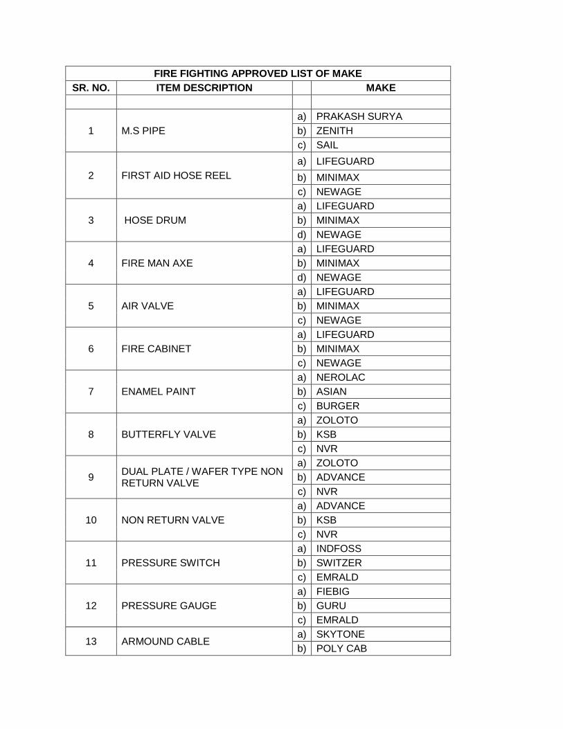
FIRE FIGHTING APPROVED LIST OF MAKE
SR. NO. ITEM DESCRIPTION MAKE
1 M.S PIPE
a) PRAKASH SURYA
b) ZENITH
c) SAIL
2 FIRST AID HOSE REEL
a) LIFEGUARD
b) MINIMAX
c) NEWAGE
3 HOSE DRUM
a) LIFEGUARD
b) MINIMAX
d) NEWAGE
4 FIRE MAN AXE
a) LIFEGUARD
b) MINIMAX
d) NEWAGE
5 AIR VALVE
a) LIFEGUARD
b) MINIMAX
c) NEWAGE
6 FIRE CABINET
a) LIFEGUARD
b) MINIMAX
c) NEWAGE
7 ENAMEL PAINT
a) NEROLAC
b) ASIAN
c) BURGER
8 BUTTERFLY VALVE
a) ZOLOTO
b) KSB
c) NVR
9 DUAL PLATE / WAFER TYPE NON RETURN VALVE
a) ZOLOTO
b) ADVANCE
c) NVR
10 NON RETURN VALVE
a) ADVANCE
b) KSB
c) NVR
11 PRESSURE SWITCH
a) INDFOSS
b) SWITZER
c) EMRALD
12 PRESSURE GAUGE
a) FIEBIG
b) GURU
c) EMRALD
13 ARMOUND CABLE a) SKYTONE
b) POLY CAB

c) BATRA HINLAY
14 FIRE PUMP
a) GRUNDFOS
b) ARMSTRONG
c) LUBI
15 FIRE EXTINGUISHER
a) LIFEGUARD
b) MINIMAX
c) NEWAGE
16 AIR VESSEL
a) LIFEGUARD
b) MINIMAX
c) NEWAGE
17 Y-STRAINER
a) ZOLOTO
b) LEADER
c) NVR
18 LANDING VALVE
a) LIFEGUARD
b) MINIMAX
c) NEWAGE
19 WELDING RODD
a) SANT
b) Advani,
c) Essab
20 ANTI-VIBRATION PADS
a) EASYFLEX
b) RESISTOFLEX
21 Support And Clamps
a) Mupro
b) Fixotech
c) UBB
22 Annunciation Panel
a) Precision system control
b) Application control Panel
c) Tricolite
25 Y- STRAINER
a) ZOLOTO
b) LEADER
c) KSB
c) SUPEREX

TECHNICAL SPECIFICATIONS PLUMBING WORKS
TECHNICAL SPECIFICATIONS – PLUMBING INSTALLATIONS
- I SANITARY FIXTURES SECTION
1. SCOPE OF WORK
1.1 Work under this section shall consist of furnishing all Material and labor as necessary and
required to completely install all Sanitary Fixtures, brass and chromium plated fittings and
accessories as required by the drawings and specified hereinafter or given in the Schedule of
Quantities.
1.2 Without restricting to the generally of the foregoing the Sanitary Fixtures shall include all
Sanitary Fixtures, C.P. fittings and Accessories etc. necessary and required for the Building.
1.3 Whether specifically mentioned or not all Fixtures and appliances shall be provided with all
fixing devices, nuts, bolts, screws, hangers as required.
2. GENERAL REQUIREMENTS
2.1 All Fixtures and fittings shall be provided with all such accessories as are required to complete
the item in working condition.
2.2 All sanitary accessory are low flow as per griha rating and green building appliances.
2.3 All Fixtures and accessories shall be fixed in accordance with a set pattern matching the tiles or
interior finish as per Architectural/ Interior designer’s requirements. Wherever necessary the
fittings shall be centered to dimensions and pattern desired.
2.4 Fixing screws shall be half round head Chromium Plated brass with C.P. washers wherever
required as per directions of Engineer-in-Charge.
2.5 All Fittings and Fixtures shall be fixed in a neat workmanlike manner true to Levels and Heights
shows on the drawings and in accordance with the manufacturer’s recommendations. Care shall
be taken to fix all Inlet and Outlet Pipes at correct positions. Faulty locations shall be made good
and any damage to the finished floor, tiling or terrace shall be made good at Contractors cost.
2.6 When directed, Contractor shall install Fixtures and accessories in a mock-up room for the
approval of the Engineer-in-Charge. Sample room Fixtures may be reused on the works if
undamaged, but no additional payment for fixing or dismantling shall be admissible.
EUROPEAN W.C.
3.1 European W.C. shall be wash down, single or double syphonic type, Mounted Wash down
European Water Closet with Soft close seat and cover, flushed by means of concealed type
flushing cistern, as specified in Schedule of Quantities. Flush pipe/bend shall be connected to the
W.C. by means of suitable rubber adapter. Wall hung W.C. shall be supported by C.I. floor
mounted chair/bolts as per approval.

3.2 Each W.C. seat shall be so fixed that it remains absolutely stationary in vertical position without
falling down on the W.C.
5 Wash Basin
5.1 Wash basins shall be black glazed vitreous china table top of size as per B.O.Q. specification,
shape and type specified in the Schedule of Quantities.
5.2 Each basin shall be provided with 32mm dia CP waste with overflow, pop-up waste or
rubber plug and CP brass chain as specified in the Schedule of Quantities.
5.3 Each basin shall be provided with hot and cold water mixing fitting or as specified in the
Schedule of Quantities.
6 2 Way Bib cock
These shall be chromium plated brass heavy quality of "EGO" type or equivalent, and shall be easy type
with capstan head. Flow Rating of two way bib cock as per green building rating. The size shall be as
specified in the Bills of Quantities
7 Double Coat Hook
7.1 A Stainless steel, chrome plated double coat hook wall mounting type shall be provided as
specified in bill of quantities
8 Towel Ring
8.1 Towel ring shall be chromium plated of stainless steel or powder coated brass of size, shape and
type specified in the Schedule of Quantities.
8.2 Towel ring shall be fixed with screws/capping having finish similar to the towel rail in wall with
rawl plugs or nylon sleeves and shall include cutting and making good as required or directed by
engineer – in- charge.
9 Soap Dispenser
9.1 Liquid Soap Dispenser shall be wall mounted suitable for dispensing liquid soaps, lotions,
detergents. The cover shall lock to body with concealed locking arrangement, opened only be key
provided.
9.2 Liquid soap dispenser body and shank shall be of high impact resistance material. The piston and
spout shall be stainless steel. The valve shall operate with less than 2.27 Kg (5 lbs) of force.
10 Grab Rail ( For Disabled Toilets )
10.1 Where specified in washroom facilities designed to accommodate physically handicapped,
accessories should be provided as directed by the Engineer - in - charge.

10.2 Stainless steel grab bars of required size suitable for concealed or exposed mounting and non-slip
gripping surface shall be provided in all washrooms to be used by physically handicapped as
directed by the Engineer - in – charge.
11 Grating
11.1 Floor and urinal traps shall be provided with 125 mm round stainless steel gratings, with frame
and rim of approved design and shape or as specified in the schedule of quantities approved by
the Engineer - in - charge.
.
11 Cockroach Trap
11.1 Wherever specified in the drawings, and/or found necessary by Engineer - in – charge to be
provide
11.2 approved cockroach trap having a minimum water seal of 50mm, suitable for fully vented one
pipe system shall be provided. When buried in floor, the traps shall be encased in cement concrete
1:2:4 mix after jointing and testing for support and stability.
12 Hand Drier
12.1 The hand drier shall be no touch operating type with solid state time delay to allow user to keep
hand in any position.
12.2 The hand drier shall be fully hygienic, rated for continuous repeat use (CRU).
12.3 The rating of hand drier shall be such that time required to dry a pair of hands up to wrists is
approximately 30 seconds. The hand drier shall be of wall mounting type suitable for 230 V,
single phase, 50 Hz, AC power supply.
13 Toilet Paper Dispenser
13.1 Toilet paper dispenser shall be wall mounted type of stainless steel. minimum 400-600 toilet
paper shall be fit on dispenser.
END OF SECTION - I

SECTION - II SOIL, WASTE & VENT PIPES
1. SCOPE OF WORK
1.1 Work under this section shall consist of furnishing all labour, materials, equipments and
appliances necessary and required to completely install all soil, waste, vent and rainwater pipes as
required by the drawings, specified hereinafter and given in the Schedule of Quantities.
1.2 Without restricting to the generally of the foregoing, the soil, waste, vent and rainwater pipes
system shall include the followings:
3. Vertical and horizontal Soil, Waste and Vent Pipes, Rainwater Pipes and Fittings, Joints
Clamps and connections to Fixtures.
4. Connection of pipes to Gully Traps & Manholes etc.
2. GENERAL REQUIREMENTS
2.1 All materials shall be best quality conforming to specifications and subject to the approval of
Engineer-in-Charge.
2.2 Pipes and fittings shall be fixed truly vertical, horizontal or in slopes as required in a neat
workmanlike manner.
2.3 Pipes shall be fixed in a manner as to provide easy accessibility for repair and maintenance and
shall not cause obstruction in shafts, passages etc.
2.4 Pipes shall be securely fixed to walls and ceilings by suitable clamps at intervals specified.
2.5 Access doors for fittings and cleanouts shall be so located that they are easily accessible for repair
and maintenance.
2.6 All works shall be executed as directed by Engineer-in-Charge.
3.0 Floor Trap Inlet
Toilet traps and connections shall ensure free and silent flow of discharging water. Where
specified, Contractor shall provide a special type G.I. inlet hopper without or with one, two or
three inlet sockets to receive the waste pipe. Hopper shall be connected to trap with at least 50
mm seal (Hopper and traps shall be paid for separately). For galvanized pipes the hopper & trap
shall be of the specified material as in bill of quantities & shall be jointed with the recommended
specifications / instructions of the manufacturer.
4. CLEANOUT PLUGS

Contractor shall provide brass cleanout plugs as required. Cleanout plugs shall be threaded and
provided with key holes for opening. Cleanout plugs shall be fixed to the pipe by a male threaded
adaptor.
5. WASTE PIPE FROM APPLIANCES
5.1 Waste pipe from appliances e.g. wash basins, sinks, urinals, bathtubs, water coolers shall be of
G.I. as given in the Schedule of Quantities or as shown on the drawings.
5.2 All pipes shall be fixed in gradient towards the outfalls of drains. Pipes inside a toilet room shall
be in chase unless otherwise shown on drawings. Where required pipes may be run at ceiling
level in suitable gradient and supported on structural clamps at approved spacing.
END OF SECTION – II
SECTION - III WTP PUMPS & EQUIPMENTS
1. PUMPS AND WATER TREATMENT EQUIPMENT
1.1 Work under this sub-head consists of furnishing all labour, with appropriate T&P
scaffolding & staging as required to completely install pumping system for various water supply
services and water treatment as per drawings, specified hereinafter and given in the Bill of Quantities.
1.2 Without restricting to the generality of the foregoing, the work of pumps and water treatment
equipment shall include the followings:
a) Raw water pumps.
b) Domestic water supply Pumping System.
c) Garden Water Supply Pumps.
d) Booster Pump Sets
e) Sump pumps for disposal from drainage and sewerage sumps for Plant rooms / Basements etc.
f) Water treatment units consisting of filters, softening plant, chlorination & RO System etc.
g) Level Control & indication System
h) Motor control panels, power and control cabling and allied electrical works.
i) Pipes, valves, accessories, hangers, supports, delivery and suction feeders and connection to
proposed pipe work.
2. RE-LIFT WATER SUPPLY PUMPSETS
2.1 Water supply pumps shall be suitable for clean water. Pumps shall be single or multistage, mono
block horizontal/vertical, centrifugal pumps with cast iron/stainless steel body and stainless
steel/bronze impeller, stainless steel shaft and coupled to a TEFC electric motor by means of a
flexible coupling or as specified in bill of quantities. Each pump should operate a curve 10m
below specified head.
2.2 Pump and motor shall be mounted on a common M.S. structural or C.I. base plate or as required
as per site conditions.

2.3 Each pump shall be provided with a totally enclosed fan cooled induction motor of required H.P.
and RPM specified in the bill of quantities and as per requirement.
2.4 Each pumping set shall be provided with a 150mm dia or of suitable size gunmetal “Bourden”
type pressure gauge with gunmetal isolation cock and connecting piping.
2.5 Each pump shall be provided with vibration-eliminating pads as suitable for each pump.
2.6 Each pump-set shall be provided with flow measuring meter with bypass arrangement as per
requirements and instructions of the engineer-in-charge. (Flow meter items shall be paid for
separately as per relevant BOQ item).
2.7 All water supply pumps shall be provided with mechanical seals, of required specifications.
2.8 Installation
Pump shall be installed as per manufacturer's recommendations. Pump sets shall be mounted on
machinery isolation cork or any other equivalent vibration isolation fitting. The vibration
isolation pads, foundation bolts etc. shall be supplied by the Contractor. Contractor shall ensure
that the foundation bolts are correctly embedded.
Pump-sets shall preferably be factory aligned, wherever necessary, site alignment shall be done
by competent persons.
2.9 Testing
Contractor shall submit all the performance curves of the pumps supplied by them. They shall
also check the capacity and total head requirements of each pump to match their own piping and
equipment layout. On completion of the entire installation, pumps shall be tested, wherever
possible, for their discharge, head, flow rate, B.H.P. Where it is not possible at least the
discharge, head and B.H.P. (as measured on the input side) shall be field tested. Test results shall
correspond to the performance curves.
2.10 Painting
After complete installation and testing, pumps accessories and fittings shall be given two coats,
three mils each of approved finishing paint.
3. SUMP PUMP
3.1 Sump pumps shall be submersible type for lifting domestic sewage or muddy water/drainage as
specified in Bill of Quantities. Pump with impeller of approved material and design shall be
mounted on waterproof motor. The impeller shall be suitable for handling solids as specified in
Bill of Quantities.
3.2 The pump shall automatically operate with high water level and stop at low water level in
the sump by means of “Electronic Level Controller”, of the approved make as per manufacturer
compatibility.

3.3 The sump pumps shall be complete in all respect and shall be installed as per manufacturer’s
requirement as shown in the drawing. All accessories shall be In-Built as per manufacturer’s
specification.
3.4 All pumps within a pump set shall run in cyclic fashion under normal operating circumstances.
All pumps within a pump set shall be capable of operating simultaneously / cumulatively in case
of emergency / high water level.
4. WATER FILTER
4.1 Water filter shall be of dual media pressure filter (comprising of minimum 300mm bed depth of
Anthracite and support media and minimum Height on Straight 1500mm) of downward or
upward flow type suitable for a rate of filtration given in Schedule of quantities.
4.2 Filter shall be vertical type of required diameter. The shell shall be fabricated from M.S. plate
suitable to withstand a working pressure of 3 Kg/cm2. The minimum thickness of shell will be
10mm and dished ends shall be 12mm.The quality of Steel shall be as per IS:2062 Grade B,
thickness as per ASME Section 8. The filter shall have at least one pressure tight manhole cover.
Filter shall be provided with screwed or flanged connections for inlet, outlet, individual drain
connections and all other connections necessary as required. Filter shall be painted inside with
two or more coats of coal tar epoxy paint, one coat of red oxide primer outside with two or more
coats of synthetic enamel paint of approved shade.
The Filter media shall comprise of 0.5 to 1.00 mm fine filtering silica sand for removal of
turbidity and suspended matter.
The initial charge of filter media as specified in above para’s shall be the responsibility of
contractor.
The pressure filter shall be complete with cleaning cycle controller adjustable to meet application
requirement, actuating control valves in required sequence for back wash.
4.3 Under Drain System
Filter shall be provided with an efficient under drain system comprising of collecting pipes,
gunmetal/polypropylene nozzles of manufacturer’s design. The entire under drain system be
provided on M.S. Plate or cement concrete supports.
4.4 Face Piping
Filter shall be provided with interconnecting face piping comprising of inlet, outlet, and
backwash pipe complete with pipes, valves and accessories, as per requirement. Piping shall be
G.I. piping, heavy duty, as per I.S: 1239 and valves shall be cast iron double flanged sluice valves
with C.I. body and Neoprene rubber diaphragm.
4.5 Accessories
Each filter shall be provided with following accessories:-
a) Air release valve with connecting piping.
b) 150mm dia dial bourden type gunmetal pressure gauges with gunmetal isolation cock and
connecting piping on inlet and outlet.
c) SS Sampling cocks on raw water inlet and filtered water outlet.

d) Individual drain connection with gunmetal fullway valve should be piped through
a properly sized G.I. pipe to nearest drain point.
5. WATER SOFTENER
5.1 Softener shall be designed to give zero commercial hardness. Softener shall be with “cation” ION
exchange resins.
5.2 Softener vessel shall be of mild steel plate with dished ends and self supporting arrangement.
Vessel shall be suitable for a minimum working pressure of 3 Kg/ Sq. cm. The vessel shall be
tested at 1.5 times the working pressure. The shell shall be designed to allow a minimum free
board space at 50% of the mineral bed depth for adequate expansion during back washing. The
shell shall have a minimum thickness of 10mm and dished ends 12mm. The quality of Steel shall
be as per IS:2062 Grade B, thickness as per ASME Section 8. All internal parts of the softener
shall be rubber lined as per approved specifications rubber lined and externally with one coat of
red oxide and two or more coats of synthetic enamel paint of approved shade.
5.3 The vessel shall have an internal collecting and distribution system of manufacturer’s design.
5.4 The softener shall have a set of interconnecting face piping consisting of inlet, outlet and brine
injection system with valves and accessories complete as per requirement. Piping shall be G.I
heavy duty, as per I.S: 1239 and valves shall be cast iron double flanged sluice valves with C.I.
body and Neoprene rubber diaphragm. Individual drain connection with gunmetal full way valve
should be piped through a properly sized G.I. pipe to nearest drain point.
5.5 The brine injection system consist of hydraulic ejector with control valve, brine delivery pipes
with adjustable indicator.
5.6 One measuring tank (Brine Tank) having a capacity of minimum one regenerations or as
specified in bill of quantities.
5.7 One orifice board for indicating wash and rinse rate to be fitted in drain sump.
5.8 One initial charge of supporting gravel, sand and “cation” ION exchange resin in requisite
quantity.
5.9 One water testing kit with instructions for testing water samples.
5.10 One rota meter to indicate flow rate.
5.11 Inlet & outlet pressure gauges.
6. SALT SATURATOR ASSEMBLY
6.1 Tanks shall in High density Polyethylene (HDPE) construction of required capacity. The
assembly shall be suitable for holding and supplying salt for softener with inlet & outlet piping
with valves and accessories complete as per requirement.
6.2 The assembly shall be provided with an automatic agitator. The automatic agitator shall be
motorized (motor of suitable rating operating on single phase, 50 Hz, AC supply) having

Stainless steel shaft with fan blade, coupled with suitable gear box duly mounted MS Frame with
Epoxy Coating .
6.3 The transfer Pump for supplying salt solution to softener shall be of multistage, Inline vertical,
centrifugal pumps with cast iron/cast steel body, SS316L stage casing, SS316L impeller, stainless
steel shaft, and directly coupled with TEFC induction motor of class "F" insulation & efficiency
class EFF-1, 2900 RPM, IP 55 enclosure, suitable for operation on 415 volts ±10%, 3 phase, 50
Hz, A.C. supply.
6.4 The contractor has to ensure that the effective capacity of the system shall be of minimum 10%
greater than actual salt required for approx. 3 Days with complete structural arrangement
including suitable foundation bolts & other accessories etc.
7. CHLORINATOR
Chemical dosing should consist of electronic / electro mechanical metering pump
with suction and delivery flexible connections and fittings. The pump shall be mounted on
FRP tank of required capacity having in-built basket for holding alum blocks and lime
blocks. The system should be completed with electrically operated single phase motor
driven stirrer having stainless steel shaft. This should be suitable for working against a
pressure of 1.5 kg/Sq.cm and should be capable of ejecting Sodium Hypo-chloride solution
/ suitable alternate chemicals with a dose of 1 ppm.
8. PIPING
8.1 Pipes for suction and delivery shall be galvanized steel pipes (heavy duty) confirming to I.S:1239
upto 150mm dia and as per I.S:3589 for dia 200mm and above or as specified in bill of quantities.
. Galvanising shall conform to IS 4736. Pipes and fittings shall be jointed with screwed/flanged
joints, flanges either screwed or welded complete and jointed with 3mm thick rubber gasket as
per requirements complete with nuts, bolts and washers etc.
8.2 Gate valve and check valve above 65mm dia shall be C.I. double flanged conforming to I.S:780
manufactured by the reputed manufacturers or C.I. double flanged butterfly valves as specified in
bill of quantities or elsewhere or as per approval of Engineer-in-charge.
8.3 Full way and check valves 65mm dia and below shall be gunmetal tested to 20Kg/cm2 pressure
certified and conforming to I.S:778.
8.4 Suction strainer or foot valves shall be C.I., confirming to I.S:4038 - 1979, as specified in bill of
quantities.
8.5 Joints
All pipes and fittings shall be provided with flanged joints, with flanges either screwed or welded
complete and jointed with 1.5mm thick gasket complete with nuts, bolts and washers etc. Welded
joints shall not be permitted for domestic water supply pumping systems or wherever potable
water quality is required.

9. PIPING INSTALLATION
9.1 Clamps
G.I. pipes shall be supported by G.I. clamps of design approved by Engineer-in-charge. Pipes in
wall chases shall be anchored by iron hooks. Pipes at ceiling level shall be supported on structural
clamps fabricated from M.S. structural works.
9.2 Unions
Contractor shall provide adequate number of unions on all pipes to enable easy dismantling later
when required. Unions shall be provided near each gunmetal valve, stop cock, or check valve and
on straight runs as necessary at appropriate locations as required and / or directed by Engineer-in-
charge.
9.3 Flanges
The M.S flanges shall confirm to I.S:6392-1971 and shall be galvanized. Flanged connections
shall be provided on pipes as required, all equipment connections as necessary and required or as
directed by Engineer-in-charge. Connections shall be made by the correct number and size of the
bolts and made with 3mm thick insertion rubber washer. Bolt hole dia for flanges shall conform
to match the specification.
9.4 Piping layout shall take due care for expansion and contraction in pipes.
9.5 All pipes using screwed fittings shall be accurately cut to the required sizes. Care shall be taken to
remove burr from the end of the pipe after cutting by a round file. Genuine red lead with grumet
and a few strands of fine hemp shall be applied and threaded in accordance with IS: 554. Open
ends of the piping shall be locked as the pipe is installed to avoid entrance of foreign matter.
Wherever reducers are to be made in horizontal runs, eccentric reducers shall be used if the
piping is to drain freely, in other locations, concentric reducers may be used.
9.6 Contractor shall provide suitable cement concrete, anchor blocks of adequate dimensions as per
spacing mentioned above & at all bends, tee connection and other places required and necessary
for overcoming pressure thrusts in pipes wherever pipes are installed on-ground / underground.
Anchor blocks shall be of cement concrete 1:2:4 mix (1 cement: 2 coarse sand: 4 stone aggregate
20 mm nominal size).
9.7 Drain shall be provided at all low points in the piping system and shall be of the following sizes:
Mains Drains
Upto 300mm dia 25mm dia
Over 300mm dia 40mm dia
Drains shall be provided with forged brass ball valve of equal size. Drains shall be piped through
equal size G.I. pipe to the nearest drain or floor waste or as shown on the drawings. Piping shall
be pitched towards drain points.
9.8 Vibration Elimination
Piping installation shall be carried out with vibration elimination fittings wherever required.
9.9 Testing
All piping shall be tested to hydrostatic test pressure of minimum 10 kg/cm² or 1.5 times the
design pressure whichever is higher for a period of not less than 24 hours. All leaks and defects in
joints revealed during the testing shall be rectified to the satisfaction of the Engineer-in-charge.
9.10 Painting
(a) After the piping has been installed, tested and run for at least ten days. The piping shall be given
two finish coats, 3 mils each of approved color.
(b) The direction of flow of fluid in the pipes shall be visibly marked in white arrows or as directed
by the Engineer-in-charge.
10. VALVES & ACCESSORIES
10.1 Sluice / Gate Valves
Sluice Valves above 65 mm (inside screw and non raising screw type) shall be of Cast Iron body
and Gunmetal seat with double flanged ends and valve wheel. They shall conform to type PN 1.6
of IS:780. Sluice valves upto 65mm (outside screw raising spindle type) shall be of Gunmetal
Full way Valve with wheel tested to 20 Kg./cm2 class-II as per I.S: 778 with female screwed
ends. Valve wheels shall be of right hand type and have an arrow head engraved or cast thereon
showing the direction for turning open and close.
10.2 Butterfly Valves
10.2.1 The Butterfly Valve shall be suitable for waterworks. The Valves conforming to IS :
13095 shall be provided. All valves shall be suitable to withstand the pressure in the system and
rating shall be PN 1.6. All valves shall be right handed (i.e. handle or key shall be rotated clock
wise to close the valve).
10.2.2 The direction of opening and closing shall be marked and an open / shut indicator fitted.
10.2.3 The material of valves shall be as under:-
Body - Cast iron
Disc - Ductile Iron
Seat - EPDM/Nitrile rubber
Shaft - Stainless Steel
10.2.4 The Valve shall be fitted between two flanges on either side of pipe flanges. The Valve edge
rubber shall be projected outside such that they are wedged within the pipe flanges to prevent
leakages.
10.3 Non-Return Valve
Non-return valves shall be of Cast Iron body and Stainless Steel seat. They shall conform to API-
594 and have companion flanges. They shall be Dual Plate Type suitable for both horizontal and

vertical installation. An arrow mark in the direction of flow shall be marked on the body of the
valve.
10.4 Air Release Valve
Air valves shall be provided at all high points in the piping system for air vent of the double float
type, with G.M. body, vulcanite balls, rubber sealing, etc. Air valves shall be of the sizes
specified and shall be associated with an equal size forged ball valve.
10.5 Ball Valve
10.5.1 The Ball Valve shall be made from forged brass and tested to 20 Kg/cm² pressure. The valve shall
be internally threaded to receive pipe connections.
10.5.2 The Ball shall be made from brass and machined to perfect round shape and subsequently chrome
plated. The seat of the valve body bonnet gasket and gland packing shall be of Teflon.
10.5.3 The handle shall be of chrome plated steel with PVC jacket. The handle shall also indicate the
direction of ‘open’ and ‘closed’ situations. The gap between the ball and the Teflon packing shall
be sealed to prevent water seeping upto 14 Kg / cm² pressure.
10.5.4 The handle shall also be provided with a lug to keep the movement of the ball valve within 90
degree.
10.6 Strainer
Strainers shall be preferably of the approved type with fabricated steel bodies designed to the test
pressure of 10 Kg/ cm². Strainers shall be fabricated by minimum 1.2 mm thick stainless steel
sheet with 3 mm dia. perforation holes. Strainers shall be provided with flanges or threaded
sockets as required. They shall be designed so as to enable blowing out accumulated dirt and
facilitate removal and replacement of screen without disconnection of the main pipe.
10.7 Pressure Gauges
Pressure gauges shall be of 150mm dia. dial and of appropriate range and be complete with shut
off gauge valve etc. duly calibrated before installation. Care shall be taken to protect pressure
gauges during pressure testing.
10.8 Flexible Connection for Pumps
All suction and delivery lines shall be provided with double flanged reinforced neoprene /
Stainless Steel flexible pipe connectors. Connectors should be suitable for a working pressure of
each pump. Length of the connector shall be as per specified or as per manufacturer’s details.
11. ELECTRICAL CONTROL PANELS
11.1 Motor Control System
The main switchboard shall be floor mounted, free standing, cubical type, compartmentalized and
shall be factory built fabricated by one of the approved switch board manufacturer. The board

shall be fabricated from 2mm thick CRCA sheet and powder coated after seven tank process. The
board shall be fabricated with IP 54 degree of protection suitable for operation of 415 volt ± 10%
, 3 phase,4 wire,50Hz, AC supply. The switch board shall have provision for termination of
cables from top as well as bottom with suitable knockouts. The layout shall be designed for
convenient connections and inter-connections with various switchgears. Connections from
individual compartments to cable alleys shall be such as not to shut down healthy circuits in the
event of maintenance work becoming necessary on a defective circuit. A base channel of 75mm
and bottom most panel of unit shall be provided. The bus bar shall be of aluminium complete
with heat shrinkable PVC sleeves. The fabrication of switch board shall be taken up only after the
drawings for the fabrication of the same are approved by the Engineer –in – charge.
Control panel shall contain starters and safety protection for different types of pump motors &
various feeders along with its controls. It shall also house the switchgears for incoming as well
for outgoings supply. Provision of voltmeter ( for incomer ) & ammeter for incomer as well as for
other feeders with selector switch, a set of LED indicating light for incoming phases as well as
status indication of each equipment as per the schedule of quantities. The voltmeter & indication
lamps shall be protected by MCBs.
The feeders for all those motors having more than 7.5 HP capacity shall be provided with fully
automatic Star Delta starters with motor duty MCCBs for short circuit protection only(ICS =
100% ICU ) & Overload Relays with contactors of suitable range & ratings, for overload
protection, while less than or equal to 7.5 HP motor shall have Motor protection circuit
breaker(MPCB) with over load & short circuit protection of suitable rating. Single phase
preventers shall be provided for all 3 phase motors. Single phase preventer shall be in conformity
with relevant ISI standards. Single phase preventers shall act when the supply voltage drops down
to 90 % of the rated voltage or failure of one or more phases. Single phase preventer shall be
voltage operated and of approved make.
Other feeders of the panel which don’t require starter, shall be housed with :
i) MCCB with Thermal magnetic release & should provide adjustable setting for overload and short
circuit protection with ICS = 100% ICU.
ii) MCB used for controlling shall be with tripping characteristics of C curve. The miniature circuit
breakers shall be 1/2/3/4 pole as per requirement. The breaking capacity of MCBs shall have
minimum 10KA.
ON-OFF switches for each motor / equipment should not be provided on the cover of the control
panel. But at the same time interlocking shall be provided between switch and the door in such a
way that the door of the panel cannot be opened when the supply is ON.
The panel shall be provided all identification tags, danger board etc as per IS standard.
All control panels shall be provided with detailed control circuit diagram indicating the terminal
numbers and color coding of the wires used in the panels. This diagram shall be pasted on the
inner side of the cover and protected with PVC transparent lamination.
All MCCBs / MPCB’s shall be equipped with extended front operated rotary handles on the
doors. Rotary handle should have provision for pad lock.

Outgoing from each of the MCCB shall be extended to the cable alley by providing necessary
busbar of suitable rating and supports etc. for terminating the outgoing feeders.
The detailed specification of switch gears and other accessories shall follow as described in
Package A of these tender specifications.
12. PUMP MOTOR CONTROLLER CUM WATER LEVEL INDICATING PANEL &
SYSTEM
12.1 Water Level Indicators and Controllers
The hydrostatic pressure sensor (Water level indicator) shall operate on hydrostatic pressure
measurement principle. The sensors shall be made of Stainless Steel for installation in storage
tanks, and capable of providing 4 to 20 mA analog signal compatible with PLC signal inputs and
all control outputs to MCC panel (Plumbing/Water supply),for various water tanks as per the
schedule of quantities. The Pressure Transducers shall be used for water level measurement, and
it shall be convenient to mount on the water tanks. Hydrostatic pressure level sensors shall be
submersible or externally mounted pressure sensors suitable for measuring the level of liquids in
deep tanks or water in reservoirs. Level measurement shall be based on the pressure measurement
principal, also referred to as hydrostatic tank gauging (HTG). It shall work on the principle that
the difference between the two pressures (d/p) is equal to the height of the liquid (h, in inches)
multiplied by the specific gravity (SG) of the fluid. Following shall be the formula used for
measurements / calibration: d/p = h(SG). These sensors sense increasing pressure with depth and
because depth is proportional to Volume for a regular tank, the Volume of Water can be easily
calculated using a PLC.
12.2 Level Indicator / Controller Panel
The Centralized PLC control panel shall be front operated, cubicle construction, wall mounted
type, fabricated out of 1.6 mm thick CRCA Sheet, with hinged lockable doors, dust and vermin
proof, powder coated of approved shade, inter-connections, having, internal wiring, earth
terminals, Top / Bottom control cable entry, numberings etc. comprises of touch-screen display
board (Minimum Diagonal size 8") along with all accessories for complete Programmable logical
controls & indications, having necessary interlocks, Inputs/Outputs, required number of repeater
amplifiers, all audio-visual alarms as per the requirements listed below i/c emergency stop push
button on the panel etc. The panel shall have BMS compatible with open protocol.
13. CABLES
13.1 Contractor shall provide all power control cables from the motor control center to various motors,
level controllers and other control devices.
13.2 Cables shall conform to I.S: 1554 and carry ISI mark.
13.3 Wiring cables shall conform to I.S 694.
13.4 All power and wiring cables shall be aluminum conductor PVC insulated armored and PVC
sheathed of 1100 volts grade.
13.5 All control cables shall be copper conductor PVC insulated armored and PVC sheathed 1100 Volt
grade.

13.6 All cables shall have stranded conductors. The cables shall be in drums as far as possible and bear
manufacturer’s name.
13.7 All cable joints shall be made in approved manner as per standard practice.
14. CABLE TRAYS
14.1 Contractor shall provide M.S slotted cable trays at locations as shown on the drawings and of
sizes as given in the bill of quantities.
14.2 Cable trays shall be supported from the bottom of the slab at intervals of 60cms at both ends by
anchor fasteners. Cost of MS angle, rods and anchor fasteners etc. shall be included in the rate of
the tray and no separate payment shall be made on this account.
14.3 Cost of clips, bolts, nuts, support rods and any other materials required to fix the trays in proper
manner shall be included in the rate for trays.
15. EARTHING
15.1 There shall be an independent earthing station. The earthing shall consist of an earth tape
connected to an independent plate made of copper or G.I. having a conductivity of not less than
100% international standard. All electrical apparatus, cable boxes and sheath/armour clamps shall
be connected to the main bar by means of branch earth connections of appropriate size. All joints
in the main bar and between main bar and branch bars shall have the lapping surface properly
tinned to prevent oxidation. The joints shall be riveted and sweated.
15.2 Earth plates shall be burried in a pit of 1.20x1.20M at minimum depth of 3M below ground. The
connections between main bar shall be made by means of three 10mm brass studs and fixed at
100mm centres. The pit shall be filled with coke breeze, rock salt and loose soil. A G.I. pipe of
20mm dia with perforations on the periphery shall be placed vertically over the plate to reach
ground level for watering.
15.3 A brick masonry manhole 30x30x30cm size shall be provided to surround the pipe for inspection.
A bolted removable link connecting main bar outside the pit portion leading to the plates shall be
accommodated in this manhole for testing.
16. CONTROL PANELS / STARTERS
16.1 Switch board cubicles of approved type shall be fabricated from 16-gauge M.S. sheet with dust
and vermin proof construction. It shall be painted with powder-coated finish of approved make
and shade. It shall be fitted with suitable etched plastic identification plates for each motor. The
cubicle shall comprise of the followings:- (Switch gear as given in the bill of quantities).
a) Incoming main isolation MCCB of required capacity.
b) Fully Aluminum taped Bush Bar of required capacity.
c) Isolation MCCB one for each motor.
d) Fully automatic as specified D.O.L/Star Delta starters suitable for motor H.P. with push buttons
one for each motor and on/off indicating neon lamps. (DOL upto 7.5 HP and Star Delta from
more than 7.5 H.P)

e) Single phase preventor of appropriate rating for each motor.
f) Panel type ampere meters one for each motor with selector switch.
g) Panel type voltmeter on incoming main with rotary selector switch to read voltage between phase
to neutral and phase-to-phase.
h) Neon phase indicating lamps for incoming main and on/off indicating lamps for each motor.
i) Rotary switch for manual or auto operation for each pump (manual/auto off).
j) Fully taped separate aluminum bus bars of required capacity and with required outlets.
k) Space for liquid level controllers as specified + 1 extra space.
l) The panel shall be pre-wired with colour-coded wiring. All interconnecting wiring from incoming
main to switch gear, meters and accessories within the switchboard panel.
m) Provision of main incoming cables from the top of the panel.
16.2 All switch gears and accessories shall be of approved make such as “Siemens, English Electric,
Larson & Toubro” or equivalent, or as specified.
16.3 Switchboard cubicles shall be floor or wall mounted type as recommended by manufacturers. All
floor-mounted switch board shall rest on minimum 225mm high platform. The contractor shall
provide the shop drawings for base and panels.
17. MEASUREMENTS
17.1 Raw water, re-lift and sump pumps and swimming pool pumps shall be measured by numbers /
sets and shall include all items as given in the bill of quantities.
17.2 Motor control panel and level controllers shall be measured by numbers.
17.3 Pipes for suction and delivery header and mains shall be measured per linear metre along the
centre line of the pipe and shall be inclusive of all fittings.
17.4 Cable trays and cables shall be measured per linear meter.
17.5 Structural clamps including hangers shall be measured by weight calculated from sections used.
No separate payment shall be admissible for bolts, anchor bolts, rawl plugs etc.
17.6 No separate payment shall be made for making connections of the existing service lines to the
pumps. Vibration eliminator pads are included in the scope of this work.
18. GUARANTEE
18.1 The contractor shall submit a warranty for all equipment, materials and accessories supplied by
him against manufacturing defects, malfunctioning or under capacity functioning.
18.2 The form of warranty shall be as approved by the Engineer-in-charge.

18.3 The warranty shall be valid for a period of one year from the date of commissioning and handing
over.
18.4 The warranty shall expressly include replacement of all defective or under capacity equipment,
Engineer-in-charge may allow repair of certain equipment if the same is found to meet the
requirement for efficient functioning of the system.
18.5 The warranty shall include replacement of any equipment found to have capacity lesser than the
rated capacity as accepted in the contract. The replacement equipment shall be approved by the
Engineer-in-charge.
18.6 The contractor shall include in his rates the operation of all mechanical equipments for a period of
six months from the date of commissioning. No separate payment will be made on this account.
19. COMMISSIONING
After successful testing of the different items in parts, the Contractor shall provide all facilities
including necessary piping, labour, tools and equipments etc. for carrying out testing and
commissioning of the entire water treatment plant complete as per requirement in the presence of
Engineer-In-charge or his representative whenever and as may be required.
END OF SECTION – III
SECTION IV SEWAGE TREATMENT PLANT
1.0 Project Description
1.1 Project : Gail, Varanasi
1.2 Usage : Office Complex
1.3 Location : Below ground
2.0 Design Consideration
2.1 Capacity (Max) : 15 m3 per day (15KLD)
2.2 STP Technology : Sustainable Microbial Anaerobic Reactor
Technology (SMART)
2.3 Influent
a) pH : 6 to 8.5
b) BOD 5 days @ 200C : upto 200-250 mg/l
c) Suspended solids (SS) : upto 200-400 mg/l
d) Oil & grease : upto 20 mg/l
2.4 Effluent (Final)
a) BOD 5 days @ 200C : less than 20 mg/l
b) Suspended solids (SS) : less than 50 mg/l c)
c) Oil & grease : less than 10mg/l
d) pH : 6.5 - 8

3.0 Salient Features
3.1 The plant should be able to operate efficiently at 10% of design flow and should be suitable
for low/peak flow.
3.2 There should be no daily/weekly/monthly sludge handling and disposal for min. 8-10 years
3.3 Water recovery rate should be 95-98% of the sewage
3.3 The plant should not create any noise, with no nuisance on fly or mosquito and no foul odors.
3.4 STP to be operated by a single operator (8.5 hours shift)
3.5 The plant should be provided with tertiary treatment in form of planted gravel filter and
ozonation system to provide suitable bacteriological standard for reuse on:
a) Irrigation system
3.6 The plant should be eco friendly
3.7 The plant should work in conjunction with probiotic microbial culture (Make:
OS1/Envirosense/Ecolog). The original and duly signed Material Safety Data Sheet of the
microbial culture issued by the manufacturer to be provided before the start of work along with
manufacturer verified activation and dosage guide to ensure smooth functioning of the STP.
4.0 Design Criteria Assumptions & Qualifications:
4.1 It is assumed that the effluent coming to STP shall be domestic sewage only and that it shall be
free of any industrial effluent contamination.
4.2 All Oil coming to sewage treatment plant is assumed to be ‘Floating Free Oil’ and free of
mineral oil contamination.
4.3 Our design assumes that 100% of influent COD & BOD is soluble & biodegradable.
4.4 Concentration of Inhibitory matter to microorganisms and heavy metals shall be less than the
threshold limits (or within any ranges specified).
4.5 The wastewater shall also be free of any substance toxic or inhibitory to the biological
treatment process.
4.6 The waste shall not contain any toxic compounds, inhibitory substances or extreme physical
conditions, which might interfere with physical/biological treatment processes and/or cause
damage to the proposed treatment equipment. Any other parameters, such as cyanide, tar,
arsenic, formaldehyde, phenols, insecticides, copper, cadmium, barium, selenium, lead, nickel,
manganese, silver, toxic compounds content are assumed absent in influent wastewater.
4.7 Variations in the influent conditions (whether changes in concentrations or the presence of
undisclosed parameters) may invalidate any warranties (performance or other) offered.
5.0 Process
SMART TM Sewage Treatment Process
(Sustainable Microbial Anaerobic Reactor Technology (SMART)TM uses a combination of technologies to
treat sewage water efficiently and economically to achieve the desired result. The following modules are
present in a SMARTTM system-
1. Primary Treatment : Sedimentation and Sludge Maintenance
2. Biological Treatment in fermentiave baffled reactor and fixed film filters
3. Filtration using Activated Carbon Filter & Pressure Sand Filter
Sedimentation Fermentative Baffled Tank
Fixed Film Filters
Filtration Disinfection
using Ozonation

4. Tertiary Treatment with Ozonation
Pre Treatment: Screening & Collection
Manual Screens are provided at the inlet in a bar screen chamber to remove in-organics and bigger
debris like plastics, half-eaten food, glass etc. OS1-WW is inoculated at the inlet. From the bar
screen chamber the waste water flows into the equalization tank from where it is pumped into the
SMART reactor at a constant rate.
Waste water from the kitchens of the messes flows into a oil & grease trap first where the grease is
skimmed at a regular basis, the waste water then flows into the main sewer line and gets mixed with
the rest of the flow. The probiotic microbes are dosed in the equalization chamber and is pumped
into the reactor along with the waste water.
Primary Treatment: Sedimentation & Sludge Maintenance
A pre-treatment sedimentation process takes place in which the heavy density solids are separated
from the liquid. This phase is called the primary settler. Within the settler, two main treatment
processes take place, first a sedimentation process and second stabilization and digestion of the
settled sludge through biological treatment. The partition wall restricts the flow of scum layer into
other chambers. In OS SMARTTM treatment the settler is incorporated as the first section of the
baffled reactor.
The settler is divided into two equal parts to ensure that in case de-silting is required after a few
years of operation, the reactor does not have to be shut down for cleaning. Each part can be cleaned
separately while the reactor remains functional. A backward slope is given in the settler to further
increase the settling ability of solids by gravity.
First Treatment Cycle: Fermentative baffled tank
In the first treatment phase, the biological processes are used to digest and remove the organic
matter. Biomass of heterotrophic bacteria utilizes the organic matter during their metabolism.
Multiple chambers are constructed in series to digest degradable substances. Baffle walls direct the
waste water stream between the chambers in a sinusoidal fashion. During this process, the influent is
digested by the active blanket of suspended particles (floating bacteria media) and microbes that
form bio-films at the bottom and walls of each chamber. The baffle walls and sinusoidal motion
reduces the washout of the bacterial colonies that form in the chambers.
Secondary Treatment Cycle: The fixed film filters
Fixed film PVC media is used in order to further improve the treatment efficiency. The filter media
increases the contact of the bio-films with the effluent stream and is extremely efficient in retaining
and digesting the left over pollutants. When the bacterial mass starts to thicken in the media the layer
closest to the film does not get food supply and enters the self-digestion mode which ensures clog-
free functioning of the media. The volume of media is based on various parameters like BOD, flow
rate and temperature.
Filtration using Activated Carbon Filter & Pressure Sand Filter
The waste water is then pumped through a series of filters; Pressure Sand Filter & Activated carbon
filter to trap suspended solids, odor and color.
Tertiary Treatment: Oxidation cell (using Ozonation)
At this stage the wastewater from the filters flows into the Oxidation cell. An ozone generator with a
recirculation pump coupled with a venturi injector is fitted in this tank. Ozone is produced when dry
air or oxygen gas is passed through the dielectrics of the ozone generating module. The ozone
generated is injected into the waste water and sufficient retention is provided in the chamber to allow

mixing of ozone with the waste water. The ozone generating module is powered by a high voltage /
high frequency board mounted inside the ozone generator. The board is designed for intermittent or
continuous operation. The ozone generating module is cooled using cooling fans which brings fresh
air from one side and throws the heated air from the other side, which helps in keeping the modules
under normal temperature and ensures efficient operation of the ozone generator.
Ozone is essentially made up by oxygen. When an oxygen molecule (O2) is exposed to electric high
voltage (or UV-light in the stratosphere), the oxygen molecule (O2) is split into two oxygen atoms
(O1). The oxygen atom (O1) then connects to oxygen molecules (O2) and ozone (O3) is formed.
Ozone then reacts with other substances and the single oxygen atom (O1) disconnects from the
ozone molecule (O3), which then again turns into an oxygen molecule.
This step further oxidizes the organics present in sewage and reduces the BOD/COD load further. It
also reduces the color, odor and pathogens present in the water. The treated water is stored in a
treated water tank from where it is pumped for reuse.
END OF SECTION – IV
LIST OF APPROVED MAKES FOR PLUMBING WORKS
S.
No.
Details of Materials / Equipment Manufacturer’s Name
1 EWS / IWC Jaquar. Kohler, Roca, Toto
2 W.C. seat cover Jaquar. Kohler, Roca, Toto
3 Flushing Cistern Jaquar. Kohler, Roca, Toto
4 Urinal / Sensor type urinal
Jaquar. Kohler, Roca, Toto
5 Urinal partitions Jaquar. Kohler, Roca, Toto
6 C.P. brass flush valve for WC and Urinals Jaquar. Kohler, Roca, Toto
7 Automatic flushing system for Urinals
Jaquar. Kohler, Roca, Toto
8 Wash basin Jaquar. Kohler, Roca, Toto
9 Toilet paper holder
Jaquar. Kohler, Roca, Toto
10 C.P. brass fittings such as bib cock, two
way bib cock, pillar cocks, stop cocks,
angular stop cocks, C.P. flexible pipes /
hose connection, C.P. brass waste, C.P.
brass cast bottle trap, C.P. brass shower
rose / shower assembly, long body bib
taps, C.P. brass health faucets, single lever
mixing fittings, sink mixture etc.
Jaquar. Kohler, Roca, Toto
11 Automatic hand drier Jaquar. Kohler, Roca, Toto
12 Stainless Steel Kitchen Sink Nirali, Neelkanth,
13 Soap dish Jaquar. Kohler, Roca, Toto
14 Liquid soap dispenser Jaquar. Kohler, Roca, Toto
15 Towel ring / Towel rail Jaquar. Kohler, Roca, Toto
16 Coat hook / Robe hook Jaquar. Kohler, Roca, Toto
17 Glass Mirror Modi Guard, Saint gobin, Modiguard, Atul
18 P- Trap (Floor Trap) SKF, NECO, Electrosteel

S.
No.
Details of Materials / Equipment Manufacturer’s Name
19 Floor Drain Prakash surya, Tata, Sail
20 Stainless Steel Grating for P- Trap /
Cockroach Trap
Vijay, Sanjay Chilly, Near
21 C.P. Grating for Floor P - Trap Vijay , Sanjay Chilly
22 GI Pipes (IS : 1239 and IS : 3589)
Prakash Surya, Tata Steel , Sail
23 GI pipes fittings Unik / Zoloto M / R Brand
24 C.I. Hubless Pipe & Fittings SKF, NECO, Electrosteel
25
GM / Forged Brass Ball Valves NVR, Advance, Zoloto
26 Sluice Valves NVR, Advance, Zoloto
27 Butterfly Valve NVR, Advance, Zoloto
28 Non Return Valve / Check Valve NVR, Advance, Zoloto
29 Motorised Butterfly Valve NVR, Advance, Zoloto
30 Air Release Valve NVR, Advance, Zoloto
31 Upvc Pipe & Fittings AKG, Supreme, SFMC
32 Y Strainer NVR, Advance, Zoloto
33 Level Controller (Water) Sant, Active Controls, Technika
34 Level Indicator (Water) Sant,, Active Controls,Technika
35 Paints Nerolac, Asian, Burger, ICI Dulux
36 MH / Water Tank Plastic Steps KGM, Neco, Kartar, Rif
37 Insulation for Hot Water Pipes Armacel – Armaflex (UK) /
Eurobatex – Union Foam (Italy) /
K-Flex
38 Electric Water Heater / Gyser Jaquar, AO Smith, Bajaj, Venus
39 Pypcoat for Burried Piping IWL / Coaltek /Polycam
40 Anaerobic STP Organic Solution, Environment Technologies
& Systems, Ecologic Waste Solutions
41 uPVC/CPVC Pipes & Fittings AKG, Supreme, SFMC, Astral, Finolex
42 uPVC/CPVC Pipes & Fittings AKG, Supreme, SFMC, Astral, Finolex
43 Water Cooler Oasis India, Blue star, Aquaguard
44 Submersible & centrifugal Pump Grundfos, Lubi, Armstrong,KBL
45 RCC Pipe Pragati, Krishna Spun Pipe, OM spun pipe,
KK Manholes
46 Stoneware pipes & Gully Trap Anand, BK Ceramics industries
47 C.I Manholes cover Neco, Kartar, Rif
48 SFRC Manhole Cover & Grating ABC-Accurate, Surabh
49 Panel Precision System Control, Advance, Lubi
50 Cable Skytone, Polycab, Batra Henlay
51 Filter & Softener Organic Solution, Environment Technologies
& Systems, Ecologic Waste Solutions

TECHNICAL SPECIFICATIONS ELECTRICAL WORKS
ELECTRICAL WORKS
SECTION I- LIGHT FIXTURES
1 LIGHT FITTINGS
TECHNICAL PARAMETERS TO BE FOLLOWED BY ALL LIGHT FIXTURES UNLESS
SPECIFIED IN :
1) Efficacy of the fixture must be minimum 100 lumen/Watt,
2) Service Life of the fixture should be minimum 50,000 burning hours,
3) The LED used should be of following makes- Nichia/Cree/Philips-Lumiled/Osram/Sharp/Seoul.
4) The CRI of the fixture should be minimum 80 for indoor applications and 70 for outdoor
applications,
5) The THD should be less than 10%.
6) The housing of the indoor fixtures should be extruded aluminum/standard alloy housing,
7) For outdoor fixtures the housing shall be of high pressure die cast aluminum housing,
8) The IP category should be IP20 or higher for indoor applications and IP65 or higher for outdoor
applications,
9) The Surge Protection to be provided conforming to relevant IS standards/IEC 61643-II Class-2 &
EN 61643-II Type-2,
10) The manufacturers name/logo should be engraved/embossed on the housing/body or Name/Logo
on aluminum plate labels or Name/logo printed on housing/body,
11) The warranty period on complete luminaire including driver/control gear, LED, all accessories
should be 5 years from the actual date of completion of work.
12) The Power factor should be 0.95 or higher,
13) The total power consumption of the fitting should not be more than 110% of rated capacity of
LED light.
2 Lighting Fixtures & Accessories
The light fixtures and fittings shall be assembled and installed in position complete and ready for
service, in accordance with details, drawings, manufacturer’s instructions and to the satisfaction
of the Engineer-in-Charge.
2.1 Scope :
Scope of work under this section shall include inspection at suppliers/ manufacturer’s premises at
site upto satisfaction of Engineer-in-Charge or authorized representative. Light fixture can only
be supplied after getting approval from Engineer-in Charge. Supplying at site, receiving at site,
safe storage, transportation from point of storage to point of erection, erection and commissioning
of light fittings, fixtures and accessories including all necessary supports, brackets, down rods and
painting etc. as required as per .

2.2 Standards :
The lighting and their associated accessories such as reflectors, housings, drivers etc., shall
comply with the latest applicable standards, more specifically the following:
2.3 Light Fittings-General Requirements:
a) Fittings shall be designed for continuous trouble free operation under atmospheric conditions
without reduction in lamp life or without deterioration of materials and internal wiring. Degree of
protection of enclosure shall be IP-65 or above and as per for outdoor fittings.
b) Fittings shall be so designed as to facilitate easy maintenance including cleaning, replacement of
drivers.
c) Out door type fittings shall be provided with weather proof junction boxes (IP-55) and IP-54
Control gear boxes. All Medium bay and high bay fixtures shall be supplied with junction box as
per site requirement and as per .
d) Each fitting shall have a terminal block suitable for loop-out connection by 1100 V PVC insulated
copper conductor wires upto 4 sq.mm. the internal wiring should be completed by the
manufacturer by means of standard copper wire and terminated on the terminal block.
e) All hardwares used in the fitting shall be suitably plated or anodized and passivated.
f) Earthing : Each lighting fitting shall be provided with an earthing terminal. All metal or metal
enclosed parts of the housing shall be bonded and connected to the earthing terminal so as to
ensure satisfactory earthing continuity throughout the fixture.
g) Painting/Finish : All surfaces of the fittings shall be thoroughly cleaned and degreased and the
fittings shall be free from scale, rust, sharp-edges, and burns.
h) The housing shall be powder coated as required and as per . The surface shall be scratch resistant.
i) Luminaire shall have dual optics with primary optics distribution of 120 degree or higher and
secondary optics as per site/ requirement.
j) Luminaire shall be designed to operate continuously for minimum 12 hours without deviation in
the output parameters.
j) All the luminaires shall have LM-79 , LM-80 and certificates from NABL accredited lab .
k) Luminaires and driver both shall be BIS certified individually.
l) Metal used in BODY of lighting fixtures shall be not less than 22 SWG or heavier if so required to
comply with specification of standards. Sheet steel reflectors shall have a thickness of not less than
20 SWG. The metal parts of the fixtures shall be completely free from burns and tool marks. Solder
shall not be used as mechanical fastening device on any part of the fixture.
m) Luminaire should be covered with suitable Glass or diffuser with High Transitivity. Outdoor
luminaire shall be with clear toughened glass or clear polycarbonate cover.
n) Heat sink used should be extruded Aluminum or Pressure Die-Cast Aluminum having high
conductivity preferably ADC 12 or LM 6.
o) Lighting fixtures and accessories shall be designed for continuous trouble free operation of
minimum of 12 hrs under diverse atmospheric conditions without deterioration of materials.

p) Gasket: An extruded silicon loop gasket shall be provided in the lantern body to ensure a weather
proof seal between the cover and the metal housing to exclude the entry of dust, water, insects, etc.
Luminaire should conform to degree of protection of IP 65 or above. Felt gasket will not be
accepted. This point is applicable only for highbays and outdoor type lumianires.
Q) The fixture shall be suitable to work under following ambient conditions. Maximum ambient air
temperature of 45 deg C (For Indoor products) Maximum ambient air temperature of 35 deg C
(For Outdoor products).
S) For outdoor type luminaire it shall consist of separate optical and control gear compartment.
Driver should be easily replaceable in the field conditions. Driver shall be integrated inside the
luminaire and should not be kept behind light engine .
L) The Luminaire should be compliant to the following standards:
IEC 60529 - Classification of degree of protections provided by enclosures
16103(Part 1) : 2012 Led Modules for General Lighting- Safety Requirements
16103(Part 2) : 2012 LED MODULES FOR GENERAL LIGHTING PART 2
PERFORMANCE REQUIREMENTS
IS 16107 (Part 1) : 2012 LUMINAIRES PERFORMANCE PART 1 GENERAL
REQUIREMENTS
IS 16107 (Part 2) : 2012 LUMINAIRES PERFORMANCE PART 2 PARTICULAR
REQUIREMENTS Section 1 LED Luminaire
IS 16104 : 2012 - d.c. or a.c. Supplied Electronic Control Gear for LED Modules -
Performance Requirements
IS 16105 : 2012 Method of Measurement of Lumen Maintenance of Solid - State Light
LED Sources
IS 16106 : 2012 - Method of Electrical and Photometric Measurements of Solid-State
Lighting (Led) Products
IES LM-79-08 - Electrical and Photometric Measurements for Solid State Lighting
Products
IES LM-80-08 - Measuring Lumen Maintenance of LED Light Sources
IEC 60598-1 - General requirement and tests
IEC 60068-2-38 - Specification for Permitted Humidity Test
Immunity to interference EN 61547
Safety EN 60928 / IEC 928 / IS 13021 (Part I)
Performance EN 60929 / IEC 929 / IS 13021 (Part II)

Vibrations & Bump tests IEC 68-2-6 FC / IEC 9001
Quality Standard ISO 9001
Environmental Standard ISO 14001
DC Operation EN 60924
Emergency Lighting Operation VDE 0108
2.4 Electronic driver
Driver shall comply with the following:
EN 6 1000-3-2 – Harmonics
EMI – Confirming to CISPR-15
No Stroboscopic Effect
Constant Wattage / Light output between 240 V ± 10%.
Circuit protection for surge current and inrush current.
Short circuits, open lamp protection
RFI < 30 MHz EN 55015
RFI > 30 MHz EN 55022
Total Harmonic Distortion (THD) ≤10%
Output voltage ripple should be within 3%
Full Load Efficiency of the driver ≥ 90%
Current waveform should meet EN 61000-3-2
2.5 Installation
Fixtures shall be installed at mounting heights as detailed on the Drawings or as instructed on site by the Engineer.
Pendent fixtures within the same room or area, shall be installed plumb and at a uniform height from the finished floor. Adjustment of height shall be made during installation. Flush mounted recessed fixtures, shall be installed so as to completely eliminate leakage of light within the fixture and between the fixture and adjacent finish.
Fixtures mounted outlet boxes shall be rigidly secured to a fixture stud in the outlet box. Hickeys or extension pieces shall be installed where required to facilitate proper installation.
Fixtures located on the exterior of the building shall be installed with non-ferrous metal screws finished to match the fixtures.
All light fittings shall be supported with appropriate fixing accessories such as clips, supporting
brackets, suspension sets, nuts, washers, screws etc. for their proper installation on different types

of ceiling panels. Suspension sets shall be of adjustable type suitable to carry the weight of the
lighting fittings unless otherwise stated or indicated on drawings.
2.6 Testing of installations:
After all lighting fixtures are installed and are connected their respective switches, test all fixtures to ensure operation on their correct switch in the presence of the Engineer. All un-operating fixtures or ones connected to the wrong or inconveniently located switch shall be correctly connected as directed by the Engineer.
SECTION – II : UNINTERRUPTED POWER SUPPLY
1. GENERAL REQUIREMENTS
1.1 This section specifies the requirement of UPS power supply system, installation, testing,
commissioning and maintenance of Uninterruptible Power Supply (UPS) System as described
herein and shown on the drawings.
1.2 The UPS system shall consist of rectifier / battery charger, batteries, inverter, static bypass
transfer switch, synchronizing devices, protective devices, bypass switch, filter circuits, and
accessories as specified herein that will automatically maintain the continuity of electrical power
within specified tolerance, without interruption, upon failure of the normal power supply.
1.3 The UPS system shall be manufactured in an internal modular way so as to enable the power of
the UPS system installed to be easily increased on the site by paralleling more than one UPS to
meet the new operating requirements and the desired reliability. In this connection,
transformation of unitary module into a multi-module configuration shall be able to be carried out
directly on site without returning the equipment to the factory for modification and with a
minimum installation down time.
1.4 STANDARDS
a) IEEE Standard 446-1987 : Emergency and standby power systems.
b) IEEE Standard 450-1975 :
c) IEEE Paper 4-177 : Some discharge characteristics of lead acid batteries.
d) IEC 146 : Performance testing of UPS
e) ANSI C 37.90a, IEEE Standard 472 : Surge withstand capability test. f) ANSI C 34.2 : Practices and requirements for
semiconductor power rectifiers.

g) ANSI C 37.90 : Relays and relay system associated with electrical power apparatus.
h) NEMA PE-1-1983 : Uninterrupted Power System Standard
i) IS 2208 & IS 9224 : Cartridge fuses for voltages upto and
including 650 V
(Part 1 & Part 2) (I.E.C. 269)
j) IS 9224 (Part - 4) : Fuses for protection of semiconductors.
k) IS 8623 (I.E.C 439) : Factory-built Assemblies of switchgear
and control gear for voltages upto and
including 1000 V AC and 1200 V DC.
l) BS 2709 (I.E.C 119) : The Electrical Performance of
Semiconductor Rectifiers.
(Metal Rectifiers)
m) IS 694 (I.E.C 228) : PVC insulated Cables for switchgear and
control gear wiring.
n) IS 1652 & IS 1652 : Lead-acid stationary cells and batteries.
o) BD 9720 : Custom-built transformers and inductors of
assessed quality.
p) IP20 : Degree of protection.
q) IEC : Semi Conductor Convertor Standards.
2. Quality Assurance
a) UPS ratings shall be the final effective valves after the application of all appropriate derating
factors. These ratings shall be adjusted to suit local conditions, viz. maximum ambient
temperature, etc. Derating factor due to the non-linearity of the load to be connected to the UPS
shall be taken into account.
b) The UPS shall be manufactured for continuous reliable operating such that the “Mean-Time-
Between-Failures” (MTBF) for individual modules of the UPS viz. Rectifier / charger unit,
inverter unit and static switch, etc. shall be more than 8760 hours.
c) To ensure minimum down time, the “Mean-Time-To-Repair (MTTR) of the UPS shall not exceed
one (1) hour. The MTTR shall be the time required to diagnose the fault and restore the UPS to
normal working condition, say by means of module replacement at site, but excluding the
traveling time.
d) All battery use shall be heavy duty type of life span of minimum 5 years.

3. Submission
3.1 All technical submissions shall be approved by the Owner’s site representative/Consultant.
As a minimum requirement, the submission shall include the following:
a) Shop drawings showing the coordinated installation detail diagram
b) Client’s works requirement;
4. System Operation
a) The UPS system shall generally include its basic and supporting equipment for the monitoring,
control and protection of the system, including input the output AC filters, electronic AC line
conditioner, AC and DC input and output circuit breakers, converter, inventor, shielded isolation
transformer, static by-pass switch and mechanical bypass switch. The battery bank may be in a
separate Rack.
b) Under normal conditions, power from the mains shall be supplied to the rectifier / charger unit.
The rectifier / charger unit shall convert the incoming AC power to DC power which is fed into
the inverter unit and battery unit. The inverter unit shall convert the DC power to AC power,
which is then supplied to the load through the static transfer switch. As long as the operable
inverter unit is supplied with DC, it shall supply AC to the load.
c) Upon failure of the mains, the battery shall maintain the flow of DC to the inverter unit and the
inverter unit shall continue to supply the load without interruption. Upon restoration of mains
supply or when the generator supply is available, input power for the inverter unit and for the
recharging of the batteries shall automatically be supplied from the rectifier / charger output
without interruption. If the battery is exhausted before the availability of the mains or generator
supply, the UPS system shall shut down automatically.
d) The static transfer switch shall normally connect the inverter output power to the load. Should
the inverter malfunction, the static switch shall automatically transfer the load to the bypass
source without interruption of the power supply to the load.
e) During periods when the UPS system is being serviced, the transfer switch shall be operated to
transfer the load to the bypass source.
f) In the case of the parallel redundant system, the total system load shall be automatically
distributed equally between the two UPS Systems under normal conditions. Malfunction in one
of the UPS System shall cause instantaneous isolation of the faulty UPS from the system and the
remaining healthy UPS shall take over the full critical load without interruption. If both UPS
modules fail, the critical load shall be transferred to the bypass source.
5. FUNCTIONAL REQUIREMENTS
a) Contractor shall furnish On-Line Uninterruptible Power Supply (UPS) system of continuous duty
of the ratings mentioned in Bill of Quantities. Each UPS shall give regulated filtered &
uninterruptible power supply as described in the specifications.

b) Contractor shall note that the KVA ratings of the UPS systems shall be guaranteed at 40 deg.C
ambient temperature. In case contractor’s standard UPS KVA rating are based at a lower
temperature, the contractor must consider a derating factor of atleast 1.5% per deg.C for
arriving at the specified UPS capacity at 40 deg.C ambient temperature.
c) In case the calculated /specified UPS capacity is not the same as one of the standard KVA ratings
of the UPS manufacturer, the next higher standard KVA rating shall be selected. UPS of non
standard rating shall not be acceptable.
d) UPS system supplied by the contractor shall be the latest state of the art technology system fully
digitalized using DSP controlled IGBT inverter.
e) Batteries shall be valve regulated specially meant for UPS application.
f) Monitoring and control system shall also be state of the art technology LCD panel type providing
all relevant data described in this document.
g) The monitoring and control system shall be capable of RS232 input software for connecting to
customer’s computer system for data display and monitoring.
h) All necessary components required for protecting UPS equipment and connected inputs and
outputs shall be furnished by the Contractor as an integral part of the UPS system.
i) The control logic power supply shall have redundant power supply AC input and the system
battery as power sources.
j) The UPS systems shall include but not be limited to the following equipment :
i. UPS system including 100% capacity float-cum-boost charger with 100% sealed valve
regulated lithium ion batteries with guaranteed battery life of 5 years.
ii. Suitable battery rack , including terminal isolator / breaker and power disconnect device.
6. STATIC CONVERTER
6.1 General
a) The static converter (rectifier) shall be a multi-functional converter providing functions of power
conversion, battery charging and shall have the additional functions of input power factor
improvement and current harmonics reduction by PWM / IGBT filter. The converter equipment
shall include all necessary control circuitry and device to conform requirements like voltage
regulation, current limiting, wave shaping, transient recovery, automatic synchronization etc. as
given below.
b) The converter shall be a solid state static PWM converter utilizing Power Module and shall
include intelligent features like the drive circuitry, over current protection, over temperature
protection, control power failure protection and short circuit protection.

c) The Power Module transistors shall enable high speed switching at 6 KHz thus reducing the heat
dissipation in the UPS and thereby providing high efficiency.
d) The PWM converter shall utilize the above and achieve unity power factor and reduce input
current harmonics as given earlier and thus improve the overall power factor of the converter
achieving input KVA savings.
e) During any step inverter load change (0-100%) the converter shall only supply 100% current to
the inverter. The battery shall not be cycled at any time during this step load changes.
6.2 Input Current Limit
a) The converter logic shall provide input current limiting by limiting the DC output current. Two
(2) line-side current transformers shall be employed as a means of sensing the current amplitude.
The converter logic shall also be capable of providing auxiliary current limited when the logic is
signaled to do so via an external dry contact closure (e.g. UPS fed from generator). The converter
shall be capable of supplying overload current in excess to the full load rating. It shall also have
sufficient capacity to provide power to a fully loaded inverter while simultaneously recharging
the system battery to 95% of full capacity within 10 times the discharge time. The DC output
current limit values shall be as follows:
- Rectifier output current (maximum) 100%
Note: 100% current shall be under the battery recharging mode.
b) Battery Charge Current Limited
The converter logic shall provide current limiting function of battery charging to prevent the
battery from damage. The following battery current limit and protection shall be provided.
- Battery charge current limit 10% of battery Ah rate.
- Over-current protection at 120% of above item.
c) Voltage Regulation
The rectifier / charger output voltage does not deviate by more than +/- 1% of the nominal output
voltage, due to the following conditions:
- Form 0 to 100% loading.
- Rectifier input variations of voltage and frequency within the limitations set in Section
3.10.
- Environmental condition variations within the limitations set in Section 3.10.

d) Automatic Input Current Walk-in
The converter logic shall employ circuitry to allow a delayed and timed ramping of input current.
Subsequent to energizing the converter input, the ramping of current shall be delayed by a
maximum of 3 seconds. Upon starting the walk-in process, the ramping of current is timed to
assume the load gradually within 1 through 60 seconds (every 1 second selectable).
e) Input Overload Protection
The A/C input fuses shall be provided at the converter input as a means of overload protection.
The AC maximum current shall be controlled by the Converter.
g) Step Load Change
During any step inverter load change (0-100%), only the converter shall supply 100% current to
the inverter. The batteries SHALL NOT be cycled at any time during these step load changes.
h) Input Voltage
The converter shall be fed from the Normal Power Supply source.
i) The converter shall meet the following specifications in addition to other requirements stated
herein:
Nominal Voltage : 415V, 3 Phase, 3 Wire
Voltage Range. : + 15% / - 30% AC
Normal Frequency : 50 Hz + 5%
Frequency Range : + 5% (+ 2.5Hz)
Input Power Factor : 0.98 lagging or more at full load and no
load
(PF improvement by active – PWM /
IGBT filters.
Input Harmonic Current THD : 5% typical at 100% Linear load
Duty : Continuous at 40 deg.C
Cooling : Forced cooling using fans with thermal
relays using a latched cut out for re-
setting as protection for cooling fans.
Each individual fan shall have its own
thermal relay.
Ambient operating temperature range : 0 to 40 deg.C maximum.

Operating Relative Humidity : 0-95% non-condensing.
Operating Altitude : Sea Level to 1,000 meters.
Magnetized sub-cycle in rush current : Typically 8 times normal full load
current
Converter Walk-in time : 1 through 60 seconds (every 1 second
selectable, (0 to 100% rated load)
Input : Suitable terminals shall be provided for
termination of cables from the AC
distribution board.
7. STATIC INVERTER
a) General
The static inverter shall be of solid state type using proven Pulse Width Modulation (PWM)
technique. The inverter equipment shall include all necessary control circuitry and devices to
conform requirements like voltage regulation, current limiting, wave shaping, transient recovery,
automatic synchronization etc. as given below.
The inverter shall utilize Insulated Gate Bipolar Transistors (IGBT) or Intelligent Power Module
(IPM) Transistors which shall provide intelligent features like the drive circuitry, over-current
protection, over temperature protection, control power failure protection and short circuit
protection.
The IGBT / IPM transistors shall enable high speed switching of 6 Khz thus reducing the heat
dissipation in the UPS and thereby providing high efficiency.
The UPS shall utilize both Voltage and Current feedback control circuits so that the inverter shall
act not only as a constant voltage source but also as a load required current source. This shall
enable the inverter to quickly adapt to the changing load current value and wave shape.
b) Voltage Regulation
The inverter output voltage shall not deviate by more than + 1% RMS due to the following steady
state conditions:
Form 0 to 100% loading
Inverter DC input voltage varies from maximum to minimum.
Environmental conditions variations within the limitations set in the section 4.8.
c) Frequency Control
The inverter output frequency shall be controlled by an oscillator internal to the UPS module
logic. It shall be capable of synchronizing to an external reference (e.g. the bypass source or
another UPS module) or operating asynchronously. The oscillator shall maintain synchronization
with the external reference within the limitations set hereunder. The inverter shall operate on self
run mode without synchronism if the bypass frequency exceeds the set value. The oscillator,
while running asynchronously, shall maintain the frequency as 50 Hz + 0.01% (or + 0.005 Hz).

Automatic adjustment of phase relationship between inverter output and standby bypass source
shall be gradual at a controlled slew rate which shall be adjustable at the rate of 0.5, 1.0, 2.0, 3.0
Hz / second. (Default 2.0 Hz / second).
The inverter output frequency shall not vary during steady state or transient operation due to the
following conditions:
a. From 0 to 100% loading.
b. Inverter DC input varies from maximum to minimum.
c. Environmental condition variations within the limitations set in section 4.8.
d) Output Voltage Harmonic Distortion
The inverter output shall limit the amount of harmonic content to the values stated in section 4.9.
The use of excessive or additional filtering shall not be required to limit the harmonic content
thus maintaining a high level of efficiency, reliability and original equipment footprint.
e) Output Overload Capability
The inverter output shall be capable of providing an overload current while maintaining rated
output voltage to the values stated in section 4.8. An LED indicator shall be located on the
control panel to identify this condition.
If the time limit associated with the overload condition expires or the overload is in excess of the
set current amplitude, the load shall be transferred to the bypass source without interruption.
f) Inverter Current Limit
The inverter output shall be limited to 150% of rated load current. The two sensing locations
shall operate separately and independently thus providing redundancy and, in the event of a
failure, preventing unnecessary damage to power transistor components / fuses. Load current
above 150% shall cause an immediate transfer of the load to the bypass source for fault clearing.
g) Inverter Overload Protection
The AC output from the inverter shall utilize fuses for overload protection. The inverter shall
utilize a contactor to isolate the inverter output from the critical bus.
The inverter fuses shall be the fast acting semiconductor type.
The inverter output isolation contactor shall be located in the UPS module and shall be controlled
by the internal UPS module system logic.
h) The inverter shall meet the following specifications in addition to other requirements stated
herein:
Voltage Input : 340-478V
For Three Phase UPS upto 80 KVA UPS
DC Bus Flexibility between 32 to 40 battery
Shall be available.
For Three Phase UPS >80 KVA & <=200

KVA, UPS DC Bus Flexibility between 36
to 40 battery shall be available.
For Higher Ratings – As per OEM Design
Nominal Voltage Output : 415 V + 1% AC 3 Phase, 4 Wire
Inverter Capacity :
30 KVA
Voltage Regulation :
a. For 0 to 100% loading
: < + 1%
b. Inverter DC input voltage vary
from maximum to minimum
:
< + 1%
c. Environmental conditions given
below:
: < + 1%
Transient Voltage Regulation :
a. AT 100% step load change : < + 3%
b. At loss or return of AC input : < + 1%
c. At load transfer from bypass to
inverter
: < + 3%
Time to recover from transient to
normal voltage
:
20 milli seconds
Wave form
a. Normal frequency
: 50 Hz
b. Frequency regulation for all
conditions of input supplies, loads
and temperature occurring
simultaneously or in any
combination (automatically
controlled)
:
+ 0.01%
c. Synchronization limits for
synchronism between the inverter
and standby AC source.
:
49 Hz to 51 Hz.
d. Field adjustment range for above
: 50 + 0.25 Hz to 50 + 1.5 Hz
Total voltage harmonic distortion : < 2% THD for 100% linear load
< 4% THD for 100% non-linear load

Duty : Continuous
Cooling : Forced cooling using fans.
Ambient operating temperature range : 0 to 40deg.C maximum continuous.
Operating relative humidity : 0-95% non-condensing.
Operating altitude. : Sea level to 1000 meters.
Output : Suitable terminals are provided for
termination of cables for connecting inverter
output to AC distribution board.
i) Built-in Input Isolation Transformer
Three Phase UPS: -
This shall provide neutral separation which shall mean that output neutral will be independent of
incoming neutral, hence critical load shall be isolated from the problems like incoming neutral
open or, short or, variations in neutral to earth voltage due to sudden loading in neighboring
installation.
Three Phase UPS > 120 : -
A separate Isolation Transformer shall be provided with Each UPS.
j) Reverse Phase Sequence Protection
In the event of Phase sequence reversal at the input, UPS system shall continue to work on the
main power supply, or UPS systems shall go into battery mode, and shall not trip the UPS
system.
k) The overall efficiency of complete UPS system (w/o transformer) shall not be less than or equal
to 94%
l) Each UPS shall be provided with Dust Filter at Air Inlet of Each UPS to improve overall
component reliability. Dust Filters shall be cleanable and washable also.
8 BYPASS AND STATIC TRANSFER SWITCH
a) A bypass circuit shall be provided as an alternate source of power other than the inverter. A high
speed switch and wrap-around contactor shall be used for the critical load during automatic
transfers to the bypass circuit. The static switch and wrap-around contactor shall drive power
from an upstream bypass feed circuit breaker internal to the UPS module provided for overload
protection. The wrap-around contactor shall be electrically connected in parallel to the static
switch and shall at the same time as the static switch, energize and upon closure, maintain the
bypass source.

b) The static switch shall only be utilized for the time needed to energize the wrap-around contactor
thus increasing reliability. The bypass circuit shall be capable of supplying the UPS rated load
current and also provide fault clearing current. The UPS system logic shall employ sensing
which shall cause the static switch to energize within 150 microseconds thus providing an
uninterrupted transfer to the bypass source when any of the following limitations shall exceed:
Inverter output under voltage or over voltage.
Overload beyond the capability of the inverter
DC circuit under voltage or over voltage
Final end voltage of system battery is reached.
Bypass source present and available
System failure (e.g. Logic fail, fuse blown, etc.)
8.1 Keeping the above requirements in view, the static switch shall have the following minimum
rating.
Capacity continuous equal to 100% of continuous rating of the inverter. Capacity overload
equivalent to overload characteristics specified for UPS.
8.2 Nominal bypass input voltage : 415 V , 3 phase, 4 wire
Voltage Range : + 10% of nominal
Nominal Frequency : 50 Hz
Frequency range : + 2%
Please refer to selectable range of Inverter
given in point 4.3 & 4.8
Output Fault Clearing :
Current : 1000%
Duration : 20 milli seconds
Ambient operating temperature : 0 to +40 degree C continuous
Operating relative humidity : 0-95% non-condensing
Operating altitude : Sea level to 1000 meters
Cooling : Natural Convection
Duty : Continuous
8.3 Automatic Re-Transfer
In the event that the critical load must be transferred to the bypass source due to an overload, the
UPS system logic monitors the overload condition and, upon the overload being cleared, perform
an automatic re-transfer back to the inverter output. The UPS system logic shall only allow a re-
transfer to occur three times within a ten minute period. Re-transfer shall be inhibited on the
fourth transfer due to the likelihood of a recurring problem at the UPS load distribution. The re-
transfer a load to the inverter shall also be inhibited due to the limitations set in section 5.3.

8.4 Manual Transfer
The UPS shall be capable of transferring the critical load to / from the bypass source via LCD
touch panel. When performing manual transfer to inverter or automatic re-transfers, the UPS
system logic shall force the inverter output voltage to match the bypass input voltage and then
parallel the inverter and bypass source providing a make-before-break transition allowing a
controlled walk-in of load current to the inverter.
8.5 Maintenance Bypass Switch (MBS)
The UPS shall include as standard equipment, a zero energy maintenance bypass switch. Full
UPS wrap-around enables personnel to do work inside the UPS module or maintenance bypass
switchboard without danger from high voltage conditions.
9. UPS BATTERY SYSTEM
a. The UPS system shall, as an integral part, provide battery system runtime as per BOQ
(Full Load) standby capacity.
b. The latest state of the art Valve Regulated Sealed Maintenance Free lithium ion Batteries
shall be used with a 20 hours discharge rating.
c. The battery system shall be sized to provide back-up as per BOQ when the UPS is
supplying 100% rated load at 0.8 load power factor.
e. The battery system design shall be provided with necessary devices to prevent deep
discharge beyond recommended limits to prevent the batteries discharging beyond end
cell voltage specified by the battery maker. The connections from battery to battery shall
be by using copper tinned cable / or copper bus bar strips and the entire battery system
shall be used in MS Battery Rack.
All batteries shall be clearly identified and identification numbers marked on the batteries
and a schematic diagram along with the complete calculations, including manufacturers
supporting curves, shall be submitted with the tender.
10. OPERATION
a. Under normal operation, the UPS load will be fed from the Inverter with the bypass
switch inhibited. The Converter, apart from providing DC power to the Inverter, also
charges the battery under the float charge mode. The battery charge system shall have
float charge, equalizing charge and recovery charge modes, to replenish the batteries self-
discharging part while the battery is fully charged, equalizing the battery cell voltage to a
constant value forcibly, and recharging the battery system to the required values when the
batteries have been used, respectively.
b. The Inverter shall constantly monitor the AC source frequency and shall be in
synchronization with the AC input source till the frequency of the AC input source is
within synchronizing limit and if the frequency of the standby source exceeds the
synchronizing limit the Inverter will work on its own internal oscillator maintaining an
output frequency of 50 Hz +/- 0.01% under all conditions of load. When the Inverter
operates on its internal oscillator, it shall continuously monitor the frequency of the input

source and when the input source frequency returns to within synchronization limit, the
Inverter shall automatically synchronize itself with the input A/C source frequency and
use it as a signal for Inverter output frequency control.
c. Battery Operation:
i) When the A/C input voltage drops below specified limits or in case of a power
failure the Inverter continues to supply AC power of constant voltage and
constant frequency utilizing the battery system as a power source until the input
voltage returns to normal requirement. When the power supply is resumed or the
input voltage returns to limits, the Converter shall automatically start and the
load fed for normal operation status.
ii) If the power failure continues beyond battery backup time or the battery voltage
drops to the final discharge voltage, the Inverter should automatically stop and at
the same time transferring the load to the bypass circuit. On resumption of
power supply, the Converter shall automatically re-start the operations and
charge the batteries whereas the Inverter should inhibit automatic start and
should be started manually.
d. Bypass Operation:
When power is supplied from the Inverter in synchronization with the bypass, it shall
accomplish the following:
i) When the UPS output current reaches overload status it shall automatically
transfer the load to bypass circuit with no interruption and when the overload
status is cleared it automatically re-transfers the load to Inverter.
ii) When the battery final discharge condition is reached, the load shall
automatically be transferred to the bypass circuit without interruption.
iii) In case of failure of the UPS, the load shall be automatically transferred to the
bypass circuit with no interruption and when the failure is cleared, re-transfer the
load to the Inverter shall be done manually.
iv) There should be provision made in the system to prevent, when necessary,
asynchronous transfer.
v) When the UPS goes on bypass mode in any of the conditions described above
and if at that time there is no bypass power supply available due to power failure,
the UPS shall remain in standby mode and as soon as the bypass power supply is
available will transfer the load to bypass.
v) A maintenance bypass transfer switch shall be provided with lock and key
arrangement and should be manually done by authorized personnel only.
10. CABINET AND ENCLOSURES
a) The entire UPS system, including all components like inverter, static switch, maintenance bypass,
shall be housed in free-standing steel type factory-finished enclosures complying with the

protection standards of IP20. The enclosure shall be open able using a special tool for internal
access. The colour shall be as per OEM.
b) Ventilation
Forced air-cooling shall be provided to allow components to operate within their rated
temperature specified. The cooling fans shall have thermal relays protection using a latched cut
fire re-setting, as a protection for the cooling fans. Similarly the backup battery system
shall also be housed in open battery rack for allowing natural air ventilation and clear
observations.
11. CONTROL AND MONITORING
a) The UPS shall utilize state of the art full DDC control software driven Control and Monitoring
System.
b) It shall be provided with LED displays. The display system shall have, as minimum individual
LEDs with different colours for the following:
i) Load on Inverter
ii) Battery operation
iii) Load on Bypass
iv) UPS failure
v) LCD failure
vi) Overload
c) The UPS shall be provided with SNMP+ MODBUS Card for monitoring the UPS system via
LAN or Building Management system if desired by client
d) The UPS shall have “option / as per BOQ” to connect Environment Monitoring Probe for
Monitoring Temperature and Humidity whenever required in future.
e) LCD panel
i) The UPS shall be provided with a operator friendly large scale LCD panel.
ii) The LCD panel shall also include graphic measurement display, operational procedures
of each activity, fault status display and also have capability to record at least 512 faults.
iii) The screen panel shall clearly define specified areas for operational function, execution
and message display.
iv) It should be possible to operate the entire UPS system and its components and obtain all
measurements and data through the screen operation. The measurement software should
provide capability to measure phase voltage, current in each phase, frequency, power
factor, available battery time etc.
v) Under all operating conditions, the system software should have capability for displaying
fault alarm automatically. The tenderer should describe in detail the faults that would be
displayed under this mode.

12. UPS TESTING
a) The Contractor shall perform the following tests
Mains Operation Verification without any active alarm
Mains to Battery Operation verification
Battery to Mains Return Operation verification
UPS Online Mode to Bypass Mode Verification
UPS Bypass Mode to Online Mode Verification
Availability of Battery MCCB
Availability of Isolation Transformer in UPS as per tender specs.
Availability of SNMP+ MODBUS Card for UPS Monitoring remotely.
LCD Display Operation
SECTION – IV: SERVER, DATA & VOICE NETWORKINGSYSTEM
1. SCOPE
1.1 This document defines the cabling system and subsystem components to include cable,
termination hardware, supporting hardware, and miscellany required to furnish, and to install a
complete cabling infrastructure supporting voice and video. The intent of this section is to
provide pertinent information to allow the vendor to bid the labor, supervision, tooling, materials,
and miscellaneous mounting hardware and consumables to install a complete system. However,
it is the responsibility of the vendor to propose any, and, all items required for a complete system
whether or not it is identified in the specification, drawings and bill of materials attached to this
specification.
2. APPLICABLE DOCUMENTS
2.1 The cabling system described in this specification is derived in part from the recommendations
made in industry standard documents. The list of documents below (or the latest revisions) has
bearing on the desired cabling infrastructure are incorporated into this specification by reference:
a) This Technical Specification and Associated Drawings
b) ANSI/TIA/EIA 568-B Commercial Building Telecommunications Cabling Standard – March
2001
c) ANSI/EIA/TIA-569-A Commercial Building Standard for Telecommunications Pathways
and Spaces - February, 1998
d) ANSI/EIA/TIA-606 Administration Standard for the Telecommunications Infrastructure of
Commercial Buildings - February, 1993
e) ANSI/TIA/EIA-607 Commercial Building Grounding and Bonding Requirements for
Telecommunications - August, 1994
3. TELEPHONE NETWORK
3.1 Telephone Tag Block: 3.1.1 General

a) The telephone tag blocks shall be suitable for the multi core telephone cables and shall have two terminal blocks, cross connect type. All incoming and outgoing cables shall be terminated on separate terminal blocks and termination shall be silver soldered. The cross connecting jumpers shall be insulated wires of same diameter and screw connected.
b) The tag blocks shall be mounted inside fabricated sheet steel boxes with removable hinged covers and shall be fully accessible. The enclosure shall be painted with 2 coats of red oxide and stove enameled.
c) CAT-5e (enhanced) unshielded twisted pair cable in MS/PVC conduit shall be used to have modern structured cabling network for telephone system, to have latest facilities for Internet and also data cabling. All the telephone Jack must terminated on RJ-11 jacks and installed onto a dual Jack faceplate. Telephone RJ-11 Jacks must be terminated with a Connector/Jack.
4. EQUIPMENT ROOM
The equipment room shall be defined as an area within the building where telecommunications
systems shall be housed along with the mechanical termination of one or more portions of the
telecommunications wiring system. Equipment room shall be considered to be distinct from
telecommunications closets because of the nature or complexity of the equipment they contain. Any
or all of the functions of a telecommunications closet shall be alternatively provided by an equipment
room.
5. CABLE SPECIFICATIONS
5.1 UTP CABLING SYSTEM
5.1.1 Unshielded twisted pair cabling system, TIA / EIA 568-B.1 addendum Category
5e Cabling system
a. Networks Supported 10 / 100 Ethernet, 155 Mbps ATM, 1000 Mbps IEEE
802.3ab Ethernet, and proposed Cat 6 Gigabit Ethernet
b. Warranty
25-year systems warranty; Warranty to cover Bandwidth
of the specified and installed cabling system, and the
installation costs
c. Performance characteristics to
be provided along with bid
Attenuation, Pair-to-pair and PS NEXT, ELFEXT and
PSELFEXT, Return Loss, ACR and PS ACR for 4-
connector channel
5.1.2 Unshielded Twisted Pair, Category 6, TIA / EIA 568-B.2
a. Material:
b. Conductors
23 AWG solid bare copper or better

c. Insulation
Polyethylene
d. Jacket
Flame Retardant PVC
e. Pair Separator
Cross-member fluted Spline.
f. Approvals
UL Listed
ETL verified to TIA / EIA Cat 6
g. Operating temperature -20 Deg. C to +60 Deg. C
h. Frequency tested up to
Minimum 600 MHz
i. Packing
Box of 305 meters
j. Delay Skew
45ns MAX.
k. Impedance
100 Ohms + / - 15 ohms, 1 to 600 MHz.
l. Performance characteristics
to be provided along with bid
Attenuation, Pair-to-pair and PS NEXT, ELFEXT and
PSELFEXT, Return Loss, ACR and PS ACR
5.2 Category 5 Riser Cable
This cable shall consist of solid copper conductors insulated with expanded polyethylene covered by
a PVC sheet.
The core shall be covered with a layer of plastic tape and overlaid with a corrugated PVC plastic. it
shall be suitable to be used without conduit. The cable shall meet. EIA/TIA -568, C S A T -529,
IEEE 802.3 & 10 B A S E -T. The pair sizes shall be as per the schedule of quantities. The cable
shall meet the following specifications.
a. Maximum DC Resistance 26.5 ohm per 100 ft.
b. Maximum D C Unbalanced Resistance 17%
c. Mutual Capacitance at 1 Khz 16 nF per 1000 ft.
6. TESTING
6.1 All the ports post termination should be tested to avoid any future data packet loss using Penta
scanning.
a) All the test result with complete documentation should be taken from cabling vendor.
b) Testing of network site should be as per EIA/TIA standard for 20/25 years network guarantee and
certification on passive components.
c) Testing & labeling:
All fiber-optic cables and connectors shall be tested.

All voice cables and connectors shall be tested for continuity and pin-out as well as live
circuit operation.
All date cables, connectors and patch cables shall be tested to EIA /TIA *568 specification
using a Penta Scanner.
All Cables, racks, enclosures, patch panels, blocks and faceplate shall be professionally and
clearly labeled using an electronic labeling devise in accordance with planned network
labeling scheme.
7. WARRANTY
Owner seeks warranty for the installed cable plant from the OEM equipment supplier.
Bidder shall ensure that the OEM norms for supply, installation, testing and
documentation as specified by the OEM supplier shall be adhered to, provided those are
in line with TIA / EIA standards and Owner requirement specifications. The warranty
shall be provided by the OEM vendor to Owner and shall be administered in India. The
duration of the warranty shall be for a minimum of 25 years and shall cover the system
performance, application assurance and the costs of the supply of components and
installation.
SECTION –IV(a) : CABLING FOR DATA SYSTEM
1. SCOPE
This document defines the cabling system and subsystem components to include cable,
termination hardware, supporting hardware, and miscellany required to furnish, and to install a
complete cabling infrastructure supporting data and video. The intent of this section is to provide
pertinent information to allow the vendor to bid the labor, supervision, tooling, materials, and
miscellaneous mounting hardware and consumables to install a complete system. However, it is
the responsibility of the vendor to propose any, and, all items required for a complete system
whether or not it is identified in the specification, drawings and bill of materials attached to this
specification.
2. APPLICABLE DOCUMENTS
2.1 The cabling system described in this specification is derived in part from the recommendations
made in industry standard documents. The list of documents below (or the latest revisions) has
bearing on the desired cabling infrastructure are incorporated into this specification by reference:
a) This Technical Specification and Associated Drawings
b) ANSI/TIA/EIA 568-B Commercial Building Telecommunications Cabling Standard – March
2001

c) ANSI/EIA/TIA-569-A Commercial Building Standard for Telecommunications Pathways and
Spaces - February, 1998
d) ANSI/EIA/TIA-606 Administration Standard for the Telecommunications Infrastructure of
Commercial Buildings - February, 1993
e) ANSI/TIA/EIA-607 Commercial Building Grounding and Bonding Requirements for
Telecommunications - August, 1994
3. CABLING SYSTEM AND COMPONENT SPECIFICATIONS
3.1 UTP Cabling System
3.2 Unshielded twisted pair cabling system, TIA / EIA 568-B.1 addendum
Category 6 Cabling system
Networks Supported 1000 Ethernet, 155 Mbps ATM, 1000 Mbps IEEE
802.3ab Ethernet, and proposed Cat 6 Gigabit
Ethernet
Warranty 25-year systems warranty; Warranty to cover
Bandwidth of the specified and installed cabling
system, and the installation costs
Performance
characteristics to be
provided along with bid
Attenuation, Pair-to-pair and PS NEXT, ELFEXT
and PSELFEXT, Return Loss, ACR and PS ACR
for 4-connector channel
3.3 Unshielded Twisted Pair, Category 6, TIA / EIA 568-B.2
Material:
Conductors 23 AWG solid bare copper or better
Insulation Polyethylene
Jacket Flame Retardant PVC
Pair Separator Cross-member fluted Spline.
Approvals UL Listed
ETL verified to TIA / EIA Cat 6
Operating temperature -20 Deg. C to +60 Deg. C
Frequency tested up to Minimum 600 MHz
Packing Box of 305 meters
Delay Skew 45ns MAX.
Impedance 100 Ohms + / - 15 ohms, 1 to 600 MHz.
Performance characteristics to
be provided along with bid
Attenuation, Pair-to-pair and PS NEXT, ELFEXT
and PSELFEXT, Return Loss, ACR and PS ACR
3.4 UTP Jacks
Type PCB based, Unshielded Twisted Pair, Category 6,
TIA / EIA 568-B.2

Durability
Modular Jack 750 mating cycles
Wire terminal 200 termination cycles
Accessories Strain relief and bend-limiting boot for cable
Integrated hinged dust cover
Materials
Housing Polyphenylene oxide, 94V-0 rated
Wiring blocks Polycarbonate, 94V-0 rated
Jack contacts Phosphorous bronze, plated with 1.27micro-meter thick gold
Approvals UL listed
Performance Characteristics to
be provided with bid
Attenuation, NEXT, PS NEXT, FEXT and Return Loss
3.5 UTP Jack Panels
Type 24-port, PCB based, Unshielded Twisted Pair,
Category 6, TIA / EIA 568-B.2
Ports 24
Port arrangement Modules of 6-ports each, arranged 1port x 6.
Category Category 6
Circuit Identification Scheme Icons on each of 24-ports
Port Identification 9mm or 12mm Labels on each of 24-ports (to be
included in supply)
Height 1 U (1.75 inches)
Durability
Modular Jack 750 mating cycles
Wire terminal (110 block) 200 termination cycles
Accessories Strain relief and bend limiting boot for cable
Materials
Housing Polyphenylene oxide, 94V-0 rated
Wiring blocks Polycarbonate, 94V-0 rated
Jack contacts Phosphhorous bronze, plated with 1.27micro-meter
thick gold
Panel Black, powder coated steel
Approvals UL listed
Termination Pattern TIA / EIA 568 A and B;
Performance Characteristics
to be provided along with
bid
Attenuation, NEXT, PS NEXT, FEXT and Return
Loss
3.6 Faceplates
Type 1-port, White surface box
Material ABS / UL 94 V-0
No. of ports One
3.7 Workstation / Equipment Cords

Type Unshielded Twisted Pair, Category 6, TIA / EIA
568-B.2
Conductor 24 AWG 7 / 32, stranded copper
Length 7-feet
Plug Protection Matching colored snag-less, elastomer
polyolefin boot
Warranty 25-year component warranty
Category Category 5
Plug
Housing Clear polycarbonate
Terminals Phosphor Bronze, 50 micron gold plating over
selected area and gold flash over remainder,
over 100 micron nickel under plate
Load bar PBT polyester
Jacket PVC
Insulation
Flame Retardant Polyethylene
Wireless Signal: The color of this parameter’s progress bar provides a visual
interpretation of signal strength. Values are given below
Excellent (green) : -57 to -45 dBms (75 to 100 %)
Good (green) : -75 to -58 dBms (40 to 74 %)
Fair (Yellow) : -85 to -76 dBms (20 to 39 %)
Poor (Red) : -95 to -86 dBms (0 to 19 %)
Note: Termination of active & Passive components shall be the part of system Integrator
4. TESTING
4.1 All the ports post termination should be tested to avoid any future data packet loss using Penta
scanning.
4.2 All the test result with complete documentation should be taken from cabling vendor.
4.3 Testing of network site should be as per EIA/TIA standard for 20/25 years network guarantee and
certification on passive components.
4.3 Testing & labeling:
a) All fiber-optic cables and connectors shall be tested.

b) All voice cables and connectors shall be tested for continuity and pin-out as well as live
circuit operation.
c) All date cables, connectors and patch cables shall be tested to EIA /TIA *568 specification
using a Penta Scanner.
d) All Cables, racks, enclosures, patch panels, blocks and faceplate shall be professionally and
clearly labeled using an electronic labeling devise in accordance with planned network
labeling scheme.
5. WARRANTY
Owner seeks warranty for the installed cable plant from the OEM equipment supplier.
Bidder shall ensure that the OEM norms for supply, installation, testing and
documentation as specified by the OEM supplier shall be adhered to, provided those are
in line with TIA / EIA standards and Owner requirement specifications. The warranty
shall be provided by the OEM vendor to Owner and shall be administered in India. The
duration of the warranty shall be for a minimum of 25 years and shall cover the system
performance, application assurance and the costs of the supply of components and
installation.
SECTION –V : EPABX TECHNICAL REQUIREMENTS AND STANDARDS:
The specification defines the requirements for a continuous duty, highly reliable, latest
and state of art technology EPABX Systems for effective intercommunication.
All equipment of system shall comply in all respects with the requirements of the latest edition of
the relevant codes and Indian Standard. The technical specifications for the system to be
executed are enclosed. Items which are not covered under the technical specifications and are
required for completeness of the system shall be executed as per latest IS/ IE rules and Indian
telecom department requirements
The EPABX system shall be TEC/DOT approved and conform to the latest issue of
relevant applicableInternational standards/IEC standard /Indian standards for design,
manufacturing,safety, inspectionand installation.
IP based Communication Server should be a full-featured IP based communications system
providing a rich feature set of the system, with pure Voice over IP (VoIP) communications,
across corporate Local and Wide Area Networks (LAN and WAN).
The system should be full featured, modular and expandable for port capacity.
Should be ROHS complied as green product with power saving

System should supports traditional circuit switching as well as VoIP functionalities.
Support feature transparency over networked PBXs.
Universal Port Architecture that has the flexibility to accommodate station terminal equipment,
trunks and adjunct processors in any available slot in the system.
Multiple networking options supporting PSTN (analog and digital) and TIE trunk (analog,
digital and IP)without additional external equipment.
Universal IP port gatekeeper control signaling for both Station and Trunk.
Remote sites should be survivable and fully operational even if the central site fails, or the
WAN connectivity between the remote site and central site fails.
Support wide range of terminals including analog phone, digital phone, IP phone (H.323 &
SIP), soft phone, and IP DECT phone.
The proposed system shall facilitate user-friendly computer telephony integration (CTI).
Basic telephony functions should be provided in one system without additional servers such
as publisher, TFTP server and other adjunct servers.
System should supports built in ACD function and no external server should be needed for
ACD functionality.
Minimum communication must be provided after discharge backup battery (Power failure
transfer).
System should be offering features with enhanced user interface. On the WAN side, the
system must provide peer-to-peer connections over IP networks with the voice compression.
Besides, the system must provide legacy line / trunk interfaces to support the existing Time
Division Multiplexing (TDM) based infrastructure, such as analog telephones, digital
telephones, analog networks and digital networks.
Both peer-to-peer connections and TDM-based connections should controlled by the CPU
board. The CPU should incorporate a built-in Device Registration Server (DRS) and a single
interface point of IP connection to IP telephone,
System Highlights:
Pure IP System capable TDM configuration
The PBX should support both pure IP switching (peer-to-peer connections) and Time Division
Multiplex Switching. The pure IP switching is provided for communications between IP
On the other hand, the TDM switching is provided for communications between legacy
stations/trunks. Connection between IP network and legacy network is made via VoIP board
on the CPU board, which converts packet-based voice data to TDM-based voice data, and
vice versa.

Powerful CPU Board with Built-in Functionalities
CPU board of the system should be like a heart of pure IP connections and TDM-based
connections. The CPU board must employ a 32 bits microprocessor. With this processing
power and DSP technology, it must integrate the following functions.
DTMF receivers
Caller ID receivers
Caller ID senders
MF senders / receivers
In-Mail
VoIPDB
In addition, by means of today's advanced LSI technology, size of the CPU board is
minimized, and VoIP which has VoIP NIC port (Gigabit Ethernet) must be mountable without
additional slots in the KSU.
Maximum System Capacities
The compact 19” KSU that has six universal slots and one power supply unit. . Additional
KSU, referred to as Expansion KSU, can be installed to increase the capacity of the system to
meet the customer’s business needs. The system can be expanded to maximum port
capacity of 512 digital terminals.
System Maximum Capacity:
Total of Analog, Digital, IP Extensions : 512
Max Analog ext 512
Max Digital ext 512
Max IP ext 512
Max. Analog Trunk : 180
Max. BRI : 180
Max. PRI : 180 B-Channel
Max. IP Trunk (SIP) : 128
Max. VoIP Channels : 128
Conference Circuits : Maximum 32 party per Conference

IN skin Voice Mail/ AA (Auto attendant) Channel on CPU : 16 port Channel with out PC (
Embedded card based ) with 500 mail boxes and 30 Hours storage capacity.
Networking with 15 locations with full features enabled.
2. Intelligent Networking
Supports peer-to-peer IP feature transparency, point-to-multipoint IP feature transparency or
TDM-based feature transparency.
Provides one system look for multi-site implementation with centralized unified systems
management.
Support feature transparency with remote office equipped with other IP PBX models from the
same vendor.
3. System Management
The PBX system can be managed under one single management interface.
Functionality distributed with call control intelligence residing in site for a multi-sites PBX
environment.
Support remote maintenance by serial interface and/or TCP/IP interface.
4. System Features
The system should support the following features:
Malicious Call Trace
Call waiting services
Hot line
Music on hold including the music sources
Operator (console button) and station (dial access) to radio paging including tone-to-rotary
conversion as necessary
Trunk answer supervision by battery reversal or metering pulse
Intercom blocking
Restriction and unrestricting of telephones
No Attendant Service
QSIG Networking conforms Trunk to Trunk Connections

Support different voice encoding technique include G.729a, G.711, G.723.1
Peer to peer support
Backward compatibility for both hardware and software must be supported. Clear migration
strategy must be illustrated.
H.323 and SIP standard phones.
System Interfaces
Availability of voice messaging system interface.
Availability of call accounting system interface.
Availability of interface to other IP applications.
Service Features
Support authorization code (at least 10 digits).
Support accounts codes (at least 10 digits).
Support forced accounts codes (at least 10 digits).
The user is allowed to key in at least 24 dialed digits to cater for called number as well as
account codes.
Call Forwarding set by Direct Inward System Access (DISA).
Call Routing & Class of Service
Support Least Cost Routing
Routing must allow user to route dialed 0, 00, 01 or 011 calls over different routes.
Support fifteen classes of service and ring-down to operator
Traffic Management
Traffic statistics recording should be available.
Station hunting technique
Circular
Pilot
Secretarial
Uniform Call Distribution

6. Terminal Details
Legacy Terminals (Analogue & Digital), IP Terminals, IP DECT, IP Soft Phone, GSM / SIP
Mobile, Standard IP Terminals.XML Applications on IP Terminals. Messaging Waiting & CLIP
on Analogue. Wideband Codecs.
Digital Terminal Set Physical Features
Must have option to use wired Handset or wireless Handset with Dial pad and at least 8
BLF/LED keys via Bluetooth support.
Same Digital/IP Terminal must be upgradeable for blue tooth handset connectivity by just
replacing wired handset to Blue tooth Handset
Minimum 24 freely programmable/fixed keys with LED’s expandable to 32 key without
replacing the original Base terminal by just replacing key Module.
Alphanumeric LCD tilt able display with 3 lines (24 characters per line); additional
Backlighting that remains illuminated for approx. 5 s.
The faceplate of the instrument should be changeable with different color option as and when
required in future.
Multiple line appearances with LED indication
Integrated Full-Duplex speakerphone with adjustable volume control
Speakerphone should allow on-hook dialing
Availability of various phone models supporting 8 to 32 programmable line/feature keys with
capability to store up to 24 digits
Availability of fixed feature keys
Faceplate overlay must be a snap-on clear plastic material
Easily accessible data port for modem connection or fax machine use
Soft tone electronic ringer with adjustable High-Low settings
Line powered (No external power or user installed batteries)
Availability of HOLD button
Availability of Digital Multi-Line Station
For wall mounted version, comes with snap-in cable connectors
Digital Terminal Basic Call Features

Extension to extension dialing
Call waiting
Call hold
Distinctive ringing
Eight party conference
Call forward on busy
Call forward on no answer
Call forward all calls
Internal and external queuing
Automatic Recall
Automatic Line Preferences
Remote Call Forwarding (External Call Forwarding)
Do Not Disturb
Busy Override
Internal Paging Through Telephone
Appearance/Bridged Station Lines
Manual Signaling (Boss/Secretary Button/Buzzer)
Boss/Secretary Intercom
Trunk Queuing with Callback
Station Queuing with Callback
Multiple Call Forwarding options
“Off Premise” call forwarding
Support display/block caller ID for both incoming and outgoing call
Fully Featured IP Telephony Support
IP Ports (Stations-Trunks)

Distributed media gateways (analog/digital station, ISDN PRI trunk interface)
Failover resiliency
IP Terminals
IP Terminal with Color LCD Touch Screen with COLOUR DISPLAY
AND xml supports With BACKLIT LCD AND KEY PAD
Must have option to use wired Handset or wireless Handset via Bluetooth support.
Same terminal must be upgradeable for blue tooth handset connectivity by just replacing
wired handset to Blue tooth Handset
Minimum 24 freely programmable/fixed keys with LED’s expandable to 32 key without
replacing the original Base terminal by just replacing key Module.
Alphanumeric LCD tilt able display with 3 lines (24 characters per line); additional
Backlighting that remains illuminated for approx. 5 s.
The faceplate of the instrument should be changeable with different color option as and when
required in future.
Multiple line appearances with LED indication
Integrated Full-Duplex speakerphone with adjustable volume control
Simple upgrade from digital phone to IP phone
Interface to native IP Telephones (H.323 & SIP)
Availability of PC Client soft phone
Availability of wireless IP DECT Handset
Full-duplex speakerphone
Easy programming of line/Feature Keys And Fixed Feature Keys
Support all the features of the Digital terminal
IP phone should equip with a build in mini switch for connectivity to a desktop/notebook
Computer
A user should be able to plug in their IP phone anywhere in the organization and automatically
receive calls without administrative intervention.
The IP phone should be powered via external power adapter, power patch panel or in line

power of the switch
Supports failover resiliency for IP stations across discrete systems, i.e., an IP telephone can
be configured behind more than one PBX
Intelligent Attendant Console
Availability of PC based and desktop operator console
Attendant administration with high operability
Call ID of incoming trunk and station (Alpha Numeric)
Trunk group busy indicators
Support trunk group access
Busy verification of station lines
Privacy, line lock out
Attendant controlled conference
Transfer and extension of calls, both internal and external
Direct access to paging including the generating of any required tones or pulses
Release loop control with at least six loops per operator console
Camp-on
Intrusion support
Class of service support
Indication of the number of calls waiting
The LCD changes with different call states and instructs the user which Multifunction keys are
available for each state.
Support Multi-function Keys to reduce the number of different buttons and greatly simplify
operation. Keys such as Busy Verify, DND Override, etc. only appear when needed.
Features of Communication Server:
Account Code – Forced/Verified/Unverified
Account Code Entry
Alarm

Alarm Reports
Alphanumeric Display
Analog Communications Interface (ACI)
Ancillary Device Connection
Answer Hold
Answer Key
Attendant Call Queuing
Automatic Call Distribution (ACD)
Automatic Release
Automatic Route Selection
Background Music
Barge-In
Battery Backup – System Memory
Battery Backup – System Power
Call Duration Timer
Call Forwarding – Park and Page
Call Forwarding
Call Forwarding with Follow Me
Call Forwarding, Off-Premise
Call Forwarding/Do Not Disturb Override
Call Monitoring
Call Redirect
Call Waiting/Camp-On
Callback
Caller ID Call Return
Caller ID
Central Office Calls, Answering
Central Office Calls, Placing
Class of Service
Clock/Calendar Display
Code Restriction
Code Restriction Override
Code Restriction, Dial Block
Conference
Conference, Remote
Conference, Voice Call/Privacy Release
Continued Dialing
Data Line Security
Delayed Ringing
Department Calling
Department Step Calling
Dial Pad Confirmation Tone
Dial Tone Detection
Dialing Number Preview
Digital Trunk Clocking
Direct Inward Dialing (DID)
Direct Inward Line (DIL)
Direct Inward System Access (DISA)
Direct Station Selection (DSS) Console
Directed Call Pickup
Directory Dialing

Distinctive Ringing, Tones and Flash Patterns
Do Not Disturb
Door Box
Drop Key
Facsimile CO Branch Connection
Flash
Flexible System Numbering
Flexible Timeouts
Forced Trunk Disconnect
Group Call Pickup
Group Listen
Handset Mute
Handsfree and Monitor
Handsfree Answerback/Forced Intercom Ringing
Headset Operation
Hold
Hot Key-Pad
Hotline
Howler Tone Service
Intercom
ISDN Compatibility
Last Number Redial
LCR-Least Cost Routing
Line Preference
Long Conversation Cutoff
Loop Keys

Maintenance
Meet Me Conference
Meet Me Paging
Meet Me Paging Transfer
Memo Dial
Message Waiting
Microphone Cutoff
Mobile Extension
Music on Hold
Name Storing
Night Service
Off-Hook Signaling
One-Touch Calling
Operator
(OPX) Off-Premise Extension
Paging, External
Paging, Internal
Park
Power Failure Transfer
Prime Line Selection
Private Line
Programmable Function Keys
Pulse to Tone Conversion
Redial Function
Repeat Redial

Reverse Voice Over
Ring Groups
Ringdown Extension (Hotline), Internal/External
Room Monitor
Save Number Dialed
Secondary Incoming Extension
Secretary Call (Buzzer)
Secretary Call Pickup
Selectable Display Messaging
Selectable Ring Tones
Serial Call
Single Line Telephones
SLT Adapter
Softkeys
Speed Dial – System/Group/Station
Station Hunt
Station Message Detail Recording
Station Name Assignment – User Programmable
Station Relocation
Synchronous Ringing
Tandem Ringing
Tandem Trunking (Unsupervised Conference)
Tone Override
Traffic Reports
Transfer
Trunk Group Routing

Trunk Groups
Trunk Queuing/Camp-On
Uniform Call Distribution (UCD)
Uniform Numbering Network
UNIVERGE Multimedia Conference Bridge
Universal Slots
User Programming Ability
Virtual Extensions
Voice Mail Integration (Analog)
Voice Mail Message Indication on Line Keys
Voice Over
Voice Response System (VRS)
Volume Controls
Warning Tone for Long Conversation
SECTION – VI - ADDRESSABLE FIRE DETECTION AND ALARM SYSTEM, PUBLIC ADDRESS SYSTEM
1. Fire Alarm - General Requirements. The contractor shall supply, install, test, connect and commission a high quality fast-acting electronic Intelligent Addressable Fire Detection and Alarm System.
The fire detection and fire alarm system shall comply with requirements of NFP70:2011 (National
Electrical Code) and NFPA72:2010 (National Fire Alarm and Signaling) code of practices for system
design, installation, commissioning and maintenance in and around buildings.
The fire detection and fire alarm system shall be manufactured by an ISO 9001:2008 certified company and the following shall apply:
The CIE (Control and Indicating Equipment) and peripheral devices shall be 100% manufactured by a single manufacturer (or division thereof). The CIE and peripheral devices shall be UL listed to the UL 864 9
th Edition, UL268, UL421, UL464 and
UL38.

The fire detection system shall be comprised of the main fire alarm control panel, optical smoke/heat sensors, manual call points, electronic sounders, interface units, etc, each with its own inbuilt short circuit isolators. All components in the system shall be fully tested and approved by the manufacturer to be compatible with each other. All system cabling and other items deemed necessary for a safe, reliable and satisfactory system shall conform to the relevant and applicable requirements and recommendations of NFPA70:2011, NFPA72 (2010) and UL864 9
th Edition.
2. System Description.
The fire detection and alarm system shall be designed to facilitate accurate identification of the source of heat / smoke / fire in its early stage to minimize the occurrence of false alarms.
The fire alarm control panel shall continually collect and analyze the required device data to enable it to
make the final decision on whether a fire or fault exists by comparing the plotted patterns from a fire
sensor against known fire and fault patterns held in its memory. The operational principle of the system
shall on a true Intelligent addressable basis, and shall provide the facility to print the output from a fire
sensor over a period of time or to transfer the data electronically to a PC for storage and analysis.
The system shall be of Intelligent addressable type i.e. all the devices on the loops of the FACP shall be
allocated addresses automatically from the panel at the time of system power up on a sequential
‘numerically lowest unused’ value basis (algorithm) and also given an address during commissioning, the
value of which shall be stored in non-volatile memory, within the electronics module of the device. This
value shall be interrogated during loop allocation and provided it is verified as valid it shall be used to set
the device primary address.Intelligent system protocol Addressing shall include the benefit of Soft
Addressing and also overcome the limitations of Hard Addressing procedures.If devices are added or
removed at a later point, all the existing devices in the loop must keepthe same address , zone and text
location.
The Control Panel shall allocate the addresses in strict sequential order when the loop is powered up in order to speed up commissioning and ensure that it is impossible for two devices to have the same address.
The fire alarm control panels shall be of a modular/rack mounted design and facilities shall be provided to constantly monitor and check the following circuits and fault conditions, and to give the following features: the power supply to the loop(s).
battery impedance to be checked every 4 hours.
open-circuit, short-circuit, ground fault and any other fault condition in the loop wiring.
communication failures and errors in all cards and loops.
monitoring of all devices status to create a table of each analogue channel for event analysis.
all devices i.e. Optical/Heat Sensor, Fire Alarm Interface Units, Manual Call Points, Sounders module etc. shall be installed on the same loop and all interface operating relay / switch devices, auxilliary relays (controlling remote plant items, door release units etc) be monitored for faults.

the FACP shall support loop powered and networked repeaters. Network repeaters shall have a
large interactive, touch screen/320x240 viewable LED screen. Repeaters shall be programmable as passive (indication only) or active (indication and control) and must be equipped with UL864 9th Edition approved power supplies.
the addressable device Labelling procedure may be carried out either by using the inbuilt touch
screen display of the FACP, by the use of PC based dedicated software package or by using a handheld programming tool for basic on-site programming.
all events, i.e. Fire, fault or warning shall be recorded with time, date and place of occurrence in the memory event log of the FACP. These events may either be displayed on the control panel LCD display, transferred electronically to PC or printed, as required.
provision shall be available for the fire alarm control panel to silence the alarm sounders but
maintain visual indication until the system is reset.
The facility to network up to 126 FACP’s using an international open protocol bus system which
must be compatible with Lon, Bacnet or Modbus.
3. System of Operation / Cause and Effect.
The fire alarm control panel shall be equipped with the following options. These features must be UL listed.
PRE-SIGNAL (NFPA72:2010 compliant).
The Cause and effect procedures must be defined by the contractor either as a basic “one out all out” or as
a detailed evacuation procedure (PRE-signal Option). Examples may include the following:
Stage 1: If a fire condition is detected in any area, only the local sounder (or group of sounders) to operate.
Stage 2: If the alarm is not acknowledged within a predetermined time delay then all sounders in the entire system to operate. Positive Alarm Sequence.
The facility of Positive Alarm Sequence programming in to allow verification and delays times to be set according to the evacuation procedure requirements. Alarm Verification.
The advantage of the Alarm verification features is to reduce unwanted false alarms wherein a typical
smoke detector reports alarm conditions for minimum period of time in order to accept a valid alarm
condition. This period can be programmed to 15s, 30s or 60s.
During the minimum 60-second alarm confirmation period following the retard-reset-restart period, re-
actuation of the same detector that initiated the alarm verification cycle, actuation of another smoke
detector on the same circuit (zone), or an alarm from another zone shall result immediately in an alarm
signal from the control unit.

4. System Components and Devices. MAIN FIRE ALARM CONTROL PANEL.
The control panel shall be processor controlled using latest Intelligent analysis techniques to
detect smoke / heat / fire conditions. The control panel shall be complete with, but not limited to, the following elements and must be UL listed to UL864 9
th .
A large interactiveLED touch screen/650 character displaycapable of accessing the
comprehensive range of programming and operating functions of the FACP.
The panel must have a total of 96 inbuilt Fire Zone LED indicators.
An inbuilt 40 character thermal printer operating through a window. There shall also be an option
to enable the printer when the door is closed.
The system shall include an Integral sealed lead acid battery and charger, with the ability to
provide a minimum of 24 hour back up in normal operation and half an hour full alarm load in the event of supply mains failure.
Simple menu driven functions with passcode protection shall allow users to access an extensive
range of software based features such as :
An event log showing at least the last 9,999 events.
A facility to Replace and Add devices.
Logs of current faults and fires.
Graphical analysis of intelligent sensor information.
The facility to enable or disable sensors, zones, sounders, interface units.
Addressable device status.
Printer status to allow ‘On Request’ or ‘Auto with filtering’ options..
Check Config facility to identify device type mismatch and to pinpoint loop open and short
circuit faults.
The Fire Alarm Control panel shall be capable of controlling the volume and tone of all
addressable Loop powered sounders.
The Fire Alarm Control Panel must have the flexibility to pulse the addressable device led status
indicators during normal operation, or to withhold normal operation indication. This feature must
be programmable by the touch screen at access level 3.
o Each loop shall support 180 minimum addressable detectors/devices out of which 160
maximum capacity of detectors, with a maximum loop length of 2km of 2core 1.5mm2
screened fire resistant cable.
o A LON based computer communication option shall be available.
o The control panel shall provide a minimum of 2 Master alarm sounder circuits (4 sounder
circuits) operating at 24V dc with a maximum capacity of 750mA per circuit.

o The system shall provide a secure networking facility to indicate a remote zone number and remote zone text across the network.
o Combination of 1/2/4 or 8 loop of panels should be available with minimum 126 panels in
one single network.
In addition to the above, all other necessary controls, elements and accessories shall be included to provide a complete and efficient panel conforming to the requirements of NPFA70/72 and UL864 9
th Edition.
B. BATTERY AND CHARGER EQUIPMENT FOR FIRE ALARM SYSTEMS.
Batteries for fire and/or security alarm systems shall be of sealed Lead Acid type. Each battery
shall have a storage capacity sufficient to maintain the system for 24 hours in the standby mode
and to supply the full alarm load for one hour without the battery terminal voltage falling below
90% of its nominal value.
The battery impedance must be monitored by the control Panel and the charger must be temperature compensated to extend the life of the batteries. SMOKE / HEAT DETECTORS.
DETECTORS.
Smoke Detector - Multi-Sensor Photo Thermal.
The multi-sensor smoke detector which will have both photoelectric as well as thermal elements shall
have built-in microprocessor, and shall be capable of taking an independent alarm decision.
Each multi smoke detector shall be capable of transmitting pre-alarm and alarm signals in addition to the
normal, trouble and need cleaning information. It shall be possible to program control panel activity to
each level. Detectors should have modern soft addressing method with built in fault isolator. Addition,
subtraction or modification of detector should not be licensed restricted or dongle restricted.
Technical details: 1. Supply Ratings : Working Voltage 18V dc to 30V dc 2. Voltage Waveform: Filtered dc +/- 1 V (max), ripple @120Hz 3. Standby Current : 220 μA (average) 220 μA (average) 220μA (average) 4. Alarm Current : 5mA (max)
5. Timings: Start-up Time 2 seconds, Reset Time 2 seconds (max) 6. Sensitivity : Sensitivity 2.55+/- 0.33%/ft 7. Operating Temperature: Smoke detector- 32ºF to 100ºF 8. Heat Class (Heat Element Rating ): Multi Detector - 135ºF
Smoke Detector – Photoelectric.
The detectors shall be use the photo electric principal to measure smoke density. Provide
analog/addressable photoelectric smoke detectors at the locations shown on the drawings.
Each smoke detector shall be capable of transmitting pre-alarm and alarm signals in addition to the
normal, trouble and need cleaning information. It shall be possible to program control panel activity to
each level. Detectors should have modern soft addressing method with built in fault isolator. Addition,
subtraction or modification of detector should not be licensed restricted or dongle restricted
Technical details: 1. Supply Ratings : Working Voltage 18V dc to 30V dc 2. Voltage Waveform: Filtered dc +/- 1 V (max), ripple @120Hz 3. Standby Current : 220 μA (average) 220 μA (average) 220μA (average)

4. Alarm Current : 5mA (max)
5. Timings: Start-up Time 2 seconds, Reset Time 2 seconds (max) 6. Sensitivity : Sensitivity 2.55+/- 0.33%/ft 7. Operating Temperature: Smoke detector- 32ºF to 100ºF
Heat Detectors. The detectors shall be use the photo electric principal to measure smoke density. Provide analog/addressable photoelectric smoke detectors at the locations shown on the drawings. Each smoke detector shall be capable of transmitting pre-alarm and alarm signals in addition to the normal, trouble and need cleaning information. It shall be possible to program control panel activity to each level. Detectors should have modern soft addressing method with built in fault isolator. Addition, subtraction or modification of detector should not be licensed restricted or dongle restricted. Technical Details:
1. Supply Ratings : Working Voltage 18V dc to 30V dc 2. Voltage Waveform: Filtered dc +/- 1 V (max), ripple @120Hz 3. Standby Current : 220 μA (average) 220 μA (average) 220μA (average) 4. Alarm Current : 5mA (max)
5. Timings: Start-up Time 2 seconds, Reset Time 2 seconds (max) 6. Sensitivity : Sensitivity 2.55+/- 0.33%/ft 7. Operating Temperature: Smoke detector- 32ºF to 100ºF 8. Heat Class (Heat Element Rating ): Multi Detector - 135ºF ROR + Fixed, + Fixed
135ºF Fixed, 194ºF Fixed
Detector bases:
The bases shall be easy to install and mount and shall be of standard type. The base
shall contain no electronics and support all series detector types.
MANUAL CALL POINTS. These shall comply with the latest UL38 requirements.
These shall be complete with all electronic components and circuitry for a safe addressable device. Optional Polycarbonate covers shall also be available if required. The manual call point shall have an inbuilt short circuit isolator and an inbuilt microprocessor to ensure a response time of less than 3 seconds. The unit shall incorporate a key operation facility for testing purposes and a specially designed film fitted over the glass to prevent fragmentation when broken or designed for use with a resettable element.
INTERFACE UNITS.
These shall be used to provide interfacing facilities triggering into the fire alarm system from 3
rd party
equipment and going out from the fire alarm system to other 3rd
party equipment. They shall be suitable to allow ‘volt-free’ connection of volt free from (or to) other services required to be interfaced with fire alarm system, e.g. interfacing with AHU's, BMS, FM200 System, Elevators, and Pressurization Fans etc. They shall be of safe addressable type with inbuilt isolator. All inputs and outputs are to provide the facility to be fully monitored for cable faults. All addressable Loop Interfaces should have inbuilt short circuit isolators and must be loop powered.
Door retention or operation devices supplied and fitted by the contractor shall be in UL listed to UL864 9
th Edition.

WIRING. All cables associated with Fire Alarm installation shall be of fire resistant 2 core 1.5mm
2 screened type.
Cables shall comply with UL1581, NFPA70:2011 and NFPA72:2010. The use of a 4 core cable for the
addressable loop circuit must be specifically avoided.
The cable for use on the Fire Alarm addressable loop circuit shall be of the following type and specification, and shall typically not exceed 2 km per circuit.
• the cable is to UL1581 having typically no more than 2 cores.
• A maximum of 0.5 micro-farad intercore capacitance.
• A maximum of 13 ohms per core.
• Each core having no less than 1.5mm2 cross sectional area with an inherent or thorough
metal conduit screen for earth continuity in order to produce electrical protection & screening and having protection from heat and mechanical damage.
• The cable screen must be suitable for through termination at each system device whilst
maintaining separation from building earth.
Multi core cables having more than 2 cores shall not be allowed for loop wiring due to inadequate
separation and likely interference problems.
SECTION – VII: Public Address system
1. General description
The contractor shall supply, install, test, connect and commission a high quality fast-acting Public
Address and Voice Alarm System complying strictly with BS 5839 part8 and EN60849 and shall be
TUV or Equivalent Agency approved.The Public Address and Voice Evacuation System shall comprise
of Audio Matrix Units, High quality speakers, Audio rack all mounted on a 19” Rack and fully connected
and integrated on the fire alarm loop. The system shall be used for Professional Sound Reproduction for
all the areas where possible special events take place.
Prior to placing order for any equipment, the contractor shall submit comprehensive document comprising
working drawings, catalogues and descriptive literature of components, acoustic calculation to meet with
BS5839 part8 RASTI (Room Acoustic Speech Transmission Index) requirements of 0.5 on the STI scale
and 0,7 on the CIS scale. The contractor shall be required to train and instruct client's personnel in the
correct use, operation and supervision of the system, preferably prior to the handing over of the project.
In order to ensure whole site integration capability, the fire and voice alarm system will be awarded to a
single specialist local supplier who will be responsible for the design, global operation, management and
interfacing of the system. The contractor shall make sure that all power tapping of the speakers must be
carried out as specified, even if the acoustic calculations indicates less power tapings. The contactor must
endure minimum of 10dB above the ambient noise levels are achieved.
The system shall be fully programmed to accommodate fire alarm and voice communication zones as
indicated on the drawings and schematics. The system shall be configured to allow on site modifications

with the minimum of disruption using the PC based software to facilitate future changes or alterations to
the buildings.
APPLICABLE STANDARD:
EVAC Compliant with IEC/EN60849
Loudspeakers -Rated power IEC 60286-Part 5
Tested in accordance with BSEN60268-5
Acoustic models ready for CATT, ULYSSES & EASE
Compliant with BS5839 Part 8
Battery backup/charger compliant with EN54 part 4
2. Scope of Work
The Scope of work under this head shall included de
The scope of work under this head shall include designing supplying and installing of Public Address
System. The work under this system shall consist of furnishing all materials, equipment’s and appliances
and labor necessary to install the said system, complete with Speakers, Amplifiers, Microphone, Zone
Selection Panel for interfacing with other systems.
The PA system is designed to serve the dual purpose of making general announcement and Voice
Evacuation at the time of Fire alarm activation.
3. System Design
The PAVA system shall be connected on the same Fire Alarm loop with in-built isolators to protect the
system in case of any cable faults. The system shall be de-centralized in nature, each distributed rack
DAU (Distributed Amplifier Unit) shall have all the DSP (Digital Signal Processing), messages,
amplifiers, monitoring in such a way that can work in a stand alone mode in case the master rack
is faulty or down.
The Man Machine Interface (MMI) shall be connected back to the control room, to monitor and control
the entire PAVA system. The MMI shall be fully BS5839 part 8 and EN60849 compliant and TUV
approved. The DAU shall play background / Foreground music and in case of Fire Alarm / Paging
announcement, the system shall go to full power as programmed to provide the enough SPL (Sound
Pressure Level) levels to comply with BS5839 part8, with minimum of 10dB above the noise levels.
All system components shall be digitally monitored including and not limited to, Messages, Amplifiers,
and back up amplifiers, Speaker Circuits, Audio Matrix units, Paging Microphone, Battery Charger and
the 230VAC line. Each amplifier / line circuit shall be monitored individually and shall report any faults
back to the Master Audio Matrix Unit as well as the Paging Microphone.
The system shall be capable of sending messages automatically to any zone at any time interval, without
affecting the music in the other areas. Each Zone and circuit speaker shall have separate amplifier, system
sharing two amplifiers to multiple circuit speakers are not acceptable. There shall be one back up
amplifier for every eight amplifiers, the system shall automatically change over to the back up in case of
any amplifier failure, and the back up amplifiers shall be monitored as well. In case of any system
component failure, the paging microphone shall override any defective unit and provide paging to the
required zone. The System can provide any Cause & Effect programs after integrating with the Fire
Alarm System, thus Alert/Evacuate messages can be programmed and delayed as well as played on any
zone / floor as per the Cause & Effect approved by the Engineer.

The Battery Back up shall provide 24 hours of back up and 30 min of alarm operation. The power supply
/ charger must comply with EN54 part 4 and shall be 19” rack mounted. Battery calculation must strictly
comply with BS5839 part 8 and shall be based on the amplifier size and not the speaker circuit load.
The PAVA system shall be properly integrated with the fire alarm system. The integrated PAVA system
shall cover all normally accessible areas including the car parks. All stair cases shall have dedicated zone
riser. The system shall be capable of being used for everyday background music and public
announcement duties with the fire alarm initiated emergency announcements overriding all other
facilities. Initiation of voice alarm shall take immediate priority and shall cancel all other PA operations.
In addition a FIRE DRILL, BOMB ALERT, EARTHQUAKE ALERT and an ALL CLEAR message
shall be incorporated into the operation. A fire alarm broadcast signal shall cancel any public address
operation and shall override it. When a fireman’s microphone is operated, this shall override any
automatic voice alarm signal being transmitted to the zone selected. The Alert and Evacuate pre-recorded
messages will be maintained in other zones while live voice fire announcements are being broadcast to
selected loudspeaker zones.
All amplifier gain shall be monitored and measured for open, short or earth faults. The Entertainment
Rack shall be located in the Control/Security Room enabling the operator to select music from the CD
player, FM tuner or the double cassette deck to transmit music to selected zones or all the zones in the
building from the touch screen paging microphone. A public address announcement shall override the
music transmission to selected zones or all zones. Paging any zone shall not interrupt music in other
zones. The Speakers shall be distributed in the entire floor and shall be configured in different zones. The
announcement can made in zone wise or to all the speakers simultaneously in ALL CALL mode. Fire
Alarm shall be announced immediately on receipt of Fire signal from the panel to all zones or group of
Zones.
System shall have following functions:
Voice Evacuation and Public Address system integration includes paging system and background music
system.
Monitoring of microphone, controller, amplifier, fireman microphone, source modular, and amplifier
changeover, AC&DC power Supply, Loudspeaker Line and Volume Control.
The Amplifier shall be used Class-D/ Class AB with Digital switching power technology
System shall have facility for Backup amplifier for at least one backup amplifier over Working Amplifier.
4. Amplifiers
All amplifiers shall be power amplifier with High quality speech and Music broadcast. The power
amplifiers shall have adequate continuous (RMS) power output to meet the requirement of the
configuration. The unit shall be capable of delivering the rated output power with less than 0.1%
harmonic distortion in the design bandwidth. The amplifier shall have a broad band frequency response of
40 Hz to 20 KHz. The output voltage and impedance shall meet with the system requirements. Amplifiers
shall be protected against over loads and output shorts and a special thermal overload on the heat sink.
The Amplifier shall be Class –D /Class AB Amplifier have one channel, Two Channel, Three Channel
and four channel’s each channel have rated power 120/240or 500W. The Amplifier shall have switch
power technology for power electricity saving, Separate PFC design for highest reliability, separate power
supply system for each channel, Separate cooling system, sleep mode is automatically enabled when no
signal input is detected.

Amplifier shall have AC 100V or 230V power supply and DC 24V input, having separate fuse for each
channel. The Amplifier shall be connected through balanced audio input and shall work on 100V Speaker
Line.
Technical Specifications
Rated Output Voltage(RMS) 120/240/500W or 2x120/2x240/2x500
4x120/4x240/4x500W
Amplification Class-D/ Class AB
Battery Voltage 24VDC (max 10% déviation)
Frequency Response 40Hz to 20KHz
S/N Ratio >90 dB
Total Harmonic Distortion <0.1% @ 1kHz
Power Efficiency >80%
Approval EN
5. Speakers
1. Speakers shall be especially designed for broadcasting high quality, integrated emergency fire alarm
signals and voice communications and approved by an appropriate authority for use in such situations.
2. Speakers shall be ceiling, wall mounted or Horn Speaker as shown in the schedule of work and shall be
completed with mounting brackets accessories etc. Speakers shall be in metal enclosures only.
3. Speakers shall be of high efficiency providing maximum output at minimum power across 120 – 14000
Hz frequency range for Indoor Speakers. Speakers shall have a line matching transformer for direct
connection to amplifiers with multiple taps.
4. Speaker external appearance shall be approved by the Architects.
5. Speakers shall be interconnected in the zone configuration.
5.1 6W Ceiling Mounted Speaker
The ceiling mounted 6 W speakers shall be installed as depicted in the drawing. The speakers support
EASE, CATT or ULYSSES models for acoustic studies. This mean the acoustic model can be designed to
simulate the sound quality and distortion prior to installation. The Speaker should be in compliance
BS/EN 60065, 2003 and EMC (BS EN 61000-6-Part 1/2/3/4). The Ceiling speaker shall work on 100V
line so that it can reduce line losses over long distance and allow easy parallel connection of multiple
loudspeakers. The Speaker shall have multiple tapping for different application according to room size
and ambient noise environment. The Speaker shall have aluminum grille and metal baffle and shall have
spring clip clamp for easy installation.
Technical Specifications
Rated power 6 W
Tapings 100V line 6/3/1.5W
Operation Voltage 100V or 70V
Effective frequency range 120 ~ 14kHz (10% Variation allowed)
SPL @ 1W/m >91 dB
S.P.L. ,@Full power/ 1m, dB >100 dB
Color White
5.2 6W Wall Mount Speaker
The Wall mounted 6 W speakers shall be installed as depicted in the drawing. The speakers support
EASE, CATT or ULYSSES models for acoustic studies. This mean the acoustic model can be designed to

simulate the sound quality and distortion prior to installation. The Speaker should be in compliance
BS/EN 60065, 2003 and EMC (BS EN 61000-6-Part 1/2/3/4). The speaker shall work on 100V line so
that it can reduce line losses over long distance and allow easy parallel connection of multiple
loudspeakers. The Speaker shall have multiple tapping for different application according to room size
and ambient noise environment. The Speaker shall have Metal grille and ABS Enclosure and shall be
closed cabinet.
Technical Specifications
Rated power 6 W
Tapings 100V line 6/3/1.5W
Operation Voltage 100V or 70V
Effective frequency range 90 ~ 18kHz (10% Variation allowed)
SPL @ 1W/m >90 dB
S.P.L. ,@Full power/ 1m, dB >98 dB
Color White
10/20W Dual directional sound projection Speaker
The speakers with 10/20W Output shall be installed as depicted in the drawing. The speakers support
EASE, CATT or ULYSSES models for acoustic studies. This mean the acoustic model can be designed to
simulate the sound quality and distortion prior to installation. The Speaker should be in compliance
BS/EN 60065, 2003 and EMC (BS EN 61000-6-Part 1/2/3/4). The speaker shall work on 100V line so
that it can reduce line losses over long distance and allow easy parallel connection of multiple
loudspeakers. The Speaker shall have multiple tapping for different application according to room size
and ambient noise environment. The Speaker shall have metallic grille and metal baffle and shall have
clamp for easy installation.
Technical Specifications
Rated power 10/20W
Tapings 100V line 5/10/20W
Operation Voltage 100V or 70V
Effective frequency range 110 ~ 15kHz (10% Variation allowed)
SPL @ 1W/m >92 dB
S.P.L. ,@Full power/ 1m, dB >102dB
Color White
IP Rate IP 66
6. Remote Paging Microphone
1. Digital voice evacuation system remote paging microphone.
2. Each microphone of 8 zone capacity.
3. Zone expansion by connection with expansion unit.
4. .System indicators of AC, DC, fault, Mic status and test.
5. 6 inputs & mic/line selection buttons.
6. 8 zone selection buttons with three-colored indicators
7. Reset/Cancel, All Call & Call buttons.
8. Two RJ45 ports for input and link output.
9. CAT5 or CAT6 cable communication up to 600 meters.
10. AC 230V and DC24V battery inputs.

11. Built-in monitor speaker.
12. Voice Alarm Controller (VCA)
1. Digital voice evacuation system all in one amplifier.
2. Specifications meet the standards of BS EN54-32 & EN608409.
3. EN54-16 standards certificate is under taken.
4. Built-in 240W & 500W, 8 zone class-D / Class AB amplifier.
5. Integration of EVAC system, paging system, PA system & BGM system together.
6. Built-in two separate players for EVAC and alert voice message by SD card.
7. Built-in 8 zone AB speaker line low impedance supervision.
8. Built-in amplifier auto changeover into standby when fault.
9. With external amplifier input to expansion the power.
10. Capacity of connection 8 unit’s remote microphone.
11. Red button EVAC message push to activate with priority except fireman mic.
12. 8 zone speaker outputs with separate zone volume control.
13. 8 zone separate indicator for EVAC, fault, music/paging & select.
14. System indicators of AC, DC, fault and indicators for EVAC, alert & fireman mic.
15. Zone capacity of 96 zones by cascaded 11 unit’s router.
16. With 8 programmable control inputs and 8 programmable control outputs for voice evacuation
system.
17. With Fault, EVAC outputs and Reset input for third party system integration.
18. With fireman microphone of highest priority.
19. Priority level: fireman mic, EVAC, input 1, remote microphone, timer & BGM.
20. Two combo inputs for mic/line, 4 line inputs and one REC output.
21. Two RJ45 for cascade router, two RJ45 for remote microphone input and two RJ45 for
LAN/WAN/Internet network.
22. IP network module for optional to buy. The IP network
23. AC 230V and DC24V battery input. Auto switch into the battery backup when AC fails.
Technical Specification:
Description 8 Zone Voice Evacuation Amplifier
Rated Power Output 240W/ 500 watt
Fireman Microphone 5Mv, 600Ω
Line 1-2 Inputs 385mV, 10kΩbalanced Combo
Line 3-6 Inputs 350mV, 10kΩ, RCA
Frequency Response 80Hz~20kHz
THD <1% at RMS,1KHz
S/N Ratio >70Db
Speaker Output 100V AB 8 zone speaker outputs
REC Output 200Mv
Control Input & 8 programmable control inputs: Max 3.3V (voltage mode) or 0V

Output closed contact
8 programmable control outputs: 0V closed contact
Control output for fault & EVAC: 0V closed contact
Reset control input: 0V closed contact
Voice Message MP3 or WMA format, two separate players of SD card with
protection cover, programmable voice message up to 255, 10 years
valid
Event Record HEX format, Hard Flash memory, events up to 1000 records, 10
years valid
Operation
Environment
Operation Temp: +5℃ ~ +40℃,Store Temp: -20℃ ~ +70℃
Operation Humidity: <95%
Power Consumption 600W
Power Supply AC230V or 115V & DC24V battery inputs, 50-60HZ
SECTION-VIII: CLOSE CIRCUIT TELEVISION SYSTEM (CCTV)
1. SYSTEM REQUIREMENT
These technical specifications cover the requirements for Designing, Engineering, Manufacturing, supplying, Delivering, Installing, Testing and Commissioning of CCTV system.
2. SYSTEM OBJECTIVE 2.1.1 To enable the important areas of the premises to be monitored remotely
2.1.2 To enable critical areas to be scanned from pre-selected position and generate alarms if any changes captured.
2.1.3 To enable automatic recording by Digital Multiplex Recorder on hard disk and to play back the recorded events on selected monitors & back-ups of the events on CD.
2.2 Standards: 2.2.1 All the CCTV products will be supplied and integrated end to end and shall be UL,EN &
FCC Listed.
2.2.2 All the CCTV products shall be of the same manufacturer.
2.3 Closed Circuit Television (CCTV) Cameras:
2.3.1 The Closed Circuit Television System (CCTV system) shall provide an on-line display of video
images on monitor. Cameras with suitable lenses shall be used to view specific areas of interest.
The primary objective of implementing a CCTV system is to ensure effective surveillance of an
area and also create a record for post event analysis.
2.3.2 All Cameras shall be of the specified (fixed or varofocal) type and shall be of
1/3” / 1/4” CCD type colour using solid-state circuitry.
The Cameras shall provide a minimum of 580 TV lines resolution.
The complete unit shall be housed in a single mountable container with a base unit, both
preferably made from injection moulded plastic.
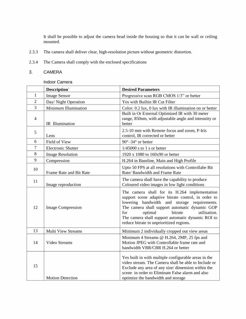
It shall be possible to adjust the camera head inside the housing so that it can be wall or ceiling
mounted.
2.3.3 The camera shall deliver clear, high-resolution picture without geometric distortion.
2.3.4 The Camera shall comply with the enclosed specifications
3. CAMERA
Indoor Camera
Description` Desired Parameters
1 Image Sensor Progressive scan RGB CMOS 1/3” or better
2 Day/ Night Operation Yes with Builtin IR Cut Filter
3 Minimum Illumination Color: 0.2 lux, 0 lux with IR illumination on or better
4
IR Illumination
Built in Or External Optimized IR with 30 meter
range, 850nm, with adjustable angle and intenstity or
better
5 Lens
2.5-10 mm with Remote focus and zoom, P-Iris
control, IR corrected or better
6 Field of View 90°–34° or better
7 Electronic Shutter 1/45000 s to 1 s or better
8 Image Resolution 1920 x 1080 to 160x90 or better
9 Compression H.264 in Baseline, Main and High Profile
10 Frame Rate and Bit Rate
Upto 50 FPS at all resolutions with Controllabe Bit
Rate/ Bandwidth and Frame Rate
11 Image reproduction
The camera shall have the capability to produce
Coloured video images in low light conditions
12 Image Compression
The camera shall for its H.264 implementation
support scene adaptive bitrate control, in order to
lowering bandwidth and storage requirements.
The camera shall support automatic dynamic GOP
for optimal bitrate utilisation.
The camera shall support automatic dynamic ROI to
reduce bitrate in unprioritized regions.
13 Multi View Streams Minimum 2 individually cropped out view areas
14 Video Streams
Minimum 4 Streams @ H.264, 2MP, 25 fps and
Motion JPEG with Controllable frame rate and
bandwidth VBR/CBR H.264 or better
15
Motion Detection
Yes built in with multiple configurable areas in the
video stream. The Camera shall be able to Include or
Exclude any area of any size/ dimension within the
scene in order to Eliminate False alarm and also
optimize the bandwidth and storage

16 Digital Auto tracking
The camera shall have Built in Capability to digitally
track the movements or Using Video Analytics
17 Pan Tilt Zoom Digital PTZ, Presets
18 Aspect Ratio
16:9 or 9:16 without change in image quality or
change in Image
19 Wide Dynamic Range 120 dB or Better
20 Privacy Masks Required
21 Event Triggers
A. The camera shall be able to send and received
trigger directly from any other camera without
interface of VMS.
B. Intelligent Video, Edge Storage Events, Software
Alarms, Camera Tampering, Intelligent Motion
Detection, Digital Autotracking, Edge Based
Analytics
22
Event Actions
File upload: FTP, HTTP, network share and email
Notification: email, HTTP and TCP
PTZ funtion, Edge Storage/ NAS Storage, Pre & Post
Alarm Recording, Actions configurable by web
interface, IR Illuminator on/off
23 Edge Storage
Built in SD card slot with support upto 128 GB with
Class 10 speed
24
Protocals
IPv4/v6, HTTP, HTTPS, SSL/TLS, QoS Layer 3
DiffServ, FTP, SFTP, CIFS/SMB, SMTP, Bonjour,
UPnPTM, SNMP v1/v2c/v3 (MIB-II), DNS,
DynDNS, NTP, RTSP, RTP, TCP, UDP, IGMP,
RTCP, ICMP, DHCP, ARP, SOCKS, SSH
25 Text Overlay
Date & time, and a customer-specific text, camera
name, graphical image etc
26
Security
Password protection, IP address filtering, HTTPS
encryption, IEEE 802.1X network access control,
Digest authentication, User access log, Centralized
certificate management
27 Firmware Upgrade
The firware upgrade shall be done though web
interface, The firmware shall be available free of cost
28 Memory
512 MB RAM, 256 MB Flash or better with Inhouse
processor
29 Interface RJ 45, 100 Base TX
30 Power requirements
Power over Ethernet IEEE 802.3af/802.3at Type 1
Class 3
31 Operating Temperature -30 °C to 50 °C
32 Operating Humidity 10–100% RH (condensing) or better
33 Casing IP66, IK10, PVC free
34 Certification
UL, CE, FCC, Shock and Vibration resistant
complying to IEC 60068-2-6, IEC 60068-2-27

35 Embedded Applications
The camera shall provide a platform allowing the
upload of third party applications into the camera
36
Application Programmers Interface
The interface shall be available for integration with
3rd party analytics and shall be available in public
domain free of Cost
37 Mount Wall/ Ceiling/ Surface
38 Onvif S & G Required
39 Warranty 2 Years OEM Warranty
360 Degree Camera
Parameter Detailed Specification
IMAGE SENSOR The camera shall use a 1/2.5-inch 5-Megapixel Array format (Active) 2592(H)
x 1944(V) CMOS digital image sensor
VIDEO RESOLUTION
Supported video resolutions shall include:
1/4MP (528x480)
1MP (1056x960)
2MP (1488x1360)
4MP (2144x1944)
Image Control
The camera shall incorporate:
Automatic exposure control
Automatic white balance (Range; 2500K~8000K)
50Hz and 60Hz mains frequency flicker control.
Sharpness control setting
EV compensation control setting
Wide dynamic range 60db
Compression The camera shall provide support for H.264 High Profile and Motion JPEG.
Lens and Lens Mount
Specifications
The camera shall use a 5 mega-pixel resolution lens or a integrated
combinations of lenses for customozed field of view with focal length of
1.6mm/ F2 .

Lens Mount The camera shall use a lens mount of M12x0.5 thread.
Certification
EMC to CISPR Class A
FCC
CE
ICES-003
Safety: CE, cUL and UL60950
Protocol Support The camera shall support the following IP protocols: TCP/IP, HTTP, DHCP,
DNS, NTP, FTP, STP, SMTP, Ipv4 (REC 791),uPnP
Transmission Speed The camera shall allow the transmission of images 10 frames per second (4MP
stream), using MJPEG and H.264 High Profile.
3D dwarping
The camera shall Provide client side ePTZ functionality ,using 3D dewarping
SDK Provide an 8x digital zoom capability when connected to a compatible
NVR that uses the client side dewarping.
SDK Support
The camera shall be supported (SDK), which shall provide necessary interface
for integration of functionality into third party software. This can provide
client side / NVR side 3D dewarping of both live and playback fisheye images.
The algorithm use to dewarp the fisheye images should be of Curvilinear type
Environmental
Specifications
The camera shall operate in the temperature range of 0°C to +40°C (-32°F to
104°F).
Electrical Specifications The camera shall have Power over Ethernet (PoE) capability, in accordance
with IEEE 802.3af Class 2 standard.
Power consumption Power consumption of the camera shall not be more than 5 watts (max).
Number of Clients Support for 20 users simultaneously
App Support The camera shall support an app based client side dewarping on any android /
apple / windows platform.

Privacy Masking 360 degree image in 2D .
Motion Detection At least individually configurable 16 zones
Mounting Details The OEM shall have option of recess mounts,Pendant Mount, Wall and
Ceiling mounts. All mounts have to be of the same make as camera.
Indoor Housing
The enclosure trim cover shall be manufactured from ABS. The bubble dome
accessory cover shall be designed and tested to meet the vandal resistance.
The bubble and trim ring for the vandal-proof cover shall be made of
polycarbonate polymers with UV inhibiters and shall be laser welded together.
Intelligent Recording The camera shall at all times continue to record the complete 360 degree
image irrespective of angle of view.
Intelligent Analysis
Based on the 360 degree recording irrespective of angle of view, client should
be able to dewarp the recorded image in any angle to have accurate forensic
analysis .
Dewarping in recorded
view
The media player should be able to 3D dewarp the recorded image of the AVI
format on the player itself for full proof forensic analysis.
Memory card Camera shall be support Micro SD card upto 128 GB.

Setup and Maintenance
The camera shall be supplied with Windows-based configuration software
which allows the assignment of IP addresses, multi-camera configuration,
backup of cameras configuration and upgrade of firmware and software.
Remotely change and configure camera IP settings / DHCP settings .
Remotely import / Export of IP settings.
Enable remote upgrade of camera firmware.
Ability to remotely send commands to the camera.
Remotely enter camera settings and values.
Event Functionality
The camera shall be equipped with an integrated event functionality, which
can be triggered by:
Video motion detection
Notification via HTTP
Image upload via FTP or SMTP
Record to SD card
Local Storage Server – Integrated VMS and Windows Based
Operating system Windows 2012 R2 or better
Power supply 1 x internal power supply
USB ports 3 x USB 2.0,
Network 1 x Gigabit Ethernet LAN
Bandwidth Support 320 Mbit/s
Supported cameras HD, Full HD, 5 MP& 4K resolution
Decoding
Compression
H.264,H.265 and MJPEG

Operating
temperature
0 °C to +40 °C
I/O 24 inputs and 6 relay outputs
Hard drives installed 4 x 6 TB Support and e SATA support
Graphics 2x HDMI ,, 1 x VGA
VMS 24 Channel pre licensed or better with analytics support
RAID Level Raid 5 or better
Operating
Temperature
+10 °C to +35 °C
Operating relative
humidity
8 to 90% (non-condensing)
SECTION-X: MEDIUM VOLTAGE 1.1 KV GRADE XLPE INSULATED PVC SHEATHED
CABLES
1. SCOPE
The MV cables shall be supplied, inspected, laid, tested and commissioned in accordance with
drawings, Specifications, relevant Standard Specifications and cable manufacturer's instruction.
2. STANDARDS AND CODES
2.1 Updated and current Indian Standard Specifications and Codes of Practice as stipulated below
shall apply to the equipments and the work covered in this section. In addition the relevant
clauses of the Indian Electricity Act 1910, Indian Electricity Rules 1956, National Building Code
1994, National Electric Code 1985, Code of Practice for Fire Safety of Building (general) :
General Principal and Fire Grading – IS 1641 as amended upto date shall also apply. Wherever
appropriate Indian Standards are not available, relevant British and/or IEC Standards shall be
applicable.
2.2 PVC insulated heavy duty cables IS 1554 - 1988
Cross link polyethylene insulated PVC (sheathed XLPE cables) IS 7098 - 1985
Code of practice for installation and maintenance of power cables IS 1255 - 1983
Conductors for insulated electrical cables IS 8130 - 1984
Drums for electrical cable IS 10418- 1982
Methods of test for cables IS 10810- 1988
Recommended current rating IS 3961 - 1987

Recommended short circuit rating of high voltage PVC cables IS 5891 - 1970
3. MATERIAL
3.1 The MV cables shall be cross linked polyethylene (XLPE) insulated PVC sheathed of 1100 volts
grade as asked for in the schedule of quantities. Cables upto 16 sq.mm shall be with copper
conductor and 25 sq.mm and above shall be with aluminium conductor.
3.1.1 TECHNICAL REQUIREMENTS:
All XLPE Aluminium/Copper Power cables shall be 1100 Volts grade, multi core constructed as per IS : 7098 Part-I of 1988 as follows :
a) Stranded Aluminium /Copper conductor in case of 10 sq.mm. and above and solid
conductor in case of 10 sq.mm. and below.
b) Cores laid up
c) The inner sheath should be bonded over with thermo-plastic material for protection against mechanical and electrical damage.
d) Armoring should be provided over the inner sheath to guard against mechanical damage. Armouring should be Galvanized steel wires or galvanized steel strips. (In single core cables used in A.C. system armouring should be non-magnetic hard aluminium Wires/Strips. Round steel wires should be used where diameter over the inner sheath does not exceed 13 mm; above 13 mm flat steel armour should be used. Round wire of different sizes should be provided against specific request.)
e) The outer sheath should be specially formulated heat resistant black PVC compound conforming to the requirement of type ST2 of IS : 5831-1984 extruded to form the outer sheath.
f) Conductor shall be of electrolytic Aluminium/Copper conforming to IS : 8130 and
are compact circular or compact shaped.
g) Insulation shall be of XLPE type as per latest IS general purpose insulation for maximum rated conductor temperature 70 degree centigrade.
h) In Inner sheath laid up cores shall be bonded over with thermoplastic material for
protection against mechanical and electrical damage.
i) Insulation, inner sheath and outer sheath shall be applied by extrusion and lapping up process only.
j) Armouring shall be of galvanized steel wire/flat.
k) Repaired cables shall not be used.
l) Current ratings of the cables shall be as per IS : 3961.

m) The XLPE insulated cables shall conform to latest revision IS read along with this specifications. The Conductor shall be stranded Aluminium/Copper circular/ sector shaped and compacted. In multi core cables the core shall be identified by red, yellow, blue and black coloring of insulation.
n) The XLPE insulated 1100 Volts grade power cables shall conform to latest IS and
shall be suitable for a steady conductor temperature of 70 degree centigrade. The conductor shall be stranded Aluminium/Copper as called for in the Schedule of quantities. The outer sheath shall be as per the requirement of type ST-2 of IS:5831 of 1984.
o) The cables shall be suitable for laying in racks, ducts, trenches, conduits and
underground buried installation with uncontrolled back fill and chances of flooding by water.
p) Progressive automatic in line sequential marking of the length of cables in meters at
every one meter shall be provided on the outer sheath of all cables.
q) Cables shall be supplied in non returnable wooden drums as per IS : 10418. Both ends of the cables shall be properly sealed with PVC/Rubber caps so as to
eliminate ingress of water during transportation, storage and erection.
r) The product should be coded as per IS :- 7098 Part-I as follows :- Aluminium Conductor A XLPE Insulation 2X Steel round wire armour W Steel strip armour F Steel Double round wire armour WW Steel Double strip armour FF Non-magnetic (Al.) round wire armour Wa Non-magnetic (Al.) strip armour Fa PVC outer sheath Y 4. INSPECTION
All cables shall be inspected by the contractor upon receipt at site and checked for any damage
during transit.
5. TESTING OF CABLES
5.1 Cables shall be tested at works for the following tests before being dispatched to site by the
project team.
a) Insulation Resistance Test.
b) Continuity resistance test.
c) Sheathing continuity test.
d) Earth test.(in armoured cables)
e) Hi Pot Test.

5.2 Test shall also be conducted at site for insulation between phases and between phase and earth
for each length of cable, before and after jointing. On completion of cable laying work, the
following tests shall be conducted in the presence of the Owner’s site representative.
a) Insulation Resistance Test( Sectional and overall)
b) Continuity resistance test.
c) Sheathing continuity test.
d) Earth test.
5.3 All tests shall be carried out in accordance with relevant Standard Code of Practice and
Electricity Rules. The Contractor shall provide necessary instruments, equipment and labour
for conducting the above tests and shall bear all expenses in connection with such tests. All
tests shall be carried out in the presence of the Owner’s site representative.
SECTION-XI: LT SWITCHBOARDS
1. GENERAL
This section covers specification of LT Switchboards
2 STANDARDS AND CODES
Updated and current Indian Standard Specifications and Codes of Practice will apply to the
equipment and the work covered by the scope of this contract. In addition the relevant clauses of
the Indian Electricity Act 2003, Indian Electricity Rules 1956, National Building Code 2005,
National Electric Code 1985, Code of Practice for Fire Safety of Building (general): General
Principal and Fire Grading – IS 1641 - 1988 as amended upto date shall also apply. Wherever
appropriate Indian Standards are not available, relevant British and/or IEC Standards shall be
applicable.
Low Voltage switchgear & controlgear IS/IEC 60947
Part I : General rules
Part II : Circuit Breakers
Part III : Switches, disconnectors ,Switch disconnectors and fuse combination units
Part IV : Contactors and Motor starters
Part V : Control circuit devices and switching elements
Marking of Switchgear busbars IS 11353 : 1985
Degree of Protection of Enclosures for low voltage switchgear. IEC 60529
Electrical relays for power system protection IS 3231 : 1986
Code of Practice for selection, installation
and Maintenance of switchgear & controlgear IS 10118 : 1982
Low voltage switchgear & controlgear assemblies IEC 60349
Danger notice plates IS 2551 : 1982

3. LT SWITCHGEAR
3.1 AIR CIRCUIT BREAKER
3.1.1 The ACB shall confirm to the requirements of IEC 60947-2 & 3 (FOR SWITCH
DISCONNECTION) / IS 13947-2 and shall be type tested & certified for compliance to
standards from–CPRI, ERDA/ any accredited international lab. The circuit breaker shall be
suitable for 415 V + 10%, 50 Hz supply system. Air Circuit Breakers shall be with moulded
housing flush front, draw out type and shall be provided with a trip free manual operating
mechanism or as indicated in drawings and bill of quantities with mechanical "ON" "OFF"
“TRIP” indications.
3.1.2 The ACB shall be 3/ 4 pole with modular construction, draw out, manually or electrically
operated version as specified. The circuit breakers shall be for continuous rating and service
short Circuit Breaking capacity (Ics) shall be as specified on the single line diagram and should
be equal to the Ultimate breaking capacity(Icu) and short circuit withstand values(Icw) for 1 sec.
Circuit breakers shall be designed to ‘close' and `trip' without opening the circuit breaker
compartment door. The operating handle and the mechanical trip push button shall be at the
front of the breakers panel. Inspection of main contacts should be possible without using any
tools. The ACB shall be provided with a door interlock. i.e. door should not be open when circuit
breaker is closed and breaker should not be closed when door is open. However, door interlock
should have defeat mechanism for on line testing of ACB
3.1.3 All current carrying parts shall be silver plated and suitable arcing contacts with proper arc
chutes shall be provided with to protect the main contacts. The ACB shall have double
insulation (Class-II) with moving and fixed contacts totally enclosed for enhanced safety and in
accessibility to live parts. All electrical closing breaker shall be with electrical motor wound
stored energy spring closing mechanism with mechanical indicator to provide ON/OFF status of
the ACB.
3.1.4 The auxiliary contacts blocks shall be so located as to be accessible from the front. The
auxiliary contacts in the trip circuits shall close before the main contacts have closed. All other
contacts shall close simultaneously with the main contacts. The auxiliary contacts in the trip
circuits shall open after the main contacts open . Minimum 4 NO and 4 NC auxiliary contacts
shall be provided on each breaker. Rated insulation voltage shall be 1000 volts AC.
ACB shall confirm compliance to ROHS/WEEE guidelines.
3.2 CRADLE
3.2.1 The cradle shall be so designed and constructed as to permit smooth withdrawal and insertion of
the breaker into it. The movements shall be free from jerks, easy to operate and shall be on steel
balls/rollers and not on flat surfaces.
3.2.2 There shall be 4 distinct and separate position with self locking arrangement of the circuit
breaker on the cradle.
3.2.3 Racking Interlock in Connected/Test/Disconnected Position.
Service Position : Main Isolating contacts and control contacts of the breaker
are engaged.

Test Position : Main Isolating contacts are isolated but control contacts
are still engaged.
Isolated Position : Both main isolating and control contacts are isolated.
3.2.4 There shall be provision for locking the breaker in any or all of the first three positions.
The following safety features shall be incorporated :
a) Withdrawal or engagement of Circuit breaker shall not be possible unless it is in open
condition.
b) Operation of Circuit breaker shall not be possible unless it is fully in service, test or drawn
out position.
c) All modules shall be provided with safety shutters operated automatically by movement of
the carriage to cover exposed live parts when the module is withdrawn.
d) All Switchgear module front covers shall have provision for locking.
e) Switchgear operating handles shall be provided with arrangement for locking in ‘OFF’
position.
3.3 PROTECTIONS
3.3.1 The breaker should be equipped with micro-controller based release to offer accurate and
versatile protection with complete flexibility and shall offer complete over current protection to
the electrical system in the following four zones :
a) Long time protection.
b) Short time protection with intentional delay.
c) Instantaneous protection.
d) Ground fault protection.
3.3.2 The protection release shall have following features and settings:
3.3.2.1 True RMS Sensing
The release shall sample the current at the rate of 16 times per cycle to monitor the actual load
current waveform flowing in the system and shall monitor the true RMS value of the load current.
It shall take into account the effect of harmonics also.
3.3.2.2 Thermal Memory
When the breaker shall reclose after tripping on overload, then the thermal stresses caused by the
overload if not dissipated completely, shall get stored in the memory of the release and this
thermal memory shall ensure reduced tripping time in case of subsequent overloads. Realistic
Hot/Cold curves shall take into account the integrated heating effects to offer closer protection to
the system.
3.3.2.3 Defined time-current characteristics :
A variety of pick-up and time delay settings shall be available to define the current thresholds and
the delays to be set independently for different protection zones thereby achieving a close-to-ideal
protection curve.

3.3.2.4 Trip Indication
Individual fault indication for each type of fault should be provided by LEDs for faster fault
diagnosis.
3.3.2.5 Self powered
The release shall draw its power from the main breaker CTs (hog slay type) and shall require no
external power supply for its operation.
3.3.2.6 Zone Selective Interlocking
The release shall be suitable for communication between breakers to enable zone selective
interlocking. This feature shall be provided for both short circuit and ground fault protection
zones to offer total discrimination between breakers. This feature enables faster clearance of fault
conditions, thereby reducing the thermal and dynamic stresses produced during fault conditions
and thus minimizes the damage to the system. To implement ZSI manufacturer should supply all
related equipment like power supply, wiring etc. On-Line change of settings should be possible. It
should be possible to carry out testing of release without tripping the breaker.
3.3.2.7 The release shall meet the EMI / EMC requirements.
3.3.2.8 Derating factor- There shall not be any derating up to 50 degree. Manufactures shall provided
the derating table/chart
3.3.2.9 4P ACB shall have 100% Neutral as same of Phase conductor with protection setting (setting of
50%,100% and Off)
3.3.2.10 ACB release shall have 1st –ON/OFF setting to co-ordinate with HT breakers.
3.3.2.11 ACB release shall have inbuilt “Auto protection” against excessive heating at terminals.
3.3.2.12 Combined accuracy (Sensor + Release) ≤ 1.5% as per IEC 61557-
3.3.2.13 The setting range of release shall be as follows as per SLD :
3.3.2.14 The release should provide local indication of actual %age loading of individual phase at any
instant. The release should be able to communicate on MODBUS RTU protocol using inbuilt
RS485 port and shall be integral part of supply with trip unit. Parameters of the Protection
Release should be changeable from Release as well as thru communication network. Release
thru dial type potentiometer and navigation keys & should have graphical LCD for display of
power parameters. The release should provide comprehensive metering as per mentioned in
SLD.
3.1 SAFETY FEATURES
a) The safety shutter shall prevent inadvertent contact with isolating contacts when breaker is
withdrawn from the Cradle.

b) It shall not be possible to interchange two circuit breakers of two different thermal ratings.
For Draw-out breakers, an arrangement shall be provided to prevent rating mismatch between
breaker and cradle.
c) There shall be provision of positive earth connection between fixed and moving portion of the
ACB either thru connector plug or sliding solid earth mechanism. Earthing bolts shall be provided
on the cradle or body of fixed ACB.
d) The incoming panel accommodating ACB shall be provided with indicating lamps for ON-OFF
positions, digital voltmeter and ammeter of size not less than 96 mm x 96 mm, selector switches,
MCB for protection circuit and measuring instrument circuits.
e) It shall be possible to bolt the drawout frame not only in connected position but also in TEST and
DISCONNECTED position to prevent dislocation due to vibration and shocks.
f) Drawout breakers should not close unless in distinct Service/Test/Isolated positions.
g) The insulation material used shall conform to Glow wire test as per IEC60695.
h) The ACB shall provide in built electrical and mechanical anti-pumping.
i) All EDO ACB`s Shall have Ready to Close Contact to ensure that the ACB gets a command only
when it is ready to close for applications of Remote Control, AMF, Synchronization and Auto
Source Change Over Systems.
3.4 MOULDED CASE CIRCUIT BREAKER (MCCB)
3.4.1 The MCCB should be current limiting type with trip time of less than 10 msec under short circuit
conditions. The MCCB should be either 3 or 4 poles as specified in BOQ. MCCB shall comply
with the requirements of the relevant standards IEC 60947-2 and should have test certificates for
Breaking capacities (Ics=Icu=100%) from independent test authorities CPRI / ERDA or any
accredited international lab.
3.4.2 MCCB shall comprise of Quick Make -break switching mechanism, arc extinguishing device and
the tripping unit shall be contained in a compact, high strength, heat resistant, flame retardant,
insulating moulded case with high withstand capability against thermal and mechanical stresses
3.4.3 The breaking capacity of MCCB shall be as specified in the schedule of quantities. The rated
service breaking capacity (Ics) should be equal to rated ultimate breaking capacities (Icu).
MCCBs for motor application should be selected in line with Type-2 Co-ordination as per IEC-
60947-2, 1989/IS 13947-2. The breaker as supplied with ROM should meet IP54 degree of
protection.
3.4.5 MCCB shall be suitable for positive Isolation as per IEC 60947-2
3.4.6 MCCB shall comply with “Class-II front facia as per IEC 61140”
3.4.7 MCCB shall be provided with continuously ratio coils.
3.4.8 MCCB shall have cross bolted termination.

3.2 Current Limiting & Coordination 3.5.1 The MCCB shall employ maintenance free minimum let-through energies and capable of
achieving discrimination up to the full short circuit capacity of the downstream MCCB. The manufacturer shall provide both the discrimination tables and let-through energy curves for all. It shall be responsibility of Panel builder & OEM to carry out the discrimination study at the time of drawing approval.
3.5.2 Protection Functions
3.5.2.1 MCCBs with ratings up to 250 A shall be equipped with Thermal-magnetic (thermal for overload and magnetic for short-circuit protection) trip units
3.5.2.2 Microprocessor MCCBs with ratings 250A and above shall be equipped with microprocessor based trip units. (both variable setting)
3.5.2.3 Microprocessor and thermal-magnetic trip units shall be adjustable and it shall be possible to fit lead seals to prevent unauthorized access to the settings
3.5.2.4 Microprocessor trip units shall comply with appendix F of IEC 60947-2 standard (measurement of rms current values, electromagnetic compatibility, etc.)
3.5.2.5 Protection settings shall apply to all poles of circuit breaker. 3.5.2.6 All Microprocessor components shall withstand temperatures up to 125 °C
3.6 Testing
a) Original test certificate of the MCCB as per IEC 60947-1 &2 or IS13947 shall be furnished.
b) Pre-commissioning tests on the switch board panel incorporating the MCCB shall be done as per standard specifications.
3.7 Interlocking
3.7.1 Moulded, case circuit breakers shall be provided with the following interlocking devices
for interlocking the door of a switch board.
a) Handle interlock to prevent unnecessary manipulations of the breaker.
b) Door interlock to prevent the door being opened when the breaker is in ON position.
c) Defeat-interlocking device to open the door even if the breaker is in ON position.
d) The MCCB shall be current limiting type and comprise of quick make – Break switching mechanism. MCCBs shall be capable of defined variable overload adjustment. All MCCBs rated 250 Amps and above shall have adjustable over load & short circuit pick-up both in Thermal magnetic and Microprocessor Trip Units.
e) All MCCB with microprocessor based release unit, the protection shall be adjustable Overload, Short circuit and earth fault protection with time delay.
f) The trip command shall override all other commands.
3.8 MOTOR PROTECTION CIRCUIT BREAKER (MPCB)
3.8.1 Motor circuit breakers shall conform to the general recommendations of standard IEC 60947 -1,2
and 4 (VDE 660, 0113 NF EN 60 947-1-2-4, BS 4752). The devices shall be in utilization
category A, conforming to IEC 947-2 and AC3 conforming to IEC 60947-4.MPCB shall have a
rated operational and insulation voltage of 690V AC (50 Hz) and MPCB shall be suitable for
isolation conforming to standard IEC 60947-2 and shall have a rated impulse withstand voltage
(Uimp) of 6 kV. The motor circuit breakers shall be designed to be mounted vertically or
horizontally without de-rating.
3.8.2 Power supply shall be from the top or from the bottom. In order to ensure maximum safety, the
contacts shall be isolated from other functions such as the operating mechanism, casing, releases,
auxiliaries, etc, by high performance thermoplastic chambers. The operating mechanism of the
motor circuit breakers must have snap action opening and closing with free tripping of the control
devices. All the poles shall close, open, and trip simultaneously. The motor circuit breakers shall
accept a padlocking device in the “isolated” position.
3.8.3 The motor circuit breakers shall be equipped with a “PUSH TO TRIP” device on the front
enabling the correct operation of the mechanism and poles opening to be checked. The auxiliary
contacts shall be front or side mounting, and both arrangements shall be possible. The front-
mounting attachments shall not change the breaker surface area. Depending on its mounting
direction the single pole contact block could be NO or NC. All the electrical auxiliaries and
accessories shall be equipped with terminal blocks and shall be plug-in type. The motor circuit
breakers shall have a combination with the downstream contactor enabling the provision of a
perfectly coordinated motor-starter. This combination shall enable type 1 or type 2 co-ordination
of the protective devices conforming to IEC 60947-4-1.Type 2 co-ordination shall be guaranteed
by tables tested and certified by an official laboratory: LOVAG (or other official laboratory). The
motor circuit breakers, depending on the type, could be equipped with a door-mounted operator
which shall allow the device setting. The motor circuit breakers shall be equipped with releases
comprising a thermal element assuring overload protection and a magnetic element for short-
circuit protection. In order to ensure safety and avoid unwanted tripping, the magnetic trip
threshold (fixed) shall be factory set to an average value of 12 Ir. All the elements of the motor
circuit breakers shall be designated to enable operation at an ambient temperature of 60°C
without de-rating. The thermal trips shall be adjustable on the front by a rotary selector. The
adjustment of the protection shall be simultaneous for all poles. Phase unbalance and phase loss
detection shall be available.
3.9 SURGE PROTECTION DEVICES ( SPD’S)
3.9.1 System
Surge Protection Devices ( SPD’S) shall be provided at main LT Panel incoming feeders (Stage
I / Class B) & Distribution Boards (Stage II / Class C) for the protection of Building electrical and
Electronics system from the effect of Lightning discharges, line induced transient surge voltage or
switching surges as per the details mentioned in the BOQ.
3.9.2 CODES & STANDARDS
3.9.2.1 The following standards & publications as referred in the various parts of this Specification shall
apply.

IEC-61643-11, IEC-61643-12
IEC 60 364 – 5 – 5 53
IEC 62 305 – 4
3.10 PRODUCT SPECIFICATIONS
3.10.1 Surge Protector at Stage I / Class B (L T Panel Protector)
The Surge Protection Device (SPD) manufacturer shall offer a complete line of Surge Protection
Devices to support the requirements for Main LT Panel Incoming feeders. The surge protector at
this stage shall be provided to protect the down stream electrical and electronics against any
lightning discharges surges that may enter into the system through Mains panel. The Protection
unit shall be based on single arc spark gap technology and shall be able to withstand 10/350
microsecond surge currents associated with external lightning discharges.
3.10.2 Protection Network Configuration:
3.10.2.1 The work required under this section consists of furnishing, installing and connecting SPD
device as specified and as asked for in BOQ. The SPD device shall be installed in a NETWORK
configuration, consisting of one set of SPD panel device at the service entrance of switchboard.
All SPD devices in this network configuration shall be of same manufacturer. All SPD device
shall be modular, mountable on 35 mm DIN rail. Unit status indicator shall be provided to
indicate the status of complete Protection unit.
3.10.2.2 Protection shall be manufactured for the specific type and voltage of the electrical Service and
shall provide clamping for both normal (L-N) and common (N-G) mode operation. Protection
shall be manufactured to withstand a maximum continuous operating voltage of not less than
115% of normal RMS Line voltage of 240 V.
3.10.2.3 The Protection shall be provided with safety MCB’s to be connected in series between Line/s to
neutral & neutral to earth as per the TNS configuration of wiring. It shall be testable on line for
routine maintenance, module failure and in order to prevent catastrophic failure modes. Protection
shall be a fail-safe type device, shall have a follow through current quenching capacity upto 25
KA r.m.s., shall have repeated surge capability state, shall be self restoring and be fully automatic
in all mode of operation. Protection shall comply with IEC 61643 and shall be approved for the
location in which they are listed. Protection shall have an operating temperature ranges from -
20oC to 60
oC.
3.10.3 Protection Criteria
a) The maximum continuous operating voltage (Rated Voltage) for SPD devices connected to
phase-neutral shall not be less than the values shown in table:
Nominal Voltage Rating per phase Maximum Continuous Operating
Voltage
(Vrms) (Vrms)
240 320
b) Listing
c) The surge protective device and associated hardware must comply with IEC 61643-11.
d) The Protection voltage of the complete rail mount surge protective device shall be type test to the
figures as indicated in table below, which must not exceed the values shown.

Service Voltage / per phase Protection Voltage @ In (Nominal
discharge current) / Protection Level
240 V < 2.5 k V (between Line to Neutral)
1.5 kV (between Neutral to Earth)
e) Surge protective device application at Low Voltage AC main LT Panel incoming feeder surge
impulse current withstanding capacity as shown in table below.
Application Panel Location Max. Single Withstand Surge Current
(of 10/350 μs Impulse)
Service Entrance (Main LT Panel) 25 KA, 10/350μs (between Line to
Neutral 100 KA, 10/350
(between neutral to Earth)
f) Compliance to this specification must be provided in the form of a certificate from an
independent testing laboratory.
g) Response time of stage-I class –B arrester should not be < 100 ns.
3.10.4 Surge protector at Stage II / Class C (Final Distribution Board Protector)
3.10.4.1 The surge Protection manufacturer shall offer a complete line of surge Protection product to
support the requirements for the Distribution Board. The surge protector at this stage shall be
provided to protect the down stream electrical and electronics against any induced switching
surges that may be passed on to the down stream electrical & electronic system.
3.10.4.2 The Protection unit shall be based on Single High Capacity Metal Oxide Varistors (MOV),
capable of handling 8/20 μs surges and shall be able to give an indication in the event module
failure and be pluggable to facilitate the in-service replacement without distributing the lines.
One extra set of replacement module shall be furnished to the job site.
3.10.4 Protection Network Configuration. The work required under this section consists of furnishing,
installing and connecting SPD device as specified and as shown in the drawings. The SPD device
shall be installed in a NETWORK configuration, consist of one set of SPD panel device at the
service entrance of switchboard. All SPD device in this network configuration shall be of same
manufacturer. All SPD device shall be modular, mountable on 35 mm DIN rail and be field
replaceable without interruption of electrical distribution circuit.
3.10.4.1 Unit status indicator shall be provided to indicate the status of complete Protection unit on the
product as well as provision for remote indication must be provided.
Protection shall be manufactured for the specific type and voltage of the electrical Service and
shall provide clamping for both normal (L-N) and common (N-G) mode operation.
3.10.4.2 Protection shall be manufactured to withstand a maximum continuous operating voltage of not
less than 115% of normal RMS Line voltage of 240 VAC.
3.10.4.3 The Protection shall be provided with internal safety fusing if required, to be connected in
parallel between Line/s to neutral & neutral to earth as per the TNS configuration of wiring. It

shall be testable on line for routine maintenance, module failure and in order to prevent
catastrophic failure modes.
3.10.4.4 Protection shall be a fail-safe type device, shall have no follow through current shall have
repeated surge capability, shall be solid state, shall be self restoring and be fully automatic in all
mode of operation. It shall have thermal disconnection and indication against overloading of the
device.
3.10.4.5 Protection shall comply with IEC 61643 standards.
3.10.4.6 Protection shall have an operating temperature ranges from -20oC to + 60
oC.
3.11 Protection Criteria
3.11.1 The maximum continuous operating voltage (Rated voltage) for SPD devices connected to phase-
neutral shall not be less than the values as shown in table below:
Nominal Voltage Rating per phase Maximum Continuous Operating
Voltage
(Vrms) (Vrms)
120 150
240 320
350 440
480 600
3.12 Listing
3.12.1 The surge protective device and associated hardware must comply with IEC 61643-11.
3.12.2 The Protection voltage of the complete rail mount surge protective device shall be type test to the
figures as indicated in table below, which must not exceed the values shown.
Service Voltage / per phase Protection Voltage @ In (Nominal
discharge current) / Protection Level
240 V 1500 V
3.12.3 Nominal Withstand Surge Current.
3.12.3.1 Surge Protective device (including all fusing and over current protection) for application at sub-
Distribution Panels shall have a Nominal surge current withstand capacity as shown in table
below. The failure or operation of any fuse / over – current device during the test is not
permissible.
Application Panel Location Max. Single Withstand Surge Current
Of 8/20 µs Impulse)
Sub-Distribution Panel
Final Distribution Board
10KA for 8 / 20 μs
(between Line to Neutral)
25 KA for 10/350 μs
(between Neutral to Earth)

3.12.3.2 Compliance to this specification must be provided in the form of a certificate from an
independent testing laboratory.
3.12.3.3 Response time of Class C arrestor should not be <25 ns.
4. SWITCHBOARDS
1 General
1.1 Switchboards shall be suitable for operation at three phase 4 wire, 415 volt, 50 Hz, neutral solidly
grounded at transformer system with a short circuit level withstand as per schedule of quantities
and drawings.
1.2 Switchboards shall comply to Form 3B for compartmentalized boards and Form 1 for non
compartmentalized boards as per BS 5486 Part I – 1990 and IEC 439-1
1.3 The enclosures shall be designed to take care of normal stress as well as abnormal electro-
mechanical stress due to short circuit conditions. All covers and doors provided shall offer
adequate safety to operating persons and provide ingress protection of IP 54 unless otherwise
stated. Ventilating openings and vent outlets, if provided, shall be arranged such that same ingress
protection of IP 54 is retained. Suitable pressure relief devices shall be provided to minimize
danger to operator during internal fault conditions.
1.4 Entire switchgear used in switchboards shall be completely fuse free. No fuses shall be used
anywhere in the installation.
1.5 All accessible bares terminals shall be provided with integral shrouds and shall be finger touch
proof.
1.6 Bimetallic connectors shall be provided for termination of cable with aluminium conductors on
copper bus bars.
2 Switchboard Configuration
2.1 The Switchboard shall be configured with Air Circuit Breakers, MCCB's, and other equipment as
called for in the schedule of quantities.
2.2 The MCCB's shall be arranged in multi-tier formation whereas the Air Circuit Breakers shall be
arranged in Single or Double tier formation only to facilitate operation and maintenance.
2.3 The Switchboards shall be of adequate size with a provision of 25% spare space to accommodate
possible future additional switch gear.
3 Equipment Specifications
All equipment used to configure the Switchboard shall comply to the relevant Standards and Codes of the Bureau of Indian Standards and to the detailed technical specifications as included in this tender document.
4 Constructional Features
4.1 The Switchboards shall be metal clad totally enclosed, floor mounted free standing type of
modular extensible design suitable for indoor mounting. The Switchboards shall be designed for a
temperature rise restricted to 40 Deg C above ambient of 45 Deg C
4.2 Switchboards shall be either compartmentalized or non compartmentalized as stipulated in
schedule of quantities.
4.3 Switchboards shall be made up of requisite vertical sections, which when coupled together, shall
for continuous dead front switchboards.
4.4 Switchboard shall be readily extensible on both sides by addition of vertical sections after
removal of the end covers.
4.5 The switchboards shall be designed for use in high ambient temperature and humid tropical
conditions as specified. Ease of inspections, cleaning and repairs while maintaining continuity of
operation shall be provided in the design.
4.6 Metal based neoprene gaskets between all adjacent units and beneath all covers shall be provided
to render the joints dust and vermin proof to provide a degree of protection of IP 54 as stipulated
in schedule of quantities .
4.7 ‘U’ Channels forming switchboard frames shall be fabricated from 2.5 mm thick electro
galvanized MS sheets. All joints shall be neatly formed and finished flush with adjacent surfaces
by grinding. No joints shall be located in corners. Bare edges shall be lipped. Structural
members and bracings where ever required shall be welded or bolted to the frame. The frame
shall be of modular design and extensible.
4.8 All doors and covers shall also be fully gasketed with metal based neoprene gaskets with fastners
designed to ensure proper compression of the gaskets. The hinged door shall open a maximum of
1500. All hinged doors shall have earth braid connected to the cubicle. Good quality door handles
fitted with toggles to operate rods to latch with suitable slots in both top and bottom of
switchboards shall be provided. Latching rods and associated brackets shall be cadmium plated.
4.9 Each vertical section shall be provided with a rear side cable chamber housing the cable end
connections and power/control cable terminations. There should be generous availability of
space for ease of installation and maintenance with adequate safety for working in one vertical
section without coming into contract with any liver parts.
4.10 Switchboard panels and cubicles shall be fabricated with CRCA Sheet Steel of thickness not less
than 2.0 mm and shall be folded and braced as necessary to provide a rigid support for all
components. The doors and covers shall be fabricated from CRCA sheet steel of thickness not
less than 1.6 mm. Joints of any kind in sheet metal shall be seam welded and all welding slag
ground off and welding pits wiped smooth with plumber metal.
4.11 All panels and covers shall be properly fitted and square with the frame. The holes in the panel
shall be correctly positioned.
4.12 Fixing screws shall enter holes tapped into an adequate thickness of metal or provided with hank
nuts. Self threading screws shall not be used in switchboards.

4.13 All electrical contacts between dissimilar metals (eg.. aluminium conductor of cables connected
to copper terminals of breakers etc..) shall be through bimetallic connection
5 Switchboard Dimensional Limitations
5.1 A base channel 75 mm x 5 mm thick shall be provided at the bottom.
5.2 A minimum of 200 mm blank space between the floor of switchboard and bottom most unit shall
be provided.
5.3 The overall height of the switchboard shall be limited to 2300 mm unless otherwise stipulated.
5.4 The height of the operating handle, push buttons etc shall be restricted between 300 mm and 2000
mm from finished floor level.
6 Switchboard Compartmentalization
6.1 For compartmentalized switchboards, separate totally enclosed compartments shall be provided
for horizontal busbars, vertical busbars, ACBs, MCCBs and cable alleys.
6.2 Earthed metal or insulated shutters shall be provided between drawout and fixed portion of the
switchgear such that no live parts are accessible with equipment drawn out. Degree of protection
within compartments shall be atleast IP 4X.
6.3 Sheet steel hinged lockable doors for each separate compartment shall be provided and duly
interlocked with the breaker in "ON" and "OFF" position.
6.4 For all Circuit Breakers separate and adequate compartments shall be provided for
accommodating instruments, indicating lamps, control contactors and control MCB etc. These
shall be accessible for testing and maintenance without any danger of accidental contact with live
parts of the circuit breaker, busbars and connections.
6.5 Each switchgear cubicles shall be fitted with label in front and back identifying the circuit,
switchgear type, rating and duty. All operating device shall be located in front of switchgear only.
Minimum height from floor level for any device mounted on panel cover shall be 250 mm.
6.6 A horizontal wire way with screwed cover shall be provided at the top to take interconnecting
control wiring between vertical sections.
6.7 Separate cable compartments running the height of the switchboard in the case of front access
boards shall be provided for incoming and outgoing cables.
6.8 Cable compartments shall be of adequate size for easy termination of all incoming and outgoing
cables entering from bottom or top.
6.9 Adequate and proper support shall be provided in cable compartments to support cables.
7 Spare Provision
25% spare cubicles/space shall be provided in all switchboards to cater for future use.

7 Switchboard Bus Bars
8.1 Busbars shall be made of high conductivity, high strength aluminium alloy, complying with
requirements of grade E 91E of IS 5082 – 1981. Design of busbar system shall comply to IS
5578 and IS 11353. Busbars shall be of rectangular cross sections suitable for full load current for
phase bus bars as also neutral bus bar . The maximum current density shall be 1 amp per Sq. mm.
Busbar shall be suitable to withstand the stresses of fault level as specified in schedule of
quantities.
8.2 Bus bars shall be insulted with heat shrunk PVC sleeving of 1.1 kV grade and bus bar joints
provided with clip-on shrouds.
8.3 The bus bars shall be extensible on either side of the switchboard.
8.4 The bus bars shall be supported on non-breakable, non-hygroscopic epoxy resin or glass fiber
reinforced polymer insulated supports able to withstand operating temperature of 110O C at
regular intervals, to withstand the forces arising from a fault level of 31 MVA at 415 volts for 1
second or as stipulated in schedule of quantities.
8.5 All bus bars shall be colour coded.
8.6 Auxiliary buses for control power supply, space heater power supply or any other specified
service shall be provided. these buses shall be insulated, adequately supported and sized to suit
specific requirement. The material for auxiliary supply bus will be electrolytic copper.
8.7 Additional cross sectional area to be added to the bus bar to compensate for the holes.
9 Switchboard Interconnection
9.1 All connection and tap offs shall be through adequately sized connectors appropriate for fault
level at location. This shall include tap off to feeders and instrument/control transformers.
Alternatively current limiters of approved make and type shall be used.
9.2 For unit ratings upto 100 amps, PVC insulated copper conductor wires of adequate size to carry
full load current shall be used. The terminations of such interconnections shall be crimped. Solid
connections shall be used for all rating of 100 amps and above.
9.3 All connections, tappings, clamping, shall be made in an approved manner to ensure minimum
contact resistance. All connections shall be firmly bolted and clamp with .even tension. Before
assembly joint surfaces shall be filed or finished to remove burrs, dents and oxides and silvered to
maintain good continuity at all joints. All screws, bolts, washers shall be cadmium plated.
9.4 Approved spring washers shall be used with cadmium plated high tensile steel bolts with BSF
threads.
9.5 All connectivity and tap offs shall have bimetallic connectors as required, finger touch proof
terminals & integral switchgear shrouds.

10 Drawout Features
10.1 Air Circuit Breakers shall be provided in fully drawout cubicles, unless otherwise stated. These
cubicles shall be such that drawout is possible without disconnection of the wires and cables. The
power and control circuits shall have self aligning and self isolating contacts.
10.2 The fixed and moving contacts shall be easily accessible for operation and maintenance.
Mechanical interlocks shall be provided on the drawout cubicles to ensure safety and compliance
to relevant Standards. The MCCB's shall be provided in fixed type cubicles.
10 Instrument Accommodation
11.1 Instruments and indicating lamps shall not be mounted on the Circuit Breaker Compartment door
for which a separate and adequate compartment shall be provided and the instrumentation shall be
accessible for testing and maintenance without danger of accidental contact with live parts of the
Switchboard.
11.2 For MCCB's instruments and indicating lamps can be provided on the compartment doors.
11.2.1 The current transformers for metering and for protection shall be mounted on the solid
copper/aluminium busbars with proper supports.
11 Wiring
11.1 All wiring for relays and meters shall be with PVC insulated copper conductor wires. The wiring
shall be coded and labelled with approved ferrules for identification. The minimum size of copper
conductor control wires shall be 2.5 sq. mm.
11.2 Wiring shall be terminated with ferrules on terminal block. CTs shall be provided with shorting
facilities
12 Cable Terminations
12.1 Knockout holes of appropriate size and number shall be provided in the Switchboard in
conformity with the location of incoming and outgoing conduits/cables.
12.2 The cable terminations of the Circuit Breakers shall be brought out to terminal cable sockets
suitably located in the cable chamber
12.3 The cable terminations for the MCCB's shall be brought out to the rear in the case of rear access
switchboards or in the cable compartment in the case of front access Switchboards.
12.4 The Switchboards shall be complete with tinned brass cable sockets, tinned brass compression
glands, gland plates, supporting clamps and brackets etc for termination of 1100 volt grade
aluminium conductor XLPE cables.
12.5 Removable gland plates shall be provided for power and control cables. The gland plates shall be
3 mm thick and for single core cables shall be of non magnetic material.
13 Space Heaters

Anti- condensation heaters shall be fitted in each cubicle together with an ON/OFF isolating
switch suitable for electrical operation at 230 volts A.C 50 Hz single phase of sufficient capacity
to raise the internal ambient temperature by 5O
C. The electrical apparatus so protected shall be
designed so that the maximum permitted rise in temperature is not exceeded if the heaters are
energized while the switchboard is in operation. As a general rule, the heaters shall be placed at
the bottom of the cubicle.
14 Ventilation Fans
The Switchboard shall be provided with panel mounting type ventilation fans in each panel with
switchgear rated for 2500 amp and above. The fan shall be interlocked with switchgear operation.
If ventilation fans cannot be provided for maintaining the required degree of ingress protection,
the design of switch board cubical shall incorporate suitable measures like decreasing current
density of conductors, increasing cubical volume for effective heat dissipation etc. in order to
restrict temperature rise to within the required limit.
15 Earthing
Continuous internal copper earth bus sized for prospective fault current to be provided with
arrangement for connecting to station earth at two points. Hinged doors / frames to be connected
to earth through adequately sized flexible braids.
16 Sheet Steel Treatment And Painting
Sheet steel used in the fabrication of switchboards shall undergo a rigorous cleaning and surface
treatment nine tank process comprising of alkaline degreasing, descaling in dilute sulphuric acid
and a recognised phosphating process after which a coat of primer paint compactively with the
final paint shall be applied over the treated surface. Final paint coat of oven baked powder
coating, of minimum 50 micron thickness, of sheet approved by Architects/Owners shall then be
provided.
17 Name Plates And Labels
Suitable engraved white on black name plates and identification labels of metal for all
Switchboards and Circuits shall be provided. These shall indicate the feeder number and feeder
designation.
18 Local Authorities Requirement
18.1 All other requirements by the local Authority that are imposed in course of execution of the work,
particularly those listed below shall be provided.
a) Danger Signs
b) Rubber floor mat of 10 m thickness and 1 m width provided for t he full length of the
switchboard.
c) A dry chemical type fire extinguisher of 9 kg capacity with approved label
d) Framed single line diagram with minimum A1 size
e) First Aid Demonstration sign.
19 CPRI TESTING

Switchboard configurations offered shall be CPRI tested. Copies of the CPRI test certificates
shall be submitted with the tender.
20 TESTING AT WORKS
Copies of type test carried out at ACB/MCCB manufacturers works and routine tests carried out
at the switchboard fabricators shop shall be furnished along with the delivery of the switchboards.
Architects/Owners reserves the right to get the switchboard inspected by their representative at
fabricators works prior to dispatch to site to witness the routine tests
21 INSTALLATION
21.1 The foundations prepared as per the manufacturers drawings shall be leveled, checked for
accuracy and the Switchboard installed. All bus bar connections shall be checked with a feeler
gauge after installation. The cable end boxes shall be sealed to prevent entry of moisture. The
main earth bar shall be connected to the sub-station earths.
21.2 Antistatic rubber matting of approved make conforming to IS 5424 – 1983, of minimum 1000
mm width 10 mm thickness shall be provided in front of and along the full length of the
Switchboard. The rubber mat shall withstand 15 KV for 1 minute and leakage current shall not
exceed 160 mA/sq. metre.
21.3 After installation the Switchboard shall be tested as required prior to commissioning.
22 TESTING AT SITE
22.1 Pre-commissioning tests as required and as per manufacturers recommendations shall be carried
out on each switchboards at site before energizing the switchboards including but not restricted to
the following.
a) Physical checking of the switchboards including checking alignment of panels, interconnection of
Bus bars, tightness of bolts/connections and evidence of damage/cracks in any components.
b) Physical checking and inspections of Inter panel wiring
c) Checking free movement of ACBs/MCCBs/SFUs
d) Checking of operation of breakers
e) Insulation tests of bus bar supports and control wiring etc. with 1.1 kV megger.
f) Primary & secondary injection tests of relays and CTs.
g) Checking of Interlocking function.
METERING EQUIPMENTS
1. GENERAL
This section covers specifications for Protection and Control Relays for breakers, Instrument
Transformers, Measuring Instruments, Push Buttons, Indicating Lamps etc. required in LT and
HT switchboards.
2. STANDARDS AND CODES

Updated and current Indian Standard Specifications and Codes of Practice will apply to the
equipment and the work covered by the scope of this contract. In addition the relevant clauses of
the Indian Electricity Act 2003, Indian Electricity Rules 1956, National Building Code 1994,
National Electric Code 1985, Code of Practice for Fire Safety of Building (general) :General
Principal and Fire Grading – IS 1641 as amended upto date shall also apply. Wherever
appropriate Indian Standards are not available, relevant British and/or IEC Standards shall be
applicable.
Application guide for Current Transformers IS 4201 :
Application guide for Voltage Transformers IS 4140 :
Application guide for Relays IS 3842 :
Electromagnetic Relays IS 5051 :
3. PROTECTION AND CONTROL RELAYS
3.1 The Circuit Breaker shall have protection and control relays as specified in the schedule of
quantities. Relays shall be approved types complying to relevant ISS and having approved
characteristic. Relays shall be flush mounted in dust proof cases. Relays shall be arranged so that
adjustments, testing and replacement can be affected with minimum of time and labour.
3.2 Incase of C.T. operated thermal overload and magnetic instantaneous short circuit release, the
overload releases shall be such that each phase can be individually set depending on the phase
unbalanced currents. The releases shall have inverse time current characteristics and the magnetic
release shall be time delayed with a minimum setting of 25 ms varying upto 300 ms for
discrimination without effecting the breaking current capacity of the ACB.
4. CURRENT TRANSFORMERS
4.1 Separate sets of CTs shall be provided for metering and protection. C/Ts shall confirm to IS 2705
(part -I, II and III) in all respects. All C/Ts used for medium voltage application shall be rated for
1 kV. C/Ts shall have rated primary current, rated burden and class of accuracy as specified in
Schedule of Quantities/drawings. Rated secondary current shall be 5A unless otherwise stated.
Minimum acceptable class for measurement shall be class 0.5 to 1 and for protection class 5P10.
C/Ts shall be capable of withstanding magnetic and thermal stresses due to short circuit faults as
applicable. Terminals of C/Ts shall be paired permanently for easy identification of poles. C/Ts
shall be provided with earthing terminals for earthing chassis, frame work and fixed part of metal
casing (if any). Each C/T shall be provided with rating plate indicating:
a) Name and make
b) Serial number
c) Transformation ratio
d) Rated burden
e) Rated voltage
f) Accuracy class
4.2 CTs shall be mounded such that they are easily accessible for inspection, maintenance and
replacement. Wiring for CT shall be with copper conductor FRLS PVC insulated wires with
proper termination works and wiring shall be bunched with cable straps and fixed to the panel
structure in a neat manner. Facilities for shorting terminal shall be provided.
5. POTENTIAL TRANSFORMER

PT’s shall conform to IS 3156 (Part I, II and III) in all respects. Primary and secondary circuit
wiring star connected and voltage ratio shall be 11 kV /3/110/3 or 415/3/110/3 as specified
in Schedule of Quantities. Class of accuracy shall be 1.0. Over voltage factor shall be 1.2
6. MEASURING INSTRUMENTS
6.1 Direct reading electrical instruments shall conform to IS 1248 or in all respects. Accuracy of
direct reading shall be 1.0 of voltmeter and 1.0 for ammeters. Other instruments shall have
accuracy of 1.0. Meters shall be suitable for continuous operation between -10o C and +45
0C.
Meters shall be flush mounting and shall be enclosed in dust tight housing. The housing shall be
of steel or phenolic mould. Design and manufacture of meters shall ensure prevention of fogging
of instrument glass. Pointer shall be black in colour and shall have Zero position adjustment
device operable from out side. Direction of deflection shall be from left to right. Suitable selector
switches shall be provided for ammeters and volt meters used in three phase system unless
otherwise stipulated, 96 mm x 96 mm instrument shall be used. The rating type and quantity of
meters, instruments and protective device shall be as per Schedule of Quantities /drawings.
Ammeter on motor circuit shall be provided with suppressed scales to take care of shorting
surges.
6.2 Ammeters
Digital type Ammeter of specified range to class 1.0 accuracy with necessary selector switches.
Ammeters shall be manufacture and calibrated as per IS 1248. Ammeters shall normally be
suitable for 5 A secondary of current transformers. Ammeters shall be capable of carrying
substantial over loads during fault conditions. Ammeters of motor circuits shall be provided with
suppressed scale to cater for starting current.
6.3 Voltmeters
Voltmeters shall be digital type range of 3 phase 415 volt voltmeters shall be 0-500. Volt meters
shall be provided with protection MCB.
6 Watt meter
Wattmeter shall be of 3 phase digital type and shall be provided with a maximum demand
indicator if required.
6.5 Power factor meters
3 phase power factor meters shall be digital type with current and potential coils suitable for
operation with current and potential transformers provided in the panel. Scale shall be calibrated
for 50% lag - 100% - 50% readings. Phase angle accuracy shall be +40.
6.6 Energy and reactive power meters
Trivector meters shall be two element, integrating type, KWH, KVA, KVARH meters. Meters
shall confirm to IEC 170 in all respects. Energy meters, KVA, and KVARH meters shall be
provided with integrating registers. The registers shall be able to record energy consumption of
500 hours corresponding to maximum current at rated voltage and unity power factor. Meters
shall be suitable for operation with current and potential transformers available in the panel.

7. INDICATING LAMPS
Cluster LED type indicating lamps shall be provided for indication of phases and Breaker
position as required in the schedule of quantities. Lamps shall be easily removed and replaced
from the front of the panel by manual means not requiring the use of extractors.
8. PUSH BUTTONS
Push buttons shall be of non hygroscopic material, non-swelling and fitted to avoid any
possibility of sticking. Contacts shall be of adequate strength and have a positive whipping action
when in operation
SECTION XII- EXTERNAL & LANDSCAPE LIGHT FIXTURE & POLE
The light fixtures and fittings shall be assembled and installed in position complete and ready
for service, in accordance with details, drawings, manufacturer's instructions and to the
satisfaction of the Project Manager.
1 SCOPE
Scope of work under this section shall include inspection at suppliers/manufacturer’s premises at
site, supply, receiving at site, safe storage, transportation from point of storage to point of
erection, erection and commissioning of light fittings, fixtures and accessories including all
necessary supports, brackets, down rods and painting etc. as required.
2 LIGHT FITTINGS GENERAL REQUIREMENTS:
TECHNICAL PARAMETERS TO BE FOLLOWED BY ALL LIGHT FIXTURES UNLESS
SPECIFIED IN :
1) Efficacy of the fixture must be minimum 100 lumen/Watt,
2) Service Life of the fixture should be minimum 50,000 burning hours,
3) The LED used should be of following makes- Nichia/Cree/Philips-Lumiled/Osram/Sharp/Seoul.
4) The CRI of the fixture should be minimum 80 for indoor applications and 70 for outdoor
applications,
5) The THD should be less than 10%.
6) The housing of the indoor fixtures should be extruded aluminum/standard alloy housing,
7) For outdoor fixtures the housing shall be of high pressure die cast aluminum housing,
8) The IP category should be IP20 or higher for indoor applications and IP65 or higher for outdoor
applications,
9) The Surge Protection to be provided conforming to relevant IS standards/IEC 61643-II Class-2 &
EN 61643-II Type-2,
10) The manufacturers name/logo should be engraved/embossed on the housing/body or Name/Logo
on aluminum plate labels or Name/logo printed on housing/body,

11) The warranty period on complete luminaire including driver/control gear, LED, all accessories
should be 5 years from the actual date of completion of work.
12) The Power factor should be 0.95 or higher,
13) The total power consumption of the fitting should not be more than 110% of rated capacity of
LED light.
3 Lighting Fixtures & Accessories
The light fixtures and fittings shall be assembled and installed in position complete and ready for
service, in accordance with details, drawings, manufacturer’s instructions and to the satisfaction
of the Engineer-in-Charge.
3.1 Scope :
Scope of work under this section shall include inspection at suppliers/ manufacturer’s premises at
site upto satisfaction of Engineer-in-Charge or authorized representative. Light fixture can only
be supplied after getting approval from Engineer-in Charge. Supplying at site, receiving at site,
safe storage, transportation from point of storage to point of erection, erection and commissioning
of light fittings, fixtures and accessories including all necessary supports, brackets, down rods and
painting etc. as required as per .
3.2 Standards :
The lighting and their associated accessories such as reflectors, housings, drivers etc., shall
comply with the latest applicable standards, more specifically the following:
3.3 Light Fittings-General Requirements :
a) Fittings shall be designed for continuous trouble free operation under atmospheric conditions
without reduction in lamp life or without deterioration of materials and internal wiring. Degree of
protection of enclosure shall be IP-65 or above and as per for outdoor fittings.
b) Fittings shall be so designed as to facilitate easy maintenance including cleaning, replacement of
drivers.
c) Out door type fittings shall be provided with weather proof junction boxes (IP-55) and IP-54
Control gear boxes. All Medium bay and high bay fixtures shall be supplied with junction box as
per site requirement and as per .
d) Each fitting shall have a terminal block suitable for loop-out connection by 1100 V PVC insulated
copper conductor wires upto 4 sq.mm. the internal wiring should be completed by the
manufacturer by means of standard copper wire and terminated on the terminal block.
e) All hardwares used in the fitting shall be suitably plated or anodized and passivated.
f) Earthing : Each lighting fitting shall be provided with an earthing terminal. All metal or metal
enclosed parts of the housing shall be bonded and connected to the earthing terminal so as to
ensure satisfactory earthing continuity throughout the fixture.
g) Painting/Finish : All surfaces of the fittings shall be thoroughly cleaned and degreased and the
fittings shall be free from scale, rust, sharp-edges, and burns.
h) The housing shall be powder coated as required and as per . The surface shall be scratch resistant.

i) Luminaire shall have dual optics with primary optics distribution of 120 degree or higher and
secondary optics as per site/ requirement.
j) Luminaire shall be designed to operate continuously for minimum 12 hours without deviation in
the output parameters.
j) All the luminaires shall have LM-79 , LM-80 and certificates from NABL accredited lab .
k) Luminaires and driver both shall be BIS certified individually.
l) Metal used in BODY of lighting fixtures shall be not less than 22 SWG or heavier if so required to
comply with specification of standards. Sheet steel reflectors shall have a thickness of not less than
20 SWG. The metal parts of the fixtures shall be completely free from burns and tool marks. Solder
shall not be used as mechanical fastening device on any part of the fixture.
m) Luminaire should be covered with suitable Glass or diffuser with High Transitivity. Outdoor
luminaire shall be with clear toughened glass or clear polycarbonate cover.
n) Heat sink used should be extruded Aluminum or Pressure Die-Cast Aluminum having high
conductivity preferably ADC 12 or LM 6.
o) Lighting fixtures and accessories shall be designed for continuous trouble free operation of
minimum of 12 hrs under diverse atmospheric conditions without deterioration of materials.
p) Gasket: An extruded silicon loop gasket shall be provided in the lantern body to ensure a weather
proof seal between the cover and the metal housing to exclude the entry of dust, water, insects, etc.
Luminaire should conform to degree of protection of IP 65 or above. Felt gasket will not be
accepted. This point is applicable only for highbays and outdoor type lumianires.
Q) The fixture shall be suitable to work under following ambient conditions. Maximum ambient air
temperature of 45 deg C (For Indoor products) Maximum ambient air temperature of 35 deg C
(For Outdoor products).
S) For outdoor type luminaire it shall consist of separate optical and control gear compartment.
Driver should be easily replaceable in the field conditions. Driver shall be integrated inside the
luminaire and should not be kept behind light engine .
L) The Luminaire should be compliant to the following standards:
IEC 60529 - Classification of degree of protections provided by enclosures
16103(Part 1) : 2012 Led Modules for General Lighting- Safety Requirements
16103(Part 2) : 2012 LED MODULES FOR GENERAL LIGHTING PART 2
PERFORMANCE REQUIREMENTS
IS 16107 (Part 1) : 2012 LUMINAIRES PERFORMANCE PART 1 GENERAL
REQUIREMENTS
IS 16107 (Part 2) : 2012 LUMINAIRES PERFORMANCE PART 2 PARTICULAR
REQUIREMENTS Section 1 LED Luminaire
IS 16104 : 2012 - d.c. or a.c. Supplied Electronic Control Gear for LED Modules -
Performance Requirements

IS 16105 : 2012 Method of Measurement of Lumen Maintenance of Solid - State Light
LED Sources
IS 16106 : 2012 - Method of Electrical and Photometric Measurements of Solid-State
Lighting (Led) Products
IES LM-79-08 - Electrical and Photometric Measurements for Solid State Lighting
Products
IES LM-80-08 - Measuring Lumen Maintenance of LED Light Sources
IEC 60598-1 - General requirement and tests
IEC 60068-2-38 - Specification for Permitted Humidity Test
Immunity to interference EN 61547
Safety EN 60928 / IEC 928 / IS 13021 (Part I)
Performance EN 60929 / IEC 929 / IS 13021 (Part II)
Vibrations & Bump tests IEC 68-2-6 FC / IEC 9001
Quality Standard ISO 9001
Environmental Standard ISO 14001
DC Operation EN 60924
Emergency Lighting Operation VDE 0108
3.4 Electronic driver
Driver shall comply with the following:
EN 6 1000-3-2 – Harmonics
EMI – Confirming to CISPR-15
No Stroboscopic Effect
Constant Wattage / Light output between 240 V ± 10%.
Circuit protection for surge current and inrush current.
Short circuits, open lamp protection
RFI < 30 MHz EN 55015
RFI > 30 MHz EN 55022
Total Harmonic Distortion (THD) ≤10%
Output voltage ripple should be within 3%
Full Load Efficiency of the driver ≥ 90%

Current waveform should meet EN 61000-3-2
3.5 Installation
Fixtures shall be installed at mounting heights as detailed on the Drawings or as instructed on site by the Engineer.
Pendent fixtures within the same room or area, shall be installed plumb and at a uniform height from the finished floor. Adjustment of height shall be made during installation. Flush mounted recessed fixtures, shall be installed so as to completely eliminate leakage of light within the fixture and between the fixture and adjacent finish.
Fixtures mounted outlet boxes shall be rigidly secured to a fixture stud in the outlet box. Hickeys or extension pieces shall be installed where required to facilitate proper installation.
Fixtures located on the exterior of the building shall be installed with non-ferrous metal screws finished to match the fixtures.
All light fittings shall be supported with appropriate fixing accessories such as clips, supporting
brackets, suspension sets, nuts, washers, screws etc. for their proper installation on different types
of ceiling panels. Suspension sets shall be of adjustable type suitable to carry the weight of the
lighting fittings unless otherwise stated or indicated on drawings.
3.6 Testing of installations:
After all lighting fixtures are installed and are connected their respective switches, test all fixtures to ensure operation on their correct switch in the presence of the Engineer. All un-operating fixtures or ones connected to the wrong or inconveniently located switch shall be correctly connected as directed by the Engineer.
3. STREET LIGHT POLE:
Standard Galvanised Octagonal Poles
Octagonal poles shall be designed as per ILE TR7 & BS5649 for structural design & as per IS875 (Part III), 1987 for dynamic loading.
The pole shaft shall be made single piece MS structure continuously tapered having polygonal (8/12 sides) cross section and a single longitudinal welding. The welding will be done as per BS 5135 / IS 9595. No circumferential welding shall be allowed in the pole shaft. The MS shall conform to BSEN 100025/100027. The structure shall be single hot dip galvanized as per BS 729 / IS 2629. A suitably designed door shall be provided at approximate 700mm height from the pole base. The door opening will be suitably reinforced for structural strength. The door shall be flushed with pole external surface and shall provide easy access for electrical connections at a maintainable height. A Suitable base flange will be welded and plate reinforcements will be provided between base flange & pole. Foundation accessories will be as per IS 1367.
POLE
DETAILS
FOUNDATION BOLT DETAILS
POLE DESCRIPTION HEIGH
T
TOP BOTTOM THICKNES
S
BASE PLATE LENGTH NOS DIA.
H TD BD T BP: LXLXT FL N D
4 MTR GI OCTAGONAL
POLE
4000 70 150 3 240X 240 X 16 600 4 16

SECTION XIII- D.G. SET
1. GENERAL
Work covered by this contract shall include design, manufacture, supply, transportation, delivery,
installation, testing and commissioning of Radiator Cooled Silent Diesel Generator Set including
Acoustic Enclosure suitable for outdoor installation and exhaust piping as required. Technical
particulars enclosed as Annexure-I, I.1, I,2 of this specifications shall be filled in by the
tenderer and enclosed along with the tender. Tenderers may submit alternative offers of
imported equipment also.
2. STANDARDS
2.1 The equipment offered shall conform to the latest revision of relevant Indian or British Standard
(BSS.) and Codes together with the requirements of the Local Supply Authority.
2.2 Tenderers shall clearly state the standards to which the equipment they are offering conform.
3. ENGINE AND ACCESSORIES
3.1 General
The DG sets shall be complete with all components, fittings, accessories, instruments, visual and
audible alarms, indications, controls and protection required for fully reliable and safe operation
of the DG sets whether specifically stated in these specifications or not.
3.2 Engine
The engine shall have the following characteristics:
Type - Suitable for generating set application, turbo charged, multi-cylinder,
solid injection, cold starting.
Cycle - Four stroke.
Speed - 1,500 r.p.m.
Speed Variation - Within 2% for operation between 10% and 100%
Method of Starting - Battery
Net site output - This shall be rating under the ambient conditions prevailing at site for
standby duty. De-rated ratings for continuous duty shall be furnished.
3.3 Starting
3.3.1 Starting system of the standby generator shall be of a heavy-duty electric motor complete with a
24 V.D.C. heavy-duty battery of required AH. The electric motor shall be capable of cranking the
engine to achieve the rated speed in less than 10 seconds from the initiation of the starting
process. The electric start battery shall be of adequate capacity for 10 successive starts. Time
delay relays shall be incorporated to provide a rest period of 1-5 seconds (adjustable) before each
successive start and a time lag period of 19-100 seconds (adjustable) before the system lock out
due to failure of the 5th start to crank up the engine.

3.3.2 The generator set shall be provided with a micro-processor based control system which is
manufactured to provide automatic starting, monitoring, and control functions for the generator
set. Interface to BMS system according to point schedule on drawings shall be provided.
3.3.3 The control system shall include an engine governor control, which shall function to provide
steady state frequency regulation. The governor control shall include adjustments for gain,
damping, and a ramping function to control engine speed and limit exhaust smoke while the unit
is starting.
3.4 Fuel Consumption
3.4.1 The engine shall be suitable for satisfactory operation on H.S.D. as locally available. The
tenderers shall declare the guaranteed fuel consumption in liters per BHP/hr, in accordance with
relevant I.S. or B.S. at 60%, 80% and 100% load under the maximum output after de-rating to
ambient conditions.
3.4.2 Such guaranteed fuel consumption is also to be expressed in liters per gross / nett kWh
output from the alternator (after supplying the requirements of auxiliaries) at 60%, 80%
and 100% load and at 0.8 and unity power factors.
3.4.3 If guaranteed fuel consumption is exceeded, the Contractor shall make such amendments or
alterations as are necessary to bring the consumption to within the guaranteed figures.
3.4.4 Tolerance of + 5% as defined in BSS-649-1958 shall be allowed.
3.5 Lubricating Oil Consumption
The tenderers shall state the guaranteed lubricating oil consumption in liters per hour.
3.6 Governing
The governor shall be of electronic type with governing class A direct.
3.7 DG Set Mounting
The engine and direct coupled alternator shall be rigidly secured to a common truly rigid base
frame fabricated from MS sections and shall be provided with GERB make antivibration
mountings so as to permit a maximum of 5% vibrations to be transmitted.
3.8 Exhaust System
3.8.1 The engines shall be fitted with a Residential type Silencers of design approved by the engine
manufacturer.
3.8.2 Silencer outlets shall be connected to exhaust piping carried to the top of the building through
shafts provided for the purpose. Exhaust piping shall be fabricated from class 'C' MS pipes of size
suitable to limit back pressure to within permissible limit (2.5” of Hg.). Tenderer shall submit
design calculation in support of the back pressure being within limits alongwith the tender. It is

important to ensure that the surface temperature of the exhaust piping does not exceed 50oC. For
this purpose, the entire length of exhaust piping shall be insulated with minimum 75 mm thick
layer of mineral wool (150 kg /m3 density covered with 26 SWG aluminium sheet cladding.
Flanged joints in the exhaust piping shall be covered with removable insulation at suitable
intervals for permitting access to the joint if and when required. Exhaust piping shall be
connected to the engine by means of flexible section or an expansion joint.
3.9 Air Filters
The engine air intake shall be fitted with a substantial air cleaner of paper
element type.
3.10 Crank Case Breather
The crankcase breather outlet of the engine shall be fitted with a filter cap capable of preventing
entry of dust.
3.11 Fuel And Lubricating Oil Filters
Filter for fuel and lubricating oil systems shall be of simplex type. Lubricating oil filters shall be
of an efficient full flow type of ample capacity and suitable for use with detergent oils. They shall
be capable of removing all foreign matter above a particle size of 5 microns.
3.12 Lubricating Oil System
The engine shall be of the totally enclosed type and fitted with a positive pressure system of
lubrication to all working parts. Lubricating oil shall be circulated in the engine by an engine
driven pump. There shall be no moving part requiring lubrication by hand prior to the starting of
the engine or while in operation.
3.13 Safety Controls
3.13.1 Low Lubricating Oil Pressure
Pressure sensors shall be fitted such that in the event of a fall in the lub oil pressure, an alarm and
indication shall be actuated. In addition, the engine shall be automatically shut down in the event
of lub oil pressure dropping to a predetermined low value.
3.13.2 High Water Temperature
An alarm shall be given if the water temperature exceeds the safe limits and the engine shall be
shut down when a pre-determined set water temperature is reached.
3.13.3 High Enclosure Temperature
An alarm shall be given if the water temperature exceeds the safe limits and the engine shall be
shut down when a pre-determined set enclosure temperature is reached.
3.13.4 Over Speed
Speed control shall be so arranged that a 12-1/2% increase over normal rated speed shall cut off
fuel supply, thus stopping the engine.

3.13.5 Overload Protection
The engine shall be adequately protected against operating under overload conditions. The
requirements shall be met by the provision of a fixed overload limit stop on the fuel pump rack
control rod to prevent the set being subject o to a load exceeding the site rating plus 10%.
3.13.6 Excess Starting Time
The starting circuit for the automatic mains failure diesel generator sets shall be arranged to
attempt upto three starting cycles, each not exceeding 10 seconds duration with a similar OFF
period between each cycle. If the set fails to start upon completion of the third attempt the starting
circuit shall be locked out until it is restored manually. An alarm shall be given and "Set failed to
start" indication given on the panel.
Provision shall also be made to avoid re-engagement of the starter pinion until after the engine
has come to rest. Failure of the starter motor to disengage shall close down or lock out the engine.
3.13.7 Fuel Level Protection
A level sensor shall be provided in the day fuel tanks to give visual and audible alarms if the level
in the tank falls to below 1/4 full.
3.13.8 Interlocking with electrical controls
Whenever the engine is shut down due to overspeed, low lubricating oil pressure, high water
temperature or excess starting time, the circuit breaker shall also be tripped and the starting
systems of the engine shall be locked out until the respective protective relay is reset.
3.14 Instruments And Accessories For Engine
3.14.1 Instruments and accessories to be provided with the engine shall be (but not limited to) as below:
a) Accessories:
Flywheel with starter ring.
Flexible coupling with guard.
Air cleaner paper element type.
Corrosion resistor.
Vacuum indicator
Radiator .
Governor –electronic.
Fuel filter
Lub. oil filter.
Fuel pump with pre and micro fuel filters
Water pump
Lube oil pump
Electric starting system including heavy duty batteries with leads and battery charger.
Exhaust silencer residential type
Interconnection wiring, cabling and piping as required
Set of standard tools
Engine test certificates
Engine maintenance manual

b) Instruments
An instrument panel mounted on the engine shall be provided and shall comprise the following flush-mounted instruments and gauges:
o Lubricating oil inlet and outlet temperature
o Lubricating oil pressure gauge
o Tachometer, positive driven
o Hour counter.
c) Protection Devices
Warning indication and automatic shut-down shall be provided for the following:
o Low oil pressure shutdown and alarm
o Low and high coolant temperature alarm
o High coolant temperature shutdown
o Fail to crank shutdown
o Overcranking shutdown
o Overspeed shutdown
o Low & high DC voltage alarm
o Low battery alarm
o Low fuel-day tank alarm
o High and Low AC voltage shutdown
o Emergency stop
o Failure indication lights and alarm for all fault conditions shall be provided on control panel
for restoring the operation to normal.
o The starting circuit shall be disconnected in the event of any of the above shutdowns.
3.15 Alternator
3.15.1 The Alternator shall have the following characteristics
Type - Drip Proof Screen protected for power generation
Speed - 1500 R.P.M.
Net Site Output - Rated continuous at ambient conditions and as per schedule of quantities.
Voltage Regulation - Within 0.5% of the rated voltage
Overload - Upto 10% of the nominal rating for 1 hour every 12 hours without
exceeding permissible temperature rise.
Harmonics - Maximum 1% between phase and neutral and total maximum 3%
3.15.2 Construction
A screen protected drip proof type, alternator directly coupled to the Diesel Engine by a flexible
coupling shall be provided. The combined engine alternator unit shall be mounted on a common

rigid fabricated base frame. The alternator shall have its windings star connected with the neutral
connection brought out to a separate terminal. The alternator shall fully comply with the latest
Standard BS 2613 and BS 269 in respect of winding insulation and fast response to maintain
steady voltage.
3.15.3 Rating And Regulation
The alternator shall be rated to deliver the rated output at 0.8 P.F. lagging, on a 3 phase 4 wire
415 volts 50 cycle system. The alternator shall be of the self regulated and self excited type. The
alternator shall be provided with a static excitation system and the voltage regulation from no
load to rated load shall be within 0.5% of rated voltage.
3.15.4 Alternator Insulation
The alternator should have class H insulation suitable to withstand tropical conditions.
4. GENERATOR CONTROL PANELS
4.1 The generator control panel shall have all necessary instruments and accessories for operation and
control of the generating set. On sensing the utility mains voltage dip to below said voltage volts,
the control panel shall send a signal to start the generator. After 5 successive start and if the
diesel generator is not started up, the alarm signal shall be activated.
4.1 The Control Panel shall be Powder coated manufactured with 14 / 16 gauge CRCA sheet
provided with following:
Combined meter for KW, kVA and PF
KWh meter
Current transformers
Aluminum busbars of suitable capacity with incoming and outgoing terminations.
Indicating lamps for “DG On” and “Load On”
Instrument fuses/ MCB duly wired and ferruled.
Power Command or equivalent control panel for microprocessor based metering; monitoring &
auto synchronizing control system(optional), AMF control panel, battery charger, remote/ auto
start panel, auto/ manual synchronizing panel, audio/ visual annunciation for faults.
4.3 Operation of DG sets shall be monitored and controlled by a 32-bit microprocessor based PLC
suitable for Automatic Mains Failure of mains and Bus couplers, Auto Changeover/ Interlocking,
Auto Load Management Functions. Synchronization of DG Sets if required shall be provided by
PCCM or equivalent DG Controller of DG Sets. The PLC Panel shall be provided by other
agencies.
5. RADIO INTERFERENCE
All equipment provided under this specification shall be so designed that it will not cause
interference with radio equipment. In the event of the inherent characteristics of the equipment
being such that radio interference is possible, efficient devices to nullify the same shall be
provided. Suppressers shall be as per the relevant I.S./B.S. Standards.

6. NOISE & EMISSION LIMITS
Noise and emission levels shall comply to the limits laid down in the currently applicable norms
issued by the concerned local Pollution Control Authorities.
7. ACOUSTIC ENCLOSURE
7.1 Certification
Design of acoustic enclosure shall guarantee the noise level at 1 m from the enclosure not to
exceed 75 dBA. In addition, the deign shall comply to applicable norms issued by Pollution
Control Authorities. The design shall be certified by the engine manufacturer to be satisfactory
for continuous operation of the DG sets without undue temperature rise or any other mall
functioning. Copy of manufacturer’s certificates shall be furnished alongwith a tender.
7.2 Construction
The weather proof acoustic enclosure provided for the silent DG sets shall be fabricated from
minimum 2 mm thick CRCA sheets. The base frame of the enclosure shall be fabricated from
ISMC sections fabricated from minimum 5 mm thick CRCA sheets. All hardware shall be high
tensile grade. All joints shall be sealed with fire proof neoprene gaskets. The acoustic enclosure
shall be of modular construction to permit easy assembly and dismantling and shall will designed
for easy access to the serviceable parts of the DG sets. The access doors shall be neoprene
gasketed The entire steel works shall be painted with weather proof, acid proof, heat resistant
powder coated paint finish of minimum 15 micron thickness which shall be applied after pre
treatment for degreasing, de-rusting, pickling, phosphating and passivation in 7 tank process.
7.3 Sound Insulation
Acoustic insulation inside the enclosure shall be provided by means of suitable thickness of resin
bonded fiberglass insulation of appropriate density, so as to achieve a maximum sound level of 75
dBA at 1m from the DG set.
7.4 Ventilation
The acoustic enclosure shall be provided with ventilation system designed to restrict the
temperature rise above ambient to 5O C. Supply air inlet and exhaust air outlet provided for the
ventilation system shall be provided with acoustic louvers for sound attenuations.
8.0 BATTERY CHARGER
8.1 GENERAL
The battery charger shall be Float cum Boost type IGBT controlled. The charger shall have
selector switch for Auto Float – Boost / Manual Float / Manual Boost Mode of operation. During
Auto Float – Boost Mode, Automatic Changeover shall take place from Float Mode to Boost
mode and Vice-Versa. This means that when the Batteries are fully charged the charging shall
automatically change from Boost charge to trickle charge.
8.2 CONSTRUCTION FEATURE
The battery charger shall be housed in sheet steel cubicle of Angle Iron frame work with sheet
steel panels of 1.6 mm thickness. Louvers shall be provided in the cabinet for the ventilation.

The cubicle shall be painted in Siemens Grey shade RAL7032 of IS-5. Four wheels shall be
provided at the base.
8.3 PERFORMANCE
8.3.1 The D.C output voltage of Float / Boost charger shall be stabilized within + 2% for AC input
variation of 230 V + 10%, frequency variation of 50 Hz + 5% and DC load variation of 0-100%.
The voltage regulation shall be achieved by a constant voltage regulator having fast response
IGBT control. The ripple content will be within 3% of DC output nominal voltage.
8.3.2 There shall be provision to select Auto Float / Manual Float / Manual Boost modes. During Auto Float Mode the battery charging shall automatically changeover from Boost Mode to Float Mode and Vice Versa. During Manual Float / Boost modes it shall be possible to set the output volts by separate potentiometers.
8.3.3 The battery charger shall have automatic output current limiting feature.
8.4 COMPONENTS
8.4.1 The battery charger shall essentially comprise of the following
a) 1 No. double pole ON/OFF MCB at AC input.
b) 1 No. pilot lamp to indicate charger ON.
c) 1 No. Main Transformer: Double wound, naturally air cooled, having copper winding.
d) 1 set single phase full wave bridge rectifier consisting of 4 Nos. IGBTs, liberally rated,
mounted on heat sinks and complete with resistor / condensor network for surge suppression.
e) 1 No. rotary switch to select auto float / manual float / manual boost. During auto float mode
automatic changeover shall take place from float mode to boost mode and vice versa.
f) 1 set solid state constant potential controller to stabilize the DC output voltage of the float
cum boost charger at + 2% of time set value for AC input voltage variation of 230 V + 10%,
frequency variation of + 5% from 50 Hz and simultaneous load variation of 0-100% and also
complete with Current Limiting Circuit to drop the Float Charger output voltage upon
overloads to enable the battery to take over.
g) 1 No. electronic controller to automatically changeover battery charging from boost to float
and vice versa.
h) 1 No. DC ammeter and toggle switch to read charger output current and battery charge /
discharge current.
i) 1 No. moving coil DC voltmeter to read the DC output voltage.
j) 2 set potentiometer to adjust the output voltage during manual /auto float and boost modes.

k) 2 No. double pole ON/OFF MCB at DC output, 1 No. at charger output and the other at load.
l) 2 set DC output terminals. 1 set for the load and the other set for the battery.
m) Alarm Annunciation : Visual and audible alarm with manual accept reset facility shall be
provided for the following for BMS Connectivity
- AC mains fail
- Charger Fail
- Load / Output overvolt.
8.5 Rating
AC Input : 230 V + 10% AC 50 Hz single phase.
DC Output : To float / boost charge batteries and also
supply a continuous load.
Current Rating : 30.0 Amps
Float Mode : 27.0 V nominal (Adjustable) between
24-28.0 V.
Boost Mode : 29.0 V nominal (Adjustable) between
24-32.0 V.
Voltage Regulation
:
+ 2% for AC input variation of 230 V +
10%. Frequency Variation of 50 Hz +
5% and DC load variation 0-100%
9. EARTHING
2 nos. earth points, isolated through DMC insulator and connected to the alternator neutral and
electrical panel body through flexible copper wires shall be provided at the side of the enclosure.
10. ENGINE MANUFACTURER’S APPROVAL
The design of the acoustic enclosure shall be specifically approved by the engine manufacturer
for ensuring satisfactory engine performance and implementation of warranties.
11. FUEL OIL SYSTEM
Diesel oil shall be stored in day fuel tanks and fuel from the tanks shall be transferred to the
individual DG sets by gravity flow.

11.1 Approvals & Clearances
11.1.1 The entire installation showing clearly the schematic arrangement, details of installation of tank,
bill of material etc. shall be as per the requirements of the Department of Explosives following
approval / clearances shall be obtained..
11.1.2 Before commencement of work - approval of shop drawing of the entire installation including bill
of material etc shall be obtained from the Department of Explosives by the Contractor.
11.1.3 After commencement of work - Clearance of the installation for use by Engineer-in-Charge
11.2 Daily Service Fuel Tank Day fuel tanks of 990 litres capacity shall be provided. The tank shall be fabricated from not less
than 4 mm thick M.S. Sheet. A removable cover of ample size with lock shall be provided to
permit access to the tank interior. The tank shall be provided with all required appurtenances like
inlet and outlet connections drain connection, overflow connection etc. Fuel level indicator with
low and high level visual shall be provided. The day tanks shall be floor/wall supported on steel
support 300 mm above FFL. Outlet valves from all storage tanks shall be located at easily
accessible points so as to facilitate immediate shutting off of the fuel supply in case of
emergency.
11.3 Pipes and pipe fittings The MS pipes shall be of minimum class B (Heavy gauge) type. Makes of pipes and pipe fittings shall be as stipulated in the list of approved makes and as approved by Project Managers.
11.4 Earthing of oil storage & transmission system
All fuel oil pipe lines, valves, pumps, tanks and associated equipments shall be electrically continuous. The electrical continuity shall be checked and tested by suitable ohm meter and the test result recorded. Since the fuel piping specially the part directly buried in ground is provided with elaborate protective coating against corrosion, this continuity testing shall be carried out before application of the protective coating including the primer paint but immediately after installation of the piping system and its pressure testing. Since the continuity will not be available wherever there is a flanged joint because of insulated gasket in between, such joints shall be bonded to form a continuous electrical path and the entire pipeline shall be effectively connected to earth. For ensuring the tanker delivering oil to be also earthed, the 2 ends of the whole pipe shall be jointed through flexible cabling through effective clamping devices.
12. ENGINE AUXILIARIES AND WIRING
All engine auxiliaries shall be checked and tested for proper operation. Wiring between the
engine auxiliaries and the DG control logic panel shall be provided with copper conductor PVC
insulated 1100 V grade armoured cables. Loop earthing as required shall be provided.
13. GUARANTEED TECHNICAL PARTICULARS
Guaranteed technical particulars in format enclosed as Appendix-III of these specifications shall
be filled in by the tenderer and enclosed along with the tender. Tenders not complying with these
requirements are liable to be rejected.

14. EMISSION LIMITS FOR DIESEL ENGINES (UPTO 800 KW) FOR GENERRATOR
SETS (GENSETS) APPLICATIONS
14.1 Emission Limits
The emission limits for diesel engines upto 800 KW, for gensets applications shall be as given
below:
Capacity of
Diesel
Engines
Date of
Implementation
Emission Limits
(g/kw-hr) for
Smoke Limited
(Light absorption
co-efficient, m-1
)
(at full load)
NOx HC CO PM
Upto 19 KW 1.4.2014 ≤ 7.5 ≤ 7.5 ≤ 3.5 ≤ 0.3 ≤0.7
>19 KW
upto
75 KW
1.4.2014 ≤ 4.7 ≤ 4.7 ≤ 3.5 ≤ 0.3 ≤ 0.7
>75 KW
upto 800
KW
1.4.2014 ≤ 4.0 ≤ 4.0 ≤ 3.5 ≤ 0.2 ≤ 0.7
14.2 Acronyms Used
MW : Mega (106) Watt
NOx : Oxides of Nitrogen
NO2 : Nitrogen Dioxide
O2 : Oxygen
NMHC : Non-Methane Hydrocarbon
C : Carbon
PM : Particulate Matter
CO : Carbon Monoxide
SO2 : Sulphur Dioxide
ppmv : Part per million (106) by volume
FO : Furnace Oil
HSD : High speed diesel
LDO : Light Diesel Oil
LSHS : Low Sulphur Heavy Stock
kPa : Kilo Pascal
mm : Milli (103) meter
kg/hr : Kilo (103) gram per hour
mg / Nm3 : Milli (10
3) gram per Normal metre cubic
14.3 Area Categories A & B are defined as follows:
Category A: Areas within the municipal limits of towns / cities having population more than
10 lakhs and also upto 5 km beyond the municipal limits of such towns / cities.
Category B: Areas not covered by Category A

14.4 The standards shall be regulated by the State Pollution Control Boards or Pollution Control
Committees, as the case may be.
14.5 LIMITS OF NOISE FOR POWER GENERATING SETS (UPTO 1000 KVA)
MANUFACTURED ON OR AFTER THE 1ST
JANUARY, 2005
14.5.1 Applicability
These rules apply to Generator sets upto 1000 KVA rated output, installed on or after 1st January,
2005.
14.5.2 Requirement of Certification
Every manufacturer or importer of Power Generating set must have valid certificates of Type
Approval and also valid certificates of conformity of production for each year, for all the product
models being manufactured or imported after 1st January, 2005 with the specified noise limit.
14.5.3 All Power Generators shall have a valid Type Approval certificate and conformity of production
certificate.
14.5.4 All Power Generators shall have conformance label meeting the requirements.
14.5.5 The conformance label shall contain the following information:
a) Name and address of the supplier (if the address is described in the Owner’s manual, it may
not be included in the label).
b) Statement “This product conforms to the Environment (Protection) Rules, 1986”
c) Noise limit viz. 75 dB(A) at 1 m.
d) Type approval certificate number.
e) Date of manufacturer of the product.
14.5.6 Authorized agencies for certification
The following agencies are authorized to carry out such tests as they deem necessary for giving
certificates for Type Approval and Conformity of production testing of Generator and to give
such certificates:
a) Automotive Research Association of India, Pune.
b) National Physical Laboratory, New Delhi.
c) Naval Science & Technology Laboratory, Palghat
d) National Acrospace Laboratory, Bangalore
SECTION – XIV: PASSENGER ELEVATORS
1 PASSENGER AND SERVICE ELEVATORS
Elevators shall include all elements conforming to specifications or as amended herein. Elevators
covered by this specification shall be provided, installed, tested, commissioned, certified and
approved as per statutory requirements by Lift Inspectorate.

Notes:
a. One Fireman’s switch at ground floor for each bank of elevators shall be provided.
b. Emergency light of adequate illumination level shall be provided in all elevator cars. It shall
be operated by self-contained nickel cadmium batteries completed with self-maintained
trickle charger. The battery shall be able to maintain the full illumination continuously for a
period not less than two hours.
c. Provision of 300 Kg weight for interior finishes shall be kept for passenger elevator. In case
interior finishing materials in cab exceeds this provision, then the elevator tenderer shall
clearly identify the loss of carrying capacity, if any. Recess in platform of 25 mm shall be
provided in floor for receiving stone flooring in the passenger elevator.
d. Home landing
e. All elevators shall be hooked to the Building Management System (BMS). Potential free
contacts to be provided for same. Elevator supplier shall co-ordinate with BMS vendor for
the software compatibility between BMS & elevators system.
2 LIST OF INDIAN STANDARDS
Code of Practice for installation, operation and
maintenance of electric passenger & goods lifts. IS-14665 (Part 2) Sec-1 : 2000
Code of practice for installation, operation and
maintenance of electric service lift. IS-14665 (Part 2) Sec-2 : 2000
Safety Rules Section-1 Passenger and Good lifts IS-14665 (Part 3) Sec-1 : 2000
Safety Rules Section-2 – Service Lifts IS-14665 (Part 3) Sec-2 : 2000
Outline dimension for electric lifts. IS-14665 (Part-1) : 2000
Inspection Manual for Electric Lifts IS-14665 (Part 5) : 1999
Electric Traction Lifts – Components IS-14665 (Part 4) Sec-1 to 9 : 2001
Specification for lifts cables. IS-4289 (Par-1) : 1984
Reaffirmed 1991
Specification for hot rolled and slit steel tee bars. IS-1173-1978
Reaffirmed 1987
Method of loading rating of worm gear. IS-7443-1974
Reaffirmed 1991
Code of practice for selection of standard
Worm and helical gear box. IS-7403-1974
Reaffirmed 1991

Isometrics screw threads. IS-4218-(Part-II)1976
Reaffirmed 1996
Degree of protection provided by enclosure
for low voltage switchgear and control gear. IS-2147-1962
Classification of insulating materials for electrical
machinery and apparatus in relation to their
thermal stability in service. IS-1271-1985
Reaffirmed 1990
Code of practice for earthing. IS-3043-1987
Electrical installation Fire Safety of Building. IS-1646-1997
PVC insulated electric cable for working v
oltageupto and including 1100 volts. IS-694-1990
Code of practice for electrical wiring
and installation IS-732-1989
PVC insulated (Heavy Duty) electric cables for
working voltage upto and including 1100 volts. IS-1554-1988 (Part-1)
Flexible steel conduits for electrical wiring IS-3480-1966
Accessories for rigid steel conduit for
electrical wiring IS-3837-1976
Boxes for the enclosure of electrical accessories IS-5133-1969 (Part 1)
Guide for safety procedures and practices
in electrical work. IS-5216-1982 (Part-1)
Conductors for insulated electric cables
and flexible cords IS-8130-1984
Miniature Circuit Breakers IS-8828-1996
Rigid steel conduits for electrical
wiring (Second revisions) IS-9537-1981
Methods of test for cables IS-10810-1998
Earth Leakage Circuit Breakers. IS-12640-1988
Moulded Case Circuit Breakers IS-13947-1993
General requirement for switchgear and
control gear for voltage not exceeding 1000 volts. IS-13947-1993

3. HOIST GEAR
The hoisting machine shall be gearless type with motor, brake and traction drive sheave
compactly mounted on a continuous bed-plate and set on steel beams. Sound isolating pads shall
be installed beneath the machine bed-plate to reduce vibration or air borne noise.
The machine shall be located directly above the hoistway. Foundation bolts shall be provided by
the elevator tenderer for building into the foundation furnished by others. Suitable beams shall be
furnished for mounting deflector pulleys, if required by the elevator tenderer.
Requirements for permanent lifting hooks hoisting beams and access hatches shall be indicated
on the drawings by the elevator system, supplier / installer.
The elevator equipment tenderer shall demonstrate to the design consultant / client how his design
of drive system can provide the specified trapezoidal acceleration profile with negligible vertical
vibration as specified and recorded in a lift car of similar duty from another site. The tenderer to
submit measured vertical acceleration plots of lift car of similar duty utilizing drives of the type
being proposed.
4. EMERGENCY CRANKING
The hoisting machines shall be provided with a set of special tools including a hand crank or its
equal to allow release of hoist brake and provide for manual movement of the car in case of
emergency. These tools shall be hung up on a tool board fitted to a wall in the lift machine room,
with instructions of their use clearly written on the bard both in English and the local language.
The lift system supplier shall qualify his bid with respect to manual cranking. Before use of
manual cranking mechanism, main switch to be put off as per codes and safety practice.
5. BRAKE
a) The electromagnetic brake shall be spring applied and electrically released. It shall come into action after the elevator has come to a complete halt to hold the car in position. The brake shall operate automatically with the safety devices and failure of the mains. It shall be released electrically. It shall be possible to release the brake manually – such release requiring the action of manual force to move the elevator in short stops.
b) The brake shall be capable of stopping and holding the Elevator car in its downward travel to
rest with 125% of its rated load from the maximum governor tripping speed. In this condition the retardation of the Car shall not exceed that resulting from the operation of the Safety gear or stopping on the buffer.
c) Springs used to apply the brake shoes (two nos.) shall be in compression and adequately
supported. d) Brake linings shall be of renewable incombustible materials and shall be secured to the brake
shoes such that normal wear shall not weaken their fixings. Band brakes shall not be used.

e) No earth fault, short circuit or residual magnetism shall prevent the brake from being applied in the event of loss of power supply to the Elevator motor and control circuit.
f) A means of adjusting the brake plunger stroke and releasing the brake in emergency shall be
provided. g) The Elevator machine shall be fitted with a manual emergency device capable of having the
brake released by hand and requiring a constant effort to keep the brake open. h) The fail safe break shall incorporate an approved design of brake switch i.e. pick up, hold,
discharge. Brake coil shall be wired in series & their respective switches in parallel. The operation of brake shall be thyristor controlled from solid state drive in order to effect minimum pick up time and synchronized start.
6. AUTOMATIC SELF-LEVELING
The elevator shall be provided with automatic self-leveling feature that shall bring the elevator
car level to within ±3 mm for passenger / service elevators and + 5 mm for freight elevator of the
landing floor regardless of load or direction of travel. The automatic self-leveling feature shall
compensate for over travel and rope stretch.
7. HOISTWAY MATERIALS
Hoistway materials shall be non flammable (02 Hour Fire Rated) except travelling cable which
shall be flame resistant. All other electrical cables shall also be flame resistant and housed in
metal conduit or other metal enclosures.
8. LIFT ACCESS SYSTEM
Lift access system shall be provided for all elevators.
9. HOISTWAY ENTRANCES & CAR DOOR
All landing hoistway entrance door shall have center opening horizontal sliding type doors
suitable for a clear opening as indicated in Technical Data for each type of elevator and shall
include flush doors of hollow metal construction, extruded aluminium sill with anti slip grooving
and hanger supports and hanger cover shall be provided. Exposed surfaces of doors and frames
shall be SS or Powder Coated Finish as oras directed by the Interior Designer.
Door Hangers and Tracks:
The car and the landing doors shall be provided with two point suspension sheave type hangers
complete with tracks. Sheaves and rollers shall be steel with moulded nylon collar and shall
include shielded ball bearings. Tracks shall be of suitable steel section with smooth surface. The
landing doors shall be complete with headers, sills, frames etc. as required.

10. CAR AND HOISTWAY DOOR OPERATOR
Door operator shall be positive acting and powered by an A.C motor rigidly connected to the door
and controlled by a VVVF unit. Operator shall simultaneously open the car and hoist way doors
and maintain the doors fully open or closed at each door step. Door operators shall be suitable for
Attendant/Automatic operation. The door operation shall ensure smooth opening of door without
any jerk and closing of door without any banging noise. The operator and VF control panel
should be mounted on Car Top.
1. The equipment shall consist of a door operator unit on the elevator car operating the car door
when the car is stopping at a landing. The car door and hoist way door shall be mechanically coupled and shall move simultaneously during opening and closing.
2. The car door and the hoist way door shall be power opened and power closed and shall be
checked in opening and closing with an oil cushioning mechanism built into the gear unit. 3. Each hoist way door shall be provided with an interlock which will prevent movement of
thecar away from the landing until the doors are locked in the closed position.
4. An electric contact for the door shall be provided which shall prevent car movement away
from the landing unless the door is in fully closed position.
5. The car door and the hoist way shall open automatically as the car is stopping at a landing.
The closing of the car door must occur before the car can be started. Doors can be stopped
and reversed during their closing motion.
11. DOOR MONITORS
An Electronic Door Monitor device shall be installed on each passenger elevator. This device
shall monitor traffic across the threshold of the door and shall initiate door closing 2 seconds after
interruption, thus overriding door open period. There shall be no dead zone in the entire opening,
which is not monitored by the device.
12. DOORS
Doors, threshold and door hangers shall be, as a system, fire rated for not less than 2.0 hours.
Multiple infrared- light beams cover the full width of door as it opens or closes to detect passengers or objects.
13. DOOR OPEN CLEARANCE
Clear door opening on passenger service elevators shall be as indicated in technical data. Any
other dimension requires Owners approval.
14. CAR TOP STATION

A car top operating station shall comprise of key operated switch and constant pressure up/down
buttons which shall be provided on each elevator. Car shall respond to up/down command. The
elevator tenderer shall provide electrical fixture of 15 watt LED light switched from car top
station.
15. SHEAVES
Sheaves shall be machined, balanced and shall maintain cable / sheave ratio well within
requirements. Lubrication points shall be extended to a location that is easily accessible.
16. CARFRAME AND SAFETY
The car frame/sling shall be fabricated from steel angle or channel section and be separate from
the lift car. The safety gear positioned below the sling shall be of gradually applied type which
can be released by lifting the car. This safety gear shall be operated by an over speed governor
located in the motor room/top of hoist way.
The governor tension weight shall be provided with a built-in switch to detect broken rope/belt.
Sheet steel thickness for Car shall be 1.6 mm and for floor it shall be 2 mm.
Every lift car body shall be carried in a steel car frame assembly which shall have sufficient
mechanical strength to resist the forces applied by the safety gear or impact of the car on the
buffers. The deflection of the steel members carrying the platform shall not exceed 1/1000 of their
span under static conditions when the rated load is evenly distributed on the platform. At least
four renewable guide shoes or shoes with renewable linings or sets of guides rollers shall be
provided two at the top and two at the top and two at the bottom of the car frame assembly.
17. SPEED GOVERNOR
Car safety shall be provided to stop the car whenever excessive descending speed is
attained. The safety shall be operated by a centrifugal speed governor located at the top of the
hoist way and connected to the governor through a continuous steel-rope. Suitable means shall be
provided to cut off power from the motor and apply the brake on application of the safety.
18. Provision to be provided to install speakers in all the elevators.
19. WIRING
All wiring and electrical interconnections shall comply with governing codes. Wiring shall be
PVC insulated 1100 volt grade flame retardant and shall run-in metal conduit, tubing or approved
electrical raceways. Travelling cables shall be flexible and suspended to relieve strain on
individual conductors. A minimum of 10% spare conductors shall be provided in travelling cable.
20. LIFT DATA LOGGING:
The Tenderer shall at no additional cost undertake data loggings annually of all lifts indicated in
Schedule. The analysis shall cover a period of not less than one working day per group and
indicate hall call response times and lift availability continuously for that period in a approved
standard format. The printed results shall be forwarded to the Owner’s representative.
21. VOLTAGE FLUCTUATIONS
All electrical equipments supplied by the lift tenderer shall withstand an incoming supply voltage
fluctuation of +10% to -15%.
22. HOISTWAY OPERATING DEVICES
Redundant series wired terminal stopping devices shall be provided to slow down and
stop the car automatically at the terminal landings. Resetting a tripped device shall be done
manually only.
23. PIT SWITCH
An emergency stop switch shall be located in the pit which when operated shall stop the car
regardless of position in the hoistway.
24. BUFFERS
For speed less than or equal to 1.5 mps, suitable heavy duty spring buffers shall be placed below
the car and counter weight but in the pit and arranged to sustain any shock, should the leftover
travel past the terminal limits. Buffers shall be mounted on RCC foundation blocks.
Dowels for the purpose shall be left while casting the pit floor alternatively floor reinforcement
could be exposed by chipping for welding additional reinforcement for dowels. Clearance from
underside of the car resting on a fully compressed buffer shall not be less than 1.20mtr.Buffers
shall be designed for a design speed + 15%. Oil buffers shall be provided for the passenger
elevators for speed of more than 1.5 mps and for Machine room less elevators for all speeds.
25. GUIDE RAILS
The car rails should be ‘TEE’ section, duly machined, tongued and grooved. Counter weigh trails
shall be ‘TEE’ section, duly machined, tongued and grooved. The guide rails shall have sections,
the properties of which shall comply with the requirement of the relevant IS code. The guides
shall be capable of withstanding forces resulting from the application of the car or counter weight
safety devices.
Guide Rail brackets shall be fixed to the wall by anchor fasteners. Adequate steel brackets of
suitable design and spacing shall be provided, so that guides shall not deflect more than 5 mm
under normal operation.
26. GUIDES
Rubber encased coil spring tension adjusted roller guides shall be provided for passenger
elevators with speed of 1.5mps or greater, mounted on top and bottom of the car frame, and on
top and bottom of the counterweight frame to engage their respective guide rails. Service
elevators and low speed elevators can have sliding guides on car and counterweights.
Guide Rail Shoes:

To prevent car shaking automatic adjustable guide rails shoes should be used. The firm should
use Teflon guide ribs on lubricated guide rails. At least four renewable guide shoes or shoes with
renewable linings or sets of guides rollers shall be provided two at the top and two at the top and
two at the bottom of the car frame assembly.
27. CABLE ANCHOR
Cable shall conform to governing code if available and shall anchor to the frame by means of an
equalizing device to insure uniform cable loading. Cable safety shall conform to governing code
if available.
28. TRAVELLING CABLE
Travelling cable shall be secured to the cars underside. Cable shall be clear of all obstructions
while car is in motion. Cable jacket shall be suitable for immersion in water, salt water and oil.
Fire proof compound coated traveling cable shall be used and shall conform to IS:4289 –
1967with latest amendment.
29. INTERLOCKS
Hoistway openings shall be provided with electro-mechanical locks.
30. COMPENSATING ROPE
Compensating ropes shall be furnished and installed for all elevators with speed over 2.0 m/sec,
and travel in excess of 30 m, to compensate for the shifting weight of the hoist ropes. A device
shall be provided to tie the car and counterweight together to limit the jump of the car or
counterweight. Compensating chain where provided shall be enclosed in a plastic flame resistant
jacket to minimize noise.
31. COUNTERWEIGHT
A structural steel frame with cast iron or steel plate filler weights shall be furnished to provide
proper counterbalance for smooth operation.
32. COUNTERWEIGHT GUARD
A metal counterweight guard shall be furnished and installed at the bottom of the hoistway, and
shall wrap around counterweight rails for a height of no less than 1.80 m in order to protect
accidental contact.
33. ROPES
These will be self lubricated; round standard steel wire ropes manufactured from high grade steel
and special flexible material and shall conform to the relevant Indian Standards. The number and
size of the hoistway ropes shall be so selected that it will have the combined breaking strength
calculated with a minimum factor of safety of 10 times the combined weight of car with full load

and also have adequate traction for the elevator. The governor ropes shall also be wire ropes. For
Machine room less
Elevators the ropes / belts shall confirm to the specifications laid down in MRL code of Practice
IS-15785:-2007
34. PLATFORM
The car platform shall be of Stainless steel plate as asked for in the technical data sheet. The
entire platform shall rest on rubber pads, so designed to form an isolating cushion between the car
and car frame. Platform deflection shall be limited to maximum 3 mm under maximum normal
operating conditions. Platform shall conform to local codes.
35. HEAVY LOADING PLATFORM (SERVICE ELEVATOR)
The platform shall be provided with slip resistant Aluminium chequered plate flooring. The
platform shall be arranged to accommodate point load of mechanical / electrical equipment, etc.
36. OVER LOAD HOLDING STOP
Elevators shall be fitted with the load weighing feature when car load reaches 110% or more of
rated load. A beep as well as voice guidance, sounds to alert the passengers that the car is
overloaded. The doors remain open and the car does not leave the floor until enough passengers
exit the car.
37. AUTOMATIC BYPASS
A fully loaded car by passes hall calls in order to maintain maximum operational efficiency.
38. CAR SPEED
Car speed shall be based on the travel distance and number of floors. This has been specified in
Technical particulars.
39. SYSTEM PERFORMANCE
The tenderer shall do the traffic analysis and submit the same with his tender. The study shall
confirm that under normal operating conditions, maximum waiting time at any landing shall not
exceed 45 seconds, if not possible tenderer shall propose most economical modification to
achieve the same.
40. ACCELERATION / DECELERATION
Acceleration / Deceleration shall be linear and smooth. Stops shall be without cable oscillations. Acceleration & Declaration shall be site adjustable.

41. NOISE LEVELS (PASSENGER ELEVATOR)
Noise from moving equipment including door operation, car motion, fan, etc. shall not intrude
into adjoining spaces by more than 20 dB and adjoining occupied areas by not more than 10
dB. (All octave bands).
Noise level inside the car shall not exceed 55 Db without car cabin fan running.
Noise level inside the car shall not exceed 58 dB in case of door opening / closing. The noise
level shall be measured at ‘Zero Activity’.
42. LATERAL QUAKING & VERTICAL VIBRATIONS
General: All equipment shall be suitable for operation specified and capable of providing smooth,
comfortable acceleration, retardation and dynamic braking per Vertical Transportation
Specification performance requirements. Design, install and adjust lift equipment to meet the
performance requirements of the complete Vertical Transportation Specification within the
following parameters;
1. Horizontal vibration levels i.e. side to side and back to front way within the cars, for all
Passenger Lifts during all riding and door operating conditions shall not exceed 10 milli g
peak to peak in the 1-12 Hz range. All other units with the exception of the kitchen lifts
shall not exceed a maximum of 15 milli g in the 1-12 Hz range.
2. Vertical vibration levels within cars, for geared and gearless passenger lifts, during all
riding and door operating conditions shall not exceed 2 milli g peak to peak in the 1-12 Hz
range when superimposed upon the specified vertical acceleration and deceleration
characteristic profile.
The above measurements will be taken with a recently calibrated accelerometer, capable of
displaying the test measurements on site, supplied by the Vertical Transportation Equipment
Tenderer. The measurements shall be taken with the accelerometer placed centrally on the lift car
platform. The Vertical Transportation Equipment Tenderer shall submit with his tender a list of
reference sites, preferably in the same geographic area, which can be visited by the Employer,
where the above specified levels of ride quality have been achieved or surpassed.
The Vertical Transportation Equipment Tenderer shall confirm within his tender documents all of
those measures required by the specification and others considered necessary that will be
undertaken to ensure the specified vibration levels are met. Lateral quaking and vertical
vibrations should not exceed 20 gal and 85 dB respectively. Tenderer to demonstrate these
parameters at site with performance analyzer.
Stopping Accuracy:
Automatic Stopping Accuracy: Stop Car within 3 mm above or below the landing sill. Avoid
over-travel as well as under-travel and maintain stopping accuracy regardless of load in car,
direction of travel, rope slippage or stretch.

43. EMERGENCY CAR LIGHTING & INTERCOM
Provision shall be made in the car for lighting, low speed and low noise fan, status indication and
communication. Wiring cabling for the above facilities shall be provided along with travelling
cable. Elevator tenderer shall provide and install hand free communication unit above the car
operation panel. Other units shall be installed in the control room and the machine room. Fan
shall be four speed and low noise and shall be approved by the Architect / Consultant. Speaker
shall be provided for emergency announcement and background music.
44. AUTOMATIC RESCUE DEVICE:
The ARD shall have the following specifications.
a) ARD should move the elevator to the nearest landing in case of power failure during normal
operation of elevator.
b) ARD should monitor the normal power supply in the main controller and shall activate rescue
operation within 10 seconds of normal power supply failure. It should bring the elevator to the nearest floor at a slower speed than the normal run. While proceeding to the nearest floor the elevator will detect the zone and stop. After the elevator has stopped, it automatically opens the doors and parks with door open. After the operation is completed by the ARD the elevator is automatically switched over to normal operation as soon as normal power supply resumes.
c) In case the normal supply resumes during ARD in operation the elevator will continue to run
in ARD mode until it reaches the nearest landing and the doors are fully opened. If normal power supply resumes when the elevator is at the landing, it will automatically be switched to normal power operation.
d) All the lift safeties shall remain active during the ARD mode of operation
45. CAR POSITION INDICATOR (PASSENGER CARS)
Scrolling alpha numeric car position indicator shall be installed above each operating panel. A
position indicator with direction arrow shall be provided inside each lift car.
46. LIGHTING
The cab manufacturer shall make all provisions for installation of lighting fixtures specified by
interior designer, including integration of emergency lighting fixtures.
47. HALL BUTTONS (ALL CARS)
For elevators hall buttons shall be provided at each terminal landing. A single micro movement
hall button with LCD/ LED display shall be provided at top most and the lowest floor landing,
two micro movement hall buttons with LCD/LED displayon a single plate shall be provided at
each intermediate floor. When a hall call is registered by momentary pressure on a landing
button, that button shall become illuminated and remain illuminated until the call is answered.

48. CALL BUTTON
Selection for call button for passenger car shall be as per Architect selection. Service elevator call
buttons shall be as per manufacturer’s standard product. The catalogues of the buttons offered
shall be submitted along with the tenders.
49. FIXTURE FINISHES
The metal faceplates of the signal and operating fixtures in the cars and at the landings, along
with the metal accessories in the cars, shall be hair line stainless steel or as selected by the
Architect. Push button fixtures at the landings shall be of design approved by the Architect. All
fixtures, form and finishes, etc. shall be subject to the Architect’s and interior designer’s
approval.
50. CAB CLADDING AND FINISHES
a. Passenger Elevator
Flooring shall have 25 mm drop for flooring by others. Car Enclosure and false Ceiling
finishes shall be as per Architect / Interior designer.
Car enclosures shall be stainless steel hairline finish or/and Powder coated finish as
approved by Architects / owners
b. Service Elevator
Flooring shall be of 5 mm thick Aluminium/ Steel chequered plate with all seams for
liquid tightness. Car enclosures shall be stainless steel hairline finish or/and Powder
coated finish as approved by Architects / owners.
51. PROVEN DRIVE SYSTEM
Only drive systems that have been field proven i.e. in commercial passenger lift use for at least
twelve months shall be acceptable. Assume no diversity factor and provide with tender return
calculations showing full load up plus 10 % running and accelerating currents. Identify assumed
power factor and efficiencies. Drive systems having controlled emergency stops with delayed
brake application shall be rejected.
52. All machines shall meet testing and “in service” Duty requirements without additional cooling
equipment being fitted. All rotating elements shall be dynamically balanced and certified in the
factory. A test certificate to be forwarded to the Employer.
53. The machine shall be designed to meet loads encountered in lift service and be continuously
rated. When run continuously with rated load at rated speed for 240 starts per hour with a
temperature rise of no more than 50 degrees centigrade measured internally at any point within
the machine over a one hour test period, without any additional or assisted cooling.
The fail-safe brake shall be tested and adjusted at the manufacturer’s works to provide a braking
torque of at least 1.5 times the motor torque output required to lift full load + 10 % in the up
direction. The resultant final length of brake springs shall be stamped on a suitable nameplate
adjacent to the fail-safe brake. Solenoid air gap dimension, if used, will also be stamped on the
nameplate.
54. AUTOMATIC ELEVATOR RETRIEVAL SYSTEM (FIRE PHASE- I)
All elevators shall be equipped with automatic elevator retrieval system which shall, upon
signal from the central fire alarm system or manually operated key switch shall, open their
doors and remain at the ground floor. All floor and car buttons shall be rendered ineffective
until the system is manually reset on all floors. A smoke, cause all elevators to be dispatched
automatically to the ground floor. Elevators detector shall be placed in close proximity to each
elevator bank on each floor. If this device senses smoke, system shall land elevators at a
preselected, alternate, landing floor. A key operated switch shall be provided at the ground floor
to activate and reset the retrieval system manually.
a. Emergency operation shall return the elevator/s to a designated floor, most commonly,
the Lobby, by means of a signal from the automatic fire alarm system.
b. On initiation from the fire alarm system, all elevators travelling away from the lobby
floors shall stop and reverse without opening their doors indicating fire mode-operation
to passengers, ignoring all car and hall calls and express to the lobby or assigned floor.
c. Cars travelling toward lobby shall express to lobby ignoring all car and hall calls. Cars
parked on intermediate floors shall close their doors and express to lobby. Cars parked at
lobby shall open their doors ignoring car and hall calls. All hall and car buttons shall
extinguish and shall accept no further hall or car registration.
d. All elevators shall, in addition and where allowed by code, be provided with a key
operated switch where designated by the Architect, for use by in-house fire brigade
e. The elevator tenderer shall coordinate and cooperate with the fire detection & alarm
system supplier / installer for his system interfacing responsibilities.
Fireman Emergency – Phase – II
Actuation of fire mode shall put all car functions as described here under fireman control by
means of a key switch.
a. Hall button giving car call indication shall cause the doors to close.
b. Applying constant pressure to the door open button shall cause door to begin to open.
Releasing the button before door is fully open shall cause the door to close.
c. Hall buttons shall be rendered inoperative.
d. Car position indicator shall indicate floor when car is within door operating range, and if
in motion it shall indicate nearest floor by flashing. When a car is within operating zone,
the position indicator shall light uninterrupted.
e. All electrical door safety locks shall remain effective.

f. Car position, direction of travel and floor conditions shall be displayed on the car
position monitor in the lobby, and at elevator system monitor in engineering room.
g. Returning the car to the designated landing floor, deactivating the lobby switch shall
render the car to original pre fire mode condition.
h. Resetting the Fire Alarm contacts in the car monitoring panel shall restore the system to
normal condition.
55. INSPECTION OPERATION - ALL ELEVATORS
A switch shall be provided in the car to permit operation of the elevator from top of the car for
inspection purposes, with car and hall buttons inoperative. Car shall travel at inspection speed not
exceeding 0.5 m/sec. Motion of car shall require constant pressure to directional button.
56. INDEPENDENT SERVICE (ALL CARS)
A key operated switch shall be provided in the car operating station which, when actuated, shall
disconnect the elevator from the hall buttons and permit operation from the car buttons only.
57. PASSENGER ELEVATORS
Passenger elevators shall conform to all details in these standards stipulated, unless otherwise
differently arranged hereunder.
Elevator Car
Car dimensions shall be as detailed under technical data of this tender.
The elevator car sill shall be flush with finished floor. Sill to sill space shall be as per
manufacturer’s standard and not exceeding 25 mm. Cab height shall be as per technical data
indicated in the tender.
Car Platform
To suppress the noise and drumming effects, the floor must be stiffened and preferably lined
with fire retarded plywood or other material which will suit the proposed finish. All finishing
materials shall be fireproof or fire resistant conforming to applicable codes.
The platform shall be mounted on rubber pads supported on an auxiliary steel frame fastened to
the car frame. This arrangement shall form an isolating cushion between the car and frame for
vibration and load weighing transducers.
Car Doors
Car doors shall, unless specifically stated, be center parting, automatic power operated, variable
frequency door operator. Each car doors shall be equipped with an electronic protective device or
dual photo electric with retractable leading edge. The electronic device shall have a 3 dimensional
zone of detection extending along across and short distance in front of leading edge of the cars
and landing doors.

Car doors shall be hung plumb and even, to within 1 mm. with minimum number of 4 gibbs per
leaf. Floor gibbs shall be well fitted so as to prevent popping noise as a car passes structural
members, or car in motion in a shared shaft, etc. Hoistway doors shall be hung plumb and show a
maximum of 6 mm joint at sides, top and bottom and 2 mm at centre joint. Narrow door frame or
jamb panel shall be supplied by elevator tenderer. A soft chime shall ring prior to doors closing
and opening.
Door Operation.
Upon the car reaching landing in response to a hall or car call, a soft chime in the car shall sound.
Door opening shall commence when the car is 25 mm from the leveling. Door open period shall
be adjustable to within a range of + 1 second. Doors shall open at a nominal speed of 1.20 m/sec.
Closing speed shall be adjustable from 1.5 to 2.5 seconds or as demanded by particular
circumstances. Door-open-period on all floors except lobby floor shall be shortened to the extent
that door closure will commence 2 seconds (field adjustable) following the sensor beam
interruption by the last boarding or disembarking passenger. This period shall be adjustable to 1.5
seconds ± 1.0 seconds. Normal door-open-period at lobby floor shall be monitored by the car’s
CPU. Door closure shall override “door-open-period” where car loading has reached by pass
limit, or when another car approaches the lobby floor.
a. Doors shall be arranged to remain open for a time period sufficient to meet handicapped
requirements.
b. The time interval for which the elevator doors remain open when a car stops at a landing
shall be independently adjustable for response to car calls and response to hall calls.
c. An approved positive interlock shall be provided for each hoistwayentrance which shall
prevent operation of the elevator unless all doors for that elevator are secured and shall
maintain the doors in their closed position while the elevator is away from the landing.
Emergency access to the hoistway as required by governing codes shall be provided.
d. Multiple infrared- light beams cover the full width of door as it opens or closes to detect passengers or objects.
Monitor Door Operation
Stopping in response to hall or car call, doors shall be normally kept open for a predetermined
period of time. With Monitor operation, the door closing period is automatically shortened to
approximately1.0 seconds. Time open period feature must be field adjustable. Door open period
shall be increased when the light ray senses a passenger leaving or entering the car.
CAR OPERATING PANEL
The car operating panel shall contain a bank of micro movement illuminated buttons marked to
correspond to the landings serviced. It shall include a series of push buttons corresponding to the
floors served, along with an emergency stop and switches required. Operating panel shall
incorporate the following: floor buttons, door open/close, emergency stop/alarm, up/down in

manual mode, manual/auto key switch and seismic operation.
The emergency alarm button shall be connected to the 12 volt rechargeable battery circuit. A
locked compartment integral with operating panel shall contain:
a. Auto/manual/inspection key operated switch.
b. Up/down button.
c. Fan switches
d. Synthesized voice announcements
On sounding of general fire alarm, the elevator shall if in motion, express to the ground floor. If
stopped, the elevator shall open its doors and remain there until reset. Emergency talk-back
system shall be provided, installed in integral cabinet and connected to the Telephone operator’s
room and in engineering control room for service and freight elevators.
All Passenger Elevators shall be provided with 2 Nos. Car operating panels located at each side
of the car entrance. The panel layout shall be subject to Owner’s approval. Graphics & Signage
of the car operator shall identify
- All day dining& Bar area.
- Meeting rooms etc.
Operation – One Car Simplex (Passenger or Service)
a. Operation shall be automatic by means of the car and landing buttons. Stops registered by
the momentary actuation of the car or landing buttons shall be made in order in which the
landings are reached in each direction of travel after the buttons have been actuated. All
stops shall be subject to the respective car or landing button being actuated sufficiently in
advance of the arrival of the car at that landing to enable the stop to be made. The
direction of travel for an idle car shall be established by the first car or hall button
actuated.
b. “UP” landing calls shall be answered while the car is travelling in the up direction and
“DOWN” landing calls shall be answered while the car is travelling down. The car shall
reverse after the uppermost or lowermost car or landing call has been answered, and
proceed to answer calls and landing calls registered in the opposite direction
c. If a car without registered car calls arrive at a floor where both up and down hall calls
have registered, it shall initially respond to the hall call in the direction that the car was
travelling. If no car call or hall call is registered for further travel in that direction, the car
shall close its doors and immediately reopen them in response to the hall call in the
opposite direction. Direction lanterns shall indicate the changed direction and initiate
gong when the doors reopen.
58. Operation
Group Control for Passenger Elevators

a. The building shall be divided into three (3) zones with one car assigned to the “Lower”
zone and the other car assigned to the top zone. Each car shall park in its assigned zone
when there are no unanswered calls.
b. The lower zone shall include the lobby, lower levels, and adjacent floors immediately
above the lobby. The remainder of the floors shall be divided between the top zone and
the middle zone. Either car may answer calls in the middle zone, but neither car shall
park in that zone.
c. The first car entering a parking zone without hall or car calls shall be assigned to that
zone. The car in the lobby zone shall park at the lobby or other pre-designated floor. The
car entering the top zone with no calls registered shall stop at the lowest floor in that
zone.
d. Optimized response to hall calls shall be achieved by computing a relative system
response (RSR) time for each registered hall call. The computation of each car’s RSR
time to a call shall be based on, but not limited to, such relevant factors as distance,
service to previously assigned car and hall calls, car load, direction, door and car motion
status, and coincidence of car and hall calls. The car with the least RSR shall have such a
call assigned to it.
e. RSR computations for each hall call shall be repeated several times a second and the hall
call assignment might be changed if a more suitable car is found available.
f. A car arriving at a floor to park shall not open its doors. Cars shall open their doors only
when stopping in response to a car or hall call.
g. If for any reason the doors are prevented from closing and the car is unable to respond to
a call, it shall lose its zone assignment and the call shall be transferred to the other car.
h. When a car is filled to a predetermined load setting, it shall no longer stop for hall calls.
Any registered hall call shall remain registered for the next elevator to respond.
i. When the independent service switch in the car operation station is actuated, that elevator
shall be disconnected from the hall button riser/s and operate independently from car
buttons only.
59. EXPANDED LOBBY ZONE ARRANGEMENT FOR HEAVY DOWN PERIOD
The group supervisory control system shall be arranged to include a number of consecutive floors
above the main floor as part of the lowest zone. Upon completion of travel within the expanded
lobby zone, the car assigned to that zone shall return to a predestinated floor.
Car to Lobby Operation
Provide a key operated switch for each elevator at the main floor which, when actuated,
shall cause the corresponding elevator to make a trip to the lobby as soon as the car is
available for response to the special call.
Next Car Up

“Next Car Up” shall be indicated by flashing of lantern for the car so designated at the lobby.
Other cars shall remain parked with doors closed until each car, in turn, is assigned as “Next Car
Up”.
Express Priority Service
a. A key switch and signal light shall be provided at each selected landing for the purpose of
providing an express priority service to each such landing.The control system shall
compute the relative response times (RST) of all available designated elevators to
service the call, based on the position and direction of the elevator relative to the
priority floor, and also based on its door status,and select the car which has the shortest
predictable response time (SPRT).Each car may be assigned to only one priority call at
a time, and all cars which are designated to provide express priority service which are in
service, and which have not already been selected and assigned to a call, may be selected
simultaneously. The cars which are to provide express priority service shall be designated
by contract.
b. Should the selected car fail to respond to its assigned priority call within an allowable
time interval (due to unpredictable circumstances, such as the failure of its doors to
close), selection shall automatically be passed on to another car, based on the
aforementioned computations.
c. Each selected car shall cancel all registered car calls andbypass all hall call on its way to
its assigned priority landing. When the car arrives at the priority landing, itshall remain
with doors open for a predetermined period of time. If not placed in service the doors
shall close, and the car shall automatically return to normal operation.
d. The signal lights shall be illuminated while a car is responding to a priority call, and shall
be extinguished whenthe car has opened its doors at its assigned priority landing.
60. DESPATCH SYSTEM
The dispatch system shall be microprocessor based. The system’s main computer shall
communicate with each car’s computer. Microprocessor shall be intelligent. It learns traffic
patterns and applies best solution to each traffic condition, as determined by shortest predictable
response. The CPU shall monitor demand on the system and shall execute the most economical
assignment of cars.
61. ELEVATOR CAR
Car interior finishes shall be detailed by the Architect or Interior Designer. The cab
manufacturer shall make provisions for ventilation inlets at the bottom of the cab (concealed
from Passenger’s view) and exhaust fan (concealed ) at ceiling.
The car sill shall be flushed with finished floor. Sill to sill space shall not exceed 25 mm. Cab
height, conditions permitting, shall be as per specification. The elevator tenderer shall coordinate
with electrical tenderer to provide normal and emergency power and lighting to each elevator.

62. SUPERVISORY PANEL
A wall mounted supervisory panel shall be provided inside the Security office or Fire Command
Centre. The panel shall be microprocessor based. The following function shall be provided :
a. Visual indication of car movement.
b. Audio-visual indication of alarm / fault / maintenance conditions.
c. Communication with lift cars
The supervisory panel shall provide a common fault / alarm contact will be linked to the Building
Management System” by others.
Also a share indication panel shall be provided in the engineering office adjacent to the fire alarm
panel.
63. M&E INTERFACING
Background Music / Emergency Public Address
Emergency Public Address System shall be provided to all elevators.
Intercom System
The lift tenderer shall provide a complete intercom system between all passenger lifts,
supervisory panel and telephone operator room. The master intercom shall be incorporated into
the main supervisory panel and shall be provided in the Telephone Operator room.
64. ELEVATOR MANAGEMENT FEATURES
Inside all lift cars, the lighting and ventilations fan shall be turned off automatically when the
lift is not in service after a pre-determined period (normally three to five minutes). The
period can be adjustable either in the lift motor or the car service cabinet.
A control feature / software shall be included to park some of the lifts within the same group
during off-peak hours (typically from midnight to six o’clock in the morning). However, the
setting can be adjusted in the lift motor room.
65. SERVICE LIFT LIGHTING
Suitable wire guards shall be provided to protect light fixtures inside all service lifts.
66. ADDITIONAL INFORMATION
Tenderer shall enclose with their offer the following additional information:
a. List of installation of 1.5 mps& above installation completed by the tenderer during the
last 5 years.
b. Details of “In-House” facilities for testing and inspection of elevator materials.
c. Details of service facilities in India.

d. Confirm that elevator may be operated on DG sets and provide power characteristic to
design the generator capacity.
Tenderers shall submit details / samples / photographs / catalogues for following. These shall be
relevant to the project and the tenderer shall indicate which of these are being offered in the bid.
a. Hall Lantern
b. Car Operating Panel.
c. Hall Buttons
d. Group Indication panel.
e. Option for stainless steel finishes
ANNEXURE-I
TECHNICAL DATA SHEET FOR ELEVATOR SYSTEM
S.NO TYPE OF ELEVATOR LIFT-01
( PASSANGER ELEVATORS )
1 LOCATION
2 UNITS 1
3 TYPE OF ELEVATOR WITHOUT MACHINE ROOM
4 CAR GROUP CONTROL DUPLEX/TRIPLEX COLLECTIVE
5 CONTROL AC- VVVF
6 OPERATION W/WO ATTENDANT WITH / WO ATTENDANT
7 CAPACITY
A RATED LOAD ( KG) 680
B WEIGHT OF MATERIAL FOR
INTERIOR OF THE CAR 250-300 KGS
C NO. OF PERSONS 10
8 MACHINE GEARLESS TYPE
9 SPEED ( MPS) RATED 0.5
10 TRAVEL FLOORS Grpound to 2nd
floor
11 OPENING FLOORS Grpound to 2
nd floor
12 RISE IN METERS 11
13 STOPS AND OPENINGS
A NO. OF STOPS
3

B NO. OF OPENINGS
3
C SAME SIDE
3
D OPPOSITE SIDE NA
14 CAR SIZE IN ( MM) (INSIDE
DIMENSIONS) As per Vendor Standard
15 HOIST IN (MM) ( WXD)
( INSIDE DIMENSIONS) As perlayout
16 CAR ENCLOSURE S.S Hairline Finish
17 CAR CEILING FALSE CEILING
18 DOOR OPERATION CO BY PARTING DOORS
19 2 HOURS FIRE RATED LANDING
DOOR TO BE PROVIDED
20 CAR AND HOISTWAY ENTRANCE
( MM) 800 (W) x 2100 (D)
21 HEIGHT OF LIFT CAR ( CLEAR) 2300
22 MACHINE ROOM MRL
A LOCATION WITHIN HOISTWAY
23
PIT DEPTH AVAILABLE( MM )
1600
24 OVERHEAD AVAILABLE (MM)
25 NOISE LEVEL IN CABIN (
RUNNING CAR) 55 DB(w/o car fan running)
26 FLOORING 25 MM RECESS
27 COOLING IN ELEVATOR BY CROSS BLOWER
28 SIGNALS
A MICROMOTION HALL BUTTON
WITH LCD DISPLAY
TO BE PROVIDED
B CAR OPERATING PANEL 1 NOS.
C
ELECTRO LUMINESCENT
DISPLAY IN THE CAR WHERE IT
SHALL ACT AS PER
ASSIGNMENT. INDICATOR, CAR
POSITION & DIRECTION
TO BE PROVIDED

INDICATOR.
D DIGITAL HALL POSITION
INDICATORS AT ALL FLOORS. TO BE PROVIDED
E EMERGENCY LIGHT TO BE PROVIDED
F OVERLOAD WARNING
INDICATOR IN CAR TO BE PROVIDED
G BUILT-IN-INTERCOM FOR TWO
WAY COMMUNICATION TO BE PROVIDED
H FIRE MAN’S SWITCH ON
GROUND FLOOR PROVIDED IN BOTH LIFT
I DOOR PROTECTIVE DEVICE TO BE PROVIDED
J BUMPERS TO PREVENT BY
SERVICE TROLLY NA
K EMERGENCY PUBLIC ADDRESS
SYSTEM TO BE PROVIDED
L SECURITY CCTV PROVISION
M LIFT ACCESS CONTROL
PROVISION
29 MOTOR RATING HP/KW MUST BE CLEARLY IDENTIFIED BY THE
BIDDERS
30 NO. OF STARTS/ HOUR
WITHSTAND
MUST BE CLEARLY IDENTIFIED BY THE
BIDDERS
31 COUNTRY / SOURCE OF THEIR
EQUIPMENT
MUST BE CLEARLY IDENTIFIED BY THE
BIDDERS
32
INFRARED LIGHT SOURCE FULL
HEIGHT CURTAIN IN CAR DOOR
OPERATION
TO BE PROVIDED
33 AUTOMATIC RESCUE DEVICE (
ARD)
TO BE PROVIDED
34 OVERLOAD HOLDING STOP TO BE PROVIDED
35 OVERLOAD BYPASS TO BE PROVIDED

SECTION – XV: PASSENGER ELEVATORS
WORK DESCRIPTION-GENERAL
This section specifies the engineering, supply, delivery to site, installation, testing,
commissioning and maintenance of solar power plant as described in the Content.
SOLAR PHOTOVOLTAIC MODULES:
The total Solar PV minimum array capacity should not be less than the KWp specified for each
location as above and should comprise of poly crystalline modules of minimum 250 Wp and
above wattage. Module capacity less than minimum 250 Wp should not be supplied. The
Photovoltaic module must be tested and certified by an independent testing laboratory that is
accredited in accordance with ISO Guide 25.
a. The PV modules should be of Indigenous make. The PV modules must conform to the
latest edition of any of the following / equivalent BIS standards for PV module design
qualification and type approval:
Crystalline Silicon Terrestrial PV Modules IEC 61215 / IS14286
Thin Film Terrestrial PV Modules IEC 61646 / Equivalent IS
In addition, the modules must conform to IEC 61730 Part 1(requirements for
Construction) & Part 2 (requirements for testing, for safety qualification).
Further, the PV modules must also qualify the Salt Mist Corrosion Testing as per
IEC61701 / IS 61701
b. SPV module Conversion efficiency should be equal to or greater than 14% at STC and
AM 1.5 radiations.
c. The PV modules shall perform satisfactorily in humidity up to 100 % with temperature
between -40ºC to +85ºC. Since the modules would be used in a high voltage circuit, the
high voltage insulation test shall be carried out on each module and a test certificate to
that effect be provided.
d. The prescribed electrical degradation shall not be less than 10 (ten) percent of the full
rated original output at the end of the period of 12 years and not less than 20 (twenty)
percent of the full rated original output at the end of 25 years.
e. Manufacturers/suppliers should confirm whether they are supplying PV modules using a
RF identification tag (RFID), which must contain the following information. The RFID
can be placed inside or outside the module laminate, but must be able to withstand harsh
environmental conditions:-
i. Name & Serial No. of the Manufacturer of PV Module.
ii. Name & Serial No. of the Manufacturer of Solar Cells
iii. Month and year of the manufacture (separately for solar cells & module)
iv. Country of origin (separately for solar cells & module)
v. I – V curve for the module
vi. Peak Wattage, Im, Vm and FF for the module
vii. Unique Serial No. and Model No. of the module
viii. Date and year of obtaining IEC PV module qualification certificate

ix. Name of the test lab issuing IEC certificate
x. Other relevant information on traceability of solar cells and module as per ISO9000
series.
f. Other general requirement for the PV modules and subsystems shall be the following:
i. Raw material (Solar cells) and technology employed in the module production shall
have to be certified and a certificate giving details of major materials i.e. cells, Glass,
back sheet, their makes and data sheets to be submitted for the modules being
supplied by the bidder.
ii. The rated output power of any supplied module shall not have negative tolerance.
iii. The peak-power point voltage and the peak-power point current of any supplied
module and/or any module string (series connected modules) shall not vary more
than 3 (three) percent from the respective arithmetic means for all modules and/or for
all module string, as the case may be
iv. Except where specified, the front module surface shall consist of impact resistant,
low-iron and high-transmission toughened glass.
v. The module frame, if any, shall be made of aluminum or corrosion-resistant material
which shall be electrolytically compatible with the structural material used for
mounting the modules.
vi. The module shall be provided with a junction box with either provision of external
screw terminal connection or sealed type and with arrangement for provision of by-
pass diode. The box shall have hinged, weather proof lid with captive screws and
cable gland entry points or may be of sealed type IP65 rated.
vii. Necessary I-V curves at 250 C, 450,600 and at NOC are required to be furnished.
viii. Fill factor of module shall not be less than 0.70
ARRAY STRUCTURE:
a. The array structure shall be so designed that it will occupy minimum space without scarifying
the output from SPV panels.
b. Wherever required, suitable number of PV panel structure shall be provided. Structures shall
be of flat-plate design either or L sections.
c. Structural material shall be corrosion resistant and electrolytically compatible with the material
used in the module frame, its fasteners, nuts and bolts. Galvanizing should meet ASTM A-123
hot dipped galvanizing or equivalent which provides at least spraying thickness of 70 micron
on steel as per IS 5905, if steel frame is used. Aluminum frame structures with adequate
strength and in accordance with relevant BIS/international standards can also be used.
d. Structures shall be supplied complete with all members to be compatible for allowing easy
installation at the roof top site and the structure atop sloping roofs shall be done by the Bidder.
e. The structures shall be designed to allow easy replacement of any module & can be either
designed to transfer point load on the roof top or UDL as per site conditions and design to be
approved by DGHS/HITES.
f. Each structure shall have a provision to adjust its angle of inclination to the horizontal as per
the site conditions.

g. The array structure shall be grounded properly using maintenance free earthing kit.
h. Each panel frame structure should be so fabricated as to be fixed on the rooftop column/wall
structures. The structure should be capable of withstanding a wind load of 200 km/hr. after
grouting & installation. The front end of the solar array must be one meter above the rooftop.
Grouting material for SPV structures shall be as per M15 (1:2:4) concrete specifications.
i. The structures shall be designed for simple mechanical and electrical installation. There shall
be no requirement of welding or complex machinery at the installation site. If prior civil work
or support platform is absolutely essential to install the structures, the supplier shall clearly and
unambiguously communicate such requirements along with their specification in the bid.
Detailed engineering drawings and instructions for such prior civil work shall be carried out
prior to the supply of Goods.
j. The supplier shall specify installation details of the PV modules and the support structures
with appropriate diagrams and drawings. Such details shall include, but not limited to, the
following:
i. Determination of true south at the site;
ii. Array tilt angle to the horizontal, with permitted tolerance;
iii. Details with drawings for fixing the modules;
iv. Details with drawings of fixing the junction/terminal boxes;
v. Interconnections details inside the junction/terminal boxes;
vi. Structural installation details and drawings;
vii. Electrical grounding (earthing);
viii. Inter-panel/Inter-row distance with allowed tolerances; and
ix. Safety precautions to be taken.
k. The array structure shall support SPV modules at a given orientation and absorb and transfer
the mechanical loads to the rooftop columns properly. All nuts and bolts shall be of very good
quality stainless steel. Detailed design and drawing shall have to be submitted for acceptance
and approval before execution of work.
NOTE: The structural design of the complete system should be compatible with the structural
strength and load bearing capacity of the roof. Design calculations and certificate to this effect
shall be provided by a qualified chartered structural engineer.
POWER CONDITIONING UNIT (PCU)
The PCU required of appropriate capacities as follows, should convert DC power produced by
SPV modules, in to AC power and adjust the voltage & frequency levels to suit the local grid
conditions.
PCU should be appropriate capacity of proposed solar PV plants.
POWER CONDITIONING UNIT (INVERTER PLUS MPPT CHARGE CONTROLLER)
Input Voltage:
• From PV Module: Minimum 08KWp, 120V nominal DC from Solar PV Array.

• From AC source: 410-415V (Phase to Phase) (+12%, - 20%), 3 ph, 50 Hz (+ .5 Hz).
Output Voltage:
Suitable for charging 120 V, 600AH tubular plate lead acid VRLA Gel type battery
bank.
Protection:
• Short Circuit
• Deep discharge
• Over charging (Automatic trickle charge mode on full charge)
• Input surge voltage
• Over current (Load)
• Battery reverse polarity
• Solar Array reverse polarity
Indication (LED/LCD Indication):
• String on
• Mains on
• Input on
• Control on
• Charge on
• 80% charged, 100% charged
• Charger overload
• Battery on trickle
• Battery disconnected/fault battery reverse polarity
• Low solar power
• System fault
• Charger over temperature
• Input over/under voltage (for AC)
Operating Temp: 0-50 Deg C
Humidity: 0-95% non condensing
Enclosure IP 32
No Load Consumption: < 1%
INVERTER:
Common Technical Specification:
Control Type: Voltage source, microprocessor assisted, output regulation
Output Voltage: 3 phase, 415 Vac (+12.5%, -20% Vac)

Frequency: 50 Hz (+3 Hz, -3 Hz)
Continuous rating: As per Table Above
DC link voltage range: 0 to 800 V
Nominal Power: As per Table Above
Total Harmonic Distortion: less than 3%
Maximum current ripple: 4% PP
Reactive Power: 0.95 inductive to 0.95 capacitive
Operating Temp. Range: 0 to 55 deg C
Housing Cabinet: INVERTER to be housed in suitable switch cabinet,
Within IP 65 Degree of ingress protection for outdoor
and IP 20 for Indoor.
Inverter efficiency: 95% and above at full load,
Power Control: MPPT
Other important Features/Protections required in the INVERTER
• Mains (Grid) over-under voltage and frequency protection
• Fool Proof protection against ISLANDING
• Designed to withstand starting in – rush current when pump is started and
provide trip free operation.
• Included authentic tracking of the solar arrays maximum power operation
voltage (MPPT)
• Array ground fault detection
• LCD and piezoelectric keypad operator interface Menu driven
• Automatic fault conditions reset for all parameter like voltage, frequency and/or
black out.
• MOV type surge arrester on AC and DC terminals for over voltage protection
from lightening-induced surges.
• INVERTER should be rated to operate at 0-55 deg. centigrade unless provision
for air conditioning is included in INVERTER
• All parameters should be accessible through an industry standard
communication link.
• Overload capacity (for 10 sec) should be 150% of continuous rating.
• The INVERTER shall be self-commuted and shall utilize a circuit topology and
components suitable for meeting the specifications listed above at high
conversion efficiency and with high reliability.
• The PCU shall give the preference to feed the loads from Solar Energy being
produced and shall draw the additional power from mains to meet the load
requirements in case the load is more than the solar energy being produced.
• PCU shall be capable to synchronize independently & automatically/to be phase
locked with Power Supply Authority grid power line frequency to attain

synchronization & export power generated by the solar panel to Power Supply
Authority grid.
• Since the INVERTER is to be used in solar photovoltaic energy system, it
should have high operational efficiency. The DC to AC conversion efficiency
shall at least be 95percent at full load. The idling current at no load must not
exceed 2 percent of the full load current.
• Transformer less inverters shall be preferred. Restriction of DC components on
AC side shall be achieved.
• The INVERTER output shall be 415 VAC, 50 Hz 3 phase.
• The INVERTER shall be capable of operating in parallel with the grid utility
service and shall be capable of interrupting line-to-line fault currents and line-
to-ground fault currents.
• The INVERTER shall be able to withstand an unbalance output load to the
extent of 30%.
• The INVERTER shall include appropriate self-protective and self-diagnostic
features to protect itself and the PV array damage in the event of INVERTER
component failure or from parameters beyond the INVERTER’s safe operating
range due to internal or external causes. The self-protective features shall not
allow signals from the INVERTER front panel to cause the INVERTER to be
operated in a manner which may be unsafe or damaging. Faults due to
malfunctioning within the INVERTER, including commutation failure, shall be
cleared by the inverter protective devices and not by the existing site utility grid
service circuit breaker.
• The INVERTER shall go to shut down/standby mode, with its contacts open,
under the following conditions before attempting an automatic restart after an
appropriate time delay;
I. Insufficient Solar Power Input
When the solar available from the PV array is insufficient to supply the losses of
the INVERTER, the INVERTER shall go to a standby/shutdown mode. The
INVERTER control shall prevent excessive cycling during rightly shut down or
extended periods of insufficient solar radiation.
II. Utility-Grid Over or Under Voltage
The INVERTER shall restart after an over or under voltage shutdown where the
utility grid voltage has returned to within limits for a minimum of two minutes.
III. Utility-Grid Over or Under Frequency
The INVERTER shall restart after an over or under frequency shutdown when the
utility grid voltage has returned to within limits for minimum of two minutes.
• The INVERTER generated harmonics measured at the point of connection to
the utility services when operating at the rated power shall not exceed a total
harmonics current distortion of 3 percent, a single frequency current distortion
of 4 percent and single frequency voltage distortion of 1 percent, when the first
through the fiftieth integer harmonics of 50 Hz are considered.

• The INVERTER power factor at the point of utility services connection shall
be 0.95 lagging or leading when operating at above 25 percent of the rated
output.
• The internal copper wiring of the INVERTER shall have flame resistant
insulation. Use of PVC is not acceptable. All conductors shall be made of
standard copper.
• The INVERTER shall withstand a high voltage test of 2000V rms, between
either the input or the output terminals and cabinet (chassis).
• Full protection against accidental open circuit and reverse polarity at the input
shall be provided.
• The INVERTER shall not produce Electromagnetic Interference (EMI) which
may cause malfunctioning of electronic instruments including communication
equipment, which are located within the facility in which the INVERTER is
housed.
• The INVERTER shall have an appropriate display on the front panel to display
the instantaneous AC power output and the DC voltage, current and power
input. Each of these measurements\ displays shall have an accuracy of 1
Percent of full scale or better.
• The display shall be visible from outside the INVERTER enclosures.
Operational status of the INVERTER, alarms, trouble indicators and A.C and
the D.C disconnect switch positions shall also be communicated by
appropriate messages or indicator lights on the front cover of the INVERTER
enclosure.
• Communication Modbus protocol with LAN/WAN options along with remote
access facility and SCADA package with latest monitoring systems including
individual string monitoring with Web/IP data monitoring.
• The Inverter shall be with Bi-directional full sine wave charge controller 120
V DC output.
Electrical safety, Earthing and Protections
a. Internal Faults: In built protection for internal faults including excess temperature,
communication failure, and overload and cooling fan failure (if fitted) is obligatory.
b. Galvanic Isolation: Galvanic Isolation is required to avoid any DC component being injected
into the grid and the potential for AC components appearing at the array.
c. Over Voltage Protection: Over Voltage Protection against atmospheric lightening discharge to
the PV array is required. Protection is to be provided against voltage fluctuations in the grid
itself and internal faults in the power conditioner, operational errors and switching transients.
d. Earth fault supervision: An integrated earth fault device shall have to be provided to detect
eventual earth fault on DC side and shall send message to the supervisory system.
e. Cabling practice: Cable connections must be made PVC Cu. cable, as per BIS standards. All
cable connections must be made using suitable terminations for effective contact. The PVC Cu
cables must be run in GL trays with covers for protection.

f. Fast acting semiconductor type current limiting fuses at the main bus-bar to protect from the
grid short circuit contribution.
g. The INVERTER shall include an easy accessible emergency OFF button located at an
appropriate position on the unit.
h. The INVERTER shall include ground lugs for equipment and PV array grounding. The DC
circuit ground shall be a solid single point ground connection in accordance with WEC 69042.
i. All exposed surfaces of ferrous parts shall be thoroughly cleaned, primed and painted or
otherwise suitably protected to survive a nominal 30 years design life of the unit.
j. The INVERTER enclosure shall be weatherproof and capable of surviving climatic changes and
should keep the INVERTER intact under all conditions in the room where it will be
housed.The INVERTER shall be located indoor and should be wall/pad mounted, Moisture
condensation and entry of rodents and insects shall be prevented in the INVERTER enclosure.
k. Components and circuit boards mounted inside the enclosures shall be clearly identified with
appropriate permanent designations, which shall also serve to identify the items on the
supplied drawings.
l. All doors, covers, panels and cable exists shall be gasketed or otherwise designed to limit the
entry of dust and moisture. All doors shall be equipped with locks. All openings shall be
provided with grills or screens with openings no larger than 0.95 cm. (about 3x8 inch).
m. In the design and fabrication of the INVERTER the site temperature (50 to 550 C), incident
sunlight and the effect of ambient temperature on component life shall be considered carefully.
Similar considerations shall be given to the heat sinking and thermal for blocking diodes and
similar components.
Factory testing
a. The INVERTER shall be tested to demonstrate operation of its control system and the ability to
be automatically synchronized and connected in parallel with a utility service, prior to its
shipment.
b. Operation of all controls, protective and instrumentation circuits shall be demonstrated by
direct test if feasible or by simulation operation conditions for all parameters that cannot be
directly tested.
c. Special attention shall be given to demonstrate utility service interface protection circuits and
functions, including calibration and functional trip tests of faults and isolation protection
equipment.
d. Operation of startup, disconnect and shutdown controls shall also be tested and demonstrated.
Stable operation of the INVERTER and response to control signals shall also be tested and
demonstrated.
e. Factory testing shall not only be limited to measurement of phase currents, efficiencies,
harmonics content and power factor, but shall also include all other necessary tests/simulations
required and requested by the Purchasers Engineers. Tests may be performed at 25, 50, 75 and
100 percent of the rated nominal power.
f. A factory Test Reports (FTR) shall be supplied with the unit after all tests. The FTR shall
include detailed description of all parameters tested qualified and warranted.
g. Factory testing of the INVERTER should be carried out and witnessed by the Purchaser’s
Engineers at the manufacturers premises.

Operating modes:
The following operating modes are to be made available:
a. Standby mode: Where the control system continuously monitors the output of the solar
generator until pre-set value is exceeded (typically 10 watts)
b. Operational or MPP tracking mode: The control system continuously adjust the voltage of the
generator to optimize the power available. The power conditioner must automatically re-enter
stand-by mode when input power reduces below the standby mode threshold. Front Panel
display should prove the status of the INVERTER, including AC Voltage, Current, Power
output & DC Current, Voltage and Power input, pf and fault Indication (if any)
Codes and standards:-
The quality of equipment supplied shall be controlled to meet the guidelines for engineering
design included in the standards and codes listed in relevant ISI and other standards, such as:
IEEE 928 Recommended Criteria for Terrestrial PV Power systems.
IEEE 929 Recommended Practices for Utility Interface of Residential and Intermediate PV
Systems.
IEEE 519 guide for Harmonic Control and Reactive Compensation of Static Power
Controllers.
National Electrical NEPA 70-(USA) or equivalent national standard.
National Electrical safety Code ANSI C2-(USA) or equivalent national standard.
JRC Specification 503 (Version 2.2 March 1991) or JPL Block V standard for PV modules.
The inverter manufacturer should attach efficiency certificate from Independent Third party
Testing laboratory i.e. IEC, TUV, SNL/ERTL or STQC. PCU should confirm to IEC 61683
for efficiency measurements and IEC 600682 for environmental testing. MPPT unit should
confirm to design qualification IEC 62093.
Plant metering/data logging
a. PV array energy production: Digital Meters to log the actual value of AC/DC Voltage,
Current & Energy generated by the PV systems shall have to be provided. 1 Nos. two
way LT 415V energy meters (import – export) class 0.2S ABT compliant shall be
incorporated in the system one for each Solar PV Plant.
b. Solar Irradiance: An integrating Pyranometer (Class-II or better) should be provided,
with the sensor mounted in the plane of the array. Readout should be integrated with
data logging system.
c. Wind Speed: An integrated wind speed measurement unit to be provided.
d. Temperature Sensor: Integrated temp. Sensor for measuring the module surface temp,
inverter inside enclosure temp. and ambient temp to be provided complete with readout
integrated with the following features:
e. Data logging systems(Hardware and software) one for each Solar PV Plant, for plant
control and monitoring shall be provided with the following features suitable
Computers: Desktop Computer 3 GHz Pentium i7 latest (3MB Cache) with 500 GB
HDD, 4 GB RD RAM, 2 Parallel & 2 Serial Port, Wi-Fi Lan Card, DVD RW Drive, 20”

LED Display, USB Scroll Mouse, along with All in one 1200 dpi/12 ppm Desktop
LaserJet printers along with a 1 KVA on-line ups with 1 hour battery backup.
f. GSM Modem / Wi Fi modem in case GSM connectivity is used or Wireless Router +
modem in case Ethernet connection is being used for remote access must be provided.
g. Remote Supervisory Control and data acquisition through SCADA software at the
purchaser location through Handheld device /GSM cellular device with latest
software/hardware configuration and service connectivity for online/real time data
monitoring/control complete to be supplied and operation and maintenance /control to
be ensured by the supplier.
h. All major parameters should be available on the digital bus and logging facility for
energy auditing through the internal microprocessor and can be read on the digital
LCD/LED front panel at any time the current values, previous values for up to a month
and the average values. The following parameters should be accessible via the operating
interface display:
AC Voltage
AC Output current
Output Power
DC Input Voltage
DC Input Current
Time Active
Time disabled
Time Idle
Temperatures (C)
Inverter Status
i. Protective function limits (viz-AC Over voltage (both input & output), AC Under
voltage (both input & output), Over current (both input & output), Over frequency,
Under frequency ground fault, PV starting voltage, PV stopping voltage, Over voltage
delay, Under voltage delay over frequency, Ground fault delay, PV starting delay, PV
stopping delay over temperature, short circuit).
Maximum Power Point Tracker (MPPT)
Maximum power point tracker shall be integrated in the Inverter to maximize energy drawn
from the array. The MPPT should be microprocessor based to minimize power losses. The
details of working mechanism of MPPT shall be mentioned. The MPPT must have provision
(manual setting) for constant voltage operation. MPPT unit should confirm to IEC 62093 for
design qualification and to IEC 600682 for environmental testing.
Disconnection and islanding
Disconnection of the PV generator in the event of loss of the main grid supply is to be
achieved by in built protection within the power conditioner. This may be achieved through
rate of change of current, phase angle, unbalanced voltage or reactive load variants. Operation
outside the limits of power quality as described in the technical data sheet should cause the
power conditioner to disconnect the grid. Additional parameters requiring automatic
disconnection are:
• Neutral voltage displacement
• Over current
• Earth fault
• Reverse power
In case of the above, tripping time should be less than 0.5 seconds. Response time in case of
grid failure due to switch off or failure based shut down should be well within 5 seconds.
Automatic reconnection after the grid failure is restored
INVERTER shall have facility to reconnect the inverter automatically to the grid following
restoration of grid, subsequent to grid failure condition. The system should have integrated
SCADA and software or plant control and remote communication with web monitoring to
monitoring individual strings and complete power plant.
ARRAY JUNCTION BOX, MAIN JUNCTION BOXES WITH STRING MONITORING FEATURE
TO THE INVERTER:
The junction boxes are to be provided in the PV yard for termination of connecting cables. The
Junction Boxes shall be made of FRP/Powder Coated Aluminum with full dust, water & vermin
proof arrangement. All wires/cables must be terminated through cable lugs. The J.Bs shall be
such that input & output termination can be made through suitable cable glands.
• Made of FRP or cast aluminum
• Copper bus bars/terminal blocks housed in the junction box with suitable termination
threads
• Conforming to IP65 (for outdoor)/ IP 21 (for indoor) standards and IEC 62208
• Hinged door with EPDM rubber gasket to prevent water entry.
• Single compression cable glands.
• Provision capacity MOVs provided within the box to protect against lightening.
PLANT CONTROL, DATA LOGGER & PLANT MONITORING UNIT
Basically, this unit should perform the following:
• Individual Array monitoring via string monitoring system.
• Measurement and/or recording of energy parameters.
• Simple data logger or energy meter to record the energy data on a predetermined interval
basis.
• Measurement & continuous acquisition of ambient air temperature, wind speed, solar
radiation, PV module temperature, individual string current, inverter output voltage and
current, output frequency.
• Operating state monitoring and failure indication.
• Representation of monitoring data in graphics mode or in tabulation mode.

• Controlling & monitoring the entire power system through remote
• Necessary hardware & software shall have to be supplied by the contractor. Both the software
and hardware required for interfacing the plant including CPUs, modems, Printers, UPS,
cellular device are to be supplied and installed by the contractor.
• Remote control/instrumentation: The microprocessor control unit should have the provision
for installation of Rs-232/485 communication link, should have remote control and
monitoring capability (by personal computer). All parameters, status and indicators and
targets accessible through the local operator interface may be accessed remotely through
these ports. Optional analog outputs (0-5 DC) for AC powers, DC current, DC Voltage can
be supplied to interface with external data acquisition systems. Optional contacts input from
an external SCAD/RTU or other remote control device can be provided within the inverter
enclosure for remotely disabling or resetting the unit.
ENERGY METER
A 3 Phase, 20-60 A Energy Meter shall be provided as approved by Engineer-in charge to
measure the quantum of energy. Meter must be provided with the necessary data cables.
Energy Meter should be 0.5 Class of accuracy.
DC DISTRIBUTION BOARD:
Each Solar PV Plant shall have its separate DC Distribution panel to receive the DC output
from the array field with analog measurement meter for voltage, current and power from
different MJBs so as to check any failure in the array field.
DCDBs shall be dust & vermin proof. The bus bars are to be made of copper of desired size.
Suitable capacity MCBs/MCCBs to be provided for controlling the DC power output to the
INVERTER along with necessary surge arrestors.
AC DISTRIBUTION PANEL BOARD
Each plant shall be supplied with its dedicated AC Distribution panel which shall be located at
an appropriate location in the building itself. ACDBs are to be provided at the cable
terminating points emanating from the inverters. The AC power from inverter of each
individual Solar PV Plant shall be fed into its dedicated AC Distribution panel. Thereafter, the
outputs shall be terminated into the main LT supply.
AC Distribution Panel Board (DPB) shall control the AC power from inverter and should have
necessary surge arresters. Interconnection from ACDB to mains at LT bus bar is to be carried
out and complete equipment along with metering to be installed in the ACDB.
Requirement/specifications of DCDB and ACDB may be changed as per site conditions.
All switches at the circuit breakers, connectors should confirm to IEC 60947, part I II & III
DC/AC Distribution Board
DCDB:Circuit - I (from Array) 80 A DC Circuit Breaker: 2 Nos. (1 in use, 1 standby)
ACDB:Incoming Circuit – I (from Inverter) 63 Amp, MCB: 2 No. (1 in use, 1 standby)
Outgoing: 32 Amp SPN MCB 4nos. (3 in use, 1 standby)
Panel type: Wall mounting type & CRCA 2.5 mm thick with IP 32 protection Cable Gland
suitable to Incoming & out going cable
CABLES & WIRES

• Cabling in the yard and control room: Cabling in the yard shall be carried out as per IE rules.
All other cabling above ground should be suitably mounted on cable trays with proper
covers. Only LSZH XLPE cables must be used.
• The size of cable for connecting module to terminal box, terminal box to panel junction box,
panel junction box to array junction box and array junction box to PCU to Battery
Bank/ACDB shall be as per site requirement. The decision of Engineer-in-charge shall be
final.
• Wires: Only FRLS copper wires of appropriate size and of reputed make shall have to be used.
• Cables ends: All connections are to be made through suitable cable/lug/terminals; crimped
properly & with use of cable glands.
• Cable marking: All cable/wires are to be marked in proper manner by good quality ferule or by
other means so that the cable can be easily identified. Any change in cabling schedule/sizes if
desired by the bidder/supplier be got approved after citing appropriate reasons. All cable
schedules/layout drawings have to be got approved from the purchaser prior to installation.
All cable tests and measurement methods should confirm to IEC 60189.
• Multi Strand, Annealed high conductivity copper conductor
• PVC type ‘A’ pressure extruded insulation
• Overall PVC insulation for UV protection and confirm to IEC 69947.
• Armored cable for underground laying
• All cables shall confirm to BIS standards (IS 694)and (IS 1554)
• The size of each type of cable selected shall be based on minimum voltage drop, however the
maximum drop shall be limited to 2 %
• Selected cable should carry a current density of minimum 1.2 Amp/Sq.mm
• All electrical/wires inside the building to be fixed in Rigid Steel Conduit for wiring inside the
building.
• Proper/trenches as per site requirement.
• Voltage rating 660/1000V.
• Excellent resistance to heat, cold, water, oil, abrasion, UV radiation.
• For laying/termination of cables, latest BIS/IEC codes/ standards to be followed.
Civil Work
Concreting
• Concrete mix shall be of M-20/M-25 grade for pedestal and earth pit chambers.
• Pedestal base shall be provided with tapered gola using water proofing compound of IS-2649.
• Curing of all concrete work shall be carried out continuously for minimum of 7days.
Array layout:
Contractor shall design the array layout by incorporating following dimensions:
• Minimum 750mm space around the periphery wall of rooftop.
• Minimum 900mm space nears the rain water exhaust pipe, water tank and rooftop entrance.
Structural Design:
IS 800-2007 shall be followed for structural design. Contractor shall submit the Design
calculations along with the structural design.
FIRE EXTINGUISHERS:
The firefighting system for the proposed power plants for the fire protection shall be consisting
of:
• CO2 type 4.5 kg fire extinguishers in the control room for fire caused by electrical short
circuits.
• Sand buckets in the control room. The installation of fire Extinguishers should confirm to TAC
regulations and BIS standards. The fire extinguishers shall be provided in the control room
housing the batteries and PCUs.
LIGHTENING PROTECTION
There shall be required number of suitable lightening arrestors installed in the array field.
Lightening protection shall be provided by the use of metal oxide arrestors and suitable earthing
such that induced transients find an alternate route to earth. Protection shall meet the safety rules
as per Indian Electricity Act.
EARTHING PROTECTION
Each array structure of the PV yard should be grounded properly. In addition the lightening
arrester/masts should also be provided inside the array field. Provision should be kept for
shorting and grounding of the PV array at the time of maintenance work. All metal
casing/shielding of plant should be thoroughly grounded in accordance with Indian Electricity
Act./IE Rules. Earth resistance should be tested in presence of the representative of
DGHS/HITES after earthing by calibrated earth tester. INVERTER ACDB and DCDB should
also be earthed properly.
DANGER BOARDS
Danger board should be provided as and where necessary as per IE act/IE rules as amended up
to date.
DRAWING & MANUALS
• 5 copies of Engineering, electrical drawings and installation and O&M manuals are to be
supplied with each Plant.
• Bidders shall provide complete technical data sheets for each equipment giving details of the
specifications along with make/makes in their bid along with basic design of the power plant
and power evacuation, along with protection equipment. Approved ISI and reputed makes for
equipment to be used.
• For complete electro-mechanical works, bidders shall supply complete design details and
drawings for approval before progressing with the installation work.
TOOLS & TACKLES AND SPARES:
After completion of installation & commissioning of the power plant, necessary tools & tackles
and spares are to be provided free of cost by the contractor for maintenance purpose. A list of

requisite spares in case of Inverter comprising of a set of logic cards, IGBT driver cards,
Junction Boxes, Fuses, MCCBs etc. along with spare set of PV modules shall be supplied with
the equipment. A minimum set of spares shall be maintained in the plant itself for the entire
period of warranty and O & M which upon use shall be replenished.
QUALITY AND ADAPTABILITY OF THE EQUIPMENT:
Bidders must verify the grid behavior, solar insulation levels, and general site conditions on
their own before bidding. The bidder shall accordingly ensure that the equipment and the design
submitted shall be able to perform as per guaranteed performance levels in the available site
conditions. The design of the plant and the equipment offered by the bidders shall be evaluated
for its quality and adaptability to the site conditions based on the purchasers past experience,
projects earlier executed by the bidders and from other sources. Bidders must submit detailed
technical operational parameters and latest performance indicators.
LIGHTENING PROTECTION SYSTEM
Lightening Protection System shall be provided for all buildings, blocks and facilities
constructed under this contract as per IS/IEC-62305:2010 amended up to date and NBC 2016.
Protection of buildings against lightning shall generally be done in accordance with latest IS-
Code. The installation shall be done as per routes and location of equipment indicated on the
drawing and bill of quantities. The conductors and the earth electrode conductor shall be fixed
so that they are free to expand and contract. Special care shall be taken in the fixing of support
to allow free movement.
The materials of lightning conductors, down conductors, earth termination etc. shall be reliably
resistant to corrosion or be adequately protected against corrosion. All air terminations shall be
GI and the conductors shall be GI.
The entire lightning protection system should be mechanically strong to withstand the
mechanical forces produced in case of a lightning strike. The system shall be installed such that
it does not spoil the architectural or aesthetic beauty of the buildings but on other hand at should
meet IS code/safety code.
Horizontal air terminations should be so interconnected that no part of the roof is more than 9
metres away from the nearest horizontal conductor. For a flat roof horizontal air termination
along the outer perimeter of the roof is used. For a roof of larger area a network of parallel
horizontal conductors shall be installed. Horizontal air terminations shall be laid along contours
such as ridges, parapets and edges of flat roofs and where necessary area flat surfaces in such a
way as to connect each air termination to the rest and shall, they form a closed network.
All metallic finials, chimneys, ducts, vent pipes, railings, gutters, metallic flag staff, on or above
the main surface of the roof of the structure shall be bonded to and form part of the air
termination network. All air terminations shall be effectively recessed against over turning
either by attachment to the object to be protected or by means to substantial braces and fixing
which shall be permanently and rigidly attached to the buildings.
Down conductors shall be distributed around the outside walls of the structure. They shall
preferably be run along the corners and other projection, due considerations being given to the
locations of air terminations and earth terminations. Lift shafts shall not be used for fixing down
conductors. Metal pipes leading rainwater from the roof to the ground may be connected to the
down conductors but cannot replace them. Such conductors shall have disconnecting joints. All

vertical conductors shall be plumbed before fixing. Insulation shall be provided between down
conductors and wall.
The lightning protective system shall have as few joints in it as possible. Wherever joints in the
down conductor above ground level are necessary they shall be mechanically and electrically
effective. The joint overlap shall not be less than the width of the tape. In the down conductor
below ground level there shall be no joint. The joints may be clamped, screwed, bolted, revitted,
sweated, braced or welded. The bonding of the external metal forming part of a structural or
drain water pipe shall have a cross sectional area not less than that employed for the main
conductors. Gas pipe, however, in no case shall be bonded to the earth termination system.
Conductors shall be securely attached to the building to be protected by fasteners, which shall be
substantial in construction, not subject to breakage and shall be of steel. The conductors shall be
secured at not more than 900mm apart for horizontal run and 750mm for vertical run.
Where tape are required to pass through roof asphalting or other waterproofing membrances, a
special seal shall be used comprising a 38mm diameter plastic, copper or aluminium tube with
100mm diameter flange 50mm from the top of the tube. The tube length shall suit the thickness
of the roof through which the conductor passes, allowing for the tube to protrude 50mm above
the membrane. The seal is to be asphalted in position and the conductor shall be sealed in the
tube by a setting waterproof compartment.
Each down conductor shall have an independent earth termination. The interconnection of all
the earth termination shall be preferable. It should be capable of isolation for testing purpose by
“testing joints” at position approchable easily for the meggar testing. The whole of the system
could have a combined resistance to earth not exceeding 2 ohm before any bonding has been
affected to metal in or on structure or two surfaces below ground.
1. SAFETY REQUIREMENTS
Safety provisions shall be generally in conformity with appendices (A) and (C) of CPWD
General Specifi cations of Electrical Works (Part I-Internal), 2013. In particular following items
shall be provided:
(a) Insulation Mats
Insulation mats conforming to IS 15652: 2006 shall be provided in front of of all HT & LT
Panels as well as other control equipments as specified.
(b) First Aid Charts and First Aid Box
Charts (one in English, one in Hindi, one in Regional language), displaying methods of giving
artifi cial respiration to a recipient of electrical shock shall be prominently provided at
appropriate place. Standard first aid boxes containing required materials should be provided in
each sub-station.
(c) Danger Plate
Danger Plates shall be provided on HV and MV equipments. MV danger notice plate shall be
200 mm x 150 mm made of mild steel at least 2 mm thick vitreous enameled white on both sides
and with the descriptions in signal red colour on front side as required. Notice plates of other
suitable materials such as stainless steel, brass or such other permanent nature material shall also
be accepted with the description engraved in signal red colour.
(d) Fire Extinguishers

Portable CO2 conforming to IS 2878: 1976/ chemical conforming to IS 2171: 1976
extinguishers, HCFC Blend A (P-IV) shall be installed in the sub-station at suitable places.
Other extinguishers recommended for electric fi
res may alsobe used.
(e) Fire Buckets
Fire buckets conforming to IS-2546: 1974 shall be installed with the suitable stand for storage of
water and sand.
(f) Tool Box
A Standard tool box containing necessary tools required for operation and maintenance shall be
provided in the sub-station.
(g) Caution Board
Necessary number of caution boards such as “Man on Line” ‘Don’t Switch on’ etc. shall be
available in the sub-station.
(h) Key Board
A keyboard of required size shall be provided at a proper place containing castle keys, and all
other keys of sub-station and allied areas
ANNEXURE - I
LIST OF INDIAN STANDARDS (IS)
IS : 694
PVC insulated Electric cable for working voltage upto and including
1100 volts.
IS : 732
Code of practice for electrical wiring and installation
IS : 1554 PVC insulated (Heavy Duty) electric cables for working voltages upto
and including 1100 volts.
IS : 1651 & 1652 Stationary cell & batteries, lead acid type.
IS : 1885
Glossary of items for electrical cables and conductors
IS : 2551 Danger notice plates.
IS : 3043 Code of practice for earthing.
IS : 3480 Flexible steel conduits for electrical wiring.
IS : 5133 Boxes for the enclosure of electrical accessories.
IS : 5216
Guide for safety procedures and practices in electrical work.
IS : 5424 Rubber mats for electrical purposes.

IS : 5578
Guide for marking of insulated conductors
IS : 8130
Conductors for insulated electric cables and flexible cords
IS : 8623 Factory built assemblies of switchgear and control gear for voltages upto
and including 1000 V AC and 1200 V D C.
IS : 8623 Bus Bar trunking system
IS : 8828 Miniature Circuit Breakers
IS : 9537 Rigid Steel Conduits for electrical wiring (Second Revisions)
IS : 10810
Methods of test for cables.
IS : 11353 Guide for uniform system of marking and identification of conductors
and apparatus terminals.
IS : 12640
Earth Leakage Circuit Breakers
IS : 13947 Air Circuit Breakers
IS : 13947 Moulded Case Circuit Breakers
IS : 13947 Degree of protection provided by enclosures for LV switchgear and
control gear.
IS : 13947
General requirement for switchgear and control gear for voltage not
exceeding 1000 Volts.
Note : Latest edition of above mentioned IS shall be referred for final installation.

ANNEXURE - II
ABBREVIATIONS
The following abbreviations have been used in the accompanying specifications, and schedule of quantities.
DG stands for Diesel Generator
GG stands for Gas Generator
G I stands for Galvanized Mild Steel.
Cu stands for Copper
M S stands for Mild Steel.
L T stands for Low Tension.
PVC stands for Polyvinyl Chloride.
AMP stands for amperes.
V stands for Volt
I S stands for Indian Standards.
IEE stands for Institution of Electrical Engineers - London.
NEC stands for National Electrical Code.
ACB stands for Air Circuit Breaker.
MCCB stands for Moulded Case Circuit Breaker.
S P stands for Single Pole.
D P stands for Double Pole.
TPN stands for Triple Pole and Neutral.
4 pole Stands for triple pole and neutral of same size as the phase conductor.
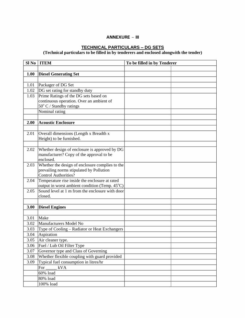
ANNEXURE – III
TECHNICAL PARTICULARS – DG SETS (Technical particulars to be filled in by tenderers and enclosed alongwith the tender)
Sl No ITEM To be filled in by Tenderer
1.00 Diesel Generating Set
1.01 Packager of DG Set
1.02 DG set rating for standby duty
1.03 Prime Ratings of the DG sets based on
continuous operation. Over an ambient of
50o C / Standby ratings
Nominal rating
2.00 Acoustic Enclosure
2.01 Overall dimensions (Length x Breadth x
Height) to be furnished.
2.02 Whether design of enclosure is approved by DG
manufacturer? Copy of the approval to be
enclosed.
2.03 Whether the design of enclosure complies to the
prevailing norms stipulated by Pollution
Control Authorities?
2.04 Temperature rise inside the enclosure at rated
output in worst ambient condition (Temp. 45oC)
2.05 Sound level at 1 m from the enclosure with door
closed.
3.00 Diesel Engines
3.01 Make
3.02 Manufacturers Model No
3.03 Type of Cooling – Radiator or Heat Exchangers
3.04 Aspiration
3.05 Air cleaner type.
3.06 Fuel / Lub Oil Filter Type
3.07 Governor type and Class of Governing
3.08 Whether flexible coupling with guard provided
3.09 Typical fuel consumption in litres/hr
For _____ kVA
60% load
80% load
100% load

Fuel consumption figures vis-a-vis Alternator
electrical output – Units/litre
60% load
80% load
100% load
3.10 Lub oil consumption at 100% load
4.00 Alternator
4.01 Make
4.02 Rated voltage and frequency
4.03 Enclosure
4.04 Insulation class
4.05 Exciter type
4.06 Temperature Rise permissible.
4.07 Voltage Regulation no load to full load
4.08 Whether Space heater provided ?
4.09 Wave form distortion on full load
4.10 Radio Interference
4.11 Telephone Interference
4.12 Stator winding thermistor with trip
5.00 Instrument and Controls. Whether the
following provided?
5.01 Instruments :
Oil temperature gauge
Oil pressure gauge
Water temperature gauge
Battery charging ammeter.
Hour meter to show total engine hours run -
10,000 hr capacity
Digital R.P.M. indicator .
5.02 Operating Controls
Auto/manual switch
Emergency stop push button
Run/off – reset/auto engine start switch
Remote manual override with ON/OFF control
5.03 Indication lamps
Emergency stop
Low battery voltage
Generator switch not in auto
Low lub oil pressure
System ready

5.04 Safety controls
Low lube oil pressure
High water temperature
Over speed

6.00 Exhaust system
Exhaust silencer type
Number of Silencers provided
Exhaust pipe diameter, material and thickness
Temperature of flue gases at exhaust manifold
Guaranteed Temperature on external face of
exhaust pipe insulation
Exhaust stack height - alongwith back pressure
calculation
7.00 Tenderer to confirm including the cost of
obtain following statutory approval.
7.01 Electrical Inspector
7.02 Electric Supply Authorities
7.03 Pollution Control Board for emission and noise
pollution
7.04 Department of Explosives

Annexure-I.1
DG SETS – COST OF GENERATION
ITEM Unit Data shall be furnished by tenderer
against each item
Make of Engine
Make of DG set
Engine Model
DG set rating KVA
DG set rating Kw
Average Load factor % 75% 75%
Units generated per hour kwh / hour
Number of hours per year hours / annum 2400 hours 2400 hours
Number of units generated per year kwh / annum
Fuel Cost
Fuel rate Rs per litre
Fuel consumption Litres/ hour
Number of units per litre of Diesel Kwh / litre
Fuel cost Rs per kwh
Lub Oil Consumption Cost
Lub oil consumption litres / hour
Cost of Lub oil Rs per litre
Lub Oil consumption cost Rs per hour
Lub Oil consumption cost Rs per kwh
Lub Oil Replacement Cost Rs per litre
Lub Oil replacement period hours
Lub Oil replacement quantity litres
Lub oil replacement litres / hour
Lub oil replacement cost Rs / hour
Lub Oil replacement cost Rs per kwh
Maintenance Cost
"B Check" maintenance period hours
"B check" maintenance kit cost Rs
"B Check" maintenance cost Rs per kwh
“C Check:” maintenance period Hours
“C Check:” maintenance kit cost Rs.
"C Check" maintenance cost Rs per kwh
“D Check:” maintenance period Hours
“D Check:” maintenance kit cost Rs.
"D Check" maintenance cost Rs per kwh

Air Cleaner element change period hours
Air Cleaner Element cost Rs
Air Cleaner Element replacement cost Rs per kwh
Total Cost per kwh generated
Signature of Tenderer

Annexure – 1.2
DG SETS – EMISSION LEVELS – at 100% Load
ITEM Emission level as per Pollution
Control Board Norms
Guaranteed emission level of the engine
offered to be filled in by the tenderer
NOx 9.2 g/kW-Hr
SOx
CO 5 g/kW-Hr
HC 1.3 g/kW-Hr
Dust
(Particulate Matter)
0.5 g/kW-Hr
Signature of tenderer

ANNEXURE-I
LIST OF INDIAN STANDARDS (IS)
IS : 374 - 1979
Ceiling fans and regulators (3rd revision)
IS : 694 - 1990
PVC insulated Electric cable for working voltage upto and including
1100 volts.
IS : 732 - 1989
Code of practice for electrical wiring and installation
IS : 1255 - 1983 Code of Practice for installation and maintenance of Power Cables upto
and including 11 KV rating (Second Revision)
IS : 1258 - 1987
Bayonet lamp holders(Third revision)
IS : 1293 - 1988
Three pin plugs and sockets outlets rated voltage upto and including
250 volts and rated current upto and including 160 amps.
IS : 1554 - 1988
( Part - I )
PVC insulated ( Heavy Duty) electric cables for working voltages upto
and including 1100 volts.
IS : 1646 - 1982
Electrical installation fire safety of buildings (general) Code of
practice.
IS : 1885 - 1971
Glossary of items for electrical cables and conductors
IS : 1913 - 1978 General and safety requirements for fluorescent lamps luminaries
Tubular.
IS : 2026 - 1977 to 81
( Part I to IV )
Power Transformers
IS : 2071 - 1974 - 76
Methods of high voltage testing
IS : 2309 - 1989
Protection of building and allied structures against lightning
IS : 2551-1982 Danger notice plate.
IS : 3043 - 1987 Code of practice for earthing.
IS : 3427 – 1997 AC Metal enclosed switch gear and control gear for rated voltages
above 1 KV and upto and including 52 KV.
IS : 3480 - 1966
Flexible steel conduits for electrical wiring.
IS : 3837 - 1976
Accessories for rigid steel conduit for electrical wiring.
IS : 4146 - 1983 Application guide for voltage transformers
IS : 4615 - 1968 Switch socket outlets.

IS : 5133 - 1969
(Part -I)
Boxes for the enclosure of electrical accessories.
IS : 5216 - 1982
(Part-I)
Guide for safety procedures and practices in electrical work.
IS : 5424 - 1969
Rubber mats for electrical purposes.
IS : 5578 &
11353-1985
Marking and arrangement of bus bars

IS : 7098 - 1985
(Part - II)
Cross linked polyethylene insulated PVC sheathed cables. For working
voltages from 1.1 KV upto and including 11 KV
IS : 8130 - 1984
Conductors for insulated electric cables and flexible cords
IS : 8623 -1977
(Part -I)
Factory built assemblies of switchgear and control gear for voltages
upto and including 1000 V AC and 1200 V.D C.
IS : 8623 - 1980
(Part -II)
Bus Bar trunking system
IS : 8828 - 1996
Miniature Circuit Breakers
IS : 9537 - 1981
Rigid Steel Conduits for electrical wiring (Second Revisions)
IS : 10810 - 1988
Methods of test for cables.
IS : 12640 - 1988
Earth Leakage Circuit Breakers
IS : 13947-1993
(Part-II)
Air Circuit Breakers
IS : 13947-1989
(Part- )
Moulded Case Circuit Breakers
IS : 13947 - 1993
(Part- )
Degree of protection provided by enclosures for LV switchgear and
control gear.
IS : 13947 - 1993
(Part- )
General requirement for switchgear and control gear for voltage not
exceeding 1000 Volts.
IS : 1651 & 1652
1991
Stationary cells and batteries lead acid type.

LIST OF APPROVED MAKES
SNO Details of Materials / Equipment Manufacturer’s Name
A MEDIUM VOLTAGE EQUIPMENT
1 Power Distribution Panel Ambit Switchgear
Precision System Control
Tricolite
Adlec
2 Final Distribution Board Hager-Novello
Legrand Ekinox3
Siemens Beta Guard 10KA
Schneider - Acti9
3 Moulded Case Circuit Breaker (MCCB) ABB Tmax
Legrand - DPX3
L&T DU sine
Schneider - NSX
Siemens 3VL
4 Miniature Circuit Breakers ABB
Hager-H3
Legrand - DX3
Siemens Beta Guard 10KA
Schneider - Acti9
5 Residual Current Circuit Breaker (RCCB) ABB
Hager-H3
Legrand - DX3
Siemens Beta Guard 10KA
Schneider - Acti9

SNO Details of Materials / Equipment Manufacturer’s Name
6 Power/Aux. Contactor ABB AF
L&T- MNX
Legrand CTX3
Siemens Sirius RT
Schneider Tesys K, D, F
7 Control Transformer/Potential Transformers Automatic Electric
KAPPA
PRECISE
8 Current Transformer (Epoxy Cast Resin) Automatic Electric
Gilbert & Maxwell
Indcoil
Pragati
Precise
9 Protection Relay (Numeric Type) ABB
Areva
Siemens
10 Indicating Lamps LED type and Push Button GE Power Controls
Larsen & Toubro (ESBEE)
Schneider Electric
Siemens
11 Overload relays with built in Single Phase
preventer
ABB
Schneider Electric
Larsen & Toubro
Siemens
12 Electronic Digital Meters
(A/V/PF/Hz/KW/KWH) with LED Display
Automatic Electric
GE
Schneider Electric

13 Static Power Meter & Logger (SPML)With
RS 485 port
Conzerv
Automatic Electric
Schneider Electric
SNO Details of Materials / Equipment Manufacturer’s Name
14 PVC insulated XLPE aluminium/copper
conductor armoured MV Cables upto 1100 V
grade
Finolex
Polycab
Havells
Lapp
Batra Henley
15 LT Jointing Kit / Termination Birla-3M
Raychem
REPL
Safe Kit
16 Cable Glands Double Compression with
earthing links
Baliga Lighting
Comet
Cosmos
17 Bimettalic Cable Lug Comet
Cosmos
Dowell’s (Biller India)
Hax Brass (Copper Alloy India)
18 PVC insulated copper conductor stranded
flexible wires (FRLS)
Finolex
Polycab
Havells
Lapp
Batra Henley
19 Mettalic / GI Conduit (ISI approved) RM-Con(AKG)
BEC
NIC
Vimco
20 PVC Conduit & Accessoires (ISI approved) AKG
BEC
Polypack
Precision
21 Lead Coated Flexible GI Conduit PLICA IndiaPvt. Ltd.

Flexicon
ABB – Lumina/ Classic
22 Switch & Socket & General
GI BOX
North West (NOVA)
MK (Wraparound)
Schneider (Opale)
SNO Details of Materials / Equipment Manufacturer’s Name
23 Industrial Socket
Splash Proof Legrand
Gewiss
Schneider Electric
24 Industrial Socket
Metal Clad Hansel
MDS
Legrand
25 Ceiling Fan Crompton Greaves
Havells
Bajaj
Usha
26 Lighting Fixture
a. LED Philips
WIPRO
27 UPS Eaton
Schneider Electric
Emerson
28 Lighting & Surge Voltage Protection ABB
Hager
ObeoBetterman
Schneider Electric
29 230/12 V Step Down Transformer with
BUILTIN Isolation Transformer
Talema
Volstat

30 Energy saving Units FMS
Inncom
Inn Link Systems
Pumba Electronics
SNO Details of Materials / Equipment Manufacturer’s Name
31 Exit Signage’s Legrand
MK
Prolite
Philips
Thorn
32 Cable tray
Ricco
Slotco
Indiana Engineering
Precision System Control
33 Raceway
Legrand - CMS
OBO
MK
Precision System Control
34 Octagonal G.I. Pole with Mounting Bracket Bajaj Electricals
Mayfair
Keselec
Advance Steel Tube
K-Lite
35 Outdoor Type Transformer Schneider Electric
Cromton Greaves
Seimens
Jyoti Ltd
36
SOLAR PV SYSTEM
MODULE Vikram/Canadian/Trina/Chint
Astroenergy/
STRING INVERTER Delta
Module Mounting
Structure
Bhushan/Jindal/Tata
SNO Details of Materials / Equipment Manufacturer’s Name
B TELEPHONE
a) Cat-6 Cable Legrand - LCS2

Panduit(Pannet)
Schneider
b) Fiber Optic Cable Legrand - LCS2
Panduit(Pannet)
Schneider
c) Telephone Tag Blocks KRONE
Om Enterprises
TVS
2. Telephone Armoured Cables DELTON CABLES
FINOLEX
SKYTOEN
3. Patch Cords, patch panels, Splitter Box,
cross connect outlet
Legrand - LCS2
Panduit(Pannet)
Schneider
4. Data Switches, Receiver, Media Converter JUNIPER
CISCO
EXTREME
5. WiFi(AP’s) AROOBA
RUCKUS
PALOALTO
6. Racks for Data Switches VALRACK
Rittal
APW
7. EPABX Avaya
Seimens
Alcatel
SNO Details of Materials / Equipment Manufacturer’s Name
C Addressable Fire Detection & Public Address System
a) Intelligent Addressable Photoelectric Smoke
Detectors
Bosch
Cooper
Siemens
Ravel
Notifier (ONYX series)
Edward
b) Intelligent Addressable Heat Detectors Bosch
Cooper
Siemens
Ravel
Notifier (ONYX series)
Edward
c) Intelligent Addressable Fixed Temperature
Heat Detectors
Bosch
Cooper

Siemens
Ravel
Notifier (ONYX series)
Edward
d) Intelligent addressable Manual Pull Station Bosch
Cooper
Siemens
Ravel
Notifier (ONYX series)
Edward
e) Intelligent addressable Control Module Bosch
Cooper
Siemens
Ravel
Notifier (ONYX series)
Edward
f) Intelligent addressable Monitor Module Bosch
Cooper
Siemens
Ravel
Notifier (ONYX series)
Edward
g) Intelligent addressable Main Panel/Repeater
Panel
Bosch
Cooper
Siemens
Honeywell ( XLS 3000)
Notifier (ONYX series)
Edward
h) Addressable Hooters/Speakers Bosch
Cooper
Siemens
Ravel
Notifier (ONYX series)
Edward
i) Fire Supression System Siemens Sinorix 1230
Novec
SNO Details of Materials / Equipment Manufacturer’s Name
i) Beam detector Bosch
Cooper
Siemens
Ravel
Notifier (ONYX series)
Edward
j) Response indicator Bosch
Cooper
Siemens
Ravel
Notifier (ONYX series)
Edward

k) Talk back unit Bosch
Cooper
Siemens
Ravel
Notifier (ONYX series)
Edward
l) PA System Honeywell
JBL
Ravel
Ateis
m) Mettalic/ GI Conduit ( ISI approved ) BEC
RM-CON
NIC
Vimco
n) Control / power Cables/wires Polycab
Finolex
Lapp
Havels
SNO Details of Materials / Equipment Manufacturer’s Name
D
CCTV SYSTEM
Makes
1. DVR, Central Monitoring software &
Accessories
Axis
Oncam
Mobotix
Avigilon
Sony
2. CCTV- Cameras Axis
Oncam
Mobotix
Avigilon
Sony
3. Lenses Axis
Oncam
Mobotix
Avigilon
Sony
4. Weatherproof Housing Axis
Oncam
Mobotix
Avigilon
5. Control / power Cables- Polycab
Finolex

Lapp
Havels
6.
Cat-6 Cables Legrand - LCS2
Panduit(Pannet)
Siemon
Schneider
7. PVC Conduits AKG
BEC
Polypack
NIC
8. Metallic Conduits (MS/GI) BEC
NIC
RM-CON
9. Personal Computer Dell
H P
IBM
SNO Details of Materials / Equipment Manufacturer’s Name
10. LCD/LED SONY
LG
SAMSUNG
11. Printer Epson
H P
NEC
TVSE
Canon
12. Mouse Dell
H P
Logitech
Microtek
F VIDEO CONFRENCING SYSTEM POLYCOM
CISCO
SONY
G PROJECTOR SONY
BARCO
CHRISTIE

H PROJECTOR SCREEN DRAPER
ELITE
MEDIATECH
I AUDIO CONFERENCE SYSTEM AKG
Bosch
Bayeydynamic
J SPEAKER FOR SOUND
REINFORCEMENT
Harman
Heinrich
Bayerdynamic
K WIRELESS HANDLED MIC, LAPEL MIC Harman
Heinrich
Bayerdynamic
L DIGITAL CONFERENCE CONTROLLER Harman
Heinrich
Bayerdynamic
S. No. Details of Materials / Equipment Manufacturer’s Name
1. Diesel Engine Cummins India
Caterpillar
Koel By Kirloskar
2. Alternator Caterpillar
Stamford
Koel Green
3. D.G. Controller Cummins
Dieff
Wood word
4. DG SET ENCLOSURE Sterling & Wilson Powergen Pvt Ltd
Sudhir Genset
Jakson & Company
5. Fire Sealant & Fire Retardant Paint BTHM Engineering
Birla 3 M
HILTI
Promat
6. M.S. Pipe AST
Jindal
Tata Steel
Zenith

7. Vibration Isolators Cori
Dunlop
Flexionics
Kanwal Industries Corporation
Resistoflex
8. Noise Control Silencer / Muffler
(Residential Type Silencer)
Intertec
Sound Control India
9. Fiberglass/Insulation Owens Corning
UP Twiga
10. Welding Rod ADOR
Advani
Cosmos
ESAB
Super Bond (S)
11. MCCB/ACB ABB
Schneider Electric
Siemens
Legrand
12. Anti-vibration mountings Gerb, KOEL
S. No. Details of Materials / Equipment Manufacturer’s Name
13. Batteries Amar Raja
Exide
HBL Nife
Standard Furukawa
14. Battery Charger AE
Amar Raja
Exide
HBL Nife
15. Butterfly valves Audco
Advance
Danfoss
16. Gate/NRV/Check valves Audco (above 50mm)

17. Strainers Emrald
Rapid Cool
S. No. Details of Materials / Equipment Manufacturer’s Name
1. Elevators & Escalators Thyssen Krupp
Otis Elevators
Schindler India Pvt. Ltd.
2. Moulded Case Circuit Breaker
(MCCB)
ABB
Larsen & Toubro
Schneider Electric
Siemens, Legrand
3. Miniature Circuit Breaker (MCB) ABB
L&T
Schneider Electric
Siemens, Legrand
4. Residual Current Circuit Breaker
(RCCB)
ABB
L&T
Schneider Electric
Siemens
5. Power/Aux. Contactor ABB
L & T
Schneider Electric
Siemens
6. PVC insulated XLPE aluminium
conductor
armoured / unarmoured MV Cables
upto 1100 V grade
Finolex
Universal
Paramount
Havels
7. Cable Glands Double Compression
with earthing links
Baliga Lighting
Comet
Cosmos
8. Bimettalic Cable Lug Comet
Cosmos
Dowell’s (Biller India)
Hax Brass (Copper Alloy India)
9. PVC insulated copper conductor
stranded flexible wires (FRLS)
Finolex
Universal
Paramount
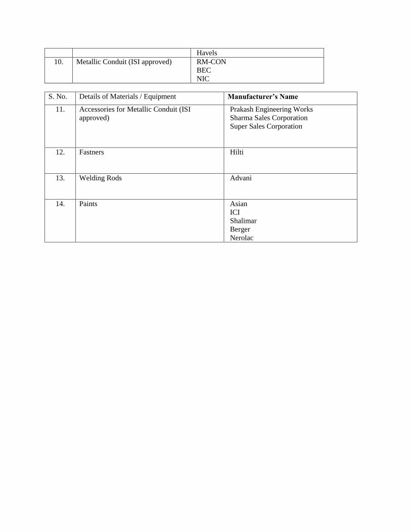
Havels
10. Metallic Conduit (ISI approved) RM-CON
BEC
NIC
S. No. Details of Materials / Equipment Manufacturer’s Name
11.
Accessories for Metallic Conduit (ISI
approved)
Prakash Engineering Works
Sharma Sales Corporation
Super Sales Corporation
12. Fastners Hilti
13. Welding Rods Advani
14. Paints Asian
ICI
Shalimar
Berger
Nerolac