Generated on 2014-05-12 15:59 GMT / ... - RadioNerds
44
TM 5-272 WAR DEPARTMENT TECHNICAL MANUAL STEEL TREAD WAY BRIDGE EQUIPAGE July 10, 1942 Generated on 2014-05-12 15:59 GMT / http://hdl.handle.net/2027/uc1.b3241344 Public Domain, Google-digitized / http://www.hathitrust.org/access_use#pd-google
-
Upload
khangminh22 -
Category
Documents
-
view
0 -
download
0
Transcript of Generated on 2014-05-12 15:59 GMT / ... - RadioNerds

TM 5-272
WAR DEPARTMENT
TECHNICAL MANUAL
STEEL TREAD WAY BRIDGE
EQUIPAGE
July 10, 1942
Genera
ted o
n 2
01
4-0
5-1
2 1
5:5
9 G
MT /
htt
p:/
/hd
l.hand
le.n
et/
20
27
/uc1
.b3
24
13
44
Public
Dom
ain
, G
oog
le-d
igit
ized
/
htt
p:/
/ww
w.h
ath
itru
st.o
rg/a
ccess
_use
#pd-g
oogle

TM 5-272
III 13
STEEL TREADWAY BRIDGE EQUIPAGE ^_
-- T/V\ Si 71 2.
Table of Contents
CHAPTER 1. CHARACTERISTICS, COMPOSITION, AND
ASSIGNMENT OF EQUIPAGE.
Pai
Characteristics
General features of design
Bridge unit
Issue
CHAPTER 2. DESCRIPTION OF EQUIPMENT.
Pneumatic ponton
Trestle
Treadways and accessories
Ponton and trestle spans
Reconnaissance boats
Transportation
CHAPTER 3. OUTBOARD MOTOR.
Issue
Description
Outboard motor bracket
Care and maintenance of motors
Employment of the motor
Element of surprise
CHAPTER 4. POWER BOAT.
Issue
Description
Employment
Care and maintenance
CHAPTER 5. CONSTRUCTION METHODS AND GENERAL
CONSIDERATIONS.
General
Trestles
Anchors
Night construction
Preparation of equipage for use
CHAPTER 6. SELECTION OF BRIDGE SITE.
General
Reconnaissance
CHAPTER 7. CONSTRUCTION BY METHOD OF PARTS.
General
Preparation of site
Unloading and assembly areas
agraph
Page
1
1
2
1
3
3
4
3
5
5
6
6
7
7
8
9
9
11
10
11
11
12
12
13
13
13
14
13
15
14
16
15
17
15
18
15
19
16
20
16
21
17
22
17
23
17
24
19
25
20
26
20
27
20
PARTS.
28
21
29
22
30
22
M532881
Genera
ted o
n 2
01
4-0
5-1
2 1
5:5
9 G
MT /
htt
p:/
/hd
l.hand
le.n
et/
20
27
/uc1
.b3
24
13
44
Public
Dom
ain
, G
oog
le-d
igit
ized
/
htt
p:/
/ww
w.h
ath
itru
st.o
rg/a
ccess
_use
#pd-g
oogle

Table of Contents (Continued)
CHAPTER 8.
CHAPTER 9.
CHAPTER 10.
CHAPTER 11.
CHAPTER 12.
Paragraph
Unloading bridge trucks 31
Location of air compressors 32
Truck crane location 33
Location of other equipment 34
SECTIONS AND DUTIES OF SECTIONS.
General 35
Officers 36
Abutment section 37
Anchor section 38
Alignment 39
Raft section 40
Assembly section 41
Approach section 42
Security section 43
CONSTRUCTION BY METHOD OF SUCCES-
SIVE PONTONS OR TRESTLES.
General 44
Floating bridge procedure 45
Fixed bridge procedure 46
REINFORCED BRIDGES.
Floating bridge reinforcement 47
Trestle bridge reinforcement 48
TRAFFIC CONTROL, MAINTENANCE
AND DISMANTLING BRIDGE.
Traffic control and bridge main-
tenance 49
Dismantling bridge 50
FERRYING.
Pneumatic float 51
Raft ferries 52
Propulsion 53
Loading 54
Crew and equipment 55
Conduct during crossing 56
CHAPTER 13.
CHAPTER 14.
MAINTENANCE OF EQUIPAGE.
General 57
Pneumatic floats 58
Trestles, treadways, and
accessories 59
LIST OF EQUIPAGE.
Steel treadway bridge equipage 60
Page
23
23
23
23
24
24
24
25
25
26
28
29
30
31
31
32
32
33
33
33
34
34
36
37
37
37
37
38
38
39
IV
Genera
ted o
n 2
01
4-0
5-1
2 1
5:5
9 G
MT /
htt
p:/
/hd
l.hand
le.n
et/
20
27
/uc1
.b3
24
13
44
Public
Dom
ain
, G
oog
le-d
igit
ized
/
htt
p:/
/ww
w.h
ath
itru
st.o
rg/a
ccess
_use
#pd-g
oogle

LIST OF ILLUSTRATIONS
Figure
Figure
Figure
Figure
Figure
Figure
Figure
Figure
Figure
Figure 10.
Figure 11.
Figure 12.
Figure 13.
Figure 14.
Figure 15.
Figure 16.
Figure 17.
Figure 18.
Figure 19.
Figure 20.
Figure 21.
Figure 22.
Figure 23.
Figure 24.
Figure 25.
Figure 26.
Figure 27.
Figure 28.
Figure 29.
Page
Floating steel treadway bridge ________________________ 2
Typical shore connection ______________________________ 3
Fixed steel treadway bridge ___________________________ 4
Pneumatic float ________________ 5
Saddle ________________ 6
Treadway adaptor ________________ 6
Steel treadway ________________ 7
Treadways used as car loading ramps ________________ 8
Treadway wedges ________________ 8
Steel treadway bridge accessories _____________________ 9
Reconnaissance boat ________________ 10
Bridge truck ________________ 12
22-HP outboard motor ________________ 13
Outboard motor bracket ______________________________ 14
Power boat mounted on trailer _______________________ 16
Anchor spacing ------------------------ 18
Layout of site ________________ 21
Typical unloading and assembly area _________________ 22
Truck crane ________________ 23
Inflation of pneumatic floats __________________________ 26
Launching ponton ---------------- 27
Placing treadways in assembling a ponton section _____ 27
Ponton section ________________ 28
Assembling a ponton section into the bridge ___________ 29
Installing connecting pins _____________________________ 30
Installing far shore approach treadways ______________ 31
Bridging a blown culvert ______________________________ 32
Typical raft ferry ---------------- 34
Method of loading and unloading raft ferries _________ 35
Genera
ted o
n 2
01
4-0
5-1
2 1
5:5
9 G
MT /
htt
p:/
/hd
l.hand
le.n
et/
20
27
/uc1
.b3
24
13
44
Public
Dom
ain
, G
oog
le-d
igit
ized
/
htt
p:/
/ww
w.h
ath
itru
st.o
rg/a
ccess
_use
#pd-g
oogle

Chapter 1
CHARACTERISTICS, COMPOSITION, AND ASSIGNMENT
OF EQUIPAGE
Paragraph
Characteristics 1
General Features of Design 2
Bridge Unit 3
Basis of Issue 4
1. Characteristics.— The steel treadway bridge is the
stream crossing means furnished the Armored Force. It is
designed to carry all vehicles in the Armored Division up to
and including the medium tank (approximately 34 tons). When
reinforced with additional floats, the capacity of the bridge is
approximately 45 tons. Because of its simplicity and rela-
tively light weight, it can be constructed in comparatively
short time. The use of collapsible pneumatic floats and high
alloy steel beam treadways reduces the volume and weight of
the equipage and makes it possible to transport a long length
of bridge in few vehicles. The flotation of the floats and the
continuous beam action of the treadway combine to give the
bridge a great load-carrying capacity. The equipage can be
used to construct either a fixed or floating bridge. The pneu-
matic floats support the floating bridge and trestles support
the fixed bridge. The treadways are used in both.
2. General features of design.— a. Floating Bridge.—
(Fig. 1) The bridge consists of two tracks of continuous beam
action steel treadways, supported at regular intervals by pneu-
matic pontons and connected to the shore by one or more
trestle spans or by shore treadways. The method of connect-
ing the floating section to the shore (Fig. 2) will depend upon
the depth of stream near the shore and the slope and condition
of the banks. Because of the difficulty of constructing and
finding adequate support for trestle footings, trestles will be
used only when absolutely necessary.
6. Fixed Bridge.— (Fig. 3) The short-span fixed bridge
employs one or two lengths of treadway as a simple beam for
each track. It is supported on end abutments and does not
require interior supports. The long-span fixed bridge employs
Genera
ted o
n 2
01
4-0
5-1
2 1
5:5
9 G
MT /
htt
p:/
/hd
l.hand
le.n
et/
20
27
/uc1
.b3
24
13
44
Public
Dom
ain
, G
oog
le-d
igit
ized
/
htt
p:/
/ww
w.h
ath
itru
st.o
rg/a
ccess
_use
#pd-g
oogle

<D
bo
2
K
>>
to
Genera
ted o
n 2
01
4-0
5-1
2 1
6:0
0 G
MT /
htt
p:/
/hd
l.hand
le.n
et/
20
27
/uc1
.b3
24
13
44
Public
Dom
ain
, G
oog
le-d
igit
ized
/
htt
p:/
/ww
w.h
ath
itru
st.o
rg/a
ccess
_use
#pd-g
oogle

I- TmSTLB
t- continuous BEAM
«-• - CCMTMUOUS ««»
2. Typical Shore Connection.
three or more lengths of treadway for each track. It utilizes
interior supports (trestles or adjustable shores) in addition
to the end abutments.
3. Bridge Unit.— The principal components of the unit
of steel treadway bridge equipage are twenty-four trestles,
seventy-two pneumatic floats, twenty spare floats, and 2160
feet of treadway. These together with certain spare parts and
accessories are transported on thirty-six 6-ton (6 x 6) bridge
trucks and eighteen 2V2-ton cargo trucks. One unit of equip-
age provides a maximum of 1080 feet of bridge which may be
floating or fixed or a combination of the two. See par. 60 for
a complete list of the components of one unit of equipage.
4. Issue.— The normal assignment is one bridge unit
to each armored division. The bridge is transported and main-
tained by the bridge company of the armored engineer bat-
talion.
Genera
ted o
n 2
01
4-0
5-1
2 1
6:0
0 G
MT /
htt
p:/
/hd
l.hand
le.n
et/
20
27
/uc1
.b3
24
13
44
Public
Dom
ain
, G
oog
le-d
igit
ized
/
htt
p:/
/ww
w.h
ath
itru
st.o
rg/a
ccess
_use
#pd-g
oogle

8,
•o
I
Genera
ted o
n 2
01
4-0
5-1
2 1
6:0
0 G
MT /
htt
p:/
/hd
l.hand
le.n
et/
20
27
/uc1
.b3
24
13
44
Public
Dom
ain
, G
oog
le-d
igit
ized
/
htt
p:/
/ww
w.h
ath
itru
st.o
rg/a
ccess
_use
#pd-g
oogle

Chapter 2
DESCRIPTION OF EQUIPMENT
Paragraph
Pneumatic Ponton 5
Trestle 6
Treadways and Accessories 7
Pontons and Trestle Spans 8
Reconnaissance Boats 9
Transportation 10
5. Pneumatic Ponton.— The pneumatic ponton is com-
posed of the pneumatic float and saddle.
a. Pneumatic Float (Fig. 4).— The pneumatic float is
seven and one-half feet in width, twenty-five feet in length,
and thirty inches in depth. It is formed by a perimeter of
rubberized canvas tubing, thirty inches in diameter, with a
floor of the same material. A detachable tube of the same dia-
meter is placed in the center of the float. This adds to the
rigidity of the float and gives added bouyancy when the float
is submerged. The float weighs about four hundred pounds
and has a flotation of approximately twelve tons. The air
pressure should be maintained at two pounds per square inch.
The maximum allowable pressure under any condition is two
and one-quarter pounds per square inch and the minimum is
one and one-quarter pounds per square inch.
Figure 4. Pneumatic Float.
b. Saddle.— The load of the bridge and the weight of
the treadways is transmitted to the floats by a saddle. As
shown in Fig. 5, the saddle consists of a system of steel beams
surmounting a bearing plate. The beams transmit the load to
Genera
ted o
n 2
01
4-0
5-1
2 1
6:0
0 G
MT /
htt
p:/
/hd
l.hand
le.n
et/
20
27
/uc1
.b3
24
13
44
Public
Dom
ain
, G
oog
le-d
igit
ized
/
htt
p:/
/ww
w.h
ath
itru
st.o
rg/a
ccess
_use
#pd-g
oogle

the float through the bearing plate which is constructed of
%-inch, five-ply, resin bonded Douglas Fir plywood. For con-
venience in handling, the saddle is made in three sections: a
center section and two end sections. Figure 5 shows one end
section in position to be joined to the center section and the
other end section already joined. The complete saddle weighs
about nine-hundred pounds.
Figure 5. Saddle.
6. Trestle.— Twenty-four 25-ton aluminum trestles, the
same as those of the 25-ton ponton bridge equipage (see TM
5-273), are included in the steel treadway bridge equipage
for use as supports for the long-span fixed bridge. Each tres-
tle is provided with a special treadway bearing plate called
a "treadway adaptor." (See Fig. 6.) The adaptor consists
essentially of a 5" channel on which the treadways bear. The
under surface of the channel is fitted with 4 semicircular "bent
bars" (see Fig. 6) which bear on the tube of the transom.
The upper surface of the channel is fitted with spacing lugs
and clamps which hold the treadways securely in position.
lt=====±
Figure 6. Treadway adaptor.
6
Genera
ted o
n 2
01
4-0
5-1
2 1
6:0
0 G
MT /
htt
p:/
/hd
l.hand
le.n
et/
20
27
/uc1
.b3
24
13
44
Public
Dom
ain
, G
oog
le-d
igit
ized
/
htt
p:/
/ww
w.h
ath
itru
st.o
rg/a
ccess
_use
#pd-g
oogle

7. Treadways and Accessories (Figs. 7 and 9).— a.
General.— The roadway of the bridge consists of two tracks
of treadways designed to accommodate narrow gauge vehicles,
such as cars and trucks, and vehicles of wide gauge and wide
tracks, such as the medium tank.
Figure 7. Steel treadway.
"b. Description.— The effective length of a treadway is
fifteen feet and the clear track width is two feet, nine inches.
Its overall length is eighteen feet, two and one-eight inches.
It is built up with two 18-inch, 33.9 pound high strength steel
channel beams tied together laterally by six 5-inch, 6.7 pound
and one 9-inch, 13.4 pound channel beams. These lateral
beams are stiffened with a 3-inch, 5.7 pound I-beam. A single
treadway weighs about 1980 pounds.
c. Connections.— The treadways are connected longi-
tudinally to form a continuous beam or to form hinge spans.
A system of engaging plates and two connecting pins per
joint connect the sections rigidly. When one pin is left out
the connection acts as a hinge joint. Spacing hooks or bars
are provided to prevent lateral movement of the treadways.
They hook into spacer eyes welded to the web of the channel
irons.
d. Uses.— Treadways are used primarily to provide a
floor and stringer system for floating and fixed bridges. They
may be used to reinforce the floor system of a weak bridge,
to span short distances without intermediate support, and to
span long distances with intermediate supports, such as tres-
Genera
ted o
n 2
01
4-0
5-1
2 1
6:0
0 G
MT /
htt
p:/
/hd
l.hand
le.n
et/
20
27
/uc1
.b3
24
13
44
Public
Dom
ain
, G
oog
le-d
igit
ized
/
htt
p:/
/ww
w.h
ath
itru
st.o
rg/a
ccess
_use
#pd-g
oogle

ties or shores. In addition to their use in bridging they are
useful for improvised car and barge loading ramps (see Fig.
8) and for roadways over marshy areas.
Figure 8. Treadways used as car loading ramps.
e. Treadway wedges.— Treadway wedges are used on
the near shore and far shore ends of steel treadway bridges
(both floating and trestle) to facilitate the movement of ve-
hicles on and off the bridge. Their employment in a trestle
bridge is shown in Figure 3. The wedges are of two types.
The hook end type (see Fig. 9) is employed on the engaging
plate end of the treadway and the blunt end type is employed
on the butt end of the treadway. The wedges are of welded
construction throughout.
RAMP WEDGE- HOOK END
RAMP WEDGE-BLUNT END
Figure 9. Treadway wedges.
8
Genera
ted o
n 2
01
4-0
5-1
2 1
6:0
1 G
MT /
htt
p:/
/hd
l.hand
le.n
et/
20
27
/uc1
.b3
24
13
44
Public
Dom
ain
, G
oog
le-d
igit
ized
/
htt
p:/
/ww
w.h
ath
itru
st.o
rg/a
ccess
_use
#pd-g
oogle

/. Treadway bridge accessories.— Various accessories of
the treadways bridge are shown in Figure 10.
8. Ponton and Trestle spans.— a. General.— The con-
tinuous beam action of the treadways makes it possible to
space pontons and trestles at irregular intervals without loss
I STR'JT- BRACE SnOf
2 TRESlXE 9RACE CL
3 WIRE CflBlF SftiP
f
14 ASSAULT BOAT PAOOtE
15 FOUR-HOSE INFLATION
MANIFOLD
^ ^ ta _ .
Figure 10. Steel treadway bridge accessories.
9
Genera
ted o
n 2
01
4-0
5-1
2 1
6:0
1 G
MT /
htt
p:/
/hd
l.hand
le.n
et/
20
27
/uc1
.b3
24
13
44
Public
Dom
ain
, G
oog
le-d
igit
ized
/
htt
p:/
/ww
w.h
ath
itru
st.o
rg/a
ccess
_use
#pd-g
oogle

of bridge efficiency. Generally, spacings are approximately
fifteen feet, measured center to center of supports. For ease
in construction, trestles are usually placed under the pin con-
nections and pontons under the center of gravity of the tread-
ways.
b. Ponton Spans.— One ponton with two treadways is
called a ponton section. This is a basic part of the bridge and
Figure 11. Reconnaissance boat.
10
Genera
ted o
n 2
01
4-0
5-1
2 1
6:0
1 G
MT /
htt
p:/
/hd
l.hand
le.n
et/
20
27
/uc1
.b3
24
13
44
Public
Dom
ain
, G
oog
le-d
igit
ized
/
htt
p:/
/ww
w.h
ath
itru
st.o
rg/a
ccess
_use
#pd-g
oogle

the bridge will usually be assembled by adding these sections
successively.
c. Trestle Spans.— Trestles will normally be spaced at
a distance of fifteen feet and placed under pin connections.
All trestles will be braced longitudinally by the use of bracing
struts or by ropes and cables. Footings may be improved by
using expanded metal mats with plank as a distribution plate.
Where footings are unstable, additional trestles should be
placed in each treadway length. These may be installed as
the need appears after the bridge is in use.
9. Reconnaissance boats (Fig. 11).— a. Description.—
The pneumatic reconnaissance boat is made of rubberized cot-
ton fabric. It weighs about forty to fifty pounds packed in a
carrying case. It has a capacity of six men. The boat is in-
flated by mouth or by a hand pump. Inflation is limited to
the minimum pressure required barely to round out the air
chambers. Standard assault boat paddles are provided.
b. Employment.— These boats will find their greatest
use in reconnaissance of river crossing sites. However, their
light weight and the ease of transportation adapt them for
all-round employment in patrolling and servicing the floating
treadway bridge and in transporting small items of equipment.
In an emergency the boats may be used to transport men, am-
munition, and small items of equipment in initial stages of a
river crossing operation or retrograde movement.
10. Transportation.— a. Issue.— The steel treadway
bridge equipment is transported by thirty-six, 6-ton bridge
trucks and eighteen, 2^-ton cargo trucks.
b. Description.— The bridge truck (see figure 12) is a
specially designed type (6x6) cargo truck with adequate
power take-off and framework for unloading, placing, and
loading steel treadways. The cargo body is slightly longer
than the overall length of a single treadway and wider than
the overall width of two treadways. These dimensions enable
it to transport four treadways stacked two-high and loaded
symmetrically. The 21/1>-ton (6x6) cargo truck is a standard
issue, quartermaster vehicle. The loadings of these vehicles
has not yet been determined definitely but they will be so
loaded that a minimum amount of equipment will have to be
unloaded to give access to the steel treadways. Such loading
is desirable since treadways will be used on numerous occas-
ions where no other equipment will be required.
11
Genera
ted o
n 2
01
4-0
5-1
2 1
6:0
1 G
MT /
htt
p:/
/hd
l.hand
le.n
et/
20
27
/uc1
.b3
24
13
44
Public
Dom
ain
, G
oog
le-d
igit
ized
/
htt
p:/
/ww
w.h
ath
itru
st.o
rg/a
ccess
_use
#pd-g
oogle

Figure 12. Bridge Truck.
c. Employment.— (1) Fixed bridge procedure.— For
spans of fifteen feet or less the treadways are placed directly
into final position in a single operation. For spans greater
than fifteen feet and not over thirty feet, treadways will be
unloaded, connected in pairs longitudinally on some flat sur-
face, picked up by the use of the frame work, and lowered
into position over the span to be bridged.
(2) Floating bridge procedure.— To employ the frame
work for unloading and placing treadways on the pneumatic
pontons the trucks are backed to the water's edge. The tread-
ways are removed and placed directly in position on the pon-
tons. As each truck is unloaded it pulls out and another is
backed into its place, continuing the assembly of ponton parts
which go to make up the floating bridge. Raft ferries are
made up in a similar manner. Unless unusually favorable
conditions exist, a means should always be provided for tow-
ing or winching the bridge trucks up from the water's edge.
Chapter 3
OUTBOARD MOTOR
Paragraph
Issue 11
Description 12
Outboard Motor Bracket 13
Care and Maintenance of Motors 14
Employment of the Motor 15
Element of Surprise . 16
11. Issue.— Included in the organizational equipment
of each bridge unit are six 22-HP outboard motors and six
attachment brackets.
12
Genera
ted o
n 2
01
4-0
5-1
2 1
6:0
1 G
MT /
htt
p:/
/hd
l.hand
le.n
et/
20
27
/uc1
.b3
24
13
44
Public
Dom
ain
, G
oog
le-d
igit
ized
/
htt
p:/
/ww
w.h
ath
itru
st.o
rg/a
ccess
_use
#pd-g
oogle

Figure, 13. 22-HP Outboard Motor.
12. Description.— The 22-HP outboard motor (see Fig.
13) is the same as the one supplied for the 10-ton and for the
25-ton ponton bridges. An instruction book on the operation
and care of the motor is furnished with each outboard unit.
The latest models permit turning the motor through 360°.
This makes it possible to use the motor to pull as well as push
loads and greatly facilitates the assembly of ponton sections
in the bridge and the ferrying of ponton rafts.
13. Outboard Motor Bracket.— An attachment bracket
especially adapted for use on the pneumatic ponton is supplied
for each motor. It is secured to the circular angle-iron of the
end of the saddle by special fasteners. Metal arms carry a
board to which the motor is attached. Figure 14 illustrates
the pneumatic ponton adaptor bracket.
14. Care and Maintenance of Motors.— Outboard motors
should be operated by trained men. If this is done, and the
directions in the manufacturer's instruction book are faith-
fully and precisely followed, successful and dependable opera-
13
Genera
ted o
n 2
01
4-0
5-1
2 1
6:0
1 G
MT /
htt
p:/
/hd
l.hand
le.n
et/
20
27
/uc1
.b3
24
13
44
Public
Dom
ain
, G
oog
le-d
igit
ized
/
htt
p:/
/ww
w.h
ath
itru
st.o
rg/a
ccess
_use
#pd-g
oogle

Figure 14. Outboard motor bracket.
tion of the motor is assured. The following points should be
watched closely in the care and maintenance of motors:
a. Motors should be protected by the canvas cover when
mounted and not in use.
b. They should be transported only in cases provided.
c. Spare sparkplugs should always be available.
d. Fuel should be mixed properly.
e. Only first echelon maintenance should be executed
by operators, unless they are well-trained and parts are avail-
able for further repairs.
/. The tactical situation permitting, the motors always
should be warmed up before using.
15. Employment of the Motor.— a. The motor greatly
facilitates the movement of the pneumatic ponton. A single
ponton with outboard motor has many uses, such as ferrying
troops, placing anchors, towing ponton sections into bridge
position, and reconnaissance and patrolling.
b. Outboard motors are also used to propel rubber pon-
ton rafts in ferrying operations. Two motors should power
each raft to reduce stoppages in mid-stream and to insure easy
and positive handling of the raft.
14
Genera
ted o
n 2
01
4-0
5-1
2 1
6:0
7 G
MT /
htt
p:/
/hd
l.hand
le.n
et/
20
27
/uc1
.b3
24
13
44
Public
Dom
ain
, G
oog
le-d
igit
ized
/
htt
p:/
/ww
w.h
ath
itru
st.o
rg/a
ccess
_use
#pd-g
oogle

c. Motors should be used only in streams of sufficient
depth to provide adequate draft for the propeller.
16. Element of Surprise.— Speed, dispersion, and sur-
prise are the three essential elements in a successful assault
boat crossing. Outboard motors have a characteristic sound
and should not be used in the initial waves of the assault but
should be used on assault boats to speed up the crossing as
soon as the enemy discovers the operation.
Chapter 4
POWER BOAT
Issue
Description
Employment
Care and Maintenance
Paragraph
17
18
19
20
17. Issue.— Two power boats with trailers are supplied
to the bridge company of the armored engineer battalion.
18. Description.— a. Dimensions.— The boat (see Fig.
15) is eighteen feet long and has a maximum breadth to the
outside of the bumper rail of six feet, seven inches. The maxi-
mum depth of the hull is two feet. To the bottom of the skid
and including the top of the towing bits, the depth is three
feet, two inches. The boat with accessories has a weight of
about 1800 pounds.
Figure 15. Power boat mounted on trailer.
15
Genera
ted o
n 2
01
4-0
5-1
2 1
6:0
7 G
MT /
htt
p:/
/hd
l.hand
le.n
et/
20
27
/uc1
.b3
24
13
44
Public
Dom
ain
, G
oog
le-d
igit
ized
/
htt
p:/
/ww
w.h
ath
itru
st.o
rg/a
ccess
_use
#pd-g
oogle

b. Power.— The boat is powered with a Marine engine,
including clutch and reverse gear. The connection of the pro-
peller to the engine is through a three to one reduction gear.
It is equipped with a governor which controls the engine at a
safe and economical speed and allows it to develop its full fifty-
seven horsepower for tow work.
c. Hull.— The hull, constructed of seven sixteenths-inch
(7/16") molded plywood, is both strong and light and has no
seams to calk. It is fitted with rope bumpers and a carrying
rail.
d. Trailer.— The two-wheel dolly type trailer is so de-
signed that the power boat can be launched easily or loaded
by a system of rollers permanently mounted on the trailer
chassis. The trailer is equipped with a towing bar adapting
it to the pintle of most quartermaster or engineer vehicles.
19. Employment.— The power boat finds its greatest use
in towing ponton sections and parts for assembly in the float-
ing bridge. In addition, it is used to place and remove anchors,
propel raft ferries, and remove debris endangering the bridge.
The boat is designed for tow work and not for speed.
20. Care and Maintenance.— An instruction book cover-
ing operation, care, and maintenance of the mechanical parts
is supplied with each boat. Other points which require special
attention are as follows:
a. Care and judgment should be exercised in launching
and loading. If the water at the launching or loading point
is shallow, the trailer should be backed into the water until
sufficient depth is reached for proper flotation. The boat
should always be raised clear of obstructions when moved.
b. Shallow places and places where obstructions such as
logs or sticks may be present should be approached at slow
speed.
c. The operating temperature of the motor should be
watched closely. Numerous causes contribute to stoppages
of the cooling system intake that may result in high and de-
structive motor temperatures.
d. Propeller wheels become entangled easily. Avoid
crossing anchor and shore lines and heavily weeded water
areas. When it is necessary to pass over a line the rotation
of the propeller should be stopped by throwing the clutch into
neutral and the boat allowed to drift over the line.
16
Genera
ted o
n 2
01
4-0
5-1
2 1
6:0
7 G
MT /
htt
p:/
/hd
l.hand
le.n
et/
20
27
/uc1
.b3
24
13
44
Public
Dom
ain
, G
oog
le-d
igit
ized
/
htt
p:/
/ww
w.h
ath
itru
st.o
rg/a
ccess
_use
#pd-g
oogle

Chapter 5
CONSTRUCTION METHODS AND GENERAL
CONSIDERATIONS
Paragraph
General 21
Trestles 22
Anchors 23
Night Construction 24
Preparation of Equipage for Use 25
21. General.— The steel treadway floating bridge may
be constructed either by the method of successive pontons or
by parts. Ordinarily, the latter method will be employed.
(1) In construction by successive pontons, trucks
loaded with bridge equipment are backed out over the com-
pleted portion of the bridge and treadways are laid on pon-
tons floated into position.
(2) In construction by parts, parts consisting of one
or more sections are assembled near the shore or in some pro-
tected tributary stream and floated into their place in the
bridge. The number of ponton sections to be included in each
part will depend upon necessity for concealment, speed of cur-
rent, and other related factors. A part containing one section
is easiest to assemble into the bridge. However, the single
section is somewhat unstable longitudinally. In rough water,
a two-section part is preferable.
22. Trestles.— Trestle sections of the bridge will be con-
structed by the method of successive bays. Trestles usually
will be assembled on the near shore, and carried to and swung
into position with the use of crane or bridge trucks.
23. Anchors. (Fig. 16).— a. The normal method of se-
curing the treadway floating bridge against current and wind
action is by anchors with three-quarter-inch rope anchor lines.
The spacing of anchors on the line of upstream anchors will
vary according to the velocity of the current. Anchors are
cast at appropriate intervals across the stream. They are
spaced at fifteen feet in a swift stream, thirty feet in a current
of two or three feet per second, and forty-five feet in a slug-
17
Genera
ted o
n 2
01
4-0
5-1
2 1
6:0
7 G
MT /
htt
p:/
/hd
l.hand
le.n
et/
20
27
/uc1
.b3
24
13
44
Public
Dom
ain
, G
oog
le-d
igit
ized
/
htt
p:/
/ww
w.h
ath
itru
st.o
rg/a
ccess
_use
#pd-g
oogle

SLUGGISH STREAM
\
N
::
::
::
: •:
::
- 1
SWIFT STREAM
Figure 16. Anchor Spacing.
gish stream. Down stream anchors are spaced at intervals
of thirty feet in swift water and sixty feet in moderate or
sluggish streams.
6. The line of upstream and downstream anchors should
be located by reconnaissance prior to the construction of the
bridge. Signal cloth or nagging may be used to mark these
lines.
c. Shore lines are used at each end of the bridge as
shown in Fig. 16 to anchor the bridge against longitudinal
movement. The lines are fastened to the near shore loops on
18
Genera
ted o
n 2
01
4-0
5-1
2 1
6:0
8 G
MT /
htt
p:/
/hd
l.hand
le.n
et/
20
27
/uc1
.b3
24
13
44
Public
Dom
ain
, G
oog
le-d
igit
ized
/
htt
p:/
/ww
w.h
ath
itru
st.o
rg/a
ccess
_use
#pd-g
oogle

the fourth treadways. Anchors should be located directly up-
stream from the final position of the pontons so that the an-
chor cables will not impose a longitudinal thrust on the struc-
ture.
24. Night construction.— a. Limitations of Equipment.
— The equipment is not well adapted for use as an assault
bridge, that is, one which must be thrown over a stream quick-
ly, without the knowledge of the enemy, and before a bridge-
head has been established. Because of the nature of the trans-
portation and equipment, assembly at the bridge site creates
noise which is audible for some distance.
b. Operations at Night.— During actual operations, con-
struction of the bridge under cover of darkness is a normal
procedure and is generally identical with construction in day-
light. However, a successful and rapid construction at night
is much more dependent upon careful planning, close control,
and adequate training. Prior practice and rehearsal should
always be given when practicable, preferably at night and on
an actual stream.
c. Difficulties Imposed by Darkness.— No particular dif-
ficulty is involved in the assembly of individual ponton sec-
tions and incorporating them into the bridge during darkness,
although the process is somewhat slower. The chief difficulty
arises in getting the equipment to the unloading points, in
placing and handling cables and lines, and in directing the
bridge to the proper point on the enemy shore. These diffi-
culties will vary widely with the width of stream, force of
current, and the degree of darkness. They may be minimized
by careful prior training, reconnaissance, planning, and organ-
ization. Suitable arrangements for signals and inter-com-
munication during the process of construction must be made.
d. Special Measures Desirable in Night Construction.—
A single flashlight providing a shielded weak white light can
be used on the far bank to assist in securing proper direction
and alignment of the bridge. Similar lights may be used to
show the position of upstream and downstream line of anchors.
Unshielded flashlights to aid in the assembly should never
be used. If available, luminous markers or paints, white trac-
ing tape, or pieces of cloth are useful in outlining essential
points such as the routes of approach to the unloading points,
vehicular parking areas, and the heads of pickets and con-
necting pins.
19
Genera
ted o
n 2
01
4-0
5-1
2 1
6:0
8 G
MT /
htt
p:/
/hd
l.hand
le.n
et/
20
27
/uc1
.b3
24
13
44
Public
Dom
ain
, G
oog
le-d
igit
ized
/
htt
p:/
/ww
w.h
ath
itru
st.o
rg/a
ccess
_use
#pd-g
oogle

e. Maintenance of Secrecy.— Although actual construc-
tion will be started ordinarily only after the need for secrecy
has passed, the use of lights or sound should be held to a
minimum at the bridge site.
25. Preparation of Equipage.— a. General.— Bridging
a stream consists of three phases: the preparation of the site;
the unloading of the equipment and its preparation for use;
and the actual construction of the bridge. The first and second
phases will usually be more time consuming than the third
and will require careful organization and planning.
b. Loading.— Each load must comprise all component
parts of a definite length of bridge, whether it be trestle or
floating. The loading should be such that those items used
first will be unloaded first. Insofar as possible the bridge
truck bed is built to facilitate this type of loading.
Chapter 6
SELECTION OF BRIDGE SITE
Paragraph
General 26
Reconnaissance , 27
26. General.— The selection of a bridge site generally
will be governed by both tactical and technical requirements.
The speed that characterizes armored force operations severe-
ly limits the time available for engineers to study the tactical
plan, the map and aerial photographs and to conduct ground
reconnaissance prior to the selection of a bridge site. Bridges
will be repaired, improvised, or built when and where they are
needed as determined by the tactical commander. The steel
treadway bridge is highly adaptable to such use.
27. Reconnaissance.— a. Reconnaissance will be made
as far in advance of construction as possible. If practicable,
the tactical commander and the unit engineer, or respective
reconnaissance sections, or both, should make joint recon-
naissances. The engineer, or his reconnaissance section, must
make a careful technical reconnaissance in any case. Where
speed is urgent, the reconnaissance may be accomplished while
the bridge equipment is being moved to the site.
20
Genera
ted o
n 2
01
4-0
5-1
2 1
6:0
8 G
MT /
htt
p:/
/hd
l.hand
le.n
et/
20
27
/uc1
.b3
24
13
44
Public
Dom
ain
, G
oog
le-d
igit
ized
/
htt
p:/
/ww
w.h
ath
itru
st.o
rg/a
ccess
_use
#pd-g
oogle

b. Data secured by reconnaissance will include adequate
information on stream width, velocity, banks, depth, variation
in water elevation, approaches, tributary streams, and location
of the main thread of the channel.
Chapter 7
CONSTRUCTION BY METHOD OF PARTS
General
Preparation of Site
Unloading and Assembly Areas
Unloading Bridge Trucks
Location of Air Compressors
Crane Truck Location
Location of Other Equipment
Paragraph
28
29
30
31
32
33
34
28. General.— The bridge equipment usually will be
brought up to the bridge site in one or more columns. Pro-
tection on the march will be gained by taking full advantage
of all cover and concealment and by maintaining proper inter-
vals (see FM 25-10). The column will be led to the unloading
point or points by the reconnaissance personnel who assisted
in reconnoitering the routes and bridge site and who are fa-
Figure 17. Layout of Site.
21
Genera
ted o
n 2
01
4-0
5-1
2 1
6:0
8 G
MT /
htt
p:/
/hd
l.hand
le.n
et/
20
27
/uc1
.b3
24
13
44
Public
Dom
ain
, G
oog
le-d
igit
ized
/
htt
p:/
/ww
w.h
ath
itru
st.o
rg/a
ccess
_use
#pd-g
oogle

miliar with the engineer plan. Trucks will maintain an inter-
val of 50 yards or more until they are unloaded. Unloaded
vehicles will move back immediately to the vehicle parking
area (Fig. 17). Columns should be organized With engineer
personnel carriers in the lead, followed by truck crane, air
compressors, and bridge trucks.
29. Preparation of Site.— The approach road should be
improved in advance to the extent that time permits to expe-
dite the movement of equipage to the bridge site. Turn-
arounds (see Fig. 17) and passing points should be provided.
The bull-dozer, power saw, and explosives are useful in this
work. The use of explosives may be limited by the tactical
situation. Hasty work to improve the unloading points gen-
erally will be worthwhile.
30. Unloading and Assembly Areas (Figs. 17 & 18).—
In the method of parts, special attention should be given to
the location of unloading and assembly areas. The essential
element in locating these areas is their accessibility to bridge
trucks. Where possible they should be located on firm, stable
ground with a down grade approach, preferably on an existing
roadway. There should be ample room for nearby truck move-
ment and for inflating pontons, assembling saddles, launching
pontons, and placing treadways. Generally, the accessibility
of the unloading and assembly areas to bridge trucks is more
important than the distance of the unloading areas from the
bridge site.
Figure 18. Typical Unloading and Assembly Area.
22
Genera
ted o
n 2
01
4-0
5-1
2 1
6:0
8 G
MT /
htt
p:/
/hd
l.hand
le.n
et/
20
27
/uc1
.b3
24
13
44
Public
Dom
ain
, G
oog
le-d
igit
ized
/
htt
p:/
/ww
w.h
ath
itru
st.o
rg/a
ccess
_use
#pd-g
oogle

31. Unloading Bridge Trucks.— Bridge trucks pass
through the unloading area in such a manner that anchors,
rubber floats, saddles, hand tools, and other bridge accessor-
ies are unloaded at the respective assembly points. If the
bank conditions permit the truck to be backed to the water's
edge, the treadways are placed directly on pontons floated just
off shore. Under less favorable conditions, the truck cranes, of
which there are two in the bridge company, may be used to
transfer treadways from bridge trucks to pontons. Unloaded
trucks will move off immediately to the vehicle parking area
or areas.
32. Location of Air Compressors.— The motorized air
compressors, of which there are four in the bridge company,
will be placed in the inflation section of the unloading and as-
sembly area between the truck roadway and the stream bank.
They will be placed so that the air lines can reach conveniently
all pontons to be inflated.
33. Crane Truck Location.— The crane truck (see Fig.
19) will be spotted on the stream bank in such a position that
it can efficiently lift treadways from trucks and transfer the
treadways to pontons floating just off shore. When placing
the near and far shore treadway spans and trestle spans the
crane will be backed into placing position along the longitud-
inal axis of the bridge.
Figure 19. Truck Crane.
34. Location of Other Equipment.— Anchors will be un-
loaded in the unloading area. Shore lines will be spotted for
the line crews. Peaveys, extra connection pins, chain hoists,
loading hooks, other equipment, and hand tools will be un-
loaded by the crews using them.
23
Genera
ted o
n 2
01
4-0
5-1
2 1
6:0
8 G
MT /
htt
p:/
/hd
l.hand
le.n
et/
20
27
/uc1
.b3
24
13
44
Public
Dom
ain
, G
oog
le-d
igit
ized
/
htt
p:/
/ww
w.h
ath
itru
st.o
rg/a
ccess
_use
#pd-g
oogle
Chapter 8
SECTIONS AND DUTIES OF SECTIONS BV
CONSTRUCTION BY PARTS
Paragraph
General 35
Officers 36
Abutment Section 37
Anchor Section 38
Alignment Section 39
Raft Section 40
Assembly Section 41
Approach Section 42
Security Section 43
35. General.— Suggested organization for construction
of the treadway bridge, and the duties of sections, is given
in the following paragraphs.
36. Officers.— a. Officers supervise the bridge con-
struction program in the same general manner as for other
ponton and fixed bridges.
&. The senior officer selects the crossing, unloading and
assembly points, routes of approach, and parking areas of ve-
hicles. He determines the method of construction and the
general plan for local security.
c. One junior officer supervises the placing of treadways
on pneumatic pontons and another the construction of abut-
ments, trestle spans, and approaches. The placing of tread-
ways on pneumatic pontons by bridge trucks or the truck
crane is the critical or controlling operation in the construction
of the bridge. Close supervision should be given this oper-
ation.
37. Abutment Section.— a. The abutment section con-
sisting of one squad will commence work immediately upon
arrival at the site. Its first task is to unload all necessary
tools and supplies.
b. The near shore abutment normally utilizes a 3 x 12-
inch or heavier timber as a sill. The sill is placed with upper
surface one foot below grade of finished approach and two
feet or less above water surface. It is anchored securely as
illustrated by Figures 2 and 3.
24
Genera
ted o
n 2
01
4-0
5-1
2 1
6:0
9 G
MT /
htt
p:/
/hd
l.hand
le.n
et/
20
27
/uc1
.b3
24
13
44
Public
Dom
ain
, G
oog
le-d
igit
ized
/
htt
p:/
/ww
w.h
ath
itru
st.o
rg/a
ccess
_use
#pd-g
oogle

c. Upon completion of near shore abutment, this squad
moves across to far shore and similarly prepares the far abut-
ment. It then lays out the upstream and downstream shore
lines. Shore lines are tied to holdfasts, or, if available, to
tree trunks about 50 feet above and below the axis of the
bridge. Free ends of the lines are coiled on banks, pending
attachment to fourth ponton section by alignment section.
d. The abutment section assists assembly section in the
placing of any near or far shore trestle sections. The noncom-
missioned officer in general charge of the construction of the
bridge supervises this operation.
38. Anchor Section.— a. The anchor section consists
of an engineer squad and is divided into two details of
one noncommissioned officer and five anchormen each. As
soon as unloading starts, both details assemble anchors with
cables attached on the first treadway raft constructed. To
provide stability these rafts should have two pontons each.
They accommodate ten or more anchors per load. Rafts should
be powered with outboard motors. Power boats will be used
instead of rafts if they are available.
&. The first detail is known as the upstream anchor de-
tail. It moves the anchor raft to the previously determined
line for upstream anchors and casts anchors according to the
stream current and wind as described in par. 23. Additional
anchors are procured and cast as necessary until all upstream
anchors are in place. Anchor lines are transferred to the
alignment section as soon as it is able to handle them.
c. After assisting in a above, the downstream anchor
detail, using another two-ponton outboard motor powered
raft or power boat, places the downstream anchors as de-
scribed in par. 23. Anchor lines are turned over to the align-
ment section.
39. Alignment Section.— This section, consisting of one
noncommissioned officer and three cable or linemen, carries
out the following sequence of work:
a. Lay out up and downstream shore lines if this has
not already been accomplished by abutment detail.
b. Fasten free ends of shore lines to shoreward treadway
loops of fourth ponton section as soon as the latter is assem-
bled in bridge. Adjust up and down stream shore lines to
25
Genera
ted o
n 2
01
4-0
5-1
2 1
6:0
9 G
MT /
htt
p:/
/hd
l.hand
le.n
et/
20
27
/uc1
.b3
24
13
44
Public
Dom
ain
, G
oog
le-d
igit
ized
/
htt
p:/
/ww
w.h
ath
itru
st.o
rg/a
ccess
_use
#pd-g
oogle

insure correct alignment of bridge. Install treadway spacer
hooks between treadways to which shore lines are attached.
c. Receive upstream and downstream anchor lines from
anchor sections and fasten them to mooring cleats on ponton
saddles. Adjust lines as necessary for proper alignment of
bridge.
d. Upon completion of bridge, fasten and adjust far
abutment shore lines, and install spacer hooks between tread-
ways to which shore lines are attached. Thereafter, the sec-
tion patrols the bridge constantly, checking line fastenings,
pin connections, inflation of boats, and alignment of bridge.
It checks and reports to the engineer officer in charge each
six-inch rise or fall of water level. It reports to the bridge
maintenance detail any other items requiring attention.
40. Raft Section.— a. The raft section consists of two
or more squads per unloading area. It constructs the tread-
way rafts or the ponton sections and assists in placing them
in the bridge. The section is broken down into half-squad
working details whose duties are as follows:
(1) Unload saddles, pneumatic floats, and other equip-
age from bridge trucks.
(2) Inflate float (see Fig. 20), attach saddle, launch
(see Fig. 21) and move to the treadway placing position. Con-
tinue inflation and launching of pontons if bridge trucks or
truck cranes are not yet in position to place treadways.
Figure 20. Inflating Pneumatic Float.
26
Genera
ted o
n 2
01
4-0
5-1
2 1
6:0
9 G
MT /
htt
p:/
/hd
l.hand
le.n
et/
20
27
/uc1
.b3
24
13
44
Public
Dom
ain
, G
oog
le-d
igit
ized
/
htt
p:/
/ww
w.h
ath
itru
st.o
rg/a
ccess
_use
#pd-g
oogle

•
•• ,...-..
••
Figure 21. Launching Ponton.
(3) Assisted by bridge truck personnel, place tread-
ways on ponton (see Fig. 22). Care should be exercised in
placing treadways to assure that ends are exactly even. This
enables rapid placing of rafts or sections in the bridge assem-
bly. Each treadway should have two pins; one installed in the
inner hole of the butt end, the other on floor of treadway near
the engaging plate end.
Figure 22. Placing treadways in assembling a ponton section.
27
Genera
ted o
n 2
01
4-0
5-1
2 1
6:1
0 G
MT /
htt
p:/
/hd
l.hand
le.n
et/
20
27
/uc1
.b3
24
13
44
Public
Dom
ain
, G
oog
le-d
igit
ized
/
htt
p:/
/ww
w.h
ath
itru
st.o
rg/a
ccess
_use
#pd-g
oogle

(4) Move treadway raft or ponton section (see Fig.
23) to end of bridge. The power boat, or an outboard motor,
is used, if available, in moving rafts or sections into position.
Othewise, they are moved by paddling.
Figure 23. Ponton Section.
(5) Assist assembly section in placing raft or ponton
section in bridge. The section then returns to the unloading
point and repeats the operation.
b. When necessary to avoid congestion at unloading
points or to secure additional protection of cover and conceal-
ment, pneumatic floats may be inflated under cover, have sad-
dles attached, and then be carried by hand to the launching
site. In this event, additional raft sections should be provided
for carrying.
c. Because of the difficulty usually encountered in se-
curing adequate and numerous unloading positions for bridge
trucks or because of the limited number of truck cranes, the
placing of treadways on pontons is the critical or controlling
operation. For this reason pontons should be made available
for placement of treadways as fast as the crane can handle
them.
41. Assembly Section.— a. The assembly section con-
sists of one noncommissioned officer and seven privates. It
28
Genera
ted o
n 2
01
4-0
5-1
2 1
6:1
0 G
MT /
htt
p:/
/hd
l.hand
le.n
et/
20
27
/uc1
.b3
24
13
44
Public
Dom
ain
, G
oog
le-d
igit
ized
/
htt
p:/
/ww
w.h
ath
itru
st.o
rg/a
ccess
_use
#pd-g
oogle

places the trestles, treadways and rafts or sections in position
in the bridge. The duties of the assembly section are as fol-
lows:
(1) Upon arrival at bridge site, assemble peaveys,
spare pins, and other necessary hand tools and equipment.
The section then helps to place the truck crane in position for
handling trestles. This section is assisted by the abutment
section in placing trestle spans.
(2) This detail assembles rafts or ponton sections
into the bridge as they are brought up by the raft sections.
The detail guides the sections (see Fig. 24) together and in-
serts connecting pins. In this operation men work in pairs on
Figure 24. Assembling a ponton section into the bridge.
each treadway. Each of the pair assists in guiding the free
raft or ponton section into position and then one, with a
peavey, brings the free treadway into final position while the
other inserts the connecting pin. (See Fig. 25.) The fifth man
follows up, inserting a cotter-key or large horse-blanket pin.
The sixth and seventh men handle guy ropes as shown to as-
sist in placing the part in position.
42. Approach Section.— The size and composition of the
approach section varies to meet the requirements of the situ-
ation. The work is accomplished, insofar as possible and prac-
ticable, by power equipment, and is generally carried on sim-
ultaneously with the construction of the bridge. This crew is
often used during the early phases of construction in prepar-
ing the unloading and assembly areas. In the latter phases
they are frequently assisted in completing the approaches by
29
Genera
ted o
n 2
01
4-0
5-1
2 1
6:1
0 G
MT /
htt
p:/
/hd
l.hand
le.n
et/
20
27
/uc1
.b3
24
13
44
Public
Dom
ain
, G
oog
le-d
igit
ized
/
htt
p:/
/ww
w.h
ath
itru
st.o
rg/a
ccess
_use
#pd-g
oogle

Figure 25. Installing connecting pins.
sections that have completed their specific operation in the
construction of the bridge.
43. Security Section.— Local security is a duty of the
unit commander in all operations and situations. Although
the bridging operation may be protected by troops other than
engineers assigned this mission, local security and antiair-
craft protection is the responsibility of the engineer officer and
he will insure that adequate protection is provided within the
means available to him and properly coordinated with security
furnished by other troops.
COMPOSITION OF CONSTRUCTION SECTIONS
Section
Equipment
Total Enlisted Men
Abutment
1 boat, reconnaissance
1 squad
Anchor
2 rafts, two-ponton (Powered
1 squad
with outboard motors)
or
2 power boats (with operators)
Raft
1 air compressor with
2 squads per
operators per
unloading
1 crane truck with un-
area. More
operators load-
if necessary
1 outboard motor or ing
motor boat with area
Alignment
operators
4) 1 squad
Assembly
8)
30
Genera
ted o
n 2
01
4-0
5-1
2 1
6:1
0 G
MT /
htt
p:/
/hd
l.hand
le.n
et/
20
27
/uc1
.b3
24
13
44
Public
Dom
ain
, G
oog
le-d
igit
ized
/
htt
p:/
/ww
w.h
ath
itru
st.o
rg/a
ccess
_use
#pd-g
oogle

Approach (size and composition as required).
Security (size and composition as required by the situa-
tion) .
Chapter 9
CONSTRUCTION BY METHOD OF SUCCESSIVE
PONTONS OK TRESTLES
General
Floating Bridge Procedure
Fixed Bridge Procedure
Paragraph
44
45
46
44. General.— In construction by the method of succes-
sive pontons or trestles, the bridge is built progressively by
adding one ponton or trestle after another and extending the
treadways so as to connect each one as it is placed. Trestle
bridges are constructed by this method almost without excep-
tion.
45. Floating Bridge Procedure.— Floats are usually in-
flated at one or more points, saddles are placed, and the com-
plete pontons are floated into position at the end of the bridge
as needed. The bridge trucks back out near the end of the
Figure 26. Installing far shore approach treadways.
31
Genera
ted o
n 2
01
4-0
5-1
2 1
6:1
7 G
MT /
htt
p:/
/hd
l.hand
le.n
et/
20
27
/uc1
.b3
24
13
44
Public
Dom
ain
, G
oog
le-d
igit
ized
/
htt
p:/
/ww
w.h
ath
itru
st.o
rg/a
ccess
_use
#pd-g
oogle

partially completed bridge and lay the treadways on the pon-
tons. The truck is then moved toward shore, after which the
ponton section is connected to the completed bridge in the
same manner as in the method of parts. The far shore ap-
proach treadways are installed as shown in Figure 26.
46. Fixed Bridge Procedure.— Trestles are usually as-
sembled and swung into position off the near shore or off the
end of the partially completed bridge, as the case may be, by
the bridge truck or the truck crane. The transom is brought
to the proper height and the trestle is temporarily guyed by
rope lines. Treadways are swung into position resting on
trestle transom and connected to treadways already in place.
Spacing hooks are attached, and treadways are clamped down
to the adaptor of the transom. If necessary, intermediate
Figure 27. Bridging a blown culvert.
trestles are placed during the process of construction. When-
ever possible the treadway is pinned to form a continuous
beam. The use of treadways to bridge a blown culvert is shown
in Figure 27.
Chapter 10
REINFORCED BRIDGES
Floating Bridge Reinforcement
Trestle Bridge Reinforcement _
Paragraph
47
48
47. Floating Bridge Reinforcement.— The capacity of
the normal floating treadway is increased by adding an ad-
ditional ponton for each treadway length or by shortening the
-spans in equal amounts between pontons. In adding additional
32
Genera
ted o
n 2
01
4-0
5-1
2 1
6:1
7 G
MT /
htt
p:/
/hd
l.hand
le.n
et/
20
27
/uc1
.b3
24
13
44
Public
Dom
ain
, G
oog
le-d
igit
ized
/
htt
p:/
/ww
w.h
ath
itru
st.o
rg/a
ccess
_use
#pd-g
oogle
pontons, the ponton should be only partially inflated so that
it can be easily floated under the assembled treadways. Trestle
and hinge spans should be eliminated, if possible, and the
bearing plate or sill of approaches should be reinforced by
the use of a subsill. Additional anchors, shore lines, and hold-
fasts should be provided to assist in preventing lateral and
longitudinal movement of the bridge. Traffic control should
be very strict when a bridge is under heavy loading.
48. Trestle Bridge Reinforcement.— The capacity of the
bridge is increased by increasing the number of trestles used
for each unit of bridge. Additional bearing power of footings
may be secured by using larger footing shoes and by using a
bearing plate or sub footing of logs, expanded metal, brush,
or planks under each shoe. The bridge is secured against
lateral and longitudinal movement by using additional shore
lines and strut bracing. A subsill should be placed under each
approach sill.
Chapter 11
TRAFFIC CONTROL, MAINTENANCE AND
DISMANTLING BRIDGE
Paragraph
Traffic Control and Bridge Maintenance 49
Dismantling Bridge 50
49. Traffic Control and Bridge Maintenance.— Rigid con-
trol of traffic and proper bridge maintenance is essential at
all times. Medium tanks should maintain a constant speed
in crossing and should maintain intervals of at least twenty
yards. Halted vehicles should be chocked. Particular atten-
tion should be given to insure that a pressure of two pounds
is maintained in the rubber floats. The maintenance detail
should patrol the bridge constantly.
50. Dismantling Bridge.— In general, the bridge is dis-
mantled by a reversal of the erection procedure. The trestle
bridge is dimantled by successive trestles. The floating bridge
may be dismantled either by the method of parts or by the
method of successive pontons. In dismantling by the method
of successive pontons, the far shore approach treadways are
removed by crane. In dismantling by parts, the bridge is dis-
assembled by parts of one or more ponton sections. The parts
are floated to loading points along the shore, taken apart, and
loaded on trucks.
33
Genera
ted o
n 2
01
4-0
5-1
2 1
6:1
7 G
MT /
htt
p:/
/hd
l.hand
le.n
et/
20
27
/uc1
.b3
24
13
44
Public
Dom
ain
, G
oog
le-d
igit
ized
/
htt
p:/
/ww
w.h
ath
itru
st.o
rg/a
ccess
_use
#pd-g
oogle

Chapter 12
FERRYING
Paragraph
Pneumatic Float 51
Raft Perries 52
Propulsion 53
Loading 54
Crew and Equipment 55
Conduct During Crossing 56
51. Pneumatic Float.— A single pneumatic float less the
center tube may be used advantageously for ferrying person-
nel with their combat equipment. It may be used also for the
same purposes and in the same manner as the reconnaissance
boat. The float is loaded by placing twelve paddlers astride
the outside tubes and twelve passengers in the center com-
partment. Those in the center will sit facing the front. All
combat equipment should be slung or carried and not laid
on the canvas floor. Passengers should board and unload from
the ponton in knee deep water to prevent rupture of the ponton
by sharp stones and sticks. Five men usually can paddle the
ponton on its return trip.
52. Raft Ferries. (Figs. 28 & 29).— a. General.— Rafts
suitable for all loads up to the capacity of the normal treadway
floating bridge may be constructed from the steel treadway
bridge equipage. Rafts are usually of the same construction
as two or more spans of the normal reinforced bridge. Addi-
tional treadway sections placed on each end make it possible
to load and unload along any usual stream bank without the
use of landing stages. The raft of two ponton sections is much
used.
Figure 28. Typical raft ferry.
6. Various Types and Capacities.— The various types
of commonly used rafts and their capacities are listed below.
34
Genera
ted o
n 2
01
4-0
5-1
2 1
6:1
8 G
MT /
htt
p:/
/hd
l.hand
le.n
et/
20
27
/uc1
.b3
24
13
44
Public
Dom
ain
, G
oog
le-d
igit
ized
/
htt
p:/
/ww
w.h
ath
itru
st.o
rg/a
ccess
_use
#pd-g
oogle
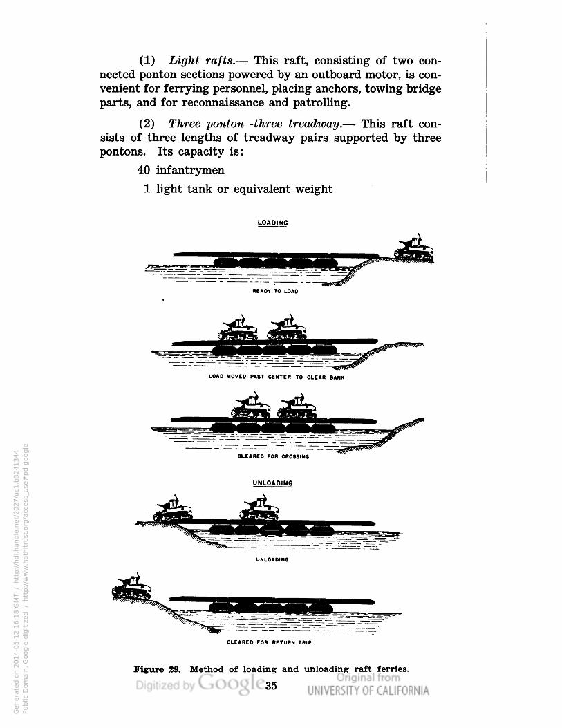
(1) Light rafts.— This raft, consisting of two con-
nected ponton sections powered by an outboard motor, is con-
venient for ferrying personnel, placing anchors, towing bridge
parts, and for reconnaissance and patrolling.
(2) Three ponton -three treadway.— This raft con-
sists of three lengths of treadway pairs supported by three
pontons. Its capacity is:
40 infantrymen
1 light tank or equivalent weight
LOAD INS
BEADY TO LOAD
LOAD MOVED PAST CENTER TO CLEAR BANK
CLEARED FOR CROSSING
CLEARED FOR RETURN TRIP
Figure 29. Method of loading and unloading raft ferries.
35
Genera
ted o
n 2
01
4-0
5-1
2 1
6:1
8 G
MT /
htt
p:/
/hd
l.hand
le.n
et/
20
27
/uc1
.b3
24
13
44
Public
Dom
ain
, G
oog
le-d
igit
ized
/
htt
p:/
/ww
w.h
ath
itru
st.o
rg/a
ccess
_use
#pd-g
oogle

(3) Five ponton - four treadway.— This raft con-
sists of four lengths of treadway pairs supported by five pon-
tons. It provides a usable roadway length of thirty feet. Its
capacity is:
80 infantrymen
1 medium tank
2 light tanks or equivalent weight
53. Propulsion.— a. Outboards.— Pneumatic ponton
rafts generally cannot be paddled effectively and paddling
should not be attempted in a current which exceeds one mile
per hour. The 22-HP outboard motors of the equipage pro-
vide an excellent means of maneuvering rafts of various sizes
in all streams whose currents are within the power capabili-
ties of the motors. Motors should be used in pairs to insure
against stoppages in midstream. The attachment bracket des-
cribed in paragraph 13 is used to attach the outboard motor
to the ponton. For better control outboard motors should be
attached to the center pontons. For the two-ponton light raft
a motor should be attached to each ponton.
b. Power boats.— Power boats are the best means of
propelling pneumatic ponton rafts. They are used to push
the rafts as a river boat pushes barges. The power boat may
be tied to the ponton raft or the bow may be butted up against
a treadway or ponton and guyed into place.
c. Truck Winch.— (1) Two vehicles with winch lines,
one placed on each stream bank, provides a satisfactory meth-
od of towing a raft across a stream. The first vehicle is rafted
across. A winch line from each vehicle is then attached to
the raft and the raft is shuttled back and forth. Two winches
on each bank give better control of the raft and a speedier
crossing.
(2) The winch on the truck crane can be used to shut-
tle a raft across a narrow stream. A rope line run through a
snatch block fastened on the far shore is tied to the raft.
Another rope line is tied directly to the raft. Each rope line
is looped loosely over the turning rope drums or capstans on
the ends of the winch shaft; one on the right and one on the
left. When drawn tight, one line will draw the raft across the
stream. When this line is released and the other line is drawn
tight, the raft will be pulled back to the near shore.
36
Genera
ted o
n 2
01
4-0
5-1
2 1
6:1
8 G
MT /
htt
p:/
/hd
l.hand
le.n
et/
20
27
/uc1
.b3
24
13
44
Public
Dom
ain
, G
oog
le-d
igit
ized
/
htt
p:/
/ww
w.h
ath
itru
st.o
rg/a
ccess
_use
#pd-g
oogle

54. Loading.— Treadway rafts provide their own land-
ings under usual conditions. The treadways are extended to
such lengths that they bridge the shallow water between the
shore and the first ponton. The tilting of the raft when the
loads are shifted, as illustrated in Fig. 29, makes it possible
to load and unload safely and quickly without landing stages.
Vehicles must be chocked to keep them from rolling while on
the raft. Personnel to be ferried will march on in double file,
one file for each treadway. These files will close up to a uni-
form distance for favorable load distribution.
55. Crew and Equipment.— An engineer officer with a
suitable detail of engineer enlisted men will be assigned to
supervise each raft. This officer will be responsible for the
safe and speedy loading, passage, and unloading of the raft.
The raft should be provided with the necessary anchors and
attached anchor lines with which to hold the raft in the stream
if the means of propulsion fails or the towing line parts. Men
should be stationed at these anchors with no other duties ex-
cept to cast them when necessary.
56. Conduct During Crossing.— From the time the loads
are turned over to the engineer officer in charge of the raft
for loading until they are unloaded on the opposite bank, the
loads are under his orders and those of the noncommissioned
officers of his crew. All instructions issued by them will be
promptly and strictly complied with. All officers and noncom-
missioned officers who are passengers on the raft will assist
the engineer officer in any way that may be necessary.
Chapter 13
MAINTENANCE OF EQUIPAGE
Paragraph
General 57
Pneumatic Floats 58
Trestles, Treadways and Accessories 59
57. General.— A regular program of inspection, clean-
ing, replacement, repair, and painting must be set up and ad-
hered to. All parts of the equipment, particularly the pneu-
matic floats, must be carefully inspected and put in good con-
dition before the equipment is stored after extended use. Com-
plete instruction books covering repair and maintenance are
provided for most items of equipage.
37
Genera
ted o
n 2
01
4-0
5-1
2 1
6:1
8 G
MT /
htt
p:/
/hd
l.hand
le.n
et/
20
27
/uc1
.b3
24
13
44
Public
Dom
ain
, G
oog
le-d
igit
ized
/
htt
p:/
/ww
w.h
ath
itru
st.o
rg/a
ccess
_use
#pd-g
oogle

58. Pneumatic floats.— a. Sr/iafl Leaks.— Small leaks
can be found by blowing up the floats, painting the outside
with thick soap suds and watching for soap bubbles. Repair
of small leaks is accomplished in the same manner as in re-
pairing an automobile inner tube. The surface around the leak
is first roughened lightly with a buffer and sandpaper and then
washed with benzine. At least two coats of air curing cement
are applied around the leak. While this is drying, a patch of
rubberized fabric is cut to the correct size and roughened up
in the same manner. Then a coat of cement is applied to the
patch. The patch is applied over the leak and rolled or pressed
down firmly.
"b. Large Leaks.— For large leaks such as snags and
tears it is desirable first to place a patch on the inside of the
tube. If necessary, the tear may be cut larger to facilitate
the application of this patch. An uncured rubber friction
patch is applied so good adhesion may be obtained. Some
cement should be spread around the inside of the tube near
the tear and the patch inserted. After this inside patch is
pressed and rolled firmly, a patch is applied to the outside of
the tube in the same manner as described for the small leak.
c. Storage.— All rubber articles are directly affected by
heat and sunlight. For this reason, pneumatic floats should
be stored in cool, dark places. When it is necessary to store
them on the beach for short periods of time the floats should
be dried out as much as possible. Since mildew will readily
attack cotton duck in the presence of moisture, the floats
should be supported by treadways or trestle parts. Pneumatic
floats should be carried in the carrying cases.
59. Trestles, Treadways, and Accessories.— The steel
elements of the bridge are rugged and of strong construction,
but nevertheless must be handled with care. Struts, shoes,
hoists, hold-fasts, peaveys, and tools should be used only for
the purpose intended. The protective paint covering must be
maintained to prevent rust. Paint should be renewed when-
ever inspection indicates the need; and any chipping, scaling,
or disintegration of the paint which exposes the steel should
be corrected at once by the application of a rust prevention
priming coat and a second coat of paint. Slight bends in tres-
tles, treadway, engaging plates, and grating and wedge ends
may be straightened in the field. Repairs other than these
generally require shop facilities.
38
Genera
ted o
n 2
01
4-0
5-1
2 1
6:1
8 G
MT /
htt
p:/
/hd
l.hand
le.n
et/
20
27
/uc1
.b3
24
13
44
Public
Dom
ain
, G
oog
le-d
igit
ized
/
htt
p:/
/ww
w.h
ath
itru
st.o
rg/a
ccess
_use
#pd-g
oogle

Chapter 14
LIST OF EQUIPAGE
Steel Treadway Bridge Equipage
Paragraph
60
60. Steel treadway bridge equipage.— The following is
a list of the equipage of one 1080-foot unit of steel treadway
bridge:
Article
Basic Quart.
with unit
Spares
with unit
Anchor (kedge 100#) 72 6
Block, snatch 32 0
Boat, Ren., (Pneumatic) 20 0
Bracket, auxiliary, trestle column 24 0
Bracket, outboard motor, 22HP 6 0
Bracing, trestle, parts consisting of
the following:
Clamp, column (complete) . 16 2
Shoe, strut, with pin and latch 8 0
Strut, bracing 8 0
Chain, with hook, ring, and load binder,
16' long, complete, %" diam. 100 50
Clip, wire rope, %" 160 0
Clip, wire rope, %» 160 0
Float, pneumatic, 12-ton, complete with
carrying case and emergency kit 72 20
Grip, cable, %" wire rope capacity 16 0
Grip, cable, %" wire rope capacity 16 0
Hoist, chain, ratchet, 1%" 3-ton capacity 12 0
Holdfast, complete w/steel pickets 12 0
Kit, repair, pneumatic float 12 0
Manifold, inflation, 4 hose 12 4
Manifold, spare parts:
Nozzle, assembly, complete 12 0
Clamp, hose 48 0
Hose 12 0
Nipple, hose 24 0
Seal, valve stem 24 0
Maul, wooden, round 8" x 10", 36"
handle, reinforced 36 0
Motor, outboard, 22HP w/chest 6 0
Paddle 72 72
Picket, steel, 1%" diam., 36" long 144 0
Pin, treadway 288 36
Rope, manila, Mr" diam., ft. 1400 1400
Rope, manila, %" diam., ft. 7200 3600
Rope, wire, %" diam., 6 x 19 galv., plow
steel on 8 spools, 250' each, ft. 2000 0
Rope, wire, %" diam., 6 x 19 galv., plow
steel on 3 spools, 600' each, ft. 1800 0
Saddle, complete 72 0
Treadway, complete 144 0
Trestle, 25-ton, complete with treadway
adaptor less ch. hoist 24 0
Total
with unit
78
32
20
24
6
18
8
8
150
160
160
92
16
16
12
12
12
16
12
48
12
24
24
36
6
144
144
324
2800
10800
2000
1800
72
144
24
39
Genera
ted o
n 2
01
4-0
5-1
2 1
6:1
8 G
MT /
htt
p:/
/hd
l.hand
le.n
et/
20
27
/uc1
.b3
24
13
44
Public
Dom
ain
, G
oog
le-d
igit
ized
/
htt
p:/
/ww
w.h
ath
itru
st.o
rg/a
ccess
_use
#pd-g
oogle

Basic Quan. Spares Total
Article with unit with unit with unil
Trestle Spare Parts:
Bracket, chain hoist 202
Column, complete 101
Column, foot, casting 404
Shoe, complete 101
Chain, shoe, column 404
Chain, foot, column 404
Pin, transom, complete with chain 808
Wedge, treadway, blunt end 20 0 20
Wedge, treadway, hook end 20 0 20
Wrench, end, adjustable, 10" (crescent) 32 0 32
Genera
ted o
n 2
01
4-0
5-1
2 1
6:1
9 G
MT /
htt
p:/
/hd
l.hand
le.n
et/
20
27
/uc1
.b3
24
13
44
Public
Dom
ain
, G
oog
le-d
igit
ized
/
htt
p:/
/ww
w.h
ath
itru
st.o
rg/a
ccess
_use
#pd-g
oogle