TM 1-1510-223-MTF MAINTENANCE TEST FLIGHT MANUAL ...
187
TM 1-1510-223-MTF MAINTENANCE TEST FLIGHT MANUAL ARMY MODEL RC-12N DISTRIBUTION STATEMENT A: APPROVED FOR PUBLIC RELEASE DISTRIBUTION IS UNLIMITED. HEADQUARTERS DEPARTMENT OF THE ARMY 28 FEBRUARY 1995
-
Upload
khangminh22 -
Category
Documents
-
view
3 -
download
0
Transcript of TM 1-1510-223-MTF MAINTENANCE TEST FLIGHT MANUAL ...

TM 1-1510-223-MTF
MAINTENANCE TEST FLIGHT MANUAL
ARMY MODEL RC-12N
DISTRIBUTION STATEMENT A: APPROVED FORPUBLIC RELEASE DISTRIBUTION IS UNLIMITED.
HEADQUARTERSDEPARTMENT OF THE ARMY
28 FEBRUARY 1995


TM 1-1510-223-MTF
A maintenance test flight is an exceptionallydemanding operation and requires a thorough flightreadiness inspection (PREFLIGHT). The flightreadiness inspection is prescribed in TM 1-1510-223-10 operator's manual and must be completed prior toeach maintenance test flight. Emergency proceduresare found in the applicable -10 or checklist (-CL) andare not duplicated in this publication. Prior to eachmaintenance test flight, the pilot will contactmaintenance/quality control personnel to determinethe maintenance that has been performed. Thismanual should be used only by qualifiedmaintenance test flight pilots as required in AR 95-1.
a/(b blank)


URGENT
TM 1-1510-223-MTF C2 CHANGE HEADQUARTERS NO. 2 DEPARTMENT OF THE ARMY
WASHINGTON, D.C., 01 October 2009
MAINTENANCE TEST FLIGHT MANUAL
ARMY MODEL
RC-12N AIRCRAFT
NSN 1510-01-361-5016
DISTRIBUTION STATEMENT A: Approved for public release; distribution is unlimited. TM 1-1510-223-MTF, 28 February 1995 is changed as follows:
1. Remove and insert pages as indicated below. A vertical bar in the margin indicates new or changed text material. A miniature pointing hand indicates an illustration change. Remove pages Insert pages A – B A – B i – ii i - ii 2-63 through 2-66 2-63 through 2-66.2 blank5-5 through 5-8 5-5 through 5-8 2. Retain this sheet in front of manual for reference purposes.

TM 1-1510-223-MTF C2 3. This change incorporates SAFETY OF FLIGHT, OPERATIONAL, RCS CSGLD-1860 (R1), RC-12 SERIES AIRCRAFT, STALL WARNING SYSTEM TEST, C-12-04-02 MSG DTG 141200Z JUN 04.
By Order of the Secretary of the Army:
GEORGE W. CASEY, JR. General, United States Army
Chief of Staff
0930015
JOYCE E. MORROW Administrative Assistant to the
Secretary of the Army
Official:
Distribution:
To be distributed in accordance with the initial distributionnumber (IDN) 313497, requirements for
TM 1-1510-223-MTF.

URGENTTM 1-1510-223-MTF
C1
CHANGE HEADQUARTERSDEPARTMENT OF THE ARMY
NO. 1 WASHINGTON, D.C., 30 March 1999
MAINTENANCE TESTFLIGHT MANUAL
FORRC-12N
AIRCRAFT
DISTRIBUTION STATEMENT A: Approved forpublic use; distribution is unlimited.
TM 1-1510-223-MTF, dated 28 February 1995, ischange as follows:
1. Remove and insert pages as indicated below.Insert the List of Effective Pages (pages A and B)immediately following the Warning Pages (pagesa/(b blank)). New or changed text material isindicated by a vertical bar in the margin. Anillustration change is indicated by a miniaturepointed hand.
Remove Pages Insert Pages- - - - - - - A and Bi and ii i and ii1-3/(1-4 blank) 1-3/(1-4 blank)5-1 and 5-2 5-1 and 5-25-9 and 5-10 5-9 and 5-10- - - - - - - 5-10.1 and 5-10.25-11 and 5-12 5-11 and 5-12- - - - - - - 5-12.1 and 5-12.2
2. Retain this sheet in front of manual forreference purposes.

TM 1-1510-223-MTFC1
By Order of the Secretary of the Army:
DENNIS J. REIMERGeneral, United States Army
Chief of Staff
Official:
JOEL B. HUDSONAdministrative Assistant to the
Secretary of the Army05714
DISTRIBUTION:To be distributed in accordance with InitialDistribution Number (IDN) 313497, requirementsfor TM 1-1510-223-MTF.

TM 1-1510-223-MTF
LIST OF EFFECTIVE PAGES
Insert latest changed pages. Dispose of superseded pages in accordance with regulations.
Note: Text affected by current revision/change indicated by a vertical bar in the outer margin.
DATES OF ISSUE FOR ORIGINAL AND CHANGED PAGES ARE:
Original 28 February 1995
Change 1 30 March 1999
Change 2 01 October 2009
TOTAL NUMBER OF PAGES IN THIS PUBLICATION IS 182, CONSISTING OF THE FOLLOWING: Page No *Change No Cover ..................... 0 a ............................. 0 b blank ................... 0 A - B ...................... 2 i-ii .......................... 2 iii ........................... 0 iv blank ................. 0 1-1 - 1-2 ............... 0 1-3 ....................... 1 1-4 blank ............. 0 2-1 - 2-62 ............ 0 2-63 – 2-66.2 …… 2 2-67 – 2-85 ……… 0 2-86 blank ............ 0 3-1 -3-8 ................ 0 4-1 - 4-27 ............. 0 4-28 blank ............ 0 A C2

TM 1-1510-223-MTF Page No *Change No 5-1 ………………………….. 1 5-2 – 5-4 …………………… 0 5-5 – 5-8 …………………… 2 5-9 – 5-12.2 ……………….. 1 5-13 ………………………… 0 5-14 blank .………………… 0 5-15 ………………………… 0 5-16 blank …………………. 0 5-17 ………………………… 0 5-18 blank ………………….. 0 *A zero in this column indicates an original page. C2 B

TM 1-1510-223-MTF
TABLE OF CONTENTS
REPORTING OF ERRORS AND RECOMMENDING IMPROVEMENTS
You can help improve this manual. If you find any mistakes or if you know of any way to improve the procedures, please let us know. Mail your letter, DA Form 2028 (Recommended Changes to Publications and Blank Forms), direct to: Commander, U.S. Army Aviation and Missile Command, ATTN: SFAE-AV-AS-FW, Redstone Arsenal, AL 35898-5000. A reply will be furnished to you. You may also send in your comments electronically to our e-mail address: [email protected] or by fax 256-955-0837/DSN 645-0837. Instructions for sending an electronic 2028 may be found at the back of the Operator’s Manual (TM 1-1510-223-10). Section . . . . . . . . . . . . . . . . . . . . . . . . . . . . . . . . Page Section I. Introduction . . . . . . . . . . . . . . . . . . . . . 1-1Section II. Maintenance Test Flight Checklist . . . 2-1Prior To Maintenance Test Flight . . . . . . . . . . . . 2-1Interior Check . . . . . . . . . . . . . . . . . . . . . . . . . . . 2-26Before Starting Engines . . . . . . . . . . . . . . . . . . . 2-28First Engine Start (Battery Start) . . . . . . . . . . . . . 2-33Second Engine Start (Battery Start) . . . . . . . . . . 2-35Abort Start . . . . . . . . . . . . . . . . . . . . . . . . . . . . . . 2-36Engine Clearing Procedure . . . . . . . . . . . . . . . . . 2-36First Engine Start (GPU Start). . . . . . . . . . . . . . . 2-36Second Engine Start (GPU Start) . . . . . . . . . . . . 2-38Before Taxiing . . . . . . . . . . . . . . . . . . . . . . . . . . 2-40Taxiing . . . . . . . . . . . . . . . . . . . . . . . . . . . . . . . . . 2-42
C2 i

TM 1-1510-223-MTF
Engine Runup . . . . . . . . . . . . . . . . . . . . . . . . . . . 2-43Before Takeoff . . . . . . . . . . . . . . . . . . . . . . . . . . . 2-51Line Up . . . . . . . . . . . . . . . . . . . . . . . . . . . . . . . . 2-52During Takeoff . . . . . . . . . . . . . . . . . . . . . . . . . . . 2-52After Takeoff . . . . . . . . . . . . . . . . . . . . . . . . . . . . 2-53Climb . . . . . . . . . . . . . . . . . . . . . . . . . . . . . . . . . . 2-54Cruise . . . . . . . . . . . . . . . . . . . . . . . . . . . . . . . . . 2-60Low Speed Systems Check . . . . . . . . . . . . . . . . 2-62Descent and Low Level Cruise . . . . . . . . . . . . . . 2-76Descent-Arrival . . . . . . . . . . . . . . . . . . . . . . . . . . 2-77Before Landing . . . . . . . . . . . . . . . . . . . . . . . . . . 2-79Landing . . . . . . . . . . . . . . . . . . . . . . . . . . . . . . . . 2-79Go Around . . . . . . . . . . . . . . . . . . . . . . . . . . . . . 2-80After Landing . . . . . . . . . . . . . . . . . . . . . . . . . . . 2-81Engine Shutdown . . . . . . . . . . . . . . . . . . . . . . . . 2-82Before Leaving Aircraft . . . . . . . . . . . . . . . . . . . . 2-84Section III. Troubleshooting . . . . . . . . . . . . . . . . 3-1Troubleshooting Guide A - Starting . . . . . . . . . . . 3-1Troubleshooting Guide B – Instruments . . . . . . . 3-3Troubleshooting Guide C – Electrical . . . . . . . . . 3-4Troubleshooting Guide D - Caution Panel . . . . . 3-15Troubleshooting Guide E - Power Plant . . . . . . . 3-16Troubleshooting Guide F – Propellers . . . . . . . . 3-21Troubleshooting Guide G – Hydraulic . . . . . . . . . 3-24Troubleshooting Guide H - Flight Controls . . . . . 3-25Troubleshooting Guide I - Not Applicable . . . . . . 3-25Troubleshooting Guide J – Vibrations . . . . . . . . . 3-25Troubleshooting Guide K – Communications /Navigation Equipment . . . . . . . . . . . . . . . . . . . . 3-26C2 ii

TM 1-1510-223-MTF
Section IV. Special Procedures ...................................................... 4-1Pressurization................................................................................. 4-1Trim and Rigging ............................................................................ 4-3Maximum TGT/N1 Availability ......................................................... 4-3Speed Performance at Maximum Cruise Power............................... 4-4Engine Performance at Maximum Continuous Power ...................... 4-5Engine Performance at Maximum Cruise Power.............................. 4-6Avionics Flight Checks.................................................................... 4-7Section V. Charts and forms .......................................................... 5-1
iii/(iv blank)


TM 1-1510-223-MTF
SECTION I. INTRODUCTION
1. Purpose. The purpose of this manual is to provide completeinstructions for performing a maintenance test flight of RC-12N aircraft.For the specific conditions which require a general or limitedmaintenance test flight, refer to applicable FAR's and manufacturers'maintenance manuals.
2. Definitions.
a. Maintenance Test Flight. A functional test flight for which theprimary purpose is to determine whether the airframe, powerplant,accessories, and other equipment are functioning in accordance withpredetermined requirements while subjected to the intendedenvironment.
b. Warnings, Cautions, and Notes. Warnings, cautions, andnotes are used to emphasize important and critical instructions and areused for the following conditions:
An operating procedure, practice, etc., which, if notcorrectly followed, could result in personal injury orloss of life.
An operating procedure, practice, etc., which, if notstrictly observed, will result in damage to ordestruction of equipment.
1-1

TM 1-1510-223-MTF
NOTE
An operating procedure, condition, etc., which isessential to highlight.
3. General Information.
a. This manual covers only maintenance test flight of RC-12Naircraft and in no way supersedes any information contained in TM 1-1510-223-10 or -CL, but is to be used in conjunction with the -10 or -CL. Normal preflight and test procedures which are contained in the -10 or -CL may not be included. For the purpose of maintenance testflights only, this manual satisfies all the requirements of the -CL fromInterior Check through Engine Shutdown.
b. Crew requirements are as specified in TM 1-1510-223-10.
4. Special Instructions.
a. Cargo and Passengers. Cargo and passengers are prohibitedon maintenance test flights.
b. Forms and Records. Forms and records will be checked priorto the maintenance test flight to determine what maintenance has beenperformed and the type of maintenance test flight required (i.e., generalor limited).
c. Configuration. The configuration of the aircraft should bedetermined prior to each maintenance test flight in order to determineperformance parameters.
d. Post Test Flight Inspection. A thorough visual inspection willbe performed to the extent necessary to ensure that deficiencies orshort-comings that may have developed as a result of the maintenancetest flight are detected.
e. References. When a maintenance test flight is required toensure proper operation of a specific system(s), refer to the applicablemaintenance manual for the limits of that system.
1-2

TM 1-1510-223-MTF
f. Asterisked Checks. An asterisk (*) prior to a checkrequires that the test flight check sheet be annotated with aspecific reading. Also, a check mark for satisfactory per-formance, or an (X) for problem detected will be recorded anda short statement entered in the remarks block of the CheckSheet.
g. An (O) prior to a check indicates a requirement if theequipment is installed.
h. Maintenance Test Flight Check Sheet. The checksheet contained in Section V will be used for all test flights.When a test flight is performed to determine if specific equip-ment or systems are operating properly, completion of onlythat portion of the maintenance test flight check sheet appli-cable to the specific equipment or systems being tested isrequired. The aircraft test flight check sheets may be locallyreproduced. Continuation sheets may be used when necessary.Items that prove to be unsatisfactory during the test flight andrequire corrective action shall be listed in the remarks blockduring flight and transferred to DA Form 2408-13-1 immedi-ately after termination of the flight. The sheet will be attachedto the DA Form 2408-13-1 upon completion. After accumula-tion of two or more sheets, the data should be reviewed todetermine if trends are developing.
i. Free Air Temperature (FAT) and Outside Air Tem-perature (OAT). For the purposes of this manual, free airtemperature (FAT) is to be considered the same as outside airtemperature (OAT).
j. Effectivity Codes. The designator symbol isused throughout this manual to identify text, illustrations, andperformance data for aircraft equipped with the ImprovedConstant Area Exhaust Stacks. The designator symbol identifies text, illustrations, and performance data for aircraftequipped with the Infra Red Reducing Exhaust Stacks. Datawhich has no icons applies to both.
1-3/(1-4 blank) C1

TM 1-1510-223-MTF
SECTION II. MAINTENANCE TESTFLIGHT CHECKLIST
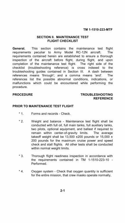
General. This section contains the maintenance test flightrequirements peculiar to Army Model RC-12N aircraft. Therequirements contained herein are established to ensure a thoroughinspection of the aircraft before flight, during flight, and uponcompletion of the maintenance test flight. The right side of thechecklist (troubleshooting reference) is cross indexed to thetroubleshooting guides contained in Section III. A dash betweenreferences means 'through'; and a comma means 'and'. Thereferences list the possible abnormal conditions, indications, ormalfunctions which could be encountered while performing theprocedure.
PROCEDURE TROUBLESHOOTINGREFERENCE
PRIOR TO MAINTENANCE TEST FLIGHT
* 1. Forms and records - Check.
* 2. Weight and balance - Maintenance test flight shall beconducted with full oil, full main tanks, full auxiliary tanks,two pilots, optional equipment, and ballast if required toremain within center-of-gravity limits. The averagetakeoff weight shall be 13,500 ±200 pounds or 15,000 ±200 pounds for the maximum cruise power and speedcheck and stall flights. All other tests shall be conductedwithin normal weight limits.
* 3. Thorough flight readiness inspection in accordance withthe requirements contained in TM 1-1510-223-10 -Performed.
* 4. Oxygen system - Check that oxygen quantity is sufficientfor the entire mission, that crew masks operate normally,
2-1

TM 1-1510-223-MTF
PROCEDURE TROUBLESHOOTINGREFERENCE
PRIOR TO MAINTENANCE TEST FLIGHT (CONT)
and that the diluter selector is set at 100%.
a. OXYGEN SUPPLY PRESSURE gages - Check.
b. SUPPLY control lever (green) - ON.
c. Diluter control lever - 100% OXYGEN.
d. EMERGENCY control lever (red) - Set to TEST MASKposition while holding mask directly away from face, thenreturn to NORMAL.
e. Oxygen mask - Put on and adjust.
f. EMERGENCY pressure control lever - Set to TEST MASKposition and check mask for leaks, then return lever toNORMAL.
g. FLOW indicator - Check. During inhalation blinkerappears, during exhalation blinker disappears. Repeat aminimum of 3 times.
h. Oxygen masks - Remove and store.
5. Seats, pedals, belts, harnesses - Check and adjust.
6. Flight controls - Check for free and correct movements.
7. PARKING BRAKE - Check. Confirm that brakes are set byapplying additional toe pressure.
2-2

TM 1-1510-223-MTF
PROCEDURE TROUBLESHOOTINGREFERENCE
Do not force the elevator trim system past the limitswhich are shown on the PITCH TRIM indicator scale.
8. Elevator trim - Set to 0 (neutral).
Do not cycle LDG GEAR CONTR handle on theground.
9. Gear- DN.10. Keylock switch - ON.11. Weather radar - OFF/SBY.
*12. Fuel control panel - Check the standby pumpsand firewall valves as follows to ensure that theyare powered through the essential bus:a. BATTERY switch - OFF.b. # 1 and # 2 STANDBY PUMP circuit
breakers - Pull.c. # 1 and # 2 FIREWALL VALVE circuit
breakers - Pull.d. # 1 and # 2 FIRE PULL handles - Pull to close
firewall valve (listen for valve operation).e. STANDBY PUMP switches - ON C41
(listen for pump operation).f. BATTERY switch - ON. C7-11g. # 1 and # 2 FUEL PRESS warning
annunciators - Illuminated.
2-3

TM 1-1510-223-MTF
PROCEDURE TROUBLESHOOTINGREFERENCE
PRIOR TO MAINTENANCE TEST FLIGHT (CONT)
h. FIRE PULL handles - In.i. # 1 and # 2 FUEL PRESS warning
annunciators - Extinguished.j. STANDBY PUMP switches - Off.k. #1 and #2 FUEL PRESS warning
annunciators - Illuminated.l. # 1 and # 2 STANDBY PUMP circuit
breakers - In.m. # 1 and # 2 FIREWALL VALVE circuit
breakers - In.n. CROSSFEED valve switch - Set C40
alternately to left and right system. Checkthat FUEL CROSSFEED light illuminates,and that the # 1 and # 2 FUEL PRESSannunciator lights are extinguished.
o. CROSSFEED valve switch - OFF.*13. Fuel quantity indicators - Check as follows: B6-8
a. Fuel quantity indicator selector switch -MAIN.
b. Fuel quantity indicators - Compareindication. With full fuel tanks, left and rightfuel quantity indicators must indicate within82 pounds of each other with fuel quantityindicator selector switch set to MAIN.
c. Fuel quantity indicator selector switch -AUXILIARY.
d. Fuel quantity indicators - Compareindication. With full fuel tanks, left andright fuel quantity indicators
2-4

TM 1-1510-223-MTF
PROCEDURE TROUBLESHOOTINGREFERENCE
must indicate within 35 pounds of eachother with fuel quantity indicator selectorswitch set to AUXILIARY.
*14. Pitot tubes (2), stall warning vane, heated fuelvents (2), and TAS temperature probe - Checkas follows:
Use caution when checking pitot tubes, stall warning vane, heated fuelvents, and TAS temperature probe for heat by feel. The heatingelements in these items can produce enough heat to cause burns topersonnel who touch them.
a. STALL WARN heat switch - ON. C55
b. PITOT heat switches (2) - ON.
c. FUEL VENT heat switches (2) - ON. C56
d. Left wing heated fuel vent - Check by feel forheat and condition.
e. Stall warning vane - Check by feel for heatand condition.
f. Left pitot tube - Check by feel for C33heat, condition, and free of obstructions.
g. Right pitot tube - Check by feel for C33heat, condition, and free of obstructions.
h. TAS temperature probe - Check by feel forheat and condition.
i. Right wing heated fuel vent - Check by feelfor heat and condition.
2-5

TM 1-1510-223-MTF
PROCEDURE TROUBLESHOOTINGREFERENCE
PRIOR TO MAINTENANCE TEST FLIGHT (CONT)
j. STALL WARN heat switch - Off.
k. PITOT heat switches (2) - Off.
l. FUEL VENT heat switches (2) - Off.
Extend the ice vanes during ground operation tominimize foreign object damage (FOD) to the engine.
15. ICE VANE CONTROL switches - ON.
*16. Lighting systems - Check. Include position C39lights, recognition lights, landing/ taxi light, wingice lights, beacons, emergency lights, andinterior lights, then off.
NOTEPlace the EMERGENCY lights override switch in theTEST position and check the emergency lights (5)for illumination and intensity. A dim light indicatesa weak battery pack which may not allow lights toturn off. At the completion of the check, cycle theswitch from the TEST position to the OFF/RESETposition and then to AUTO.
*17. HYD FLUID SENSOR TEST switch - C22Depress. Check HYD FLUID LOW annunciatorlight illuminates after approximately 2 seconds,and extinguishes after approximately 6 seconds.
*18. Engine fire protection system - Check as follows: C43-47
2-6

TM 1-1510-223-MTF
PROCEDURE TROUBLESHOOTINGREFERENCE
a. ENG FIRE TEST switches - Hold switchesto DET position, check that FIRE PULLhandle warning annunciators and MASTERWARNING annunciators illuminate.
b. ENG FIRE TEST switches - Hold switchesto EXT position, check that SQUIB OK andEXTGH DISCH annunciators and MASTERCAUTION annunciators illuminate.
NOTEIf MASTER WARNING is canceled between tests, itmay not re-illuminate.
*19. Stall and gear warning system - Check C34,35as follows:
a. STALL WARN TEST switch - TEST. Checkthat warning horn sounds.
b. LDG GEAR WARN TEST switch - TEST. C30Check that warning horn sounds and thatthe LDG GEAR CONTR handle warninglights illuminate.
*20. Flaps - Check in full down and full up positions. C31, C32
21. BATTERY switch - As required.
*22. Seat belts - Check for security and properconnections.
*23. Toilet - Check condition.
*24. Emergency equipment - Check that all requiredemergency equipment is available and that fireextinguishers and
2-7

TM 1-1510-223-MTF
PROCEDURE TROUBLESHOOTINGREFERENCE
PRIOR TO MAINTENANCE TEST FLIGHT (CONT)
first-aid kits have current inspection dates.
O*25. Parachutes - Check secure and for currentinspection and repack dates.
*26. Check all interior and exterior placards andmarkings.
*27. Trim tab travel and direction - Check. Operatetrim tabs through the full range of travel, notingany excessive friction or binding. Check tabdirection and neutral position at the control andthe surface.
*28. Flight controls - Check operation and direction.Check movement of control surfaces fordirection with movement of cockpit controls.Check for any abnormal friction or obstructionsthrough full range of travel.
29. GPU - Connect as required. C1230. Mission control panel switches - Check and set
as required:a. ANT STEERING selector switch - AUTO.
b. ANT ORIDE switch - AUTO.
c. MISSION CONTROL switch - AUTO.
d. TDOA system switch - As required.
e. DATA LINK HV switch - STBY.
f. DATA LINK ANT SEL switch - AUTO.
g. ASE SILENT switch - As required.
2-8
TM 1-1510-223-MTF
PROCEDURE TROUBLESHOOTINGREFERENCE
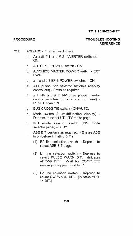
*31. ASE/ACS - Program and check.a. Aircraft # I and # 2 INVERTER switches -
ON.b. AUTO PLT POWER switch - ON.c. AVIONICS MASTER POWER switch - EXT
PWR.d. # 1 and # 2 EFIS POWER switches - ON.e. ATT pushbutton selector switches (display
controllers) - Press as required.f. # I INV and # 2 INV three phase inverter
control switches (mission control panel) -RESET, then ON.
g. BUS CROSS TIE switch - ON/AUTO.h. Mode switch A (multifunction display) -
Depress to select UTILITY mode page.i. INS mode selector switch (INS mode
selector panel) - STBY.j. ASE BIT perform as required. (Ensure ASE
is on before initiating BIT.)(1) R2 line selection switch - Depress to
select ASE BIT page.
(2) L1 line selection switch - Depress toselect PULSE WARN BIT. (InitiatesAPR-39 BIT.) Wait for COMPLETEmessage to appear next to L1.
(3) L2 line selection switch - Depress toselect CW WARN BIT. (Initiates APR-44 BIT.)
2-9

TM 1-1510-223-MTF
PROCEDURE TROUBLESHOOTINGREFERENCE
PRIOR TO MAINTENANCE TEST FLIGHT (CONT)
Wait for COMPLETE message toappear next to L2.
(4) L4 line selection switch - Depress twicewithin three seconds to initiate ALQ-156test. ALQ-156 must be on for BIT.
(a) First depression - Boxes text andarms FLARE TEST.
(b) Second depression - Causes aflare fire pulse to be sent fromALQ-156 to the M-130 and flarecount to be decreased by one. (Ifweight is on wheels a flare cannotbe fired.)
(5) R1 line selection switch - Depress toselect PULSE JAM BIT. (Initiates ALQ-136 BIT.) Wait for PASS text to appearnext to R1.
(6) R2 line selection switch - Depress toselect CW JAM BIT. (Initiates ALQ-162bit.) Wait for PASS text to appear nextto R2.
(7) R3 or R4 line selection switches -Depress as required. R3 increasesvolume, R4 decreases volume.Maximum volume is 15, off is 0.
k. Waypoint list - Build as follows:
(1) Mode switch B - Depress to selectFLIGHT PLAN page.
2-10

TM 1-1510-223-MTF
PROCEDURE TROUBLESHOOTINGREFERENCE
(2) R4 line selection switch - Depress toselect WAYPOINT LIST page.
(3) Waypoint string (line number, WPT ID,and LAT/LONG coordinates) - Enterinto scratch-pad.
(4) R1 line selection switch - Depress toload selected waypoint into system.
l. Flight plan - Build as follows:
(1) WPT numbers - Enter into scratch-pad in order of desired use (up to nine).
(2) Mode switch B - Depress to selectFLIGHT PLAN page.
(3) L1 line selection switch - Depress toselect NEW FPLN. INS LOADINGmessage will appear at the top of thedisplay for 2 to 3 minutes, then flightplan will be usable.
m. TACAN list - Build as follows:
(1) Mode switch B - Depress to selectFLIGHT PLAN page.
(2) R5 line selection switch - Depress toselect NAV SETUP page.
(3) R3 line selection switch - Depress toselect TACAN LIST.
(4) TACAN station information (listnumber, ID, channel number,latitude/longitude, and station elevation)- Enter into scratch-pad.
2-11
TM 1-1510-223-MTF
PROCEDURE TROUBLESHOOTINGREFERENCE
PRIOR TO MAINTENANCE TEST FLIGHT (CONT)
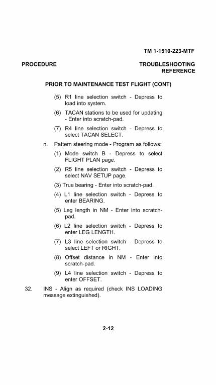
(5) R1 line selection switch - Depress toload into system.
(6) TACAN stations to be used for updating- Enter into scratch-pad.
(7) R4 line selection switch - Depress toselect TACAN SELECT.
n. Pattern steering mode - Program as follows:
(1) Mode switch B - Depress to selectFLIGHT PLAN page.
(2) R5 line selection switch - Depress toselect NAV SETUP page.
(3) True bearing - Enter into scratch-pad.
(4) L1 line selection switch - Depress toenter BEARING.
(5) Leg length in NM - Enter into scratch-pad.
(6) L2 line selection switch - Depress toenter LEG LENGTH.
(7) L3 line selection switch - Depress toselect LEFT or RIGHT.
(8) Offset distance in NM - Enter intoscratch-pad.
(9) L4 line selection switch - Depress toenter OFFSET.
32. INS - Align as required (check INS LOADINGmessage extinguished).
2-12

TM 1-1510-223-MTF
PROCEDURE TROUBLESHOOTINGREFERENCE
a. Mode switch B - Depress to select FLIGHTPLAN page.
b. R5 line selection switch (multifunctiondisplay) - Depress to select NAV SETUPpage.
c. R5 line selection switch (multifunctiondisplay) - Depress to select INS SETUP.
d. If ALIGN POS NOT ENTERED is displayed,or align position needs to be changed,perform the following:
NOTEN, S, E, W is not required before the LAT/LONG.
(1) L1 line selection switch - Depress.Position will load and ALIGN STATE: 9will appear below coordinates.
(2) INS mode switch - ALIGN.
NOTEINS BIT is not possible until readiness state 8 orbelow is obtained.
e. INS BIT - Perform as follows:
(1) INS/TCN pushbutton selector switch(display controller) - Depress to selectINS.
(2) Single needle bearing pointer sourceselector switch - INS.
(3) Mode switch A (multifunction display) -Depress to select UTILITY page.
2-13

TM 1-1510-223-MTF
PROCEDURE TROUBLESHOOTINGREFERENCE
PRIOR TO MAINTENANCE TEST FLIGHT (CONT)
(4) RI line selection switch - Depress toselect SYSTEM BIT page.
(5) R2 line selection switch - Depress toselect INS BIT.
(6) NAV switch-indicator (flight directormode selector) - Depress.
(7) AP ENGAGE pushbutton switch -Depress and check the followingindications:
(a) Multifunction display - Check thatINS BATT, INS FAIL, andWAYPOINT ALERT areannunciated.
(b) EHSI - Check that single needlepointer indicates 30°, coursedeviation bar is displaced right,then single-needle pointer centeringand course deviation bar displacingleft. Check WPT alert annunciatorilluminated.
(c) Control wheels - Follow coursedeviation bar.
(d) INS mode selector - Check thatREADY light (green) and BATTlight (red) are illuminated.
(e) Mission annunciator panel - Checkthat INS UPDATE annunciator light(green) and NO INS
2-14

TM 1-1510-223-MTF
PROCEDURE TROUBLESHOOTINGREFERENCE
UPDATE annunciator light (yellow) areilluminated.
(8) Multifunction display - Check forCOMPLETE text at R2.
NOTEFailure codes will appear below COMPLETE text.Check action and malfunction codes for correctiveaction. Depressing R2 again may clear fault codes.
f. INS mode selector switch - NAV (whenalignment state 5 or less has been reached).Then perform the following:
(1) Mode switch B - Depress to selectFLIGHT PLAN page.
(2) R5 line selection switch - Depress toselect NAV SETUP page.
(3) R5 line selection switch - Depress toselect INS SETUP page.
(4) R3 line selection switch - Depress tochange AUTO MIXING to TACAN, DL,GPS, or OFF as required.
(5) R2 line selection switch - Depress toselect ROLL LIMIT ON or OFF asrequired.
(6) L3 line selection switch - Depress toselect LEG CHANGES to MAN orAUTO as required.
2-15

TM 1-1510-223-MTF
PROCEDURE TROUBLESHOOTINGREFERENCE
PRIOR TO MAINTENANCE TEST FLIGHT (CONT)
g. Multifunction display - Wait for INSLOADING message to extinguish. INSLOADING message will extinguish after 6 to8 minutes. Complete autopilot/flight directorcheck while waiting.
NOTEWhile the INS LOADING message is illuminated onthe multifunction display, the functions on theFLIGHT PLAN, NAV SETUP, ROUTES, TACANLIST, INS SETUP, INS UPDATE STATUS,MONITOR, SYSTEM BIT - INS, and ASE RTU pagesare inhibited.
h. Autopilot EFIS selector switch (above pilot'sADI) - AP EFIS 1.
*33. Pilot's and copilot's EFIS TEST switches -Depress. Verify the following indications:
a. Radio altimeter - Slews to 100 ± 10 feet.
b. EADI - DH display replaced with dashes.
c. EHSI - CRS select, HDG select, and GSPDdisplays replaced with dashes.
d. Caution and warning flags - All will be inview.
e. Pitch and roll command cue - Out of view.
f. Verify that audio alarm occurs within 5 to 6seconds.
2-16

TM 1-1510-223-MTF
PROCEDURE TROUBLESHOOTINGREFERENCE
NOTEA localizer frequency must be tuned on both NAVreceivers to annunciate ILS.
g. EADI - TEST appears in left center ofdisplay to indicate that flight director modeselector lamp test is good. FD FAIL willappear momentarily and be replaced byTEST in the left center of the EADI displayto indicate a problem in the EFIScomponents or interconnection of the flightdirector computer.
NOTEPreflight test of the composite mode will cause thesame results as the above test, except the digitalheading readout will be replaced with a red FAILindication, and the expanded localizer scale andpointer will be removed.
Test is inhibited during glideslope capture.
*34. Flight director/autopilot preflight test.
a. BATTERY switch (overhead control panel) -ON.
b. Aircraft # I and # 2 INVERTER switches -ON.
c. AVIONICS MASTER POWER switch(overhead control panel) - ON or EXT PWRas required.
d. # 1 and # 2 EFIS POWER switches(overhead control panel) - ON.
e. AUTO PLT POWER switch (overheadcontrol panel) - ON.
2-17

TM 1-1510-223-MTF
PROCEDURE TROUBLESHOOTINGREFERENCE
PRIOR TO MAINTENANCE TEST FLIGHT (CONT)
f. RUDDER BOOST/YAW CONTROL TESTswitch (pedestal extension) - RUDDERBOOST.
g. RADIO ALT switch (mission control panel) -ON.
h. Autopilot EFIS selector switch (instrumentpanel) - AP EFIS 1.
i. Altitude alerter - Check as follows:
(1) Pilot's altimeter - Set to field elevation.
(2) Altitude preselector - Set to more than1000 feet above field elevation.
(3) Pilot's altimeter barometric set knob -Slowly increase pilot's altimeter setting.
(4) Altitude alerter annunciator and horn -Verify that the altitude alert annunciatoron the pilot's altimeter illuminates andthe altitude alerter horn sounds whenthe pilot's altimeter reading isapproximately 1000 feet from the valueset on the altitude select controller.
(5) Pilot's altimeter - Reset to fieldelevation.
(6) Altitude preselector - Reset to fieldelevation.
(7) Pilot's altimeter barometric set knob -Slowly increase pilot's altimeter setting.
(8) Altitude alerter annunciator and horn -Verify that the alti-
2-18

TM 1-1510-223-MTF
PROCEDURE TROUBLESHOOTINGREFERENCE
tude alerter annunciator on the pilot'saltimeter illuminates and the altitudealerter horn sounds when the altimeterreading is approximately 250 feet fromthe value set on the altitude alertcontroller.
(9) Pilot's altimeter - Reset to currentbarometric altimeter setting or to fieldelevation.
j. Flight director/autopilot annunciators/alerterhorns - Check as follows:
(1) SBY pushbutton switch indicator (flight director modeselector) - Depress for at least 5 to 8 seconds andverify the following indications:
(a) Flight director mode selectorannunciators illuminate.
(b) Autopilot controller annunciatorsilluminate.
(c) All 8's illuminate on the altitudeselect controller.
(d) Altitude alert annunciator on pilot'saltimeter illuminates.
(e) FD FAIL (amber) will beannunciated on the EADI.
(2) After the SBY pushbutton switch-indicator has been held depressed for 5to 8 seconds, verify that:
(a) AP TRIM annunciator illuminates.
2-19

TM 1-1510-223-MTF
PROCEDURE TROUBLESHOOTINGREFERENCE
PRIOR TO MAINTENANCE TEST FLIGHT (CONT)
(b) Autopilot disconnect horn sounds
(3) SBY pushbutton switch indicator-Release.
(4) FD and ATT annunciations on the EADI- Check extinguished.
(5) TRIM annunciators (autopilot controller)- Check extinguished.
NOTESteady illumination of the TRIM UP or TRIM DNannunciator on the autopilot controller indicates thatthe autopilot automatic synchronization is notfunctioning correctly and that the autopilot should notbe engaged in flight.
(6) TURN knob (autopilot controller) -Check in center detent position.
(7) ELEV TRIM switch (pedestal extension)- ELEV TRIM. Check ELEC TRIM OFFannunciator extinguished.
(8) RUDDER BOOST/YAW CONTROLTEST switch (pedestal extension) -RUDDER BOOST. Check RUDDERBOOST annunciator extinguished. (IfRUDDER BOOST annunciatorilluminates, cycle rudder boost/yawcontrol test switch to OFF then back toRUDDER BOOST.)
2-20
TM 1-1510-223-MTF
PROCEDURE TROUBLESHOOTINGREFERENCE
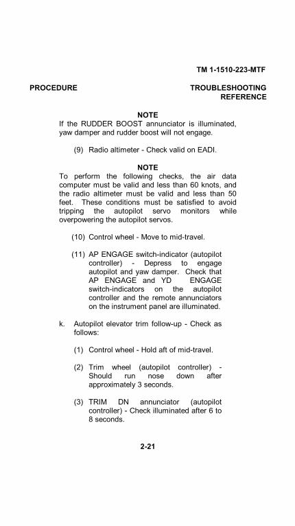
NOTEIf the RUDDER BOOST annunciator is illuminated,yaw damper and rudder boost will not engage.
(9) Radio altimeter - Check valid on EADI.
NOTETo perform the following checks, the air datacomputer must be valid and less than 60 knots, andthe radio altimeter must be valid and less than 50feet. These conditions must be satisfied to avoidtripping the autopilot servo monitors whileoverpowering the autopilot servos.
(10) Control wheel - Move to mid-travel.
(11) AP ENGAGE switch-indicator (autopilotcontroller) - Depress to engageautopilot and yaw damper. Check thatAP ENGAGE and YD ENGAGEswitch-indicators on the autopilotcontroller and the remote annunciatorson the instrument panel are illuminated.
k. Autopilot elevator trim follow-up - Check asfollows:
(1) Control wheel - Hold aft of mid-travel.
(2) Trim wheel (autopilot controller) -Should run nose down afterapproximately 3 seconds.
(3) TRIM DN annunciator (autopilotcontroller) - Check illuminated after 6 to8 seconds.
2-21

TM 1-1510-223-MTF
PROCEDURE TROUBLESHOOTINGREFERENCE
PRIOR TO MAINTENANCE TEST FLIGHT (CONT)
(4) APFTRIM annunciators (instrumentpanel, above EADI's) - Checkilluminated after approximately 15seconds.
(5) Control wheel - Hold forward of midtravel.
(6) Trim wheel (autopilot controller) -Should run nose up after approximately3 seconds.
(7) TRIM UP annunciator (autopilotcontroller) - Check illuminated after 6 to8 seconds.
(8) AP/TRIM annunciators (instrumentpanel, above EADI's) - Checkilluminated after approximately 15seconds.
(9) AP & YDITRIM DISC switch (controlwheel) - Depress to first level todisengage the autopilot/yaw damper.
l. Autopilot overpower check - Perform asfollows:
(1) AP ENGAGE switch-indicator (autopilotcontroller) - Depress to engageautopilot and yaw damper. Check thatAP ENGAGE and YD ENGAGE switch-indicators on the autopilot controllerand the remote annunciators on theinstrument panel are illuminated.
(2) Control wheel - Slowly overpowerautopilot in pitch and roll axis.
2-22

TM 1-1510-223-MTF
PROCEDURE TROUBLESHOOTINGREFERENCE
(3) Rudder pedals - Slowly overpower yawdamper in both directions.
NOTE
If unable to overpower the autopilot in any axis, or if theautopilot or yaw damper disengages during the overpowercheck, use of the autopilot or yaw damper in flight is notrecommended.
(4) AP & YDFTRIM DISC switch (control wheel)- Depress to first level. Check that autopilotand yaw damper disengage, AP ENGAGEand YD ENGAGE switch-indicators on theautopilot controller and remote annunciatorsabove the EADI's flash 5 times.
(5) GO AROUND button (left POWER lever) -Depress. Check GA annunciator on EADIilluminates. Yaw damper will automaticallyengage and YD ENGAGE switch-indicatorwill be illuminated on the autopilot controllerand the remote annunciators above theEADI's will be illuminated.
(6) AP & YD/TRIM DISC switch (control wheel)- Depress to first level. Check that yawdamper disengages and that YD ENGAGEswitch-indicator on the autopilot controllerextinguishes and the remote annunciatorsabove the EADI's flash 5 times.
2-23

TM 1-1510-223-MTF
PROCEDURE TROUBLESHOOTINGREFERENCE
PRIOR TO MAINTENANCE TEST FLIGHT (CONT)
(7) YD ENGAGE pushbutton switch-indicator(autopilot controller) - Depress. Check thatyaw damper engages, and that YDENGAGE switch-indicator on the autopilotcontroller and the remote annunciator on theinstrument panel above the EADI'silluminates.
(8) RUDDER BOOST/YAW CONTROL TESTswitch (pedestal extension) - TEST. Checkthat RUDDER BOOST annunciator abovethe EADI's illuminates, yaw damperdisengages, YD ENGAGE switch-indicatoron the autopilot controller extinguishes,and the YD ENG remote annunciatorsabove the EADI's flash 5 times.
(9) YD ENGAGE pushbutton switch-indicator(autopilot controller) - Depress whileholding rudder boost/yaw control test switchin TEST. Yaw damper should not engage.
(10) RUDDER BOOST/YAW CONTROL TESTswitch - RUDDER BOOST. Check RUDDERBOOST annunciator extinguished.
2-24

TM 1-1510-223-MTF
PROCEDURE TROUBLESHOOTINGREFERENCE
If the SBY annunciator on the flight director mode selectordoes not illuminate within 10 seconds after the avionicsmaster switch is turned on, the autopilot has failed self-testand is considered inoperative and should not be used. Do notforce the elevator trim system beyond the limits which areindicated on the ELEVATOR trim tab indicator.
m. Electric elevator trim - Check.
(1) ELEV TRIM switch - On.
(2) Pilot and copilot trim switches- Check operation.
Operation of the electric trim system should occur only bymovement of pairs of switches. Any movement of the elevatortrim wheel while depressing only one switch element indicatesa trim system malfunction. Turn the electric elevator trimcontrol switch OFF and conduct flight by operating theelevator trim wheel manually. Do not use autopilot.
(3) Pilot and copilot. Check individual elementfor no movement of trim, then check properoperation of both elements.
(4) Check pilot switches override copilotswitches while trim-
2-25

TM 1-1510-223-MTF
PROCEDURE TROUBLESHOOTINGREFERENCE
PRIOR TO MAINTENANCE TEST FLIGHT (CONT)
ming in opposite directions, and trim movesin direction commanded by pilot.
(5) Check trim disconnects while activating pilotand copilot trim disconnect switches.
(6) ELEV TRIM switch - OFF then on (ELECTRIM OFF annunciator extinguishes).
35. BATTERY switch - As required.
INTERIOR CHECK
1. Cargo/loose equipment - Check secured.
* 2. Cabin/cargo doors - Test and lock:
a. Cabin door - Check closed and latched by thefollowing:
(1) Safety arm and diaphragm plunger - Checkposition (lift door step
(2) Index marks on rotary cam locks (6) - Checkaligned with indicator windows.
b. Cargo door - Check closed and latched by thefollowing:
(1) Upper handle - Check closed and latched.(Observe through cargo door latch handleaccess cover window.)
(2) Index marks on rotary cam locks (4) - Checkaligned with indicator windows.
2-26

TM 1-1510-223-MTF
PROCEDURE TROUBLESHOOTINGREFERENCE
(3) Lower pin latch handle - Check closed andlatched. (Observe through cargo door lowerlatch handle access cover window.)
(4) Carrier rod - Check orange indicator alignedwith orange stripe carrier rod. (Observethrough window, aft lower corner.)
c. BATTERY switch - As required
NOTE
If unable to place BATTERY switch in the OFF position due toINS operation, CABIN DOOR annunciator light operation fromthe hot battery bus (step e) will not be verified.
d. Cargo door - Check closed and latched.
e. Cabin door - Close but leave unlatched. CheckCABIN DOOR annunciator light illuminated.
f. Cabin door - Open. Check CABIN DOORannunciator light extinguished.
g. BATTERY switch - ON. Check CABIN DOORannunciator light illuminated.
h. Cabin door - Close and latch. Check CABINDOOR annunciator light extinguished.
2-27

TM 1-1510-223-MTF
PROCEDURE TROUBLESHOOTINGREFERENCE
INTERIOR CHECK (CONT)
NOTE
The above procedures check both cargo and cabin doorsecurity provisions.
* 3. Emergency exit - Check secure and key removed.
* 4. Mission cooling ducts - Check open and free ofobstructions.
* 5. Flare/chaff dispenser preflight test - Completed.
6. COMSEC keys - Loaded as required.
7. Crew briefing - As required.
BEFORE STARTING ENGINES
1. Seats, pedals, belts, harnesses - Adjust.
2. Flight controls - Check for free and correctmovements.
3. PARKING BRAKE - Check. Confirm that brakesare set by applying additional toe pressure.
4. Oxygen system - Set as required.
5. Circuit breakers - Check in.
6. Overhead panel - Check and set.a. Light dimming controls - As required. C39b. Cockpit lights (3) - As required.c. CABIN AIR MODE SELECT switch - OFF.d. ENG INLET LIP HEAT switches - OFF.
2-28

TM 1-1510-223-MTF
PROCEDURE TROUBLESHOOTINGREFERENCE
e. ICE VANE POWER SELECT switches (2) -MAIN.
f. ICE VANE CONTROL switches (2) - ON.
g. ICE & RAIN switches - Off.
h. Exterior light switches - As required.
i. # 1 and # 2 EFIS POWER switches - Off.
j. AVIONICS MASTER POWER switch - Asrequired.
k. AUTO PLT POWER switch - Off.
l. # 1 and # 2 INVERTER switches - As required.
m. Environmental switches - As required.
n. AUTOFEATHER switch - OFF.
o. # 1 AUTO IGNITION switch - Off.
p. # 1 ENG START switch - OFF.
q. BATTERY switch - As required.
r. GENERATOR switches (2) - OFF.
s. # 2 ENG START switch - OFF.
t. # 2 AUTO IGNITION switch - Off.
7. Fuel panel switches - Check.
a. STANDBY PUMP switches (2) - Off.
b. AUX XFER switches (2) - AUTO.
c. CROSSFEED switch - OFF.
2-29

TM 1-1510-223-MTF
PROCEDURE TROUBLESHOOTINGREFERENCE
BEFORE STARTING ENGINES (CONT)
NOTE
Refer to operator's manual or aircraft placarding to determineconditions affecting standby compass headings.
* 8. Magnetic compass - Check for fluid, heading, andcurrent correction card.
CAUTION
Do not move POWER levers below the flight idle gate with theengines not operating. Movement of the POWER levers belowthe flight idle gate with the engines not operating may result inbending and damage to control linkage.
9. Pedestal controls - Set.
a. POWER levers - IDLE.
b. PROP levers - As required.
c. CONDITION levers - FUEL CUT-OFF.
d. Flaps - As required.
10. Pedestal extension switches - Set.
a. Avionics - As required.
b. RUDDER BOOST switch - On.
c. ELEV TRIM switch - On.
11. LANDING GEAR ALTERNATE EXTENSION pumphandle - Stowed.
* 12. Free air temperature gage - Check. Note currentreading.
13. Pilot's instrument panel - Check and set.
2-30
TM 1-1510-223-MTF
PROCEDURE TROUBLESHOOTINGREFERENCE
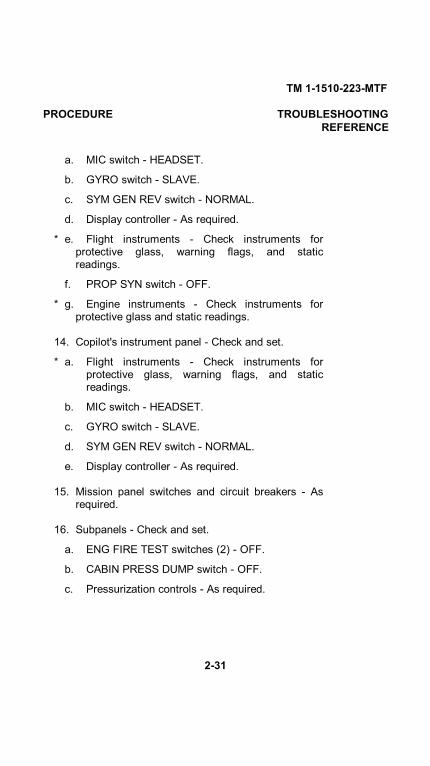
a. MIC switch - HEADSET.
b. GYRO switch - SLAVE.
c. SYM GEN REV switch - NORMAL.
d. Display controller - As required.
* e. Flight instruments - Check instruments forprotective glass, warning flags, and staticreadings.
f. PROP SYN switch - OFF.
* g. Engine instruments - Check instruments forprotective glass and static readings.
14. Copilot's instrument panel - Check and set.
* a. Flight instruments - Check instruments forprotective glass, warning flags, and staticreadings.
b. MIC switch - HEADSET.
c. GYRO switch - SLAVE.
d. SYM GEN REV switch - NORMAL.
e. Display controller - As required.
15. Mission panel switches and circuit breakers - Asrequired.
16. Subpanels - Check and set.
a. ENG FIRE TEST switches (2) - OFF.
b. CABIN PRESS DUMP switch - OFF.
c. Pressurization controls - As required.
2-31
TM 1-1510-223-MTF
PROCEDURE TROUBLESHOOTINGREFERENCE
BEFORE STARTING ENGINES (CONT)
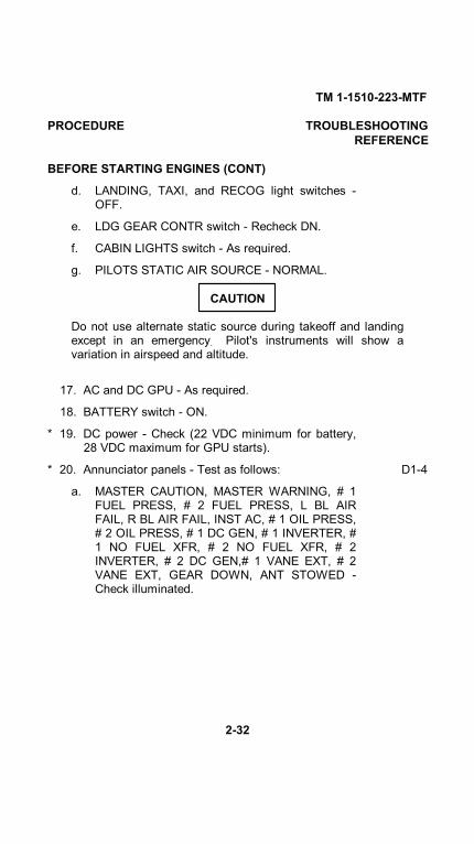
d. LANDING, TAXI, and RECOG light switches -OFF.
e. LDG GEAR CONTR switch - Recheck DN.
f. CABIN LIGHTS switch - As required.
g. PILOTS STATIC AIR SOURCE - NORMAL.
CAUTION
Do not use alternate static source during takeoff and landingexcept in an emergency. Pilot's instruments will show avariation in airspeed and altitude.
17. AC and DC GPU - As required.
18. BATTERY switch - ON.
* 19. DC power - Check (22 VDC minimum for battery,28 VDC maximum for GPU starts).
* 20. Annunciator panels - Test as follows: D1-4
a. MASTER CAUTION, MASTER WARNING, # 1FUEL PRESS, # 2 FUEL PRESS, L BL AIRFAIL, R BL AIR FAIL, INST AC, # 1 OIL PRESS,# 2 OIL PRESS, # 1 DC GEN, # 1 INVERTER, #1 NO FUEL XFR, # 2 NO FUEL XFR, # 2INVERTER, # 2 DC GEN,# 1 VANE EXT, # 2VANE EXT, GEAR DOWN, ANT STOWED -Check illuminated.
2-32

TM 1-1510-223-MTF
PROCEDURE TROUBLESHOOTINGREFERENCE
b. ANNUNCIATOR TEST switch - Hold to TESTposition. Check that all annunciator panels, FIREPULL handle annunciators, ANT AZIMUTHindicator, MASTER CAUTION, and MASTERWARNING annunciators are illuminated.
c. MASTER CAUTION and MASTER WARNINGannunciators - Press and release. Bothannunciators should extinguish.
FIRST ENGINE START (BATTERY START)
NOTE
The engines must not be started until after the INS is placedinto the NAV mode or OFF, as required.
Starting procedures are identical for both engines. Assign acrewmember to monitor the fire guard throughout the engine startprocedures.
1. INS - As required.
2. Exterior lights switches - As required.
3. Fire guard - Posted.
4. Propeller area - Clear. A1-7
5. # 2 ENG START switch - START-IGNITION. # 2IGN ON annunciator should illuminate and # 2FUEL PRESS annunciator should extinguish.
NOTEFalse fuel flow indications may be observed with the starter-generator engaged and the CONDITION lever in FUELCUTOFF.
2-33

TM 1-1510-223-MTF
PROCEDURE TROUBLESHOOTINGREFERENCE
FIRST ENGINE START (BATTERY START) (CONT)
CAUTION
If ignition does not occur within 10 seconds after movingCONDITION lever to LOW IDLE, initiate Abort Startprocedure. If for any reason a starting attempt is discontinued,the entire starting sequence must be repeated after allowingthe engine to come to a complete stop (1 minute minimum).
6. CONDITION lever (after N1 RPM E1,J1passes 13% minimum) - LOW IDLE.
CAUTION
Monitor TGT to avoid a hot start. If there is a rapid rise inTGT, be prepared to abort the start before limits are exceeded.During starting, the maximum allowable TGT is 1000°C for 5seconds. If this limit is exceeded, initiate Abort Startprocedure and discontinue start. Enter the peak temperatureand duration on DA Form 2408-13-1.
7. TGT and N! (TGT 1000°C Maximum).
8. Oil pressure - Check (60 PSI minimum). E7-9
9. # 2 ENG START switch - OFF after TGT peaks.
10. CONDITION lever - HIGH IDLE. E2Monitor TGT as CONDITION lever isadvanced.
11. # 2 GENERATOR switch - RESET, then ON. C1
2-34

TM 1-1510-223-MTF
PROCEDURE TROUBLESHOOTINGREFERENCE
SECOND ENGINE START (BATTERY START)
1. # 2 generator load - Verify less than 50%.
2. Propeller area - Clear.
3. # 1 ENG START switch - START-IGNITION. A1-7# 1 IGN ON annunciator should illuminate and # 1FUEL PRESS annunciator should extinguish.
4. CONDITION lever (after N1 RPM passes13% E1, J1minimum - LOW IDLE.
5. TGT and N1 - Monitor (TGT 1000°C maximum).
6. Oil pressure - Check (60 PSI minimum). E7-9
7. # 1 ENG START switch - OFF after TGT peaks. E2
8. CONDITION levers - HIGH IDLE. Monitor TGT asCONDITION lever is advanced.
9. POWER levers - GROUND FINE.
10. PROP levers - Retard to FEATHER detent.
11. BATTERY CHARGE annunciator - Check on.BATTERY CHARGE annunciator should extinguishwithin 5 minutes following a normal engine start onbattery.
12. # 1 and # 2 INVERTER switches - ON, checkINVERTER annunciators off.
13. # 1 GENERATOR switch - RESET, then ON. C1
2-35
TM 1-1510-223-MTF
PROCEDURE TROUBLESHOOTINGREFERENCE
SECOND ENGINE START (BATTERY START) (CONT)
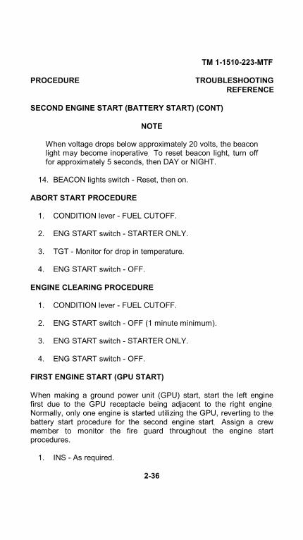
NOTE
When voltage drops below approximately 20 volts, the beaconlight may become inoperative. To reset beacon light, turn offfor approximately 5 seconds, then DAY or NIGHT.
14. BEACON lights switch - Reset, then on.
ABORT START PROCEDURE
1. CONDITION lever - FUEL CUTOFF.
2. ENG START switch - STARTER ONLY.
3. TGT - Monitor for drop in temperature.
4. ENG START switch - OFF.
ENGINE CLEARING PROCEDURE
1. CONDITION lever - FUEL CUTOFF.
2. ENG START switch - OFF (1 minute minimum).
3. ENG START switch - STARTER ONLY.
4. ENG START switch - OFF.
FIRST ENGINE START (GPU START)
When making a ground power unit (GPU) start, start the left enginefirst due to the GPU receptacle being adjacent to the right engine.Normally, only one engine is started utilizing the GPU, reverting to thebattery start procedure for the second engine start. Assign a crewmember to monitor the fire guard throughout the engine startprocedures.
1. INS - As required.
2-36
TM 1-1510-223-MTF
PROCEDURE TROUBLESHOOTINGREFERENCE
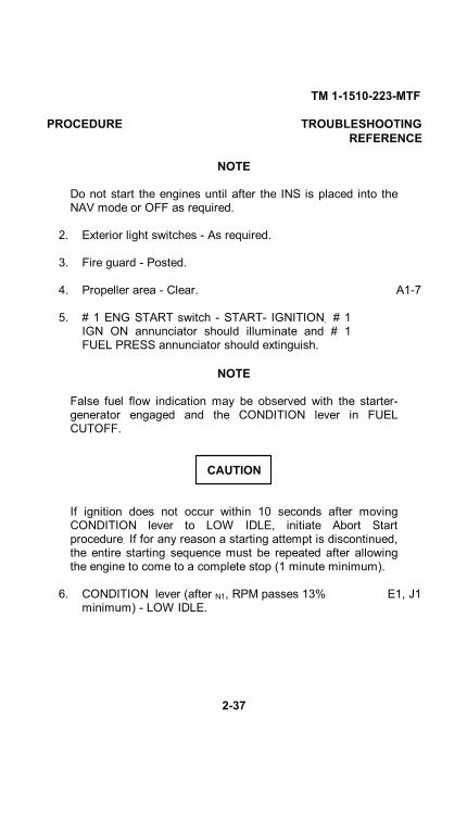
NOTE
Do not start the engines until after the INS is placed into theNAV mode or OFF as required.
2. Exterior light switches - As required.
3. Fire guard - Posted.
4. Propeller area - Clear. A1-7
5. # 1 ENG START switch - START- IGNITION. # 1IGN ON annunciator should illuminate and # 1FUEL PRESS annunciator should extinguish.
NOTE
False fuel flow indication may be observed with the starter-generator engaged and the CONDITION lever in FUELCUTOFF.
CAUTION
If ignition does not occur within 10 seconds after movingCONDITION lever to LOW IDLE, initiate Abort Startprocedure. If for any reason a starting attempt is discontinued,the entire starting sequence must be repeated after allowingthe engine to come to a complete stop (1 minute minimum).
6. CONDITION lever (after N1, RPM passes 13% E1, J1minimum) - LOW IDLE.
2-37

TM 1-1510-223-MTF
PROCEDURE TROUBLESHOOTINGREFERENCE
FIRST ENGINE START (GPU START) (CONT)
CAUTION
Monitor TGT to avoid a hot start. If there is a rapid rise inTGT, be prepared to abort the start before limits are exceeded.During engine start, the maximum allowable TGT is 1000°Cfor 5 seconds. If this limit is exceeded, initiate Abort Startprocedure and discontinue start. Enter the peak temperatureand duration on DA Form 2408-13-1.
7. TGT and N1 - Monitor (TGT 1000°C maximum).
8. Oil pressure - Check (60 PSI minimum). E7-9
9. # 1 ENG START switch - OFF after TGT peaks.
10. CONDITION lever - HIGH IDLE. E2Monitor TGT as CONDITION lever is advanced.
11. DC GPU disconnect - As required.
12. # 1 GENERATOR switch - RESET C1then ON, for second engine battery start.
SECOND ENGINE START (GPU START)
1. Propeller area - Clear.
2. # 2 ENG START switch - START- IGNITION. A1-7# 2 IGN ON annunciator should illuminate and # 2FUEL PRESS annunciator should extinguish.
3. CONDITION lever (after N1 RPM passes 13%minimum) - LOW IDLE.
2-38

TM 1-1510-223-MTF
PROCEDURE TROUBLESHOOTINGREFERENCE
4. TGT and N1 - Monitor (TGT 1000°C maximum).
5. Oil pressure - Check (60 PSI minimum).
6. # 2 ENG START switch - OFF after TGT peaks.
7. CONDITION lever - HIGH IDLE. Monitor TGT asCONDITION lever is advanced.
CAUTION
Monitor oil temperature closely during ground operation withpropellers in FEATHER due to lack of air flow over oil cooler.If necessary move propeller control out of FEATHER to keepoil temperature within limits.
8. PROP levers - FEATHER (if required).
9. AC and DC GPU units - Disconnect (check aircraftexternal power and mission external powerannunciator extinguished).
10. PROP levers - Advance, then retard to FEATHERdetent.
11. POWER levers - GROUND FINE.
12. # 1 and # 2 INVERTER switches - ON. CheckINVERTER annunciators extinguished.
13. GENERATOR switches - RESET, then ON. C1
2-39
TM 1-1510-223-MTF
PROCEDURE TROUBLESHOOTINGREFERENCE
SECOND ENGINE START (GPU START) (CONT)
NOTE
To reset beacon light, turn OFF approximately 5 seconds,then ON. When voltage drops below approximately 20 volts,the beacon light may become inoperative.
14. BEACON lights switch - Reset, then on.
BEFORE TAXIING
CAUTION
Propeller speeds below 1000 RPM are not authorized, unlessthe propeller is feathered.
1. BRAKE deice switch - Check and set as required.To activate the brake deice system, proceed asfollows:
a. LEFT PNEU & ENVIRO BLEED AIR valve switch- Off.
b. RIGHT PNEU & ENVIRO BLEED AIR valveswitch - ON.
c. BRAKE deice switch - Turn ON and observe thatthe BRAKE DE-ICE ON light is illuminated.
d. PNEUMATIC PRESSURE gage - Check for amomentary pressure decrease.
e. Repeat procedure for opposite bleed air valve.
2. CABIN AIR MODE SELECT switch - Set asdesired.
3. CABIN AIR TEMP control rheostat - Set asdesired.
2-40

TM 1-1510-223-MTF
PROCEDURE TROUBLESHOOTINGREFERENCE
NOTE
For maximum cooling on the ground, turn the PNEU &ENVIRO BLEED AIR valve switches to PNEU ONLY position.Verify airflow is present from aft cockpit eyeball outlets toensure sufficient cooling for mission equipment.
Check may also be accomplished by switching the # 1GENERATOR OFF and leaving the #2 GENERATOR ON.
* 4. AC/DC power/current limiters/inverters - Check as follows:
a. # 1 GENERATOR switch - ON.
b. # 2 GENERATOR switch - OFF.
c. # 1 and # 2 INVERTER switches - ON. C36,37Check for the following indications:
(1) # 1 and # 2 INVERTER annunciator lightsnot illuminated.
* (2) AC frequency - 394 to 406 Hz.
* (3) AC voltage - 104 to 124 VAC.
* (4) DC voltage - 28 to 28.5 VDC.
(5) Battery ammeter - Check for chargeindication.
NOTE
This procedure checks both 400 and 500 ampere currentlimiters that tie the aircraft bus systems together.
d. # 2 GENERATOR switch - ON.
5. AUTO PLT POWER switch - ON.
2-41

TM 1-1510-223-MTF
PROCEDURE TROUBLESHOOTINGREFERENCE
BEFORE TAXIING (CONT)
6. AVIONICS MASTER POWER switch - ON.
7. # 1 and # 2 EFIS POWER switches - ON.
8. Mission control panel - Check and set as required.
9. Avionics - Check and set as required.
10. Flaps - Check.
11. Altimeters - Check and set.
TAXIING
CAUTION
Extend the ice vanes during ground operation to minimizeforeign object damage (FOD) to the engine.
Taxi speed can be effectively controlled by the use of power applicationand the use of the variable pitch propellers in the ground fine rangewith the PROP levers retarded to the FEATHER detent.
* 1. Brakes - Check. G1-4,6-8
NOTE
If brakes have been overhauled, "burn in" the brakes byapplying near maximum braking (short of locking) for one ortwo landings or high speed taxi runs. After this, check brakesfor any tendency to drag.
* 2. Flight instruments - Check for normal operation.
2-42

TM 1-1510-223-MTF
PROCEDURE TROUBLESHOOTINGREFERENCE
* 3. Nosewheel steering - Check for no turningtendency while taxiing straight ahead with thesame RPM on both engines, with no braking andno rudder applied to either side. (This check mustbe performed with minimum cross wind.) Checkfreedom of movement and ability to turn aircraftusing rudder pedals, engines and brakes. Note anyindication of nosewheel vibration or shimmy duringtakeoff or landing.
* 4. Magnetic compass - Check for freedom of B4movement.
ENGINE RUNUP
1. Nose wheel - Center.
* 2. PARKING BRAKE - Set. The parking brake must G5lock without undue pressure on the brake pedalsand release cleanly when PARKING BRAKEhandle is reset.
CAUTION
Monitor oil temperature closely during ground operation withPROP levers in FEATHER due to lack of air flow over oilcooler.
* 3. Engine low idle speed - Check 60 to62% N1, E1with propellers feathered.
* 4. Propeller feathering - Check as follows: F14,15
a. CONDITION lever - HIGH IDLE.
b. Left PROP lever - FEATHER. Check that propeller featherswith no hesitation.
2-43

TM 1-1510-223-MTF
PROCEDURE TROUBLESHOOTINGREFERENCE
ENGINE RUNUP (CONT)
c. Check for proper pedestal control detentposition.
d. Left PROP lever - HIGH RPM.
e. Repeat procedure for right propeller.
* 5. Engine acceleration - Check as follows: E5,14-20
a. Left POWER lever - Set 64% N1, then rapidlymove lever to maximum forward travel.Acceleration time required for N, to reach 93.5 %is 2.5 to 4.0 seconds.
b. Left POWER lever - Immediately retard to IDLEas N1 passes through 93.5%.
c. Repeat procedure for right engine.
* 6. Engine high idle speed - Check 71 to 73% N1. E2
* 7. N1 speed switch (air conditioning) - Check asfollows:
a. Right engine CONDITION lever - LOW IDLE.
b. Right engine PROP lever - FEATHER.
c. CABIN AIR MODE SELECT switch - MANUALCOOL.
d. Verify that AIR COND N, LOW annunciator lightis illuminated.
e. Right engine CONDITION lever - Advance toincrease N1 to above 62%.
2-44

TM 1-1510-223-MTF
PROCEDURE TROUBLESHOOTINGREFERENCE
f. Verify that AIR COND N1 LOW annunciator lightis extinguished with N1 above 62%.
g. CABIN AIR MODE SELECT switch - AUTO.
* 8. Pneumatics/Vacuum/Pressurization - Check asfollows:
a. PNEUMATIC PRESSURE gage/GYROSUCTION gage - Check in green arcs.
b. CABIN ALT controller - Set 500 feet lower thanfield pressure altitude.
c. Cabin pressurization RATE control - Set tomaximum.
d. ENVIRO & PNEU BLEED AIR valve switches (2)- ENVIRO & PNEU off.
e. PNEUMATIC PRESSURE gage/GYROSUCTION gage - Check. Pressure should dropto zero.
f. BL AIR OFF annunciators (2) - Checkilluminated.
g. BL AIR FAIL annunciators (2) - Checkilluminated.
h. CABIN PRESS switch - TEST (hold).
i. LEFT PNEU & ENVIRO BLEED AIR valve switch- ON.
j. L BL AIR OFF annunciator - Check extinguished.
k. BL AIR FAIL annunciators (2) - Checkextinguished.
2-45
TM 1-1510-223-MTF
PROCEDURE TROUBLESHOOTINGREFERENCE
ENGINE RUNUP (CONT)
l. PNEUMATIC PRESSURE gage/GYROSUCTION gage - Check in green arc.
m. CABIN CLIMB indicator - Check for descentindication within 10 - 15 seconds, then releasetest switch.
n. LEFT PNEU & ENVIRO BLEED AIR valve switch- Off.
o. Repeat steps e through m using the right bleedair valve.
p. CABIN PRESS switch - Set to pressure position(center).
q. CABIN ALT controller - Reset as required.
r. Cabin pressurization RATE control - Reset asrequired.
s. PNEU & ENVIRO BLEED AIR valve switches (2)- As required.
* 9. Rudder boost - Check as follows:
a. RUDDER BOOST/YAW CONTROL TEST switch- YAW CONTROL TEST. Check that RUDDERBOOST annunciator light (flight directorannunciator panel) is illuminated.
b. Yaw damper - Engage. Yaw damper should notengage.
c. RUDDER BOOST/YAW CONTROL TEST switch- RUDDER BOOST. Check that RUDDERBOOST annunciator light is illuminated.
2-46

TM 1-1510-223-MTF
PROCEDURE TROUBLESHOOTINGREFERENCE
d. RUDDER BOOST/YAW CONTROL TEST switch- Off (center). Check that RUDDER BOOSTannunciator light is extinguished.
e. RUDDER BOOST/YAW CONTROL TEST switch- RUDDER BOOST.
f. Yaw damper pushbutton switch - Depress toengage yaw damper. Check that YD ENGannunciator is illuminated.
g. Left POWER lever - Advance. At a torquedifferential of approximately 60%, observe thatthe YD ENG annunciator light extinguishes, andthat the left rudder pedal begins to moveforward. Check that increasing power results inincreasing rudder pedal deflection.
h. Left POWER lever - Slowly retard.
NOTE
YD ENG annunciator light may flicker at a torque differentialof approximately 50%.
i. Repeat steps f through h for the right engine.
* 10. Autofeather/auto ignition - Check as follows: F4-15
a. AUTO IGNITION switches - ARM.
b. POWER levers - Approximately 25% torque.
c. AUTOFEATHER switch - Hold to TEST (bothAUTOFEATHER annunciators illuminated).
2-47

TM 1-1510-223-MTF
PROCEDURE TROUBLESHOOTINGREFERENCE
ENGINE RUNUP (CONT)
d. POWER levers - Retard individually.
(1) At 13% to 19% torque - OppositeAUTOFEATHER annunciator extinguished,IGN ON annunciator illuminated.
(2) At 7% to 13% torque - BothAUTOFEATHER annunciators extinguished(propeller starts to feather).
NOTE
The POWER lever may have to be lifted and pulled towardsthe ground fine gate in order to attain the 7% to 13% torque.
AUTOFEATHER annunciators will illuminate and extinguishwith each fluctuation of torque as the propeller feathers.
(3) Return POWER lever to approximately 25%torque.
e. Repeat steps c and d for other engine.
f. AUTOFEATHER switch - ARM.
g. AUTO IGNITION switches - Off.
* 11. Propeller overspeed governors - Check as follows: F1-3
a. PROP levers - HIGH RPM.
b. PROP GOVERNOR test switch - Hold in TESTposition.
c. Left engine POWER lever - Advance untiloverspeed governor governs propeller (1540 to1580
2-48

TM 1-1510-223-MTF
PROCEDURE TROUBLESHOOTINGREFERENCE
RPM). Do not exceed temperature and torquelimits.
d. PROP GOVERNOR test switch - Release. Verifythat propeller RPM increases.
e. Left engine POWER lever - IDLE.
f. Repeat steps b through e for right engine.
* 12. Primary governors - Check as follows: F1-3
a. POWER levers - Set 1500 RPM.
b. PROP levers - Move aft to detent.
c. Propeller RPM - Check 1150 +50.
d. PROP levers - HIGH RPM.
* 13. Propeller low pitch stop - Check one engine at a E3time as follows:
a. Aircraft - Position crosswind.
b. Read the corrected propeller torque in % at 1500RPM from figure 1.
c. PROP lever - HIGH RPM (full forward).
d. POWER lever - Set 1500 RPM.
e. Torquemeter - Read and record torque.
f. POWER lever - IDLE.
g. Torque reading taken in step e must equal thecorrected torque in step b, within +2%.
2-49

TM 1-1510-223-MTF
PROCEDURE TROUBLESHOOTINGREFERENCE
ENGINE RUNUP (CONT)h. Repeat steps c through g for other engine.
Observe that the difference in torque readingsbetween left and right engines is not greater than1%.
* 14. Engine anti-ice - Check as follows:
a. ICE VANE POWER SELECT switches (2) -MAIN.
b. ICE VANE CONTROL switches (2) - Off. Verify# 1 and # 2 VANE EXT annunciators extinguish.
c. ICE VANE POWER SELECT switch - STBY.
d. ICE VANE CONTROL switches - ON, verify # 1and # 2 VANE EXT annunciators illuminated.
e. ICE VANE POWER SELECT switch - MAIN.
Do not operate the weather radar set while personnel orcombustible materials are within 18 feet of the antennareflector. When the weather radar set is operating, high-powerradio frequency energy is emitted from the antenna reflector,which can have harmful effects on the human body and canignite combustible materials. Do not operate radar incongested areas.
2-50

TM 1-1510-223-MTF
PROCEDURE TROUBLESHOOTINGREFERENCE
CAUTION
Do not operate the weather radar system in a confined spacewhere the nearest metal wall is 50 feet from the antennareflector. Scanning such surfaces within 50 feet of the antennareflector may damage receiver crystals.
NOTE
Test the weather radar system before each flight on which thesystem is to be used.
* 15. Weather radar/LSS - Test and set as required.
BEFORE TAKEOFF
1. AUTOFEATHER switch - ARM.
2. PNEU & ENVIRO BLEED AIR valves (2) - Asrequired.
CAUTION
Do not use pitot heat for more than 15 minutes while theaircraft is on the ground. Overheating may damage theheating elements.
3. ICE & RAIN switches - As required. As a minimum,PITOT, STALL WARN, and FUEL VENT switchesshall be ON.
4. Fuel panel - Check fuel quantity and switchpositions.
5. Flight and engine instruments - Check for normalindications and EFIS display controllers are set
2-51

TM 1-1510-223-MTF
PROCEDURE TROUBLESHOOTINGREFERENCE
BEFORE TAKEOFF (CONT)
to desired setting.
6. CABIN CONTROLLER - Set.
7. Annunciator panels - Check (note indications).
8. Flaps - As required.
9. Trim - Set.
10. ASE/ACS - Set.
11. Avionics - Set.
12. Flight controls - Check.
13. Departure briefing - Complete.
LINE UP
1. Engine anti-ice - As required.
2. Engine AUTO IGNITION switches - ARM.
3. PROP levers - HIGH RPM.
4. Altitude alerter - Check. Set as required.
5. Transponder - As required.
6. Weather radar/LSS - Set as required.
7. Lights - As required.
NOTE
Use landing lights for takeoff to assist in avoiding bird strikesand to make the aircraft more visible while operating incongested areas.
DURING TAKEOFF
* 1. Propeller tachometers - Check. During takeoff E28verify that propeller tachometers indicate
2-52

TM 1-1510-223-MTF
PROCEDURE TROUBLESHOOTINGREFERENCE
1700 RPM. With propellers synchronized,minimum indicated RPM is 1700 RPM. Themaximum difference between the indicators is 20RPM.
2. Engine instruments - Check the followinginstrument indications:
* a. Torque E24* b. TGT B9,E26,* c. N1 E27* d. Oil pressure E7-9* e. Oil temperature E10
AFTER TAKEOFF
Immediately after takeoff, the pilot flying the aircraft shouldavoid adjusting controls located on the aft portion of theextended pedestal to preclude inducing spatial disorientation.
1. Gear- UP.
NOTE
Listen for unusual noises during landing gear retraction.
* 2. Tail boom antenna - Check that ANT OPERATEannunciator light illuminates after landing gear hasretracted.
3. Flaps - UP.
4. Landing lights - OFF.
2-53
TM 1-1510-223-MTF
PROCEDURE TROUBLESHOOTINGREFERENCE
AFTER TAKEOFF (CONT)
CAUTION
Turn windshield anti-ice on to normal when passing 10,000feet AGL or prior to entering the freezing level (whichevercomes first). Leave on until no longer required during descentfor landing. Select high temperature, as required, after aminimum warm-up period of 15 minutes.
5. Windshield anti-ice - As required.
CLIMB
1. Climb power - Set.
2. Propeller synchronization - As required.
3. Yaw damper - ENGAGE (required above 17,000ft).
4. Brake deice - As required.
5. ICE VANE CONTROL switches - As required.
6. STANDBY PUMP switches - As required.
7. Cabin pressurization - Check. Adjust rate controlknob so that cabin rate-of-climb equals one third ofaircraft rate-of-climb.
* 8. Wings and center section - Check for security and E29no fuel fuel/oil leaks.
9. Flare/chaff dispenser safety pin - Remove asrequired.
10. ASE - As required.
* 11. Engine and flight instruments - Moni- E6
2-54
TM 1-1510-223-MTF
PROCEDURE TROUBLESHOOTINGREFERENCE
tor. All instruments must give proper indicationwith minimum fluctuation.
*12. Engine control levers - Check for alignment. E29
*13. Vertical speed indicators - Check nor- B2mal operation against altimeter as follows:
a. Aircraft rate of climb - Fly an indicated 1000feet per minute.
b. Read altimeter at beginning of timing, andtime for one minute.
c. Read altimeter at end of one minute.Second reading must be 1000 200 feetmore than first reading.
*14. Surface deice system - Check as follows: C42
a. SURFACE deice switch - AUTO. Verify thatsurface boots inflate and automaticallydeflate for one cycle, and that wing bootsstay inflated for 6 seconds, then tail bootsstay inflated for 4 seconds.
b. SURFACE deice switch - Hold to MANUALposition. Verify that boots stay inflated untilswitch is released.
c. SURFACE deice switch - Release. Checkboots visually to see that they are suckeddown flat after use.
*15. Antenna deice system - Check as follows: C42
2-55

TM 1-1510-223-MTF
PROCEDURE TROUBLESHOOTINGREFERENCE
CLIMB (CONT)
a. ANTENNA deice switch - AUTO. Check thatwing dipole antenna boots inflate andautomatically deflate for one cycle.
b. ANTENNA deice switch - Hold to MANUALposition. Check that wing dipole antennaboots inflate and stay inflated until switch isreleased.
c. ANTENNA deice switch - Release. Checkboots visually to see that they are suckeddown flat after use.
*16. Propeller deice system - Check as fol- C54lows:
a. PROP deice switch - Set to AUTO position.
b. PROP deice ammeter - Monitor for 26 to 30amperes and for a slight needle deflectionevery 90 seconds.
c. MANUAL deice - Hold switch to ON position.Note a 28 ampere increase in eachloadmeter indication.
*17. Windshield anti-ice system - Check operationas follows:
a. Pilot's WINDSHIELD anti-ice switch - OFF.
b. Pilot's WINDSHIELD anti-ice switch -NORMAL, check for load-meter rise.
2-56

TM 1-1510-223-MTF
PROCEDURE TROUBLESHOOTINGREFERENCE
c. Pilot's WINDSHIELD anti-ice switch - HI,check for an increased loadmeterindication, then OFF.
d. Copilot's WINDSHIELD anti-ice switch -Check by repeating steps a through c.
e. Windshield anti-ice system - Set asrequired.
*18. Radome anti-icing system - Check as follows:
a. RADOME anti-ice switch - ON.
b. Loadmeters - Monitor for increase.
c. PNEUMATIC PRESSURE GAGE- Check fordecrease.
d. RADOME HEAT annunciator light - Checkilluminated within 5 minutes.
e. RADOME HOT annunciator light- Checkextinguished.
*19. Waveguide pressurization system -Verify thatthe WAVE GUIDE annunciator light isilluminated when N, is above 80%.
*20. Cabin and cockpit ventilation system -Checkthe following items for flow of air, bindingcontrols, and the capability of being shut off byappropriate control:
a. Eye-ball cold air vents.
b. Pilot's and copilot's air vents.
c. Windshield defroster ducts.
d. Main cabin air ducts.2-57
TM 1-1510-223-MTF
PROCEDURE TROUBLESHOOTINGREFERENCE
CLIMB (CONT)
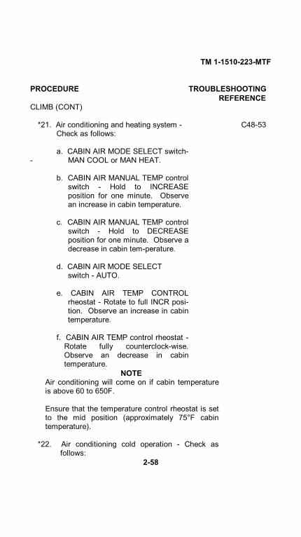
*21. Air conditioning and heating system - C48-53Check as follows:
a. CABIN AIR MODE SELECT switch-- MAN COOL or MAN HEAT.
b. CABIN AIR MANUAL TEMP controlswitch - Hold to INCREASEposition for one minute. Observean increase in cabin temperature.
c. CABIN AIR MANUAL TEMP controlswitch - Hold to DECREASEposition for one minute. Observe adecrease in cabin tem-perature.
d. CABIN AIR MODE SELECTswitch - AUTO.
e. CABIN AIR TEMP CONTROLrheostat - Rotate to full INCR posi-tion. Observe an increase in cabintemperature.
f. CABIN AIR TEMP control rheostat -Rotate fully counterclock-wise.Observe an decrease in cabintemperature.
NOTEAir conditioning will come on if cabin temperatureis above 60 to 650F.
Ensure that the temperature control rheostat is setto the mid position (approximately 75°F cabintemperature).
*22. Air conditioning cold operation - Check asfollows:
2-58

TM 1-1510-223-MTF
PROCEDURE TROUBLESHOOTINGREFERENCE
a. Verify that the AC COLD OPN annunciatorlight is illuminated only when the FAT isbelow 45° F.
b. CABIN AIR MODE SELECT switch - ACCOLD OPN. Check that air conditionerturns on in 8 to 12 seconds and the A/CCOLD OPN annunciator extinguishes.
c. Verify that air conditioner operation is thesame as the AUTO mode except that the airconditioner operates continuously above61% N1.
23. Pressurization system - Check as required(Section IV).
*24. Carbon monoxide - Check the cockpit and cabinfor the presence of carbon monoxide.Maximum carbon monoxide allowable is0.005%.
CRUISE
1. Power- Set.2. ICE & RAIN switches - As required.3. AUTOFEATHER - As required.4. Volt-loadmeters - Check.5. Auxiliary fuel gages - Monitor. Ensure that fuel
is being transferred from auxiliary tanks.6. Altimeters - Check.
* 7. Engine instrument indications - Check E21-28all engine instruments for normal indications.
8. RECOG lights - As required.
2-59
TM 1-1510-223-MTF
PROCEDURE TROUBLESHOOTINGREFERENCE
CRUISE (CONT)
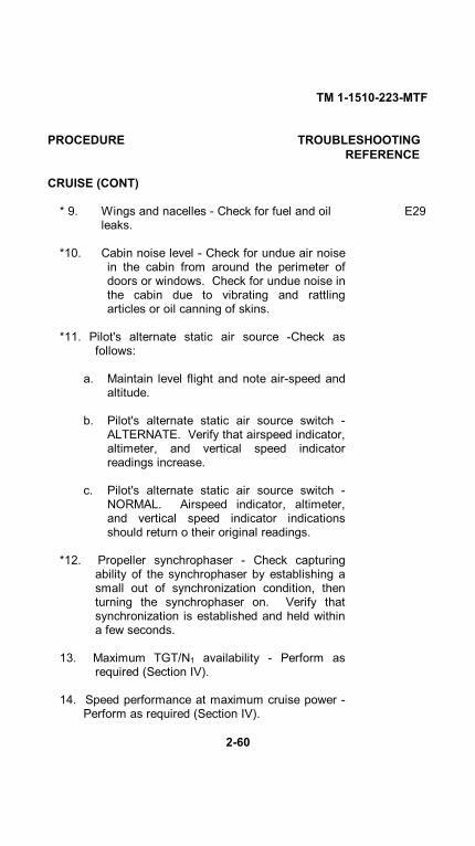
* 9. Wings and nacelles - Check for fuel and oil E29leaks.
*10. Cabin noise level - Check for undue air noisein the cabin from around the perimeter ofdoors or windows. Check for undue noise inthe cabin due to vibrating and rattlingarticles or oil canning of skins.
*11. Pilot's alternate static air source -Check asfollows:
a. Maintain level flight and note air-speed andaltitude.
b. Pilot's alternate static air source switch -ALTERNATE. Verify that airspeed indicator,altimeter, and vertical speed indicatorreadings increase.
c. Pilot's alternate static air source switch -NORMAL. Airspeed indicator, altimeter,and vertical speed indicator indicationsshould return o their original readings.
*12. Propeller synchrophaser - Check capturingability of the synchrophaser by establishing asmall out of synchronization condition, thenturning the synchrophaser on. Verify thatsynchronization is established and held withina few seconds.
13. Maximum TGT/N1 availability - Perform asrequired (Section IV).
14. Speed performance at maximum cruise power -Perform as required (Section IV).
2-60

TM 1-1510-223-MTF
PROCEDURE TROUBLESHOOTINGREFERENCE
15. Engine performance at maximum continuouspower - Perform as required (Section IV).
16. Engine performance at maximum cruise power -Perform as required (Section IV).
*17. Engine ice vanes - Check operation as follows:
a. #1 and #2 ICE VANE POWER SELECTswitches (2) - MAIN.
b. #1 and #2 ICE VANE CONTROL switches -ON. Check #1 and #2 VANE EXTannunciators illuminated.
c. Torquemeters - Monitor for approximately a10% drop in torque with ice vanesextended.
d. #1 and #2 ICE VANE CONTROL switches -Retract (up).
e. Torquemeters - Monitor for an increase intorque.
f. ICE VANE CONTR MAIN circuit breakers -Pull. Check that #1 and #2 VANE FAILannunciator lights illuminate.
g. #1 and #2 ICE VANE POWER SELECTswitches (2) - STBY. Check that #1 and #2VANE FAIL annunciator lights extinguish.
h. #1 and #2 ICE VANE CONTROL switches -ON. Check that #1 and #2 VANE EXTannunciators illuminate.
i. #1 and #2 ICE VANE CONTROL switches -Retract (up).
2-61
TM 1-1510-223-MTF
PROCEDURE TROUBLESHOOTINGREFERENCE
CRUISE (CONT)
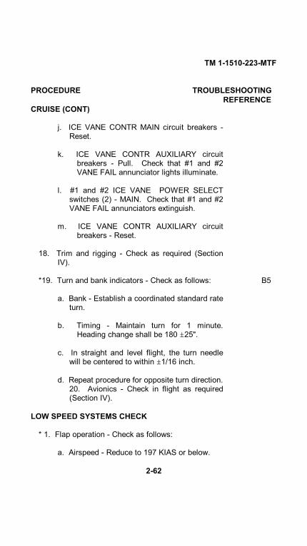
j. ICE VANE CONTR MAIN circuit breakers -Reset.
k. ICE VANE CONTR AUXILIARY circuitbreakers - Pull. Check that #1 and #2VANE FAIL annunciator lights illuminate.
l. #1 and #2 ICE VANE POWER SELECTswitches (2) - MAIN. Check that #1 and #2VANE FAIL annunciators extinguish.
m. ICE VANE CONTR AUXILIARY circuitbreakers - Reset.
18. Trim and rigging - Check as required (SectionIV).
*19. Turn and bank indicators - Check as follows: B5
a. Bank - Establish a coordinated standard rateturn.
b. Timing - Maintain turn for 1 minute.Heading change shall be 180 25".
c. In straight and level flight, the turn needlewill be centered to within 1/16 inch.
d. Repeat procedure for opposite turn direction.20. Avionics - Check in flight as required(Section IV).
LOW SPEED SYSTEMS CHECK
* 1. Flap operation - Check as follows:
a. Airspeed - Reduce to 197 KIAS or below.
2-62
TM 1-1510-223-MTF
PROCEDURE TROUBLESHOOTINGREFERENCE
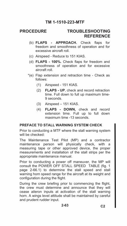
(b) FLAPS - APPROACH. Check flaps for freedom and smoothness of operation and for excessive aircraft roll.
(c) Airspeed - Reduce to 151 KIAS. (d) FLAPS - 100%. Check flaps for freedom and
smoothness of operation and for excessive aircraft roll.
*(e) Flap extension and retraction time - Check as follows: (1) Airspeed - 151 KIAS. (2) FLAPS - UP, check and record retraction
time. Full down to full up maximum time- 9 seconds.
(3) Airspeed – 151 KIAS. (4) FLAPS - DOWN, check and record
extension time. Full up to full down maximum time -13 seconds.
PREFACE TO STALL WARNING SYSTEM CHECK Prior to conducting a MTF where the stall warning systemwill be checked: The Maintenance Test Pilot (MP) and a contractormaintenance person will physically check, with ameasuring tape or other approved device, the propermeasurements and installation of the stall strips per the appropriate maintenance manual. Prior to conducting a power off maneuver, the MP willconsult the POWER OFF STALL SPEED TABLE (fig. 1page 2-66.1) to determine the stall speed and stallwarning horn speed range for the aircraft at its weight and configuration during the flight. During the crew briefing prior to commencing the flight,the crew must determine and announce that they willcease aileron inputs at activation of the stall warninghorn. A wings level attitude shall be maintained by careful and prudent rudder input.
2-63 C2

TM 1-1510-223-MTF WARNING
The RC-12 may not produce a clean aerodynamic “break” (i.e. In the C-12 the nose does not pitch down during a stall). The indication of the stall when the aircraft pitch attitude is held constant may be a moderate buffet, a loss in control effectiveness, full aft yoke, or any sink rate as indicated on the altimeter or VSI. Generally, 800 feet of altitude will be lost during a normal stall recovery. Delayed recovery from a stall can result in a “deep stall” which is characterized by a level pitch attitude,flight path angle of approximately 45 degrees down,and a sink rate of up to 8500 FPM. Recovery from a“deep stall” requires a 10-15 degree nose-down pitch change to break the stall. Allow the airspeed to increase to at least 25 KIAS above the stall speedbefore recovery.
NOTE In the event of an inadvertent stall, recovery can be effected by relaxing aft control force, lowering the nose below the visible horizon and adding power to reduce altitude loss. Rapid recovery is hampered by a pronounced secondary stall tendency (recurrence of buffet). Secondary stall can be avoided by increasing the airspeed 25 KIAS above the stall speed. Stall warning horn shall sound at no more than 12, and no less than 5 knots above the stall speed IAW fig. 1 page 2-66.1. Do not perform the low speed systems checks in turbulence conditions greater than occasional light turbulence.
* 2. Stall warning system (gear and flaps up, power off) – Check as follows:
C34-35
WARNING Begin the maneuver at 160 KIAS at an altitude that will allow recovery to be safely completed no lower than 7500 AGL.
2-64 C2

TM 1-1510-223-MTF
PROCEDURE TROUBLESHOOTINGREFERENCE
a. GEAR – UP.
b. FLAPS – UP.
c. PROP levers – HIGH RPM.
d. CONDITION levers – HIGH IDLE.
e. POWER levers – IDLE.
f. Trim aircraft IAW Fig. 1 page 2-66.1 (Make no further pitch trim adjustments).
WARNING If the aircraft reaches an airspeed 5 KTS above the stall speed IAW fig. 1 page 2-66.1 with no stall horn activation, terminate the LOW SPEED SYSTEMS CHECK and have maintenance personnel adjust/repair the stall warning horn system.
g. Airspeed – Reduce at a rate NO GREATER THAN one knot/second until the stall horn ACTIVATES, but NO LOWER THAN 5 knots above the published stall speed specified in fig. 1 page 2-66.1.
* h. Airspeed – Record at onset of the stall warning horn and terminate the maneuver.
* 3. Stall warning system, (gear and flaps down, power off) – Check as follows:
WARNING Begin the maneuver at 160 KIAS at an altitude that will allow recovery to be safely completed no lower than 7500 AGL.
NOTE Configure the aircraft by performing the BEFORE LANDING CHECK. Allow the aircraft to slow to approximately 120 KIAS and perform the following.
a. GEAR– DN.
b. FLAPS – DOWN.
2-65 C2

TM 1-1510-223-MTF
PROCEDURE TROUBLESHOOTINGREFERENCE
LOW SPEED SYSTEMS CHECK (CONT) c. PROP levers – HIGH RPM.
d. CONDITION levers – HIGH IDLE.
e. POWER levers– IDLE.
f. Trim aircraft IAW Fig. 1 page 2-66.1 (Make no further pitch trim adjustments).
WARNING If the aircraft reaches an airspeed 5 KTS above the stall speed IAW fig. 1 page 2-66.1 with no stall horn activation, terminate the LOW SPEED SYSTEMS CHECK and have maintenance personnel adjust/repair the stall warning horn system.
g. Airspeed – Reduce at a rate NO GREATER THAN one knot/second until the stall horn ACTIVATES, but NO LOWER THAN 5 knots above the published stall speed specified in fig. 1 page 2-66.1.
* h. Airspeed – Record at onset of the stall warning horn and terminate the maneuver.
4. Step deleted.
5. Step deleted.
6. Step deleted.
7. Step deleted.
8. FLAPS – UP. C31,32
9. GEAR – UP.
C2
2-66

TM 1-1510-223-MTF
PROCEDURE TROUBLESHOOTINGREFERENCE
NOTE
The MP is responsible for ensuring the aircraft is within required weight and balance limits IAW the appropriate maintenance manual.
RC-12N
13,500 TRIM
SPEED
Gear & Flaps UP Power Idle 147 KIAS Gear & Flaps DOWN Power Idle 123 KIAS
15,000 TRIM
SPEED
Gear & Flaps UP Power Idle 155 KIAS Gear & Flaps DOWN Power Idle 127 KIAS
WEIGHT STALL SPEEDS Vs Vso
WARNING HORN RANGE Vs Vso
16,000 102 76 107 – 114 81 – 88
15,500 100 75 105 – 112 80 – 87
15,000 99 74 104 – 111 79 – 86
14,500 98 73 103 – 110 78 – 85
14,000 96 72 101 – 108 77 – 84
13,500 95 71 100 – 107 76 – 83
13,000 93 70 98 – 105 75 – 82
12,500 91 68 96 – 103 73 – 80
12,000 89 67 94 – 101 72 – 79
Figure 1. Power Off Stall Speeds Table.
C2
2-66.1/(2-66.2 blank)


TM 1-1510-223-MTF
PROCEDURE TROUBLESHOOTINGREFERENCE
*10. Autoignition - Check as follows:
a. AUTO IGNITION switches -ARM.
b. Slowly retard each POWER lever.
c. Respective IGN ON annunciator lightilluminates at 13 to 19 % torque.
d. Power - Establish cruise power withautoignition armed.
e. CONDITION lever (engine to be tested) -Rapidly retard to IDLE CUTOFF for 3seconds, then return to LOW IDLE.Observe that engine relight occurs within 3to 5 seconds. Monitor engine accelerationand TGT rise. If relight does not occurwithin limits, or acceleration or TGT do notappear normal, abort the start. Restartengine using Normal Procedures.
f. Repeat substep e for opposite engine ifrequired.
*11. Propeller feathering - Check each en- F14,15gine as follows:
a. Airspeed - 120 KIAS.
b. POWER lever (engine to be feathered) -IDLE.
c. PROP lever (engine to be feathered) - HIGHRPM.
d. CONDITION lever (engine to be feathered) -IDLE CUTOFF. Allow N, RPM to decaybelow 20%.
e. PROP lever (engine to be feathered) -FEATHER. Time to feather must notexceed 10 seconds from
2-67

TM 1-1510-223-MTF
PROCEDURE TROUBLESHOOTINGREFERENCE
LOW SPEED SYSTEMS CHECK (CONT)
windmilling at 1700 RPM to no rotation inthe feathered position.
f. Engine cleanup.
(1) CONDITION lever - FUEL CUTOFF.
(2) AUTO IGNITION switch -Off.
(3) AUTOFEATHER switch -OFF.
(4) GENERATOR switch - OFF.
(5) PROP SYN switch - OFF.
g. Engine restart.
Airstarts using the starter assist procedures willmomentarily cause the loss of all electronic flightinstrument system (EFIS) data. The engine restartduring flight (no starter assist procedure), orturning EFIS power off prior to a starter assistedrestart, should normally be performed.
CAUTION
Do not attempt engine airstarts above 25,000 feet.During engine acceleration to idle speed, it maybecome necessary to move the CONDITION leverinto FUEL CUTOFF in order to avoid an overtemperature condition.
(1) CABIN AIR MODE SELECT switch -OFF.
2-68

TM 1-1510-223-MTF
PROCEDURE TROUBLESHOOTINGREFERENCE
(2) FWD VENT BLOWER switch- AUTO.
(3) AUTO PLT POWER switch -Off.
(4) EFIS POWER switches (2) -OFF (ifconditions permit).
NOTE
If EFIS power is turned off, aircraft attitude shouldbe maintained by using outside visual referencesor the air driven standby attitude indicator andturn-and-slip indicator.
(5) Radar - SBY or OFF.(6) POWER lever - IDLE.(7) PROP lever - Low RPM.(8) CONDITION lever - FUEL CUTOFF.(9) FIRE PULL handle - Push in (to
extinguish annunciator).
NOTE
If conditions permit, reduce power on the operativeengine to obtain a TGT of 700°C or less to reducethe possibility of exceeding TGT limit. Reduceelectrical load to minimum consistent with flightconditions.
False fuel flow indications may be observed withthe starter engaged and the CONDITION lever inFUEL CUTOFF.
(10) ENG START switch -START-IGNITION. Check IGN ONannunciator illuminated.
2-69

TM 1-1510-223-MTF
PROCEDURE TROUBLESHOOTINGREFERENCE
LOW SPEED SYSTEMS CHECK (CONT)
(11) CONDITION lever - LOW IDLE.
(12) ENG START switch - OFF after TGTpeaks.
(13) CONDITION lever - HIGH IDLE.
(14) PROP lever - As required.
(15) POWER lever - As required.
(16) GENERATOR switch - RESET, thenON.
(17) Engine AUTO IGNITION -As required.(18) PROP SYNC switch - As required.(19) Electrical equipment - As required.
h. Repeat step g for opposite engine ifrequired.
*12. Propeller autofeathering system and F4,15propeller unfeathering - Check as follows:
a. AUTOFEATHER switch - ARM.
b. Airspeed - 120 KIAS.
c. PROP levers - Set 1700 RPM.
d. POWER levers - Set as required to arm autofeather system.
e. CONDITION lever (engine to be feathered) -IDLE CUTOFF.
*f. Record the time from fuel cutoff untilpropeller is feathered. (Propeller isconsidered to be feathered
2-70
TM 1-1510-223-MTF
PROCEDURE TROUBLESHOOTINGREFERENCE
when the blades are individuallyvisible to the human eye, but thepropeller is still rotating.) Time tofeather shall not exceed 10seconds.
NOTE
For proper autofeather operation, propeller muststop completely.
g. Engine cleanup.
(1) CONDITION lever - FUEL CUTOFF.
(2) AUTO IGNITION switch -OFF.
(3) AUTOFEATHER switch -OFF.
(4) GENERATOR switch - OFF.
(5) PROP SYN switch - OFF.
h. Engine restart.
Airstarts using the starter assist procedures willmomentarily cause the loss of all electronic flightinstrument system (EFIS) data. The engine restartduring flight (no starter assist procedure), orturning EFIS power off prior to a starter assistedrestart, should normally be performed.
2-71

TM 1-1510-223-MTF
PROCEDURE TROUBLESHOOTINGREFERENCE
LOW SPEED SYSTEMS CHECK (CONT)
CAUTION
Do not attempt engine airstarts above 25,000 feet.During engine acceleration to idle speed, it maybecome necessary to move the CONDITION leverinto FUEL CUTOFF in order to avoid an over-temperature condition.
(1) CABIN AIR MODE SELECT switch -OFF.
(2) FWD VENT BLOWER switch- AUTO.
(3) AUTO PLT POWER switch -Off.
(4) EFIS POWER switches (2) -OFF (ifconditions permit).
NOTE
If EFIS power is turned off, aircraft attitude shouldbe maintained by using outside visual referencesor the air driven standby attitude indicator andturn-and-slip indicator.
(5) Radar - SBY or OFF.
(6) POWER lever - IDLE.
(7) PROP lever - Low RPM.
(8) CONDITION lever - FUEL CUTOFF.
(9) FIRE PULL handle - Push in (toextinguish annunciator).
2-72

TM 1-1510-223-MTF
PROCEDURE TROUBLESHOOTINGREFERENCE
NOTE
If conditions permit, reduce power on the operativeengine to obtain a TGT of 700°C or less to reduce thepossibility of exceeding TGT limit. Reduce electricalload to minimum consistent with flight conditions.
False fuel flow indications may be observed withthe starter engaged and the CONDITION lever in FUELCUTOFF.
(10) ENG START switch START-IGNITION.Check IGN ON annunciatorilluminated.
(11) CONDITION lever - LOW IDLE.
(12) ENG START switch - OFF after TGTpeaks.
(13) CONDITION lever - HIGH IDLE.
(14) PROP lever - As required.
(15) POWER lever - As required.
(16) GENERATOR switch - RESET, thenON.
(17) Engine AUTO IGNITION -As required.
(18) PROP SYNC switch - As required.
(19) Electrical equipment - As required.
*(20) Propeller unfeathering-Check as followswith propeller in the feathered positionwith the gas generator running in HIGHIDLE:
2-73

TM 1-1510-223-MTF
PROCEDURE TROUBLESHOOTINGREFERENCE
LOW SPEED SYSTEMS CHECK (CONT)
(a) POWER lever - IDLE. PROP lever -Move out of FEATHER detent to fullforward. Propeller RPM must reach1,000 RPM in 20 seconds or less.
i. Repeat step h for other engine if required.
NOTE
The landing gear warning horn is automaticallysilenced by an altitude sensing switch, provided tosilence the landing gear warning horn when above12,500 feet.
*13. Landing gear warning horn - Check as follows: C24-26
a. POWER levers - Retard slowly, individually,until landing gear warning horn first sounds.
*b. Turbine tachometers - Read N1 tachometerson first hearing landing gear warning horn.Verify that the landing gear warning hornsounds when POWER levers are retardedbelow 84 to 86% N, and airspeed is below140 KIAS.
c. Flaps - Extend beyond APPROACH position.Verify that the landing gear warning hornsounds regardless of POWER lever position(with airspeed less 140 KIAS).
d. POWER levers - Advance past 84 to 86%N1. Check that landing gear warning horn isarmed again.
2-74

TM 1-1510-223-MTF
PROCEDURE TROUBLESHOOTINGREFERENCE
With the airspeed greater than 153 KIASand the flaps retracted, verify that thelanding gear warning horn is silentregardless of power setting.
*14. Landing gear normal operation - Check C13-30as follows:
a. Airspeed - 179 KIAS.
b. LDG GEAR CONTR switch - DN.
*c. Landing gear extension time -Record (7seconds maximum).
d. Landing gear handle lights (red) -Checkilluminated while gear is in transit.
e. GEAR DOWN indicator lights (3, green) -Check illuminated.
f. Airspeed - 160 KIAS.
g. LDG GEAR CONTR switch - UP.
*h. Landing gear retraction time -Record (8seconds maximum).
i. Landing gear handle lights (red) -Checkilluminated while gear is in transit.
j. GEAR DOWN indicator lights (3, green) -Check all extinguished.
*15. Emergency landing gear extension system -Check operation and condition as follows:
a. Airspeed - 179 KIAS.b. LANDING GEAR CONTROL circuit breaker
- Out (pulled).c. LDG GEAR CONTR switch - DN.
2-75

TM 1-1510-223-MTF
PROCEDURE TROUBLESHOOTINGREFERENCE
LOW SPEED SYSTEMS CHECK (CONT)
d. LANDING GEAR ALTERNATE EXTENSIONpump handle - Unstow.
e. LANDING GEAR ALTERNATE EXTENSIONpump handle -Pump.
f. GEAR DOWN indicator lights (3)- Monitor.Stop pumping lever when GEAR DOWNindicator lights are illuminated or resistanceis felt.
NOTEEighty or more strokes of the handle could berequired to fully extend the landing gear.
g. LANDING GEAR ALTERNATE EXTENSIONpump handle - Stow.
h. LANDING GEAR CONTROL circuit breaker- In.
i. LDG GEAR CONTR switch - UP.
DESCENT AND LOW LEVEL CRUISE
* 1. Maximum rate (Vmo) descent. If the test pilot issatisfied that the entire aircraft is functioningproperly, perform the maximum rate descentcheck as follows:
a. Establish cruise altitude in accordance withfigure 3.
b. POWER levers - IDLE.
c. PROP levers - Set 1700 RPM.
d. Gear - UP.
e. Flaps - UP.2-76

TM 1-1510-223-MTF
PROCEDURE TROUBLESHOOTINGREFERENCE
f. Airspeed - In accordance with figure 3.
Immediately reduce airspeed if any flutter, oscilla-tion or vibration is encountered.
*g. Flight controls - Check for any indication offlutter, oscillation, vibration, or malfunction.
*h. Windows and doors - Check for wind noiseindicating air leaks.
i. Level off aircraft at 10,000 feet.
* 2. Elevator trim - Nose down trim stops will be setas follows:
a. POWER levers - Set maximum continuouspower. Do not exceed N, or TGT limits.
b. PROP levers - Set 1700 RPM.
c. Airspeed - 240 KIAS.
d. Trim aircraft.
e. Verify that excess nose down trim is at least0.9, but does not exceed 1.4 trim wheelindicator units.
DESCENT-ARRIVAL
Perform the following checks prior to the final descentfor landing:
2-77
TM 1-1510-223-MTF
PROCEDURE TROUBLESHOOTINGREFERENCE
DESCENT-ARRIVAL (CONT)
Mmo may be easily exceeded when descendingfrom high altitude. The pilot should frequentlycross check the airspeed and Mach limit indicatorsto avoid exceeding Mmo. Exceeding Mmo couldresult in structural failure and loss of airframeintegrity.
1. CABIN CONTROLLER - Set.
2. ICE & RAIN switches - As required.
3. WINDSHIELD anti-ice - As required.
CAUTION
Set windshield anti-ice to NORMAL or HIGH asrequired well before descent into icing conditionsor into warm moist air to aid in defogging. Turn offwindshield anti-ice when descent is completed tolower altitudes and when heating is no longerrequired. This will preclude possible wind screendistortions.
4. RECOG lights - On.
5. Altimeters - Set to current altimeter setting(QNH) when passing through transitionalaltitude.
6. ASE - As required.
7. Flare/chaff dispenser safety pin - Insert.
8. CONDITION lever - HIGH IDLE.2-78
TM 1-1510-223-MTF
PROCEDURE TROUBLESHOOTINGREFERENCE
9. Avionics and EFIS display controller -Set andcheck. Ensure EFIS displays match procedureto be flown.
10. Arrival briefing - Complete.
BEFORE LANDING
1. PROP SYN switch - OFF.
2. AUTOFEATHER switch - ARM.
3. Ice vane control switches - As required.
4. PROP levers - As required.
5. Flaps (below 197 KIAS) - APPROACH.
6. Gear (below 179 KIAS) - DN.
7. Landing lights - As required.
8. BRAKE deice - As required.
LANDING
CAUTION
The maximum demonstrated crosswindcomponent is 20 knots at 90° . Landing theaircraft in a crab will impose side loads on thelanding gear. Record landing the aircraft in a crabon DA Form 2408-13-1.
When landing is assured:
1. Autopilot and yaw damper - Disengage.
2. GEAR DOWN annunciators - Check.
3. Flaps - Down. After touchdown:2-79

TM 1-1510-223-MTF
PROCEDURE TROUBLESHOOTINGREFERENCE
LANDING (CONT)
4. POWER levers - Lift and retard to GROUNDFINE.
* 5. Brake operation - Check during landing roll forany tendency to bleed down, drag after release,or indicate assymmetrical braking power.
* 6. Propeller reversing - Check as follows: E4
a. During landing utilize maximum reversepower.
b. Check for smoothness of operation andequal thrust from engines.
*c. Turbine tachometers - Maximum reverse N1is 86 to 88%. Observe that maximumdifference between engines is 2% N1.
* 7. Oil temperature - Monitor. Ground idle limitsare 10 to 105°C.
* 8. Oil pressure - Monitor. Ground idle limits are 60PSI minimum.
GO-AROUND
1. Power - Maximum allowable.
2. Flaps - As required.
3. Gear- UP.
4. Flaps - UP.
5. Landing lights - OFF.
6. Climb power - Set.
7. BRAKE deice - Off.2-80
TM 1-1510-223-MTF
PROCEDURE TROUBLESHOOTINGREFERENCE
AFTER LANDING
Complete the following procedures after the aircraft hascleared the runway:
1. CONDITION levers - HIGH IDLE.
2. PROP levers - Retard to FEATHER detent.
3. ICE VANE CONTROL switches - ON.
4. Engine AUTO IGNITION switches -Off.
5. ICE & RAIN switches - Off.
6. Flaps - UP.
7. Radar/transponder - As required.
* 8. Lightning sensor system (LSS) - Test as follows:
a. Lightning sensor system mode selectorswitch (weather radar/LSS control panel) -CLR/TST. Display should show asimulated lightning strike at a bearing of045 degrees at 25 nautical miles.
NOTE
The lightning sensor system antenna is used inthis test, and as a result, any real lightning activitythat occurs while the test is in operation may alsobe displayed.
9. Lights - As required.
10. Mission control panel - Set as follows:
a. ELINT power switch (mission status panel,in rack behind pilot) -OFF.
2-81

TM 1-1510-223-MTF
PROCEDURE TROUBLESHOOTINGREFERENCE
AFTER LANDING (CONT)
b. ELINT battery switch (mission status panel,in rack behind pilot) -OFF.
c. DATA LINK HV switch - OFF.d. TDOA SYSTEM switch - OFF.e. RADIO ALT switch - OFF.f. MISSION CONTROL ORIDE switch - OFF.
ENGINE SHUTDOWN
NOTETo prevent sustained loads on rudder shock links,park the aircraft with the nose gear centered.
1. PARKING BRAKE - Set.
2. LANDING and TAXI light switches -OFF.
3. INS - OFF.
4. Mission equipment - Set and check as follows:a. KG-45 (mission status panel, in rack behind
pilot) - ZEROIZE.b. BUS CROSS TIE switch - OFF.
5. CABIN AIR MODE SELECT switch -OFF.
6. FWD and AFT VENT BLOWER switches -AUTO.
7. AUTOFEATHER switch - OFF.
8. INVERTER switches (4) - Off.
9. AUTO PLT POWER switch - Off.
2-82

TM 1-1510-223-MTF
PROCEDURE TROUBLESHOOTINGREFERENCE
10. #1 and #2 EFIS power switches - Off.
11. BRAKE deice - Off.
*12. Battery condition - Check.
13. TGT - Check stabilized for 1 minute prior toshutdown.
14. POWER levers - Flight IDLE.
15. PROP levers - FEATHER.
CAUTION
Monitor TGT during shutdown. If sustained com-bustion is observed, proceed immediately to AbortStart procedure.
16. CONDITION levers - FUEL CUT-OFF.
17. Oxygen system - OFF.
Do not turn exterior lights off until propeller rotationhas stopped.
18. EXTERIOR LTS switches - Off.
19. IR FLOOD light switches - Off.
20. COCKPIT LIGHTS MASTER switch- Off.
21. AVIONICS MASTER POWER switch- Off.
22. MASTER SWITCH - OFF.
2-83

TM 1-1510-223-MTF
PROCEDURE TROUBLESHOOTINGREFERENCE
ENGINE SHUTDOWN (CONT)
23. Keylock switch - OFF.
BEFORE LEAVING AIRCRAFT
NOTE
Release brakes after chocks are in place (rampconditions permitting).
1. Wheels - Chocked.
2. PARKING BRAKE - As required.3. Flight controls - Locked.
4. STANDBY PUMP switches - Off.
5. COMSEC - Zeroize as required.6. Windows - As required.
7. Emergency exit lock - As required.8. Aft cabin lights - OFF.9. Door light - OFF.
*10. Walk-around inspection - Complete. E11-13Conduct a thorough walk-around inspection,checking for damage, fluid leaks, and fluidlevels. Check that covers, tiedowns, restraints,and chocks are installed as required.
NOTE
A cold oil check is unreliable. Check oil within 10minutes after stopping engine.
*11. Aircraft forms - Complete. In addition toestablished requirement for reporting anysystem defects, unusual and excessiveoperation such as hard landings, etc., theflight crew will also make entries on DA Form2408-13-1
2-84
TM 1-1510-223-MTF
PROCEDURE TROUBLESHOOTINGREFERENCE
to indicate when limits in the operator'smanual have been exceeded.
12. Aircraft - Check secured. Lock cabin door asrequired.
2-85/ (2-86 blank)


TM 1-1510-223-MTF
SECTION III. TROUBLESHOOTING
General. This section contains troubleshootinginformation that has been referenced in Section II. Thissection lists possible conditions, abnormal conditionsand indications and probable causes. The informationis to be used only as a quick reference and may not beall-encompassing.
TROUBLESHOOTING GUIDE A - STARTING
CONDITIONPROBABLE CAUSE
A1. Both starter-generators inoperative.
a. Low battery.
b. Loose connection or open circuit betweenbattery relay and power cabinet.
A2. One starter-generator inoperative.
a. Starter relay inoperative.b. Poor ground at starter-generator.c. Open circuit.d. Defective starter-generator.e. Defective switch.f. Defective wiring.g. Defective generator control unit.h. Current transformer miswired.
A3. Engine slow to start or does not start.
a. Low battery.b. High resistance starter circuit.c. Defective starter-generator.d. Turbine dragging.e. Defective generator control unit.f. Current transformer miswired.
3-1

TM 1-1510-223-MTF
A4. Engine fails to light up.
a. Improper engine starting procedure.b. Ignition system.
(1) No power to ignition exciter.(2) Defective wiring or components.
c. Fuel system.
(1) Debris or ice in fuel system.(2) Air lock in fuel control unit.
d. Engine driven primary high pressure pumpfailure.
A5. Engine fails or is slow to accelerate to idle. N 1speed.
a. Improper engine starting procedure.b. Leaks or restrictions on fuel control unit
pneumatic system.c. Leaks in pneumatic line of propeller governor.d. Fuel control unit contaminated with water or ice,
or corroded.
A6. Hot start or delayed light up.
a. Improper engine starting procedure.b. Insufficient power from battery or ground power
unit.c. Poor connections on power input lines or
starter-generator.d. Low power to ignition exciter.e. Defective ignition cable.f. Defective igniters.g. Defective ignition exciter.h. Bleed air leaking or system in aircraft using
bleed air is on.i. Engine control linkage improperly rigged.j. Fuel nozzle restrictions.
3-2

TM 1-1510-223-MTF
A7. Engine fails to or is slow to accelerate propeller toidle. speed.
a. Propeller oil transfer sleeve binding.
TROUBLESHOOTING GUIDE B - INSTRUMENTS
CONDITIONPROBABLE CAUSE
B1. Airspeed indicator reading remains fixed.
a. Pitot pressure line clogged with ice or debris.b. Defective indicator.
B2. Vertical speed indicator inaccurate orinoperative.
a. Static line clogged.b. Leak in line or instrument case or loose fittings.c. Defective vertical velocity indicator.
B3. Airspeed indicator reads incorrectly orfluctuates excessively.
a. Pitot tube or pressure line partially restricted orleaking.
b. Static port or line clogged or static line leaking.c. Faulty airspeed indicator.
B4. Magnetic compass inaccurate, sluggish, orerratic.
a. Insufficient liquid.b. External magnetic interference.c. Defective compass.d. Windshield heat on.e. Air conditioner on.f. Sun visors not stowed outboard.g. EFIS power switches on.
B5. Turn-and-slip indicator inoperative or erratic.
a. No pneumatic pressure.b. Defective turn-and-slip instrument.
3-3

TM 1-1510-223-MTF
B6. Fuel quantity indicator fluctuates or reads low.
a. Defective pins in connector on harness thatmates with gage.
b. Compensator immersed in water.c. Circuit out of calibration.d. Tank unit(s) out of circuit.e. Defective pins in connector on fuel probes and
wing harness used to connect fuel probes.
B7. Fuel quantity gage pegs down scale againststop.
a. Defective probe.b. Defective pins on connectors on both gage and
probes.c. Nacelle probe body is making contact with metal
braided hose inside of nacelle tank.d. Defective indicator.e. No power to fuel quantity indicator system.
B8. Fuel quantity indicator needle pegs up scaleagainst stop.
a. Defective indicator.
B9. Turbine gas temperature indicator inoperativeor indicates inaccurately.
a. Defective or out of adjustment balance resistor.b. Defective turbine gas temperature harness.c. Defective turbine gas temperature indicator.
TROUBLESHOOTING GUIDE C - ELECTRICAL
CONDITIONPROBABLE CAUSE
C1. Zero or low voltage indicated.
a. Circuit breaker tripped.b. Loose connection.
3-4

TM 1-1510-223-MTF
c. Open or shorted field circuit in generator or defectivearmature.
d. Brushes not contacting commutator.
e. Brushes worn out.
f. Dirty commutator.
g. Defective generator control unit.
h. Starter-generator switch on.
C2. No generator output.
a. Improper connections.
b. Circuit breaker tripped.
c. Open or short circuit.
d. Loss of residual magnetism.
e. Generator control switch not ON or RESET.
f. Defective generator control switch.
g. Starter-generator switch on.
h. Generator control unit over-voltage circuit defective.
i. Paralleling circuit open.
j. Defective generator control unit.
k. High resistance field circuit.
l. Shorted field.
m. Generator feeder fault.
C3. Low generator output.
a. Generators not paralleled.
b. Defective generator control unit.
C4. Low voltage.
Malfunctioning generator control unit.
C5. Volt-loadmeter reads off scale in wrong direction.
Generator field magnetized in wrong direction.
3-5

TM 1-1510-223-MTFC6. Volt-loadmeter does not indicate.
a. Tripped circuit breaker.
b. Open volt-loadmeter lead.
c. Defective volt-loadmeter.
C7. No power indicated with BATTERY MASTER SWITCH ON.
a. Battery discharged or defective.
b. Open circuit between battery and MASTER SWITCH.
c. MASTER switch defective.
d. Defective relay.
e. Keylock switch OFF.
C8. Power on with MASTER SWITCH in OFF position.
a. Master switch defective.
b. Relay contacts stuck.
C9. Apparent loss of battery capacity.
a. Cells unbalanced.
b. Electrolyte level too low.
c. Charging rate too low in aircraft.
d. Too little usage or shallow discharges.
C10. Complete failure of battery to operate.
a. Loose or broken lead.
b. Loose or disengaged terminals in battery.
c. Battery not charged.
d. Cell open internally.
e. Battery feeder fault.
C11. Below normal battery output.
a. BATTERY switch left ON.
b. Generator control unit set too low.
3-6

TM 1-1510-223-MTF
c. Internal connection links loose.
d. External connector burned or pitted.
e. Defective or reversed cells.
f. Cell case current leakage.
C12. External power fails to energize aircraft.
a. Defective or incorrectly polarized external power source.
b. Defective external power receptacle.
c. Defective external power relay.
d. Loose or wrong connection in external power circuit.
e. Defective external power overvoltage monitor.
f. APU voltage too high.
g. APU defective.
h. Defective switch.
i. Circuit breaker tripped.
j. External power feeder fault.
k. Battery feeder fault.
C13. Landing gear will not retract or extend.
a. LANDING GEAR CONTROL circuit breaker(overhead circuit breaker panel) tripped.
b. LANDING GEAR POWER circuit breaker (under floor in cabin) tripped.
c. Landing gear power safety control circuit breaker (under floor in cabin) tripped. floor in cabin) tripped.
e. Landing gear safety power circuit breaker (under floor in cabin) tripped.
f. Faulty power pack motor.
g. Faulty power relay.
3-7

TM 1-1510-223-MTF
h. Faulty remote-controlled circuit breaker (RCCB), (under floor in cabin).
i. Defective landing gear control switch.
j. Defective wiring.
C14. Landing gear fails to retract.
a. Safety switch not closing.
b. Pressure switch not closing.
c. Gear selector valve stuck.
d. Circuit is open between the selector valve and the powerrelay.
e. Time delay circuit opening prematurely.
f. Hand pump handle improperly stowed.
g. Service valve in up position.
h. Defective landing gear control switch.
i. Defective wiring.
C15. Landing gear fails to extend.
a. Service valve switches faulty.
b. Landing gear selector valve stuck in up position.
c. Control switch not providing power to the extend side of selector valve.
d. Defective limit switch.
e. Defective landing gear control switch.
C16. Landing gear pump motor continues to run after the gear is retracted, causing the circuit breaker to trip.
a. Pressure switch not opening on high pressure.
b. Low accumulator charge.
c. Excessive fluid leakage past the piston seals in theactuators.
d. Defective valve in the power pack.
3-8
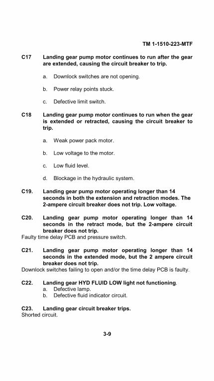
TM 1-1510-223-MTF
C17 Landing gear pump motor continues to run after the gearare extended, causing the circuit breaker to trip.
a. Downlock switches are not opening.
b. Power relay points stuck.
c. Defective limit switch.
C18 Landing gear pump motor continues to run when the gearis extended or retracted, causing the circuit breaker totrip.
a. Weak power pack motor.
b. Low voltage to the motor.
c. Low fluid level.
d. Blockage in the hydraulic system.
C19. Landing gear pump motor operating longer than 14seconds in both the extension and retraction modes. The2-ampere circuit breaker does not trip. Low voltage.
C20. Landing gear pump motor operating longer than 14seconds in the retract mode, but the 2-ampere circuitbreaker does not trip.
Faulty time delay PCB and pressure switch.
C21. Landing gear pump motor operating longer than 14seconds in the extended mode, but the 2 ampere circuitbreaker does not trip.
Downlock switches failing to open and/or the time delay PCB is faulty.
C22. Landing gear HYD FLUID LOW light not functioning.a. Defective lamp.b. Defective fluid indicator circuit.
C23. Landing gear circuit breaker trips.Shorted circuit.
3-9

TM 1-1510-223-MTF
C24. Landing gear warning horn inoperative when LDG GEARCONTR switch is in the up position and weight of aircraftis on struts, but operates when a POWER lever is closedand the gear is retracted.
a. Poor ground at landing gear control switch.b. Defective wiring between LDG GEAR CONTR switch and
landing gear safety switch.c. Defective stall/landing gear warning module.d. Defective speaker.
C25. Landing gear warning horn inoperative when POWERlever is closed and landing gear is up.
a. Defective or out of adjustment POWER lever switch.b. Defective wiring between POWER lever switches and
pedestal terminal board, and between LDG GEARCONTR switch and stall/landing gear warning hornmodule.
c. Defective "Q" switch.
C26. Landing gear warning horn fails to shut off when landinggear is extended.
Defective or out of adjustment down-lock switches.
C27. Landing GEAR DOWN position indicator lights areilluminated with landing gear retracted.
a. Defective or out of adjustment down lock switch.b. Wrong connection in light test circuit.c. Ground between light and down lock switch.
C28. Landing GEAR DOWN position indicator lightinoperative.
Defective or out of adjustment down lock switch.
C29. Landing gear handle light is illuminated with gear up andlocked.
Defective or out of adjustment up-lock switch.
3-10

TM 1-1510-223-MTF
C30. Landing gear handle light inoperative.
a. Defective or out of adjustment up-lock or downlockswitch.
b. Defective landing gear control switch.c. Defective bulbs in handle.
C31. Flaps fail to extend or retract.a. Tripped circuit breaker.b. Defective flap motor.c. Defective flap control switch.d. Defective mechanical component in actuator system.e. Defective wiring.f. Defective split flap switch.g. Split flap condition.
C32. Flap position indicator inoperative.a. Tripped circuit breaker.b. Defective position indicator.c. Defective position transmitter.d. Defective wiring.
C33. Pilot tube heater fails to operate.a. Tripped circuit breaker.b. Defective heater.c. Defective wiring.d. Defective switch.
C34. Stall warning system inoperative.a. Defective stall warning transducer.b. Defective stall warning computer.c. Defective wiring.d. Defective stall/landing gear warning module.e. Defective speaker.
3-11

TM 1-1510-223-MTFC35. Stall warning horn sounds continuously.
a. Defective stall warning transducer.
b. Defective stall warning test system.
c. Defective wiring.
d. Defective stall warning computer.
C36. Both inverters inoperative.
Defective wiring in inverter system.
C37. One inverter inoperative.
a. Tripped inverter circuit breaker (on DC power distributionpanel beneath floor).
b. Loose or corroded ground connection.
c. Defective wiring to inverter.
d. Defective inverter switch.
C38. BATTERY CHARGE annunciator light inoperative.
a. Defective light bulb.
b. Connections on battery shunt loose or corroded.
c. Defective battery charge monitor module.
C39. One portion of interior lighting or lighting control systeminoperative.a. Defective light circuit board.
b. Defective light bulbs.
c. Defective components in overhead control panel.
d. Defective power supply.
C40. Fuel crossfeed valve inoperative or FUEL PRESSannunciator light remains illuminated.a. Defective standby fuel pump.
b. Defective crossfeed valve.
3-12
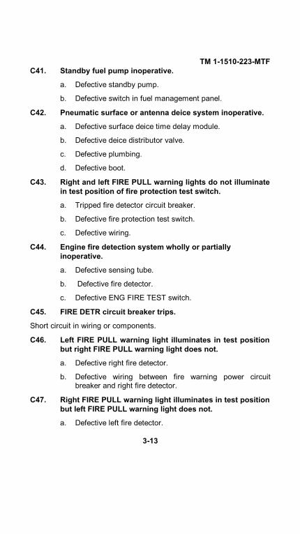
TM 1-1510-223-MTFC41. Standby fuel pump inoperative.
a. Defective standby pump.
b. Defective switch in fuel management panel.
C42. Pneumatic surface or antenna deice system inoperative.
a. Defective surface deice time delay module.
b. Defective deice distributor valve.
c. Defective plumbing.
d. Defective boot.
C43. Right and left FIRE PULL warning lights do not illuminatein test position of fire protection test switch.
a. Tripped fire detector circuit breaker.
b. Defective fire protection test switch.
c. Defective wiring.
C44. Engine fire detection system wholly or partiallyinoperative.
a. Defective sensing tube.
b. Defective fire detector.
c. Defective ENG FIRE TEST switch.
C45. FIRE DETR circuit breaker trips.
Short circuit in wiring or components.
C46. Left FIRE PULL warning light illuminates in test positionbut right FIRE PULL warning light does not.
a. Defective right fire detector.
b. Defective wiring between fire warning power circuitbreaker and right fire detector.
C47. Right FIRE PULL warning light illuminates in test positionbut left FIRE PULL warning light does not.
a. Defective left fire detector.
3-13

TM 1-1510-223-MTF
b. Defective wiring between fire warning power circuitbreaker and left fire detector.
C48. Ventilation blower will not run.
a. Tripped vent blower circuit breaker.
b. Defective motor brushes.
c. Defective wiring.
d. Defective motor.
e. Defective switch.
C49. Ventilation blower draws excessive current.
a. Misaligned or preloaded bearings.
b. Defective bearings.
C50. Ventilation blower runs at reduced speed.
Brushes not seated properly.
C51. Ventilation blower draws excessive current and runs at high speed.
Shorted turns in field windings.
C52. Ventilation blower draws excessive current and speedsurges.
Shorted turns in armature.
C53. Ventilation blower has excessive vibration.
a. Armature out of balance.
b. Fan damaged.
c. Fan out of balance.
d. Defective bearings.
C54. Propeller deice inoperative.
a. Circuit breaker tripped.
b. Propeller deice switch defective.
c. Ammeter defective.
d. Defective propeller deice timer.
3-14

TM 1-1510-223-MTF
C55. Stall warning deice inoperative.
a. STALL WARN circuit breaker tripped.
b. STALL WARN circuit breaker defective.
c. STALL WARN deice switch defective.
d. Defective stall warning deice heating element.
C56. Left or right fuel vent deice inoperative.
a. FUEL VENT HEAT circuit breaker tripped.
b. FUEL VENT HEAT circuit breaker defective.
c. FUEL VENT deice switch defective.
d. Defective fuel vent deice heating element.
TROUBLESHOOTING GUIDE D CAUTION PANEL
CONDITION
PROBABLE CAUSE
D1. Place card light (annunciator panel) will not illuminatewhen press-to-test button is pressed.a. Defective placard light.
b. Defective lamps.
c. Defective fault detection module.
D2. MASTER WARNING or MASTER CAUTION annunciatorlight will not illuminate for any red or yellow faults.a. Defective fault warning light.
b. Defective fault detection module.
c. Defective annunciator control module.
D3. Depressing the press-to-test switch has no effect on faultwarning system operation.a. Defective switch.
b. Defective circuit breaker.
c. Defective wiring.
3-15

TM 1-1510-223-MTF
D4. Dim control does not function properly.
a. Defective rheostat switch.
b. Defective annunciator control module.
TROUBLESHOOTING GUIDE E - POWER PLANTCONDITION
PROBABLE CAUSE
E1. LOW IDLE speed is either high or low.
LOW IDLE speed improperly adjusted.
E2. HIGH IDLE speed is either high or low.
HIGH IDLE speed improperly adjusted.
E3. Low or high torque is observed during torque check.
Barrel adjustable stop is improperly adjusted.
E4. Reverse torque, N1, and propeller RPM is too high or low.
Reverse adjusting screw is improperly adjusted.
E5. Newly rigged engine accelerates faster or slower than opposite engine.
Engine rigging, components, or engine is mismatched.
E6. POWER levers are not aligned.
Fuel control rod improperly adjusted.
E7. High engine oil pressure.
a. Defective oil pressure indicating system.
b. Defective pressure relief valve.
E8. Low engine oil pressure.
a. Insufficient oil.
b. Defective oil pressure indicating system.
c. Dirty oil filter
d. Leak in oil lines or oil cooler.
3-16

TM 1-1510-223-MTF
e. Defective pressure relief valve.
E9. Fluctuating engine oil pressure.
a. Insufficient or excess oil.
b. Defective oil pressure indicating system
c. Dirty oil filter.
d. Defective pressure relief valve.
E10. High oil temperature.
a. Insufficient oil supply.
b. Defective oil temperature indicating system.
c. Excessive idling in feather.
d. Restriction in oil cooler.
e. Cooling air flow blocked.
E11. Oil leak from compressor inlet.
a. Defective preformed packing and plastic ring on oil filter housing.
b. Defective preformed packings on accessory gearbox.
E12. Excessive oil discharge from overboard breather.
a. Excess oil in tank.
b. Defective preformed packing and plastic ring on oil filter.
c. Excessive back pressure in scavenge system due torestrictions in oil scavenge tubes, pump screen or oil-to-fuel heater tubes.
E13. Excessive engine oil consumption.
a. Excess oil in tank.
b. Leak or restriction in pressure scavenge oil tubes.
c. Defective preformed packing and plastic ring on oil filterhousing.
d. Leakage in oil to fuel heat exchanger.
e. Defective centrifugal breather carbon seal.
3-17

TM 1-1510-223-MTF
f. Defective air seals.
E14. Failure of engine to decelerate.
a. Fuel control unit defective.
b. Disconnected or improperly adjusted linkage.
E15. Gas generator overspeed.
a. Defective turbine tachometer system.
b. Sheared or worn fuel control unit splined coupling or drivespline.
c. Defective fuel control unit.
E16. Gas generator uncontrolled acceleration.
a. Sheared or worn fuel control unit splined coupling or drivespline.
b. Defective fuel control unit.
E17. Surge during acceleration.
a. Defective compressor bleed valve.
b. Defective fuel control unit.
c. Compressor damaged.
E18. Slow to accelerate.
a. Possible leak or restriction in Py air bleed tube or P3 air delivery tube.
b. P3 air filter needs replacing.
c. Improper acceleration adjustment on fuel control unit.
d. Propeller governor out of adjustment.
e. Defective fuel control unit.
f. Defective propeller governor.
E19. Flame out.
a. Fuel supply contaminated with ice, water, or debris.
b. Engine driven high pressure fuel pump defective.
c. Fuel control unit contaminated or corroded.
3-18
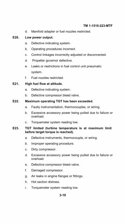
TM 1-1510-223-MTF
d. Manifold adapter or fuel nozzles restricted.
E20. Low power output.
a. Defective indicating system.
b. Operating procedures incorrect.
c. Control linkages incorrectly adjusted or disconnected.
d. Propeller governor defective.
e. Leaks or restrictions in fuel control unit pneumatic
system.
f. Fuel nozzles restricted.
E21. High fuel flow at altitude.
a. Defective indicating system.
b. Defective compressor bleed valve.
E22. Maximum operating TGT has been exceeded.
a. Faulty instrumentation, thermocouples, or wiring.
b. Excessive accessory power being pulled due to failure oroverload.
c. Torquemeter system reading low.
E23. TGT limited (turbine temperature is at maximum limitbefore target torque is reached).
a. Defective instruments, thermocouple, or wiring.
b. Improper operating procedure.
c. Dirty compressor.
d. Excessive accessory power being pulled due to failure oroverload.
e. Defective compressor bleed valve.
f. Damaged compressor.
g. Air leaks in engine flanges or fittings.
h. Hot section distress.
i. Torquemeter system reading low.
3-19

TM 1-1510-223-MTF
E24. Fluctuating torque indication.
a. Faulty instrumentation system.
b. Defective power turbine governor.
c. Engine driven high pressure pump shaft seal leakage.
d. Defective or out of adjustment propeller overspeedgovernor.
e. Defective propeller primary governor.
f. Sticking beta mechanism.
E25. Fluctuating fuel flow.
a. Faulty instrumentation system.
b. Defective power turbine governor.
c. Engine driven high-pressure fuel pump shaft seal leaking.
d. Defective propeller overspeed governor.
e. Sticking beta mechanism.
E26. Fluctuating TGT.
a. Faulty instrumentation system.
b. Defective power turbine governor.
c. Defective engine driven high pressure fuel pump shaftseal
d. Defective or out of adjustment propeller overspeedgovernor.
e. Defective propeller primary governor.
f. Sticking beta mechanism.
E27. Fluctuating gas generator speed.
a. Faulty instrumentation system.
b. Defective power turbine governor.
c. Defective engine driven primary high pressure fuel pump shaft seal
d. Defective or out of adjustment propeller overspeed governor.
3-20

TM 1-1510-223-MTF
e. Defective propeller primary governor.
f. Sticking beta mechanism.
E28. Fluctuating torque and propeller RPM.
a. Defective or out of adjustment propeller overspeed
governor.
b. Defective propeller primary governor.
c. Sticking beta mechanism.
E29. Fuel leaking overboard.
a. Fuel cap not seated and anti-siphon valve defective.
b. Filler cap or preformed packing defective and anti-siphonvalve defective.
c. Fuel transfer module defective.
d. Fuel level transmitter defective.
TROUBLESHOOTING GUIDE F PROPELLERS
CONDITION
PROBABLE CAUSE
F1. Propeller governor system partially or completelyinoperative.
Defective propeller governor test switch.
F2. Propeller governor test system inoperative.
a. Tripped propeller governor test circuit breaker.
b. Defective wiring.
c. Defective switch.
d. Defective propeller governor reset solenoid.
F3. Propeller governor test system inoperative on oneengine.
a. Defective PROP GOVERNOR test switch.
b. Defective propeller governor reset solenoid.
3-21

TM 1-1510-223-MTF
F4. Propeller autofeather system inoperative (propellerAUTOFEATHER switch in ARM or TEST position).
a. Tripped circuit breaker.
b. Defective arming light out relay or feathering relay.
c. Defective arc suppression diode on relays or featherdump valve.
d. Defective ground blocking diode.
F5. AUTOFEATHER circuit breaker trips (AUTO-FEATHER switch in ARM or TEST position).
a. Defective ARM-TEST switch.
b. Defective wiring.
F6. One AUTOFEATHER arm light illuminates when powersetting is less than 90 percent N, (AUTOFEATHER switchin ARM position).
Defective or out of adjustment power lever switch.
F7. Neither AUTOFEATHER arm light illuminates whenPOWER levers are advanced (AUTOFEATHER switch inARM position).
Defective AUTOFEATHER switch (overhead control panel).
F8. One arm light does not illuminate when POWER leversare advanced (AUTOFEATHER switch in ARM position).
a. Defective or out of adjustment power lever switch.
b. Defective No. 1 (4.7 PSI) torque pressure switch.
F9. Both arm lights remain illuminated when one POWERlever is retarded (AUTOFEATHER switch in ARMposition).
Defective or out of adjustment power lever switch.
3-22

TM 1-1510-223-MTF
F10. Propeller does not start to feather after engine torquefalls below 7% (AUTOFEATHER switch in ARM position).
a. Defective No. 2 (3.1 PSI) torque pressure switch onretarded engine.
b. Defective autofeather dump valve.
F11. One arm light does not illuminate when POWER leversare advanced to 90 percent N1, (AU- TOFEATHER ARMTEST switch in TEST position).
Defective No. 1 (4.7 PSI) torque pressure switch.
F12. Both arm lights extinguish when one POWER lever isretarded (engine torque 7 to 12% on retarded engine,AUTOFEATHER ARM-TEST switch in TEST position).
Defective No. 2 (3.1 PSI) torque pressure switch on retarded engine.
F13. One arm light remains illuminated after torque of oneengine falls below 7% on retarded engine,
AUTOFEATHER ARM-TEST switch in TEST position).
a. Defective No. 2 (3.1 PSI) torque pressure switch onretarded engine.
b. Defective autofeather dump valve.
F14. Propeller slow to feather.
a. Preformed packing leak at transfer tube or transferhousing.
b. Defective propeller governor.
F15. Propeller slow to unfeather.
Defective propeller governor.
3-23

TM 1-1510-223-MTF
TROUBLESHOOTING GUIDE G HYDRAULIC
CONDITION
PROBABLE CAUSE
G1. Solid pedal, no brakes.
Brake linings worn beyond allowable limits.
G2. Spongy brakes.
a. Air in brake hydraulic system.
b. Low hydraulic fluid.
G3. Unable to hold brake pressure.
a. Leak in brake hydraulic system.
b. Brake cylinder seal leaking.
c. Master cylinder seal leaking.
G4. Brake pedals bottom, no brakes.
a. Broken or leaking hydraulic lines.
b. Brake cylinder seal failure.
c. Master cylinder seal leaking.
G5. Parking brake will not hold.
a. Air in brake hydraulic system.
b. Defective parking brake valve.
c. PARKING BRAKE control out of adjustment.
G6. Brakes grab.
a. Stones or foreign matter locking brake disc.
b. Warped or bent disc.
G7. Brakes drag.
Packing nut or threaded bushing too loose.
G8. Brakes weak.
Packing nut or threaded bushing, as applicable, too tight.
3-24

TM 1-1510-223-MTF
TROUBLESHOOTING GUIDE H FLIGHT
CONTROLS CONDITIONPROBABLE CAUSE
For complete troubleshooting of autopilot system, refer to Honeywellmaintenance manual P/N A15-1146-059.
TROUBLESHOOTING GUIDE I NOT APPLICABLE
CONDITIONPROBABLE CAUSE
TROUBLESHOOTING GUIDE 1 VIBRATIONS
CONDITION
PROBABLE CAUSE
J1. Engine vibration.
a. Propeller damaged or blade angle slipped.
b. Loose engine mounting bracket bolts.
c. Compressor damaged.
d. Turbine damaged.
TROUBLESHOOTING GUIDE K -COMMUNICATION/NAVIGATION EQUIPMENT
CONDITIONPROBABLE CAUSE
K1. Interphone system: No audio signals heard in headset.
a. No power to audio system.
b. Defective microphone.
c. Defective control wheel microphone switch.
d. Defective foot microphone switch.
e. Defective headset-microphone cord or jack.
f. Defective microphone jack.
g. Defective audio control panel.
3-25

TM 1-1510-223-MTF
h. Headset-oxygen mask switch set in wrong position.
K2. Interphone system: Audio signals can be heard at otherheadset stations when transmitter selector switches ataudio control panels are at different positions andreceiver monitor switches are pulled out.
a. Defective audio control panel.
b. Defective wiring.
K3. UHF VOL control has no effect on receiver noise orincoming signal.
a. Defective UHF control panel.
K4. UHF channeling tone not heard.
Defective UHF command set.
K5. UHF squelch switch has no effect on receiver noise.
a. Defective UHF command set.
b. Defective static wicks.
K6. UHF guard receiver noise not audible.
Defective UHF command set.
K7. Cannot establish UHF two-way communications.
a. Defective audio distribution channels.
b. Defective antenna or antenna cabling.
c. Defective UHF command set.
K8. Cannot establish VHF two-way communications.
a. Defective audio distribution channels.
b. Defective antenna or cabling.
c. Defective VHF command set.
K9. VHF volume control does not affect received audio level.
a. Defective VHF control panel.
b. Defective antenna or antenna cabling.
3-26

TM 1-1510-223-MTF
K10. HF transmitted or received signal or sidetone not clear.
a. Defective HF receiver-transmitter.
b. Defective antenna cabling.
c. Defective HF control panel.
d. Defective audio control panel.
K11. No VOR audio tone heard in headset.
a. Defective VOR receiver.
b. Defective VOR control panel.
c. Defective audio control panel.
K12. VOR receiver inoperative.
a. No power to equipment.
b. Defective VOR control panel.
c. Defective VOR receiver.
K13. Marker beacon signals not heard in headset.
a. Defective audio control panel.
b. Defective marker beacon volume control or sensitivityswitch on pedestal extension.
c. Defective VOR receiver.
K14. ADF radio set inoperative.
No power to ADF radio set.
K15. No ADF audio heard in headsets.
a. No power to equipment.
b. Defective ADF receiver.
c. Defective ADF control panel.
d. Defective ADF antenna.
K16. Quality of ADF reception is poor.
a. Defective ADF control panel.
b. Defective audio control panel.
c. Defective ADF receiver.3-27
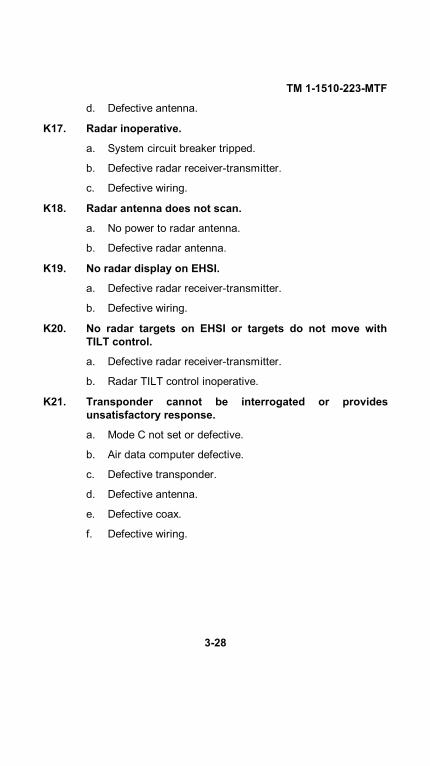
TM 1-1510-223-MTF
d. Defective antenna.
K17. Radar inoperative.
a. System circuit breaker tripped.
b. Defective radar receiver-transmitter.
c. Defective wiring.
K18. Radar antenna does not scan.
a. No power to radar antenna.
b. Defective radar antenna.
K19. No radar display on EHSI.
a. Defective radar receiver-transmitter.
b. Defective wiring.
K20. No radar targets on EHSI or targets do not move withTILT control.
a. Defective radar receiver-transmitter.
b. Radar TILT control inoperative.
K21. Transponder cannot be interrogated or providesunsatisfactory response.
a. Mode C not set or defective.
b. Air data computer defective.
c. Defective transponder.
d. Defective antenna.
e. Defective coax.
f. Defective wiring.
3-28
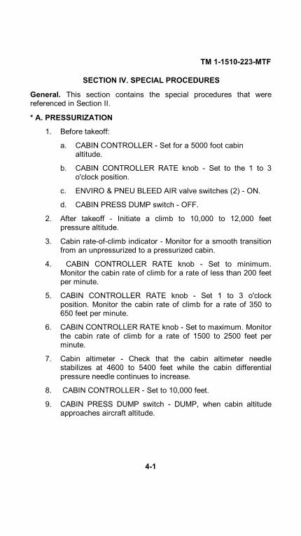
TM 1-1510-223-MTF
SECTION IV. SPECIAL PROCEDURES
General. This section contains the special procedures that werereferenced in Section II.
* A. PRESSURIZATION
1. Before takeoff:
a. CABIN CONTROLLER - Set for a 5000 foot cabin altitude.
b. CABIN CONTROLLER RATE knob - Set to the 1 to 3o'clock position.
c. ENVIRO & PNEU BLEED AIR valve switches (2) - ON.
d. CABIN PRESS DUMP switch - OFF.
2. After takeoff - Initiate a climb to 10,000 to 12,000 feetpressure altitude.
3. Cabin rate-of-climb indicator - Monitor for a smooth transitionfrom an unpressurized to a pressurized cabin.
4. CABIN CONTROLLER RATE knob - Set to minimum.Monitor the cabin rate of climb for a rate of less than 200 feetper minute.
5. CABIN CONTROLLER RATE knob - Set 1 to 3 o'clockposition. Monitor the cabin rate of climb for a rate of 350 to650 feet per minute.
6. CABIN CONTROLLER RATE knob - Set to maximum. Monitorthe cabin rate of climb for a rate of 1500 to 2500 feet perminute.
7. Cabin altimeter - Check that the cabin altimeter needlestabilizes at 4600 to 5400 feet while the cabin differentialpressure needle continues to increase.
8. CABIN CONTROLLER - Set to 10,000 feet.
9. CABIN PRESS DUMP switch - DUMP, when cabin altitudeapproaches aircraft altitude.
4-1

TM 1-1510-223-MTF
10. Continue climbing and ensure that the ALT WARN annunciatorlight illuminates between 12,000 and 12,500 feet
11. CABIN PRESS DUMP switch - OFF.
12. CABIN CONTROLLER - Set to 0 feet.
13. Continue climbing to between 15,000 and 16,000 feet. As thealtitude cabin descends to 0 feet, ensure that the ALT WARNannunciator extinguishes prior to 9,000 feet cabin altitude.
14. CABIN CONTROLLER RATE knob - Set to minimum. Monitorthe cabin rate of climb for a rate of less than 200 feet perminute.
15. CABIN CONTROLLER RATE knob - Set 1 to 3 o'clockposition. Monitor the cabin rate of climb for a rate of 350 to 650feet per minute.
16. CABIN CONTROLLER RATE knob - Set to maximum. Monitorthe cabin rate of climb for a rate of 1500 to 2500 feet perminute.
17. Cabin altimeter - Check that the cabin altimeter needle stabilizesand remains at -250 to +250 feet until the maximum differentialpressure of 6.5 +.I PSI is reached. At this point (approximately15,300 feet pressure altitude), verify that cabin altitudeincreases and differential pressure remains constant.
18. With the cabin at maximum differential pressure, place bothENVIRO & PNEU BLEED AIR switches to PNEU ONLY. As thecabin differential pressure decreases from 6.1 to 5.7 PSI, thecabin rate of climb shall not exceed 2200 feet per minute.
19. ENVIRO & PNEU BLEED AIR switches - ON and re-establishmaximum differential pressure.
20. Left ENVIRO & PNEU BLEED AIR switch - PNEU ONLY.
21. Slowly retard the right POWER lever to flight idle and determinethe minimum N. required to maintain cabin pressure. Verify thatcabin pressurization is maintained down to flight idle NI.
22. Left ENVIRO & PNEU BLEED AIR switch - ON.
4-2

TM 1-1510-223-MTF
23. Right ENVIRO & PNEU BLEED AIR switch - PNEU ONLY.
24. Slowly retard the left POWER lever to flight idle and determine theminimum N. required to maintain cabin pressure. Verify that cabinpressurization is maintained down to flight idle N1.
25. Right ENVIRO & PNEU BLEED AIR switch - ON.
26. Cabin pressurization controller - Set to 500 feet above fieldelevation.
* B. TRIM AND RIGGING
Check as follows:
In smooth air, at cruise power, the aircraft will fly hands off, straightand level with the ailerons symmetrically aligned at the trailing edgeand the aileron adjustable tab set to zero.
* C. MAXIMUM TGT/N1 AVAILABILITY
Ensure that sufficient POWER lever travel is available at 16,000 feetto produce a TGT of 840°C or an N. of 104%. Check the maximumPOWER lever position as follows:
NOTE
The only requirement of the maximum POWER leverposition check is to verify that it is possible to obtainmaximum allowable gas generator RPM (No) with thePOWER levers in the full forward position. If during the testthe TGT temperature limit or N1 limit is obtained prior toreaching maximum N1, the check is completed.
1. Altitude - 16,000 feet pressure altitude.
2. PROP levers - Set 1700 RPM.
3. Ice vanes - Retracted.
4. ENVIRO & PNEU BLEED AIR valve switches (2) - ON.
5. Airspeed - As required.
4-3

TM 1-1510-223-MTF
6. POWER levers Full forward (do not exceed TGT and/or No.Maximum N. is 104%. Maximum TGT is 840° C.
* D. SPEED PERFORMANCE AT MAXIMUM CRUISE POWER
NOTE
A new or rebuilt engine operated at the torque valuepresented in the Maximum Cruise Speed and Power chart(figure 4) will show a TGT margin below the maximumcruise limit for the torque value presented in the table.With ice vanes retracted, cruise torque settings shown onthe Maxi- mum Cruise Speed and Power chart (figure 4)shall be obtained without exceeding TGT limits.
Speed-power runs shall be made in smooth air to determineconsistency with performance figures. Determine torque settings, fuelflow, and airspeed to be achieved by referencing Maximum CruiseSpeed and Power Chart (figure 4).
1. Record the following:
*a. Engine serial number.
*b. Engine hours since new.
*c. Engine hours since overhaul.
2. Altitude 25,000 feet pressure altitude.
3. Propeller RPM 1700 RPM.
4. Ice vanes Retracted.
5. FAT Determine and record.
6. Power setting Read torque for the recorded FAT from figure 4.
7. Set torque on left and right engines to the torque from figure 4.
8. Verify that pilot's and copilot's airspeed indicators agree within 4KIAS, and that neither indicator reads more than 3 KIAS less thanthe chart value.
9. Allow conditions to stabilize for one minute, then record thefollowing for each engine being tested.
4-4

TM 1-1510-223-MTF
*a. Pressure altitude.
*b. Propeller RPM.
*c. FAT.
*d. Torque.
*e. Fuel flow.
*f. KIAS.
*g. TGT.
*h. N1.
10. Indicated fuel flow must be within +21 and -25 lb/hr of chart valuefor Jet-A fuel.
11. If observed TGT exceeds chart value, conduct the EnginePerformance at Maximum Cruise Power check.
12. Repeat steps 2 through 11 for opposite engine if required.
* E. ENGINE PERFORMANCE AT MAXIMUM CONTINUOUSPOWER
1. Record the following:
*a. Engine serial number.
*b. Engine hours since new.
*c. Engine hours since overhaul.
2. Altitude - Establish level flight at 16,000 feet pressure altitude.
3. PROP levers - Set 1700 RPM.
4. Adjust the opposite engine to maintain 160 KIAS.
5. Ice vanes - Retracted.
*6. FAT - Determine and record.
7. Power setting - Read torque for the recorded FAT from figure 5.
8. Set torque on engine being tested to the torque from figure 5.
4-5
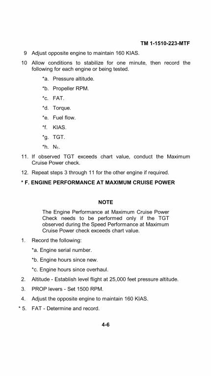
TM 1-1510-223-MTF
9 Adjust opposite engine to maintain 160 KIAS.
10 Allow conditions to stabilize for one minute, then record thefollowing for each engine or being tested.
*a. Pressure altitude.
*b. Propeller RPM.
*c. FAT.
*d. Torque.
*e. Fuel flow.
*f. KIAS.
*g. TGT.
*h. N1.
11. If observed TGT exceeds chart value, conduct the MaximumCruise Power check.
12. Repeat steps 3 through 11 for the other engine if required.
* F. ENGINE PERFORMANCE AT MAXIMUM CRUISE POWER
NOTE
The Engine Performance at Maximum Cruise PowerCheck needs to be performed only if the TGTobserved during the Speed Performance at MaximumCruise Power check exceeds chart value.
1. Record the following:
*a. Engine serial number.
*b. Engine hours since new.
*c. Engine hours since overhaul.
2. Altitude - Establish level flight at 25,000 feet pressure altitude.
3. PROP levers - Set 1500 RPM.
4. Adjust the opposite engine to maintain 160 KIAS.
* 5. FAT - Determine and record.
4-6
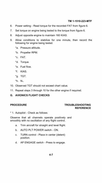
TM 1-1510-223-MTF
6. Power setting - Read torque for the recorded FAT from figure 6.
7. Set torque on engine being tested to the torque from figure 6.
8. Adjust opposite engine to maintain 160 KIAS.
9. Allow conditions to stabilize for one minute, then record thefollowing for engine being tested.
*a. Pressure altitude.
*b. Propeller RPM.
*c. FAT.
*d. Torque.
*e. Fuel flow.
*f. KIAS.
*g. TGT.
*h. N1.
10. Observed TGT should not exceed chart value.
11. Repeat steps 3 through 10 for the other engine if required.
G. AVIONICS FLIGHT CHECKS
PROCEDURE TROUBLESHOOTINGREFERENCE
* 1. Autopilot - Check as follows:
Observe that all channels operate positively andsmoothly with no oscillation of any flight control.
a. Trim aircraft for straight and level flight.
b. AUTO PLT POWER switch - ON.
c. TURN control - Place in center (detent)position.
d. AP ENGAGE switch - Press to engage.
4-7

TM 1-1510-223-MTF
PROCEDURE TROUBLESHOOTINGREFERENCE
G. AVIONICS FLIGHT CHECKS (CONT)
e. Check autopilot heading preselection asfollows:
(1) Autopilot HEADING selector knob (onpedestal extension) - Set test heading.
(2) HDG switch-indicator (flight directormode selector) - Press on.
(3) Aircraft should automatically turn androll out on preselected heading.
f. Check altitude control and selection asfollows:
(1) Pitch thumbwheel (autopilot controller) -Move UP and DN while observing thataircraft and pitch trim indicator respondproperly.
g. Check autopilot VOR/ILS operation asfollows:
(1) VOR receiver Set.
(2) V/L pushbutton selector switch(display controller) - Depress toselect VOR.
(3) NAV switch-indicator (flight directormode selector) - Depress on.
(4) When the aircraft is within 10degrees of the selected radial,observe that the aircraft begins agradual interception of the radial orglideslope signal.
h. Check autopilot altitude hold function asfollows:
4-8

TM 1-1510-223-MTF
PROCEDURE TROUBLESHOOTINGREFERENCE
(1) Fly aircraft to test altitude.
(2) ALT switch-indicator (flight director modeselector) - Press on.
(3) Verify that the aircraft maintains thealtitude being flown at the time the ALThold switch was pressed.
i. Check autopilot indicated airspeed holdfunction as follows:
(1) Fly aircraft to test airspeed.
(2) IAS switch-indicator (flight director modeselector) - Press on.
(3) Aircraft should maintain airspeed that wasbeing flown at the time IAS hold switchwas pressed.
j. Check roll command function of autopilot asfollows:
(1) TURN control knob (autopilot controller) -Turn to L and R and verify that autopilotturns aircraft left or right respectively.
* 2. Slaved compass systems - Check that systemsagree with known magnetic headingswithin ±2° and within 3° of each other.
* 3. Inertial Navigation System Flight Test - Perform asfollows:
Demonstrate satisfactory performance by flying overthree known checkpoints, and comparing the inertialpresent position readouts with the coordinates of thecheckpoints. Establish a
4-9
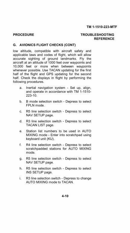
TM 1-1510-223-MTF
PROCEDURE TROUBLESHOOTINGREFERENCE
G. AVIONICS FLIGHT CHECKS (CONT)
low altitude, compatible with aircraft safety andapplicable laws and codes of flight, which will allowaccurate sighting of ground landmarks. Fly theaircraft at an altitude of 1000 feet over waypoints and10,000 feet or more when between waypointswhenever possible. Use TACAN updating for the firsthalf of the flight and GPS updating for the secondhalf. Check the displays in flight by performing thefollowing procedures.
a. Inertial navigation system - Set up, align,and operate in accordance with TM 1-1510-223-10.
b. B mode selection switch - Depress to selectFPLN mode.
c. R5 line selection switch - Depress to selectNAV SETUP page.
d. R3 line selection switch - Depress to selectTACAN LIST page.
e. Station list numbers to be used in AUTOMIXING mode - Enter into scratchpad usingkeyboard unit (KU).
f. R4 line selection switch - Depress to selectscratchpadded stations for AUTO MIXINGmode.
g. R5 line selection switch - Depress to selectNAV SETUP page.
h. R5 line selection switch - Depress to selectINS SETUP page.
i. R3 line selection switch - Depress to changeAUTO MIXING mode to TACAN.
4-10
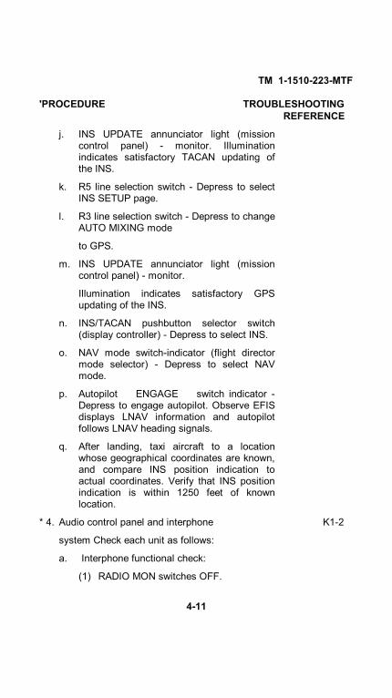
TM 1-1510-223-MTF
'PROCEDURE TROUBLESHOOTINGREFERENCE
j. INS UPDATE annunciator light (missioncontrol panel) - monitor. Illuminationindicates satisfactory TACAN updating ofthe INS.
k. R5 line selection switch - Depress to selectINS SETUP page.
l. R3 line selection switch - Depress to changeAUTO MIXING mode
to GPS.
m. INS UPDATE annunciator light (missioncontrol panel) - monitor.
Illumination indicates satisfactory GPSupdating of the INS.
n. INS/TACAN pushbutton selector switch(display controller) - Depress to select INS.
o. NAV mode switch-indicator (flight directormode selector) - Depress to select NAVmode.
p. Autopilot ENGAGE switch indicator -Depress to engage autopilot. Observe EFISdisplays LNAV information and autopilotfollows LNAV heading signals.
q. After landing, taxi aircraft to a locationwhose geographical coordinates are known,and compare INS position indication toactual coordinates. Verify that INS positionindication is within 1250 feet of knownlocation.
* 4. Audio control panel and interphone K1-2
system Check each unit as follows:
a. Interphone functional check:
(1) RADIO MON switches OFF.
4-11

TM 1-1510-223-MTF
PROCEDURE TROUBLESHOOTINGREFERENCE
G. AVIONICS FLIGHT CHECKS (CONT)
(2) ICS switch - NORM.
(3) Transmitter selector switches on pilot's andcopilot's audio control panel - ICS. This willallow the pilot to talk to the copilot bypressing a micro- phone switch andspeaking into microphone or visa-versafrom copilot's position.
(4) Microphone switches - Actuate one at a timeand speak into appropriate microphone.Side tone should be heard and speechshould be heard in other headset.
(5) ICS switch - HOT MIC. Verify that crew isable to converse on intercom withoutdepressing microphone switches.
(6) VOL control - Check for function.
b. Receiver and transmitter facilities
-Check as follows:
(1) RADIO MON volume controls -Turn all fullycounter- clockwise.
(2) RADIO MON switches (audio control panel)-Push on one at a time and turn clockwise toincrease volume and increase volume onappropriate receiver, listening for eitherradio reception or background noise.
4-12

TM 1-1510-223-MTF
PROCEDURE TROUBLESHOOTINGREFERENCE
(a) Cycle PROP deice switch fromOFF to AUTO and return to OFF.
(b) Cycle electric standby fuel pumps.
(3) Pull each RADIO MON switch (on audiocontrol panel) out to the off position andeach receiver volume control fullycounterclockwise.
(4) Transmitter selector switches (pilot'sand copilot's audio control panels) -INTPH.
(5) Audio control panel VOL control (pilot's)- Turn fully clockwise. Listen forexcessive noise.
(6) Repeat for other audio control panel.
c. Receiver/transmitter selectors -
Check as follows:
(1) Transmit and receive on each radiousing all microphone switches one at atime.
(2) Repeat entire procedure for each audiocontrol panel.
* 5. UHF radio set - Check as follows: K3-7
a. Altitude - 1200 feet above ground level(AGL).
b. Transmitter selector switch - #3 or #5.
c. Function selector switch (UHF commandset) - BOTH.
4-13

TM 1-1510-223-MTF
PROCEDURE TROUBLESHOOTINGREFERENCE
G. AVIONICS FLIGHT CHECKS (CONT)
d. Frequency selector switches Select requiredtest frequencies.
e. Mode selector - As required.
f. Volume control - As required.
g. Squelch switch - As required.
h. Fly aircraft to a point 35 nautical milesaway from test station.
i. Communicate with test station when 20miles away and again at 35 miles.
j. At 35 nautical miles maintaincommunication with test station each 10°while flying a 360° flat turn (not to exceed 5°bank). Verify that communication isuniformly loud and clear through thesetests.
k. Repeat procedure for frequencies in low,middle, and high ranges.
* 6. VHF radio set Check as follows K8-9
a. Altitude - 1000 feet AGL.
b. Transmitter selector switch (audio controlpanel) - #1 or #2.
c. Off-volume control - Turn clock- wise, setvolume as required.
d. Frequency selector - Set desired frequency.
e. Fly aircraft to a point 40 nautical miles awayfrom test station.
f. At 40 nautical miles, maintaincommunication with test station each 10°while flying a 360° flat turn (not to exceed 5°bank). Verify that
4-14

TM 1-1510-223-MTF
PROCEDURE TROUBLESHOOTINGREFERENCE
communication is uniformly loud and clearthrough these tests.
g. Repeat procedure for frequencies in low,middle, and high ranges.
* 7. HF radio set Check as follows. K10
a. Transmitter selector switch (audio controlpanel) #4.
b. Mode selector (HF control panel) - Setdesired operating mode.
c. Microphone switch Press momentarily andwait for antenna coupler to tune. A 1000 Hztone will be heard in the headphones untiltuning is complete. Verify that tuning timedoes not exceed 30 seconds.
d. Establish communications with a groundstation at least 150 miles distant on at leastthree frequencies (one each from the lower,middle, and upper frequency ranges).Establish two-way communications on AMand, when possible, on USB. Obtain signalquality reports from the other station andnote received signal quality.
NOTE
The intelligibility of SSB voice operationsbecomes degraded when the receiver andtransmitter differ in frequency by a smallamount (approximately 50 Hz). The voicepitch will sound either too high or too low.The cause may be either the receiver ortransmitter.
e. Frequency accuracy Check as follows:
4-15

TM 1-1510-223-MTF
PROCEDURE TROUBLESHOOTINGREFERENCE
G. AVIONICS FLIGHT CHECKS (CONT)
(1) Station WWV - Select the frequency thatprovides the best signal. The stationbroadcasts on 2.5000, 5.0000, 10.000,15.0000, and 20.0000 MHz. The higher thefrequency selected, the more accurate thefrequency check will be.
NOTE
Do not key transmitter when set to WWV.
(2) Mode selector - USB.
(3) Listen to the time tick, tone, or voiceannouncements. The tone is preferable.
* 8. ADF radio set Check as follows: K13-16
a. Power and mode switch - ADF.
b. Tuning knobs - Set test frequency. Tune theADF receiver to at least three frequencies asnearly equally spaced as possiblethroughout the frequency range of 200 to1750 KHz.
c. Single or double bearing pointer sourceselector switch (display controller) - ADF.Both single and double needle pointers onboth the pilot's and copilot's EHSI should befunctionally checked.
d. Verify accuracy of ADF indications on pilot'sand copilot's EFIS displays over a knownground reference point approximately every90° throughout 360°.
* 9. Navigation receivers (VOR/localizer/ K11-12,
4-16

TM 1-1510-223-MTF
PROCEDURE TROUBLESHOOTINGREFERENCE
glideslope/marker beacon) - Check as follows:
a. VOR receivers - Check each VORreceiver as follows:
(1) NAV A control (audio control panel)- Depress on and rotate clockwiseto set volume.
(2) Power and mode switch (VHFnavigation receiver control unit) -ON.
(3) Volume control (VHF navigationreceiver control unit) - As required.
(4) Tuning knobs - Set test frequency.
(5) VOR/localizer pushbutton selectorswitch (display controller) -Depress to select VOR1 or VOR2navigation source annunciator onrespective HSI.
(6) Check the operational status andaccuracy of the VOR receivers byone of the following methods:
(a) A VOT (VOR test facility).Maximum permissiblebearing error is ±4°.
(b) A radiated test signal from anappropriately rated repairstation. Maximumpermissible bearing error is±4°.
(c) A certified airborne checkpoint. Maximum permissiblebearing error is ±6°.
4-17

TM 1-1510-223-MTF
PROCEDURE TROUBLESHOOTINGREFERENCE
G. AVIONICS FLIGHT CHECKS (CONT)
(d) Certified check points on anairport surface. Maximumpermissible error is +4°.
(e) Comparison of indications ofdual aircraft VOR systems.The maximum permissiblevariation between the twoindicated bearings is 4°.
b. Localizer/glideslope/marker beacon -Check as follows:
(1) Marker beacon volume control(pedestal extension) - Rotate fullclockwise.
(2) NAV A control (pilot's audio controlpanel) - Push on and turnclockwise to adjust volume. Verifythat clear audio signals areavailable.
(3) Tuning knobs (VOR control panel) -Select localizer frequency.
(4) VOR/localizer pushbutton selectorswitch (display controller) -Depress to select ILS 1 or ILS2navigation source annunciator onrespective HSI.
(5) Glideslope indicator (EADI andEHSI) - Read glideslopeindications.
(6) Fly an ILS approach monitoringlocalizer and glideslope indicationsand marker beacon indicator lightsand audio tone for proper function.
4-18
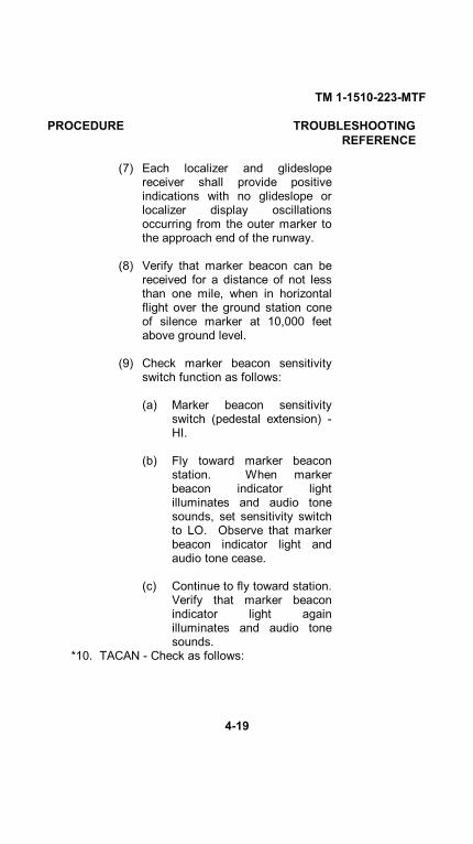
TM 1-1510-223-MTF
PROCEDURE TROUBLESHOOTINGREFERENCE
(7) Each localizer and glideslopereceiver shall provide positiveindications with no glideslope orlocalizer display oscillationsoccurring from the outer marker tothe approach end of the runway.
(8) Verify that marker beacon can bereceived for a distance of not lessthan one mile, when in horizontalflight over the ground station coneof silence marker at 10,000 feetabove ground level.
(9) Check marker beacon sensitivityswitch function as follows:
(a) Marker beacon sensitivityswitch (pedestal extension) -HI.
(b) Fly toward marker beaconstation. When markerbeacon indicator lightilluminates and audio tonesounds, set sensitivity switchto LO. Observe that markerbeacon indicator light andaudio tone cease.
(c) Continue to fly toward station.Verify that marker beaconindicator light againilluminates and audio tonesounds.
*10. TACAN - Check as follows:
4-19

TM 1-1510-223-MTF
PROCEDURE TROUBLESHOOTINGREFERENCE
G. AVIONICS FLIGHT CHECKS (CONT)
a. NAV B control (audio control panel) -Depress on and rotate clockwise to setvolume.
b. Frequency selectors (TACAN controlpanel) - Set test frequency.
c. Volume control (TACAN control panel) -As required.
(1) INS/TACAN pushbutton selectorswitch (display controller) -Depress to select TCN navigationsource annunciator on respectiveEADI.
d. Fly directly toward a TACAN station ofknown direction and near enough toprovide a reliable signal.
e. Set direction to station on courseindicator (EHSI) using remote courseknob (pedestal extension). Verify thatcourse deviation bar is nearly centeredand the to/from indicator reads to.
f. Set reciprocal of direction to station oncourse indicator (EHSI) using remotecourse knob (pedestal extension).Observe that course deviation bar isnearly centered and the to/fromindicator reads from.
g. Set direction to station again on courseindicator (EHSI) using remote courseknob (pedestal extension). Observethat course deviation bar is nearlycentered and the to/from indicator readsto.
4-20

TM 1-1510-223-MTF
PROCEDURE TROUBLESHOOTINGREFERENCE
h. Fly a 90° right turn such that the flightpath is at a 90° angle to the direction tothe station. Observe that the coursedeviation indicator needle deflectsnoticeably to the left after one or twomiles of flight (assuming the station is25 to 50 miles from the aircraft).
i. TACAN range test: Achieve adequateusable reception at 45 miles at 1,250feet above station antenna altitude.
j. TACAN ground-track accuracy test: Flyaircraft over a predetermined groundcheck point. The maximum error is±3%.
*k. TACAN distance measuringequipment - Check against knowndistances (on the ground if possible)using known checkpoints. Verify thatTACAN distance accuracy is within 2%of known distances.
*11. Transponder set - Check as follows: K22
a. MASTER control - STBY (allow 2minute warm up).
b. MASTER control - NORM.c. Mode switches - Set test mode.d. Code selectors - Set test code.e. Fly aircraft within line of sight of
interrogating stations.f. Contact the facility by radio and request
that the aircraft be interrogated and thatthe reply be checked for satisfactoryresponse.
4-21

TM 1-1510-223-MTF
PROCEDURE TROUBLESHOOTINGREFERENCE
G. AVIONICS FLIGHT CHECKS (CONT)
*12. Encoding altimeter - Check as follows:
a. Mode C switch (transponder controlpanel) - ON.
b. Contact ground radar facility andrequest their altitude readout. Observethat ground facility altitude readoutagrees with aircraft altitude within ±200feet.
*13. Radar set - Check while airborne as follows: K17-21
a. RADAR system mode selector switch -OFF.
b. Radar receiver GAIN control - Preset(pushed in) position.
c. Antenna TILT angle control - +15degrees.
d. Weather (WX) pushbutton selectorswitch (display controller) - Depress toselect weather display mode on theEHSI.
e. Radar mode selector switch - SBY orTEST.
NOTE
When power is first applied, the radar will be inthe wait mode for 45 seconds to allow themagnetron to warm up.
f. RADAR mode selector switch - WX orGMAP.
g. Range switches - As required.Satisfactory operation of the weatherradar shall be verified using 5, 25,
4-22

TM 1-1510-223-MTF
PROCEDURE TROUBLESHOOTINGREFERENCE
50, 100, 200, and 300 nautical milesweep ranges.
h. TILT control - Move up or down toobserve targets above or below aircraft.Verify that echo displays change inshape and location only and thatweather targets do not change shape orlocation. Ground targets will notchange shape or location. Groundtargets are selected as a function of tilt.
i. Antenna stabilization check:
(1) Fly to an altitude above 10,000 feetAGL.
(2) RADAR system mode selectorswitch - WX.
(3) SECT scan angle pushbuttonselector switch - 120 or 60.
(4) STAB pushbutton selector switch -Push OFF to remove stabilization.
(5) While flying level (0° pitch, 0° roll),adjust TILT control to obtain avideo pattern through-out the upperrange marks. Note TILT controlsetting. If the inner ring of video isnot parallel to the range mark, theerror is caused by mechanicaldisplacement of the antenna aboutthe roll axis of the aircraft. UseTILT control to determine exacterror. Correct on ground, ifnecessary, before further in-flightcalibration.
(6) Attitude stabilization pushbuttonselector switch - Push on to restorestabilization.
4-23

TM 1-1510-223-MTF
PROCEDURE TROUBLESHOOTINGREFERENCE
G. AVIONICS FLIGHT CHECKS (CONT)
(7) Verify that pattern does notchange. If the pattern shifts eitherleft or right, ground check levelingof the gyro and accuracy of thehorizon indicator. Use TILT controlto find exact error.
(8) Roll the aircraft 20° right. Forperfect stabilization, the terrainband will be displayed throughoutthe third range marks.
(9) If the terrain band shifts to the rightaround the second range marks,increase tilt angle using TILTcontrol until pattern is displayedthroughout the third range marks.Note new position of TILT control.Tilt will not be more than twodegrees above that noted in step(5).
(10) If the terrain band shifts (in step 8)to the left around the second rangemarks, decrease tilt angle usingTILT control until pattern isdisplayed throughout the thirdrange marks. Note new position ofTILT control. Verify that tilt is nomore than two degrees below thatnoted in step (5).
(11) If the differences between steps(10) and (5) or steps (9) and (5)are greater than two degrees,recalibrate roll stabilization circuitryto the gyro
4-24

TM 1-1510-223-MTF
PROCEDURE TROUBLESHOOTINGREFERENCE
using the following procedure:
(a) Altitude - 10,000 feet AGL.
(b) Range switches - Set range to100 NM.
(c) TILT control - Adjust until afairly solid band of groundclutter is visible.
(d) Radar receiver GAIN control -Pull to select variable gain.Observe that VAR is observedon radar display.
(e) RCT pushbutton switch -Depress four times within fourseconds. Observe that VAR isnot displayed. This puts theunit in roll compensationmode.
(f) RCT pushbutton switch -Depress once more. Verifythat VAR is not displayed. If itis, repeat this step.
(g) Manual GAIN control - Adjustuntil ground clutter display issymmetrical.
NOTE
Do not touch manual GAIN control once displayis adjusted properly
(h) RCT pushbutton switch -Depress four times within fourseconds to exit the
4-25

TM 1-1510-223-MTF
PROCEDURE TROUBLESHOOTINGREFERENCE
G. AVIONICS FLIGHT CHECKS (CONT)
roll compensation mode. When VAR isdisplayed again, the roll compensationmode has been exited. Set variable orpreset GAIN as desired.
(12) Ground mapping operatingprocedure: MODE switch - GMAP.
(13) Standby procedure: function switch- STBY.
(14) Shutdown procedure: Functionswitch - OFF.
*14. Lightning Sensor System (LSS) - Check asfollows:
a. Range switches (radar control panel) -Select range of 50 miles or greater.
b. Lightning sensor system (LSS) modeselector switch (radar control panel) -CLR/TST. Verify that all lightning ratesymbols are erased from display.
NOTE
After 3 or 4 seconds, simulated lightning testpulses are sent to the display.
c. Verify that a rate symbol is displayed at25 nautical miles, at 45 degrees to rightof center. This symbol will takeapproximately 5 to 7 seconds to buildup.
4-26

TM 1-1510-223-MTF
PROCEDURE TROUBLESHOOTINGREFERENCE
NOTE
This time will be extended to approximately 15seconds if TST is selected immediately fromOFF, due to lightning processor initialization.
The symbol's range may vary by as much 5nautical miles if strong local interference ispresent.
d. Verify that a magenta lightning alertsymbol is displayed at maximumselected range, at 45 degrees right ofcenter. This must remain on display for3 to 7 seconds.
e. To restart the test, switch to LX modeand back to CLR/TST mode.
4-27/(4-28 blank)


TM 1-1510-223-MTF
SECTION V. CHARTS AND FORMS
General. This section contains the necessary charts andforms required to ascertain that the aircraft is performing toestablished standards and to record readings, pressures, RPM,etc., obtained during maintenance test flight.
Performance tables for aircraft with Infra Red exhaust stackconfiguration are identified with the designation in thefigure title. Performance tables for aircraft with Constant Areaexhaust stack configuration are identified with the designation
the figure title.LIST OF CHARTS
FIGURE NUMBER . . . . . TITLE . . PAGE NUMBER
Figure 1. Propeller Low Pitch Stop . . . . . . . . . . . . . . . . . . . . . 5 -2
Figure 2. Stall Speeds . . . . . . . . . . . . . . . . . . . . . . . . . . . . . 5-6
Figure 3. Airspeeds for Vmo . . . . . . . . . . . . . . . . . . . . . . . . . . . . . . 5 - 8
Figure 4. Maximum Cruise Speed and Power . . . . 5 - 9
Figure 4.1. Maximum Cruise Speed and Power ...5-10.1
Figure 5. Maximum Continuous Power . . . . . . . . . 5-11
Figure 5.1 Maximum Continuous Power . . . . . . .5 - 1 2
Figure 6. Maximum Cruise Power . . . . . . . . . . . . . . .5 -12 .1
. . . . . . . . . . . . 5-12.2Figure 6.1. Maximum Cruise Power
Figure 7. Maintenance Test Flight Checksheet . . . . . . . . . 5-13
5-1 C 1

TM 1-1510-223-MTF
Figure I. Propeller Low Pitch Stop (Sheet 1 of 4)
5 - 2

TM 1-1510-223-MTF
Figure 1. Propeller Low Pitch Stop (Sheet 2 of 4)
5-3
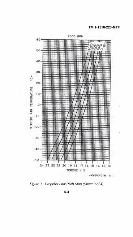
TM 1-1510-223-MTF
Figure 1. Propeller Low Pitch Stop (Sheet 3 of 4)
5-4

TM 1-1510-223-MTF
Figure 1. Propeller Low Pitch Stop (Sheet 4 of 4)
5-5

TM 1-1510-223-MTF
C2
THIS FIGURE HAS BEEN DELETED
Figure 2. Stall Speeds (Sheet 1 of 2)
5-6

TM 1-1510-223-MTF
THIS FIGURE HAS BEEN DELETED
Figure 2. Stall Speeds (Sheet 2 of 2)
C2
5-7

TM 1-1510-223-MTF
Figure 3. Airspeeds for Vmo Dive.
5-8
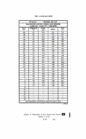
TM 1-1510-223-MTF
Figure 4. Maximum Cruise Speed and Power (Sheet 1 of 2)
5 - 9 C1

TM 1-1510-223-MTF
Figure 4. Maximum Cruise Speed and Power (Sheet 2 of 2)
C 1 5-10
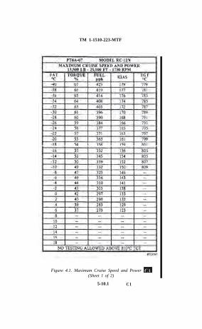
TM 1-1510-223-MTF
Figure 4.1. Maximum Cruise Speed and Power (Sheet 1 of 2)
5-10.1 C1

TM 1-1510-223-MTF
Figure 4.1. Maximum Cruise Speed and Power (Sheet 2 of 2)
C1 5-10.2

TM 1-1510-223-MTF
Figure 5. Maximum Continuous Power
5-11 C 1
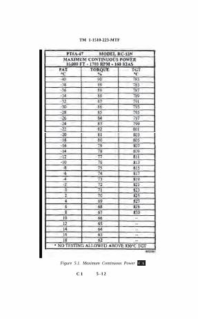
TM 1-1510-223-MTF
Figure 5.1. Maximum Continuous Power
C 1 5 - 1 2

TM 1-1510-223-MTF
Figure 6. Maximum Cruise Power rm
5-12.1 C 1

TM 1-1510-223-MTF
Figure 6.1. Maximum Cruise Power
C 1 5-12.2P I N : 0 7 5 3 5 8 - 0 0 1

TM 1-1510-223-MTF
Figure 7. Maintenance Test Flight Checksheet (Sheet 1 of 3)
5-13/(5-14 blank)

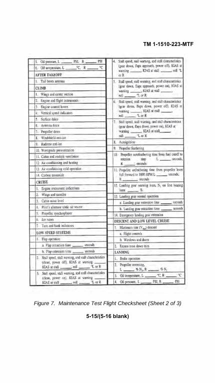
TM 1-1510-223-MTF
Figure 7. Maintenance Test Flight Checksheet (Sheet 2 of 3)
5-15/(5-16 blank)


TM 1-1510-223-MTF
Figure 7. Maintenance Test Flight Checksheet (Sheet 3 of 3)
5-17/(5-18 blank)


PIN: 073633-000

This fine document...
Was brought to you by me:
Liberated Manuals -- free army and government manuals
Why do I do it? I am tired of sleazy CD-ROM sellers, who take publicly available information, slap “watermarks” and other junk on it, and sell it. Those masters of search engine manipulation make sure that their sites that sell free information, come up first in search engines. They did not create it... They did not even scan it... Why should they get your money? Why are not letting you give those free manuals to your friends?
I am setting this document FREE. This document was made by the US Government and is NOT protected by Copyright. Feel free to share, republish, sell and so on.
I am not asking you for donations, fees or handouts. If you can, please provide a link to liberatedmanuals.com, so that free manuals come up first in search engines:
<A HREF=http://www.liberatedmanuals.com/>Free Military and Government Manuals</A>
– SincerelyIgor Chudovhttp://igor.chudov.com/