Unexploded ordnance detection experiments using ultrawideband synthetic aperture radar
10
Unexploded Ordnance Detection Experiments Using Ultra- Wideband Synthetic Aperture Radar Clyde C. DeLuca, Vincent Marinelli , Marc Ressler, and Tuan Ton U.S. Army Research Laboratory, Sensors and Electronic Devices Directorate, 2800 Powder Mill Rd, Adelphi, Md 20783 ABSTRACT The Army Research Laboratory (ARL) has several technology development programs that are evaluating the use of ultra- wideband synthetic aperture radar (UWB SAR) to detect and locate targets that are subsurface or concealed by foliage. Under these programs, a 1-GHz-bandwidth, low-frequency, fully polarimetric UWB SAR instrumentation system was developed to collect the data needed to support foliage and ground-penetrating radar studies. The radar was integrated onto a 150-ft-high mobile boomlift platform in 1995 and was thus named the BoomSAR. In 1997, under the sponsorship of the Strategic Environmental Research and Development Program (SERDP), ARL began a project focused on enhancing the detection and discrimination of unexploded ordnance (UXO). The program’s technical approach is to collect high-quality, precision data to support phenomenological investigations of electromagnetic wave propagation through varying dielectric media, which in turn supports the development of algorithms for automatic target detection. For this project, a UXO test site was set up at the Steel Crater Test Area--an existing test site that already contained subsurface mines, tactical vehicles, 55-gallon drums, storage containers, wires, pipes, and arms caches located at Yuma Proving Ground (YPG), Arizona. More than 600 additional pieces of inert UXO were added to the Steel Crater Test Area, including bombs (250, 500, 750, 1000, and 2000 lb), mortars (60 and 81 mm), artillery shells (105 and 155 mm), 2.75-in. rockets, submunitions (M42, BLU-63, M68, BLU-97, and M118), and mines (Gator, VS1.6, M12, PMN, and POM-Z). In the selection of UXO to be included at YPG, an emphasis was placed on the types of munitions that may be present at CONUS test and training ranges. Keywords: unexploded ordnance, ground-penetrating radar, synthetic aperture radar, ultra-wideband. 1. BOOMSAR SYSTEM The Army Research Laboratory designed and fabricated an ultra-wideband (UWB) synthetic aperture radar (SAR) measurement asset to collect data to support the validation of high-fidelity electromagnetic models and the development of unique low-frequency target detection algorithms. This UWB radar, known as "BoomSAR" (see figure 1), spans a frequency range from 20 to 1100 MHz. This range extends beyond the frequency region of potential future operational foliage or ground-penetrating systems [1]. Post-processing of the wideband data allows numerous sub-bands to be evaluated so that we can determine the optimal frequency range for detecting the desired concealed target in postulated radar designs. The BoomSAR system emulates the trajectory that would be flown by an airborne radar (see figure 2). Unlike an airborne system, the BoomSAR permits us to perform precisely controlled and repeatable experiments aimed at developing a better understanding of the full potential of an airborne UWB SAR for detection of concealed targets with reduced operational costs. Thus the BoomSAR data collected are used to define the upper bound of performance for a radar of this type; then we can trade off the issues associated with the use of different frequency bands, integration angles (resolution), power levels, polarizations, and motion compensation requirements to determine the operating characteristics of an advanced development system.
-
Upload
independent -
Category
Documents
-
view
4 -
download
0
Transcript of Unexploded ordnance detection experiments using ultrawideband synthetic aperture radar
Unexploded Ordnance Detection Experiments Using Ultra-Wideband Synthetic Aperture Radar
Clyde C. DeLuca, Vincent Marinelli , Marc Ressler, and Tuan Ton
U.S. Army Research Laboratory, Sensors and Electronic Devices Directorate,2800 Powder Mill Rd, Adelphi, Md 20783
ABSTRACT
The Army Research Laboratory (ARL) has several technology development programs that are evaluating the use of ultra-wideband synthetic aperture radar (UWB SAR) to detect and locate targets that are subsurface or concealed by foliage.Under these programs, a 1-GHz-bandwidth, low-frequency, fully polarimetric UWB SAR instrumentation system wasdeveloped to collect the data needed to support foliage and ground-penetrating radar studies. The radar was integrated ontoa 150-ft-high mobile boomlift platform in 1995 and was thus named the BoomSAR.
In 1997, under the sponsorship of the Strategic Environmental Research and Development Program (SERDP), ARL began aproject focused on enhancing the detection and discrimination of unexploded ordnance (UXO). The program’s technicalapproach is to collect high-quality, precision data to support phenomenological investigations of electromagnetic wavepropagation through varying dielectric media, which in turn supports the development of algorithms for automatic targetdetection.
For this project, a UXO test site was set up at the Steel Crater Test Area--an existing test site that already containedsubsurface mines, tactical vehicles, 55-gallon drums, storage containers, wires, pipes, and arms caches located at YumaProving Ground (YPG), Arizona. More than 600 additional pieces of inert UXO were added to the Steel Crater Test Area,including bombs (250, 500, 750, 1000, and 2000 lb), mortars (60 and 81 mm), artillery shells (105 and 155 mm), 2.75-in.rockets, submunitions (M42, BLU-63, M68, BLU-97, and M118), and mines (Gator, VS1.6, M12, PMN, and POM-Z). Inthe selection of UXO to be included at YPG, an emphasis was placed on the types of munitions that may be present atCONUS test and training ranges.
Keywords: unexploded ordnance, ground-penetrating radar, synthetic aperture radar, ultra-wideband.
1. BOOMSAR SYSTEM
The Army Research Laboratory designed and fabricated an ultra-wideband (UWB) synthetic aperture radar (SAR)measurement asset to collect data to support the validation of high-fidelity electromagnetic models and the development ofunique low-frequency target detection algorithms. This UWB radar, known as "BoomSAR" (see figure 1), spans a frequencyrange from 20 to 1100 MHz. This range extends beyond the frequency region of potential future operational foliage orground-penetrating systems [1]. Post-processing of the wideband data allows numerous sub-bands to be evaluated so that wecan determine the optimal frequency range for detecting the desired concealed target in postulated radar designs.
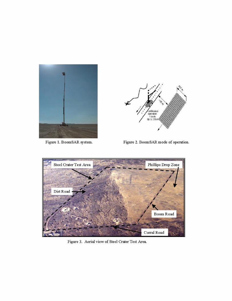
The BoomSAR system emulates the trajectory that would be flown by an airborne radar (see figure 2). Unlike an airbornesystem, the BoomSAR permits us to perform precisely controlled and repeatable experiments aimed at developing a betterunderstanding of the full potential of an airborne UWB SAR for detection of concealed targets with reduced operationalcosts. Thus the BoomSAR data collected are used to define the upper bound of performance for a radar of this type; then wecan trade off the issues associated with the use of different frequency bands, integration angles (resolution), power levels,polarizations, and motion compensation requirements to determine the operating characteristics of an advanceddevelopment system.
While collecting data, the BoomSAR system drives at approximately 1 km/hr, creating the desired synthetic aperture. Theside-looking radar surveys a 300-m swath in range. A typical data-collection run consists of a 1-km-long cross-range path.For the system to achieve the desired constant 90 degrees (+/-5 degrees) integration angle for the SAR imagery producedduring image processing of the data, 750 m of synthetic aperture is required. (The image processor uses a mosaickingstrategy to achieve the constant integration angle throughout the image). The 30-ton boom-lift platform requires arelatively flat road (5% grade maximum) that is wide enough to accommodate its 18-ft wheel base.
2. YUMA PROVING GROUND (YPG) TEST SITE
In 1997, ARL started a Strategic Environmental Research and Development Program (SERDP) project focused on thedetection and discrimination of unexploded ordnance (UXO). For this project, the Steel Crater Test Area at YPG wasexpanded to include more than 600 additional pieces of inert UXO. The majority of these UXO were items likely to bepresent on CONUS test and training ranges, including bombs (250 to 2000 lb), mortars (60 and 81 mm), artillery shells(105 and 155 mm), 2.75-in. rockets, submunitions (M42, BLU-63, M-68, BLU-97, and M118), and mines (Gator, VS1.6,M12, PMN, and POM-Z). The UXO, segregated by type, were placed in 112-m long rows, each containing 16 pieces spaced7 m apart. The spacing between the existing targets and the newly placed UXO was also 7 m, except for the 2.75-in.rockets, 105- and 155-mm shells, which were spaced 10 m apart. The UXO was placed from west to east in ascending orderof size, starting from the east side of the existing minefield.
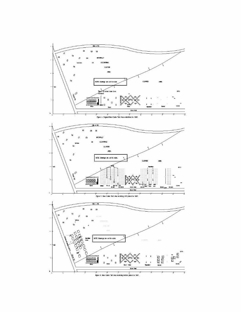
The Steel Crater Test Area is unique in that half of the area is part of the Phillips Drop Zone, in which the soil has beenturned over to a depth of about 2 ft and is virtually free of vegetation, an almost homogeneous soil layer. This featurepermits the investigation of electromagnetic wave propagation studies in a realistic but relatively easily definable soil.Figure 3 shows an aerial view of the entire Steel Crater Test Area. Figure 4 shows the original Steel Crater Site that, withsupport from YPG and MIT/Lincoln Laboratory, ARL established in July 1995. The original area contained vehicles,mines, boxes, disks/back-filled holes, repeaters, barrels and clones. As shown in figure 4, there is considerable space within(e.g., within the box or repeaters area ) and between adjacent target areas to place the UXO. Figure 5 shows the Steel CraterSite and locations of the UXO that was placed for the SERDP program. The disks/holes area has not been touched, becausewe want to see if the radar can still distinguish the holes that were back-filled two years ago. A group of 10 mines that werelocated east of the main group of mines have been removed, and will be placed at a later time in the natural occurringclutter area. The bombs were placed in both the natural occurring clutter area facing Corral Road, and in the cleared areafacing Boom Road as shown in figure 6.
In order to fully understand the results of the BoomSAR data collection and to foster the implementation of new andadvanced data processing algorithms, it is critical to know the exact placement of each UXO item. Precise locationinformation (depth, entry angle, and angle with respect to Boom/Corral Road) allows us to more accurately evaluate andmodify data processing programs and better understand the phenomenology associated with UXO target scattering.
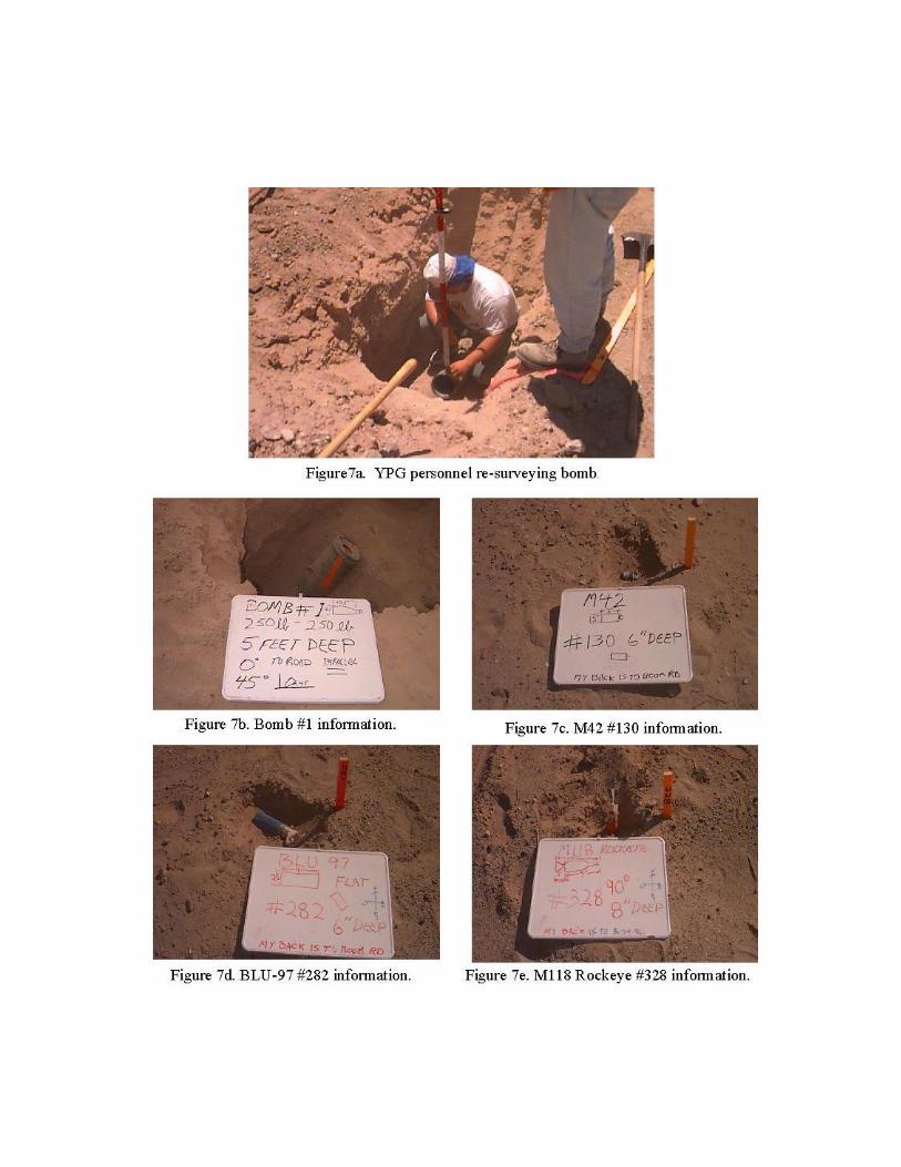
To ensure ground truth accuracy, each UXO item was assigned a number, labeled, photographed, and videotaped, and thenplaced in its assigned location, which had been previously surveyed by YPG geodetics personnel. Before the UXO wasburied, it was photographed and videotaped as it lay on the ground, and each item location was re-surveyed. The UXO wasburied at different depths, entry angles, and angles with respect to Boom/Corral Road in an attempt to represent realisticUXO locations and orientations, and to provide us with a wide variation of aspect angles to evaluate algorithm performance.The bombs were placed at depths ranging from surface to 2 m deep, entry angles of 0 to 90 degrees, and angles from 0 to315 degrees with respect to Boom/Corral Road. Orientation, with respect to Boom or Corral road, and depth of burial wereverified by Yuma Geodetics personnel, and the angle of burial was verified within one degree using a gunner’s quadrant.Figure 7a shows YPG personnel re-surveying a bomb. Figures 7b to 7e show a 250-lb bomb, M42 submunition, BLU-97,and a M118 Rockeye, respectively, each with its relevant information recorded on a placard. A total of 624 locations weresurveyed for the placement of the UXO, and 29 locations were surveyed for the placement of the bombs. Of the 624surveyed locations for UXO placement, 512 pieces have been placed. The remaining UXO will be placed in the test area, insmall groups, after each predetermined series of data collections has been completed, to gather data for evaluating changedetection algorithms. Of the 29 bombs buried, 18 are located in the natural occurring clutter area of the Steel Crater TestArea, which faces Corral Road, and the remaining 11 were buried facing Boom Road. In addition to burying the 18 bombs

in the natural occurring area, six holes were dug and immediately back-filled, to investigate the radar signature of disturbedsoil versus an actual target.
3. SOIL CONDITIONS
The University of Florida performed soil analysis and characterization of the soils at the Steel Crater Test Area at YPGbefore ARL's September 1997 UXO ground-penetrating radar (GPR) measurements [2]. The objective was to characterizethe soil conditions, particularly moisture content and dielectric permittivity. Measurements of soil moisture and dielectricpermittivity allow for improved estimates of soil related GPR performance, especially soil attenuation.
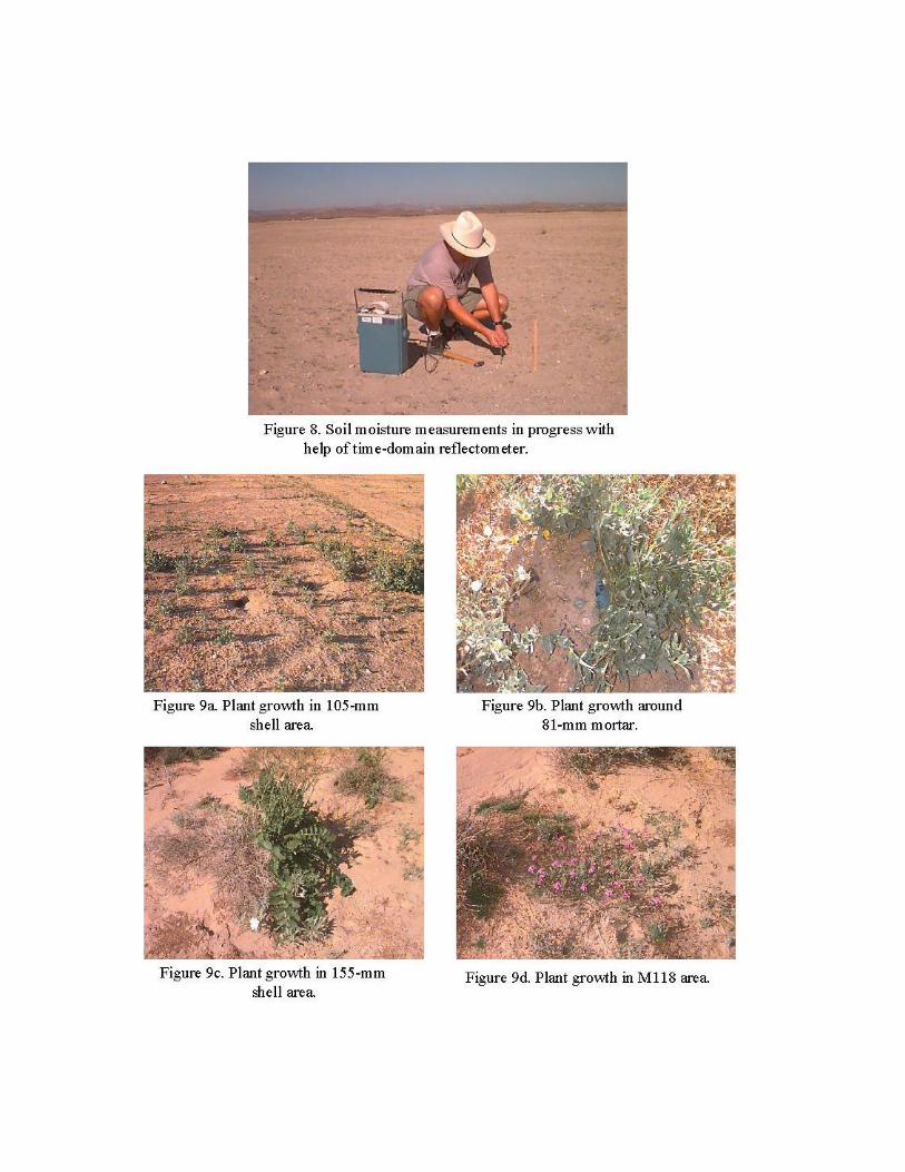
Several types of tests were performed on the soils on 23 and 24 September 1997, and subsequently in the laboratory, inorder to characterize the soil conditions in the areas of interest. Time-domain reflectometer (TDR) tests were made withprobes inserted directly into the ground (see figure 8), soil visual inspections and tests were made in the field, and soilsamples were collected for further laboratory testing at the University of Florida. The TDR makes a measurement of a pulsewaveform input to parallel probes inserted into the soil. From the TDR measurements, the effective velocity of the pulse inthe soil is measured and, in turn, the soil dielectric constant (approximately the real dielectric permittivity) and volumetricmoisture content can be calculated. The characteristics of the TDR pulse return also allow estimates of low-frequency soilconductivity. Soil samples were collected to make bulk density measurements, gravimetric moisture measurements, soilcomposition, dc conductivity, and other measurements in the laboratory.
Previous work with YPG soils and results of soil modeling efforts are used here to estimate the complex dielectricpermittivity of several Yuma soils having different compositions and at different moisture contents [3-5]; the most recentwork was by Miller and Kurtz [6]. Prior modeling work has shown that the soil composition (sand and clay) can be used ina model to make reasonable estimates of dielectric permittivity after modifying the model to "fit" measured permittivity datafor Yuma soils. Such a modified model has been used here to make dielectric permittivity estimates for several Yuma soilswith varying moisture content. The soil dielectric permittivity from the model is then used to make soil attenuation versusfrequency estimates.
The average soil moisture was approximately 4.6% for the Steel Crater Test Area. These measurements were taken justbefore Tropical Storm Nora arrived in Yuma on 25 September 1997. Readings taken by ARL personnel using the TDR afterthe storm showed that the soil had a considerablely higher moisture content (approximate average of 7.2%). Table 1 showsdata extracted from University of Florida calculations for one of the Steel Crater Test Area locations previously tested.
Table 1. Estimated Soil Attenuation Versus Frequency. Frequency (MHz) 74.47 149.76 301.83 501.35 696.36 899.20 1099.60
Moisture = 7%Dielectric Permittivity 5.15 5.15 5.15 5.15 5.15 5.15
5.15One-wayAttenuation (dB/m) 6.55 7.33 10.75 16.45 22.44 28.64 36.03
Moisture = 8%Dielectric Permittivity 5.56 5.56 5.56 5.56 5.56 5.56 5.56One-wayAttenuation (dB/m) 6.59 7.39 10.92 16.91 23.28 29.97 37.99
As one can see from this table, as the moisture increases, the attenuation increases, and, as the frequency increases, theattenuation also increases.
4. DATA COLLECTION
Two data collections were attempted: September 1997 and January 1998. The September 1997 data collection was plaguedby Tropical Storm Nora and several other rains. Two data runs were made in September, with the hope of collecting usefuldata. The average moisture content at the time of the data collection was approximately 7.2%. The corresponding one-wayattenuation can be inferred by looking at table 1 (at 300 MHz, the one-way attenuation is 10.79 dB/m, and at 900 MHz, theone-way attenuation is 28.91 dB/m). After the data was processed, it became obvious that the soil attenuation was too greatto overcome, as we were able to detect the surface items, and only a few of the shallow buried items. At that point, littlemeaningful data could be collected, therefore further data collection was delayed until January 1998.
The soil conditions encountered in the January 1998 data collection were actually worse (soil moisture averageapproximately 9%) due to two major rains just before our arrival in Yuma. One major difference between the September1997 data collection and the January 1998 attempt was the tremendous amount of plant growth (see figures 9a to 9d) in thetest site. Although the soil conditions were not conducive to detecting underground objects, the tremendous amount of plantgrowth afforded us an unique opportunity to collect clutter data. The data collected will be extremely useful in developingand enhancing our clutter reduction algorithms and various ground clutter canceler algorithms. The soil conditions in thisEl Nino year represent a "once in a hundred years" event for this area.
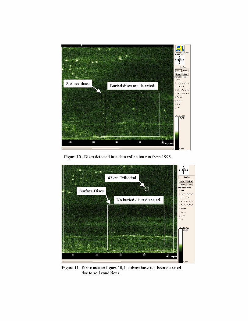
Figure 10 shows a pictorial representation of data taken from the discs/holes area at the original Steel Crater Test Area in1995. Figure 11 shows a pictorial representation of the data taken from the discs/holes area in January 1998. Refer tofigure 4 to see the general layout of the discs area. The left-most row of discs is located on the surface, while the rest of thediscs are buried at varying depths ranging from flush with the ground to 6 in. deep. The boxed areas in figure 10 show thediscs (surface and buried) detected in 1995. The only discs that were detected in the data collection run made in January1998 were located on the surface, as shown in figure 11.
5. FUTURE PLANS
A third attempt to collect data will be made between May and July 1998, allowing ample time for the soil to dry out. Otherchallenges will await us, as average temperatures in Yuma rise well into the 100-degree range at that time of the year.
6. CONCLUSION
The ARL BoomSAR is a state-of-the-art instrumentation radar that can provide the high-resolution, high-sensitivity dataneeded to conduct foliage and ground-penetrating radar investigations. This system complements existing airborne low-frequency SAR systems, because it provides the ability to collect reasonable amounts of data in a very controlledenvironment with the same depression angles as airborne sensors. The unique features of the low-frequency data and theresultant imagery of the data collected with the BoomSAR indicate that there is potential for low-frequency UWB radar todetect targets embedded in foliage and subsurface targets. However, more work is needed to develop effective target/clutterdiscrimination techniques to autonomously detect targets and ensure a reasonably low false-alarm rate. The September 1997and January 1998 data collections will provide much of the data to facilitate the development of effective discriminationtechniques.
The UXO test site at YPG is a national asset that is available to support the development and demonstration of detectiontechnologies. The careful design and precise installation of the test site can give technology developers a betterunderstanding of sensor phenomenology, which then could be applied to the development of improved target detectionalgorithms.

ACKNOWLEDGMENTS
We would like to note the important contributions made by our colleagues at the Army Research Laboratory. This teamworked long and arduous hours in the field collecting the data that will be used in developing and enhancing clutter-reduction algorithms and various ground clutter canceler algorithms. Our particular thanks go out to David Wong, ThoaiNguyen, Greg Smith, Darshanpal Gill, Steve Post, and Matt Bennett.
7. REFERENCES
1. K. Kappra, F. Le, L. Nguyen, T. Ton, and M. Bennett, "Ultra-Wideband Foliage- and Ground-Penetrating RadarExperiments," Sensors and Electronic Devices Symposium (January 1997).
2. J. Kurtz, J. Cowdery, and M. E. Collins, "Additional Soil Evaluations at Yuma Proving Ground," University of FloridaReport to the Army Research Laboratory, 15 December 1997.
3. M. E. Collins, R. J. Kuehl, D. Heuberger, and J. Kurtz, "Soil Properties at the Yuma Proving Grounds as Related toGround Penetrating Radar," University of Florida Report to MIT/Lincoln Laboratory and the Army Research Laboratory,December 1995.
4. J. L. Kurtz, R. M. Keller, B. K. Miller, and M. E. Collins, "Radar and Ground Truth Evaluations of Areas Near Yuma,Arizona," University of Florida Report to MIT/Lincoln Laboratory and the Army Research Laboratory," 28 February 1996.
5. M.E. Collins, F. A. Ovalles, R. J. Kuehl, D. Heuberger, and J. L. Kurtz, "Characterization and Comparison of Soils forGround Penetrating Radar Measurements," University of Florida Report to MIT/Lincoln Laboratory and the Army ResearchLaboratory, October 1996.
6. B. K. Miller and J. L. Kurtz, "Modeling of Soil EM Properties for Ground Penetrating Radar Assessment," Report for theArmy Research Laboratory, 27 January 1997.