An insect eye-based image sensor with very large field of view
8
An insect eye based image sensor with very large field of view Els Moens *a , Youri Meuret a , Heidi Ottevaere a , Mukul Sarkar b , David San Segundo Bello c , Patrick Merken d , Hugo Thienpont a a Vrije Universiteit Brussel, Faculty of Engineering, Brussels Photonics Team B-PHOT, TONA FirW, Pleinlaan 2, B-1050 Brussel, Belgium; b IMEC / TU Delft, High Tech Campus 31, 5656 AE Eindhoven, Netherlands; c IMEC, Kapeldreef 75, 3001 Leuven, Belgium; d Royal Militairy Academy, Renaissancelaan 30, 1000 Brussel, Belgium; ABSTRACT In this paper we discuss the design of a novel miniaturized image sensor based on the working principle of insect facet eyes. The main goals are to design an imaging system which captures a large field of view (FOV) and to find a good trade-off between image resolution and sensitivity. To capture a total FOV of 124 ◦ , we split up this FOV into 25 different zones. Each of these angular zones is imaged by an isolated optical channel on our image sensor. There is an overlap between the zones to cover the full FOV but the different zones are imaged on separated regions at the image sensor. Every optical channel in the designed component consists of two lenses that are tilted with respect to each other and the optical axis. Because of this tilt of the lenses, we are able to minimize field curvature and distortion in the obtained images at the detector, and have an angular resolution below 1 ◦ . The optical system was implemented and optimized in the ray-tracing program ASAP. The parameters (in one channel) that are optimized to obtain this large FOV with a good image resolution and sensitivity are the radius of curvature of the two lenses, their conical factor and their tilt in two directions with respect to the optical axis of the complete system. The lenses are each placed on a pedestal that connects the lens to a planar substrate. We also add absorbing tubes that connect the two lenses in one channel to eliminate stray-light between different optical channels. The obtained image quality of the design is analyzed using our simulation model. This is determined by different parameters as there are: modulation transfer function, distortion, sensitivity, angular resolution, energy distribution in each channel and channel overlap. The modulation transfer function shows us that maximum contrast in the image is reached up to 0.3LP/ ◦ , distortion is maximal 21% in one of the 25 different channels, the sensitivity is 0.3% and the resolution is better than 1 ◦ . Keywords: Micro-optics, optical design, wide field of view, image quality, image sensor 1. INTRODUCTION Today lots of applications like endoscopy 1, 2 and security cameras require wide field of view (FOV) image sensors. 3 In this paper we discuss the design of a new wide FOV (124 ◦ ) micro-optical imaging system. Except for the wide FOV, it is our goal to design an image sensor with a good trade-of between obtained image quality and sensitivity. For designing the micro-optical system, we were inspired by nature. Indeed our design is based on nature’s insect facet eyes, which also have a very large FOV. Each facet eye is built up out of hundreds to thousands channels, called ommatidia. 4 These capture light, with certain angles of incidence, from the outside world and guide it to the receptor cells. Since these ommatidia are placed on a curved surface these insect facet eyes have a very large FOV. Two types of facet eyes exist: superposition and apposition eyes (Fig. 1). In superposition eyes, each receptor captures light from several neigboring channels. In apposition eyes, each receptor only receives light from a single channel. The main difference between these two types of facet eyes is the sensitivity which is higher in the superposition eyes. On the other hand, in apposition eyes, the resolution is better. Light that enters a single channel in an apposition eye is guided through the ommatidium and on the receptor cells the light is captured. The angle between the different ommatidia axes is almost equal to the acceptance angle of a * [email protected];phone +32 (0)2 629 13 81; fax +32 (2) 629 34 50; www.b-phot.org Micro-Optics 2010, edited by Hugo Thienpont, Peter Van Daele, Jürgen Mohr, Hans Zappe, Proc. of SPIE Vol. 7716, 77162D · © 2010 SPIE · CCC code: 0277-786X/10/$18 doi: 10.1117/12.854455 Proc. of SPIE Vol. 7716 77162D-1 Downloaded from SPIE Digital Library on 24 Jun 2010 to 131.180.130.109. Terms of Use: http://spiedl.org/terms
Transcript of An insect eye-based image sensor with very large field of view

An insect eye based image sensor with very large field of view
Els Moens*a, Youri Meureta, Heidi Ottevaerea, Mukul Sarkarb, David San Segundo Belloc,Patrick Merkend, Hugo Thienponta
aVrije Universiteit Brussel, Faculty of Engineering, Brussels Photonics Team B-PHOT, TONAFirW, Pleinlaan 2, B-1050 Brussel, Belgium;
bIMEC / TU Delft, High Tech Campus 31, 5656 AE Eindhoven, Netherlands;cIMEC, Kapeldreef 75, 3001 Leuven, Belgium;
dRoyal Militairy Academy, Renaissancelaan 30, 1000 Brussel, Belgium;
ABSTRACT
In this paper we discuss the design of a novel miniaturized image sensor based on the working principle of insectfacet eyes. The main goals are to design an imaging system which captures a large field of view (FOV) and to finda good trade-off between image resolution and sensitivity. To capture a total FOV of 124 ◦, we split up this FOVinto 25 different zones. Each of these angular zones is imaged by an isolated optical channel on our image sensor.There is an overlap between the zones to cover the full FOV but the different zones are imaged on separatedregions at the image sensor. Every optical channel in the designed component consists of two lenses that aretilted with respect to each other and the optical axis. Because of this tilt of the lenses, we are able to minimizefield curvature and distortion in the obtained images at the detector, and have an angular resolution below 1 ◦.The optical system was implemented and optimized in the ray-tracing program ASAP. The parameters (in onechannel) that are optimized to obtain this large FOV with a good image resolution and sensitivity are the radiusof curvature of the two lenses, their conical factor and their tilt in two directions with respect to the optical axisof the complete system. The lenses are each placed on a pedestal that connects the lens to a planar substrate.We also add absorbing tubes that connect the two lenses in one channel to eliminate stray-light between differentoptical channels. The obtained image quality of the design is analyzed using our simulation model. This isdetermined by different parameters as there are: modulation transfer function, distortion, sensitivity, angularresolution, energy distribution in each channel and channel overlap. The modulation transfer function showsus that maximum contrast in the image is reached up to 0.3LP/◦, distortion is maximal 21% in one of the 25different channels, the sensitivity is 0.3% and the resolution is better than 1 ◦.
Keywords: Micro-optics, optical design, wide field of view, image quality, image sensor
1. INTRODUCTION
Today lots of applications like endoscopy1, 2and security cameras require wide field of view (FOV) image sensors.3
In this paper we discuss the design of a new wide FOV (124 ◦) micro-optical imaging system. Except for thewide FOV, it is our goal to design an image sensor with a good trade-of between obtained image quality andsensitivity.
For designing the micro-optical system, we were inspired by nature. Indeed our design is based on nature’sinsect facet eyes, which also have a very large FOV. Each facet eye is built up out of hundreds to thousandschannels, called ommatidia.4 These capture light, with certain angles of incidence, from the outside world andguide it to the receptor cells. Since these ommatidia are placed on a curved surface these insect facet eyes have avery large FOV. Two types of facet eyes exist: superposition and apposition eyes (Fig. 1). In superposition eyes,each receptor captures light from several neigboring channels. In apposition eyes, each receptor only receiveslight from a single channel. The main difference between these two types of facet eyes is the sensitivity whichis higher in the superposition eyes. On the other hand, in apposition eyes, the resolution is better. Light thatenters a single channel in an apposition eye is guided through the ommatidium and on the receptor cells thelight is captured. The angle between the different ommatidia axes is almost equal to the acceptance angle of a
* [email protected];phone +32 (0)2 629 13 81; fax +32 (2) 629 34 50; www.b-phot.org
Micro-Optics 2010, edited by Hugo Thienpont, Peter Van Daele, Jürgen Mohr, Hans Zappe,Proc. of SPIE Vol. 7716, 77162D · © 2010 SPIE · CCC code: 0277-786X/10/$18
doi: 10.1117/12.854455
Proc. of SPIE Vol. 7716 77162D-1
Downloaded from SPIE Digital Library on 24 Jun 2010 to 131.180.130.109. Terms of Use: http://spiedl.org/terms

single ommatidium. Since the FOV of one channel abuts the field of its neighbor, an overal erect image madeup of a mosaic of adjacent FOVs is produced. In superposition eyes the receptor cell is a single sheet, not acombination of several cells in each ommatidium.5 Each optical part in the ommatidia of the superposition eyeredirects a parallel beam of light to form another parallel beam on the same side of the optical axis. There arethree possible ways to do this in superposition eyes: a two-lens telescope, a plane mirror and a combination of acurved mirror and a lens.4 The images from different ommatidia are superimposed to form a single erect image.
Figure 1. Superposition facet eye (left) and apposition facet eye (right)
In the literature there are already several systems described that perform image transfer through separatedoptical channels of which some are inspired by nature’s insect facet eyes.6–8 Two of these artificial insect facet eyesare fabricated with wafer-scale techniques: the cluster eye and the artificial apposition compound eye (APCO).6
The cluster eye is inspired by the apposition eye and consists of three micro-lens arrays with different pitch. Theoptical axes of the different channels are thus tilted with respect to each other. Each of these channels samplesa small part of the object and makes an intermediate image on the second lens array. On the detector theseintermediate images are then brought together to form one single image. The trade-off between resolution andsensitivity is in this case made by the number of lenses in each micro-lens array. The second system, the APCO,is based on the apposition compound eye, where each channel samples one direction in space. It consists of amicrolens array with at the focal length of the lenses, just in front of the detector, a pinhole array with slightlydifferent pitch than the microlens array. The optical axes of the system are pointed outwards. Each of theselenses is thus capturing light with a certain angle of incidence. Every micro-lens is optimized for reduction ofaberrations under oblique incidence.9 Here, the pinhole diameter defines the sensitivity/resolution trade-off. Themain restriction of both systems is the FOV because the lenses are not tilted outwards, as is the case in insectfacet eyes.
A major diference between the insect facet eyes and the artificial eyes is the shape of the detector which isflat in the artificial case and curved for the insect eyes. From a technological point of view it is more difficultto work with a curved CMOS than with a flat one, although progress has been made in this field.10 Because oflow-cost and robustness we opted to work with a flat CMOS detector without neglecting the goal to have a goodimage quality and large FOV.
In the design we made, we want to enlarge the FOV of the system with respect to the cluster eye and APCOand find a good resolution/sensitivity trade-off. For the cluster eye and the APCO, the resolution is 3.3LP/◦
over a FOV of 33 ◦ by 12 ◦ and 1.6LP/◦ over a FOV of 25 ◦ by 25 ◦ respectively. In our design we want to enlargethis FOV up to 124 ◦ and reach a resolution below 1 ◦. Our design consists of multiple two micro-lens channels,which are tilted with respect to each other and the optical axis to increase the total FOV and to monitor a goodresolution/sensitivity trade-off. We chose to use two micro-lenses per channel since this increases the reductionof aberrations and facilitates the alignment. Because the image plane where a CMOS detector will be positionedcaptures incident light with an angular difference of 1 ◦, we had to find a good transformation between theincident angles and position of the respective light spots on the image plane.11
Proc. of SPIE Vol. 7716 77162D-2
Downloaded from SPIE Digital Library on 24 Jun 2010 to 131.180.130.109. Terms of Use: http://spiedl.org/terms

2. DESIGN OF THE MICRO-OPTICAL SYSTEM
2.1 Design Method
By using 25 separated imaging channels, we want to image the total FOV (which is circular) onto a flat, squaredetector (which is a square). The detector was divided into 25 zones. There are two spherical coordinates thatdescribe each point in the far field of the image sensor: the angles phi (φ) and theta (θ). Light with a certainpredefined angle of incidence is imaged in the center of a certain zone of the CMOS detector. By mapping thedesired FOV on circles with a radius equal to the parameter φ, we define these center angles of incidence. For aquarter of the total FOV, we define the center directions by varying θ in three steps for φ=25 ◦ and in five stepsfor φ=50 ◦ (Fig. 2).
Figure 2. Angle To Position Transformation: (a) Mapping of a sphere onto a square. (b) Angles phi (φ) and theta (θ) forthe center directions of angles of incidence for the first nine channels.
Our goal is to design an optical system that maps these center directions onto the corresponding zones atthe detector plane. To sample the complete FOV of 124 ◦, we allow an overlap of the different angular regionsmapped by the separate optical channels. Fig. 3 shows a quarter of this total FOV.
Figure 3. Overlap of the different sub - FOVs.
We can reconstruct a simple image from the different distorted image regions because there is a direct relationbetween angle of incidence and position on the detector. Our primary design goal is to image the center directionsin the center of the CMOS zones and that light with angles of incidence with an angular difference of 1 ◦ createspoint spread functions (PSFs) on the detector that do not overlap.
We have 25 channels, each containing two lenses tilted with respect to each other and the optical axis. Thelenses, substrates and pedestals will be fabricated in poly-methyl-methacrylate (pmma) material. Fig. 4 showschannel two together with the rays in the center and at the edges of the desired FOV, traced through the opticalsystem. Tab. 1 gives the dimensions of this channel. There are four free parameters for each lens in a singlechannel: the radius of curvature (R), the conical factor (C) and the tilt of the lens with respect to the X (TX)and Y (TY ) axis. The function of the first lens is to capture the correct part of light from the total FOV and to
Proc. of SPIE Vol. 7716 77162D-3
Downloaded from SPIE Digital Library on 24 Jun 2010 to 131.180.130.109. Terms of Use: http://spiedl.org/terms
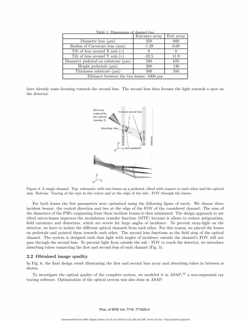
Table 1. Dimensions of channel twoEntrance array Exit array
Diameter lens (μm) 250 600Radius of Curvature lens (mm) -1.39 0.68Tilt of lens around X axis (◦) 0 0Tilt of lens around Y axis (◦) -22.5 11.9
Diameter pedestal on substrate (μm) 500 670Height pedestals (μm) 200 130
Thickness substrate (μm) 300 350Distance between the two lenses: 1000 μm
have already some focusing towards the second lens. The second lens then focuses the light towards a spot onthe detector.
Figure 4. A single channel. Top: schematic with two lenses on a pedestal, tilted with respect to each other and the opticalaxis. Bottom: Tracing of the rays in the center and at the edge of the sub - FOV through the lenses.
For both lenses the free parameters were optimized using the following figure of merit. We choose threeincident beams: the central direction and two at the edge of the FOV of the considered channel. The sum ofthe diameters of the PSFs originating from these incident beams is then minimized. The design approach to usetilted micro-lenses improves the modulation transfer function (MTF) because it allows to reduce astigmatism,field curvature and distortion, which are severe for large angles of incidence. To prevent stray-light on thedetector, we have to isolate the different optical channels from each other. For this reason, we placed the lenseson pedestals and pointed them towards each other. The second lens functions as the field stop of the opticalchannel. The system is designed such that light with angles of incidence outside the channel’s FOV will notpass through the second lens. To prevent light from outside the sub - FOV to reach the detector, we introduceabsorbing tubes connecting the first and second lens of each channel (Fig. 5).
2.2 Obtained image quality
In Fig. 6, the final design result illustrating the first and second lens array and absorbing tubes in between isshown.
To investigate the optical quality of the complete system, we modeled it in ASAP,12 a non-sequential raytracing software. Optimization of the optical system was also done in ASAP.
Proc. of SPIE Vol. 7716 77162D-4
Downloaded from SPIE Digital Library on 24 Jun 2010 to 131.180.130.109. Terms of Use: http://spiedl.org/terms

Figure 5. Introducing absorbing tubes to reduce straylight
Figure 6. 25 zones of the micro-optical design with side view, complete first and second lens array, absorbing tubes andlens on a pedestal
We define the angular resolution as the smallest angular difference between two incident beams which resultsin non-overlapping PSFs. We sent light beams with an angular difference of 1 ◦ through the system to check thisangular resolution and found that for each of the channels there was no overlap of the PSFs. For channels one,two, four and seven (Fig. 2), we could even do better and reach an angular resolution of 0.5 ◦. Fig. 7 shows thelight spots on the detector for channel seven. The central spot and the outer spots originating from the incidentrays for which the channel was optimized, are shown. The other spots come from incident rays with an angulardifference of 1 ◦. It is clear that all the spots are distinguishable on the detector.
Figure 7. Channel seven: Light spots on the detector. There is an angular resolution of 1 ◦
Proc. of SPIE Vol. 7716 77162D-5
Downloaded from SPIE Digital Library on 24 Jun 2010 to 131.180.130.109. Terms of Use: http://spiedl.org/terms
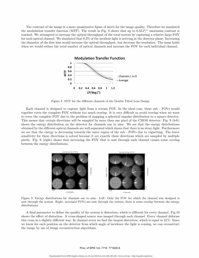
The contrast of the image is a more quantitative figure of merit for the image quality. Therefore we simulatedthe modulation transfer function (MTF). The result in Fig. 8 shows that up to 0.3LP/◦ maximum contrast isreached. We attempted to increase the optical throughput of the total system by capturing a relative large FOVfor each optical channel. We simulated that 0.3% of the incident light is arriving at the detector plane. Increasingthe diameter of the first lens would increase the optical throughput, but decrease the resolution. The same holdswhen we would reduce the total number of optical channels and increase the FOV for each individual channel.
Figure 8. MTF for the different channels of the Double Tilted Lens Design
Each channel is designed to capture light from a certain FOV. In the ideal case, these sub - FOVs wouldtogether cover the complete FOV without too much overlap. It is very difficult to avoid overlap when we wantto cover the complete FOV due to the problem of mapping a spherical angular distribution to a square detector.This means that certain directions will be sampled by more than one pixel of the CMOS detector. Fig. 9 (left)shows the energy distribution on the detector for channels one to nine. We see that the energy distributionsobtained by the different optical channels are well separated which shows that there is no stray-light. Furthermorewe see that the energy is decreasing towards the outer region of the sub - FOVs due to vignetting. The lowersensitivity for these directions is solved because it are exactly these directions which are sampled by multiplepixels. Fig. 9 (right) shows that increasing the FOV that is sent through each channel causes some overlapbetween the energy distributions.
Figure 9. Energy distributions for channels one to nine. Left: Only the FOV for which the channel was designed issent through the system. Right: increased FOVs are sent through the system; there is some overlap between the energydistributions.
A final parameter to define the quality of the system is distortion, which is different for every channel. Fig.10shows the effect of distortion. A cross-shaped source was imaged through each channel. Every channel deformsthis cross in a slightly different way. In channel seven we find the largest distortion, which is equal to 21%. Sincewe know for each position on the detector from which angle of incidence the light is coming, we can reconstructthe image by use of image reconstruction algorithms.
Proc. of SPIE Vol. 7716 77162D-6
Downloaded from SPIE Digital Library on 24 Jun 2010 to 131.180.130.109. Terms of Use: http://spiedl.org/terms

Figure 10. Distortion of cross-shaped sources sent through channels one to nine of the micro-optical system
3. CONCLUSIONS
We designed a miniaturized imaging system with a large FOV (124◦) and an angular resolution below 1◦. Thesensitivity of the system is 0.3% and the maximum distortion is 21%. The MTF shows that maximum contrastin the image is reached up to 0.3LP/◦. Our designed system is currently being fabricated using state-of-the-artsingle point diamond turning method. The different components will be aligned on top of a CMOS detector tocompare the obtained experimental results with our design results.
ACKNOWLEDGMENTS
This work was supported in part by the DWTC-IAP, in part by the FWO, in part by the GOA, in part bythe 6th FP European Network of Excellence on Micro-Optics(NEMO), in part by the Methusalem and Herculesfoundations and in part by the OZR of the Vrije Universiteit Brussel. The work of H. Ottevaere was supported bythe Flemish Fund for Scientific Research (FWO) which provided her a ”Postdoctoraal Onderzoeker” fellowship.
REFERENCES
[1] Yamaguchi, T., Nakamoto, M., Sato, Y., Hashizume, M., Sugano, N., Yoshikawa, H., Tamura, S., ”De-velopment of camera model and calibration procedure for oblique-viewing endoscope,” Transactions of theInstitute of Electronics, Information and Communication Engineers D-II J87D-II(1), 313-324 (2004 ).
[2] Yingke, G., Xiang, X., Ziqiang, W., Guolin, L., Tianjia, S., Nan, Q., Chun, Z., Zhihua, W., ”A new glob-ularity capsule endoscopy system with multi-camera,” IEEE Biomedical Circuits and Systems Conference,289-292 (2009)
[3] Feng, G., Tian, W., Huang, C., Liu, T., Zhang, S., ”Wide field of view CCD camera based on multi-sensorsimage mosaics,” Proc. First International Congress on Image and Signal Processing 2, 432-435 (2008)
[4] Land, M.F. and Nilsson, D.E., Animal Eyes, Oxford Animal Biology Series, Oxford University Press, Oxford,122-177 (2002).
[5] Volkel, R., Eisner M., Weible, K.J., ”Miniaturized imaging systems,” Microelectronic Engineering 67-68,461-472(2003).
[6] Duparre, J., Schreiber, P., Dannberg, P., Scharf, T., Pelli, P., Volkel, R., Herzig, H-P., Brauer, A., ”Artificialcompound eyes - different concepts and their application to ultra flat image acquisition sensors,” Proc. SPIE5346, 89-100 (2004).
[7] Hornsey, R., Thomas, P., Wong, W., Pepic, S., Yip, K., Krishnasamy, R., ”Electronic Compound-Eye ImageSensor: Construction and Calibration,” Proc. SPIE 5301,13-24 (2004).
[8] Hamanaka, K., Koshi, H., ”An artificial compound eye using a microlens array and its application to scale-invariant processing,” Opt. Rev. 3, 264268 (1996)
[9] Duparre, J., Schreiber, P., Volkel, R., ”Theoretical analysis of an artificial superposition compound eye forapplication in ultra flat digital image acquisition devices,” Proc. SPIE 5249, 408-418 (2004).
Proc. of SPIE Vol. 7716 77162D-7
Downloaded from SPIE Digital Library on 24 Jun 2010 to 131.180.130.109. Terms of Use: http://spiedl.org/terms

[10] Cho Ko,H., Stoykovic, M. P., Song, J., Malyarchuk, V., Mook Choi, W., Yu, C., Geddes III, J. B., Xiao,J.,Wang, S., Huang, Y., Rogers, J., ”A hemispherical electronic eye camera based on compressible siliconoptoelectronics,” Nature 454, 748-753 (2008).
[11] Dresel, T., Beyerlein, M., Schwider, J., ”Design of computer-generated beam-shaping holograms by iterativefinite-element mesh adaption,” Applied Optics 35 (35), 6865-6874 (1996).
[12] http://www.breault.com
Proc. of SPIE Vol. 7716 77162D-8
Downloaded from SPIE Digital Library on 24 Jun 2010 to 131.180.130.109. Terms of Use: http://spiedl.org/terms