This document was developed by the SFF Committee prior to it
23
This document was developed by the SFF Committee prior to it becoming the SFF TA (Technology Affiliate) TWG (Technical Working Group) of the SNIA (Storage Networking Industry Association) in 2016. The information below should be used instead of the equivalent herein. POINTS OF CONTACT: SFF TA TWG Chair Email: [email protected]. LOCATION OF SFF DOCUMENTS: http://www.snia.org/sff/specifications. Suggestions for improvement of this specification are welcome and should be submitted to http://www.snia.org/feedback. If you are interested in participating in the activities of the SFF TA TWG, additional information and the membership application can be found at: http://www.snia.org/sff.
-
Upload
khangminh22 -
Category
Documents
-
view
2 -
download
0
Transcript of This document was developed by the SFF Committee prior to it

This document was developed by the SFF Committee prior to it
becoming the SFF TA (Technology Affiliate) TWG (Technical
Working Group) of the SNIA (Storage Networking Industry
Association) in 2016.
The information below should be used instead of the equivalent herein.
POINTS OF CONTACT: SFF TA TWG Chair Email: [email protected].
LOCATION OF SFF DOCUMENTS: http://www.snia.org/sff/specifications.
Suggestions for improvement of this specification are welcome and should be
submitted to http://www.snia.org/feedback.
If you are interested in participating in the activities of the SFF TA TWG, additional
information and the membership application can be found at:
http://www.snia.org/sff.
PUBLISHED SFF-8086 Rev 2.6
Mini Multilane 4X 10 Gb/s Common Elements Connector Page 1
SFF Committee documentation may be purchased in hard copy or electronic form. SFF specifications are available at ftp://ftp.seagate.com/sff
SFF Committee
SFF-8086
Specification for
Mini Multilane 4X 10 Gb/s Common Elements Connector
Rev 2.6 August 31, 2018
Secretariat: SFF Committee Abstract: This specification defines the physical interface and general performance requirements of the mating interface for the Mini Multilane Connector that is designed for use in high speed serial interconnect applications at speeds up to 10 Gb/s. One such use is as the Serial Attached SCSI Mini SAS 4i (wide compact internal connector) and Mini SAS 4X (wide compact external connector). This specification provides a common reference for systems manufacturers, system integrators, and suppliers. This is an internal working specification of the SFF Committee, an industry ad hoc group. This is an internal working document of the SFF Committee, an industry ad hoc group. This specification is made available for public review, and written comments are solicited from readers. Comments received by the members will be considered for inclusion in future revisions of this document. The description of a connector in this specification does not assure that the specific component is actually available from connector suppliers. If such a connector is supplied it must comply with this specification to achieve interoperability between suppliers. Support: This specification is supported by the identified member companies of the SFF Committee. POINTS OF CONTACT: Jay Neer I. Dal Allan Molex Chairman SFF Committee 2222 Wellington Court 14426 Black Walnut Court Lisle, Il 60532 Saratoga, CA 95070 561-447-2907x3889 408-867-6630 [email protected] [email protected]
PUBLISHED SFF-8086 Rev 2.6
Mini Multilane 4X 10 Gb/s Common Elements Connector Page 2
EXPRESSION OF SUPPORT BY MANUFACTURERS The following member companies of the SFF Committee voted in favor of this industry specification.
Amphenol Applied Micro Comax Dell Computer ENDL FCI Foxconn Fujitsu CPA Hewlett Packard HGST Hitachi Cable
IBM Intel LSI Molex Seagate Shenzhen Sun Microsystems TE Connectivity Toshiba Unisys
The following member companies of the SFF Committee voted to abstain on this industry specification.
Arista EMC Emulex Finisar Infineon
JDS Uniphase Maxtor Picolight Sumitomo Vitesse Semiconductor
The user's attention is called to the possibility that implementation to this Specification may require use of an invention covered by patent rights. By distribution of this Specification, no position is taken with respect to the validity of this claim or of any patent rights in connection therewith. Members of the SFF Committee, which advise that a patent exists, are required to provide a statement of willingness to grant a license under these rights on reasonable and non-discriminatory terms and conditions to applicants desiring to obtain such a license. Change History: April 16 2011: Editorial revision to incorporate 2011 titling and review content for consistency prior to being submitted for EIA standardization. March 14 2013: Letter ballot for EIA-975 distributed for approval, and specification re-classified as Expired. Minor editing changes made as requested. April 25, 2015: Revised/Updated Table 6-1 C08 between the contact pads on the Free (Plug) Paddle Card to reflect the larger gap approved and specified by later designs/manufacturing tolerances that maintain the integrity of the design. Rev 2.6 (August 31, 2018)
- Document to be withdrawn from EIA; other than the changes to the header and cover page, no content or formatting changes have been made since Rev 2.5 of this document.
PUBLISHED SFF-8086 Rev 2.6
Mini Multilane 4X 10 Gb/s Common Elements Connector Page 3
Foreword The development work on this specification was done by the SFF Committee, an industry group. The membership of the committee since its formation in August 1990 has included a mix of companies which are leaders across the industry. When 2 1/2" diameter disk drives were introduced, there was no commonality on external dimensions e.g. physical size, mounting locations, connector type, connector location, between vendors. The first use of these disk drives was in specific applications such as laptop portable computers and system integrators worked individually with vendors to develop the packaging. The result was wide diversity, and incompatibility. The problems faced by integrators, device suppliers, and component suppliers led to the formation of the SFF Committee as an industry ad hoc group to address the marketing and engineering considerations of the emerging new technology. During the development of the form factor definitions, other activities were suggested because participants in the SFF Committee faced more problems than the physical form factors of disk drives. In November 1992, the charter was expanded to address any issues of general interest and concern to the storage industry. The SFF Committee became a forum for resolving industry issues that are either not addressed by the standards process or need an immediate solution. Those companies which have agreed to support a specification are identified in the first pages of each SFF Specification. Industry consensus is not an essential requirement to publish an SFF Specification because it is recognized that in an emerging product area, there is room for more than one approach. By making the documentation on competing proposals available, an integrator can examine the alternatives available and select the product that is felt to be most suitable. SFF Committee meetings are held during T10 weeks (see www.t10.org), and Specific Subject Working Groups are held at the convenience of the participants. Material presented at SFF Committee meetings becomes public domain, and there are no restrictions on the open mailing of material presented at committee meetings. Most of the specifications developed by the SFF Committee have either been incorporated into standards or adopted as standards by EIA (Electronic Industries Association), ANSI (American National Standards Institute) and IEC (International Electrotechnical Commission). If you are interested in participating or wish to follow the activities of the SFF Committee, the signup for membership and/or documentation can be found at: www.sffcommittee.com/ie/join.html The complete list of SFF Specifications which have been completed or are currently being worked on by the SFF Committee can be found at: ftp://ftp.seagate.com/sff/SFF-8000.TXT If you wish to know more about the SFF Committee, the principles which guide the activities can be found at: ftp://ftp.seagate.com/sff/SFF-8032.TXT Suggestions for improvement of this specification will be welcome. They should be sent to the SFF Committee, 14426 Black Walnut Ct, Saratoga, CA 95070.
PUBLISHED SFF-8086 Rev 2.6
Mini Multilane 4X 10 Gb/s Common Elements Connector Page 4
SFF Committee -- Mini Multilane 4X Common Elements Connector 1. Scope
This specification defines the terminology and physical requirements for the mating interface and physical characteristics of the Mini Multilane Connector. The dimensions specified apply to the various sizes of the family, which covers a variety of circuit sizes, see SFF-8087 Mini Multilane Unshielded Connector and SFF-8088 Mini Multilane Shielded Connector. Fibre Channel, SAS, and other standards define requirements on the characteristic impedance and ability to transmit multi-gigabit signals for cable assemblies and backplanes. When this connector is used in such an interconnect, it is subject to these requirements. 2. References
The SFF Committee activities support the requirements of the storage industry, and it is involved with several standards. 2.1 Industry Documents
The following interface standards and specifications are relevant to this Specification. - T10/1601D SAS 1-1 (Serial Attached SCSI - 1.1) - INCITS 352:2002 FC-PI Fibre Channel Physical Interface - INCITS 404:200x FC-PI-2 Fibre Channel Physical Interface -2 - T11/1625D FC-PI-3 Fibre Channel Physical Interface -3 - IEEE 802.3z Gigabit Task Force - InfiniBand IBTA Spec - SFF-8410 High Speed Serial Testing for Copper Links - INF-8074i SFP (Small Formfactor Pluggable) Transceiver - SFF-8075 PCI Card Version of SFP Cage 2.2 SFF Specifications
There are several projects active within the SFF Committee. The complete list of specifications which have been completed or are still being worked on are listed in the specification at ftp://ftp.seagate.com/sff/SFF-8000.TXT 2.3 Sources
Those who join the SFF Committee as an Observer or Member receive electronic copies of the minutes and SFF specifications (http://www.sffcommittee.com/ie/join.html). Copies of ANSI standards may be purchased from the InterNational Committee for Information Technology Standards (http://tinyurl.com/c4psg). Copies of SFF, ASC T10 (SCSI), T11 (Fibre Channel) and T13 (ATA/SATA) standards and standards still in development are available on the HPE version of CD_Access (http://tinyurl.com/85fts).
PUBLISHED SFF-8086 Rev 2.6
Mini Multilane 4X 10 Gb/s Common Elements Connector Page 5
CONTENTS
1. Scope ........................................................................ 4
2. References ................................................................... 4
2.1 Industry Documents ........................................................ 4 2.2 SFF Specifications ........................................................ 4 2.3 Sources ................................................................... 4
3. General Description .......................................................... 6
4. Definitions and Conventions .................................................. 6
4.1 Definitions ............................................................... 6 4.2 Conventions ............................................................... 8
5. Connector Description ........................................................ 9
5.1 Electrical and Mechanical Requirements .................................... 9 5.2 High Frequency Performance Requirements ................................... 9 5.3 Test Criteria ............................................................. 9 5.4 Test Results ............................................................. 11 5.5 Connector Configurations .................................................. 12 5.5 Connector Configurations .................................................. 12
6. Connector Dimensions ........................................................ 13
6.1 Free (Plug) Paddle Card .................................................. 14 6.2 Fixed (Receptacle) Right Angle Connector ................................. 15 6.3 Fixed (Receptacle) Straight Connector .................................... 19 6.4 Contact Numbering ........................................................ 22
FIGURES Figure 4-1 Mating Side Gender Definition ........................................ 8 Figure 5-1 General View of Fixed (Receptacle) Configurations ................... 12 Figure 6-1 Free (Plug) Paddle Card ............................................. 14 Figure 6-2 Fixed (Receptacle) Right Angle Connector ............................ 16 Figure 6-3 Fixed (Receptacle) Right Angle Connector Footprint .................. 18 Figure 6-4 Fixed (Receptacle) Straight Connector ............................... 20 Figure 6-5 Fixed (Receptacle) Straight Connector Footprint ..................... 21
TABLES
Table 5-1 Electrical Requirements ............................................... 9 Table 5-2 Mechanical Requirements ............................................... 9 Table 5-3 Test Criteria ........................................................ 10 Table 5-4 Performance Requirements ............................................. 11 Table 6-1 Free (Plug) Paddle Card .............................................. 14 Table 6-2 Fixed (Receptacle) Right Angle Connector ............................. 15 Table 6-3 Fixed (Receptacle) Right Angle Connector Footprint ................... 17 Table 6-4 Fixed (Receptacle) Straight Connector ................................ 19 Table 6-5 Fixed (Receptacle) Straight Connector Footprint ...................... 21 Table 6-6 Contact Numbering .................................................... 22
PUBLISHED SFF-8086 Rev 2.6
Mini Multilane 4X 10 Gb/s Common Elements Connector Page 6
3. General Description
The 0.8 mm connection system of the Mini Multilane Connector is based on industry-proven card edge style contacts, which mate with a single wipe, and are very difficult to damage. The mating interfaces of paddle card to receptacle body and receptacle body to circuit board are common between SFF-8087 Mini Multilane 4X Unshielded Connector and SFF-8088 Mini Multilane 4X Shielded Connector. The shell is mounted separately to the body so that the stress imposed by insertion and removal of the cable plug does not affect the signal/body solder joints. This connector system was designed to satisfy the needs for gigabit serial data transmission applications where signals have rise times typically in the range of 100 ps over a nominal 100 ohm differential balanced copper link. Design goals were Minimization of crosstalk and Minimum transmission line impedance discontinuity across the connector interface at speeds of up to 10 Gb/s on both rows of contacts. The transmission line impedance of the connector itself (not including the termination interface to the wire or board) matches the electrical bulk cable within the tolerances allowed for the bulk cable. This connection scheme may be used in multiple places within a cabling environment. Though it has been designed for a 100 ohm environment this connector will function acceptably at other impedance levels (to be optimized on a case by case basis). This specification includes the Minimum lengths, widths and positional tolerances of the contacts. The connector is of a straightforward construction that does not rely on advanced materials or processes, and is physically robust. 4. Definitions and Conventions
4.1 Definitions
For the purpose of this specification, the following definitions apply: Advanced grounding contacts: Connector contacts that make first and break last and are capable of carrying power ground return currents and performing electrostatic discharge. Other terms sometimes used to describe these features are: grounding pins, ESD contacts, grounding contacts, static drain, and pre-grounding contacts. Alignment guides: Connector features that preposition insulators prior to electrical contact. Other terms sometimes used to describe these features are: guide pins, guide posts, blind mating features, mating features, alignment features, and mating guides. Board Termination Technologies: Surface mount single row, surface mount dual row, through hole, hybrid, and straddle mount. Cable Termination: The attachment of wires to the termination side of a connector. Schemes commonly used in the industry are IDC (Insulation Displacement Contact), IDT (Insulation Displacement Termination), wire slots, solder, weld, crimp, braise, etc. Contact mating sequence: Order of electrical contact during mating/unmating process. Other terms sometimes used to describe this feature are: contact sequencing, contact positioning, make first/break last, EMLB (early make late break) staggered contacts, and long pin / short pin.
PUBLISHED SFF-8086 Rev 2.6
Mini Multilane 4X 10 Gb/s Common Elements Connector Page 7
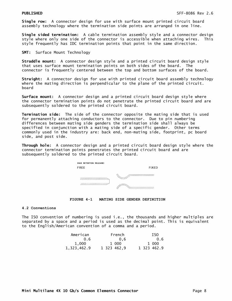
Fixed: Used to describe the gender of the mating side of the connector that accepts its mate upon mating. This gender is frequently, but not always, associated with the common terminology "receptacle". Other terms commonly used are "female" and "socket connector". The term "fixed" is adopted from EIA standard terminology as the gender that most commonly exists on the fixed end of a connection, for example, on the board or bulkhead side. In this document "fixed" is specifically used to describe the mating side gender illustrated in Figure 4-1. Free: Used to describe the gender of the mating side of the connector that penetrates its mate upon mating. This gender is frequently, but not always, associated with the common terminology "plug". Other terms commonly used are "male" and "pin connector". The term "free" is adopted from EIA standard terminology as the gender that most commonly exists on the free end of a connection, for example, on the cable side. In this document "free" is specifically used to describe the mating side gender illustrated in Figure 4-1. Frontshell: That metallic part of a connector body that directly contacts the backshell or other shielding material that provides mechanical and shielding continuity between the connector and the cable. Other terms sometimes used to describe this part of a cable assembly are: housing, nosepiece, cowling, and metal shroud. Free Board: A connector that uses a free gender mating side and a termination side suitable for any of the printed circuit board termination technologies. Fixed Board: A connector that uses a fixed gender mating side and a termination side suitable for any of the printed circuit board termination technologies. Height: Distance from board surface to farthest overall connector feature. MSA: Multiple Source Agreement Mating side: The side of the connector that joins and separates from the mating side of a connector of opposite gender. Other terms commonly used in the industry are mating interface, separable interface and mating face. Offset: An alignment shift from the centerline of the connector. Optional: This term describes features that are not required by the SFF Specification. However, if any feature defined by the SFF Specification is implemented, it shall be done in the same way as defined by the Specification. Describing a feature as optional in the text is done to assist the reader. If there is a conflict between text and tables on a feature described as optional, the table shall be accepted as being correct. Reserved: Where this term is used for defining the signal on a connector pin its actual function is set aside for future standardization. It is not available for vendor specific use. Where this term is used for bits, bytes, fields and code values; the bits, bytes, fields and code values are set aside for future standardization. The default value shall be zero. The originator is required to define a Reserved field or bit as zero, but the receiver should not check Reserved fields or bits for zero. Right Angle: A connector design for use with printed circuit board assembly technology where the mating direction is parallel to the plane of the printed circuit board. SFP: Small Formfactor Pluggable
PUBLISHED SFF-8086 Rev 2.6
Mini Multilane 4X 10 Gb/s Common Elements Connector Page 8
Single row: A connector design for use with surface mount printed circuit board assembly technology where the termination side points are arranged in one line. Single sided termination: A cable termination assembly style and a connector design style where only one side of the connector is accessible when attaching wires. This style frequently has IDC termination points that point in the same direction. SMT: Surface Mount Technology Straddle mount: A connector design style and a printed circuit board design style that uses surface mount termination points on both sides of the board. The connector is frequently centered between the top and bottom surfaces of the board. Straight: A connector design for use with printed circuit board assembly technology where the mating direction is perpendicular to the plane of the printed circuit. board Surface mount: A connector design and a printed circuit board design style where the connector termination points do not penetrate the printed circuit board and are subsequently soldered to the printed circuit board. Termination side: The side of the connector opposite the mating side that is used for permanently attaching conductors to the connector. Due to pin numbering differences between mating side genders the termination side shall always be specified in conjunction with a mating side of a specific gender. Other terms commonly used in the industry are: back end, non-mating side, footprint, pc board side, and post side. Through hole: A connector design and a printed circuit board design style where the connector termination points penetrates the printed circuit board and are subsequently soldered to the printed circuit board.
FIGURE 4-1 MATING SIDE GENDER DEFINITION
4.2 Conventions
The ISO convention of numbering is used i.e., the thousands and higher multiples are separated by a space and a period is used as the decimal point. This is equivalent to the English/American convention of a comma and a period.
American French ISO 0.6 0,6 0.6 1,000 1 000 1 000 1,323,462.9 1 323 462,9 1 323 462.9
PUBLISHED SFF-8086 Rev 2.6
Mini Multilane 4X 10 Gb/s Common Elements Connector Page 9
5. Connector Description
5.1 Electrical and Mechanical Requirements
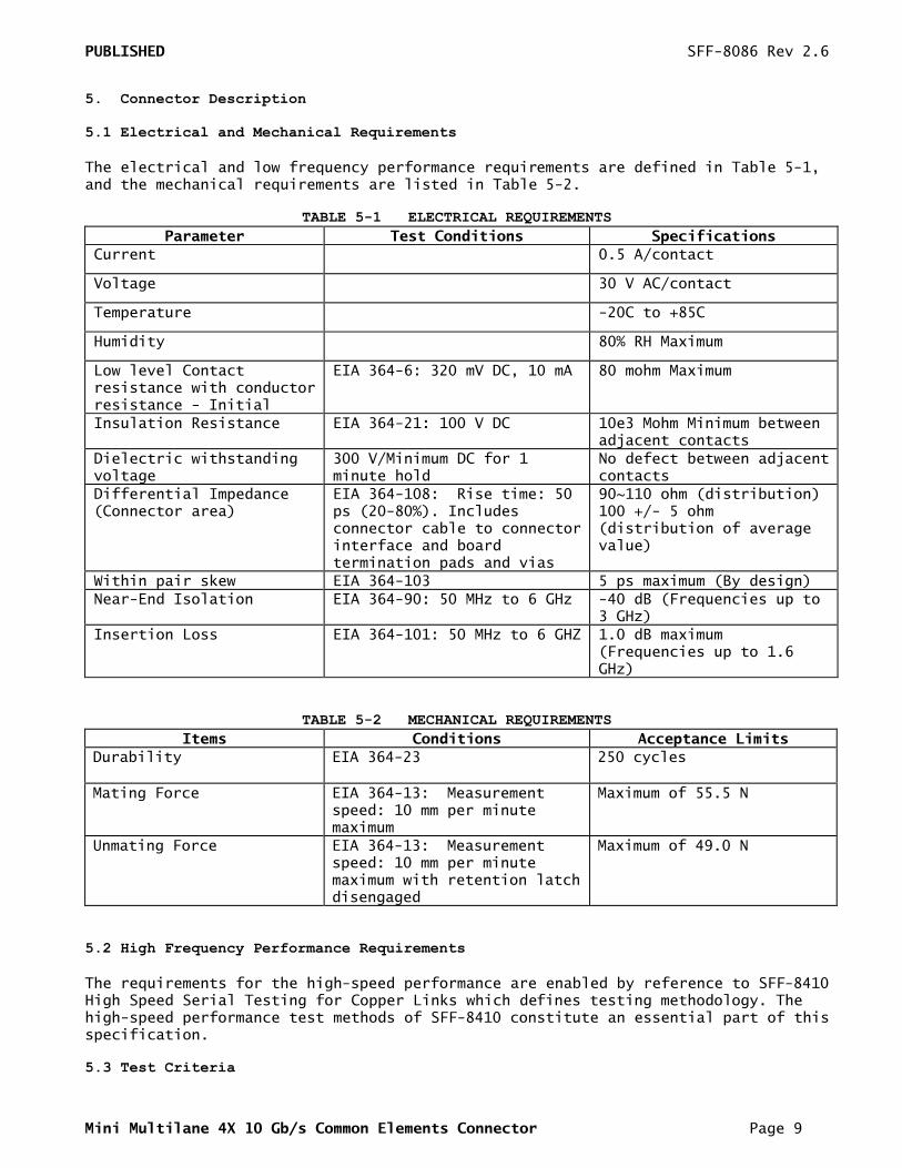
The electrical and low frequency performance requirements are defined in Table 5-1, and the mechanical requirements are listed in Table 5-2.
TABLE 5-1 ELECTRICAL REQUIREMENTS
Parameter Test Conditions Specifications
Current 0.5 A/contact
Voltage 30 V AC/contact
Temperature -20C to +85C
Humidity 80% RH Maximum
Low level Contact resistance with conductor resistance - Initial
EIA 364-6: 320 mV DC, 10 mA
80 mohm Maximum
Insulation Resistance EIA 364-21: 100 V DC 10e3 Mohm Minimum between adjacent contacts
Dielectric withstanding voltage
300 V/Minimum DC for 1 minute hold
No defect between adjacent contacts
Differential Impedance (Connector area)
EIA 364-108: Rise time: 50 ps (20-80%). Includes connector cable to connector interface and board termination pads and vias
90~110 ohm (distribution) 100 +/- 5 ohm (distribution of average value)
Within pair skew EIA 364-103 5 ps maximum (By design)
Near-End Isolation EIA 364-90: 50 MHz to 6 GHz -40 dB (Frequencies up to 3 GHz)
Insertion Loss EIA 364-101: 50 MHz to 6 GHZ 1.0 dB maximum (Frequencies up to 1.6 GHz)
TABLE 5-2 MECHANICAL REQUIREMENTS
Items Conditions Acceptance Limits
Durability EIA 364-23
250 cycles
Mating Force EIA 364-13: Measurement speed: 10 mm per minute maximum
Maximum of 55.5 N
Unmating Force EIA 364-13: Measurement speed: 10 mm per minute maximum with retention latch disengaged
Maximum of 49.0 N
5.2 High Frequency Performance Requirements
The requirements for the high-speed performance are enabled by reference to SFF-8410 High Speed Serial Testing for Copper Links which defines testing methodology. The high-speed performance test methods of SFF-8410 constitute an essential part of this specification. 5.3 Test Criteria
PUBLISHED SFF-8086 Rev 2.6
Mini Multilane 4X 10 Gb/s Common Elements Connector Page 10
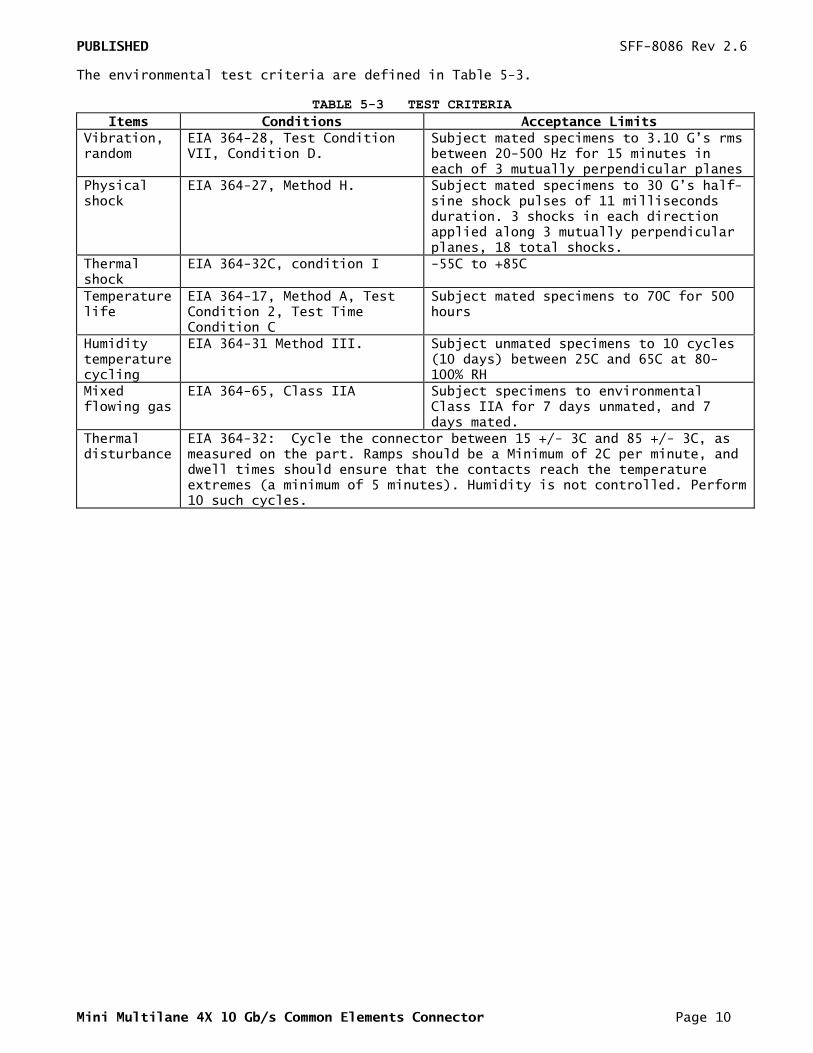
The environmental test criteria are defined in Table 5-3.
TABLE 5-3 TEST CRITERIA
Items Conditions Acceptance Limits
Vibration, random
EIA 364-28, Test Condition VII, Condition D.
Subject mated specimens to 3.10 G’s rms between 20-500 Hz for 15 minutes in each of 3 mutually perpendicular planes
Physical shock
EIA 364-27, Method H. Subject mated specimens to 30 G’s half-sine shock pulses of 11 milliseconds duration. 3 shocks in each direction applied along 3 mutually perpendicular planes, 18 total shocks.
Thermal shock
EIA 364-32C, condition I
-55C to +85C
Temperature life
EIA 364-17, Method A, Test Condition 2, Test Time Condition C
Subject mated specimens to 70C for 500 hours
Humidity temperature cycling
EIA 364-31 Method III. Subject unmated specimens to 10 cycles (10 days) between 25C and 65C at 80-100% RH
Mixed flowing gas
EIA 364-65, Class IIA Subject specimens to environmental Class IIA for 7 days unmated, and 7 days mated.
Thermal disturbance
EIA 364-32: Cycle the connector between 15 +/- 3C and 85 +/- 3C, as measured on the part. Ramps should be a Minimum of 2C per minute, and dwell times should ensure that the contacts reach the temperature extremes (a minimum of 5 minutes). Humidity is not controlled. Perform 10 such cycles.
PUBLISHED SFF-8086 Rev 2.6
Mini Multilane 4X 10 Gb/s Common Elements Connector Page 11
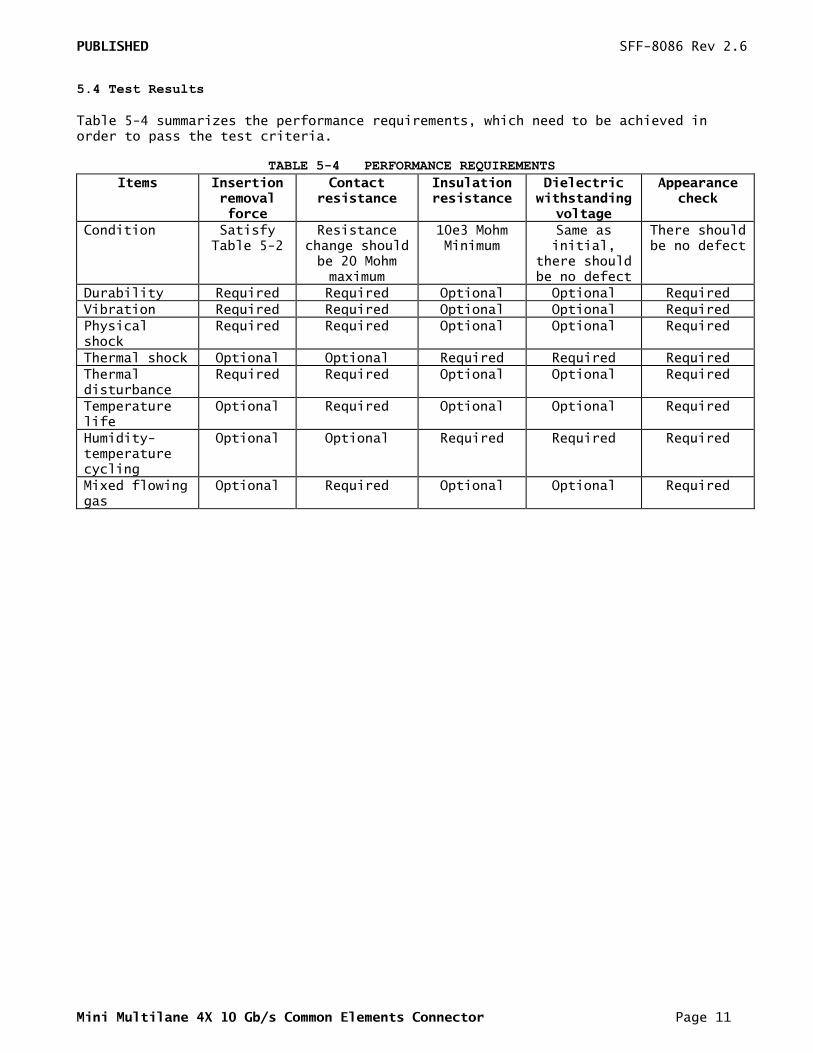
5.4 Test Results
Table 5-4 summarizes the performance requirements, which need to be achieved in order to pass the test criteria.
TABLE 5-4 PERFORMANCE REQUIREMENTS
Items Insertion removal force
Contact resistance
Insulation resistance
Dielectric withstanding
voltage
Appearance check
Condition Satisfy Table 5-2
Resistance change should be 20 Mohm maximum
10e3 Mohm Minimum
Same as initial,
there should be no defect
There should be no defect
Durability Required Required Optional Optional Required
Vibration Required Required Optional Optional Required
Physical shock
Required Required Optional Optional Required
Thermal shock Optional Optional Required Required Required
Thermal disturbance
Required Required Optional Optional Required
Temperature life
Optional Required Optional Optional Required
Humidity-temperature cycling
Optional Optional Required Required Required
Mixed flowing gas
Optional Required Optional Optional Required
PUBLISHED SFF-8086 Rev 2.6
Mini Multilane 4X 10 Gb/s Common Elements Connector Page 12
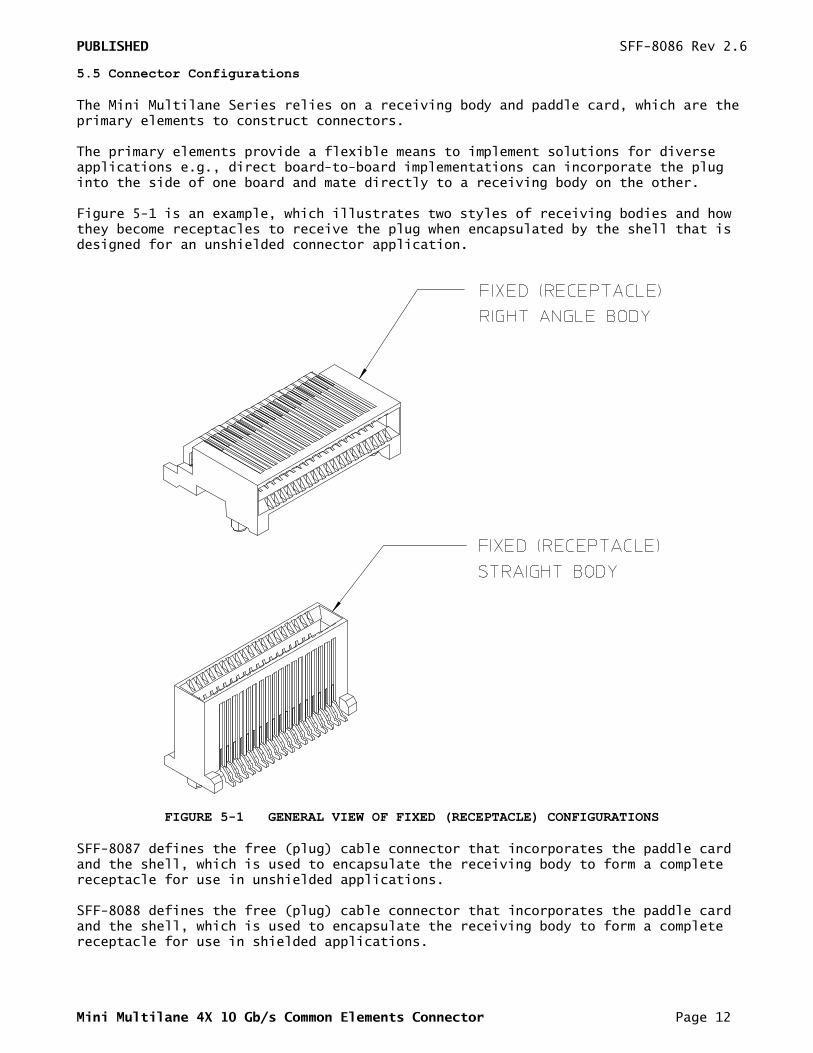
5.5 Connector Configurations
The Mini Multilane Series relies on a receiving body and paddle card, which are the primary elements to construct connectors. The primary elements provide a flexible means to implement solutions for diverse applications e.g., direct board-to-board implementations can incorporate the plug into the side of one board and mate directly to a receiving body on the other. Figure 5-1 is an example, which illustrates two styles of receiving bodies and how they become receptacles to receive the plug when encapsulated by the shell that is designed for an unshielded connector application.
FIGURE 5-1 GENERAL VIEW OF FIXED (RECEPTACLE) CONFIGURATIONS
SFF-8087 defines the free (plug) cable connector that incorporates the paddle card and the shell, which is used to encapsulate the receiving body to form a complete receptacle for use in unshielded applications. SFF-8088 defines the free (plug) cable connector that incorporates the paddle card and the shell, which is used to encapsulate the receiving body to form a complete receptacle for use in shielded applications.
PUBLISHED SFF-8086 Rev 2.6
Mini Multilane 4X 10 Gb/s Common Elements Connector Page 13
The shell provides guidance and retention for the free (plug) cable connector, and absorbs the stress imposed by insertion and removal of the free (plug) cable connector. This protects the signal quality of the solder joints to the body. 6. Connector Dimensions
The dimensioning conventions are described in ANSI-Y14.5M, Dimensioning and tolerancing. All dimensions are in millimeters. Dimension related requirements for the connector system addressed in this document are specified in the tables and figures in this clause.
PUBLISHED SFF-8086 Rev 2.6
Mini Multilane 4X 10 Gb/s Common Elements Connector Page 14
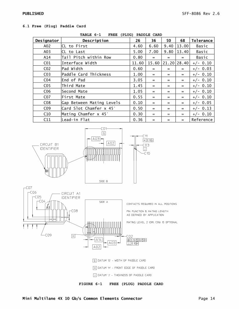
6.1 Free (Plug) Paddle Card
TABLE 6-1 FREE (PLUG) PADDLE CARD
Designator Description 26 36 50 68 Tolerance
A02 CL to First 4.60 6.60 9.40 13.00 Basic
A03 CL to Last 5.00 7.00 9.80 13.40 Basic
A14 Tail Pitch within Row 0.80 = = = Basic
C01 Interface Width 11.60 15.60 21.20 28.40 +/- 0.10
C02 Pad Width 0.60 = = = +/- 0.03
C03 Paddle Card Thickness 1.00 = = = +/- 0.10
C04 End of Pad 3.05 = = = +/- 0.10
C05 Third Mate 1.45 = = = +/- 0.10
C06 Second Mate 1.05 = = = +/- 0.10
C07 First Mate 0.55 = = = +/- 0.10
C08 Gap Between Mating Levels 0.10 = = = +/- 0.05
C09 Card Slot Chamfer x 45° 0.50 = = = +/- 0.13
C10 Mating Chamfer x 45° 0.30 = = = +/- 0.10
C11 Lead-in Flat 0.36 = = = Reference
FIGURE 6-1 FREE (PLUG) PADDLE CARD
PUBLISHED SFF-8086 Rev 2.6
Mini Multilane 4X 10 Gb/s Common Elements Connector Page 15
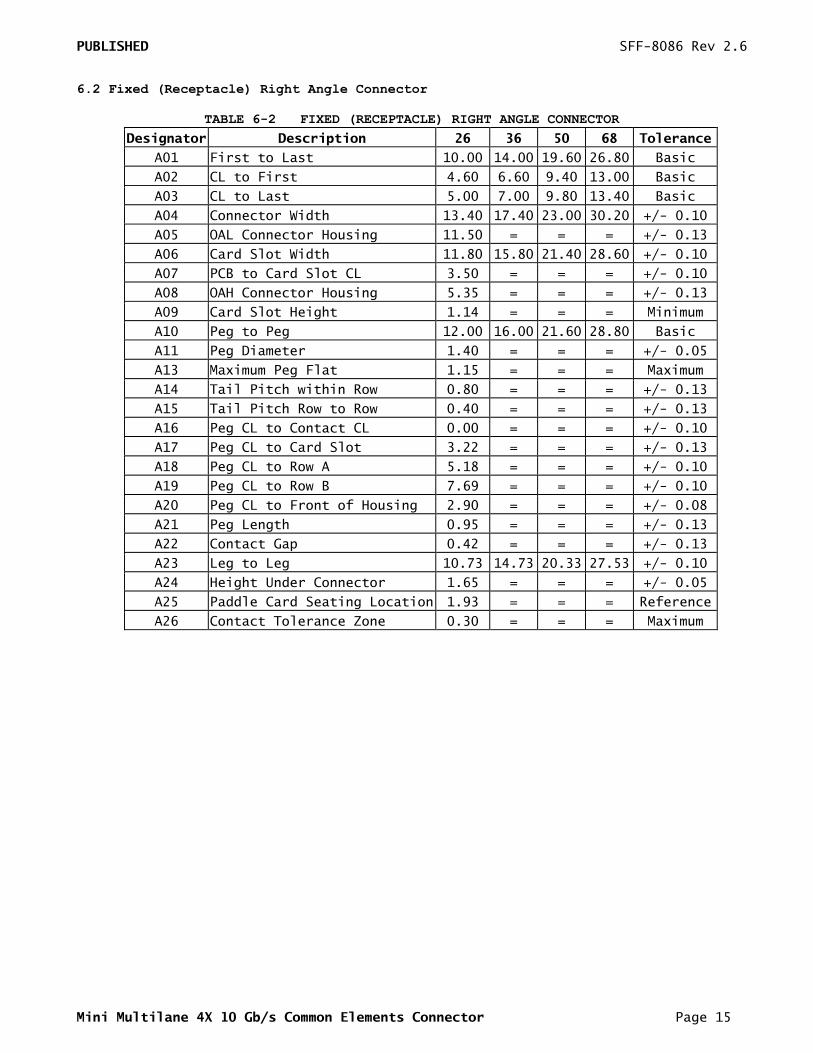
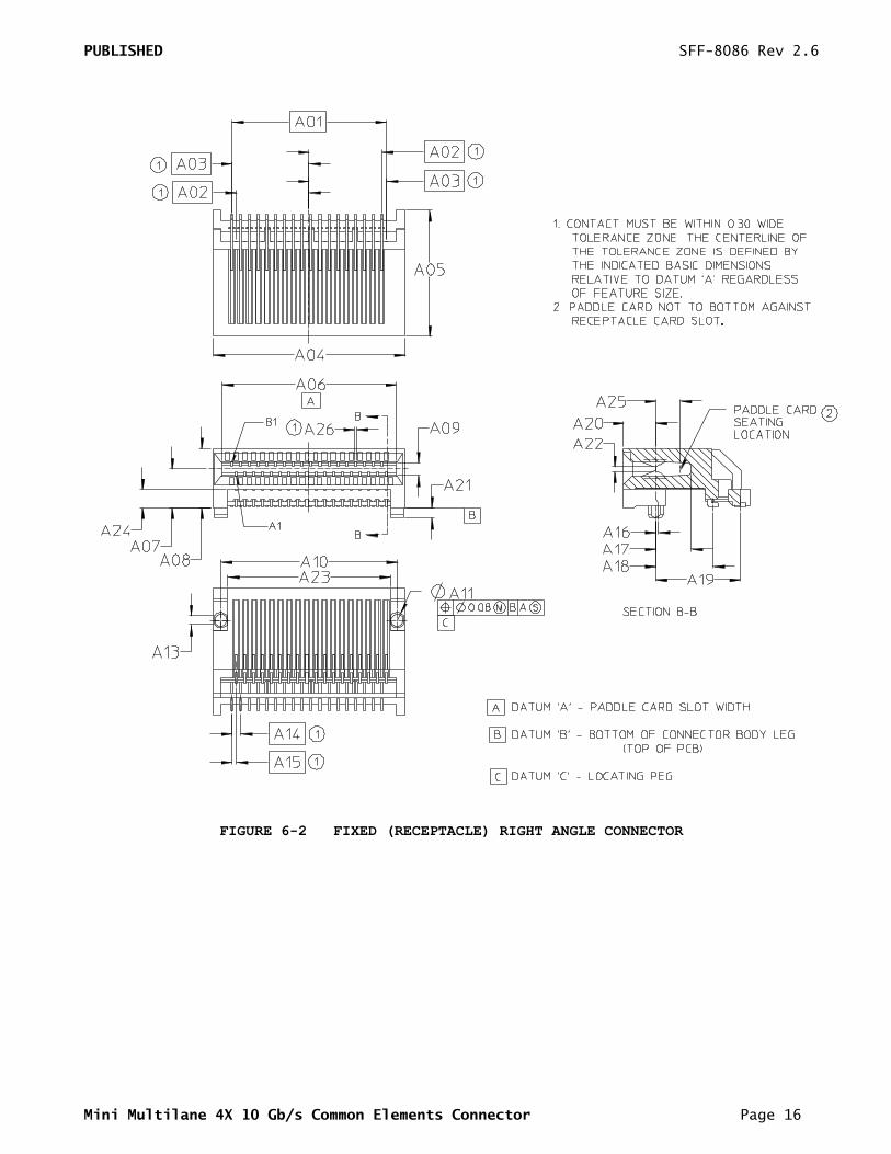
6.2 Fixed (Receptacle) Right Angle Connector
TABLE 6-2 FIXED (RECEPTACLE) RIGHT ANGLE CONNECTOR
Designator Description 26 36 50 68 Tolerance
A01 First to Last 10.00 14.00 19.60 26.80 Basic
A02 CL to First 4.60 6.60 9.40 13.00 Basic
A03 CL to Last 5.00 7.00 9.80 13.40 Basic
A04 Connector Width 13.40 17.40 23.00 30.20 +/- 0.10
A05 OAL Connector Housing 11.50 = = = +/- 0.13
A06 Card Slot Width 11.80 15.80 21.40 28.60 +/- 0.10
A07 PCB to Card Slot CL 3.50 = = = +/- 0.10
A08 OAH Connector Housing 5.35 = = = +/- 0.13
A09 Card Slot Height 1.14 = = = Minimum
A10 Peg to Peg 12.00 16.00 21.60 28.80 Basic
A11 Peg Diameter 1.40 = = = +/- 0.05
A13 Maximum Peg Flat 1.15 = = = Maximum
A14 Tail Pitch within Row 0.80 = = = +/- 0.13
A15 Tail Pitch Row to Row 0.40 = = = +/- 0.13
A16 Peg CL to Contact CL 0.00 = = = +/- 0.10
A17 Peg CL to Card Slot 3.22 = = = +/- 0.13
A18 Peg CL to Row A 5.18 = = = +/- 0.10
A19 Peg CL to Row B 7.69 = = = +/- 0.10
A20 Peg CL to Front of Housing 2.90 = = = +/- 0.08
A21 Peg Length 0.95 = = = +/- 0.13
A22 Contact Gap 0.42 = = = +/- 0.13
A23 Leg to Leg 10.73 14.73 20.33 27.53 +/- 0.10
A24 Height Under Connector 1.65 = = = +/- 0.05
A25 Paddle Card Seating Location 1.93 = = = Reference
A26 Contact Tolerance Zone 0.30 = = = Maximum
PUBLISHED SFF-8086 Rev 2.6
Mini Multilane 4X 10 Gb/s Common Elements Connector Page 16
FIGURE 6-2 FIXED (RECEPTACLE) RIGHT ANGLE CONNECTOR
PUBLISHED SFF-8086 Rev 2.6
Mini Multilane 4X 10 Gb/s Common Elements Connector Page 17
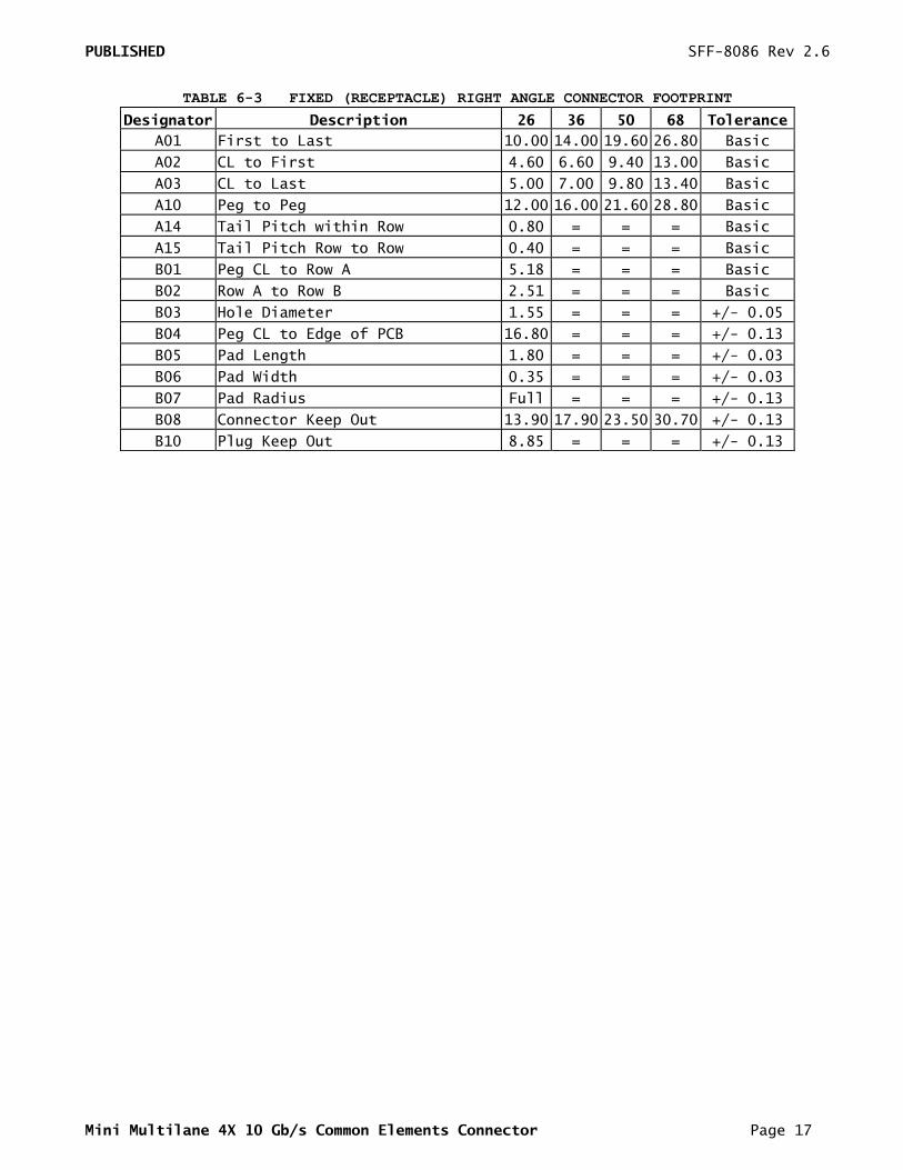
TABLE 6-3 FIXED (RECEPTACLE) RIGHT ANGLE CONNECTOR FOOTPRINT
Designator Description 26 36 50 68 Tolerance
A01 First to Last 10.00 14.00 19.60 26.80 Basic
A02 CL to First 4.60 6.60 9.40 13.00 Basic
A03 CL to Last 5.00 7.00 9.80 13.40 Basic
A10 Peg to Peg 12.00 16.00 21.60 28.80 Basic
A14 Tail Pitch within Row 0.80 = = = Basic
A15 Tail Pitch Row to Row 0.40 = = = Basic
B01 Peg CL to Row A 5.18 = = = Basic
B02 Row A to Row B 2.51 = = = Basic
B03 Hole Diameter 1.55 = = = +/- 0.05
B04 Peg CL to Edge of PCB 16.80 = = = +/- 0.13
B05 Pad Length 1.80 = = = +/- 0.03
B06 Pad Width 0.35 = = = +/- 0.03
B07 Pad Radius Full = = = +/- 0.13
B08 Connector Keep Out 13.90 17.90 23.50 30.70 +/- 0.13
B10 Plug Keep Out 8.85 = = = +/- 0.13
PUBLISHED SFF-8086 Rev 2.6
Mini Multilane 4X 10 Gb/s Common Elements Connector Page 18
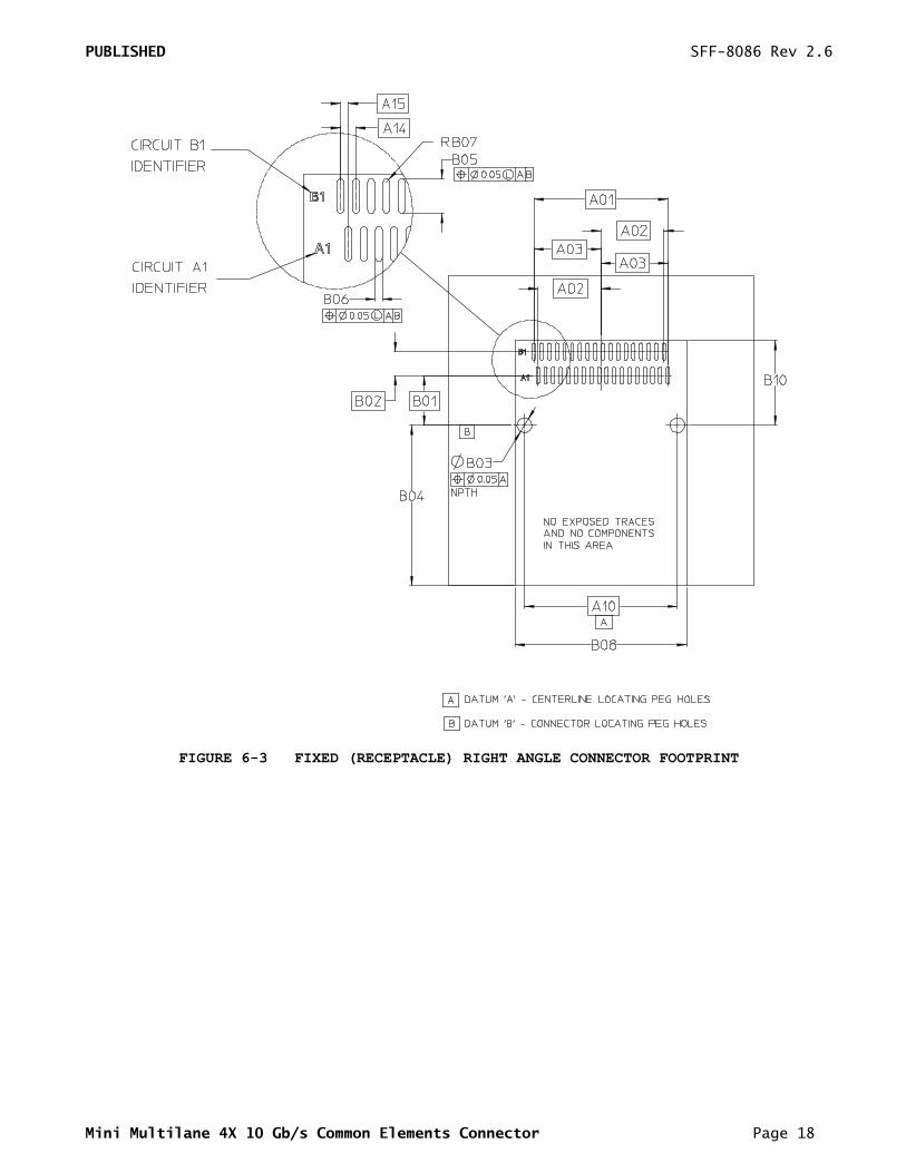
FIGURE 6-3 FIXED (RECEPTACLE) RIGHT ANGLE CONNECTOR FOOTPRINT
PUBLISHED SFF-8086 Rev 2.6
Mini Multilane 4X 10 Gb/s Common Elements Connector Page 19
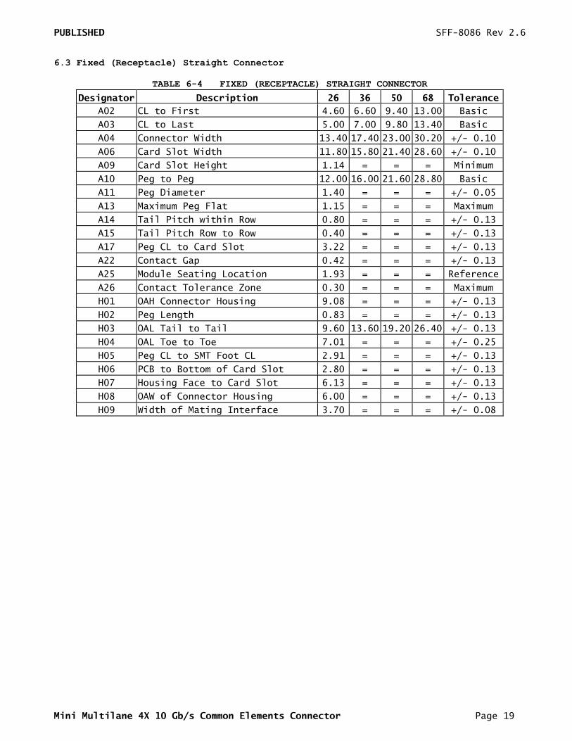
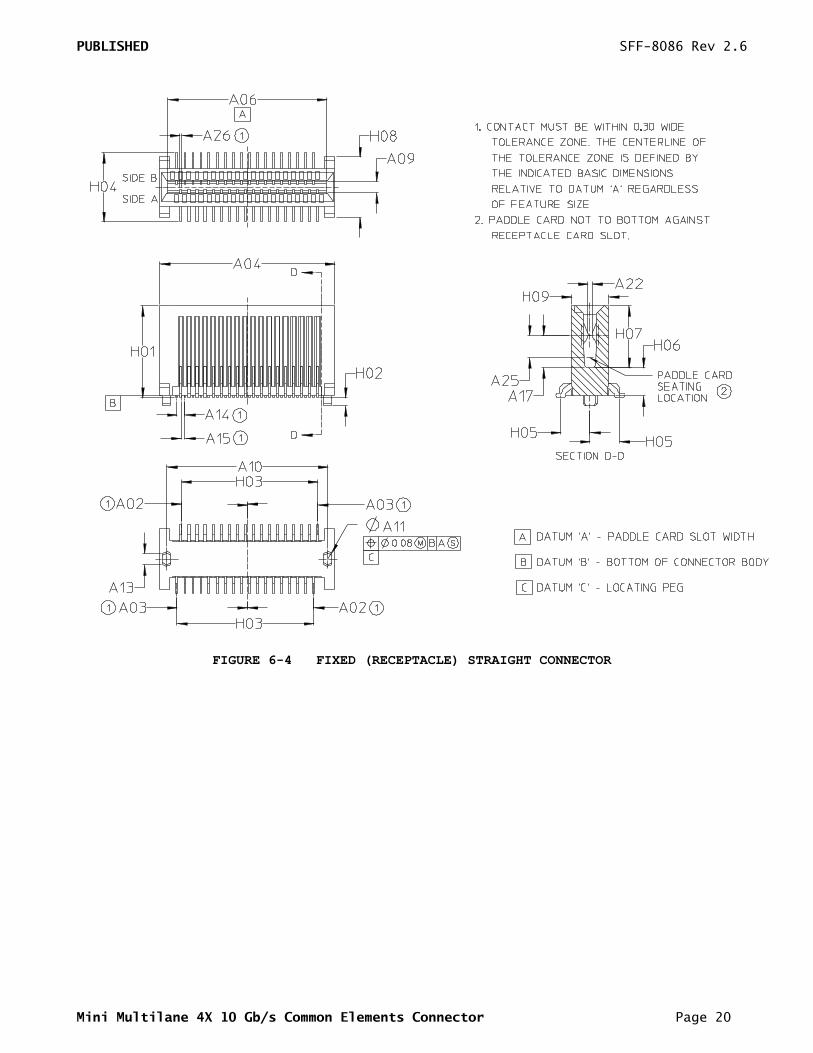
6.3 Fixed (Receptacle) Straight Connector
TABLE 6-4 FIXED (RECEPTACLE) STRAIGHT CONNECTOR
Designator Description 26 36 50 68 Tolerance
A02 CL to First 4.60 6.60 9.40 13.00 Basic
A03 CL to Last 5.00 7.00 9.80 13.40 Basic
A04 Connector Width 13.40 17.40 23.00 30.20 +/- 0.10
A06 Card Slot Width 11.80 15.80 21.40 28.60 +/- 0.10
A09 Card Slot Height 1.14 = = = Minimum
A10 Peg to Peg 12.00 16.00 21.60 28.80 Basic
A11 Peg Diameter 1.40 = = = +/- 0.05
A13 Maximum Peg Flat 1.15 = = = Maximum
A14 Tail Pitch within Row 0.80 = = = +/- 0.13
A15 Tail Pitch Row to Row 0.40 = = = +/- 0.13
A17 Peg CL to Card Slot 3.22 = = = +/- 0.13
A22 Contact Gap 0.42 = = = +/- 0.13
A25 Module Seating Location 1.93 = = = Reference
A26 Contact Tolerance Zone 0.30 = = = Maximum
H01 OAH Connector Housing 9.08 = = = +/- 0.13
H02 Peg Length 0.83 = = = +/- 0.13
H03 OAL Tail to Tail 9.60 13.60 19.20 26.40 +/- 0.13
H04 OAL Toe to Toe 7.01 = = = +/- 0.25
H05 Peg CL to SMT Foot CL 2.91 = = = +/- 0.13
H06 PCB to Bottom of Card Slot 2.80 = = = +/- 0.13
H07 Housing Face to Card Slot 6.13 = = = +/- 0.13
H08 OAW of Connector Housing 6.00 = = = +/- 0.13
H09 Width of Mating Interface 3.70 = = = +/- 0.08
PUBLISHED SFF-8086 Rev 2.6
Mini Multilane 4X 10 Gb/s Common Elements Connector Page 20
FIGURE 6-4 FIXED (RECEPTACLE) STRAIGHT CONNECTOR
PUBLISHED SFF-8086 Rev 2.6
Mini Multilane 4X 10 Gb/s Common Elements Connector Page 21
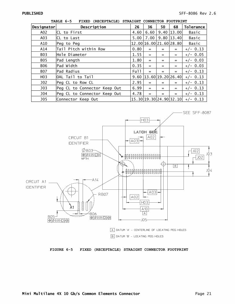
TABLE 6-5 FIXED (RECEPTACLE) STRAIGHT CONNECTOR FOOTPRINT
Designator Description 26 36 50 68 Tolerance
A02 CL to First 4.60 6.60 9.40 13.00 Basic
A03 CL to Last 5.00 7.00 9.80 13.40 Basic
A10 Peg to Peg 12.00 16.00 21.60 28.80 Basic
A14 Tail Pitch within Row 0.80 = = = +/- 0.13
B03 Hole Diameter 1.55 = = = +/- 0.05
B05 Pad Length 1.80 = = = +/- 0.03
B06 Pad Width 0.35 = = = +/- 0.03
B07 Pad Radius Full = = = +/- 0.13
H03 OAL Tail to Tail 9.60 13.60 19.20 26.40 +/- 0.13
J02 Peg CL to Row CL 2.95 = = = +/- 0.13
J03 Peg CL to Connector Keep Out 6.99 = = = +/- 0.13
J04 Peg CL to Connector Keep Out 4.78 = = = +/- 0.13
J05 Connector Keep Out 15.30 19.30 24.90 32.10 +/- 0.13
FIGURE 6-5 FIXED (RECEPTACLE) STRAIGHT CONNECTOR FOOTPRINT
PUBLISHED SFF-8086 Rev 2.6
Mini Multilane 4X 10 Gb/s Common Elements Connector Page 22
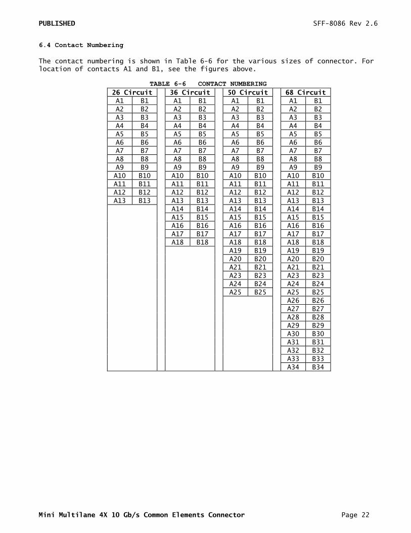
6.4 Contact Numbering
The contact numbering is shown in Table 6-6 for the various sizes of connector. For location of contacts A1 and B1, see the figures above.
TABLE 6-6 CONTACT NUMBERING
26 Circuit 36 Circuit 50 Circuit 68 Circuit
A1 B1 A1 B1 A1 B1 A1 B1
A2 B2 A2 B2 A2 B2 A2 B2
A3 B3 A3 B3 A3 B3 A3 B3
A4 B4 A4 B4 A4 B4 A4 B4
A5 B5 A5 B5 A5 B5 A5 B5
A6 B6 A6 B6 A6 B6 A6 B6
A7 B7 A7 B7 A7 B7 A7 B7
A8 B8 A8 B8 A8 B8 A8 B8
A9 B9 A9 B9 A9 B9 A9 B9
A10 B10 A10 B10 A10 B10 A10 B10
A11 B11 A11 B11 A11 B11 A11 B11
A12 B12 A12 B12 A12 B12 A12 B12
A13 B13 A13 B13 A13 B13 A13 B13
A14 B14 A14 B14 A14 B14
A15 B15 A15 B15 A15 B15
A16 B16 A16 B16 A16 B16
A17 B17 A17 B17 A17 B17
A18 B18 A18 B18 A18 B18
A19 B19 A19 B19
A20 B20 A20 B20
A21 B21 A21 B21
A23 B23 A23 B23
A24 B24 A24 B24
A25 B25 A25 B25
A26 B26
A27 B27
A28 B28
A29 B29
A30 B30
A31 B31
A32 B32
A33 B33
A34 B34