
Thinking Prevention of Engine Trouble - Japan P&I Club
114
P&I Loss Prevention Bulletin The Japan Ship Owners’Mutual Protection & Indemnity Association Loss Prevention and Ship Inspection Department J APAN P& I CLUB Thinking Prevention of Engine Trouble Vol.38 March 2017
-
Upload
khangminh22 -
Category
Documents
-
view
2 -
download
0
Transcript of Thinking Prevention of Engine Trouble - Japan P&I Club
P&
I Loss Prevention B
ulletin Vol.3
8
P&ILossPreventionBulletinJAPAN P& I CLUB
P&ILossPreventionBulletinThe Japan Ship Owners’Mutual Protection & Indemnity Association Loss Prevention and Ship Inspection Department
JAPAN P& I CLUB
● PrincipalOffice(Tokyo) 2-15-14, Nihonbashi-Ningyocho Chuoh-ku, Tokyo 103-0013, Japan Tel:03-3662-7229 Fax:03-3662-7107● KobeBranch 6th Floor Shosen-Mitsui Bldg. 5, Kaigandori Chuoh-ku, Kobe, Hyogo 650-0024, Japan Tel:078-321-6886 Fax:078-332-6519● FukuokaBranch 6th Floor Meiji-Dori Business Center 1-1, Shimokawabata-machi, Hakata-ku, Fukuoka 812-0027, Japan Tel:092-272-1215 Fax:092-281-3317● ImabariBranch 2-2-1, Kitahorai-cho, Imabari, Ehime 794-0028, Japan Tel:0898-33-1117 Fax:0898-33-1251● SingaporeBranch 80 Robinson Road #14-01B SINGAPORE 068898 Tel:65-6224-6451 Fax:65-6224-1476● JapanP&IClub(UK)ServicesLtd 38 Lombard Street, London EC3V 9BS U.K. Tel:44-20-7929-3633 Fax:44-20-7929-7557
JAPAN P& I CLUBWebsite http://www.piclub.or.jp
Thinking Prevention of Engine Trouble
Vol.38 March 2017
Japan P&I ClubAssistant General Manager/Loss Prevention and Ship Inspection DepartmentChief engineer Keishi Kuwada
(Supervision)Master Mariner/General Manager/Loss Prevention and Ship Inspection Dept.Capt. Takuzo Okada
JAPAN P& I CLUBJAPAN P& I CLUB
INDEX
Introduction ………………………………………… 2
Chapter 1 Occurrence Status of Engine Trouble and Trend of Accident Causes
1.1 Statistics for Marine accidents (Japan Coast Guard) …………………………… 31.2 Statistics for Marine accident Inquiry (Japan Marine Accident Tribunal) ……………… 41.3 Damage Statistics (Class NK) …………………… 51.4 Summary of Statistics ………………………… 91.5 Details of Damaged Parts ……………………… 101.6 Summary of Damaged Parts & Overview ………… 20
Chapter 2 Trend of Claims Caused by Engine Trouble in Ships Entered with our Club
2.1 Trends in Our Club ……………………………… 212.2 Case Studies …………………………………… 242.2.1 Cargo Claims (Cargo Shortage ) : Boiler Trouble … 242.2.2 Harbour Facilities Claims(Damage to Submarine Cable):
Main Engine Start Failure ……………………… 332.2.3 Cargo Claims : Generator Engine Re-start Failure (Blackout) …… 402.2.4 Environmental Claims : Incomplete Combustion of the boiler …………… 492.2.5 Summary ……………………………………… 532.2.6 [Reference] Out of P&I Insurance Coverage ……… 54
Chapter 3 Trouble Related to Bunker Oil
3.1 Oil Pollution Accidents Trends …………………… 553.2 Case Study : Oil Pollution at Bunkering ………… 563.3 Cappuccino Bunker (Special Trouble Related Short-Delivered bunkers) … 62
Chapter 4 Engine-room Resource Management (ERM)
4.1 Reviewing : “Thinking Safety” …………………… 684.2 Difference Between ERM and BRM ……………… 704.3 What is ERM? ………………………………… 714.4 Did ERM Function in the Case Studies? ………… 764.5 What is Engine Management? (ERM+α ) ……… 78
Chapter 5 Correspondence in Case of Deviation
5.1 Regulation Under the Relevant law ……………… 825.2 Situation Where Deviation is to be Expected …… 835.3 Coverage of Insurance Related to Deviation ……… 835.4 Case Study …………………………………… 845.5 Summary ……………………………………… 905.6 Relationship between Fuel Consumption and Speed … 925.7 Example Format of Sea Protest ………………… 94
Summary …………………………………………… 95
Reference Information
(1) Planned Maintenance System, Main Engine Inspection Measurement Sheet/Check List/Reminder (Technical Information) etc. (refer to Reference ⑥ - ⑩ )
………………………………………………… 96(2) Reference Information ① Turbo Charger ……………………………… 96 ② Intermediate Bearing ………………………… 97 ③ Marine Fuel Oil ……………………………… 98 ④ Photographic : ④ -1 Broken / Damaged / Scratch of Turbocharger 99 ④ -2 Broken / Damaged / Wornout of Cylinder
Unit related Parts …………………………100 ④ -3 Burnout / Damage of Shafting Arrangement
System (Intermediate Bearing & CPP) ……101
List of References ………………………………102
List of Attachments ……………………………102
- 1-
P&ILossPreventionBulletinJAPAN P& I CLUB
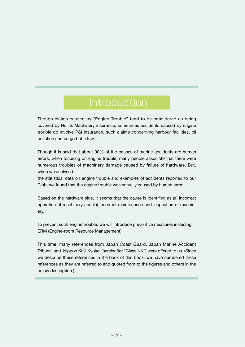
IntroductionThough claims caused by “Engine Trouble” tend to be considered as being
covered by Hull & Machinery insurance, sometimes accidents caused by engine
trouble do involve P&I insurance, such claims concerning harbour facilities, oil
pollution and cargo but a few.
Though it is said that about 90% of the causes of marine accidents are human
errors, when focusing on engine trouble, many people associate that there were
numerous troubles of machinery damage caused by failure of hardware. But,
when we analysed
the statistical data on engine trouble and examples of accidents reported to our
Club, we found that the engine trouble was actually caused by human error.
Based on the hardware side, it seems that the cause is identified as (a) incorrect
operation of machinery and (b) incorrect maintenance and inspection of machin-
ery.
To prevent such engine trouble, we will introduce preventive measures including
ERM (Engine-room Resource Management).
This time, many references from Japan Coast Guard, Japan Marine Accident
Tribunal and Nippon Kaiji Kyokai (hereinafter "Class NK") were offered to us. (Since
we describe these references in the back of this book, we have numbered these
references as they are referred to and quoted from to the figures and others in the
below description.)
- 2-
JAPAN P& I CLUB
First of all, we will look at statistical data to analyse the trends and causes of engine trouble.
Engine trouble may be due both to the mishandling of engine operation and to the poor maintenance & inspection (operator error). There are a lot of devices arranged in the engine room So, the causes of engine trouble are considered to be defects of machinery itself. But, this consideration is not necessarily to study the cases.
1.1 Statistics of Marine Accidents (Japan Coast Guard)
1.1.1 Statistics of Marine Accidents
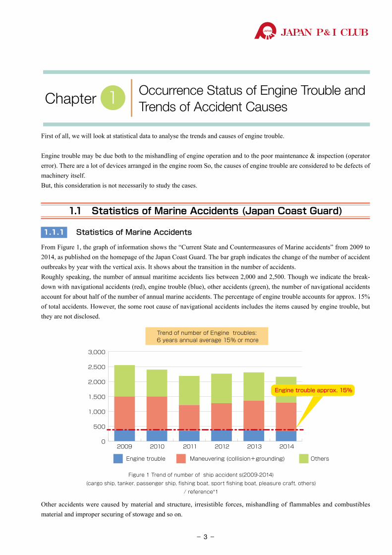
From Figure 1, the graph of information shows the “Current State and Countermeasures of Marine accidents” from 2009 to 2014, as published on the homepage of the Japan Coast Guard. The bar graph indicates the change of the number of accident outbreaks by year with the vertical axis. It shows about the transition in the number of accidents. Roughly speaking, the number of annual maritime accidents lies between 2,000 and 2,500. Though we indicate the break-down with navigational accidents (red), engine trouble (blue), other accidents (green), the number of navigational accidents account for about half of the number of annual marine accidents. The percentage of engine trouble accounts for approx. 15% of total accidents. However, the some root cause of navigational accidents includes the items caused by engine trouble, but they are not disclosed.
Other accidents were caused by material and structure, irresistible forces, mishandling of flammables and combustibles material and improper securing of stowage and so on.
Occurrence Status of Engine Trouble and Trends of Accident CausesChapter 1
0
500
1,000
1,500
2,000
2,500
3,000
2009 2010 2011 2012 2013 2014
Engine trouble Maneuvering (collision+grounding)
Trend of number of Engine troubles: 6 years annual average 15% or more
Others
Engine trouble approx. 15%
Figure 1 Trend of number of ship accident s(2009-2014)(cargo ship, tanker, passenger ship, fishing boat, sport fishing boat, pleasure craft, others)
/ reference*1
- 3-
P&ILossPreventionBulletinJAPAN P& I CLUB
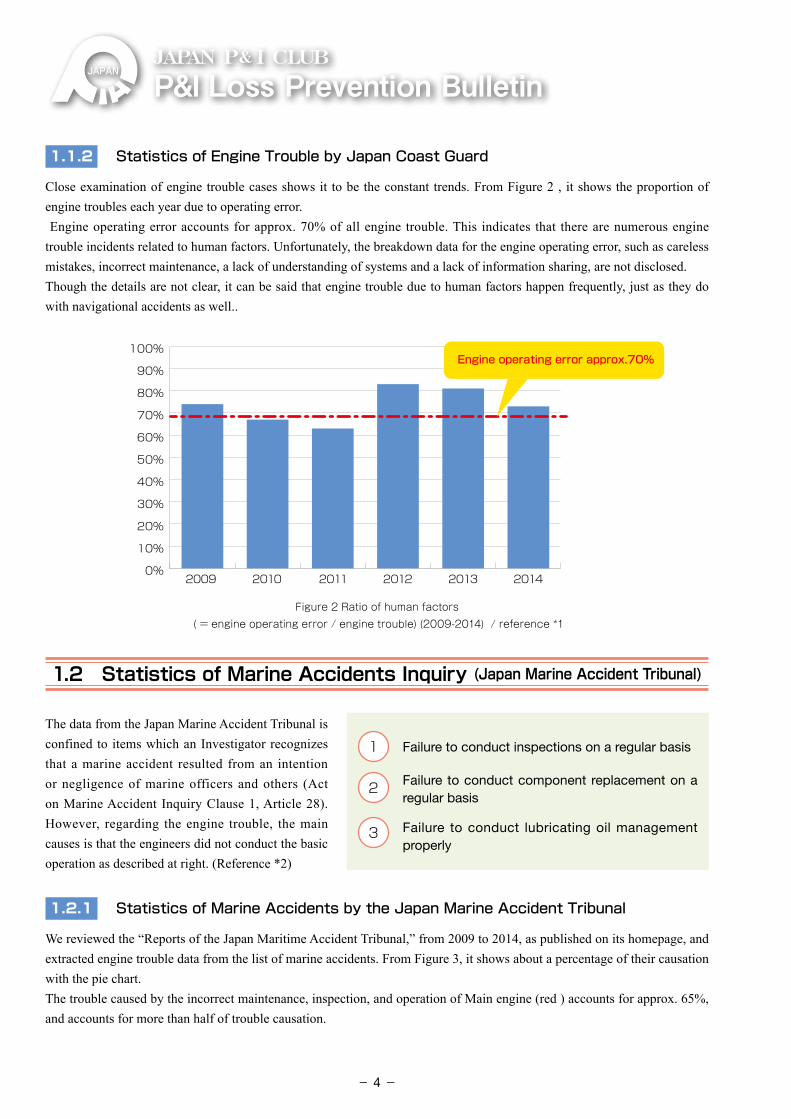
1.1.2 Statistics of Engine Trouble by Japan Coast Guard
Close examination of engine trouble cases shows it to be the constant trends. From Figure 2 , it shows the proportion of engine troubles each year due to operating error. Engine operating error accounts for approx. 70% of all engine trouble. This indicates that there are numerous engine trouble incidents related to human factors. Unfortunately, the breakdown data for the engine operating error, such as careless mistakes, incorrect maintenance, a lack of understanding of systems and a lack of information sharing, are not disclosed.Though the details are not clear, it can be said that engine trouble due to human factors happen frequently, just as they do with navigational accidents as well..
0%
10%
20%
30%
40%
50%
60%
70%
80%
90%
100%
2009 2010 2011 2012 2013 2014
Engine operating error approx.70%
Figure 2 Ratio of human factors ( = engine operating error / engine trouble) (2009-2014) / reference *1
1.2 Statistics of Marine Accidents Inquiry (Japan Marine Accident Tribunal)
The data from the Japan Marine Accident Tribunal is confined to items which an Investigator recognizes that a marine accident resulted from an intention or negligence of marine officers and others (Act on Marine Accident Inquiry Clause 1, Article 28). However, regarding the engine trouble, the main causes is that the engineers did not conduct the basic operation as described at right. (Reference *2)
1.2.1 Statistics of Marine Accidents by the Japan Marine Accident Tribunal
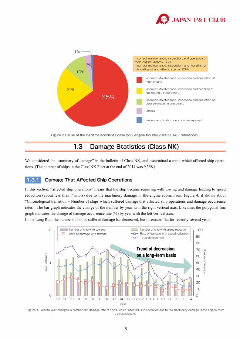
We reviewed the “Reports of the Japan Maritime Accident Tribunal,” from 2009 to 2014, as published on its homepage, and extracted engine trouble data from the list of marine accidents. From Figure 3, it shows about a percentage of their causation with the pie chart.The trouble caused by the incorrect maintenance, inspection, and operation of Main engine (red ) accounts for approx. 65%, and accounts for more than half of trouble causation.
1 Failure to conduct inspections on a regular basis
2 �Failure to conduct component replacement on a regular basis
3 �Failure to conduct lubricating oil management properly
- 4-
JAPAN P& I CLUB
21%
10%
3%
1%
65%
Incorrect maintenance, inspection, and operation of main engine: Approx. 65%Incorrect maintenance, inspection and handling of lubricating oil and others: approx. 20%
Incorrect Maintenance, inspection and operation of main engine
Incorrect Maintenance, inspection and handling of lubricating oil and others
Incorrect Maintenance, inspection and operation of auxiliary machine and others
Others
Inadequacy of ship operation management
Figure 3 Cause of the maritime accident's case (only engine trouble)(2009-2014) / reference*3
1.3 Damage Statistics (Class NK)
We considered the “summary of damage” in the bulletin of Class NK, and ascertained a trend which affected ship opera-tions. (The number of ships in the Class NK Fleet at the end of 2014 was 9,358.)
1.3.1 Damage That Affected Ship Operations
In this section, “affected ship operations” means that the ship became requiring with towing and damage leading to speed reduction (about less than 7 knots) due to the machinery damage in the engine room. From Figure 4, it shows about “Chronological transition – Number of ships which suffered damage that affected ship operations and damage occurrence rates”. The bar graph indicates the change of the number by year with the right vertical axis. Likewise, the polygonal line graph indicates the change of damage occurrence rate (%) by year with the left vertical axis.In the Long Run, the numbers of ships suffered damage has decreased, but it remains flat for recently several years.
‘95 ‘96 ‘97 ‘98 ‘99 ‘00 ‘01 ‘02 ‘03 ‘04 ‘05 ‘06 ‘07 ‘08 ‘09 ‘10 ‘11 ‘12 ‘13 ‘14
2
1
0
year
Num
ber of vessels
damage rates
100
90
80
70
60
50
40
30
20
10
0
Number of ship with towage Number of ship with speed reductionRate of damage with speed reductionRate of damage with towageTotal damage rate
Trend of decreasingon a long-term basis
Figure 4 Year-to-year changes in number and damage rate of ships which affected shp operation due to the machinery damage in the engine room / reference *4
- 5-
P&ILossPreventionBulletinJAPAN P& I CLUB
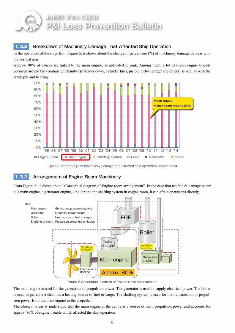
1.3.2 Breakdown of Machinery Damage That Affected Ship Operation In the operation of the ship, from Figure 5, it shows about the change of percentage (%) of machinery damage by year with the vertical axis.Approx. 80% of causes are linked to the main engine, as indicated in pink. Among them, a lot of diesel engine trouble occurred around the combustion chamber (cylinder cover, cylinder liner, piston, turbo charger and others) as well as with the crank pin and bearing.
‘95 ‘96 ‘97 ‘98 ‘99 ‘00 ‘01 ‘02 ‘03 ‘04 ‘05 ‘06 ‘07 ‘08 ‘09 ‘10 ‘11 ‘12 ‘13 ‘14
100%
90%
80%
70%
60%
50%
40%
30%
20%
10%
0%
othersGeneratorBoilerShafting systemEngine Room Main Engine
‘95 ‘96 ‘97 ‘98 ‘99 ‘00 ‘01 ‘02 ‘03 ‘04 ‘05 ‘06 ‘07 ‘08 ‘09 ‘10 ‘11 ‘12 ‘13 ‘14
100%
90%
80%
70%
60%
50%
40%
30%
20%
10%
0%
Cylinder Unit related Crank Shaft related Cam/valve control unit Turbo Charger Other
Cylinder unit related: Approx. over 20%
Turbo charger: Approx. over 30%
Major cause: main engine approx.80%
Figure 5 Percentage of machinery damage that affected ship operation /reference*4
1.3.3 Arrangement of Engine Room Machinery
From Figure 6, it shows about “Conceptual diagram of Engine room arrangement”. In the case that trouble & damage occur to a main engine, a generator engine, a boiler and the shafting system in engine room, it can affect operations directly.
21%
Boiler
EGE
GeneratorengineMain engine
Approx. 80%
AuxiliarymachineShafting
system
Use: Main engine: Generating propulsion power Generator: Electrical power supplyBoiler: Heat source of fuel or cargoShafting system: Propulsion power transmission
Use: Main engine: Generating propulsion power Generator: Electrical power supplyBoiler: Heat source of fuel or cargoShafting system: Propulsion power transmission
IntermediateBearing
Turbocharger
Figure 6 Conceptual diagram of Engine room arrangement
The main engine is used for the generation of propulsion power. The generator is used to supply electrical power. The boiler is used to generate a steam as a heating source of fuel or cargo. The shafting system is used for the transmission of propul-sion power from the main engine to the propeller.Therefore, it is easily understood that the main engine at the centre is a source of main propulsion power and accounts for approx. 80% of engine trouble which affected the ship operation.
- 6-
JAPAN P& I CLUB
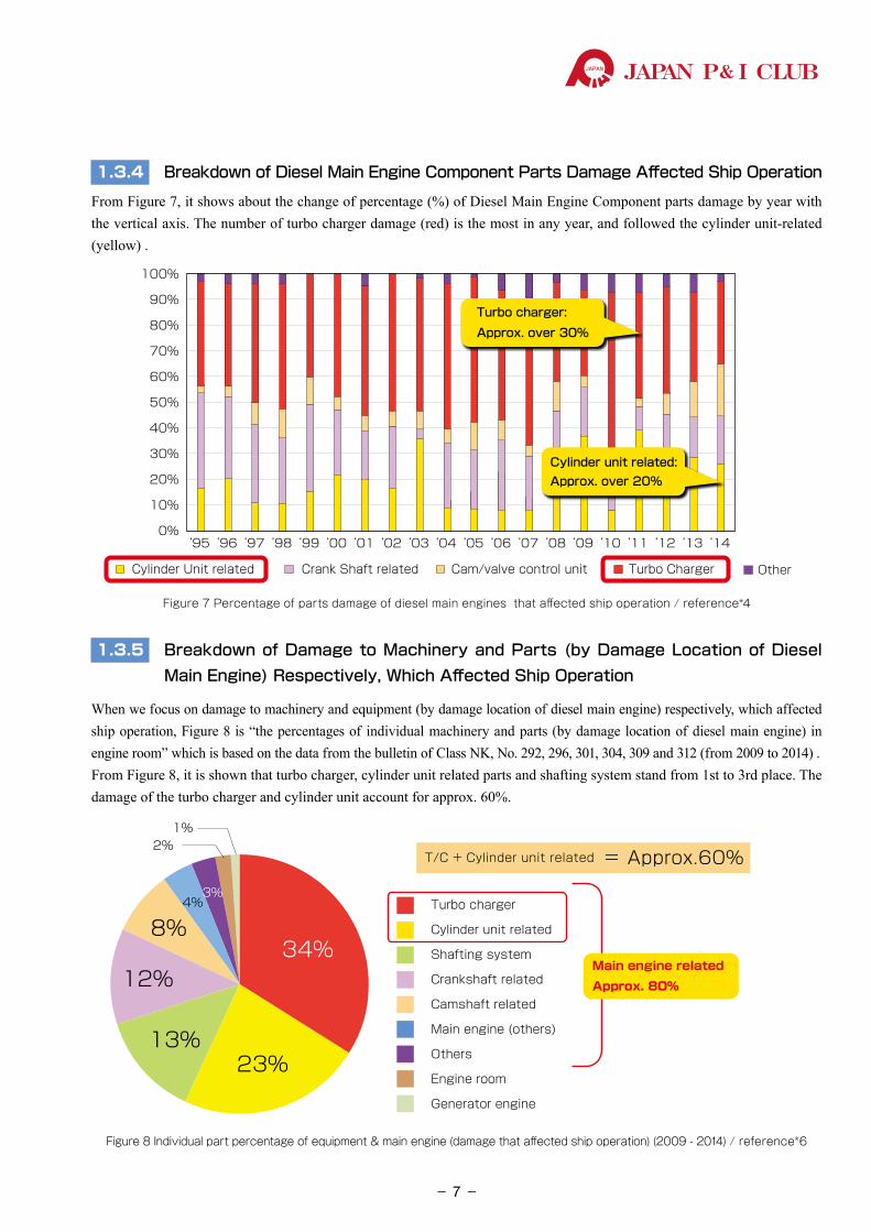
1.3.4 Breakdown of Diesel Main Engine Component Parts Damage Affected Ship Operation
From Figure 7, it shows about the change of percentage (%) of Diesel Main Engine Component parts damage by year with the vertical axis. The number of turbo charger damage (red) is the most in any year, and followed the cylinder unit-related (yellow) .
‘95 ‘96 ‘97 ‘98 ‘99 ‘00 ‘01 ‘02 ‘03 ‘04 ‘05 ‘06 ‘07 ‘08 ‘09 ‘10 ‘11 ‘12 ‘13 ‘14
100%
90%
80%
70%
60%
50%
40%
30%
20%
10%
0%
othersGeneratorBoilerShafting systemEngine Room Main Engine
‘95 ‘96 ‘97 ‘98 ‘99 ‘00 ‘01 ‘02 ‘03 ‘04 ‘05 ‘06 ‘07 ‘08 ‘09 ‘10 ‘11 ‘12 ‘13 ‘14
100%
90%
80%
70%
60%
50%
40%
30%
20%
10%
0%
Cylinder Unit related Crank Shaft related Cam/valve control unit Turbo Charger Other
Cylinder unit related: Approx. over 20%
Turbo charger: Approx. over 30%
Major cause: main engine approx.80%
Figure 7 Percentage of parts damage of diesel main engines that affected ship operation / reference*4
1.3.5 Breakdown of Damage to Machinery and Parts (by Damage Location of Diesel Main Engine) Respectively, Which Affected Ship Operation
When we focus on damage to machinery and equipment (by damage location of diesel main engine) respectively, which affected ship operation, Figure 8 is “the percentages of individual machinery and parts (by damage location of diesel main engine) in engine room” which is based on the data from the bulletin of Class NK, No. 292, 296, 301, 304, 309 and 312 (from 2009 to 2014) .From Figure 8, it is shown that turbo charger, cylinder unit related parts and shafting system stand from 1st to 3rd place. The damage of the turbo charger and cylinder unit account for approx. 60%.
4%3%
1%2%
34%
23%13%
12%
8%Turbo charger
Cylinder unit related
Shafting system
Crankshaft related
Camshaft related
Main engine (others)
Others
Engine room
Generator engine
Main engine related
Approx. 80%
T/C + Cylinder unit related = Approx.60%
Figure 8 Individual part percentage of equipment & main engine (damage that affected ship operation) (2009 - 2014) / reference*6
- 7-
P&ILossPreventionBulletinJAPAN P& I CLUB
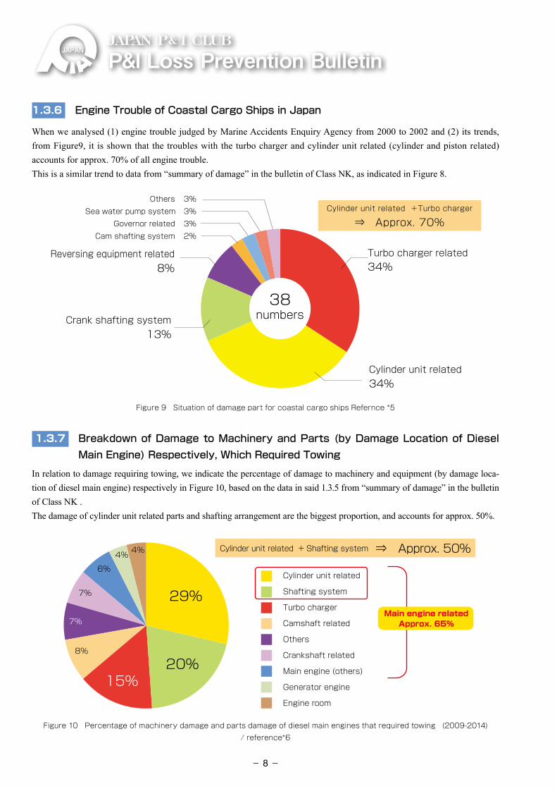
1.3.6 Engine Trouble of Coastal Cargo Ships in Japan
When we analysed (1) engine trouble judged by Marine Accidents Enquiry Agency from 2000 to 2002 and (2) its trends, from Figure9, it is shown that the troubles with the turbo charger and cylinder unit related (cylinder and piston related) accounts for approx. 70% of all engine trouble. This is a similar trend to data from “summary of damage” in the bulletin of Class NK, as indicated in Figure 8.
Cam shafting system 2%
Turbo charger related34%
Cylinder unit related34%
Crank shafting system13%
Reversing equipment related8%
Cylinder unit related +Turbo charger
⇒ Approx. 70% Governor related 3% Sea water pump system 3% Others 3%
38numbers
Figure 9 Situation of damage part for coastal cargo ships Refernce *5
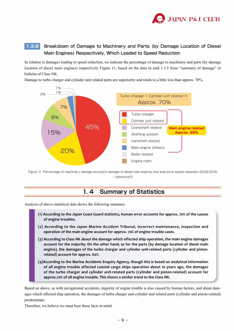
1.3.7 Breakdown of Damage to Machinery and Parts (by Damage Location of Diesel Main Engine) Respectively, Which Required Towing
In relation to damage requiring towing, we indicate the percentage of damage to machinery and equipment (by damage loca-tion of diesel main engine) respectively in Figure 10, based on the data in said 1.3.5 from “summary of damage” in the bulletin of Class NK . The damage of cylinder unit related parts and shafting arrangement are the biggest proportion, and accounts for approx. 50%.
4%4%
6%
7%
7%
8%
15%
29%
20%29%
Cylinder unit related
Shafting system
Turbo charger
Camshaft related
Others
Crankshaft related
Main engine (others)
Generator engine
Engine room
Main engine relatedApprox. 65%
Cylinder unit related + Shafting system ⇒ Approx. 50%
Figure 10 Percentage of machinery damage and parts damage of diesel main engines that required towing (2009-2014)/ reference*6
- 8-
JAPAN P& I CLUB
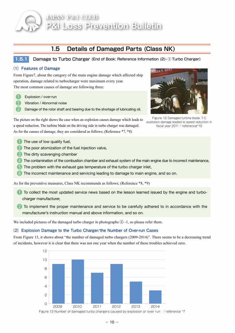
1.3.8 Breakdown of Damage to Machinery and Parts (by Damage Location of Diesel Main Engines) Respectively, Which Leaded to Speed Reduction
In relation to damages leading to speed reduction, we indicate the percentage of damage to machinery and parts (by damage location of diesel main engines) respectively Figure 11, based on the data in said 1.3.5 from “summary of damage” in bulletin of Class NK. Damage to turbo charger and cylinder unit related parts are superiority and totals to a little less than approx. 70%.
3% 1%1%
8%
7%
45%15%
20%
Turbo charger
Cylinder unit related
Crankshaft related
Shafting system
Camshaft related
Main engine (others)
Boiler related
Engine room
Turbo charger + Cylinder unit related ⇒
Approx. 70%
Main engine relatedApprox. 90%
Figure 11 Percentage of machinery damage and parts damage of diesel main engines that lead ed to speed reduction (2009-2014)/ reference*6
1. 4 Summary of Statistics
Analysis of above statistical data shows the following summary.
(1) According to the Japan Coast Guard statistics, human error accounts for approx. 70% of the causes of engine troubles.
(2) According to the Japan Marine Accident Tribunal, incorrect maintenance, inspection and operation of the main engine account for approx. 70% of engine trouble cases.
(3) According to Class NK about the damage which affected ship operation, the main engine damages account for the majority. On the other hand, as for the parts (by damage location of diesel main engine), the damages of the turbo charger and cylinder unit-related parts (cylinder and piston-related) account for approx. 60%.
(4)According to the Marine Accidents Enquiry Agency, though this is based on analytical information of all engine trouble affected coastal cargo ships operation about 10 years ago, the damages of the turbo charger and cylinder unit-related parts (cylinder and piston-related) account for approx.70% of all engine trouble. This shows a similar trend to the Class NK.
Based on above, as with navigational accidents, majority of engine trouble is also caused by human factors, and about dam-ages which affected ship operation, the damages of turbo charger and cylinder unit related parts (cylinder and piston-related) predominate.Therefore, we believe we must bear these facts in mind.
- 9-
P&ILossPreventionBulletinJAPAN P& I CLUB
1.5 Details of Damaged Parts (Class NK)
1.5.1 Damage to Turbo Charger (End of Book: Reference Information (2)- ① Turbo Charger)
(1) Features of DamageFrom Figure7, about the category of the main engine damage which affected ship operation, damage related to turbocharger were maximum every year. The most common causes of damage are following three:
❶ Explosion / over-run
❷ Vibration / Abnormal noise
❸ �Damage of the rotor shaft and bearing due to the shortage of lubricating oil.
The picture on the right shows the case when an explosion causes damage which leads to a speed reduction. The turbine blade on the driving side in turbo charger was damaged. As for the causes of damage, they are considered as follows; (Reference *7, *8)
❶ The use of low quality fuel,
❷ The poor atomization of the fuel injection valve,
❸ The dirty scavenging chamber
❹ The contamination of the combustion chamber and exhaust system of the main engine due to incorrect maintenance,
❺ The problem with the exhaust gas temperature of the turbo charger inlet,
❻ The incorrect maintenance and servicing leading to damage to main engine, and so on.
As for the preventive measures, Class NK recommends as follows; (Reference *8, *9)
❶ To collect the most updated service news based on the lesson learned issued by the engine and turbo-
charger manufacturer,
❷ To implement the proper maintenance and service to be carefully adhered to in accordance with the
manufacturer’s instruction manual and above information, and so on.
We included pictures of the damaged turbo charger in photographs ④ -1, so please refer them.
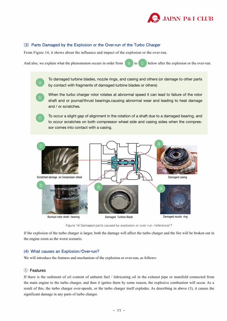
(2) Explosion Damage to the Turbo Charger/the Number of Over-run CasesFrom Figure 13, it shows about “the number of damaged turbo chargers (2009-2014)”. There seems to be a decreasing trend of incidents, however it is clear that there was not one year when the number of these troubles achieved zero.
0
2
4
6
8
10
12
2009 2010 2011 2012 2013 2014Figure 13 Number of damaged turbo chargers caused by explosion or over run / reference *7
Figure 12 Damaged turbine blade, T/C explosion damage leaded to speed reduction in
fiscal year 2011 / reference*10
- 10-
JAPAN P& I CLUB
(3) Parts Damaged by the Explosion or the Over-run of the Turbo Charger
From Figure 14, it shows about the influence and impact of the explosion or the over-run.
And also, we explain what the phenomenon occurs in order from a to c below after the explosion or the over-run.
a �To damaged turbine blades, nozzle rings, and casing and others (or damage to other parts
by contact with fragments of damaged turbine blades or others)
b �When the turbo charger rotor rotates at abnormal speed it can lead to failure of the rotor
shaft and or journal/thrust bearings.causing abnormal wear and leading to heat damage
and / or scratches.
c �To occur a slight gap of alignment in the rotation of a shaft due to a damaged bearing, and
to occur scratches on both compressor wheel side and casing sides when the compres-
sor comes into contact with a casing.
Scratched damage on Compressor wheel
Burnout rotor shaft / bearing Damaged Turbine Blade Damaged nozzle ring
Damaged casing
c
b a a
a
Figure 14 Damaged parts caused by explosion or over run /reference*7
If the explosion of the turbo charger is larger, both the damage will affect the turbo charger and the fire will be broken out in the engine room as the worst scenario.
(4) What causes an Explosion/Over-run?We will introduce the features and mechanism of the explosion or over-run, as follows:
① FeaturesIf there is the sediment of oil content of unburnt fuel / lubricating oil in the exhaust pipe or manifold connected from the main engine to the turbo charger, and then it ignites them by some reason, the explosive combustion will occur. As a result of this, the turbo charger over-speeds, or the turbo charger itself explodes. As describing in above (3), it causes the significant damage in any parts of turbo charger.
- 11-
P&ILossPreventionBulletinJAPAN P& I CLUB
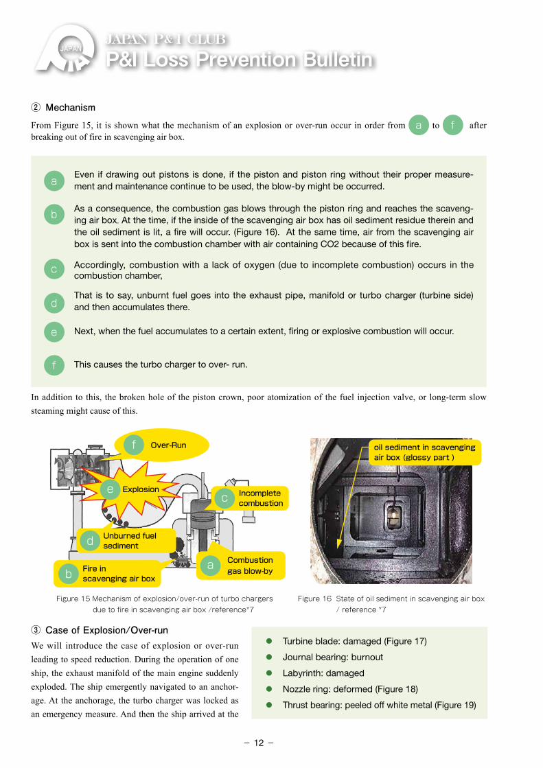
② MechanismFrom Figure 15, it is shown what the mechanism of an explosion or over-run occur in order from a to f after breaking out of fire in scavenging air box.
a �Even if drawing out pistons is done, if the piston and piston ring without their proper measure-ment and maintenance continue to be used, the blow-by might be occurred.
b �As a consequence, the combustion gas blows through the piston ring and reaches the scaveng-ing air box. At the time, if the inside of the scavenging air box has oil sediment residue therein and the oil sediment is lit, a fire will occur. (Figure 16). At the same time, air from the scavenging air box is sent into the combustion chamber with air containing CO2 because of this fire.
c �Accordingly, combustion with a lack of oxygen (due to incomplete combustion) occurs in the combustion chamber,
d �That is to say, unburnt fuel goes into the exhaust pipe, manifold or turbo charger (turbine side)
and then accumulates there.
e Next, when the fuel accumulates to a certain extent, firing or explosive combustion will occur.
f �This causes the turbo charger to over- run.
In addition to this, the broken hole of the piston crown, poor atomization of the fuel injection valve, or long-term slow steaming might cause of this.
Fire in scavenging air box b
Combustion gas blow-by
Unburned fuel sediment
a
Incompletecombustion
Over-Run f
ce Explosion
oil sediment in scavenging air box (glossy part )
d
Figure 16 State of oil sediment in scavenging air box / reference *7
Figure 15 Mechanism of explosion/over-run of turbo chargers due to fire in scavenging air box /reference*7
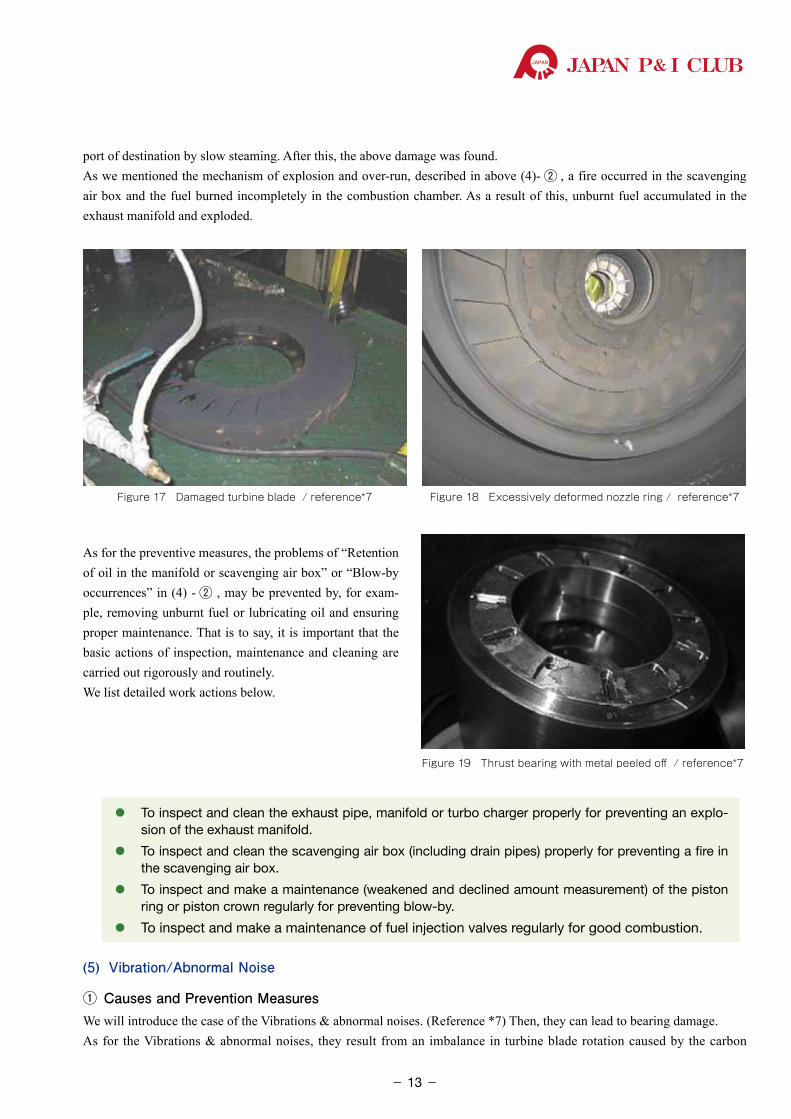
③ Case of Explosion/Over-runWe will introduce the case of explosion or over-run leading to speed reduction. During the operation of one ship, the exhaust manifold of the main engine suddenly exploded. The ship emergently navigated to an anchor-age. At the anchorage, the turbo charger was locked as an emergency measure. And then the ship arrived at the
⃝ Turbine blade: damaged (Figure 17)
⃝ Journal bearing: burnout
⃝ Labyrinth: damaged
⃝ Nozzle ring: deformed (Figure 18)
⃝ Thrust bearing: peeled off white metal (Figure 19)
- 12-
JAPAN P& I CLUB
port of destination by slow steaming. After this, the above damage was found.As we mentioned the mechanism of explosion and over-run, described in above (4)- ② , a fire occurred in the scavenging air box and the fuel burned incompletely in the combustion chamber. As a result of this, unburnt fuel accumulated in the exhaust manifold and exploded.
Figure 18 Excessively deformed nozzle ring / reference*7Figure 17 Damaged turbine blade / reference*7
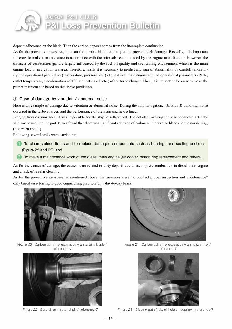
As for the preventive measures, the problems of “Retention of oil in the manifold or scavenging air box” or “Blow-by occurrences” in (4) - ② , may be prevented by, for exam-ple, removing unburnt fuel or lubricating oil and ensuring proper maintenance. That is to say, it is important that the basic actions of inspection, maintenance and cleaning are carried out rigorously and routinely. We list detailed work actions below.
⃝ �To inspect and clean the exhaust pipe, manifold or turbo charger properly for preventing an explo-sion of the exhaust manifold.
⃝ �To inspect and clean the scavenging air box (including drain pipes) properly for preventing a fire in the scavenging air box.
⃝ �To inspect and make a maintenance (weakened and declined amount measurement) of the piston ring or piston crown regularly for preventing blow-by.
⃝ �To inspect and make a maintenance of fuel injection valves regularly for good combustion.
(5) Vibration/Abnormal Noise
① Causes and Prevention MeasuresWe will introduce the case of the Vibrations & abnormal noises. (Reference *7) Then, they can lead to bearing damage.As for the Vibrations & abnormal noises, they result from an imbalance in turbine blade rotation caused by the carbon
Figure 19 Thrust bearing with metal peeled off / reference*7
- 13-
P&ILossPreventionBulletinJAPAN P& I CLUB
deposit adherence on the blade. Then the carbon deposit comes from the incomplete combustion As for the preventive measures, to clean the turbine blade regularly could prevent such damage. Basically, it is important for crew to make a maintenance in accordance with the intervals recommended by the engine manufacturer. However, the dirtiness of combustion gas are largely influenced by the fuel oil quality and the running environment which is the main engine load or navigation sea area. Therefore, firstly it is necessary to predict any sign of abnormality by carefully monitor-ing the operational parameters (temperature, pressure, etc.) of the diesel main engine and the operational parameters (RPM, outlet temperature, discolouration of T/C lubrication oil, etc.) of the turbo charger. Then, it is important for crew to make the proper maintenance based on the above prediction.
② Case of damage by vibration / abnormal noiseHere is an example of damage due to vibration & abnormal noise. During the ship navigation, vibration & abnormal noise occurred in the turbo charger, and the performance of the main engine declined.Judging from circumstance, it was impossible for the ship to self-propell. The detailed investigation was conducted after the ship was towed into the port. It was found that there was significant adhesion of carbon on the turbine blade and the nozzle ring, (Figure 20 and 21). Following several tasks were carried out,
❶ To clean stained items and to replace damaged components such as bearings and sealing and etc.
(Figure 22 and 23), and
❷ To make a maintenance work of the diesel main engine (air cooler, piston ring replacement and others).
As for the causes of damage, the causes were related to dirty deposit due to incomplete combustion in diesel main engine and a lack of regular cleaning.As for the preventive measures, as mentioned above, the measures were “to conduct proper inspection and maintenance” only based on referring to good engineering practices on a day-to-day basis.
Figure 20 Carbon adhering excessively on turbine blade / reference *7
Figure 21 Carbon adhering excessively on nozzle ring / reference*7
Figure 22 Scratches in rotor shaft / reference*7 Figure 23 Slipping out of lub. oil hole on bearing / reference*7
- 14-
JAPAN P& I CLUB
1.5.2 Burnout of the Rotor Shaft and Bearing Due to shortage of lubricating oil.
(1) Features and Causes
We will introduce the features and causes of the burnouts of the rotor shaft and bearing due to shortage of lubricating oil. (Reference *7)It is estimated that most of the burnouts of the rotor shaft and bearing were due to shortage of lubricating oil. Specifically, the causes are considered to the following three listed.
1 Deterioration of lubricating oil itself (contaminated with the water and others)
2 Blockage of the oil hole on the bearing
3 Flow shortage of lubricating oil due to malfunction of lubricating oil pump.
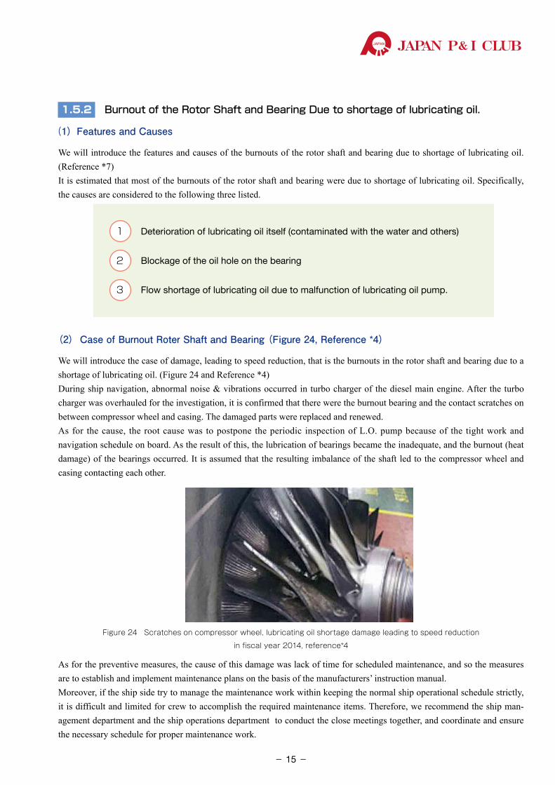
(2) Case of Burnout Roter Shaft and Bearing (Figure 24, Reference *4)
We will introduce the case of damage, leading to speed reduction, that is the burnouts in the rotor shaft and bearing due to a shortage of lubricating oil. (Figure 24 and Reference *4)During ship navigation, abnormal noise & vibrations occurred in turbo charger of the diesel main engine. After the turbo charger was overhauled for the investigation, it is confirmed that there were the burnout bearing and the contact scratches on between compressor wheel and casing. The damaged parts were replaced and renewed. As for the cause, the root cause was to postpone the periodic inspection of L.O. pump because of the tight work and navigation schedule on board. As the result of this, the lubrication of bearings became the inadequate, and the burnout (heat damage) of the bearings occurred. It is assumed that the resulting imbalance of the shaft led to the compressor wheel and casing contacting each other.
Figure 24 Scratches on compressor wheel, lubricating oil shortage damage leading to speed reduction
in fiscal year 2014, reference*4
As for the preventive measures, the cause of this damage was lack of time for scheduled maintenance, and so the measures are to establish and implement maintenance plans on the basis of the manufacturers’ instruction manual.Moreover, if the ship side try to manage the maintenance work within keeping the normal ship operational schedule strictly, it is difficult and limited for crew to accomplish the required maintenance items. Therefore, we recommend the ship man-agement department and the ship operations department to conduct the close meetings together, and coordinate and ensure the necessary schedule for proper maintenance work.
- 15-
P&ILossPreventionBulletinJAPAN P& I CLUB
1.5.3 Damage to Cylinder Unit Related Parts
(1) Features of Damage
From Figure 7, the cylinder unit-related damages are the second most common. (Reference *4)These can lead to the damage not only to the cylinder unit-related parts (the combustion chamber components) but also to the turbo charger.
As for the cause of damage, the cause may be the use of low quality fuel oil, poor maintenance, and so on. As for the preventive measure, especially when you found that the using fuel is the low quality fuel oil, we recommend the following necessary preventive measures;
❶ To carry out the fuel pre-treatment rigorously,
❷ To reduce the operating load of the diesel main engine,
❸ To dilute the low quality fuel by mixing light quality oil and to improve it
❹ To use the fuel additives and so on.
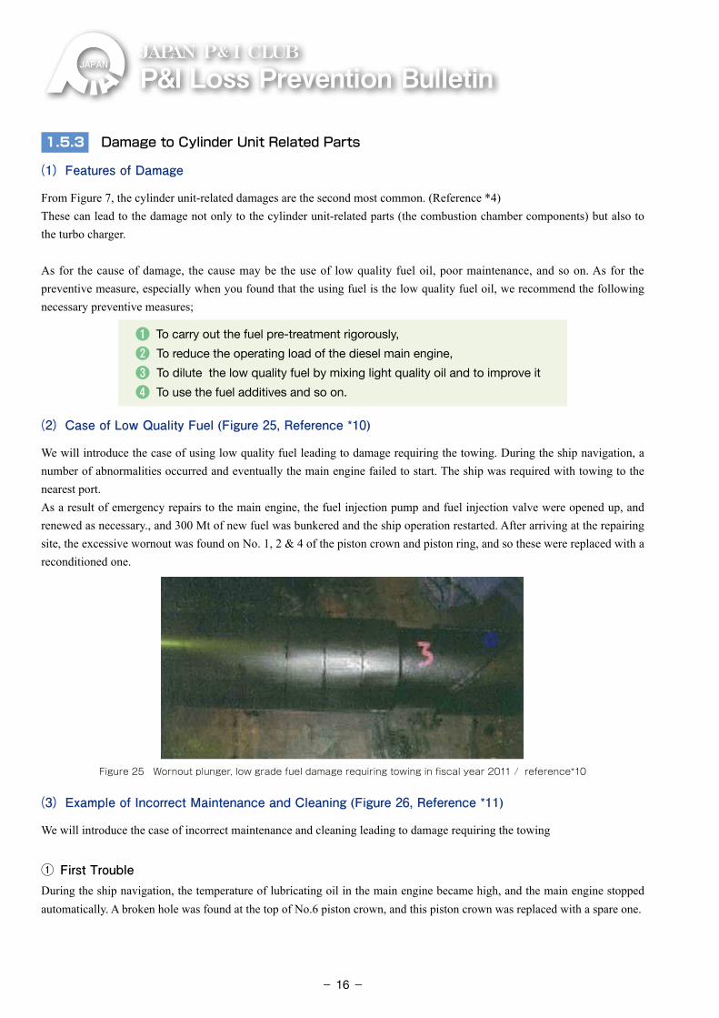
(2) Case of Low Quality Fuel (Figure 25, Reference *10)
We will introduce the case of using low quality fuel leading to damage requiring the towing. During the ship navigation, a number of abnormalities occurred and eventually the main engine failed to start. The ship was required with towing to the nearest port.As a result of emergency repairs to the main engine, the fuel injection pump and fuel injection valve were opened up, and renewed as necessary., and 300 Mt of new fuel was bunkered and the ship operation restarted. After arriving at the repairing site, the excessive wornout was found on No. 1, 2 & 4 of the piston crown and piston ring, and so these were replaced with a reconditioned one.
Figure 25 Wornout plunger, low grade fuel damage requiring towing in fiscal year 2011 / reference*10
(3) Example of Incorrect Maintenance and Cleaning (Figure 26, Reference *11)
We will introduce the case of incorrect maintenance and cleaning leading to damage requiring the towing
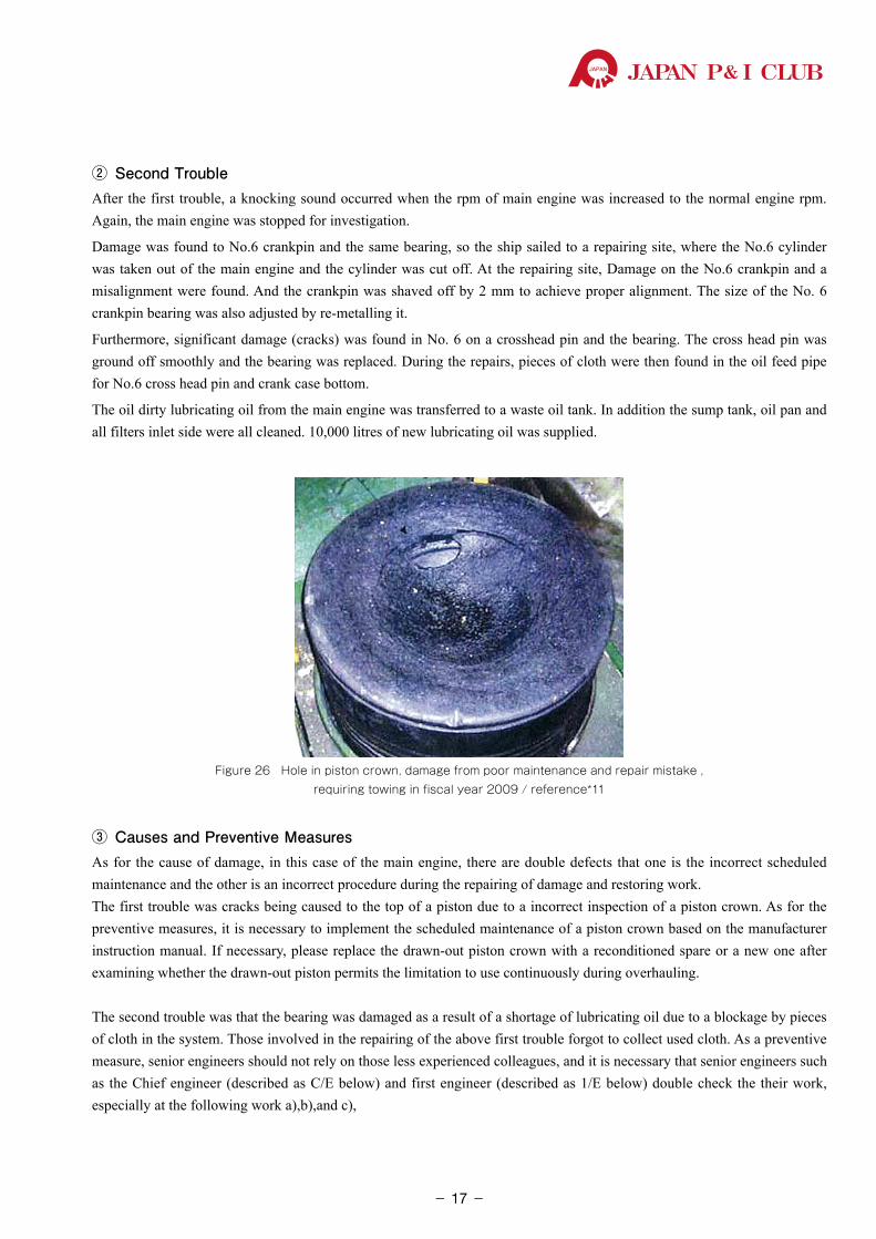
① First Trouble During the ship navigation, the temperature of lubricating oil in the main engine became high, and the main engine stopped automatically. A broken hole was found at the top of No.6 piston crown, and this piston crown was replaced with a spare one.
- 16-
JAPAN P& I CLUB
② Second Trouble After the first trouble, a knocking sound occurred when the rpm of main engine was increased to the normal engine rpm. Again, the main engine was stopped for investigation.
Damage was found to No.6 crankpin and the same bearing, so the ship sailed to a repairing site, where the No.6 cylinder was taken out of the main engine and the cylinder was cut off. At the repairing site, Damage on the No.6 crankpin and a misalignment were found. And the crankpin was shaved off by 2 mm to achieve proper alignment. The size of the No. 6 crankpin bearing was also adjusted by re-metalling it.
Furthermore, significant damage (cracks) was found in No. 6 on a crosshead pin and the bearing. The cross head pin was ground off smoothly and the bearing was replaced. During the repairs, pieces of cloth were then found in the oil feed pipe for No.6 cross head pin and crank case bottom.
The oil dirty lubricating oil from the main engine was transferred to a waste oil tank. In addition the sump tank, oil pan and all filters inlet side were all cleaned. 10,000 litres of new lubricating oil was supplied.
Figure 26 Hole in piston crown, damage from poor maintenance and repair mistake , requiring towing in fiscal year 2009 / reference*11
③ Causes and Preventive MeasuresAs for the cause of damage, in this case of the main engine, there are double defects that one is the incorrect scheduled maintenance and the other is an incorrect procedure during the repairing of damage and restoring work.The first trouble was cracks being caused to the top of a piston due to a incorrect inspection of a piston crown. As for the preventive measures, it is necessary to implement the scheduled maintenance of a piston crown based on the manufacturer instruction manual. If necessary, please replace the drawn-out piston crown with a reconditioned spare or a new one after examining whether the drawn-out piston permits the limitation to use continuously during overhauling.
The second trouble was that the bearing was damaged as a result of a shortage of lubricating oil due to a blockage by pieces of cloth in the system. Those involved in the repairing of the above first trouble forgot to collect used cloth. As a preventive measure, senior engineers should not rely on those less experienced colleagues, and it is necessary that senior engineers such as the Chief engineer (described as C/E below) and first engineer (described as 1/E below) double check the their work, especially at the following work a),b),and c),
- 17-
P&ILossPreventionBulletinJAPAN P& I CLUB
a Not to leave residues
b To clean contact area when assembling
c �To preserve the manufacturer instruction manual and your own work instructions for
assembling, fastening torque, technique of fastening and other special cautions.
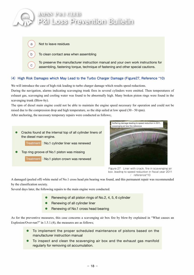
(4) High Risk Damages which May Lead to the Turbo Charger Damage (Figure27, Reference *10)
We will introduce the case of high risk leading to turbo charger damage which results speed reductions. During the navigation, alarms indicating scavenging trunk fires in several cylinders were emitted. Then temperatures of exhaust gas, scavenging and cooling water was found to be abnormally high. Many broken piston rings were found in the scavenging trunk (Blow-by).The rpm of diesel main engine could not be able to maintain the engine speed necessary for operation and could not be raised due to the compression drop and high temperature, so the ship sailed at low speed (30 - 50 rpm).After anchoring, the necessary temporary repairs were conducted as follows;.
Figure 27 Liner with crack, fire in scavenging air box ,leading to speed reduction in fiscal year 2011
/ reference*10
Suffering damage leading to speed reduction in 2011,
scavenging air box fire reference
⃝ �Cracks found at the internal top of all cylinder liners of the diesel main engine.
Treatment:No.1 cylinder liner was renewed
⃝ Top ring groove of No.1 piston was missing
Treatment:No.1 piston crown was renewed
A damaged (peeled off) white metal of No.1 cross head pin bearing was found, and this permanent repair was recommended by the classification society.Several days later, the following repairs to the main engine were conducted.
⃝ Renewing of all piston rings of No.2, 4, 5, 6 cylinder
⃝ Renewing of all cylinder liner
⃝ Renewing of No.1 cross head bearing
As for the preventive measures, this case concerns a scavenging air box fire by blow-by explained in “What causes an Explosion/Over-run?” in 1.5.1.(4), the measures are as follows;
⃝ �To implement the proper scheduled maintenance of pistons based on the manufacturer instruction manual
⃝ �To inspect and clean the scavenging air box and the exhaust gas manifold regularly for removing oil accumulation.
- 18-
JAPAN P& I CLUB
1.5.4 Damage to Shafting System: Intermediate Bearing (End of Book: Reference Information
(2)- ② Intermediate bearing)
(1) Features of Damage
In damage of the shafting system, it may be difficult for crew to prevent breakage, however there might be the preventive measure against damage to the intermediate bearing. We will introduce that the features of damage to intermediate bearing are cracks of shaft and wearing / peel-off / burn-out of bearing, as discussed below.
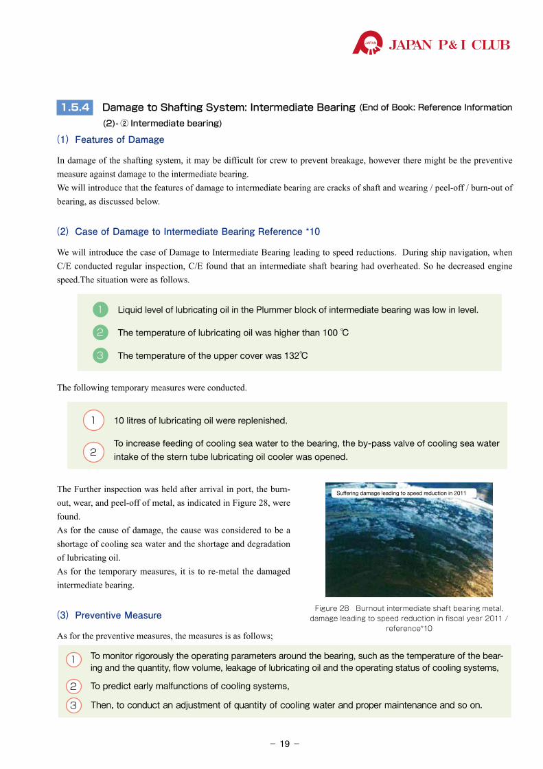
(2) Case of Damage to Intermediate Bearing Reference *10
We will introduce the case of Damage to Intermediate Bearing leading to speed reductions. During ship navigation, when C/E conducted regular inspection, C/E found that an intermediate shaft bearing had overheated. So he decreased engine speed.The situation were as follows.
1 Liquid level of lubricating oil in the Plummer block of intermediate bearing was low in level.
2 The temperature of lubricating oil was higher than 100 ℃
3 �The temperature of the upper cover was 132℃
The following temporary measures were conducted.
1 10 litres of lubricating oil were replenished.
2 �To increase feeding of cooling sea water to the bearing, the by-pass valve of cooling sea water
intake of the stern tube lubricating oil cooler was opened.
The Further inspection was held after arrival in port, the burn-out, wear, and peel-off of metal, as indicated in Figure 28, were found. As for the cause of damage, the cause was considered to be a shortage of cooling sea water and the shortage and degradation of lubricating oil.As for the temporary measures, it is to re-metal the damaged intermediate bearing.
(3) Preventive Measure
As for the preventive measures, the measures is as follows;
1 �To monitor rigorously the operating parameters around the bearing, such as the temperature of the bear-ing and the quantity, flow volume, leakage of lubricating oil and the operating status of cooling systems,
2 �To predict early malfunctions of cooling systems,
3 Then,�to�conduct�an�adjustment�of�quantity�of�cooling�water�and�proper�maintenance�and�so�on.
Figure 28 Burnout intermediate shaft bearing metal, damage leading to speed reduction in fiscal year 2011 /
reference*10
Suffering damage leading to speed reduction in 2011
- 19-
P&ILossPreventionBulletinJAPAN P& I CLUB
1.6 Summary of Damaged Parts and Overview
The summary on the damaged part is as follows.
1
The number of damage involving the turbo charger is the most common, and the major types of damages
are the following three.
① Explosion/Over-run
② Vibration/Abnormal noise
③ Damage to the rotor shaft and bearing due to the shortage of lubricating oil
Each of these looks different, however the common preventive measures are how to manage the incorrect maintenance. So, these damages could be prevented by learning, understanding and following the manufacturer instruction manual and by familiarising and implementing the proper maintenance in accordance with them.
2
The cylinder unit-related damage is the second most common. There is a high risk that damage to components in combustion chamber and damage to turbo charger will occur. The causes include the use of low quality fuel, and incorrect maintenance.To rectify this, it is necessary for crew to conduct the severe fuel management and the continuous proper maintenance rigorously.
3
The third most common damage is to the shafting system, it is specially relating to the bearing damage caused by the shortage of lubricating oil and incorrect maintenance of cooling system in troubles. The preventive measures include the ensuring proper operational management and the proper maintenance rigorously.
When comprehensively analysing statistical data on engine trouble damage that affected ship operation, the causes include maintenance management often. In other words, the causes are human in nature. That is to say, it is important for crew to conduct maintenance and inspection systematically and regularly and to arrange a management system which is capable of comprehending the operating status of an engine so that the device and system can operate properly on the basis of rule and principle of science and technology. In addition to above, it is important for your ship to review your ISM procedures and the planned maintenance system (PMS) if it is practicable for your crew. If necessary, you need to update them.
On the other hand, loss prevention measures on board are considered to be limited. It is important for the ship management department to improve measures to control problems by understanding the features of damage in several cases and then collecting the most updated service news, in order to add to the existing manufacturer’s instruction manual. Their considered measures must instruct to the ship and then finally preventive measures for implementing engine operation and daily inspec-tion and maintenance properly can be developed
Of course, since securing maintenance time is difficult in busy and limited operation period, it is important that ship and shore-side work together in such a way that the ship management department reports necessary information to the opera-tions department and to arrange the system to secure the time necessary for maintenance to implement proper scheduled maintenance for prevention of accidents. The information introduced above is open to the public, however there are many important messages in these public information. We would ask that you continue to pay attention to all these public informa-tion discussed in this chapter.
- 20-
JAPAN P& I CLUB
In this chapter, we shall consider the claims caused by the engine trouble in the P&I claims handled by our Club, and study and examine specifically what we must pay attention.
We are going to study the claims caused by the engine trouble from 2008 policy year (hereinafter “PY”) to 2014 PY, and first to analyse their trend. We then discuss case studies, and examine their preventive measures.In addition, for your reference information, we explain the important points of engine room bilge management, related to the violation of International Convention for the Prevention of Pollution from Ships (hereinafter “MARPOL”) which are not covered by P&I insurance.
2.1 Trend in Our Club
2.1.1 Trend of Claims by Risk
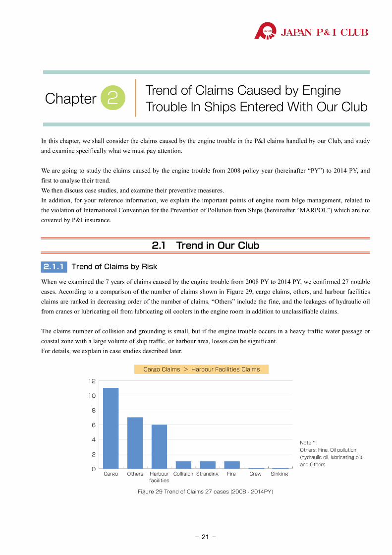
When we examined the 7 years of claims caused by the engine trouble from 2008 PY to 2014 PY, we confirmed 27 notable cases. According to a comparison of the number of claims shown in Figure 29, cargo claims, others, and harbour facilities claims are ranked in decreasing order of the number of claims. “Others” include the fine, and the leakages of hydraulic oil from cranes or lubricating oil from lubricating oil coolers in the engine room in addition to unclassifiable claims.
The claims number of collision and grounding is small, but if the engine trouble occurs in a heavy traffic water passage or coastal zone with a large volume of ship traffic, or harbour area, losses can be significant.For details, we explain in case studies described later.
0
2
4
6
8
10
12
Cargo Others Harbourfacilities
Collision Stranding Fire SinkingCrew
Cargo Claims > Harbour Facilities Claims
Note * : Others: Fine, Oil pollution (hydraulic oil, lubricating oil), and Others
Figure 29 Trend of Claims 27 cases (2008 - 2014PY)
Trend of Claims Caused by Engine Trouble In Ships Entered With Our ClubChapter 2
- 21-
P&ILossPreventionBulletinJAPAN P& I CLUB
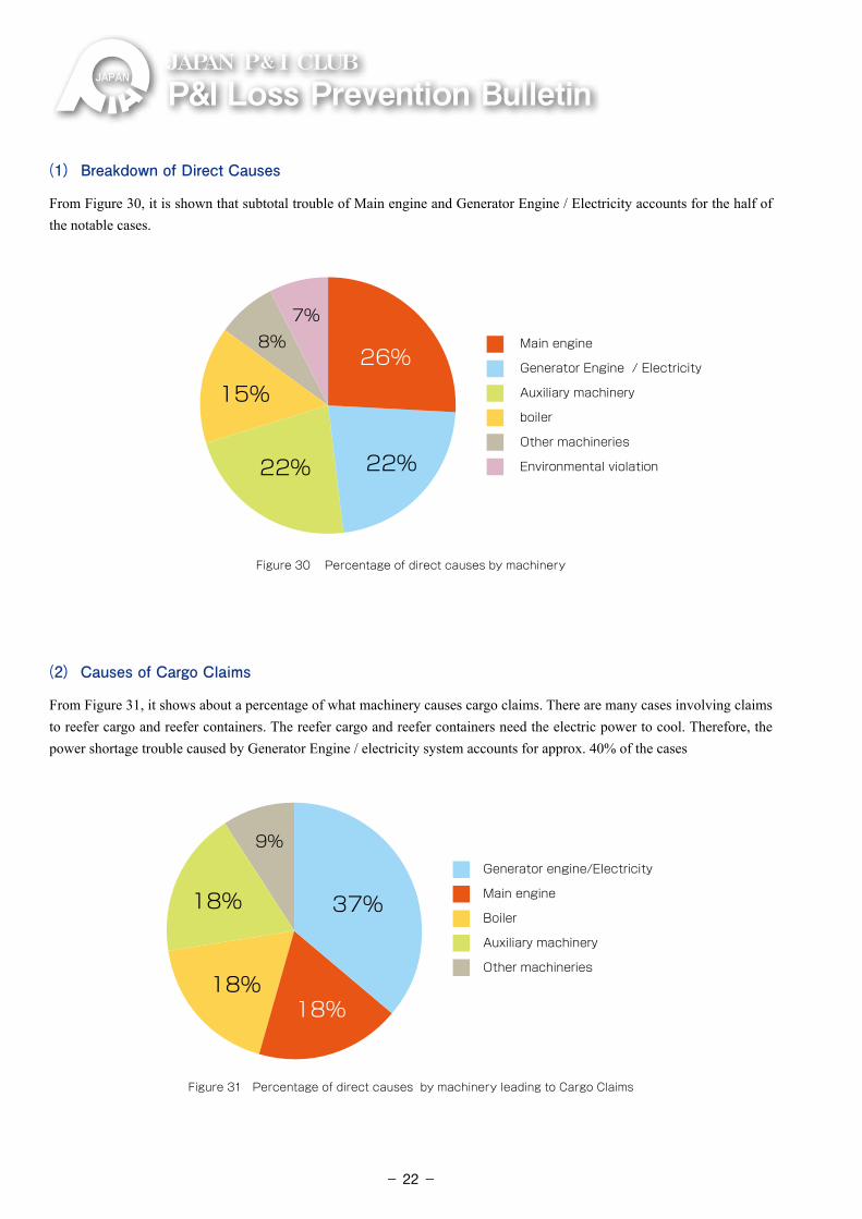
(1) Breakdown of Direct Causes
From Figure 30, it is shown that subtotal trouble of Main engine and Generator Engine / Electricity accounts for the half of the notable cases.
8%7%
26%
15%
22% 22%
Main engine
Generator Engine / Electricity
Auxiliary machinery
boiler
Other machineries
Environmental violation
Figure 30 Percentage of direct causes by machinery
(2) Causes of Cargo Claims
From Figure 31, it shows about a percentage of what machinery causes cargo claims. There are many cases involving claims to reefer cargo and reefer containers. The reefer cargo and reefer containers need the electric power to cool. Therefore, the power shortage trouble caused by Generator Engine / electricity system accounts for approx. 40% of the cases
9%
37%18%
18%18%
Generator engine/Electricity
Main engine
Boiler
Auxiliary machinery
Other machineries
Figure 31 Percentage of direct causes by machinery leading to Cargo Claims
- 22-
JAPAN P& I CLUB
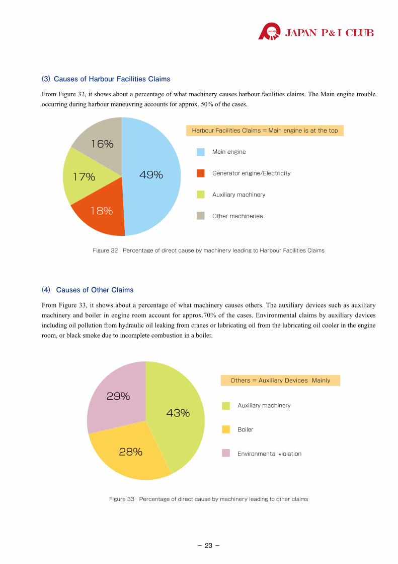
(3) Causes of Harbour Facilities Claims
From Figure 32, it shows about a percentage of what machinery causes harbour facilities claims. The Main engine trouble occurring during harbour maneuvring accounts for approx. 50% of the cases.
49%
16%
17%
18%
Main engine
Generator engine/Electricity
Auxiliary machinery
Other machineries
Harbour Facilities Claims = Main engine is at the top
Figure 32 Percentage of direct cause by machinery leading to Harbour Facilities Claims
(4) Causes of Other Claims
From Figure 33, it shows about a percentage of what machinery causes others. The auxiliary devices such as auxiliary machinery and boiler in engine room account for approx.70% of the cases. Environmental claims by auxiliary devices including oil pollution from hydraulic oil leaking from cranes or lubricating oil from the lubricating oil cooler in the engine room, or black smoke due to incomplete combustion in a boiler.
43%
29%
28%
Auxiliary machinery
Boiler
Environmental violation
Others = Auxiliary Devices Mainly
Figure 33 Percentage of direct cause by machinery leading to other claims
- 23-
P&ILossPreventionBulletinJAPAN P& I CLUB
2.2 Case Studies
We have extracted 4 case studies of claims caused by engine trouble, as handled by our Club. First we discuss their outline, insurance money, and what happened in their engine room. We then examine their causes and applicable preventive measures.
2.2.1 Cargo Damage : Boiler Trouble (Cargo shortage)
2.2.2 Harbour Facilities Claims : Main Engine Start Failure (Damage to submarine cable)
2.2.3 Cargo Claims : Generator Re-start Failure (Blackout)
2.2.4 Environmental Claims : Incomplete Combustion of the Boiler
2.2.1 Cargo Claims (Cargo Shortage ) : Boiler Trouble
(1) Outline
During ship’s navigating and carrying benzene to its discharging port, a leakage of boiler water was found on board. So, the crew stopped the boiler operation immediately. As a result of this trouble, the ship couldn’t heat the cargo during her voyage and entered into port. The temperature of the cargo tank at this time was 5.25℃ on average, which was less than the melting point of benzene (5.5℃).
The ship started unloading cargo operations by receiving heating steam from the shore terminal, but this heating work for unloading was not enough. Some cargo could not be heated and remained on the tank wall, therefore it resulted a cargo short-age.
Cargo interests claimed US$20,000 from owners including supplying the steam. Eventually, this case was settled at US$10,000.(2) Insurance Money
Settlement amount of cargo claim : US$ 10,000
Surveyors fee : US$ 2,000
Correspondent fees : US$ 3,000
Total :approx. US$ 15,000
(3) What Happened in the Engine Room?
① The crew stopped operating the boiler when water was found leaking in the lower boiler casing in the engine room.
- 24-
JAPAN P& I CLUB
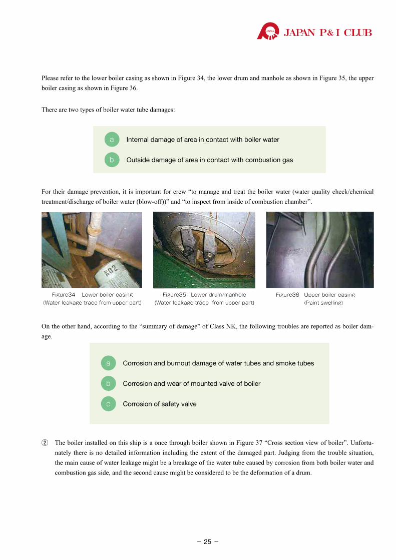
Please refer to the lower boiler casing as shown in Figure 34, the lower drum and manhole as shown in Figure 35, the upper boiler casing as shown in Figure 36.
There are two types of boiler water tube damages:
a Internal damage of area in contact with boiler water
b Outside damage of area in contact with combustion gas
For their damage prevention, it is important for crew “to manage and treat the boiler water (water quality check/chemical treatment/discharge of boiler water (blow-off))” and “to inspect from inside of combustion chamber”.
Figure34 Lower boiler casing (Water leakage trace from upper part)
Figure35 Lower drum/manhole (Water leakage trace from upper part)
Figure36 Upper boiler casing (Paint swelling)
On the other hand, according to the “summary of damage” of Class NK, the following troubles are reported as boiler dam-age.
a Corrosion and burnout damage of water tubes and smoke tubes
b Corrosion and wear of mounted valve of boiler
c Corrosion of safety valve
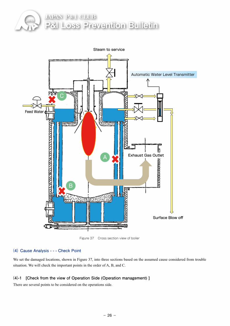
② The boiler installed on this ship is a once through boiler shown in Figure 37 “Cross section view of boiler”. Unfortu-nately there is no detailed information including the extent of the damaged part. Judging from the trouble situation, the main cause of water leakage might be a breakage of the water tube caused by corrosion from both boiler water and combustion gas side, and the second cause might be considered to be the deformation of a drum.
- 25-
P&ILossPreventionBulletinJAPAN P& I CLUB
Figure 37 Cross section view of boiler
(4) Cause Analysis - - - Check Point
We set the damaged locations, shown in Figure 37, into three sections based on the assumed cause considered from trouble situation. We will check the important points in the order of A, B, and C.
(4)-1 [Check from the view of Operation Side (Operation management) ]There are several points to be considered on the operations side.
A
B
C
Exhaust Gas OutletExhaust Gas Outlet
Feed Water
Surface Blow offSurface Blow off
Steam to serviceSteam to service
Automatic Water Level Transmitter
- 26-
JAPAN P& I CLUB
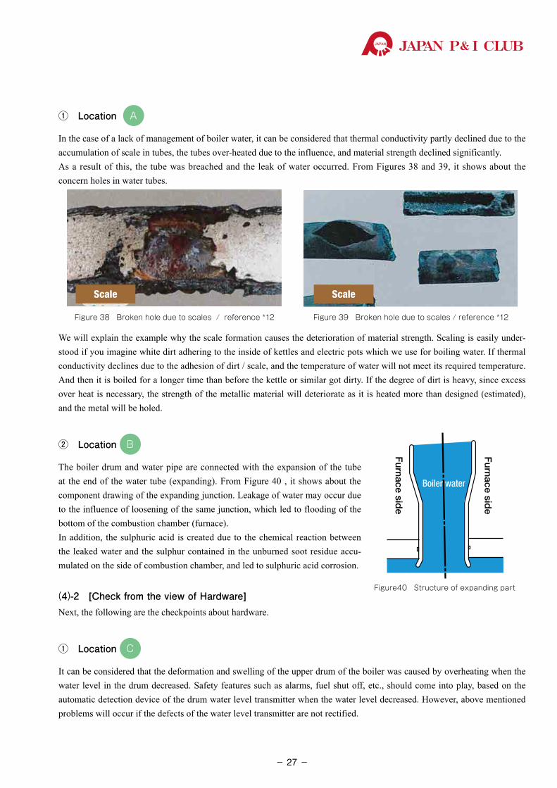
① Location A
In the case of a lack of management of boiler water, it can be considered that thermal conductivity partly declined due to the accumulation of scale in tubes, the tubes over-heated due to the influence, and material strength declined significantly.As a result of this, the tube was breached and the leak of water occurred. From Figures 38 and 39, it shows about the concern holes in water tubes.
Scale
Figure 38 Broken hole due to scales / reference *12
Scale
Figure 39 Broken hole due to scales / reference *12
We will explain the example why the scale formation causes the deterioration of material strength. Scaling is easily under-stood if you imagine white dirt adhering to the inside of kettles and electric pots which we use for boiling water. If thermal conductivity declines due to the adhesion of dirt / scale, and the temperature of water will not meet its required temperature. And then it is boiled for a longer time than before the kettle or similar got dirty. If the degree of dirt is heavy, since excess over heat is necessary, the strength of the metallic material will deteriorate as it is heated more than designed (estimated), and the metal will be holed.
② Location B
The boiler drum and water pipe are connected with the expansion of the tube at the end of the water tube (expanding). From Figure 40 , it shows about the component drawing of the expanding junction. Leakage of water may occur due to the influence of loosening of the same junction, which led to flooding of the bottom of the combustion chamber (furnace).In addition, the sulphuric acid is created due to the chemical reaction between the leaked water and the sulphur contained in the unburned soot residue accu-mulated on the side of combustion chamber, and led to sulphuric acid corrosion.
(4)-2 [Check from the view of Hardware]Next, the following are the checkpoints about hardware.
① Location C
It can be considered that the deformation and swelling of the upper drum of the boiler was caused by overheating when the water level in the drum decreased. Safety features such as alarms, fuel shut off, etc., should come into play, based on the automatic detection device of the drum water level transmitter when the water level decreased. However, above mentioned problems will occur if the defects of the water level transmitter are not rectified.
Figure40 Structure of expanding part
Furnace sid
e
Furnace sid
e
Boiler water
- 27-
P&ILossPreventionBulletinJAPAN P& I CLUB
In this way, it can be considered that the cause is not a single incorrect operation or incorrect maintenance. That is, a number of defects overlapping which led to the negative chain (error chain) and the trouble occurred due to a failure of cut-off the error chain.
(5) Preventive measures
It is necessary for crew to understand sufficiently basic operation provided by the boiler manufacturer (operation, management and various inspections and maintenance items), and to implement carefully the inspection, management, and maintenance. These are essential to prevent the boiler troubles. Accordingly, following prevention measures are recommended in this case.
(5)-1 [Preventive Measures from the view of Operation Side (Operation management)]Since the scale is slightly soluble in water, once it adheres, it is very difficult for crew to clean up.For prevention of adhesion of scale in tubes, the management of quality of boiler water and feeded water must be done thoroughly.
① Water Quality Management of Boiler Water, Condensed Water and Supplied Water
⃝ It is necessary for crew to maintain the result of chloride ion concentration and all sorts analysis within control limit value which are recommended by the boiler manufacturer for prevention of scale adhesion and corrosion and carry over.
⃝ Boiler water analysis must be conducted once a week at the minimum (once in two days in the case of high pressure boiler)
⃝ And, if necessary, please add chemicals. In the case that boiler water is concentrated, it is necessary for crew to discharge the dirty old boiler water out of the ship with sludge and then supply new boiler water with adjusting the water quality.
② Minimization of Impurities which contaminated from Feed Water (management of makeup water)
⃝ It is necessary for crew to set condition to feed pure water to boiler regularly by cleaning inside of cascade tank. The boiler water should be kept the high temperature and control the dissolved oxygen
⃝ It is necessary for crew to maintain and manage chloride content of water and hardness component of fresh water for feed water to the low level.
⃝ In this case that distilled water from fresh water generator was used as feed water, it is necessary for crew to secure the capacity of storage tank and the cleanness inside the tank and to operate properly fresh water generator and to maintain the accuracy of the chloride meter.
③ Prevention of Sea Water Mixing
⃝ In the case of boiler system equipped with condenser cooled by sea water system, there is a risk that sea water mixes into condensate water system of the feed water. In this case, it is necessary for crew to check the concentra-tion of chloride and contents in the condensate water in a cascade tank rigorously and regularly.
⃝ During blow-off (discharging outside to the ship) of boiler water, it is necessary for crew to pay attention to the operation of the valve.
For example, it is normal for crew to release the valves operation in the order from high pressure side of boiler to low pressure on the overboard side when starting blowing, and close valves in the order from low pressure on the overboard side to high pressure on the side of boiler when finishing blowing.
In addition, It is important that crew must pay attention that the boiler mounted valve and overboard valve are
Negative chain
- 28-
JAPAN P& I CLUB
opened fully and flow adjustment is conducted with intermediate valve near the overboard valve. It is because intermediate valve can be replaced directly if there is a defect. However, the replacement of mounted valve and overboard valve are impossible to replace during boiler operation under normal sea service condition. It should be done at Dry Docking.
⃝ The reason to detect contamination of sea water strictly can be understood easily from the view of the importance of monitoring chloride ion as explained above① .
④ Prevention of Low Temperature Corrosion (sulphate corrosion) To prevent low temperature corrosion means to prevent sulphate corrosion. it is important for crew to understand its
mechanism of occurrence, and to implement a preventive measures to eliminate the cause. As the mechanism of its occurrence, sulphur contents in combustion gas adheres to the outside surface of the boiler water
tube, and it combines with water in the part of low temperature. It becomes sulphuric acid and then corrosion occurs. The following preventive measures are recommendable.
⃝ Crew should clean inside the furnace regularly, and continue to implement removal of combustion soot. Also they carry out the observation and recording the condition inside of furnace area.
⃝ As for supplying excess air during combustion, the production of soot can be controlled if excess air ratio is large. However, as there is a risk of sulphate corrosion occurring if the combustion temperature does not go up and localized low temperature occurs, it is important for crew to control excess air ratios in the proper range in order to obtain good combustion.
⃝ It is necessary for crew to prevent to drop drain into the furnace if the boiler is equipped with steam soot blower. If there is the dropped drain from the soot blower, it reacts with soot and combustion gas, as similar mechanism to
the previous location B (Figure 40: structure of expanding part) and the broken hole of sulphate corrosion occurs.
(5)-2 [Preventive Measures from the view of Hardware]We must avoid the too low water level situation. It is important for crew to monitor the water level carefully all the time in order to keep Normal Water Level properly. Thus, the following preventive measures are recommendable.
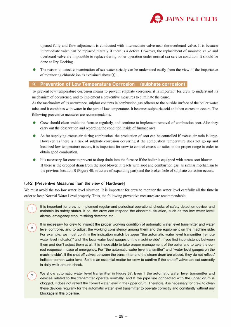
1 �It is important for crew to implement regular and periodical operational checks of safety detection device, and maintain its safety status. If so, the crew can respond the abnormal situation, such as too low water level, alarms, emergency stop, misfiring detector, etc..
2 �It is necessary for crew to inspect the proper working condition of automatic water level transmitter and water
level controller, and to adjust the working consistency among them and the equipment on the machine side. For example, we must confirm the indication match between “the automatic water level transmitter (remote water level indicator)” and “the local water level gauges on the machine side”. If you find inconsistency between them and don't adjust them at all, it is impossible to take proper management of the boiler and to take the cor-rect response in case of emergency. For “the automatic water level transmitter” and “water level gauges on the machine side”, if the shut off valves between the transmitter and the steam drum are closed, they do not reflect/indicate correct water level. So it is an essential matter for crew to confirm if the shutoff valves are set correctly in daily walk-around check.
3 �We show automatic water level transmitter in Figure 37. Even if the automatic water level transmitter and devices related to the transmitter operate normally, and If the pipe line connected with the upper drum is clogged, it does not reflect the correct water level in the upper drum. Therefore, it is necessary for crew to clean these devices regularly for the automatic water level transmitter to operate correctly and constantly without any blockage in this pipe line.
- 29-
P&ILossPreventionBulletinJAPAN P& I CLUB
However, above are important matters seeing at technical aspect.In addition to these, we must pay attention to the followings;
There are many cases that junior engineer takes in charge of auxiliary machinery because of very simple and clear system such as the boiler.However, even if the devices are simple such as a boiler, and if once trouble occurs on it, it is important for junior engineers to understand always that the boiler failure affects largely to the cargo work such as this case study.
There have been examples where junior engineers do not give a pay attention about maintenance works as they were preoccupied with machinery handling and operation, and they were so devoted to doing work in front of them. They tend to judge the incorrect priority to their work and then to postpone the important matters. Please be careful that there is a trend of carelessness towards thinking about “how important is their work” and “what is the highest priority work for them” on the ship and all engine department.
As a measure related these potential causes, senior engineers such as C/E&1/E must explain and motivate junior engineers how important the equipment they are in charge. And this will be result into the growth of the junior engineers. Specially, in this case, the insurance money of the cargo shortage was not particularly expensive, however, one defect by the crew will lead to losing the trust relationship between owners and charters, and it will require a long time period to restore this relationship. The senior engineers must keep in mind tenaciously that Junior education is one of the important tasks from above view points.
In this case analysis, it is important of course for crew to understand the technical matters as a basic manner of engineers. However, we would like to emphasize the “importance of motivation in the fundamental part”, why we conduct the inspec-tion and maintenance.
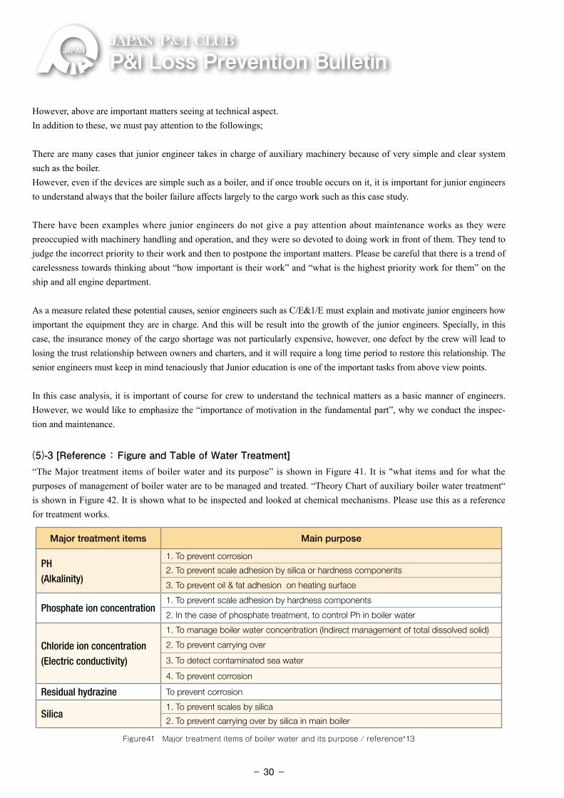
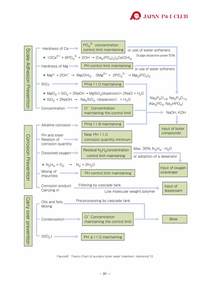
(5)-3 [Reference : Figure and Table of Water Treatment]“The Major treatment items of boiler water and its purpose” is shown in Figure 41. It is "what items and for what the purposes of management of boiler water are to be managed and treated. “Theory Chart of auxiliary boiler water treatment“ is shown in Figure 42. It is shown what to be inspected and looked at chemical mechanisms. Please use this as a reference for treatment works.
Major treatment items Main purpose
PH(Alkalinity)
1. To prevent corrosion
2. To prevent scale adhesion by silica or hardness components
3. To prevent oil & fat adhesion on heating surface
Phosphate ion concentration1. To prevent scale adhesion by hardness components
2. In the case of phosphate treatment, to control Ph in boiler water
Chloride ion concentration(Electric conductivity)
1. To manage boiler water concentration (Indirect management of total dissolved solid)
2. To prevent carrying over
3. To detect contaminated sea water
4. To prevent corrosion
Residual hydrazine To prevent corrosion
Silica1. To prevent scales by silica
2. To prevent carrying over by silica in main boiler
Figure41 Major treatment items of boiler water and its purpose / reference*13
- 30-
JAPAN P& I CLUB
Figure42 Theory Chart of auxiliary boiler water treatment reference*13
Hardness of Ca or use of water softenersSludge dispersive power 50%
Hardness of Mgor use of water softeners
SiO2 Na (Na
Concentration NaOH, KOH
Na6P6O18, Na5P3O10
(Na3PO4, Na2HPO4)
Alkaline corrosion
PH and steelRelation of corrosion quantity
Max. 35% N2H4・H2ODissolved oxygen
or adoption of a deaerator
Mixing of impurities
Corrosion productCarrying in
Filtering by cascade tank
Low molecular weight polymer
Oils and fatsMixing
Pre-processing by cascade tank
Cl- Concentrationmaintaining the control limit
Condensation
(SiO2 )
PO43- concentration
control limit maintaining
PH control limit maintaining
PH≧11.0 maintaining
Cl- Concentrationmaintaining the control limit
Scale A
dhesion Prevention
Corrosion P
reventionC
arry over prevention
PH≦11.8 maintaining
Near PH 11.0 corrosion quantity minimum
Residual N2H4concentration
control limit maintaining
input of boiler compounds
Input of oxygen scavengerPH control limit maintaining
Input of dispersant
Blow
* 10Ca2+ + 6PO43- + 2OH- → [Ca5(PO4)2]3Ca(OH)2
* Mg2+ + 2OH- → Mg(OH)2 , 3Mg2+ + 2PO43- → Mg3(PO4)2
* MgCl2 + SiO2 + 2NaOH → MgSiO3(dispersion)+ 2NaCl + H2O
* SiO2 + 2NaOH → Na2SiO3(dispersion) + H2O
* N2H4 + O2 → N2 + 2H2O
PH ≧11.0 maintaining
- 31-
P&ILossPreventionBulletinJAPAN P& I CLUB
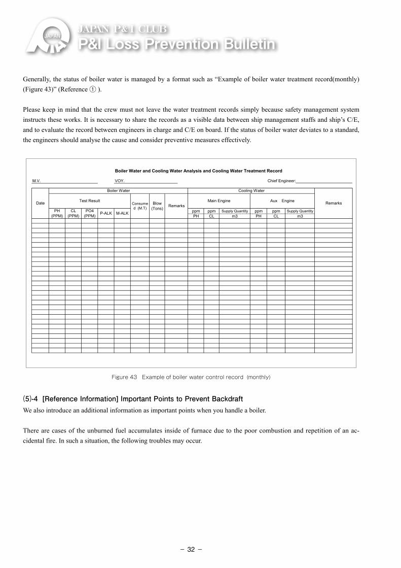
Generally, the status of boiler water is managed by a format such as “Example of boiler water treatment record(monthly) (Figure 43)” (Reference ① ).
Please keep in mind that the crew must not leave the water treatment records simply because safety management system instructs these works. It is necessary to share the records as a visible data between ship management staffs and ship’s C/E, and to evaluate the record between engineers in charge and C/E on board. If the status of boiler water deviates to a standard, the engineers should analyse the cause and consider preventive measures effectively.
Boiler Water and Cooling Water Analysis and Cooling Water Treatment Record
M.V. VOY.
ppm ppm Supply Quantity ppm ppm Supply QuantityPH CL m3 PH CL m3
Main Engine Aux Engine
PH(PPM)
CL(PPM)
PO4(PPM) P-ALK M-ALK
Chief Engineer:__________________________
Date
Boiler Water Cooling Water
RemarksTest ResultConsumed (M.T)
Blow(Tons) Remarks
Figure 43Figure 43 Example of boiler water control record (monthly)
(5)-4 [Reference Information] Important Points to Prevent BackdraftWe also introduce an additional information as important points when you handle a boiler.
There are cases of the unburned fuel accumulates inside of furnace due to the poor combustion and repetition of an ac-cidental fire. In such a situation, the following troubles may occur.
- 32-
JAPAN P& I CLUB
1 �When opening manholes to inspect inside of a furnace, as the backdraft occurs due to the explosive combustion when a large amount of air entered in to the furnace..
2 �During re-ignition, the boiler itself exploded, and the crew who are starting the
inspection and standing nearby around the burner set place will be died or have serious injured. So we have to send the crew from ship to shore by an emergency transportation
We must give a keen attention to the following points as the backdraft prevention.
⃝ ��On the operation side, the crew must inspect condition after post-purge inside of furnace manually when an accidental fire happens, and must not repeat the re-ignition automatically. The crew who open the cover of combustion devices must implement this action in a position where they can completely avoid the front cover (dodging).
⃝ �On the maintenance side, please carry out inspection and maintenance regularly. Its purpose is that solenoid valves for fuel and burners can work and operate normally and properly without an accidental fire.
2.2.2 Harbour Facilities Claims (Damage to Submarine Cable): Main Engine Start Failure
(1) Outline
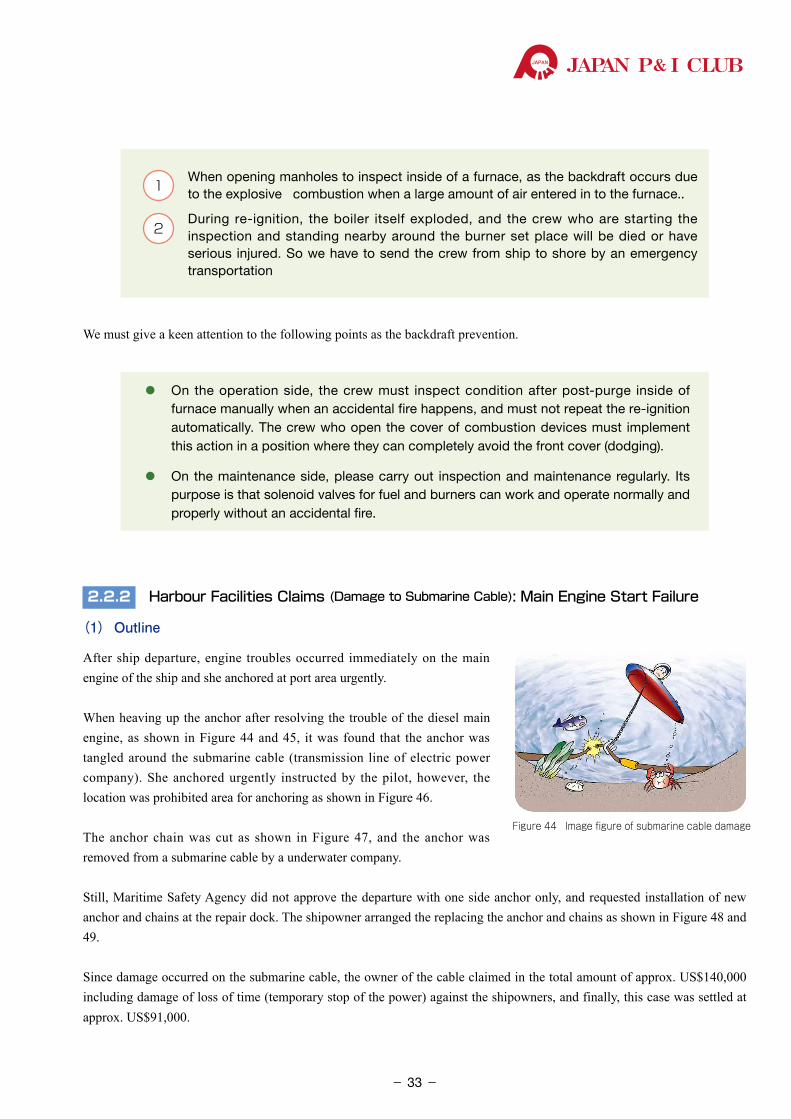
After ship departure, engine troubles occurred immediately on the main engine of the ship and she anchored at port area urgently.
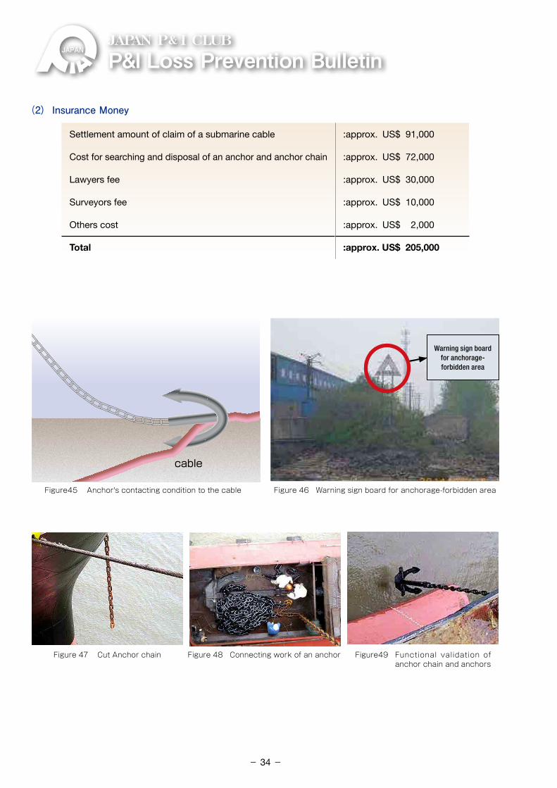
When heaving up the anchor after resolving the trouble of the diesel main engine, as shown in Figure 44 and 45, it was found that the anchor was tangled around the submarine cable (transmission line of electric power company). She anchored urgently instructed by the pilot, however, the location was prohibited area for anchoring as shown in Figure 46.
The anchor chain was cut as shown in Figure 47, and the anchor was removed from a submarine cable by a underwater company.
Still, Maritime Safety Agency did not approve the departure with one side anchor only, and requested installation of new anchor and chains at the repair dock. The shipowner arranged the replacing the anchor and chains as shown in Figure 48 and 49.
Since damage occurred on the submarine cable, the owner of the cable claimed in the total amount of approx. US$140,000 including damage of loss of time (temporary stop of the power) against the shipowners, and finally, this case was settled at approx. US$91,000.
Figure 44 Image figure of submarine cable damage
- 33-
P&ILossPreventionBulletinJAPAN P& I CLUB
cable
Figure45 Anchor's contacting condition to the cable
Figure 47 Cut Anchor chain Figure 48 Connecting work of an anchor Figure49 Functional validation of anchor chain and anchors
Figure 46 Warning sign board for anchorage-forbidden area
Warning sign board for anchorage-forbidden area
(2) Insurance Money
Settlement amount of claim of a submarine cable :approx. US$ 91,000
Cost for searching and disposal of an anchor and anchor chain :approx. US$ 72,000
Lawyers fee :approx. US$ 30,000
Surveyors fee :approx. US$ 10,000
Others cost :approx. US$ 2,000
Total :approx. US$ 205,000
- 34-
JAPAN P& I CLUB
(3) What Happened in the Engine Room?
1
The engine department carried out repairing of the main engine while her port staying. So before its port stay, the main engine fuel oil system was switched from HFO to MDO. After completion of maintenance works, the engineers conducted the main engine inspection before departure as usual, and confirmed it in good operation by conducting “Ahead/Astern” for the main engine trial run using MDO. After this, according to the instruction from Bridge, the engine department made the status of the main engine to the standby (hereinafter “S/B”).
2
Then at 15 minutes after S/B, C/E instructed a third engineer (described below as 3/E) to change the setting temperature of the fuel oil heating controller to 90℃ . And then, C/E also instructed 3/E to switch the fuel oil from MDO to HFO during leaving port operation under the maneuvering mode of main engine operation. The status of the engine was, as indicated above, S/B status. Since the ship had already departed, the control position of the main engine was on the bridge.
3After putting S/B engine, there are no engine order during this 15 minutes, then the main engine telegraph was operated at Dead Slow Ahead on the bridge, but it failed to start the main engine. At the time, fuel oil temperature had reached 100℃ .
4
After the emergency anchoring, the following work was conducted, and finished the recovery work of the engine. Then it was back to normal service.
⃝ �After stopping the fuel oil supply pump and fuel oil circulation pump, and etc., and lowering the temperature of fuel oil system, the heated MDO was discharged from the fuel oil system, and new cool MDO was refilled afresh.
⃝ �After that, related auxiliary machinery are re-started and re-operated for engine preparation, and when the main engine was tried to re-start , the crew could confirm it in good operation.
(4) Cause Analysis - - - Check Point
(4)-1 [Check from the view of Operation Side (Operation management)]In terms of operation, the check points are as follows.
① Instruction of Changing Fuel Oil Temperature Setting to 90℃
The change of temperature setting of fuel oil was carried out on the basis of fuel switching procedure at the time of departure. However, the adjustments based on the status monitoring was not conducted during the operation.
Originally, fuel oil in the system must be adjusted properly depending on the condition, such as transition of consump-tion, temperature and viscosity of fuel oil. Its purpose is that it can maintain the manufacturer recommended fuel viscosity range at engine inlet.
② Timing of Switching Fuel OilIt was too long from "changing temperature setting of fuel" to "starting operation of the main engine" because there is an idling S/B duration of No operation of the main engine under the departure ship maneuvering operation. We will explain the reason why the main engine didn’t work at First Starting Order from the bridge. We will explain in the system review later, however, it was estimated that MDO was vaporised in fuel oil supply pipe, so there were not enough liquid fuel oil for continuous operation in the pipe at first starting order of diesel main engine. That is, the situation in the pipe was occupied with the mixed oil and gas.Essentially, it is important for crew to consider avoiding the incorrect timing of continuous usage of the main engine when changing the fuel oil temperature setting and switching of fuel oil. Before departure, master and C/E must share the information such as timing of continuous usage of the main engine well in advance from the view of the resource management of this ship (Vessel Resource Management). And during S/B, an engine control room must communicate a bridge well. At the same time, the engine department at the engine control room also can intercept the transceiver
- 35-
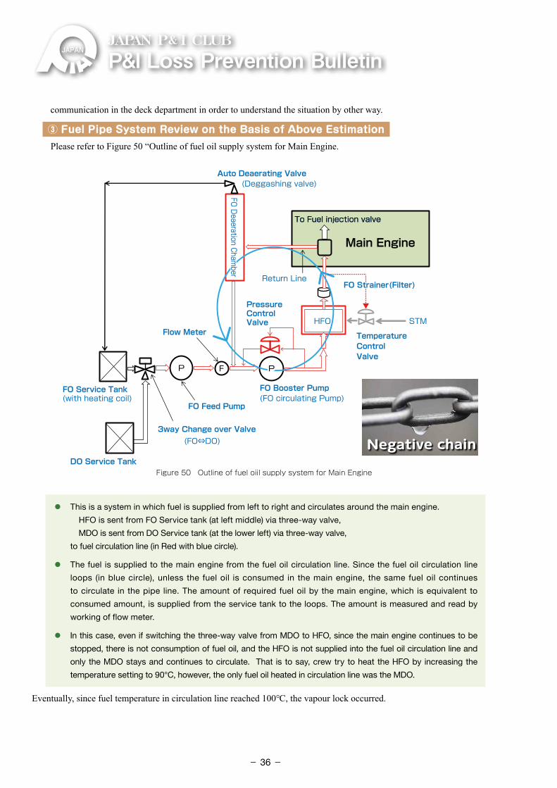
P&ILossPreventionBulletinJAPAN P& I CLUB
communication in the deck department in order to understand the situation by other way.
③ Fuel Pipe System Review on the Basis of Above Estimation Please refer to Figure 50 “Outline of fuel oil supply system for Main Engine.
Fuel Injection Pump
Figure 50 Outline of fuel oiil supply system for Main Engine
Auto Deaerating ValveAuto Deaerating Valve(Deggashing valve)(Deggashing valve)
To Fuel injection valve To Fuel injection valve
Return LineReturn Line
Pressure ControlValve
Pressure ControlValve STMSTM
TemperatureControlValve
TemperatureControlValve
Flow MeterFlow Meter
3way Change over Valve3way Change over Valve(FO⇔DO)(FO⇔DO)
F
FO Service Tank(with heating coil)FO Service Tank(with heating coil)
DO Service Tank DO Service Tank
FO Feed PumpFO Feed Pump
FO Booster Pump(FO circulating Pump)FO Booster Pump(FO circulating Pump)
FO Strainer(Filter)FO Strainer(Filter)
Main Engine
HFOHFOFO Deaeration Cham
berFO Deaeration Cham
ber
⃝ �This is a system in which fuel is supplied from left to right and circulates around the main engine.
HFO is sent from FO Service tank (at left middle) via three-way valve,
MDO is sent from DO Service tank (at the lower left) via three-way valve,
to fuel circulation line (in Red with blue circle).
⃝ �The fuel is supplied to the main engine from the fuel oil circulation line. Since the fuel oil circulation line
loops (in blue circle), unless the fuel oil is consumed in the main engine, the same fuel oil continues
to circulate in the pipe line. The amount of required fuel oil by the main engine, which is equivalent to
consumed amount, is supplied from the service tank to the loops. The amount is measured and read by
working of flow meter.
⃝ �In this case, even if switching the three-way valve from MDO to HFO, since the main engine continues to be
stopped, there is not consumption of fuel oil, and the HFO is not supplied into the fuel oil circulation line and
only the MDO stays and continues to circulate. That is to say, crew try to heat the HFO by increasing the
temperature setting to 90°C, however, the only fuel oil heated in circulation line was the MDO.
Eventually, since fuel temperature in circulation line reached 100℃, the vapour lock occurred.
Negative chain
- 36-
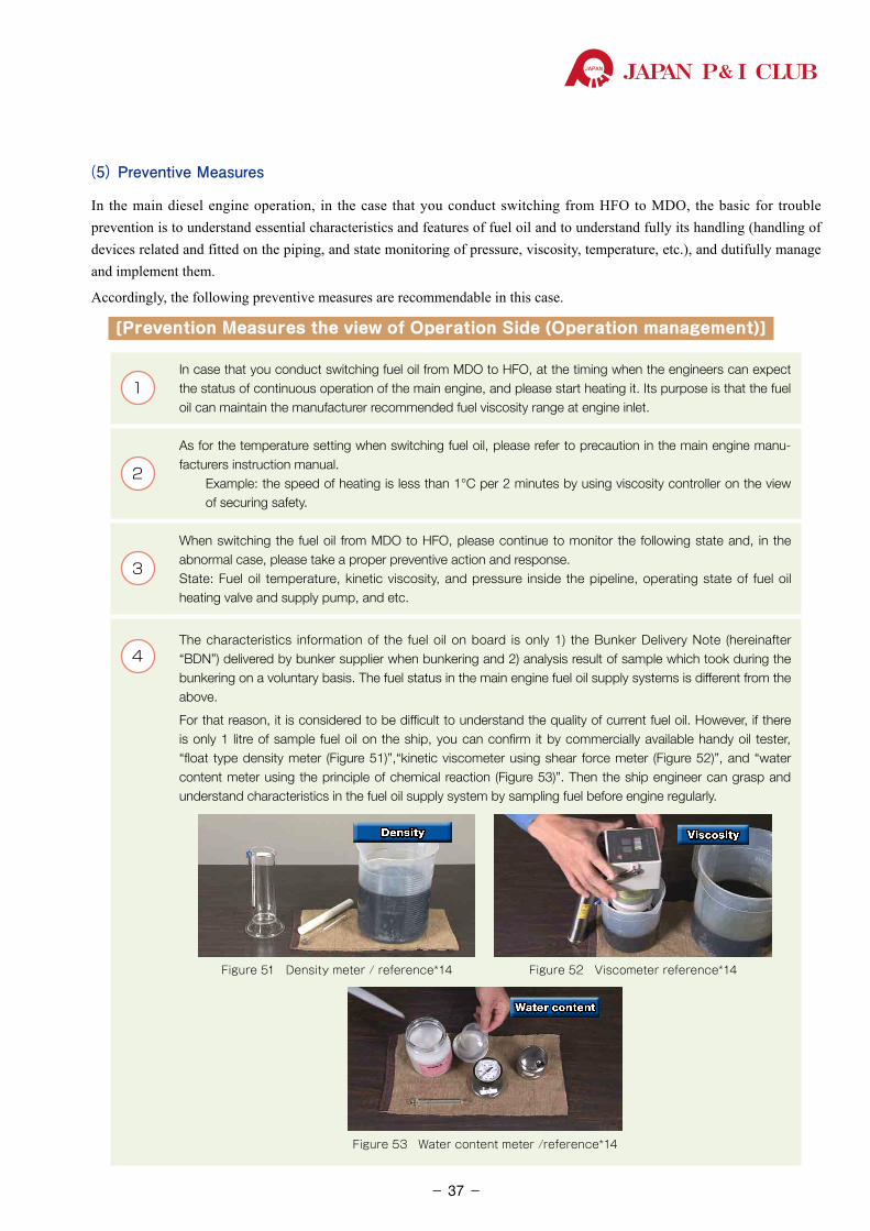
JAPAN P& I CLUB
(5) Preventive Measures
In the main diesel engine operation, in the case that you conduct switching from HFO to MDO, the basic for trouble prevention is to understand essential characteristics and features of fuel oil and to understand fully its handling (handling of devices related and fitted on the piping, and state monitoring of pressure, viscosity, temperature, etc.), and dutifully manage and implement them.
Accordingly, the following preventive measures are recommendable in this case.
[Prevention Measures the view of Operation Side (Operation management)]
1In case that you conduct switching fuel oil from MDO to HFO, at the timing when the engineers can expect the status of continuous operation of the main engine, and please start heating it. Its purpose is that the fuel oil can maintain the manufacturer recommended fuel viscosity range at engine inlet.
2
As for the temperature setting when switching fuel oil, please refer to precaution in the main engine manu-facturers instruction manual. �Example: the speed of heating is less than 1°C per 2 minutes by using viscosity controller on the view
of securing safety.
3
When switching the fuel oil from MDO to HFO, please continue to monitor the following state and, in the abnormal case, please take a proper preventive action and response.State: Fuel oil temperature, kinetic viscosity, and pressure inside the pipeline, operating state of fuel oil heating valve and supply pump, and etc.
4 The characteristics information of the fuel oil on board is only 1) the Bunker Delivery Note (hereinafter “BDN”) delivered by bunker supplier when bunkering and 2) analysis result of sample which took during the bunkering on a voluntary basis. The fuel status in the main engine fuel oil supply systems is different from the above.
For that reason, it is considered to be difficult to understand the quality of current fuel oil. However, if there is only 1 litre of sample fuel oil on the ship, you can confirm it by commercially available handy oil tester, “float type density meter (Figure 51)”,“kinetic viscometer using shear force meter (Figure 52)”, and “water content meter using the principle of chemical reaction (Figure 53)”. Then the ship engineer can grasp and understand characteristics in the fuel oil supply system by sampling fuel before engine regularly.
Figure 51 Density meter / reference*14 Figure 52 Viscometer reference*14
Figure 53 Water content meter /reference*14
Density Viscosity
Water content
- 37-
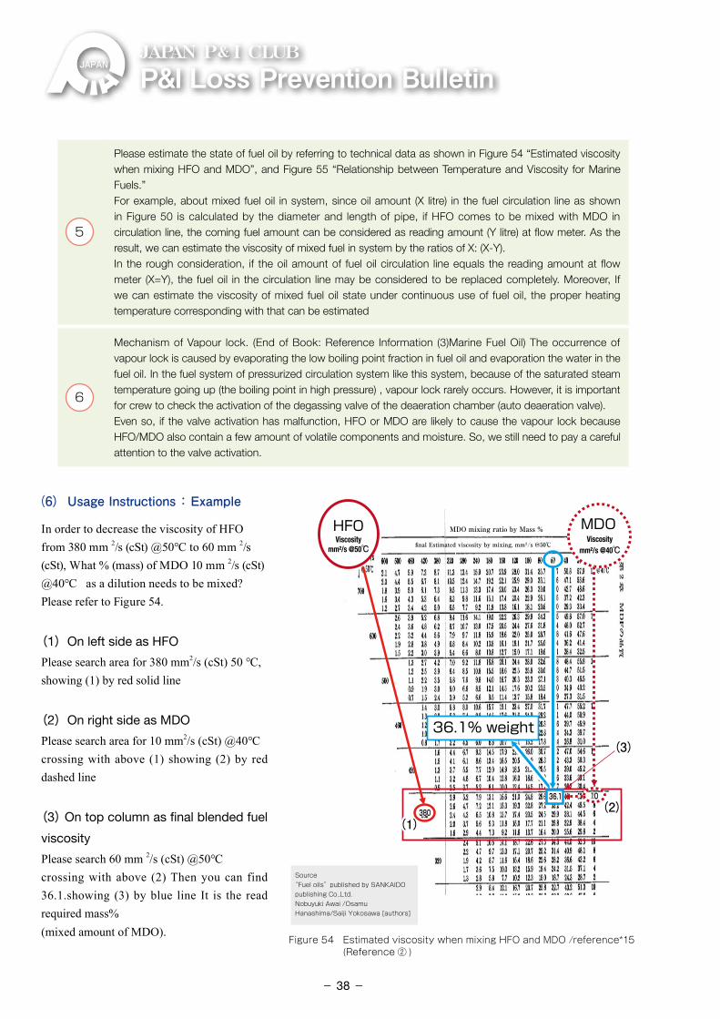
P&ILossPreventionBulletinJAPAN P& I CLUB
5
Please estimate the state of fuel oil by referring to technical data as shown in Figure 54 “Estimated viscosity when mixing HFO and MDO”, and Figure 55 “Relationship between Temperature and Viscosity for Marine Fuels.”For example, about mixed fuel oil in system, since oil amount (X litre) in the fuel circulation line as shown in Figure 50 is calculated by the diameter and length of pipe, if HFO comes to be mixed with MDO in circulation line, the coming fuel amount can be considered as reading amount (Y litre) at flow meter. As the result, we can estimate the viscosity of mixed fuel in system by the ratios of X: (X-Y).In the rough consideration, if the oil amount of fuel oil circulation line equals the reading amount at flow meter (X=Y), the fuel oil in the circulation line may be considered to be replaced completely. Moreover, If we can estimate the viscosity of mixed fuel oil state under continuous use of fuel oil, the proper heating temperature corresponding with that can be estimated
6
Mechanism of Vapour lock. (End of Book: Reference Information (3)Marine Fuel Oil) The occurrence of vapour lock is caused by evaporating the low boiling point fraction in fuel oil and evaporation the water in the fuel oil. In the fuel system of pressurized circulation system like this system, because of the saturated steam temperature going up (the boiling point in high pressure) , vapour lock rarely occurs. However, it is important for crew to check the activation of the degassing valve of the deaeration chamber (auto deaeration valve). Even so, if the valve activation has malfunction, HFO or MDO are likely to cause the vapour lock because HFO/MDO also contain a few amount of volatile components and moisture. So, we still need to pay a careful attention to the valve activation.
(6) Usage Instructions : Example
In order to decrease the viscosity of HFO from 380 mm 2/s (cSt) @50℃ to 60 mm 2/s (cSt), What % (mass) of MDO 10 mm 2/s (cSt) @40℃ as a dilution needs to be mixed?Please refer to Figure 54.
(1)On left side as HFO
Please search area for 380 mm2/s (cSt) 50 ℃, showing (1) by red solid line
(2)On right side as MDO
Please search area for 10 mm2/s (cSt) @40℃crossing with above (1) showing (2) by red dashed line
(3) On top column as final blended fuel
viscosity
Please search 60 mm 2/s (cSt) @50℃crossing with above (2) Then you can find 36.1.showing (3) by blue line It is the read required mass%(mixed amount of MDO).
36.1% weight
(2)(2)
(3)(3)
36.136.1 1010
380380(1)(1)
MDOMDOHFOHFO
Source“Fuel oils”published by SANKAIDO publishing Co.,Ltd.Nobuyuki Awai /Osamu Hanashima/Saiji Yokosawa [authors]
MDO mixing ratio by Mass %
final Estimated viscosity by mixing, mm²/s @50℃Viscosity
mm²/s @50℃Viscosity
mm²/s @40℃
Figure 54 Estimated viscosity when mixing HFO and MDO /reference*15 (Reference ② )
- 38-
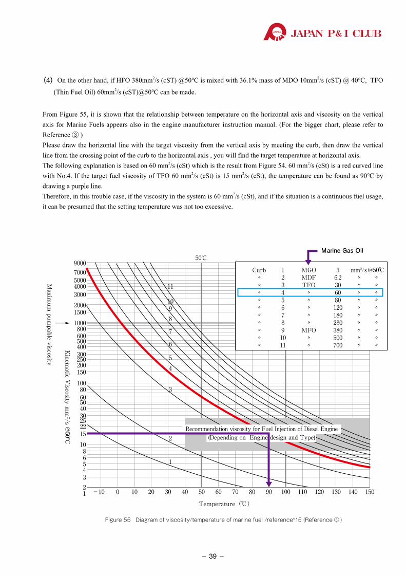
JAPAN P& I CLUB
(4) On the other hand, if HFO 380mm2/s (cST) @50℃ is mixed with 36.1% mass of MDO 10mm2/s (cST) @ 40℃, TFO
(Thin Fuel Oil) 60mm2/s (cST)@50℃ can be made.
From Figure 55, it is shown that the relationship between temperature on the horizontal axis and viscosity on the vertical axis for Marine Fuels appears also in the engine manufacturer instruction manual. (For the bigger chart, please refer to Reference ③ )Please draw the horizontal line with the target viscosity from the vertical axis by meeting the curb, then draw the vertical line from the crossing point of the curb to the horizontal axis , you will find the target temperature at horizontal axis.The following explanation is based on 60 mm2/s (cSt) which is the result from Figure 54. 60 mm2/s (cSt) is a red curved line with No.4. If the target fuel viscosity of TFO 60 mm2/s (cSt) is 15 mm2/s (cSt), the temperature can be found as 90℃ by drawing a purple line. Therefore, in this trouble case, if the viscosity in the system is 60 mm2/s (cSt), and if the situation is a continuous fuel usage, it can be presumed that the setting temperature was not too excessive.
-10 01234568
101522253040
6050
80100
150200300400500600800
1000
Maxim
um pum
pable viscosity
1500200030004000500070009000
50℃Marine Gas Oil
250
10 20 30 40
1
3
45
6
7
8910
11
50 60
Temperature(℃)
70 80 90 100 110 120 130 140 150
→
Kinem
atic Viscosity m
m²/s @
50°C
Curb 1 MGO 3 mm2/s @50℃ 〃 2 MDF 6.2 〃 〃 〃 3 TFO 30 〃 〃 〃 4 〃 60 〃 〃 〃 5 〃 80 〃 〃 〃 6 〃 120 〃 〃 〃 7 〃 180 〃 〃 〃 8 〃 280 〃 〃 〃 9 MFO 380 〃 〃 〃 10 〃 500 〃 〃 〃 11 〃 700 〃 〃
2Recommendation viscosity for Fuel Injection of Diesel Engine
(Depending on Engine design and Type)
Figure 55 Diagram of viscosity/temperature of marine fuel /reference*15 (Reference ③ )
- 39-
P&ILossPreventionBulletinJAPAN P& I CLUB
2.2.3 Cargo Claims: Unable to Re-start Generators (Blackout)
(1) Outline
The vessel loaded approx. 2,100 containers, including 23 reefer containers, in the Far East. The power failure (hereinafter "blackout") occurred at the point of approx. 900 miles to the west of Los Angeles while heading for Panama.
The crews tried to re-start generators but failed to do so. A rescue company was to tow the vessel to Los Angeles. The ship must wait for the black out power recovery for 21 days. Moreover, the fact that the reefer containers loading foods and etc. were unable to get power supply brought about cargo damage after the blackout occurred.
Many of the reefer containers became the total loss. The cargo interests claimed the cargo damage which was equivalent 16 containers in the amount of approx. US$1.6 million against shipowners. Finally, this claim settled at US$645,000.
(2) Insurance Money
Settlement Amount of Cargo Claim : approx. US$ 645,000
Lawyers fees : approx. US$ 200,000
Surveyors fees : approx. US$ 35,000
Total : approx.US$ 880,000
(3) What Happened in the Engine Room?
1
The Situation of Generators OperationThe vessel had four generators (hereinafter referred to as GE). During navigating, No.3 GE and No.4 GE were operated in parallel, and HFO was used as fuel oil.Stand-by GE (hereinafter “S/B”) had HFO circulation status; No1. GE was to be the first S/B and No.2 GE was to be the second S/B.
2
The Emergency Stop of No.4 GENo.4 GE emergently stopped.No.1 GE and No.2 GE, which were in S/B status, were to be started automatically, but they could not start them.
3The Close Failure for the Air Circuit-breaker of No.1 GECrews manually started No.1 GE at once. However, they failed to close the air circuit-breaker (hereinafter “ACB”).
4The Emergency Stop of No.3 GE Afterwards, No.3 GE also emergently stopped.In addition, 1 minute later, No.1 GE immediately stopped as well.
5Strainer InspectionIn order to find out the cause, they checked oil strainer of fuel supply pipeline, but the abnormality was not found.
- 40-
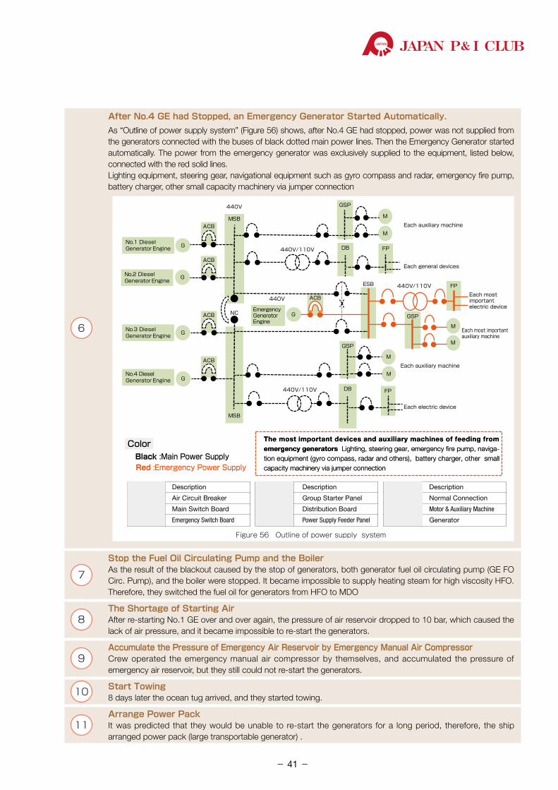
JAPAN P& I CLUB
6
After No.4 GE had Stopped, an Emergency Generator Started Automatically.As “Outline of power supply system” (Figure 56) shows, after No.4 GE had stopped, power was not supplied from the generators connected with the buses of black dotted main power lines. Then the Emergency Generator started automatically. The power from the emergency generator was exclusively supplied to the equipment, listed below, connected with the red solid lines.Lighting equipment, steering gear, navigational equipment such as gyro compass and radar, emergency fire pump, battery charger, other small capacity machinery via jumper connection
440V
440V/110V
Each general devices
Each auxiliary machine
ESB 440V/110V
440VEach mostimportant electric device
NC
Each most important auxiliary machine
440V/110V
Each electric device
Each auxiliary machine
Figure 56 Outline of power supply system
ACB
ACB
ACB
GSP
FP
FPDB
MSB
MSB
G
G
G
G
ACB
M
EmergencyGeneratorEngine
G
ACB
FPDB
M
GSP
M
M
GSP
M
M
No.4 Diesel Generator Engine
Black :Main Power Supply
No.3 Diesel Generator Engine
No.2 Diesel Generator Engine
No.1 Diesel Generator Engine
The most important devices and auxiliary machines of feeding from emergency generators Lighting, steering gear, emergency fire pump, naviga-tion equipment (gyro compass, radar and others), battery charger, other small capacity machinery via jumper connection
The most important devices and auxiliary machines of feeding from emergency generators Lighting, steering gear, emergency fire pump, naviga-tion equipment (gyro compass, radar and others), battery charger, other small capacity machinery via jumper connection
Color
Red :Emergency Power Supply
Description
Air Circuit Breaker
Main Switch Board
Emergency Switch Board
Abbreviation
ACB
MSB
ESB
Abbreviation Description
Group Starter PanelGSP
Description
Normal Connection
Motor & Auxiliary Machine
Generator
NC
M
G
DB
FP
Distribution Board
Power Supply Feeder Panel
Abbreviation
7
Stop the Fuel Oil Circulating Pump and the BoilerAs the result of the blackout caused by the stop of generators, both generator fuel oil circulating pump (GE FO Circ. Pump), and the boiler were stopped. It became impossible to supply heating steam for high viscosity HFO. Therefore, they switched the fuel oil for generators from HFO to MDO
8The Shortage of Starting AirAfter re-starting No.1 GE over and over again, the pressure of air reservoir dropped to 10 bar, which caused the lack of air pressure, and it became impossible to re-start the generators.
9Accumulate the Pressure of Emergency Air Reservoir by Emergency Manual Air CompressorCrew operated the emergency manual air compressor by themselves, and accumulated the pressure of emergency air reservoir, but they still could not re-start the generators.
10 Start Towing 8 days later the ocean tug arrived, and they started towing.
11Arrange Power PackIt was predicted that they would be unable to re-start the generators for a long period, therefore, the ship arranged power pack (large transportable generator) .
- 41-
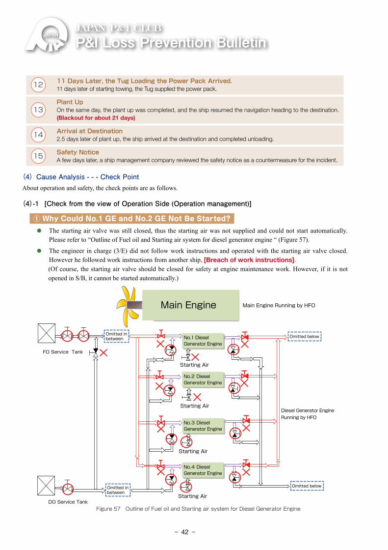
P&ILossPreventionBulletinJAPAN P& I CLUB
12 11 Days Later, the Tug Loading the Power Pack Arrived.11 days later of starting towing, the Tug supplied the power pack.
13Plant Up On the same day, the plant up was completed, and the ship resumed the navigation heading to the destination. (Blackout for about 21 days)
14 Arrival at Destination2.5 days later of plant up, the ship arrived at the destination and completed unloading.
15 Safety NoticeA few days later, a ship management company reviewed the safety notice as a countermeasure for the incident.
(4) Cause Analysis - - - Check PointAbout operation and safety, the check points are as follows.
(4)-1 [Check from the view of Operation Side (Operation management)]
① Why Could No.1 GE and No.2 GE Not Be Started?
⃝ The starting air valve was still closed, thus the starting air was not supplied and could not start automatically. Please refer to “Outline of Fuel oil and Starting air system for diesel generator engine “ (Figure 57).
⃝ The engineer in charge (3/E) did not follow work instructions and operated with the starting air valve closed. However he followed work instructions from another ship, [Breach of work instructions].
�(Of course, the starting air valve should be closed for safety at engine maintenance work. However, if it is not opened in S/B, it cannot be started automatically.)
Main Engine
Omitted inbetween
Omitted inbetween
Omitted below
Omitted below
Starting Air
Starting Air
Starting Air
Starting Air
Figure 57 Outline of Fuel oil and Starting air system for Diesel Generator Engine
FO Service Tank
Diesel Generator EngineRunning by HFO
Main Engine Running by HFO
No.4 Diesel Generator Engine
No.3 Diesel Generator Engine
No.2 Diesel Generator Engine
No.1 Diesel Generator Engine
DO Service Tank
- 42-
JAPAN P& I CLUB
② Why Did Crews Fail to Re-start the Generators Over and Over Again?
⃝ Crew repeated re-starting without finding the cause of the starting failure for the generators, ⃝ After the blackout, the HFO heating steam could not be supplied from the boiler, and the fluidity of HFO in the
pipeline for generator fuel supply became low. As the result, the fuel oil supply pipeline was clogged. ⃝ In other words, the crew made incorrect procedure of the changing fuel oil for the generator from HFO to MDO.
③ Why Did the Air Reservoir Become Empty?
⃝ According to the work instructions, during a normal voyage, there are two delivery valves fitted on the air reservoirs, and only one should be opened and the other should be closed to be used for preparation. However, both of them were left open when the accident occurred. [Breach of work instructions]
⃝ Since the crew repeated the re-starting operation with opening the delivery valves of both two air reservoirs, the pressure of the two air reservoirs are lost at the same time.
(4)-2 [Check from the view of Safety Instruction and Safety Notice]① Why Could No.1 GE and No.2 GE Not be Started?
⃝ The engineer in charge (3/E) did not follow the work instructions, and the starting air valve of the S/B generator was still closed. [Breach of work instructions]
② Why Did They Fail to Re-start the Generators Over and Over Again?
⃝ Crew did not understand the recovery procedure from the cold condition of engine system. (Blackout recovery drill was not carried out)
③ Was the Safety Notice Issued by the Ship Management Company Later Appropriate?
⃝ The safety notice was just warning against trouble due to close of starting air valve on S/B generator. There was no further instruction or reminder of the preventive measures based on root cause analysis.
Next, the following are the check points about the hardware.
(4)-2 [Check from the view of Hardware]
(4)-2-1 Maintenance System Management
① Maintenance System of Generators
⃝ We focus on the generator’s operating record, which is the relation between output and load indicator figure. At the trial operation before the ship delivery, the engine rated output 1,470kW and load indicator 8.6. But, the measurement record during a year before this incident was shown output 500kW, which was approx. 30% output, and load indicator to reach 10,
⃝ Moreover, in the process of investigation, worn-down plungers (parts for fuel pressurisation) were found when they opened and inspect the fuel injection pump of No.1 GE after this incident.
② Why Could Crew Not closed ACB?
⃝ Generally, ACB’s closed condition requires the establishment of generator engine speed, voltage and frequency. When these conditions are satisfied, ACB’s closed signal will transmit.
- 43-
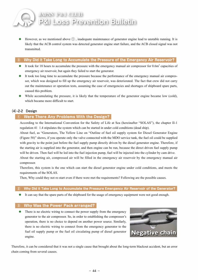
P&ILossPreventionBulletinJAPAN P& I CLUB
⃝ However, as we mentioned above ① , inadequate maintenance of generator engine lead to unstable running. It is likely that the ACB control system was detected generator engine start failure, and the ACB closed signal was not transmitted.
③ Why Did it Take Long to Accumulate the Pressure of the Emergency Air Reservoir?
⃝ It took for 18 hours to accumulate the pressure with the emergency manual air compressor for 0.6m2 capacities of emergency air reservoir, but again they failed to start the generator.
⃝ It took too long time to accumulate the pressure because the performance of the emergency manual air compres-sor, which was designed to fill up the emergency air reservoir, was deteriorated. The fact that crew did not carry out the maintenance or operation tests, assuming the case of emergencies and shortages of shipboard spare parts, caused this problem.
⃝ While accumulating the pressure, it is likely that the temperature of the generator engine became low (cold), which became more difficult to start.
(4)-2-2 Design① Were There Any Problems With the Design?
According to the International Convention for the Safety of Life at Sea (hereinafter “SOLAS”), the chapter II-1 regulation 41 1.4 stipulates the system which can be started in under cold conditions (dead ship).About fuel, as “Generators, The Yellow Line on “Outline of fuel oil supply system for Diesel Generator Engine (Figure 58)” shows, if you operate only the valve connected with the MDO service tank, the fuel oil could be supplied with gravity to the point just before the fuel supply pump directly driven by the diesel generator engine. Therefore, if the starting air is supplied into the generator, and then engine can be run, because the direct driven fuel supply pump will be driven. Then fuel will be led into the fuel injection pump, fuel will be injected into the cylinder by cam drive.About the starting air, compressed air will be filled in the emergency air reservoir by the emergency manual air compressor.Therefore, this system is the one which can start the diesel generator engine under cold conditions, and meets the requirements of the SOLAS.Then, Why could they not re-start even if there were met the requirements? Following are the possible causes.
② Why Did it Take Long to Accumulate the Pressure Emergency Air Reservoir of the Generator?
⃝ It can say that the spare parts of the shipboard for the usage of emergency equipment were not good enough.
③ Why Was the Power Pack arranged?
⃝ There is no electric wiring to connect the power supply from the emergency generator to the air compressor. So, in order to establishing the compressor’s operation, there is no choice to depend on another power source. Similarly, there is no electric wiring to connect from the emergency generator to the fuel oil supply pump or the fuel oil circulating pump of diesel generator engine.
Therefore, it can be considered that it was not a single cause that brought about the long-term blackout accident, but an error chain coming from several causes.
Negative chain
- 44-
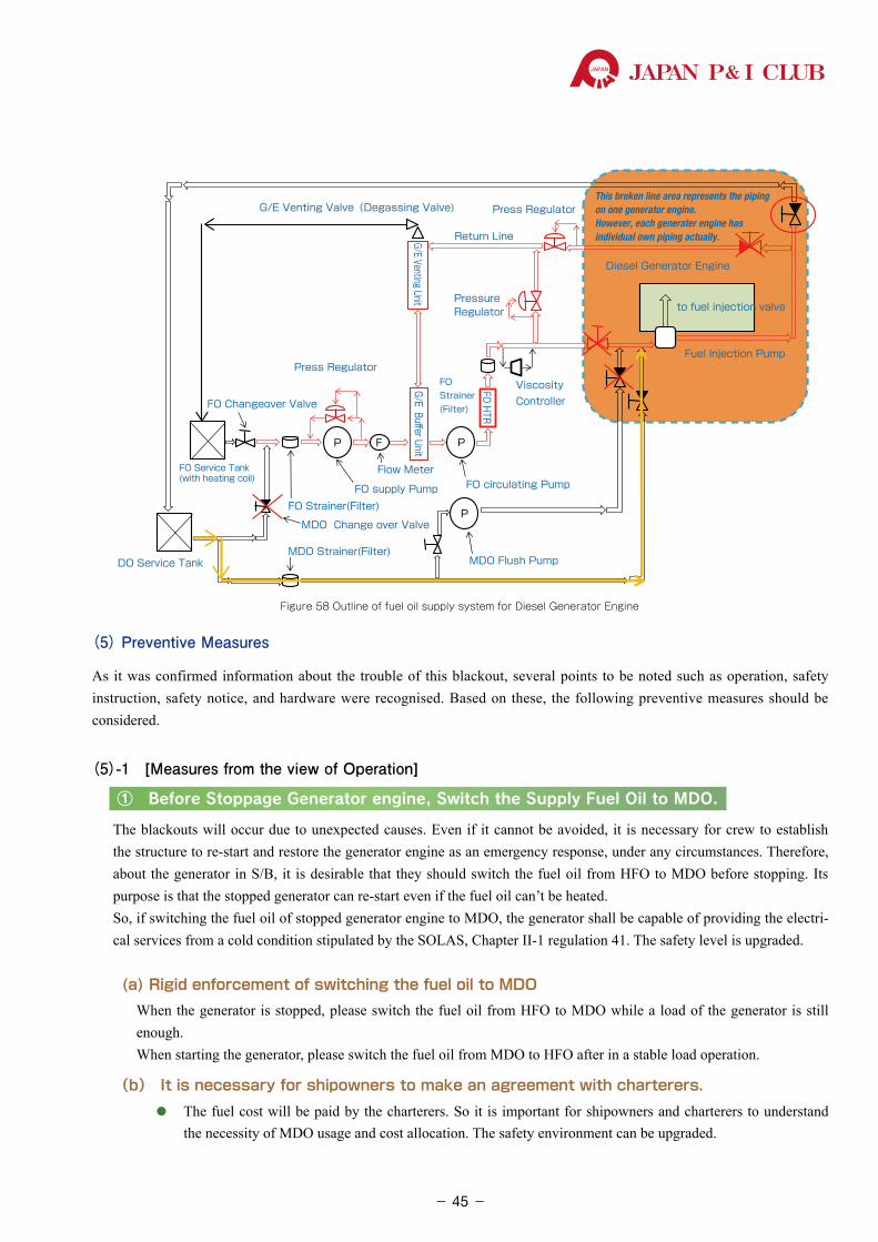
JAPAN P& I CLUB
(5) Preventive Measures
As it was confirmed information about the trouble of this blackout, several points to be noted such as operation, safety instruction, safety notice, and hardware were recognised. Based on these, the following preventive measures should be considered.
(5)-1 [Measures from the view of Operation]
① Before Stoppage Generator engine, Switch the Supply Fuel Oil to MDO.
The blackouts will occur due to unexpected causes. Even if it cannot be avoided, it is necessary for crew to establish the structure to re-start and restore the generator engine as an emergency response, under any circumstances. Therefore, about the generator in S/B, it is desirable that they should switch the fuel oil from HFO to MDO before stopping. Its purpose is that the stopped generator can re-start even if the fuel oil can’t be heated.So, if switching the fuel oil of stopped generator engine to MDO, the generator shall be capable of providing the electri-cal services from a cold condition stipulated by the SOLAS, Chapter II-1 regulation 41. The safety level is upgraded.
(a) Rigid enforcement of switching the fuel oil to MDO When the generator is stopped, please switch the fuel oil from HFO to MDO while a load of the generator is still
enough. When starting the generator, please switch the fuel oil from MDO to HFO after in a stable load operation.
(b) It is necessary for shipowners to make an agreement with charterers.
⃝ The fuel cost will be paid by the charterers. So it is important for shipowners and charterers to understand the necessity of MDO usage and cost allocation. The safety environment can be upgraded.
PP F
P
G/E Venting Valve(Degassing Valve)
ViscosityController
FOStrainer(Filter)
DO Service Tank
FO Service Tank(with heating coil)
MDO Change over Valve
FO supply Pump
FO Changeover Valve
Diesel Generator Engine
FO Strainer(Filter)
PressureRegulator
Press Regulator
Press Regulator
Flow Meter
Fuel Injection Pump
to fuel injection valve
Return Line
FO circulating Pump
G/E Buffer UnitG/E Venting Unit
FO HTR
MDO Flush PumpMDO Strainer(Filter)
Figure 58 Outline of fuel oil supply system for Diesel Generator Engine
This broken line area represents the piping on one generator engine. However, each generater engine has individual own piping actually.
- 45-
P&ILossPreventionBulletinJAPAN P& I CLUB
⃝ For example, the MDO consumption will be increased approx. Q = 0.6 Mt of monthly under the following condition. Even if MDO is US$1,000 per Mt (metric tons), security levels will be upgraded greatly and precisely by approx. US$600.
The conditions are as follows: The number of starting and stopping the generator is 20 times in a month (stop: 10 times, start: 10 times). �The MDO is consumed during 15 minutes before stop load sharing, 15 minutes after starting and parallel
operation (if the load is 500 kW).�The average fuel consumption rate of generator is 220 g/kWh. The MDO’s consumption amount will be as follows;
Monthly Fuel Consumption (Q Mt/month) = 220 g/kWh × load 500 kW × (15 minutes/time × 20 times/month) = 220 g/kWh × load 500 kW × 5 Hr/month = 0.6 Mt/month
We recommend you to check the operation method or performance level of equipment installed on the each vessel again in order to conduct the simulation calculations precisely.
② Establish the Feasible Fuel Switching Instructions Firmly
⃝ As explained in the case of 2.2.2 Harbour Facilities Claims, it is important for crew to establish the switching instruc-tions firmly. At the same time, please understand the essential characteristics and features of each fuel oil type.
�For example, in case that intense pressure fluctuation occurs in the fuel supply pipeline during the switching operation, the gas may be generated in the line. It should remove the gas from a higher place in the line as much as possible. Its location is the air vent pipe of strainer or that of the fuel oil heater.
③ Understand Fuel Oil Characteristics and Manage Adequately
⃝ The fuel oil quality of the vessel was indicated on BDN delivered by the fuel oil supplier. However, there are some cases that the received fuel oil from several ports or supplier, which have different fuel oil characteristics, which is different from the state in the line or in the settling tank. Crew should understand that the characteristics is not always the same.
⃝ Therefore, it is important for crew to understand the fuel oil used in the vessel and analyse by using commercially available handy oil testers, shown from Figure 51 to 53. Its purpose is that it can examine at the site how to deal with it.
④ Manage Engine Operation Thoroughly to Meet Operation Status
⃝ The status of the engine plant will be different in each situation: the navigation, anchorage, and entering & departure of the port. So, you should manage the engine operation appropriately in each situation.
⃝ While S/B of entering or departure, the following equipment are operated. The electric consumption during S/B is more than that during the navigation. So during S/B, the multiple generator operation is required as below.
Engine Department: ⃝Auxiliary Blower used in main engine
Deck Department: ⃝ The Multiple Operation of Steering Gear Drive Equipment for the Improvement of control effectiveness
⃝ Mooring Arrangement (including Anchor Windlass),
⃝ Bow ThrusterOn the other hand, during navigation, number of generator is minimum.
- 46-
JAPAN P& I CLUB
⃝ For example, two generators were 30% of load. However, if the generator is fully maintained, one generator can manage enough with 60% of load. If you operate more generators than minimum, you should be careful because you must carry out more maintenance work.
⑤ Rigid Enforcement of Daily Check of S/B Generator and Correction of the Defect
⃝ C/E and 1/E also should do the following things as routine works:
(a) to check the engine room regularly,
(b) to understand the situation of S/B generator, and
(c) to check if the S/B generator is in a situation that can start automatically in an emergency.
In the case if abnormality is found, please correct it immediately and understand that it is important for all members of the engine department to share the information.
⃝ On the other hand, about the important valves which are conducted the following switching operations, it is important to put and arrange the sign plate. Its purpose is that it can recognise the situation (open and close) and easily detect the abnormality, starting air inlet valve, air reservoir discharge valve, the change-over valve of fuel supply pipeline, the air vent pipe of oil strainer and etc
(5)-2 [Measures from the view of Safety Instruction or Safety Notice]① Don’t breach Work Instructions (including the elements of safety instructions)
⃝ At the site, crew handle the engine operations based on the work instructions for maintenance or operation. Crew will get the maximum effect from the instructions if they fully understand the following points,.
(a)The meaning of each procedure described in the work instructions.
(b)The relationship between pipeline and equipment actuation
⃝ It is important for crew to make an effort to read between the lines of each work instructions during on-board training or study sessions on board. For example, crew should learn what problem will be occurred in the pipeline by switching from HFO to MDO.
⃝ If the work instructions do not fit for the truth, crew should consider the procedure to amend them with the reasonable verification. (Crew should not allow the shortcuts with the work instructions!)
② Carry Out Blackout Recovery Drill Regularly
⃝ About the plant-up from a cold condition of engine plant, its opportunity is limited only in the dry dock which is once every from 2.5 to 3 years.
��Even if crew make a few mistakes during restoring the procedure in the dock, it is possible to restore even if crew take time, except for a fire or an explosion.
⃝ Therefore, the crew, who don’t have work experience in the dock, sometimes fail to understand the recovery procedure of the power supply system precisely.
⃝ So, it is one of the options that crew carry out the blackout recovery by meaning of both the on-board training and the equipment work test during normal navigation.
⃝ There are some methods of the blackout recovery drill. One is to carry out drill by actually stopping the generators emergently. The other is to confirm and follow the recovery procedure by finger pointing & calling with allocating crew.
⃝ However, in the case of actually executing a blackout, it takes time to restore and may affect the vessel’s schedule. So shipowners is recommended to obtain the charterers’ permission just in case in advance.
- 47-
P&ILossPreventionBulletinJAPAN P& I CLUB
③ For Preventive measures, Include Lessons Learned Based on the Root Cause Analysis in the Safety Notice
⃝ The importance of safety notices based on the lessons learned have the purpose to confirm the facts firmly, clarify causes, and prevent the recurrence of similar troubles as well as finding out the superficial direct cause. The Management Company and shipowners should also immediately issue the effective safety notice by considering following matter,
(a) to analyse about the background of the root cause with getting support from the manufacturer.
(b) to clarify and share the preventive measures
⃝ The ship management company may sometimes cause crew misunderstanding that they find the person responsi-ble when confirming the facts of trouble
However, it is important for the company to collect the truth as much as possible with following pose
(a) first to clarify the purpose to establish preventive measures
(b) then to get the crew’s maximum cooperation
(c) finally to find out the root cause
(5)-3 [Measures from the view of Hardware]① Rigid Periodic Maintenance of Generator (including equipment for emergency)
⃝ It is basic for crew to follow the manufacturers’ instruction manual and to conduct the inspection and maintenance work regularly. Moreover, manufacturers give the updated service news which is the safety guide about how to maintain or deal with equipment, based on their lessons learned. Therefore, it is also necessary for the ship management company both to make efforts to collect the updated information from the manufacturer, and to establish the regime in which shore and ship are united.
⃝ Moreover, at this time, the emergency manual air compressor become deteriorated and then it interfered in early recovery. In order to use the emergency equipment precisely in any case as well as recovery drill described in above, crew should conduct the inspection and maintenance work of them. Its purpose is that the equipment will be operated as designed. It is also important to appropriately check spare parts, which have the risk of deteriorat-ing. If any of spare parts are no longer supplied, you should also arrange alternative spare parts for back-up.
(5)-4 [Recommendation] Consider the Architectural Design, from the Emergency Generator to the Equipment That Can Get Power Supply
1 �As the SOLAS, chapter II-1 regulation 41 1.4 indicates, the power generating equipment should have a system “to
be able to start under cold conditions”. Therefore, if it can supply MDO with gravity and fill the starting air reservoir by using the emergency manual air compressor, it meets the requirements surely.
2 �There was the fact that all the fuel oil pipelines were switched from HFO to MDO. However, at this time, in order to
restore the power, crew had to wait for the main air reservoir to be filled by the air compressor whose power was sup-plied by the power pack. The power pack was transported by the tug from shore.
3 �Therefore, emergency manual air compressor meets minimal required specifications. However, as you understand this
case, if crew forget to make its appropriate maintenance, it is vulnerable in the case of an emergency.
4 �On the other hand, during that time, the power supply to the emergency power system in the ship was maintained by
the normal operation of emergency generator.
5 �Therefore, it is one idea that you can put the air compressor with the direct driving of the handy diesel engine, or put
one that operates off another power source other than the main power, such as the power supply from the emergency generator, on emergency air reservoir.
6 �Similarly, it is also the idea that you put the air compressor, which makes handy diesel engine’s driving possible, or
makes power supply and driving from the emergency generator possible, on the regular air reservoir.
- 48-
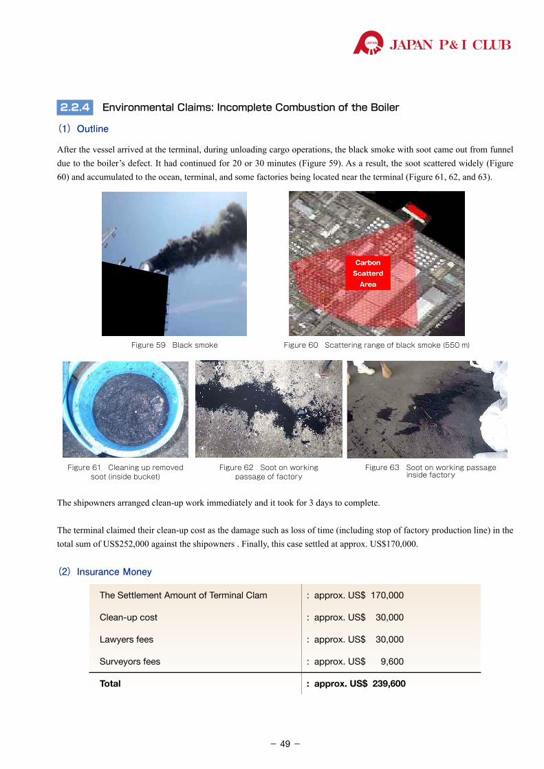
JAPAN P& I CLUB
2.2.4 Environmental Claims: Incomplete Combustion of the Boiler
(1)Outline
After the vessel arrived at the terminal, during unloading cargo operations, the black smoke with soot came out from funnel due to the boiler’s defect. It had continued for 20 or 30 minutes (Figure 59). As a result, the soot scattered widely (Figure 60) and accumulated to the ocean, terminal, and some factories being located near the terminal (Figure 61, 62, and 63).
Figure 61 Cleaning up removed soot (inside bucket)
Figure 62 Soot on working passage of factory
Figure 63 Soot on working passage inside factory
Figure 59 Black smoke Figure 60 Scattering range of black smoke (550 m)
The shipowners arranged clean-up work immediately and it took for 3 days to complete.
The terminal claimed their clean-up cost as the damage such as loss of time (including stop of factory production line) in the total sum of US$252,000 against the shipowners . Finally, this case settled at approx. US$170,000.
(2)Insurance Money
The Settlement Amount of Terminal Clam : approx. US$ 170,000
Clean-up cost : approx. US$ 30,000
Lawyers fees : approx. US$ 30,000
Surveyors fees : approx. US$ 9,600
Total : approx. US$ 239,600
- 49-
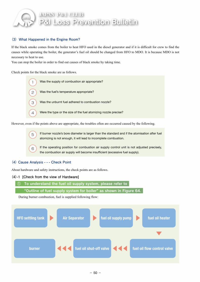
P&ILossPreventionBulletinJAPAN P& I CLUB
(3) What Happened in the Engine Room?
If the black smoke comes from the boiler to heat HFO used in the diesel generator and if it is difficult for crew to find the causes while operating the boiler, the generator’s fuel oil should be changed from HFO to MDO. It is because MDO is not necessary to heat to use.You can stop the boiler in order to find out causes of black smoke by taking time.
Check points for the black smoke are as follows.
1 Was the supply of combustion air appropriate?
2 �Was the fuel’s temperature appropriate?
3 Was the unburnt fuel adhered to combustion nozzle?
4 Were the type or the size of the fuel atomizing nozzle precise?
However, even if the points above are appropriate, the troubles often are occurred caused by the following.
5 �If burner nozzle’s bore diameter is larger than the standard and if the atomisation after fuel
atomizing is not enough, it will lead to incomplete combustion.
6 �If the operating position for combustion air supply control unit is not adjusted precisely,
the combustion air supply will become insufficient (excessive fuel supply).
(4) Cause Analysis - - - Check Point
About hardware and safety instructions, the check points are as follows.
(4)-1 [Check from the view of Hardware]
① To understand the fuel oil supply system, please refer to
“Outline of fuel supply system for boiler” as shown in Figure 64.
During burner combustion, fuel is supplied following flow:
HFO settling tank Air Separator fuel oil supply pump fuel oil heater
fuel oil shut-off valve fuel oil flow control valveburner
▶ ▶ ▶
▶▶▶▶▶▶▶
- 50-
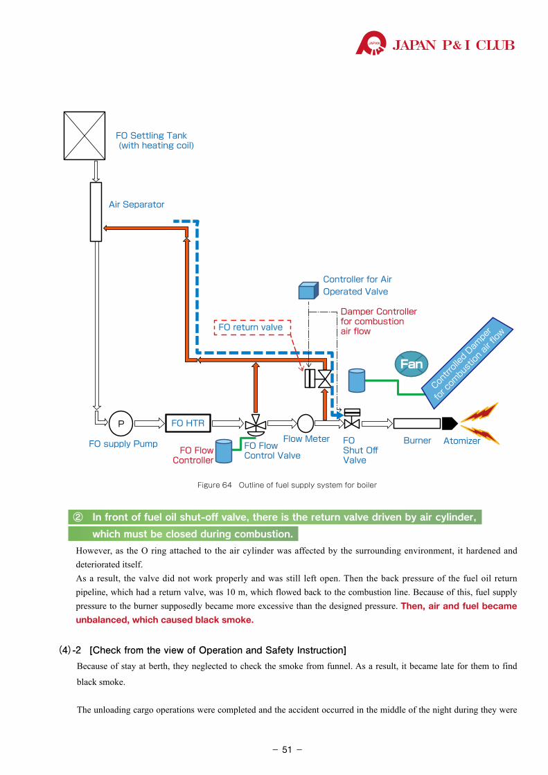
JAPAN P& I CLUB
P
FanFan
FO HTR
FO Settling Tank (with heating coil)
Air Separator
FO supply PumpFO Flow
Controller
FOShut OffValve
FO return valve
Burner Atomizer Con
trroll
ed D
ampe
r
for co
mbust
ion ai
r flow
Damper Controller for combustionair flow
Flow MeterFO FlowControl Valve
Controller for Air Operated Valve
Figure 64 Outline of fuel supply system for boiler
② In front of fuel oil shut-off valve, there is the return valve driven by air cylinder,
which must be closed during combustion.
However, as the O ring attached to the air cylinder was affected by the surrounding environment, it hardened and deteriorated itself.
As a result, the valve did not work properly and was still left open. Then the back pressure of the fuel oil return pipeline, which had a return valve, was 10 m, which flowed back to the combustion line. Because of this, fuel supply pressure to the burner supposedly became more excessive than the designed pressure. Then, air and fuel became unbalanced, which caused black smoke.
(4)-2 [Check from the view of Operation and Safety Instruction] Because of stay at berth, they neglected to check the smoke from funnel. As a result, it became late for them to find
black smoke.
The unloading cargo operations were completed and the accident occurred in the middle of the night during they were
- 51-
P&ILossPreventionBulletinJAPAN P& I CLUB
waiting for the sunrise to departure. So, the caution against black smoke emis-sion was not enough. Moreover, the engine department failed to the immediate response with black smoke. Thus the black smoke became one of the factors to make its emission prolonged.
�Like the 2.2.3 blackout accident, it can be considered that it was not a single cause that brought about the accident, but the error chain coming from several causes.
(5) Preventive MeasuresAs for the black smoke emission, it is confirmed the above check points to be careful about hardware and operation. Taking these into consideration, the following preventive measures are recommendable.
(5)-1 [Measures from the view of Hardware]
1 �It is necessary to carry out planned maintenance regularly and to establish a system of purchasing spare parts.
2 �Before arriving at the port, inspect the furnace or combustion-related equipment, and make them maintenance
if necessary. Afterwards, crew should do the ignition test & combustion trial.
3 �The following works are needed regularly based on the manufactures’ instruction,
(a) overhaul
(b) maintenance and inspection (including measurements).
If it has beyond the limit of usage, it is necessary to exchange it for a new one.
4 �After the maintenance of burner, it should be done ignition combustion trial. In doing the said trial, compare the current state of the operating parameter such as the temperature and pressure with that of sea trial. If crew find wide gap between them, they have to adjust it..
(5)-2 [Measures from the view of Operation and Safety Instructions]
1 �During staying alongside the terminal in port, both the watch person of the engine control room (ECR) and the watch person of the bridge should check and monitor the state of smoke emission coming from the funnel, and share information with each other.
Reference: In the terminal or the place where harbour regulations are strict, the ship equips CCTV for monitoring the smoke from ECR.
2 �It is necessary for crew to carry out the drill how to react immediately under following circumstances. For example, switching fuel oil for the generator engine from HFO to MDO where heating is unnecessary, and stopping the boiler, etc.. Of course, it may not be able to stop the boiler from time to time, due to loading the cargo heating is necessary. It is important to carry out the maintenance based on a long-term plan.
�The securing maintenance time is difficult in busy and limited operation period. So, it is important that ship and shore-side work together in such a way that the ship management department reports necessary information to the operations department. Its purpose is to arrange the system to secure the necessary time for maintenance to implement proper scheduled maintenance for accident prevention.
Negative chain
- 52-
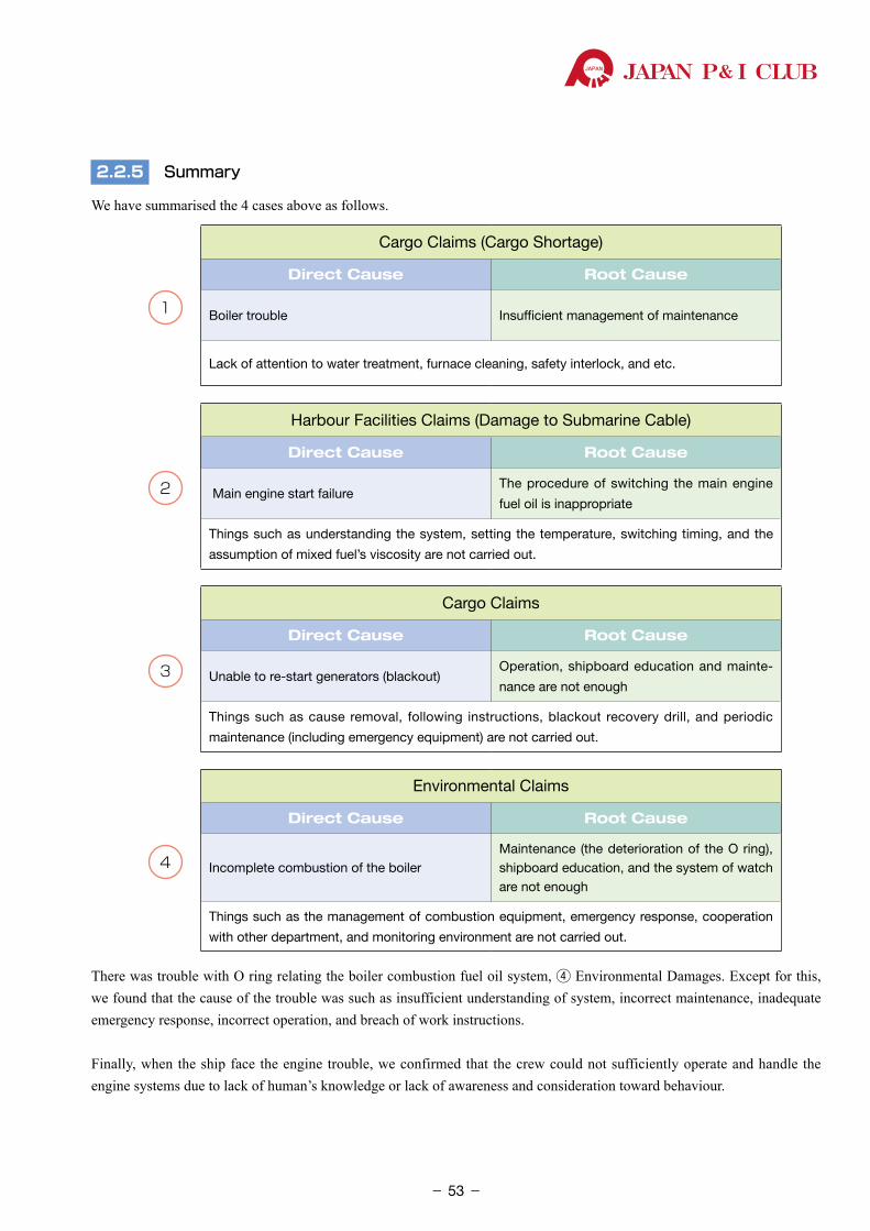
JAPAN P& I CLUB
2.2.5 Summary
We have summarised the 4 cases above as follows.
1
Cargo Claims (Cargo Shortage)
Direct Cause Root Cause
Boiler trouble Insufficient management of maintenance
Lack of attention to water treatment, furnace cleaning, safety interlock, and etc.
2
Harbour Facilities Claims (Damage to Submarine Cable)
Direct Cause Root Cause
Main engine start failureThe procedure of switching the main engine
fuel oil is inappropriate
Things such as understanding the system, setting the temperature, switching timing, and the
assumption of mixed fuel’s viscosity are not carried out.
3
Cargo Claims
Direct Cause Root Cause
Unable to re-start generators (blackout)Operation, shipboard education and mainte-
nance are not enough
Things such as cause removal, following instructions, blackout recovery drill, and periodic
maintenance (including emergency equipment) are not carried out.
4
Environmental Claims
Direct Cause Root Cause
Incomplete combustion of the boilerMaintenance (the deterioration of the O ring), shipboard education, and the system of watch are not enough
Things such as the management of combustion equipment, emergency response, cooperation
with other department, and monitoring environment are not carried out.
There was trouble with O ring relating the boiler combustion fuel oil system, ④ Environmental Damages. Except for this, we found that the cause of the trouble was such as insufficient understanding of system, incorrect maintenance, inadequate emergency response, incorrect operation, and breach of work instructions.
Finally, when the ship face the engine trouble, we confirmed that the crew could not sufficiently operate and handle the engine systems due to lack of human’s knowledge or lack of awareness and consideration toward behaviour.
- 53-
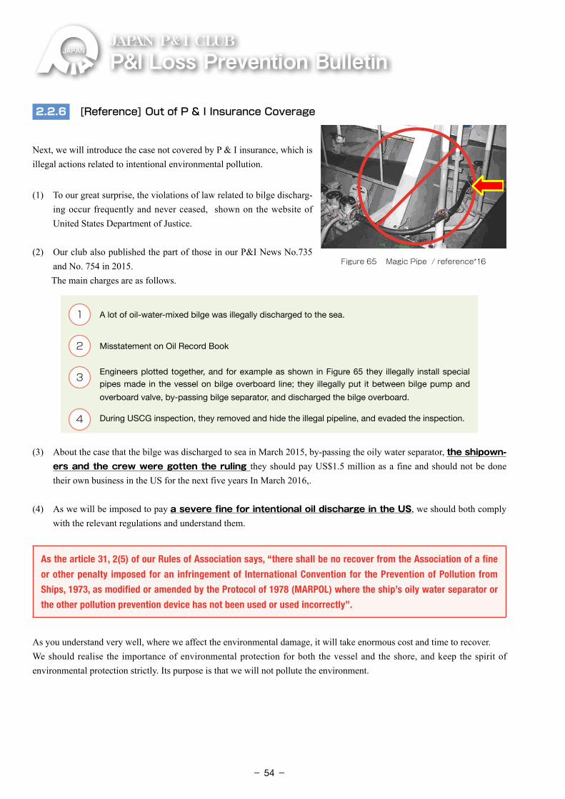
P&ILossPreventionBulletinJAPAN P& I CLUB
2.2.6 [Reference] Out of P & I Insurance Coverage
Next, we will introduce the case not covered by P & I insurance, which is illegal actions related to intentional environmental pollution.
(1) To our great surprise, the violations of law related to bilge discharg-ing occur frequently and never ceased, shown on the website of United States Department of Justice.
(2) Our club also published the part of those in our P&I News No.735 and No. 754 in 2015.
The main charges are as follows.
1 �A lot of oil-water-mixed bilge was illegally discharged to the sea.
2 �Misstatement on Oil Record Book
3 �Engineers plotted together, and for example as shown in Figure 65 they illegally install special pipes made in the vessel on bilge overboard line; they illegally put it between bilge pump and
overboard valve, by-passing bilge separator, and discharged the bilge overboard.
4 �During USCG inspection, they removed and hide the illegal pipeline, and evaded the inspection.
(3) About the case that the bilge was discharged to sea in March 2015, by-passing the oily water separator, the shipown-ers and the crew were gotten the ruling they should pay US$1.5 million as a fine and should not be done their own business in the US for the next five years In March 2016,.
(4) As we will be imposed to pay a severe fine for intentional oil discharge in the US, we should both comply
with the relevant regulations and understand them.
As the article 31, 2(5) of our Rules of Association says, “there shall be no recover from the Association of a fine
or other penalty imposed for an infringement of International Convention for the Prevention of Pollution from
Ships, 1973, as modified or amended by the Protocol of 1978 (MARPOL) where the ship’s oily water separator or
the other pollution prevention device has not been used or used incorrectly”.
As you understand very well, where we affect the environmental damage, it will take enormous cost and time to recover.We should realise the importance of environmental protection for both the vessel and the shore, and keep the spirit of environmental protection strictly. Its purpose is that we will not pollute the environment.
Figure 65 Magic Pipe / reference*16
- 54-
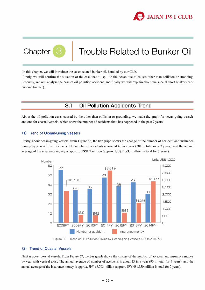
JAPAN P& I CLUB
In this chapter, we will introduce the cases related bunker oil, handled by our Club. Firstly, we will confirm the situation of the case that oil spill to the ocean due to causes other than collision or stranding. Secondly, we will analyse the case of oil pollution accident, and finally we will explain about the special short bunker (cap-puccino bunker).
3.1 Oil Pollution Accidents Trend
About the oil pollution cases caused by the other than collision or grounding, we made the graph for ocean-going vessels and one for coastal vessels, which show the number of accidents that, has happened in the past 7 years.
(1)Trend of Ocean-Going Vessels
Firstly, about ocean-going vessels, from Figure 66, the bar graph shows the change of the number of accident and insurance money by year with vertical axis. The number of accidents is around 40 in a year (281 in total over 7 years), and the annual average of the insurance money is approx. US$1.7 million (approx. US$11,833 million in total for 7 years).
0
10
20
30
40
50
60
2009PY2008PY 2010PY 2011PY 2012PY 2013PY 2014PY
$537
$2,213
$512
$3,619
$689
$1,386
$2,877
Unit: US$1,000Number
34
55
35
47
3842
30
Number of accident Insurance money
0
500
1,000
1,500
2,000
2,500
3,000
3,500
4,000
Figure 66 Trend of Oil Pollution Claims by Ocean-going vessels (2008-2014PY)
(2) Trend of Coastal Vessels
Next is about coastal vessels. From Figure 67, the bar graph shows the change of the number of accident and insurance money by year with vertical axis., The annual average of number of accidents is about 13 in a year (90 in total for 7 years), and the annual average of the insurance money is approx. JPY 68.793 million (approx. JPY 481,550 million in total for 7 years).
Trouble Related to Bunker OilChapter 3
- 55-
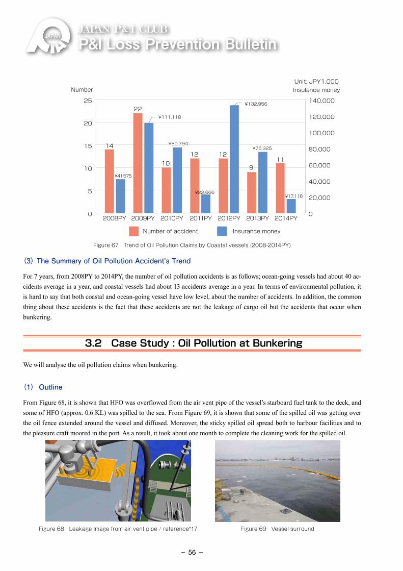
P&ILossPreventionBulletinJAPAN P& I CLUB
0
5
10
15
20
25
2009PY2008PY 2010PY 2011PY 2012PY 2013PY 2014PY
14
22
1012 12
911
Unit: JPY1,000Insulance money
Number of accident Insurance money
Number
0
20,000
40,000
60,000
80,000
100,000
120,000
140,000
¥17,116
¥75,325
¥22,666
¥80,794¥80,794
¥111,118
¥41,575
¥132,956
Figure 67 Trend of Oil Pollution Claims by Coastal vessels (2008-2014PY)
(3) The Summary of Oil Pollution Accident’s Trend
For 7 years, from 2008PY to 2014PY, the number of oil pollution accidents is as follows; ocean-going vessels had about 40 ac-cidents average in a year, and coastal vessels had about 13 accidents average in a year. In terms of environmental pollution, it is hard to say that both coastal and ocean-going vessel have low level, about the number of accidents. In addition, the common thing about these accidents is the fact that these accidents are not the leakage of cargo oil but the accidents that occur when bunkering.
3.2 Case Study : Oil Pollution at Bunkering
We will analyse the oil pollution claims when bunkering.
(1) Outline
From Figure 68, it is shown that HFO was overflowed from the air vent pipe of the vessel’s starboard fuel tank to the deck, and some of HFO (approx. 0.6 KL) was spilled to the sea. From Figure 69, it is shown that some of the spilled oil was getting over the oil fence extended around the vessel and diffused. Moreover, the sticky spilled oil spread both to harbour facilities and to the pleasure craft moored in the port. As a result, it took about one month to complete the cleaning work for the spilled oil.
Figure 68 Leakage Image from air vent pipe / reference*17 Figure 69 Vessel surround
- 56-
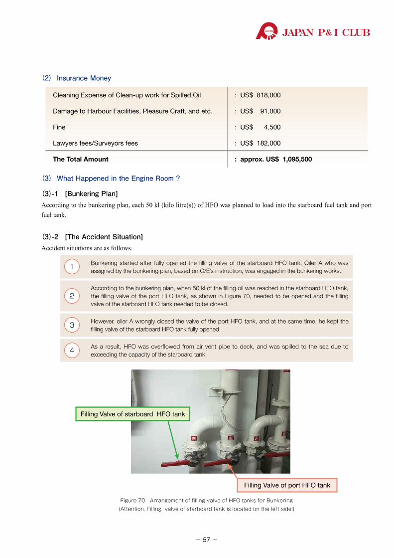
JAPAN P& I CLUB
(2) Insurance Money
Cleaning Expense of Clean-up work for Spilled Oil : US$ 818,000
Damage to Harbour Facilities, Pleasure Craft, and etc. : US$ 91,000
Fine : US$ 4,500
Lawyers fees/Surveyors fees : US$ 182,000
The Total Amount : approx. US$ 1,095,500
(3) What Happened in the Engine Room ?
(3)-1 [Bunkering Plan]According to the bunkering plan, each 50 kl (kilo litre(s)) of HFO was planned to load into the starboard fuel tank and port fuel tank.
(3)-2 [The Accident Situation]Accident situations are as follows.
1 Bunkering started after fully opened the filling valve of the starboard HFO tank, Oiler A who was assigned by the bunkering plan, based on C/E’s instruction, was engaged in the bunkering works.
2According to the bunkering plan, when 50 kl of the filling oil was reached in the starboard HFO tank, the filling valve of the port HFO tank, as shown in Figure 70, needed to be opened and the filling valve of the starboard HFO tank needed to be closed.
3 However, oiler A wrongly closed the valve of the port HFO tank, and at the same time, he kept the filling valve of the starboard HFO tank fully opened.
4 As a result, HFO was overflowed from air vent pipe to deck, and was spilled to the sea due to exceeding the capacity of the starboard tank.
Filling Valve of starboard HFO tank
Filling Valve of port HFO tank
Figure 70 Arrangement of filling valve of HFO tanks for Bunkering (Attention, Filling valve of starboard tank is located on the left side!)
- 57-
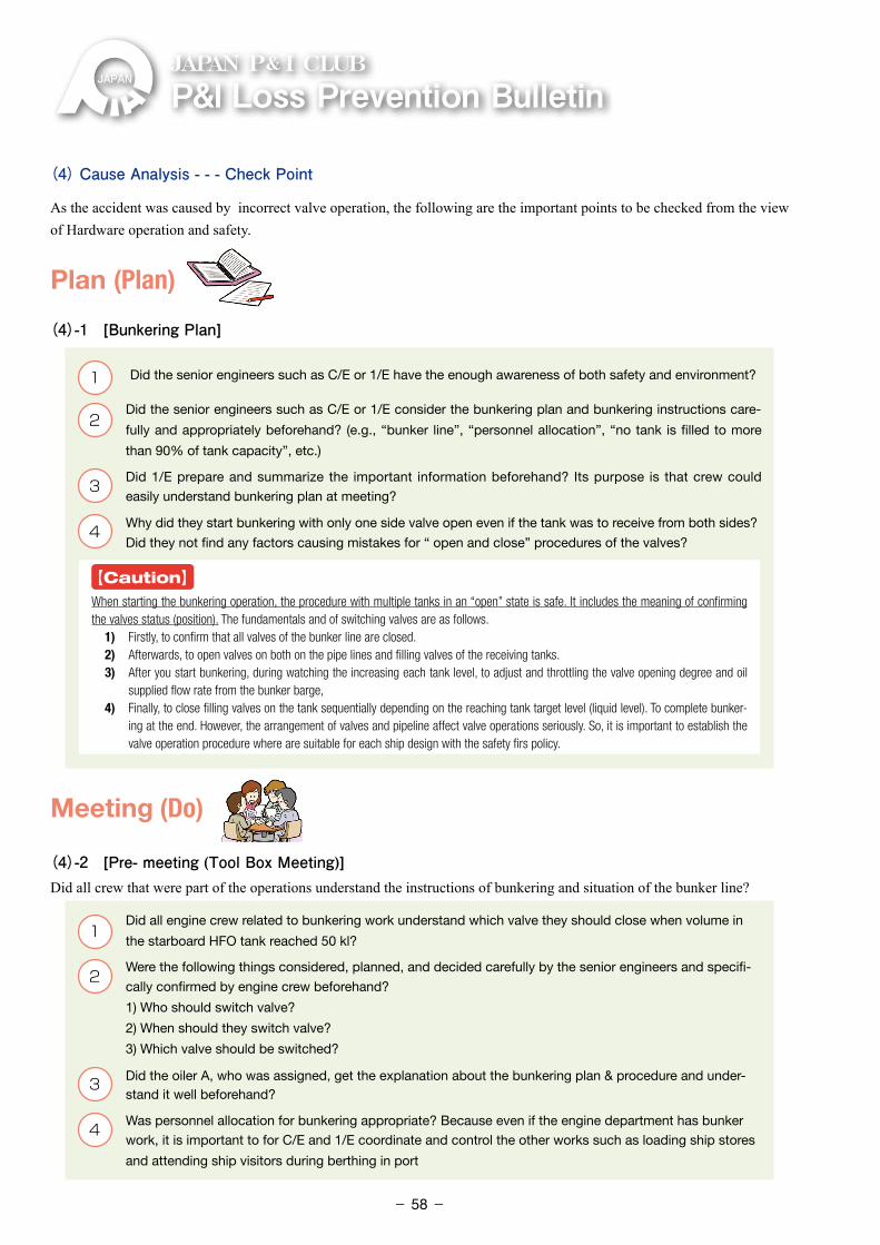
P&ILossPreventionBulletinJAPAN P& I CLUB
(4) Cause Analysis - - - Check Point
As the accident was caused by incorrect valve operation, the following are the important points to be checked from the view of Hardware operation and safety.
Plan (Plan)
(4)-1 [Bunkering Plan]
1 �Did the senior engineers such as C/E or 1/E have the enough awareness of both safety and environment?
2 �Did the senior engineers such as C/E or 1/E consider the bunkering plan and bunkering instructions care-
fully and appropriately beforehand? (e.g., “bunker line”, “personnel allocation”, “no tank is filled to more
than 90% of tank capacity”, etc.)
3 �Did 1/E prepare and summarize the important information beforehand? Its purpose is that crew could easily understand bunkering plan at meeting?
4 �Why did they start bunkering with only one side valve open even if the tank was to receive from both sides?
Did they not find any factors causing mistakes for “ open and close” procedures of the valves?
【Caution】
When starting the bunkering operation, the procedure with multiple tanks in an “open” state is safe. It includes the meaning of confirming the valves status (position). The fundamentals and of switching valves are as follows. 1) Firstly, to confirm that all valves of the bunker line are closed. 2) Afterwards, to open valves on both on the pipe lines and filling valves of the receiving tanks. 3) After you start bunkering, during watching the increasing each tank level, to adjust and throttling the valve opening degree and oil
supplied flow rate from the bunker barge, 4) Finally, to close filling valves on the tank sequentially depending on the reaching tank target level (liquid level). To complete bunker-
ing at the end. However, the arrangement of valves and pipeline affect valve operations seriously. So, it is important to establish the valve operation procedure where are suitable for each ship design with the safety firs policy.
Meeting (Do)
(4)-2 [Pre- meeting (Tool Box Meeting)]Did all crew that were part of the operations understand the instructions of bunkering and situation of the bunker line?
1 �Did all engine crew related to bunkering work understand which valve they should close when volume in
the starboard HFO tank reached 50 kl?
2 �Were the following things considered, planned, and decided carefully by the senior engineers and specifi-
cally confirmed by engine crew beforehand?
1) Who should switch valve? �2) When should they switch valve? �3) Which valve should be switched?
3 �Did the oiler A, who was assigned, get the explanation about the bunkering plan & procedure and under-stand it well beforehand?
4 �Was personnel allocation for bunkering appropriate? Because even if the engine department has bunker work, it is important to for C/E and 1/E coordinate and control the other works such as loading ship stores
and attending ship visitors during berthing in port
- 58-
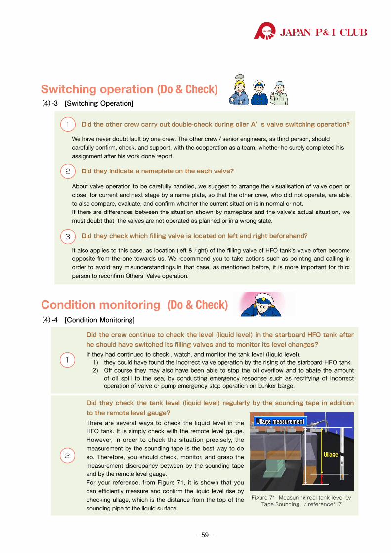
JAPAN P& I CLUB
Switching operation (Do & Check)(4)-3 [Switching Operation]
1 Did the other crew carry out double-check during oiler A’s valve switching operation?
�We have never doubt fault by one crew. The other crew / senior engineers, as third person, should carefully confirm, check, and support, with the cooperation as a team, whether he surely completed his assignment after his work done report.
2 Did they indicate a nameplate on the each valve?
�About valve operation to be carefully handled, we suggest to arrange the visualisation of valve open or close for current and next stage by a name plate, so that the other crew, who did not operate, are able to also compare, evaluate, and confirm whether the current situation is in normal or not.
�If there are differences between the situation shown by nameplate and the valve’s actual situation, we
must doubt that the valves are not operated as planned or in a wrong state.
3 Did they check which filling valve is located on left and right beforehand?
�It also applies to this case, as location (left & right) of the filling valve of HFO tank’s valve often become opposite from the one towards us. We recommend you to take actions such as pointing and calling in order to avoid any misunderstandings.In that case, as mentioned before, it is more important for third person to reconfirm Others’ Valve operation.
Condition monitoring (Do & Check)(4)-4 [Condition Monitoring]
1
Did the crew continue to check the level (liquid level) in the starboard HFO tank after he should have switched its filling valves and to monitor its level changes?If�they�had�continued�to�check�,�watch,�and�monitor�the�tank�level�(liquid�level),� 1) they�could�have�found�the�incorrect�valve�operation�by�the�rising�of�the�starboard�HFO�tank. 2) �Off�course�they�may�also�have�been�able�to�stop�the�oil�overflow�and�to�abate�the�amount�
of�oil�spill� to� the�sea,�by�conducting�emergency� response�such�as� rectifying�of� incorrect�operation�of�valve�or�pump�emergency�stop�operation�on�bunker�barge.
2
Did they check the tank level (liquid level) regularly by the sounding tape in addition to the remote level gauge?There are several ways to check the liquid level in the HFO tank. It is simply check with the remote level gauge. However, in order to check the situation precisely, the measurement by the sounding tape is the best way to do so. Therefore, you should check, monitor, and grasp the measurement discrepancy between by the sounding tape and by the remote level gauge.For your reference, from Figure 71, it is shown that you can efficiently measure and confirm the liquid level rise by checking ullage, which is the distance from the top of the sounding pipe to the liquid surface.
Figure 71 Measuring real tank level by Tape Sounding / reference*17
- 59-
P&ILossPreventionBulletinJAPAN P& I CLUB
3
Was the bunkering flow rate (m3/h) appropriate?During the valve switching operation, the pressure inside of the pipeline temporarily becomes unstable. Therefore, in order to focus on the safety in the most priority, you should also request the barge to reduce the bunkering flow rate temporarily, or to suspend pumping if a majority of the crew are inexperienced.When the open & close operation of the valve during bunkering, as there are some risks inside of the pipeline, you should give your full attention to ensure safety.For example, you would carefully check the pressure changes in the pipeline with the manifold pres-sure gauge or by watching the shaking of the bunker hose, which will help you to ensure safety.
This accident is also the case that it was not a single cause that brought about the accident, but the error chain coming from several causes.
Negative chain(5) Preventive Measures
Supposing that there is some risks in these check points, you should prepare for bunkering so that you can avoid the risks.In this case, the most important thing is to eradicate the mistakes of valve operation. About this, we have also found measures for operations and for safety from the above mentioned check points. Therefore, again, we would like to suggest the following as preventive measures.
(5)-1 Motivation at normal time (awareness for environmental protection)
1 �At the daily study sessions, the engine department crew
must be educated with the working instructions thoroughly.
2 �Therefore, they should realise that even if they make any
tiny mistakes during bunkering, and if it may occur oil spill, then it will have a significant negative impact on the ocean environment.
� �They also should have the essential awareness that they should carefully follow each procedure in accordance with the working instructions and play each crew’s role based on a great deal of caution.
(5)-2 Establish Appropriate Bunkering Plan These points are the same as mentioned before.
1 �To secure enough extra space for the receiving tank plan and to secure an appropriate flow rate (m3/h)
2 To clarify the work assignments ( “line switching”, “working description”, “allocation" and etc.)
The most important:
Eradicate valve operation mistakes!
- 60-
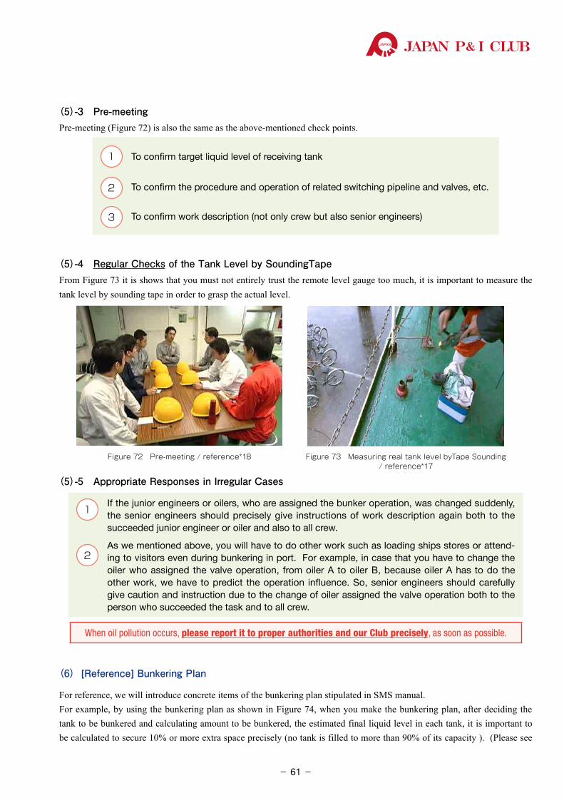
JAPAN P& I CLUB
(5)-3 Pre-meetingPre-meeting (Figure 72) is also the same as the above-mentioned check points.
1 To confirm target liquid level of receiving tank
2 To confirm the procedure and operation of related switching pipeline and valves, etc.
3 To confirm work description (not only crew but also senior engineers)
(5)-4 Regular Checks of the Tank Level by SoundingTape From Figure 73 it is shows that you must not entirely trust the remote level gauge too much, it is important to measure the tank level by sounding tape in order to grasp the actual level.
Figure 72 Pre-meeting / reference*18 Figure 73 Measuring real tank level byTape Sounding / reference*17
(5)-5 Appropriate Responses in Irregular Cases
1 If the junior engineers or oilers, who are assigned the bunker operation, was changed suddenly,
the senior engineers should precisely give instructions of work description again both to the succeeded junior engineer or oiler and also to all crew.
2 As we mentioned above, you will have to do other work such as loading ships stores or attend-
ing to visitors even during bunkering in port. For example, in case that you have to change the oiler who assigned the valve operation, from oiler A to oiler B, because oiler A has to do the other work, we have to predict the operation influence. So, senior engineers should carefully give caution and instruction due to the change of oiler assigned the valve operation both to the person who succeeded the task and to all crew.
When oil pollution occurs, please report it to proper authorities and our Club precisely, as soon as possible.
(6) [Reference] Bunkering Plan
For reference, we will introduce concrete items of the bunkering plan stipulated in SMS manual.For example, by using the bunkering plan as shown in Figure 74, when you make the bunkering plan, after deciding the tank to be bunkered and calculating amount to be bunkered, the estimated final liquid level in each tank, it is important to be calculated to secure 10% or more extra space precisely (no tank is filled to more than 90% of its capacity ). (Please see
- 61-
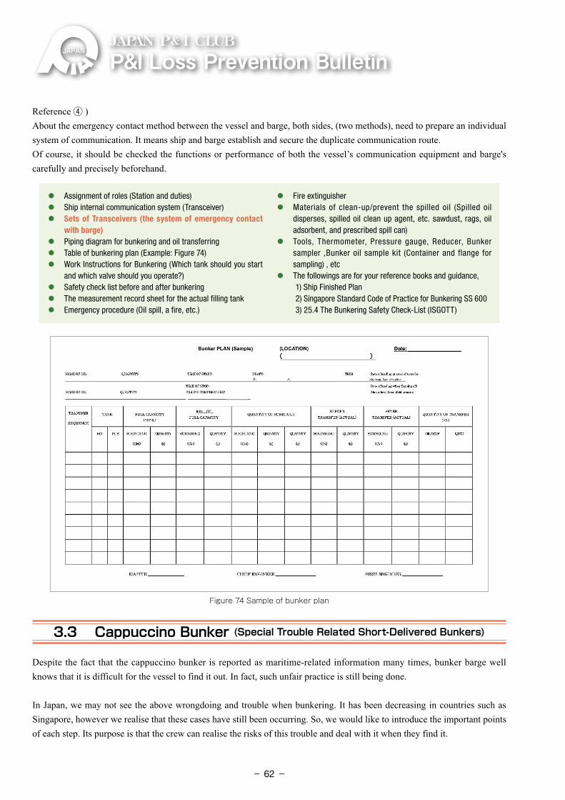
P&ILossPreventionBulletinJAPAN P& I CLUB
Reference ④ )About the emergency contact method between the vessel and barge, both sides, (two methods), need to prepare an individual system of communication. It means ship and barge establish and secure the duplicate communication route.Of course, it should be checked the functions or performance of both the vessel’s communication equipment and barge's carefully and precisely beforehand.
⃝ Assignment of roles (Station and duties)⃝ Ship internal communication system (Transceiver)⃝ �Sets of Transceivers (the system of emergency contact
with barge)⃝ Piping diagram for bunkering and oil transferring⃝ Table of bunkering plan (Example: Figure 74)⃝ �Work Instructions for Bunkering (Which tank should you start
and which valve should you operate?)⃝ Safety check list before and after bunkering⃝ The measurement record sheet for the actual filling tank⃝ Emergency procedure (Oil spill, a fire, etc.)
⃝ Fire extinguisher⃝ �Materials of clean-up/prevent the spilled oil (Spilled oil
disperses, spilled oil clean up agent, etc. sawdust, rags, oil adsorbent, and prescribed spill can)
⃝ �Tools, Thermometer, Pressure gauge, Reducer, Bunker sampler ,Bunker oil sample kit (Container and flange for sampling) , etc
⃝ The followings are for your reference books and guidance, �1) Ship Finished Plan �2) Singapore Standard Code of Practice for Bunkering SS 600 �3) 25.4 The Bunkering Safety Check-List (ISGOTT)
Figure 74 Sample of bunker plan
3.3 Cappuccino Bunker (Special Trouble Related Short-Delivered Bunkers)
Despite the fact that the cappuccino bunker is reported as maritime-related information many times, bunker barge well knows that it is difficult for the vessel to find it out. In fact, such unfair practice is still being done.
In Japan, we may not see the above wrongdoing and trouble when bunkering. It has been decreasing in countries such as Singapore, however we realise that these cases have still been occurring. So, we would like to introduce the important points of each step. Its purpose is that the crew can realise the risks of this trouble and deal with it when they find it.
- 62-
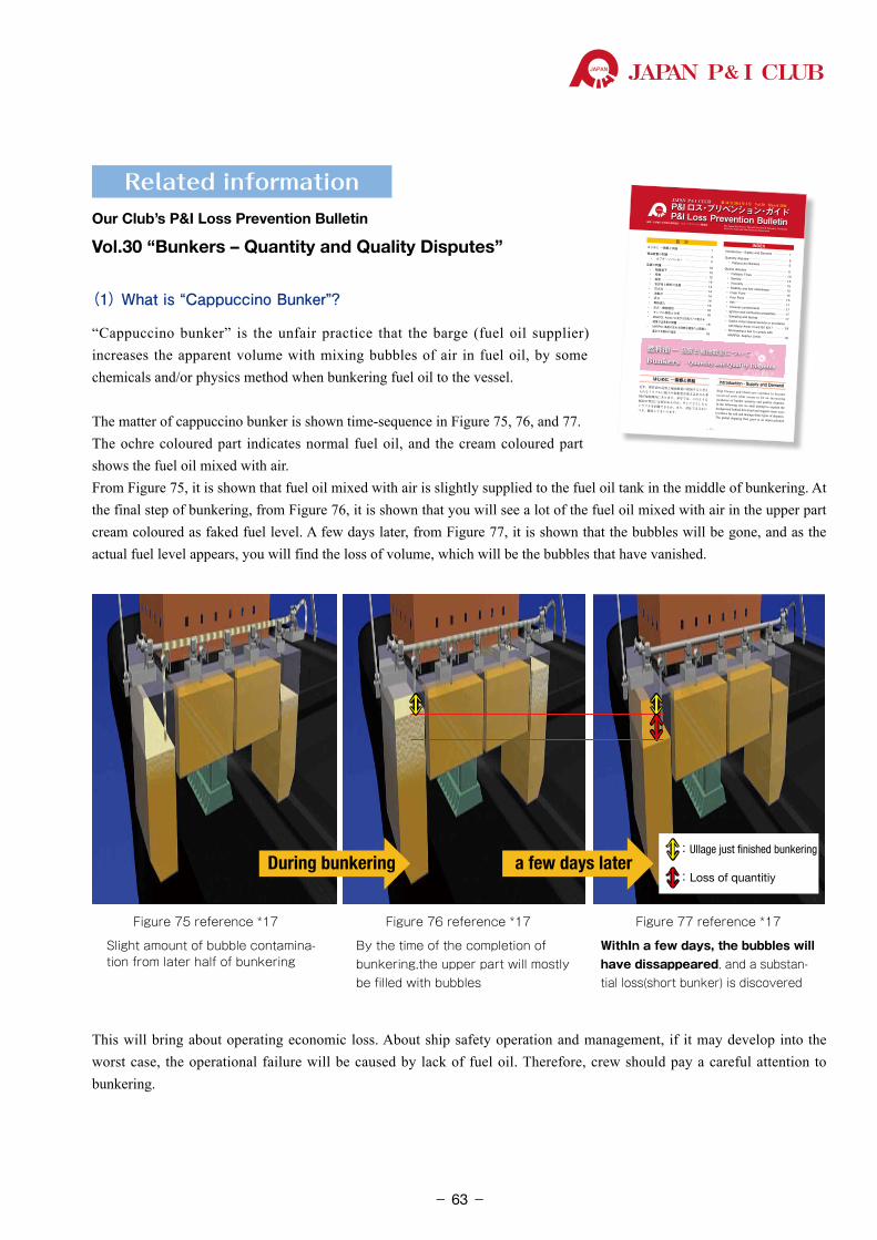
JAPAN P& I CLUB
Related informationOur Club’s P&I Loss Prevention Bulletin
Vol.30�“Bunkers – Quantity and Quality Disputes”
(1) What is “Cappuccino Bunker”?
“Cappuccino bunker” is the unfair practice that the barge (fuel oil supplier) increases the apparent volume with mixing bubbles of air in fuel oil, by some chemicals and/or physics method when bunkering fuel oil to the vessel.
The matter of cappuccino bunker is shown time-sequence in Figure 75, 76, and 77.The ochre coloured part indicates normal fuel oil, and the cream coloured part shows the fuel oil mixed with air.From Figure 75, it is shown that fuel oil mixed with air is slightly supplied to the fuel oil tank in the middle of bunkering. At the final step of bunkering, from Figure 76, it is shown that you will see a lot of the fuel oil mixed with air in the upper part cream coloured as faked fuel level. A few days later, from Figure 77, it is shown that the bubbles will be gone, and as the actual fuel level appears, you will find the loss of volume, which will be the bubbles that have vanished.
During bunkering a few days later:Ullage just finished bunkering
:Loss of quantitiy
Slight amount of bubble contamina-tion from later half of bunkering
By the time of the completion of bunkering,the upper part will mostly be filled with bubbles
WithIn a few days, the bubbles will have dissappeared, and a substan-tial loss(short bunker) is discovered
Figure 75 reference *17 Figure 76 reference *17 Figure 77 reference *17
This will bring about operating economic loss. About ship safety operation and management, if it may develop into the worst case, the operational failure will be caused by lack of fuel oil. Therefore, crew should pay a careful attention to bunkering.
P&I ロス・プリベンション・ガイドP&I Loss Prevention BulletinThe Japan Ship Owners’Mutual Protection & Indemnity AssociationLoss Prevention and Ship Inspection Department
編集:日本船主責任相互保険組合 ロス・プリベンション推進部
JAPAN P& I CLUB
- 1 -
第 30 号 2014 年 3 月 Vol.30 March 2014
はじめに ―需要と供給 ………………………… 1補油数量の問題…………………………………… 4• カプチーノバンカー …………………… 4品質の問題………………………………………… 10• 触媒粒子 ………………………………… 12• 密度 ……………………………………… 12• 粘度 ……………………………………… 14• 安定性と燃料の品質 …………………… 14• 引火点 …………………………………… 14• 流動点 …………………………………… 14• 灰分 ……………………………………… 14• 異物混入 ………………………………… 16• 点火・燃焼特性 ………………………… 16• サンプル採取と分析 …………………… 16• MARPOL Annex VI 及び ISO8217 の定める 硫黄分含有率の問題 ……………………… 18• MARPOL 条約の定める硫黄分濃度の上限値に 適合する燃料の指定 ……………………… 18
Introduction - Supply and Demand …………… 1Quantity disputes ………………………………… 5• Cappuccino Bunkers ……………………… 5Quality disputes ………………………………… 11• Catalytic Fines …………………………… 13• Density ……………………………………… 13• Viscosity …………………………………… 15• Stability and fuel cleanliness …………… 15• Flash Point ………………………………… 15• Pour Point ………………………………… 15• Ash…………………………………………… 17• Unusual contaminants …………………… 17• Ignition and combustion properties ……… 17• Sampling and testing ……………………… 17• Sulphur content dispute resolution in accordance with Marpol Annex VI and ISO 8217 ……… 19• Nominating a fuel to comply with
MARPOL Sulphur Limits ………………… 19
INDEX目 次
はじめに ―需要と供給近年、燃料油の品質と補油数量に起因すると考えられるトラブルに船主や用船者が巻き込まれる事例が増加傾向にあります。本号では、このような傾向の背景には何があるのか、そしてどうしたらトラブルを回避できるか、また、対応できるかにつき、解説してまいります。
Introduction - Supply and DemandShip Owners and Charterers continue to become involved with what seems to be an increasing incidence of bunker quantity and quality disputes. In the following text we shall attempt to explain the background behind this trend and suggest some ways to reduce the risk and manage these types of disputes.The global shipping fleet grew at an unprecedented
燃料油 ― 品質と補油数量についてBunkers – Quantity and Quality Disputes
- 63-
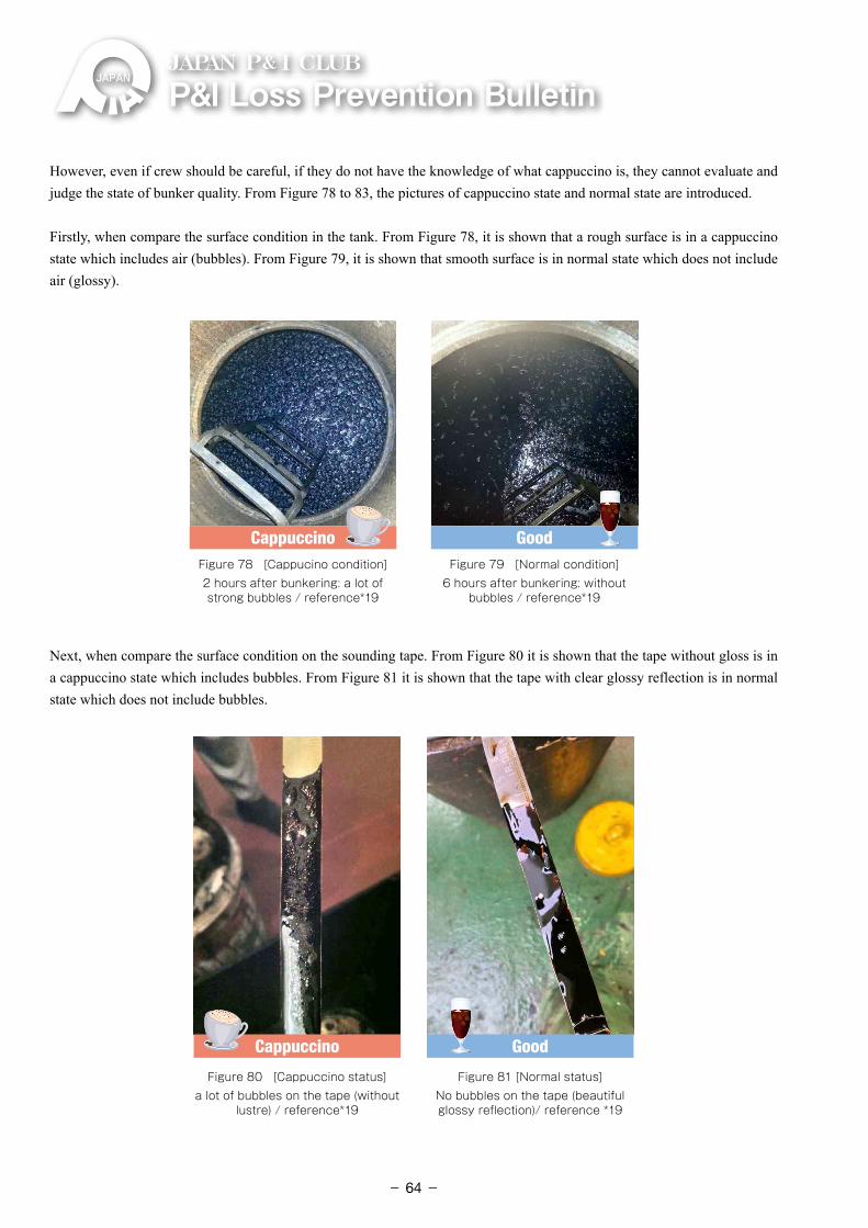
P&ILossPreventionBulletinJAPAN P& I CLUB
However, even if crew should be careful, if they do not have the knowledge of what cappuccino is, they cannot evaluate and judge the state of bunker quality. From Figure 78 to 83, the pictures of cappuccino state and normal state are introduced.
Firstly, when compare the surface condition in the tank. From Figure 78, it is shown that a rough surface is in a cappuccino state which includes air (bubbles). From Figure 79, it is shown that smooth surface is in normal state which does not include air (glossy).
Cappuccino GoodFigure 78 [Cappucino condition]2 hours after bunkering: a lot of strong bubbles / reference*19
Figure 79 [Normal condition]6 hours after bunkering: without
bubbles / reference*19
Next, when compare the surface condition on the sounding tape. From Figure 80 it is shown that the tape without gloss is in a cappuccino state which includes bubbles. From Figure 81 it is shown that the tape with clear glossy reflection is in normal state which does not include bubbles.
Cappuccino Good
Figure 80 [Cappuccino status]a lot of bubbles on the tape (without
lustre) / reference*19
Figure 81 [Normal status]No bubbles on the tape (beautiful glossy reflection)/ reference *19
- 64-
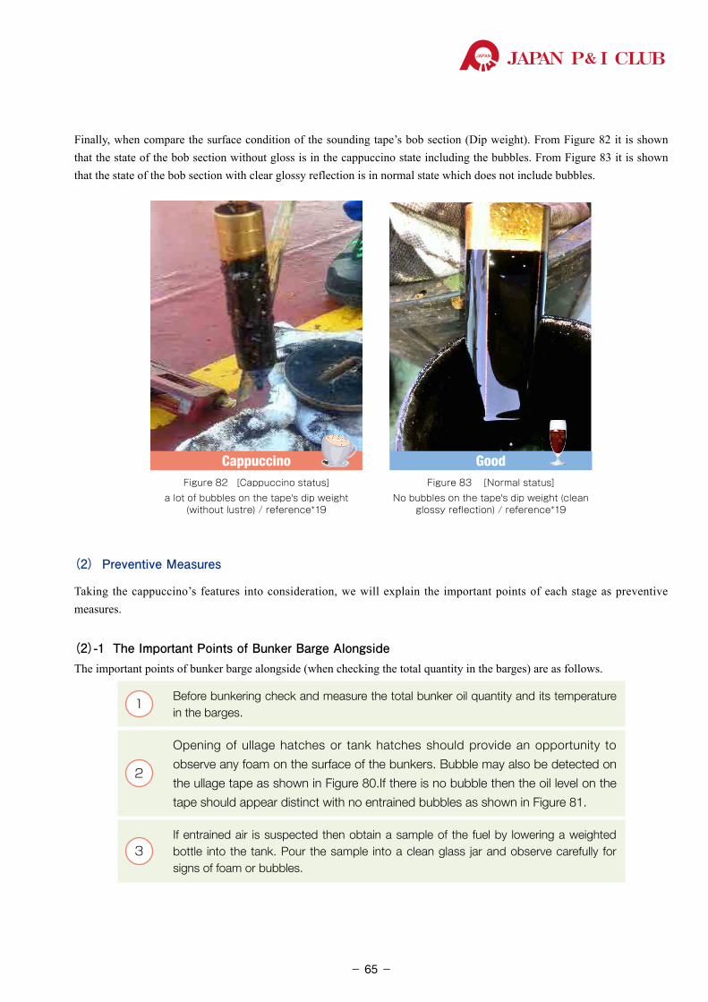
JAPAN P& I CLUB
Finally, when compare the surface condition of the sounding tape’s bob section (Dip weight). From Figure 82 it is shown that the state of the bob section without gloss is in the cappuccino state including the bubbles. From Figure 83 it is shown that the state of the bob section with clear glossy reflection is in normal state which does not include bubbles.
Cappuccino GoodFigure 82 [Cappuccino status]
a lot of bubbles on the tape's dip weight (without lustre) / reference*19
Figure 83 [Normal status] No bubbles on the tape's dip weight (clean
glossy reflection) / reference*19
(2) Preventive Measures
Taking the cappuccino’s features into consideration, we will explain the important points of each stage as preventive measures.
(2)-1 The Important Points of Bunker Barge AlongsideThe important points of bunker barge alongside (when checking the total quantity in the barges) are as follows.
1Before bunkering check and measure the total bunker oil quantity and its temperature in the barges.
2
Opening of ullage hatches or tank hatches should provide an opportunity to
observe any foam on the surface of the bunkers. Bubble may also be detected on
the ullage tape as shown in Figure 80.If there is no bubble then the oil level on the
tape should appear distinct with no entrained bubbles as shown in Figure 81.
3If entrained air is suspected then obtain a sample of the fuel by lowering a weighted bottle into the tank. Pour the sample into a clean glass jar and observe carefully for signs of foam or bubbles.
- 65-
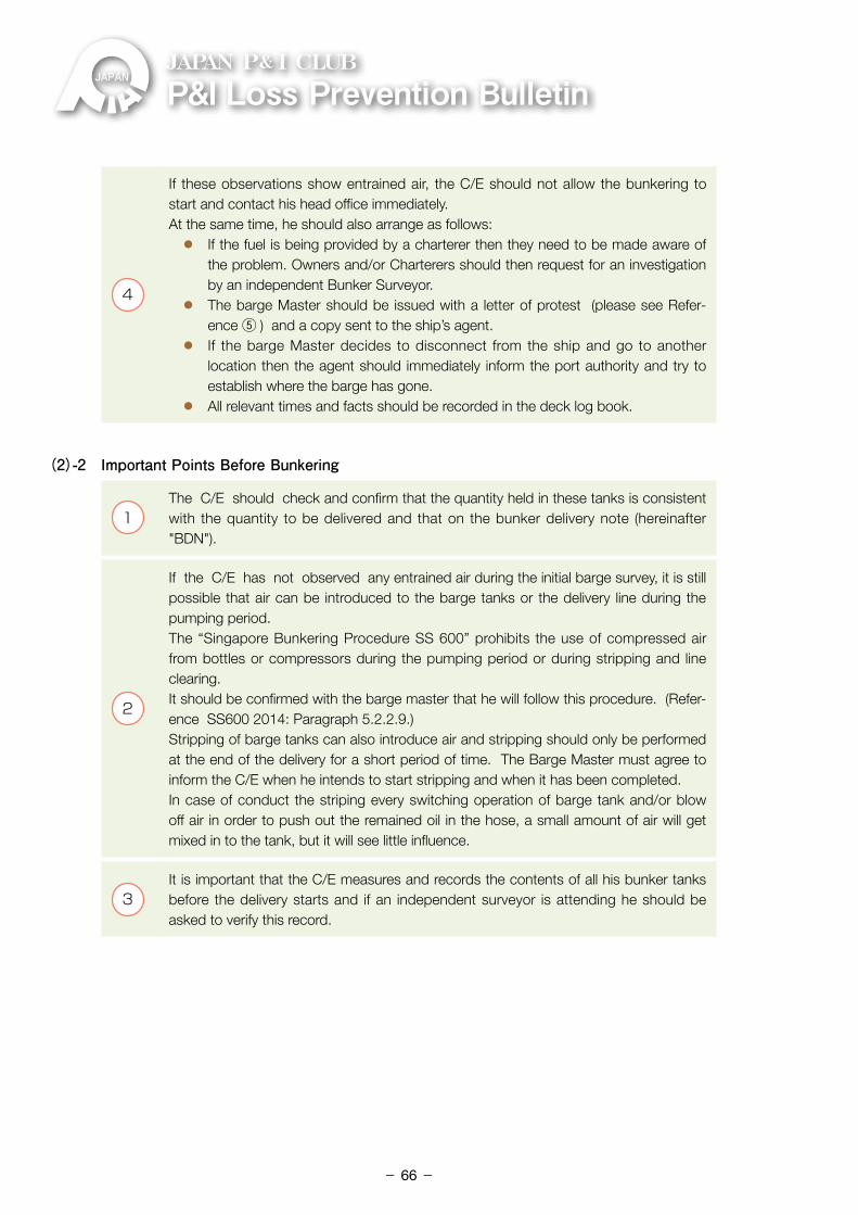
P&ILossPreventionBulletinJAPAN P& I CLUB
4
If these observations show entrained air, the C/E should not allow the bunkering to start and contact his head office immediately.At the same time, he should also arrange as follows: ⃝ If the fuel is being provided by a charterer then they need to be made aware of
the problem. Owners and/or Charterers should then request for an investigation by an independent Bunker Surveyor.
⃝ The barge Master should be issued with a letter of protest (please see Refer-ence ⑤ ) and a copy sent to the ship’s agent.
⃝ If the barge Master decides to disconnect from the ship and go to another location then the agent should immediately inform the port authority and try to establish where the barge has gone.
⃝ All relevant times and facts should be recorded in the deck log book.
(2)-2 Important Points Before Bunkering
1The C/E should check and confirm that the quantity held in these tanks is consistent with the quantity to be delivered and that on the bunker delivery note (hereinafter "BDN").
2
If the C/E has not observed any entrained air during the initial barge survey, it is still possible that air can be introduced to the barge tanks or the delivery line during the pumping period.The “Singapore Bunkering Procedure SS 600” prohibits the use of compressed air from bottles or compressors during the pumping period or during stripping and line clearing. It should be confirmed with the barge master that he will follow this procedure. (Refer-ence SS600 2014: Paragraph 5.2.2.9.)Stripping of barge tanks can also introduce air and stripping should only be performed at the end of the delivery for a short period of time. The Barge Master must agree to inform the C/E when he intends to start stripping and when it has been completed.In case of conduct the striping every switching operation of barge tank and/or blow off air in order to push out the remained oil in the hose, a small amount of air will get mixed in to the tank, but it will see little influence.
3It is important that the C/E measures and records the contents of all his bunker tanks before the delivery starts and if an independent surveyor is attending he should be asked to verify this record.
- 66-
JAPAN P& I CLUB
(2)-3 Important Points During Bunkering
1
Ship’s crew need to be alert during bunkering and check for the following signs: ⃝ Unusual movement of the delivery hose. ⃝ Unusual sounds when standing in vicinity of bunker manifold with contacting the
ear or the auscultation rod, ⃝ Fluctuations of pressure indication on manifold pressure gauge. ⃝ Unusual noises from the bunker barge ⃝ Excessive bubbles observed on the sounding tape while taking sounding of
bunkers in the ship’s tanks.
2
If these observations suggest that air is being introduced into the bunkers then the C/E should request the barge Master to stop the pumping operation. In this case, open the manhole of the vessel’s receiving fuel oil tank, and request to also confirm and understand the situation with barge master.
3
In addition to the above, take the sample of fuel oil and observe the condition such as air bubble and foaming.The C/E should aboard to the barge, measure all the tanks, note records, and obtain a signature from the barge master. Reporting to the shipowners or charterers, letter of protest, and noting in the log book are the same as the above (2)-1- ④ .
4
The bunker receipt should not be signed and no agreement reached with the barge
Master on the quantity discharged or received.
This should be checked and verified by an independent surveyor.
Again, if the barge departs then the time of departure needs to be recorded and the
ship’s agent advised.
(2)-4 Important Points After Leaving Port
1As a further check it would be prudent to remeasure ALL the ship’s fuel oil tank con-tents about 12 hours after the delivery to check for any apparent loss but remember it would be very difficult to resolve any differences after the C/E has signed the BDN.
2The crews should keep all check lists, sounding records, records of all matters and contents of meetings, receipts, and all other related records for later reference.
(3) [Summary]
Basically, it is very important to carry out appropriate measurements in the vessel’s tank when bunkering at any port in order to avoid short delivery, regardless of cappuccino bunker. In order to prevent cappuccino bunker, it is important to have acute power of observation “before and during” bunkering, especially about the above (2)-1- ② & ③ and (2)-3- ① . The most important thing is to detect as earliest.
- 67-
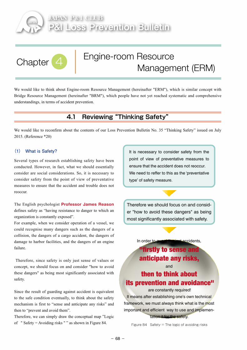
P&ILossPreventionBulletinJAPAN P& I CLUB
We would like to think about Engine-room Resource Management (hereinafter "ERM"), which is similar concept with Bridge Resource Management (hereinafter "BRM"), which people have not yet reached systematic and comprehensive understandings, in terms of accident prevention.
4.1 Reviewing “Thinking Safety”
We would like to reconfirm about the contents of our Loss Prevention Bulletin No. 35 “Thinking Safety” issued on July 2015. (Reference *20)
(1) What is Safety?
Several types of research establishing safety have been conducted. However, in fact, what we should essentially consider are social considerations. So, it is necessary to consider safety from the point of view of preventative measures to ensure that the accident and trouble does not reoccur.
The English psychologist Professor James Reason defines safety as “having resistance to danger to which an organization is constantly exposed”.For example, when we consider operation of a vessel, we could recognise many dangers such as the dangers of a collision, the dangers of a cargo accident, the dangers of damage to harbor facilities, and the dangers of an engine failure.
Therefore, since safety is only just sense of values or concept, we should focus on and consider "how to avoid these dangers" as being most significantly associated with safety.
Since the result of guarding against accident is equivalent to the safe condition eventually, to think about the safety mechanism is first to “sense and anticipate any risks” and then to “prevent and avoid them”. Therefore, we can simply draw the conceptual map ”Logic of " Safety = Avoiding risks " ” as shown in Figure 84.
It is necessary to consider safety from the point of view of preventative measures to ensure that the accident does not reoccur.We need to reffer to this as the ‘preventative type’ of safety measure.
Therefore we should focus on and consid-er "how to avoid these dangers" as being most significantly associated with safety.
In order to guard against accidents,
"firstly to sense and anticipate any risks,
and
then to think about its prevention and avoidance"
are constantly required! It means after establishing one's own technical
framework, we must always think what is the most important and efficient way to use and implemen-
tation it for the safety.
Figure 84 Safety = The logic of avoiding risks
Engine-room Resource Management (ERM)
Chapter 4
- 68-
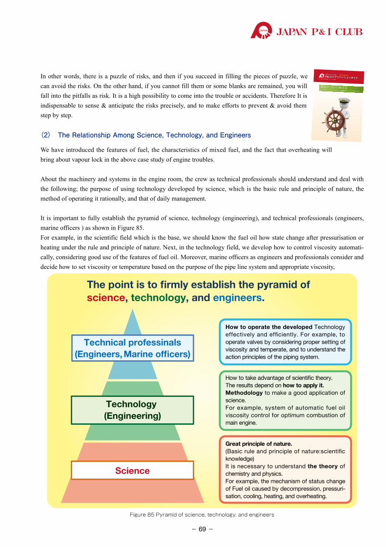
JAPAN P& I CLUB
In other words, there is a puzzle of risks, and then if you succeed in filling the pieces of puzzle, we can avoid the risks. On the other hand, if you cannot fill them or some blanks are remained, you will fall into the pitfalls as risk. It is a high possibility to come into the trouble or accidents. Therefore It is indispensable to sense & anticipate the risks precisely, and to make efforts to prevent & avoid them step by step.
(2) The Relationship Among Science, Technology, and Engineers
We have introduced the features of fuel, the characteristics of mixed fuel, and the fact that overheating will bring about vapour lock in the above case study of engine troubles.
About the machinery and systems in the engine room, the crew as technical professionals should understand and deal with the following; the purpose of using technology developed by science, which is the basic rule and principle of nature, the method of operating it rationally, and that of daily management.
It is important to fully establish the pyramid of science, technology (engineering), and technical professionals (engineers, marine officers ) as shown in Figure 85.For example, in the scientific field which is the base, we should know the fuel oil how state change after pressurisation or heating under the rule and principle of nature. Next, in the technology field, we develop how to control viscosity automati-cally, considering good use of the features of fuel oil. Moreover, marine officers as engineers and professionals consider and decide how to set viscosity or temperature based on the purpose of the pipe line system and appropriate viscosity,
The point is to firmly establish the pyramid ofscience, technology, and engineers.
Technical professinals(Engineers, Marine officers)
Technology (Engineering)
Science
How to operate the developed Technology effectively and efficiently. For example, to operate valves by considering proper setting of viscosity and temperate, and to understand the action principles of the piping system.
How to take advantage of scientific theory. The results depend on how to apply it. Methodology to make a good application of science. For example, system of automatic fuel oil viscosity control for optimum combustion of main engine.
Great principle of nature. (Basic rule and principle of nature:scientific knowledge)It is necessary to understand the theory of chemistry and physics. For example, the mechanism of status change of Fuel oil caused by decompression, pressuri-sation, cooling, heating, and overheating.
Figure 85 Pyramid of science, technology, and engineers
P&I ロスプリベンションガイド編集:日本船主責任相互保険組合 ロスプリベンション推進部
JAPAN P& I CLUB 第 35号 2015 年 7月P&I
ロスプリベンションガイド
第35号
P&I ロスプリベンションガイドJAPAN P& I CLUB
安全について考えるブリッジリソースマネジメントと機関室リソースマネジメント
●東京本部 〒 103-0013 東京都中央区日本橋人形町 2丁目 15 番 14 号………… Tel:03-3662-7229Fax:03-3662-7107●神戸支部 〒 650-0024兵庫県神戸市中央区海岸通 5番地商船三井ビル 6階…… Tel:078-321-6886Fax:078-332-6519●福岡支部 〒 812-0027福岡県福岡市博多区下川端町1番 1号明治通りビジネスセンター 6 階 … Tel:092-272-1215Fax:092-281-3317●今治支部 〒 794-0028 愛媛県今治市北宝来町 2丁目 2番地 1………………… Tel:0898-33-1117Fax:0898-33-1251●シンガポール支部 80RobinsonRoad#14-01BSINGAPORE068898…… Tel:65-6224-6451Fax:65-6224-1476 SingaporeBranch● JPI 英国サービス株式会社38LombardStreet,LondonEC3V9BSU.K. ……… Tel:44-20-7929-3633Fax:44-20-7929-7557 Japan P&I Club (UK) Services Ltd
JAPAN P& I CLUBホームページ http://www.piclub.or.jp
日本船主責任相互保険組合ロスプリベンション推進部長船長 岡田卓三
著者近影
- 69-
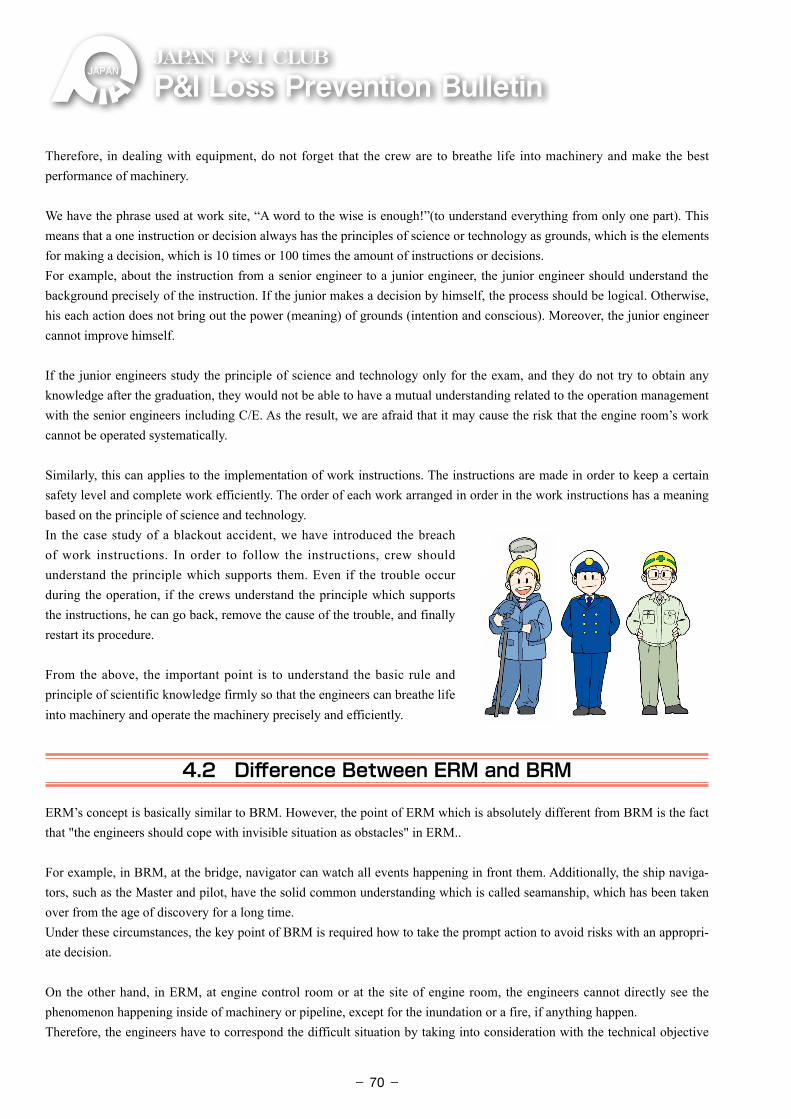
P&ILossPreventionBulletinJAPAN P& I CLUB
Therefore, in dealing with equipment, do not forget that the crew are to breathe life into machinery and make the best performance of machinery.
We have the phrase used at work site, “A word to the wise is enough!”(to understand everything from only one part). This means that a one instruction or decision always has the principles of science or technology as grounds, which is the elements for making a decision, which is 10 times or 100 times the amount of instructions or decisions.For example, about the instruction from a senior engineer to a junior engineer, the junior engineer should understand the background precisely of the instruction. If the junior makes a decision by himself, the process should be logical. Otherwise, his each action does not bring out the power (meaning) of grounds (intention and conscious). Moreover, the junior engineer cannot improve himself.
If the junior engineers study the principle of science and technology only for the exam, and they do not try to obtain any knowledge after the graduation, they would not be able to have a mutual understanding related to the operation management with the senior engineers including C/E. As the result, we are afraid that it may cause the risk that the engine room’s work cannot be operated systematically.
Similarly, this can applies to the implementation of work instructions. The instructions are made in order to keep a certain safety level and complete work efficiently. The order of each work arranged in order in the work instructions has a meaning based on the principle of science and technology.In the case study of a blackout accident, we have introduced the breach of work instructions. In order to follow the instructions, crew should understand the principle which supports them. Even if the trouble occur during the operation, if the crews understand the principle which supports the instructions, he can go back, remove the cause of the trouble, and finally restart its procedure.
From the above, the important point is to understand the basic rule and principle of scientific knowledge firmly so that the engineers can breathe life into machinery and operate the machinery precisely and efficiently.
4.2 Difference Between ERM and BRM
ERM’s concept is basically similar to BRM. However, the point of ERM which is absolutely different from BRM is the fact that "the engineers should cope with invisible situation as obstacles" in ERM..
For example, in BRM, at the bridge, navigator can watch all events happening in front them. Additionally, the ship naviga-tors, such as the Master and pilot, have the solid common understanding which is called seamanship, which has been taken over from the age of discovery for a long time.Under these circumstances, the key point of BRM is required how to take the prompt action to avoid risks with an appropri-ate decision.
On the other hand, in ERM, at engine control room or at the site of engine room, the engineers cannot directly see the phenomenon happening inside of machinery or pipeline, except for the inundation or a fire, if anything happen. Therefore, the engineers have to correspond the difficult situation by taking into consideration with the technical objective
- 70-
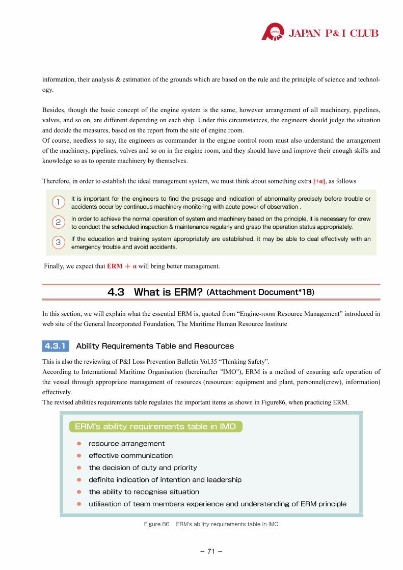
JAPAN P& I CLUB
information, their analysis & estimation of the grounds which are based on the rule and the principle of science and technol-ogy.
Besides, though the basic concept of the engine system is the same, however arrangement of all machinery, pipelines, valves, and so on, are different depending on each ship. Under this circumstances, the engineers should judge the situation and decide the measures, based on the report from the site of engine room.Of course, needless to say, the engineers as commander in the engine control room must also understand the arrangement of the machinery, pipelines, valves and so on in the engine room, and they should have and improve their enough skills and knowledge so as to operate machinery by themselves.
Therefore, in order to establish the ideal management system, we must think about something extra [+α], as follows
1 �It is important for the engineers to find the presage and indication of abnormality precisely before trouble or accidents occur by continuous machinery monitoring with acute power of observation .
2 In order to achieve the normal operation of system and machinery based on the principle, it is necessary for crew to conduct the scheduled inspection & maintenance regularly and grasp the operation status appropriately.
3 �If the education and training system appropriately are established, it may be able to deal effectively with an emergency trouble and avoid accidents.
Finally, we expect that ERM + α will bring better management.
4.3 What is ERM? (Attachment Document*18)
In this section, we will explain what the essential ERM is, quoted from “Engine-room Resource Management” introduced in web site of the General Incorporated Foundation, The Maritime Human Resource Institute
4.3.1 Ability Requirements Table and Resources
This is also the reviewing of P&I Loss Prevention Bulletin Vol.35 “Thinking Safety”. According to International Maritime Organisation (hereinafter "IMO"), ERM is a method of ensuring safe operation of the vessel through appropriate management of resources (resources: equipment and plant, personnel(crew), information) effectively. The revised abilities requirements table regulates the important items as shown in Figure86, when practicing ERM.
ERM’s ability requirements table in IMO
⃝ resource arrangement
⃝ effective communication
⃝ the decision of duty and priority
⃝ definite indication of intention and leadership
⃝ the ability to recognise situation
⃝ utilisation of team members experience and understanding of ERM principle
Figure 86 ERM’s ability requirements table in IMO
- 71-
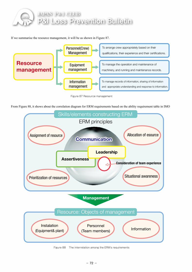
P&ILossPreventionBulletinJAPAN P& I CLUB
If we summarise the resource management, it will be as shown in Figure 87.
Resource management
To arrange crew appropriately based on their
qualifications, their experience and their certifications.
Personnel(Crew)Management
Equipment management
Information management
To manage the operation and maintenance of
machinery, and running and maintenance records.
To manage records of information, sharing of information
and appropriate understanding and response to information.
Figure 87 Resource management
From Figure 88, it shows about the correlation diagram for ERM requirements based on the ability requirement table in IMO
Skills/elements constructing ERMERM principles
Resource: Objects of management
Management
CommunicationCommunicationAllocation of esource
Situational awareness
InformationPersonnel
(Team members)Instalation
(Equipment& plant)
Assignment of resource
Prioritization of resources
Assertiveness
Leadership
Consideration of team experience
Figure 88 The interrelation among the ERM’s requirements
- 72-
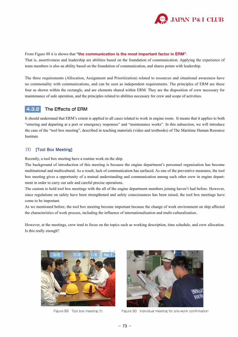
JAPAN P& I CLUB
From Figure 88 it is shown that “the communication is the most important factor in ERM”.That is, assertiveness and leadership are abilities based on the foundation of communication. Applying the experience of team members is also an ability based on the foundation of communication, and shares points with leadership.
The three requirements (Allocation, Assignment and Prioritization) related to resources and situational awareness have no commonality with communications, and can be seen as independent requirements. The principles of ERM are these four as shown within the rectangle, and are elements shared within ERM. They are the disposition of crew necessary for maintenance of safe operation, and the principles related to abilities necessary for crew and scope of activities.
4.3.2 The Effects of ERM
It should understand that ERM’s extent is applied to all cases related to work in engine room. It means that it applies to both “entering and departing at a port or emergency responses” and “maintenance works”. In this subsection, we will introduce the case of the “tool box meeting”, described in teaching materials (video and textbooks) of The Maritime Human Resource Institute
(1) [Tool Box Meeting]
Recently, a tool box meeting have a routine work on the ship.The background of introduction of this meeting is because the engine department’s personnel organisation has become multinational and multicultural. As a result, lack of communication has surfaced. As one of the preventive measures, the tool box meeting gives a opportunity of a mutual understanding and communication among each other crew in engine depart-ment in order to carry out safe and careful precise operations. The custom to hold tool box meetings with the all of the engine department members joining haven’t had before. However, since regulations on safety have been strengthened and safety consciousness has been raised, the tool box meetings have come to be important.As we mentioned before, the tool box meeting become important because the change of work environment on ship affected the characteristics of work process, including the influence of internationalisation and multi-culturalisation..
However, at the meetings, crew tend to focus on the topics such as working description, time schedule, and crew allocation. Is this really enough?
Figure 89 Tool box meeting (1) Figure 90 Individual meeting for pre-work confirmation
3/E C/E 1/E No.1
- 73-
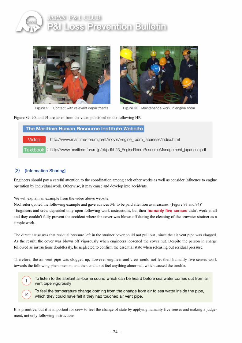
P&ILossPreventionBulletinJAPAN P& I CLUB
Figure 91 Contact with relevant departments Figure 92 Maintenance work in engine room
Figure 89, 90, and 91 are taken from the video published on the following HP.
The Maritime Human Resource Institute Website
Video :http://www.maritime-forum.jp/et/movie/Engine_room_japanese/index.html
Textbook : http://www.maritime-forum.jp/et/pdf/h23_EngineRoomResourceManagement_japanese.pdf
(2) [Information Sharing]
Engineers should pay a careful attention to the coordination among each other works as well as consider influence to engine operation by individual work. Otherwise, it may cause and develop into accidents.
We will explain an example from the video above website; No.1 oiler quoted the following example and gave advices 3/E to be paid attention as measures. (Figure 93 and 94)"“Engineers and crew depended only upon following work instructions, but their humanly five senses didn't work at all and they couldn't fully prevent the accident where the cover was blown off during the cleaning of the seawater strainer as a simple work.
The direct cause was that residual pressure left in the strainer cover could not pull out , since the air vent pipe was clogged. As the result, the cover was blown off vigorously when engineers loosened the cover nut. Despite the person in charge followed as instructions doubtlessly, he neglected to confirm the essential state when releasing out residual pressure.
Therefore, the air vent pipe was clogged up, however engineer and crew could not let their humanly five senses work towards the following phenomenon, and then could not feel anything abnormal, which caused the trouble.
1 �To listen to the sibilant air-borne sound which can be heard before sea water comes out from air vent pipe vigorously
2 �To feel the temperature change coming from the change from air to sea water inside the pipe,
which they could have felt if they had touched air vent pipe.
It is primitive, but it is important for crew to feel the change of state by applying humanly five senses and making a judge-ment, not only following instructions.
- 74-
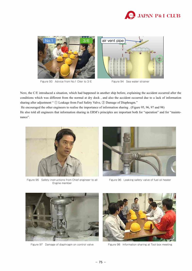
JAPAN P& I CLUB
No.1 3/E
Figure 93 Advice from No.1 Oiler to 3/E
air vent pipe
Figure 94 Sea water strainer
Next, the C/E introduced a situation, which had happened in another ship before, explaining the accident occurred after the conditions which was different from the normal at dry dock , and also the accident occurred due to a lack of information sharing after adjustment “ ① Leakage from Fuel Safety Valve, ② Damage of Diaphragm.” He encouraged the other engineers to realise the importance of information sharing . (Figure 95, 96, 97 and 98)He also told all engineers that information sharing in ERM’s principles are important both for “operation” and for “mainte-nance”.
Figure 95 Safety instructions from Chief engineer to all Engine member
Figure 97 Damage of diaphragm on control valve
Figure 96 Leaking safety valve of fuel oil heater
Figure 98 Information sharing at Tool box meeting
- 75-
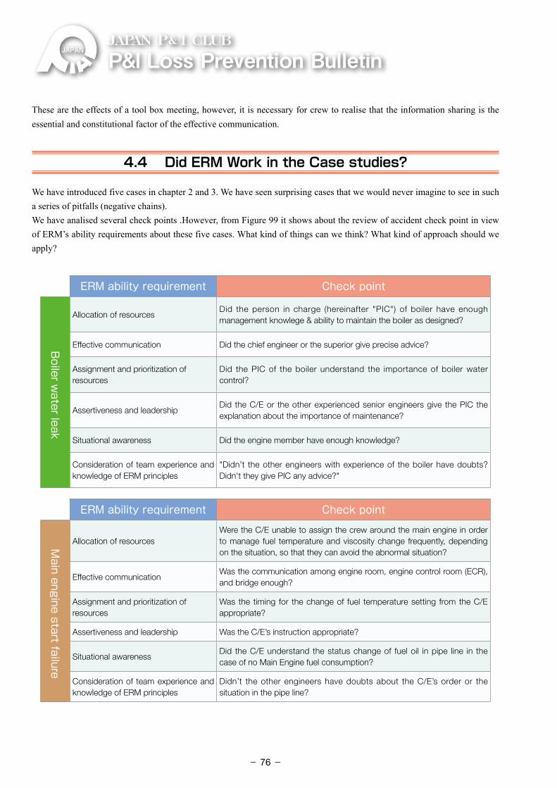
P&ILossPreventionBulletinJAPAN P& I CLUB
These are the effects of a tool box meeting, however, it is necessary for crew to realise that the information sharing is the essential and constitutional factor of the effective communication.
4.4 Did ERM Work in the Case studies?
We have introduced five cases in chapter 2 and 3. We have seen surprising cases that we would never imagine to see in such a series of pitfalls (negative chains).We have analised several check points .However, from Figure 99 it shows about the review of accident check point in view of ERM’s ability requirements about these five cases. What kind of things can we think? What kind of approach should we apply?
ERM ability requirement Check point
Boiler w
ater leak
Allocation of resourcesDid the person in charge (hereinafter "PIC") of boiler have enough management knowlege & ability to maintain the boiler as designed?
Effective communication Did the chief engineer or the superior give precise advice?
Assignment and prioritization of resources
Did the PIC of the boiler understand the importance of boiler water control?
Assertiveness and leadershipDid the C/E or the other experienced senior engineers give the PIC the explanation about the importance of maintenance?
Situational awareness Did the engine member have enough knowledge?
Consideration of team experience and knowledge of ERM principles
"Didn’t the other engineers with experience of the boiler have doubts? Didn't they give PIC any advice?"
ERM ability requirement Check pointM
ain engine start failure
Allocation of resourcesWere the C/E unable to assign the crew around the main engine in order to manage fuel temperature and viscosity change frequently, depending on the situation, so that they can avoid the abnormal situation?
Effective communicationWas the communication among engine room, engine control room (ECR), and bridge enough?
Assignment and prioritization of resources
Was the timing for the change of fuel temperature setting from the C/E appropriate?
Assertiveness and leadership Was the C/E’s instruction appropriate?
Situational awarenessDid the C/E understand the status change of fuel oil in pipe line in the case of no Main Engine fuel consumption?
Consideration of team experience and knowledge of ERM principles
Didn’t the other engineers have doubts about the C/E’s order or the situation in the pipe line?
- 76-
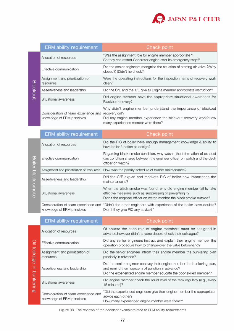
JAPAN P& I CLUB
ERM ability requirement Check point
Blackout
Allocation of resources"Was the assignment role for engine member appropriate ? So they can restart Generator engine after its emergency stop?"
Effective communicationDid the senior engineers recognise the situation of starting air valve ?(Why closed?) (Didn’t he check?)
Assignment and prioritization of resources
Were the operating instructions for the inspection items of recovery work clear?
Assertiveness and leadership Did the C/E and the 1/E give all Engine member appropriate instruction?
Situational awarenessDid engine member have the appropriate situational awareness for Blackout recovery?
Consideration of team experience and knowledge of ERM principles
Why didn’t engine member understand the importance of blackout recovery drill?Did any engine member experience the blackout recovery work?How many experienced menber were there?
ERM ability requirement Check point
Boiler black sm
oke
Allocation of resourcesDid the PIC of boiler have enough management knowledge & ability to have boiler function as design?
Effective communicationRegarding black smoke condition, why wasn’t the information of exhaust gas condition shared between the engineer officer on watch and the deck officer on watch?
Assignment and prioritization of resources How was the priority schedule of burner maintenance?
Assertiveness and leadershipDid the C/E explan and motivate PIC of boiler how importance the maintenance is?
Situational awarenessWhen the black smoke was found, why did engine member fail to take effective measures such as suppressing or preventing it?Didn’t the engineer officer on watch monitor the black smoke outside?
Consideration of team experience and knowledge of ERM principles
"Didn’t the other engineers with experience of the boiler have doubts? Didn't they give PIC any advice?"
ERM ability requirement Check point
Oil leakage in bunkering
Allocation of resourcesOf course the each role of engine members must be assigned in advance,however didn’t anyone double-check their colleague?
Effective communicationDid any senior engineers instruct and explain their engine member the operation procedure how to change-over the valve beforehand?
Assignment and prioritization of resources
Did the senior engineer infrom their engine member the bunkering plan precisely in advance?
Assertiveness and leadershipDid the senior engineer conevey their engine member the bunkering plan, and remind them concern oil pollution in advance?Did the experienced engine member educate the poor skilled member?
Situational awarenessDid engine member check the liquid level of the tank regularly (e.g., every 15 minutes)?
Consideration of team experience and knowledge of ERM principles
"Did the experienced engineers give their engine member the appropriate advice each other?How many experienced engine menber were there?"
Figure 99 The reviews of the accident examplerelated to ERM ability requirements
- 77-
P&ILossPreventionBulletinJAPAN P& I CLUB
4.5 What is Engine Management? (ERM +α )
Engine-room Resource Management (ERM) is the management of resources and means the system where crew in the engine department can directly cooperate with each other and organically function.
On the other hand, where we think about the appropriate engine management that can avoid accidents in terms of practical aspects, it is important to establish the situation monitoring, the maintenance, and the educational system which will be a base for engine management. It is something extra [+α] which supports essential ERM operation, causing indirect effect.
(1) What is Direct? (ERM)
The work site of direct effect for ERM generally means the following operating situation including the maintenance opera-tion said in 4.3.2.
1 �To handle the immediate response system to the standby maneuvering (engine operation) during the entering and departing at port.
2 �To handle the immediate response system to emergencies such as a blackout, main engine’s stop, oil leakage, a fire, and flooding.
3 �To handle operation such as the bunkering of fuel or lubricating oil and discharge with sludge which may have the possibility of an oil pollution accident.
4 To handle watch-keeping at sea (cooperate with bridge maneuvering, engine operation)
5 �To handle watch-keeping in port (cooperating with loading/discharge operation, maintenance operation)
6 �To handle Maintenance operation (important information sharing , establish operational mutual coopera-
tion, communication, support, and understanding the situation, normal operations, share the special status of the valves and equipment not to be operated, cooperation with other departments and so on.)
Speaking of cooperation, the cooperation in engine department is of course important. However, as we have introduced the case that the main engine start failure brought about submarine cable damages in chapter 2-2.2.2, we have pointed out that it is important for the deck department and engine department to communicate with each other in advance, about the timing of switching fuel oil when departing the port.
Another similar case is in case of that the fuel oil tank is located in the lower part of cargo hold; if a cargo weak to heating is to be loaded, the cargo department should issue a caution to request about the heating temperature of the fuel oil tank to the engine department. The engine department would have to flexibly adjust the temperature. Thus, it should pay an attention to the resource management focus on the optimality of the vessel.
The communication is important, however the engine room has big noise and it is difficult for the crew to communicate with each other. Therefore, it is necessary to think about the way to communicate. For example, the crew should try to use clear and simple phrases in order to convey their intentions clearly and can avoid misunderstandings.When closing something, for instance, crew should decide on the word to use: “close” or “shut”. It is necessary to have a firm policy to convey information.
- 78-
JAPAN P& I CLUB
(2) What is Indirect [ +α ] ?In order to prevent accidents, it is important to establish situation monitoring, maintenance, and educational system which is something extra [+α] as shown below, which supports direct operation:
1 Situation monitoring and judgement for continuous operating information of main engine and
auxiliary machinery.(early detection of abnormal symptoms, understanding the characteristics under the environment of vessel operation, trial, comparing the same type of ships and so on )
As each ship has different sea service areas and loads, about status management, it is necessary for engineers to compare the current operational state with sea trial data or a normal operation state regularly. To understand the characteristics of each machinery or system enables to find out something unusual, and to take appropriate measures on a timely.
2 Appropriately Planned Maintenance System: to maintain the situation so that machinery design
performance can function. (The instruction manual of the finished plan, manufacturer service information, maintenance instruc-tions based on lessons learned (knowledge of experience), etc.)
Based on the case study, we learned and reconfirmed the importance of maintenance. The vessel, ship management company, and operation department should do maintenance as a whole team under a common understanding. Moreover, the operation department should also understand the importance of ensur-ing the time of maintenance.About maintenance, recommended maintenance interval has been given by the manufacturer, however the load on machinery will be different, depending on the operation environment such as operation load, operation pattern, sea service area, fuel oil and lubricating oil to be used and, etc. Therefore, it is important for crew to carry out maintenance work with appropriate timing set by each company or each ship, considering the lessons learned (knowledge of experience) based on operational evaluation or the trouble experience of the company comprehensively. For example, each company should observe the state of deterioration by measuring at the overhauling maintenance.That is, it is the know-how of maintenance. once again, this is one of the best management methods to avoid trouble, however it must not be the know-how with lowest safety.
3 Education on the ship: Establish the common understanding related to the engine system
Not taking too much time to complete the check list, and not taking the science part of the principle only as an armchair theory, let's think about the education on the ship to develop feasible engine management in terms of practical engineering. We have considered the methods and introduce below.
・ Hold study sessions regularly, about the meaning of the engine operations
& the work instructions or the management of system operation.
- 79-
P&ILossPreventionBulletinJAPAN P& I CLUB
This is a repetition of 4.1 (2), the relationship among science, technology, and engineers. On the ship, the work instructions are made and managed in order to keep a certain safety level, and complete work efficiently. The work instructions are based on principles. Even if the trouble occur during the operation, if the crews understand the principle which supports the instructions, he can go back, remove the cause of the trouble, and finally restart its procedure.
・ Information sharing on examples and experiences of trouble.
About information sharing, we have introduced the case of tool box meeting before. However, the crew do not have many opportunities to experience notable trouble that we would not be able to forget, at the work site. It is important for crew to share the experienced crew’s experience on another ship, or past instances accumulated at a ship management company.
・ Study sessions focusing on maintenance work instructions or risk assessment.
Making good use of the lessons learned (knowledge of experience) based on trouble experience, anticipating risks and making efforts to upgrade the safety level are very important. For example, since the junior crew have little experience, they will be able to develop the ability to avoid risks by sharing the experienced senior crew’s experience at another ship, and by discussing the past instance accumulated at a ship management company.
・ Conduct emergency drills such as a blackout recovery drill
Needless to say, it should carry out the drill regularly. It's purpose is that the crew can respond promptly when trouble of critical machinery occurs, which does not occur frequently.In the case of a blackout, there are two procedures: one is procedure of automatic recovery and the other is pro-cedure of manual recovery. It is important for engineers to recognise both of them. At the same time, it is helpful to understand the machinery and equipment supplied by emergency generators, which are not operated regularly. Furthermore, it will be a great opportunity to think about what kind of attention the engineers should be paid even during normal operation, about the machinery and equipment which cannot be fed by the emergency generators.
・ Review of reasonableness of check lists, instructions, and SMS by the study sessions.
We advised before that the work instructions have a reason/background.When theories match practices at work site rationally, the established procedures will be followed for a long time. However, if the first version of work instructions were established based on the crew’s experience, that is, if the first version of work instructions were established based on custom which done at the work site from a long time ago, it is focused on the priority to the rationality of work, or on the contrary, excess the safety factor. In the case, it is necessary to revise and optimise instructions due to generational change or technical innovation. While the ship has instructions, once accidents occur, it is necessary to take preventive measures.For example, the contents of descriptions and the details will be different, depending on level of the safety knowledge and safety performance for marine officers (engineers). For those who have a lot of knowledge and experience, the framework of instructions will be enough, as each of them can take actions flexibly and individually.
- 80-
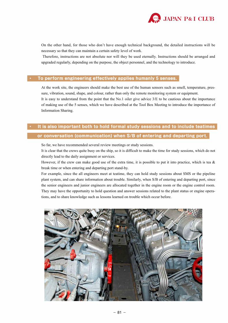
JAPAN P& I CLUB
On the other hand, for those who don’t have enough technical background, the detailed instructions will be necessary so that they can maintain a certain safety level of work. Therefore, instructions are not absolute nor will they be used eternally. Instructions should be arranged and upgraded regularly, depending on the purpose, the object personnel, and the technology to introduce.
・ To perform engineering effectively applies humanly 5 senses.
At the work site, the engineers should make the best use of the human sensors such as smell, temperature, pres-sure, vibration, sound, shape, and colour, rather than only the remote monitoring system or equipment.It is easy to understand from the point that the No.1 oiler give advice 3/E to be cautious about the importance of making use of the 5 senses, which we have described at the Tool Box Meeting to introduce the importance of Information Sharing.
・ It is also important both to hold formal study sessions and to include teatimes
or conversation (communication) when S/B of entering and departing port.
So far, we have recommended several review meetings or study sessions.It is clear that the crews quite busy on the ship, so it is difficult to make the time for study sessions, which do not directly lead to the daily assignment or services. However, if the crew can make good use of the extra time, it is possible to put it into practice, which is tea & break time or when entering and departing port stand-by. For example, since the all engineers meet at teatime, they can hold study sessions about SMS or the pipeline plant system, and can share information about trouble. Similarly, when S/B of entering and departing port, since the senior engineers and junior engineers are allocated together in the engine room or the engine control room. They may have the opportunity to hold question and answer sessions related to the plant status or engine opera-tions, and to share knowledge such as lessons learned on trouble which occur before.
- 81-
P&ILossPreventionBulletinJAPAN P& I CLUB
In this chapter, we will explain countermeasures for when “deviation” from the scheduled course has occurred, preventing the sailing to destination for reasons like engine trouble.
5.1 Regulation Under the Relevant Law
First, we would like to confirm Japanese domestic laws, which will be applied to the case of deviation. In Japan, Japanese Seamen’s Law as a law that is applied. Most countries other than Japan have almost the same regulations.
(1) Japanese Seamen’s Law Article 9 (fulfilment of voyage)
When the preparation for voyage is completed, the Master must depart on a voyage on time, and also must conduct ship operation to the port of destination without changing the scheduled traffic route, except for cases when needed.
That is, the Master must sail directly to the port of destination.
In addition, the law stipulates the following as the report duty about ship operations.
(2) Japanese Seamen’s Law Article 19 (reporting about ship operation)
If the case applies to one of following items, the Master must report to the Minister of Land, Infrastructure, Transport and Tourism, by following Ordinance of the Ministry of Land, Infrastructure, Transport and Tourism.1. When the following occurs; ship’s collision, stranding, sinking, destruction, fire, engine trouble,
and other maritime accidents.2. When engaged in lifesaving or rescue of ship.3. When the existence of another shipwreck is known and informed in any other way than wireless
telegraphy.4. When a member of the ship passes away, or goes missing.5. When changes are made to the scheduled traffic route.6. When the ship is detained or captured, or other accidents related to the ship occur.
As the 5 cases above indicate, when the scheduled traffic route is changed, the Master have the duty to report it.
As for private companies, changing the scheduled traffic route will cost unnecessary expenses, and will take time, which will bring about expense settlements between shipowners and charterers.
Correspondence in Case of Deviation
Chapter 5
- 82-
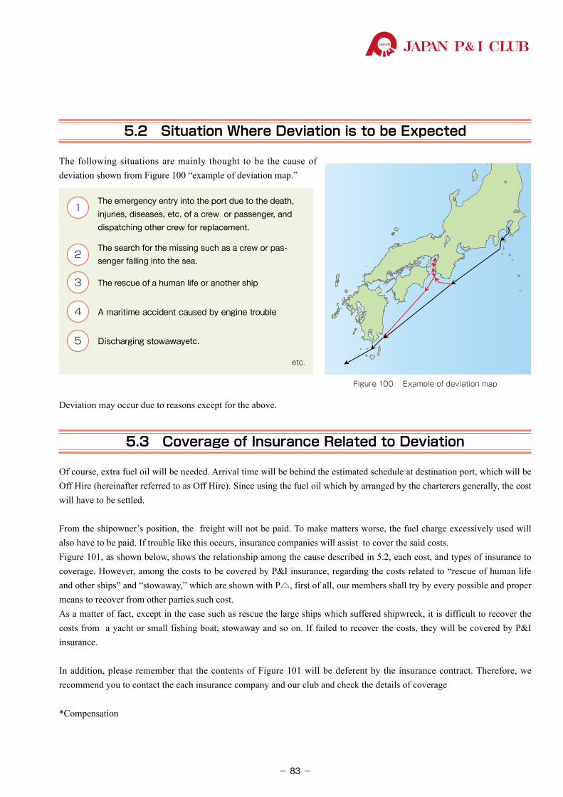
JAPAN P& I CLUB
5.2 Situation Where Deviation is to be Expected
The following situations are mainly thought to be the cause of deviation shown from Figure 100 “example of deviation map.”
Deviation may occur due to reasons except for the above.
5.3 Coverage of Insurance Related to Deviation
Of course, extra fuel oil will be needed. Arrival time will be behind the estimated schedule at destination port, which will be Off Hire (hereinafter referred to as Off Hire). Since using the fuel oil which by arranged by the charterers generally, the cost will have to be settled.
From the shipowner’s position, the freight will not be paid. To make matters worse, the fuel charge excessively used will also have to be paid. If trouble like this occurs, insurance companies will assist to cover the said costs. Figure 101, as shown below, shows the relationship among the cause described in 5.2, each cost, and types of insurance to coverage. However, among the costs to be covered by P&I insurance, regarding the costs related to “rescue of human life and other ships” and “stowaway,” which are shown with P△, first of all, our members shall try by every possible and proper means to recover from other parties such cost.As a matter of fact, except in the case such as rescue the large ships which suffered shipwreck, it is difficult to recover the costs from a yacht or small fishing boat, stowaway and so on. If failed to recover the costs, they will be covered by P&I insurance.
In addition, please remember that the contents of Figure 101 will be deferent by the insurance contract. Therefore, we recommend you to contact the each insurance company and our club and check the details of coverage
*Compensation
Figure 100 Example of deviation map
1 �The emergency entry into the port due to the death,
injuries, diseases, etc. of a crew or passenger, and
dispatching other crew for replacement.
2 �The search for the missing such as a crew or pas-
senger falling into the sea.
3 �The rescue of a human life or another ship
4 A�maritime�accident�caused�by�engine�trouble
5 Discharging�stowawayetc.
etc.
- 83-
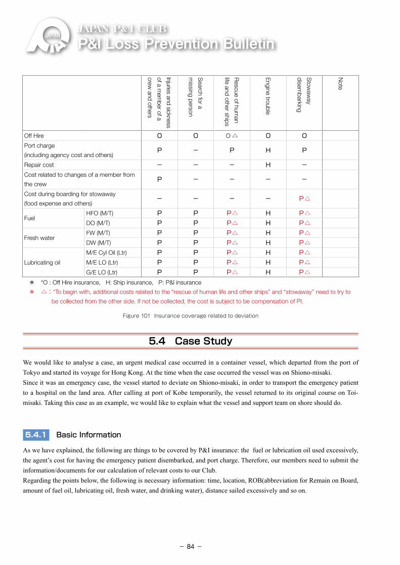
P&ILossPreventionBulletinJAPAN P& I CLUB
Injuries and sickness
of a mem
ber of a
crew and others
Search for a
missing person
Rescue of hum
an
life and other ships
Engine trouble
Stow
away
disembarking
Note
Off Hire O O O △ O OPort charge
(including agency cost and others)P - P H P
Repair cost - - - H -Cost related to changes of a member from
the crewP - - - -
Cost during boarding for stowaway
(food expense and others)- - - - P△
FuelHFO (M/T) P P P△ H P△DO (M/T) P P P△ H P△
Fresh waterFW (M/T) P P P△ H P△DW (M/T) P P P△ H P△
Lubricating oil
M/E Cyl Oil (Ltr) P P P△ H P△M/E LO (Ltr) P P P△ H P△G/E LO (Ltr) P P P△ H P△
* *O : Off Hire insurance, H: Ship insurance,�� P: P&I insurance
* △: *To begin with, additional costs related to the “rescue of human life and other ships” and “stowaway” need to try to
be collected from the other side. If not be collected, the cost is subject to be compensation of PI.
Figure 101 Insurance coverage related to deviation
5.4 Case Study
We would like to analyse a case, an urgent medical case occurred in a container vessel, which departed from the port of Tokyo and started its voyage for Hong Kong. At the time when the case occurred the vessel was on Shiono-misaki.Since it was an emergency case, the vessel started to deviate on Shiono-misaki, in order to transport the emergency patient to a hospital on the land area. After calling at port of Kobe temporarily, the vessel returned to its original course on Toi-misaki. Taking this case as an example, we would like to explain what the vessel and support team on shore should do.
5.4.1 Basic Information
As we have explained, the following are things to be covered by P&I insurance: the fuel or lubrication oil used excessively, the agent’s cost for having the emergency patient disembarked, and port charge. Therefore, our members need to submit the information/documents for our calculation of relevant costs to our Club. Regarding the points below, the following is necessary information: time, location, ROB(abbreviation for Remain on Board, amount of fuel oil, lubricating oil, fresh water, and drinking water), distance sailed excessively and so on.
- 84-
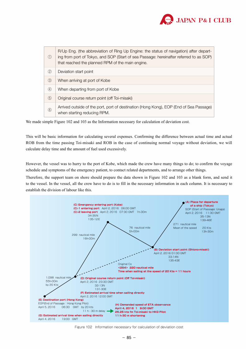
JAPAN P& I CLUB
①R/Up Eng. (the abbreviation of Ring Up Engine: the status of navigation) after depart-ing from port of Tokyo, and SOP (Start of sea Passage: hereinafter referred to as SOP) that reached the planned RPM of the main engine.
② Deviation start point
③ When arriving at port of Kobe
④ When departing from port of Kobe
⑤ Original course return point (off Toi-misaki)
⑥Arrived outside of the port, port of destination (Hong Kong), EOP (End of Sea Passage) when starting reducing RPM.
We made simple Figure 102 and 103 as the Information necessary for calculation of deviation cost.
This will be basic information for calculating several expenses. Confirming the difference between actual time and actual ROB from the time passing Toi-misaki and ROB in the case of continuing normal voyage without deviation, we will calculate delay time and the amount of fuel used excessively.
However, the vessel was to hurry to the port of Kobe, which made the crew have many things to do; to confirm the voyage schedule and symptoms of the emergency patient, to contact related departments, and to arrange other things.
Therefore, the support team on shore should prepare the data shown in Figure 102 and 103 as a blank form, and send it to the vessel. In the vessel, all the crew have to do is to fill in the necessary information in each column. It is necessary to establish the division of labour like this.
76 nautical mile5h-00m
299 nautical mile16h-00m
(B) Deviation start point (Shiono-misaki)April 2, 2016 01:00 GMT 33-14N 135-43E
Original Co<254> 220 nautical mileTime when sailing at the speed of 20 Kts = 11 hours
(A) Place for departure of a ship (Tokyo)SOP (Start of Passage: Uraga)April 2, 2016 11:30 GMT 35-13N 139-46E
271 nautical mileMean of the speed 20 Kts 13h-30m
(C) Emergency entering port (Kobe)(C)-1 entering port April 2, 2016 06:00 GMT(C)-2 leaving port April 2, 2016 07:30 GMT 1h-30m 34-35N 135-12E
1,098 nautical mile55h-00mby 20 Kts
(D) Original course return point (Off Toi-misaki)April 2, 2016 23:30 GMT 32-13N 131-30E(F) Estimated arrival time when sailing directlyApril 2, 2016 12:00 GMT
(E) Destination port (Hong Kong)EOP(End of Passage :Hong Kong Pilot)April 5, 2016 06:30 GMT by 20 kts
11 h - 30 m delay
(H) Demanded speed of ETA observanceApril 4, 2016 1 9:00 GMT25.25 kts fm Toi-misaki to HKG Pilot11 h-30 m shortening(G) Estimated arrival time when sailing directly
April 4, 2016 19:00 GMT
Figure 102 Information necessary for calculation of deviation cost
- 85-
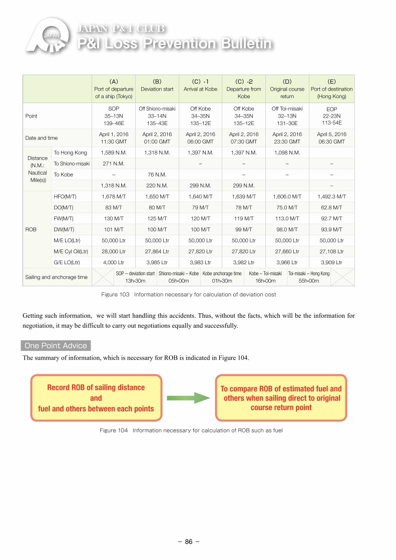
P&ILossPreventionBulletinJAPAN P& I CLUB
(A)Port of departure of a ship (Tokyo)
(B)Deviation start
(C)-1Arrival at Kobe
(C)-2Departure from
Kobe
(D)Original course
return
(E)Port of destination
(Hong Kong)
PointSOP
35–13N139–46E
Off Shiono-misaki33–14N135–43E
Off Kobe34–35N135–12E
Off Kobe34–35N135–12E
Off Toi-misaki32–13N131–30E
EOP22-23N113-54E
Date and timeApril 1, 201611:30 GMT
April 2, 201601:00 GMT
April 2, 201606:00 GMT
April 2, 201607:30 GMT
April 2, 201623:30 GMT
April 5, 201606:30 GMT
Distance (N.M.:
Nautical Mile(s))
To Hong Kong 1,589 N.M. 1,318 N.M. 1,397 N.M. 1,397 N.M. 1,098 N.M.
To Shiono-misaki 271 N.M. – – – –
To Kobe – 76 N.M. – – –
1,318 N.M. 220 N.M. 299 N.M. 299 N.M. –
ROB
HFO(M/T) 1,678 M/T 1,650 M/T 1,640 M/T 1,639 M/T 1,606.0 M/T 1,492.3 M/T
DO(M/T) 83 M/T 80 M/T 79 M/T 78 M/T 75.0 M/T 62.8 M/T
FW(M/T) 130 M/T 125 M/T 120 M/T 119 M/T 113.0 M/T 92.7 M/T
DW(M/T) 101 M/T 100 M/T 100 M/T 99 M/T 98.0 M/T 93.9 M/T
M/E LO(Ltr) 50,000 Ltr 50,000 Ltr 50,000 Ltr 50,000 Ltr 50,000 Ltr 50,000 Ltr
M/E Cyl Oil(Ltr) 28,000 Ltr 27,864 Ltr 27,820 Ltr 27,820 Ltr 27,660 Ltr 27,108 Ltr
G/E LO(Ltr) 4,000 Ltr 3,985 Ltr 3,983 Ltr 3,982 Ltr 3,966 Ltr 3,909 Ltr
Sailing and anchorage timeSOP – deviation start
13h-30mShiono-misaki – Kobe
05h-00mKobe anchorage time
01h-30mKobe – Toi-misaki
16h-00mToi-misaki – Hong Kong
55h-00m
Figure 103 Information necessary for calculation of deviation cost
Getting such information, we will start handling this accidents. Thus, without the facts, which will be the information for negotiation, it may be difficult to carry out negotiations equally and successfully.
One Point AdviceThe summary of information, which is necessary for ROB is indicated in Figure 104.
Record ROB of sailing distance and
fuel and others between each points
To compare ROB of estimated fuel and others when sailing direct to original
course return point
Figure 104 Information necessary for calculation of ROB such as fuel
- 86-
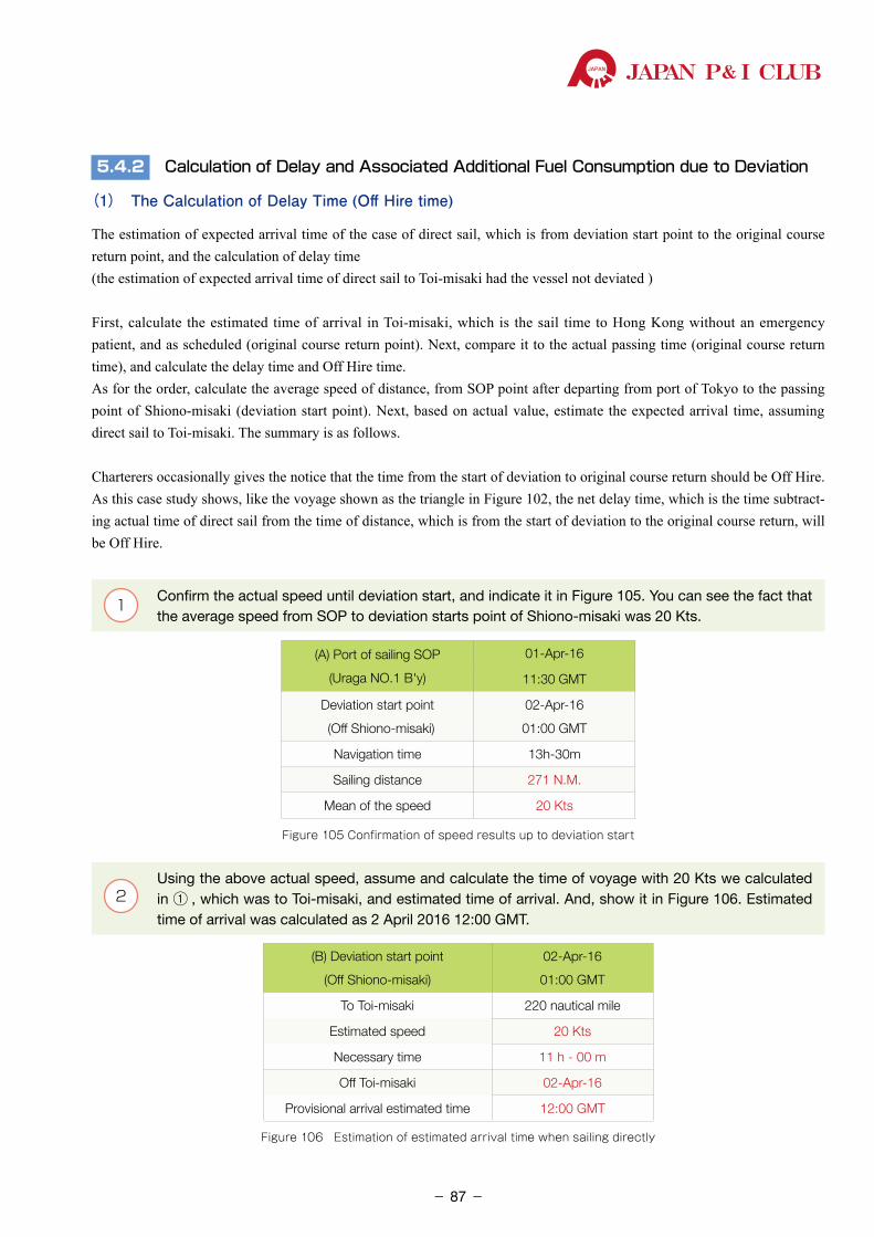
JAPAN P& I CLUB
5.4.2 Calculation of Delay and Associated Additional Fuel Consumption due to Deviation
(1) The Calculation of Delay Time (Off Hire time)
The estimation of expected arrival time of the case of direct sail, which is from deviation start point to the original course return point, and the calculation of delay time(the estimation of expected arrival time of direct sail to Toi-misaki had the vessel not deviated )
First, calculate the estimated time of arrival in Toi-misaki, which is the sail time to Hong Kong without an emergency patient, and as scheduled (original course return point). Next, compare it to the actual passing time (original course return time), and calculate the delay time and Off Hire time.As for the order, calculate the average speed of distance, from SOP point after departing from port of Tokyo to the passing point of Shiono-misaki (deviation start point). Next, based on actual value, estimate the expected arrival time, assuming direct sail to Toi-misaki. The summary is as follows.
Charterers occasionally gives the notice that the time from the start of deviation to original course return should be Off Hire. As this case study shows, like the voyage shown as the triangle in Figure 102, the net delay time, which is the time subtract-ing actual time of direct sail from the time of distance, which is from the start of deviation to the original course return, will be Off Hire.
1 Confirm the actual speed until deviation start, and indicate it in Figure 105. You can see the fact that the average speed from SOP to deviation starts point of Shiono-misaki was 20 Kts.
(A) Port of sailing SOP
(Uraga NO.1 B'y)
01-Apr-16
11:30 GMT
Deviation start point
(Off Shiono-misaki)
02-Apr-16
01:00 GMT
Navigation time 13h-30m
Sailing distance 271 N.M.
Mean of the speed 20 Kts
Figure 105 Confirmation of speed results up to deviation start
2 Using the above actual speed, assume and calculate the time of voyage with 20 Kts we calculated
in ① , which was to Toi-misaki, and estimated time of arrival. And, show it in Figure 106. Estimated time of arrival was calculated as 2 April 2016 12:00 GMT.
(B) Deviation start point
(Off Shiono-misaki)
02-Apr-16
01:00 GMT
To Toi-misaki 220 nautical mile
Estimated speed 20 Kts
Necessary time 11 h - 00 m
Off Toi-misaki 02-Apr-16
Provisional arrival estimated time 12:00 GMT
Figure 106 Estimation of estimated arrival time when sailing directly
- 87-
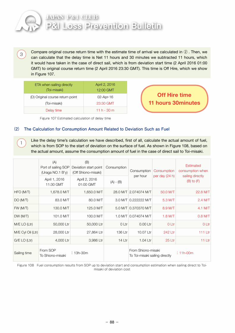
P&ILossPreventionBulletinJAPAN P& I CLUB
3 Compare original course return time with the estimate time of arrival we calculated in ② . Then, we can calculate that the delay time is Net 11 hours and 30 minutes we subtracted 11 hours, which it would have taken in the case of direct sail, which is from deviation start time (2 April 2016 01:00 GMT) to original course return time (2 April 2016 23:30 GMT). This time is Off Hire, which we show in Figure 107.
ETA when sailing directly (Toi-misaki)
April 2, 2016
12:00 GMT
(D) Original course return point
(Toi-misaki)
02-Apr-16
23:30 GMT
Delay time 11 h - 30 m
Figure 107 Estimated calculation of delay time
(2) The Calculation for Consumption Amount Related to Deviation Such as Fuel
1 Like the delay time’s calculation we have described, first of all, calculate the actual amount of fuel, which is from SOP to the start of deviation on the surface of fuel. As shown in Figure 108, based on the actual amount, assume the consumption amount of fuel in the case of direct sail to Toi-misaki.
(A) Port of sailing SOP(Uraga NO.1 B'y)
(B) Deviation start point(Off Shiono-misaki)
ConsumptionConsumption
per hourConsumption per day (24 h)
Estimated consumption when
sailing directly (B) to (F)April 1, 2016
11:30 GMTApril 2, 201601:00 GMT
(A) - (B)
HFO (M/T) 1,678.0 M/T 1,650.0 M/T 28.0 M/T 2.074074 M/T 50.0 M/T 22.8 M/T
DO (M/T) 83.0 M/T 80.0 M/T 3.0 M/T 0.222222 M/T 5.3 M/T 2.4 M/T
FW (M/T) 130.0 M/T 125.0 M/T 5.0 M/T 0.370370 M/T 8.9 M/T 4.1 M/T
DW (M/T) 101.0 M/T 100.0 M/T 1.0 M/T 0.074074 M/T 1.8 M/T 0.8 M/T
M/E LO (Ltr) 50,000 Ltr 50,000 Ltr 0 Ltr 0.00 Ltr 0 Ltr 0 Ltr
M/E Cyl Oil (Ltr) 28,000 Ltr 27,864 Ltr 136 Ltr 10.07 Ltr 242 Ltr 111 Ltr
G/E LO (Ltr) 4,000 Ltr 3,986 Ltr 14 Ltr 1.04 Ltr 25 Ltr 11 Ltr
Sailing timeFrom SOPTo Shiono-misaki
: 13h-30mFrom Shiono-misakiTo Toi-misaki sailing directly
:11h-00m
Figure 108 Fuel consumption results from SOP up to deviation start and consumption estimation when sailing direct to Toi-misaki of deviation cost
Off Hire time11 hours 30minutes
- 88-
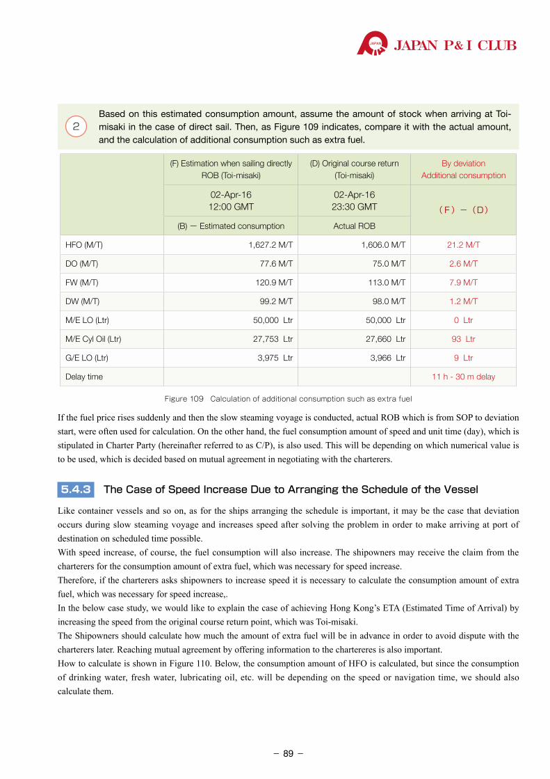
JAPAN P& I CLUB
. 2 Based on this estimated consumption amount, assume the amount of stock when arriving at Toi-
misaki in the case of direct sail. Then, as Figure 109 indicates, compare it with the actual amount, and the calculation of additional consumption such as extra fuel.
(F) Estimation when sailing directlyROB (Toi-misaki)
(D) Original course return(Toi-misaki)
By deviationAdditional consumption
02-Apr-1612:00 GMT
02-Apr-1623:30 GMT (F)-(D)
(B)- Estimated consumption Actual ROB
HFO (M/T) 1,627.2 M/T 1,606.0 M/T 21.2 M/T
DO (M/T) 77.6 M/T 75.0 M/T 2.6 M/T
FW (M/T) 120.9 M/T 113.0 M/T 7.9 M/T
DW (M/T) 99.2 M/T 98.0 M/T 1.2 M/T
M/E LO (Ltr) 50,000 Ltr 50,000 Ltr 0 Ltr
M/E Cyl Oil (Ltr) 27,753 Ltr 27,660 Ltr 93 Ltr
G/E LO (Ltr) 3,975 Ltr 3,966 Ltr 9 Ltr
Delay time 11 h - 30 m delay
Figure 109 Calculation of additional consumption such as extra fuel
If the fuel price rises suddenly and then the slow steaming voyage is conducted, actual ROB which is from SOP to deviation start, were often used for calculation. On the other hand, the fuel consumption amount of speed and unit time (day), which is stipulated in Charter Party (hereinafter referred to as C/P), is also used. This will be depending on which numerical value is to be used, which is decided based on mutual agreement in negotiating with the charterers.
5.4.3 The Case of Speed Increase Due to Arranging the Schedule of the Vessel
Like container vessels and so on, as for the ships arranging the schedule is important, it may be the case that deviation occurs during slow steaming voyage and increases speed after solving the problem in order to make arriving at port of destination on scheduled time possible.With speed increase, of course, the fuel consumption will also increase. The shipowners may receive the claim from the charterers for the consumption amount of extra fuel, which was necessary for speed increase. Therefore, if the charterers asks shipowners to increase speed it is necessary to calculate the consumption amount of extra fuel, which was necessary for speed increase,.In the below case study, we would like to explain the case of achieving Hong Kong’s ETA (Estimated Time of Arrival) by increasing the speed from the original course return point, which was Toi-misaki.The Shipowners should calculate how much the amount of extra fuel will be in advance in order to avoid dispute with the charterers later. Reaching mutual agreement by offering information to the chartereres is also important.How to calculate is shown in Figure 110. Below, the consumption amount of HFO is calculated, but since the consumption of drinking water, fresh water, lubricating oil, etc. will be depending on the speed or navigation time, we should also calculate them.
- 89-
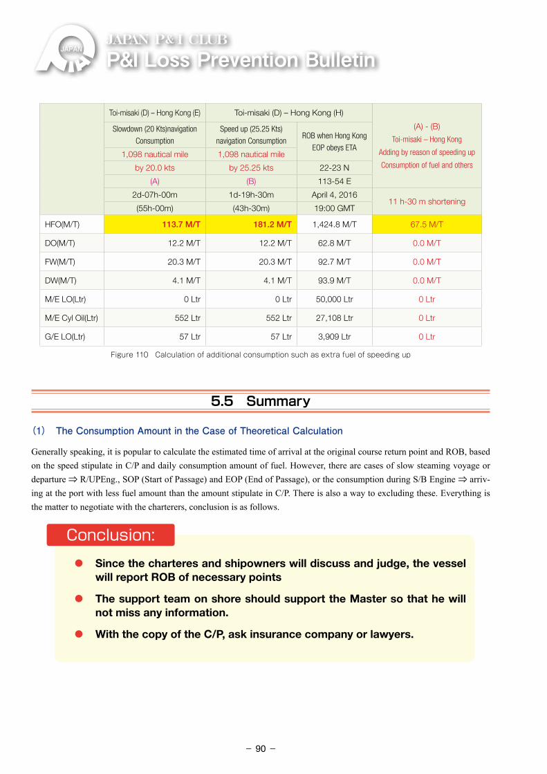
P&ILossPreventionBulletinJAPAN P& I CLUB
Toi-misaki (D) – Hong Kong (E) Toi-misaki (D) – Hong Kong (H)
(A) - (B)
Toi-misaki – Hong Kong
Adding by reason of speeding up
Consumption of fuel and others
Slowdown (20 Kts)navigation
Consumption
Speed up (25.25 Kts)
navigation ConsumptionROB when Hong Kong
EOP obeys ETA1,098 nautical mile 1,098 nautical mile
by 20.0 kts by 25.25 kts 22-23 N
(A) (B) 113-54 E
2d-07h-00m 1d-19h-30m April 4, 201611 h-30 m shortening
(55h-00m) (43h-30m) 19:00 GMT
HFO(M/T) 113.7 M/T 181.2 M/T 1,424.8 M/T 67.5 M/T
DO(M/T) 12.2 M/T 12.2 M/T 62.8 M/T 0.0 M/T
FW(M/T) 20.3 M/T 20.3 M/T 92.7 M/T 0.0 M/T
DW(M/T) 4.1 M/T 4.1 M/T 93.9 M/T 0.0 M/T
M/E LO(Ltr) 0 Ltr 0 Ltr 50,000 Ltr 0 Ltr
M/E Cyl Oil(Ltr) 552 Ltr 552 Ltr 27,108 Ltr 0 Ltr
G/E LO(Ltr) 57 Ltr 57 Ltr 3,909 Ltr 0 Ltr
Figure 110 Calculation of additional consumption such as extra fuel of speeding up
5.5 Summary
(1) The Consumption Amount in the Case of Theoretical Calculation
Generally speaking, it is popular to calculate the estimated time of arrival at the original course return point and ROB, based on the speed stipulate in C/P and daily consumption amount of fuel. However, there are cases of slow steaming voyage or departure ⇒ R/UPEng., SOP (Start of Passage) and EOP (End of Passage), or the consumption during S/B Engine ⇒ arriv-ing at the port with less fuel amount than the amount stipulate in C/P. There is also a way to excluding these. Everything is the matter to negotiate with the charterers, conclusion is as follows.
・ Since the charteres and shipowners will discuss and judge, the vessel will report ROB of necessary points
・ The support team on shore should support the Master so that he will not miss any information.
・ With the copy of the C/P, ask insurance company or lawyers.
Conclusion:
- 90-
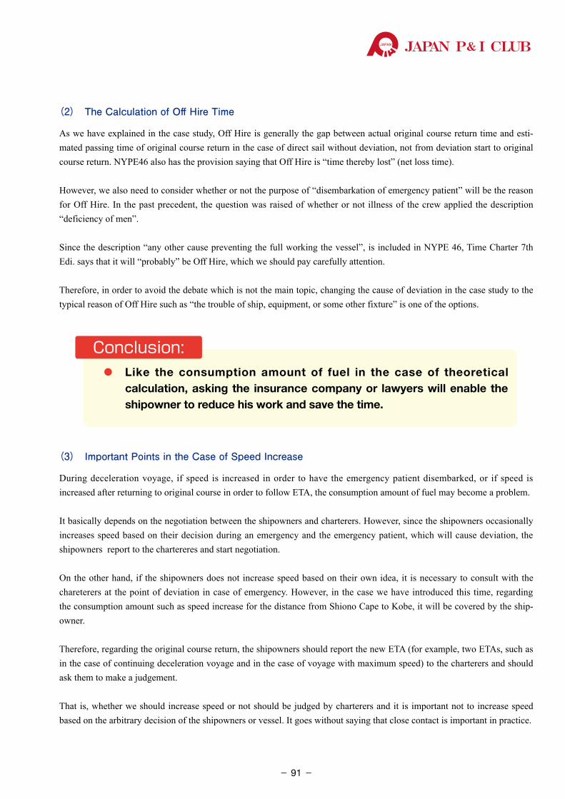
JAPAN P& I CLUB
(2) The Calculation of Off Hire Time
As we have explained in the case study, Off Hire is generally the gap between actual original course return time and esti-mated passing time of original course return in the case of direct sail without deviation, not from deviation start to original course return. NYPE46 also has the provision saying that Off Hire is “time thereby lost” (net loss time).
However, we also need to consider whether or not the purpose of “disembarkation of emergency patient” will be the reason for Off Hire. In the past precedent, the question was raised of whether or not illness of the crew applied the description “deficiency of men”.
Since the description “any other cause preventing the full working the vessel”, is included in NYPE 46, Time Charter 7th Edi. says that it will “probably” be Off Hire, which we should pay carefully attention.
Therefore, in order to avoid the debate which is not the main topic, changing the cause of deviation in the case study to the typical reason of Off Hire such as “the trouble of ship, equipment, or some other fixture” is one of the options.
・ �Like the consumption amount of fuel in the case of theoretical calculation, asking the insurance company or lawyers will enable the shipowner to reduce his work and save the time.
Conclusion:
(3) Important Points in the Case of Speed Increase
During deceleration voyage, if speed is increased in order to have the emergency patient disembarked, or if speed is increased after returning to original course in order to follow ETA, the consumption amount of fuel may become a problem.
It basically depends on the negotiation between the shipowners and charterers. However, since the shipowners occasionally increases speed based on their decision during an emergency and the emergency patient, which will cause deviation, the shipowners report to the chartereres and start negotiation.
On the other hand, if the shipowners does not increase speed based on their own idea, it is necessary to consult with the chareterers at the point of deviation in case of emergency. However, in the case we have introduced this time, regarding the consumption amount such as speed increase for the distance from Shiono Cape to Kobe, it will be covered by the ship-owner.
Therefore, regarding the original course return, the shipowners should report the new ETA (for example, two ETAs, such as in the case of continuing deceleration voyage and in the case of voyage with maximum speed) to the charterers and should ask them to make a judgement.
That is, whether we should increase speed or not should be judged by charterers and it is important not to increase speed based on the arbitrary decision of the shipowners or vessel. It goes without saying that close contact is important in practice.
- 91-
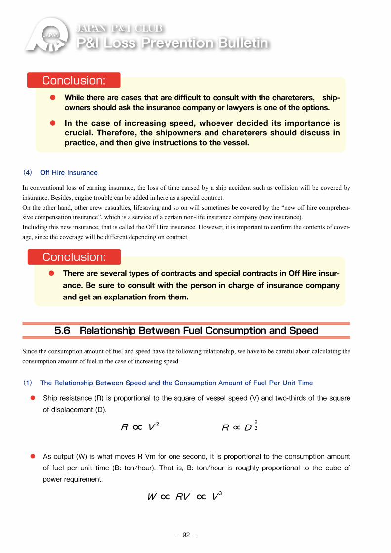
P&ILossPreventionBulletinJAPAN P& I CLUB
・ While there are cases that are difficult to consult with the chareterers, ship-owners should ask the insurance company or lawyers is one of the options.
・ In the case of increasing speed, whoever decided its importance is crucial. Therefore, the shipowners and chareterers should discuss in practice, and then give instructions to the vessel.
Conclusion:
(4) Off Hire Insurance
In conventional loss of earning insurance, the loss of time caused by a ship accident such as collision will be covered by insurance. Besides, engine trouble can be added in here as a special contract.On the other hand, other crew casualties, lifesaving and so on will sometimes be covered by the “new off hire comprehen-sive compensation insurance”, which is a service of a certain non-life insurance company (new insurance).Including this new insurance, that is called the Off Hire insurance. However, it is important to confirm the contents of cover-age, since the coverage will be different depending on contract
・ �There are several types of contracts and special contracts in Off Hire insur-ance. Be sure to consult with the person in charge of insurance company and get an explanation from them.
Conclusion:
5.6 Relationship Between Fuel Consumption and Speed
Since the consumption amount of fuel and speed have the following relationship, we have to be careful about calculating the consumption amount of fuel in the case of increasing speed.
(1) The Relationship Between Speed and the Consumption Amount of Fuel Per Unit Time
・ �Ship�resistance�(R)�is�proportional�to�the�square�of�vessel�speed�(V)�and�two-thirds�of�the�square�of�displacement�(D).���
R ∝ V 2 23R ∝ D
W ∝ RV ∝ V3
Ba=K x Va3 Bb=K x Vb 3
Va3K = BaVb3K = Bb
Va3 Vb 3Ba = Bb 3
Va3Bb = Ba x Vb
K : constant
Vb 3
Va=Bb Ba x ( )
DistVaVa
Necessary time by Necessary time by Necessary time by
Necessary time by
Fuel consumption by
Necessay time by
= timeDistVb
VbNecessary time by = time
2Dist 3 2
Va VaVa Fa = x = xK・VaBa = K・Dist・Va2
Dist
Dist
Dist Dist3 2
Vb VbVb Fb = x Bb = xK・Vb = K・ ・Vb
Va2 Vb2Fb=K・Dist Fa =
Vb 2
VaX ( )Fb = Fa
・ �As�output�(W)�is�what�moves�R�Vm�for�one�second,�it�is�proportional�to�the�consumption�amount�of� fuel�per�unit� time� (B:� ton/hour).�That� is,�B:� ton/hour� is� roughly�proportional� to� the�cube�of�power�requirement.
R ∝ V 2 23R ∝ D
W ∝ RV ∝ V3
Ba=K x Va3 Bb=K x Vb 3
Va3K = BaVb3K = Bb
Va3 Vb 3Ba = Bb 3
Va3Bb = Ba x Vb
K : constant
Vb 3
Va=Bb Ba x ( )
DistVaVa
Necessary time by Necessary time by Necessary time by
Necessary time by
Fuel consumption by
Necessay time by
= timeDistVb
VbNecessary time by = time
2Dist 3 2
Va VaVa Fa = x = xK・VaBa = K・Dist・Va2
Dist
Dist
Dist Dist3 2
Vb VbVb Fb = x Bb = xK・Vb = K・ ・Vb
Va2 Vb2Fb=K・Dist Fa =
Vb 2
VaX ( )Fb = Fa
- 92-
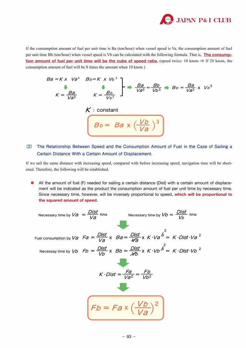
JAPAN P& I CLUB
If the consumption amount of fuel per unit time is Ba (ton/hour) when vessel speed is Va, the consumption amount of fuel per unit time Bb (ton/hour) when vessel speed is Vb can be calculated with the following formula. That is, The consump-tion amount of fuel per unit time will be the cube of speed ratio. (speed twice: 10 knots ⇒ If 20 knots, the consumption amount of fuel will be 8 times the amount when 10 knots )
R ∝ V 2 23R ∝ D
W ∝ RV ∝ V3
Ba=K x Va3 Bb=K x Vb 3
Va3K = BaVb3K = Bb
Va3 Vb 3Ba = Bb 3
Va3Bb = Ba x Vb
K : constant
Vb 3
Va=Bb Ba x ( )
DistVaVa
Necessary time by Necessary time by Necessary time by
Necessary time by
Fuel consumption by
Necessay time by
= timeDistVb
VbNecessary time by = time
2Dist 3 2
Va VaVa Fa = x = xK・VaBa = K・Dist・Va2
Dist
Dist
Dist Dist3 2
Vb VbVb Fb = x Bb = xK・Vb = K・ ・Vb
Va2 Vb2Fb=K・Dist Fa =
Vb 2
VaX ( )Fb = Fa
(2) The Relationship Between Speed and the Consumption Amount of Fuel in the Case of Sailing a Certain Distance With a Certain Amount of Displacement.
If we sail the same distance with increasing speed, compared with before increasing speed, navigation time will be short-ened. Therefore, the following will be established.
・ �All the amount of fuel (F) needed for sailing a certain distance (Dist) with a certain amount of displace-ment will be indicated as the product the consumption amount of fuel per unit time by necessary time. Since necessary time, however, will be inversely proportional to speed, which will be proportional to the squared amount of speed.
R ∝ V 2 23R ∝ D
W ∝ RV ∝ V3
Ba=K x Va3 Bb=K x Vb 3
Va3K = BaVb3K = Bb
Va3 Vb 3Ba = Bb 3
Va3Bb = Ba x Vb
K : constant
Vb 3
Va=Bb Ba x ( )
DistVaVa
Necessary time by Necessary time by Necessary time by
Necessary time by
Fuel consumption by
Necessay time by
= timeDistVb
VbNecessary time by = time
2Dist 3 2
Va VaVa Fa = x = xK・VaBa = K・Dist・Va2
Dist
Dist
Dist Dist3 2
Vb VbVb Fb = x Bb = xK・Vb = K・ ・Vb
Va2 Vb2Fb=K・Dist Fa =
Vb 2
VaX ( )Fb = Fa
- 93-
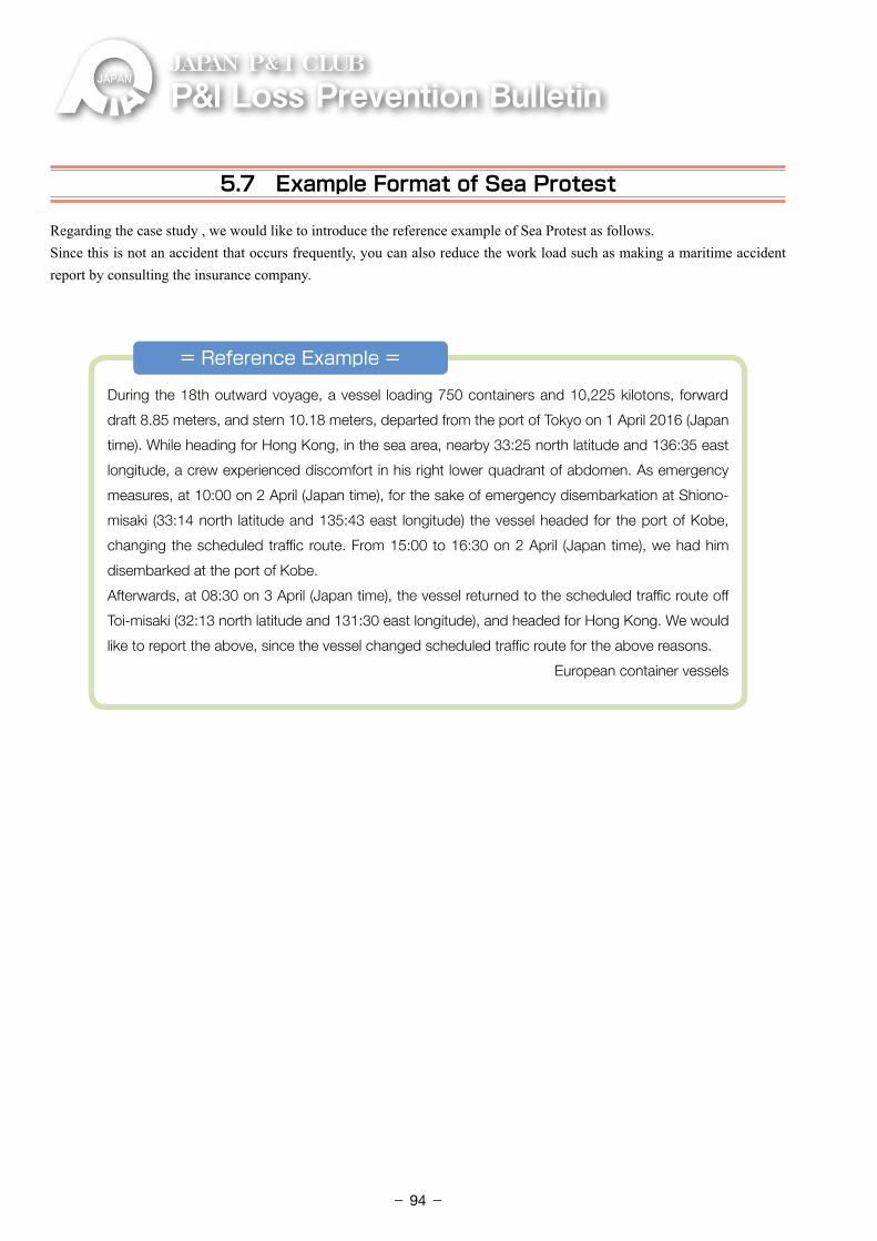
P&ILossPreventionBulletinJAPAN P& I CLUB
5.7 Example Format of Sea Protest
Regarding the case study , we would like to introduce the reference example of Sea Protest as follows.Since this is not an accident that occurs frequently, you can also reduce the work load such as making a maritime accident report by consulting the insurance company.
During the 18th outward voyage, a vessel loading 750 containers and 10,225 kilotons, forward
draft 8.85 meters, and stern 10.18 meters, departed from the port of Tokyo on 1 April 2016 (Japan
time). While heading for Hong Kong, in the sea area, nearby 33:25 north latitude and 136:35 east
longitude, a crew experienced discomfort in his right lower quadrant of abdomen. As emergency
measures, at 10:00 on 2 April (Japan time), for the sake of emergency disembarkation at Shiono-
misaki (33:14 north latitude and 135:43 east longitude) the vessel headed for the port of Kobe,
changing the scheduled traffic route. From 15:00 to 16:30 on 2 April (Japan time), we had him
disembarked at the port of Kobe.
Afterwards, at 08:30 on 3 April (Japan time), the vessel returned to the scheduled traffic route off
Toi-misaki (32:13 north latitude and 131:30 east longitude), and headed for Hong Kong. We would
like to report the above, since the vessel changed scheduled traffic route for the above reasons.
European container vessels
= Reference Example =
- 94-
JAPAN P& I CLUB
Summary
To make steady efforts step by step
From chapter 1 to 4, we have explained statistics, case studies, risk prediction, and resource management. As you see from the case studies, the cause of accident has been composed of several factors. In other words, the accident occurred due to a series of “error” management condi-tions: the tiny mistake caused by lack of understanding for system, and the incorrect Planned Maintenance System caused by lack of understanding for reason and purpose of maintenance. Therefore, the preventive measures were not able to solve the problem with only one correction to make. As a result, we could not find a landmark solution just like a miracle drug. Thus, we should be on our guard and protect ourselves, not missing error chain so that we can prevent accidents.Important point is to make efforts to establish something extra [+α], which is state monitoring, maintenance, and educational system, as well as ERM ability require-ments.
In short, we don’t have any miracle drug, and it is necessary to make steady efforts step by step.
In chapter 5, we have explained how to deal with deviation, but when accidents occur, the vessel will be so busy that the crews will have many things to do. In order to grasp the situation, the shipowners cannot but depend on the vessel’s report, they should establish the system that support team on shore, and can reduce and assist the work in the vessel as much as possible.
- 95-
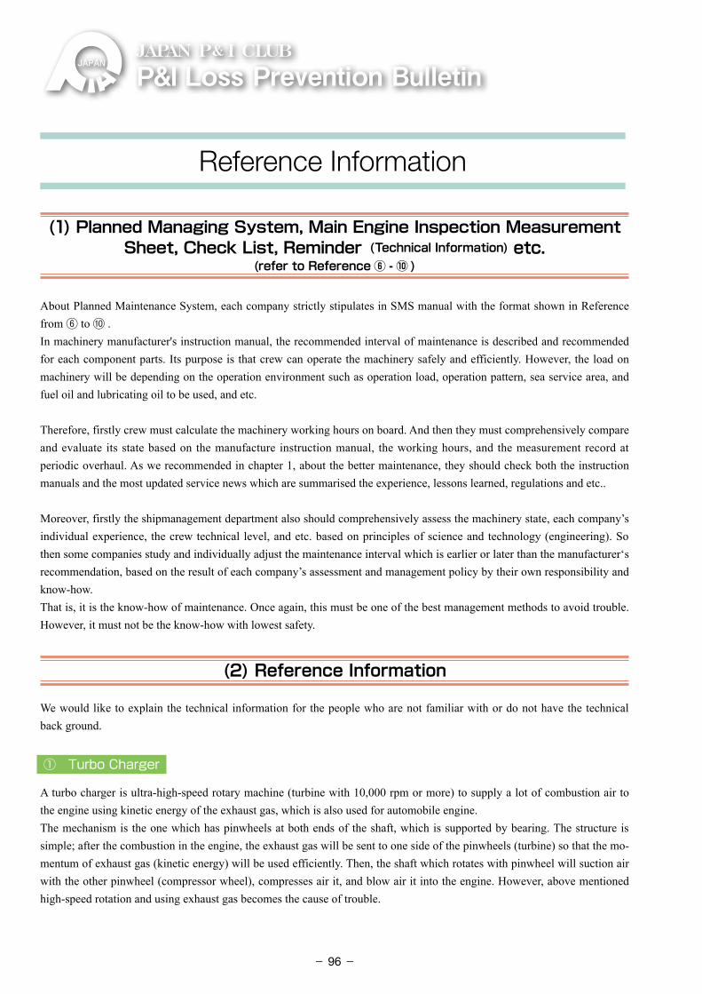
P&ILossPreventionBulletinJAPAN P& I CLUB
(1) Planned Managing System, Main Engine Inspection Measurement Sheet, Check List, Reminder (Technical Information) etc.
(refer to Reference ⑥ - ⑩ )
About Planned Maintenance System, each company strictly stipulates in SMS manual with the format shown in Reference from ⑥ to ⑩ .In machinery manufacturer's instruction manual, the recommended interval of maintenance is described and recommended for each component parts. Its purpose is that crew can operate the machinery safely and efficiently. However, the load on machinery will be depending on the operation environment such as operation load, operation pattern, sea service area, and fuel oil and lubricating oil to be used, and etc.
Therefore, firstly crew must calculate the machinery working hours on board. And then they must comprehensively compare and evaluate its state based on the manufacture instruction manual, the working hours, and the measurement record at periodic overhaul. As we recommended in chapter 1, about the better maintenance, they should check both the instruction manuals and the most updated service news which are summarised the experience, lessons learned, regulations and etc..
Moreover, firstly the shipmanagement department also should comprehensively assess the machinery state, each company’s individual experience, the crew technical level, and etc. based on principles of science and technology (engineering). So then some companies study and individually adjust the maintenance interval which is earlier or later than the manufacturer‘s recommendation, based on the result of each company’s assessment and management policy by their own responsibility and know-how. That is, it is the know-how of maintenance. Once again, this must be one of the best management methods to avoid trouble. However, it must not be the know-how with lowest safety.
(2) Reference Information
We would like to explain the technical information for the people who are not familiar with or do not have the technical back ground.
① Turbo Charger
A turbo charger is ultra-high-speed rotary machine (turbine with 10,000 rpm or more) to supply a lot of combustion air to the engine using kinetic energy of the exhaust gas, which is also used for automobile engine.The mechanism is the one which has pinwheels at both ends of the shaft, which is supported by bearing. The structure is simple; after the combustion in the engine, the exhaust gas will be sent to one side of the pinwheels (turbine) so that the mo-mentum of exhaust gas (kinetic energy) will be used efficiently. Then, the shaft which rotates with pinwheel will suction air with the other pinwheel (compressor wheel), compresses air it, and blow air it into the engine. However, above mentioned high-speed rotation and using exhaust gas becomes the cause of trouble.
Reference Information
- 96-
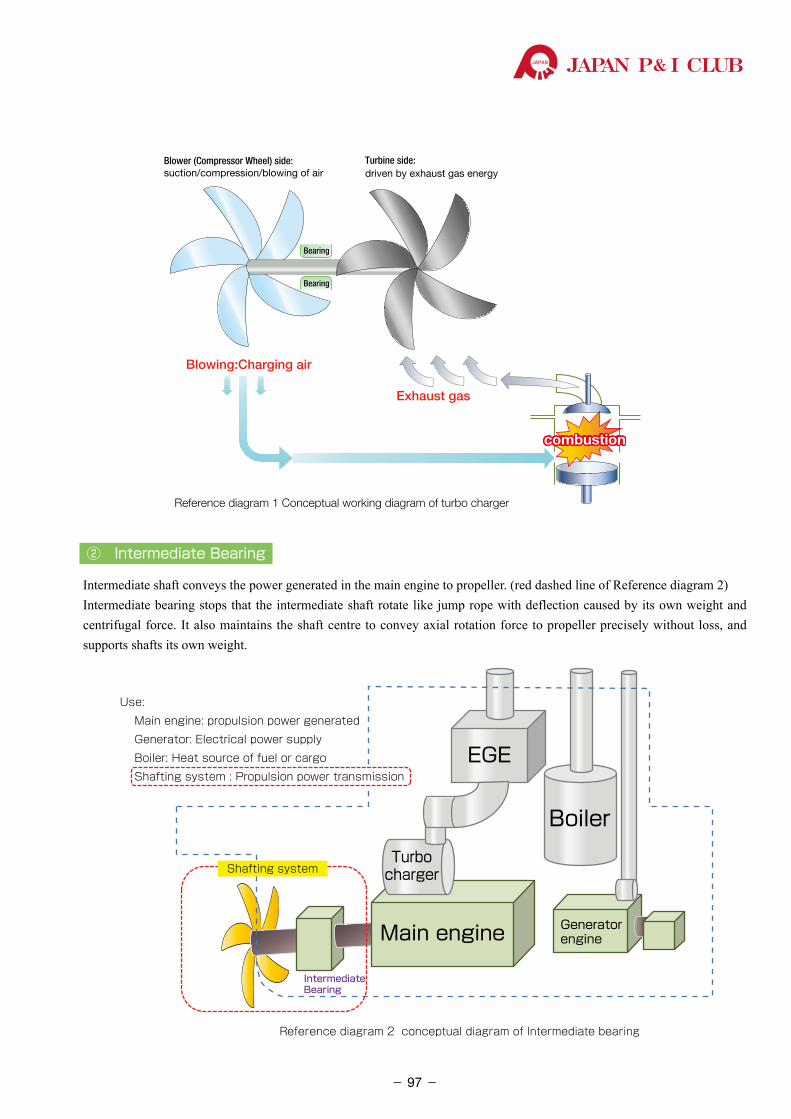
JAPAN P& I CLUB
② Intermediate Bearing
Intermediate shaft conveys the power generated in the main engine to propeller. (red dashed line of Reference diagram 2)Intermediate bearing stops that the intermediate shaft rotate like jump rope with deflection caused by its own weight and centrifugal force. It also maintains the shaft centre to convey axial rotation force to propeller precisely without loss, and supports shafts its own weight.
Turbine side: driven by exhaust gas energy
Blower (Compressor Wheel) side: suction/compression/blowing of air
Bearing
Bearing
Blowing:Charging air
Exhaust gas
combustioncombustion
Reference diagram 1 Conceptual working diagram of turbo charger
Turbo charger
Shafting system
IntermediateBearing
Reference diagram 2 conceptual diagram of Intermediate bearing
Use:
Main engine: propulsion power generated
Generator: Electrical power supply
Boiler: Heat source of fuel or cargo
Shafting system : Propulsion power transmission
Boiler
EGE
GeneratorengineMain engine
IntermediateBearing
Turbocharger
- 97-
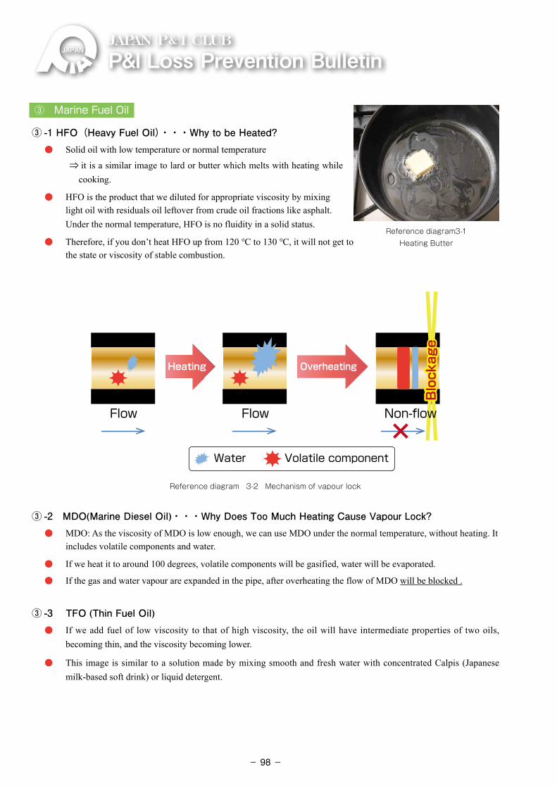
P&ILossPreventionBulletinJAPAN P& I CLUB
③ Marine Fuel Oil
③ -1 HFO(Heavy Fuel Oil)・・・Why to be Heated? ・ �Solid oil with low temperature or normal temperature
⇒ it is a similar image to lard or butter which melts with heating while cooking.
・ �HFO is the product that we diluted for appropriate viscosity by mixing light oil with residuals oil leftover from crude oil fractions like asphalt. Under the normal temperature, HFO is no fluidity in a solid status.
・ �Therefore, if you don’t heat HFO up from 120 ℃ to 130 ℃, it will not get to the state or viscosity of stable combustion.
Water Volatile component
Flow Flow
Heating Overheating
Blockage
Blockage
Non-flow
Reference diagram 3-2 Mechanism of vapour lock
③ -2 MDO(Marine Diesel Oil)・・・Why Does Too Much Heating Cause Vapour Lock? ・ �MDO: As the viscosity of MDO is low enough, we can use MDO under the normal temperature, without heating. It
includes volatile components and water.
・ �If we heat it to around 100 degrees, volatile components will be gasified, water will be evaporated.
・ �If the gas and water vapour are expanded in the pipe, after overheating the flow of MDO will be blocked .
③ -3 TFO (Thin Fuel Oil) ・ �If we add fuel of low viscosity to that of high viscosity, the oil will have intermediate properties of two oils,
becoming thin, and the viscosity becoming lower.
・ �This image is similar to a solution made by mixing smooth and fresh water with concentrated Calpis (Japanese milk-based soft drink) or liquid detergent.
Reference diagram3-1 Heating Butter
- 98-
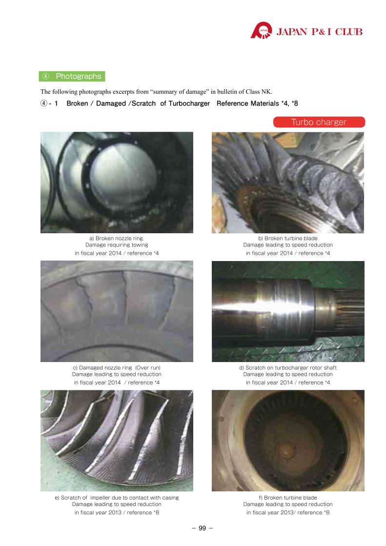
JAPAN P& I CLUB
④ Photographs
The following photographs excerpts from “summary of damage” in bulletin of Class NK.
④ - 1 Broken / Damaged /Scratch of Turbocharger Reference Materials *4, *8
a) Broken nozzle ring. Damage requiring towing
in fiscal year 2014 / reference *4
b) Broken turbine blade Damage leading to speed reduction in fiscal year 2014 / reference *4
d) Scratch on turbocharger rotor shaft Damage leading to speed reduction in fiscal year 2014 / reference *4
f) Broken turbine blade Damage leading to speed reduction in fiscal year 2013/ reference *8
c) Damaged nozzle ring (Over run) Damage leading to speed reductionin fiscal year 2014 / reference *4
e) Scratch of impeller due to contact with casing Damage leading to speed reductionin fiscal year 2013 / reference *8
Turbo charger
- 99-
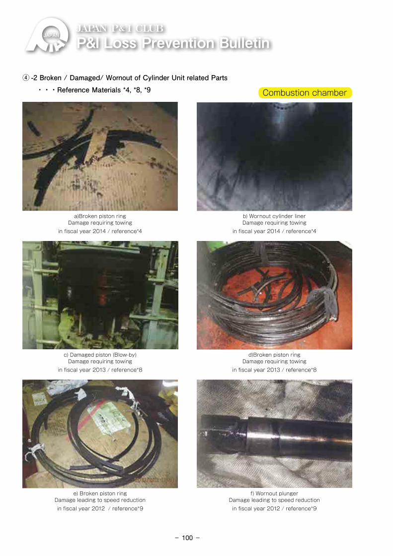
P&ILossPreventionBulletinJAPAN P& I CLUB
④ -2 Broken / Damaged/ Wornout of Cylinder Unit related Parts ・・・Reference Materials *4, *8, *9
a)Broken piston ring Damage requiring towing
in fiscal year 2014 / reference*4
b) Wornout cylinder liner Damage requiring towing
in fiscal year 2014 / reference*4
d)Broken piston ring Damage requiring towing
in fiscal year 2013 / reference*8
f) Wornout plunger Damage leading to speed reduction
in fiscal year 2012 / reference*9
c) Damaged piston (Blow-by) Damage requiring towing
in fiscal year 2013 / reference*8
e) Broken piston ring Damage leading to speed reduction in fiscal year 2012 / reference*9
Combustion chamber
- 100-
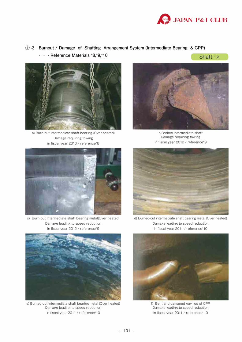
JAPAN P& I CLUB
④ -3 Burnout / Damage of Shafting Arrangement System (Intermediate Bearing & CPP) ・・・Reference Materials *8,*9,*10
a) Burn-out Intermediate shaft bearing (Over-heated)Damage requiring towing
in fiscal year 2013 / reference*8
b)Broken intermediate shaft Damage requiring towing
in fiscal year 2012 / reference*9
d) Burned-out intermediate shaft bearing metal (Over heated)Damage leading to speed reduction in fiscal year 2011 / reference*10
f) Bent and damaged guy rod of CPP Damage leading to speed reduction in fiscal year 2011 / reference* 10
c) Burn-out Intermediate shaft bearing metal(Over heated)Damage leading to speed reduction
in fiscal year 2012 / reference*9
e) Burned-out intermediate shaft bearing metal (Over heated) Damage leading to speed reduction in fiscal year 2011 / reference*10
Shafting
- 101-
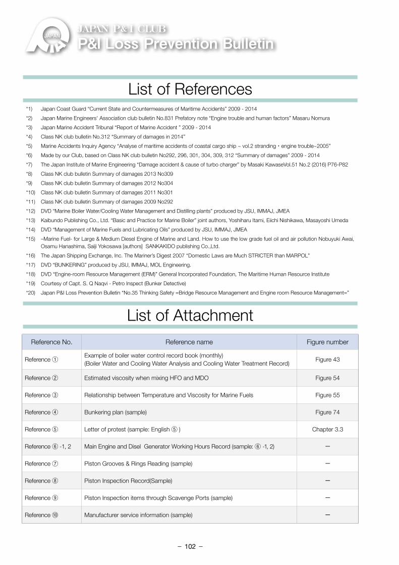
P&ILossPreventionBulletinJAPAN P& I CLUB
List of References
List of Attachment
*1) Japan Coast Guard “Current State and Countermeasures of Maritime Accidents” 2009 - 2014
*2) Japan Marine Engineers' Association club bulletin No.831 Prefatory note “Engine trouble and human factors” Masaru Nomura
*3) Japan Marine Accident Tribunal “Report of Marine Accident ” 2009 - 2014
*4) Class NK club bulletin No.312 “Summary of damages in 2014”
*5) Marine Accidents Inquiry Agency “Analyse of maritime accidents of coastal cargo ship ~ vol.2 stranding・engine trouble~2005”
*6) Made by our Club, based on Class NK club bulletin No292, 296, 301, 304, 309, 312 “Summary of damages” 2009 - 2014
*7) The Japan Institute of Marine Engineering “Damage accident & cause of turbo charger” by Masaki KawaseVol.51 No.2 (2016) P76-P82
*8) Class NK club bulletin Summary of damages 2013 No309
*9) Class NK club bulletin Summary of damages 2012 No304
*10) Class NK club bulletin Summary of damages 2011 No301
*11) Class NK club bulletin Summary of damages 2009 No292
*12) DVD “Marine Boiler Water/Cooling Water Management and Distilling plants” produced by JSU, IMMAJ, JMEA
*13) Kaibundo Publishing Co., Ltd. “Basic and Practice for Marine Boiler” joint authors, Yoshiharu Itami, Eiichi Nishikawa, Masayoshi Umeda
*14) DVD “Management of Marine Fuels and Lubricating Oils” produced by JSU, IMMAJ, JMEA
*15) –Marine Fuel- for Large & Medium Diesel Engine of Marine and Land. How to use the low grade fuel oil and air pollution Nobuyuki Awai, Osamu Hanashima, Saiji Yokosawa [authors] �SANKAKIDO publishing Co.,Ltd.
*16) The Japan Shipping Exchange, Inc. The Mariner’s Digest 2007 “Domestic Laws are Much STRICTER than MARPOL”
*17) DVD “BUNKERING” produced by JSU, IMMAJ, MOL Engineering.
*18) DVD “Engine-room Resource Management (ERM)” General Incorporated Foundation, The Maritime Human Resource Institute
*19) Courtesy of Capt. S. Q Naqvi - Petro Inspect (Bunker Detective)
*20) Japan P&I Loss Prevention Bulletin “No.35 Thinking Safety =Bridge Resource Management and Engine room Resource Management=”
Reference No. Reference name Figure number
Reference ① Example of boiler water control record book (monthly)(Boiler Water and Cooling Water Analysis and Cooling Water Treatment Record)
Figure 43
Reference ② Estimated viscosity when mixing HFO and MDO Figure 54
Reference ③ Relationship between Temperature and Viscosity for Marine Fuels Figure 55
Reference ④ Bunkering plan (sample) Figure 74
Reference ⑤ Letter of protest (sample: English ⑤ ) Chapter 3.3
Reference ⑥ -1, 2 Main Engine and Disel Generator Working Hours Record (sample: ⑥ -1, 2) -
Reference ⑦ Piston Grooves & Rings Reading (sample) -
Reference ⑧ Piston Inspection Record(Sample) -
Reference ⑨ Piston Inspection items through Scavenge Ports (sample) -
Reference ⑩ Manufacturer service information (sample) -
- 102-
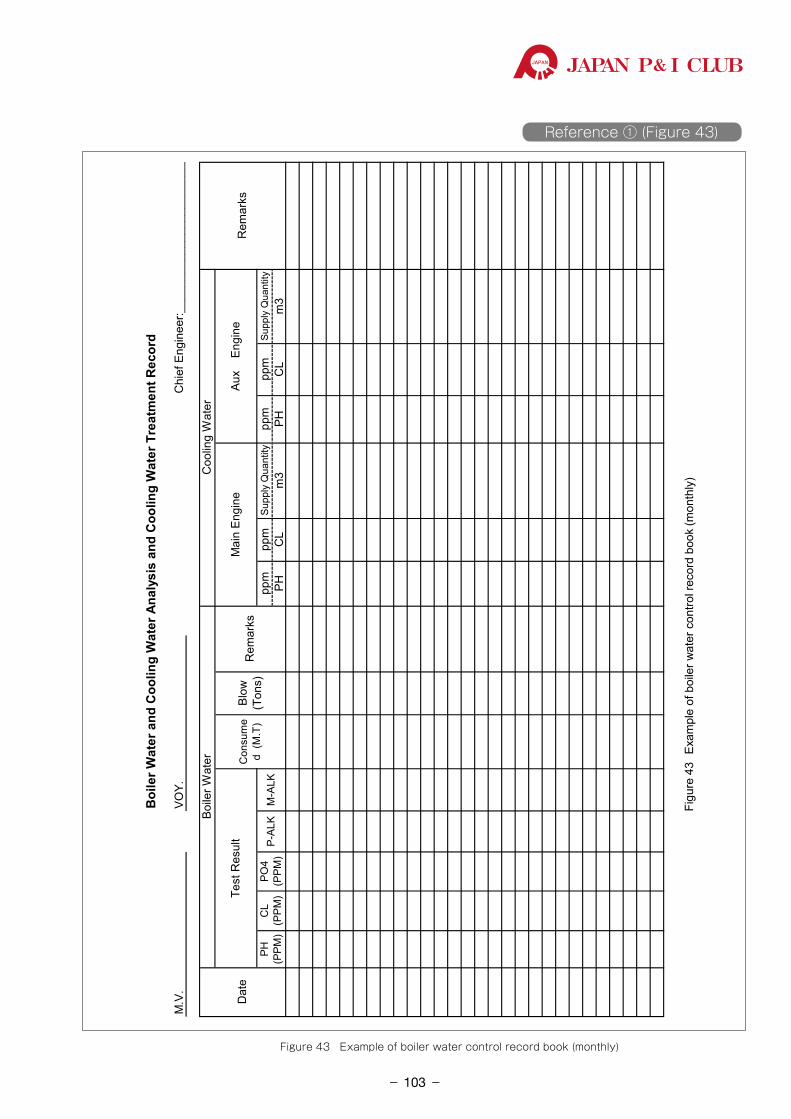
JAPAN P& I CLUB
Boi
ler W
ater
and
Coo
ling
Wat
er A
naly
sis
and
Coo
ling
Wat
er T
reat
men
t Rec
ord
M.V
.VO
Y.
ppm
ppm
Supp
ly Q
uant
itypp
mpp
mSu
pply
Qua
ntity
PHC
Lm
3PH
CL
m3
Mai
n En
gine
Aux
En
gine
PH(P
PM)
CL
(PPM
)PO
4(P
PM)
P-AL
KM
-ALK
Chi
ef E
ngin
eer:_
____
____
____
____
____
____
_
Dat
e
Boile
r Wat
erC
oolin
g W
ater
Rem
arks
Test
Res
ult
Con
sum
ed
(M.T
)Bl
ow(T
ons)
Rem
arks
Figu
re 4
3Ex
ampl
e of
boi
ler w
ater
con
trol r
ecor
d bo
ok (m
onth
ly)
Reference ① (Figure 43)
Figure 43 Example of boiler water control record book (monthly)
- 103-
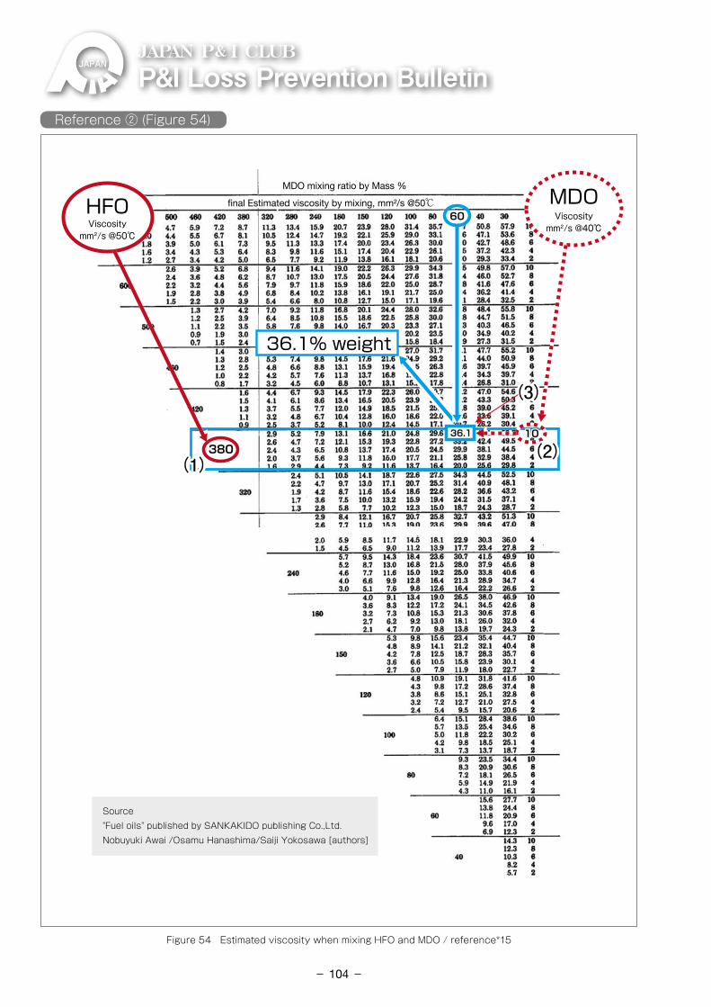
P&ILossPreventionBulletinJAPAN P& I CLUB
36.1% weight
(2)(2)
(3)(3)
36.136.1 1010
6060
380380(1)(1)
HFOHFO
Source"Fuel oils" published by SANKAKIDO publishing Co.,Ltd.Nobuyuki Awai /Osamu Hanashima/Saiji Yokosawa [authors]
Viscositymm²/s @40℃Viscosity
mm²/s @50℃
MDO mixing ratio by Mass %
final Estimated viscosity by mixing, mm²/s @50℃ MDOMDO
Reference ② (Figure 54)
Figure 54 Estimated viscosity when mixing HFO and MDO / reference*15
- 104-
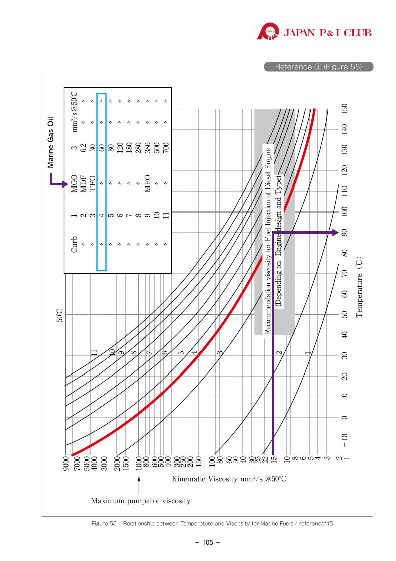
JAPAN P& I CLUB
Reference ③ (Figure 55)
-10
0123456810152225304060 5080100
150
200
300
400
500
600
800
1000
Maximum pumpable viscosity
1500
2000
3000
4000
5000
7000
9000
50℃
Mar
ine
Gas
Oil
250
1020
3040
134567891011
5060
Tem
pera
ture
(℃
)
7080
9010
011
012
013
014
015
0
→
Kinematic Viscosity mm²/s @50°C
Cu
rb
1 M
GO
3 m
m2 /s
@50
℃
〃
2 M
DF
6.2
〃
〃
〃
3 T
FO
30
〃
〃
〃
4 〃
60
〃
〃
〃
5
〃
80
〃
〃
〃
6 〃
12
0 〃
〃
〃
7
〃
180
〃
〃
〃
8 〃
28
0 〃
〃
〃
9
MFO
38
0 〃
〃
〃
10
〃
50
0 〃
〃
〃
11
〃
70
0 〃
〃
2Re
com
men
datio
n vi
scos
ity fo
r Fue
l Inj
ectio
n of
Dies
el En
gine
(Dep
endi
ng o
n E
ngin
e de
sign
and
Typ
e)
Figure 55 Relationship between Temperature and Viscosity for Marine Fuels / reference*15
- 105-
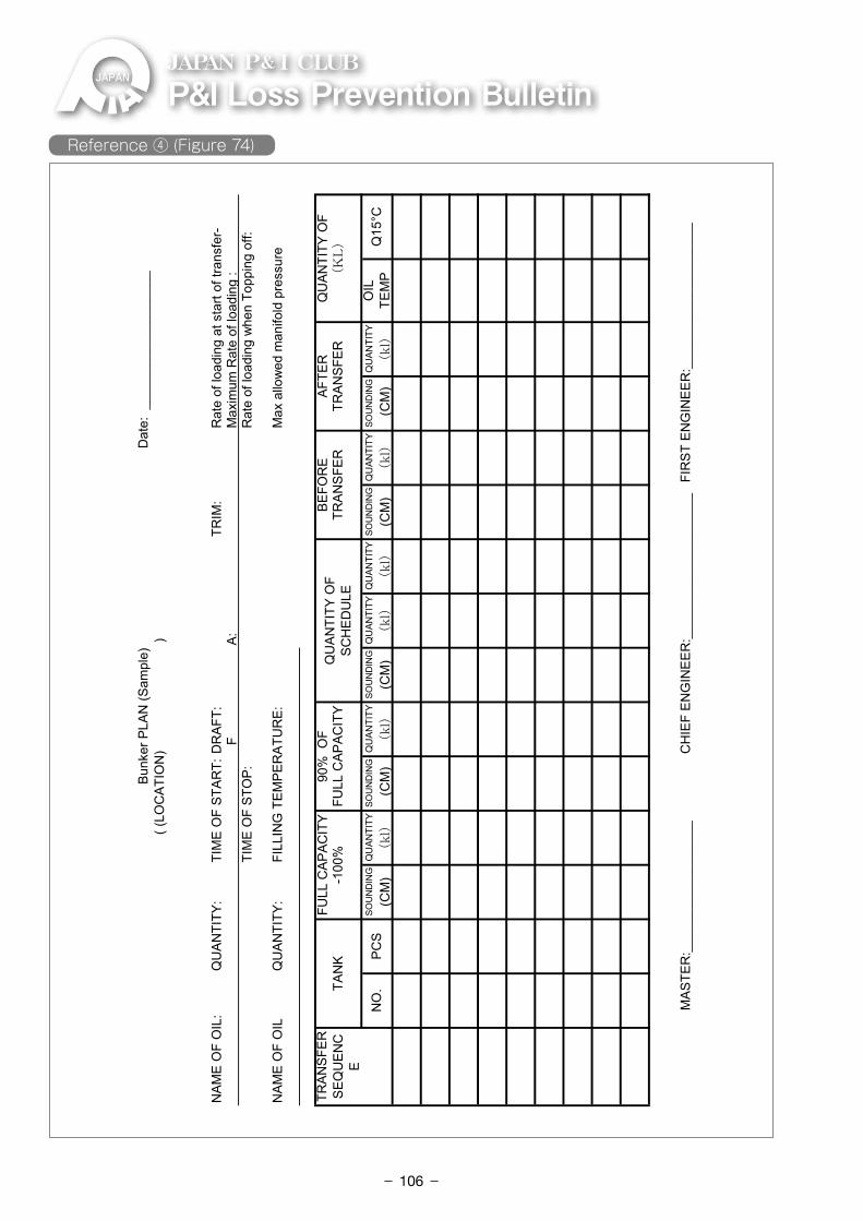
P&ILossPreventionBulletinJAPAN P& I CLUB
NAM
E O
F O
IL:
QU
ANTI
TY:
TIM
E O
F ST
ART:
DR
AFT:
TRIM
:
Rat
e of
load
ing
at s
tart
of tr
ansf
er-
FA:
Max
imum
Rat
e of
load
ing
: TI
ME
OF
STO
P:
R
ate
of lo
adin
g w
hen
Topp
ing
off:
NAM
E O
F O
ILQ
UAN
TITY
:FI
LLIN
G T
EMPE
RAT
UR
E:M
ax a
llow
ed m
anifo
ld p
ress
ure
SOU
ND
ING
QU
ANTI
TYSO
UN
DIN
GQ
UAN
TITY
SOU
ND
ING
QU
ANTI
TYQ
UAN
TITY
SOU
ND
ING
QU
ANTI
TYSO
UN
DIN
GQ
UAN
TITY
(CM
)(kl)
(CM
)(kl)
(CM
)(kl)
(kl)
(CM
)(kl)
(CM
)(kl)
M
ASTE
R:_
____
____
____
____
_C
HIE
F EN
GIN
EER
:___
____
____
____
____
_FI
RST
EN
GIN
EER
:___
____
____
____
____
_
NO
.PC
SO
ILTE
MP
Q15
°C
Bun
ker P
LAN
(Sam
ple)
Dat
e: _
____
____
____
____
__
( (
LOC
ATIO
N)
)
TRAN
SFER
SEQ
UEN
CE
TAN
KFU
LL C
APAC
ITY
90%
OF
QU
ANTI
TY O
FSC
HED
ULE
BEFO
RE
AFTE
RQ
UAN
TITY
OF
-100
%FU
LL C
APAC
ITY
TRAN
SFER
TRAN
SFER
(KL)
(Figure 74)
Reference ④ (Figure 74)
- 106-
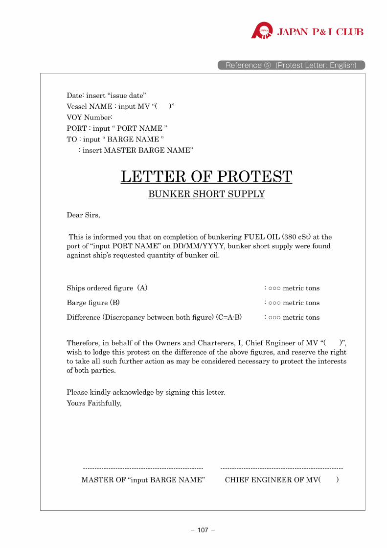
JAPAN P& I CLUB
Reference ⑤ (Protest Letter: English)
Date: insert “issue date” Vessel NAME : input MV “( )”VOY Number:PORT : input “ PORT NAME ”TO : input “ BARGE NAME ” : insert MASTER BARGE NAME”
LETTER OF PROTESTBUNKER SHORT SUPPLY
Dear Sirs,
This is informed you that on completion of bunkering FUEL OIL (380 cSt) at the port of “input PORT NAME” on DD/MM/YYYY, bunker short supply were found against ship’s requested quantity of bunker oil.
Ships ordered figure (A) : ○○○ metric tons
Barge figure (B) : ○○○ metric tons
Difference (Discrepancy between both figure) (C=A-B) : ○○○ metric tons
Therefore, in behalf of the Owners and Charterers, I, Chief Engineer of MV “( )”, wish to lodge this protest on the difference of the above figures, and reserve the right to take all such further action as may be considered necessary to protect the interests of both parties.
Please kindly acknowledge by signing this letter.Yours Faithfully,
---------------------------------------------------- ----------------------------------------------------- MASTER OF “input BARGE NAME” CHIEF ENGINEER OF MV( )
- 107-
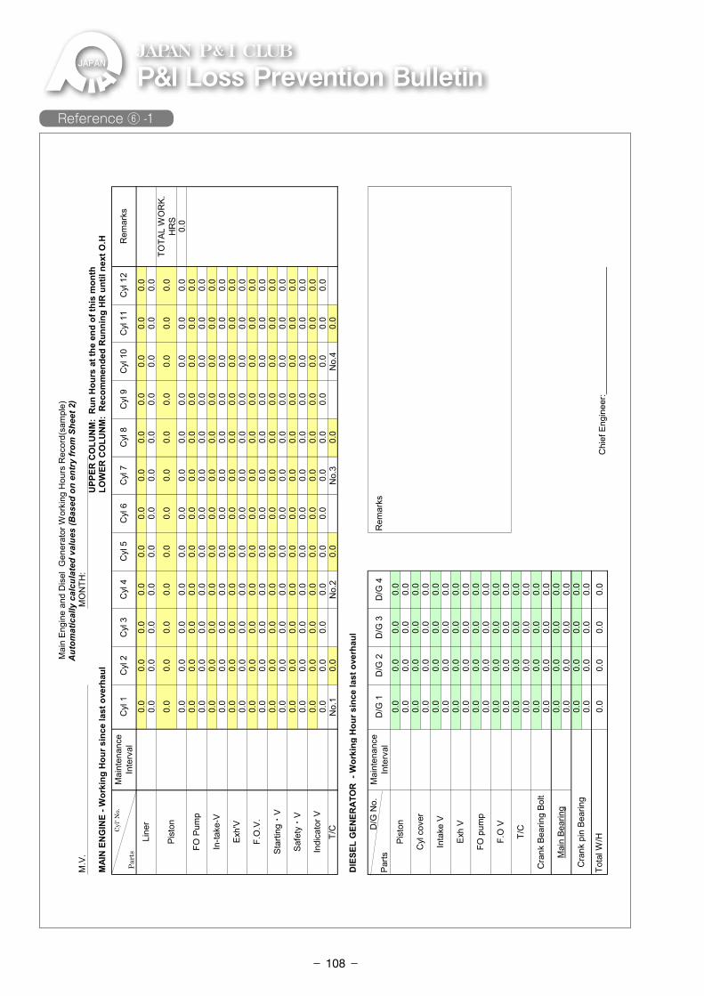
P&ILossPreventionBulletinJAPAN P& I CLUB
M.V
.M
ON
TH:
UPP
ER C
OLU
NM
: R
un H
ours
at t
he e
nd o
f thi
s m
onth
MAI
N E
NG
INE
- Wor
king
Hou
r sin
ce la
st o
verh
aul
LOW
ER C
OLU
NM
: R
ecom
men
ded
Run
ning
HR
unt
il ne
xt O
.H
0.0
0.0
0.0
0.0
0.0
0.0
0.0
0.0
0.0
0.0
0.0
0.0
0.0
0.0
0.0
0.0
0.0
0.0
0.0
0.0
0.0
0.0
0.0
0.0
0.0
0.0
0.0
0.0
0.0
0.0
0.0
0.0
0.0
0.0
0.0
0.0
TOTA
L W
OR
K.H
RS
0.0
0.0
0.0
0.0
0.0
0.0
0.0
0.0
0.0
0.0
0.0
0.0
0.0
0.0
0.0
0.0
0.0
0.0
0.0
0.0
0.0
0.0
0.0
0.0
0.0
0.0
0.0
0.0
0.0
0.0
0.0
0.0
0.0
0.0
0.0
0.0
0.0
0.0
0.0
0.0
0.0
0.0
0.0
0.0
0.0
0.0
0.0
0.0
0.0
0.0
0.0
0.0
0.0
0.0
0.0
0.0
0.0
0.0
0.0
0.0
0.0
0.0
0.0
0.0
0.0
0.0
0.0
0.0
0.0
0.0
0.0
0.0
0.0
0.0
0.0
0.0
0.0
0.0
0.0
0.0
0.0
0.0
0.0
0.0
0.0
0.0
0.0
0.0
0.0
0.0
0.0
0.0
0.0
0.0
0.0
0.0
0.0
0.0
0.0
0.0
0.0
0.0
0.0
0.0
0.0
0.0
0.0
0.0
0.0
0.0
0.0
0.0
0.0
0.0
0.0
0.0
0.0
0.0
0.0
0.0
0.0
0.0
0.0
0.0
0.0
0.0
0.0
0.0
0.0
0.0
0.0
0.0
0.0
0.0
0.0
0.0
0.0
0.0
0.0
0.0
0.0
0.0
0.0
0.0
0.0
0.0
0.0
0.0
0.0
0.0
0.0
0.0
0.0
0.0
0.0
0.0
0.0
0.0
0.0
0.0
0.0
0.0
0.0
0.0
0.0
0.0
0.0
0.0
0.0
0.0
0.0
0.0
0.0
0.0
0.0
0.0
0.0
0.0
0.0
0.0
0.0
No.
10.
0N
o.2
0.0
No.
30.
0N
o.4
0.0
DIE
SEL
GEN
ERAT
OR
- W
orki
ng H
our s
ince
last
ove
rhau
l
Mai
nten
ance
Inte
rval
D/G
1D
/G 2
D/G
3D
/G 4
Rem
arks
0.0
0.0
0.0
0.0
0.0
0.0
0.0
0.0
0.0
0.0
0.0
0.0
0.0
0.0
0.0
0.0
0.0
0.0
0.0
0.0
0.0
0.0
0.0
0.0
0.0
0.0
0.0
0.0
0.0
0.0
0.0
0.0
0.0
0.0
0.0
0.0
0.0
0.0
0.0
0.0
0.0
0.0
0.0
0.0
0.0
0.0
0.0
0.0
0.0
0.0
0.0
0.0
0.0
0.0
0.0
0.0
0.0
0.0
0.0
0.0
0.0
0.0
0.0
0.0
0.0
0.0
0.0
0.0
0.0
0.0
0.0
0.0
0.0
0.0
0.0
0.0
0.0
0.0
0.0
0.0
0.0
0.0
0.0
0.0
Chi
ef E
ngin
eer:_
____
____
____
____
____
____
_
Mai
n Be
arin
g
Cra
nk p
in B
earin
g
Tota
l W/HF.
O V
T/C
Cra
nk B
earin
g Bo
lt
Inta
ke V
Exh
V
FO p
ump
T/C
D
/G N
o.Pa
rts
Pist
on
Cyl
cov
er
Star
ting・
V
Safe
ty・
V
Indi
cato
r V
In-ta
ke-V
Exh'
V
F.O
.V.
Line
r
Pist
on
FO P
ump
Cyl
7C
yl 8
Cyl
9
Mai
n En
gine
and
Dis
el G
ener
ator
Wor
king
Hou
rs R
ecor
d(sa
mpl
e)A
utom
atic
ally
cal
cula
ted
valu
es (B
ased
on
entr
y fr
om S
heet
2)
Mai
nten
ance
Inte
rval
Cyl
1C
yl 2
Cyl
3C
yl 4
Cyl
5C
yl 6
Rem
arks
Cyl
10
Cyl
11
Cyl
12
Cyl'
No.
Part
s
Attachment Reference ⑥-1 Attachment Reference ⑥ -1
- 108-
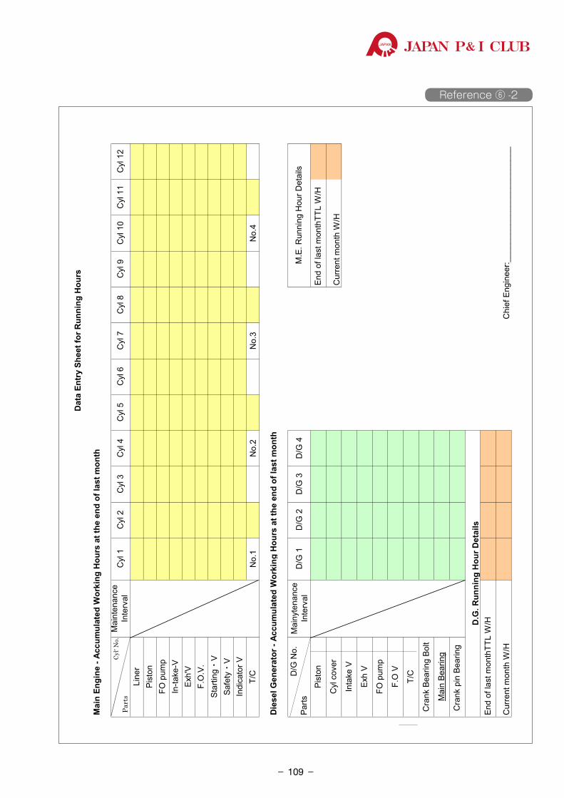
JAPAN P& I CLUB
Reference ⑥ -2M
ain
Engi
ne -
Accu
mul
ated
Wor
king
Hou
rs a
t the
end
of l
ast m
onth
No.
1N
o.2
No.
3N
o.4
Die
sel G
ener
ator
- Ac
cum
ulat
ed W
orki
ng H
ours
at t
he e
nd o
f las
t mon
th
Mai
nyte
nanc
eIn
terv
alD
/G 1
D/G
2D
/G 3
D/G
4
D.G
. Run
ning
Hou
r Det
ails
End
of la
st m
onth
TTL
W/H
Cur
rent
mon
th W
/HC
hief
Eng
inee
r:___
____
____
____
____
____
__
Exh
V
FO p
ump
F.O
V
T/C
Cra
nk B
earin
g Bo
lt
Mai
n Be
arin
g
D
/G N
o.Pa
rtsM
.E. R
unni
ng H
our D
etai
ls
Pist
onEn
d of
last
mon
thTT
L W
/H
Cyl
cov
erC
urre
nt m
onth
W/H
Inta
ke V
Cra
nk p
in B
earin
g
Line
rPi
ston
FO p
ump
In-ta
ke-V
Exh'
VF.
O.V
.St
artin
g・V
Safe
ty・
V
Cyl
7C
yl 8
Cyl
9C
yl 1
0C
yl 1
1C
yl 1
2
Indi
cato
r VT/
C
Dat
a En
try
Shee
t for
Run
ning
Hou
rs
Mai
nten
ance
Inte
rval
Cyl
1C
yl 2
Cyl
3C
yl 4
Cyl
5C
yl 6
Cyl'
No.
Part
s
Attachment Reference ⑥-2
- 109-
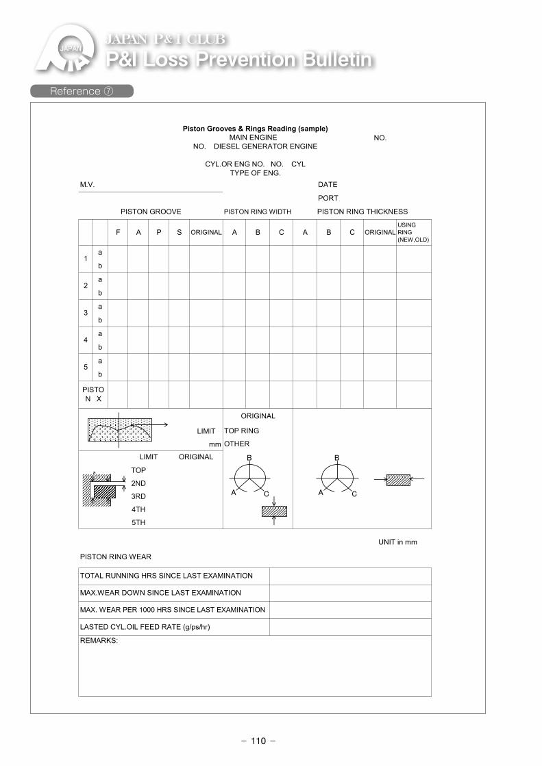
P&ILossPreventionBulletinJAPAN P& I CLUB
NO.
F A P S ORIGINAL A B C A B C ORIGINALUSINGRING(NEW,OLD)
a
b
a
b
a
b
a
b
a
b
LIMIT
mm
TOP
2ND
3RD
4TH
5TH
REMARKS:
MAX.WEAR DOWN SINCE LAST EXAMINATION
MAX. WEAR PER 1000 HRS SINCE LAST EXAMINATION
LASTED CYL.OIL FEED RATE (g/ps/hr)
UNIT in mm
PISTON RING WEAR
TOTAL RUNNING HRS SINCE LAST EXAMINATION
TOP RING
OTHER
LIMIT ORIGINAL
ORIGINAL
PORT
PISTON GROOVE PISTON RING WIDTH PISTON RING THICKNESS
1
2
3
4
5
PISTON X
M.V. DATE
Piston Grooves & Rings Reading (sample)MAIN ENGINE
NO. DIESEL GENERATOR ENGINE
CYL.OR ENG NO. NO. CYLTYPE OF ENG.
A
B
C A
B
C
a
×
Attachment reference ⑦Reference ⑦
- 110-
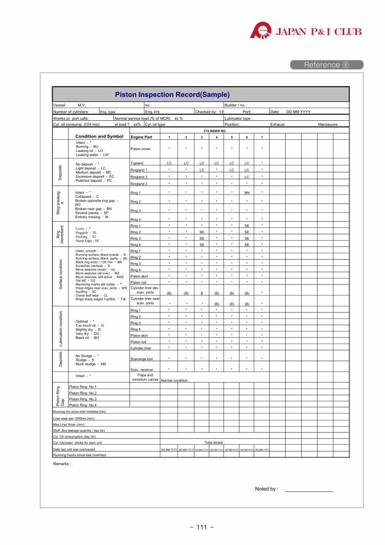
JAPAN P& I CLUB
Piston Inspection Record(Sample)Vessel: M.V. no.: Builder / no.:
Number of cylinders: Eng. hrs.: Port: Date:
Weeks pr. port calls: Normal service load (% of MCR): xx % Lubricator type :Cyl. oil consump. (l/24 hrs): at load % xx% Cyl. oil type: Position: Exhaust Manoeuvre
Condition and Symbol Engine Part 1 2 3 4 5 6 7
Piston crown * * * * * * *
Topland LC LC LC LC LC LC *
Ringland 1 * * LC * LC LC *
Ringland 2 * * * * * LC *
Ringland 3 * * * * * * *
Ring 1 * * * * * BN *
Ring 2 * * * * * * *
Ring 3 * * * * * * *
Ring 4 * * * * * * *
Ring 1 * * * * * SE *
Ring 2 * * SE * * SE *
Ring 3 * * SE * * SE *
Ring 4 * * SE * * SE *
Ring 1 * * * * * * *
Ring 2 * * * * * * *
Ring 3 * * * * * * *
Ring 4 * * * * * * *
Piston skirt * * * * * * *
Piston rod * * * * * * *Cylinder liner abv.
scav. ports (B) (B) B (B) (B) (B) *Cylinder liner near
scav. ports * * * (B) (B) (B) *
Ring 1 * * * * * * *
Ring 2 * * * * * * *
Ring 3 * * * * * * *
Ring 4 * * * * * * *
Piston skirt * * * * * * *
Piston rod * * * * * * *
Cylinder liner * * * * * * *
Scavenge box * * * * * * *
Scav. receiver * * * * * * *Flaps and
nonreturn valves
Piston Ring No.1
Piston Ring No.2
Piston Ring No.3
Piston Ring No.4
Running hrs since liner installed (hrs)
Liner wear per 1000hrs (mm)
Max Liner Wear (mm)
Stuff. Box leakage quantity / day (ltr)
Cyl. Oil consumption /day (ltr)
Cyl. lubricator stroke for each unit
Date last unit was overhauled DD MM YYYY DD MM YYYY DD MM YYYY DD MM YYYY DD MM YYYY DD MM YYYY DD MM YYYY
Running hours since last overhaul
Noted by :
CYLINDER NO.
Eng. type: Checked by: 1/E DD MM YYYY
Normal condition
Pist
on R
ing
Gap
Total stroke :
Remarks :
Intact - *Burning - BULeaking oil - LOLeaking water - LW
Optimal - *Too much oil - OSlightly dry - DVery dry - DOBlack oil - BO
No Sludge - *Sludge - S Much sludge - MS
Intact - *
Intact - *Collapsed - CBroken opposite ring gap -BOBroken near gap - BNSeveral pieces - SPEntirely missing - M
No deposit - *Light deposit - LCMedium deposit - MCExcessive deposit - ECPolished deposit - PC
Loose - *Sluggish - SLSticking - STSharp Edge - SE
Dep
osits
Rin
g br
eaka
ge
Ring
m
ovem
ent
Surfa
ce c
ondi
tion
Lubr
icat
ion
cond
ition
Dep
osits
Clean, smooth - *Running surface, Black,overall - BRunning surface, Black, partly - (B)Black ring ends > 100 mm - BRScratches (vertical) - SMicro-seizures (local) - mzMicro-seizures (all over) - MZMicro-seizures, still active - MAZOld MZ - OZMachining marks still visible - **Wear-ridges near scav. ports - WRScuffing - SCClover-leaf wear - CLRings sharp-edged Top/Bot. - T/B
Attachment reference ⑧ Reference ⑧
- 111-
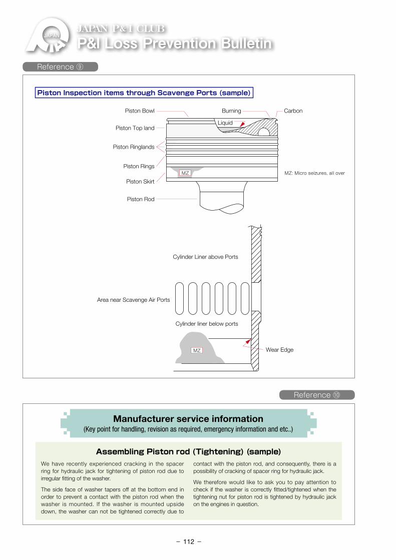
P&ILossPreventionBulletinJAPAN P& I CLUB
Piston Bowl
Piston Inspection items through Scavenge Ports (sample)
Burning Carbon
LiquidPiston Top land
Piston Ringlands
Piston Rings
Piston Skirt
MZ MZ: Micro seizures, all over
MZ
Piston Rod
Cylinder Liner above Ports
Cylinder liner below ports
Wear Edge
Area near Scavenge Air Ports
Reference ⑨
We have recently experienced cracking in the spacer ring for hydraulic jack for tightening of piston rod due to irregular fitting of the washer.
The side face of washer tapers off at the bottom end in order to prevent a contact with the piston rod when the washer is mounted. If the washer is mounted upside down, the washer can not be tightened correctly due to
contact with the piston rod, and consequently, there is a possibility of cracking of spacer ring for hydraulic jack.
We therefore would like to ask you to pay attention to check if the washer is correctly fitted/tightened when the tightening nut for piston rod is tightened by hydraulic jack on the engines in question.
Manufacturer service information (Key point for handling, revision as required, emergency information and etc..)
Assembling Piston rod (Tightening) (sample)
Reference ⑩
- 112-
P&
I Loss Prevention B
ulletin Vol.3
8
P&ILossPreventionBulletinJAPAN P& I CLUB
P&ILossPreventionBulletinThe Japan Ship Owners’Mutual Protection & Indemnity Association Loss Prevention and Ship Inspection Department
JAPAN P& I CLUB
● PrincipalOffice(Tokyo) 2-15-14, Nihonbashi-Ningyocho Chuoh-ku, Tokyo 103-0013, Japan Tel:03-3662-7229 Fax:03-3662-7107● KobeBranch 6th Floor Shosen-Mitsui Bldg. 5, Kaigandori Chuoh-ku, Kobe, Hyogo 650-0024, Japan Tel:078-321-6886 Fax:078-332-6519● FukuokaBranch 6th Floor Meiji-Dori Business Center 1-1, Shimokawabata-machi, Hakata-ku, Fukuoka 812-0027, Japan Tel:092-272-1215 Fax:092-281-3317● ImabariBranch 2-2-1, Kitahorai-cho, Imabari, Ehime 794-0028, Japan Tel:0898-33-1117 Fax:0898-33-1251● SingaporeBranch 80 Robinson Road #14-01B SINGAPORE 068898 Tel:65-6224-6451 Fax:65-6224-1476● JapanP&IClub(UK)ServicesLtd 38 Lombard Street, London EC3V 9BS U.K. Tel:44-20-7929-3633 Fax:44-20-7929-7557
JAPAN P& I CLUBWebsite http://www.piclub.or.jp
Thinking Prevention of Engine Trouble
Vol.38 March 2017
Japan P&I ClubAssistant General Manager/Loss Prevention and Ship Inspection DepartmentChief engineer Keishi Kuwada
(Supervision)Master Mariner/General Manager/Loss Prevention and Ship Inspection Dept.Capt. Takuzo Okada


![[8] self diag and trouble code](https://static.fdokumen.com/doc/165x107/632be615c5a27f694c03170e/8-self-diag-and-trouble-code.jpg)