Thesis document - University Digital Conservancy
59
ACHIEVING NORMALCY: POSSIBILITY AND PERMANENCE IN A WORKSHOP FOR ARTISTS A THESIS SUBMITTED TO THE FACULTY OF THE GRADUATE SCHOOL OF THE UNIVERSITY OF MINNESOTA BY Joseph Robert Ford IN PARTIAL FULFILLMENT OF THE REQUIREMENTS FOR THE DEGREE OF MASTER OF ARCHITECTURE Marc Swackhamer, Adviser August 2012
-
Upload
khangminh22 -
Category
Documents
-
view
0 -
download
0
Transcript of Thesis document - University Digital Conservancy

ACHIEVING NORMALCY: POSSIBILITY AND PERMANENCE IN A WORKSHOP FOR ARTISTS
A THESIS SUBMITTED TO THE FACULTY OF THE GRADUATE SCHOOLOF THE UNIVERSITY OF MINNESOTA
BY
Joseph Robert Ford
IN PARTIAL FULFILLMENT OF THE REQUIREMENTSFOR THE DEGREE OF
MASTER OF ARCHITECTURE
Marc Swackhamer, Adviser
August 2012

© Joseph Robert Ford 2012
i
CONTENTS
TABLE OF CONTENTS iTABLE OF FIGURES & IMAGES ii
I. THESIS STATEMENT 1II. PROGRAM 2
A. SUMMARY OF SPACES 4III. SITE
A. SITE SELECTION 6
B. LOCAL TEXTURE 7C. SITE HISTORY 8D. DEVELOPMENT & THE FUTURE 9E. MAPS & SITE STUDIES 10
IV. PRECEDENTA. CRAFT CENTER AT BALERNA 13B. STUDIO FOR REMY ZAUGG 14C. NORDIC ARTISTS’ CENTER 15D. PHOTOGRAPHIC STUDIO FREI 16E. ATELIER IN OYODO ANNEX 17
V. TECHNOLOGY 18VI. THEORY 20VII. CODES & REGULATIONS 22VIII. PROCESS 23 IX. THE PROJECT 30X. THESIS ORAL PRESENTATION MATERIALS 44XI. STRUCTURAL CONCEPTS 49
BIBLIOGRAPHY & IMAGE CREDITS 54
ii
TABLE OF FIGURES & IMAGESNO. DESCRIPTION PAGE
1 WOODWORKER (PHOTO) 12 PRINTMAKER (PHOTO) 13 METALWORKER (PHOTO) 14 WOOD SHOP (PHOTO) 25 METAL SHOP (PHOTO) 26 PRINT SHOP (PHOTO) 27 WOODWORKER (PHOTO) 38 SCULPTOR (PHOTO) 39 WELDER (PHOTO) 310 AERIAL PHOTO DIAGRAM 611 LYN-LAKE / UPTOWN SITE CONTEXT PHOTO 612 LYN-LAKE / UPTOWN SITE CONTEXT PHOTO 613 LYN-LAKE / UPTOWN SITE CONTEXT PHOTO 614 LYN-LAKE / UPTOWN SITE CONTEXT PHOTO 615 EEL CAR (PHOTO) 716 INTERMEDIA ARTS (PHOTO) 717 JUNGLE THEATER (PHOTO) 718 CALHOUN ARTS BUILDING (PHOTO) 719 ART MATERIALS INC. (PHOTO) 720 CONTRACTOR’S YARD (PHOTO) 721 PLAT MAP 822 DERELICT RAILS (PHOTO) 823 FORMER GRAIN ELEVATOR SITE (PHOTO) 824 PROPOSED GREENWAY DEVELOPMENT MAP 925 CONTEXT MAP 1026 FIGURE / GROUND W/ MAP UNDERLAY 1127 FIGURE / GROUND 1128 SITE PANORAMA (PHOTO) 1229 SITE PANORAMA (PHOTO) 1230 SITE PANORAMA (PHOTO) 1231 CRAFT CENTER @ BALERNA: AXONOMETRIC 1332 CRAFT CENTER @ BALERNA: PHOTO 1333 CRAFT CENTER @ BALERNA: PHOTO 1334 STUDIO ZAUGG: PLAN / SECTION 1435 STUDIO ZAUGG: PHOTO 1436 STUDIO ZAUGG: PHOTO 1437 NORDIC ARTIST’S CENTER: PHOTO 1538 NORDIC ARTIST’S CENTER: PLANS & SECTIONS 1539 STUDIO FREI: PLAN & SECTION 1640 STUDIO FREI: PHOTO 1641 STUDIO FREI: PHOTO 1642 ATELIER IN OYODO ANNEX: PLANS 1743 ATELIER IN OYODO ANNEX: AXONOMETRIC 17
NO. DESCRIPTION PAGE
44 ATELIER IN OYODO ANNEX: PHOTO 1745 PRINT SHOP (PHOTO) 1846 WOOD SHOP (PHOTO) 1847 METALWORKING SHOP (PHOTO) 1848 WELDING SHOP (PHOTO) 1849 STUDY MODEL (PHOTO) 2450 CONCEPT PLAN 2551 SCHEMATIC SECTION 2552 AXONOMETRIC DIAGRAM 2553 ISOMETRIC STUDIES 2654 STUDY MODEL PERSPECTIVES 2755 WOODWORKING STUDIO / CORRIDOR ISO. 2756 MASSING / MATERIAL DIAGRAM 2857 LARGE PROJECT SPACE ISOMETRIC 2858 STUDY MODEL PERSPECTIVE 2959 STUDY MODEL PERSPECTIVE 2960 FIRST FLOOR PLAN 3161 PRESENTATION MODEL: BIRDSEYE FROM SW 3262 PRESENTATION MODEL: VIEW FROM NW 3363 PRESENTATION MODEL: VIEW FROM NE 3564 LONGITUDINAL SECTION 3665 SECOND FLOOR PLAN 3666 PRESENTATION MODEL: VIEW FROM SW 3867 NORTH ELEVATION 3968 PRESENTATION MODEL: VIEW FROM NE 3969 SOUTH ELEVATION 4070 PRESENTATION MODEL: VIEW FROM SE 4071 CROSS SECTION 4172 WEST ELEVATION 4173 PARTIAL ENLARGED WEST ELEVATION 4274 AXONOMETRIC @ WOODWORKING MACH. RM. 4375 AXONOMETRIC @ METALWORKING STUDIO 4376 THESIS ORAL PRESENTATION MATERIALS 4477 SITE, CONTEXT & MAP BOARDS 4578 FLOOR PLANS 4679 ELEVATION, SECTION, DETAILS 4780 ELEVATIONS, SECTION 4881 FOOTING & FOUNDATION ISOMETRIC 5082 ISOMETRIC DIAGRAM 52
1
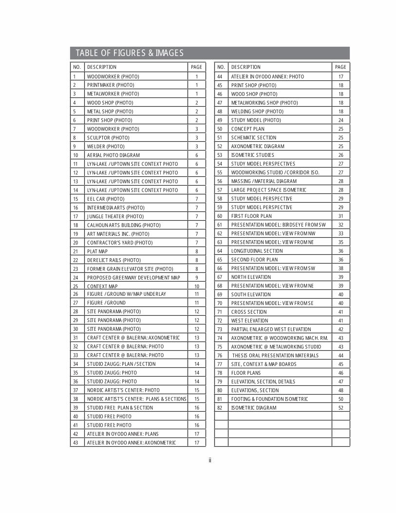
This project entails the design of a multimedia workshop for artists. In
the making of art there is a continuum of creation that begins with a
concept and ends with the art object. The intermediaries between the
concept and the creation of the object are the tools artists wield in the
pursuit of their craft. Many artists, while fl ush with vision, lack the tools
they need to engage in the process of creation and arrive at a material
expression of their artistic drive. This prevents artists from living the life
that is normal to their innate creativity.
The workshop will serve as a place for the cooperative ownership of
tools and workspace. By sharing costs artists gain access to a range of
equipment that would otherwise be unavailable to them. This workshop
represents the provision of otherwise denied possibilities as well as a
place that simply enables artists to sate their need to make art.
The workshop also serves a function in the community. Due to the
processes involved in making art, artists frequently seek out spa-
cious derelict or underutilized spaces where they can live and work
inexpensively. As they conduct their work the artists begin to build a
cultural profi le in the area they inhabit. This profi le eventually attracts
development. Ultimately, the artists draw a level of development that
drives them out of the neighborhood they rediscovered. This cycle of
gentrifi cation repeats itself as the artists move on to the next abandoned
site. The workshop seeks to arrest this nomadic cycle by establishing a
permanent, accessible place to work in a neighborhood that is already
home to a large art community. The permanence of the workshop
secures the habitability of the neighborhood for artists.
I. THESIS STATEMENT
ARTISTS AND THEIR TOOLS
WOODWORKERFig. 1
PRINTMAKERFig. 2
METALWORKERFig. 3

2
II. PROGRAM
The workshop will be run as a cooperative enterprise,
operated and supported by its members. The coop-
erative structure is based upon three different levels
of memberships. The fi rst level is those people who
need a permanent full-time place to work. The long-
term commitment of these people lends stability to the
workshop community and forms a core constituency.
Second are those who need a place to work, but who
do not devote a full-time effort to their craft. These
people also have a long-term presence in the shop but
have lesser needs for space and place fewer demands
on equipment. Third are those who need space and
tools for a single piece of work or short-term project.
These people will have an intermittent relationship with
the shop, dropping in to use the shop for a few hours,
a day, or a week at a time.
The character of this workshop is infl uenced by the
nature of the media it includes. The workshop will facili-
tate the media of sculpture and printmaking with shops
for woodworking, metalworking, and printing. Each of
these media require tools that are large and costly, and
spacious studios that can accommodate dust, noise,
and fi re hazards. With these physical realities taken
into consideration, these media are prime candidates
for the cooperative ownership of tools and workspace.
SHOPS FOR WOODWORKING, METALWORKING, AND PRINTING
Fig. 4
Fig. 5
Fig. 6

3
The practice of these art forms also require the knowledge
of myriad and complex tools and processes. With a diverse
group of practitioners gathered under one roof, the work-
shop also becomes a repository of shared experience and wisdom.
The primary elements of the program, in both size and
importance, are the working spaces: the print shop, metal
shop, and wood shop. The metal and wood shops also
connect to multipurpose large project space and outdoor
working spaces. A small number of private studios adjoin
the shops. The shop spaces will contain a mixture of
shared spaces and dedicated personal spaces. While the
cooperative spirit is essential to the workshop, having a
number of spaces that can be dedicated to individuals on
a long-term basis helps form a stable core constituency for
the workshop.
STAFF
The workshop will have a staff of six people. Each of the
three shops will have an attendant responsible for maintain-
ing the spaces and offering technical assistance to those
working in the shops. There is a main offi ce staff of two
people who will be responsible for administering member-
ships and caring for the general operations of the workshop.
There will be one staff member responsible for custodial
tasks and building maintenance.
Fig. 7
Fig. 8
Fig. 9

4
SUMMARY OF SPACES
Woodworking Shop: 6000SF shared machine area, bench area, personal storage, receiving and storage area, tool crib, attendant’s station, fi nishing room
Metalworking Shop: 4500SF shared machine area, bench area, personal storage, receiving and storage area, tool crib, attendant’s station
Printmaking Shop: 3000SFshared press area, acid room, darkroom (2-person, B/W photo only), personal storage, attendant’s station.
Large Project Space: 2000SFAn open space with access to outdoors and the wood and metal shops. Includes a gantry for moving heavy objects.
Outdoor Work Areas: 3000SFThese areas will include a variety of open and canopy-covered spaces. The spaces will accommodate work that is unsuitable for indoors as well as simple personal preference for working outdoors.
Private Studios (10 @150SF): 1500SFIndividual studios equipped with a sink.
Gallery: 2000SFThe gallery accommodates the display and sale of 2D and 3D artwork.
Seminar Room: 350SFThe seminar room provides a venue for administrative or cooperative meetings. It also provides a space for group instruction that cannot be conducted in the shops.
Lounge: 600SFAn area for relaxation, gathering, and communication. Separated from the noise, dust, and vapors of the shops.
Administrative offi ces: 500SFIncludes a control desk proximate to the gallery and the entry to the shops. The control desk is the point where shop membership and entry is administered. Supervision of the gallery is also made from the control desk. Offi ce space also included for full-time staff.

5
Custodial Spaces: 750SFRooms for recycling and trash removal. Storage for cleaning toolsand supplies
Bathrooms: 800SF
SUBTOTAL SQUARE FOOTAGE: 25,000SF
Circulation allowance: 2500SFIncludes corridors, circulation paths within the work spaces, and elevatorsand their mechanical rooms.
Mechanical Spaces: 2500SF
TOTAL SQUARE FOOTAGE: 30,000SF

6
The site is located in the Lyn-Lake area of Uptown Minne-
apolis at the intersection of Lyndale Avenue and the defunct
railbed at approximately 29th St. This site is currently oc-
cupied by a construction company. The site is bounded by
Lyndale Ave. to the west, Garfi eld Ave. to the east, and the
railbed to the south. The northern boundary is 14’ south of
the main building of the construction company.
III. SITE
AERIAL PHOTO OF SITEYELLOW RECTANGLE INDICATES OUTLINE OF SITE
SITE SELECTION
The Lyn-Lake neighborhood has a number of features, both physical and intangible, that make it a
desirable site for an artists’ workshop. Foremost among these are the people who live there. Simply
put, in colloquial terms, Lyn-Lake is the ‘hipster’ neighborhood. It is home to a large number of artists
and creative people, particularly young ones. The Minneapolis College of Art and Design is in the
nearby Whittier neighborhood, and many MCAD students and graduates live in the Uptown area. In
general, Uptown is a favored neighborhood for urban-oriented people arriving in Minneapolis from
other towns or leaving the local colleges and their campuses. The neighborhood also has a relatively
large number of apartment units. A young artist living in a small apartment is precisely the type of
person who needs access to tools and a place to work. Uptown is a very livable urban neighborhood
with many amenities, siting a workshop in this area fi lls the gap in livability that a lack of workspace
represents to artists.
SNAPSHOTS OF LYN-LAKE & UPTOWN
Fig. 10
Fig. 11 Fig. 12
Fig. 13 Fig. 14
7
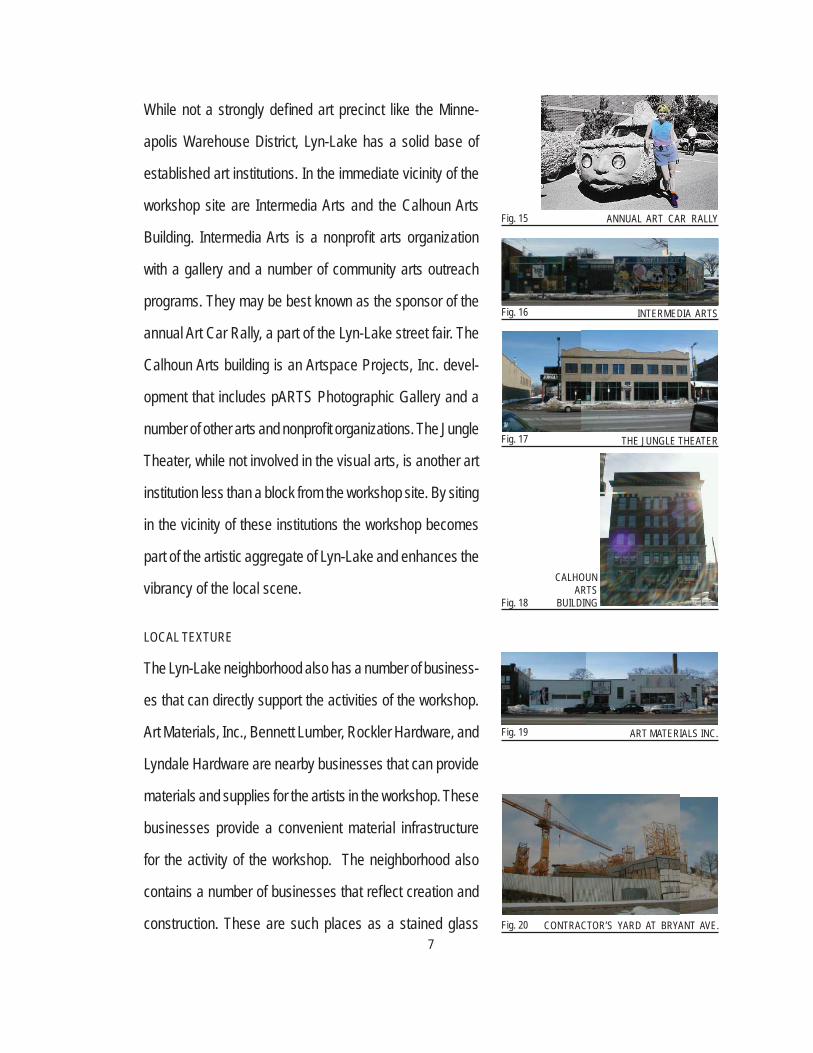
While not a strongly defi ned art precinct like the Minne-
apolis Warehouse District, Lyn-Lake has a solid base of
established art institutions. In the immediate vicinity of the
workshop site are Intermedia Arts and the Calhoun Arts
Building. Intermedia Arts is a nonprofi t arts organization
with a gallery and a number of community arts outreach
programs. They may be best known as the sponsor of the
annual Art Car Rally, a part of the Lyn-Lake street fair. The
Calhoun Arts building is an Artspace Projects, Inc. devel-
opment that includes pARTS Photographic Gallery and a
number of other arts and nonprofi t organizations. The Jungle
Theater, while not involved in the visual arts, is another art
institution less than a block from the workshop site. By siting
in the vicinity of these institutions the workshop becomes
part of the artistic aggregate of Lyn-Lake and enhances the
vibrancy of the local scene.
LOCAL TEXTURE
The Lyn-Lake neighborhood also has a number of business-
es that can directly support the activities of the workshop.
Art Materials, Inc., Bennett Lumber, Rockler Hardware, and
Lyndale Hardware are nearby businesses that can provide
materials and supplies for the artists in the workshop. These
businesses provide a convenient material infrastructure
for the activity of the workshop. The neighborhood also
contains a number of businesses that refl ect creation and
construction. These are such places as a stained glass
ART MATERIALS INC.
ANNUAL ART CAR RALLY
INTERMEDIA ARTS
THE JUNGLE THEATER
CALHOUNARTS
BUILDING
CONTRACTOR’S YARD AT BRYANT AVE.
Fig. 15
Fig. 16
Fig. 17
Fig. 18
Fig. 19
Fig. 20
8
studio and a building contractor’s yard strewn with rusted
machinery and piles of lumber. Other shops: a classic car
rebuilder, a vacuum cleaner repairman, a picture framer;
add to the mix and create an atmosphere where everyone
seems to be at work with their hands.
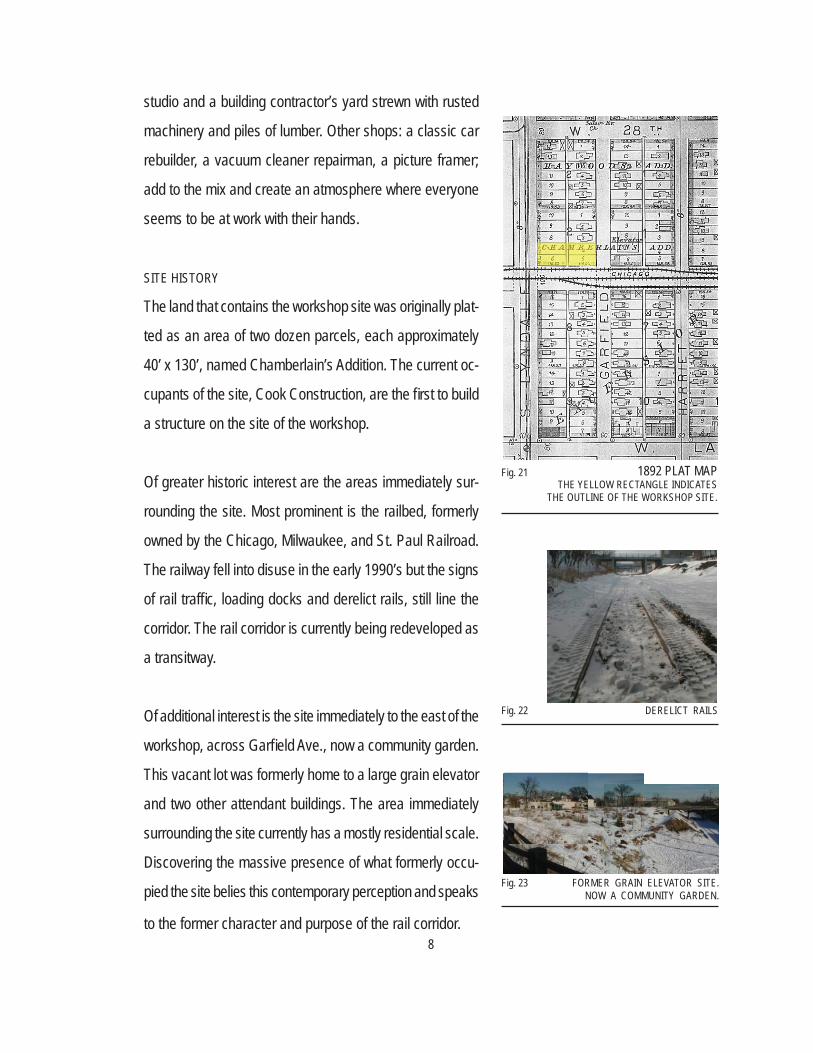
SITE HISTORY
The land that contains the workshop site was originally plat-
ted as an area of two dozen parcels, each approximately
40’ x 130’, named Chamberlain’s Addition. The current oc-
cupants of the site, Cook Construction, are the fi rst to build
a structure on the site of the workshop.
Of greater historic interest are the areas immediately sur-
rounding the site. Most prominent is the railbed, formerly
owned by the Chicago, Milwaukee, and St. Paul Railroad.
The railway fell into disuse in the early 1990’s but the signs
of rail traffi c, loading docks and derelict rails, still line the
corridor. The rail corridor is currently being redeveloped as
a transitway.
Of additional interest is the site immediately to the east of the
workshop, across Garfi eld Ave., now a community garden.
This vacant lot was formerly home to a large grain elevator
and two other attendant buildings. The area immediately
surrounding the site currently has a mostly residential scale.
Discovering the massive presence of what formerly occu-
pied the site belies this contemporary perception and speaks
to the former character and purpose of the rail corridor.
DERELICT RAILS
FORMER GRAIN ELEVATOR SITE. NOW A COMMUNITY GARDEN.
1892 PLAT MAPTHE YELLOW RECTANGLE INDICATES
THE OUTLINE OF THE WORKSHOP SITE.
Fig. 21
Fig. 22
Fig. 23
9
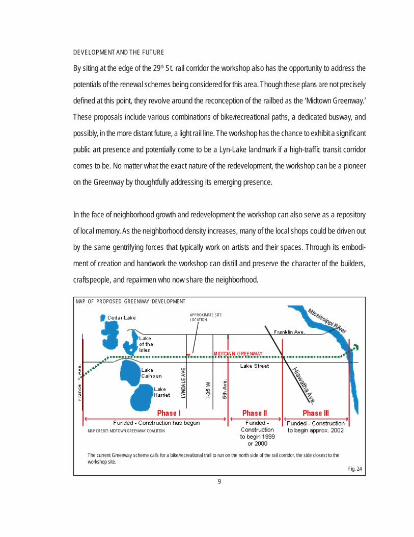
DEVELOPMENT AND THE FUTURE
By siting at the edge of the 29th St. rail corridor the workshop also has the opportunity to address the
potentials of the renewal schemes being considered for this area. Though these plans are not precisely
defi ned at this point, they revolve around the reconception of the railbed as the ‘Midtown Greenway.’
These proposals include various combinations of bike/recreational paths, a dedicated busway, and
possibly, in the more distant future, a light rail line. The workshop has the chance to exhibit a signifi cant
public art presence and potentially come to be a Lyn-Lake landmark if a high-traffi c transit corridor
comes to be. No matter what the exact nature of the redevelopment, the workshop can be a pioneer
on the Greenway by thoughtfully addressing its emerging presence.
In the face of neighborhood growth and redevelopment the workshop can also serve as a repository
of local memory. As the neighborhood density increases, many of the local shops could be driven out
by the same gentrifying forces that typically work on artists and their spaces. Through its embodi-
ment of creation and handwork the workshop can distill and preserve the character of the builders,
craftspeople, and repairmen who now share the neighborhood.
MAP OF PROPOSED GREENWAY DEVELOPMENT
APPROXIMATE SITE LOCATION
MAP CREDIT: MIDTOWN GREENWAY COALITION
The current Greenway scheme calls for a bike/recreational trail to run on the north side of the rail corridor, the side closest to the workshop site.
Fig. 24

10
ART-RELATED BUSINESSES AND INSTITUTIONSSHOPS OF CRAFT, CONSTRUCTION, AND REPAIRSITE OUTLINE
MAPS & SITE STUDIESThis map diagrams the presence of art, craft, and construction related businesses and institutions
proximate to the workshop site. The map shows a concentration of such places along Lyndale Avenue
and the former rail corridor.
Fig. 25

11
FIGURE - GROUND
NO SCALE
These maps show a fi gural study
of the area immediately around
the workshop site. The fi gure-only
diagram reveals the spatial char-
acteristics of the neighborhood.
Lyndale Avenue has a relatively
well-defi ned street wall, especially
as it intersects Lake Street. How-
ever, this density quickly reverts
to the small fragments that repre-
sent the residential blocks as one
moves away from Lyndale proper.
The fi gure of the rail corridor is
distinctive in that it simultaneously
gathers large structures and large
voids. The large structures speak
to the industrial memory of the
railroad. Some of the voids do
as well, as they are the sites of
working buildings that have been
demolished. Other voids repre-
sent spaces that have remained
undeveloped due to their proximity
to the railroad.
RAILBED
LAKE ST.
LYND
ALE
Fig. 26
Fig. 27

12
SITE
GREE
NWAY
ELE
VATI
ON -
LOO
KING
NOR
TH
SITE
LYND
ALE
ELE
VATI
ON -
AT
THE
SIT
E
SITE
PAN
ORAM
AS
Thes
e ph
otos
illus
trate
the
site
and
its im
media
te su
rroun
dings
. The
blue
sh
ed, w
hich
is pr
omine
nt in
these
im-
ages
, will
be d
emoli
shed
. The
view
s fro
m the
bridg
e and
the G
reen
way s
how
evide
nce
of the
con
struc
tion
curre
ntly
unde
rway
. Wha
t cur
rent
ly ap
pear
as
moun
ds o
f ear
th w
ill be
gra
ded
and
shap
ed b
y re
taini
ng w
alls
along
the
Gree
nway
path.
SITE
SITE
PER
SPEC
TIVE
- F
ROM
THE
LYN
DALE
BRI
DGE
Fig. 2
8: To
pFig
. 29:
Midd
leFig
. 30:
Botto
m
13
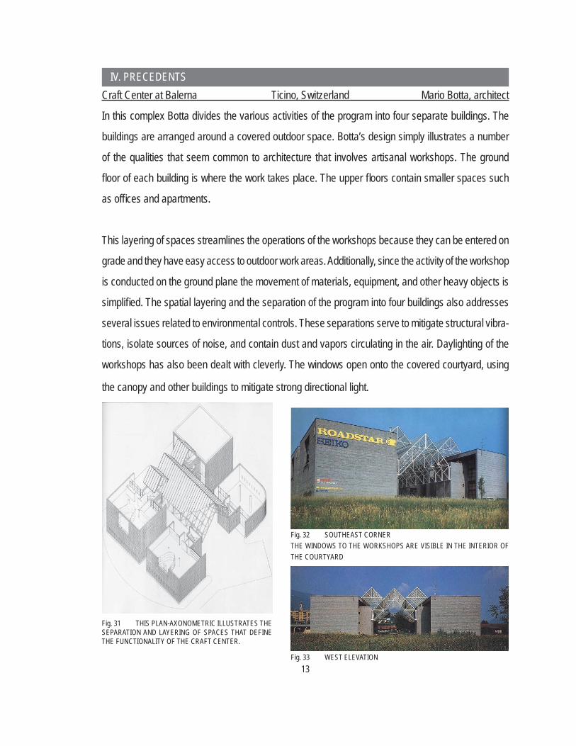
Craft Center at Balerna Ticino, Switzerland Mario Botta, architect
In this complex Botta divides the various activities of the program into four separate buildings. The
buildings are arranged around a covered outdoor space. Botta’s design simply illustrates a number
of the qualities that seem common to architecture that involves artisanal workshops. The ground
fl oor of each building is where the work takes place. The upper fl oors contain smaller spaces such
as offi ces and apartments.
This layering of spaces streamlines the operations of the workshops because they can be entered on
grade and they have easy access to outdoor work areas. Additionally, since the activity of the workshop
is conducted on the ground plane the movement of materials, equipment, and other heavy objects is
simplifi ed. The spatial layering and the separation of the program into four buildings also addresses
several issues related to environmental controls. These separations serve to mitigate structural vibra-
tions, isolate sources of noise, and contain dust and vapors circulating in the air. Daylighting of the
workshops has also been dealt with cleverly. The windows open onto the covered courtyard, using
the canopy and other buildings to mitigate strong directional light.
Fig. 31 THIS PLAN-AXONOMETRIC ILLUSTRATES THE SEPARATION AND LAYERING OF SPACES THAT DEFINE THE FUNCTIONALITY OF THE CRAFT CENTER.
Fig. 32 SOUTHEAST CORNER THE WINDOWS TO THE WORKSHOPS ARE VISIBLE IN THE INTERIOR OF THE COURTYARD
Fig. 33 WEST ELEVATION
IV. PRECEDENTS
14
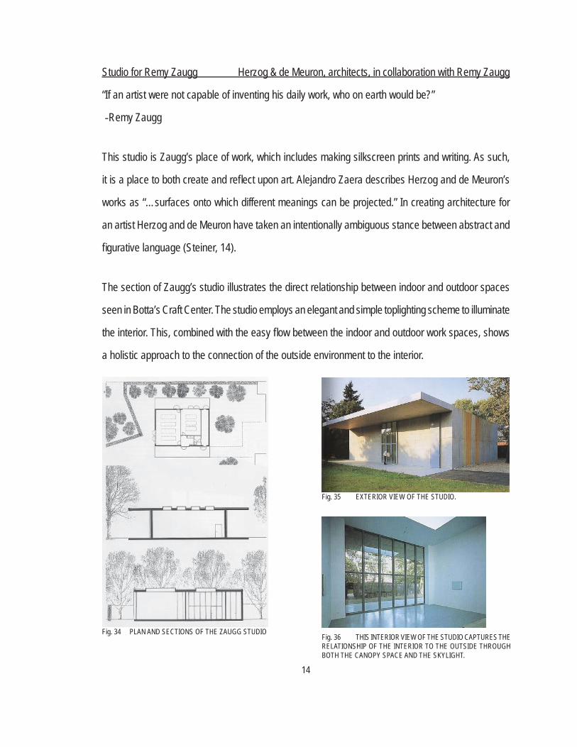
Studio for Remy Zaugg Herzog & de Meuron, architects, in collaboration with Remy Zaugg
“If an artist were not capable of inventing his daily work, who on earth would be?”
-Remy Zaugg
This studio is Zaugg’s place of work, which includes making silkscreen prints and writing. As such,
it is a place to both create and refl ect upon art. Alejandro Zaera describes Herzog and de Meuron’s
works as “…surfaces onto which different meanings can be projected.” In creating architecture for
an artist Herzog and de Meuron have taken an intentionally ambiguous stance between abstract and
fi gurative language (Steiner, 14).
The section of Zaugg’s studio illustrates the direct relationship between indoor and outdoor spaces
seen in Botta’s Craft Center. The studio employs an elegant and simple toplighting scheme to illuminate
the interior. This, combined with the easy fl ow between the indoor and outdoor work spaces, shows
a holistic approach to the connection of the outside environment to the interior.
Fig. 34 PLAN AND SECTIONS OF THE ZAUGG STUDIO
Fig. 35 EXTERIOR VIEW OF THE STUDIO.
Fig. 36 THIS INTERIOR VIEW OF THE STUDIO CAPTURES THE RELATIONSHIP OF THE INTERIOR TO THE OUTSIDE THROUGH BOTH THE CANOPY SPACE AND THE SKYLIGHT.

15
Nordic Artists’ Center Dalsalen, Norway Haga and Grov, Hjeltnes, Egge, architects
“The spaces immediately surrounding the artists as they work are the simplest, the most abstracted,
with the least number of choices already made – leaving the artists free to get on with their own work.”
The Nordic Artists’ Center is a residential artists’ colony that includes individual studios and a shared
workshop. The workspaces here have been described as “blank pages waiting to receive the marks
of the inhabitants - hammer blows, nail holes, footsteps and shouts, the din of machinery, scorch
marks, paint spills (Almaas, 63).” These quotations describe an architecture that defers to the pres-
ence of artists and their work.
This raises the question of how an artist relates to their workshop. In one sense, the building must
come to the artist in the form of building services such as light and fresh air, especially in technically
intensive crafts such as metalwork. Yet, the architecture should simultaneously stand off, and be wary
of the presence it projects into the artist’s creative space.
Fig. 38 PLANS AND SECTIONS OF THE INDIVIDUAL AND COMMON WORKSHOPS
Fig. 37 INTERIOR PHOTO OF THE SHARED WORKSHOP AT NORDIC ARTISTS’ CENTER
16
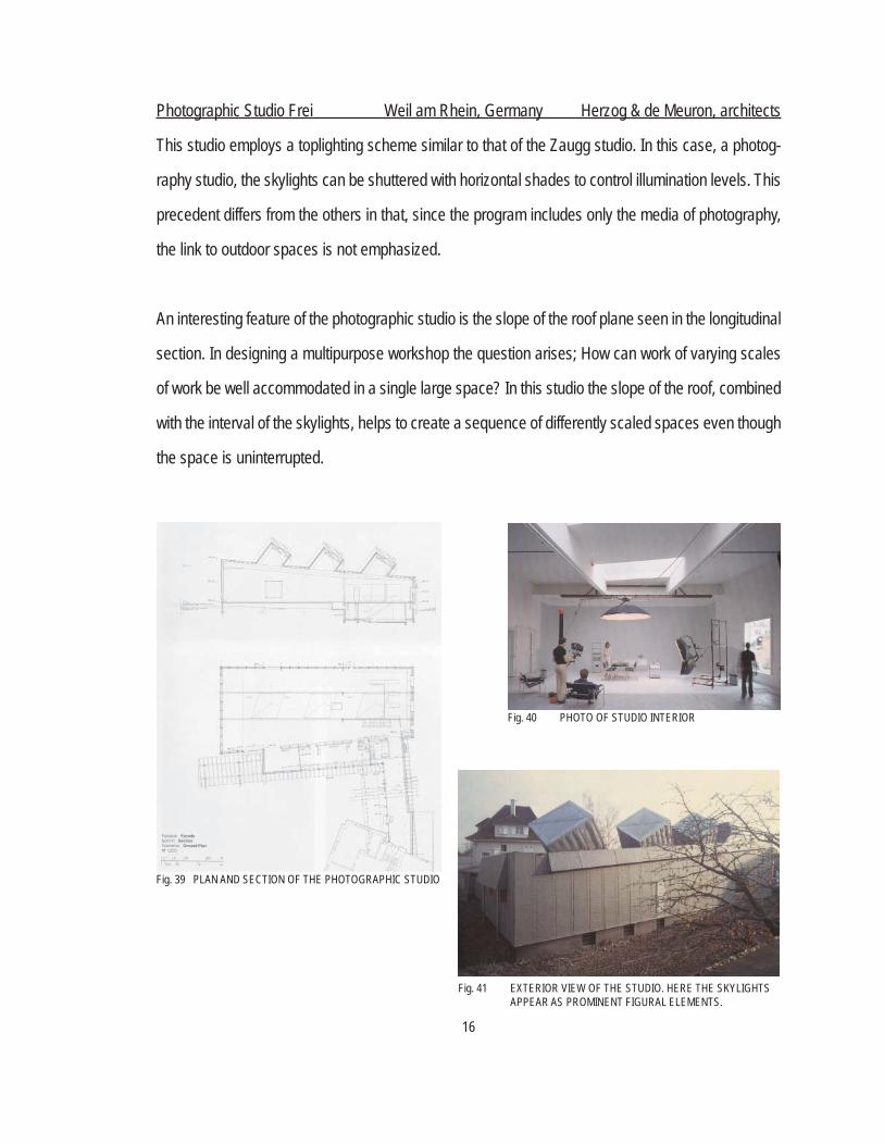
Photographic Studio Frei Weil am Rhein, Germany Herzog & de Meuron, architects
This studio employs a toplighting scheme similar to that of the Zaugg studio. In this case, a photog-
raphy studio, the skylights can be shuttered with horizontal shades to control illumination levels. This
precedent differs from the others in that, since the program includes only the media of photography,
the link to outdoor spaces is not emphasized.
An interesting feature of the photographic studio is the slope of the roof plane seen in the longitudinal
section. In designing a multipurpose workshop the question arises; How can work of varying scales
of work be well accommodated in a single large space? In this studio the slope of the roof, combined
with the interval of the skylights, helps to create a sequence of differently scaled spaces even though
the space is uninterrupted.
Fig. 39 PLAN AND SECTION OF THE PHOTOGRAPHIC STUDIO
Fig. 40 PHOTO OF STUDIO INTERIOR
Fig. 41 EXTERIOR VIEW OF THE STUDIO. HERE THE SKYLIGHTS APPEAR AS PROMINENT FIGURAL ELEMENTS.
17
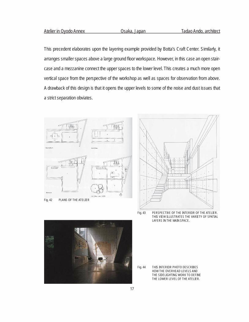
Atelier in Oyodo Annex Osaka, Japan Tadao Ando, architect
This precedent elaborates upon the layering example provided by Botta’s Craft Center. Similarly, it
arranges smaller spaces above a large ground fl oor workspace. However, in this case an open stair-
case and a mezzanine connect the upper spaces to the lower level. This creates a much more open
vertical space from the perspective of the workshop as well as spaces for observation from above.
A drawback of this design is that it opens the upper levels to some of the noise and dust issues that
a strict separation obviates.
Fig. 42 PLANS OF THE ATELIER
Fig. 43 PERSPECTIVE OF THE INTERIOR OF THE ATELIER. THIS VIEW ILLUSTRATES THE VARIETY OF SPATIAL LAYERS IN THE MAIN SPACE.
Fig. 44 THIS INTERIOR PHOTO DESCRIBES HOW THE OVERHEAD LEVELS AND THE SIDELIGHTING WORK TO DEFINE THE LOWER LEVEL OF THE ATELIER.

18
V. BUILDING TECHNOLOGYThe workshop includes tools and materials that create a
number of technical issues in the areas of environmental
control and fi re resistance. The shops produce varying
amounts of dust, fumes, vapors, noise, and vibration from
machinery. Fire hazards are created by things ranging from
welding torches to printing solvents to piles of lumber.
Since there will be a variety of activities occurring simultane-
ously in the workshop, close control of potential nuisances
is necessary to create a harmonious working environment.
The importance of technological issues in the workshop
requires that they be addressed in the earliest stages of
design. An integrated approach to building utilities will
ensure that the spaces are adequately served in a manner
that is architecturally intentional.
TECHNICAL ISSUES AND FACTORS:
FIRE PROTECTION: This issue includes planning for the
everyday hazards posed by such things as welding torches
as well as accidental fi res. Safe storage of possible sources
of ignition and fuel for fi res is an additional consideration.
Design implications include choosing fi re resistant as-
semblies and compartmentalizing potential dangers. The
provision of an automatic fi re sprinkler system will mitigate
a wide variety of risks.
Fig. 45
Fig. 46
Fig. 47
Fig. 48
19
STRUCTURAL VIBRATIONS: Much of the machinery used in the wood and metal shops produces
vibrations that affect the comfort of everyone in the building. Addressing this issue includes placing
and installing machinery so as to reduce vibrations. Structural systems can be designed to dampen
and isolate vibration.
DURABLE WEAR SURFACES: This issue extends to both building materials and fi xtures. Wear
resistance and ease of cleaning both factor into the choice of materials in the workshop. A building
with a lower cost of ownership will help fi nancially sustain the workshop.
ACOUSTICS / NOISE CONTROL: Portable and stationary machine tools as well as simple tools such
as hammers are all potential sources of noise. Stationary tools can be placed in contained areas in
order to isolate noise. Refl ective surfaces that amplify noise should be minimized, though this factor
will have to be reconciled with the need for hard and durable surfaces.
ENVIRONMENTAL CONTROLS: FRESH AIR AND TEMPERATURE: The control of dust, fumes, and
vapors is the greatest challenge in designing the environmental systems for the workshop. Air quality
issues include both safety and comfort. Maintaining thermal comfort is also a complicated issue. The
artists in the building will be engaged in a wide range of physical activity, ranging from drawing to
heavy labor such as grinding or swinging a mallet. These activities, combined with sources of heat
such as running machinery and welding torches, create the need for an environmental control system
that can be closely attuned to the operation of the workshop.
HAZARDOUS MATERIALS: Solvents, paints, and many of the chemicals necessary for printmaking
processes are both fl ammable and environmental hazards. The proper storage, use, and disposal of
these materials need to be considered in the design of the workshop.
LIGHTING: The east-west orientation of the workshop site offers ample opportunity for daylighting the
interior. The openness of the rail corridor guarantees access to light, though steps must be taken to
mitigate direct sunlight and glare. The uses in the workshop require both ambient and task-specifi c
lighting. Light should be plentiful and easily adjustable.
20
VI. THEORYIn approaching the role of theory in the design of a workshop for artists, the fi rst question I posed
is, “How can theory explain the relationship between art and architecture?” To explore this question
it was fi rst necessary to defi ne the stance of the workshop regarding the work of art. Central to the
mission of the workshop is enabling artists to pursue their creativity by providing tools and a place to
work. By understanding the role of work as central to the nature of the workshop the focus of inquiry
came to rest on the process of creation rather than the art object.
The process of creation is a central issue to both making art and the construction of architecture. In
The Production of Space Henri Lefebvre emphasizes the importance of lived experience over the
image or symbolic explanation as a means of understanding architecture. As part of this experiential
approach, Lefebvre thought it important to be able to trace the path from the object, or building, to the
production activity. He raised the issue of whether the process of creation is subsumed or revealed
in the fi nished object (Lefebvre, 113).
Related to the theories of Lefebvre, Reyner Banham describes the implications of the arrangement of
architectural systems in The Architecture of the Well-Tempered Environment. Banham explains the
implications of exposed and concealed systems and establishes a continuum within which the disposi-
tion of systems can be understood. This continuum was based upon the categories of emphasized,
allowed to be seen, and concealed. Banham believed that there was an intellectual and moral need
to be able to distinguish the structure of architecture from the systems that power it (Banham, 242).
Banham’s description of open systems establishes a framework for understanding the assembly and
operation of a building. This understanding of assembly and operation brings the revelation of process
advocated by Lefebvre to the milieu of contemporary buildings.

21
Earlier theorists such as Viollet-le-Duc believed that meaning in architecture lay in the manner in
which the order of relationships in construction was made manifest (Angelil, 31). If meaning were to
be understood as the search for truth, Viollet-le-Duc found truth in the utility rather than the formalist
beauty of architecture. Viollet-le-Duc asserted that the logic which governed architectural form was to
be based upon the realities of construction. The theories of Gottfried Semper were also informed by
the connection of truth to utility. He asserted that the meaning of the work of art was determined by
its function, material, and the technique of its creation (Angelil, 33). Semper envisioned architecture
as simultaneously a system of production and as artistic expression.
Taken together as a guide for the design of the workshop, these theories suggest an architecture that
contains a narrative of its construction and operation. It is an architecture of articulation that explains
the whole in terms of its elements and component parts. In design, this articulation could potentially
be explained through the use of architectural systems and materials that embody work done by hu-
man hands.
22
VII. CODES AND REGULATIONS
OCCUPANCY GROUPS
Woodshop: 6000SF: F-1
Metal Shop: 4500SF: F-1
Print Studio: 3000SF: F-1
Large Project Space: 2000SF: F-1
Private Studios: 10 @ 150SF: B
Gallery: 2000SF: M
Seminar Room: 350SF: B
Lounge: 600SF: B
Administrative Offi ces: 500SF: B
Due to the relatively small square footages, building height and area limitations are not a factor in
the building’s design. With sprinklers, any construction type is permissible for these spaces. Without
sprinklers, unprotected wood light frame construction is prohibited.
The building’s occupancies will include the use of materials posing a physical hazard (fl ammable/
combustible). In planning the building, it is assumed that quantities of hazardous materials will be
managed such that code compliance can be achieved with one or more control areas. The intent of
this strategy is to avoid creation of an H (hazardous) occupancy.
EGRESS
Minimum number of exits: 2.
Maximum travel distance to nearest exit: 150’.
Rooms that may have only one door: private studios, administrative offi ces, seminar room.
Minimum corridor clear width: 44”

23
VIII. DESIGN PROCESS
At the outset of this project I identifi ed several themes that the design would explore. One of these is
responsiveness to the site. The project location in the Lyn-Lake neighborhood was chosen in large
part due to the character of the neighborhood: a character where the Artist’s Center and the neigh-
borhood offer reciprocal benefi ts. This reciprocity suggests a building that embraces and respects
its context. Another important aspect of designing for this site is engaging its particular geography.
The site is at the intersection of a unique bi-level streetscape which asks the building to address the
public realm in a multifaceted way.
In terms of simple functionality, the design must create spaces that are conducive to the type of work
undertaken in each of them. Art media have varying physical requirements in terms of the volume
of space they require, light conditions, surface fi nishes, fi xtures, and environmental controls. At the
same time, these fragments of the program are collected and arranged together as parts of a single
shared enterprise. The design must integrate these fragments so that, beyond simply coexisting, they
can create a whole greater than the sum of its parts. There is the opportunity to shape a community
in tandem with spaces for the creation of art.
The building’s form is explored as an architectural expression of the creative work taking place at
the site. This provides a means to describe parallels between art and architecture. These analogs
include the raw materials of the work and the tools and methods of assembly, as well as the creativity
of the individual.
The design was developed through an iterative process of hand sketching, overlay, and study models.
At intervals in the process hard line drawings were made in order to validate concepts in terms of
functionality and feasibility. Plans, sections, elevations, isometrics and details were drawn in a non-
linear sequence that allowed both small and large-scale ideas to infl uence the overall course of design.

24
Initial plans had the entire program arrayed on a single level aligned with the street grade. This was
driven by a pragmatic concept that arranging all of the spaces on single level at street grade would
ease the movement of materials and objects through the building. The defi cit of this pragmatic ap-
proach was that it resulted in a building that seemed perched above the Greenway. The plan ac-
knowledged this amenity but did little to truly integrate it into the design.
SITE INVESTIGATION & SCHEMATIC DESIGNS
Due to the site’s location in a residential-scale urban street grid it has a traditionally defi ned public,
street-facing front and private, rear-facing secondary access. The rear of the site actually fronts on
Garfi eld Avenue. However, the lots on the opposite side of the street are all unbuilt, giving the street
more of a rear yard or alley character. The immediate context has a consistent street facade of build-
ings with little to no setback from the street and sidewalk. Schematic designs for the building aligned
with this context, with a strong street-facing front on Lyndale Ave. and service functions positioned
at the rear. This arrangement held throughout the design. While the site has a typical interior side
yard shared with the adjacent property, what distinguishes it is the second public side that faces the
Greenway. It is not unlike a corner lot confi guration with intersecting public streets, but in this case
the second public street passes the site at a level approximately twenty feet below the predominant
pedestrian and traffi c grade of the site on Lyndale Avenue.
PUBLIC FACE STREET LEVEL
PUBLIC FACE GREENWAY LEVEL
INTERIOR SIDE YARD
SERVICE
EARLY SITE AND BUILDING FORM STUDY MODELFig. 49

25
Further iterations of the design investigated breaking away from the street level plane and re-layering the spaces in a way that better engaged the site while still serving the building’s program. Closer scrutiny of the needs of each spaces determined which could most easily move above or below street grade. The gallery remained in front at street level to provide a space that would engage the public and fi t within the local context of street level retail storefronts.
Among the work spaces, the large project space and metal shop had the clearest need to remain at street level, in order to facilitate material handling and moving objects in and out of the building. The physical constraints on the woodworking shop and print shop were not as strong. In the section sketch at right, the woodworking shop has been located in the center of the building and depressed so that its fl oor level more closely aligns with the grade of the Greenway. The print shop as well as offi ces and studios have been moved to a street side second level, resulting in a more generous gallery space on the main fl oor.
The axonometric drawing at right illustrates how the woodworking shop has been lowered. Floor level of the metal shop is at right and the back wall of the gallery and second fl oor spaces is at left. A street level corridor skirts behind the shop.
Fig. 50 CONCEPT FLOOR PLAN
Fig. 51 SCHEMATIC SECTION
Fig. 52 WOODWORKING SHOP AXONOMETRIC
26
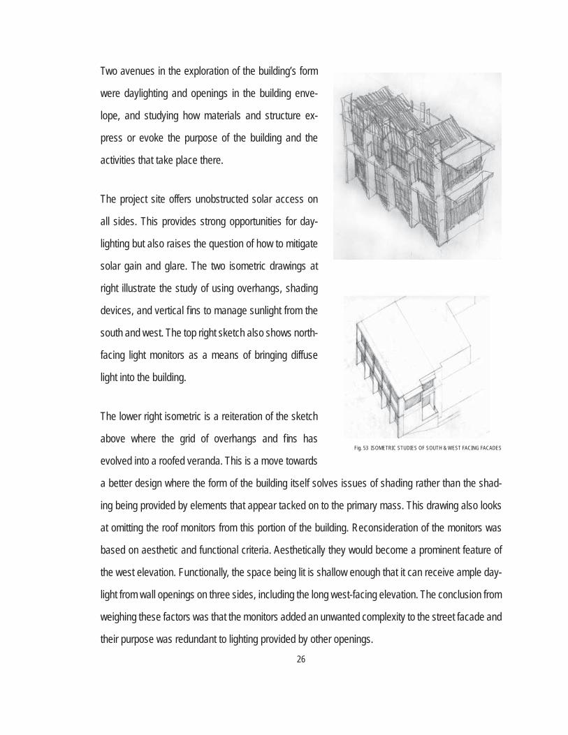
Two avenues in the exploration of the building’s form
were daylighting and openings in the building enve-
lope, and studying how materials and structure ex-
press or evoke the purpose of the building and the
activities that take place there.
The project site offers unobstructed solar access on
all sides. This provides strong opportunities for day-
lighting but also raises the question of how to mitigate
solar gain and glare. The two isometric drawings at
right illustrate the study of using overhangs, shading
devices, and vertical fi ns to manage sunlight from the
south and west. The top right sketch also shows north-
facing light monitors as a means of bringing diffuse
light into the building.
The lower right isometric is a reiteration of the sketch
above where the grid of overhangs and fi ns has
evolved into a roofed veranda. This is a move towards
a better design where the form of the building itself solves issues of shading rather than the shad-
ing being provided by elements that appear tacked on to the primary mass. This drawing also looks
at omitting the roof monitors from this portion of the building. Reconsideration of the monitors was
based on aesthetic and functional criteria. Aesthetically they would become a prominent feature of
the west elevation. Functionally, the space being lit is shallow enough that it can receive ample day-
light from wall openings on three sides, including the long west-facing elevation. The conclusion from
weighing these factors was that the monitors added an unwanted complexity to the street facade and
their purpose was redundant to lighting provided by other openings.
Fig. 53 ISOMETRIC STUDIES OF SOUTH & WEST FACING FACADES

27
Additional design of lighting and wall openings was done with study models. In the model view at left the creation of south-facing openings is extremely tentative at the large studios. There are large openings high on the wall at the metalworking studio as well as in the notch at the center of the wood-working studio. Otherwise, the small punched windows in the south walls point to the unresolved nature of the design at this point.
The light monitor strategy is being tested at the large project space and the metalworking studio, where the monitor has become the main architectural expression of the roof of this component. At the large project space the sawtooth array of monitors fully lights this room, where wall openings have been minimized to emphasize the massive nature of this block.
Fig. 54 STUDY MODEL PERSPECTIVES
LARGE PROJECT SPACE
METALWORKINGSTUDIO WOODWORKING
STUDIO
PRINT STUDIO (ABOVE)GALLERY (BELOW)LARGE PROJECT
SPACE
METALWORKINGSTUDIOWOODWORKING
STUDIO
PRINT STUDIO (ABOVE)GALLERY (BELOW)
SOUTH ELEVATION
The model view at right shows the roof monitor openings and large areas of glazing to take advantage of diffuse north light. At grade level there is a fully glazed corridor running the length of the building. In addition to its role in building circulation this space was studied as a means of bringing borrowed light into the interior of the woodworking studio via a second wall of in-terior glazing.
At the west/front elevation the covered veranda scheme for the upper level has been retained, while large openings are shown at the fi rst fl oor gallery level. These fi rst fl oor openings are problematic and unresolved at this point in the process. There is a desire to have large openings in order to display the gallery and engage the public. However, the directly west-facing windows would be diffi cult to shade and failing to mitigate the light from this direction would severely detract from the quality of the space.
Fig. 55 WOODWORKING STUDIO / CORRIDOR ISOMETRIC

28
Part of the development of the design was looking at
ways materials and structure could be used to express
the building’s presence and communicate its purpose.
The thumbnail sketch at top right associates wood,
steel, concrete and masonry with distinct program
blocks of the building and examines how these parts mass together. The sketch makes a direct as-
sociation between wood and the woodworking studio and steel with the metalworking studio. At this
phase, the association of the materials with surface, structure or both is not determined.
The large project space is intended as an
area that facilitates work on grand scale
projects. The isometric at right shows a
block built with panel-cast concrete walls
and precast concrete roof beams. This
concept predates the roof monitors that
were later added to the roof. The intent of
the drawing is see how the concrete can
describe the particular nature of what is
going on inside this space. The work being
done here is envisioned as carving large
blocks of stone or creating tall assem-
blages. The concrete embodies density
and weight. At the same time, the harshness of the material evokes the arduousness of the type of
work this space is tailored to. This block of concrete is also being thought of in it’s role in the overall
architectural composition of the building. It could serve as a strong ending point for the building. It
could also provide a backdrop or contrast for other parts of the building that have a greater degree
of articulation and detail.
Fig. 56 MASSING / MATERIAL DIAGRAM
Fig. 57 LARGE PROJECT SPACE ISOMETRIC
29
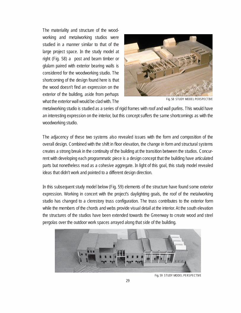
The materiality and structure of the wood-working and metalworking studios were studied in a manner similar to that of the large project space. In the study model at right (Fig. 58) a post and beam timber or glulam paired with exterior bearing walls is considered for the woodworking studio. The shortcoming of the design found here is that the wood doesn’t fi nd an expression on the exterior of the building, aside from perhaps what the exterior wall would be clad with. The metalworking studio is studied as a series of rigid frames with roof and wall purlins. This would have an interesting expression on the interior, but this concept suffers the same shortcomings as with the woodworking studio.
The adjacency of these two systems also revealed issues with the form and composition of the overall design. Combined with the shift in fl oor elevation, the change in form and structural systems creates a strong break in the continuity of the building at the transition between the studios. Concur-rent with developing each programmatic piece is a design concept that the building have articulated parts but nonetheless read as a cohesive aggregate. In light of this goal, this study model revealed ideas that didn’t work and pointed to a different design direction. In this subsequent study model below (Fig. 59) elements of the structure have found some exterior expression. Working in concert with the project’s daylighting goals, the roof of the metalworking studio has changed to a clerestory truss confi guration. The truss contributes to the exterior form while the members of the chords and webs provide visual detail at the interior. At the south elevation the structures of the studios have been extended towards the Greenway to create wood and steel pergolas over the outdoor work spaces arrayed along that side of the building.
Fig. 58 STUDY MODEL PERSPECTIVE
Fig. 59 STUDY MODEL PERSPECTIVE

30
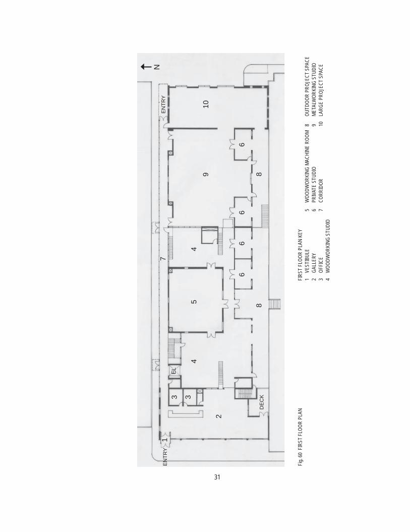
IX. THE PROJECT : A NARRATIVE WALKTHROUGH
The Lyn-Lake Artists’ Center has a public entrance on the Lyndale Avenue side of the building. The
entrance opens to the gallery, where there is a reception desk / sales counter directly inside the
vestibule. The reception desk is paired with the Center’s small administrative area. The design and
layout of the gallery has a two-fold purpose: the display and sale of artwork as well as introducing
visitors to the Center and the artists who work there. Gallery visitors can browse the space to view
artwork made at the Center. At the east wall of the gallery is glazing that provides an overlook into the
woodworking studio. Adjacent to the windows are service entrances into the working spaces which
allow for moving work in and out of the gallery. At the south side of the gallery doors open onto a
terrace that overlooks the Greenway and the outdoor project spaces.
The reception desk also serves as a point where artists seeking to work at the Center can register
and be admitted to the center. Running the full length of the north side of the building is a corridor
that serves as the main pedestrian path through the building. Once past the reception desk, the
corridor provides access to all of the work spaces on both fl oors. At the east end of the corridor as
well as at two intermediate points are private entrances that can be used by those with established
access to the building. Also at the east side of the building are the service doors at the large project
space that open onto the alley. The service doors are the entry point for the material handling path
that traverses all three of the large studios and ends at the gallery. Material handling through these
spaces is augmented with a lift between the levels of the woodworking and metalworking studios, as
well as a beam crane running the full length of the spaces.
The intent of the building’s circulation scheme is to provide two parallel paths: one for people and one
for things. Via the corridor, people can enter, exit and travel through the building without necessarily
being exposed to the workshop environments. Likewise, the material path provides a means of seg-
regating industrial-type work from foot traffi c so that everything and everyone can easily move about.
31
FIRS
T FL
OOR
PLAN
KEY
1VE
STIB
ULE
5W
OODW
ORKI
NG M
ACHI
NE R
OOM
8OU
TDOO
R PR
OJEC
T SP
ACE
2GA
LLER
Y6
PRIV
ATE
STUD
IO9
META
LWOR
KING
STU
DIO
3OF
FICE
7CO
RRID
OR10
LARG
E PR
OJEC
T SP
ACE
4W
OODW
ORKI
NG S
TUDI
O
4
1
2
3
5
6
4
EL
3
66
6
7
8
9 8
10
N
Fig. 6
0 FI
RST
FLOO
R PL
AN
EN
TRY
EN
TRY
DE
CK

32
Fig. 6
1 PR
ESEN
TATI
ON M
ODEL
: BIR
DSEY
E VI
EW F
ROM
SOUT
HWES
T

33
As one progresses into the pedestrian corridor from the entry there is a vertical circulation node with
a three-stop elevator and stairwell. The node connects the lower level of the woodworking studio,
the main fl oor and the second fl oor printmaking studio and seminar room. The corridor is fully glazed
on the north side. The glazing provides light and views in what would otherwise be a very long and
narrow hall. Interior windows on the south wall of the corridor allow people to see into the spaces as
well as allow the spaces to borrow light from the exterior glazing. The borrowed light helps to balance
the daylighting in the spaces that are too deep to be entirely daylit from the south side.
Moving further into the building, the fi rst workspace is the woodworking studio. From the corridor, two
sets of stairs lead down into the space. The woodworking studio is divided into three primary space
types. The main room is open bench space, where there is an array of workbenches for projects. The
main room contains two small ancillary spaces: a dust-free fi nishing room and a tool crib.
Positioned in the center of the studio is a large woodworking machine room. The intent of this room
is to separate equipment that produces relatively more noise and dust from the bench space. On
a purely functional level, the machine room helps control environmental nuisances and makes the
Fig. 62 PRESENTATION MODEL - VIEW FROM NORTHWEST

34
overall space quieter and cleaner. In addition, by locating the machine room in the center of the
studio it creates separate east and west bench spaces. The division of the open space also prevents
activity in one part from dominating the atmosphere of the whole room.
Those working at benches may be assembling pieces or working with hand tools. Creating separate
rooms as well as defi ning rooms within the room provides a means of tailoring spaces to the mode of
work. Working with machinery and working with hand tools are distinct processes. Most woodwork-
ers use both, while some are very intentional about using traditional methods. Having different types
of spaces to work in, while keeping them all in the same realm, allows people to fi nd a space that fi ts
their work style or even just the particular phase their piece of work is in.
At the south side of the woodworking studio is access to the outdoor project space. A variety of
hinged and overhead doors allow materials and projects to be brought outside. Two staircases con-
nect the woodworking studio’s outdoor project space to the adjacent metalworking space as well as
to the Greenway below. A tall timber pergola overhangs the center of the space. Two private studios
also open onto the outdoor space, each with its own sets of doors.
The metalworking studio shares some commonalities with woodworking: there is an array of benches
and a pair of private studios at the perimeter of the main space. There is an analogous connection to
the outdoor work area. In terms of scale, this studio is a mid-way point between the woodworking stu-
dio and the large project space. This relates in part to a concept of the building form stepping down
into the Greenway and stepping back out again. The studio is also scaled to the things made here;
conceived of as mainly castings and welded assemblages. Having more of a contiguous ballroom-
type space in addition to the benches provides room for staging castings as well as laydown area for
organizing assemblies. Since even moderately sized metal objects require equipment to pick them
up and move them around a greater fl oor area is needed to accommodate the maneuvering required
by the work.
35
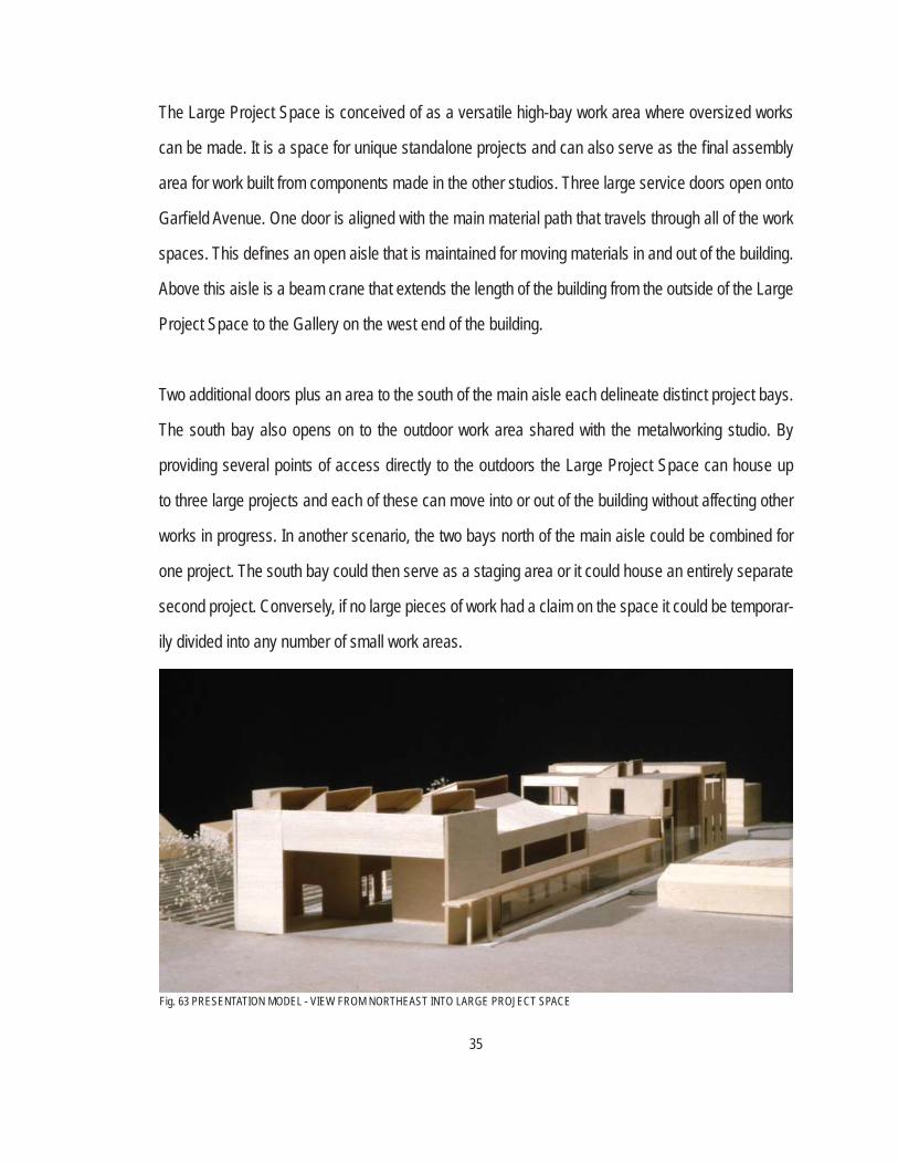
The Large Project Space is conceived of as a versatile high-bay work area where oversized works
can be made. It is a space for unique standalone projects and can also serve as the fi nal assembly
area for work built from components made in the other studios. Three large service doors open onto
Garfi eld Avenue. One door is aligned with the main material path that travels through all of the work
spaces. This defi nes an open aisle that is maintained for moving materials in and out of the building.
Above this aisle is a beam crane that extends the length of the building from the outside of the Large
Project Space to the Gallery on the west end of the building.
Two additional doors plus an area to the south of the main aisle each delineate distinct project bays.
The south bay also opens on to the outdoor work area shared with the metalworking studio. By
providing several points of access directly to the outdoors the Large Project Space can house up
to three large projects and each of these can move into or out of the building without affecting other
works in progress. In another scenario, the two bays north of the main aisle could be combined for
one project. The south bay could then serve as a staging area or it could house an entirely separate
second project. Conversely, if no large pieces of work had a claim on the space it could be temporar-
ily divided into any number of small work areas.
Fig. 63 PRESENTATION MODEL - VIEW FROM NORTHEAST INTO LARGE PROJECT SPACE
36
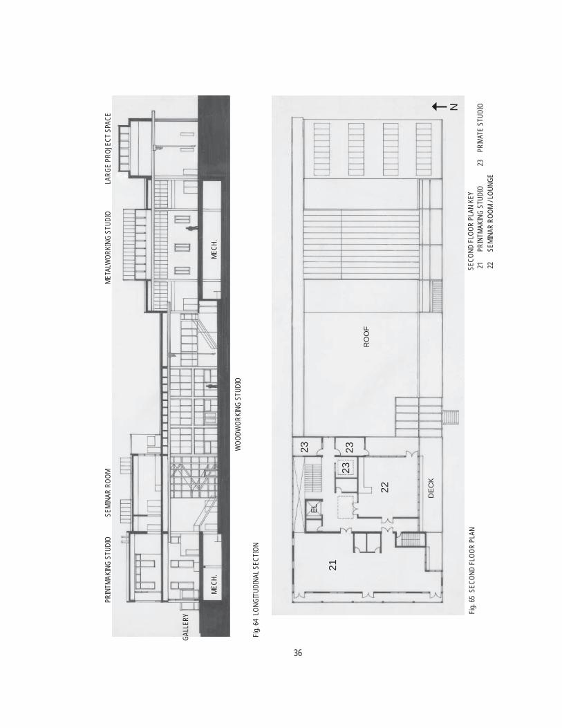
Fig. 6
4 LO
NGIT
UDIN
AL S
ECTI
ON
MECH
.
WOO
DWOR
KING
STU
DIO
META
LWOR
KING
STU
DIO
PRIN
TMAK
ING
STUD
IO
GALL
ERY
SEMI
NAR
ROOM
LARG
E PR
OJEC
T SP
ACE
MECH
.
SECO
ND F
LOOR
PLA
N KE
Y 21
PRIN
TMAK
ING
STUD
IO23
PRIV
ATE
STUD
IO 22
SEMI
NAR
ROOM
/ LOU
NGE
21
22
DE
CK
RO
OF
EL
23
23 23
NFig
. 65
SECO
ND F
LOOR
PLA
N
37
The primary spaces on the second fl oor are the Printmaking Studio, private studios, and the Seminar
Room. The second fl oor is envisioned as the quiet part of the building. In most respects, printmaking
is a standalone craft that doesn’t need the physical connection that the fi rst fl oor studios have to each
other. The materials central to printing: paper and ink, are of a lighter nature and call for a space that
is less industrial in feel. The equipment involved is of a similar character. Hand presses can be im-
pressive machines but they are operated by hand. As opposed to the fi rst fl oor studios, printmaking
is much more of a non-motorized, manual process.
The main room of the Printmaking Studio contains a variety of presses for different printing process-
es: copperplate etching, stone lithography, monoprint, et cetera. Work tables and benches are inter-
spersed among the presses, as well as other printing equipment such as drying racks and shelving
and drawers for paper and prints. Two ancillary spaces include an acid room and a small darkroom.
The acid room contains the acid baths used in copperplate etching. The vapors are a health hazard
and have an acrid odor, therefore this space is enclosed and vented directly to the outdoors. The
darkroom contains equipment and chemical baths for black and white printing. It is not intended as
another full studio, but rather as a process space ancillary to the other printing processes.
Across the hall from the Printmaking Studio are three private studios; similar to the woodworking and
metalworking studios where there are private rooms adjacent to the main space. These second fl oor
studios, while belonging to Printmaking in a sense, could also be rented by artists working in other
media who just need a room to work in, for example: painters.
The seminar room may be more accurately termed a multipurpose room. A main function of the
space would be to hold classes, which would be a source of revenue for the Center and a means of
introducing artists and patrons to the building. The room would also serve as a lounge for anyone
working at the Center. The room would have table and chairs, soft seating, a kitchenette, and would
38
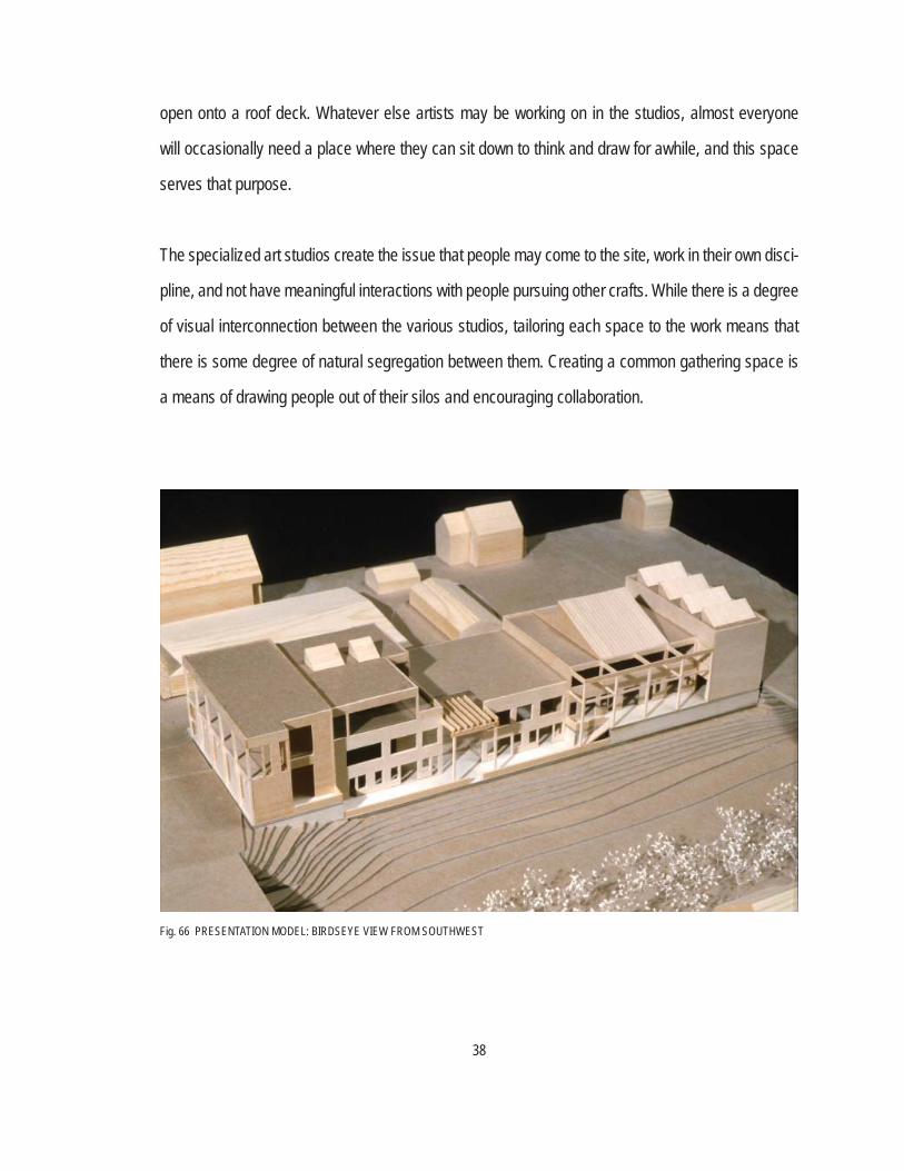
open onto a roof deck. Whatever else artists may be working on in the studios, almost everyone
will occasionally need a place where they can sit down to think and draw for awhile, and this space
serves that purpose.
The specialized art studios create the issue that people may come to the site, work in their own disci-
pline, and not have meaningful interactions with people pursuing other crafts. While there is a degree
of visual interconnection between the various studios, tailoring each space to the work means that
there is some degree of natural segregation between them. Creating a common gathering space is
a means of drawing people out of their silos and encouraging collaboration.
Fig. 66 PRESENTATION MODEL: BIRDSEYE VIEW FROM SOUTHWEST
39
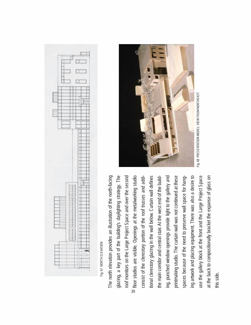
Fig. 6
7 NO
RTH
ELEV
ATIO
N
Fig. 6
8 PR
ESEN
TATI
ON M
ODEL
: VIE
W F
ROM
NORT
HEAS
T
The
north
elev
ation
pro
vides
an
illustr
ation
of t
he n
orth-
facing
gla
zing,
a ke
y pa
rt of
the b
uildin
g’s d
aylig
hting
stra
tegy.
The
roof
monit
ors o
n the
Lar
ge P
rojec
t Spa
ce a
nd o
ver t
he se
cond
fl o
or s
tudios
are
visi
ble. O
penin
gs a
t the
meta
lwor
king
studio
co
nsist
of t
he c
leres
tory
portio
n of
the ro
of tru
sses
and
add
i-tio
nal c
leres
tory g
lazing
in th
e wa
ll belo
w. C
urtai
n wa
ll defi
nes
the m
ain co
rrido
r and
centr
al sta
ir. At
the w
est e
nd of
the b
uild-
ing, p
unch
ed w
indow
ope
nings
pro
vide
light
to the
gall
ery a
nd
makin
g stud
io. T
he cu
rtain
wall w
as no
t con
tinue
d at th
ese
spac
es b
ecau
se o
f the
nee
d to
pres
erve
wall
spa
ce fo
r han
g-ing
artw
ork a
nd p
lacing
equ
ipmen
t. Th
ere
was a
lso a
des
ire to
us
e the
gall
ery b
lock a
t the
fron
t and
the
Larg
e Pr
oject
Spac
e at
the b
ack t
o co
mpos
itiona
lly b
rack
et the
exp
anse
of g
lass o
n thi
s side
.
40
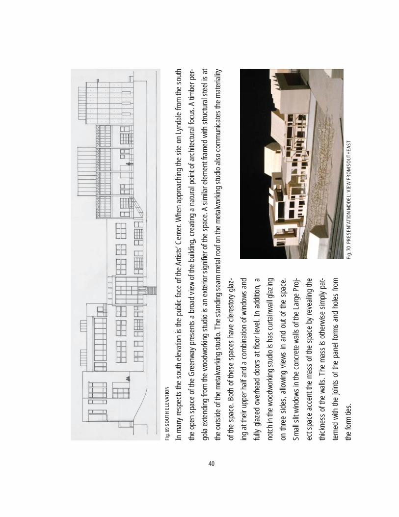
In ma
ny re
spec
ts the
south
elev
ation
is th
e pu
blic f
ace
of the
Artis
ts’ C
enter
. Whe
n ap
proa
ching
the
site
on Ly
ndale
from
the
south
the
ope
n sp
ace
of the
Gre
enwa
y pre
sents
a b
road
view
of t
he b
uildin
g, cre
ating
a n
atura
l poin
t of a
rchite
ctura
l focu
s. A
timbe
r per
-go
la ex
tendin
g fro
m the
woo
dwor
king
studio
is a
n ex
terior
sign
ifi er o
f the
spac
e. A
simila
r elem
ent f
rame
d wi
th str
uctur
al ste
el is
at the
outsi
de of
the m
etalw
orkin
g stud
io. T
he st
andin
g sea
m me
tal ro
of on
the m
etalw
orkin
g stud
io als
o com
munic
ates t
he m
ateria
lity
of the
spac
e. Bo
th of
these
spac
es h
ave
clere
story
glaz-
ing a
t the
ir up
per h
alf a
nd a
comb
inatio
n of
wind
ows a
nd
fully
glaze
d ov
erhe
ad d
oors
at fl o
or le
vel.
In ad
dition
, a
notch
in th
e woo
dwor
king s
tudio
is ha
s cur
tainw
all gl
azing
on
thre
e sid
es, a
llowi
ng v
iews
in an
d ou
t of t
he s
pace
. Sm
all sl
it wind
ows i
n the
conc
rete
walls
of th
e Lar
ge P
roj-
ect s
pace
acc
ent t
he m
ass o
f the
spac
e by
reve
aling
the
thick
ness
of t
he w
alls.
The
mass
is o
therw
ise si
mply
pat-
terne
d wi
th the
joint
s of
the p
anel
forms
and
hole
s fro
m the
form
ties.
Fig. 6
9 SOU
TH E
LEVA
TION
Fig. 7
0 PR
ESEN
TATI
ON M
ODEL
: VIE
W F
ROM
SOUT
HEAS
T
41
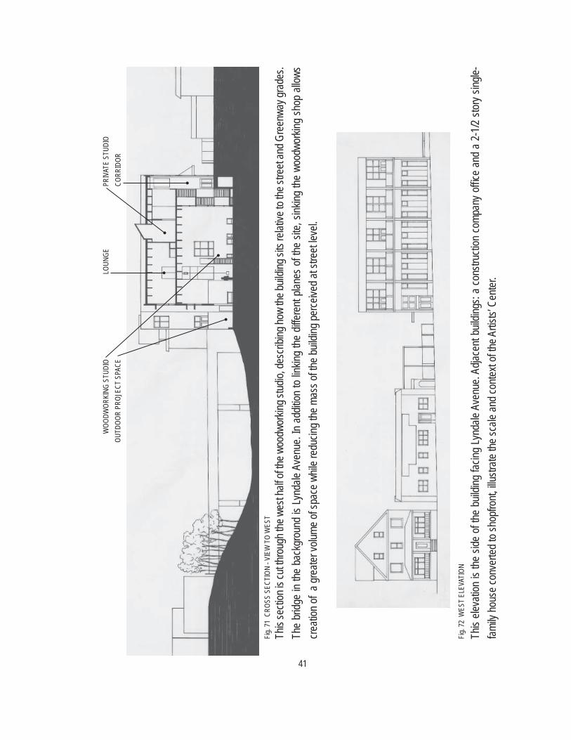
Fig. 7
1 CR
OSS
SECT
ION
- VIE
W T
O W
EST
PRIV
ATE
STUD
IOLO
UNGE
WOO
DWOR
KING
STU
DIO
CORR
IDOR
OUTD
OOR
PROJ
ECT
SPAC
E
Fig. 7
2 W
EST
ELEV
ATIO
N
This
secti
on is
cut th
roug
h the
wes
t half
of th
e woo
dwor
king s
tudio,
desc
ribing
how
the bu
ilding
sits
relat
ive to
the s
treet
and G
reen
way g
rade
s. Th
e br
idge
in the
bac
kgro
und
is Ly
ndale
Ave
nue.
In ad
dition
to lin
king
the d
iffere
nt pla
nes o
f the
site,
sink
ing th
e wo
odwo
rking
shop
allo
ws
creati
on of
a gr
eater
volum
e of s
pace
whil
e red
ucing
the m
ass o
f the b
uildin
g per
ceive
d at s
treet
level.
This
eleva
tion
is the
side
of t
he b
uildin
g fac
ing Ly
ndale
Ave
nue.
Adjac
ent b
uildin
gs: a
cons
tructi
on co
mpan
y offi c
e an
d a
2-1/2
stor
y sing
le-fam
ily ho
use c
onve
rted t
o sho
pfron
t, illu
strate
the s
cale
and c
ontex
t of th
e Artis
ts’ C
enter
.
42
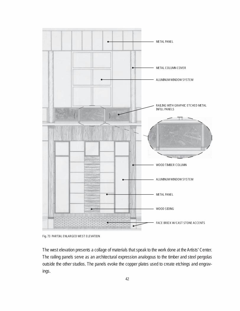
Fig. 73 PARTIAL ENLARGED WEST ELEVATION
The west elevation presents a collage of materials that speak to the work done at the Artists’ Center. The railing panels serve as an architectural expression analogous to the timber and steel pergolas outside the other studios. The panels evoke the copper plates used to create etchings and engrav-ings.
METAL PANEL
METAL COLUMN COVER
ALUMINUM WINDOW SYSTEM
RAILING WITH GRAPHIC ETCHED METAL INFILL PANELS
WOOD TIMBER COLUMN
ALUMINUM WINDOW SYSTEM
METAL PANEL
WOOD SIDING
FACE BRICK W/ CAST STONE ACCENTS

43
Fig. 74 AXONOMETRIC DETAIL @ WOODWORKING MACHINE ROOM
Fig. 75 AXONOMETRIC @ METALWORKING STUDIO
The detail at left shows an outside corner of the woodworking machine room. The room has a cast-in-place concrete side walls. The walls are formed with plywood panels so that the grain of the wood will be imprinted on the concrete surface.
The front wall of the machine room is framed with concrete columns and beams and has an a sound-insulat-ed wood panel infi ll. At intervals the woods panels are replaced with vision windows at fl oor level and clerestory windows above to borrow light from the south-facing glazing at the exte-rior walls.
The axonometric drawing at bottom left shows the structure of the met-alworking studio. The design intent was to place the structural steel side-by-side with the clerestory trusses so that the bulk of the steel sections could contrast with the latticework effect of the truss chords and webs. Light entering through the glazing in the truss would further emphasize the thinness of the truss members.
44
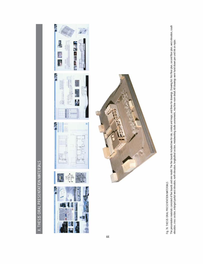
Fig. 7
6 TH
ESIS
ORA
L PRE
SENT
ATIO
N MA
TERI
ALS
The p
rese
ntatio
n mate
rials
cons
isted
of fi v
e boa
rds a
nd on
e mod
el. T
he fi v
e boa
rds i
nclud
ed tw
o for
site,
conte
xt an
d map
s; an
d thr
ee fo
r dra
wing
s. Dr
awing
list: fi
rst fl
oor p
lan, s
econ
d fl oo
r plan
, wes
t elev
ation
, sou
th ele
vatio
n, cro
ss se
ction
, enla
rged
partia
l wes
t elev
ation
, nor
th ele
vatio
n, lon
gitud
inal s
ectio
n, me
talwo
rking
stud
io ax
onom
etric,
mac
hine r
oom
detai
l. All d
rawi
ngs w
ere h
and d
rawn
pen a
nd in
k on m
ylar.
X. T
HESI
S OR
AL P
RESE
NTAT
ION
MATE
RIAL
S
45
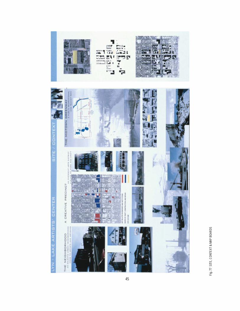
Fig. 7
7 SI
TE, C
ONTE
XT &
MAP
BOA
RDS

46
Fig. 7
8 FL
OOR
PLAN
S

47
Fig. 7
9 EL
EVAT
ION,
SEC
TION
, DET
AILS

48
Fig. 8
0 EL
EVAT
IONS
, SE
CTIO
N

49
A main emphasis of the design of the Artists’ Center was using structural systems as a means of
expressing the purpose of the building. To pursue this aim timber, steel and cast-in-place concrete
were all employed. In some segments of the building the structure is the most prominent architec-
tural concept; in others it is secondary to the surface material or skin of the facade. This section will
provide a narrative of the structural systems in the building, identify structural issues that would have
to be addressed as part of the design, and propose possible solutions and alternate approaches to
structuring the building.
FOOTINGS & FOUNDATIONS:
Prior to addressing questions about the building supports the site itself has to be considered. Due
in part to the site history, the soil bearing capacity needs to be tested. There is existing construction
to be demolished where the Artists’ Center would sit. However, it consists of single-story shed-type
outbuildings that do not give any indications of the site’s suitability for something larger. The site’s
location on a former rail bed and industrial corridor also raises the possibility junk fi ll, e.g.: waste
from prior construction, manufacturing byproducts such as sawdust or ash; that would have to be
excavated and replaced with clean fi ll.
The building site creates some complexity in the design of footings and below-grade walls. The fl oor
level of the woodworking shop is 10’ below the main part of the fi rst level, which aligns with street
grade. Also aligned with the woodworking shop fl oor level are mechanical spaces underneath the
gallery and metalworking studio. Having this substantial below-grade footprint means that earth re-
tention will be required along the full length of the west, north and east sides of the building. Partial
retention would be required on the south side, where grade slopes up from the Greenway to Lyndale
Avenue. At the east end of the building, the retention occurs at the transition from the Large Project
Space to the metalworking studio, rather than at the building perimeter. The building perimeter and
its relation to the property boundary poses additional issues that affect the footing design and con-
XI: STRUCTURAL CONCEPTS
50
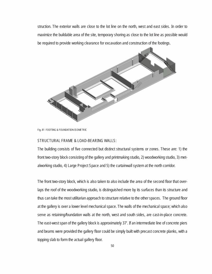
struction. The exterior walls are close to the lot line on the north, west and east sides. In order to
maximize the buildable area of the site, temporary shoring as close to the lot line as possible would
be required to provide working clearance for excavation and construction of the footings.
STRUCTURAL FRAME & LOAD-BEARING WALLS:
The building consists of fi ve connected but distinct structural systems or zones. These are: 1) the
front two-story block consisting of the gallery and printmaking studio, 2) woodworking studio, 3) met-
alworking studio, 4) Large Project Space and 5) the curtainwall system at the north corridor.
The front two-story block, which is also taken to also include the area of the second fl oor that over-
laps the roof of the woodworking studio, is distinguished more by its surfaces than its structure and
thus can take the most utilitarian approach to structure relative to the other spaces. The ground fl oor
at the gallery is over a lower level mechanical space. The walls of the mechanical space; which also
serve as retaining/foundation walls at the north, west and south sides, are cast-in-place concrete.
The east-west span of the gallery block is approximately 37’. If an intermediate line of concrete piers
and beams were provided the gallery fl oor could be simply built with precast concrete planks, with a
topping slab to form the actual gallery fl oor.
Fig. 81 FOOTING & FOUNDATION ISOMETRIC

51
The fi rst and second fl oors of the gallery block can be built with a steel frame. At the fi rst fl oor of
the west side, timber columns are part of the palette of materials there, and these would need to be
integrated with the steel system. The second fl oor is supported with steel joists and metal deck with
a composite concrete slab. The roof could be similarly built with steel joists and metal deck.
The building has a narrow section in the north-south direction. This being the case, either shear walls
or lateral bracing need to be accounted for in north-south oriented walls. The northern half of the east
wall of the gallery block presents a good opportunity to insert diagonal bracing at both the fi rst and
second fl oors. There are minimal openings through this wall, so the bracing could be located here
without an impact on the fl oor plan or circulation.
The woodworking studio was initially conceived of as a post and beam timber structure with perim-
eter columns and girders being the primary load-bearing members. The cast-in-place concrete walls
of the machine room would also serve as intermediate bearing points for the timber roof structure. In
this scheme there would still be spans up to 40’. Achieving this with solid sawn timbers would result in
relatively large sections, raising questions of expense and sourcing. In addition, a massive overhead
structure doesn’t necessarily express the desired architectural intent.
At the pergola over the outdoor project space, having solid timbers is important to the architectural
expression. If a more selective approach to how materials are used was taken, this would be the
place to retain the timber construction. At the interior, glulam girders and beams would be an effec-
tive substitute and still present the sought after character. In addition, glulams would have greater
spanning capability; obviating the possibility of having to add additional column grids and breaking
up the open fl oor areas.

52
Preliminary calculations of solid sawn timber roof beams yielded sizes on the order of 8”x24”. This as-
sumes a roof assembled with 3x solid wood decking, with purlins serving as intermediate members.
The prospect of a 24” beam depth raises the possibility of using wood trusses and eliminating solid
wood beams altogether. Fig. 82 above is a model study of a hybrid roof structure with a combination
of solid sawn timbers, glulam interior girders and wood trusses for the majority of the roof framing.
The structure of the metalworking studio was partially developed in the course of the schematic
design and described in some detail in previous parts of this paper. This part of the building has two
sets of components: the steel columns and beams composing the superstructure and pergola, and
the clerestory trusses. The columns and beams are simple wide fl ange structural shapes. The clere-
story trusses are a typical Pratt truss confi guration, with a non-structural extension of the top chord
forming the clerestory. The trusses have a span of approximately 62’. At this size, welded back-to-
back steel angles could serve as members for the chords and webs. The shared wall between the
metalworking and woodworking studios is another location where diagonal bracing could be placed.
There is glazing between the studios but in this instance having the braces pass in front of the glass
would not be a detriment.
Fig. 82 ISOMETRIC DIAGRAM OF WOODWORKING STUDIO STRUCTURE.
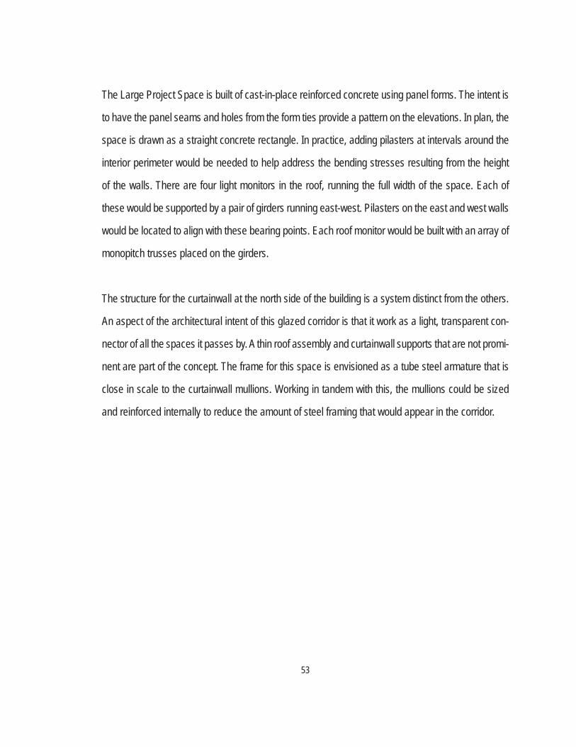
53
The Large Project Space is built of cast-in-place reinforced concrete using panel forms. The intent is
to have the panel seams and holes from the form ties provide a pattern on the elevations. In plan, the
space is drawn as a straight concrete rectangle. In practice, adding pilasters at intervals around the
interior perimeter would be needed to help address the bending stresses resulting from the height
of the walls. There are four light monitors in the roof, running the full width of the space. Each of
these would be supported by a pair of girders running east-west. Pilasters on the east and west walls
would be located to align with these bearing points. Each roof monitor would be built with an array of
monopitch trusses placed on the girders.
The structure for the curtainwall at the north side of the building is a system distinct from the others.
An aspect of the architectural intent of this glazed corridor is that it work as a light, transparent con-
nector of all the spaces it passes by. A thin roof assembly and curtainwall supports that are not promi-
nent are part of the concept. The frame for this space is envisioned as a tube steel armature that is
close in scale to the curtainwall mullions. Working in tandem with this, the mullions could be sized
and reinforced internally to reduce the amount of steel framing that would appear in the corridor.

54
BIBLIOGRAPHY & RESOURCES
Almaas, Ingerid Helsing. “State of the Art [Artists’ Center, Fjaler, Norway].” Architectural Review 1998 Apr., v.203, n.1214, p.59-[63].
Angelil, Marc. “The Construction of a Meta-Physical Structure : Truth and Utility in Nineteenth Century Architectural Theory.” Modulus. 1993.
Banham, Reyner. The Architecture of the Well-Tempered Environment. Chicago, IL: University of Chicago Press, 1984.
“Craft Center at Balerna, Canton Ticino, Switzerland, 1979; architect: Mario Botta.” GA document 1980 Autumn, n.2, p.[50]-[57].
Krell, David Ferrell. Martin Heidegger: Basic Writings. San Franscisco: Harper Collins. 1993.
Landis, Scott. The Workshop Book. Newtown, CT: Taunton Press, 1991.
Lefebvre, Henri. The Production of Space. translated by Donald Nicholson-Smith. Oxford, OX, UK ; Cambridge, Mass., USA : Blackwell, 1991.
Miles, Malcolm. Art, Space and the City: Public Art and Urban Futures. New York: Routledge, 1997
Peppiatt, Michael. Imagination’s Chamber : Artists and Their Studios. Boston : Little, Brown, 1982.
Steiner, Dietmar. “Herzog & de Meuron: Atelier per un Artista, Mulhouse-Pfastalt = Studio for an Artist, Mulhouse-Pfastalt.” Domus 1997 June, n.794, p.10-17.
Swenarton, Mark. Artisans and Architects: the Ruskinian Tradition in Architectural Thought. New York: St. Martin’s Press. 1989.
“Tadao Ando Architect & Associates: Atelier in Oyodo Annex [Osaka, Japan].” Japan Architect 1998 Winter, n.28, p.118-121.
Vance, Mary. Artist Studios: A Bibliography. Monticello, IL: Vance Bibliographies, 1986.
Wang, Wilfried, Ed. Herzog & de Meuron: Projects and Buildings 1982 - 1990. Cambridge, Mass. : Harvard University, Graduate School of Design ; New York : Rizzoli, 1990.
55
Page 1: top: www.altavista.com image library. middle: www.kala.org, Kala Art Institute home page. bottom: www.altavista.com image library.
Page 2: top: www.altavista.com image library. middle: www.altavista.com image library. bottom: http://www.gpsart.co.uk, Glasgow Print Studio home page.
Page 3: top: www.altavista.com image library. middle: www.altavista.com image library. ottom: www.altavista.com image library.
Page 7: top: www.artcars.com, the “Eel Car.”
Page 13: all: from the article: “Craft Center at Balerna, Canton Ticino, Switzerland, 1979; architect: Mario Botta.” GA document. 1980 Autumn, n.2, p.[50]-[57].
Page 14: all: from the article: Steiner, Dietmar. “Herzog & de Meuron: Atelier per un Artista, Mul-house-Pfastalt = Studio for an Artist, Mulhouse-Pfastalt.” Domus 1997 June, n.794,
p.10-17.
Page 15: all: from the article: Almaas, Ingerid Helsing. “State of the Art [Artists’ Center, Fjaler, Nor-way.” Architectural review. 1998 Apr., v.203, n.1214, p.59-[63].
Page 16: all: from the book: Wang, Wilfried, Ed. Herzog & de Meuron: Projects and Buildings 1982 - 1990. Cambridge, Mass. : Harvard University, Graduate School of Design ; New York : Rizzoli, 1990.
Page 17: all: from the article: “Tadao Ando Architect & Associates: Atelier in Oyodo Annex [Osaka, Japan].” Japan Architect 1998 Winter, n.28, p.118-121.
Page 18: top: www.kala.org, Kala Art Institute home page. middle 1: www.altavista.com image li-brary. middle 2: www.altavista.com image library. bottom: www.altavista.com image library.
All other images, drawings and photos are by the author.
IMAGE CREDITS